Potential low-temperature application and hybrid-ionic conducting property of ceria-carbonate...
7
Potential low-temperature application and hybrid-ionic conducting property of ceria-carbonate composite electrolytes for solid oxide fuel cells Liangdong Fan a,b , Chengyang Wang a, *, Mingming Chen a , Jing Di a , Jiaming Zheng a , Bin Zhu b a Key Laboratory for Green Chemical Technology of Ministry of Education, School of Chemical Engineering and Technology, Tianjin University, Tianjin 300072, PR China b Department of Energy Technology, Royal Institute of Technology, Stockholm S-100 44, Sweden article info Article history: Received 14 February 2011 Received in revised form 28 April 2011 Accepted 10 May 2011 Available online 12 June 2011 Keywords: Solid oxide fuel cells Composite electrolyte Compatibility Electrochemical impedance spectroscopy Hybrid-ionic conduction abstract Ceria-carbonate composite materials have been widely investigated as candidate electro- lytes for solid oxide fuel cells operated at 300e600 C. However, fundamental studies on the composite electrolytes are still in the early stages and intensive research is demanded to advance their applications. In this study, the crystallite structure, microstructure, chemical activity, thermal expansion behavior and electrochemical properties of the samaria doped ceria-carbonate (SCC) composite have been investigated. Single cells using the SCC composite electrolyte and Ni-based electrodes were assembled and their electrochemical performances were studied. The SCC composite electrolyte exhibits good chemical compatibility and thermal-matching with Ni-based electrodes. Peak power density up to 916 mW cm 2 was achieved at 550 C, which was attributed to high electrochemical activity of both electrolyte and electrode materials. A stable discharge plateau was obtained under a current density of 1.5 A cm 2 at 550 C for 120 min. In addition, the ionic conducting property of the SCC composite electrolyte was investigated using electrochemical imped- ance spectroscopy technique. It was found that the hybrid-ionic conduction improves the total ionic conductivity and fuel cell performance. These results highlight potential low-temperature application of ceria-carbonate composite electrolytes for solid oxide fuel cells. Copyright ª 2011, Hydrogen Energy Publications, LLC. Published by Elsevier Ltd. All rights reserved. 1. Introduction Solid oxide fuel cells (SOFCs) are potential next-generation energy conversion devices and have reached a proper level of maturity for their high thermodynamic efficiency and fuel flexibility [1]. Conventional SOFCs operating at high temperature (800e1000 C) enable adequate ionic conductivity of the electrolyte and superior catalytic activity of electrode materials; on the other hand it brings many problems, such as high integration costs, materials degradation and limited applications [2]. Therefore, the development of SOFCs operating at intermediate temperatures (600e800 C), or even in a low-temperature range (300e600 C), is urgent since they can effectively overcome these problems. As the heart of fuel cells, electrolytes play an essential role as concerns the overall cell performance. In the past decades, the development of advanced electrolyte materials has been an active research topic. Currently, electrolytes in SOFCs usually * Corresponding author. Tel./fax: þ86 22 27890481. E-mail address: [email protected] (C. Wang). Available at www.sciencedirect.com journal homepage: www.elsevier.com/locate/he international journal of hydrogen energy 36 (2011) 9987 e9993 0360-3199/$ e see front matter Copyright ª 2011, Hydrogen Energy Publications, LLC. Published by Elsevier Ltd. All rights reserved. doi:10.1016/j.ijhydene.2011.05.055
Transcript of Potential low-temperature application and hybrid-ionic conducting property of ceria-carbonate...
i n t e r n a t i o n a l j o u r n a l o f h y d r o g e n en e r g y 3 6 ( 2 0 1 1 ) 9 9 8 7e9 9 9 3
Avai lab le a t www.sc iencedi rec t .com
journa l homepage : www.e lsev ier . com/ loca te /he
Potential low-temperature application and hybrid-ionicconducting property of ceria-carbonate composite electrolytesfor solid oxide fuel cells
Liangdong Fan a,b, Chengyang Wang a,*, Mingming Chen a, Jing Di a, Jiaming Zheng a,Bin Zhu b
aKey Laboratory for Green Chemical Technology of Ministry of Education, School of Chemical Engineering and Technology,
Tianjin University, Tianjin 300072, PR ChinabDepartment of Energy Technology, Royal Institute of Technology, Stockholm S-100 44, Sweden
a r t i c l e i n f o
Article history:
Received 14 February 2011
Received in revised form
28 April 2011
Accepted 10 May 2011
Available online 12 June 2011
Keywords:
Solid oxide fuel cells
Composite electrolyte
Compatibility
Electrochemical impedance
spectroscopy
Hybrid-ionic conduction
* Corresponding author. Tel./fax: þ86 22 278E-mail address: [email protected] (C. W
0360-3199/$ e see front matter Copyright ªdoi:10.1016/j.ijhydene.2011.05.055
a b s t r a c t
Ceria-carbonate composite materials have been widely investigated as candidate electro-
lytes for solid oxide fuel cells operated at 300e600 �C. However, fundamental studies on the
composite electrolytes are still in the early stages and intensive research is demanded to
advance their applications. In this study, the crystallite structure, microstructure, chemical
activity, thermal expansion behavior and electrochemical properties of the samaria doped
ceria-carbonate (SCC) composite have been investigated. Single cells using the SCC
composite electrolyte and Ni-based electrodes were assembled and their electrochemical
performances were studied. The SCC composite electrolyte exhibits good chemical
compatibility and thermal-matching with Ni-based electrodes. Peak power density up to
916 mW cm�2 was achieved at 550 �C, which was attributed to high electrochemical activity
of both electrolyte and electrode materials. A stable discharge plateau was obtained under
a current density of 1.5 A cm�2 at 550 �C for 120 min. In addition, the ionic conducting
property of the SCC composite electrolyte was investigated using electrochemical imped-
ance spectroscopy technique. It was found that the hybrid-ionic conduction improves
the total ionic conductivity and fuel cell performance. These results highlight potential
low-temperature application of ceria-carbonate composite electrolytes for solid oxide fuel
cells.
Copyright ª 2011, Hydrogen Energy Publications, LLC. Published by Elsevier Ltd. All rights
reserved.
1. Introduction high integration costs, materials degradation and limited
Solid oxide fuel cells (SOFCs) are potential next-generation
energy conversion devices and have reached a proper level of
maturity for their high thermodynamic efficiency and fuel
flexibility [1]. Conventional SOFCs operating at high
temperature (800e1000 �C) enable adequate ionic conductivity
of the electrolyte and superior catalytic activity of electrode
materials; on the other hand it brings many problems, such as
90481.ang).2011, Hydrogen Energy P
applications [2]. Therefore, the development of SOFCs
operating at intermediate temperatures (600e800 �C), or evenin a low-temperature range (300e600 �C), is urgent since they
can effectively overcome these problems.
As the heart of fuel cells, electrolytes play an essential role
as concerns the overall cell performance. In the past decades,
thedevelopmentofadvancedelectrolytematerialshasbeenan
active research topic. Currently, electrolytes in SOFCs usually
ublications, LLC. Published by Elsevier Ltd. All rights reserved.
i n t e rn a t i o n a l j o u r n a l o f h y d r o g e n en e r g y 3 6 ( 2 0 1 1 ) 9 9 8 7e9 9 9 39988
consist of single-phase materials, such as stabilized zirconia,
doped ceria oxides [3] and doped LaGaO3 perovskite [4]. Among
these candidates, doped ceria oxides have been greatly
investigated for their low activation energy for oxygen ion
diffusion and well chemically compatible with electrode
materials. Nevertheless, there are still some inherent
drawbacks for ceria-based single-phase electrolyte, such as
the inadequate ionic conductivity at low temperatures and
electronic conduction under low oxygen partial pressure [5],
which remain as obstacles to their widespread applications.
As a result, developing novel electrolyte materials with high
ionic conductivity and low electronic conductivity for low-
temperature utilization is still a challenging issue.
Recently, two-phase composites consisting of doped ceria
oxides and various carbonates have been developed and
extensively studied as functional electrolytes for low-
temperature operating SOFCs because of their impressive
electrical conductivities and unique hybrid-ionic conducting
properties [6e13]. SOFCs using ceria-carbonate composite
electrolytes and Ni-based electrodes (Ni for the anode and
lithiated NiO as cathode) have demonstrated exceptional fuel
cell performances below 600 �C [7,9]. Combined with the low
cost of raw materials and reduced fuel cell manufacturing
processes, ceria-carbonate composites have shown promising
applications in low-temperature SOFCs.
Although the previous performance results are very
encouraging, basic research on composite electrolytes is still
needed. To approach fuel cell performance of commercial
interest, many issues need to be clarified, such as the interac-
tions and thermal expansion properties between cell compo-
nents, fuel cell durability and the possibility for performance
improvement. Besides, numerous results from previous
studies on ionic conducting property of composite electrolytes
in fuel cells are still controversial [7,11,13,14]. For example,
Di et al. [11] had adopted a ceria-carbonate composite as
electrolyte for low-temperature SOFCs and reported that
the composite electrolyte was a mixed proton and oxygen
ion conductor at fuel cell condition and the oxygen ionic
conductivity contributed to the major part of the whole
conductivity. However, Huang et al. [14] found that the ceria-
based composite electrolyte was a proton conductor at the
same operating condition. Therefore, the objective of this
work is to study the chemical and thermal compatibility
between SCC composite electrolytes and Ni-based electrodes
and investigate their operating stability in fuel cells in order to
evaluate their feasibility for low-temperature applications.
The hybrid-ionic conducting property of the composite
electrolyte is also analyzed using the electrochemical
impedance spectroscopy (EIS) technique.
2. Experimental
2.1. Materials preparation
SCC electrolytes with a composition of 80 wt.% Ce0.8S-
m0.2O1.9e20 wt.% (Li2/Na2)CO3 were prepared according to our
previous work [11]. The NiO was synthesized by the citratee
nitrate combustion method. The preparation procedure is
similar to that of composite electrolyte precursor-Ce0.8Sm0.2O1.9
(SDC) [11]. To get a pure nickel oxide, the powders were
calcined at 600 �C for 1 h. The cathode materials-lithiated NiO
powders were prepared by solid-state reaction at 700 �C for 3 h
with an equal molar ratio of LiOH (Guangfu Fine Chemical
Research Institute, China) and as obtained NiO powders.
2.2. Cell construction and performance test
Single cells were fabricated by a one-step dry-pressing and co-
firing technique using the SCC composite as electrolyte. The
electrodes were mixture of catalysts (NiO for anode and
lithiated NiO for cathode) and composite electrolyte at a mass
ratio of 55:45. The anode, electrolyte and cathode powders
were successively loaded in a steel die, and were dry-pressed
in one-step under 300 MPa to form sandwich green pellets.
The green pellet was then sintered in air at 600 �C for 0.5 h.
Finally, both surfaces of the sintered pellet were painted with
silver paste (DAD-87, Shanghai Research Institute of Synthetic
Resins, China) as current collector and sintered in air at 600 �Cfor 0.5 h. The final thicknesses of the anode, electrolyte and
cathode are 500 mm, 250 mm and 200 mm, respectively.
The currentevoltage data were recorded by a fuel cell test
instrument (SM-102, SanMu Corp., China) between 600 �C and
450 �C at 50 �C intervals, using humidified H2 (3 vol.% H2O) as
fuel and flowed air as oxidant. The gas flow rates were
controlled in the range of 80e100 ml min�1. Prior to the elec-
trochemical performance testing, the composite anode was
reduced to NieSCC by flowingH2 at 600 �C for 0.5 h. Thereafter,
air was allowed to pass through the surface of the cathode.
The active area of the single cell is 0.785 cm2. Short-term
stability test was examined under a constant current density
of 1.5 A cm�2 at 550 �C. EIS was recorded under open circuit
voltage (OCV) or discharging conditions during performance
measurements.
2.3. Other characterizations
Crystal structures of the prepared powders were identified by
X-ray diffraction (XRD) at room temperaturewith aD/max 2500
v/pc instrument (Rigaku Corp., Japan) using Cu Ka radiation
(l ¼ 1.5406 A). The powder morphologies and single cell
microstructures were characterized by scanning electron
microscopy (SEM, JSM-6700F, JEOL Ltd., Japan). For electrical
conductivity measurements, SDC and SCC composite pellets
with 13mmindiameterwerepreparedbyuniaxiallypressingof
the powders under 300 MPa and sintering at 1350 �C for 2 h and
650 �Cfor0.5h, respectively.Then,bothsidesofpreparedpellets
were covered with silver electrodes to form symmetrical cells.
Thermal expansion characteristics of the cylindrical cell
components (all sintered at 680 �C for 2 h) weremeasured from
100 �C to 650 �C using a dilatometer (402C, NETZSCH DIL,
Germany) at a ramp rate of 5 �Cmin�1 in air. EISwas performed
on an electrochemical workstation (PARSTAT 2273, Princeton
Applied Research, USA) over a frequency range from 100 kHz to
0.01 Hz with excitation potentials of 10 mV. The inductance
contributions, caused by the stainless steel clamp and the
instrument leads, to ohmic resistances were subtracted by
a blank cell EIS test atdifferent temperatures before theEISdata
were normalized by the thickness and active area of the pellets.
i n t e r n a t i o n a l j o u r n a l o f h y d r o g e n en e r g y 3 6 ( 2 0 1 1 ) 9 9 8 7e9 9 9 3 9989
3. Results and discussion
3.1. Powder morphologies and electrolyte microstructurebefore test
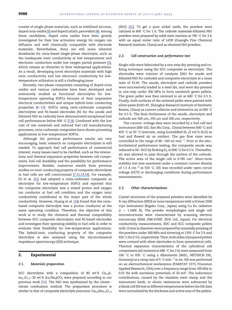
SEM images of SDCandSCCpowders are shown inFig. 1a andb.
It can be seen that SDC powder before pulverization presents
a highly foam-like microstructure with severe agglomeration,
which is the typical structure for materials prepared by the
combustion synthesis method. From Fig. 1b, we can see that
SDC and carbonate are well dispersed and the SDC is
homogeneously covered by carbonate. As shown in Fig. 1c,
sub-micrometer particles with good size distribution are
observed for lithiated NiO prepared by solid-state reaction.
The microstructure of the compacted composite electrolyte
before test is also displayed in Fig. 1d. Plenty of micro-pores
still exist after sintering at 600 �C, which is visibly different
from that of SDC-based SOFCs, in which 95% of relative
density is required to reduce gas leakage and ensure ion
conductivity. SCC composite electrolytes cannot be fully
dense because of the solidifying of carbonate around melting
point during the cooling cycle and the relatively lower
sintering temperature. However, they still can be used as gas-
tight electrolytes for SOFCs when the operating temperature
reaches a critical point.
Fig. 1 e SEM images of the powders: (a) SDC without pulverizatio
the compacted SCC electrolyte layer before the stability test.
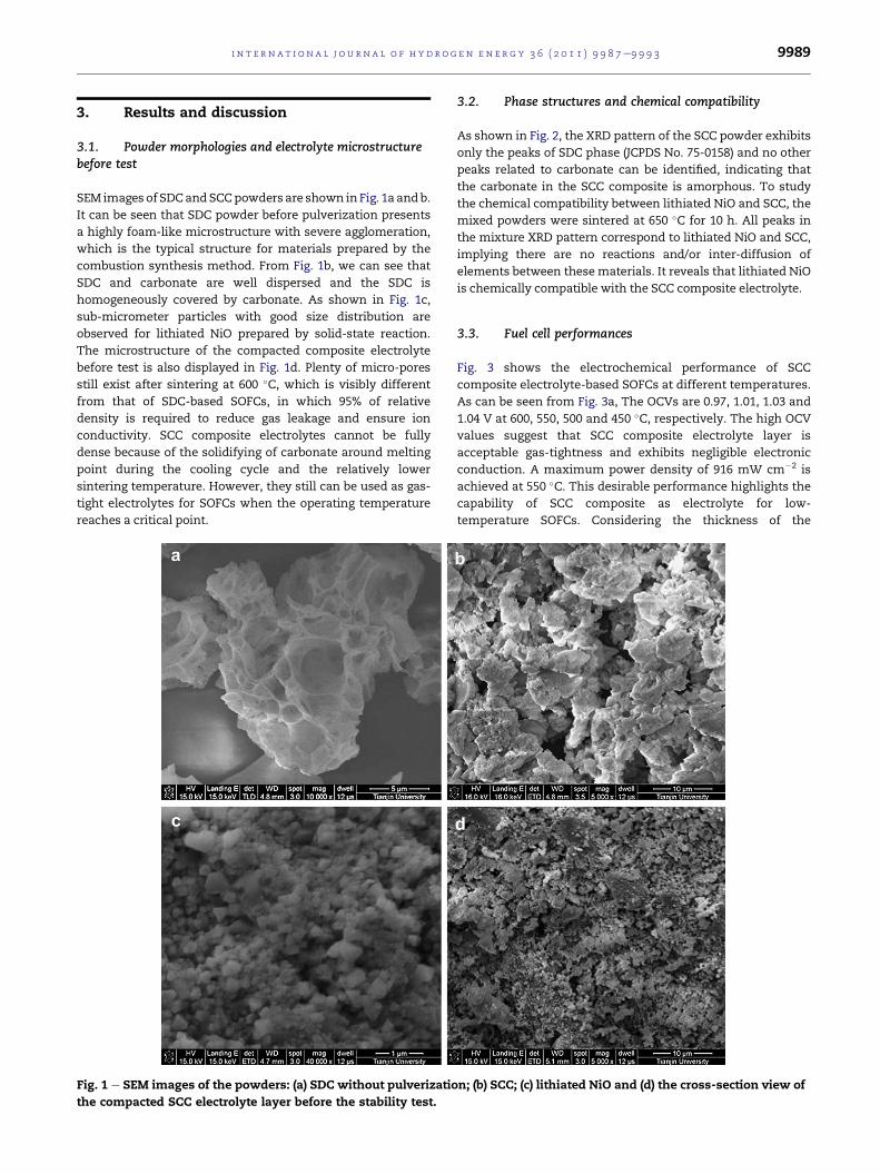
3.2. Phase structures and chemical compatibility
As shown in Fig. 2, the XRD pattern of the SCC powder exhibits
only the peaks of SDC phase (JCPDS No. 75-0158) and no other
peaks related to carbonate can be identified, indicating that
the carbonate in the SCC composite is amorphous. To study
the chemical compatibility between lithiated NiO and SCC, the
mixed powders were sintered at 650 �C for 10 h. All peaks in
the mixture XRD pattern correspond to lithiated NiO and SCC,
implying there are no reactions and/or inter-diffusion of
elements between thesematerials. It reveals that lithiated NiO
is chemically compatible with the SCC composite electrolyte.
3.3. Fuel cell performances
Fig. 3 shows the electrochemical performance of SCC
composite electrolyte-based SOFCs at different temperatures.
As can be seen from Fig. 3a, The OCVs are 0.97, 1.01, 1.03 and
1.04 V at 600, 550, 500 and 450 �C, respectively. The high OCV
values suggest that SCC composite electrolyte layer is
acceptable gas-tightness and exhibits negligible electronic
conduction. A maximum power density of 916 mW cm�2 is
achieved at 550 �C. This desirable performance highlights the
capability of SCC composite as electrolyte for low-
temperature SOFCs. Considering the thickness of the
n; (b) SCC; (c) lithiated NiO and (d) the cross-section view of
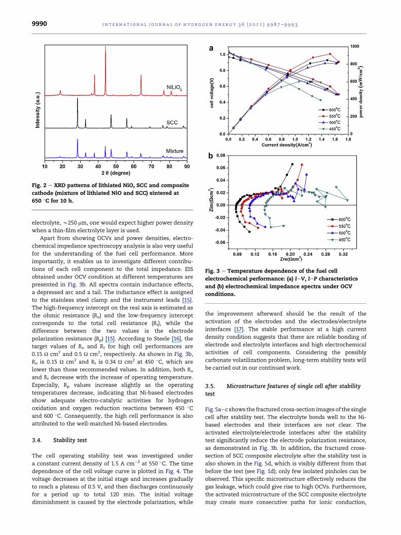
Fig. 2 e XRD patterns of lithiated NiO, SCC and composite
cathode (mixture of lithiated NiO and SCC) sintered at
650 �C for 10 h.
Fig. 3 e Temperature dependence of the fuel cell
electrochemical performance: (a) IeV, IeP characteristics
and (b) electrochemical impedance spectra under OCV
conditions.
i n t e rn a t i o n a l j o u r n a l o f h y d r o g e n en e r g y 3 6 ( 2 0 1 1 ) 9 9 8 7e9 9 9 39990
electrolyte, w250 mm, one would expect higher power density
when a thin-film electrolyte layer is used.
Apart from showing OCVs and power densities, electro-
chemical impedance spectroscopy analysis is also very useful
for the understanding of the fuel cell performance. More
importantly, it enables us to investigate different contribu-
tions of each cell component to the total impedance. EIS
obtained under OCV condition at different temperatures are
presented in Fig. 3b. All spectra contain inductance effects,
a depressed arc and a tail. The inductance effect is assigned
to the stainless steel clamp and the instrument leads [15].
The high-frequency intercept on the real axis is estimated as
the ohmic resistance (Ro) and the low-frequency intercept
corresponds to the total cell resistance (Rt), while the
difference between the two values is the electrode
polarization resistance (Rp) [15]. According to Steele [16], the
target values of Ro and Rt for high cell performances are
0.15 U cm2 and 0.5 U cm2, respectively. As shown in Fig. 3b,
Ro is 0.15 U cm2 and Rt is 0.34 U cm2 at 450 �C, which are
lower than those recommended values. In addition, both Ro
and Rt decrease with the increase of operating temperature.
Especially, Rp values increase slightly as the operating
temperatures decrease, indicating that Ni-based electrodes
show adequate electro-catalytic activities for hydrogen
oxidation and oxygen reduction reactions between 450 �Cand 600 �C. Consequently, the high cell performance is also
attributed to the well-matched Ni-based electrodes.
3.4. Stability test
The cell operating stability test was investigated under
a constant current density of 1.5 A cm�2 at 550 �C. The time
dependence of the cell voltage curve is plotted in Fig. 4. The
voltage decreases at the initial stage and increases gradually
to reach a plateau of 0.5 V, and then discharges continuously
for a period up to total 120 min. The initial voltage
diminishment is caused by the electrode polarization, while
the improvement afterward should be the result of the
activation of the electrodes and the electrodes/electrolyte
interfaces [17]. The stable performance at a high current
density condition suggests that there are reliable bonding of
electrode and electrolyte interfaces and high electrochemical
activities of cell components. Considering the possibly
carbonate volatilization problem, long-term stability tests will
be carried out in our continued work.
3.5. Microstructure features of single cell after stabilitytest
Fig. 5aec shows the fractured cross-section images of the single
cell after stability test. The electrolyte bonds well to the Ni-
based electrodes and their interfaces are not clear. The
activated electrolyte/electrode interfaces after the stability
test significantly reduce the electrode polarization resistance,
as demonstrated in Fig. 3b. In addition, the fractured cross-
section of SCC composite electrolyte after the stability test is
also shown in the Fig. 5d, which is visibly different from that
before the test (see Fig. 1d); only few isolated pinholes can be
observed. This specific microstructure effectively reduces the
gas leakage, which could give rise to high OCVs. Furthermore,
the activated microstructure of the SCC composite electrolyte
may create more consecutive paths for ionic conduction,
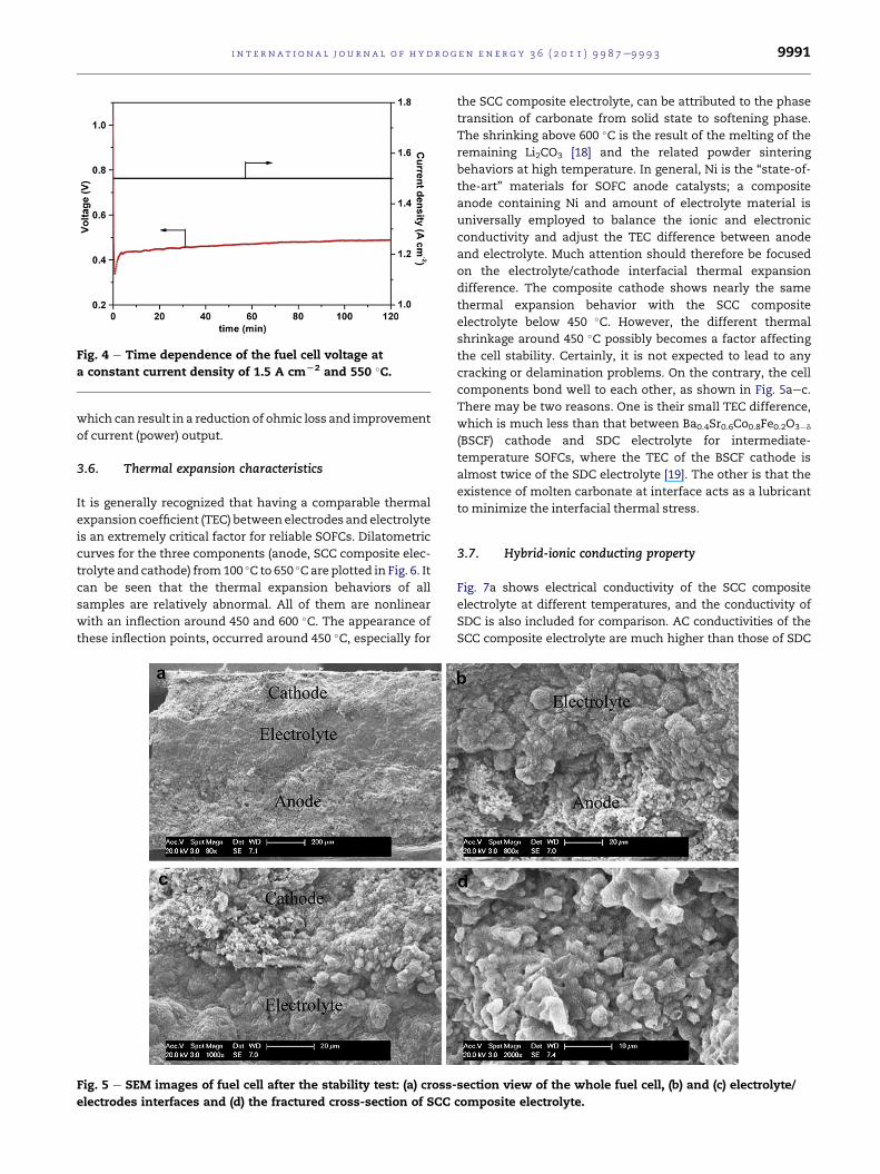
Fig. 4 e Time dependence of the fuel cell voltage at
a constant current density of 1.5 A cmL2 and 550 �C.
i n t e r n a t i o n a l j o u r n a l o f h y d r o g e n en e r g y 3 6 ( 2 0 1 1 ) 9 9 8 7e9 9 9 3 9991
which can result in a reduction of ohmic loss and improvement
of current (power) output.
3.6. Thermal expansion characteristics
It is generally recognized that having a comparable thermal
expansion coefficient (TEC) between electrodes and electrolyte
is an extremely critical factor for reliable SOFCs. Dilatometric
curves for the three components (anode, SCC composite elec-
trolyte and cathode) from100 �C to 650 �Care plotted in Fig. 6. It
can be seen that the thermal expansion behaviors of all
samples are relatively abnormal. All of them are nonlinear
with an inflection around 450 and 600 �C. The appearance of
these inflection points, occurred around 450 �C, especially for
Fig. 5 e SEM images of fuel cell after the stability test: (a) cross-
electrodes interfaces and (d) the fractured cross-section of SCC
the SCC composite electrolyte, can be attributed to the phase
transition of carbonate from solid state to softening phase.
The shrinking above 600 �C is the result of the melting of the
remaining Li2CO3 [18] and the related powder sintering
behaviors at high temperature. In general, Ni is the “state-of-
the-art” materials for SOFC anode catalysts; a composite
anode containing Ni and amount of electrolyte material is
universally employed to balance the ionic and electronic
conductivity and adjust the TEC difference between anode
and electrolyte. Much attention should therefore be focused
on the electrolyte/cathode interfacial thermal expansion
difference. The composite cathode shows nearly the same
thermal expansion behavior with the SCC composite
electrolyte below 450 �C. However, the different thermal
shrinkage around 450 �C possibly becomes a factor affecting
the cell stability. Certainly, it is not expected to lead to any
cracking or delamination problems. On the contrary, the cell
components bond well to each other, as shown in Fig. 5aec.
There may be two reasons. One is their small TEC difference,
which is much less than that between Ba0.4Sr0.6Co0.8Fe0.2O3�d
(BSCF) cathode and SDC electrolyte for intermediate-
temperature SOFCs, where the TEC of the BSCF cathode is
almost twice of the SDC electrolyte [19]. The other is that the
existence of molten carbonate at interface acts as a lubricant
to minimize the interfacial thermal stress.
3.7. Hybrid-ionic conducting property
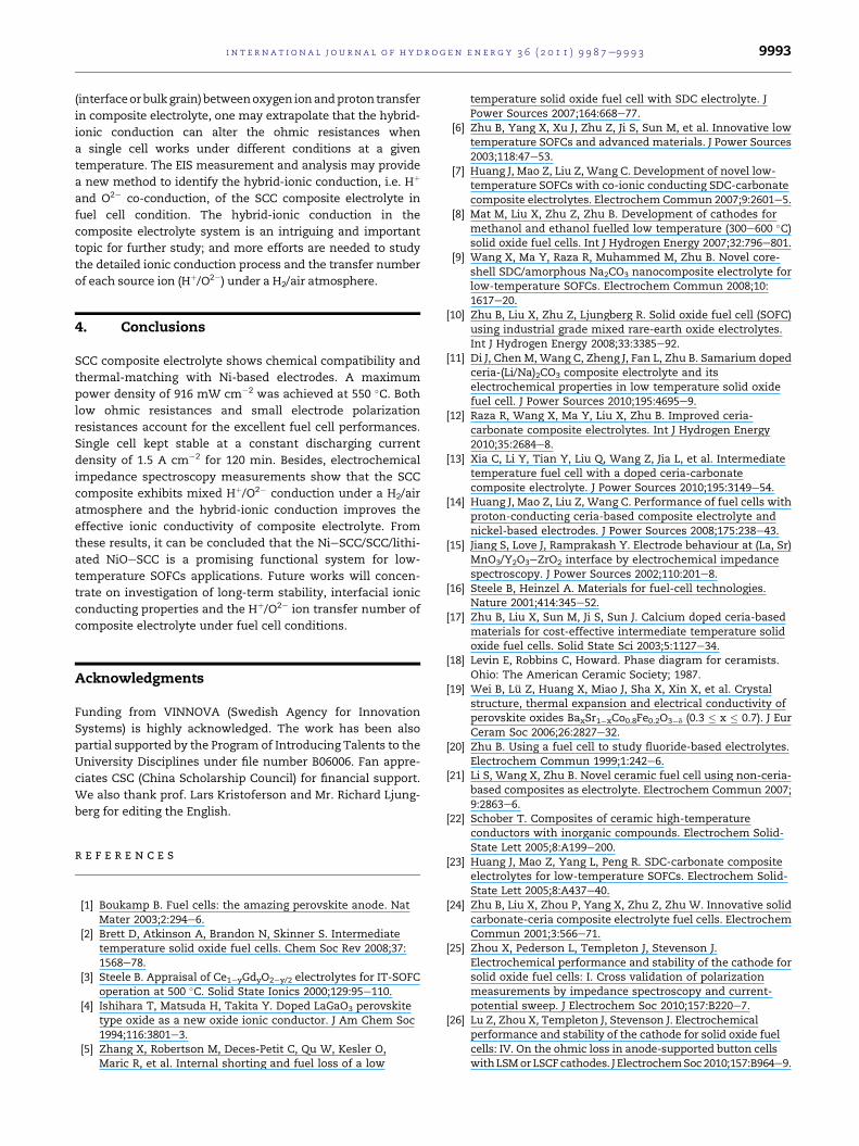
Fig. 7a shows electrical conductivity of the SCC composite
electrolyte at different temperatures, and the conductivity of
SDC is also included for comparison. AC conductivities of the
SCC composite electrolyte are much higher than those of SDC
section view of the whole fuel cell, (b) and (c) electrolyte/
composite electrolyte.
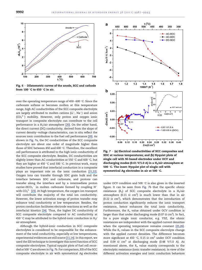
Fig. 6 e Dilatometric curves of the anode, SCC and cathode
from 100 �C to 650 �C in air.
Fig. 7 e (a) Electrical conductivities of SCC composites and
SDC at various temperatures; and (b) Nyquist plots of
single cell with Ni-based electrodes under OCV and
discharging modes (0.61 V/1.0 A) in a H2/air atmosphere at
500 �C. The inset: Nyquist plot of single cell with
symmetrical Ag electrodes in air at 500 �C.
i n t e rn a t i o n a l j o u r n a l o f h y d r o g e n en e r g y 3 6 ( 2 0 1 1 ) 9 9 8 7e9 9 9 39992
over the operating temperature range of 450e600 �C. Since the
carbonate softens or becomes molten at this temperature
range, high AC conductivities of the SCC composite electrolyte
are largely attributed to molten cations (Liþ, Naþ) and anion
(CO32�) mobility. However, only proton and oxygen ionic
transport in composite electrolyte can contribute to the cell
performance in a H2/air atmosphere [20]. On the other hand,
the direct current (DC) conductivity, derived from the slope of
current densityevoltage characteristics, can in situ reflect the
sources ionic contribution to the fuel cell performance [20]. As
shown in Fig. 7a, the DC conductivities of the SCC composite
electrolyte are about one order of magnitude higher than
those of SDC between 450 and 600 �C. Therefore, the excellent
cell performance is attributed to the high ionic conductivity of
the SCC composite electrolyte. Besides, DC conductivities are
slightly lower than AC conductivities at 550 �C and 600 �C, butthey are higher at 450 �C and 500 �C. In previous work, many
studies have proved that interfacial conduction in a composite
plays an important role on the ionic conduction [21,22].
Oxygen ions can transfer through SDC grain bulk and the
interface between SDC and carbonate, and protons can
transfer along the interface and by a intermediate proton
carrier-HCO3� in molten carbonate formed by coupling Hþ
with CO32� [23]. At high temperature, the oxygen ion transport
will contribute the majority of the total ion conductivity.
However, the lower activation energy of proton transfer may
enhance total conductivity at low temperature. Besides, the
proton conduction facilitates electrode reactions as well as the
interfacial kinetics [24]. Thus, the higher DC conductivity of
SCC composite electrolyte compared to AC conductivity at
450 �C may be attributed to the hybrid-ionic conduction in H2/
air atmosphere.
Although the hybrid-ionic conduction in SCC composite
electrolytes is considered to be responsible for the enhance-
ment of the total conductivity, especially at low temperatures,
experimental evidences are still scarce [11,14]. In this report,we
used the EIS technique to investigate this novel function of SCC
composite electrolytes. Typical nyquist plots of fuel cell recor-
dedat500 �Care shown inFig. 7b. For comparison, EISof theSCC
composite electrolyte in air with symmetrical Ag electrodes
under OCV condition and 500 �C is also given in the inserted
figure. It can be seen from Fig. 7b that the specific ohmic
resistance (Ro) of SCC composite electrolyte in a H2/air
atmosphere (0.11 U cm2) is much lower than that in air
(0.22 U cm2), which demonstrates that the introduction of
proton conduction significantly reduces the ionic transport
resistance, hence enhances the total ionic conductivity.
Furthermore, the Ro value obtained under OCV condition is
larger than that under discharging mode (0.07 U cm2). In fact,
for a pure single ionic conductor, e.g. YSZ, the ohmic
resistances are independent with the applied current densities
when the operating temperature remains constant [25,26].
While the Ro values in the SCC composite electrolyte change
with the applied current densities. The difference becomes
more significant at 450 �C, 0.15 U cm2 under OCV condition
and 0.09 U cm2 at discharging mode (0.48 V/1.0 A). As
mentioned above, the Ro value mainly corresponds to the
electrolytic resistance (ionic transfer resistance). In view of the
different activation energies and ionic conduction behaviors
i n t e r n a t i o n a l j o u r n a l o f h y d r o g e n en e r g y 3 6 ( 2 0 1 1 ) 9 9 8 7e9 9 9 3 9993
(interfaceorbulkgrain)betweenoxygen ionandproton transfer
in composite electrolyte, one may extrapolate that the hybrid-
ionic conduction can alter the ohmic resistances when
a single cell works under different conditions at a given
temperature. The EIS measurement and analysis may provide
a new method to identify the hybrid-ionic conduction, i.e. Hþ
and O2� co-conduction, of the SCC composite electrolyte in
fuel cell condition. The hybrid-ionic conduction in the
composite electrolyte system is an intriguing and important
topic for further study; and more efforts are needed to study
the detailed ionic conduction process and the transfer number
of each source ion (Hþ/O2�) under a H2/air atmosphere.
4. Conclusions
SCC composite electrolyte shows chemical compatibility and
thermal-matching with Ni-based electrodes. A maximum
power density of 916 mW cm�2 was achieved at 550 �C. Bothlow ohmic resistances and small electrode polarization
resistances account for the excellent fuel cell performances.
Single cell kept stable at a constant discharging current
density of 1.5 A cm�2 for 120 min. Besides, electrochemical
impedance spectroscopy measurements show that the SCC
composite exhibits mixed Hþ/O2� conduction under a H2/air
atmosphere and the hybrid-ionic conduction improves the
effective ionic conductivity of composite electrolyte. From
these results, it can be concluded that the NieSCC/SCC/lithi-
ated NiOeSCC is a promising functional system for low-
temperature SOFCs applications. Future works will concen-
trate on investigation of long-term stability, interfacial ionic
conducting properties and the Hþ/O2� ion transfer number of
composite electrolyte under fuel cell conditions.
Acknowledgments
Funding from VINNOVA (Swedish Agency for Innovation
Systems) is highly acknowledged. The work has been also
partial supported by the Program of Introducing Talents to the
University Disciplines under file number B06006. Fan appre-
ciates CSC (China Scholarship Council) for financial support.
We also thank prof. Lars Kristoferson and Mr. Richard Ljung-
berg for editing the English.
r e f e r e n c e s
[1] Boukamp B. Fuel cells: the amazing perovskite anode. NatMater 2003;2:294e6.
[2] Brett D, Atkinson A, Brandon N, Skinner S. Intermediatetemperature solid oxide fuel cells. Chem Soc Rev 2008;37:1568e78.
[3] Steele B. Appraisal of Ce1�yGdyO2�y/2 electrolytes for IT-SOFCoperation at 500 �C. Solid State Ionics 2000;129:95e110.
[4] Ishihara T, Matsuda H, Takita Y. Doped LaGaO3 perovskitetype oxide as a new oxide ionic conductor. J Am Chem Soc1994;116:3801e3.
[5] Zhang X, Robertson M, Deces-Petit C, Qu W, Kesler O,Maric R, et al. Internal shorting and fuel loss of a low
temperature solid oxide fuel cell with SDC electrolyte. JPower Sources 2007;164:668e77.
[6] Zhu B, Yang X, Xu J, Zhu Z, Ji S, Sun M, et al. Innovative lowtemperature SOFCs and advanced materials. J Power Sources2003;118:47e53.
[7] Huang J, Mao Z, Liu Z, Wang C. Development of novel low-temperature SOFCs with co-ionic conducting SDC-carbonatecomposite electrolytes. Electrochem Commun 2007;9:2601e5.
[8] Mat M, Liu X, Zhu Z, Zhu B. Development of cathodes formethanol and ethanol fuelled low temperature (300e600 �C)solid oxide fuel cells. Int J Hydrogen Energy 2007;32:796e801.
[9] Wang X, Ma Y, Raza R, Muhammed M, Zhu B. Novel core-shell SDC/amorphous Na2CO3 nanocomposite electrolyte forlow-temperature SOFCs. Electrochem Commun 2008;10:1617e20.
[10] Zhu B, Liu X, Zhu Z, Ljungberg R. Solid oxide fuel cell (SOFC)using industrial grade mixed rare-earth oxide electrolytes.Int J Hydrogen Energy 2008;33:3385e92.
[11] Di J, Chen M, Wang C, Zheng J, Fan L, Zhu B. Samarium dopedceria-(Li/Na)2CO3 composite electrolyte and itselectrochemical properties in low temperature solid oxidefuel cell. J Power Sources 2010;195:4695e9.
[12] Raza R, Wang X, Ma Y, Liu X, Zhu B. Improved ceria-carbonate composite electrolytes. Int J Hydrogen Energy2010;35:2684e8.
[13] Xia C, Li Y, Tian Y, Liu Q, Wang Z, Jia L, et al. Intermediatetemperature fuel cell with a doped ceria-carbonatecomposite electrolyte. J Power Sources 2010;195:3149e54.
[14] Huang J, Mao Z, Liu Z, Wang C. Performance of fuel cells withproton-conducting ceria-based composite electrolyte andnickel-based electrodes. J Power Sources 2008;175:238e43.
[15] Jiang S, Love J, Ramprakash Y. Electrode behaviour at (La, Sr)MnO3/Y2O3eZrO2 interface by electrochemical impedancespectroscopy. J Power Sources 2002;110:201e8.
[16] Steele B, Heinzel A. Materials for fuel-cell technologies.Nature 2001;414:345e52.
[17] Zhu B, Liu X, Sun M, Ji S, Sun J. Calcium doped ceria-basedmaterials for cost-effective intermediate temperature solidoxide fuel cells. Solid State Sci 2003;5:1127e34.
[18] Levin E, Robbins C, Howard. Phase diagram for ceramists.Ohio: The American Ceramic Society; 1987.
[19] Wei B, Lu Z, Huang X, Miao J, Sha X, Xin X, et al. Crystalstructure, thermal expansion and electrical conductivity ofperovskite oxides BaxSr1�xCo0.8Fe0.2O3�d (0.3 � x � 0.7). J EurCeram Soc 2006;26:2827e32.
[20] Zhu B. Using a fuel cell to study fluoride-based electrolytes.Electrochem Commun 1999;1:242e6.
[21] Li S, Wang X, Zhu B. Novel ceramic fuel cell using non-ceria-based composites as electrolyte. Electrochem Commun 2007;9:2863e6.
[22] Schober T. Composites of ceramic high-temperatureconductors with inorganic compounds. Electrochem Solid-State Lett 2005;8:A199e200.
[23] Huang J, Mao Z, Yang L, Peng R. SDC-carbonate compositeelectrolytes for low-temperature SOFCs. Electrochem Solid-State Lett 2005;8:A437e40.
[24] Zhu B, Liu X, Zhou P, Yang X, Zhu Z, Zhu W. Innovative solidcarbonate-ceria composite electrolyte fuel cells. ElectrochemCommun 2001;3:566e71.
[25] Zhou X, Pederson L, Templeton J, Stevenson J.Electrochemical performance and stability of the cathode forsolid oxide fuel cells: I. Cross validation of polarizationmeasurements by impedance spectroscopy and current-potential sweep. J Electrochem Soc 2010;157:B220e7.
[26] Lu Z, Zhou X, Templeton J, Stevenson J. Electrochemicalperformance and stability of the cathode for solid oxide fuelcells: IV. On the ohmic loss in anode-supported button cellswithLSMorLSCFcathodes. J ElectrochemSoc 2010;157:B964e9.