Electrochemical incineration of sulfanilic acid at a boron-doped diamond anode
Journal of Power Sources 196 (2011) 1019–1029
Contents lists available at ScienceDirect
Journal of Power Sources
journa l homepage: www.e lsev ier .com/ locate / jpowsour
Study on local morphological changes of nickel in solid oxide fuel cell anodeusing porous Ni pellet electrode
Zhenjun Jiaoa,!, Norikazu Takagia, Naoki Shikazonoa, Nobuhide Kasagib
a Institute of Industrial Science, University of Tokyo, 4-6-1 Komaba, Meguro-ku, Tokyo 153-8505, Japanb Department of Mechanical Engineering, University of Tokyo, Bunkyo-ku, Tokyo 113-8656, Japan
a r t i c l e i n f o
Article history:Received 4 March 2010Received in revised form 17 August 2010Accepted 18 August 2010Available online 26 August 2010
Keywords:SOFCTPB depositionNi redistributionNi dropletInterlock
a b s t r a c t
Morphological change of nickel, especially the aggregation of nickel, in solid oxide fuel cell anode isan important deactivation mechanism which results in long-period degradation of anode. In order tostudy the mechanisms which cause local morphological changes of nickel in solid oxide fuel cell anode,porous nickel pellet, which is mechanically pressed against dense YSZ pellet with LSM cathode, wasemployed as the anode of the cell. The cell was tested by static-potential method in hydrogen withdifferent humidities environment for 60 h. The study focused on the vicinity of three phase boundarywhich concentrated at nickel–YSZ interface. After the discharging test, the cell performance and themicrostructure at nickel–YSZ contacting point of interface were studied and correlated to nickel mor-phological changes. The interlocking effect and the spreading of densified nickel layer phenomena wereobserved between nickel and YSZ substrate after discharging with an anode to cathode terminal voltage of0.6 V. Humidity enhanced nickel surface diffusion and humidity gradient driving vaporization–depositionmechanism, which caused the growing and merging of independent nickel droplets, were used to explainthe local morphological changes and redistribution of nickel inside and along the edge of YSZ surfacebonded nickel cluster, respectively. The bulk nickel morphological changes were also studied to supportthe humidity enhanced nickel surface diffusion mechanism. The competition of interlocking effect, nickelredistribution at TPB and bulk nickel sintering finally determined the cell performance.
© 2010 Elsevier B.V. All rights reserved.
1. Introduction
Solid oxide fuel cell (SOFC) has been emerged as an attractivedevice because of its advantages such as fuel flexibility and highefficiency. The current challenge focuses on the long-time stabilityand durability of SOFC electrodes. In the stationary applications,more than 40,000 h lifetime is generally required. The SOFC anodeexhibits slow degradation in long-time discharging experimentswith nickel (Ni, hereafter) coarsening, which can be explained byparticle sintering [1]. With higher current density or overpoten-tial, rapid degradation or even sudden failing of the cell is observed[2]. Generally speaking, the performance degradation and failureare correlated to the electrode reaction mechanisms. In conventi-nal SOFC anodes, porous Ni–YSZ cermet is widely used, while Niexhibits certain morphological changes at the cell operating tem-perature. Thus, great efforts have been payed to investigate thefactors which influence the anode aging process.
! Corresponding author. Tel.: +81 354526777; fax: +81 354526777.E-mail addresses: [email protected] (Z. Jiao), [email protected]
(N. Shikazono).
Simwonis et al. [3] studied the coarsening of Ni particles inporous anode and correlated the changes in electrical conductivitywith the microstructural parameters. A large decrease in electrodeelectrical conductivity was observed in 4000 h exposure in humid-ified hydrogen without discharging, which can be explained by theincrease of average Ni particle size from 2 to 2.6 !m. Koch et al.[1] tested the performance and degradation of SOFC under severaloperating conditions. A critical anode–cathode voltage was foundto be around 0.75 V, below which the degradation rates were sig-nificant. The same result has also been proved by Matsui et al. [2],and at the same time, the influence of fuel humidity was observedto be significant on the performance and stability of Ni–YSZ cermetanode. In their experiments, sudden failure of the cell was observedwhen the fuel humidity was 40%. Rapid microstructure change ofNi was observed. It can be concluded that some factors other thansintering of Ni may cause degradation or even sudden death of theSOFC anode. The possible reasons can be attributed to the localdegradation at three phase boundary (TPB, hereafter). However, theelementary nature of the reaction steps at TPB is still unclear. Good-win et al. [4] predicted that the effective distance from TPB is below100 nm, and out of this distance the reaction rates are independentof position because of the equilibrium established between solidsurface and gas phase. Marcel et al. [5] built their model for surface
0378-7753/$ – see front matter © 2010 Elsevier B.V. All rights reserved.doi:10.1016/j.jpowsour.2010.08.047
1020 Z. Jiao et al. / Journal of Power Sources 196 (2011) 1019–1029
transport process and concluded that the reactants concentrationsnear TPB may largely deviate from those derived from thermody-namical equilibrium considerations. This supports the assumptionof local degradation at TPB. Hansen et al. [6] studied the Ni–YSZinteraction along TPB by using Ni wire as a simplified anode. A filmof impurities was found at Ni–YSZ interface while impurity ridgeswere also found at TPB. At the same time, Ni redistribution wasfound to form hill and valley structures in sub-micron scale at thecontacting area. Several kinds of impurities were found in the ridgealong TPB, which made the local reaction even more complex. Intheir study, no model was proposed to explain the local morpholog-ical change of Ni. In order to elucidate the reaction mechanism withpure Ni, Mazusaki et al. [7] employed Ni stripe pattern electrodesprepared on the surface of YSZ with well defined morphology. Therate of anodic reaction was found to be determined by the reac-tion of hydrogen and the absorbed oxygen on Ni surface. Fromthe literature, it can be concluded that the long-period degrada-tion of Ni–YSZ cermet anode is due to Ni migration [1,8,9] whichcan cause the coarsening of Ni network. According to the authors’knowledge, no systematical work has been carried out to studythe local morphological changes of Ni and correlate them to cellperformances.
In this paper, a porous Ni pellet which was mechnically pressedagainst the dense YSZ electrolyte pellet, with LSM cathode screen-printed, was employed as an anode. The study focuses on the localmorphological changes of Ni at Ni–YSZ interface. Compared to nor-mal Ni–YSZ composite anode, this new method has the advantageof easy observation of the reaction sites at Ni–YSZ interface, whichfacilitates the correlation of phase changes to cell performances. Inaddition, this method can also be applied to observe the influencesof operating gas environment on bulk Ni particle simultaneously[6,7,10].
2. Experimental devices
2.1. Preparation of experimental materials
NiO powder used in this study has an average particle diameterof 1.1 !m. The powder was then ball milled with 10 wt% organicpore former in ethanol for 24 h and dried in air at 200 "C. The porousNiO pellets were obtained by uniaxial-pressing in a steel die of adiameter 20 mm at a pressure of 20 MPa. The pressed pellets werethen sintered at 1400 "C for 3 h to get porous NiO pellets with adiameters of 16 mm and a thickness of 0.5 mm.
(La0.8Sr0.2)0.97MnO3 (LSM) powder (0.4 !m) was used as cath-ode material. The powder was mixed with the terpineol solvent andthe ethylcellulose binder in agate mortar to obtain cathode printingslurry. And the slurry was screen-printed onto commercial denseYSZ pellet (diameter 20 mm, thickness 0.5 mm) with a diameter of10 mm. After screen printing, the cathode was sintered at 1150 "Cfor 3 h.
2.2. Fuel cell measurement system
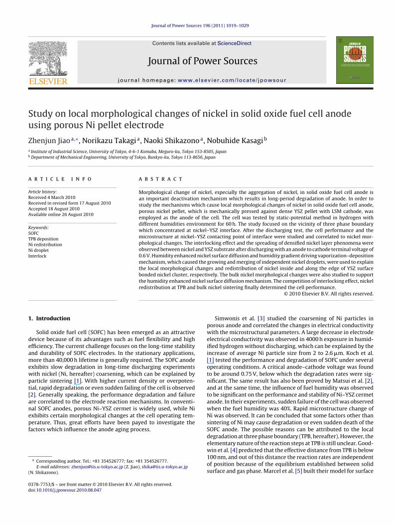
The SOFC performance measurement setup is shown in Fig. 1. Ptmeshes was used as current collectors, which were pressed againstthe electrodes by springs connected to alumina tubes. Glass ringswere used as seals between two outer alumina tubes, and the twoouter tubes were also pressed against the cell by springs. The YSZpellet was surrounded by a Pt wire as reference electrode. Pt pastewas used to enhance the conductive connection between Pt wireand YSZ pellet. Nitrogen was used as the protective gas in theinitial heating up stage. After the furnace temperature had beenincreased to 600 "C, glass seals started to melt and covered bothedges of the cell, the reference electrode and two outer tube edges,
Fig. 1. Schematic of SOFC measurement setup.
which resulted in good sealing. Then, dry hydrogen gas (50 sccm)was introduced to reduce the porous NiO pellet for 1 h before celltesting was conducted. The performance of SOFC was evaluated at800 "C by using humidified hydrogen as a fuel and pure oxygen asan oxidant (50 sccm for both anode and cathode). H2O bubbler wasused to control the fuel humidity. In order to enhance the local elec-trochemical reactions at TPB, low terminal voltages were appliedin the cell potential-static discharging experiments [1].
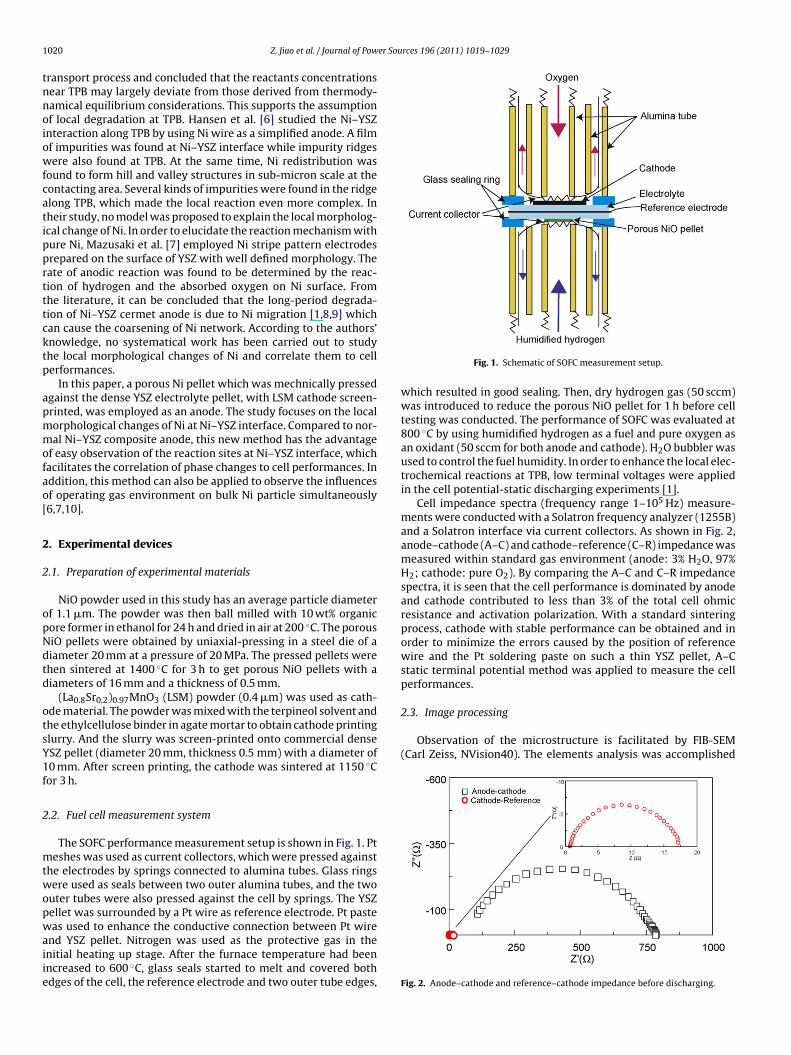
Cell impedance spectra (frequency range 1–105 Hz) measure-ments were conducted with a Solatron frequency analyzer (1255B)and a Solatron interface via current collectors. As shown in Fig. 2,anode–cathode (A–C) and cathode–reference (C–R) impedance wasmeasured within standard gas environment (anode: 3% H2O, 97%H2; cathode: pure O2). By comparing the A–C and C–R impedancespectra, it is seen that the cell performance is dominated by anodeand cathode contributed to less than 3% of the total cell ohmicresistance and activation polarization. With a standard sinteringprocess, cathode with stable performance can be obtained and inorder to minimize the errors caused by the position of referencewire and the Pt soldering paste on such a thin YSZ pellet, A–Cstatic terminal potential method was applied to measure the cellperformances.
2.3. Image processing
Observation of the microstructure is facilitated by FIB-SEM(Carl Zeiss, NVision40). The elements analysis was accomplished
Fig. 2. Anode–cathode and reference–cathode impedance before discharging.
Z. Jiao et al. / Journal of Power Sources 196 (2011) 1019–1029 1021
Fig. 3. Cell performances measured in different humidified hydrogen withpotential-static method (A–C terminal voltage, 0.6 V).
by energy dispersive X-ray spectroscopy (EDX; Thermo Electron,NSS300). Cross-section of sample to be observed was polished byAr-ion beam cross-section polisher (JEOL Ltd., SM-09010), whichprovides less damage and smoother cross-section compared to thediamond slurry polishing.
3. Experimental results
3.1. Cell performances within different humidified environments
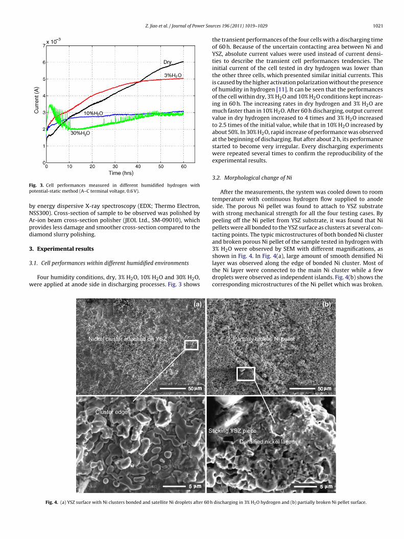
Four humidity conditions, dry, 3% H2O, 10% H2O and 30% H2O,were applied at anode side in discharging processes. Fig. 3 shows
the transient performances of the four cells with a discharging timeof 60 h. Because of the uncertain contacting area between Ni andYSZ, absolute current values were used instead of current densi-ties to describe the transient cell performances tendencies. Theinitial current of the cell tested in dry hydrogen was lower thanthe other three cells, which presented similar initial currents. Thisis caused by the higher activation polarization without the presenceof humidity in hydrogen [11]. It can be seen that the performancesof the cell within dry, 3% H2O and 10% H2O conditions kept increas-ing in 60 h. The increasing rates in dry hydrogen and 3% H2O aremuch faster than in 10% H2O. After 60 h discharging, output currentvalue in dry hydrogen increased to 4 times and 3% H2O increasedto 2.5 times of the initial value, while that in 10% H2O increased byabout 50%. In 30% H2O, rapid increase of performance was observedat the beginning of discharging. But after about 2 h, its performancestarted to become very irregular. Every discharging experimentswere repeated several times to confirm the reproducibility of theexperimental results.
3.2. Morphological change of Ni
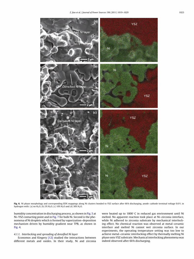
After the measurements, the system was cooled down to roomtemperature with continuous hydrogen flow supplied to anodeside. The porous Ni pellet was found to attach to YSZ substratewith strong mechanical strength for all the four testing cases. Bypeeling off the Ni pellet from YSZ substrate, it was found that Nipellets were all bonded to the YSZ surface as clusters at several con-tacting points. The typic microstructures of both bonded Ni clusterand broken porous Ni pellet of the sample tested in hydrogen with3% H2O were observed by SEM with different magnifications, asshown in Fig. 4. In Fig. 4(a), large amount of smooth densified Nilayer was observed along the edge of bonded Ni cluster. Most ofthe Ni layer were connected to the main Ni cluster while a fewdroplets were observed as independent islands. Fig. 4(b) shows thecorresponding microstructures of the Ni pellet which was broken.
Fig. 4. (a) YSZ surface with Ni clusters bonded and satellite Ni droplets after 60 h discharging in 3% H2O hydrogen and (b) partially broken Ni pellet surface.

1022 Z. Jiao et al. / Journal of Power Sources 196 (2011) 1019–1029
Fig. 5. (a) Top view of the densified Ni layer on YSZ substrate and (b) cross-section of the interlocked interface between Ni and YSZ.
It is shown that in the non-contacting region, Ni particle structureremained porous, while at the contacting point, certain amount ofNi was bonded to YSZ surface as clusters. Some broken YSZ pieceshad been found attached to densified Ni at contacting region. Themechanical bonding between Ni and YSZ was even stronger thanNi–Ni bonding. In order to explain this bonding mechanism, cross-section of Ni–YSZ interface at contacting point was observed bySEM with larger magnification. Fig. 5(a) shows the top view of thebonding contacting area, which indicates that certain Ni at con-tacting point had been densified and spreading over YSZ surfaceafter 60 h discharging with 3% H2O. Fig. 5(b) shows the cross-section morphology of Ni–YSZ interface. With knowing that Nihas very little solid solubility in YSZ [12], it is clear to see thatthe Ni–YSZ mechanical bonding is due to the densified Ni and itsgapless interlocking effect with rough YSZ surface. The mechanicalinterlocking theory states that mechanical bonding occurs whena solid penetrates into the pores, holes, crevices and other irreg-ularities of the substrate surface, and locks mechanically to thesubstrate.
The microstructures of the Ni–YSZ contacting points tested indifferent humidity conditions are compared in Fig. 6. EDX mappingwas used to identify the element distributions. For all the four cases,densified Ni layers can be found at Ni–YSZ interface. In dry hydro-gen and 3% H2O, the densified Ni layer size is much larger than thosein 10% H2O. From the clearly shown crystal boundaries, we can seethat most of the Ni droplets had already merged each other in theirgrowing process. For the cell tested in 30% H2O, no densified Nilayer was observed along the cluster edge and only certain Ni rimwas observed at Ni–YSZ contacting point within cluster. No signif-icant impurities were found from EDX mappings for all the cases.From the comparison, it is clearly shown that with the increase ofhumidity in the fuel flow, densified Ni layer redistribution alongthe cluster edge was prohibited while the redistribution of den-sification Ni at Ni–YSZ contacting point within Ni cluster existedfor all the cases. All the densified Ni phase shows smooth surfacecompared to bulk Ni.
The cross-section of the bulk porous Ni phase far from contactinglayer were compared with the sample right after reduction for thethree cases with humidities of 3%, 10% and 30%, as shown in Fig. 7,to study the effect of humidity on bulk Ni sintering. It is shown that,within 60 h, Ni particle coarsening happened to all the three casescompared to the state after initial reduction. Total porosity as wellas sub-micron inner porosity were measured. The latter is definedas the area percentage of the pore with a diameter smaller than1 !m which is surrounded by Ni phase. The statistic results of twoporosities are shown in Fig. 8. Compared to the sample after initialreduction, total porosity increased with the increase of humidity,while the porosity of inner pore smaller than 1 !m decreased afterinitial reduction but kept almost constant in the three humidityconditions after 60 h.
In order to clarify the forming process of densified Ni layer, themicrostructures along the edge of the bonded Ni cluster at dif-ferent time steps, with a humidity of 3%, were also compared inFig. 9. It is shown that after 10 h discharging, Ni pellet could be eas-ily peeled off from YSZ surface without Ni clusters bonded, whichmeans that mechanical interlocking effect between Ni and YSZ wasstill weak and there was no enough mechanical bonding built upafter 10 h discharging. After 20 h discharging, Ni clusters startedto bond to YSZ surface with strong mechanical bonding while noobvious Ni droplets can be observed. After 40 h discharging, a lot ofindependent Ni droplets can be observed along the edge of bondedNi clusters. After 60 h discharging, the island Ni droplets grew andmerged each other to form larger size densified Ni layer.
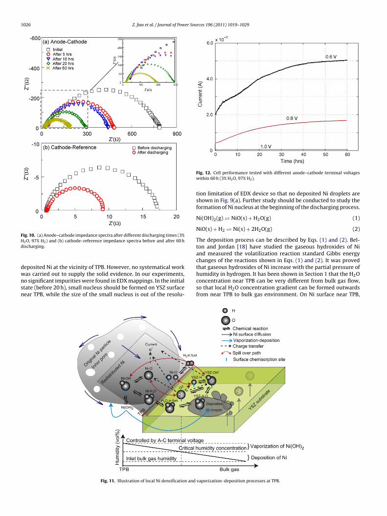
The corresponding A–C and C–R impedance spectra was alsomeasured at different time steps. As shown in Fig. 10(a), it is clearlyseen that for A–C impedance, both the ohmic resistance and acti-vation polarization decrease with time. From initial to 60 h, thetime ohmic resistance reduced from about 80–25 !, and activationpolarization reduced from about 700 to 170 !. For C–R impedance,the ohmic resistance kept constant and the activation polarizationdecreased obviously with time, based on the current passage effecton LSM cathode [11].
4. Discussions
4.1. Morphological changes of Ni
Sintering is a phenomena which occurs by the diffusion of atomsthrough microstructure. Diffusion is caused by a gradient of chem-ical potential, while atoms move from a higher chemical potentialto a lower one. The different paths that the atom movements fol-low are corresponding to different sintering mechanisms. Severaltypical diffusion mechanisms are: surface diffusion, vaporizationtransport, grain boundary diffusion, lattice diffusion and plasticdeformation. Among all the mechanisms, only surface diffusionand vaporization transport can be influenced by surface adsorbedspecie, like humidity in our experiments. Besides, these two mech-anisms are non-densifying, while they take atoms from the surfaceand rearrange them onto another surface or part of the same sur-face. These mechanisms simply rearrange inner pores and do notcause inner pore densification. The rest of the mechanisms in sin-tering process are mainly dominated by temperature, mechanicalpressure, sintering time and so on [13]. As the above parameterswere all kept constants in our experiments, this paper focuses onlyon the study of surface diffusion mechanism enhanced by humid-ity and the vaporization transport mechanism driven by humiditygradient.
Based on the experimental observations, two typical morpho-logical changes of Ni can be concluded. First is the enhancedsintering of Ni near TPB which is dominated by the local high
Z. Jiao et al. / Journal of Power Sources 196 (2011) 1019–1029 1023
Fig. 6. Ni phase morphology and corresponding EDX mappings along Ni clusters bonded to YSZ surface after 60 h discharging, anode–cathode terminal voltage 0.6 V, inhydrogen with: (a) no H2O, (b) 3% H2O, (c) 10% H2O and (d) 30% H2O.
humidity concentration in discharging process, as shown in Fig. 5 atNi–YSZ contacting point and in Fig. 7 for bulk Ni. Second is the phe-nomena of Ni droplets which is formed by vaporization–depositionmechanism driven by humidity gradient near TPB, as shown inFig. 4.
4.1.1. Interlocking and spreading of densified Ni layerEconomos and Kingery [12] studied the interactions between
different metals and oxides. In their study, Ni and zirconia
were heated up to 1800 "C in reduced gas environment until Nimelted. No apparent reaction took place at Ni–zirconia interface,while Ni adhered to zirconia substrate by mechanical interlock-ing effect. No chemical reaction was observed at metal–ceramicinterface and melted Ni cannot wet zirconia surface. In ourexperiments, the operating temperature setting was too low toachieve metal–ceramic interlocking effect by thermally melting Niphase onto YSZ substrate. Mechanical interlocking phenomena wasindeed observed after 60 h discharging.

1024 Z. Jiao et al. / Journal of Power Sources 196 (2011) 1019–1029
Fig. 7. Cross-sectinal images of bulk Ni phase: (a) after initial reduction, (b) after 60 h discharging in hydrogen with 3% H2O, (c) 10% H2O and (d) 30% H2O.
Some researchers have tried to develop a computational modelwhich can represent the coupled behavior of the elementary chem-istry, electrochemistry and transport in the vicinity of SOFC TPBon Ni surface. The interactions of hydrogen, steam and Ni surfacewere widely studied [4,11]. Ni surface adsorbed species includehydrogen atom, oxygen atom and hydroxyl species and the chargetransfer process is accomplished by the spillover effects of thesespecies between Ni and YSZ surfaces [4], which is shown in Fig. 11.The potential oxygen adsorption-desorption reaction is alwaysneglected because oxygen bonds strongly to Ni surface and can-not desorb as oxygen molecular especially when hydrogen atom isavailable that Ni surface adsorbed water molecular can be formed.Under ordinary SOFC anode operating conditions, the gas-phase
Fig. 8. Bulk Ni phase porosity and sub-micron inner porosity versus hydrogenhumidity.
oxygen partial pressure is so low that oxygen adsorption is usu-ally unimportant. Jens et al. [14] have shown that Ni–OH bondinghas a much lower energy of formation than Ni adatoms on Ni sur-face in different temperatures. In their studies, it was consideredthat in humidified reduction environment at high temperature,hydroxyl species can exist stably on Ni surface. They concluded thatin steam/hydrogen mixtures, hydroxyl bonded Ni dimers (a dimeris defined as a chemical entity consisting of two structurally similarsubunits, which are joined by bonds, which can be strong or weak)dominated the surface diffusion of Ni particles and consequent sin-tering via particle migration and coalescence. The sintering ratein humidified reduction environment then can be accelerated tohundreds of times more than conventional thermal sintering. Thisexplains the fast densification of Ni and interlocking effect within arelatively low operation temperature in discharging process. It hasbeen shown in Section 1 that the H2O concentration near TPB can bevery different from bulk gas in discharging. With a lower A–C ter-minal voltage, high electrochemical reaction efficiency may createhigh humidity concentration atmosphere at TPB, which results inthe accelerated surface diffusion enhanced sintering of Ni at Ni–YSZinterface. The sintering process finally leaded to the fast inter-locking between Ni and YSZ in a short time and low temperaturedischarging. As shown in Fig. 11, in the the surface diffusion pro-cess, surface Ni atom bonded by hydroxyl species always traveledtowards surface with large curvature which has lower chemicalpotential. In the sintering process, the enhanced surface diffusionfinally filled all the pores, holes, crevices and other irregularities ofNi at Ni–YSZ interface and the YSZ substrate. The filling of Ni intoall the substrate YSZ irregularities finally resulted in interlocking.
For bulk Ni, the total porosity after 60 h discharging increasedand the sub-micron inner porosity was kept almost constant withthe increase of humidity, as shown in Fig. 8. Because the samples ofbulk Ni were taken far from Ni–YSZ contacting layer, the influenceof humidity generated in the chemical reactions can be ignored.

Z. Jiao et al. / Journal of Power Sources 196 (2011) 1019–1029 1025
Fig. 9. Ni phase morphology and corresponding EDX mappings along TPB after: (a) 20 h, (b) 40 h and (c) 60 h (3% H2O, 97% H2).
The sintering of Ni in all the three samples tested in humidifiedhydrogen environments were dominated by the bulk gas humid-ity enhanced surface diffusion only. Because the inner pore has nocontact with the bulk gas, the sintering was mainly dominated bytemperature caused densifying factors so that similar values wereobtained after discharging. The results supports the enhancementof Ni sintering dominated by hydroxyl species on Ni surface withinhumidified hydrgen.
4.1.2. Vaporization–deposition phenomena of Ni caused byhumidity gradient
It is known from thermodynamic data that the standard Gibbsfree energy "G" of Ni surface adsorbed hydroxyl species is lowerthan those of surface adsorbed hydrogen and oxygen in high tem-perture [4]. The hydroxyl species has been proven to exist asNi(OH)2 layer [15]. Matsui et al. [2] calculated the molar frac-tion of volatile Ni species in humidified hydrogen atmosphereat 1000 "C. The calculation showed us that 20% mole fraction ofhumidity in hydrogen is a critical value above which the molefraction of volatile Ni(OH)2 is more than both NiO and Ni. The
Ni–YSZ interface microstructures after different discharging timesshown in Fig. 9 give the evidence for the assumption of Nivaporization–deposition mechanism. Simner et al. [16] have shownthat metal vaporization–deposition and accumulation at reducingTPB happen with in SOFC cathode when Pt or Ag current collectorswere used. In our paper, most of the Ni droplets were found to beindependent islands after 40 h discharging within 3% H2O, whichmeans that Ni droplets cannot be formed by surface diffusion whichmust result in continuous Ni layer.
de Boer et al. [17] have tested SOFC with porous Ni elec-trode prepared by electron-beam evaporation technique. Thesmooth Ni droplets found in our experiment has similar mor-phology as the electrode deposited by electron-beam evaporationmethod, with very smooth surface. This also supports the assump-tion that the Ni droplets in our experiment were formed byvaporization–deposition mechanism. Similar redistribution phe-nomena has also been reported by Brown et al. [8,9]. In theirresearches, Ni wire point-electrode was applied by mechanicalpressing against ScSZ electrolyte. The accumulation phenomenawas explained by the dynamic accumulation of impurities and
1026 Z. Jiao et al. / Journal of Power Sources 196 (2011) 1019–1029
Fig. 10. (a) Anode–cathode impedance spectra after different discharging times (3%H2O, 97% H2) and (b) cathode–reference impedance spectra before and after 60 hdischarging.
deposited Ni at the vicinity of TPB. However, no systematical workwas carried out to supply the solid evidence. In our experiments,no significant impurities were found in EDX mappings. In the initialstate (before 20 h), small nucleus should be formed on YSZ surfacenear TPB, while the size of the small nucleus is out of the resolu-
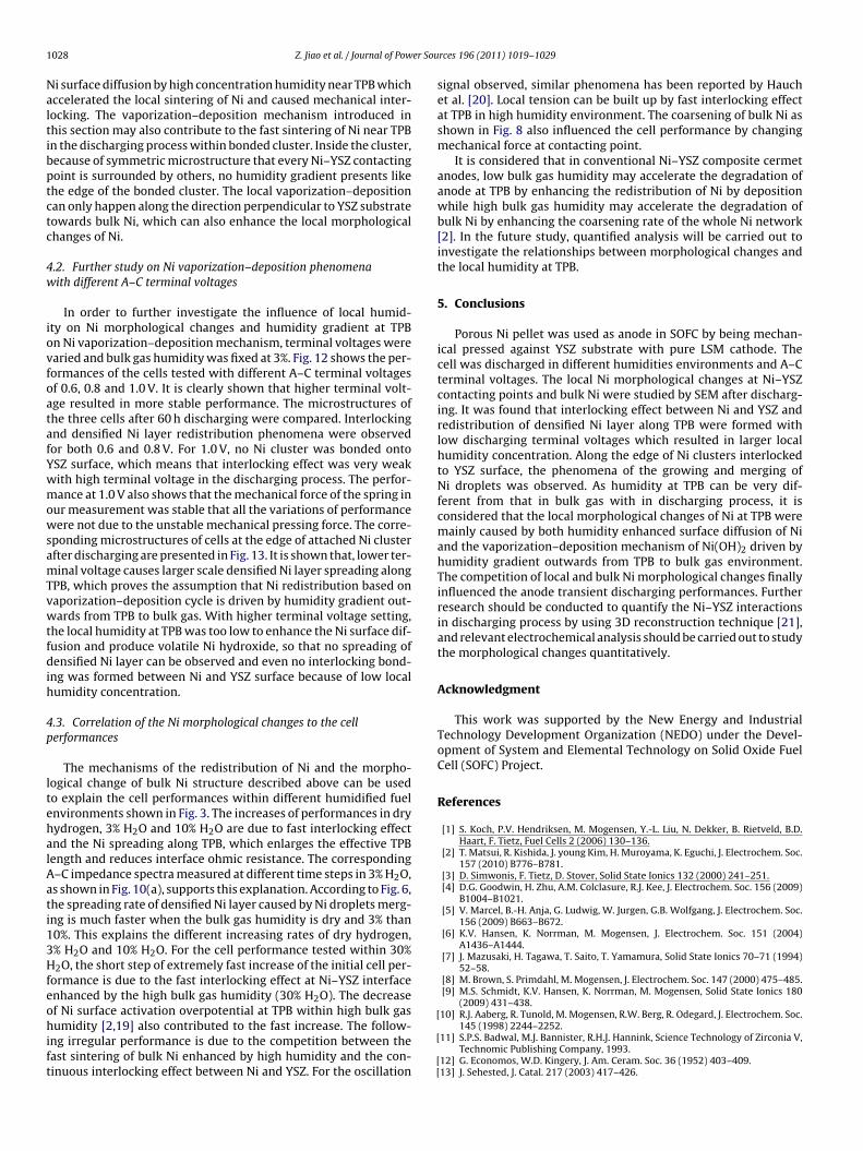
Fig. 12. Cell performance tested with different anode–cathode terminal voltageswithin 60 h (3% H2O, 97% H2).
tion limitation of EDX device so that no deposited Ni droplets areshown in Fig. 9(a). Further study should be conducted to study theformation of Ni nucleus at the beginning of the discharging process.
Ni(OH)2(g) ! NiO(s) + H2O(g) (1)
NiO(s) + H2 ! Ni(s) + 2H2O(g) (2)
The deposition process can be described by Eqs. (1) and (2). Bel-ton and Jordan [18] have studied the gaseous hydroxides of Niand measured the volatilization reaction standard Gibbs energychanges of the reactions shown in Eqs. (1) and (2). It was provedthat gaseous hydroxides of Ni increase with the partial pressure ofhumidity in hydrogen. It has been shown in Section 1 that the H2Oconcentration near TPB can be very different from bulk gas flow,so that local H2O concentration gradient can be formed outwardsfrom near TPB to bulk gas environment. On Ni surface near TPB,
Fig. 11. Illustration of local Ni densification and vaporization–deposition processes at TPB.

Z. Jiao et al. / Journal of Power Sources 196 (2011) 1019–1029 1027
high concentration of H2O during discharging may drive the reac-tion to the left hand side of Eq. (1). Relatively high concentration ofNi(OH)2 can be formed on Ni surface and then vaporize from Ni sur-face. The humidity concentration gradient then drives the volatileNi(OH)2 outwards from TPB. Once Ni(OH)2 leaved Ni surface andtraveled with humidity gradient to a lower humidity environment,gas state Ni(OH)2 was then deposited onto YSZ surface reducedto Ni. With this redistribution phenomena of Ni continuing, thedeposited Ni droplets kept growing and merged to each other andfinally formed a dense Ni layer which was firmly interlocked to YSZsurface.
Fig. 11 shows the illustration of the vaporization–depositionprocess. The critical value of mole fraction of humidity in hydrogenabove which volatile Ni(OH)2 can exist stably over Ni and NiO isestimated to be larger than 20%, when the temperature was lowerthan 1000 "C [2]. In these discharging experiments, spreading ofdensified Ni layer caused by merging of Ni droplets phenomenacan only be observed when the bulk gas was dry or humidifiedby 3% H2O and 10% H2O. No such phenomena was observed whenthe gas was humidified by 30% H2O. So that the critical value ofmole fraction of humidity in hydrogen in our measurements can
be estimated to be a value between 20% and 30%. 30% H2O cannotcause the deposition of Ni near TPB even there was certain humiditygradient, because Ni hydroxide can exist stably in the gas environ-ment and only enhanced the bulk Ni surface diffusion with a highsurface concentration of Ni surface adsorbed hydroxyl specie. Forthe cells tested in hydrogen, which was dry, humidified by 3% H2Oand 10% H2O, the deposition phenomena was prohibited by theincrease of humidity because of the decreasing humidity gradientfrom TPB to bulk gas when the terminal voltage was fixed, which isshown in Fig. 6. For dry hydrogen, densified Ni layer almost withoutgap was observed after discharging testing. Clear crystal boundaryindicated the merging and growing of small Ni droplets. For hydro-gen humidified by 3% H2O, similar phenomena can be observedwhile more gaps and much more clear grain boundary existed atthe same time. For hydrogen humidified by 10% H2O, only a littledensified Ni layer can be observed very close to contacting point.For hydrogen humidified by 30% H2O, no spreading of densified Nilayer was observed along the edge of cluster. What is common for allthe four testings is that densified Ni redistribution can be found atNi–YSZ interface within Ni clusters which resulted in the interlock-ing effect. In last section, we have introduced the enhancement of
Fig. 13. Ni morphology and corresponding EDX mappings along TPB after 60 h discharging with different anode–cathode terminal voltages: (a) 0.6 V, (b) 0.8 V and (c) 1 V (3%H2O, 97% H2).
1028 Z. Jiao et al. / Journal of Power Sources 196 (2011) 1019–1029
Ni surface diffusion by high concentration humidity near TPB whichaccelerated the local sintering of Ni and caused mechanical inter-locking. The vaporization–deposition mechanism introduced inthis section may also contribute to the fast sintering of Ni near TPBin the discharging process within bonded cluster. Inside the cluster,because of symmetric microstructure that every Ni–YSZ contactingpoint is surrounded by others, no humidity gradient presents likethe edge of the bonded cluster. The local vaporization–depositioncan only happen along the direction perpendicular to YSZ substratetowards bulk Ni, which can also enhance the local morphologicalchanges of Ni.
4.2. Further study on Ni vaporization–deposition phenomenawith different A–C terminal voltages
In order to further investigate the influence of local humid-ity on Ni morphological changes and humidity gradient at TPBon Ni vaporization–deposition mechanism, terminal voltages werevaried and bulk gas humidity was fixed at 3%. Fig. 12 shows the per-formances of the cells tested with different A–C terminal voltagesof 0.6, 0.8 and 1.0 V. It is clearly shown that higher terminal volt-age resulted in more stable performance. The microstructures ofthe three cells after 60 h discharging were compared. Interlockingand densified Ni layer redistribution phenomena were observedfor both 0.6 and 0.8 V. For 1.0 V, no Ni cluster was bonded ontoYSZ surface, which means that interlocking effect was very weakwith high terminal voltage in the discharging process. The perfor-mance at 1.0 V also shows that the mechanical force of the spring inour measurement was stable that all the variations of performancewere not due to the unstable mechanical pressing force. The corre-sponding microstructures of cells at the edge of attached Ni clusterafter discharging are presented in Fig. 13. It is shown that, lower ter-minal voltage causes larger scale densified Ni layer spreading alongTPB, which proves the assumption that Ni redistribution based onvaporization–deposition cycle is driven by humidity gradient out-wards from TPB to bulk gas. With higher terminal voltage setting,the local humidity at TPB was too low to enhance the Ni surface dif-fusion and produce volatile Ni hydroxide, so that no spreading ofdensified Ni layer can be observed and even no interlocking bond-ing was formed between Ni and YSZ surface because of low localhumidity concentration.
4.3. Correlation of the Ni morphological changes to the cellperformances
The mechanisms of the redistribution of Ni and the morpho-logical change of bulk Ni structure described above can be usedto explain the cell performances within different humidified fuelenvironments shown in Fig. 3. The increases of performances in dryhydrogen, 3% H2O and 10% H2O are due to fast interlocking effectand the Ni spreading along TPB, which enlarges the effective TPBlength and reduces interface ohmic resistance. The correspondingA–C impedance spectra measured at different time steps in 3% H2O,as shown in Fig. 10(a), supports this explanation. According to Fig. 6,the spreading rate of densified Ni layer caused by Ni droplets merg-ing is much faster when the bulk gas humidity is dry and 3% than10%. This explains the different increasing rates of dry hydrogen,3% H2O and 10% H2O. For the cell performance tested within 30%H2O, the short step of extremely fast increase of the initial cell per-formance is due to the fast interlocking effect at Ni–YSZ interfaceenhanced by the high bulk gas humidity (30% H2O). The decreaseof Ni surface activation overpotential at TPB within high bulk gashumidity [2,19] also contributed to the fast increase. The follow-ing irregular performance is due to the competition between thefast sintering of bulk Ni enhanced by high humidity and the con-tinuous interlocking effect between Ni and YSZ. For the oscillation
signal observed, similar phenomena has been reported by Hauchet al. [20]. Local tension can be built up by fast interlocking effectat TPB in high humidity environment. The coarsening of bulk Ni asshown in Fig. 8 also influenced the cell performance by changingmechanical force at contacting point.
It is considered that in conventional Ni–YSZ composite cermetanodes, low bulk gas humidity may accelerate the degradation ofanode at TPB by enhancing the redistribution of Ni by depositionwhile high bulk gas humidity may accelerate the degradation ofbulk Ni by enhancing the coarsening rate of the whole Ni network[2]. In the future study, quantified analysis will be carried out toinvestigate the relationships between morphological changes andthe local humidity at TPB.
5. Conclusions
Porous Ni pellet was used as anode in SOFC by being mechan-ical pressed against YSZ substrate with pure LSM cathode. Thecell was discharged in different humidities environments and A–Cterminal voltages. The local Ni morphological changes at Ni–YSZcontacting points and bulk Ni were studied by SEM after discharg-ing. It was found that interlocking effect between Ni and YSZ andredistribution of densified Ni layer along TPB were formed withlow discharging terminal voltages which resulted in larger localhumidity concentration. Along the edge of Ni clusters interlockedto YSZ surface, the phenomena of the growing and merging ofNi droplets was observed. As humidity at TPB can be very dif-ferent from that in bulk gas with in discharging process, it isconsidered that the local morphological changes of Ni at TPB weremainly caused by both humidity enhanced surface diffusion of Niand the vaporization–deposition mechanism of Ni(OH)2 driven byhumidity gradient outwards from TPB to bulk gas environment.The competition of local and bulk Ni morphological changes finallyinfluenced the anode transient discharging performances. Furtherresearch should be conducted to quantify the Ni–YSZ interactionsin discharging process by using 3D reconstruction technique [21],and relevant electrochemical analysis should be carried out to studythe morphological changes quantitatively.
Acknowledgment
This work was supported by the New Energy and IndustrialTechnology Development Organization (NEDO) under the Devel-opment of System and Elemental Technology on Solid Oxide FuelCell (SOFC) Project.
References
[1] S. Koch, P.V. Hendriksen, M. Mogensen, Y.-L. Liu, N. Dekker, B. Rietveld, B.D.Haart, F. Tietz, Fuel Cells 2 (2006) 130–136.
[2] T. Matsui, R. Kishida, J. young Kim, H. Muroyama, K. Eguchi, J. Electrochem. Soc.157 (2010) B776–B781.
[3] D. Simwonis, F. Tietz, D. Stover, Solid State Ionics 132 (2000) 241–251.[4] D.G. Goodwin, H. Zhu, A.M. Colclasure, R.J. Kee, J. Electrochem. Soc. 156 (2009)
B1004–B1021.[5] V. Marcel, B.-H. Anja, G. Ludwig, W. Jurgen, G.B. Wolfgang, J. Electrochem. Soc.
156 (2009) B663–B672.[6] K.V. Hansen, K. Norrman, M. Mogensen, J. Electrochem. Soc. 151 (2004)
A1436–A1444.[7] J. Mazusaki, H. Tagawa, T. Saito, T. Yamamura, Solid State Ionics 70–71 (1994)
52–58.[8] M. Brown, S. Primdahl, M. Mogensen, J. Electrochem. Soc. 147 (2000) 475–485.[9] M.S. Schmidt, K.V. Hansen, K. Norrman, M. Mogensen, Solid State Ionics 180
(2009) 431–438.[10] R.J. Aaberg, R. Tunold, M. Mogensen, R.W. Berg, R. Odegard, J. Electrochem. Soc.
145 (1998) 2244–2252.[11] S.P.S. Badwal, M.J. Bannister, R.H.J. Hannink, Science Technology of Zirconia V,
Technomic Publishing Company, 1993.[12] G. Economos, W.D. Kingery, J. Am. Ceram. Soc. 36 (1952) 403–409.[13] J. Sehested, J. Catal. 217 (2003) 417–426.

Z. Jiao et al. / Journal of Power Sources 196 (2011) 1019–1029 1029
[14] J. Sehested, J.A. Gelten, I.N. Remediakis, H. Bengaard, J.K. Norskov, J. Catal. 223(2004) 432–443.
[15] N. Kitakatsu, V. Maurice, C. Hinnen, P. Marcus, Surf. Sci. 407 (1998) 36–58.[16] S.P. Simner, M.D. Anderson, L.R. Pederson, J.W. Stevenson, J. Electrochem. Soc.
152 (2005) A1851–A1859.[17] B. de Boer, M. Gonzalez, H.J.M. Bouwmeester, H. Verweij, Solid State Ionics 127
(1999) 269–276.
[18] G.R. Belton, A.S. Jordan, J. Phys. Chem. 71 (1967) 4114–4120.[19] S.P. Jiang, Y. Ramprakash, Solid State Ionics 116 (1999) 145–156.[20] A. Hauch, S.D. Ebbesen, S.H. Jensen, M. Mogensen, J. Electrochem. Soc. 155
(2008) B1184–B1193.[21] H. Iwai, N. Shikazono, T. Matsui, H. Teshima, M. Kishimoto, R. Kishida, D.
Hayashi, K. Matsuzaki, D. Kanno, M. Saito, H. Muroyama, K. Eguchi, N. Kasagi,H. Yoshida, J. Power Sources 195 (2010) 955–961.
Copyright © 2022 FDOKUMEN