Germanium Nanocrystals-MWCNTs Composites as Anode Materials for Lithium Ion Batteries
Upload
independentCategory
view
4download
0
Methane reforming kinetics within a Ni–YSZ SOFC anode support
Ethan S. Hecht a, Gaurav K. Gupta b, Huayang Zhu a, Anthony M. Dean b,Robert J. Kee a,*, Luba Maier c, Olaf Deutschmann c
a Engineering Division, Colorado School of Mines, Golden, CO 80401, USAb Chemical Engineering Department, Colorado School of Mines, Golden, CO 80401, USA
c Institute for Chemical Technology and Polymer Chemistry, University of Karlsruhe, Karlsruhe, Germany
Received 13 July 2005; received in revised form 28 July 2005; accepted 3 August 2005
Abstract
This paper reports experimental and modeling investigations of thermal methane reforming chemistry within porous Ni–YSZ anode
materials. Because the reforming chemistry is difficult to observe directly in an operating fuel cell, a specially designed experiment is
developed. In the experiment a 0.75 mm-thick anode is sandwiched between two small co-flowing gas channels. One channel represents the
fuel channel of a solid-oxide fuel cell (SOFC). The composition in the other channel carries the species that would be produced in an operating
fuel cell by the electrochemical charge-transfer reactions in the thin three-phase regions near the interface between the anode and the dense
electrolyte membrane (i.e., H2O and CO2). Because the anode structure is porous (and there is no dense electrolyte or cathode applied), there is
convective and diffusive species flux between the two flow channels. The entire assembly is maintained at approximately 800 �C in a furnace.
The results of heterogeneous reforming kinetics are determined by using mass spectrometry to measure the species composition at the outlet
of both channels. Experimental results are interpreted using a computational model that incorporates channel gas flow, porous-media
transport, and elementary heterogeneous chemical kinetics. The overall objective is to develop quantitative models of non-electrochemical
heterogeneous reforming chemistry within a Ni–YSZ anode.
# 2005 Elsevier B.V. All rights reserved.
Keywords: Methane reforming; Solid-oxide fuel cell; Heterogeneous kinetics; Reaction mechanism
www.elsevier.com/locate/apcata
Applied Catalysis A: General 295 (2005) 40–51
1. Introduction
An important attribute of solid-oxide fuel cells (SOFC) is
the ability to incorporate hydrocarbons into the fuel stream.
However, because of deposit-formation problems associated
with pure hydrocarbon fuels, practical SOFC systems
usually operate on mixtures of H2, CO, and hydrocarbons
[1,2]. The hydrocarbons can be heterogeneously reformed
within the anode structure by reacting with steam and
CO2 that are produced by electrochemical charge-transfer
processes. There may also be benefits associated with
incorporating some oxygen (or air) in the fuel stream,
causing internal partial oxidation [3]. Fuel-cell performance
depends on the inlet fuel mixture and all the subsequent
* Corresponding author. Tel.: +1 303 273 3379.
E-mail address: [email protected] (R.J. Kee).
0926-860X/$ – see front matter # 2005 Elsevier B.V. All rights reserved.
doi:10.1016/j.apcata.2005.08.003
chemistry within the fuel cell itself. Because hydrocarbon
conversion to H2 and CO greatly affects the charge-transfer
chemistry, it is important to understand these thermal
reforming processes.
Fig. 1 illustrates the general structure of a Ni–YSZ anode-
supported SOFC. The supporting anode is usually on the
order of a millimeter thick, with the dense electrolyte and the
cathode being on the order of 10 mm thick. In an anode-
supported cell, the word ‘‘anode’’ is commonly used with
both a broad and narrow meaning. In the narrow, strictly
electrochemical, meaning, the anode (negative electrode) is
comprised of the Ni particles in the three-phase region
(TPR) near the dense electrolyte membrane. Electrons are
delivered into the Ni as products of the charge-transfer
chemistry. Because the YSZ in the porous Ni–YSZ structure
conducts oxygen ions, the thin three-phase region may
extend a few microns into the thick porous structure. In the

E.S. Hecht et al. / Applied Catalysis A: General 295 (2005) 40–51 41
Fig. 1. Illustrated cross-section of an anode-supported SOFC. The rela-
tively thick anode structure is a Ni–YSZ porous ceramic–metallic com-
posite. The dark-colored spheres are meant to represent the Ni with the
lighter spheres representing YSZ. To assist visualization, the length scales
within the anode structure are distorted. The entire anode structure may be
on the order of 1 mm thick, with electrochemical charge-transfer reactions
confined to a three-phase region (TPR) that is on the order of 10 mm thick.
The particle and pore dimensions are typically on the order of a few
microns.
broad meaning, the entire porous Ni–YSZ structure is
simply referred to as the anode. Nevertheless, electro-
chemistry is confined to the very thin three-phase region.
Although the physical composition (materials, porosity,
microstructure, etc.) may be uniform throughout the anode
thickness, the majority of the structure serves non-
electrochemical purposes. It serves as a structural support;
the Ni is an electron conductor that carries electrons from the
charge-transfer region to an interconnect material; and the
Ni serves as a reforming catalyst. The work reported in this
paper is concerned entirely with the thermal chemistry and
transport in the majority of the anode structure where
electrochemical effects are completely negligible.
Within the thin three-phase regions of an operating SOFC
anode, H2O and CO2 are produced via charge-transfer
processes. For example, in global terms:
H2ðgÞ þ O2�ðYSZÞÐH2OðgÞ þ 2 e�ðNiÞ: (1)
In words, gas-phase hydrogen H2(g) reacts with an oxygen
ion emerging from the electrolyte O2�(YSZ) to form steam
in the gas phase H2O(g) and deliver electrons to the anode
e�(Ni). Although the details of the elementary charge-
transfer steps remain uncertain, there is no doubt that
H2O and CO2 are either direct or indirect products of
electrochemical charge-transfer reactions. It is also clear
that the H2O and CO2 must be transported through the
porous anode structure away from the TPR and toward
the fuel channel.
Within an SOFC anode structure there is ample
opportunity for heterogeneous reforming chemistry. Gas-
eous species are transported via molecular diffusion and
pressure-driven flow processes between the anode flow
channel and the interface with the dense electrolyte
membrane. On their way toward the interface, the
hydrocarbons mix with the counter flowing H2O and CO2
that are formed as a result of charge-transfer chemistry in the
thin TPR. In the presence of a reforming catalyst (e.g., Ni),
hydrocarbons may be reformed to produce H2 and CO. The
CO may further react to form CO2 via water–gas-shift
processes. The extent of these processes affects the
concentrations of H2, CO, and hydrocarbons available in
the three-phase region, and thus affects details of the charge-
transfer processes.
There is considerable evidence that fuel-cell performance
can be improved greatly using functionally graded anode
structures [4]. Functional variations can include physical
structure (e.g., porosity, particle diameter, pore size, and
tortuosity) and catalytic activity. Predictive models that
quantitatively describe chemical kinetics and gas transport
within anode structures are a valuable tools in the optimal
design and evaluation of anode structures.
Using specially designed experiments and computational
models, the objective of this paper is to develop and validate
models that quantitatively describe chemical kinetics and
gas transport within anode structures. This paper is
specifically concerned with porous ceramic–metallic anodes
using nickel and yttria-stabilized zirconia (Ni–YSZ).
Further, the paper is specifically concerned with methane
as the fuel. Conventional practice in SOFC modeling is to
consider that reforming and water–gas-shift processes can
be represented as global kinetics processes, or even assumed
to be locally equilibrated. The work reported here considers
elementary heterogeneous chemical kinetics, coupled with
Dusty-Gas representation of the gas transport within the
anode.
2. Experimental system
In an operating fuel cell it is difficult to measure directly
the heterogeneous chemistry behavior. Moreover, it is
essentially impossible to observe the species composition
within the very fine (order 1 mm) pore spaces of a ceramic–
metallic anode. The interface between the porous anode
structure and the dense electrolyte membrane is also
completely obscured from direct observation. The purpose
of the experiment described here is to create an environment
that is much more amenable than the fuel-cell itself for the
investigation of thermal chemistry.
A photograph of the experiment is shown in Fig. 2 and a
cutaway drawing of the anode assembly is illustrated in
Fig. 3. The anode is pressed between two steel fixtures into
which 5 cm-long flow channels are machined. The channels
have a square cross section of 6.25 mm2. The anode and

E.S. Hecht et al. / Applied Catalysis A: General 295 (2005) 40–5142
Fig. 2. Photograph of the experiment designed to measure reforming within
an SOFC anode. The anode assembly is placed at the center of a tempera-
ture-controlled furnace.
Fig. 3. Cutaway illustration of the anode assembly portion of the experi-
ment.
fixture assembly are placed within a furnace that maintains
the assembly at a uniform high temperature around 800 �C.
Thin mica sheets (0.5 mm thick) are used to form a seal
between the anode and the steel [5].
A jack at the lower end of the assembly is used to
compress a spring at the upper end. The compressive load is
carried through 2.5 cm diameter alumina tubes that
compress the anode between the channel fixtures. Alumina
is used to reduce conductive heat losses from the furnace
region. The net compressive pressure to seal the anode
between the channels is maintained at about 100 psi
(6:9 � 105 Pa).
The upper channel is meant to represent the fuel channel
of an SOFC. In the results reported subsequently, it will be
fed with a mixture of forming gas (i.e., 3.5% H2 in Ar) and
CH4. The lower channel is meant to represent the interface
between the dense electrolyte and the anode. It is fed with
mixtures of forming gas, steam, and CO2. In an actual fuel
cell, the H2O and CO2 would be the products of charge-
transfer reactions in the three-phase region. The experiment
is designed such that the reforming agents (H2O and CO2)
and the hydrocarbon (CH4) are being transported through the
porous anode in opposite directions. This counter-flow
behavior represents the situation in an operating fuel-cell
anode structure.
Pressure taps, which are positioned in the center of both
channels, are used to monitor and control the pressure
difference between the channels. Depending on the fuel and
the current density in an SOFC, the pressure difference
across the anode can be as high as a few thousand Pascals.
The experiment is designed to determine the effects of such
pressure differences on the porous-media transport across
the anode and hence the reforming chemistry. However, for
the experimental conditions reported in this paper, pressure
differences as great as 3000 Pa were found to have only a
small influence on the reforming rates.
A flow diagram for the system is shown in Fig. 4. Mass
flow controllers (Sierra Instruments 810c and Unit Instru-
ments UFC-1100) are used to regulate the inlet-gas flows.
On the electrolyte side, inlet gases can flow through a
temperature-regulated bubbler where steam is incorporated
into the carrier gas. The steam partial pressure is determined
from a fit to the vapor–pressure relationship as
pH2O ¼ 133:322 exp
�18:3036 � 3816:44
T � 46:13
�; (2)
where pH2O is in Pa and T is in K. Between the bubbler and
the furnace, heat tape maintains an elevated line temperature
to prevent steam condensation. Both the differential pressure
and the pressure in the inert channel relative to atmosphere
are measured by differential pressure transducers (MKS
Instruments Baratron 223b). Needle valves are teed off both

E.S. Hecht et al. / Applied Catalysis A: General 295 (2005) 40–51 43
Fig. 5. Photograph of an anode that has been reduced in the area under the
flow channels. The regions under the channels and mica are gray in color
and the outer regions where NiO is not reduced are green. A faint outline of
the relatively narrow channel can be seen in the central area of the reduced
region.
Fig. 4. Flow diagram for the experiment.
exhausts to provide a leak of exhaust gas to the mass
spectrometer. These lines are also maintained at high tem-
perature to prevent steam condensation. Downstream of the
leak valves, both exhausts flow through mass flow control-
lers (Unit Instruments UFC-1020). A feedback loop from the
pressure transducers regulates these flows and can be used to
control the overall pressure above atmosphere as well as the
differential pressure across the anode.
Because the anode is porous, there is gas transport
between the channels. Methane from the fuel channel reacts
heterogeneously on the Ni–YSZ surfaces with H2O and CO2
from the lower electrolyte channel to produce H2 and CO.
Flow rates are kept sufficiently high that the chemistry is not
equilibrated, and thus the net conversion depends on flow
rate. By varying the flow rates chemical kinetics information
can be inferred.
A quadrupole mass spectrometer (UTI Instruments model
100C) is used to measure the exhaust composition of both
channels. Software was written to identify and fit signals for
seven species. At least one peak of the cracking patterns of
these molecules is available at a mass-to-charge ratio (m=e)
that does not overlap significantly with the other species
except for CO, whose cracking pattern overlaps with the
CO2 cracking pattern. CO2 can be measured accurately at
m=e ¼ 44. Since the contribution to the signal at m=e ¼ 28
due to CO2 is always a fraction of the signal at m=e ¼ 44,
this contribution is determined and subtracted from the
signal at m=e ¼ 28. The only remaining contribution to the
signal at 28 is from CO. The nominal m=e values for the
species are taken as Ar, 40; H2O, 18; CH4, 15; CO2, 44; CO,
28; O2, 32; H2, 2. The methane peak at m=e ¼ 15 was used to
avoid overlap with a contribution from the H2O signal. The
system was calibrated using gas mixtures of known
composition.
3. Ni–YSZ anodes
The anodes used in this work were supplied by ITN
Energy Systems (Littleton, CO). They are fabricated by
mixing 62.5 g of NiO (Novamet) powder and 37.5 g of
8 mol YSZ (Tosoh) powder with dispersants, binders and
water to make a slip. The slip is aged for 3 days and tape cast
with a doctor blade. The tapes are approximately 250 mm
thick when dry. Four pieces of tape are laminated in a
hydraulic press with heated plates (80 �C and 1500 psi). The
tapes are then sintered at 1400 �C for 2 h, and subsequently
creep-flattened at 1375 �C for 4 h. The final dimensions of
the rectangular anodes used in this experiment are
approximately 60 mm � 30 mm � 0.75 mm.
The experimental procedure begins by placing the anode-
channel assembly within the hot zone of a furnace. Initially
the Ni in the Ni–YSZ anode is oxidized as a result of anode-
fabrication processes. As the anode is brought to tempera-
ture at a rate of 100 �C/h, a flow of forming gas over the
anode reduces the nickel oxide to Ni. The anode is
considered fully reduced after it has been at temperature
under forming gas for more than 24 h.
Fig. 5 shows a photograph of a reduced anode. The region
that is between the channels has a gray color, indicating that
the NiO has been reduced to Ni. The outer portions of the
anode, which are exposed to air, are not reduced and retain
the as-fabricated green color. The porosity of the oxidized
material is very low, which limits leakage from the channels
through the porous anode.
4. Reactive flow model
Fig. 6 illustrates the framework in which the computa-
tional model is posed. The model considers plug flow in the
fuel- and electrolyte-side channels and reacting porous-
media flow within the anode.
4.1. Plug flow in channels
With the small channel dimensions and low flow
velocities, the low Reynolds numbers justify a plug-flow
approximation. The velocity profile develops rapidly within

E.S. Hecht et al. / Applied Catalysis A: General 295 (2005) 40–5144
Fig. 6. The computational framework to model transport and chemistry
within the anode. Computational solution is accomplished in finite-volume
form using an axial mesh interval Dx along the channel length and
transverse mesh intervals of Dy through the thickness of the anode.
the channels and using a mean velocity is adequate. Rapid
species diffusion across the channel width effectively
homogenizes the composition transverse to the flow.
The one-dimensional steady-state channel flows may be
described with species continuity and overall continuity
equations in each channel as [6–8]:
dðrYkuÞdx
¼ Pe
Ac
JkWk; (3)
dðruÞdx
¼XKg
k¼1
Pe
Ac
JkWk: (4)
The independent variable is the distance along the channel x
and the dependent variables are mean channel velocities u
and species mass fractions Yk. Although the pressure p could
be determined by solving momentum equations, the pressure
variations along a channel are sufficiently small that the
pressure is considered a parameter. However, the pressure
may be different in the two channels. The temperature is
assumed to be uniform at the imposed furnace temperature.
The local gas-phase density r is determined from a perfect-
gas equation of state, involving the pressure, temperature,
and species composition. The species molecular weights are
represented as Wk.
Because the anode is porous, gases from one channel are
free to pass through the anode toward the other channel.
Within the anode the gases are free to react heterogeneously,
consuming some species and forming others. The gas-phase
transport is modeled using a Dusty-Gas model described
subsequently. The molar flux of each species entering (or
leaving) a channel is represented as Jk. The perimeter Pe is
the specific area along the channel wall through which the
flux Jk flows. In the experiment here Pe is effectively the
width of the anode exposed to the channel flow. The
transport and chemistry within the anode couples the two
channel flows via the fluxes Jk that enter and exit each
channel.
The plug-flow formulation (Eqs. (3) and (4)) neglects
gas-phase chemistry, heterogeneous chemistry on the metal
channel walls, and stream-wise species diffusion. It should
be noted, however, that retaining these effects in the channel
model presents no essential difficulties and our software
implementation provides the capability to retain these
effects when appropriate.
At temperatures around 800 �C and lower, homogeneous
methane pyrolysis or reaction with H2O or CO2 is very slow.
For the short residence times in the experiments here it is
very reasonable to neglect the gas-phase chemistry [9].
However, in other circumstances including higher tempera-
tures, higher hydrocarbons, or partial-oxidation conditions,
homogeneous chemistry should be retained. Relative to the
very high catalyst-surface area within the anode it is
reasonable to neglect any heterogeneous chemistry on the
stainless-steel channel walls.
Even though the flow velocities in the channels are low,
axial species diffusion is negligible under the experimental
conditions used here. Although diffusion coefficients can be
high for light species like hydrogen, the gradients are low.
Even for light species like hydrogen, diffusion velocities are
estimated to be on the order of 1 cm/s. With typical
convective velocities in the range of 60–180 cm/s, it is
reasonable to neglect axial diffusion.
4.2. Reactive porous media
Within the anode, where the pore size is comparable to
the molecular mean-free-path length, there is very little
probability for gas–gas collisions. Consequently, gas-phase
chemistry can be safely neglected. However, it is essential to
model gaseous species transport through the pore system and
thermal heterogeneous chemistry. The continuity equation
for reactive porous-media species transport is written as
r � ðjkÞ ¼ AsWksk; k ¼ 1; . . . ;Kg; (5)
where jk ¼ WkJk are gas-phase mass fluxes, Jk are mole
fluxes, Wk are molecular weights, and As is the specific
catalyst area (i.e., area per unit volume). The species pro-
duction rates by heterogeneous chemistry are represented by
sk. The mass fluxes are evaluated using the Dusty-Gas model
(DGM), in which the fluxes are driven by gradients in
concentrations and pressure [10].
The DGM can be written as an implicit relationship
among the molar concentrations, molar fluxes, concentra-
tions gradients, and the pressure gradient [11,12]:
X‘ 6¼ k
½X‘�Jk � ½Xk�J‘
½XT �Dek‘
þ Jk
Dek;Kn
¼ �r½Xk� �½Xk�De
k;Kn
Bg
mr p:
(6)
In this relationship ½Xk� are the molar concentrations and
½XT � ¼ p=RT is the total molar concentration. The mixture
viscosity is given as m, and Dek‘ and De
k;Kn are the effective

E.S. Hecht et al. / Applied Catalysis A: General 295 (2005) 40–51 45
molecular binary diffusion coefficients and Knudsen diffu-
sion coefficients.
The effective molecular binary diffusion coefficients in
the porous media Dek‘ are related to the ordinary binary
diffusion coefficients Dk‘ in the bulk phase as
Dek‘ ¼
fg
tg
Dk‘; (7)
where fg is the porosity and tg is the tortuosity [10]. The
ordinary binary diffusion coefficients, Dk‘, which are deter-
mined from kinetic theory, may be evaluated with software
such as CHEMKIN [13] or CANTERA [14]. Knudsen diffusion,
which occurs due to gas-wall collisions, becomes dominant
when the mean-free path of the molecular species is much
larger than the pore diameter. The effective Knudsen diffu-
sion coefficient can be expressed as
Dek;Kn ¼ 4
3Kg
ffiffiffiffiffiffiffiffiffi8RT
pWk
r; (8)
where the Knudsen permeability coefficient Kg ¼ rpfg=tg,
and rp is the average pore radius [10].
Assuming that the porous electrode is formed by closely
packed spherical particles with diameter dp (an idealization),
the permeability Bg can be expressed by the Kozeny–
Carman relationship [15] as
Bg ¼f3
gd2p
72tgð1 � fgÞ2: (9)
Other porous-media situations have different permeability
relationships.
Assuming one-dimensional transport through the thick-
ness of the anode, Eq. (5) is a second-order boundary-value
problem. Its solution requires boundary conditions at the
interfaces with the two flow channels. Here the boundary
conditions are taken to be the gas-phase species composi-
tions in the channels.
4.2.1. Heterogeneous chemistry
In recent years an increasing number of heterogeneous
catalysis systems have been successfully described by
mechanistic schemes based on molecular behavior at the
catalytic surface. For example, this approach has led to a
better understanding of three-way catalytic converters
[16], syngas production by partial oxidation of methane
over Rh [17], and oxidative dehydrogenation of ethane
over Pt [18].
Using a mean-field approximation, the species molar-
production rates sk depend on the concentrations of the
gaseous species and also on the coverages of all surface
species, which must be computed self-consistently with the
gas-phase species concentrations. At steady state, the net
production rates of all surface species must vanish, since
transport of surface species over macroscopic distances by
surface diffusion is assumed to be negligible. Therefore,
the Kg gas-phase continuity equations (i.e., Eq. (5)) are
supplemented by the following Ks algebraic equations of the
surface species:
sk ¼ 0; k ¼ 1; . . . ;Ks: (10)
which are functions of the surface-species coverages uk and
the gas-phase concentrations and temperature.
It is known that Ni can catalyze coke formation from
hydrocarbon fuels. However, under the flow conditions
reported here, no coking is observed. The experiment is run
for days at a time without any degradation in reforming
performance. The photograph shown in Fig. 5, which was
taken after 5 days of operation, shows no evidence of coking
or deposit formation. Several factors may contribute to the
deposit-free operation. The methane is relatively dilute in
argon and there is always sufficient H2O or CO2 available to
avoid deposits.
4.3. Computational algorithm
The governing equations are a system of differential–
algebraic equations that may be solved computationally [8].
The time-like independent variable is x, the distance along
the channels. The plug-flow equations (Eqs. (3) and (4)) are
ordinary differential equations coupled to the anode porous-
media problem (Eqs. (5) and (10)) by the species fluxes Jkexchanged between the anode and the channels. The porous-
media problem is a boundary-value problem in y, the
coordinate normal to the channels. The boundary values
required for solution are the species compositions in the
channels. Computationally, the porous-media problem
(having no time-like derivatives) behaves as an algebraic
constraint on the plug-flow differential equations.
The solution algorithm used here is a finite-volume
method. The channels are divided into cells of length Dx and
the anode is divided into cells of height Dy (Fig. 6). For the
results shown subsequently the 5 cm long channels have
been divided into 200 cells and the anode is divided into 50
cells across its 0.75 mm thickness. Solution requires a few
minutes on a personal computer.
5. Heterogeneous reaction mechanism
In the anode application, Ni serves as both a reforming
catalyst and an electrical current conductor. Because nickel
is used widely as a reforming catalyst there is a great deal of
information available about its catalytic behavior. Depend-
ing on the actual process (e.g., steam reforming, dry
reforming with CO2, total and partial oxidation) different
reaction mechanisms and corresponding kinetic models
[19–22] have been proposed. Recently, mechanistic models
based on the knowledge about the elementary steps and their
energetics have been developed [22–24].
The geometrical layout and support structure of steam
reformers or catalytic partial oxidation (CPOX) reactors
are usually quite different from that in an SOFC anode.

E.S. Hecht et al. / Applied Catalysis A: General 295 (2005) 40–5146
Steam reforming reactors are usually implemented in
packed-bed, porous-foam, or monolith configurations. The
ceramic support is usually alumina. An SOFC anode is
fabricated as a porous metal–ceramic composite, where the
metal, ceramic, and gas phases each occupy roughly 30%
of the volume. Although porosity is roughly 30%, the
characteristic pore dimensions are typically much smaller
(say around 1 mm) than would be typical of a packed-bed or
Table 1
Heterogeneous reaction mechanism for CH4 reforming on Ni-based catalysts
Reaction
1. H2 + Ni(s) + Ni(s) !H(s) + H(s)
2. H(s) + H(s) !Ni(s) + Ni(s) + H2
3. O2 + Ni(s) + Ni(s) ! O(s) + O(s)
4. O(s) + O(s) !Ni(s) + Ni(s) + O2
5. CH4 + Ni(s) ! CH4(s)
6. CH4(s) !Ni(s) + CH4
7. H2O + Ni(s) ! H2O(s)
8. H2O(s) !Ni(s) + H2O
9. CO2 + Ni(s) ! CO2(s)
10. CO2(s) !Ni(s) + CO2
11. CO + Ni(s) ! CO(s)
12. CO(s) !Ni(s) + CO
13. O(s) + H(s) !OH(s) + Ni(s)
14. OH(s) + Ni(s) ! O(s) + H(s)
15. OH(s) + H(s) ! H2O(s) + Ni(s)
16. H2O(s) + Ni(s) ! OH(s) + H(s)
17. OH(s) + OH(s) ! O(s) + H2O(s)
18. O(s) + H2O(s) ! OH(s) + OH(s)
19. O(s) + C(s) ! CO(s) + Ni(s)
20. CO(s) + Ni(s) ! O(s) + C(s)
21. O(s) + CO(s) !CO2(s) + Ni(s)
22. CO2(s) + Ni(s) !O(s) + CO(s)
23. HCO(s) + Ni(s) ! CO(s) + H(s)
24. CO(s) + H(s) !HCO(s) + Ni(s)
25. HCO(s) + Ni(s) ! O(s) + CH(s)
26. O(s) + CH(s) ! HCO(s) + Ni(s)
27. CH4(s) + Ni(s) ! CH3(s) + H(s)
28. CH3(s) + H(s) ! CH4(s) + Ni(s)
29. CH3(s) + Ni(s) ! CH2(s) + H(s)
30. CH2(s) + H(s) ! CH3(s) + Ni(s)
31. CH2(s) + Ni(s) ! CH(s) + H(s)
32. CH(s) + H(s) ! CH2(s) + Ni(s)
33. CH(s) + Ni(s) ! C(s) + H(s)
34. C(s) + H(s) ! CH(s) + Ni(s)
35. O(s) + CH4(s) ! CH3(s) + OH(s)
36. CH3(s) + OH(s) ! O(s) + CH4(s)
37. O(s) + CH3(s) ! CH2(s) + OH(s)
38. CH2(s) + OH(s) ! O(s) + CH3(s)
39. O(s) + CH2(s) ! CH(s) + OH(s)
40. CH(s) + OH(s) ! O(s) + CH2(s)
41. O(s) + CH(s) ! C(s) + OH(s)
42. C(s) + OH(s) ! O(s) + CH(s)
a Arrhenius parameters for the rate constants written in the form: k ¼ ATn exp ð�b Sticking coefficient.c Coverage-dependent activation energy (see Eq. (11)). Total available surfac
porous-foam reactor. In the SOFC application the ceramic
should be an oxygen-ion conductor (e.g., YSZ), which
alumina is not. Thus the catalyst-support chemistry may be
different with a YSZ support than it is for an alumina
support. Moreover there is evidence that the YSZ itself also
has catalytic activity for partial oxidation [25].
Table 1 lists a reaction mechanism that we have
developed to describe the heterogeneous kinetics within a
Aa n Ea
1:000 � 10�02 b 0.0 0.00
5:593 � 10þ19 0.0 88.12
1:000 � 10�02 b 0.0 0.00
2:508 � 10þ23 0.0 470.39
8:000 � 10�03 b 0.0 0.00
5:302 � 10þ15 0.0 33.15
1:000 � 10�01 b 0.0 0.00
4:579 � 10þ12 0.0 62.68
1:000 � 10�05 b 0.0 0.00
9:334 � 10þ07 0.0 28.80
5:000 � 10�01 b 0.0 0.00
4:041 � 10þ11 0.0 112.85
eCOðsÞ �50:0 c
5:000 � 10þ22 0.0 97.90
2:005 � 10þ21 0.0 37.19
3:000 � 10þ20 0.0 42.70
2:175 � 10þ21 0.0 91.36
3:000 � 10þ21 0.0 100.00
5:423 � 10þ23 0.0 209.37
5:200 � 10þ23 0.0 148.10
1:418 � 10þ22 �3:0 115.97
eCOðsÞ �50:0 c
2:000 � 10þ19 0.0 123.60
eCOðsÞ �50:0 c
3:214 � 10þ23 �1:0 86.50
3:700 � 10þ21 0.0 0.0
eCOðsÞ 50.0c
2:338 � 10þ20 �1:0 127.98
3:700 � 10þ24 �3:0 95.80
7:914 � 10þ20 0.0 114.22
3:700 � 10þ21 0.0 57.70
4:438 � 10þ21 0.0 58.83
3:700 � 10þ24 0.0 100.00
9:513 � 10þ22 0.0 52.58
3:700 � 10þ24 0.0 97.10
3:008 � 10þ24 0.0 76.43
3:700 � 10þ21 0.0 18.80
4:400 � 10þ22 0.0 160.49
1:700 � 10þ24 0.0 88.30
8:178 � 10þ22 0.0 28.72
3:700 � 10þ24 0.0 130.10
3:815 � 10þ21 0.0 21.97
3:700 � 10þ24 0.0 126.80
1:206 � 10þ23 0.0 45.42
3:700 � 10þ21 0.0 48.10
1:764 � 10þ21 0.0 129.08
E=RTÞ. The units of A are given in terms of moles, cm, and s. E is in kJ/mol.
e site density is G ¼ 2:60 � 10�9 mol/cm2.
E.S. Hecht et al. / Applied Catalysis A: General 295 (2005) 40–51 47
Ni–YSZ anode.1 This mechanism was initially developed
and validated to describe steam-assisted catalytic partial
oxidation of methane in small-channel monolith reactors
using Ni supported on alumina. The 42 irreversible reactions
involve 6 gas-phase and 12 surface-adsorbed species. Most
reaction rates are represented in the Arrhenius form or as a
sticking coefficient. However, the net activation energy of
reactions 12, 20, 21, and 23 depend on the CO(s) coverage
uCOðsÞ as [8]:
k ¼ ATn exp
�� E
RT
�exp
��eCOðsÞuCOðsÞ
RT
�: (11)
The unity bond index-quadratic exponential potential
(UBI-QEP) approach is used to determine the heats of
adsorption, reaction enthalpies, and activation barriers for
most relevant reactions [26–29]. In particular, the kinetic
parameters for the desorption of O2, CH4, H2O, CO2
(reactions (4), (6), (8), and (10), respectively) [26], CO
formation and decomposition (reactions (19) and (20)) [28],
HCO reactions (reactions (23) and (24)) [26], and non-
oxidative methane decomposition and formation (reactions
(27)–(34)) [28] are based on this method. The water and CO2
formation (reactions (13)–(18) and (21)–(22)), the second
pathway for HCO formation (reactions (25) and (26)), and
the oxidative decomposition and formation of CH4
(reactions (35)–(42)) are also obtained from a theoretical
study on CO2 reforming of methane [29]. The sticking
coefficient for hydrogen (reaction (1)) is taken from
chemisorption studies on Ni(1 1 1) [30]. Hydrogen deso-
rption (reaction (2)) is based on an experimental study on Ni
single crystal surfaces [31]. Sticking coefficients for oxygen
and water (reactions (3) and (7), respectively) are simply
taken from studies on partial oxidation of methane over
rhodium [17] due to a lack of data on Ni. The sticking
coefficients for CH4 and CO2 adsorption (reactions (5) and
(9), respectively) are derived from experimental studies
of reforming and oxidation of methane over Ni-coated
monoliths [32]. The data for CO adsorption/desorption
(reactions (11) and (12)) on a vacant surface are taken from
Al-Sarraf et al. [33].
Since the original kinetic data set is taken from a variety
of different studies, the mechanism is a priori not
thermodynamically consistent. Therefore, some of the
original kinetic parameters were modified by an optimiza-
tion procedure to ensure overall thermodynamic consistency
regarding enthalpy and entropy. This methodology also
permits the computation of the reverse rate coefficients,
which depend on the forward rate coefficients and the
thermodynamics [8].
Since the reaction mechanism is based on elementary
molecular processes, it represents all the global processes in
an SOFC anode, including (1) steam reforming of CH4 to
CO and H2; (2) water–gas-shift processes; (3) surface-
1 The mechanism may be downloaded from http://www.detchem.com/
mechanisms.
carbon coverage. Although the mechanism includes surface-
adsorbed carbon C(s) and oxygen O(s) on the surface up to
one monolayer, it has not been validated for conditions
where coking and bulk-phase Ni oxidation occur. The
experiments discussed in this paper are designed to operate
under conditions where neither coking nor NiO formation
occur. Practical fuel cells are also designed to operate under
conditions that do not cause oxidation of the nickel or
deposit formation. Nevertheless, there is value in extending
reaction mechanisms to embody these effects. Such
extended mechanisms would assist in design of cell
architectures and operating conditions that avoid deleterious
phenomena.
6. Results and discussion
A series of experiments are reported, seeking to
understand and quantify steam and dry reforming within
the anode. In these experiments the fuel-side flow is a
mixture of forming gas and methane. The electrolyte side
flow is a mixture of forming gas with various amounts of
steam and carbon dioxide. Holding the channel inlet
compositions fixed, the inlet flow rates are varied to alter
the residence time in the channels. For the results reported
here, the inlet flow rates in both channels are nominally the
same. Generally speaking, the lower flow rates lead to longer
residence times and more-complete reforming. However,
even at the highest flow rates reported, there is still
considerable reforming observed.
These experiments use flow rates that are high compared
to flow rates in a typical fuel cell. With an objective of
understanding the reforming kinetics, it is important to
establish conditions where kinetics is important. At
sufficiently low flow rates, there can be sufficient residence
time that the chemistry within the anode may equilibrate. In
this case, there is essentially no sensitivity to the kinetic
pathways and rates.
In all cases, the measurements are compared with
simulation results. The model does a very good job of
representing the data, and certainly captures all the observed
trends.
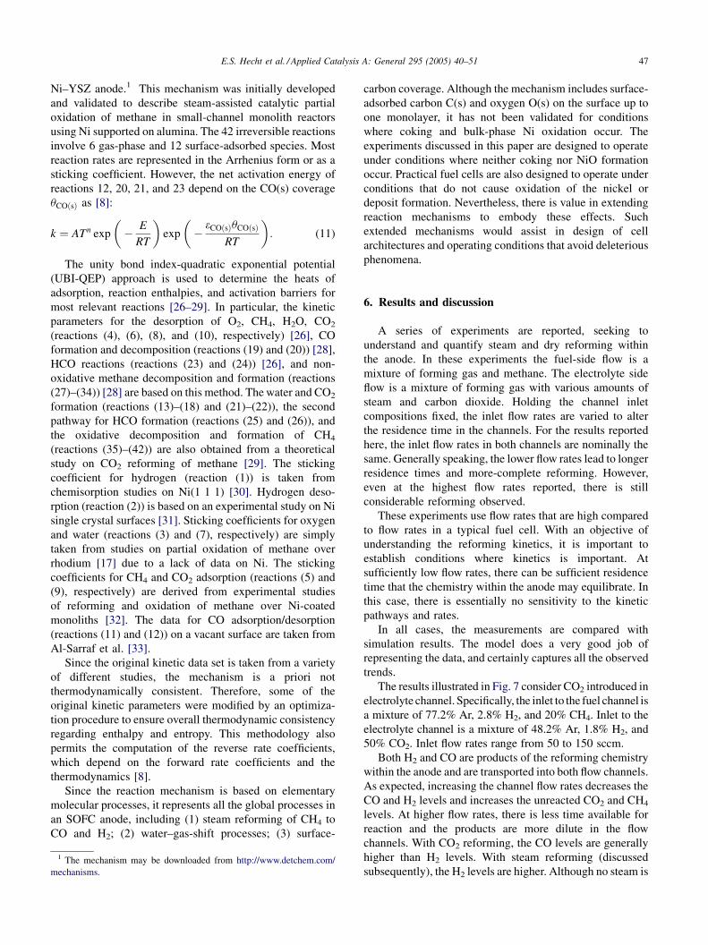
The results illustrated in Fig. 7 consider CO2 introduced in
electrolyte channel. Specifically, the inlet to the fuel channel is
a mixture of 77.2% Ar, 2.8% H2, and 20% CH4. Inlet to the
electrolyte channel is a mixture of 48.2% Ar, 1.8% H2, and
50% CO2. Inlet flow rates range from 50 to 150 sccm.
Both H2 and CO are products of the reforming chemistry
within the anode and are transported into both flow channels.
As expected, increasing the channel flow rates decreases the
CO and H2 levels and increases the unreacted CO2 and CH4
levels. At higher flow rates, there is less time available for
reaction and the products are more dilute in the flow
channels. With CO2 reforming, the CO levels are generally
higher than H2 levels. With steam reforming (discussed
subsequently), the H2 levels are higher. Although no steam is

E.S. Hecht et al. / Applied Catalysis A: General 295 (2005) 40–5148
Fig. 9. Comparison of measurements (symbols) and model (solid lines) for
mixed (CO2/H2O) reforming within the anode. Exhaust gas measurements
for the fuel-side channel (upper panel) and the electrolyte-side channel
(lower panel). Nominal inlet mole fractions to the fuel channel are
CH4 ¼ 0:2, H2 ¼ 0:028, and Ar ¼ 0:772. Nominal inlet mole fractions
to the electrolyte channel are H2O ¼ 0:5 and CO2 ¼ 0:5. The temperature is
800 �C and the pressure in both channels is 5000 Pa above atmospheric.
Fig. 7. Comparison of measurements (symbols) and model (solid lines) for
dry reforming (CO2) within the anode. Exhaust gas measurements for the
fuel-side channel (upper panel) and the electrolyte-side channel (lower
panel). Nominal inlet mole fractions to the fuel channel are CH4 ¼ 0:20,
H2 ¼ 0:028, and Ar ¼ 0:772. Nominal inlet mole fractions to the electrolyte
channel are CO2 ¼ 0:5, H2 ¼ 0:0175, and Ar ¼ 0:4825. The temperature is
800 �C and the pressure in both channels is 5000 Pa above atmospheric.
introduced into the reactor, steam is a reaction product that
can participate in the reforming process.
Fig. 8 shows a set of experiments where 50% steam is
introduced into the electrolyte-side channel as the reforming
agent. In this case H2 is the dominant product of the
reforming chemistry, with CO levels only reaching about
one third of the H2 levels. Low levels of CO2 are also
observed as a result of water–gas-shift processes. This CO2
is available to participate as a dry-reforming reactant. Of all
the cases reported here, the steam-reforming cases lead to
Fig. 8. Comparison of measurements (symbols) and model (solid lines) for
steam (H2O) reforming within the anode. Exhaust gas measurements for the
fuel-side channel (upper panel) and the electrolyte-side channel (lower
panel). Nominal inlet mole fractions to the fuel channel are CH4 ¼ 0:20,
H2 ¼ 0:028, and Ar ¼ 0:772. Nominal inlet mole fractions to the electrolyte
channel are H2O ¼ 0:48, H2 ¼ 0:018, and Ar ¼ 0:502. The temperature is
800 �C and the pressure in both channels is 5000 Pa above atmospheric.
the highest H2 yields. As in all cases, higher channel flow
rates lead to less reformate in the exhaust.
Fig. 9 shows a set of experiments where a mixture of 50%
steam and 50% CO2 is introduced into the electrolyte-side
channel as the reforming agent. As anticipated, the results lie
between the steam and dry reforming cases.
As a check on the self-consistency of the measurements,
element balances were evaluated for C, O, H, and Ar. Inlet
mass-flow rates for each channel are controlled with mass-
flow controllers and are known. However, since there is mass
exchange between the channels through the porous anode,
the exhaust mass-flow rates are not known for each channel.
Although there are mass-flow controllers on the exhaust
lines as part of the pressure-control system, they are not
specifically calibrated for the exhaust-gas compositions.
Therefore, model-predicted exhaust mass flow rates were
used in estimating the element balances. The element
balances were generally very good. For the dry-reforming
cases (Fig. 7) the element balances closed to within about
2%. The steam-reforming cases (Fig. 8) had larger element
imbalances averaging about 6%, with the O imbalance being
about 15% at the lowest flow rates.
Perhaps the largest source of error in these experiments is
the H2O inlet flow rate. The partial pressure of steam coming
out of the bubbler is highly sensitive to the bubbler
temperature. A feedback control system maintains the
bubbler temperature. Nevertheless, especially at high steam
loadings around 50%, even a 2 �C temperature uncertainty
leads to uncertainties in the steam loading of nearly 10%.
Direct metering of H2O by a syringe pump should reduce
this uncertainty.
All the cases reported show comparable CH4 consump-
tion rates. This is consistent with the results reported by Wei

E.S. Hecht et al. / Applied Catalysis A: General 295 (2005) 40–51 49
and Iglesia [24], showing that the steam- and dry reforming
of methane on Ni-based catalysts proceed at similar rates.
They attribute this similarity to the rate-limiting step being
the first H-abstraction step in CH4 on Ni, with the subsequent
H-abstractions (ultimately forming surface carbon) being
much faster. Comparing the rate coefficients of reactions
(27), (29), (31), and (33) in Table 1 indicates similar kinetic
behavior in this mechanism; the rate constant k27 is an order
of magnitude smaller than any of the subsequent abstrac-
tions.
Over the entire range of conditions studied, the model
represents the experimental observations well. Although
there are many physical parameters in the model that could
potentially be used as fitting parameters, all the parameters
remain fixed for the simulations reported. The physical
parameters for the porous 0.75 mm thick Ni–YSZ are:
porosity f ¼ 0:35, pore radius rp ¼ 0:35mm, particle
diameter dp ¼ 1:0mm, and tortuosity t ¼ 4:5. Although
these parameters are not measured directly, they are
certainly all quite reasonable. The specific area of catalyst
surface is taken as As ¼ 5000 cm2/cm3. This value is
consistent with the area that would be available for close-
packed 1 mm diameter Ni spheres occupying 30% of the
solid volume and with 30% of the Ni area being catalytically
active. This area, which is difficult to estimate, was adjusted
once to produce a good fit with the measurements for the
mixed reforming case (Fig. 9) at the 100 sccm flow rate.
Transport properties of the gases (e.g., viscosity and
diffusion coefficients) are computed from kinetic theory
with no adjustable parameters [8]. The rate constants in the
Fig. 10. Simulation predictions for mole-fraction profiles in the anode and electroly
porous anode. Operating conditions are the same as in Fig. 9, with inlet flow ra
heterogeneous reaction mechanism (Table 1) have not been
adjusted in this work.
The experimental results are measured only at the
channel exits. However, the models can provide much more
information about the composition along the channel length
and the local composition within the anode. Fig. 10
illustrates model results for the mixed CO2–H2O case at
100 sccm (Fig. 9). The top panel shows gas-phase species
profiles along the length of the fuel channel, and the lower
panel shows profiles along the electrolyte channel. The three
panels in the middle show the predicted gas-phase profiles in
the anode pore space and the surface-coverage profiles at
three axial locations along the channels. Heterogeneous
chemistry within the anode consumes the methane
introduced in the fuel channel and the CO2 and H2O
introduced in the electrolyte channel. There is net transport
of CH4 from the fuel channel toward the electrolyte channel
and a net transport of CO2 and H2O from the electrolyte
channel toward the fuel channel. There is also a net flow of
Ar from the fuel channel toward the electrolyte channel. As
the CH4, CO2, and H2O mix within the anode pore space
they react heterogeneously on the Ni surfaces. It is evident
from the middle panels that H2 and CO have maximum
values within the anode where they are formed. They are
transported diffusively and convectively (via the Dusty-Gas
model) into both flow channels. Throughout the anode the Ni
surfaces remain approximately 60% open. The surface
coverages are dominated by adsorbed CO(s), H(s), and O(s).
The objective of the experiments and the modeling is to
explore heterogeneous chemical-kinetic behavior within the
te channels and for gas-phase mole fractions and surface coverage within the
tes of 100 sccm.

E.S. Hecht et al. / Applied Catalysis A: General 295 (2005) 40–5150
Fig. 11. Gas-phase mole-fraction profiles within the channels, comparing
the effects of heterogeneous kinetics (solid lines) with assumed equilibrium
(dashed lines) within the anode. Operating conditions are the same as in
Fig. 9, with inlet flow rates of 100 sccm.
anode. Through the models, it is interesting to compare the
limiting case of chemical equilibrium within the anode. A
convenient method to simulate equilibrium within the anode
pore space is to introduce two reversible global gas phase
reactions that proceed at very high rates:
CH4 þ H2OÐ 3H2 þ CO; (12)
CO þ H2OÐH2 þ CO2: (13)
Because these global reactions involve only gas phase
species, the equilibrium constants are easily calculated from
well known thermodynamic properties.
Fig. 11 shows the gas-phase compositions in the two
channels for the same operating conditions as in Fig. 10. The
solid lines show the same profiles as in Fig. 10 and the
dashed lines show the solutions when the heterogeneous
chemistry within the anode is equilibrated. Under these
circumstances, it is immediately evident that the kinetics
processes are rate-limiting. The kinetics simulations show
very much slower consumption of CH4 and production of
CO and H2. Inasmuch as the kinetics simulations agree well
with the measurements, it is clear that heterogeneous
kinetics play an important role. Thus, it is reasonable to
assume that the experiments are run in regimes where
valuable information about the kinetics can be determined.
Depending on operating conditions, flow rates in fuel-cell
channels can be much lower than those in the experiments
reported here. As flow rates decrease the residence times
increase. At sufficiently low flow rates, the kinetics can run
sufficiently fast as to approach equilibrium behavior.
Although not reported in this paper, we apply the kinetics
models in fuel-cell models. At relatively high cell voltages
where the current density is relatively low, the kinetics tends
toward equilibrium behavior. However, at low cell voltages,
where current densities are high the reforming kinetics can be
rate-limiting. The detailed kinetics models are general in the
sense that they can predict the entire range of behavior from
chemistry rate limitations to near-equilibrium behavior.
7. Summary and conclusions
The heterogeneous kinetics within porous Ni–YSZ anode
structures has been studied using experiments and comple-
mentary models. The experiments are designed to measure the
extent of reformation processes under conditions that are
well away from chemical equilibrium. The model, which
incorporates channel flow, convective and diffusive porous-
media transport, and an elementary heterogeneous reaction
mechanism, predicts the measured performance. Results are
presented over a range of conditions that include pure steam
reforming and pure CO2 reforming as well as combination of
the two. The understanding developed and the quantitative
validation of the heterogeneous reaction mechanism can play
an important role in the optimal design of anode structures for
new solid-oxide fuel cells.
Acknowledgements
This work was supported by the DoD Multidisciplinary
University Research Initiative (MURI) program adminis-
tered by the Office of Naval Research under Grant N00014-
02-1-0665. We are grateful to Dr. Paul Thoen of ITN Energy
Systems for providing the Ni–YSZ anodes used in the
experiments and to Prof. Neal Sullivan (Colorado School of
Mines) for many helpful suggestions in developing the
experiment.
References
[1] S. Singhal, K. Kendall, High-temperature Solid Oxide Fuel Cells:
Fundamentals, Design and Applications, Elsevier Science Ltd, 2004.
[2] Fuel Cell Handbook (7th ed.), Tech. Rep. DOE/NETL 2004/1206,
National Energy Technology Laboratory, Morgantown, WV, available
at: http://www.netl.doe.gov (2004).
[3] Z. Zhan, J. Liu, S. Barnett, Appl. Catal. A 262 (2004) 255–259.
[4] F. Zhao, A. Virkar, J. Power Sources 141 (2005) 79–95.
[5] Y.-S. Chou, J. Stevenson, L. Chick, J. Power Sources 112 (2002) 130–
161.
[6] H. Zhu, R. Kee, J. Power Sources 117 (2003) 61–74.
[7] K. Walters, A. Dean, H. Zhu, R. Kee, J. Power Sources 123 (2003)
182–189.
[8] R. Kee, M. Coltrin, P. Glarborg, Chemically Reacting Flow: Theory
and Practice, Wiley, 2003.
[9] G. Gupta, E. Hecht, H. Zhu, A. Dean, R. Kee, J. Power Sources, in
press.
[10] E. Mason, A. Malinauskas, Gas Transport in Porous Media: The
Dusty-Gas Model, American Elsevier, New York, 1983.
[11] T. Thampan, S. Malhotra, H. Tang, R. Datta, J. Electrochem. Soc. 147
(2000) 3242–3250.
[12] T. Thampan, S. Malhotra, J. Zhang, R. Datta, Catal. Today 67 (2001)
15–32.

E.S. Hecht et al. / Applied Catalysis A: General 295 (2005) 40–51 51
[13] R. Kee, G. Dixon-Lewis, J. Warnatz, M. Coltrin, J. Miller, A Fortran
computer code package for the evaluation of gas-phase multicompo-
nent transport properties, Tech. Rep. SAND 86–8246, Sandia National
Laboratories, 1986.
[14] D. Goodwin, in: M. Allendorf, F. Maury, F. Teyssandier (Eds.),
Chemical Vapor Deposition XVI and EUROCVD 14, vol. PV
2003–08, Electrochemical Society, 2003, pp. 155–162, see also
http://www.cantera.org.
[15] J. Bear, Dynamics of Fluids in Porous Media, American Elsevier, New
York, 1972.
[16] D. Chatterjee, O. Deutschmann, J. Warnatz, Faraday Discuss. 119
(2001) 371–384.
[17] R. Schwiedernoch, S. Tischer, C. Correa, O. Deutschmann, Chem.
Eng. Sci. 58 (2003) 633–642.
[18] D. Zerkle, M. Allendorf, M. Wolf, O. Deutschmann, J. Catal. 196
(2000) 18–39.
[19] M. Bradford, M. Vannice, Catal. Rev. Sci. Eng. 41 (1999) 1–42.
[20] J. Xu, G. Froment, AIChE J. 35 (1989) 88–96.
[21] J. Rostrup-Nielsen, J. Anderson, M. Boudart, CATALYSIS—Science
and Technology, vol. 5, Springer, 1984.
[22] D. Chen, R. Lodeng, A. Anundskas, O. Olsvik, A. Holmen, Chem.
Eng. Sci. 56 (2001) 1371–1379.
[23] L. Aparicio, J. Catal. 165 (1997) 262–273.
[24] J. Wei, E. Iglesia, J. Catal. 224 (2004) 370–383.
[25] J. Zhu, J. van Ommen, L. Lefferts, J. Catal. 225 (2004) 388–397.
[26] E. Shustorovich, Adv. Catal. 37 (1990) 101–163.
[27] E. Shustorovich, H. Sellers, Surf. Sci. Rep. 31 (1998) 1–119.
[28] A. Bell, E. Shustorovich, Metal Surface Reaction Energetics: Theory
and Application to Heterogeneous Catalysis, Chemisorption and Sur-
face Diffusion, Wiley, 1991 (Chapter 5).
[29] M. Hei, H. Chen, J. Yi, Y. Lin, Y. Lin, G. Wei, D. Liao, Surf. Sci. 417
(1998) 82–96.
[30] J. Lapujoulade, K. Neil, J. Chem. Phys. 57 (1972) 3535–3545.
[31] K. Christmann, O. Schober, G. Ertl, M. Neumann, J. Chem. Phys. 60
(1974) 4528–4540.
[32] B. Schadel, Untersuchung von Reformierungsprozessen von Methan
an Rhodium- und Nickelkatalysatoren, Master’s Thesis, Department
of Chemistry and Biosciences, University of Karlsruhe, 2004.
[33] N. Al-Sarraf, J. Stuckless, C. Wartnaby, D. King, Surf. Sci. 283 (1993)
427–437.
Copyright © 2022 FDOKUMEN