Development of Anode Gas Recycle System Using Ejector for 1 KW Solid Oxide Fuel Cell
9
Soumei Baba 1 Thermal and Fluid System Group, Energy Technology Research Institute, National Institute of Advanced Industrial Science and Technology (AIST), 1-2-1 Namiki, Tsukuba-shi, Ibaraki 305-8564, Japan e-mail: [email protected] Nariyoshi Kobayashi Thermal and Fluid System Group, Energy Technology Research Institute, National Institute of Advanced Industrial Science and Technology (AIST), 1-2-1 Namiki, Tsukuba-shi, Ibaraki 305-8564, Japan e-mail: [email protected] Sanyo Takahashi Thermal and Fluid System Group, Energy Technology Research Institute, National Institute of Advanced Industrial Science and Technology (AIST), 1-2-1 Namiki, Tsukuba-shi, Ibaraki 305-8564, Japan e-mail: [email protected] Satoshi Hirano Thermal and Fluid System Group, Energy Technology Research Institute, National Institute of Advanced Industrial Science and Technology (AIST), 16-1 Onogawa, Tsukuba-shi, Ibaraki 305-8569, Japan e-mail: [email protected] Development of Anode Gas Recycle System Using Ejector for 1 KW Solid Oxide Fuel Cell An anode gas recycle (AGR) system using an ejector for 1 kW solid oxide fuel cells (SOFCs) was developed to increase the electrical efficiency of combined power genera- tion. We call this an AGR–SOFC. The effects of recirculation ratio, externally steam feed rate, and fuel utilization were determined experimentally on the AGR–SOFC perform- ance (i.e., output power, stack temperature, and gas composition) using a variable flow ejector and a recirculation ratio of 0.55–0.62, overall fuel utilization of 0.720–84, and steam feed rate of 0–1.5 g/min. A quadrupole mass spectrometer was used to identify the recirculation ratio, the gas composition of reformed gas at the AGR–SOFC inlet, and that of the recycle gas at the outlet. Compared to one-path SOFC systems, i.e., without an AGR, the AGR–SOFC was stable and generated about 15 W more electricity when the overall fuel utilization was 0.84 and the recirculation ratio was 0.622 with no steam sup- ply. This improved performance was due to the reduced H 2 O concentration in the anodic gas. In addition, although the recirculation ratio did not affect the AGR–SOFC perform- ance, a high recirculation ratio can provide steam produced via the electrochemical reaction to the injected fuel for the steam reforming process. [DOI: 10.1115/1.4028361] Introduction SOFCs applied to stationary power generation systems have two major advantages: (i) Highest efficiency among all fuel cells, (ii) lower cost by using nonplatinum catalysts. Furthermore, micro combined heat and power (mCHP) systems based on SOFCs are being actively researched to obtain an even higher efficiency by utilizing the high temperature exhaust gas (>700 C) from the SOFC itself. Unlike gas turbine engines, Stirling engines are external combustion engines that can be combined with SOFCs at normal pressures with practical efficiencies of roughly 20% for small scale power generation about 1 kW class. In addition, oper- ating temperature of a Stirling engine is near the exhaust tempera- ture of an SOFC. Takahashi et al. [1] investigated the performance of a combined SOFC–Stirling engine system fueled with methane by means of thermodynamic system modeling. The results showed a 10% higher efficiency for the combined system at low excess air ratio (<2.0), compared with SOFC systems alone. They also stated the need to develop a steam reforming sys- tem with an anode gas recirculation to improve the electrical effi- ciency of combined power generation. Steam is required to convert hydrocarbon fuel to hydrogen and carbon monoxide. This method is called steam reforming process. Hydrogen and carbon monoxide are produced from methane under high temperature conditions via steam reforming reaction and water–gas shift reaction to prevent carbon deposition on the anode. Assuming that the inflow rate of the steam is 2.5 times higher than that of the fed methane fuel, 175 kJ/mol of methane must be provided to convert water at 25 C to steam at 800 C. In other words, about 20% of the enthalpy of the methane combus- tion (890 kJ/mol) is consumed in the production of hot steam. For anodic gas recycle, steam produced via the electrochemical reac- tion can be used in steam reforming of methane, and thus there is no need for an external steam supply. Therefore, overall genera- tion efficiency of CHP, including bottoming engines, can be improved. For AGR system without an external steam supply, a large recirculation ratio is required to recycle enough steam to avoid carbon formation via methane cracking and Boudouard reactions. Steam leads to the carbon gasification reaction from carbon atoms to carbon monoxide, which proceeds rapidly. As background, we review here the existing research on anode gas recirculation. The first development of tubular SOFC with an- ode recycle driven by an ejector was reported by Westinghouse [2] in the early 1990s. Marsano et al. [3] reported the design and off- design performance of an AGR system with an ejector for methane-fueled SOFC hybrid systems by using a 1D modeling technique. They investigated the effects of AGR on SOFC perform- ance, i.e., steam-to-carbon ratio and CH 4 conversion at an external reformer. Ferrari and Massardo [4] developed an emulator rig instead of an actual fuel stack, and then emulated SOFC hybrid sys- tems with an anodic ejector at an electrical load 20–74.1 kW. They 1 Corresponding author. Contributed by the Combustion and Fuels Committee of ASME for publication in the JOURNAL OF ENGINEERING FOR GAS TURBINES AND POWER. Manuscript received July 11, 2014; final manuscript received July 16, 2014; published online September 10, 2014. Editor: David Wisler. Journal of Engineering for Gas Turbines and Power FEBRUARY 2015, Vol. 137 / 021504-1 Copyright V C 2015 by ASME Downloaded From: http://gasturbinespower.asmedigitalcollection.asme.org/ on 09/12/2014 Terms of Use: http://asme.org/terms
-
Upload
independent -
Category
Documents
-
view
4 -
download
0
Transcript of Development of Anode Gas Recycle System Using Ejector for 1 KW Solid Oxide Fuel Cell

Soumei Baba1
Thermal and Fluid System Group,
Energy Technology Research Institute,
National Institute of Advanced Industrial Science
and Technology (AIST),
1-2-1 Namiki, Tsukuba-shi,
Ibaraki 305-8564, Japan
e-mail: [email protected]
Nariyoshi KobayashiThermal and Fluid System Group,
Energy Technology Research Institute,
National Institute of Advanced Industrial Science
and Technology (AIST),
1-2-1 Namiki, Tsukuba-shi,
Ibaraki 305-8564, Japan
e-mail: [email protected]
Sanyo TakahashiThermal and Fluid System Group,
Energy Technology Research Institute,
National Institute of Advanced Industrial Science
and Technology (AIST),
1-2-1 Namiki, Tsukuba-shi,
Ibaraki 305-8564, Japan
e-mail: [email protected]
Satoshi HiranoThermal and Fluid System Group,
Energy Technology Research Institute,
National Institute of Advanced Industrial Science
and Technology (AIST),
16-1 Onogawa, Tsukuba-shi,
Ibaraki 305-8569, Japan
e-mail: [email protected]
Development of Anode GasRecycle System Using Ejectorfor 1 KW Solid Oxide Fuel CellAn anode gas recycle (AGR) system using an ejector for 1 kW solid oxide fuel cells(SOFCs) was developed to increase the electrical efficiency of combined power genera-tion. We call this an AGR–SOFC. The effects of recirculation ratio, externally steam feedrate, and fuel utilization were determined experimentally on the AGR–SOFC perform-ance (i.e., output power, stack temperature, and gas composition) using a variable flowejector and a recirculation ratio of 0.55–0.62, overall fuel utilization of 0.720–84, andsteam feed rate of 0–1.5 g/min. A quadrupole mass spectrometer was used to identify therecirculation ratio, the gas composition of reformed gas at the AGR–SOFC inlet, andthat of the recycle gas at the outlet. Compared to one-path SOFC systems, i.e., without anAGR, the AGR–SOFC was stable and generated about 15 W more electricity when theoverall fuel utilization was 0.84 and the recirculation ratio was 0.622 with no steam sup-ply. This improved performance was due to the reduced H2O concentration in the anodicgas. In addition, although the recirculation ratio did not affect the AGR–SOFC perform-ance, a high recirculation ratio can provide steam produced via the electrochemicalreaction to the injected fuel for the steam reforming process. [DOI: 10.1115/1.4028361]
Introduction
SOFCs applied to stationary power generation systems havetwo major advantages: (i) Highest efficiency among all fuel cells,(ii) lower cost by using nonplatinum catalysts. Furthermore, microcombined heat and power (mCHP) systems based on SOFCs arebeing actively researched to obtain an even higher efficiency byutilizing the high temperature exhaust gas (>700 �C) from theSOFC itself. Unlike gas turbine engines, Stirling engines areexternal combustion engines that can be combined with SOFCs atnormal pressures with practical efficiencies of roughly 20% forsmall scale power generation about 1 kW class. In addition, oper-ating temperature of a Stirling engine is near the exhaust tempera-ture of an SOFC. Takahashi et al. [1] investigated theperformance of a combined SOFC–Stirling engine system fueledwith methane by means of thermodynamic system modeling. Theresults showed a 10% higher efficiency for the combined systemat low excess air ratio (<2.0), compared with SOFC systemsalone. They also stated the need to develop a steam reforming sys-tem with an anode gas recirculation to improve the electrical effi-ciency of combined power generation.
Steam is required to convert hydrocarbon fuel to hydrogen andcarbon monoxide. This method is called steam reforming process.
Hydrogen and carbon monoxide are produced from methaneunder high temperature conditions via steam reforming reactionand water–gas shift reaction to prevent carbon deposition on theanode. Assuming that the inflow rate of the steam is 2.5 timeshigher than that of the fed methane fuel, 175 kJ/mol of methanemust be provided to convert water at 25 �C to steam at 800 �C. Inother words, about 20% of the enthalpy of the methane combus-tion (890 kJ/mol) is consumed in the production of hot steam. Foranodic gas recycle, steam produced via the electrochemical reac-tion can be used in steam reforming of methane, and thus there isno need for an external steam supply. Therefore, overall genera-tion efficiency of CHP, including bottoming engines, can beimproved. For AGR system without an external steam supply, alarge recirculation ratio is required to recycle enough steam toavoid carbon formation via methane cracking and Boudouardreactions. Steam leads to the carbon gasification reaction fromcarbon atoms to carbon monoxide, which proceeds rapidly.
As background, we review here the existing research on anodegas recirculation. The first development of tubular SOFC with an-ode recycle driven by an ejector was reported by Westinghouse [2]in the early 1990 s. Marsano et al. [3] reported the design and off-design performance of an AGR system with an ejector formethane-fueled SOFC hybrid systems by using a 1D modelingtechnique. They investigated the effects of AGR on SOFC perform-ance, i.e., steam-to-carbon ratio and CH4 conversion at an externalreformer. Ferrari and Massardo [4] developed an emulator riginstead of an actual fuel stack, and then emulated SOFC hybrid sys-tems with an anodic ejector at an electrical load 20–74.1 kW. They
1Corresponding author.Contributed by the Combustion and Fuels Committee of ASME for publication in
the JOURNAL OF ENGINEERING FOR GAS TURBINES AND POWER. Manuscript received July11, 2014; final manuscript received July 16, 2014; published online September 10,2014. Editor: David Wisler.
Journal of Engineering for Gas Turbines and Power FEBRUARY 2015, Vol. 137 / 021504-1Copyright VC 2015 by ASME
Downloaded From: http://gasturbinespower.asmedigitalcollection.asme.org/ on 09/12/2014 Terms of Use: http://asme.org/terms

reported the interaction between micro gas turbine (MGT) andAGR and the effects of cathode–anode differential pressure ondesign at rated load operation. In addition, the performance of anSOFC/MGT hybrid system on off-design operation, i.e., start-upand shutdown (Ferrari et al. [5]) and load changes (Traverso et al.[6], Ferrari [7]) were reported. Zhu et al. [8] used a 2D ejectormodel to analyze the performance of an ejector consisting of a con-verging–diverging nozzle in an SOFC system with AGR. They con-firmed that the steam-to-carbon ratio S/C is significantly reducedwith decreasing ejector entrainment ratio, although the entrainmentratio has relatively little effect on system temperature and outlet gascomposition. The 2D model was improved by Zhu et al. [9] fortransient behaviors. Recently, Zhu et al. [10] proposed a one-equation model technique validated by comparison with numericalsimulation data using an ejector computational fluid dynamicsmodel developed by Zhu et al. [11]. Analysis of ethanol-fueledSOFC with anode recirculation ratio of 0.4–0.7 was presented bySaebea et al. [12], who reported that the electrical and thermal effi-ciency for this AGR system was higher than a one-path system. Inaddition, their results showed that the recirculation ratio improvedthe electrical efficiency under low fuel utilization condition, andvice versa. A SOFC with AGR driven by an ejector was also ana-lyzed by Liu et al. [13], where they developed a thermodynamicsystem model using natural gas and gasification syngas as fuel.They proposed a critical pressure at the ejector inlet and boundaryconditions for carbon deposition and nickel oxidation. Santarelliet al. [14] measured the terminal voltage to the axial temperatureprofile of a stack, the postcombustion plenum temperature and thefuel consumption for a Siemens 100 kW tubular SOFC generator.Their results showed that fuel consumption is defined similarly tofuel utilization. In addition, the quantitative impact of fuel con-sumption and generator temperature on terminal voltage and tem-perature in the postcombustion plenum was clarified. They alsoreported that temperature of the bottom of a stack, i.e., fuel inlet,increases with increasing fuel consumption due to the effects offuel cooling. Peters et al. [15] discussed different configurations ofSOFC system combinations, in terms of power generation scale,cell type, fuel utilization, fuel type, anode recirculation ratio anddriving force. Their results indicate that AGR systems have up to a16% higher electrical efficiency compared to one-path systemsdepending on the operation parameters.
System configurations of small-scale CHP based on SOFC withoff-gas recycle system at two fuel reforming processes, i.e., steamreforming and partial oxidation, have been discussed by severalresearchers. Design configurations of SOFC/MGT systems fueledeither by natural gas or hydrogen were analyzed by Braun et al.[16]. They reported that the highest efficiency CHP was one withboth anode and cathode gas recirculation systems. Farhad et al. [17]simulated SOFC mCHP systems fueled by biogas at a fuel utiliza-tion of 0.6–0.8. The AGR, steam reforming, and partial oxidationwere separately employed as a fuel reforming process to avoid car-bon deposition. For an anodic gas recycle system, the highest elec-trical efficiency of a SOFC without AGR was 42.4% obtained at afuel utilization of 0.8. In contrast, the highest CHP efficiency(80.5%) was obtained with partial oxidation. Liso et al. [18] simu-lated natural gas-fueled small-scale CHP based on an SOFC withanode and cathode gas recycle systems. They reported a 4.4%increase in electrical efficiency with a steam reforming process dueto reduction in the amount of steam provided and the heat input atthe preheater. In addition, their results showed that the CH4 conver-sion at prereforming increases with recirculation ratio. Recently,Liso et al. [19] developed the fuel ejector model for AGR, and usedthis model to reveal that both the entrainment ratio and ejector effi-ciency are strongly affected by the temperature of the injected fuel.
Dietrich et al. [20] experimentally demonstrated a net efficiencyof 0.41 for steady-state operation of 300 W SOFCs fueled by pro-pane with AGR using partial oxidation and external steam reform-ing during start-up and steady state, respectively.
Brunner et al. [21] designed a convergent nozzle ejector to con-trol fuel flow rate with a stepper motor leadscrew based on a linear
actuator. The recirculation system driven by the ejector was testedon a polymer electrolyte fuel cell hybrid bus at the University ofDelaware.
Powell et al. [22] reported the performance of a 2 kW SOFC sys-tem with an AGR loop constructed with an external reformer,blower and recuperator. The blower was installed to recycle anodicgas by cooling anodic off-gas emitted from SOFC to 200 �C, and thecompact recuperator with microchannel was used because of theirlarge heat transfer coefficients, and small size and volume per unitheat load. Although the single-pass fuel utilization which was basedon fuel flow rate at a SOFC inlet was only 0.55, the overall fuel utili-zation was up to 0.93 at an anode recirculation ratio of 0.90. Theyobtained 1720 W net output power with a net lower heating value(LHV) efficiency of 0.566 at an overall fuel utilization of 0.91.
Although several analyses of SOFC systems with AGR havebeen conducted over the past decade, there is little experimentaldata on stack temperature and gas components by using actualequipment under limited conditions. In existing research, torecycle anodic off-gas, either a blower or ejector has been intro-duced as the drive power. An ejector drive system can easily workat extremely high temperature such as that of the anodic off-gas,because unlike blowers, ejectors have no rotating parts. In thisstudy, an AGR system driven by a variable flow ejector with aneedle was developed for a 1 kW SOFC power generator. We callthis system an AGR–SOFC. This paper shows the results ofAGR–SOFC experiments, and reports the effect of AGR on theperformance of a tubular-type SOFC operating using methane asfuel. To clarify the effects of recirculation ratio on performance ofAGR–SOFC corresponding to reaction rate in the fuel cell, gascomposition of SOFC inlet and outlet were measured with quadru-pole mass spectrometer, and besides, the stack temperature profilewas measured by thermocouples.
Experimental Apparatus
Figure 1 shows a schematic of the AGR–SOFC. The anode gasloop consists of an ejector, external prereformer generator ple-num, recycle plenum and combustion plenum. The ejector wasdesigned to convert the pressure energy of a primary fuel to ki-netic energy to entrain anodic gas, including unused fuel as wellas gas produced by electrochemical reaction. Injected fuel flowsto the prereformer via suction gas. The fuel reforming reaction,which is endothermic, is promoted in the prereformer that isheated by both an electric heater and hot recycle gas. The flowstraightener produces a large pressure drop and thus provides auniform velocity profile at the inlet to the SOFC. The cell arrange-ment inside a stack is shown in the top-right schematic in Fig. 1.The cell is a 16-mm-diameter tubular-type SOFC made by TOTO.The electrolyte is made from yttria-stabilized zirconia. Air is fedthrough a supply tube located centrally inside each cylindricaltube, while the fuel is fed along the outside of the tubes.Cathode inlet air temperature is heated from ambient to about580 �C by the cathode preheater. The stack cross section is162 mm� 128 mm and 660 mm high. The bundle consists of 12cells in which groups of two cells each are arranged in parallel,and groups of six cells are arranged in serial. Electric current pro-duced in the cells flows through three bundles connected in seriesto an electrical load unit. Local temperature of the cell is meas-ured by thermocouples located at the bottom, middle, and top ofthe cell, which is defined the distance z from the bottom of theflow straightener as shown in Fig. 1. The recycle gas and exhaustgas are separated at the recycle plenum located downstream of thestack. Combustion of the exhaust gas occurs in unused air fromthe cathode at the combustion plenum located downstream of therecycle plenum. In the combustion plenum, the goal is to increasethe temperature not only of the exhaust gas but also the airinjected into the cathode. A ceramic partition plate is installedbetween the recycle plenum and the combustion plenum to avoidgas diffusion leakage of a specific gas such as helium and hydro-gen through the micro porous partition made from alumina fiber.
021504-2 / Vol. 137, FEBRUARY 2015 Transactions of the ASME
Downloaded From: http://gasturbinespower.asmedigitalcollection.asme.org/ on 09/12/2014 Terms of Use: http://asme.org/terms

To determine the steam concentration in the recycle gas and thereaction rate of a cell, gas composition was measured at the SOFCinlet and the recycle plenum (S1 and S2 in Fig. 1). Mole fractionof the gases on a dry basis was measured using a QuadrupoleMass Spectrometer (AMETEK ProLine) through a dehumidifica-tion unit, and H2O concentration was calculated from the dewpoint measured using an optical dew point transmitter (MichellInstruments OptiDew ST2). The error in the mole fraction anddew point measurement was less than 6 0.5% f.s. and 6 0.2 K,respectively. Consequently, the uncertainty in the H2O concentra-tion was 6 0.5% f.s. On the other hand, the error is assumed to beat most 0.1% f.s., because the mole fraction and dew point wereevaluated by calibration based on simulant gas that consisted ofgas mixture for full-load conditions. In assessing the ejector effi-ciency, it is important to accurately calculate the recirculation ra-tio defined by the ratio of recycle gas to off-gas from a stack.Helium and argon were supplied at less than 0.3 l/min at theSOFC inlet and recycle plenum. Assuming the flow rate of theseinert gases at the two sampling points, the recirculation ratio r wasobtained as
r ¼
YHe;S2
YAr;S2
YHe;S1
YAr;S1
(1)
where Yj,S1 is mole fraction of species j at sampling point S1 on adry basis. The accuracy in the r calculation based on the error inthe mole fraction measurement was 67%.
Figure 2 shows the cross section of the ejector assembly con-sisting of an injection nozzle, suction chamber, throat, and dif-fuser. The injection nozzle was designed as a convergent nozzlewith an outlet inner diameter of 1.27 mm. The performance of theejector can be controlled with constant flow rate of primary fuel,because the nozzle exit opening area can be changed correspond-ing to the needle position inside the nozzle. The needle position xis defined as the distance from the point that the needle is in con-tact with the nozzle exit as shown in Fig. 2. In the diffuser, the ki-netic energy of the mixture is converted (with minimum loss) intopressure energy, which is higher than that of the suction gas, butconsiderably less than the inlet driver gas pressure. The diffuser is
Fig. 1 1 kW SOFC power generation system with AGR
Fig. 2 Ejector configuration for AGR in 1 kW SOFC power generation
Journal of Engineering for Gas Turbines and Power FEBRUARY 2015, Vol. 137 / 021504-3
Downloaded From: http://gasturbinespower.asmedigitalcollection.asme.org/ on 09/12/2014 Terms of Use: http://asme.org/terms
straight and is a cone with an angle of about 7.4 deg. To draw an-odic off-gas, the recovered pressure must correspond to the pres-sure drop in the anodic loop, including all components such asprereformer and flow straightener.
Three operation modes were performed from start-up to fullload condition as follows:
(i) Heat-up mode I: Cathode and anode gases were heated byheater wire wrapped around the supply piping to heat thecell stack to about 600 �C. Hydrogen and nitrogen gaseswere injected into the anodic loop to maintain the reduc-tive atmosphere.
(ii) Heat-up mode II: Hydrogen gas was injected as a start-upfuel. In addition, the stack temperature was increased byinternal heat generation via electrochemical reaction, andthus the collector electrode of the stack was connectedwith an electrical load unit.
(iii) Load-up mode: Injected fuel was switched from H2 toCH4 in stages with increasing current for load. Finally,only CH4 was injected at designed full load period.
Anodic circulating gas was composed of production gas (H2,CO, CH4, CO2, and H2O) and tracer gas (He and Ar). In prac-tice, steam-to-carbon ratio S/C defined as the mole ratiobetween H2O and CH4 feed rate of 2.0–3.0 is normally used asa criterion in a steam reforming system. However, becausemethane fuel becomes mixed with recycle gas consisting ofCH4, H2, CO, CO2, H2O, the modified S/C for a recycle systemis defined as
S=Cð Þrec¼NCO þ NH2O þ 2NCO2
NCO þ NCH4þ NCO2
(2)
where N is molar flow rate. Because this relation refers to the ratioof oxygen to carbon molar flow rate, the modified S/C is describedas O/C in this article. The O/C can be obtained as follows by cal-culating the mole fraction of each gas on a wet basis from molefraction on a dry basis and dew point
O=C ¼ XCO;S1 þ XH2O;S1 þ 2XCO2;S1
XCO;S1 þ XCH4 ;S1 þ XCO2 ;S1
(3)
where Xj,S1 is mole fraction of species j at S1. Consequently,enough steam produced at an ultrasonic evaporator was fed intothe supply port between the prereformer and the stack to fullyconvert the CH4 fuel into a H2-rich gas whose O/C> 1.8.
The overall reaction for CH4-fueled SOFC, i.e., reforming reac-tion, water–gas shift reaction and hydrogen oxidation reaction,can be summarized as
CH4 þ 2O2 ! CO2 þ 2H2O (4)
Current drawn from the stack was calculated as follows using themolar in-flow rate Nch4,0 and uf,o
I ¼ 2CF � uf;oNch4;0 (5)
where F is Faraday constant (96485 C/mol) and C is the numberof cells in series. Thus the relation between uf,o and single-passfuel utilization uf,sp is described as
uf;spNch4;in ¼ uf;oNch4;0 (6)
where Nch4,in is fuel flow rate at the SOFC inlet determined from r as
Nch4;in ¼Nch4;0
1� r 1� uf;sp
� � (7)
Consequently, uf,sp becomes
uf;sp ¼1� r
1� ruf;ouf;o (8)
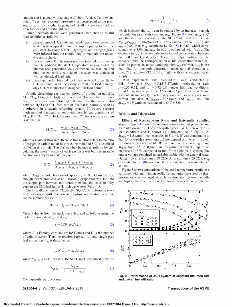
which indicates that uf,sp can be reduced by an increase in anoderecirculation ratio with constant uf,o. Figure 3 shows uf,sp, O/C,and the ratio of flow rate at the SOFC inlet and in-flow rateNch4,in/Nch4,0 as function of r. For example, when r¼ 0.7 anduf,o¼ 0.85, then uf,sp calculated by Eq. (8) is 0.63, which corre-sponds to a 35% increase in Nch4,in compared with Nch4,0. Thedecrease in uf,sp indicates a decrease in fuel concentration betweenthe SOFC inlet and outlet. Therefore, output voltage can beenhanced with the homogenization of fuel concentration in a cellstack. In particular, under extremely high uf,o (�0.95), uf,sp is lessthan that for one-path generation under normal operation atr> 0.7. In addition, O/C> 2.0 at high r without an external steamsupply.
AGR experiments with AGR–SOFC were conducted atCH4 flow rate Qch4,0¼ 3.15–3.37 l/min, recirculation ratior¼ 0.55–0.62, and uf,o¼ 0.72–0.84 under full road conditions.In addition, to compare the AGR–SOFC performance with andwithout steam supply, preliminary one-path experiments werecarried out also at Qch4,0¼ 3.15 l/min and uf,o¼ 0.84. TheMH2O¼ 6.9 g/min corresponded to O/C¼ 3.0.
Results and Discussion
Effects of Recirculation Ratio and Externally SuppliedSteam. Figure 4 shows the relation between output power W andrecirculation ratio r. For a one-path system, W � 914 W at full-load condition and is shown as a broken line in Fig. 4. AtMH2O¼ 1.5 g/min (open triangles in Fig. 4), W was comparable tothat for one-path system and did not depend on r when r< 0.61.In contrast, when r> 0.61, W increased with increasing r andMH2O from 1.5 to 0 g/min in 0.5 g/min increments; up to anincrease of 15 W compared to that for the one-path system. Theoutput voltage remained remarkably stable with no external water(MH2O¼ 0) at maximum r (0.622). At maximum r (0.622), uf,sp
calculated by Eq. (8) was about 0.72, although uf,o was maintainedat 0.84.
Figure 5 shows comparison of the axial temperature profile in acell stack with and without AGR. Temperature measured by ther-mocouples was averaged at each location (i.e., bottom, middleand top) in the flow direction. The overall temperature profile can
Fig. 3 Performance of AGR system at constant fuel feed rateand overall fuel utilization
021504-4 / Vol. 137, FEBRUARY 2015 Transactions of the ASME
Downloaded From: http://gasturbinespower.asmedigitalcollection.asme.org/ on 09/12/2014 Terms of Use: http://asme.org/terms

be explained as follows. The middle part of the stack produces themost current. The bottom of the stack has the lowest temperaturedue to the steam reforming reaction, which is endothermic forCH4 unreacted at the prereformer. The top of a cell stack dependson the cathode gas temperature because chemical reaction is mini-mal. For AGR, the bottom of the stack is about 50 K lower thanthat in a one-path system, because much more CH4 is reformedvia steam reforming reaction associated with a decreasing reactionrate of steam reforming at the prereformer Reforming ratedepends on temperature, relation between reaction speed andgas retention time, diffusivity in mixture gas, and steam concen-tration. Results (Fig. 5) reveal almost no difference betweenAGR–SOFC and one-path system in their temperature in the pre-reformer and outlet gas at the prereformer. Therefore, the maincause of the reduction in prereforming rate is still not known.Generally, ohmic loss is the main problem for SOFCs, and thusthe output power is due to an appropriate balance between twoeffects as follows: (i) An increase in stack temperature producesan increase in output voltage attributed to a decrease in the electri-cal resistance of the electrodes. (ii) If the flow rate of unreformedmethane is increased, then the amount of direct internal reformingincreases, and thus the optimal hydrogen concentration is main-tained to the fuel downstream at the generator plenum. In suchcase, differential current density in a cell for the recycle modebecomes low, particularly because the current density in the topstack increases. The top stack temperature with AGR was higherthan with AGR, because cathode preheater power was controlledto match the average temperature of the overall cell stack underboth conditions, although the cathode temperature for the AGRsystem was set higher than that for the one-path system.
Figure 6 shows the variation in r and O/C with needle positionin the nozzle. By moving the needle, r could be changed up to0.608 at MH2O¼ 1.5 g/min, which was 69% lower than that corre-sponding to the recorded O/C value. Increasing r from 0.553 to0.581 increased the O/C from 2.13 to 2.25 due to the increase inamount of returned steam in the anode recycle gas. In other words,steam concentration in the mixing gas of injected CH4 and recyclegas increases at the ejector outlet. Figure 7 shows the effect of ron stack temperature profile in an AGR–SOFC. Although the tem-perature at the bottom was slightly higher at r¼ 0.581, thereappears to be no overall difference in temperature between higherand lower r conditions. Therefore, the temperature difference inthe bottom stack can be considered to be due to the uncertainty inthe temperature measurements. Because there is no significant dif-ference in stack temperature profile with respective to r, theamount of reactions can be thought as being independent of r. Inaddition, off-gas components at the SOFC outlet were also notaffected by r (see Fig. 8). Under constant Qch4,0 and MH2O, gascomponents of anodic off-gas related to chemical equilibrium atthe temperature of the top of the stack is maintained regardless ofthe anode recycle.
Figure 9 shows the r and O/C as a function of MH2O, and Fig.10 shows r as a function of the pressure difference between thefuel plenum and the recycle plenum DP2. The pressure drop at an-odic loop decreased with MH2O, resulting in large r. Although theflow rate of recycled steam increased with r, the decrease in MH2O
had a stronger effect on O/C. Figure 11 shows the axial tempera-ture profile at MH2O¼ 0 and 1.5 g/min conditions. The reductionin the inlet temperature in a stack with MH2O indicates an increase
Fig. 5 Stack temperature profile for a one-path system and arecycle system with no steam supply (MH2O 5 0 g/min)
Fig. 6 Recirculation ratio r for various ejector needle positionx
Fig. 7 Stack temperature profile for various recirculation ratio r
Fig. 4 Output power W at various recirculation ratio r
Journal of Engineering for Gas Turbines and Power FEBRUARY 2015, Vol. 137 / 021504-5
Downloaded From: http://gasturbinespower.asmedigitalcollection.asme.org/ on 09/12/2014 Terms of Use: http://asme.org/terms

in the rate of water–gas shift reaction. This increase was due to adecrease in steam reforming reaction in the prereformer withdecreasing O/C. In contrast, the stack temperature from the mid-dle to the top parts was relatively constant at either MH2O value,indicating that the internal reforming was complete above themiddle parts of a stack at either MH2O value. Figure 12 shows thegas components at the recycle plenum. Steam concentration in an-odic off-gas decreased with decreasing MH2O, while the mole frac-tions of CO and CO2 slightly increased. The CH4 concentrationremained at almost zero. Thus, although reaction rate at pre-reformer changed with MH2O, all of the unformed methane wasconverted to hydrogen by internal reforming. Because He and Arwere fed at a constant inflow rate, the variation in their respectivemole fractions was due to the variation was the mole flow rate ofother gas components, especially steam.
The above results (Figs. 4 and 12) clearly show the negativeeffect of MH2O on W of AGR–SOFC, while there was no effect of
recirculation ratio on W. A lower steam feed rate enhanced thehydrogen gas diffusivity from bulk flow toward the reaction sur-face associated with moisture removed from a catalyst layer, thuscausing an increase in cell voltage. In contrast, reduction of mois-ture in the catalyst layer decreases the electrical resistance of thatlayer, and the resulting decrease in ionic conductivity degradedthe catalyst activation. The relation between effects of hydrogengas diffusivity and the electrical resistance of catalyst layer leadto the increment of output power of SOFC with the amount of fedsteam. Furthermore, the steam mole fraction in the mixture gas atthe ejector outlet also increased with increasing r, although Wremained constant due to the limitation of the performance of thetop cell.
When r¼ 0.6, the calculated Nch4,in was about two times higherthan that of in-flow rate of methane Nch4,0 (Eq. (7)). Assuming fur-ther improvement in r, the fuel concentration would be dilutedwith recycled steam, as indicated by the increase in O/C. In suchcase, there is a possibility of voltage reduction, because hydrogenwould be in short supply near a reaction layer compared in withthe decrease in hydrogen concentration due to hydrogen oxidationreaction. Future study is needed on the effects of flow rate and gascomposition on fuel concentration distribution in the cross sectionof the cell stack for various r.
Effects of Overall Fuel Utilization. To determine the effect ofuf,o on the SOFC, anode recycle experiments were conducted witha steam feed rate of 1.5 g/min at various uf,o from 0.72 to 0.84 bychanging the combination of load current and fuel feed rate
Fig. 8 Gas composition at the recycle plenum for various recir-culation ratio r
Fig. 9 Recirculation ratio r versus in-flow rate of externallysupplied steam MH2O
Fig. 10 Recirculation ratio r versus differential pressurebetween the fuel plenum and the recycle plenum DP2
Fig. 11 Stack temperature profile for various in-flow rate ofexternally supplied steam MH2O
021504-6 / Vol. 137, FEBRUARY 2015 Transactions of the ASME
Downloaded From: http://gasturbinespower.asmedigitalcollection.asme.org/ on 09/12/2014 Terms of Use: http://asme.org/terms

Qch4,0¼ 3.15, 3.25, and 3.37 l/min. Figure 13 shows the relationbetween r and O/C and uf,o. Because the electrochemical half-reaction rate was changed by fuel utilization, the O/C ratiostrongly depended on the oxygen molecular content. The single-pass fuel utilization uf,sp was reduced to about 0.52 and 0.62 (bro-ken lines in Fig. 13) for uf,o¼ 0.72 and 0.79, respectively.
Figure 14 shows the axial stack temperature distribution foreach uf,o. At the higher uf,o, the temperature from the bottom tomiddle of the stack was higher, indicating enhanced half-reactions, which are exothermic. The bottom stack temperaturefor uf,o¼ 0.84 was about 60 K higher than that for uf,o¼ 0.72.While the top stack temperature was unaffected by uf,o, becausethe temperature strongly depends on cathode gas temperatureheated at constant power. Figure 15 shows the gas components atthe SOFC outlet as a function of uf,o. With increasing uf,o, themole fraction of hydrogen decreased from 0.172 to 0.074 due toreduced fuel consumption, whereas the steam concentrationincreased. Furthermore, the concentrations of other gas
components were constant with uf,o. The increasing uf,o enhancedthe electrochemical half-reaction, resulting in an increase in MH2O
produced by the reaction with uf,o. These results indicate that onlyhydrogen was consumed through the half-reaction in a stack.Assuming the same reduction rate of hydrogen concentration touf,o as observed in these data, the hydrogen concentration woulddrop below 3% when uf,o exceeds about 0.90. Consequently,although the AGR led to a low uf,sp in comparison with uf,o,because the local hydrogen concentration near the catalytic layerwas less than the average value, the fuel utilization limitation ofthe operation is estimated to be as much as one-path system toavoid the local lack of hydrogen as useful fuel.
Leakage Effects. Table 1 shows gas components on a dry basisat SOFC inlet and outlet when Qch4,0¼ 3.15 l/min, uf,o¼ 0.84,x¼ 0.30 mm, and tracer gas He and Ar are fed at an inflow rate of0.3 l/min. Incorporation of N2 suggests that there was a smallamount of leakage. In addition, mole fraction of Ar was about 1%
Fig. 12 Gas composition at the recycle plenum for various in-flow rate of externally supplied steam MH2O
Fig. 13 Recirculation ratio r versus overall fuel utilization uf,o
Fig. 14 Stack temperature profile for various overall fuel utili-zation uf,o
Fig. 15 Gas composition at the recycle plenum versus overallfuel utilization uf,o
Journal of Engineering for Gas Turbines and Power FEBRUARY 2015, Vol. 137 / 021504-7
Downloaded From: http://gasturbinespower.asmedigitalcollection.asme.org/ on 09/12/2014 Terms of Use: http://asme.org/terms

f.s. larger than that of He at the recycle plenum. For He and Ar,the ratio of mole flow rate at the recycle plenum and feed rate isdefined by using r as follows:
NHe;S2
NHe;0¼ NAr;S2
NAr;0¼ r
1� r(9)
At equal feed rate in He and Ar, NHe,S2 must be equal to NAr,S2,which refers to same mole fraction in them at the recycle plenum(XHe,S2¼XAr,S2). Therefore, at least He leaks out of the generatorplenum. The r calculated from Eq. (1) is affected by the leakageof tracer gas, i.e., He and Ar, but not that of N2 and the other gascomponents. Furthermore, the sensitivity of r to leakage dependson the location of the leakage. If the leakage of He was to beassumed about 20% of feed rate from S1 to S2 in anodic loop, rwould be underestimated by up to 10% over the range of theexperimental conditions studied here. On the other hand, if theleakage was to be assumed from S2 to S1, r would be affected byonly the leakage of Ar, and thus r would be underestimated by upto 25% with Ar leakage about 20%. Furthermore, based on therobustness of welded anodic piping, He leakage occurred fromthe anode to the cathode through the electrolyte layer and fromthe alumina fiber partition between the recycle plenum and thecombustion plenum.
Conclusions
In order to evaluate the effects of recirculation ratio, steam feedrate, and fuel utilization on the AGR–SOFC performance, experi-ments using a 1 kW tubular-type SOFC with the anode recyclesystem driven by a variable flow ejector were carried out at arecirculation ratio r of 0.55–0.62, overall fuel utilization uf,o of0.72–0.84, and externally steam feed rate MH2O at 0–1.5 g/min. Toidentify r, gas composition of reformed gas at the SOFC inlet andrecycled gas at the SOFC outlet were measured using a quadru-pole mass spectrometer. The results are summarized as follows:
(i) For uf,o¼ 0.84, the AGR–SOFC at r¼ 0.622 andMH2O¼ 0 had about 15 W higher output power comparedto a one-path system. The differential temperature in astack for the recycle system was larger than that for a one-path system due to a temperature drop caused by internalreforming, which is endothermic in the bottom part of thestack (fuel inlet). In addition, the AGR–SOFC showed sta-ble behavior, without an external steam supply.
(ii) At MH2O¼ 1.5 g/min, r could be controlled by adjustingthe needle in the ejector. Furthermore, with increasing r,the oxygen-to-carbon ratio increased corresponding to therecycle rate of steam produced in the cell stack. On theother hand, stack temperature and gas components atthe SOFC outlet were independent of r, confirming thatthe output power is limited by the reaction rate at the topof a cell stack, and this rate is constant with r.
(iii) Reduction in the steam feed rate in the anodic gasenhanced the output power, due to the water removedfrom the catalyst layer. In addition, the pressure drop atthe anodic loop decreased with steam feed rate at a high rvalue of 0.622.
(iv) Temperature distribution in the stack was strongly affectedby electrochemical reaction. Thus, O/C increased with uf,o
as a result of the reaction activation.
(v) Although the AGR led to an extremely low single-pass uti-lization uf,sp in comparison with uf,o, the mole fraction ofhydrogen at SOFC outlet is little affected by anode recycleratio, resulting the fuel utilization limitation of the opera-tion is estimated to be as much as one-path systems.
Nomenclature
F ¼ Faraday constant 96485 (C/mol)I ¼ current (A)
Mj ¼ mass flow rate of species j (g/min)Nj ¼ molar flow rate of species j (mol/min)
O/C ¼ oxygen to carbon ratioQj ¼ volumetric flow rate of species j (l/min)
r ¼ recirculation ratioS/C ¼ steam to carbon ratio
T ¼ temperature ( �C K)uf ¼ fuel utilizationV ¼ voltage (V)W ¼ output power (W)x ¼ ejector needle position (mm)
Xj ¼ mole fraction of species j on a wet basisYj ¼ mole fraction of species j on a dry basisz ¼ thermocouple location from the bottom of the flow
straightener (mm)
Greek Symbol
DP ¼ deferential pressure
Subscripts
ex ¼ exitin ¼ inleto ¼ overall
rec ¼ recyclesp ¼ single-pass
stack ¼ cell stackS1 ¼ sampling port S1S2 ¼ sampling port S2
0 ¼ initial
References[1] Takahashi, S., Kobayashi, N., Iki, N., Furutani, H., and Yamashita, I., 2004,
“Feasibility Study on SOFC-Stirling Engine Combined System,” Trans. Jpn.Soc. Mech. Eng. Ser. B, 70(689), pp. 192–200.
[2] Ray, E. R., and Veyo, S. E., 1993, “High Temperature Solid Oxide Fuel Cell—Customer Test Units,” Joint Contractors Meeting FE/EE Advanced TurbineSystem Conference: FE Fuel Cell and Coal Fired Heat Engine Conference,Morgantown, WV, Aug. 3–5, pp. 304–312.
[3] Marsano, F., Magistri, L., and Massardo, A. F., 2004, “Ejector PerformanceInfluence on a Solid Oxide Fuel Cell Anodic Recirculation System,” J. PowerSources, 129(2), pp. 216–228.
[4] Ferrari, M. L., and Massardo, A. F., 2013, “Cathode–Anode Side Interaction inSOFC Hybrid Systems,” Appl. Energy, 105, pp. 369–379.
[5] Ferrari, M. L., Pascenti, M., Magistri, L., and Massardo, A. F., 2010, “HybridSystem Test Rig: Startup and Shutdown Physical Emulation,” ASME J. FuelCell Sci. Technol., 7(2), p. 021005.
[6] Traverso, A., Trasino, F., Magistri, L., and Massardo, A. F., 2008, “Time Char-acterization of the Anodic Loop of a Pressurized Solid Oxide Fuel Cell Sys-tem,” ASME J. Eng. Gas Turbines Power, 130(2), p. 021702.
[7] Ferrari, M. L., 2011, “Solid Oxide Fuel Cell Hybrid System: Control Strategyfor Stand-Alone Configurations,” J. Power Sources, 196(5), pp. 2682–2690.
[8] Zhu, Y., Cai, W., Wen, C., and Li, Y., 2007, “Fuel Ejector Design and Simula-tion Model for Anodic Recirculation SOFC System,” J. Power Sources, 173(1),pp. 437–449.
[9] Zhu, Y., Cai, W., Li, Y., and Wen, C., 2008, “Anode Gas Recirculation Behav-ior of a Fuel Ejector in Hybrid Solid Oxide Fuel Cell Systems: PerformanceEvaluation in Three Operational Modes,” J. Power Sources, 185(2), pp.1122–1130.
[10] Zhu, Y., Li, Y., and Cai, W., 2011, “Control Oriented Modeling of Ejector inAnode Gas Recirculation Solid Oxygen Fuel Cell Systems,” Energy Convers.Manage., 52(4), pp. 1881–1889.
[11] Zhu, Y., Cai, W., Wen, C., and Li, Y., 2009, “Numerical Investigation of Ge-ometry Parameters for Design of High Performance Ejectors,” Appl. Therm.Eng., 29(5–6), pp. 898–905.
Table 1 Anode gas composition on a dry basis atQch4,0 5 3.15 l/min, uf,o 5 0.84, and x 5 0.30 mm
He Ar H2 N2 CH4 CO CO2
S1 0.039 0.029 0.353 0.039 0.088 0.119 0.335S2 0.046 0.056 0.156 0.057 0.001 0.158 0.527
021504-8 / Vol. 137, FEBRUARY 2015 Transactions of the ASME
Downloaded From: http://gasturbinespower.asmedigitalcollection.asme.org/ on 09/12/2014 Terms of Use: http://asme.org/terms

[12] Saebea, D., Patcharavorachot, Y., and Arpornwichanop, A., 2012, “Analysis ofan Ethanol-Fuelled Solid Oxide Fuel Cell System Using Partial Anode ExhaustGas Recirculation,” J. Power Sources, 208, pp. 120–130.
[13] Liu, M., Lanzini, A., Halliop, W., Cobas, V. R. M., Verkooijen, A. H. M., andAravind, P. V., 2013, “Anode Recirculation Behavior of a Solid Oxide FuelCell System: A Safety Analysis and a Performance Optimization,” Int. J.Hydrogen Energy, 38(6), pp. 2868–2883.
[14] Santarelli, M. G., Leone, P., Cali, M., and Orsello, G., 2007, “ExperimentalAnalysis of the Voltage and Temperature Behavior of a Solid Oxide Fuel CellGenerator,” ASME J. Fuel Cell Sci. Technol., 4(2), pp. 143–153.
[15] Peters, R., Deja, R., Blum, L., Pennanen, J., Kiviaho, J., and Hakala, T., 2013,“Analysis of Solid Oxide Fuel Cell System Concepts With Anode Recycling,”Int. J. Hydrogen Energy, 38(16), pp. 6809–6820.
[16] Braun, R. J., Klein, S. A., and Reindl, D. T., 2006, “Evaluation of System Con-figurations for Solid Oxide Fuel Cell-Based Micro-Combined Heat and PowerGenerators in Residential Applications,” J. Power Sources, 158(2), pp.1290–1305.
[17] Farhad, S., Hamdullahpur, F., and Yoo, Y., 2010, “Performance Evaluation ofDifferent Configurations of Biogas-Fuelled SOFC Micro-CHP Systems for Res-idential Applications,” Int. J. Hydrogen Energy, 35(8), pp. 3758–3768.
[18] Liso, V., Olesen, A. C., Nielsen, M. P., and Kær, S. K., 2011, “PerformanceComparison Between Partial Oxidation and Methane Steam Reforming Proc-esses for Solid Oxide Fuel Cell (SOFC) Micro Combined Heat and Power(CHP) System,” Energy, 36(7), pp. 4216–4226.
[19] Liso, V., Nielsen, M. P., and Kær, S. K., 2013, “Ejector Design and Perform-ance Evaluation for Recirculation of Anode Gas in a Micro Combined Heat andPower Systems Based on Solid Oxide Fuel Cell,” Appl. Therm. Eng., 54(1),pp. 26–34.
[20] Dietrich, R. U., Oelze, J., Lindermeir, A., Spitta, C., Steffen, M., K€uster, T.,Chen, S., Schlitzberger, C., and Leithnerd, R., 2011, “Efficiency Gain of SolidOxide Fuel Cell Systems by Using Anode Offgas Recycle—Results for a SmallScale Propane Driven Unit,” J. Power Sources, 196(17), pp. 7152–7160.
[21] Brunner, D. A., Marcks, S., Bajpai, M., Prasad, A. K., and Advani, S. G., 2012,“Design and Characterization of an Electronically Controlled Variable FlowRate Ejector for Fuel Cell Applications,” Int. J. Hydrogen Energy, 37(5), pp.4457–4466.
[22] Powell, M., Meinhardt, K., Sprenkle, V., Chick, L., and McVay, G., 2012,“Demonstration of a Highly Efficient Solid Oxide Fuel Cell Power SystemUsing Adiabatic Steam Reforming and Anode Gas Recirculation,” J. PowerSources, 205, pp. 377–384.
Journal of Engineering for Gas Turbines and Power FEBRUARY 2015, Vol. 137 / 021504-9
Downloaded From: http://gasturbinespower.asmedigitalcollection.asme.org/ on 09/12/2014 Terms of Use: http://asme.org/terms