
RECYCLE IT - Create your own video
75
PLUS WIN A PICDEM Lab Development Kit – see page 29 Rolling Code Keyless Entry System Part 2 – Installation and Setting-up PROGRAMMABLE IGNITION SYSTEM FOR CARS – Part 1 i Suits most 4-stroke and 2-stroke engines i Plug-in LCD hand contoller for adjustments i Points, reluctor, hall effect, digital signal or optical triggering i Timing mapped against RPM and engine load RECYCLE IT Salvaging the good bits from a cordless drill and putting them to use $8.75 US $10.25 CAN SEPT 2009 PRINTED IN THE UK
-
Upload
khangminh22 -
Category
Documents
-
view
1 -
download
0
Transcript of RECYCLE IT - Create your own video

PLUS
WIN
A PICDEM Lab
Development Kit –
see page 29
Rolling Code Keyless Entry System Part 2 – Installation and Setting-up
PROGRAMMABLE IGNITION SYSTEM FOR CARS – Part 1 i Suits most 4-stroke and 2-stroke engines i Plug-in LCD hand contoller for adjustmentsi Points, reluctor, hall effect , digital signal or optical triggeringi Timing mapped against RPM and engine load
RECYCLE ITSalvaging the good bits from a cordless drill and putting them to use
$8.75 US $10.25 CANSEPT 2009 PRINTED IN THE UK
SEPTEMBER2009 Cover.indd 1 27/07/2009 14:50:12

STEWART of READING17A King Street, Mortimer, Near
Reading RG7 3RSTelephone: (0118) 933 1111
Fax: (0118) 933 23759am – 5pm Monday - Friday
CHECK OUT OUR WEBSITE,1,000’s of items currently in stock
www.stewart-of-reading.co.ukExtra Special Oscilloscope
offer still on
Used Equipment – GUARANTEEDMost Manuals Supplied
Please check availability before ordering or calling.
Prices plus carriage and VAT
AGILENT E4402B Spectrum Analyser100HZ – 3GHZ with Option 1DN Tracking Gen; 1 DR Narrow Res; A4H GPIB, UKB £5800HP 8591E Spectrum Analyser9KHZ – 1.8GHZ with Tracking Gen £1500No Moudlings, No Handle £1250HP 35670A FFT Dynamic Signal Analyser2 Channel. Unused in original box £2500AGLIENT 83752B Synthesised Sweeper0.01-20GHZ £7000HP83731B Synthesised 1-20GHZ with Opts IEI Attenuator, IE5 High Performance Mod Gen, IE5 High Stab TB £4500HP83711B Synthesised 1-20GHZ with Opt IEIAttenuator £5000AGILENT/HP E4431B Signal Generator 250KHZ-2GHZ Digital Modulation £2750AGILENT 6632B Power Supply 0-20V 0-5A Digital IEEE £195HP8116A Pulse/Function Gen 50 MHZ £575MARCONI 2024 Signal Generator 9KHZ-2.4GHZ Opt 04/11 HPIB £950
TEKTRONIX TDS OSCILLOSCOPESSupplied with Operating Instructions & Mains Leads544A 4 Ch 500MHZ 1 GS/S Colour £1050540A 4 Ch 500MHZ 1 GS/S £950540 4 Ch 500MHZ 1 GS/S £750524A 2+2 Ch 500MHZ 500 MS/S Colour £750520A 2+2 Ch 500MHZ 500 MS/S £650
520 2+2 Ch 500MHZ 500 MS/S £550460 4 Ch 350MHZ 100 MS/S £495430A 2 Ch 400MHZ 100 MS/S £495380 2 Ch 400MHZ 2 GS/S £650350 2 Ch 200MHZ 1 GS/S £500340A 2 Ch 100MHZ 500 MS/S £395320 2 Ch 100MHZ 500 MS/S £325310 2 Ch 50 MHZ 200 MS/S £2501012 2 Ch 100MHZ 1 GS/S £425
OSCILLOSCOPESTEKTRONIX 465/465B Dual Trace 100MHZ Delay Sweep £75/£95TEKTRONIX 2235 Dual Trace 100MHZ Dual TB £150TEKTONIX 2445A 4 Ch 150MHZ Delay Sweep Cursors £225HP 54501A Digitising 2+2 Ch 100MHZ 10 MS/S £150HP 54600B Dual Trace 100MHZ 20MS/S £225PHILIPS PM3055 2+1 Ch 60MHZ Dual TB/DelayAutoset £95PHILIPS PM3065 2+1 Ch 100MHZ Dual TB/Delay Autoset £125FARNELL DTV60 Dual Trace 100MHZ £75FARNELL DTV12-14 Dual Trace 12MHZ £40HITACHI V212 Dual Trace 20MHZ £50GOULD OS300 Dual Trace 20MHZ £60LEADER LBO523 Dual Trace 40MHZ £65wer Supplies
POWER SUPPLIESFARNELL B30-10 30V 10A Variable No Meters £45FARNELL B30-20 30V 20A Variable No Meters £75FARNELL L30-1 0-30V 0-1A £30FARNELL L30-2 0-30V 0-2A £40FARNELL L30-5 0-30V 0-5A 2 Meters £50FARNELL LT30-1 0-30V 0-1A Twice £50FARNELL TSV70 MK2 0-70V 0-5A or 0-35V 0-10A £60FARNELL XA35.2T 0-35V 0-2A Twice Digital £75TAKASAGO TMO35-2 0.35V 0-2A 2 Meters £30THURLBY PL330 0-32V 0-3A Digital (Kenwood Badged) £60THURLBY PL320 0-30V 0-2A Digital £45THURLBY TS3021S 0-30V 0-2A LCD £55
MISCELLANEOUSAVO DA116 3½ Digit with Batteries & Leads £20AVO BA8 MK2 Meggar 1000V in Case £25ADRET 104A Programmable DC Voltage CurrentReference Standard IEEE & BCD £75BEAMIX 303 Temperature Calibrator £150BECKMAN HD110 3½ Digit Handheld in Carrying Case £25BLACKSTAR Orion Colour Bar Generator £50CIRRUS CRL254 Sound Level Meter with Calibrator £65COSSOR Isolating Transformer Input 250V
Output 500VA Unused £25FARNELL LF1 Sine/Sq Oscillator 10HZ-1MHZ £40FARNELL J3B Sine/Sq Oscillator 10HZ-100KHZ Low Distortion £65FLUKE 4250A Programmable Power Source 1A £125FLUKE 5200A AC Calibrator £350HP3312A Func Gen 0.1HZ-13MHZ AM/FM Sweep/Tri etc £125HP3336C Synthesised Level Gen 10HZ-21MHZ £195HP3400A True RMS Voltmeter 10HZ-10MHZ, 1mV-300V £50HP3488AHP8922S with 83220E GSM MS Test set with DSC/PSC Test Set with Aux. Ports POAHP VXI Main Frames (75000 Series; E1401A/B;E8401A) £400HP33311 Co-Axial Switch 18GHZ £75HUNTING HIVOLT DCM30/4A 0-30 KV £35LEADER LAG120B Sine/Sq Audio Gen 10HZ-1MHZ £50LEADER LDC9043 Digital Counter 100MHZ £75MARCONI TF2331 Distortion Meter £35MARCONI 2370 Spectrum Analyser 30HZ-110MHZ £395MARCONI 2430A Freq Meter 10HZ-80MHZ £50METRIX GX500 Pulse Generator Programmable £125NATIONAL PANASONIC VP7705A Distortion Meter £95PANASONIC VP8401B TV Sig Gen NTSC/PAL/MONTSC £75RACAL 1991 Counter/Timer 160MHZ 9 Digit £125RACAL 9008 Modulation Meter £50RACAL 9009 Modulation Meter £40RACAL 9904 Counter Timer 50MHZ £40RACAL 9916 Counter 10HZ – 520MHZ £55RACAL 9300B True RMS Millivoltmeter 5HZ-20MHZ usable to 60MHZ 100uV-316V £40RACAL 6103/E/G Digital Radio Test Set Various Options from £500ROBIN OM33 Digital Thermometer –No Probe. Unused £15ROBIN OM65 Digital L/C Meter Handheld, Unused £25SEWARD NOVA Pat Tester £175SHIBASOKU VS12CX Video Sweep Gen NTSC/PAL £125SOLATRON 7045 4½ Digit Bench Multimeter £30SOLATRON 7150 PLUS 6½ Digit Multimeter True RMS IEEE etc £65SOLATRON 7075 7½ Digit Multimeter, no inputconnector, AC/DS Volts Ohms £95THANDAR TG101 Function Gen 200KHZ £25THURLBY TG210 Function Gen 0.002HZ-2MHZ TTL (Kenwood Badged) £60TIME 9811 Programmable Resistance Potential Divider 10hm-1.5 Mohm 6 Digit LC Display IEEE £75WAVETEK 178 Programmable Waveform Synthesiser 1uHZ-50MHZ £195
HP53131A UNIVERSAL COUNTER WITHOPT 001 (oven)Unused Boxed 3GHZ £850 Unused Boxed 225MHZ £595Used 225MHZ £495
HP33120A FUNCTION GENERATOR100 MicroHZ – 15MHZUnused Boxed £595
stewarts full page:Mobile Europe cover template.qxd 17/7/09 10:46 Page 39
STEWART - SEPT 09 FULL PAGE.indd 1 22/07/2009 15:26:37

Copyright 2008, Wimborne Publishing Ltd (Sequoia House, 398a Ringwood Road, Ferndown, Dorset BH22 9AU, UK)
and TechBites Interactive Inc.,
(PO Box 857, Madison, Alabama 35758, USA)
All rights reserved.
WARNING! The materials and works contained within EPE Online — which are made available by Wimborne Publishing Ltd and TechBites Interactive Inc — are copyrighted. You are permitted to make a backup copy of the downloaded file and one (1) hard copy of such materials and works for your personal use. International copyright laws, however, prohibit any further copying or reproduction of such materials and works, or any republication of any kind. TechBites Interactive Inc and Wimborne Publishing Ltd have used their best efforts in preparing these materials and works. However, TechBites Interactive Inc and Wimborne Publishing Ltd make no warranties of any kind, expressed or implied, with regard to the documentation or data contained herein, and specifically disclaim, without limitation, any implied warranties of merchantability and fitness for a particular purpose. Because of possible variances in the quality and condition of materials and workmanship used by readers, EPE Online, its publishers and agents disclaim any responsibility for the safe and proper functioning of reader-constructed projects based on or from information published in these materials and works. In no event shall TechBites Interactive Inc or Wimborne Publishing Ltd be responsible or liable for any loss of profit or any other commercial damages, including but not limited to special, incidental, consequential, or any other damages in connection with or arising out of furnishing, performance, or use of these materials and works.

Everyday Practical Electronics, September 2009 1
Projects and CircuitsPROGRAMMABLE IGNITION SYSTEM FOR CARS – PART 1 10by John Clarke A highly versatile PIC-controlled system
ROLLING CODE KEYLESS ENTRY SYSTEM – PART 2 by John Clarke 24A super secure system with up to 16 keyfob transmitters
PIC PROGRAMMER SOIC CONVERTER 30Allows easy programming of 18-pin surface mount PICs
RANDOM MAINS TIMER by Bill Naylor 38Effectively simulates a house being occupied when it’s empty
INGENuITY uNLIMITED 57Battery tester for sealed lead-acid batteries
Series and FeaturesTEChNO TALK by Mark Nelson 22Thanks for the Ramory
QuICKBuILDER 2 REVIEW by Robert Penfold 33Summit Electronics’ software tool for project development
RECYCLE IT! by Julian Edgar 47Salvaging the good bits from cordless drills – and putting them to work
PRACTICALLY SPEAKING by Robert Penfold 52Mounting PCBs
CIRCuIT SuRGERY by Ian Bell 54Filter circuits – Part 3
PIC N’ MIx by Mike Hibbett 60Debugging – an art not science
NET WORK by Alan Winstanley 66EPE delivers worldwide; First aid
Regulars and ServicesEDITORIAL 7
NEWS – Barry Fox highlights technology’s leading edge 8Plus everyday news from the world of electronics
WIN A MICROChIP PICDEM LAB DEVELOPMENT KIT 29An EPE exclusive offer
BACK ISSuES Did you miss these? 31
ELECTRONICS TEACh-IN 2 37New book with Free CD-ROM – Using PIC Microcontrollers
MAx’S COOL BEANS by Max The Magnificent 44
SuBSCRIBE TO EPE and save money 46
PIC PROJECTS CD-ROM 50A plethora of handPICed projects
PIC RESOuRCES CD-ROM 51EPE PIC Tutorial V2, plus PIC Toolkit Mk3 and a selection of PIC-related articles
PLEASE TAKE NOTE 56Lightning Detector (June ’09); Heating Oil Storage Tank Burglar Alarm (July ’09)
ELECTRONICS MANuALS 58The Modern Electronics Manual and Electronic Service Manual on CD-ROM
CD-ROMS FOR ELECTRONICS 62A wide range of CD-ROMs for hobbyists, students and engineers
DIRECT BOOK SERVICE 67A wide range of technical books available by mail order, plus more CD-ROMs
EPE PCB SERVICE 70
ADVERTISERS INDEx 72
INCORPORATING ELECTRONICS TODAY INTERNATIONAL
www.epemag.com
ISSN 0262 3617
PROJECTS ThEORY NEWS COMMENT POPuLAR FEATuRES
VOL. 38. No 9 September 2009
Readers’ Services • Editorial and Advertisement Departments 7
© Wimborne Publishing Ltd 2009. Copyright in all drawings, photographs and articles published in EVERYDAY PRACTICAL ELECTRONICS is fully protected, and reproduction or imitations in whole or in part are expressly forbidden.
Our October 2009 issue will be published on Thursday 10 September 2009, see page 72 for details.
Contents.indd 1 29/07/2009 15:33:17

PIC Programmer Board
Low cost PIC programmer board supporting a wide range of Microchip® PIC™ microcontrollers. Requires PC serial port. Windows interface supplied. Kit Order Code: K8076KT - £39.95
PIC Programmer & Experimenter Board
The PIC Programmer & Experimenter Board with test buttons and LED indi-cators to carry out educa-tional experiments, such as the supplied programming examples. In-cludes a 16F627 Flash Microcontroller that can be reprogrammed up to 1000 times for experimenting at will. Software to compile and program your source code is included. Kit Order Code: K8048KT - £39.95 Assembled Order Code: VM111 - £59.95
USB Experiment Interface Board 5 digital input chan-nels and 8 digital out-put channels plus two analogue inputs and two analogue outputs with 8 bit resolution. Kit Order Code: K8055KT - £38.95 Assembled Order Code: VM110 - £64.95 Rolling Code 4-Channel UHF Remote State-of-the-Art. High security. 4 channels. Momentary or latching relay output. Range up to 40m. Up to 15 Tx’s can be learnt by one Rx (kit in-cludes one Tx but more avail-able separately). 4 indicator LED ’s. Rx: PCB 77x85mm, 12Vdc/6mA (standby). Two & Ten Channel versions also available. Kit Order Code: 3180KT - £49.95 Assembled Order Code: AS3180 - £59.95 Computer Temperature Data Logger
Serial port 4-channel tem-perature logger. °C or °F. Continuously logs up to 4 separate sensors located 200m+ from board. Wide
range of free software applications for stor-ing/using data. PCB just 45x45mm. Powered by PC. Includes one DS1820 sensor. Kit Order Code: 3145KT - £19.95 Assembled Order Code: AS3145 - £26.95 Additional DS1820 Sensors - £3.95 each
Quasar Electronics Limited PO Box 6935, Bishops Stortford CM23 4WP, United Kingdom Tel: 01279 467799 Fax: 01279 267799 E-mail: [email protected] Web: www.quasarelectronics.com
All prices INCLUDE 15.0% VAT. Postage & Packing Options (Up to 0.5Kg gross weight): UK Standard 3-7 Day Delivery - £4.95; UK Mainland Next Day Delivery - £9.95; Europe (EU) - £9.95; Rest of World - £14.95 (up to 0.5Kg). !Order online for reduced price Postage (from just £1) Payment: We accept all major credit/debit cards. Make cheques/PO’s payable to Quasar Electronics. Please visit our online shop now for full details of over 500 electronic kits, projects, modules and publications. Discounts for bulk quantities.
Credit Card
Sales
NEW! USB & Serial Port PIC Programmer USB/Serial connection. Header cable for ICSP. Free Windows XP soft-ware. See website for PICs supported. ZIF Socket and USB lead extra. 18Vdc.
Kit Order Code: 3149KT - £49.95 Assembled Order Code: AS3149 - £59.95 NEW! USB 'All-Flash' PIC Programmer USB PIC programmer for all ‘Flash’ devices. No external power supply making it truly portable. Supplied with box and Windows XP Software. ZIF Socket and USB lead not incl. Assembled Order Code: AS3128 - £49.95 Assembled with ZIF socket Order Code: AS3128ZIF - £64.95 ‘PICALL’ ISP PIC Programmer
Will program virtually all 8 to 40 pin serial-mode AND parallel-mode (PIC15C family) PIC microcontrol-lers. Free Windows soft-
ware. Blank chip auto detect for super fast bulk programming. Optional ZIF socket. Assembled Order Code: AS3117 - £29.95 Assembled with ZIF socket Order Code: AS3117ZIF - £44.95 ATMEL 89xxxx Programmer
Uses serial port and any standard terminal comms program. 4 LED’s display the status. ZIF sockets not included. Supply: 16Vdc.
Kit Order Code: 3123KT - £27.95 Assembled Order Code: AS3123 - £37.95 Introduction to PIC Programming Go from complete beginner to burning a PIC and writing code in no time! Includes 49 page step-by-step PDF Tutorial Manual, Program-ming Hardware (with LED test section), Win 3.11—XP Programming Software (Program, Read, Verify & Erase), and 1rewritable PIC16F84A that you can use with different code (4 detailed examples pro-vided for you to learn from). PC parallel port. Kit Order Code: 3081KT - £16.95 Assembled Order Code: AS3081 - £24.95
PIC & ATMEL Programmers
We have a wide range of low cost PIC and ATMEL Programmers. Complete range and documentation available from our web site.
Programmer Accessories: 40-pin Wide ZIF socket (ZIF40W) £14.95 18Vdc Power supply (PSU120) £19.95 Leads: Parallel (LDC136) £3.95 / Serial (LDC441) £3.95 / USB (LDC644) £2.95
4-Ch DTMF Telephone Relay Switcher Call your phone num-ber using a DTMF phone from anywhere in the world and re-motely turn on/off any of the 4 relays as de-sired. User settable Security Password, Anti-Tamper, Rings to Answer, Auto Hang-up and Lockout. Includes plastic case. 130 x 110 x 30mm. Power: 12Vdc. Kit Order Code: 3140KT - £74.95 Assembled Order Code: AS3140 - £89.95 8-Ch Serial Port Isolated I/O Relay Module Computer controlled 8 channel relay board. 5A mains rated relay outputs and 4 opto-isolated digital inputs (for monitoring switch states, etc). Useful in a variety of control and sensing applications. Programmed via serial port (use our new Windows interface, termi-nal emulator or batch files). Serial cable can be up to 35m long. Includes plastic case 130x100x30mm. Power: 12Vdc/500mA. Kit Order Code: 3108KT - £64.95 Assembled Order Code: AS3108 - £79.95 Infrared RC 12–Channel Relay Board
Control 12 onboard relays with included infrared remote con-trol unit. Toggle or momentary. 15m+ range. 112 x 122mm. Supply: 12Vdc/0.5A
Kit Order Code: 3142KT - £59.95 Assembled Order Code: AS3142 - £69.95
Audio DTMF Decoder and Display Detect DTMF tones from tape recorders, receivers, two-way radios, etc using the built-in mic or direct from the phone line. Char-acters are displayed on a
16 character display as they are received and up to 32 numbers can be displayed by scroll-ing the display. All data written to the LCD is also sent to a serial output for connection to a computer. Supply: 9-12V DC (Order Code PSU445). Main PCB: 55x95mm. Kit Order Code: 3153KT - £34.95 Assembled Order Code: AS3153 - £44.95
Telephone Call Logger
Stores over 2,500 x 11 digit DTMF numbers with time and date. Records all buttons pressed during a call. No need for any con-nection to computer during operation but logged data can be downloaded into a PC via a serial port and saved to disk. Includes a plastic case 130x100x30mm. Supply: 9-12V DC (Order Code PSU445). Kit Order Code: 3164KT - £54.95 Assembled Order Code: AS3164 - £69.95
Controllers & Loggers
Here are just a few of the controller and data acquisition and control units we have. See website for full details. 12Vdc PSU for all units: Order Code PSU445 £7.95
Most items are available in kit form (KT suffix) or pre-assembled and ready for use (AS prefix).
The Electronic Kit Specialists Since 1993
Quasar - SEPTEMBER09 P1.indd 2 30/07/2009 09:03:03

Secure Online Ordering Facilities Full Product Listing, Descriptions & Photos Kit Documentation & Software Downloads
500-in-1 Electronic Project Lab Top of the range. Com-plete self-contained elec-tronics course. Takes you from beginner to ‘A’ Level standard and beyond! Contains all the hardware and manuals to assemble 500 projects. You get 3 comprehensive course books (total 368 pages) - Hardware Entry Course, Hardware Advanced Course and a microprocessor based Software Program-ming Course. Each book has individual circuit explanations, schematic and connection dia-grams. Suitable for age 12+. Order Code EPL500 - £179.95 Also available: 30-in-1 £19.95, 50-in-1 £29.95, 75-in-1 £39.95 £130-in-1 £44.95 &
300-in-1 £69.95 (see website for details)
Two-Channel USB Pc Oscilloscope This digital storage oscillo-scope uses the power of your PC to visualize electrical sig-nals. Its high sensitive display resolution, down to 0.15mV, combined with a high band-width and a sampling fre-quency of up to 1GHz are giving this unit all the power you need. Order Code: PCSU1000 - £399.95 Personal Scope 10MS/s The Personal Scope is not a graphical multimeter but a com-plete portable oscilloscope at the size and the cost of a good mul-timeter. Its high sensitivity - down to 0.1mV/div - and extended scope functions make this unit ideal for hobby, service, automo-tive and development purposes. Because of its exceptional value for money, the Personal Scope is well suited for educational use. Order Code: HPS10 - £189.95 £169.95
See website for more super deals!
Tools & Test Equipment We stock an extensive range of soldering tools, test equipment, power supplies, inverters & much more - please visit web-site to see our full range of products.
Most items are available in kit form (KT suffix) or assembled and ready for use (AS prefix).
DC Motor Speed Controller (100V/7.5A) Control the speed of almost any common DC motor rated up to 100V/7.5A. Pulse width modulation output for maximum motor torque
at all speeds. Supply: 5-15Vdc. Box supplied. Dimensions (mm): 60Wx100Lx60H. Kit Order Code: 3067KT - £17.95 Assembled Order Code: AS3067 - £24.95 Computer Controlled / Standalone Unipo-lar Stepper Motor Driver Drives any 5-35Vdc 5, 6 or 8-lead unipolar stepper motor rated up to 6 Amps. Provides speed and direc-tion control. Operates in stand-alone or PC-controlled mode for CNC use. Connect up to six 3179 driver boards to a single parallel port. Board supply: 9Vdc. PCB: 80x50mm. Kit Order Code: 3179KT - £15.95 Assembled Order Code: AS3179 - £22.95 Computer Controlled Bi-Polar Stepper Motor Driver Drive any 5-50Vdc, 5 Amp bi-polar stepper motor using externally supplied 5V lev-els for STEP and DIREC-TION control. Opto-isolated inputs make it ideal for CNC applications using a PC running suitable software. Board supply: 8-30Vdc. PCB: 75x85mm. Kit Order Code: 3158KT - £23.95 Assembled Order Code: AS3158 - £33.95 Bidirectional DC Motor Speed Controller
Control the speed of most common DC motors (rated up to 32Vdc/10A) in both the forward and re-verse direction. The
range of control is from fully OFF to fully ON in both directions. The direction and speed are controlled using a single potentiometer. Screw terminal block for connections. Kit Order Code: 3166v2KT - £22.95 Assembled Order Code: AS3166v2 - £32.95 AC Motor Speed Controller (700W) Reliable and simple to install project that allows you to adjust the speed of an electric drill or 230V AC single phase induction motor rated up to 700 Watts. Simply turn the potentiometer to adjust the motors RPM. PCB: 48x65mm. Not suit-able for use with brushless AC motors. Kit Order Code: 1074KT - £14.95 Assembled Order Code: AS1074—£23.95
See www.quasarelectronics.com for lots more motor controllers
Motor Speed Controllers
Here are just a few of our controller and driver modules for AC, DC, Unipolar/Bipolar stepper motors and servo motors. See website for full details.
4-Channel Serial Port Temperature Monitor & Controller Relay Board 4 channel computer serial port temperature monitor and relay con-troller with four inputs for Dallas DS18S20 or DS18B20 digital ther-mometer sensors (£3.95 each). Four 5A rated relay channels provide output control. Relays are independent of sensor channels, allowing flexibility to setup the linkage in any way you choose. Commands for reading temperature and relay control sent via the RS232 interface using simple text strings. Control using a simple terminal / comms program (Windows HyperTerminal) or our free Windows application software. Kit Order Code: 3190KT - £69.95 Assembled Order Code: AS3190 - £84.95 40 Second Message Recorder Feature packed non-volatile 40 second multi-message sound recorder module us-ing a high quality Winbond sound recorder IC. Stand-alone operation using just six onboard but-tons or use onboard SPI interface. Record using built-in microphone or external line in. 8-24 Vdc operation. Just change one re-sistor for different recording duration/sound quality. sampling frequency 4-12 kHz. Kit Order Code: 3188KT - £28.95 Assembled Order Code: AS3188 - £36.95 120 second version also available Bipolar Stepper Motor Chopper Driver Get better performance from your stepper motors with this dual full bridge motor driver based on SGS Thompson chips L297 & L298. Motor current for each phase set using on-board potentiometer. Rated to han-dle motor winding currents up to 2 Amps per phase. Operates on 9-36Vdc supply voltage. Provides all basic motor controls including full or half stepping of bipolar steppers and direc-tion control. Allows multiple driver synchroni-sation. Perfect for desktop CNC applications. Kit Order Code: 3187KT - £39.95 Assembled Order Code: AS3187 - £49.95 Video Signal Cleaner Digitally cleans the video signal and removes un-wanted distortion in video signal. In addition it stabilises picture quality and luminance fluctuations. You will also benefit from improved picture quality on LCD monitors or projectors. Kit Order Code: K8036KT - £32.95 Assembled Order Code: VM106 - £49.95
Hot New Products!
Here are a few of the most recent products added to our range. See website or join our email Newsletter for all the latest news.
Electronic Project Labs
Great introduction to the world of electron-ics. Ideal gift for budding electronics expert!
The Electronic Kit Specialists Since 1993
Quasar - SEPTEMBER09 P2.indd 1 30/07/2009 09:05:13

September ‘09
0800 032 7241 jaycarelectronics.co.uk
ORDER YOURFREE
CATALOGUETODAY!
Everyday Practical Electronics Magazine has been publishing a series of popular kits by the acclaimed Silicon Chip Magazine Australia. These
projects are 'bullet proof' and already tested down under. All Jaycar kits aresupplied with specified board components, quality fibreglass tinned PCBs and
have clear English instructions. Watch this space for future featured kits.
• Secure on-line ordering• ALL prices in Pounds Sterling• Minimum order ONLY £10
THE'FLEXITIMER'
KA-1732 £6.00 plus postage & packingUses a handful of components toaccurately time intervals from afew seconds to a whole day. Itcan switch a number ofdifferent output devices onand off at timed intervals.Powered by a battery ormains plugpack, this kitincludes PCB and all components.
As published in EPE September 2007
RFID SECURITYMODULE RECEIVER
KC-5393 £28.95 plus postage & packingRadio Frequency Identity (RFID) is a non-contact method ofcontrolling an event such as a door strike or alarm etc. An"RFID Tag" transmits a unique code when energised by thereceiver's magnetic field. As long as a pre-programmed tag isrecognised by the receiver, access is granted. This moduleprovides normally open and normally closed relay contacts forflexibility. It works with all EM-4001compliant RFID tags. Kit supplied with PCB, tag, and allelectroniccomponents.
As published in EPE August 2007
3V TO 9V DC TO DCCONVERTER
KC-5391 £4.75 plus postage & packingEnables you to use regular Ni-Cd or Ni-MH 1.2V cells, oralkaline 1.5V cells for 9V applications. Using low cost, highcapacity rechargeable cells, this kit will pay for itself in no-time! Imagine the extra capacity you can have using two9000mAh D cells instead of a low capacity 9V cell. Kitsupplied with PCB, and allelectronic components.
As publishedin EPE June2007
SMART CARD READER /PROGRAMMER
KC-5361 £16.00 plus postage & packingProgram both the microcontroller and EEPROM in thepopular gold, silver and emerald wafercards that conform to ISO-7816standards. Powered by 9-12VDCwall adaptor or a 9V battery.Instructions outline softwarerequirements that are freely availableon the Internet. Kit supplied withPCB, wafer card socket and allelectronic components.
As published in EPE May 2007
FAST NI-MH BATTERY CHARGER
KC-5453 £12.50 plus postage & packingIdeal for RC enthusiastswho burn through a lotof batteries. Capable ofhandling up to15 of the sametype of Ni-MH orNi-Cd cells. Buildit to suit any sizecells or cell capacity andset your own fast or tricklecharge rate. It also has overcharge protection includingtemperature sensing. Kit includes solder mask & overlay PCB,programmed micro and all specified electronic components.Case, heatsink and battery holder not included.
As published in EPE August 2009
AV SIGNALBOOSTER
KC-5350 £31.95 plus postage & packingYou may experience somesignal loss when usinglong AV cables. Thiskit will boost yourcomposite, S-Videoand stereo audiosignals, preserving themfor the highest quality transmission to your home theatre,projector or large screen TV. Kit includes case, PCB, silk-screened punched panels and all electronic components withclear English instructions. Requires 9VAC wall adaptor.
As published in EPE March 2006
KC-5424 £6.75 pluspostage & packing
This versatile kit will allow you tomonitor the battery voltage, the airflow meter
or oxygen sensor in your car. It has a 10 LED bar that indicatesthe range of the measured voltage, with 9-16V, 0.-5V and 0-1Vpreset ranges. Features a fast response time, high inputimpedance & auto dimming for night time driving. Kit includesPCB with overlay, LED bar graph & all electronic components.• 12VDC
As published in EPE November 2007
KC-5442 £27.75 plus post & packingAn advanced ignition system for either two or four stroke engines. Used to modify thefactory ignition timing or as the basis for a stand-alone ignition system with variableignition timing, electronic coil control and anti-knock sensing. Kit includes PCB withoverlay, programmed micro, all electronic components and die cast box.
• Timing retard & advance over a wide range • Suitable for single coil systems• Dwell adjustment • Single or dual mapping ranges • Max & min RPM adjustment
As published in this issue of EPE
VOLTAGEMONITOR
PIC LOGICPROBE
NEWTO EPE
NEWTO EPE
NEWTO EPE
PROGRAMMABLE HIGHENERGY IGNITION SYSTEM
ROLLING CODE IRKEYLESS ENTRY SYSTEM
KC-5458 £19.00 plus postage & packingAn excellent keyless entrysystem featuring twoindependent door strike outputsand recognises up to 16separate key fobs. Itsynchronises the codedkey fobs to the receiverand compensates forrandom button presses.Supplied with solder maskedand silk screen printed PCB, two programmed micros, batteryand all electronic components. The receiver requires a 12VDC1.5A power supply. Some SMD soldering is required.
As published in this issue of EPE
NEWTO EPE
KC-5457 £5.00 plus post & packing
Operating on 2.8-15VDC, this logic probe is suitable for use on the most modern circuits. Extremely compact with SMT devices on a PCB only 5mm wide. It's capable of picking up a pulse only 50mS long and also detects and holds infrequent pulses when in latch mode. Kit includes PCB and all specified electroniccomponents including pre-programmed PIC. You'll need to add yourown case and probe - a clear ballpoint pen and a darning needlework well.
As published in EPE Magazine July 2009
EPE SEPTEMBER 21/7 9-30AM 21/7/09 9:23 AM Page 1
Jaycar SEPT09.indd 1 27/07/2009 12:15:32

0800 032 7241 jaycarelectronics.co.uk
FREE CATALOGUECheckout Jaycar’s extensive rangeWe have kits & electronic projects for use in:
• Audio & Video• Car & Automotive• Computer • Lighting• Power • Test & Meters• Learning & Educational• General Electronics Projects• Gifts, Gadgets & Just for fun!
For your FREE catalogue log on to:www.jaycarelectronics.co.uk/catalogueor check out the range at: www.jaycarelectronics.co.uk
HOW TO ORDERPOST & PACKING CHARGESOrder Value Cost£10 - £49.99 £5£50 - £99.99 £10£100 - £199.99 £20£200 - £499.99 £30£500+ £40
Note: Products are despatched from Australia,so local customs duty & taxes may apply.Prices valid until 30/9/09
• ORDER ON-LINE: www.jaycarelectronics.co.uk• PHONE: 0800 032 7241*• FAX: +61 2 8832 3118*• EMAIL: [email protected]• POST: P.O. Box 107, Rydalmere NSW 2116 Australia • ALL PRICING IN POUNDS STERLING• MINIMUM ORDER ONLY £10
Max weight 12lb (5kg).Heavier parcels POA.Minimum order £10.
*Australian Eastern Standard Time (Monday - Friday09.00 to 17.30 GMT + 10 hours only)Expect 10-14 days for air parcel delivery
ULTRA-LOW DISTORTIONAMPLIFIER MODULEKC-5470 £27.75 plus postage
& packingUsing new ThermalTrak power
transistors, this ultra-lowdistortion amplifier
module has no needfor a quiescent
current adjustment or a Vbemultiplier transistor. Kit supplied with
PCB and all electronic components. Heatsink and power supply not included.
Output power: 135WRMS @ 8 ohms & 200WRMS @ 4 ohmsFrequency response: 4Hz to 50kHz, 1mHarmonic distortion: <0.008% @ 20Hz-20kHz
Also available: Suitable Balanced Power Supply Kit KC-5471 £16.25
KC-5417 £10.25 plus postage & packingEnables you to drive one or two stereo headphones from anyline level (1volt peak to peak) input. The circuit features a facilityto drive headphones with impedances from about 8-600 ohms.Comes with PCB and components, PCB size 134 x 103mm.
Recommended box HB-6012 £2.00
STEREO HEADPHONEDISTRIBUTION AMPLIFIER
KC-5469 £8.25 plus postage & packingEnables you to run a stereo amplifier in 'Bridged Mode' toeffectively double the power available to drive a single speaker.There are no modifications required on the amplifier as thisclever kit does the signal processing. Supplied with silkscreened PCB and components.Requires balanced (+/-) powersupply.
BRIDGE MODE ADAPTOR FORSTEREO AMPLIFIERS
KC-5450 £10.25 plus postage & packingIt's primarily designed to protect your expensive speakersagainst damage in the event of catastrophic amplifier failure. Italso banishes those annoying switchon/off thumps and protects againstthermal overload.Configurable for 22VDC-70VDC. Supplied with a silkscreened PCB and all electroniccomponents.
SPEAKER PROTECTION &MUTING MODULE
KC-5150 £8.75 plus postage & packingA single chip module that provides 50WRMS @ 8 ohmswith very low distortion. PC Board and electroniccomponents supplied. PC Boardsize only 84 x 58mm. Requires heatsink. See website for full specs.
Heatsink to suit HH-8590 £5.75
50 WATT AMPLIFIERMODULE
KC-5468 £9.75 plus postage & packingStandard audio geardoes not have thebalanced inputsand outputs found inprofessional systems. Thiskit overcomes the problemby adapting an unbalancedinput to balanced output and vice versa. This allows domesticequipment to be integrated into a professional installation whilemaintaining the inherent high immunity to noise pick-up on longcable runs provided by balanced lines.
• PCB and all electronic components included• ±9-15VDC, or 9-30VDC, or 7-12VAC
BALANCED TO UNBALANCEDAUDIO CONVERTER
KA-1809 £8.25 plus postage & packingAssists people who have difficulty hearing high audiofrequencies, or use as an interesting teaching aid in theclassroom. By amplifying high audio frequencies,conversations will be made clearer and you will hearsounds not normally heard such as insects or awatch ticking. Kit supplied with case,front label, PCB, 9V battery, and all electronic components.Headphones required.
Note: Not a replacement for a proper hearing aid.
THE SUPEREAR
KC-5475 £21.75 plus postage &packingThe ever-popularTheremin is betterthan ever! Frompiercing shrieks to
menacing growls,create your own
eerie science fictionsound effects by simply moving your hand near the antenna.Now easier to set up and build, it also runs on AC to avoid theinterference switchmode plugpacks can cause. Complete kitcontains PCB with overlay, pre-machined case and all specified components.
THEREMINSYNTHESISER MKII
STUDIO 350 - HIGHPOWER AMPLIFIER
KC-5372 £50.75 plus postage & packingStudio quality sound and distortion with tremendous poweroutput. This will deliver a whopping 350WRMS into 4 ohms,or 200WRMS into 8 ohms. Using eight 250V 200W plasticpower transistors, it is super quiet, with a signal to noise ratioof -125dB(A) at full power. Harmonic distortion is just0.002%, and frequency response is almost flat (less than -1dB) between 15Hz and 60kHz! Kit supplied in short formwith PCB & electronic components.
As published in EPEOct/Nov 2006
EPE SEPTEMBER 21/7 9-30AM 21/7/09 9:24 AM Page 2
Jaycar SEPT09.indd 2 27/07/2009 12:21:02

Prices Exclude Vat @15%.UK Carriage £2.50 (less than 1kg)
£5.50 greater than 1kg or >£30Cheques / Postal orders payable to
ESR Electronic Components Ltd.PLEASE ADD CARRIAGE & VAT TO ALL ORDERS
www.esr.co.uk
Station RoadCullercoatsTyne & WearNE30 4PQ
Tel: 0191 2514363Fax: 0191 [email protected]
4000 Series4000B £0.274001B £0.164002B £0.194006B £0.654009UB £0.234010B £0.234011B £0.164012B £0.164013B £0.184014B £0.304015B £0.274016B £0.204017B £0.264018B £0.254019B £0.254020B £0.254021B £0.224022B £0.384023B £0.234024B £0.224025B £0.204026B £0.674027B £0.214028B £0.214029B £0.384030B £0.174035B £0.314040B £0.244041B £0.314042B £0.194043B £0.354046B £0.424047B £0.254048B £0.344049B £0.294049UB £0.174050B £0.204051B £0.234052B £0.324053B £0.204054B £0.564055B £0.344060B £0.174063B £0.414066B £0.174067B £2.204068B £0.194069UB £0.184070B £0.154071B £0.204072B £0.254073B £0.174075B £0.174076B £0.304075B £0.154077B £0.284078B £0.304081B £0.134082B £0.214085B £0.284086B £0.334093B £0.164094B £0.294098B £0.404099B £0.354502B £0.324503B £0.404508B £1.404510B £0.454511B £0.304512B £0.274515B £0.994516B £0.444518B £0.264520B £0.344521B £0.684526B £0.404527B £0.404529B £0.444532B £0.244536B £1.004538B £0.264541B £0.334543B £0.474555B £0.324556B £0.404584B £0.334585B £0.474724B £0.9440106B £0.1940109B £0.5840174B £0.4640175B £0.4174HC Series74HC00 £0.1674HC02 £0.1774HC03 £0.2174HC04 £0.1474HC08 £0.1774HC10 £0.2174HC11 £0.2174HC14 £0.1874HC20 £0.2874HC27 £0.1674HC30 £0.2274HC32 £0.1474HC42 £0.3674HC73 £0.4074HC74 £0.1574HC75 £0.3174HC85 £0.2374HC86 £0.2174HC107 £0.4074HC123 £0.3374HC125 £0.2674HC126 £0.4674HC132 £0.2674HC133 £0.3474HC137 £0.3074HC138 £0.2674HC139 £0.3174HC151 £0.33
74HC153 £0.3074HC154 £0.9474HC157 £0.2274HC158 £0.2374HC161 £0.2774HC162 £0.4574HC163 £0.2674HC164 £0.2074HC165 £0.2174HC173 £0.3874HC174 £0.2774HC175 £0.3574HC193 £0.3974HC195 £0.3274HC240 £0.3274HC241 £0.3774HC244 £0.4074HC245 £0.3474HC251 £0.3074HC253 £0.2574HC257 £0.2574HC259 £0.2974HC273 £0.3274HC299 £0.6174HC365 £0.2874HC367 £0.3874HC368 £0.2974HC373 £0.3574HC374 £0.3474HC390 £0.3774HC393 £0.3674HC563 £0.5674HC573 £0.2774HC574 £0.3074HC595 £0.2774HC597 £0.2274HC688 £0.4674HC4002 £0.3174HC4017 £0.2474HC4020 £0.3674HC4040 £0.2974HC4049 £0.3174HC4051 £0.5074HC4052 £0.3474HC4053 £0.2274HC4060 £0.2374HC4075 £0.2774HC4078 £0.3274HC4511 £0.6474HC4514 £0.8474HC4538 £0.4174HC4543 £0.9074LS Series74LS00 £0.3874LS01 £0.1474LS02 £0.3874LS03 £0.2174LS04 £0.3074LS05 £0.1474LS08 £0.1974LS09 £0.1574LS10 £0.2774LS11 £0.1774LS12 £0.2574LS14 £0.3674LS15 £0.2474LS20 £0.2774LS21 £0.2074LS26 £0.1774LS27 £0.2574LS30 £0.2074LS32 £0.2374LS37 £0.3174LS38 £0.1874LS40 £0.1474LS51 £0.2474LS83 £0.3874LS85 £0.4874LS86 £0.2574LS92 £0.4574LS93 £0.5874LS107 £0.3074LS109 £0.2174LS112 £0.2474LS113 £0.2374LS114 £0.3674LS122 £0.3174LS123 £0.3174LS125 £0.2874LS126 £0.2574LS132 £0.4774LS133 £0.3674LS136 £0.2374LS138 £0.3374LS145 £0.5674LS148 £0.6474LS151 £0.2974LS156 £0.3674LS157 £0.2274LS158 £0.2174LS160 £0.4874LS161 £0.3274LS162 £0.4474LS163 £0.3274LS164 £0.4374LS165 £0.4874LS173 £0.2474LS175 £0.3074LS191 £0.2774LS192 £0.6074LS193 £0.5074LS195 £0.2474LS221 £0.4174LS240 £0.3274LS241 £0.3274LS243 £0.3074LS244 £0.4174LS245 £0.4574LS247 £0.6074LS251 £0.2474LS257 £0.2474LS258 £0.2474LS266 £0.14
74LS273 £0.3274LS279 £0.2474LS283 £0.4774LS365 £0.2174LS367 £0.2174LS368 £0.2174LS373 £0.3974LS374 £0.3874LS378 £0.6274LS390 £0.3474LS393 £0.3374LS395 £0.26
Linear ICsAD524AD £23.04AD548JN £2.48AD590JH £5.28AD595AQ £13.92AD620AN £9.88AD625JN £16.20AD633JN £5.93AD648JN £2.57AD654JN £5.51AD711JN £1.97AD712JN £2.51AD736JN £5.80AD797AN £7.25AD811N £6.00AD812AN £6.32AD820AN £3.41AD822AN £4.27AD829JN £6.41AD830AN £5.44AD847JN £5.95AD9696KN £7.73ADEL2020A £5.06ADM222AH £3.55ADM232AA £3.55ADM485JN £2.97ADM666AN £2.72ADM690AN £5.13ADM691AN £6.48ADM695AN £6.48ADM699AN £3.58CA3130E £0.87CA3140E £0.63CA3240E £0.91DG211CJ £1.25DG411DJ £2.00ICL7106CPL £2.21ICL7107CPL £2.72ICL7109CLP £5.76ICL7611DCP £1.00ICL7621 £0.84ICL7660SCP £0.80ICM7555 £0.48ICM7556 £1.04L165V £2.26L272M £1.21L293E £4.20L297 £5.12L298N £3.80L4960 £2.81L6219 £4.48LF347N £0.41LF351N £0.44LF353N £0.40LF356 £0.52LF411CN £1.00LM311N8 £0.17LM319N14 £0.90LM324 £0.20LM335Z £1.12LM339N £0.18LM348N £0.36LM35DZ £1.37LM358N £0.13LM380N £0.90LM386 £0.50LM392N £1.10LM393N £0.21LM1881 £2.90LM2901N £0.15LM2917N8 £1.98LM3900N £0.72LM3914 £1.90LM3915 £2.10LM13700 £1.35LMC660CN £1.26LMC6032IN £1.55LP311N £0.74LP324N £0.75LP339N £0.75LT1013CN8 £4.64M34-1 £0.30M34-2 £0.30MAX202CPE £2.00MAX208CN £6.99MAX220CPE £5.06MAX222CPE £5.06MAX232CPE £1.30MAX483CP £3.13MAX485CP £2.04MAX631ACP £4.99MAX635ACP £4.99MAX1232CP £2.80MC1458N £0.27MC1488 £0.40MC1489 £0.35MC4558P £0.18MK484 £0.66NE521N £6.39NE555N £0.18NE556N £0.24NE5532N £0.48NE5534N £0.54NE5539N £4.35OP27CN £2.33OP90GP £2.91OP97FP £1.84OP113GP £3.44OP176GP £2.09OP177GP £1.76OP200GP £5.60
OP275GP £2.57OP282GP £2.27OP283GP £5.20OP290GP £4.28OP297GP £4.64OP400GP £11.81OP495GP £8.69RC4136 £1.00SG3524N £0.82SG3543 £6.88SSM2141P £3.21SSM2142P £6.16SSM2143P £3.78TBA120S £1.04TBA800 £0.75TBA820M £0.53TDA1170S £4.80TDA2004 £2.24TDA2003V £1.25TDA2030AV £1.24TDA2050V £2.51TDA2611A £1.88TDA2822A £0.79TDA2653A £2.99TED3718DP £5.03TEA5115 £3.11TL061CP £0.21TL062CP £0.21TL064CN £0.29TL071CN £0.30TL072CN £0.20TL074CN £0.25TL081CN £0.17TL082CN £0.32TL084CN £0.37TL7705ACP £0.82TLC271 £0.63TS272CN £0.57TS274CN £0.50TS555CN £0.26TMP01FP £5.60UA741CN £0.18ULN2003A £0.38ULN2004A £0.44ULN2803A £0.45ULN2804A £0.41
74 Series7407 £0.40
RAMGM76C88. £3.60
EPROM’s24LC08BP £0.7324LC16BP £0.6927128-200 £3.9927256-200 £3.9927C64A-15F £3.9927C256B-15F £3.0027C1001-15. £3.9827C2001-15. £4.4127C4001-10F£5.9893C46N £0.28
A/D ConvertersData Acquisi-tionAD420AN £25.38AD7528JN £11.42AD7545AK £14.04AD7828KN £20.33DAC0800 £1.36ICL7109CPL £7.75uControllersAT89C2051 £6.38PIC Series12C508A04P £0.7812C509A04P £0.8316C54C04P £1.4916C54BJW £7.6016C56A-04P £1.5616F84-04P £3.1416F84-10P £4.1616F627-04P £1.6516F627-20IP £1.8017F628-20IP £2.4016F867-04SP £5.1016F877-20P £4.62
Diodes1N914 £0.051N4001 £0.041N4002 £0.051N4003 £0.031N4004 £0.041N4005 £0.041N4006 £0.041N4007 £0.031N4148 £0.031N4149 £0.071N5400 £0.081N5401 £0.081N5402 £0.081N5404 £0.091N5406 £0.101N5407 £0.101N5408 £0.106A05 £0.276A1 £0.306A2 £0.276A4 £0.286A6 £0.326A8 £0.306A10 £0.35BA157 £0.07BA159 £0.13BAT41 £0.12BAT42 £0.07BAT46 £0.12BAT85 £0.09BAV21 £0.07BAW62 £0.08BAX16 £0.05BY127 £0.18BY133 £0.10OA91 £0.32OA200 £0.56UF4001 £0.08UF4002 £0.08UF4003 £0.09UF4004 £0.08UF4005 £0.10UF4006 £0.10UF4007 £0.14Zeners 2.7 to 33V500mW £0.061.3W £0.10
VoltageRegulators7805 £0.277806 £0.297808 £0.277812 £0.237815 £0.2378L05 £0.2278L06 £0.3278L08 £0.2278L12 £0.1678L15 £0.2678L24 £0.3978S05 £0.5378S12 £0.4278S15 £0.327905 £0.237912 £0.247915 £0.227924 £0.3879L05 £0.2079L12 £0.2679L15 £0.2879L24 £0.30ADM666AN £3.44L200CV £1.67L296 £4.42LM2940CT5 £0.84LM317LZ £0.25LM317T £0.30LM317K £2.28LM323K £2.40LM334Z £0.96LM337T £0.64LM338K £5.31LM338T £1.10LM723 £0.40LP2950CZ5.0 £0.72REF01CP £2.31TL431CP £0.14
TriacsBT136-500 £0.58BT136-600 £0.50BT137-600 £0.58BT139-500 £1.00BT139-600 £1.20BTA08-600B £0.84BTA08-600BW£0.76BTA08-600C £0.96BTA08-600SW£0.93BTA08-600TW£1.10BTA12-600BW£0.92BTA16-600CW£1.45BTA16-600B £1.28BTA26-600B £2.78TIC206D £0.84TIC206M £0.75TIC226D £0.80TIC226M £1.00TIC246D £1.00TIC246M £1.00TIC236D £1.12
Thyristors2N5060 £0.192N5061 £0.19BT151-500R £0.65PO102AA £0.30TIC106D £0.60TIC116D £0.66TIC126D £0.77
Bridge Rectifiers1A 50V £0.351A 100V £0.321A 200V £0.391A 600V £0.401A 800V £0.431.5A 50V £0.191.5A 100V £0.111.5A 200V £0.191.5A 400V £0.201.5A 600V £0.241.5A 800V £0.261.5A 1kV £0.182A 100V £0.342A 200V £0.342A 400V £0.352A 800V £0.362A 1000V £0.453A 200V £0.343A 400V £0.403A 600V £0.333A 1000V £0.334A 100V £0.784A 200V £0.804A 400V £0.864A 600V £0.906A 100V £0.496A 200V £0.646A 400V £0.536A 600V £0.676A 800V £0.378A 100V £0.988A 200V £1.008A 400V £1.208A 600V £1.338A 1000V £1.0525A 100V £1.4725A 200V £1.5425A 400V £1.9825A 600V £1.8235A 100V £1.5735A 200V £1.8035A 400V £1.4435A 600V £1.9035A 1000V £2.32
Transistors2N2222A £0.202N2646 £1.022N2904A £0.352N2905A £0.302N2907A £0.282N3053 £0.382N3054 £0.852N3055 £0.622N3439 £0.622N3440 £0.502N3702 £0.092N3703 £0.102N3704 £0.112N3705 £0.082N3772 £1.722N3773 £1.912N3819 £0.202N3903 £0.112N3904 £0.052N3905 £0.102N4401 £0.082N4403 £0.092N5245 £0.802N5296 £0.572N5401 £0.122N5551 £0.072N6491 £1.582N7000 £0.122SB548 £0.30AC127 £0.50AC187 £0.68AC188 £0.97ACY17 £4.84AD149 £1.29AD161 £0.73AD162 £0.95BC107 £0.18BC107B £0.14BC108 £0.18BC108B £0.14BC108C £0.18BC109 £0.19BC109C £0.16BC114 £0.19BC115 £0.41BC118 £0.41BC132 £0.36BC134 £0.36BC135 £0.36BC142 £0.50BC159 £0.17BC160 £0.28BC170B £0.16BC177 £0.25BC178 £0.18BC179 £0.15BC182B £0.09BC182L £0.11BC183L £0.09BC184 £0.09BC184L £0.13BC206B £0.72
BC208 £0.72BC209A £0.72BC212L £0.09BC214 £0.11BC214L £0.10BC225 £0.15BC237B £0.11BC238B £0.11BC250A £0.15BC261B £0.30BC262B £0.24BC267B £0.36BC319C £0.13BC327 £0.08BC327-25 £0.08BC328 £0.09BC337-16 £0.10BC337-25 £0.08BC348B £0.14BC357 £0.25BC393 £0.73BC461 £0.41BC463 £0.29BC477 £0.52BC479 £0.32BC516 £0.21BC517 £0.14BC546B £0.06BC546C £0.08BC547A £0.09BC547B £0.09BC547C £0.10BC548A £0.08BC548B £0.09BC548C £0.08BC549B £0.09BC549C £0.09BC550C £0.11BC556A £0.08BC556B £0.10BC557A £0.09BC557B £0.09BC557C £0.09BC558A £0.08BC558B £0.09BC559A £0.08BC560B £0.13BC636 £0.10BC637 £0.19BC638 £0.21BC639 £0.09BC640 £0.12BCY72 £0.20BD124P £6.86BD131 £0.48BD132 £0.46BD135 £0.22BD136 £0.21BD137 £0.23BD138 £0.19BD139 £0.19BD140 £0.14BD150C £0.82BD201 £0.40BD202 £0.70BD232 £0.50BD237 £0.32BD238 £0.44BD240C £0.37BD245C £1.10BD246C £1.18BD283 £0.61BD284 £0.61BD400 £0.79BD437 £0.17BD438 £0.22BD442 £0.37BD534 £0.47BD535 £0.50BD646 £0.52BD648 £0.52BDX32 £1.78BDX34C £0.45BDX53C £0.53BDX54C £0.50BF180 £0.31BF182 £0.31BF245B £0.40BF257 £0.33BF259 £0.33BF337 £0.40BF422 £0.15BF423 £0.15BF459 £0.33BF469 £0.36BFX29 £0.29BFX85 £0.33BFX88 £0.27
BFY50 £0.30BFY51 £0.22BFY52 £0.32BS107 £0.21BS170 £0.15BU208A £1.53BU326A £1.40BU500 £1.54BU508A £1.40BU508D £0.98BU806 £1.06BUT11AF £1.14BUX84 £0.78BUZ900 £7.68BUZ900P £5.74BUZ905 £7.68BUZ905P £5.55IRF530 £0.75IRF540 £0.78IRF630 £0.42IRF640 £0.72IRF730 £0.66IRF740 £0.91IRF830 £0.68IRF840 £0.78MJ2955 £0.90MJ2501 £1.60MJ3001 £1.84MJ11015 £2.45MJ11016 £2.78MJE340 £0.33MJE350 £0.32MPSA05 £0.14MPSA13 £0.09MPSA42 £0.14MPSA55 £0.13MPSA56 £0.12STP14NF10 £0.49STW80NE-10 £3.80TIP29A £0.32TIP29C £0.33TIP30A £0.47TIP30C £0.27TIP31A £0.23TIP31C £0.35TIP32A £0.29TIP32C £0.30TIP41A £0.32TIP41C £0.32TIP42A £0.47TIP42C £0.43TIP50 £0.28TIP110 £0.28TIP120 £0.30TIP121 £0.32TIP122 £0.37TIP125 £0.31TIP126 £0.31TIP127 £0.37TIP132 £0.50TIP137 £0.64TIP141 £0.93TIP142 £0.93TIP147 £1.07TIP2955 £0.46TIP3055 £0.46ZVN2106A £0.40ZVN3306A £0.30ZVN4206A £0.52ZVN4210A £0.56ZVN4306A £0.86ZVN4310A £0.88ZVP2106A £0.42ZVP2110A £0.46ZVP3306A £0.32ZTX302 £0.17ZTX450 £0.19ZTX451 £0.21ZTX453 £0.26ZTX502 £0.17ZTX550 £0.22ZTX551 £0.33ZTX600 £0.33ZTX600B £0.35ZTX605 £0.36ZTX651 £0.33ZTX653 £0.37ZTX689B £0.40ZTX690B £0.37ZTX705 £0.39ZTX750 £0.25ZTX751 £0.34ZTX753 £0.40ZTX789A £0.41ZTX790A £0.41ZTX851 £0.50ZTX853 £0.50ZTX951 £0.54
ZTX1048A £0.48ZTX1051A £0.46ZTX1053A £0.45
DiacDB3, 32V £0.08
QualityComponentsNo surplus or
redundant stock.All from leadingmanufactures.
QualityService
Sameday des-patch on allstock items.
Friendly helpfulstaff.
Fast DeliveryNextday servicefor all orders atno extra charge.
No MinimumOrder
Order what youneed, no pack
quantities or minorder value.
QuantityDiscountsAvailable
We offer dis-counts for all
items subject toquantity re-
quired, phone,fax or email for
a quote.
On the WEBCheck out ourweb site withmore products
than ever before.ComponentsConnectors
CableCCTV
EnclosuresFans & Heat-
sinksFuses
HardwareLampsLeads
PCB EquipmentPower Supplies
RelaysSolderingSoundersSwitches
Test EquipmentTools
Transformersand more
0909
NOW ONLINETransformersLarge selection
of mains &audio
transformers.
Fuses20mm, 32mmQuick Blow &
Time-lagGlass, Ceramic
www.esr.co.uk
Potty aboutPots!
We now carry instock a wide
range ofpositive position
pots.With either witha centre click or41 click posi-tions. Log, Lin,Single or Dual
gang.
Mixed Packs224 CeramicCaps £8.50120 ElectrolyticRadil Caps £8.50120 Diode &Rectifiers £5.9580 3 & 5mmMixed LEDs £5.95610 E12 ¼WResistors £5.75480 E3 ¼WResistors £4.95100 BC..Transistors £9.90
The UK’s number 1 source of VELLEMAN® products..
We are the only current UK supplier able to offer the full range ofVelleman - Mini Kits - Kits - Modules & Test Equipment. All thelatest products added as released.

Everyday Practical Electronics, September 2009 7
Editorial Offices:EVERYDAY PRACTICAL ELECTRONICS EDITORIALWimborne Publishing Ltd., Sequoia House, 398a Ringwood Road, Ferndown, Dorset BH22 9AUPhone: (01202) 873872. Fax: (01202) 874562.Email: [email protected] Site: www.epemag.comSee notes on Readers’ Technical Enquiries below – we regret technical enquiries cannot be answered over the telephone. Advertisement Offices:Everyday Practical Electronics AdvertisementsSequoia House, 398a Ringwood Road, Ferndown, Dorset BH22 9AUPhone: 01202 873872 Fax: 01202 874562Email: [email protected]
Editor: MATT PULZERConsulting Editor: DAVID BARRINGTONSubscriptions: MARILYN GOLDBERGGeneral Manager: FAY KEARNEditorial/Admin: (01202) 873872Advertising and Business Manager: STEWART KEARN (01202) 873872On-line Editor: ALAN WINSTANLEYEPE Online (Internet version) Editors:CLIVE (Max) MAXFIELD and ALVIN BROWNPublisher: MIKE KENWARD
READERS’ TECHNICAL ENQUIRIESEmail: [email protected] are unable to offer any advice on the use, purchase, repair or modification of commercial equipment or the incorporation or modification of designs published in the magazine. We regret that we cannot provide data or answer queries on articles or projects that are more than five years’ old. Letters requiring a personal reply must be accompanied by a stamped self-addressed envelope or a self-addressed envelope and international reply coupons. We are not able to answer technical queries on the phone.
PROJECTS AND CIRCUITSAll reasonable precautions are taken to ensure that the advice and data given to readers is reliable. We cannot, however, guarantee it and we cannot accept legal responsibility for it.A number of projects and circuits published in EPE employ voltages that can be lethal. You should not build, test, modify or renovate any item of mains-powered equipment unless you fully understand the safety aspects involved and you use an RCD adaptor.
COMPONENT SUPPLIESWe do not supply electronic components or kits for building the projects featured, these can be supplied by advertisers.We advise readers to check that all parts are still available before commencing any project in a back-dated issue.
ADVERTISEMENTSAlthough the proprietors and staff of EVERYDAY PRACTICAL ELECTRONICS take reasonable precautions to protect the interests of readers by ensuring as far as practicable that advertisements are bona fide, the magazine and its publishers cannot give any undertakings in respect of statements or claims made by advertisers, whether these advertisements are printed as part of the magazine, or in inserts.The Publishers regret that under no circumstances will the magazine accept liability for non-receipt of goods ordered, or for late delivery, or for faults in manufacture.
TRANSMITTERS/BUGS/TELEPHONEEQUIPMENTWe advise readers that certain items of radio transmitting and telephone equipment which may be advertised in our pages cannot be legally used in the UK. Readers should check the law before buying any transmitting or telephone equipment, as a fine, confiscation of equipment and/or imprisonment can result from illegal use or ownership. The laws vary from country to country; readers should check local laws.
AVAILABILITYCopies of EPE are available on subscription anywhere in the world (see opposite) and from all UK newsagents (distributed by SEYMOUR). EPE can also be purchased from retail magazine outlets around the world. An Internet online version can be purchased and downloaded for just $18.99US (approx £13) per year, available from www.epemag.com
PLUS
RECYCLE ITA low-cost large-display anemometer from recycled parts
BREADBOARDING PROJECTSi Festive Lights
ROLLING CODE KEYLESS ENTRY SYSTEM i Up to 16 key fob transmitters i T wo door-strike outputsi High securit yi Alarm system
FAST CHARGER FOR NiMH BATTERIESA versatile, safe charger to suit any size cells
AUGUST 2009 £3.95
AUGUST2009 Cover.indd 1 23/06/2009 15:47:30
VOL. 38 No. 9 SEPTEMBER 2009
THE UK’S NO.1 MAGAZINE FOR ELECTRONICS TECHNOLOGY & COMPUTER PROJECTS
SUBSCRIPTIONSSubscriptions for delivery direct to any address in the UK: 6 months £19.95, 12 months £37.90, two years £70.50; Overseas: 6 months £23.00 standard air service or £32.00 express airmail, 12 months £44.00 standard air service or £62.00 express airmail, 24 months £83.00 standard air service or £119.00 express airmail.
Online subscriptions, for downloading the magazine via the Internet, $18.99US (approx £13) for one year available from www.epemag.com.
Cheques or bank drafts (in £ sterling only) payable to Everyday Practical Electronics and sent to EPE Subs. Dept., Wimborne Publishing Ltd. Sequoia House, 398a Ringwood Road, Ferndown, Dorset BH22 9AU. Tel: 01202 873872. Fax: 01202 874562. Email: [email protected]. Also via the Web at: www.epemag.com. Subscriptions start with the next available issue. We accept MasterCard, Maestro or Visa. (For past issues see the Back Issues page.)
BINDERSBinders to hold one volume (12 issues) are available from the above address. These are finished in blue PVC, printed with the magazine logo in gold on the spine. Price £7.95 plus £3.50 p&p (for overseas readers the postage is £6.00 to everywhere except Australia and Papua New Guinea which cost £10.50). Normally sent within seven days, but please allow 28 days for delivery – more for overseas.
Payment in £ sterling only please. Visa, Maestro and MasterCard accepted. Send, fax or phone your card number, card expiry date, valid from date and card security code (the last 3 digits on or just under the signature strip), with your name, address etc. Or order on our secure server via our UK website. Overseas customers – your credit card will be charged by the card provider in your local currency at the existing exchange rate.
A second North Sea energy bonanza
Britain has been unusually fortunate with the energy resources
nature has provided. From the coal that drove the world’s first
industrial revolution to the oil in the North Sea, we have rarely been
without access to much of the raw materials we need to drive industry
and generate electrical power. However, oil is not limitless and we
know that coal presents serious environmental problems – burning it
for decades without carbon capture is no longer considered an option.
What to do? Well, again, nature has been generous to Britain.
Around our coasts we have tremendous offshore wind energy
resources – estimates vary, but it is generally agreed that at least a
third of Europe’s best wind energy locations are on our doorstep. In
fact, the title of this editorial is misleading, these sites are not just
in the North Sea. Current plans will see large-scale wind farms from
Brighton to the Orkneys, taking in Wales and the Irish Sea, as well
as our long coast facing the North Sea.
I’ve recently attended several conferences organised by the
British Wind Energy Association (www.bwea.com) and the scale and
ambition of Britain’s wind energy industry is impressive – there really
is going to be a revolution in how we generate electricity. Gigawatts
of capacity, involving structures 150m tall are planned for installation
many miles off-shore. This will be a vast engineering exercise,
drawing on our considerable oil sector experience of working in
hostile marine environments. It will produce tens of thousands
engineering jobs in Britain and help to secure much of our energy
requirements with greatly reduced CO2 emissions.
But that’s not all. At home, you too can take advantage of free
energy with your own turbine thanks to the government’s new ‘feed-
in’ tariff legislation, which allows anyone to
generate power and sell it at a good price to
the grid. I hope to cover this in much more
detail in future issues, helping EPE readers
to become electrically self-sufficient.
Editorial.indd 7 28/07/2009 15:37:08
A roundup of the latest Everyday News from the world of
electronics
NEWS
JogglerWill O2’s new Joggler replace fridge door stickers?
Barry Fox investigates.
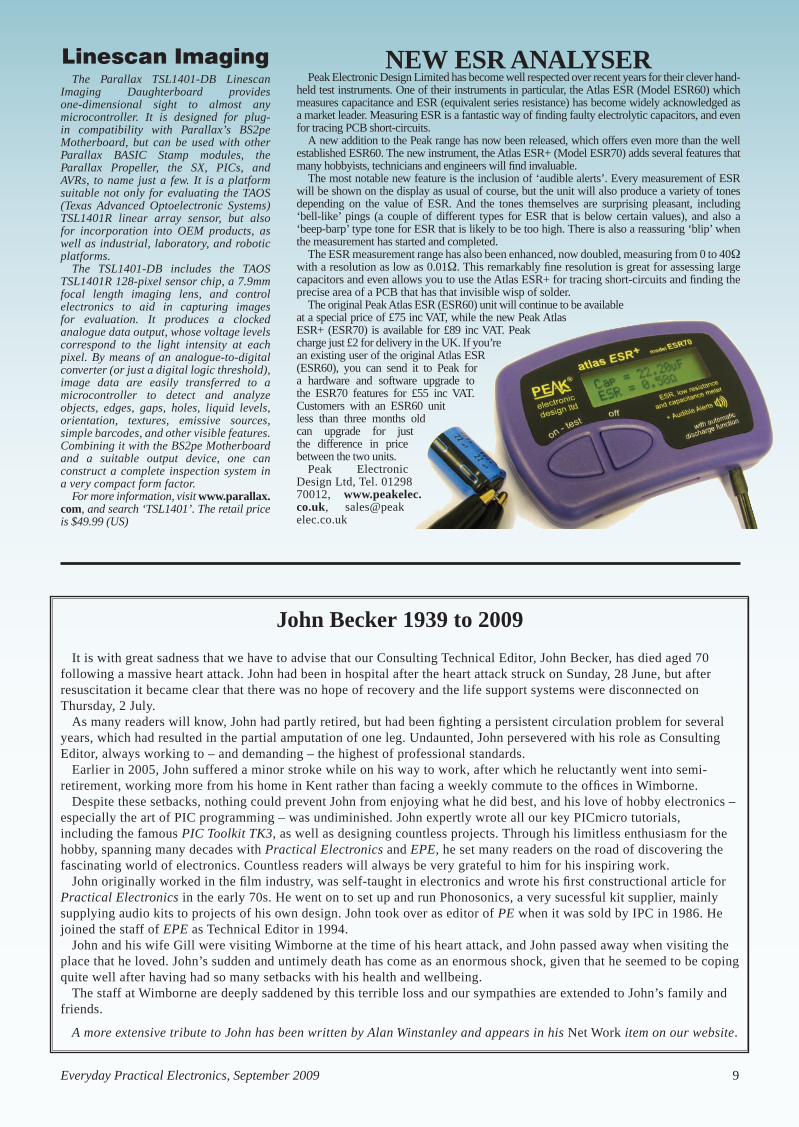
AUDON’S CGR-101The Circuitgear CGR-101 from Audon Electronics is a PC-based
instrument that provides the features of seven devices in one USB-powered compact box. The device offers the performance of a two-channel 10-bit 20MSa/sec 2MHz oscilloscope, a two-channel spectrum-analyser, and a 3MHz 8-bit arbitrary-waveform/standard-function generator with eight digital I/O lines. It also functions as a network analyser, a noise generator and a PWM output source. Its open-source software runs with Windows, Linux and Mac OS.
The CGR-101’s oscilloscope capability provides a two-channel 10-bit ±0.25Vp-p to ±25Vp-p 2MHz basic scope, but with sophisticated marker measurements, triggering (normal, auto, single-shot and pre-trigger) with timebase adjustable from 50ns/division to 100ms/division. With a 1k sample/channel data buffer, the user can even view pre-trigger signals. The two-channel FFT spectrum analyser feature offers marker measurements, and when used with the internal signal generator, displays Bode plots and performs vector network analysis, showing gain and phase values.
The signal generator is an 8-bit 0.1Hz to 3MHz signal source, offering sine/square/triangle/ramp waveforms, as well as being capable of outputting arbitrary or preloaded waveforms such as ECGs. The user can enable the generator, connect its signal to a circuit and perform measurements with the oscilloscope and/or spectrum analyser. The generator can also be set to function as a white noise source. A slider-controlled PWM generator is also provided, with mark-space ratio clearly displayed.
The included visual interface software enables simple control and display of information. The oscilloscope, generator, and digital I/O are operated from a custom open-source Tcl/Tk software GUI included with the hardware. As the software is open source, the code can be read and even added to or customised. The CGR-101
UK cellphone network O2, set up by BT in 1984, now owned by Telefónica Europe and sole distributor of the iPhone in Britain, is moving into the sale of consumer elec-tronics devices that need no cellphone con-nection or subscription – and no PC either. The new O2 Joggler, which costs around £150, is a touch-sensitive digital picture frame that connects to walled garden Inter-net services provided by O2, using Ether-net cable or WiFi connection to any home broadband router.
Joggler has a seven inch, 800 × 480 screen, Intel Atom processor, 1GB of on-board memory and USB connector for additional memory. With no PC needed, it connects to O2’s servers and displays a touch menu of Sky news, sport, traffic, and weather, music or movies, games and a
family calendar which can be updated and shared by text messages using O2 mobiles.
A free and automatic software update lets the Joggler receive text messages and send 50 free texts a month to any mobile in the UK, with no need for a cellphone subscrip-tion. Another promised free update will add Internet radio.
Several common audio and video codecs are built in, but not DivX, and AAC, as need-ed to play iTunes format files. These codecs may be offered later, inside new applications. To protect children and block malware there is no web browser for open Internet access.
O2 is cagey about how it plans to earn revenue from a device that is sold for a one-off fee and needs no cellphone subscription, but guardedly confirms that Joggler may later be given access to online shopping sites.
Joggler is made in China for O2 by US company OpenPeak, which already supplies a somewhat similar device to Verizon in the USA for use with an ordinary home phone network.
Registering the device online to get an ‘O2 portal account’ is confusing, for in-stance the screen several times asks the question “Do you want to view only the webpage content that was delivered se-curely?” and – against all logic – the user has to click ‘No’!, and by implication “I want to risk insecurity”. Clicking ‘Yes’ for Security takes the user round in mad-dening circles. Also, although the Joggler can read music, video and pictures from some USB Flash sticks, it can’t read from others – and O2 is still trying to work out why not!
is also Labview compatible and can be controlled by any serial-port-driving software, such as Matlab or Visual Basic.
Project-based electronics lab teaching materials are also available for use with Circuitgear CGR-101. Price £139 + VAT. Audon Electronics, phone: 0115 925 8412, email: [email protected], website: www.audon.co.uk
8 Everyday Practical Electronics, September 2009
News.indd 8 30/07/2009 09:16:21
Everyday Practical Electronics, September 2009 9
Linescan ImagingThe Parallax TSL1401-DB Linescan
Imaging Daughterboard provides one-dimensional sight to almost any microcontroller. It is designed for plug-in compatibility with Parallax’s BS2pe Motherboard, but can be used with other Parallax BASIC Stamp modules, the Parallax Propeller, the SX, PICs, and AVRs, to name just a few. It is a platform suitable not only for evaluating the TAOS (Texas Advanced Optoelectronic Systems) TSL1401R linear array sensor, but also for incorporation into OEM products, as well as industrial, laboratory, and robotic platforms.
The TSL1401-DB includes the TAOS TSL1401R 128-pixel sensor chip, a 7.9mm focal length imaging lens, and control electronics to aid in capturing images for evaluation. It produces a clocked analogue data output, whose voltage levels correspond to the light intensity at each pixel. By means of an analogue-to-digital converter (or just a digital logic threshold), image data are easily transferred to a microcontroller to detect and analyze objects, edges, gaps, holes, liquid levels, orientation, textures, emissive sources, simple barcodes, and other visible features. Combining it with the BS2pe Motherboard and a suitable output device, one can construct a complete inspection system in a very compact form factor.
For more information, visit www.parallax.com, and search ‘TSL1401’. The retail price is $49.99 (US)
New eSR aNalySeRPeak Electronic Design Limited has become well respected over recent years for their clever hand-
held test instruments. One of their instruments in particular, the Atlas ESR (Model ESR60) which measures capacitance and ESR (equivalent series resistance) has become widely acknowledged as a market leader. Measuring ESR is a fantastic way of finding faulty electrolytic capacitors, and even for tracing PCB short-circuits.
A new addition to the Peak range has now been released, which offers even more than the well established ESR60. The new instrument, the Atlas ESR+ (Model ESR70) adds several features that many hobbyists, technicians and engineers will find invaluable.
The most notable new feature is the inclusion of ‘audible alerts’. Every measurement of ESR will be shown on the display as usual of course, but the unit will also produce a variety of tones depending on the value of ESR. And the tones themselves are surprising pleasant, including ‘bell-like’ pings (a couple of different types for ESR that is below certain values), and also a ‘beep-barp’ type tone for ESR that is likely to be too high. There is also a reassuring ‘blip’ when the measurement has started and completed.
The ESR measurement range has also been enhanced, now doubled, measuring from 0 to 40 with a resolution as low as 0.01. This remarkably fine resolution is great for assessing large capacitors and even allows you to use the Atlas ESR+ for tracing short-circuits and finding the precise area of a PCB that has that invisible wisp of solder.
The original Peak Atlas ESR (ESR60) unit will continue to be available at a special price of £75 inc VAT, while the new Peak Atlas ESR+ (ESR70) is available for £89 inc VAT. Peak charge just £2 for delivery in the UK. If you’re an existing user of the original Atlas ESR (ESR60), you can send it to Peak for a hardware and software upgrade to the ESR70 features for £55 inc VAT. Customers with an ESR60 unit less than three months old can upgrade for just the difference in price between the two units.
Peak Electronic Design Ltd, Tel. 01298 70012, www.peakelec.co.uk, sales@peak elec.co.uk
John Becker 1939 to 2009
It is with great sadness that we have to advise that our Consulting Technical Editor, John Becker, has died aged 70 following a massive heart attack. John had been in hospital after the heart attack struck on Sunday, 28 June, but after resuscitation it became clear that there was no hope of recovery and the life support systems were disconnected on Thursday, 2 July.
As many readers will know, John had partly retired, but had been fighting a persistent circulation problem for several years, which had resulted in the partial amputation of one leg. Undaunted, John persevered with his role as Consulting Editor, always working to – and demanding – the highest of professional standards.
Earlier in 2005, John suffered a minor stroke while on his way to work, after which he reluctantly went into semi-retirement, working more from his home in Kent rather than facing a weekly commute to the offices in Wimborne.
Despite these setbacks, nothing could prevent John from enjoying what he did best, and his love of hobby electronics – especially the art of PIC programming – was undiminished. John expertly wrote all our key PICmicro tutorials, including the famous PIC Toolkit TK3, as well as designing countless projects. Through his limitless enthusiasm for the hobby, spanning many decades with Practical Electronics and EPE, he set many readers on the road of discovering the fascinating world of electronics. Countless readers will always be very grateful to him for his inspiring work.
John originally worked in the film industry, was self-taught in electronics and wrote his first constructional article for Practical Electronics in the early 70s. He went on to set up and run Phonosonics, a very sucessful kit supplier, mainly supplying audio kits to projects of his own design. John took over as editor of PE when it was sold by IPC in 1986. He joined the staff of EPE as Technical Editor in 1994.
John and his wife Gill were visiting Wimborne at the time of his heart attack, and John passed away when visiting the place that he loved. John’s sudden and untimely death has come as an enormous shock, given that he seemed to be coping quite well after having had so many setbacks with his health and wellbeing.
The staff at Wimborne are deeply saddened by this terrible loss and our sympathies are extended to John’s family and friends.
A more extensive tribute to John has been written by Alan Winstanley and appears in his Net Work item on our website.
News.indd 9 27/07/2009 14:44:51

Constructional Project
10 Everyday Practical Electronics, September 2009
Constructional Project Constructional Project
This latest Programmable igni-tion system has fairly advanced
features (see panels) for a DiY project, including the ability to produce an ac-curate ‘advance’ curve. it also includes a plug-in LCD hand controller, which shows values and setting adjustments on its display.
it is a complete stand-alone ignition system that is triggered by an engine
Want to program the ignition timing on your car? Now you can, with this completely new design. It can be used in older cars which presently do not have electronic ignition, or used as an ‘interceptor’ for cars with engine management systems.
position sensor and then drives the ignition coil. it can be triggered from one of many sensors in a distributor, including points, reluctor, hall effect, optical trigger and the 5V signal from the car’s Engine Control Unit (ECU).
Measuring engine loadin order to measure engine load,
the Programmable ignition can use a
sensym absolute pressure sensor. in fact, provision has been made to mount this sensor directly on the PC board, the sensor then being connected to the engine manifold via plastic tubing.
Alternatively, you can connect the ignition circuit to an existing manifold pressure sensor if present. This is commonly called a ‘manifold absolute pressure’ (or MAP) sensor and is found on many cars these days. You could also use a secondhand MAP sensor from a car scrapyard.
Changing the timingA fully effective ignition system
needs to increase the timing advance with increasing RPM, and to alter the timing according to engine load – all with a fair degree of precision.
By JOHN CLARKE
Programmable Ignition System For Cars Part 1
Programmable Ignition0307.indd 10 28/07/2009 15:41:02

Constructional ProjectConstructional Project Constructional Project
Everyday Practical Electronics, September 2009 11
Additionally, some means to detect detonation (knock) and retard the timing would be an advantage. In this way, the ignition can be advanced fur-ther than would otherwise be possible without knock sensing.
This programmable ignition system incorporates all these features. What’s more, there is an option to select be-tween two separate ignition-timing curves using a switch. This option is ideal if you are running both petrol and gas, where a different timing curve is required for each type of fuel.
The complete block schematic of the Programmable Ignition System For Cars is shown in Fig.1. It comes in four modules: an LCD Hand Control-ler, a Programmable Ignition Timing (PIT) module, an Ignition Coil Driver
module and a Knock Sensor module. The first three modules are mandatory, while the fourth, the Knock Sensor module, is optional.
The heart of the system is the Pro-grammable Ignition Timing module, based on a PIC16F88-E/P micro. It is programmed by the LCD Hand Con-troller and it delivers a signal to the Ignition Coil Driver. The latter, as its name suggests, then drives the igni-tion coil.
LCD Hand ControllerThe Hand Controller is used dur-
ing the initial setting-up procedure. It plugs into the main unit and can be used while the engine is either running or stopped. It is then disconnected from the main unit after all adjust-ments have been made.
Using the Hand Controller, you can set all the initial parameters and also program the ignition advance/retard curve. Several pushbutton switches on the Hand Controller enable these changes to be made.
Knock sensorThe optional Knock Sensor module
enables ‘pinking’ (or ‘pinging’) to be sensed and the ignition timing retarded for a brief period. In brief, engine pinking is monitored by the Knock Sensor and the Programmable Ignition Timing (PIT) module for the first 6ms after each spark. However, at high RPM, there is less than 6ms between each firing, and so knock signal monitoring is carried out between each spark and the start of the next coil dwell period.
When engine knock is detected, the timing is retarded for the next ten sparks. The amount of retardation varies according to the severity of the knock signal. More details on this are given in the specifications.
Different usesThe Programmable Ignition can be
used either as an interceptor or for fully mapped ignition timing. In the interceptor role, it can vary the existing ignition timing by advancing or retard-ing it from its current value – ie, it can be used to alter the timing signals from the car’s ECU.
Alternatively, when used to com-pletely replace the existing ignition timing, you will need to obtain the advance/retard curve for your vehicle so that the entire timing curve can be produced by the Programmable Ignition. For some vehicles, you may be able to obtain the curves from the manufacturer. For other cars, you will need to plot out the existing curve and transfer the resulting timing map to the Programmable Ignition.
Plotting out this timing curve is not hard to do and can, in fact, be done us-ing the Programmable Ignition System itself and a timing light.
In practice, the ignition timing is mapped out in an array of either two 11-RPM by 11-engine load site maps, or as a single 15-RPM by 15-engine load site map. Timing arrays (or ig-nition maps) are the most common method that car manufacturers use to set the ignition advance curve for both RPM and engine load.
Fig.1: this diagram shows the four main modules used in the Programmable Ignition System. The LCD Hand Controller is used only during the initial setting-up.
Programmable Ignition System For Cars Part 1
Programmable Ignition0307.indd 11 28/07/2009 15:41:19

Constructional Project
12 Everyday Practical Electronics, September 2009
Constructional Project Constructional Project
Mapping is a way of plotting the ad-vance curve as a series of steps rather than setting an ignition advance or retard value at every possible engine RPM and load value. Thus, mapping sets the ignition advance or retard
values at specified preset points for both RPM and engine load.
For example, we can specify the timing advance to be 25° at 3000 RPM and 28° at 3400 RPM. However, we do not specify individual values
at 3100, 3200 or 3300 RPM. Instead, the advance values at these RPMs are interpolated (ie, calculated), based on the values set for 3000 and 3400 RPM.
At 3200 RPM, the amount of advance is easily calculated because it is exactly in the middle between the 3000 RPM and 3400 RPM sites. The advance change between 3000 RPM and 3400 RPM is 3° (ie, from 25° to 28°) and half of this is 1.5°. So the advance required at 3200 RPM is simply 25° + 1.5° = 26.5°.
Another calculation is required for engine load values that are in-between the specified load sites.
For our Programmable Ignition, if you require two separate engine ad-vance curves then you need to select the 11×11 arrays. If only one advance curve is required, you then have the option of using a 15×15 array for greater accuracy.
By the way, don’t confuse the igni-tion timing map with the MAP (mani-fold air pressure) sensor. They are two completely different things.
Plotting the timing valuesWe used the Programmable Ignition,
the LCD Hand Controller and a timing light to plot out the ignition timing values for a 1988 2-litre Ford Telstar. We’ll describe exactly how this is done in some detail in a later article.
The resulting timing vs RPM values were tabled (Table 1) and then plotted using Microsoft Excel. These files will be available from the Library section on our website so that you can use the tables and edit the values (just by wip-ing over the values and rewriting them) to suit your car’s engine. It is not really necessary to use Excel though and you can just as easily use a pencil and piece of paper to draw out the map instead.
• Advance and retard adjustment over a wide range
• Plug-in LCD Hand Controller for adjustments
• Hand Controller LCD shows values and settings for adjustment
• Suitable for single-coil ignition systems with a distributor
• Can be used as a timing interceptor or as a replacement ignition
• Ignition timing mapped against RPM and engine load
• Interpolated values used for RPM and load values between sites
• Optional single map or dual timing maps
• Single map has 15 RPM sites × 15 engine load sites
• Dual maps each have 11 RPM sites × 11 engine load sites
• 1° or 0.5° adjustments
• Dwell adjustment
• Knock sensing indication, with optional ignition retard
• Suits 1 to 12-cylinder engines (4-stroke) and 1 to 6-cylinder 2-stroke engines
• Two debounce settings
• High-level or low-level triggering
• Points, reluctor, Hall effect, digital signal or optical triggering
• Works with many pressure sensors (MAP sensors)
• Minimum and maximum RPM adjustments
• Minimum and maximum engine load adjustments
• Diagnostic RPM and load readings
• Add-on knock sensing unit (optional)
• Requires evenly spaced firing between cylinders. For V-twins, you will need two ignition systems and a separate trigger for each cylinder.
Main Features
RPM0 Min RPM Max RPMRPM Site RPM1 RPM2 RPM3 RPM4 RPM5 RPM6 RPM7 RPM8 RPM9 RPM10 RPM11
Load Site 0 1000 1400 1800 2200 2600 3000 3400 3800 4200 4600 5000Min load LOAD1 16 16 18.5 21.5 23 25.5 29 32 36 38 42.5 44
LOAD2 15 15 17.5 20.5 22 24.5 28 31 35 37 41.5 43LOAD3 14 14 16.5 19.5 21 23.5 27 30 34 36 40.5 42LOAD4 13 13 15.5 18.5 20 22.5 26 29 33 35 39.5 41LOAD5 12 12 14.5 17.5 19 21.5 25 28 32 34 38.5 40LOAD6 11 11 13.5 16.5 18 20.5 24 27 31 33 37.5 39LOAD7 10 10 12.5 15.5 17 19.5 23 26 30 32 36.5 38LOAD8 9 9 11.5 14.5 16 18.5 22 25 29 31 35.5 37LOAD9 8 8 10.5 13.5 15 17.5 21 24 28 30 34.5 36LOAD10 7 7 9.5 12.5 14 16.5 20 23 27 29 33.5 35
Max load LOAD11 6 6 8.5 11.5 13 15.5 19 22 26 28 32.5 34
LOA
D1
LOA
D2
LOA
D3
LOA
D4
LOA
D5
LOA
D6
LOA
D7
LOA
D8
LOA
D9
LOA
D10
LOA
D11
RP
M1
RP
M2
RP
M3
RP
M4
RP
M5
RP
M6
RP
M7
RP
M8
RP
M9
RP
M10
RP
M11
0
5
10
15
20
25
30
35
40
45
Advance(Degrees)
Engine Load RPM
11 x 11Ignition Timing Map
40-4535-4030-3525-3020-2515-2010-155-100-5
Table 1: these ignition advance values were measured for a 1988 2-litre Ford Telstar using a timing light and the Programmable Ignition.
Programmable Ignition0307.indd 12 28/07/2009 15:41:29

Constructional ProjectConstructional Project Constructional Project
Everyday Practical Electronics, September 2009 13
Fig.2 shows the ignition timing versus RPM and engine load from 1000-5000 RPM. Since we have 11 RPM sites, each RPM site covers a span of 400 RPM.
RPM0 is an extra site, and is shown covering the range from 0-1000 RPM. The RPM0 wording is shown on a dif-ferent line because it is not an actual RPM site and cannot be adjusted. It has the same values as RPM1.
RPM0 is shown because it explains what the advance curve is below the minimum RPM1 site while the en-gine is being started. The same thing happens for RPM above RPM11. In this case, the advance remains at the RPM11 values.
Engine load is shown with LOAD1 as the minimum engine load, while LOAD11 is the maximum engine load. LOAD1 is usually accessed when the engine is on overrun, while LOAD11 is usually accessed under acceleration or when the car is climbing a hill. The load values were measured using a sec-ond-hand pressure sensor from a car scrapyard. These were then converted to load values ranging from 1-11.
The curve can be plotted in three dimensions showing RPM, load and ignition advance. If you use our Excel file, then the curve will be automati-cally replotted whenever a value is altered.
Using the Hand ControllerAs mentioned earlier, the Hand
Controller is used to enter the settings and to enter the ignition map. The values are displayed on the 2-line 16-character LCD screen. There are eight direction pushbuttons, a Run/View pushbutton and a Reset.
The Reset switch is recessed to prevent accidental activation. It is used to return all mapped advance or retard values to 0°. The eight direction pushbuttons alter the values and can configure the display to show the dif-ferent settings or a different load site.
Finally, the Run/View pushbutton only works in the Timing mode. This mode is selected using a jumper link on the Programmable Ignition Timing Module.
RUN modesThe Timing mode has four possible
display modes, selected by pressing the Run/View pushbutton. It selects one of four modes – called SITE, FULL, DIAG and VIEW – in cyclic fashion.
Each display mode shows a slightly different aspect of the mapping sites. One feature in common is that they all display the MAP and the current advance or retard value on the top
line, although there is a difference in the displayed value as we shall see.
When the 11×11 maps are selected (from the settings mode), the display will show either MAPa or MAPb,
11 × 11 Ignition Timing Map
15 × 15 Ignition Timing Map
RPM0 Min RPM Max RPMRPM Site RPM1 RPM2 RPM3 RPM4 RPM5 RPM6 RPM7 RPM8 RPM9 RPM10 RPM11 RPM12 RPM13 RPM14 RPM15Load Site 0 1000 1300 1600 1900 2200 2500 2800 3100 3400 3700 4000 4300 4600 4900 5200
Min load LOAD1 16 16 18 20 22 23 25 27 29.5 32 35 37 39 42.5 43.5 44LOAD2 15 15 17 19 21 22 24 26 28.5 31 34 36 38 41.5 42.5 43LOAD3 14 14 16 18 20 21 23 25 27.5 30 33 35 37 40.5 41.5 42LOAD4 13.5 13.5 15.5 17.5 19.5 20.5 22.5 24.5 27 29.5 32.5 34.5 36.5 40 41 41.5LOAD5 13 13 15 17 19 20 22 24 26.5 29 32 34 36 39.5 40.5 41LOAD6 12 12 14 16 18 19 21 23 25.5 28 31 33 35 38.5 39.5 40LOAD7 11 11 13 15 17 18 20 22 24.5 27 30 32 34 37.5 38.5 39LOAD8 10.5 10.5 12.5 14.5 16.5 17.5 19.5 21.5 24 26.5 29.5 31.5 33.5 37 38 38.5LOAD9 10 10 12 14 16 17 19 21 23.5 26 29 31 33 36.5 37.5 38LOAD10 9 9 11 13 15 16 18 20 22.5 25 28 30 32 35.5 36.5 37LOAD11 8.5 8.5 10.5 12.5 14.5 15.5 17.5 19.5 22 24.5 27.5 29.5 31.5 35 36 36.5LOAD12 8 8 10 12 14 15 17 19 21.5 24 27 29 31 34.5 35.5 36LOAD13 7 7 9 11 13 14 16 18 20.5 23 26 28 30 33.5 34.5 35LOAD14 6.5 6.5 8.5 10.5 12.5 13.5 15.5 17.5 20 22.5 25.5 27.5 29.5 33 34 34.5
Max load LOAD15 6 6 8 10 12 13 15 17 19.5 22 25 27 29 32.5 33.5 34
LOA
D1
LOA
D3
LOA
D5
LOA
D7
LOA
D9
LOA
D11
LOA
D13
LOA
D15
RP
M2
RP
M4
RP
M6
RP
M8
RP
M10
RP
M12
RP
M14
0
5
10
15
20
25
30
35
40
45
Advance(Degrees)
Engine Load RPM
15 x 15Ignition Timing Map
40-4535-4030-3525-3020-2515-2010-155-100-5
RPM0 Min RPM Max RPMRPM Site RPM1 RPM2 RPM3 RPM4 RPM5 RPM6 RPM7 RPM8 RPM9 RPM10 RPM11
Load Site 0 1000 1400 1800 2200 2600 3000 3400 3800 4200 4600 5000Min load LOAD1 16 16 18.5 21.5 23 25.5 29 32 36 38 42.5 44
LOAD2 15 15 17.5 20.5 22 24.5 28 31 35 37 41.5 43LOAD3 14 14 16.5 19.5 21 23.5 27 30 34 36 40.5 42LOAD4 13 13 15.5 18.5 20 22.5 26 29 33 35 39.5 41LOAD5 12 12 14.5 17.5 19 21.5 25 28 32 34 38.5 40LOAD6 11 11 13.5 16.5 18 20.5 24 27 31 33 37.5 39LOAD7 10 10 12.5 15.5 17 19.5 23 26 30 32 36.5 38LOAD8 9 9 11.5 14.5 16 18.5 22 25 29 31 35.5 37LOAD9 8 8 10.5 13.5 15 17.5 21 24 28 30 34.5 36LOAD10 7 7 9.5 12.5 14 16.5 20 23 27 29 33.5 35
Max load LOAD11 6 6 8.5 11.5 13 15.5 19 22 26 28 32.5 34
LOA
D1
LOA
D2
LOA
D3
LOA
D4
LOA
D5
LOA
D6
LOA
D7
LOA
D8
LOA
D9
LOA
D10
LOA
D11
RP
M1
RP
M2
RP
M3
RP
M4
RP
M5
RP
M6
RP
M7
RP
M8
RP
M9
RP
M10
RP
M11
0
5
10
15
20
25
30
35
40
45
Advance(Degrees)
Engine Load RPM
11 x 11Ignition Timing Map
40-4535-4030-3525-3020-2515-2010-155-100-5
Fig.3: this 3-dimensional graph is also for a 1988 2.0-litre Ford Telstar, but this time the ignition advance is plotted against engine RPM and engine load as a 15×15 map (300 RPM per site).
Fig.2: this 3-dimensional graph plots ignition advance against engine RPM and engine load as an 11×11 array – ie, 11 Load sites and 11 RPM sites. Note how the ignition advance increases with RPM and decreases with higher engine load. The graph here was produced for a 1988 2-litre Ford Telstar.
Programmable Ignition0307.indd 13 28/07/2009 15:41:41

Constructional Project
14 Everyday Practical Electronics, September 2009
Constructional Project Constructional Project
depending on which map is selected. If the 15×15 map is selected, then the display will only show MAP, without the alpha or beta symbols.
Following the MAP legend, the display shows the advance or retard value. The display format depends on whether the setting is for 0.5° or 1° resolution. In all cases, a ‘–’ sign indicates a retard value, while a ‘+’ sign indicates an advance value. When there is no change in advance or retard, the value simply shows 0.0 for the 0.5° resolution setting or 0 for the 1° resolution setting.
The advance or retard value is changed using the Up (), Down (), Step Up () and Step Down () pushbuttons. The and pushbuttons increase or decrease the setting by the resolution value; ie, by either 0.5° or 1° for each switch press.
By contrast, the and pushbuttons change the advance/retard value by 2° on 0.5° resolution and by 4° on 1° resolution. The resulting values are stored in memory and remain there even if power is turned off, unless they are changed by the pushbuttons or by the Reset switch.
At the end of the top line, the display shows either SITE, FULL, DIAG or VIEW, to indicate the selected mode. Note that the SITE, FULL and DIAG modes are called the
‘Run’ modes because they show what sites are accessed while the engine is running.
Site modeThe SITE mode is displayed each
time the Programmable Ignition is powered up when the Run/View mode is selected with the jumper link. In this mode, the second line shows the current RPM site and the current LOAD site. These are from sites 1 to 11 when the 11×11 mapping is selected, or from 1 to 15 when the 15×15 mapping is selected.
The advance or retard value is shown as the value entered at that load site. In practice, the LOAD and RPM sites only change with changes in engine RPM and engine load. In other words, this is a real time display that shows the current load and RPM sites and the current advance or retard value setting.
Full modePressing the Run/View pushbutton
brings up the FULL mode. In this case, the second line shows the RPM site as before (eg, RPM1) but it also shows the actual position between this site and the next. For example, with the 11×11 ignition timing map (Fig.2), each site is 400 RPM away from the next.
In practice, however, the RPM is measured in 100 RPM steps. As a result, the display shows the RPM 1 position as RPM 1;0, RPM 1;1, RPM 1;2 or RPM 1;3. These values correspond to 1000, 1100, 1200 and 1300 RPM respectively. There is no RPM 1;4 position as this becomes the RPM 2;0 site for 1400 RPM.
If you don’t understand this, it will become clearer when we describe how the Programmable Ignition is set up in the forthcoming articles.
Similarly, for the LOAD sites, the position within the site is shown after the semicolon (;). Note that the word LOAD is abbreviated to just LD, so that the values fit within the display line.
In the FULL display mode, the advance or retard value is the interpolated value that is calculated for the positions between each load site.
Let’s go back to our earlier example and consider the RPM 6 (3000 RPM) and RPM 7 (3400 RPM) sites. At these sites, the advance is 25° and 28° respectively. This means that at RPM 6;0 the advance value will be displayed as +25.0°, while at RPM 7;0 the value will be shown as + 28.0°.
The interpolated value will be shown for RPM values between these two sites. For example, at 3200 RPM (RPM 6;2), the advance value will be
The LCD Hand Controller connects to the Ignition Timing Module via a standard DB25 RS-232 cable. It’s used to program in the various settings and the ignition timing MAP(s) and can display all programmed data on a 2-line 16-character LCD module.
Programmable Ignition0307.indd 14 28/07/2009 15:41:52

Constructional ProjectConstructional Project Constructional Project
Everyday Practical Electronics, September 2009 15
+26.5°. Consequently, this is the value that will be shown at site RPM6;2.
Note that this is a simplistic exam-ple because we are ignoring the fact that the LOAD value could also be in-between LOAD sites. In that case, both the RPM and LOAD values are interpolated to give the advance or retard value.
Note also that if the advance or re-tard value is increased or decreased in this mode, it will be the interpolated value that is displayed rather than the site value. The site that will be changed is the next lowest RPM and LOAD site.
Having said all that, interpolation can be switched off within the settings if required.
Knock sensingWhen knock sensing is set, the
display shows the modified timing value after knock retard is taken into account. This means that if the dis-play is showing +26.0° and the knock sensing subsequently introduces a 6° timing retard, the display will then immediately show +20.0°. This is the actual advance value used for ignition.
Note that engine knock detection is indicated by an exclamation mark (!) that is positioned between the RPM site value and the LOAD on the second line of the display. The (!) is shown when knock is detected, regardless as to whether the knock retard feature is on or off. The knock symbol is shown in the SITE, FULL and DIAG display modes.
Diagnostic modePressing the Run/View switch again
switches to the DIAG mode. This is the diagnostic mode, and it is very useful when it comes to determining your engine’s RPM range, as well as measuring the output range from the MAP sensor.
In this mode, the second line shows the actual RPM with 100 RPM resolu-tion and the actual LOAD value from 0 to 255. The advance/retard value on the top line normally shows the interpolated value in the same way as the FULL mode.
As mentioned above, interpolation can be switched off and this is useful when measuring the manufacturer’s advance curve (more on this in a later article).
Specifications
Timing adjustment resolution: 0.5° resolution advance and retard or 1° resolution advance and retard.
Timing adjustment range: ±60° for 12-cylinder engines, ±90° for 8-cylinder engines, ±120° for 6-cylinder engines, ±127° for less than 6 cylinders. Using less than 75% of the limit is recommended to prevent timing ‘drop-out’ with sudden RPM changes.
Timing adjustment accuracy (above Low RPM setting): 0.2% for a 2-cylinder 4-stroke; 0.3% for a 6-cylinder 4-stroke; 0.4% for an 8-cylinder 4-stroke (note: 0.3% is equivalent to 0.12° at 40° advance or retard for a 6-cylinder engine).
Timing update: the update period is the time between successive firings.
Timing calculation period: 700ms maximum.
Timing jitter: ±5ms at 333Hz (5ms is equivalent to 0.3° for a 6-cylinder engine at 10,000 RPM).
Minimum input frequency: 0.6Hz (corresponds to 36 RPM for a 2-cylinder 4-stroke engine; 18 RPM for a 4-cylinder 4-stroke engine, etc).
Maximum input frequency: 700Hz (corresponds to 14,000 RPM for a 6-cylinder 4-stroke; 7000 RPM for a 12-cylinder 4-stroke.
Cylinder settings: 1 to 12 cylinders for a 4-stroke engine and 1 to 6 cylinders for a 2-stroke engine.
Minimum RPM setting: 0 to 25,500 RPM in 100 RPM steps
Maximum RPM setting: indirectly set by RPM/SITE – 0 to 25,500 RPM in 100 RPM steps.
Minimum load setting: 0 to 255 in steps of 1 (corresponds to 0 to 5V).
Maximum load setting: indirectly adjusted by changing loads per site (0 to 255 in steps of 1).
Debounce adjustment: 0.4ms or 2ms.
Dwell adjustment: 0 to 25.3ms in 0.2048ms steps (multiplied with voltage below 12V).
Dwell variation with supply: x1 for >12V; ×2 for 9V to 12V; ×3 for 7.2V to 9V; × 4 for <7.2V.
Firing edge selection: low or high.
Spark duration: 1ms.
Map settings: two 11×11 maps (MAPa and MAPb) or single 15×15 map.
Knock input range: 0 to 5V (0 to 1.25V = no retard; 1.25V to 5V = progressive retard in 16 steps). 9° at 3.75V; 12° at 5V for 1° resolution; 4.5° and 6° respectively for 0.5° resolution.
Knock monitoring (requires an additional knock circuit): monitored for the first 6ms after firing. This period is reduced at higher RPM with the start of dwell. Optional 4000 RPM or 6000 RPM sensing limit. Ignition retard activation (when enabled) is set for a minimum of 10 sparks with the onset of knocking.
Internal test oscillator: 4.88Hz.
Response to low RPM setting: 0 to 25,500 RPM in 100 RPM steps. Typically set at around 1000 to 2000 RPM.
Programmable Ignition0307.indd 15 28/07/2009 15:42:01

Constructional Project
16 Everyday Practical Electronics, September 2009
Constructional Project Constructional Project
Pressing the Run/View pushbutton yet again switches to the VIEW mode. This is not a real-time display because the RPM and LOAD sites do not change with the engine RPM or load. Instead, you can step through each site manu-ally using the Right (), Step Right (), Left () and Step Left () pushbuttons.
The and pushbuttons increase or decrease the LOAD site value. When increasing the LOAD site value and it reaches its maximum value (either 11 or 15), pressing the switch again causes the RPM site to increase by 1 and the LOAD site to return to 1. In this way, you can step through the entire ignition-timing map.
The same thing happens when de-creasing the LOAD site value. After reaching 1, the RPM site value is de-creased by 1 on the next switch press and the LOAD site goes to either 11 or 15 (depending on the MAP setting).
The and switches just alter the RPM sites up or down without altering the LOAD site. In this way you can check the ignition advance or retard settings for each RPM site at a particular LOAD site.
Note that the , , and push-buttons do not operate in the SITE, FULL and DIAG modes. In these modes, the sites are only changed in response to engine RPM and load inputs.
SettingsThe Settings display is invoked
when jumper link LK1 in the Pro-grammable Ignition Timing Module is moved to the settings position. The display is then used to set up the programmable ignition to suit your engine.
The display will initially show <SETTINGS>. The < and > brackets in-dicate that each setting can be selected with either the left () or right () pushbutton switch. The values within the settings can then be changed us-ing the and pushbuttons. These values (except for the oscillator set-ting) are stored in memory and do not change unless altered using the Up and Down pushbuttons.
Note that the oscillator setting is always off when power is re-applied to the Programmable Ignition.
Pressing the pushbutton brings up the Cylinder setting. You can then select cylinder values from 1 to 12 for a 4-stroke engine, and from 1 to 6 for a 2-stroke engine. During this time,
the top line of the display will show STROKE and then two numbers – ie, 4 and [2] for 4-stroke 2-stroke engines respectively. Directly below these on the second line is the word CYLINDER and the selected cylinder numbers (the bracketed number is the cylinder value for a 2-stroke engine).
The cylinder value is changed using the and pushbuttons. Note that a dash is shown in the two 2-stroke column when odd 4-stroke cylinder numbers are selected, as this is not a valid setting for a 2-stroke engine.
The next four settings are for adjust-ing the range of the RPM sites and the LOAD sites. These are crucial in ensuring you get the full use of the available sites. In other words, there is not much point in having the RPM sites cover a range from 0 to 25,000 RPM when, for example, the engine does not run above 5000 RPM. In this case, you would only be using 20% of the available RPM sites (ie, RPM 1, RPM 2 and part of RPM3 only) for mapping the advance curve.
RPM site adjustmentsThe first of these settings is the
Minimum RPM. This sets the RPM for the RPM 1 LOAD site. The display will show SET MIN RPM X00 RPM, where the X represents a number from 0-255. Typically, this is set at the idle speed for the car, but it may be set differently depending on how you want the igni-tion curve to operate (more on this in a later article). The settings can be changed from 0 RPM through to 25,500 RPM in 100 RPM steps.
In practice, you would use the DIAG (diagnostic) setting mentioned earlier to determine the minimum and maxi-mum engine RPM range. Alternatively, you can use the idle and red-line specifications for your engine.
The second setting is for the Maxi-mum RPM. This value of RPM is in-directly set by the value of the RPM per site (RPM/SITE) adjustment, as shown on the top line of the display. It can be set from 0 to 25,500 RPM in 100 RPM steps.
The second display line shows the maximum RPM. This is calculated based on the minimum RPM setting and the RPM/site value. It is shown in the second line of the display as MAX RPM X00 RPM, where X is a number from 0 to 255. An ERROR indication is shown instead of the maximum RPM if the setting would be over 25,500 RPM.
The reason why we adjust the RPM/SITE value rather than the Maximum RPM directly is because the Program-mable Ignition requires a discrete number of 100 RPM steps between each RPM site.
In practice, the RPM/SITE value is altered so that the maximum RPM is at or just over the value required. You can also adjust the minimum RPM setting to achieve the best compromise for the adjustment.
An example may help here using the 11 × 11 map. If, say, the minimum RPM is set at 1000 RPM, then the RPM/SITE value can be set to say 400 RPM for a 5000 RPM maximum, or to 500 RPM for a 6000 RPM maximum. Thus, if you had a red line of say 5500 RPM, you could set the RPM/site value to 500 for the 6000 RPM maximum. Alternatively, you could lower the minimum RPM value to say 800 RPM, with the RPM/site set to 500 for a 5800 RPM maximum.
LOAD site adjustmentsThe third and fourth settings
are for the LOAD sites. Again, in practice, you would use the DIAG (diagnostic) mode to determine the minimum and maximum values from the MAP sensor. The maximum load values occur when the car is accel-erating up a hill, while minimum load values are present under very light throttle conditions and when the engine is being overrun in low gear downhill.
The Minimum Load adjustment can be set from 0 to 255 in steps of 1. These 0 to 255 values correspond to the 0V to 5V output from the MAP sensor. This value is set to the reading obtained in the DIAG (diagnostic) mode when the engine is being overrun.
By contrast, the Maximum Load is adjusted indirectly by changing the loads per site (LOADS/SITE) set-ting. This can be changed in steps of 1 from 0 to 255. The second display line shows the calculated maximum load (MAX LOAD) value based on the minimum load and the LOADS/SITE setting. An ERROR indication shows if the calculated maximum LOAD value is over 255.
In practice, the Minimum Load and the LOADS/SITE settings are adjusted so that they cover the range of the MAP sensor output, although they may slightly overlap the required minimum and maximum values.
Programmable Ignition0307.indd 16 28/07/2009 15:42:12

Constructional ProjectConstructional Project Constructional Project
Everyday Practical Electronics, September 2009 17
Other settings that follow these map-ping values are: 1) MAPS: here you can select either the two 11×11 maps (Mapa and Mapb) or the single 15×15 map. Note that any ignition values mapped into an 11×11 map will no longer be correct if the map is subsequently changed to a 15×15 array and vice versa. Instead, you have to re-enter the values.2) Resolution: this sets the resolution of the advance/retard adjustments and can be either 1° or 0.5°. Once ignition values have been entered into the map on one resolution setting, they will be incorrect if the resolution is changed to the alternative setting.3) Response to low RPM setting: at low RPM, the engine speed can change quite quickly. Because the calculation for RPM can only occur between each detected firing pulse, the response to RPM changes can be too slow and can lag behind the engine. This can noticeably retard the ignition with increasing RPM. The ‘Response to low RPM’ setting is included to improve low RPM re-sponse, particularly at starting. The downside of this setting is that there is some slight ignition retardation, but this is less than 1° for typical low RPM settings.
The RPM value can be set from 0 to 25,500 RPM in 100 RPM steps. The low RPM response operates for RPM below the set value (typically just below idle speed). Above this setting, the standard response to RPM occurs. By contrast, the response at higher RPM is satisfactory because there is only a short period between plug fir-ing and the engine speed will not vary much during this time.
Usually, the setting is adjusted so that it operates at engine cranking speed, but stops when the engine reaches idle speed. In other cases, it may be neces-sary to raise this RPM limit so that the engine can rev correctly from idle.4) Debounce: the debounce setting affects the trigger input and its resil-ience to a noisy signal, as can typically occur with points bounce in older car ignition systems. Unless corrected, points bounce can upset the detection of engine RPM and affect the timing. Typically, you can use the 0.4ms debounce setting, but the alternative 2ms debounce setting, can be selected if the ignition appears to be erratic due to a noisy input sensor signal.
5) Dwell: dwell is the period during which the ignition coil ‘charges’ before each plug firing. It is alterable from be-tween 0 to 25.3ms in 0.2048ms steps. We have provided an oscillator fea-ture (see below) that allows the ignition coil to be driven by the Programmable Ignition and the spark produced by the coil to be monitored. The dwell is then progressively adjusted upwards from 0ms until the spark reaches its maximum voltage. The dwell is then increased slightly above the set value to ensure there is more than sufficient spark when the engine runs.
In addition, the dwell is automati-cally increased when the battery volt-age is low – ie, to ×2 for battery voltages between 9V and 12V; to ×3 for voltages between 7.2V and 9V; and to ×4 for voltages below 7.2V.
6) Edge: this sets the ignition to trigger from either a low-going input signal edge or a high-going signal. In most cases, a high-going signal edge must be selected, but some optical, Hall-effect and reluctor outputs will require the low-going edge selection.
7) Knock: this sets the KNOCK retard feature either ON or OFF and sets the LIMIT at either 4000 or 6000 RPM (these settings are all shown on the LCD). Pressing the and pushbuttons cycle the selections between these options. The LIMIT setting sets the RPM value at which knock sensing ceases. This is usually set to 4000 to 6000 RPM because at higher revs, the engine noise drowns out any knocking, and so would either be undetectable or would cause false readings.
Ignition Timing – A Quick Primer
A typical internal combustion engine has one or more pistons that travel up and down inside cylinders to turn a crankshaft. As a piston rises inside its cylinder during the compression stroke, a mixture of fuel and air is com-pressed. In petrol and gas engines, this fuel-air mixture is then ignited using a spark to drive the piston as it starts its downward stroke.
This ignition must be timed accurately to ensure maximum power and ef-ficiency. If the mixture is fired too late in the cycle, power will be lost because the piston will have travelled too far down in the cylinder for the burning fuel to have maximum effect. Conversely, if the mixture is ignited too early, it will ‘push’ against the piston in the wrong direction as it rises towards top dead centre (TDC).
Ideally, each spark plug is fired so that there is just enough time for the ignited fuel to apply maximum force to the piston as it starts its downward power stroke. In practice, the fuel takes a certain amount of time to burn and so the spark plug needs to be fired before the piston reaches the top of its stroke or top dead centre.
At low engine RPM, the spark only needs to occur a few degrees before top dead centre. However, as engine RPM rises, the ignition must be fired progressively earlier in order to give the fuel the same time to fully ignite – ie, the spark timing must be progressively advanced as engine RPM rises.
This timing requirement is called the ‘RPM ignition advance curve’ and is often around 6° before TDC at idle, rising to about 40° at the engine’s recom-mended maximum RPM (the redline).
As stated, if the spark ignites the fuel far too early, then the piston may be pushed downwards before it reaches top dead centre. However, if the igni-tion is only early by a small amount, then the engine will exhibit a knocking sound as the piston rattles within the cylinder. This effect is called ‘detonation’ (also called ‘pinking’, ‘pinging’ or ‘knocking’) and can cause serious engine damage in severe cases.
Engine load is also an important factor when it comes to ignition timing. Under light loads, the advance timing can usually be at the maximum. However, when the engine is heavily loaded, such as when accelerating or powering uphill, the fuel takes less time to ignite because of higher fuel pressures and temperature (and because the mixture is richer). As a consequence, as engine load increases, the ignition timing must be retarded to prevent detonation.
Programmable Ignition0307.indd 17 28/07/2009 15:42:27
233
2009
-08-
18 1
6:27
:44

Constructional Project
18 Everyday Practical Electronics, September 2009
Constructional Project Constructional Project
Note that knocking will only be detected if the separate knock sens-ing circuit (to be described) is added and a knock sensor is installed on the vehicle.
8) Diagnostic: this sets the interpola-tion either ON or OFF. It is normally set to ON and should only be set to OFF when making ignition curve measurements using the Programma-ble Ignition and a timing light.
9) Oscillator: this sets the internal oscillator ON or OFF. It’s normally OFF, but can be set to ON to test the ignition coil spark with varying dwell settings. The oscillation rate is about five times a second (5Hz).
Circuit detailsSo much for all the fancy features
built (or more accurately, programmed) into the unit. Let’s now take a look at the circuit details.
The circuit for the Programmable Ignition can be split into three sec-tions. First, there is the Programmable Ignition Timing circuit, as shown in Fig.4. To this is added an input trigger circuit, depending on the ignition trig-ger used – see Fig.6. This can be either points, optical, Hall effect or reluctor, or can be taken from the engine man-agement unit (EMU).
Finally, a separate circuit, control-led by the Programmable Ignition
Timing circuit, drives the ignition coil – see Fig.5.
The LCD Hand Controller, to be described in Part 2, is a completely separate unit, which connects to the Programmable Ignition Timing module via a DB25 cable. As stated, it’s used only during the setting-up procedure, after which it is no longer required un-less you wish to reprogram the system (eg, to alter the timing map).
Ignition timing circuitThe main Programmable Ignition
Timing circuit (Fig.4) is based on IC1, which is a PIC16F88-E/P high-tem-perature microcontroller. This micro processes the input trigger and MAP
PROGRAMMABLE IGNITION TIMING MODULE
Fig.4: the Ignition Timing Module is based on a PIC16F88-E/P microcontroller. This processes the input trigger, MAP sensor and optional knock sensor signals and provides outputs to drive the Ignition Coil Driver circuit (Fig.5) and a tachometer. It also monitors the Hand Controller’s switches and drives the LCD.
Programmable Ignition0307.indd 18 28/07/2009 15:42:37

Constructional ProjectConstructional Project Constructional Project
Everyday Practical Electronics, September 2009 19
sensor signals and provides an out-put to drive the Ignition Coil Driver circuit. It also drives the LCD module in the Hand Controller and monitors its switches.
Timing signals for IC1 are provided by crystal X1. This sets the internal oscillator to run at 20MHz, which enables the software programmed into IC1 to run as fast as possible.
In operation, IC1 accepts the igni-tion trigger signal at its RB0 input (pin 6) and drives its RB3 output to switch the ignition coil (via the driver circuit) accordingly. As shown, the RB0 input is protected from excess voltages by a series 2.2kW resistor, which prevents excessive current flow in IC1’s internal clamping diodes. Clamping occurs when the voltage goes below 0V or if it goes above the +5V supply (ie, the input is clamped to –0.6V or +5.6V).
The 1nF capacitor at the RB0 input shunts transient voltages and high-frequency signals, to filter false timing signals.
Transistor Q4 is also driven from the trigger input. The transistor is used to provide a tachometer output at its collector (C). In operation, Q4’s collector is normally held high via a 2.2kW pull-up resistor, but switches low each time the transistor turns on (ie, when the trigger input is high).
Q4’s collector output can be used to drive most modern tachometers. However, an impulse tachometer (now very rare) requires a different con-nection and this type should operate when connected to the ignition coil’s negative terminal.
MAP sensorThe MAP sensor signal is applied to
the analogue AN2 input of IC1 (pin 1) via a 1.8kW resistor. A 10nF capacitor filters out unwanted high-frequency signals to prevent false readings.
In operation, the AN2 input meas-ures an input voltage ranging from 0 to 5V and converts this to a digital value ranging from 0 to 255. This is the value that’s read from the DIAG (diagnostic) display.
Note that +5V supply and ground rails are provided for the sensor. If the Sensym sensor is used, it can be directly mounted on the PC board used for the Programmable Ignition Timing Module.
The optional knock sensor signal is applied to IC1’s analogue AN1 input (pin 18). As before, this input accepts
signal voltages from 0 to 5V and con-verts them to digital values.
Conversely, if the knock sensing circuit is not used, this input must be tied to ground using jumper link LK2 to disable the knock sensing function.
The third analogue input at AN3 (pin 2) is used to monitor the +12V ignition supply. As shown in Fig.4, this supply voltage is divided down using 100kW and 47kW resistors and filtered using a 10mF electrolytic ca-pacitor, before being applied to the AN3 input. This divider effectively converts the supply voltage to a 0 to 5V signal, which is then used to determine if the dwell period should be increased to compensate for a low supply voltage.
Note that the voltage across diode D1 is accounted for in this measurement.
Link LK1 selects either the timing map display or the settings display. In the settings position, the RA5 input is tied to ground via a 10kW resistor. Conversely, when LK1 is in the tim-ing position, RA5 is tied to 5V via the 10kW resistor.
Note that the RA5 input differs from the other inputs in that it cannot be directly tied to one of the supply rails, otherwise the micro could latch up. The 10kW input resistor eliminates this problem.
Switch S1 is used to select between the two 11×11 timing maps. When S1 is open, RA4 is pulled low via the 10kW resistors and Mapa is selected. Conversely, when S1 is closed, RA4 is pulled to +5V and Mapb is selected.
Note that this switch operates only when the 11×11 maps are selected using the LCD Hand Controller. It has no effect if a 15×15 map is selected.
Driving the LCDPins 7, 8 and 10 to 13 of the micro-
controller are used to drive the LCD module in the Hand Controller (via a DB25 connector). The 10W resistors in series with these outputs act as stoppers to keep RF signals out of IC1.
In addition, the RA0 input at pin 17 monitors the switches from the Hand Controller. The associated 1kW resistor pulls the input voltage to 0V unless a switch is closed, at which point the
IGNITION COIL DRIVER (PROGRAMMABLE IGNITION)
Fig.5: the Ignition Coil Driver is based on transistors Q1-Q3. Darlington transistor Q1 switches the ignition coil, while the four series Zener diodes across Q1 protect it against voltage spikes when the transistor turns off.
Programmable Ignition0307.indd 19 28/07/2009 15:42:46

Constructional Project
20 Everyday Practical Electronics, September 2009
Constructional Project Constructional Project
line is pulled high to +5V. The 1nF capacitor filters out any RF signals.
Power supplyPower for the circuit is derived via
the vehicle’s ignition switch. This supply is then filtered using inductor L1 and the 100nF capacitor. Diode D1 provides reverse polarity protection, after which the supply is decoupled using a 1000mF capacitor.
As a further precaution, the circuit is protected from voltage spikes using transient voltage suppressor TVS1. This clamps any high voltages that may otherwise damage following components.
Following TVS1, the supply is reg-ulated to +5V using regulator REG1. This is a low-dropout device and is used here to ensure that a regulated +5V supply is maintained during starting when the battery voltage can drop well below l2V.
A 100mF capacitor decouples the regulator’s output, while a 100nF ca-pacitor (located close to pin 14 of IC1) shunts high frequencies to ground.
Ignition coil driverFig.5 shows the Ignition Coil Driver
circuit. It’s fairly straightforward and is based on transistors Q1 to Q3.
Q1 is a Darlington transistor spe-cifically made for ignition systems. It’s capable of handling currents in excess of 10A and voltages exceed-ing 400V. As shown, four 75V Zener diodes (ZD1 to ZD4) are connected in series between its collector and emitter terminals. These protect the transistor from excess voltages by clamping Q1’s collector (C) at 300V, which is well within its rating.
The circuit works like this: when the input signal is low (or there is no signal), transistor Q3 is off, Q2 is on (due to base current through the 1.2kW resistor) and Q1 is off. Conversely, when the input subsequently switches high, Q3 turns on and switches Q2 off by pulling its base to ground. As a result, Q1 turns on and current flows through the primary winding of the ignition coil.
The ignition input signal now sub-sequently switches low again and so Q3 immediately turns off due to the 470W resistor between its base termi-nal and ground. When that happens, Q2 switches on and Q1 switches off, interrupting the current through the ignition coil.
As a result, the coil’s magnetic flux rapidly collapses and this generates a
high voltage in the secondary to fire one of the spark plugs. The 1nF capaci-tor on Q3’s base is there to suppress any RF signals that may otherwise be injected when the current through the ignition coil is interrupted (ie, when Q1 switches off).
Resistor R1 is included to make the module more versatile. In our application, R1 is not used and is replaced with a wire link. For other applications, where a separate igni-tion coil driver is required, R1 will be required. Typically, a 470W resistor would be used for a 5V drive signal, while a 1.2kW resistor would be used for a 12V drive signal.
Finally, the module can also be configured to drive transistor Q1 when the input signal switches low. In this case, Q3 is left out of circuit and a link installed between the pads on the PC board for its base (B) and collector (C)leads. The 1.2kW resistor pull-up is also removed from circuit.
Trigger inputsThe Programmable Electronic Igni-
tion is configured for the appropriate trigger input during construction. The seven possible input circuits are shown in Fig.6.
Fig.6: the seven input trigger circuits: (a) points triggering; (b) ignition module (see text); (c) Hall effect and Lumenition triggering; (d) triggering from an engine management module; (e) reluctor pickup; (f) Crane optical pickup; and (g) Piranha optical pickup.
Programmable Ignition0307.indd 20 28/07/2009 15:42:57

Constructional ProjectConstructional Project Constructional Project
Everyday Practical Electronics, September 2009 21
Points triggerThe points trigger is shown in
Fig.6(a) and includes a 100W 5W wire-wound resistor connected to the 12V supply. This resistor provides a ‘wet-ting’ current for the points to ensure there is a good contact between the two mating faces when they are closed. The wetting current is sufficient to keep the contacts clean, but not so high as to damage them.Ignition trigger
The ignition module version is shown in Fig.6(b). This is essentially the same as the points input, except that a transistor inside the ignition module switches the input to ground instead.
This type of input has been included because some electronic ignition systems do not provide access to the actual trigger (usually a reluctor) and the only output is the ignition coil driver transistor. In this case, the coil is replaced with the 100W resistor to provide the necessary pull-up to +12V when the transistor is off.Hall trigger
Fig.6(c) shows the Hall effect trigger. It uses a 100W current-limiting resistor to feed the Hall sensor, while the 1kW resistor pulls the output voltage to +5V when the internal open-collector transistor is off. Conversely, the output signal is pulled to 0V when the internal transistor is on.
Note that the same circuit is used for the Lumenition optical module.EMU trigger
The engine management input cir-cuit is shown in Fig.6(d) and is quite simple. Its 0V to 5V output signal connects to the trigger section of the main circuit in Fig.4.Reluctor sensors
Reluctor sensors are catered for using the circuit in Fig.6(e). These produce an AC signal and so require a more complex input circuit.
In this case, transistor Q5 switches on or off, depending on whether the reluctor voltage is positive or negative. It works as follows: initially, with no reluctor voltage, Q5 is switched on via current through VR1 and a 47kW resistor. The voltage applied to Q5’s base depends on the 10kW resistor across the reluctor coil and the internal resistance of the reluctor.
Trimpot VR1 is included to provide for a wide range of reluctor types. In practice, VR1 is adjusted so that
Q5 is just switched on when there is no signal from the reluctor. The 10kW resistor provides a load for the reluctor, while the 470pF capacitor filters any RF signals that may have been induced.
The 2.2nF capacitor ensures that Q5 quickly switches off when the reluctor signal goes negative.
Optical pickupFinally, Fig.6(f) and Fig.6(g) show
two different optical pickup circuits. Fig.6(f) is for a module that has a com-mon 0V supply connection (eg, Crane), while Fig.6(g) is for a module that has a common positive supply (eg, Piranha). In each case, current for the LED is supplied via a 120W resistor, while the photodiode current is supplied via a 22kW resistor.
SoftwareThe software for the Programmable
Ignition is probably the largest and most complex to date. In all, the final assembler code totals some 6020 lines to perform all the necessary functions, including monitoring the ignition trigger and pressure sensor signals and providing an output based on the ignition timing map.
Basically, the software includes several multiply and divide routines
(some 24-bit) to calculate the timing, based on the RPM and load site. These routines are also used to calculate engine RPM and the interpolated advance/retard values and must be performed constantly to maintain the correct timing as engine RPM and load vary.
We managed to perform all the re-quired calculations in under 1ms – fast enough for high revving engines.
A significant part of the software has also been devoted to the many functions accessible via the Hand Controller and to allow the Hand Controller to be used while the engine is running.
In the end, we used all the data memory space of the PIC16F88 to store the ignition timing maps and the adjustable parameters, along with some 97% of the program memory.
Next month: Details of the LCD Hand Controller module and assembly of the Programmable Ignition module – there are six versions to choose from.
This inside view shows the assembled PC board for the Ignition Timing Module but without the optional Sensym MAP sensor fitted. The full assembly details will be in Part 2 next month.
Reproduced by arrangement with SILICON CHIP
magazine 2009.www.siliconchip.com.au
Programmable Ignition0307.indd 21 28/07/2009 15:43:07

22 Everyday Practical Electronics, September 2009
For computers at least, memory has never been cheaper. Memory can be somewhat volatile (like human grey cells!), which is why manufacturers are
developing and improving several new types of memory that don’t fade (or vanish when you turn the power off). Non-volatile memory has a promising future in
several forms, as Mark Nelson reports here.
Mark Nelson
Thanks for the Ramory
data access, but needs refreshing every few milliseconds. Both SRAM and DRAM are ‘volatile’, meaning that the stored data will be lost the moment the power is cut. Non-volatile RAM, such as flash RAM, preserves the data while powered down.
New kids on the blockIt’s time now to meet the new RAMs:
FRAM, MRAM, RRAM and EcoRAM. Each has its own particular advantages and applications.
FRAM (or FeRAM) stands for Ferroelectric RAM, a non-volatile form of memory that is similar in construction to DRAM, but uses a ferroelectric (instead of dielectric) layer to achieve non-volatility. It is very much a niche product, competitive in applications where its operating characteristics give it an advantage over Flash memory. It works by applying an electric field across a ferroelectric crystal, the central atom moves in the direction of the applied field and the polarity of this atom remains the same when the electric field is removed.
Serial FRAMs are compatible with serial EEPROMs, while parallel FRAMs are compatible with parallel SRAMs. FRAM has the advantage of no-delay write speed, ability to withstand 100 trillion read-write cycles and requiring far less power to write and erase.
Magnetoresistive Random Access Memory (MRAM) also occupies only a niche position in the overall memory market, mainly because Flash RAM and DRAM offer greater density. Nevertheless, its proponents believe that MRAM’s advantages are so overwhelming that eventually it will become the dominant memory type for all applications.
The M in MRAM underlines its fundamental difference from conventional RAM technologies. Magnetic storage elements store data without using electric charges or current flows. Ferromagnetic plates, separated by a thin insulating layer, hold the magnetic field in which one of the two plates is a permanent magnet and the other’s field changes according to an external field. Data is read by measuring the electrical resistance of the cell.
Meteoric matterRRAM (resistive RAM) aims to supplant
Flash RAM by taking advantage of controllable resistance changes in thin-oxide films. Potentially, this could provide greater density, lower power usage, greater speed
and lower cost than Flash memory. Dozens of patent applications have been made around the world already for a process in which an electrical pulse induces a change in the resistance of the conduction path through films of nickel or perovskite oxide. The process is reversible. Perovskite, by the way, is a kind of calcium titanium oxide composed of calcium titanate. The mineral occurs in several places around the world, in some meteorites and in the debris ejected by Mount Vesuvius.
EcoRAM is designed specifically for use in server farms, where low power consumption is more important than speed. Internet data centre power requirements are said to be rising by 20% a year, consuming globally as much energy as a country the size of Sweden or Mexico.
Earlier this year, the Guardian newspaper reported that US data centres used 61 billon kilowatt-hours of energy in 2006 – enough to supply the whole of the UK for two months, and 1.5 per cent of the entire electricity usage of the USA. According to Intel, memory consumes more power than processors in large server farms, so memory power consumption has to be reduced.
Solid-state, but not as we know itFinally, it’s worth recalling some older
(and bulkier) types of data memory that were also solid-state, but in a different way.
At a radio rally around 1980, I bought a Raytheon video data entry terminal that combined a keyboard with a dual scan video monitor. Rather like some of the video game machines found at the time in pubs and amusement arcades, the CRT monitor was scanned simultaneously both horizontally and vertically (in a system known as quadradiddle). I never got it working, far less fathomed out how it functioned, but I do remember the seller telling me that it was from an aircraft radar system and used delay line memory (put this phrase into Wikipedia to read a very informative article).
Delay lines are solid-state (even the ones using mercury, if you consider mercury a solid liquid), as are core stores. In fact, core stores are ferromagnetic (see ‘magnetic core memory’ in Wikipedia) and as the article explains, this uses small magnetic ferroceramic rings that store information by means of the polarity of the magnetic field they contain. Core stores were used in computers of course, but also in television test pattern generators (to produce the circular design elements) and in telephone exchanges to translate dialling codes into the actual control or routing codes used within the switching apparatus.
EMPlOyINg memory for data storage has always involved a compromise between size, cost and functionality. If
you ever owned a Sinclair ZX-81 computer, you almost certainly suffered the problems of the wobbly add-on RAM pack, with the consequent loss of hours of programming. The blame for this could not be laid at the memory, however; it was just the result of an insecure mechanical connection, in other words lousy engineering.
Today’s memory products are fantastic by comparison, both in performance and affordability. It’s hard to believe how deep a hole that a 16kB RAM pack made in the pocket back in 1981 (£49.95 to be precise, equivalent to £212 based on average earnings). We have it so much better now.
Nevertheless, even the best solid-state memory of today has disadvantages. Flash memory, for instance, has a limited number of erase-write cycles before the memory capacity begins to deteriorate. Memory cards and ‘sticks’ are not recommended for long-term data storage, and the current generation of sold-state drives (SSDs) have lower storage density and slower writer speeds than hard disk drives.
Dynamic RAM (DRAM)-based SSDs require more power than hard disks and they still use power when the rest of the computer is turned off, whereas hard disks do not. little wonder then that hardware manufacturers are still looking for the perfect memory storage device.
Chips with everythingIt goes more or less without saying that the
ideal storage medium for memory is chips. We already have memory chips in desktop and portable computers, in MP3 players and digital cameras, also in bank cards, swipe cards and ‘lobster’ cards for travel. Memory chips contain no moving parts (making them more reliable than disk drives) and are far more durable than magnetic tape. The disadvantages of solid-state memory for mass data storage mentioned above will probably disappear before long.
When we look what’s under development there’s some new vocabulary to learn. The acronym RAM is of course familiar. It stands for random access memory, so called because the elements of stored data can be written and read in any order (at random in other words, regardless of its physical location in the storage medium). We all know the difference between static RAM (SRAM), which stays where it is put (until the power goes off) and dynamic RAM (DRAM), which offers faster
TechnoTalk.indd 21 29/07/2009 14:05:49

The PicoScope 4224 and 4424 High Resolution Oscilloscopes have true 12-bit resolution inputs with a vertical accuracy of 1%. This latest generation of PicoScopes features a deep memory of 32 M samples. When combined with rapid trigger mode, this can capture up to 1000 trigger events at a rate of thousands of waveforms per second.
• PC-based - capture, view and use the acquired waveform on your PC, right where you need it • Software updates - free software updates for the life of the product • USB powered and connected - perfect for use in the field or the lab• Programmable - supplied with drivers and example code
www.picotech.com/scope102801480 396395
Resolution 12 bits (up to 16 bits with resolution enhancement)
Bandwidth 20 MHz (for oscillscope and spectrum modes)
Buffer Size 32 M samples shared between active channels
Sample Rate 80 MS/s maximum
Channels PicoScope 4224: 2 channels
PicoScope 4424: 4 channels
Connection USB 2.0
Trigger Types Rising edge, falling edge, edge with hysteresis,
pulse width, runt pulse, drop out, windowed
The new PicoScope 4000 Series high-resolution oscilloscopes
Pico
Scop
e 40
00 S
erie
s
CRICKLEWOODELECTRONICS
Visit our shop at:40-42 Cricklewood BroadwayLondon NW2 3ET020 8452 0161
Frustrated with your suppier?Visit our component packed
website for a vast range ofparts - old and new,
many unavailable elsewhere!www.cricklewoodelectronics.com
10001000’s OF PRICES REDUCED!
Alternatively phone us on020 8452 0161 with your
requirements.
Visit our Shop, Call or Buy online at:www.cricklewoodelectronics.com
Established 1981
supplier?
Cricklewood - MAR09.indd 1 28/01/2009 11:08:21
SHERWOOD ELECTRONICS
SP1 15 x 5mm Red LEDsSP2 12 x 5mm Green LEDsSP3 12 x 5mm Yellow LEDsSP5 25 x 5mm 1 part LED clipsSP6 15 x 3mm Red LEDsSP7 12 x 3mm Green LEDsSP8 10 x 3mm Yellow LEDsSP9 25 x 3mm 1 part LED clipsSP10 100 x 1N4148 diodesSP11 30 x 1N4001 diodesSP12 30 x 1N4002 diodesSP18 20 x BC182B transistorsSP20 20 x BC184B transistorsSP23 20 x BC549B transistorsSP24 4 x CMOS 4001SP25 4 x 555 timersSP26 4 x 741 Op AmpsSP28 4 x CMOS 4011SP29 4 x CMOS 4013SP33 4 x CMOS 4081SP34 20 x 1N914 diodesSP36 25 x 10/25V radial elect. caps.SP37 12 x 100/35V radial elect. caps.SP38 15 x 47/25V radial elect capsSP39 10 x 470/16V radial elect. caps.SP40 15 x BC237 transistorsSP41 20 x Mixed transistorsSP42 200 x Mixed 0·25W C.F. resistorsSP47 5 x Min. PB switchesSP49 4 x 5 metres stranded-core wireSP102 20 x 8-pin DIL socketsSP103 15 x 14-pin DIL socketsSP104 15 x 16-pin DIL socketsSP109 15 x BC557B transistorsSP112 4 x CMOS 4093SP115 3 x 10mm Red LEDsSP116 3 x 10mm Green LEDsSP118 2 x CMOS 4047SP124 20 x Assorted ceramic disc capsSP130 100 x Mixed 0·5W C.F. resistorsSP131 2 x TL071 Op AmpsSP133 20 x 1N4004 diodesSP134 15 x 1N4007 diodesSP135 5 x Miniature slide switchesSP136 3 x BFY50 transistors
SP137 4 x W005 1·5A bridge rectifiersSP138 20 x 2·2/63V radial elect. caps.SP142 2 x CMOS 4017SP143 5 Pairs min. crocodile clips
(Red & Black)SP144 5 Pairs min.crocodile clips
(assorted colours)SP146 10 x 2N3704 transistorsSP147 5 x Stripboard 9 strips x
25 holesSP151 4 x 8mm Red LEDsSP152 4 x 8mm Green LEDsSP153 4 x 8mm Yellow LEDsSP154 15 x BC548B transistorsSP156 3 x Stripboard, 14 strips x
27 holesSP160 10 x 2N3904 transistorsSP161 10 x 2N3906 transistorsSP164 2 x C106D thyristorsSP165 2 x LF351 Op AmpsSP166 20 x 1N4003 diodesSP167 5 x BC107 transistorsSP168 5 x BC108 transistorsSP172 4 x Standard slide switchesSP173 10 x 220/25V radial elect. capsSP174 20 x 22/25V radial elect. capsSP175 20 x 1/63V radial elect. caps.SP177 10 x 1A 20mm quick blow fusesSP178 10 x 2A 20mm quick blow fusesSP181 5 x Phono plugs – asstd coloursSP182 20 x 4·7/63V radial elect. caps.SP183 20 x BC547B transistorsSP186 8 x 1M horizontal trimpotsSP189 4 x 5 metres solid-core wireSP192 3 x CMOS 4066SP195 3 x 10mm Yellow LEDsSP197 6 x 20-pin DIL socketsSP198 5 x 24-pin DIL socketsSP199 5 x 2·5mm mono jack plugsSP200 5 x 2·5mm mono jack sockets
Catalogue available £1 inc. P&P orFREE with first order.
P&P £1.75 per order. NO VATCheques and Postal Orders to:SHERWOOD ELECTRONICS,
10 NEWSTEAD STREET,MANSFIELD, NOTTS. NG19 6JJ
RESISTOR PACKS – C.FilmRP3 5 each value – total 365 0·25W £3.40RP7 10 each value – total 730 0·25W £4.65RP10 1000 popular values 0·25W £6.60RP4 5 each value – total 305 0·5W £4.20RP8 10 each value – total 610 0·5W £6.85RP11 1000 popular values 0·5W £8.95
Buy 10 x £1 Special Packs and choose another one FREE
SHERWOOD - Dec 2008.qxp 30/10/2008 15:28 Page 1
Page 22.indd 47 29/07/2009 14:03:45

Constructional Project
24 Everyday Practical Electronics, September 2009
Constructional Project Constructional Project
Having completed the receiver board assembly, as described last
month, it can be housed in a UB3-sized plastic box. as shown in the photo last month, it simply clips into place, but first you will need to drill a hole in one end for iRD1, plus a hole in the other end for the external wiring.
You will also have to drill matching holes in the lid for the ack/Power and arm LEDs (LED1 and LED2).
now for the initial set-up. First, install a jumper link in the minus
Last month, we described the circuitry and gave the PC board assembly details for our Rolling Code Keyless Entry System. This month, we cover the installation and setting-up procedures and describe an optional SOIC adaptor board, so that you can program the PIC micro out of circuit.
(–) position for LK2. This will set the Strike2 output to toggle mode (note: LK2 must always have a jumper con-nection, either to the ‘+’ or ‘–’ posi-tion). Leave jumpers LK1, LK3 and LK4 out for now.
next, set trimpots vR1 and vR2 to mid-range. These trimpots are later used to set the various time periods.
Transmitter set-upat this stage, the transmitter is
already partially set up because its
identity is selected during construc-tion. if the transmitter’s PiC micro-controller has not been programmed, then program it now via the iCSP connection. This connection can be made by soldering five leads to the transmitter’s iCSP pins and then con-necting the other ends of these leads to a 5-way iCSP socket to plug into the PiC programmer.
after the iC has been programmed, clip in the 12v battery and check that the green acknowledge LED lights when a switch is pressed.
Of course, if you buy a complete kit, the PiC microcontroller (and the PiC in the receiver) will be supplied pre-programmed, so you won’t have to worry about that last step.
Testing the receiverThe receiver can now be tested. First,
with iC1 out of its socket, connect a 12v power source that can supply at least 60ma. That done, switch on and check that there is 5v between pins 14 and 5
Rolling Code Keyless Entry System
Versatile IR unit also functions as an alarm
Part.2: By JOHn CLaRKE
RollingCode1107 (from Matt).indd 24 27/07/2009 12:41:13

Constructional ProjectConstructional Project Constructional Project
Everyday Practical Electronics, September 2009 25
of the IC socket. If this is within 10% of 5V (4.5V to 5.5V), switch off and plug IC1 into its socket, making sure that it is correctly orientated.
Next, wire up the test LEDs as shown in Fig.6. These are all wired in series with 2.2kW current-limiting resistors.Once the LEDs are wired up, apply power and check that the receiver’s power LED flashes briefly at about once per second. If it does, then so far so good.
The transmitter must now be ran-domised and then synchronised with the receiver. Let’s now take a look at these two procedures.
RandomisingRandomisation of the transmitter
ensures that it uses a unique set of pa-rameters to calculate the rolling code. This procedure is important because the original parameters programmed in are the same for every transmitter.
Basically, you need to personalise the parameters to prevent another trans-mitter that has the same identity from operating your receiver. If randomisa-tion is not done, there is the real risk that someone else’s transmitter that has
also not been randomised will operate your receiver.
To randomise a transmitter, simply connect pins 3 and 5 of its ICSP con-nector together and then press switch S2. The transmit LED will flash at a one-second rate for the duration. Re-lease the switch when you are ready (after between several seconds and several minutes).
The parameters are all altered every 40ms (that’s 25,000 times a second), so they will be different for each transmit-ter after even short presses.
SynchronisingAfter randomising, the transmitter
must then be synchronised with the receiver. To do this, disconnect pins 3 and 5 of the ICSP header and connect pins 3 and 4 together instead. That done, press and hold down S1 on the receiver and then press one of the switches on the transmitter.
The transmit LED will now flash twice momentarily and the receiver’s acknowledge LED will flash on and off at a one-second rate until switch S1 on the receiver is released.
Rolling Code Protection: Keeping It Secret
As previously noted, the Rolling Code Keyless Entry System provides a high level of security because the transmitted code changes each time it is sent. However, to further improve security, we have also included code protection for both the transmitter and receiver.
Basically, code protection prevents the program and data within the PIC micro-controllers from being read by a PIC programmer. As a result, the parameters used to calculate successive rolling codes are kept safe within the microcontrollers. In particular, this effectively prevents a transmitter from being ‘interrogated’, in order to make a duplicate transmitter that will operate the door lock.
So, while the hex files can be used to program the microcontrollers, they can-not be read back once programming has been verified. The parameters used for calculating the rolling code are then randomised in the transmitter using the set-up procedure already described. It is these parameter and the rolling code seed values that are hidden by the code protection.
Fig.6: the test LEDs are connected to the receiver as shown here. Follow the procedure in the text to synchronise the transmitters and test the receiver.
Now remove the link between pins 3 and 4 on the transmitter’s ICSP header. Once that’s done, you should now find that the transmitter operates the receiv-er. If it doesn’t, try synchronising again and make sure that the IR receiver has a clear ‘view’ of the transmitting LED.
The above randomisation and syn-chronisation procedures must be done for each new transmitter. Note that a transmitter that has not been synchro-nised will not be able to operate its receiver, even if their rolling codes are the same. Note also that synchronising a new transmitter prevents the use of a previously synchronised transmitter that has the same identity.
Next, press the main switch on the transmitter and check that the receiver’s Strike1 LED lights for about five sec-onds. The external Arm LED should also light, while the receiver’s on-board Arm LED should flash with an even on-off duty cycle. This flashing shows the exit delay.
After about 20s, the exit delay should expire and the Arm LED should then flash briefly once per second.
Now check the operation of the second (smaller) switch which is on the transmitter. This switch should toggle the Strike2 LED on and off with successive pressings.
Testing the alarmTo test the alarm, arm the unit and
short Input1 on the receiver to ground (0V) using a clip lead. The external alarm (ALRM) LED should light after 20s and should then stay on for 60s.
You can check the operation of the delayed exit by arming the unit and momentarily shorting Input1 or Input2 to 0V during the exit period. The alarm LED should not light after the exit period has expired.
Receiver optionsThe receiver can be powered from
a 12V DC plugpack or a 12V battery. When powered by a plugpack, make sure it can supply the necessary cur-rent for the electric striker and an alarm siren if fitted. Many electric strikes draw around 800mA, so a 1A plugpack will be required.
Note that the armed status is stored in case the power goes off; the armed or disarmed mode will be returned when power is reconnected. So, if the receiver was armed when power was lost, then the armed mode will be restored when power is returned.
RollingCode1107 (from Matt).indd 25 27/07/2009 12:41:44

Constructional Project
26 Everyday Practical Electronics, September 2009
Constructional Project Constructional Project
When powering from a 12V battery, a charger should also be connected to maintain battery charge – see Fig.7. A 12V 350mA charger for sealed lead-acid batteries would be suitable. These charg-ers are fully automatic – they charge the battery when required and maintain full charge with a trickle current.
Depending on your application, Strike1 can be optioned to operate on arming, on disarming or on both arming and disarming. These options are selected using link LK1. Table 1 shows what each link connection does. You may also wish to place a small buzzer across the door strike connection to give an audible in-dication of door strike operation.
The Strike2 output can be momentar-ily activated whenever the secondary switch on the transmitter is pressed. Alternatively, it can be toggled on or off with each switch pressing. Link LK2 selects these options.
Receiver time periodsTrimpots VR1 and VR2 are used to set
the time periods for Strike1 and Strike2, the exit and entry delays for Input1 and Input2, and the alarm period. Link LK3 provides the means to set each time period – see Table 3.
With LK3 in the ‘+’ position, VR1 and VR2 set the strike period for Strike1 and Strike2 respectively. Table 3 shows the various voltages that VR1 and VR2 can provide to set the strike periods. These voltages can be measured at TP1 for VR1 and at TP2 for VR2.
To set the strike periods, simply adjust VR1 and VR2 to the voltage settings re-quired and press the synchronise switch (S1) on the receiver board.
The delayed inputs (ie, the entry delays for Input1 and Input2) are set when LK3 is in the ‘–’ position. Once again, it’s simply a matter of setting the voltages at TP1 and TP2 and pressing S1 to set the values.
Finally, when LK3 is out, VR1 sets the alarm period (VR2’s setting is ignored). Just set the required voltage at TP1 and press S1 to program the period in.
Note that because pressing switch S1 programs in the timing adjustments, synchronisation will also alter the timing. This means that if you syn-chronise a transmitter to the receiver at a later date, you will have to make sure that VR1 and VR2 are in the correct positions for the LK3 option selected before pressing S1.
Table 1: Strike1 operation (LK1)LK1 + – Open
Strike1 operates on
Arm Only Disarm Only
Arm and Disarm
Table 2: Strike2 operation (LK2)LK2 + – Open
Strike2 operation
Momen-tary Toggle Not valid
Table 3: LK3, VR1 and VR2 settingsLK3 + – Open
Operates when S1 pressed
VR1 sets Strike1 period VR2 sets Strike2 period
VR1 sets Input1 delay VR2 sets Input2 delay VR1 sets alarm period
Notes
5V sets 64s2.5V sets 32s1.25V sets 16s 0.625V sets 8s0.313V sets 4s0.156Vsets 2s
5V sets 64s2.5V sets 32s1.25V sets 16s 0.625V sets 8s0.313V sets 4s0.156Vsets 2s
5V sets 128s2.5V sets 64s1.25V sets 32s 0.625V sets 18s0.313V sets 8s0.156Vsets 4s
Where To Get The BitsSuitable reed switch assemblies, door strikes and sirens are available from Jaycar electronics. They can also supply kits for this project.
The parts available from Jaycar include: (1) the LA-5072 normally closed (NC) reed switch magnet assembly; (2) the LA-5078 door strike; and (3) the LA-5255 and LA-5256 piezo sirens.
Above right: door strike available from Jaycar.
In practice, this just means leaving VR1, VR2 and LK3 in their final positions after you finish the timing adjustments. That way, if you synchronise a transmit-ter later on, the last set timing values are simply reset to the same values.
Arm output optionLink LK4 sets the arm output option
– see Table 4. When LK4 is in the ‘+’ position, the Arm output is low on arm and open on disarm. Conversely, when LK4 is in the ‘–’ position, the Arm output is open on arm and low on disarm. It all depends on how you intend to use this output as to which option you choose.
Receiver lockoutAny transmitter that has been syn-
chronised can later be locked out from operating the receiver. This is done by setting links LK1, LK2, LK3 and LK4 in the receiver and pressing switch S1 during power up.
Table 5 shows the link options for each transmitter identity. Note that these link settings correspond exactly to the links used in the transmitter to set the transmitter identity
When lockout is performed, the power LED flashes the identity number to indicate that the procedure has been successfully completed. So, for example, if you lock-out an identity 3 transmitter, the power LED will flash three times at a nominal 1s rate before a 4s break until S1 is released.
When S1 is released, the receiver then operates normally, but with the selected transmitter now locked out.
If S1 is held closed, the cycle of LED flashing continues. At the end of the third cycle, all identities will be locked out and the power LED will stay lit until S1 is released. This feature is included as a short cut to locking out all identities.
If one transmitter is locked out and a second one also needs to be locked out, then the power will have to be
switched off and links LK1-LK4 repo-sitioned for that transmitter identity. The power must then be re-applied
with S1 pressed.Once the lockout procedure has
been completed, you must relocate links LK1-LK4 to their correct posi-tions for the receiver functions that you wish to select. It is then best to test that everything is correct by pressing the switches on another (non-locked-out) transmitter and verifying that the receiver operates as expected.
RollingCode1107 (from Matt).indd 26 27/07/2009 12:41:52
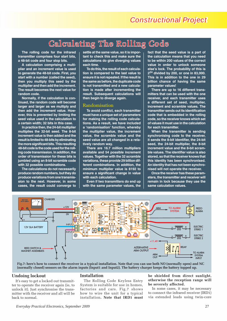
Constructional ProjectConstructional Project Constructional Project
Everyday Practical Electronics, September 2009 27
Undoing lockoutIt’s easy to get a locked out transmit-
ter to operate the receiver again (ie, to unlock it). Just synchronise the trans-mitter with the receiver and all will be back to normal.
The rolling code for the infrared transmitter comprises four start bits, a 48-bit code and four stop bits.
A calculation comprising a multi-plier and an increment value is used to generate the 48-bit code. First, you start with a number (called the seed), then you multiply this seed by the multiplier and then add the increment. The result becomes the next value for random code.
Normally, if the calculation is con-tinued, the random code will become larger and larger as we multiply and then add the increment value. How-ever, this is prevented by limiting the seed value used in the calculation to a certain width; 32 bits in this case.
In practice then, the 24-bit multiplier multiplies the 32-bit seed. The 8-bit increment value is then added and the result is limited to 48-bits by eliminating the more significant bits. This resulting 48-bit code is the code used for the roll-ing code transmission. In addition, the order of transmission for these bits is jumbled using an 8-bit scramble code with 32 possible combinations.
The calculations do not necessarily produce random numbers, but they do produce variations from one transmis-sion to the next. However, in some cases, the result could converge to
settle at the same value, so it is impor-tant to check this and make sure the calculations do give diverging values each time.
To do this, the result of each calcula-tion is compared to the last value to ensure it is not repeated. If the result is the same as before, the duplicate code is not transmitted and a new calcula-tion is made after incrementing the result. Subsequent calculations will then begin to diverge again.
RandomisationTo avoid conflict, each transmitter
must have a unique set of parameters for making the rolling code calcula-tions. As a result, we have included a ‘randomisation’ function, whereby the multiplier value, the increment value, the scramble value and the seed value are all changed in a rela-tively random way.
There are 16.7 million multipliers available and 54 possible increment values. Together with the 32 scramble variations, these provide 29 billion dif-ferent combinations. In addition, the minimum multiplier value is 8192 to ensure a significant change in value with each calculation.
Even if two transmitters do end up with the same parameter values, the
fact that the seed value is a part of the calculation means that you need to be within 200 values of the correct value in order to unlock someone else’s lock. The probability of this is 224 divided by 200, or one in 83,000. This is in addition to the one in 29 billion chance of having the same parameter values!
There are up to 16 different trans-mitters that can be used with the one receiver, and each transmitter uses a different set of seed, multiplier, increment and scramble values. The transmitter sends out its identification code that is embedded in the rolling code, so the receiver knows which set of values it must use in the calculation for each transmitter.
When the transmitter is sending synchronising code to the receiver, it sends the 8-bit identifier, the 24-bit seed, the 24-bit multiplier, the 8-bit increment value and the 8-bit scram-ble values. The identifier value is also stored, so that the receiver knows that this identity has been synchronised. An identity that has not been synchro-nised will not operate the receiver.
Once the receiver has these param-eters, the transmitter and receiver will remain in lock because they use the same calculation values.
Calculating The Rolling Code
InstallationThe Rolling Code Keyless Entry
System is suitable for use in homes, factories and cars. Fig.7 shows how to wire the unit for a typical installation. Note that IRD1 must
be shielded from direct sunlight, otherwise the reception range will be severely affected.
In some cases, it may be necessary to connect the infrared receiver (IRD1) via extended leads using twin-core
Fig.7: here’s how to connect the receiver in a typical installation. Note that you can use both NO (normally open) and NC (normally closed) sensors on the alarm inputs (Input1 and Input2). The battery charger keeps the battery topped up.
RollingCode1107 (from Matt).indd 27 27/07/2009 12:42:03

Constructional Project
28 Everyday Practical Electronics, September 2009
Constructional Project Constructional Project
shielded cable (eg, if the receiver is mounted on one side of a wall, but in-frared reception is needed on the other side). Fig.8 shows how this is done.
The two alarm inputs (Input1 and Input2) can be used in conjunction with reed switch magnet assemblies that change state when a door or window is opened or closed. You can use either normally closed (NC) or normally open (NO) types. (See last month’s weather station project for the lowdown on reed switches.)
As shown in Fig.9, NC types are connected in series, while NO types are connected in parallel. However, for best security, use only one sensor per input.
Alternatively, you can use a PIR de-tector or a glass breakage detector on one or both of the inputs. EPE
Table 5: Receiver lockout selections
Lockout Identity LK1 LK2 LK3 LK4
1 + + + +
2 + + + –
3 + + – +
4 + + – –
5 + – + +
6 + – + -
7 + – – +
8 + – – –
9 – + + +
10 – + + –
11 – + – +
12 – + – –
13 – – + +
14 – – + –
15 – – – +
16 – – – –
Table 4: Arm output (LK4)LK4 + –
Arm output low on arm, open on disarm
Arm output open on arm, low on disarm
Fig.8: the IR receiver (IRD1) can be connected via twin-core shielded cable as shown here.
Above: you can buy both NO and NC reed switch assemblies.
Fig.9: here’s how to wire the two different sensor types (NO and NC) to the alarm inputs on the receiver board.
Reproduced by arrangement with SILICON CHIP
magazine 2009.www.siliconchip.com.au
Get your magazine ‘instantly’ anywhere in the world –
buy and download from the web.
TAKE A LOOK, A FREE ISSUE
IS AVAILABLE
A one year subscription (12 issues) costs just $18.99(US)
Back issues are also available
RollingCode1107 (from Matt).indd 28 29/07/2009 09:54:35

Everyday Practical electronics is offering its readers the chance to win one
of four new PicdeM lab development Kits from Microchip. the PicdeM lab development Kit is a comprehensive entry-level development platform for all of Microchip’s 8-bit Flash Pic microcontrollers (McUs) with 20 or fewer pins.
aimed at educators, students and newcomers to microcontrollers, the PicdeM lab development Kit comes complete with five popular 8-bit Pic McUs, along with a selection of discrete components, a Pickit 2 debugger/programmer and a cd containing a User’s Guide, labs and application examples. the kit provides every-thing needed to quickly and easily develop applications using Microchip’s 8-bit Pic microcontrollers.
a solderless prototyping area on the PicdeM lab development board allows users to explore a number of application examples described in the ‘hands-on’ labs from the PicdeM lab User’s Guide that comes with the kit. the easy-to-follow labs provide an intuitive introduction to common peripherals and then move into a variety of application examples to reinforce core concepts. all of the code examples are written in the high level programming language c, and can be compiled using the Hi tecH c compiler, available as a free download from www.microchip.com/HI-TECH
the PicdeM lab comes complete with the following:
1 PICDEM Lab Development Board, with samples of five 8-bit PIC microcontrollers1 component Kit1 Pickit 2 debugger/programmer1 cd containing comprehensive User’s Guide, labs and application examples1 Free Hi-tecH c compiler available at http://www.microchip.com/Hi-tecH.
How To EnTErFor your chance to win a Microchip PicdeM lab development kit, visit www.microchip-comp.com/epe-picdemlab and enter your details in the online entry form. the four winners will be picked at random by Microchip.
CLoSInG DATE
the closing date for this offer is 31 october 2009
Win a Microchip PICDEM Lab Development
Kit!
WORTH$124.99
(approx. £77.00)
EACH
EPE EXCLUSIVE
Microchip offer.indd 1 27/07/2009 14:42:41

PIC Programmer SOIC ConverterProgramming 18-lead surface-mount SOIC PIC microcontrollers can be quite difficult, because access to the tiny leads is tricky. This adaptor PC board accepts 18-pin SOIC PIC microcontrollers and plugs directly into a conventional PIC programmer.
Parts List 1 PC board, code 723, available
from the EPE PCB Service, size 29mm × 48mm
1 100nF monolithic ceramic capacitor (code 104 or 100n)
2 9-way header strips with 2.54mm spacing
1 80mm length of 0.7mm tinned copper wire
Fig.1: the SOIC Converter uses just two 9-pin SIL headers and a 100nF capacitor.
Most people will probably consider buying a kit for the
Rolling Code Keyless Entry System project, and the PIC micros used in the transmitter and receiver will come pre-programmed. But what if you want to program them yourself?
One way of programming the SOIC (surface-mount) PIC16F628A –20/SO used in the transmitter is to use the In-Circuit Serial Program-ming (ICSP) header on the PC board. Basically, you have to connect the Vdd, Vss, MCLR, RB6 and RB7 pins on the processor to the +5V, 0V, Vpp, clock and data ICSP connections on a PIC programmer. However, this technique is only good for as-sembled PC boards (assuming ICSP connections are available on the PIC programmer).
Converter boardIf you want to program an SOIC PIC
out of circuit (eg, for production runs) some other method is needed. This simple SOIC Converter board solves the problem. It provides a means to connect the pins on the SOIC PIC to a standard 18-pin DIP socket on a PIC programmer.
Below: the SOIC device is held in place for programming using a spring-loaded clip.
Fig.2: assemble the SOIC Converter as shown here.
In use, the SOIC PIC is positioned on the converter board and held in place using a spring-loaded clip (eg, a clothes peg or a bulldog clip). The SOIC Converter then plugs into the PIC programmer, after which programming is carried out in the normal manner.
Circuit detailsFig.1 shows the circuit for the
SOIC Converter. There’s not much to it – just two 9-pin SIL headers and a 100nF capacitor. The SIL header pins connect to the Vss, Vdd, Vpp, RB6 and RB7 pins of the SOIC device.
No provision has been made for low voltage programming (LVP) because the LVP pin varies between
different processors. The 100nF capacitor bypasses the 5V supply.
The PC board (code 723 and meas-uring 29mm × 48mm) is assembled by first installing the three links on the non-copper side of the PC board – see Fig.2. The two 9-way header strips are then installed and soldered in place.
Finally, the 100nF capacitor is mounted on the copper side of the board – see photo.
Note that power must always be off when mounting the SOIC device or removing it from the board. EPE
Constructional Project
30 Everyday Practical Electronics, September 2009
Constructional ProjectConstructional ProjectConstructional ProjectConstructional Project Constructional Project
PIC Programmer SOIC Converter1107 (from Matt).indd 32 30/07/2009 09:20:54

32 Everyday Practical Electronics, September 2009
STORE YOUR BACK ISSUES ON CD-ROMS
BACK ISSUES CD-ROM ORDER FORM
Please send me the following Back Issue CD-ROMs.
Volume Numbers:. . . . . . . . . . . . . . . . . . . . . . . . . . . . . . . . . . . . . . . . . . . . . .
. . . . . . . . . . . . . . . . . . . . . . . . . . . . . . . . . . . . . . . . . . . . . . . . . . . . . . . . . .
Price £16.45 each, £29.95 for Five Year CD-ROM – includes
postage to anywhere in the world.
Name . . . . . . . . . . . . . . . . . . . . . . . . . . . . . . . . . . . . . . . . . . . . . . . . . . . .
Address . . . . . . . . . . . . . . . . . . . . . . . . . . . . . . . . . . . . . . . . . . . .
. . . . . . . . . . . . . . . . . . . . . . . . . . . . . . . . . . . . . . . . . . . . . . . . . . .
. . . . . . . . . . . . . . . . . . . . . . . . . . . . . . . . . . . . . . . . . . . . . . . . . . .
Post Code. . . . . . . . . . . . . . . . . . . . . . . . . . . . . . . . . . . . . . . . . . .
I enclose cheque/P.O./bank draft to the value of £ . . . . . . . . .
please charge my Visa/Mastercard/Maestro £ . . . . . . . . . . . .
Card No. . . . . . . . . . . . . . . . . . . . . . . . . . . . . . . . . . . . . . . . . . . . .
Card Security Code . . . . . . . . . . (The last 3 digits on or just under the signature strip)
Valid From. . . . . . . . . . . . . . . . Expiry Date . . . . . . . . . . . . . . . . .
Maestro Issue No.. . . . . . . . . .
SEND TO: Everyday Practical Electronics,Wimborne Publishing Ltd., Sequoia House, 398a Ringwood
Road, Ferndown, Dorset BH22 9AU.
Tel: 01202 873872. Fax: 01202 874562.E-mail: [email protected]
Payments must be by card or in £ Sterling – cheque or bank draft drawn on a UK bank.
Normally posted within seven days of receipt of order.
VOL 1: BACK ISSUES – January 1999 to June 1999 Plus some bonus material from Nov and Dec 1998
VOL 2: BACK ISSUES – July 1999 to December 1999
VOL 3: BACK ISSUES – January 2000 to June 2000
VOL 4: BACK ISSUES – July 2000 to December 2000
VOL 5: BACK ISSUES – January 2001 to June 2001
VOL 6: BACK ISSUES – July 2001 to December 2001
VOL 7: BACK ISSUES – January 2002 to June 2002
VOL 8: BACK ISSUES – July 2002 to December 2002
VOL 9: BACK ISSUES – January 2003 to June 2003
VOL 10: BACK ISSUES – July 2003 to December 2003
VOL 11: BACK ISSUES – January 2004 to June 2004
VOL 12: BACK ISSUES – July 2004 to December 2004
VOL 13: BACK ISSUES – January 2005 to June 2005
VOL 14: BACK ISSUES – July 2005 to December 2005
VOL 15: BACK ISSUES – January 2006 to June 2006
VOL 16: BACK ISSUES – July 2006 to December 2006
VOL 17: BACK ISSUES – January 2007 to June 2007
VOL 18: BACK ISSUES – July 2007 to December 2007
VOL 19: BACK ISSUES – January 2008 to June 2008
VOL 20: BACK ISSUES – July 2008 to December 2008
NEW – FIVE YEAR CD-ROM – Jan 2003 to Dec 2007
NOTE: These CD-ROMs are suitable for use on any PC with a CD-ROM drive. They require Adobe Acrobat Reader (available free
from the Internet – www.adobe.com/acrobat)
WHAT IS INCLUDEDAll volumes include the EPE Online editorial content of every listed issue, plus links to all the available PIC Project Codes for the PIC projects published in those issues. Please note that we are unable to answer technical queries or provide data on articles that are more than five years old. Please also ensure that all components are still available before commencing construction of a project from a back issue.
PHONE/FAX MISSED CALL ALERT
Provides extra visual and
audible latched signalling
SERIAL I/O CONTROLLER
& ANALOGUE SAMPLER
A versatile easy-to-drive I/O controller for your PC
PIC CARILLONWant to be a bell-ringer?
P I C C o n t r o l l e d
F o u r o c t a v e r a n g e
S y n t h e s i s e d b e l l s o u n d s
TEACH-IN 2008Using PIC Microcontrollers – Part 3
JAN 2008 £3.75
WIN AMICROCHIP PICDEM
MC DEVELOPMENT
BOARD
TEACH-IN 2008 Using PIC microcontrollersPart Two – Programme Basic Commands Plus Simple LED Control
PIC SPEECH SYNTHESISERAdd speech to your PIC projects
MIDI DRUM KIT - 1 546 different drum sounds Use with a computer or synthesiser Up to seven instruments at one time Precussion plate, hand plate and foot activation LCD shows sensor, patch and volume settings
iPOD AND MP3 CHARGERCharge from a plug-pack or car batteryDEC 2007 £3.75
STANDBY POWER SAVER
Save power – remotely turns
off TVs/DVDs/Amplifiers etc.
PLUS BUILD YOUR OWN SEISMOGRAPH
INDUCTANCE & Q-FACTOR METER – 1
I n d u c t a n c e f r o m 2 0 0 n H t o 1 0 m H
Q - F a c t o r 1 - 1 2 0 ( a p p r o x )
A u t o r a n g i n g m e a s u r e m e n t f r e q u e n c y
V8 DOORBELLVROOM!
V8 DOORBELLV8 DOORBELLV8 DOORBELLV8 DOORBELLV8 DOORBELLV8 DOORBELLV8 DOORBELLV8 DOORBELLV8 DOORBELLV8 DOORBELLVROOM!VROOM!VROOM!VROOM!VROOM!VROOM!VROOM!VROOM!VROOM!VROOM!VROOM!VROOM!VROOM!VROOM!VROOM!VROOM!VROOM!VROOM!VROOM!VROOM!VROOM!VROOM!VROOM!VROOM!VROOM!VROOM!VROOM!VROOM!VROOM!VROOM!VROOM!VROOM!VROOM!VROOM!VROOM!VROOM!VROOM!VROOM!VROOM!VROOM!VROOM!VROOM!VROOM!VROOM!VROOM!VROOM!VROOM!VROOM!VROOM!VROOM!VROOM!
V8 DOORBELLVROOM!VROOM!VROOM!VROOM!VROOM!VROOM!VROOM!VROOM!VROOM!VROOM!VROOM!VROOM!VROOM!VROOM!VROOM!VROOM!VROOM!VROOM!VROOM!VROOM!VROOM!VROOM!VROOM!VROOM!
WUMP!
VROOM!VROOM!VROOM!VROOM!VROOM!VROOM!VROOM!VROOM!VROOM!VROOM!VROOM!WUMP!WUMP!WUMP!WUMP!WUMP!WUMP!WUMP!WUMP!WUMP!WUMP!WUMP!
VROOM!VROOM!VROOM!VROOM!VROOM!VROOM!VROOM!VROOM!VROOM!VROOM!VROOM!VROOM!VROOM!VROOM!VROOM!VROOM!VROOM!VROOM!VROOM!VROOM!VROOM!WUMP!WUMP!WUMP!WUMP!WUMP!WUMP!WUMP!WUMP!WUMP!WUMP!WUMP!WUMP!WUMP!WUMP!WUMP!WUMP!WUMP!WUMP!WUMP!WUMP!WUMP!WUMP!WUMP!WUMP!WUMP!WUMP!WUMP!WUMP!WUMP!WUMP!WUMP!WUMP!WUMP!WUMP!WUMP!WUMP!WUMP!WUMP!WUMP!WUMP!WUMP!WUMP!WUMP!WUMP!WUMP!WUMP!WUMP!WUMP!WUMP!WUMP!WUMP!WUMP!WUMP!WUMP!WUMP!WUMP!WUMP!WUMP!WUMP!WUMP!WUMP!WUMP!WUMP!WUMP!WUMP!WUMP!WUMP!WUMP!WUMP!WUMP!WUMP!WUMP!WUMP!WUMP!WUMP!WUMP!WUMP!WUMP!WUMP!WUMP!WUMP!WUMP!WUMP!WUMP!WUMP!WUMP!WUMP!WUMP!WUMP!WUMP!WUMP!WUMP!WUMP!WUMP!WUMP!WUMP!WUMP!WUMP!WUMP!WUMP!WUMP!WUMP!WUMP!WUMP!WUMP!WUMP!WUMP!WUMP!WUMP!WUMP!WUMP!WUMP!WUMP!WUMP!WUMP!WUMP!WUMP!WUMP!WUMP!WUMP!WUMP!WUMP!WUMP!WUMP!WUMP!WUMP!WUMP!WUMP!WUMP!WUMP!WUMP!WUMP!WUMP!WUMP!WUMP!WUMP!WUMP!WUMP!WUMP!WUMP!WUMP!WUMP!WUMP!WUMP!WUMP!WUMP!WUMP!WUMP!WUMP!
OCT 2007 £3.50
A great way to buy EPE Back Issues – our CD-ROMs contain back issues from our EPE Online website plus bonus articles, all the relevant PIC software links and web links.
Note: no free gifts are included.
Order on-line fromwww.epemag.com
or by phone, fax, email or post
ONLY
£16.45(£29.95 FOR 5 YEAR) each including VAT and p&p
FIVE YEAR CD-ROM
NOW AVAILABLE
Back Issues CDs.indd 32 27/07/2009 14:38:10

Everyday Practical Electronics, September 2009 33
QuickBuilder 2 is a software tool that can aid the development
of projects based on a wide range of Pic16*** and Pic18*** series micro-controllers, plus a few others. A large list of compatible devices is available at the QuickBuilder website.
This program was originally avail-able as normal commercial software, but it has been re-launched as a free download with no time limits or other restrictions. The hardware require-ments for running the program are not very demanding, and are given as a Pc with Pentium class processor running Windows95/98/NT/2000/XP, and having 4MB hard disk space.
Practically any Pc should have the wherewithal to run QuickBuilder 2, but there is a potential problem for some users in that it is not guaran-teed to be compatible with Windows
Vista. it does seem to run under Vista without any obvious problems, but it is necessary to download an add-on from the Microsoft website in order to use the built-in Help system and its old style HLP files. As with any pro-gram that is largely graphics oriented, a reasonably high screen resolution is preferable, but it is not essential in this case.
C how it worksWhen first running and experi-
menting with QuickBuilder 2, you get the impression that it is a program for beginners, where you develop proj-ects by assembling on-screen building blocks to build up the circuit, then set the appropriate parameters, and finally get the program to produce the Pic code. However, this is not quite the way that it works, and it is not a program for beginners at all.
its purpose is to help experienced PIC project developers work more efficiently.
You do actually start by building up circuits from predefined building blocks, or ‘sub-circuits’ as they are called in Quick-Builder parlance, and there is software linked to each building block. The Build function is used to produce the code for the circuit, which is in the c programming language. Therefore, a c compiler is needed, in order to produce the assembly language that is used to program the Pic chip.
The output of QuickBuilder 2 is designed for use with a ccS c com-piler, and a limited demonstration version of this program is available as a free download. unfortunately, the output of QuickBuilder 2 is not compatible with the popular Hi-Tech Pic c compiler.
Although it is not necessary to pro-duce any code for each sub-circuit, the user does have to add the software that integrates everything into a work-ing application before compiling the program. The code linked to each sub-circuit sets up the lines of the Pic chip in the appropriate fashion, and provides the appropriate support where necessary, but it is up to the user to bring everything together and make it all work in the appropriate fashion. This obviously requires a reasonable knowledge of the c pro-gramming language, and preferably the ccS version of Pic c.
In useThe download is quite small, just
1.2 megabytes, so it is a practical proposition if only a dial-up con-nection is available. installing the program is very easy and proceeds in normal Windows fashion. The program itself has a conventional layout with the usual menu bar at the top, a small toolbar immediately beneath, and most of the main screen area available for the circuit.
However, the right-hand section of the screen provides a dynamic map that makes it easy to navigate the drawing area, and this section of the screen is also used for a palette of sub-circuits that can be added to the circuit. One slight peculiarity is
Reviewing Summit Electronics’ QuickBuilder 2 software tool
QuickBuilder 2 by Robert Penfold
Fig.1. The required sub-circuits are added to the palette by double-clicking their entries in this list
ReviewReview
Summit Review.indd 33 29/07/2009 16:09:22

34 Everyday Practical Electronics, September 2009
that the program insists on running in widescreen format, even if a monitor having a normal aspect ratio is used. When set to run in full-screen mode this can result in an unused band along the bottom of the screen, which can be a bit distracting.
On targetWith the program ‘up and running’,
the first task is to select the target PIC chip using a menu accessed via the toolbar. Then one or more sub-circuits are added to the drawing area, or design sheet as it is termed in the QuickBuilder documentation.
In order to populate the design sheet with sub-circuits, it is first a matter of adding them to the pal-ette. Right-clicking the palette and selecting the Add option from the pop-up menu produces a small win-dow (Fig.1) where the required sub-circuits are added by double-clicking their entries in the list.
The sub-circuits are then added to the design sheet, and this is just a matter of left-clicking an entry in the palette in order to select it, and then left-clicking again on the design sheet. When two or more sub-circuits of the same type are required, simply left-click on the design sheet for each copy that is needed.
A reasonable range of predefined sub-circuits are supplied, ranging from simple ports, switches, and LED indi-cators, through to more complex types, such as multiplexed LED displays, a dot matrix LCD, EEPROMs, and a QWERTY keypad. The supplied sub-circuits should suffice to get started with QuickBuilder 2, but I suppose that with this type of thing there will never be enough pre-defined circuits to satisfy every requirement. Ultimately, it will be necessary to delve deeper into the program and modify the sup-plied sub-circuits or design your own.
Once in place, the sub-circuits can be repositioned by dragging them around the screen, or erased by right-clicking and selecting the delete op-tion from the pop-up menu. The design sheet is large enough to accommodate a fair number of sub-circuits, but even with a high resolution screen it is not possible to display the entire sheet. With larger circuits it is necessary to resort to the Pan panel in order to display the required section of the circuit. No zoom facility is available.
Getting connected
With the sub-cir-cuits in place, the next step is to allo-cate an input/output line of the PIC chip to each input/output terminal of every sub-circuit. This is achieved by right-clicking the first sub-circuit and select-ing Properties from the pop-up menu. A small pop-up win-dow is then used to allocate each input output terminal of the sub-circuit (Fig.2).
Any lines of the PIC chip that have been allocated already are marked with an asterisk, which should help to avoid incorrectly allocating the same line to more than one function. A full list of input/output allocations is available, see the View menu.
A footnote can be added using the textbox provided in the Properties window. This text appears on the design sheet in a yellow box beneath the sub-circuit. It is also possible to add notes for the entire project by selecting Notes from the Project menu or using the appropriate button on the toolbar. The required text is then entered into the pop-up window. This text does not appear on the design sheet, and is only accessed via the pop-up text editor.
Once the input/output terminals of the first sub-circuit have been allocated, the process is repeated for the remain-ing sub-circuits, and the circuit is then complete. The end result is something like Fig.3, which is the circuit for a remote terminal, and is one of the demonstration circuits supplied with the program. The program has the usual Print facility that can be used to provide hard copy of the design sheet using any Windows-compatible printer.
Having given everything a final check, it is then time to produce the C code by selecting the Build option from the Project menu or operat-ing the Build button on the toolbar. A pop-up window reports on the progress of the build process, and if
Fig.2. This window is used to allocate each input/output terminal of the sub-circuit to a pin of the PIC chip. Pins that are already allocated are marked with an asterisk
Fig.3. One of the demonstration circuits supplied with the program. It is for a remote terminal with an RS232C interface
ReviewReview
Summit Review.indd 34 29/07/2009 16:09:33

Everyday Practical Electronics, September 2009 35
all is well it will almost immediately report that the build was successful.
If required, the output of the pro-gram can then be viewed from within QuickBuilder 2 (Fig.4) by operating the View Output button. The destina-tion folder for the output text file can be specified using the options window available from the Project menu. With the output code generated, Quick-Builder 2 has completed its part of the development process, and it is then up to you to complete the process and get everything working correctly.
ConclusionAs pointed out previously, it is a
mistake to think of QuickBuilder 2 as a program for beginners. It makes it quick and easy to produce a range of PIC-based circuits and the basic PIC C code to go with them.
However, in order to utilize the program it is essential to already have an understanding of the circuits and the techniques used, such as display multiplexing and RS232C interfacing. It is also necessary to have a reasonable knowledge of PIC C programming in or-der to turn the output of QuickBuilder 2 into the finished product. QuickBuilder 2 is responsible for much of the ‘donkey work’, leaving the project developer to get on with the clever stuff.
I think it is fair to say that this soft-ware is more to do with reusing circuit and software blocks than with the pro-duction of instant PIC circuits. Proba-bly every PIC project developer reuses their favourite circuits and supporting software anyway, but QuickBuilder 2 provides a proper framework to work within, putting everything in a neat and easily accessible form. Whether the QuickBuilder approach to things suits you is very much a matter of personal preference. The same is true of the PIC C programming language.
When producing a review, it is not possible to exhaustively test every as-pect of the program, but running under Windows XP, QuickBuilder 2 proved to be totally stable and error-free during the test period. As explained previously, it also ran perfectly well under Windows Vista, even though it is not guaranteed to do so.
When using the program with Vista, it is important to download the Help add-on from the Microsoft website so that the built-in Help system becomes active, since this is the only documen-tation provided. There is no separate instruction manual.
On the face of it, value for money is not an issue since QuickBuilder 2 is
now completely free. Bear in mind though, that there is no free version of the CCS compiler other than a time-limited demonstration version that also has a 2k file size limit. You can try the program for nothing, but unless you already own a suitable C compiler it will be necessary to buy one (at 150 US dollars) in or-der to go on using QuickBuilder 2. This was of less importance when the original QuickBuilder software was a commercial product, but is clearly of more significance now it is available as a freebie. If you are already into PIC C programming, or are considering an entry into this type of PIC programming, then it is certainly worth trying QuickBuilder 2, but keep in mind the true cost of using this program.
Further details of QuickBuilder 2 and the free download are available at: www.quickbuilder.co.uk
Further information about the CCS PIC C compiler can be obtained at: ww.ccsinfo.com/ EPE
Fig.4. The output of the program can be viewed from within QuickBuilder 2. At this stage, the program has completed its part of the process, and it is up to the user to complete the project PIC® MCU and dsPIC®DSC are registered trademarks of Microchip Technology, Inc.
You Get:
Servo Control
Turn my lights on and off
Electronic Keypad Lock
·Phone: 262-522-6500 x35·[email protected]·
$149
1 day projectswith my CCS Compiler
G-Force Meter
+ ++
101: C on PIC16F818
Everything you need to start a project with C
and PIC®MCU
www.ccsinfo.com/EDPE
Review
Summit Review.indd 35 29/07/2009 16:12:12

36 Everyday Practical Electronics, September 2009
RadioBygonesApril/May 2009
Issue No. 118
£3.75
ISSN 0956-974X
Signalling To Submarines
The Care Of Racal RA17/117s
Clandestine Communications And The Paraset
www.radiobygones.com
Return Of The Swan
RadioBygones
June/July 2009Issue No. 119
£3.75ISSN 0956-974X
Heathkit UXR-1 and UXR-2 Transistor Radios
Don’t Panic! There’s A Missile On The Way
The Care Of Racal RA17/117s
www.radiobygones.com
Eddystone ‘All Wave Four’ Receiver
RadioBygonesAugust/September 2009Issue No. 120
£3.75ISSN 0956-974X
Converting A Russian 6E5C Valve For Use As A Y63
HF Propogation And Clandestine Communications
Restoring A Wartime Economy Receiverwww.radiobygones.com
Metal Rectifiers – Pioneers In TheSemiconductor Revolution
Radio Bygones
The leading magazine for vintage radio
enthusiasts
ARTICLES on restoration and repair, history, circuit techniques, personalities, reminiscences and just plain nostalgia – you’ll find them all. Plus features on museums and private collections and a full-colour photo-feature in every issue.IT’S MOSTLY about valves, of course, but ‘solid-state’ – whether of the coherer and spark-gap variety or early transistors – also has a place.FROM THE DAYS of Maxwell, Hertz, Lodge and Marconi to what was the state-of-the-art just a few short years ago . . .There is also a selection of free readers’ For Sale and Wanted advertisements in every issue.
Radio Bygones covers it all!THE MAGAZINE is published six times a year, and is only available by postal subscription. it is not available at newsagents.TO TAKE OUT a subscription, or to request a sample copy, please complete the form below and return it to:RADIO BYGONES, Wimborne Publishing Ltd, Sequoia House, 398a Ringwood Road, Ferndown, Dorset BH22 9AU.Tel: 01202 873872. Fax: 01202 874562. Web sites: www.radiobygones.co.uk www.radiobygones.com
Radio BygonesA SAMPLE COPY of Radio Bygones . . . . . . . . . . . £3.75
(Add 75p for overseas airmail postage)
SUBSCRIPTIONS (post paid): . . . . . . . . 1 YEAR 2 YEAR
UNITED KINGDOM . . . . . . . . . . . . . . . . . £21.00 £40.00
REST OF EUROPE (AIRMAIL) . . . . . . . . £23.50 £45.00
REST OF THE WORLD (AIRMAIL) . . . . . £29.00 £56.00
Yes, I would like a sample copy for £3.75(A free issue is available for download from www.radiobygones.com)
Yes, I would like to take out a subscription for:
One year (6 issues) Two years (12 issues)
I enclose a cheque/Bankers Draft/PO for £ . . . . . . . . payable to Wimborne Publishing Ltd
Please debit my Visa/Mastercard/Maestro card
My card number is:
. . . . . . . . . . . . . . . . . . . . . . . . . . . . . . . . . . . . . . . . . . . . . . . . . . . . .
Please print clearly, and check that you have the number correct
The card is valid from: . . . . . . . . . . . . . To: (Exp. date) . . . . . . . . . . .
Maestro Issue No: . . . . . . . . . . . . . Card Security Code . . . . . . . . .
My name is . . . . . . . . . . . . . . . . . . . . . . . . . . . . . . . . . . . . . . . . . . .
My address . . . . . . . . . . . . . . . . . . . . . . . . . . . . . . . . . . . . . . . . . . .
. . . . . . . . . . . . . . . . . . . . . . . . . . . . . . . . . . . . . . . . . . . . . . . . . . . . .
Post Code/Zip . . . . . . . . . . . . . . . . Tel . . . . . . . . . . . . . . . . . . . . . . . .
Signed . . . . . . . . . . . . . . . . . . . . . . . . . . . . . . . . . . . . . . . . . . . . . .
(the last 3 digits on the signature strip)
If you do not wish to cut your issue, send a letter or a copy of this form.
ORDER FORM
RB Advert A4.indd 36 30/07/2009 09:54:15

ELECTRONICS TEACH-IN 2
PIC N’ MIXA host of practical programming and interfacing information
C FOR PICsA beginners guide to using the C programming language to programme
PIC microcontrollers
PLUS
The
Microchip
name
andlogo, M
PLA
B, PIC
anddsPIC
are registered trademarks of Microchip Technology Incorporated in the USA and otherco
untries
. ©20
09M
icro
chip
Tech
nolo
gyIn
c.A
llri
ghts
rese
rved
.Iss
ue1.
MC
CD
1016
-02.
09.Ele
ctronics Teach-In 2© Wimborne Publishing Ltd 2009
All the software for the
projects/features in the
Teach-In 2 series and PIC
N’ Mix in the Electronics
Teach-In 2 book. Plus PIC
Project Source Codes and
PIC Tricks.
MPLAB®IDE V8.20 (Integrated Development Environment)
MAPS V2.32
Latest Treelink
Motor Control Solutions
16-bit Embedded Solutions
16-bit Tools & Solutions
Human Interface Solutions
8-bit PIC®Microcontrollers
PIC24 Microcontrollers
PIC32 Microcontrollers with USB
dsPIC®Digital Signal Controllers
CDROM CoverUntitled-1.indd 1
10/03/2009 15:30:09
USING PIC MICROCONTROLLERS
A practical introduction
i Breadboard layouts to
aid understandingi Free software on CDROM
i Simple programmer project
i Free PIC Toolkit software
Everything you need to get you started
FROM THE PUBLISHERS OF
£7.99FR
EE
CD-R
OM
Teach In 2 Cover.indd 1
23/03/2009 11:39:27
ELECTRONICS TEACH-IN 2 now on sale in WHSmiths or available direct from us:
01202 873872 www.epemag.com £9.50
Including UK P & P
Teach-In 2 advert.indd 1 27/04/2009 15:47:46

Constructional Project
38 Everyday Practical Electronics, September 2009
Constructional Project Constructional Project
This article describes the design of a mains timer with a level of
randomness to the switching times to more effectively simulate a house being occupied when it is empty. It also has a light sensor to prematurely activate a lamp if the ambient light level is unusually low.
IntroductionToday, home security is more im-
portant than ever before. The average home is kitted out with a feast of electronic gadgets that a thief would love to get his hands on. Moreover, these items are portable, easy to steal and easy to sell – ideal food for the hungry burglar.
Unfortunately, some thieves watch their victims’ premises before they strike. Many home owners activate a light timer to make their house look oc-cupied, but if the light just switches on early in the evening and off at the end of the evening, the house can indeed look like it is being lit with just a timer-controlled light.
A level of randomness is needed that automatically switches a light on and off throughout the evening at ‘random’ times to more effectively simulate a property that is occupied. In addition, a light sensor is needed in case of low light levels in the early evening when an occupied house would have its lights on.
Circuit detailsThe Random Mains Timer does ex-
actly that, and the full circuit diagram is shown in Fig.1. At the heart of the circuit is a PIC16F883 microcontroller. This drives a four digit, 7-segment LED display that shows the current time and, at the press of a button, the time for the light sequence to start, thus it dou-bles up as a handy clock too. The power supply to the circuit was provided by a 9V DC plug-in mains adaptor regulated to 5V by a 7805 linear regulator.
The 7-segment display pinout de-tails are shown in Fig.2. Segments ‘a’ to ‘g’ are wired with a common cath-ode, connected to pins 3 and 8. The circuit uses four such LED displays,
and to save port pins, the 7-segment displays are multiplexed. Thus, the four ‘a’ segments are wired together and driven from a common port pin. The same with the four ‘b’ pins … etc.
Each of the four digits is then acti-vated by driving the common cathode pin. So at any one time, the anodes of the LEDs may have a voltage applied to them, but they only light when the corresponding cathode is driven too. If the anode voltage is applied, then the cathode is pulled low for approxi-mately 10ms, each LED digit can be shown in turn.
An LCD display was considered for the design, but a 7-segment display is much cheaper and easier to read from a distance, despite having a more complex driving method.
Time clockThe time is maintained by a DS1337
real time clock (RTC) chip, from Max-im. The pinout and internal function information is included on the circuit diagram Fig.1 – see IC2.
By BILL NAYLOR
Random Mains Timer
Effectively simulates a house being occupied when it is empty!
Random Mains Timer.indd 38 29/07/2009 14:36:42

Constructional ProjectConstructional Project Constructional Project
Everyday Practical Electronics, September 2009 39
These devices are simple, yet take such a headache away from the soft-ware designer. This RTC consists of three banks of registers, with each bank storing hours, minutes, seconds, day, date, year etc. One bank keeps the time and the other two banks store two alarm settings, Alarm A and Alarm B.
The device (IC2) also has a 32.768kHz oscillator that increments the registers every second, thus keep-ing track of time. Most crystal-based circuits need external capacitors (ap-prox 30pF), but the DS1337 works perfectly well without them and keeps good time.
Maintaining such registers inside a microcontroller and then increment-ing them every second and checking for an alarm condition makes the soft-ware quite complex. The addition of an RTC removes this headache.
The DS1337 constantly compares the current time with the values in the alarm registers. If the values match, the corresponding INTA or INTB pins (3, 7) on the RTC are pulled low signal-ling to the microcontroller to respond to the alarm condition.
When the circuit is first powered, the RTC is initialised and the Time register is loaded with 00:00 (mid-night). Alarm Register A is loaded with 1500 hours (3pm). Alarm Reg-ister B is set equal to Alarm Register A, then incremented by a ‘random’ time stored in memory. The ‘time’ values are stored in a look-up table
Fig
.2. T
he
7-se
gmen
t d
isp
lay,
com
mon
cat
hod
e, p
inou
t an
d s
egm
ent
det
ails
Fig
.1. F
ull
cir
cuit
dia
gram
for
th
e R
and
om M
ain
s Ti
mer
, wit
h ‘b
uil
t-in
’ lig
ht
sen
sor
for
sen
sin
g lo
w l
igh
t co
nd
itio
ns
du
rin
g th
e d
ay
a gb c
d
ef
109
87
6
12
34
5
ag
fb
ce
dD
P
DP
k aa 7
k ab 6
k ac 4
k
kk
k
ad 2
3, 8
k ae 1
k af 9
k ag 10
k aDP 5
MA
INS
01/S
EP
0926
0mm
x 2
CO
L
C1
47µ
c e
bTR1
BC
547
c e
bTR5
BC
547
a gb c
d
ef
109
87
6
12
34
5
ag
fb
ce
dD
P NC
R12
220Ω
R13
220Ω
R15
220Ω
R14
220Ω
R8
220Ω
R19
1k
R4
1k
R18
1k R17
1k R16
1kR9
220Ω
R10
220Ω
c e
bTR2
BC
547
a gb c
d
ef
109
87
6
12
34
5
ag
fb
ce
dD
P NC
c e
bTR3
BC
547
a gb c
d
ef
109
87
6
12
34
5
ag
fb
ce
dD
P NC
c e
bTR4
BC
547
a gb c
d
ef
109
87
6
12
34
5
ag
fb
ce
dD
P
NC
NC
DISP1
1 2 3 4 5 6 7 8 9 10 11 12 13 14
RB
7
RB
6
RB
5
RB
4
RB
3
RB
2
RB
1
RB
0
V
V
RC
7
RC
6
RC
5
RC
4
28 27 26 25 24 23 22 21 20 19 18 17 16 15
RE
3
RA
0
RA
1
RA
2
RA
3
RA
4
RA
5
V RA
7
RA
6
RC
0
RC
1
RC
2
RC
3
IC1
16F8
83SS
SSDD
1 2 3 4
V
SQ
W/IN
TB SC
L
SD
A
8 7 6 5
X1
X2
INTA
GN
D
CC
NC
NC
NC
NC
NC
+
C2
47µ
R3
10k
S3 UP
R2
10k
S2
ALA
RM
R1
10k
R5
10k
S1
TIM
E
LDR
1
R6
10k
R7
10k
R20
10k
R11
10k
IC2
DS
1337
X1
32.7
68kH
z
RLA 1
RLA
akD
11N
4148
PO
LEN
O
NC
CO
N2
LIV
E IN
LIV
E O
UT
INO
UT
C3
47µ
IC3
LM78
05C
T
CO
MC
ON
1
+5V
+5V
+5V
0V0V
0V
0V
0V
++
9V D
C
DISP2
DISP3
DISP4
Random Mains Timer.indd 39 28/07/2009 13:56:58

Constructional Project
40 Everyday Practical Electronics, September 2009
Constructional Project Constructional Project
in software, and can be as short as one minute.
As time progresses, Alarm Register B is incremented with random times and the Alarm B interrupt (INTB) is monitored. When an alarm occurs, INTB goes low, the relay is toggled, the Alarm 2 register is incremented, the RTC interrupt is cleared and the microprocessor waits for the next INTB pulse.
The RTC is interfaced to the micro-controller using an I2C interface. This serial two-wire bus is a bit clunky to write in software, but it provides a neat interface solution while only using two microcontroller pins.
Some microcontrollers have a dedicated I2C bus implemented in their hardware, but on this occasion it was decided to write a software I2C routine. Thus, if the project is revised in future to use a lower functionality micro, the designer’s choice is not limited to those with dedicated I2C hardware on chip.
It is worth pointing out that the clock and data lines are open collec-tor, so they need a 10k pull-up resis-tor connected to them. In this circuit, although only INTB is used, a pull-up resistor (R20) was added to INTA in case of further software revisions.
Light sensorA light sensor is connected to one
of the inputs of the PIC’s analogue-to-digital converter (ADC). The re-sistance of the light sensor increases with decreasing light level, thus pulling the input of the ADC down. When this input falls below 1.1V, the relay is activated and the light switches on.
The light sensor looks at the light level only before the lighting sequence has started. Once the mi-crocontroller starts switching the light on and off, the light sensor is ignored.
Likewise, once the switching rou-tine has finished (at midnight for example) the light sensor is also ig-nored to avoid the light coming back on again and staying on all night. The light sensor is ignored until noon the following day.
Writing and debugging the software
The software code was the most complex part of the design and is indeed the heart of the system. The
software initialises the microcon-troller, configures the ports and sets up the RTC.
Since the light timer is only used on a day-by-day basis, it was decided to ig-nore the day, date and year registers and just set the interrupts to occur when the hours and minutes registers matched. With very little code change, this circuit could be configured to come on at any date in the next century, which just goes to demonstrate the usefulness of an RTC!
The anodes of the 7-segment LED displays were driven by setting/clear-ing the port pins of Port B. The 220 resistors limit the current through each LED to about 15mA. Transistors TR1 to TR4 are then turned on in sequence to activate each LED digit. Each digit is displayed for approxi-mately 10ms before the next LED digit is activated. By persistence of vision, all four digits appear to be displayed together.
Parts List – Random Mains Timer
1 PC board, code 724, available from the EPE PCB Service, size 127mm × 74mm
1 ABS plastic box, size 150mm × 80mm × 50mm approx.
1 5V relay, with 230V AC mains changeover contacts (RLA)
1 2.5mm DC power socket, with matching plug (CON1)
1 2-way screw terminal block, 5mm (CON2)
3 tactile, click effect switches (S1 to S3)
3 nylon PCB standoff bushes, or nylon nuts and bolts
1 8-pin DIL IC socket1 28-pin ‘skinny’ DIL socketMains cable, length as required
Semiconductors1 PIC16F883-I/SP
microcontroller, preprogrammed (IC1)
1 DS1337 real time clock (IC2)1 LM7805 +5V 1A voltage
regulator (IC3)5 BC547 NPN transistors (TR1 to TR5)1 1N4148 signal diode (D1)4 7-segment displays, common
cathode (DISP1 to DISP4)1 32.768kHz crystal (X1)
Capacitors3 47F radial electrolytic, 16V
(C1 to C3)
Resistors (All 0.25W, 5% carbon film)8 10kW (R1 to R3, R5 to R7,
R11, R20)5 1kW (R4, R16 to R19)7 220W (R8 to R10, R12 to R15)1 light dependent resistor (20k to 100k at 10lux, and
5k at 100lux) (LDR1)
The prototype circuit board mounted in its plastic case using nylon nuts, bolts and spacers. Not shown on the board are resistors R11, R20 and capacitor C3
Random Mains Timer.indd 40 30/07/2009 11:57:41

Constructional ProjectConstructional Project Constructional Project
Everyday Practical Electronics, September 2009 41
Fig.3: this 3-dimensional graph is also for a 1988 2.0-litre Ford Telstar but this time the ignition advance is plotted against engine RPM and engine load as a 15×15 map (300 RPM per site).
Most serial communication protocols consist of a clock
signal and a data signal, and these two signals are sent to all devices on the bus. However, if two or more devices occupy the bus, a way is needed to in-dividually address each device and avoid data being sent to all the devices.
the serial Peripheral Interface (sPI) has a separate Chip select (Cs) signal for each device on the bus, so although all the data lines are common and all the clock lines are common, each chip only responds to the clock and data when its Cs line is pulled low. the problem with this interface is that you need an extra signal line (and port pin) for each device on the bus.
the I2C bus overcomes this by embedding an address in the data it sends. thus, the bus can interface many devices, but only use two port pins. Fig.3 shows an extract from the Ds1337 datasheet.
Data linethe data line, sDA, can only
change state when the clock line is low. If it changes when the clock line is high, this represents either a start or stop condition, as shown.
once a start condition has been sent, the microprocessor holds the clock line low (to al-low the data to change state if needed), the data is presented on the line by the microcontroller (MsB first), then the clock line is set high. this clocks one bit of data into the Ds1337.
the clock line is then taken low, the next bit is applied to the data line and the clock line is taken high again. thus, after eight clock cycles, eight bits of data have been sent to the slave device (the Ds1337). the eighth bit (the LsB) dictates whether data is about to be read from
A brief overview of I2C
the Ds1337 (if it is logic 1) or written to it (if it is logic 0). the port pin on the microcontroller that issues the data signal is then changed from an output to an in-put. A ninth clock pulse is applied to the bus and the slave sends an Acknowledge (ACK) back to the microcontroller, telling it that the byte has been received.
Time lineso, to program the Ds1337 with
the correct time, the slave address is sent (the device address of the Ds1337 is 1101 000) the LsB is cleared (to indicate we are writ-ing to the device). Next, the word address is sent (indicating which register we need to program), then the data is sent (representing
the time). this process is repeated for hours, minutes, seconds etc. – see Fig.4.
to read from the Ds1337, the device address is sent, the LsB is set (indicating we want to read from the slave) and the word ad-dress is sent (to indicate what register we want to read). the device address is then resent and the data port pin changed from an output to an input to receive the incoming data. thereafter, the data can be read from the slave Ds1337. this is detailed in Fig.5.
Finally, to terminate a trans-mission, a stop signal has to be sent to the Ds1337. this is sent by taking the clock line high, then taking the data line high, as shown in Fig.3.
Fig.3. An extract from the Maxim DS1337 real time clock datasheet
Fig.4. Data write to slave sequence (Source Maxim DS1337 datasheet)
Fig.5. Data read sequence (Source Maxim DS1337 datasheet)
1 2 6 7 8 9
ACK
MSBSLAVE
ADDRESS R/WDIRECTION
BIT
*
ACKNOWLEDGEMENTSIGNAL FROM
RECEIVER
STARTCONDITION
STOP CONDITIONOR REPEATED
START CONDITION
SDA
SCL
Random Mains timer.indd 41 28/07/2009 13:57:24

Constructional Project
42 Everyday Practical Electronics, September 2009
Constructional Project Constructional Project
The main program is a loop that just reads the RTC, updates the display, scans the input keys and responds to interrupts from the RTC. The RTC issues an interrupt on INTB, indicating that the first alarm time has been reached. The relay is activated and the next random value is loaded into the alarm register. The main program loop then continues.
During the light sequence, a flag is set to disable the light detector. Once the sequence has finished, the first
light sequence (say 3pm) is loaded back into the alarm register. The light sensor is only activated once the first light sequence has been reached. This will prevent the light sensor activating the relay once the light sequence has finished and burning bright through-out the night.
SoftwareThe software files will be available
via the EPE Library site, acess via www.
epemag.com. Pre-programmed PICs will be available from the author, Bill Naylor – see the end of this article.
ConstructionThe Random Mains Timer is built
on a single-sided printed circuit board (PCB) measuring 127mm × 74mm. This board is available from the EPE PCB Service, code 724. The PCB component layout and full size copper foil master is shown in Fig.6.
Fig.6. Topside printed circuit board component layout and full-size copper foil master for the Random Mains Timer. Note: the mains relay contacts must be suitably rated to control the appliance being used
724
IC1+
C1
+X1
+C2
OUTCOMIN
+
TR1
e
b
cTR2
e
b
cTR3
e
b
cTR4
e
b
c
R15R
1R2
R3
R20
R11
R7
R6
R14
R8
R9
R10
R19
R18
R17
R16
R13
R12
1 28
IC2
IC31 8
DISP1 DISP2 DISP3 DISP4
S1 S2 S3
R5
R4
TR5e
b
c
LDR1
C3
D1a k
RLA1
COIL
CON2
CON1
5.0in (127mm)
2.9in(74mm)
9V DC
LIVE IN LIVE OUT
Random Mains Timer.indd 42 28/07/2009 13:57:35
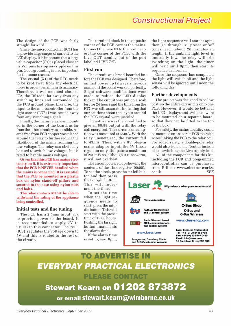
Constructional ProjectConstructional Project Constructional Project
Everyday Practical Electronics, September 2009 43
The design of the PCB was fairly straight forward.
Since the microcontroller (IC1) has to provide large surges of current to the LED display, it is important that a large value capacitor (C1) is placed close to its Vcc pins to stop any ripple on this pin. Good grounding is also important for the same reason.
The crystal (X1) of the RTC needs to be kept away from any electrical noise in order to maintain its accuracy. Therefore, it was mounted close to IC2, the DS1337, far away from any switching lines and surrounded by the PCB ground plane. Likewise, the input to the microcontroller from the light sensor (LDR1) was routed away from any switching signals.
Finally, the mains relay was mount-ed in the corner of the board, as far from the other circuitry as possible. An area free from PCB copper was placed around the relay to further reduce the likelihood of the mains reaching the low voltage. The relay can obviously be used to switch low voltages, but is rated to handle mains voltages.
Given that this PCB has mains elec-tricity on it, it is extremely important that the PCB is NEVER handled when the mains is connected. It is essential that the PCB be mounted in a plastic box on nylon stand-off pillars and secured to the case using nylon nuts and bolts.
The relay contacts MUST be able to withstand the rating of the appliance being controlled.
Initial tests and fine tuningThe PCB has a 2.5mm input jack
to provide power to the board. It is recommended to apply 7V to 9V DC to this connector. The 7805 (IC3) regulates the voltage down to 5V and this is routed to the rest of the circuit.
The terminal block in the opposite corner of the PCB carries the mains. Connect the Live IN to the port near-est the corner of the PCB, with the Live OUT coming out of the port labelled LIVE O/P.
First runThe circuit was bread-boarded be-
fore the PCB was designed. Therefore, on first power up (always a nervous occasion) the board worked perfectly. Slight software modifications were made to reduce the LED display flicker. The circuit was put on a soak test for 24 hours and the time from the RTC was still accurate, indicating that our cautions about the layout around the RTC crystal were justified.
The software was then modified to give an 88:88 output with the relay coil energised. The current consump-tion was measured at 65mA. With the relay unenergised, the current fell to 43mA. Thus, with a 9V plug-in mains adaptor input, the 5V linear regulator only dissipates a maximum of 250mW so, although it runs warm, it will not overheat.
The circuit powered up showing the contents of the Time register (00:00). To set the clock, press the far left but-ton and then press the far right button. This will incre-ment the time.
To set the time when the light se-quence needs to start, press the mid-dle button. This will start with the preset time of 15:00 hours. Pushing the far right button increments the alarm time.
If the alarm time is set to, say, 8pm,
the light sequence will start at 8pm, then go through 31 preset on/off times, each about 20 minutes in length. If the ambient light level is unusually low, the relay will trip switching on the light, the timer will wait until 8pm, then start its sequence as normal.
Once the sequence has completed the light will switch off and the light sensor will be ignored until noon the following day.
Further developmentsThe project was designed to be low
cost, so the entire circuit fits onto one PCB. However, it would be better if the LED displays and switches were to be mounted on a separate board, so that they can be fitted to the top of the box.
For safety, the mains circuitry could be mounted on a separate PCB too, with wires linking the PCB to the relay coil. For added safety, a double-pole relay would also isolate the Neutral instead of just switching the Live supply lead.
All of the components for this kit, including the PCB and programmed microcontroller can be purchased from Bill at: www.electronworks.co.uk EPE
TO ADVERTISE IN EVERYDAY PRACTICAL ELECTRONICS
PLEASE CONTACT
Stewart Kearn on 01202 873872or email [email protected]
Random Mains Timer.indd 43 30/07/2009 11:57:58
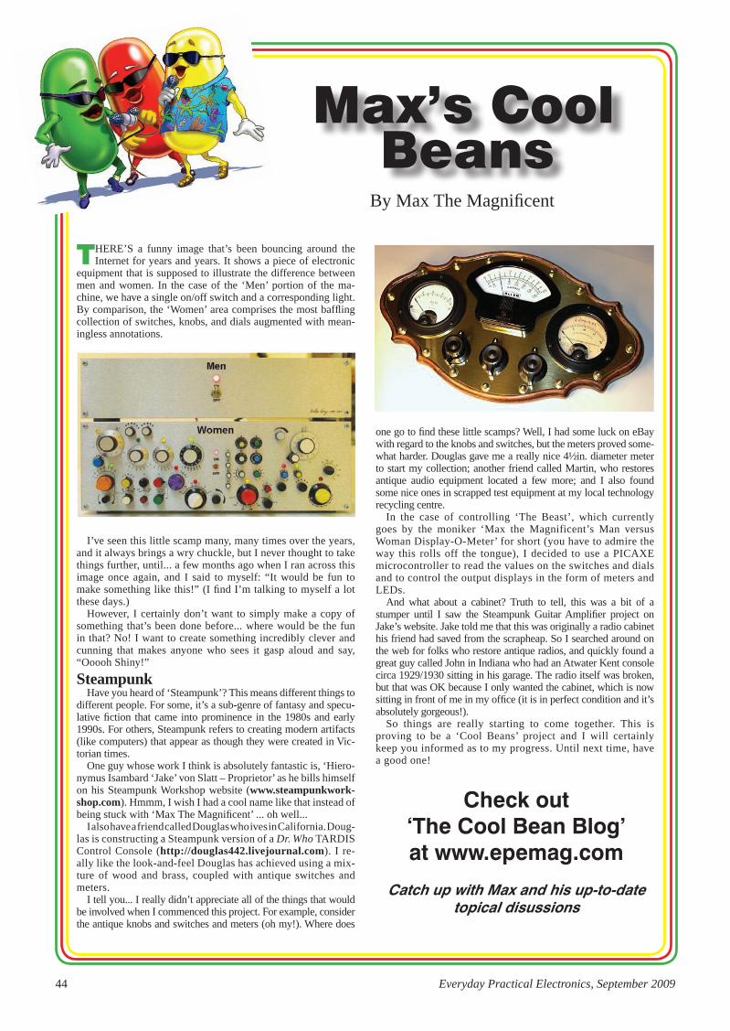
44 Everyday Practical Electronics, September 2009
There’s a funny image that’s been bouncing around the Internet for years and years. It shows a piece of electronic
equipment that is supposed to illustrate the difference between men and women. In the case of the ‘Men’ portion of the ma-chine, we have a single on/off switch and a corresponding light. By comparison, the ‘Women’ area comprises the most baffling collection of switches, knobs, and dials augmented with mean-ingless annotations.
I’ve seen this little scamp many, many times over the years, and it always brings a wry chuckle, but I never thought to take things further, until... a few months ago when I ran across this image once again, and I said to myself: “It would be fun to make something like this!” (I find I’m talking to myself a lot these days.)
however, I certainly don’t want to simply make a copy of something that’s been done before... where would be the fun in that? No! I want to create something incredibly clever and cunning that makes anyone who sees it gasp aloud and say, “Ooooh shiny!”
Steampunkhave you heard of ‘steampunk’? This means different things to
different people. For some, it’s a sub-genre of fantasy and specu-lative fiction that came into prominence in the 1980s and early 1990s. For others, steampunk refers to creating modern artifacts (like computers) that appear as though they were created in Vic-torian times.
One guy whose work I think is absolutely fantastic is, ‘hiero-nymus Isambard ‘Jake’ von slatt – Proprietor’ as he bills himself on his steampunk Workshop website (www.steampunkwork-shop.com). hmmm, I wish I had a cool name like that instead of being stuck with ‘Max The Magnificent’ ... oh well...
I also have a friend called Douglas who ives in California. Doug-las is constructing a steampunk version of a Dr. Who TArDIs Control Console (http://douglas442.livejournal.com). I re-ally like the look-and-feel Douglas has achieved using a mix-ture of wood and brass, coupled with antique switches and meters.
I tell you... I really didn’t appreciate all of the things that would be involved when I commenced this project. For example, consider the antique knobs and switches and meters (oh my!). Where does
one go to find these little scamps? Well, I had some luck on eBay with regard to the knobs and switches, but the meters proved some-what harder. Douglas gave me a really nice 4½in. diameter meter to start my collection; another friend called Martin, who restores antique audio equipment located a few more; and I also found some nice ones in scrapped test equipment at my local technology recycling centre.
In the case of controlling ‘The Beast’, which currently goes by the moniker ‘Max the Magnificent’s Man versus Woman Display-O-Meter’ for short (you have to admire the way this rolls off the tongue), I decided to use a PICAXe microcontroller to read the values on the switches and dials and to control the output displays in the form of meters and LeDs.
And what about a cabinet? Truth to tell, this was a bit of a stumper until I saw the steampunk Guitar Amplifier project on Jake’s website. Jake told me that this was originally a radio cabinet his friend had saved from the scrapheap. so I searched around on the web for folks who restore antique radios, and quickly found a great guy called John in Indiana who had an Atwater Kent console circa 1929/1930 sitting in his garage. The radio itself was broken, but that was OK because I only wanted the cabinet, which is now sitting in front of me in my office (it is in perfect condition and it’s absolutely gorgeous!).
so things are really starting to come together. This is proving to be a ‘Cool Beans’ project and I will certainly keep you informed as to my progress. Until next time, have a good one!
Max’s Cool Beans
By Max The Magnificent
Check out ‘The Cool Bean Blog’at www.epemag.com
Catch up with Max and his up-to-date topical disussions
P44.indd 44 29/07/2009 14:24:09

The Most Popular 8-bit Microcontrollers!The Best Customer Support.
Serial EEPRO
Ms
AnalogD
igital Signal Controllers
Microcontrollers
The Microchip name and logo, the Microchip logo, MPLAB and PIC are registered trademarks of Microchip Technology Incorporated in the U.S.A. and other countries. All other trademarks mentioned herein are property of their respective companies. © 2009, Microchip Technology Incorporated. All Rights Reserved. ME223Eng/02.09
Now&Tomorrow...
Now&Tomorrow...
Now&Tomorrow...
Now&Tomorrow...
Now&Tomorrow...
Now&Tomorrow...
Now&Tomorrow...
Now&Tomorrow...
Now&Tomorrow...YOU
The world’s most popular 8-bit microcontroller family has the best customer support and the industry’s shortest leadtime – 3-4 weeks!
With over 400 different variants, there is an 8-bit PIC® microcontroller for every design. Microchip’s 8-bit family now includes microcontrollers with the smallest form-factor, industry-first peripherals and up to 16 MIPS performance.
Pin- and code-compatibility ensure easy migration across the 8-bit family and up to 16-bit designs and Microchip’s MPLAB® IDE is absolutely free, and supports ALL of Microchip’s 8-, 16-, and 32-bit microcontrollers – from 6 to 100 pins!
With over 7 Billion PIC microcontrollers shipped worldwide and increased investment in product development and customer support, you can count on Microchip to be here for you - especially through the tough times.
Comprehensive support starts with the Microchip Advanced Part Selector (MAPS)and extends throughout the design cycle with free or low-cost development tools, online and regional training and 24/7 technical support.
• Smallest form-factor, lowest cost - PIC10 and PIC12 MCUs• Advanced peripherals - PIC16 MCUs• Highest-performance - PIC18 MCUs
www.microchip.com/8bit
24/7 Support•Only Microchip offers full support 24/7
•Increased Field Application Engineer support team
•Increased Customer Application Engineer support team
•IncreasedCustomer Training Support through Regional Training Centers (RTCs)
For the best product support and availability - think Microchip!

Everyday Practical Electronics, September 2009 47
With the incredibly low price of new cordless drills, it’s really
not worthwhile repairing a defective one – especially when they’re usually discarded because the battery pack is defunct. For the price of a new bat-tery pack (or even less), you can buy a complete new drill.
What about in your own garage? Likely as not, you’ve got one or more broken cordless drills tucked away at
Salvaging the good bits from cordless drills – and putting them to workCordless drills are now probably the most frequently discarded power tools. Whether it’s at the local tip, at garage sales or even in kerbside rubbish skips, there are always plenty of defective battery-powered (cordless) drills available.
the back of the workbench. if not, there are lots of cordless drills that can be picked up for nothing. And there are several useful items that can be made from the components inside them!
it just takes a little salvage work to retrieve those bits.
InternalsCordless drill chucks usually have
a maximum rotational speed of 1000
rpm or less. however, the motor speed is much higher than this. to reduce the speed of the DC electric motor (and to increase the torque), a planetary gear-box is used. in fact, there are usually two planetary gear sets back-to-back – rather like the gear systems used in automotive automatic transmissions. And like auto transmissions, some cordless drills let you select between ratios – more on this in a moment.
For their size, planetary gears are very strong and, especially when two sets are used, allow high reduction ratios to be achieved in small volumes. Considering their size and torque capacity, these are really nice little gearboxes.
the torque multiplication might be achieved by the gearbox, but if you want to quickly drill holes or drive screws, you need real motor power. this is provided by a high-current, brushed DC motor. typically, the ‘motor-stalled’ DC current is around 10A at 12V, and considering that the motors are about the size of a ‘D’ cell, that makes for quite a powerful (and useful) motor – especially since it hasn’t cost anything!
Up to speedMany cordless drills have an elec -
tronic variable speed function, achiev-ed by pulse-width modulating the power fed to the motor via a switch-ing transistor. this transistor is usu-ally mounted on a separate interior heatsink, and the rest of the control electronics are integrated into a hous-ing with the trigger switch.
A reversing switch is also often mounted directly above the speed con-trol. So even if you salvage just these parts, you have a handy high-current electric motor speed control (or, for example, a 12V DC light dimmer).
➊➋➌➍
➎
➏
Nearly all cordless drills look like this inside: (1) chuck, (2) clutch, (3) planetary gearbox, (4) DC motor, (5) speed control, (6) speed control switching transistor and heatsink. Note that in this drill, there is a misalignment between the motor and gearbox, caused by some loose screws. Tightening them subsequently fixed it!
Recycle It!BY JULIAN EDGAR
Reproduced by arrangement with SiLiCON ChiP
magazine 2009.www.siliconchip.com.au
Recycle ItRecycle It
Recycle It (from Matt).indd 47 29/07/2009 16:16:14

48 Everyday Practical Electronics, September 2009
Finally, most of these drills have an adjustable slipping clutch that allows the peak torque to be set before drive ceases.
Using the partsThere are plenty of uses for these
bits and pieces. One of the easiest is to simply pull the body of the drill apart (because they are low voltage devices, tamper-proof screws aren’t fitted, making it really easy) and cut the supply wires at the motor. Bend a piece of steel rod into a crank-shaped handle and lock one end in the chuck. Turn the handle and – hey presto! – you have a pretty ‘grunty’ small DC electric generator.
How grunty? Well, on one unit I measured, it was quite easy to run a half-amp load at 5V – that’s 2.5W! And 2.5W is plenty to run a torch bulb
or two high-efficiency Luxeon LEDs. It’s also quite enough to charge two 1.2V rechargeable cells or a mobile phone battery.
If you pick a drill that has two user-selectable gear ratios, it works even better. In one ratio, turning the handle is easy, but the amount of power gener-ated is lower (that’s the ‘topping up’ setting, if you like). Alternatively, you can slide over the gear selection lever and have around twice the power out-put at the same rotational speed – but it’s much harder to turn the handle.
To protect it and allow it to be easily held, the generator/gearbox/clutch/chuck assembly is best squeezed inside a length of PVC pipe (again picked up for nothing, this time from the rubbish pile of a building site). If it needs to be semi-weatherproof, just add PVC end caps with appropriate holes drilled for the crank handle and power wire exits.
Mechanical driveThe motor/gearbox/clutch/chuck
assembly can also be used wherever
Cordless drills use planetary gearboxes to reduce the chuck speed and increase torque. Usually two back-to-back geartrains are used – this view shows the motor input side. These gearboxes are compact, have a high reduction ratio and are strong for their size.
One of the easiest uses of the innards of a discarded cordless electric drill is as a hand-cranked DC generator. In this application, the gearbox steps-up the rotational speed of the chuck, allowing up to 0.5A at 5V to be generated with ease – quite good for such a small generator!
A discarded cordless drill can provide a compact and powerful drive assembly for nothing! The motor/gearbox/clutch/chuck combination can be used to drive robots, power small winches – or even be a portable drill for use on car power.
Fig.1: these scope shots show a typical speed control output for low PWM (left) and high PWM (right) duty cycle settings.
Recycle ItRecycle It
Recycle It (from Matt).indd 48 29/07/2009 16:17:41

Everyday Practical Electronics, September 2009 49
Whenever you throw away an old TV (or VCR or washing machine or dishwasher or printer) do you always think that surely there must be some good salvageable components inside? Well, this column is for you! (And it’s also for people without a lot of dough.) Each month we’ll use bits and pieces sourced from discards, sometimes in mini-projects and other times as an ideas smorgasbord.
And you can contribute as well. If you have a use for specific parts which can
easily be salvaged from goods commonly being thrown away, we’d love to hear from you. Perhaps you use the pressure switch from a washing machine to control a pump. Or maybe you have a use for the high- quality bearings from VCR heads. Or perhaps you’ve found how the guts of a cassette player can be easily turned into a metal detector. (Well, we made the last one up but you get the idea . . .)
If you have some practical ideas, write in and tell us!
Rat It Before You Chuck It!
a high-torque output, low-voltage mech anical drive is needed. For example, two of these assemblies can easily be combined to form the individual wheel traction motors for a small robot (or you can use four for the ultimate in manoeuvrability!). Another possibility is to use one of these assemblies to drive a small winch – eg, to hoist a model railway baseboard up near the ceiling when it isn’t being used.
In these applications, the inbuilt slipping clutch is a real asset, as it stops the motor from being overloaded when the output is stalled.
Since nearly all these motors will happily work for short periods on 12V (even when the nominal battery
voltage of the drill might be only 9.6V), the salvaged cordless drill is easily equipped with a long cable with some battery clips to allow it to be powered by a car battery.
Variable speed controllerThe variable speed controller is a
mixed blessing. While it is capable of handling high currents (very high for short periods), the physical layout of the module lends itself only to those applications where a squeeze or push trigger is needed. Unless you have lots of spare units to play with, don’t pull the module apart in an attempt to substitute a rotary potentiometer for the slide type – once it’s apart, it can be very hard to put back together.
Fig.2: here’s how to adapt the control unit to allow low-voltage light dimming or speed control of DC motors. The threaded bolt goes through a captive nut and is turned to smoothly deflect the speed control trigger. Above right is a typical pulse-width modulated (PWM) control unit, complete with its heatsink-mounted switching transistor.
A better approach is to build a mechanical system that can vary and maintain the trigger movement needed in the application. For example, by using a coarse-threaded bolt and a fixed nut, the original trigger can be progressively moved by rotating the bolt – see Fig.2. The unit can then be used wherever low-voltage DC mo-tor speed control (eg, for a miniature 12V lathe) or filament light dimming is required.
Finally, the electric motor itself is ideal for driving a fan. Small fan blade assemblies can be salvaged for nothing from microwave ovens.
Be careful with microwave ovens though – they can pack a lethal punch, even with the power switched off. Make absolutely certain that all high-voltage capacitors inside the oven have been discharged before attempting to salvage any parts. Don’t think of even opening up a microwave oven if you don’t know what you are doing.
ConclusionWhen you see a cordless drill, sal-
vage it and strip it back to the internals. The resulting bits take up very little storage room and can be used to make a hand-cranked generator or as a pow-erful low-voltage motor/gearbox unit with variable speed control. EPE
Recycle It
Recycle It (from Matt).indd 49 29/07/2009 16:20:00

50 Everyday Practical Electronics, September 2009
PIC-Based Ultrasonic Tape MeasureYou’ve got it taped if you PIC this ultrasonic distance measuring calculatorEPE Mind PICklerWant seven ways to relax? Try our PIC-controlled mind machine!PIC MIDI Sustain PedalAdd sustain and glissando to your MIDI line-up with this inexpensive PIC-controlled effects unitPIC-based MIDI HandbellsRing out thy bells with merry tolling – plus a MIDI PIC-up, of course!EPE Mood PICkerOh for a good night’s sleep! Insomniacs rejoice – your wakeful nights could soon be over with this mini-micro under the pillow!PIC Micro-ProbeA hardware tool to help debug your PIC softwarePIC Video CleanerImproving video viewing on poorly maintained TVs and VCRsPIC Graphics LCD ScopeA PIC and graphics LCD signal monitor for your workshopPIC to Printer InterfaceHow to use dot-matrix printers as data loggers with PIC microcontrollersPIC PolywhatsitA novel compendium of musical effects to delight the creative musicianPIC Magick MusickConjure music from thin air at the mere untouching gesture of a fingertipPIC Mini-EnigmaShare encrypted messages with your friends — true spymaster entertainmentPIC Virus ZapperCan disease be cured electronically? Investigate this controversial subject for yourselfPIC Controlled Intruder AlarmA sophisticated multi-zone intruder detection system that offers a variety of monitoring facilitiesPIC Big-Digit DisplayControl the giant ex-British Rail platform clock 7-segment digits that are now available on the surplus marketPIC Freezer AlarmHow to prevent your food from defrosting unexpectedlyPIC World ClockGraphically displays world map, calendar, clock and global time-zone dataPICAXE ProjectsA 3-part series using PICAXE devices – PIC microcontrollers that do not need specialist knowledge or programming equipmentPIC-based Tuning Fork and MetronomeThrill everyone by at long last getting your instrument properly tuned!Versatile PIC FlasherAn attractive display to enhance your Christmas decorations or your child’s ceiling
EPE PIC PROJECTS VOLUME 1
MINI CD-ROMA plethora of 20 ‘hand-PICked’ PIC Projects from selected past issues of EPETogether with the PIC programming software for each project plus bonus articlesThe projects are:
EPE PIC PROJECTS CD-ROM ORDER FORM
Please send me ........ (quantity)
EPE PIC PROJECTS VOL 1 CD-ROM
Price £14.45 each – includes postage to anywhere in the world.
Name .............................................................................
Address .........................................................................
........................................................................................
........................................................................................
.................................... Post Code .................................
I enclose cheque/P.O./bank draft to the value of £ ..........
please charge my Visa/Mastercard/Maestro £ ................
Card No. ........................................................................
Card Security Code .......... (The last 3 digits on or just under the signature strip)
Valid From ........................ Expiry Date .........................
Maestro Issue No. .................
SEND TO: Everyday Practical Electronics,
Wimborne Publishing Ltd.,Sequoia House, 398a Ringwood Road, Ferndown,
Dorset BH22 9AU.Tel: 01202 873872. Fax: 01202 874562.Email: [email protected]
Payments must be by card or in £ Sterling – cheque or bank draft drawn on a UK bank.
Normally posted within seven days of receipt of order. Send a copy of this form, or order by letter if you do
not wish to cut your issue.
Order on-line fromwww.epemag.com
or by Phone, Fax, Email or Post.
NOTE: The PDF files on this CD-ROM are suitable to use on any PC with a CD-ROM drive. They require Adobe Acrobat Reader
– included on the CD-ROM
BECOME A PIC PROJECT BUILDER WITH THE HELP OF EPE!
ONLY£14.45INCLUDING
VAT and P&P
PIC Projects.indd 50 27/07/2009 11:05:07

Everyday Practical Electronics, September 2009 51
EPE PIC Tutorial V2 complete series of articles plus demonstration software, John Becker, April, May, June ’03
PIC Toolkit Mk3 (TK3 hardware construction details), John Becker, Oct ’01
PIC Toolkit TK3 for Windows (software details), John Becker, Nov ’01
Plus these useful texts to help you get the most out of your PIC programming:
How to Use Intelligent LCDs, Julyan Ilett, Feb/Mar ’97
PIC16F87x Microcontrollers (Review), John Becker, April ’99
PIC16F87x Mini Tutorial, John Becker, Oct ’99
Using PICs and Keypads, John Becker, Jan ’01
How to Use Graphics LCDs with PICs, John Becker, Feb ’01
PIC16F87x Extended Memory (how to use it), John Becker, June ’01
PIC to Printer Interfacing (dot-matrix), John Becker, July ’01
PIC Magick Musick (use of 40kHz transducers), John Becker, Jan ’02
Programming PIC Interrupts, Malcolm Wiles, Mar/Apr ’02
Using the PIC’s PCLATH Command, John Waller, July ’02
EPE StyloPIC (precision tuning musical notes), John Becker, July ’02
Using Square Roots with PICs, Peter Hemsley, Aug ’02
Using TK3 with Windows XP and 2000, Mark Jones, Oct ’02
PIC Macros and Computed GOTOs, Malcolm Wiles, Jan ’03
Asynchronous Serial Communications (RS-232), John Waller, unpublished
Using I2C Facilities in the PIC16F877, John Waller, unpublished
Using Serial EEPROMs, Gary Moulton, unpublished
Additional text for EPE PIC Tutorial V2, John Becker, unpublished
EPE PIC RESOURCES CD-ROM V2
Version 2 includes the EPE PICTutorial V2 series of Supplements(EPE April, May, June 2003)The CD-ROM contains the followingTutorial-related software and texts:
EPE PIC RESOURCES V2 CD-ROM ORDER FORM
Please send me ........ (quantity)
EPE PIC RESOURCES V2 CD-ROM
Price £14.45 each – includes postage to anywhere in the world.
Name .............................................................................
Address .........................................................................
........................................................................................
........................................................................................
.................................... Post Code .................................
I enclose cheque/P.O./bank draft to the value of £ ..........
please charge my Visa/Mastercard/Maestro £ ................
Card No. ........................................................................
Card Security Code .......... (The last 3 digits on or just under the signature strip)
Valid From ........................ Expiry Date .........................
Maestro Issue No. .................
SEND TO: Everyday Practical Electronics,
Wimborne Publishing Ltd.,Sequoia House, 398a Ringwood Road, Ferndown,
Dorset BH22 9AU.Tel: 01202 873872. Fax: 01202 874562.Email: [email protected]
Payments must be by card or in £ Sterling – cheque or bank draft drawn on a UK bank.
Normally posted within seven days of receipt of order. Send a copy of this form, or order by letter if you do
not wish to cut your issue.
Order on-line fromwww.epemag.com
or by Phone, Fax, Email or Post.
NOTE: The PDF files on this CD-ROM are suitable to use on any PC with a CD-ROM drive. They require Adobe
Acrobat Reader – included on the CD-ROM
BECOME A PIC WIZARD WITH THE HELP OF EPE!
ONLY£14.45INCLUDING
VAT and P&P
PIC Resources.indd 51 27/07/2009 11:05:37
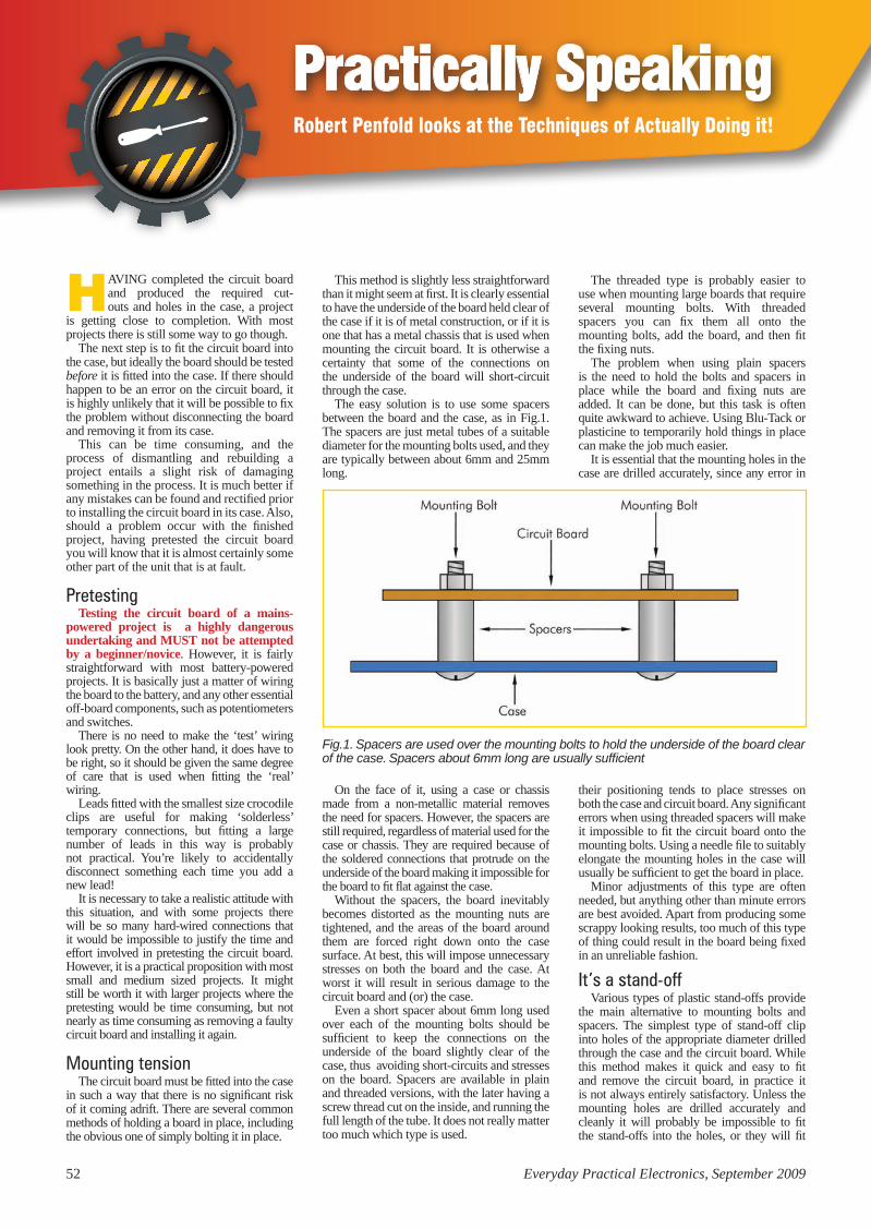
52 Everyday Practical Electronics, September 2009
Practically SpeakingRobert Penfold looks at the Techniques of Actually Doing it!
Having completed the circuit board and produced the required cut-outs and holes in the case, a project
is getting close to completion. With most projects there is still some way to go though.
The next step is to fit the circuit board into the case, but ideally the board should be tested before it is fitted into the case. if there should happen to be an error on the circuit board, it is highly unlikely that it will be possible to fix the problem without disconnecting the board and removing it from its case.
This can be time consuming, and the process of dismantling and rebuilding a project entails a slight risk of damaging something in the process. it is much better if any mistakes can be found and rectified prior to installing the circuit board in its case. also, should a problem occur with the finished project, having pretested the circuit board you will know that it is almost certainly some other part of the unit that is at fault.
PretestingTesting the circuit board of a mains-
powered project is a highly dangerous undertaking and MUST not be attempted by a beginner/novice. However, it is fairly straightforward with most battery-powered projects. it is basically just a matter of wiring the board to the battery, and any other essential off-board components, such as potentiometers and switches.
There is no need to make the ‘test’ wiring look pretty. On the other hand, it does have to be right, so it should be given the same degree of care that is used when fitting the ‘real’ wiring.
Leads fitted with the smallest size crocodile clips are useful for making ‘solderless’ temporary connections, but fitting a large number of leads in this way is probably not practical. You’re likely to accidentally disconnect something each time you add a new lead!
it is necessary to take a realistic attitude with this situation, and with some projects there will be so many hard-wired connections that it would be impossible to justify the time and effort involved in pretesting the circuit board. However, it is a practical proposition with most small and medium sized projects. it might still be worth it with larger projects where the pretesting would be time consuming, but not nearly as time consuming as removing a faulty circuit board and installing it again.
Mounting tensionThe circuit board must be fitted into the case
in such a way that there is no significant risk of it coming adrift. There are several common methods of holding a board in place, including the obvious one of simply bolting it in place.
This method is slightly less straightforward than it might seem at first. it is clearly essential to have the underside of the board held clear of the case if it is of metal construction, or if it is one that has a metal chassis that is used when mounting the circuit board. it is otherwise a certainty that some of the connections on the underside of the board will short-circuit through the case.
The easy solution is to use some spacers between the board and the case, as in Fig.1. The spacers are just metal tubes of a suitable diameter for the mounting bolts used, and they are typically between about 6mm and 25mm long.
The threaded type is probably easier to use when mounting large boards that require several mounting bolts. With threaded spacers you can fix them all onto the mounting bolts, add the board, and then fit the fixing nuts.
The problem when using plain spacers is the need to hold the bolts and spacers in place while the board and fixing nuts are added. it can be done, but this task is often quite awkward to achieve. Using Blu-Tack or plasticine to temporarily hold things in place can make the job much easier.
it is essential that the mounting holes in the case are drilled accurately, since any error in
Fig.1. Spacers are used over the mounting bolts to hold the underside of the board clear of the case. Spacers about 6mm long are usually sufficient
On the face of it, using a case or chassis made from a non-metallic material removes the need for spacers. However, the spacers are still required, regardless of material used for the case or chassis. They are required because of the soldered connections that protrude on the underside of the board making it impossible for the board to fit flat against the case.
Without the spacers, the board inevitably becomes distorted as the mounting nuts are tightened, and the areas of the board around them are forced right down onto the case surface. at best, this will impose unnecessary stresses on both the board and the case. at worst it will result in serious damage to the circuit board and (or) the case.
Even a short spacer about 6mm long used over each of the mounting bolts should be sufficient to keep the connections on the underside of the board slightly clear of the case, thus avoiding short-circuits and stresses on the board. Spacers are available in plain and threaded versions, with the later having a screw thread cut on the inside, and running the full length of the tube. it does not really matter too much which type is used.
their positioning tends to place stresses on both the case and circuit board. any significant errors when using threaded spacers will make it impossible to fit the circuit board onto the mounting bolts. Using a needle file to suitably elongate the mounting holes in the case will usually be sufficient to get the board in place.
Minor adjustments of this type are often needed, but anything other than minute errors are best avoided. apart from producing some scrappy looking results, too much of this type of thing could result in the board being fixed in an unreliable fashion.
It’s a stand-offvarious types of plastic stand-offs provide
the main alternative to mounting bolts and spacers. The simplest type of stand-off clip into holes of the appropriate diameter drilled through the case and the circuit board. While this method makes it quick and easy to fit and remove the circuit board, in practice it is not always entirely satisfactory. Unless the mounting holes are drilled accurately and cleanly it will probably be impossible to fit the stand-offs into the holes, or they will fit
Practically Speaking.indd 52 27/07/2009 11:02:36

Everyday Practical Electronics, September 2009 53
into the holes but will not lock into place reliably.
With some stand-offs, it does not seem to matter how accurately the mounting holes are drilled. They never provide a reliable means of mounting the circuit board. Some of these stand-offs are probably designed to be used in conjunction with mounting bolts rather than as the only means of mounting the board. The motherboards in PCs are often mounted on the case using a mixture of bolts and some extremely basic stand-offs, as are many very large boards.
Stand-offs that snap in and out of position are hardly ever satisfactory when used with stripboard. The likely cause of this problem is that the matrix of pre-drilled holes in the board makes it impossible to produce really neat mounting holes. Drilling out one of the existing holes tends to make it merge with four of the other pre-drilled holes. This produces a rather odd shaped mounting hole that prevents the stand-off from snapping into place properly.
This type of stand-off is only suitable for use where the circuit board will be mounted on a chassis within the case, rather than directly on the outer casing. Obviously, it is physically possible to use this type of stand-off with most cases, but the clips would protrude a few millimetres from the surface of the case, which would not provide a neat finish. Also,
Off the railsThere is a similar problem with the guide rails
(Fig.3) that are moulded into a fair proportion of plastic project cases. As in this example, there are usually two sets of rails so that circuit boards can be fitted horizontally or vertically. This is a very simple but effective method, where the board just slides into place, and there are no unsightly mounting bolts showing on the exterior of the case. Provided it is just the right size, the circuit board is normally held in place very securely when the case lid is fitted.
Like built-in mounting pillars though, guide rails are only usable with boards that are specifically designed for that particular case. It might be possible to produce an oversize board that accurately fits the guide-rails if you make your own printed circuit boards or use stripboard. Simply cut a board of the correct size and leave blank areas at each end where it will fit into the guide-rails.
Unfortunately, in most cases, any built-in guide rails will be unusable. Some guide rails border on being unusable simply because they are minute and the circuit board can easily come ‘off the rails’. It is probably best not to use this method unless the rails are fairly substantial.
A further problem with guide rails is that with most cases it is only possible to use quite small circuit boards. Larger boards could be accommodated if it was possible to mount the boards parallel to the front and rear panels instead of perpendicular to them.
With some cases this can be achieved with the aid of plastic clips that are fitted to the board. The clip and board assembly is then slotted into the guide rails. An indirect method such as this inevitably provides a less secure method of mounting compared to simply fitting the board straight into the guide rails, but it usually works well enough.
Fig.2. Some stand-offs use mounting bolts at both ends (left), and are much the same as threaded spacers. A variation on this (right) is to have the stand-off bolted to the case with the circuit board just clipped into place
there would probably be a tendency for the clips to get knocked out of position, leaving the circuit board detached from the case.
Mounting bolts are a much better choice with stripboard, although the type of stand-off shown on the left in Fig.2 is a good choice for stripboard. These usually take the form of a plastic outer section with a metal insert that has the screw threads. They differ from threaded spacers in that there are only a few millimetres of screw thread at each end, rather than having the thread running the whole length of the spacer. A threaded spacer could be used, but this type of stand-off cannot be used as a threaded spacer. Due to the limited length of the screw thread, it is essential to use very short (about 5mm or 6mm) mounting bolts with this type of stand-off.
There is another type of stand-off that is a cross between screw fixing and snap-on varieties. One end is fixed to the case using a short bolt, but the circuit board clips in place at the other end. This type of stand-off is shown on the right in Fig.2. This is probably the most popular type, and it works well provided the board will clip into position securely.
There is a further variation that has the stand-off secured to the case by a self-adhesive pad. Getting this type positioned accurately on the case or chassis can be tricky, but there is an easy way. Fit all the stand-offs onto the circuit board, and then press this assembly down into place in the case, making sure that it is in a suitable position before finally pressing it into place. The soft plastics used for some project cases defy most types of glue, but with this type of stand-off it is usually very difficult to remove it once it has been fixed to the case.
Some cases have built-in mounting pillars, but these are rarely of any practical value. The obvious problem with this type is that the circuit board has to be designed to suit the positioning of the mounting pillars. In the present context, this is unlikely to be the case, and any built-in mounting pillars are more likely to be a hindrance than a help. In fact, they can get in the way to such an extent that it becomes necessary to drill them down. Use a drill bit that is slightly larger in diameter than the mounting pillar.
Fig.3. Plastic cases often have guide-rails moulded into the interior, permitting boards to be fitted horizontally or vertically
Practically Speaking.indd 53 27/07/2009 11:02:54

54 Everyday Practical Electronics, September 2009
Filters circuits Part 3
This month we conclude our three-part article on active filters prompted by a
question posted by Paul Goodson on the EPE Chat Zone (chatzones.co.uk). Paul was interested in bandpass filters for audio signals, but was struggling with the apparently dissimilar information on filters he had read from different sources.
in the first article we provided an overview of filter basics and terminology. Then, last month, we discussed some of the different types of filter response and showed that basic filter design seems at least to be reasonably straightforward with the help of suitable software. in fact, it is not quite as simple as just typing a few values into a program, as the quality of the components used can have a big impact on filter performance.
This month, we will take a look at some practical aspects of filter circuit design, in particular how to choose components for filters, including capacitors, resistors and op amps. But first, we will take a look at band- pass filters, starting with a few extra basics and definitions.
Bandpass filtersThe generalised frequency response of
a bandpass filter is shown in Fig.1. The bandwidth is BW = f
h – f
L. For example,
if fL
= 2khz and fh = 4khz then BW =
2khz. The centre frequency, fC , is given
by:
Large values of Q (small fractional bandwidths) imply very narrow passbands and place higher demands on the circuit’s components (op amp performance and component tolerance).
if the fraction bandwidth is large, say over 100%, then the bandpass filter can be made from a simple series combination of a low pass filter with a cutoff of f
h and a high pass
filter with a cutoff of fh. For smaller fractional
bandwidths, a specific bandpass filter circuit must be used.
Multiple feedbackThe multiple feedback (MFB), or Rauch,
filter circuit uses a single op amp and is a
Circuit SurgeryRegular Clinic by Ian Bell
Note that because we are using a log scale, the centre is the geometric mean of f
L and f
h, not a point arithmetically half
way between fL
and fh . For example, if f
L
= 2khz and fh = 4khz then f
C is 2.828khz,
not 3khz.
The fractional bandwidth is the bandwidth divided by the centre frequency:
Circuit Surgery Ian Bell 30/06/09
This month we conclude out three-part article on active filters prompted by a question posted by Paul Goodson on the EPE Chatzone (chatzones.co.uk). Paul was interested in band pass filters for audio signals, but was struggling with the apparently dissimilar information on filters he had read from different sources. In the first article we provided an overview of filter basics and terminology. Then last month we discussed some of the different types of filter response and showed that basic filter design seems at least to be reasonably straightforward with the help of suitable software. In fact it is not quite as simple as just typing a few values into a program as the quality of the components used can have a big impact on filter performance. This month we will take a look at some practical aspects of filter circuit design, in particular how to choose components for filters, including the capacitors, resistors and opamps. But first we will take a look at band pass filters, starting with a few extra basics and definitions.
Bandpass Filters Figure 1 shows the generalised frequency response of a bandpass filter. The
bandwidth is BW = fH - fL. For example if fL = 2 kHz and fH = 4 kHz then BW = 2 kHz. The centre frequency, fC , is given by
LHC fff
Note that because we are using a log scale the centre is the geometric mean of fL and fH, not a point arithmetically half way between fL and fH . So for example if fL = 2 kHz and fH = 4 kHz then is fC 2.828 kHz, not 3 kHz.
The fractional bandwidth is the bandwidth divided by the centre frequency
Fractional Bandwidth LH
LH
C ffff
FBW
This is often expressed as a percentage, as the percentage bandwidth. For example if FL = 2 kHz and fH = 4 kHz then the fractional bandwidth is 0.71 or 71%.
The inverse of fractional bandwidth is the Q factor of the bandpass filter:
LH
C
fffQ
Large values of Q (small fractional bandwidths) imply very narrow passbands and place higher demands on the circuit’s components (opamp performance and component tolerance).
If the fraction bandwidth is large (say over100%) then bandpass filter can be made from a simple series combination of a low pass filter with a cutoff of fH and a high pass filter with a cutoff of fH. For smaller fractional bandwidths a specific bandpass filter circuit must be used.
The Multiple Feedback (MFB), or Rauch, filter circuit uses a single opamp and is a useful and simple means of creating relative low Q bandpass circuits (Q less than 20 and ideally less than 5). An opamp with a high gain-bandwidth product is required for this circuit, particularly for higher Qs. One opamp gives you a second order stage and these can be cascaded for higher order filters.
Fractional Bandwidth
This is often expressed as a percentage, the percentage bandwidth. For example, if f
L = 2khz and f
h = 4khz then the fractional
bandwidth is 0.71 or 71%. The inverse of fractional bandwidth is the Q
factor of the bandpass filter:
Circuit Surgery Ian Bell 30/06/09
This month we conclude out three-part article on active filters prompted by a question posted by Paul Goodson on the EPE Chatzone (chatzones.co.uk). Paul was interested in band pass filters for audio signals, but was struggling with the apparently dissimilar information on filters he had read from different sources. In the first article we provided an overview of filter basics and terminology. Then last month we discussed some of the different types of filter response and showed that basic filter design seems at least to be reasonably straightforward with the help of suitable software. In fact it is not quite as simple as just typing a few values into a program as the quality of the components used can have a big impact on filter performance. This month we will take a look at some practical aspects of filter circuit design, in particular how to choose components for filters, including the capacitors, resistors and opamps. But first we will take a look at band pass filters, starting with a few extra basics and definitions.
Bandpass Filters Figure 1 shows the generalised frequency response of a bandpass filter. The
bandwidth is BW = fH - fL. For example if fL = 2 kHz and fH = 4 kHz then BW = 2 kHz. The centre frequency, fC , is given by
LHC fff
Note that because we are using a log scale the centre is the geometric mean of fL and fH, not a point arithmetically half way between fL and fH . So for example if fL = 2 kHz and fH = 4 kHz then is fC 2.828 kHz, not 3 kHz.
The fractional bandwidth is the bandwidth divided by the centre frequency
Fractional Bandwidth LH
LH
C ffff
FBW
This is often expressed as a percentage, as the percentage bandwidth. For example if FL = 2 kHz and fH = 4 kHz then the fractional bandwidth is 0.71 or 71%.
The inverse of fractional bandwidth is the Q factor of the bandpass filter:
LH
C
fffQ
Large values of Q (small fractional bandwidths) imply very narrow passbands and place higher demands on the circuit’s components (opamp performance and component tolerance).
If the fraction bandwidth is large (say over100%) then bandpass filter can be made from a simple series combination of a low pass filter with a cutoff of fH and a high pass filter with a cutoff of fH. For smaller fractional bandwidths a specific bandpass filter circuit must be used.
The Multiple Feedback (MFB), or Rauch, filter circuit uses a single opamp and is a useful and simple means of creating relative low Q bandpass circuits (Q less than 20 and ideally less than 5). An opamp with a high gain-bandwidth product is required for this circuit, particularly for higher Qs. One opamp gives you a second order stage and these can be cascaded for higher order filters.
GAIN / dB
STOP BANDSTOP BAND
FREQUENCY / Hz(LOG SCALE)
PASS BAND
PASS BAND RIPPLE
TRANSITIONREGION
TRANSITIONREGION
A MAX
A MAX –3dB
fL fC fH
Fig.1. (left) Band-pass filter frequency response
+
–
C1212nF
C113.9nF
R1326.7k
R122.87k
R1120.5k
OUT
IN
0.5VDD
Fig.2. (below). A synthesised 2kHz to 4kHz MFB bandpass filter using Microchip’s FilterLab
Fig.3. Screen shot of Microchip’s FilterLab software displaying the frequency response plot for Fig.2
Circuit Surgery Ian Bell 30/06/09
This month we conclude out three-part article on active filters prompted by a question posted by Paul Goodson on the EPE Chatzone (chatzones.co.uk). Paul was interested in band pass filters for audio signals, but was struggling with the apparently dissimilar information on filters he had read from different sources. In the first article we provided an overview of filter basics and terminology. Then last month we discussed some of the different types of filter response and showed that basic filter design seems at least to be reasonably straightforward with the help of suitable software. In fact it is not quite as simple as just typing a few values into a program as the quality of the components used can have a big impact on filter performance. This month we will take a look at some practical aspects of filter circuit design, in particular how to choose components for filters, including the capacitors, resistors and opamps. But first we will take a look at band pass filters, starting with a few extra basics and definitions.
Bandpass Filters Figure 1 shows the generalised frequency response of a bandpass filter. The
bandwidth is BW = fH - fL. For example if fL = 2 kHz and fH = 4 kHz then BW = 2 kHz. The centre frequency, fC , is given by
LHC fff
Note that because we are using a log scale the centre is the geometric mean of fL and fH, not a point arithmetically half way between fL and fH . So for example if fL = 2 kHz and fH = 4 kHz then is fC 2.828 kHz, not 3 kHz.
The fractional bandwidth is the bandwidth divided by the centre frequency
Fractional Bandwidth LH
LH
C ffff
FBW
This is often expressed as a percentage, as the percentage bandwidth. For example if FL = 2 kHz and fH = 4 kHz then the fractional bandwidth is 0.71 or 71%.
The inverse of fractional bandwidth is the Q factor of the bandpass filter:
LH
C
fffQ
Large values of Q (small fractional bandwidths) imply very narrow passbands and place higher demands on the circuit’s components (opamp performance and component tolerance).
If the fraction bandwidth is large (say over100%) then bandpass filter can be made from a simple series combination of a low pass filter with a cutoff of fH and a high pass filter with a cutoff of fH. For smaller fractional bandwidths a specific bandpass filter circuit must be used.
The Multiple Feedback (MFB), or Rauch, filter circuit uses a single opamp and is a useful and simple means of creating relative low Q bandpass circuits (Q less than 20 and ideally less than 5). An opamp with a high gain-bandwidth product is required for this circuit, particularly for higher Qs. One opamp gives you a second order stage and these can be cascaded for higher order filters.
Circuit Surgery.indd 54 27/07/2009 16:01:44

Everyday Practical Electronics, September 2009 55
useful and simple means of creating relatively low Q bandpass circuits (Q less than 20 and ideally less than 5). An op amp with a high gain-bandwidth product is required for this circuit, particularly for higher Q values. One op amp gives you a second-order stage and these can be cascaded for higher-order filters.
An example of an MFB second-order bandpass filter is shown Fig.2. This has f
L =
2kHz and fH = 4kHz. This was synthesised
using the FilterLab 2.0 software from Microchip. The software is available free from www.microchip.com/filterlab (or search for ‘filterlab’ on the Microchip home page). FilterLab can create filters up to eighth-order, using both MFB and Sallen and Key stages.
FilterLab will plot the filter’s response for you. A screenshot of FilterLab displaying the response of the circuit in Fig.2 is shown in Fig.3. Readers will recall that last month we looked at another useful filter synthesis program, Filter Free. It is worth downloading and trying out more than one filter design program as they provide different options for filter design.
The MFB filter is economic, in that a second-order bandpass stage only uses one op amp.However, it has quite severe limitations in terms of the Q factors it can achieve and is sensitive to the op amp’s gain-bandwidth product. The state variable filter (SVF) delivers higher performance and lower component sensitivity, but a second-order stage uses three or four op amps, depending on the version employed.
from Texas Instruments (originally it was a Burr Brown device) is such a device. This implements a second order SVF, similar to Fig.4, but with all three responses (high, low and bandpass) available.
Its integrators already have 0.5% accurate 1000pF (1nF) on-chip capacitors, meaning that many filters do not require additional external capacitors. The chip also contains an uncommitted op amp of the same type as the others. The UAF42 is available in 14-pin DIP and SOIC-16 surface-mount packages. The
bulletin, which are required. It also shows you how the various stages should be connected together.
In this case, we need two ‘PP1’ stages, as shown in Fig.7. The required component values are as follows (1% resistors):
Stage 1: RF1 = 41.2k R
F2 = 41.2k
RQ = 14.7k
Stage 2: RF1
= 76.8k RF2
= 76.8k R
Q = 14.7k
Fig.6. Screen shot of Filter42 software, which is used to design state variable filters (SVFs) using Texas Instruments UAF42 universal active filter chip
INPUT
+
–A1
C1
R1
R2
+
–A2
C2
R3LOW PASSOUTPUT
+
–A3
R5
R4
R6
BAND PASSOUTPUT
1
2
3
4
5
6
7
14
13
12
11
10
9
8
LOW-PASS V
V
V
AUX OP AMP, +IN
AUX OP AMP, –IN
AUX OP AMP, V
BANDPASS V
IN3
O
IN1
O
IN2
O
O
FREQ ADJ2
HIGH-PASS V
V
GROUND
V+
V–
FREQ ADJ1
UAF42
Fig.4. A Tow-Thomas biquadratic filter, which provides low-pass and high-pass outputs. It comprises integrator circuits, op amps A1 and A2, and an inverting amplifier, A3
Fig.5. Pinout connections for the UAF42 universal filter IC from Texas Instruments
Universal filtersThe SVF is called a universal filter because
it can simultaneously provide low-pass, high-pass and bandpass outputs, although not all versions provide all three. A further advantage over MFB and Sallen and Key filters is that it is possible to independently adjust gain, frequency and Q factor with SVFs, making them easily tuneable, although not all variants allow all three properties to be independently tuned. As usual, multiple SVF stages can be cascaded to achieve higher-order filters.
As we have indicated, there are a number of ways of implementing SVFs, and we do not have space to look at all the possibilities here. A popular version is the Tow-Thomas Biquadratic Filter (see Fig.4), which provides low-pass and high-pass outputs. The filter comprises two integrator circuits using op amps A1 and A2, and an inverting amplifier using A3. Input and feedback signals are summed at the input of A1
The large number of op amps required for implementing SVFs may be a disadvantage, but the problem can be overcome by using a dedicated chip. The UAF42 universal filter
pin connections of the 14-pin DIP device are shown in Fig.5.
Filter42Again, design software comes to our
aid. This time it is called Filter42, and it is specifically designed to calculate component values for the UAF42 universal filter chip.
Full details of all the various circuit configurations and software options are provided in the document ‘Filter Design Program for the UAF42 Universal Active Filter’ (currently available from TI at http://focus.ti.com/lit/an/sbfa002/sbfa002.pdf). The programme is DOS-based, but runs fine in Windows-XP. If you are using this chip you should also read the datasheet, currently available at http://focus.ti.com/lit/ds/symli nk/uaf42.pdf.
A screen shot of the programme ready to calculate the component values for a fourth-order 1dB ripple Chebyshev filter, with a 2kHz to 4kHz pass band, is shown in Fig.6. Pressing F2 displays the component values for whichever of the six or so circuit configurations, detailed in the application
The Bandpass VO output pin (pin 7) (BP
Out on Fig.7) of the first stage is connected to the V
IN3 (pin 2) input pin of the second
stage (VIN
on Fig.7). The filter attenuates the signal by one quarter in the pass band and has a maximum input voltage of 10V on a ±15V supply.
PerformanceThe performance of filter circuits is often
sensitive to component value variations and imperfections of the resistors and capacitors used; as well as certain key op amp specifications, such as the gain-bandwidth product. This sensitivity is typically worse for small fractional bandwidths (large Q factors).
Using inadequate components may, for example, cause your filter’s cut-off frequencies to be incorrect, for the level of attenuation in the stop band to be much less than expected, or for the signal to be distorted. Filters responses depend on the combination of R and C values rather than absolute values, so you can choose relatively high or low resistor or capacitor values for the same filter and this has an impact on filter performance. Filter software gives varying degrees of control over this.
Circuit Surgery.indd 55 27/07/2009 16:01:57

56 Everyday Practical Electronics, September 2009
ResistorsLarge resistors reduce loading on the op amps
outputs and allow you to use smaller (cheaper) capacitor values, but the capacitors should not be too small (see below). Large resistors will also tend to reduce the power consumed by the filter, but increase noise in the circuit.
Some filters are affected by op amp offsets, reducing the value of resistors through which op amp input bias currents flow will reduce offsets, as will using a low offset op amp and one with low bias currents. Some high speed op amps (which may be required in some filters) need relatively low resistor values to perform well.
CapacitorsThe capacitors used in active filters
should not be too small (less than 100pF), otherwise other capacitances, such as the op amp’s input capacitance (for some filters) may have to be taken into account. The op amp’s input capacitance should be a known quantity, but stray capacitances from the circuit board and wiring, which may affect any filter with small capacitors, will be hard to quantify.
High-order filters are sensitive to comp-onent values, which is a worse problem with capacitors than resistors, because high tolerance capacitors are rare and more expensive than their resistor counterparts. If your filter design software allows you to enter capacitor values (so it sets the resistors) you may be able to use measured capacitor values for a one-off circuit.
Non-ideal behaviour of capacitors may have a significant impact if you are trying to build a high performance filter, in particular losses in the capacitors result in errors in filter behaviour.
Capacitors suffer from dielectric adsorption (DA), which is the tendency of a capacitor to recharge itself after being discharged. At first this might seem to be a low frequency effect, but detailed analysis of dielectric absorption shows that it affects the behaviour of the capacitor over its entire usable frequency range. Mylar and Hi-K ceramic capacitors have high DA values and should be avoided.
A capacitor’s ‘equivalent series resistance (ESR)’ is the effective resistance in series with the capacitor; the higher the ESR the more losses in the capacitor. Capacitors also have inductance, again resulting in non- ideal behaviour. The effect of both ESR and inductance is included in the dispersion factor (DF) often quoted on capacitor datasheets. A large DF means more losses and worse filter performance. Sometimes, the inverse of DF, Q-factor is quoted. The lower a capacitor’s Q factor the higher the losses.
Ceramic capacitors, except NP0 types, and particularly those with high dielectric constants (high-k ceramics) should be avoided in filter circuits. General good choices for filters are NP0 ceramic, silver mica, metalized polycarbonate, polypropylene and polystyrene.
Op ampsOp amps have very high open loop gains
(hundreds of thousands or millions) at low frequencies, but their gain is deliberately made to fall off as frequency increases to prevent instability. Op amps are usually used with large amounts of negative feedback, resulting in low (often units or tens) closed-loop gain.
If the closed-loop gain is much smaller than the open-loop gain, the circuit’s gain depends almost entirely on the feedback components and is largely independent of the op amp’s gain. That is why you can set the gain of an op amp amplifier with two resistors without knowing the gain of the op amp.
Given that the op amp’s gain falls with frequency, it follows that as frequency is increased we will reach a point at which the op amp’s (open loop) gain falls to a value close to that of the circuit. At this point, the design equations (eg, gain = R1/R2) no longer hold and the circuit gain will start decreasing too.
The larger the closed-loop gain the lower the frequency at which this will occur. So, for a higher circuit gain, the circuit bandwidth will be smaller. In fact, for closed-loop op amp amplifiers we have:
Gain × Bandwidth = Constant
This constant is called the ‘gain bandwidth product’ (variously abbreviated GB GBW, GBP and GBWP).
If the GBP is 5MHz, the open loop gain falls to unity at 5MHz. If such an op amp is used in closed loop with a gain of 10, then the circuit will work more or less up to 500kHz (as 10 × 500kHz = 5MHz). Similarly, if a bandwidth of 100kHz is required, the circuit gain cannot be more than 50 (50 × 100kHz = 5MHz).
Gain bandwidth product is important for op amps in MFB and Sallen and Key filter stages. The formula for required GBP varies depending on how the filter is configured and specified, but for an MFB bandpass filter Microchip state GBP = K × Q × 100 × fH
, where K is the stage’s gain.
For Fig.2, this is roughly GBP = 1 × 1.4 × 100 × 4000 or 0.56MHz, which is not particularly demanding and is probably within the specification of the popular 741 op amp. However, it does not take much to make this requirement more difficult though. For example, shifting the 2kHz bandwidth up to 8kHz to 10kHz to give a Q of 4.47, we get GBP = 1 × 4.47 × 100 × 10000 or 4.47MHz, which is beyond the limit of a few common general purpose op amps, although easily covered by faster devices.
Output impedanceOp amp output impedance is also affected
by frequency, because the output impedance in closed loop is the open-loop output impedance divided by the gain. At high frequencies, as the op amp gain decreases, the effective output impedance also increases. Once this impedance becomes similar to the impedances of the components in the feedback network it will start influencing the filter’s response. The filter gain may, therefore, not continue to behave (eg, fall off continuously) at high frequencies, as would be expected from the idealised response curves.
If the filter is handling reasonably large voltages (a few volts rather than a few millivolts), then the op amps slew rate is likely to be important. Slew rate is a measure of how fast an op amp’s output can change and limits the device’s ability to accurately reproduce input waveforms, particularly for larger signals and high frequencies.
For a signal peak of VP volts and a
maximum in-band frequency of f, the op amp’s slew rate should be at least 2πfV
PV/s. For example, a 50kHz filter
with a 10V peak-to-peak (VP = 5V)
signal requires a slew rate of 1.6MV/s or 1.6V/s. Note that the popular 741 can only manage about 0.5V/s and would therefore cause distortion in this application.
+
–A1
C21nF
R250k
R450k
R350k
R
+
–A2
C11nF
HP OUT BP OUT
+
–A3
R150k
Q
RF1
VIN
RF2
LP OUT
12 13 8 7 14
11
1
2
3
UAF42
Fig.7. A UAF42 circuit required for a fourth-order Chebyshev 2kHz to 4kHz bandpass filter. Two of these stages are required (see text)
PLEASE TAKE NOTELightning Detector –
Breadboarding Projects June ’09 Page 49, Fig 9.1. The type number for op amp IC2 should be a 7611 device.
Heating Oil Storage Tank Burglar Alarm July ’09 Page 55, Fig.2. Transistor TR1 should be a type BFY51, not as shown.
Circuit Surgery.indd 56 27/07/2009 16:02:05

Everyday Practical Electronics, September 2009 57
Our regular round-up of readers’ own circuits
WIN A PICO PC-BASEDOSCILLOSCOPE WORTH £799• 200MHz Analogue Bandwidth Dual Channel Storage Oscilloscope• Spectrum Analyser• Frequency Meter• Multimeter• USB Interface.If you have a novel circuit idea which would be of use to other readers then a Pico Technology PC-based oscilloscope could be yours.After every 20 published IU circuits, Pico Technology will be awarding a PicoScope 3206 digital storage oscilloscope for the best IU submission. In addition a PicoScope 2105
Handheld ‘Scope worth £199 will be presented to the runner up.
We pay between £10 and £50 for all material published, depending on length and technical merit. We’re looking for novel applications and circuit designs, not simply mechanical, electrical or software ideas. Ideas must be the reader’s own work and must not have been published or submitted for publication elsewhere.The circuits shown have NOT been proven by us. Ingenuity Unlimited is open to ALL abilities, but items for consideration in this column should be typed or word-processed, with a brief circuit description (between 100 and 500 words maximum) and include a full circuit diagram showing all component values. Please draw all circuit schematics as clearly as possible. Send your circuit ideas to: Ingenuity Unlimited, Wimborne Publishing Ltd., Sequoia House, 398a Ringwood Road, Ferndown, Dorset BH22 9AU. Email: [email protected].
Your ideas could earn you some cash and a prize !
Readers’ Circuits
Battery Tester for SLAs – Health check
R echargeable sealed lead-acid batter-ies (SLAs) don’t last forever, and eventually have to be thrown out, but,
although you might suspect the capacity is down, it would be useful to know exactly how far down; is it 80% or only 20%? Without this information it isn’t possible to make a rational decision on whether or not to keep one.
The only meaningful way of deciding whether to keep it is to do a proper ‘drop test’ in which you apply a realistic load to the battery and watch the fall of the ter-minal voltage over a time-frame that will be anywhere from five to 10 hours. This used to be done with a chart-recorder, but nowadays you’d use your computer. Nor-mally, you would also need a data-logger to execute the analogue-to-digital conver-sion required.
Data-loggers are high-tech gadgets, but this level of sophistication is wholly inappropriate here. Remember, all we want is a rough visual guide as to the health of the SLA. In any case, few hobbyists could justify the expense. The circuit diagram in Fig.1 shows a method of achieving our aim, and one which should cost you next to nothing.
The trick is to recall that most comput-ers already has an analogue-to-digital con-verter: there is one incorporated in the au-dio chip. All we need is a computer, some audio-recorder software (plenty free on the internet) and the circuit described here.
You will need to load the battery with a high-wattage resistor that will drain the
battery in about five hours. The rest of the circuit is simply an inexpensive CMOS chip configured to oscillate at some arbitrary rate (I chose 1kHz). The output of this oscillator is virtually rail-to-rail, and so its amplitude closely reflects the battery’s terminal volt-age (we aren’t after precision here, only a trend). The resistive divider picks off a small signal which goes to the computer (I used the Line-in, which requires around 200mV).
It is interesting to compare the charts of various SLAs and to see the different failure modes. A good battery will stay above 10V until it is drained, and then quickly fall away. With an older one, only a single cell might be down. Or the entire voltage may rap-idly collapse to virtually nothing under load. This sort of detailed information will help you better decide whether to keep it or bin it.
Bruce Clothier, Oadby
Fig.1. Circuit diagram for the sealed lead-acid battery tester
IU.indd 57 27/07/2009 14:43:21

58 Everyday Practical Electronics, September 2009
ELECTRONICS MANUALS ON CD-ROM £29.95 EACH
Everything you need to know to get started in repairing electronic equipment Around 900 pages Fundamental principles Troubleshooting techniques Servicing techniques Choosing and using test equipment Reference data Manufacturers’ web links Easy-to-use Adobe Acrobat format Clear and simple layout Vital safety precautions Professionally written Supplements
SAFETY: Safety Regulations, Electrical Safety and First Aid. UNDERPINNING KNOWLEDGE: Electrical and Electronic Principles, Active and Passive Components, Circuit Diagrams, Circuit Measurements, Radio, Computers, Valves and manufacturers’ Data, etc. PRACTICAL SKILLS: Learn how to identify Electronic Components, Avoid Static Hazards, Carry Out Soldering and Wiring, Remove and Replace Components. TEST EQUIPMENT: How to Choose and Use Test Equipment, Assemble a Toolkit, Set Up a Workshop, and Get the Most from Your Multimeter and Oscilloscope, etc. SERVICING TECHNIQUES: The Manual includes vital guidelines on how to Service Audio Amplifiers. The Supplements include similar guidelines for Radio Receivers, TV Receivers, Cassette Recorders, Video Recorders, Personal Computers, etc. TECHNICAL NOTES: Commencing with the IBM PC, this section and the Supplements deal with a very wide range of specific types of equipment – radios, TVs, cassette recorders, amplifiers, video recorders etc. REFERENCE DATA: Diodes, Small-Signal Transistors, Power Transistors, Thyristors, Triacs and Field Effect Transistors. Supplements include Operational Amplifiers, Logic Circuits, optoelectronic Devices, etc.
The essential reference work for everyone studying electronics Over 800 pages In-depth theory Projects to build Detailed assembly instructions 1 Full components checklists Extensive data tables Manufacturers’ web links Easy-to-use Adobe Acrobat format Clear and simple layout Comprehensive subject range Professionally written Supplements
BASIC PRINCIPLES: Electronic Components and their Characteristics; Circuits Using Passive Components; Power Supplies; The Amateur Electronics Workshop; The Uses of Semiconductors; Digital Electronics; Operational Amplifiers; Introduction to Physics, including practical experiments; Semiconductors and Digital Instruments.CIRCUITS TO BUILD: The Base Manual describes 12 projects including a Theremin and a Simple TENS Unit.ESSENTIAL DATA: Extensive tables on diodes, transistors, thyristors and triacs, digital and linear i.c.s.EXTENSIVE GLOSSARY: Should you come across a technical word, phrase or abbreviation you’re not familiar with, simply look up the glossary and you’ll find a comprehensive definition in plain English.The Manual also covers Safety and provides web links to component and equipment Manufacturers and Suppliers.
Full contents list available online at: www.epemag.com
SUPPLEMENTS: Additional CD-ROMs each containing approximately 500 pages of additional information on specific areas of electronics are available for £19.95 each. Information on the availability and content of each Supplement CD-ROM will be sent to you.
PRESENTATION: CD-ROM suitable for any modern PC. Requires Adobe Acrobat Reader which is included on the CD-ROM.
Wimborne Publishing Ltd., Sequoia House, 398a Ringwood Road, Ferndown, Dorset BH22 9AU. Tel: 01202 873872. Fax: 01202 874562.
PLEASE send me THE MODERN ELECTRONICS MANUAL CD-ROM ELECTRONICS SERVICE MANUAL CD-ROMI enclose payment of £29.95 (for one manual) or £49.90 for both manuals (saving £10 by ordering both together).
FULL NAME ..........................................................................................................
ADDRESS .............................................................................................................
............................................................................................................................... ....................................................................... POSTCODE ..................................
SIGNATURE .................................................................. I enclose cheque/PO in UK pounds payable to Wimborne Publishing Ltd. Please charge my Visa/Mastercard/Maestro
Card No ................................................................. Maestro Issue No .................
Valid From .................. Expiry Date .................. Card Security Code ..................
ORDER FORMSimply complete and return the order form with
your payment to the following address:Wimborne Publishing Ltd,
Sequoia House, 398a Ringwood Road, Ferndown, Dorset BH22 9AU
Price includes postage to anywhere in the World
We will happily exchange any faultyCD-ROMs but since the content can be printed
out we do not offer a refund on these items.
Your CD-ROM(s) will be posted to you by first class mail or airmail,
normally within four working days of receipt of your order(The last 3 digits on or just under the signature strip)
ELECTRONICS SERVICE MANUAL MODERN ELECTRONICS MANUAL
SPECIALOFFER
SAVE £10Order both Manuals
together and
Electronics Manuals.indd 58 29/07/2009 14:19:57

Everyday Practical Electronics, September 2009 59
E L E C T R O N I C S LT D
135 Hunter Street Burton on Trent Staffs DE14 2STTel: 01283 565435 Fax: 01283 546932
www.magenta2000.co.uk [email protected]
Low distortion 11W/channelStereo/20W Mono. True (rms) RealPower. High Slew Rate/bandwidth& low noise. Ideal MP3 booster.Short Circuit & Overtemp. Protect-ed. STA7360 chip. Needs 8 to 18Vsupply. EPE Project May2005.
MICROSTEPPERStepping Motor Driver
KIT 914£11.90
All Prices Include VAT, Add £3.00 P&P per order, or £7.99 for nextday. Chqs. P.O. & most major cards accepted. Mail Order Only.
Includesall parts &heatsinkfor stereo& mono
20W Stereo Amp.
May 09 EPE. 1/2 1/4 1/8 and 1/16microstep driver for standard 4 phaseunipolar motors. Up to 46V at 3A.
KIT 920£18.76
Special Offer - Kit 920 + MD23200 Step motor £31.91
Adjustable current with efficientPWM control. Opto isolated in-puts and outputs for computer(LPT)# or logic level control.SLA7062M driver chip containsall sequencer logic - Only needsStep and Direction inputs.Kit includes PTH circuit boardChip, and all components.# Connection details and (Slowspeed) demo PC software: freedownload from website.
Learn more at www.iobridge.co.uk
WEARDALE ELECTRICSFor all your electronic & electrical needs.
Mail/Website Orders Only.www.weardale-electrics.co.uk
All prices include VAT Delivery Extra, pay by CHEQUE / P.O / or PAYPAL / Google
Choose Weardale Electrics for: Computer Systems both New & Second User,Electronic Components, Test Gear, Lamps, Connectors, Cable, Metal Detectors,
Hardware, Tools, PSU’s, Switches, Electrical Installation Parts, Hard-Drives,Monitors, Disco & Stage Lighting, Mixers, Audio & Video Leads, Telephone Ext Kits,
Diodes, Fuses, Capacitors, Enclosures, Car & Caravan Accessories, SolderingGear, Loudspeakers, Resistors, Scart Switches & Cables, Printers, Joysticks,
Relays, Transformers & much much more!
Check out these great offersWHILE STOCKS LAST!
220uF 16V Cap85C 29p for 5
20mm 6.3A QBFuse 49p for 10
20mm F/Holder49p for 10
22pin DIL SKT49p for 5
Min DPDT SlideSwitch 49p for 5
100x160 coatedF/glass £1 for 1
BZX55 5.6v ZD12p for 5
5m Tel Ext Lead99p each
M/meter c/wBuzzer £4.99
2w/2g Brass f/pDimmer £5 ea
G/brass cookerSwitch £5.99 ea
G/P phono plugBlack £1 for 10
4w 12db TVAMP £7.29 ea
470uF 25v Cap105c 20p for 2
1K H Trimpot29p for 5
Strain reliefBush 49p for 20
20m Tel Ext Kit£4.49 ea
Red Scotch lock£1 for 20
3m Usb Am-BmCable £1.99 ea
2w HDMI switch£9.99 ea
For more details of these and many other great offers visitwww.weardale-electrics.co.uk
Weardale Electrics, 10 Front Street, Frosterley, DL13 2QL Tel: 01388 [email protected]
Sorry no personal callers. VAT # GB 971 8562 82 Full T&C on website E&OE
Page 59.indd 45 27/07/2009 11:20:27

60 Everyday Practical Electronics, September 2009
One of the hardest, yet most interesting challenges that we have to deal with when designing
software is debugging. Debugging is the art – yes it’s an art not a science – of how you solve problems with the way your software and circuit operates.
Loosely speaking, there are three categories of errors in software, and each has a different debugging approach:Syntax Errors – The compiler or assembler is unable to convert your text into an actual programIncorrect Behavior – Your program operates, but it doesn’t do what you intendedErratic Behavior – Your program operates correctly, most of the time, but sometimes goes wrong at unpredictable times.
Syntax errors are easy to solve because the compiler or assembler will display a helpful message saying exactly what the problem is, and on what line number, to the extent that you sometimes wonder why the compiler didn’t fix the problem in the source code itself!
Incorrect behavior is the kind of error that we are most familiar with. Maybe the software flashes an LED at the wrong rate, or sends too many bits out to a serial memory device.
These problems are relatively easy to track down because they always occur whenever you run the program – you simply need to track down which part of the software is doing it, and fix it. OK, perhaps it’s not always that simple, but we will discuss the techniques in a minute.
The final category, erratic behavior, is the bane of all software engineers. Your software appears to work perfectly, except that once in a while it does something unexpected – a corrupted message over a serial port, freezing for an unusual amount of time, a sudden crash.
For a professional engineer these issues are a nightmare – your boss, who is used to project plans and estimates that are probably accurate to within 20% asks “when will it be fixed” and your only answer is “when it’s done”. Problems like these can take a day, or several months to solve. You just can’t say.
So how do software engineers debug problems within software?
EmulatorsIn the old days, the only option
available for debugging was to use a processor emulator, custom hardware that implemented the normal functionality of the processor, but also provided access to the address and data lines of the CPU,
which were not available on the standard IC. This hardware was very expensive, costing thousands of pounds, and was very difficult to get hold of due to limited production runs.
With an emulator and the debugger software that came with it (often on a custom computer) you could set ‘breakpoints’ – instructions to the debugger to freeze operation of the processor if a particular address was reached. Once the debugger detected an access to this address it stopped the program and allowed the user to inspect the registers of the processor. It was possible to set complicated scenarios, under which these breakpoints would occur, such as ‘break if this address is reached and the accumulator has a value of 0x12 and this is the second time you have been at this address’.
Emulators are very powerful tools, but way beyond the reach of hobbyists, and even small companies.
Crash and burnThere are other more primitive techniques
available that don’t require expensive hardware, but instead rely on the hardware of the target circuit itself. Toggling an LED, displaying text on an LCD or even transmitting information over a serial port as the program reaches a critical point in the code are all popular alternatives, and sometimes the only practical solution.
Debugging under these conditions is known as ‘crash and burn’, from the days when programs were held on EPROM memory. You would write your test code, burn it into an EPROM and then run it. When it crashes, you hopefully have learned enough about the problem to write some new test code, and the cycle repeats.
As EPROMs used to take 20 minutes to erase under a UV lamp it was normal for each developer to have a stack of EPROMs erased and ready to be programmed, and they would make frequent trips to the UV eraser to clear a bunch of chips at a time. In large organisations it was not unusual for arguments to occur over who was next in line for the eraser!
Engineers with a little foresight, and with target hardware that had enough spare RAM, would write a ‘debug monitor’ to assist with the debugging process. A monitor is a small program that is programmed into EPROM or Flash memory, and that can itself transfer programs from a PC via a serial link directly into RAM.
The monitor allows you to start the program, manually halt it and even run the program a single instruction at a time, allowing the processor registers to be displayed between each execution. These
monitors are small, simple and crude, but offer a significant timesaving over the crash and burn technique – so long as your target can support it.
What monitors cannot do is allow your program to run at full speed while providing breakpoints – that still requires an expensive emulator.
BDMAt some point, probably due to
pressure from the large number of small and relatively cash-poor software companies that sprang up in the 1980s, the microprocessor manufacturers woke up to the problem of debugging software. They realised that with the addition of a small amount of silicon space on their processors they could provide a ‘halfway house’ between full emulation and simple monitor debugging.
Often referred to as ‘background debug mode’ or BDM, it allows a simple low-cost external system to control the operation of the processor – and crucially, allow the placement of one or more breakpoints within the target application. As the mechanisms improved over the years, we have now reached the stage where a powerful debug tool can be created for a processor that retails for less than thirty pounds – the Microchip PicKit2 for example.
While the PicKit2 (and its replacement, the PicKit3) are most frequently used for programming microprocessors, they are, in fact, also powerful debugging interfaces. The software to drive this interface is wrapped up within MPLAB. You can view your assembly or C source code and step through it, line by line if you wish, while it executes on the circuit board. When the processor halts, you can view the content of variables and all processor registers.
It significantly reduces the time required to fix bugs in the software, and turns the debugging experience from an act of frustration into an interesting adventure. There is something quite magical about seeing your normally lifeless source code come to life, exercising the circuit as you step line by line through the program!
To gain access to the benefits of in-circuit debugging, you only need to reserve two pins on the processor for use by the external debugger. These are normally called PGD and PGC, and along with power and the RESET pin are the only connections required. The author automatically adds these signals to a small standard six-pin header with every new design right from the start of the design process, ready to be plugged directly into a PicKit2 once the circuit has been built.
Debugging – an art not science
PIC n’ MixOur periodic column for PIC programming enlightenment
Mike Hibbett
Pic n Mix.indd 60 27/07/2009 11:03:30

Everyday Practical Electronics, September 2009 61
SimulatorsWhile some form of hardware debugging
is essential for solving problems with your software design, there are other techniques available that can help avoid having the problem in the first place – unit testing and simulation.
Simulation is where you run your microprocessor software in a program on a PC that implements a ‘virtual’ microprocessor. This program allows full, complex control over your code, and is limited only by the complexity of the simulator software. The simulator cannot run your code at full speed (although modern PCs simulating the slower PIC processors get very close ) and, of course, it cannot interface to the hardware of your circuit, although it may be able to simulate peripherals such as the serial port.
Simulators are highly useful tools because they enable you to develop software before your circuit has been produced. By carefully writing your code so that the portion of it that interfaces to hardware is cleanly isolated from the rest, you can develop and fully test much of your code in the simulator, even before you have designed your hardware. Testing this way means that you can create rock-solid, bug-free code that can be reused elsewhere.
The term ‘unit testing’ refers to testing these individual, isolated pieces of code. Writing code that is independent of other
parts of the software so that it is reusable means that you can write it once, test it once and use it with confidence many times, in different projects, never needing to worry about it again. That’s the theory anyway, but it’s a good goal for us all to aspire to!
As a final thought, it’s also a good idea, where possible, to keep the processor hardware similar, so that you can first download a previously tested debugging program to verify the basic operation. The author tries wherever possible to use a standard processor design, including an RS232 interface, even if the project doesn’t call for one. This allows for the use of a standard bootloader application (covered in a previous PIC n’ Mix article) which allows for:
Verifying that the hardware works, or works at least enough to run softwareProviding a standard, quick way to load softwareThe use of a standard, well tested and proven set of startup code – so you can think about your application, not how to get the CPU up and running.The author has several standard
bootloaders for different processor families – 18F, 24H and PIC32. Generally, they either work ‘out of the box’ or are modified slightly to suit the hardware requirements of the project in hand. This approach is particularly helpful if you
find yourself jumping from one processor type to another – it’s very easy to forget the peculiarities of each type, and to make mistakes in the basic startup sequence that can leave you spending hours looking for wiring errors when it fact it is nothing more than a missing line of code!
More on videoFor those of you who have been following
our articles on video generation and seen the review of the commercial XGS PIC game development system (EPE July ’09), you might be interested in the Uzebox, an ‘open source’ game system developed by BeLogic. It’s a low-cost circuit consisting of just two ICs – an Atmel ATmega644 processor and an RGB to composite video converter.
Being open source, the circuit and software are freely available, so you can build your own or purchase a fully assembled development system. The support for the platform is fantastic, and not only are there a number of games freely available for it, but also the development team have managed to play videos on it – a real accomplishment for an 8-bit processor running at just 28MHz.The commercial version is available through Sparkfun Electronics, and the project website is at http://belogic.com/uzebox/
For those of you who are wondering, then yes, we will be covering colour video generation on the PIC24 later!
Pleaseadd£2.00p&pperorder.PricesincludeUKVAT.Seewebsiteforoverseasprices.
SpecialOfferpricesforlimitedperiodorwhilestockslast.
PeakElectronicDesignLtd,WestRoadHouse,WestRoad,Buxton,Derbyshire,SK176HF.
MeasurecapacitanceandESR!Capacitancefrom1uFto22,000uFESRfrom0.01ohmsto20ohms
Batteryincluded+Goldplatedcrocclips
Thisnewmodelofthefamous offersallthegreatfeaturesoftheESR60butwith
extendedmeasurementrangeandaudiblealerts.
AtlasESR
AtlasESRPlusThisisthe !
TheNew AtlasESRPlus,ModelESR70
AtlasSCR-ModelSCR100 AtlasESR-ModelESR60
£89.00incVAT
(£77.39+VAT)
£75.00incVAT(£65.21+VAT)
£87.00incVAT(£75.65+VAT)
Passivecomponentanalyser.Automaticallyidentifyandmeasureinductors,capacitorsandresistors.
Autofrequencyselection.Removableprobes.
1uH-10H1pF-10,000uF1Ohms-2M
AtlasLCR-ModelLCR40
£77.31incVAT(£67.23+VAT)
NEWMODEL
SpecialOffer!
Includesthe AtlasLCRPassiveComponent Analyser,AtlasDCA SemiconductorAnalyser,premiumpaddedcarrycaseanduserguides.
Completewithextrasparebattery.
AtlasStarPack(LCR/DCA)
£124.99incVAT(£108.69+VAT)
MoneySavingPack:Save£20
Connect Triacsor Thyristorsanywayround.Autopartidentificationandpinoutdisplay.Categorisesgatefrom100uA to100mA.
Loadconditionsregulatedat12V,100mA,evenforadyingbattery.
Measuresgatevoltagedrop.Longlifealkalinebatterysupplied.
Suppliedwithpremiumprobes.
electronicdesignltd
Don’tjusttestit......Analyseit!
Capacitancefrom1uFto22,000uF.ESRfrom0.01ohmsto40ohms.GreatforESRandlowresistancemeasurements(shorttracingetc).Automaticcontrolleddischargefunction.Audible Alerts(forgoodESR,poorESR,opencircuitandmore).Goldplatedcrocclips.UserGuideandBatteryincluded.
was£97
Identifynetworkcablingfaultsaswellasidentifyingmanytypesofconnection
configurationsautomatically.Greatfortestingsocketsandcables.
Completewithallthis:
AtlasIT-ModelUTP05
£69.00incVAT(£60.00+VAT)
SpecialO
ffer!
was£85
was£87
AtlasDCA -ModelDCA55
£53.83incVAT(£46.81+VAT)
DarlingtonsMOSFETsDiodesTransistorsLEDsandmore...
ThefamousPeak Atlas,nowwithfittedpremiumprobes.Justconnectanywayroundtoidentifythetypeofsemiconductor,pinoutandlotsofparameterstoo.Completewithbattery,userguideandprobes.
Look!NewProbes.
ReducedPrice!
Peak - SEPT 09.indd 1 22/07/2009 14:46:08
Pic n Mix.indd 61 27/07/2009 11:03:44

62 Everyday Practical Electronics, September 2009
EPE IS PLEASED TO BE ABLE TO OFFER YOU THESE
ELECTRONICS CD-ROMS
Hobbyist/Student . . . . . . . . . . . . . . . . . . . . . . . . . . . . . . £44 inc VATInstitutional (Schools/HE/FE/Industry) . . . . . . . . . . . . £99 plus VATInstitutional 10 user (Network Licence) . . . . . . . . . . . . £249 plus VATSite licence . . . . . . . . . . . . . . . . . . . . . . . . . . . . . . . . . . . £499 plus VAT
PRICESPrices for each of the CD-ROMs above are:
(Order form on third page)
(UK and EU customers add VAT at 15% to ‘plus VAT’ prices)
Case study of the Milford Instruments Spider
Robotics and Mechatronics is designed to enable hobbyists/students with little previous experience of electronics to design and build electromechanical systems. The CD-ROM deals with all aspects of robotics from the control systems used, the transducers available, motors/actuators and the circuits to drive them. Case study material (including the NASA Mars Rover, the Milford Spider and the Furby) is used to show how practical robotic systems are designed. The result is a highly stimulating resource that will make learning, and building robotics and mechatronic systems easier. The Institutional versions have additional worksheets and multiple choice questions.
• Interactive Virtual Laboratories
• Little previous knowledge required
• Mathematics is kept to a minimum and all calculations are explained
• Clear circuit simulations
ROBOTICS &MECHATRONICS
Electronic Projects is split into two main sections: Building Electronic Projects contains comprehensive information about the components, tools and techniques used in developing projects from initial concept through to final circuit board production. Extensive use is made of video presentations showing soldering and construction techniques. The second section contains a set of ten projects for students to build, ranging from simple sensor circuits through to power amplifiers. A shareware version of Matrix’s CADPACK schematic capture, circuit simulation and p .c .b . design software is included.The projects on the CD-ROM are: Logic Probe; Light, Heat and Moisture Sensor; NE555 Timer; Egg Timer; Dice Machine; Bike Alarm; Stereo Mixer; Power Amplifier; Sound Activated Switch; Reaction Tester. Full parts lists, schematics and p.c.b. layouts are included on the CD-ROM.
ELECTRONICS PROJECTS
Logic Probe testing
Analogue Electronics is a complete learning resource for this most difficult branch of electronics. The CD-ROM includes a host of virtual laboratories, animations, diagrams, photographs and text as well as a SPICE electronic circuit simulator with over 50 pre-designed circuits.Sections on the CD-ROM include: Fundamentals – Analogue Signals (5 sections),Transistors (4 sections), Waveshaping Circuits (6 sections). Op Amps – 17 sections covering everything from Symbols and Signal Connections to Differentiators. Amplifiers – Single Stage Amplifiers (8 sections), Multi-stage Amplifiers (3 sections). Filters – Passive Filters (10 sections), Phase Shifting Networks (4 sections), Active Filters (6 sections). Oscillators – 6 sections from Positive Feedback to Crystal Oscillators. Systems – 12 sections from Audio Pre-Amplifiers to 8-Bit ADC plus a gallery showing representative p.c.b. photos.
ANALOGUE ELECTRONICS
Complimentary output stage
Analogue Filters is a complete course in designing active and passive filters that makes use of highly interactive virtual laboratories and simulations to explain how filters are designed. It is split into five chapters: Revision which provides underpinning knowledge required for those who need to design filters. Filter Basics which is a course in terminology and filter characterization, important classes of filter, filter order, filter impedance and impedance matching, and effects of different filter types. Advanced Theory which covers the use of filter tables, mathematics behind filter design, and an explanation of the design of active filters. Passive Filter Design which includes an expert system and filter synthesis tool for the design of low-pass, high-pass, band-pass, and band-stop Bessel, Butterworth and Chebyshev ladder filters. Active Filter Design which includes an expert system and filter synthesis tool for the design of low-pass, high-pass, band-pass, and band-stop Bessel, Butterworth and Chebyshev op.amp filters.
ANALOGUE FILTERS
Filter synthesis
Electronics Circuits & Components V2.0 provides an introduction to the principles and application of the most common types of electronic components and shows how they are used to form complete circuits. The virtual laboratories, worked examples and pre-designed circuits allow students to learn, experiment and check their understanding. Version 2 has been considerably expanded in almost every area following a review of major syllabuses (GCSE, GNVQ, A level and HNC). It also contains both European and American circuit symbols. Sections include: Fundamentals: units and multiples, electricity, electric circuits, alternating circuits. Passive Components: resistors, capacitors, inductors, transformers. Semiconductors: diodes, transistors, op amps, logic gates. Passive Circuits . Active Circuits. The Parts Gallery will help students to recognise common electronic components and their corresponding symbols in circuit diagrams.Included in the Institutional Versions are multiple choice questions, exam style questions, fault finding virtual laboratories and investigations/worksheets.
ELECTRONIC CIRCUITS & COMPONENTS V2.0
Circuit simulation screen
Version 2
Digital Electronics builds on the knowledge of logic gates covered in Electronic Circuits & Components (above), and takes users through the subject of digital electronics up to the operation and architecture of microprocessors. The virtual laboratories allow users to operate many circuits on screen.Covers binary and hexadecimal numbering systems, ASCII, basic logic gates, monostable action and circuits, and bistables – including JK and D-type flip-flops. Multiple gate circuits, equivalent logic functions and specialised logic functions. Introduces sequential logic including clocks and clock circuitry, counters, binary coded decimal and shift registers. A/D and D/A converters, traffic light controllers, memories and microprocessors – architecture, bus systems and their arithmetic logic units. Sections on Boolean Logic and Venn diagrams, displays and chip types have been expanded in Version 2 and new sections include shift registers, digital fault finding, programmable logic controllers, and microcontrollers and microprocessors. The Institutional versions now also include several types of assessment for supervisors, including worksheets, multiple choice tests, fault finding exercises and examination questions.
DIGITAL ELECTRONICS V2.0
Virtual laboratory - Traffic Lights
Version 2
CD-ROMs Pages.indd 62 27/07/2009 11:07:07

Everyday Practical Electronics, September 2009 63
PICmicro TUTORIALS AND PROGRAMMING
VERSION 3 PICmicro MCU development board
Suitable for use with the three software packageslisted below.
This flexible development board allows students to learn both how to program PICmicro microcontrollers as well as program a range of 8, 18, 28 and 40-pin devices from the 12, 16 and 18 series PICmicro ranges. For experienced programmers all programming software is included in the PPP utility that comes with the development board. For those who want to learn, choose one or all of the packages below to use with the Development Board.
• Makes it easier to develop PICmicro projects
• Supports low cost Flash-programmable PICmicro devices
• Fully featured integrated displays – 16 individual l.e.d.s, quad 7-segment display and alphanumeric l.c.d. display
• Supports PICmicro microcontrollers with A/D converters
• Fully protected expansion bus for project work
• USB programmable
• Can be powered by USB (no power supply required)
ASSEMBLY FOR PICmicro V3
(Formerly PICtutor)Assembly for PICmicro microcontrollers V3.0 (previously known as PICtutor) by John Becker contains a complete course in programming the PIC16F84 PICmicro microcontroller from Arizona Microchip. It starts with fundamental concepts and extends up to complex programs including watchdog timers, interrupts and sleep modes.
The CD makes use of the latest simulation techniques which provide a superb tool for learning: the Virtual PICmicro micro-controller. this is a simulation tool that allows users to write and execute MPASM assembler code for the PIC16F84 microcontroller on-screen. Using this you can actually see what happens inside the PICmicro MCU as each instruction is executed which enhances understanding.
• Comprehensive instruction through 45 tutorial sections • Includes Vlab, a Virtual PICmicro microcontroller: a fully functioning simulator • Tests, exercises and projects covering a wide range of PICmicro MCU applications • Includes MPLAB assembler • Visual representation of a PICmicro showing architecture and functions • Expert system for code entry helps first time users
• Shows data flow and fetch execute cycle and has challenges (washing machine, lift, crossroads etc.)
• Imports MPASM files.
‘C’ FOR 16 Series PICmicroVersion 4
The C for PICmicro microcontrollers CD-ROM is designed for students and professionals who need to learn how to program embedded microcontrollers in C. The CD contains a course as well as all the software tools needed to create Hex code for a wide range of PICmicro devices – including a full C compiler for a wide range of PICmicro devices.
Although the course focuses on the use of the PICmicro microcontrollers, this CD-ROM will provide a good grounding in C programming for any microcontroller.
• Complete course in C as well as C programming for PICmicro microcontrollers • Highly interactive course • Virtual C PICmicro improves understanding • Includes a C compiler for a wide range of PICmicro devices • Includes full Integrated Development Environment • Includes MPLAB software • Compatible with most PICmicro programmers • Includes a compiler for all the PICmicro devices.
FLOWCODE FOR PICmicro V3
Flowcode is a very high level language programming system for PICmicro microcontrollers based on flowcharts. Flowcode allows you to design and simulate complex systems in a matter of minutes. A Powerful language that uses macros to facilitate the control of devices like 7-segment displays, motor controllers and l.c.d.’s. The use of macros allows you to control these devices without getting bogged down in understanding the programming.
Flowcode produces MPASM code which is compatible with virtually all PICmicro programmers. When used in conjunction with the Version 3 development board this provides a seamless solution that allows you to program chips in minutes.
• Requires no programming experience • Allows complex PICmicro applications to be designed quickly • Uses international standard flow chart symbols • Full on-screen simulation allows debugging and speeds up the development process.
• Facilitates learning via a full suite of demonstration tutorials • Produces ASM code for a range of 18, 28 and 40-pin devices • New features in Version 3 include 16-bit arithmetic, strings and string manipulation, improved graphical user interface and printing, support for 18 series devices, pulse width modulation, I2C, new ADC component etc. The Hobbyist/Student version is limited to 4K of code (8K on 18F devices)
£155 including VAT and postage, supplied with USB cable and programming software
£40 OFF Buy the Development Board together with any Hobbyist/Student or Institutional versions of the software CD-ROMs listed below and take £40 off the total (including VAT) price.
HARDWARE
SOFTWARE
Hobbyist/Student . . . . . . . . . . . . . . . . . . . . . . . . . . . . . . £44 inc VATInstItutional (Schools/HE/FE/Industry) . . . . . . . . . . . . £99 plus VATInstitutional/Professional 10 user (Network Licence) £300 plus VATSite licence . . . . . . . . . . . . . . . . . . . . . . . . . . . . . . . . . . . £599 plus VATFlowcode 10 user (Network Licence) . . . . . . . . . . . . . . £350 plus VATFlowcode 50 user (Network Licence) . . . . . . . . . . . . . . £699 plus VAT
PRICESPrices for each of the CD-ROMs above are:
(Order form on next page)
(UK and EU customers add VAT at 15% to ‘plus VAT’ prices)
Minimum system requirements for these items: Pentium PC running Windows 98, NT, 2000, ME, XP; CD-ROM drive; 64MB
RAM; 10MB hard disk space.Flowcode will run on XP or later
operating systems
SPECIALOFFER
CD-ROMs Pages.indd 63 27/07/2009 11:07:18

64 Everyday Practical Electronics, September 2009
Counter projectDigital Works Version 3.0 is a graphical design tool that enables you to construct digital logic circuits and analyze their behaviour. It is so simple to use that it will take you less than 10 minutes to make your first digital design. It is so powerful that you will never outgrow its capability • Software for simulating digital logic circuits • Create your own macros – highly scalable • Create your own circuits, components, and i.c.s • Easy-to-use digital interface • Animation brings circuits to life • Vast library of logic macros and 74 series i.c.s with data sheets
• Powerful tool for designing and learning.
Hobbyist/Student £44 inc. VAT. Institutional £99 plus VAT.Institutional 10 user £249 plus VAT.Site Licence £599 plus VAT.
A high quality selection of over 200 jpg images of electronic components. This selection of high resolution photos can be used to enhance projects and presentations or to help with training and educational material. They are royalty free for use in commercial or personal printed projects, and can also be used royalty free in books, catalogues, magazine articles as well as worldwide web pages (subject to restrictions – see licence for full details).
Now contains Irfan View image software for Windows, with quick-start notes included.
Price £19.95 inc. VAT
DIGITAL WORKS 3.0
TINA Analogue, Digital, Symbolic, RF, MCU and Mixed-Mode Circuit Simulation, Testing and PCB DesignTINA Design Suite is a powerful yet affordable software package for analysing, designing and real time testing analogue, digital, MCU, and mixed electronic circuits and their PCB layouts. You can also analyse RF, communication, optoelectronic circuits, test and debug microcontroller applications.
Enter any circuit (up to 100 nodes) within minutes with TINA’s easy-to-use schematic editor. Enhance your schematics by adding text and graphics. Choose components from the large library containing more than 10,000 manufacturer models. Analyse your circuit through more than 20 different analysis modes or with 10 high tech virtual instruments. Present your results in TINA’s sophisticated diagram windows, on virtual instruments, or in the live interactive mode where you can even edit your circuit during operation.
Customise presentations using TINA’s advanced drawing tools to control text, fonts, axes, line width, colour and layout. You can create, and print documents directly inside TINA or cut and paste your results into your favourite word- procesing or DTP package.
TINA includes the following Virtual Instruments: Oscilloscope, Function Generator, Multimeter, Signal Analyser/Bode Plotter, Network Analyser, Spectrum Analyser, Logic Analyser, Digital Signal Generator, XY Recorder.
Flowcode V3 (Hobbyist/Student) – For details on Flowcode, see the previous page.
This offer gives you two seperate CD-ROMs in DVD style cases – the software will need registering (FREE) with Designsoft (TINA) and Matrix Multimedia (Flowcode), details are given within the packages.
Get TINA + Flowcode for a total of just £50, including VAT and postage.
SPECIAL PACKAGE OFFERTINA Pro V7 (Basic) + Flowcode V3 (Hobbyist/Student)
ELECTRONIC COMPONENTS PHOTOS
An interactive CD-ROM to guide you through the process of circuit design. Choose from an extensive range of input, process and output modules, including CMOS Logic, Op-Amps, PIC/PICAXE, Remote Control Modules (IR and Radio), Transistors, Thyristors, Relays and much more.Click Data for a complete guide to the pin layouts of i.c.s, transistors etc. Click More Information for detailed background information with many animated diagrams.Nearly all the circuits can be instantly simulated in Crocodile Technology* (not included on the CD-ROM) and you can customise the designs as required.
WHAT’S INCLUDEDLight Modules, Temperature Modules, Sound Modules, Moisture Modules, Switch Modules, Astables including 555, Remote Control (IR & Radio), Transistor Amplifiers, Thyristor, Relay, Op-Amp Modules, Logic Modules, 555 Timer, PIC/PICAXE, Output Devices, Transistor Drivers, Relay Motor Direction & Speed Control, 7 Segment Displays.Data sections with pinouts etc., Example Projects, Full Search Facility, Further Background Information and Animated Diagrams.Runs in Microsoft Internet Explorer*All circuits can be viewed, but can only be simulated if your computer has Crocodile Technoloy version 410 or later. A free trial version of Crocodile Technology can be downloaded from: www.crocodile-clips.com. Animated diagrams run without Crocodile Technology.
Single User £39.00 inc. VAT. Multiple Educational Users (under 500 students) £59.00 plus VAT. Over 500 students £79.00 plus VAT.
(UK and EU customers add VAT at 15% to “plus VAT’’ prices)
PROJECT DESIGN WITH CROCODILE TECHNOLOGYAn Interactive Guide to Circuit Design
Please send me: CD-ROM ORDER FORM Electronic Projects Electronic Circuits & Components V2.0 Analogue Electronics Version required: Digital Electronics V2.0 Hobbyist/Student Analogue Filters Institutional Electronics CAD Pack Institutional/Professional 10 user Robotics & Mechatronics Site licence Assembly for PICmicro V3 ‘C’ for 16 Series PICmicro V4 Flowcode V3 for PICmicro Digital Works 3.0
PICmicro Development Board V3 (hardware)
TINA Pro V7 Basic + Flowcode V3 Hobbyist/Student Electronic Components Photos; Version 1.1 Project Design – Single User Project Design – Multiple User (under 500 students) Project Design – Multiple User (over 500 students)
Full name: . . . . . . . . . . . . . . . . . . . . . . . . . . . . . . . . . . . . . . . . . . . . . . . . . . . . . . . . . . . . . . . . .Address: . . . . . . . . . . . . . . . . . . . . . . . . . . . . . . . . . . . . . . . . . . . . . . . . . . . . . . . . . . . . . . . . . .. . . . . . . . . . . . . . . . . . . . . . Post code: . . . . . . . . . . . . . . . . . Tel. No: . . . . . . . . . . . . . . . . . . . Signature: . . . . . . . . . . . . . . . . . . . . . . . . . . . . . . . . . . . . . . . . . I enclose cheque/PO in £ sterling payable to WIMBORNE PUBLISHING LTD for £ . . . . . . . . . Please charge my Visa/Mastercard/Maestro: £ . . . . . . . . . . Valid From: . . . . . . . . . . Card expiry date: . . . . . . . . . . . . . Card No: . . . . . . . . . . . . . . . . . . . . . . . . . . . . . . . . . . . . . . . . Maestro Issue No. . . . . . . . . .Card Security Code . . . . . . . . . . (The last 3 digits on or just under the signature strip)
Note: The software on each version is the same, only the licence for use varies.
Minimum system requirements for these CD-ROMs: Pentium PC, CD-ROM drive, 32MB RAM, 10MB hard disk space. Windows 95/98/NT/2000/ME/XP, mouse, sound card, web browser.
ORDERINGALL PRICES INCLUDE UK
POSTAGE
Student/Single User/Standard Version price includes postage to most countries in the worldEU residents outside the UK add £5 for airmail
postage per order
Institutional, Multiple User and Deluxe Versions – overseas readers add £5 to the basic price of each order for airmail postage (do not add VAT unless you live in an EU (European Union) country, then add 15% VAT or provide your official VAT registration number).
Send your order to:Direct Book Service
Wimborne Publishing LtdSequoia House, 398a Ringwood Road
Ferndown, Dorset BH22 9AUTo order by phone ring
01202 873872. Fax: 01202 874562Goods are normally sent within seven days
E-mail: [email protected] shop:
www.epemag.com
Over 150 pagesOver 600 images
£50.00inc. VAT
and p&p
NEW VERSION
CD-ROMs Pages.indd 64 27/07/2009 11:07:29

Everyday Practical Electronics, September 2009 65
Volume 1 ‘Wireless Sets No.1 to 88’ – covers the early radios, prior to the outbreak of World War II, and wartime sets which were never released in large quantities or were abandoned after trials. Volume 1 contains 360 A4 pages in softback format.
Volume 2 ‘Standard Sets for World War II’ – provides informa-tion in detail of mass-produced Wireless Sets such as No.18, 19, 22 and 38. Additionally included are a number of post-war sets on which development had been started during World War II. Volume 2 contains 722 A4 pages in hardback format, and features more than 200 photographs, 750 line drawings and 180 data tables.
Volume 3 ‘Reception Sets’ – the receivers described span the era 1932 to the 1960s, and coverage includes not only recep-tion sets specifically designed or adapted for the British Army, but also sets adopted from other arms (RN and RAF), special receivers, direction finding receivers, army broadcast reception sets, Canadian and Australian army sets, commercial receivers
Wireless for the Warrior Volumes 1 to 4
A technical history of Radio Communication Equipment in the British Army
Full name: ..................................................................................................................
Address: ....................................................................................................................
...................................................................................................................................
...................................................................................................................................
Post code: ........................... Telephone No: ..............................................................
Signature: .......................................................................................
I enclose cheque/PO payable to DIRECT BOOK SERVICE for £ ........................
Please charge my card £ ....................................... Card expiry date...................
Card Number ....................................................................... .....................................
Maestro Issue No.......................
Valid From Date ............... Card Security Code ..............(The last three digits on signature strip)
Please send: .............................................................................................................
BOOK ORDER FORMPrices Including postage
Europe airmail, Rest of World Rest Of World UK surface mail airmailVol 1 £36.50 £37.50 £45Vol 2 £49.50 £52.50* £64*Vol 3 £48.50 £49 £59Vol 4 £49.50 £52.50* £64*
*For delivery to Canada Vol.2 and Vol 4 can only be sent by surface post, this can take up to 8 weeks.
Cheques made payable to Direct Book Service.
Direct Book Service, Wimborne Publishing Ltd, Sequoia House, 398a Ringwood Road, Ferndown,
Dorset BH22 9AUTel: 01202 873872 Fax: 01202 874562
www.radiobygones.co.uk
adopted by the army, and army welfare reception sets. Volume 3 includes information on more than 70 receivers. It contains 546 A4 pages in hardback format, and features more than 230 photographs, 470 line drawings and 200 data tables.
Volume 4 ‘Clandestine Radio’ – A technical history of radio communication equipment in clandestine and special forces operations. Not only ‘spy’ equipment but sets used by Special Forces, Partisans, Resistance, ‘Stay Behind’ organisations, Diplomatic Service, Australian Coast Watchers, RDF and inter-cept receivers, bugs and radar beacons. The information has been compiled through the collaboration of a vast number of collectors and enthusiasts around the world. Volume 4 includes information on more than 230 sets and ancillaries. It contains 692 pages in hardback format, and features over 850 photo-graphs, 360 line drawings and 440 data tables.
WWW AD.indd 65 30/07/2009 10:08:45

66 Everyday Practical Electronics, September 2009
Surfing The Internet
Net WorkAlan Winstanley
Welcome to this month’s Net Work, the column specially written to help readers get more out of the Internet. We start with a
timely reminder of our own services available to readers via the web. Regular readers will know that, over the past twelve months or so, we have redeveloped our Internet presence to focus more on the online downloadable version. We believe we were the first UK magazine to offer both a hardcopy on the newsstands as well as supplying a downloadable PDF as an option. By visiting www.epemag3.com you can buy a year’s subscription to EPE Online for the remarkably low price of just US $18.99 for twelve issues.
We try hard to accommodate every visitor, but the EPE website is optimised for IE7 and Firefox, and despite our best efforts, some browsers may not be fully compatible with some features. Our website is hosted by our USA-based co-partners – a number of readers will have communicated in the past with Max, Alvin or Dean – and the ‘Library’ link along the top of the home page is your first port of call to access source codes and PCB foil downloads.
Each month’s source codes and PCBs are compressed together into zip files, accessible by month/year. More recently, we have added a Free Project Archive in the Library, containing nearly 100 constructional projects, available as free PDF downloads. They are categorised under various headings, including games, PIC projects, lab equipment, radio and audio projects.
Sometimes, you may have to substitute parts and you should check availability of key components prior to commencing construction. Although we cannot feasibly provide technical support for legacy projects, the EPE Chat Zone forum at www.chatzones.co.uk is as lively as ever and is a good place to exchange hints and tips with like-minded readers. Why not download some of our free projects now, and if you know anyone keen to get started in hobby electronics, then spread the word!
EPE delivers worldwideIf you wish to purchase any of our merchandise, EPE offers
e-commerce facilities, and we deliver to most countries in the world. In the top menu of our home page readers will see links for ‘UK Store’ and ‘US Store’. Due to the way our online presence has evolved, the two systems are different, but they sell a selected range of common products, as well as having their own unique items. Readers may choose which site to purchase from: our US store accepts US dollars and sells subscriptions to EPE Online, Radio Bygones, books and technical CDs, and also accepts subscriptions for the hard copy.
Our UK store is run from the head offices here in Wimborne, UK, and accepts credit card payments in Pounds Sterling only. Again, we deliver worldwide and you can buy electronics books, CDs and subscribe to the hard copy from the UK, and also order back issues or reprints. Basically, readers can choose whichever site they prefer to deal with. UK telephone orders can also be placed by calling 01202 873 872 (International: +44 1202 873 872). Our Email address for enquiries is [email protected].
One web user berated the writer somewhat for allegedly failing to cater for Apple internet users, but being an electronics magazine dedicated to the PC means that we cannot realistically hope to cover every option. Rightly or wrongly, the PC is the choice of the mass market, with Internet Explorer 7/8 or Firefox being the mainstream browsers in use today.
First aidMicrosoft has had a busy time recently, starting with the delivery of
Internet Explorer 8 for XP, Vista or Windows Server (see www.microsoft.com/windows/internet-explorer/worldwide-sites.aspx). Another int-eresting free product is Microsoft Family Safety, which is part of the current Microsoft Live suite, and it attempts to protect against accessing inappropriate sites. The filtering settings can be controlled from any computer and usage reports can be viewed online as well. If you have youngsters sharing your web feed, then this filtering product is worth a try and it won’t cost you a penny. More details from http://www.microsoft.com/protect/products/family/onecarefamilysafety.mspx.
Microsoft’s paid-for ‘Windows Live OneCare’ PC healthcare package is gradually being wound down during Summer 2009, primarily because it has not kept pace with the explosive growth of online threats. Coming soon will be a new antivirus package called ‘Microsoft Security Essentials’ available for free in the second half of 2009. It claims to guard against viruses, Trojans, malware and many other threats, all in one ‘lightweight’ package, which hopefully will not bring a moderate PC to its knees, as some security packages tend to do. A restricted beta is available (not UK) from http://www.microsoft.com/security_essentials/market.aspx
I’ll be keeping a close eye on Microsoft Security Essentials, but the big news this month is the launch, in beta phase, of Bing (www.bing.com), Microsoft’s attempt to oust Google from pole position. Bing holds the promise of a friendlier and more focussed search engine, presented in a clean minimalist style. Particularly useful is the flyout pop-up window available on the right hand of a search entry, which offers a little more information about that link.
I’ll take a look at Bing in a bonus EPE Online article at www.epemag3.com – see you there! You can email me at [email protected].
Microsoft Family Safety is a free tool to help protect younger users against inappropriate websites or other online resources
Bing goes your web search – the face of Microsoft’s new search engine that plans to go head-to-head with Google
Network.indd 66 27/07/2009 11:00:56

Everyday Practical Electronics, September 2009 67
Electronics Teach-In + FREE CD-ROM
Mike TooleyA broad-based introduction to electronics – find out how circuits work and what goes on inside them. Plus 15 easy-to-build projects. The 152 page A4 book comes with a free CD-ROM containing the whole Teach-In 2006 series (originally published in EPE) in PDF form, interactive quizzes to test your knowledge, TINA circuit simulation software (a limited version – plus a specially written TINA Tutorial), together with simulations of the circuits in the Teach-In series, plus Flowcode (a limited version) a high level programming system for PIC microcontrollers based on flowcharts.
The Teach-In series covers everything from Electric Current through to Microprocessors and Microcontrollers and each part includes demonstration circuits to build on breadboards or to simulate on your PC.
In addition to the Teach-In series, the book includes 15 CMOS-based simple projects from the Back-To-Basics series by Bart Trepak, these are: Fridge/Freezer Alarm, Water Level Detector, Burglar Alarm, Scarecrow, Digital Lock, Doorchime, Electronic Dice, Kitchen Timer, Room Thermometer, Daily Reminder, Whistle Switch, Parking Radar, Telephone Switch, Noughts and Crosses Enigma and a Weather Vane. There is also a MW/LW Radio project in the Teach-In series.
152 pages + CD-ROM Order code ETI £8.50
152 pages + CD-ROM Order code ETI £8.50
ROBOTICS
RADIO
The books listed have been selected by Everyday Practical Electronics editorial staff as being of special interest to everyone involved in electronics and computing. They are supplied by mail order direct to your door. Full ordering details are given on the last book page.
All prices include UK postage
FOR A FURTHER SELECTION OF BOOKS SEE THE NEXT TWO ISSUES OF EPE
COMPUTERS AND COMPUTING
INTRODUCING ROBOTICS WITH LEGO MINDSTORMSRobert PenfoldShows the reader how to build a variety of increasingly sophisticated computer controlled robots using the brilliant Lego Mindstorms Robotic Invention System (RIS). Initially covers fundamental building techniques and mechanics needed to construct strong and efficient robots using the various “click-together’’ components supplied in the basic RIS kit. Then explains in simple terms how the “brain’’ of the robot may be programmed on screen using a PC and “zapped’’ to the robot over an infra-red link. Also, shows how a more sophisticated Windows programming language such as Visual BASIC may be used to control the robots.
Detailed building and programming instructions provided, including numerous step-by-step photographs.
288 pages - large format Order code BP901 £14.99
MORE ADVANCED ROBOTICS WITH LEGOMINDSTORMS – Robert PenfoldShows the reader how to extend the capabilities of the brilliant Lego Mindstorms Robotic Invention System (RIS) by using lego’s own accessories and some simple home constructed units. You will be able to build robots that can provide you with ‘waiter service’ when you clap your hands, perform tricks, ‘see’ and avoid objects by using ‘bats radar’, or accurately follow a line marked on the floor. Learn to use additional types of sensors including rotation, light, temperature, sound and ultrasonic and also explore the possibilities provided by using an additional (third) motor. For the less experienced, RCX code programs accompany most of the featured robots. However, the more adventurous reader is also shown how to write programs using Microsoft’s VisualBASIC running with the ActiveX control (Spirit.OCX) that is provided with the RIS kit.
Detailed building instructions are provided for the featured robots, including numerous step-by-step photographs. The designs include rover vehicles, a virtual pet, a robot arm, an ‘intelligent’ sweet dispenser and a colour conscious robot that will try to grab objects of a specific colour.
198 pages Order code BP902 £14.99
ANDROIDS, ROBOTS AND ANIMATRONSSecond Edition – John Iovine Build your own working robot or android using both off-the-shelf and workshop constructed materials and devices. Computer control gives these robots and androids two types of artificial intelligence (an expert system and a neural network). A lifelike android hand can be built and programmed to function doing repetitive tasks. A fully animated robot or android can also be built and programmed to perform a wide variety of functions.
The contents include an Overview of State-of-the-Art Robots; Robotic Locomotion; Motors and Power Controllers; All Types of Sensors; Tilt; Bump; Road and Wall Detection; Light; Speech and Sound Recognition; Robotic Intelligence (Expert Type) Using a Single-Board Computer Programmed in BASIC; Robotic Intelligence (Neutral Type) Using Simple Neural Networks (Insect Intelligence); Making a Lifelike Android Hand; A Computer-Controlled Robotic Insect Programmed in BASIC; Telepresence Robots With Actual Arcade and Virtual Reality Applications; A Computer-Controlled Robotic Arm; Animated Robots and Androids; Real-World Robotic Applications.
224 pages Order code MGH1 £16.99
BASIC RADIO PRINCIPLES AND TECHNOLOGY Ian PooleRadio technology is becoming increasingly important in today’s high technology society. There are the traditional uses of radio which include broadcasting and point to point radio as well as the new technologies of satellites and cellular phones. All of these developments mean there is a growing need for radio engineers at all levels.
Assuming a basic knowledge of electronics, this book provides an easy to understand grounding in the topic.
Chapters in the book: Radio Today, Yesterday, and Tomorrow; Radio Waves and Propagation; Capacitors, Inductors, and Filters; Modulation; Receivers; Transmitters; Antenna Systems; Broadcasting; Satellites; Personal Communications; Appendix – Basic Calculations.
263 pages Order code NE30 £20.00
PROJECTS FOR RADIO AMATEURS AND S.W.L.S. R. A. PenfoldThis book describes a number of electronic circuits, most of which are quite simple, which can be used to enhance the performance of most short wave radio systems.
The circuits covered include: An aerial tuning unit; A simple active aerial; An add-on b.f.o. for portable sets;
A wavetrap to combat signals on spurious responses; An audio notch filter; A parametric equaliser; C.W. and S.S.B. audio filters; Simple noise limiters; A speech processor; A volume expander.
Other useful circuits include a crystal oscillator, and RTTY/C.W. tone decoder, and a RTTY serial to parallel converter. A full range of interesting and useful circuits for short wave enthusiasts.
92 pages Order code BP304 £4.45
AN INTRODUCTION TO AMATEUR RADIO I. D. PooleAmateur radio is a unique and fascinating hobby which has attracted thousands of people since it began at the turn of the last century. This book gives the newcomer a comprehensive and easy to understand guide through the subject so that the reader can gain the most from the hobby. It then remains an essential reference volume to be used time and again. Topics covered include the basic aspects of the hobby, such as operating procedures, jargon and setting up a station. Technical topics covered include propagation, receivers, transmitters and aerials etc.
150 pages Order code BP257 £5.49
THE INTERNET FOR THE OLDER GENERATIONJim GatenbyEspecially written for the over 50s. Uses only clear and easy-to-understand language. Larger type size for easy reading. Provides basic knowledge to give you confidence to join the local computer class.
This book explains how to use your PC on the Internet and covers amongst other things: Choosing and setting up your computer for the Internet. Getting connected to the Internet. Sending and receiving emails, photographs, etc., so that you can keep in touch with family and friends all over the world. Searching for and saving information on any subject. On-line shopping and home banking. Setting up your own simple web site.
228 pages Order code BP600 £8.99
BUILD YOUR OWN PC – Fourth EditionMorris Rosenthal
More and more people are building their own PCs. They get more value for their money, they create exactly the machine they want, and the work is highly satisfying and actually fun. That is, if they have a unique beginner’s guide like this one, which visually demonstrates how to construct a computer from start to finish.
Through 150 crisp photographs and clear but minimal text, readers will confidently absorb the concepts of computer building. The extra-big format makes it easy to see what’s going on in the pictures. The author goes ‘under the hood’ and shows step-by-step how to create a Pentium 4 computer or an Athlon 64 or Athlon 64FX, covering: What first-time builders need to know; How to select and purchase parts; How to assemble the PC; How to install Windows XP. The few existing books on this subject, although outdated, are in steady demand. This one delivers the expertise and new technology that fledgling computer builders are looking for.
224 pages - large format Order code MGH2 £16.99
THE PIC MICROCONTROLLERYOUR PERSONAL INTRODUCTORY COURSE – THIRD EDITION John MortonDiscover the potential of the PIC microcontroller through graded projects – this book could revolutionise your electronics construction work!
A uniquely concise and practical guide to getting up and running with the PIC Microcontroller. The PIC is one of the most popular of the microcontrollers that are transforming electronic project work and product design.
Assuming no prior knowledge of microcontrollers and introducing the PICs capabilities through simple projects, this book is ideal for use in schools and colleges. It is the ideal introduction for students, teachers, technicians and electronics enthusiasts. The step-by-step explanations make it ideal for self-study too: this is not a reference book – you start work with the PIC straight away.
The revised third edition covers the popular reprogrammable Flash PICs: 16F54/16F84 as well as the 12F508 and 12F675.
270 pages Order code NE36 £20.99
PROGRAMMING 16-BIT PIC MICROCONTROLLERS IN C– LEARNING TO FLY THE PIC24 Lucio Di Jasio (Application Segments Manager, Microchip, USA)A Microchip insider tells all. Focuses on examples and exercises that show how to solve common, real-world design problems quickly. Includes handy checklists to help readers perform the most common programming and debugging tasks. FREE CD-ROM includes source code in C, the Microchip C30 compliler, and MPLAB SIM software, so that readers gain practical, hands-on programming experience.
Until recently, PICs didn’t have the speed and memory necessary for use in designs such as video- and audio-enabled devices. All that changed with the introduction of the 16-bit PIC family, the PIC24. This new guide teaches readers everything they need to know about the architecture of these chips, how to program them, how to test them and how to debug them. Lucio’s common-sense, practical, hands-on approach starts out with basic functions and guides the reader step-by-step through even the most sophisticated programming scenarios.
Experienced PIC users and newcomers alike will benefit from the text’s many thorough examples, which demonstrate how to nimbly side-step common obstacles and take full advantage of all the 16-bit features.
496 pages +CD-ROM Order code NE45 £32.99
FREE CD-ROM
DIRECT BOOK SERVICE
3
Books3.indd 67 27/07/2009 11:08:26

68 Everyday Practical Electronics, September 2009
THEORY AND REFERENCE
BOOK + CD-ROM
ELECTRONIC CIRCUITS – FUNDAMENTALS & APPLICATIONSThird EditionMike TooleyA comprehensive reference text and practical electronics handbook in one volume – at an affordable price!
New chapter on PIC microcontrollers – the most popular chip family for use in project work by hobbyists and in colleges and universities.
New companion website: spreadsheet design tools to simplify circuit calculations; circuit models and templates to enable virtual simulation; a bank of on-line questions for lecturers to set as assignments, and on-line self-test multiple choice questions for each chapter with automatic marking, to enable students to continually monitor their progress and understanding.
The book’s content is matched to the latest pre-degree level courses, making this an invaluable reference for all study levels, and its broad coverage is combined with practical case studies, based in real-world engineering contexts throughout the text.
The unique combination of a comprehensive reference text, incorporating a primary focus on practical applications, ensures this text will prove a vital guide for students and also for industry-based engineers, who are either new to the field of electronics, or who wish to refresh their knowledge.
400 pages Order code NE43 £23.99
BEBOP TO THE BOOLEAN BOOgIEThird EditionClive (Max) MaxfieldThis book gives the “big picture’’ of digital electronics. This indepth, highly readable, guide shows you how electronic devices work and how they’re made. You’ll discover how transistors operate, how printed circuit boards are fabricated, and what the innards of memory ICs look like. You’ll also gain a working knowledge of Boolean Algebra and Karnaugh Maps, and understand what Reed-Muller logic is and how it’s used. And there’s much, MUCH more. The author’s tongue-in-cheek humour makes it a delight to read, but this is a REAL technical book, extremely detailed and accurate. Comes with a free CD-ROM which contains an eBook version with full text search plus bonus chapter – An Illustrated History of Electronics and Computing.
Contents: Fundamental concepts; Analog versus digital; Conductors and insulators; Voltage, current, resistance, capacitance and inductance; Semiconductors; Primitive logic functions; Binary arithmetic; Boolean algebra; Karnaugh maps; State diagrams, tables and machines; Analog-to-digital and digital-to-analog; Integrated circuits (ICs); Memory ICs; Programmable ICs; Application-specific integrated circuits (ASICs); Circuit boards (PWBs and DWBs); Hybrids; Multichip modules (MCMs); Alternative and future technologies.
500 pages Order code BEB1 £32.95
BEBOP BYTES BACK (and theBeboputer Computer Simulator) CD-ROMClive (Max) Maxfield and Alvin BrownThis follow-on to Bebop to the Boolean Boogie is a multimedia extravaganza of information about how computers work. It picks up where “Bebop I’’ left off, guiding you through the fascinating world of computer design . . . and you’ll have a few
chuckles, if not belly laughs, along the way. In addition to over 200 megabytes of mega-cool multimedia, the CD-ROM contains a virtual microcomputer, simulating the motherboard and standard computer peripherals in an extremely realistic manner. In addition to a wealth of technical information, myriad nuggets of trivia, and hundreds of carefully drawn illustrations, the CD-ROM contains a set of lab experiments for the virtual microcomputer that let you recreate the experiences of early computer pioneers. if you’re the slightest bit interested in the inner workings of computers, then don’t dare to miss this!
Over 800 pages in Adobe Acrobat format
FUNDAMENTAL ELECTRICAL AND ELECTRONIC PRINCIPLESThird EditionC. R. RobertsonCovers the essential principles that form the foundations for electrical and electronic engineering courses. The coverage of this new edition has been carefully brought in line with the core unit ‘Electrical and Electronic Principles’ of the 2007 BTEC National Engineering specification. This qualification from Edexcel attracts more than 10,000 students per year.
The book explains all theory in detail and backs it up with numerous worked examples. Students can test their understanding with end of chapter assignment questions for which answers are provided. In this new edition, the layout has been improved and colour has been added. A free companion website with additional worked examples and chapters is also available.
368 pages Order code NE47 £21.95
STARTINg ELECTRONICS Third EditionKeith brindleyA punchy practical introduction to self-build electronics. The ideal starting point for home experimenters, technicians and students who want to develop the real hands-on skills of electronics construction.
A highly practical introduction for hobbyists, students, and technicians. Keith Brindley introduces readers to the functions of the main component types, their uses, and the basic principles of building and designing electronic circuits.
Breadboard layouts make this very much a ready-to-run book for the experimenter, and the use of multimeter, but not oscilloscopes, and readily available, inexpensive components makes the practical work achievable in a home or school setting as well as a fully equiped lab.
288 pages Order code NE42 £12.99
THE AMATEUR SCIENTISTCD-ROM – VERSION 2The complete collection of The Amateur Scientist articles from Scientific American magazine. Over 1,000 classic science projects from a renowned source of winning projects. All projects are rated for cost, difficulty and possible hazards. Plus over 1,000 pages of helpful science techniques that never appeared in Scientific American.
Exciting science projects in: Astronomy; Earth Science; Biology; Physics; Chemistry; Weather . . . and much more! The most complete resource ever assembled for hobbyists, and professionals looking for novel solutions to research problems. Includes extensive Science Software Library with even more science tools. Suitable for Mac, Windows, Linux or UNIX. 32MB RAM minimum, Netscape 4.0 or higher or Internet Explorer 4.0 or higher. Over 1,000 projects.
CD-ROM Order code ASI CD-ROM £19.95
eBAY FOR BEgINNERS Cherry NixonThere are two kinds of people, those who are trading on eBay and the rest who are missing out. Though eBay has been embraced by entrepreneurs all over the world, it remains the peoples’ site and offers the largest market for the smallest fee.
eBay presents an opportunity for everyone, the trick is to master it. This book shows you how to start trading on eBay UK. It also offers advice on getting organised and tips to put you ahead.
The book has been developed from Cherry’s popular hands-on course “Buying and Selling on eBay for Technological Simpletons”. In addition to fully explaining eBay and how to trade on it there are sections on Paypal, producing pictures of your sale items, fees and accounts, safety and security, including what to do when things go wrong and what protection is provided.
178 pages Order code BP551 £8.99
MUSIC, AUDIO AND VIDEO
MAKINg MUSIC WITH YOUR COMPUTERStephen BennettNearly everyone with musical aspirations also has a computer. This same computer can double as a high quality recording studio capable of producing professional recordings. This book tells you what software and hardware you will need to get the best results.
You’ll learn about recording techniques, software and effects, mixing, mastering and CD production.
Suitable for PC and Mac users, the book is full of tips, “how to do” topics and illustrations. It’s the perfect answer to the question “How do I use my computer to produce my own CD?”
92 pages Order code PC120 £10.95
QUICK gUIDE TO MP3 AND DIgITAL MUSICIan WaughMP3 files, the latest digital music format, have taken the music industry by storm. What are they? Where do you get them? How do you use them? Why have they thrown record companies into a panic? Will they make music easier to buy? And cheaper? Is this the future of music?
All these questions and more are answered in this concise and practical book which explains everything you need to know about MP3s in a simple and easy-to-understand manner. It explains:
How to play MP3s on your computer; How to use MP3s with handheld MP3 players; Where to find MP3s on the Web; How MP3s work; How to tune into Internet radio stations; How to create your own MP3s; How to record your own CDs from MP3 files; Other digital audio music formats.
Whether you want to stay bang up to date with the latest music or create your own MP3s and join the on-line digital music revolution, this book will show you how.
60 pages Order code PC119 £7.45
VIDEO PROJECTS FOR THEELECTRONICS CONSTRUCTORR. A. Penfold Written by highly respected author R. A. Penfold, this book contains a collection of electronic projects specially designed for video enthusiasts. All the projects can be simply
constructed, and most are suitable for the newcomer to project construction, as they are assembled on stripboard.
There are faders, wipers and effects units which will add sparkle and originality to your video recordings, an audio mixer and noise reducer to enhance your soundtracks and a basic computer control interface. Also, there’s a useful selection on basic video production techniques to get you started.
Complete with explanations of how the circuit works, shopping lists of components, advice on construction, and guidance on setting up and using the projects, this invaluable book will save you a small fortune.
Circuits include: video enhancer, improved video enhancer, video fader, horizontal wiper, improved video wiper, negative video unit, fade to grey unit, black and white keyer, vertical wiper, audio mixer, stereo headphone amplifier, dynamic noise reducer, automatic fader, pushbutton fader, computer control interface, 12 volt mains power supply.
124 pages Order code PC115 £10.95 £5.45
ALL PRICES INCLUDE UK POST & PACKINg
CD-ROM
CD-ROM
CD-ROM Order code BEB2 CD-ROM £21.95
Books3.indd 68 27/07/2009 11:08:52

Everyday Practical Electronics, September 2009 69
PROJECT BUILDING AND TESTING
All prices include UK postage. For postage to Europe (air) and the rest of the world (surface) please add £2 per book. Surface mail can take up to 10 weeks to some countries. For the rest of the world airmail add £3 per book. CD-ROM prices include VAT and/or postage to anywhere in the world. Send a PO, cheque, international money order (£ sterling only) made payable to Direct Book Service or card details, Visa, Mastercard or Maestro to: DIRECT BOOK SERVICE, WIMBORNE PUBLISHING LIMITED, SEQUOIA HOUSE, 398a RINGWOOD ROAD, FERNDOWN, DORSET BH22 9AU.
Books are normally sent within seven days of receipt of order, but please allow 28 days for delivery – more for overseas orders. Please check price and availability (see latest issue of Everyday Practical Electronics) before ordering from old lists.
For a further selection of books see the next two issues of EPE. Tel 01202 873872 Fax 01202 874562. E-mail: [email protected]
Order from our online shop at: www.epemag.com
BOOK ORDERING DETAILS
Full name: .......................................................................................................................................
Address: ..........................................................................................................................................
.........................................................................................................................................................
.........................................................................................................................................................
.............................................. Post code: ........................... Telephone No: ....................................
Signature: ........................................................................................................................................
I enclose cheque/PO payable to DIRECT BOOK SERVICE for £ ..............................................
Please charge my card £ ....................................... Card expiry date.........................................
Card Number ....................................................................... Maestro Issue No..............................
Valid From Date ................ Card Security Code ................ (The last three digits on or just below the signature strip)
Please send book order codes: .......................................................................................................
.......................................................................................................................................................... Please continue on separate sheet of paper if necessary
BOOK ORDER FORM
DATA AND DESIGN
RADIO BYGONESWe also carry a selection of books aimed at readers of EPE’s sister magazine on vintage radio Radio Bygones. These books include, the four volumes of our own Wireless For the Warrior by Louis Meulstee. These are a technical history of radio communication equipment in the British Army and clandestine equipment from pre-war through to the 1960s.For details see the shop on our UK web site at www.epemag.com or contact us for a list of Radio Bygones books.
PRACTICAL ELECTRONIC FILTERS Owen Bishop This book deals with the subject in a non-mathematical way. It reviews the main types of filter, explaining in simple terms how each type works and how it is used.
The book also presents a dozen filter-based projects with applications in and around the home or in the constructor’s workshop. These include a number of audio projects such as a rythm sequencer and a multi-voiced electronic organ.
Concluding the book is a practical step-by-step guide to designing simple filters for a wide range of purposes, with circuit diagrams and worked examples.
88 pages Order code BP299 £5.49
DIGITAL LOGIC GATES AND FLIP-FLOPSIan R. SinclairThis book, intended for enthusiasts, students and technicians, seeks to establish a firm foundation in digital electronics by treating the topics of gates and flip-flops thoroughly and from the beginning.
Topics such as Boolean algebra and Karnaugh mapping are explained, demonstrated and used extensively, and more attention is paid to the subject of synchronous counters than to the simple but less important ripple counters.
No background other than a basic knowledge of electronics is assumed, and the more theoretical topics are explained from the beginning, as also are many working practices. The book concludes with an explaination of microprocessor techniques as applied to digital logic.
200 pages Order code PC106 £9.95
A BEGINNER’S GUIDE TO TTL DIGITAL ICs R. A. Penfold This book first covers the basics of simple logic circuits in general, and then progresses to specific TTL logic integrated circuits. The devices covered include gates, oscillators, timers, flip/flops, dividers, and decoder circuits. Some practical circuits are used to illustrate the use of TTL devices in the “real world’’.
142 pages Order code BP332 £5.45
MICROCONTROLLER COOKBOOKMike JamesThe practical solutions to real problems shown in this cookbook provide the basis to make PIC and 8051 devices really work. Capabilities of the variants are examined, and ways to enhance these are shown. A survey of common interface devices, and a description of programming models, lead on to a section on development techniques. The cookbook offers an introduction that will allow any user, novice or experienced, to make the most of microcontrollers.
240 pages Order code NE26 £25.99
ELECTRONIC PROJECT BUILDINGFOR BEGINNERS R. A. PenfoldThis book is for complete beginners to electronic project building. It provides a complete introduction to the practical side of this fascinating hobby, including the following topics:
Component identification, and buying the right parts; resistor colour codes, capacitor value markings, etc; advice on buying the right tools for the job; soldering; making easy work of the hard wiring; construction methods, including stripboard, custom printed circuit boards, plain matrix boards, surface mount boards and wire-wrapping; finishing off, and adding panel labels; getting “problem’’ projects to work, including simple methods of fault-finding.
In fact everything you need to know in order to get started in this absorbing and creative hobby.
135 pages Order code BP392 £5.99
ELECTRONIC PROJECTS FOR EXPERIMENTERS R. A. PenfoldMany electronic hobbyists who have been pursuing their hobby for a number of years seem to suffer from the dreaded “seen it all before’’ syndrome. This book is fairly and squarely aimed at sufferers of this complaint, plus any other electronics enthusiasts who yearn to try something a bit different. No doubt many of the projects featured here have practical applications, but they are all worth a try for their interest value alone.
The subjects covered include:- Magnetic field detector, Basic Hall effect compass, Hall effect audio isolator, Voice scrambler/descrambler, Bat detector, Bat style echo location, Noise cancelling, LED stroboscope, Infra-red “torch’’, Electronic breeze detector, Class D power amplifier, Strain gauge amplifier, Super hearing aid.
138 pages Order code BP371 £5.45
PRACTICAL FIBRE-OPTIC PROJECTS R. A. PenfoldWhile fibre-optic cables may have potential advantages over ordinary electric cables, for the electronics enthusiast it is probably their novelty value that makes them worthy of exploration. Fibre-optic cables provide an innovative interesting alternative to electric cables, but in most cases they also represent a practical approach to the problem. This book provides a number of tried and tested circuits for projects that utilize fibre-optic cables.
The projects include:- Simple audio links, F.M. audio link, P.W.M. audio links, Simple d.c. links, P.W.M. d.c. link, P.W.M. motor speed control, RS232C data links, MIDI link, Loop alarms, R.P.M. meter.
All the components used in these designs are readily available, none of them require the constructor to take out a second mortgage.
132 pages Order code BP374 £5.45
GETTING THE MOST FROM YOURMULTIMETERR. A. PenfoldThis book is primarily aimed at beginners and those of limited experience of electronics. Chapter 1 covers the basics of analogue and digital multimeters, discussing the relative merits and the limitations of the two types. In Chapter 2 various methods of component checking are described, including tests for transistors, thyristors, resistors, capacitors and diodes. Circuit testing is covered in Chapter 3, with subjects such as voltage, current and continuity checks being discussed.
In the main little or no previous knowledge or experience is assumed. Using these simple component and circuit testing techniques the reader should be able to confidently tackle servicing of most electronic projects.
96 pages Order code BP239 £5.49
Books3.indd 69 29/07/2009 14:20:48

70 Everyday Practical Electronics, September 2009
Printed circuit boards for most recent EPE constructional projects are available from the PCB Service, see list. These are fabricated in glass fibre, and are fully drilled and roller tinned. Double-sided boards are NOT plated through hole and will require ‘vias’ and some components soldering to both sides. All prices include VAT and postage and packing. Add £1 per board for airmail outside of Europe. Remittances should be sent to The PCB Service, Everyday Practical Electronics, Wimborne Publishing Ltd., Sequoia House, 398a Ringwood Road, Ferndown, Dorset BH22 9AU. Tel: 01202 873872; Fax 01202 874562; Email: [email protected]. On-line Shop: www.epemag.com. Cheques should be crossed and made payable to Everyday Practical Electronics (Payment in £ sterling only).NOTE: While 95% of our boards are held in stock and are dispatched within seven days of receipt of order, please allow a maximum of 28 days for delivery – overseas readers allow extra if ordered by surface mail.Back numbers or photocopies of articles are available if required – see the Back Issues page for details. WE DO NOT SUPPLY KITS OR COMPONENTS FOR OUR PROJECTS.
Please check price and availability in the latest issue. A large number of older boards are listed on, and can be ordered from, our website.
Boards can only be supplied on a payment with order basis.
PCB SERVICE
PROJECT TITLE ORDER CODE COST
JunE ’08 Monopoly Money 671 £7.30 Universal High-Energy LED Lighting System 673 £6.82
JuLy ’08 PIC MIDI Sound Wave Generator 672 £11.20Galactic Voice 674 £6.82Coolmaster 675 £6.34
AuguST ’08Four-Channel A/V Selector 676 £9.51DC Relay Switch For High Current Loads 677 £6.02Versatile Temperature Switch 678 £6.66 Mains Monitor – Monitor 679 £7.13 – Interface 680 £5.71
SEPTEmbER ’08Magnetic Cartridge Preamplifier 681 £7.45 Super Speedo Corrector 682 £6.66Ultrasonic Eavesdropper 683 £6.82S-Video To Composite Video Converter (double-sided) 684 £9.98
OCTObER ’08 Inteligent Car Air-Conditioner Controller 685 £6.66 Cordless Power Tool Charger Controller 686 £6.1820W Class-A Amplifier Module – Left Channel 687 £7.29 – Right Channel 688 £7.29 – PSU 689 £6.50
nOvEmbER ’08 50MHz Frequency Meter – Mk. 2 – Version 1 581 £6.66 – Version 2 582 £6.66 – Version 3 583 £6.66Variable Turbo Boost Control 690Fuel Cut Defeater 691
DECEmbER ’08 Christmas Star 692 £6.9720W Class-A Amplifier – Speaker Protector & Muting 693 £6.66Radar Speed Gun – Head 694 – Display 695
JAnuARy ’0920W Class-A Amplifier – Preamplifier and Remote Volume Control 696 £7.931000:1 UHF Prescaler (double sided) 697 £12.05
FEbRuARy ’091.3V To 22V Regulated Power Supply 698 £5.39
LED Tachometer – Control Board 699 – Display Board 700
mARCH ’09Tank Water Level Indicator 701 £6.34
Digital Stereo VU/Peak Meter – Main Board 702 – Switch Board 703
APRIL ’09Versatile 4-Input Mixer 704 £10.31 Oscar Noughts & Crosses Machine 705 £7.29 GPS-Based Frequency Reference – Main Board 706 – Display Board 707
PROJECT TITLE ORDER CODE COST
mAy ’09Infrared Audio Headphone Link 708 709Microstepping Unipolar Stepping Motor Driver 710 £7.49
JunE ’09 Spectacular Bike Wheel POV Display 711 (set of 3) £23.73 (double-sided) Remote Volume Control & Preamplifier Module – Main Board 714 – Display Board 715 – Power Supply Board 716
JuLy ’09 Solar Water Heating System Controller – Main Board 712 – Display Board 713 PIC Probe (double-sided) 717 £9.50 Simple Data-Logging Weather Station – Main Board 718 – RS232 Board 719
AuguST ’09Fast Charger For NiMH Batteries 720 £6.66Rolling Code Keyless Entry System – Main Board 721 £7.29 – Transmitter (2off) 722 (2off) £6.18
SEPTEmbER ’09PIC Programmer SOIC Converter 723 £5.07 Random Mains Timer 724 £9.51
EPE SOFTWARE All software programs for EPE Projects marked with a star, and others previously published can be downloaded free from the Library on our website, accessible via our
home page at: www.epemag.com
PCB MASTERSPCB masters for boards published from the March ’06 issue onwards can also be downloaded from our website (www.
epemag.com); go to the ‘Library’ section.
EPE PRINTED CIRCUIT BOARD SERVICEOrder Code Project Quantity Price
. . . . . . . . . . . . . . . . . . . . . . . . . . . . . . . . . . . . . . . . . . . . . .
Name . . . . . . . . . . . . . . . . . . . . . . . . . . . . . . . . . . . . . . . .
Address . . . . . . . . . . . . . . . . . . . . . . . . . . . . . . . . . . . . . .
. . . . . . . . . . . . . . . . . . . . . . . . . . . . . . . . . . . . . . . . . . . . . .
Tel. No. . . . . . . . . . . . . . . . . . . . . . . . . . . . . . . . . . . . . . . .
I enclose payment of £ . . . . . . . . . . . . . . (cheque/PO in £ sterling only) to:
Everyday PracticalElectronics
Card No. . . . . . . . . . . . . . . . . . . . . . . . . . . . . . . . . . . . . .
Valid From . . . . . . . . . . . . . Expiry Date . . . . . . . . . . . .
Card Security No. . . . . . . . Maestro Issue No. . . . . . .
Signature . . . . . . . . . . . . . . . . . . . . . . . . . . . . . . . . . . . . .
Note: You can also order PCBs by phone, Fax or Email or via the Shop on our website on a secure server:
http://www.epemag.com
set £9.52
set £8.24
set £6.34
set £9.20
set £15.00
set £6.66
set £14.95
set £9.20
set £11.10
PCB Service.indd 70 27/07/2009 14:36:30

If you want your advertisements to be seen by the largest readership at the most economical price our classified page offers excellent value. The rate for semi-display space is £10 (+VAT) per centimetre high, with a minimum height of 2·5cm. All semi-display adverts have a width of 5.5cm. The prepaid rate for classified adverts is 40p (+VAT) per word (minimum 12 words).
All cheques, postal orders, etc., to be made payable to Everyday Practical Electronics. VAT must be added. Advertisements, together with remittance, should be sent to Everyday Practical Electronics Advertisements, Sequoia House, 398a Ringwood Road, Ferndown, Dorset BH22 9AU. Phone: 01202 873872. Fax: 01202 874562. Email: [email protected]. For rates and information on display and classified advertising please contact our Advertisement Manager, Stewart Kearn as above.
CLASSIFIED ADVERTISEMENTS
Everyday Practical Electronics reaches more UK readers than any other UK monthly hobby electronics magazine, our sales figures prove it. We have been the leading monthly magazine in this market for the last twenty-three years.
BTEC ELECTRONICSTECHNICIAN TRAINING
LONDON ELECTRONICS COLLEGE20 PENYWERN ROAD
EARLS COURT, LONDON SW5 9SUTEL: (020) 7373 8721
www.lec.org.uk
NATIONAL ELECTRONICSVCE ADVANCED ICT
HNC AND HND ELECTRONICSFOUNDATION DEGREES
NVQ ENGINEERING AND ITDESIGN AND TECHNOLOGY
Everyday Practical Electronics, September 2009 71
Miscellaneous
ELECTRONICS TEACH-IN
BY MIKE TOOLEY
plus FREE CD-ROM
See our Direct Book Service – pages 67 to 69
INCLUDING P&P FROM OUR DIRECT BOOK SERVICE
ONLY £8.50
www.partridgeelectronics.co.ukFor The Electronic Components &
Hardware You Have Been Looking For
Archive Website. Archiving extracts for 140+ Newsletters from
1966-2002. Currently have interesting and useful selected articles from 19
Newsletters.
The British Amateur
Electronics Club
Also a section about built electronics projects with schematics and photos.
Plus useful info., downloads and links. “NO ADVERTS!”
Website Address: http://baec.tripod.com
BAEC - Jan 09 indd.indd 1 12/11/2008 10:02:11
BOWOOD ELECTRONICS LTDSuppliers of Electronic Components
Place a secure order on our website or call our sales lineAll major credit cards accepted
Web: www.bowood-electronics.co.ukUnit 10, Boythorpe Business Park, Dock Walk, Chesterfield,
Derbyshire S40 2QR. Sales: 01246 200222Send 60p stamp for catalogue
Bowood - Jan 09.indd 1 17/11/2008 16:12:31
VALVES AND ALLIED COMPONENTS IN STOCK. Phone for free list. Valves, books and magazines wanted. Geoff Davies (Radio), tel. 01788 574774.
Canterbury WindingsUK manufacturer of toroidal transformers
(10VA to 1kVA)All transformers made to order. No design fees.
No minimum order.www.canterburywindings.co.uk
01227 450810
Canterbury Windings - Mar 09.ind1 1 28/01/2009 11:27:39
28 & 40 pin USB PIC
Prototyping KitsFrom £12.99
www.cstech.co.uk
AUGUST 09.indd 1 17/06/2009 17:11:33
Spinvent - JUNE 09.indd 1 01/04/2009 14:24:06
www.apdanglia.org.ukFor RFID Components
EM4100 Cards .99p - Keyfobs £1.09 T5557 keyfobs £1.65 inc vat plus RFID Coils, 125 khz R/W modules - RFID RS232 PCB’s, RFID IC’s EM4095 - U2270B- Prox keypads
Technical information pages Visit our website for further details
No min order charge - UK Delivery £2.50
APD Anglia - JULY 09.indd 1 08/06/2009 11:04:28
CPS SolarSolar panels, solar cells, and many
more alternative energy products for battery charging etc, please visit our
website for further info or callTel: 0870 765 2334.
www.solarpanelsonline.co.uk
Take a look at the all NEW BlackJack SolderWerks soldering/desoldering range at
Aug/Sept 09 promo – 10% discount for EPE readers: discount code
EPE08 www.circuitspecialists.eu
SEPT 09.indd 1 30/07/2009 11:03:57
KITS, TOOLS, COMPONENTS. S.A.E. Catalogue. SIR-KIT ELECTRONICS, 52 Severn Road, Clacton, CO15 3RB, www.geocities.com/sirkitukSELLWEB LTD
Supplying electronic components to schools, colleges, Private & commercial clients.
No Minimum order. Low package charge. Buy online: www.sellweb.co.uk
Tel: 01827 285750
Sellweb - Sept 09.indd 1 24/06/2009 11:22:28
classified ads.indd 1 30/07/2009 11:06:40

Published on approximately the second Thursday of each month by Wimborne Publishing Ltd., Sequoia House, 398a Ringwood Road, Ferndown, Dorset BH22 9AU. Printed in England by Acorn Web Offset Ltd., Normanton, WF6 1TW. Distributed by Seymour, 86 Newman St., London W1T 3EX. Subscriptions INLAND: £19.95 (6 months); £37.90 (12 months); £70.50 (2 years). OVERSEAS: standard air service, £23.00 (6 months); £44.00 (12 months); £83.00 (2 years). Express airmail, £32.00 (6 months); £62.00 (12 months); £119.00 (2 years). Payments payable to “Everyday Practical Electronics’’, Subs Dept, Wimborne Publishing Ltd. Email: [email protected]. EVERYDAY PRACTICAL ELECTRONICS is sold subject to the following conditions, namely that it shall not, without the written consent of the Publishers first having been given, be lent, resold, hired out or otherwise disposed of by way of Trade at more than the recommended selling price shown on the cover, and that it shall not be lent, resold, hired out or otherwise disposed of in a mutilated condition or in any unauthorised cover by way of Trade or affixed to or as part of any publication or advertising, literary or pictorial matter whatsoever.
ADVERTISERS INDEXAUDON ELECTRONICS . . . . . . . . . . . . . . . . . . . . . . . 59BETA LAYOUT . . . . . . . . . . . . . . . . . . . . . . . . . . . . . . . 59BRUNNING SOFTWARE . . . . . . . . . . . . . . . . . Cover (iii)CUSTOMER COMPUTER SERVICES INC . . . . . . . . . 35CRICKLEWOOD . . . . . . . . . . . . . . . . . . . . . . . . . . . . . 23DISPLAY ELECTRONICS . . . . . . . . . . . . . . . . . . . . . . 72ESR ELECTRONIC COMPONENTS . . . . . . . . . . . . . . . 6JAYCAR ELECTRONICS . . . . . . . . . . . . . . . . . . . . . . .4/5JPG ELECTRONICS . . . . . . . . . . . . . . . . . . . . . . . . . . 72LABCENTER . . . . . . . . . . . . . . . . . . . . . . . . . . Cover (iv)LASER BUSINESS SYSTEMS . . . . . . . . . . . . . . . . . . 43MAGENTA ELECTRONICS . . . . . . . . . . . . . . . . . . . . . 59MICROCHIP . . . . . . . . . . . . . . . . . . . . . . . . . . . . . . . . . 45NURVE NETWORKS LLC . . . . . . . . . . . . . . . . . . . . . . 28PEAK ELECTRONIC DESIGN. . . . . . . . . . . . . . . . . . . 61PICO TECHNOLOGY. . . . . . . . . . . . . . . . . . . . . . . . . . 23QUASAR ELECTRONICS . . . . . . . . . . . . . . . . . . . . . .2/3SHERWOOD ELECTRONICS . . . . . . . . . . . . . . . . . . . 23STEWART OF READING. . . . . . . . . . . . . . . . . . Cover (ii)WEARDALE ELECTRONICS. . . . . . . . . . . . . . . . . . . . 59
ADVERTISEMENT OFFICES:Sequoia House, 398a Ringwood Road, Ferndown, Dorset BH22 9AUPHONE: 01202 873872 Fax: 01202 874562EMAIL: [email protected]
For Editorial address and phone numbers see page 7
NEXT MONTH1pps Driver For Quartz CloCks Remember our GPS-Based Frequency Reference project from April/May ’09 issues? Well, we’ve produced a fantastic add-on module for it. Using the 1Hz pulses available at the rear of the unit enables you to drive the escapement coil of a low-cost quartz clock movement – thus providing super accurate time keeping, but with an analogue face!
Minispot 455kHz MoDulateD osCillatorThis is a great little project for radio fans. The circuit produces a 455kHz carrier waveform, amplitude-modulated with a 500Hz tone. Use it to align the intermediate frequency (IF) stages of any AM broadcast or shortwave radio.
prograMMable ignition – part 2 In next month’s instalment, we’ll look at the circuit for the system’s LCD Hand Controller module, including all the assembly details. We’ll also cover the six possible versions of the Programmable Ignition System – so just about every possible automotive scenario is covered.
reCYCle it! – speaker MoDs We’ve all seen bargain loudspeakers at car boot sales – but are they any good? Well, for the ones going for a few pounds it hardly matters and even if they are not top-of-the range hifi there are plenty of effective, and cheap and easy modifications you can try out, courtesy of our scavenging guru, Julian Edgar.
OCTOBER ’09 ISSUE ON SALE 10 SEPTEMBER
Content may be subject to change
ADVERTISERS INDEXAREXX ENGINEERING . . . . . . . . . . . . . . . . . . . . . . . . . . . .71AUDON ELECTRONICS . . . . . . . . . . . . . . . . . . . . . . . . . . . .59BETA-LAYOUT . . . . . . . . . . . . . . . . . . . . . . . . . . . . . . . . . . .59CRICKLEWOOD ELECTRONICS . . . . . . . . . . . . . . . . . . . .62DISPLAY ELECTRONICS . . . . . . . . . . . . . . . . . . . . . . . . . 80ESR ELECTRONIC COMPONENTS . . . . . . . . . .6, Cover (iii)JAYCAR ELECTRONICS . . . . . . . . . . . . . . . . . . . . . . . . . . .4/5JPG ELECTRONICS . . . . . . . . . . . . . . . . . . . . . . . . . . . . . .80LABCENTER . . . . . . . . . . . . . . . . . . . . . . . . . . . . . . .Cover (iv)LASER BUSINESS SYSTEMS . . . . . . . . . . . . . . . . . . . . . . .55LEKTRONIX INTERNATIONAL . . . . . . . . . . . . . . . . . . . . . .32MAGENTA ELECTRONICS . . . . . . . . . . . . . . . . . . . . . . . . .59MICROCHIP . . . . . . . . . . . . . . . . . . . . . . . . . . . . . . . .Cover (ii)NURVE NETWORKS LLC . . . . . . . . . . . . . . . . . . . . . . . . . .62PEAK ELECTRONIC DESIGN . . . . . . . . . . . . . . . . . . . . . . .21PICO TECHNOLOGY . . . . . . . . . . . . . . . . . . . . . . . . . . . . . .19QUASAR ELECTRONICS . . . . . . . . . . . . . . . . . . . . . . . . . .2/3SHERWOOD ELECTRONICS . . . . . . . . . . . . . . . . . . . . . . .59STEWART OF READING . . . . . . . . . . . . . . . . . . . . . . . . . . .21THE UNDERWATER CENTRE . . . . . . . . . . . . . . . . . . . . . . .33
ADVERTISEMENT OFFICES:SEQUOIA HOUSE, 398A RINGWOOD ROAD, FERNDOWN, DORSET BH22 9AUPHONE: 01202 873872 FAX: 01202 874562EMAIL: [email protected]
For editorial address and phone numbers see page 7
Published on approximately the second Thursday of each month by Wimborne Publishing Ltd., Sequoia House, 398a Ringwood Road, Ferndown, Dorset BH22 9AU. Printed in England by Apple Web OffsetLtd., Warrington, WA1 4RW. Distributed by Seymour, 86 Newman St., London W1T 3EX. Subscriptions INLAND: £19.95 (6 months); £37.90 (12 months); £70.50 (2 years). OVERSEAS: Standard airservice, £23.00 (6 months); £44.00 (12 months); £83.00 (2 years). Express airmail, £32.00 (6 months); £62.00 (12 months); £119.00 (2 years). Payments payable to “Everyday Practical Electronics’’, Subs Dept,Wimborne Publishing Ltd. Email: [email protected]. EVERYDAY PRACTICAL ELECTRONICS is sold subject to the following conditions, namely that it shall not, without the written consentof the Publishers first having been given, be lent, resold, hired out or otherwise disposed of by way of Trade at more than the recommended selling price shown on the cover, and that it shall not be lent, resold,hired out or otherwise disposed of in a mutilated condition or in any unauthorised cover by way of Trade or affixed to or as part of any publication or advertising, literary or pictorial matter whatsoever.
Everyday Practical Electronics, ISSN 0262 3617 is published monthly (12times per year) by Wimborne Publishing Ltd., USA agent USACAN MediaDist. Srv. Corp. at 26 Power Dam Way Suite S1-S3, Plattsburgh, NY 12901.Periodicals postage paid at Plattsburgh, NY and at additional mailing Offices.
NEXT MONTHNEXT MONTHMAINS MONITORJohn Becker has done it again – another original and satisfyingproject from the workbench of EPE’s resident design guru!John shows you how to monitor up to 15 mains power outlets(230V or 110V) and keep track of where those increasinglyexpensive electrons are going. A fascinating and useful project,which covers instrumentation, digital design and software.
AUTOMOTIVE TEMPERATURE SWITCHA handy thermistor-based circuit for those of us who liketo add genuinely useful systems to our car. You’ll have noexcuse this summer for sitting on the hard shoulder with asteaming radiator!
DC RELAY SYSTEMThis useful circuit does exactly what it says on the tin,enabling you to switch tens of amps with under a milliamp.
A-V CHANNEL SELECTORNo more scrabbling around behind the TV, pulling onecable out and connecting another every time you want toconnect an extra component. The A-V Channel Selectorsolves the problem with a straightforward, easy-to-builddesign.
AUG ’08 ISSUE ON SALE JULY 10
Europe’s Largest Surplus Store
20,000,000 Items on line NOW !New items added daily
Established for over 25 years, UK companyDisplay Electronics prides itself on offering amassive range of electronic and associatedelectro-mechanical equipment and parts tothe Hobbyist, Educational and Industrialuser. Many current and obsolete hard to getparts are available from our vast stocks,which include:
6,000,000 Semiconductors 5,000 Power Supplies25,000 Electric Motors10,000 Connectors100,000 Relays & Contactors2000 Rack Cabinets & Accessories4000 Items of Test Equipment5000 Hard Disk Drives
www.distel.co.ukDisplay Electronics29 / 35 Osborne RoadThornton HeathSurrey UK CR7 8PD
Telephone [44] 020 8653 3333
Fax [44] 020 8653 8888
We ShipWorldwide
Surplus Wanted
Rechargeable Batteries With Solder Tags
NIMH
AA 2000mAh ......................£2.82C 4Ah ...................................£4.70D 9Ah ...................................£7.60PP3 150mAh ..................... £4.95
Instrument case with edge connector and screw terminals
Size 112mm x 52mm x 105mm tall
This box consists of a cream base with a PCB slot, a cover plate to pro-tect your circuit, a black lid with a 12 way edge connector and 12 screwterminals built in (8mm pitch) and 2 screws to hold the lid on. The creambases have minor marks from dust and handling price £2.00 +VAT(=£2.35) for a sample or £44.00+VAT (=£51.70) for a box of 44.
866 battery pack originally intended to beused with an orbitel mobile telephone itcontains 10 1·6Ah sub C batteries (42 x22 dia. the size usually used in cordlessscrewdrivers etc.) the pack is new andunused and can be broken open quiteeasily £7.46 + VAT = £8.77
Please add £1.66 + VAT = £1.95 postage & packing per order
JPG ElectronicsShaws Row, Old Road, Chesterfield, S40 2RB.
Tel 01246 211202 Fax 01246 550959www.JPGElectronics.com
Mastercard/Visa/Switch Callers welcome 9.30 a.m. to 5.30 p.m. Monday to Saturday
NICAD
AA 650mAh...................... £1.41C 2.5Ah ...............................£3.60D 4Ah ...................................£4.95
Ads Index & Carry over.qxp 29/05/2008 18:19 Page 1
Carry Over.indd 1 29/07/2009 15:32:06

P928 PIC Training Course £164The best place to begin learning about microcontrollers is the PIC16F627A. This is very simple to use, costs just £1.30, yet is packed full of features including 16 input/output lines, internal oscillator, comparator, serial port, and with two software changes is a drop in replacement for the PIC16F84.
Our PIC training course starts in the very simplest way. At the heart of our system are two real books which lie open on your desk while you use your computer to type in the programme and control the hardware. Start with four simple programmes. Run the simulator to see how they work. Test them with real hardware. Follow on with a little theory.....
Our PIC training course consists of our PIC programmer, a 318 page book teaching the fundamentals of PIC programming, a 262 page book introducing the C language, and a suite of programmes to run on a PC. The module uses a PIC to handle the timing, programming and voltage switching. Two ZIF sockets allow most 8, 18, 28 and 40 pin PICs to be programmed. The programming is performed at 5 volts, verified with 2 volts or 3 volts and verified again with 5.5 volts to ensure that the PIC works over its full operating voltage. UK orders include a plugtop power supply.
P928-V PIC Training & Development Course comprising..... Enhanced 16C, 16F and 18F PIC programmer module + Book Experimenting with PIC Microcontrollers + Book Experimenting with PIC C + PIC assembler and C compiler software on CD + PIC16F627A, PIC16F88, PIC16F870 and PIC18F2321 test PICs + USB adaptor and USB cable. . . . . . . . . . . £164.00 (Postage & insurance UK £10, Europe £18, Rest of world £27)
Experimenting with PIC MicrocontrollersThis book introduces PIC programming by jumping straight in with four easy experiments. The first is explained over seven pages assuming no starting knowledge of PICs. Then having gained some experience we study the basic principles of PIC programming, learn about the 8 bit timer, how to drive the liquid crystal display, create a real time clock, experiment with the watchdog timer, sleep mode, beeps and music, including a rendition of Beethoven’s Fur Elise. Then there are two projects to work through, using a PIC as a sinewave generator, and monitoring the power taken by domestic appliances. Then we adapt the experiments to use the PIC16F877 family, PIC16F84 and PIC18F2321. In the space of 24 experiments, two projects and 56 exercises we work through from absolute beginner to experienced engineer level using the most up to date PICs.
Experimenting with PIC CThe second book starts with an easy to understand explanation of how to write simple PIC programmes in C. Then we begin with four easy experiments to learn about loops. We use the 8/16 bit timers, write text and variables to the LCD, use the keypad, produce a siren sound, a freezer thaw warning device, measure temperatures, drive white LEDs, control motors, switch mains voltages, and experiment with serial communication.
Web site:- www.brunningsoftware.co.uk
PH28 Training Course £189 PIC training and Visual C# training combined into one course. This is the same as the P928 course with an extra book teaching about serial communication. The first two books and the programmer module are the same as the P928. The third book starts with very simple PC to PIC experiments. We use PC assembler to flash the LEDs on the programmer module and write text to the LCD. Then we learn to use Visual C# on the PC. Flash the LEDs, write text to the LCD, gradually creating more complex routines until a full digital storage oscilloscope is created. (Postage & ins UK £10, Europe £20, rest of world £34).
Assembler Book 2Experimenting with PIC Microcontrollers Book 2 is an optional extra. We delve deeper into PIC assembler but use library routines to keep it simple. We flash LEDs using the internal oscillator, use the keypad to control the LEDs, and write to the LCD. We consider how to use the real time library to switch house lights to give the appearance of being at home. We experiment with a radio frequency link to switch the house lights, and study the principles of Manchester encoding. Finally we build a radio frequency temperature measuring system. Book £25.00. Four blank PCB and kits of components to build the light control transmitter, light switching receiver, and temperature measuring radio system: £51.00 plus postage. CD of latest software £10.00. See web site for more information.
Ordering Information Our P928 course is supplied with a USB adaptor and
USB lead as standard but can be supplied with a COM port lead if required. All software referred to in this advertisement will operate within Windows XP, NT, 2000, Vista etc (For Windows 98, ME or DOS order P928-BS £159+pp).
Telephone with Visa, MasterCard or Switch, or send cheque/PO. All prices include VAT if applicable.
Learn About Microcontrollers
White LED and MotorsOur PIC training system uses a very practical approach.
Towards the end of the second book circuits need to be built on the plugboard. The 5 volt supply which is already wired to the plugboard has a current limit setting which ensures that even the most severe wiring errors will not be a fire hazard and are very unlikely to damage PICs or other ICs.
We use a PIC16F627A as a freezer thaw monitor, as a step up switching regulator to drive 3 ultra bright white LEDs, and to control the speed of a DC motor with maximum torque still available. A kit of parts can be purchased (£31) to build the circuits using the white LEDs and the two motors. See our web site for details.
138 The Street, Little Clacton, Clacton-on-sea,Essex, CO16 9LS. Tel 01255 862308
Mail order address:
Brunning SEPT 09.indd 1 27/07/2009 11:11:01

Labcenter Electronics Ltd. 53-55 Main Street, Grassington, North Yorks. BD23 5AA. Registered in England 4692454 Tel: +44 (0)1756 753440, Email: [email protected]
n
n
n
n
n
nAutomatic mitre/unmitre commands.
nIndustry standard CADCAM & ODB++ output.
nIntegrated 3D Viewer with 3DS and DXF export.
Automatic component placement and gateswap optimization.
Highly configurable design rules.
Interactive design rule checking.
Polygonal and split power planes.
World class shape based autorouter.
nEasy to use, standard Windows interface.
nPublication quality schematics.
nFully configurable bill of materials.
nLarge component libraries for both
simulation and PCB layout.
nMixed mode SPICE circuit simulation.
nCo-simulation of PIC, AVR, 8051 and ARM7 microcontroller firmware.
nIntegrates with MP-LAB and AVR Studio.
All levels of the Proteus Design Suite now include a world class fully integrated shape based autorouter at no additional cost - prices start from just £150 exc. VAT & delivery
Visit our website or phone 01756 753440
for more details
PROTEUS DESIGN SUITE Features:
Powerful EDA Software at Affordable Prices
LEAP INTO THE FUTURE...
Labcentre JUNE09.indd 1 20/04/2009 11:46:04