Electrochemical Characterization of LSM/YSZ Composite Cathode In Anode-Supported SOFC Configuration
8
Proceedings of the International Workshop “Portable and Emergency Energy Sources – from Materials to Systems” 16 – 22 Sept. 2005, Primorsko, Bulgaria ELECTROCHEMICAL CHARACTERIZATION OF LSM/YSZ COMPOSITE CATHODE IN ANODE-SUPPORTED SOFC CONFIGURATION Maria Paola Carpanese 1* , Antonio Barbucci 1 , Giacomo Cerisola 1 , Christos Comninellis 2 , Gyorgy Fóti 2 , Gabriele Prosperi 3 , Massimo Viviani 4 1 DICheP, University of Genova, P.le Kennedy 1, 16129 Genova, Italy 2 Ecole Polytechnique Fédérale de Lausanne (EPFL), SB-ISIC-GGEC, CH-1015 Lausanne, Switzerland 3 Ecole Polytechnique Fédérale de Lausanne (EPFL), STI-ISE-LENI, CH-1015 Lausanne, Switzerland 4 Institute for Energetics and Interphases, CNR, Via De Marini 6, 16149 Genova, Italy * Corresponding author: [email protected] Abstract Sr-doped LaMnO 3 (LSM) and yttria stabilized zirconia (YSZ) composites are widely studied as cathodic materials for high temperature solid oxide fuel cells. The oxygen reduction (O.R.) mechanism of these electrodes is still uncertain. In previous works we suggested the existence of a “critical” temperature for the activation of the entire composite cathode volume close to 750°C and the presence of transport limitations. In this study the behaviour of the system is investigated in anode-supported cell with the aim to individuate and characterize the cathodic contribution from the overall impedance response, varying the partial pressure of the reactant gases. The LSM/YSZ composite cathode is screen printed on a Ni/YSZ cermet anode- supported half-cell with yttria stabilized zirconia (8YSZ) electrolyte. The cell is analyzed by Electrochemical Impedance Spectroscopy in different fuel and oxygen partial pressure conditions in the temperature range between 650 and 850°C. A procedure for the interpretation of the possible kinetic mechanism controlling the O.R. process is presented and discussed. The results confirm that between 700 and 800°C the rate determining step of the oxygen reduction reaction changes. Keywords: LSM/YSZ composite cathodes, Oxygen reduction, Electrochemical Impedance Spectroscopy 1. Introduction Composites of Sr-doped LaMnO 3 (LSM) and yttria stabilized zirconia (YSZ) show a better performance as cathodes for high temperature solid oxide fuel cells (SOFCs). The target is the additional lowering of the operating temperature below 900 °C. This would reduce materials degradation and allow the use of the cheaper metallic interconnects, which is of particular importance for planar stacks. However, for improved cell performance at lower operation temperatures, it is essential to understand better the kinetics of the oxygen reduction (O.R.) – a problem, which is still uncertain despite of the great deal of work carried out over the last ten years on the LSM/YSZ system. Moreover, there are already some promising results with a composite LSM/YSZ cathode on an anode-supported cell with YSZ electrolyte: ~0.82 W/cm 2 at 650°C and ~1.8 W/cm 2 at 800°C [1]. C1-1
Transcript of Electrochemical Characterization of LSM/YSZ Composite Cathode In Anode-Supported SOFC Configuration

Proceedings of the International Workshop “Portable and Emergency Energy Sources – from Materials to Systems” 16 – 22 Sept. 2005, Primorsko, Bulgaria
ELECTROCHEMICAL CHARACTERIZATION OF LSM/YSZ COMPOSITE CATHODE IN ANODE-SUPPORTED SOFC CONFIGURATION
Maria Paola Carpanese1*, Antonio Barbucci1, Giacomo Cerisola1, Christos Comninellis2, Gyorgy Fóti2 , Gabriele Prosperi3, Massimo Viviani4
1DICheP, University of Genova, P.le Kennedy 1, 16129 Genova, Italy
2Ecole Polytechnique Fédérale de Lausanne (EPFL), SB-ISIC-GGEC, CH-1015 Lausanne, Switzerland
3 Ecole Polytechnique Fédérale de Lausanne (EPFL), STI-ISE-LENI, CH-1015 Lausanne, Switzerland
4 Institute for Energetics and Interphases, CNR, Via De Marini 6, 16149 Genova, Italy *Corresponding author: [email protected]
Abstract Sr-doped LaMnO3 (LSM) and yttria stabilized zirconia (YSZ) composites are widely studied as cathodic materials for high temperature solid oxide fuel cells. The oxygen reduction (O.R.) mechanism of these electrodes is still uncertain. In previous works we suggested the existence of a “critical” temperature for the activation of the entire composite cathode volume close to 750°C and the presence of transport limitations. In this study the behaviour of the system is investigated in anode-supported cell with the aim to individuate and characterize the cathodic contribution from the overall impedance response, varying the partial pressure of the reactant gases. The LSM/YSZ composite cathode is screen printed on a Ni/YSZ cermet anode-supported half-cell with yttria stabilized zirconia (8YSZ) electrolyte. The cell is analyzed by Electrochemical Impedance Spectroscopy in different fuel and oxygen partial pressure conditions in the temperature range between 650 and 850°C. A procedure for the interpretation of the possible kinetic mechanism controlling the O.R. process is presented and discussed. The results confirm that between 700 and 800°C the rate determining step of the oxygen reduction reaction changes. Keywords: LSM/YSZ composite cathodes, Oxygen reduction, Electrochemical Impedance Spectroscopy 1. Introduction Composites of Sr-doped LaMnO3 (LSM) and yttria stabilized zirconia (YSZ) show a better performance as cathodes for high temperature solid oxide fuel cells (SOFCs). The target is the additional lowering of the operating temperature below 900 °C. This would reduce materials degradation and allow the use of the cheaper metallic interconnects, which is of particular importance for planar stacks. However, for improved cell performance at lower operation temperatures, it is essential to understand better the kinetics of the oxygen reduction (O.R.) – a problem, which is still uncertain despite of the great deal of work carried out over the last ten years on the LSM/YSZ system. Moreover, there are already some promising results with a composite LSM/YSZ cathode on an anode-supported cell with YSZ electrolyte: ~0.82 W/cm2 at 650°C and ~1.8 W/cm2 at 800°C [1].
C1-1

In a previous work [2] we have investigated LSM/YSZ composite cathodes of different size in a typical three-electrode configuration, using a thick electrolyte. It was found that the oxygen reduction reaction takes place not only at the electrode/electrolyte interface, but also in the bulk of the composite material, which confirms an increased number of triple-phase boundary (TPB) positions due to the increased contacts between the two phases of the composite cathode. Additional impedance analysis on LSM and LSM/YSZ composite cathodes with the technique of the Differential Impedance Analysis (DIA) which does not need a preliminary working hypothesis [3-6] showed significant limitations in the oxygen ions transport in LSM and more pronounced collective character of the conductivity in the LSM/YSZ system. The obtained results explain the better performance of the composite material [7]. At low frequencies, however, DIA registered a noisy step with lower effective resistance and higher effective capacitance. This behaviour might be associated with accumulation of oxygen ion species at the electrolyte/counter electrode interface, causing changes of the reference electrode potential with the frequency. Some authors [7,8,9] also highlight possible influence of some frequency-dependent parasitic effects coming from geometric configurations of the cell set-up and electrode screening in the three electrodes measurements. In this study a two electrodes system for characterization of the LSM/YSZ cathode is applied, which avoids the use of a reference electrode. The measurements are performed in an anode-supported cell operating with different fuel composition and oxygen partial pressure, which ensures conditions closer to the working ones. 2. Experimental procedure The LSM/YSZ composite cathode (LSM: (La0,75Sr0,25)0,9MnO3 from Praxair, d50=0,9µm; surface area 5,0m2/g; YSZ: 8 % mol YSZ from Tosoh) with an area of 1 cm2 is screen printed on anode-supported half-cell (HTceramix) and sintered at 1100 °C for 1 h, following the procedure for powders sintering given in [2]. The cathode thickness is 40 µm. A current collector LSM layer is deposited on the composite and sintered at 1100 °C for 1 h. The anode support consists of a co-sintered 8 % mol yttria stabilized zirconia (8YSZ) electrolyte layer and a Ni/YSZ cermet anode (totally 265 µm thick). For electric contacts Pt mesh and Pt wires are used at the cathode and Ni mesh and Pt wires - at the anode. The cell is held between two alumina fibres layers and heated up to 760°C (180°C/h) in air flow at the cathode side and argon at the anode side, maintaining the two electrodes at OCV. Finally the anode is exposed for reduction in hydrogen for 1 h. The cell is characterized electrochemically by impedance measurements in a two-electrode configuration at potentiostatic mode, in the temperature range 650÷850°C with amplitude of the a.c. signal 10 mV and density 10 points per decade. The gas supply on the cathode side is air or O2/Ar mixture and on the anode side - humidified hydrogen or humidified H2/CO mixture. Thus different humidified fuel compositions and oxygen partial pressures are applied. AUTOLAB potentiostat-galvanostat is used for the measurements. 3. Results and Discussion The impedance analysis operates with the polarisation resistance Rp, which is evaluated by the difference between the low-frequency and the high-frequency intercept of the Nyquist plots
C1-2

with the real axis. This quantity gives the sum of the two electrodes resistances. On this stage of the investigation the influence of each of them in the total resistance is evaluated based on preliminary analysis of the influence of the operating conditions on the impedance response. Thus the conclusions for the cathode behaviour are extracted from experiments which do not affect principally the operation of the anode. Fig. 1 presents the impedance plots of the anode-supported cell for different fuels and fuel conditions, while Fig. 2 shows the influence of the oxygen partial pressure. The frequency dependence of the real and imaginary parts of the impedance is also used for representation of the oxygen and fuel effect on the cell impedance (Fig. 3). This description emphasizes on some important differences, necessary for the further interpretation of the results concerning the cathode behaviour.
0,0 0,1 0,2 0,3 0,4 0,5 0,6 0,7 0,8-0,2
-0,1
0,0
0,1
0,2
0,3
0,4
a) 156 Nml/min H2
78 Nml/min H2
Z re/O
hm c
m2
-Zim/Ohm cm2
1
10
100
1 kHz
10 kHz
850 °C
0,1 0,2 0,3 0,4 0,5 0,6 0,7 0,8 0,9 1,0
0,0
0,1
0,2
0,3
0,4
0,5
0,6
1 atm H2 0.75 atm H2 0.50 atm H2
Z re/O
hm c
m2
-Zim/Ohm cm2
1
10
1001 kHz
10 kHz
800 °Cb)
Fig. 1. Complex plane impedance diagram of the cell at OCV: (a) different flows of pure humidified hydrogen;
(b) different partial pressure of humidified H2+CO. The cathode gas is air. The real part is corrected for the ohmic resistance.
0,0 0,1 0,2 0,3 0,4 0,5 0,6 0,7 0,8 0,9 1,0 1,1-0,1
0,0
0,1
0,2
0,3
0,4
0,5
0,6
0,7
1 atm O2
0.75 atm O2
0.50 atm O2
0.21 atm O2
-Zim
/Ohm
cm
2
Zre/Ohm cm2
1
10
100
1 kHz10 kHz
a)
0,0 0,5 1,0 1,5 2,0 2,5 3,0-0,5
0,0
0,5
1,0
1,5b) 0.21 atm O2
0.50 atm O2
1 atm O2
0.10 atm O2
-Zim
/Ohm
cm
2
Zre/Ohm cm2
110
100
1 kHz
10 kHz
Fig. 2. OCV Impedance plots at different partial pressure of the oxygen in a mixture with argon at: (a) 800oC; (b) 700 oC. The anode gas is pure humidified hydrogen. The real part is corrected for the ohmic
resistance.
C1-3
-1 0 1 2 3 4 5
0,0
0,2
0,4
0,6
0,8
1,0
0,0
0,2
0,4
0,6
0,8
1,0a)
-Zim
/Ohm
cm
2
Log(f/Hz)
1 atm O2
0.75 atmO2
0.50 atmO2
0.21 atmO2
Zre /O
hm cm
2
800 °C
-1 0 1 2 3 4 5
0,0
0,2
0,4
0,6
0,8
1,0
0,0
0,2
0,4
0,6
0,8
1,0
1 atm H2
0.75atm H2
0.50atm H2
0.25atm H2
b)
-Zim
/Ohm
cm
2
Log(f/Hz)
Zre /O
hm cm
2
800 °C
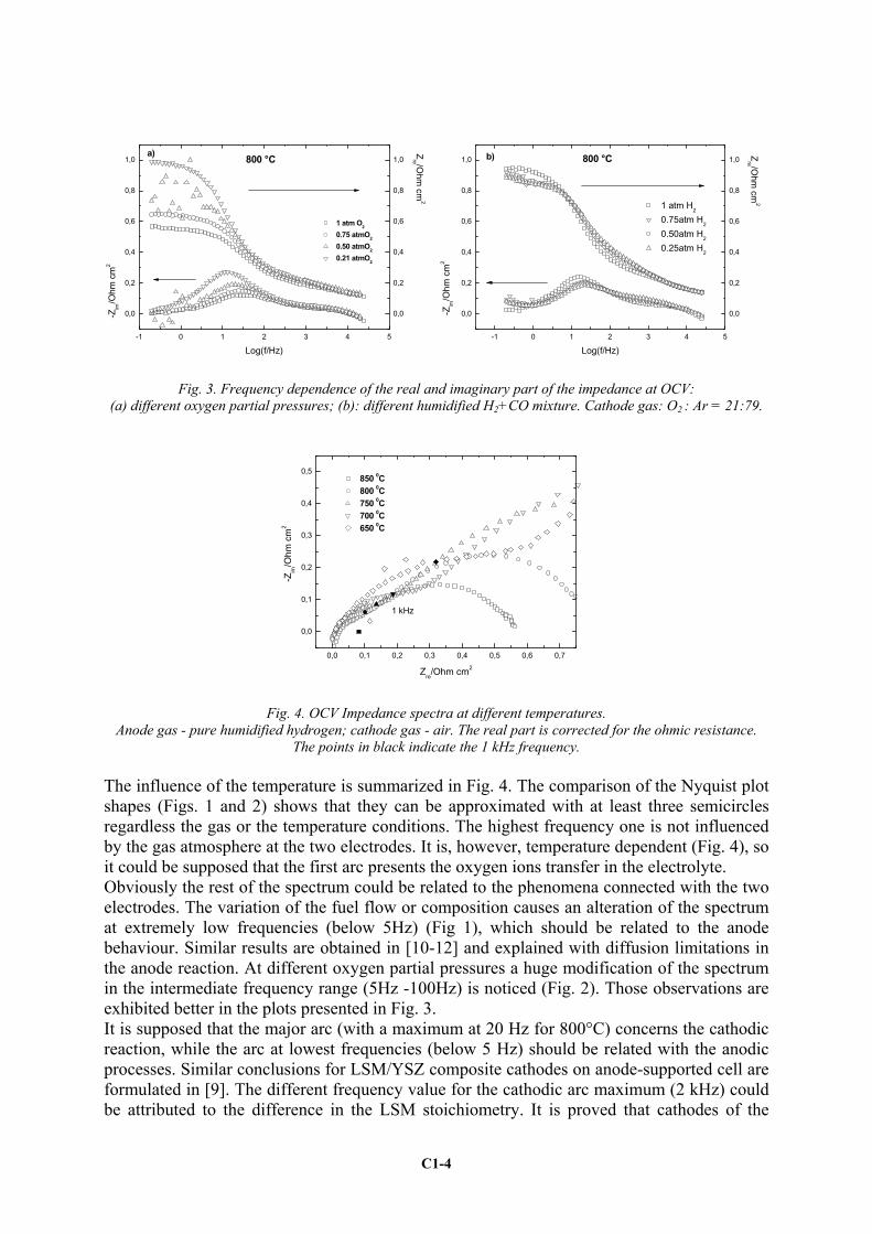
Fig. 3. Frequency dependence of the real and imaginary part of the impedance at OCV: (a) different oxygen partial pressures; (b): different humidified H2+CO mixture. Cathode gas: O2 : Ar = 21:79.
0,0 0,1 0,2 0,3 0,4 0,5 0,6 0,7
0,0
0,1
0,2
0,3
0,4
0,5 850 0C 800 0C 750 0C 700 0C 650 0C
-Zim
/Ohm
cm
2
Zre/Ohm cm2
1 kHz
Fig. 4. OCV Impedance spectra at different temperatures. Anode gas - pure humidified hydrogen; cathode gas - air. The real part is corrected for the ohmic resistance.
The points in black indicate the 1 kHz frequency. The influence of the temperature is summarized in Fig. 4. The comparison of the Nyquist plot shapes (Figs. 1 and 2) shows that they can be approximated with at least three semicircles regardless the gas or the temperature conditions. The highest frequency one is not influenced by the gas atmosphere at the two electrodes. It is, however, temperature dependent (Fig. 4), so it could be supposed that the first arc presents the oxygen ions transfer in the electrolyte. Obviously the rest of the spectrum could be related to the phenomena connected with the two electrodes. The variation of the fuel flow or composition causes an alteration of the spectrum at extremely low frequencies (below 5Hz) (Fig 1), which should be related to the anode behaviour. Similar results are obtained in [10-12] and explained with diffusion limitations in the anode reaction. At different oxygen partial pressures a huge modification of the spectrum in the intermediate frequency range (5Hz -100Hz) is noticed (Fig. 2). Those observations are exhibited better in the plots presented in Fig. 3. It is supposed that the major arc (with a maximum at 20 Hz for 800°C) concerns the cathodic reaction, while the arc at lowest frequencies (below 5 Hz) should be related with the anodic processes. Similar conclusions for LSM/YSZ composite cathodes on anode-supported cell are formulated in [9]. The different frequency value for the cathodic arc maximum (2 kHz) could be attributed to the difference in the LSM stoichiometry. It is proved that cathodes of the
C1-4

same composition can show quite different electro-catalytic performance due to the chosen powder synthesis [13,14] or stoichiometry [15,16]. This study focuses on the cathodic process, where the electrochemical exchange of oxygen between the gas phase and YSZ occurs. The overall reaction path can be divided into a number of possible reaction steps: Step 1: Dissociative oxygen adsorption on the LSM:
(LSM)2O2(gas)O ads2 ⇔+ s , (1) where indicates an adsorption site on the LSM surface. s Step 2: Diffusion which occurs when the concentration of the adsorbed oxygen on the LSM and at the TPB is not uniform:
( ) (TPBOLSMO adsads ⇔ ) . (2) Step 3: Incorporation of oxygen ions into the YSZ:
s+⇔++ •• XOOads O2eV(TPB)O , (3)
where and O represent respectively the oxygen vacancies and the occupied oxygen lattice sites in the YSZ.
••OV X
O
Any of the aforementioned reaction steps, or others, may be rate determining. As indicated in Annex A, if the oxygen adsorption is the rate limiting step of the reduction, the reaction velocity should be proportional to p(O2) (Eqn. A4) . If, however, Step 2 or Step 3 are the limiting ones, the reaction velocity would be proportional to p(O2)½ (Eqns. A7 and A10). Having into account the analysis of the impedance behaviour caused by the gas conditions at the two electrodes (Figs. 1-3), it is assumed that the cathodic gas variation could not affect principally the operation of the anode, so it could be accepted, that in general the changes in the polarization resistance due to the oxygen partial pressure would be informative for the kinetics of the cathodic reaction. Thus the reaction rate could be evaluated experimentally from the reciprocal value of the area specific resistance (1/Rp).
y = 0,1018x2 + 0,5419x + 0,8209
y = 0,4097x + 0,3548y = 0,9769x - 0,4121
-1,2
-0,8
-0,4
0
0,4
0,8
1,2
-2 -1,5 -1 -0,5 0
Ln[p(O2)/atm)]
Ln[1
/Rp/
Ohm
cm
2 )]
800 °C
750 °C
700 °C
Fig. 5. Dependence between ln(1/Rp) and ln[p(O2)] at three different temperatures. The anode gas is humidified
hydrogen. The solid lines describe the calculated equations.
C1-5

Fig. 5 shows the dependence between 1/Rp and the oxygen partial pressure p(O2) at different temperatures. The logarithmic presentation gives a pathway to estimate the value of the exponent α for the basic relation (1/Rp) ∝ p(O2)α , which could suggest the rate determining step in the frames of the possibilities described in Annex A. The graphical presentation of the equations which describe the corresponding dependencies are also plotted as solid lines. At 750 and 800 °C α is very close to ½ and according to the accepted assumptions, this result indicates that the rate determining step should be either Step 2 or Step 3. Comparing cathodes with different diameters, it was recently found [17], that the electrocatalytic activity in pure LSM is confined to the electrode/electrolyte surface only. This is in contrast to the behaviour of composite LSM/YSZ electrodes, where above 750oC the volume is also activated. Recent results obtained by the technique of the Differential Impedance Analysis informed for transport hampered by the host LSM matrix, combined with a fast charge transfer [7]. The results for the composite LSM/YSZ cathode material suggested the same structural, but different parametric identification with lower values of the resistance. Although accelerated transport was registered for the composite cathode, on this stage of the analysis Step 2, i.e. the Oads diffusion from LSM to TPB could be still accepted as the more possible rate determining stage. The cathode reaction studies need further investigations, which should be performed at least in two aspects: (i) application of DIA for separation of the different steps in the total impedance, extraction of the cathode and the anode-related contributions and determination of the rate limiting stage; (ii) analysis of additional possible cathode reaction steps, including that of the charge transfer. At 700 °C and high oxygen partial pressure, α is close to 1 and the oxygen adsorption on the LSM surface can be regarded as the limiting process. At lower p(O)2, however, there is a deviation from this dependence (Figs. 2b and 5), which shows that a different mechanism takes place. One possible interpretation is related to the dependence of the LSM defect structure on the oxygen partial pressure. The concentration of surface active adsorption sites which correspond to oxygen vacancies increases with the decrease of the oxygen partial pressure. In addition at lower temperatures it can increase further due to Mn3+ reduction [2]. The reaction rate given with Eqn. A4 depends on the square of the adsorption sites concentration s. Since the decrease of p(O2) could result in an increase of s, this parameter is not anymore constant and gives additional contribution to the increase of v(1) , which explains the higher values for 1/Rp at lower oxygen partial pressures. The obtained results are in agreement with our previous conclusions [2] about the existence of a “critical” temperature between 700 and 750 °C for the oxygen reduction reaction in composite LSM/YSZ cathodes. Considering the applied approach as valuable for understanding the complex behaviour of the electroactive materials towards O.R., it is necessary to increase the accuracy in the determination of the different contributions of the anode-supported single cell components in the overall impedance response, which is in progress. 4. Acknowledgements M.P. Carpanese acknowledges the European Community for the grant which supported her participation in the Workshop Portable and Emergency Energy Sources – from Materials to Systems, 16-22 Sept. 2005, Primorsko, Bulgaria (specific program “Energy, Environment and Sustainable Development – Part B: Energy program”, contract No NNE5/2002/18). The financial support for the Italian project “FISR: Nanosistemi Inorganici ed Ibridi per lo Sviluppo e l’Innovazione di Celle a Combustibile” is also acknowledged.
C1-6

Annex A [15-17] The overall oxygen exchange reaction may be divided into three possible steps:
(1) (LSM)O22(gas)O ads
a
a2
k
ks
−⇔+
(2) (A1) (TPB)O(LSM)O ads
d
dads
k
k−⇔
k
(3) . sk
+⇔++−
•• XO
i
iOads O2eV(TPB)O
If step (1) is the rate determining one,
22a(a) ]][[O skv =
r ; , (A2) 2LSMadsa)( ][Oakv −− =
s
while the other two steps reach the equilibrium:
( )LSMads
TPBads2 ][O
][O=K ;
][V][O]][[O
OTPBads
XO
(3) ••=
sK . (A3)
After simple calculations, the following expression for the reaction velocity (1)ν is obtained:
2(3)
2(2)
2O
22
a2
2aLSMads
(1) ][V][][
]][[O][
KKsO
kskdt
Odv
XO
••−−== . (A4)
If step (2) is the rate determining one, LSMadsd(d) ][Okv =
r ; ( ) TPBadsdd ][O−− = kvs , (A5) the other two steps reach the equilibrium:
22
2LSMads
(1) ]][[O][Os
K = ; ][V][O
]][[O
OTPBads
XO
(3) ••=
sK . (A6)
Then the reaction velocity (2)ν is:
(3)O
XO
d21
221
(1)dLSMads
(2) ][V]][[O
][][Odt
]d[OKs
ksKkv••−+−== . (A7)
If step (3) is the rate determining one,
][V][O OTPBadsi••= kvi
r ; ]][[Ok XOii sv −− =
s . (A8) The other two steps in equilibrium:
C1-7

22
2LSMads
(1) ]][[O][Os
K = ; LSMads
TPBads(2) ][O
][O=K . (A9)
The reaction velocity (3)ν is:
]][[O]][[V][Od
]d[ XOiO
21
221
(1)(2)TPBads
(3) sksKKkt
Ov i −
•• +−== . (A10)
5. References 1. W. Kim, A. V. Virkar, K.-Z. Fung, K. Mehta and S. C. Singhal, J. Electrochem. Soc. 146
(1) (1999) 69. 2. A. Barbucci, P. Carpanese, G. Cerisola, M. Viviani, Solid State Ionics 176 (2005) 1753. 3. D. Vladikova, Z. Stoynov, J. Electroanal. Chem. 572 (2004) 377. 4. Z. Stoynov, D. Vladikova, Differential Impedance Analysis, Academic Publishing House
M. Drinov, Sofia, 2005. 5. D. Vladikova, P. Zoltovski, E. Makowska, Z. Stoynov, Electrochim. Acta 47 (2002) 2943. 6. D. Vladikova, G. Raikova, Z. Stoynov, H. Takenouti, J. Kilner, St. Skinner, Solid State
Ionics 176 (2005) 2005. 7. Barbucci, M. Viviani, P. Carpanese, D. Vladikova and Z. Stoynov, Electrochimica Acta,
in press. 8. A. Webber, A. Muller, D. Herbstritt, E. Ivers-Tiffee in: H. Yokokawa and S.C. Singhal,
M. Dokiya (Eds.), Solid Oxide Fuel Cells (SOFCVII), The Electrochemical Society Proceedings Series, Pennington, NJ, 2001-16 (2001) 952.
9. S. McIntosh, J. M. Vohs and R. J. Gorte, J. Electrochem. Soc. 150 (10) A1305 (2003) 10. P. Holtappels, T. Graule, B. Gut, U. Vigt in: S.C. Singhal and M. Dokiya (Eds.), Solid
Oxide Fuel Cells (SOFCVIII), The Electrochemical Society Proceedings Series, Pennington, NJ, 2003-07 (2003) 1003.
11. P.V. Hendriksen, S. Koch, M. Mogensen, Y.L. Liu, P.H. Larsen, Solid Oxide Fuel Cells (SOFCVIII), The Electrochemical Society Proceedings Series, Pennington, NJ, 2003-07 (2003) 1147.
12. R. Ihringer, S. Rambert, L. Constantin, J. Van herle in: H. Yokokawa and S.C. Singhal, M. Dokiya (Eds.), Solid Oxide Fuel Cells (SOFCVII), The Electrochemical Society Proceedings Series, Pennington, NJ, 2001-16 (2001) 1002.
13. R. J. Bell, G. J. Millar, J. Drennan, Solid State Ionics 131 (2000) 211. 14. J. Sfeir, S. Vaucher, P. Holtappels, U. Vogt, H.-J. Schindler, J. Van herle, E. Suvorova, P.
Buffat, N. Xanthopoulos, O. Bucheli, J. European Ceramic Society 25 (2005) 1991. 15. K. Yasumoto, N. Mori, J. Mizusaki, H. Tagawa, M. Dokiya, J. of Electrochem. Soc. 148
(1) A105 (2001). 16. K. Yasumoto, M. Spiono, H. Tagava, M. Dokiya, K. Hirano, J. Mizusaki, J. Electrochem.
Soc. 149 (5) A531 (2002). 17. A. Bassano, graduation thesis, University of Genova, 2005, p. 83.
C1-8