Preparation of Ni–YSZ thin and thick films on metallic interconnects as cell supports....
8
Open Archive Toulouse Archive Ouverte (OATAO) OATAO is an open access repository that collects the work of Toulouse researchers and makes it freely available over the web where possible. This is an author-deposited version published in: http://oatao.univ-toulouse.fr/ Eprints ID : 2326 To link to this article : URL : :http://dx.doi.org/10.1007/s10971-008-1689-0 To cite this version : Rieu, M. and Lenormand, Pascal and Ansart, Florence and Maury, Francis and Fullenwarth, J. and Zahid, M. ( 2008) Preparation of Ni–YSZ thin and thick films on metallic interconnects as cell supports. Applications as anode for SOFC. Journal of Sol-Gel Science and Technology, vol. 45 (n° 3). pp. 307-313. ISSN 0928-0707 Any correspondence concerning this service should be sent to the repository administrator: [email protected]
-
Upload
independent -
Category
Documents
-
view
1 -
download
0
Transcript of Preparation of Ni–YSZ thin and thick films on metallic interconnects as cell supports....

Open Archive Toulouse Archive Ouverte (OATAO) OATAO is an open access repository that collects the work of Toulouse researchers and makes it freely available over the web where possible.
This is an author-deposited version published in: http://oatao.univ-toulouse.fr/ Eprints ID : 2326
To link to this article : URL : :http://dx.doi.org/10.1007/s10971-008-1689-0
To cite this version : Rieu, M. and Lenormand, Pascal and Ansart, Florence and Maury, Francis and Fullenwarth, J. and Zahid, M. ( 2008) Preparation of Ni–YSZ thin and thick films on metallic interconnects as cell supports. Applications as anode for SOFC. Journal of Sol-Gel Science and Technology, vol. 45 (n° 3). pp. 307-313. ISSN 0928-0707
Any correspondence concerning this service should be sent to the repository
administrator: [email protected]

Preparation of Ni–YSZ thin and thick films on metallicinterconnects as cell supports. Applications as anode for SOFC
M. Rieu Æ P. Lenormand Æ F. Ansart Æ F. Mauvy ÆJ. Fullenwarth Æ M. Zahid
Abstract In this work, we propose the preparation of a
duplex anodic layer composed of both a thin (100 nm) and
a thick film (10 lm) with Ni–YSZ material. The support of
this anode is a metallic substrate, which is the interconnect
of the SOFC unit cell. The metallic support limits the
temperature of thermal treatment at 800 �C to keep a good
interconnect mechanical behaviour and to reduce corro-
sion. We have chosen to elaborate anodic coatings by
sol–gel route coupled with dip-coating process, which are
low cost techniques and allow working with moderate
temperatures. Thin films are obtained by dipping inter-
connect substrate into a sol, and thick films into an
optimized slurry. After thermal treatment at only 800 �C,
anodic coatings are adherent and homogeneous. Thin films
have compact microstructures that confer ceramic protec-
tive barrier on metal surface. Further coatings of 10 lm
thick are porous and constitute the active anodic material.
Keywords Sol–gel � Coatings � Ni–YSZ � Anode �SOFC
1 Introduction
During the last 30 years, SOFC (Solid Oxide Fuel Cell)
technology has progressed, in order to reduce cost of SOFC
stack, in the aim of future commercialization. Actually, the
first generation (1G) of planar SOFC configuration
(Fig. 1a) used electrolyte as mechanical support, so it
needs a sufficient thickness (around 200 lm) to assume this
function. Ionic conductivity of the electrolyte (Yttria Sta-
bilised Zirconia, common electrolyte material [1])
increases with temperature and on this configuration, with
the important thickness of the electrolyte, a temperature
above 1,000 �C is necessary to allow a good cell working.
Due to this problem, electrolyte thickness was then
reduced in the second generation (2G) of planar SOFC
(Fig. 1b). YSZ thickness is 10–50 lm to allow cell work-
ing at 800 �C. 2G SOFC is anode supported, which is also
a ceramic compound and its thickness is in the range 200–
1,000 lm. Moreover, an advantage is that this decrease of
working temperature allows to use metallic interconnects
[2], that are cheaper than ceramic interconnect (like LaC-
rO3) previously used in 1G SOFC.
However SOFC technologies can still be improved. Here,
we propose to work on the third SOFC generation (3G). This
new generation (Fig. 1c) use metallic interconnects as
mechanical cell supports. Active materials (anode, electro-
lyte, cathode) are ceramic films of lower thickness, limiting
the quantity of ceramic matter used, and so reducing the price
of the complete cell. Performances are still good because of
the electrolyte thickness decreases (some few tens microns).
The working temperature is in the range 600–700 �C. Fur-
thermore, with a good mechanical behaviour, the metallic
interconnect support is a good electrical conductor to collect
current, and also a good thermal conductor allowing a good
temperature distribution. Moreover, when assembling single
M. Rieu (&) � P. Lenormand � F. Ansart
CIRIMAT, Universite Paul Sabatier, UMR CNRS 5085, Bat II
R1, 118 Route de Narbonne, 31062 Toulouse Cedex 9, France
e-mail: [email protected]
F. Mauvy � J. Fullenwarth
ICMC Bordeaux-CNRS UPR 9048, 87,
Avenue du Dr. A. Schweitzer, Universite de Bordeaux 1,
Pessac Cedex 33608, France
M. Zahid
EIFER, Emmy-Noether-Strasse 11, 76131 Karlsruhe, Germany

cells in stack, it is easier to weld or connect metallic materials
than ceramic ones.
In this prospect, this paper deals with the preparation of
anodic layers of 10 lm thick by sol–gel process associated to
dip-coating technique on metallic interconnects substrates,
which is an adapted route to prepare various oxides films at
low temperature with controlled morphology [3, 4]. Anodic
material is Ni–YSZ because this cermet is well-known and is
the most commonly used [5]. Performances improvement of
Ni–YSZ needs electrochemical properties optimization. We
propose to optimize microstructure and both phases (Ni and
YSZ) distribution by using original elaboration method (sol–
gel synthesis and slurries) so that SOFC systems become
economically competitive. Film microstructure will depend
on several parameters corresponding to either suspension
nature (solvent, concentration, rheology), substrate (surface,
topography), dip-coating technique (withdrawal speed) and
thermal treatment. A control of these experimental param-
eters will allow to obtain homogeneous and adherent
micronic layers with controlled porosity and thickness.
However, the use of metallic material as cell support restricts
some parameters and in particular sintering temperature of
anodic material. Indeed, a heat thermal treatment above
800 �C would degrade metal support. It will thus be neces-
sary to consolidate and sinter anodic coating on the
interconnect at relatively low temperature.
So, we propose to prepare a duplex microstructured anode
(Fig. 2). To begin with, we first consider preparation of an
anodic interfacial thin layer. This thin film will make it
possible to better check the wettability of the substrate, to
improve the adhesion of a further thicker anodic layer and to
help the accommodation of mechanical stresses between
ceramic (anode) and metallic (interconnect) materials. Then,
we will optimize the processing of composite powders YSZ–
NiO synthesized by sol–gel, in order to obtain a stable slurry.
The deposits will be carried out by dip-coating the metallic
substrate into the suspension. After thermal treatment at
800 �C, anodic coatings will then be characterized.
2 Experimental
In this work, we propose to prepare a Ni–YSZ duplex
anode coating on metallic substrates, which are ferritic
stainless steels (F18TNb) manufactured by the UGINE
company.
In order to elaborate anodic interfacial films, an alkoxide
sol is synthesized [6]. Precursors as zirconium n-propoxide
(Aldrich, 70 wt%), n-propanol (Acros organics +99%),
yttrium nitrate (Acros Organics 99.9%), nickel nitrate
(Acros Organics 99%), acetylacetone (acac, Acros Organ-
ics +99%) and water were mixed to synthesize sols. The
synthesis parameters were the following: C = 0.1 mol/L
for the zirconium n-propoxide concentration, R0 = [acac]/
{[Zr] + [Y]} = 0.7 for the complexing agent ratio and
W0 = [H2O]/{[Zr] + [Y]} = 30 for the hydrolysis ratio.
The nickel precursor quantity insert in the sol corresponds
to 50% Ni vol obtained after reduction treatment in the
final material. The obtained sol is clear and homogeneous.
Thick films are obtained by a dip-coating process in a
slurry composed of YSZ–NiO composite powders which
are previously synthesized by a sol–gel polymeric route
[6], derived from Pechini process [7]. Precursors were
zirconyl nitrate (Acros Organics 99.5%), yttrium nitrate
(Acros Organics 99.9%) and nickel nitrate (Acros Organics
99%). The initial concentration was adjusted at CYSZ =
0.2 mol/L compared to the polymer matrix volume. The
quantity of nickel is also kept at 50 vol% Ni after reduction
treatment in the final material. The polymeric sol was
obtained by polymerization and polycondensation reactions
between hexamethylenetetramine (HMTA, Acros Organics
99%) and acetylacetone (acac, Acros Organics +99%) in
acetic acid (VWR) media. The molar ratio between HMTA
and acac was 1:1. After heat treatment at 800 �C—2 h,
obtained powders consist of two kinds of particles: some
small spheres of diameter 30 nm corresponding to YSZ and
other faceted particles of 100 nm, which correspond to
NiO. There is a good dispersion between the two phases.
C
E
A
SOFC 1G(a) (b) (c)
Electrolyte support
CE
A
SOFC 2G
Anode support
CEA
I
SOFC 3G
Interconnect support
Fig. 1 Various SOFC planar
cell configurations
10 µm
100 nm Thin layer
Thick layer
Interconnect
Fig. 2 Duplex anodic system on interconnect cell support

Slurries are prepared by addition of these NiO–YSZ
powders, under mechanical stirring, in an azeotropic mix-
ture MEK–EtOH (methylethylketone–ethanol) with a
polyester-phosphate (MELIORAN P312, CECA) additive
used as dispersant.
In order to have stable slurries, Zeta potential instrument
(Zetasizer 300HS, Malvern Instruments Ltd.) is used to
determine surfacic charges and to adjust the quantity of
dispersant to add into suspensions.
Both surface roughness of substrates and thickness of
thick films are measured by optical interferometry device
(‘‘New View 100’’ ZYGO Corp).
Structural and microstructural analyses on composite
powders and films were achieved, at room temperature, by
X-ray diffraction using a D4 ENDEAVOR (BRUKER)
diffractometer with the Cu Ka radiation, and Scanning
Electron Microscopy (JEOL JSM 6700F).
Electrical conductivity experiments were performed
using the four probe method. Four gold wires (/ = 0.1 mm)
were connected to the sample using gold paste. The applied
current was 10 mA (current density J & 100 mA�cm-2).
Reducing atmospheres surrounding the sample were
obtained by flowing a mixture of hydrogen and water vapour
into the sample chamber. Hydrogen is produced by water
electrolysis (Dominik Hunter), and humidified by passing
through a bubbler. After reduction at 800 �C, the electrical
conductivity of the Cermet pellets was measured versus
temperature in hydrogen:water (97:3) gas mixture.
3 Results
3.1 Metallic substrate
We use ferritic stainless steel as substrate. The chemical
composition of this steel, manufactured by UGINE, is given
in Table 1. This steel has many advantages like a fairly good
corrosion resistance provided by the formation of protective
oxides like Cr2O3 and it has good mechanical properties at
high temperature. Steel has to be gastight. As we can see on
Fig. 3, the steel presents some anfractuosities on the surface,
but it is dense. Average roughness coefficient of these steels
is Ra = 0.4 lm.
3.2 Thin film
Composite films have been directly deposited onto metallic
substrates by dip-coating of an alkoxide sol [6]. Various
withdrawal speeds have been investigated: between 1 and
40 cm�min-1. After dipping, the film is heat treated at
800 �C during 2 h. A withdrawal speed of 5 cm�min-1 has
been chosen as the best compromise to keep homogenous
layers on a macroscopic scale.
SEM micrographs reported on Fig. 4 show the com-
posite film microstructure. Film appears continuous,
adherent and homogeneous. Roughness of thin film has
been measured and the average coefficient is Ra = 0.4 lm,
which is the same as substrate before deposit, that is to say
the upper layer duplicates steel surface. These thin films
are around 100 nm thick as we can see on the cross-section
micrograph of a layer deposited on dense YSZ substrate
(Fig. 4). They are composed of small spheres of diameter
30 nm, with a good arrangement and a compact micro-
structure. This kind of microstructure is commonly
obtained by sol–gel route and in this range of annealing
temperature, the microstructural evolution of the coating is
not influenced by the interface substrate/layer [8, 9].
However, it is impossible to precisely separate YSZ and
NiO grains, but we have determined crystallite sizes of this
composite. They were calculated from XRD pattern using
the Williamson and Hall relation, and we see that YSZ and
NiO are composed of elementary particles (crystallites) of
30 nm of diameter.
Table 1 Steel F18TNb
chemical compositionwt% C Mn Si Ni Cr N Ti Nb S ppm
F18TNb 0.012 0.208 0.58 0.110 17.73 0.015 0.153 0.499 29
Fig. 3 SEM micrographs of
steel surface

As we can see in Fig. 5, steel used as interconnect
corrodes itself under air atmosphere at 800 �C during 2 h.
But when steel is covered by an YSZ–NiO thin film, the
compactness of the layer reduces oxygen diffusion and so it
limits the formation of steel corrosion products. That is an
important characteristic of such coatings where compact
particles organization confers an anticorrosion property of
metallic substrate.
Usually, steels used as interconnects need to be coated
to limit corrosion. However, these coatings are spinel phase
like (Mn,Co)3O4 [10], perovskite like LaCrO3 or (La,Sr)-
CoO3 [11, 12], or coatings with reactive element oxides
like Y2O3 [13]. These coatings improve performances of
the steel because of the reduction of corrosion products.
But we have not found any NiO–YSZ coating protective
against corrosion in the literature and this offers new
prospects for such metallic substrates.
3.3 Optimization of slurry composition
As we can see on Fig. 6, the composite powder consists of
agglomerates constituted of two types of particles: YSZ
spheres of 30 nm and NiO faceted particles of 100 nm. In
order to desagglomerate such powders and to be able to
stabilize slurries and to avoid sedimentation, composite
powder is mechanically milled for 1 h. Then the composite
powder is first dispersed in MEK–EtOH (60–40) azeotropic
mixtures by using a commercial dispersant (P312). This
dispersive solvent and dispersant were chosen according to
previous optimization work on the formulation of slurries
for tape-casting process [14, 15].
In order to obtain a homogeneous and stable suspension,
dispersant ratio has been discussed. Several tests have been
performed in the range 0–3% in weight. P312 commercial
dispersant was first dispersed in the azeotropic mixture and
then powder was added under constant mechanical stirring.
Zeta potential measurements are reported in Fig. 7, powder
concentration for these measurements is 0.1 mg/mL, pH of
suspensions is around 6. We see that the best dispersant ratio
Fig. 4 SEM micrographs of
thin alkoxide film after
annealing at 800 �C during 2 h:
(a) surface, (b) cross-section
0
100
200
300
400
500
600
202θ (°)
Inte
nsity
(a.
u.)
# # #+ + +# # #+ + +
° ° ° ° ° ° ° °° ° ° ° ° ° ° °
Steel Steel
#
+ YSZ
NiO#
+
° Metallic oxide(Steel corrosion products)
(a)
(b)
(c)
30 40 50 60 70
Fig. 5 XRD patterns of (a) Steel F18TNb, (b) Steel F18TNb
annealed at 800 �C—2 h in air, (c) Steel F18TNb + thin alkoxide
film annealed at 800 �C—2 h in air
Fig. 6 SEM micrographs of
composite powder (NiO–YSZ)
after calcination at 800 �C
during 2 h
is in the range 2–3%. By sedimentation tests, we try to refine
this dispersant ratio. Sedimentation tests were performed by
pouring 50 mL of a given suspension into a 50 mL gradu-
ated Pyrex glass cylinder. For this test, 1 g of composite
powder was dispersed in MEK–EtOH solution with different
amounts of dispersant (1.5; 2; 2.5 and 3%). With a value of
2.5 wt% of dispersant, the suspension is very stable. Even
after 72 h, no sediment volume was observed.
3.4 Thick film
After this first step of optimization, we have defined the
elaboration conditions of thick films: 67 wt% of com-
posite powder, 33 wt% of MEK–EtOH and a dispersant
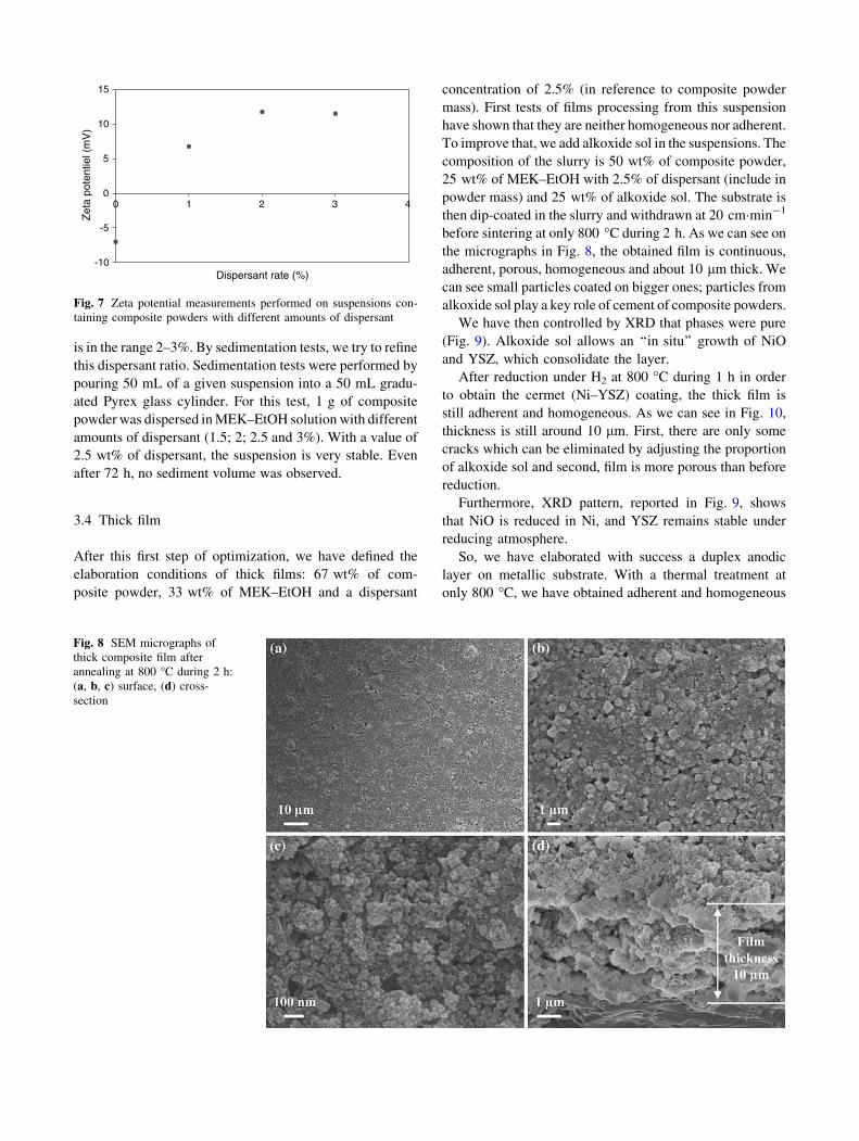
concentration of 2.5% (in reference to composite powder
mass). First tests of films processing from this suspension
have shown that they are neither homogeneous nor adherent.
To improve that, we add alkoxide sol in the suspensions. The
composition of the slurry is 50 wt% of composite powder,
25 wt% of MEK–EtOH with 2.5% of dispersant (include in
powder mass) and 25 wt% of alkoxide sol. The substrate is
then dip-coated in the slurry and withdrawn at 20 cm�min-1
before sintering at only 800 �C during 2 h. As we can see on
the micrographs in Fig. 8, the obtained film is continuous,
adherent, porous, homogeneous and about 10 lm thick. We
can see small particles coated on bigger ones; particles from
alkoxide sol play a key role of cement of composite powders.
We have then controlled by XRD that phases were pure
(Fig. 9). Alkoxide sol allows an ‘‘in situ’’ growth of NiO
and YSZ, which consolidate the layer.
After reduction under H2 at 800 �C during 1 h in order
to obtain the cermet (Ni–YSZ) coating, the thick film is
still adherent and homogeneous. As we can see in Fig. 10,
thickness is still around 10 lm. First, there are only some
cracks which can be eliminated by adjusting the proportion
of alkoxide sol and second, film is more porous than before
reduction.
Furthermore, XRD pattern, reported in Fig. 9, shows
that NiO is reduced in Ni, and YSZ remains stable under
reducing atmosphere.
So, we have elaborated with success a duplex anodic
layer on metallic substrate. With a thermal treatment at
only 800 �C, we have obtained adherent and homogeneous
-10
-5
0
5
10
15
0
Dispersant rate (%)
Zet
a po
tent
iel (
mV
)
1 2 3 4
Fig. 7 Zeta potential measurements performed on suspensions con-
taining composite powders with different amounts of dispersant
Fig. 8 SEM micrographs of
thick composite film after
annealing at 800 �C during 2 h:
(a, b, c) surface, (d) cross-
section

anodic coatings. Nowadays, anodes are still mainly bulk
materials [16], excepted some anode functional layers 5–
10 lm thick elaborated by screen printing [17] or pres-
surized spray process [18], but they use a heat thermal
treatment at 1,300 �C. In our knowledge, no thick anodic
layer has been elaborated on metallic support.
3.5 Electrical conductivity
Electrical conductivity measurements were performed on
massive anode. For that, composite powder, previously
synthesized by the modified Pechini process, is pressed into
pellets under 350 MPa and sintered in air at 1,200 �C
during 2 h. Pellets are then reduced in hydrogen at 800 �C
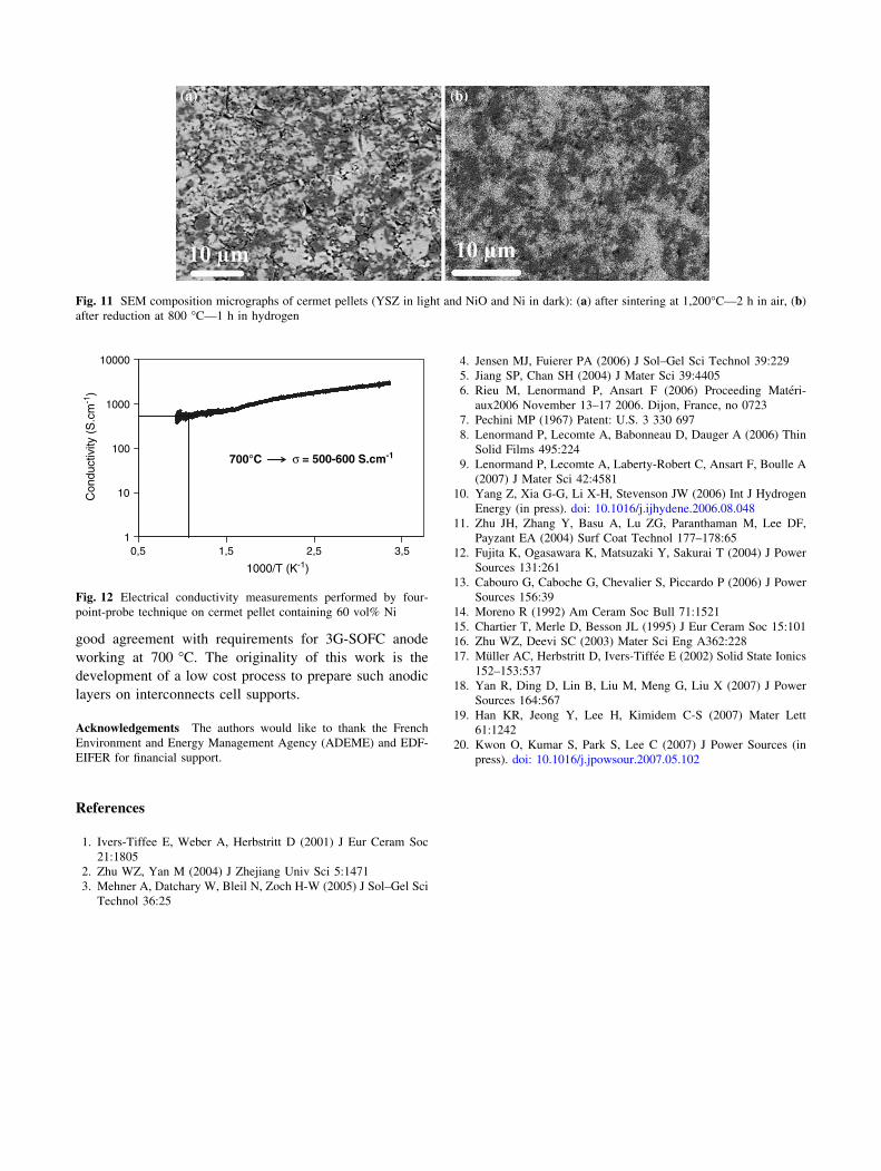
during 1 h. As we can see on micrographs reported in
Fig. 11, there is a homogenous distribution of the two
phases. The electrical conductivity has been measured with
the four-point technique. The conductivity value is in the
range of 500–600 S�cm-1 at 700 �C (Fig. 12) and increa-
ses when the temperature decreases. This result is
promising for a IT-SOFC application. That is a very good
conductivity since the required conductivity is only
200 S�cm-1 at working temperature [19, 20].
4 Conclusion
An alternative experimental process which combines both
dip-coating method and optimized slurries technology was
developed in this work to prepare NiO–YSZ duplex sys-
tems (thin film + thick film) on metallic substrates. We
have first obtained, at 800 �C, NiO–YSZ thin film
(100 nm), continuous, compact and protective against
corrosion. Then to elaborate thick film, the dip-coating
media consists of sol–gel synthesized NiO–YSZ powders
in suspensions in organics compounds, which contain a
proportion of alkoxide sol. After calcinations at only
800 �C, the obtained layers are continuous, homogeneous
and adherent. The layers microstructure is significantly
porous. The films thickness is around 10 lm, which is in
0
1000
2000
3000
4000
5000
6000
7000
8000
9000
10000
202θ (°)
Inte
nsity
(a.
u.)
##
#++ +
NiO##
YSZ++ Steel
Steel
Beforereduction
Afterreduction
++
+
Ni
30 40 50 60 70
Fig. 9 XRD pattern of thick composite film annealed at 800 �C—2 h
in air and of thick cermet film reduced at 800 �C—1 h in hydrogen
Fig. 10 SEM micrographs of thick cermet film after reduction at 800 �C—1 h in hydrogen: (a, b, c) surface, (d) cross-section
good agreement with requirements for 3G-SOFC anode
working at 700 �C. The originality of this work is the
development of a low cost process to prepare such anodic
layers on interconnects cell supports.
Acknowledgements The authors would like to thank the French
Environment and Energy Management Agency (ADEME) and EDF-
EIFER for financial support.
References
1. Ivers-Tiffee E, Weber A, Herbstritt D (2001) J Eur Ceram Soc
21:1805
2. Zhu WZ, Yan M (2004) J Zhejiang Univ Sci 5:1471
3. Mehner A, Datchary W, Bleil N, Zoch H-W (2005) J Sol–Gel Sci
Technol 36:25
4. Jensen MJ, Fuierer PA (2006) J Sol–Gel Sci Technol 39:229
5. Jiang SP, Chan SH (2004) J Mater Sci 39:4405
6. Rieu M, Lenormand P, Ansart F (2006) Proceeding Materi-
aux2006 November 13–17 2006. Dijon, France, no 0723
7. Pechini MP (1967) Patent: U.S. 3 330 697
8. Lenormand P, Lecomte A, Babonneau D, Dauger A (2006) Thin
Solid Films 495:224
9. Lenormand P, Lecomte A, Laberty-Robert C, Ansart F, Boulle A
(2007) J Mater Sci 42:4581
10. Yang Z, Xia G-G, Li X-H, Stevenson JW (2006) Int J Hydrogen
Energy (in press). doi: 10.1016/j.ijhydene.2006.08.048
11. Zhu JH, Zhang Y, Basu A, Lu ZG, Paranthaman M, Lee DF,
Payzant EA (2004) Surf Coat Technol 177–178:65
12. Fujita K, Ogasawara K, Matsuzaki Y, Sakurai T (2004) J Power
Sources 131:261
13. Cabouro G, Caboche G, Chevalier S, Piccardo P (2006) J Power
Sources 156:39
14. Moreno R (1992) Am Ceram Soc Bull 71:1521
15. Chartier T, Merle D, Besson JL (1995) J Eur Ceram Soc 15:101
16. Zhu WZ, Deevi SC (2003) Mater Sci Eng A362:228
17. Muller AC, Herbstritt D, Ivers-Tiffee E (2002) Solid State Ionics
152–153:537
18. Yan R, Ding D, Lin B, Liu M, Meng G, Liu X (2007) J Power
Sources 164:567
19. Han KR, Jeong Y, Lee H, Kimidem C-S (2007) Mater Lett
61:1242
20. Kwon O, Kumar S, Park S, Lee C (2007) J Power Sources (in
press). doi: 10.1016/j.jpowsour.2007.05.102
Fig. 11 SEM composition micrographs of cermet pellets (YSZ in light and NiO and Ni in dark): (a) after sintering at 1,200�C—2 h in air, (b)
after reduction at 800 �C—1 h in hydrogen
1
10
100
1000
10000
0,5
1000/T (K-1)
Con
duct
ivity
(S
.cm
-1)
700°C σ = 500-600 S.cm-1
1,5 2,5 3,5
Fig. 12 Electrical conductivity measurements performed by four-
point-probe technique on cermet pellet containing 60 vol% Ni