Analysis of on-chip inductance effects for distributed RLC interconnects
Upload
independentCategory
view
1download
0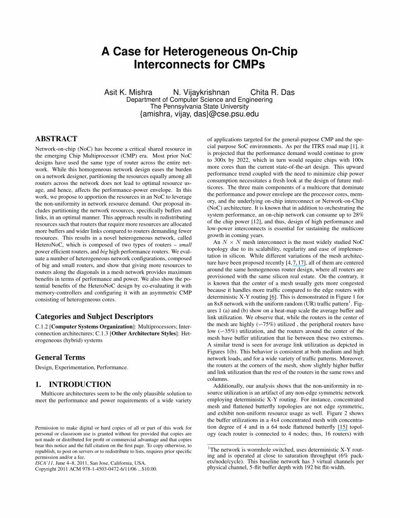
A Case for Heterogeneous On-ChipInterconnects for CMPs
Asit K. Mishra N. Vijaykrishnan Chita R. DasDepartment of Computer Science and Engineering
The Pennsylvania State University{amishra, vijay, das}@cse.psu.edu
ABSTRACT
Network-on-chip (NoC) has become a critical shared resource inthe emerging Chip Multiprocessor (CMP) era. Most prior NoCdesigns have used the same type of router across the entire net-work. While this homogeneous network design eases the burdenon a network designer, partitioning the resources equally among allrouters across the network does not lead to optimal resource us-age, and hence, affects the performance-power envelope. In thiswork, we propose to apportion the resources in an NoC to leveragethe non-uniformity in network resource demand. Our proposal in-cludes partitioning the network resources, specifically buffers andlinks, in an optimal manner. This approach results in redistributingresources such that routers that require more resources are allocatedmore buffers and wider links compared to routers demanding fewerresources. This results in a novel heterogeneous network, calledHeteroNoC, which is composed of two types of routers – small
power efficient routers, and big high performance routers. We eval-uate a number of heterogeneous network configurations, composedof big and small routers, and show that giving more resources torouters along the diagonals in a mesh network provides maximumbenefits in terms of performance and power. We also show the po-tential benefits of the HeteroNoC design by co-evaluating it withmemory-controllers and configuring it with an asymmetric CMPconsisting of heterogeneous cores.
Categories and Subject Descriptors
C.1.2 [Computer Systems Organization]: Multiprocessors; Inter-connection architectures; C.1.3 [Other Architecture Styles]: Het-erogeneous (hybrid) systems
General Terms
Design, Experimentation, Performance.
1. INTRODUCTIONMulticore architectures seem to be the only plausible solution to
meet the performance and power requirements of a wide variety
Permission to make digital or hard copies of all or part of this work forpersonal or classroom use is granted without fee provided that copies arenot made or distributed for profit or commercial advantage and that copiesbear this notice and the full citation on the first page. To copy otherwise, torepublish, to post on servers or to redistribute to lists, requires prior specificpermission and/or a fee.ISCA’11, June 4–8, 2011, San Jose, California, USA.Copyright 2011 ACM 978-1-4503-0472-6/11/06 ...$10.00.
of applications targeted for the general-purpose CMP and the spe-cial purpose SoC environments. As per the ITRS road map [1], itis projected that the performance demand would continue to growto 300x by 2022, which in turn would require chips with 100xmore cores than the current state-of-the-art design. This upwardperformance trend coupled with the need to minimize chip powerconsumption necessitates a fresh look at the design of future mul-ticores. The three main components of a multicore that dominatethe performance and power envelope are the processor cores, mem-ory, and the underlying on-chip interconnect or Network-on-Chip(NoC) architecture. It is known that in addition to orchestrating thesystem performance, an on-chip network can consume up to 28%of the chip power [12], and thus, design of high performance andlow-power interconnects is essential for sustaining the multicoregrowth in coming years.
An N × N mesh interconnect is the most widely studied NoCtopology due to its scalability, regularity and ease of implemen-tation in silicon. While different variations of the mesh architec-ture have been proposed recently [4,7,17], all of them are centeredaround the same homogeneous router design, where all routers areprovisioned with the same silicon real estate. On the contrary, itis known that the center of a mesh usually gets more congestedbecause it handles more traffic compared to the edge routers withdeterministic X-Y routing [6]. This is demonstrated in Figure 1 foran 8x8 network with the uniform random (UR) traffic pattern1. Fig-ures 1 (a) and (b) show on a heat-map scale the average buffer andlink utilization. We observe that, while the routers in the center ofthe mesh are highly (∽75%) utilized , the peripheral routers havelow (∽35%) utilization, and the routers around the center of themesh have buffer utilization that lie between these two extremes.A similar trend is seen for average link utilization as depicted inFigures 1(b). This behavior is consistent at both medium and highnetwork loads, and for a wide variety of traffic patterns. Moreover,the routers at the corners of the mesh, show slightly higher bufferand link utilization than the rest of the routers in the same rows andcolumns.
Additionally, our analysis shows that the non-uniformity in re-source utilization is an artifact of any non-edge symmetric networkemploying deterministic X-Y routing. For instance, concentratedmesh and flattened butterfly topologies are not edge symmetric,and exhibit non-uniform resource usage as well. Figure 2 showsthe buffer utilizations in a 4x4 concentrated mesh with concentra-tion degree of 4 and in a 64 node flattened butterfly [15] topol-ogy (each router is connected to 4 nodes; thus, 16 routers) with
1The network is wormhole switched, uses deterministic X-Y rout-ing and is operated at close to saturation throughput (6% pack-ets/node/cycle). This baseline network has 3 virtual channels perphysical channel, 5-flit buffer depth with 192 bit flit-width.

2 4 6 8
1
2
3
4
5
6
7
835
40
45
50
55
60
65
70
75
2 4 6 8
1
2
3
4
5
6
7
8
30
40
50
60
70
(a) Buffer utilization (b) Link utilization
Figure 1: Buffer and link utilization (in percentage) across all routers
in an 8x8 mesh on a heat-map scale.
1 2 3 4
0.5
1
1.5
2
2.5
3
3.5
4
4.5
60
65
70
75
1 2 3 4
0.5
1
1.5
2
2.5
3
3.5
4
4.5
40
45
50
55
60
(a) Concentrated Mesh (b) Flattened Butterfly
Figure 2: Buffer utilization (in percentage) in other topologies on a
heat-map scale.
UR traffic. Like the mesh topology, these two topologies also ex-hibit non-uniform resource demand (link utilization results are notshown due to brevity.), and thus, this argument should be true forany non-edge symmetric network, although we use the mesh inter-connect to demonstrate our idea in this paper.
This observation of non-uniform resource usage leads us to re-think the traditional mesh interconnect design by questioning therationality of uniform resource distribution across all routers. In-tuitively, since the central routers in a mesh handle more trafficcompared to the peripheral routers, we should be able to enhanceperformance by allocating more buffer and link bandwidth to thecenter routers compared to the latter. This implies that we shouldbe looking at different types of router architectures, where the pe-ripheral routers employ a small router with fewer buffers (virtualchannels (VCs)) and narrow link width, while the central and otherhighly utilized routers employ relatively large number of VCs andwider link width (big routers). This essentially moves us from thehomogeneous NoC to a heterogeneous NoC domain, an emergingarea that has remained unexplored in the context of performance-power trade-offs.
The heterogeneous NoC concept is further supported by the factthat future multicores/SoCs will have heterogeneous cores and com-ponents [11, 18, 19]. However, it is not intuitively clear if such het-erogeneous cores would benefit more from a heterogeneous NoC.Towards this end, this paper examines the rationality of resource re-distribution and proposes a heterogeneous mesh architecture, calledHeteroNoC, for optimizing both performance and power. In thiscontext, we attempt to answer the following questions: (i) Should
we design a heterogeneous NoC with two types (small and big) of
routers? (ii) If yes, how many such big/small routers do we need
and how do we redistribute the buffer and link width between these
routers without changing the original bisection width and buffer
resources? (iii) Is there an optimal placement of big routers that
would maximize the performance and power benefits compared to
the baseline homogeneous mesh? and (iv) How else can a Het-
eroNoC design be leveraged to achieve better performance/power
in a CMP?
Starting with an (N×N ) homogeneous mesh network, we ex-plore the design space of the proposed HeteroNoC with two typesof routers with different link widths and buffer organizations, andplacement of such routers, while keeping the bisection bandwidththe same. Our analysis with synthetic and real applications showsthat with small and big routers, where the big routers are assignedmore VCs and double the link width of small routers, we can designa heterogeneous mesh with 2N big routers for providing better per-formance and power behavior over the baseline homogeneous net-work. Furthermore, by placing the big routers in the diagonals of amesh to help traffic flow in high activity network regions, we get the
maximum benefit compared to other placements. The advantagesof the HeteroNoc architecture is also demonstrated in the contextof heterogeneous CMPs and placement of memory controllers. Insummary, the primary contributions of this paper are the following:
• We propose a novel heterogeneous network for general purposeCMPs and show that, strategic placement of big and small routersconnected to homogeneous cores can help improve performanceand reduce power. Using the same amount of link resources and33% fewer buffer resources compared to a homogeneous network,we show that a carefully designed heterogeneous network can re-duce average latency by 23%, improve network throughput by 24%and reduce power by 26% with synthetic traffic patterns. With realapplications, the best HeteroNoC design shows 18.5% reductionin packet latency leading to 12% improvement in IPC, while con-suming 22% less power compared to an equivalent homogeneousnetwork. Moreover, we show that these benefits are realized us-ing a very simple implementation that does not require significantmodification to the router design.
• After a rigorous design space exploration, we observe six het-erogeneous network layouts that provide superior performance amongall possible placements, and show detailed performance/power char-acterization with each one of them to conclude that the diagonalplacement of big routers results in the best configuration.
• To further demonstrate the applicability of our HeteroNoC pro-posals, we co-evaluate our proposed network with a recently pro-posed memory controller placement scheme [2], and show how thepresence of big and small routers in a network benefits the place-ment of memory controllers. Furthermore, we also show that het-erogeneous CMPs, composed of large and small cores, can leveragea heterogeneous network to further improve system performance.
The remainder of this paper is organized as follows: In Sec-tions 2 and 3, we discuss the architectural and micro-architecturaldesign details for the HeteroNoC, respectively; Section 4 summa-rizes our experimental platform and in Sections 5, 6 and 7, wediscuss the performance and power benefits. Related work is dis-cussed in Section 8, followed by conclusions in Section 9.
2. HETERONOC ARCHITECTUREWithout loss of generality, we chose a (5x5) baseline router with
3VCs per physical channel (PC), and 192b links/flit-width. Table 1shows the architectural level details of the homogeneous routers.The baseline (8x8) homogeneous network is configured using theserouters. For keeping the design space of the HeteroNoC simple, weconsidered the network to be composed of two types of routers -small power efficient routers, and relatively big performance boost-ing routers. However, a network designer might choose other typesof routers to compose a heterogeneous network at the expense of

Table 1: Comparison of homogeneous and heterogeneous routersPower Area Frequency
Homogeneous network 3VCs/5 buffer depth/192b 0.67W 0.290mm2 2.2 GHz
Heterogeneous network2VCs/5 buffer depth/128b (small router) 0.30W 0.235mm2 2.25 GHz
6VCs/5 buffer depth/256b (big router) 1.19W 0.425mm2 2.07 GHz
Total buffers in homogeneous network = 64 (routers) * 3 (VCs) * 5 (PCs) * 5 (buffer depth) =4800 buffers @ 192 bits/buffer = 921,600 bits
Total buffers in heterogeneous network = 48 (routers) * 2 (VCs) * 5 (PCs) * 5 (buffer depth) + 16 (routers) * 6 (VCs) * 5 (PCs) * 5 (buffer depth) =4800 buffers @ 128 bits/buffer = 614,400 bits (33% reduction over the homogeneous case)
0 1 2 3 4 5 6 7
7 8 9 10 11 12 13 14
15 16 17 18 19 20 21 22
23 24 25 26 27 28 29 30
31 32 33 34 35 36 37 38
39 40 41 42 42 44 45 46
47 47 49 50 51 52 53 54
55 56 57 58 59 60 61 62
0 1 2 3 4 5 6 7
7 8 9 10 11 12 13 14
15 16 17 18 19 20 21 22
23 24 25 26 27 28 29 30
31 32 33 34 35 36 37 38
39 40 41 42 42 44 45 46
47 47 49 50 51 52 53 54
55 56 57 58 59 60 61 62
0 1 2 3 4 5 6 7
7 8 9 10 11 12 13 14
15 16 17 18 19 20 21 22
23 24 25 26 27 28 29 30
31 32 33 34 35 36 37 38
39 40 41 42 42 44 45 46
47 47 49 50 51 52 53 54
55 56 57 58 59 60 61 62
0 1 2 3 4 5 6 7
7 8 9 10 11 12 13 14
15 16 17 18 19 20 21 22
23 24 25 26 27 28 29 30
31 32 33 34 35 36 37 38
39 40 41 42 42 44 45 46
47 47 49 50 51 52 53 54
55 56 57 58 59 60 61 62
(a) Baseline (b) Center+B (c) Row2_5+B (d) Diagonal+B
Baseline router (3VCs per PC/ 5
flits buffer depth/ 192 bits flit width)
Baseline link (width =192 bits)
Small router (2VCs per PC/ 5 flits
buffer depth/ 128 bits flit width)
Big router (6VCs per PC/ 5 flits
buffer depth/ 256 bits flit width)
Narrow link (width =128 bits)
Wide link (width =256 bits)
0 1 2 3 4 5 6 7
8 9 10 11 12 13 14 15
16 17 18 19 20 21 22 23
24 25 26 27 28 29 30 31
32 33 34 35 36 37 38 39
40 41 42 43 44 45 46 47
48 49 50 51 52 53 54 55
56 57 58 59 60 61 62 63
0 1 2 3 4 5 6 7
7 8 9 10 11 12 13 14
15 16 17 18 19 20 21 22
23 24 25 26 27 28 29 30
31 32 33 34 35 36 37 38
39 40 41 42 42 44 45 46
47 47 49 50 51 52 53 54
55 56 57 58 59 60 61 62
0 1 2 3 4 5 6 7
8 9 10 11 12 13 14 15
16 17 18 19 20 21 22 23
24 25 26 27 28 29 30 31
32 33 34 35 36 37 38 39
40 41 42 43 44 45 46 47
48 49 50 51 52 53 54 55
56 57 58 59 60 61 62 63
(e) Center+BL (f) Row2_5+BL (g) Diagonal+BL
Figure 3: Six layouts of an (8x8) HeteroNoC
added complexity in design and verification. Since buffers andlinks are the primary building blocks of a (5x5) router, we con-sidered redistributing these resources to leverage non-uniform re-source utilization in the network. There were two primary con-straints in designing the small and big routers - the total number
of VCs and network bi-section bandwidth are kept the same in the
baseline and heterogeneous networks.HeteroNoC Link Re-distribution: Since we decided to use only
two types of routers, a natural choice was to have two kinds of linksconnecting these routers. Link width significantly affects routerpower (precisely buffer and crossbar power), and since our goal isto design power efficient small routers, their crossbar width (andhence, link width) should be less than that of big routers. Thisdesign principle and constant bisection bandwidth constraint led usformulate the link width equation as:
Whomo × n = Whetero × Nnarrow + 2Whetero × Nwide;where Whomo is the link width in the homogeneous network, n
is the number of links crossing the bisection-cut in one directionin the homogeneous network, Whetero is the link width of smallrouters, and Nnarrow and Nwide are the number of narrow andwide links, respectively, crossing the bisection-cut in the heteroge-neous network.
In our case, with an (8x8) baseline network with 192b links, andconsidering an equal size (= 8x8) heterogeneous network bisection-cut to consist of equal number of wide and narrow links2, we have:
2Compared to the baseline design consisting of 8 192b links cross-ing one direction, our initial evaluations showed significant perfor-mance benefit with just equal number (4) of narrow and wide links.A sensitivity study of how performance varies with the change inratio of the number of wide and narrow links is left for future work.
192×8 = Whetero×4+2Whetero×4; implying Whetero = 128.Hence, we chose narrow links to be 128b and wide links to be 256b.
One other design guideline that dictated the wide-link width tobe double of the narrow-link width is that, narrower links (com-pared to baseline) in small routers dictate the flit-width to be lessthan the baseline network (128b vs. 192b), and hence, transferlatency increases in the heterogeneous network. We use a novelscheme to merge two flits together and transmit them simultane-ously for reducing the transfer latency (discussed later in Section 3.2).This simultaneous transmission of two flits, requires the link widthof big routers to be double of the flit-width.
HeteroNoC Buffer Re-distribution: Since buffers consume about35% of router power [29, 30], having more VCs in a router in-creases the network power consumption. However, more buffers(and hence, VCs) in a router improve performance. In our design,we allocate more VCs to big routers and fewer VCs to small routersby stripping a few VCs from the small routers, while keeping thetotal number of VCs constant with respect to the homogeneous net-work. Our experimental analysis shows that, having 1VC/PC ina router degrades performance due to the inability of the routerin multiplexing packet flows. Hence, we provision 2VCs/PC inthe small routers and allocate 3 VCs stripped from three baselinerouters (to make them small routers) to another baseline router tomake it a big router with 6VCs/PC. The power and area profiles ofthe big and small routers are shown in Table 1.
Number of Small and Big Routers: Our design goal was to keepthe network area and power consumption of the heterogeneous net-work less (or equal) than that of the homogeneous network. Thisconstrained the number of big routers in the heterogeneous net-work. To calculate the number of small and big routers in the net-work, we use the inequality:

0.67×N2≥ 0.3×ns +1.19× (N2
−ns); where 0.67, 0.3 and1.19 are the power consumption (in Watts) of the baseline, smalland big router respectively, N2 is the total number of routers in themesh network and ns is the number of small routers3. Simplifying
the inequality gives us 1.71 ≥N
2
ns.
In our design, N = 8, implying ns ≥ 37.4. Thus, we shouldhave a minimum of 38 small routers in the network to guaranteethat the heterogeneous network is power efficient than the homo-geneous network. Symmetry considerations led us select 48 smallrouters and 16 (= 2N) big routers, where for every 3 small routers,we have a big router in the network (this was the reason for strip-ping a VC from three baseline routers to make them small routersand allocating the 3 VCs to a big router).
Placement of Routers in HeteroNoC: The next obvious questionis how do we place these two types of routers in the HeteroNoC.Here, we consider two design options. First, let us design the bigand small router by redistributing the buffers only (6VCs/PC and2VCs/PC for big and small routers, respectively) without changingthe original link width (192b). Next, we redistribute both the bufferand link width for the two routers (6VC/PC and 256b link widthfor big routers, and 2VCs/PC and 128b width for small routers).Figure 3 shows six layouts considered for our evaluations. We an-notate the buffer only redistribution configurations with a +B ex-tension and combined buffer with link redistribution with a +BLextension after the names of the configurations. Figure 3 (a) showsthe baseline network layout and Figures 3 (b), (c) and (d) show thethree network layouts with only buffer re-distribution. Figures 3(e), (f) and (g) depict the HeteroNoC layouts with combined bufferand link redistribution. These heterogeneous configurations werethe best six configurations among thousands of configurations eval-uated, and hence, for experimental evaluations, we only discussthese six layouts4.
The Center+B (Figure 3 (b)) layout is motivated by non-uniformbuffer utilization (Figure 1) in the network, where we apportionmore buffers in the central regions of the network and reduce buffersfrom the peripheral routers. In the Row2_5+B layout (Figure 3(c)), the big routers are arranged in the second and fifth row ofthe mesh network for minimizing the average hop count to reacha big router. In the Diagonal+B configuration, the big routers arearranged along the network diagonals to spread the big routers asfar as possible and also to have a few big routers in the center ofthe mesh network. Particularly, placing a few big routers in eachrow and column helps most of the flows to use the big routers. Also,big routers at the corner of the mesh network help alleviate resourcecontention in these routers.
With both the buffer and link re-distribution approach, we allo-cate more buffers and links to the highly utilized routers in the net-
3This inequality serves as an empirical guideline. The power pro-file of each router changes with its utilization levels, and the num-bers present in the inequality represent the power profile of a routerat 50% activity factor. However, in all our simulations, we use theactual utilization of a router to calculate its power consumption.4Apart from the heterogeneous network configurations presented,we did a comprehensive design space exploration on a smaller net-work size and extrapolated the configurations to an 8x8 networksize. Specifically, with a 4x4 network, we evaluated all possibleplacements of (4 small, 12 big), (6 small, 10 big) and (8 small, 8big) routers. In our case, the number of simulations was tractablesince, symmetry and constant bisection bandwidth constraints lim-ited the number of cases to be evaluated to a few thousands (1820,8008 and 12870 configurations in each case respectively). Such anexhaustive analysis in an 8x8 network is infeasible because the de-sign space bloats (e.g. the number of ways to place 48 small routers
and 16 small routers in a 64 node network is`
64
48
´
= 4.89E+14).
work. Again, we consider the above three configurations to eval-uate the combined buffer and link redistribution approach. Cen-
ter+BL, Row2_5+BL and Diagonal+BL are similar to the Cen-ter+B, Row2_5+B and Diagonal+B layouts, respectively, with theexception that the big routers have wider links (256b) and smallrouters have narrow links (128b).
3. HETERONOC DESIGN DETAILS
3.1 Impact on Crossbar DesignHeteroNoC design requires minor modifications to the buffering,
switch arbitration and crossbar stages of the routers. In the Het-eroNoC architecture with combined buffer and link re-distribution,we use both 128b and 256b links with flit size being 128b. Hence,when communication takes place between a small and a big router(or two big routers) between which a 256b link exists, two 128bflits can be combined to be simultaneously sent over the wider link.This is depicted in Figures 4 (b)-(f), where we show the possiblecrossbar architectures for HeteroNoCs. Essentially, in all the Het-eroNoC configurations, when a small and big router communicate,rather than having a single input port mapped to a single outputport, there exists a possibility of two input ports to be able to mapto a single output port so that flits from these input ports can simul-taneously be sent to the output.
3.2 Impact on Buffer Read/Write StageIn our design, a 256b link exists between a small router and a
big router, and between two big routers. Figure 5 (b) shows themodifications done to the buffering stage in the router compared toa standard design shown in Figure 5 (a), where B is the channelwidth. Our design is similar to the XShare technique proposedin [7], where two small flits ( e.g. coherence traffic whose flitsizes are very small compared to data flits) are combined and sentover the link to the next router. However, in HeteroNoC, wheneverpossible, we combine two 128 data flits and transmit them simul-taneously over the wider link. Simultaneous transmission of twoflits requires minimal modification to the credit based flow controlscheme - instead of requiring a credit for a single flit in the up-stream router, the downstream router now needs two credits in theupstream router.
When two combined 128 bits arrive at an upstream router port,the individual flits are demuxed based on the virtual channel ids(VCIDs) of the two flits. This requires that the data path of the inputDEMUX and the switch MUX to be split into two separable halves.Similarly, to combine two flits, a switch allocation (SA) controllogic now sends two demux signals that determine which half of thecrossbar a flit needs to be routed (Upper Half is Data Set1 (DSET1)and Lower Half is Data Set2 (DSET2)). The buffers are still main-tained as 128 bit FIFO buffers requiring no additional modifica-tions. They are treated as two separate logical halves (DSETs) bythe MUX/DEMUX logic. The primary overhead comes from in-cluding the second layer of smaller muxes (shaded black in thefigures). Typically, the buffer read / write stages are the shorteststages in a generic router pipeline, and hence, have sufficient slackfor two 2:1 muxes without affecting the router cycle time.
3.3 Impact on SA StageFigure 6 (a) shows the switch arbitration (SA) stage of the base-
line router. The SA stage can be broken into two sub-stages. Inthe first sub-stage, (SA stage 1), a v:1 arbiter for each input portchooses which of its virtual channels (vi) can bid for an outputport. In the second stage, (SA stage 2), a p:1 arbiter for each outputport (po) chooses one of the input ports(pi). Hence, at the end of
PEin
Nin
Ein
Sin
Win
PEoutNoutEoutWoutSout
3B/4 3B/4 3B/4 3B/4 3B/4
3B/4
3B/4
3B/4
3B/4
3B/4
PEin
Nin
Ein
Sin
Win
PEoutNoutEoutWoutSout
B/2 B/2 B/2 B/2 B/2
B/2
B/2
B/2
B/2
B/2
PEin
Nin
Ein
Sin
Win
PEoutNoutEoutWoutSout
BB/2B/2 B/2B/2
B
B
B
B
B/2
(a) Ein → Wout (b) Ein → Wout (c) 1/2Ein + 1/2Sin → Nout
PEin
Nin
Ein
Sin
Win
PEoutNoutEoutWoutSout
BB/2B/2 B/2B/2
B
B
B
B
B/2
PEin
Nin
Ein
Sin
Win
PEoutNoutEoutWoutSout
B
B
B
B
B
B
B B B B/2
PEin
Nin
Ein
Sin
Win
PEoutNoutEoutWoutSout
B B/2 B/2 B/2B/2
B
B
B
B
B/2
(d) Ein → Nout (e) Nin → Wout (f) 1/2Ein → Wout
Figure 4: Crossbar architecture details (B=256 bits). The figure shows in each case a
mapping (shown by the highlighted circle) from i/p port(s) to an o/p port; (a) Baseline
xbar (192b wide); (b) Small router (128b wide) when connected to small routers on
all sides e.g. router 11 in Fig. 3(g); (c) Small router when connected to a big router
on Nout (shows two VC’s from two different i/p ports of small router being mapped
to Nout) e.g. router 52 in Fig. 3(f); (d) Small router when connected to a big router
on Nout (shows two VC’s from the same i/p port of small routers being mapped to
an o/p port) (e) Big router (256b wide) when connected to big routers on all sides e.g.
router 35 in Fig. 3(e) and; (f) Big router when connected to a small router on Wout
e.g. router 26 in Fig. 3(e).
B B:
:
:
:
:
:
:
:
DSET2DSET1
B/2
B
B/2
B
B/2
VCID1
VCID2
(a) Baseline design (b) HeteroNoC
Figure 5: Baseline and HeteroNoC input buffer organi-
zation1ststage arbiters 2
ndstage arbiters
One v:1 Arbiter per
Input Port
(Total of P v:1
Arbiters)
One P:1 Arbiter per
Output Port
(Total of P P:1
Arbiters)
Inp. Port 1
Inp. Port P
Out. Port 1
Out. Port P
2ndstage arbiters
1ststage arbiters
Inp. Port 1
Inp. Port P
Out. Port 1
Out. Port P
One v:1 Arbiter
per Input Port
(Total of P v:1
Arbiters) Two P:1 Arbiter in Parallel
per Output Port
(Total of 2P P:1 Arbiters)
(a) Baseline design (b) HeteroNoC
Figure 6: Baseline and HeteroNoC SA stage organization
the SA stage, a (pi, vi) pair is chosen for each output port po and acrossbar mapping is enabled between pi and po. Two 128 bit flitscan be combined in the HeteroNoC only when - (a) Two input VCswithin a single input port request the same output port and (b) Twoinput VCs from different input ports request the same output port.In case (a), a combined request for both input VCs can be sent toSA stage 1, and if the combined request wins in the SA stage 2,both the flits can be sent together. In case (b), the requests can becombined in SA stage 2. For low network loads, analysis showsthat, two flits can be combined 40% of the time, and at moderate tohigh network loads, this can be done 80% of the time.
The complexity of flit combination can be attributed to selectingthe second flit in SA stage. This can be done by using two simul-taneous p:1 arbiters as shown in Figure 6 (b). When the top arbiterpicks a 128 bit, the second arbiter will supply a matching 128 bitflit if there exists one. The area overhead of additional arbiters isaround 2.5% of the router area (obtained from Synopsys synthesis).
3.4 Impact on Router FrequencyA critical parameter that is affected as a result of increasing the
buffers and the crossbar width in larger routers is the router operat-ing frequency. Increasing the number of VCs in a router increasesthe cycle time, and hence, reduces the router frequency [22]. Inour router design, the VA stage is the dominating stage and the fre-quency of the big routers consisting of 6 VCs is reduced by 6%compared to the frequency of the baseline router (=2.2 GHz) with3 VCs. On the other hand, the frequency of the small routers with 2VCs is boosted by 2% compared to the baseline frequency. For sim-plicity, in all our analysis, we consider the heterogeneous networkto be operated at the worst case operating frequency, i.e. frequencyof the big routers.
3.5 Impact on AreaOur analysis, using Synopsys Design Compiler, shows that the
area of the big routers increase by 46% and the area of the smallrouters decreases by 18% compared to the baseline design. We be-lieve such heterogeneous router layouts can be handled with floor-planning constraints that combine multiple processors and routerblocks to create larger tiles. Hence, we assume that the increasein area of a router can be accommodated within the tile width ofthe core to which the router is connected and, thus, it does not in-crease the cycle time of the link stage. In fact, factoring out linkarea (since they are the same in both designs), the total area of Het-eroNoC routers is 18.08 mm2 (=0.235 mm2*48 + 0.425mm2*16)which is less than the total router area of the homogeneous network( = 18.56mm2 = 0.290mm2*64 routers).
4. EXPERIMENTAL SETUPWe conduct our experiments with a 64-node network, laid out
as an 8x8 2D-mesh. We use a cycle-accurate NoC simulator andmodel a state-of-the art two stage router pipeline based on [27].The baseline router in our case has 5 PCs including the local node-to-router port and 3 VCs/PC. For the HeteroNoC experiments, thenumber of VCs vary depending upon the router type. A data packetconsists of 1024b (= cache line size) and is decomposed into 6 flitsin the baseline design (with 192b buffer/crossbar/link width) and8 flits in the HeteroNoC design (with 128b buffer/crossbar width).An address packet is composed of 1 flit in both cases. We use abuffer depth of 5 flits per VC across all designs.
We simulate a wormhole-switched network with deterministicX-Y routing and credit-based flow control. The router along withthe proposed modifications, described in Section 3, was imple-mented in structural RTL Verilog and synthesized using SynopsysDesign Compiler using 65 nm cell library. The homogeneous net-

5
10
15
20
25
30
35
40
45
50
0.00
4
0.01
2
0.02
0.02
8
0.03
6
0.04
4
0.05
2
0.06
0.06
8
0.07
6
Late
ncy
(nan
osec
onds
)
Injection ratio (packets/node/cycle)
Baseline
Center+B
Diagonal+B
Center+BL
Diagonal+BL
0
5
10
15
20
25
30
Perc
enta
ge o
ver
bas
elin
e d
esig
n Throughput Avg. Latency Zero Load
0
5
10
15
20
25
30
35
40
45
Pow
er (W
atts
)
Injection ratio (packets/node/cycle)
Baseline
Row2_5+BL
Center+BL
Diagonal+BL
(a) Latency (b) Throughput improvement and latency reduction (c) Power
Figure 7: Performance and network power behavior with UR traffic.
work operates at a clock voltage of 1V and 2.20 GHz and the Het-eroNoC at 2.07 GHz. The dynamic and leakage power numberswere extracted using Orion [30] and incorporated in our simulatorfor detailed power analysis of the network. We report results forthe seven configurations shown in Figure 3.
We use both synthetic and real world benchmarks for perfor-mance and power consumption analysis. When simulating syn-thetic traffic, the network is initially warmed up with 1000 pack-ets and the statistics are collected for 100,000 packets. We mea-sure average flit latency, average power consumption, and networkthroughput as a function of input load with Uniform Random (UR),Nearest Neighbor (NN), Transpose, Bit-Complement and Self-Similartraffic patterns. For real application workloads, we use four com-mercial workloads and six benchmarks from the PARSEC suite [5](Table 2(b), (c)) and measure reduction in latency, power savingsand IPC improvements over the baseline network configuration.
5. EXPERIMENTAL RESULTS
5.1 Network-only AnalysisFigure 7 (a) shows the load-latency plots of HeteroNoC config-
urations with the UR traffic pattern. Since the flit sizes and theflits/packet vary across the baseline and HeteroNoC configurations,we measure the latency across packet injection rates rather than flitinjection rates. To preserve clarity, we do not show the performancecurves for Row2_5+B and Row2_5+BL. However, in Figure 7 (b),we summarize the benefits across all six configurations with respectto the homogeneous design.
As can be seen in Figures 7 (a) and (b), all HeteroNoC con-figurations outperform the baseline design. The performance im-provements with a simple buffer-only redistribution brings an av-erage 9% reduction in latency. Center+B and Diagonal+B configu-rations, in particular, outperform the Row2_5+B configuration. InCenter+B, more buffers are allocated to the central routers and thishelps to reduce latency by 10.5% and improve throughput by 11%.The Diagonal+B configuration helps packet flows in the center andcorners of the mesh and shows an additional 3% latency reductionand 4% throughput improvement over the Center+B layout. Al-though Row2_5+B helps reduce latency by reducing the averagehop count to a big router, not having big routers at the center of themesh in this layout, only leads to 4% reduction in latency and 4.5%increase in throughput. This analysis shows that the placement ofbig and small routers is non-trivial and a poor layout choice maylead to network under-performance.
Diagonal+BL is the best HeteroNoC configuration compared toall cases, and reduces latency on an average by 24% and increasesthroughput by 22% over the baseline design with UR traffic. Withcombined buffer and link re-distribution in the network, we find, on
an average, 12% reduction in zero-load latency with the HeteroNoCconfigurations. Reducing zero-load latency helps lower end-to-endlatency at low loads, and hence, HeteroNoC design helps reducelatency at both low and high injection rates.
The primary reason for the diagonal layouts showing superiorperformance over their counterparts is that: with diagonal layouts,big routers are distributed over the network and more network flowson an average are able to use these big routers. This shows that,simply allocating more resources to central routers is not optimal,rather, for optimal design, allocation of resources should be suchthat more flows are able to leverage the performance of big routers(in addition to placing the big routers at locations where utilizationis high). Further, allocation of more link resources to big routerscomplements more buffer allocation in these routers, and hence, all+BL designs outperform their counterpart +B designs.
Figure 7 (c) shows the power curves with the three optimal Het-eroNoC designs for UR traffic. HeteroNoC reduces power by bal-ancing the number of big and small routers in the network. Bufferonly redistribution does not reduce the overall power in the networksignificantly compared to baseline design (hence omitted in all thepower plots), since, with this kind of redistribution, neither cross-bar width nor buffer resources are reduced in the network. How-ever, with the combined buffer and link re-distribution, the totalbuffer resources are reduced by 33% (shown in Table 1). Addi-tionally, in HeteroNoC design, there are 48 small routers and 16big routers compared to all 64 medium sized routers in the baselinedesign. Many small routers help cut down the power consumptionfurther. On an average, we find 21.5% (28% with Diagonal+BL)power reduction for UR traffic across all HeteroNoC designs withthe combined buffer and link re-distribution.
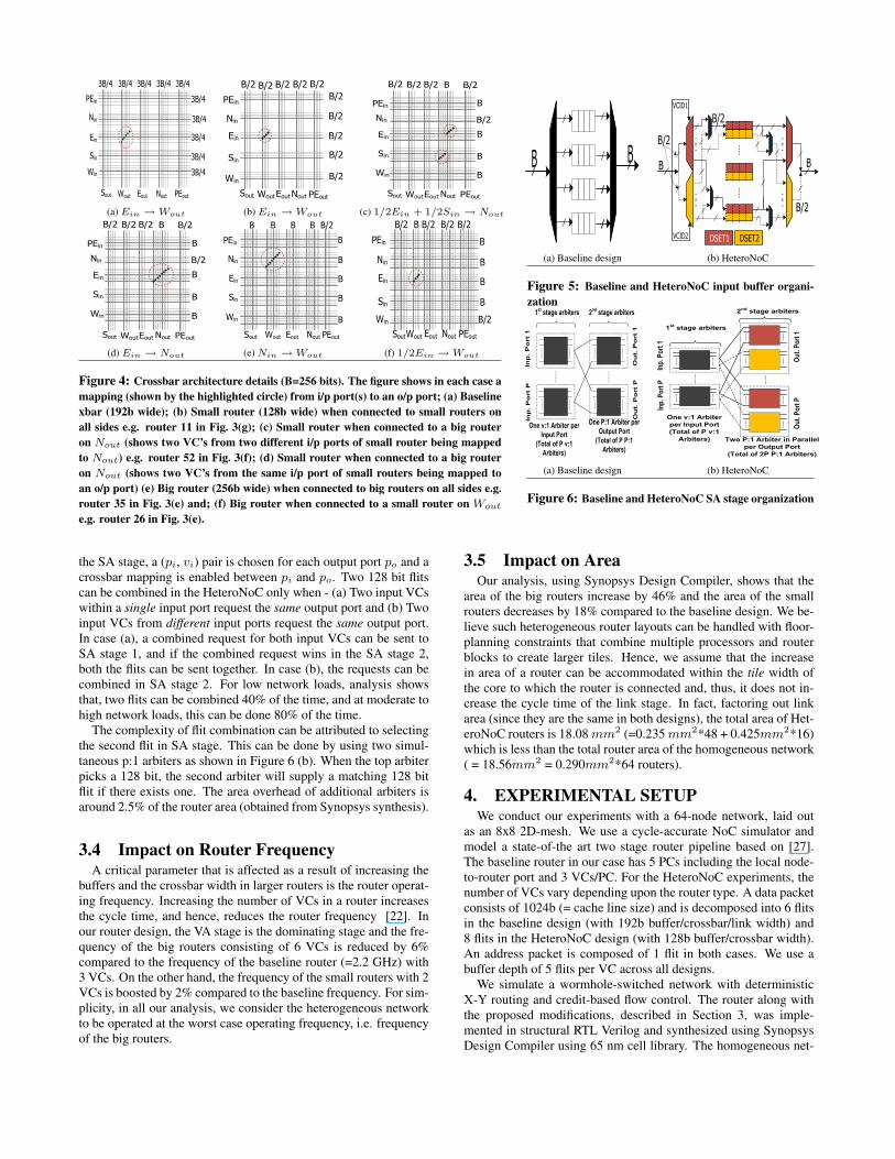
The detailed latency and power breakdowns across all HeteroNoCconfigurations with UR traffic are depicted in Figure 8. The net-work latency is divided into transfer latency, queuing delay at thesource node, and blocking delay at intermediate hops. The overallpower consumption in the routers is composed of the power con-sumptions in the router buffers (to read/write), arbiters and logic,crossbar transfer and link transmission. With the HeteroNoC de-sign, latency reduction results primarily by reducing the queuingand blocking latency (Figure 8 (a)). Wider links in big routersand combining two flits for simultaneous transmission help reducethese latency components. Power reduction comes primarily fromreduction in buffers (33%) and crossbar power (Figure 8 (b)).
Apart from UR traffic pattern, we also analyzed HeteroNoC con-figurations with transpose, bit-complement and self-similar trafficpatterns (not shown here due to space limitations) and observedthat the load-latency and power consumption curves are very simi-lar in trend to those obtained with UR traffic. This re-enforces thefact that our HeteroNoC design is not limited to a particular traffic

0
2
4
6
8
10
12
14
0.00
3125
0.01
25
0.02
5
0.03
75
0.05
0.06
25
0.07
5
0.08
75 0.1
0.11
25
Late
ncy
(nan
osec
onds
)
Injection ratio (packets/node/cycle)
Baseline
Center+B
Diagonal+B
Center_BL
Diagonal+B
-20
-15
-10
-5
0
5
10
15
20
25
Perc
enta
ge o
ver
bas
elin
e d
esig
n Throughput Avg. Latency Zero Load
0
5
10
15
20
25
Pow
er (W
atts
)
Injection ratio (packets/node/cycle)
Baseline
Center+BL
Diagonal+BL
Row2_5+BL
(a) Latency (b) Throughput improvement and latency reduction (c) Power
Figure 9: Performance and network power behavior with NN traffic.
0
10
20
30
40
50
60
70
80
90
100
% b
reak
dow
n in
late
ncy
(nor
mal
ized
to b
asel
ine)
blocking latency queuing latency transfer latency
(a) Latency breakdown
0
10
20
30
40
50
60
70
80
90
100
Baseline Center+BL Diagonal+BL Row2_5+BL
% b
reak
dow
n in
pow
er
(nor
mal
ized
to b
asel
ine
)
Links Xbar Arbiters+Logic Buffers
(b) Power breakdown
Figure 8: Latency and power breakdown with UR traffic.
pattern or layout. Rather, by redistributing resources intelligently,HeteroNoC is able to provide power-performance benefits acrossvarious traffic patterns. The only anomaly we found was with theNN traffic pattern (Figure 9 shows the performance-power curveswith NN traffic). With NN pattern, communication occurs betweenneighboring nodes. Since in HeteroNoC designs, we reduce thebuffer and link resources in most of the network routers, this affectsperformance for neighboring router communications and the net-work saturates earlier compared to the baseline design. Although,the zero-load latency reduces by 16% on an average in the com-bined buffer and link redistribution designs, the average networklatency increases by 7% and throughput reduces by 9.5%. Powerbenefits are also minimal (7%) with NN traffic. With NN traffic,Center+BL performs better than Diagonal+BL, since having all bigrouters in the center aids nearest neighbor communication betweenthe central routers.
5.1.1 Comparison with an Edge-Symmetric Network:Torus
To examine how our proposal performs with an edge-symmetricnetwork, we evaluated our design with an 8x8 torus network. Fig-ure 10 shows the results of this analysis, where the bars show theaverage latency reduction across all the application benchmarkssummarized in Table 2. For comparison, we also show the re-
0
5
10
15
20
Pe
rce
nta
ge
re
du
ctio
n o
ve
r
ba
seli
ne
Figure 10: Latency reduction in an 8x8 mesh vs. torus.
sults for a mesh network. While using heterogeneous routers ina torus topology provides marginal performance gain, the benefitsare on an average 44% less compared to employing heterogeneityin a mesh topology. Intuitively, this makes sense since on an aver-age, roughly 50% traffic use the loop-around links in the torus net-work and these traffic do not benefit from the additional resourcessolely at the central routers in the torus. Also, unlike the meshtopology, the heterogeneity in resource consumption is not primar-ily restricted to the center of the network, and changes dynamicallywith applications. Overall, static allocation of more resources to afew routers in a torus does not provide significant benefits.
5.2 System-level AnalysisFor system-level analysis, we evaluate our proposed CMP net-
work configurations using a trace-driven, cycle-accurate x86 CMPsimulator. The dynamic memory traces are collected using Simics.Our trace format consists of load/stores and the number of non-memory instructions between them. Our CPU model consists of afetch/issue/commit out-of-order pipeline with a reorder buffer (Ta-ble 2). We use a 64-tile CMP laid out on an 8x8 mesh platform witheach tile consisting of a core with a private write-back L1 cache andan L2 cache bank. The memory instructions are modeled throughthe detailed memory hierarchy and network model. The memoryhierarchy uses a two-level directory-based MESI cache coherenceprotocol and the network connects the cores, L2 cache banks, andmemory controllers. All requests and responses are faithfully mod-eled by the network. The CPU, network configurations and work-load details are given in Table 2, and the VC configurations for thetwo networks (homogeneous and HeteroNoC) are given in Table 1.
Figure 11 (a) shows the impact of using various HeteroNoC lay-outs on network latency. Re-distributing resources appropriatelyhelps reduce contention in the network and reduces end-to-end de-lay. Simultaneous transmission of flits reduces serialization latencyand thus, transfer latency (shown in Figure 11 (b)). Overall, wefind 18.5% average latency reduction with the Diagonal+BL layout

Table 2: CPU, Cache, Network and Workloads Configuration
CPU and network configuration
Processor Pipeline: 64 x86 based 2.2 GHz (nomi-nal) processors, two-way out of order, 64-entry in-struction window
Fetch/Exec/Commit width: 3 instructions per cy-cle in each core; only 1 can be a memory operation
L1 Caches: 32 KB per-core(private), 4-way set as-sociative, 128B block size, 2-cycle latency, write-back, split I/D caches
L2 Caches: 1MB bank(per-core), shared, 16-wayset associative, 128B block size, 6-cycles bank la-tency, 32 MSHRs
Main Memory: 4GB DRAM, up to 16 outstand-ing requests for each processor, 400 cycle access, 4memory controllers placed at corners of the meshnetwork (baseline)
Network and Router: 8x8 mesh network(eachtile consists of 1 CPU, private L1 cache, 1 sharedL2 bank and 1 router), 2-stage wormhole switchedrouter, X-Y routing.
Commercial workloads
App. Benchmark(SAP): SAP stands for Standard ApplicationBenchmark and represents a sales and distribution workload.Server Workload(SPECjbb): SPECjbb2000 is a Java basedbenchmark that models a 3-tier system. We simulated 64 ware-houses on 64 processors and start measurements 30 seconds afterramp-up time.Transaction Processing(TPC-C): TPC-C is an OLTPbenchmark.TPC-C simulates a complete computing environ-ment where a population of users executes transactions against adatabase.SPEC Java App. Server(SJAS): SJAS is a multi-tier benchmarkfor measuring the performance of J2EE technology-based applica-tion servers.The traces for TPC-C, SAP and SJAS benchmark were collectedfrom a CMP server configurations at Intel Corporation and we use64 threads from each benchmark.
SPEC2K6 libquantum benchmark: libquantum simulates a quan-tum computer, running Shor’s polynomial time factorization al-gorithm. We use liquantum when co-evaluating HeteroNoC withasymmetric CMPs.
PARSEC
PARSEC suite includes emergingRMS applications as well as largescale multi-threaded programsfor CMPs. From this suite wechoose three application bench-marks(ferret (frrt), facesim
(fsim) and vips) and three kernelbenchmarks(canneal (canl),
dedup (ddup) and streamclus-
ter (sclust)) and ran them withsimlarge input sets. Traces werecollected on a CMP platform(seeconfig. in (a)) using Simics for64 threads of each benchmark for20 million L2 references and thensimulated in our cycle-accurateprocessor-cache-network simula-tor.
(a) (b) (c)
across all of our application suites. Figures 11 (c) and (d) showthe reduction in power consumption and power breakdown, respec-tively. Reduction in crossbar power (using 128b wires vs 192bwires in baseline) and buffer power (since HeteroNoC uses 33%fewer buffers) are the primary reasons for reduction in overall net-work power. On an average, we find 18% (22% with Diagonal+BL)network power reduction with HeteroNoC designs across all appli-cation suites we evaluated.
Figures 12 (a) and (b) depict the percentage improvement in IPCover the baseline case, and again Diagonal+BL has the best resultswith 12% and 10% average improvements in IPC for commercialapplications and PARSEC benchmarks, respectively. Thus, withthe HeteroNoC designs, we not only use 33% fewer buffer and savein network power consumption, but also see IPC improvement.
6. CASE STUDY I: EVALUATION WITH
MEMORY CONTROLLERSA recent work by Abts et al. in [2] showed the efficacy of an op-
timal memory controller arrangement in a mesh based CMP plat-form with X-Y routing. They considered several memory controllerplacements and showed that when multiple memory controllers areplaced either along the network diagonals or in a diamond shape inthe network, the average packet latency and request-response vari-ance is minimized. Since, this work considers the placements ofbig and small routers in a mesh network, we co-examine Abts etal.’s memory controller layouts with our HeteroNoC designs.
For this co-evaluation, we considered both diagonal and diamondlayouts of memory controllers in the mesh network (the best lay-outs proposed in [2]) with the big routers placed along the net-work diagonals (the best HeteroNoC layout). Diamond placementof memory controllers complements the diagonal placement of bigrouters (Diagonal+BL design) with the memory controllers dis-tributed uniformly and symmetrically in the network. The numberof memory controllers used in this analysis is 16 (two controllersper row/column of the mesh). With diagonal placement of memorycontrollers, the big routers have additional local port VC buffersthat relay traffic destined to memory controllers. On an L2 miss,we use the low order address bits above the cache line address tochoose the destination memory controller.
We measured the round trip request-response delay from when amemory request is generated by a core to when the request arrivesback at the core after being serviced by the memory controller and
DRAM. To model the behavior of Miss Status Handling Registers(MSHRs) when using UR traffic, we perform a closed-loop evalu-ation, where up to 16 outstanding requests are allowed from a nodebefore halting packet injection in that node until the response pack-ets arrive from the requested memory controller. With benchmarks,we use the core and network configurations mentioned in Table 2(a).
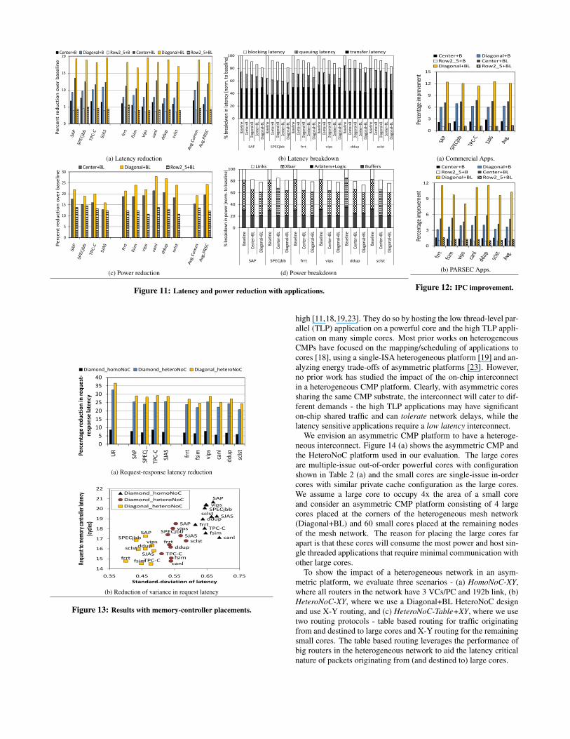
Figure 13 (a) shows the reduction in request-response latencyfor the three scenarios evaluated - (a) diamond memory controllerplacement in a homogeneous network where all routers have 3VCsand 192b links; annotated as Diamond_homoNoC in the figure, (b)diamond memory controller placement in a heterogeneous network(Diagonal+BL design); annotated as Diamond_heteroNoC, and (c)diagonal memory controller placement in the heterogeneous net-work (Diagonal+BL design); annotated as Diagonal_heteroNoC.
Diamond_homoNoC is the design which Abts et al. evaluatedin their work. Compared to this design that reduces the averageround trip latency by 8%, Diamond_heteroNoC helps lower aver-age request-response latency across all workloads by 22%. This issolely due to the HeteroNoC design that provisions more resourcesto the routers that service more traffic. Diagonal_heteroNoC per-forms the best and reduces average round trip delay by 28%. WithDiagonal_heteroNoC design, the memory controllers are attachedto big routers, which have more resources to effectively handle in-creased traffic without getting congested.
In addition, a diagonal placement of memory controllers helpsreduce the variance (or jitter) in the request latency to memorycontrollers. Figure 13 (b) shows the request latency vs. standarddeviation in request latency for the three configurations. The Di-agonal_heteroNoC design reduces the variance (0.46) when com-pared to the Diamond_homoNoC design (0.66). A lower standarddeviation together with reduced latency between cores and mem-ory controllers indicates that a combination of HeteroNoC and thediagonal configuration of memory controllers, provides predictabledelays to memory controllers regardless of which core a thread isscheduled on.
7. CASE STUDY II: EVALUATION WITH
ASYMMETRIC CORESRecent research has shown the potential of heterogeneous CMPs
in providing high single-threaded performance when thread par-allelism is low, and high throughput when thread parallelism is
0
5
10
15
20P
erc
en
t re
du
cti
on
ove
r b
ase
lin
eCenter+B Diagonal+B Row2_5+B Center+BL Diagonal+BL Row2_5+BL
0
20
40
60
80
100
Bas
elin
e
Cen
ter+
B
Dia
gon
al+B
Cen
ter+
BL
Dia
gon
al+B
L
Bas
elin
e
Cen
ter+
B
Dia
gon
al+B
Cen
ter+
BL
Dia
gon
al+B
L
Bas
elin
e
Cen
ter+
B
Dia
gon
al+B
Cen
ter+
BL
Dia
gon
al+B
L
Bas
elin
e
Cen
ter+
B
Dia
gon
al+B
Cen
ter+
BL
Dia
gon
al+B
L
Bas
elin
e
Cen
ter+
B
Dia
gon
al+B
Cen
ter+
BL
Dia
gon
al+B
L
Bas
elin
e
Cen
ter+
B
Dia
gon
al+B
Cen
ter+
BL
Dia
gon
al+B
L
SAP SPECjbb frrt vips ddup sclst
% b
reak
dw
on
in la
ten
cy (n
orm
. to
bas
elin
e)
blocking latency queuing latency transfer latency
(a) Latency reduction (b) Latency breakdown
0
5
10
15
20
25
30
Pe
rce
nt
red
ucti
on
ove
r b
ase
lin
e
Center+BL Diagonal+BL Row2_5+BL
0
20
40
60
80
100
Bas
elin
e
Cen
ter+
BL
Dia
gon
al+B
L
Bas
elin
e
Cen
ter+
BL
Dia
gon
al+B
L
Bas
elin
e
Cen
ter+
BL
Dia
gon
al+B
L
Bas
elin
e
Cen
ter+
BL
Dia
gon
al+B
L
Bas
elin
e
Cen
ter+
BL
Dia
gon
al+B
L
Bas
elin
e
Cen
ter+
BL
Dia
gon
al+B
L
SAP SPECjbb frrt vips ddup sclst
% b
reak
do
wn
in p
ow
er (
no
rm. t
o b
asel
ine)
Links Xbar Arbiters+Logic Buffers
(c) Power reduction (d) Power breakdown
Figure 11: Latency and power reduction with applications.
0
3
6
9
12
15
Perc
enta
ge im
prov
emen
t
Center+B Diagonal+B
Row2_5+B Center+BL
Diagonal+BL Row2_5+BL
(a) Commercial Apps.
0
3
6
9
12
Perc
enta
ge im
prov
emen
t
Center+B Diagonal+B
Row2_5+B Center+BL
Diagonal+BL Row2_5+BL
(b) PARSEC Apps.
Figure 12: IPC improvement.
0
5
10
15
20
25
30
35
40
UR
SAP
SPECj…
TPC-C
SJAS
frrt
fsim
vips
canl
ddup
sclst
Pe
rce
nta
ge
re
du
ctio
n i
n r
eq
ue
st-
resp
on
se l
ate
ncy
Diamond_homoNoC Diamond_heteroNoC Diagonal_heteroNoC
(a) Request-response latency reduction
SAP
SPECjbb
TPC-C
SJAS
frrt
fsim
vips
canl
ddup
sclst
SAP
SPECjbb
TPC-C
SJASfrrt
fsim
vipsddup
sclst
SAP
SPECjbb
TPC-C
SJAS
frrt
fsim
vips
canl
ddup
sclst
14
15
16
17
18
19
20
21
22
0.35 0.45 0.55 0.65 0.75
Requ
est t
o m
emor
y co
ntro
ller l
aten
cy
(cyc
les)
Diamond_homoNoC
Diamond_heteroNoC
Diagonal_heteroNoC
0.35 0.45 0.55 0.65 0.75
Standard-deviation of latency
(b) Reduction of variance in request latency
Figure 13: Results with memory-controller placements.
high [11,18,19,23]. They do so by hosting the low thread-level par-allel (TLP) application on a powerful core and the high TLP appli-cation on many simple cores. Most prior works on heterogeneousCMPs have focused on the mapping/scheduling of applications tocores [18], using a single-ISA heterogeneous platform [19] and an-alyzing energy trade-offs of asymmetric platforms [23]. However,no prior work has studied the impact of the on-chip interconnectin a heterogeneous CMP platform. Clearly, with asymmetric coressharing the same CMP substrate, the interconnect will cater to dif-ferent demands - the high TLP applications may have significanton-chip shared traffic and can tolerate network delays, while thelatency sensitive applications require a low latency interconnect.
We envision an asymmetric CMP platform to have a heteroge-neous interconnect. Figure 14 (a) shows the asymmetric CMP andthe HeteroNoC platform used in our evaluation. The large coresare multiple-issue out-of-order powerful cores with configurationshown in Table 2 (a) and the small cores are single-issue in-ordercores with similar private cache configuration as the large cores.We assume a large core to occupy 4x the area of a small coreand consider an asymmetric CMP platform consisting of 4 largecores placed at the corners of the heterogeneous mesh network(Diagonal+BL) and 60 small cores placed at the remaining nodesof the mesh network. The reason for placing the large cores farapart is that these cores will consume the most power and host sin-gle threaded applications that require minimal communication withother large cores.
To show the impact of a heterogeneous network in an asym-metric platform, we evaluate three scenarios - (a) HomoNoC-XY,where all routers in the network have 3 VCs/PC and 192b link, (b)HeteroNoC-XY, where we use a Diagonal+BL HeteroNoC designand use X-Y routing, and (c) HeteroNoC-Table+XY, where we usetwo routing protocols - table based routing for traffic originatingfrom and destined to large cores and X-Y routing for the remainingsmall cores. The table based routing leverages the performance ofbig routers in the heterogeneous network to aid the latency criticalnature of packets originating from (and destined to) large cores.

With table-based routing, packets to/from large cores are routedsuch that they leverage the big routers maximally. Figure 14 (a)shows two paths that packets originating from core 0 use to reachcache banks connected to routers 7 and 55. When packets origi-nating from core 0 (and hence router 0) want to reach a cache bankconnected to router 7, they are routed similar to X-Y routing. How-ever, when these packets want to access a cache bank connected torouter 55, they are routed in a zig-zag X-Y-X-Y fashion so as tomaximally use the big routers laid out along the diagonals. Table-based routing mandates maintaining source/destination pair infor-mation in all routers in the network. However, we use table-basedrouting only for packets to/from the four large cores, and hence,the table sizes are minimal when compared to maintaining tableinformation for all 64 cores in the network. Since the table-basedrouting approach can lead to deadlock scenarios, reserved escapeVCs are used in the big routers to resolve deadlocks. We sched-ule 60 threads of SPECjbb on the small cores and one instanceof libquantum benchmark on each large core. libquantum is a la-tency sensitive benchmark, whereas the multi-threaded SPECjbb,with each thread simulating one instance of a warehouse in a 3-tierJAVA server, represents a throughput-oriented application havinghigh TLP.
Figure 14 (b) shows the weighted speedup and harmonic speedupof the system with the three network layouts. These speedup met-rics are two commonly used multi-program performance metrics [8]based on comparing the IPC of an application when it runs aloneversus when it runs together with others. Harmonic speedup is ameasure of both performance and fairness. When computing theharmonic speedup, we take into account the IPC of the slowestthread of SPECjbb for computing the metric.
Table-based routing expedites libquantum packets by routing themthrough big routers. It also helps to accelerate SPECjbb packetsby reducing contention in small routers, since small routers arenow less frequently used by libquantum packets. Table-based rout-ing along with X-Y routing in a heterogeneous network providesthe maximum weighted speedup demonstrating the advantages ofselectively expediting libquantum packets. HeteroNoC+XY andHeteroNoC-Table+XY show 6% and 11% improvement, respec-tively, in weighted speedup over the HomoNoC-XY design. Theharmonic speedup also increases with HeteroNoC and table based-routing showing that selective expedition of libquantum packetsdoes not lead to system unfairness. With HeteroNoC-Table+XY,we find 11.5% improvement in harmonic speedup over the HomoNoC-XY design.
8. RELATED WORKInterest in on-chip networks has rapidly garnered momentum
over the last few years. Towards this end, most research has fo-cused on two major themes - improving the performance and reduc-ing power consumption. For improving performance, researchershave proposed the use of VCs and path speculation [27], smartpipelines [25], dynamic traffic re-distribution [16], and novel net-work topologies [14, 15]. To reduce power and thermal profilesin on-chip networks, several prior works have proposed communi-cation aware topologies [7, 9], power and thermal management inrouters [12, 22, 28], and bufferless routing [24]. Our approach isdifferent from all these proposals since, we leverage the fact thatnetworks have non-uniform resource usage, and hence, allocateresources accordingly without changing the routing or the trafficflows.
Prior work in the SoC domain have proposed customization ofon-chip resources like buffers [13], links [10, 20, 26] and topol-ogy [20, 21]. However, all these works adopt a static approach,
L2 $Large
Core 0 1 6 7
56 57 62 63
Large Core
Large Core
8 9 14 15
48 49 54 55
L2 $
L2 $
L2 $
L2 $
L2 $
L2 $
L2 $
L2 $
L2 $
L2 $
L2 $
L2 $
L2 $
Large CoreL2
$L2 $
Small Core
(a) Layout of an asymmetric CMP
0.6
0.62
0.64
0.66
0.68
0.7
0.72
0.74
0
0.25
0.5
0.75
1
1.25
1.5
HomoNoC-XY HeteroNoC-XY HeteroNoC-Table+XY
Ha
rmo
nic
Sp
ee
du
p
We
igh
ted
Sp
ee
du
p
Weighted Speedup Harmonic Speedup
(b) Performance improvement of SPECjbb and libquantum
Figure 14: Evaluation with an asymmetric CMP.
where optimal buffer sizes and link widths are pre-determined atdesign time based on a detailed analysis of application-specifictraffic patterns. The sizing is optimal for only one particular ap-plication or similar application suites and one hardware mapping.Thus, application characteristic needs to be known a-priori and thenetwork is customized for each target application. In contrast, wepropose a truly heterogeneous interconnect that is independent ofapplication type and is targeted for general purpose CMPs, whichhost a variety of applications, and, where customizing the NoC forone application is prohibitive.
A recent work by Bakhoda et al. [3] showed the effectiveness ofusing two kinds of routers – limited and full connectivity routers, ina mesh-based NoC for GPGPU applications. This design is basedon the observation of many-to-few-to-many traffic pattern in many-core accelerators. The limited connectivity routers allow traffic tobe routed only in certain directions and hence is inefficient (as iden-tified by the authors) for handling large number of cache to cachetransfers (e.g. coherence messages). Thus, such limited connectiv-ity and restricted routing works well in the context of accelerators,and it is not effective for general purpose CMPs, where traffic pat-terns are not deterministic and there are large number of inter-cachemessages. On the other hand, HeteroNoC is a generic concept thatcan be exploited for improving performance and power savings inany non-edge symmetric NoC.
Overall, we believe that no prior work has made a case for us-ing heterogeneous network for general purpose CMPs with carefulconsideration to the types, number and placement of heterogeneousrouters.
9. CONCLUSIONSIn this paper, we propose to leverage the non-uniform resource
usage in a homogeneous mesh interconnect for designing a het-erogeneous network, composed of big and small routers, by re-distributing the buffer and link bandwidth. We explore the designspace analysis in choosing the size, number and placement of thesebig and small routers and show that our HeteroNoC design with bigrouters placed along the network diagonals performs significantlybetter than the traditional homogeneous network under a variety of

traffic patterns. Detailed experimental analysis shows that for syn-thetic traffic patterns, our HeteroNoC design with the big routersalong the diagonals provides maximum benefits (23% and 26% re-duction in latency and power consumption, respectively) comparedto an equivalent homogeneous network. Evaluation with 10 di-verse application benchmarks shows that HeteroNoC can provideIPC improvements up to 12% and power reduction up to 22%. Ad-ditionally, our analysis shows that the non-uniformity in resourceutilization is an artifact of any non-edge symmetric network de-sign and deterministic X-Y routing, and this inherent artifact canbe leveraged to better customize the network.
In addition, we also demonstrated how the HeteroNoC can beuseful for enhancing the performance of heterogeneous CMPs andcomplement the placement of memory controllers in an NoC. Basedon our evaluations, we argue in favor of using heterogeneous NoCsfor enhancing the performance and reducing power consumptionof future general purpose multicore architectures, specifically de-signed with non-edge symmetric networks. The design is simple,should be applicable to a wide class of network configurations anddoes not incur significant overheads for practical implementation.
10. ACKNOWLEDGEMENTSWe thank Ravi Iyer (Intel Labs/IPR) for his valuable suggestions
in improving our work. We also thank the anonymous reviewersfor their reviews and comments towards improving this paper. Thiswork is supported in part by National Science Foundation (NSF)grants CCF-0702617, CNS-0916887 and CCF-0903432.
11. REFERENCES[1] International Technology Roadmap for Semiconductors,
2010 Edition.http://www.itrs.net/Links/2010ITRS/Home2010.htm.
[2] D. Abts, N. D. Enright Jerger, J. Kim, D. Gibson, and M. H.Lipasti. Achieving Predictable Performance Through BetterMemory Controller Placement in Many-Core CMPs. In 36th
ISCA, 2009.
[3] A. Bakhoda, J. Kim, and T. M. Aamodt.Throughput-Effective On-Chip Networks for ManycoreAccelerators. In MICRO-43, 2010.
[4] J. Balfour and W. J. Dally. Design Tradeoffs for Tiled CMPOn-Chip Networks. In ICS-20, 2006.
[5] C. Bienia, S. Kumar, J. P. Singh, and K. Li. The PARSECBenchmark Suite: Characterization and ArchitecturalImplications. In 17th PACT, 2008.
[6] W. J. Dally and B. Towles. Principles and Practices of
Interconnection Networks. Morgan Kaufmann, 2003.
[7] R. Das, S. Eachempati, A. Mishra, V. Narayanan, andC. Das. Design and Evaluation of a Hierarchical On-ChipInterconnect for Next-Generation CMPs. In 15th HPCA,
2009.
[8] S. Eyerman and L. Eeckhout. System-Level PerformanceMetrics for Multiprogram Workloads. Micro, IEEE, 2008.
[9] B. Grot, J. Hestness, S. Keckler, and O. Mutlu. Express CubeTopologies for on-Chip Interconnects. In 15th HPCA 2009.
[10] Z. Guz, I. Walter, E. Bolotin, I. Cidon, R. Ginosar, andA. Kolodny. Network Delays and Link Capacities inApplication-Specific Wormhole NoCs. VLSI ’07: Journal of
VLSI Design, vol. 2007.
[11] M. D. Hill and M. R. Marty. Amdahl’s Law in the MulticoreEra. IEEE COMPUTER, 2008.
[12] Y. Hoskote, S. Vangal, A. Singh, N. Borkar, and S. Borkar. A5-GHz Mesh Interconnect for a Teraflops Processor. InMicro, IEEE, volume 27, pages 51–61, Sept.-Oct. 2007.
[13] J. Hu and R. Marculescu. Application-specific buffer spaceallocation for networks-on-chip router design. In ICCAD,2004.
[14] J. Kim, W. Dally, S. Scott, and D. Abts. Technology-Driven,Highly-Scalable Dragonfly Topology. In 35th ISCA 2008.
[15] J. Kim, W. J. Dally, and D. Abts. Flattened Butterfly: ACost-Efficient Topology for High-Radix Networks. In 34th
ISCA, 2007.
[16] J. Kim, D. Park, T. Theocharides, N. Vijaykrishnan, andC. R. Das. A Low Latency Router Supporting Adaptivity forOn-Chip Router. In 42nd DAC, 2005.
[17] A. Kumar, L.-S. Peh, P. Kundu, and N. K. Jha. ExpressVirtual Channels: Towards the Ideal Interconnection Fabric.In 34th ISCA, 2007.
[18] R. Kumar, D. M. Tullsen, N. P. Jouppi, and P. Ranganathan.Heterogeneous Chip Multiprocessors. Computer, 38(11),2005.
[19] R. Kumar, D. M. Tullsen, P. Ranganathan, N. P. Jouppi, andK. I. Farkas. Single-ISA Heterogeneous Multi-CoreArchitectures for Multithreaded Workload Performance.SIGARCH Computer Architecture News, 32(2), 2004.
[20] R. Marculescu, U. Y. Ogras, and N. H. Zamora. Computationand Communication Refinement for Multiprocessor SoCDesign: A System-Level Perspective. ACM TODAES, 11(3),2006.
[21] A. Mejia, M. Palesi, J. Flich, S. Kumar, P. López,R. Hoismark, and J. Duato. Region-Based Routing: AMechanism to Support Efficient Routing Algorithms inNoCs. IEEE Transactions On VLSI Systems, 17(3), 2009.
[22] A. Mishra, R. Das, S. Eachempati, R. Iyer, V. Narayanan,and C. Das. A Case for Dynamic Frequency Tuning inOn-Chip Networks. In MICRO-42, 2010.
[23] T. Y. Morad, U. C. Weiser, A. Kolodny, M. Valero, andE. Ayguade. Performance, Power Efficiency and Scalabilityof Asymmetric Cluster Chip Multiprocessors. IEEE
Computer Architecture Letters, 2006.
[24] T. Moscibroda and O. Mutlu. A Case for Bufferless Routingin On-Chip Networks. In 36th ISCA, 2009.
[25] R. Mullins, A. West, and S. Moore. Low-LatencyVirtual-Channel Routers for On-Chip Networks. In 31st
ISCA, 2004.
[26] S. Murali, M. Coenen, A. Radulescu, K. Goossens, andG. De Micheli. Mapping and Configuration Methods forMulti-Use-Case Networks on Chips. In ASPDAC, 2006.
[27] L.-S. Peh and W. J. Dally. A Delay Model and SpeculativeArchitecture for Pipelined Routers. In 7th HPCA, 2001.
[28] L. Shang, L.-S. Peh, A. Kumar, and N. K. Jha. ThermalModeling, Characterization and Management of On-ChipNetworks. In MICRO-37, 2004.
[29] H. Wang, L.-S. Peh, and S. Malik. A Technology-Aware andEnergy-Oriented Topology Exploration for On-ChipNetworks. In DATE, 2005.
[30] H. Wang, X. Zhu, L.-S. Peh, and S. Malik. Orion: APower-Performance Simulator for Interconnection Networks.In MICRO-35, 2002.
Copyright © 2022 FDOKUMEN