Erin Boiler Solid Fuel Stove - Waterford Stanley
21
Erin Boiler Solid Fuel Stove INSTALLATION AND OPERATING INSTRUCTIONS This appliance is hot while in operation and retains its heat for a long period of time after use. Children, aged or infirm persons should be supervised at all times and should not be allowed to touch the hot working surfaces while in use or until the appliance has thoroughly cooled. When using the boiler stove in situations where children, aged and/or infirm persons are present a fire- guard must be used to prevent accidental contact with the stove. The fireguard should be manufactured in accordance with BS 6539.
-
Upload
khangminh22 -
Category
Documents
-
view
1 -
download
0
Transcript of Erin Boiler Solid Fuel Stove - Waterford Stanley
Erin Boiler Solid Fuel Stove
INSTALLATION AND OPERATING INSTRUCTIONSThis appliance is hot while in operation and retains its heat for a long period of time after use. Children,aged or infirm persons should be supervised at all times and should not be allowed to touch the hotworking surfaces while in use or until the appliance has thoroughly cooled.
When using the boiler stove in situations where children, aged and/or infirm persons are present a fire-guard must be used to prevent accidental contact with the stove. The fireguard should be manufactured in accordance with BS 6539.
TABLE OF CONTENTS
PAGE NO.
1. General . . . . . . . . . . . . . . . . . . . . . . . . . . . . . . . . . . . . . . . . . . . . . . . . . . . . . . . . . . . . . . . . . . . . . . . 4
Handling . . . . . . . . . . . . . . . . . . . . . . . . . . . . . . . . . . . . . . . . . . . . . . . . . . . . . . . . . . . . . . . . . . . . 4
Fire Cement . . . . . . . . . . . . . . . . . . . . . . . . . . . . . . . . . . . . . . . . . . . . . . . . . . . . . . . . . . . . . . . . . 4
Asbestos . . . . . . . . . . . . . . . . . . . . . . . . . . . . . . . . . . . . . . . . . . . . . . . . . . . . . . . . . . . . . . . . . . . . 4
Metal Parts . . . . . . . . . . . . . . . . . . . . . . . . . . . . . . . . . . . . . . . . . . . . . . . . . . . . . . . . . . . . . . . . . . 4
2. Pre-Installation Assembly . . . . . . . . . . . . . . . . . . . . . . . . . . . . . . . . . . . . . . . . . . . . . . . . . . . . . . . . . 4
3. Baffle Fitting Instructions . . . . . . . . . . . . . . . . . . . . . . . . . . . . . . . . . . . . . . . . . . . . . . . . . . . . . . . . . . 5
4. Flues . . . . . . . . . . . . . . . . . . . . . . . . . . . . . . . . . . . . . . . . . . . . . . . . . . . . . . . . . . . . . . . . . . . . . . . . . 6
5. Flue Pipes . . . . . . . . . . . . . . . . . . . . . . . . . . . . . . . . . . . . . . . . . . . . . . . . . . . . . . . . . . . . . . . . . . . . . 6
6. Top Flue Exit . . . . . . . . . . . . . . . . . . . . . . . . . . . . . . . . . . . . . . . . . . . . . . . . . . . . . . . . . . . . . . . . . . . 7
7. Rear Flue Exit . . . . . . . . . . . . . . . . . . . . . . . . . . . . . . . . . . . . . . . . . . . . . . . . . . . . . . . . . . . . . . . . . . 7
8. Chimney . . . . . . . . . . . . . . . . . . . . . . . . . . . . . . . . . . . . . . . . . . . . . . . . . . . . . . . . . . . . . . . . . . . . . . 7
9. Ventilation & Combustion Air Requirements . . . . . . . . . . . . . . . . . . . . . . . . . . . . . . . . . . . . . . . . . . . 7
10. Location . . . . . . . . . . . . . . . . . . . . . . . . . . . . . . . . . . . . . . . . . . . . . . . . . . . . . . . . . . . . . . . . . . . . . . . 8
11. Installation Clearances . . . . . . . . . . . . . . . . . . . . . . . . . . . . . . . . . . . . . . . . . . . . . . . . . . . . . . . . . . . 8
12. Floor Protection . . . . . . . . . . . . . . . . . . . . . . . . . . . . . . . . . . . . . . . . . . . . . . . . . . . . . . . . . . . . . . . . . 8
13. Permanent Air Vent . . . . . . . . . . . . . . . . . . . . . . . . . . . . . . . . . . . . . . . . . . . . . . . . . . . . . . . . . . . . . . 8
Extractor Fan . . . . . . . . . . . . . . . . . . . . . . . . . . . . . . . . . . . . . . . . . . . . . . . . . . . . . . . . . . . . . . . . 8
14. Flue & Water Pipe Locations . . . . . . . . . . . . . . . . . . . . . . . . . . . . . . . . . . . . . . . . . . . . . . . . . . . . . . 9
15. Shroud Assembly . . . . . . . . . . . . . . . . . . . . . . . . . . . . . . . . . . . . . . . . . . . . . . . . . . . . . . . . . . . . . . . 9
16. Plumbing . . . . . . . . . . . . . . . . . . . . . . . . . . . . . . . . . . . . . . . . . . . . . . . . . . . . . . . . . . . . . . . . . . . . . . 10
17. Regulations . . . . . . . . . . . . . . . . . . . . . . . . . . . . . . . . . . . . . . . . . . . . . . . . . . . . . . . . . . . . . . . . . . . . 10
18. Gravity Circuit . . . . . . . . . . . . . . . . . . . . . . . . . . . . . . . . . . . . . . . . . . . . . . . . . . . . . . . . . . . . . . . . . . 10
19. Injector Tee . . . . . . . . . . . . . . . . . . . . . . . . . . . . . . . . . . . . . . . . . . . . . . . . . . . . . . . . . . . . . . . . . . . . 10
20. Water Circuit Temperature . . . . . . . . . . . . . . . . . . . . . . . . . . . . . . . . . . . . . . . . . . . . . . . . . . . . . . . . 10
21. Pipe Thermostat . . . . . . . . . . . . . . . . . . . . . . . . . . . . . . . . . . . . . . . . . . . . . . . . . . . . . . . . . . . . . . . . 11
22. Handover . . . . . . . . . . . . . . . . . . . . . . . . . . . . . . . . . . . . . . . . . . . . . . . . . . . . . . . . . . . . . . . . . . . . . . 11
23. Specification . . . . . . . . . . . . . . . . . . . . . . . . . . . . . . . . . . . . . . . . . . . . . . . . . . . . . . . . . . . . . . . . . . . 11
24. Technical Data . . . . . . . . . . . . . . . . . . . . . . . . . . . . . . . . . . . . . . . . . . . . . . . . . . . . . . . . . . . . . . . . . . 11
25. Important Notes . . . . . . . . . . . . . . . . . . . . . . . . . . . . . . . . . . . . . . . . . . . . . . . . . . . . . . . . . . . . . . . . . 12
26. Lighting . . . . . . . . . . . . . . . . . . . . . . . . . . . . . . . . . . . . . . . . . . . . . . . . . . . . . . . . . . . . . . . . . . . . . . . 13
27. Operating Instructions . . . . . . . . . . . . . . . . . . . . . . . . . . . . . . . . . . . . . . . . . . . . . . . . . . . . . . . . . . . . 14
28. Recommended Fuels . . . . . . . . . . . . . . . . . . . . . . . . . . . . . . . . . . . . . . . . . . . . . . . . . . . . . . . . . . . . 14
29. Thermostat Operation . . . . . . . . . . . . . . . . . . . . . . . . . . . . . . . . . . . . . . . . . . . . . . . . . . . . . . . . . . . . 14
30. Secondary Air Control . . . . . . . . . . . . . . . . . . . . . . . . . . . . . . . . . . . . . . . . . . . . . . . . . . . . . . . . . . . . 14
31. De-Ashing . . . . . . . . . . . . . . . . . . . . . . . . . . . . . . . . . . . . . . . . . . . . . . . . . . . . . . . . . . . . . . . . . . . . . 15
32. Disposal of Ashes . . . . . . . . . . . . . . . . . . . . . . . . . . . . . . . . . . . . . . . . . . . . . . . . . . . . . . . . . . . . . . . 15
33. To Clean Chimney Back Outlet . . . . . . . . . . . . . . . . . . . . . . . . . . . . . . . . . . . . . . . . . . . . . . . . . . . . . 16
34. To Replace Rocker Op Sleeve . . . . . . . . . . . . . . . . . . . . . . . . . . . . . . . . . . . . . . . . . . . . . . . . . . . . . 16
35. Radiation Surface . . . . . . . . . . . . . . . . . . . . . . . . . . . . . . . . . . . . . . . . . . . . . . . . . . . . . . . . . . . . . . . 16
2
TABLE OF CONTENTS
PAGE NO.
36. Fire Safety . . . . . . . . . . . . . . . . . . . . . . . . . . . . . . . . . . . . . . . . . . . . . . . . . . . . . . . . . . . . . . . . . . . . . 16
37. In Case of Fire . . . . . . . . . . . . . . . . . . . . . . . . . . . . . . . . . . . . . . . . . . . . . . . . . . . . . . . . . . . . . . . . . 17
38. Vitreous Enamel Cleaning . . . . . . . . . . . . . . . . . . . . . . . . . . . . . . . . . . . . . . . . . . . . . . . . . . . . . . . . . 17
39. Door Latch Adjustment . . . . . . . . . . . . . . . . . . . . . . . . . . . . . . . . . . . . . . . . . . . . . . . . . . . . . . . . . . . 17
40. Glass Cleaning . . . . . . . . . . . . . . . . . . . . . . . . . . . . . . . . . . . . . . . . . . . . . . . . . . . . . . . . . . . . . . . . . 18
41. Glass Replacement . . . . . . . . . . . . . . . . . . . . . . . . . . . . . . . . . . . . . . . . . . . . . . . . . . . . . . . . . . . . . . 18
42. CO Alarm . . . . . . . . . . . . . . . . . . . . . . . . . . . . . . . . . . . . . . . . . . . . . . . . . . . . . . . . . . . . . . . . . . . . . . 18
43. Exploded View . . . . . . . . . . . . . . . . . . . . . . . . . . . . . . . . . . . . . . . . . . . . . . . . . . . . . . . . . . . . . . . . . 19
44. Installation Check List . . . . . . . . . . . . . . . . . . . . . . . . . . . . . . . . . . . . . . . . . . . . . . . . . . . . . . . . . . . . 20
3
THE ERIN SOLID FUEL CENTRAL HEATING STOVE
INSTALLATION & OPERATING INSTRUCTIONS
GENERAL
When installing, operating and maintaining your
Erin Stove respect basic standards of fire safety.
Read these instructions carefully before commenc-
ing the installation. Failure to do so may result in
damage to persons and property. consult your local
Municipal office and your insurance representative
to determine what regulations are in force. Save
these instructions for future reference.
Please note that it is a legal requirement under
England & Wales Building Regulations that the
installation of the stove is either carried out under
Local Authority Building Control approval or is
installed by a Competent Person registered with a
Government approved Competent Persons
Scheme. HETAS Ltd operate such a scheme and a
listing of their Registered Competent Persons can
be found on their website at www.hetas.co.uk.
Special care must be taken when installing the stove
such that the requirements of the Health & Safety at
Work Act are met.
HandlingAdequate facilities must be available for loading,
unloading and site handling.
Fire CementSome types of fire cement are caustic and should
not be allowed to come into contact with the skin. In
case of contact with the skin wash immediately with
plenty of water.
AsbestosThis stove contains no asbestos. If there is a possi-
bility of disturbing any asbestos in the course of
installation then please seek specialist guidance and
use appropriate protective equipment.
Metal PartsWhen installing or servicing this stove care should
be taken to avoid the possibility of personal injury.
“IMPORTANT WARNING”
This stove must not be installed into a chimney that
serves any other heating appliance.
There must not be an extractor fan fitted in the same
room as the stove as this can cause the stove to
emit fumes into the room.
4
The complete installation must be done in accor-dance with current Standards and Local Codes. Itshould be noted that the requirements and thesepublications may be superseded during the life ofthis manual.
(E) Manover the stove so that it overlaps the pallet
by no more than 80mm.
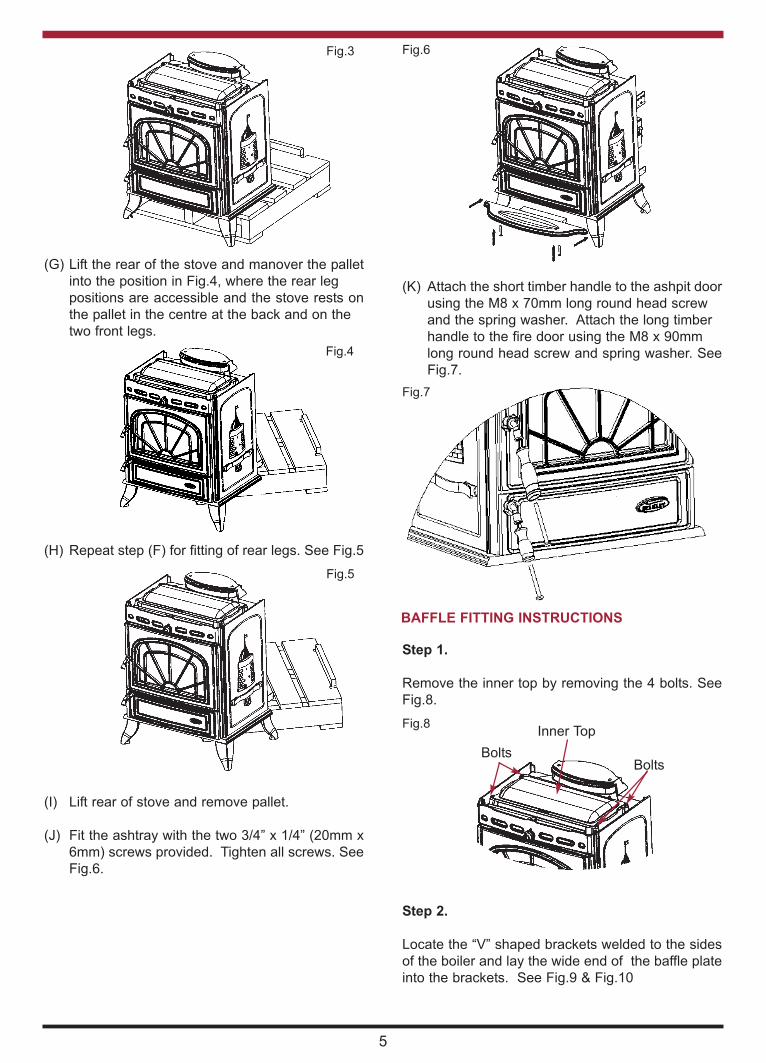
(F) Remove the two transport screws from the front
leg positions and fit the legs using the M10 x
20mm hex head bolts. See Fig. 2 & 3.
Fig.2
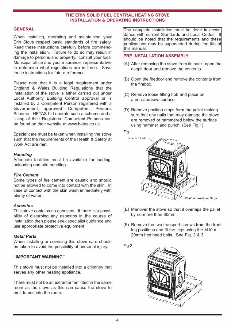
Fig.1
PRE INSTALLATION ASSEMBLY
(A) After removing the stove from its pack, open the
ashpit door and remove the contents.
(B) Open the firedoor and remove the contents from
the firebox.
(C) Remove loose fitting hob and place on
a non abrasive surface.
(D) Remove position stops form the pallet making
sure that any nails that may damage the stove
are removed or hammered below the surface
using hammer and punch. (See Fig.1)
(H) Repeat step (F) for fitting of rear legs. See Fig.5
(G) Lift the rear of the stove and manover the pallet
into the position in Fig.4, where the rear leg
positions are accessible and the stove rests on
the pallet in the centre at the back and on the
two front legs.
Fig.3
Fig.4
Fig.5
(I) Lift rear of stove and remove pallet.
(J) Fit the ashtray with the two 3/4” x 1/4” (20mm x
6mm) screws provided. Tighten all screws. See
Fig.6.
Fig.6
(K) Attach the short timber handle to the ashpit door
using the M8 x 70mm long round head screw
and the spring washer. Attach the long timber
handle to the fire door using the M8 x 90mm
long round head screw and spring washer. See
Fig.7.
Fig.7
5
BAFFLE FITTING INSTRUCTIONS
Step 1.
Remove the inner top by removing the 4 bolts. See
Fig.8.
Inner Top
Bolts Bolts
Step 2.
Locate the “V” shaped brackets welded to the sides
of the boiler and lay the wide end of the baffle plate
into the brackets. See Fig.9 & Fig.10
Fig.8

Fig.9
Step 3
Lift the top edge of the baffle plate and place the
wedge shape on the boiler cross tank with the
pointed end facing up. Push the wedge down which
will push the baffle back into position. See Fig.11
Fig.11
Fig.10
FLUES
Flues should be vertical wherever possible and
where a bend is necessary, it should not make an
angle of more than 45o with the vertical. Horizontal
flue runs should be avoided except in the case of a
back outlet from the appliance, when the length of
the horizontal section should not exceed 150mm
(6”).
In order to minimise flue resistance and to make
sweeping easier it is recommended to use 2 x 45o
bends rather than a 90o bend.
The flue termination point must be located to min-
imise any wind effects. Wind effects of suction,
pressure zones and turbulence can be created by
the roof and adjacent objects. Wind effects can also
be created by natural land contours.
To minimise the wind effects, the flue termination
point should be located a minimum of 1000mm from
the roof measured vertically and 2300mm measured
horizontally. Where this termination point does not
suffice it may be necessary to extend the flue pipe
so that the termination point is above the apex. (See
Fig.12)
2300
1000
Soot DoorAppliance
Fig.12
FLUE PIPES
A flue pipe should only be used to connect an appli-
ance to a chimney and should not pass through any
roof space.
6
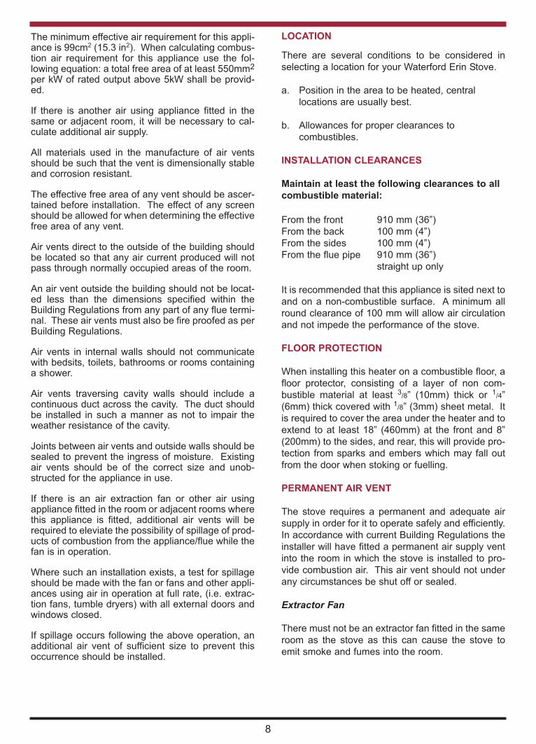
REAR FLUE EXIT
Fit the top cover plate to the stove with the two
screws holding on the rear exit cover plate making
sure that the sealing rope is properly seated on the
stove flue outlet. Tighten screws.
It is recommended that a minimum clearance of
100mm be maintained from the sides and rear of the
appliance to a tiled fireplace or masonry wall, espe-
cially on the right of the appliance as access is
required for the controls. See Fig.14.
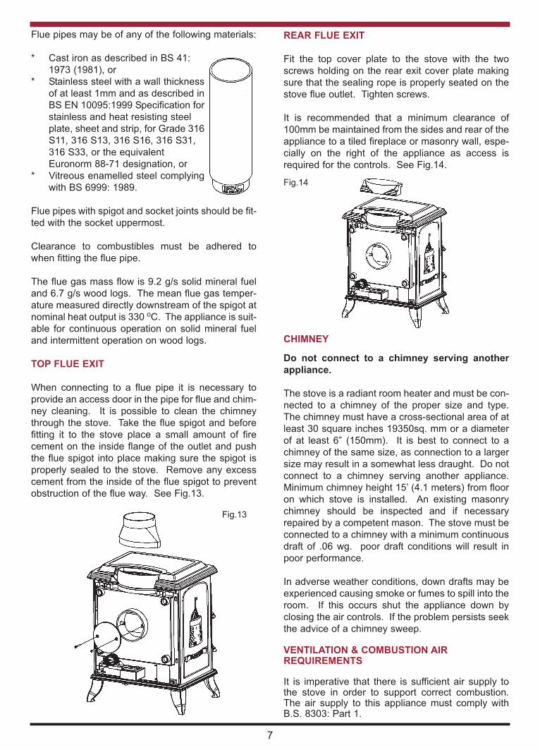
Fig.13
Flue pipes may be of any of the following materials:
* Cast iron as described in BS 41:
1973 (1981), or
* Stainless steel with a wall thickness
of at least 1mm and as described in
BS EN 10095:1999 Specification for
stainless and heat resisting steel
plate, sheet and strip, for Grade 316
S11, 316 S13, 316 S16, 316 S31,
316 S33, or the equivalent
Euronorm 88-71 designation, or
* Vitreous enamelled steel complying
with BS 6999: 1989.
Flue pipes with spigot and socket joints should be fit-
ted with the socket uppermost.
Clearance to combustibles must be adhered to
when fitting the flue pipe.
The flue gas mass flow is 9.2 g/s solid mineral fuel
and 6.7 g/s wood logs. The mean flue gas temper-
ature measured directly downstream of the spigot at
nominal heat output is 330 oC. The appliance is suit-
able for continuous operation on solid mineral fuel
and intermittent operation on wood logs.
TOP FLUE EXIT
When connecting to a flue pipe it is necessary to
provide an access door in the pipe for flue and chim-
ney cleaning. It is possible to clean the chimney
through the stove. Take the flue spigot and before
fitting it to the stove place a small amount of fire
cement on the inside flange of the outlet and push
the flue spigot into place making sure the spigot is
properly sealed to the stove. Remove any excess
cement from the inside of the flue spigot to prevent
obstruction of the flue way. See Fig.13.
Fig.14
7
CHIMNEY
Do not connect to a chimney serving another
appliance.
The stove is a radiant room heater and must be con-
nected to a chimney of the proper size and type.
The chimney must have a cross-sectional area of at
least 30 square inches 19350sq. mm or a diameter
of at least 6” (150mm). It is best to connect to a
chimney of the same size, as connection to a larger
size may result in a somewhat less draught. Do not
connect to a chimney serving another appliance.
Minimum chimney height 15’ (4.1 meters) from floor
on which stove is installed. An existing masonry
chimney should be inspected and if necessary
repaired by a competent mason. The stove must be
connected to a chimney with a minimum continuous
draft of .06 wg. poor draft conditions will result in
poor performance.
In adverse weather conditions, down drafts may be
experienced causing smoke or fumes to spill into the
room. If this occurs shut the appliance down by
closing the air controls. If the problem persists seek
the advice of a chimney sweep.
VENTILATION & COMBUSTION AIR REQUIREMENTS
It is imperative that there is sufficient air supply tothe stove in order to support correct combustion.The air supply to this appliance must comply withB.S. 8303: Part 1.
The minimum effective air requirement for this appli-ance is 99cm2 (15.3 in2). When calculating combus-tion air requirement for this appliance use the fol-lowing equation: a total free area of at least 550mm2
per kW of rated output above 5kW shall be provid-ed.
If there is another air using appliance fitted in thesame or adjacent room, it will be necessary to cal-culate additional air supply.
All materials used in the manufacture of air ventsshould be such that the vent is dimensionally stableand corrosion resistant.
The effective free area of any vent should be ascer-tained before installation. The effect of any screenshould be allowed for when determining the effectivefree area of any vent.
Air vents direct to the outside of the building shouldbe located so that any air current produced will notpass through normally occupied areas of the room.
An air vent outside the building should not be locat-ed less than the dimensions specified within theBuilding Regulations from any part of any flue termi-nal. These air vents must also be fire proofed as perBuilding Regulations.
Air vents in internal walls should not communicatewith bedsits, toilets, bathrooms or rooms containinga shower.
Air vents traversing cavity walls should include acontinuous duct across the cavity. The duct shouldbe installed in such a manner as not to impair theweather resistance of the cavity.
Joints between air vents and outside walls should besealed to prevent the ingress of moisture. Existingair vents should be of the correct size and unob-structed for the appliance in use.
If there is an air extraction fan or other air usingappliance fitted in the room or adjacent rooms wherethis appliance is fitted, additional air vents will berequired to eleviate the possibility of spillage of prod-ucts of combustion from the appliance/flue while thefan is in operation.
Where such an installation exists, a test for spillageshould be made with the fan or fans and other appli-ances using air in operation at full rate, (i.e. extrac-tion fans, tumble dryers) with all external doors andwindows closed.
If spillage occurs following the above operation, anadditional air vent of sufficient size to prevent thisoccurrence should be installed.
8
LOCATION
There are several conditions to be considered in
selecting a location for your Waterford Erin Stove.
a. Position in the area to be heated, central
locations are usually best.
b. Allowances for proper clearances to
combustibles.
INSTALLATION CLEARANCES
Maintain at least the following clearances to all
combustible material:
From the front 910 mm (36”)
From the back 100 mm (4”)
From the sides 100 mm (4”)
From the flue pipe 910 mm (36”)
straight up only
It is recommended that this appliance is sited next to
and on a non-combustible surface. A minimum all
round clearance of 100 mm will allow air circulation
and not impede the performance of the stove.
FLOOR PROTECTION
When installing this heater on a combustible floor, a
floor protector, consisting of a layer of non com-
bustible material at least 3/8” (10mm) thick or 1
/4”
(6mm) thick covered with 1/8” (3mm) sheet metal. It
is required to cover the area under the heater and to
extend to at least 18” (460mm) at the front and 8”
(200mm) to the sides, and rear, this will provide pro-
tection from sparks and embers which may fall out
from the door when stoking or fuelling.
PERMANENT AIR VENT
The stove requires a permanent and adequate air
supply in order for it to operate safely and efficiently.
In accordance with current Building Regulations the
installer will have fitted a permanent air supply vent
into the room in which the stove is installed to pro-
vide combustion air. This air vent should not under
any circumstances be shut off or sealed.
Extractor Fan
There must not be an extractor fan fitted in the same
room as the stove as this can cause the stove to
emit smoke and fumes into the room.
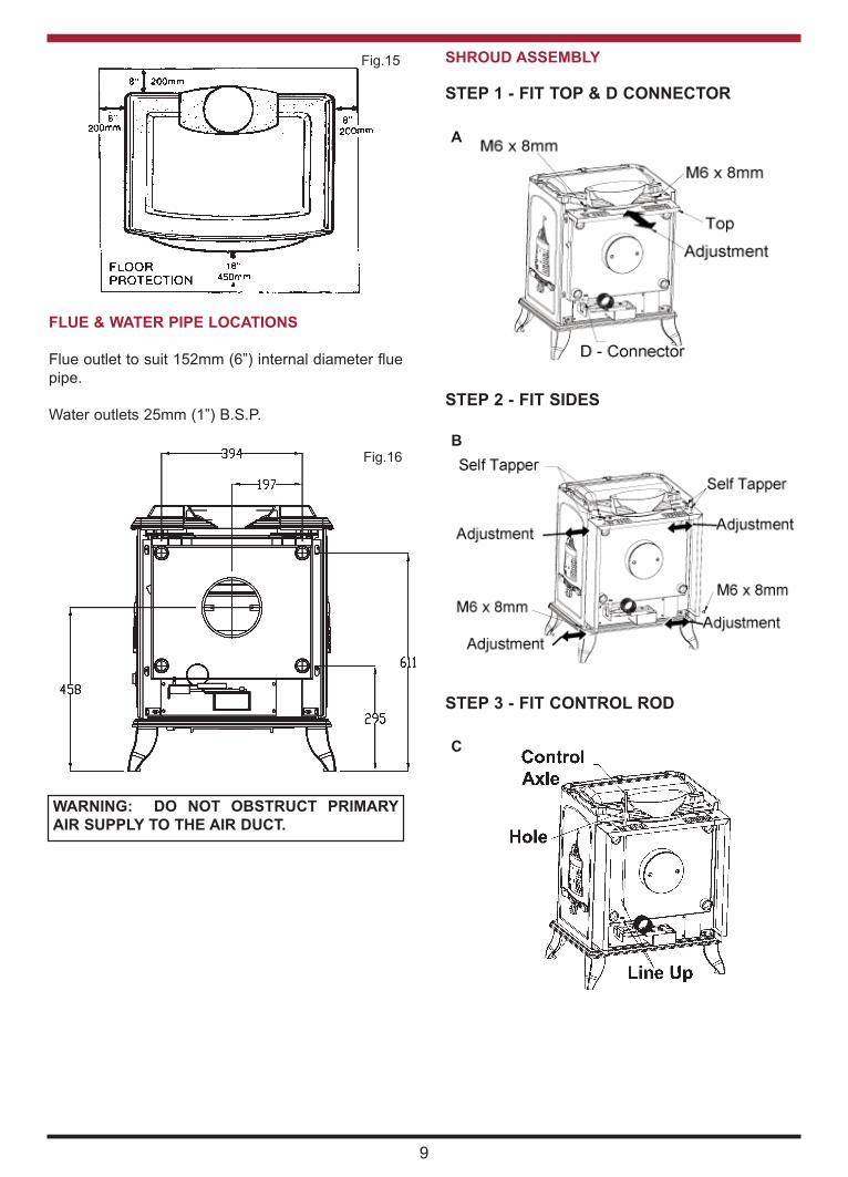
Fig.15
FLUE & WATER PIPE LOCATIONS
Flue outlet to suit 152mm (6”) internal diameter flue
pipe.
Water outlets 25mm (1”) B.S.P.
Fig.16
WARNING: DO NOT OBSTRUCT PRIMARY
AIR SUPPLY TO THE AIR DUCT.
9
SHROUD ASSEMBLY
STEP 1 - FIT TOP & D CONNECTOR
STEP 2 - FIT SIDES
STEP 3 - FIT CONTROL ROD
A
B
C

PLUMBING
REGULATIONS
The plumbing must be in accordance with all
relevant regulations and practices. It must include a
gravity circuit with expansion pipe, open to the
atmosphere. The central heating will normally be
pump-driven as with other types of boilers.
GRAVITY CIRCUIT
The gravity circuit consists of the domestic hot water
tank of 135 litres indirect cylinder, fixed in an upright
position, recommended for hot water storage and it
should be connected to the boiler by 28mm diame-
ter flow and return piping. The pipes should not
exceed 7.8 meters (25ft) in length and cylinder and
pipework should be fully lagged. The shorter the run
of pipe work the more effective the water
heating.There must be no gate valves on this circuit
and it must have an expansion pipe exhausting to
atmosphere. Cylinder and pipe work should be
lagged to minimise heat loss.
This diagram illustrates the basic principal of water
heating systems and must not be regarded as a
working drawing. See Fig.17.
Fig.17
INJECTOR TEE
Where the gravity and central heating circuits join
together to return to the stove we recommend the
use of an injector tee connection, situated as close
to the unit as possible. This type of tee encourages
a stable flow of hot water through both circuits and
helps to prevent priority being given to the stronger
flow, which is most commonly the pumped central
heating circuit. This way, there will be no shortage
of hot water to the taps when the heating is on.
WATER CIRCUIT TEMPERATURE
The return water temperature should be maintained
at not less than 40°C so as to avoid condensation on
the boiler and return piping. Fitting a pipe thermo-
stat to the flow pipe of the gravity circuit and wiring it
into the pump control will ensure rapid circulation of
the hot water.
In some circumstances it may be possible to over-
heat the appliance and the water inside will boil.
This will be evident by the sound of a knocking noise
coming from the appliance and pipes around the
house. If this occurs close off all air controls and
manually start the central heating pump if fitted.
One radiator on the heating circuit should be uncon-
trolled to act as a heat leak in the event that the
appliance overheats and has nowhere to discharge
a build up of hot water should the heating circuit be
satisfied. Be aware that steam and boiling water will
be expended from any open vent from the heating
system probably in the roof space at the expansion
tank.
In the unlikely event that the appliance is not oper-
ating in freezing conditions the water must be
drained from the boiler to prevent frost damage.
Injector Tee
Pump
STEP 4 - FIT CONTROL KNOB & INSERT
SPLIT PIN
D
10
11
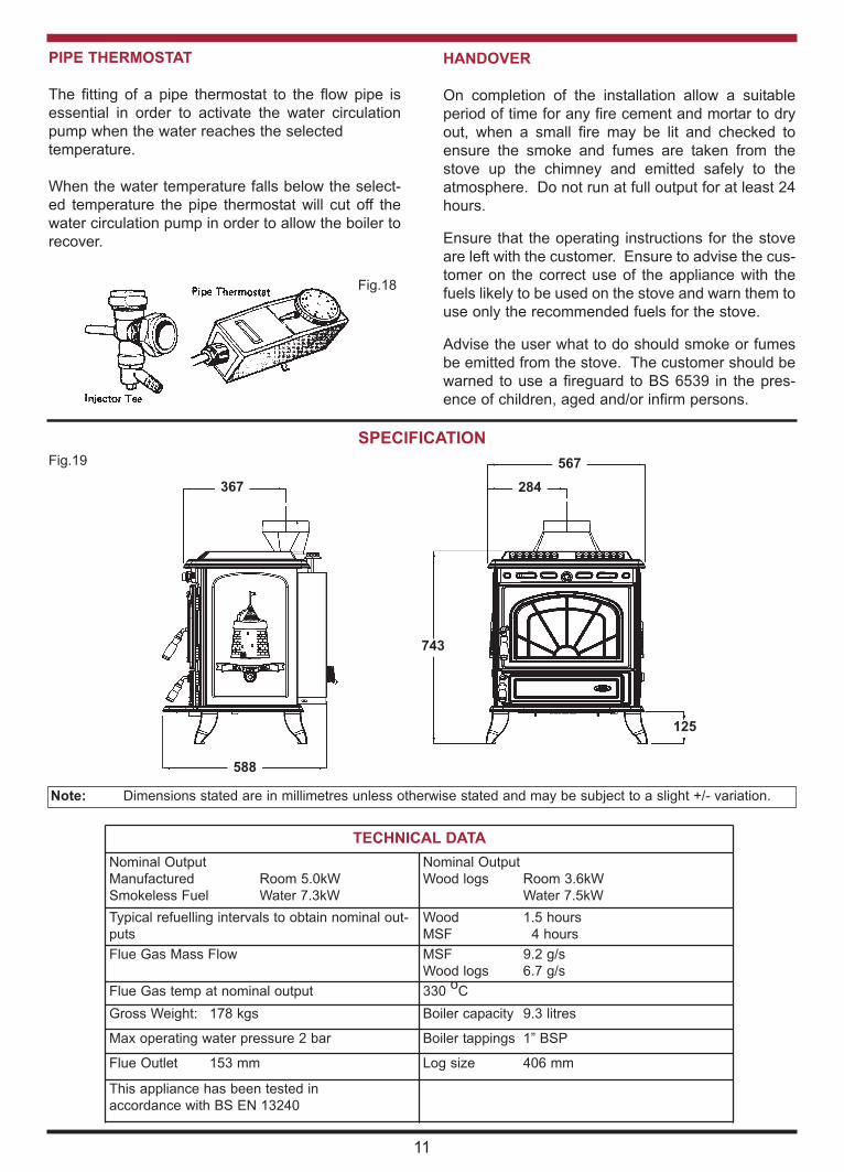
PIPE THERMOSTAT
The fitting of a pipe thermostat to the flow pipe is
essential in order to activate the water circulation
pump when the water reaches the selected
temperature.
When the water temperature falls below the select-
ed temperature the pipe thermostat will cut off the
water circulation pump in order to allow the boiler to
recover.
Fig.18
HANDOVER
On completion of the installation allow a suitable
period of time for any fire cement and mortar to dry
out, when a small fire may be lit and checked to
ensure the smoke and fumes are taken from the
stove up the chimney and emitted safely to the
atmosphere. Do not run at full output for at least 24
hours.
Ensure that the operating instructions for the stove
are left with the customer. Ensure to advise the cus-
tomer on the correct use of the appliance with the
fuels likely to be used on the stove and warn them to
use only the recommended fuels for the stove.
Advise the user what to do should smoke or fumes
be emitted from the stove. The customer should be
warned to use a fireguard to BS 6539 in the pres-
ence of children, aged and/or infirm persons.
SPECIFICATION
Fig.19
743
588
367
567
284
125
TECHNICAL DATA
Nominal Output
Manufactured Room 5.0kW
Smokeless Fuel Water 7.3kW
Nominal Output
Wood logs Room 3.6kW
Water 7.5kW
Typical refuelling intervals to obtain nominal out-
puts
Wood 1.5 hours
MSF 4 hours
Flue Gas Mass Flow MSF 9.2 g/s
Wood logs 6.7 g/s
Flue Gas temp at nominal output 330 o
C
Gross Weight: 178 kgs Boiler capacity 9.3 litres
Max operating water pressure 2 bar Boiler tappings 1” BSP
Flue Outlet 153 mm Log size 406 mm
This appliance has been tested in
accordance with BS EN 13240
Note: Dimensions stated are in millimetres unless otherwise stated and may be subject to a slight +/- variation.

IMPORTANT NOTES
Now that your Solid Fuel Stove is installed and no doubt you are looking forward to many comforts it will pro-
vide, we would like to give you some tips on how to get the best results from your stove.
1. We would like if you could take some time to read the operating instructions/hints, which we are
confident, will be of great benefit to you.
2. Do not burn fuel with a high moisture content, such as a damp peat or unseasoned timber. This will
only result in a build up of tar in the stove and in the chimney.
3. Clean the flue-ways of the stove weekly and ensure that there are no blockages. Check flueways
before lighting especially after a shut down period. Please refer to manual for instructions.
4. Before loading fresh fuel into the firebox, riddle fully to remove all ashes this will allow better and
cleaner burning. See Re-Fuelling section.
5. Never allow a build up of ashes in the ash pan, as this will cause the grate to burn out prematurely.
Empty the ashpan when refuelling.
6. Allow adequate air ventilation to ensure plenty of air for combustion.
7. Do not use as an incinerator burning rubbish/household waste.
8. Do not leave ash-door open for long periods as this will over heat the unit causing unnecessary
damage. Close the ash door between removing and replacing the ashpan.
9. Clean the chimney at least twice a year.
10. Burning soft fuels such as timber and peat will stain the glass. Regular cleaning will prevent
permanent staining. Clean with soapy water when cool.
11. Keep all combustible materials a safe distance away from unit, please see section for clearances
to combustibles.
12. For safety reasons never leave children or the elderly unaccompanied while stove is in use. Use a
fire guard.
13. Avoid contact with the appliance when in use as stove reaches very high operating temperatures.
14. This appliance should be regularly maintained by a competent service engineer.
Use only replacement parts recommended by Stanley. Making unauthorised modifications, or using unautho-
rised parts will invalidate your guarantee and may cause damage or injury.
FUEL CALORIFIC VALUES - SOLID FUELS
Anthracite 25-50mm C.V.: 8.2kW/Kg 14,000 BTUs/lb
House Coal 25-75mm C.V.: 7.2kW/Kg 12,000 BTUs/lb
Timber - Firebox size C.V.: 5.0kW/Kg 8,600 BTUs/lb
Peat Briquettes C.V.: 4.8kW/Kg 8,300 BTUs/lb
12
AN ODOUR WILL EMIT FROM STOVE ON FIRST FIRING, WHEN FIRE REACHES MAXIMUM
TEMPERATURE OVER A NUMBER OF HOURS THE ODOUR WILL SUBSIDE.
IT IS BEST ADVISED TO OPEN WINDOWS DURING THIS PERIOD.
THE ODOUR IS UNPLEASANT BUT NOT TOXIC. YOU MAY WISH TO VACATE THE ROOM WHILE THE
PAINT CURES.

LIGHTING
1. Open firedoor and open the primary air inlet by turning the control knob on the right hand
side of the stove to setting 4 on the thermostat.
2. Open the secondary air inlet by turning it anti-clockwise for coal and wood only.
3. Cover with crumpled pieces of paper.
4. Lay 10-12 pieces of kindling on top of the paper towards the back of the firebox.
5. Ignite and close the firedoor.
6. Under no circumstances should any flammable liquid i.e. petrol, paraffin etc., be
used to light the fire.
7. When the kindling is well alight open the firedoor and add more kindling of a larger size
to sustain the fire. Close the firedoor.
8. When a hot bed of coal is established add the normal fuel.
9. When well lighted, adjust the thermostat to give the required heat output.
10. To shut the fire down, do not add fuel, make sure that the firedoor is properly closed and
that the primary and secondary air controls are all in the closed position. Cutting off the
air supply will reduce the heat output.
11. Following a prolonged shutdown of the appliance perhaps after the summer break,
ensure the flueway is free from obstruction prior to re-lighting.
Re-fuelling-Open the firedoor and reload, close the firedoor.
Fig.20
Before lighting the stove check with the installer that the installation work andcommissioning checks described in the installation instructions have been carriedout correctly and that the chimney has been swept clean, is sound and free from anyobstructions. As part of the stove’s commissioning and handover the installershould have demonstrated how to operate correctly.
13
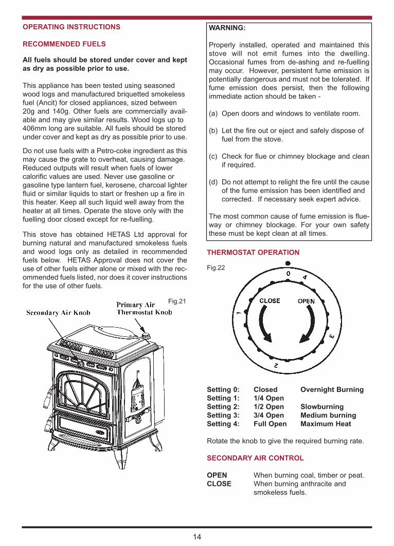
THERMOSTAT OPERATION
Setting 0: Closed Overnight Burning
Setting 1: 1/4 Open
Setting 2: 1/2 Open Slowburning
Setting 3: 3/4 Open Medium burning
Setting 4: Full Open Maximum Heat
Rotate the knob to give the required burning rate.
SECONDARY AIR CONTROL
OPEN When burning coal, timber or peat.
CLOSE When burning anthracite and
smokeless fuels.
14
Fig.21
Fig.22
OPERATING INSTRUCTIONS
RECOMMENDED FUELS
All fuels should be stored under cover and kept
as dry as possible prior to use.
This appliance has been tested using seasoned
wood logs and manufactured briquetted smokeless
fuel (Ancit) for closed appliances, sized between
20g and 140g. Other fuels are commercially avail-
able and may give similar results. Wood logs up to
406mm long are suitable. All fuels should be stored
under cover and kept as dry as possible prior to use.
Do not use fuels with a Petro-coke ingredient as this
may cause the grate to overheat, causing damage.
Reduced outputs will result when fuels of lower
calorific values are used. Never use gasoline or
gasoline type lantern fuel, kerosene, charcoal lighter
fluid or similar liquids to start or freshen up a fire in
this heater. Keep all such liquid well away from the
heater at all times. Operate the stove only with the
fuelling door closed except for re-fuelling.
This stove has obtained HETAS Ltd approval for
burning natural and manufactured smokeless fuels
and wood logs only as detailed in recommended
fuels below. HETAS Approval does not cover the
use of other fuels either alone or mixed with the rec-
ommended fuels listed, nor does it cover instructions
for the use of other fuels.
WARNING:
Properly installed, operated and maintained this
stove will not emit fumes into the dwelling.
Occasional fumes from de-ashing and re-fuelling
may occur. However, persistent fume emission is
potentially dangerous and must not be tolerated. If
fume emission does persist, then the following
immediate action should be taken -
(a) Open doors and windows to ventilate room.
(b) Let the fire out or eject and safely dispose of
fuel from the stove.
(c) Check for flue or chimney blockage and clean
if required.
(d) Do not attempt to relight the fire until the cause
of the fume emission has been identified and
corrected. If necessary seek expert advice.
The most common cause of fume emission is flue-
way or chimney blockage. For your own safety
these must be kept clean at all times.
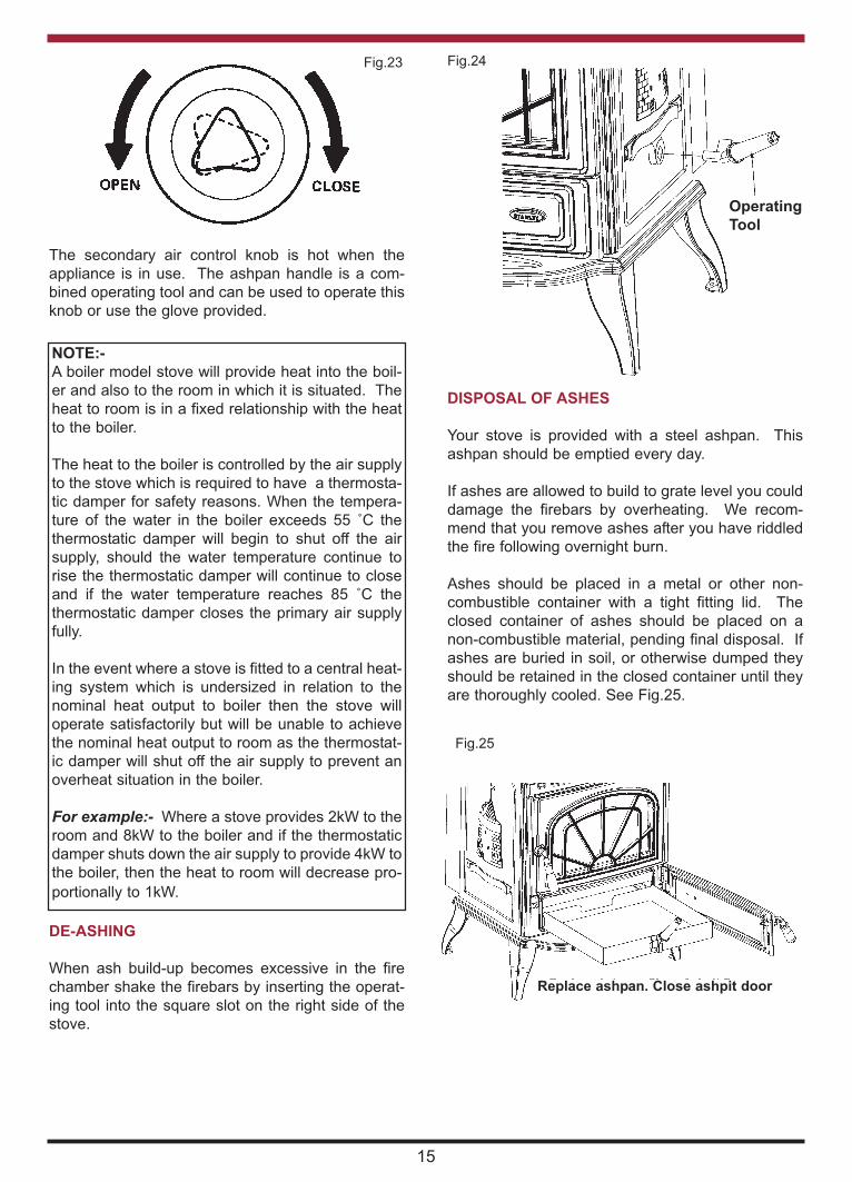
Fig.23
The secondary air control knob is hot when the
appliance is in use. The ashpan handle is a com-
bined operating tool and can be used to operate this
knob or use the glove provided.
NOTE:-
A boiler model stove will provide heat into the boil-
er and also to the room in which it is situated. The
heat to room is in a fixed relationship with the heat
to the boiler.
The heat to the boiler is controlled by the air supply
to the stove which is required to have a thermosta-
tic damper for safety reasons. When the tempera-
ture of the water in the boiler exceeds 55 ˚C the
thermostatic damper will begin to shut off the air
supply, should the water temperature continue to
rise the thermostatic damper will continue to close
and if the water temperature reaches 85 ˚C the
thermostatic damper closes the primary air supply
fully.
In the event where a stove is fitted to a central heat-
ing system which is undersized in relation to the
nominal heat output to boiler then the stove will
operate satisfactorily but will be unable to achieve
the nominal heat output to room as the thermostat-
ic damper will shut off the air supply to prevent an
overheat situation in the boiler.
For example:- Where a stove provides 2kW to the
room and 8kW to the boiler and if the thermostatic
damper shuts down the air supply to provide 4kW to
the boiler, then the heat to room will decrease pro-
portionally to 1kW.
DE-ASHING
When ash build-up becomes excessive in the fire
chamber shake the firebars by inserting the operat-
ing tool into the square slot on the right side of the
stove.
DISPOSAL OF ASHES
Your stove is provided with a steel ashpan. This
ashpan should be emptied every day.
If ashes are allowed to build to grate level you could
damage the firebars by overheating. We recom-
mend that you remove ashes after you have riddled
the fire following overnight burn.
Ashes should be placed in a metal or other non-
combustible container with a tight fitting lid. The
closed container of ashes should be placed on a
non-combustible material, pending final disposal. If
ashes are buried in soil, or otherwise dumped they
should be retained in the closed container until they
are thoroughly cooled. See Fig.25.
Fig.24
Operating
Tool
Fig.25
Replace ashpan. Close ashpit door
15

Fig.26
Hob
Screws
1. Lift off hob.
2. Remove 4 brass screws.
3. Lift off fire box cover.
4. Clean out fire box chamber.
5. Replace all parts in reverse order.
TO CLEAN CHIMNEY BACK OUTLET
Remove baffle underneath the boiler cross flow
chamber by lifting it upwards and pulling it outwards
and insert cleaning brush. Replace baffle before
lighting fire.
When fitted correctly the baffle should fall forward to
close onto the bottom of the boiler. The appliance
will not function correctly with this baffle misaligned
or missing.
Cleaning Firebox Chamber
16
Fig.27
Removable
Baffle
Boiler
Grate
TO REPLACE ROCKER OPERATING SLEEVE
1. Remove the 3 fire bars.
2. Lift the grate at the left hand end and remove it.
3. Withdraw the Rocker Operating Sleeve from
under the boiler at the right hand side.
4. Replace with new sleeve and sealing washer.
5. Replace grate and make sure that the square
shank on the centre fire bar engages with the
socket in the sleeve. See Fig.28.
Fig.28
Grate
Rocker Operating
Sleeve
RADIATION SURFACE
Heating surface only 23.87 Sq. M (257 sq. ft.)
Heating plus Domestic Hot Water 18.58 Sq. M. (200
sq.ft.)
FIRE SAFETY
To provide reasonable fire safety, the following
should be given serious consideration.
1. Do not over fire the stove.
2. Overfiring will also damage painted or enamel
finish.
3. Install a smoke detector in the room.
4. A conveniently located class A fire extinguisher to
contend with small fires resulting from burning
embers.
5. A practical evacuation plan.

17
6. A plan to deal with a chimney fire as follows:-
(a) Notify the fire department.
(b) Prepare occupants for immediate evacua-
tion.
(c) Close all openings into the stove.
(d) While awaiting the fire department watch for
ignition to adjacent combustibles from over-
heated flue pipe or from embers or sparks
from the chimney.
IN CASE OF FIRE
Close all openings into the stove, watch for ignition
of adjacent combustibles from over heated stove, or
hot embers or sparks from chimney.
VITREOUS ENAMEL CLEANING
General cleaning must be carried out when the
stove is cool.
If this stove is finished in a high gloss vitreous
enamel, to keep the enamel in the best condition
observe the following tips:
1. Wipe over daily with a soapy damp cloth,
followed by a polish with a clean dry duster.
2. For stubborn deposits a soap impregnated
pad can be carefully used on the vitreous
enamel.
3. Use only products recommended by the
Vitreous Enamel Association, these products
carry the Vitramel label.
4. DO NOT USE ABRASIVE PADS OR OVEN
CLEANSERS CONTAINING CITRIC ACID
ON ENAMELLED SURFACES. ENSURE
THAT THE CLEANSER MANUFACTUR
ERS INSTRUCTIONS ARE ADHERED TO.
DOOR LATCH ADJUSTMENT
If the door latch should be come loose over time due
to compression/ hardening of the rope inside the fire
door, an adjustment can be carried out by removing
one of the washers.
Remove the nut, spacer, latch and one washer, then
replace the nut, spacer and latch leaving only one
washer, see Figs. 29 & 30.
Fig.29
Fig.30
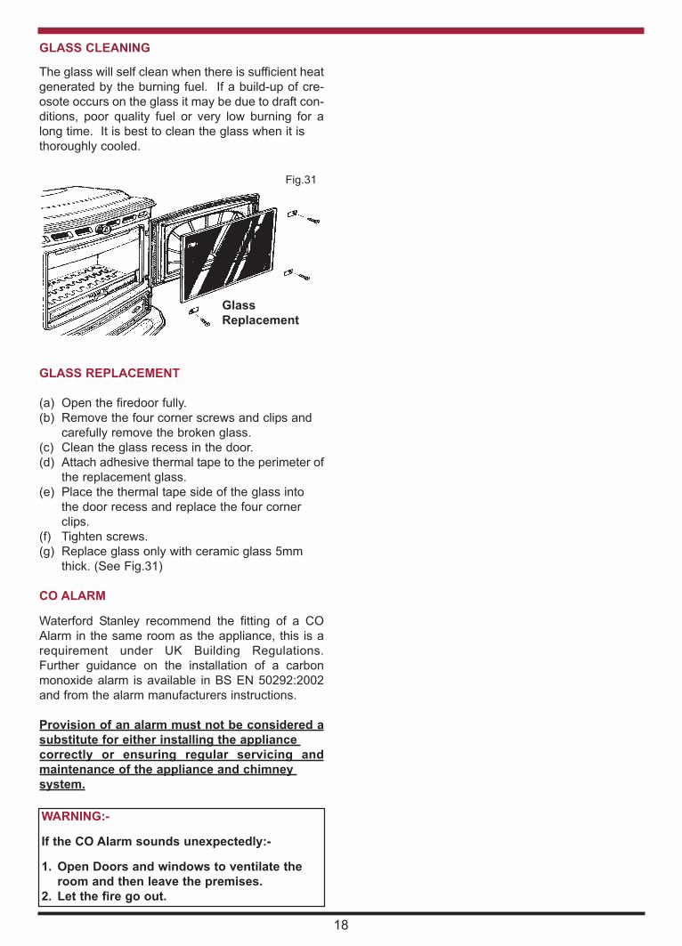
GLASS CLEANING
The glass will self clean when there is sufficient heat
generated by the burning fuel. If a build-up of cre-
osote occurs on the glass it may be due to draft con-
ditions, poor quality fuel or very low burning for a
long time. It is best to clean the glass when it is
thoroughly cooled.
GLASS REPLACEMENT
(a) Open the firedoor fully.
(b) Remove the four corner screws and clips and
carefully remove the broken glass.
(c) Clean the glass recess in the door.
(d) Attach adhesive thermal tape to the perimeter of
the replacement glass.
(e) Place the thermal tape side of the glass into
the door recess and replace the four corner
clips.
(f) Tighten screws.
(g) Replace glass only with ceramic glass 5mm
thick. (See Fig.31)
CO ALARM
Waterford Stanley recommend the fitting of a CO
Alarm in the same room as the appliance, this is a
requirement under UK Building Regulations.
Further guidance on the installation of a carbon
monoxide alarm is available in BS EN 50292:2002
and from the alarm manufacturers instructions.
Provision of an alarm must not be considered a
substitute for either installing the appliance
correctly or ensuring regular servicing and
maintenance of the appliance and chimney
system.
18
Fig.31
WARNING:-
If the CO Alarm sounds unexpectedly:-
1. Open Doors and windows to ventilate the
room and then leave the premises.
2. Let the fire go out.
Glass
Replacement

ERIN SF HPB EXPLODED VIEW
39. SHAKER BARRELL - Q00046AXX
40. FIRE FENCE RETAINER - Q00048CXX
41. GLASS - T00003AXX
42. AIR CONTROL KNOB - U00006AXX
43. DOOR HANDLE (SHORT) - U00008AXX
44. DOOR HANDLE (LONG) - U00009AXX
45. HINGE - U00153AXX
46. BOILER PLUG - V00016AXX
47. OPERATION TOOL - V00020BXX
48. SPIGOT TO DOOR HANDLE - V00021AXX
49. DOOR HANDLE AXLE - V00022BXX
50. DOOR CATCH - V00023AXX
51. CONCIAL SPRING - V00024AXX
52. HANK BUSHING - V00025AXX
53. PRIMARY AIR CONTROL SHAFT - V00027AXX
54. SPACER TO DOOR HANDLE - V00033AXX
55. SPRING - V00034AXX
56. SPACER - V00039AXX
57. SPACER - V000489AXX
58. BADGE - V00730BXX
59. D SHAFT CONNECTOR - V00964AXX
60. CONTROL ROD - V00965AXX
61. FIRE FENCE - Z00003AXX
62. BOILER CLEANING PLATE - Z00004BXX
63. SIDE FIRE BAR - Z00027AXX
64. ROCKER FIRE BAR - Z00028AXX
65. FIRE BAR FRAME - Z00030AXX
12. LEFT HAND SIDE PANEL - B00066EZZ
13. FRONT FRAME - B00069EZZ
14. BASE - B00079CZZ
15. INNER TOP - B00553AZZ
16. ACCESS PLATE - B00578AZZ
17. DOOR GLASS CLIP - F00003AXX
18. GASKET CLAMP PLATE - F00022AXX
19. TOP LATCH COVER PLATE - F00023AXX
20. LOWER LATCH COVER PLATE - F00024AXX
21. ASHPAN - F00898AXX
22. BAFFLE PLATE - F00923AXX
23. BAFFLE SUPPORT - F00924AXX
24. TOP SHROUD - F01048AXX
25. RH SHROUD - F01049AXX
26. LH SHROUD - F01050AXX
27. FLOATING BRACKET - F011051AXX
28. STAT PLATE - F01055AXX
29. BOILER - F01065AXX
30. THERMOSTAT - G00001AXX
31. LH FRONT BRICK - H00010AXX
32. RH FRONT BRICK - H00011AXX
33. SIDE INSULATION - J00007AXX
34. SERIAL NUMBER PLATE - N00234BXX
35. DATA PLAQUE - N00469AXX
36. PRIMARY AIR BOX - Q00028AXX
37. PRIMARY AIR SHUTTER - Q00029AXX
38. GRATE SUPPORT - Q00040BXX
1. TOP FLUE OUTLET - B00053AZZ
2. LEG (SHORT) - B00054AZZ
3. TOP FLUE BLANKING PLATE - B00055AZZ
4. ASHTRAY - B00056AZZ
5. HOB - B00057BZZ
6. DOOR GRILL - B00058AZZ
7. FIRE DOOR - B00059CZZ
8. ASHPIT DOOR - B00060DZZ
9. AIR CONTROL KNOB - B00063AZZ
10. FLUE BLANKING PLATE - B00064AZZ
11. RIGHT HAND SIDE PANEL - B00065BZZ
18

INSTALLATION CHECK LIST
Flue System
1. Minimum Flue Height of 4.6 metres (15 feet).
2. Appliance should be connected to a minimum of 1.8 metres (6 feet) of 150mm (6”)
flue pipe with a horizontal run not exceeding 150mm (6”).
3. Appliance should be connected to a chimney of less than 200mm (8”) in diameter
(otherwise the chimney must be lined with a 6” flue liner).
4. The chimney venting position must be above the main ridge of the roof or adjacent
outside obstructions.
5. The chimney serving this appliance should not serve any other appliance.
6. Access should be provided to the chimney serving the appliance to allow for cleaning.
Location
7. Clearance to combustible materials must be adhered to as described in the Clearance
to Combustible section.
8. The stove must be installed on a floor protector that covers the area under the stove
and extends 18” to the front & 8” to the sides and back.
Plumbing
9. Appliance must be connected to a gravity circuit using 1” ID flow & return piping.
10. The length of pipes from the cylinder to the cooker should not exceed 7.8 metres
(251/2 feet).
11. A circulation pump should be fitted to the return pipe of the radiator circuit and controlled by
a pipe stat fitted to the flow pipe of the gravity circuit to the cylinder.
Ventilation & Combustion Air Requirements
12. The room in which the appliance is located should have an air vent of adequate
size to support correct combustion (see Ventilation & Combustion Air Requirement
Section for specific details).
Tick
20
Item No: N00030AXX YS 13061621
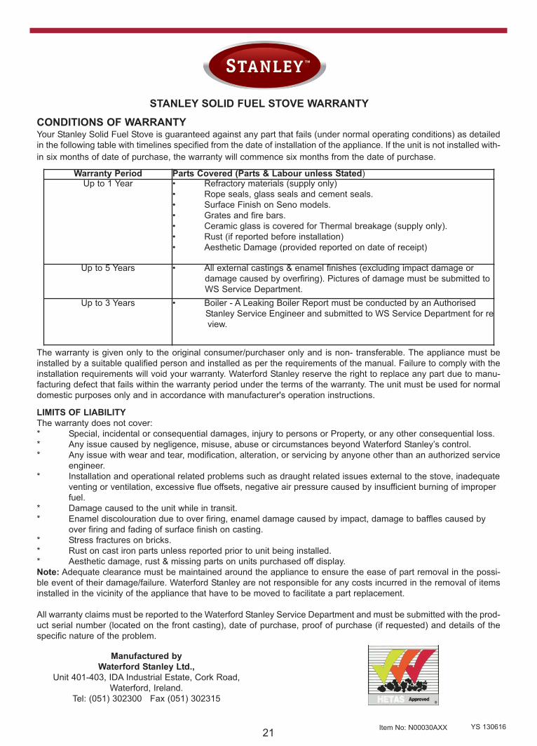
STANLEY SOLID FUEL STOVE WARRANTY
CONDITIONS OF WARRANTYYour Stanley Solid Fuel Stove is guaranteed against any part that fails (under normal operating conditions) as detailed
in the following table with timelines specified from the date of installation of the appliance. If the unit is not installed with-
in six months of date of purchase, the warranty will commence six months from the date of purchase.
Warranty Period Parts Covered (Parts & Labour unless Stated)Up to 1 Year • Refractory materials (supply only)
• Rope seals, glass seals and cement seals.
• Surface Finish on Seno models.
• Grates and fire bars.
• Ceramic glass is covered for Thermal breakage (supply only).
• Rust (if reported before installation)
• Aesthetic Damage (provided reported on date of receipt)
Up to 5 Years • All external castings & enamel finishes (excluding impact damage or
damage caused by overfiring). Pictures of damage must be submitted to
WS Service Department.
Up to 3 Years • Boiler - A Leaking Boiler Report must be conducted by an Authorised
Stanley Service Engineer and submitted to WS Service Department for re
view.
The warranty is given only to the original consumer/purchaser only and is non- transferable. The appliance must be
installed by a suitable qualified person and installed as per the requirements of the manual. Failure to comply with the
installation requirements will void your warranty. Waterford Stanley reserve the right to replace any part due to manu-
facturing defect that fails within the warranty period under the terms of the warranty. The unit must be used for normal
domestic purposes only and in accordance with manufacturer's operation instructions.
LIMITS OF LIABILITY
The warranty does not cover:
* Special, incidental or consequential damages, injury to persons or Property, or any other consequential loss.
* Any issue caused by negligence, misuse, abuse or circumstances beyond Waterford Stanley’s control.
* Any issue with wear and tear, modification, alteration, or servicing by anyone other than an authorized service
engineer.
* Installation and operational related problems such as draught related issues external to the stove, inadequate
venting or ventilation, excessive flue offsets, negative air pressure caused by insufficient burning of improper
fuel.
* Damage caused to the unit while in transit.
* Enamel discolouration due to over firing, enamel damage caused by impact, damage to baffles caused by
over firing and fading of surface finish on casting.
* Stress fractures on bricks.
* Rust on cast iron parts unless reported prior to unit being installed.
* Aesthetic damage, rust & missing parts on units purchased off display.
Note: Adequate clearance must be maintained around the appliance to ensure the ease of part removal in the possi-
ble event of their damage/failure. Waterford Stanley are not responsible for any costs incurred in the removal of items
installed in the vicinity of the appliance that have to be moved to facilitate a part replacement.
All warranty claims must be reported to the Waterford Stanley Service Department and must be submitted with the prod-
uct serial number (located on the front casting), date of purchase, proof of purchase (if requested) and details of the
specific nature of the problem.
Manufactured by
Waterford Stanley Ltd.,
Unit 401-403, IDA Industrial Estate, Cork Road,
Waterford, Ireland.
Tel: (051) 302300 Fax (051) 302315