Waterford Steam Electric Station, Unit 3, Revision 309 to Final ...
168
WSES-FSAR-UNIT 3 9.3-1 Revision 307 (07/13) 9.3 PROCESS AUXILIARIES 9.3.1 COMPRESSED AIR SYSTEM 9.3.1.1 Design Bases (EC-41355, R307) The compressed air system, consisting of the Instrument and Service Air Systems, is designed to provide a reliable supply of dry, oil-free air for pneumatic instruments and controls, pneumatically operated valves and the necessary service air for normal plant operation and maintenance. The system serves no safety function since it is not required to achieve safe shutdown or to mitigate the consequences of an accident. Air accumulators are provided on valves where instrument air is required for operation during the safe shutdown of the plant following an accident or to mitigate the consequences of an accident. Air accumulators required for containment isolation are provided with safety related remote makeup capability to ensure long term operability of the valves following loss of the plant instrument air system. Other safety-related air accumulators are capable of providing motive air to pneumatically operated valves for 10 hours. Procedures are established for operating manual handwheel overrides or lining up backup air supplies for continued safety function after 10 hours. Safety-related valves with air accumulators are listed in Table 9.3-1a and with nitrogen accumulators in Table 9.3-1b. (EC-41355, R307) 9.3.1.2 System Description The compressed air system is shown schematically in Figure 9.3-1 (for Figure 9.3-1, Sheet 3, refer to Drawing G152, Sheet 3 and for Figure 9.3-1, Sheet 4, refer to Drawing G152, Sheet 4). The compressed air system consists of the following: a) two nonlubricated rotary instrument air compressors b) one vertical instrument air receiver c) two instrument air dryers with pre- and after-filters d) three nonlubricated rotary station air compressors e) one vertical station air receiver f) piping, valves and instrumentation Each instrument air compressor package consists of an inlet filter, compressor, moisture separator, heat exchanger and discharge filter. Water used in the liquid ring of the compressor is cooled in the heat exchanger by water from the Turbine Closed Cooling Water System. Air from these packages is discharged into the instrument air receiver by a common header. This compressed air is then passed through one of the instrument air dryers and filters assemblies. The compressed air system then divides into various branches. Two in. lines supply instrument air to the demineralizer plant, yard area, Turbine Building, Reactor Auxiliary Building, Reactor Building, Fuel Handling Building, Service Building, and intake structure. In the Turbine, Reactor Auxiliary and Reactor Buildings, these branches are divided into several sub-branches located at various elevations. The various air operated valves, pneumatic instruments and controls are supplied from these lines. (DRN 01-692, R11-A) During normal operation, both instrument air compressors operate to maintain receiver pressure between 112-120 psig. The compressor designated as "standby" starts automatically if the instrument air receiver pressure fall below 105 psig, and continues to operate in a load/unload mode until manually stopped. (DRN 01-692, R11-A)
-
Upload
khangminh22 -
Category
Documents
-
view
3 -
download
0
Transcript of Waterford Steam Electric Station, Unit 3, Revision 309 to Final ...
WSES-FSAR-UNIT 3
9.3-1 Revision 307 (07/13)
9.3 PROCESS AUXILIARIES 9.3.1 COMPRESSED AIR SYSTEM 9.3.1.1 Design Bases (EC-41355, R307) The compressed air system, consisting of the Instrument and Service Air Systems, is designed to provide a reliable supply of dry, oil-free air for pneumatic instruments and controls, pneumatically operated valves and the necessary service air for normal plant operation and maintenance. The system serves no safety function since it is not required to achieve safe shutdown or to mitigate the consequences of an accident. Air accumulators are provided on valves where instrument air is required for operation during the safe shutdown of the plant following an accident or to mitigate the consequences of an accident. Air accumulators required for containment isolation are provided with safety related remote makeup capability to ensure long term operability of the valves following loss of the plant instrument air system. Other safety-related air accumulators are capable of providing motive air to pneumatically operated valves for 10 hours. Procedures are established for operating manual handwheel overrides or lining up backup air supplies for continued safety function after 10 hours. Safety-related valves with air accumulators are listed in Table 9.3-1a and with nitrogen accumulators in Table 9.3-1b. (EC-41355, R307)
9.3.1.2 System Description The compressed air system is shown schematically in Figure 9.3-1 (for Figure 9.3-1, Sheet 3, refer to Drawing G152, Sheet 3 and for Figure 9.3-1, Sheet 4, refer to Drawing G152, Sheet 4). The compressed air system consists of the following: a) two nonlubricated rotary instrument air compressors b) one vertical instrument air receiver c) two instrument air dryers with pre- and after-filters d) three nonlubricated rotary station air compressors e) one vertical station air receiver f) piping, valves and instrumentation Each instrument air compressor package consists of an inlet filter, compressor, moisture separator, heat exchanger and discharge filter. Water used in the liquid ring of the compressor is cooled in the heat exchanger by water from the Turbine Closed Cooling Water System. Air from these packages is discharged into the instrument air receiver by a common header. This compressed air is then passed through one of the instrument air dryers and filters assemblies. The compressed air system then divides into various branches. Two in. lines supply instrument air to the demineralizer plant, yard area, Turbine Building, Reactor Auxiliary Building, Reactor Building, Fuel Handling Building, Service Building, and intake structure. In the Turbine, Reactor Auxiliary and Reactor Buildings, these branches are divided into several sub-branches located at various elevations. The various air operated valves, pneumatic instruments and controls are supplied from these lines. (DRN 01-692, R11-A) During normal operation, both instrument air compressors operate to maintain receiver pressure between 112-120 psig. The compressor designated as "standby" starts automatically if the instrument air receiver pressure fall below 105 psig, and continues to operate in a load/unload mode until manually stopped. (DRN 01-692, R11-A)

WSES-FSAR-UNIT 3
9.3-2 Revision 9 (12/97)
Station air compressor packages also consist of an inlet filter, compressor, moisture separator, heatexchanger and discharge filter. Compressed air from these packages is discharged into the station airreceiver by a common header. Downstream of the receiver, the system is divided into various branches.Two inch lines supply service air to demineralizer plant, yard area, Turbine Building, Reactor AuxiliaryBuilding, Reactor Building, Service Building, hot machine shop and decontamination room, Fuel HandlingBuilding and intake structure. These branches are divided into several subbranches in all of thesebuildings and are located at various elevations. Service air is used for the operation of pneumatic tools,equipment used for plant maintenance, and for occasional air lancing of the wet cooling tower basin waterto control microbiological growth.
A station air compressor maintains a pressure of 112-120 psig in the station air receiver. If the receiverpressure falls below 105 psig, the second station air compressor starts automatically. The Instrument Airand Service Air Systems are cross connected through a self actuated pressure control valve throughwhich the Service Air System can feed the Instrument Air System.
The instrument air dryers are provided with a bypass so that when the dryer outlet pressure falls below 95psig the bypass is automatically opened, thereby maintaining the pressure in the system. A strainer isinstalled in this line to coarse filter the air.
The instrument air dryers and filters are expected to remove 99% of particulate matter (oil and dust) over0.3 microns in size, and reduce the moisture content to a dew point of -40°F at 100 psig. The equipmentis subjected to the manufacturer’s required maintenance procedures to assure this cleanliness level.�Some safety-related valves which are air operated are equipped with air filters. Normal operatingprocedures will assure that the filters are maintained clean. Unlikely clogging of the filter would result inloss of air to the valve, putting the valve to its fail safe position, thereby not interfering in its performance ofsafety-related function.�Design data for the compressed air system components is given in Table 9.3-2.
9.3.1.3 Safety Evaluation
Complete loss of instrument or service air during full power operation or under accident conditions doesnot reduce the ability of the reactor protective system or the engineered safety features and theirsupporting systems. to safely shut down the reactor or to mitigate the consequences of an accident.
Since the compressed air system serves no safety function, this system is not designed to any safetyclass or seismic requirements. The portion of instrument air and service air piping and valves penetratingthe containment is designed to safety class 2 and seismic Category I requirements (refer to Subsection6.2.4). The containment instrument air header outer isolation valve is designed to fail closed. Thecontainment service air outerisolation valve is locked closed because no compressed service air is required in the containment duringnormal plant operation.
Instrument Air System redundancy is provided by the two sets of instrument air compressor units plus theback up from the Service Air System. A total loss of instrument air is highly unlikely during normaloperation.

WSES-FSAR-UNIT 3
9.3-3 Revision 9 (12/97)
Failure of compressed air equipment, including air receivers does not have any detrimental effect onsafety related equipment, even if the failure produces missiles. Other than process lines, the compressedair equipment is located in the Turbine Building which does not house any safety related equipment.
The power supply for the station air compressor motors is from the Plant Auxiliary Power DistributionSystem. The power supply for the instrument air compressors is from the engineered safety featuresbuses. If a loss of offsite power occurs, the instrument air compressors are tripped and manuallyreconnected to the emergency diesel generators for main control room operators convenience in plantshutdown.
Accumulators are provided on those valves where instrument air is required for operation during the safeshutdown of the plant following an accident or to mitigate the consequences of an accident. Theaccumulators are designed to seismic Category I requirements.
9.3.1.4 Testing and Inspection
The compressor packages are performance tested at the manufacturer’s plant. The systems areinspected, cleaned and tested prior to service. Instruments are calibrated during testing and automaticcontrols are tested for actuation at the proper set points. Alarm functions are checked for operability andlimits during plant operational testing. The system is operated and tested initially with regard to flow paths,flow capacity, and mechanical operability.
The compressed air system is in service during normal plant operation. System performance willtherefore be checked by the performance of the components utilizing instrument or service air.
9.3.1.5 Instrument Application
The running station or instrument air compressors are loaded and unloaded between 112 and 120 psig inthe air receivers. If the pressure falls below 105 psig, the standby compressor starts and runs in aloading/unloading fashion between 112 and 120 psig until manually stopped. The controls are locatedlocally. If the air pressure in the instrument air receiver falls below the preset limit, a self actuatedpressure control valve is opened, admitting service air into this system. Annunciation is provided in themain control room for the Instrument and Service Air Systems for the following conditions:
a) low air receiver pressure
b) high and low moisture separator level, and
Local instruments are provided to indicate pressure in the air receivers. In addition, the service andinstrument air header pressures, are indicated in the main control room.
9.3.2 PROCESS SAMPLING SYSTEM�Process sampling is accomplished by a Primary Sampling System (PSL), a Secondary Sampling System(SSL), and an automatic gas analyzer panel (WGAP).
�

WSES-FSAR-UNIT 3
9.3-4 Revision 11-B (06/02)
9.3.2.1 Design Bases
The PSL is designed to collect fluid and gaseous samples contained in the Reactor Coolant System(RCS) and associated auxiliary system process streams during all modes of operation from full power tocold shutdown without requiring access to the containment.
The SSL is designed to collect water and steam samples from the secondary cycle, makeup demineralizerand Steam Generator.
�(DRN 00-695)
The Waste Gas Analyzer Panel (WGAP) can be programmed to sample gas from the following locations:Holdup Tanks, Volume Control Tank, Gas Decay Tanks, Gas Surge Tank, Vent Gas Collection Header,Waste Gas Compressor Discharge, and Equipment Drain Tank.�(DRN 00-695)
9.3.2.2 System Description
Figure 9.3-2 (for Figure 9.3-2, Sheet 3, refer to Drawing G162, Sheet 3) shows the flow diagrams for thePSL, SSL, and WGAP.
Provisions are made to assure that representative samples are obtained from well mixed streams orvolumes of effluent by the selection of proper sampling equipment and location of sampling points as wellas the proper sampling procedures.
The throttling valves in the sampling system have a limited flow coefficient (Cv) range. This range isbased on the flow required and the differential head available under operating conditions. This limits thesample flow rate to the required value and prevents excessively high flow.
9.3.2.2.1 Primary Sampling System
The PSL takes samples from the RCS and auxiliary systems, as listed in Table 9.3-3, and brings them toa common location in the primary sampling room PSL panel in the Reactor Auxiliary Building (elevation -4ft. MSL) for analysis by the plant operating staff. The analyses performed on the samples determinefission and corrosion product activity levels, boron concentration, residual hydrazine, silica, lithium, pH andconductivity levels, crud concentration, dissolved gas concentration and chloride. The results of theanalyses are used to regulate boron concentration, and monitor fuel rod integrity, to evaluate theperformance of ion exchanger and filters, specify chemical additions to the various systems, and maintainthe proper hydrogen and nitrogen overpressure in the volume control tank.
Table 9.3-3 includes the pressure and temperature for each primary sample point, as well as indicatingwhether the sample passes through the sample coolers.
The requirements for the PSL water chemistry are given in Subsection 9.3.4 for the reactor coolant andSubsection 10.3.5 for the steam generators.
The samples taken from the RCS pass through a run of piping long enough to ensure a minimum decaytime of 90 seconds for short-lived radioactivity, including N-16, before the fluid leaves the containment.

WSES-FSAR-UNIT 3
9.3-5 Revision 9 (12/97)
�The samples are cooled by individual heat exchangers to a maximum temperature of 120°F in the primarysampling room’s PSL panel sample coolers and then reduced in pressure by pressure reducing valves.�The reactor coolant and pressurizer steam space samples may be collected in detachable samplecylinders for gas analysis.�Samples taken from the Safety Injection System, the CVCS, the RCS, and the Pressurizer are reduced inpressure by means of manually set throttling valves in the primary sampling room’s PSL panel.
Low temperature and low pressure liquid samples from the Primary Water Storage System are routeddirectly to the primary sampling room’s PSL panel.
Temperature, pressure and flow rate indication of all the above samples is provided in the PSL panel.�To obtain representative samples, the stagnant lines are purged for several volumes. If there is anindication of crud buildup, there is also the capability to use the system pressure to provide the motiveforce to achieve a higher purge rate.�All liquid samples of the PSL are connected to a common header and discharged to the BMS holdup tankor the Volume Control Tank.�The sample sink is of stainless steel construction with a raised edge to retain any splashed fluid. The sinkarea is provided with a hood equipped with an exhaust to the plant vent system. Demineralizer water isprovided to flush and clean the sink. The sink drains by gravity through a water trap to the WMS chemicalwaste tank.
9.3.2.2.2 Secondary Sampling System�The SSL takes water and steam samples from the secondary cycle, makeup demineralizer andcondensate transfer pump discharge, and Steam Generator as listed in Table 9.3-4 and brings them to acommon location in the secondary Lab & sampling room SSL panel in the Reactor Auxiliary Building(elevation - 4 ft MSL) for analysis by the plant operating staff. Water quality analyses are performed toprovide a basis for the control of the secondary cycle water chemistry, and Steam Generator integrity.The analyses performed on the samples are appropriate to determine pH, specific and cation conductivitylevels, silica, sodium, dissolved oxygen and residual hydrazine concentrations.
Steam generator are monitored on a continuous basis. The steam generator samples are drawn from thelower portion of the steam generators. The samples are used for chemistry control. Solenoid valves areoperated from the sampling room to allow the operator to select the desired steam generator samplesource.
�

WSES-FSAR-UNIT 3
9.3-6 Revision 9 (12/97)
�The steam generator samples are analyzed for radioactivity with one combined steam generator radiationmonitor. Should the radiation level rise above a set limit, an alarm is activated in the main control room(see Subsection 11.5.2.4).�Each steam generator sample is automatically monitored for specific and cation conductivity, pH, silicaand sodium. Should any of these parameters rise above operating limits, a local alarm is activated. Inaddition, cation conductivity, pH and sodium are also alarmed in the main control room. Grab sampleprovisions are also provided.
Table 9.3-4 includes the pressure and temperature for each sample point, as well as indicating whetherthe sample passes through a multi-tube heat exchanger, as well as the chiller-bath cooling coils.
The temperature control of the samples having a temperature of 141°F or above is accomplished by amulti-tube heat exchanger and an integrated automatic sample temperature control system (chiller-bathcooling coils) to maintain sample temperatures at 77°F + 1°F, as required for the analyzers. Thetemperature control of the low temperature (below 141°F) samples is accomplished by using only theintegrated automatic sample temperature control system.
The multi-tube heat exchanger is a compact, single shell unit designed to cool and condense severalindividual samples concurrently. The coils are internally baffled so that each coil is thermally insulatedfrom one another allowing the adjustment of cooling water flow over each individual coil. The ComponentCooling Water System removes heat from the heat exchanger.�The analyzers drain header is routed to the sample recovery tank and pumped to the industrial wastesump.
9.3.2.2.3 Waste Gas Analyzer Panel
Gas samples from the locations listed in 9.3.2.1 can be analyzed by the gas analyzer for potentiallyhazardous concentrations of oxygen and hydrogen. Samples may be collected in a sample vessel andtaken to the radio-chemistry laboratory for further analysis. The gas analyzer is part of the WMS and isdiscussed in Section 11.3.�9.3.2.2.4 Metal Transport Sampling System
The Metal Transport Sampling System continuously obtains a representative sample of approximately1,100 ml/min from the Feedwater (FW), Main Steam (MS), and Blowdown (BD) systems. This isaccomplished by the use of sample probes which extend into the process piping approximately 1/3 of thepipe diameter. The samples are cooled below 120°F and approximately 100 ml/min is routed through aMillipore filter and the balance (1000 ml/min) is diverted through a bypass. The bypass flow is maintainedcontinuously to reduce mineral depositing on the sample tubing which could be sloughed off by flowsurges, water hammers and thermal expansion. The millipore filter is periodically isolated, removed andanalyzed to monitor the accumulation of corrosion products.

WSES-FSAR-UNIT 3
9.3-7 Revision 9 (12/97)
9.3.2.3 Safety Evaluation�The Process Sampling System is not essential for safe plant shutdown. Safety features are provided toprotect plant personnel and to prevent the spread of contamination from the primary/secondary labsampling rooms when samples are being collected. The system is designed to limit radioactivity releasesbelow the 10CFR20 limits under normal and failure conditions. The temperature and pressure of thevarious samples are reduced to minimize the possibility of local airborne activity. Instrumentation isprovided in the sampling rooms to monitor the temperature and pressure of the samples before they arecollected. Samples are normally taken only when the hood fan is operating. The Reactor AuxiliaryBuilding Normal Ventilation System provides a backup means of maintaining the low airborne activitylevels.
The sample lines penetrating the containment are each equipped with two pneumatically operatedisolation valves which close upon receipt of a Containment Isolation Actuation Signal. The penetrationpiping and isolation valves are safety class 2 and seismic Category 1. The containment isolation valvesare also designed to fail closed on loss of air supply (refer to Subsection 6.2.4). Remote control of thesevalves is provided to isolate any line failure which might occur outside of the containment. Should any ofthe remotely operated valves in the sampling system fail to close after a sample has been taken, backupmanual valves in the sampling room may be closed.�9.3.2.4 Testing and Inspection
The system is inspected and cleaned prior to service. Demineralized water is used to flush each part ofthe system. The system is operated and tested initially with regard to flow paths, flow rate, thermalcapacity and mechanical operability. Instruments are calibrated during plant hot functional testing. Theset points of the relief valves are also checked at this time.�All automatic analyzers are calibrated and their output results verified. Proper sequencing of the WGAPsolenoid valves are verified. The proper operation and availability of the Process Sampling System isproved inservice by its daily use during normal plant operation.
The sequencing operation of the WGAP is tested by observing proper solenoid valve operation andappropriate sample flow through the analyzer. The analyzer is calibrated against known hydrogen andoxygen sources.�The sampling systems are inspected during normal operation by observing proper operation of thecomponents while samples are being drawn. The malfunction of automatic analyzers will be observed byinappropriate readouts on the recorders or by alarms.
9.3.2.5 Instrument Application�The PSL and SSL use local pressure, temperature and flow indicators to facilitate manual operation and todetermine sample conditions before samples are drawn. The radiation monitor and microprocessor ishoused in its own panel.�The plant monitoring computer records the sample parameters from the steam generator.

WSES-FSAR-UNIT 3
9.3-8
9.3.3 EQUIPMENT AND FLOOR DRAINAGE SYSTEMS
9.3.3.1 Design Basis
The Equipment and Floor Drain Systems collect waste liquids from the various plant operational systemsand convey them from their points of origin by gravity, by pumps, or a combination thereof, to theappropriate Waste Management System collection tank. Gravity flow paths for the movement of wastewater directly to the Waste Management System tanks are utilized whenever such design can beaccomplished. When total gravity flow is precluded by abnormal or unusual conditions, liquids are routedby gravity to intermediate collection sumps or tanks and subsequently pumped to the Waste ManagementSystem collection tanks.
The radioactive drainage systems and non-radioactive drainage systems are designed to be totallyisolated from each other. Therefore there is no potential for inadvertent transfer of radioactivecontaminated fluids to a non-radioactive drainage system. Each area housing safety related equipment isprovided with an independent drainage system and attendant sump to preclude the flooding of such areasfrom other drainage systems.
The Equipment and Floor Drainage Systems do not serve any safety function and are classified as non-nuclear safety. Therefore, they are not required to withstand the effects of adverse environmentalphenomena such as earthquakes, tornadoes, hurricanes, floods, or the effects of high and moderate pipebreaks.
A Storm Water Drainage System is provided and sized for the design rain intensity storm condition of 5-1/2 in./hr.
Equipment and floor drainage piping in areas of potential or actual radioactive discharges are constructedin accordance with ANSI B31.1-0, Power Piping Specification, Winter 1975.
9.3.3.2 System Description
The drainage systems are divided into two major classifications; radioactive drainage systems and non-radioactive drainage systems. These classifications are further defined into subsystems for the purpose ofidentifications, isolation, routing and processing.
Radioactive Drainage Systems
a) Equipment Drain System
b) Floor Drain System
c) Detergent Waste System
d) Chemical Waste System
Non-Radioactive Drainage Systems
a) Storm Water Drainage System
b) Acid Waste and Vent System

WSES-FSAR-UNIT 3
9.3-9 Revision 10 (10/99)
c) Acid and Caustic Waste System
d) Oil Drainage Systems
e) Industrial Waste System
f) Sprinkler Discharge Drainage System�Equipment and Floor Drainage Systems are shown on Figures 9.3-3, 4 and 5 (for Figure 9.3-3, Sheet 1,refer to Drawing G173, Sheet 1).�The drainage system components consist of drain fittings specifically selected for a planned or anticipatedliquid discharge, and a network of pipe, fittings, valves, sumps, and pumps to achieve rapid andunobstructed flow paths from the point of liquid influent to the point of treatment or disposal.
Table 9.3-5 lists construction materials and the type of joint for each subsystem. Each system componentis engineered so as to be capable of conveying the designed volume of leakage expected. Uncontrolledlarge volumes of liquids released by pipe or equipment failure, or by tank overflow will spill upon the floor.All floors are pitched approximately 1/8 in. per ft. to a floor drain for rapid carry-off of such spillage.
Each gravity drainage system is designed using the normal anticipated maximum discharge in gallons perminute through an enclosed pipe flowing a maximum of 75 percent full. Horizontal drainage piping issloped at a uniform rate of 1/4 in. per ft. as standard practice. Where conditions are such that standardpitch cannot be maintained, a pitch of 1/8 in. per ft. minimum is used. Fittings are drainage patternwhenever possible and are installed so as to provide a continuous extension of piping runs. Dischargeheaders from pumps are routed as true as possible to their final destination, keeping to a minimum turnsand traps.
Cleanouts are provided on each drainage system to permit cleaning in the event a blockage occurs. Thesize of cleanouts are in direct proportion to the size of the pipe it serves, up to four in. Thereafter four in.cleanouts are standard for all larger pipes. Cleanouts are located where the change of direction inhorizontal runs is 90 degrees or greater, at maximum intervals of 50 ft. on straight runs and at the base ofall stacks. Piping runs encased or embedded in concrete or located in inaccessible areas have cleanoutsextended to accessible locations.
9.3.3.2.1 Radioactive Drainage Systems
The radioactive drainage systems provide the interface between the RCS, reactor auxiliaries equipment,and the waste management treatment facilities. They provide for the drainage of equipment, tanks, andwetted surfaces during normal plant operation as well as anticipated large volume flow associated withabnormal or accident conditions.

WSES-FSAR-UNIT 3
9.3-10 Revision 11-B (06/02)
9.3.3.2.1.1 Equipment Drain System
Reactor Auxiliary Building
Liquid discharges of reactor grade fluids from equipment, tanks, and miscellaneous leak-off points locatedat elevation -35 ft. MSL are collected by drain fittings located at the equipment discharge points androuted by gravity through piping buried in the mat to the equipment drain sump no. 1. Two sump pumpsdischarge the sump contents to the equipment drain tank through the recycle drain header.�(DRN 00-695)
Liquid discharges of reactor grade fluids from equipment, tanks, and miscellaneous leak-off points locatedat elevation -4 ft. MSL and above are collected by the recycle drain header and routed by gravity to theequipment drain tank located on elevation -35 ft. MSL. The tank liquids are drained by means of theequipment drain tank pump through the reactor drain tank pump discharge header to the holdup tanks inthe Boron Management System.
Reactor Building
Liquid discharges of reactor grade fluids from equipment and miscellaneous leak-off points are collectedby the containment drain header and routed by gravity to the reactor drain tank. The reactor drain tankpump discharges the tank liquids to the holdup tanks in the Boron Management System.�(DRN 00-695)
9.3.3.2.1.2 Floor Drain System
Reactor Building
Liquid discharges of low purity (non-reactor grade) wastes from equipment, tanks, miscellaneous leak-offpoints, and floor drainage are collected by drain fittings located at the equipment discharge point and byfloor drains located at low points in the floors, and routed by gravity to the containment sump which islocated at the lowest point within the reactor cavity. In entering the sump, all liquids pass through a leakdetection tank which is located within the sump. This tank is equipped with a triangular weir. Liquids fromthe tank drain into the sump through the weir. Two sump pumps discharge the sump contents to thewaste tanks through a radiation monitor located outside the containment.
Alternate flow paths are provided on the containment sump discharge header for decontaminationwashdown (see Subsection 9.3.3.2.1.3).
Reactor Auxiliary Building
Liquid discharges of low purity wastes from equipment, tanks, miscellaneous leak-off points, and floordrainage, are collected by drain fittings located at the equipment discharge points and by floor drainslocated at low points in the floors and routed by gravity to floor drain sumps at elevation -35 ft. MSL.Each sump is provided with two pumps which discharge the sump contents to the waste tanks.

WSES-FSAR-UNIT 3
9.3-11 Revision 11-A (02/02)
Fuel Handling Building
Liquid discharges of low purity wastes from equipment, tanks, miscellaneous leak-off points, and floordrainage are collected by drain fittings located at the equipment discharge points and by floor drains locatedat low points in the floors and routed by gravity to the floor drain sump no. 1 at elevation -35 ft. MSL. Twopumps discharge the sump contents to the waste tanks.
9.3.3.2.1.3 Detergent Waste System
Reactor Building
For those periods when the reactor head laydown and wash area will be used for decontamination, thecontainment sump discharge header provides an alternate discharge path for removal of liquids containingthose chemicals used for decontamination procedures. The flow path is directly to the laundry tanks.
Reactor Auxiliary Building
Liquid discharges containing chemical cleaning compounds from those areas and associated equipmentlisted on Table 9.3-6 are routed by gravity to the laundry tanks located on elevation -35 ft. MSL. All fixtures,equipment drains, and floor drains are provided with traps and are vented to the vent gas collection header.
Equipment drains and floor drains serving laundry process equipment on elevation -35 ft. MSL are routed tothe detergent waste sump no. 1. Two sump pumps discharge the sump contents to the laundry tanks viathe laundry tank collection header.
Fuel Handling Building
Drainage is provided for the spent fuel cask decontamination pit, refueling canal, and the spent fuel caskstorage area for decontamination washdown of walls, floors, and fuel casks. Floor drains collect the wastewater and route it to the refueling canal drain pump. The refueling canal drain pump discharge headerprovides two alternate flow paths. One flow path is provided directly to the laundry tanks for liquid from initialwashdown with decontamination chemicals. The second flow path directs subsequent rinse water to thespent fuel pool.
9.3.3.2.1.4 Chemical Waste System
Reactor Auxiliary Building�(DRN 00-1054)
Chemical wastes from the radio-chem laboratory and sampling room located at elevation -4 ft. MSL arerouted by gravity to the chemical waste tank located at elevation -35 ft. MSL. The chemical waste pumproutes the liquids through the waste concentrate storage tank to the waste management drumming station.Plumbing fixture vents are provided for vapor removal from the system. The vents are connected to the ventgas collection header.�(DRN 00-1054)
WSES-FSAR-UNIT 3
9.3-12
9.3.3.2.1.5 Sump Operation
Sumps have been sized to accommodate all anticipated normal and transient leakage from the equipmentthey serve. All sumps throughout the plant have been provided with duplex full capacity pumps.
Level switch and level operated mechanical alternator are provided for controlling the sump level. Thelevel control is delineated in the following steps.
a) When the level reaches the predetermined "High", the alternator starts the selectedpump. The mechanical alternator initiates operation of the pumps alternately on successive lowlevel incidences. The pump is also tripped automatically on low level.
b) If the level continues to rise and reaches the predetermined "High-High", thealternator will start the second pump.
c) An independent level switch is provided to detect that the level in the sump is highenough to necessitate operation of the standby pump and to initiate an alarm in main controlroom.
A local control switch is provided for each pump to enable its manual operation when level in the sump isbetween low and high extremes.
9.3.3.2.2 Non-Radioactive Drain Systems
The non-radioactive drainage systems provide the interface between various drainage discharge pointsand their respective internal and/or external waste treatment facilities. They provide for the draining ofequipment, tanks, and flooded surfaces during normal plant operation, as well as of anticipated largevolume flow associated with abnormal or accident conditions.
9.3.3.2.2.1 Storm Water Drainage System
The Storm Water Drainage System consists of various types of drain inlets and catch basins for stormwater capture from structure roofs, plant grounds and roads, and an interconnected network of stormwater piping for conveyance. It provides the entire plant site with the means to effectively collectaccumulations of rainwater, and creates the flow path for offsite disposal.
Surfaces exposed and subjected to rainwater are sloped to the collection appurtenance; roof drains, deckdrains, area drains, and catch basins. Drains have been selected so as to fully meet all pertinentrequirements of the surface to be drained. Obstructions between high surface points and drain inlets havebeen minimized so as to affect accelerated and total drainage of the surface.
The building systems are designed as gravity systems with a minimum pipe slope of 1/4 in. per ft. formaximum self-cleaning velocity. Additionally, the systems are designed so as to minimize the deposit ofsolids and clogging, and with adequate cleanouts so arranged that the systems may be readily cleaned.
WSES-FSAR-UNIT 3
9.3-13 Revision 301 (09/07)
Total isolation from all other drainage systems preclude flooding due to abnormal weather conditions. The systems will provide storm water collection, conveyance, and offsite disposal without puddling or flooding of the plant site or structure roofs. The Louisiana State Construction Code (1963), applicable to plumbing, is used for permissible square feet of drainage for a given pipe size and pitch, in terms of square feet of projected drainage area. Reactor Building Roof drains are provided around the circumference of the dome walkway. Leaders are embedded within the containment walls to points of exit from where they run exposed through the dry cooling tower areas to the yard Storm Water Drainage System. (DRN 01-0073) 9.3.3.2.2.1 Storm Water Drainage System Cooling Tower Areas (DRN 99-0577; EC-2097, R301) Area drains are provided to collect and route storm water to two area drain sumps (1&2) located at elevation -35 ft. MSL. Each sump is provided with two 270-gpm minimum capacity pumps, and radiation monitors are provided on the discharge of each sump. Flow can be diverted to one of three discharge paths for offsite disposal. The normal flow path discharges storm water into the Circulatory Water system for discharge to the Mississippi River. An alternate flow path is provided to allow discharge to the 40 Arpent Canal via the yard Storm Water Drainage System. Upon detecting high radiation activity, a simultaneous signal will automatically stop the pumps and alarm the operator who will then manually transfer the flow to the waste tanks in the Reactor Auxiliary Building. In addition to the 270-gpm motor driven sump pumps, a single diesel powered sump pump with a minimum capacity of 300-gpm is provided in each cooling tower area. The pumps are provided with hoses which are used to discharge rainwater directly over the Nuclear Island exterior floodwall. These pumps are used to supplement the motor driven sump pumps during periods of intense rainfall, as described in Subsection 2.4.2.3. (EC-2097, R301) If a loss of offsite power occurs during a discharge, both the pumps and monitors are de-energized. The operator can manually load the pumps onto the EDGs as described in Table 8.3-1. However, the monitor contacts remain in the “alarm” state and actuate a signal that locks out the pumps. A selector switch on the MCC cubicle of each sump pump allows the operator to bypass this condition until power is restored to the monitors. (DRN 99-0577; 01-0073) 9.3.3.2.2.2 Acid Waste and Vent System Liquid wastes from battery rooms in the Reactor Auxiliary Building are routed to local neutralizing tanks for neutralization and then discharged to the Sanitary Drainage System for disposal. Each fixture and floor drain is provided with a local pipe vent which connects to a main vent. The main vent is extended through the roof to the atmosphere. 9.3.3.2.2.3 Acid and Caustic Waste System Drains receiving intermittent acid and caustic wastes from the blowdown treatment area at elevation -4 ft. MSL of the Reactor Auxiliary Building are routed to a neutralizing tank at elevation -35 ft. MSL. The tank discharge is routed to the Oil Drainage System which routes the neutralized liquids to the oil sump No. 3.

WSES-FSAR-UNIT 3
9.3-14 Revision 12-B (04/03)
9.3.3.2.2.4 Oil Drainage Systems
Diesel Oil Storage Tank Compartments
Each tank compartment is provided with its own individual sump (oil sump no. 1 and oil sump no. 2). Each sump is provided with two pumps which discharge to the Turbine Building Industrial Waste System (see Subsection 9.3.3.2.2.5).
Emergency Diesel Generator Rooms, Charging Pumps,Emergency Diesel Oil Feed Tanks
These areas are provided with floor drains and equipment drains to collect oil spills from equipment and surrounding piping. Liquids are routed to the oil sump no. 3 at elevation -35 ft. MSL. Two sump pumps discharge the sump contents to the Turbine Building Industrial Waste System. Provisions for pumping the sump contents to local oil drums for offsite removal are available.
9.3.3.2.2.5 Industrial Waste System (Turbine Building)
The Industrial Waste System consists of floor drains, equipment drains, and curbed area oil collection drains. The system provides the means to collect and convey the various Turbine Building operational waste liquids from their points of collection to their ultimate disposal.
Floor drains are provided throughout the building to accept normal maintenance washdown as well as abnormal liquid discharges such as from a high or moderate energy piping rupture. Concrete floors are sloped to floor drains which are located at low points on the floors to facilitate drainage and prevent water puddles.
Equipment drains are provided for mechanical equipment such as pumps, tanks, and leak-off points. These drains serve to accept continual or intermittent discharge as part of routine operation. They additionally provide the means for equipment drain down in the event of maintenance when required, or for replacement of the equipment when necessary. For equipment requiring flushing on a regular or occasional basis, this system will provide that capability as well.
Floor drains and/or equipment drains are provided in curbed oil areas to service mechanical equipment using oil in their operation. Valves are placed on floor drain outlets to provide the capability of containing substantial oil spills within the curbs. Equipment drains are elevated above curbs to preclude their use as overflows. However, when this elevation presents drainage problems to the equipment it serves, closed equipment drains are utilized.
Concrete containment curbs are provided where hazardous chemicals associated with the Chemical Feed Skids are handled and stored. The volume of the curbed area will accommodate the failure of a single 345 gallon portable chemical shipping container. Drains are not provided in this area to allow for the neutralizingof any spilled chemicals prior to disposal as appropriate.
� (DRN 99-0480, R11; 03-213, R12-B)
All Turbine Building drainage is routed to two industrial waste sumps, both located on elevation +15 ft.MSL. Two pumps are provided for each sump. Under normal conditions, industrial waste will be discharged through a radiation monitor to an oil separator located in the yard to affect separation of the oil. The water will then be pumped by the oil separator discharge pumps to the 40 Arpent Canal or the Circulating Water System discharge. In the event that the radiation monitor on the industrial waste discharge header detects a high radiation level, automatic valves are activated, closing the discharge path to the oil separator and opening the discharge path to the waste tanks in the Reactor Auxiliary Building. The monitor will also send a signal to sound an alarm in the main control room.� (DRN 99-0480, R11; 03-213, R12-B)

WSES-FSAR-UNIT 3
9.3-15 Revision 11-A (02/02)
9.3.3.2.2.6 Sprinkler Discharge Drainage System (Reactor Auxiliary Building)
Floor drains are provided in the electrical penetration and cable vault areas at elevation +35 ft. MSL toaccept sprinkler discharge water in the event of sprinkler system activation. The drainage system is sizedto accept a designed flow of 0.3 gpm for any 3000 sq. ft. of space (900 gpm). The Sprinkler DischargeDrainage System is routed by gravity directly to the yard Storm Water Drainage System for offsite disposal.
9.3.3.3 Safety Evaluation
Reactor Building sump pump discharge piping penetrating the containment is designed to seismic CategoryI and safety class 2 requirements. All other portions of the Equipment and Floor Drainage Systems are notdesigned to either seismic Category I or safety class requirements as they do not perform any safetyfunction.
Each engineered safeguard features room is provided with the independent drainage and sumps to preventflooding and thus assure the integrity of each train operation. The sumps and sump pumps have sufficientcapacity to meet the guidelines of BTP APCSP 3-1 concerning internal plant flooding as a result ofpostulated piping failures (see Appendix 3.6A). In addition, the control room operator is alerted to wateraccumulation in these areas via Class 1E instrumentation (level indicator with annunciator), to facilitateisolation of the affected system.
The failure of non-safety related Equipment and Floor Drain system components which could affect theoperation of safety related equipment, (i.e., mechanical equipment and piping, HVAC ducts, electrical cabletrays and conduits, instrumentation and controls) have been investigated with respect to the area ofinfluence of the failed component. Interactions are eliminated by adherence to criteria stated in Subsection3.2-1.
9.3.3.4 Tests and Inspections
All portions of the Equipment and Floor Drainage Systems are subjected to a hydrostatic pressure test of atleast 10 ft. head of water.
Welded joints in the radioactive Equipment and Floor Drainage Systems are visually inspected.
9.3.3.5 Instrumentation Applications
Level indicators and alarms are provided in the main control room for the monitoring of all sump operationmodes.
The triangular weir of the leak detection tank located in the Reactor Building sump is precalibrated so thatthe level in the detection tank is transmitted to the main panel of the main control room. A predeterminedhigh level (leakage rate) will sound an alarm.
9.3.4 CHEMICAL AND VOLUME CONTROL SYSTEM
9.3.4.1 Design Bases

WSES-FSAR-UNIT 3
9.3-16 Revision 307 (07/13)
9.3.4.1.1 Functional Requirements The Chemical and Volume Control System (CVCS) is designed to perform the following functions: a) Maintain the chemistry and purity of the reactor coolant during normal operation and
during shutdowns; b) Maintain the required volume of water in the Reactor Coolant System (RCS)
compensating for reactor coolant contraction or expansion resulting from changes in reactor coolant temperature and for other coolant losses or additions;
c) Provide a controlled path for discharging reactor coolant to the Boron Management
System (BMS) and venting gas to the Gaseous Waste Management System (GWMS). The BMS and GWMS are described further in Sections 11.2 and 11.3, respectively;
d) Control the boron concentration in the RCS to obtain optimum control element assembly
(CEA) positioning, to compensate for reactivity changes associated with major changes in reactor coolant temperature, core burnup, and xenon variations, and to provide shutdown margin for maintenance and refueling operations;
e) Provide auxiliary pressurizer spray for operator control of pressure during the final
stages of shutdown and to allow pressurizer cooling; f) Provide a means for functionally testing the check valves which isolate the Safety
Injection System (SIS) from the RCS; g) Provide continuous measurement of reactor coolant boron concentration and fission
product activity; h) Collect the controlled bleedoff from the reactor coolant pump seals; i) Leak test the RCS; j) Inject concentrated boric acid into the RCS upon a safety injection actuation signal
(SIAS); k) Provide a means for filling the RCS; (EC-8458, R307)
l) Provide a means for hydrostatic testing of the RCS. (EC-8458, R307) (EC-4019, R305) m) Inject zinc into the RCS from the Zinc Injection Skid, via the charging pumps, to reduce plant radiation dose rates and Primary Water Stress Corrosion Cracking (PWSCC) in plant materials. (EC-4019, R305) 9.3.4.1.2 Design Criteria The CVCS is designed in accordance with the following criteria: a) The CVCS is designed to accept RCS letdown when the reactor coolant is heated at the
administrative rate of 75°F/hr and to provide the required makeup using two of three charging pumps when the reactor coolant is cooled at the rate of 75°F/hr;

WSES-FSAR-UNIT 3
9.3-17 Revision 307 (07/13)
b) The CVCS is designed to supply makeup water or accept excess reactor coolant as power decreases or increases;
c) The CVCS is designed to allow 10 percent step power increases between zero percent
and 90 percent of full power and 10 percent step power decreases between 100 percent and 10 percent of full power, as well as for ramp changes of five percent of full power per minute between 15 and 100 percent power;
d) The volume control tank is sized with sufficient capacity to accommodate the
inventory change resulting from a full to zero power decrease with no primary makeup water system operation, assuming that the volume control tank level is initially in the normal operating level band;
e) The CVCS provides a means for maintaining activity in the RCS within the limits
specified in Section 11.1, corresponding to a one percent failed fuel condition and continuous full power operation;
f) The CVCS is designed to maintain the reactor coolant chemistry within the limits
specified in Table 9.3-7; g) Letdown and charging portions of the system are designed to withstand the design
transients defined in Table 9.3-8 without any adverse effects, as applicable; (EC-8458, R307)
h) Components of the CVCS are designed in accordance with applicable codes as shown in Table 9.3-9. Safety classes and seismic categories are as shown in Table 3.2-1;
i) The environmental design conditions of the CVCS are given in Section 3.11; j) The CVCS is designed to change the reactor coolant boron concentration to the value
required for a reactor shutdown, for maintenance and/or refueling and to bring the reactor coolant to the refueling concentration. The capability of this system for changing the RCS boron concentration is shown in Table 9.3-11. The schedule of waste generation for the various plant maneuvers is shown in Table 9.3-12;
k) The CVCS is designed to allow for a safe plant shutdown following a loss of CVCS
letdown flow. (EC-8458, R307)
9.3.4.2 System Description 9.3.4.2.1 System Functional Description 9.3.4.2.1.1 Plant Startup Plant startup is the series of operations which brings the plant from a cold shutdown condition to a hot standby condition at normal operating pressure and zero power temperature with the reactor critical at a low power level.

WSES-FSAR-UNIT 3
9.3-18 Revision 10 (10/99)
The charging pumps and letdown backpressure valves are used during initial phases of RCS heatup tomaintain the RCS pressure until the pressurizer steam bubble is established. One charging pump willnormally operate during plant startup to cool the letdown fluid in order to establish a controlled heatup rateof the RCS within prescribed limitations and to maintain proper RCS pressure during this period.
Oxygen scavenging during plant startup is discussed in Subsection 9.3.4.2.1.4.
During the heatup, the pressurizer water level is controlled manually using the backpressure control valvesand the letdown control valves. The letdown flow is automatically diverted to the BMS when the high levellimit is reached in the volume control tank. The volume control tank is initially purged with nitrogen, priorto establishing the hydrogen blanket.
The RCS boron concentration may be reduced during heatup in accordance with shutdown marginlimitations. The makeup controller is operated in the dilute mode, as described in Subsection 9.3.4.2.1.2,to inject a predetermined amount of primary makeup water at a preset rate. Technical Specifications areset to define those conditions of the CVCS necessary to assure safe reactor operation and shutdown.
9.3.4.2.1.2 Normal Operation�The normal reactor coolant flow path through the CVCS is indicated by the heavy lines on the piping andinstrumentation diagram, Figure 9.3-6 (for Figure 9.3-6, Sheet 1, refer to Drawing G168, Sheet 1).
Parameters for the CVCS are listed in Table 9.3-11. Equipment design parameters for the majorcomponents are shown in Table 9.3-9. Process flow, temperature and pressure data are given in Table9.3-13 with locations corresponding to those noted in the ellipses on Figure 9.3-6 (for Figure 9.3-6, Sheet1, refer to Drawing G168, Sheet 1). The tabulation of the process flow data is for three modes ofpurification loop operation and nine modes of makeup system operation. Basically, a letdown flow of 38gpm is used for normal purification operation, a letdown flow of 82 gpm is used for intermediatepurification operation, and a letdown flow of 126 gpm is used for maximum purification operation. Typicaloperating conditions are given for the various makeup system operating modes.�Normal operation includes hot standby operation and power generation when the RCS is at normaloperating pressure and temperature.
Letdown flow from one cold leg passes through the tube side of the regenerative heat exchanger for aninitial temperature reduction. The pressure is then reduced by a letdown control valve to the letdown heatexchanger operating pressure. The final reduction to the purification subsystem operating pressure andtemperature is made by the letdown heat exchanger and letdown backpressure valve. The flow thenpasses through the purification filter in order to remove insoluble particulates from the reactor coolant.Flow is then directed through one or more of the purification ion exchangers. The normal purification ionexchanger contains mixed bed resin which becomes boron and lithium saturated through use and is used forremoval of corrosion and fission

WSES-FSAR-UNIT 3
9.3-19 Revision 304 (06/10)
products. The second purification ion exchanger contains mixed bed resin which becomes boron saturated through use and is used as necessary to control lithium concentration. The third purification ion exchanger contains anion resin only and is used for boron removal at the end of core cycle life when it is no longer practical to use feed and bleed for boron dilution because of the quantity of waste generated. Any of the three purification ion exchangers can be used for any function. Flow continues through a strainer and is sprayed into the volume control tank where hydrogen gas is absorbed by the coolant. Flow also enters the volume control tank from the reactor coolant pump controlled bleedoff header. The charging pumps take suction from the volume control tank and pump the coolant into the RCS. One charging pump is normally in operation and one letdown control valve is controlled to maintain an exact balance between letdown flow rate plus reactor coolant pump bleedoff flow rate and charging flow rate. The charging flow passes through the shell side of the regenerative heat exchanger for recovery of heat from the letdown flow before being returned to the RCS. (EC-13560, R304) When the Shutdown Cooling System is operational, a flow path through the CVCS can be established to remove fission and activation products. This is accomplished by diverting a portion of the flow from the shutdown cooling heat exchanger to the letdown line. The flow then passes through the purification filter, purification ion exchanger, the letdown strainer, and is returned to the suction of the low-pressure safety injection pumps. (EC-13560, R304) (DRN 00-1054, R11-A; 05-332, R14; EC-14241, R303)
A makeup system is provided for changes in reactor coolant boron concentration. Boron is initially added to the CVCS using the boric acid batching tank. Demineralized water is added to the boric acid batching tank via the primary water pumps, and the fluid is heated by immersion heaters. Boric acid powder is added to the heated fluid while the mixer agitates the fluid. A boric acid concentration as high as 12 w/o can be prepared. Electric immersion heaters maintain the temperature of the solution in the boric acid batching tank high enough to preclude precipitation. The boric acid is then drained to the boric acid makeup tanks. Concentrated boric acid solution, prepared in the batching tank, is then stored in the two boric acid makeup tanks. This boric acid solution is supplied to the volume control tank via the boric acid pumps, while the primary water stored in the primary water storage tank is supplied to the volume control tank via the primary water pumps. Four modes of operation by the makeup controller in the makeup subsystem are provided. In the dilute mode, a preset quantity of primary water is introduced into the volume control tank at a preset rate. In the borate mode, a preset quantity of boric acid is introduced at a preset rate. In the manual blend mode, the flow rates of the primary water and the boric acid can be preset to give any concentration of boric acid solution between zero and the refueling concentration. The manual mode is used to provide makeup to the refueling water storage pool and the safety injection tanks as well as the volume control tank. In the automatic mode, a preset blended boric acid solution is automatically introduced into the volume control tank upon demand from the volume control tank level controller. The concentration setting as adjusted periodically by the operator to match the boric acid concentration being maintained in the RCS. Preferred makeup is accomplished in manual mode. (DRN 00-1054, R11-A; 05-332, R14; EC-14241, R303)
The Chemical Addition Metering System provides a means of controlling the reactor coolant chemistry. Chemical additives for oxygen scavenging and pH control are prepared in the chemical addition tank and injected into the charging pump suction header by the chemical

WSES-FSAR-UNIT 3
9.3-20 Revision 305 (11/11)
addition metering pump. These chemicals are transported to the charging pump suction with primary water. The tank is sized to hold a sufficient quantity of lithium to allow batch additions to the RCS. It will also hold a sufficient quantity of hydrazine to reduce the reactor coolant oxygen concentration to below the maximum acceptable level during startup or shutdown. (EC-4019, R305) The Zinc Injection system provides a means of injecting zinc acetate dihydrate to the RCS via the suction side of the Charging Pumps. The Zinc Injection Skid will add zinc into the discharge side of the Chemical Addition Pumps via CVC-6051. The Chemical Addition discharge line connects to the suction side piping of the Charging Pumps between the Volume Control Tank (VCT) and the Charging Pumps. The Charging Pumps then deliver the zinc to the RCS to reduce radiation levels and Primary Water Stress Corrosion Cracking (PWSCC) in plant materials. (EC-4019, R305) The volume of water in the RCS is automatically controlled using pressurizer level instrumentation. The pressurizer level setpoint is programmed to vary as a function of reactor power in order to minimize the transfer of fluid between the RCS and the CVCS during power changes. This linear relationship is shown on Figure 5.4-7. Reactor power is determined for this situation using the average reactor coolant temperature derived from hot and cold leg temperature measurements. A level error signal is obtained by comparing the programmed setpoint with the measured pressurizer water level. Volume control is achieved by automatic control of the standby charging pumps and a letdown control valve in accordance with the pressurizer level control program shown on Figure 5.4-7. Two parallel letdown control valves are provided. The letdown control valve chosen for operation is normally controlled by the pressurizer level control program to maintain letdown flow equal to the total charging flow minus the total reactor coolant pump controlled bleedoff flow. Normally, one charging pump is operated, but two or three pump operations can be selected for higher purification flow if desired. Proper level can normally be maintained by valve positioning; large changes in pressurizer level due to power changes or abnormal operations result in automatic operation of the standby charging pumps and/or modulation of the operating letdown control valve. (DRN 05-332, R14)
VCT Level (Hi & Low) is protected. The letdown flow is automatically diverted to the BMS when the highest permissible water level is reached in the volume control tank. A low-low level signal automatically closes the outlet valve on the volume control tank and switches the charging pump suction to the refueling water storage pool (RWSP). (DRN 05-332, R14)
9.3.4.2.1.3 Plant Shutdown Plant shutdown is accomplished by a series of operations which bring the reactor plant from a hot standby condition at normal operating pressure and zero power temperature to a cold shutdown for maintenance and/or refueling. The schedule of waste generation for various plant maneuvers is shown in Table 9.3-12. (DRN 00-695, R11-B)
Should degasification be necessary, it is performed prior to plant cooldown by venting the volume control tank hydrogen overpressure and diverting the letdown flow to the holdup tanks in the BMS. Makeup is added to the volume control tank or charging pump suction in the normal manner. (DRN 00-695, R11-B)
The boron concentration in the reactor coolant is increased to the cold shutdown value in accordance with the technical specifications, primarily through the use of the boric acid makeup tanks. During the cooldown, the charging pumps, letdown control valves and the letdown backpressure valves are used to adjust and maintain the pressurizer water level. High charging flow

WSES-FSAR-UNIT 3
9.3-21
results in a low level in the volume control tank which initiates automatic makeup at the selected shutdownboron concentration. If the shutdown is for refueling the suction of the charging pumps is connected to theRWSP during plant cooldown. All of the charging flow may be used for auxiliary spray to cool thepressurizer in the event reactor coolant pumps are secured.
For a refueling shutdown, after the reactor vessel head is removed, the low pressure safety injectionpumps take the borated water from the refueling water storage pool and inject the water into the reactorcoolant loops via the normal flow paths thereby filling the refueling pool. The resulting concentration of therefueling pool and the RCS is above the lower operating boron concentration limitation of 1720 ppm (firstcycle), 2150 ppm (equilibrium cycle) for the refueling water storage pool. Thus, the contents of therefueling pool can be returned directly to the refueling water storage pool prior to plant startup withouthindering plant operations due to low boric acid storage concentration.
9.3.4.2.1.4 Chemistry and Purity Control
During normal operations and during plant shutdowns, the chemistry and purity of the reactor coolant arecontrolled to provide the following:
a) minimum reactor plant radiation levels to permit ready access for plant maintenanceand operation,
b) avoidance of excessive fouling of heat transfer surfaces, and
c) minimum corrosion rate of materials in contact with reactor coolant.
The chemistry of the reactor coolant is described in Table 9.3-7.
The oxygen and chloride limits specified in Table 9.3-7 were established from the relationships betweenoxygen and chloride concentrations and the susceptibility to stress corrosion cracking of austeniticstainless steel. This relationship is described in References 1 and 2. This indicates that if the chlorideions and oxygen concentrations are maintained below the specified concentrations, chloride stresscorrosion will not occur.
This data reveals that no chloride stress corrosion occurs at oxygen concentrations below approximately0.8 ppm over the entire range of chloride concentrations. This oxygen limit was reduced by a factor ofeight to give the conservative concentration of 0.1 ppm oxygen. The maximum amount of oxygen from airdissolved in water at 25°C is approximately eight ppm. At this concentration, a chloride concentration ofless than approximately 1.5 ppm would preclude the possibility of chloride stress corrosion. This limit wasreduced by a factor of 10 to provide a conservative chloride limit of 0.15 ppm.
The fluoride limit of 0.1 ppm for reactor coolant is based on the identification of the fluoride ion as a use ofintergranular corrosion of sensitized austenitic stainless steels.(3) Based on this data, it is essential tominimize fluoride ions in the reactor coolant.
During the preoperational test period, 30 to 50 ppm of hydrazine is maintained in the reactor coolantwhenever the reactor coolant temperature is below 150°F. This is done to

WSES-FSAR-UNIT 3
9.3-22 Revision 15 (03/07)
prevent halide-induced corrosion attack of stainless steel surfaces which can occur in the presence of significant quantities of fluorides or chlorides and dissolved oxygen. During heatup, any dissolved oxygen is scavenged by hydrazine thus eliminating one necessary ingredient for halide-induced corrosion. Elimination of oxygen on heatup also minimizes the potential for general corrosion. At higher temperatures, the hydrazine decomposes, not necessarily completely, producing ammonia and a high pH which aids in the development of passive oxide films on RCS surfaces that minimize corrosion product release. The corrosion rates of Ni-Cr-Fe alloy-600 and 300 series stainless steels decrease with time when exposed to prescribed reactor coolant chemistry conditions. These rates approach low steady state values within approximately 200 days. The high pH condition produced by high ammonia concentration (to 50 ppm) minimizes corrosion product release and assists in the rapid development of the passive oxide film. Most of the film is established within seven days at hot, high pH conditions. This is discussed in Reference 4. To aid in maintaining the pH during this passivation period, lithium in the form of lithium hydroxide is added to the coolant and maintained within the limits given in Table 9.3-7.
By the end of the preoperational test period, any fluorides or chlorides have been removed from the system and concentrations in the coolant are maintained at low levels by reactor coolant purification and demineralized water addition. High hydrazine concentration is not required to inhibit halide-induced corrosion, but hydrazine, added at 1.5 times the oxygen concentration, (maximum of 20 ppm) is used during heatup to scavenge oxygen. This assures complete removal of oxygen on heatup while minimizing ammonia and nitrogen generation when hot and at power. When at power, oxygen is controlled to a very low concentration by maintaining excess dissolved hydrogen in the coolant. The excess hydrogen forces the water decomposition/synthesis reaction in the reactor core to water rather than hydrogen and oxygen. Any oxygen in the makeup water is also removed by this process.
�(DRN 06-1142, R15)
Since operating with a basic pH control agent results in lower general corrosion release rates from the RCS materials, and because the alkali metal lithium is generated in significant quantities by the core neutron flux through the reaction B-10 (n, alpha) Li-7, lithium is selected as the pH control agent. The production rate of lithium from this reaction is approximately 100 ppb per day at the beginning of core life and decreases with core lifetime in proportion to the decrease in boron concentration. However, even though lithium is the choice for pH control, there exists a threshold for accelerated attack on zircaloy at approximately 35 ppm lithium and therefore, the lithium concentration limits are specified as 0.2 to 3.5 ppm to provide a wide margin between the upper operating limit and the threshold for attack in the event any concentrating phenomena exist. The chemistry of the reactor coolant is maintained within specified limits by the purification ion exchangers and by controlling hydrogen and lithium concentration.Hydrogen, controlled in the reactor coolant by maintaining a hydrogen overpressure on the volume control tank is present to scavenge any oxygen which may be introduced into the RCS. Lithium is added in the form of lithium-7 hydroxide via the chemical addition tank and is present due to the B-10 (n. alpha) Li-7 reaction in the RCS. It is maintained within 0.2 to 3.5 ppm range to reduce the corrosion product solubility, resulting in fewer dissolved corrosion products circulating in the reactor coolant. Thus promoting a condition within the coolant for selective deposition of corrosion products on cooler surfaces (steam generator) rather than hot surfaces (core), and maintains a more tenacious passive oxide layer on out of core system surfaces. Early in core life, lithium production is the greatest and periodic removal by ion exchange is required to control the concentration below the upper limit. �(DRN 06-1142, R15)

WSES-FSAR-UNIT 3
9.3-23 Revision 305 (11/11)
Various reactions taking place within the reactor during operation result in the production of tritium, which appears in the reactor coolant as tritiated water. See Section 11.1 for a discussion of tritium. (EC-4019, R305) Zinc is added to the RCS from the Zinc Injection Skid in low concentrations to reduce plant radiation dose rates and reduce Primary Water Stress Corrosion Cracking (PWSCC) in plant materials. When zinc is added a chemical reaction occurs that incorporates zinc into the oxide film on all wetted austenitic stainless steel and nickel-based alloy components surfaces. The fundamental mechanism of zinc addition is a modification of the plant oxide films, eventually resulting in lowered corrosion rates. Zinc addition results in thinner oxide films and modification of the structure of the corrosion films. This leads to the preferential release of nickel and cobalt by the substitution of zinc with these elements. The modification of the oxide films results in material (PWSCC) and dose rate reduction benefits. (EC-4019, R305) 9.3.4.2.1.5 Reactivity Control (EC-14241, R303) The boron concentration is preferentially controlled in manual during normal operation to obtain optimum CEA positioning to compensate for reactivity changes associated with changes in coolant temperature, core burnup, xenon concentration variations to provide shutdown margin for maintenance and refueling operations or emergencies. (EC-14241, R303) The normal method of adjusting boron concentration is by the technique of feed and bleed. To change concentration, the makeup system supplies either demineralized water or concentrated boric acid to the volume control tank, and the letdown stream is diverted to the BMS. Toward the end of a core cycle, the quantities of waste produced due to feed and bleed operations become excessive due to the low boron concentration and at least one purification ion exchanger is used to reduce the RCS boron concentration. The ion exchanger used for deborating uses an anion resin initially in the hydroxyl form which is converted to a borate form as boron is removed from the bleed stream. The capability of the CVCS for changing the RCS boron concentration is shown on Table 9.3-11. 9.3.4.2.2 Component Description The major components of the CVCS are described in this subsection. The principal component data summary including component design codes and materials of construction is given in Table 9.3-9. a) Regenerative Heat Exchanger - The regenerative heat exchanger, located within the
containment, conserves RCS thermal energy by transferring heat from the letdown stream to the charging stream and serves to minimize charging nozzle thermal transients. The heat exchanger is designed to maintain a letdown outlet temperature below 45O°F under all normal operating conditions. This component is designed to accommodate the transients listed in Table 9.3-8.
b) Letdown Heat Exchanger - The letdown heat exchanger, located within the Reactor
Auxiliary Building, uses component cooling water to cool the letdown flow from the outlet temperature of the regenerative heat exchanger to a temperature suitable for long-term operation of the purification system. The unit is sized to cool the maximum rate of letdown flow from the maximum outlet temperature of the regenerative heat exchanger (450°F) to the maximum allowable temperature of the ion exchange resins (140°F).
To prevent possible damage to the heat exchanger by excessive component cooling water
flow, the flow control valves are preset to limit the flow to 1200 gpm (maximum). The cooling water flow rate is indicated in the main control room. This component is designed to accommodate the transients listed in Table 9.3-8.
c) Purification Filter - This filter, located in the Reactor Auxiliary Building, is
designed to remove insoluble particles from the reactor coolant. The unit is designed to pass the maximum letdown flow without exceeding the allowable

WSES-FSAR-UNIT 3
9.3-24 Revision 14 (12/05)
differential pressure across the element in the defined maximum fouled condition. Due to the buildup of high activity levels during normal operation, the unit is designed for efficient remote removal of the contaminated element assembly.
d) Purification Ion Exchangers- The three purification ion exchangers, located withinthe Reactor Auxiliary Building, are each sized for the maximum letdown flow rate. One purification ion exchanger is used continuously to remove impurities and radionuclides from the reactor coolant and one is used intermittently to control the lithium concentration in the reactor coolant. The third ion exchanger is used to reduce the reactor coolant boron concentration at the end of a core cycle. Any ion exchanger is capable of either function and operations procedures control specific usage.
� (DRN 99-0971)
e) Not used. � (DRN 99-0971)
f) Volume Control Tank- The volume control tank, located within the Reactor AuxiliaryBuilding, is used to accumulate letdown water from the RCS to provide for control of hydrogen concentration in the reactor coolant and to provide a reservoir of reactor coolant for the charging pumps. The tank is sized to store sufficient liquid volume below the normal operating level band to allow a swing from full power to zero power without makeup operation, to provide a volume for in automatic makeup control band of 500 gallons, and to provide sufficient gas volume to prevent exceeding tank design pressure when undergoing an insurge from the RCS during a power increase from 0 to 100 percent power. The tank has hydrogen and nitrogen gas supplies and a vent to the Waste Management System to enable venting of hydrogen, nitrogen, helium, and fission gases. The volume control tank is initially purged with nitrogen to exclude oxygen and a hydrogen overpressure is then established.
g) Charging Pumps - The charging pumps, located in the Reactor Auxiliary Building, takesuction from the volume control tank and return the purification flow to the RCS during plant steady state operations. Normally one pump is running to balance the letdown purification flow rate plus the reactor coolant pump controlled bleedoff flow rate. The second and third pumps are automatically started (stopped) as pressurizer level decreases (increases) due to plant unloading (loading) transients.
� (DRN 99-0971)
The charging pumps are positive displacement type pumps, with an integral leakage collection system. Each charging pump is provided (with discharge pulsation dampeners. These consist of a stainless steel vessel (volume 2.5 gallons) and an ethylene - propylene rubber bladder charged with nitrogen. The pressure containing portions of the pump and internals are austenitic and/or 17-4PH, Condition H 1100 stainless steel materials for compatibility with pumped fluid chemistry.
� (DRN 99-0971)
� (DRN 03-2063, R14)
h) Boric Acid Makeup Tanks - Two boric acid makeup tanks, located in the ReactorAuxiliary Building, provide a source of boric acid solution (2.8 w/o minimum) for injection into the RCS. Each tank is insulated, has redundant electrical strip heaters, and is capable of storing boric acid in concentrations up to 12 w/o. However, the tank insulation and strip heaters are not required to be maintained when the maximum boric acid concentration cannot exceed 3.5 w/o by the technical
� (DRN 03-2063, R14)

WSES-FSAR-UNIT 3
9.3-25 Revision 305 (11/11)
specifications. The combination of the BAM tanks and the refueling water storage pool contain sufficient volume to perform a safe shutdown following a loss of letdown at operation conditions. The total volume of both tanks is sufficient to bring the RCS to the refueling boron concentration during a cooldown for refueling.
i) Boric Acid Batching Tank - The boric acid batching tank, located in the Reactor
Auxiliary Building and above the boric acid makeup tanks, is used for the preparation of concentrated boric acid which is gravity drained to the makeup tanks. The tank is designed to permit handling of up to 12 w/o boric acid. The tank is heated and insulated and receives demineralized water for mixing the boric acid solution. Sampling provisions, mixer, temperature controller and electric immersion heaters are an integral part of the batching system.
(DRN 99-0971) j) Boric Acid Pumps - The two boric acid pumps, located in the Reactor Auxiliary
Building, take suction from the overhead boric acid makeup tanks and provide boric acid to the makeup subsystem and to the charging pump suction header. The capacity of each pump is greater than the combined capacity of all three charging pumps. The boric acid makeup pumps are also used to recirculate makeup tank contents, to pump from one makeup tank to the other, and to supply makeup to the RWSP. The pumps are single stage centrifugal pumps with mechanical seals and liquid and vapor leakage collection connections.
(DRN 99-0971) k) Chemical Addition Tank - The chemical addition tank , located in the Reactor
Auxiliary Building, provides a means to inject chemicals into the charging pump suction header. Demineralized water is supplied for chemical dilution and flushing operations. The tank size is based on the maximum service requirements of lithium injection for a batch addition prior to hot functional testing.
l) Chemical Addition Metering Pump - The chemical addition metering pump provides a
means of injecting chemicals into the suction of the charging pumps at a controlled rate. (DRN 99-0971; EC-4019, R305) m) The Zinc Injection Skid – metering pumps provides the means of adding zinc acetate dihydrate to the RCS via the suction side of the Charging Pumps at a controlled rate. (DRN 99-0971; EC-4019, R305)

WSES-FSAR-UNIT 3
9.3-26 Revision 11 (05/01)
� (DRN 99-0971)
n) Not Used.� (DRN 99-0971)
o) Piping, and Valves - The CVCS piping is austenitic stainless steel. The coolingwater side of the letdown heat exchanger is carbon steel. All piping is in accordance with ASMECode Section III, Class 1, 2 or 3, or ANSI B31.1.0, as applicable.

WSES-FSAR-UNIT 3
9.3-27 Revision 11 (05/01)
All CVCS valves have design features to limit stem leakage when in the open position.� (DRN 99-0971)
p) Electric Heaters - Redundant electrical heat tracing is installed on all piping, valves and other line-mounted components that may potentially contain greater than 3.5 w/o boric acid solutions. Theportions of the system that that are heat traced are indicated on the piping and instrumentationdiagrams, Figure 9.3-6 (for Figure 9.3-6, Sheet 1, refer to Drawing G168, Sheet 1).
� (DRN 99-0971)
Two independent full capacity electrical strip heater banks are installed on each boric acid makeuptank. The heaters are sized to compensate for heat loss through the tank insulation to thesurroundings and to maintain the tank temperature above the saturation temperature and within thetechnical specification limits. The strip heaters are only required to be maintained operable whentechnical specifications allow a BAM tank boron concentration above 3.5 w/o. A common alarmwith high and low temperature annunciation is provided for each boric acid makeup tank.
� (DRN 99-0971)
The batching tank is provided with corrosion resistant electrical immersion heaters. The heaters aresized to supply sufficient heat in six hours to increase the temperature of 500 gallons of 12 w/oboric acid solution from 40°F to 160°F, including the heat of solution required to dissolve the boricacid granules. The boric acid is not added to the tank until the demineralized water temperatureexceeds the final saturation temperature by at least 20°F.
� (DRN 99-0971)
q) Thermal Insulation - Thermal insulation is required for conservation of heat and toprotect personnel from contact with high temperature piping, valves, and components. Equipmentand sections of the system that are insulated are the regenerative heat exchanger, the chargingand auxiliary spray lines downstream of the regenerative heat exchanger and the letdown linefrom the reactor coolant loop to the letdown heat exchanger. Thermal insulation on these sectionsis designed to limit heat losses to 65 Btu/hr/ft2 (80 Btu/hr/ft2 for reflective insulation), based on themaximum expected piping and component temperatures. Insulation on all stainless steelsurfaces is limited to 20 ppm chloride content (200 ppm chloride content if stress corrosioninhibitor is used) to ensure that it will not cause stress corrosion oil stainless steel surfaces.
9.3.4.3 Safety Evaluation
9.3.4.3.1 Performance Requirements Capabilities and Reliabilities
The minimum amount of boric acid solution (allowed by technical specifications) stored in the boric acidmakeup tank is sufficient to bring the plant to a safe shutdown condition

WSES-FSAR-UNIT 3
9.3-28 Revision 11 (05/01)
following loss of letdown at any time during plant life with the highest worth CEA stuck out of the core, andwith additional core shrinkage volume made up with refueling water storage pool water. Gravity feed linesfrom each boric acid makeup tank to the charging pump suction are provided to assure makeup andboron injection.
The charging pumps are used to inject concentrated boric acid into the RCS. With one pump normally inoperation, the other charging pumps are automatically started by the pressurizer level control. The safetyinjection actuation signal (SIAS) will start pumps A and B, or pump AB, if it was assigned to replace pumpA or B. The SIAS also causes the charging pump suction to be switched from the volume control tank tothe boric acid pump discharge. Should the pumped boric acid supply be unavailable, the charging pumpsare also lined up for gravity feed from the boric acid makeup tanks. Should the charging line inside thecontainment be inoperative for any reason, the line may be isolated outside of the containment, and thecharging flow may be injected via the SIS. The malfunction or failure of one active component does notreduce the ability to borate the RCS since an alternate flow path is always available for emergencyboration.
The capability of the CVCS to borate is not compromised by stopping letdown flow. Because safeshutdown can be achieved without letdown flow, this portion of the CVCS, which includes the letdown heatexchanger, has no specific requirement to function for post-accident operation. It is for this reason thatthe Component Cooling Water System serving the letdown heat exchanger is not Safety Class 2. Further,for accidents which involve a SIAS or CIAS, the letdown line is automatically isolated.
If the letdown temperature exceeds the maximum operating temperature of the resin in the ionexchangers (140°F) the flow will automatically bypass the ion exchangers.
The charging pumps, boric acid makeup pumps, and all related automatic control valves are connected toan emergency bus should the normal power supply system fail. There are two emergency dieselgenerator sets available for this service and the components are aligned to the diesels as designated inTable 9.3-14.� (DRN 99-0971)
The boric acid solution is stored in heated and insulated tanks. Automatic temperature controls andindependent alarm circuits are included in the heating system. The tank heaters and associatedinstrumentation are not Class-1E.
� (DRN 99-0971)

WSES-FSAR-UNIT 3
9.3-29 Revision 8 (5/26)
Frequently used, manually operated valves located in high radiation or inaccessible areas are providedwith extention stem handwheels terminating in low radiation and accessible control areas. Manuallyoperated valves are provided with locking provisions if unauthorized operation of the valve is considered apotential hazard to plant operation or personnel safety.
A high degree of functional reliability is assured by providing standby components and by assuring fail-safe responses to the most probable modes of failure. Redundancy is provided as follows:
Component Redundancy
�
Purification Three identical componentsIon Exchangers�Charging Pumps Two standby, one operating pumpCharging Isolation Valve One parallel, redundant valveLetdown Control Valve One parallel, standby valve
Letdown Backpressure One parallel, standby valveControl ValveAuxiliary Spray valve One parallel, redundant valveBoric Acid Pump One parallel, standby pump
Boric Acid Makeup Tank One standby tank�In addition to the component redundancy it is possible to operate the CVCS in a manner such that somecomponents are bypassed. While the normal charging path is through the regenerative heat exchanger, itis also possible to charge through the high pressure safety injection header. It is possible to transfer boricacid to the charging pump suction header bypassing the volume control tank or by bypassing the makeupflow controls and the volume control tank. The purification filter and purification ion exchangers can bebypassed. Controls bleedoff flow can be routed to the quench tank rather than the volume control tank viathe reactor coolant pump controlled bleedoff header relief.�9.3.4.3.2 Overpressure Protection
In order to provide for safe operation of the CVCS, relief valve protection is provided throughout thesystem. The following is a description of the relief valves that are located in the CVCS:
a) Intermediate Pressure Letdown Relief Valve - The relief valve down stream of the letdown control valves protects the intermediate pressure letdown piping and letdown heatexchanger from overpressure. The valve capacity is equal to the capacity of both letdown controlvalves in the wide open position during startup operation. The relief valve is set to protect theintermediate pressure letdown piping and letdown heat exchanger.
b) Low Pressure Letdown Relief Valve - The relief valve downstream of the letdownbackpressure control valves protects the low pressure piping, purification filters, ion exchangers,and letdown strainer from overpressure. The valve capacity is

WSES-FSAR-UNIT 3
9.3-30 Revision 13 (04/04)
slightly greater than the capacity of the intermediate pressure letdown relief valve. The set pressure is equal to the design pressure of the low pressure piping and components.
�(DRN 00-364, R11)
b) 1) Letdown Line Thermal Relief Valve - A thermal relief valve is provided for the Letdown piping which passes through containment penetration number 26. The function of the thermal relief valve is to provide overpressure protection, due to the thermal expansion of water, for the portion of Letdown piping between containment isolation valves CVC-103 and CVC-109, during post-LOCA conditions.The thermal relief valve is located inside the primary containment, and discharges directly to the primary containment atmosphere. Operation of the thermal relief valve is only required during faulted plant conditions.
�(DRN 00-364, R11)
c) Charging Pump Discharge Relief Valve - The relief valve on the discharge side of the charging pumps are sized to pass the maximum rated flow of the associated pump with maximum backpressure, without exceeding the maximum rated total head for the pump assembly. The valvesare set to open when the discharge pressure exceed the RCS design pressure by 10 percent.
d) Charging Pump Suction Relief Valve - The relief valve on the charging pump common suction header is sized to pass the maximum expected fluid thermal expansion rate that would occur if all pumps were operating with the discharge isolation valves closed. The set pressure is equal to the design pressure of the charging pump suction piping.
e) Volume Control Tank Relief Valve - The relief valve on the volume control tank is sized to pass a liquid flow rate equal to the sum of the following flow rates: the maximum operating flow rate from the reactor coolant pump controlled bleedoff line, the maximum letdown flow rate possible without actuating the high flow alarm on the letdown flow indicator, the design purge flow rate of the Process Sampling System, and the maximum flow rate that the boric acid makeup set pressure is equal to the design pressure of the volume control tank.
f) Volume Control Tank Gas Supply Relief Valve - The relief valve is sized to exceed the combined maximum capacity of the nitrogen and hydrogen gas regulators. The set pressure is lower than the volume control tank design pressure.
�(DRN 03-760, R13)
g) Reactor Coolant Pump Controlled Bleedoff Header Relief Valve - The relief valve at the reactor coolant pump controlled bleedoff header allows the controlled bleedoff flow to continue to the quench tank in the event that a valve in the line to the volume control tank is closed. It serves as an overpressure relief device for the portion of the Controlled Bleedoff piping between valvesCVC-403, CVC-4061 and CVC-4064. The valve is sized to pass the flow rate required to assure closure of one excess flow check valve in the event of failure of the seals in one reactor coolant pump plus the normal bleedoff from the other reactor coolant pumps. The maximum relief valve opening pressure is less than the controlled bleedoff high-high pressure alarm pressure.
�(DRN 03-760, R13)
�(DRN 00-364, R11)
h) Reactor Coolant Pump Thermal Relief Valve - A thermal relief valve is provided for the Reactor Coolant Pump Controlled Bleedoff piping which passes through containment penetration number 44.The function of the thermal relief valve is to provide overpressure protection, due to the thermal expansion of water, for the portion of Reactor Coolant Pump Controlled Bleedoff piping between containment isolation valves CVC-401 and RC-606, during post-LOCA conditions. The thermal relief valve is located inside the primary containment, and discharges directly to the primary containment atmosphere. Operation of the thermal relief valve is only required during faulted plant conditions.
�(DRN 00-364, R11)

WSES-FSAR-UNIT 3
9.3-31 Revision 11 (05/01)
i) Heat Traced Piping Relief Valves - Relief valves are provided for those portions ofthe boric acid system that are heat traced and which can be individually isolated. The setpressure is equal to the design pressure of the corresponding portion of the system piping. Eachvalve is sized to relieve the maximum fluid thermal expansion rate that would occur if maximumduplicate heat tracing power were inadvertently applied to the isolated line.
Charging Line Thermal Relief Valve - The relief valve on the charging line downstream of theregenerative heat exchanger is sized to relieve the maximum fluid thermal expansion rate thatwould occur if hot letdown flow continued after charging flow was stopped by closing bothcharging line distribution valves with both auxiliary spray valves shut. The valve is a spring-loadedcheck valve.
9.3.4.3.3 Isolation of System
The letdown line and the reactor coolant pump controlled bleedoff line penetrate the containment with flowin the outward direction. The letdown line contains three pneumatically operated valves, two insidecontainment and one outside containment. The two pneumatically operated valves inside containment areautomatically closed on a SIAS. One of the valves inside containment and the valve outside containmentin the letdown line are automatically closed on a CIAS. The controlled bleedoff line contains twopneumatically operated valves, one inside and one outside the containment, which close automatically ona CIAS.
The charging pump discharge line carries flow in the containment. Within the containment this linebranches into three lines. Two lines direct charging flow to reactor coolant loops 1A and 2A and the otherline diverts flow as auxiliary spray to the pressurizer during a plant shutdown. All these lines are providedwith check valves that preclude back flow from the reactor coolant loop. Each line to the loops has anormally open, fail-close solenoid operated isolation valve. The solenoid operated isolation valves forauxiliary spray are normally closed and fail closed. A fail open, locked open pneumatically operated valvewith a handwheel is provided on the charging line just outside the containment. This valve remains openupon actuation of CIAS or SIAS to allow a path for makeup and boron injection, if necessary.
9.3.4.3.4 Leakage Detection and Control
The components in the CVCS are provided with welded connections wherever possible to minimizeleakage to the atmosphere. However, flanged connections are provided on all pump suction anddischarge lines, on relief valve inlet and outlet connections, on the volume control tank spray nozzle, andon the flow meters to permit removal for maintenance. Leakage from CVCS valves inside containment ismonitored by the Reactor Coolant Pressure Boundary Leakage Detection System described in Subsection5.2.5.
One charging pump is used to pressurize the RCS to operating pressure for the leakage test during plantstartup operations.
The CVCS can also monitor the total RCS water inventory. If there is no leakage throughout the plant, thelevel in the volume control tank should remain constant during steady-state operation. Therefore, adecreasing level in the volume control tank alerts the operator to a possible leak somewhere in thesystem.
9.3.4.3.5 Natural Phenomena
The CVCS components are located in the Reactor Auxiliary Building and the containment and, therefore,would not be subject to the natural phenomena described in Chapter 3 other than seismic.

WSES-FSAR-UNIT 3
9.3-32 Revision 11 (05/01)
9.3.4.3.6 Radiological Evaluation� (DRN 00-364)
The CVCS is designed to limit radioactive releases to the environment to allowable limits for both normaloperation and accident conditions. During normal operation, reactor coolant is diverted through theCVCS. As the coolant passes through the CVCS purification line, the temperature of the fluid is reduced.The coolant passes through the purification filter and reduces the concentrations of solid corrosionproducts. In addition, the concentration of selected soluble isotopes are reduced by the purification ionexchangers. Coolant is then normally returned to the RCS via the charging pumps. However, diversion ofletdown flow to the BMS is performed where changes in coolant inventory or boron concentration isnecessitated by startups, shutdown, fuel depletion, etc., or on the high volume control tank liquid level. Afurther discussion of this system is presented in Section 11.2. Appropriate CVCS equipment drains,vents, leakage, valve stem leakoffs, and relief valve discharges are routed to the BMS, with the exceptionof the CVCS system thermal relief valves discussed in Section 9.3.4.3.2. Sources containing fissiongases, such as the volume control tank, have provisions for venting to the GWMS for storage and decay(see Section 11.3 for a further description).� (DRN 00-364)
Since the CVCS letdown line penetrates the containment, it is isolated at the containment wall duringaccident conditions. Radioactive releases to the environment are negligible as sufficient isolation andcontainment shielding exists to provide the necessary boundary for retaining the harmful radiation.
9.3.4.3.7 Failure Mode and Effects Analysis
Table 9.3-15 shows a failure mode and effects analysis for the CVCS. At least one failure is postulatedfor each major component. Additionally, various component leaks throughout the safety-relatedsubsystems are considered. In each case the possible cause of such a failure is presented as well as thelocal effects, detection methods and compensating provisions.
9.3.4.3.8 Compliance with Applicable General Design Criteria
Conformance with the NRC General Design Criteria is discussed in Section 3.1.
9.3.4.4 Testing and Inspection Requirements
Each component is inspected and cleaned prior to installation into the CVCS. A high velocity flush usinginhibited water used to flush particulate material and other potential contamination from all lines in thissystem.
Instrumentation calibration is verified during preoperational testing. Automatic controls are tested foractuation at the proper set points and alarm functions are checked for operability and proper set points.The relief valve settings are checked and adjusted as required. All sections of the CVCS are operatedand tested initially with regard to flow paths, flow capacity and mechanical operability. Pumps are testedto demonstrate head and capacity.
Prior to preoperational testing, the components of the CVCS are tested for operability. The componentsand subsystems checked include the following:
a) operation of all automatic and remote controlled valves;
b) operation of boric acid pumps;
c) operation of nitrogen and hydrogen pressurization systems;

WSES-FSAR-UNIT 3
9.3-33 Revision 11-A (02/02)
d) charging pump operational check;
e) check of miscellaneous valve function, alarms and interlocks;
f) instrumentation on the boric acid makeup tanks, volume control tank and boric acid batching tank;and
g) inspection of all valves for proper flow direction.
The charging pumps permit leak testing of the RCS during plant start-up operations.
A charging pump is periodically used to check the operability and leak tightness of the check valves whichisolate the RCS from the SIS.�(DRN 00-691)
�(DRN 00-691)
As part of normal plant operation, tests, inspections, data tabulation and instrument calibrations are madeto evaluate the condition and performance of the CVCS equipment and instrumentation. Data is takenperiodically during normal plant operation to confirm heat transfer capabilities and purification efficiency.Pump and valve leakage is monitored.
Where required, in-service testing of valves and pumps, is performed in accordance with ASME Section XI,Subsections IWV and IWP. Appropriate vents, drains, and test connections are provided for this purpose.
9.3.4.5 Instrumentation Requirements
9.3.4.5.1 Temperature Instrumentation
a) Boric Acid Batching Tank Temperature - The batching tank temperature measurementchannel controls the tank heaters. Local indication is provided to facilitate batching operations.
�(DRN 00-691)
b) Letdown Line Temperature - The regenerative heat exchanger letdown outlet temperatureis indicated on the main control panel in the main control room and on the Remote Shutdown Panel,LCP-43. An alarm is provided in the main control room to alert the operator to abnormally highletdown temperature. The instrument provides a signal for closing the letdown stop valve insidecontainment at a setpoint above the high temperature alarm. The valve must be manually reopenedto restore letdown flow.
�(DRN 00-691)

WSES-FSAR-UNIT 3
9.3-34 Revision 11-A (02/02)
c) Letdown Heat Exchanger Outlet Temperature - This channel is used to control thecomponent cooling water flow through the letdown heat exchanger to maintain the proper letdowntemperature for purification system operation. Temperature is indicated on the main control panel.
�(DRN 00-691)
d) Ion Exchanger Inlet Temperature - This channel actuates isolation valves to bypassflow around the ion exchangers, if the letdown temperature exceeds the highest permissible ionexchanger operating temperature. Temperature indication and a high temperature alarm areprovided in the main control room. Also, remote temperature indication is provided on the RemoteShutdown Panel, CP-43 outside the main control room. The flow control valve to the ion exchangersremains in the open position, on high temperature, if the control switch is in the "open" position.However, if the control switch is in the "auto" position, the valve will close on high temperature andthen reopen when the temperature decreases.
�(DRN 00-691)
e) Volume Control Temperature - The volume control tank is provided with temperatureindication on the main control panel. A high temperature alarm is provided in the main control roomto alert the operator to abnormally high water temperature in the volume control tank.
f) Charging Line Temperature - The regenerative heat exchanger charging outlettemperature is indicated on the main control panel. This indication is used to monitor heatexchanger performance and verify that auxiliary spray initiation conditions are satisfied.
g) Boric Acid Makeup Tank Temperature - Each boric acid makeup tank is provided withredundant temperature measurement channels with local indication. A common high and low alarmprovides annunciation in the main control room. Each measurement channel controls one of thetwo heater banks on the tank which prevents precipitation of the boric acid, but that are required tobe maintained operable only when technical specifications allow a boron concentration of greaterthan 3.5 w/o.
9.3.4.5.2 Pressure Instrumentation
a) Letdown Backpressure Controller - The pressure measurement channel upstream of theletdown backpressure control valves controls these valves to maintain the proper intermediateletdown pressure. High and low pressure alarms are also provided in the main control room.
b) Ion Exchanger and Letdown Strainer Differential Pressures - Differential pressureindicators are provided to indicate the pressure loss across the ion exchangers and across theletdown strainer. The strainer differential pressure indicator has a local readout with a main controlroom high differential pressure alarm. Local readout only is provided for the ion exchangerdifferential pressure indication.
Periodic readings of these instruments will indicate any progressive loading of the units.

WSES-FSAR-UNIT 3
9.3-35
c) Boric Acid Pump Discharge Pressures - Discharge pressure of each pump is indicatedlocally. A low pressure alarm annunciating in the main control room is provided for bothmeasurement channels.
d) Charging Line Pressure - Both indication and an alarm are provided for the chargingline pressure at the main control panel and at the auxiliary control panel. A low charging linepressure alarm during normal operation is indicative of a charging line failure.
e) Reactor Coolant Pump Controlled Bleedoff Pressure - A pressure measurement channel isprovided to measure the pressure at the reactor coolant pump controlled bleedoff header.Indication is provided at the main control panel, and the measuring device provides overpressureprotection for RCS design pressure. A high alarm and a high-high alarm are annunciated at themain control panel. The high alarm indicates that a valve in the line to the volume control tankhas been closed. The high-high alarm indicates that the controlled bleedoff flow to the volumecontrol tank and the quench tank has stopped.
f) Charging Pump Suction Line Pressure Switches - A pressure switch on each chargingpump suction manifold stops the associated charging pump on low suction line pressure in theabsence of an SIAS, thus preventing damage due to cavitation.
g) Volume Control Tank Pressure - The volume control tank pressure is indicated at themain control panel. High and low pressure alarms are also provided at the main control panel. Ahigh pressure alarm would indicate one or more of the following:
1) the automatic controls for the inlet valve have failed when the volume controltank level was increasing due to excessive letdown,
2) the automatic controls for stopping the boric acid makeup pumps have failedwhen the volume control tank level was increasing via automatic makeup,
3) the operator was filling the volume control tank in the manual makeup mode anddid not stop at the high level indication, and/or
4) the hydrogen gas regulator valve setting was incorrectly adjusted or hasfailed.
A low pressure alarm would indicate a failure or improper setting to either the supply or vent gasregulator valve.
h) Charging Pump Packing Cooling System Pressure - The seal lubrication system pressureis indicated locally for each charging pump.
i) Charging Pump Packing Cooling System Low Pressure Switch - A low pressure switch oneach charging pump seal lubrication system annunciates an alarm in the main control room on alow system pressure.

WSES-FSAR-UNIT 3
9.3-36 Revision 11-B (06/02)
j) Charging Pump Packing Cooling System High Pressure Switch - A high pressure switch oneach charging pump seal lubrication system annunciates an alarm in the main control room on ahigh system pressure.
k) Charging-Pump Lubricating Oil Pressure - The lubricating oil pressure for eachcharging pump oil lubrication system is indicated locally.
l) Charging Pump Lubricating Oil Low Pressure Switch - A pressure switch on eachcharging pump oil lubrication system precludes the operation of the associated charging pump onlow oil pressure preventing damage to the pump bearings.
m) Purification Filter Differential Pressure - A differential pressure measurementchannel is provided to indicate the pressure drop across the purification filter. The channel has alocal readout with a high differential pressure alarm annnunciated in the main control room.
9.3.4.5.3 Level Instrumentation�(DRN 00-695)
a) Volume Control Tank Level - One differential pressure level instrument providesvolume control tank level indication at the main control panel in the main control room and on theauxiliary control panel outside the main control room. This instrument controls the starting andstopping of the automatic makeup system. This channel also provides a high level alarm at themain control panel. The alarm is set above the level at which letdown diversion to the BMS wouldnormally occur. A low level alarm at the main control panel is set below the level at whichautomatic makeup would normally occur.
b) Volume Control Tank Level - A second differential pressure level instrument on thevolume control tank automatically diverts letdown flow to the BMS on high level and switchescharging pumps suction from the volume control tank to the refueling water storage pool andactuates a local low-low level alarm.
�(DRN 00-695)
c) Boric Acid Makeup Tank Level - Each boric acid makeup tank is provided with two levelindicators. One readout indication is located at the main control panel, the other is indicatedlocally. High, low and low-low alarms are provided in the main control room to alert the operatorto abnormal boric acid levels within the tank.
d) Charging Pump Packing Cooling Tank Level - Level indication is provided locally atthe packing cooling tank.
e) Charging Pump Packing Cooling Tank Level Switch - A level switch on each packingcooling tank opens or closes the automatic fill valve which regulates the flow of demineralizedwater to the cooling tank. This type of control maintains the tank level within a predeterminedoperating range.
f) Charging Pump Crankcase Oil Level - A sight glass is provided on each Charging pumpin order to monitor the oil level within the pump's crankcase.

WSES-FSAR-UNIT 3
9.3-37 Revision 11-A (02/02)
9.3.4.5.4 Flow Instrumentation
a) Letdown Flow - An orifice-type flow meter indicates letdown flowrate. This channelindicates and actuates a high-flow alarm at the main control panel in the main control room. Also,remote flow indication is provided on the auxiliary control panel outside the main control room.
b) Deleted
c) Concentrated Boric Acid Flow - An electromagnetic flow meter is provided to measurethe concentrated boric acid flow rate to the blending tee. This channel controls the boric acidcontrol valve to obtain a preset flow rate. High and low flow alarms in the main control room aredelayed after initiation of the makeup signal to allow the set flow rate to become established. Theflow rate is recorded and the total quantity is indicated at the main control panel. In the boratemode of makeup controller operation, a preset batch quantity of boric acid can be added.
d) Primary Makeup Water Flow - A flow meter is provided to measure the primary makeup water flowrate to the blending tee. This channel controls the reactor makeup water control valve to obtain apreset flow rate. High and low flow alarms in the main control room are delayed to allow the set flowrate to become established. The flow is recorded and the total quantity is indicated at the maincontrol panel. In the dilute mode of operation, a preset batch quantity of primary makeup water canbe added.
e) Charging Flow - Charging flow rate indication and low flow annunciation are providedat the main control panel and at the remote shutdown panel.
f) Charging Pump Packing Cooling System Water Flow - The seal lubrication system waterflow for each charging pump is indicated locally.
g) Volume Control Tank Hydrogen Gas Flow - A rotameter is located downstream of thehydrogen gas regulator to the volume control tank. This channel provides a local readout ofhydrogen flow to the volume control tank.
h) Volume Control Tank Nitrogen Gas Flow - A rotameter is located downstream of thenitrogen gas regulator to the volume control tank. This channel provides a local readout of nitrogenflow to the volume control tank.
�(DRN 00-691)
�(DRN 00-691)

WSES-FSAR-UNIT 3
9.3-38 Revision 307 (07/13)
(DRN 00-691, R11-A) (DRN 00-691, R11-A)
9.3.5 STANDBY LIQUID CONTROL SYSTEM (BWRs) This system is not applicable to Waterford 3. 9.3.6 SHUTDOWN COOLING SYSTEM (RESIDUAL HEAT REMOVAL SYSTEM) 9.3.6.1 Design Basis The Shutdown Cooling System (SDCS) is shown on the piping and instrumentation diagrams of Figure 6.3-1 (for Figure 6.3-1, Sheet 1, refer to Drawing G167, Sheet 1) as a subsystem of the Safety Injection System. During shutdown cooling operation, a portion of the reactor coolant is diverted to the SDCS headers via the shutdown cooling nozzles located in the RCS hot legs. The flow is then cooled by circulating through two shutdown cooling heat exchangers via two low pressure safety injection pumps. The cooled flow returns to the RCS through four low pressure safety injection headers connected to the cold legs. Plant cooldown rate is controlled by two flow control valves which permit proportioning the amount of shutdown cooling flow passing through the heat exchangers and heat exchanger bypass line. (EC-8458, R307)
Pilgrim 2 (Docket 50471) and all CE System 80 plants utilize a similar system. (EC-8458, R307)
9.3.6.1.1 Functional Requirements The SDCS is used in conjunction with the main Steam Supply and main Feedwater Systems to reduce the temperature of the RCS in post shutdown periods from normal operating temperature to the refueling temperature. The Emergency Feedwater System is not used for normal shutdown except when the main Feedwater System is inoperable. The initial phase of the cooldown is accomplished by heat rejection from the steam generators to the condenser or atmosphere. After the reactor coolant temperature and pressure have been reduced to approximately 350°F and 377 psig, the SDCS is put into operation to reduce the reactor coolant temperature to the refueling temperature and to maintain this temperature during refueling. The shutdown cooling heat exchangers (SDCHX) are also used for containment spray purposes, as discussed in Subsections 6.2.2 and 6.5.2.

WSES-FSAR-UNIT 3
9.3-39 Revision 307 (07/13)
The SDCS is used in conjunction with steam generator atmospheric dump and emergency feedwater (assuming loss of main feedwater) to cool down and depressurize the Reactor Coolant System following a small break LOCA (see Section 6.3). 9.3.6.1.2 Design Criteria In addition to the functional requirements of Subsection 9.3.6.1.1, the following design requirements form the design basis for the SDCS: a) The functional requirements in Subsection 9.3.6.1.1 must be met assuming the failure
of a single component.
b) No single active failure will allow overpressurization of the SDCS. Positive isolation from the RCS is provided whenever the RCS is above the shutdown cooling initiation pressure of 377 psig (pressurizer). Isolation valves with appropriate interlocks are provided on the SDCS suction lines for this purpose. The valves and interlocks are discussed in Subsection 9.3.6.2.2.
Overpressure protection from the safety injection tanks is discussed in Subsection 6.3.2.2.1.
The SDCS is provided with appropriate relief valves for overpressure protection. Design basis for pressure relief capacity is discussed in Subsection 9.3.6.2.2.
c) No single failure of an active component during residual heat removal results in a
loss of core cooling capability or prevents the initiation of shutdown cooling, either during normal plant cooldown or following an accident. A failure modes and effects analysis of the SDCS is provided in Table 9.3-16.
(DRN 03-2063, R14; EC-8458, R307)
d) The shutdown cooling heat exchangers are sized to remove decay heat at 17 1/2 hours after shutdown based upon a refueling water temperature of 140F and a component cooling water temperature of 90F (both trains operable). The system is designed to attain a refueling temperature of 140F in 24 1/4 hours after shutdown during normal conditions with both trains in operation. Further information on the cooldown times is provided in Subsection 9.3.6.3.
(DRN 03-2063, R14; EC-8458, R307)
e) The SDCS is placed into operation when the RCS temperature and pressure are below
350F and 377 psig, respectively. f) Materials are selected to preclude system performance degradation due to effects of
short and long term corrosion. g) The safety and seismic classifications for the SDCS are given in Table 3.2-1. h) In the event of a single active failure, and to assure availability of the system
when required, redundant components are provided. Redundant components are powered from independent emergency power sources (see Section 8.3). Instrumentation to assure proper system operation is described in Subsection 9.3.6.2.2. Protection of system redundance is covered in Subsection 9.3.6.3.1.

WSES-FSAR-UNIT 3
9.3-40 Revision 307 (07/13)
i) The SDCS is designed, fabricated, inspected, tested and installed in accordance with the appropriate ASME codes (see Subsection 3.9.6 and 9.3.6.2.4).
9.3.6.2 System Description 9.3.6.2.1 Functional Description (DRN 00-703, R11-A) The SDCS is shown in Figure 6.3-1 (for Figure 6.3-1, refer to Drawing G167, Sheets 2 and 3). (DRN 00-703, R11-A) During shutdown cooling, reactor coolant is circulated by the low pressure safety injection (LPSI) pumps through the shutdown cooling heat exchangers to the LPSI headers and returned to the RCS cold legs through the four safety injection nozzles. (DRN 06-898, R15; EC-30976, R307)
The initial cooldown rate is maintained at 75F/hr or less. The cooldown rate is manually controlled by adjusting the flow rate through the heat exchangers with temperature control valves SI-415A and SI-415B on the discharge of the heat exchangers. (DRN 06-898, R15)
(DRN 00-703, R11-A) With the shutdown cooling flow indicators, the operator maintains the desired total shutdown cooling flow rate by adjusting the amount of coolant which bypasses the shutdown cooling heat exchangers with flow control valves SI-129A and 129B. During initial cooldown the temperature differences for heat transfer are large, thus only a portion of the total shutdown flow is diverted through the heat exchangers. As cooldown proceeds, the temperature differences become less and the flow rate through the heat exchangers is increased. The flow is increased periodically until full shutdown cooling flow is through the shutdown cooling heat exchangers. This mode is maintained until the RCS reaches refueling temperatures. (DRN 00-703, R11-A; EC-30976, R307) A warmup recirculation line is provided in the SDCS to limit thermal stress in the piping and components that would occur if a step change in temperature from ambient to reactor coolant temperature were permitted during system lineup. No credit is taken for warmup in equipment selection. (DRN 03-2063, R14)
The SDCS is designed to cool the RCS from 350F and 377 psig to 140F and atmospheric pressure in 24 1/4 hours. The cooldown is assumed to commence 3 1/2 hours after shutdown with two shutdown cooling heat exchangers and two LPSI pumps in operation. The RCS can be brought to refueling temperature using one LPSI and one shutdown cooling heat exchanger. However, with the design heat load, the cooldown would be considerably longer than the specified 24 1/4 hour time period. One LPSI pump will provide sufficient flow through the core to maintain the core T at a value less than the full power T (60F). (DRN 03-2063, R14)
(DRN 00-703, R11-A; EC-14765, R305) SDCS components, where design pressure and temperature are less than the RCS design limits, are provided with overpressure protection devices. Each shutdown cooling suction line is equipped with three isolation valves in a series arrangement. Valves SI-401A and SI-405A / SI-4052A for Train A and SI-401B and SI-405B / SI-4052B for Train B are located inside containment while valves SI-407A (Train A) and SI-407B (Train B) are located outside containment. With this arrangement, a redundant, parallel shutdown cooling path is available should a single failure preclude the availability of one of the shutdown cooling trains. (DRN 00-703, R11-A; EC-14765, R305)

WSES-FSAR-UNIT 3
9.3-41 Revision 305 (11/11)
(EC-14765, R305) Each valve inside containment is provided with an interlock to prevent opening whenever the RCS pressure exceeds a preset value (see Subsection 9.3.6.2.2). In addition, during normal operation, the circuit breakers in the power circuits for motor operated valves ISI-V1504A and ISI-V1502B and DC power to the solenoids for valves SI-405A / SI-4052A and SI-405B / SI-4052B are locked in the open position to prevent inadvertent opening. Additional interlocks to prevent SDCS overpressurization are provided on the safety injection tank isolation valves, as described in Subsection 6.3.2.2.1. Both interlocks are discussed further in Section 7.6. (EC-14765, R305) (EC-935, R302) To assure availability of the SDCS and positive isolation of the reactor coolant pressure boundary, the RCS isolating valves (SI-651 for train A and SI-665 for train B) are provided with pneumatic operators. The pneumatic double acting piston operators have a safety related air supply circuit incorporating three (3) accumulators and filled by Instrument Air (IA), with Essential Instrument Air (EIA) backup, is sized (600 gallons/valve) to accommodate valve strokes necessary for design basis accidents. The solenoid valve is fail open (vents) when de-energized to ensure that the valve will fail close on loss of power. (EC-935, R302) (EC-14765, R305) Each shutdown train is powered from their respective buses to assure that power failure in one train will not jeopardize availability of the other train. (EC-14765, R305) The containment isolation valves (SI-440 for train A and SI-441 for train B) are motor operated and are powered from their respective buses. A pressure relief valve in each shutdown cooling suction line protects the system from overpressurization during system operation when the suction valves are open and the system is not isolated from the RCS. The valves are sized considering transients due to inadvertent operation of charging pumps, HPSI pumps, and pressurizer heaters. Additional pressure relief valves are provided to protect isolated sections of piping from thermal overpressure (see Subsection 9.3.6.2.2). (DRN 00-691, R11-A) No single failure of an active component during residual heat removal will result in a loss of core cooling capability or prevent the initiation of shutdown cooling. (DRN 00-691, R11-A) Each train receives power from a separate emergency power source, in the event that offsite power is unavailable during an accident. The two trains are physically separated from each other so that a failure and its consequential effects (i.e., fire, flooding, steam impingement, or missiles) in one train will not result in the failure of the other train. The design location, arrangement and installation of the system and its components are such that it will withstand the effects of earthquakes and other natural phenomena, without loss of the capability of performing its safety function as specified in General Design Criterion 2 of 1OCFR50 Appendix A. Operability requirements and analysis of this system and components relative to NRC Regulatory Guides 1.29 and 1.48 are described in Section 3.2 and Subsection 3.9.3.

WSES-FSAR-UNIT 3
9.3-42 Revision 307 (07/13)
9.3.6.2.2 Equipment and Component Descriptions a) Low Pressure Safety Injection Pumps
The LPSI pumps are used jointly as part of the SDCS and SIS. During all periods of plant operation, when SIS operability is required, the LPSI pumps are aligned for emergency core cooling operation.
During shutdown cooling, the LPSI pumps take flow from the reactor (hot leg) pipes and discharge through the shutdown cooling heat exchangers. The shutdown cooling flow is then returned to the RCS through the LPSI headers to the reactor inlet (cold leg) pipes. One low pressure safety injection pump is aligned to each shutdown cooling heat exchanger.
The LPSI pump design flow rate of 4050 gpm is based on maintaining a core T (60F) at shutdown cooling initiation 3 1/2 hours after shutdown. The LPSI pump characteristics and the available NPSH are further discussed in Section 6.3.
b) Shutdown Cooling Heat Exchangers (SDCHXs)
The SDCHXs remove core decay heat, RCS sensible heat, and safeguard pump heat during plant cooldown and cold shutdown. The SDCHXs are sized to maintain refueling water temperature
(DRN 03-2063, R14)
(140F) with the design component cooling water temperature of 90F at 24 1/4 hours shutdown. (DRN 03-2063, R14)
A conservative fouling factor is assumed, resulting in an additional area margin for the heat exchangers. The SDCHX characteristics for the shutdown cooling mode are given in Table 9.3-17.
c) Piping
All SDCS piping is austenitic stainless steel. All piping joints and connections are welded except for a minimum number of flanged connections that are used to facilitate equipment maintenance or accommodate component design.
d) Valves
Design pressures and temperatures for the SDCS valves are provided in Table 9.3-18. (DRN 00-703, R11-A; EC-30976, R307)
Manual isolation valves are provided to isolate equipment for maintenance. Throttle valves (SI-129A, SI-129B, SI-415A and SI-415B) are provided for remote control of heat exchanger tube side and bypass flows. Position indication for these valves is provided in the main control room.
(DRN 00-703, R11-A; EC-30976, R307)
Each shutdown cooling suction line is equipped with three remotely controlled isolation valves in a series arrangement with two valves inside containment and one valve outside containment. Position indication is provided for each of these valves in the main control room.

WSES-FSAR-UNIT 3
9.3-43 Revision 305 (11/11)
In addition to normal offsite power, independent emergency power supplies are provided for the isolation valve combination, arranged to assure that a single failure of an isolation valve or power supply does not preclude availability of the system or preclude positive isolation at the boundary with the RCS.
(EC-14765, R305)
Since the SDCS is not designed to accommodate full RCS pressure, isolation of the system suction lines is assured by interlocks on the four suction line isolation valves inside containment. An independent interlock, utilizing pressurizer pressure, is provided for each of the valves. Each interlock is designed to prevent opening of its associated valve whenever pressurizer pressure is > 392 psia. This pressure is the maximum allowable (including margin) shutdown cooling initiation pressure which will not result in overpressurization of the LPSI pump seals. An audible alarm sounds in the main control room whenever any of the valves is off the full closed position and pressurizer pressure is > 392 psia. Each of the six suction line isolation valves is equipped with open/close position indication in the main control room. During normal operating conditions, the circuit breakers in the power circuits for motor operated valves (ISI-V1504A and ISI-V1502B) and DC power to the solenoids for valves SI-405A / SI-4052A and SI-405B / SI-4052B are locked in the open position to prevent inadvertent opening. Valve control circuitry and interlocks are discussed further in Section 7.6. Additional interlocks are provided on the safety injection tank isolation valves for overpressure protection of the SDCS. The safety injection tank (SIT) interlocks are discussed in Section 7.6 and Subsection 6.3.2.2.1.
(EC-14765, R305) (DRN 00-703, R11-A)
Further protection from overpressurization is provided by relief valves SI-406A and SI-406B located in the shutdown cooling suction lines between the inside and outside containment isolation valves. The relief valve protects the system from all inadvertent RCS pressurization during SDCS operation when the suction line isolation valves are open. Each relief valve is designed to protect the system from overpressurization due to the worst combination of the following incidents: all backup pressurizer heaters energized, all charging pumps actuated, and all HPSI pumps actuated.
(DRN 00-703, R11-A) The SDCS relief valves are a direct-acting, spring-loaded, closed bonnet design with a single outlet. Figure 9.3-10 illustrates the valves. Relief fluid is collected in the containment sump. Design parameters are given in Table 9.3-22.
(DRN 00-691, R11-A)
An operability evaluation for relief valves SI-486 and SI-487 was submitted to the NRC in W3P84-3491 dated December 14, 1984. The operability evaluation was based on water test data for a Crosby 6R8 JB-25-3-TD relief valve and steam test data for a 4P6 JB-56-TD and a 6RIO JB-56-TD relief valve. The operability evaluation correlated the test data to SDCS valve performance expected for plant transient conditions. The physical geometry, mechanical, materials, and functional characteristics of the Waterford 3 relief valves were evaluated. The operability evaluation demonstrated the operability of the SDCS relief valves at SDCS operating pressure and temperature conditions.
(DRN 00-691, R11-A) The NRC on the basis of the operability evaluation concluded in SSER 10, Section 5.4.3, that the Waterford 3 SDCS relief valves can adequately perform their intended function to relieve system over pressure and subsequently close.

WSES-FSAR-UNIT 3
9.3-44 Revision 305 (11/11)
(DRN 00-92) Additional relief valves provided in the system protect isolated sections of piping from thermal transient effects. Suitable provisions are made to collect the discharges from these overpressure protection devices. Valves SI-404B and SI-404A have a capacity of five gpm each with a setpoint of 2460 psig. Valves SI-408A and SI-408B have a capacity of five gpm each with a setpoint of 425 psig.
(DRN 00-92) 9.3.6.2.3 Interface With Other Systems a) Reactor Coolant System (DRN 00-691, R11-A; EC-14765, R305)
Temperature control during plant cooldown and refueling is accomplished by recirculating reactor coolant through the shutdown cooling heat exchangers. During normal operation, two valves, one motor operated and one pneumatic operated, in a series arrangement in each shutdown cooling suction line inside the containment provide isolation of the SDCS from the RCS. These isolation valves are provided with pressure interlocks, as described in Section 7.6. A third motor operated valve in each SDCS suction line outside containment provides containment isolation.
(DRN 00-691, R11-A; EC-14765, R305) b) Safety Injection System
During all periods of plant operation when required, the LPSI pumps are aligned for emergency core cooling (see Section 6.3).
c) Containment Spray System
During normal operation, the containment spray pumps are aligned to discharge through the shutdown cooling heat exchangers. This is the required alignment for emergency operation (operation following a LOCA). During shutdown cooling, the heat exchangers are isolated from the Containment Spray System (see Subsection 6.2.2).
d) Chemical and Volume Control System
Piping and valves are provided in the CVCS such that during shutdown cooling a portion of the flow can be bypassed from the outlet of the shutdown cooling heat exchangers through the letdown portion of the CVCS and returned to the shutdown cooling suction lines. Flow through this bypass stream provides filtration and ion exchange of the reactor coolant.
e) Refueling
The transfer of refueling water from the refueling water storage pool to the refueling pool may be accomplished using the SDCS at the start of refueling. After the reactor vessel head is removed, the HPSI pumps are used to transfer borated water from the refueling water storage pool to the refueling pool by discharging to the reactor coolant loops. The LPSI pumps or the containment spray pumps may also be used for this operation. At the end of refueling, the water is returned to the refueling water storage pool using the LPSI pumps. A connection is provided from the

WSES-FSAR-UNIT 3
9.3-45 Revision 307 (07/13)
shutdown cooling heat exchangers discharge to the refueling water storage pool for this purpose. f) Component Cooling Water System
The Component Cooling Water System provides the heat sink to which the residual heat is rejected. Cooling water flows through the shell side of the shutdown cooling heat exchangers and also functions to cool the shaft seals on the LPSI pumps as they circulate the heated reactor coolant (see Section 9.2).
g) Refueling Water Level Indicating System
The Refueling Water Level Indicating System (RWLIS) allows for the continuous monitoring of the RCS level during draindown (see Subsection 5.4.16).
9.3.6.2.4 Application Codes and Classifications Piping ASME III, Class 1, 2 or 3, as applicable (1971 Edition, up to and including Winter 1972 addenda) Valves ASME III, Class 1, 2 or 3, as applicable (1971 Edition, up to and including Summer 1973 addenda) Heat Exchangers Tubular Exchangers Manufacturing Association (TEMA) and ASME III Class C and Section VIB (1968 Edition, up to and including Summer 1970 addenda) Further information on component classifications is given in Section 3.2. 9.3.6.3 Safety Evaluation 9.3.6.3.1 System Reliability Considerations The SDCS is designed to perform its design function assuming a single failure, as described in Subsection 9.3.6.1.2, items A through C. (DRN 03-2063, R14)
To assure availability of the SDCS when required, redundant shutdown cooling trains are provided. The single failure of an active component during residual heat removal operations will not result in a loss of core cooling capability. The RCS can be brought to refueling temperature using one low pressure safety injection pump and one shutdown cooling heat exchanger, but the cooldown process would be considerably longer than the specified 24 1/4 hour time period. (DRN 03-2063, R14) (EC-30976, R307)
A loss of instrument air to the SDCS will not result in a loss of cooling ability. The air operated shutdown cooling heat exchanger bypass valves are equipped with a hand wheel, if local dose rates permit, for positioning upon loss of instrument air. A backup safety related control air supply is also available for valve control in the -15 RAB valve gallery for some SBLOCA cases that may not permit entry for hand wheel control due to high dose rates. (EC-30976, R307) (EC-935, R302) The RCS isolating valves (SI-651 for train A and SI-665 for train B) are provided with pneumatic operators which have a safety related air supply circuit incorporating three (3) accumulators and filled by Instrument Air (IA), with Essential Instrument Air (EIA) backup, is sized (600 gallons/valve) to accommodate valve strokes necessary for design basis accidents. (EC-935, R302) Inadvertent overpressurization of the SDCS is precluded by the use of pressure relief valves and interlocks installed on the shutdown cooling suction line isolation valves and safety injection tank isolation valves (see Section 7.6).

WSES-FSAR-UNIT 3
9.3-46 Revision 307 (07/13)
The instrumentation, control and electric equipment and power supplies pertaining to the SDCS were designed to applicable portions of IEEE Standard 279-1971, as described in Section 7.6 and IEEE Standard 308-1971. In addition to normal offsite power sources, physically and electrically separated and redundant emergency power supply systems are provided to power safety related components. Refer to Chapter 8 for further discussion. Since the SDCS is essential for a safe shutdown of the reactor, it is a seismic Category I system and designed to remain functional in the event of a safe shutdown earthquake. For long-term performance of the SDCS without degradation due to corrosion, only materials compatible with the pumped fluid are used. Environmental conditions are specified for system components to ensure acceptable performance in normal and applicable accident environments (see Section 3.11). 9.3.6.3.2 Manual Actions The SDCS is a manually aligned and actuated system. Alignment to the shutdown cooling mode is accomplished via manual alignment of valves from the main control room, except for CS117A(B) which require local manual operation from the RAB-15 level valve gallery. Once system alignment to the shutdown cooling mode is accomplished, the system, and hence plant cooldown, can be controlled remotely from the main control room during normal plant conditions. Valve actuations required for normal SDCS alignment and operation that are accomplished from the main control room are given in Table 9.3-20. In addition to the valves mentioned above, both low pressure safety injection pumps are activated from the main control room. Each pump may also be started from LCP-43 the remote shutdown panel. For the most limiting single active failure, whereby only one SDCHX and one LPSI pump are in operation, the required manual actions are no greater than for normal shutdown cooling operation described above with all SDCS components operable. (EC-30976, R307)
For post-LOCA SDCS operation, a loss of air is assumed for flow control valves SI-129A and 129B since the air supplies for these valves are not seismically qualified. Under these circumstances, valves SI-129A and 129B fail open and cannot be remotely controlled from the main control room. The shutdown cooling process is then controlled by adjusting the flow rate of reactor coolant through the shutdown cooling heat exchangers remotely from the main control room with throttle valves SI-415A and SI-415B and adjusting total shutdown cooling flow locally by manually positioning valves SI-129A and SI-129B via hand wheel. If dose rates are too high to access the handwheels, cooldown is controlled by remotely shutting SI-129A and/or SI-129B via seismically qualified backup air supplies located in the -15 RAB valve gallery. Air is manually turned on and closes the valves bypassing and venting the original air volume tank that initially failed the valves open. All RCS flow is routed to the SDCHx where cooldown is controlled instead by setting SI-415A and SI-415B at the LPSI design flow rate and the shutdown heat exchanger CCW control valves CC-963A and CC-963B failed open. Analysis demonstrates that, with CC-963A(B) fully open, CCW piping temperature downstream of the SDC HX is less than the rated temperature of 270°F for RCS temperatures less than 350°F and that RCS cooldown limit of 100°F/hr will not be exceeded. (EC-30976, R307)
(EC-8458, R307)
For a moderate energy line break during shutdown cooling the operator, within 20 minutes, will initiate corrective action in accordance with the emergency operating procedures. The most limiting break in the SDCS was determined to be a moderate energy critical crack break of 0.98 in2 in the LPSI pump discharge line, with a maximum leak rate of 484 gpm. The total RCS water volume above the top of the hot leg is 3,046 ft3, or 22,780 gallons (assuming an active tube volume for each steam generator of 1,356 ft3 ). Given a 484 gpm leak rate the RCS (EC-8458, R307)

WSES-FSAR-UNIT 3
9.3-47 Revision 307 (07/13)
volume above the top of the hot leg has been decreased by 9,680 gallons in 20 minutes. Therefore, because the amount of SDCS fluid leakage over a 20 minute period is less than the RCS volume above the top of the hot leg, the top of the leg will not be uncovered before corrective action can be taken by the operator. 9.3.6.3.3 Performance Evaluation (DRN 03-2063, R14)
The design point of the SDCS is taken at 17 1/2 hours after plant shutdown. At this point, the heat load design basis is to maintain the 140°F refueling temperature with 90°F component cooling water. Two shutdown cooling heat exchangers plus two LPSI pumps were assumed to be in operation at the design flow of 4000 gpm each. The SDCHX size is determined at this point since it yields the greatest heat transfer area due to the relatively small ΔT between primary fluid and component cooling water. The design heat load at 17 1/2 hours is based on decay heat at 17 1/2 hours assuming infinite reactor operation. Additional energy input to the RCS from two LPSI pumps running at design flow rate of 4000 gpm each was also included; no credit is taken for component energy losses to the external environment. For the cooldown process from the shutdown cooling initiation temperature of 350°F to the refueling temperature of 140°F, the heat load utilized is comprised of the instantaneous decay heat, LPSI pump heat input and sensible heat of the primary and secondary liquid and metal masses. Metal mass is assumed to be steel with a specific heat of 0.12 Btu/lbm F. The temperature of the component cooling water to the SDCHX is taken as 90°F initially when 140°F refueling temperature is reached. (EC-8458, R307)
At each time interval in the cooldown, an iterative process is utilized to analyze transient performance whereby the permissible heat removal is established by balancing the available heat load with the SDCHX heat removal capability. Maximum cooldown rate is limited to < 75°F/hr throughout the cooldown. For normal cooldown, two shutdown cooling trains can bring the RCS temperature to the refueling temperature of 140°F approximately 24 1/4 hours after shutdown. With the most limiting single active failure in the SDCS, RCS temperature can be brought to the refueling temperature of 140°F in approximately 193 hours following shutdown using only one LPSI pump and one SDCHX. Design parameters for the SDCHX and for the CCWS are given in Tables 9.2-3, 9.2-9 and 9.3-17. Decay heat loading is defined in Subsection 6.3.1.2. (DRN 03-2063, R14, EC-8458, R307)
A failure modes and effects analysis for the SDCS can be found in Table 9.3-16. The analysis demonstrates the the SDCS can withstand any single active failure and still perform its design function. The analysis is based on the following assumptions: a) one active failure of a component or a single operator error is assumed to occur in
the system, b) the analysis considers only failures that occur during the time period of SDCS
operation, c) relief and check valve failures are not considered credible failures, and d) failure to respond to an external signal is considered an active failure.

WSES-FSAR-UNIT 3
9.3-48 Revision 308A (10/15)
→(LBDCR 15-028, R308A)
9.3.6.3.3.1 Natural Circulation Cooldown Analysis The natural circulation cooldown analyses are accomplished in two phases, the first phase is the initial cooldown to shutdown cooling initiation temperature and pressure, then shutdown cooling system (FSAR Section 9.3.6) operation phase to cool to the reactor coolant system temperature of 200°F. For a loss of offsite power and associated natural circulation cooldown, the initial phase is accomplished through the emergency feedwater system (FSAR Section 10.4.9) and the atmospheric dump valves (FSAR Section 10.3). This equipment is used to reduce the reactor coolant system temperature and pressure to values that permit operation of the shutdown cooling system. This analyses utilizes the CENTS code (refer to FSAR Section 15.0.3.1.6 for the code description) to model the nuclear steam supply system transient. The shutdown cooling system removes core decay heat and provides long-term core cooling following the initial phase of reactor cooldown. These analyses calculate the time to cooldown the plant to cold shutdown conditions and the emergency feedwater inventory required. The natural circulation cooldown analyses are used to demonstrate compliance with Branch Technical Position (BTP) 5-4. BTP 5-4 delineates the design requirements of the residual heat removal system that was formerly BTP Reactor System Branch (RSB) 5-1. These analyses demonstrate that the following BTP 5-4 paragraph B functional requirements are met.
1. The design shall be such that the reactor can be taken from normal operating conditions to cold shutdown using only safety-grade systems satisfying General Design Criteria 1 through 5.
2. The systems shall have suitable redundancy in components and features, and suitable interconnections, leak detection, and isolation capabilities to assure that for onsite electrical power system operation (assuming offsite power is not available) and for offsite electrical power system operation (assuming onsite power is not available) the system function can be accomplished assuming a single failure.
3. The systems shall be capable of being operated from the control room with either only
onsite or only offsite power available. In demonstrating that the systems can perform their function assuming a single failure, limited operator action outside the control room is considered acceptable if suitably justified.
4. The systems shall be capable of bringing the reactor to a cold shutdown condition, with
only onsite or offsite power available, within a reasonable period of time following shutdown, assuming the most limiting single failure.
The limiting single failure with respect to emergency feedwater inventory usage is the failure of an atmospheric dump valve. For this single failure, the atmospheric dump valve is permanently unavailable, forcing a cooldown on a single steam generator. Once on the shutdown cooling system, the cooldown proceeds rapidly, as two trains are available. The analysis demonstrates that sufficient safety related emergency feedwater inventory is available to achieve cold shutdown conditions. Figures 9.3-8a and 9.3-8b show the cooldown profile for the natural circulation cooldown with a failed atmospheric dump valve. The atmospheric dump valve actuators (FSAR Section 10.3.1) backup supply of motive gas is provided by Safety Class 3, Seismic Category I accumulators and provides a ten hour minimum supply. For this scenario, shutdown cooling entry conditions exceed 10 hours, thus procedural actions are credited for manually operating the remaining atmospheric dump valve handwheel or lining up backup air supplies for continued operation. (LBDCR 15-028, R308A)
(LBDCR 15-028, R308A)

WSES-FSAR-UNIT 3
9.3-49 Revision 308A (10/15)
The limiting single failure with respect to the longest cooldown time is the loss of a DC bus. The loss of a DC bus causes that train emergency diesel generator and atmospheric dump valve control logic to fail. In this scenario, only one train of safety related equipment is available, and in particular only one shutdown cooling system train is available for cooldown from 350°F to 200°F. The transient credits local manual control of the atmospheric dump valve within the four hour hold period prior to cooldown initiation. Thus, the Waterford 3 plant is capable of being cooled to a cold shutdown condition with only offsite or onsite power available within a reasonable period of time of 40 hours.
CEN-259 (Reference 5) documents the results of a natural circulation cooldown test performed at San Onofre Nuclear Generating Station that is applicable to Waterford 3. This report shows that adequate boron mixing can be achieved with natural circulation and no letdown and that the cooldown can be achieved without the formation of a void in the upper head. This test was reviewed and approved by the NRC as applicable to Waterford 3 (Reference 6). Thus, the requirements of BTP RSB 5-4 are met. The natural circulation cooldown analysis does not credit the operation of the pressurizer heaters. Therefore, operator action to energize the pressurizer heaters is not a time critical operator action. (LBDCR 15-028, R308A)
9.3.6.3.4 Loss of SDCS with RCS Partially Filled In response to Generic Letter 87-12 dated July 9, 1987, a study was conducted to review accident scenarios initiated from the loss of SDC while the RCS was partially filled. A response was submitted in letter W3P87-1775 dated September 21, 1987. If shutdown cooling is lost for an extended period of time, the RCS water temperature will increase. If boiling occurs and the RCS is open, then inventory will be lost. This could result in eventual core uncovery unless makeup flow is provided or SDC is re-established. If the RCS is closed, boiling will increase the pressure in the upper plenum causing the water level in the reactor vessel to be depressed down to the elevation of the RCP suction (e.g., core cooling is maintained since this level is above the top of the core). Condensation of steam in the RCS by the steam generators limits the pressure increase. The study concluded: 1. Reactor Coolant Pump (RCP) design is such that RCS pressurization of approximately 60
psig is necessary before significant water loss could occur when an RCP seal is removed. (DRN 03-2063, R14)
2. For a closed RCS (including RCP seal replacement), heat transfer (steam condensation) to a steam generator results in that generator boiling dry (with no makeup) in approximately 5 hours with a maximum RCS pressure of approximately 35 psig before boiling dry.
3. For an open RCS (removal of an RCP or steam generator manway) at one day after
reactor shutdown, core uncovery will not occur until after 1.4 hours. This is based on the conservative assumption that no primary system steam is condensed in the steam generator(s). The time for core uncovery increases as the time after reactor shutdown increases.
(DRN 03-2063, R14)
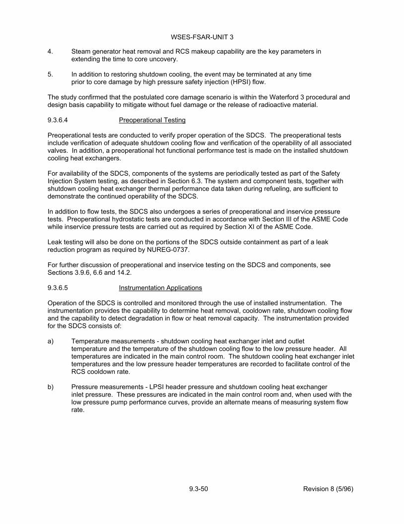
WSES-FSAR-UNIT 3
9.3-50 Revision 8 (5/96)
4. Steam generator heat removal and RCS makeup capability are the key parameters in extending the time to core uncovery.
5. In addition to restoring shutdown cooling, the event may be terminated at any time
prior to core damage by high pressure safety injection (HPSI) flow. The study confirmed that the postulated core damage scenario is within the Waterford 3 procedural and design basis capability to mitigate without fuel damage or the release of radioactive material. 9.3.6.4 Preoperational Testing Preoperational tests are conducted to verify proper operation of the SDCS. The preoperational tests include verification of adequate shutdown cooling flow and verification of the operability of all associated valves. In addition, a preoperational hot functional performance test is made on the installed shutdown cooling heat exchangers. For availability of the SDCS, components of the systems are periodically tested as part of the Safety Injection System testing, as described in Section 6.3. The system and component tests, together with shutdown cooling heat exchanger thermal performance data taken during refueling, are sufficient to demonstrate the continued operability of the SDCS. In addition to flow tests, the SDCS also undergoes a series of preoperational and inservice pressure tests. Preoperational hydrostatic tests are conducted in accordance with Section III of the ASME Code while inservice pressure tests are carried out as required by Section XI of the ASME Code. Leak testing will also be done on the portions of the SDCS outside containment as part of a leak reduction program as required by NUREG-0737. For further discussion of preoperational and inservice testing on the SDCS and components, see Sections 3.9.6, 6.6 and 14.2. 9.3.6.5 Instrumentation Applications Operation of the SDCS is controlled and monitored through the use of installed instrumentation. The instrumentation provides the capability to determine heat removal, cooldown rate, shutdown cooling flow and the capability to detect degradation in flow or heat removal capacity. The instrumentation provided for the SDCS consists of: a) Temperature measurements - shutdown cooling heat exchanger inlet and outlet
temperature and the temperature of the shutdown cooling flow to the low pressure header. All temperatures are indicated in the main control room. The shutdown cooling heat exchanger inlet temperatures and the low pressure header temperatures are recorded to facilitate control of the RCS cooldown rate.
b) Pressure measurements - LPSI header pressure and shutdown cooling heat exchanger
inlet pressure. These pressures are indicated in the main control room and, when used with the low pressure pump performance curves, provide an alternate means of measuring system flow rate.
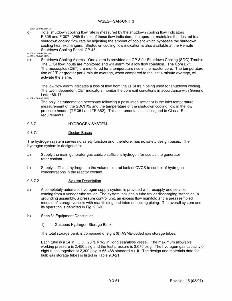
WSES-FSAR-UNIT 3
9.3-51 Revision 15 (03/07)
(DRN 00-691, R11-A) c) Total shutdown cooling flow rate is measured by the shutdown cooling flow indicators
F-306 and F-307. With the aid of these flow indicators, the operator maintains the desired total shutdown cooling flow rate by adjusting the amount of coolant which bypasses the shutdown cooling heat exchangers. Shutdown cooling flow indication is also available at the Remote Shutdown Cooling Panel, CP-43.
(DRN 00-691, R11-A) (DRN 06-886, R15) d) Shutdown Cooling Alarms - One alarm is provided on CP-8 for Shutdown Cooling (SDC) Trouble.
The LPSI flow inputs are monitored and will alarm for a low flow condition. The Core Exit Thermocouples (CET) are monitored for a temperature rise in the reactor core. The temperature rise of 2°F or greater per 4 minute average, when compared to the last 4 minute average, will activate the alarm.
The low flow alarm indicates a loss of flow from the LPSI train being used for shutdown cooling. The two independent CET indicators monitor the core exit conditions in accordance with Generic Letter 88-17.
(DRN 06-886, R15) The only instrumentation necessary following a postulated accident is the inlet temperature measurement of the SDCHXs and the temperature of the shutdown cooling flow in the low pressure header (TE 351 and TE 352). This instrumentation is designed to Class 1E requirements.
9.3.7 HYDROGEN SYSTEM 9.3.7.1 Design Bases The hydrogen system serves no safety function and, therefore, has no safety design bases. The hydrogen system is designed to: a) Supply the main generator gas cubicle sufficient hydrogen for use as the generator
rotor coolant. b) Supply sufficient hydrogen to the volume control tank of CVCS to control of hydrogen
concentrations in the reactor coolant. 9.3.7.2 System Description a) A completely automatic hydrogen supply system is provided with resupply and service
coming from a vendor tube trailer. The system includes a tube trailer discharging stanchion, a grounding assembly, a pressure control unit, an excess flow manifold and a preassembled module of storage vessels with manifolding and interconnecting piping. The overall system and its operation is depicted in Fig. 9.3-9.
b) Specific Equipment Description 1) Gaseous Hydrogen Storage Bank
The total storage bank is composed of eight (8) ASME-coded gas storage tubes.
Each tube is a 24 in. O.D., 20 ft. 6 1/2 in. long seamless vessel. The maximum allowable working pressure is 2,450 psig and the test pressure is 3,675 psig. The hydrogen gas capacity of eight tubes together at 2,300 psig is 55,488 standard cu. ft. The design and materials data for bulk gas storage tubes is listed in Table 9.3-21.

WSES-FSAR-UNIT 3
9.3-52 Revision 7 (10/94)
2) Pressure Control Unit
The pressure control unit is an automatic pressure-reducing manifold mounted in a shop-fabricated control cabinet complete with accessories designed specifically for this installation. The automatic reducing manifold has two parallel pressure reducing regulators. The discharge pressure range of these regulators is 0 to 250 psig so that pressures can be adjusted if required. The unit is set to operate in the automatic mode by setting the regulators at 150 psig and valving PCV-2 regulator off for use as a standby. Other settings could also be selected or changed at any time. Pressure control switches sound an alarm when the active bank pressure is depleted to 200 psig. A pressure transmitter is provided to send system status information to a monitoring computer.
Additional features of the equipment are as listed below. The piping is all industry-standard brass, thus maintenance is virtually eliminated. The cabinet is provided with a support stand so it is free-standing and may thus be isolated from the storage bank for additional safety. Safety valves are provided and set to 250 psig to protect low pressure downstream piping. Pressure regulators, are designed for manifold-type service and are 2 stage so discharge pressure will be constant with a minimum of physical complexity.
The flow capability of these regulators is in excess of 14,000 scfh. Two gauges are provided on each regulator, with ranges of 0 to 400 psig and 0 to 4,000 psig respectively.
An explosion-proof pressure switch is provided set at 200 psig. The switch is located inside the control cabinet. Sufficient hand valves are provided to insure complete operational flexibility. The cabinet is painted inside and out, and the piping is purged.
3) Excess Flow Manifold
The excess flow manifold is included to safeguard the line against rupture between the hydrogen system and the generator. Because there is a great distance between the hydrogen station and the use point at the generator, the line may be damaged. If line damage should occur, then an unprotected hydrogen system will discharge at the maximum capacity of both regulators to the atmosphere, thus exposing personnel and property to possible fire damage and accumulation of gas which could result in an explosion. The excess flow manifold has an excess flow valve which is designed to close at 1000 scfh hydrogen flow. Should a line rupture occur, the flow would instantly reach 1000 scfh and the valve would close bubble-tight to cut off all hydrogen flow.
For purging initially filling, or other high flow requirements, the full flow bypass valve would be manually opened. Thus, full regulator capacity can be utilized.
If the excess flow valve were to fail, it can be bypassed, valved off, and removed without disturbing the hydrogen flow.
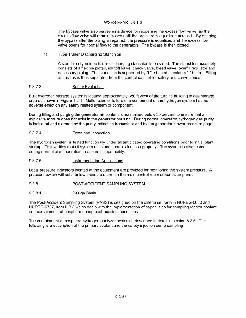
WSES-FSAR-UNIT 3
9.3-53
The bypass valve also serves as a device for reopening the excess flow valve, as the excess flow valve will remain closed until the pressure is equalized across it. By opening the bypass after the piping is repaired, the pressure is equalized and the excess flow valve opens for normal flow to the generators. The bypass is then closed.
4) Tube Trailer Discharging Stanchion
A stanchion-type tube trailer discharging stanchion is provided. The stanchion assembly consists of a flexible pigtail, shutoff valve, check valve, bleed valve, overfill regulator and necessary piping. The stanchion is supported by "L" -shaped aluminum "I" beam. Filling apparatus is thus separated from the control cabinet for safety and convenience.
9.3.7.3 Safety Evaluation Bulk hydrogen storage system is located approximately 350 ft west of the turbine building in gas storage area as shown in Figure 1.2-1. Malfunction or failure of a component of the hydrogen system has no adverse effect on any safety related system or component. During filling and purging the generator air content is maintained below 30 percent to ensure that an explosive mixture does not exist in the generator housing. During normal operation hydrogen gas purity is indicated and alarmed by the purity indicating transmitter and by the generator blower pressure gage. 9.3.7.4 Tests and Inspection The hydrogen system is tested functionally under all anticipated operating conditions prior to initial plant startup. This verifies that all system units and controls function properly. The system is also tested during normal plant operation to ensure its operability. 9.3.7.5 Instrumentation Applications Local pressure indicators located at the equipment are provided for monitoring the system pressure. A pressure switch will actuate low pressure alarm on the main control room annunciator panel. 9.3.8 POST-ACCIDENT SAMPLING SYSTEM 9.3.8.1 Design Basis The Post-Accident Sampling System (PASS) is designed on the criteria set forth in NUREG-0660 and NUREG-0737, Item II.B.3 which deals with the implementation of capabilities for sampling reactor coolant and containment atmosphere during post-accident conditions. The containment atmosphere hydrogen analyzer system is described in detail in section 6.2.5. The following is a description of the primary coolant and the safety injection sump sampling

WSES-FSAR-UNIT 3
9.3-54 Revision 10 (10/99)
system referred to as the RC PASS (Reactor Coolant Post-Accident Sampling System). The RC PASS is capable of the following: a) Obtaining a representative reactor coolant sample and a SIS sump sample (via the HPSI pump
recirculation line to the RWSP). b) Cooling the high temperature samples to allow for safe handling c) Continuously sampling the reactor coolant for dissolved oxygen content and pH d) Indication and recording of the dissolved oxygen concentration and pH of the liquid e) Capturing a diluted liquid grab sample to analyze for chloride, boron and
radioisotopes f) Capturing an undiluted grab sample to analyze for chloride, boron and radioisotopes g) Indication; and recording of the hydrogen content in the gas phase h) Capturing a diluted gas grab sample to analyze for hydrogen, noble gases and gaseous
radioisotopes 9.3.8.2 System Description The RC PASS is shown on Figure 9.3-2 (for Figure 9.3-2, Sheet 3, refer to Drawing G162, Sheet 3). The RC PASS consists of sample coolers selection and strainer station (Skid No. 1), Liquid Sample Panel (LSP or Skid No. 2), and the Process Control Panel (PCP of Skid No. 4). In addition, there are six auxiliary stations for obtaining diluted, undiluted, and full pressure liquid samples, gas grab samples, and for calibrating pH and dissolved oxygen sensors. The PASS is located in the wing area of the RAB. Skid No. 1 and 3 are located at El. - 4' O" MSL. Skids Nos. 2 and 4 are located at El. + 21' O". Skid No. 2 is situated in an accessible shielded room. The auxiliary stations are also located in an accessible shielded room adjacent to the Skid 2 room. Since post-accident radiation levels will be higher than during normal operating conditions, all system valves in direct contact with the reactor coolant are designed for this environment. The reactor coolant sample or the SIS sump sample enters Skid No. 1 of the post accident sampling system (PASS) at a set flow rate. The sample passes through heat exchanger no. 2, cooled by train A of CCW, where its temperature is reduced prior to collection and analysis. The sample is then strained to remove any undissolved solids. The sample is then directed to Skid No. 2 which serves the general purpose of directing sample flow past the necessary instrumentation required to analyze the sample. The multiple flow paths that are possible enable the operator to obtain single or simultaneous measurements. Flow paths are chosen and aligned by input signals to each solenoid valve originating from the Process Control Panel. Within Skid No. 2, the operator is capable of determining the pH and dissolved oxygen concentration of the process stream. Additionally, samples can be isolated, heated and then stripped using an inert gas directed to an in-line

WSES-FSAR-UNIT 3
9.3-55 Revision 9 (12/97)
gas chromatograph for determination of the H2 gas concentration. Also included in this skid are the utility fluids of demineralized water for flushing and sample dilution, argon stripping gas and instrument air. If desired, alternate flow paths can be aligned to allow sample to be directed to the various auxiliary stations. The flow path chosen and the existing sampling conditions determines the type of grab sample that will be obtained. The Process Control Panel (PCP) or Skid No. 4 is located away from the LSP and grab sample station cubicles in the open area adjacent to the Switchgear Room B on the +21'0" elevation. This panel, designed as a console and contains all of the readout devices for the LSP analyzers and instruments. In addition, the console also houses the remote valve switches used to actuate the LSP solenoid valves. With the exception of individual grab samples, all other system operations are performed from the PCP. The remote controls of the PCP permit operators to obtain sample data without being exposed to large volumes of potentially highly radioactive coolant. 9.3.8.3 Safety Evaluation The RC PASS is designed in compliance with the requirements set forth in NUREG-0660; NUREG-0737, Item II.B.3 and Regulatory Guide 1.97. In-line instruments are available to quantify RCS dissolved oxygen, pH and hydrogen. The capability is provided to obtain and analyze reactor coolant samples in 3-hours or less from the time a decision is made to take a sample. Grab samples are taken to the onsite lab which is capable of providing, within the 3-hour time frame, quantification of the following: a) Radionuclides (noble gases, iodines, cesiums, and non-volatiles) b) RCS boron concentration c) RCS hydrogen concentration. Grab sample analysis of RCS chlorides is accomplished within the 4-day time frame. Design features and capabilities of the PASS that comply with NUREG-0660, and NUREG-0737, Item II.B.3, are listed below: a) The system is capable of receiving a continuous sample, thus insuring a
representative reactor coolant sample of the core area b) A flow restriction orifice is provided inside the containment to limit reactor
coolant losses from a rupture of the sample line c) Deionized water and argon are provided to purge sample lines and dilute liquid and
gas samples d) The residues of the gas samples are returned to the containment or to the Gaseous Waste
Management System.

WSES-FSAR-UNIT 3
9.3-56 Revision 14 (12/05)
e) The residues of the liquid samples are directed into the waste tanks or containment sump f) The existing reactor coolant sampling system does not require an isolated auxiliary system to be
placed in operation during post-accident conditions (DRN 00-691, R11-A) g) Samples will be analyzed for dissolved gases (H2). Additionally, the capability of obtaining a
pressurized reactor coolant sample under post-accident conditions is available (DRN 00-691, R11-A) h) The grab sample and the in-line calibration stations are located near Skid No. 2. The undiluted
grab sample receiver and Skid No. 2 are shielded. The shielding requirements are based on the NUREG-0737 source terms in the reactor coolant and on the condition of a monthly averaged dose rate of 15 mr/hr at the shield wall
i) The sampling cabinet (Skid No. 2) is located in an enclosure of NEMA 12 classification with a top
vent. The vent from Skid No. 2 and the vents from the diluted liquid grab sample ports are connected to the plant HVAC system. Thus, any gaseous effluents from these sources will be filtered through charcoal absorbers and HEPA filters
j) Grab sample chloride analysis will be performed on or off site within 4 days of the sample being
taken. The PASS is not required to assure any of the following conditions: a) The integrity of the RCPB b) The capability to shut down the reactor and maintain it in a safe shutdown condition (DRN 04-977, R14)
c) The ability to prevent or mitigate the consequence of an accident which could result in potential offsite exposures in excess of 10CFR50.67 guideline exposures.
(DRN 04-977, R14)
The PASS is isolated from the RCPB and the containment and therefore is NNS and does not meet seismic Category I requirements. All lines in the PASS are constructed of corrosion-resistant stainless steel. Each portion of the system is designed for source pressure and temperature. Overpressure protection is provided through a pressure relief valve which discharges to the waste tanks. The system is designed to minimize pipe runs and grab sample sizes thus minimizing radiation exposure and the effects of equipment failure. All PASS valves located in an inaccessible post-accident area are environmentally qualified. All electrically powered components associated with post-accident sampling are capable of being supplied with power and operated within thirty minutes of an accident in which there is core degradation, assuming loss of offsite power.

WSES-FSAR-UNIT 3
9.3-57 Revision 307 (07/13)
9.3.8.4 Testing and Inspection Each component will be inspected and cleaned prior to installation. The system will be operated and tested initially with regard to flow paths, flow and thermal capacity, and mechanical operability. Instruments will be calibrated during testing. Data will be taken during normal plant operation to confirm that the sample heat exchangers and pressure reducing valve in the system are properly set to give the desired conditions for sampling. The PASS will be exercised and parameters tested (as allowed by normal operation) at least once every six months. 9.3.8.5 Instrumentation Application All necessary instrumentation and control for satisfactory operation of the Reactor Coolant Post-Accident Sampling System is provided and located on the Process Control Panel. All equipment is arranged in a manner conducive to safety as well as ease of inspection, maintenance, operation and calibration. I&C Readout on the Process Control Panel is listed below. Liquid flow Indicator pH Indicator-Recorder Dissolved 02 Indicator-Recorder H2 Analyzer Recorder Temperature Indicator Pressure Indicator
9.3.9 NITROGEN SYSTEM
9.3.9.1 Design Bases (EC-41355, R307)
The nitrogen system is designed to provide a reliable supply of nitrogen for the nitrogen accumulators on pneumatically operated valves and the necessary nitrogen for normal plant operation and maintenance. Nitrogen accumulators are provided as a backup source of compressed gas for various safety-related valves needed to mitigate the consequences of an accident or for the safe shutdown of the plant following an accident. Safety-related valves serviced by nitrogen accumulators are listed in Table 9.3-1b. Safety related Nitrogen accumulators are capable of providing motive air to pneumatically operated valves for 10 hours. Procedures are established for operating manual handwheel overrides or lining up backup air supplies for continued safety function after 10 hours. (EC-41355, R307)
9.3.9.2 System Description The completely automatic storage and supply system is resupplied from a vendor tanker/trailer. The system withdraws liquid nitrogen from the storage vessel, compresses and vaporizes it for storage in high pressure storage tubes. The high pressure nitrogen is then withdrawn and regulated for delivery to the system. The pump controls monitor the storage tubes capacity and automatically refill when required. The pump is in a standby status at all times. The pumping system is protected from overpressure by safety switches and relief devices. Pressure, temperature, and liquid level switches send signals to the pump control panel for start, stop and emergency shutdown.

WSES-FSAR-UNIT 3
9.3-58 Revision 307 (07/13)
9.3.9.2.1 Specific Equipment Description
Gaseous Nitrogen Storage Bank
The storage bank is composed of three ASME-coded gas storage tubes. Each tube is a 24" O.D., 22' 6-1/2" long seamless vessel. The maximum allowable working pressure is 2,450 psig and the test pressure is 3,675 psig.
High Pressure Control Manifold
This manifold maintains constant regulated final line pressure adjustable between 0-1,000 psig. The active regulator controls and the reserve regulator is used as a standby in the event the active regulator fails. Pressure transmitters are installed on the inlet side of the manifold for remote monitoring of system pressure.
Tube Trailer Discharging Stanchion
A stanchion-type tube trailer discharging station is provided for service from a tube trailer in the event of a liquid system failure. The stanchion assembly consists of a flexible pigtail, shutoff valve, check valve, a bleed valve and necessary piping. Filling apparatus is thus separated from the modular storage bank assembly for safety and convenience. (DRN 99-1082, R11) High Pressure Nitrogen System Safety Class 2 Relief Valve
Relief Valve NG-1523 is installed to protect the safety related nitrogen accumulators and RCB Penetration No. 14 from over-pressurization should the non-safety related pressure reducing valves NG-147A(B) and the non-safety related pressure relief valves NG-149 and/or NG-1505 fail to function properly. NG-1523 is located at the (+)46.00’ elevation of the Reactor Auxiliary Building Wing Area, adjacent to nitrogen accumulators V and VI. An exception is taken to ASME Code Subsection NC-7153 in that a locked open isolation valve (NG-1522) is located upstream of relief valve NG-1523. FSAR Section 6.3.2.5.4 reflects that relief valve failures are not considered credible failures and ANSI N658-1976 specifically exempts active failure of code safety relief valves so single failure is not applicable. (DRN 99-1082, R11) (EC-41095, R307)
Backup Air Supply to Accumulators 1 and 2
Backup Air bottles are provided that may be manually aligned to re-pressurize the Nitrogen Accumulators 1 & 2 following a design basis event concurrent with a loss of Instrument Air. This feature enables control room operators to realign Essential Chiller cooling water valves from the Wet Cooling Towers to the Dry Cooling Towers to preserve Wet Cooling Tower basin water inventory. (EC-41095, R307)
9.3.9.3 Safety Evaluation
A complete loss of the nitrogen supply system during full power operation does not reduce the ability of the reactor protective system or the engineered safety features and their supporting systems to safely shutdown the reactor or to mitigate the consequences of an accident.
The nitrogen supply system exclusive of the nitrogen accumulators is a non-safety-related system, serves no safety function and is not designed to seismic requirements. The portion of the nitrogen piping and valves penetrating the containment is designed to Safety Class 2 and seismic Category I requirements (refer to Subsection 6.2.4). The containment nitrogen header outer isolation valve is designed to fail closed. (EC-41355, R307)
The nitrogen accumulators provide a backup source of compressed gas to operate pneumatic safety-related valves in the event of a loss of instrument air. Table 9.3-lb lists all safety-related valves provided with backup nitrogen accumulators. The accumulators are designed to Safety Class 3 and seismic Category I requirements. They are sized to permit sufficient stroking of all specified valves in the course (EC-41355, R307)

WSES-FSAR-UNIT 3
9.3-59 Revision 307 (07/13)
(EC-41355, R307)
of performing their safety-related functions. Upon a loss of instrument air, a low pressure signal will open the respective nitrogen supply valves. Nitrogen that is stored in the accumulators will then charge the valve operators' supply lines permitting continued valve operation. Safety related nitrogen accumulators are capable of providing motive air to pneumatically operated valves for 10 hours. Procedures are established for operating manual handwheel overrides or lining up backup air supplies for continued safety function after 10 hours. (EC-41355, R307)
9.3.9.4 Tests and Inspection The nitrogen system is tested functionally prior to initial plant startup. These tests verify that all system units and controls function properly. The system is also tested during normal plant operation to ensure its operability. 9.3.9.5 Instrumentation Applications Local pressure indicators located at the equipment are provided for monitoring the system pressure. Pressure switches will actuate a low pressure alarm on the main control room annunciator panel.

WSES-FSAR-UNIT 3
9.3-60 Revision 308A (10/15)
SECTION 9.3 REFERENCES 1 - Williams, W. L.,. Corrosion, 13539t, 1957. 2 - Proceedings of Conference: Fundamental Aspects of Stress Corrosion Cracking, 1967. 3 - Ward, C. T., Mathis, D. L., and Stachle, R. W., "Intergranular Attack of Sensitized
Austenitic Stainless Steels by Water Containing Fluoride Ions", Corrosion, NACE, Vol. 25, No. 9, September 1969.
4 - Miller, D. A. and Bryant, P.E.C., Corrosion and Coolant Chemistry Interactions in
Pressurized Water Reactors, National Association of Corrosion Engineers Conference, March 1970.
5 - CEN-259, "An Evaluation of the Natural Circulation Cooldown Test Performed at the San
Onofre Nuclear Generating Station", January 1984. →(LBDCR 15-028, R308A)
6 - NRC Safety Evaluation for Natural Circulation Cooldown, April 8, 1988. ←(LBDCR 15-028, R308A)

WSES-FSAR-UNIT-3
TABLE 9.3-1a Revision 302 (12/08)
SAFETY CLASS VALVES WITH AIR ACCUMULATORS Valve Tag Figure Valve Tag Figure CC MVAAA710 (2CC-F243A/B) 9.2-1 * CC MVAAA641 (2CC-F146A/B) 9.2-1 * CC MVAAA135A (3CC-B201A) 9.2-1 * CC MVAAA713 (2CC-F147A/B) 9.2-1 * CC MVAAA135B (3CC-B203B) 9.2-1 * CC MVAAA807A (2CC-F154A1) 9.2-1 * CC MVAAA134B (3CC-B262B) 9.2-1 * CC MVAAA808A (2CC-F155A2) 9.2-1 * CC MVAAA134A (3CC-B265A) 9.2-1 * CC MVAAA808B (2CC-F156B1) 9.2-1 * CVRMVAAA201 (2HV-B156A) 9.2-1 * CC MVAAA807B (2CC-F157B2) 9.2-1 * CVRMVAAA101 (2HV-B157B) 9.2-1 * CC MVAAA823A (2CC-F158A1) 9.2-1 * CS MVAAA125A (2CS-F305A) Dwg. G163 CC MVAAA822A (2CC-F159A2) 9.2-1 * CS MVAAA125B (2CS-F306B) 6.3-35 CC MVAAA822B (2CC-F160B1) 9.2-1 * (EC-935, R302)
SI MVAAA405A (1SI-V1503A) 6.3-1 ** CC MVAAA823B (2CC-F161B2) 9.2-1 * SI MVAAA405B (1SI-V1501B) 6.3-1 ** CC MVAAA963A (3CC-F130A) 9.2-1 * (EC-935, R302) CC MVAAA636 (3CC-TM169A/B) 9.2-1 * CC MVAAA620 (3CC-FM138A/B) 9.2-1 * • For Figure 9.2-1, Sheet 4, refer to Drawing G160, Sheet 4 and for Figure 9.2-1, Sheet 6, refer to
Drawing G160, Sheet 6 (EC-935, R302) ** For Figure 6.3-1, Sheet 2, refer to Drawing G167, Sheet 2. (EC-935, R302)

WSES-FSAR-UNIT-3
TABLE 9.3-1b Revision 10 (10/99)
SAFETY CLASS VALVES WITH NITROGEN ACCUMULATORS
�Valve Tag Figure Valve Tag Figure
ACCMVAAA126A (3CC-TM290A 9.2-1 * CC MVAAA301A (3CC-F272A) 9.2-1 *
ACCMVAAA126B (3CC-TM291B) 9.2-1 * CC MVAAA301B (3CC-F273B 9.2-1 *
CC MVAAA114A (3CC-F113A/B) 9.2-1 * CC MVAAA322A (3CC-F274A) 9.2-1 *
CC MVAAA115A (3CC-F114A/B) 9.2-1 * CC MVAAA322B (3CC-F275B) 9.2-1 *
CC MVAAA115B (3CC-F115A/B) 9.2-1 * EFWMVAAA224B (2FW-V853A) 10.4-2 **
CC MVAAA114B (3CC-F116A/B) 9.2-1 * EFWMVAAA228B (2FW-V850B) 10.4-2 **
CC MVAAA126B (3CC-F112A/B) 9.2-1 * EFWMVAAA223B (2FW-V854B) 10.4-2 **
CC MVAAA126A (3CC-F109A/B 9.2-1 * EFWMVAAA229B (2FW-V849A 10.4-2 **
CC MVAAA127A (3CC-F110A/B) 9.2-1 * EFWMVAAA229A (2FW-V84F7B) 10.4-2 **
CC MVAAA127B (3CC-F111A/B) 9.2-1 * EFWMVAAA228A (2FW-V848A) 10.4-2 **
ACCMVAAA112A (3CC-F276A) 9.2-1 * EFWMVAAA224A (2FW-V851B) 10.4-2 **
ACCMVAAA112B (3CC-F277B) 9.2-1 * EFWMVAAA223A (2FW-V852A) 10.4-2 **
ACCMVAAA139A (3CC-F278A) 9.2-1 * CC MVAAA727 (3CC-F120A) 9.2-1 *
ACCMVAAA139B (3CC-F279B) 9.2-1 * CC MVAAA563 (3CC-F121B) 9.2-1 *
MS MVAAA116A (MS-PM629A) 10.2-4 CC MVAAA200A (3CC-F122A) 9.2-1 *
MS MVAAA116B (2MS-PM630B) 10.2-4 CC MVAAA200B (3CC-F123B) 9.2-1 *
SI MVAAA106A (2SI-L103A 6.3-1 (for Fig. 6.3-1 Sht 1, refer toDwg. G167, Sht.1)
SI MVAAA106B (2SI-L104B) 6.3-1 (for Fig. 6.3-1, Sht 1, refer toDwg. G167, Sht.1)
• For Figure 9.2-1, Sheet 4, refer to Drawing G160, Sheet 4 and for Figure 9.2-1, Sheet 6, refer to Drawing G160,Sheet 6.
** For Figure 10.4-2, Sheet 1, refer to Drawing G153, Sheet 1.
�

WSES-FSAR-UNIT-3
TABLE 9.3-2 (Sheet 1 of 3) Revision 11 (05/01)
DESIGN DATA FOR COMPRESSED AIR SYSTEM COMPONENTS
Service and Instrument Air Compressors
Type Horizontal, nonlubricated, rotary, single stage
Quantity 5 (2-Instrument air, 3-service air)
Capacity, SCFM 280
Operating Pressure, psig 112-120
Design Pressure, psig 130
Speed, rpm 1770� (DRN 99-0674)
Brake Horsepower, hp 130 @ 120 psig� (DRN 99-0674)
Materials of Construction
Casing Bronze
Head Cast Iron
Rotor Bronze
Shaft Steel
Driver
Type Electric Motor
Rating/Speed 150 hp/1800 rpm
Voltage/Phase/Frequency 460 V/3 φ/60 Hz
Service Factor 1.15
Intake Filter Silencer
Type Dry Type, Air Maze
Heat Exchanger
Type Shell and Tube
Material:
Shell Red Brass
Tubes Admiralty

WSES-FSAR-UNIT-3
TABLE 9.3-2 (Sheet 2 of 3) Revision 7 (10/94)
DESIGN DATA FOR COMPRESSED AIR SYSTEM COMPONENTS
Heat Exchanger(Cont’d)
Tube Sheets Forged Brass
Air Receiver
Type Vertical
Quantity 2 (1-Instrument air, 1-Service air)�Capacity, cu ft 100
Design Pressure, psig 150�Design Temperature, °F 125
Diameter, inches 42
Height, feet 10
Material Carbon Steel
Prefilter
Type Cartridge
Quantity 2
Capacity, SCFM 300
Filtration 99.97% of all particles 0.3 - 0.6 micronsor larger
Air Dryer
Quantity Two
Type Heatless
Capacity, SCFM 300
Desiccant Activated Alumina
Dew Point -40°F at 100 psig
Drying Chambers, Quantity 2
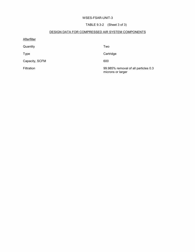
WSES-FSAR-UNIT-3
TABLE 9.3-2 (Sheet 3 of 3)
DESIGN DATA FOR COMPRESSED AIR SYSTEM COMPONENTS
Afterfilter
Quantity Two
Type Cartridge
Capacity, SCFM 600
Filtration 99.985% removal of all particles 0.3microns or larger

WSES-FSAR-UNIT-3
TABLE 9.3-3 Revision 15 (03/07)
PRIMARY SAMPLE POINTS Pressure Temperature Analytical Design Operating Design Operating Sample Points Source Components (psig) (psig) F F Coolers P1 Primary Coolant Grab Sample, 2485 2350 650 616 2 Sample Vessel P2 Pressurizer Surge Grab Sample 2485 2350 700 653 1 Line P3 Pressurizer Steam Grab Sample, 2485 2350 700 653 2 Space Sample Vessel P4A & Shutdown Cooling Grab Sample 440 415 400 350 1 P4B Suction Line P5A & High Pressure Safety Grab Sample 1950 1800 400 350 1 P5B Injection Pump Mini Flow Line P6 Purification Filter Dissolved Hydrogen 200 100 250 120 1 Inlet Analyzer, Grab Sample, Sample Vessel P7 Purification Filter Grab Sample, 200 100 250 120 1 Outlet - Ion Sample Vessel Exchanger Inlet P8 Ion Exchanger Outlet Grab Sample 200 100 250 120 1 �(DRN 06-901, R15) P9 Volume Control Tank Sample Vessel 75 50 250 120 1 �(DRN 06-901, R15) P10 Primary Water Grab Sample 150 104 125 92 1 Storage Tank

WSES-FSAR-UNIT-3
TABLE 9.3-4 (Sheet 1 of 3) Revision 307 (07/13)
SECONDARY SAMPLE POINTS Pressure Temperature Sample Analytical Design Operating Design Operating Sample Chiller Bath Points Source Components (psig) (psig) F F __ Coolers Cooling Coils (DRN 05-251, R14; EC-8465, R307) S1 Main Steam No. 1 Grab Sample,Silica, 1085 945 555 540 1 1 Cation Conductivity, (Sodium, S2) S2 Main Steam No. 2 Grab Sample,Silica, 1085 945 555 540 1 1 Cation Conductivity, (Sodium, S1) (EC-8465, R307) S3A Condenser Hotwell Grab Sample, Atmos. 2.26” Hg 125 105 1 1A Cation Conductivity, (Sodium, S6) S3B Condenser Hotwell Grab Sample, Atmos. 2.26” Hg 125 105 1 2A Cation Conductivity, (Sodium, S6) S4A Condenser Hotwell Grab Sample, Atmos. 2.26” Hg 125 105 1 1B Cation Conductivity, (Sodium, S6) S4B Condenser Hotwell Grab Sample, Atmos. 2.26” Hg 125 105 1 2B Cation Conductivity, (Sodium, S6) S5A Condenser Hotwell Grab Sample, Atmos. 2.26” Hg 125 105 1 1C Cation Conductivity, (Sodium, S6) S5B Condenser Hotwell Grab Sample, Atmos. 2.26” Hg 125 105 1 2C Cation Conductivity, (Sodium, S6) (EC-8465, R307) S6 Condensate Pump Grab Sample,Silica, 610 482 150 106 1 Discharge Cation Conductivity, pH, Hydrazine, DO (Sodium, 3A & B, 4A & B, 5A & B) (DRN 06-843, R15) S7 Combined Heater Grab Sample 642 634 388 363 1 Drain Pump Discharge (DRN 05-251, R14; 06-843, R15; EC-8465, R307)

WSES-FSAR-UNIT-3
TABLE 9.3-4 (Sheet 2 of 3) Revision 307 (07/13) Pressure Temperature Sample Analytical Design Operating Design Operating Sample Chiller Bath Points Source Components (psig) (psig) F____ F____ _ Coolers Cooling Coils (DRN 05-251, R14; 06-843, R15; EC-8465, R307) S7A Drain Collector Grab Sample 1085 804 550 521 1 Train 1A S7B Drain COllector Grab Sample 1085 804 550 521 ** Tank 2A S7C Drain Collector Grab Sample 1085 804 550 521 ** Tank 1B S7D Drain Collector Grab Sample 1085 804 550 521 ** Tank 2B (DRN 06-843, R15; EC-8465, R307) S8 Combined Heater Grab Sample,Silica, 1400 1080 480 449 1 1 Outlet Specific Conductivity Cation Conductivity pH, DO, Sodium, (Hydrazine, S8E) (DRN 06-843, R15; EC-8465, R307) S8A Moisture Separator Grab Sample 265 179 411 379 1 Drain Tank 1A S8B Moisture Separator Grab Sample 265 179 411 379 *** Drain Tank 2A S8C Moisture Separator Grab Sample 265 179 411 379 *** Drain Tank 1B S8D Moisture Separator Grab Sample 265 179 411 379 *** Drain Tank 2B (DRN 06-843, R15) S8E Feedwater Pumps Grab Sample 610 482 388 370 1 1 Suction (Hydrazine, S8) (EC-8465, R307) S9A Makeup Demineralizer Grab Sample 125 90 125 92 - 1 Effluent (Sodium, Silica, Spec. Conductivity, S9B) (DRN 06-843, R15) S9B Condensate Transfer Grab Sample 150 90 120 109 - **** Pump Discharge (Sodium, Silica, Spec. Conductivity, S9A) (DRN 05-251, R14; 06-843, R15)

WSES-FSAR-UNIT-3
TABLE 9.3-4 (Sheet 3 of 3) Revision 307 (07/13) Pressure Temperature Sample Analytical Design Operating Design Operating Sample Chiller Bath Points Source Components (psig) (psig) F____ F______ Coolers Cooling Coils (DRN 05-251, R14; EC-8465, R307) S21 A&B Steam Generator Grab Sample 1085 945 555 540 1 1 Blowdown 1 Radiation*, pH, Silica, Sodium, (S22) Specific, Cation Conductivity S22 A&B Steam Generator Grab Sample 1085 945 555 540 1 1 Blowdown 2 Radiation*, pH Silica, Sodium, (S21) Specific Cation Conductivity (EC-8465, R307) S23 Steam Generator Grab Sample 175 150 150 120 1 1 Blowdown Silica, Demineralizer Sodium, Effluent Cation Conductivity (DRN 01-775, R12-A) Steam Generator Local Grab Sample 175 150 150 120 - - Blowdown & Composite Sampler Discharge to (Proportional) CWS & Low Volume Wastewater Basin (DRN 01-775, R12-A) S24 Feedwater upstream 0.45 micron 1400 1080 480 449 1 - of the Steam Generators Millipore filter (EC-8465, R307) S25 Main Steam common 0.45 micron 1085 945 555 540 1 - header in TGB Millipore filter S26 Steam Generator 0.45 Micron 1085 945 555 540 1 - no. 2 Blowdown Millipore filter (DRN 05-251, R14; EC-8465, R307) *Common system for SP No. S21 and S22, one radiation monitor supplied by CE. (DRN 06-843, R15) ** Share line with S7A *** Share line with S8A **** Share line with S9A (DRN 06-843, R15)
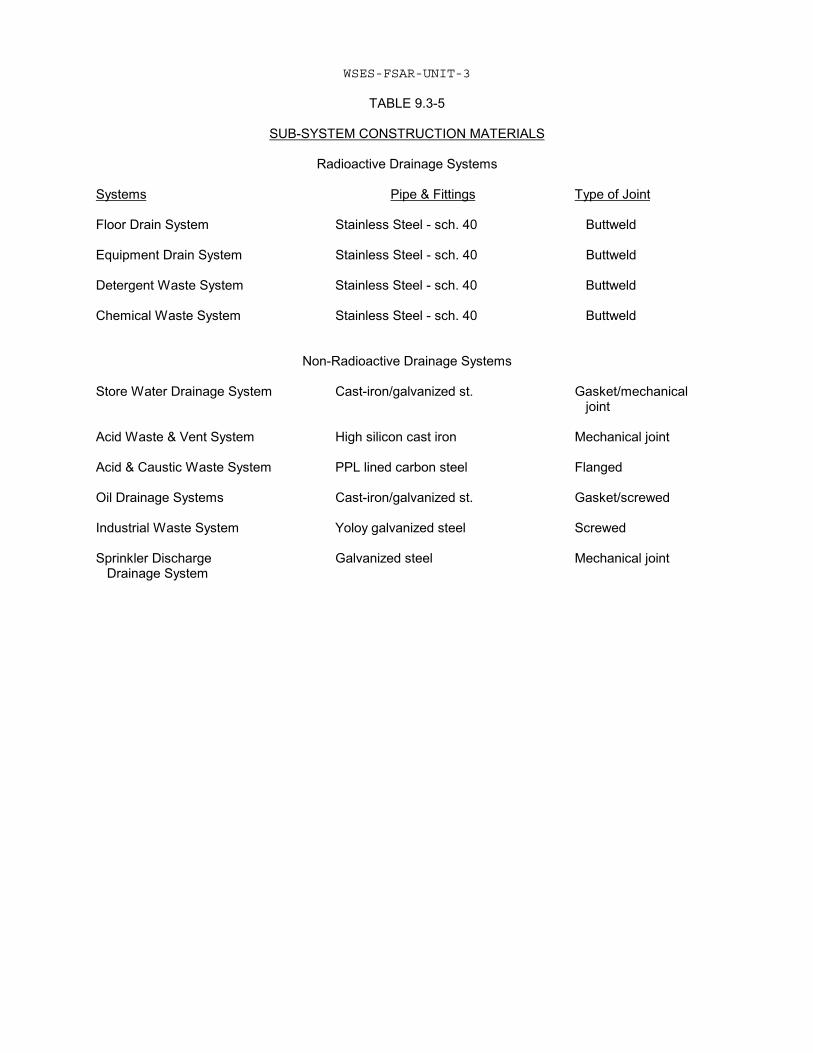
WSES-FSAR-UNIT-3
TABLE 9.3-5
SUB-SYSTEM CONSTRUCTION MATERIALS
Radioactive Drainage Systems
Systems Pipe & Fittings Type of Joint
Floor Drain System Stainless Steel - sch. 40 Buttweld
Equipment Drain System Stainless Steel - sch. 40 Buttweld
Detergent Waste System Stainless Steel - sch. 40 Buttweld
Chemical Waste System Stainless Steel - sch. 40 Buttweld
Non-Radioactive Drainage Systems
Store Water Drainage System Cast-iron/galvanized st. Gasket/mechanical joint
Acid Waste & Vent System High silicon cast iron Mechanical joint
Acid & Caustic Waste System PPL lined carbon steel Flanged
Oil Drainage Systems Cast-iron/galvanized st. Gasket/screwed
Industrial Waste System Yoloy galvanized steel Screwed
Sprinkler Discharge Galvanized steel Mechanical joint Drainage System

WSES-FSAR-UNIT-3
9.3-66
TABLE 9.3-6
DECONTAMINATION AREAS
Area Elevation Equipment
a) Central Decon Facility +21.00 ft. MSL Ultrasonic & rinse tanksWork bench sinkSpray was boothTurbulatorParts laydown areasFloor drains
b) Health Physics Personnel -4.00 ft. MSL Hot showers Decon Area Hot lavatories
Floor drains
c) Laundry Room -4.00 ft. MSL Washing machinesService sinkFloor drains
d) Radio-chem Lab -4.00 ft. MSL Dishwasher

WSES-FSAR-UNIT-3
TABLE 9.3-7 Revision 305 (11/11)
REACTOR COOLANT AND REACTOR MAKEUP WATER CHEMISTRY 1. MAKEUP WATER Analysis Normal Chloride (C1) <0.15 ppm Conductivity <2.0 mhos/cm3 pH 6.0 - 8.0 (1) Fluoride (F) <0.10 ppm 2. PRIMARY WATER
Cycle One Analysis Hot Functionals (3) Initial Criticality Power Operation (8) pH (77 F) 9.0 - 10.4 4.5 - 10.2 4.5 - 10.2 Conductivity (4) (4) (4) Hydrazine 30 - 50 ppm 1.5 Oxygen ppm 1.5 x Oxygen ppm (max. 20 ppm) Ammonia <50 ppm <50 ppm <0.5 ppm Dissolved Gas <10 cc (STP)/kg H20 - (7) (DRN 06-1142, R15) Lithium 1 - 2 ppm 1.0 - 2.0 ppm 0.2- 3.5 ppm (DRN 06-1142, R15) Hydrogen - 25 - 50 cc (STP)H2/ 25 - 50 cc (STP)H2/ Kg (H20)(6) Kg (H2O) Oxygen <0.1 ppm <0.1 ppm <0.1 ppm Suspended <0.5 ppm, <0.5 ppm, 0.5 ppm, Solids (2 ppm max.) (2 ppm max.) (2 ppm max.) Chloride <0.15 ppm <0.15 ppm < 0.15 ppm Fluoride <0.1 ppm <0.1 ppm < 0.1 ppm Boron -- 1720-2300 ppm 2050-2900 ppm (5) (EC-4019, R305) Zinc -- -- ≤ 40 ppb (Max Target) Acetate ≤ 80 ppb (Plant Transient) Dihydrate (EC-4019, R305) Notes: (1) May be as low as 5.8 if proven due to CO2 absorption. (2) Deleted (3) Special hot conditioning limits: Temperature: <350°F Time: 7-10 days (4) Consistent with concentration of additives. (5) As needed for reactivity control (6) Not applicable during core load. (7) Prior to shutdown and depressurization, reduce hydrogen concentration to <5 cc/Kg (H2O) to limit the possibility of explosive mixtures.
(8) These limits are minimum requirements. Plant specific procedures may impose more restrictive limits than specified in this Table.

WSES-FSAR-UNIT-3
TABLE 9.3-8
CVCS DESIGN TRANSIENTS
The components and piping in the CVCS are designed to accommodate, without adverse effect, the flowand thermal transient responses which result from the following plant evolutions:
1. Plant Startup - It is assumed that the plant is started 500 times during the 40 year design life ofthe plant.
2. Ramp Power Change (15 Percent to 100 Percent at 5 Percent/Min.) - It is assumed that a rampchange in power from 15 to 100 percent at the rate of 5 percent/minute with a step increase of 10percent occurs 17,000 times during the life of the plant.
3. Ramp Power Change (100 percent to 15 Percent at -5 Percent/Min.) - It is assumed that a rampchange in power from 100 percent to 15 percent at the rate of -5 percent/minute with a stepdecrease of 10 percent occurs 17,000 times during the life of the plant.
4. Reactor Trip - It is assumed that the reactor is tripped from 100 percent power 500 times duringthe 40 year design life of the plant.
5. Maximum Purification - It is assumed that the CVCS is switched from the normal purificationmode to the maximum purification mode 11,000 times during the life of the plant.
6. Loss of Charging - It is assumed that the charging flow is stopped 100 times during the life of theplant.
7. Loss of Letdown - It is assumed that the letdown flow is stopped 100 times during the life of theplant.
8. Plant Cooldown - It is assumed that the plant is cooled down 500 times during the 40 year designlife of the plant.

WSES-FSAR-UNIT-3
TABLE 9.3-9 (Sheet 1 of 7) Revision 15 (03/07)
PRINCIPAL COMPONENT DESIGN DATA SUMMARY Design Parameters Operating Parameters Component
Parameter
Description
Parameter
Normal
Min Letdown/ Max Charging
Max Letdown/ Max Charging
Max Letdown/ Min Charging
Regenerative heat exchanger �(DRN 06-843, R15) �(DRN 06-843, R15)
Quantity Type Code Tube side, letdown Fluid Design pressure, psig Design temperature, �F Materials Pressure lost at 128 gpm, psi Normal flow gpm Design flow gpm Shell side, charging Fluid Design pressure, psig Design temperature, �F Materials Pressure loss at 132 gpm, psi Normal flow, gpm Design flow, gpm
1 Shell and tube, vertical ASME Section III, Class 2(1971) Reactor Coolant 2,485 650 Austenitic stainless steel (seamless tubes) 25 38 128 Reactor coolant, boric acid � 12 wt% 3,025 650 Austenitic stainless steel 24.6 44 132
Tube side, letdown Flow (gpm @ 120 �F) Inlet temp. �F Outlet temp. �F Shell side, Charging Flow gpm @ 120�F Inlet temp �F Outlet temp �F
38 550 254 44 120 393
30 550 152 132 120 223
126 550 362 132 120 320
126 550 439 44 120 476
Letdown heat Exchanger �(DRN 06-843, R15) �(DRN 06-843, R15)
Quantity Type Tube side, letdown Code Fluid Design pressure, psig Design temperature, �F Pressure loss at 128 gpm psi Normal flow, gpm Design, gpm Materials
1 Shell and tube horizontal ASME Section III, Class2(1971) Reactor coolant 650 550 42.1 38 128 Austenitic stainless steel (seamless tubes)
Tube side, letdown Flow, gpm @ 120�F Inlet temp. �F Outlet temp. �F Shell side, cooling water Flow, gpm @ 120�F Inlet temp �F Outlet temp. �F
38 254 120 176.6 100 141.2
30 152 120 34.6 100 128.6
126 362 120 1197.6 100 130
126 439 130 1176.4 100 144.3

WSES-FSAR-UNIT-3
TABLE 9.3-9 (Sheet 2 of 7) Revision 304 (06/10)
Design Parameters Component Parameter Description Letdown heat Shell side, cooling water exchanger (Cont'd) Code ASME Section III, Class 3 (1971) Fluid Inhibited water Design pressure, psig 150 Design temperature, °F 250 Materials Carbon steel Normal flow, gpm 176.6 Design flow, gpm 1,200 Pressure loss at 1197.6 gpm, psi 15 Purification Quantity 1 filter Type Resin bonded glass fiber and polyster (DRN 99-0971; EC-13560, R304) Design temperature, °F 250 Design pressure, psig 200 Design flow, gpm 250 Normal temperature, °F 120 Normal pressure, psig 60-110 Normal flow, gpm 37 Clean ΔP at 250 gpm, psi 10 Loaded ΔP at 250 gpm, psi 25 Removal Rating Absolute (Beta Method) ≤20 microns Fluid Reactor coolant Code ASME III, Class C (1968/Summer 1970) (EC-13560, R304) Shell materials, wetted Austenitic stainless steel Purification Quantity 3 ion exchangers Type Flushable Design pressure, psig 200 Design temperature, °F 250 Normal operating temperature, °F 120 Normal operating pressure, psig 40-75 Resin volume, total, ft3 each 36.2 Resin volume, useful, ft3 each 32.0 Normal flow, gpm 38 Design flow, gpm 128 Code for vessel ASME III, Class 2 (1968/Summer 1970) (DRN 99-0971)

WSES-FSAR-UNIT-3
TABLE 9.3-9 (Sheet 3 of 7) Revision 11 (05/01)
Design Parameters
Component Parameter Description
Maximum ΔP at 128 gpm psi 5
Purification ion Retention screen size 80 U.S. meshexchangers (Cont’d) Material Austenitic stainless steel
Fluid Reactor coolantResin type Cation/anion mixed bed for
purification, anion bed fordeborating
� (DRN 99-0971)Volume control Quantity 1tank Type Vertical, cylin drical
Internal volume, gal 4,780Design pressure, internal, psig 75Design pressure, external, psig 15Design temperature, °F 250Normal operating pressure, psig 25-50Normal operating temperature, °F 120Normal spray flow, gpm 38Blanket gas, during plant operation HydrogenFluid Reactor coolant, boric acid,
<12 w/oMaterial ASME SA-240, Type 304Code ASME III, Class C
(1968/Summer 1970)
Charging pumps Quantity 3Type Horizontal, positive
Displacement, triplexDesign pressure, psig 2,735Design temperature, °F 250Capacity per pump, gpm 44Normal discharge pressure, psig 2,350Normal suction pressure, psig 40-65Normal temperature of pumped fluid, °F 120NPSH available, psia 6.5Pump rating (hp) 100
� (DRN 99-0971)

WSES-FSAR-UNIT-3
TABLE 9.3-9 (Sheet 4 of 7) Revision 11 (05/01)
Design Parameters
Component Parameter Description
Charging pumps Materials in contract with (Cont’d) with pumped fluid Austenitic and/or 17-4PH,
Condition H 1100stainless steel
Fluid Reactor coolant, boric acid≤12 w/o
Code ASME III, Class 2 (1968/March 1970)
� (DRN 99-0971)PulsationDampeners Quantity 3 (discharge of pumps only)
Vessel material SA-240 SS 304Vessel volume, gallons (Nominal) 2.5Design pressure, psig 3,125Design temperature, °F 250Design flowrate, gpm 44Maximum operating pressure, psig 2735Normal temperature, °F 120Bladder material Ethylene propylene rubberPrecharge pressure, psig 1,606Outlet pressure pulsation, psi Full amplitude 92 Half amplitude 46Code ASME III, Class 2
(1974/Winter 1976)� (DRN 99-0971)

WSES-FSAR-UNIT-3
TABLE 9.3-9 (Sheet 5 of 7) Revision 9 (12/97)
Design Parameters
Component Parameter Description
Boric acid Quantity 2pumps Type Centrifugal, horizontal
Design pressure, psig 150Design temperature, °F 250Design head, ft 231Design flow, gpm 143
� Normal operating temperature, °F 100° F to 110° F
� Normal suction pressure psig available 9NPSH at the design flow, ft 20Motor, hp 25Fluid, boric acid maximum, w/o 3.5Material in contact withliquid Austenitic stainless steelCode ASME III, Class 3
(1971/Summer 1972)Boric acid Quantity 2makeup tanks Type Vertical, cylindrical
Volume, ea. gal. 11,800Design pressure, internal, psig 15Design pressure, external, psig 0Design temperature, °F 200
� Normal operating temperature, °F 100° F to 110° F
� Number heaters 6*Type heater Electrical strip*Heater capacity, KW ea 2.25 KW (2 banks of 3 ea)Fluid, boric acid, maximum wt% 3.5Material ASME SA-240, Type 304Code ASME III, Class 3
(1968/Summer 1970)
* Heater operability is only required when technical specifications allow a boric acid makeup tank boronconcentration in excess of 3.5 w/o.

WSES-FSAR-UNIT-3
TABLE 9.3-9 (Sheet 6 of 7) Revision 15 (03/07)
Design Parameters Component Parameter Description Boric acid Quantity 1 batching tank Type Vertical, cylindrical Internal volume, gal 630 Design pressure Atmospheric Design temperature, �F 200 Normal operating temperature, �F 150-155 Type heater Electrical immersion Number of heaters 3 Heater capacity, kW ea 15 Fluid, boric acid, maximum w/o 12 Material ASME SA-240, Type 304 Code None Mixer type One 1/2 hp portable, single blade propeller mixer; 42 in. long shaft; wetted parts are stainless steel Chemical Quantity 1 addition Internal volume, gal 18 tank Design and normal operating pressure, psig 150/100 Design temperature, �F 150 Normal operating temperature, �F 40-120 Material Austenitic stainless steel Code None Chemical Quantity 1 addition Type Positive displacement metering (variable capacity) pump �(DRN 06-843, R15) Design pressure, psig 165 �(DRN 06-843, R15) Design temperature, �F 150 Capacity, gph, max 40 �(DRN 06-843, R15) Normal discharge pressure, psig 15-20 �(DRN 06-843, R15) Normal suction pressure, psig Atmospheric Normal temperature of pumped fluid, �F 40-120 Pump rating (hp) 1/2 Materials in contact with pumped fluid Austenitic stainless steel Fluid N2H4, (max 35 wt%) LiOH-H2O (max 37,167 ppm Li)

WSES-FSAR-UNIT-3
TABLE 9.3-9 (Sheet 7 of 7) Revision 12 (10/02)
Design Parameters
Component Parameter Description
Code None�(DRN 99-1031)
Process (Note 1) Quantity 1radiation Detection principle Gamma-ray scintillationmonitor Vessel Design pressure,�(DRN 99-1031) psig 200
Internals Design temperature, °F 150Normal operating temperature, °F 110Normal flowrate, (gpm) 3-5Normal operating pressure (psig) 53Instrument range (μci/cc) 10-4 to 10+2 Rb88
gammaCode ASME VIII, Div. 1 (1974)Fluid Reactor coolant
�(DRN 99-1031)
Boronometer (Note 1) Quantity 1�(DRN 99-1031) Vessel design
temperature, °F 250Internals design temperature, °F 150Vessel design pressure,psig 200Normal operating temperature, °F 120Normal flowrate, gpm 0.5Normal operating pressure,psig 60-110Instrument range, ppm boron 0-5000Accuracy, sample ± 1% ± 5 ppmCode for vessel ASME VIII, Div. 1
(1974/Summer 1976)Fluid Reactor Coolant
�(DRN 99-1031)
Note 1: These devices have been functionally Abandoned-in-place by DC 3432.�(DRN 99-1031)

WSES-FSAR-UNIT-3
Table 9.3-10 has been deleted.

WSES-FSAR-UNIT-3
TABLE 9.3-11 Revision 307 (07/13)
CHEMICAL AND VOLUME CONTROL SYSTEM PROCESS PARAMETERS Item Value Normal letdown and purification flow, gpm 38 Maximum letdown and purification flow, gpm 126 Normal charging flow, gpm 44 Maximum charging flow, gpm 132 Reactor coolant pump controlled bleedoff, 4 pumps gpm 6 (DRN 03-2063, R14)
Normal letdown temperature from RCS loop, F 543 (DRN 03-2063, R14)
Normal charging temperature to RCS loop, F 410 Normal ion exchanger operating temperature, F 120 (DRN 03-2063, R14)
Boric acid makeup tank boron concentration, boric acid, minimum weight % 2.8 (DRN 03-2063, R14)
(EC-8458, R307)
Refueling water storage pool boron concentration, boric acid, minimum weight % 1.173 (EC-8458, R307)
(EC-8458, R307)
(EC-8458, R307)

WSES-FSAR-UNIT-3
TABLE 9.3-12
SCHEDULE OF WASTE GENERATION
Quantity(a)Source (gal/yr at 120 F)
Refueling shutdown and startup (refueling at theend of core life) 106,507
Cold shutdowns and startups (to 5% subcritical)
At 30% core life 57,651
At 60% core life 80,909
At 90% core life 154,111
Hot critical shutdowns and startups
At 55% core life 58,200
At 65% core life 72,800
Boron dilution (fuel burnup waste to 30 ppm boron) 252,300
Back-to-back cold shutdowns and startups (to 5% 183,857subcritical at 85% core life)
(a) For a UO2 core.

WSES-FSAR-UNIT-3
� (DRN 99-0971)TABLE 9.3-13(c)(e) (Sheet 1 of 4) Revision 11 (05/01)
� (DRN 99-0971)CHEMICAL AND VOLUME CONTROL SYSTEM PROCESS FLOW DATA
CVCS NORMAL PURIFICATION OPERATION (One Charging Pump in Operation)(a)
CVCSLocation:
1 1a 2 2a 3 3a 4 4a 5 6 6a 7 7a 7b 7c 7d 8 9 9a
Flow (gpm) 38 38 38 38 38 38 38 38 38 37 37 1 1 1/2 1/2 1 38 38 38Press (psig) 2215 2206 2203 2197 469 467 462 460 63 63 60 63 63 63 63 31 31 30 30Temp. (F) 550 550 254 254 254 254 120 120 120 120 120 120 120 120 120 120 120 120 120
CVCS INTERMEDIATE PURIFICATION OPERATION (Two Charging Pumps in Operation)(a)
CVCSLocation:
1 1a 2 2a 3 3a 4 4a 5 6 6a 7 7a 7b 7c 7d 8 9 9a
Flow (gpm) 82 82 82 82 82 82 82 82 82 81 81 1 1 1/2 1/2 1 82 82 82Press (psig) 2215 2176 2164 2141 496 488 468 460 75 75 71 77 77 77 77 45 45 43 43Temp. (F) 550 550 320 320 320 320 120 120 120 120 120 120 120 120 120 120 120 120 120
CVCS MAXIMUM PURIFICATION OPERATION (Three Charging Pumps in Operation)(a)
CVCSLocation:
1 1a 2 2a 3 3a 4 4a 5 6 6a 7 7a 7b 7c 7d 8 9 9a
Flow (gpm) 126 126 126 126 126 126 126 126 126 125 125 1 1 1/2 1/2 1 126 126 126Press (psig) 2215 2124 2099 2054 536 519 477 460 102 101 96 106 106 106 106 74 73 69 68Temp. (F) 550 550 362 362 362 362 120 120 120 120 120 120 120 120 120 120 120 120 120
CVCS NORMAL PURIFICATION OPERATION (One Charging Pump in Operation)(a)
CVCS Location: 10 10a 10b 10c 11 12 13 13a 13b 13c 14a,b,c,d 14e 14f 14g 14h
Flow (gpm) 38 38 38 44 44 44 44 44 44 44 1.5 0 6 6 6Press (psig) 29 28 25 29 40 2322 2304 2301 2291 2291 62 62 39 30 28Temp. (F) 120 120 120 120 120 120 120 393 550 550 150 150 150 150 150
CVCS INTERMEDIATE PURIFICATION OPERATION (Two Charging Pumps in Operation)(a)
CVCS Location: 10 10a 10b 10c 11 12 13 13a 13b 13c 14a,b,c,d 14e 14f 14g 14h
Flow (gpm) 82 82 82 88 88 88 88 88 88 88 1.5 0 6 6 6Press (psig) 40 38 25 29 40 2408 2340 2329 2291 2291 62 62 39 30 28Temp. (F) 120 120 120 120 120 120 120 354 550 550 150 150 150 150 150

WSES-FSAR-UNIT-3
TABLE 9.3-13 (Sheet 2 of 4) Revision 11 (05/01)
CHEMICAL AND VOLUME CONTROL SYSTEM PROCESS FLOW DATA
CVCS MAXIMUM PURIFICATION OPERATION (Three Charging Pumps in Operation)(a)
CVCS Location: 10 10a 10b 10c 11 12 13 13a 13b 13c 14a,b,c,d 14e 14f 14g 14h
Flow (gpm) 126 126 126 132 132 132 132 132 132 132 1.5 0 6 6 6Press (psig) 63 59 25 29 40 2550 2401 2376 2291 2291 62 62 39 30 28Temp. (F) 120 120 120 120 120 120 120 320 550 550 150 150 150 150 150
CVCS MAKEUP SYSTEM OPERATION - AUTOMATIC MODE (Blended Boric Acid Concentration - 900 PPM)(b)
CVCSLocation:
15 15a 16 17 18 19 20 21 22 23 24 25 26 27 28 29 30 30a 31 32 33
� (DRN 99-0971)
Flow (gpm) 143 143 143 9* 9* 0 9* 123* 123* 132 0 0 0 134* 126* 8* 8* 134* 0 0 0� (DRN 99-0971)
Press (psig) 11 9 109 109 108 30 36 100 36 36 30 109 30 109 80 80 17 0 30 30 30Temp. (F) 160* 160* 160* 160* 160* 160* 160* 104 104 120 120 160* 160* 160* 160* 160* 160* 160* 160* 160* 160*
CVCS MAKEUP SYSTEM OPERATION - AUTOMATIC MODE (Blended Boric Acid Concentration - 900 PPM)(b)
CVCSLocation:
15 15a 16 17 18 19 20 21 22 23 24 25 26 27 28 29 30 30a 31 32 33
Flow (gpm) 143 143 143 22 22 22 0 0 0 0 0 0 22 121 113 8 8 121 0 0 0Press (psig) 11 9 109 109 107 31 37 100 15 15 30 109 30 109 80 80 17 0 30 30 30Temp. (F) 160* 160* 160* 160* 160* 160* 160* 104 104 120 120 160 160 160 160 160 160 160 160 160 160
CVCS MAKEUP SYSTEM OPERATION - DILUTE MODE (Three Charging Pumps Operating)(b)
CVCSLocation:
15 15a 16 17 18 19 20 21 22 23 24 25 26 27 28 29 30 30a 31 32 33
Flow (gpm) 143 143 0 0 0 0 0 126 126 126 0 0 0 143 136 7 7 136 0 0 0Press (psig) 11 9 109 109 109 30 36 100 36 36 30 109 30 109 78 78 30 0 30 30 30Temp. (F) 160* 160* 160* 160* 160* 160* 160* 104 104 170 170 160* 160* 160* 160* 160 160 160 160 160 160
CVCS MAKEUP SYSTEM OPERATION - MANUAL MODE (Blended Boric Acid Concentration - 2150 PPM)(b)
CVCSLocation:
15 15a 16 17 18 19 20 21 22 23 24 25 26 27 28 29 30 30a 31 32 33
Flow (gpm) 143 143 143 22* 22* 0 22* 110* 110* 132 0 0 0 121* 113* 8* 8* 121* 0 0 0Press (psig) 11 9 109 109 107 30 36 100 35 35 30 106 30 109 80 80 17 0 30 30 30Temp. (F) 160* 160* 160* 160* 160* 160* 160* 104 104 120 120 120 160* 160* 160* 160* 160* 160* 160* 160* 160*

WSES-FSAR-UNIT-3
TABLE 9.3-13 (Sheet 3 of 4) Revision 305 (11/11)
CHEMICAL AND VOLUME CONTROL SYSTEM PROCESS FLOW DATA
CVCS MAKEUP SYSTEM OPERATION - EMERGENCY BORATION (SIAS) (Via Boric Acid Makeup Pumps - One Pump is Operating; Three Charging Pumps Operating)(b)(d) CVCS Location:
15 15a 16 17 18 19 20 21 22 23 24 25 26 27 28 29 30 30a 31 32 33
Flow (gpm) 142 142 142 132 0 0 0 0 0 0 0 132 132 10 0 10 10 10 0 0 0 Press (psig) 11 9 110 110 110 108 15 100 15 15 30 108 109 110 110 110 0 0 30 30 30 Temp. (F) 160* 160* 160* 160* 160* 160* 160* 104 104 160* 120 160* 160* 160* 160* 160* 160* 160* 160* 160* 160* CVCS MAKEUP SYSTEM OPERATION - EMERGENCY BORATION (SIAS) (Via Gravity Feed)(b) CVCS Location:
15 15a 16 17 18 19 20 21 22 23 24 25 26 27 28 29 30 30a 31 32 33
Flow (gpm) 66 0 0 0 0 0 0 0 0 0 0 0 0 0 0 0 0 0 66 66 132 Press (psig) 11 11 11 11 11 6 15 100 15 15 6 11 6 11 0 0 0 0 11 11 6 Temp. (F) 160* 160* 160* 160* 160* 160* 160* 104 104 160* 120 160* 160* 160* 160* 160* 160* 160* 160* 160* 160* CVCS MAKEUP SYSTEM OPERATION - SHUTDOWN BORATION(b) CVCS Location:
15 15a 16 17 18 19 20 21 22 23 24 25 26 27 28 29 30 30a 31 32 33
Flow (gpm) 143 143 143 22 22 0 22 22 22 44 0 0 0 121 113 8 8 121 0 0 0 Press (psig) 11 9 109 109 107 30 31 100 31 31 30 109 30 109 80 80 17 0 30 30 30 Temp. (F) 160* 160* 160* 160* 160* 160* 160* 104 104 160* 120 160* 160* 160* 160* 160* 160* 160* 160* 160* 160* CVCS Makeup System Operation - Boric Acid Batching CVCS Location:
34 35 36 37 38
Flow (gpm) 50 50 70 70 70 Pressure (psig)
92 0 0 0 0
Temperature (F)
104 104 150 150 150
(EC-4019, R305) CVCS Makeup System Operation - Chemical Addition / Zinc Injection (EC-4019, R305) CVCS Location:
39 40 41 42 43 44 45
Flow (gpm) 1 1 1 1 1 1 1 Pressure (psig)
100 30 30 30 30 30 30
Temperature (F)
104 104 104 104 104 104 104

WSES-FSAR-UNIT-3
TABLE 9.3-13 (Sheet 4 of 4) Revision 12-B (04/03)
CHEMICAL AND VOLUME CONTROL SYSTEM PROCESS FLOW DATA
Notes:
a. The pressure drop across the purification filter, ion exchanger and letdown strainer varies with loading. The pressure drops as shown are given with minimal crud deposition. The pressure in the volume control tank varies and affects the pressures at locations 3 and 14a through 14g, 20, 22 and 23 proportionally.
b. The data shown for the various modes of operation is typical. The pressure in the isolated piping of the CVCS makeup system will normally be 0 psig but may be as high as 200 psig before the relief valve lifts.
c. Since line pressure drops are dependent on piping and equipment elevations and assumed pipe lengths were used for calculation purposes, the pressure values are approximate.
d. Value shown for three pump operation. Following SIAS, two or three pumps may be operating.
� (DRN 99-0971, R11; 03-275, R12-B)
e. Deleted.�(DRN 03-275, R12-B)
* Temperature values and flow values will change depending on the actual Boric Acid Makeup Tank concentration. With a concentration < 3.5 weight % Boric Acid, the tank will be maintained at 100 degrees Fahrenheit.
� (DRN 99-0971, R11)

WSES-FSAR-UNIT-3
TABLE 9.3-14 Revision 9 (12/97)
CVCS COMPONENT DIESEL LOADING
Please refer to FSAR Table 8.3-1.

WSES-FSAR-UNIT-3
TABLE 9.3-15 (Sheet 1 of 60) Revision 12 (10/02)
CHEMICAL AND VOLUME CONTROL SYSTEM (BORON ADDITION PORTION)
FAILURE MODE AND EFFECTS ANALYSIS
No. Name Failure Mode Cause Symptoms and Local EffectsIncluding Dependent Failures Method of Detection
InherentCompensating Provision Remarks
�(DRN 99-1031) 1. Demineralized
water supply tova lve7CH-V624(CH-119)PMU-134
a. Fails in closedposition
Mechanicalfailure
Unable to add makeup water toboric acid batching tank tomakeup a batch of boric acidsolution.
Operator None Required
b. Fails partiallyopen
Seat leakage,contamination
Possible makeup water leakageinto tank when makeup waterpumps are operating.
(water in tank) Operator None Required
2. Boric acidbatching mixerBAM-EMTR-64AB-9
a. Fails tostart or mix
Motor failure,broken agitator
Unable to mix boric acidsolution properly. Possiblestratification in solution.Possible boron precipitationin lines connecting batchtank to B/A make-up tanks.
Operator Batch can be mixed usingpaddle if necessary
SUfficientreserve in BAMTuntil fault iscorrected.
3. Boric acidbatching tanklocal samplevalve,7CH-V610-8(CH-120)BAM-102
a. Failsclosed (unableto open)
Mechanicalfailure
Unable to obtain a localsample when making up abatch of boric acidsolution.
Operator detection None Boric acid batchingtank is generallyempty, except duringboric acid solutionbatching.
�(DRN 99-1031)b. Fails partiallyopen
Seat leakage,contamination
Local boric acid solutionspill when making up abatch of boric acidsolution.
Operator None Sufficient reservein BAMT
4. Boric acidbatching tankimmersionheater,H-213
a. Fails off Electricalfailure, opencircuit.
Unable to heat boric acidsolution. Possibleprecipitation of boric acidin the batching tank whenmaking up a batch of boricacid solution.
Temperature indica-tor-controller,TIC-213.
None Sufficient reservein BAMT until faultis corrected.
b. Fails fullon
Electricalfailure-short circuit
Boric acid solution overheatedwhile making up the batch.Possible heater damage
Temperature indica-tor controller,TIC-213
Manual power breaker Same as 4 a.

WSES-FSAR-UNIT-3
TABLE 9.3-15 (Sheet 2 of 60) Revision 12 (10/02)
FAILURE MODE AND EFFECTS ANALYSIS
No. Name Failure Mode Cause Symptoms and Local EffectsIncluding Dependent Failures Method of Detection
InherentCompensating Provision Remarks
5. Temperatureindicator-controller,TIC-213
a. Erroneoushigh temperatureindication orcontrols temp. low
Electrical ormechanicalfailures
The heater would be continu-ously off resulting in under-heating of the boric acidsolution and possible boricacid precipitation.
Operator None Operator should beable to keep theboric acid insolution by mixing.Then the batch canbe drained, thecontroller repairedand a new batch madeup.
�(DRN 99-1031)b. Erroneous lowtemperature indica-tions or controlstemp. high.
Electrical ormechanicalfailure
The heater would be continu-ously on resulting in the boricacid solution being overheated.
None while solution Hand switch to turn offheater in batching tank ifdetected.
6. Boric acidbatching tankdrain valve,7CH-V610-9(CH-121)BAM-101
a. Fails inclosed position
Mechanicalfailure
Uable to drain and flushboric acid batching tankafter making up a batch ofboric acid solution.
Operator None required Same as 4 a.
b. Fails partlyopen
Seat leak,contamination
Leakage from batching tankto the waste managementsystem.
Visual, decreasein batch tank level.
None
7. Boric acidbatching tankoutlet valve7CH-V616-1(CH-122)BAM-103
a. Fails inclosed position
b. Fails partlyopen
Mechanicalfailure
Seat Leakagecontamination
Unable to add boric acidsolution to boric acidmakeup tanks.
Loss of boric acid solution(possibly of low concentra-tion) to the dischargeheader while making up abatch of concentrated boricsolution.
Operator
Operator
None
Series normally closedvalve downstream of7CH-V616
Same as 4 a.
All failure modeswhich could resultin batching errorssignificantlyaffecting make-uptank concentrationare detectable byperiodic localsampling.
�(DRN 99-1031)

WSES-FSAR-UNIT-3
TABLE 9.3-15 (Sheet 3 of 60) Revision 12 (10/02)
FAILURE MODE AND EFFECTS ANALYSIS
No. Name Failure Mode Cause Symptoms and Local EffectsIncluding Dependent Failures Method of Detection
InherentCompensating Provision Remarks
�(DRN 99-1031) 8. Boric acid
batching tankoutlet relief7CH-R190(CH-123)BAM-104
a. Opensspuriously
Spring failure,set pointdrift
Flow back to batching tankfrom outlet line
Possi ble increasein batching tanklevel.
None This is a thermalrelief valve,designed torelieve back tothe batching tank.
�(DRN 99-1031)b. Fails toopen
Mechanicalfailure
Possible excessive damage tobatching tank discharge linesdue to heat up of liquidtrapped in lines.
Periodic test None
c. Fails toreseat
Contamination Seat leak. Same as 7 b. Same as 8 a. None
�(DRN 99-1031) 9. Boric acid
batchingstrainerBAM-MSTRN-0001
a. Fails tostrain
Perforatedstrainerelement
Possible introduction ofparticulate matter to boricacid make-up tanks when addingboric acid from boric acidbatching tank.
Periodic inspection Replacement
�(DRN 99-1031)b. Plugged Particle
build-upSlow boric acid solution add-ition rate to boric acid make-up tanks. Possibly unableto add boric acid solution tothe make-up tanks from thebatching tank.
Operator Replacement
�(DRN 99-1031)10. Boric acid
batching tankBAM-MTNK-0003
a. Externalleakage
Mfg. Defect,corrosion
Some loss of boric acidsolution while making-upa batch.
Operator None
11. Boric acidbatching tankstop valve to:BAMT "A"7CH-V616-2(CH-124)BAM-105ABAMT "B"7CH-V616-3(CH-135)BAM-105B
a. Fails inclosed posi-tion
b. Failspartly open
Mechanicalfailure
Seat leakage,contamination
Unable to add boric acidsolution to one boric acidmake-up tank.
Possible overfilling of onemake-up tank while trans-ferring boric acid from thebatching tank to the othermake-up tank.
Operator
Boric acid makeuptank level indicatorsand high levelalarms fromLIT-206 or LIT-205
Two redundant 100%capacity boric acidmake-up tanks.
Each make-up tankhas an overflow linewhich drains to the WMS
�(DRN 99-1031)

WSES-FSAR-UNIT-3
TABLE 9.3-15 (Sheet 4 of 60) Revision 12 (10/02)
FAILURE MODE AND EFFECTS ANALYSIS
No. Name Failure Mode Cause Symptoms and Local EffectsIncluding Dependent Failures Method of Detection
InherentCompensating Provision Remarks
12. Boric acidbatching tankdischarge lineheat tracingcircuit A & B
Fails off Open circuits,Elect. Malf.
Possible boron precipitationif there was boric acid solu-tion left in the lines.Decrease in temp. in heattraced lines.
Malfunction of heattracing annunciatedby alarm.
Redundant heat tracingcircuits
13. DELETED
14. Boric acidmake-up tanklevel transmit-ters LIT-206and LIT-208(for tanks Aand B respec-tively).
a. Erroneouslow levelindicationsand/or Lowor Low-Lowlevelalarms.
Electrical ormechanicalmalfunction
No direct impact on system.Possible overfilling of boricacid make-up tank whentransferring boric acid fromthe batching tank.
Local level indica-tors LI-CH-0240 &LI-CH-0241 for tanksA & B respectivelywould provide veri-fication of actualtank level. Operatordetects overfilling.
Each tank has an overflowline to protect it againstoverpressurization.
�(DRN 99-1031)b. Indicateshigh
Electrical ormechanicalmalfunction
Possible undetected lowlevel condition in make-uptank.
Local level indica-tors LI-CH-0240 &LI-CH-0241 for tanksA & B respectivelywould provide veri-fication of actualtank level. Boricacid pump pressureindicatorsPIS-206 or PIS-208should alarm on lowpressure if a tankactually drainsdown.
�(DRN 99-1031)

WSES-FSAR-UNIT-3
TABLE 9.3-15 (Sheet 5 of 60) Revision 12 (10/02)
FAILURE MODE AND EFFECTS ANALYSIS
No. Name Failure Mode Cause Symptoms and Local EffectsIncluding Dependent Failures Method of Detection
InherentCompensating Provision Remarks
�(DRN 99-1031)15. Boric acid
make-up tankA heatersH-206,H-207
a. Fails lowor off
Electricalfailure
Cooldown of boric acid solu-tion. Possible precipitationof boric acid in tank,possible deboration incidentof tank A is being used forboron addition.
Temperature indica-tor controllersTIC-206, TIC-207alarm on low temp-erature.
Two redundant fullcapacity heaters. Tworedundant make-up tanks.
Boron concentration levelin the tank ≤ 3.5 weightpercent does not requireheat tracing. Heaterscould be eliminated.
b. Fails fullon
Electricalfailure
Excessive heatup of boricacid solution. Possible toincrease boric acid concen-tration if water is "boiled"away. Ultimately leads toboric acid precipitation intank.
Temperature indica-tors controllers;TIC-206, andTIC-207 alarm onhigh temperature.Periodic localsample.
Fully redundant make-uptank can be usedwhile heater is beingrepaired.
Manual powerbreakers for theheaters wouldallow the failedheater to beremoved from service,and the redundantheater could assumetemperature control.
�(DRN 99-1031)16. Boric acid
make-up tankA temperatureindicators-controllers;TIC-206 &TIC-207
a. Controlstemperature lowor erroneoushigh temp.indication
Mechanical orelectricalmalfunction
Cooldown of boric acid solu-tion. Possible boric acidprecipitation in tank.
Redundant tempera-ture indicator-controller with lowtemperature alarm.
Fully redundant tempera-ture indicator-controllerwith heater is capableof maintaining requiredtemperature.
�(DRN 99-1031)b. Controlstemperaturehigh orerroneous lowtemp. indication
Electrical ormechanicalmalfunction
Excessive heatup of boricacid solution. Possibleboiling and boric acidconcentration increase.Possible eventual boricacid precipitation.
Redundant tempera-ture indicator-controller withhigh temperaturealarm. Peridiclocal sample.
Redundant boric acidmake-up tank to supplyboric acid solution atrequired temperatureand concentration.
�(DRN 99-1031)17. Boric acid
make-up tankB heaters,H-208 and H-209
Same as 15 Same as 15 Same as 15 Temp. Indicator/controllers TIC-208,TIC-209 alarm onlow/high temp.
Same as 15
18. Boric acidmake-up tankB, temperatureindicators-controllers,TIC-208 andTIC-209.
Same as 16

WSES-FSAR-UNIT-3
TABLE 9.3-15 (Sheet 6 of 60) Revision 12 (10/02)
FAILURE MODE AND EFFECTS ANALYSIS
No. Name Failure Mode Cause Symptoms and Local EffectsIncluding Dependent Failures Method of Detection
InherentCompensating Provision Remarks
�(DRN 99-1031)19. Boric acid
make-up tankdrain valves;3CH-V658A(CH-127)BAM-110A3CH-V658B(CH-137)BAM-110B
a. Fails inclosed position
b. Failspartly open
Mechanicalfailure
Seat leakagecontamination
No impact on normal systemoperation, unable to drainmake-up tank.
Loss of boric acid solutionfrom make-up tank to theWMS
Operator
Level indicatorswith low and low-low level alarms,level sensor withlow level alarms.
None Required
2 redundant full capacityboric acid make-up tanks.
20. Boric acidmake-up tanksoutlet manualvalves,3CH-V101A(CH-131)BAM-112A3CH-V103B(CH-142)BAM-112B
a. Fails open
b. Fails closed
Mechanicalfailure
Mechanicalfailure
No impact on normal systemoperation. Unable to isolatea boric acid make-up tankfor repair.
Unable to re-establish boronaddition from affected tank.
Operator
Operator
Make-up tanks can beisolated using othervalves.
2 redundant make-uptanks.
In general, make-uptanks will notbe isolated whileplant is in operation.
Valves are normallylocked open.
21. Boric acidmake-up tankslocal samplevalves;3CH-V615(CH-128)BAM-111A3CH-V615(CH-139)BAM-111B
a. Fails inclosed position
b. Failspartly open
Mechanicalfailure
Seat leakage,contamination
Unable to obtain local sampleof boric acid solution
Local spill of boric acidsolution from make-up tank.Loss of boric acid solutioninventory from one tank.
Operator
Low level alarms onmake-up tank, levelindicators andsensors if tank drainsdown.
None
Two redundant full capa-city boric acid make-uptanks.
22. BAMT Gravityfeed motor-operated valves,3CH-V106A(CH-509)BAM-113A3CH-V107B(CH-508)BAM-113B
a. Fails inclosed position
Mechanicalfailure, valveoperator mal-function. Lossof power.
Loss of one of two gravityfeed boron addition linesused for boron additionduring safety injection.
Valve positionindicator in controlroom.
Two redundant gravityfeed, boron additionlines, one for each B.A.Make-up tank. Also boricacid pumps are used forboron addition. Handwheel onvalve.
�(DRN 99-1031)

WSES-FSAR-UNIT-3
TABLE 9.3-15 (Sheet 7 of 60) Revision 12 (10/02)
FAILURE MODE AND EFFECTS ANALYSIS
No. Name Failure Mode Cause Symptoms and Local EffectsIncluding Dependent Failures Method of Detection
InherentCompensating Provision Remarks
�(DRN 99-1031)22. BAMT Gravity
feed motor-operated valves3CH-V106A(CH-509)BAM-113A3CH-V107B(CH-508)BAM-113B (Cont'd)
b. Fails to openposition or partlyopen
Valve operatormalfunction,spurious signal
Unwanted an uncontrolled add-ition of boric acid solutionto primary coolant. Increasedboron concentration in primarycoolant. Possibly one boricacid make-up tank drained.
Valve position in-dicator in controlroom, low level alarmsfrom make-up tanklevel indicator andsensor. IncreasedRCS boron level.
Affected boric acid make-up tank can be isolated forvalve repair. Redun-dant make-up tank avail-able for controlled boronaddition and shutdownrequirements.
23. BAMT Gravityfeed headercheck valve,2CH-V128A/B(CH-190)BAM-115
a. Failsclosed
Mechanical failure,blockage
Loss of both gravity feed boroninjection lines. (These lines areused for boron addition duringsafety injection.)
None Redundant paths for boronaddition through boric acidpumps and valve 3CH-V112A/B. (CH-514) BAM-133
�(DRN 01-193)b. Fails open Mechanical failure Some back leakage
of primary coolant into gravityfeed boron injection lines orpossible BAM pump runout.
None Gravity feed boration flowpath available.
�(DRN 01-193)24. BAMT Gravity
feed headersample isolationvalve,3CH-V615-7(CH-189)BAM-114
a. Fails closed
b. Fails partly open
Mechanicalfailure
Contamination
No impact on normal systemoperation. Unable to takelocal sample.
Seat leakage. Boric acid solutionwill drain from part of gravity feedboron addition line. Some loss ofboric acid solution during safetyinjection.
Operator
Operator
None Required
None
Manually operated oneinch valve-normallyclosed.
25. Boric acid pumpsuction isolationmanual valves,3CH-V102A(CH-145),BAM-118A3CH-V104B(CH-143)BAM-118B
a. Fails open Mechanical failure Unable to isolate affectedboric acid pump for repair.
Operator Discharge isolation valve forappropriate boric acid make-up tank can be closed.
Closing the BAMTdischarge isolation valvewill remove one of theredundant boron additiontrains.
�(DRN 99-1031)

WSES-FSAR-UNIT-3
TABLE 9.3-15 (Sheet 8 of 60) Revision 12 (10/02)
FAILURE MODE AND EFFECTS ANALYSIS
No. Name Failure Mode Cause Symptoms and Local EffectsIncluding Dependent Failures Method of Detection
InherentCompensating Provision Remarks
�(DRN 99-1031)25. Boric acid pump
isolation suctionmanual valves,3CH-V102A(CH-145),BAM-118A3CH-V104B(CH-143)BAM-118B(Cont'd)
b. Fails in the closedposition
Mechanical failure Unable to re-establish boric acidsolution flow through affectedpump. Loss of one normal boronaddition path.
Operator Redundant pump and boronaddition path
Appropriate only afterpump maintenance. Valveis normally open duringoperation.
26. Boric acidmake-up tankoutlet manualcross-connect3CH-V105A/B(CH-144)BAM-117
a. Fails in closedposition
b. Fails partly open
Mechanical failure
Contamination
No impact on normal operation.Unable to establish cross-flow fromone BAMT to opposite boric acidpump.
Seat leakage. The operating boricacid pump will tend to draw downthe redundant BAMT
Operator
Level indicators in theredundant boric acidmake-up tank (BAMT).
None Required
None Required
27. Boric acidpump casing ventvalves,7CH-V612(CH-373),(CH-367)
a. Fails open
b. Fails in closedposition
Mechanicalfailure
Mechanical failure
No impact on system operation.
Possible trapped air pocket in pumpafter maintenance. Pumpcavitation.
Operator
Operator
None Required
Redundant boric acid pumpcan be used.
Valves normally open-manually operated.
28. Boric acidpump cavity sealdrain valves,7CH-V612(CH-368),(CH-388)
a. Fails in closedposition
b. Fails partly open
Mechanicalfailure
Contamination
No impact on normal operation.Unable to drain affected pump formaintenance.
Seat leakage. Minor amount ofboric acid make-up flow dischargedto waste management systemrather than to volume control tankor primary system.
Operator
None
None Required
None Required
�(DRN 99-1031)

WSES-FSAR-UNIT-3
TABLE 9.3-15 (Sheet 9 of 60) Revision 12 (10/02)
FAILURE MODE AND EFFECTS ANALYSIS
No. Name Failure Mode Cause Symptoms and Local EffectsIncluding Dependent Failures Method of Detection
InherentCompensating Provision Remarks
�(DRN 99-1031)29. Boric acid pumps
A and BBAM-MPMP-0001ABAM-MPMP-0001B
a. Operating pumpfails
Shaft shear, shaftseizure, motorfailure, electricalfailure.
Loss of normal boron addition. Low pressure alarmfrom pump dischargepressure indicator, PI-206 or PI-208 low flowalarm from boronaddition flow"indicator,"FRC-210Y.
Redundant pump on standbystarted manually.
b. Spurious start ofstandby pump
Spurious signal. Possible excessive boron addition. Pump dischargepressure indicators;PI-206 or PI-208 flowrate controller: FRC-210Y, high flow ratealarm; pump statuslights in control room.
Make-up controller will closeflow control valve, CH-21OY.Pump min. flow lines will takerest of flow.
Manual power breakersfor pumps would allowpumps to be stopped inevent of this type offailure.
c. Standby pumpsfails to start.
Mechanical binding,motor failure, "airbinding."
Unable to bring pump on line forboron addition. Loss of one pathfor shutdown boron addition.
Pump dischargepressure indicator lowpressure alarm, pumpstatus indicators incontrol.
For normal boron addition,redundant pump. Forshutdown, each BAMT iscapable of meeting theshutdown boron additionrequirements through itspump or its gravity feed line.
30. Boric acid pumpdischargeindicators;PI-206,PI-208
a. Erroneous lowpressure indication oralarm.
b. Erroneous highpressure indication.
Electrical ormechanicalmalfunction
Electrical ormechanicalmalfunction
No direct impact on systemoperation.
No direct impact on systemoperation.
Flow rate indicator-controller,FRC-21OY, if borationin progress.
Flow rate indicator-controller,FRC-21OY, if borationin progress.
None Required
None Required
These pressure indicatorsDO NOT have a controlfunction.
�(DRN 99-1031)

WSES-FSAR-UNIT-3
TABLE 9.3-15 (Sheet 10 of 60) Revision 12 (10/02)
FAILURE MODE AND EFFECTS ANALYSIS
No. Name Failure Mode Cause Symptoms and Local EffectsIncluding Dependent Failures Method of Detection
InherentCompensating Provision Remarks
�(DRN 99-1031)31. Boric acid pump
discharge checkvalves.3CH-V108A(CH-155),BAM-129A3CH-V110B(CH-154)BAM-129B
a. Fails in closedposition
b. Fails partly open
Mechanical binding,blockage
Seat leakage,contamination
Unable to establish normalboron addition flow throughaffected pump. Effective loss ofone pump for shutdown boronaddition.
Possible small reduction in boronaddition flow due to leakage intostandby pump discharge lines.Gradual level increase in standbyBAMT. No effect with both BoricAcid Pumps working.
Pump dischargepressure indicator.
BAMT level indicators,on standby BAMT, lowflow indications andpossibly alarm fromflow rate control-ler,FRC-21OY.
Redundant boric acid pumpfor normal boron addition,plus gravity feed path forsafety injection boronaddition.
Standby pumps dischargeisolation valve can be closeduntil check valve is repaired.
Applies only to valves forstandby boric acid make-up pump while normalboration is in progress.
32. Boric acid pumpdischarge manualisolation valves;3CH-V109A(CH-153),BAM-131A3CH-V111B(CH-152)BAM-131B
a. Fails in open orpartly open position
b. Fails in closedposition
Mechanical failure,contamination
Mechanicalfailure
Unable to isolate affected pumpfor repair, seat leakage.
Unable to establish boration flowthrough affected pumpEffective loss of one make-uppump for boron addition.
Operator
Operator
Appropriate dischargecheck valve & a blind flangecan be used for isolation ifneeded.
Redundant pump availablefor boration. Gravity feed lineavailable for boron addition.Safety injection.
Applies only if the pumphas been down for repair,valve normally open.
33. Boric acid pumpdischarge headermanual stop valve3CH-V606-1(CH-161),BAM-136
a. Fails in open orpartly open position
Mechanical failure,contamination
Unable to isolate flow ratecontroller, FRC-21OY for repair,seat leakage.
Operator Upstream isolation can beachieved by closing valves(3CH-V109A), BAM-131A and(3CH-V111B), BAM-131B anddownstream isolation can beachieved using valve CH-21OY, BAM-141.
3CH-V606-2(CH-172)BAM-139
b. Fails in closedposition.
Mechanical failure Unable to re-establish normalboration flow path.
Operator None Applies only after flowrate controller, FRC-21OY has been down forrepair.
�(DRN 99-1031)

WSES-FSAR-UNIT-3
TABLE 9.3-15 (Sheet 11 of 60) Revision 12 (10/02)
FAILURE MODE AND EFFECTS ANALYSIS
No. Name Failure Mode Cause Symptoms and Local EffectsIncluding Dependent Failures Method of Detection
InherentCompensating Provision Remarks
�(DRN 99-1031)34. Boric acid
make-up flow ratecontroller,FRC-210Y
a. Controls borationflow too low
Electrical ormechanicalmalfunction
Possible deboration of primarycoolant during automatic boration.
Possibly see highpressure indicationon Boric Acid pumpdischarge pressureindicator.
None
b. Controls borationflow too high
Electrical ormechanicalmalfunction
Gradual over-boration of primarycoolant. Slow reactor powerdecrease.
Reactor powerindicators.
None
35. Boric acidmake-up flowcontrol valve,3CH-FM172A/B(CH-21OY)(Air Operated)BAM-141
a. Excessive flowrestriction (closedtoo much)
Shaft binding,valve operatormalfunction
Low boric acid solution flow rate.Possible deboration of primarycoolant.
Low flow alarm fromflow rate control-ler, FRC-21OY.
None Make-up controller can beswitched to manualto add the proper boricacid make-up flow.
b. Insufficientflow restriction(open too much)
Shaft binding,valve operatorfailure
Excessive boric acid flow rate,over-boration of primary coolantsystem.
High flow rate alarmfrom flow controller,FRC-21OY, lowdischarge pressureindications from B.A.pump dischargepressure indicator.
Make-up controller can beadjusted to increasemake-up water flow rate toattain proper blend. Whenrequired level is achieved inVCT, the Boric Acid pumpcan be stopped.
�(DRN 99-1031)
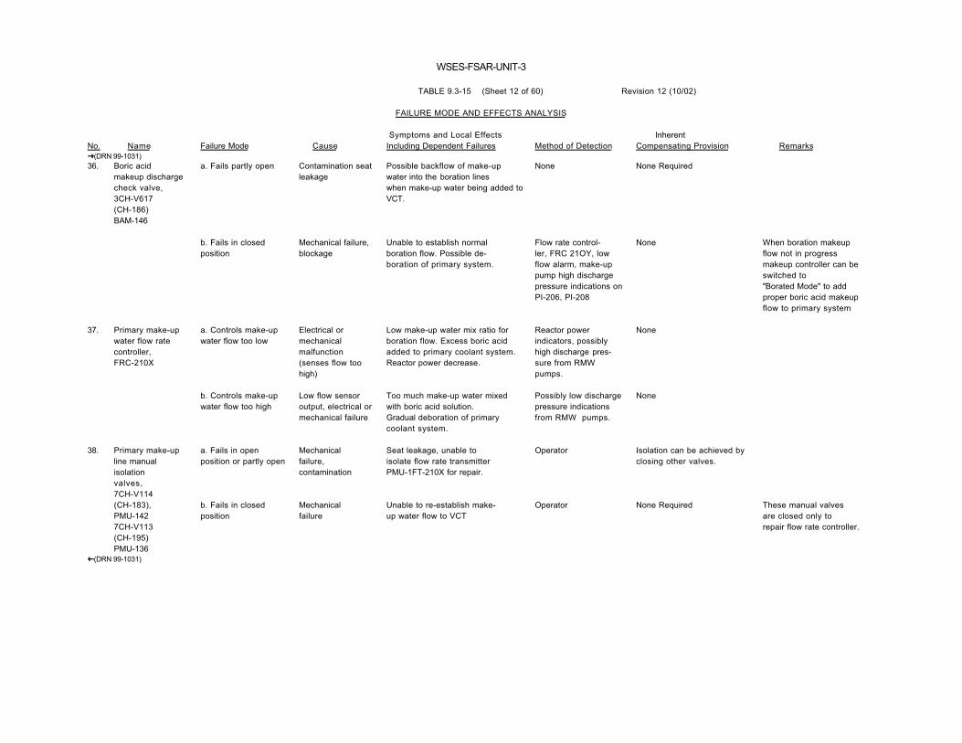
WSES-FSAR-UNIT-3
TABLE 9.3-15 (Sheet 12 of 60) Revision 12 (10/02)
FAILURE MODE AND EFFECTS ANALYSIS
No. Name Failure Mode Cause Symptoms and Local EffectsIncluding Dependent Failures Method of Detection
InherentCompensating Provision Remarks
�(DRN 99-1031)36. Boric acid
makeup dischargecheck valve,3CH-V617(CH-186)BAM-146
a. Fails partly open Contamination seatleakage
Possible backflow of make-upwater into the boration lineswhen make-up water being added toVCT.
None None Required
b. Fails in closedposition
Mechanical failure,blockage
Unable to establish normalboration flow. Possible de-boration of primary system.
Flow rate control-ler, FRC 21OY, lowflow alarm, make-uppump high dischargepressure indications onPI-206, PI-208
None When boration makeupflow not in progressmakeup controller can beswitched to"Borated Mode" to addproper boric acid makeupflow to primary system
37. Primary make-upwater flow ratecontroller,FRC-210X
a. Controls make-upwater flow too low
Electrical ormechanicalmalfunction(senses flow toohigh)
Low make-up water mix ratio forboration flow. Excess boric acidadded to primary coolant system.Reactor power decrease.
Reactor powerindicators, possiblyhigh discharge pres-sure from RMWpumps.
None
b. Controls make-upwater flow too high
Low flow sensoroutput, electrical ormechanical failure
Too much make-up water mixedwith boric acid solution.Gradual deboration of primarycoolant system.
Possibly low dischargepressure indicationsfrom RMW pumps.
None
38. Primary make-upline manualisolationvalves,7CH-V114(CH-183),PMU-1427CH-V113(CH-195)PMU-136
a. Fails in openposition or partly open
b. Fails in closedposition
Mechanicalfailure,contamination
Mechanicalfailure
Seat leakage, unable toisolate flow rate transmitterPMU-1FT-210X for repair.
Unable to re-establish make-up water flow to VCT
Operator
Operator
Isolation can be achieved byclosing other valves.
None Required These manual valvesare closed only torepair flow rate controller.
�(DRN 99-1031)
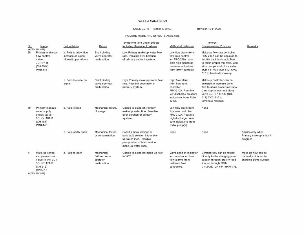
WSES-FSAR-UNIT-3
TABLE 9.3-15 (Sheet 13 of 60) Revision 12 (10/02)
FAILURE MODE AND EFFECTS ANALYSIS
No. Name Failure Mode Cause Symptoms and Local EffectsIncluding Dependent Failures Method of Detection
InherentCompensating Provision Remarks
�(DRN 99-1031)39. Primary make-up
flow controlvalve,7CH-F115(CH-210X)PMU-144
a. Fails to allow flowincrease on signal(doesn't open wider)
Shaft binding,valve operatormalfunction
Low Primary make-up water flowrate. Possible over-borationof primary coolant system.
Low flow alarm fromflow rate control-ler, FRC-210X pos-sible high dischargepressure indicationsfrom RMW pump(s).
Make-up flow rate controllerFRC 210X can be adjusted tothrottle back boric acid flowto attain proper mix ratio. Canstop pumps and close valve3CH-F117A/B (CH-512) CVC-510 to terminate makeup.
b. Fails to close onsignal
Shaft binding,valve operatormalfunction
High Primary make-up water flowrate. Possible deboration ofprimary system.
High flow alarmfrom flow ratecontroller,FRC-210X. Possiblelow discharge pressureindications from RMWpump.
Make-up controller can beadjusted to increase boricflow to attain proper mix ratio.Can stop pumps and closevalve 3CH-F117A/B (CH-512) CVC-510 toterminate makeup.
40. Primary makeupwater supplycheck valve3CH-V116A/B(CH-184)PMU-146
a. Fails closed Mechanical failure,blockage
Unable to establish Primarymake-up water flow. Possibleover boration of primarysystem.
Low flow alarm fromflow rate controllerFRC-210X. Possiblehigh discharge pres-sure indications fromRMW pump(s).
None
b. Fails partly open Mechanical failureor contamination
Possible back leakage ofboric acid solution into make-up water lines. Possibleprecipitation of boric acid inmake-up water lines.
None None Applies only whenPrimary makeup is not inprogress.
41. Make-up controlair operated stopvalve to the VCT3CH-F117A/B(CH-512)CVC-510
a. Fails to open Mechanicalfailure, valveoperatormalfunction
Unable to establish make-up flowto VCT.
Valve position indicatorin control room. Lowflow alarms frommake-up flowcontrollers.
Boration flow can be routeddirectly to the charging pumpsuction through gravity feedline, or through 3CH-V112A/B, (CH-514) BAM-133.
Make-up flow can bemanually directed tocharging pump suction.
�(DRN 99-1031)

WSES-FSAR-UNIT-3
TABLE 9.3-15 (Sheet 14 of 60) Revision 12 (10/02)
FAILURE MODE AND EFFECTS ANALYSIS
No. Name Failure Mode Cause Symptoms and Local EffectsIncluding Dependent Failures Method of Detection
InherentCompensating Provision Remarks
�(DRN 99-1031)41. Make-up control
air operated stopvalve to the VCT3CH-F117A/B(CH-512)CVC-510(Cont.)
b. Spurious closureduring make-up
Valve operatormalfunction,spurioussignal.
Sudden termination of make-upflow.
Valve positionindicator in con-trol room, low flowalarms from flow ratecontrollers,FRC-210X, andFRC-21OY.
Same as 41 a. If spurioussignal, can clear and reopenvalve.
Same as 41 a.
c. Fails to close onSIAS signal.
Valve operatormalfunction,mechanical failure.
Portion of boric acid solutiondiverted to VCT during shutdownboron addition. Reduced amount ofboron addition to primary system.
Valve position indicatorin control room.
None required It would takeseveral unusualconditions before thisfailure would cause lessthan the contents of oneBAMT to be injected i.e.,VCT at low level, borationin progress at moderateto high rate, and oneBAMT drawn down closeto low level and an SIAS.
42. Make-up headerto the VCTcheck valve,2CH-V118A/B(CH-188)CVC-511
a. Fails in closedposition
Mechanicalfailure,contamination
Unable to establish make-up flowto Volume Control Tank.
Low flow alarms fromflow rate controllers,FRC-210X andFRC-210Y.
Make-up flow can be routeddirectly to the charging pumpsuction through manual valve3CH-V119A/B (CH-196)CVC-502 & air operatedvalve 3CH-V121A/B (CH-504) CVC-507
b. Fails partly open Seat leakage,contamination
Possibly some back leakage ofprimary coolant into make-up linedownstream of valve3CH-F117A/B.
None None Required
43. Make-up headerlocal samplevalve, (Manual)3CH-V615-6(CH-185)CVC-501
a. Fails in closedposition
b. Fails partly open
Mechanicalfailure
Contamination
Unable to obtain local samplefrom make-up line. No impacton system operation.
Seat leakage. Local spill ofboric acid solution. Minorreduction of make-up flow possible.
Operator
Local leak detectors
None
None
Normally closed-manually operatedvalve.
�(DRN 99-1031)

WSES-FSAR-UNIT-3
TABLE 9.3-15 (Sheet 15 of 60) Revision 12 (10/02)
FAILURE MODE AND EFFECTS ANALYSIS
No. Name Failure Mode Cause Symptoms and Local EffectsIncluding Dependent Failures Method of Detection
InherentCompensating Provision Remarks
�(DRN 99-1031)44. Boric acid
make-up to theRWSP isolationmanual valve.3CH-V119A/B(CH-196)CVC-502
a. Fails in closedposition
b. Fails partly open
Mechanicalfailure
Contamination
Unable to route make-up flowdirectly to charging pump suction.
Seat leakage. Refueling waterstorage pool discharge linescontaminated with boric acidsolution. Possible boric acidprecipitation at valve 3CH-V121A/B(CH-504) CVC-507
Operator
None
Normal make-up path toVCT.
None
This is an alternatemake-up path. Manualvalve.
The refueling water tankdischarge lineto charging pump suctionis filled so boric acidsolution contaminationwould be a slow process.
45. Boric acidmake-up to theRWSP checkvalve,3CH-V120A/B(CH-193)CVC-503
a. Fails in closedposition
b. Fails partly open
Mechanical failure,contamination
Contamination
Unable to route make-up flowdirectly to charging pump suction.
Seat leakage. Possible dilu-tion of boric acid solutionwith RWT water.
Low flow alarms fromflow rate controllers FRC-210X andFRC-21OY.
None
Normal make-up path to VCTavailable.
Valve 3CH-V119A/B providesrequired isolation.
46. Primary make-upwater supply tocharging pumpsuction.7CH-V619(CH-180)PMU-140
a. Fails in closedposition
Mechanicalfailure
Unable to dilute primarysystem coolant directlythrough charging pump(s).
Operator Normal dilution paththrough VCT.
This is an alternatedilution path and is usedonly with cautionbecause it bypasses thecontrol system.
b. Fails partly open Seat leakage,contamination
Unwanted direct dilution ofprimary coolant system.
Flow indications fromflow rate controllerFRC-210X.
None Valve is normally lockedclosed.
47. Primary make-upwater supply tocharging pumpsuction checkvalve.2CH-V620(CH-179)PMU-141
a. Fails in closedposition
b. Fails partly open
Mechanicalfailure,blockage
Contamination
Unable to dilute primarysystem coolant directlythrough charging pump(s).
Seat leakage. Contaminationof reactor make-up water withprimary coolant.
Operator
None
Normal dilution paththrough VCT.
Valve CH-V619 (CH-180)PMU-140 provides requiredisolation.
�(DRN 99-1031)

WSES-FSAR-UNIT-3
TABLE 9.3-15 (Sheet 16 of 60) Revision 12 (10/02)
FAILURE MODE AND EFFECTS ANALYSIS
No. Name Failure Mode Cause Symptoms and Local EffectsIncluding Dependent Failures Method of Detection
InherentCompensating Provision Remarks
�(DRN 99-1031)48. Boric acid
makeup manualbypassof 3CH-V112A/B.(CH-514) BAM-1333CH-V606-3(CH-174)BAM-138
a. Fails in closedposition
b. Fails partly open
Mechanical failure
Seat leakage,contamination
Unable to establish "alternatepath" safety injection boroninjection if primary path isunavailable.
Gradual over boration ofprimary coolant system.
Operator Gravity feed boroninjection lines.
None
49. Make-up controlbypass tocharging pumpsuction checkvalve2CH-V130A/B(CH-177)BAM-135
a. Fails in closedposition
Mechanicalfailure -blockage
Unable to establish "pumped"safety injection boroninjection flow path.
High dischargepressure indicationsfrom boric acidmake-up pumps
Gravity feed boron injectionlines.
b. Fails partly open Seat leakage,contamination
Possible dilution of boration lineswith primary coolant.
None Valves 3CH-V112A/B (CH-514) BAM-133 and3CH-V606-3 (CH-174) BAM-138 provide isolation.
50. Make-up controlsbypass tocharging pumpair operatedsuction valve3CH-V112A/B(CH-514)BAM-133
a. Fails in closedposition or fails toopen on SIAS
Mechanical failure,valve operatormalfunction.
Loss of "pumped" boron injec-tion capability during safetyinjection.
Valve positionindicator in controlroom, high dischargepressure indicationsfrom B.A. make-uppumps.
Gravity feed boron injectionlines
There is an alternate"pumped" boron injectionpath throughvalve 3CH-V606-3(CH-174 BAM-138, amanually operated valve.
b. Fails open or partlyopen
Spurious signal,valve operatormalfunction or seatleakage.
Over boration of primary coolant ifboric acid pumps are running.
Possibly low flowalarms from flow ratecontroller FRC-21OY.
Can stop boric acidmake-up pumps.
51. Make-up controlbypass headerto chargingsuction samplevalve3CH-V615-5(CH-176)BAM-134
a. Fails in closedposition
Mechanicalfailure
Unable to obtain localsample of boron injectionline contents to determineboron concentration.
Operator None
�(DRN 99-1031)

WSES-FSAR-UNIT-3
TABLE 9.3-15 (Sheet 17 of 60) Revision 12 (10/02)
FAILURE MODE AND EFFECTS ANALYSIS
No. Name Failure Mode Cause Symptoms and Local EffectsIncluding Dependent Failures Method of Detection
InherentCompensating Provision Remarks
�(DRN 99-1031)51. Make-up controls
bypass headerto charging pumpssuctionsample valve3CH-V615(CH-176)BAM-134 (Cont'd)
b. Fails partly open Seat leakage,contamination
Possible gradual drainage of boroninjection line. Some loss of boricacid solution during shutdownboration.
Possibly high levelalarm from drain sumplevel detectors
None
52. Primary make-upwater linerelief valve,7CH-R180(CH-376)PMU-145
a. Fails in closedposition
Mechanicalfailure, setpointdrift
Loss of make-up water lineover pressure protection inthe event that valve3CH-F117A/B (CH-512) CVC-510is tripped closed while RMW pumpsare operating.
Periodic test None
b. Spuriously opens Setpoint drift Some diversion of make-upwater flow during boration/dilution. Possible over-boration due to improper mix ratio.
Possibly a high flowalarm or short termhigh flow indicationfrom flow ratecontroller FRC-210X.
None
c. Failure to reseat Contamination Seat leakage (see 52 b). None None
53. Boric acidmake-up tankair operatedrecirculationisolationvalves,3CH-F170A(CH-510),BAM-126A3CH-F171B(CH-511)BAM-126B
a. Fails in closedposition
b. Fails in the openposition
Mechanical failure,valve operatormalfunction. Lossof air power
Mechanical failure,valve operatormalfunction.
Possible boric acid concentrationstratification in tank.
Unable to terminate recirculationflow especially on SIAS.Decreased boron injection rateduring safety injection. Howevertotal amount not affected becauseother paths available.
Valve position indicatorin control room. Highdischargepressure indicationfrom associated boricacid pump.
Valve position indicatorin control room. Lowdischarge pressureindications fromassociated Boric Acidpump.
Some recirculation ispossible through associatedBoric Acid pump's mini-flowbypassline.
Gravity feed injectionline, plus pumping willcontinue until BAMT is empty.
These valves arenormally open andcontinuous recircu-lation is in progress ifpumps are on.
�(DRN 99-1031)

WSES-FSAR-UNIT-3
TABLE 9.3-15 (Sheet 18 of 60) Revision 12 (10/02)
FAILURE MODE AND EFFECTS ANALYSIS
No. Name Failure Mode Cause Symptoms and Local EffectsIncluding Dependent Failures Method of Detection
InherentCompensating Provision Remarks
�(DRN 99-1031)54. Boric acid
make-up tankrecirculationline manualisolationvalves,3CH-V613-2(CH-158),BAM-122A3CH-V613-1(CH-151),BAM-122B3CH-V131A,BAM-127A3CH-V653BBAM-127B
a. Fail in open position
b. Fails in closedposition
Mechanicalfailure
Mechanicalfailure
Unable to isolate BAMT recirc.line for Boric Acid pumpor recirc. line repair. Un-able to establish tank to tanktransfer of boric acid solu-tion while boration in progress.
Unable to re-establish normalrecirc. flow for affected BAMT.Isolates thermal relief valves(see 57) from BAMTs
Operator
Operator
None Required
Same as 53 a. and thermalreliefs discharge to bothBAMT's simultaneously.
Normally open manualvalves
55. Boric acidpump make-uprecirculationline manual cross-connect valve,3CH-V613-3(CH-159)BAM-123
a. Fails in closedposition
b. Fails partly open
Mechanicalfailure
Contamination
Unable to make tank to tanktransfer of boric acid solu-tion.
Seat leakage. Some cross flowbetween BAMTS during recircu-lation of one or both tanks.
Operator
Level indications inBAMTs if only onetank being recirculated,other-wise none.
None Required
None Required
56. Boric acid pumpsmin-flow manualvalves,3CH-N173A,(CH-134)BAM-125A3CH-N174B(CH-148)BAM-125B
a. Fails in openposition
b. Fails in closedposition
Mechanical failure
Mechanicalfailure
Unable to isolate Boric Acidpump min-flow bypass line forpump maintenance. Unable tothrottle pump bypass flow.
Unable to establish Boric Acidpump bypass flow on start-up. Possible damage to pump ifstarted against a closed system.
Operator
Operator
None Required
Valve 3CH-F170A(CH-510) BAM-126A3CH-F171B(CH-511) BAM-126B can beused by operator.
Manually operatednormally throttled needlevalve.
�(DRN 99-1031)

WSES-FSAR-UNIT-3
TABLE 9.3-15 (Sheet 19 of 60) Revision 12 (10/02)
FAILURE MODE AND EFFECTS ANALYSIS
No. Name Failure Mode Cause Symptoms and Local EffectsIncluding Dependent Failures Method of Detection
InherentCompensating Provision Remarks
�(DRN 99-1031)57. Deleted
�(DRN 99-1031)
� (DRN 99-0971)58. Concentrated
boric acidlines heattracing
a. Fails off or low Electricalmalfunction controlmalfunction
Cooldown of concentrated boricacid in static line segments.Precipitation of boric acidand potential plugging of lineswhere boric acid concentrationexceeds 3.5 w/o.
Malfunction of heattracing annunciates analarm..
Two independent andreduncant heat tracingcircuits.
� (DRN 99-0971)

WSES-FSAR-UNIT-3
TABLE 9.3-15 (Sheet 20 of 60) Revision 12 (10/02)
FAILURE MODE AND EFFECTS ANALYSIS
No. Name Failure Mode Cause Symptoms and Local EffectsIncluding Dependent Failures Method of Detection
InherentCompensating Provision Remarks
58. b. Fails to highoutput
Electrical orcontrol mal-function
Excessive heating of boricacid solution.
All boric acid linesections that can berestricted have thermalrelief valves thatrelieveto the BAMTs.
59. Boric acidmake-up tanks1 and 2
a. Leakage Corrosion mfg.defect
Loss of all or part of thecontents of one BAMT.
Low level alarms fromlevel indicatorand level sensor inaffected BAMT.
2 fully redundant BAMTs.
�(DRN 99-1031)60. Boration bypass
air operated controlvalve;3CH-F175A/B(CH-522)BAM-143
a. Fails in closedposition
Mechanical failure,loss of air or power
Loss of direct boration capability. Valve position in-dicator in controlroom, flow ratecontroller,FRC-210Y, low flowindications.
Direct boration can beaccomplished manually viavalves 3CH-V119A/B(CH-196) CVC-502 and3CH-V121A/B(CH-504) CVC-507.
b. Fails open Spurious signal,seat leakage
Concentrated boric acid diverted tocharging pump suction duringmake-up. Over boration of RCS.
Flow rate controllerFRC-21OY,
For spurious signal, clearsignal and close valve, forseat leakage close isolationvale 3CH-V606-4(CH-175) BAM-145.
61. 3CH-F175A/B(CH-522) BAM-143outlet stop valve(manual)3CH-V606-4(CH-175)BAM-145
a. Fails open Mechanicalfailure
No impact on normal systemoperation. Unable to isolate directboration control valve for maint.
Operator None Required Normally open, manualva lve
b. Fails closed Mechanical failure Unable to establish direct borationflow
Operator None Required
62. Boric acidmake-uptank ventvalves;7CH-V614-1BAM-106B7CH-V614-2BAM-106A
a. Fails open
b. Fails closed
Mechanicalfailure
Mechanicalfailure
No impact on system operation
Loss of tank venting, possiblepressure differential betweentanks. Possible overpressuri-zation.
Operator
Operator
None Required
None required, tanks arenot pressurized.
Normally open manualvalves.
�(DRN 99-1031)

WSES-FSAR-UNIT-3
TABLE 9.3-15 (Sheet 21 of 60) Revision 12 (10/02)
CHEMICAL AND VOLUME CONTROL SYSTEM (CVCS)
FAILURE MODE AND EFFECTS ANALYSIS
No. Name Failure Mode Cause Symptoms and Local EffectsIncluding Dependent Failures Method of Detection
InherentCompensating Provision Remarks
�(DRN 99-1031) 1. Letdown stop
air operated valveinside containment1CH-F1516A/B(CH-515)CVC-101
a. Fails open Mechanicalbinding
Unable to automatically term-inate letdown flow on hightemperature. Possible damageto downstream components.Loss of double isolation ofletdown line on SIAS.
Position indicationin control room.Temperature alarm,TIC-221. Flowindicator, FI-202
Remote manual closure ofredundant valve for hitemp. condition. Seriesredundant valve closeson SIAS.
Potential compensation- CCW flow throughletdown HX increased byTIC-224. Problemonly if regenerativeHX discharge temp.exceeds 450°F.
b. Fails closed Air or Powerfailure orspurious signal
Loss of letdown flow. Possibleovercharging of RCS.
Low flow alarm,FI-203. Positionindicator in con-trol room, flowindicator, FI-202.
None Letdown not requiredfor safe shutdown ofplant.
2. Letdown con-tainment airoperated isolationvalve insidecontainment1CH-F2501A/B(CH-516)CVC-103
a. Fails open
b. Fails closed
Mechanicalbinding
Air or powerfailure, mechanicalfailure orspurioussignal
Unable to automatically iso-late letdown lines on SIAS orCIAS.
Same as 1 b.
Position indicatorin control room.Flow indicator,FI-202.
Series redundant valve,1CH-F1516A/B (CH-515)CVC-101, closes onSIAS, 1CH-1518A/B (CH-523)CVC-109, closes on CIAS.
3. Regenerativeheat exchanger
a. Plugged tubes Corrosionbuildup, boronbuildup, foreignmaterial in RCS.
Reduced letdown flow. Flow indicator,FI-202 or FI-203
None Complete plugging ofall tubes is unlikely.Flow deterioration shouldbe detected long beforecomplete plugging occurs.
b. Insufficient heattransfer
Scale buildup ontubes
Letdown temperature fromregenerative HX may exceed450°F. Possible damage todownstream components.
Temperature indicatorand alarm,TIC-221.
Temp. indicator/control-ler, TIC-221 will closevalve 1CH-F1516A/B (CH-515) CVC-101, iftemp. exceeds 470°F, thusterminating letdown.
�(DRN 99-1031)

WSES-FSAR-UNIT-3
TABLE 9.3-15 (Sheet 22 of 60) Revision 12 (10/02)
CHEMICAL AND VOLUME CONTROL SYSTEM (CVCS)
FAILURE MODE AND EFFECTS ANALYSIS
No. Name Failure Mode Cause Symptoms and Local EffectsIncluding Dependent Failures Method of Detection
InherentCompensating Provision Remarks
�(DRN 99-1031) 3. Regenerative
heat exchanger(Cont'd)
c. External leakage Casing crack,seat leakageon vent valve,2CH-V1503(CH-443)CVC-213
Reduction to letdown flow, primarycoolant released in-side containment.
Eventually contain-ment radiation mon-itors, possibly flowindicator FI-202,excessive make-uprate.
None If HX leak is serious,it will be readily de-tected, and the heatexchanger can be isolated
d. Flow path crossleakage
Corrosion, vibrationwere, Mfg. defect.
Possible contaminant buildupin primary coolant, reduced abilityto change boron con-centration, reduced effective-ness of charging pumps.
Possible effect ontemp., boron levelsand radiation.
None If leak is large, CVCSletdown samples will notbe consistent with RCSsamples.
4. Temperatureindicator-controller,TIC-221.
a. False indicationof high temp.
Electro-mechanical failure,set-point drift.
Valve 1CH-F1516A/B (CH-515)CVC-101 closed, loss of letdownflow.
Low flow alarm,FI-203, flow indicator,FIC-202,1CH-F1516A/B(CH-515) CVC-101position indicatorin control room.
None
b. False indi-cation of low ornormal temp.
Electro-mechanical failure.
Possible loss of detection for hightemp. letdown flow.
Temp. Indicator,TIC-223, TIC-224.
None. (TIC-223 will tend toincrease CCW flow thruletdown HX to compensatefor hi temp. flow. On hitemp., TIC-224 will divert flowto protect components.
This failure causes noproblem unless there is acoexistent hi temp. willcause alarm from TIC-224.
5. Letdown con-tainment isola-tion air operatedvalve outside con-tainment,2CH-F1518A/B(CH-523)CVC-109
a. Fails open
b. Fails closed
Mechanicalbinding
Air or power failure,mechanical failure,or spurious signal.
Loss of redundant isolation ofletdown line on CIAS.
Same as 1 b.
Position indicator incontrol room.
Series redundant valve,1CH-F2501A/B (CH-516)CVC-103, close on CIAS
�(DRN 99-1031)

WSES-FSAR-UNIT-3
TABLE 9.3-15 (Sheet 23 of 60) Revision 12 (10/02)
CHEMICAL AND VOLUME CONTROL SYSTEM (CVCS)
FAILURE MODE AND EFFECTS ANALYSIS
No. Name Failure Mode Cause Symptoms and Local EffectsIncluding Dependent Failures Method of Detection
InherentCompensating Provision Remarks
�(DRN 99-1031) 6. Letdown control
air operated valve,2CH-FM1536A/B(CH-110P)CVC-113A2CH-FM1535A/B(CH-110Q)CVC-113B
a. Regulates low
b. Regulates hi
Valve operatorfailure, mech.failure, falsesignal
Valve operatorfailure, spurioussignal
Reduced letdown flow.
Increased letdown flow.
Low flow indicationon flow indicator,FI-202. Low pres-sure indication onPIC-201. Possible PZRlevel increase.Charging pumpsmay cycle more thannormal.
Flow indicator,FI-202, pressureindication PIC-201,possible PZR leveldecrease.
Parallel redundant con-trol valve can be placedin operation by openingisolation valves.
Parallel redundant controlvalve.
One of two parallelredundant controlvalves is normallyisolated by manualisolation valves whileother valve controls flow.Flow control can beswitched by openingisolation valves forstandby control valve,and closing isolationvalves for "operating"control valve.
�(DRN 99-1031)c. Fails closed Air or Power failure,
spurious signalLoss of letdown flow, possibleovercharging of RCS. Possibleoverpressurization of RCS duringshutdown cooling.
Flow indicator,FI-202, pressureindication fromPIC-201. Valveposition indication incontrol room.
Parallel redundant controlvalve can be valved in.
Rapid overpressuriza-tion of RCS if this failureoccurs during shutdowncooling.
�(DRN 99-1031) 7. Letdown control
valve isolationmanual valves;2CH-V1523-1(CH-341),CVC-111A2CH-V1523-2(CH-343),CVC-111B2CH-V1505-1(CH-342),CVC-113A2CH-V1505-2(CH-344)CVC-113B
a. Fails open
b. Fails closed
Mechanical failure
Mechanical failure
No impact on system function.Unable to isolate one control valvefor standby or maintenance.
Unable to transfer letdown flowcontrol to standby control valve.
Operator
Operator
Two series redundant isolationvalves for each controlvalve.
None if the operating flowcontrol valve hasmalfunctioned.
One set of isolationvalves normally closed(for standby controlvalve) other set is open(for operating controlvalve.)
�(DRN 99-1031)c. Seat leakage Contamination Possible boron precipitation on
standby control valve due toprimary coolant leaking into thespace betwseen the isolation valveand the standby control valve, andcooling.
Operator None

WSES-FSAR-UNIT-3
TABLE 9.3-15 (Sheet 24 of 60) Revision 12 (10/02)
CHEMICAL AND VOLUME CONTROL SYSTEM (CVCS)
FAILURE MODE AND EFFECTS ANALYSIS
No. Name Failure Mode Cause Symptoms and Local EffectsIncluding Dependent Failures Method of Detection
InherentCompensating Provision Remarks
�(DRN 99-1031) 8. Letdown line
relief valves,2CH-R626A/B(CH-345)CVC-1152CH-R629A/B(CH-354)CVC-126
a. Fails closed Mechanical failure,setpointdrift
No direct impact on systemoperation. Loss of overpressureprotection for potentially closed linesection.
Periodic test None
�(DRN 99-1031)b. Fails open Setpoint drift,
mechanical failurePrimary coolant discharged toholdup tanks.
Excessive use ofmakeup water,possible low flowindications on flowindicator, FI-202.Possible low pres-sure indications onPIC-201.
None
� (DRN 00-1638)8a. Letdown line
thermal reliefvalve CVC-1081
a. Fails closed
b. Fails open
Mechanical failure.Setpoint drift.
Mechanical failure.Setpoint drift.
No direct impact on systemoperation. Loss of overpressureprotection for portion of Letdownline bounded by containmentisolation valves CVC-103 andCVC-109 following a LOCA.
Primary Coolant discharged insideprimary containment.
Periodic test
Excessive use ofmakeup water.Radiation detectors.Possibly low flowindication on FI 202.Possibly low pressureIndications on PIC-201.
None
None Letdown line must beisolated until relief valvecan be repaired orreplaced.
� (DRN 00-1638)�(DRN 99-1031) 9. Shutdown
cooling manualisolation to LHX2CH-V644A/B(CH-436)SI-423
a. Fails closed Mechanical failure Unable to use CVCS for puri-fication of shutdown cooling flow.
Operator Purification of theprimary coolant duringshutdown cooling can beaccomplished via normalletdown and charging.
�(DRN 99-1031)

WSES-FSAR-UNIT-3
TABLE 9.3-15 (Sheet 25 of 60) Revision 12 (10/02)
CHEMICAL AND VOLUME CONTROL SYSTEM (CVCS)
FAILURE MODE AND EFFECTS ANALYSIS
No. Name Failure Mode Cause Symptoms and Local EffectsIncluding Dependent Failures Method of Detection
InherentCompensating Provision Remarks
9. Shutdowncooling isola- tionto LHX2CH-V644A/B(CH-463)
b. Seat leakage Contamination Primary coolant diverted toshutdown cooling system duringnormal letdown.
Possibly flow indicatorFI-202.
Series redundant check valveand isolation valve inshutdown cooling system.
10. Letdown heatexchanger
a. Tube leak Corrosion, mfg.defect
Contamination of componentcooling water with primary coolant.
CCW radiation moni-tors, possibly lowflow indication onFI-202, CCW surgetank level increase,excessive use ofmake-up water.
None
b. Tubes plugged Corrosion buildup,boron buildup,contaminantbuildup
Reduced letdown flow. Flow indicator,FI-202 and FI-203
None
�(DRN 99-1031)c. Insufficient heattransfer
Scale buildup,malfunction ofCCW flow controlvalve.
High temp. discharge from HX,possible damage to downstreamcomponents.
Temperature indicator-controller, TIC-224,alarms on high temp.
Temp. Indicator-controller,TIC-223, will sense hi temp.and increase CCW flowthrough HX
Temp. Indicator-controller,TIC-224, will divert hitemp. letdown flow pastIon Exchangers.
�(DRN 99-1031)d. External leakage Casing crack, Seat
leakage on ventvalve, CH-444.
Primary coolant released outsidecontainment
Area radiationmonitors, Local leakdetection, flowindication from FI-202,excessive use ofmake-up water.
None When leak is located,letdown flow can beterminated and HX can beisolated for repair.
11. Letdown line ventvalves(6 valves)
a. Fails closed
b. Seat leakage
Mechanical failure
Contamination
No impact on system operation.
Primary coolant released, eitherinside containment oroutside containment.
Operator
Radiation monitors,local leak monitors.
None Required
Vent valves are capped. When leak is located,letdown flow can beterminated, andappropriate line sectionisolated to repair valve.

WSES-FSAR-UNIT-3
TABLE 9.3-15 (Sheet 26 of 60) Revision 12 (10/02)
CHEMICAL AND VOLUME CONTROL SYSTEM (CVCS)
FAILURE MODE AND EFFECTS ANALYSIS
No. Name Failure Mode Cause Symptoms and Local EffectsIncluding Dependent Failures Method of Detection
InherentCompensating Provision Remarks
12. Letdown linedrain valves(13 valves)
a. Fails closed
b. Seat leakage
Mechanical failure
Contamination
No impact on system operation.
Primary coolant diverted to drainheader and BMS during letdown.
Operation
Equip. drain tank levelindication, possibly lowflow indication fromFI-202.
None Required
None Required
�(DRN 99-1031)13. Temperature
Indicator-controller,TIC-223
a. False lowtemperature indication
Electro-mechanicalmalfunction
Letdown HX CCW control valve willbe throttled back, resulting indecreased heat removal in letdownHX. High temp. discharge fromletdown HX and possible damage todownstream components.
Temp. indicator-controller, TIC-224alarms on high temp.
TIC-224 will divert letdownflow past the ion exchangers.
�(DRN 99-1031)b. False hightemperature indication
Electro-mechanicalmalfunction
Letdown HX CCW control valve willbe opened, resulting in increasedheat removal in letdown HX. Lowtemperature discharge fromletdown HX not considered aproblem.
Low temp. indicationfrom TIC-224
None Required
�(DRN 99-1031)14. Temperature
indicator-controller,TIC-224
a. False lowtemperature indication
Electrical ormechanicalmalfunction
Failure to bypass ion exchanger. Temperature indica-tor TIC-223.
None Required
b. False hightemperature indication
Electrical ormechanicalmalfunction
Ion exchanger bypass valveopened. Buildup of corrosionproducts in primary coolant. Lossof boron and radiation monitoring.
TIC-224 alarms on hitemp. Also use TIC-223 or TIC-221 toassess temp. Positionindication on (CH-520)CVC-140 and2CH-W136A/B.
None This condition drivesvalves 2CH-W136A/B(CH-520) CVC-140 totheir safe position.
15. Pressure indicator-controller,PIC-201
a. False low pressureindication
Electrical ormechanicalmalfunction
Letdown pressure control valvewill start to close, thus reducingletdown flow. Letdownflow control valve will open tocounteract. May lift relief valve,2CH-R626A/B (CH-345) CVC-115.
Flow indicator,FI-201, PIC-201will alarm on lowpressure
None
�(DRN 99-1031)

WSES-FSAR-UNIT-3
TABLE 9.3-15 (Sheet 27 of 60) Revision 12 (10/02)
CHEMICAL AND VOLUME CONTROL SYSTEM (CVCS)
FAILURE MODE AND EFFECTS ANALYSIS
No. Name Failure Mode Cause Symptoms and Local EffectsIncluding Dependent Failures Method of Detection
InherentCompensating Provision Remarks
15. Pressure indicator-controller,PIC-201(Cont’d)
b. False high pressureindication
Electricalmechanicalmalfunction
Letdown pressure control valve willopen, increasing letdownflow. Letdown flow control valvewill close to counteract.
Possible hi level alarmon VCT. Low levelalarm on PZR. Highletdown flow alarmbefore letdown valvereduces flow.
As PZR level drops, theletdown flow control valve willclose.
Possible PIC-201 hi.Pressure alarm.
�(DRN 99-1031)16. Letdown Back-
Pressure control airoperated valve;2CH-PM627A/B(CH-201Q),CVC-123A2CH-PM628A/B(CH-201P)CVC-123B
a. Fails to closeproperly on decreasedupstream pressure
Valve operatormalfunction,mechanical binding
Some pressure decrease down-stream. Possible flashing inletdown HX may result inexcessive letdown temp.
Pressure indicatorcontroller, PIC-201,alarms on lo press.hi temp. alarm fromTIC-224.
Parallel redundant controlvalve can be manuallyvalved in and activated.
Two pressure controlvalves, one active andother on standby.Standby valve is isolatedby manual valves.
b. Fails to openproperly on increasedupstream pressure
Valve operatormalfunction,mechanical binding
Pressure increase upstream inletdown HX. May lift 2CH-R626A/B(relief valve). Possible reducedletdown flow.
Pressure Indicator-controller PIC-201alarms on highpressure.
Same as above. Relief valve 2CH-R626A/B (CH-345)CVC-115 protects againstoverpressure.
c. Fails closed Air or power failure,spurious signal
Loss of letdown flow. Possibleoverpressurization of RCS,especially during shutdown cooling.May lift 2CH-R626A/B (CH-345)CVC-115. PZR level increase.
Pressure indicator /controller, PIC-201alarms on hi press.valve positionindication control room,Flow indicator, FI-201,PZR HI. LVL alarm.
Parallel redundant valve canbe manually valved in andactivated during normaloperation. PZR level controlswill stop backup chargingpumps.
If this occurs duringshutdown cooling, RCSover-pressurization willhappen very rapidly assystem is solid.
17. Letdown Back-pressure controlvalve isolationmanual valves;2CH-V605-1(CH-347)CVC-121A2CH-V640A/B(CH-349)CVC-125A2CH-V605-2(CH-348)CVC-121B2CH-V641A/B(CH-350)CVC-125B
a. Fails open
b. Fails closed
Mechanical binding
Mechanicalbinding
No impact on system perfor-mance. Unable to isolate onepressure control valve forstandby status or maintenance.
Unable to transfer letdown pressurecontrol to standbypressure control valve.
Operator
Operator
Series redundant isolationvalve.
None if operating pressurecontrol valve hasmalfunctioned.
Two sets of isolationvalves, one set normallyclosed for standbypressure control valve,other set normally openfor pressure control valvein operation.
�(DRN 99-1031)

WSES-FSAR-UNIT-3
TABLE 9.3-15 (Sheet 28 of 60) Revision 12 (10/02)
CHEMICAL AND VOLUME CONTROL SYSTEM (CVCS)
FAILURE MODE AND EFFECTS ANALYSIS
No. Name Failure Mode Cause Symptoms and Local EffectsIncluding Dependent Failures Method of Detection
InherentCompensating Provision Remarks
�(DRN 99-1031)17. Letdown Back-
pressure controlvalve isolationmanual valves;2CH-V605-1(CH-347),2CH-V640A/B(CH-349),CVC-125A2CH-V605-2(CH-348),CVC-121B2CH-V641A/B(CH-350),CVC-125B(Cont’d)
c. Seat leakage Contamination Possible boron precipitation onstandby pressure control valve dueto primary coolant leaking into thespace between the isolation valveand the control valve and cooling.
Operator None
18. Letdown line airoperated samplevalves2CH-F661A/B(CH-525),CVC-131,2CH-F660A/B(CH-526)CVC-1312CH-F643A/B(CH-527)CVC-139
a. Fails open
b. Fails closed
Mechanical failure
Mechanicalfailure
No impact on system performanceUnable to use valve to isolateletdown sample line.
No direct impact on systemoperation. Unable to obtain letdownsample
Operator
Unable to establishsample flow.
Series redundant valves(normally closed) in samplingsystem.
None Required
Valves normally closedmanually operated.
Same as above.
19. Boronometer andprocess radiationmonitor lineisolationvalve,2CH-V608(2 valves)
a. Fails open
b. Fails closed
Mechanical failure
Mechanical failure
No impact on system operation.Unable to isolate boronometerand PRM line for maintenance.
Unable to establish flow thruboronometer and PRM. Loss ofboron and radiation monitoring.
Operator
Operator
Series redundant isola-tion valves for borono-meter and PRM.
None Required
These valves are closedby DC 3432 tofunctionally abandon-in-place the Boronometerand Process RadiationMonitor.
�(DRN 99-1031)
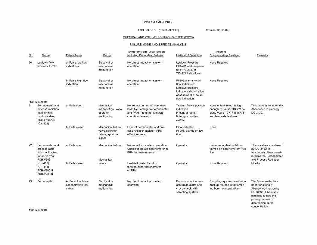
WSES-FSAR-UNIT-3
TABLE 9.3-15 (Sheet 29 of 60) Revision 12 (10/02)
CHEMICAL AND VOLUME CONTROL SYSTEM (CVCS)
FAILURE MODE AND EFFECTS ANALYSIS
No. Name Failure Mode Cause Symptoms and Local EffectsIncluding Dependent Failures Method of Detection
InherentCompensating Provision Remarks
20. Letdown flowindicator FI-202
a. False low flowindications
b. False high flowindication
Electrical ormechanicalmalfunction
Electrical ormechanicalmalfunction
No direct impact on systemoperation.
No direct impact on systemoperation.
Letdown PressurePIC-201 and tempera-ture TIC-223, orTIC-224 indications.
FI-202 alarms on hiflow indications.Letdown pressureindicators should allowassessment of falseflow indication.
None Required
None Required
�(DRN 99-1031)21. Boronometer and
process radiationmonitor inletcontrol valve;2CH-F195A/B(CH-521)
a. Fails open
b. Fails closed
Mechanicalmalfunction, valveoperatormalfunction
Mechanical failure,valve operatorfailure, spurioussignal
No impact on normal operation.Possible damage to boronometerand PRM if hi temp. letdowncondition develops.
Loss of boronometer and pro-cess radiation monitor (PRM)effectiveness.
Testing. Valve positionindicationin control room ifhi temp. conditionexists.
Flow indicator,FI-203, alarms on lowflow.
None unless temp. is highenough to cause TIC-221 toclose valve 1CH-F1516A/Band terminate letdown.
None
This valve is functionallyAbandoned-in-place byDC 3432.
22. Boronometer andprocess radia-tion monitor isolation valves;7CH-V603(CH-410)(CH-411)7CH-V205-57CH-V205-6
a. Fails open
b. Fails closed
Mechanical failure
Mechanicalfailure
No impact on system operation.Unable to isolate boronometer orPRM for maintenance.
Unable to establish flowthrough either boronometeror PRM.
Operator
Operator
Series redundant isolationvalves on boronometer/PRMline.
None Required
These valves are closedby DC 3432 tofunctionally Abandoned-in-place the Boronometerand Process RadiationMonitor.
23. Boronometer A. False low boronconcentration indi-cation
Electrical ormechanicalmalfunction
No direct impact on systemoperation.
Boronometer low con-centration alarm andcross-check withsampling system.
Sampling system provides abackup method of determin-ing boron concentration.
The Boronometer hasbeen functionallyAbandoned-in-place byDC 3432. Chemistrysampling is now theprimary means ofdetermining boronconcentration.
�(DRN 99-1031)

WSES-FSAR-UNIT-3
TABLE 9.3-15 (Sheet 30 of 60) Revision 12 (10/02)
CHEMICAL AND VOLUME CONTROL SYSTEM (CVCS)
FAILURE MODE AND EFFECTS ANALYSIS
No. Name Failure Mode Cause Symptoms and Local EffectsIncluding Dependent Failures Method of Detection
InherentCompensating Provision Remarks
23. Boronometer False indicationsof high boron con-centration
Electrical ormechanicalmalfunction
NO direct impact on systemoperation.
Boronometer highconcentration alarmand cross-check withsampling system
Sampling System backup.
�(DRN 99-1031)24. Process radiation
monitora. False high radiationlevel indications
b. False low radiationlevel in-dication
Electricalmalfunction
Electricalmalfunction
No direct impact on systemoperation.
No direct impact on systemoperation. May not detect a fuelelement failure if one occurs.
PRM high level alarm,iodine analysis.
Iodine analysis.
Sampling System backup.
Sampling System backup.
The Process RadiationMonitor has beenfunctionally Abandoned-in-place by DC 3432.Chemistry sampling andArea Radiation Monitorsare now the primarymeans of detecting highactivity in the letdownpiping.
25. Flow indicatorFI-203
a. False low flowalarms
Electrical ormechanicalmalfunction
No direct impact on systemoperation.
Periodic test None The letdown flow indicatorhas been functionallyAbandoned-in-place byDC 3432.
b. False high flowindication
Electrical ormechanicalmalfunction
No direct impact on systemoperation.
Periodic test None
26. Boronometer/pro-cess radiationmonitor outletcheck valve2CH-V676
a. Fails open
b. Fails closed
Mechanical failure
Mechanical failure,blockage
No impact on system operation.
Same as 21 b.
None None Required This valve has beenfunctionally Abandoned-in-place by DC 3432.
27. Process radiationmonitor localsample vale
a. Fails closed
b. Seat leakage
Mechanical failure
Contamination
No impact on system operation.Unable to sample PRM or to flushPRM.
Release of primary coolant outsidecontainment.
Operator
Local leak detectors,local radiationmonitors, flowindicator FI-203
None Required
None Required
This valve has beenfunctionally Abandoned-in-place by DC 3432.
�(DRN 99-1031)

WSES-FSAR-UNIT-3
TABLE 9.3-15 (Sheet 31 of 60) Revision 12 (10/02)
CHEMICAL AND VOLUME CONTROL SYSTEM (CVCS)
FAILURE MODE AND EFFECTS ANALYSIS
No. Name Failure Mode Cause Symptoms and Local EffectsIncluding Dependent Failures Method of Detection
InherentCompensating Provision Remarks
�(DRN 99-1031)28. Process radiation
monitor primarywater flush valve,7DW-V690
a. Fails closed
b. Seat leakage
Mechanical failure
Contamination
No impact on system operation.Unable to flush PRM withdemineralized water.
Primary coolant diverted todemineralized water system.
Operator
Low flow indicationfrom flow indicatorFI-203
None Required
Series redundant isola-tion valves in deminer-alized water system.
This valve has beenfunctionally Abandoned-in-place by DC 3432.
29. Deleted
�(DRN 99-1031)30. Purification
filter bypassvalve,2CH-V630(CH-355)
a. Fails closed
b. Seat leakage
c. Fails open
Mechanical failure
Contamination
Mechanical failure
No impact on normal systemoperation. Unable to bypassfilter for maintenance.
Minor letdown flow diverted pastfilter. Reduced filter efficiency.
Reduced filter efficiency, reducedflow to PRM and boronometer.
Operator
Delta-P indicatorPDI-202
Delta-P indicator,PDI-202, flowindicator, FI-203.
None Required
None
None
31. Purificationfilter isolationvalves;2CH-V33A/B(CH-358),2CH-V135A/B(CH-360)
a. Fails open
b. Fails closed
Mechanical failure
Mechanical failure
No impact on system operation.Unable to isolate filter formaintenance.
Unable to reestablish flowthrough filter after maintenance.
Operator
Operator, Delta-Pindicator PDI-202.
None
None Valves are normallyopen manually operated.

WSES-FSAR-UNIT-3
TABLE 9.3-15 (Sheet 32 of 60) Revision 12 (10/02)
CHEMICAL AND VOLUME CONTROL SYSTEM (CVCS)
FAILURE MODE AND EFFECTS ANALYSIS
No. Name Failure Mode Cause Symptoms and Local EffectsIncluding Dependent Failures Method of Detection
InherentCompensating Provision Remarks
32. Purification filter a. Does not filter "Punch-through"of the element
Particle buildup in ion ex-changers. EVentually escessiveion exchanger Delta-P or radiationlevels.
Differential pres-sure detector PDI-202, differntialpressure detectorPDI-203, PDI-205, orPDI-207. Samplingsystem downstream offilter.
Ion exchanger can removeparticulate matter. Filtercan be isolated and repairedwhile maintainingletdown flow through bypassvalve , 2CH-V630.
Extremely unlikely failuremode.
�(DRN 99-1031)CVC-MFLT-0001 b. Blocked Element plugged
with particulatematter
Reduced letdown flow. PDI-202 high di f f .Press. alarm, FI-202low flow indication.
Letdown flow can bypassthe filter through valve2CH-V630 (CH-355) CVC-138while elements are beingreplaced.
33. DifferentialPressure indica-tor PDI-202
a. Erroneous lowdifferential pres-sure indications
Electrical ormechanicalmalfunction
No impact on system operations.May fail to detect blocked/dirtyfilter.
Operator None
b. Erroneous highdifferential pres-sure indication
Electrical ormechanicalmalfunction
No impact on system operation. No improvement whenbypass valve isopened.
None
34. Ion exchanger airoperated bypassvalve,2CH-W136A/B(CH-520)CVC-140
a. Fails in the "IX"position
Valve operatormalfunction,mechanicalmalfunction
No direct impact on systemoperation. Unable to bypass ionexchangers on high temp. dis-charge from letdown HX. Pos-sible damage to ion exchangersresin.
None until demand,then the valve posi-tion indicator andrespective IX di f f .pres. indicator,PDI-203, 205 or 207,and hi temp. alarmfrom TIC-224.
Alternate bypass flowpaths can be manuallyaligned.
�(DRN 99-1031)b. Fails to the"bypass IX" position
Valve operatormalfunction,mechanical failure,spurioussignal, loss of airor power
Ion exchangers bypassed, build-up of fission products in primarycoolant.
Valve positionindicator, respec-tive IX diff. press.indicator, PDI-203,205, or 207
None Feed and bleed can be used to control RCSchemistry andradioactivity.

WSES-FSAR-UNIT-3
TABLE 9.3-15 (Sheet 33 of 60) Revision 12 (10/02)
CHEMICAL AND VOLUME CONTROL SYSTEM (CVCS)
FAILURE MODE AND EFFECTS ANALYSIS
No. Name Failure Mode Cause Symptoms and Local EffectsIncluding Dependent Failures Method of Detection
InherentCompensating Provision Remarks
�(DRN 99-1031)35. Purification Ion
Exchanger (IX)isolation manualvalves;2CH-V139A(CH-369),CVC-144A2CH-V145A(CH-378)CVC-155A
a. Fails open
b. Fails closed
Mechanical failure
Mechanical failure
No direct impact on systemoperation. Unable to isolateIX #A when other IX placed inservice.
Unable to reestablish letdownflow through IX #A.
Operator
Operator
For 2CH-V139A, none.For 2CH-V145A, can closevalve 2CH-V148A/B.
Parallel redundant purificationIXB or IXC.
Valves normally open.
36. Ion Exchangerinlet check valves;2CH-V140A(CH-370),CVC-146A2CH-V144B(CH-384),CVC-146B2CH-V142A/B(CH-403)CVC-146C
a. Fails open
b. Fails closed
Mechanical failure
Mechanical failure
No impact on normal systemoperation.
Unable to establish letdown flowthrough affected IX.
None
IX differential pressureindicator,PDI-203, 205 or 207
Manual isolation vavleupstream.
None
37. Ion exchangermanual valves;2CH-V637(CH-371),CVC-150A2CH-V638(CH-386),CVC-150B2CH-V639(CH-401)CVC-150C
a. Fail closed
b. Fails open
Mechanical failure
Seat leakage
No impact on system operation.Unable to vent IX during filloperations.
Minor leakage of potentiallyradioactive gas or liquid fromIX to waste management system.
Operator
Operator
Redundant vent valves toatmosphere.
Redundant normally closedvent isolation valve down-stream of IX vents to WMSdesigned for radioactivegases.
Manual valves normallyopen when IX is idle,closed when IX is inoperation.
38. Ion exchangeratmosphericmanual ventvalves,2CH-V669-2CVC-149A2CH-V669-1CVC-149B2CH-V669-3CVC-149C
a. Fails closed
b. Seat leakage
Mechanical failure
Contamination
No impact on system operation.
Minor leakage of potentiallyradioactive gas or liquid toatmosphere.
Operator
Local radiationmonitors.
Redundant vent valves towaste management system.
Valves are capped.
�(DRN 99-1031)

WSES-FSAR-UNIT-3
TABLE 9.3-15 (Sheet 34 of 60) Revision 12 (10/02)
CHEMICAL AND VOLUME CONTROL SYSTEM (CVCS)
FAILURE MODE AND EFFECTS ANALYSIS
No. Name Failure Mode Cause Symptoms and Local EffectsIncluding Dependent Failures Method of Detection
InherentCompensating Provision Remarks
�(DRN 99-1031)39. Ion exchanger
resin additionair operatedvalves;2CH-F200A(CH-540),CVC-151A2CH-F202B(CH-541),CVC-151B2CH-F201A/B(CH-542)CVC-151C
a. Fails closed
b. Fails open
Mechanical Failure
Seat leakage
No impact on system operation.Unable to add resin to IX.
No impact on system operation.
Operator
Operator
None Required
Resin addition lines are blindflanged.
Manual, normally closedvalves.
40. Ion exchangerresin sluice outletmanual valves;2CH-V157A(CH-380),CVC-152A2CH-V159B(CH-391),CVC-152B2CH-V158A/B(CH-400)CVC-152C
a. Fails closed
b. Fails open
Mechanical failure
Seat leakage
No impact on system operation.Unable to flush spent resin fromIX.
Leakage of primary coolant andresin to spent resin tank.
Operator
Operator
None Required
Normally closed drainvalve in series (7WM-V151)at inlet of spent resin tank.
Manual, normally closedvalve.
41. Ion exchangerresin sluiceinlet manualvalves;2CH-V633(CH-379),CVC-154A2CH-V635(CH-390),CVC-154B2CH-V634(CH-399)CVC-154C
a. Fails closed
b. Seat leakage
Mechanical failure
Contamination
No direct impact on system.Unable to flush resin from ionexchangers.
Leakage of primary coolant to resinsluice header.
Operator
Excessive use ofmakeup water.
None Required
None Required
42. Deleted�(DRN 99-1031)

WSES-FSAR-UNIT-3
TABLE 9.3-15 (Sheet 35 of 60) Revision 12 (10/02)
CHEMICAL AND VOLUME CONTROL SYSTEM (CVCS)
FAILURE MODE AND EFFECTS ANALYSIS
No. Name Failure Mode Cause Symptoms and Local EffectsIncluding Dependent Failures Method of Detection
InherentCompensating Provision Remarks
�(DRN 99-1031)43. Purification ion
exchanger B and Cheader inlet valve,2CH-V137A/B(CH-374)CVC-141
a. Fails closed
b. Fails open
Mechanical failure
Seat leakage
Unable to establish "single path"flow through IXB or IXC.
Primary coolant leakage into"Inlet header." Possible boronprecipitation.
Operator
None
IXB or IXC can be used inseries with IXA, which doesnot require use of this valve.
None Required
Normally closed manualvalve.
44. Purification ionexchanger B inletmanual valve2CH-V143B(CH-383)CVC-144B
a. Fails closed
b. Fails open
Mechanical failure
Seat leakage
Unable to establish flow throughIXB.
No impact.
Operator
Operator
IXA or IXC can be used.
IXB is isolated from letdownflow by valves 2CH-V137A/B(CH-374) CVC-141 and 2CH-V138A/B (CH-392) CVC-142.
Only IXB can removelithium.
45. Purification ionexchanger C inletmanual valve2CH-V141A/B(CH-404)CVC-144C
a. Fails closed
b. Fails open
Mechanical failure
Seat Leakage
Unable to establish flow throughIXC.
None
Operator
Operator
Use IXA, IXB, or feed andbleed boron removal.
"Series redundant" valves,2CH-V138A/B (CH-392) CVC-142, 2CH-V156A/B (CH-394)CVC-158, 2CH-V146A/B (CH-398) CVC-155C, closed.
Normally closed-manual valve.
46. Purification ionexchanger B and Cmanual inlet crossconnect.2CH-V138A/B(CH-392)CVC-142
a. Fails closed
b. Fails open
Mechanical failure
Seat leakage
Unable to put PIX C on line.
No impact on normal systemoperation.
Operator
Operator
Flow path through valve2CH-V156A/B (CH-394) CVC-158.
Other isolation valves inheader protect ionexchangers.
47. Isolation valve,series purificationflow line manualva lve2CH-V155A/B(CH-381)CVC-156
a. Fails closed
b. Fails open
Mechanical failure
Seat leakage
Unable to use PIX A in series.
None unless PIX B or C in usewithout PIX A, then bypass A.
Operator
Ion exchangerdifferential pres- sureindicator,PDI-205.
PIX B can be used alone.
None
Normally closed-manual valve.
�(DRN 99-1031)
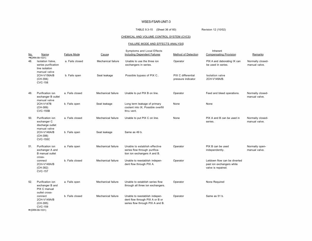
WSES-FSAR-UNIT-3
TABLE 9.3-15 (Sheet 36 of 60) Revision 12 (10/02)
CHEMICAL AND VOLUME CONTROL SYSTEM (CVCS)
FAILURE MODE AND EFFECTS ANALYSIS
No. Name Failure Mode Cause Symptoms and Local EffectsIncluding Dependent Failures Method of Detection
InherentCompensating Provision Remarks
�(DRN 99-1031)48. Isolation Valve,
series purificationline isolationmanual valve2CH-V156A/B(CH-394)CVC-158
a. Fails closed
b. Fails open
Mechanical failure
Seat leakage
Unable to use the three ionexchangers in series.
Possible bypass of PIX C..
Operator
PIX C differentialpressure indicator
PIX A and deborating IX canbe used in series.
Isolation valve2CH-V149A/B.
Normally closed-manual valve.
49. Purification ionexchanger B outletmanual valve2CH-V147B(CH-389)CVC-155B
a. Fails closed
b. Fails open
Mechanical failure
Seat leakage
Unable to put PIX B on line.
Long term leakage of primarycoolant into IX. Possible overfillthru vent.
Operator
None
Feed and bleed operations.
None
Normally closed-manual valve.
50. Purification ionexchanger Cdischarge outletmanual valve2CH-V146A/B(CH-398)CVC-155C
a. Fails closed
b. Fails open
Mechanical failure
Seat leakage
Unable to put PIX C on line.
Same as 49 b.
None PIX A and B can be used inseries.
Normally closed-manual valve.
51. Purification ionexchanger A andB manual outletcross-connect2CH-V148A/B(CH-382)CVC-157
a. Fails open
b. Fails closed
Mechanical failure
Mechanical failure
Unable to establish effectiveseries flow through purifica-tion ion exchangers A and B.
Unable to reestablish indepen-dent flow through PIX A.
Operator
Operator
PIX B can be usedindependently.
Letdown flow can be divertedpast ion exchangers whilevalve is repaired.
Normally open-manual valve.
52. Purification ionexchanger B andPIX C manualoutlet cross-connect2CH-V149A/B(CH-395)CVC-159
a. Fails open
b. Fails closed
Mechanical failure
Mechanical failure
Unable to establish series flowthrough all three ion exchangers.
Unable to reestablish indepen-dent flow through PIX A or B orseries flow through PIX A and B.
Operator
Operator
None Required
Same as 51 b.
�(DRN 99-1031)

WSES-FSAR-UNIT-3
TABLE 9.3-15 (Sheet 37 of 60) Revision 12 (10/02)
CHEMICAL AND VOLUME CONTROL SYSTEM (CVCS)
FAILURE MODE AND EFFECTS ANALYSIS
No. Name Failure Mode Cause Symptoms and Local EffectsIncluding Dependent Failures Method of Detection
InherentCompensating Provision Remarks
�(DRN 99-1031)53. Purification ion
exchangers A, B,and C.CVC-MIX-0001ACVC-MIX-0001BCVC-MIX-0001C
a. Ineffective ionremoval
b. Plugged
Degraded resin
Particulatecontamination
Primary coolant fission productsconcentration increases.Decreased boron removalcapability at “end of cycle”.
Decreased letdown flow.Decreased boron removalcapability at “end of cycle”.
Ion exchangerdifferential pressureindicators, PDI-203,205, and 207.
Redundant IX or feed andbleed.
Redundant IX or feed andbleed.
CVC-MIX-0001ACVC-MIX-0001BCVC-MIX-0001C
c. External leakage Cracked container,corrosion, mfg.defect.
Primary coolant released out-side containment.
Local leak rate andradiation monitors, ionexchanger differentialpressure indicators,PDI-203, 205, and207.
�(DRN 99-1031)54. Deleted
55. Ion exchangerdifferentialpressure indicatorPDI-203,PDI-205,PDI-207
a. Erroneous Lowpressure indication
b. Erroneous highpressure indication
Electrical ormechanicalmalfunction
Electrical ormechanicalmalfunction
No direct impact on systemoperation. Unable to detect aplugged IX.
No direct impact on systemoperation. May lead to early resinchange.
Test
Periodic test. Noimprovement whenstandby IX placed online.
None Required
None Required
�(DRN 99-1031)56. Letdown strainer
inlet isolationmanual valve2CH-V150A/B(CH-415)CVC-160
a. Fails open
b. Fails closed
Mechanical failure
Mechanical failure
No impact on normal systemoperation. Unable to isolate letdownstrainer for maintenance.
Unable to reestablish letdown flowthrough ion exchangers.
Operator
Operator
Redundant isolation valve.
Ion exchangers can bebypassed while valve isrepaired.
Normally open-manual valve.
�(DRN 99-1031)

WSES-FSAR-UNIT-3
TABLE 9.3-15 (Sheet 38 of 60) Revision 12 (10/02)
CHEMICAL AND VOLUME CONTROL SYSTEM (CVCS)
FAILURE MODE AND EFFECTS ANALYSIS
No. Name Failure Mode Cause Symptoms and Local EffectsIncluding Dependent Failures Method of Detection
InherentCompensating Provision Remarks
57. DifferentialPressure indicatorPDI-204
a. Erroneous lowpressure indication
b. Erroneous highpressure indication
Electrical ormechanicalmalfunction
Electrical ormechanicalmalfunction
No impact on system operation.
No direct impact on systemoperation. May lead to earlymaintenance on strainer.
Periodic Test
Periodic TestPossible Hi d i f f .Pres. alarm
None Required
None Required
58. Letdown strainer a. Plugged Containmentbuildup
Reduced letdown flow. Diff. pres. indica-tor PDI-204, highdp alarm.
Strainer and ion exchangerscan be bypassedwhile strainer repaired
b. Fails to strainproperly
"Ruptured" element Particulates and resin possiblydeposited in volume control tank.Possible contamination of chargingpumps.
Same as above. Same as above.
c. External leakage corrosion, mfg.defect
Primary coolant released out-side containment.
Local leak andradiation monitors.
Same as above.
�(DRN 99-1031)59. Letdown Strainer
Drain valve2CH-BV623(CH-419)CVC-162
a. Fails closed
b. Fails open
Mechanical failure
Seat leakage
No impact on system operation.Unable to drain strainer formaintenance.
Primary coolant released to spentresin tank.
Operator
Diff. press. indi-cator, PDI-204.Excessive use ofmakeup water.
None Required
None Required
60. Shutdown coolingpurification returnline isolationmanual valve,2CH-V302A/B(CH-439)CVC-164
a. Fails closed
b. Fails open
Mechanical failure
Seat leakage
No impact on normal operation.Unable to use ion exchangersfor purification of shutdowncooling flow.
Letdown flow diverted to shut-down cooling header.
Operator
None
None
Series redundant isolationvalves in shutdown coolingsystem.
�(DRN 99-1031)

WSES-FSAR-UNIT-3
TABLE 9.3-15 (Sheet 39 of 60) Revision 12 (10/02)
CHEMICAL AND VOLUME CONTROL SYSTEM (CVCS)
FAILURE MODE AND EFFECTS ANALYSIS
No. Name Failure Mode Cause Symptoms and Local EffectsIncluding Dependent Failures Method of Detection
InherentCompensating Provision Remarks
�(DRN 99-1031)61. Letdown strainer
isolation manualva lve2CH-V152A/B(CH-418)CVC-166
a. Fails open
b. Fails closed
Mechanical failure
Mechanical failure
No impact on normal systemoperation.
Unable to isolate letdown strainerfor maintenance.
Same as 56 b.
Operator
Operator
None Required
None
Normally open-manual valve.
Letdown flow would haveto be terminated to repairvalve.
62. Volume ControlTank Bypass airoperated valve2CH-W153A/B(CH-500)CVC-169
a. Fails open to thevolume control tank
Valve operatormalfunction,mechanical failure
No impact on normal systemoperation, but unable to bypassletdown flow to the boronmanagement system on high levelin VCT or to remove radioactivitythat ion exchangers could notremove.
VCT level detectors,LIC-226, LC-227position indicator inControl Room
None Letdown flow would haveto be terminated to repairva lve
�(DRN 99-1031)b. Fails to the bypassposition
Valve operatormalfunction,spurious signal
Unplanned release of primarycoolant to boron managementsystem. Decrease in VCT level.
VCT level detectorsLIC-226, LC-227.Position indicator inControl Room.
Termination of letdown flowuntil valve is repaired. Duringbypass make-up will maintainVCT level.
�(DRN 99-1031)63. Vol. Cont. tank
inlet check valve2CH-V154A/B(CH-101)CVC-172
Fails closed
Fails open
Corrosion
Contamination
Inability to establish letdownflow.
None during normal systemoperation.
Low level in vol. cont.tank alarm, LIC-226.
None
On low low level in VCT,charging pumps will switchsuction to the refueling watertank.
During VCT bypass mode ofoperation, potential leakageof the VCT cover gas to theBMC is prevented by valveCH-500.
�(DRN 99-1031)64. Purification ion
exchanger outletheader isolationvalve CVC-1661
a. Fails open
b. Fails closed
Mechanical failure
Mechanical failure
No impact on normal systemoperation. Primary coolantdiverted to VCT during shutdowncooling purification causingpossible loss of SDC during mid-loop operation
Unable to reestablish letdown flow.
Operator
Operator
Non required.
None.
Normally open manualvalve.
Letdown not required forsafe shutdown of plant.

WSES-FSAR-UNIT-3
TABLE 9.3-15 (Sheet 40 of 60) Revision 13 (04/04)
CHEMICAL AND VOLUME CONTROL SYSTEM (REACTOR COOLANT PUMP CONTROLLED BLEEDOFF)
FAILURE MODE AND EFFECTS ANALYSIS
No. Name Failure Mode Cause Symptoms and Local EffectsIncluding Dependent Failures Method of Detection
InherentCompensating Provision Remarks
�(DRN 99-1031, R12) 1. Reactor coolant
pump controlled bleedoff excessflow check valves,2CH-V1519(CH-301),RC-409A2CH-V1520(CH-302),RC-409B2CH-V1521(CH-303),RC-509A2CH-V1522(CH-304)RC-509B
a. Fail closed
b. Fail open
High Tension spring, plugged, mechanical failure
Mechanical failure, contamination
Loss of controlled seal bleed-off for reactor coolant pump.Possible damage to RCP seals due to overheating. Pressure buildup in bleed-off line.
Possible excessive flow of high temperature primary coolant coolant into VCT. Possible thermal damage to charging system, possible pressure surge in controlled bleed-off line.
Flow Temp and pres-sure indicators and alarm on the individual bleedoff lines inside containment.
VCT temperature indicator, TI -225.Pressure indicatorPI-215, high alarm.
Valve 2CH-F1512A/B(CH-505) CVC-401 can be closed terminating all bleed-off to VCT. Bleed-off will be routed to quench tank via relief valve, 2CH-R1515A/B.(CH-199) RC-603
Associated RCP must be shutdown.
This mode most important if ther is also concurrent RCP seal degradation, because the primary coolant system pressure is the driving force for controlled bleed-of f .
�(DRN 99-1031, R12)
�(DRN 03-2021, R13) 2. Pressure
indicatorPI-215
a. Erroneous low pressur indication
b. Erroneous high pressure indications and alarms
Electrical or mechanicalmalfunction
Electrical or mechanicalmalfunctions
No direct impact on system operation.
No direct impact on system operation.
Vapor seal cavity pressure indicators.
Same as 2 a.
None Required
None Required
The pressure indicator is used to verify a minimum reactor pump seal controlled bleedoff backpressure as recommended by the RCP seal vendor.Throttling with the RCP controlled bleedoff outlet head isolation valve should not be done without checking the individual vapor seal cavity pressure indicators.
�(DRN 03-2021, R13)

WSES-FSAR-UNIT-3
TABLE 9.3-15 (Sheet 41 of 60) Revision 12 (10/02)
FAILURE MODE AND EFFECTS ANALYSIS
No. Name Failure Mode Cause Symptoms and Local EffectsIncluding Dependent Failures Method of Detection
InherentCompensating Provision Remarks
�(DRN 99-1031) 3. Reactor coolant
pump controlledbleedoff reliefvalve,2CH-R1515A/B(CH-199)RC-603
a. Spuriously open
b. Fails closed
Setpoint drift,mechanical failure.
Mechanical failure,blockage.
Unplanned release of primarycoolant to quench tank.
No impact on normal systemoperation. Loss of bleed-offheader over pressure protection.
Pressure indicatorPI-215, quench tankpressure indicator.
Periodic Test
Valve 2CH-F1514A/B(CH-507) RC-602 can beclosed to isolate the reliefvalve.
None
Flashing, reduced cooling.
�(DRN 99-1031)� (DRN 00-1638)3a. Reactor coolant
pump controlledbleed off thermalrelief valve (RC-6061)
a. Fails closed
b. Fails open
Mechanical failure.Set point drift
Mechanical failure.Set point drift
No impact on normal systemoperation. Loss of over pressureprotection for the portion of thebleed off line bounded bycontainment isolation valves CVC-401 and RC-606.
Primary coolant discharged insideprimary containment.
Periodic Test
Excessive use ofmakeup water.Radiation detectors.
None
None Controlled bleed off linemust be isolated untilrelief valve is repaired orreplaced.
� (DRN 00-1638)c. Fails to reseat Contamination Seat leakage Periodic Test Same as 3 a. Possible detection via
quench tank pressureindicator
�(DRN 99-1031) 4. Reactor coolant
pump controlledbleedoff reliefair operated valvestop2CH-F1514A/B(CH-507)RC-602
a. Fails open Mechanical failure,operatormalfunction.
No impact on normal systemoperation. Unable to isolate reliefvalve on a loss of AC transientresulting in reduction in primarycoolant inventory.
Periodic Test None No serious effect on lossof A/C transient.
b. Fails closed Mechanical failure,valve operatormalfunction,spurious signal.
NO direct impact on normalsystem operation. Loss of bleed-off header over pressureprotection.
Valve position indicatorin control room.
None
�(DRN 99-1031)

WSES-FSAR-UNIT-3
TABLE 9.3-15 (Sheet 42 of 60) Revision 13 (04/04)
FAILURE MODE AND EFFECTS ANALYSIS
No. Name Failure Mode Cause Symptoms and Local EffectsIncluding Dependent Failures Method of Detection
InherentCompensating Provision Remarks
�(DRN 99-1031, R12)5. Reactor coolant
pump controlled bleed-of f con-tainment isola-tion air operated valve,2CH-F1512A/B(CH-505),CVC-4012CH-F1513A/B(CH-506)
a. Fails open
b. Fails closed
Mechanical failure,operatormalfunction.
Mechanical failure, valve operator malfunction, lossof power
Partial loss of containment isoaltion capabaility. No impact on normal system operation.
Loss of all controlled bleed-off flow to the VCT. Possible damage to pump seals due to overheating. Pressure build-up in the bleed-off line.
Valve position indicator in control room, periodic test.
Valve position indicator in control room, pressure indicator, PI -215, bleed-off flow and temp indicators.
Manual throttle valve,2CH-N1511A/B (CH-198)CVC-403, can be closed. Series redundantisolation valve.
Controlled bleed-off will be routed to the quench tank.
Since bleed-off is to a closed system, cont.isolation is not solely dependent on the isolation valve.
�(DRN 03-2021, R13) 6. Reactor coolant
pump controlledbleedoffOutlet HeaderIsolation manual Valve,2CH-N1511A/B(CH-198)CVC-403
a. Fails closed
b. Fails open
Mechanical failure, binding
Mechanical failure, binding
Unable to establish controlled bleed-off flow to VCT on startup.
Unable to throttle controlledbleed-off flow properly.
Operator
Operator
Startup delayed until valve repaired.
None Maintaining the RCP controlled bleedoff outlet header isolation valve in the open position should ensure the back pressure is maintained as recommended by the RCP seal vendor.Throttling of the valve should not normally be required.
�(DRN 03-2021, R13)
7. Reactor coolantpump controlledbleedoff back-flowto the sampling systemcheck valve2CH-V622(CH-197)PSL-181
a. Fails closed
b. Fails open or partly open
Mechanical failure
Seal leakage,contamination
Loss of sample system purgecapability and heat exchangerpressure protection.
Unplanned loss of primary coolant to sampling system.
None Required
None
None Required
Series redundant check valves in sampling system.
Sampling can not be accomplished until fault is corrected.
�(DRN 99-1031, R12)

WSES-FSAR-UNIT-3
TABLE 9.3-15 (Sheet 43 of 60) Revision 12 (10/02)
FAILURE MODE AND EFFECTS ANALYSIS
No. Name Failure Mode Cause Symptoms and Local EffectsIncluding Dependent Failures Method of Detection
InherentCompensating Provision Remarks
�(DRN 99-1031) 8. Reactor coolant
pump controlledbleedoff headerdrain to theRDH 2CH-V623-3,CVC-406
a. Fails closed
b. Fails open
Mechanical failure
Seat leakage
No impact on normal operation,cannot drain section of pipefor repair.
Divert part of bleed-off flow toRDH.
Operator
RDH level indicator
Parallel redundant drainvalve.
None
9. Reactor coolantpump controlledbleedoff headervent 2CH-V623CVC-405
a. Fails closed
b. Fails open
Mechanical failure
Seat leakage
No impact on system operation.
Divert part of the bleed-off flow
Operator
None
None
Capped
�(DRN 99-1031)�(DRN 01-994)10. Reactor coolant
pump controlledbleed-offbackpressurecontrol valve(CVC-4063)
a. Fails open Mechanical failure Unable to throttle controlled bleed-off flow properly.
Operator Valve can be isolated andflow can be manuallythrottled in a parallel path.
b. Fails closed Mechanical failure Loss of all controlled bleed-off flowto the VCT. Possible damage topump seals due to overheating.Pressure buildup in the bleed-offline.
Press, bleed-off flowand temp indicators
Controlled bleed-off will berouted to the quench tank.
11. Reactor coolantpump controlledbleed-off manualbackpressurecontrol valve(CVC-4061)
a. Fails open Mechanical failure Unable to throttle controlled bleed-off flow properly.
Operator Manual valve CVC-403 canbe adjusted to throttlecontrolled bleed-off flow.
b. Fails closed Mechanical failure No impact. None Controlled bleed-off flow willbe maintained through CVC-4063.
12. Reactor coolantpump controlledbleed-offbackpressurecontrol drainvalvesCVC-40621CVC-40631
a. Fails open Seat leakage Divert part of the bleed-off flow. None Capped Drain valves normallyclosed - manual valve
�(DRN 01-994)

WSES-FSAR-UNIT-3
TABLE 9.3-15 (Sheet 44 of 60) Revision 12 (10/02)
CHEMICAL AND VOLUME CONTROL SYSTEM (CHEMICAL ADDITION PORTION)
FAILURE MODE AND EFFECTS ANALYSIS
No. Name Failure Mode Cause Symptoms and Local EffectsIncluding Dependent Failures Method of Detection
InherentCompensating Provision Remarks
�(DRN 99-1031) 1. Primary makeup
water supply tothe chemicaladdition tank.3CH-V625(CH-312)PMU-139
a. Fails closed
b. Fails open
Mechanical failure,binding
Seat leakage
Unable to add makeup water tothe chemical addition tank.
Possible leakage of makeup waterto the chemical addition tank anddilution of chemical solution ifmake-up pumps are operating.Pressurization of the chemicaladdition tank.
Operator
Operator
None Required
None Required
Manually operated valve -normally closed.
No effect unlesschemical addition is inprogress.
�(DRN 99-1031) 2. Chemical addition
tank chemical fillvalve,7CH-V625(CH-313)
a. Fails closed
b. Fails open
Mechanical failure
Seat leakage
Unable to add chemicals to tank.
No impact
Operator
Operator
None Required
None Required
Manually operated valve -normally closed
3. Chemical additiontank vent valve,7CH-V625(CH-447)
a. Fails closed Mechanical failure,binding.
Unable to vent tank when filling ordraining. Possiblepressure buildup on fill. Possible todraw a vacuum on drain.
Operator None Required
b. Fails open Seat leak Unable to add chemicals Operator None Required�(DRN 99-1031) 4. Chemical addition
tank drain valve,7CH-V625-8(CH-310)CVC-602
a. Fails closed Mechanical failure No impact on normal operationunable to drain excess chemicalsolution, or waste solution whencleaning tank.
Operator None Required Drain valve normallyclosed - manual valve.
�(DRN 99-1031)b. Fails open Seat leakage Unwanted loss of chemical solution
to waste management systemwhen chemical solution in tank.
None None Required Chemical addition tank isgenerally empty. Usuallymake up a "batch" onlywhen required.

WSES-FSAR-UNIT-3
TABLE 9.3-15 (Sheet 45 of 60) Revision 12 (10/02)
FAILURE MODE AND EFFECTS ANALYSIS
No. Name Failure Mode Cause Symptoms and Local EffectsIncluding Dependent Failures Method of Detection
InherentCompensating Provision Remarks
�(DRN 99-1031) 5. Chemical Addition
tankCVC-MTNK-0001
a. External leakage Mfg. defect,corrosion
Chemical solution spill. Reducedchemical addition capability (lessvolume available).
Operator None Required The chemical addition is a18 gal. SS tank.It is generally empty.Chemical solution ismade up only when it isneeded, and is added toprimary coolant at thattime. This is not a storagetank.
6. Chemical additionstrainer andMetering Pumpisolation valves7CH-V625-7(CH-309)CVC-6037CH-V625-6(CH-307)CVC-605
a. Fail closed
b. Fail open
Mechanical failure
Seat leakage
Unable to add chemical solu-tion to primary coolant system
No impact
Operator
None Required
None Required
Series redundant valves The chemical additiontank is generally emptyexcept when making up abatch of chemicalsolution for addition to theprimary coolant system.Therefore, both valvesare generally dry.
7. Chemical additionstrainerCVC-MSTRN-0002
a. Plugged Containmentbuildup
Chemical addition rate reduced. Ifscreen completely plugged, unableto add chemical solution to primarycoolant system.
Operator None Required
b. Doesn't strain outcontaminants
Perforated strainerelement.
Small amounts of contaminantspossibly released to primarycoolant system.
Periodic examination None Required
c. External leakage Corrosion, Mfg.defect.
Some loss of chemical solutionwhile adding it to the primarycoolant system.
Operator None Required
�(DRN 99-1031)

WSES-FSAR-UNIT-3
TABLE 9.3-15 (Sheet 46 of 60) Revision 305 (11/11)
FAILURE MODE AND EFFECTS ANALYSIS No.
Name
Failure Mode
Cause
Symptoms and Local Effects Including Dependent Failures
Method of Detection
Inherent Compensating Provision
Remarks
(DRN 99-1031, R12) 8. VCT liquid
backflow to the chemical addition tank check valve, 2CH-V611 (CH-308) CVC-606
a. Fails closed b. Fails open
Mechanical failure, blockage. Seat leakage
Unable to add chemical solu- tion to primary coolant system. Leakage of primary coolant into chemical addition line. Possible boron precipitation on valve 7CH-V625-6 (CH-307) CVC-605
Operator Operator
None Required None Required
9. Chemical addition
strainer drain valve 7CH-V623 (CH-107) CVC-604
a. Fails open B. Fails closed
Mechanical failure Mechanical failure
Loss of chemical solution to drain header. Unable to drain strainer after chemical addition.
Operator Operator
None Required Drain valve 7CH-V625-8 (CH-310) CVC-602
10. Chemical Addition
Metering Pump CVC-MPMP-0002
a. Pump fails Electrical or Mechanical
Unable to add chemical solution to primary coolant system
Operator None Required
(DRN 99-1031, R12) (EC-4019, R305) 11. Zinc Injection Skid
CVC-MINJ0001 a. Component failure; Pump, Valve, Tank, Power Supply
Electrical or Mechanical
Unable to add chemical solution to primary coolant system
Operator None required
(EC-4019, R305)

WSES-FSAR-UNIT-3
TABLE 9.3-15 (Sheet 47 of 60) Revision 12 (10/02)
CHEMICAL AND VOLUME CONTROL SYSTEM (CHARGING AND VOLUME CONTROL)
FAILURE MODE AND EFFECTS ANALYSIS
No. Name Failure Mode Cause Symptoms and Local EffectsIncluding Dependent Failures Method of Detection
InherentCompensating Provision Remarks
�(DRN 99-1031) 1. Volume Control
Tank (VCT) ventline ManualIsolation Valves;3CH-V618(CH-100),GWM-1182CH-V604-1(CH-102)CVC-175
a. Fails in openposition or partly open
b. Fails in closedposition
Mechanical failure,contamination
Mechanical failure
Unable to isolate vent line forControl Valve or pressure regulatorvalve maintenance.Seat leakage.
Unable to vent VCT. Possibleoverpressurization of VCT.
Operator
Operator, High VCTPressure Alarm
If Pressure Regulator Valvesmaintenance is required,control valve.2CH-F185A/B, can be usedfor partial isolation.Also, Valves in VGSH.
VCT relief valve 2CH-R182A/B (CH-115) CVC-182protects againstoverpressure.
This mode applies only ifvalves have been closedfor vent linemaintenance.
2. VCT vent linecontrol valves,2CH-F185A/B(CH-513)GWM-112
a. Fails in closedposition
b. Fails in openposition
Mechanical failure,valve operatormalfunction
Mechanical failure
Unable to vent VCT. Possibleoverpressurization of VCT.
Unable to automatically isolateVCT vent line to terminate venting.
Valve positionIndicator in ControlRoom. VCT pressureindicator, PI-225.
Valve position indicatorin Control Room. H2analysis at gasanalyzer.
Same as above.
Pressure Regulator Valve7CH-PM179A/B (CH-414)GWM-114, manual isolationvalve, 2CH-V604, (CH-102)CVC-175, if not timeconstraint.
3. VCT vent linepressure regulator7CH-PM179A/B(CH-414)GWM-114
a. Controls pressuretoo high
Sensormalfunction, valveoperatormalfunction,failure.
Possible overpressurization ofVCT.
VCT pressure indicatorPI-225, High PressureAlarm.
Relief Valve, 2CH-R182A/B(CH-115) CVC-182 providessome overpressure protectionfor VCT.
b. Controls pressuretoo low
Sensor mal-function, valveoperator mal-function,mechanical failure.
Possible overpressurization VCT.Possible excessive releases ofradioactive gases, possibleoverpressurization of vent gassystem header. Excessive use ofH2 blanket gas.
VCT pressure indicatorPI-225, H2flow indicatorFI-225. H2 analysis ofgas.
Downstream pressure controlvalve will close to protectVGSH. Thereby terminating"Blowdown" of VCT.
Charging pumps may tripon low suction pressure.
�(DRN 99-1031)

WSES-FSAR-UNIT-3
TABLE 9.3-15 (Sheet 48 of 60) Revision 12 (10/02)
FAILURE MODE AND EFFECTS ANALYSIS
No. Name Failure Mode Cause Symptoms and Local EffectsIncluding Dependent Failures Method of Detection
InherentCompensating Provision Remarks
�(DRN 99-1031) 4. VCT vent line
"Downstream"pressure regulator7CH-PM178A/B(CH-406)GWM-116
a. Controls pressuretoo high
Sensor malfunc-tion, valve operatormal-function,mechanical failure.
Possible overpressurization ofVGSH.
Pressure indicatorPI-225, alarm.
Relief valve at the waste gassurge tank providesoverpressure protection.
b. Controls pressuretoo low
Sensor mal-function, valveoperator mal-functionmechanical failure.
VCT venting restricted, possi-ble pressure buildup in VCT.
Pressure indicatorPI-225, alarm
Relief valve 2CH-R182A/B(CH-115) CVC-182 providesVCT overpressureprotection.
�(DRN 99-1031) 5. Pressure indi-
cator, PI-225a. Erroneous lowpressure indications oralarms
Electrical ormechanicalmalfunction
No direct impact on normal systemoperation. Possible undetected highpressure condition in VCT.
Test VCT pressure is auto-matically regulated by ventvalves and the blanket gassystem.
b. Erroneous highpressure indications oralarms
Electrical ormechanicalmalfunction
No direct impact on normal systemoperation. Possible undetected lowpressure condition in VCT.
Test VCT pressure is auto-matically controlled by ventline pressure control valvesand the blanket gas system.
�(DRN 99-1031) 6. VCT to Gas
Analyzer stop2CH-V662A/B(CH-104)CVC-173
a. Fails in openposition
Mechanical failure,contamination
Unable to isolate Gas Analyzer formaintenance.
Operator, periodictest
None Required
�(DRN 99-1031)b. Fails in closedposition
Mechanical failure Unable to analyze gas in VCT. Operator None Applies only if valve hasbeen closed for GasAnalyzer maintenance.
7. VCT temperatureindicator TI-225
a. Erroneous lowtemperature indication
Electrical ormechanicalmalfunction
No direct impact on normal systemoperation. Possible undetected hightemperature condition in VCT.
Test None Required

WSES-FSAR-UNIT-3
TABLE 9.3-15 (Sheet 49 of 60) Revision 12 (10/02)
FAILURE MODE AND EFFECTS ANALYSIS
No. Name Failure Mode Cause Symptoms and Local EffectsIncluding Dependent Failures Method of Detection
InherentCompensating Provision Remarks
7. VCT temperatureindicatorTI-225 (Cont'd)
b Erroneous hightemperature indica-tion or alarms
Electrical ormechanicalmalfunction
No direct impact on normal systemoperation. Possible undetected lowtemperature condition in VCT.
Test None Required
�(DRN 99-1031) 8. VCT H2 Regulator
Isolation valves;7CH-V664-1(CH-107),HG-2027CH-V664-2(CH-108)HG-204
a. Fails in openposition
b. Fails in closedposition
Mechanical failure,contamination
Mechanical failure
Unable to isolate pressureregulating valve, 7CH-V654, formaintenance. No impact on normalsystem operation.
Unable to provide VCT with H2Blanket Gas. Possible low pressurein VCT. Possible lowH2 concentration in primarycoolant.
Operator
Blanket gas flowindicator, FI-225. VCTpressure indicator, PI-225, low pressurealarm.
None Required
None
9. VCT H2 Pressureregulator7CH-P654(CH-502)HG-203
a. Controls pressuretoo high
Sensor malfunc-tion, valve oper-ator failure,mechanical failure
Possible overpressurization ofVCT with H2. Possible High H2concentration in Primary coolant.
Blanket Gas flowindicator FI-225. HighPressure alarm fromPressure Indicator PI-225.
The VCT pressure regu-lating vent valves willattempt to maintain VCT atrequired pressure afteroperator opens valve2CH-F185A/B (CH-513)GWM-112.
Relief Valve2CH-R182A/B (CH-115)CVC-182 preventsoverpressure.
�(DRN 99-1031)b. Controls pressuretoo low
Sensor malfunc-tion, valve oper-ator failure,mechanical failure
Possible underpressure condi-tion in VCT. Possible decreasein primary coolant H2 concen-tration. See Remarks.
Blanket Gas flowindicator FI-225, LowPressure alarm fromPressure Indi-cator, PI-225.
VCT vent line pressureregulating valve3CH-PM179A/B will close toprevent further pressuredrop.
A spurious low pressurecondition in the VCT willcause all charging pumpsto trip on suctionpressure.
�(DRN 99-1031)10. VCT N2 Regulator
Isolation valves;7CH-V664-3(CH-109),NG-2227CH-V664-4(CH-110)NG-224
a. Fails in closedposition
b. Fails partly open
Mechanical failuresystem.
Contamination
No impact on normal systemoperation. Unable to purge VCT towaste management.
Possible inadvertent releaseof N2 to the VCT. Reduced H2concentration in primary coolant.Seat leakage.
None Two series redundant valvesplus a pressure regulatingvalve.
�(DRN 99-1031)
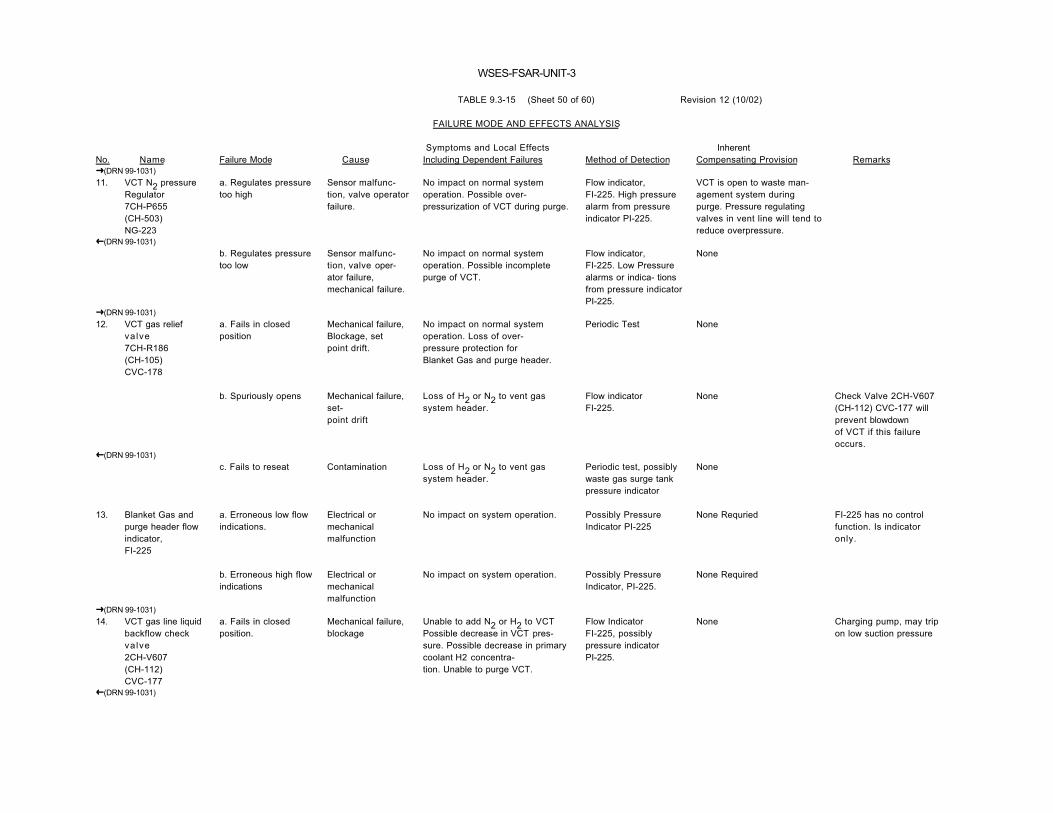
WSES-FSAR-UNIT-3
TABLE 9.3-15 (Sheet 50 of 60) Revision 12 (10/02)
FAILURE MODE AND EFFECTS ANALYSIS
No. Name Failure Mode Cause Symptoms and Local EffectsIncluding Dependent Failures Method of Detection
InherentCompensating Provision Remarks
�(DRN 99-1031)11. VCT N2 pressure
Regulator7CH-P655(CH-503)NG-223
a. Regulates pressuretoo high
Sensor malfunc-tion, valve operatorfailure.
No impact on normal systemoperation. Possible over-pressurization of VCT during purge.
Flow indicator,FI-225. High pressurealarm from pressureindicator PI-225.
VCT is open to waste man-agement system duringpurge. Pressure regulatingvalves in vent line will tend toreduce overpressure.
�(DRN 99-1031)b. Regulates pressuretoo low
Sensor malfunc-tion, valve oper-ator failure,mechanical failure.
No impact on normal systemoperation. Possible incompletepurge of VCT.
Flow indicator,FI-225. Low Pressurealarms or indica- tionsfrom pressure indicatorPI-225.
None
�(DRN 99-1031)12. VCT gas relief
va lve7CH-R186(CH-105)CVC-178
a. Fails in closedposition
Mechanical failure,Blockage, setpoint drift.
No impact on normal systemoperation. Loss of over-pressure protection forBlanket Gas and purge header.
Periodic Test None
b. Spuriously opens Mechanical failure,set-point drift
Loss of H2 or N2 to vent gassystem header.
Flow indicatorFI-225.
None Check Valve 2CH-V607(CH-112) CVC-177 willprevent blowdownof VCT if this failureoccurs.
�(DRN 99-1031)c. Fails to reseat Contamination Loss of H2 or N2 to vent gas
system header.Periodic test, possiblywaste gas surge tankpressure indicator
None
13. Blanket Gas andpurge header flowindicator,FI-225
a. Erroneous low flowindications.
Electrical ormechanicalmalfunction
No impact on system operation. Possibly PressureIndicator PI-225
None Requried FI-225 has no controlfunction. Is indicatoronly.
b. Erroneous high flowindications
Electrical ormechanicalmalfunction
No impact on system operation. Possibly PressureIndicator, PI-225.
None Required
�(DRN 99-1031)14. VCT gas line liquid
backflow checkvalve2CH-V607(CH-112)CVC-177
a. Fails in closedposition.
Mechanical failure,blockage
Unable to add N2 or H2 to VCTPossible decrease in VCT pres-sure. Possible decrease in primarycoolant H2 concentra-tion. Unable to purge VCT.
Flow IndicatorFI-225, possiblypressure indicatorPI-225.
None Charging pump, may tripon low suction pressure
�(DRN 99-1031)

WSES-FSAR-UNIT-3
TABLE 9.3-15 (Sheet 51 of 60) Revision 12 (10/02)
FAILURE MODE AND EFFECTS ANALYSIS
No. Name Failure Mode Cause Symptoms and Local EffectsIncluding Dependent Failures Method of Detection
InherentCompensating Provision Remarks
�(DRN 99-1031)14. Blanket Gas and
purge headercheck valve,2CH-V607(CH-112)CVC-177(Cont'd)
b. Fails open or partlyopen
Contamination Possible back leakage ofradioactive gases into blanket gasand purge header possiblepressurization of header by VCT.
None The pressure regulatingvalves in the header shouldprevent contamination of theH2 & N2 supplies. Reliefvalve, 7CH-R186 (CH-105)CVC-178, provides over-pressure protection.
�(DRN 99-1031)15. VCT level indicator
controller, L-226a. Erroneous low levelindication or alarm
Electrical ormechanicalmalfunction
Potential over-filling of VCTwith Boric Acid solution or makeupwater from boron additionsubsystem
None On high VCT level controllerLC-227 will switch letdownflow to waste managementsystem.
b. Erroneous highlevel indication oralarm
Electricalmechanicalmalfunction
Early termination of makeup flow.Normal primary coolant systemlosses not compensated for withmakeup. Possible gradual emptyingof VCT.
None On low-low VCT level, levelcontroller, LC-227, will switchthe charging pump suctionfrom the VCT to the refuelingwater storage pool (RWSP).
�(DRN 99-1031)16. VCT level control,
LC-227a. Erroneous low-lowlevel alarm
Electrical ormechanicalmalfunction
Possible Inadvertent Transfer ofcharging pump suction fromVCT to RWSP and letdown flow tothe waste management system.
Comparison with levelindicator,LI-226
VCT level indicator LI-226
�(DRN 99-1031)b. Erroneous highlevel indications
Electrical ormechanicalmalfunction
Possible inadvertent diversion ofletdown flow to waste managementsystem. Potential emptying ofVCT.
Level indicator,LI-226
On low VCT level, levelindicator, controller,LIC-226, will initiate makeupflow.
�(DRN 99-1031)17. VCT local
sample valve,2CH-V608-2(CH-116)CVC-180
a. Fails in closedposition
Mechanical failure Unable to obtain local sample ofVCT contents.
Operator None Required
b. Fails partly open Seat leakage,contamination
Local spill, outside contain-ment, of radioactive primarycoolant. Gradual loss of inventoryfrom VCT.
Local spill and radiationmonitors, possibleyVCT level sensorindication/actuation LIC-226,LC-227
Valves in sample systemact as a backup.
�(DRN 99-1031)

WSES-FSAR-UNIT-3
TABLE 9.3-15 (Sheet 52 of 60) Revision 12 (10/02)
FAILURE MODE AND EFFECTS ANALYSIS
No. Name Failure Mode Cause Symptoms and Local EffectsIncluding Dependent Failures Method of Detection
InherentCompensating Provision Remarks
�(DRN 99-1031)18. VCT Drain Valve,
2CH-V608-3(CH-117)CVC-181
a. Fails in closedposition
Mechanical failure No impact on normal operation,unable to drain VCT.
Operator None Required
�(DRN 99-1031)b. Fails partly open Contamination Gradual loss of primary coolant
inventory to boron managementsystem.
Possibly VCT levelsensors indication/actuation LIC-226,LC-227.
Boron addition subsystemcompensates for minorcoolant losses.
�(DRN 99-1031)19. VCT liquid
Relief Valve2CH-R182A/B(CH-115)CVC-182
a. Fails in closedposition
Mechanical failure,blockage, set-point drift.
No impacts on normal systemoperation. Loss of VCT, dischargeline overpressureprotection.
Periodic Test VCT will act as a PressureSurge Tank for a short period.
�(DRN 99-1031)b. Spuriously opens Setpoint drift,
Mechanical failureMinor loss of primary coolantinventory to hold-up tank.
Possibly VCT levelsensors indication/actuationLIC-226, LC-227.
Boron addition subsystem willcompensate for minor coolantlosses.
c. Fails to reseat Contamination Minor loss of coolant to hold-uptank.
Same as 19b. Same as 19b.
�(DRN 99-1031)20. VCT outlet air
operated valve2CH-V123A/B(CH-501)CVC-183
a. Fails in openposition on closesignal
Mechanical failure,valve operatormalfunction
Possible emptying of VCT.Possible air aspiration into chargingpumps suction.
Valve position indicatorin control room,possibly VCT levelsensors indication/actuationLIC-226, LC-227.
Charging pump suction isswitched to RWSP or BAMTsif 2CH-V123A/B (CH-501)CVC-183 is signaled closed.These water sources may besufficient to prevent airaspiration into chargingpumps.
b. Fails to the closedposition
Spurious signal,mechanical failure,valve operatormalfunction.
Loss of charging flow. Loss ofcharging pump suction.
Charging pump suctionpressure switch shutsoff pumps. Valveposition indicator incontrol room. Lowcharging flow alarm.
Charging pump suction canbe manually switched toRWSP from control room.Pumps are protected by lowsuction pressure trips.
c. Fails in closedposition
Mechanical failurevalve operatormalfunction
Unable to establish charging flowfrom VCT.
Valve position indi-cator in control room.
Charging pumps can takesuction from the RWTthrough valve,3CH-V121A/B.(CH-504) CVC-507
Normal charging flow isfrom the VCT, so thisvalve is generally open.
�(DRN 99-1031)

WSES-FSAR-UNIT-3
TABLE 9.3-15 (Sheet 53 of 60) Revision 12 (10/02)
FAILURE MODE AND EFFECTS ANALYSIS
No. Name Failure Mode Cause Symptoms and Local EffectsIncluding Dependent Failures Method of Detection
InherentCompensating Provision Remarks
�(DRN 99-1031)21. VCT outlet
check vavle2CH-V124A/B(CH-118)CVC-184
a. Fails in closedposition
Mechanical failure,blockage
Unable to establish charging flowfrom VCT.
Charging pump suc-tion pressure switchshuts off pumps. Lowcharging flow alarm
Charging pump suction canbe switched to RWSP fromcontrol room.
Pumps are protected bylow suction pressure trip.
b. Fails in openposition or partly open
Contamination Potential back leakage into VCTDischarge Lines when chargingpumps are taking suction fromBAMT or RWSP.
None Valve 2CH-V123A/B (CH-501) CVC-183 providespositive isolation for line.
22. Refueling waterstorage pool tocharging pumpsuction checkvalve2CH-V129A/B(CH-191)CVC-508
a. Fails in closedposition
Mechanical failure,blockage
Unable to switch charging pumpsuction from VCT to RWSP on lowVCT level. Loss of charging flow.
Low suction pressureswitch from chargingpump suction pressurecontrollersshuts off pumps. Lowcharging flow alarmfrom flow indicatorFI-212.
Charging pump suctionpressure controllers will stopcharging pumps on lowsuction pressure.
In case of emergencycharging pump suctioncan be switched toBAMTs from controlroom.
b. Fails partly open Contamination Potential back leakage ofprimary coolant in RWSP whencharging from VCT.
None RWSP suction line isolationvalve 3CH-V121A/B (CH-504) CVC-507 providespositive isolation for RWSP.
23. Refueling waterstorage pool tocharging pumpsuction isolation airoperated valve,3CH-V121A/B(CH-504)CVC-507
a. Fails in closedposition
b. Fails partly open,or fails to the openposition
Mechanical failure,operatormalfunction
Seat leakage orspurious signal,valve operatormalfunction,mechanical failure
Same as 22 a.
Unwanted addition of refuelingwater to primary system. Loss ofRWSP Inventory. Increase inboron concentration in primarysystem.
Same as 22 a, plusvalve position indicatorin control room.
Eventually - RWTLevel Indicators andalarms, also, for "failsto open position" -valve position indicatorin control room.
Same as 22 a.
Manual isolation valve.3CH-V122A/B (CH-192) CVC-504 can be closed until valve3CH-V121A/B (CH-504) CVC-507 is repaired.
Same as 22 a.
�(DRN 99-1031)

WSES-FSAR-UNIT-3
TABLE 9.3-15 (Sheet 54 of 60) Revision 12 (10/02)
FAILURE MODE AND EFFECTS ANALYSIS
No. Name Failure Mode Cause Symptoms and Local EffectsIncluding Dependent Failures Method of Detection
InherentCompensating Provision Remarks
�(DRN 99-1031)24. RWSP to charging
pump isolationmanual valve3CH-V122A/B(CH-192)CVC-504
a. Fails in openposition
b. Fails in closedposition
Mechanical failure
Mechanical failure
No impact on normal operationUnable to isolate line formaintenance.
Same as 22 a.
Operator
Operator
None
None CH-192 is normally open-manually operated valve.It is closed only for linemaintenance.
25. Charging pumpsuction headerrelief valve,2CH-R184A/B(CH-311)CVC-185
a. Opens spuriously Mechanical failure,setpoint drift.
Gradual loss of primary to boronmanagement system.
Equip. drain. Sump #1.Level 1
The makeup control auto-matically compensates forminor losses.
�(DRN 99-1031)b. Fails in closedposition
Mechanical failure,blockage, setpointdrift.
No impact on normal operation.Loss of overpressure protectionfor a potentially closed line section.
Periodic Test None
c. Fails to reset Contamination Same as 25 a. Periodic Test None�(DRN 99-1031)26. Charging pump
isolation manualvalve pairs,suctionand discharge;2CH-V125A(CH-316),CVC-188A2CH-V1501-4(CH-339),CVC-196A2CH-V127A/B(CH-319),CVC-188AB2CH-V1501-2(CH-337),CVC-196AB2CH-V126B(CH-322),CVC-188B2CH-V1501-1(CH-336)CVC-196B
a. Fails in openposition
b. Fails in closedposition
Mechanical failure
Mechanical failure
Unable to isolate affected pumpfor maintenance test.
Unable to establish chargingflow through affected pump aftermaintenance test.
Operator
Operator
None
None
�(DRN 99-1031)

WSES-FSAR-UNIT-3
TABLE 9.3-15 (Sheet 55 of 60) Revision 12 (10/02)
FAILURE MODE AND EFFECTS ANALYSIS
No. Name Failure Mode Cause Symptoms and Local EffectsIncluding Dependent Failures Method of Detection
InherentCompensating Provision Remarks
�(DRN 99-1031)27. Charging pump
drain valve pairs,suction anddischarge;2CH-V608-4(CH-317),CVC-189A2CH-V1504-9(CH-329),CVC-193A2CH-V608-5(CH-320)CVC-189AB2CH-V1504-10(CH-332),CVC-193AB2CH-V608-6(CH-323),CVC-189B2CH-V1504-11(CH-335)CVC-193B
a. Fails in closedposition
b. Fails partly open
Mechanical failure
Contamination
Unable to drain affected pump formaintenance
Gradual loss of primary coolantand reduction of VCT level. Also,for dishcarge drain valve, minorreduction in charging flow.
Operator
Equip. drain. Sump #1level
None
Same as 25 a.
�(DRN 99-1031)28. Charging pump
suction pressureindicator con-trollers,PC-224 X, Y, Z
a. Erroneous highpressure indications
Electrical orMechanicalMalfunction
Loss of protection for the chargingpump on low suction pressure.
Suction pressureindicators on othercharging pumps.
Redundant charging pumps.
b. Erroneous lowpressure indications
Electrical orMechanicalMalfunctions
Charging pumps shutoff on lowsuction pressure.
Charging line flowindicator FI-212.Suction pressureindicators on othercharging pumps.
Redundant charging pumps -started by pressurizer levelcontrols.
�(DRN 99-1031)29. Charging pump
discharge checkvalves;2CH-V1502-1(CH-328),CVC-194A2CH-V1502-2(CH-331),CVC-194A/B2CH-V1502-3(CH-334)CVC-194B
a. Fails in closedposition
Mechanical failure,blockage
Unable to establish charging flowthrough affected pump.
Charging line flowindicator FI-212
Redundant charging pumps,plus discharge safety reliefvalve provides overpressureprotection for affected pump.
�(DRN 99-1031)

WSES-FSAR-UNIT-3
TABLE 9.3-15 (Sheet 56 of 60) Revision 12 (10/02)
FAILURE MODE AND EFFECTS ANALYSIS
No. Name Failure Mode Cause Symptoms and Local EffectsIncluding Dependent Failures Method of Detection
InherentCompensating Provision Remarks
�(DRN 99-1031)29. Charging pump
discharge checkvalves;2CH-V1502-1(CH-328),CVC-194A2CH-V1502-2(CH-331),CVC-194A/B2CH-V1502-3(CH-334)CVC-194B(Cont'd)
b. Fails partly open Contamination No impact on normal operation.Some back leakage of primarycoolant into standby chargingpumps.
None None Required.
30. Charging pumpdischarge pres-sure relief2CH-R1526A(CH-326),CVC-192A2CH-R1527A/B(CH-325),CVC-192AB2CH-R1528B(CH-324)CVC-192B
Spuriously opens
b. Fails in closedposition
Set-pointdrift
Mechanical failure,blockage
Part of charging pump dis-charge diverted back to the pumpsuction. Reduced charging flow.
No immediate impact on system.Loss of overpressure protectionfor affected pump's discharge line.Loss of Min-flow by passrecirculation capability for pump.
Low flow indicationfrom charging flowindicator FI-212.
Periodic Test
Redundant charging pumpsavailable for use.
None
c. Fails to reseat Contamination Same as 30 a. Periodic Test None
31. Charging pumps,CP-A, B, A/BCVC-MPMP-0001ACVC-MPMP-0001ABCVC-MPMP-0001B
a. Operating pumpfails
Electrical orMechanical sealfailure, low NPSH
Loss of charging flow. Lowpressurizer level. High letdowntemp.
Charging flow indi-cator FI-212, low flowalarms, low pressurealarm from PI-212.Low pressur-izer level. AbnormalRHX letdown temp.
2 additional redundant pumps.
�(DRN 99-1031)b. Standby pump failsto start
Electrical orMechanical failure
Unable to meet charging re-quirement in excess of 1 pumpcapacity. Unable to establishcharging flow from affected pump.
Pump run indicator incontrol room, flowindicator,FI-212.
Redundant standby pumpavailable

WSES-FSAR-UNIT-3
TABLE 9.3-15 (Sheet 57 of 60) Revision 12 (10/02)
FAILURE MODE AND EFFECTS ANALYSIS
No. Name Failure Mode Cause Symptoms and Local EffectsIncluding Dependent Failures Method of Detection
InherentCompensating Provision Remarks
Charging pumps,CP-A, B, A/BCVC-MPMP-0001ACVC-MPMP-0001ABCVC-MPMP-0001B(Cont'd)
c. Spurious start ofstandby pump
ElectricalMalfunction,switching failure
Sudden excess charging flowrate. Possible inventory reductionin VCT. Possible increase inpressurizer level. Rapid change inboron concentration in RCS is adilution or addition is in progress.
Charging flowindicator, FI-212,charging pressureindicator, PI-212,possibly VCT andpressurizer levelindicators. Pump "run"indicator in controlroom. RHX letdowntemp. decrease.
Pressurizer level control willincrease letdown flow and/orturn off one charging pump.
�(DRN 99-1031)32. Charging pump
discharge cross-connect2CH-V1501-3(CH-338)CVC-203
a. Fails in openposition
b. Fails in closedposition
Mechanical failure
Mechanical failure
Unable to pressure test HPSIsystem while charging is inprogress.
Effective loss of one chargingpump.
Operator
Operator
None
2 redundant charging pumps.
33. Charging pump/HPSI pump headerisolation valve,2CH-V1501-5(CH-340)CVC-199
a. Fails closed Mechanical failure Unable to test HPSI system withcharging pumps, unable to useHPSI header for charging with thecharging pumps.
Operator None
b. Fails partly open Contamination Seat leakage. Possible inadvertentpressurization of HPSI header.
Pressure Indicators onHPSI headers
Pressure relief valves onHPSI headers.
34. Charging pumpto HPSI headercheck valve,2CH-V1502-4(CH-440)CVC-202
a. Fails in closedposition
b. Fails partly open
Mechanical failure
Contamination
Same as 34 a.
Seat leak. No impact on system
Pressure Indicators onHPSI headers
None
None
Line is isolated by valve CH-340
35. Charging pressureindicatorPI-212
a. Erroneous lowpressure indications oralarms.
Electrical ormechanicalmalfunction
No direct impact on system Flow indicator,FI-212.
None
b. Erroneous highpressure indications
Electrical ormechanicalmalfunction
NO direct impact on system. Flow indicator,FI-212.
None
�(DRN 99-1031)36. Charging Line Flow
Indicator,FI-212
a. Erroneous low flowindicationsor alarms.
Electrical ormechanicalmalfunction
No direct impact on systemoperation or control.
Pressure IndicatorPI-212. Pressurizerlevel indicator andletdown flow instru-ment, F-202.
None Required

WSES-FSAR-UNIT-3
TABLE 9.3-15 (Sheet 58 of 60) Revision 12 (10/02)
FAILURE MODE AND EFFECTS ANALYSIS
No. Name Failure Mode Cause Symptoms and Local EffectsIncluding Dependent Failures Method of Detection
InherentCompensating Provision Remarks
Charging Line FlowIndicator,FI-212(Cont'd)
b. Erroneous high flowindications
Electrical ormechanicalmalfunctions
NO direct impact on systemoperation or control.
Pressure Indicator,PI-212. Pressurizerlevel indicator andletdown flowinstrument, F-202.
None Required
�(DRN 99-1031)37. Charging pump
discharge headermanual stop valve;2CH-V1506(CH-429)CVC-208
a. Fails in openposition
b. Fails in closedposition
Mechanical failure
Mechanical failure
No impact on normal operation.Unable to isolate charging line formaintenance.
Unable to re-establish chargingthrough normal path. Loss ofletdown.
Operator
Operator
Depending on conditions,could use charging pumpmanual isolation valves.
Can charge through HPSIheaders if required.
38. Charging lineisolation airoperated valveoutside contain-ment2CH-F1529A/B(CH-524)CVC-209
a. Fails in closedposition
Mechanical failure,spurious signal
Unable to establish charging flowthrough normal path.
Flow indicatorFI-212, pressure in-dicator, PI-212, lowalarms. Valve positionindicator.
Can charge through HPSIheaders if required.
b. Fails open Mechanical failure,loss of air or power
Unable to isolate charging line topressure test HPSI system
Valve position indicator Manual isolation valve2CH-V1506 (CH-429)CVC-208
�(DRN 99-1031)39. Charging Line
temperature in-dicator, TI-229
a. Erroneous lowtemperatur readings
Electrical ormechanicalmalfunction
No direct impact on normal systemoperation or control.
Temperature indica-tor, TI-221.
None Required
b. Erroneous hightemperature indica-tions.
Electrical ormechanicalmalfunction
No direct impact on normal systemoperation or control.
Temperature indica-tor, TI-221.
None Required
�(DRN 99-1031)40. Auxiliary Spray
solenoid valves,1CH-E2505A(CH-517)CVC-ISV-0216A1CH-E2505BCVC-ISV-0216B
a. Fails in closedposition
Loss of Power,Mechanical fail-ure, valve oper-ator malfunction.
Loss of one auxiliary spray path Valve position indi-cators in control room.
Two redundant auxiliary spraypaths.
b. Fails open Valve operatormalfunction,spurious signal.
Possible inadvertent depress-urization of primary system.
Pressurizer level andpressure indica-tors and alarms.
None Valves are normallylocked closed.
�(DRN 99-1031)

WSES-FSAR-UNIT-3
TABLE 9.3-15 (Sheet 59 of 60) Revision 12 (10/02)
FAILURE MODE AND EFFECTS ANALYSIS
No. Name Failure Mode Cause Symptoms and Local EffectsIncluding Dependent Failures Method of Detection
InherentCompensating Provision Remarks
�(DRN 99-1031)41. Auxiliary spray
check valves,1CH-V2502-1(CH-431)CVC-217A1CH-V2502-4CVC-217B
a. Fails closed Mechanical failure,blockage
Loss of one auxiliary spray flowpath.
Possibly flow indi-cator, FI-212, pressureindicator,PI-212, Temperatureindicator TI-224, orhigh pressurizerpressure.
Two redundant parallelauxiliary spray valves.
b Fails partly open Contamination Possible back leakage of pres-surizer spray flow into auxiliaryspray line. No impact on systemoperation.
None Auxiliary spray valves arenormally closed, providingisolation.
42. Charging isola-tion solenoidvalves;1CH-E2503A(CH-519),CVC-ISV-0218A1CH-E2504B(CH-518)CVC-ISV-0218B
a. Fails closed Loss of power,Mechanical failure,valve operatormalfunction
Loss of one primary charging path. Valve position indicatorin control room,pressure indicator, PI-212
Two redundant primarycharging paths.
b. Fails open Mechanical failure,valve operatormalfunction.
Unable to terminate chargingflow to one charging line. Reducedaux. spray during cooldownoperations when RCP';s aresecured.
Valve position indi-cator in control room.Pressure indicator, PI-212
Terminate total charging flowat some point up-stream.
43. Charging Linecheck valves;1CH-V2502-2(CH-432)CVC-221B1CH-V2502-3(CH-433)CVC-221A
a. Fails in closedposition
b. Fails partly open
Mechanical failure,blockage
Contamination
Loss of one primary charging path.
No impact on normal operation.Possible back leakage of primarycoolant into charging lines whencharging not in progress.
Pressure indicator,PI-212.
None
Two redundant primarycharging paths.
Charging control valvesprovide positive isolation.
44. Charging Lineswing-checkvalve;1CH-V2506(CH-435)CVC-219
a. Fails partly open Contamination No impact on normal systemoperation. Possible back leakage ofprimary coolant into charging lineswhen charging not in progress.
None Check valve 1CH-V2502-3(CH-433) CVC-221A will limitback leakage through 1CH-V2506 (CH-435) CVC-219
�(DRN 99-1031)b. Fails in closedposition
Mechanical failure,blockage
Loss of thermal relief protec-tion for charging line when chargingcontrol valves are closed.
None None

WSES-FSAR-UNIT-3
TABLE 9.3-15 (Sheet 60 of 60) Revision 12 (10/02)
FAILURE MODE AND EFFECTS ANALYSIS
No. Name Failure Mode Cause Symptoms and Local EffectsIncluding Dependent Failures Method of Detection
InherentCompensating Provision Remarks
�(DRN 99-1031)45. 1CH-E2503A
CH-519CVC-ISV-0218Abypass isolationvalve;1CH-V2507(CH-434)CVC-220
a. Fails in openposition
b. Fails in closedposition
Mechanical failure
Mechanical failure
Unable to isolate chargingline bypass swing-checkvalve for maintenance.
Same as 44 b.
Operator
Operator
None
None
Operator Error Same as 44 b.
46. Charging Linedrain valves,2CH-V1504-14CVC-2102CH-V1504-6CVC-2002CH-V1547CVC-2042CH-V1508-2CVC-215
a. Fail in closedposition
b. Seat leakage
Mechanical failure
Contamination
No impact on normal systemoperation. Unable to drain a sectionof the charging line formaintenance.
Primary coolant released to drainheaders
Operator
Excessive use ofmakeup water. Pos-sible indications fromcharging line flow andpressure indicators.
None Required.
None
47. Charging pumpdischarge pulsa-tion dampeners;CVC-MACC-0001ACVC-MACC-001BCVC-MACC-0001A/B
Fails to damppressure pulses onpump startup
Mechanical failure Pressure Pulse transients inchargine line. Possible damage todownstream equipment.
Erratic indications onPI-212 andFI-212, noise.
None Required. Problem serious only ifrepeated pump starts aremade with a failedpulsation dampeners.
�(DRN 99-1031)48. CVCS CHRG
PUMPS RECIRC& RELIEF LINEVENT VALVESCVC-1922ACVC-1922BCVC-1922A/B
a. Fails in closed position
b. Fails partly open
Mechanical failure
Seat leakage
No impact on normal operation
Unwanted loss of boric acid towaste management system
none
none
None Required.
Line capped downstream
Vent valve normallyclosed manual valve.

WSES-FSAR-UNIT-3 TABLE 9.3-16 (Sheet 1 of 11) Revision 10 (10/99)
FAILURE MODE AND EFFECTS ANALYSISSHUTDOWN COOLING SYSTEM (SDCS)
�
This FMEA covers failures that impact the function and operation of the Shutdown Cooling System (SDCS). Specifically, failures are considered which impact the operator’s ability to initiate one or both trains of SDC or which impactcore decay heat removal once the system is in operation. Refer to FSAR Table 6.3-1 for a FMEA of the Safety Injection System.
No Name1 Failure Mode CauseSymptoms and Local EffectsIncluding Dependent Failures Method of Detection
Inherent CompensatingProvision
Effect Upon Remarks and OtherEffects
1. SDCS suction isolationvalve1SI-V1504A(SI-652),1SI-V1502B(SI-666),1SI-V1503A(SI-651),1SI-V1501B(SI-665),2SI-V327A(SI-440),2SI-V326A(SI-441)
a. Fails to open
b. Inadvertentlyclosed
Mechanicalbinding, operatormalfunction
Operator error
Cannot initiate one train of SDC
Loss of one train of SDC
Valve position indication in controlroom
SDC trouble alarm in control room
Redundant flow trainavailable. Operator mustmaintain at least one RCSloop (with SG and RCP)operable
Redundant decay heatremoval success paths.Operator restores SDC flow.
Decreasedcooldown
rates
N/A
See plant TechnicalSpecifications forSDCS/loop operabilityrequirements
Technical Specificationspermit only one SDC trainto be operable in Mode 6provided water level is ≥23 feet above reactorflange
2. Relief valves1SI-R2501A(SI-469),1SI-R2502B(SI-464),2SI-R339A(SI-486),2SI-R340B(SI-487),2SI-R614A(SI-468),2SI-R612B(SI-478)
a. Fails to open
b. Fails to reseat
Mechanicalbinding,blockage
Seat leakage,spring failure
Possible over-pressurization of SDCSpiping and/or RCS
Loss of primary coolant to drain header(or containment sump) duringshutdown cooling. Possible loss ofSDC.
Operator
RWLIS, RCSLMS, RCS pressure
Redundant relief pathavailable for LTOP valves
None required. One train ofSDC would be degraded, butthe redundant train would beavailable
N/A
N/A
1
Valve tag numbers (SI-XXX) in this Table are CE valve numbers.�

WSES-FSAR-UNIT-3 TABLE 9.3-16 (Sheet 2 of 11) Revision 10 (10/99)
FAILURE MODE AND EFFECTS ANALYSISSHUTDOWN COOLING SYSTEM (SDCS)
�
No Name Failure Mode CauseSymptoms and Local EffectsIncluding Dependent Failures Method of Detection
Inherent CompensatingProvision
Effect Upon Remarks and OtherEffects
3. SDCS suction line drainand vent valves to SDCvacuum priming pumps1SI-V2503-1, -2, -3, -4
a. Fails in closedposition
b. Inadvertentlyopened
Mechanicalbinding
Operator error
Unable to vent gases at system high point
Leakage of primary coolant insidecontainment
Operator
Operator
Redundant decay heatremoval success paths in theevent flow cannot beestablished due to gas binding
Two series redundant valvesprevent inadvertent flow
N/A
N/A
4. Return cross over valves2SI-V353A(SI-400),2SI-V346B(SI-450)
a. Fails to open
b. Inadvertentlyopened
Mechanicalbinding
Operator error
Unable to initiate pre-shutdown coolingwarm-up recirculation cycle for one line
A portion of shutdown cooling flow willshort circuit the core through the warm uplines
Operator
Operator
Redundant shutdown coolingline
Redundant decay heatremoval success paths.Operator restores SDC flow
N/A
N/A
5. Manual isolation valves2SI-V303A/B(SI-442),2SI-V352(SI-479)
a. Fails in openposition
b. Inadvertentlyclosed
Mechanicalbinding
Operator error
Unable to isolate SDCS line formaintenance
Loss of one SDCS suction line
Operator
SDC trouble alarm in controlroom
None required
Redundant decay heatremoval success paths.Operator restores SDC flow.
N/A
N/A Manual valves, normallylocked open
�

WSES-FSAR-UNIT-3 TABLE 9.3-16 (Sheet 3 of 11) Revision 10 (10/99)
FAILURE MODE AND EFFECTS ANALYSISSHUTDOWN COOLING SYSTEM (SDCS)
�
No Name Failure Mode CauseSymptoms and Local EffectsIncluding Dependent Failures Method of Detection
Inherent CompensatingProvision
Effect Upon Remarks and OtherEffects
6. Shutdown coolingsuction line samplevalves2SI-F624A(SI-443),2SI-F623B
a. Fails in closedposition
b. Inadvertentlyopened
Mechanicalbinding, valveoperator
Operator error
No impact on SDC. Unable to sampleSDC suction line.
No impact on SDC function
Local valve position indicator
Operator
None required
Series redundant isolationvalve in sampling systemprevents inadvertent flow
N/A
N/A
7. CVCS shutdownpurification line isolationvalves2SI-V341A,2SI-V342B
a. Fails in closedposition
b. Inadvertentlyopened
Mechanicalbinding
Operator error
Unable to purify shutdown cooling flow
No impact on SDC function
Operator
None
None required
Series redundant isolationvalves in CVCS preventinadvertent flow
N/A
N/A
8. LPSI suction lineisolation valves2SI-B301A(SI-444),2SI-B302B(SI-432)
Fails in openposition
Mechanicalbinding
Possible to draw partial suction fromRWSP or containment sump duringshutdown cooling
Operator, possibly RWSP levelalarms
Redundant isolation valves inRWSP and containment sumplines
N/A
�

WSES-FSAR-UNIT-3 TABLE 9.3-16 (Sheet 4 of 11) Revision 10 (10/99)
FAILURE MODE AND EFFECTS ANALYSISSHUTDOWN COOLING SYSTEM (SDCS)
�
No Name Failure Mode CauseSymptoms and Local EffectsIncluding Dependent Failures Method of Detection
Inherent CompensatingProvision
Effect Upon Remarks and OtherEffects
9. LPSI pump A, B Fails Electrical,mechanicalfailure
Loss of one SDC train SDC trouble alarm in controlroom
Redundant decay heatremoval success paths
Decreasedcooldown
rates
Technical Specificationspermit only one SDC trainto be operable in Mode 6provided water level is ≥23 feet above reactorflange
10. LPSI pump dischargecheck valves2SI-V333A(SI-433),2SI-V334B(SI-423)
a. Fails in closedposition
b. Fails in openposition
Mechanicalbinding,blockage
Mechanicalbinding,blockage
Unable to establish shutdown cooling flowthrough one LPSI pump
No impact on shutdown cooling
Low flow indication from flowindicator controller SIIFIC0306, -307
None required
Redundant parallel LPSI pumpand shutdown cooling line
None required
N/A
N/A
11. LPSI pump dischargeisolation valves2SI-V309A(SI-446),2SI-V310B(SI-434)
a. Fails in openposition
b. Inadvertentlyclosed
Mechanicalbinding
Operator error
No impact on shutdown cooling. Unableto isolate one LPSI pump formaintenance.
Unable to establish shutdown cooling flowthrough one LPSI pump. Loss of oneSDC train.
Operator
Operator, SDC trouble alarm incontrol room
None required
Redundant decay heatremoval success paths
N/A
N/A This is a manual valvethat is normally lockedopen
�

WSES-FSAR-UNIT-3 TABLE 9.3-16 (Sheet 5 of 11) Revision 10 (10/99)
FAILURE MODE AND EFFECTS ANALYSISSHUTDOWN COOLING SYSTEM (SDCS)
�
No Name Failure Mode CauseSymptoms and Local EffectsIncluding Dependent Failures Method of Detection
Inherent CompensatingProvision
Effect Upon Remarks and OtherEffects
12. SDC HX isolation valves(motor)2SI-V306A(SI-452),2SI-V305B(SI-453),2SI-V307A(SI-457),2SI-V308B(SI-456)
a. Fails in closedposition
b. Inadvertentlyclosed
Mechanicalbinding
Operator error
Unable to establish shutdown cooling flowthrough one heat exchanger
Loss of one SDC train
Operator
SDC trouble alarm in controlroom
Redundant heatExchanger
Redundant decay heatremoval paths. Operatorrestores SDC flow.
N/A
N/A
Locked closed valves
13. SDC HXsCS MHX0001A, B
a. Inefficient heatremoval
b. Excessive heatremoval
c. Cross leakage
Low CCW flow,containmentbuildup,Partial blockageof tubes
High CCW flowrate, low CCWtemperature
Corrosion,manufact.defects
Reduced cooldown rate
Increased cooldown rate. Possiblethermal shock to primary coolant system.
Contamination of CCW system withprimary coolant
Differential temperature –recorders SI ITR0351, -352; temperature indicatorsCS ITI0303X, Y
Differential temperaturerecorders SI ITR0351, -352; temperature indicatorsCS ITI0303X, Y
Radiation monitors in CCWsystem
Flow through heat exchangercan be increased by operatorto compensate for reducedcooldown rate
Flow through heat exchangercan be decreased by operatorto compensate for highcooldown rate
HX can be isolated and SDCcompleted using remaining HX
N/A
N/A
N/A
14. Pressure TransmittersCS IPT0303X, Y
Erroneouspressureindication
Electrical ormechanicalfailure
No impact on SDC. Backup processmonitor only
Operator None required N/A
�

WSES-FSAR-UNIT-3 TABLE 9.3-16 (Sheet 6 of 11) Revision 10 (10/99)
FAILURE MODE AND EFFECTS ANALYSISSHUTDOWN COOLING SYSTEM (SDCS)
�
No Name Failure Mode CauseSymptoms and Local EffectsIncluding Dependent Failures Method of Detection
Inherent CompensatingProvision
Effect Upon Remarks and OtherEffects
15. Temperature indicatorsCS ITI0303X,Y
Erroneoustemperatureindication
Electrical ormechanicalfailure
No impact on SDC. Backup processmonitor only
Operator None required N/A
16. Isolation valves2SI-V344A,2SI-V343B
a. Fails in closedposition
b. Inadvertentlyopened
Mechanicalbinding
Operator error
Unable to divert portion of shutdowncooling flow to CVCS for purification. Noimpact on SDC function.
Portion of SDC flow diverted to CVCS.No impact on SDC function.
Operator
Operator
Flow can be diverted to CVCSfrom the other SDC line
Series redundant valve inCVCS prevents inadvertentflow
N/A
N/A
17. Isolation valves2SI-V345A,2SI-V319B
a. Fails in closedposition
b. Inadvertentlyopened
Mechanicalbinding
Operator error
No impact on SDC
Portion of SDC flow diverted to RWSP.Loss of primary coolant inventory.
None required
RWLIS/RCSLMS, RCSpressure, flow indication indrain line to RWSP
None required
Redundant SDC trainavailable. Operator isolatesflow path and restores RCSinventory
N/A
N/A Normally closed, lockedclosed manual valves
18. SDC control valves2SI-FM318A(SI-657),2SI-FM349B(SI-656)
(Continued)
a. Fails to open
b. Controls flowthrough heatexchanger too low
Mechanicalbinding, valveoperatormalfunction
Erroneouspositionindication
Unable to establish SDC flow through oneheat exchanger
Reduced flow through one heatexchanger. Reduced cooldown rate.
Valve position indicator incontrol room
Low differential temperatureindication from SI ITR0351, -352
Redundant decay heatremoval success paths
Redundant SDC line.Operator can throttle valve toget desired differentialtemperature.
Decreasedcooldown
rates
N/A
�

WSES-FSAR-UNIT-3
TABLE 9.3-16 (Sheet 7 of 11) Revision 307 (07/13)
FAILURE MODE AND EFFECTS ANALYSIS SHUTDOWN COOLING SYSTEM (SDCS)
No
Name
Failure Mode
Cause
Symptoms and Local Effects Including Dependent Failures
Method of Detection
Inherent Compensating
Provision
Effect Upon
Remarks and Other
Effects (Continued from
previous page) c. Controls flow through heat exchanger too high
Erroneous position indication
Excessive flow through one heat exchanger. Excessive cooldown rate.
High differential temperature indication from SI ITR0351, -352
Redundant SDC line. Operator can throttle valve to get desired differential temperature.
N/A
19. Pressure indicators
SI IPI0306 SI IPI0307
a. Reads high b. Reads low
Electrical, mechanical malfunction Electrical, mechanical malfunction
No impact on SDC No impact on SDC
Operator Operator
None required None required
N/A
N/A
(EC-30976, R307) 20. Flow control valves
SI MVAAA129A (2SI FM317A/SI-307) SI MVAAA129B (2SI FM348B/SI-306)
a. Fails open b. Bypass flow controlled high c. Bypass flow controlled low d. Fails open
Mechanical binding Mechanical binding, valve operator malfunction Valve operator malfunction Loss of control air
Unable to control SDC flow bypassing one heat exchanger; reduced cooldown rate on one line Excessive flow past one heat exchanger, reduced cooldown rate Insufficient heat exchanger bypass flow in one line, but no impact on SDC ability to perform safety function Unable to control SDC flow bypassing both heat exchangers; reduced cooldown rate on both lines
Low differential temperature indication from temperature recorder SI ITR0351, -352 Low differential temperature indication from temperature recorder SI ITR0351, -352 High differential temperature indication from temperature recorder SI ITR0351, -352 Low differential temperature indication from temperature recorder SIITR0351, -0352
Redundant decay heat removal success paths Redundant decay heat removal success paths None required. However, operator would override controller Operator can manually throttle handwheel of 129 valve on available train or close valve with alternate air supply
Decreased cooldown
rate
Same as above
N/A N/A
(EC-30976, R307)
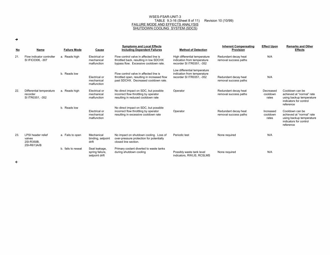
WSES-FSAR-UNIT-3 TABLE 9.3-16 (Sheet 8 of 11) Revision 10 (10/99)
FAILURE MODE AND EFFECTS ANALYSISSHUTDOWN COOLING SYSTEM (SDCS)
�
No Name Failure Mode CauseSymptoms and Local EffectsIncluding Dependent Failures Method of Detection
Inherent CompensatingProvision
Effect Upon Remarks and OtherEffects
21. Flow indicator controllerSI IFIC0306, -307
a. Reads high
b. Reads low
Electrical ormechanicalmalfunction
Electrical ormechanicalmalfunction
Flow control valve in affected line isthrottled back, resulting in low SDCHXbypass flow. Excessive cooldown rate.
Flow control valve in affected line isthrottled open, resulting in increased flowpast SDCHX. Decreased cooldown rate.
High differential temperatureindication from temperaturerecorder SI ITR0351, -352
Low differential temperatureindication from temperaturerecorder SI ITR0351, -352
Redundant decay heatremoval success paths
Redundant decay heatremoval success paths
N/A
N/A
22. Differential temperaturerecorderSI ITR0351, -352
a. Reads high
b. Reads low
Electrical ormechanicalmalfunction
Electrical ormechanicalmalfunction
No direct impact on SDC, but possibleincorrect flow throttling by operatorresulting in reduced cooldown rate
No direct impact on SDC, but possibleincorrect flow throttling by operatorresulting in excessive cooldown rate
Operator
Operator
Redundant decay heatremoval success paths
Redundant decay heatremoval success paths
Decreasedcooldown
rates
Increasedcooldown
rates
Cooldown can beachieved at “normal” rateusing backup temperatureindicators for controlreference
Cooldown can beachieved at “normal” rateusing backup temperatureindicators for controlreference
23. LPSI header reliefvalves2SI-R350B,2SI-R613A/B
a. Fails to open
b. fails to reseat
Mechanicalbinding, setpointdrift
Seat leakage,spring failure,setpoint drift
No impact on shutdown cooling. Loss ofover-pressure protection for potentiallyclosed line section.
Primary coolant diverted to waste tanksduring shutdown cooling
Periodic test
Possibly waste tank levelindicators, RWLIS, RCSLMS
None required
None required
N/A
N/A
�

WSES-FSAR-UNIT-3 TABLE 9.3-16 (Sheet 9 of 11) Revision 10 (10/99)
FAILURE MODE AND EFFECTS ANALYSISSHUTDOWN COOLING SYSTEM (SDCS)
�
No Name Failure Mode CauseSymptoms and Local EffectsIncluding Dependent Failures Method of Detection
Inherent CompensatingProvision
Effect Upon Remarks and OtherEffects
24. LPSI header isolationvalves2SI-V1549A1(SI-615),2SI-V1539B1(SI-625),2SI-V1541A2(SI-635),2SI-V1543B2(SI-645)
a. Fails to open
b. Fails open
Mechanicalbinding, valveoperatormalfunction
Mechanicalbinding, valveoperatormalfunction
Cannot establish flow in one of four SDCflow paths
No impact on SDC
Valve position indicator incontrol room, pressure andtemperature indicators onaffected line
Valve position indicators incontrol room
Redundant SDC line, plusother decay heat removalsuccess paths
None required
Decreasedcooldown
rates
The unblocked line on theaffected LPSI header maynot pass the full LPSIpump discharge flow
25. LPSI header checkvalves1SI-V1517RL1A(SI-114),1SI-V1518RL1B(SI-124),1SI-V1519RL2A(SI-134),1SI-V1520RL2B(SI-144)
a. Fails in closedposition
b. Fails in openposition
Mechanicalbinding,blockage
Seat leakage,mechanicalbinding
Loss of one of four SDC flow paths,reduced cooldown rate
No impact on SDC
Pressure and flow indicators inaffected line
None
Redundant SDC line plussecond line on header stilluseable
None required
Extendedtime requiredfor SDC
N/A
If one of the two lines on aLPSI header is closed off,the other line can takesome but not all of the lostflow
26. HPSI header checkvalves1SI-V1522RL1A(SI-113),1SI-V1523RL1B(SI-123),1SI-V1524RL2A(SI-133),1SI-V1525RL2B(SI-143)
a. Fails in closedposition
b. Fails partlyopen
Mechanicalbinding,blockage
Seat leakage
No impact on SDC
Diversion of primary coolant to HPSIheader during SDC
None
None
None required
Isolation valves in HPSIheader
N/A
N/A
�
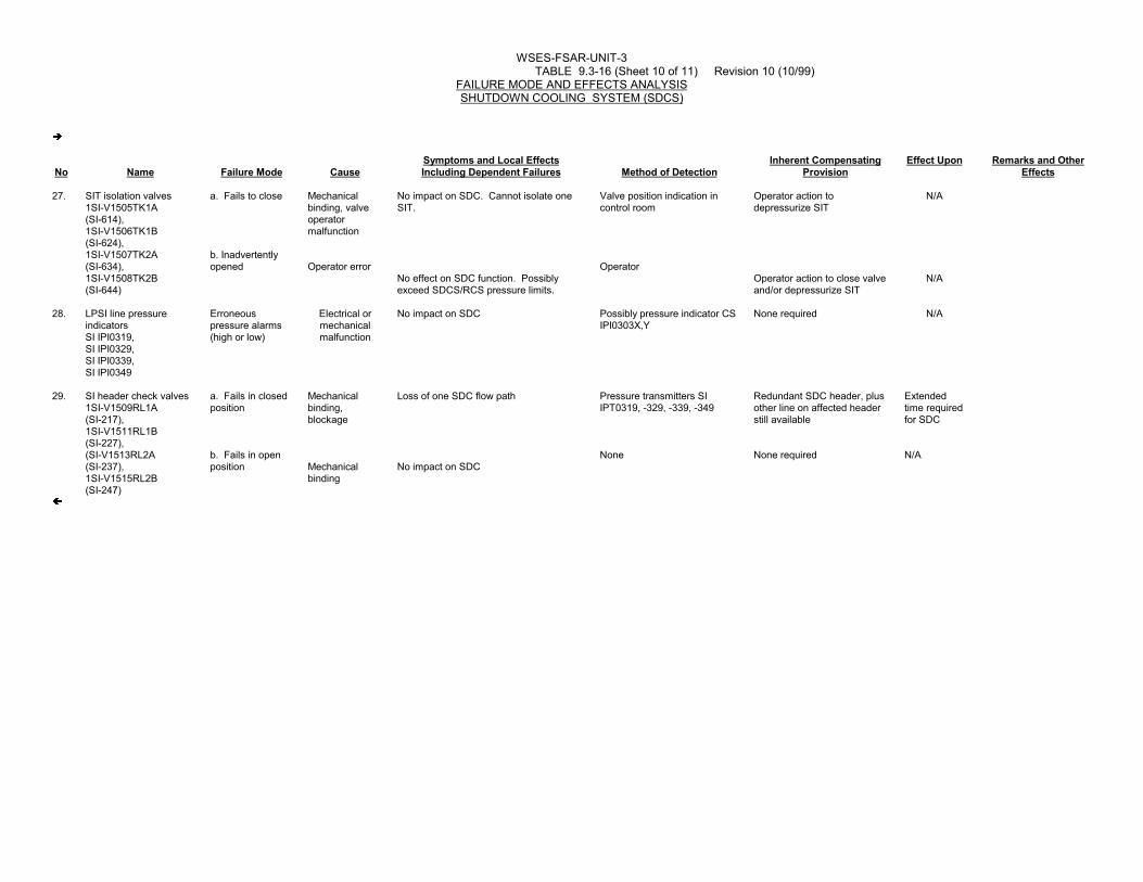
WSES-FSAR-UNIT-3 TABLE 9.3-16 (Sheet 10 of 11) Revision 10 (10/99)
FAILURE MODE AND EFFECTS ANALYSISSHUTDOWN COOLING SYSTEM (SDCS)
�
No Name Failure Mode CauseSymptoms and Local EffectsIncluding Dependent Failures Method of Detection
Inherent CompensatingProvision
Effect Upon Remarks and OtherEffects
27. SIT isolation valves1SI-V1505TK1A(SI-614),1SI-V1506TK1B(SI-624),1SI-V1507TK2A(SI-634),1SI-V1508TK2B(SI-644)
a. Fails to close
b. Inadvertentlyopened
Mechanicalbinding, valveoperatormalfunction
Operator error
No impact on SDC. Cannot isolate oneSIT.
No effect on SDC function. Possiblyexceed SDCS/RCS pressure limits.
Valve position indication incontrol room
Operator
Operator action todepressurize SIT
Operator action to close valveand/or depressurize SIT
N/A
N/A
28. LPSI line pressureindicatorsSI IPI0319,SI IPI0329,SI IPI0339,SI IPI0349
Erroneouspressure alarms(high or low)
Electrical ormechanicalmalfunction
No impact on SDC Possibly pressure indicator CSIPI0303X,Y
None required N/A
29. SI header check valves1SI-V1509RL1A(SI-217),1SI-V1511RL1B(SI-227),(SI-V1513RL2A(SI-237),1SI-V1515RL2B(SI-247)
a. Fails in closedposition
b. Fails in openposition
Mechanicalbinding,blockage
Mechanicalbinding
Loss of one SDC flow path
No impact on SDC
Pressure transmitters SIIPT0319, -329, -339, -349
None
Redundant SDC header, plusother line on affected headerstill available
None required
Extendedtime requiredfor SDC
N/A
�

WSES-FSAR-UNIT-3
TABLE 9.3-16 (Sheet 11 of 11) Revision 12-A (01/03)
FAILURE MODE AND EFFECTS ANALYSISSHUTDOWN COOLING SYSTEM (SDCS)
No Name Failure Mode CauseSymptoms and Local Effects
Including Dependent Failures Method of DetectionInherent Compensating
ProvisionEffect Upon Remarks and Other
Effects
30. Safety injection line pressure bleed valves 1SI-F1551TK1A(SI-618),1SI-F1552TK1B(SI-628),1SI-F1553TK2A(SI-638),1SI-F1554TK2B(SI-648)
a. Fails in closed position
b. Inadvertently opened
Mechanicalbinding, valve operatormalfunction
Operator error
No impact on SDC
No impact on SDC function
None required
Operator
None required
Series redundant valve in line to RWSP prevents inadvertent flow
N/A
N/A
31. LPSI mini recirc line solenoid valves 2SI-E1587A,2SI-E1588B
Fails in open position
Mechanicalbinding, seat leakage
Radioactive fluid may be introduced into RWSP from LPSI pump. Unable to initiate one train of SDC.
Operator, valve position indication
Redundant decay heat removal success paths
N/A Fail open solenoid valves
32. Containment spray header isolation valves 2CS-F305A,2CS-F306B
Inadvertentlyopened
Operator error Possible diversion of a portion of SDC f low through spray header. Possible loss of SDC flow
Spray flow indication, RWLIS, RCSLMS, SDC trouble alarm
Redundant decay heat removal flow paths. Operator takes action to isolate leak and refill RCS
N/A
�(DRN 02-1054, R12)33. LPSI Header Auto Vent
Isolation valvesSI-ISV-6011SI-ISV-6012
Inadvertently left open or fails open
Operator error.Loss of power failed solenoid
Redundant valve provided, no effect on system
Periodic testing None required N/A Fail open
�(DRN 02-1054, R12)
�(DRN 02-1636, R12-A)34. LPSI Header Auto Vent
Isolation Valves SI ISV 14023A & SI ISV 14024A
a. Inadvertently opened
b. Fails closed
Operator error
Loss of power
No impact on SDC
No impact on SDC
Operator, valve position indication locally (SI 14024A) in control room (SI 14023A)
Operator, valve position indication locally (SI 14024A) in control room (SI 14023A)
None
None
N/A
N/A
�(DRN 02-1636, R12-A)

WSES-FSAR-UNIT-3
TABLE 9.3-17 (Sheet 1 of 2) Revision 14 (12/05)
SHUTDOWN COOLING HEAT EXCHANGER DATA
Parameter Value
Quantity 2
Type Shell and tube horizontal U-Tube � (DRN 99-1092, R11)
Surface transfer rate 299 (Btu/hr F-ft2 ) � (DRN 99-1092, R11)
Heat transfer area per heat 7000 exchanger, ft2
Tube side:
Fluid Reactor coolant
Design pressure, psig 650
Design temperature, F 400
Material Austenitic stainless steel
Shell side:
Fluid Component cooling water
Design pressure, psig 150
Design temperature, F 250
Material Carbon steel
�(DRN 03-2063, R14)
At 17 1/2 hours after shutdown:
Tube side: � (DRN 99-1092, R11)
Flow, million lbm/hr 1.969 � (DRN 99-1092, R11)
Inlet temperature, F 140 � (DRN 99-1092, R11)
Outlet temperature, F 118.5 � (DRN 99-1092, R11; 03-2063, R14)

WSES-FSAR-UNIT-3
TABLE 9.3-17 (Sheet 2 of 2) Revision 14 (12/05)
SHUTDOWN COOLING HEAT EXCHANGER DATA
Parameter Value
Shell side:
�(DRN 03-2063, R14)
Flow, million lbm/hr - HX 1.495 �(DRN 03-2063, R14)
Inlet temperature, F 90 � (DRN 99-1092, R11)
Outlet temperature, F 116
�(DRN 03-2063, R14)
Heat load (million Btu/hr-HX) 42.24 � (DRN 99-1092, R11; 03-2063, R14)

WSES-FSAR-UNIT-3
TABLE 9.3-18
SHUTDOWN COOLING SYSTEM VALVESDESIGN PRESSURES AND TEMPERATURES
Valve Valve No. Design Pressure, psig Design Temp. F
Shutdown Cooling SI-307 650 400Flow Control SI-306 650 400
SI-657 650 400 SI-656 650 400
Low Pressure SI-615 2485 650Safety Injection SI-625 2485 650Header Isolation SI-635 2485 650
SI-645 2485 650
WSES-FSAR-UNIT-3
Table 9.3-19 has been deleted.

WSES-FSAR-UNIT-3
TABLE 9.3-20 (Sheet 1 of 2) Revision 305 (11/11)
REQUIRED VALVE ACTUATIONS ACCOMPLISHED FROM THE MAIN CONTROL ROOM Valve No. Valve Operation SI-452 SDCHX inlet isolation Open SI-453 SDCHX inlet isolation Open SI-400 Warmup Bypass Open/Close SI-450 Warmup Bypass Open/Close SI-456 SDCHX return line isolation Open SI-457 SDCHX return line isolation Open SI-651 Shutdown cooling suction line isolation Open (EC-14765, R305) SI-4052A SI-405A Bypass Fill Valve Open/Close (EC-14765, R305) SI-652 Shutdown cooling suction line isolation Open SI-665 Shutdown cooling suction line isolation Open (EC-14765, R305) SI-4052B SI-405B Bypass Fill Valve Open/Close (EC-14765, R305) SI-666 Shutdown cooling suction line isolation Open SI-440 Shutdown cooling suction line isolation Open SI-441 Shutdown cooling suction line isolation Open SI-615 LP header injection Open SI-625 LP header injection Open SI-635 LP header injection Open SI-645 LP header injection Open SI-659 Miniflow isolation Close SI-660 Miniflow isolation Close SI-667 Miniflow isolation Close SI-668 Miniflow isolation Close SI-306 SDCHX bypass flow control Throttle

WSES-FSAR-UNIT-3
TABLE 9.3-20 (Sheet 2 of 2) Revision 12 (10/02)
Valve No. Valve Operation
SI-307 SDCHX bypass flow control Throttle
SI-656 SDCHX flow control Throttle
SI-657 SDCHX flow control Throttle
SI-614 SIT isolation Close
SI-624 SIT isolation Close
SI-634 SIT isolation Close
SI-644 SIT isolation Close
SI-611 SIT drain(a) Open/Close
SI-621 SIT drain(a) Open/Close
SI-631 SIT drain(a) Open/Close
SI-641 SIT drain(a) Open/Close
SI-682 RWST return line containment isolation(a) Open/Close
SI-605 SIT vent(b) Open/Close orSI-613 SIT vent(b) Open/Close
SI-606 SIT vent(b) Open/Close orSI-623 SIT vent(b) Open/Close
SI-607 SIT vent(b) Open/Close orSI-633 SIT vent(b) Open/Close
SI-608 SIT vent(b) Open/Close orSI-643 SIT vent(b) Open/Close�(DRN 02-1040)
SI-ISV-6011 LPSI Header Open/CloseAuto Vent Isolation
orSI-ISV-6012 LPSI Header Open/Close
Auto Vent Isolation�(DRN 02-1040)
(a) Valves required for reducing pressure in the SIT's under normal operation (see Section 6.3)
(b) Valves required for alternate means of SIT pressure reduction under normal operation (see Section6.3). Valves required for reducing pressure in the SIT's under accident conditions (see Section6.3).

WSES-FSAR-UNIT-3
TABLE 9.3-21
DESIGN AND MATERIALS DATA FOR BULK GAS STORAGE TUBES
1) Design Standard. . . . . . . . . . . . . . . . ASME BPV Code Section VIII andCode Case 1205
2) Design Temperature . . . . . . . . . . . . . . Minus 20°F to Plus 200°F
3) Service. . . . . . . . . . . . . . . . . . . . Noncorrosive Gas, Nonshock
4) Vessel Material. . . . . . . . . . . . . . . . ASME SA-372, Class IV
Minimum Tensile. . . . . . . . . . . . . . . . 105,000 psi Minimum
Yield. . . . . . . . . . . . . . . . . . . . . 65,000 psi Minimum
5) Fabrication. . . . . . . . . . . . . . . . . . Each Vessel Shall beSeamless Type withSwaged Ends
6) Heat Treatment . . . . . . . . . . . . . . . . Normalize and Temper
7) Inspection . . . . . . . . . . . . . . . . . . ASME Certified and NationalBoard Commissioned
8) Stamping . . . . . . . . . . . . . . . . . . . ASME and National Boardper Code Case 1205
9) Registration . . . . . . . . . . . . . . . . . Registered with NationalBoard
10) Exterior . . . . . . . . . . . . . . . . . . . Shot Blast and MagnafluxInspection Paint One (1)Coat Zinc Chromate Primerand One (1) Coat Enamel
11) Interior . . . . . . . . . . . . . . . . . . . Shot Blast Free of LooseScale and Blow Down withDry Oil-Free Air. Purgewith Dry Nitrogen and Plugfor Shipment

WSES-FSAR-UNIT-3
�TABLE 9.3-21A Revision 9 (12/97)
DESIGN AND MATERIALS DATA FOR ESSENTIAL AIR ACCUMULATORS
1) Design Standard DOT 3AA in accordance with CFRSection 49, Part 178.37
2) Service Pressure/Temperature 2400 PSIG at 70 DEFG(10% overfill is allowed)
3) Service Compressed air, Nonshock
4) Vessel Material ANSI 4130X chrome-moly steel
5) Fabrication Seamless forged construction
6) Heat Treatment Quench and Temper
7) Inspection Cochrane Laboratories as approved bythe Associate Administrator forhazardous Materials Safety, inaccordance with CFR49, Part 173.300a,registered in accordance with ISO9001/EN29001/ANSI
8) Stamping DOT 3AA-2400Serial NumberManufacturers SymbolAuthorized Inspectors MarkTest Date, Overfill Mark
9) Exterior Blasted, buffed, baked enamel
10) Interior Blasted, washed, visually inspected priorto valve installation
�

WSES-FSAR-UNIT-3
TABLE 9.3-22 Revision 11 (05/01)
SHUTDOWN COOLING SYSTEM RELIEF VALVE PARAMETERS
Design Pressure: 440 psig
Design Temperature: 400°F
Fluid: Reactor Coolant (Water)
Set Pressure: 415 psig� (DRN 01-369)
Capacity: 3345 gpm� (DRN 01-369)
Accumulation: 10%
Blowdown: 10%
Maximum Back Pressure: 0-70 psig
Materials:
Body: SA182 Gr F304
Nozzle: SA479 Type 304
Disc: SA479 Type 304
Manufacturer: Crosby Valve & Gage Company
ASME Code Date: Section III ’71 Edition
through Winter ’73 Addenda