Characterisation of the fracture properties in the ductile to brittle transition region of the weld...
17
This article appeared in a journal published by Elsevier. The attached copy is furnished to the author for internal non-commercial research and education use, including for instruction at the authors institution and sharing with colleagues. Other uses, including reproduction and distribution, or selling or licensing copies, or posting to personal, institutional or third party websites are prohibited. In most cases authors are permitted to post their version of the article (e.g. in Word or Tex form) to their personal website or institutional repository. Authors requiring further information regarding Elsevier’s archiving and manuscript policies are encouraged to visit: http://www.elsevier.com/copyright
Transcript of Characterisation of the fracture properties in the ductile to brittle transition region of the weld...

This article appeared in a journal published by Elsevier. The attachedcopy is furnished to the author for internal non-commercial researchand education use, including for instruction at the authors institution
and sharing with colleagues.
Other uses, including reproduction and distribution, or selling orlicensing copies, or posting to personal, institutional or third party
websites are prohibited.
In most cases authors are permitted to post their version of thearticle (e.g. in Word or Tex form) to their personal website orinstitutional repository. Authors requiring further information
regarding Elsevier’s archiving and manuscript policies areencouraged to visit:
http://www.elsevier.com/copyright

Author's personal copy
Characterisation of the fracture properties in the ductile to brittle transitionregion of the weld material of a reactor pressure vessel
M. Scibetta a, D. Ferreño b,⇑, I. Gorrochategui c,d, R. Lacalle b, E. van Walle a, J. Martín d, F. Gutiérrez-Solana b
a SCK-CEN, Boeretang 200, 2400 Mol, Belgiumb University of Cantabria, ETS Ingenieros de Caminos, Av/Los Castros s/n, 39005 Santander, Spainc Centro Tecnológico de Componentes (CTC), Parque Científico y Tecnológico de Cantabria, Isabel Torres N� 1, 39011 Santander, Spaind Nuclenor, SA, C/Hernán Cortés 26, 39003 Santander, Spain
a r t i c l e i n f o
Article history:Received 15 March 2010Accepted 14 January 2011Available online 23 January 2011
a b s t r a c t
This work presents the results of the fracture characterisation of the weld material of a nuclear vessel, cur-rently in service, in the ductile to brittle transition region. The tests consisted of Charpy impact and tensiletests, performed in the framework of the surveillance programme of the plant. Moreover, in the context ofthis research, KJc fracture toughness tests on pre-cracked Charpy V notch specimens (evaluated according tothe Master Curve methodology) together with some mini-tensile tests, were performed; non-irradiated andseveral irradiated material conditions were characterised. The analysis of the experimental results revealedsome inconsistencies concerning the material embrittlement as measured through Charpy and KJc fracturetests: in order to obtain an adequate understanding of the results, an extended experimental scope wellbeyond the regulatory framework was developed, including Charpy tests and KJc fracture tests, both per-formed on reconstituted specimens. Moreover, Charpy specimens irradiated in the high flux BR2 materialtest reactor were tested with the same purpose. With this extensive experimental programme, a coherentand comprehensive description of the irradiation behaviour of the weld material in the transition regionwas achieved. Furthermore it revealed better material properties in comparison with the initial expecta-tions based on the information obtained in the framework of the surveillance programme.
� 2011 Elsevier B.V. All rights reserved.
1. Introduction and objectives
Nuclear reactor pressure vessel (RPV) steels are degraded dueto various causes during plant operation. Several embrittlementphenomena contribute to this degradation, fast neutron irradia-tion being the most relevant. This embrittlement leads to an in-crease in strength, a decrease in toughness and, as aconsequence, a shift in the ductile to brittle transition tempera-ture (DBTT). Therefore, it is essential to know in advance the evo-lution of material properties with irradiation to avoid the inservice failure of the vessel. For this reason, embrittlement trendcurves are established base on a large database and supportingmechanistic models. In addition, all nuclear utilities have a sur-veillance programme (SP) in place that consists of attaching tothe inside wall of the vessel, in the beltline region (that is, thegeneral area of the reactor vessel near the core midplane whereradiation dose rates are relatively high), capsules holding speci-mens fabricated with the same steel (base, heat affected zone –HAZ – and weld materials) and fabrication history as that of thevessel. Thus, the specimen irradiation history replicates the neu-tron spectrum, temperature, and maximum neutron fluence expe-
rienced by the reactor vessel inner surface. When the surveillancecapsule lead factor (i.e., the ratio of the neutron fluence rate,E > 1 MeV, at the specimens in a surveillance capsule to the neu-tron fluence rate, E > 1 MeV, at the reactor pressure vessel insidethe surface peak fluence location) is less than three, it is assumedthat the calculational uncertainties in extrapolating the surveil-lance measurements from the specimens to the reactor pressurewall are minimised. The objectives of a reactor vessel SP arethreefold: first, to monitor changes in the fracture toughnessproperties, second to verify the embrittlement trend curve andthird, to make use of the data obtained (in case data are deemedcredible) to determine the conditions under which the vessel canbe operated throughout its service life.
Before the development of elastic–plastic fracture mechanics(EPFM) in the 70s, only the tools of linear-elastic fracture mechan-ics (LEFM) were available to characterise the fracture toughness ofthe steel and to ensure the structural integrity of the vessel. Never-theless, two drawbacks arose when trying to implement LEFM inthe SPs to characterise the material toughness in the ductile to brit-tle transition (DBT) region. First, very large specimens are requiredto obtain valid linear-elastic fracture toughness values, because ofthe stringent size requirements imposed by the KIc test Standard[1]. Second, fracture toughness in the DBT region shows large scat-ter and an extremely large number of specimens would be neces-
0022-3115/$ - see front matter � 2011 Elsevier B.V. All rights reserved.doi:10.1016/j.jnucmat.2011.01.024
⇑ Corresponding author. Tel.: +34 942 200916E-mail address: [email protected] (D. Ferreño).
Journal of Nuclear Materials 411 (2011) 25–40
Contents lists available at ScienceDirect
Journal of Nuclear Materials
journal homepage: www.elsevier .com/ locate / jnucmat

Author's personal copy
sary to accurately describe the behaviour of the material. Due tothe intrinsic nuclear reactor space limitations, LEFM is thereforenot applicable in SPs. These facts forced nuclear regulators to adoptindirect means, i.e., correlations between Pellini tests, Charpy Vnotch (CVN) impact toughness and fracture toughness, to assessthe fracture toughness of RPV steels under irradiated condition.The use of this indirect process to quantify the effects of irradiationon toughness, not theoretically justified, was, therefore, motivatedby the extremely large specimens required to obtain valid LEFMtoughness values.
Advances in theoretical fracture mechanics have made it possi-ble to improve this approach in three different aspects. First, thedevelopment of EPFM allows fracture toughness values to be deter-mined using much smaller specimens and utilising J integral tech-niques that is, measuring values of KJc instead of KIc. In this sense,the Master Curve (MC) approach, described in Section 2, representsa model to describe KJc toughness in the DBT region. Second, fromhalves of specimens tested in the SP, usually CVN, it is feasible toconstruct new small specimens to perform additional fracturetoughness tests; this possibility enables the evolution of steel ves-sel toughness with irradiation to be monitored from the beginning
of plant operation. Finally, the analytical techniques for structuralintegrity assessment can now be expressed in terms of EPFM.
In a previous research [2], making use of the available informa-tion coming from the SP, the base material of the vessel of a boilingwater reactor (BWR) nuclear power plant (NPP) currently in service,was characterised in the DBT region. The experimental process wasperformed with pre-cracked Charpy V notch (PCCv) standard speci-mens and two configurations of reconstituted samples: compacttension (0.4T-CT, 10 mm thickness) and PCCv specimens with in-serts of 10 mm, demonstrating the reliability of both configurations.The present contribution focuses on characterising the weld mate-rial of this NPP in the DBT region. For this purpose, the NPP has madeavailable the information obtained in the framework of the SP as wellas broken irradiated specimen from the SP and additional unirradi-ated weld material from the original surveillance coupon for re-search. In this sense, the structure of the paper includes threedifferent parts, described below.
� In Section 4, the experimental results concerning the weldmaterial obtained in the SP of the plant are described. Theseinclude tensile tests on irradiated specimens together with
Nomenclature
B specimen thickness or crack front lengthB0 reference thickness for Master Curve analysis
(B0 = 25.4 mm)b ligament sizeE Young’s modulusJ J integralJc J integral fracture toughnessK stress intensity factorK0 normalising fracture toughness corresponding to 63.2%
probability of fractureKIC plane strain (quasi-static) fracture toughness; ASME
curve describing a lower envelope of quasi-static frac-ture toughness data
KIR ASME curve describing a lower envelope of dynamic andcrack arrest fracture toughness data
KJ stress intensity factor determined from J integralKJc elastic–plastic fracture toughness (determined from J
integral)KJc(0.01) 1% lower bound Master Curve fracture toughnessKJc(0.05) 5% lower bound Master Curve fracture toughnessKJc(0.95) 95% upper bound Master Curve fracture toughnessKJc(0.99) 99% upper bound Master Curve fracture toughnessKJc,1T fracture toughness related to reference thickness B0
KJc(lim) maximum KJc capacity of a specimenKJc(med) median (50% cumulative failure probability) Master
Curve fracture toughnessKJc,Pf Master Curve fracture toughness corresponding to a
cumulative failure probability Pf
L1, to L6 layer one to layer six (numbering the rows of specimensin the thickness of the vessel)
M margin to be added (Regulatory Guide 1.99) to obtain aconservative estimate of RTNDT
N total number of tests performed to obtain T0
Pf cumulative failure probabilityr number of valid (non censored) dataRTNDT ASME reference temperature – nil ductility temperatureRTNDT(U) ASME reference temperature – nil ductility tempera-
ture, unirradiated material conditionRTT0 Code Case N-629/N-631 T0-based reference temperaturesY yield stresssU ultimate stress
T temperatureT0 Master Curve reference temperatureT28J temperature corresponding to the Charpy transition
curve indexed at 28 JT41J temperature corresponding to the Charpy transition
curve indexed at 41 JW specimen nominal widthb value used to obtain the standard deviation in T0
m Poisson’s ratiorT0 standard deviation on the estimate of T0 associated with
the use of only a few specimens to establish T0
DRTNDT shift in the reference temperature RTNDT due to irradia-tion
AcronymsASME American Society of Mechanical EngineersASTM American Society for Testing and MaterialsASW arc stud weldingBWR boiling water reactorCT compact tension specimenCRP copper-rich precipitationCVN Charpy V notchDBT ductile to brittle transitionDBTT ductile to brittle transition temperatureEPFM elastic–plastic fracture mechanicsHAZ heat affected zoneID inside diameterLEFM linear-elastic fracture mechanicsMC Master CurveMML maximum likelihoodNPP nuclear power plantOD outside diameterPCCv pre-cracked Charpy V notchRPV reactor pressure vesselSEM scanning electron microscopySMD stable matrix damageSP surveillance programmeTTS transition temperature shift
26 M. Scibetta et al. / Journal of Nuclear Materials 411 (2011) 25–40

Author's personal copy
CVN tests on unirradiated and irradiated samples. In both cases,two different levels of fluence were available: 5.70 � 1017 and1.26 � 1018 n cm�2 (E > 1MeV), respectively.� The original experimental scope of this study is presented in
Section 5. The main objective is to provide a MC descriptionof the fracture toughness of the weld material in the DBT region,under both unirradiated and irradiated conditions, to determinethe material embrittlement and to compare it with the resultsof the SP. The experimental scope was based on fracture tough-ness tests performed on unirradiated and irradiated(3.55 � 1017 n cm�2, E > 1 MeV) weld PCCv standard specimens.This irradiation was performed at the surveillance position ofthe NPP as an addition to the SP.� The experimental results obtained in the SP (CVN tests, Section
4) and in the original research (KJc fracture tests, Section 5)revealed non negligible inconsistencies between these twoapproaches. Therefore, an additional intensive research wasdeveloped to properly understand the effect of irradiation onthe fracture properties of the weld material. A detailed descrip-tion of this extensive analysis is presented in Section 6; itincludes: tensile and PCCv tests on irradiated specimens, tensileand CVN tests on irradiated and thermally annealed specimensand CVN tests on weld specimens irradiated in the high flux BR2material reactor. For these tasks, the reconstitution techniquesvalidated in [2] were of great importance to make the mostout of the limited material available.
2. Description of fracture toughness in the DBT region
The regulations requiring the imposition of pressure–tempera-ture limits on the reactor coolant pressure boundary for Spanishnuclear power plants designed in the USA are given by the US fed-eral regulation 10CFR50 [3]. This law establishes, in its Appendix G,that fracture toughness requirements for ferritic materials mustfulfil the acceptance and performance criteria of Appendix G ofSection XI of the ASME Boiler and Pressure Vessel Code [4], whichis based on LEFM principles. The toughness of the vessel materialin the DBT region before irradiation is described by the referencetemperature RTNDT(U) obtained from Charpy impact and Pellini dropweight tests. This parameter is used to index two generic curves,developed in 1973, provided by the ASME Code [4,5] relatingtoughness vs. temperature, (see Eqs. (1) and (2) where the temper-atures must be expressed in �C and the toughness is obtained inMPa m1/2): the KIc curve describes the lower envelope of a largeset of KIc data while the KIR is a lower envelope of a combined setof KIc, KId (dynamical test) and KIa (crack arrest test) data, beingtherefore more conservative than the former.
KIc ¼ 36:45þ 22:766 � e0:036�½T�RTNDT �; ð1Þ
KIR ¼ 29:40þ 13:776 � e0:0261�½T�RTNDT �: ð2Þ
The decrease in material toughness due to neutron irradiationin the DBT region is currently estimated through semi-empiricalmethods based on the shift experienced by the Charpy impactcurves obtained from the surveillance capsule CVN specimenswhich are retrieved periodically, according to the plant withdrawalschedule. As stated in 10CFR50 [3], the effect of neutron fluence onthe behaviour of the material is predicted by Regulatory Guide 1.99Revision 2 [6] which provides the below equation for the evolutionof RTNDT:
RTNDT ¼ RTNDTðUÞ þ DRTNDT þM; ð3Þ
where DRTNDT represents the shift in the reference temperature dueto irradiation which is assumed to be equal to the shift of the Char-py transition curve indexed at 41 J; thus, DRTNDT = DT41J. The third
term, M, is the margin that is to be added to obtain a conservativeestimation. The procedure in [6] allows DRTNDT to be obtained evenwhen no credible surveillance data are available by means of anequation based on the chemistry of the steel and the neutron flu-ence received. This regulatory method was called ‘‘conventional’’approach by Lucon et al. [7].
As an alternative to this semi-empirical indirect methodology,the MC approach, originally proposed by Wallin [8–12], providesa reliable tool based on a direct characterisation of the fracturetoughness in the DBT region. The basic MC method for analysisof brittle fracture test results is defined in ASTM Standard E1921-09-a [13]. The main features of the method are summarised below(a detailed description is presented in [2]). The mathematical andempirical details of the procedure are available in [14,15]:
� The dependence between the elastic–plastic fracture toughnessof a B0 = 25.4 mm (1T, according to ASTM terminology [13])thick specimen, KJc(1T), and the temperature, T, in the DBT regionis given by Eq. (4) which depends on the cumulative failureprobability, Pf. T0, the MC reference temperature, is the materialproperty describing the fracture behaviour in the DBT region: itcorresponds to the temperature where the median fracturetoughness for a 25.4 mm thickness specimen is 100 MPa m1/2.
KJc ;Pf¼ 20þ ½� lnð1� Pf Þ�0:25 � ½11þ 77 � e0:019ðT�T0 Þ �: ð4Þ
� Applying the above equation , the confidence bounds of the dis-tribution (usually taking Pf = 0.01 or 0.05 for the lower boundand 0.95 or 0.99 for the upper bound) can be obtained. As a par-ticular case, the expression for the median fracture toughness(Pf = 0.5) (see Eq. (5)) is determined.KJcðmedÞ ¼ 30þ 70 � e0:019ðT�T0Þ: ð5Þ
� The distribution fitting procedure involves finding the optimumvalue of T0 for a particular set of data. T0 is estimated from thesize adjusted KJC data (KJC,1T) using a multi-temperature maxi-mum likelihood expression (MML). It is worth noting that thestatistical analysis can be reliably performed even with a smallnumber of fracture toughness tests (usually between 6 and 10specimens). To estimate the reference temperature, T0, a previ-ous censoring of the non size adjusted data must be applied. Frac-ture toughness data that are greater than the validity limit givenby Eq. (6), as defined in [13], are reduced to the validity limit,KJc(lim) and treated as censored values in the subsequent estima-tion stage. This condition is imposed to guarantee high constraintconditions in the crack front during the fracture process.
KJcðlimÞ ¼
ffiffiffiffiffiffiffiffiffiffiffiffiffiffiffiffiffiffiffiffiffiffiffiffiffiffiE � sY � b0
30 � ð1� m2Þ
s: ð6Þ
In the above equation, sy is the yield strength at test temperature,E is the modulus of elasticity, b0 the initial ligament and m is thePoisson’s ratio.� The standard deviation in the estimate of T0, expressed in �C, is
given by the below equation:
rT0 ¼bffiffiffirp ; ð7Þ
where r represents the total number of valid specimens (not cen-sored results) used to establish T0. The values of the factor b are pro-vided in [13].� The following weighting system, Eq. (8), specifies the required
number of data:X3
i¼1
ri � ni P 1; ð8Þ
where ri is the number of valid specimens within the ith tempera-ture range, (T�T0), and ni is the specimen weighting factor for thesame temperature range as stipulated in [13].
M. Scibetta et al. / Journal of Nuclear Materials 411 (2011) 25–40 27

Author's personal copy
To enable the use of the MC methodology without completelymodifying the structure of the ASME code [4,5] a different ap-proach was adopted, as stated in Code Cases N-629 [16] and N-631 [17]. It consists of defining a new index temperature, RTT0,for the KIc and KIR ASME curves (1, 2), as an alternative to RTNDT.The definition of RTT0 is given in Eq. (9).
RTT0 ¼ T0 þ 19:4 �C ð9Þ
3. Description of the SP of the plant and the weld material
As mentioned above, the 10CFR50 [3] is the regulation in forceconcerning the USA designed NPPs in Spain. The Appendix H to10CFR50 establishes the reactor vessel material SP requirements,which refers to the ASTM Standard E-185 [18], as the procedureto be followed by the plant. According to this standard, a sufficientnumber of surveillance capsules must be provided to monitor theeffects of neutron irradiation on the reactor vessel throughout itsoperating lifetime. The basis for the number of capsules to be in-stalled at the beginning of the life of the plant is the predicted tran-sition temperature shift. The capsule withdrawal schedule shouldpermit periodic monitoring of long-time irradiation effects. The re-sults of all Charpy tests conducted on the beltline materials in theirradiated and unirradiated conditions must be reported by theplant and submitted to the Office of Nuclear Reactor Regulation.
At present, the material coming from capsules 1 and 2 of theplant here analysed was tested (including tensile and CVN speci-mens of base, HAZ and weld material, together with the dosimetricwires), with fluences up to 5.70 � 1017 and 1.26 � 1018 n cm�2,E > 1 MeV, respectively. A third capsule is currently being irradi-ated inside the vessel for future research.
Fig. 1 shows a scheme of the RPV whose weld material is beinganalysed in this research; the vessel consists of a set of 10 forgedrings (base material) 150 mm thick, joined through circumferentialwelds. For this reactor, no vertical welds are present. The core ofthe reactor is placed at a height corresponding to rings number fiveand six. For the sake of reliability, a ‘‘surveillance semi-ring’’ wasextracted from ring number five, see Fig. 2a, prior to the assemblyof the vessel. In Fig. 2b–d, the sequence followed to manufacturethis surveillance semi-ring is shown. First, Fig. 2b, a 360 mm highslice, was separated from ring number five; then, the slice wassymmetrically divided into two halves (Fig. 2c) and, finally, thesetwo halves were welded, following an identical procedure to thatapplied in the assembly of the vessel. In Fig. 2d, a scheme of thesurveillance semi-ring is given. The specimens tested in the SP,including base, weld and HAZ materials, were extracted from thispart. As an example, relevant for further discussions, Fig. 3 showstwo drawings representing some of the specimens extracted fromthe surveillance semi-ring; the weld that joins the two halves isindicated in dark in both schemes. In Fig. 3a, the weld-CVN speci-mens are shown whereas in Fig. 3b the HAZ-CVN specimens areshown (in this case the notch of the specimen is placed in the baseside of the junction between the weld and the base materials). Inboth cases, the TL oriented specimens (according to the ASTMnomenclature, see [1]) are distributed in six rows, the distance tothe inside surface (ID) of the vessel (indicated in Fig. 3) being 10,30, 50, 70, 90 and 110 mm. These rows will be mentioned as layersone to six (L1 to L6), respectively. It should be noted that, for thesake of clarity of further analysis, the layer of each set of testedspecimens will be explicitly indicated throughout the paper.
4. Experimental results in the SP
The chemical composition of the weld material of the vessel, gi-ven in Table 1, was provided by the plant. Due to the high copper
content (0.30%), high sensitivity to neutron irradiation is expected,thus leading to substantial embrittlement (this issue is later dis-cussed in detail). Also, the experimental CVN and tensile resultsobtained in the framework of the SP of the plant were availablefor analysis and comparison. The CVN tests were performed onunirradiated specimens (taken from L2 and L3), and specimens (ta-ken from L1) from capsules 1 and 2, with fluences up to 5.70 � 1017
and 1.26 � 1018 n cm�2, E > 1 MeV, respectively. The tensile testswere performed on specimens from capsules 1 and 2, extractedfrom the surveillance semi-ring at a depth of 10 mm (thereforeequivalent to L1). It should be noted that the experimental scopeoutlined in the last paragraph represents the requirements im-posed by the legislation in force [3,18]; the additional experimen-tal information included in this paper is a consequence of the effortof the NPP to characterise its beltline material in the DBT regionaccording to the MC approach.
4.1. Tensile tests in the SP
Two tests on capsule 1 specimens (5.70 � 1017 n cm�2) at atemperature of 288 �C, and three tests on capsule 2 specimens(1.26 � 1018 n cm�2) at 20, 66 and 288 �C, were performed in theframework of the SP. In both cases, the specimens were extractedfrom L1. Table 2 summarises the relevant results: yield stress, sY,and ultimate strength, sU.
4.2. CVN tests in the SP
The main results from the SP consist of CVN impact tests per-formed on TL weld specimens both under unirradiated condition(24 tests, L2 and L3, the data are mixed) and two levels of fluencecorresponding to capsules 1 (12 tests, L1) and 2 (12 tests, L1),respectively. The experimental values of absorbed energy vs. tem-perature are shown in Fig. 4. The hyperbolic tangent fitting of thedata are included in the figure and, from them, the values of T41J
and the upper shelf energy (USE) for the three material conditions
Ring 1
Ring 8
Ring 4
Ring 6
Ring 10
Ring 9
Ring 7
Ring 5
Ring 3
Ring 2
Top HeadVessel Flange
Weld 4/5Core
Fig. 1. Schematic description of the vessel, consisting of a set of 10 rings joinedthrough circumferential welds (not in scale).
28 M. Scibetta et al. / Journal of Nuclear Materials 411 (2011) 25–40

Author's personal copy
were obtained. As complementary information, the unirradiatedreference temperature RTNDT = �50 �C was provided by the NPP.
4.3. Discussion of the experimental results obtained in the SP
It is difficult to provide any definitive conclusions about theembrittlement of the weld material from the tensile tests, as notests were performed on unirradiated material. Nevertheless, nosignificant differences are found between the mechanical proper-ties of capsule 1 and capsule 2 specimens (care must be taken, asthis comparison can be performed only for the test temperatureof 288 �C).
The effect of embrittlement is obvious when assessing the CVNcurves (see Fig. 4): the reference temperature for unirradiatedmaterial is T41J = �70 �C, for capsule 1 (5.70 � 1017 n cm�2),T41J = �21 �C and for capsule 2 (1.26 � 1018 n cm�2) T41J = �21 �C,therefore, DT41J = 49 �C for both capsules. This assertion is sup-ported by the effect of irradiation on USE: for unirradiated materialUSE = 152 J, for capsule 1 USE = 121 J and for capsule 2 USE = 116 J.A significant shift between unirradiated and capsule 1 material isfollowed by a negligible change between capsule 1 and capsule2, in close agreement with the conclusions from tensile tests. Themost plausible interpretation consists of considering that thematerial embrittlement has saturated for the fluence of capsule1. This feature is not so surprising and is partially supported by re-sults in the literature [19–22] obtained from materials with similarcharacteristics to the weld here analysed.
5. Description of the experimental scope in this research
The steel examined in this research, supplied by the NPP, con-sists of a set of 27 nontested weld material (TL oriented) CVN spec-imens. 15 of them (extracted from L4, see Fig. 3) were underunirradiated condition, whereas the rest of them (extracted fromL3, see Fig. 3) were irradiated to a fluence up to 3.55 � 1017 n cm�2
(E > 1 MeV). The irradiated material comes from an experimentalcapsule inserted in the NPP at a SP position. This capsule wasexclusively dedicated to this research project and goes beyondthe regulatory SP. The purpose is to obtain T0, in order to evaluatethe effect of irradiation on the weld material and to obtain directly
the fracture toughness without using the semi-empirical approachbased on CV and Pellini test.
Moreover, eight mini-tensile T oriented specimens with a diam-eter of 2.4 mm have been manufactured from two HAZ CVN unir-radiated specimens (L3); as shown in Fig. 3, one half of each HAZspecimen consists of weld material, from which the mini-tensiletests were fabricated.
5.1. Tensile tests
The specimens were subjected to tensile testing at tempera-tures ranging from �150 to 300 �C. Seven tests were performedto cover this temperature interval (the remaining specimen wassaved for eventualities). The load–elongation curves were recordedup to fracture. Fig. 5 summarises the results of yield stress, sY, andultimate strength, sU. The temperature dependence of these resultswas fitted using suitable expressions of the form sY, sU =A + B�exp(�CT). The fittings are given in Fig. 5. Moreover, the re-sults obtained in the SP were also included in the figure.
5.2. KJc fracture tests on PCCv specimens
The KJc fracture tests were carried out according to the ASTM1921 Standard [13]. The fatigue precrack was produced at roomtemperature using the tensile properties of the steel to choosethe fatigue loads. The Standard requires the relation between theinitial fatigue crack length and the width of the specimen, a0/W,to be within the interval (0.45–0.55). This requirement has beenfully satisfied in all cases. The fracture test temperatures were se-lected using the empirical correlations provided by the Standard[13], based on the values of T28J and T41J (see Fig. 4). It is worth not-ing that these correlations can be far from accurate; nevertheless,the multi-temperature procedure included in [13] permits differ-ent specimens to be tested at different temperatures, getting closerto T0 as the number of tests increases. The test temperatures ran-ged from �130 to �90 �C on unirradiated weld and from �130 to�100 �C on irradiated material.
All specimens failed due to unstable crack extension, not pre-ceded by stable tearing, at loading levels ranging from linear elas-ticity to general yielding, as shown by the load–displacement
Fig. 2. Description of the process in four steps (a–d) followed to fabricate the surveillance semi-ring.
M. Scibetta et al. / Journal of Nuclear Materials 411 (2011) 25–40 29

Author's personal copy
curves recorded prior to fracture. Most of the failures occurred be-fore the end of J dominance, namely, below the limit adopted bythe Standard [13] to ensure high constraint conditions (Eq. (6)).The results that did not fulfil this requirement were censored forT0 estimation.
The reference temperatures T0 were estimated for both materialconditions after performing the tests, evaluating the KJc values,
applying the censoring process described by Eq. (6) and calculatingthe size adjusted KJC data (KJC,1T) [13]. The final results are summa-rised in Table 3, including 2r as the uncertainty, the total numberof tests (N), the number of non censored tests (r), and the weight-
(a)
1030
50
7090
110
150
Layer 1 Layer 2 Layer 3 Layer 4 Layer 5 Layer 6
ID OD
(b)
1030
50
7090
110
150
Layer 1 Layer 2 Layer 3 Layer 4 Layer 5 Layer 6
ID OD
Fig. 3. Drawing showing some of the specimens extracted from the surveillance semi-ring. (a) Weld material, (b) HAZ material.
Table 1Nominal chemical composition of the weld analysed in this research (wt.%).
C Mn Si P S Cr Ni Mo Cu
0.068 1.49 0.37 0.012 0.009 0.050 0.090 0.51 0.3
Table 2Relevant results of the tensile tests performed in the SP.
Fluence (n cm�2, E > 1 MeV) Layer T (�C) sY (MPa) sU (MPa)
5.70 � 1017 1 288 484 631288 567 651
1.26 � 1018 1 20 529 64066 520 618
280 480 606
30 M. Scibetta et al. / Journal of Nuclear Materials 411 (2011) 25–40

Author's personal copy
ing condition imposed by Eq. (8). Fig. 6 represents the KJc,1T exper-imental results vs. temperature. The curves for KJc(med), the lowerbound KJc(0.01) – and the upper bound KJc(0.99) have also been plot-ted for both material conditions.
From a macromechanical point of view, the failure of all thefracture specimens occurred by unstable propagation of the fatiguecrack. The fracture surfaces were examined by SEM to ascertain theexistence of cleavage as the physical fracture mechanism and to lo-cate the initiation sites. The SEM images were in agreement withthe macromechanical cleavage event. All the specimens showedthe multifaceted surface with river patterns typical of cleavage
fracture. The general aspect of the fracture surfaces is illustratedby the photograph in Fig. 7. The two SEM images of the fracturesurface, also included in the figure, show, (b), a detail of the cleav-ages and, (c), the border between the fatigue and propagationregions.
5.3. Discussion of experimental results in this research
Three independent sources are available to evaluate the poten-tial loss of fracture properties due to neutron irradiation: tensile,CVN and KJc fracture tests. Concerning the tensile results (seeFig. 5), it is evident that irradiation has noticeably affected themechanical properties of the material. A substantial increase inyield stress and ultimate strength, up to 70–90 MPa, can be appre-ciated between unirradiated and capsule 2 material(1.26 � 1018 n cm�2). Concerning the material coming from cap-sule 1 (5.70 � 1017 n cm�2), the embrittlement is also evidentand, according to the data, even more substantial than that of cap-sule 2. Nevertheless, as only two tests were performed at the same
0
40
80
120
160
200
-100 -50 0 50 100 150 200 250 300
T (ºC)
E (J
)
Non irradiated (L2, L3)
Non irradiated fitting (L2, L3)
Capsule 1 (5.7 E+17 n·cm-2, L1)
Capsule 1 fitting (L1)
Capsule 2 (1.26 E+18 n·cm-2, L1)
Capsule 2 fitting (L1)
152 J
121 J
116 J
-70ºC-21ºC
-21ºC
41 J
Fig. 4. CVN curves (energy vs. temperature) for unirradiated, capsule 1 and 2, TL oriented weld material. In all cases the original layer of the specimens is indicated in thelegend.
0
200
400
600
800
1000
1200
-200 -100 0 100 200 300
Temperature (°C)
Stre
ss (M
Pa)
sY (non irradiated, L3) sU (non irradiated, L3)sY fitting (non irradiated, L3) sU fitting (non irradiated, L3)sY (5.7 E+17 n·cm-2, L1) sU (5.7 E+17 n·cm-2, L1)sY (1.26 E+18 n·cm-2, L1) sU (1.26 E+18 n·cm-2, L1)
Fig. 5. Yield stress (sY) and ultimate strength (sU) as a function of temperature for unirradiated, L3, (including fittings) and irradiated, L1, (capsules 1 and 2) weld material.
Table 3Summary of Master Curve test results obtained in specimens obtained from L4 and L3.
Fluence (n cm�2,E > 1 MeV)
Layer T0 (�C) 2r(�C)
N r P3i¼1ri � ni
0 4 �95 10 15 12 1.553.55 � 1017 3 �107 11 12 11 1.69
M. Scibetta et al. / Journal of Nuclear Materials 411 (2011) 25–40 31

Author's personal copy
temperature (288 �C), the interpretation of the data should bemade with caution.
As a consequence of the embrittlement detected through tensileand CVN tests (see Fig. 4), it was initially expected that a noticeableshift in the toughness due to irradiation should be observed. Table3 shows the results for the MC reference temperature T0. A slightnegative shift in T0 is obtained: DT0 = �107�(�95) = �12 �C. Tak-ing into consideration the uncertainties in the estimations of T0
(measured through the standard deviations, r), this result can onlybe understood by assuming that no embrittlement has taken place.Nevertheless, on the contrary, the tensile and CVN tests show a
noticeable change in material properties with irradiation that sat-urates with fluences corresponding to capsule 1 (5.70 �1017 n cm�2).
In order to understand the reason for the inconsistency betweenexperimental results, several available correlations to predict theeffect of irradiation on the material fracture properties in theDBT were analysed. The first model is the Regulatory Guide 1.99Revision 2 [6], which is the current basis document for safetyassessment of reactors in the United States and in many othercountries. As mentioned above (see Section 2), DRTNDT (essentiallyequivalent to DT41J) can be obtained even when no credible sur-
0
25
50
75
100
125
150
175
200
-140 -130 -120 -110 -100 -90 -80
T (ºC)
KJc
,1T (
MPa
·m1/
2 )
PCCv standard, TL, non irradiated (L4)
PCCv standard, TL, irradiated (3.55 E+17 n/cm2, L3)
KJc (0.01)
KJc (0.99)
KJc (med)
-107 ºC -95 ºC
Fig. 6. Representation of KJc,1T vs. temperature scale for unirradiated and irradiated (3.55 � 1017 n cm�2) weld material. In both cases the 0.01, 0.5 (median) and 0.99confidence bounds are included. Censored data are represented with background coloured markers. (For interpretation of the references to color in this figure legend, thereader is referred to the web version of this article.)
(a)
(b)
(c)
10 μm
30 μm
Fig. 7. Photograph of the fracture surface of a PCCv broken specimen (a) and SEM images showing the cleavage area (b) and the fatigue precrack (c).
32 M. Scibetta et al. / Journal of Nuclear Materials 411 (2011) 25–40

Author's personal copy
veillance data are available by means of Eq. (3), which is based onthe chemistry of the steel (copper and nickel content) and the neu-tron fluence received. According to [6], the generic margin to beadded for weld material is M = 56�F = 31.1 �C. Moreover, in 2002,the ASTM committee approved the ASTM Standard E 900-02 [23]to predict the radiation-induced transition temperature shift(TTS) in reactor vessel materials. The embrittlement correlationproposed, which allows DT41J to be estimated, was developed usingthe following variables: copper and nickel contents, irradiationtemperature, and neutron fluence. The overall database used to de-velop this guide includes weld materials equivalent to the weldhere analysed. It should be also noted that the database containa larger proportion of PWR compare to BWR data. For this reason,the embrittlement trend curve is considered less accurate for lowfluence data. The form of the terms is mechanistically guided,and the terms represent the hardening contribution from smallmicrostructural defects and clusters created during irradiation.The form of the model was based on the current understandingof two mechanisms of embrittlement: stable matrix damage(SMD) and copper-rich precipitation (CRP); saturation of copper ef-fects (for different weld materials) was included. The mean valueof the TTS is calculated by applying the below equation:
TTS ¼ SMDþ CRP ð10Þ
Several important features of the model are summarised below:
� The SMD contribution depends on the irradiation temperature,and the neutron fluence.� The CRP term is dependent on the chemistry (copper and nickel
contents) and the neutron fluence, including a specific materialfactor (which distinguishes between weld, forgings, Combus-tion Engineering Reactors plates and other plates). It must bepointed out, also, that when the copper content is less than0.072 wt.%, then CRP = 0 and that the maximum copper contentconsidered is 0.305 wt.% for welds (which is close to the coppercontent of the weld studied in this research).� The standard error of the correlation is 22.0 �F (12.2 �C).� The neutron fluence rate is not included in the model. Although
the surveillance capsule database includes neutron fluencerates ranging from 2 � 108 n cm�2s�1 to 1 � 1012 n cm�2s�1,the preponderance of the data lies between 3 � 109 n cm�2s�1
and 2 � 1011 n cm�2s�1. Within the limitations of the surveil-lance capsule database and a thorough review of mechanisticunderstanding, a neutron fluence rate effect could not be unam-biguously identified. No additional adjustments to uncertaintyare required for typical reactor pressure vessel beltline neutronfluence rates.
In Fig. 8, based on the chemical composition present in Table 1,the predictions of the Regulatory Guide 1.99 Revision 2 [6] and theASTM Standard E 900-02 [23] are represented as a function of flu-ence, together with the experimental available results: DT0 fromKJc fracture tests and DT41J from CVN tests of capsule 1 and 2.Although different parameters are being considered (DRTNDT – bythe Regulatory Guide – DT41J – by the ASTM Standard and CVN re-sults – and DT0 – from KJc fracture tests), it must be stressed thatDRTNDT is essentially equivalent to DT41J (see [5]). On the otherhand, it is generally accepted that an approximate 1:1 correlation(slightly different for base and weld metals) does exist betweenthe corresponding irradiation-induced shifts, DRTNDT and DT0, asillustrated by an international database compiled by Sokolov andNanstad from various publications [24,25]. In this sense, the linearfitting DT0 = 1.04�DT41J is proposed in [24] (for a database of 126data including both base and weld materials) with an uncertaintyof 34 �C.
In view of Fig. 8, even taking into consideration the inherentuncertainties of both correlations, a discrepancy is present be-tween the KJC (DT0) and CVN (DT41J) results. The DT0 is well belowthe predictions whereas these same models underestimate theshift in T41J, experimentally detected. This fact will be analysed inSection 6.
From the structural integrity assessment point of view, andmaking abstraction of the inconsistency between the KJC (DT0)and CVN (DT41J) results, it is interesting to evaluate the ReferenceTemperatures for the different conditions investigated in this re-search. The reference temperatures RTNDT (obtained through Eq.(3) without considering the margin M) and RTT0 (Eq. (9)) are sum-marised in Table 4.
In all conditions, the RTT0 values are substantially lower thanthe RTNDT. This finding confirms the conservatism of the currentregulatory approach and is in good agreement with several resultsobtained in [7].
6. Explanatory additional research
The experimental results obtained in the SP and in the originalresearch highlighted noticeable discrepancies concerning thematerial embrittlement as characterised through tensile or CVNtests and KJc fracture tests. It must be considered that a large differ-ence between DT41J and DT0 is in contradiction with the generallyaccepted 1:1 correlation between these parameters. For this rea-son, the experimental scope of this extended research is focusedon elucidating the reasons underlying this phenomenon. The unex-pected behaviour of the weld material here studied could eventu-ally be explained by the fact that the dose of the experimentalcapsule containing the KJc tested specimens (3.55 � 1017 n cm�2)is lower than that of any of the surveillance capsules (5.70 � 1017
and 1.26 � 1018 n cm�2, respectively). Another possibility is thatdue to material inhomogeneities, the surveillance capsules led todifferent results than the experimental capsule and that the ob-served shift is just an artefact.
In a previous research [2], the potential of reconstitution ofspecimens from standard specimens previously tested wasexploited. For old NPPs, practically no coupons of original surveil-lance material remain unused. However, there are usually largequantities of previously tested specimens. Therefore, it seems rea-sonable to use this material as efficiently as possible. The sameconditions are valid in the context of this investigation, as theavailable material was almost consumed by the SP and the originalresearch. Methods for reconstitution of fracture toughness speci-mens have been developed in the past [26,27]. Currently, twoexperimental configurations are widely reconstituted from CVNspecimens previously tested: PCCv, and CT specimens. In [2] acomplete description of the process to validate both configurationsis presented; in particular, the welding conditions selected in orderto minimise the volume of affected material (following the recom-mendations given in [28,29]) is extensively described. In the pres-ent study, PCCv specimens reconstituted by SCK-CEN with arc studwelding (ASW) were adopted for allowing additionalcharacterisation.
On the other hand, one of the open issues to be solved is todetermine whether the material tested in the frame of the SP reallyembrittled or whether it is an artefact. It is well known that theloss of toughness experienced by the RPV beltline region can bepartially and, in some cases, totally recovered by means of anannealing heat treatment. In this sense, the Regulatory Guide1.162 [30] states that thermal annealing is ‘‘the only known meth-od for restoring toughness properties to materials degraded byneutron radiation’’. It consists of heating the RPV walls to a highertemperature than the operating temperature, for a sufficient period
M. Scibetta et al. / Journal of Nuclear Materials 411 (2011) 25–40 33

Author's personal copy
of time. This process was performed on some of the available irra-diated specimens as a proof to confirm the actual embrittlement ofthe weld metal.
Apart from the halves of samples already tested in this research,the following specimens, previously tested in the framework of theSP, were available for additional tests and for fabrication of com-plementary specimens:
� Twelve HAZ-CVN specimens from capsule 1(5.70 � 1017 n cm�2, TL oriented, L1).� Four weld-CVN specimens from capsule 1 (5.70 � 1017 n cm�2,
TL oriented, L1).� Moreover, 10 CVN weld unirradiated specimens, not previously
tested, from L4 and L5, were available. The following sequenceof activities was developed with this material:� Two out of the twelve HAZ-CVN specimens were used to fabri-
cate 4 + 4 mini tensile specimens (with a diameter of 2.4 mm)and to perform four tests on irradiated condition and four testson irradiated and annealed condition (the annealing heat treat-ment consisted of fixing a temperature of 475 ± 10 �C for 100 h,which was considered [20] to completely recover materialproperties after irradiation). The purpose of this heat treatmentis to investigate the recovery of properties, which would dem-onstrate that embrittlement really took place on material fromcapsule 1 (see Section 6.1).� With the same purpose, the ten remaining HAZ-CVN specimens
(the weld part of each sample, see Fig. 3b) were used to recon-stitute 10 CVN specimens (with 24 mm long inserts) that wereannealed (475 ± 10 �C, 100 h) prior to testing (see Section 6.2.1).� The 10 unirradiated weld-CVN specimens from L4 and L5 were
irradiated to a fluence up to 1.11 � 1018 n cm�2 (E > 1 MeV)(similar to the fluence of capsule 2) in the high flux BR2 materialtest reactor of SCK-CEN. Again, the intention is to quantify theinfluence of irradiation on fracture toughness of weld material(L4 and L5) and to reveal the amount of embrittlement under-gone (see Section 6.2.2).
� Seven PCCV specimens were reconstituted from the four weldspecimens of capsule 1 (two 24 mm inserts were extracted fromeach of the two halves of the previously tested specimens). Theywere tested on irradiated condition (5.70 � 1017 n cm�2) withthe intention of detecting differences in DT0 in comparison withthe material from the experimental capsule(3.55 � 1017 n cm�2) which showed no shift (DT0 = �12 �C)(see Section 6.2.3).
6.1. Tensile tests in the extended research (capsule 1, 5.70 � 1017
n cm�2, L1)
The yield stress and ultimate strength of the 4 + 4 mini-tensiletests performed are represented in Fig. 9. The fittings of the unirra-diated material of Fig. 5 (performed on specimens from layer 3) arealso included to facilitate the analysis. Two main features are evi-dent: first, the yield stress and ultimate strength have undergone anoticeable increase (between 30 and 60 MPa), approximatelyequivalent to that reported in the SP (see Fig. 5). Second, a system-atic recovery of properties has taken place as a consequence of theannealing heat treatment; on average, the mechanical propertieshave recovered their original values, previous to any irradiationembrittlement. As a consequence, the real embrittlement dis-played by the weld material of L1 seems to be a plausibleconclusion.
6.2. Fracture characterisation in the DBT region in the extendedresearch
6.2.1. CVN tests on annealed reconstituted specimens (capsule 1,5.70 � 1017 n cm�2, L1)
The experimental values of absorbed energy vs. temperature areshown in Fig. 10. The hyperbolic tangent fitting of the data are in-cluded in the figure and, from them, the values of T41J = �57 �C andthe upper shelf energy, USE = 151 J were obtained. As can be appre-ciated, the annealing heat treatment completely recovered thefracture properties prior to irradiation; this assertion is supportedboth from the T41J and USE values. These facts are in completeagreement with the results coming from the tensile tests.
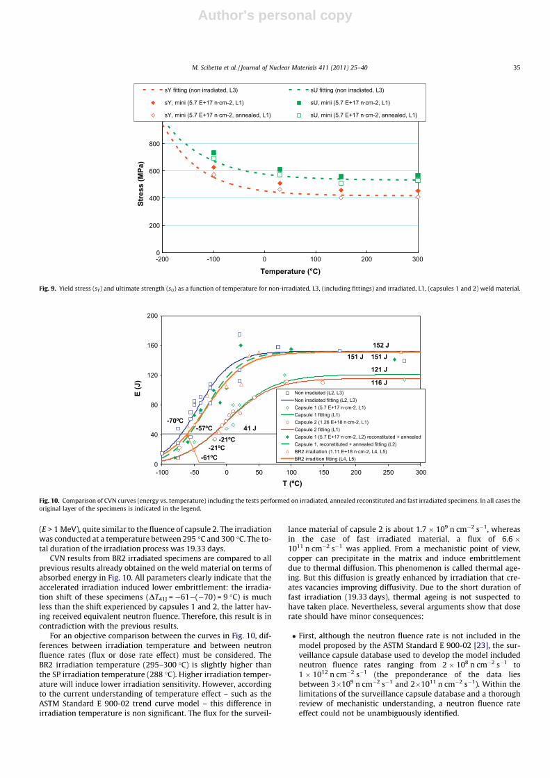
6.2.2. CVN tests on BR2 irradiated specimens (unirradiated, L4 and L5)In order to analyse the susceptibility of weld material (L4 and L5)
to irradiation, the 10 available weld-CVN specimens (not previouslytested) were fast irradiated to a fluence up to 1.11 � 1018 n cm�2
-20
-10
0
10
20
30
40
50
60
0.0E+00 4.0E+17 8.0E+17 1.2E+18 1.6E+18 2.0E+18Fluence (n·cm-2, E>1 MeV)
ΔΔT41
J, ΔT
0, ΔR
T ND
T (ºC
)
KJc (this research) (DT0, L3, L4)CVN Capsule 1 (DT41J, L1)CVN Capsule 2 (DT41J, L1)R.G. 1.99 Rev. 2 (DRTNDT)R.G. 1.99 Rev. 2 (DRTNDT + M)ASTM E900-02 (DT41J)ASTM E900-02 (DT41J + 12.2 ºC)
M = 31.1 ºC
σ = 12.2 ºC
Fig. 8. Comparison of experimental TTS according to the ASTM Standard E 900-02 [23] and Regulatory Guide 1.99 Revision 2 [6] embrittlement predictions.
Table 4Reference temperatures of the weld material.
Fluence (n cm�2, E > 1 MeV) RTNDT (�C) RTT0 (�C)
0 �50 �76 (L4)3.55 � 1017 n.a. �88 (L3)5.7 � 1017 �1 (L1) n.a.1.26 � 1018 �1 (L1) n.a.
34 M. Scibetta et al. / Journal of Nuclear Materials 411 (2011) 25–40
Author's personal copy
(E > 1 MeV), quite similar to the fluence of capsule 2. The irradiationwas conducted at a temperature between 295 �C and 300 �C. The to-tal duration of the irradiation process was 19.33 days.
CVN results from BR2 irradiated specimens are compared to allprevious results already obtained on the weld material on terms ofabsorbed energy in Fig. 10. All parameters clearly indicate that theaccelerated irradiation induced lower embrittlement: the irradia-tion shift of these specimens (DT41J = �61�(�70) = 9 �C) is muchless than the shift experienced by capsules 1 and 2, the latter hav-ing received equivalent neutron fluence. Therefore, this result is incontradiction with the previous results.
For an objective comparison between the curves in Fig. 10, dif-ferences between irradiation temperature and between neutronfluence rates (flux or dose rate effect) must be considered. TheBR2 irradiation temperature (295–300 �C) is slightly higher thanthe SP irradiation temperature (288 �C). Higher irradiation temper-ature will induce lower irradiation sensitivity. However, accordingto the current understanding of temperature effect – such as theASTM Standard E 900-02 trend curve model – this difference inirradiation temperature is non significant. The flux for the surveil-
lance material of capsule 2 is about 1.7 � 109 n cm�2 s�1, whereasin the case of fast irradiated material, a flux of 6.6 �1011 n cm�2 s�1 was applied. From a mechanistic point of view,copper can precipitate in the matrix and induce embrittlementdue to thermal diffusion. This phenomenon is called thermal age-ing. But this diffusion is greatly enhanced by irradiation that cre-ates vacancies improving diffusivity. Due to the short duration offast irradiation (19.33 days), thermal ageing is not suspected tohave taken place. Nevertheless, several arguments show that doserate should have minor consequences:
� First, although the neutron fluence rate is not included in themodel proposed by the ASTM Standard E 900-02 [23], the sur-veillance capsule database used to develop the model includedneutron fluence rates ranging from 2 � 108 n cm�2 s�1 to1 � 1012 n cm�2 s�1 (the preponderance of the data liesbetween 3�109 n cm�2 s�1 and 2�1011 n cm�2 s�1). Within thelimitations of the surveillance capsule database and a thoroughreview of mechanistic understanding, a neutron fluence rateeffect could not be unambiguously identified.
0
200
400
600
800
1000
1200
-200 -100 0 100 200 300
Temperature (°C)
Stre
ss (M
Pa)
sY fitting (non irradiated, L3) sU fitting (non irradiated, L3)
sY, mini (5.7 E+17 n·cm-2, L1) sU, mini (5.7 E+17 n·cm-2, L1)
sY, mini (5.7 E+17 n·cm-2, annealed, L1) sU, mini (5.7 E+17 n·cm-2, annealed, L1)
Fig. 9. Yield stress (sY) and ultimate strength (sU) as a function of temperature for non-irradiated, L3, (including fittings) and irradiated, L1, (capsules 1 and 2) weld material.
0
40
80
120
160
200
-100 -50 0 50 100 150 200 250 300
T (ºC)
E (J
)
Non irradiated (L2, L3)Non irradiated fitting (L2, L3)Capsule 1 (5.7 E+17 n·cm-2, L1)Capsule 1 fitting (L1)Capsule 2 (1.26 E+18 n·cm-2, L1)Capsule 2 fitting (L1)Capsule 1 (5.7 E+17 n·cm-2, L2) reconstituted + annealedCapsule 1, reconstituted + annealed fitting (L2)BR2 irradiation (1.11 E+18 n·cm-2, L4, L5)BR2 irradition fitting (L4, L5)
152 J
121 J
116 J
-70ºC
-21ºC-21ºC
41 J-57ºC
151 J151 J
-61ºC
Fig. 10. Comparison of CVN curves (energy vs. temperature) including the tests performed on irradiated, annealed reconstituted and fast irradiated specimens. In all cases theoriginal layer of the specimens is indicated in the legend.
M. Scibetta et al. / Journal of Nuclear Materials 411 (2011) 25–40 35

Author's personal copy
� Second, in [19] the dose rate effect is investigated for a materialwith a copper content of 0.31 wt.%. in the range 2 � 1012–7 � 1013 n cm�2 s�1, E > 1 MeV. Although the experimentaldata do not allow a general rule to be provided, they show thatthe small flux effect detected is within the experimentaluncertainties.� Finally, a third model, which has been the basis for establishing
the ASTM Standard E 900-02 [23] and has been described in anEPRI report [31], can be considered. The main difference with[23] is that it includes an irradiation duration term (dose rateeffect) that affects the CRP term. However, this effect is mar-ginal: for a fluence of 1.2 � 1018 n cm�2, the expected TTS is ofabout 34 �C for a flux equivalent to capsule 2 and 25 �C for adose rate equivalent to that applied to the fast irradiated weldmetal. This difference is well below the shift analysed.
6.2.3. KJc fracture tests on PCCv reconstituted specimensFig. 11 represents the KJc,1T experimental results of the tests per-
formed on PCCv reconstituted specimens, L1, from capsule 1(5.70 � 1017 n cm�2 s�1). The curves for KJc(med), the lower boundKJc(0.01) – and the upper bound KJc(0.99) have also been plotted forboth material conditions. The result T0 = �113 �C was obtained inthis case. In Table 5 a summary of the results is presented; as be-fore, 2r was included as the uncertainty, together with N, r andthe weighting condition imposed by Eq. (8).
6.3. Discussion of experimental results in the extended research
Three main features became evident from the experimental re-sults of this extended research:
� The tensile and CVN tests performed on annealed specimensfrom capsule 1 (L1) revealed a complete recovery of properties,apparently to the level corresponding to unirradiated material.� In contrast, irradiation hardly affected the fracture properties of
the BR2 irradiated specimens (with a fluence close to that ofcapsule 2) from internal layers (L4 and L5).� Moreover, up to the present, no systematic behaviour can be
deduced from the KJc fracture tests; thus, uncertainties remainconcerning the material embrittlement.
Therefore, the experimental scope developed to characterise theweld material here studied revealed an unexpected behaviourshowing contradictory results between different experimentaltechniques for evaluating the material embrittlement (tensile,CVN and KJc fracture tests). With the aim of detecting any materialinhomogeneity, it was decided to analyse the chemical composi-tion of the weld material as a function of the depth in the thicknessof the vessel. This possibility is specifically proposed by the IAEATechnical Document [32], where it can be read:
. . .in some plants, especially older plants, weld chemistry isunknown. When chemistry data are unavailable, an upper bandis mandated by Regulatory Guide 1.99 Revision 2 [6] whichspecifies an upper bound chemistry of 0.35 Cu (%wt) and 1.0Ni [. . .] most surveillance welds were made well after the vesselweld certification test was performed [. . .] so in many casesthere is a period of years between weld certification chemistry,measurements and fabrication of the surveillance weld. As aresult, the surveillance weld was typically made from a differ-ent coil of weld metal wire, even though it bears the same heatnumber as the qualification weld. Due to the variability ofchemistry in different coils of weld wire, chemistry reportedfor the certification weld can differ significantly from the chem-istry of the surveillance weld.
An example of a NPP with some weld material having materialinhomogeneity is published in the open literature in [33]. Due todifference in Cu coating of the weld wire, Cu concentration variedfrom 0.13% to 0.35% in the deposited weld material.
These statements emphasise the need to carefully analyse theweld chemistry. Several chemical components participate in theembrittlement process: the ASTM Standard E 900-02 [23] indicatesthat sensitivity to neutron fluence is a direct consequence of thecopper and nickel contents, the former being the more importantof the two. Moreover, the model described in the EPRI report
0
25
50
75
100
125
150
175
200
-140 -130 -120 -110 -100 -90 -80
T (ºC)
KJc
,1T (
MPa
·m1/
2 )
PCCv reconstituted, TL, irradiated ( 5.70 E+17 n/cm2, L1)
KJc (0.01)
KJc (0.99)
KJc (med)
-113 ºC
Fig. 11. Representation of KJc,1T vs. temperature scale for irradiated (5.70 � 1017 n cm�2) weld material. The 0.01, 0.5 (median) and 0.99 confidence bounds are included.Censored data are represented with background coloured markers. (For interpretation of the references to color in this figure legend, the reader is referred to the web versionof this article.)
Table 5Summary of Master Curve test results obtained in specimens obtained from L1.
Fluence (n cm�2, E > 1 MeV) Layer T0 (�C) 2r (�C) N r P3i¼1ri � ni
5.70 � 1017 1 �113 15 7 6 1.00
36 M. Scibetta et al. / Journal of Nuclear Materials 411 (2011) 25–40

Author's personal copy
[31], also considers the effect of phosphorus and includes an irra-diation duration term (dose rate effect). In Fig. 12 the effect of Cucontent, according to ASTM Standard E 900-02 [23] is representedas a function of neutron fluence; five values of Cu were consideredin the range 0.10–0.305 wt.%; in this extreme case the marginr = 12.2 �C was also represented. As can be shown in Fig. 12, theexperimental results obtained in this research lie either belowthe Cu = 0.10% or above the Cu = 0.305% (plus 12.2 �C); this resultsuggest that a substantial copper inhomogeneity could be presentin the material. According to these remarks, the material contentsin Cu, Ni and P (and for the sake of completeness, also in C, Mn, S,Cr, Mo, V, Si) were determined (by means of glow discharge opticalemission spectroscopy) for some available weld and HAZ speci-mens taken from L1 to L5; in fact, the specimens of L3 were ana-lysed in three different positions with depths of 45, 50 and55 mm. In Fig. 13–15, the results corresponding to Cu, Ni and Pare represented (when several tests were performed on differentspecimens, the uncertainty is also represented in the figurethrough the standard deviation).
Whereas only slight differences were detected for Ni or P, re-sults clearly show a significantly lower Cu content in specimensfrom internal layers (L4 and L5) as compared to external layers(L1 and L2); moreover, a steep transition in Cu content takes placein the ten millimetres corresponding to L3. Finally, negligiblechanges were detected in the rest of the chemical elements ana-lysed (C, Mn, S, Cr, Mo, V, Si). In the light of the discovery of thiscopper segregation, the Regulatory Guide 1.99 Revision 2 [6] trendcurves in Fig. 12 can be checked again: despite the great uncer-tainty of this formula, the experimental data can be properlyunderstood. The present result allows the explanation of manyopen questions related to the weld material:
� It is a proof of the difference between the first and second layerand deeper layers.� It explains the irradiation embrittlement behaviour of the first
and second capsule and the annealing recovery of the first cap-sule: this material has high copper content and is thereforeprone to CRP.
-30
-20
-10
0
10
20
30
40
50
60
0,0E+00 4,0E+17 8,0E+17 1,2E+18 1,6E+18 2,0E+18
Fluence (n·cm-2, E>1 MeV)
ΔΔT41
J, ΔT
0, ΔR
T ND
T (ºC
)
KJc (this research; 3.55 E+17 n/cm2) (DT0)
CVN Capsule 1 (5.70 E+17 n/cm2) (DT41J)
CVN Capsule 2 (1.26 E+18 n/cm2) (DT41J)
BR2 Irradiation (1.11 E+18 n/cm2) (DT41J)
Cu = 0.10 %
Cu = 0.15 %
Cu = 0.20 %Cu = 0.25 %
Cu = 0.305 %
Cu = 0.305 %+ Margin
σ = 12.2 ºC
Fig. 12. Embrittlement effect of Cu content (wt.%), according to ASTM Standard E 900-02 [24].
0.00
0.05
0.10
0.15
0.20
0.25
0.30
0.35
0.40
0 10 20 30 40 50 60 70 80 90 100
Distance (mm)
Cu
(%w
t)
Weld specimens
HAZ specimens
L1 L2
L4 L5
L3
Fig. 13. Cu content as a function of depth (when several tests were performed on different specimens, the uncertainty is also represented in the figure through the standarddeviation). The layer of the specimens (L1–L5) is indicated in the figure.
M. Scibetta et al. / Journal of Nuclear Materials 411 (2011) 25–40 37

Author's personal copy
� It justifies the limited irradiation embrittlement of the experi-mental capsule irradiated to 3.55 � 1017 n cm�2, as this mate-rial (L3) has a low copper content.� It justifies the limited irradiation embrittlement of the acceler-
ated irradiation in the BR2 reactor, as this material (L4 and L5)has a low copper content.
It is not the purpose of this research to elucidate the origin ofthe copper segregation here discovered, but to report it and to jus-tify the consistency between all the experimental sources. Never-theless, it is worth noting that the chemical compositionoriginally provided by the plant (see Table 1) is in agreement withthe chemistry of the first and second layers and that the actualweld material here analysed (with the exception of L1 and L2)must show much better behaviour to irradiation than originally ex-pected, due to the lower Cu content (see Table 1).
The only remaining open issue is the relative good fracturetoughness of the L1 as measured on reconstituted KJc weld-CVNspecimens from the second capsule (5.7 � 1017 n cm�2). It couldbe speculated that this could be due to a better initial fracture
toughness of L1 and L2 compared to deeper layer. But due to thevery limited amount of unirradiated material available from L1and L2, the hypothesis cannot be currently verified.
Finally, the evidence obtained in this research about the chem-istry of the weld material emphasises the need to carefully evalu-ate the chemistry especially in the case of older plants, as stated inthe IAEA Technical Document [32] and experienced in Doel plant[33]. Moreover, it highlights the fact that inconsistencies can ap-pear even when a NPP has strictly followed the requirements ofthe legislation in force [3,18] regulating the SP.
7. Summary and conclusions
Disposing of the experimental results obtained in the frame-work of the SP (capsules 1 and 2) of a NPP currently in service,an exhaustive research was carried out to characterise the weldmetal (TL orientation) of the vessel in the DBT region. The originalexperimental scope of this study consisted on 27 KJc fracture testsperformed on PCCv specimens, 15 fabricated from unirradiated
0.00
0.02
0.04
0.06
0.08
0.10
0.12
0.14
0.16
0.18
0 10 20 30 40 50 60 70 80 90 100
Distance (mm)
Ni (
%w
t)
Weld specimens
HAZ specimens
L1 L2 L3 L4 L5
Fig. 14. Ni content as a function of depth (when several tests were performed on different specimens, the uncertainty is also represented in the figure through the standarddeviation). The layer of the specimens (L1–L5) is indicated in the figure.
0.000
0.005
0.010
0.015
0.020
0.025
0 10 20 30 40 50 60 70 80
Distance (mm)
P (%
wt)
Weld specimens
HAZ specimens
L1 L2 L3 L4
Fig. 15. P content as a function of depth (when several tests were performed on different specimens, the uncertainty is also represented in the figure through the standarddeviation). The layer of the specimens (L1–L4) is indicated in the figure.
38 M. Scibetta et al. / Journal of Nuclear Materials 411 (2011) 25–40

Author's personal copy
material and the remaining 12 from specimens irradiated to a flu-ence up to 3.55 � 1017 n cm�2 (E > 1 MeV).
The comparison of the material embrittlement measuredthrough CVN impact tests (DT41J) and KJc fracture tests (DT0) re-vealed a serious lack of consistency. The CVN tests performed inthe framework of the SP of the plant showed a noticeable increasein T41J (DT41J = 49 �C) for the fluence level of capsule 1(5.70 � 1017 n cm�2) that apparently saturates (DT41J = 49 �C,again) for capsule 2 (1.26 � 1018 n cm�2). The same conclusionsare supported by the information coming from the tensile test re-sults. However, the KJc fracture tests showed an unexpectedembrittlement behaviour as, for the fluence level of the experimen-tal capsule holding the PCCv specimens (3.55 � 1017 n cm�2,slightly lower than the fluence of capsule 1), no TTS was observed(DT0 = �12 �C, with an uncertainty of the same order).
As no plausible explanation was found, this last issue motivatedthe development of additional research to properly understand theeffect of irradiation of the weld material in the DBT region. The fol-lowing features were observed:
� The tensile tests showed performed on unirradiated, irradiatedand annealed specimens demonstrated that the embrittlementdisplayed by the weld material of L1 can be expressed beyondany doubt.� The experimental results obtained on previously annealed CVN
specimens showed that the embrittlement detected in theframework of the SP is not an artefact but a reality.� CVN results from fast irradiated specimens clearly indicate that
the accelerate irradiation induced minor embrittlement; thus, anew contradiction between experimental sources appears.� The chemical analysis performed on specimens from L1 to L5
clearly showed a significantly lower Cu content in specimensfrom external layers (L4 and L5) as compared to internal layers(L1 and L2); this Cu segregation allows the contradiction betweenexperimental sources mentioned above to be explained.� The only remaining open issue is the relative good fracture tough-
ness of the L1 as measured on reconstituted KJc test weld-CVNspecimens from the second capsule (5.7 � 1017 n cm�2). Futureresearch using the weld material which is currently being irradi-ated in the third capsule of the NPP could play a useful role to clar-ify this issue.
Several additional comments are outlined below, related to thestructural and methodological consequences of this research andto the weld material behaviour here characterised:
� The chemical composition of the weld material originallyreported by the NPP (Table 1) is in agreement with the chemis-try of L1 and L2. For this reason, the material embrittlementestimations performed by the plant in the past were necessarilyconservative, as high copper content was considered.� This research highlights the fact that inconsistencies can appear
even when a NPP has strictly followed the requirements of thelegislation in force [3,18] regulating the SPs.� Early shift in transition temperature, as detected in the weld
material here analysed, is a well known empirical observationfor high Copper weld materials. This behaviour has beenexplained by the formation of CRPs. Additional observed TTS willbe attributable to SMD mechanisms which, according to theavailable models [22,23], is expected to be of minor importance.
Acknowledgments
This investigation was performed within a research project(CUPRIVA) sponsored by the Spanish Nuclear Regulatory Body
(CSN), the electric utility consortium UNESA and the utility NUCLE-NOR, represented by J.M. Figueras and L. Francia and J. Martín,respectively. The authors wish to express particular gratitude totheir colleagues Ph.D. A. Ballesteros and Eng. X. Jardí for their con-tribution to the dosimetry measurements and analysis.
References
[1] ASTM Standard E 399-90 (Reapproved 1997), Standard test method for plane-strain fracture toughness testing of metallic materials, Annual Book of ASTMStandards, vol. 03.01, ASTM International, West Conshohocken, PA, 2005.
[2] D. Ferreño, M. Scibetta, I. Gorrochategui, R. Lacalle, E. van Walle, F. Gutiérrez-Solana, Eng. Fract. Mech. 76 (16) (2009) 2495.
[3] Rules and Regulations Title 10. Code of federal regulations part 50.61,Appendix G, Fracture Toughness Requirements for Protection AgainstPressurized Thermal Shock Events, Washington, DC, US Government PrintingOffice, US Nuclear Regulatory Commission (1986).
[4] ASME Boiler and Pressure Vessel Code, Section XI, Inservice inspection ofnuclear power plant, American Society for Mechanical Engineers, 2007.
[5] ASME Boiler and Pressure Vessel Code, Section III, Rules for construction ofnuclear power plant components, American Society of Mechanical Engineers,New York, 2007.
[6] Regulatory Guide 1.99 Revision 2, Radiation embrittlement of reactor vesselmaterials, Office of Nuclear Regulatory Research, US Nuclear RegulatoryCommission, Washington, DC, 1988.
[7] E. Lucon, M. Scibetta, R. Chaouadi, E. van Walle, R. Gérard, Int. J. Press. VesselsPip. 84 (9) (2007) 536.
[8] K. Wallin, T. Saario, K. Törrönen, Met. Sci. 18 (1984) 13.[9] K. Wallin, Eng. Fract. Mech. 19 (6) (1984) 1085.
[10] K. Wallin, Eng. Fract. Mech. 22 (1985) 149.[11] K. Wallin, A simple theoretical Charpy V–KIc correlation for irradiation
embrittlement, Innovative approaches to irradiation damage and fractureanalysis, PVP 170, ASME, 1989, p. 93.
[12] A. Valiente, J. Ruiz, M. Elices, Eng. Fract. Mech. 72 (5) (2005) 709.[13] ASTM Standard E1921-09-a, Standard Test Method for Determination of
Reference Temperature, T0, for Ferritic Steels in the Transition Range, ASTMInternational, West Conshohocken, PA, 2008.
[14] J.G. Merkle, K. Wallin, D.E. McCabe, Technical Basis for an ASTM Standard onDetermining the Reference Temperature T0 for Ferritic Steel in the TransitionRange, NUREG/CR-5504, USMNRC, 1998.
[15] D. Ferreño, Integridad estructural de vasijas nucleares en base a la curvapatrón obtenida mediante probetas reconstruidas, PhD thesis, University ofCantabria, Spain, 2008.
[16] ASME Boiler and Pressure Vessel Code–Code Case N-629, Use of fracturetoughness test data to establish reference temperature for pressure retainingmaterials, Section XI, Division 1, 1999.
[17] ASME Boiler and Pressure Vessel Code–Code Case N-631, Use of fracturetoughness test data to establish reference temperature for pressure retainingmaterials other than bolting for class 1 vessels, Section III, Division 1, 1999.
[18] ASTM Standard E185-02, Standard Practice for Design of SurveillancePrograms for Light-Water Moderated Nuclear Power Reactor Vessels, AnnualBook of ASTM Standards, vol. 03.02, ASTM International, West Conshohocken,PA, 2005.
[19] R. Chaouadi, R. Gérard, J. Nucl. Mater. 345 (2005) 65.[20] G.E. Lucas, G.R. Odette, P. Lombrozo, J.W. Sheckherd, The effects of
composition, temperature, and microstructure on the radiation hardening ofpressure vessel steels, in: Twelfth International Symposium on the Effects ofIrradiation on Materials Effects of Irradiation on Materials, ASTM STP-870,1985, p. 901.
[21] T.J. Williams, P.R. Burch, C.A. English, P.H.N. de la cour Ray,in: G.J. Tbeus, J.R.Weeks (Eds.), Proc. third Int. Symp. on Environmental Degradation of Materialsin Nuclear Reactors-Water Reactors, The Metallurgical Society, Warrendale,PA, 1988, p. 121.
[22] B.D. Wirth, G.R. Odette, W. Pavinich, G.E. Lucas, S. Spooner, Small angleneutron scattering study of Linde 80 RPV welds, in: Eighteenth InternationalSymposium on the Effects of Radiation on Materials, ASTM STP-1325, ASTM,1999, p. 102.
[23] ASTM Standard E 900-02, Standard Guide for predicting radiation-inducedtransition temperature shift in reactor vessel materials, E706 (IIF), AnnualBook of ASTM Standards vol. 12.02, American Society for Testing andMaterials, West Conshohocken, PA, 2002.
[24] M.A. Sokolov, R.K. Nanstad, Comparison of irradiation-induced shifts of KJc andCharpy impact toughness for reactor pressure vessel steels, in: R.K. Nanstad,M.L. Hamilton, F.A. Garner, A.S. Kumar (Eds.), Effects of radiation onmaterials: eighteenth international symposium, ASTM STP 1325, AmericanSociety for Testing and Materials, West Conshohocken, PA, 1999.
[25] M.A. Sokolov, R.K. Nanstad, Comparison of irradiation-induced shifts of KJc andCharpy impact toughness for reactor pressure vessel steels, NUREG/CR-6609(ORNL/TM-13755), USNRC (2001).
[26] E. van Walle, Reconstitution: where do we stand?, in: D.S. Gelles, R.K. Nanstad,A.S. Kumar, E.A. Little (Eds.), Effects of Radiation on Materials: SeventeenthInternational Symposium, ASTM, West Conshohocken, PA, 1996, p. 415.
M. Scibetta et al. / Journal of Nuclear Materials 411 (2011) 25–40 39

Author's personal copy
[27] ASTM Standard 1253-99, Standard guide for reconstitution of irradiatedcharpy specimens, Annual Book of ASTM Standards, vol. 12.02, ASTMInternational, West Conshohocken, PA, 2005.
[28] E. Van Walle, M. Scibetta, M.J. Valo, H.-W. Viehrig, H. Richter, T. Atkins, M.R.Wootton, E. Keim, L. Debarberis, M. Horsten, RESQUE: reconstitutiontechniques qualification & evaluation to study ageing phenomena of nuclearpressure vessel materials, in: M.A. Sokolov, J.D. Landes, G.E. Lucas (Eds.), SmallSpecimen Test Techniques, vol. 4, vol. ASTM STP 1418, American society forTesting and Materials, West Conshohocken, PA, 2002, pp. 409–425.
[29] M. Scibetta, R. Chaouadi, Effect of reconstitution on fracture toughnessmeasured with PCCv, Report BLG-749, SCK-CEN Mol., Belgium, 1997.
[30] Regulatory Guide 1.162, Format and content of report for thermal annealingreactor pressure vessels, US-NRC, 1996.
[31] Charpy Embrittlement Correlations – Status of combined mechanistic andstatistical bases for US RPV steels (MRP-45), PWR Material Reliability Program(PWRMRP), EPRI, Palo Alto, CA, 2001.
[32] Assessment and management of ageing of major nuclear power plantcomponents important to safety: bwr pressure vessels, IAEA TECDOC Series1470, ISBN 92-0-109305-5, 2005
[33] R. Gerard et al., In-service embrittlement of the pressure vessel welds at theDoel I and II nuclear power plants, in: David S. Gelles, Randy K. Nanstad,Arvind S. Kumar, Edward A. Little (Eds.), Effects of Radiation on Materials:Seventeenth International Symposium, vol. II, vol. ASTM STP 1046, AmericanSociety for Testing and Materials, 1996, p. 294.
40 M. Scibetta et al. / Journal of Nuclear Materials 411 (2011) 25–40