Analysis of Ductile-to-Brittle Transition Temperature of Mild Steel
10
NOVATEUR NOVATEUR NOVATEUR NOVATEUR PUBLICATIONS PUBLICATIONS PUBLICATIONS PUBLICATIONS INTERNATIONAL JOURNAL OF INNOVATIONS IN ENGINEERING RESEARCH AND TECHNOLOGY [IJIERT] INTERNATIONAL JOURNAL OF INNOVATIONS IN ENGINEERING RESEARCH AND TECHNOLOGY [IJIERT] INTERNATIONAL JOURNAL OF INNOVATIONS IN ENGINEERING RESEARCH AND TECHNOLOGY [IJIERT] INTERNATIONAL JOURNAL OF INNOVATIONS IN ENGINEERING RESEARCH AND TECHNOLOGY [IJIERT] VOLUME 1, ISSUE 1 NOV VOLUME 1, ISSUE 1 NOV VOLUME 1, ISSUE 1 NOV VOLUME 1, ISSUE 1 NOV-2014 2014 2014 2014 1 | Page Analysis of Ductile-to-Brittle Transition Temperature of Mild Steel Mr. Sahadev Shivaji Sutar Department of Mechanical Engineering, Solapur University / SSPNBNSCOE, Solapur, India [email protected] Mr. Gorakshanath Shivaji Kale Engg. Nath Pvt.Ltd. Hadapsar /Pune, Maharashtra, India [email protected] Mr. Sujit Haridas Merad Department of Mechanical Engineering, Solapur University / VVPIET, Solapur, India [email protected] ABSTRACT The Ductile-to-Brittle Transition Temperature (DBTT) is a phenomenon that is widely observed in metals. Below critical temperature (DBTT), the material suddenly loss ductility and becomes brittle. The controlling mechanism of this transition still remains unclear despite of large efforts made in experimental and theoretical investigation. All ferrous materials (except the austenitic grades) exhibit a transition from ductile to brittle when tested above and below a certain temperature, called as Transition Temperature. The paper deals with the determination of the ‘Ductile to Brittle Transition Temperature of stainless steel. Work carried out in this is purchasing the material followed by test specimen preparation. The specimens then keep in the liquid nitrogen for cooling for soaking time of 15 min. Then the actual charpy impact testing of the specimens at variable temperature ranging are carried out in controlled atmosphere. The readings taken are the impact energy (joules) of specimen at specific temperature. The graph of energy absorbed vs temperature is plotted to get the range of transition temperature. INTRODUCTION NEED TO DETERMINE TRANSITION TEMPERATURE AND COMPARING Why should steel that is normally capable of sustaining great loads and capable of ductility greater than 20 percent suddenly, when cold, become so brittle so brittle that it could be shattered a minor blow or similar impact? This was the question asked over a hundred years ago when fracture occurred in steel structures in severe structures in severe weather. Since then many similar failure have been documented. There are number of possible reasons for such failures: • Fatigue. • Corrosion. • Fabrication. • Design errors. • Poor quality steel. The most dramatic and unexpected cause of brittle failure in ferrous alloys is their tendency to lose almost all of their toughness when the temperature drops below their ductile to brittle transition temperature. Between 1942 and 1952 around 250 large welded steel ships were lost due to catastrophic brittle failure. Another 1200 welded ships suffered relatively minor damage(cracks less than 10 feet long)while over 1900 riveted ship have broken in two or lost at sea. Most of the failure occurred during the winter months. Failures occurred both when the ships were in heavy seas and when they were anchored at dock. These calamities focused attention on the fact that normally ductile steel can become brittle under certain conditions.
-
Upload
khangminh22 -
Category
Documents
-
view
1 -
download
0
Transcript of Analysis of Ductile-to-Brittle Transition Temperature of Mild Steel
NOVATEUR NOVATEUR NOVATEUR NOVATEUR PUBLICATIONSPUBLICATIONSPUBLICATIONSPUBLICATIONS INTERNATIONAL JOURNAL OF INNOVATIONS IN ENGINEERING RESEARCH AND TECHNOLOGY [IJIERT]INTERNATIONAL JOURNAL OF INNOVATIONS IN ENGINEERING RESEARCH AND TECHNOLOGY [IJIERT]INTERNATIONAL JOURNAL OF INNOVATIONS IN ENGINEERING RESEARCH AND TECHNOLOGY [IJIERT]INTERNATIONAL JOURNAL OF INNOVATIONS IN ENGINEERING RESEARCH AND TECHNOLOGY [IJIERT]
VOLUME 1, ISSUE 1 NOVVOLUME 1, ISSUE 1 NOVVOLUME 1, ISSUE 1 NOVVOLUME 1, ISSUE 1 NOV----2014201420142014
1 | P a g e
Analysis of Ductile-to-Brittle Transition Temperature of Mild Steel
Mr. Sahadev Shivaji Sutar
Department of Mechanical Engineering, Solapur University / SSPNBNSCOE, Solapur, India [email protected]
Mr. Gorakshanath Shivaji Kale
Engg. Nath Pvt.Ltd. Hadapsar /Pune, Maharashtra, India
Mr. Sujit Haridas Merad
Department of Mechanical Engineering, Solapur University / VVPIET, Solapur, India [email protected]
ABSTRACT The Ductile-to-Brittle Transition Temperature (DBTT) is a phenomenon that is widely observed in metals.
Below critical temperature (DBTT), the material suddenly loss ductility and becomes brittle. The controlling
mechanism of this transition still remains unclear despite of large efforts made in experimental and
theoretical investigation. All ferrous materials (except the austenitic grades) exhibit a transition from ductile
to brittle when tested above and below a certain temperature, called as Transition Temperature. The paper
deals with the determination of the ‘Ductile to Brittle Transition Temperature of stainless steel. Work
carried out in this is purchasing the material followed by test specimen preparation. The specimens then
keep in the liquid nitrogen for cooling for soaking time of 15 min. Then the actual charpy impact testing of
the specimens at variable temperature ranging are carried out in controlled atmosphere. The readings taken
are the impact energy (joules) of specimen at specific temperature. The graph of energy absorbed vs
temperature is plotted to get the range of transition temperature.
INTRODUCTION NEED TO DETERMINE TRANSITION TEMPERATURE AND COMPARING
Why should steel that is normally capable of sustaining great loads and capable of ductility greater than 20
percent suddenly, when cold, become so brittle so brittle that it could be shattered a minor blow or similar
impact? This was the question asked over a hundred years ago when fracture occurred in steel structures in
severe structures in severe weather. Since then many similar failure have been documented. There are
number of possible reasons for such failures:
• Fatigue.
• Corrosion.
• Fabrication.
• Design errors.
• Poor quality steel.
The most dramatic and unexpected cause of brittle failure in ferrous alloys is their tendency to lose almost
all of their toughness when the temperature drops below their ductile to brittle transition temperature.
Between 1942 and 1952 around 250 large welded steel ships were lost due to catastrophic brittle failure.
Another 1200 welded ships suffered relatively minor damage(cracks less than 10 feet long)while over 1900
riveted ship have broken in two or lost at sea. Most of the failure occurred during the winter months.
Failures occurred both when the ships were in heavy seas and when they were anchored at dock. These
calamities focused attention on the fact that normally ductile steel can become brittle under certain
conditions.
NOVATEUR NOVATEUR NOVATEUR NOVATEUR PUBLICATIONSPUBLICATIONSPUBLICATIONSPUBLICATIONS INTERNATIONAL JOURNAL OF INNOVATIONS IN ENGINEERING RESEARCH AND TECHNOLOGY [IJIERT]INTERNATIONAL JOURNAL OF INNOVATIONS IN ENGINEERING RESEARCH AND TECHNOLOGY [IJIERT]INTERNATIONAL JOURNAL OF INNOVATIONS IN ENGINEERING RESEARCH AND TECHNOLOGY [IJIERT]INTERNATIONAL JOURNAL OF INNOVATIONS IN ENGINEERING RESEARCH AND TECHNOLOGY [IJIERT]
VOLUME 1, ISSUE 1 NOVVOLUME 1, ISSUE 1 NOVVOLUME 1, ISSUE 1 NOVVOLUME 1, ISSUE 1 NOV----2014201420142014
2 | P a g e
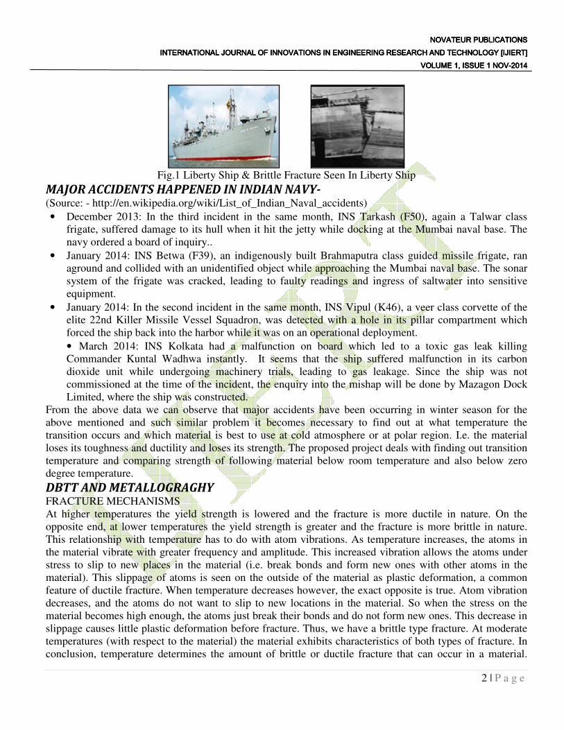
Fig.1 Liberty Ship & Brittle Fracture Seen In Liberty Ship
MAJOR ACCIDENTS HAPPENED IN INDIAN NAVY- (Source: - http://en.wikipedia.org/wiki/List_of_Indian_Naval_accidents)
• December 2013: In the third incident in the same month, INS Tarkash (F50), again a Talwar class
frigate, suffered damage to its hull when it hit the jetty while docking at the Mumbai naval base. The
navy ordered a board of inquiry..
• January 2014: INS Betwa (F39), an indigenously built Brahmaputra class guided missile frigate, ran
aground and collided with an unidentified object while approaching the Mumbai naval base. The sonar
system of the frigate was cracked, leading to faulty readings and ingress of saltwater into sensitive
equipment.
• January 2014: In the second incident in the same month, INS Vipul (K46), a veer class corvette of the
elite 22nd Killer Missile Vessel Squadron, was detected with a hole in its pillar compartment which
forced the ship back into the harbor while it was on an operational deployment.
• March 2014: INS Kolkata had a malfunction on board which led to a toxic gas leak killing
Commander Kuntal Wadhwa instantly. It seems that the ship suffered malfunction in its carbon
dioxide unit while undergoing machinery trials, leading to gas leakage. Since the ship was not
commissioned at the time of the incident, the enquiry into the mishap will be done by Mazagon Dock
Limited, where the ship was constructed.
From the above data we can observe that major accidents have been occurring in winter season for the
above mentioned and such similar problem it becomes necessary to find out at what temperature the
transition occurs and which material is best to use at cold atmosphere or at polar region. I.e. the material
loses its toughness and ductility and loses its strength. The proposed project deals with finding out transition
temperature and comparing strength of following material below room temperature and also below zero
degree temperature.
DBTT AND METALLOGRAGHY FRACTURE MECHANISMS
At higher temperatures the yield strength is lowered and the fracture is more ductile in nature. On the
opposite end, at lower temperatures the yield strength is greater and the fracture is more brittle in nature.
This relationship with temperature has to do with atom vibrations. As temperature increases, the atoms in
the material vibrate with greater frequency and amplitude. This increased vibration allows the atoms under
stress to slip to new places in the material (i.e. break bonds and form new ones with other atoms in the
material). This slippage of atoms is seen on the outside of the material as plastic deformation, a common
feature of ductile fracture. When temperature decreases however, the exact opposite is true. Atom vibration
decreases, and the atoms do not want to slip to new locations in the material. So when the stress on the
material becomes high enough, the atoms just break their bonds and do not form new ones. This decrease in
slippage causes little plastic deformation before fracture. Thus, we have a brittle type fracture. At moderate
temperatures (with respect to the material) the material exhibits characteristics of both types of fracture. In
conclusion, temperature determines the amount of brittle or ductile fracture that can occur in a material.
INTERNATIONAL JOURNAL OF INNOVATIONS IN ENGINEERING RESEARCH AND TECHNOLOGY [IJIERT]INTERNATIONAL JOURNAL OF INNOVATIONS IN ENGINEERING RESEARCH AND TECHNOLOGY [IJIERT]INTERNATIONAL JOURNAL OF INNOVATIONS IN ENGINEERING RESEARCH AND TECHNOLOGY [IJIERT]INTERNATIONAL JOURNAL OF INNOVATIONS IN ENGINEERING RESEARCH AND TECHNOLOGY [IJIERT]
Another factor that determines the amount of brittle or ductile fracture that occurs in a material is
dislocation density. The higher the dislocation density, the more brittle the fracture will be in the ma
The idea behind this theory is that plastic deformation comes from the movement of dislocations. As
dislocations increase in a material due to stresses above the materials yield point, it becomes increasingly
difficult for the dislocations to move
dislocation density can only deform but so much before it fractures in a brittle manner.
grain size. As grains get smaller in a material, the fracture becomes more
the fact that in smaller grains, dislocations have less space to move before they hit a grain boundary. When
dislocations cannot move very far before fracture, then plastic deformation decreases. Thus, the material's
fracture is more brittle.
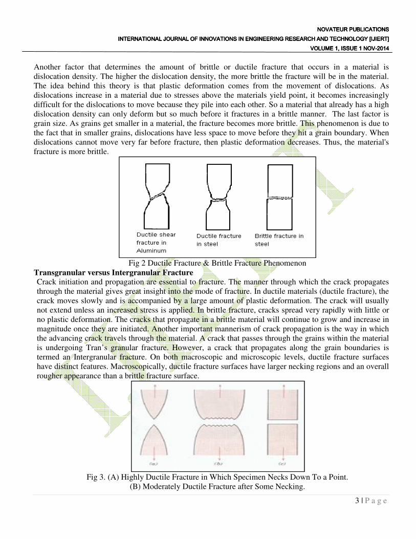
Fig 2 Ductile Fracture & Brittle Fracture Phenomenon
Transgranular versus Intergranular Fracture
Crack initiation and propagation are essential to fracture. The manner through which the crack propagates
through the material gives great insight into the mode of fracture. In ductile materials (ductile fracture), the
crack moves slowly and is accompanied by a large amount of plastic deformation. The crack will usually
not extend unless an increased stress is applied.
no plastic deformation. The cracks that propagate in a brittle material will continue to grow and increase in
magnitude once they are initiated. Another important mannerism of crack propagation is the way in wh
the advancing crack travels through the material. A crack that passes through the grains within the material
is undergoing Tran’s granular fracture. However, a crack that propagates along the grain boundaries is
termed an Intergranular fracture. On bot
have distinct features. Macroscopically, ductile fracture surfaces have larger necking regions and an overall
rougher appearance than a brittle fracture surface.
Fig 3. (A) Highly Ductile Fr
(B) Moderately Ductile Fracture after Some Necking.
INTERNATIONAL JOURNAL OF INNOVATIONS IN ENGINEERING RESEARCH AND TECHNOLOGY [IJIERT]INTERNATIONAL JOURNAL OF INNOVATIONS IN ENGINEERING RESEARCH AND TECHNOLOGY [IJIERT]INTERNATIONAL JOURNAL OF INNOVATIONS IN ENGINEERING RESEARCH AND TECHNOLOGY [IJIERT]INTERNATIONAL JOURNAL OF INNOVATIONS IN ENGINEERING RESEARCH AND TECHNOLOGY [IJIERT]VOLUME 1, ISSUE 1 NOVVOLUME 1, ISSUE 1 NOVVOLUME 1, ISSUE 1 NOVVOLUME 1, ISSUE 1 NOV
Another factor that determines the amount of brittle or ductile fracture that occurs in a material is
dislocation density. The higher the dislocation density, the more brittle the fracture will be in the ma
The idea behind this theory is that plastic deformation comes from the movement of dislocations. As
dislocations increase in a material due to stresses above the materials yield point, it becomes increasingly
difficult for the dislocations to move because they pile into each other. So a material that already has a high
dislocation density can only deform but so much before it fractures in a brittle manner.
grain size. As grains get smaller in a material, the fracture becomes more brittle. This phenomenon is due to
the fact that in smaller grains, dislocations have less space to move before they hit a grain boundary. When
dislocations cannot move very far before fracture, then plastic deformation decreases. Thus, the material's
Ductile Fracture & Brittle Fracture Phenomenon
Transgranular versus Intergranular Fracture Crack initiation and propagation are essential to fracture. The manner through which the crack propagates
great insight into the mode of fracture. In ductile materials (ductile fracture), the
crack moves slowly and is accompanied by a large amount of plastic deformation. The crack will usually
not extend unless an increased stress is applied. In brittle fracture, cracks spread very rapidly with little or
no plastic deformation. The cracks that propagate in a brittle material will continue to grow and increase in
magnitude once they are initiated. Another important mannerism of crack propagation is the way in wh
the advancing crack travels through the material. A crack that passes through the grains within the material
is undergoing Tran’s granular fracture. However, a crack that propagates along the grain boundaries is
termed an Intergranular fracture. On both macroscopic and microscopic levels, ductile fracture surfaces
have distinct features. Macroscopically, ductile fracture surfaces have larger necking regions and an overall
rougher appearance than a brittle fracture surface.
(A) Highly Ductile Fracture in Which Specimen Necks Down To a Point.
(B) Moderately Ductile Fracture after Some Necking.
NOVATEUR NOVATEUR NOVATEUR NOVATEUR PUBLICATIONSPUBLICATIONSPUBLICATIONSPUBLICATIONS INTERNATIONAL JOURNAL OF INNOVATIONS IN ENGINEERING RESEARCH AND TECHNOLOGY [IJIERT]INTERNATIONAL JOURNAL OF INNOVATIONS IN ENGINEERING RESEARCH AND TECHNOLOGY [IJIERT]INTERNATIONAL JOURNAL OF INNOVATIONS IN ENGINEERING RESEARCH AND TECHNOLOGY [IJIERT]INTERNATIONAL JOURNAL OF INNOVATIONS IN ENGINEERING RESEARCH AND TECHNOLOGY [IJIERT]
VOLUME 1, ISSUE 1 NOVVOLUME 1, ISSUE 1 NOVVOLUME 1, ISSUE 1 NOVVOLUME 1, ISSUE 1 NOV----2014201420142014
3 | P a g e
Another factor that determines the amount of brittle or ductile fracture that occurs in a material is
dislocation density. The higher the dislocation density, the more brittle the fracture will be in the material.
The idea behind this theory is that plastic deformation comes from the movement of dislocations. As
dislocations increase in a material due to stresses above the materials yield point, it becomes increasingly
because they pile into each other. So a material that already has a high
dislocation density can only deform but so much before it fractures in a brittle manner. The last factor is
brittle. This phenomenon is due to
the fact that in smaller grains, dislocations have less space to move before they hit a grain boundary. When
dislocations cannot move very far before fracture, then plastic deformation decreases. Thus, the material's
Crack initiation and propagation are essential to fracture. The manner through which the crack propagates
great insight into the mode of fracture. In ductile materials (ductile fracture), the
crack moves slowly and is accompanied by a large amount of plastic deformation. The crack will usually
re, cracks spread very rapidly with little or
no plastic deformation. The cracks that propagate in a brittle material will continue to grow and increase in
magnitude once they are initiated. Another important mannerism of crack propagation is the way in which
the advancing crack travels through the material. A crack that passes through the grains within the material
is undergoing Tran’s granular fracture. However, a crack that propagates along the grain boundaries is
h macroscopic and microscopic levels, ductile fracture surfaces
have distinct features. Macroscopically, ductile fracture surfaces have larger necking regions and an overall
acture in Which Specimen Necks Down To a Point.
NOVATEUR NOVATEUR NOVATEUR NOVATEUR PUBLICATIONSPUBLICATIONSPUBLICATIONSPUBLICATIONS INTERNATIONAL JOURNAL OF INNOVATIONS IN ENGINEERING RESEARCH AND TECHNOLOGY [IJIERT]INTERNATIONAL JOURNAL OF INNOVATIONS IN ENGINEERING RESEARCH AND TECHNOLOGY [IJIERT]INTERNATIONAL JOURNAL OF INNOVATIONS IN ENGINEERING RESEARCH AND TECHNOLOGY [IJIERT]INTERNATIONAL JOURNAL OF INNOVATIONS IN ENGINEERING RESEARCH AND TECHNOLOGY [IJIERT]
VOLUME 1, ISSUE 1 NOVVOLUME 1, ISSUE 1 NOVVOLUME 1, ISSUE 1 NOVVOLUME 1, ISSUE 1 NOV----2014201420142014
4 | P a g e
(C) Brittle Fracture without Any Plastic Deformation.
Ductile to Brittle Transition temperature
The ductile-brittle transition is exhibited in bcc metals, such as low carbon steel, which become brittle at
low temperature or at very high strain rates. FCC metals, however, generally remain ductile at low
temperatures. In metals, plastic deformation at room temperature occurs by dislocation motion. The stress
required to move a dislocation depends on the atomic bonding, crystal structure, and obstacles such as solute
atoms, grain boundaries, precipitate particles and other dislocations. If the stress required moving the
dislocation is too high, the metal will fail instead by the propagation of cracks and the failure will be brittle.
Thus, either plastic flow (ductile failure) or crack propagation (brittle failure) will occur, depending on
which process requires the smaller applied stress. In fcc metals, the flow stress, i.e. the force required to
move dislocations, is not strongly temperature dependent. Therefore, dislocation movement remains high
even at low temperatures and the material remains relatively ductile. In contrast to fcc metal crystals, the
yield stress or critical resolved shear stress of bcc single crystals is markedly temperature dependent, in
particular at low temperatures. The temperature sensitivity of the yield stress of bcc crystals has been
attributed to the presence of interstitial impurities on the one hand, and to a temperature dependent Peierls-
Nabarro force on the other. However, the crack propagation stress is relatively independent of temperature.
Thus the mode of failure changes from plastic flow at high temperature to brittle fracture at low
temperature.
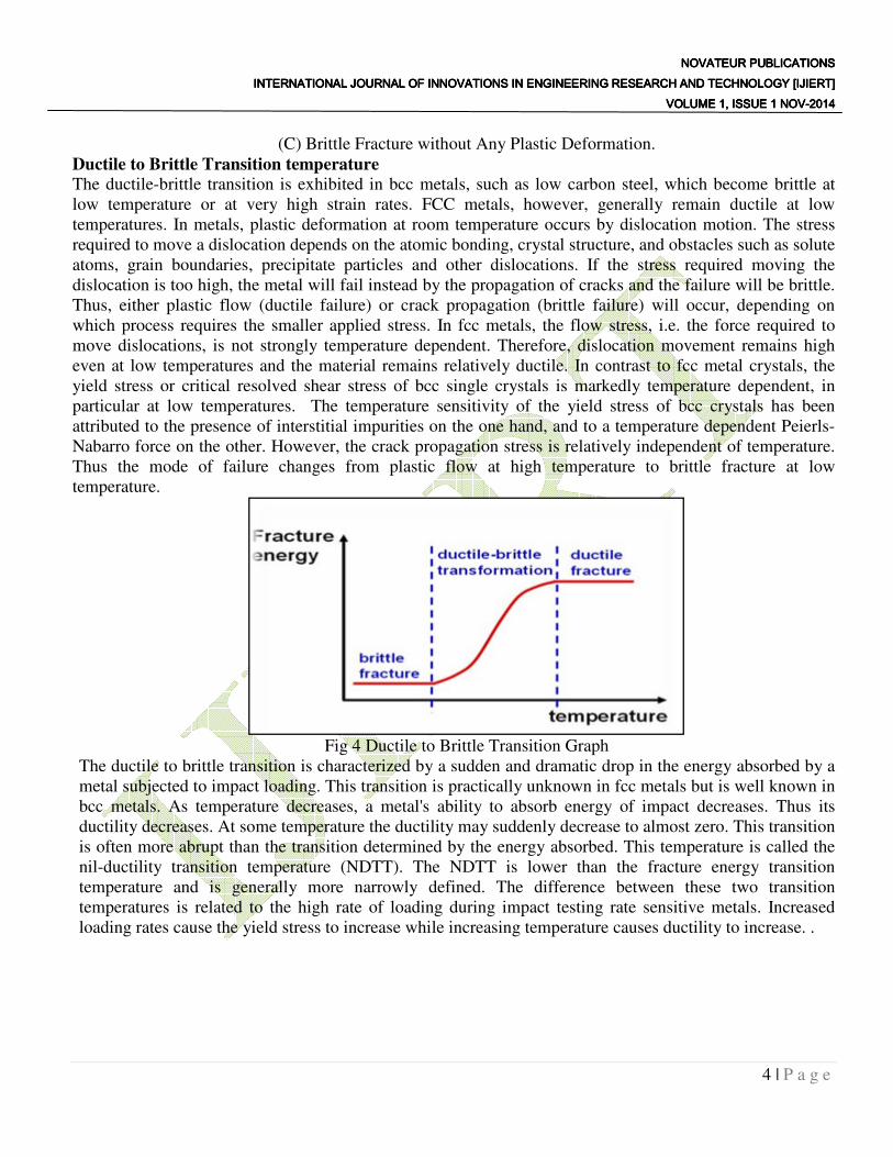
Fig 4 Ductile to Brittle Transition Graph
The ductile to brittle transition is characterized by a sudden and dramatic drop in the energy absorbed by a
metal subjected to impact loading. This transition is practically unknown in fcc metals but is well known in
bcc metals. As temperature decreases, a metal's ability to absorb energy of impact decreases. Thus its
ductility decreases. At some temperature the ductility may suddenly decrease to almost zero. This transition
is often more abrupt than the transition determined by the energy absorbed. This temperature is called the
nil-ductility transition temperature (NDTT). The NDTT is lower than the fracture energy transition
temperature and is generally more narrowly defined. The difference between these two transition
temperatures is related to the high rate of loading during impact testing rate sensitive metals. Increased
loading rates cause the yield stress to increase while increasing temperature causes ductility to increase. .
NOVATEUR NOVATEUR NOVATEUR NOVATEUR PUBLICATIONSPUBLICATIONSPUBLICATIONSPUBLICATIONS INTERNATIONAL JOURNAL OF INNOVATIONS IN ENGINEERING RESEARCH AND TECHNOLOGY [IJIERT]INTERNATIONAL JOURNAL OF INNOVATIONS IN ENGINEERING RESEARCH AND TECHNOLOGY [IJIERT]INTERNATIONAL JOURNAL OF INNOVATIONS IN ENGINEERING RESEARCH AND TECHNOLOGY [IJIERT]INTERNATIONAL JOURNAL OF INNOVATIONS IN ENGINEERING RESEARCH AND TECHNOLOGY [IJIERT]
VOLUME 1, ISSUE 1 NOVVOLUME 1, ISSUE 1 NOVVOLUME 1, ISSUE 1 NOVVOLUME 1, ISSUE 1 NOV----2014201420142014
5 | P a g e
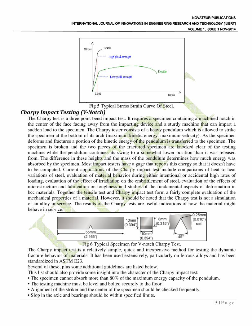
Fig 5 Typical Stress Strain Curve Of Steel.
Charpy Impact Testing (V-Notch) The Charpy test is a three point bend impact test. It requires a specimen containing a machined notch in
the center of the face facing away from the impacting device and a sturdy machine that can impart a
sudden load to the specimen. The Charpy tester consists of a heavy pendulum which is allowed to strike
the specimen at the bottom of its arch (maximum kinetic energy, maximum velocity). As the specimen
deforms and fractures a portion of the kinetic energy of the pendulum is transferred to the specimen. The
specimen is broken and the two pieces of the fractured specimen are knocked clear of the testing
machine while the pendulum continues its swing to a somewhat lower position than it was released
from. The difference in these heights and the mass of the pendulum determines how much energy was
absorbed by the specimen. Most impact testers have a gage that reports this energy so that it doesn't have
to be computed. Current applications of the Charpy impact test include comparisons of heat to heat
variations of steel, evaluation of material behavior during either intentional or accidental high rates of
loading, evaluation of the effect of irradiation on the embrittlement of steel, evaluation of the effects of
microstructure and fabrication on toughness and studies of the fundamental aspects of deformation in
bcc materials. Together the tensile test and Charpy impact test form a fairly complete evaluation of the
mechanical properties of a material. However, it should be noted that the Charpy test is not a simulation
of an alloy in service. The results of the Charpy tests are useful indications of how the material might
behave in service.
Fig 6 Typical Specimen for V-notch Charpy Test.
The Charpy impact test is a relatively simple, quick and inexpensive method for testing the dynamic
fracture behavior of materials. It has been used extensively, particularly on ferrous alloys and has been
standardized in ASTM E23.
Several of these, plus some additional guidelines are listed below.
This list should also provide some insight into the character of the Charpy impact test:
• The specimen cannot absorb more than 80% of the maximum energy capacity of the pendulum.
• The testing machine must be level and bolted securely to the floor.
• Alignment of the striker and the center of the specimen should be checked frequently.
• Slop in the axle and bearings should be within specified limits.
NOVATEUR NOVATEUR NOVATEUR NOVATEUR PUBLICATIONSPUBLICATIONSPUBLICATIONSPUBLICATIONS INTERNATIONAL JOURNAL OF INNOVATIONS IN ENGINEERING RESEARCH AND TECHNOLOGY [IJIERT]INTERNATIONAL JOURNAL OF INNOVATIONS IN ENGINEERING RESEARCH AND TECHNOLOGY [IJIERT]INTERNATIONAL JOURNAL OF INNOVATIONS IN ENGINEERING RESEARCH AND TECHNOLOGY [IJIERT]INTERNATIONAL JOURNAL OF INNOVATIONS IN ENGINEERING RESEARCH AND TECHNOLOGY [IJIERT]
VOLUME 1, ISSUE 1 NOVVOLUME 1, ISSUE 1 NOVVOLUME 1, ISSUE 1 NOVVOLUME 1, ISSUE 1 NOV----2014201420142014
6 | P a g e
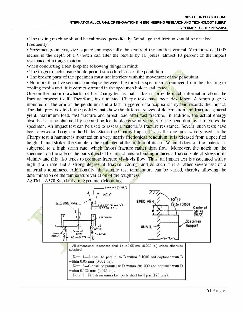
• The testing machine should be calibrated periodically. Wind age and friction should be checked
Frequently.
• Specimen geometry, size, square and especially the acuity of the notch is critical. Variations of 0.005
inches in the depth of a V-notch can alter the results by 10 joules, almost 10 percent of the impact
resistance of a tough material.
When conducting a test keep the following things in mind:
• The trigger mechanism should permit smooth release of the pendulum.
• The broken parts of the specimen must not interfere with the movement of the pendulum.
• No more than five seconds can elapse between the time the specimen is removed from then heating or
cooling media until it is correctly seated in the specimen holder and tested.
One on the major drawbacks of the Charpy test is that it doesn't provide much information about the
fracture process itself. Therefore, instrumented Charpy tests have been developed. A strain gage is
mounted on the arm of the pendulum and a fast, triggered data acquisition system records the impact.
The data provides load-time profiles that show the different stages of deformation and fracture: general
yield, maximum load, fast fracture and arrest load after fast fracture. In addition, the actual energy
absorbed can be obtained by accounting for the decrease in velocity of the pendulum as it fractures the
specimen. An impact test can be used to assess a material’s fracture resistance. Several such tests have
been devised although in the United States the Charpy Impact Test is the one most widely used. In the
Charpy test, a hammer is mounted on a very nearly frictionless pendulum. It is released from a specified
height, h, and strikes the sample to be evaluated at the bottom of its arc. When it does so, the material is
subjected to a high strain rate, which favors fracture rather than flow. Moreover, the notch on the
specimen on the side of the bar subjected to impact tensile loading induces a triaxial state of stress in its
vicinity and this also tends to promote fracture vis-à-vis flow. Thus, an impact test is associated with a
high strain rate and a strong degree of triaxial loading, and as such it is a rather severe test of a
material’s toughness. Additionally, the sample test temperature can be varied, thereby allowing the
determination of the temperature variation of the toughness.
ASTM – A370 Standards for Specimen Mounting
NOVATEUR NOVATEUR NOVATEUR NOVATEUR PUBLICATIONSPUBLICATIONSPUBLICATIONSPUBLICATIONS INTERNATIONAL JOURNAL OF INNOVATIONS IN ENGINEERING RESEARCH AND TECHNOLOGY [IJIERT]INTERNATIONAL JOURNAL OF INNOVATIONS IN ENGINEERING RESEARCH AND TECHNOLOGY [IJIERT]INTERNATIONAL JOURNAL OF INNOVATIONS IN ENGINEERING RESEARCH AND TECHNOLOGY [IJIERT]INTERNATIONAL JOURNAL OF INNOVATIONS IN ENGINEERING RESEARCH AND TECHNOLOGY [IJIERT]
VOLUME 1, ISSUE 1 NOVVOLUME 1, ISSUE 1 NOVVOLUME 1, ISSUE 1 NOVVOLUME 1, ISSUE 1 NOV----2014201420142014
7 | P a g e
MATERIAL SPECIFICATION After studying the applications of various materials the material selected for DBTT determination are
following MILD STEEL Chemical composition-
Carbon max.0.14
Manganese 0.90 -1.30
Phosphorus max.0.11.
Sulfur 0.27 - 0.33
Silicon max. 0.05
Lead 0.20 - 0.35
Iron as Balance
Mechanical Properties- Tensile strength (Rm): 570-820 MPa.
Heat Treatment- This quality is not made for hardening purposes, unless the carbon content is at the upper
limit it is possible to do an edge hardening or nitridization process.
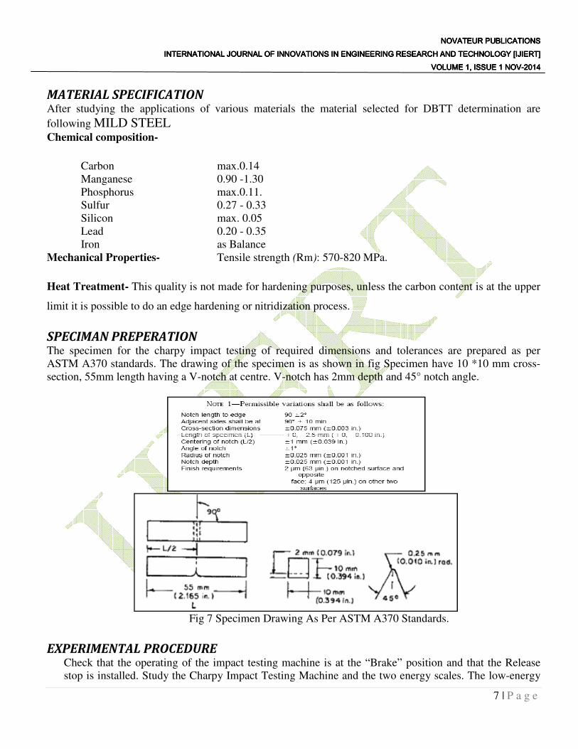
SPECIMAN PREPERATION The specimen for the charpy impact testing of required dimensions and tolerances are prepared as per
ASTM A370 standards. The drawing of the specimen is as shown in fig Specimen have 10 *10 mm cross-
section, 55mm length having a V-notch at centre. V-notch has 2mm depth and 45° notch angle.
Fig 7 Specimen Drawing As Per ASTM A370 Standards.
EXPERIMENTAL PROCEDURE Check that the operating of the impact testing machine is at the “Brake” position and that the Release
stop is installed. Study the Charpy Impact Testing Machine and the two energy scales. The low-energy
NOVATEUR NOVATEUR NOVATEUR NOVATEUR PUBLICATIONSPUBLICATIONSPUBLICATIONSPUBLICATIONS INTERNATIONAL JOURNAL OF INNOVATIONS IN ENGINEERING RESEARCH AND TECHNOLOGY [IJIERT]INTERNATIONAL JOURNAL OF INNOVATIONS IN ENGINEERING RESEARCH AND TECHNOLOGY [IJIERT]INTERNATIONAL JOURNAL OF INNOVATIONS IN ENGINEERING RESEARCH AND TECHNOLOGY [IJIERT]INTERNATIONAL JOURNAL OF INNOVATIONS IN ENGINEERING RESEARCH AND TECHNOLOGY [IJIERT]
VOLUME 1, ISSUE 1 NOVVOLUME 1, ISSUE 1 NOVVOLUME 1, ISSUE 1 NOVVOLUME 1, ISSUE 1 NOV----2014201420142014
8 | P a g e
scale will be used for tests at 0°C and the high-energy scale for tests at temperature above 0°C.Practice
the proper method to grip the specimen using the special purpose tongs provided. Also learn to mount
the specimen properly in the impact testing machine. Turn the operating lever to “latch” position raise
the pendulum to the lower energy or higher energy position depending upon the temperature at which
the test is to be done. Keep all parts of your body well away from under the pendulum until the test is
completed. Adjust the recording pointer on the energy scale such that it touches the moving pointer at
the proper scale. Gripping a EN-19 specimen with the tongs’ immerse it into the liquid nitrogen
provided and hold until the liquid nitrogen stops boiling. Remove the specimen from the liquid nitrogen
bath and, without any loss of time, mount it into the impact testing machine. Keeping a good distance
from the machine, Turn the operating lever to “Release” position. The pendulum will swing down, hit
the specimen, break it and swing up to the other side. Turn the operating lever to “Break” position. Read
on the scale the value of the impact energy absorbed by the specimen for the fracture. Repeat the step 4
to 7 at the various temperatures. The temperatures can be achieved by immersing the specimen into
constant temperature baths of liquid nitrogen, plain ice and boiling water. Repeat the steps 4 to 8 for the
specimen of different alloys specified at the beginning
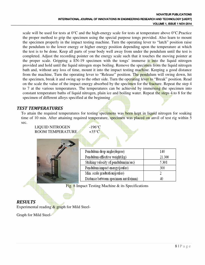
TEST TEMPERATURES To attain the required temperatures for testing specimens was been kept in liquid nitrogen for soaking
time of 10 min. After attaining required temperature, specimen was placed on anvil of test rig within 5
sec.
LIQUID NITROGEN -196°C
ROOM TEMPERATURE +35°C
Fig. 8 Impact Testing Machine & its Specifications
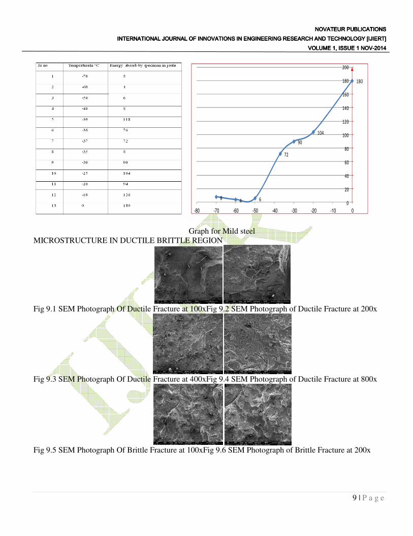
RESULTS Experimental reading & graph for Mild Steel-
Graph for Mild Steel-
NOVATEUR NOVATEUR NOVATEUR NOVATEUR PUBLICATIONSPUBLICATIONSPUBLICATIONSPUBLICATIONS INTERNATIONAL JOURNAL OF INNOVATIONS IN ENGINEERING RESEARCH AND TECHNOLOGY [IJIERT]INTERNATIONAL JOURNAL OF INNOVATIONS IN ENGINEERING RESEARCH AND TECHNOLOGY [IJIERT]INTERNATIONAL JOURNAL OF INNOVATIONS IN ENGINEERING RESEARCH AND TECHNOLOGY [IJIERT]INTERNATIONAL JOURNAL OF INNOVATIONS IN ENGINEERING RESEARCH AND TECHNOLOGY [IJIERT]
VOLUME 1, ISSUE 1 NOVVOLUME 1, ISSUE 1 NOVVOLUME 1, ISSUE 1 NOVVOLUME 1, ISSUE 1 NOV----2014201420142014
9 | P a g e
Graph for Mild steel
MICROSTRUCTURE IN DUCTILE BRITTLE REGION
Fig 9.1 SEM Photograph Of Ductile Fracture at 100xFig 9.2 SEM Photograph of Ductile Fracture at 200x
Fig 9.3 SEM Photograph Of Ductile Fracture at 400xFig 9.4 SEM Photograph of Ductile Fracture at 800x
Fig 9.5 SEM Photograph Of Brittle Fracture at 100xFig 9.6 SEM Photograph of Brittle Fracture at 200x
84 6
72
90
104
180
0
20
40
60
80
100
120
140
160
180
200
-80 -70 -60 -50 -40 -30 -20 -10 0
NOVATEUR NOVATEUR NOVATEUR NOVATEUR PUBLICATIONSPUBLICATIONSPUBLICATIONSPUBLICATIONS INTERNATIONAL JOURNAL OF INNOVATIONS IN ENGINEERING RESEARCH AND TECHNOLOGY [IJIERT]INTERNATIONAL JOURNAL OF INNOVATIONS IN ENGINEERING RESEARCH AND TECHNOLOGY [IJIERT]INTERNATIONAL JOURNAL OF INNOVATIONS IN ENGINEERING RESEARCH AND TECHNOLOGY [IJIERT]INTERNATIONAL JOURNAL OF INNOVATIONS IN ENGINEERING RESEARCH AND TECHNOLOGY [IJIERT]
VOLUME 1, ISSUE 1 NOVVOLUME 1, ISSUE 1 NOVVOLUME 1, ISSUE 1 NOVVOLUME 1, ISSUE 1 NOV----2014201420142014
10 | P a g e
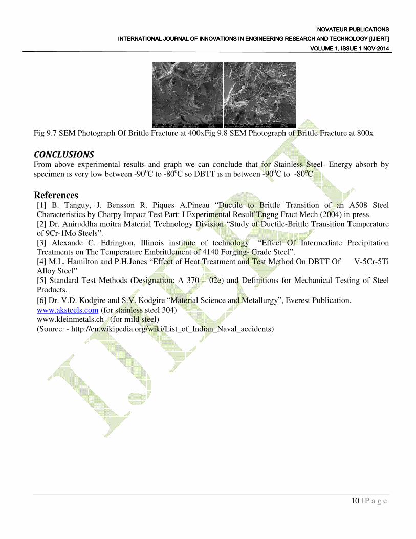
Fig 9.7 SEM Photograph Of Brittle Fracture at 400xFig 9.8 SEM Photograph of Brittle Fracture at 800x
CONCLUSIONS From above experimental results and graph we can conclude that for Stainless Steel- Energy absorb by
specimen is very low between -90oC to -80
oC so DBTT is in between -90
oC to
-80
oC
References [1] B. Tanguy, J. Bensson R. Piques A.Pineau “Ductile to Brittle Transition of an A508 Steel
Characteristics by Charpy Impact Test Part: I Experimental Result”Engng Fract Mech (2004) in press.
[2] Dr. Aniruddha moitra Material Technology Division “Study of Ductile-Brittle Transition Temperature
of 9Cr-1Mo Steels”.
[3] Alexande C. Edrington, Illinois institute of technology “Effect Of Intermediate Precipitation
Treatments on The Temperature Embrittlement of 4140 Forging- Grade Steel”.
[4] M.L. Hamilton and P.H.Jones “Effect of Heat Treatment and Test Method On DBTT Of V-5Cr-5Ti
Alloy Steel”
[5] Standard Test Methods (Designation: A 370 – 02e) and Definitions for Mechanical Testing of Steel
Products.
[6] Dr. V.D. Kodgire and S.V. Kodgire “Material Science and Metallurgy”, Everest Publication. www.aksteels.com (for stainless steel 304) www.kleinmetals.ch (for mild steel)
(Source: - http://en.wikipedia.org/wiki/List_of_Indian_Naval_accidents)