ADAPTIVE STRATEGY FOR DUCTILE FRACTURE ANALYSIS IN DAMAGED ELASTOPLASTIC SOLIDS
19
COMPUTATIONAL MECHANICS New Trends and Applications S. Idelsohn, E. O˜ nate and E. Dvorkin (Eds.) c CIMNE, Barcelona, Spain 1998 ADAPTIVE STRATEGY FOR DUCTILE FRACTURE ANALYSIS IN DAMAGED ELASTOPLASTIC SOLIDS M. Vaz Jr. * , M. Dutko †,‡ and D.R.J. Owen † * Departamento de Engenharia Mecˆanica Universidade do Estado de Santa Catarina Campus Universit´ ario, 89223-100 Joinville, Brasil †Department of Civil Engineering University of Wales, Swansea, Singleton Park, SA2 8PP Swansea, U.K. ‡Also at Mechanical Engineering Faculty Slovak Technical University 812 31 Bratislava, Slovakia Key words: Finite Elements, Ductile Fracture, Damage Mechanics, Mesh Adaption Abstract. Ductile fracture has long been subject of the intense research, leading to the development of several predictive techniques such as COD and J-integral amongst others. Continuum Damage Mechanics has emerged as an alternative approach to conventional fracture mechanics by introducing new state variables into the material constitutive model. On the other hand, mesh adaption has become an indispensable tool in the numerical analysis of practical metal forming problems, such as forging and extrusion. Adaptive techniques for these problems have been introduced in recent years when mesh generation techniques, error indicators and transfer operators have been developed. In the present work, error indicators for problems involving material failure are proposed. Estimates based on rate of damage work and rate of fracture indicators are suggested for damaged and conventional J 2 elasto-plastic materials respectively. Discussion on the use of rate of plastic work for this class of problems is also presented. 1
-
Upload
independent -
Category
Documents
-
view
0 -
download
0
Transcript of ADAPTIVE STRATEGY FOR DUCTILE FRACTURE ANALYSIS IN DAMAGED ELASTOPLASTIC SOLIDS

COMPUTATIONAL MECHANICSNew Trends and Applications
S. Idelsohn, E. Onate and E. Dvorkin (Eds.)c©CIMNE, Barcelona, Spain 1998
ADAPTIVE STRATEGY FOR DUCTILE FRACTURE ANALYSIS INDAMAGED ELASTOPLASTIC SOLIDS
M. Vaz Jr.∗, M. Dutko†,‡ and D.R.J. Owen†
∗Departamento de Engenharia MecanicaUniversidade do Estado de Santa Catarina
Campus Universitario, 89223-100 Joinville, Brasil
†Department of Civil EngineeringUniversity of Wales, Swansea,
Singleton Park, SA2 8PP Swansea, U.K.
‡Also at Mechanical Engineering FacultySlovak Technical University812 31 Bratislava, Slovakia
Key words: Finite Elements, Ductile Fracture, Damage Mechanics, Mesh Adaption
Abstract. Ductile fracture has long been subject of the intense research, leading to thedevelopment of several predictive techniques such as COD and J-integral amongst others.Continuum Damage Mechanics has emerged as an alternative approach to conventionalfracture mechanics by introducing new state variables into the material constitutive model.On the other hand, mesh adaption has become an indispensable tool in the numericalanalysis of practical metal forming problems, such as forging and extrusion. Adaptivetechniques for these problems have been introduced in recent years when mesh generationtechniques, error indicators and transfer operators have been developed. In the presentwork, error indicators for problems involving material failure are proposed. Estimatesbased on rate of damage work and rate of fracture indicators are suggested for damagedand conventional J2 elasto-plastic materials respectively. Discussion on the use of rate ofplastic work for this class of problems is also presented.
1
M. Vaz Jr., M. Dutko and D.R.J. Owen
1 INTRODUCTION
Numerical simulation of metal forming problems presents higher complexity comparedto its elastic structural counterparts. Large plastic deformations not only bring complica-tions from the mathematical point of view, but also can cause rapid solution degradationdue to element distortion. Therefore, application of adaptive re-meshing techniques tothis class of problems is essential to obtain reliable numerical solutions. Moreover, addi-tional complexities emerge when material failure takes place and the numerical model hasboth to indicate the correct site of fracture onset and to efficiently re-mesh the criticalzones.
The present analysis is inserted in the general context of creating a numerical modelable to analyse elasto-plastic problems involving ductile fracture. To accomplish the tasksuccessfully, a ductile fracture algorithm1, thermo-mechanical coupling2, error estimatorsand adaptive mesh refinement procedures using an explicit time integration scheme3 havebeen developed. This work describes the development of error estimators within thisframework, in which estimates based on rate of damage work and rate of fracture indicatorsare proposed for damaged and conventional J2 elasto-plastic materials respectively.
2 ERROR ESTIMATES AND ADAPTIVE REFINEMENT ININELASTIC PROBLEMS
Error estimation has become an important issue in computational mechanics since thelate seventies when Babuska and Rheinboldt4,5 proposed a posteriori error estimates forthe finite element method using norms of Sobolev spaces. The topic gained momentumwhen Zienkiewicz and Zhu6 introduced error estimates based on post-processing tech-niques of the finite element solutions which could easily be used in conjunction with meshrefinement strategies.
A posteriori error estimates have been continuously developed and extensively appliedto linear and some classes of nonlinear problems over the last twenty years, however, itsuse in history-dependent nonlinear problems in solid mechanics is relatively recent.
One of the first reported works on application of error estimates to metal formingoperations has been presented by Zienkiewicz, Liu and Huang7 for steady-state extrusionusing flow formulation. The authors, using the projection/smoothing technique developedfor linear elliptic problems, proposed an error estimate based on the rate of energy dissipa-tion. Application of this error estimate was later extended to analyse shear localization8
and expanded to account for porous material models9. Zienkiewicz and Zhu’s estimatewas later modified by Fourment and Chenot10 by correcting a possible unbalance of thegoverning equations with regard to the smoothed solution. A similar approach was alsoadopted by Moal and Massoni11 for mesh refinement in thermo-mechanical coupled pro-blems using rigid-viscoplastic materials. The new element size is chosen from the smallestvalue provided by separate error estimation of the mechanical and thermal solutions.
2

M. Vaz Jr., M. Dutko and D.R.J. Owen
An adaptive refinement strategy for strain localization problems was proposed by Ortizand Quigley12 based on the assumption that the optimality condition for interpolationerror minimization is that some suitable norm of the solution be equi-distributed overthe elements in the mesh. According to the authors, the variation of the velocity fieldover the elements of the mesh, allied to a W 1,1 semi-norm, is sufficient to produce reliablesolutions. Sobolev norms associated with stress, strains and damage have also been usedby Min, Tworzydlo and Xiques13 to the modelling of low-cycle continuum damage andlife prediction of high-temperature components. A residual error estimate based on theenergy norm has also been presented by Johnson and Hansbo14 for Henckey problems atsmall-strain perfect plasticity.
In the context of strain localization, Peric, Yu and Owen15, introduced use of thethermodynamical formulation of the problem to define error estimation in small-strainelasto-plasticity. The authors proposed three separate error estimates, i.e., energy normof the generalized stresses, dissipation functional and rate of plastic work respectively. Ap-plication of the error estimation based on the rate of plastic work has been later extendedto large-strain elasto-plastic problems by Owen et al.16 and Marusich and Ortiz17. Theformer used an implicit time integration scheme whereas the latter adopted a dynamicexplicit algorithm.
Error estimates in large strain problems have been proposed by Lee and Bathe18 ac-counting for the equilibrium error and the error in plastic strain increments. The formerapproach adopts a projection/smoothing technique for pressure and equivalent plasticstrain whereas the latter is computed based on the difference between the plastic strainincrements obtained using the trapezoidal rule and the Euler-backward method.
Combined error indicators have also been proposed, in which elastic, plastic, time andother components were included in the estimate. For instance, Li et al.19 combined elasticand plastic components whereas Gallimard, Ladeveze and Pelle20,21,22 derived an estimatebased on Drucker’s inequality in which spatial and time components were included. Fur-thermore, Barthold, Schmidt and Stein23, for small-strain elasto-plasticity, proposed aspatial error estimate based on comparative analysis of Prandtl-Reuss elasto-plasticityand Hencky plasticity. The error indicator was assumed to be dependent on the elas-tic (free energy function) and plastic (dissipation) components and loading/unloading(Kuhn-Tucker) conditions. The time discretization error was based on the L2 norm of thenumerical integration of the flow rule.
This brief review shows that most of the contributions has been made over the pastfew years. Moreover, the majority of the analyses have been applied either to small-strainelasto-plasticity or rigid-viscoplastic problems. Therefore, there exists a need for furtherdevelopments where aspects of large-deformation, thermo-mechanical coupling, damagemechanics and material failure are to be fully explored.
The present work aims to develop error estimates for elasto-plastic problems followingthe notion that mesh refinement should reflect the dynamic nature of the physical phe-
3

M. Vaz Jr., M. Dutko and D.R.J. Owen
nomena, being able, not only to capture the progression of plastic deformation, but alsoto produce efficiently refined meshes at regions of possible material failure.
3 ERROR ESTIMATE BASED ON RATE OF DAMAGE WORK
The theory of continuous damage mechanics postulates that elasto-plastic deformationproduces degradation of the material, which is quantified by the damage variable, D andgoverned by a damage law.
In the present work, Lemaıtre’s24,25 isotropic damage model has been adopted, in whichD represents the local ratio between the area of micro-voids and the total area of thematerial and ranges from 0 (virgin material) to 1 (rupture).
Application of the irreversible thermodynamic theory to isotropic and kinematic har-dening materials in conjunction with Lemaıtre’s damage model shows that
T : Ep − β : X − q α − Y D + Tq · div
[1
T
]≥ 0, (1)
which corresponds to the Clausius-Duhem inequality, where X, α and D are the internalvariables representing the kinematic hardening, isotropic hardening and isotropic damagerespectively. The associated variables β, q and Y are the backstress, radius of the yieldsurface and damage strain release rate parameter respectively. The thermal effect isaccounted for by the heat flux, q, and temperature, T .
The damage strain release rate parameter, −Y , in Equation (1) is
−Y (TH , J2) =J2(T)2
2E(1 − D)2
2
3(1 + ν) + 3(1 − 2ν)
(TH
J2(T)
)2 (2)
where TH and J2 are the hydrostatic stress and Von Mises equivalent stress respectivelyand T is the rotated stress tensor.
The error estimate employs only the damage component of Equation (1),
ωD = (−Y )D (3)
which corresponds to the rate of damage work, ωD. It is worthy of note that the sameerror estimate can be derived using the concept of rate of fracture indicator presented inSection 4, which, in this case, is given by
ID =∫ Dc
0(−Y )dD (4)
4

M. Vaz Jr., M. Dutko and D.R.J. Owen
The error estimate adopted in this work follows the procedure originally proposed byZienkiewicz and Zhu6 for linear elliptical problems and extended by Peric, Yu and Owen15
for small-strain elasto-plasticity.
The approximation error for a generic element K and its corresponding global measureare
|eωD|2K :=
∫K
[(−Y ) − (−Y )h
](D − D
h) dΩ (5)
|eωD|2 =
∑K
|eωD|2K (6)
in which −Y and D are the exact solutions and (−Y )h and Dh correspond to the finiteelement solutions of the problem.
The error estimate technique is based on the replacement of the exact values of −Yand D by some corresponding post-processed values of higher accuracy obtained from theavailable finite element solution. Zienkiewicz and Zhu6, observed that, for linear ellipticproblems, the exact stresses, σ, may be represented accurately by smoothed stresses, σ∗,derived from a suitable projection of σh. Extension of this concept is applied to thequantities associated with the elasto-plastic damaged problem, so that
∫Ω
Π(−Y )[(−Y )∗ − (−Y )h]d Ω = 0 (7)
∫Ω
ΠD(D∗ − Dh)d Ω = 0 (8)
where Π is the projection matrix, which, in the present analysis, uses the interpolationfunctions.
Therefore, the errors associated with the smoothed solution are
ε2ωD,K :=
∫K
[(−Y )∗ − (−Y )h
](D
∗ − Dh) dΩ (9)
and
ε2ωD
=∑K
ε2ωD,K (10)
where ε2ωD,K is the error estimated for a generic element K and ε2
ωDis the corresponding
global value.
The ideal mesh requires an equal distribution of element errors, ηωD,K , which have beendefined as
5
M. Vaz Jr., M. Dutko and D.R.J. Owen
ηωD ,K =|eωD
|K(ωD + |eωD
|2m
)1/2≈ εωD,K(
ωhD + ε2
ωD
m
)1/2(11)
where m is the number of elements and ωD and ωhD are given respectively by
ωD =∑K
(−Y ) : D (12)
ωhD =
∑K
(−Y )h : Dh (13)
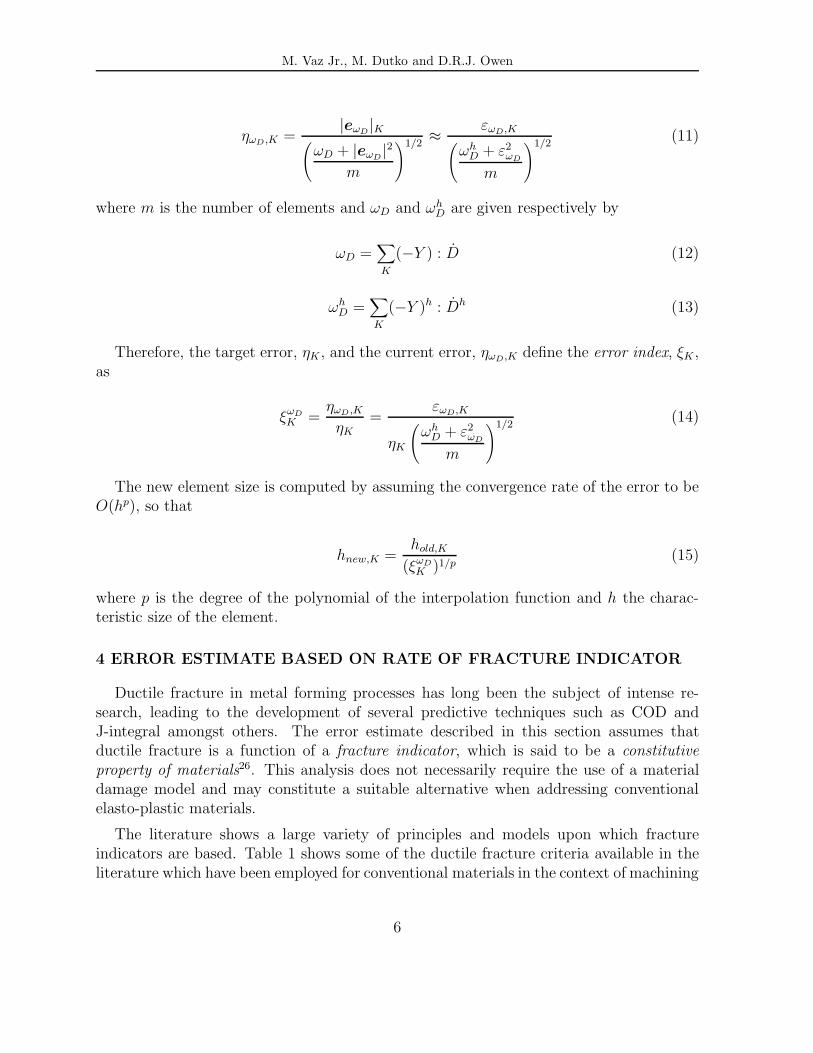
Therefore, the target error, ηK , and the current error, ηωD,K define the error index, ξK ,as
ξωDK =
ηωD ,K
ηK=
εωD,K
ηK
(ωh
D + ε2ωD
m
)1/2(14)
The new element size is computed by assuming the convergence rate of the error to beO(hp), so that
hnew,K =hold,K
(ξωDK )1/p
(15)
where p is the degree of the polynomial of the interpolation function and h the charac-teristic size of the element.
4 ERROR ESTIMATE BASED ON RATE OF FRACTURE INDICATOR
Ductile fracture in metal forming processes has long been the subject of intense re-search, leading to the development of several predictive techniques such as COD andJ-integral amongst others. The error estimate described in this section assumes thatductile fracture is a function of a fracture indicator, which is said to be a constitutiveproperty of materials26. This analysis does not necessarily require the use of a materialdamage model and may constitute a suitable alternative when addressing conventionalelasto-plastic materials.
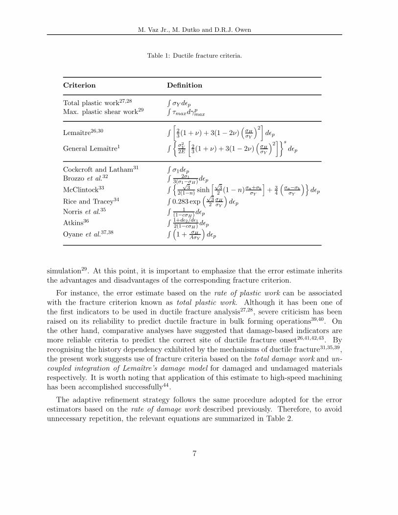
The literature shows a large variety of principles and models upon which fractureindicators are based. Table 1 shows some of the ductile fracture criteria available in theliterature which have been employed for conventional materials in the context of machining
6
M. Vaz Jr., M. Dutko and D.R.J. Owen
Table 1: Ductile fracture criteria.
Criterion Definition
Total plastic work27,28∫
σY dεp
Max. plastic shear work29∫
τmaxdγpmax
Lemaıtre26,30∫ [2
3 (1 + ν) + 3(1 − 2ν)(
σHσY
)2]dεp
General Lemaıtre1∫ σ2
Y2E
[23(1 + ν) + 3(1 − 2ν)
(σHσY
)2]s
dεp
Cockcroft and Latham31∫
σ1dεp
Brozzo et al.32∫ 2σ1
3(σ1−σH)dεp
McClintock33∫ √
32(1−n) sinh
[√3
2 (1 − n)σa+σbσY
]+ 3
4
(σa−σb
σY
)dεp
Rice and Tracey34∫
0.283 exp(√
32
σHσY
)dεp
Norris et al.35∫ 1
(1−cσH )dεp
Atkins36∫ 1+dε2/dε1
2(1−cσH ) dεp
Oyane et al.37,38∫ (
1 + σHAσY
)dεp
simulation29. At this point, it is important to emphasize that the error estimate inheritsthe advantages and disadvantages of the corresponding fracture criterion.
For instance, the error estimate based on the rate of plastic work can be associatedwith the fracture criterion known as total plastic work. Although it has been one ofthe first indicators to be used in ductile fracture analysis27,28, severe criticism has beenraised on its reliability to predict ductile fracture in bulk forming operations39,40. Onthe other hand, comparative analyses have suggested that damage-based indicators aremore reliable criteria to predict the correct site of ductile fracture onset26,41,42,43. Byrecognising the history dependency exhibited by the mechanisms of ductile fracture31,35,39,the present work suggests use of fracture criteria based on the total damage work and un-coupled integration of Lemaıtre’s damage model for damaged and undamaged materialsrespectively. It is worth noting that application of this estimate to high-speed machininghas been accomplished successfully44.
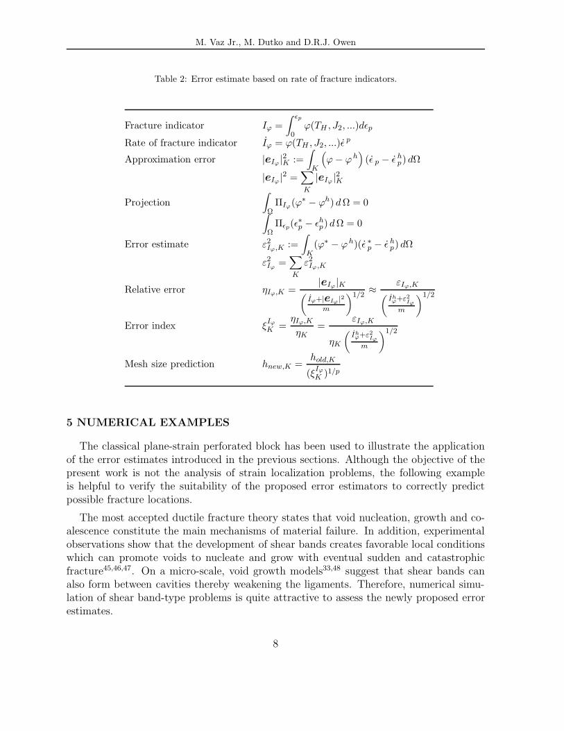
The adaptive refinement strategy follows the same procedure adopted for the errorestimators based on the rate of damage work described previously. Therefore, to avoidunnecessary repetition, the relevant equations are summarized in Table 2.
7
M. Vaz Jr., M. Dutko and D.R.J. Owen
Table 2: Error estimate based on rate of fracture indicators.
Fracture indicator Iϕ =∫ εp
0ϕ(TH , J2, ...)dεp
Rate of fracture indicator Iϕ = ϕ(TH , J2, ...)ε p
Approximation error |eIϕ |2K :=∫
K
(ϕ − ϕh
)(ε p − ε h
p) dΩ
|eIϕ |2 =∑K
|eIϕ |2K
Projection∫Ω
ΠIϕ(ϕ∗ − ϕh) dΩ = 0∫Ω
Πεp(ε∗p − εh
p) dΩ = 0
Error estimate ε2Iϕ,K :=
∫K
(ϕ∗ − ϕh)(ε ∗p − ε h
p) dΩ
ε2Iϕ
=∑K
ε2Iϕ,K
Relative error ηIϕ,K =|eIϕ|K(
Iϕ+|eIϕ |2m
)1/2≈ εIϕ,K(
Ihϕ+ε2
Iϕ
m
)1/2
Error index ξIϕ
K =ηIϕ,K
ηK=
εIϕ,K
ηK
(Ihϕ+ε2
Iϕ
m
)1/2
Mesh size prediction hnew,K =hold,K
(ξIϕ
K )1/p
5 NUMERICAL EXAMPLES
The classical plane-strain perforated block has been used to illustrate the applicationof the error estimates introduced in the previous sections. Although the objective of thepresent work is not the analysis of strain localization problems, the following exampleis helpful to verify the suitability of the proposed error estimators to correctly predictpossible fracture locations.
The most accepted ductile fracture theory states that void nucleation, growth and co-alescence constitute the main mechanisms of material failure. In addition, experimentalobservations show that the development of shear bands creates favorable local conditionswhich can promote voids to nucleate and grow with eventual sudden and catastrophicfracture45,46,47. On a micro-scale, void growth models33,48 suggest that shear bands canalso form between cavities thereby weakening the ligaments. Therefore, numerical simu-lation of shear band-type problems is quite attractive to assess the newly proposed errorestimates.
8

M. Vaz Jr., M. Dutko and D.R.J. Owen
Table 3: Material data and other simulation parameters.
Description Symbol Value
Specific mass ρ 7800 kg/m3
Specific heat c 483.3 J/kg kThermal conductivity k 48 J/kg m kYoung’s Modulus E 200.0 GPaPoisson’s ratio ν 0.3Yield stress TY 300.0 MPaDamage data r 4.0 MPa
s 1.0
Initial temperature T0 298 KPlastic dissipation factor ξp 0.85Coupling interval 10 time steps
Error checking 50 time stepsTarget error ηωp 1.5 %
ηωD3.0 %
ηIϕ 3.0 %Maximum element size hmax 1.0 mmMinimum element size hmin 0.1 mm
A first insight on the use of a posteriori error estimates in strain localization problemswas given by Zienkiewicz and Huang8 who, by using flow formulation and an error esti-mation based on the energy norm, presented solutions for compression of a rectangularspecimen with a central circular opening.
Ortiz and Quigley12 proposed the use of adaptive re-meshing based on the equi-distribution of the velocity field over the elements of the mesh. The authors observethat due to the loss, or nearly loss, of ellipcity of the governing equations at the pointof inception of localization, error estimates based on elliptic estimates become ineffective.Solutions were presented for J2 elasto-plasticity in rectangular specimens under tensileload and plane-strain compression of a sand specimen using a Drucker-Prager yield crite-rion with non-associated flow rule.
Further considerations have been made by Peric, Yu and Owen15, who adopted theCosserat continuum as a material description and proposed a posteriori error estimatesbased on the generalized stresses, dissipation functional and rate of plastic work. Theauthors concluded that the use of a Cosserat continuum associated with the new error
9

M. Vaz Jr., M. Dutko and D.R.J. Owen
estimates were able to capture efficiently strain localization in elasto-plastic solids. Exam-ples based on a rectangular strip under tensile loading were presented for both Cosseratcontinuum and conventional materials.
The following example aims to assess the error estimates based on rate of plastic work,rate of damage work and rate of fracturing indicator for damaged and undamaged mate-rials. An elastic-perfectly-plastic material15 combined with Lemaıtre’s24 isotropic damagemodel and a thermo-mechanical coupling strategy2 were used. The material data andother simulation parameters are shown in Table 3 whereas the problem geometry andinitial mesh are presented in Figure 1.
(a) Problem geometry (b) Initial mesh
10 mm
18 m
m
U
5 mm
Please Wait..
Figure 1: Perforated block.
The new temperature distribution is evaluated every 10 time steps whereas the errorsare computed and checked every 50 time steps. The maximum and minimum elementsize have been restricted to hmax = 1.0 mm and hmin = 0.1 mm respectively. The targeterrors, ηK , for each case have been chosen to provide meshes able to combine small numberof elements and yet able to capture shear localization.
10

M. Vaz Jr., M. Dutko and D.R.J. Owen
(a) Mesh (b) Equivalent plastic strain rate
Please Wait..
0.0
1943.9
1781.9
1619.9
1457.9
1295.9
1133.9
971.9
810.0
648.0
486.0
324.0
162.0
Please Wait..
Figure 2: Adaptive re-meshing using rate of plastic work for undamaged materials.
5.1 Rate of plastic work
Simulation of a similar problem using an error estimator based on rate of plastic workhas been recently reported by Owen et al.16 for large-strain elasto-plasticity, implicit timeintegration scheme and conventional materials. The present analysis provided the samedistribution pattern of mesh refinement found in Figures 8.3(b)-(d) of Reference [16]. Inboth cases, the adaptive procedure was able to capture shear band formation. However,the zone comprising small elements was found to be larger then those obtained by usingrate of damage work and rate of fracture indicator. The relative ”poorer” performancecould be attributed, not only to the low efficiency of the energy norm for strain localizationproblems, but also, and mainly, to the inefficiency inherited from the total plastic workas a fracture indicator.
Figure 2 shows the mesh and the distribution of equivalent plastic strain rate for U =0.5 mm. Although the re-meshing procedure has approximated the strain localizationzone reasonably well, it has produced a refined region substantially wider than the shearband itself. The choice of the target error was important in this case, since the elementdistribution over the new meshes has been particularly sensitive to it. Smaller values oftarget errors cause the number of elements to increase unnecessarily, even after no effecton the width of the shear band has been observed. Conversely, larger target errors will
11
M. Vaz Jr., M. Dutko and D.R.J. Owen
produce coarser meshes with consequent increase of the shear band width.
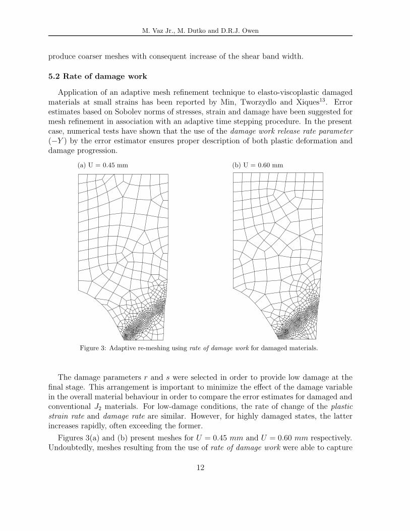
5.2 Rate of damage work
Application of an adaptive mesh refinement technique to elasto-viscoplastic damagedmaterials at small strains has been reported by Min, Tworzydlo and Xiques13. Errorestimates based on Sobolev norms of stresses, strain and damage have been suggested formesh refinement in association with an adaptive time stepping procedure. In the presentcase, numerical tests have shown that the use of the damage work release rate parameter(−Y ) by the error estimator ensures proper description of both plastic deformation anddamage progression.
(a) U = 0.45 mm (b) U = 0.60 mm
Please Wait.. Please Wait..
Figure 3: Adaptive re-meshing using rate of damage work for damaged materials.
The damage parameters r and s were selected in order to provide low damage at thefinal stage. This arrangement is important to minimize the effect of the damage variablein the overall material behaviour in order to compare the error estimates for damaged andconventional J2 materials. For low-damage conditions, the rate of change of the plasticstrain rate and damage rate are similar. However, for highly damaged states, the latterincreases rapidly, often exceeding the former.
Figures 3(a) and (b) present meshes for U = 0.45 mm and U = 0.60 mm respectively.Undoubtedly, meshes resulting from the use of rate of damage work were able to capture
12

M. Vaz Jr., M. Dutko and D.R.J. Owen
strain localization phenomena more accurately than the corresponding rate of plasticwork. The principal reason for the success lies in the capacity of damage-based fractureindicators, in special total damage work, to predict fracture onset.
(a) Damage variable (b) Damage rate
0.0039
0.0322
0.0298
0.0275
0.0251
0.0228
0.0204
0.0180
0.0157
0.0133
0.0109
0.0086
0.0063
Please Wait..
0.00
190.26
174.39
158.54
142.68
126.83
110.98
95.12
79.27
63.42
47.56
31.71
15.85
Please Wait..
Figure 4: Damaged material: damage variable and damage rate for U = 0.45 mm.
It is interesting to note that, even for low damage conditions, as illustrated in Figure4(a), and despite the fact that the damage rate is around ten times smaller than theequivalent plastic strain rate, this estimate exhibits good performance.
The temperature distribution, shown in Figure 5(a), has been computed using theadiabatic thermo-mechanical model described in Vaz Jr. and Owen2. The highest tem-peratures are found at the internal surface of the specimen over the X-X symmetry line,where the largest plastic deformation takes place.
The fracture criterion used in this simulation is based on the total damage work,
ID =∫ Dc
0(−Y )dD, (16)
whose distribution is shown in Figure 5(b). Although a low-damage material has beenused in this example, the fracture indicator, ID, not only points to the correct fractureonset site, but also predicts a high gradient near the critical zone.
13

M. Vaz Jr., M. Dutko and D.R.J. Owen
(a) Temperature (b) Fracture criterion
301.8
324.5
322.6
320.7
318.8
316.9
315.0
313.1
311.3
309.4
307.5
305.6
303.7
Please Wait..
0.12e+5
1.14e+5
1.05e+5
0.97e+5
0.89e+5
0.80e+5
0.72e+5
0.63e+5
0.55e+5
0.46e+5
0.37e+5
0.29e+5
0.20e+5
Please Wait..
Figure 5: Damaged material: temperature and fracture criterion for U = 0.45 mm.
5.3 Rate of fracture indicator
In general, fracture indicators based on void nucleation, growth and coalescence havebeen more reliable in predicting fracture onset due their dependency upon the hydrostaticstresses, included in the form of the relation TH/TY . The ductile fracture criterion basedon the uncoupled integration of Lemaıtre’s isotropic damage model has been selectedto illustrate the adaptive procedure using the rate of fracture indicator. The fractureindicator can be expressed as
Iϕ =∫ εp
0ϕ(TH , J2) dεp
=∫ εp
0
J2(T)2
2E
2
3(1 + ν) + 3(1 − 2ν)
(TH
J2(T)
)2
s
dεp
(17)
in which s = 1 is employed to make it compatible with the damage data adopted in theprevious case. The similarity between the expressions for the rate of damage work,
ωD =J2(T)2
2E(1 − D)2
2
3(1 + ν) + 3(1 − 2ν)
(TH
J2(T)
)2 D (18)
14
M. Vaz Jr., M. Dutko and D.R.J. Owen
(a) U = 0.45 mm (b) U = 0.60 mm
Please Wait.. Please Wait..
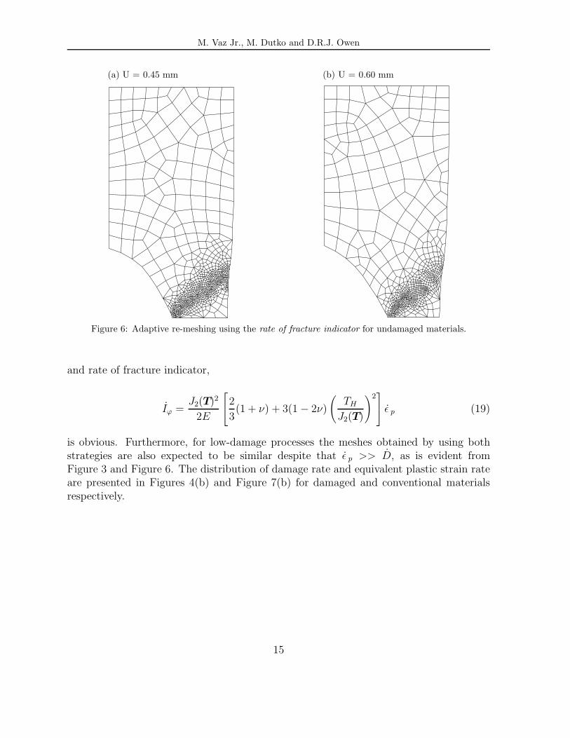
Figure 6: Adaptive re-meshing using the rate of fracture indicator for undamaged materials.
and rate of fracture indicator,
Iϕ =J2(T)2
2E
2
3(1 + ν) + 3(1 − 2ν)
(TH
J2(T)
)2 ε p (19)
is obvious. Furthermore, for low-damage processes the meshes obtained by using bothstrategies are also expected to be similar despite that ε p >> D, as is evident fromFigure 3 and Figure 6. The distribution of damage rate and equivalent plastic strain rateare presented in Figures 4(b) and Figure 7(b) for damaged and conventional materialsrespectively.
15

M. Vaz Jr., M. Dutko and D.R.J. Owen
(a) Equivalent plastic strain (b) Equivalent plastic strain rate
0.046
0.366
0.339
0.312
0.286
0.259
0.233
0.206
0.180
0.153
0.126
0.100
0.073
Please Wait..
0.0
2587.7
2372.0
2156.4
1940.8
1725.1
1509.5
1293.8
1078.2
862.5
646.9
431.3
215.6
Please Wait..
Figure 7: Undamaged material: equivalent plastic strain and equivalent plastic strain rate for U = 0.45mm.
6 CONCLUSIONS
Adaptive re-meshing has become an essential tool in the analysis of metal formingproblems. Additionally, situations involving large deformations and ductile fracture havealso been the focus of attention due to the wide range of practical applications. Onthe other hand, in recent years, several error estimates have been proposed for inelasticproblems based not only on mathematical aspects, but also on physical considerations.The present work focuses on the development of a posteriori error estimates for elasto-plastic problems accounting for aspects of ductile fracture.
Rate of damage work and rate of fracture indicators are suggested as error estimates fordamaged and conventional J2 elasto-plastic materials respectively. An example involvingplastic localization is presented and both estimates were able to capture the phenomenonefficiently.
References
[1] M. Vaz Jr. and D.R.J. Owen. Numerical simulation of metal cutting using ductilefracture concepts. In M. Crisfield, editor, Computational Mechanics in the U.K.,pages 56–59, Dept. of Aeronautics, Imperial College, London (1997).
16
M. Vaz Jr., M. Dutko and D.R.J. Owen
[2] M. Vaz Jr. and D.R.J. Owen. Thermo-mechanical coupling and large-scale elasto-plastic problems. In S. Basri, A.A.A. Samad, and A.M. Hamouda, editors, Appli-cation of Numerical Methods in Engineering, pages 377–388, UPM Press, Serdang,Malaysia (1997).
[3] M. Dutko, D. Peric, D.R.J. Owen, Z. Wei, and J. Yu. Bulk forming simulation byadaptive explicit FEM. In E. Onate, D.R.J. Owen and E. Hinton, editors, Compu-tational Plasticity: Theory and Applications, volume 2, pages 1305–1312, CIMNE,Barcelona (1997).
[4] I. Babuska and W.C. Rheinboldt. Error estimates for adaptive finite element com-putations. SIAM J. Numer. Anal., 15, 736–754 (15).
[5] I. Babuska and W.C. Rheinboldt. A posteriori error estimates for the finite elementmethod. Int. J. Num. Meth. Eng., 12, 1597–1615 (1978).
[6] O.C. Zienkiewicz and J.Z. Zhu. A simple error estimator and adaptive procedure forpractical engineering analysis. Int. J. Num. Meth. Eng., 24, 337–357 (1987).
[7] O.C. Zienkiewicz, Y.C. Liu, and G.C. Huang. Error estimation and adaptivity inflow formulation for forming problems. Int. J. Num. Meth. Eng., 25, 23–42 (1988).
[8] O.C. Zienkiewicz and G.C. Huang. A note on localization phenomena and adaptivefinite-element analysis in forming processes. Comm. Appl. Num. Meth., 6, 71–76(1990).
[9] O.C. Zienkiewicz, G.C. Huang, and Y.C. Liu. Adaptive FEM computation of formingprocess - application to porous and non-porous materials. Int. J. Num. Meth. Eng.,30, 1527–1553 (1990).
[10] L. Fourment and J.L. Chenot. Error estimators for viscoplastic materials: Applica-tion to forming processes. Engng. Comp., 12, 469–490 (1995).
[11] A. Moal and E. Massoni. Finite element simulation of the inertia welding of twosimilar parts. Engng. Comp., 12, 497–512 (1995).
[12] M. Ortiz and J.J. Quigley IV. Adaptive mesh refinement in strain localization pro-blems. Comp. Meth. Appl. Mech. Eng., 90, 781–804 (1991).
[13] J.B. Min, W.W. Tworzydlo, and K.E. Xiques. Adaptive finite element methods forcontinuum damage modeling. Comp. & Struc., 58, 887–900 (1995).
[14] C. Johnson and P. Hansbo. Adaptive finite element methods in computational me-chanics. Comp. Meth. Appl. Mech. Eng., 101, 143–181 (1992).
[15] D. Peric, . J. Yu, and D.R.J. Owen. On error estimates and adaptivity in elastoplasticsolids: Application to the numerical simulation of localization in classical and cosseratcontinua. Int. J. Num. Meth. Eng., 37, 1351–1379 (1994).
[16] D.R.J. Owen, D. Peric, A.J.L. Crook, E.A. de Souza Neto, J. Yu, and M. Dutko.Advanced computational strategies for 3-d large scale metal forming simulations. InNumerical Methods in Industrial Forming Processes, New York (1995).
[17] T.D. Marusich and M. Ortiz. Modelling and simulation of high-speed machining.Int. J. Num. Meth. Eng., 38, 3675–3694 (1995).
[18] N.S. Lee and K.J. Bathe. Error indicators and adaptive remeshing in large deforma-
17
M. Vaz Jr., M. Dutko and D.R.J. Owen
tion finite element analysis. Finite Elem. Anal. Des., 16, 99–139 (1994).[19] L.Y. Li, P. Bettess, I. Applegarth, J.W. Bull, and T.J. Bond. A new mesh refinement
formulation for h-adaptative finite element computations. In E. Onate, D.R.J. Owenand E. Hinton, editors, Computational Plasticity: Theory and Applications, volume 1,pages 444–454, Pineridge Press, Swansea (1995).
[20] L. Gallimard, P. Ladeveze, and J.P. Pelle. A posteriori error estimator for non-linearF.E. computations: application to elastoplasticity. In D.R.J. Owen and E. Onate,editors, Computational Plasticity - Fundamentals and Applications, pages 373–382,Pineridge Press, Swansea (1995).
[21] L. Gallimard, P. Ladeveze, and J.P. Pelle. Error estimation and adaptivity in elasto-plasticity. Int. J. Num. Meth. Eng., 39, 189–217 (1996).
[22] L. Gallimard, P. Ladeveze, and J.P. Pelle. Drucker-type a posteriori error estimatorfor elastoplasticity and viscoplasticity finite element computation and an associatedadaptivity procedure. In E. Onate, D.R.J. Owen and E. Hinton, editors, Com-putational Plasticity: Theory and Applications, volume 1, pages 603–610, CIMNE,Barcelona (1997).
[23] F.-J. Barthold, M. Schmidt, and E. Stein. Error estimation mesh adaptivity forelasto-plastic deformations. In E. Onate, D.R.J. Owen and E. Hinton, editors, Com-putational Plasticity: Theory and Applications, volume 1, pages 597–602, CIMNE,Barcelona (1997).
[24] J. Lemaıtre. Coupled elasto-plasticity and damage constitutive equations. Comp.Meth. Appl. Mech. Eng., 51, 31–49 (1985).
[25] J. Lemaıtre. How to use damage mechanics. Nuclear Engng. Design, 80, 233–245(1984).
[26] W. Tai and B.X. Yang. A new damage mechanics criterion for ductile fracture.Engng. Frac. Mech., 27, 371–378 (1987).
[27] A.M. Freudenthal. The inelastic behaviour of engineering materials and structures.John Wiley & Sons, New York (1950).
[28] L.F. Gillemot. Criterion of crack initiation and spreading. Engng. Frac. Mech., 8,239–253 (1976).
[29] M. Vaz Jr. and D.R.J. Owen. Ductile fracture and mechanisms of chip formation inorthogonal machining. Technical Report CR/961/97, University of Wales, Swansea,Department of Civil Engineering, Swansea (1997).
[30] J. Lemaıtre. A continuous damage mechanics model for ductile fracture. J. Engng.Mat. Tech., Trans. ASME, 107, 83–89 (1985).
[31] M.G. Cockcroft and D.J. Latham. Ductility and workability of metals. J. Inst.Metals, 96, 33–39 (1968).
[32] P. Brozzo, B. Deluca, and R.A. Rendina. A new method for the prediction of theformability limits of metal sheets. In Proc. 7th Biennial Conf. Int. Deep DrawingResearch Group (1972).
[33] F.A. McClintock. A criterion for ductile fracture by growth of holes. J. Appl. Mech.,
18

M. Vaz Jr., M. Dutko and D.R.J. Owen
35, 363–371 (1968).[34] J.R. Rice and D.M. Tracey. On the ductile enlargement of voids in triaxial stress
fields. J. Mech. Phys. Solids, 17, 201–217 (1969).[35] D.M. Norris, J.E. Reaugh, B. Moran, and D.F. Quinones. A plastic-strain, mean-
stress criterion for ductile fracture. J. Engng. Mat. Tech., Trans. ASME, 100, 279–286 (1978).
[36] A.G. Atkins. Possible explanation for unexpected departures in hydrostatic tension-fracture strain relations. Metal Sci., 15, 81–83 (1981).
[37] M. Oyane, S. Shima, and T. Tabata. Considerations of basic equations, and theirapplication in the forming of metal powders and porous metals. J. Mech. Work.Tech., 1, 325–341 (1978).
[38] M. Oyane, T. Sato, K. Okimoto, and S. Shima. Criteria for ductile fracture and theirapplications. J. Mech. Work. Tech., 4, 65–81 (1980).
[39] A.G. Atkins and Y-W. Mai. Elastic and plastic fracture. Ellis Horwood Ltd., Chich-ester (1985).
[40] B.P.P.A. Gouveia, J.M.C. Rodrigues, and P.A.F. Martins. Fracture predicting inbulk metal forming. Int. J. Mech. Sci., 38, 361–372 (1996).
[41] Y.Y. Zhu, S. Cescotto, and A-M. Habraken. A fully coupled elastoplastic damagemodeling and fracture criteria in metalforming process. J. Mat. Proc. Tech., 32,197–204 (1992).
[42] S. Cescotto and Y.Y. Zhu. Modelling of ductile fracture initiation during bulk form-ing. In D.R.J. Owen and E. Onate, editors, Computational Plasticity - Fundamentalsand Applications, pages 987–998, Pineridge Press, Swansea (1995).
[43] A. Benallal, R. Billardon, and I. Doghri. Numerical aspects of the damage and failureanalysis of engineering structures. In E. Hinton, D.R.J. Owen and E. Onate, editors,Computational Plasticity: Models Software and Applications, volume 1, pages 297–309, Pineridge Press, Swansea (1989).
[44] M. Vaz Jr., D.R.J. Owen, and D. Peric. Finite element techniques applied to high-speed machining (submitted to the 6th International Conference on Numerical Me-thods in Industrial Forming Processes).
[45] B. Dodd and Y. Bai. Ductile fracture and ductility. Academic Press, London (1987).[46] Y. Bai and B. Dodd. Adiabatic shear localization. Pergamon Press, Oxford (1992).[47] Y. Bai, Q. Xue, Y. Xu, and Shen. L. Characteristics and microstructure in the
evolution of shear localization in Ti-6Al-4V alloy. Mech. Materials, 17, 155–164(1994).
[48] F.A. McClintock, S.M. Kaplan, and C.A. Berg. Ductile fracture by hole growth inshear bands. Int. J. Frac. Mech., 2, 614–627 (1966).
19