
A Quantitative Weld Sizing Criterion for Welded Connections ...
Upload
khangminh22Category
view
1download
0
SVM151-AJuly, 2000
Safety Depends on You
Lincoln arc welding and cuttingequipment is designed and builtwith safety in mind. However, your overall safety can be in-creased by proper installation . . .and thoughtful operation on your part. DO NOT INSTALL,OPERATE OR REPAIR THISEQUIPMENT WITHOUT READING THIS MANUAL ANDTHE SAFETY PRECAUTIONSCONTAINED THROUGHOUT.And, most importantly, think before you act and be careful.
SERVICE MANUAL
For use with machines having Code Numbers: 1064510736
Multi-Weld 350 Arc ConverterTM
• Sales and Service through Subsidiaries and Distributors Worldwide •
Cleveland, Ohio 44117-1199 U.S.A. TEL: 216.481.8100 FAX: 216.486.1751 WEB SITE: www.lincolnelectric.com
• World's Leader in Welding and Cutting Products •
Copyright © 2000 Lincoln Global Inc.

i iSAFETY
FOR ENGINEpowered equipment.
1.a. Turn the engine off before troubleshooting and maintenancework unless the maintenance work requires it to be running.
____________________________________________________1.b.Operate engines in open, well-ventilated
areas or vent the engine exhaust fumes outdoors.
____________________________________________________1.c. Do not add the fuel near an open flame weld-
ing arc or when the engine is running. Stopthe engine and allow it to cool before refuel-ing to prevent spilled fuel from vaporizing oncontact with hot engine parts and igniting. Donot spill fuel when filling tank. If fuel is spilled,wipe it up and do not start engine until fumeshave been eliminated.
____________________________________________________1.d. Keep all equipment safety guards, covers
and devices in position and in goodrepair.Keep hands, hair, clothing and toolsaway from V-belts, gears, fans and all othermoving parts when starting, operating orrepairing equipment.
____________________________________________________
1.e. In some cases it may be necessary to remove safetyguards to perform required maintenance. Removeguards only when necessary and replace them when themaintenance requiring their removal is complete.Always use the greatest care when working near movingparts.
___________________________________________________1.f. Do not put your hands near the engine fan. Do not attempt to
override the governor or idler by pushing on the throttle con-trol rods while the engine is running.
___________________________________________________1.g. To prevent accidentally starting gasoline engines while
turning the engine or welding generator during maintenancework, disconnect the spark plug wires, distributor cap ormagneto wire as appropriate.
ARC WELDING can be hazardous. PROTECT YOURSELF AND OTHERS FROM POSSIBLE SERIOUS INJURY OR DEATH.KEEP CHILDREN AWAY. PACEMAKER WEARERS SHOULD CONSULT WITH THEIR DOCTOR BEFORE OPERATING.
Read and understand the following safety highlights. For additional safety information, it is strongly recommended that youpurchase a copy of “Safety in Welding & Cutting - ANSI Standard Z49.1” from the American Welding Society, P.O. Box 351040,Miami, Florida 33135 or CSA Standard W117.2-1974. A Free copy of “Arc Welding Safety” booklet E205 is available from theLincoln Electric Company, 22801 St. Clair Avenue, Cleveland, Ohio 44117-1199.
BE SURE THAT ALL INSTALLATION, OPERATION, MAINTENANCE AND REPAIR PROCEDURES AREPERFORMED ONLY BY QUALIFIED INDIVIDUALS.
WARNING
Mar ‘95
ELECTRIC AND MAGNETIC FIELDSmay be dangerous
2.a. Electric current flowing through any conductor causes localized Electric and Magnetic Fields (EMF). Welding current creates EMF fields around welding cables and welding machines
2.b. EMF fields may interfere with some pacemakers, andwelders having a pacemaker should consult their physicianbefore welding.
2.c. Exposure to EMF fields in welding may have other healtheffects which are now not known.
2.d. All welders should use the following procedures in order tominimize exposure to EMF fields from the welding circuit:
2.d.1. Route the electrode and work cables together - Securethem with tape when possible.
2.d.2. Never coil the electrode lead around your body.
2.d.3. Do not place your body between the electrode andwork cables. If the electrode cable is on your right side, the work cable should also be on your right side.
2.d.4. Connect the work cable to the workpiece as close aspossible to the area being welded.
2.d.5. Do not work next to welding power source.
1.h. To avoid scalding, do not remove theradiator pressure cap when the engine ishot.
CALIFORNIA PROPOSITION 65 WARNINGS
Diesel engine exhaust and some of its constituentsare known to the State of California to cause can-cer, birth defects, and other reproductive harm.
The engine exhaust from this product containschemicals known to the State of California to causecancer, birth defects, or other reproductive harm.
The Above For Diesel Engines The Above For Gasoline Engines

ii iiSAFETY
ARC RAYS can burn.4.a. Use a shield with the proper filter and cover
plates to protect your eyes from sparks andthe rays of the arc when welding or observingopen arc welding. Headshield and filter lensshould conform to ANSI Z87. I standards.
4.b. Use suitable clothing made from durable flame-resistantmaterial to protect your skin and that of your helpers fromthe arc rays.
4.c. Protect other nearby personnel with suitable, non-flammablescreening and/or warn them not to watch the arc nor exposethemselves to the arc rays or to hot spatter or metal.
ELECTRIC SHOCK can kill.3.a. The electrode and work (or ground) circuits
are electrically “hot” when the welder is on.Do not touch these “hot” parts with your bareskin or wet clothing. Wear dry, hole-freegloves to insulate hands.
3.b. Insulate yourself from work and ground using dry insulation.Make certain the insulation is large enough to cover your fullarea of physical contact with work and ground.
In addition to the normal safety precautions, if weldingmust be performed under electrically hazardousconditions (in damp locations or while wearing wetclothing; on metal structures such as floors, gratings orscaffolds; when in cramped positions such as sitting,kneeling or lying, if there is a high risk of unavoidable oraccidental contact with the workpiece or ground) usethe following equipment:
• Semiautomatic DC Constant Voltage (Wire) Welder.• DC Manual (Stick) Welder.• AC Welder with Reduced Voltage Control.
3.c. In semiautomatic or automatic wire welding, the electrode,electrode reel, welding head, nozzle or semiautomaticwelding gun are also electrically “hot”.
3.d. Always be sure the work cable makes a good electricalconnection with the metal being welded. The connectionshould be as close as possible to the area being welded.
3.e. Ground the work or metal to be welded to a good electrical(earth) ground.
3.f. Maintain the electrode holder, work clamp, welding cable andwelding machine in good, safe operating condition. Replacedamaged insulation.
3.g. Never dip the electrode in water for cooling.
3.h. Never simultaneously touch electrically “hot” parts ofelectrode holders connected to two welders because voltagebetween the two can be the total of the open circuit voltageof both welders.
3.i. When working above floor level, use a safety belt to protectyourself from a fall should you get a shock.
3.j. Also see Items 6.c. and 8.
FUMES AND GASEScan be dangerous.5.a. Welding may produce fumes and gases
hazardous to health. Avoid breathing thesefumes and gases.When welding, keepyour head out of the fume. Use enoughventilation and/or exhaust at the arc to keep
fumes and gases away from the breathing zone. Whenwelding with electrodes which require specialventilation such as stainless or hard facing (seeinstructions on container or MSDS) or on lead orcadmium plated steel and other metals or coatingswhich produce highly toxic fumes, keep exposure aslow as possible and below Threshold Limit Values (TLV)using local exhaust or mechanical ventilation. Inconfined spaces or in some circumstances, outdoors, arespirator may be required. Additional precautions arealso required when welding on galvanized steel.
5.b. Do not weld in locations near chlorinated hydrocarbon vaporscoming from degreasing, cleaning or spraying operations.The heat and rays of the arc can react with solvent vapors toform phosgene, a highly toxic gas, and other irritating products.
5.c. Shielding gases used for arc welding can displace air andcause injury or death. Always use enough ventilation,especially in confined areas, to insure breathing air is safe.
5.d. Read and understand the manufacturer’s instructions for thisequipment and the consumables to be used, including thematerial safety data sheet (MSDS) and follow youremployer’s safety practices. MSDS forms are available fromyour welding distributor or from the manufacturer.
5.e. Also see item 1.b. Mar ‘95

iii iiiSAFETY
FOR ELECTRICALLYpowered equipment.
8.a. Turn off input power using the disconnectswitch at the fuse box before working onthe equipment.
8.b. Install equipment in accordance with the U.S. NationalElectrical Code, all local codes and the manufacturer’srecommendations.
8.c. Ground the equipment in accordance with the U.S. NationalElectrical Code and the manufacturer’s recommendations.
CYLINDER may explodeif damaged.7.a. Use only compressed gas cylinders
containing the correct shielding gas for theprocess used and properly operatingregulators designed for the gas and
pressure used. All hoses, fittings, etc. should be suitable forthe application and maintained in good condition.
7.b. Always keep cylinders in an upright position securelychained to an undercarriage or fixed support.
7.c. Cylinders should be located:• Away from areas where they may be struck or subjected tophysical damage.
• A safe distance from arc welding or cutting operations andany other source of heat, sparks, or flame.
7.d. Never allow the electrode, electrode holder or any otherelectrically “hot” parts to touch a cylinder.
7.e. Keep your head and face away from the cylinder valve outletwhen opening the cylinder valve.
7.f. Valve protection caps should always be in place and handtight except when the cylinder is in use or connected foruse.
7.g. Read and follow the instructions on compressed gascylinders, associated equipment, and CGA publication P-l,“Precautions for Safe Handling of Compressed Gases inCylinders,” available from the Compressed Gas Association1235 Jefferson Davis Highway, Arlington, VA 22202.
Mar ‘95
WELDING SPARKS cancause fire or explosion.6.a. Remove fire hazards from the welding area.
If this is not possible, cover them to preventthe welding sparks from starting a fire.Remember that welding sparks and hot
materials from welding can easily go through small cracksand openings to adjacent areas. Avoid welding nearhydraulic lines. Have a fire extinguisher readily available.
6.b. Where compressed gases are to be used at the job site,special precautions should be used to prevent hazardoussituations. Refer to “Safety in Welding and Cutting” (ANSIStandard Z49.1) and the operating information for theequipment being used.
6.c. When not welding, make certain no part of the electrodecircuit is touching the work or ground. Accidental contact cancause overheating and create a fire hazard.
6.d. Do not heat, cut or weld tanks, drums or containers until theproper steps have been taken to insure that such procedureswill not cause flammable or toxic vapors from substancesinside. They can cause an explosion even though they havebeen “cleaned”. For information, purchase “RecommendedSafe Practices for the Preparation for Welding and Cutting ofContainers and Piping That Have Held HazardousSubstances”, AWS F4.1 from the American Welding Society(see address above).
6.e. Vent hollow castings or containers before heating, cutting orwelding. They may explode.
6.f. Sparks and spatter are thrown from the welding arc. Wear oilfree protective garments such as leather gloves, heavy shirt,cuffless trousers, high shoes and a cap over your hair. Wearear plugs when welding out of position or in confined places.Always wear safety glasses with side shields when in awelding area.
6.g. Connect the work cable to the work as close to the weldingarea as practical. Work cables connected to the buildingframework or other locations away from the welding areaincrease the possibility of the welding current passingthrough lifting chains, crane cables or other alternate circuits.This can create fire hazards or overheat lifting chains orcables until they fail.
6.h. Also see item 1.c.

iv ivSAFETY
PRÉCAUTIONS DE SÛRETÉPour votre propre protection lire et observer toutes les instructionset les précautions de sûreté specifiques qui parraissent dans cemanuel aussi bien que les précautions de sûreté générales suiv-antes:
Sûreté Pour Soudage A L’Arc1. Protegez-vous contre la secousse électrique:
a. Les circuits à l’électrode et à la piéce sont sous tensionquand la machine à souder est en marche. Eviter toujourstout contact entre les parties sous tension et la peau nueou les vétements mouillés. Porter des gants secs et sanstrous pour isoler les mains.
b. Faire trés attention de bien s’isoler de la masse quand onsoude dans des endroits humides, ou sur un planchermetallique ou des grilles metalliques, principalement dans
les positions assis ou couché pour lesquelles unegrande partie du corps peut être en contact avec lamasse.
c. Maintenir le porte-électrode, la pince de masse, le câblede soudage et la machine à souder en bon et sûr étatdefonctionnement.
d. Ne jamais plonger le porte-électrode dans l’eau pour lerefroidir.
e. Ne jamais toucher simultanément les parties sous tensiondes porte-électrodes connectés à deux machines à soud-er parce que la tension entre les deux pinces peut être letotal de la tension à vide des deux machines.
f. Si on utilise la machine à souder comme une source decourant pour soudage semi-automatique, ces precautionspour le porte-électrode s’applicuent aussi au pistolet desoudage.
2. Dans le cas de travail au dessus du niveau du sol, se pro-téger contre les chutes dans le cas ou on recoit un choc. Nejamais enrouler le câble-électrode autour de n’importe quellepartie du corps.
3. Un coup d’arc peut être plus sévère qu’un coup de soliel,donc:
a. Utiliser un bon masque avec un verre filtrant appropriéainsi qu’un verre blanc afin de se protéger les yeux durayonnement de l’arc et des projections quand on soudeou quand on regarde l’arc.
b. Porter des vêtements convenables afin de protéger lapeau de soudeur et des aides contre le rayonnement del‘arc.
c. Protéger l’autre personnel travaillant à proximité ausoudage à l’aide d’écrans appropriés et non-inflamma-bles.
4. Des gouttes de laitier en fusion sont émises de l’arc desoudage. Se protéger avec des vêtements de protectionlibres de l’huile, tels que les gants en cuir, chemise épaisse,pantalons sans revers, et chaussures montantes.
5. Toujours porter des lunettes de sécurité dans la zone desoudage. Utiliser des lunettes avec écrans lateraux dans leszones où l’on pique le laitier.
6. Eloigner les matériaux inflammables ou les recouvrir afin deprévenir tout risque d’incendie dû aux étincelles.
7. Quand on ne soude pas, poser la pince à une endroit isoléde la masse. Un court-circuit accidental peut provoquer unéchauffement et un risque d’incendie.
8. S’assurer que la masse est connectée le plus prés possiblede la zone de travail qu’il est pratique de le faire. Si on placela masse sur la charpente de la construction ou d’autresendroits éloignés de la zone de travail, on augmente le risquede voir passer le courant de soudage par les chaines de lev-age, câbles de grue, ou autres circuits. Cela peut provoquerdes risques d’incendie ou d’echauffement des chaines et descâbles jusqu’à ce qu’ils se rompent.
9. Assurer une ventilation suffisante dans la zone de soudage.Ceci est particuliérement important pour le soudage de tôlesgalvanisées plombées, ou cadmiées ou tout autre métal quiproduit des fumeés toxiques.
10. Ne pas souder en présence de vapeurs de chlore provenantd’opérations de dégraissage, nettoyage ou pistolage. Lachaleur ou les rayons de l’arc peuvent réagir avec lesvapeurs du solvant pour produire du phosgéne (gas forte-ment toxique) ou autres produits irritants.
11. Pour obtenir de plus amples renseignements sur la sûreté,voir le code “Code for safety in welding and cutting” CSAStandard W 117.2-1974.
PRÉCAUTIONS DE SÛRETÉ POURLES MACHINES À SOUDER ÀTRANSFORMATEUR ET ÀREDRESSEUR
1. Relier à la terre le chassis du poste conformement au code
de l’électricité et aux recommendations du fabricant. Le dis-
positif de montage ou la piece à souder doit être branché à
une bonne mise à la terre.
2. Autant que possible, I’installation et l’entretien du posteseront effectués par un électricien qualifié.
3. Avant de faires des travaux à l’interieur de poste, ladebrancher à l’interrupteur à la boite de fusibles.
4. Garder tous les couvercles et dispositifs de sûreté à leurplace.
Mar. ‘93

v v- MASTER TABLE OF CONTENTS FOR ALL SECTIONS -
MULTI-WELD 350
PageSafety .................................................................................................................................................i-iv
Installation .............................................................................................................................Section A
Operation...............................................................................................................................Section B
Accessories ..........................................................................................................................Section C
Maintenance ..........................................................................................................................Section D
Theory of Operation .............................................................................................................Section E
Troubleshooting and Repair ................................................................................................Section F
Electrical Diagrams ..............................................................................................................Section G
Parts Manual......................................................................................................................P361 Series

Installation.............................................................................................................................Section A
Technical Specifications ..............................................................................................................A-2
Safety Precautions ......................................................................................................................A-3
Quick-Connect “Pig-Tails” ...........................................................................................................A-3
Attachment and Arrangement of “Pig-Tails” ................................................................................A-3
Work Connection.........................................................................................................................A-4
Case Grounding ..........................................................................................................................A-4
Inter-Connection of Converters ...................................................................................................A-4
Power Source Setup ...................................................................................................................A-6
Section A-1 Section A-1TABLE OF CONTENTS
- INSTALLATION SECTION -
MULTI-WELD 350

A-2 A-2INSTALLATION
MULTI-WELD 350
ELECTRICAL SPECIFICATIONS
Amps (DC+) Volts (DC+)
Output Rating @ 50°C (122°F) 350 34
Input Rating @ 50°C (122°F) 165 80
Max. Input Range 50-113 (Peak)
Max. O.C.V. 78
Output Preset Range 30-350 15-40
PHYSICAL DIMENSIONS
Height Width Depth Net Weight
11.6 in. 10.0 in. 21.5 in. 59.5 lbs.
295 mm 254 mm 546 mm 27.0 kg.
TEMPERATURE RANGES
Operating Temperature Range Storage Temperature Range
-40 to +122°F -40 to +185°F
-20 to +50°C -40 to +85°C
TECHNICAL SPECIFICATIONS - MULTI-WELD 350 (K1735-1)

Read this entire installation section before youstart installation.
SAFETY PRECAUTIONS
ELECTRIC SHOCK can kill.
• Do not touch electrically liveparts or electrodes with yourskin or wet clothing.
• Insulate yourself from thework and ground.
• Always wear dry insulatinggloves.
Only qualified personnel should install, use, or ser-vice this equipment.
QUICK-CONNECT “PIG-TAILS”The Multi-Weld 350 is factory provided with two 21in.(53 cm) long 2/0 AWG (70 mm2) “pig-tail” cables.Their 0.5" (13 mm) hole lug ends are routed throughthe “INPUT +” (on back) and “ELECTRODE +” (onfront) cable channels of the Converter. They areattached to the bottom-accessed covered cable con-nection studs.
Attach the preferred standard, user-provided Quick-connect terminal (such as Lincoln Twist-Mate or Tweco2-MPC type) to the cut-off end of these cables. Use thefemale connector on the “ELECTRODE +” cable andthe male connector on the “INPUT +” cable.
ATTACHMENT ANDARRANGEMENT OF “PIG-TAILS”To best suit the desired inter-connection of theConverters, the “pig-tail” cables may be routed into thefront or back cable channels. For single or double “pig-tail” cables, route through the bottom-accessed cov-ered cable connection studs. (See Figures A.1 and B.1.)
To connect the “pig-tail” cables to the Converter:
1. Stand the Converter vertically on its rear handleand skid to gain access to the bottom stud covers.Then remove the two 0.25"(6.3 mm) screws secur-ing each cover and fold out the cover insulation.
2. Route the appropriate “pig-tail” cable lug endsunder the skid rail (for strain-relief) through thedesired front and/or rear corner channels to theexposed 0.5" (13 mm) stud. Remove the flangenut with a .75" (19 mm) wrench.
NOTE: Input supply cable(s) must connect through“INPUT +” labeled channels, and output weld cable(s)must connect through “ELECTRODE +” labeled channels.
3. Slip the “pig-tail” cable lug(s) over the stud and re-secure the flange nut. Make sure that the lug(s) donot touch any sheetmetal of the stud housing. Foldback the cover insulation and replace the studcover.
A-3 A-3INSTALLATION
MULTI-WELD 350
WARNING
BOTTOM VIEW
TO ELECT.
TO ELECT.
TO WORK
TO POWERSOURCE
TO POWERSOURCE
+INPUT
+ELECTRODE
ELECT.+
ELECT.++
IN
+IN
FIGURE A.1 – PIG-TAIL CONNECTIONS

Be sure to follow the safety practice touse the female connector on the cablewhich would normally be electrically "hot"(supply lead) if disconnected when thesystem is energized, and the male on the
normally “cold” (load lead) side. If practical, shut offpower before connecting or disconnecting terminals.
WORK CONNECTIONEach Converter in the Multi-Weld system must have itsindividual “Work” lead connected (clipped) to the work.The #3 AWG (27 mm2) Work clip lead must have cleanmetal connection to the work to complete the DC inputsupply and output power circuits of the Multi-Weld 350.
Do not disconnect the Work clip lead without firstswitching OFF the Converter panel switch. Failure todo so will allow the Work lead clip to be electrically “hot”to work and “hot” to the electrode, through the circuit ofthe Converter, for about 5 seconds until the input con-tactor opens.
CASE GROUNDINGAs shipped, the case of the Multi-Weld 350 is isolatedfrom all of the DC input and output welding terminals.It is equipped with a grounding terminal screw(.31” / 7.9 mm) marked with the symbol located onthe bottom rear of the base assembly. (Refer to the bot-tom view figure.) In order to comply with CSA and ULcase grounding specifications, this terminal is providedfor connection to weldment work that must be properlygrounded per methods meeting local and national elec-trical codes. Refer to “Safety in Welding, Cutting andAllied Processes,” ANSI Z49.1 (US) and W117.2(Canada).
Since any case fault would only involve the DC weldingcircuit, the size of the grounding lead should have thecapacity to ground the potential fault current withoutburning open. Use at least #6 AWG (13 mm2), but neednot exceed the size of the input cable supplying theMulti-Weld 350.
Connect the Multi-Weld grounding lead to the workpiece separately from the Work clip. If the same clip isused for both ground and work connection, the Multi-Weld case will be electrically “hot” to the work if the clipis removed without first switching OFF the panelswitch. ( Refer to the Work clip WARNING).
INTER-CONNECTION OF CONVERTERSThe input and electrode cables of the Multi-Weld 350Converters may be inter-connected in a Multi-Weldsystem using any combination of Distribution Box(es)(see Figure B.1), paralleling (CC mode only) and“daisy-chaining” (see Figure A.2). Choose the config-uration that best fits the field application setup withinthe capacity of the power source supplying the system.
Power Source (Volts x Amp) capacity > 1.1 xSum of Converters’ (Volts x Amps) arcs
Paralelled units may be powered from more than onesource. Disconnect all inputs, including outputs fromother sources, before working on the equipment.Before removing the parallel jumper, be sure bothConverters are switched OFF. If not, the male side ofthe first disconnection will be electrically “hot” to work.
A-4 A-4INSTALLATION
MULTI-WELD 350
WARNING
WARNING
WARNING

A-5 A-5INSTALLATION
MULTI-WELD 350
DAISY CHAIN OPERATION
FIXED PARALLEL OPERATION
TO WORK
TO POWERSOURCE
TO WORK
TO ELECT.
TO POWERSOURCE
TO WORK
TO ELECT.
TO WORK
TO ELECT.
SEPARABLE PARALLEL OPERATION
TO WORK
TO WORK
TO POWERSOURCE
TO POWERSOURCE
TO WORK
TO ELECT.
TO ELECT.
PARALLELJUMPER
+IN
+IN
ELECT.+
+IN
+IN
ELECT.+
+IN
+IN
ELECT.+
+IN
ELECT.+
+IN
+IN
ELECT.+
ELECT.+
ELECT.+
ELECT.+
FIGURE A.2 – INTER-CONNECTING CONVERTERS

For Converters (operating at rated output) less than200 ft. (61 m) from the power source, the following min-imum cable sizes are recommended for the indicatedquantity of Converters supplied by the input cable runto keep cable temperature and voltage drop withinacceptable limits:
Converters Cable Sizeon Cable AWG (mm2 )
1 1/0 (50)
2 2/0 (70)
3 3/0 (95)
4 4/0 (120)
5 2x3/0 (2x95)
The output “Electrode” cable should be 2/0 AWG (70 mm2) if sized for rated output up to 200 ft.(61 m)from the Converter. If paralleled, the output cable to thearc should be 4/0 (120 mm2).
Do not disconnect the Work clip lead without firstswitching OFF the Converter panel switch. Failure todo so will allow the Work lead clip to be electrically “hot”to work and “hot” to the electrode, through the circuit ofthe Converter, for about 5 seconds until the input con-tactor opens.
POWER SOURCE SETUPRefer to the Instruction Manual provided with the Multi-Source power source, or other DC power source beingused, for input power supply connections, output con-nections and controls setup.
In general:
1. Connect the positive (+) output connection terminalto the input supplying the Multi-Weld system andthe negative (-) output connection terminal to thework. (See Figure A.1.)
2. If not using a Multi-Source power source:
a. If an inductance control, or tap, is selectable,use lowest inductance.
b. Use CC (Constant Current) mode for maximumsupply voltage.
c. Set panel output control to maximum for maxi-mum current capacity.
d. Activate output with the “output terminals on”switch, or jumper (2-4 on Lincoln Electric termi-nal strips).
A-6 A-6INSTALLATION
MULTI-WELD 350
WARNING

Operation...............................................................................................................................Section B
Safety Instructions.......................................................................................................................B-2
Product Description.....................................................................................................................B-3
Recommended Equipment and Processes.................................................................................B-4
Multi-System Power Source .................................................................................................B-4
Distribution Box.....................................................................................................................B-4
“Pig-Tail” Leads and Connectors ..........................................................................................B-4
Remote Output Control Options ...........................................................................................B-5
CV Mode Wire Welding ........................................................................................................B-5
CC Mode Stick Welding and Gouging..................................................................................B-5
Front Panel Controls ...................................................................................................................B-6
Recessed Panel Controls............................................................................................................B-7
Paralleled Converters..................................................................................................................B-8
Remote Control of Paralleled Converters ...................................................................................B-8
Transporting and Storage of the Multi-Weld 350 ........................................................................B-8
Cable Handling .....................................................................................................................B-8
Transporting..........................................................................................................................B-9
Storage .................................................................................................................................B-9
Protection Features.....................................................................................................................B-9
Fan as Needed (F.A.N.)........................................................................................................B-9
Over-Voltage Protection........................................................................................................B-9
Over-Current Protection........................................................................................................B-9
Over-Temperature Shutdown................................................................................................B-9
Section B-1 Section B-1TABLE OF CONTENTS
- OPERATION SECTION -
MULTI-WELD 350

OPERATING INSTRUCTIONSRead and understand this entire section of operatinginstructions before operating the machine.
SAFETY INSTRUCTIONS
ELECTRIC SHOCK can kill.
• Do not touch electrically live parts orelectrodes with your skin or wet clothing.
• Insulate yourself from the work andground.
• Always wear dry insulating gloves.
FUMES AND GASES CAN BEDANGEROUS.
• Keep your head out of fumes.
• Use ventilation or exhaust to removefumes from breathing zone.
WELDING SPARKS CAN CAUSEFIRE OR EXPLOSION.
• Keep flammable material away.
• Do not weld on containers that have heldcombustibles.
ARC RAYS CAN BURN.
• Wear eye, ear, and body protection.
Observe additional Safety Guidelines detailed inthe beginning of this manual.
B-2 B-2OPERATION
MULTI-WELD 350
WARNING

PRODUCT DESCRIPTIONThe Multi-Weld 350 Arc Converter (K1735-1) is part ofa Multi-Weld system, ideally suited for construction sitewelding. It uses a single DC power source as theonly input supply and provides independent, full-range
control of up to 350A continuous with each Converterarc for + polarity stick and wire processes, as well asfor arc-air gouging. (See Figure B.1.)
The Multi-Weld 350 is a DC to DC Converter that con-verts higher voltage/lower current input power to lowervoltage/higher current output power with over 90% effi-ciency.
For example, a single 600A continuous rated 70-80Vpower source could supply up to five Multi-Weld 350converters, each wire welding at 300 amps, or aboutten converters for stick welding at 150 amps with 26-29V at the arcs.
The Multi-Weld 350 Arc Converter is a single “world”model built to IEC and CSA standards and meeting thespecific needs inherent to construction site welding:
Versatile
• Constant Current (CC) mode for stick and gouging.Includes Hot Start and Arc Force controls to optimizeCC performance, and can be paralleled for highercapacity welding and arc gouging.
• Constant Voltage (CV) mode for positive polaritycored and solid wire welding with arc-powered feed-ers (such as the LN-25).
Portable
• The Multi-Weld 350 can be moved quickly. The light-weight Converter is easy to carry or pull and is smallenough to fit through a 15" (38 cm) diameter or 12" x16" (31x 41 cm) elliptical man-hole.
• The Converter is powered by the welding cable fromthe DC power source, without the safety hazard ofhigh AC input supply voltages.
• Welding controls are near the arc without long con-trol cables, and a receptacle is provided for anoptional remote for even closer user output control.
B-3 B-3OPERATION
MULTI-WELD 350
FIGURE B.1 – MULTI-WELD SYSTEM

Simple
• Easy installation with 10 ft. (3 m) work clip lead anduser preference quick-connect “pig-tails” for inputand electrode weld cables.
• Easy setup with only a few intuitive welding controlsand lit displays. This includes a single Power/Modeswitch with Input level light, and a single presettableOutput Control with separate digital meters for Ampsand Volts, featuring post-weld five second memorydisplay.
• Easy Service with quick-to-replace cable “pig-tails”and “plug-in” assembly modules, including accessi-ble PC boards and interchangeable “plug-n-play”panel instruments.
Robust
• Capacity is rated for continuous operation at 350amps in 50°C (122°F) ambient temperature, and canbe paralleled to multiply CC mode output rating.
• Overload protection is provided with electronic limit-ing of output current, and with thermostat and over-voltage shutdown protection that automatically reset.
• Outdoor operation protected with sealed control andpower electronics compartments, with sealed inter-connections, housing “potted” circuit boards, andusing “Central-Air” cooling with “Fan-As-Needed” forless dirt intake.
• Handling (and mishandling protection) is enhancedwith light, but durably designed, aluminum construc-tion with front to back, top and bottom, handles (alsoserving as “roll bar” and skid), and a sheetmetal shellattached with 1/4" steel threaded fasteners.
RECOMMENDED EQUIPMENT ANDPROCESSES
MULTI-SYSTEM POWER SOURCE
The Multi-Source 40KW, 80VDC buss power source(K1752-1) is recommended for use in the Multi-Weldsystem. However, other DC power sources capable ofsupplying the required system buss current, at above60 volts, may be used. It is recommended that thispower source have lower output inductance (choke)such as the Lincoln Electric DC-1000, DC-655 or DC-600 set for maximum output in CC mode. The powersource output VA capacity should be 10% greater thanthe sum of the maximum VA of the converter arcs,which may all be simultaneously welding or gouging:
Power Source (Volts x Amps) capacity > 1.1 xSum of Converters’ (Volts x Amps) arcs
DISTRIBUTION BOX
The Multi-Weld Distribution Box (K1736-1) is availablefor interconnection of the Multi-System using the same“pig-tail” connection method provided with the Multi-Weld 350 converter. Six cable strain-relief ports areprovided for connection of up to (12) cables for distrib-ution or "daisy-chain" inter-connection to other boxes.Four “pig-tail” leads (see below) are included with theBox.
“PIG-TAIL” LEADS AND CONNECTORS
Accessory “pig-tail” leads and Twist-Mate connectorsare available from Lincoln for extra connections to theMulti-Weld 350 or the Distribution Box:
Order No. Description:
CL012705 22 in.(56 cm) long 2/0 (70 mm2) cablewith 0.5 in.(13 mm) hole lug and cut-offends.
K852-70 Twist-Mate male insulated plug for 1/0-2/0 (50-70 mm2) cable.
K852-95 Twist-Mate male insulated plug for 2/0-3/0 (70-95 mm2) cable.
K1759-70 Twist-Mate female insulated receptaclefor 1/0-2/0 (50-70 mm2) cable.
K1759-95 Twist-Mate female insulated receptaclefor 2/0-3/0 (70-95 mm2) cable.
B-4 B-4OPERATION
MULTI-WELD 350

REMOTE OUTPUT CONTROL OPTIONS
The Multi-Weld 350 is provided with a 6-pin remotereceptacle to permit use with the 25 ft.(7.6 m) K857 or100 ft. (30.4 m) K857-1 Remote Output Controloptions. The remote receptacle can also be used withthe LN-25 equipped with the K444-1 Remote Controloption. These remotes have single-turn resolution on aMinimum to Maximum numbered dialplate.
CV MODE WIRE WELDING
The Converter in CV mode was designed for use withan arc-powered wire feeder like the LN-25. TheConverter output is always “hot” when the mode switchis not OFF. Therefore it is recommended that the LN-25 model be equipped with the internal contactor inorder to have a “cold” electrode when the gun trigger isreleased.
The CV mode recommended processes are positive(+) polarity wire welding within the output capacity ofthe Converter, including:
Flux Cored Arc Welding (FCAW)
Innershield: NS3M (5/64-3/32)NR305 (.068)
Outershield: OS-70 (1/16-5/64)OS-71 (.045-1/16)
MC-710 (.045-5/64)
Gas Metal Arc Welding (GMAW)
Carbon Steel: L50/56 (.030-1/16)
CC MODE STICK WELDINGAND GOUGING
The CC mode recommended processes are positive(+) polarity stick and arc gouging within the outputcapacity of single, or paralleled, Converters, including:
Shielded Metal Arc Welding (SMAW)
E6010/6011: FW5P/180 (3/32-1/4)“fast-freeze”
E6013: FW37 (3/32-3/16)“fill-freeze”
E7010/8010: SA85/70+ (3/32-7/32)“fast-freeze” HT pipe
E7018/7028: JW LH70/3800 (3/32-5/32)“low-hydrogen”
E7024/6027: JW1,3/2 (1/8-5/16)“fast-fill”
Arc Air Carbon (AAC)
Gouging: Carbons (5/32-3/8)
B-5 B-5OPERATION
MULTI-WELD 350

FRONT PANEL CONTROLSThe numbered items of Figure B.2 match the num-bered items described below:
These few instruments and controls are basic to theoperation and monitoring of the Converter. They areintuitively laid out so that the panel left side is weld cur-rent related, and the right side is weld voltage related:
(1) Input Power/ Mode Switch has three positions:
Center is OFF, which shuts off input power to theConverter.
• Neither displays nor output is on if in OFFposition.
Left is on for CC (constant current) welding mode.
• Only AMPS digital meter is lit, displaying thepreset current setting.
• Output will be on at o.c.v. (open circuit voltage).
Right is on for CV (constant voltage) weldingmode.
• Only VOLTS digital meter is lit, displaying thepreset voltage setting.
• Output will be on at the output voltage setting.
(2) Output Control has 3-3/4 turn resolution with slip-clutch to prevent control pot damage.
In CC mode it presets AMPS (30-350A range)when not welding and adjusts actual arc currentwhile welding.
In CV mode it presets VOLTS (15-40v range)when not welding and adjusts actual arc voltagewhile welding.
(3) AMPS Digital Meter is a 3-1/2 digit LED meterwhich displays:
Preset AMPS in CC mode when not welding.
“Blank” in CV mode when not welding.
Actual AMPS while welding in both CC and CVmodes.
B-6 B-6OPERATION
MULTI-WELD 350
1
2
3 4
56
7
8
9
10
INPUT
WORK
ELECTRODE
+ +
FIGURE B.2 – FRONT PANEL CONTROLS

Average AMPS for about 7 seconds after weldingstops in CC and CV modes only.
• The 5 second memory display is indicated by thedisplay’s left-most decimal point blinking, and isinterrupted if arc is restarted.
Accuracy of Actual AMPS is within 3%, and typical-ly within 10 amps of Preset.
• An Actual AMPS meter calibration adjustmenttrimmer is provided. (See the Maintenance sec-tion).
Two front screws secure the meter bezel, whichholds a replaceable spatter shield lens (Lincolnpart no. T14807-9).
(4) VOLTS Digital Meter is a 3-1/2 digit LED meterwhich displays:
Preset VOLTS in CV mode when not welding.
“Blank” in CC mode when not welding.
Actual VOLTS while welding in both CV and CCmodes.
Average VOLTS for about 7 seconds after weldingstops in CV and CC modes only.
• The 7 second memory display is indicated by thedisplay’s left-most decimal point blinking, and isinterrupted if arc is restarted.
Accuracy of Actual VOLTS is within 3%, and typi-cally within 1 volt of Preset.
• An Actual VOLTS meter calibration adjustmenttrimmer is provided. (See the Maintenance sec-tion).
Two front screws secure the meter bezel, whichholds a replaceable spatter shield lens.
(5) Thermal Shutdown (yellow) Light turns on if out-put is shutdown because internal overheating hasoccurred. (See Over Temperature Shutdown inthis section).
(6) Input Voltage (green) Light indicates appropriatelevel of input supply voltage:
“On” for adequate input voltage over 50 V for CC orCV mode.
“Off” for inadequate input voltage under 50 V, noinput or Power Switch OFF.
NOTE: If green light is “blinking,” the input voltage maybe drifting above and below the 50 V level due to loadson supply and cables. This may also cause the inputcontactor to “chatter.”
RECESSED PANEL CONTROLSThese instruments are recessed behind a screw-secured hinged cover panel, and are not typicallyrequired for normal operator access. They may be leftcovered, as factory set, or set up as desired with orwithout the hinged cover secured:
(7) Hot Start Control is provided to enhance arcstarting in both CC and CV modes with an extraoutput “boost” at the arc strike that returns to thesetting level in less than a second (about 0.30sec. in CC mode, and 0.045 sec. in CV mode).This extra Hot Start amplitude is adjustable from“0” (no extra) to “10” (100% of setting extra), withthe factory set “5” (center) position typically goodfor most weld starting. However, “0” may providesmoother starting for fine wire CV MIG.
(8) Arc Force Control is only functional in the CCmode with Stick/Gouge slope. (See below). ArcForce prevents “stubbing” of the electrode by pro-viding extra weld current if the arc voltage dropsbelow about 14 V. This extra weld current isadjustable from “-10” (no extra) to “+10” (60% ofsetting extra), with the factory set “0” (center)position typically good for most welding.
(9) CC Slope Switch is provided to enhance stickwelding on “fast-freeze” type electrodes (such asE6010 and E7010) typically used on pipe weldingapplications for fast root pass vertical down"drag" technique (not “whipping”). For this type ofapplication, improved operating appeal may beobtained if the CC Slope is switched from the fac-tory set STICK/GOUGE position to the PIPEposition.
NOTE: The PIPE position uses a “drooping” typeslope (~22v/100A), so preset current (not actualcurrent) accuracy may be affected if arc lengthvoltage is not maintained at the typical 28 V usedfor these electrodes. Typically this error shouldnot be more than about 10 A.
(10) Remote Control Receptacle is provided to per-mit the use of an optional Remote output controlto provide operator control even closer to the arc.
Connecting the Remote plug to this receptacleautomatically transfers output control from thepanel Output Control (item (2) above) to theRemote pot control, which will function the samebut with only single-turn resolution.
B-7 B-7OPERATION
MULTI-WELD 350

Disconnecting the Remote plug from this recepta-cle automatically transfers output control back tothe panel Output Control (item (2) above).
Remote output On/Off switching can also be donethrough this Remote Control receptacle by per-forming the following wiring changes:
1. Making sure the input to the Converter isremoved, remove the case wraparound.
2. Locate the 4-pin plug (P21) on the back panelof the control box module, and cut the jumperlead looping from the back of the plug. (Refer tothe Wiring Diagram in the Electrical Diagramssection.) Insulate the cut lead ends and leavelong enough to possibly splice back togetheragain at some future time.
3. Replace the case wraparound.
4. Connect a user-provided remote switch be-tween pins D and E of an MS3106A-18-12Pplug (Lincoln part no. S12020-27 with S12024-1 cable clamp). See the diagram below:
Pin: Remote Function:
A Max. of 10K potB Wiper of 10K potC Min. of 10K potD Output SwitchE Output SwitchF No connection
5. Connect this switch plug to the Multi-Weld 350Remote Control Receptacle (10) with switchopened. Closing the switch activates theConverter output.
PARALLELED CONVERTERSMulti-Weld 350 converters that are paralleled (see INTER-CONNECTION OF CONVERTERS in the Installationsection) must each be set up in the same manner in orderto manage the arc current drawn from each:
1. Set to CC mode with CC SLOPE switch set toSTICK/GOUGE.
2. Preset Output Controls of both paralleledConverters to ~1/2 desired total AMPS.
If arc current from each Converter gets too out of bal-ance (primarily a problem if trying to use CV mode) thehotter running Converter could go into current-limitingand/or Thermal shutdown (See OVER-TEMPERA-TURE SHUTDOWN in the Installation section.) Thismight then overload the other, or at least interrupt theoperator’s process. However, no damage will occur tothe Converters.
REMOTE CONTROL OFPARALLELED CONVERTERS
(FOR CC STICK/GOUGE MODE ONLY)
Full Range remote control can be accomplished with aseparate optional Remote output control (see theInstallation section) connected to each Converter. Thecurrent contribution of each Converter will depend onits remote output setting.
Partial Range remote control can be accomplished witha single Remote Control connected to the outputConverter. The input Converter must be preset with itspanel Output Control to below the minimum desiredoutput range. The Remote Control, connected to theoutput Converter, will control its output to add to thepreset level.
Remote Output On/Off switching may be set up foreach of the paralleled Converters. Electrically isolatedswitches must be used to activate each separately butsimultaneously.
TRANSPORTING AND STORAGEOF THE MULTI-WELD 350
CABLE HANDLING
The input and electrode cables are easily disconnect-ed from the quick-connect “pig-tails.” The Work leadcan be reeled around the Multi-Weld 350 case cradledby the base skid handles, to which the clip can besecured.
B-8 B-8OPERATION
MULTI-WELD 350
A F E
B DC

TRANSPORTING
The Converter may be carried by one or two personsusing the front and rear top and bottom handles. It canalso be set vertically on a two wheel cart, or horizon-tally on a wagon, to move it longer distances.
STORAGE
The Multi-Weld 350 may be set on a floor, or shelf, hor-izontally on its skid, or vertically standing on its rear topand bottom handles.
PROTECTION FEATURESThe Multi-Weld 350 design features electronic protec-tion systems to help assure reliable operation evenunder adverse conditions. These systems include:
FAN AS NEEDED (F.A.N.)
The cooling fan will turn on when the arc starts andremain on for about a minute after the arc is out to cooldown the power components.
This feature electronically controls the fan so it doesnot run continuously when the power switch is turnedon. This will minimize the amount of contaminate andclogging debris which may be drawn into theConverter. It enhances the “Central-Air” system designwhich intakes lower velocity air through the higher sidelouvers and blows it out through the lower back louverswith higher velocity.
OVER-VOLTAGE PROTECTION
The Multi-Weld 350 input contactor will open if the inputsupply voltage is above 113 VDC, and will automatical-ly reclose if the voltage drops back below. During Over-Voltage Shutdown the panel displays will be as appro-priate for the non-welding mode. (See FRONT PANELCONTROLS in this section.)
When the contactor recloses, the output of theConverter will reactivate. Switching OFF input powerprevents unexpected reactivation.
This feature protects internal components of theConverter from excessive voltage levels.
OVER-CURRENT PROTECTION
The maximum output current of the Multi-Weld 350 iselectronically limited, to protect internal power compo-nents, so as not to exceed about 375 amps averageand 500 amps peak. When the current load starts toexceed these limits, the output is reduced (lower volt-age) to sustain these maximum levels until the currentis reduced, even to a shorted output.
Prolonged output at this maximum current limit levelmay eventually overheat the Converter’s internalpower components, causing over-temperature shut-down. (See following section.)
Short circuit protection is also provided to reduce max-imum output current to about 200 amps, if the outputvoltage is reduced, by loading or current limiting, tobelow 14 volts for over 7 seconds (indicating a shortedoutput). The output current must be interrupted to resetthis reduced protective level.
This maximum 200 amp short circuit level will allowusing the Multi-Weld 350 for “pipe-thawing” applica-tions without causing over-temperature shutdown.(See following section.)
OVER-TEMPERATURE SHUTDOWN
A second over-load protection switch in the ImbalanceProtector Module was added to Multi-Weld 350 modelswith codes 10736 and higher. This module senses foran imbalance of current between the paralleledChopper boards by sensing the differential choke volt-age. If this voltage exceeds 1 V for a sustained time,the Imbalance Protector will also activate over-temper-ature shutdown to protect the higher current Chopperboard from over heating.
When the thermostat resets, the output of theConverter will reactivate. Switching OFF input powerprevents reactivation but also shuts off the cooling fan,which prolongs the reset time.
During Over-Temperature Shutdown the panel displayswill be as appropriate for the non-welding mode. (SeeFRONT PANEL CONTROLS in this section.) The fanwill remain running and the Thermal Shutdown (yellow)Light will be lit until reset. Typically, if shutdown occursrepeatedly below 300 amps output with fan running,imbalance of the Chopper board current may likely bethe cause.
B-9 B-9OPERATION
MULTI-WELD 350
CAUTION
CAUTION

B-10 B-10NOTES
MULTI-WELD 350
Accessories ..........................................................................................................................Section C
Options/Accessories ...................................................................................................................C-2
Field Installed Options .........................................................................................................C-2
Semiautomatic Welding Accessories ..........................................................................................C-2
Connection of Lincoln Electric Wire Feeders..............................................................................C-2
Connection of the LN-25 ......................................................................................................C-3
Section C-1 Section C-1TABLE OF CONTENTS
- ACCESSORIES SECTION -
MULTI-WELD 350

OPTIONS/ACCESSORIESThe following options/accessories are available foryour Multi-Weld 350 from your local Lincoln Distributor.
FIELD INSTALLED OPTIONS
K1736-1 DISTRIBUTION BOX - Makes connecting upto 10 Multi-Weld 350s quick and easy. Contains cop-per bus bar for connecting multiple “pig-tails.” Four“pig-tails” included.
K857 25 ft. (7.5 m) or K857-1 100 ft. (30.4 m)REMOTE CONTROL - Provides 25 ft. or 100 ft. (7.5 mor 30 m) of remote output control. Connects to 6-pinreceptacle on front of Multi-Weld 350.
WELDING CABLE CONNECTORS
Twist-Mate™ plug for fast connection of additionalMulti-Weld 350s.
K852-70 - Twist-Mate male plug for 1/0-2/0 (500-70 mm2) cable.
K852-90 - Twist-Mate male plug for 2/0-3/0 (70-95 mm2) cable.
K1759-70 - Twist-Mate female plug for 1/0-2/0 (50-70 mm2) cable.
K1759-90 - Twist-Mate female plug for 2/0-3/0 (70-95 mm2) cable.
SEMIAUTOMATIC WELDING ACCESSORIESK449 LN-25 WIRE FEEDER - The LN-25 is perfect foruse with the Multi-Weld 350. It is designed to run“across-the-arc” with no control cables. This portablewire feeder offers constant wire feed speed in a ruggedcase.
CONNECTION OF LINCOLN ELECTRIC WIRE FEEDERS
ELECTRIC SHOCK can kill.
• Only qualified personnel should per-form this maintenance.
• Turn the input power OFF at the dis-connect switch or fuse box beforeworking on this equipment.
• Do not touch electrically hot parts.
C-2 C-2ACCESSORIES
MULTI-WELD 350
WARNING

CONNECTION OF THE LN-25 TO THE MULTI-WELD 350 “ACROSS THE ARC”(SEE FIGURE C.1.)
1. Shut the welder off.
2. Connect the electrode cable from the LN-25 to the“+” terminal of the welder.
NOTE: Welding cable must be sized for current andduty cycle of application.
3. Attach the single lead from the LN-25 to the workusing the spring clip on the end of the lead. This isonly a sense lead – it carries no welding current.
If you are using an LN-25 without an internal contactor,the electrode will be “HOT” when the Multi-Weld 350 isturned ON.
4. Set the MODE switch to “CV.”
5. Adjust wire feed speed at the LN-25.
6. Adjust the HOT START CONTROL to the desiredlevel. (Use “O” for fine wire.)
7. Set VOLTMETER switch to the positive position.
C-3 C-3ACCESSORIES
MULTI-WELD 350
AMPHENOL
TO WORK
WORK CLIP LEAD
LN-25WIRE FEEDER
OPTIONAL K444REMOTE CONTROL
TO WORKELECTRODE
6 PIN
TO WORK
CAUTION
FIGURE C.1MULTI-WELD 350/LN-25 ACROSS THE ARC CONNECTION DIAGRAM

C-4 C-4NOTES
MULTI-WELD 350

Maintenance..........................................................................................................................Section D
Safety Precautions......................................................................................................................D-2
Maintenance................................................................................................................................D-2
Digital Meter Calibration..............................................................................................................D-2
Service ........................................................................................................................................D-3
Section D-1 Section D-1TABLE OF CONTENTS
- MAINTENANCE SECTION -
MULTI-WELD 350

SAFETY PRECAUTIONS
ELECTRIC SHOCK can kill.
• Do not touch electrically live parts orelectrode with skin or wet clothing.
• Insulate yourself from work and ground.
• Always wear dry insulating gloves.
Have qualified personnel do the maintenance work.
Always use the greatest care when working near mov-ing parts.
If a problem cannot be corrected by following theinstructions, take the machine to the nearest LincolnField Service Shop.
See additional warning information throughout thismanual.
MAINTENANCEThe only maintenance that may be required for theMulti-Weld 350 is to clean out any accumulated dirt anddebris. Clogging could contaminate internal compo-nents or obstruct proper cooling of the power compo-nents, resulting in premature over-temperature shut-down.
The recommended cleaning procedure is as follows:
1. Be sure to disconnect the Converter input cable toremove its input power.
2. Remove the four screws securing the rear louverpanel and remove the panel to expose the coolingtunnel heatsinks. (See Figure D.1 below.)
3. Holding the unit by the front handles, so the back isfacing down, shake the loose debris out of the unit.Raking out the heatsink fins may be necessary forjammed debris.
4. If necessary, remove the case wraparound cover.Using the skid handles to hold the unit upside down,carefully dump out any remaining loose debris orcarefully blow out using low pressure air.
5. Reassemble the cleaned out Converter by reversingthe above steps.
DIGITAL METER CALIBRATIONIf calibration of either digital meter is ever necessary,meter calibration adjustment trimmers are provided onthe Weld Control PC board inside the Control Module.(See Figure D.2.) Calibration must be done with anOutput current load, so meters are displaying Actual(not Preset) values. It is recommended that the cali-bration levels be near the rating plate values, for bestaccuracy, and compared to "master" meters with betterthan 2% accuracy.
The accuracy of Actual AMPS meter should be within3% of the welding amps monitored. The AMPS metertrimmer (R561) is located near the center of the WeldControl PC board just below the VOLTS meter trimmer(R562). Clockwise rotation of the trimmer adjustmentscrew will decrease the meter reading.
The accuracy of Actual VOLTS meter should be within3% of the welding volts monitored. The VOLTS metertrimmer (R562) is located near the center of the WeldControl PC board just above the AMPS meter trimmer(R561). Clockwise rotation of the trimmer adjustmentscrew will decrease the meter reading. The “master”voltmeter should be connected as close as possible tothe “ELECTRODE +” stud and “WORK -” lead bolt forbest accuracy.
D-2 D-2MAINTENANCE
MULTI-WELD 350
WARNING
FIGURE D.1 – TUNNEL HEATSINKS

SERVICEThe Multi-Weld 350 was designed for easy serviceusing quick-to-replace components and assemblymodules that can be simply swapped out at the job siteto minimize down time. More prolonged troubleshoot-ing and repair of the module may be done later on theservice bench.
Figure D.2 shows the three assembly modules of theConverter which are covered with the CaseWraparound (item (4):
Control Module (item (1) is removed from the BaseModule assembly by removing the two bottomaccessed screws and disconnecting the three sealedharness plugs from the receptacles on the back of theControl box.
This module is a sealed enclosure containing replace-able electronic components:
• Sealed back cover which mounts the internal “pot-ted” Weld Control and Peripheral PCBs.
• Front panel with “plug-n-play” instruments that indi-vidually plug to the Control PCB.
• Interchangeable “potted” digital meters with frontreplaceable spatter shield lenses.
• Harness lead receptacles that connect to BaseModule harness lead plugs.
Tunnel Module (item (2) is removed from the BaseModule assembly by removing the four bottomaccessed screws and disconnecting the two sealedharness plugs and power leads.
NOTE: Removal of Control Module improves access todisconnect Tunnel Module power leads.
This module assembly includes:
• Heatsinked power switching (IGBT) boards and iso-lated diodes.
• Capacitors and potted power supply boards.
• Fan and sheetmetal bulkhead tunnel and componentenclosure.
• Harness lead receptacles and power leads that con-nect to Base Module.
Base Module (item (3) is the mounting and connectionplatform for the other modules.
This module assembly includes:
• Base sheetmetal with input/output connection cham-bers with "pigtail" leads.
• Input contactor, input diodes heat sink assembly andWork clip lead.
• Output chokes and current shunt.
• Lead harness sealed plugs connect to Tunnel andControl Module receptacles.
D-3 D-3MAINTENANCE
MULTI-WELD 350
2
4
1
3
FIGURE D.2 – MAJOR COMPONENT LOCATIONS
1. CONTROL MODULE2. TUNNEL MODULE3. BASE MODULE4. CASE WRAPAROUND

D-4 D-4NOTES
MULTI-WELD 350

General Description .......................................................................................................................E-2
Input Power Source, Contactor and DC Buss Power Supply Board ..........................................E-2
Power Modules and Feedback ...................................................................................................E-3
Analog Control Power Supply Board and Weld Control Board .................................................E-4
Mode Selector and Output Controls............................................................................................E-5
Protection Features.....................................................................................................................E-6
Insulated Gate Bipolar Transistor (IGBT) Operation...................................................................E-7
Pulse Width Modulation ..............................................................................................................E-8
Chopper Technology Fundamentals ...........................................................................................E-9
Section E-1 Section E-1TABLE OF CONTENTS
- THEORY OF OPERATION SECTION -
MULTI-WELD 350
CHOKE
IGBT
IGBT
SHUNT
WORK
TO ELECTRODE CABLE
+
ANALOGCONTROLPOWER SUPPLYBOARD
WELDCONTROL
BOARD
ARCFORCECONTROL
OUTPUTCONTROL
HOT START
DCBUS
POWERSUPPLYBOARD
FAN
+DC
POWERSOURCE
(EXTERNAL)
_ REMOTERECEPTACLE
INPUT DIODES
INPUT CONTACTOR
MULTI-WELD 350 BLOCK LOGIC DIAGRAM
CC SLOPE(STICK/GOUGE or PIPE)
PERIPHERALBOARD INPUT
INDICATOR LIGHT
ON/OFFMODESWITCH(1/2)
CR1
CHOPPER MODULE
CHOPPER MODULEON/OFFMODESWITCH(1/2)
VOLTS AMPS
THERMAL LIGHT
FREEWHEELING DIODE
FREEWHEELING DIODE
REGULATEDVOLTAGES
CR1COIL
15 VDC
CURRENT FEEDBACKTO WELD CONTROL BOARD
20VDC x 2
-
INPUTCAPACITORS
40VDC
LEFT AND RIGHT CHOPPER MODULES
GATESIGNALS
40 VDC
FIGURE E.1 – MULTI-WELD 350 BLOCK LOGIC DIAGRAM

GENERAL DESCRIPTIONThe MULTI-WELD 350 Converter uses a single DCinput power source to provide up to 350 continuousamps for positive polarity stick, wire processes, andarc-air gouging. The machine converts higher volt-age/lower current DC input power to lowervoltage/higher current DC output power with over 90%efficiency. This DC output is controlled by ChopperTechnology to produce DC current for multi-purposewelding applications.
INPUT POWER SOURCE, CONTACTOR AND DC BUSSPOWER SUPPLY BOARDThe Multi-Weld 350 receives DC input power from an80 VDC buss Multi-Source (recommended), althoughother external DC sources such as the Lincoln ElectricDC-1000, DC-655, or DC-600 can be used if they pro-duce 50 VDC or above.
The +50 VDC supply voltage is applied to the inputcontactor via two large input diodes. The input contac-tor establishes the electrical connection between theMulti-Weld 350 and the power source when theON/OFF MODE switch is activated in either the con-stant current (CC-stick) mode or the constant voltage(CV-wire) mode.
A 40 VDC Buss Power Supply Board supplies 40 VDCpower to the Analog Control Power Supply Board,which in turn feeds regulated voltages to a WeldControl Board and 15 VDC to the Peripheral Board.The Peripheral Board powers the input contactor coiland the input indicator light on the front panel. The 40VDC is also supplied to the Peripheral Board and ispassed on to the Weld Control Board.
E-2 E-2THEORY OF OPERATION
MULTI-WELD 350
CHOKE
IGBT
IGBT
SHUNT
WORK
TO ELECTRODE CABLE
+
ANALOGCONTROLPOWER SUPPLYBOARD
WELDCONTROL
BOARD
ARCFORCECONTROL
OUTPUTCONTROL
HOT START
DCBUS
POWERSUPPLYBOARD
FAN
+DC
POWERSOURCE
(EXTERNAL)
_ REMOTERECEPTACLE
INPUT DIODES
INPUT CONTACTOR
MULTI-WELD 350 BLOCK LOGIC DIAGRAM
CC SLOPE(STICK/GOUGE or PIPE)
PERIPHERALBOARD INPUT
INDICATOR LIGHT
ON/OFFMODESWITCH(1/2)
CR1
CHOPPER MODULE
CHOPPER MODULEON/OFFMODESWITCH(1/2)
VOLTS AMPS
THERMAL LIGHT
FREEWHEELING DIODE
FREEWHEELING DIODE
REGULATEDVOLTAGES
CR1COIL
15 VDC
CURRENT FEEDBACKTO WELD CONTROL BOARD
20VDC x 2
-
INPUTCAPACITORS
40VDC
LEFT AND RIGHT CHOPPER MODULES
GATESIGNALS
40 VDC
FIGURE E.2 – INPUT POWER SOURCE, CONTACTOR AND DC BUSS POWER SUPPLY BOARD
NOTE: Unshaded areas of Block Logic Diagram are the subject of discussion.

POWER MODULES AND FEED-BACKThe external DC source voltage is applied to parallelcapacitors incorporated within each of the two Power(Chopper) Modules. These capacitors function as fil-ters and as power supplies for the IGBTs. See IGBTOperation in this section. The IGBTs act as high-speed switches operating at 20KHZ. These devicesare switched on and off by the Weld Control Boardthrough pulse width modulation gate signals. SeePulse Width Modulation in this section. This“chopped” DC output is applied through choke coilsand a shunt to the welding output terminals. The
chokes function as current filters. Free-wheelingdiodes are incorporated in the power circuit to providea current path for the stored energy in the chokes whenthe IGBTs are turned off. See Chopper Technology inthis section.
Output voltage and current feedback information is fedto the Weld Control Board. This information is sensedfrom the output terminal circuits and the shunt. Thefeedback information is processed by the Weld ControlBoard, which regulates output voltage and current.
E-3 E-3THEORY OF OPERATION
MULTI-WELD 350
NOTE: Unshaded areas of Block Logic Diagram are the subject of discussion.
CHOKE
IGBT
IGBT
SHUNT
WORK
TO ELECTRODE CABLE
+
ANALOGCONTROLPOWER SUPPLYBOARD
WELDCONTROL
BOARD
ARCFORCECONTROL
OUTPUTCONTROL
HOT START
DCBUS
POWERSUPPLYBOARD
FAN
+DC
POWERSOURCE
(EXTERNAL)
_ REMOTERECEPTACLE
INPUT DIODES
INPUT CONTACTOR
MULTI-WELD 350 BLOCK LOGIC DIAGRAM
CC SLOPE(STICK/GOUGE or PIPE)
PERIPHERALBOARD INPUT
INDICATOR LIGHT
ON/OFFMODESWITCH(1/2)
CR1
CHOPPER MODULE
CHOPPER MODULEON/OFFMODESWITCH(1/2)
VOLTS AMPS
THERMAL LIGHT
FREEWHEELING DIODE
FREEWHEELING DIODE
REGULATEDVOLTAGES
CR1COIL
15 VDC
CURRENT FEEDBACKTO WELD CONTROL BOARD
20VDC x 2
-
INPUTCAPACITORS
40VDC
LEFT AND RIGHT CHOPPER MODULES
GATESIGNALS
40 VDC
FIGURE E.3 – POWER MODULES AND FEEDBACK

ANALOG CONTROL POWER SUPPLY BOARD AND WELD CONTROL BOARDThe Analog Control Power Supply Board, which is pow-ered by 40 VDC delivered from the DC Buss PowerSupply Board, supplies various regulated DC voltagesto operate the Weld Control Board circuitry. It also pro-vides two regulated 20 VDC supplies to operate theelectronics on the Chopper Module Boards and appliesa 15 VDC supply to the Peripheral Board.
The Weld Control Board monitors the operator controls(arc control, output control, hot start control, modeselector switch, CC Slope switch and the remote con-trol receptacle). It compares these commands to the
current and voltage feedback information it receivesfrom the shunt and output terminal circuits. The cir-cuitry on the Weld Control Board determines how theoutput should be controlled to optimize welding results,and it sends the correct PWM gate signals to the IGBTdriver circuits. The Weld Control Board commands thevoltmeter and ammeter, which display both preset andactual (while welding) voltage and current. The WeldControl Board also controls the cooling fan motor andthe thermal indicator (light).
E-4 E-4THEORY OF OPERATION
MULTI-WELD 350
NOTE: Unshaded areas of Block Logic Diagram are the subject of discussion.
CHOKE
IGBT
IGBT
SHUNT
WORK
TO ELECTRODE CABLE
+
ANALOGCONTROLPOWER SUPPLYBOARD
WELDCONTROL
BOARD
ARCFORCECONTROL
OUTPUTCONTROL
HOT START
DCBUS
POWERSUPPLYBOARD
FAN
+DC
POWERSOURCE
(EXTERNAL)
_ REMOTERECEPTACLE
INPUT DIODES
INPUT CONTACTOR
MULTI-WELD 350 BLOCK LOGIC DIAGRAM
CC SLOPE(STICK/GOUGE or PIPE)
PERIPHERALBOARD INPUT
INDICATOR LIGHT
ON/OFFMODESWITCH(1/2)
CR1
CHOPPER MODULE
CHOPPER MODULEON/OFFMODESWITCH(1/2)
VOLTS AMPS
THERMAL LIGHT
FREEWHEELING DIODE
FREEWHEELING DIODE
REGULATEDVOLTAGES
CR1COIL
15 VDC
CURRENT FEEDBACKTO WELD CONTROL BOARD
20VDC x 2
-
INPUTCAPACITORS
40VDC
LEFT AND RIGHT CHOPPER MODULES
GATESIGNALS
40 VDC
FIGURE E-4 – ANALOG CONTROL POWER SUPPLY BOARD AND WELD CONTROL BOARD

MODE SELECTOR AND OUTPUTCONTROLSIn CC mode, machine output is at open circuit voltage.The OUTPUT control presets amps in the 30 to 350 Arange and then adjusts actual welding current to matchthe preset when welding. In CV mode, machine outputis at the voltage level set at the OUTPUT control. TheOUTPUT control presets volts, then adjusts the actualarc voltage to match the preset when welding.
A HOT START control is provided to enhance arc start-ing with an adjustable output “boost” in either CC or CVmode. The ARC FORCE control (CC mode only) pro-vides extra weld current to prevent electrode “stubbing”An additional CC SLOPE switch improves “fast-freeze”stick electrode performance during vertical pipe weld-ing when set to the PIPE position.
E-5 E-5THEORY OF OPERATION
MULTI-WELD 350
NOTE: Unshaded areas of Block Logic Diagram are the subject of discussion.
CHOKE
IGBT
IGBT
SHUNT
WORK
TO ELECTRODE CABLE
+
ANALOGCONTROLPOWER SUPPLYBOARD
WELDCONTROL
BOARD
ARCFORCECONTROL
OUTPUTCONTROL
HOT START
DCBUS
POWERSUPPLYBOARD
FAN
+DC
POWERSOURCE
(EXTERNAL)
_ REMOTERECEPTACLE
INPUT DIODES
INPUT CONTACTOR
MULTI-WELD 350 BLOCK LOGIC DIAGRAM
CC SLOPE(STICK/GOUGE or PIPE)
PERIPHERALBOARD INPUT
INDICATOR LIGHT
ON/OFFMODESWITCH(1/2)
CR1
CHOPPER MODULE
CHOPPER MODULEON/OFFMODESWITCH(1/2)
VOLTS AMPS
THERMAL LIGHT
FREEWHEELING DIODE
FREEWHEELING DIODE
REGULATEDVOLTAGES
CR1COIL
15 VDC
CURRENT FEEDBACKTO WELD CONTROL BOARD
20VDC x 2
-
INPUTCAPACITORS
40VDC
LEFT AND RIGHT CHOPPER MODULES
GATESIGNALS
40 VDC
FIGURE E.5 – MODE SELECTOR AND OUTPUT CONTROLS

PROTECTION FEATURESThe Multi-Weld 350 design features electronic protec-tion systems to help assure reliable operation evenunder adverse conditions. These systems include:
FAN AS NEEDED (F.A.N.)
The cooling fan will turn on when the arc starts andremain on for about a minute after the arc is out to cooldown the power components.
This feature electronically controls the fan so it doesnot run continuously when the power switch is turnedon. This will minimize the amount of contaminate andclogging debris that may be drawn into the converter.The “Central-Air” system design intakes lower velocityair through the higher side louvers and blows it outthrough the lower back louvers with higher velocity.
OVER-TEMPERATURE SHUTDOWN
The Multi-Weld 350 has a temperature sensing ther-mostat on the input diode heat sink to protect thepower components within the converter from overheat-ing. If this thermostat temperature exceeds about 95degrees C (203 degrees F), the converter will electron-ically shut off the output and turn on the ThermalShutdown (yellow) Light until the thermostat is cooledenough to reset.
When the thermostat resets, the converter output willreactivate. Switching OFF input power prevents reac-tivation but also shuts off the cooling fan, which pro-longs the reset time.
During over-temperature shutdown the panel displayswill be appropriate for the non-welding mode.However, the fan will remain running and the ThermalShutdown Light will be lit until reset.
OVER-CURRENT PROTECTION
The maximum output current of the Multi-Weld 350 iselectronically limited so as not to exceed 375 ampsaverage and 500 amps peak to protect internal powercomponents. When the current load starts to exceedthese limits, the output is reduced (lower voltage) tosustain maximum levels until the current is reduced,even to a shorted output.
Prolonged output at this maximum current limit levelmay eventually over heat the converter’s internalpower components, causing over-temperature shut-down.
Short circuit protection is also provided to reduce max-imum output current to about 200 amps if the outputvoltage is reduced, by loading or current limiting, tobelow 14 volts for over 7 seconds (indicating a shortedoutput). The output current must be interrupted toreset this reduced protective level.
This maximum 200 amp short circuit level will allowusing the Multi-Weld 350 for “pipe-thawing” applica-tions without causing over-temperature shutdown.
When the contactor recloses, the converter output willreactivate. Switching OFF input power prevents unex-pected reactivation.
This feature protects internal components of the con-verter from excessive voltage levels.
OVER-VOLTAGE PROTECTION
The Multi-Weld 350 input contactor will open if the inputsupply voltage is above 113 VDC, and it will automati-cally reclose if the voltage drops back to 113 VDC.During over-voltage shutdown the panel displays willbe as appropriate for the non-welding mode.
E-6 E-6THEORY OF OPERATION
MULTI-WELD 350
CAUTION
CAUTION

INSULATED GATE BIPOLAR TRANSISTOR (IGBT) OPERATIONAn IGBT is a type of transistor. IGBTs are semicon-ductors well suited for high frequency switching andhigh current applications.
Drawing A shows an IGBT in a passive mode. There isno gate signal, zero volts relative to the source, andtherefore, no current flow. The drain terminal of theIGBT may be connected to a voltage supply; but sincethere is no conduction the circuit will not supply currentto components connected to the source. The circuit isturned off like a light switch in the OFF position.
Drawing B shows the IGBT in an active mode. Whenthe gate signal, a positive DC voltage relative to thesource, is applied to the gate terminal of the IGBT, it iscapable of conducting current. A voltage supply con-nected to the drain terminal will allow the IGBT to con-duct and supply current to circuit components coupledto the source. Current will flow through the conductingIGBT to downstream components as long as the posi-tive gate signal is present. This is similar to turning ONa light switch.
E-7 E-7THEORY OF OPERATION
MULTI-WELD 350
FIGURE E.6 – IGBT OPERATION
DRAIN
SOURCEGATE
INJECTING LAYER
BUFFER LAYER
DRAIN DRIFT REGION
BODY REGION
p +
n +
n -
p
n + n +
DRAIN
SOURCEGATE
INJECTING LAYER
BUFFER LAYER
DRAIN DRIFT REGION
BODY REGION
p +
n +
n -
p
n + n +
POSITIVE VOLTAGEAPPLIED
B. ACTIVEA. PASSIVE

PULSE WIDTH MODULATIONThe term PULSE WIDTH MODULATION is used todescribe how much time is devoted to conduction in thecycle. Changing the pulse width is known as MODU-LATION. Pulse Width Modulation (PWM) is the varyingof the pulse width over the allowed range of a cycle toaffect the output of the machine.
MINIMUM OUTPUT
By controlling the duration of the gate signal, the IGBTis turned on and off for different durations during acycle. The top drawing shows the minimum output sig-nal possible over a 50-microsecond time period.
The shaded portion of the signal represents the IGBT,conducting for 2 microseconds. Since only 2 microsec-onds of the 50-microsecond time period is devoted toconducting, the output power is minimized.
MAXIMUM OUTPUT
By holding the gate signals on for 48 microseconds andallowing only 2 microseconds of off time during the 50-microsecond cycle, the output is maximized. The dark-ened area under the min. curve can be compared tothe darkened area under the max. curve. The moredarkened area, the more power is present.
E-8 E-8THEORY OF OPERATION
MULTI-WELD 350
FIGURE E.7 – TYPICAL IGBT OUTPUTS
MINIMUM OUTPUT
MAXIMUM OUTPUT
50
50 sec
sec
sec 48 sec
48 sec
2

CHOPPER TECHNOLOGYFUNDAMENTALS The new era of welding machines such as the Multi-Weld 350 employ a technology whereby a DC sourceis turned on and off (chopped up) at high speed, thensmoothed through an inductor to control an arc.
Hence the name “Chopper.” The biggest advantage ofchopper technology is the high-speed control of thearc, similar to how inverter machines operate. A blockdiagram for this is as follows:
In this system, current from a DC source such as theMULTI-SOURCE is applied through a solid state switchto an inductor. By turning the switch on and off, current
in the inductor and the arc can be controlled. The fol-lowing diagram depicts the current flow in the systemwhen the switch is open and closed:
When the switch is closed, current is applied throughthe inductor to the arc. When the switch opens, currentstored in the inductor sustains flow in the arc andthrough the diode. The repetition rate of switch closureis 20Khz, which allows ultra-fast control of the arc. By
varying the ratio of on time versus off time of the switch(Duty Cycle), the current applied to the arc is con-trolled. This is the basis for Chopper Technology:Controlling the switch in such a way as to producesuperior welding.
E-9 E-9THEORY OF OPERATION
MULTI-WELD 350
EXTERNAL DCSOURCE
INDUCTORAND DIODE
ARC
ARCCONTROL
SOLID STATESWITCH
INDUCTOR
SWITCH
DIODEARC
CURRENT WITH SWITCH OPEN
CURRENT WITH SWITCH CLOSED
70-80VDC

E-10 E-10NOTES
MULTI-WELD 350

Troubleshooting & Repair Section......................................................................................Section F
How to Use Troubleshooting Guide ...........................................................................................F-2
PC Board Troubleshooting Procedures ......................................................................................F-3
Troubleshooting Guide ....................................................................................................F-4 - F-12
Test Procedures .......................................................................................................................F-13
Case Cover Assembly Removal and Replacement Procedure .........................................F-13
Power Module Capacitor Discharge Procedure ................................................................F-15
Input Contactor Coil Resistance and Supply Voltage Test .................................................F-17
Analog Control Power Supply PC Board Test ....................................................................F-20
DC Buss Power Supply PC Board Test ..............................................................................F-23
Chopper PC Board Input Voltages and Resistance Tests ..................................................F-26
Oscilloscope Waveforms ..........................................................................................................F-29
Normal Open Circuit Voltage Waveform (CC Mode) – Input Voltage Applied 75 VDC ...........................................................................................F-29
Normal Open Circuit Voltage Waveform (CV Mode) – Output Control at Maximum................................................................................................F-30
Normal Weld Voltage Waveform (CC Stick Mode) – Machine Loaded to 350 Amps at 34 Volts ..........................................................................F-31
Normal Weld Voltage Waveform (CV Mode) – Machine Loaded to 350 Amps at 34 Volts ..........................................................................F-32
Normal Open Circuit Voltage Waveform (CV Mode) – Output Control at Maximum................................................................................................F-33
Replacement Procedures .........................................................................................................F-34
Case Front Assembly Removal and Replacement .............................................................F-34
Weld Control Board Removal and Replacement ...............................................................F-36
Amps/Volts Digital Meter and Potentiometer Removal and Replacement .........................F-39
Input Contactor Removal and Replacement.......................................................................F-42
Input Diode Removal and Replacement.............................................................................F-45
Fan Motor Assembly Removal and Replacement ..............................................................F-48
Power Capacitor Removal and Replacement.....................................................................F-51
Chopper PC Board and Diode Module Removal and Replacement .................................F-54
Diode Module Removal and Replacement .........................................................................F-57
Retest After Repair ...................................................................................................................F-60
Section F-1 Section F-1TABLE OF CONTENTS
- TROUBLESHOOTING & REPAIR SECTION -
MULTI-WELD 350

This Troubleshooting Guide is provided to helpyou locate and repair possible machine malfunc-tions. Simply follow the three-step procedure list-ed below.
Step 1. LOCATE PROBLEM (SYMPTOM). Lookunder the column labeled “PROBLEM” (SYMP-TOMS). This column describes possible symp-toms that the machine may exhibit. Find the list-ing that best describes the symptom that themachine is exhibiting. Symptoms are groupedinto four main categories: Output Problems,Function Problems and Welding Problems.
Step 2. PERFORM EXTERNAL TESTS. Thesecond column, labeled “POSSIBLE AREAS OFMISADJUSTMENT(S)”, lists the obvious externalpossibilities that may contribute to the machinesymptom. Perform these tests/checks in theorder listed. In general, these tests can be con-ducted without removing the case cover.
Step 3. PERFORM COMPONENT TESTS. Thelast column, labeled “Recommended Course ofAction” lists the most likely components that mayhave failed in your machine. It also specifies theappropriate test procedure to verify that the sub-ject component is either good or bad. If there area number of possible components, check thecomponents in the order listed to eliminate onepossibility at a time until you locate the cause ofyour problem.
All of the referenced test procedures referred to inthe Troubleshooting Guide are described in detailat the end of this section. Refer to theTroubleshooting and Repair Table of Contents tolocate each specific Test Procedure. All of thereferred to test points, components, terminalstrips, etc., can be found on the referenced elec-trical wiring diagrams and schematics. Refer tothe Electrical Diagrams Section Table of Contentsto locate the appropriate diagram.
F-2 F-2TROUBLESHOOTING & REPAIR
MULTI-WELD 350
HOW TO USE TROUBLESHOOTING GUIDE
Service and repair should be performed by only Lincoln Electric Factory Trained Personnel.Unauthorized repairs performed on this equipment may result in danger to the technician and machineoperator and will invalidate your factory warranty. For your safety and to avoid Electrical Shock, pleaseobserve all safety notes and precautions detailed throughout this manual.
WARNING
CAUTION
If for any reason you do not understand the test procedures or are unable to perform the test/repairssafely, contact the Lincoln Electric Service Department for electrical troubleshooting assistance beforeyou proceed. Call 1-800-833-9353.

ELECTRIC SHOCK can kill.
Have an electrician install and servicethis equipment. Turn the machine OFFbefore working on equipment. Do not
touch electrically hot parts.
Sometimes machine failures appear to be due to PCboard failures. These problems can sometimes betraced to poor electrical connections. To avoid prob-lems when troubleshooting and replacing PC boards,please use the following procedure:
1. Determine to the best of your technical ability thatthe PC board is the most likely component causingthe failure symptom.
2. Check for loose connections at the PC board toassure that the PC board is properly connected.
3. If the problem persists, replace the suspect PCboard using standard practices to avoid static elec-trical damage and electrical shock. Read the warn-ing inside the static resistant bag and perform thefollowing procedures:
PC Board can be damaged bystatic electricity.
• Remove your body’s static chargebefore opening the static-shieldingbag. Wear an anti-static wriststrap. For safety, use a 1 Megohm resistive cord connected to agrounded part of the equipmentframe.
• If you don’t have a wrist strap,touch an unpainted, grounded,part of the equipment frame. Keeptouching the frame to prevent sta-tic build-up. Be sure not to touchany electrically live parts at thesame time.
• Tools which come in contact with the PC Board mustbe either conductive, anti-static or static-dissipative.
• Remove the PC Board from the static-shielding bagand place it directly into the equipment. Don’t set thePC Board on or near paper, plastic or cloth whichcould have a static charge. If the PC Board can’t beinstalled immediately, put it back in the static-shielding bag.
• If the PC Board uses protective shorting jumpers,don’t remove them until installation is complete.
• If you return a PC Board to The Lincoln ElectricCompany for credit, it must be in the static-shieldingbag. This will prevent further damage and allow prop-er failure analysis.
4. Test the machine to determine if the failure symp-tom has been corrected by the replacement PCboard.
NOTE: Allow the machine to heat up so that all electri-cal components can reach their operating temperature.
5. Remove the replacement PC board and substituteit with the original PC board to recreate the originalproblem.
a. If the original problem does not reappearby substituting the original board, then thePC board was not the problem. Continueto look for bad connections in the controlwiring harness, junction blocks, and termi-nal strips.
b. If the original problem is recreated by thesubstitution of the original board, then thePC board was the problem. Reinstall thereplacement PC board and test themachine.
6. Always indicate that this procedure was followedwhen warranty reports are to be submitted.
NOTE: Following this procedure and writing on thewarranty report, “INSTALLED AND SWITCHED PCBOARDS TO VERIFY PROBLEM,” will help avoiddenial of legitimate PC board warranty claims.
F-3 F-3TROUBLESHOOTING & REPAIR
MULTI-WELD 350
PC BOARD TROUBLESHOOTING PROCEDURES
WARNING
ATTENTIONStatic-SensitiveDevicesHandle only atStatic-SafeWorkstations
ReusableContainerDo Not Destroy

Observe Safety Guidelines TROUBLESHOOTING GUIDEdetailed in the beginning of this manual.
CAUTIONIf for any reason you do not understand the test procedures or are unable to perform the test/repairs safely, contact the Lincoln Electric Service Department for electrical troubleshooting assistance before you proceed. Call1-800-833-9353.
PROBLEMS(SYMPTOMS)
POSSIBLE AREAS OFMISADJUSTMENT(S)
RECOMMENDEDCOURSE OF ACTION
OUTPUT PROBLEMS
Major physical or electrical damageis evident.
1. Contact your local LincolnAuthorized Field ServiceFacility.
1. Contact the Lincoln ElectricService Department at 1-800-833-9353 (WELD)
The Multi-Weld 350 is completelydead. The meters do not light andthe input contactor does not acti-vate when the ON/OFF ModeSelector switch is turned on.
1. Make sure the power source isworking properly and supplyingat least 50VDC to the Multi-Weld 350. The electrode cablemust be positive polarity and thework cable negative polarity.
2. Check the electrode and workcables for loose or faulty con-nections.
1. Measure the input voltage to theMulti-Weld 350. It must bebetween 50 and 113VDC.
2. The ON/OFF Mode Selectorswitch (S1) may be faulty.Check and replace if faulty. Seethe Wiring Diagram. Also checkassociated wiring.
3. The input diode D1/D2 may beopen. Check. See the WiringDiagram.
4. Perform the DC Buss SupplyBoard Test.
5. Perform the Analog ControlPower Supply Board Test.
6. The Weld Control Board may befaulty. Replace.
F-4 F-4TROUBLESHOOTING & REPAIR
MULTI-WELD 350

TROUBLESHOOTING GUIDE Observe Safety Guidelinesdetailed in the beginning of this manual.
CAUTIONIf for any reason you do not understand the test procedures or are unable to perform the test/repairs safely, contact the Lincoln Electric Service Department for electrical troubleshooting assistance before you proceed. Call1-800-833-9353.
PROBLEMS(SYMPTOMS)
POSSIBLE AREAS OFMISADJUSTMENT(S)
RECOMMENDEDCOURSE OF ACTION
OUTPUT PROBLEMS
The meters light, but the input con-tactor does not activate when theON/OFF Mode Selector switch isturned on. The Multi-Weld 350does not have output.
1. Make sure the input voltageapplied to the Multi-Weld 350 isnot greater than 113VDC.
1. Check leads 330 and 303A forloose or faulty connections.See the Wiring Diagram.
2. Perform the Input ContactorCoil Resistance and SupplyVoltage Test.
3. The Peripheral Board may befaulty.
4. The Weld Control Board may befaulty.
The Thermal Light is on. The Multi-Weld 350 does not have output.The fan operates normally.
1. The output rating of themachine may be exceeded.See the TechnicalSpecifications.
2. Wait until the machine cools andthe Thermal Light goes out. Themachineís output should berestored.
1. The Thermostat, located on theinput diode heat sink, may befaulty.
2. Check leads 306, 307, 206, 207and plugs J22 and J11 for looseor faulty connections. See theWiring Diagram.
F-5 F-5TROUBLESHOOTING & REPAIR
MULTI-WELD 350

Observe Safety Guidelines TROUBLESHOOTING GUIDEdetailed in the beginning of this manual.
CAUTIONIf for any reason you do not understand the test procedures or are unable to perform the test/repairs safely, contact the Lincoln Electric Service Department for electrical troubleshooting assistance before you proceed. Call1-800-833-9353.
PROBLEMS(SYMPTOMS)
POSSIBLE AREAS OFMISADJUSTMENT(S)
RECOMMENDEDCOURSE OF ACTION
OUTPUT PROBLEMS
The Multi-Weld 350 does not haveoutput. The meters turn on, theinput contactor activates and theThermal light is off.
1. Check the welding cables forloose or faulty connections.
1. Check for loose or faulty con-nections at the Control box, theChopper boards, and theAnalog Power Supply Board.See the Wiring Diagram.
2. Check the heavy current carry-ing leads at the choke, thechopper boards, the shunt andthe output terminals for loose orfaulty connections. See theWiring Diagram.
3. Perform the Chopper BoardInput Voltage and ResistanceTest.
4. Perform the Analog ControlPower Supply Board Test.
5. The Weld Control Board may befaulty. Replace.
F-6 F-6TROUBLESHOOTING & REPAIR
MULTI-WELD 350

TROUBLESHOOTING GUIDE Observe Safety Guidelinesdetailed in the beginning of this manual.
CAUTIONIf for any reason you do not understand the test procedures or are unable to perform the test/repairs safely, contact the Lincoln Electric Service Department for electrical troubleshooting assistance before you proceed. Call1-800-833-9353.
PROBLEMS(SYMPTOMS)
POSSIBLE AREAS OFMISADJUSTMENT(S)
RECOMMENDEDCOURSE OF ACTION
FUNCTION PROBLEMS
The preset amps (CC mode) orvolts (CV mode) are not adjustable.
1. The panel Output Control is dis-abled when a remote controldevice is plugged into the 6-pinremote receptacle.
1. The Output Control (R1) may befaulty. Check or replace. Alsocheck associated leads forloose or faulty connections.
2. Check all the plug connectionsto the Weld Control Board forloose or faulty connections.See the Wiring Diagram.
3. The Weld Control Board may befaulty. Replace.
The preset range is not correct. 1. The panel Output Control is dis-abled when a remote controldevice is plugged into the 6-pinremote receptacle.
1. Make sure plug P3 is connectedsecurely to receptacle J3 on theWeld Control Board. See theWiring Diagram. Make certainall the jumper leads are in place.
2. Check all the plug connectionsto the Weld Control Board forloose or faulty connections.See the Wiring Diagram.
3. The Weld Control Board may befaulty. Replace.
F-7 F-7TROUBLESHOOTING & REPAIR
MULTI-WELD 350

Observe Safety Guidelines TROUBLESHOOTING GUIDEdetailed in the beginning of this manual.
CAUTIONIf for any reason you do not understand the test procedures or are unable to perform the test/repairs safely, contact the Lincoln Electric Service Department for electrical troubleshooting assistance before you proceed. Call1-800-833-9353.
PROBLEMS(SYMPTOMS)
POSSIBLE AREAS OFMISADJUSTMENT(S)
RECOMMENDEDCOURSE OF ACTION
FUNCTION PROBLEMS
The meters do not light in either CVor CC modes.
1. In the CC mode, only the AMPSmeter will light. In the CV mode,only the VOLTS meter will light.
1. Check all the plug connectionsto the Weld Control Board forloose or faulty connections.See the Wiring Diagram.
2. Check the leads and connec-tions between the meters andthe Weld Control Board. Seethe Wiring Diagram.
3. Perform the Analog ControlPower Supply Board Test.
4. The meters may be faulty.
5. The Weld Control Board may befaulty. Replace.
One or both of the meter’s readingsare not accurate.
1. Make sure the test or externalmeter is reliable and accurate.
1. Check shunt feedback leadsR326, 327, R226, 227, plugsP21 and P6 for loose or faultyconnections. See the WiringDiagram.
2. Check the integrity of lead 237at plug P12 on the Weld ControlBoard and also at plug P31 onthe Peripheral Board.
3. See the Digital Meter Calibra-tion and Adjustment Test inthe Maintenance section.
4. Perform the Analog ControlPower Supply Board Test.
5. The Weld Control Board may befaulty. Replace.
F-8 F-8TROUBLESHOOTING & REPAIR
MULTI-WELD 350

TROUBLESHOOTING GUIDE Observe Safety Guidelinesdetailed in the beginning of this manual.
CAUTIONIf for any reason you do not understand the test procedures or are unable to perform the test/repairs safely, contact the Lincoln Electric Service Department for electrical troubleshooting assistance before you proceed. Call1-800-833-9353.
PROBLEMS(SYMPTOMS)
POSSIBLE AREAS OFMISADJUSTMENT(S)
RECOMMENDEDCOURSE OF ACTION
FUNCTION PROBLEMS
The fan motor does not run whenthe machine is turned on.
1. Normal operation. The Multi-Weld 350 utilizes a Fan OnDemand system. The fanshould activate when welding.
1. Carefully check for approxi-mately 40VDC at the fan motorleads (303+ to 300-). This testmust be performed while themachine is connected to a resis-tive load or welding. If the40VDC is NOT present, checkthe associated leads and plugsfor loose or faulty connections.See the Wiring Diagram. If thecorrect voltage IS present andthe fan is not running, the fanmotor may be faulty.
2. If the correct voltage (40VDC) isnot present in the above test,perform the DC Buss SupplyBoard Test.
3. The Weld Control Board may befaulty. Replace.
The fan does not run when welding. 1. The fan should turn on when thearc starts and remain on forabout a minute after the arc isout.
F-9 F-9TROUBLESHOOTING & REPAIR
MULTI-WELD 350

Observe Safety Guidelines TROUBLESHOOTING GUIDEdetailed in the beginning of this manual.
CAUTIONIf for any reason you do not understand the test procedures or are unable to perform the test/repairs safely, contact the Lincoln Electric Service Department for electrical troubleshooting assistance before you proceed. Call1-800-833-9353.
PROBLEMS(SYMPTOMS)
POSSIBLE AREAS OFMISADJUSTMENT(S)
RECOMMENDEDCOURSE OF ACTION
WELDING PROBLEMS
The welding output is high with nocontrol.
1. Check all input and outputcables for shorts. Check thepositive input and output cablesfor “grounded” connections tothe machine’s case.
1. Check shunt feedback leadsR326, 327, R226, 227, plugsP21 and P6, for loose or faultyconnections. See the WiringDiagram.
2. Check the continuity of leads401, 301, 201, plugs P20, P22and P31. See the WiringDiagram.
3. Check the Output Control R1and the associated leads. Seethe Wiring Diagram.
4. The Weld Control Board may beFaulty.
No control of welding output. 1. The panel Output Control is dis-abled when a remote controldevice is plugged into the 6-pinremote receptacle.
2. Check the welding cables forloose or faulty connections.
1. Check the Output Control (R1)and the associated leads forloose or faulty connections.
2. Check all the plug connectionsto the Weld Control Board forloose or faulty connections.See the Wiring Diagram.
3. The Weld Control Board may befaulty. Replace.
F-10 F-10TROUBLESHOOTING & REPAIR
MULTI-WELD 350

TROUBLESHOOTING GUIDE Observe Safety Guidelinesdetailed in the beginning of this manual.
CAUTIONIf for any reason you do not understand the test procedures or are unable to perform the test/repairs safely, contact the Lincoln Electric Service Department for electrical troubleshooting assistance before you proceed. Call1-800-833-9353.
PROBLEMS(SYMPTOMS)
POSSIBLE AREAS OFMISADJUSTMENT(S)
RECOMMENDEDCOURSE OF ACTION
WELDING PROBLEMS
When welding in the Stick Mode,the current changes with arclength.
1. Make sure the machine settingsare correct for the processbeing used. When stick weld-ing, the CC Slope Switch (S2)should be in the Stick/Gougeposition.
2. Check the welding cables forloose or faulty connections.
1. Check the CC Slope Switch(S2) and the associated leadconnections.
2. Check all the plug connectionsto the Weld Control Board forloose or faulty connections.See the Wiring Diagram
3. The Weld Control Board may befaulty. Replace.
When using “fast freeze” type elec-trodes such as E6010 or E7010,the welding performance is poor.
1. Make sure the machine settingsare correct for the processbeing used. When stick weldingwith “fast freeze” type elec-trodes, the CC Slope Switch(S2) should be in the Pipe posi-tion.
2. Check the welding cables forloose or faulty connections.
1. Check the CC Slope Switch(S2) and the associated leadconnections.
2. Check all the plug connectionsto the Weld Control Board forloose or faulty connections.See the Wiring Diagram.
3. The Weld Control Board may befaulty. Replace.
F-11 F-11TROUBLESHOOTING & REPAIR
MULTI-WELD 350

Observe Safety Guidelines TROUBLESHOOTING GUIDEdetailed in the beginning of this manual.
CAUTIONIf for any reason you do not understand the test procedures or are unable to perform the test/repairs safely, contact the Lincoln Electric Service Department for electrical troubleshooting assistance before you proceed. Call1-800-833-9353.
PROBLEMS(SYMPTOMS)
POSSIBLE AREAS OFMISADJUSTMENT(S)
RECOMMENDEDCOURSE OF ACTION
WELDING PROBLEMS
The arc starting is not satisfactory. 1. The Hot Start Control may notbe set correctly for the processbeing used.
2. Make sure the Output Control isadjusted correctly for theprocess being used.
1. Check the Hot Start Control(R2) and associated leads andconnections. Note: The ArcForce Control and Hot StartControl are interchangeable andmay be switched to aid in trou-bleshooting. See the WiringDiagram.
2. The Weld Control Board may befaulty.
When stick welding the electrode“stubs”.
1. The Arc Force Control may notbe set correctly for the processbeing used. Increase the ArcForce.
2. Make sure the Output Control isadjusted correctly for theprocess being used.
3. Check the welding cables forloose or faulty connections.
1. Check the Arc Force Control(R3) and associated leads andconnections. Note: The ArcForce Control and Hot StartControl are interchangeable andmay be switched to aid in trou-bleshooting. See the WiringDiagram.
2. The Weld Control Board may befaulty.
F-12 F-12TROUBLESHOOTING & REPAIR
MULTI-WELD 350

TROUBLESHOOTING & REPAIRF-13 F-13
MULTI-WELD 350
CASE COVER ASSEMBLY REMOVALAND REPLACEMENT PROCEDURE
WARNING
Service and repair should be performed by only Lincoln Electric factory trained personnel.Unauthorized repairs performed on this equipment may result in danger to the technicianor machine operator and will invalidate your factory warranty. For your safety and to avoidelectrical shock, please observe all safety notes and precautions detailed throughout thismanual.
If for any reason you do not understand the test procedures or are unable to perform thetest/repairs safely, contact the Lincoln Electric Service Department for electrical trou-bleshooting assistance before you proceed. Call 1-800-833-9353 (WELD).
TEST DESCRIPTION
This procedure will aid the technician in the removal and replacement of the case sheetmetal cover.
MATERIALS NEEDED
3/8" Wrench or socket wrench
This procedure should take approximately 5 minutes to perform.
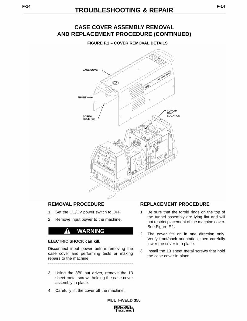
TROUBLESHOOTING & REPAIRF-14 F-14
MULTI-WELD 350
MULMULTI-W
ELD 350
TI-WELD 350
MULTI-WELD 350
LINCOLNELECTRIC
AMPS
VOLTS
A
V
ELECTRODE
INPUT
WORK
CHOPPER TECHNOLOGY
CASE COVER
FRONT
SCREW HOLE (13)
TOROIDRING LOCATION
FIGURE F.1 – COVER REMOVAL DETAILS
CASE COVER ASSEMBLY REMOVALAND REPLACEMENT PROCEDURE (CONTINUED)
REMOVAL PROCEDURE
1. Set the CC/CV power switch to OFF.
2. Remove input power to the machine.
ELECTRIC SHOCK can kill.
Disconnect input power before removing thecase cover and performing tests or makingrepairs to the machine.
3. Using the 3/8" nut driver, remove the 13sheet metal screws holding the case coverassembly in place.
4. Carefully lift the cover off the machine.
REPLACEMENT PROCEDURE
1. Be sure that the toroid rings on the top ofthe tunnel assembly are lying flat and willnot restrict placement of the machine cover.See Figure F.1.
2. The cover fits on in one direction only.Verify front/back orientation, then carefullylower the cover into place.
3. Install the 13 sheet metal screws that holdthe case cover in place.
WARNING

TROUBLESHOOTING & REPAIRF-15 F-15
MULTI-WELD 350
POWER MODULE CAPACITOR DISCHARGE PROCEDURE
WARNING
Service and repair should be performed by only Lincoln Electric factory trained personnel.Unauthorized repairs performed on this equipment may result in danger to the technicianor machine operator and will invalidate your factory warranty. For your safety and to avoidelectrical shock, please observe all safety notes and precautions detailed throughout thismanual.
If for any reason you do not understand the test procedures or are unable to perform thetest/repairs safely, contact the Lincoln Electric Service Department for electrical trou-bleshooting assistance before you proceed. Call 1-800-833-9353 (WELD).
TEST DESCRIPTION
This procedure will insure that the large capacitor in each chopper power module hasbeen discharged. This procedure should be performed whenever work is to be attempt-ed on or near the power modules.
MATERIALS NEEDED
3/8" Wrench or socket wrenchVolt/OhmmeterResistor (25-1000 ohms and 25 watts minimum)Jumper leads
This procedure should take approximately 15 minutes to perform.

TROUBLESHOOTING & REPAIRF-16 F-16
MULTI-WELD 350
MULTI-WELD 350
LINCOLNELECTRIC
AMPS
VOLTS
A
V
ELECTRODE
INPUT
WORK
CHOPPER TECHNOLOGY
POWER MODULECAPACITORTERMINALS
FIGURE F.2 – POWER MODULE CAPACITOR TERMINAL DISCHARGE
POWER MODULE CAPACITOR DISCHARGE PROCEDURE (CONTINUED)
PROCEDURE
1. Set the CC/CV power switch to OFF.
2. Remove input power to the machine.
ELECTRIC SHOCK can kill.
Disconnect input power before removing thecase cover and performing tests or makingrepairs to the machine.
3. Perform the Case Cover AssemblyRemoval procedure.
4. Locate the power module capacitors on theright and left sides of the tunnel assembly.See Figure F.2.
5. Using the resistor and jumper leads, CARE-FULLY discharge the capacitor terminals.NEVER USE A SHORTING STRAP FORTHIS PURPOSE. DO NOT TOUCH THETERMINALS WITH YOUR BARE HANDS.Repeat the procedure for the secondcapacitor.
6. Using the volt/ohmmeter, check the voltageacross the capacitor terminals. It should bezero volts.
WARNING

TROUBLESHOOTING & REPAIRF-17 F-17
MULTI-WELD 350
INPUT CONTACTOR COIL RESISTANCE AND SUPPLY VOLTAGE TEST
WARNING
Service and repair should be performed by only Lincoln Electric factory trained personnel.Unauthorized repairs performed on this equipment may result in danger to the technicianor machine operator and will invalidate your factory warranty. For your safety and to avoidelectrical shock, please observe all safety notes and precautions detailed throughout thismanual.
If for any reason you do not understand the test procedures or are unable to perform thetest/repairs safely, contact the Lincoln Electric Service Department for electrical trou-bleshooting assistance before you proceed. Call 1-800-833-9353 (WELD).
TEST DESCRIPTION
This test will determine if the input contactor is functioning properly.
MATERIALS NEEDED
Volt/Ohmmeter3/8" Nut driverNeedle nose pliersWiring DiagramExternal, isolated 40 VDC power supply
This procedure should take approximately 40 minutes to perform.

TROUBLESHOOTING & REPAIRF-18 F-18
MULTI-WELD 350
LEADS#303A#330
FIGURE F.3 – INPUT CONTACTOR DETAILS
INPUT CONTACTOR COIL RESISTANCE AND SUPPLY VOLTAGE TEST (CONTINUED)
COIL TEST PROCEDURE
1. Set the CC/CV power switch to OFF.
2. Remove input power to the machine.
ELECTRIC SHOCK can kill.
Disconnect input power before removing thecase cover and performing tests or makingrepairs to the machine.
3. Perform the Case Cover Removal proce-dure.
4. Perform the Power Module CapacitorDischarge procedure.
5. Locate the input contactor and coil leads#303A and #330. See Figure F.3.
6. Label and disconnect leads #303A and#330 at their in-line connectors.
7. Check the coil resistance. Normal coilresistance is approximately 100 ohms. Ifthe coil resistance is abnormally high orlow, the contactor may be faulty. Replacethe contactor.
8. Reconnect leads #303A and #330 to thecoil leads.
WARNING

TROUBLESHOOTING & REPAIRF-19 F-19
MULTI-WELD 350
INPUT CONTACTOR COIL RESISTANCE AND SUPPLY VOLTAGE TEST (CONTINUED)
ELECTRIC SHOCK can kill.
With the input power ON, there are high volt-ages inside the machine. Do not reach into themachine or touch any internal part of themachine while power is on.
9. Carefully apply the correct input power tothe Multi-Weld 350 (50 – 113 VDC).
10. Set the Multi-Weld 350 to either CC or CVmode. The contactor should activate. If itdoes not, increase the input voltage but donot exceed 113 VDC.
11. Carefully check for approximately 40 VDCat leads #303A to #330. If the 40 VDC isapplied to the coil leads, the contactorshould activate.
12. If the reading is less than 40 VDC or notpresent, perform the DC Buss PowerSupply PC Board Test.
13. Also check leads #303A, #330, #303, #403,#230 and their associated plugs for loose orfaulty connections. See the WiringDiagram.
TEST FOR CONTACT CONTINUITY
1. Disconnect input power to the Multi-Weld350.
ELECTRIC SHOCK can kill.
Disconnect input power before removing thecase cover and performing tests or makingrepairs to the machine.
2. Perform the Power Module CapacitorDischarge procedure.
3. Locate the input contactor and coil leads#303A and #330. See Figure F.3.
4. Label and disconnect leads #303A and#330 at their in-line connectors.
5. Using the external, isolated 40 VDC powersupply, carefully apply 40 VDC to the coilleads. The contactor should activate.
6. With the contactor activated, check the con-tinuity across the large contacts. (Zeroohms or very low resistance is normal.)See Figure F.3. If the resistance is high,the input contactor is faulty. Replace theinput contactor.
7. When the contactor is not activated, theresistance should be infinite or very highacross the contacts. If the resistance is low,the input contactor is faulty. Replace theinput contactor.
8. Remove the 40 VDC external supply andreconnect the coil leads previouslyremoved.
9. If finished testing, perform the Case CoverReplacement procedure.
WARNING
WARNING

TROUBLESHOOTING & REPAIRF-20 F-20
MULTI-WELD 350
ANALOG CONTROL POWER SUPPLY PC BOARD TEST
WARNING
Service and repair should be performed by only Lincoln Electric factory trained personnel.Unauthorized repairs performed on this equipment may result in danger to the technicianor machine operator and will invalidate your factory warranty. For your safety and to avoidelectrical shock, please observe all safety notes and precautions detailed throughout thismanual.
If for any reason you do not understand the test procedures or are unable to perform thetest/repairs safely, contact the Lincoln Electric Service Department for electrical trou-bleshooting assistance before you proceed. Call 1-800-833-9353 (WELD).
TEST DESCRIPTION
This test will determine if the Analog Control Power Supply PC Board is receiving andpassing the proper signal voltages.
MATERIALS NEEDED
3/8" Nut driverAnalog Volt/OhmmeterWiring Diagram
This procedure should take approximately 30 minutes to perform.

TROUBLESHOOTING & REPAIRF-21 F-21
MULTI-WELD 350
MULTI-WELD 350
LINCOLNELECTRIC
AMPS
VOLTS
A
V
ELECTRODE
INPUT
WORK
CHOPPER TECHNOLOGY
P42
P41
ANALOG CONTROLPOWER SUPPLYPC BOARD
1 2 3 4 5
6 7 8 9 10
1 2
3 4
P41 P42
FIGURE F.4 – ANALOG CONTROL POWER SUPPLY PC BOARD
ANALOG CONTROL POWER SUPPLY PC BOARD TEST (CONTINUED)
TEST PROCEDURE
1. Set the CC/CV power switch to OFF.
2. Remove input power to the machine.
ELECTRIC SHOCK can kill.
Disconnect input power before removing thecase cover and performing tests or makingrepairs to the machine.
3. Perform the Case Cover Removal proce-dure.
4. Perform the Power Module CapacitorDischarge procedure.
5. Locate the Analog Control Power SupplyPC Board and plugs P41 and P42. SeeFigure F.4.
6. Carefully apply the correct input power tothe Multi-Weld 350 (50 – 113 VDC).
7. Set the Multi-Weld 350 to either CC or CVmode. Make sure the input contactor acti-vates. If it does not, increase the input volt-age but do not exceed 113 VDC. The LEDon the DC Buss Power Supply PC Boardshould light.
8. Check the Analog Control Power Supply PCBoard input and output voltages accordingto Table F.1. See Figure F.4 and the WiringDiagram.
WARNING

TROUBLESHOOTING & REPAIRF-22 F-22
MULTI-WELD 350
TABLE F.1ANALOG CONTROL POWER SUPPLY PC BOARD VOLTAGE TABLE
Positive Meter Probe Negative Meter Probe Acceptable VoltageConditions/Comments
Test Point Test Point Reading
Plug P41 – Pin 1 Plug P41 – Pin 2 38.0 – 42.0 VDCSupply from DC BussPower Supply Board
Plug P42 – Pin 1 Plug P42 – Pin 6 18.0 – 21.0 VDCSupply for right sideChopper PC Board
Plug P42 – Pin 3 Plug P42 – Pin 8 18.0 – 21.0 VDCSupply for left sideChopper PC Board
Plug P42 – Pin 10 Plug P42 – Pin 4 14.0 – 16.0 VDC+15 VDC Supply toPeripheral Board
Plug P42 – Pin 5 Plug P42 – Pin 7 14.0 – 16.0 VDC+15 VDC Supply toWeld Control Board
Plug P42 – Pin 2 Plug P42 – Pin 7 4.5 – 5.5 VDC+5 VDC Supply toWeld Control Board
Plug P42 – Pin 9 Plug P42 – Pin 7 -14.0 – 16.0 VDC-15 VDC Supply toWeld Control Board
ANALOG CONTROL POWER SUPPLY PC BOARD TEST (CONTINUED)
9. If all the voltages are correct, the AnalogControl Power Supply PC Board is operat-ing properly.
10. If any of the output voltages are not correctand the input voltage is correct, the AnalogControl Power Supply PC Board may befaulty.
11. If the input voltage is not correct, checkleads #436, #437 and their associatedplugs for loose or faulty connections. Seethe Wiring Diagram. Perform the DC BussPower Supply PC Board Test.
12. If finished testing, perform the Case CoverReplacement procedure.

TROUBLESHOOTING & REPAIRF-23 F-23
MULTI-WELD 350
DC BUSS POWER SUPPLY PC BOARD TEST
WARNING
Service and repair should be performed by only Lincoln Electric factory trained personnel.Unauthorized repairs performed on this equipment may result in danger to the technicianor machine operator and will invalidate your factory warranty. For your safety and to avoidelectrical shock, please observe all safety notes and precautions detailed throughout thismanual.
If for any reason you do not understand the test procedures or are unable to perform thetest/repairs safely, contact the Lincoln Electric Service Department for electrical trou-bleshooting assistance before you proceed. Call 1-800-833-9353 (WELD).
TEST DESCRIPTION
This test will determine if the DC Buss Power Supply PC Board is receiving and process-ing the proper signal voltages.
MATERIALS NEEDED
3/8" Nut driverAnalog Volt/OhmmeterWiring Diagram
This procedure should take approximately 30 minutes to perform.

TROUBLESHOOTING & REPAIRF-24 F-24
MULTI-WELD 350
MULTI-WELD 350
LINCOLNELECTRIC
AMPS
VOLTS
A
V
ELECTRODE
INPUT
WORK
CHOPPER TECHNOLOGY
DC BUSSPOWERSUPPLYPC BOARD
P46
P47
1 2 1 2 3 4
5 6 7 8 3 4
P46 P47
FIGURE F.5 – DC BUSS POWER SUPPLY PC BOARD
DC BUSS POWER SUPPLY PC BOARD TEST(CONTINUED)
TEST PROCEDURE
1. Set the CC/CV power switch to OFF.
2. Remove input power to the machine.
ELECTRIC SHOCK can kill.
Disconnect input power before removing thecase cover and performing tests or makingrepairs to the machine.
3. Perform the Case Cover Removal proce-dure.
4. Perform the Power Module CapacitorDischarge procedure.
5. Locate the DC Buss Power Supply PCBoard and plugs P46 and P47. See FigureF.5.
6. Carefully apply the correct input power tothe Multi-Weld 350 (50 – 113 VDC).
7. Set the Multi-Weld 350 to either CC or CVmode. Make sure the input contactor acti-vates. If it does not, increase the input volt-age but do not exceed 113 VDC. The LEDon the DC Buss Power Supply PC Boardshould light.
WARNING
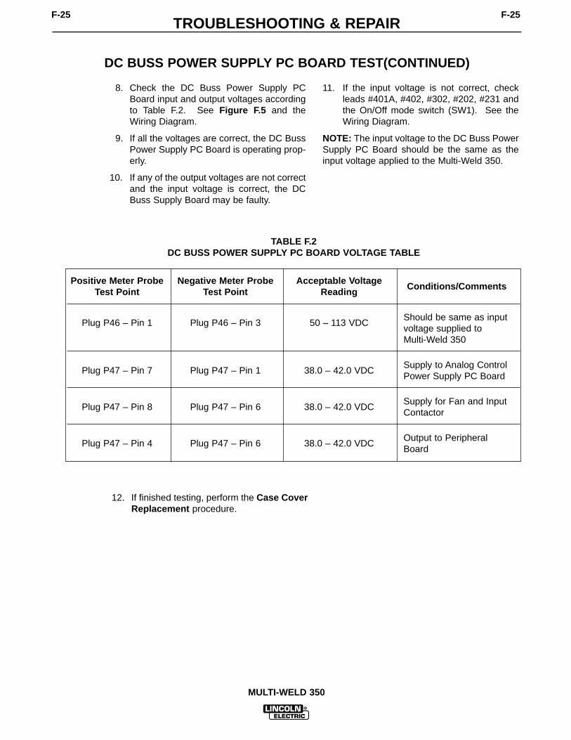
TROUBLESHOOTING & REPAIRF-25 F-25
MULTI-WELD 350
DC BUSS POWER SUPPLY PC BOARD TEST(CONTINUED)
8. Check the DC Buss Power Supply PCBoard input and output voltages accordingto Table F.2. See Figure F.5 and theWiring Diagram.
9. If all the voltages are correct, the DC BussPower Supply PC Board is operating prop-erly.
10. If any of the output voltages are not correctand the input voltage is correct, the DCBuss Supply Board may be faulty.
11. If the input voltage is not correct, checkleads #401A, #402, #302, #202, #231 andthe On/Off mode switch (SW1). See theWiring Diagram.
NOTE: The input voltage to the DC Buss PowerSupply PC Board should be the same as theinput voltage applied to the Multi-Weld 350.
12. If finished testing, perform the Case CoverReplacement procedure.
TABLE F.2DC BUSS POWER SUPPLY PC BOARD VOLTAGE TABLE
Positive Meter Probe Negative Meter Probe Acceptable VoltageConditions/Comments
Test Point Test Point Reading
Plug P46 – Pin 1 Plug P46 – Pin 3 50 – 113 VDCShould be same as inputvoltage supplied to Multi-Weld 350
Plug P47 – Pin 7 Plug P47 – Pin 1 38.0 – 42.0 VDCSupply to Analog ControlPower Supply PC Board
Plug P47 – Pin 8 Plug P47 – Pin 6 38.0 – 42.0 VDCSupply for Fan and InputContactor
Plug P47 – Pin 4 Plug P47 – Pin 6 38.0 – 42.0 VDCOutput to PeripheralBoard

TROUBLESHOOTING & REPAIRF-26 F-26
MULTI-WELD 350
CHOPPER PC BOARD INPUT VOLTAGES AND RESISTANCE TEST
WARNING
Service and repair should be performed by only Lincoln Electric factory trained personnel.Unauthorized repairs performed on this equipment may result in danger to the technicianor machine operator and will invalidate your factory warranty. For your safety and to avoidelectrical shock, please observe all safety notes and precautions detailed throughout thismanual.
If for any reason you do not understand the test procedures or are unable to perform thetest/repairs safely, contact the Lincoln Electric Service Department for electrical trou-bleshooting assistance before you proceed. Call 1-800-833-9353 (WELD).
TEST DESCRIPTION
This test will determine if there are shorted IGBTs or Chopper PC Boards. This test willalso verify that the Chopper PC Boards are receiving the correct operating voltages.
MATERIALS NEEDED
Volt/Ohmmeter3/8"Nut driver7/16" WrenchWiring Diagram
This procedure should take approximately 50 minutes to perform.

TROUBLESHOOTING & REPAIRF-27 F-27
MULTI-WELD 350
MULTI-WELD 350
LINCOLNELECTRIC
AMPS
VOLTS
A
V
ELECTRODE
INPUT
WORK
CHOPPER TECHNOLOGY
COPPER CAPACITOR NEGATIVESTRAPLEADS#X1 #X4#401#401A
+
-
REMOVE CASE BACK PANELTO ACCESSHEAT SINKTEST POINT(4 SCREWS)
DIODE D5
COPPERCAPACITOR POSITIVE STRAP
1 2 3
4 5 6
P45/45A
CLAMP
BRACKET
IGBTHEAT SINK
DIODE MODULE D3
FIGURE F.6 – POWER MODULE ASSEMBLY DETAILS
CHOPPER PC BOARD INPUT VOLTAGES AND RESISTANCE TEST (CONTINUED)
TEST PROCEDURE
1. Set the CC/CV power switch to OFF.
2. Remove input power to the machine.
ELECTRIC SHOCK can kill.
Disconnect input power before removing thecase cover and performing tests or makingrepairs to the machine.
3. Perform the Case Cover Removal proce-dure.
4. Perform the Power Module CapacitorDischarge procedure.WARNING

TROUBLESHOOTING & REPAIRF-28 F-28
MULTI-WELD 350
CHOPPER PC BOARD INPUT VOLTAGES AND RESISTANCE TEST (CONTINUED)
Test Procedure for the Left Side Power Module
1. Locate the Power Module Capacitor termi-nals. Using the 7/16" wrench, disconnectleads #X1, #X4, #401, #401A and the cop-per straps. Carefully electrically isolatethese leads and straps from the capacitorterminals and heat sink assembly. SeeFigure F.6.
2. Using the 3/8" nut driver, remove the fourscrews holding the case back to the tunnelassembly. This will provide access to theIGBT heat sinks.
3. Using the analog ohmmeter, connect thepositive meter probe to the positive copperstrap and the negative meter probe to theIGBT heat sink. (This is the inner heatsink.) See Figure F.6 for test point loca-tions. The resistance should be very high(over 20,000 ohms). If the resistance islow, then either the IGBT is shorted or thediode D5 is shorted. Disconnect the smallD5 cathode lead to isolate the problem. Itis possible that both devices may be faulty.
4. Reverse the meter leads. The resistanceshould be low (approximately 100 ohms). Ifthe resistance is high, the diode D5 may beopen.
5. Using the analog ohmmeter, check diodemodule D3. Connect the negative meterprobe to the negative copper strap connect-ed to the diode module and the positiveprobe to the heat sink. See Figure F.6 forthe test point locations. The resistanceshould be very high (over 20,000 ohms). Ifthe resistance is low, the diode module D3may be shorted.
6. Reverse the meter leads. The resistanceshould be low (approximately 100 ohms). Ifthe resistance is high, the diode module D3may be open.
7. Repeat Steps 1 through 5 for the RightSide Power Module. See the WiringDiagram.
8. Replace all leads previously removed. SeeFigure F.6 and the Wiring Diagram. Torquethe capacitor bolts to 50 to 60 inch pounds.
CHOPPER PC BOARD VOLTAGETESTS FOR BOTH LEFT AND RIGHT SIDES
1. Locate Plug P45(A) and disconnect it fromJ45(A). See Figure F.6.
ELECTRIC SHOCK can kill.
With the input power ON, there are high volt-ages inside the machine. Do not reach into themachine or touch any internal part of themachine while power is on.
2. Carefully apply the correct input voltage tothe Multi-Weld 350 (50 – 113 VDC). Themachine should be in the CC mode and theCC Slope switch should be in theStick/Gouge position.
3. Turn the machine on and carefully check for18.0 – 21.0 VDC at P45(A) pin 1 (+) toP45(A) pin 3 (-). This is the 20 VDC supplyfrom the Analog Control Power Supply PCBoard to the Chopper PC Board.
NOTE: Be careful not to touch the capacitorterminals.
4. Also carefully check for 11.0 – 14.0 VDC atP45(A) pin 7 (+) to P45(A) pin 9 (-). This isthe Pulse Width Modulation Signal from theWeld Control Board to the Chopper PCboard.
5. If any of the voltages are not present, checkassociated leads and plugs for loose orfaulty connections. See the WiringDiagram.
6. Remove the input power and perform thePower Module Capacitor DischargeProcedure.
7. Reconnect the plugs previously discon-nected.
8. If finished testing, perform the Case CoverReplacement procedure.
WARNING

TROUBLESHOOTING & REPAIRF-29 F-29
MULTI-WELD 350
This is the typical CC open circuit out-put voltage generated from a properlyoperating machine. Note that eachvertical division represents 50 voltsand that each horizontal division rep-resents 5 µs in time.
SCOPE SETTINGS
Volts/Div.....................50V/Div.Horizontal Sweep......5 µs/Div.Coupling.............................DCTrigger.........................Internal
NORMAL OPEN CIRCUIT VOLTAGE WAVEFORM
CC MODE – INPUT VOLTAGE APPLIED 75 VDC
0 volts0 volts
50V 5µs

TROUBLESHOOTING & REPAIRF-30 F-30
MULTI-WELD 350
This is the typical CV output voltagegenerated from a properly operatingmachine. Note that each vertical division represents 50 volts and thateach horizontal division represents 5 µs in time.
SCOPE SETTINGS
Volts/Div.....................50V/Div.Horizontal Sweep......5 µs/Div.Coupling.............................DCTrigger.........................Internal
NORMAL OPEN CIRCUIT VOLTAGE WAVEFORM
CV MODE – OUTPUT CONTROL AT MAXIMUM
0 volts0 volts
50V 5µs

TROUBLESHOOTING & REPAIRF-31 F-31
MULTI-WELD 350
This is the typical CC output voltagegenerated from a properly operatingmachine. Note that each vertical divi-sion represents 50 volts and that eachhorizontal division represents 50µs intime.
The machine was loaded with a resis-tance grid bank to 350 amps at 34volts.
SCOPE SETTINGS
Volts/Div.....................50V/Div.Horizontal Sweep .....50µs/Div.Coupling.............................DCTrigger.........................Internal
NORMAL WELD VOLTAGE WAVEFORM
MACHINE LOADED TO 350 AMPS AT 34 VOLTS – CC-STICK MODE
0 volts
50V 50µs

TROUBLESHOOTING & REPAIRF-32 F-32
MULTI-WELD 350
NORMAL WELD VOLTAGE WAVEFORM
MACHINE LOADED TO 350 AMPS AT 34 VOLTS – CV MODE
This is the typical CV output voltagegenerated from a properly operatingmachine. Note that each vertical divi-sion represents 50 volts and that eachhorizontal division represents 50µs intime.
The machine was loaded with a resis-tance grid bank to 350 amps at 34volts.
SCOPE SETTINGS
Volts/Div.....................50V/Div.Horizontal Sweep .....50µs/Div.Coupling.............................DCTrigger.........................Internal
50V 50µs
0 volts

TROUBLESHOOTING & REPAIRF-33 F-33
MULTI-WELD 350
This is the typical CV open circuit out-put voltage generated from a properlyoperating machine. Note that eachvertical division represents 50 voltsand that each horizontal division rep-resents 1 millisecond in time.
SCOPE SETTINGS
Volts/Div.....................50V/Div.Horizontal Sweep .....1 ms/Div.Coupling.............................DCTrigger.........................Internal
NORMAL OPEN CIRCUIT VOLTAGE WAVEFORM
CV MODE – OUTPUT CONTROL AT MINIMUM
0 volts0 volts
50V 1ms

TROUBLESHOOTING & REPAIRF-34 F-34
MULTI-WELD 350
CASE FRONT ASSEMBLY REMOVAL AND REPLACEMENT
WARNING
Service and repair should be performed by only Lincoln Electric factory trained personnel.Unauthorized repairs performed on this equipment may result in danger to the technicianor machine operator and will invalidate your factory warranty. For your safety and to avoidelectrical shock, please observe all safety notes and precautions detailed throughout thismanual.
If for any reason you do not understand the test procedures or are unable to perform thetest/repairs safely, contact the Lincoln Electric Service Department for electrical trou-bleshooting assistance before you proceed. Call 1-800-833-9353 (WELD).
DESCRIPTION
The following procedure will aid the technician in removing and replacing the case frontassembly on the Multi-Weld 350.
MATERIALS NEEDED
3/8" Nut driver, wrench or socket wrenchWiring Diagram
This procedure should take approximately 15 minutes to perform.

TROUBLESHOOTING & REPAIRF-35 F-35
MULTI-WELD 350
BASE SCREWS (2)ACCESS FROMBOTTOM
PLUG ASSEMBLIES(3)
MULTI-WELD 350
LINCOLNELECTRIC
AMPS
VOLTS
A
V
ELECTRODE
INPUT
WORK
CHOPPER TECHNOLOGY
FIGURE F.7 – CASE FRONT ASSEMBLY REMOVAL
CASE FRONT ASSEMBLY REMOVAL AND REPLACEMENT (CONTINUED)
REMOVAL PROCEDURE
1. Set the CC/CV power switch to OFF.
2. Remove input power to the machine.
ELECTRIC SHOCK can kill.
Disconnect input power before removing thecase cover and performing tests or makingrepairs to the machine.
3. Perform the Case Cover AssemblyRemoval procedure.
4. Perform the Power Capacitor Dischargeprocedure.
5. Label and disconnect the three wiring har-ness plug assemblies that connect to thecase front assembly. See Figure F.7 andthe Wiring Diagram.
6. Carefully turn the machine onto its side.See Figure F.7 for location.
7. Using the 3/8" nut driver, remove the twoscrews holding the case front assembly tothe machine base. Support the case frontassembly as you remove the second screw.
8. Carefully remove the case front assemblyand set the machine back upright.
REPLACEMENT PROCEDURE
1. Carefully turn the machine onto its side.
2. Position the case front assembly on thebase and attach it with two screws previ-ously removed.
3. Set the machine back upright. Connect thethree wiring harness plug assemblies.
4. Replace the case cover.
WARNING

TROUBLESHOOTING & REPAIRF-36 F-36
MULTI-WELD 350
WELD CONTROL OR PERIPHERAL PC BOARD REMOVAL AND REPLACEMENT
WARNING
Service and repair should be performed by only Lincoln Electric factory trained personnel.Unauthorized repairs performed on this equipment may result in danger to the technicianor machine operator and will invalidate your factory warranty. For your safety and to avoidelectrical shock, please observe all safety notes and precautions detailed throughout thismanual.
If for any reason you do not understand the test procedures or are unable to perform thetest/repairs safely, contact the Lincoln Electric Service Department for electrical trou-bleshooting assistance before you proceed. Call 1-800-833-9353 (WELD).
DESCRIPTION
The following procedure will aid the technician in removing and replacing the Weld Controlor Peripheral PC Board on the Multi-Weld 350.
MATERIALS NEEDED
3/8" Nut driver, wrench or socket wrench5/16" Nut driverWiring Diagram
This procedure should take approximately 30 minutes to perform.

TROUBLESHOOTING & REPAIRF-37 F-37
MULTI-WELD 350
PERIPHERALPC BOARD
JUMPERPLUG P3
PLUG P31
SCREWS (7)
WELD CONTROLPC BOARD
NUTS
HOT START
ARC FORCE
OTE
CCSLOPE
PIPE
STICK 7018GOUGE L11141-2
CC
CVOFF
AMPS
VOLTS
A
V
MULTI-WELD 350
LINCOLNELECTRIC
ELECTRODE
INPUT
WORK
CHOPPER TECHNOLOGY
4
4
2
20
6
610
10
8
8
543
2
0
6
109
8
7
FIGURE F.8 – CASE FRONT ASSEMBLY DETAILS
WELD CONTROL OR PERIPHERAL PC BOARD REMOVAL AND REPLACEMENT (CONTINUED)
REMOVAL PROCEDURE
Refer to Figure F.8.
1. Set the CC/CV power switch to OFF.
2. Remove input power to the machine.
ELECTRIC SHOCK can kill.
Disconnect input power before removing thecase cover and performing tests or makingrepairs to the machine.
3. Perform the Case Cover AssemblyRemoval procedure.
4. Perform the Power Capacitor Dischargeprocedure.
5. Perform the Case Front AssemblyRemoval procedure.
6. Using the 5/16" nut driver, remove theseven screws from the control box rearpanel.
WARNING

TROUBLESHOOTING & REPAIRF-38 F-38
MULTI-WELD 350
WELD CONTROL OR PERIPHERAL PC BOARD REMOVAL AND REPLACEMENT (CONTINUED)
7. Carefully label and remove the 12 molexplugs from the Weld Control PC board.Press and hold the keeper on each plug asyou remove it. Also remove plug P31 fromthe Peripheral PC Board as shown inFigure F.8. This will allow the assembly tolie flat.
8. Using the 3/8" nut driver, remove the fournuts holding the Weld Control PC Board inplace.
NOTE: Verify the orientation of the Weld Con-trol PC Board for replacement. You may needto remove a nut on the Peripheral PC Board inorder to free the Weld Control PC Board.
9. Carefully remove the Weld Control PCBoard.
NOTE: It may be necessary to pry gently on thePC Board to remove it.
REPLACEMENT PROCEDURE
1. Set the Weld Control PC Board squarelyonto the studs and press it in place. Verifyproper orientation. Replace any nutsremoved from the Peripheral PC Board atdisassembly.
2. Tighten the four 3/8" nuts holding the boardin place.
3. Attach the molex plugs, including the plugremoved from the Peripheral PC Board atdisassembly. See the Wiring Diagram.
NOTE: Make sure jumper plug P3 is in place.
4. Attach the rear panel with seven 5/16"screws.
5. Perform the Case Front AssemblyReplacement procedure.
6. Perform the Case Cover AssemblyReplacement procedure.

TROUBLESHOOTING & REPAIRF-39 F-39
MULTI-WELD 350
AMPS/VOLTS DIGITAL METER AND POTENTIOMETERREMOVAL AND REPLACEMENT
WARNING
Service and repair should be performed by only Lincoln Electric factory trained personnel.Unauthorized repairs performed on this equipment may result in danger to the technicianor machine operator and will invalidate your factory warranty. For your safety and to avoidelectrical shock, please observe all safety notes and precautions detailed throughout thismanual.
If for any reason you do not understand the test procedures or are unable to perform thetest/repairs safely, contact the Lincoln Electric Service Department for electrical trou-bleshooting assistance before you proceed. Call 1-800-833-9353 (WELD).
DESCRIPTION
The following procedure will aid the technician in removing and replacing the Amps orVolts Digital Meter or the Output Control potentiometer on the Multi-Weld 350.
MATERIALS NEEDED
3/8" Nut driver, wrench or socket wrench5/16" Nut driverPhillips screw driverAllen head wrenchDiagonal cuttersWiring Diagram
This procedure should take approximately 30 minutes to perform.

TROUBLESHOOTING & REPAIRF-40 F-40
MULTI-WELD 350
DIGITALMETER
OUTPUTCONTROLPOTENTIOMETER
BEZEL
LENS
KNOB
SPACER
SEAL
HOT START
ARC FORCE
OTE
4
4
2
20
6
6
10
543
26
109
8
7
CCSLOPE
PIPE
STICK 7018GOUGE L11141-2
CC
CVOFF
AMPS
VOLTS
A
V
MULTI-WELD 350
LINCOLNELECTRIC
ELECTRODE
INPUT
WORK
CHOPPER TECHNOLOGY
FIGURE F.9 – DIGITAL METER AND POTENTIOMETER DETAILS
AMPS/VOLTS DIGITAL METER AND POTENTIOMETERREMOVAL AND REPLACEMENT (CONTINUED)
DIGITAL METER REMOVALPROCEDURE
Refer to Figure F.9.
1. Set the CC/CV power switch to OFF.
2. Remove input power to the machine.
ELECTRIC SHOCK can kill.
Disconnect input power before removing thecase cover and performing tests or makingrepairs to the machine.
3. Perform the Case Cover AssemblyRemoval procedure.
4. Perform the Power Capacitor Dischargeprocedure.
5. Perform the Case Front AssemblyRemoval procedure.
6. Using the 5/16" nut driver, remove theseven screws from the control box rearpanel.
WARNING
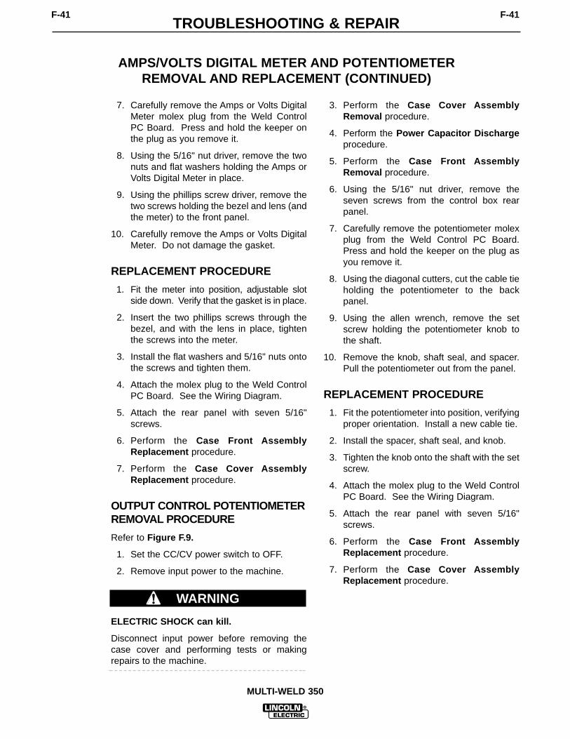
TROUBLESHOOTING & REPAIRF-41 F-41
MULTI-WELD 350
AMPS/VOLTS DIGITAL METER AND POTENTIOMETERREMOVAL AND REPLACEMENT (CONTINUED)
7. Carefully remove the Amps or Volts DigitalMeter molex plug from the Weld ControlPC Board. Press and hold the keeper onthe plug as you remove it.
8. Using the 5/16" nut driver, remove the twonuts and flat washers holding the Amps orVolts Digital Meter in place.
9. Using the phillips screw driver, remove thetwo screws holding the bezel and lens (andthe meter) to the front panel.
10. Carefully remove the Amps or Volts DigitalMeter. Do not damage the gasket.
REPLACEMENT PROCEDURE
1. Fit the meter into position, adjustable slotside down. Verify that the gasket is in place.
2. Insert the two phillips screws through thebezel, and with the lens in place, tightenthe screws into the meter.
3. Install the flat washers and 5/16" nuts ontothe screws and tighten them.
4. Attach the molex plug to the Weld ControlPC Board. See the Wiring Diagram.
5. Attach the rear panel with seven 5/16"screws.
6. Perform the Case Front AssemblyReplacement procedure.
7. Perform the Case Cover AssemblyReplacement procedure.
OUTPUT CONTROL POTENTIOMETERREMOVAL PROCEDURE
Refer to Figure F.9.
1. Set the CC/CV power switch to OFF.
2. Remove input power to the machine.
ELECTRIC SHOCK can kill.
Disconnect input power before removing thecase cover and performing tests or makingrepairs to the machine.
3. Perform the Case Cover AssemblyRemoval procedure.
4. Perform the Power Capacitor Dischargeprocedure.
5. Perform the Case Front AssemblyRemoval procedure.
6. Using the 5/16" nut driver, remove theseven screws from the control box rearpanel.
7. Carefully remove the potentiometer molexplug from the Weld Control PC Board.Press and hold the keeper on the plug asyou remove it.
8. Using the diagonal cutters, cut the cable tieholding the potentiometer to the backpanel.
9. Using the allen wrench, remove the setscrew holding the potentiometer knob tothe shaft.
10. Remove the knob, shaft seal, and spacer.Pull the potentiometer out from the panel.
REPLACEMENT PROCEDURE
1. Fit the potentiometer into position, verifyingproper orientation. Install a new cable tie.
2. Install the spacer, shaft seal, and knob.
3. Tighten the knob onto the shaft with the setscrew.
4. Attach the molex plug to the Weld ControlPC Board. See the Wiring Diagram.
5. Attach the rear panel with seven 5/16"screws.
6. Perform the Case Front AssemblyReplacement procedure.
7. Perform the Case Cover AssemblyReplacement procedure.
WARNING

TROUBLESHOOTING & REPAIRF-42 F-42
MULTI-WELD 350
INPUT CONTACTOR REMOVAL AND REPLACEMENT
WARNING
Service and repair should be performed by only Lincoln Electric factory trained personnel.Unauthorized repairs performed on this equipment may result in danger to the technicianor machine operator and will invalidate your factory warranty. For your safety and to avoidelectrical shock, please observe all safety notes and precautions detailed throughout thismanual.
If for any reason you do not understand the test procedures or are unable to perform thetest/repairs safely, contact the Lincoln Electric Service Department for electrical trou-bleshooting assistance before you proceed. Call 1-800-833-9353 (WELD).
DESCRIPTION
The following procedure will aid the technician in removing and replacing the input con-tactor on the Multi-Weld 350.
MATERIALS NEEDED
3/8" Nut driver, wrench or socket wrench17 mm Wrench or socket wrenchDiagonal cuttersWiring Diagram
This procedure should take approximately 30 minutes to perform.

TROUBLESHOOTING & REPAIRF-43 F-43
MULTI-WELD 350
LEADS#303A#330
LEADS #X1A#X1#XBP5
INPUT CONTACTOR
LEAD #331
COPPER STRAP
HEAT SINK BOLTS & NYLONINSULATORS (2)
BASE BOLTS (2)
INPUT DIODE HEAT SINK
FIGURE F.10 – INPUT CONTACTOR ASSEMBLY DETAILS
INPUT CONTACTOR REMOVAL AND REPLACEMENT (CONTINUED)
REMOVAL PROCEDURE
Refer to Figure F.10.
1. Set the CC/CV power switch to OFF.
2. Remove input power to the machine.
ELECTRIC SHOCK can kill.
Disconnect input power before removing thecase cover and performing tests or makingrepairs to the machine.
3. Perform the Case Cover AssemblyRemoval procedure.
4. Perform the Power Capacitor Dischargeprocedure.
5. Perform the Case Front AssemblyRemoval procedure.
6. Label and disconnect leads #330 and#303A at their in-line connectors. Cut anynecessary cable ties.
WARNING

TROUBLESHOOTING & REPAIRF-44 F-44
MULTI-WELD 350
INPUT CONTACTOR REMOVAL AND REPLACEMENT (CONTINUED)
7. Using the 17 mm wrench, remove the nutsfrom the input contactor terminal closest tothe machine front. Label the leads andnote their placement: bottom nut (notremoved), lead #X1A, Lead #X1, lead#BP5.
NOTE: The top nut has grooves on the side thatfaces up.
8. Using the 17 mm wrench, remove the nutsfrom the other input contactor terminal.Bottom nut (not removed), copper contac-tor strap, center nut, lead #331, top nut.
NOTE: The top nut has grooves on the side thatfaces up.
9. With the 3/8" socket wrench, remove thetwo bolts and nylon insulators holding theinput contactor to the input diode heat sink.
NOTE: The mylar insulation sheet fits betweenthe nylon insulators at replacement.
10. Using the 3/8" socket wrench, remove thetwo screws holding the input contactor tothe machine base.
11. Carefully remove the input contactor.
REPLACEMENT PROCEDURE
1. Set the input contactor onto the machinebase and install two 3/8" screws in the basemounting holes.
2. Install the two sets of 3/8" bolts and nyloninsulators, along with the mylar insulationsheet, to the input diode heat sink. Themylar sheet fits between the nylon insula-tors under the mounting bracket.
3. Install the copper contactor strap and lead#331 to the input contactor rear terminal.See Figure F.10.
4. Install leads #X1A, X1, and #BP5 to theinput contactor front terminal. See FigureF.10. Be sure the top nut on each terminalis the grooved nut, with the grooves facingup.
5. Connect leads #330 and #303A at their in-line connectors.
6. Replace any cable ties cut at disassembly.
7. Perform the Case Front AssemblyReplacement procedure.
8. Perform the Case Cover AssemblyReplacement procedure.

TROUBLESHOOTING & REPAIRF-45 F-45
MULTI-WELD 350
INPUT DIODE REMOVAL AND REPLACEMENT
WARNING
Service and repair should be performed by only Lincoln Electric factory trained personnel.Unauthorized repairs performed on this equipment may result in danger to the technicianor machine operator and will invalidate your factory warranty. For your safety and to avoidelectrical shock, please observe all safety notes and precautions detailed throughout thismanual.
If for any reason you do not understand the test procedures or are unable to perform thetest/repairs safely, contact the Lincoln Electric Service Department for electrical trou-bleshooting assistance before you proceed. Call 1-800-833-9353 (WELD).
DESCRIPTION
The following procedure will aid the technician in removing and replacing stud type diodeson the aluminum heat sinks of the Multi-Weld 350.
MATERIALS NEEDED
3/8" Nut driver, wrench or socket wrench1/2" socket wrench and extension17 mm Wrench or socket wrench11⁄4 " Open end wrench Penetrox A13 joint compound Loctite 271“Slip” type torque wrench No. 000 fine steel woolDiagonal cuttersWiring Diagram
This procedure should take approximately 45 minutes to perform.

TROUBLESHOOTING & REPAIRF-46 F-46
MULTI-WELD 350
{
}
INPUTTERMINALSTRAPBOLT
THERMOSTAT(LEADS #306 ij)
MYLAR
CHOKE ATTACHMENTPOINT
DIODE
PIGTAILS
MYLAR
HEATSINK
CONTACTORSTRAP
CHOKE
FIGURE F.11 – INPUT DIODE ASSEMBLY DETAILS
INPUT DIODE REMOVAL AND REPLACEMENT (CONTINUED)
REMOVAL PROCEDURE
Refer to Figure F.11.
1. Set the CC/CV power switch to OFF.
2. Remove input power to the machine.
ELECTRIC SHOCK can kill.
Disconnect input power before removing thecase cover and performing tests or makingrepairs to the machine.
3. Perform the Case Cover AssemblyRemoval procedure.
4. Perform the Power Capacitor Dischargeprocedure.
5. Perform the Case Front AssemblyRemoval procedure.
6. Perform the Input Contactor Removalprocedure.
7. Using the 3/8" socket wrench, remove thebolt, nylon insulators and mylar insulationsheet where the diode heat sink attaches tothe choke. Note order for replacement.
8. Using the 1/2" socket wrench and exten-sion, remove the nut, lock washer, flatwasher, and bolt holding the heat sink to theinput terminal strap. Note the flat washerunder the bolt head.
9. Using the 1/2" wrench, remove the bolt andwashers connecting the diode pig-tails tothe contactor strap if this was not done dur-ing input contactor removal.
WARNING

TROUBLESHOOTING & REPAIRF-47 F-47
MULTI-WELD 350
INPUT DIODE REMOVAL AND REPLACEMENT (CONTINUED)
10. Disconnect thermostat leads #306 and#307.
11. Carefully remove the input diode assembly.
12. Using the 11⁄4" wrench, loosen the appropri-ate diode and remove the diode that is tobe replaced.
13. Clean the area on the heat sink around thediode mounting surface using a putty knifeor similar tool. DO NOT SCRATCH THEDIODE MOUNTING SURFACE.
14. Polish the heat sink’s mounting surface toprovide a bright, clean surface where thediode seats on the heat sink. Wipe the sur-face clean with a lint-free cloth or papertowel.
15. Inspect the mounting surfaces of each newdiode. Remove all burrs and wipe clean.Do not use steel wool or any abrasivecleanser on the diode mounting surface.
16. Apply a thin (0.003" to 0.007") uniformlayer of Penetrox A13 joint compound tothe heat sink mounting surface.
17. Do not apply compound to the diode studor mounting threads.
18. Apply two drops of Loctite 271 to the diodestud threads before tightening.
NOTE: The diode threads must be clean andfree of defects so that it can be finger tightenedbefore applying torque. A “slip” type torquewrench must be used to tighten the diode.
19. Tighten the diode to the specifications inthe following table.
DIODE STUD FOOT-POUNDS INCH-POUNDSSIZE
3/4 - 16 25-27 300-324
REPLACEMENT PROCEDURE
Refer to Figure F.11.
1. Set the input diode assembly into themachine base. Connect the heat sink to theinput terminal strap with the 1/2" bolt, wash-ers, and nut. Note order – see removal pro-cedures.
2. Install the heat sink to the choke, using the3/8" bolt and nylon insulators, along withthe mylar insulation sheet. The mylar sheetfits between the nylon insulators.
3. Connect thermostat leads #306 and #307.See the Wiring Diagram.
4. Perform the Input Contactor Replace-ment procedure. Be sure to connect theinput diode pig-tails to the contactor strap atthe contactor rear terminal.
5. Replace any cable ties cut at disassembly.
6. Perform the Case Front AssemblyReplacement procedure.
7. Perform the Case Cover AssemblyReplacement procedure.

TROUBLESHOOTING & REPAIRF-48 F-48
MULTI-WELD 350
FAN MOTOR ASSEMBLY REMOVAL AND REPLACEMENT
WARNING
Service and repair should be performed by only Lincoln Electric factory trained personnel.Unauthorized repairs performed on this equipment may result in danger to the technicianor machine operator and will invalidate your factory warranty. For your safety and to avoidelectrical shock, please observe all safety notes and precautions detailed throughout thismanual.
If for any reason you do not understand the test procedures or are unable to perform thetest/repairs safely, contact the Lincoln Electric Service Department for electrical trou-bleshooting assistance before you proceed. Call 1-800-833-9353 (WELD).
DESCRIPTION
The following procedure will aid the technician in removing and replacing the cooling fanand motor of the Multi-Weld 350.
MATERIALS NEEDED
3/8" Nut driver, wrench or socket wrench17 mm socket wrench and extensionPhillips head screw driverDiagonal cutters
This procedure should take approximately 45 minutes to perform.

TROUBLESHOOTING & REPAIRF-49 F-49
MULTI-WELD 350
MOTORLEADS #303A#330
FAN MOTOR
SCREWS (2)
FIGURE F.12 – FAN MOTOR ASSEMBLY DETAILS
FAN MOTOR ASSEMBLY REMOVAL AND REPLACEMENT(CONTINUED)
REMOVAL PROCEDURE
Refer to Figure F.12.
1. Set the CC/CV power switch to OFF.
2. Remove input power to the machine.
ELECTRIC SHOCK can kill.
Disconnect input power before removing thecase cover and performing tests or makingrepairs to the machine.
WARNING

TROUBLESHOOTING & REPAIRF-50 F-50
MULTI-WELD 350
FAN MOTOR ASSEMBLY REMOVAL AND REPLACEMENT(CONTINUED)
3. Perform the Input Diode Removal proce-dure.
4. Disconnect the red motor lead from leads#303 and #303A and the blue motor leadfrom lead #300 at their in-line connectors.Cut any necessary cable ties.
5. Disconnect the two plug harness connec-tions at the top of the tunnel assembly.
6. Using the phillips head screw driver,remove the two screws holding the fanmotor housing to the tunnel assembly.
7. Carefully remove the fan motor assembly.
REPLACEMENT PROCEDURE
1. Set the fan motor assembly into themachine, against the tunnel assembly, withthe motor nameplate label facing into thetunnel assembly.
2. Connect the red motor lead to leads #303and #303A and the blue motor lead to lead#300 at their in-line connectors.
3. Mount the fan motor housing to the tunnelassembly with two phillips screws.
4. Connect the two plug harness connectionsat the top of the tunnel assembly.
5. Replace any cable ties previously removed.
6. Perform the Input Diode Replacementprocedure.

TROUBLESHOOTING & REPAIRF-51 F-51
MULTI-WELD 350
POWER CAPACITOR REMOVAL AND REPLACEMENT
WARNING
Service and repair should be performed by only Lincoln Electric factory trained personnel.Unauthorized repairs performed on this equipment may result in danger to the technicianor machine operator and will invalidate your factory warranty. For your safety and to avoidelectrical shock, please observe all safety notes and precautions detailed throughout thismanual.
If for any reason you do not understand the test procedures or are unable to perform thetest/repairs safely, contact the Lincoln Electric Service Department for electrical trou-bleshooting assistance before you proceed. Call 1-800-833-9353 (WELD).
DESCRIPTION
This procedure will aid the technician in the removal and replacement of the power capac-itors on the Multi-Weld 350.
MATERIALS NEEDED
3/8" Wrench or socket wrenchSlot head screw driver7/16" WrenchResistor (25 – 1000 ohms, 25 watts minimum)Wiring Diagram
This procedure should take approximately 30 minutes to perform.

TROUBLESHOOTING & REPAIRF-52 F-52
MULTI-WELD 350
CLAMP
BRACKET
ANALOG CONTROLSUPPLY PC BOARD (4 SCREWS)
SCREWS (2)
CHOPPER PC BOARD
CAPACITORPOSITIVESTRAP
CAPACITOR NEGATIVE STRAPLEADS
+
-
RIGHTSIDE
LEFTSIDE
#X4A#X1A
#X4#X1#401#401A
FIGURE F.13 – POWER CAPACITOR MOUNTING DETAILS
POWER CAPACITOR REMOVAL AND REPLACEMENT (CONTINUED)
PROCEDURE
Refer to Figure F.13.
1. Set the CC/CV power switch to OFF.
2. Remove input power to the machine.
ELECTRIC SHOCK can kill.
Disconnect input power before removing thecase cover and performing tests or makingrepairs to the machine.
3. Perform the Case Cover AssemblyRemoval procedure.
4. Perform the Power Capacitor Dischargeprocedure.
5. Disconnect the two plug harness connec-tions at the top of the tunnel assembly.
6. Disconnect the plug harness connectionabove each Chopper PC board.
WARNING

TROUBLESHOOTING & REPAIRF-53 F-53
MULTI-WELD 350
POWER CAPACITOR REMOVAL AND REPLACEMENT (CONTINUED)
7. Using the slot head screw driver, removethe two screws and lock washers from thetunnel assembly top cover. Then removethe four screws, lock washers, and flatwashers that mount the Analog ControlPower Supply PC Board. This will allowyou to access the clamps that hold thecapacitors to their brackets in the heatsinks.
8. Lift off the top cover of the tunnel assem-bly. Peel away the adhesive-backed rub-ber stripping (if present) as necessary.Use care – the stripping may tear.
9. Using the slot head screw driver, loosenthe clamp from around the bracket of thecapacitor you want to remove.
10. Using the 7/16" wrench, remove heavyleads #X1, #X4 and small leads #401 and401A (left side) or #X1A and #X4A (rightside) of the capacitor terminals. Note thefasteners for reassembly: bolt, lock wash-er, and flat washer. See the WiringDiagram.
11. Using the 7/16" wrench, remove the twobolts holding the negative strap to thediode module. Note the fasteners forreassembly: bolt, lock washer, two flatwashers.
12. Using the 7/16" wrench, remove the twonuts holding the positive strap to theChopper PC board. Hold the bolt headbehind the board to remove each nut.Note the fasteners for reassembly: flatwasher, lock washer, nut. Note the place-ment of the reverse diode lead on the bot-tom bolt.
13. Push the capacitor from the inside, out ofthe heat sink. Note that the bracket staysin the heat sink.
REASSEMBLY
1. Slide the capacitor into the heat sink.Position the positive (+) terminal next tothe Chopper PC board.
2. Tighten the bracket clamp.
3. Replace the leads and straps as labeled(Figure F.13) and tighten the fasteners.Use the 7/16" socket and torque wrench totighten the capacitor terminal bolt to 50-60in-lbs. Tighten the nuts holding the positivestrap to the Chopper PC board to 50-60 in-lbs.
4. Tighten the two 7/16" screws that hold thenegative strap to the diode module to 30-40in-lbs.
5. Replace any adhesive-backed rubber strip-ping, if present, that was damaged duringdisassembly.
6. Replace the Analog Control Power SupplyPC Board.
7. Replace the tunnel assembly top cover.
8. Connect the wire harness plug assembliesabove each Chopper PC Board and abovethe tunnel assembly (four plugs total).
9. Perform the Case Cover AssemblyReplacement procedure.

TROUBLESHOOTING & REPAIRF-54 F-54
MULTI-WELD 350
CHOPPER PC BOARD AND DIODE MODULEREMOVAL AND REPLACEMENT
WARNING
Service and repair should be performed by only Lincoln Electric factory trained personnel.Unauthorized repairs performed on this equipment may result in danger to the technicianor machine operator and will invalidate your factory warranty. For your safety and to avoidelectrical shock, please observe all safety notes and precautions detailed throughout thismanual.
If for any reason you do not understand the test procedures or are unable to perform thetest/repairs safely, contact the Lincoln Electric Service Department for electrical trou-bleshooting assistance before you proceed. Call 1-800-833-9353 (WELD).
DESCRIPTION
This procedure will aid the technician in the removal and replacement of the Chopper PCBoard and the diode module assembly.
MATERIALS NEEDED
3/8" Wrench or socket wrench7/16" Wrench or socket wrench1/2" Wrench3/16" Allen head wrench9/64" Allen head wrenchTorque wrench with 7/16" hex and 1/4" and 9/64" allen head socketsPhillips head screw driverDiagonal cuttersElectrical thermal joint compound – Penetrox A-13Resistor (25 – 1000 ohms, 25 watts minimum)Small block of wood (approximately 1" x 3")
This procedure should take approximately 1 hour to perform.

TROUBLESHOOTING & REPAIRF-55 F-55
MULTI-WELD 350
MULTI-WELD 350
LINCOLNELECTRIC
AMPS
VOLTS
A
V
ELECTRODE
INPUT
WORK
CHOPPER TECHNOLOGY
4 SCREWSACCESSEDFROM BOTTOM
+-
CAPACITORPOSITIVESTRAP
HEX-HEADBOLTS (2)
REVERSE DIODE LEADCONNECTION
CHOPPERPC BOARD
ALLEN-HEADSCREWS (2)
FIGURE F. 14 – CHOPPER PC BOARD AND DIODE MODULE CONNECTIONS
CHOPPER PC BOARD REMOVAL AND REPLACEMENT (CONTINUED)
REMOVAL
Refer to Figure F.14.
1. Set the CC/CV power switch to OFF.
2. Remove input power to the machine.
ELECTRIC SHOCK can kill.
Disconnect input power before removing thecase cover and performing tests or makingrepairs to the machine.
WARNING

TROUBLESHOOTING & REPAIRF-56 F-56
MULTI-WELD 350
CHOPPER PC BOARD REMOVAL AND REPLACEMENT (CONTINUED)
3. Perform the Case Cover Removal proce-dure.
4. Perform the Power Capacitor Dischargeprocedure.
5. Carefully turn the machine onto its side.
6. Using the 3/8" wrench, remove the fourscrews holding the tunnel assembly to themachine base. Support the tunnel assem-bly, then carefully turn the machine backupright.
7. With the slot head screw driver, carefullyraise the tunnel assembly unit about oneinch and block it with the piece of wood.This will allow access to the bottom allenhead screws on the Chopper PC Board.Peel away the adhesive-backed rubberstripping if present. Use care – the strip-ping may tear.
8. Disconnect the plug harness connectionabove the Chopper PC Board. Slip thewires out of the cord clip.
9. Using the 7/16" wrench, loosen the bolt atthe positive capacitor terminal. Thenremove the two nuts, lock washers and flatwashers holding the positive strap to theChopper PC Board. Hold the screw headsbehind the board with your finger toremove the nuts. Note the placement ofthe reverse diode lead on the bottom bolt.Note the fastener order for reassembly: flatwasher, lock washer, nut.
10. With the 7/16" wrench, remove the twohex-head bolts, lock washers, and flatwashers holding the Chopper PC Board tothe heat sink. Catch the copper stand-offsbehind the board.
11. Using the 3/16" allen head wrench, removethe two allen-head screws and lock wash-ers holding the Chopper PC Board to theheat sink.
12. Swing the positive capacitor strap out ofthe way and remove the Chopper PCBoard.
REPLACEMENT
Refer to Figure F.14.
1. Make sure the mating surfaces between thecopper and the heat sink are clean, dry, andfree of grease.
2. Apply a thin coating of electrical thermaljoint compound (Penetrox A-13) to the mat-ing surfaces between the copper and thealuminum heat sink.
3. Using the torque wrench and 3/16" allenhead socket, install the two allen-headscrews and lock washers that hold theChopper PC Board to the heat sink.Tighten the screws finger tight, then tobetween 24 and 28 in-lbs., then again tobetween 40 and 48 in-lbs.
4. Using the 7/16" socket and torque wrench,install the two bolts, lock washers, and flatwashers that hold the Chopper PC Board tothe heat sink. Note the two spacersrequired. Tighten the bolts finger tight, thento between 50 and 60 in-lbs.
5. Put the positive strap (+) in position and theproper heavy lead. Using the 7/16" wrench,tighten the bolt at the positive capacitor ter-minal to between 50 and 60 in-lbs. Thenput the flat washers, lock washers and nutson the board side of the strap with thereverse diode lead on the bottom connec-tion. Tighten to between 50 and 60 in-lbs.
6. Remove the wooden blocking and carefullylower the tunnel assembly onto themachine base. Support the tunnel assem-bly and turn the machine onto its side.
7. With the 3/8" wrench, install the four screwsthat hold the tunnel assembly to themachine base. Turn the machine backupright.
8. Connect the harness plug above theChopper PC board. Slip the wires into thecord clip.
See the procedures following for removal andreplacement of the diode module. When proce-dures are complete, perform the Case CoverAssembly Replacement procedure.

TROUBLESHOOTING & REPAIRF-57 F-57
MULTI-WELD 350
MULTI-WELD 350
LINCOLNELECTRIC
AMPS
VOLTS
A
V
ELECTRODE
INPUT
WORK
CHOPPER TECHNOLOGY
+-
3/16" ALLEN-HEADSCREWS (2)
DIODEMODULE
CAPACITORNEGATIVESTRAP
MOUNTING BOLTS (2) 9/64"
ALLEN-HEADSCREW (1)
FIGURE F.15 – DIODE MODULE MOUNTING DETAILS
DIODE MODULE REMOVAL AND REPLACEMENT
REMOVAL
Refer to Figure F.15.
1. Set the CC/CV power switch to OFF.
2. Remove input power to the machine.
ELECTRIC SHOCK can kill.
Disconnect input power before removing thecase cover and performing tests or makingrepairs to the machine.
WARNING

TROUBLESHOOTING & REPAIRF-58 F-58
MULTI-WELD 350
DIODE MODULE REMOVAL AND REPLACEMENT(CONTINUED)
3. Perform the Case Cover Removal proce-dure.
4. Perform the Power Capacitor Dischargeprocedure.
5. Carefully turn the machine onto its side.
6. Using the 3/8" wrench, remove the fourscrews holding the tunnel assembly to themachine base. Then carefully turn themachine back upright.
7. With the slot head screw driver, carefullyraise the tunnel assembly unit about oneinch and block it with the piece of wood.This will allow access to the bottom allenhead screw on the diode module. Peelaway the adhesive-backed rubber strippingas necessary. Use care – the strippingmay tear.
8. Using the 7/16" wrench, remove the twoouter screws, lock washers, and flat wash-ers holding the negative capacitor strap tothe diode module. Note fastener order forreassembly.
9. Using the 3/16" allen head wrench, removethe two screws, flat washers, and springwashers holding the diode module to theheat sink.
10. Using the 9/64" allen wrench, remove theset screw from the center of the diodemodule.
11. Remove the diode module from the heatsink.
REPLACEMENT
Refer to Figure F.15.
The proper tightening sequence is required tomount the diode module to the heat sink inorder to avoid warping the base plate. Applythe proper torque to all fasteners.
1. Be sure the heat sink mounting surface isclean, dry, and free of grease.
2. Apply a thin, even coat (.1 to .25mm or .004to .010 in) of Penetrox A13 thermal jointcompound to the diode module base plateonly, under the plastic body of the module.Do not apply compound to the area underthe mounting holes.
3. Press the module firmly against the heatsink, aligning the mounting holes.
CAUTION

TROUBLESHOOTING & REPAIRF-59 F-59
MULTI-WELD 350
SPRING WASHER
PLAIN WASHER
2 TO 3TURNS EACH FINGER TIGHT
5.0-10 IN-LBS.
5.0-10 IN-LBS.
12-18 IN-LBS. 30-40 IN-LBS.
1 2
3 4
FIGURE F.16 – DIODE MODULE TIGHTENING SEQUENCE
DIODE MODULE REMOVAL AND REPLACEMENT(CONTINUED)
Refer to Figure F.16.
4. Place a spring washer then a flat washerover each outer mounting screw and insertthem into the holes. Insert the allen headscrew into the center hole. Tighten all threescrews 2 – 3 turns each, finger-tight only.(1)
5. Using the torque wrench and 7/16" socket,tighten the outer screws to between 5.0 and10 in-lbs. (2)
6. Using the torque wrench and 9/64" allenhead socket, tighten the center screwbetween 12 and 18 in-lbs. (3)
7. Now tighten the two outer screws between30 and 40 in-lbs. (4)
8. Place the negative capacitor strap over thediode module and align the mounting holes.Place a lock washer and two flat washers
over each 7/16" screw and insert them intothe holes. Using the torque wrench and7/16" socket, tighten each screw between30 and 40 in-lbs.
9. Install the 7/16" bolt, lock washer, flatwasher, heavy lead and negative strap tothe negative terminal on the capacitor.Tighten the bolt to 50-60 in-lbs.
10. Remove the wooden blocking and careful-ly lower the tunnel assembly onto themachine base. Support the tunnel assem-bly and turn the machine onto its side.
11. With the 3/8" wrench, install the fourscrews that hold the tunnel assembly to themachine base. Turn the machine backupright.
12. Perform the Case Cover AssemblyReplacement procedure.

TROUBLESHOOTING & REPAIRF-60 F-60
MULTI-WELD 350
RETEST AFTER REPAIRRetest a machine:
• If it is rejected under test for any reason that requires you to remove any mechanical part which could affect themachine’s electrical characteristics. OR
• If you repair or replace any electrical components.
IDLE AMPS
Input Volts Maximum Idle Amps
50 – 113 VDC 1 Amp
OPEN CIRCUIT VOLTAGES
Mode Input Voltage Open Circuit Voltage
CC Stick 72 – 113 VDC 74 – 78 VDC
CC Stick 60 – 72 VDC Volts In + 4 VDC
CC Pipe (200 A preset) 72 – 113 VDC 73 – 78 VDC
CV Min. Preset 60 – 113 VDC 17 – 20 VDC
CV Max. Preset 60 – 113 VDC 50 – 54 VDC
LOAD TEST
Mode Input Voltage Output Amps and Volts
CC Stick/Gouge 60 – 113 VDC 100 Amps @ 24 VDC
CC Stick/Gouge 60 – 113 VDC 200 Amps @ 28 VDC
CC Stick/Gouge 60 – 113 VDC 350 Amps @ 34 VDC
FAN AS NEEDED (F.A.N.)
The fan should turn on when the machine is loaded and stay on for 50–70 seconds after the output load isremoved.

G-1ELECTRICAL DIAGRAMSG-1
TABLE OF CONTENTS -ELECTRICAL DIAGRAMS SECTION-
ELECTRICAL DIAGRAMS . . . . . . . . . . . . . . . . . . . . . . . . . . . . . . . . . . . . . . . . . . . . . . . . . . . . . . . SECTION GWIRING DIAGRAM . . . . . . . . . . . . . . . . . . . . . . . . . . . . . . . . . . . . . . . . . . . . . . . . . . . . . . . . . G-2CONTROL PC BOARD SCHEMATIC #1 . . . . . . . . . . . . . . . . . . . . . . . . . . . . . . . . . . . . . . . . . G-3CONTROL PC BOARD SCHEMATIC #2 . . . . . . . . . . . . . . . . . . . . . . . . . . . . . . . . . . . . . . . . . G-4CONTROL PC BOARD SCHEMATIC #3 . . . . . . . . . . . . . . . . . . . . . . . . . . . . . . . . . . . . . . . . . G-5CONTROL PC BOARD SCHEMATIC #4 . . . . . . . . . . . . . . . . . . . . . . . . . . . . . . . . . . . . . . . . . G-6CONTROL PC BOARD SCHEMATIC #5 . . . . . . . . . . . . . . . . . . . . . . . . . . . . . . . . . . . . . . . . . G-7CONTROL PC BOARD ASSEMBLY . . . . . . . . . . . . . . . . . . . . . . . . . . . . . . . . . . . . . . . . . . . . . G-8PERIPHERAL PC BOARD SCHEMATIC . . . . . . . . . . . . . . . . . . . . . . . . . . . . . . . . . . . . . . . . . G-9PERIPHERAL PC BOARD ASSEMBLY . . . . . . . . . . . . . . . . . . . . . . . . . . . . . . . . . . . . . . . . . . G-10POWER PC BOARD SCHEMATIC. . . . . . . . . . . . . . . . . . . . . . . . . . . . . . . . . . . . . . . . . . . . . . G-11POWER PC BOARD ASSEMBLY. . . . . . . . . . . . . . . . . . . . . . . . . . . . . . . . . . . . . . . . . . . . . . . G-12ANALOG PC BOARD SCHEMATIC . . . . . . . . . . . . . . . . . . . . . . . . . . . . . . . . . . . . . . . . . . . . . G-13ANALOG PC BOARD ASSEMBLY . . . . . . . . . . . . . . . . . . . . . . . . . . . . . . . . . . . . . . . . . . . . . . G-14BY-PASS PC BOARD SCHEMATIC . . . . . . . . . . . . . . . . . . . . . . . . . . . . . . . . . . . . . . . . . . . . . G-15BY-PASS PC BOARD ASSEMBLY . . . . . . . . . . . . . . . . . . . . . . . . . . . . . . . . . . . . . . . . . . . . . . G-16CHOPPER PC BOARD SCHEMATIC. . . . . . . . . . . . . . . . . . . . . . . . . . . . . . . . . . . . . . . . . . . . G-17CHOPPER PC BOARD ASSEMBLY. . . . . . . . . . . . . . . . . . . . . . . . . . . . . . . . . . . . . . . . . . . . . G-18
MULTI-WELD 350

ELECTRICAL DIAGRAMS G-2
MULTI-WELD 350
WIRING DIAGRAM - MULTI-WELD 350
9-17-99A
G3676
MULTI-WELD 350 WIRING DIAGRAM
REMOTE RECEPTACLE
ARC FORCE
FAN
(LEFT)
(RIGHT)
L1 L2
CHOPPER PCB(LEFT)
CHOPPER PCB(RIGHT)
C1 C2
REVERSEDIODE
D5
D4
HEATSINK CONNECTION
OFF
S1
R3
S2
ON/OFF & MODE SELECT
202231
217
218
219
202A
222
223
217 22
1 AA
BB
CC
D
E
X1 X1A
HEATSINK CONNECTION
+
-
INPUT CAPACITORINPUT CAPACITOR(LEFT)
(RIGHT)
INPUT CONTACTOR
INPU
T D
IOD
ES
PL1 PL2
FREE
WH
EELI
NG
DIO
DES
(RIG
HT)
FREE
WH
EELI
NG
DIO
DES
(LEF
T)
OUTPUT CHOKE (LEFT) OUTPUT CHOKE (RIGHT)
PIPE
STICK/GOUGE
RESISTORS = OHMS/WATT UNLESS OTHERWISE SPECIFIEDALL SWITCH WIRING VIEWED FROM REAR OF SWITCH
GENERAL INFORMATIONELECTRICAL SYMBOLS PER E1537
50 mV/400A SHUNT
CASEGROUNDING
SCREW(-) INPUT / WORK
X1
F
COVERED PANEL(VIEWED FROM
REAR)
(+) INPUT
R 326
327
CC SLOPE
4 PIN
PCB CONNECTOR CAVITY NUMBERING SEQUENCEÝ `.Ð
(VIEWED FROM COMPONENT SIDE OF P.C. BOARD)
NOTE: SINCE COMPONENTS OR CIRCUITRY OF A PRINTED CIRCUIT BOARDMAY CHANGE WITHOUT AFFECTING THE INTERCHANGEABILITY OF ACOMPLETE BOARD. THIS DIAGRAM MAY NOT SHOW THE EXACT COMPONENTSOR CIRCUITRY OF CONTROLS HAVING A COMMON CODE NUMBER.
OUTPUT CONTROL
R1
AMP
R 4
1341
4
J45J45A
X1A
X4X4A
PO
WER
SU
PPLY
PC
B
DC
BU
SS P
OW
ER S
UPP
Y PC
B
PERIPHERAL PCB
WELD CONTROL PCB
J21
J31 J32
J30
J6 J4 J11 J2 J10
J3
J1J8 J12 J13
J42
J41
J46
J47
R 3
15
316
R 3
1331
4
306
307
300
309
312
311
31032
7
R 3
26
331
302
304
301
308
330
308
316
R 3
15
314
R 3
13
304
312
303
311
302
310
301
309
231
202
204
201
208
230
230
201
204
208
410
411409
412
408
438439
440441
416
R 4
15414
R 4
13 408
209
212
210
211
209
212
210
211
R 2
15
R 2
13 214
216
200
206
207
R 2
13
R 2
15216
214
200
206
207
R 2
26 227
R 2
2622
7
412
411
410
409
401
402
403
404
401A
403404
401 40
1A
442
442
436
437437
436
402
CR1 CR1
+
303A
330
303
30023
7
238
236
234A 23
6
237
238
M1
M2
M3
M4
M5
M6
M9
M10
M1
M2
M3
M4
M5
M6
M9
M10
J5
M1
M2
M3
M4
M5
M6
M9
M10
VOLT
M1
M2
M3
M4
M5
M6
M9
M10
234
234
234A
224
224
202B
202B
219
218
J7
223
222
HI
WIP
ERLO
HIWIPER
LO
221
DD1EE1
AD
BE
C
D3
E3
MAX
VAR
MIN
HOT START
R2
MAX
VAR
MIN
MAX
VAR
MIN
J9
MAX
VAR
MIN
L6
L7
L9
L8
X4 X4A
331
L3
L4
L5
PANEL RECEPTACLE CAVITY NUMBERING SEQUENCEÝ `.Ð
(VIEWED FROM LEAD SIDE OF RECEPTACLE)
1
22 PIN
J6
1 2
3 4
J7, J8, J9J41, J46
1 3
4 66 PIN
J10, J11, J45
1 5
6 10
1 4
5 88 PINJ2, J3
J13, J47
10 PINJ4, J5, J42
1 8
9 1616 PIN
J12, J31
INPUTINDICATOR
LIGHT
THERMALLIGHT
303A
TUNNEL ASSEMBLY
BY-PASS PCB
CONTROL BOXBACK PANEL
R1: 10K, MULTI-TURN
R2, R3: 10K, ONE TURN
L3 THROUGH L10: RF CHOKES
ANAL
OG
CO
NTR
OL
THERMOSTAT
306
307
L10
CC CV
RED
LEA
D
TIN TERMINAL
441
440
B7
B3 B1
B2
7 9 1 38 45 26
B1
B2 B7
B3
7 91 38 45 26
R 4
1541
6
439
438
P45P45A
1 2 3 4 5 6 7 8 9 1 2 3 4 5 6 7 8 91 2 3 41 2 3 4 5 6 7 8 91 2 3 4 5 6 7 8 9
KEY
PIN
KEY
PIN
KEY
PIN
J22
P22P21
J23
P23
(VIEWED FROM PCB SIDE)
PANEL RECEPTACLES
PANEL PLUGS
J20
P20P24
J24
PANEL PLUGS
PANEL RECEPTACLES
N.A.
HOT START ARC FORCE
OUTPUTCONTROL
4 PINJ21
9 PINJ20, J22, J23,J24, J45, J45A
CONTROL BOXFRONT PANEL(VIEWED FROM REAR)
(VIEWED FROM PCB SIDE)
D1 E1
1
3
4
2
123
6 5 4
9 8 7
1
2
4
3
321
4 5 6
7 8 9
4 PINP21
9 PINP20,P22, P23,P24,P45, P45A
N.B. R-XXX DENOTES A RED LEAD NUMBERED XXXRECEPTACLE (SEE INSTRUCTION MANUAL)OUTPUT SWITCHING FROM REMOTE
N.A. CUT THIS JUMPER TO ENABLE ON/OFFNOTES:
REVERSEDIODE
D6
D1 D2
BP1
BP5
BP3
BP2
BP4
G-2
NOTE: This diagram is for reference only. It may not be accurate for all machines covered by this manual. The wiring diagram specific to your code is pasted inside one of the enclosure panels of your machine.

ELECTRICAL DIAGRAMS G-3
MULTI-WELD 350
SCHEMATIC - CONTROL PC BOARD #1
G-3
NOTE: This diagram is for reference only. It may not be accurate for all machines covered by this manual.

ELECTRICAL DIAGRAMS G-4
MULTI-WELD 350
SCHEMATIC - CONTROL PC BOARD #2
G-4
NOTE: This diagram is for reference only. It may not be accurate for all machines covered by this manual.

ELECTRICAL DIAGRAMS G-5
MULTI-WELD 350
SCHEMATIC - CONTROL PC BOARD #3
G-5
NOTE: This diagram is for reference only. It may not be accurate for all machines covered by this manual.

ELECTRICAL DIAGRAMS G-6
MULTI-WELD 350
SCHEMATIC - CONTROL PC BOARD #4
G-6
NOTE: This diagram is for reference only. It may not be accurate for all machines covered by this manual.
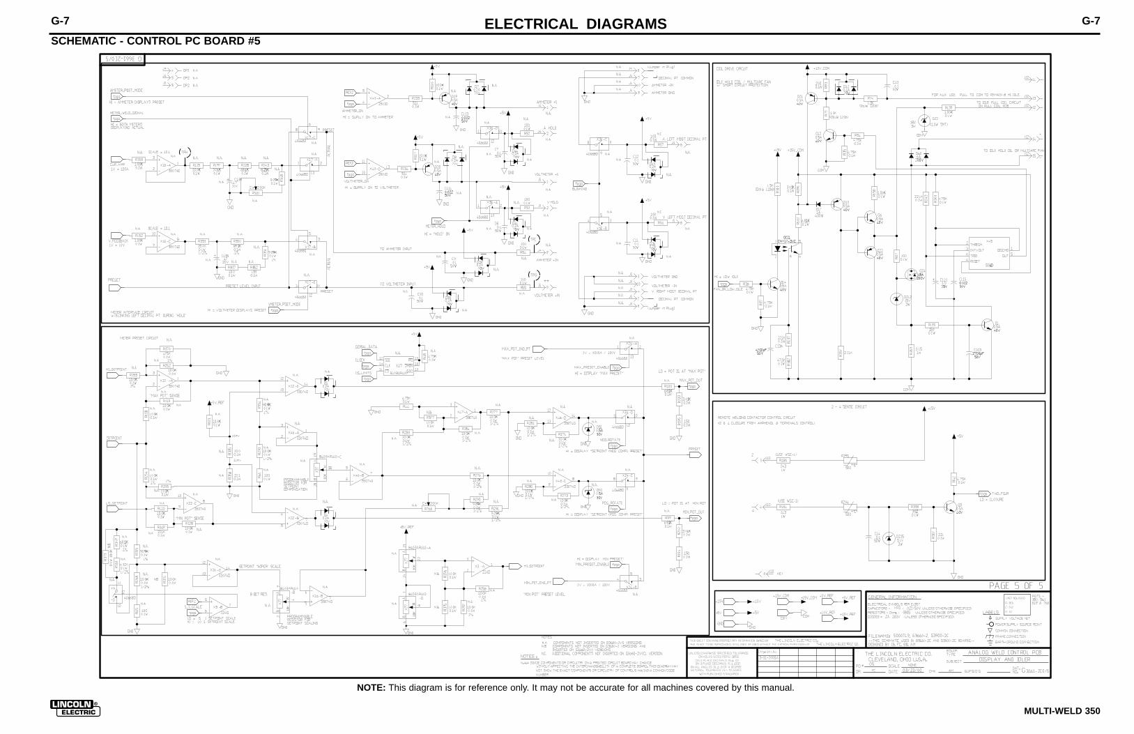
ELECTRICAL DIAGRAMS G-7
MULTI-WELD 350
SCHEMATIC - CONTROL PC BOARD #5
G-7
NOTE: This diagram is for reference only. It may not be accurate for all machines covered by this manual.

SO
LID
ED
GE
EN
-170
MANUFACTURING TOLERANCE PER E2056UNLESS OTHERWISE SPECIFIED TOLERANCE
SCALE:DO NOT SCALE THIS DRAWING
ON 3 PLACE DECIMALS IS ±� .002
THIS SHEET CONTAINS PROPRIETARY INFORMATION OWNED BY THE LINCOLN ELECTRIC COMPANY AND IS NOT TO BE REPRODUCED, DISCLOSED OR USED WITHOUT THE EXPRESS WRITTEN PERMISSION OF THE LINCOLN ELECTRIC COMPANY, CLEVELAND, OHIO U.S.A.
DESIGN INFORMATION
t
DRAWN BY:
WITH PUBLISHED STANDARDS.DATE:
ON 2 PLACE DECIMALS IS ±�.02
MATERIAL TOLERANCE (" ") TO AGREEON ALL ANGLES IS ±� .5 OF A DEGREE SUBJECT:
Chg. Sheet No.
ENGINEER:
EQUIPMENT TYPE:
DRAWING No.:APM
ILD
MAPCOMMON ANALOG CONTROL
WELD CONTROL PCB ASSEMBLYG1:5X 1-27-2000
REFERENCE:
SUPERSEDING:
G3660-1
APPROVED:
"X" INFO.
5000738
5000762
XB-RW
3660-2
UNLESS OTHERWISE SPECIFIED:RESISTANCE = OHMS
BUY PER E3867TEST PER E3869-C
BUY AS
IDENTIFICATION CODE
G3660-2C0}
PART NO.
}
2
2
22 2
2
N.F.
N.B.3
4
N.C.
(4.84)
(7.84)
SCHEMATIC REFERENCE -G3661_2C0
N.G.N.H.
VR155,R156,R157,R158,R159
R160
R161,R162,R163,R164,R165
R166
63 S25001-1213SMT 3 R167,R168,R169 RESISTOR,SMD,121K,1/4W,1206,1%,TR
64 S25000-2211SMT 5 R170,R171,R172,R173,R174 RESISTOR,SMD,METAL FILM,1/10W,2.21K,1
65 S25001-7500SMT 1 R175 RESISTOR,SMD,750OHMS,1/4W,1206,1%,TR
66 S25001-2002SMT 3 R176,R177,R178 RESISTOR,SMD,20K,1/4W,1206,1%,TR
67 S25000-3321SMT 5 R179,R180,R181,R182,R183 RESISTOR,SMD,METAL FILM,1/10W,3.32K,1
68 S25004-2430SMT 4 R184,R185,R186,R187 RESISTOR,SMD,1W,243OHMS,1%
69 S25000-2002SMT 1 R188 RESISTOR,SMD,METAL FILM,1/10W,20.0K,1
R190,R191,R192,R193,R194
R195,R372
R196,R197,R198,R199,R200
R201,R202,R203,R204,R205
R206,R207
72 S25000-1822SMT 2 R208,R209 RESISTOR,SMD,METAL FILM,1/10W,18.2K,1
73 S25000-2670SMT 1 R211 RESISTOR,SMD,METAL FILM,1/10W,267OHMS
74 S25000-3322SMT 2 R213,R214 RESISTOR,SMD,METAL FILM,1/10W,33.2K,1
75 S25000-2213SMT 5 R215,R216,R217,R218,R369 RESISTOR,SMD,METAL FILM,1/10W,221K,1%
76 S25000-1503SMT 1 R219 RESISTOR,SMD,METAL FILM,1/10W,150K,1%
77 S25000-3922SMT 5 R220,R221,R222,R223,R371 RESISTOR,SMD,METAL FILM,1/10W,39.2K,1
78 S25000-3323SMT 2 R224,R225 RESISTOR,SMD,METAL FILM,1/10W,332K,1%
79 S25000-6813SMT 1 R226 RESISTOR,SMD,METAL FILM,1/10W,681K,1%
80 S25000-6812SMT 2 R227,R228 RESISTOR,SMD,METAL FILM,1/10W,68.1K,1
81 S25001-7681SMT 3 R229,R230,R231 RESISTOR,SMD,7.68K,1/4W,1206,1%,TR
R232,R233,R234,R235,R236
R237,R379
83 S25000-2212SMT 4 R238,R239,R240,R242 RESISTOR,SMD,METAL FILM,1/10W,22.1K,1
84 S25000-4322SMT 4 R241,R320,R321,R322 RESISTOR,SMD,METAL FILM,1/10W,43.2K,1
85 S25003-47R5SMT 5 R245,R246,R247,R248,R249 RESISTOR,SMD,1W,47.5OHMS,1%
R250,R251,R252,R253,R254
R255,R256,R257,R258,R259
87 S25008-4321SMT 2 R260,R261 RESISTOR,SMD,PREC,MF,1/10W,4.32K,0.5%
88 S25010-3SMT 3 R262,R263,R264 RESISTOR,SMD,MF,1W,20.0K,1%,SURGE
89 S25001-1211SMT 1 R265 RESISTOR,SMD,1.21K,1/4W,1206,1%,TR
90 S25000-6191SMT 2 R266,R267 RESISTOR,SMD,METAL FILM,1/10W,6.19K,1
R269,R270,R271,R272,R273
R274,R275,R276,R277,R278
R279,R280,R281,R282,R283
R284
92 S25000-4R70SMT 3 R285,R286,R287 RESISTOR,SMD,METAL FILM,1/10W,4.70OHM
93 S25000-5621SMT 1 R288 RESISTOR,SMD,METAL FILM,1/10W,5.62K,1
94 S25008-9091SMT 3 R289,R290,R291 RESISTOR,SMD,PREC,MF,1/10W,9.09K,0.5%
95 S18380-14 4 R292,R293,R294,R295 THERMISTOR,PTC,500OHMS,28mA
96 S25008-4751SMT 1 R296 RESISTOR,SMD,PREC,MF,1/10W,4.75K,0.5%
97 S25007-2150SMT 1 R297 RESISTOR,SMD,PREC,MF,1/10W,215OHMS,0.
98 S25007-6040SMT 1 R298 RESISTOR,SMD,PREC,MF,1/10W,604OHMS,0.
99 S25001-4751SMT 1 R299 RESISTOR,SMD,4.75K,1/4W,1206,1%,TR
100 S25000-2001SMT 1 R300 RESISTOR,SMD,METAL FILM,1/10W,2.00K,1
91 S25008-1002SMT 16 RESISTOR,SMD,PREC,MF,1/10W,10.0K,0.5%
RESISTOR,SMD,METAL FILM,1/10W,511OHMS
86 S25004-2430SMT 10 RESISTOR,SMD,PREC,MF,1/10W,10.0K,0.1%
82 S25000-5110SMT 7
71 S25000-3011SMT 12 RESISTOR,SMD,METAL FILM,1/10W,3.01K,1
70 S25000-1500SMT 7 RESISTOR,SMD,METAL FILM,1/10W,150OHMS
62 S25001-1000SMT 6 RESISTOR,SMD,100OHMS,1/4W,1206,1%,TR
61 S25000-28R7SMT 6 RESISTOR,SMD,METAL FILM,1/10W,28.7OHM
101 S25000-2801SMT 1 R305 RESISTOR,SMD,METAL FILM,1/10W,2.80K,1
102 S25000-2210SMT 2 R306,R307 RESISTOR,SMD,METAL FILM,1/10W,221OHMS
103 S25001-1501SMT 5 R308,R309,R310,R311,R312 RESISTOR,SMD,1.5K,1/4W,1206,1%,TR
104 S25000-1503SMT 2 R316,R317 RESISTOR,SMD,METAL FILM,1/10W,1.82K,1
105 S25000-1003SMT 2 R318,R319 RESISTOR,SMD,METAL FILM,1/10W,100K,1%
106 S25001-1001SMT 2 R323,R324 RESISTOR,SMD,1K,1/4W,1206,1%,TR
107 S25000-39R2SMT 1 R325 RESISTOR,SMD,METAL FILM,1/10W,39.2OHM
108 S25000-4753SMT 2 R326,R370 RESISTOR,SMD,METAL FILM,1/10W,475K,1%
R327,R328,R329,R330,R331
R332,R333,R334
110 S25000-10R0SMT 4 R335,R336,R337,R338 RESISTOR,SMD,METAL FILM,1/10W,10.0OHM
111 S25007-2431SMT 1 R339 RESISTOR,SMD,PREC,MF,1/10W,2.43K,0.1%
112 S25007-1301SMT 1 R340 RESISTOR,SMD,PREC,MF,1/10W,1.30K,0.1%
113 S25007-1023SMT 1 R341 RESISTOR,SMD,PREC,MF,1/10W,102K,0.1%,
114 S25000-5111SMT 1 R342 RESISTOR,SMD,METAL FILM,1/10W,5.11K,1
115 S25001-2370SMT 2 R343,R344 RESISTOR,SMD,237OHMS,1/4W,1206,1%,TR
116 S25008-6812SMT 1 R345 RESISTOR,SMD,PREC,MF,1/10W,68.1K,0.5%
117 S25008-1503SMT 1 R346 RESISTOR,SMD,PREC,MF,1/10W,150K,0.5%,
118 S25008-1212SMT 1 R347 RESISTOR,SMD,PREC,MF,1/10W,12.1K,0.5%
119 S25000-9091SMT 1 R348 RESISTOR,SMD,METAL FILM,1/10W,9.09K,1
120 S25007-6812SMT 2 R349,R350 RESISTOR,SMD,PREC,MF,1/10W,68.1K,0.1%
121 S25007-9091SMT 1 R351 RESISTOR,SMD,PREC,MF,1/10W,9.09K,0.1%
122 S25000-1330SMT 1 R352 RESISTOR,SMD,METAL FILM,1/10W,133OHMS
123 S25008-1502SMT 1 R353 RESISTOR,SMD,PREC,MF,1/10W,15.0K,0.5%
124 S25007-9092SMT 2 R354,R355 RESISTOR,SMD,PREC,MF,1/10W,90.9K,0.1%
125 S25000-22R1SMT 1 R356 RESISTOR,SMD,METAL FILM,1/10W,22.1OHM
126 S25010-1SMT 1 R357 RESISTOR,SMD,MF,2.21K,1/4W,1%,SURGE
127 S25000-3320SMT 1 R358 RESISTOR,SMD,METAL FILM,1/10W,332OHMS
128 S25003-0R15SMT 1 R359 RESISTOR,SMD,1W,0.15OHMS,1%
R360,R361,R362,R363,R364
R365,R366,R367,R383
130 S25007-3321SMT 1 R368 RESISTOR,SMD,PREC,MF,1/10W,3.32K,0.1%
131 S25056-2SMT 4 R380,R561,R619,R766 TRIMMER,SMD,MT,1/4W,2K,10%,LINEAR
132 S15128-27SMT 1 X1 IC,OP-AMP,SINGLE,PRECISION,LT1097S8
X2,X3,X39,X40,X41,X42,X51
X55
X4,X5,X6,X7,X16,X22,X46
X47,X52,X56
135 M15458-6SMT 1 X8 IC,SMD,PWM-CONTROL
X9,X10,X11,X14,X17,X24,X34
X35,X36
137 S15128-11SMT 2 X15,X43 IC,SMT,COMPARATOR,QUAD,2901D
138 S25065-1SMT 1 X20 IC,SMD,MULTIPLEXER,2 TO 1 LINE DATA,H
139 S25057-3SMT 3 X27,X53,X57 POT,DIGITAL,SMD,10K,QUAD,TSSOP-24
140 S25069-2SMT 1 X30 IC,SMD,CMOS,EEPROM,SERIAL,SPI,64Kx8,S
141 S25070-5SMT 1 X31 IC,SMD,FPGA,XCS20,TQFP,144PIN
142 S25069-5SMT 1 X33 IC,SMD,EEPROM,CMOS,CONFIGURATION,256K
143 S15128-10SMT 1 X44 IC,SMD,VOLTAGE REF,ADJ, PECISION,431I
144 S25067-1SMT 1 X45 IC,BIPOLAR,TIMER,SOIC-14
145 S15018-11SMT 1 X50 IC,SMD,CMOS,SWITCH,ANALOG,QUAD,201(SS
146 S25057-2SMT 1 X54 POT,SMD,DIGITAL,10K,1-CHNL,SOIC-8
136 S15018-6SMT 9 IC,SMD,CMOS,SWITCH,ANALOG,QUAD, 4066B
134 S15128-18SMT 10 IC,OP-AMP,SMT,QUAD,HIGH-PERF,33074D
133 S15128-4SMT 8 OP-AMP,SMD,QUAD, GEN-PURPOSE,224D
129 S25001-2001SMT 9 RESISTOR,SMD,2K,1/4W,1206,1%,TR
109 S25002-2000SMT 8 RESISTOR,SMD,200OHMS,1/3W,MF,1%,S1210
41 S24020-4 3 J7,J8,J9 CONNECTOR,MOLEX,MINI,PCB,4-PIN,TIN
42 S24020-16 1 J12 CONNECTOR,MOLEX,MINI,PCB,16-PIN,TIN
43 S15000-22SMT 1 OCI1 OPTOCOUPLER,SMD,PHOTO-TRANSISTOR,70V,
Q1,Q2,Q3,Q4,Q5,Q6,Q7,Q8,Q9
Q10,Q11,Q12,Q14
Q15,Q16,Q17,Q18,Q19,Q20
Q21,Q22
46 S25051-1SMT 1 Q23 TRANSISTOR,SMD,NMF,SOT-223,1.5A,100V,
47 S25051-2SMT 1 Q24 TRANSISTOR,SMD,NMF,D2PAK,18A,200V,IRF
R1,R24,R25,R26,R27,R28,R29
R30,R31,R32,R34,R35,R36
R37,R38,R39,R41,R42,R43
R44,R45,R46,R47,R48,R49
R382
R2,R3,R4,R5,R6,R7,R8,R9
R10,R11,R12,R13,R14,R17
R63
50 S25000-4750SMT 6 R18,R19,R20,R21,R22,R23 RESISTOR,SMD,METAL FILM,1/10W,475OHMS
R50,R51,R52,R53,R54,R55
R56,R57,R58,R59,R60,R61
R64,R65,R66,R67,R68,R69
R70,R71,R72,R73
52 S25000-8251SMT 5 R62,R243,R244,R268,R381 RESISTOR,SMD,METAL FILM,1/10W,8.25K,1
53 S25001-1301SMT 4 R74,R75,R76,R77 RESISTOR,SMD,1.3K,1/4W,1206,1%,TR
R78,R79,R80,R81,R82,R83
R84,R85,R86,R87,R88,R89
R90,R91
55 S25000-2000SMT 4 R92,R93,R94,R210 RESISTOR,SMD,METAL FILM,1/10W,200OHMS
R95,R96,R97,R98,R99,R100
R101,R102,R103,R212
57 S25000-1212SMT 2 R105,R106 RESISTOR,SMD,METAL FILM,1/10W,12.1K,1
R107,R108,R109,R110,R111
R112,R113,R114,R115,R116
R117,R118,R119,R120,R121
R122,R123,R124,R125,R126
R127,R128,R129,R130,R131
R132,R133,R134,R135,R136
R137,R138
R378
R139,R140,R141,R142,R143
R144,R145,R146,R148,R149
R150,R151,R152,R153,R154
60 S25000-4752SMT 5 R147,R301,R302,R303,R304 RESISTOR,SMD,METAL FILM,1/10W,47.5K,1
59 S25000-1001SMT 15 RESISTOR,SMD,METAL FILM,1/10W,1.00K,1
58 S25000-1001SMT 38 RESISTOR,SMD,METAL FILM,1/10W,10.0K,1
56 S25000-6811SMT 10 RESISTOR,SMD,METAL FILM,1/10W,6.81K,1
54 S25001-4750SMT 14 RESISTOR,SMD,475OHMS,1/4W,1206,1%,TR
51 S25000-1000SMT 22 RESISTOR,SMD,METAL FILM,1/10W,100OHMS
RESISTOR,SMD,METAL FILM,1/10W,4.75K,1
49 S25000-1501SMT 15 RESISTOR,SMD,METAL FILM,1/10W,1.50K,1
48 S25000-4751SMT 26
45 S25050-2SMT 8 TRANSISTOR,SMS,PNP,SOT23,0.5A, 40V,MM
44 S25050-1SMT 13 TRANSISTOR,SMD,NPN,0.5A,40V,SOT-23,MM
NOTE: G3990-2 MUST BE REVIEWED WHEN MODIFYING THIS BOARD.
NOTES:
N.A. CAUTION: THIS DEVICE IS SUBJECT TO DAMAGE BY STATIC ELECTRICITY. LINCOLN ELECTRIC TO SEE E2454 BEFORE HANDLING.
N.B. PLACE CONNECTOR KEYING PLUG, OVER HEADER PIN, INLOCATION SHOWN. PLUG SHOULD BE INSERTED BELOWCONNECTOR TOP SURFACE (6 PLACES).
N.C. SECURE P.C. BOARD ASSEMBLY IN PLACE WITH ITEM (4).(2 PLACES, 5.3 +/- .5 IN. LBS).
N.F. PLACE BARCODED ASSEMBLY NUMBER IDENTIFICATION ANDBARCODED SERIAL NUMBER IDENTIFICATION IN AREA SHOWN.
N.G. PROGRAM ITEM (140) WITH ITEM (7).
N.H. PROGRAM ITEM (142) WITH ITEM (8).
N.J. PARTS SHOWN MUST BE COMPLETELY COVEREDWITH ENCAPSULATION.
N.J.
ITEM PART NO. QTY PC BOARD REFERENCE DESIGNATORS DESCRIPTION
1 G3660-C 1 WELD CONTROL PCB BLANK
2 S24671 7 PLUG,KEYING PLUG
3 M19436-2 1 POTTING TRAY
4 S8025-80 2 SELF TAPPING SCREW
5 E2527 170 g EPOXY ENCAPSULATING RESIN
6 E3539 AS REQ. ELECTRICAL INSULATING COMPOUND
7 S24762-4 1 X30 SOFTWARE
8 S24763-4 1 X33 SOFTWARE
C1,C2,C3,C4,C5,C6,C7,C8,C9
C10,C11,C12,C13,C14,C15
C16,C17,C20,C21,C22,C23
C24,C25,C26,C27,C28,C29
C30,C31,C32,C33,C34,C35
C36,C37,C38,C39,C40,C41
C42,C43,C44,C45,C46,C47
C48,C49,C50,C51,C52,C53
C54,C55,C56,C57,C58,C59
C60,C61,C62,C63,C64,C65
C66,C67,C68,C69,C70,C71
C72,C73,C74,C75,C76,C77
C78,C79,C80,C81,C82,C83
C84,C85,C86,C87,C88,C89
C90,C91,C92,C93,C94,C95
C96,C97,C98,C99,C100,C101
C133,C141,C142
C18,C19,C108,C109,C110
C111,C112,C113,C114,C115
C116
C102,C103,C104,C105,C106
C107
12 S25024-6SMT 2 C117,C118 CAPACITOR,SMD,TANTALUM,22MF,16V,10%,S
13 S25020-4SMT 1 C119 CAPACITOR,SMD,CERAMIC,820pF,50V,5%,CO
C120,C121,C122,C123,C124
C125
15 S25020-8SMT 2 C126,C127 CAPACITOR,SMD,CERAMIC,0.056MF,50V,10%
16 S25020-16SMT 1 C128 CAPACITOR,SMD,CERAMIC,0.018MF,50V,1%,
17 S25024-1SMT 1 C129 CAPACITOR,SMD,TANTALUM,0.47MF,50V,10%
18 S25024-5SMT 3 C130,C131,C132 CAPACITOR,SMD,TANTALUM,4.7MF,35V,10%,
19 S25024-3SMT 1 C134 CAPACITOR,SMD,TANTALUM,2.2MF,20V,10%,
20 S25020-10SMT 2 C135,C136 CAPACITOR,SMD,CERAMIC,4700pF,50V,10%,
21 S25020-1SMT 1 C137 CAPACITOR,SMD,CERAMIC,0.022MF,50V,1%,
22 S25024-7SMT 2 C138,C139 CAPACITOR,SMD,TANTALUM,47MF,20V,10%,S
23 S25020-17SMT 1 C140 CAPACITOR,SMD,CERAMIC,0.27MF,50V,10%,
D1,D2,D3,D4,D5,D6,D7,D8,D9
D10,D11,D12
D13,D14,D15,D16,D17,D18
D19,D20,D21,D22,D23,D24
D25,D26,D27,D28,D29,D30
D31,D32
D33,D34,D35,D36,D37,D38
D39,D40,D41,D42,D43,D44
D45,D46,D47,D48
D49,D50,D51,D52,D54,D55
D61,D63,D64
28 S25040-4SMT 3 D56,D57,D62 DIODE,SMD,DUAL,0.200A,70V,UFR
29 S25049-2SMT 2 D58,D59 DIODE,SMD,1A,30V,SMA,SCHOTTKY
30 S25040-3SMT 1 D60 DIODE,SMD,DUAL,6A,200V,DPAK,CC,ULTRA-
31 S25044-5SMT 2 DZ1,DZ2 ZENER DIODE,SMD,3W,18V,5%, SMB
32 S25044-3SMT 3 DZ3,DZ4,DZ14 ZENER DIODE,SMD,3W,12V,5%, SMB
DZ5,DZ6,DZ7,DZ8,DZ9,DZ10
DZ11
34 S25044-4SMT 2 DZ12,DZ13 ZENER DIODE,SMD,3W,15V,5%, SMB
35 S25044-1SMT 1 DZ15 ZENER DIODE,SMD,3W,5.1V,5%, SMB
36 S18248-12 1 J1 CONNECTOR,MOLEX,MINI,PCB,12-PIN
37 S24020-8 2 J2,J13 CONNECTOR,MOLEX,MINI,PCB,8-PIN,TIN
38 S24020-6 3 J3,J10,J11 CONNECTOR,MOLEX,MINI,PCB,6-PIN,TIN
39 S24020-10 2 J4,J5 CONNECTOR,MOLEX,MINI,PCB,10-PIN,TIN
40 S24020-2G 1 J6 CONNECTOR,MOLEX,MINI,PCB,2-PIN,GOLD
FOR ITEMS LISTED BELOW REFER TO ELECTRONIC COMPONENT DATABASE FOR COMPONENT SPECIFICATIONS
9 S25020-3SMT 102 CAPACITOR,SMD,CERAMIC,0.1MF,50V,10%,X
10 S25020-2SMT 11 CAPACITOR,SMD,CERAMIC,0.022MF,50V,10%
11 S25020-5SMT 6 CAPACITOR,SMD,CERAMIC,2700pF,50V,5%,X
14 S25024-2SMT 6 CAPACITOR,SMD,TANTALUM,1.0MF,35V,10%,
24 S25040-6SMT 12 DIODE,SMD,DUAL,0.200A,70V,UDR,CC,SOT-
25 S25040-2SMT 20 DIODE,SMD,1A,400V,DO-214BA/AC
26 S25040-5SMT 16 DIODE,SMD,DUAL,0.200A,70V,UFR
27 S25049-1SMT 9 DIODE,SMD,0.5A,30V,SOD-123,SCHOTTKY
33 S25045-1SMT 7 ZENER_DIODE,SMD,225mW,12V,5%,SOT-23
N.F.
NOTE: Lincoln Electric assumes no responsibility for liablilities resulting from board level troubleshooting. PC Board repairs will invalidate your factory warranty. Individual Printed Circuit Board Components are not available from Lincoln Electric. This information is pro-vided for reference only. Lincoln Electric discourages board level troubleshooting and repair since it may compromise the quality of the design and may result in danger to the Machine Operator or Technician. Improper PC board repairs could result in damage to themachine.
ELECTRICAL DIAGRAMS G-8
MULTI-WELD 350
PC BOARD ASSEMBLY-CONTROL
G-8

ELECTRICAL DIAGRAMS G-9
MULTI-WELD 350
SCHEMATIC - PERIPHERAL PRINTED CIRCUIT BOARD
G-9
NOTE: This diagram is for reference only. It may not be accurate for all machines covered by this manual.

NOTE: Lincoln Electric assumes no responsibility for liablilities resulting from board level troubleshooting. PC Board repairs will invalidate your factory warranty. Individual Printed Circuit Board Components are not available from Lincoln Electric. This information is pro-vided for reference only. Lincoln Electric discourages board level troubleshooting and repair since it may compromise the quality of the design and may result in danger to the Machine Operator or Technician. Improper PC board repairs could result in damage to themachine.
ELECTRICAL DIAGRAMS G-10
MULTI-WELD 350
PC BOARD ASSEMBLY-PERIPHERAL
SO
LID
ED
GE
EN
-170
MANUFACTURING TOLERANCE PER E2056UNLESS OTHERWISE SPECIFIED TOLERANCE
SCALE:DO NOT SCALE THIS DRAWING
ON 3 PLACE DECIMALS IS ±� .002
THIS SHEET CONTAINS PROPRIETARY INFORMATION OWNED BY THE LINCOLN ELECTRIC COMPANY AND IS NOT TO BE REPRODUCED, DISCLOSED OR USED WITHOUT THE EXPRESS WRITTEN PERMISSION OF THE LINCOLN ELECTRIC COMPANY, CLEVELAND, OHIO U.S.A.
DESIGN INFORMATION
t
DRAWN BY:
WITH PUBLISHED STANDARDS.DATE:
ON 2 PLACE DECIMALS IS ±�.02
MATERIAL TOLERANCE (" ") TO AGREEON ALL ANGLES IS ±� .5 OF A DEGREE SUBJECT:
Chg. Sheet No.
ENGINEER:
EQUIPMENT TYPE:
DRAWING No.:
9-17-99A
3-24-2000JAPM
ILDCOMMON ANALOG CONTROL
PERIPHERAL CONTROL PCB ASSEMBLYG1.5X 2/10/99
REFERENCE:
SUPERSEDING:
G3360-2
APPROVED:
"X" INFO.
XM5627
XF-UF
XG-UF
3662-1
N.B.
(2.09)
(6.59)
BUY PER E3867TEST PER E3869-P
N.F.
N.G.
NOTES:
N.A. CAUTION: THIS DEVICE IS SUBJECT TO DAMAGE BY
STATIC ELECTRICITY. LINCOLN ELECTRIC TO SEE E2454
BEFORE HANDLING.
N.B. PLACE CONNECTOR KEYING PLUG, OVER HEADER PIN, IN
LOCATION SHOWN. PLUG SHOULD BE INSERTED BELOW
CONNECTOR TOP SURFACE.
N.C. SECURE PC BOARD ASSEMBLY IN PLACE WITH ITEM (4).
(2 PLACES)
N.F. IDENTIFY COMPLETE ASSEMBLY WITH A PRINTED LABEL OR
OTHER PERMANENT MARKING IN AREA SHOWN.
N.G. NO COMPONENTS ON BOTTOM SIDE OF PC BOARD.
N.H. PROGRAM ITEM 55 WITH ITEM 7 .
34
2
N.C.
UNLESS OTHERWISE SPECIFIED:RESISTANCE = OHMS
BUY AS
G3662-1B0
IDENTIFICATION CODEPART NO.
SCHEMATIC REFERENCE - G3663
VITEM PART NO. QTY
PC BOARD REFERENCE DESIGNATORS
DESCRIPTION
1 G3662-B 1 PCB BLANK
2 S24671 1 PLUG,KEYING PLUG
3 M19436-4 1 POTTING TRAY
4 S8025-80 2 SELF TAPPING SCREW
5 E2527 65g EPOXY ENCAPSULATING RESIN
6 E3539 AS REQ. ELECTRICAL INSULATING COMPOUND
7 S24764-2 1 X5 SOFTWARE
8 S25020-3SMT 15 C15,C17,C19,C20,C21,C22,
C28,C29,C30,C31,C32,C37,
C40,C41,C42
SCAP,0.1uF,0805,50V,X7R,10%,TR,NP
9 S25020-2SMT 7 C2,C3,C36,C43,C44,C45,C46 SCAP,0.022uF,CER,0805,50V,X7R,10%,TR
10 T11577-58 1 C23 CAP,0.0047,3000V,20%,CERAMIC DISC
11 S25024-5SMT 2 C24,C27 SCAP,4.7uF,TANT,7343,35V,10%,TR,NP
12 S25024-9SMT 1 C34 SCAP,100uF,TAN,7343,20V,20%,TR,NP
13 S25024-7SMT 2 C35, C38 SCAP,47uF,TAN,7343,20V,10%
14 S25024-8SMT 1 C39 SCAP,22uF,TAN,7343,25V,10%,POLAR,TR
15 S25040-3SMT 1 D1 SDIO,MURD620CT,6A,200V,ULTRA-FAST,TR,NP
16 S25040-2SMT 11 D6,D7,D10,D11,D12,D15,
D17,D18,D19,D20,D22
SDIO,1A,400V,DO-214BA,GLS,NP
17 S25044-4SMT 2 DZ2,DZ3 SDIO,1SMB5929BT3,3W,15V,5%
18 S25044-6SMT 1 DZ4 SDIO,1SMB5935BT3,3W,27V,5%,TR,NP
19 S25044-7SMT 1 DZ5 SDIO,1SMB5943BT3,3W,56V,5%
20 S25044-8SMT 1 DZ6 SDIO,1SMB5932BT3,3W,20V,5%
21 S18248-6 1 J30 CON,MOLEX,39-28-1063,PCB,6 PIN,TIN
22 S24020-16 1 J31 CON,MOLEX,15-97-7162,MINI,PCB,16 PIN,TIN
23 S24020-12 1 J32 CON,MOLEX,15-97-7122,MINI,PCB,12 PIN,TIN
24 S25051-2SMT 1 Q1 STRA,IRF640S,200V,D2 PAK
25 S25050-1SMT 3 Q2,Q3,Q4 STRA,2N4401,SOT-23,NPN,TR,
26 S25050-2SMT 1 Q5 STRA,2N4403L,PNP,SOT-23,NP
27 S25000-5110SMT 6 R102,R156,R157,R158,
R159,R160
SRES,511,TKF,0805,1%,1/10W,TR
28 S25000-47R5SMT 1 R103 SRES,47.5,0805,1%,1/10W
29 S25000-4750SMT 1 R127 SRES,475,TKF,0805,1%.1/10W,TR
30 S25000-1211SMT 3 R129,R130,R144 SRES,1.21K,0805,1%,1/10W,TR,NP
31 S25000-1501SMT 5 R131,R132,R141,R142,R173 SRES,1.5K,TKF,0805,1%,1/10W,TR
32 S25001-47R5SMT 2 R133,R150 SRES,47.5,TKF,1206,1%,1/4W
33 S25010-4SMT 1 R134 SRES,4.32K,2512,1%,1W
34 S25010-5SMT 2 R135, R143 SRES,3.92K,2512,1%,1W
35 S25000-7500SMT 1 R136 SRES,750,TKF,0805,1%,1/10W
36 S25000-2210SMT 2 R145,R146 SRES,221,TKF,0805,1%,1/10W,TR
37 S25000-2000SMT 1 R162 SRES,200,TKF,0805,1%,1/10W
FOR ITEMS LISTED BELOW REFER TO ELECTRONIC COMPONENT DATABASE FOR COMPONENT
SPECIFICATIONS
38 S25000-5111SMT 1 R163 SRES,5.11K,TKF,0805,1%,1/10W
39 S25000-2002SMT 1 R168 SRES,20K,TKF,0805,1%,1/10W
40 S25056-3SMT 1 R169 SRES,50K,5 TURN POT,1/4W,10%
41 S25000-1502SMT 1 R170 SRES,15K,TKF,0805,1%,1/10W
42 S25000-6811SMT 2 R171, R172 SRES,6.81K,TKF,0805,1%,1/10W
43 S25000-4751SMT 20 R20,R21,R23,R25,R27,R30,
R32,R33,R34,R109,
R113,R114,R115,R116,R138,
R151,R152,R153,R154,R166
SRES,4.75K,0805,1%,TR,NP
44 S25000-6812SMT 2 R35,R111 SRES,68.1K,0805,1%,1/10W,NP
45 S25000-3321SMT 6 R37,R118,R119,R139, R140,
R155
SRES,3.32K,0805,1%,1/10W,NP(B80Q42M71)
46 S25000-1001SMT 3 R40,R46,R167 SRES,1K,0805,1%,1/10W,TR,NP
47 S25056-4SMT 1 R47 SRES,5K,5 TURN POT,1/4W,10%
48 S25000-2212SMT 1 R51 SRES,22.1K,TKF,0805,1%,1/10W
49 S25000-1000SMT 4 R55,R124,R125,R126 SRES,100,TKF,0805,1%,1/10W
50 S25001-2670SMT 8 R57,R58,R59,R60,R62,R63,
R64,R65
SRES,267,1206,1%,1/4W,TR,NP
51 S25000-1002SMT 4 R7,R110,R164,R165 SRES,10K,0805,1%,1/10W,TR,NP
52 S15128-11SMT 2 X1,X2 SICS,2901,NP
53 M15102-4SMT 1 X3 SICS,MC1413BD,ARRAY DRIVER,SO16
54 S25068-1SMT 1 X4 SICS,5V REG,0.5A,2%,DPAK
55 S25070-3SMT 1 X5 SICS,XC9536,44-PIN,VQ44
56 S17900-8SMT 1 X6 SICS,74HC14A
N.H.
N.H.
Br
G-10

ELECTRICAL DIAGRAMS G-11
MULTI-WELD 350
SCHEMATIC - POWER PRINTED CIRCUIT BOARD
G-11
NOTE: This diagram is for reference only. It may not be accurate for all machines covered by this manual.

NOTE: Lincoln Electric assumes no responsibility for liablilities resulting from board level troubleshooting. PC Board repairs will invalidate your factory warranty. Individual Printed Circuit Board Components are not available from Lincoln Electric. This information is pro-vided for reference only. Lincoln Electric discourages board level troubleshooting and repair since it may compromise the quality of the design and may result in danger to the Machine Operator or Technician. Improper PC board repairs could result in damage to themachine.
ELECTRICAL DIAGRAMS G-12
MULTI-WELD 350
PC BOARD ASSEMBLY-POWERCAD
9-17
-99
RM
T/
F
ULL
RT
3-26
-99
t
UN
LESS
OTH
ERW
ISE
SPEC
IFIE
D T
OLE
RA
NC
EO
N H
OLE
SIZ
ES P
ER E
2056
ON
2 P
LAC
E D
ECIM
ALS
IS
.02
WIT
H P
UB
LISH
ED S
TAN
DA
RD
S.
ON
3 P
LAC
E D
ECIM
ALS
IS
.002
ON
ALL
AN
GLE
S IS
.5
OF
A D
EGR
EEM
ATE
RIA
L TO
LER
AN
CE
(" "
) TO
AG
REE
THE
LINC
OLN
ELEC
TRIC
CO.
CLE
VELA
ND
, OH
IO U
.S.A
.
EQ
UIP
.TY
PE
SC
ALE
SU
BJE
CT
DR
DA
TEC
HK
RE
F.S
UP
'S'D
'GS
HT.
NO
.
THE L
INCO
LN EL
ECTR
IC C
O.TH
IS S
HEE
T C
ON
TAIN
S PR
OPR
IETA
RY
INFO
RM
ATI
ON
&
&
OW
NED
BY
AN
D IS
NO
T TO
BE
REP
RO
DU
CED
, DIS
CLO
SED
OR
USE
D
THE L
INCO
LN EL
ECTR
IC C
O.L
LW
ITH
OU
T TH
E EX
PRES
S PE
RM
ISSI
ON
OF
1107
8-1
MAKE PER E1911
L11078-1B0
MANUFACTURED AS:
IDENTIFICATION CODE
}}
CAPACITORS = MFD/VOLTS
RESISTORS = OHMS, 1/4 WATT (UNLESS OTHERWISE SPECIFIED)
ITEM REQ'D PART NO IDENTIFICATION
ITEM REQ'D PART NO. DESCRIPTION
1 1
11078-1
G3699-B
1
0
3.85~.04
40V
DC
BU
S P.
C. B
OAR
D A
SSEM
BLY
MUL
TI-W
ELD
350
P.C. BOARD BLANK
0 4.50~.04
TEST PER E3862
.20
.20
3.65
4.30
ELECTRICITY. SEE E2454 BEFORE HANDLING.CAUTION:N.A. THIS DEVICE IS SUBJECT TO DAMAGE BY STATIC
N.A.
N.A.
N.A.
2 13
M16100-43E2527
ELECTRONIC MODULE
N.B.
2
SCHEMATIC REFERENCE - M19330
X
E-UF
POT PER E1911-E
100 g EPOXY ENCAPSULATING RESIN
N.B. THESE HOLES TO BE KEPT FREE OF POTTING MATERIAL. (.50 DIA. MIN.)
POTTING MATERIAL BUILD UP.N.C. COVER EXPOSED BOTTOM SURFACE OF ELECTRONIC MODULE TO AVOID
G-12

ELECTRICAL DIAGRAMS G-13
MULTI-WELD 350
SCHEMATIC - ANALOG PRINTED CIRCUIT BOARD
G-13
NOTE: This diagram is for reference only. It may not be accurate for all machines covered by this manual.
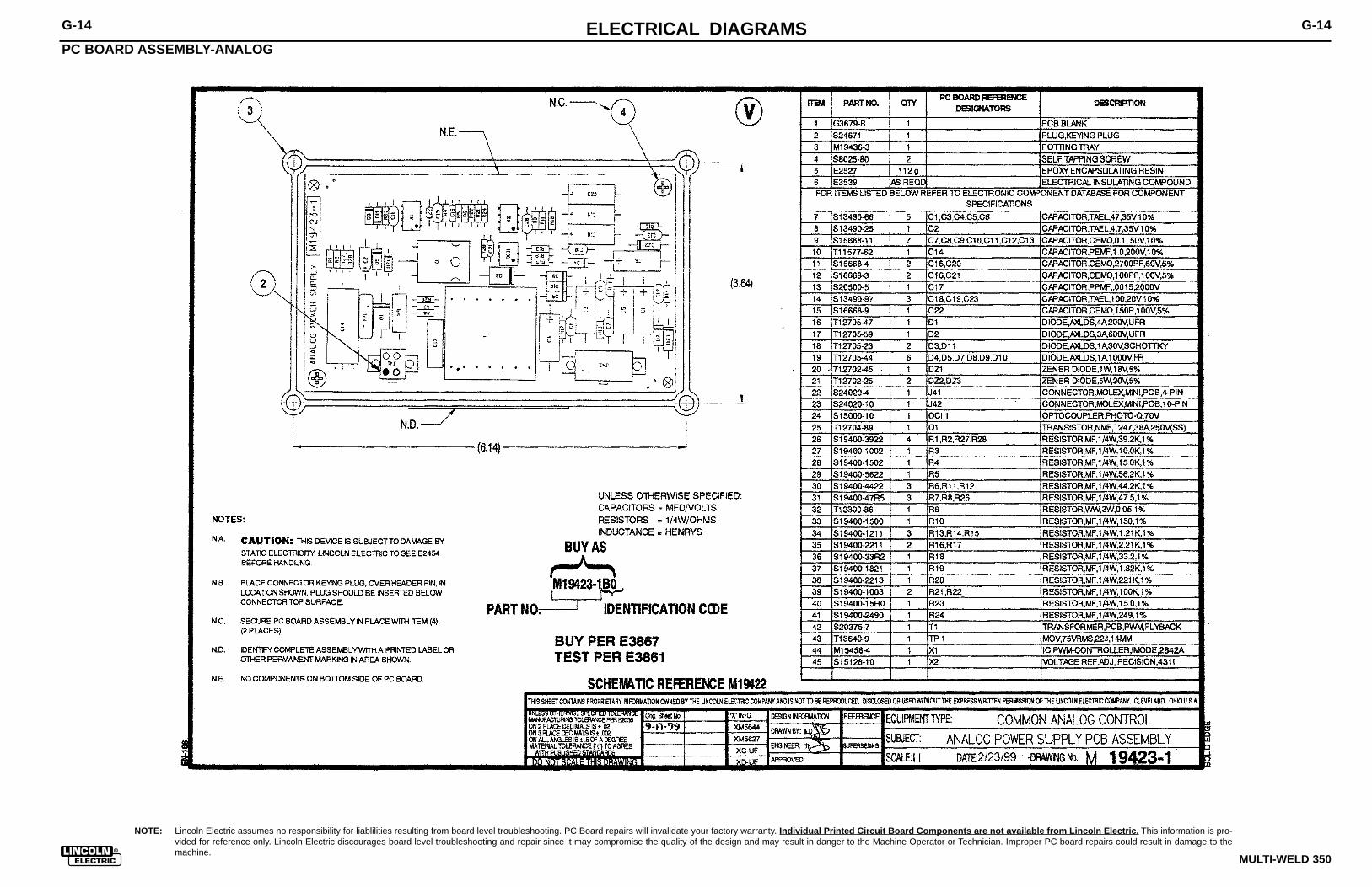
NOTE: Lincoln Electric assumes no responsibility for liablilities resulting from board level troubleshooting. PC Board repairs will invalidate your factory warranty. Individual Printed Circuit Board Components are not available from Lincoln Electric. This information is pro-vided for reference only. Lincoln Electric discourages board level troubleshooting and repair since it may compromise the quality of the design and may result in danger to the Machine Operator or Technician. Improper PC board repairs could result in damage to themachine.
ELECTRICAL DIAGRAMS G-14
MULTI-WELD 350
PC BOARD ASSEMBLY-ANALOG
G-14

ELECTRICAL DIAGRAMS G-15
MULTI-WELD 350
SCHEMATIC - BY-PASS PRINTED CIRCUIT BOARD
G-15
NOTE: This diagram is for reference only. It may not be accurate for all machines covered by this manual.

NOTE: Lincoln Electric assumes no responsibility for liablilities resulting from board level troubleshooting. PC Board repairs will invalidate your factory warranty. Individual Printed Circuit Board Components are not available from Lincoln Electric. This information is pro-vided for reference only. Lincoln Electric discourages board level troubleshooting and repair since it may compromise the quality of the design and may result in danger to the Machine Operator or Technician. Improper PC board repairs could result in damage to themachine.
ELECTRICAL DIAGRAMS G-16
MULTI-WELD 350
PC BOARD ASSEMBLY - BY-PASS
G-16

ELECTRICAL DIAGRAMS G-17
MULTI-WELD 350
SCHEMATIC - CHOPPER PRINTED CIRCUIT BOARD
50V0.1C1
1W16VDZ5
D1
150V8AQ1
B1
D2
4735V
C250050V
C5+ t.24
R14.75K
R14
D3
D5
D4
B2
10.0
R15
4.75K
R6
10.0
R11
G1C2
E4
C1 C3
G2
C4
E2 E5
C5
G3
E1G5
G4
E3
A1
5 118
12
7 10
15
9
4 13
6
3
1
2 14
10.0
R13
1W16VDZ3
10.0
R17
1.0A30V
D7
com
4.75K
R18
4.75K
R20
4.75K
R16
M16100-39
+15
1.0A30V
D8
R-
SHT.
THIS SHEET CONTAINS PROPRIETARY INFORMATION OWNED BY
ON 2 PLACE DECIMALS IS + .O2
FILENAME: M19303_1DA
M
INPUT
NCNC
OCI1
5
2 8
3
6
41
7
19303
B3
D6
PWM
63V1.0C6
DR.
50V0.1C3
B7
8
10.0
R10562
R3
COMMON CONNECTION
com
+15
com
com
+15
WITH PUBLISHED STANDARDS
LABELSC-
ON 3 PLACE DECIMALS IS + .OO2
ON HOLES SIZES PER E-2056UNLESS OTHERWISE SPECIFIED TOLERANCE
MATERIAL TOLERANCE ("t") TO AGREE
D-
EQUIP.
11-11-97DATE
NONECLEVELAND, OHIO U.S.A.
NO.
ON ALL ANGLES IS + .5 OF A DEGREE
CHK.
AND IS NOT TO BE REPRODUCED, DISCLOSED OR USED WITHOUT THE EXPRESS PERMISSION OF
SUPPLY
FRAME CONNECTION
1.21KR2
1.00K
R4
475
R7
GNDGND
VS VS
X2
MIC4451BN
54
1 8
50V0.1C4
50V0.1C7
1W5.1VDZ1
WITHOUT AFFECTING THE INTERCHANGEABILITY OF A COMPLETE BOARD, THIS DIAGRAM MAYNOT SHOW THE EXACT COMPONENTS OR CIRCUITRY OF CONTROLS HAVING A COMMON CODENUMBER.
NOTES :
22 to 32 Vac
.022/50V
SUBJECT
SUP'S'D'G.
TYPETHE LINCOLN ELECTRIC CO.
SCALE
IEB
20
DZ- 5
19303
X- 2
LAST NO. USED
OCI- 1
M
VOLTAGE NET
7
SCHEMATIC
com
POWER SUPPLY SOURCE POINT
EARTH GROUND CONNECTION
CHOPPER,200 AMP
1A, 400V
N.A. SINCE COMPONENTS OR CIRCUITRY ON A PRINTED CIRCUIT BOARD MAY CHANGE
Ch'ge.Sht.No.
THE LINCOLN ELECTRIC CO.THE LINCOLN ELECTRIC CO.
(
to heatsink
UNLESS OTHERWISE SPECIFIED)(UNLESS OTHERWISE SPECIFIED)
UNLESS OTHERWISE SPECIFIED)CAPACITORS =
DIODES =
MFDRESISTORS = Ohms ( 1/4W
GENERAL INFORMATION
ELECTRICAL SYMBOLS PER E1537
54
81
OUT
OUT
GNDGND
IN
VSVS
NC
X2
MIC4451BN
6
2 7
3
XC-RW
9-17-99
G-17
NOTE: This diagram is for reference only. It may not be accurate for all machines covered by this manual.

NOTE: Lincoln Electric assumes no responsibility for liablilities resulting from board level troubleshooting. PC Board repairs will invalidate your factory warranty. Individual Printed Circuit Board Components are not available from Lincoln Electric. This information is pro-vided for reference only. Lincoln Electric discourages board level troubleshooting and repair since it may compromise the quality of the design and may result in danger to the Machine Operator or Technician. Improper PC board repairs could result in damage to themachine.
ELECTRICAL DIAGRAMS G-18
MULTI-WELD 350
PC BOARD ASSEMBLY - CHOPPER
G-18

SVM ERROR REPORTING FORM
We need to know if there are errors in our manuals. We also value any suggestions as toadditional tests or procedures that would make this SVM a better tool for you.
If you discover new or different “Problems or Symptoms” that are not covered in the three col-umn troubleshooting chart, please share this information with us. Please include themachine’s code number and how the problem was resolved.
Thank You,Technical Services GroupLincoln Electric Co.22801 ST. Clair Ave.Cleveland, Ohio 44117-1199
FAX 216-481-2309
SVM Number ___________________________
Page Number if necessary__________________
Your Company__________________________
Your Name_____________________________
Please give detailed description below:
_______________________________________________________________________________________________________________________________________________________________________________________________________________________________________________________________________________________________________________________________________________________________________________________________________________________________________________________________________________________________________________________________________________________________________________________________________________________________________________________________________________________________________________________________________________________________________________________________________________________________________________________________________________________________________________________________________________________________________________________________________________
SD287 01/99
Copyright © 2022 FDOKUMEN