Cardiovascular impedance
8
1176 IEEE TRANSACTIONS ON BIOMEDICAL ENGINEERING, VOL. 57, NO. 5, MAY 2010 Experimental Verification of the Feasibility of the Cardiovascular Impedance Simulator Kwan-Woong Gwak*, Brad E. Paden, Fellow, IEEE, James F. Antaki, Member, IEEE, and Ihn-Seok Ahn Abstract—Mock circulatory systems (MCS) are often used for the development of cardiovascular devices and for the study of the dynamics of blood flow through the cardiovascular system. How- ever, conventional MCS suffer from the repeatability, flexibility, and precision problems because they are typically built up with passive and linear fluidic elements such as compliance chamber, manual valve, and tube. To solve these limitations, we have devel- oped an impedance simulator, comprised of a feedback-controlled positive displacement pump that is capable of generating analo- gous dynamic characteristics as the conventional fluidic elements would generate, thereby replacing the conventional passive fluidic elements that often cause problems. The impedance simulator is ex- perimentally proven to reproduce the impedance of the various dis- crete elements, such as resistance and compliance of the cardiovas- cular system model, as well as the combined impedances of them. Index Terms—Cardiovascular impedance, feedback control, gear pump, mock circulatory system. I. INTRODUCTION M OST biomedical devices including artificial hearts go through the development cycle of designing, in vitro tests, animal tests, and clinical trials before commercialization. However, animal tests and clinical trials induce costs and ethical problems. Moreover, it is difficult to obtain various operating conditions under which new features of devices must be evalu- ated. Instead, mock circulatory systems (MCS)—in vitro eval- uation platform that replicates some physiologic characteristics of human body using hydraulic elements—are often used. It is very useful for training, testing, and research. The physiological characteristics of human cardiovascular circulatory systems are accurately described by using well- developed mathematical models of cardiovascular systems. Mathematical models are typically given in the form of the Manuscript received March 16, 2009; revised May 26, 2009. First published August 25, 2009; current version published April 21, 2010. This work was sup- ported in part by the Korea Research Foundation Grant funded by the Korean Government Ministry of Education and Human Resources Development, Ba- sic Research Promotion Fund under Grant KRF-2007-331-D00019, and in part by the Korea Health 21 Research and Development Project of the Ministry of Health and Welfare under Grant A020609, Republic of Korea. Asterisk indicates corresponding author. ∗ K.-W. Gwak is with the Department of Mechanical Engineering, Sejong University, Seoul 143-747, Korea (e-mail: [email protected]). B. E. Paden is with the Department of Mechanical Engineering, and Depart- ment of Electrical and Computer Engineering, University of California, Santa Barbara, CA 93106 USA (e-mail: [email protected]). J. F. Antaki is with the Department of Biomedical Engineering, Carnegie Mel- lon University, Pittsburgh, PA 15219 USA (e-mail: [email protected]). I.-S. Ahn is with the Division of Energy and Electrical Engineering, Uiduk University, Kyoungju 780-713, Korea (e-mail: [email protected]). Color versions of one or more of the figures in this paper are available online at http://ieeexplore.ieee.org. Digital Object Identifier 10.1109/TBME.2009.2030498 lumped parameter electrical circuit model obtained from the electrical-hydraulics analogy. As various well-developed elec- trical circuit models are available, the best way to construct the MCS is to convert the electrical circuit model consisting of the electrical elements into the hydraulic circuit with hydraulic elements. In conventional MCS, the manual valves are generally used for the implementation of the resistance (R), and the compliance chambers filled with compressed air and water (also known as accumulators) to reproduce the capacitance or compliance (C) of the vasculature. Inertance (L) can be realized by appropriately dimensioned fluid conduit (tubes). However, such hydraulic el- ements have the common limitations in that they all are passive and linear fluidic elements and several critical problems are, thereby, induced. First, MCS based on such elements has poor flexibility. Pas- sive elements just respond to the given pressure and flow condi- tions around them but cannot actively change the pressure and flow conditions as needed. Hence, their dynamic characteristics, i.e., impedance, are fixed once their hardware setup is fixed, and this implies that hardware needs to be reconfigured whenever parameter changes are required. Second, MCS has poor precision and repeatability problems due to the manual calibration. Also, its calibration process is time consuming and inefficient for the same reason. Third, if a complex electrical network model is used for more detailed behavior analysis, its corresponding MCS will be very complex and its calibration will be very dif- ficult because one electrical element is transformed to one hydraulic element. To solve these limitations of the conventional MCS, we pro- pose an active and programmable cardiovascular impedance simulator. The proposed impedance simulator is basically a servo-controlled gear pump unit. A gear pump is a posi- tive displacement type and pumps belonging to this class be- have analogous to controlled current sources. Thus, they may be programmed to provide a prescribed dynamic relationship between pressure and flow—the impedance—using feedback control. This means that if impedance of the gear pump is con- trolled to be same as that of the passive element by the feed- back control for the given condition, the impedance simulator could generate the same dynamic behavior as the passive ele- ment would, and hence, the impedance simulator can replace the problem-making passive elements used in the conventional MCS and performance limitations can be eliminated. Note this is possible due to the controllable impedance of the gear pump while the impedance of the passive elements are fixed with their hardware configuration. 0018-9294/$26.00 © 2009 IEEE
-
Upload
independent -
Category
Documents
-
view
0 -
download
0
Transcript of Cardiovascular impedance
1176 IEEE TRANSACTIONS ON BIOMEDICAL ENGINEERING, VOL. 57, NO. 5, MAY 2010
Experimental Verification of the Feasibility of theCardiovascular Impedance Simulator
Kwan-Woong Gwak*, Brad E. Paden, Fellow, IEEE, James F. Antaki, Member, IEEE, and Ihn-Seok Ahn
Abstract—Mock circulatory systems (MCS) are often used forthe development of cardiovascular devices and for the study of thedynamics of blood flow through the cardiovascular system. How-ever, conventional MCS suffer from the repeatability, flexibility,and precision problems because they are typically built up withpassive and linear fluidic elements such as compliance chamber,manual valve, and tube. To solve these limitations, we have devel-oped an impedance simulator, comprised of a feedback-controlledpositive displacement pump that is capable of generating analo-gous dynamic characteristics as the conventional fluidic elementswould generate, thereby replacing the conventional passive fluidicelements that often cause problems. The impedance simulator is ex-perimentally proven to reproduce the impedance of the various dis-crete elements, such as resistance and compliance of the cardiovas-cular system model, as well as the combined impedances of them.
Index Terms—Cardiovascular impedance, feedback control,gear pump, mock circulatory system.
I. INTRODUCTION
MOST biomedical devices including artificial hearts gothrough the development cycle of designing, in vitro
tests, animal tests, and clinical trials before commercialization.However, animal tests and clinical trials induce costs and ethicalproblems. Moreover, it is difficult to obtain various operatingconditions under which new features of devices must be evalu-ated. Instead, mock circulatory systems (MCS)—in vitro eval-uation platform that replicates some physiologic characteristicsof human body using hydraulic elements—are often used. It isvery useful for training, testing, and research.
The physiological characteristics of human cardiovascularcirculatory systems are accurately described by using well-developed mathematical models of cardiovascular systems.Mathematical models are typically given in the form of the
Manuscript received March 16, 2009; revised May 26, 2009. First publishedAugust 25, 2009; current version published April 21, 2010. This work was sup-ported in part by the Korea Research Foundation Grant funded by the KoreanGovernment Ministry of Education and Human Resources Development, Ba-sic Research Promotion Fund under Grant KRF-2007-331-D00019, and in partby the Korea Health 21 Research and Development Project of the Ministry ofHealth and Welfare under Grant A020609, Republic of Korea. Asterisk indicatescorresponding author.
∗K.-W. Gwak is with the Department of Mechanical Engineering, SejongUniversity, Seoul 143-747, Korea (e-mail: [email protected]).
B. E. Paden is with the Department of Mechanical Engineering, and Depart-ment of Electrical and Computer Engineering, University of California, SantaBarbara, CA 93106 USA (e-mail: [email protected]).
J. F. Antaki is with the Department of Biomedical Engineering, Carnegie Mel-lon University, Pittsburgh, PA 15219 USA (e-mail: [email protected]).
I.-S. Ahn is with the Division of Energy and Electrical Engineering, UidukUniversity, Kyoungju 780-713, Korea (e-mail: [email protected]).
Color versions of one or more of the figures in this paper are available onlineat http://ieeexplore.ieee.org.
Digital Object Identifier 10.1109/TBME.2009.2030498
lumped parameter electrical circuit model obtained from theelectrical-hydraulics analogy. As various well-developed elec-trical circuit models are available, the best way to constructthe MCS is to convert the electrical circuit model consisting ofthe electrical elements into the hydraulic circuit with hydraulicelements.
In conventional MCS, the manual valves are generally usedfor the implementation of the resistance (R), and the compliancechambers filled with compressed air and water (also known asaccumulators) to reproduce the capacitance or compliance (C)of the vasculature. Inertance (L) can be realized by appropriatelydimensioned fluid conduit (tubes). However, such hydraulic el-ements have the common limitations in that they all are passiveand linear fluidic elements and several critical problems are,thereby, induced.
First, MCS based on such elements has poor flexibility. Pas-sive elements just respond to the given pressure and flow condi-tions around them but cannot actively change the pressure andflow conditions as needed. Hence, their dynamic characteristics,i.e., impedance, are fixed once their hardware setup is fixed, andthis implies that hardware needs to be reconfigured wheneverparameter changes are required.
Second, MCS has poor precision and repeatability problemsdue to the manual calibration. Also, its calibration process istime consuming and inefficient for the same reason.
Third, if a complex electrical network model is usedfor more detailed behavior analysis, its corresponding MCSwill be very complex and its calibration will be very dif-ficult because one electrical element is transformed to onehydraulic element.
To solve these limitations of the conventional MCS, we pro-pose an active and programmable cardiovascular impedancesimulator. The proposed impedance simulator is basically aservo-controlled gear pump unit. A gear pump is a posi-tive displacement type and pumps belonging to this class be-have analogous to controlled current sources. Thus, they maybe programmed to provide a prescribed dynamic relationshipbetween pressure and flow—the impedance—using feedbackcontrol. This means that if impedance of the gear pump is con-trolled to be same as that of the passive element by the feed-back control for the given condition, the impedance simulatorcould generate the same dynamic behavior as the passive ele-ment would, and hence, the impedance simulator can replacethe problem-making passive elements used in the conventionalMCS and performance limitations can be eliminated. Note thisis possible due to the controllable impedance of the gear pumpwhile the impedance of the passive elements are fixed with theirhardware configuration.
0018-9294/$26.00 © 2009 IEEE
GWAK et al.: EXPERIMENTAL VERIFICATION OF FEASIBILITY OF CARDIOVASCULAR IMPEDANCE SIMULATOR 1177
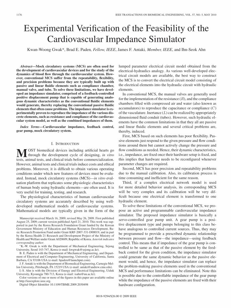
Fig. 1. Simple reference model of MCS.
Gear pumps already have been used for the mock loop inseveral papers. Ferrari et al. [1]–[3] implemented the dynamiccharacteristics of the hydraulic arterial circulation section con-nected to the numerical model of the circulation using two gearpumps. In their papers, two gear pumps were simply used asflow generators supplying the flow into and out of the hydraulicarterial circulation section based on the static pressure–flowrelationship. However, if two gear pumps are not perfectly syn-chronized and errors made from each gear pumps accumulate,the greater the chance that the dynamics of the arterial circula-tion section will be distorted. Also, using two gear pumps makesthe system more complicated and costly.
In this paper, we use the gear pump as the pressure controllerbased on the feedback control of the dynamic pressure–flowrelationship rather than using it as simple flow source based onthe static relationship. As a result, the dynamic characteristicsof the arterial circulation section can be completely regeneratedwith only one gear pump, thereby making the system simpleand intelligent.
Note that this paper is an experimental extension of ourprevious paper—a theoretical development of the impedancesimulator [4]. The objective of current paper is to provide ex-perimental validation of the impedance simulator to reproducephysiologic systemic vascular impedance, hence arterial hemo-dynamic waveforms.
II. REFERENCE MCS
The reference MCS to be used in this paper is adapted fromthe lumped parameter electrical equivalence model described byLoh and Yu [5]. As the main objective of this paper is to evaluatethe feasibility and performance of the impedance simulator, thefour-element Windkessel model, with its atria and right ventri-cle simplified as shown in Fig. 1, is used in this paper to focuson the afterload impedances. Therefore, reference MCS is com-posed of the left ventricle and the afterload impedance, which iscomprised of aortic compliance CAO , arterial resistance R, andinertance L. As mentioned, venous return system is simplifiedwith a left-atrium compliance CLA .
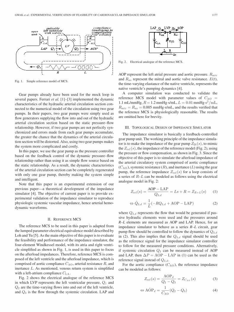
Fig. 2 shows the electrical analogue of the reference MCSin which LVP represents the left ventricular pressure, Q1 andQ2 are the time-varying flows into and out of the left ventricle,and Q3 is the flow through the systemic circulation. LAP and
Fig. 2. Electrical analogue of the reference MCS.
AOP represent the left atrial pressure and aortic pressure. Rmtrand Rao represent the mitral and aortic valve resistance. E(t),the time-varying elastance of the native ventricle, represents thenative ventricle’s pumping dynamics [4].
A computer simulation was conducted to validate thereference MCS model with parameter values of CAO =1.1 mL/mmHg, R = 1.2 mmHg·s/mL, L = 0.01 mmHg·s2/mL,Rmtr = Rao = 0.005 mmHg·s/mL, and the results verified thatthe reference MCS is physiologically reasonable. The resultsare omitted here for brevity.
III. TOPOLOGICAL DESIGN OF IMPEDANCE SIMULATOR
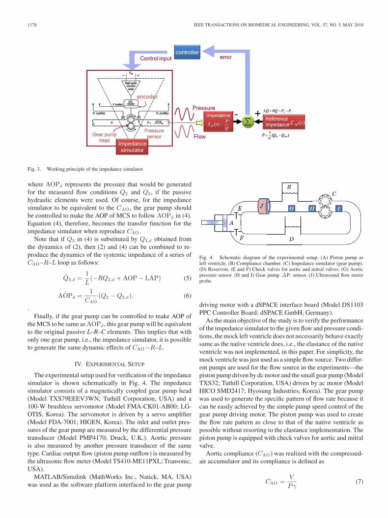
The impedance simulator is basically a feedback-controlledgear pump unit. The working principle of the impedance simula-tor is to make the impedance of the gear pump ZIS(s), to mimicthe Zref (s), the impedance of the reference model (Fig. 2), usingthe pressure or flow compensation, as shown in Fig. 3. Since theobjective of this paper is to simulate the afterload impedance ofthe arterial circulatory system comprised of aortic compliance(CAO ), systemic resistance (R), and inertance (L) using the gearpump, the reference impedance Zref (s) for a loop consists ofa series of R–L can be modeled as follows using the electricalanalogue model in Fig. 2:
Zref (s) =AOP − LAP
Q3,d= Ls + R = ZR+L (s) (1)
⇔ Q3,d =1L
(−RQ3,d + AOP − LAP) (2)
where Q3,d represents the flow that would be generated if pas-sive hydraulic elements were used and the pressures aroundR–L elements are measured as AOP and LAP. Hence, for animpedance simulator to behave as a series R–L circuit, gearpump flow should be controlled to follow the dynamics of Q3,d
in (2). This also implies that the Q3,d signal should be usedas the reference signal for the impedance simulator controllerto follow for the measured pressure conditions. Alternatively,if systemic circulation Q3 can be measured instead of AOPand LAP, then ∆P = AOP − LAP in (1) can be used as thereference signal instead of Q3,d .
For the aortic compliance (CAO ), the reference impedancecan be modeled as follows:
Zref (s) =AOPd
Q2 − Q3= ZCA O (s) (3)
⇔ AOPd =1
CAO(Q2 − Q3) (4)
1178 IEEE TRANSACTIONS ON BIOMEDICAL ENGINEERING, VOL. 57, NO. 5, MAY 2010
Fig. 3. Working principle of the impedance simulator.
where AOPd represents the pressure that would be generatedfor the measured flow conditions Q2 and Q3 , if the passivehydraulic elements were used. Of course, for the impedancesimulator to be equivalent to the CAO , the gear pump shouldbe controlled to make the AOP of MCS to follow AOPd in (4).Equation (4), therefore, becomes the transfer function for theimpedance simulator when reproduce CAO .
Note that if Q3 in (4) is substituted by Q3,d obtained fromthe dynamics of (2), then (2) and (4) can be combined to re-produce the dynamics of the systemic impedance of a series ofCAO–R–L loop as follows:
Q3,d =1L
(−RQ3,d + AOP − LAP) (5)
AOPd =1
CAO(Q2 − Q3,d). (6)
.Finally, if the gear pump can be controlled to make AOP of
the MCS to be same as AOPd , this gear pump will be equivalentto the original passive L–R–C elements. This implies that withonly one gear pump, i.e., the impedance simulator, it is possibleto generate the same dynamic effects of CAO−R–L.
IV. EXPERIMENTAL SETUP
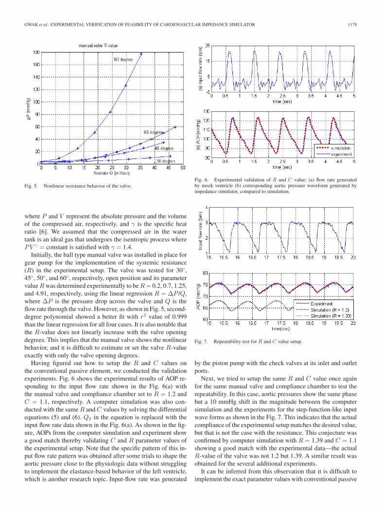
The experimental setup used for verification of the impedancesimulator is shown schematically in Fig. 4. The impedancesimulator consists of a magnetically coupled gear pump head(Model TXS79EEEV3WN; Tuthill Corporation, USA) and a100-W brushless servomotor (Model FMA-CK01-AB00; LG-OTIS, Korea). The servomotor is driven by a servo amplifier(Model FDA-7001; HIGEN, Korea). The inlet and outlet pres-sures of the gear pump are measured by the differential pressuretransducer (Model PMP4170; Druck, U.K.). Aortic pressureis also measured by another pressure transducer of the sametype. Cardiac output flow (piston pump outflow) is measured bythe ultrasonic flow meter (Model TS410-ME11PXL; Transonic,USA).
MATLAB/Simulink (MathWorks Inc., Natick, MA, USA)was used as the software platform interfaced to the gear pump
Fig. 4. Schematic diagram of the experimental setup. (A) Piston pump asleft ventricle. (B) Compliance chamber. (C) Impedance simulator (gear pump).(D) Reservoir. (E and F) Check valves for aortic and mitral valves. (G) Aorticpressure sensor. (H and I) Gear pump. ∆P: sensor. (J) Ultrasound flow meterprobe.
driving motor with a dSPACE interface board (Model DS1103PPC Controller Board; dSPACE GmbH, Germany).
As the main objective of the study is to verify the performanceof the impedance simulator to the given flow and pressure condi-tions, the mock left ventricle does not necessarily behave exactlysame as the native ventricle does, i.e., the elastance of the nativeventricle was not implemented, in this paper. For simplicity, themock ventricle was just used as a simple flow source. Two differ-ent pumps are used for the flow source in the experiments—thepiston pump driven by dc motor and the small gear pump (ModelTXS32; Tuthill Corporation, USA) driven by ac motor (ModelHICO SMD2417; Hyosung Industries, Korea). The gear pumpwas used to generate the specific pattern of flow rate because itcan be easily achieved by the simple pump speed control of thegear pump driving motor. The piston pump was used to createthe flow rate pattern as close to that of the native ventricle aspossible without resorting to the elastance implementation. Thepiston pump is equipped with check valves for aortic and mitralvalve.
Aortic compliance (CAO ) was realized with the compressed-air accumulator and its compliance is defined as
CAO =V
Pγ(7)
GWAK et al.: EXPERIMENTAL VERIFICATION OF FEASIBILITY OF CARDIOVASCULAR IMPEDANCE SIMULATOR 1179
Fig. 5. Nonlinear resistance behavior of the valve.
where P and V represent the absolute pressure and the volumeof the compressed air, respectively, and γ is the specific heatratio [6]. We assumed that the compressed air in the watertank is an ideal gas that undergoes the isentropic process wherePV γ = constant is satisfied with γ = 1.4.
Initially, the ball type manual valve was installed in place forgear pump for the implementation of the systemic resistance(R) in the experimental setup. The valve was tested for 30◦,45◦, 50◦, and 60◦, respectively, open position and its parametervalue R was determined experimentally to be R = 0.2, 0.7, 1.25,and 4.91, respectively, using the linear regression R = ∆P /Q,where ∆P is the pressure drop across the valve and Q is theflow rate through the valve. However, as shown in Fig. 5, second-degree polynomial showed a better fit with r2 value of 0.999than the linear regression for all four cases. It is also notable thatthe R-value does not linearly increase with the valve openingdegrees. This implies that the manual valve shows the nonlinearbehavior, and it is difficult to estimate or set the valve R-valueexactly with only the valve opening degrees.
Having figured out how to setup the R and C values onthe conventional passive element, we conducted the validationexperiments. Fig. 6 shows the experimental results of AOP re-sponding to the input flow rate shown in the Fig. 6(a) withthe manual valve and compliance chamber set to R = 1.2 andC = 1.1, respectively. A computer simulation was also con-ducted with the same R and C values by solving the differentialequations (5) and (6). Q2 in the equation is replaced with theinput flow rate data shown in the Fig. 6(a). As shown in the fig-ure, AOPs from the computer simulation and experiment showa good match thereby validating C and R parameter values ofthe experimental setup. Note that the specific pattern of this in-put flow rate pattern was obtained after some trials to shape theaortic pressure close to the physiologic data without strugglingto implement the elastance-based behavior of the left ventricle,which is another research topic. Input-flow rate was generated
Fig. 6. Experimental validation of R and C value: (a) flow rate generatedby mock ventricle (b) corresponding aortic pressure waveform generated byimpedance simulator, compared to simulation.
Fig. 7. Repeatability test for R and C value setup.
by the piston pump with the check valves at its inlet and outletports.
Next, we tried to setup the same R and C value once againfor the same manual valve and compliance chamber to test therepeatability. In this case, aortic pressures show the same phasebut a 10 mmHg shift in the magnitude between the computersimulation and the experiments for the step-function-like inputwave forms as shown in the Fig. 7. This indicates that the actualcompliance of the experimental setup matches the desired value,but that is not the case with the resistance. This conjecture wasconfirmed by computer simulation with R = 1.39 and C = 1.1showing a good match with the experimental data—the actualR-value of the valve was not 1.2 but 1.39. A similar result wasobtained for the several additional experiments.
It can be inferred from this observation that it is difficult toimplement the exact parameter values with conventional passive
1180 IEEE TRANSACTIONS ON BIOMEDICAL ENGINEERING, VOL. 57, NO. 5, MAY 2010
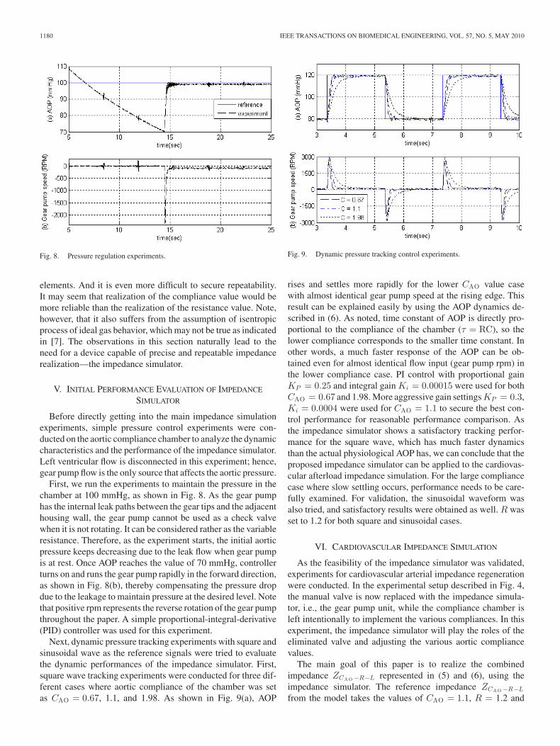
Fig. 8. Pressure regulation experiments.
elements. And it is even more difficult to secure repeatability.It may seem that realization of the compliance value would bemore reliable than the realization of the resistance value. Note,however, that it also suffers from the assumption of isentropicprocess of ideal gas behavior, which may not be true as indicatedin [7]. The observations in this section naturally lead to theneed for a device capable of precise and repeatable impedancerealization—the impedance simulator.
V. INITIAL PERFORMANCE EVALUATION OF IMPEDANCE
SIMULATOR
Before directly getting into the main impedance simulationexperiments, simple pressure control experiments were con-ducted on the aortic compliance chamber to analyze the dynamiccharacteristics and the performance of the impedance simulator.Left ventricular flow is disconnected in this experiment; hence,gear pump flow is the only source that affects the aortic pressure.
First, we run the experiments to maintain the pressure in thechamber at 100 mmHg, as shown in Fig. 8. As the gear pumphas the internal leak paths between the gear tips and the adjacenthousing wall, the gear pump cannot be used as a check valvewhen it is not rotating. It can be considered rather as the variableresistance. Therefore, as the experiment starts, the initial aorticpressure keeps decreasing due to the leak flow when gear pumpis at rest. Once AOP reaches the value of 70 mmHg, controllerturns on and runs the gear pump rapidly in the forward direction,as shown in Fig. 8(b), thereby compensating the pressure dropdue to the leakage to maintain pressure at the desired level. Notethat positive rpm represents the reverse rotation of the gear pumpthroughout the paper. A simple proportional-integral-derivative(PID) controller was used for this experiment.
Next, dynamic pressure tracking experiments with square andsinusoidal wave as the reference signals were tried to evaluatethe dynamic performances of the impedance simulator. First,square wave tracking experiments were conducted for three dif-ferent cases where aortic compliance of the chamber was setas CAO = 0.67, 1.1, and 1.98. As shown in Fig. 9(a), AOP
Fig. 9. Dynamic pressure tracking control experiments.
rises and settles more rapidly for the lower CAO value casewith almost identical gear pump speed at the rising edge. Thisresult can be explained easily by using the AOP dynamics de-scribed in (6). As noted, time constant of AOP is directly pro-portional to the compliance of the chamber (τ = RC), so thelower compliance corresponds to the smaller time constant. Inother words, a much faster response of the AOP can be ob-tained even for almost identical flow input (gear pump rpm) inthe lower compliance case. PI control with proportional gainKP = 0.25 and integral gain Ki = 0.00015 were used for bothCAO = 0.67 and 1.98. More aggressive gain settings KP = 0.3,Ki = 0.0004 were used for CAO = 1.1 to secure the best con-trol performance for reasonable performance comparison. Asthe impedance simulator shows a satisfactory tracking perfor-mance for the square wave, which has much faster dynamicsthan the actual physiological AOP has, we can conclude that theproposed impedance simulator can be applied to the cardiovas-cular afterload impedance simulation. For the large compliancecase where slow settling occurs, performance needs to be care-fully examined. For validation, the sinusoidal waveform wasalso tried, and satisfactory results were obtained as well. R wasset to 1.2 for both square and sinusoidal cases.
VI. CARDIOVASCULAR IMPEDANCE SIMULATION
As the feasibility of the impedance simulator was validated,experiments for cardiovascular arterial impedance regenerationwere conducted. In the experimental setup described in Fig. 4,the manual valve is now replaced with the impedance simula-tor, i.e., the gear pump unit, while the compliance chamber isleft intentionally to implement the various compliances. In thisexperiment, the impedance simulator will play the roles of theeliminated valve and adjusting the various aortic compliancevalues.
The main goal of this paper is to realize the combinedimpedance ZCA O −R−L represented in (5) and (6), using theimpedance simulator. The reference impedance ZCA O −R−L
from the model takes the values of CAO = 1.1, R = 1.2 and

GWAK et al.: EXPERIMENTAL VERIFICATION OF FEASIBILITY OF CARDIOVASCULAR IMPEDANCE SIMULATOR 1181
Fig. 10. Block diagram of the impedance simulation experiment.
L = 0.01 mmHg·s2/mL. However, the effect of inertance onthe reference impedance was found to be negligible by the com-puter simulation due to its small value (0.01 mmHg·s2/mL).Therefore, instead of ZCA O −R−L , a simplified impedanceZCA O −R was adopted as the new reference impedance for thisexperiment
AOPd =1
CAO(Q2 − Q3,d)
=1
CAO
(Q2 −
AOP − LAPR
)
= − 1CAOR
AOP +1
CAOQ2 +
1CAOR
LAP (8)
where CAO = 1.1 and R = 1.2. Note that ZCA O −R now isa first-order dynamics. Based on the reference impedance in(8), impedance simulation experiment can be represented as theblock diagram in Fig. 10. As shown, desired aortic pressureAOPd is calculated first from the desired impedance dynamicsusing the LAP and Q2 measured from the experimental setup.Next, the error is computed by comparing AOPd with the mea-sured AOP. Then, feedback controller adjusts the gear pumpspeed to drive the AOP to follow the AOPd .
Now, the experimental setup consists of only a compliancechamber and a gear pump but no valve. Aortic compliance ofthe chamber was set to the same value as the reference model,i.e., parameters for experimental setup are Cexp = 1.1 andRexp ≈ 12 (static resistance of gear pump experimentally ob-tained). Therefore, the impedance simulator needs to com-pensate for the difference between the reference impedance(CAO = 1.1 and R = 1.2) and the actual impedance of ex-perimental setup Cexp = 1.1 and Rexp ≈ 12, i.e., it needs tomimic the roles of the eliminated valve R only. Fig. 11 showsthe experimental results of the systemic resistance impedanceZR simulation. Note that the input flow Q2 is not based on theelastance waveform.
Three different scenarios (R = 0.5 for decreased afterload,R = 1.2 for nominal case, R = 2.1 for increased afterload)were tested. The solid line in Fig. 11(b) represents the datafrom the computer simulation with three different referenceimpedances R = 0.5, 1.2, and 2.1 with C = 1.1, and the dashedline represents the corresponding experimental results. All three
Fig. 11. Experimental results of the systemic resistance impedance ZR sim-ulation.
Fig. 12. Experimental results of the systemic resistance impedance ZC A O −R
simulation using the impedance simulator.
cases showed good matches with the computer simulation re-sults (reference signal) obtained from the desired impedance—asuccessful simulation of ZR . This good performance was wellpredicted beforehand from the mathematical expression of theZR = R = ∆P/Q. As ZR does not involve any dynamics,just involves a static relationship, the gear pump is expectedto generate the required pump flow well, unless ∆P changesabruptly, which is unlikely but may limit the performance, ifany, because it may involve high acceleration that gear pumpdriving motor may not tolerate. PID controller with KP =0.77, Ki = 0.002 ∼ 0.004, Kd = 0.01 were used for theseexperiments.
Upon completion of the ZR simulation, experiments to simu-late the ZCA O −R were conducted. Fig. 12 shows the experimen-tal and computer simulation results of ZCA O −R for the input flowshown in Fig. 12(a). For the realization of ZCA O −R with the ref-erence value CAO = 1.1 and R = 1.2, actual aortic complianceof the experimental setup was intentionally set different from thedesired value (CAO = 1.1) as Cexp = 0.166, 0.46, 1.1, and 2.
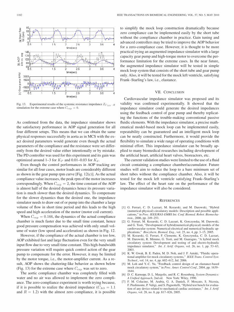
1182 IEEE TRANSACTIONS ON BIOMEDICAL ENGINEERING, VOL. 57, NO. 5, MAY 2010
Fig. 13. Experimental results of the systemic resistance impedance ZC A O −R
simulation for the extreme case where Cexp = 0.
As confirmed from the data, the impedance simulator showsthe satisfactory performance in AOP signal generation for allfour different setups. This means that we can obtain the samephysical responses successfully in aorta as in MCS with the ex-act desired parameters would generate even though the actualparameters of the compliance and the resistance were set differ-ently from the desired value either intentionally or by mistake.The PD controller was used for this experiment and its gain wasoptimized around 1–3 for KP and 0.01–0.03 for Kd .
Even though the control performances in AOP tracking aresimilar for all four cases, motor loads are considerably differentas shown in the gear pump rpm curve [Fig. 12(c)]. As the actualcompliance value increases, the peak rpm of the motor increasescorrespondingly. When Cexp = 2, the time constant of the AOPis almost half of the desired dynamics hence its pressure varia-tion is much slower than the desired dynamics. To compensatefor the slower dynamics than the desired one, the impedancesimulator needs to draw out of or pump into the chamber a largevolume of flow in short time period and this leads to the highspeed and high acceleration of the motor (motor coil current).
When Cexp = 0.166, the dynamics of the actual compliancechamber is much faster due to the small time constant, hencegood pressure compensation was achieved with only small vol-ume of water (low speed and acceleration) as shown in Fig. 12.
However, if the compliance of the actual chamber is too low,AOP exhibited fast and large fluctuation even for the very smallinput flow due to very small time constant. This high-bandwidthpressure variation will require quick control action of the gearpump to compensate for the error. However, it may be limitedby the motor torque, i.e., the motor-amplifier current. As a re-sult, AOP shows the chattering-like behavior as shown below(Fig. 13) for the extreme case where Cexp was set to zero.
The aortic compliance chamber was completely filled withwater and no air was allowed to implement the zero compli-ance. The zero-compliance experiment is worth trying because,if it is possible to realize the desired impedance (CAO = 1.1and R = 1.2) with the almost zero compliance, it is possible
to simplify the mock loop construction dramatically becausezero compliance can be implemented easily by the short tubewithout the compliance chamber in practice. Gain tuning andadvanced controllers may be tried to improve the AOP behaviorfor a zero-compliance case. However, it is thought to be morepractical trying an augmented impedance simulator with a largecapacity gear pump and high-torque motor to overcome the per-formance limitation for the extreme cases. In the near future,the augmented impedance simulator will be tested in simplemock loop system that consists of the short tube and gear pumponly. Also, it will be tested for the mock left ventricle, satisfyingFrank–Starling’s law, i.e., elastance.
VII. CONCLUSION
Cardiovascular impedance simulator was proposed and itsvalidity was confirmed experimentally. It showed that theimpedance simulator could generate the desired impedancesusing the feedback control of gear pump and thereby replicat-ing the functions of the trouble-making conventional passivefluidic elements. With the impedance simulator, a precise math-ematical model-based mock loop can be implemented easily,repeatability can be guaranteed and an intelligent mock loopcan be neatly constructed. Furthermore, it would provide theflexibility to simulate a wide range of operating conditions withminimal effort. This impedance simulator can be broadly ap-plied to many biomedical researches including development ofthe artificial heart, artificial heart valves, bioreactors, etc.
The current validation studies were limited to the use of a fluidcircuit containing a compliance chamber/accumulator. Futurestudies will aim to reduce the loop to a bare minimum set ofshort tubes without the compliance chamber. Also, it will betested for the mock left ventricle satisfying Frank–Starling’slaw. The effect of the heart rate on the performance of theimpedance simulator will also be considered.
REFERENCES
[1] G. Ferrari, C. D. Lazzari, M. Kozarski, and M. Darowski, “Hybrid(numerical-physical) circulatory models: Description and possible appli-cations,” in Proc. IEEE/RAS-EMBS Int. Conf. Biomed. Robot. Biomecha-tron., 2006, pp. 249–253.
[2] G. Ferrari, M. Kozarski, C. D. Lazzari, K. Gorczynska, M. Darowski,and G. Tosti, “Development of hybrid(numerical-physical) models of thecardiovascular system: Numerical-electrical and numerical hydraulic ap-plications,” Biocybern. Biomed. Eng., vol. 25, no. 4, pp. 3–15, 2005.
[3] M. Kozarski, G. Ferrari, F. Clemente, K. Gorczynska, C. D. Lazzari,M. Darowski, R. Mimmo, G. Tosti, and M. Guaragno, “A hybrid mockcirculatory system: Development and testing of and electro-hydraulicimpedance simulator,” Int. J. Artif. Organs, vol. 26, no. 1, pp. 53–63,2003.
[4] K. W. Gwak, B. E. Paden, M. D. Noh, and J. F. Antaki, “Fluidic opera-tional amplifier for mock circulatory systems,” IEEE Trans. Control Syst.Technol., vol. 14, no. 4, pp. 602–612, Jul. 2006.
[5] M. Loh and Y.-C. Yu, “Feedback control design of an elastance-basedmock circulatory system,” in Proc. Amer. Control Conf., 2004, pp. 1639–1644.
[6] D. C. Karnopp, D. L. Margolis, and R. C. Rosenberg, System Dynamics:A Unified Approach, 2nd ed. New York: Wiley, 1990.
[7] F. M. Colacino, M. Arabia, G. A. Danieli, F. Moscato, S. Nicosia,F. Piedimonte, P. Valigi, and S. Pagnottelli, “Hybrid test bench for evalua-tion of any device related to mechanical cardiac assistance,” Int. J. Artif.Organs, vol. 28, no. 8, pp. 817–826, 2005.
GWAK et al.: EXPERIMENTAL VERIFICATION OF FEASIBILITY OF CARDIOVASCULAR IMPEDANCE SIMULATOR 1183
Kwan-Woong Gwak received the B.S. and M.S. de-grees in mechanical engineering from Korea Uni-versity, Korea, in 1993 and 1995, respectively, andthe Ph.D. degree with a specialization in nonlinearcontrol system design from the University of Texas,Austin, in 2003.
He joined the Robotics Laboratory, Korean Insti-tute of Science and Technology, Seoul, as a ResearchScientist to develop the die polishing robot systems,in 1995. From 2003 to 2004, he was a PostdoctoralFellow with LaunchPoint Technologies, Inc., Goleta,
CA. From 2004 to 2006, he was a Manager with Samsung SDI ProductionEngineering Research Center, Seoul, to develop the fuel cell performance testsystem. He has been an Assistant Professor with the Department of MechanicalEngineering, Sejong University, Seoul, since 2006.
His current research interests include nonlinear optimal control with applica-tion to electromechanial and biomedical systems, adaptive control of artificialheart, mechatronic system for the biomedical engineering, and fuel-cell perfor-mance test system.
Brad E. Paden (S’83–M’85–SM’02–F’05) receivedthe Ph.D. degree in electrical engineering from theUniversity of California, Berkeley, in 1985.
He is currently a Professor with the Departmentof Mechanical Engineering, University of Califor-nia, Santa Barbara, and also with the Department ofElectrical and Computer Engineering. His researchinterests include nonlinear control theory and itsapplication to electromechanical systems. He was aVisiting Fellow with the Department of Mathemat-ics, University of Western Australia, Crawley, WA,
Australia, in 1988. He is the Co-founder and President of LaunchPoint Tech-nologies, Goleta, CA—a systems firm specializing in venture engineering. Heholds 12 patents.
Dr. Paden received the Best Paper Award from the ASME Journal of DynamicSystems, Measurement, and Control, in 1993, the IEEE Control System SocietyTechnology Award, in 2001, and the James Yorke Red Sock Award given atthe SIAM Conference on Applications of Dynamical Systems for his work onexperimental chaos, in 2001. He was consulted for industry on the design andcontrol of magnetic bearings, design of medical devices, and has served as anAssociate Editor for the Journal of Robotic Systems. He was a distinguishedForeign Visitor and Plenary Speaker at the Brazilian Control Conference—thelargest control conference in South America, in 2002.
James F. Antaki (M’86) received the B.S. degreein mechanical and electrical engineering from Rens-selaer Polytechnic Institute, Troy, NY, in 1985, andthe Ph.D. degree in mechanical engineering from theUniversity of Pittsburgh, Pittsburgh, PA, in 1991.
Over the past 12 years, he has conducted researchin the field of prosthetic cardiovascular organs. In1997, his team completed the development of a novelmagnetically levitated turbodynamic blood pump, theStreamliner, which recorded the world’s first in vivoimplant of such a device. He is currently an Associate
Professor of with the Department of Biomedical Engineering, Carnegie MellonUniversity, Pittsburgh, along with a courtesy appointment with the Departmentof Computer Science. He also holds academic positions in the Departments ofSurgery and Bioengineering, University of Pittsburgh. For the past three years,he has also been teaching the capstone design course with the Department ofBioengineering, University of Pittsburgh. He is a proponent of teaching methodsthat promote the integration of didactic course work with industrial mentorship,aimed at solving practical problems in biomedicine with particular emphasison engineering of medical devices. After joining Carnegie Mellon University,he intensified his research on advancing the methodology by which medicaldevices are designed. He has recently founded the Laboratory for Innovationand Optimization of Medical Devices, which seeks to promote creative collab-orations between medical professionals, industrial partners, and faculty expertsin the field of design. He holds 12 patents related to artificial organs and four inother fields.
Dr. Antaki received the IEEE Control Systems Technology Award, in 2001.
Ihn-Seok Ahn received the B.S., M.S., and Ph.D.degrees in electrical engineering from Yonsei Uni-versity, Seoul, Korea, in 1987, 1989, and 1997,respectively.
From 1989 to 1999, he was with the Automationand Science Engineering Institute, Samsung Elec-tronics Company, Seoul, as a Senior Research Sci-entist. He has been an Associate Professor with theDivision of Energy and Electrical Engineering, UidukUniversity, Kyoungju, since 1999. His current re-search interests include intelligent control system,
robotics, automation systems, and application to electromechanial and biomed-ical systems.