C90RC-V01 C90S TECHNICAL MANUAL
354
OPERATION, MAINTENANCE AND PARTS MANUAL TRAILER CONCRETE PUMP 01 MODEL C90S REED, provides this manual for the guidance of all owners, operators and servicing personnel in order to obtain the longest possible trouble-free service. It contains data, specifications, warranty, schematics, operating instructions, lubrication procedures, maintenance procedures, illustrated parts breakdown, vendor information, service bulletins, and safety rules. Serial No.: Date Delivered: Customer: NOTE: Additional copies of this manual (P/N: 87719A) maybe obtained through the REED Parts Department. FIRST EDITION: JULY 16, 2007 STARTING SERIAL NUMBER: 3.07.1.2699 REED, Technical Publications • A Member of the Shea Family of Companies 13822 Oaks Avenue • Chino, California 91710 • USA Phone 909-287-2100 • Fax 909-287-2140
-
Upload
khangminh22 -
Category
Documents
-
view
0 -
download
0
Transcript of C90RC-V01 C90S TECHNICAL MANUAL

OPERATION, MAINTENANCE AND PARTS MANUAL
TRAILER CONCRETE PUMP 01 MODEL C90S
REED, provides this manual for the guidance of all owners, operators and servicing personnel in order to obtain the longest possible trouble-free service. It contains data, specifications, warranty, schematics, operating instructions, lubrication procedures, maintenance procedures, illustrated parts breakdown, vendor information, service bulletins, and safety rules.
Serial No.: Date Delivered: Customer:
NOTE: Additional copies of this manual (P/N: 87719A) maybe obtained through the REED Parts Department.
FIRST EDITION: JULY 16, 2007
STARTING SERIAL NUMBER: 3.07.1.2699
REED, Technical Publications • A Member of the Shea Family of Companies 13822 Oaks Avenue • Chino, California 91710 • USA
Phone 909-287-2100 • Fax 909-287-2140
REED 01 MODEL: C90S TRAILER CONCRETE PUMP
GEN’L
PAGE 00
REVISION:
REED 01 MODEL: C90S TRAILER CONCRETE PUMP
GEN’L
PAGE 01
INTRODUCTION
A major factor in the minds of the operators and maintenance personnel should be use of the machine in a SAFE and PROFICIENT manner. This can only be accomplished by having a better understanding of the operation and maintenance of the 01 MODEL C90S TRAILER MOUNTED CONCRETE PUMP. This manual (Part Number: 87719A) is provided to assist in accomplishing this goal. It is considered to be a VALUABLE tool for our CUSTOMERS. It includes an Operation Section, General Maintenance/Repair Procedures and Illustrated Parts Section. Everyone involved with the operation, maintenance and repair of the machine should be given and should take the opportunity to READ and thoroughly UNDERSTAND all sections of this manual. It is in their BEST INTEREST to do so. The manual covers and is applicable to a STANDARD EQUIPPED MACHINE. Depending on the circumstances, it is possible some machines may be supplied with various options and specialized equipment. REED has tried to incorporate in the manual the appropriate data for these machines. If by chance, service information is not found, it is suggested you contact the REED SERVICE DEPARTMENT who will forward the proper information if available. All product descriptions, illustrations and specifications found throughout this manual were in effect at the time the manual was released for printing. It should be noted REED RESERVES THE RIGHT TO MAKE CHANGES IN DESIGN OR TO MAKE ADDITIONS TO OR IMPROVEMENTS IN THE PRODUCT WITHOUT IMPOSING ANY OBLIGATIONS UPON ITSELF TO INSTALL THEM ON PRODUCTS PREVIOUSLY MANUFACTURED.
If you have not yet done so, please record the SERIAL NUMBER of your 01 MODEL C90S on the cover page of this manual. Throughout this manual, reference may be made to the serial number. When talking to our SERVICE DEPARTMENT or ORDERING PARTS, use of the serial number will assist us in giving prompt and accurate response and service.
REVISION:
REED 01 MODEL: C90S TRAILER CONCRETE PUMP
GEN’L
PAGE 02
PRODUCT DESCRIPTION
The REED 01 MODEL C90S is a trailer mounted concrete pump. It’s operation encompasses the use of hydraulic and electrical systems employing related components for the specific purpose to pump wet concrete through a delivery system of pipes and hoses. The machine is of rugged construction and durable design enabling the unit to pump even the harshest mixes within it’s published ratings and specifications.
The main power source for operation of the concrete pump is provided by use of a Cummins liquid-cooled diesel engine model QSB6.7-220 having a horsepower rating of 220HP at 2000 RPM. The engine is used to drive a direct connected variable displacement axial piston pump and a hydraulic gear pump. The piston pump is used to provide and meet the hydraulic requirements for operation of the pump’s material cylinders. The gear pump is used to shift the swing tube and operate the optional remixer if so equipped. The 01 MODEL C90S utilizes a swing tube design delivery system. This system incorporates two (2) material cylinders, powered by two (2) hydraulic cylinders that operate alternately. With concrete material in the hopper and the pump operating, one material cylinder retracts which causes the concrete to be sucked or drawn back inside the cylinder tube. At full retraction of the cylinder, a sensor located in the splash box generates a signal. The signal is sent to the hydraulics and electrics of the swing tube circuit, which directs hydraulic fluid to the shift cylinder causing the swing tube to shift over to the fully loaded material cylinder. The piston of the loaded material cylinder is now driven forward, pushing the concrete out through the swing tube and into the delivery lines. The shifting from one cylinder to the other cylinder continuously takes place, providing a continuous flow of material through the delivery piping system. The hopper has a capacity of 14.5 cu ft. (410L) and the material cylinders are 7” inches (175mm) in diameter with a 5 inch (127mm) outlet. All functions for operation of the concrete pump can be accomplished from the controls located on the right side of the unit. A hand held remote unit is also provided that enables the pump to be started-stopped away from the unit up to a distance of 100 feet (30m).
REVISION:
REED 01 MODEL: C90S TRAILER CONCRETE PUMP
GEN’L
PAGE 03
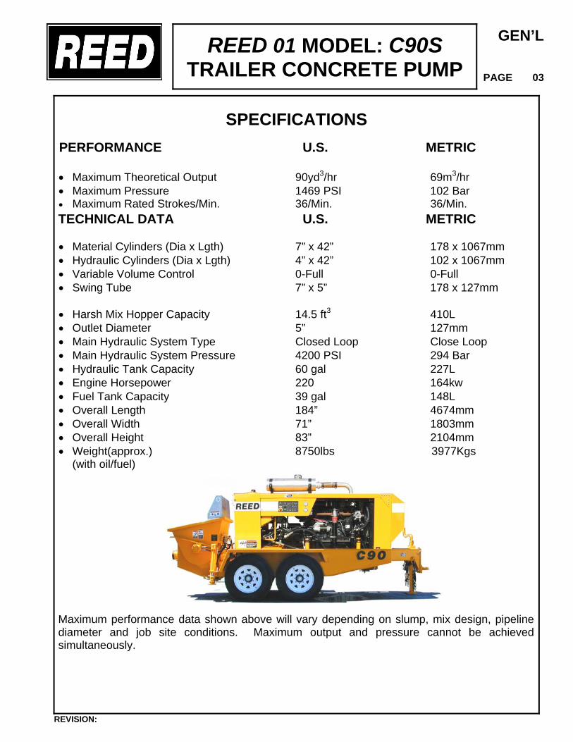
SPECIFICATIONS
PERFORMANCE U.S. METRIC • Maximum Theoretical Output 90yd3/hr 69m3/hr • Maximum Pressure 1469 PSI 102 Bar • Maximum Rated Strokes/Min. 36/Min. 36/Min.
TECHNICAL DATA U.S. METRIC • Material Cylinders (Dia x Lgth) 7” x 42” 178 x 1067mm • Hydraulic Cylinders (Dia x Lgth) 4” x 42” 102 x 1067mm • Variable Volume Control 0-Full 0-Full • Swing Tube 7” x 5” 178 x 127mm
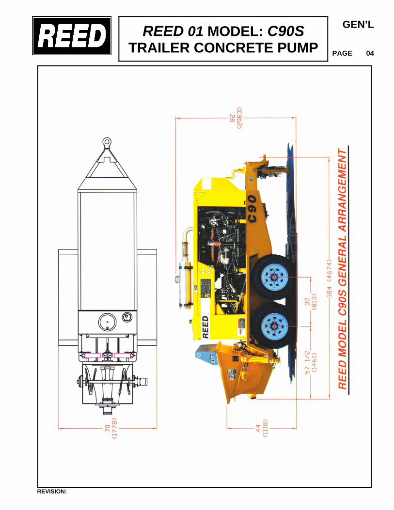
• Harsh Mix Hopper Capacity 14.5 ft3 410L • Outlet Diameter 5” 127mm • Main Hydraulic System Type Closed Loop Close Loop • Main Hydraulic System Pressure 4200 PSI 294 Bar • Hydraulic Tank Capacity 60 gal 227L • Engine Horsepower 220 164kw • Fuel Tank Capacity 39 gal 148L • Overall Length 184” 4674mm • Overall Width 71” 1803mm • Overall Height 83” 2104mm • Weight(approx.) 8750lbs 3977Kgs
(with oil/fuel)
Maximum performance data shown above will vary depending on slump, mix design, pipeline diameter and job site conditions. Maximum output and pressure cannot be achieved simultaneously.
REVISION:
REED 01 MODEL: C90S TRAILER CONCRETE PUMP
GEN’L
PAGE 04
REVISION:
REED 01 MODEL: C90S TRAILER CONCRETE PUMP
GEN’L
PAGE 05
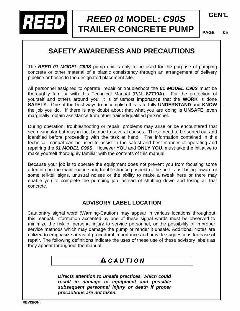
SAFETY AWARENESS AND PRECAUTIONS
The REED 01 MODEL C90S pump unit is only to be used for the purpose of pumping concrete or other material of a plastic consistency through an arrangement of delivery pipeline or hoses to the designated placement site. All personnel assigned to operate, repair or troubleshoot the 01 MODEL C90S must be thoroughly familiar with this Technical Manual (P/N: 87719A). For the protection of yourself and others around you, it is of utmost importance that the WORK is done SAFELY. One of the best ways to accomplish this is to fully UNDERSTAND and KNOW the job you do. If there is any doubt about that what you are doing is UNSAFE, even marginally, obtain assistance from other trained/qualified personnel. During operation, troubleshooting or repair, problems may arise or be encountered that seem singular but may in fact be due to several causes. These need to be sorted out and identified before proceeding with the task at hand. The information contained in this technical manual can be used to assist in the safest and best manner of operating and repairing the 01 MODEL C90S. However YOU and ONLY YOU, must take the initiative to make yourself thoroughly familiar with the contents of this manual. Because your job is to operate the equipment does not prevent you from focusing some attention on the maintenance and troubleshooting aspect of the unit. Just being aware of some tell-tell signs, unusual noises or the ability to make a tweak here or there may enable you to complete the pumping job instead of shutting down and losing all that concrete.
ADVISORY LABEL LOCATION
Cautionary signal word (Warning-Caution) may appear in various locations throughout this manual. Information accented by one of these signal words must be observed to minimize the risk of personal injury to service personnel, or the possibility of improper service methods which may damage the pump or render it unsafe. Additional Notes are utilized to emphasize areas of procedural importance and provide suggestions for ease of repair. The following definitions indicate the uses of these use of these advisory labels as they appear throughout the manual:
Directs attention to unsafe practices, which could result in damage to equipment and possible subsequent personnel injury or death if proper precautions are not taken.
REVISION:
REED 01 MODEL: C90S TRAILER CONCRETE PUMP
GEN’L
PAGE 06
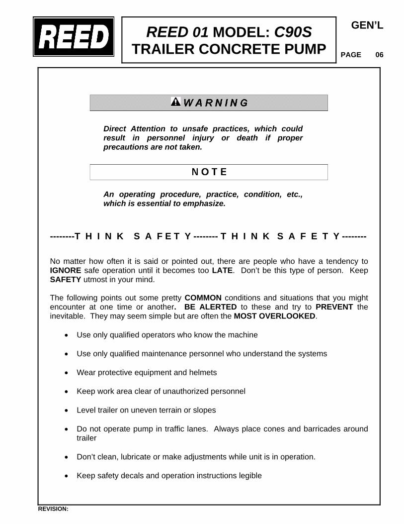
Direct Attention to unsafe practices, which could result in personnel injury or death if proper precautions are not taken.
An operating procedure, practice, condition, etc., which is essential to emphasize.
--------T H I N K S A F E T Y -------- T H I N K S A F E T Y -------- No matter how often it is said or pointed out, there are people who have a tendency to IGNORE safe operation until it becomes too LATE. Don’t be this type of person. Keep SAFETY utmost in your mind. The following points out some pretty COMMON conditions and situations that you might encounter at one time or another. BE ALERTED to these and try to PREVENT the inevitable. They may seem simple but are often the MOST OVERLOOKED.
• Use only qualified operators who know the machine • Use only qualified maintenance personnel who understand the systems • Wear protective equipment and helmets • Keep work area clear of unauthorized personnel • Level trailer on uneven terrain or slopes • Do not operate pump in traffic lanes. Always place cones and barricades around
trailer • Don’t clean, lubricate or make adjustments while unit is in operation. • Keep safety decals and operation instructions legible
REVISION:

REED 01 MODEL: C90S TRAILER CONCRETE PUMP
GEN’L
PAGE 07
• Do not alter or disconnect safety devices
• Maintain specified tire pressure
• Report items that need attention or require service
BETTER SAFE THAN SORRY - DON’T TAKE CHANCES THAT COULD CAUSE INJURY TO YOU AND/OR OTHERS
• Never REMOVE the hopper grill cover when the pump is in OPERATION. It
protects against accidental contact with the agitator and other moving parts inside the hopper.
• Never enter the hopper with any parts of your body. It is a DANGER area and
physical INJURY can occur even if the engine is shutdown. • The concrete delivery system should not be OPENED without relieving the
pressure. This can be done by reversing the pump and pumping backwards. • Hydraulic oil systems can be dangerous. Know the circuit you are repairing, it may
contain high pressure and injury could occur. If in doubt, stop the machine and allow sufficient time for the oil pressure to zero. Check system pressure gauge.
• Do not pour material into the hopper without having grate in place. Operator must
monitor material being dumped into the hopper, keeping a watchful eye out for unmixed or dry material, sticks, pieces of metal and other foreign objects.
REVISION:
REED 01 MODEL: C90S TRAILER CONCRETE PUMP
GEN’L
PAGE 08
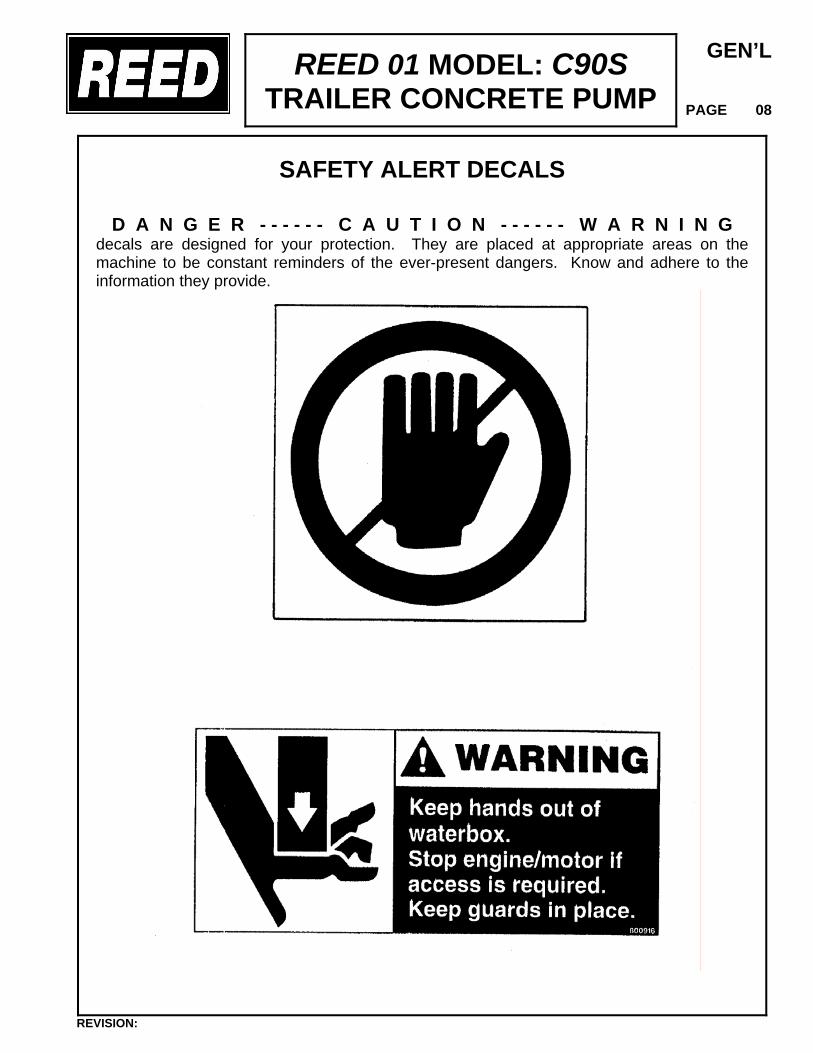
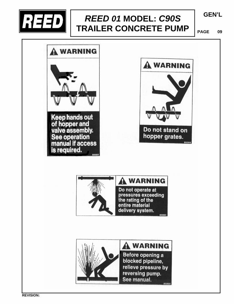
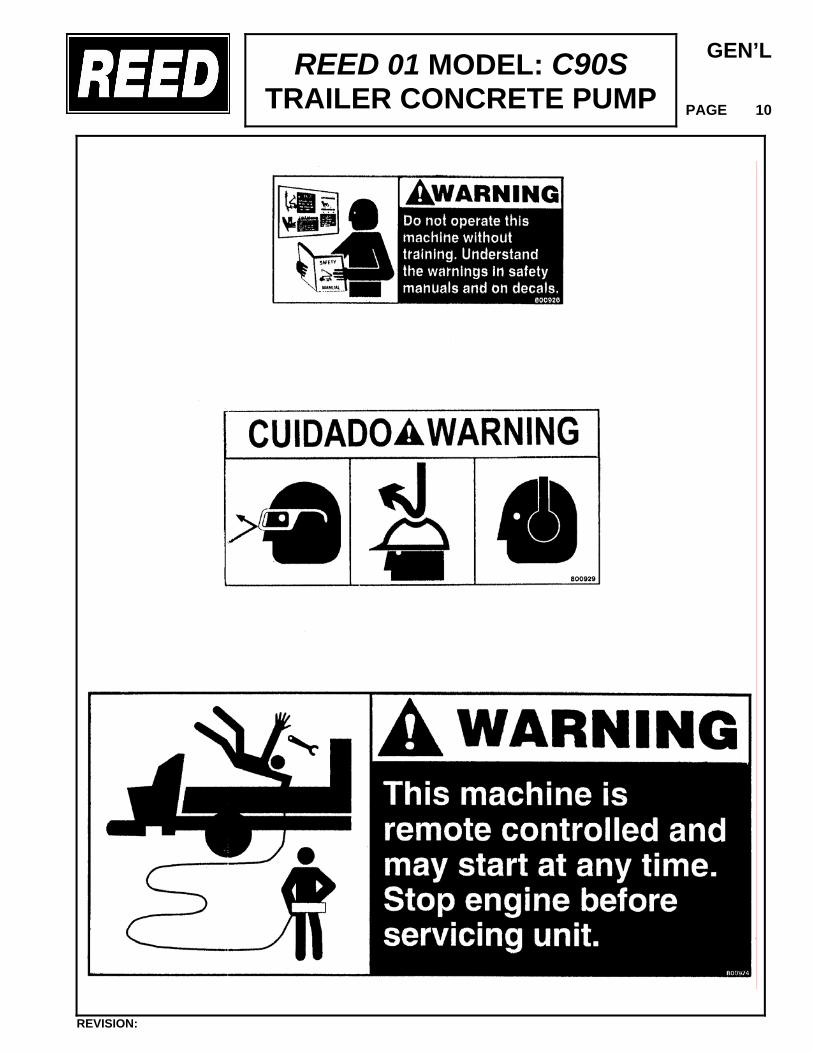
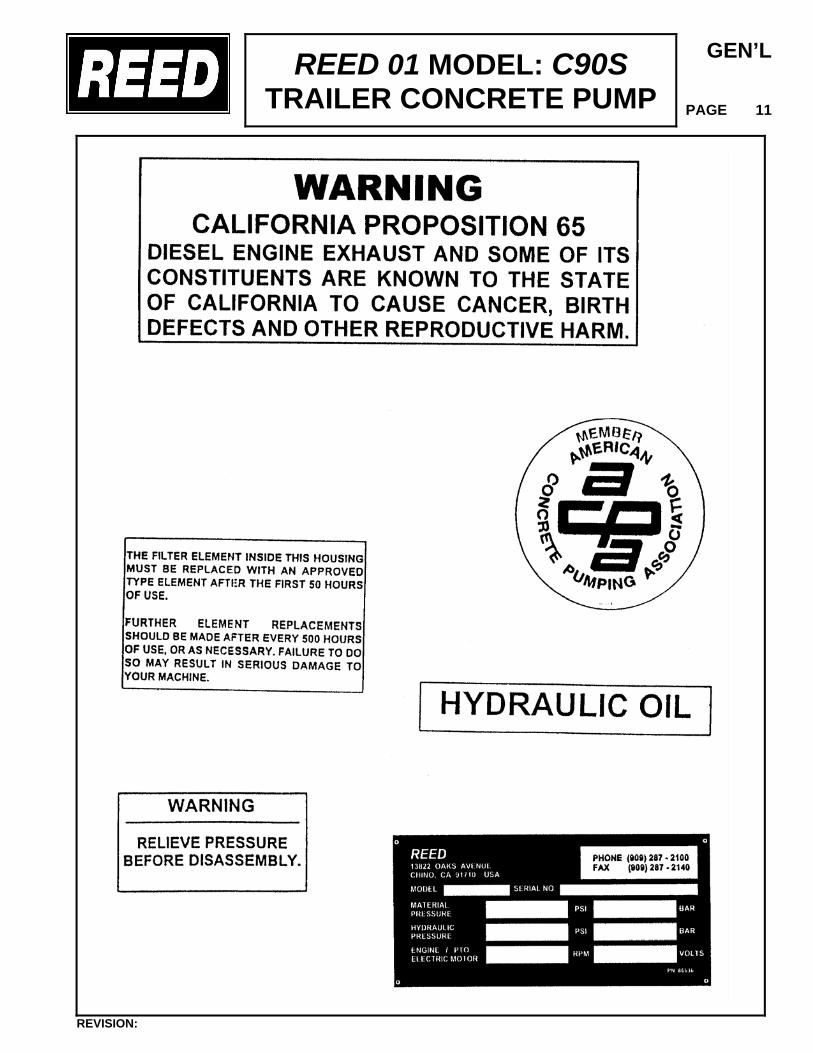
SAFETY ALERT DECALS
D A N G E R - - - - - - C A U T I O N - - - - - - W A R N I N G decals are designed for your protection. They are placed at appropriate areas on the machine to be constant reminders of the ever-present dangers. Know and adhere to the information they provide.
REVISION:
REED 01 MODEL: C90S TRAILER CONCRETE PUMP
GEN’L
PAGE 09
REVISION:
REED 01 MODEL: C90S TRAILER CONCRETE PUMP
GEN’L
PAGE 10
REVISION:
REED 01 MODEL: C90S TRAILER CONCRETE PUMP
GEN’L
PAGE 11
REVISION:
REED 01 MODEL: C90S TRAILER CONCRETE PUMP
GEN’L
PAGE 12
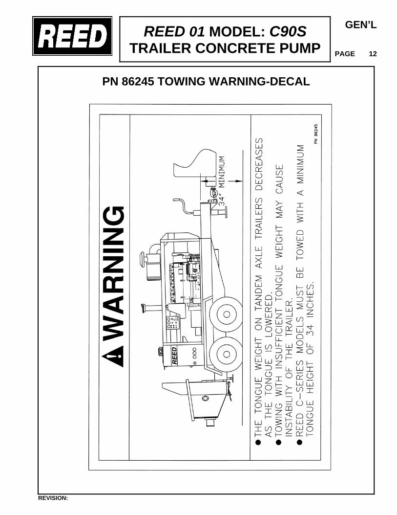
PN 86245 TOWING WARNING-DECAL
REVISION:
GEN’L PAGE 13
REED 01 MODEL: C90S TRAILER CONCRETE PUMP
OPERATOR QUALIFICATIONS Making the choice for an operator is a vital decision as it affects safety and productivity. The 01 MODEL C90S has been thoroughly inspected and tested by the REED Quality Control Department prior to shipment. The design of the unit incorporates several built-in safety features and also allows for an average skilled person to readily become proficient in the safe operation of the 01 MODEL C90S. The unit is a pressurized material pump and can be potentially DANGEROUS in the hands of UNTRAINED OR CARELESS OPERATORS. Knowing the characteristics of the machine and function of the controls are important to SAFE, PROPER OPERATION and USE. It is the responsibility of all users to read and comply with the following rules and information designed to promote SAFETY and UNDERSTANDING of the 01 MODEL C90S concrete pump. • The first requirement for any user/operator is to obtain a thorough understanding of the
operating characteristics and limitations of the machine. This should not be overlooked regardless of their prior experience with similar type equipment.
• Only QUALIFIED TRAINED personnel who have been authorized must be allowed to
operate the 01 MODEL C90S. A Qualified Trained Operator is one who has READ and UNDERSTOOD the instructions in this manual and is thoroughly familiar with the operating characteristics and limitations of the machine.
• Individuals who cannot READ and UNDERSTAND the signs, warnings, notices and
operating instructions that are part of the job, in the language in which it is printed MUST NOT BE ALLOWED to operate the 01 MODEL C90S.
• Know and follow all cautions, warnings and operating instructions on the machine.
• Repair and adjustments must only be made by QUALIFIED TRAINED personnel.
• No modification is to be made to the machine without prior written consent of the REED
Customer Service Department.
• Attach a SIGN-OFF sheet on the unit to enable the operator to report any damage, defects, problems or accidents to his work supervisor.
• Understand and OBEY all applicable Local and Government statutes and regulations
applying to safe operation and use of material pumping machines.
REED 01 MODEL: C90S TRAILER CONCRETE PUMP
OPER.
PAGE 00
PRE-OPERATION INSPECTION
The CONDITION of the unit prior to start-up is a very IMPORTANT factor as it directly affects the operator’s safety as well as those around him. It should be a common practice that the operator performs a general inspection of the REED 01 MODEL C90S before each day’s operation. The purpose of the operator’s inspection is to keep the equipment in PROPER working condition and to DETECT any sign of malfunction during normal operations between scheduled maintenance checks. DOWNTIME is COSTLY and can possibly be prevented by taking a few minutes prior to start-up to do a thorough walk-around inspection. This inspection must be performed each day before the unit is operated. Report any damage or faulty operation immediately. Attach a sign, if need be, at the control panel which states ------ DO NOT OPERATE ------. Repair any discrepancies before use. Some major items to be considered for your inspection include the following: 1. OVERALL MACHINE CONDITION
• External structural damage • Wheel lug nuts missing or loose • Brake line wiring, connection • Condition of tires, pits, tears, cuts, inflation • Decals, placards, warning signs • Missing, broken or damaged parts • Remote switch & cable condition • Gauges, Throttle control
2. HYDRAULIC SYSTEM • Loose or damaged hoses, tubing, fittings • Hydraulic leaks
REVISION:

REED 01 MODEL: C90S TRAILER CONCRETE PUMP
OPER.
PAGE 01
• Hydraulic fluid level • Cleanliness of fluid, filter condition indicator • Hydraulic valves and control levers
• Hydraulic cylinders
3. HOPPER • Grate in place not damaged • Agitator condition • Drive motor • Swing tube connection • Shift cylinders condition • Outlet Connection
4. ELECTRICAL • Frayed or broken wires or loose connections • Condition of switches, lights, connections • Instruments and gauges - condition
Defective components, structural damage, missing parts or equipment malfunctions, jeopardize the SAFETY of the operator and other personnel and can cause extensive damage to the machine. A poorly MAINTAINED machine can become the greatest OPERATIONAL HAZARD you may encounter.
REVISION:

REED 01 MODEL: C90S TRAILER CONCRETE PUMP
OPER.
PAGE 02
GETTING ACQUAINTED (UNIT FAMILIARIZATION)
As previously indicated, it is important from a SAFE operational standpoint that you, the OPERATOR, know your machine. This means the function of each control as to what happens when it is activated, how it might interact with other functions and any limitations, which might exist. A GOOD UNDERSTANDING of the controls and capabilities will enhance operation and assure maximum operating and efficiency and SAFETY. These next few pages will assist you in GETTING ACQUAINTED with the 01 MODEL C90S concrete pump. Carefully study these.
REVISION:
REED 01 MODEL: C90S TRAILER CONCRETE PUMP
OPER.
PAGE 03
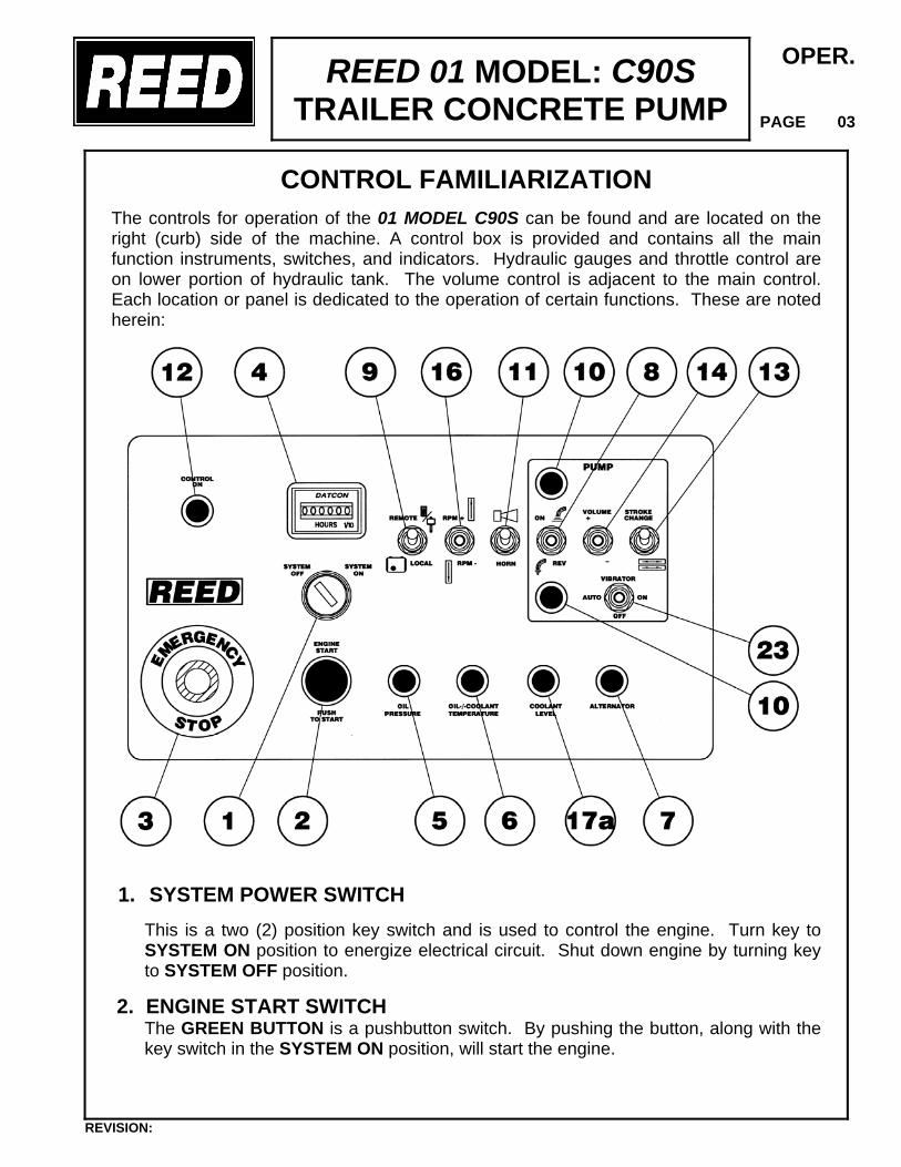
CONTROL FAMILIARIZATION
The controls for operation of the 01 MODEL C90S can be found and are located on the right (curb) side of the machine. A control box is provided and contains all the main function instruments, switches, and indicators. Hydraulic gauges and throttle control are on lower portion of hydraulic tank. The volume control is adjacent to the main control. Each location or panel is dedicated to the operation of certain functions. These are noted herein:
1. SYSTEM POWER SWITCH
This is a two (2) position key switch and is used to control the engine. Turn key to SYSTEM ON position to energize electrical circuit. Shut down engine by turning key to SYSTEM OFF position.
2. ENGINE START SWITCH The GREEN BUTTON is a pushbutton switch. By pushing the button, along with the key switch in the SYSTEM ON position, will start the engine.
REVISION:
REED 01 MODEL: C90S TRAILER CONCRETE PUMP
OPER.
PAGE 04
3. EMERGENCY STOP This is an emergency switch and is used to shut down the pump in an emergency situation. It is of the push-pull type. Depress PUSH knob in to STOP operation. PULL knob out to REACTIVATE system. NOTE – The HORN/RESET must be switched one time to restart pump operation.
4. HOUR METER This instrument is used to record the number of hours the electric system has been activated. The hourmeter becomes operational when the ignition key is ON.
5. LOW OIL INDICATOR-(OIL PRESSURE) Light, when lit, indicates engine oil level is low and requires attention.
6. OIL /COOLANT TEMPERATURE INDICATOR Light, when lit, indicates engine temperature has reached a critical temperature and requires attention.
7. ALTERNATOR INDICATOR Light, when lit, indicates a faulty charging circuit for the battery.
8. PUMP DIRECTION SWITCH This is a three (3) position toggle switch and is used to control the cycle direction of the concrete pump. CENTER position of toggle is PUMP-OFF. Move toggle to UP position to activate PUMP-ON AND FORWARD cycling. Move toggle in DOWN position for REVERSE cycling
REVISION:
REED 01 MODEL: C90S TRAILER CONCRETE PUMP
OPER.
PAGE 05
9. CONTROL SWITCH
This is a two (2) position toggle switch and is used to select the pump control location. Move toggle to LOCAL to enable operation of concrete pump from main stationary panel. Move toggle to REMOTE for operation using the remote control.
10. INDICATOR LIGHTS
These green lights, located above and below the switches are used, when lit, to indicate the position of the toggles.
11. HORN/RESET
This is a momentary toggle switch and is used to reactivate the control and pump circuit after machine has been shut down using the EMERGENCY STOP switch. Once the emergency stop has been depressed it will be necessary to pull out switch and move toggle of HORN switch momentary to RESET position.
12. CONTROL ON INDICATOR
This is a green indicator light, when lit denotes control circuit is energized.
13. STROKE CHANGE SWITCH
This switch is a two (2) position spring return switch and has two functions. One is A momentary toggle to change stroke from one side to the other to help clear a possible line plug. The other function is when the switch is held DOWN and allow for end of stroke. High pressure check or in ths instance of equalizing the stroking pistons. The allowance of the spring return sets the machine back in forward stroke.
14. VOLUME CONTROL
This control is installed on the discharge port of the main hydraulic pump. It is used to adjust volume OUTPUT of the material cylinders which in turn is controlled by the hydraulic pump. Flipping toggle switch UPWARD will INCREASE volume, flipping toggle switch DOWNWARD will DECREASE volume.
15. THROTTLE CONTROL-CABLE
This is used to adjust the engine RPM. Turn knob COUNTERCLOCKWISE to INCREASE engine speed. Turn knob CLOCKWISE to DECREASE engine speed. The control is equipped with a quick release feature which consists of pushing button in center of knob. This releases the throttle allowing engine to return to idle.
16. THROTTLE CONTROL-TOGGLE SWITCH
This is a three (3) position spring centered switch and is used to adjust the engine RPM. Toggle UP to INCREASE engine speed. Toggle DOWN to DECREASE
engine speed. Speed of engine will retained as set until reset.
REVISION:
REED 01 MODEL: C90S TRAILER CONCRETE PUMP
OPER.
PAGE 06
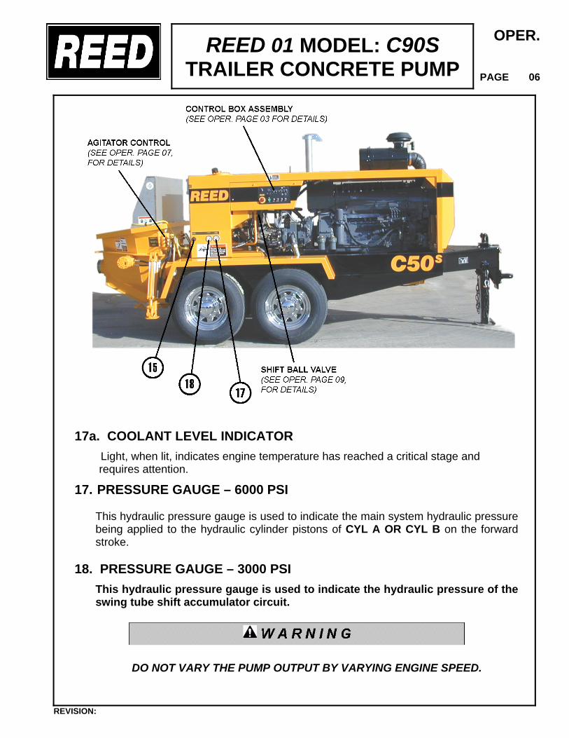
17a. COOLANT LEVEL INDICATOR
Light, when lit, indicates engine temperature has reached a critical stage and requires attention.
17. PRESSURE GAUGE – 6000 PSI This hydraulic pressure gauge is used to indicate the main system hydraulic pressure being applied to the hydraulic cylinder pistons of CYL A OR CYL B on the forward stroke.
18. PRESSURE GAUGE – 3000 PSI
This hydraulic pressure gauge is used to indicate the hydraulic pressure of the swing tube shift accumulator circuit.
DO NOT VARY THE PUMP OUTPUT BY VARYING ENGINE SPEED.
REVISION:
REED 01 MODEL: C90S TRAILER CONCRETE PUMP
OPER.
PAGE 07
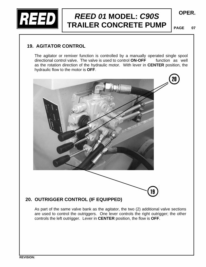
19. AGITATOR CONTROL The agitator or remixer function is controlled by a manually operated single spool directional control valve. The valve is used to control ON-OFF function as well as the rotation direction of the hydraulic motor. With lever in CENTER position, the hydraulic flow to the motor is OFF.
20. OUTRIGGER CONTROL (IF EQUIPPED)
As part of the same valve bank as the agitator, the two (2) additional valve sections are used to control the outriggers. One lever controls the right outrigger; the other controls the left outrigger. Lever in CENTER position, the flow is OFF.
REVISION:
REED 01 MODEL: C90S TRAILER CONCRETE PUMP
OPER.
PAGE 08
.
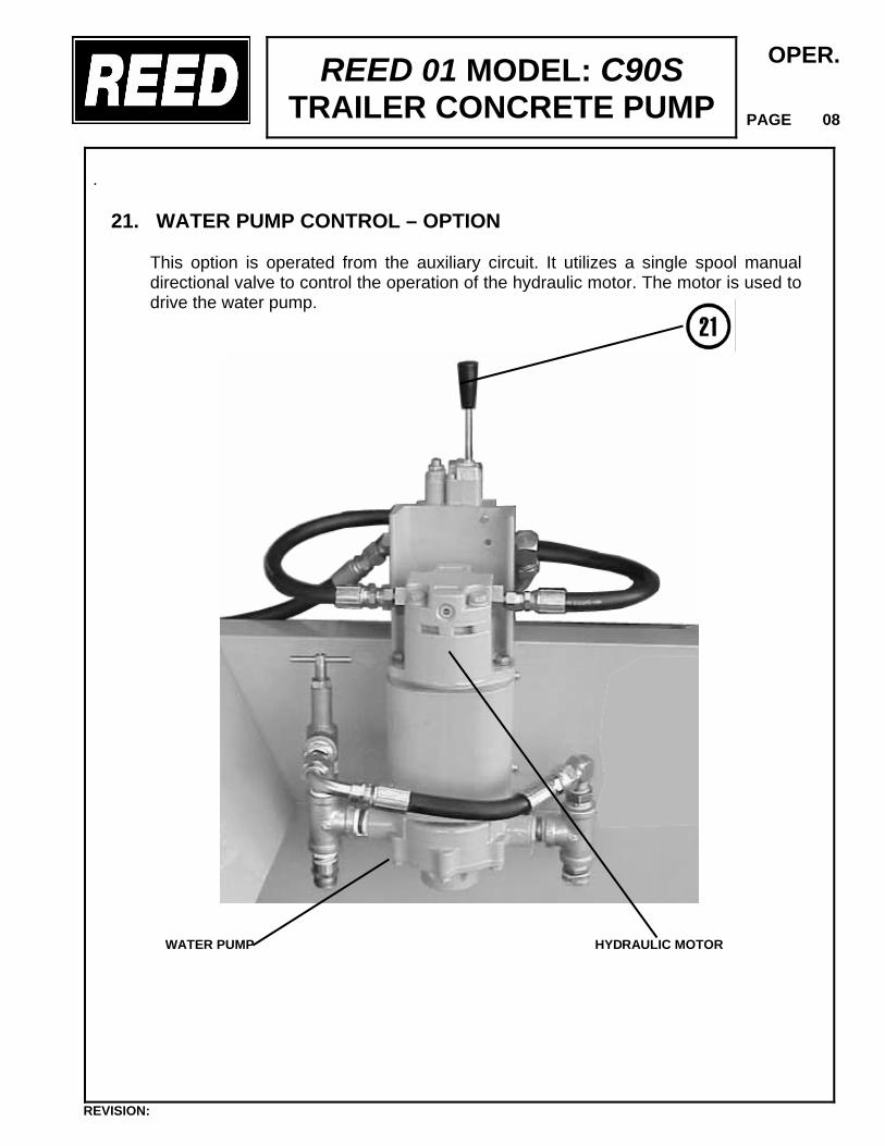
21. WATER PUMP CONTROL – OPTION This option is operated from the auxiliary circuit. It utilizes a single spool manual directional valve to control the operation of the hydraulic motor. The motor is used to drive the water pump.
WATER PUMP HYDRAULIC MOTOR
REVISION:
REED 01 MODEL: C50S TRAILER CONCRETE PUMP
OPER.
PAGE 09
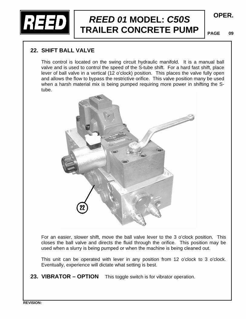
22. SHIFT BALL VALVE
This control is located on the swing circuit hydraulic manifold. It is a manual ball valve and is used to control the speed of the S-tube shift. For a hard fast shift, place lever of ball valve in a vertical (12 o’clock) position. This places the valve fully open and allows the flow to bypass the restrictive orifice. This valve position many be used when a harsh material mix is being pumped requiring more power in shifting the S-tube. For an easier, slower shift, move the ball valve lever to the 3 o’clock position. This closes the ball valve and directs the fluid through the orifice. This position may be used when a slurry is being pumped or when the machine is being cleaned out. This unit can be operated with lever in any position from 12 o’clock to 3 o’clock. Eventually, experience will dictate what setting is best.
23. VIBRATOR – OPTION This toggle switch is for vibrator operation.
REVISION:
REED 01 MODEL: C90S TRAILER CONCRETE PUMP
OPER.
PAGE 10
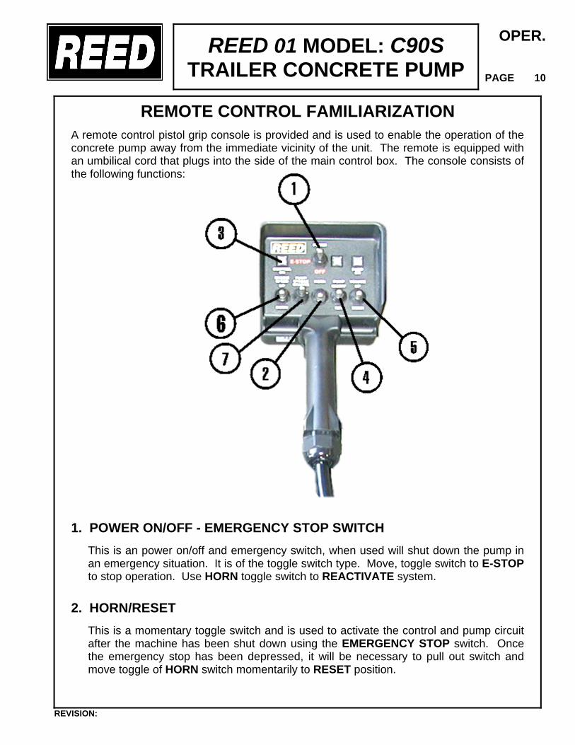
REMOTE CONTROL FAMILIARIZATION
A remote control pistol grip console is provided and is used to enable the operation of the concrete pump away from the immediate vicinity of the unit. The remote is equipped with an umbilical cord that plugs into the side of the main control box. The console consists of the following functions:
1. POWER ON/OFF - EMERGENCY STOP SWITCH This is an power on/off and emergency switch, when used will shut down the pump in an emergency situation. It is of the toggle switch type. Move, toggle switch to E-STOP to stop operation. Use HORN toggle switch to REACTIVATE system.
2. HORN/RESET This is a momentary toggle switch and is used to activate the control and pump circuit after the machine has been shut down using the EMERGENCY STOP switch. Once the emergency stop has been depressed, it will be necessary to pull out switch and move toggle of HORN switch momentarily to RESET position.
REVISION:
REED 01 MODEL: C90S TRAILER CONCRETE PUMP
OPER.
PAGE 11
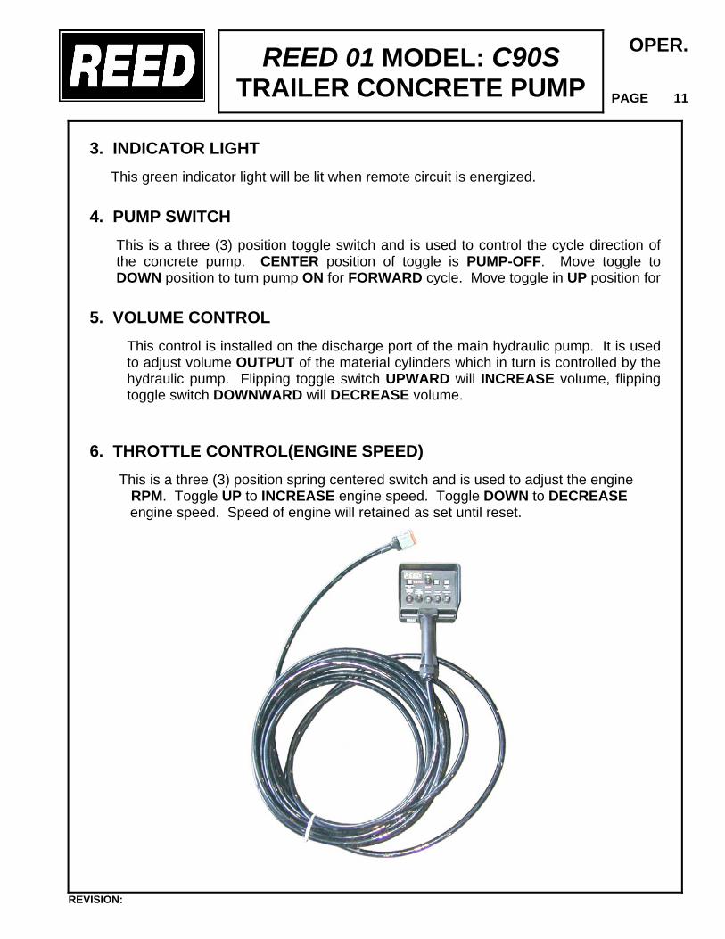
3. INDICATOR LIGHT
This green indicator light will be lit when remote circuit is energized.
4. PUMP SWITCH This is a three (3) position toggle switch and is used to control the cycle direction of the concrete pump. CENTER position of toggle is PUMP-OFF. Move toggle to DOWN position to turn pump ON for FORWARD cycle. Move toggle in UP position for
5. VOLUME CONTROL
This control is installed on the discharge port of the main hydraulic pump. It is used to adjust volume OUTPUT of the material cylinders which in turn is controlled by the hydraulic pump. Flipping toggle switch UPWARD will INCREASE volume, flipping toggle switch DOWNWARD will DECREASE volume.
6. THROTTLE CONTROL(ENGINE SPEED)
This is a three (3) position spring centered switch and is used to adjust the engine RPM. Toggle UP to INCREASE engine speed. Toggle DOWN to DECREASE
engine speed. Speed of engine will retained as set until reset.
REVISION:
REED 01 MODEL: C90S TRAILER CONCRETE PUMP
OPER.
PAGE 12
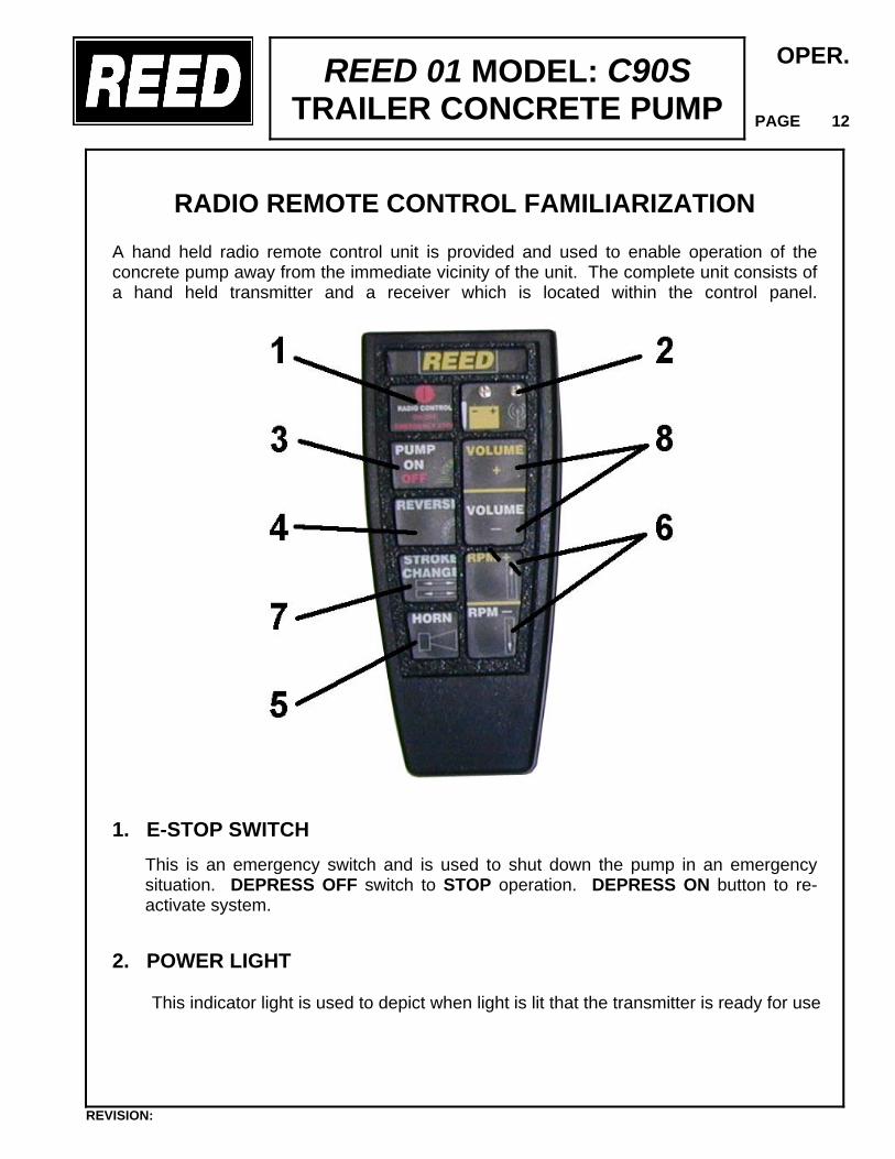
RADIO REMOTE CONTROL FAMILIARIZATION A hand held radio remote control unit is provided and used to enable operation of the concrete pump away from the immediate vicinity of the unit. The complete unit consists of a hand held transmitter and a receiver which is located within the control panel.
1. E-STOP SWITCH
This is an emergency switch and is used to shut down the pump in an emergency situation. DEPRESS OFF switch to STOP operation. DEPRESS ON button to re-activate system.
2. POWER LIGHT
This indicator light is used to depict when light is lit that the transmitter is ready for use
REVISION:
REED 01 MODEL: C90S TRAILER CONCRETE PUMP
OPER.
PAGE 13
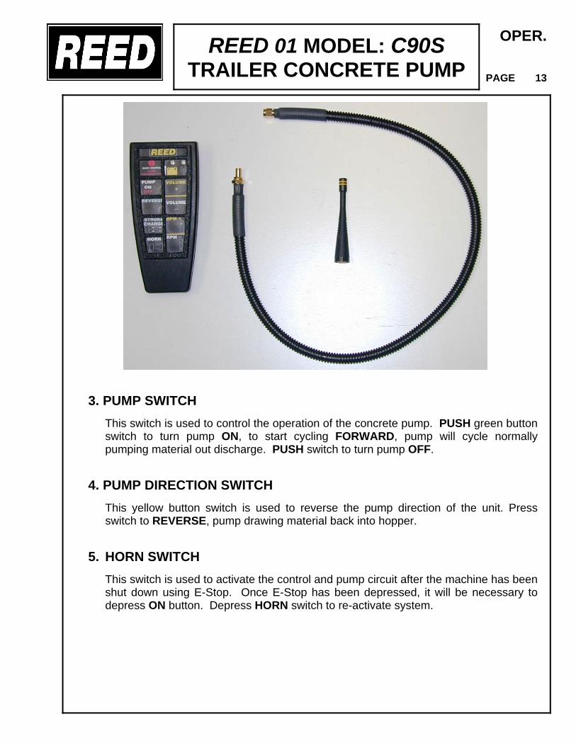
3. PUMP SWITCH This switch is used to control the operation of the concrete pump. PUSH green button switch to turn pump ON, to start cycling FORWARD, pump will cycle normally pumping material out discharge. PUSH switch to turn pump OFF.
4. PUMP DIRECTION SWITCH This yellow button switch is used to reverse the pump direction of the unit. Press switch to REVERSE, pump drawing material back into hopper.
5. HORN SWITCH This switch is used to activate the control and pump circuit after the machine has been shut down using E-Stop. Once E-Stop has been depressed, it will be necessary to depress ON button. Depress HORN switch to re-activate system.
OPER.
PAGE 14
6. THROTTLE CONTROL
Two push button switches control the speed of the engine. The green button switch, function is to INCREASE engine speed. The red button switch, function is to DECREASE the speed of the engine. The speed of engine will retained as set, until it is reset.
7. STROKE CHANGE SWITCH Refer to OPER. SECTION page 05 for switch’s function.
8. VOLUME CONTROL Refer to OPER. SECTION page 05 for switch’s function
9. RED BATTERY INDICATOR (Located at top right corner of remote) This red BATTERY indicator turns on momentarily when touchpad key is pressed and turns off if the battery is good.
This indicator will remain on when the battery voltage is low. There is enough power in the battery for about 15 minutes of operation after the light remains on. When this time is up, the red battery will turn off and the transmitter will no longer function properly until the battery has been changed. The transmitter is powered by a 9 volt alkaline battery. The operation time of the battery is determined by both frequency and duration of use.
RADIO REMOTE OPERATION Before proceeding to start-up and operate the radio remote control, make sure it is safe to do so. Make sure the same safety precautions normally required for safe pump operation are adhered to.
• Place control switch on main panel to REMOTE position. The receiver POWER light should be lit.
• Press the transmitter ON switch. The POWER light on transmitter should slowly flash and the receiver ACTIVE light should be lit.
• When ready to cycle pump, press the transmitter switch to PUMP, and the DIRECTION switch to FORWARD. The receiver PUMP light should be lit. To stop the pump, momentarily press the transmitter switch to STOP. PUMP LED should go out.
• To change the pump direction to reverse, press the REVERSE switch. The reverse LED should light.
• Press transmitter OFF switch to deactivate radio remote transmitter.
Do not leave the transmitter unattended with the pump engine is operating.
REED 01 MODEL: C90S TRAILER CONCRETE PUMP
REED 01 MODEL: C90S TRAILER CONCRETE PUMP
OPER.
PAGE 15
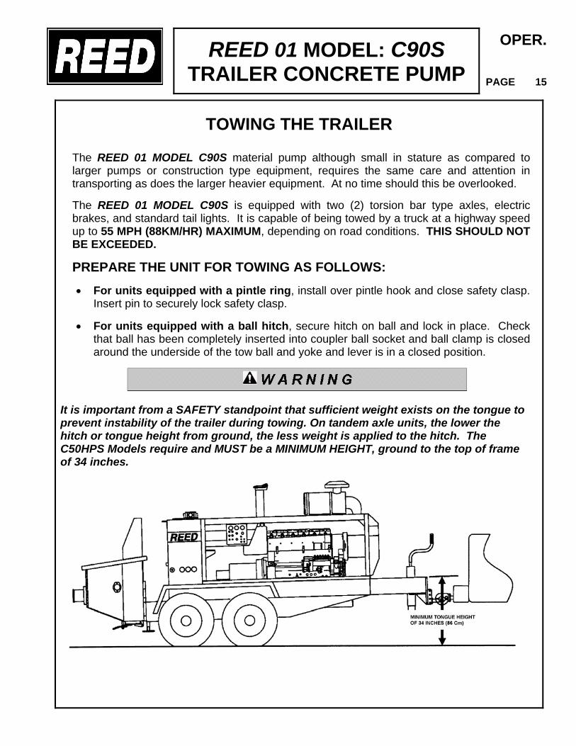
TOWING THE TRAILER
The REED 01 MODEL C90S material pump although small in stature as compared to larger pumps or construction type equipment, requires the same care and attention in transporting as does the larger heavier equipment. At no time should this be overlooked. The REED 01 MODEL C90S is equipped with two (2) torsion bar type axles, electric brakes, and standard tail lights. It is capable of being towed by a truck at a highway speed up to 55 MPH (88KM/HR) MAXIMUM, depending on road conditions. THIS SHOULD NOT BE EXCEEDED.
PREPARE THE UNIT FOR TOWING AS FOLLOWS:
• For units equipped with a pintle ring, install over pintle hook and close safety clasp. Insert pin to securely lock safety clasp.
• For units equipped with a ball hitch, secure hitch on ball and lock in place. Check that ball has been completely inserted into coupler ball socket and ball clamp is closed around the underside of the tow ball and yoke and lever is in a closed position.
It is important from a SAFETY standpoint that sufficient weight exists on the tongue to prevent instability of the trailer during towing. On tandem axle units, the lower the hitch or tongue height from ground, the less weight is applied to the hitch. The C50HPS Models require and MUST be a MINIMUM HEIGHT, ground to the top of frame of 34 inches.
REED 01 MODEL: C90S TRAILER CONCRETE PUMP
OPER.
PAGE 16
• Always attach the SAFETY CHAINS to towing vehicle and attach the breakaway cable.
• Connect trailer electrical cable to truck connection to establish trailer brake circuit and lighting. Check that lighting is operational.
• Raise outrigger legs and secure in place with retainer pin.
• Make sure that hopper cleanout door is securely closed.
• Fully raise front jackleg and lock handle.
• Check the tires for proper inflation pressure and inspect for any cuts and excessive wear.
• Survey underside of pump and trailer to look for other possible obstructions.
Towing trailers at excessive speeds is DANGEROUS. Some trailers may weigh as much or more than the vehicle doing the towing, and can affect the control of the towing vehicle causing an OVERTURN condition. This situation can arise from excessive speed or rapid braking. Therefore, always maintain a sufficient distance for safe braking.
TOWING TIPS:
• Never travel with concrete in hopper. The trailer pump is not designed to be towed with this extra weight.
• Remove all delivery lines from hopper outlet.
• Travel only as fast as conditions allow. DO NOT EXCEED 55 MPH (88KM/HR).
• Always leave sufficient distance between you and the vehicle ahead to allow SAFE BRAKING.
• Reduce speed at dips, bumps and rough road areas.
If trailer begins to sway or swerve side to side, ease off of accelerator to slow down. DO NOT JAM ON BRAKES. Gently touch brake pedal intermittently to come to a stop. Check to determine cause of sway. Check hitch.
REVISION:
REED 01 MODEL: C90S TRAILER CONCRETE PUMP
OPER.
PAGE 17
OPERATION INSTRUCTIONS Having READ and UNDERSTOOD the previous pages on SAFETY and CONTROL FAMILIARIZATION you are now in a position to learn how to operate the unit. If you have not READ the previous pages we suggest you do so before PROCEEDING.
For your own SAFETY and others around you it is your RESPONSIBILITY to insure the unit is in proper working condition. Check out the unit by using the PRE-OPERATION INSPECTION notes previously identified.
OBSERVE ALL SAFETY PRECAUTIONS WHILE OPERATING THIS MACHINE.
SELECTION AND SET-UP AT JOB SITE Your first and primary concern when arriving at the job site is to insure the machine can be safely operated and it will afford the maximum production efficiency without jeopardizing safety.
• The machine should be located on as level ground as is possible.
• Lower the front leg jack to ground and if necessary place wooden blocking under the
jack pad.
• Lower rear outriggers and pin in place. If necessary, place additional blocking under the pads.
• Lower and apply pressure to the front jack on the ground and if necessary place wooden blocking under the jack pad. This will transfer weight to the outrigger legs.
DAMGE WILL OCCUR IF OUTRIGGERS ARE NOT USED. WARRANTY WILL NOT BE HONERED IN THIS SITUATION!
REVISION:
REED 01 MODEL: C90S TRAILER CONCRETE PUMP
OPER.
PAGE 18
• Keep a sufficient distance away from slopes, pits, trenches and excavations that
could breakaway. • Make every attempt to set up as near as possible to placement site. The shorter the
pumping distance the greater the material delivery.
When the site for the operation has been selected proceed to set up unit for pumping. • Disconnect safety chain, electrical cable and hitch from towing vehicle.
DELIVERY SYSTEM SUGGESTIONS The delivery system is an arrangement of those components used from the pump discharge to the placement site. This could consist of rubberized material hose, steel piping, clamps, couplers and reducers. How this delivery system is set up, what components are used will greatly affect the end result of efficient and productive concrete pumping. The following suggestions are offered to assist in achieving your objective and for your consideration in laying out the delivery line.
• Use the most direct line as is feasible from the concrete pump to the placement area. • Set up the delivery line using a minimum of rubber hose. Rubber hose offers three
(3) times the resistance to the flow of concrete as compared to steel pipe.
• Concrete will also flow with less back-pressure through pipe than through hose. • Minimize the use of bends in the hose. This requires more pumping pressure. • Place the hoses or pipe to the farthest placement point from the hopper discharge
outlet FIRST. It is easier to remove lines than it is to add as the pumping operation takes place.
• The steel pipe, elbows, and reducers and hoses should be equipped with heavy-duty
ends. These ends have a higher-pressure capability than the standard ends. • Only connect together couplings or clamps that are clean and seals that will retain the
slurry in the delivery line. Dirty couplings LEAK and when pressurized the leaking of water will inevitably cause blockage.
• DO NOT USE any worn or damaged hoses, pipes or couplings.
REVISION:
REED 01 MODEL: C90S TRAILER CONCRETE PUMP
OPER.
PAGE 19
• If the delivery line will cross rebars, support must be considered for the pipe so that it
does not contact the rebar mat. • For best pumping results it is important to size the inside diameter of the pipe or
hose to that of the size of the aggregate in the concrete to be pumped. The general rule is the inside diameter of the pump or hose shall be 3 to 4 times the size of the largest aggregate in the mix. As an example:
1. Aggregate classified as 1 ½ inch (38mm) rock, 8 to 10% maximum content
by weight requires a 5 inch (127mm) diameter concrete delivery system. 2. Aggregate classified a 1 inch (25mm) rock, 10 to 15% maximum content by
weight, requires a 4 inch (100mm) diameter concrete delivery system. 3. Aggregate classified as ¾ inch (19mm)or smaller rock, 10 to 15% maximum
content by weight, requires a 3 inch (76mm) diameter concrete delivery system.
• For vertical concrete delivery system, the vertical pipe line should be anchored to the
building or other supporting structures every 10 ft (3m) of height.
PRE-PUMPING PREPARATIONS Again we REMIND you to make sure the machine is in PROPER WORKING CONDITION. One of the worst, and possibly the most expensive, situation to encounter is to begin pumping and have a failure occur due to NEGLIGENCE of a thorough pre-operation inspection. STARTING THE PUMP Before starting diesel engine, check the position of the following controls and functions:
• That the PUMP CYCLE switch is OFF • That the VOLUME CONTROL is CLOSED, screwed in. • That the AGITATOR control lever is in OFF position.
• Check flush box is filled that sufficient lubrication oil or water exists. Replace cover.
REVISION:
REED 01 MODEL: C90S TRAILER CONCRETE PUMP
OPER.
PAGE 20
When you have completed the above checks, the unit is ready for start up.
• At the main control panel, turn key switch and start engine. When engine starts, release key.
• Check the engine indicator lights of alternator, oil temperature, low coolant and low
oil.
• Check that CONTROL LOCATION switch is in LOCAL position.
• Allow a few minutes for engine to warm up.
• Increase engine RPM by adjusting THROTTLE control to desired engine speed as indicated on tachometer.
• Check the swing tube pressure gauge (3000 PSI/210 BAR gauge) that it is
operational. Gauge should read approximately 2000 PSI (140 BAR). • Pressure gauge (6000 PSI/420 BAR) will only indicate pressure when pump switch
is ON. • DO NOT CYCLE PUMP unless water or material has been placed in the hopper. • To cycle pump adjust THROTTLE and VOLUME control to desired setting. • Place pump switch to ON position. The hydraulic drive and material cylinders will
now cycle.
• Turn pump switch OFF to stop cycling.
At START-UP, ALWAYS OPERATE AT LOW SPEED AND LOW VOLUME until proper operation has been assured.
REVISION:
REED 01 MODEL: C90S TRAILER CONCRETE PUMP
OPER.
PAGE 21
PRIMING THE PUMP SYSTEM Before proceeding to cycle and pump concrete material it will be necessary to prime the pump system and delivery lines. This operation consists of pumping a coating of lubrication grout through the S-tube and delivery lines to enable the regular concrete mix to flow smoothly. The grout used for priming and lubrication should consist of two (2) parts sand and one (1) part cement and mixed to a consistency of thick soup. This will coat the delivery line ahead of the actual material mix and will assist in preventing the possibility of packing when the line is filled with regular mix. How much grout will be needed depends on the length of the delivery line as well as the material being pumped. Experience will eventually indicate the amount to be required. • Using a water hose wet down the inside of the hopper with about one (1) gallon of
water.
• When the concrete from the ready-mix truck is ready to be placed in the hopper, pour the grout into hopper.
• Adjust THROTTLE to FULL RPM • At pump panel adjust VOLUME control to about ½ open and turn PUMP ON.
• As the slurry is being pumped out begin charging, pouring concrete from the truck into
the hopper.
• Engage the AGITATOR using appropriate control.
• Continue to pump until a steady flow is discharged from end of delivery line.
• Once this point has been reached, the VOLUME control can be adjusted to the desired concrete output.
• During the pumping operation observe the 6000 PSI hydraulic gauge. Be alert to unactuated sudden changes in pressure, high or low.
• The S-TUBE gauge should read approximately 2000 PSI just prior to the shifting of the S-tube. As shift is made gauge will quickly lose pressure then bounce back.
• To check pumping pressure, actuate TEST switch to either CYL “A” or CYL “B”
position. Hold toggle until piston bottoms out. Read pressure on 6000 PSI gauge.
REVISION:
REED 01 MODEL: C90S TRAILER CONCRETE PUMP
OPER.
PAGE 22
The pressure by which the concrete is being pumped is based on the ratio between the hydraulic cylinder and the material cylinders and that is divided into the hydraulic pressure being applied to the drive cylinders.
In this instance the ratio is 2.25 (piston side) and the concrete pressure is calculated as follows: SYSTEM GAUGE-PSI CONCRETE PRESSURE PSI 1000 440 2000 889 3000 1333 3500 1556 4000 1778 4200 1867 On the other hand the hydraulic pressure being applied to the drive cylinders is controlled by the amount the VOLUME control is opened. When turned to the FULL OPEN position this will produce approximately 4200 PSI on gauge.
PUMPING TIPS AND PRECAUTIONS Your SAFETY is our utmost CONCERN and it is your RESPONSIBILITY to operate the equipment in a SAFE manner. The following TIPS and PRECAUTIONS are offered as AWARENESS facts and should be OBSERVED for proper safe operation. • Always maintain the material level in the hopper to no less than the height of the
remixer shaft height or 1/2 full. This is IMPORTANT otherwise air will be sucked into the material cylinders and the continuous smooth flow may be interrupted.
• The concrete output is influenced and related to the quality and consistency of the
concrete mix. Mix consistency is a decisive factor when it comes to the filling rate of the material cylinders.
With stiffer consistency and unfavorable grading curve of the aggregate, (smaller portion of sand, crushed materials) the rate of filling the material cylinders becomes less efficient resulting in a lesser concrete output. When you encounter this condition it is suggested that pumping at a slower speed can positively increase the output by allowing more time to fill the material cylinders.
REVISION:
REED 01 MODEL: C90S TRAILER CONCRETE PUMP
OPER.
PAGE 23
• When it is necessary to pump unfavorable mixes such as extremely stiff, under
sanded, lightweight concrete, the best procedure is to keep the remixer/agitator shaft visible all the time. In so doing, the hopper will only be filled to the lower edge of the remixer shaft making the concrete easier to pump.
• This method is called the AIR-PLUG method which allows air to be sucked into the
material cylinders along with the unfavorable concrete mix. • When it is necessary to pump concrete that is very liquid and has a high
percentage of rough aggregate that tends to separate, keep the concrete level in the hopper as low as possible in case you encounter a work stoppage.
• Concrete that has separated or has begun to set and become lumpy should never
be pumped. • It is common that at sometime during the concrete placement you will be required
to stop pumping for a period of time. This could be due to job site problems or possibly lack of concrete. Regardless of the reason, it is IMPORTANT to MOVE the concrete in the line during these periods. This can be accomplished by operating the pump in REVERSE for 2-3 strokes and then after another 10-15 minutes operate the pump FORWARD for 2-3 strokes.
• Downtime between forward and reverse movements will depend on the consistency
and type of mix. Also if shutdown is for too long a period it may be necessary to clean out the delivery system and pump. Determine this from your experience in the material being pumped.
• Avoid having the material in the hopper separate during shut down. • Air pockets in the delivery line can be dangerous as the air compresses within the
delivery line and when it is released abruptly at the end of the line, the material being pumped is discharged in an explosive manner. Avoid air pockets. Keep sufficient material in hopper to prevent the induction of air into the material cylinders.
• Never bend or kink the flexible hose during the pumping operation. A kink is an
obstruction that can stop the material flow, allowing pressure to build up in the system creating a dangerous condition.
When this occurs, the pumping direction must be REVERSED for 3-4 strokes to relieve the pressure in the line. Stop the pump and straighten out the kink, then resume pumping.
REVISION:
REED 01 MODEL: C90S TRAILER CONCRETE PUMP
OPER.
PAGE 24
TROUBLESHOOTING TIPS - PUMPING & BLOCKAGE
• A drop in volume can occur when pumping long distances or with stiff mixes as compared with shorter lines and wetter mixes.
• Water leaking from a connection can cause separation of the mix in the delivery line
and will eventually develop into a blockage at that point. • Avoid using damaged hoses with internal restrictions. They can cause blockage. • When using snap joint couplings with gaskets to join the hoses, be sure they are
washed and cleaned after completion of the job. We also suggest the couplings and gaskets be dipped in water prior to use for easier installation.
• Don't be alarmed by a slight pulsation of the delivery hose near the outlet. This is a normal condition. However, excessive pulsation near the pump is normally due to higher than average line pressure that may be caused by pumping stiff harsh mixes or pumping extremely long distances. Using hose with a larger internal diameter will help in reducing the line pressure.
• Be alert to the fact that if the delivery system is blocked or the hose is kinked, the
pump could suddenly force out the blockage or straighten out the kink. This rapid surge could cause the line to whip or move in such a manner that it may cause INJURY.
• When a blockage in the hose occurs, walk along the hose until you find the point of
trouble. The hose will be soft immediately past the blockage point. Elevate the hose at that point with the blockage hanging down toward the free end. Shake the hose or pound with a hammer until the blockage loosens and the material flows freely again.
• DOWNHILL pumping involves some extra attention and can be difficult on some jobs.
The reason for this is that when the pumping operation is stopped the material can flow slowly down the incline causing the hose to collapse. This can only result in a blockage when pumping is resumed. Kinking off the hose at the discharge while the pump is stopped can prevent this. Also the use of stiffer mixes when pumping downhill will lessen the gravity flow.
• When pumping over 40 feet vertically up the side of a structure, steel pipe should be
used and should be securely fastened as necessary to support the pipe column. Install long radius 90º pipe sweeps at the top and bottom of the steel pipe delivery line. Also use a short section 20 - 25 feet of hose off the pump discharge to take up the pulsation. Use steel pipe for the balance.
REVISION:
REED 01 MODEL: C90S TRAILER CONCRETE PUMP
OPER.
PAGE 25
CLEARING A PACK OR BLOCKAGE Blockage in the delivery line during pumping operation will no doubt happen at one time or another. An observant alert operator, who can recognize the symptoms is of great value. A blockage can create excessive pressure in the system which is a dangerous condition. When this occurs IMMEDIATELY STOP the pump. • Place the pump direction switch to REVERSE. Then turn the pump switch to ON
allowing the pump to stroke 2-3 times in reverse to assist in relieving the pressure from the delivery line blockage back to the pump outlet
• Switch the pump OFF
NEVER ATTEMPT TO CLEAR A PACK OR BLOCKAGE IN THE DELIVERY SYSTEM USING THE PUMP PRESSURE.
• Warn all personnel in the immediate area of the imminent DANGER and to stay clear of the area.
• Make sure those assigned to clear the blockage are fitted with EYE PROTECTION
before they open the clamping devise.
Extreme caution must be exercised when opening the clamping devices on any part of the delivery system. The possibility may still exist that there is still some pressure trapped in the line.
• Open the clamp in the area of the blockage and clear the pack. • When blockage has been cleared START pump, placing DIRECTION switch to
FORWARD. Pump the material at a LOW VOLUME until material flows steadily out the end hose.
REVISION:
REED 01 MODEL: C90S TRAILER CONCRETE PUMP
OPER.
PAGE 26
CLEAN UP OF THE PUMP This sometimes may seem tedious, tiresome and a distasteful task, however, the clean up is a VERY IMPORTANT operation. We pointed out previously the importance of the pre-operation inspection. The clean up is no different because it sets the stage as to how well the pump will perform the next time it is used. The clean up involves the removal of unpumped material remaining in the hopper, swing tube, material cylinders and delivery system piping.
The flushing and cleaning operation should only be done at LOW VOLUME.
• At pump panel set VOLUME control to approximately 1/3 volume. • With everything still in tact, pump as much material out of the system as possible,
making sure there is still sufficient material in the hopper for lubrication of the piston cups. Then turn PUMP switch to OFF position.
• Open the hopper clean out door and dispose of the remaining concrete. • Uncouple the delivery line at the pump outlet. If a reducer is used, disconnect the line
right after the reducer.
• Using a water hose with spray nozzle attached to create some pressure, flush out the inside of the hopper, the inside of the S-tube and reducer if used.
• Place DIRECTION switch in REVERSE. Place the water hose through the pump
discharge outlet. START the PUMP. Water will drain into the material cylinders and as pump cycles, any sand and rocks will be forced out through the open clean out door. This will take approximately 10-12 strokes.
• Remove the hose and continue to stroke the pump to make sure all the sand has been
cleaned out. Turn the pump OFF.
• Close the hopper clean out door. Place the clean out sponge into the disconnected delivery line. Reconnect the line to the hopper outlet or reducer with the sponge inserted.
REVISION:
REED 01 MODEL: C90S TRAILER CONCRETE PUMP
OPER.
PAGE 27
• Fill the hopper with water. Place the DIRECTION switch to the FORWARD position
and check that VOLUME control is set at low speed. Turn PUMP ON and cycle the pump until the sponge passes through the entire delivery system.
It is suggested that a SPONGE CATCHER be installed at the end of the delivery line to catch the sponge as it is discharged from the line.
• Turn OFF pump and allow the water to drain from the system. • Clean up the remaining areas of the machine hosing them down as appropriate.
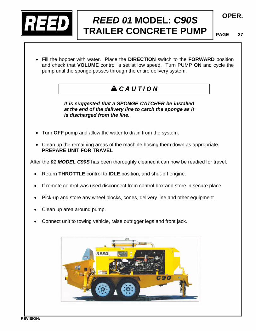
PREPARE UNIT FOR TRAVEL After the 01 MODEL C90S has been thoroughly cleaned it can now be readied for travel.
• Return THROTTLE control to IDLE position, and shut-off engine.
• If remote control was used disconnect from control box and store in secure place.
• Pick-up and store any wheel blocks, cones, delivery line and other equipment.
• Clean up area around pump.
• Connect unit to towing vehicle, raise outrigger legs and front jack.
REVISION:
REED 01 MODEL: C90S TRAILER CONCRETE PUMP
OPER.
PAGE 28
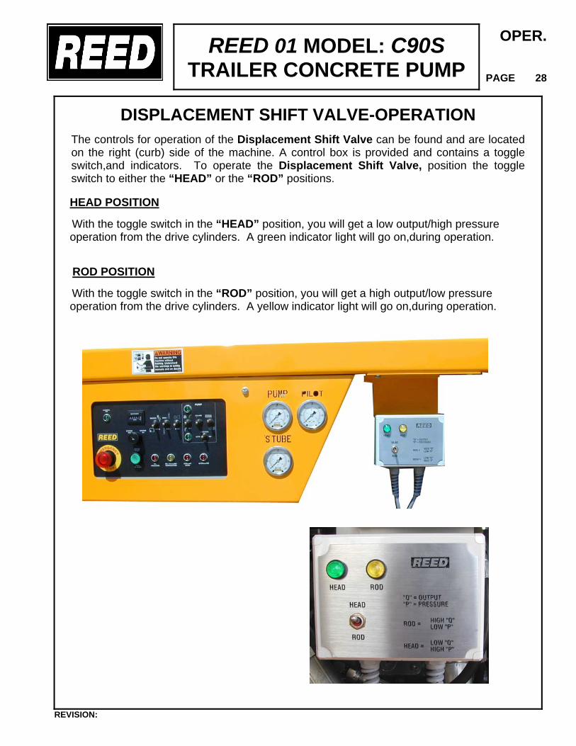
DISPLACEMENT SHIFT VALVE-OPERATION
The controls for operation of the Displacement Shift Valve can be found and are located on the right (curb) side of the machine. A control box is provided and contains a toggle switch,and indicators. To operate the Displacement Shift Valve, position the toggle switch to either the “HEAD” or the “ROD” positions.
HEAD POSITION With the toggle switch in the “HEAD” position, you will get a low output/high pressure operation from the drive cylinders. A green indicator light will go on,during operation.
ROD POSITION With the toggle switch in the “ROD” position, you will get a high output/low pressure operation from the drive cylinders. A yellow indicator light will go on,during operation.
REVISION:
REED 01 MODEL: C90 TRAILER CONCRETE PUMP
OPER.
PAGE 29
REVISION:
REED 01 MODEL: C90S TRAILER CONCRETE PUMP
MAINT
PAGE 00
PREVENTATIVE MAINTENANCE
How good is any of the equipment you own? It is only as good as it is MAINTAINED. Even the finest equipment manufactured requires attention and care. The 01 MODEL C90S is no different. A good well planned and carried out preventative maintenance program will enhance a properly operating unit as well as the safety of those operating and using the equipment. It is very important to establish a good maintenance program. Costly repairs and loss of revenue can often be avoided by planning ahead, setting a regular schedule and exercising good preventative maintenance techniques. The following section is offered as a guide and depicts a start for developing your own preventative maintenance program for the 01 MODEL C90S concrete pump. The program is depicted and broken into sections of INSPECTION and LUBRICATION.
All points noted herein regarding the maintenance and checks are not intended to replace any local or regional regulations which may pertain to this type of equipment. It should also be noted that the list and schedule is not considered to be inclusive. Interval times may vary due to the climate and/or conditions associated with the location area in which the equipment will be used.
It is your responsibility to always insure that the applicable safety precautions are strictly observed when performing the inspections and maintenance checks. Make certain any components that are found to be defective are replaced or those in need of adjustments or repair are corrected before operating the machine.
REVISION:
REED 01 MODEL: C90S TRAILER CONCRETE PUMP
MAINT
PAGE 01
SCHEDULED INSPECTION
The main purpose of accomplishing scheduled inspections is to identify and detect any potential malfunction before it can expand into a major problem. The list presented herein should be inspected and checked on a regular basis. In so doing, it will help ensure a good, safe unit performance. 1. TRAILER • Frame integrity, visually check welds, cracks • Torsion axles secure • Wheels and tires, lug nuts tight, tire inflation • Electric brakes, breakaway switch connected • Front jack stand handle turns easily, smoothly • Outriggers operate properly • Lighting good condition operational
2. ENGINE
• Inspect mountings, bolts, brackets • Oil level proper, any leaks • Fuel system, tank mounting, filter condition, leaks, damaged lines • Battery hold down, condition, tightness of cables • Key switch, indicator lights operable • Throttle control functional • Air cleaner and muffler securely mounted
REVISION:
REED 01 MODEL: C90S TRAILER CONCRETE PUMP
MAINT
PAGE 02
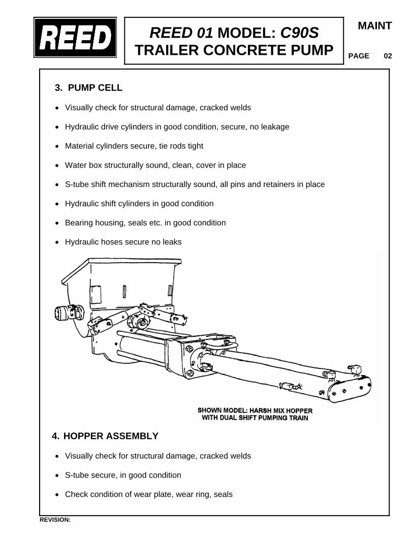
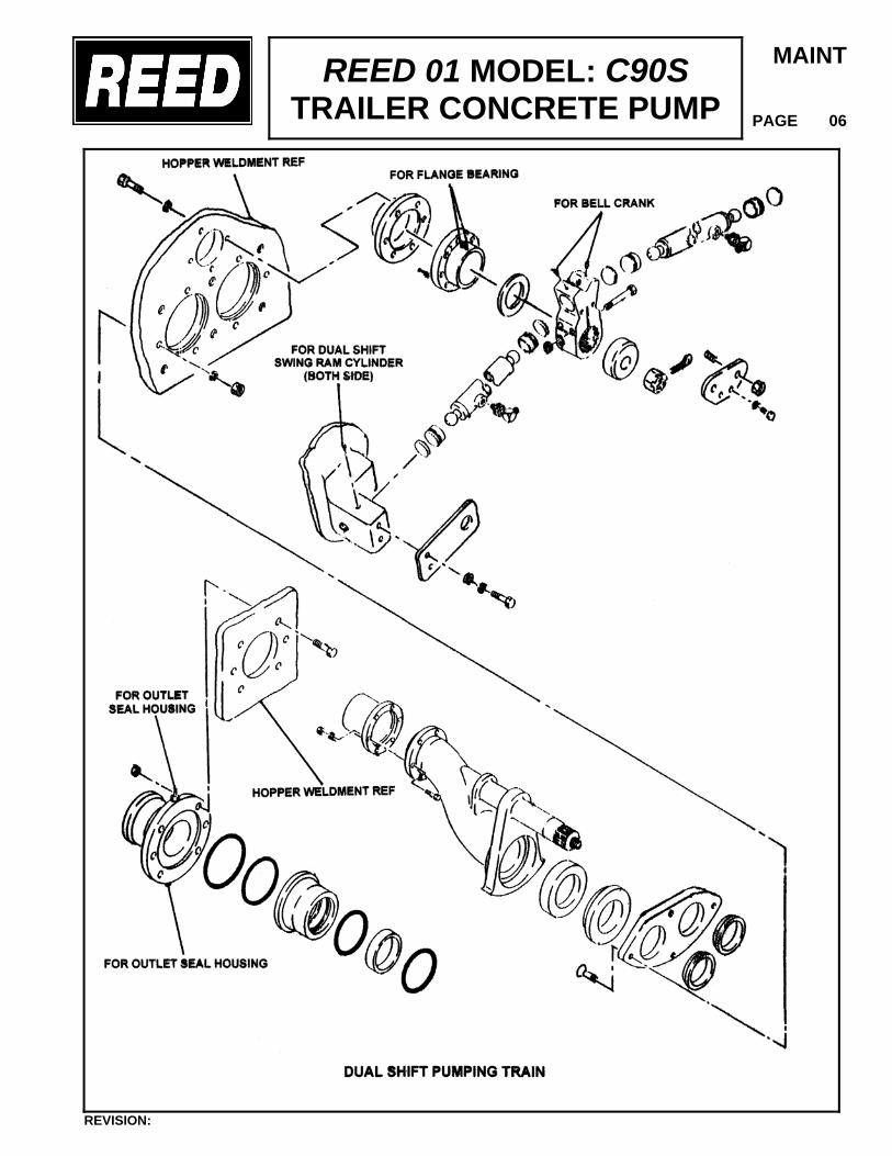
3. PUMP CELL • Visually check for structural damage, cracked welds • Hydraulic drive cylinders in good condition, secure, no leakage • Material cylinders secure, tie rods tight • Water box structurally sound, clean, cover in place • S-tube shift mechanism structurally sound, all pins and retainers in place • Hydraulic shift cylinders in good condition • Bearing housing, seals etc. in good condition • Hydraulic hoses secure no leaks
4. HOPPER ASSEMBLY • Visually check for structural damage, cracked welds • S-tube secure, in good condition
• Check condition of wear plate, wear ring, seals
REVISION:
REED 01 MODEL: C90S TRAILER CONCRETE PUMP
MAINT
PAGE 03
• Check connection of S-tube to outlet, seals, bearing • Hopper drain is functional • Remixer / Agitator in good condition, motor secure
5. MAIN CONTROL • Control box in good condition, not damaged • All toggles in good condition, stay in position or momentarily return to center • Control identification in good condition, legible • Gauges in good condition
6. REMOTE CONTROL • Control console in good condition, not damaged • Switch in good condition • Umbilical cord in good condition, no cuts, securely mounted to box
7. HYDRAULIC SYSTEM • Hydraulic tank securely mounted, covers tight • Filler cap and strainer in place, level sight gauge in proper condition • Check filter condition indicators • Hydraulic oil cooler securely mounted, fan motor secure, connections tight • Check accumulator condition, mounting brackets & clamps • Hydraulic fluid to proper level and clean • All hoses and tubing secure, no leaks
REVISION:
REED 01 MODEL: C90S TRAILER CONCRETE PUMP
MAINT
PAGE 04
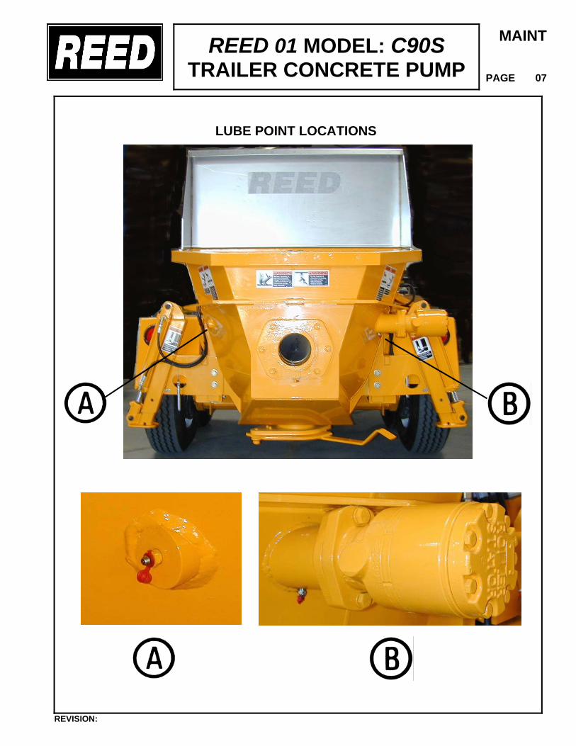
LUBRICATION
The 01 MODEL C90S concrete pump is equipped with several components that because of the application require frequent lubrication. These areas involve the S-tube shifting mechanism, swing components, the shift and outlet bearings and agitator. To insure the economical service and the long life of these components, grease fittings are installed at each point.
Rapid wear and probable component breakdown will result if the unit is operated with inadequate lubrication. Follow the recommended interval and if need be increase the interval when above normal usage takes place.
LUBE POINT LOCATIONS • Swing Tube Shift
• Quantity 1 at cylinder barrel pivot • Quantity 2 at bell crank • Quantity 2 at swing tube shaft bearing housing
• Swing Tube Outlet
• Quantity 2 on outlet bearing housing
• Agitator/Remixer
• Quantity 2 – On non motor end • Quantity 1 – One on motor end
Recommended Lubricant: GENERAL PURPOSE GREASE, SHELL ALVANIA EPLFH2 or
EQUAL Recommended Interval: DAILY, BEFORE START-UP AND AS REQUIRED DURING OPERATION
REVISION:
REED 01 MODEL: C90S TRAILER CONCRETE PUMP
MAINT
PAGE 05
LUBRICANT AND INTERVAL The lubricant that is recommended is generally the best choice, however, should this lubricant be unavailable in your area, consult your local supplier for an equivalent. On the same basis, recommended lubrication intervals are based on normal use, in normal environmental conditions. User is CAUTIONED to adjust the lubrication interval accordingly to meet each individual condition and usage If the swing tube bearing housings become extremely hot or lubricant becomes a liquid and oozes out around the bearing or seal, the area should be relubricated. If the 01 MODEL C90S has been stored or exposed to environmental conditions of extreme low humidity, high dust level, elevated temperatures or heavy rainfall, lubrication of components may be required more frequently than under normal conditions.
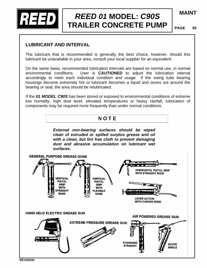
External non-bearing surfaces should be wiped clean of extruded or spilled surplus grease and oil with a clean, but lint free cloth to prevent damaging dust and abrasive accumulation on lubricant wet surfaces.
REVISION:
REED 01 MODEL: C90S TRAILER CONCRETE PUMP
MAINT
PAGE 06
REVISION:
REED 01 MODEL: C90S TRAILER CONCRETE PUMP
MAINT
PAGE 07
LUBE POINT LOCATIONS
REVISION:
REED 01 MODEL: C90S TRAILER CONCRETE PUMP
MAINT
PAGE 08
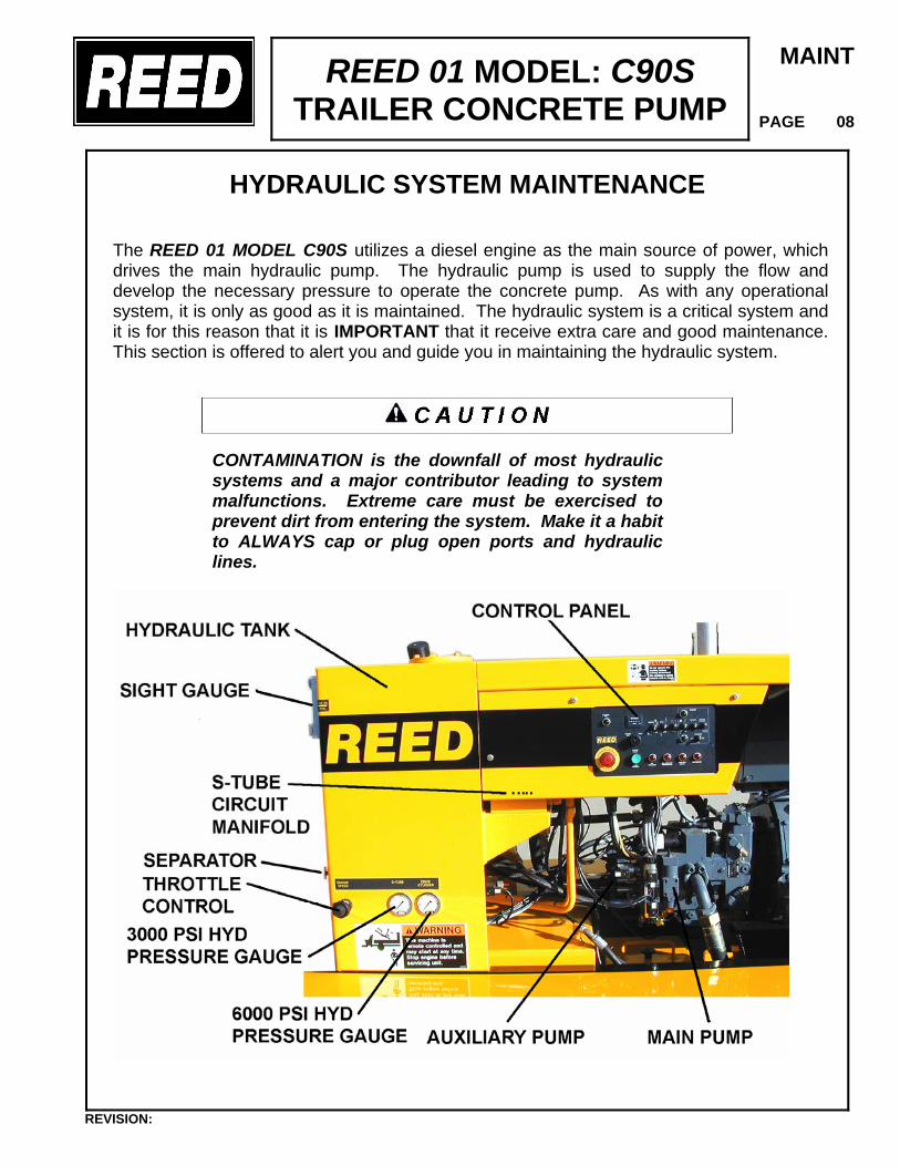
HYDRAULIC SYSTEM MAINTENANCE
The REED 01 MODEL C90S utilizes a diesel engine as the main source of power, which drives the main hydraulic pump. The hydraulic pump is used to supply the flow and develop the necessary pressure to operate the concrete pump. As with any operational system, it is only as good as it is maintained. The hydraulic system is a critical system and it is for this reason that it is IMPORTANT that it receive extra care and good maintenance. This section is offered to alert you and guide you in maintaining the hydraulic system.
CONTAMINATION is the downfall of most hydraulic systems and a major contributor leading to system malfunctions. Extreme care must be exercised to prevent dirt from entering the system. Make it a habit to ALWAYS cap or plug open ports and hydraulic lines.
REVISION:
REED 01 MODEL: C90S TRAILER CONCRETE PUMP
MAINT
PAGE 09
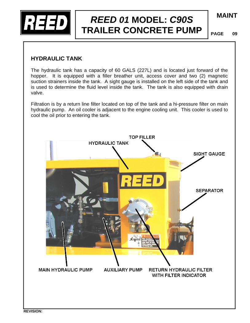
HYDRAULIC TANK The hydraulic tank has a capacity of 60 GALS (227L) and is located just forward of the hopper. It is equipped with a filler breather unit, access cover and two (2) magnetic suction strainers inside the tank. A sight gauge is installed on the left side of the tank and is used to determine the fluid level inside the tank. The tank is also equipped with drain valve. Filtration is by a return line filter located on top of the tank and a hi-pressure filter on main hydraulic pump. An oil cooler is adjacent to the engine cooling unit. This cooler is used to cool the oil prior to entering the tank.
REVISION:
REED 01 MODEL: C90S TRAILER CONCRETE PUMP
MAINT
PAGE 10
SYSTEM MAINTENANCE ITEMS The following are specific items for care and maintenance of the hydraulic system.
• FLUID LEVEL Check level daily with sight gauge provided. Maintain level at full mark. Add through filter. • TANK BREATHER Clean every 50 hours of operation. Remove from tank, clean with solvent and air blow dry. • RETURN LINE FILTER One (1) 10-micron filter; change after first 50 Hours of operation. Thereafter change every 150 hours of operation or when condition gauge indicates to do so. • HYDRAULIC TANK Change oil in tank every 1000 hours of operation of yearly whichever comes first.
After fluid loss for any reason, filter replacement, component removal etc., sufficient fluid must be added to properly maintain required level in tank.
HYDRAULIC FLUID The 01 MODEL C90S utilizes in its hydraulic system a fluid manufactured by the SHELL OIL CO. and is designated as TELLUS #46. It is to be used in ambient temperatures of 39-90° F (4-32° C). The normal fluid temperature will range from 100-167° F (38-75° C). For ambient temperatures of 90° F (32° C) and above use fluid designated as a ISO rating of 68. Use ISO 32 for ambient temperatures of 32° F (4° C) and below.
USE ONLY SHELL TELLUS 46 or equal hydraulic fluid and NEVER MIX with other type fluids. Always use a CLEAN fluid. Using impure or other type of fluids not specified will contaminate the hydraulic system and can lead to eventual system malfunction or damage and possibly deteriorate the hydraulic seals.
REVISION:
REED 01 MODEL: C90S TRAILER CONCRETE PUMP
MAINT
PAGE 11
ADDING HYDRAULIC FLUID As previously indicated, a hydraulic systems worst enemy is CONTAMINATION. Exercise extreme care when adding fluid to the hydraulic tank. • To prevent any dirt or water from entering the hydraulic tank, thoroughly clean area
around top of filter. Remove plug on top of filter. • Use fresh clean hydraulic fluid. If a hand pump is used to transfer the fluid, check that
pump filter is clean. If pouring of fluid from a container, pour it through a fine wire mesh screen, 200 mesh or finer.
• Replace plug immediately after filling tank to proper level.
Do not use a cloth for straining fluid as lint is harmful to the hydraulic system.
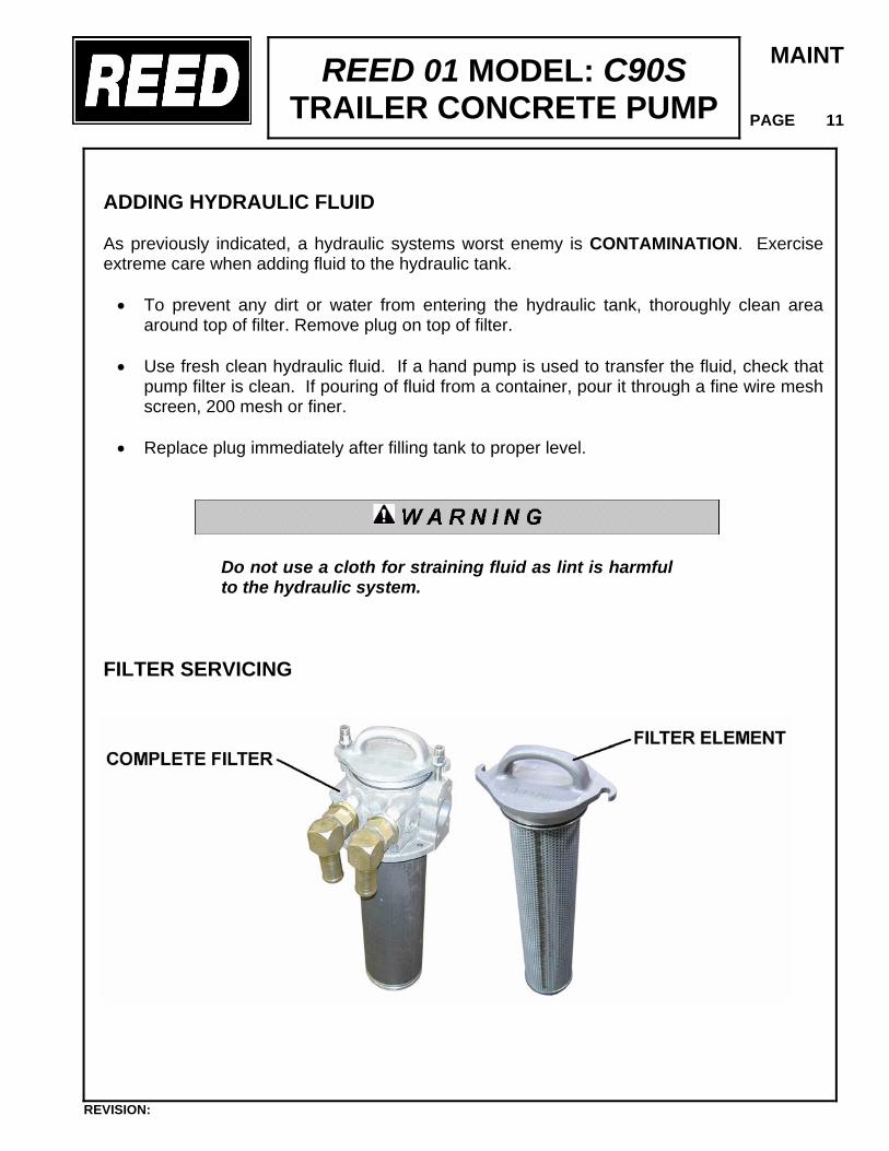
FILTER SERVICING
REVISION:
REED 01 MODEL: C90S TRAILER CONCRETE PUMP
MAINT
PAGE 12
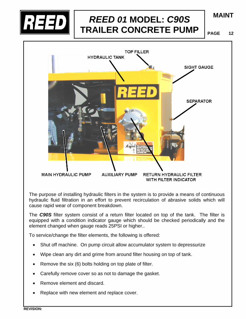
The purpose of installing hydraulic filters in the system is to provide a means of continuous hydraulic fluid filtration in an effort to prevent recirculation of abrasive solids which will cause rapid wear of component breakdown. The C90S filter system consist of a return filter located on top of the tank. The filter is equipped with a condition indicator gauge which should be checked periodically and the element changed when gauge reads 25PSI or higher.. To service/change the filter elements, the following is offered:
• Shut off machine. On pump circuit allow accumulator system to depressurize
• Wipe clean any dirt and grime from around filter housing on top of tank.
• Remove the six (6) bolts holding on top plate of filter.
• Carefully remove cover so as not to damage the gasket.
• Remove element and discard.
• Replace with new element and replace cover.
REVISION:
REED 01 MODEL: C90S TRAILER CONCRETE PUMP
MAINT
PAGE 13
• Start up machine and observe for leakage.
DO NOT ATTEMPT TO WASH OUT FILTER ELEMENT. These are disposable types and more harm can be done than it is worth.
CLEANING THE HYDRAULIC TANK The hydraulic tank should be drained and cleaned after 1000 hours of operation or yearly whichever comes first. This will assist in keeping the systems clean and in proper condition. To accomplish this the following is offered.
• Shut off machine. On pump circuit allow accumulator system to depressurize
Place a suitable size container under the hydraulic tank drain fitting located at back of tank facing the hopper. NOTE: The tank has a capacity of 60gals (227 L). Make sure your drain container is large enough. Remove drain plug.
• Remove the access cover on the hydraulic tank being careful not to damage the
gasket • Remove the two (2) suction strainers • After tank has drained, flush the inside of the hydraulic tank with clean solvent and
wipe clean with lint free cloths. DO NOT USE PAPER TOWELS. Remove any particles from tank bottom and sump
• Clean the suction strainers by soaking them in fresh solvent and then air blow dry • Install the tank drain plug. Reinstall the suction strainers and access cover with gasket • Clean the filler breather with solvent and air blow dry • Change the hydraulic system filter element • Refill the hydraulic tank with new CLEAN hydraulic fluid, SHELL TELLUS 46 • Start machine and check for leaks
REVISION:
REED 01 MODEL: C90S TRAILER CONCRETE PUMP
MAINT
PAGE 14
DESCRIPTION OF HYDRAULIC SYSTEM
The hydraulic system of the 01 MODEL C90S consists of three separate circuits and although integrated, each is designed to perform a particular function within the operation of the concrete pump. The three circuits utilized are: • Main Pump Circuit - It controls the function for operation of the hydraulic drive cylinder
and material cylinders. • S-tube Shift Circuit - It controls the function for operation of shifting the S-tube from
one material cylinder to the other during concrete pumping. • Auxiliary Circuit - This controls the operational function for the agitator/remixer.
For the purpose of making the operation of each circuit easier to understand, they are being described separately. SPECIFICS – PRESSURES
• Main System Max. Pressure = 4700 PSI (327 Bar) • Main System Relief Pressure = 4200 PSI (294 Bar) • S-tube Shift System Relief Pressure = 2500 PSI (174 Bar) • Accumulator Pre-Charge Pressure = 1200 PSI ( 83 Bar) • Auxiliary System Relief Pressure = 1800 PSI (125 Bar)
SYSTEM FILTRATION The hydraulic tank has a capacity of 60 gals (227L) of SHELL TELLUS #46 hydraulic fluid. The start of system filtration begins inside the tank where two (2) magnetic type suction strainers are installed. The system return fluid must pass through a 10-micron filter element before returning to the tank and after passing through the oil cooler.
REVISION:
REED 01 MODEL: C90S TRAILER CONCRETE PUMP
MAINT
PAGE 15
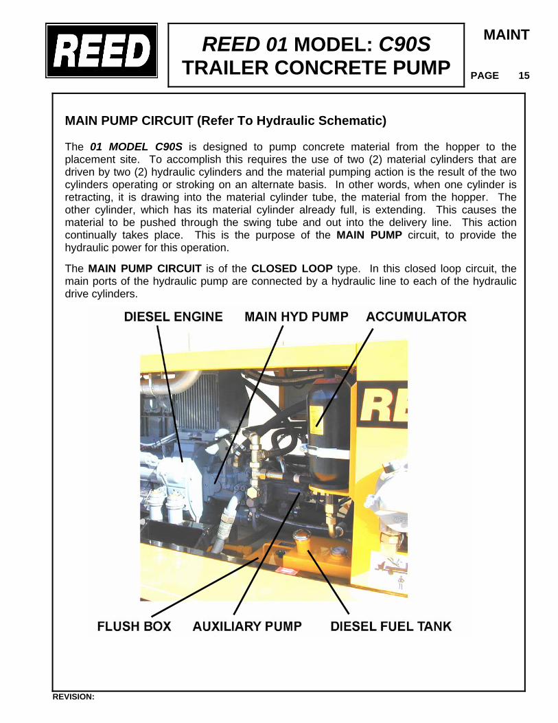
MAIN PUMP CIRCUIT (Refer To Hydraulic Schematic) The 01 MODEL C90S is designed to pump concrete material from the hopper to the placement site. To accomplish this requires the use of two (2) material cylinders that are driven by two (2) hydraulic cylinders and the material pumping action is the result of the two cylinders operating or stroking on an alternate basis. In other words, when one cylinder is retracting, it is drawing into the material cylinder tube, the material from the hopper. The other cylinder, which has its material cylinder already full, is extending. This causes the material to be pushed through the swing tube and out into the delivery line. This action continually takes place. This is the purpose of the MAIN PUMP circuit, to provide the hydraulic power for this operation. The MAIN PUMP CIRCUIT is of the CLOSED LOOP type. In this closed loop circuit, the main ports of the hydraulic pump are connected by a hydraulic line to each of the hydraulic drive cylinders.
REVISION:
REED 01 MODEL: C90S TRAILER CONCRETE PUMP
MAINT
PAGE 16
By making an internal change within the pump an external control, the flow output of the fluid can be directed to either “A” Port or “B” Port. As an example, from one side of the pump to one drive cylinder with return fluid from the other cylinder going back to the pump, then changing directions to pressure the other cylinder. To meet the volume and pressure requirements of the main pump circuit, a Sundstrand hydraulic pump is used. This pump is a variable displacement axial piston pump of a swashplate design. The pistons run against the swashplate, which is capable of being tilted. This tilting or angle varies the stroke length of the pistons which in turn varies the displacement of the fluid. The larger the angle, the greater the flow. In the case of the Model 01 C90S, the angle of the swashplate is varied by the use of the VOLUME control. The main hydraulic pump is driven through a gear box by the diesel engine. Placing the toggle switch to ON will place the pump in operation. However, at this point since PUMP switch if OFF, there is no volume demand, thus the charge pump within the main pump is basically circulating the oil and lubricating the inside of the pump.
To energize the cycling circuit, the PUMP switch must be ON. When this is done, an electrical signal is generated which engages the hydraulic pump to start and direct the flow to the appropriate drive cylinder. Where, how, and why is this electrical signal generated? It was previously noted that the material pumping action is the result of the two material cylinders cycling on an alternate basis. This alternating cycling is controlled by an electrical signal that is generated at the end of each material cylinder’s suction, retraction stroke. A proximity sensor, one for each material cylinder, is installed in the flush box. As the piston coupler passes under the proximity sensor, it generates an electrical signal that is sent to the logic controller or which is better known as the black box. The black box is a REED proprietary solid state device, designed to control the alternating action of the material cylinders and to synchronize the movement of the swing tube. The signal from the black box is then sent to the PCP valve. The PCP valve (pressure control pilot) is a component of the Sundstrand pump. When energized it is used to convert the electrical signal to a hydraulic signal, which in turn, shifts the hydraulic pumps servo piston. The servo piston is used to change the position of the swashplate which is used to direct the flow of fluid to either CYL “A” or “B”, based on the signal received and which sensor was activated. The PCP valve is also used to vary the angle of the swashplate which changes the displacement fo fluid to either a higher or lower output in proportion to the amount of volume demand placed on it by the potentiometers electrical signal.
REVISION:
REED 01 MODEL: C90S TRAILER CONCRETE PUMP
MAINT
PAGE 17
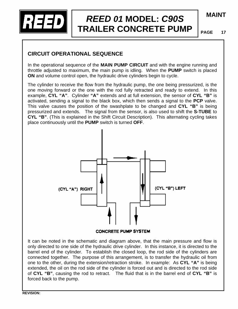
CIRCUIT OPERATIONAL SEQUENCE In the operational sequence of the MAIN PUMP CIRCUIT and with the engine running and throttle adjusted to maximum, the main pump is idling. When the PUMP switch is placed ON and volume control open, the hydraulic drive cylinders begin to cycle. The cylinder to receive the flow from the hydraulic pump, the one being pressurized, is the one moving forward or the one with the rod fully retracted and ready to extend. In this example, CYL “A”. Cylinder “A” extends and at full extension, the sensor of CYL “B” is activated, sending a signal to the black box, which then sends a signal to the PCP valve. This valve causes the position of the swashplate to be changed and CYL “B” is being pressurized and extends. The signal from the sensor, is also used to shift the S-TUBE to CYL “B”. (This is explained in the Shift Circuit Description). This alternating cycling takes place continuously until the PUMP switch is turned OFF.
It can be noted in the schematic and diagram above, that the main pressure and flow is only directed to one side of the hydraulic drive cylinder. In this instance, it is directed to the barrel end of the cylinder. To establish the closed loop, the rod side of the cylinders are connected together. The purpose of this arrangement, is to transfer the hydraulic oil from one to the other, during the extension/retraction stroke. In example: As CYL “A” is being extended, the oil on the rod side of the cylinder is forced out and is directed to the rod side of CYL “B”, causing the rod to retract. The fluid that is in the barrel end of CYL “B” is forced back to the pump.
REVISION:
REED 01 MODEL: C90S TRAILER CONCRETE PUMP
MAINT
PAGE 18
With this arrangement of connecting the two cylinders together, it is possible for various reasons, such as leakage around the piston seals that more oil exists on the rod side of the cylinder than is required. When this condition exists, some hydraulic oil remains at the rod end of the cylinder being extended while the other cylinder is fully retracted. As a result the cylinder cannot be totally extended and thus it SHORT STROKES which will also happen eventually to the other cylinder. This condition can be corrected by actuating the switch on the electrical control box to position “A” or “B” whichever cylinder is extending, and to HOLD switch until extended cylinder is fully bottomed out. Hydraulically, this is accomplished by use of the check valves installed on both cylinders. By holding the CYL A-B switch, you have interrupted the cycle and are forcing more oil into the barrel of the extending cylinder. This oil is then directed and unseats the check valve at the rod end of the extending cylinder “A”, putting more oil on the rod side which is then transferred to the rod side of CYL “B”. Since that cavity is full, pressure is built up in the rod side of CYL “B”, which unseats the barrel side check valve forcing the excess oil back to the tank. Once the extending cylinder is at full stroke, regular operation can continue.
In addition to piston leakage, a SHORT STROKE condition may result from incorrect proximity sensor location or leaking check valves.
As protection to the MAIN PUMP CIRCUIT against excessive pressure, a relief valve has been installed and is set to open at 4200 PSI which is 200 PSI over the main system pressure. Thus when the system pressure reaches 4200 PSI, the relief valve opens directing the oil back to the tank. S-TUBE SHIFT CIRCUIT (Refer to Hydraulic Schematic) In the foregoing description of the Main Pump Circuit, we learned that the hydraulic drive cylinders operate on an alternating basis causing the material cylinders to do the same. Since there is only one outlet for the pumping material, a means is required to transfer the material from the material cylinder to the outlet and into the delivery line. To accomplish this a component referred to as the swing tube or S- tube is installed in the hopper. Since there are two material cylinders and one S-tube, the S-tube must be shifted from one material cylinder to the other, whichever one is loaded with the pumping material. Thus the incorporation of a S-TUBE SHIFT CIRCUIT.
REVISION:
REED 01 MODEL: C90S TRAILER CONCRETE PUMP
MAINT
PAGE 19
The S-tube shift hydraulic circuit is of the open center type, meaning that when the control valves are in the NEUTRAL position hydraulic non operational (unactuated), the internal passages of the valves are open, free flow, allowing the hydraulic fluid to return to the tank. With the engine running the hydraulic pump is operating, producing a flow of oil which, with no control energized, will pass through the shift circuit on its way back to tank. To meet the flow and pressure requirements of the shift circuit, one section of a tandem pump is used. Note: a single pump is used if unit is not equipped with an agitator. The TANDEM HYDRAULIC PUMP is of the gear pump design, having a fixed displacement meaning it is designed to constantly produce the same displacement at pre-set maximum engine RPM. The tandem gear pump is direct connected and driven through the gear box. In addition to the hydraulic pump, the swing tube shift circuit consists of an unloader manifold, an accumulator, a solenoid directional valve and two (2) hydraulic cylinders. The following is offered to describe the function of each in the system. SHIFT CIRCUIT MANIFOLD The shift circuit is also equipped with a manifold block, which is located at the rear of the hydraulic tank. It contains a relief cartridge, solenoid valve cartridge, check valve and a differential pressure sensor. A solenoid operated directional valve is mounted on top of the block and a S-tube selector control valve is located on front of the block. Each of these components is designed to perform a particular function in the swing circuit as explained in the following descriptions:
• RELIEF CARTRIDGE - This cartridge is located on the top side of the manifold block and is used to protect the system from excessive pressure and to limit the amount of pressure being applied to the accumulator and is set at 2300 PSI (160 Bar)
• UNLOADER VALVE - This cartridge is used to divert the pump flow from going to the
accumulator once its capacity has been reached, directing it back to tank. It becomes operational when the relief cartridge setting has been reached.
• SOLENOID VALVE CARTRIDGE – There are two (2) of these cartridges used in the
circuit. One, which may be referred to as a dump valve, is designed into the shift circuit as a SAFETY VALVE. Its purpose is to automatically relieve the pressure in the accumulator through an orifice. The valve is controlled by the PUMP CYCLE switch and the valve OPENS when the pump switch is OFF. This prevents the unintentional shifting of the S-tube when the pump is not operating.
REVISION:
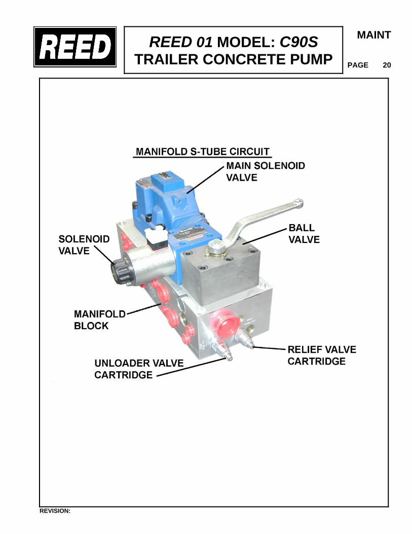
REED 01 MODEL: C90S TRAILER CONCRETE PUMP
MAINT
PAGE 20
REVISION:
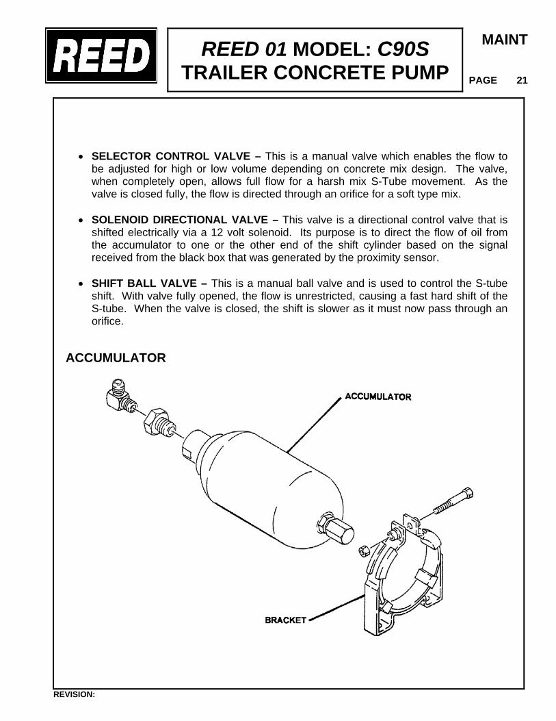
REED 01 MODEL: C90S TRAILER CONCRETE PUMP
MAINT
PAGE 21
• SELECTOR CONTROL VALVE – This is a manual valve which enables the flow to
be adjusted for high or low volume depending on concrete mix design. The valve, when completely open, allows full flow for a harsh mix S-Tube movement. As the valve is closed fully, the flow is directed through an orifice for a soft type mix.
• SOLENOID DIRECTIONAL VALVE – This valve is a directional control valve that is
shifted electrically via a 12 volt solenoid. Its purpose is to direct the flow of oil from the accumulator to one or the other end of the shift cylinder based on the signal received from the black box that was generated by the proximity sensor.
• SHIFT BALL VALVE – This is a manual ball valve and is used to control the S-tube
shift. With valve fully opened, the flow is unrestricted, causing a fast hard shift of the S-tube. When the valve is closed, the shift is slower as it must now pass through an orifice.
ACCUMULATOR
REVISION:
REED 01 MODEL: C90S TRAILER CONCRETE PUMP
MAINT
PAGE 22
ACCUMULATOR The accumulator is incorporated into the shift circuit to provide instant pressure and volume for the shifting of the swing tube, which cannot be obtained under normal circumstances. An accumulator is a hydraulic reservoir that retains the hydraulic fluid under high pressure. To accomplish this, the accumulator contains a rubber bladder on the inside of the reservoir. This bladder prior to the installation of the accumulator on the machine must be pre-charged to a certain pressure using a dry nitrogen gas. In this pre-charge operation, the bladder is expanded much like a balloon and is retained in that state. In the application of the shift circuit, the hydraulic fluid is pumped into the accumulator at a higher pressure than that inside the bladder. This compresses the bladder building up high pressure within the accumulator that is retained until released. CIRCUIT OPERATIONAL SEQUENCE In the operational sequence of the shift circuit with the engine at full RPM, the tandem pump is operating, producing its rated displacement. The flow is going through the system and is being dumped or directed back to the tank by the solenoid cartridge of the unloader manifold. When the “E-STOP” switch is placed to ON and the horn sounds, an electrical signal, closes the solenoid cartridge. When this occurs the hydraulic fluid is now directed to the accumulator where it starts compressing the bladder building up pressure. When the pressure in the shift circuit reaches the setting of the relief cartridge, which in this application is 2300 PSI (160 Bar), the relief opens and activates the unloader valve. The valve then shifts and directs the flow from the pump back to the tank through the relief in lieu of continuing to pressurize the accumulator. The check valve then prevents the fluid in the accumulator from going back to the pump line. In the Main Pump Circuit description it was described how an electrical signal was generated by the proximity sensor which was sent to the black box and used to control the alternating action of the hydraulic drive cylinders. This same signal is also used to shift the swing tube so that its movement is synchronized with that of the hydraulic drive cylinder, shifting the swing tube to the material cylinder, which is ready to extend (normal forward operation). The electrical signal activates the solenoid coil of the directional valve, shifting the spool to the appropriate side. The accumulator then releases, exhausting the fluid which is then directed to the appropriate side of the shift cylinder. As soon as the shift is made the accumulator is refilled immediately and the sequence starts all over again.
REVISION:
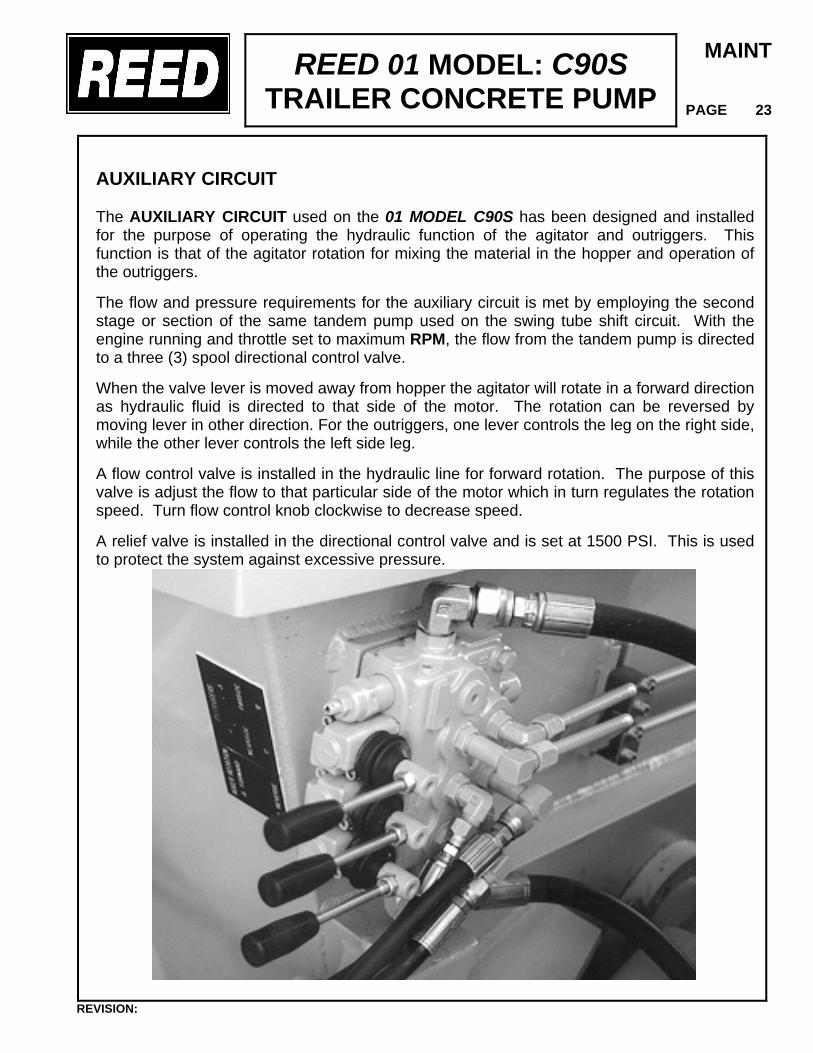
REED 01 MODEL: C90S TRAILER CONCRETE PUMP
MAINT
PAGE 23
AUXILIARY CIRCUIT The AUXILIARY CIRCUIT used on the 01 MODEL C90S has been designed and installed for the purpose of operating the hydraulic function of the agitator and outriggers. This function is that of the agitator rotation for mixing the material in the hopper and operation of the outriggers. The flow and pressure requirements for the auxiliary circuit is met by employing the second stage or section of the same tandem pump used on the swing tube shift circuit. With the engine running and throttle set to maximum RPM, the flow from the tandem pump is directed to a three (3) spool directional control valve. When the valve lever is moved away from hopper the agitator will rotate in a forward direction as hydraulic fluid is directed to that side of the motor. The rotation can be reversed by moving lever in other direction. For the outriggers, one lever controls the leg on the right side, while the other lever controls the left side leg. A flow control valve is installed in the hydraulic line for forward rotation. The purpose of this valve is adjust the flow to that particular side of the motor which in turn regulates the rotation speed. Turn flow control knob clockwise to decrease speed. A relief valve is installed in the directional control valve and is set at 1500 PSI. This is used to protect the system against excessive pressure.
REVISION:
REED 01 MODEL: C90S TRAILER CONCRETE PUMP
MAINT
PAGE 24
ADJUSTMENT PROCEDURES
It is not unusual that over a period of time due to usage, troubleshooting, making repairs or replacement of parts that certain components may require periodic adjustments to maintain the factory type performance. This section of the manual is offered to assist you in making the necessary adjustments.
ADJUSTMENTS TO HYDRAULIC SYSTEM
(TEST GAUGES)
The 01 MODEL C90S concrete pump has undergone an extensive quality control inspection and testing phase during the manufacturing process prior to being shipped. All the required settings and adjustments to provide an efficient and safe operating machine have been made. The various pressure settings and adjustments should NOT BE ALTERED. However, it may be necessary through the course of using the machine or replacement of parts to check and reset the pressure settings to the factory established guidelines. This should only be done by QUALIFIED MAINTENANCE PERSONNEL who understand the systems. The following is offered to assist in accomplishing the task.
The unit is equipped with a test port which is used to install a test gauge. To perform the following checks and adjustments, the following test gauges may be required.
TEST GAUGE #1 – This test gauge consists of a small diameter hose having one end connected to a 0-1000 PSI (0-70 Bar) hydraulic pressure gauge and the other end containing a female adapter.
TEST GAUGE #2 – This test gauge consists of same set up as GAUGE 1 except the
gauge is a 0-6000 PSI (0-420 Bar) hydraulic pressure gauge is used. The TEST GAUGE KITS are available from the REED Parts Department.
REVISION:
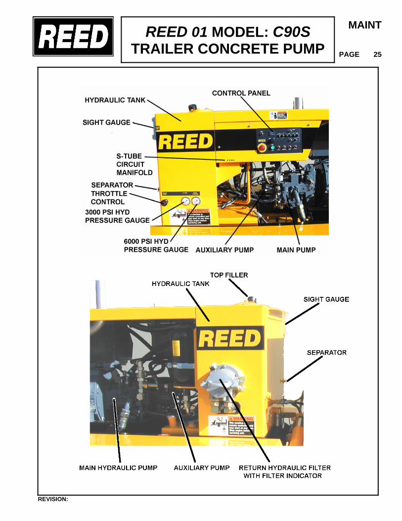
REED 01 MODEL: C90S TRAILER CONCRETE PUMP
MAINT
PAGE 25
REVISION:
REED 01 MODEL: C90S TRAILER CONCRETE PUMP
MAINT
PAGE 26
ADJUSTMENTS TO HYDRAULIC SYSTEM
1. MAIN HYDRAULIC PUMP
The main hydraulic pump is manufactured by Sundstrand and all internal adjustments and settings have been made by Sundstrand to REED specifications. No further adjustments are required. Should it become, at some point, necessary to make adjustments, refer to the Sundstrand pump data located in the VENDOR SECTION of this manual.
DO NOT OPERATE CONCRETE PUMP WITHOUT OIL OR WATER IN THE FLUSH/WATERBOX.
2. PRESSURE LIMITER RELIEF VALVE-SET @ 4200 PSI/294 BAR
Two (2) relief valves have been installed in the system to limit and protect the main system from excessive pressure. The valves, one for each of the hydraulic drive cylinders, are located on the right side, just behind the engine and adjacent to the main hydraulic pump. To check or adjust the valves to the proper setting, proceed as follows:
A. CHECKING THE PRESSURE
• Start engine and adjust THROTTLE to maximum RPM.
• Place CONTROL LOCATION switch to LOCAL.
• Rotate VOLUME control to full ON position.
• Actuate PUMP switch to ON.
• On the control box actuate the switch to the CYL “A” position and HOLD.
• While doing this, observe the CYL “A” pressure gauge located at the bottom of the hydraulic tank. Gauge should register 4200 PSI.
• Actuate CYL “B” switch and observe the pressure gauge. It too should register 4200 PSI.
• Turn PUMP switch to OFF position.
• If pressure on either gauge does not read 4200 PSI, then an adjustment is necessary.
REVISION:
REED 01 MODEL: C90S TRAILER CONCRETE PUMP
MAINT
PAGE 27
B. ADJUSTING THE PRESSURE
• To make the pressure adjustment, loosen the locknut on the relief valve and adjust.
• Turn PUMP switch ON and again actuate and hold TEST CYL switch ”A” or “B”.
• Using a #3 Metric Allen Wrench, turn the adjustment screw IN to INCREASE pressure and turn OUT to DECREASE. Observe the pressure gauge while making the adjustment.
• Retighten locknut after adjustment has been made.
• Repeat procedure if other cylinder relief valve needs adjustment.
3. SHIFT CIRCUIT SYSTEM PRESSURE-SET @ 2000 PSI/140 Bar SHIFT RELIEF PRESSURE- 2300 PSI/160 BAR
The S-Tube Shift Circuit manifold is located on the backside of the tank. It contains the relief and unloader valve. These cartridge valves are used to protect and limit the pressure being applied to the accumulator and are used to adjust and set the SHIFT system pressure. To check and adjust the pressure the following is offered:
A. CHECKING THE PRESSURE
• Start engine and adjust THROTTLE to maximum RPM. • Turn VOLUME control so that it is partially open, #3 position. • Loosen locknut on the unload cartridge valve. • Using an allen wrench, turn set screw all the way IN. • Monitor the accumulator pressure gauge. Gauge should read 2400 PSI. This
indicates the RELIEF VALVE setting. If gauge reads otherwise, then an adjustment is necessary.
REVISION:
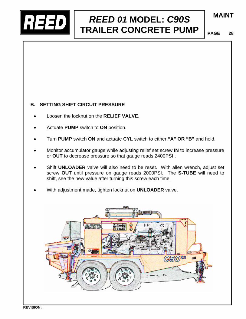
REED 01 MODEL: C90S TRAILER CONCRETE PUMP
MAINT
PAGE 28
B. SETTING SHIFT CIRCUIT PRESSURE
• Loosen the locknut on the RELIEF VALVE. • Actuate PUMP switch to ON position. • Turn PUMP switch ON and actuate CYL switch to either “A” OR “B” and hold. • Monitor accumulator gauge while adjusting relief set screw IN to increase pressure
or OUT to decrease pressure so that gauge reads 2400PSI . • Shift UNLOADER valve will also need to be reset. With allen wrench, adjust set
screw OUT until pressure on gauge reads 2000PSI. The S-TUBE will need to shift, see the new value after turning this screw each time.
• With adjustment made, tighten locknut on UNLOADER valve.
REVISION:
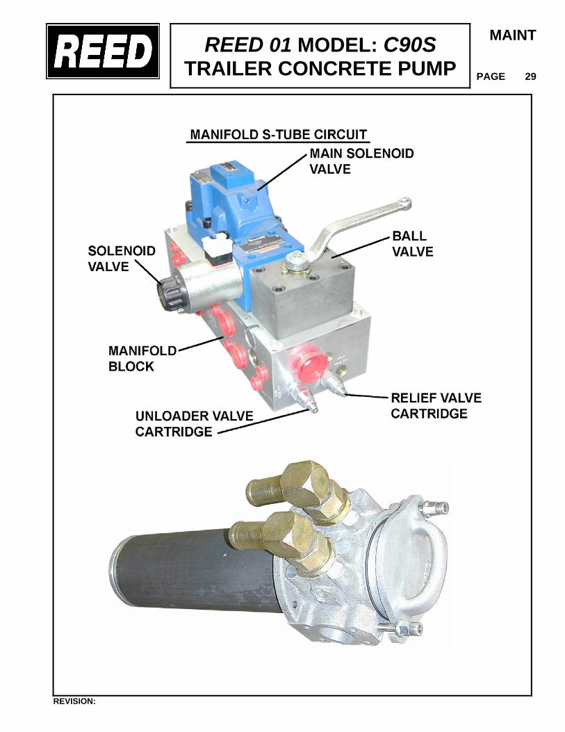
REED 01 MODEL: C90S TRAILER CONCRETE PUMP
MAINT
PAGE 29
REVISION:
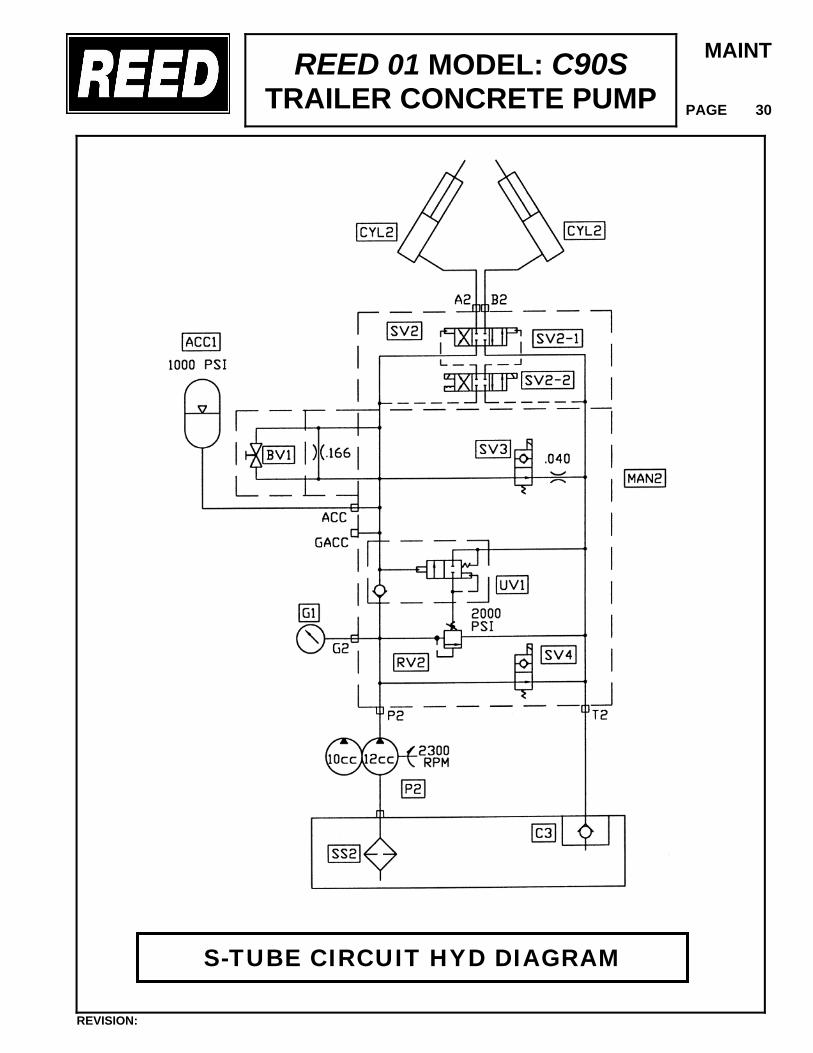
REED 01 MODEL: C90S TRAILER CONCRETE PUMP
MAINT
PAGE 30
REVISION:
S-TUBE CIRCUIT HYD DIAGRAM
REED 01 MODEL: C90S TRAILER CONCRETE PUMP
MAINT
PAGE 31
4. AUXILIARY CIRCUIT RELIEF
The auxiliary circuit for the 01 MODEL C90S is used to operate the agitator function. In this circuit, the relief valve set pressure and the system operating pressure is the same. To check and make an adjustment the following is offered: Agitator Pressure – Set @ 1500 PSI (105 Bar) To check or set this pressure, it will be necessary to install a test pressure gauge in the system. • Turn off pump and engine. • Slowly loosen hose fitting at hydraulic motor and then disconnect hose. Plug or cap end
of hose securely against pressure. • Install in the motor a 3000-PSI pressure gauge directly or attach the gauge to a test
hose and install other end in motor. • Start engine and adjust THROTTLE to maximum RPM.
• Put a 2 x 4 wood piece to lock-up remixer auger. • At control, actuate the directional control valve lever to either FWD or REV which would
be the direction that still has pressure hose connected. (Not gauge side) • Monitor pressure gauge. Gauge should read 1500 PSI. • If gauge reads higher or lower, then re-adjust relief valve as follows:
• The relief valve is located in the directional control valve. • Loosen locknut on valve cartridge. Turn set screw IN to increase pressure and OUT
to decrease pressure. • When correct pressure is reached, tighten locknut. • Shutdown engine. • Disconnect pressure gauge and reinstall hose onto motor.
REVISION:
REED 01 MODEL: C90S TRAILER CONCRETE PUMP
MAINT
PAGE 32
ADJUSTMENT TO SWING TUBE
It is important from an operational standpoint that the swing tube shift properly from side to side and that it is properly adjusted to prevent leakage particularly at high pressure and high volume pumping. On a properly adjusted swing tube, the shifting motion from one material cylinder to the other shall be smooth providing a very light scraping noise. The gap between the swing tube and the wear plate installed on the hopper shall be almost non-existent, but not so tight that it impedes a smooth movement. Located inside the swing tube is a wear ring and it is designed to stay continually in contact with the wear plate providing the necessary sealing action for efficient operation. This is the scraping noise that should be heard. If there is a lack of the scraping noise or the swing tube shifts too freely this is usually the first indication that an adjustment is required, To adjust the swing tube clearance:
• Shut off engine. If unit was being run, allow a few minutes for the accumulator pressure to subside.
• Remove cotter pin from large castle nut on swing tube shaft. • Tighten the castle nut with a 24” adjustable wrench, until no more turning is possible. • Start engine and adjust THROTTLE to a low RPM. • Actuate the PUMP switch to ON position and see if the swing tube shifts from side to
side, if it does, the wear parts are very worn and should be replaced. • If the scraping noise of the swing tube is slight and the tube shifts briskly from side to
side, the adjustment is correct. • If further adjustment is necessary, again tighten hex nut a little at a time. DO NOT
OVER TIGHTEN or swing tube may bind while pumping material at high pressure. • If the swing tube hesitates or stutters during the change over, the adjustment is too tight.
Loosen lock nut a little at a time • Once adjustment is finalized, replace cotter pin and cover.
REVISION:
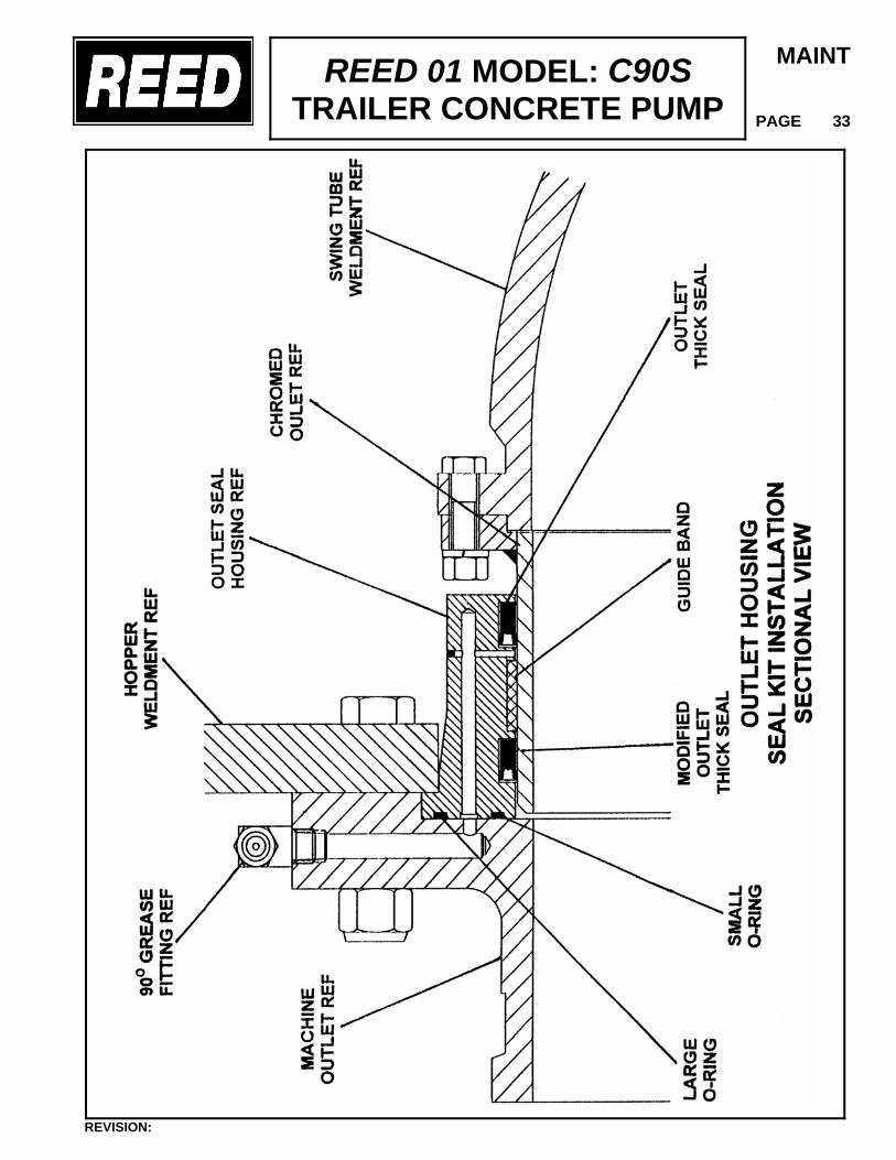
REED 01 MODEL: C90S TRAILER CONCRETE PUMP
MAINT
PAGE 33
REVISION:
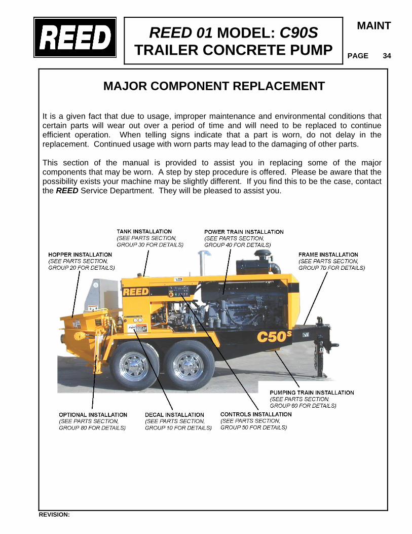
REED 01 MODEL: C90S TRAILER CONCRETE PUMP
MAINT
PAGE 34
MAJOR COMPONENT REPLACEMENT
It is a given fact that due to usage, improper maintenance and environmental conditions that certain parts will wear out over a period of time and will need to be replaced to continue efficient operation. When telling signs indicate that a part is worn, do not delay in the replacement. Continued usage with worn parts may lead to the damaging of other parts. This section of the manual is provided to assist you in replacing some of the major components that may be worn. A step by step procedure is offered. Please be aware that the possibility exists your machine may be slightly different. If you find this to be the case, contact the REED Service Department. They will be pleased to assist you.
REVISION:
REED 01 MODEL: C90S TRAILER CONCRETE PUMP
MAINT
PAGE 35
SWING TUBE & COMPONENTS The sealing characteristics of the swing tube depends on metal to metal friction of the wear ring, located inside the swing tube, to the wear plate installed on the inside of the hopper at the material cylinders. This friction and the abrasiveness of the pumping material mixes will cause wear and a breakdown of the sealing action. As this breakdown occurs, periodic adjustments to the swing tube can be made as described in the ADJUSTMENT SECTION. This will help to improve the sealing quality, however, eventually the components will need to be replaced. Some telling signs or identifying symptoms, that adjustment is needed or parts are worn might be as follows:
• When deep grooves have developed on the face of the wear plate and/or on the wear ring.
• When the output volume at the end of the delivery line noticeably begins to decrease or
eventually stops for no apparent reason. • When the material being pumped is being forced back into the hopper under pressure.
Be sure pressure in accumulator shift circuit has been released
before doing any work inside the hopper or flush box.
Do not place hands in the water box or adjacent area while
motor is running. Always check that the pressure in the accumulator has been released before performing any work.
REVISION:
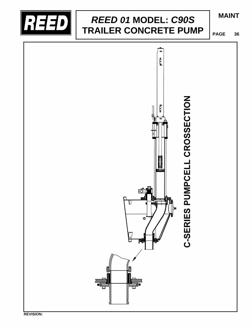
REED 01 MODEL: C90S TRAILER CONCRETE PUMP
MAINT
PAGE 36
REVISION:
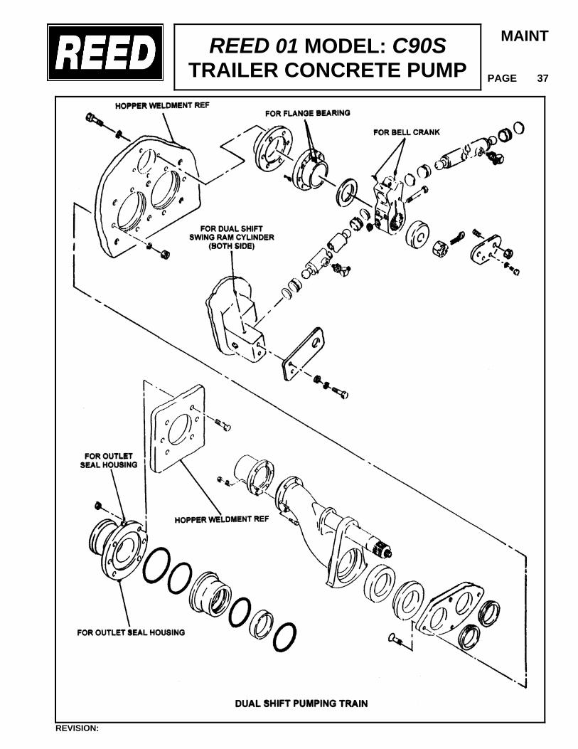
REED 01 MODEL: C90S TRAILER CONCRETE PUMP
MAINT
PAGE 37
REVISION:
REED 01 MODEL: C90S TRAILER CONCRETE PUMP
MAINT
PAGE 38
WEAR RING AND WEAR PLATE REMOVAL/REPLACEMENT
• Turn off engine to shut down the system. BE SURE ACCUMULATOR PRESSURE IS RELEASED.
• At the bell crank, remove retainer, swing tube bolt, bell crank and shift cylinders.
• Place a sling from an overhead hoist around the discharge end of swing tube to help support the tube.
• Unbolt outlet flange from hopper and remove, being careful not to damage any of the seals and o-rings.
• Work swing tube back toward the outlet. It may be necessary to nudge it with a pry bar. EXERCISE CARE. The swing tube only needs to be moved toward the outlet a sufficient distance to enable the wear ring to be replaced.
• Remove wear ring and thrust ring from inside of swing tube.
• If it is necessary to replace the wear plate, this can be accomplished by backing out the mounting bolts located on the outside back the hopper. The bolts only have to be backed out a sufficient distance to enable wear plate to be removed. Maneuver the wear plate up through the gap between swing tube and hopper.
• Clean out the end of the swing tube where the wear ring will sit. Also clean the surface of the hopper where new wear plate will be installed. Make sure that all concrete material is fully removed, failure of the new parts will occur if this step is ignored.
RE-ASSEMBLY
• Apply a small amount of general-purpose grease on the outside area of the wear ring and thrust ring. Install both pieces into swing tube.
• Slide the new wear plate down between the swing tube and hopper. Reinstall and
tighten the bolts. • Slide swing tube forward until wear ring is set against wear plate. • Install outlet flange assembly being careful not to damage any of the seals. Tighten
bolts. • Reinstall bellcrank parts, shift cylinder, and castle nut. Remove sling. • Adjust the swing tube. Refer to procedure outlined in ADJUSTMENT SECTION.
REVISION:
REED 01 MODEL: C90S TRAILER CONCRETE PUMP
MAINT
PAGE 39
SWING TUBE REPLACEMENT The swing tube, like the wear plate and wear ring, is considered a wear item, meaning that it will eventually need to be replaced. When this situation is encountered, the following is offered to assist you in accomplishing the replacement.
The removal of the swing tube involves the disassembly of several other wear components. It is suggested that these be replaced as well.
REMOVAL
• Turn off engine to shut down the system. BE SURE ACCUMULATOR PRESSURE IS RELEASED.
• Remove the cover over the shift cylinder and bell crank.
• At the bell crank, remove the cotter pin, castle nut, bell crank, and shift cylinder.
• Place a sling from an overhead hoist around the discharge end of the swing tube to help support the tube.
• Unbolt both the outlet from swing tube and outlet housing from hopper. Remove both parts.
• Maneuver and work the swing tube toward the hopper outlet as far as it will go or until end of shaft is inside hopper. Sometimes the S-Tube shaft must be placed in the concrete cylinder, (protect the chrome surface) and then the S-Tube will come out back end first.
• Using the hoist and sling, lift swing tube out of hopper.
RE-ASSEMBLY Before reassembly of the swing tube this is a good opportunity to clean out hopper of cured material, replace wear plate or do any maintenance on the material cylinders. It is recommended that when the swing tube is replaced that all seals on the outlet and bearing housing be replaced as well as any other wear items. This is good preventative maintenance.
REVISION:
REED 01 MODEL: C90S TRAILER CONCRETE PUMP
MAINT
PAGE 40
• Reassemble the swing tube and components in basically the reverse order used in
disassembly. Some important items to be noted are:
• Make sure all components that are to be reused are cleaned from any residual material or grease.
• Inspect all parts for damage such as nicks, scratches etc. • Smear a small amount of clean grease on all seals, polypacks and O-rings before
installing. • Pay particular attention to the position and direction of seals when installing. • Make sure all bolts and nuts are tight. • Lubricate as required.
• Test movement of swing tube and make necessary adjustments following the procedure
noted in the ADJUSTMENT SECTION. MATERIAL CYLINDER COMPONENTS
Two (2) material cylinders powered by two (2) hydraulic drive cylinders are arranged in the system to operate alternately. While one cylinder is drawing material into the cylinder tube from the hopper on the retraction stroke, the other cylinder is pushing the material out the swing tube and discharge on the forward stroke. Because of the abrasiveness of the material being pumped, it will be necessary to periodically replace the piston cups.
Some telling signs and identifying systems of worn parts might be:
• A slurry of the material being pumped starts to appear in the flush box. • The water or lubricating oil, if used, begins to rapidly lower the level without any sign of
leakage from the box. • Operation of the cylinder is rough and erratic.
Be sure pressure in accumulator shift circuit has been released before doing any work inside the hopper or inside the flush box.
REVISION:
REED 01 MODEL: C90S TRAILER CONCRETE PUMP
MAINT
PAGE 41
Do not place hands in the water box or in adjacent area while motor is running. Always check that the pressure in the accumulator has been released before performing any work.
PISTON CUP REMOVAL/REPLACEMENT
• Cycle machine using appropriate controls until one of the cylinders is at full extension. Jog swing tube so that it is shifted over to other cylinder. This will expose fully extended piston.
• Turn off engine and allow pressure to subside. • Remove the four (4) 3/8 – 20 x 1½” long bolts and lockwashers securing the piston
plate, and piston cup to the piston adapter. • Pry out the old piston cup and plate. Clean piston plate and inspect piston adapter,
and clean if needed. • Apply a good amount of grease on lip of piston cup. Tip should be facing hopper.
Insert two (2) 3/8 – 20 x 4 long bolts through piston plate and cup in opposite holes. This will allow you to locate the cup in a correct position for lining up the holes.
• Screw the bolts by hand into the piston adapter. Start the piston cup into the cylinder
and using a wooden dowel, tap the piston plate which will force the piston cup into the material cylinder.
• With the cup against the adapter, insert two (2) of the original 3/8 – 20 x 1½” long bolts
and tighten. Remove the two (2 ) long bolts and replace with the originals Replace piston cup in other cylinder in the same manner.
REVISION:
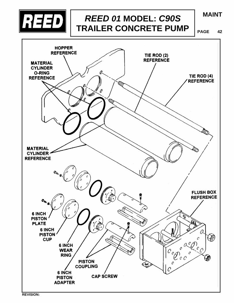
REED 01 MODEL: C90S TRAILER CONCRETE PUMP
MAINT
PAGE 42
REVISION:
REED 01 MODEL: C90S TRAILER CONCRETE PUMP
MAINT
PAGE 43
PISTON ADAPTER O-RING REMOVAL/REPLACEMENT
Installed on the piston adapter, is an o-ring that is used as a second seal for the material cylinders. This o-ring will need replacing and a tell-tell sign is if the material cylinders only partially fill with material. This o-ring cannot be replaced from the hopper end, but must be done at the flush box end. To change the piston adapter o-ring, the following is offered:
• Cycle machine until one of the cylinders is completely retracted. Turn off engine and
allow the pressure to subside.
• Drain all oil or water from the flush box.
• As a precaution, mark location of proximity sensor adjusting bracket. Remove proximity sensor cross bracket.
• Mark the end of the piston coupler so that on reassembly, it can be placed in the same
relation.
• Unbolt and remove top half of coupler. Pull the piston assembly toward you.
• Inspect piston cup, clean up or if necessary replace.
• Remove old o-ring from adapter and smear some clean grease on the new o-ring. Install on adapter.
• Place piston cup assembly into material cylinder at an angle so that center of adapter is
angling toward bottom of flush box.
• Pull up on adapter to square up piston assembly.
• Install coupler halves and bolt together. Follow same procedure to remove and replace the o-ring on the other cylinder. After this installation proceed to:
• Replace proximity sensor cross bar and check position of adjustment bracket to previous mark.
• Refill flush box with water or oil.
REVISION:
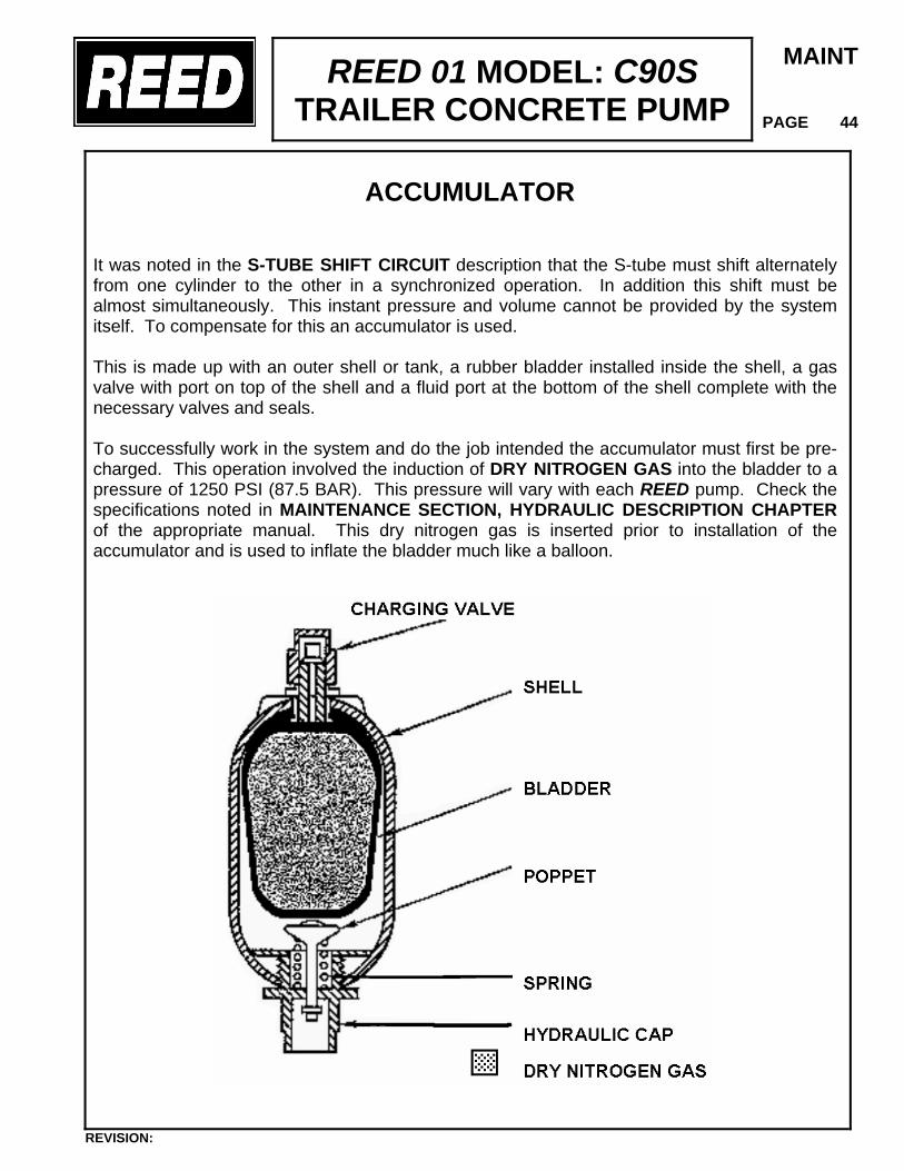
REED 01 MODEL: C90S TRAILER CONCRETE PUMP
MAINT
PAGE 44
ACCUMULATOR
It was noted in the S-TUBE SHIFT CIRCUIT description that the S-tube must shift alternately from one cylinder to the other in a synchronized operation. In addition this shift must be almost simultaneously. This instant pressure and volume cannot be provided by the system itself. To compensate for this an accumulator is used. This is made up with an outer shell or tank, a rubber bladder installed inside the shell, a gas valve with port on top of the shell and a fluid port at the bottom of the shell complete with the necessary valves and seals. To successfully work in the system and do the job intended the accumulator must first be pre-charged. This operation involved the induction of DRY NITROGEN GAS into the bladder to a pressure of 1250 PSI (87.5 BAR). This pressure will vary with each REED pump. Check the specifications noted in MAINTENANCE SECTION, HYDRAULIC DESCRIPTION CHAPTER of the appropriate manual. This dry nitrogen gas is inserted prior to installation of the accumulator and is used to inflate the bladder much like a balloon.
REVISION:
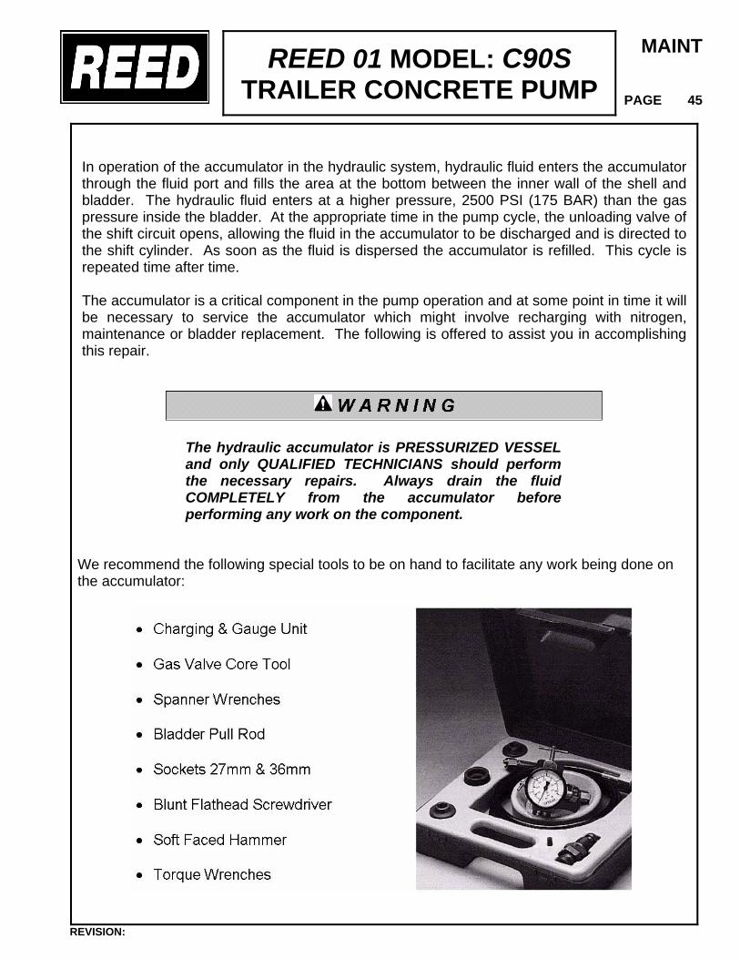
REED 01 MODEL: C90S TRAILER CONCRETE PUMP
MAINT
PAGE 45
In operation of the accumulator in the hydraulic system, hydraulic fluid enters the accumulator through the fluid port and fills the area at the bottom between the inner wall of the shell and bladder. The hydraulic fluid enters at a higher pressure, 2500 PSI (175 BAR) than the gas pressure inside the bladder. At the appropriate time in the pump cycle, the unloading valve of the shift circuit opens, allowing the fluid in the accumulator to be discharged and is directed to the shift cylinder. As soon as the fluid is dispersed the accumulator is refilled. This cycle is repeated time after time. The accumulator is a critical component in the pump operation and at some point in time it will be necessary to service the accumulator which might involve recharging with nitrogen, maintenance or bladder replacement. The following is offered to assist you in accomplishing this repair.
The hydraulic accumulator is PRESSURIZED VESSEL and only QUALIFIED TECHNICIANS should perform the necessary repairs. Always drain the fluid COMPLETELY from the accumulator before performing any work on the component.
We recommend the following special tools to be on hand to facilitate any work being done on the accumulator:
REVISION:
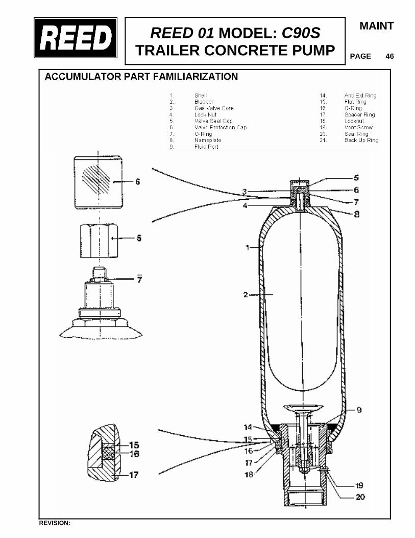
REED 01 MODEL: C90S TRAILER CONCRETE PUMP
MAINT
PAGE 46
REVISION:
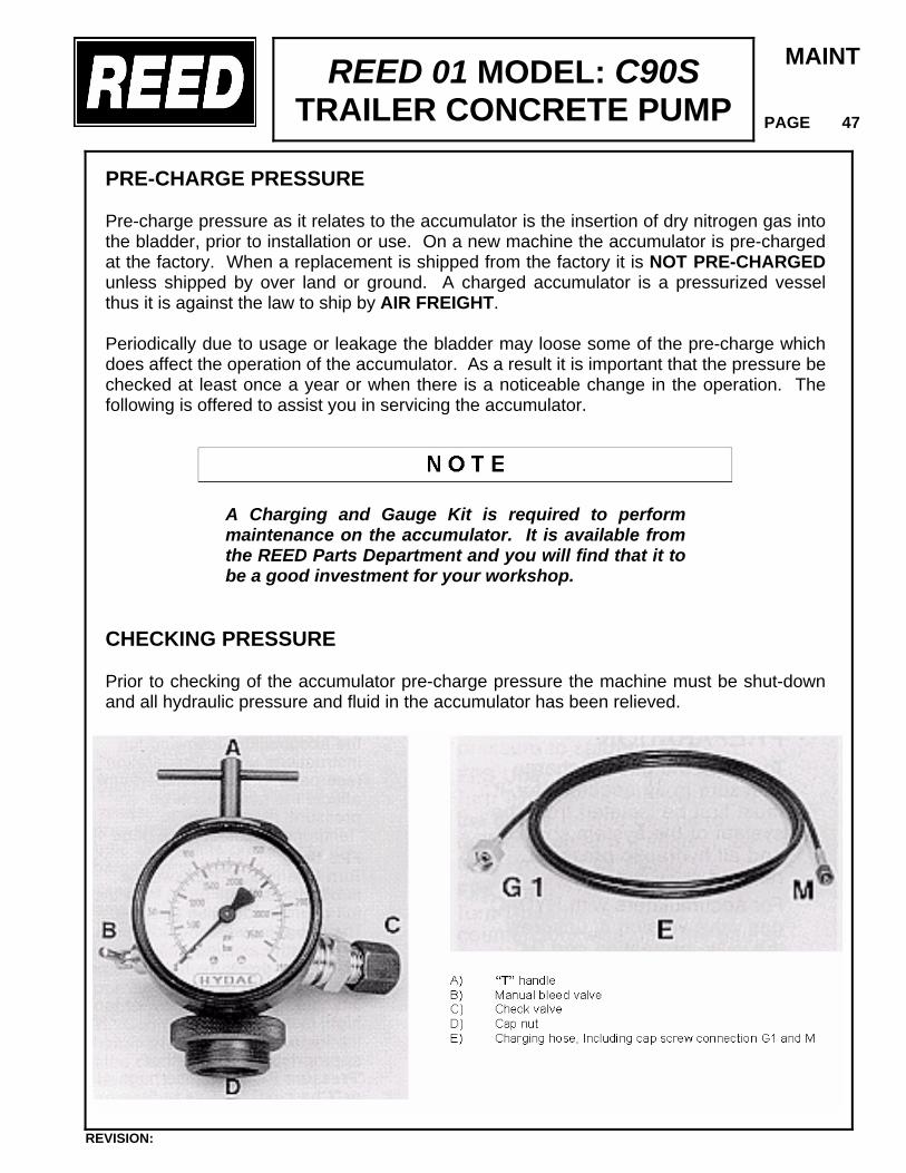
REED 01 MODEL: C90S TRAILER CONCRETE PUMP
MAINT
PAGE 47
PRE-CHARGE PRESSURE Pre-charge pressure as it relates to the accumulator is the insertion of dry nitrogen gas into the bladder, prior to installation or use. On a new machine the accumulator is pre-charged at the factory. When a replacement is shipped from the factory it is NOT PRE-CHARGED unless shipped by over land or ground. A charged accumulator is a pressurized vessel thus it is against the law to ship by AIR FREIGHT. Periodically due to usage or leakage the bladder may loose some of the pre-charge which does affect the operation of the accumulator. As a result it is important that the pressure be checked at least once a year or when there is a noticeable change in the operation. The following is offered to assist you in servicing the accumulator.
A Charging and Gauge Kit is required to perform maintenance on the accumulator. It is available from the REED Parts Department and you will find that it to be a good investment for your workshop.
CHECKING PRESSURE Prior to checking of the accumulator pre-charge pressure the machine must be shut-down and all hydraulic pressure and fluid in the accumulator has been relieved.
REVISION:
REED 01 MODEL: C90S TRAILER CONCRETE PUMP
MAINT
PAGE 48
• Unscrew the valve protection cap #6 and valve seal hex cap #5. Exercise extreme care not to damage the O-ring #7 when removing the cap.
• Before making the installation of the gauge unit to the accumulator, turn the “T” handle
counterclockwise until some resistance is felt. Check that the manual bleed valve is closed. It not close hand tight.
• Install gauge unit on the accumulator by screwing the cap nut onto the gas valve. Hand
tighten. • Proceed to turn T-handle clockwise a maximum of 3 full turns from the full
counterclockwise position. • The gauge should then indicate the pre-charge pressure. Refer to specifications for
correct pressure:
• If pressure reading is TOO LOW then accumulator will need RECHARGED. • If pressure is TOO HIGH then it will be necessary to RELEASE pressure.
RELEASE OF PRESSURE When gauge indicates that the pre-charge pressure is too high proceed as follows to release some of the pressure within bladder.
• With gauging valve installed, carefully open the MANUAL BLEED valve, releasing some of the nitrogen gas.
• While doing this observe gauge until sufficient gas has been released and desired
pressure has been reached. • Close the manual bleed valve. Wait approximately 10 minutes for the pressure to
stabilize, then recheck and if necessary adjust accordingly. • To remove the gauging unit, turn “T” handle until resistance is felt to close the gas
valve. Open manual bleed valve. • Disconnect the gauging unit by unscrewing the cap from the gas valve. Replace valve
seal hex cap and tighten to 18 lb. ft. Screw on valve protection cap, hand tight.
REVISION:
REED 01 MODEL: C90S TRAILER CONCRETE PUMP
MAINT
PAGE 49
INCREASE PRE-CHARGE PRESSURE In checking the pre-charge pressure if it is found to be too low then add nitrogen gas as follows:
• Install gauging unit as previously described. Turn “T” handle clockwise until needle on gauge begins to move then from this point turn it another full turn.
USE DRY NITROGEN GAS ONLY - NEVER USE OXYGEN OR AIR. THIS COULD CAUSE AN EXPLOSION.
• Connect the charging hose to the cap screw adapter and to the nitrogen bottle
discharge. It is recommended that the commercial nitrogen bottle be equipped with a regulator to adjust pressure. Full pressure may damage gauge.
• Open the shut-off on the nitrogen bottle and slowly fill the accumulator. Charging
too quickly may damage the accumulator.
The gauge on the gauging unit during pre-charge registers the incoming line pressure and not necessarily the accumulator pressure while charging.
• The accumulator pressure can be checked by first closing the shut-off valve on
nitrogen bottle.
• Allow a few minutes for the temperature and pressure in the accumulator to stabilize.
• Check the accumulator pressure as previously described, then fill or release
pressure as required.
• Close shut-off valve on the nitrogen bottle. Turn “T” handle counterclockwise to close gas valve.
• Open bleed valve, disconnect charging hose and remove gauging unit from
accumulator. Reinstall hex cap and protective cap.
REVISION:
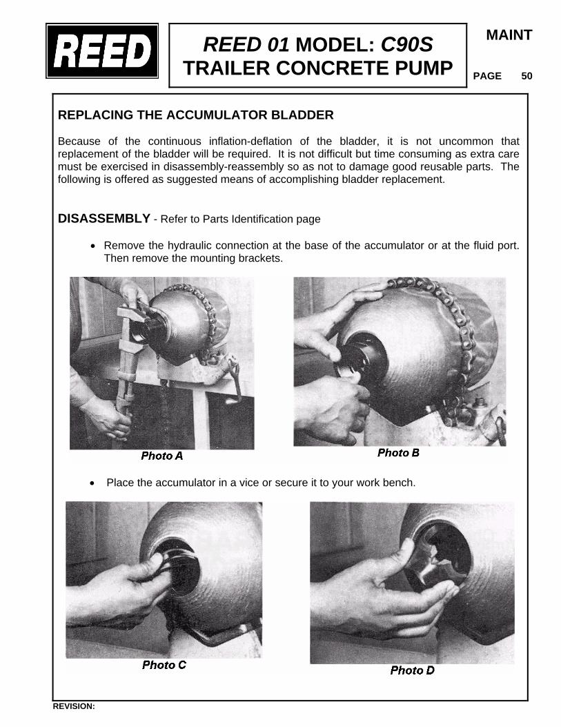
REED 01 MODEL: C90S TRAILER CONCRETE PUMP
MAINT
PAGE 50
REPLACING THE ACCUMULATOR BLADDER Because of the continuous inflation-deflation of the bladder, it is not uncommon that replacement of the bladder will be required. It is not difficult but time consuming as extra care must be exercised in disassembly-reassembly so as not to damage good reusable parts. The following is offered as suggested means of accomplishing bladder replacement. DISASSEMBLY - Refer to Parts Identification page
• Remove the hydraulic connection at the base of the accumulator or at the fluid port. Then remove the mounting brackets.
• Place the accumulator in a vice or secure it to your work bench.
REVISION:
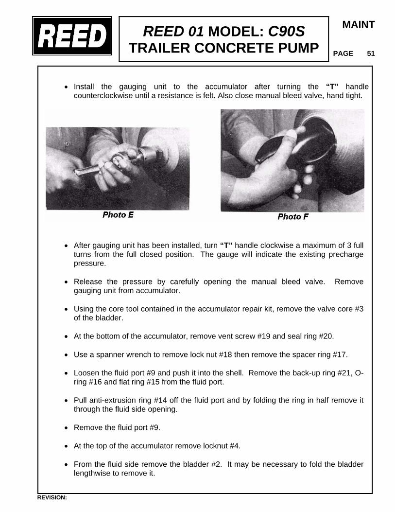
REED 01 MODEL: C90S TRAILER CONCRETE PUMP
MAINT
PAGE 51
• Install the gauging unit to the accumulator after turning the “T” handle counterclockwise until a resistance is felt. Also close manual bleed valve, hand tight.
• After gauging unit has been installed, turn “T” handle clockwise a maximum of 3 full turns from the full closed position. The gauge will indicate the existing precharge pressure.
• Release the pressure by carefully opening the manual bleed valve. Remove
gauging unit from accumulator.
• Using the core tool contained in the accumulator repair kit, remove the valve core #3 of the bladder.
• At the bottom of the accumulator, remove vent screw #19 and seal ring #20.
• Use a spanner wrench to remove lock nut #18 then remove the spacer ring #17.
• Loosen the fluid port #9 and push it into the shell. Remove the back-up ring #21, O-
ring #16 and flat ring #15 from the fluid port.
• Pull anti-extrusion ring #14 off the fluid port and by folding the ring in half remove it through the fluid side opening.
• Remove the fluid port #9.
• At the top of the accumulator remove locknut #4.
• From the fluid side remove the bladder #2. It may be necessary to fold the bladder
lengthwise to remove it.
REVISION:
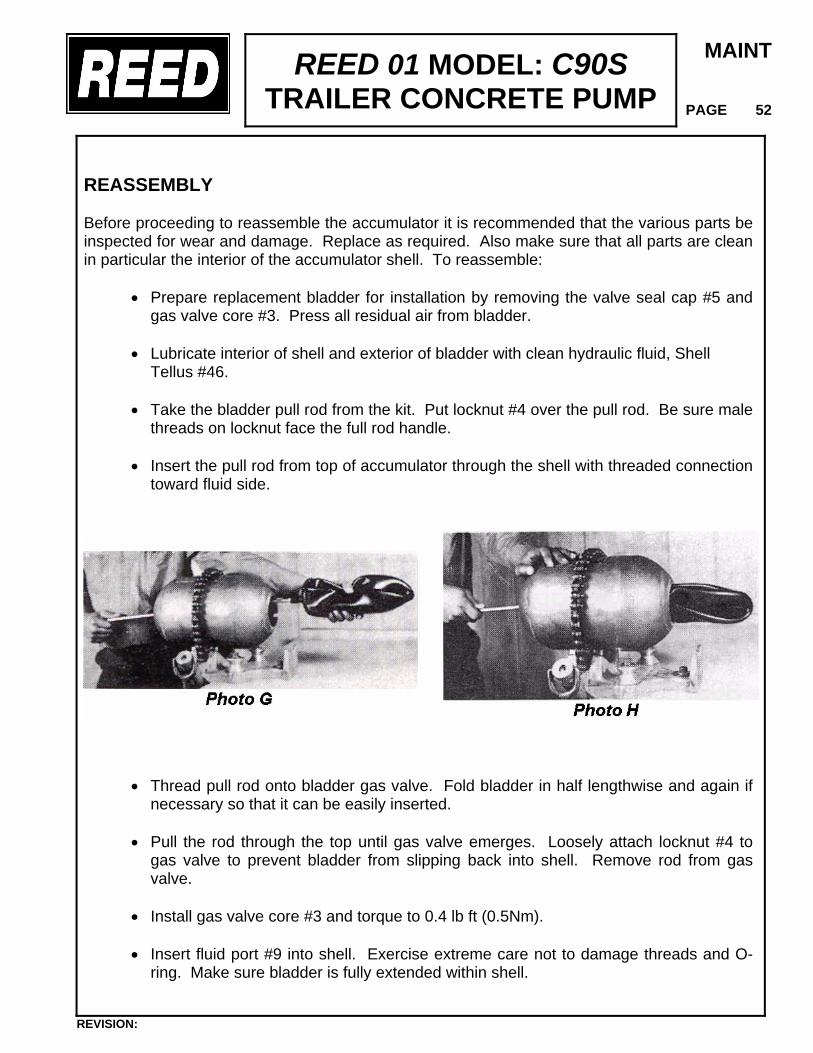
REED 01 MODEL: C90S TRAILER CONCRETE PUMP
MAINT
PAGE 52
REASSEMBLY Before proceeding to reassemble the accumulator it is recommended that the various parts be inspected for wear and damage. Replace as required. Also make sure that all parts are clean in particular the interior of the accumulator shell. To reassemble:
• Prepare replacement bladder for installation by removing the valve seal cap #5 and gas valve core #3. Press all residual air from bladder.
• Lubricate interior of shell and exterior of bladder with clean hydraulic fluid, Shell
Tellus #46.
• Take the bladder pull rod from the kit. Put locknut #4 over the pull rod. Be sure male threads on locknut face the full rod handle.
• Insert the pull rod from top of accumulator through the shell with threaded connection
toward fluid side.
• Thread pull rod onto bladder gas valve. Fold bladder in half lengthwise and again if
necessary so that it can be easily inserted.
• Pull the rod through the top until gas valve emerges. Loosely attach locknut #4 to gas valve to prevent bladder from slipping back into shell. Remove rod from gas valve.
• Install gas valve core #3 and torque to 0.4 lb ft (0.5Nm).
• Insert fluid port #9 into shell. Exercise extreme care not to damage threads and O-
ring. Make sure bladder is fully extended within shell.
REVISION:
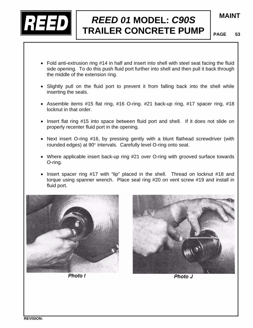
REED 01 MODEL: C90S TRAILER CONCRETE PUMP
MAINT
PAGE 53
• Fold anti-extrusion ring #14 in half and insert into shell with steel seat facing the fluid side opening. To do this push fluid port further into shell and then pull it back through the middle of the extension ring.
• Slightly pull on the fluid port to prevent it from falling back into the shell while
inserting the seals.
• Assemble items #15 flat ring, #16 O-ring. #21 back-up ring, #17 spacer ring, #18 locknut in that order.
• Insert flat ring #15 into space between fluid port and shell. If it does not slide on
properly recenter fluid port in the opening.
• Next insert O-ring #16, by pressing gently with a blunt flathead screwdriver (with rounded edges) at 90° intervals. Carefully level O-ring onto seat.
• Where applicable insert back-up ring #21 over O-ring with grooved surface towards
O-ring.
• Insert spacer ring #17 with “lip” placed in the shell. Thread on locknut #18 and torque using spanner wrench. Place seal ring #20 on vent screw #19 and install in fluid port.
REVISION:
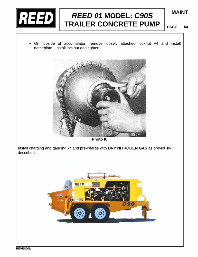
REED 01 MODEL: C90S TRAILER CONCRETE PUMP
MAINT
PAGE 54
• On topside of accumulator, remove loosely attached locknut #4 and install nameplate. Install locknut and tighten.
Photo K
Install charging and gauging kit and pre-charge with DRY NITROGEN GAS as previously described.
REVISION:
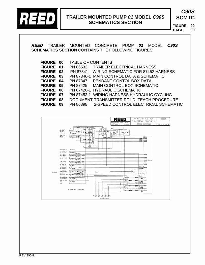
TRAILER MOUNTED PUMP 01 MODEL C90S
SCHEMATICS SECTION
C90S SCMTC
FIGURE 00 PAGE 00
REED TRAILER MOUNTED CONCRETE PUMP 01 MODEL C90S SCHEMATICS SECTION CONTAINS THE FOLLOWING FIGURES:
FIGURE 00 TABLE OF CONTENTS FIGURE 01 PN 86532 TRAILER ELECTRICAL HARNESS FIGURE 02 PN 87341 WIRING SCHEMATIC FOR 87452 HARNESS FIGURE 03 PN 87346-1 MAIN CONTROL DATA & SCHEMATIC FIGURE 04 PN 87347 PENDANT CONTOL BOX DATA FIGURE 05 PN 87425 MAIN CONTROL BOX SCHEMATIC FIGURE 06 PN 87426-1 HYDRAULIC SCHEMATIC FIGURE 07 PN 87452-1 WIRING HARNESS HYDRAULIC CYCLING
FIGURE 08 DOCUMENT-TRANSMITTER RF I.D. TEACH PROCEDURE FIGURE 09 PN 86898 2-SPEED CONTROL ELECTRICAL SCHEMATIC
REVISION:
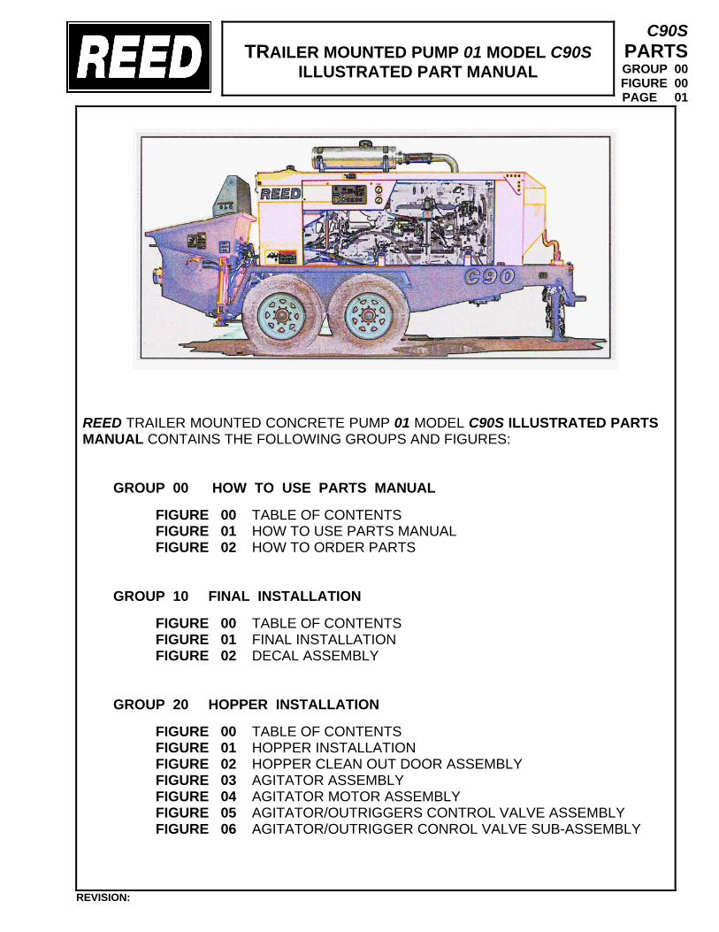
TRAILER MOUNTED PUMP 01 MODEL C90S
ILLUSTRATED PART MANUAL
C90S PARTS GROUP 00 FIGURE 00 PAGE 01
REED TRAILER MOUNTED CONCRETE PUMP 01 MODEL C90S ILLUSTRATED PARTS MANUAL CONTAINS THE FOLLOWING GROUPS AND FIGURES:
GROUP 00 HOW TO USE PARTS MANUAL FIGURE 00 TABLE OF CONTENTS FIGURE 01 HOW TO USE PARTS MANUAL FIGURE 02 HOW TO ORDER PARTS
GROUP 10 FINAL INSTALLATION
FIGURE 00 TABLE OF CONTENTS FIGURE 01 FINAL INSTALLATION FIGURE 02 DECAL ASSEMBLY
GROUP 20 HOPPER INSTALLATION
FIGURE 00 TABLE OF CONTENTS FIGURE 01 HOPPER INSTALLATION FIGURE 02 HOPPER CLEAN OUT DOOR ASSEMBLY FIGURE 03 AGITATOR ASSEMBLY FIGURE 04 AGITATOR MOTOR ASSEMBLY FIGURE 05 AGITATOR/OUTRIGGERS CONTROL VALVE ASSEMBLY FIGURE 06 AGITATOR/OUTRIGGER CONROL VALVE SUB-ASSEMBLY
REVISION:
TRAILER MOUNTED PUMP 01 MODEL C90S
ILLUSTRATED PART MANUAL
C90S PARTS GROUP 00 FIGURE 00 PAGE 02
GROUP 30 TANK INSTALLATION
FIGURE 00 TABLE OF CONTENTS FIGURE 01 TANK INSTALLATION FIGURE 02 HYDRAULIC TANK ASSEMBLY FIGURE 03 ACCUMULATOR ASSEMBLY FIGURE 04 ACCUMULATOR BLADDER REPAIR KIT FIGURE 05 SWING TUBE CIRCUIT MANIFOLD ASSEMBLY FIGURE 06 SWING TUBE CIRCUIT MAIN SOLENOID VALVE ASSEMBLY FIGURE 07 BALL VALVE ASSEMBLY
GROUP 40 POWER TRAIN INSTALLATION FIGURE 00 TABLE OF CONTENTS FIGURE 01 POWER TRAIN INSTALLATION FIGURE 02 POWER TRAIN ASSEMBLY FIGURE 03 DOUBLE AUXILIARY PUMP ASSEMBLY FIGURE 04 SINGLE AUXILIARY PUMP ASSEMBLY (OPTIONAL) FIGURE 05 MAIN HYDRAULIC PUMP ASSEMBLY FIGURE 06 BATTERY MOUNTING ASSEMBLY
GROUP 50 CONTROLS INSTALLATION FIGURE 00 TABLE OF CONTENTS FIGURE 01 CONTROLS INSTALLATION FIGURE 02 CONTROL BOX ASSEMBLY FIGURE 03 50 FEET CABLE REMOTE CONTROL ASSEMBLY FIGURE 04 100 FEET CABLE REMOTE CONTROL ASSEMBLY FIGURE 05 RADIO REMOTE CONTROL ASSEMBLY
GROUP 60 PUMPING TRAIN INSTALLATION FIGURE 00 TABLE OF CONTENTS FIGURE 01 PUMPING TRAIN INSTALLATION FIGURE 02 SWING VALVE ASSEMBLY FIGURE 03 SWING RAM CYLINDER SUB-ASSEMBLY FIGURE 04 CONCRETE CYLINDER ASSEMBLY FIGURE 05 FLUSHBOX ASSEMBLY FIGURE 06 HYDRAULIC DRIVE CYLINDER ASSEMBLY FIGURE 07 HYDRAULIC DRIVE CYLINDER SUB-ASSEMBLY
REVISION:
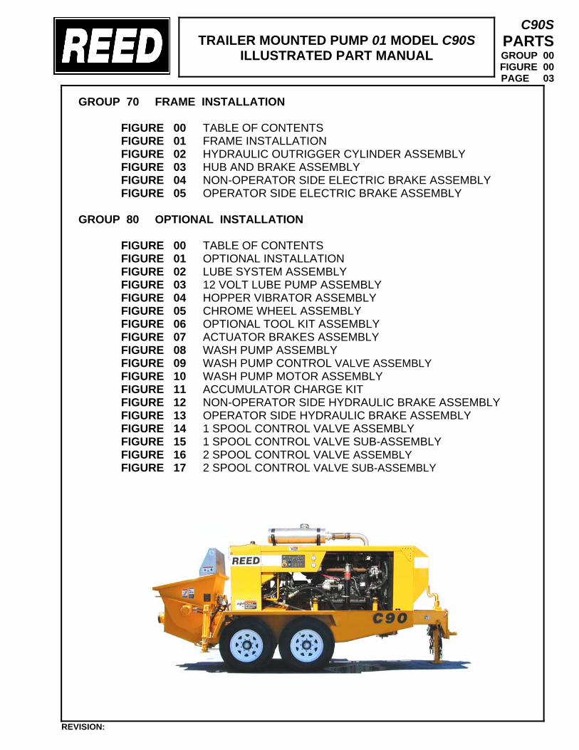
TRAILER MOUNTED PUMP 01 MODEL C90S
ILLUSTRATED PART MANUAL
C90S PARTS GROUP 00 FIGURE 00 PAGE 03
GROUP 70 FRAME INSTALLATION
FIGURE 00 TABLE OF CONTENTS FIGURE 01 FRAME INSTALLATION FIGURE 02 HYDRAULIC OUTRIGGER CYLINDER ASSEMBLY FIGURE 03 HUB AND BRAKE ASSEMBLY FIGURE 04 NON-OPERATOR SIDE ELECTRIC BRAKE ASSEMBLY FIGURE 05 OPERATOR SIDE ELECTRIC BRAKE ASSEMBLY
GROUP 80 OPTIONAL INSTALLATION FIGURE 00 TABLE OF CONTENTS FIGURE 01 OPTIONAL INSTALLATION FIGURE 02 LUBE SYSTEM ASSEMBLY FIGURE 03 12 VOLT LUBE PUMP ASSEMBLY FIGURE 04 HOPPER VIBRATOR ASSEMBLY FIGURE 05 CHROME WHEEL ASSEMBLY FIGURE 06 OPTIONAL TOOL KIT ASSEMBLY FIGURE 07 ACTUATOR BRAKES ASSEMBLY FIGURE 08 WASH PUMP ASSEMBLY FIGURE 09 WASH PUMP CONTROL VALVE ASSEMBLY FIGURE 10 WASH PUMP MOTOR ASSEMBLY FIGURE 11 ACCUMULATOR CHARGE KIT FIGURE 12 NON-OPERATOR SIDE HYDRAULIC BRAKE ASSEMBLY FIGURE 13 OPERATOR SIDE HYDRAULIC BRAKE ASSEMBLY FIGURE 14 1 SPOOL CONTROL VALVE ASSEMBLY FIGURE 15 1 SPOOL CONTROL VALVE SUB-ASSEMBLY FIGURE 16 2 SPOOL CONTROL VALVE ASSEMBLY FIGURE 17 2 SPOOL CONTROL VALVE SUB-ASSEMBLY
REVISION:
TRAILER MOUNTED PUMP 01 MODEL C90S
HOW TO USE PART MANUAL
C90S PARTS GROUP 00 FIGURE 01 PAGE 01
I. PURPOSE
This parts manual is prepared, issued and/or revised by REED Manufacturing, for
the exclusive use of its customers and is intended for use in provisioning, requisitioning, storing and issuing replaceable REED trailer mounted pump 01 model C90S. The contents are proprietary to REED and are subject to change without notice. The use of any part of this document by any other person or persons or for any other purpose without the written consent of REED is expressly prohibited. In addition, REED expressly disclaims any and all responsibility arising in or any way related to such REED’s prior written consent thereto.
The parts number content of this document, arrangement and breakdown
sequence of items is compatible with Military Standard (MS) and Air Transport Association Specification (ATA).
II. GENERAL SYSTEM OF ASSEMBLY ORDER – Detailed Parts List (Refer to Next Page)
1. This area refers to the corresponding illustration
MODEL – GROUP – FIGURE – PAGE
A. MODEL shows which is REED’s model number.
B. GROUP should be divided with: 00 01 MODEL C90S PARTS MANUAL 10 FINAL INSTALLATION 20 HOPPER INSTALLATION 30 TANK INSTALLATION 40 POWER TRAIN INSTALLATION 50 CONTROL INSTALLATION 60 PUMPING TRAIN INSTALLATION 70 FRAME INSTALLATION 80 OPTIONAL INSTALLATION
C. FIGURE belong to the group. Please see page of contents and each group.
D. PAGE numbers follow to the right of each figure number.
2. The ITEM NUMBER corresponds to the item number shown for the part in illustration. Parts with item number preceded by a dash (such as: -1, -5, -12 etc.) are not illustrated.
3. PARTS NUMBERS that carry a REED part number.
REVISION:
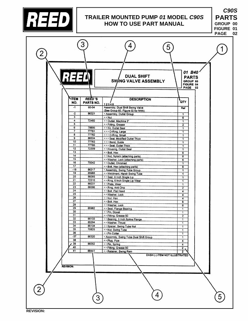
TRAILER MOUNTED PUMP 01 MODEL C90S
HOW TO USE PART MANUAL
C90S PARTS GROUP 00 FIGURE 01 PAGE 02
REVISION:
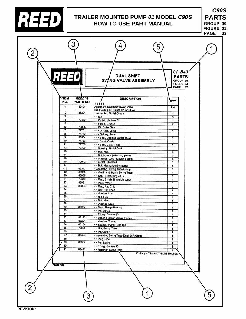
TRAILER MOUNTED PUMP 01 MODEL C90S
HOW TO USE PART MANUAL
C90S PARTS GROUP 00 FIGURE 01 PAGE 03
REVISION:
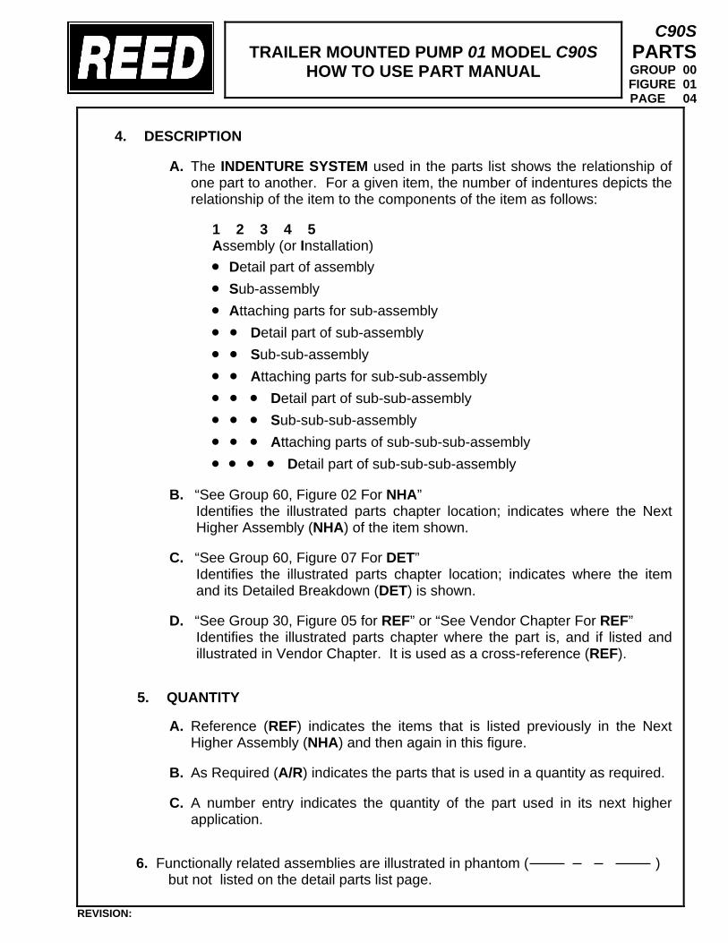
TRAILER MOUNTED PUMP 01 MODEL C90S
HOW TO USE PART MANUAL
C90S PARTS GROUP 00 FIGURE 01 PAGE 04
4. DESCRIPTION
A. The INDENTURE SYSTEM used in the parts list shows the relationship of one part to another. For a given item, the number of indentures depicts the relationship of the item to the components of the item as follows:
1 2 3 4 5 Assembly (or Installation) • Detail part of assembly • Sub-assembly • Attaching parts for sub-assembly • • Detail part of sub-assembly • • Sub-sub-assembly • • Attaching parts for sub-sub-assembly • • • Detail part of sub-sub-assembly • • • Sub-sub-sub-assembly • • • Attaching parts of sub-sub-sub-assembly • • • • Detail part of sub-sub-sub-assembly
B. “See Group 60, Figure 02 For NHA”
Identifies the illustrated parts chapter location; indicates where the Next Higher Assembly (NHA) of the item shown.
C. “See Group 60, Figure 07 For DET”
Identifies the illustrated parts chapter location; indicates where the item and its Detailed Breakdown (DET) is shown.
D. “See Group 30, Figure 05 for REF” or “See Vendor Chapter For REF”
Identifies the illustrated parts chapter where the part is, and if listed and illustrated in Vendor Chapter. It is used as a cross-reference (REF).
5. QUANTITY
A. Reference (REF) indicates the items that is listed previously in the Next Higher Assembly (NHA) and then again in this figure.
B. As Required (A/R) indicates the parts that is used in a quantity as required.
C. A number entry indicates the quantity of the part used in its next higher
application.
6. Functionally related assemblies are illustrated in phantom ( )
but not listed on the detail parts list page.
REVISION:
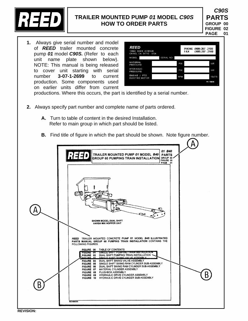
TRAILER MOUNTED PUMP 01 MODEL C90S
HOW TO ORDER PARTS
C90S PARTS GROUP 00 FIGURE 02 PAGE 01
1. Always give serial number and model of REED trailer mounted concrete pump 01 model C90S. (Refer to each unit name plate shown below). NOTE: This manual is being released to cover unit starting with serial number 3-07-1-2699 to current production. Some components used on earlier units differ from current productions. Where this occurs, the part is identified by a serial number.
2. Always specify part number and complete name of parts ordered.
A. Turn to table of content in the desired Installation. Refer to main group in which part should be listed. B. Find title of figure in which the part should be shown. Note figure number.
REVISION:
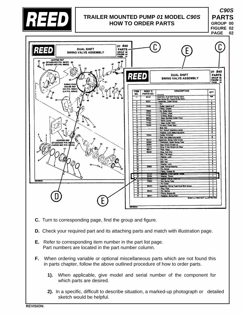
TRAILER MOUNTED PUMP 01 MODEL C90S
HOW TO ORDER PARTS
C90S PARTS GROUP 00 FIGURE 02 PAGE 02
C. Turn to corresponding page, find the group and figure. D. Check your required part and its attaching parts and match with illustration page. E. Refer to corresponding item number in the part list page. Part numbers are located in the part number column. F. When ordering variable or optional miscellaneous parts which are not found this
in parts chapter, follow the above outlined procedure of how to order parts.
1). When applicable, give model and serial number of the component for which parts are desired.
2). In a specific, difficult to describe situation, a marked-up photograph or detailed
sketch would be helpful.
REVISION:
TRAILER MOUNTED PUMP 01 MODEL C90S
HOW TO ORDER PARTS
C90S PARTS GROUP 00 FIGURE 02 PAGE 03
3. Do not designate quantity by “set”. State specifically how many parts are wanted. 4. Always give complete address and full shipping instructions. Specify shipping
instructions, truck freight, air freight. United Parcel Service (UPS), or FedEx and DHL are available in designated areas.
5. TO ORDER
A. BY MAIL Attention: Parts Department REED 13822 Oaks Avenue Chino, CA. 91710 B. BY FAX (909) 287 - 2141 C. BY PHONE (909) 287 - 2100
6. Parts return without authorization will not be accepted. If it is necessary to return parts for any reason, written authorization may be obtained from REED Parts Department, Chino, CA. 91710. A Parts Return Authorization form is provided when REED deems its necessary to have the part returned for evaluation. The form is issued by the Warranty of Parts Department of REED.
A. The form will be filled by REED unless requesting necessary information
and you will receive a copy as well as shipping tag.
B. Attach shipping tag to part insert return original invoice.
C. Ship part to REED PREPAID.
D. Part must be returned to REED within 30 days from date of authorization.
REVISION:
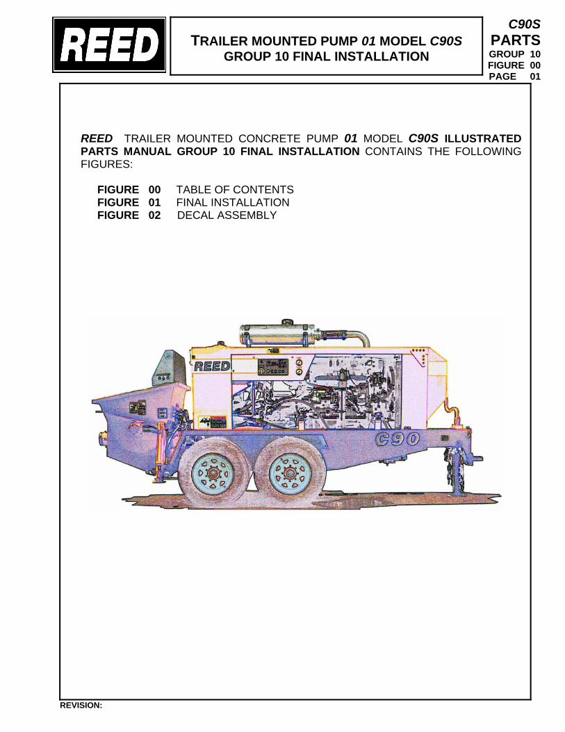
TRAILER MOUNTED PUMP 01 MODEL C90S
GROUP 10 FINAL INSTALLATION
C90S PARTS GROUP 10 FIGURE 00 PAGE 01
REED TRAILER MOUNTED CONCRETE PUMP 01 MODEL C90S ILLUSTRATED PARTS MANUAL GROUP 10 FINAL INSTALLATION CONTAINS THE FOLLOWING FIGURES:
FIGURE 00 TABLE OF CONTENTS FIGURE 01 FINAL INSTALLATION FIGURE 02 DECAL ASSEMBLY
REVISION:
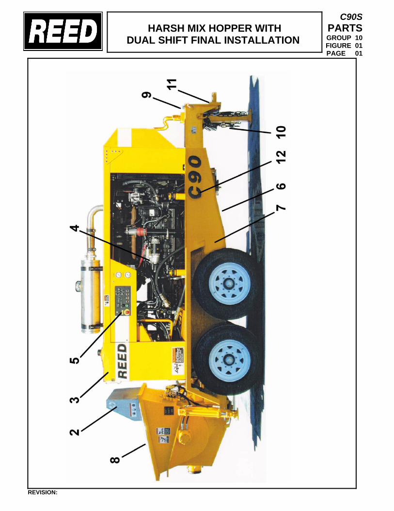
HARSH MIX HOPPER WITH
DUAL SHIFT FINAL INSTALLATION
C90S PARTS GROUP 10 FIGURE 01 PAGE 01
REVISION:
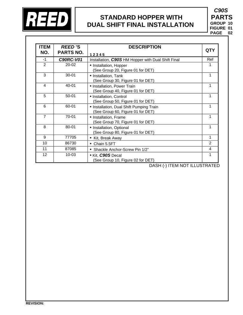
STANDARD HOPPER WITH
DUAL SHIFT FINAL INSTALLATION
C90S PARTS GROUP 10 FIGURE 01 PAGE 02
DASH (-) ITEM NOT ILLUSTRATED
ITEM NO.
REED ’S PARTS NO.
DESCRIPTION 1 2 3 4 5
QTY
-1 C90RC-V01 Installation, C90S HM Hopper with Dual Shift Final Ref 2 20-02 • Installation, Hopper
(See Group 20, Figure 01 for DET) 1
3 30-01 • Installation, Tank
(See Group 30, Figure 01 for DET) 1
4 40-01 • Installation, Power Train
(See Group 40, Figure 01 for DET) 1
5 50-01 • Installation, Control (See Group 50, Figure 01 for DET)
1
6 60-01 • Installation, Dual Shift Pumping Train
(See Group 60, Figure 01 for DET) 1
7 70-01 • Installation, Frame
(See Group 70, Figure 01 for DET) 1
8 80-01 • Installation, Optional (See Group 80, Figure 01 for DET)
1
9 77705 • Kit, Break Away 1 10 86730 • Chain 5.5FT 2 11 87085 • Shackle Anchor-Screw Pin 1/2” 4 12 10-03 • Kit, C90S Decal
(See Group 10, Figure 02 for DET) 1
REVISION:
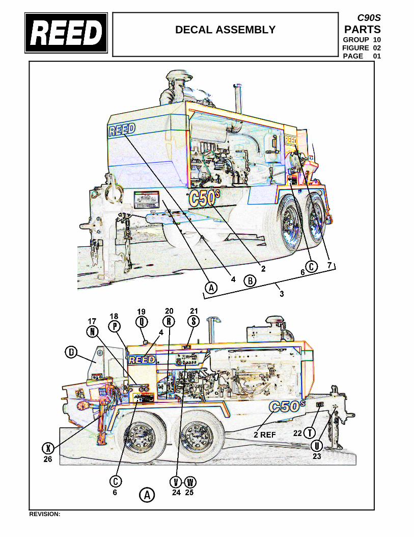
DECAL ASSEMBLY
C90S PARTS GROUP 10 FIGURE 02 PAGE 01
REVISION:
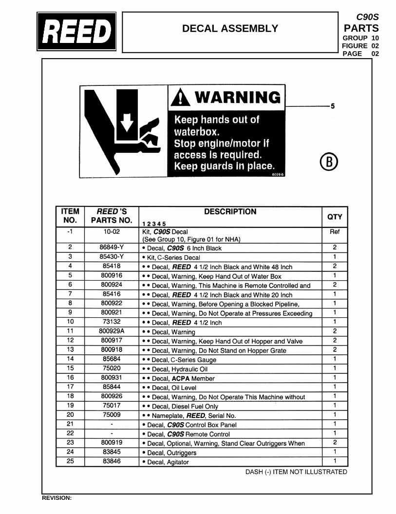
DECAL ASSEMBLY
C90S PARTS GROUP 10 FIGURE 02 PAGE 02
REVISION:
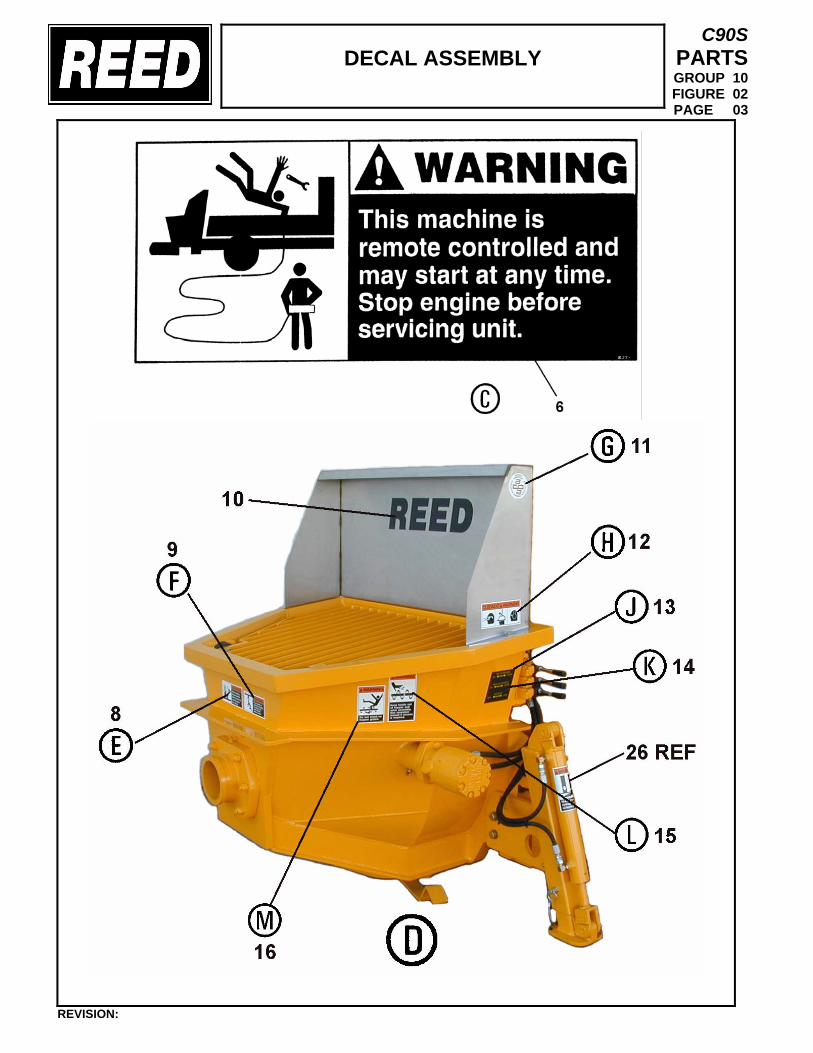
DECAL ASSEMBLY
C90S PARTS GROUP 10 FIGURE 02 PAGE 03
REVISION:
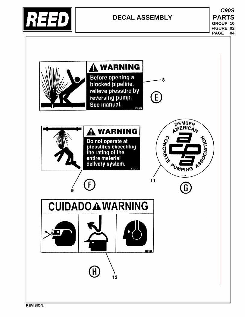
DECAL ASSEMBLY
C90S PARTS GROUP 10 FIGURE 02 PAGE 04
REVISION:
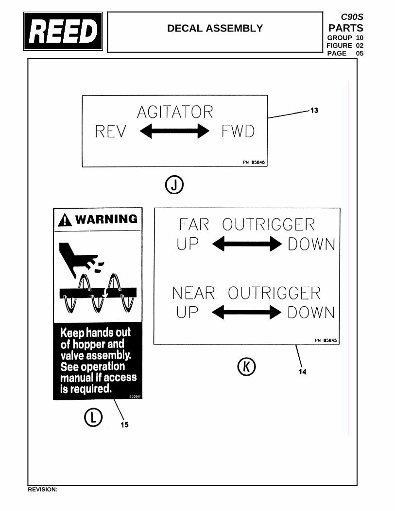
DECAL ASSEMBLY
C90S PARTS GROUP 10 FIGURE 02 PAGE 05
REVISION:
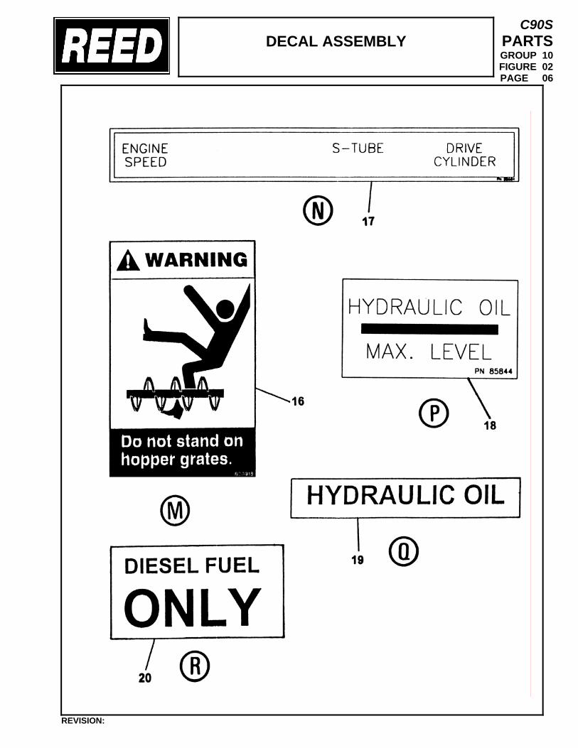
DECAL ASSEMBLY
C90S PARTS GROUP 10 FIGURE 02 PAGE 06
REVISION:
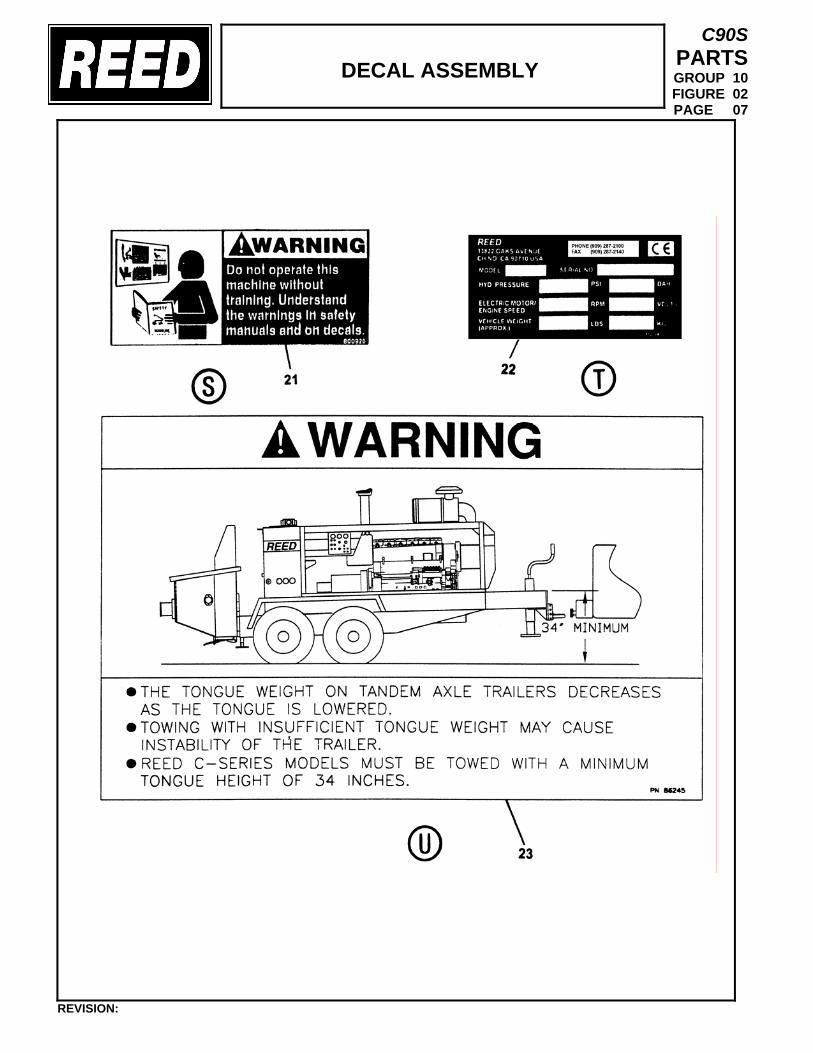
DECAL ASSEMBLY
C90S PARTS GROUP 10 FIGURE 02 PAGE 07
REVISION:
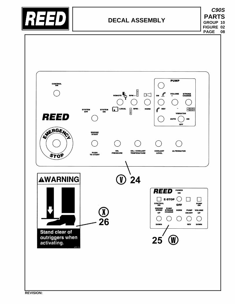
DECAL ASSEMBLY
C90S PARTS GROUP 10 FIGURE 02 PAGE 08
REVISION:
TRAILER MOUNTED PUMP 01 MODEL C90S GROUP 10 FINAL INSTALLATION
C90S PARTS GROUP 10 FIGURE 03 PAGE 01
REVISION:
THIS PAGE INTENTIONALLY LEFT BLANK.
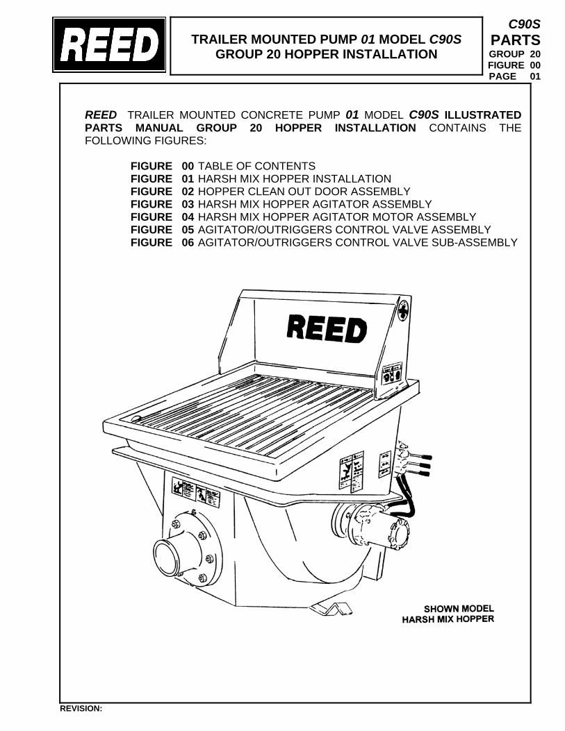
TRAILER MOUNTED PUMP 01 MODEL C90S
GROUP 20 HOPPER INSTALLATION
C90S PARTS GROUP 20 FIGURE 00 PAGE 01
REED TRAILER MOUNTED CONCRETE PUMP 01 MODEL C90S ILLUSTRATED PARTS MANUAL GROUP 20 HOPPER INSTALLATION CONTAINS THE FOLLOWING FIGURES:
FIGURE 00 TABLE OF CONTENTS FIGURE 01 HARSH MIX HOPPER INSTALLATION FIGURE 02 HOPPER CLEAN OUT DOOR ASSEMBLY FIGURE 03 HARSH MIX HOPPER AGITATOR ASSEMBLY FIGURE 04 HARSH MIX HOPPER AGITATOR MOTOR ASSEMBLY FIGURE 05 AGITATOR/OUTRIGGERS CONTROL VALVE ASSEMBLY FIGURE 06 AGITATOR/OUTRIGGERS CONTROL VALVE SUB-ASSEMBLY
REVISION:
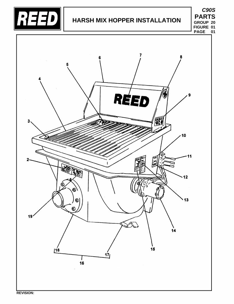
HARSH MIX HOPPER INSTALLATION
C90S PARTS GROUP 20 FIGURE 01 PAGE 01
REVISION:
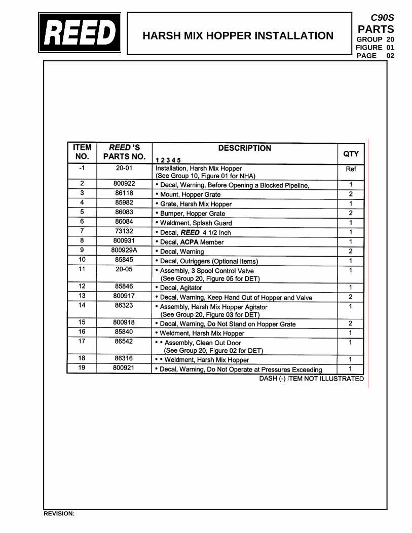
HARSH MIX HOPPER INSTALLATION
C90S PARTS GROUP 20 FIGURE 01 PAGE 02
REVISION:

HOPPER CLEAN OUT
DOOR ASSEMBLY (ROUNDED)
C90S PARTS GROUP 20 FIGURE 02 PAGE 01
REVISION:
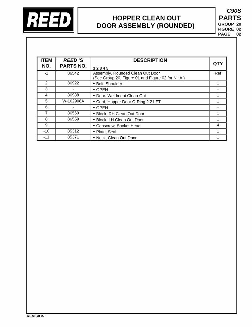
HOPPER CLEAN OUT
DOOR ASSEMBLY (ROUNDED)
C90S PARTS GROUP 20 FIGURE 02 PAGE 02
ITEM NO.
REED ’S PARTS NO.
DESCRIPTION 1 2 3 4 5
QTY
-1 86542 Assembly, Rounded Clean Out Door (See Group 20, Figure 01 and Figure 02 for NHA )
Ref
2 86922 • Bolt, Shoulder 1 3 - • OPEN - 4 86988 • Door, Weldment Clean-Out 1 5 W-102908A • Cord, Hopper Door O-Ring 2.21 FT 1 6 - • OPEN - 7 86560 • Block, RH Clean Out Door 1 8 86559 • Block, LH Clean Out Door 1 9 • Capscrew, Socket Head 4
-10 85312 • Plate, Seal 1 -11 85371 • Neck, Clean Out Door 1
REVISION:
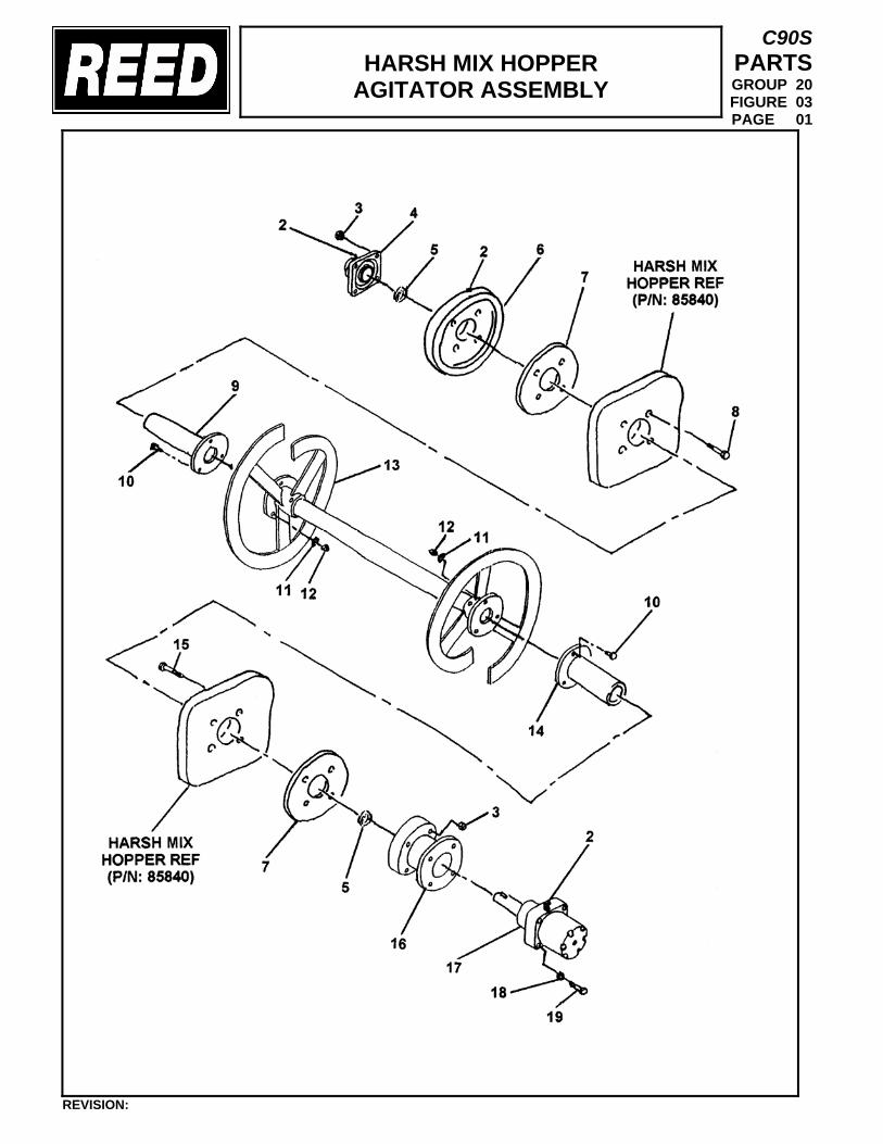
HARSH MIX HOPPER
AGITATOR ASSEMBLY
C90S PARTS GROUP 20 FIGURE 03 PAGE 01
REVISION:
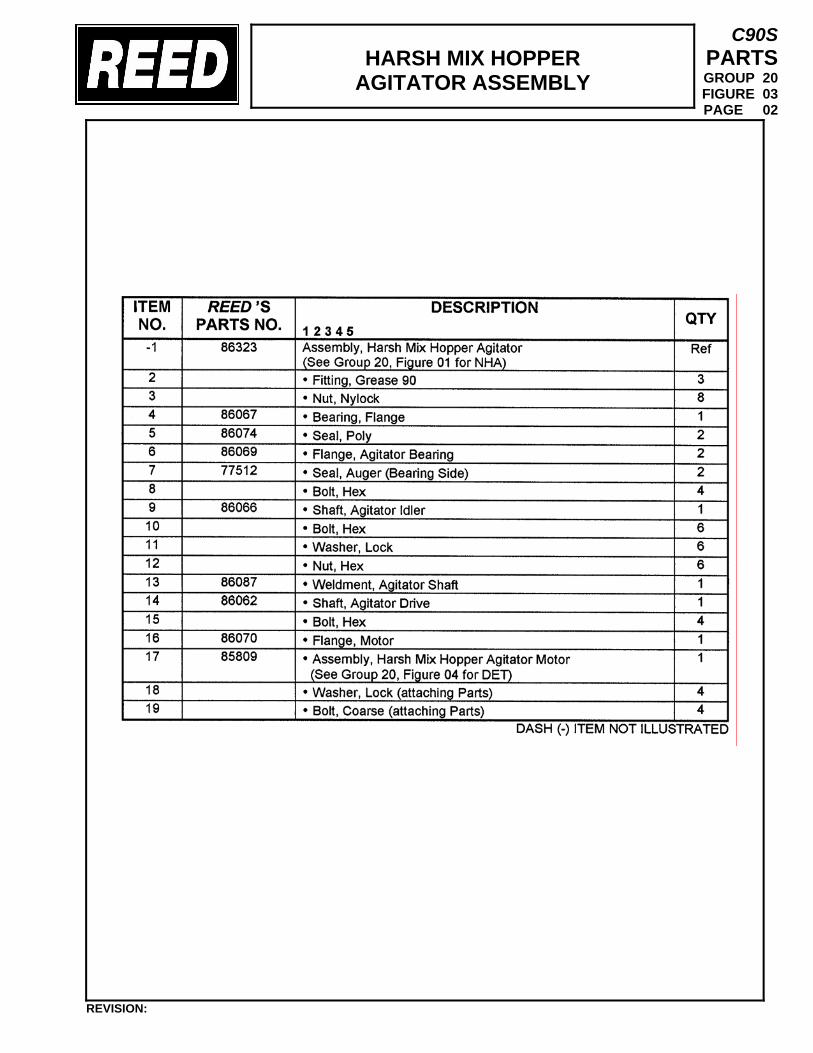
HARSH MIX HOPPER
AGITATOR ASSEMBLY
C90S PARTS GROUP 20 FIGURE 03 PAGE 02
REVISION:
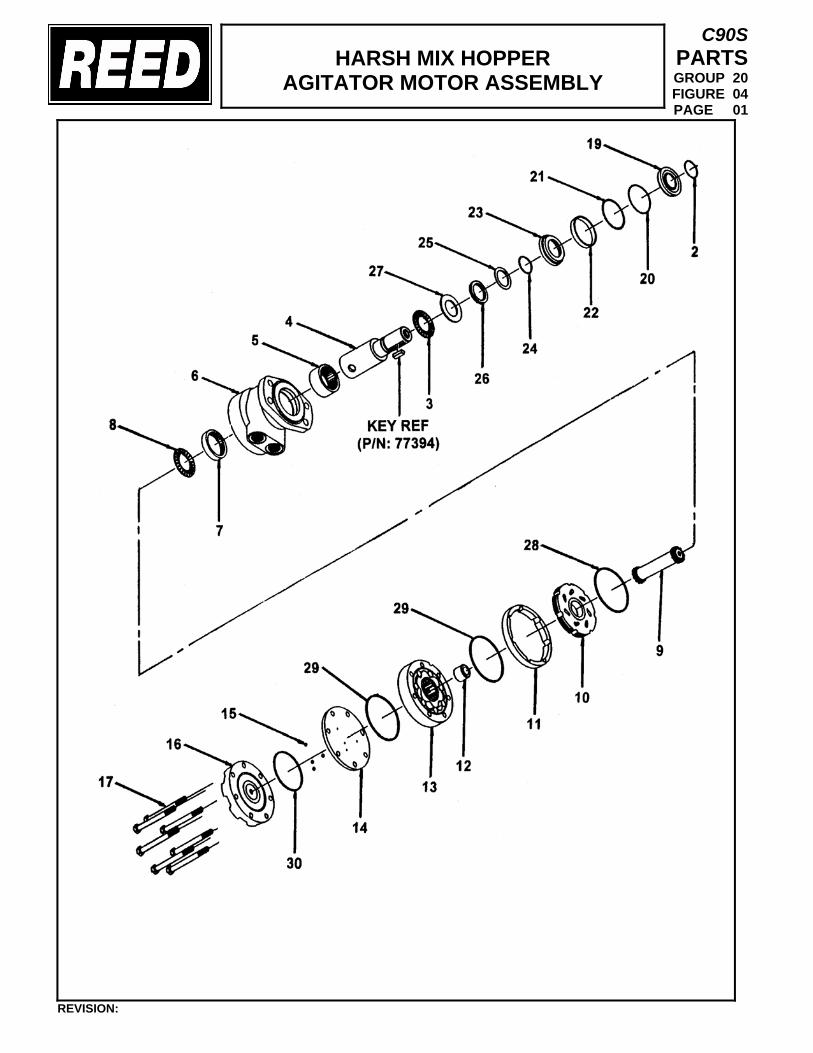
HARSH MIX HOPPER
AGITATOR MOTOR ASSEMBLY
C90S PARTS GROUP 20 FIGURE 04 PAGE 01
REVISION:
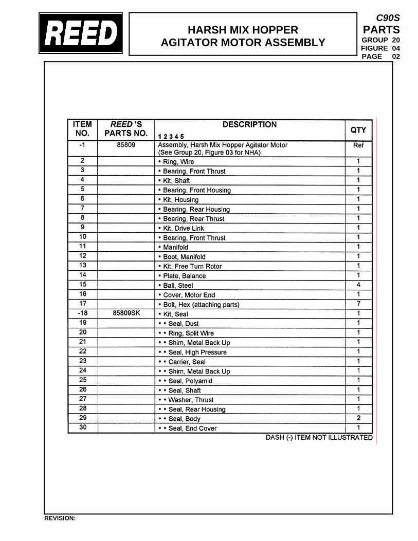
HARSH MIX HOPPER
AGITATOR MOTOR ASSEMBLY
C90S PARTS GROUP 20 FIGURE 04 PAGE 02
REVISION:
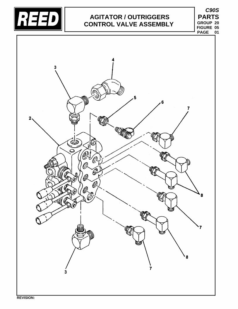
AGITATOR / OUTRIGGERS
CONTROL VALVE ASSEMBLY
C90S PARTS GROUP 20 FIGURE 05 PAGE 01
REVISION:
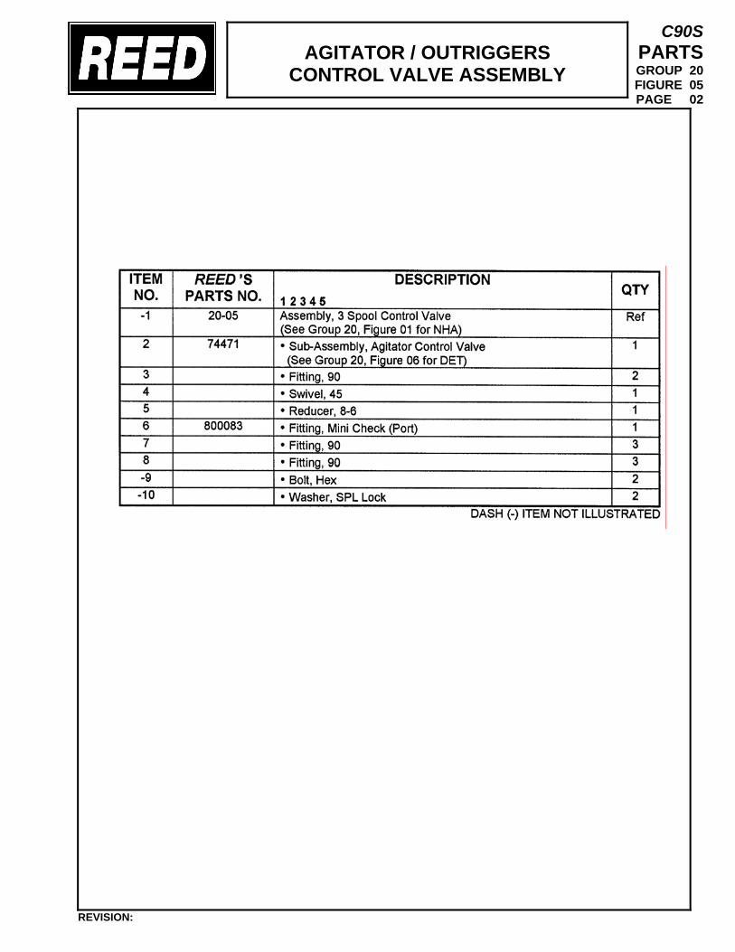
AGITATOR / OUTRIGGERS
CONTROL VALVE ASSEMBLY
C90S PARTS GROUP 20 FIGURE 05 PAGE 02
REVISION:
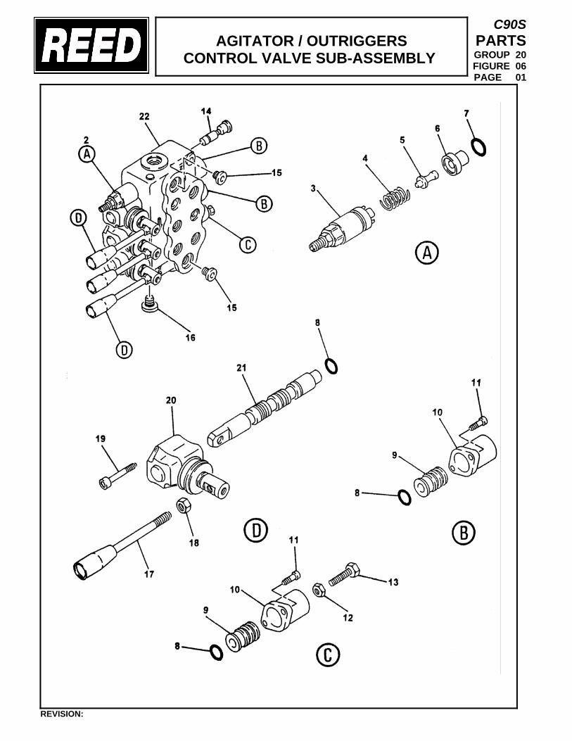
AGITATOR / OUTRIGGERS
CONTROL VALVE SUB-ASSEMBLY
C90S PARTS GROUP 20 FIGURE 06 PAGE 01
REVISION:
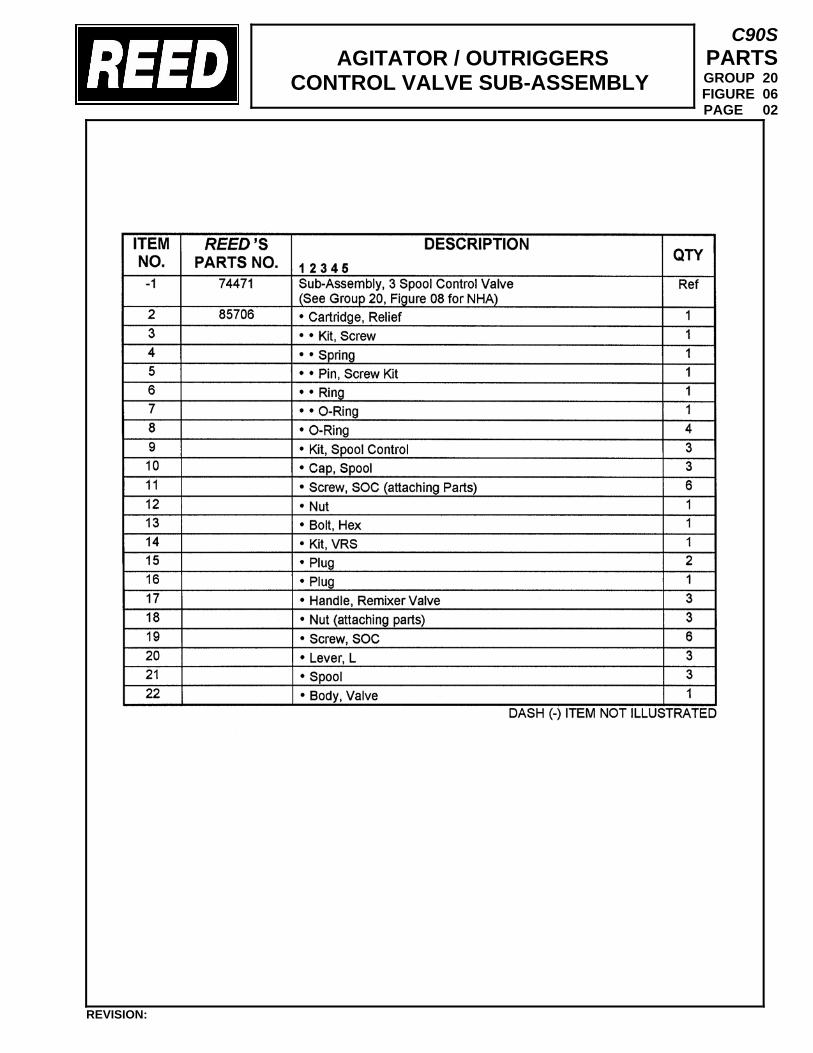
AGITATOR / OUTRIGGERS
CONTROL VALVE SUB-ASSEMBLY
C90S PARTS GROUP 20 FIGURE 06 PAGE 02
REVISION:
TRAILER MOUNTED PUMP 01 MODEL C90S
GROUP 20 HOPPER INSTALLATION
C90S PARTS GROUP 20 FIGURE 07 PAGE 01
REVISION:
THIS PAGE INTENTIONALLY LEFT BLANK.
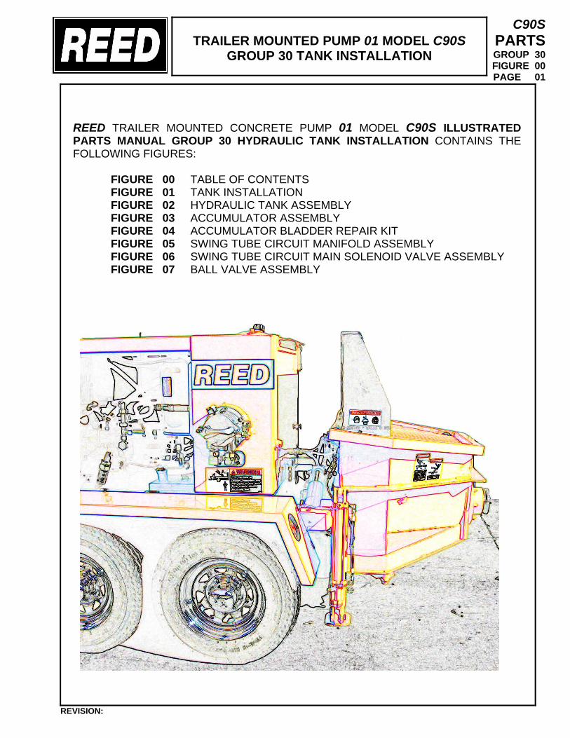
TRAILER MOUNTED PUMP 01 MODEL C90S
GROUP 30 TANK INSTALLATION
C90S PARTS GROUP 30 FIGURE 00 PAGE 01
REED TRAILER MOUNTED CONCRETE PUMP 01 MODEL C90S ILLUSTRATED PARTS MANUAL GROUP 30 HYDRAULIC TANK INSTALLATION CONTAINS THE FOLLOWING FIGURES:
FIGURE 00 TABLE OF CONTENTS FIGURE 01 TANK INSTALLATION FIGURE 02 HYDRAULIC TANK ASSEMBLY FIGURE 03 ACCUMULATOR ASSEMBLY FIGURE 04 ACCUMULATOR BLADDER REPAIR KIT FIGURE 05 SWING TUBE CIRCUIT MANIFOLD ASSEMBLY FIGURE 06 SWING TUBE CIRCUIT MAIN SOLENOID VALVE ASSEMBLY FIGURE 07 BALL VALVE ASSEMBLY
REVISION:
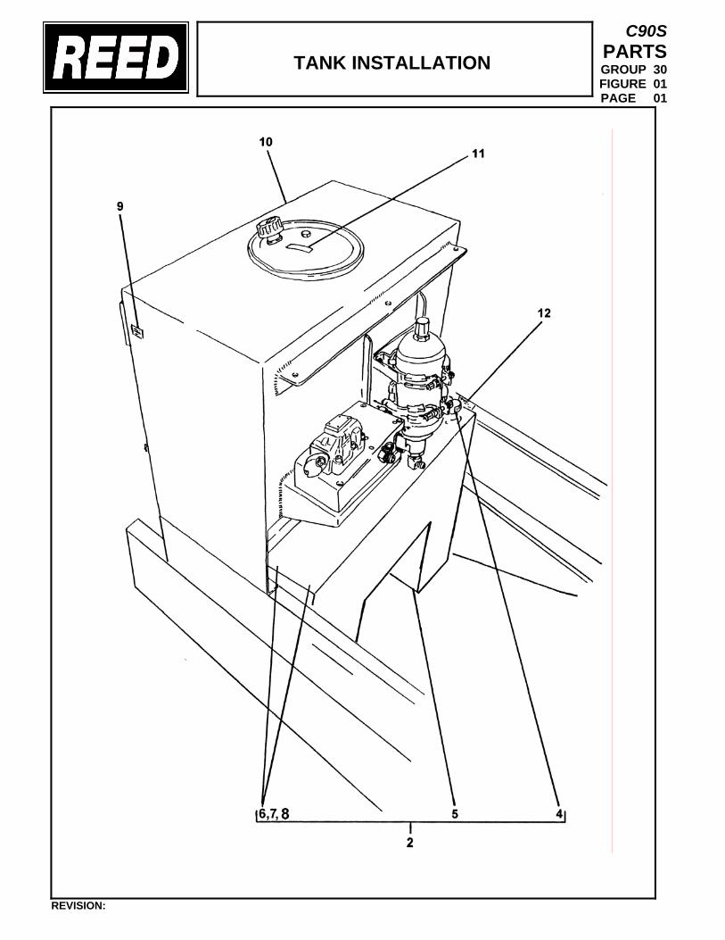
TANK INSTALLATION
C90S PARTS GROUP 30 FIGURE 01 PAGE 01
REVISION:
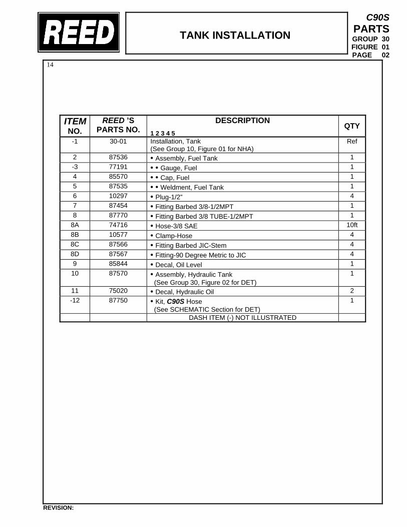
TANK INSTALLATION
C90S PARTS GROUP 30 FIGURE 01 PAGE 02
14
ITEM NO.
REED ’S PARTS NO.
DESCRIPTION 1 2 3 4 5
QTY
-1 30-01
Installation, Tank (See Group 10, Figure 01 for NHA)
Ref
2 87536 • Assembly, Fuel Tank 1 -3 77191 • • Gauge, Fuel 1 4 85570 • • Cap, Fuel 1 5 87535 • • Weldment, Fuel Tank 1 6 10297 • Plug-1/2” 4 7 87454 • Fitting Barbed 3/8-1/2MPT 1 8 87770 • Fitting Barbed 3/8 TUBE-1/2MPT 1
8A 74716 • Hose-3/8 SAE 10ft 8B 10577 • Clamp-Hose 4 8C 87566 • Fitting Barbed JIC-Stem 4 8D 87567 • Fitting-90 Degree Metric to JIC 4 9 85844 • Decal, Oil Level 1 10 87570 • Assembly, Hydraulic Tank
(See Group 30, Figure 02 for DET) 1
11 75020 • Decal, Hydraulic Oil 2 -12 87750 • Kit, C90S Hose
(See SCHEMATIC Section for DET) 1
DASH ITEM (-) NOT ILLUSTRATED
REVISION:
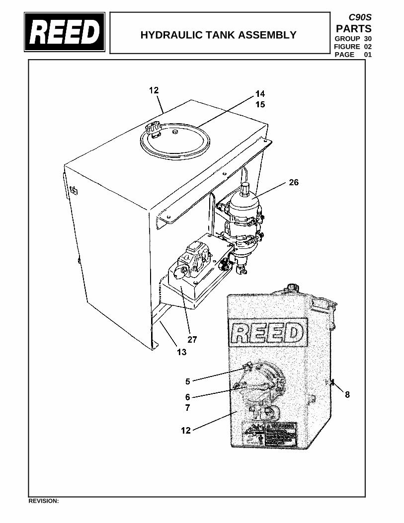
HYDRAULIC TANK ASSEMBLY
C90S PARTS GROUP 30 FIGURE 02 PAGE 01
REVISION:
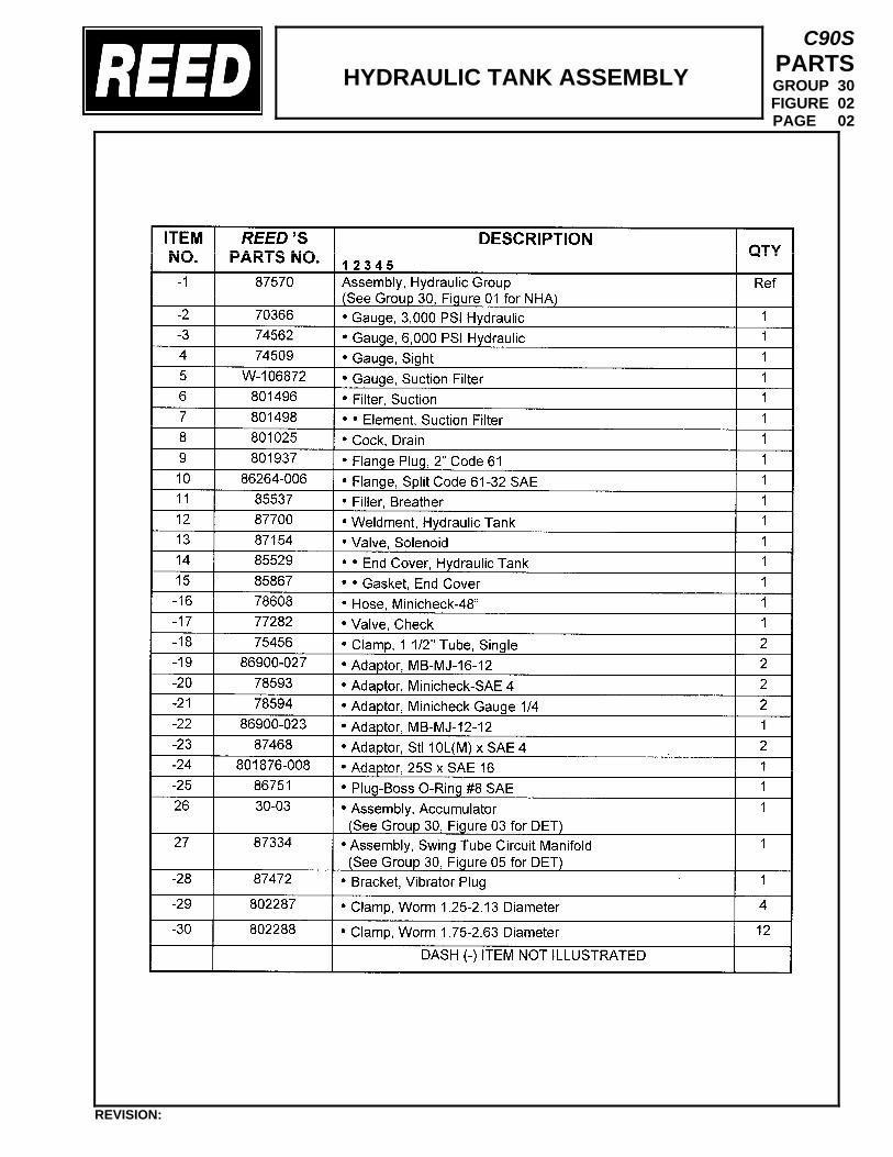
HYDRAULIC TANK ASSEMBLY
C90S PARTS GROUP 30 FIGURE 02 PAGE 02
REVISION:
MikeN
Text Box
802585
MikeN
Text Box
*Pressure filter for main pump is W-109849. O-ring is 801499-ORING
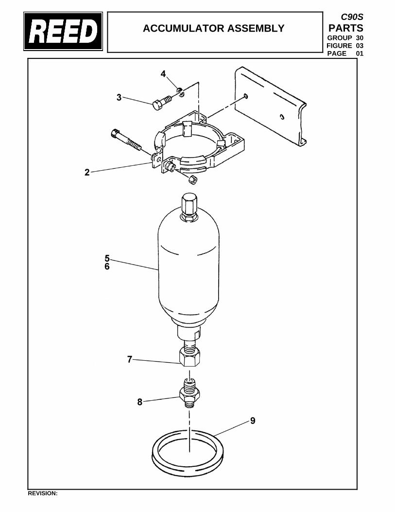
ACCUMULATOR ASSEMBLY
C90S PARTS GROUP 30 FIGURE 03 PAGE 01
REVISION:
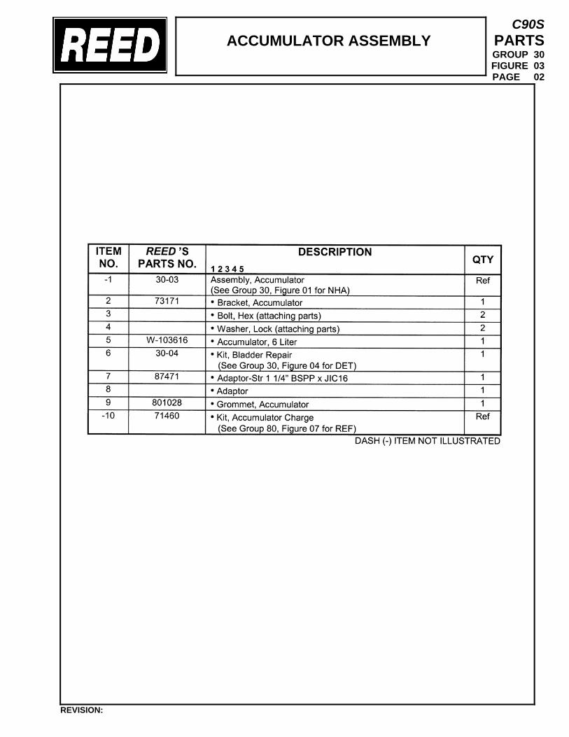
ACCUMULATOR ASSEMBLY
C90S PARTS GROUP 30 FIGURE 03 PAGE 02
REVISION:
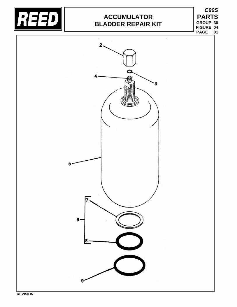
ACCUMULATOR
BLADDER REPAIR KIT
C90S PARTS GROUP 30 FIGURE 04 PAGE 01
REVISION:
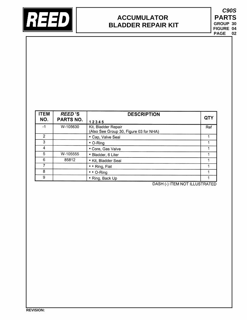
ACCUMULATOR
BLADDER REPAIR KIT
C90S PARTS GROUP 30 FIGURE 04 PAGE 02
REVISION:
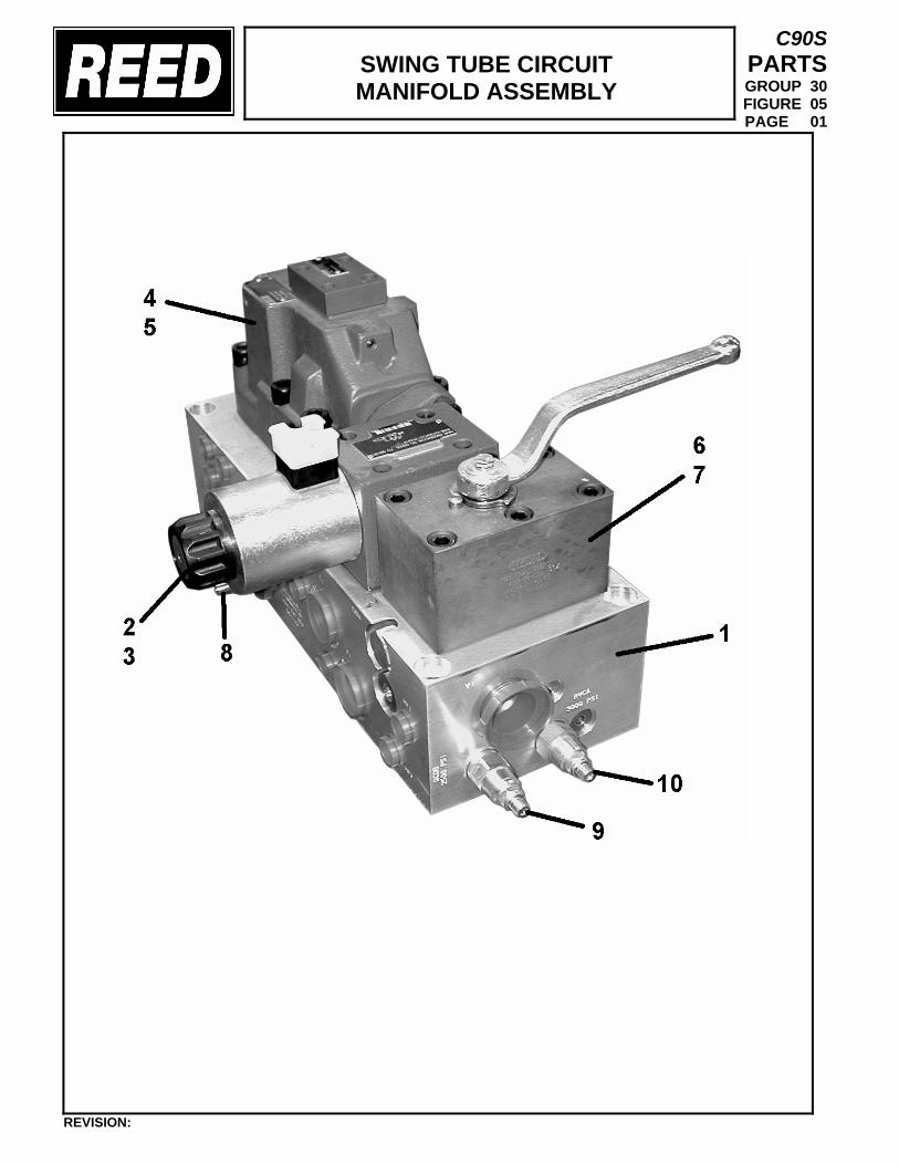
SWING TUBE CIRCUIT MANIFOLD ASSEMBLY
C90S PARTS GROUP 30 FIGURE 05 PAGE 01
REVISION:
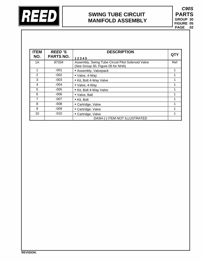
SWING TUBE CIRCUIT MANIFOLD ASSEMBLY
C90S PARTS GROUP 30 FIGURE 05 PAGE 02
ITEM NO.
REED ’S PARTS NO.
DESCRIPTION 1 2 3 4 5
QTY
1A 87334 Assembly, Swing Tube Circuit Pilot Solenoid Valve (See Group 30, Figure 05 for NHA)
Ref
1 -001 • Assembly, Valvepack 1 2 -002 • Valve, 4-Way 1 3 -003 • Kit, Bolt 4-Way Valve 1 4 -004 • Valve, 4-Way 1 5 -005 • Kit, Bolt 4-Way Valve 1 6 -006 • Valve, Ball 1 7 -007 • Kit, Bolt 1 8 -008 • Cartridge, Valve 1 9 -009 • Cartridge, Valve 1 10 -010 • Cartridge, Valve 1
DASH (-) ITEM NOT ILLUSTRATED
REVISION:
MikeN
Text Box
87922 is valve w/ coil (coil only is 86674)
MikeN
Text Box
87922-BK
MikeN
Text Box
87919
MikeN
Text Box
87921
MikeN
Text Box
85704
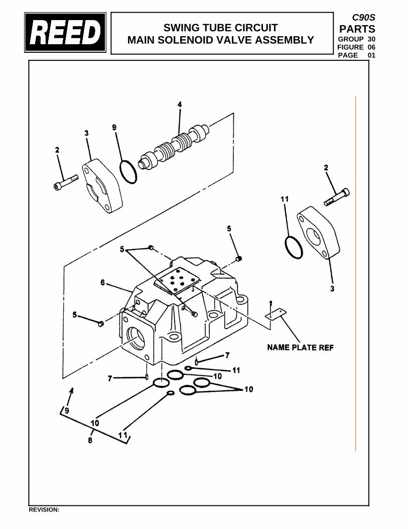
SWING TUBE CIRCUIT MAIN SOLENOID VALVE ASSEMBLY
C90S PARTS GROUP 30 FIGURE 06 PAGE 01
REVISION:
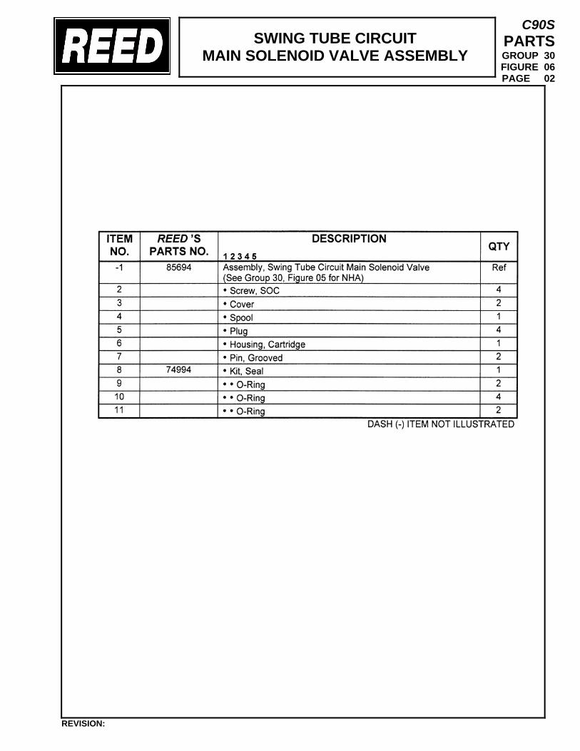
SWING TUBE CIRCUIT MAIN SOLENOID VALVE ASSEMBLY
C90S PARTS GROUP 30 FIGURE 06 PAGE 02
REVISION:
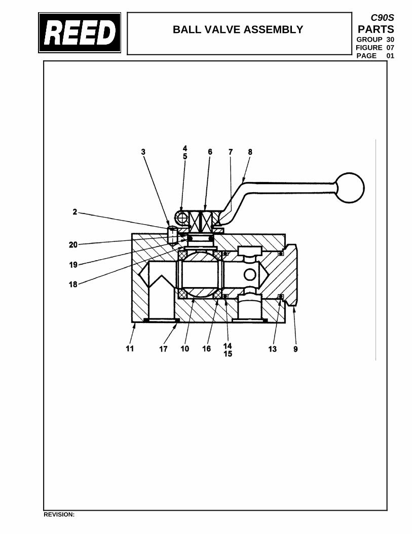
BALL VALVE ASSEMBLY
C90S PARTS GROUP 30 FIGURE 07 PAGE 01
REVISION:
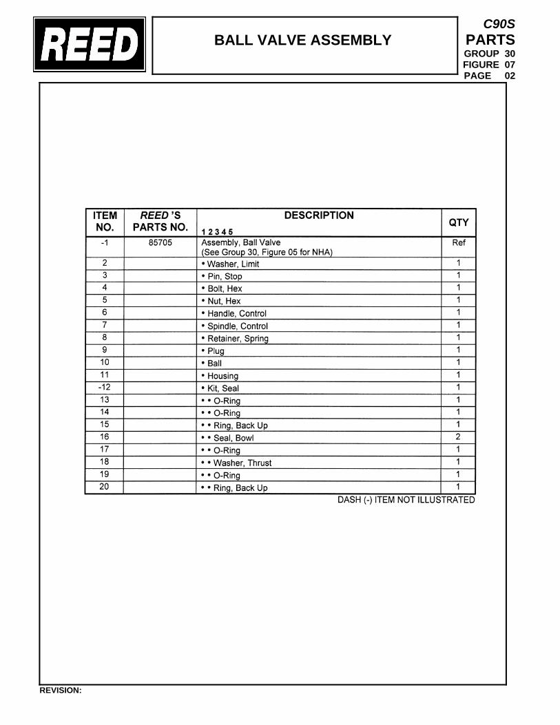
BALL VALVE ASSEMBLY
C90S PARTS GROUP 30 FIGURE 07 PAGE 02
REVISION:

TRAILER MOUNTED PUMP 01 MODEL C90S
GROUP 30 TANK INSTALLATION
C90S PARTS GROUP 30 FIGURE 08 PAGE 01
REVISION:
THIS PAGE INTENTIONALLY LEFT BLANK.
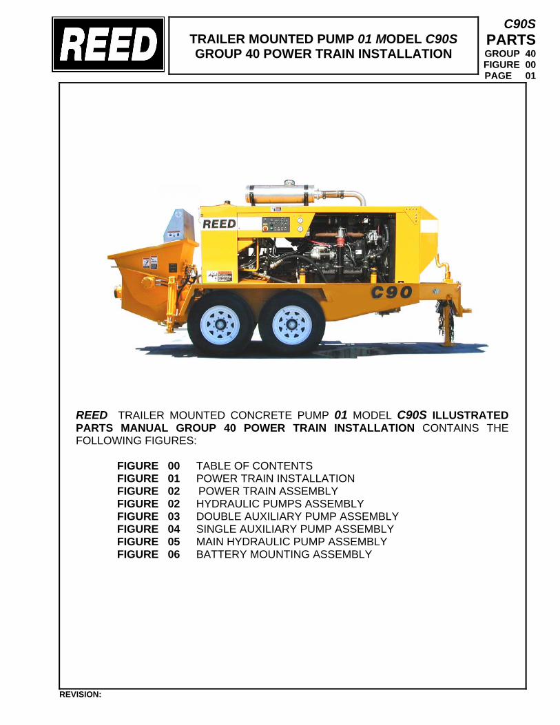
TRAILER MOUNTED PUMP 01 MODEL C90S GROUP 40 POWER TRAIN INSTALLATION
C90S PARTS GROUP 40 FIGURE 00 PAGE 01
REED TRAILER MOUNTED CONCRETE PUMP 01 MODEL C90S ILLUSTRATED PARTS MANUAL GROUP 40 POWER TRAIN INSTALLATION CONTAINS THE FOLLOWING FIGURES:
FIGURE 00 TABLE OF CONTENTS FIGURE 01 POWER TRAIN INSTALLATION FIGURE 02 POWER TRAIN ASSEMBLY FIGURE 02 HYDRAULIC PUMPS ASSEMBLY FIGURE 03 DOUBLE AUXILIARY PUMP ASSEMBLY FIGURE 04 SINGLE AUXILIARY PUMP ASSEMBLY FIGURE 05 MAIN HYDRAULIC PUMP ASSEMBLY FIGURE 06 BATTERY MOUNTING ASSEMBLY
REVISION:
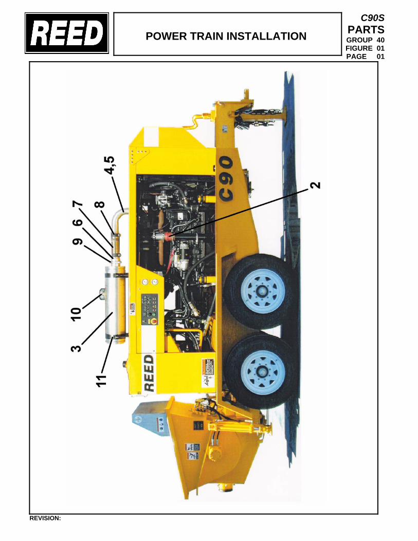
POWER TRAIN INSTALLATION
C90S PARTS GROUP 40 FIGURE 01 PAGE 01
REVISION:
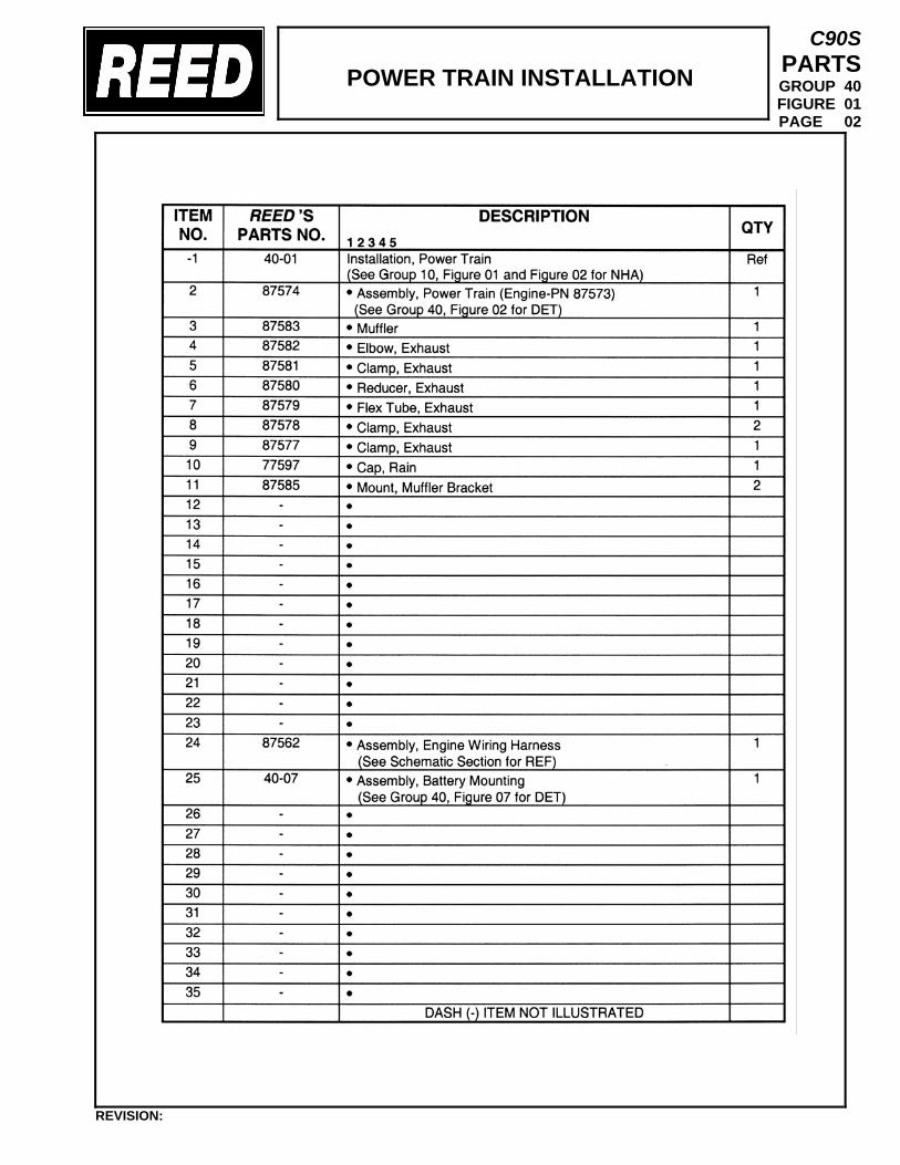
POWER TRAIN INSTALLATION
C90S PARTS GROUP 40 FIGURE 01 PAGE 02
REVISION:
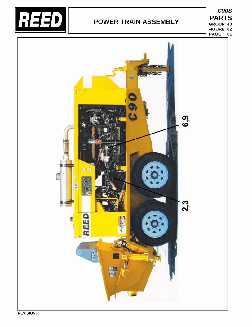
POWER TRAIN ASSEMBLY
C90S PARTS GROUP 40 FIGURE 02 PAGE 01
REVISION:
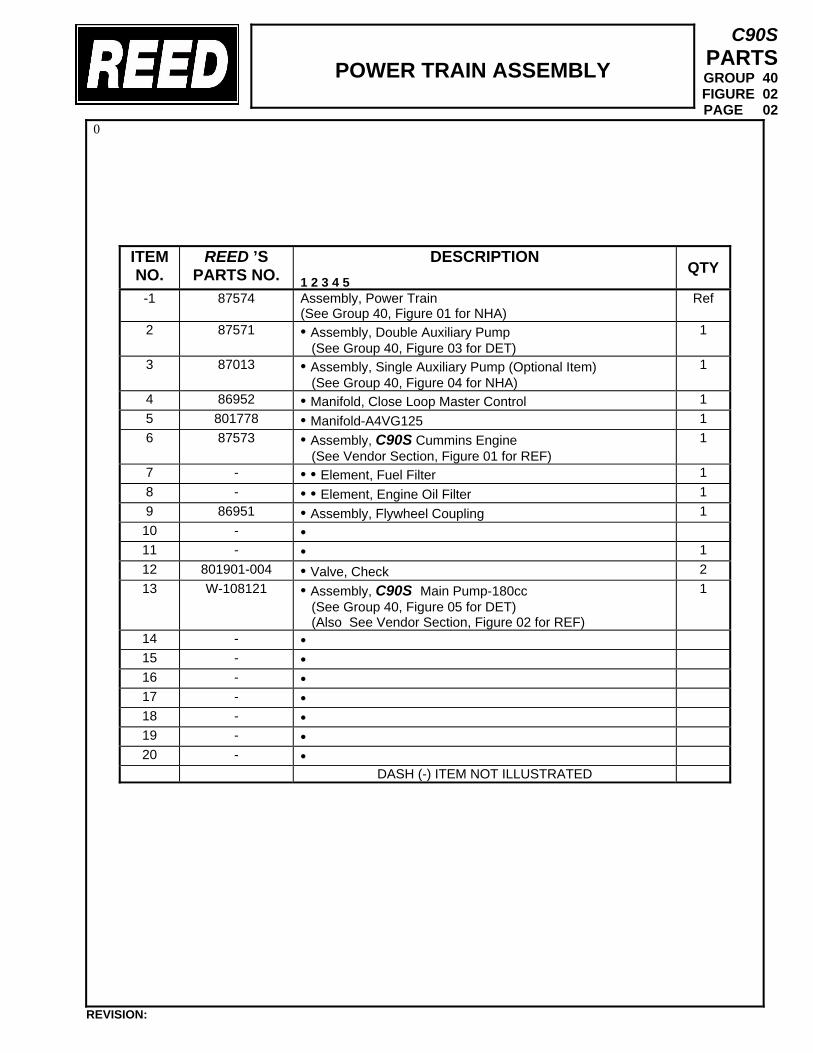
POWER TRAIN ASSEMBLY
C90S PARTS GROUP 40 FIGURE 02 PAGE 02
0
ITEM NO.
REED ’S PARTS NO.
DESCRIPTION 1 2 3 4 5
QTY
-1 87574 Assembly, Power Train (See Group 40, Figure 01 for NHA)
Ref
2 87571 • Assembly, Double Auxiliary Pump (See Group 40, Figure 03 for DET)
1
3 87013
• Assembly, Single Auxiliary Pump (Optional Item) (See Group 40, Figure 04 for NHA)
1
4 86952 • Manifold, Close Loop Master Control 1 5 801778 • Manifold-A4VG125 1 6 87573 • Assembly, C90S Cummins Engine
(See Vendor Section, Figure 01 for REF) 1
7 - • • Element, Fuel Filter 1 8 - • • Element, Engine Oil Filter 1 9 86951 • Assembly, Flywheel Coupling 1 10 - • 11 - • 1 12 801901-004 • Valve, Check 2 13 W-108121 • Assembly, C90S Main Pump-180cc
(See Group 40, Figure 05 for DET) (Also See Vendor Section, Figure 02 for REF)
1
14 - • 15 - • 16 - • 17 - • 18 - • 19 - • 20 - •
DASH (-) ITEM NOT ILLUSTRATED
REVISION:
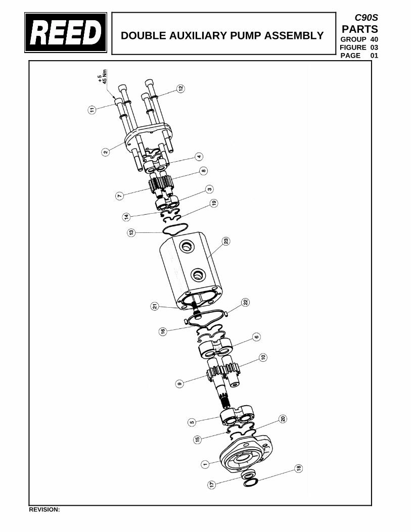
DOUBLE AUXILIARY PUMP ASSEMBLY
C90S PARTS GROUP 40 FIGURE 03 PAGE 01
REVISION:
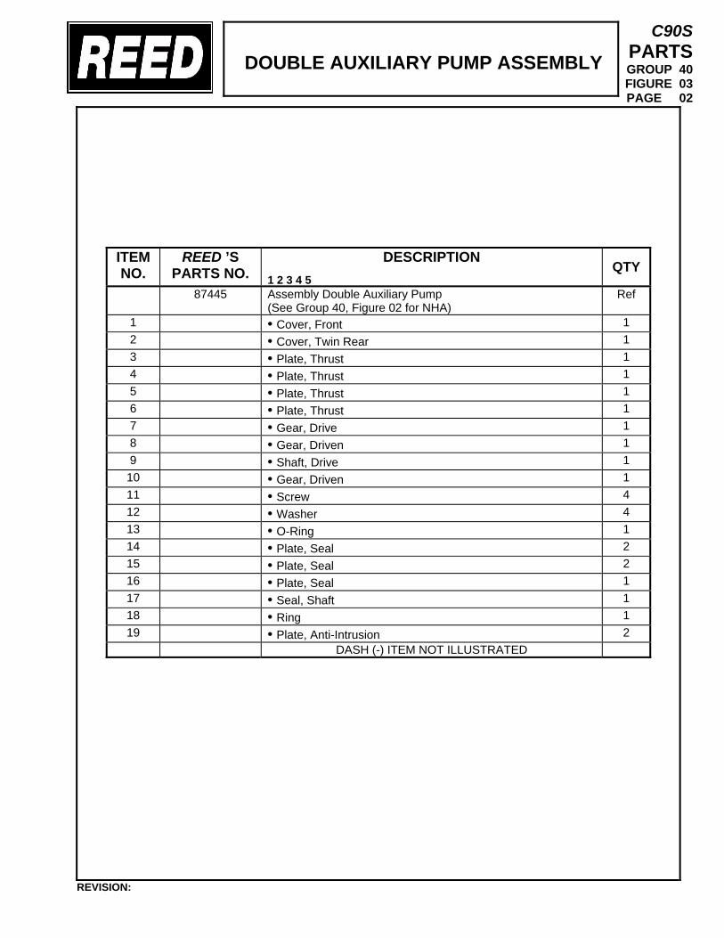
DOUBLE AUXILIARY PUMP ASSEMBLY
C90S PARTS GROUP 40 FIGURE 03 PAGE 02
ITEM NO.
REED ’S PARTS NO.
DESCRIPTION 1 2 3 4 5
QTY
87445
Assembly Double Auxiliary Pump (See Group 40, Figure 02 for NHA)
Ref
1 • Cover, Front 1 2 • Cover, Twin Rear 1 3 • Plate, Thrust 1 4 • Plate, Thrust 1 5 • Plate, Thrust 1 6 • Plate, Thrust 1 7 • Gear, Drive 1 8 • Gear, Driven 1 9 • Shaft, Drive 1 10 • Gear, Driven 1 11 • Screw 4 12 • Washer 4 13 • O-Ring 1 14 • Plate, Seal 2 15 • Plate, Seal 2 16 • Plate, Seal 1 17 • Seal, Shaft 1 18 • Ring 1 19 • Plate, Anti-Intrusion 2
DASH (-) ITEM NOT ILLUSTRATED
REVISION:
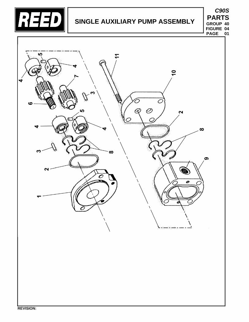
SINGLE AUXILIARY PUMP ASSEMBLY
C90S PARTS GROUP 40 FIGURE 04 PAGE 01
REVISION:
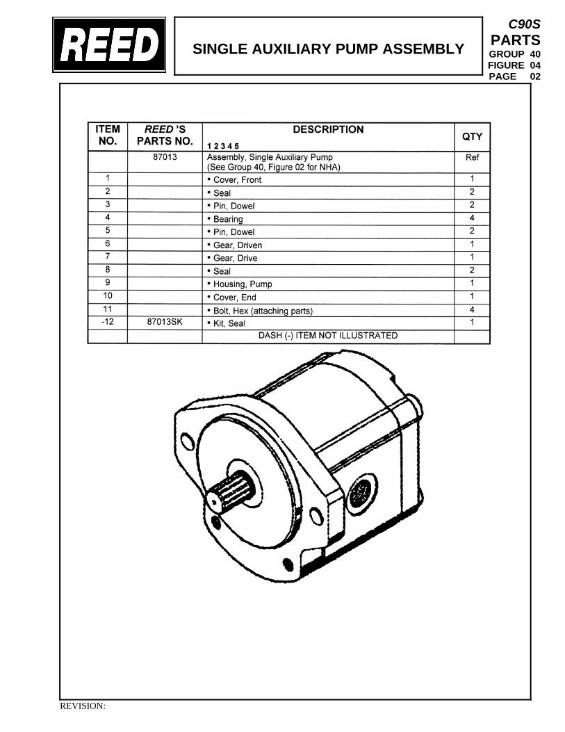
SINGLE AUXILIARY PUMP ASSEMBLY
C90S PARTS GROUP 40 FIGURE 04 PAGE 02
REVISION:
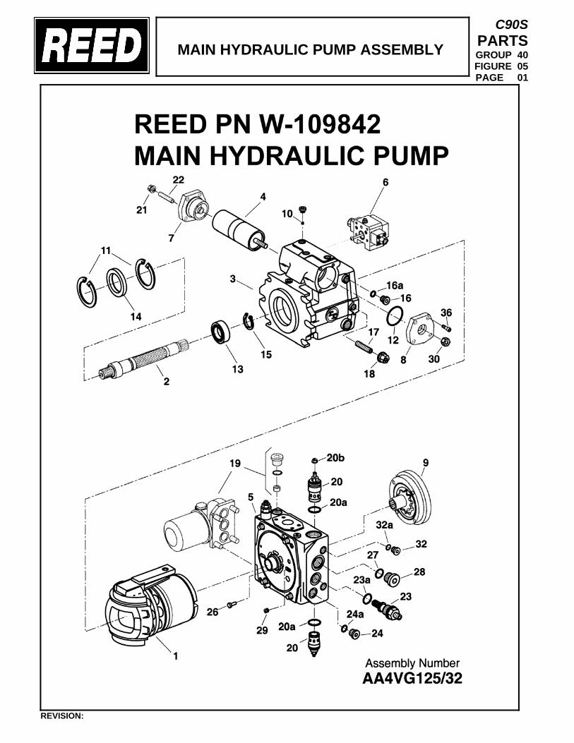
MAIN HYDRAULIC PUMP ASSEMBLY
C90S PARTS GROUP 40 FIGURE 05 PAGE 01
REVISION:
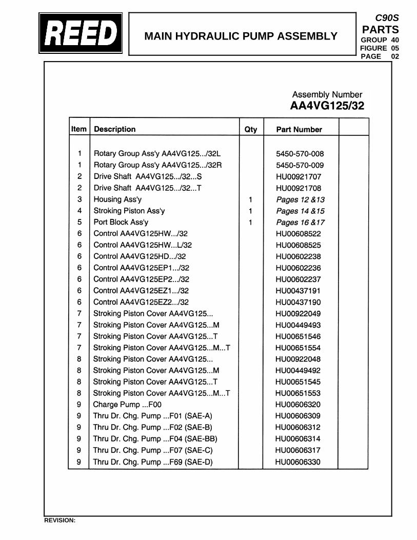
MAIN HYDRAULIC PUMP ASSEMBLY
C90S PARTS GROUP 40 FIGURE 05 PAGE 02
REVISION:
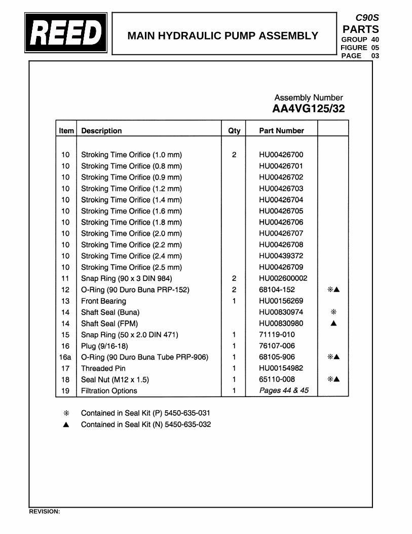
MAIN HYDRAULIC PUMP ASSEMBLY
C90S PARTS GROUP 40 FIGURE 05 PAGE 03
REVISION:
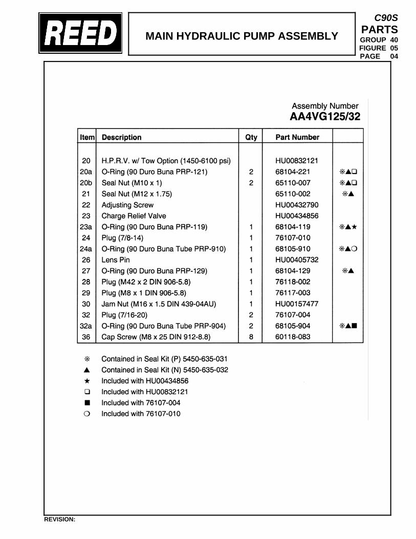
MAIN HYDRAULIC PUMP ASSEMBLY
C90S PARTS GROUP 40 FIGURE 05 PAGE 04
REVISION:
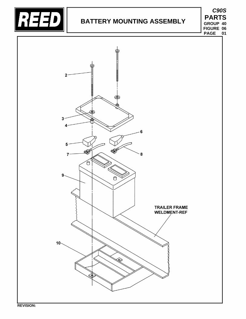
BATTERY MOUNTING ASSEMBLY
C90S PARTS GROUP 40 FIGURE 06 PAGE 01
REVISION:
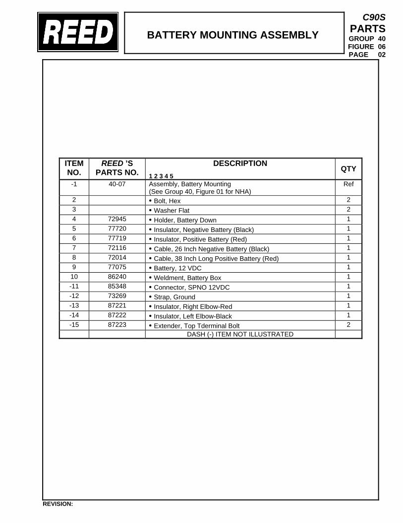
BATTERY MOUNTING ASSEMBLY
C90S PARTS GROUP 40 FIGURE 06 PAGE 02
ITEM NO.
REED ’S PARTS NO.
DESCRIPTION 1 2 3 4 5
QTY
-1 40-07
Assembly, Battery Mounting (See Group 40, Figure 01 for NHA)
Ref
2 • Bolt, Hex 2 3 • Washer Flat 2 4 72945 • Holder, Battery Down 1 5 77720 • Insulator, Negative Battery (Black) 1 6 77719 • Insulator, Positive Battery (Red) 1 7 72116 • Cable, 26 Inch Negative Battery (Black) 1 8 72014 • Cable, 38 Inch Long Positive Battery (Red) 1 9 77075 • Battery, 12 VDC 1 10 86240 • Weldment, Battery Box 1 -11 85348 • Connector, SPNO 12VDC 1 -12 73269 • Strap, Ground 1 -13 87221 • Insulator, Right Elbow-Red 1 -14 87222 • Insulator, Left Elbow-Black 1 -15 87223 • Extender, Top Tderminal Bolt 2
DASH (-) ITEM NOT ILLUSTRATED
REVISION:
TRAILER MOUNTED PUMP 01 MODEL C90S GROUP 40 POWER TRAIN INSTALLATION
C90S PARTS GROUP 40 FIGURE 07 PAGE 01
THIS PAGE INTENTIONALLY LEFT BLANK.
REVISION:
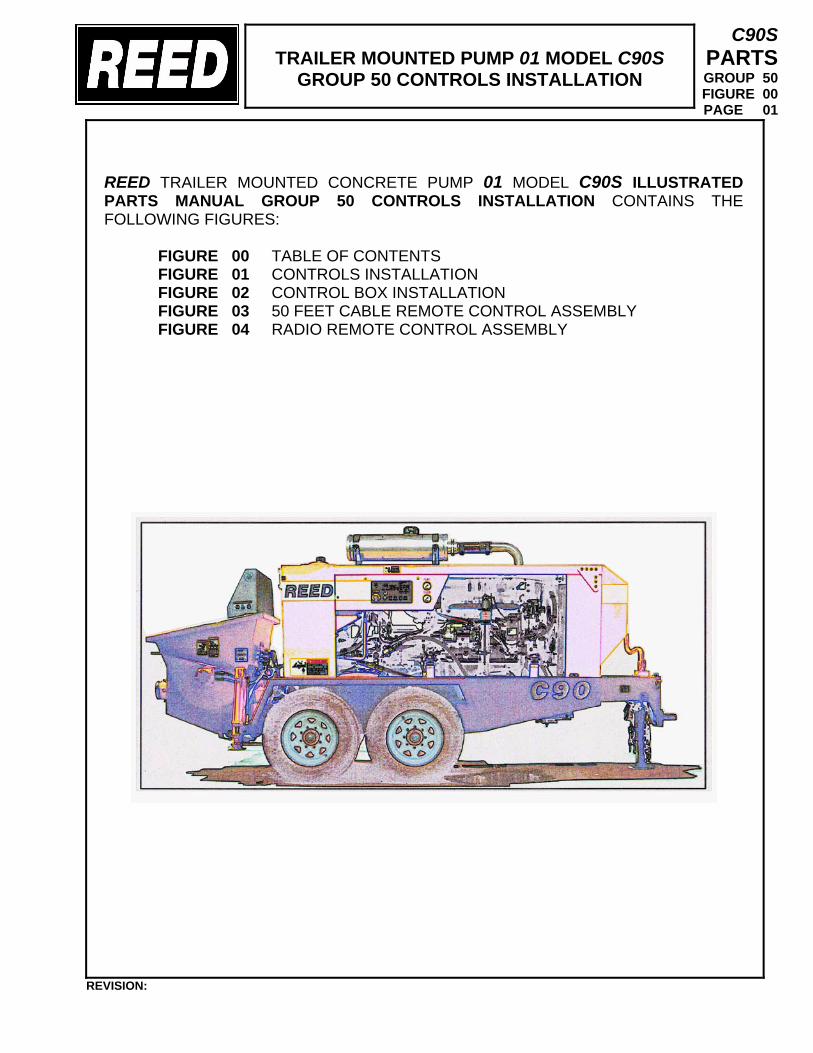
TRAILER MOUNTED PUMP 01 MODEL C90S
GROUP 50 CONTROLS INSTALLATION
C90S PARTS GROUP 50 FIGURE 00 PAGE 01
REED TRAILER MOUNTED CONCRETE PUMP 01 MODEL C90S ILLUSTRATED PARTS MANUAL GROUP 50 CONTROLS INSTALLATION CONTAINS THE FOLLOWING FIGURES:
FIGURE 00 TABLE OF CONTENTS FIGURE 01 CONTROLS INSTALLATION FIGURE 02 CONTROL BOX INSTALLATION FIGURE 03 50 FEET CABLE REMOTE CONTROL ASSEMBLY FIGURE 04 RADIO REMOTE CONTROL ASSEMBLY
REVISION:
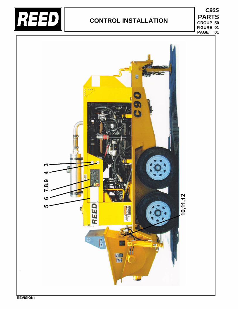
CONTROL INSTALLATION
C90S PARTS GROUP 50 FIGURE 01 PAGE 01
.
REVISION:
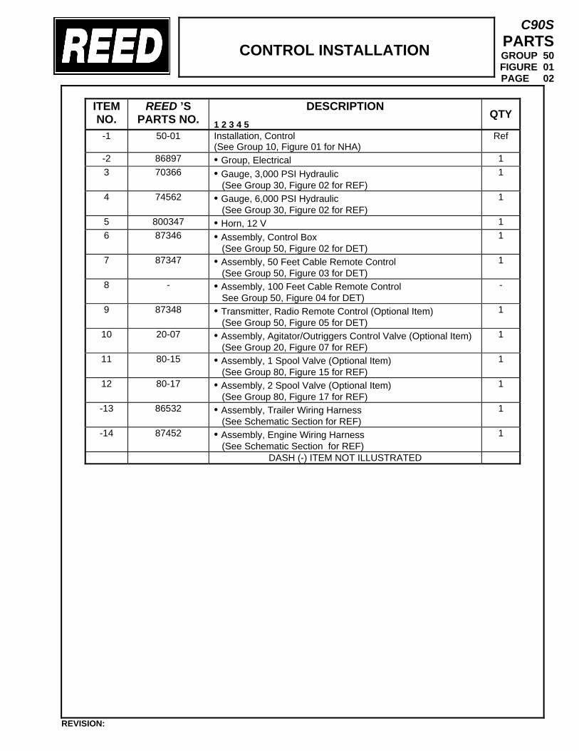
CONTROL INSTALLATION
C90S PARTS GROUP 50 FIGURE 01 PAGE 02
ITEM NO.
REED ’S PARTS NO.
DESCRIPTION 1 2 3 4 5
QTY
-1 50-01
Installation, Control (See Group 10, Figure 01 for NHA)
Ref
-2 86897 • Group, Electrical 1 3 70366 • Gauge, 3,000 PSI Hydraulic
(See Group 30, Figure 02 for REF) 1
4 74562 • Gauge, 6,000 PSI Hydraulic (See Group 30, Figure 02 for REF)
1
5 800347 • Horn, 12 V 1 6 87346 • Assembly, Control Box
(See Group 50, Figure 02 for DET) 1
7 87347 • Assembly, 50 Feet Cable Remote Control (See Group 50, Figure 03 for DET)
1
8 - • Assembly, 100 Feet Cable Remote Control See Group 50, Figure 04 for DET)
-
9 87348 • Transmitter, Radio Remote Control (Optional Item) (See Group 50, Figure 05 for DET)
1
10 20-07 • Assembly, Agitator/Outriggers Control Valve (Optional Item) (See Group 20, Figure 07 for REF)
1
11 80-15 • Assembly, 1 Spool Valve (Optional Item) (See Group 80, Figure 15 for REF)
1
12 80-17 • Assembly, 2 Spool Valve (Optional Item) (See Group 80, Figure 17 for REF)
1
-13 86532 • Assembly, Trailer Wiring Harness (See Schematic Section for REF)
1
-14 87452 • Assembly, Engine Wiring Harness (See Schematic Section for REF)
1
DASH (-) ITEM NOT ILLUSTRATED
REVISION:
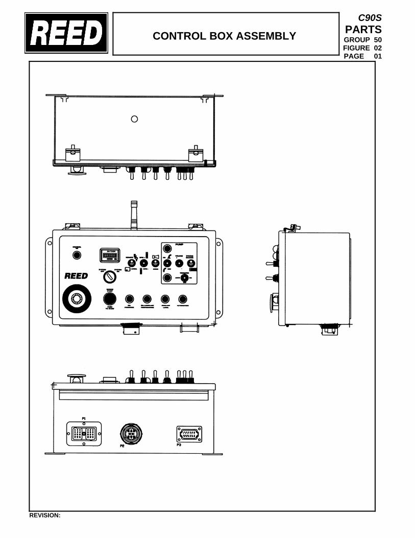
CONTROL BOX ASSEMBLY
C90S PARTS GROUP 50 FIGURE 02 PAGE 01
REVISION:
CONTROL BOX ASSEMBLY
C90S PARTS GROUP 50 FIGURE 02 PAGE 02
ITEM NO.
REED ’S PARTS NO.
DESCRIPTION 1 2 3 4 5
QTY
1 87346 Assembly, Control Box (See Group 50, Figure 01 for NHA)
Ref
2 • 3 • 4 • 5 • 6 • 7 • 8 • 9 • 10 • 11 • 12 • 13 • 14 • 15 • 16 • 17 • 18 • 19 • 20 •
DASH (-) ITEM NOT ILLUSTRATED
REVISION:
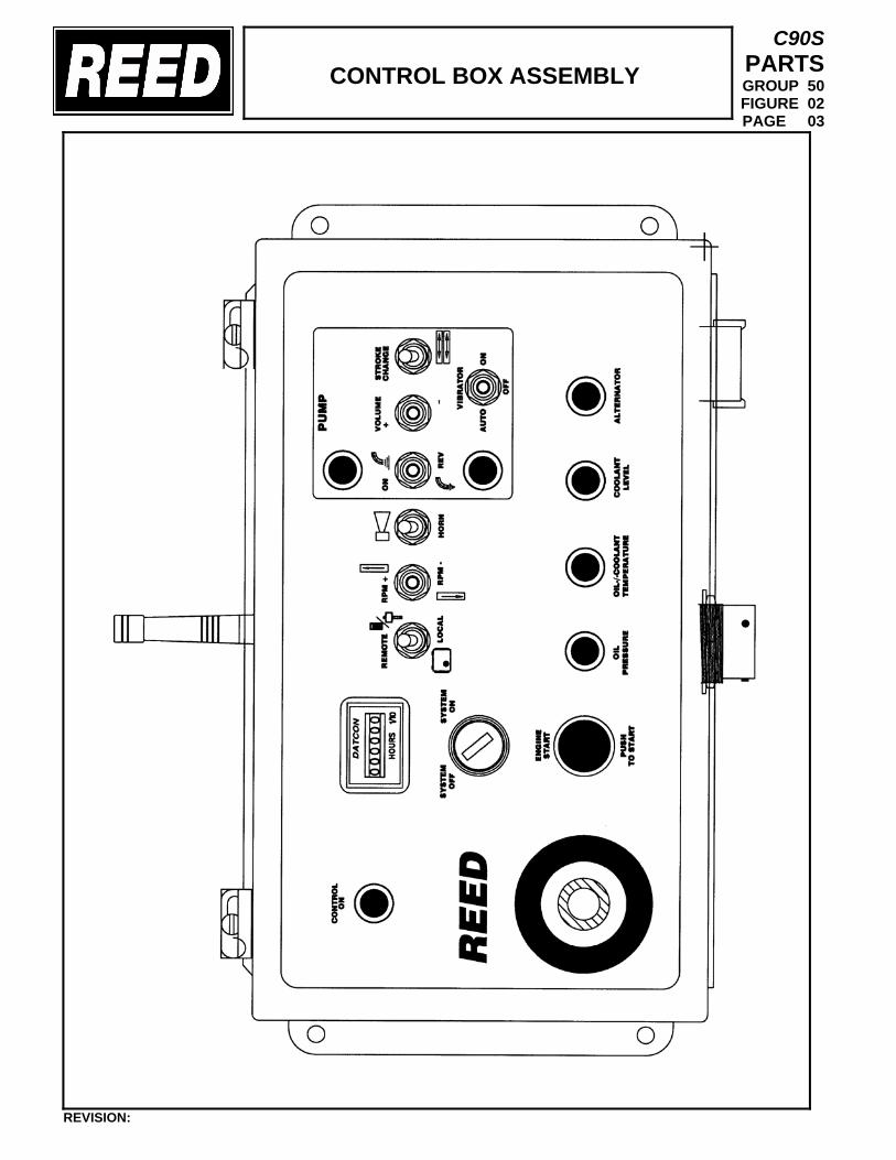
CONTROL BOX ASSEMBLY
C90S PARTS GROUP 50 FIGURE 02 PAGE 03
REVISION:
CONTROL BOX ASSEMBLY
C90S PARTS GROUP 50 FIGURE 02 PAGE 04
ITEM NO.
REED ’S PARTS NO.
DESCRIPTION 1 2 3 4 5
QTY
1 87346 Assembly, Control Box (See Group 50, Figure 01 for NHA)
Ref
2 • 3 • 4 • 5 • 6 • 7 • 8 • 9 • 10 • 11 • 12 • 13 • 14 • 15 • 16 • 17 • 18 • 19 • 20 •
DASH (-) ITEM NOT ILLUSTRATED
REVISION:
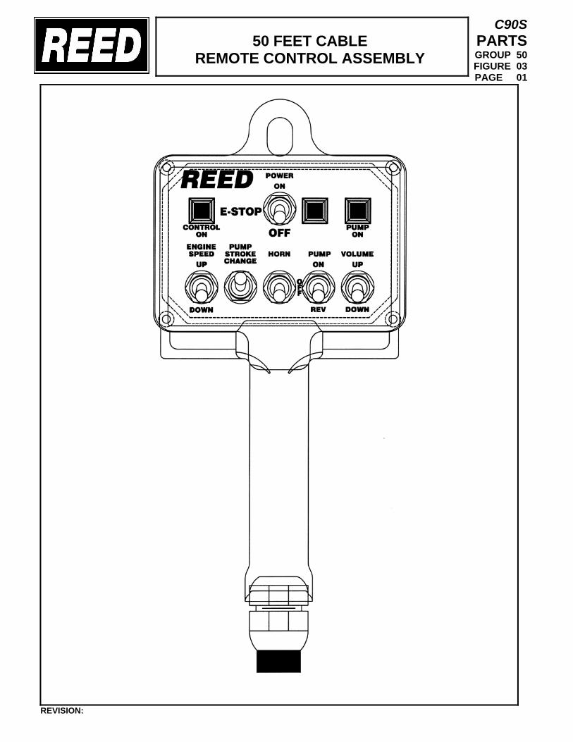
50 FEET CABLE REMOTE CONTROL ASSEMBLY
C90S PARTS GROUP 50 FIGURE 03 PAGE 01
REVISION:
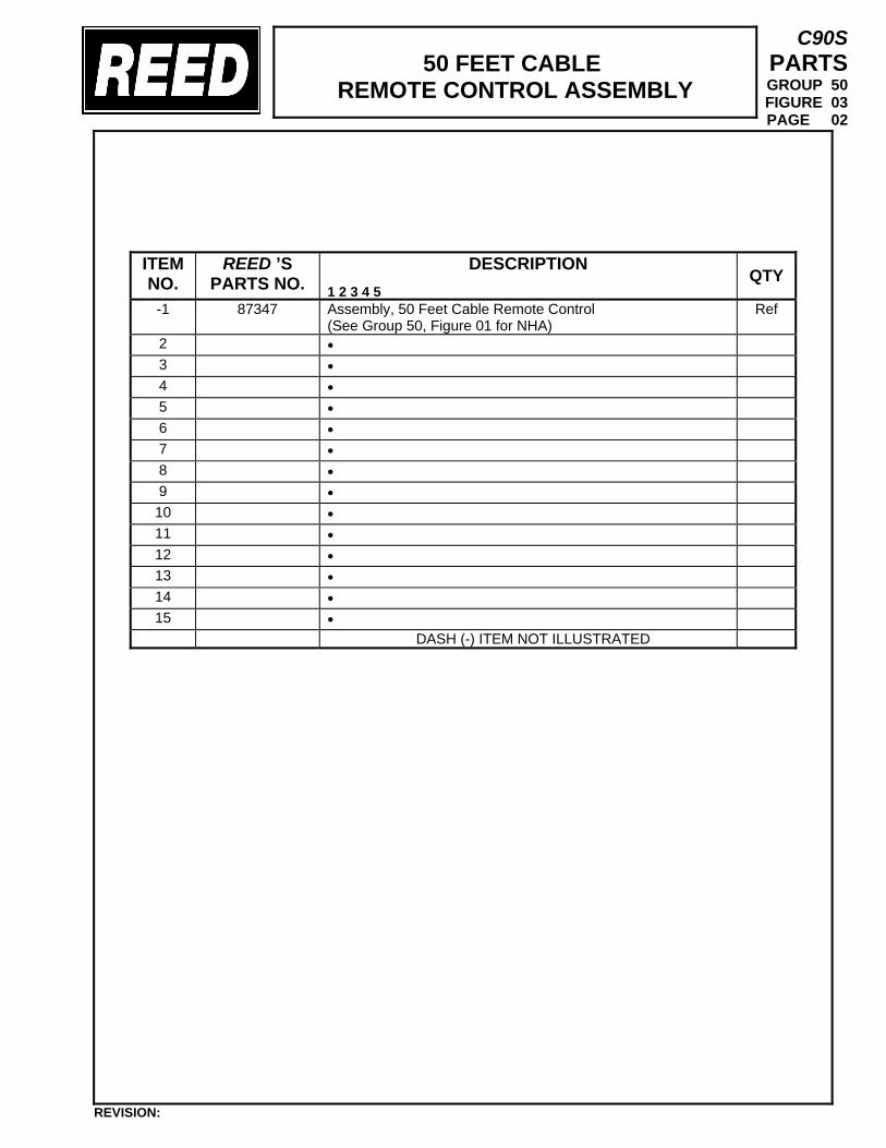
50 FEET CABLE
REMOTE CONTROL ASSEMBLY
C90S PARTS GROUP 50 FIGURE 03 PAGE 02
ITEM NO.
REED ’S PARTS NO.
DESCRIPTION 1 2 3 4 5
QTY
-1 87347 Assembly, 50 Feet Cable Remote Control (See Group 50, Figure 01 for NHA)
Ref
2 • 3 • 4 • 5 • 6 • 7 • 8 • 9 • 10 • 11 • 12 • 13 • 14 • 15 •
DASH (-) ITEM NOT ILLUSTRATED
REVISION:
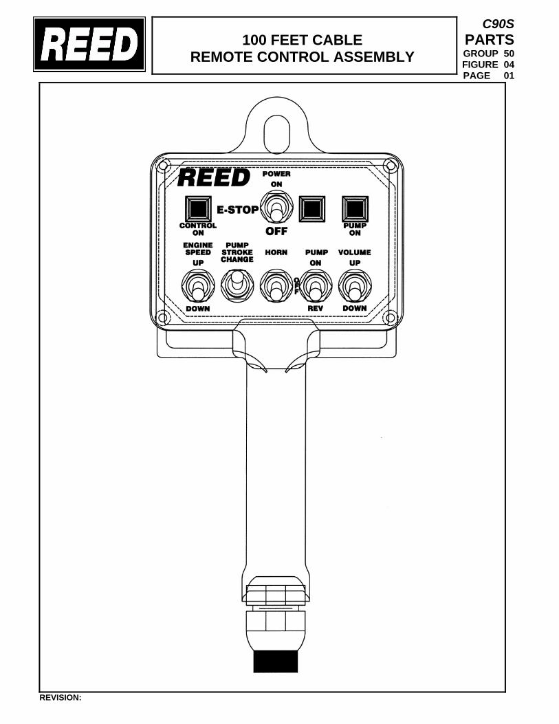
100 FEET CABLE
REMOTE CONTROL ASSEMBLY
C90S PARTS GROUP 50 FIGURE 04 PAGE 01
REVISION:
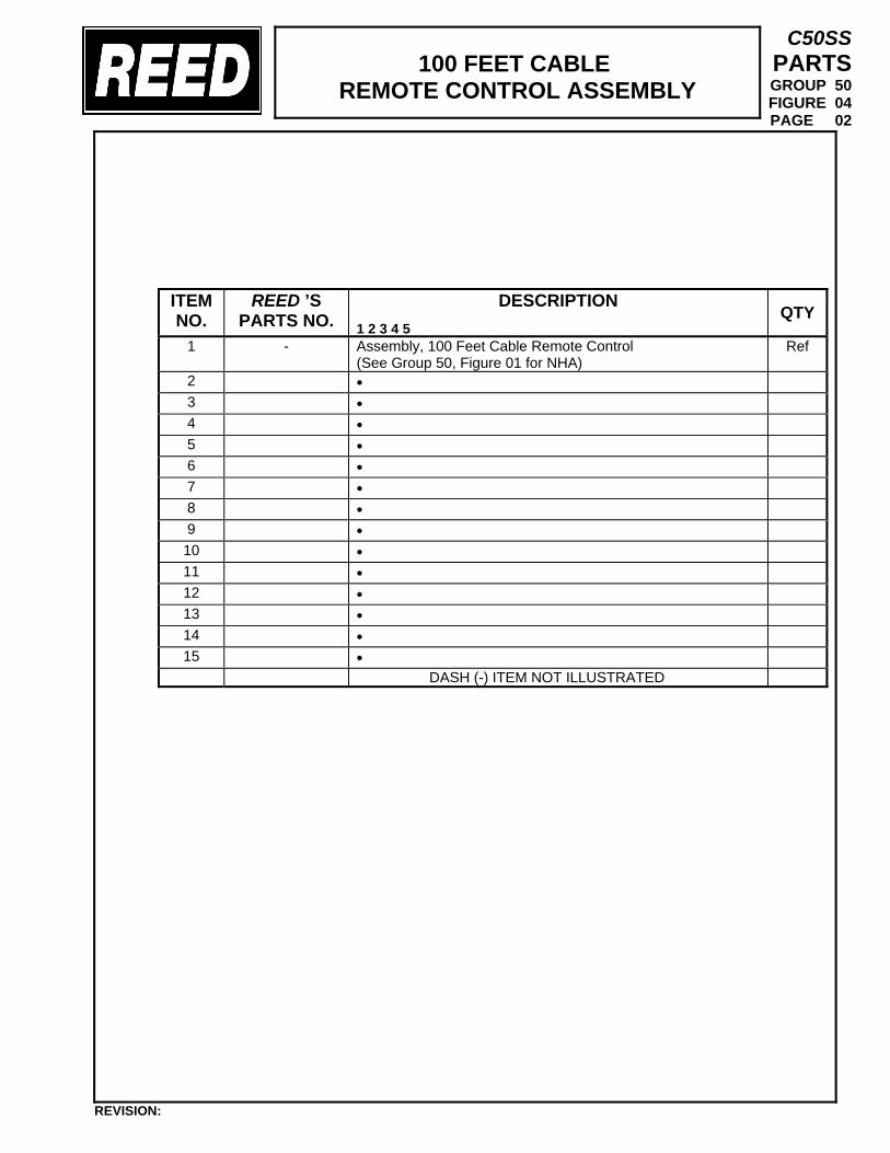
100 FEET CABLE
REMOTE CONTROL ASSEMBLY
C50SS PARTS GROUP 50 FIGURE 04 PAGE 02
ITEM NO.
REED ’S PARTS NO.
DESCRIPTION 1 2 3 4 5
QTY
1 - Assembly, 100 Feet Cable Remote Control (See Group 50, Figure 01 for NHA)
Ref
2 • 3 • 4 • 5 • 6 • 7 • 8 • 9 • 10 • 11 • 12 • 13 • 14 • 15 •
DASH (-) ITEM NOT ILLUSTRATED
REVISION:
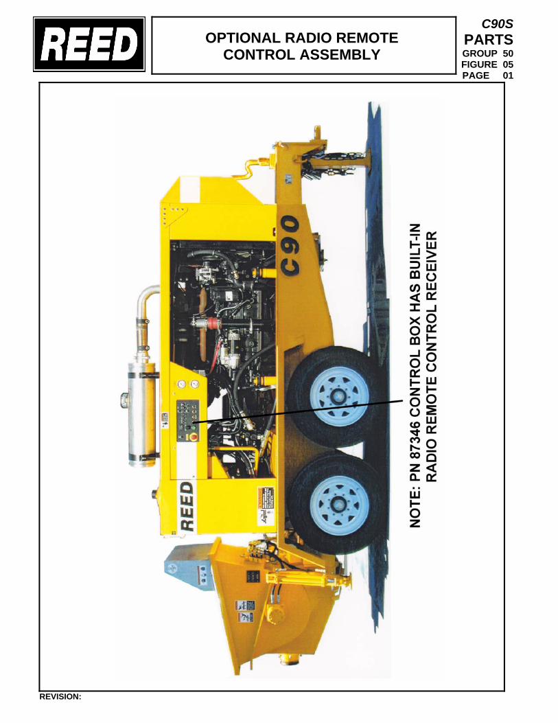
OPTIONAL RADIO REMOTE CONTROL ASSEMBLY
C90S PARTS GROUP 50 FIGURE 05 PAGE 01
REVISION:
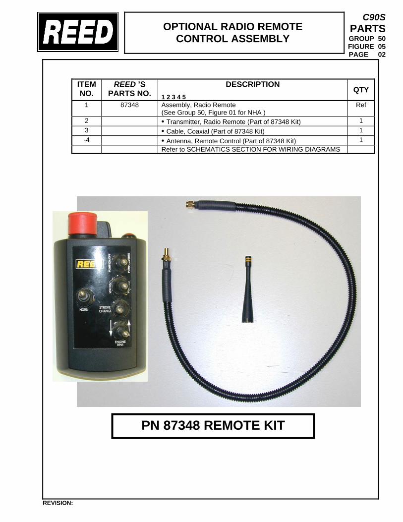
OPTIONAL RADIO REMOTE CONTROL ASSEMBLY
C90S PARTS GROUP 50 FIGURE 05 PAGE 02
ITEM NO.
REED ’S PARTS NO.
DESCRIPTION 1 2 3 4 5
QTY
1 87348 Assembly, Radio Remote (See Group 50, Figure 01 for NHA )
Ref
2 • Transmitter, Radio Remote (Part of 87348 Kit) 1 3 • Cable, Coaxial (Part of 87348 Kit) 1 -4 • Antenna, Remote Control (Part of 87348 Kit) 1 Refer to SCHEMATICS SECTION FOR WIRING DIAGRAMS
REVISION:
PN 87348 REMOTE KIT
TRAILER MOUNTED PUMP 01 MODEL C90S
GROUP 50 CONTROLS INSTALLATION
C90S PARTS GROUP 50 FIGURE 06 PAGE 01
REVISION:
THIS PAGE INTENTIONALLY LEFT BLANK.
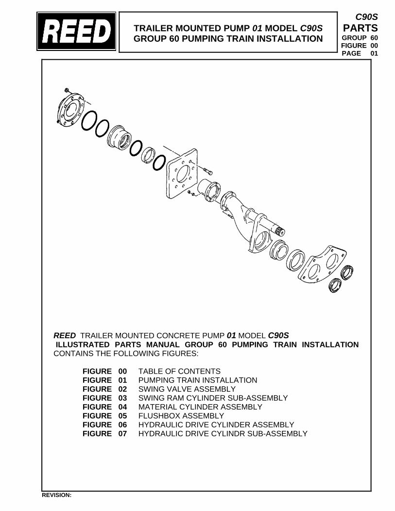
TRAILER MOUNTED PUMP 01 MODEL C90S GROUP 60 PUMPING TRAIN INSTALLATION
C90S PARTS GROUP 60 FIGURE 00 PAGE 01
REED TRAILER MOUNTED CONCRETE PUMP 01 MODEL C90S ILLUSTRATED PARTS MANUAL GROUP 60 PUMPING TRAIN INSTALLATION CONTAINS THE FOLLOWING FIGURES:
FIGURE 00 TABLE OF CONTENTS FIGURE 01 PUMPING TRAIN INSTALLATION FIGURE 02 SWING VALVE ASSEMBLY FIGURE 03 SWING RAM CYLINDER SUB-ASSEMBLY FIGURE 04 MATERIAL CYLINDER ASSEMBLY FIGURE 05 FLUSHBOX ASSEMBLY FIGURE 06 HYDRAULIC DRIVE CYLINDER ASSEMBLY FIGURE 07 HYDRAULIC DRIVE CYLINDR SUB-ASSEMBLY
REVISION:
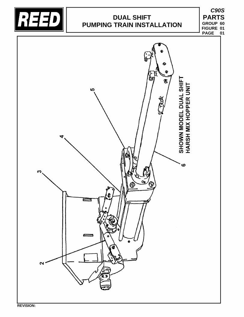
DUAL SHIFT
PUMPING TRAIN INSTALLATION
C90S PARTS GROUP 60 FIGURE 01 PAGE 01
REVISION:
DUAL SHIFT
PUMPING TRAIN INSTALLATION
C90S PARTS GROUP 60 FIGURE 01 PAGE 02
ITEM NO.
REED ’S PARTS NO.
DESCRIPTION 1 2 3 4 5
QTY
-1 60-01
Installation, Dual Shift Pumping Train (See Group 10, Figure 01 and Figure 04 for NHA)
Ref
2 60-03 • Assembly, Dual Shift Swing Valve (See Group 60, Figure 03 for DET)
1
3 20-02 • Installation, Harsh Mix Hopper (See Group 20, Figure 02 for REF)
Ref
4 86312 • Assembly, Material Cylinder (See Group 60, Figure 07 for DET)
1
5 86492 • gROUP, Flushbox (See Group 60, Figure 08 for DET)
1
6 87546 • Group, Hydraulic Drive Cylinder (See Group 60, Figure 09 for DET)
1
DASH (-) ITEM NOT ILLUSTRATED
REVISION:
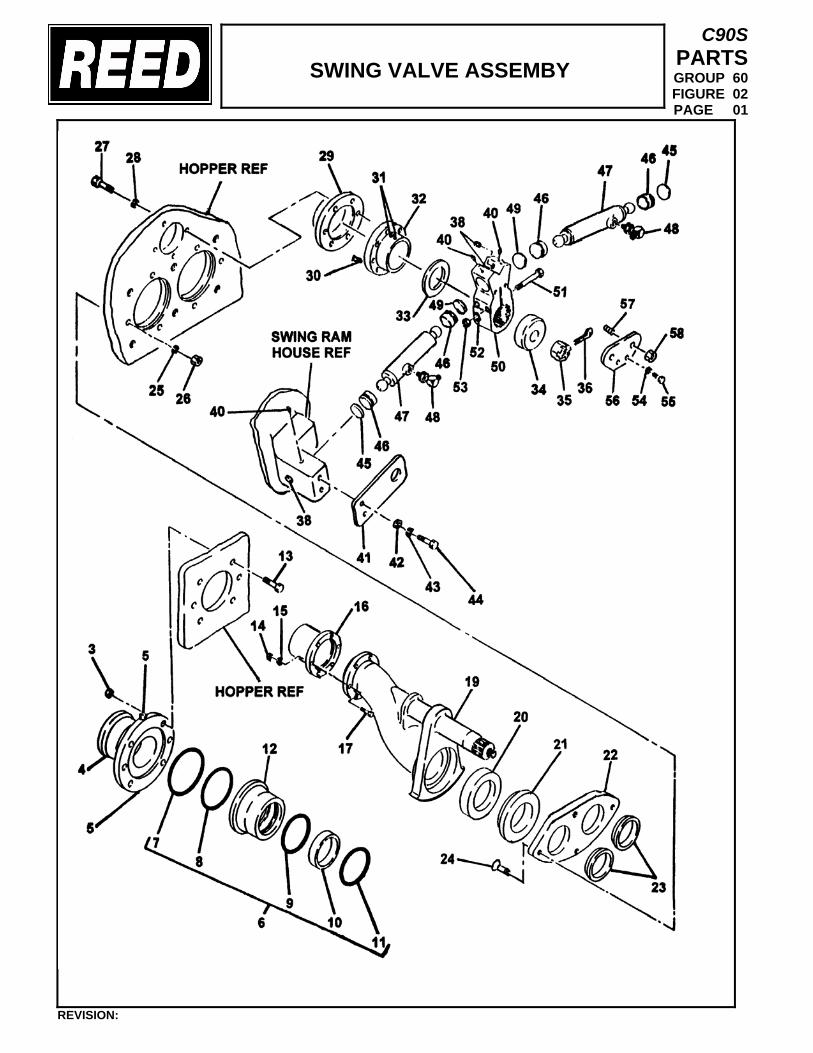
SWING VALVE ASSEMBY
C90S PARTS GROUP 60 FIGURE 02 PAGE 01
REVISION:
SWING VALVE ASSEMBLY
C90S PARTS GROUP 60 FIGURE 02 PAGE 02
REVISION:
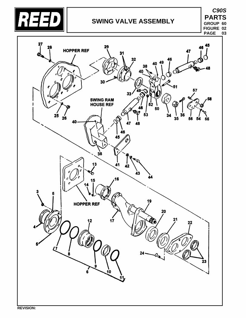
SWING VALVE ASSEMBLY
C90S PARTS GROUP 60 FIGURE 02 PAGE 03
REVISION:
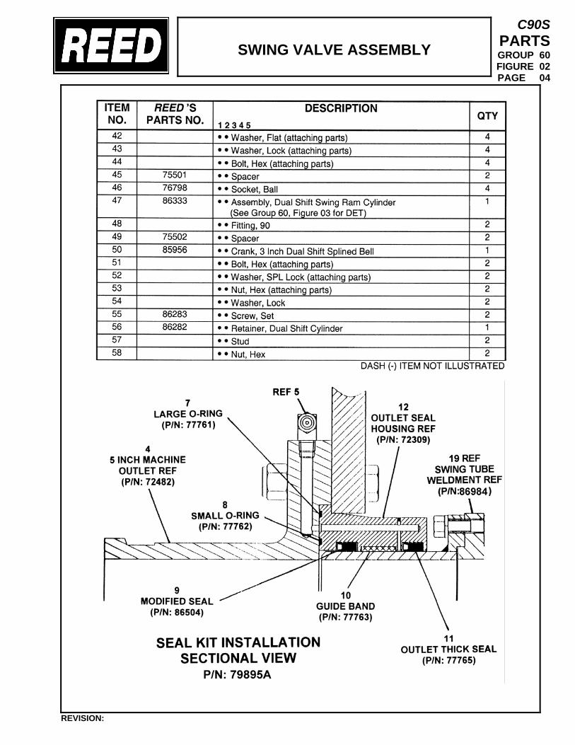
SWING VALVE ASSEMBLY
C90S PARTS GROUP 60 FIGURE 02 PAGE 04
REVISION:
miken
Text Box
87333a
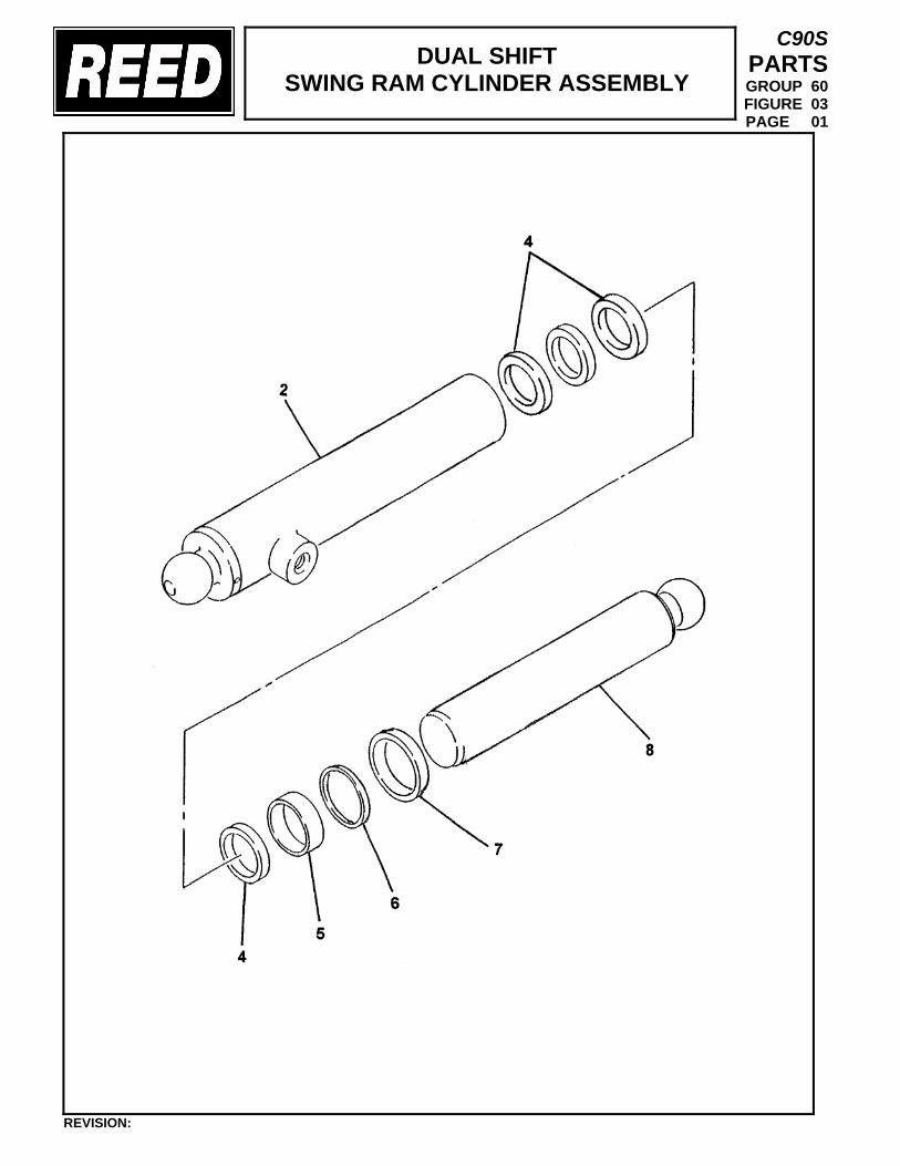
DUAL SHIFT SWING RAM CYLINDER ASSEMBLY
C90S PARTS GROUP 60 FIGURE 03 PAGE 01
REVISION:
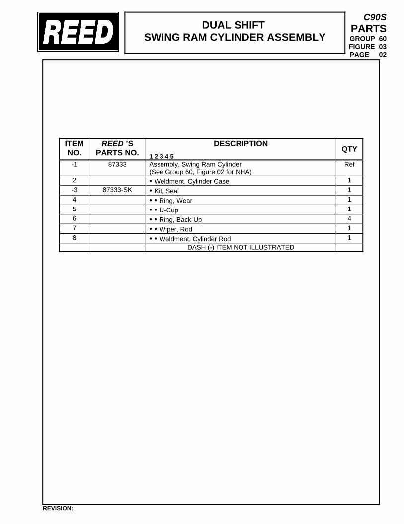
DUAL SHIFT SWING RAM CYLINDER ASSEMBLY
C90S PARTS GROUP 60 FIGURE 03 PAGE 02
ITEM NO.
REED ’S PARTS NO.
DESCRIPTION 1 2 3 4 5
QTY
-1 87333 Assembly, Swing Ram Cylinder (See Group 60, Figure 02 for NHA)
Ref
2 • Weldment, Cylinder Case 1 -3 87333-SK • Kit, Seal 1 4 • • Ring, Wear 1 5 • • U-Cup 1 6 • • Ring, Back-Up 4 7 • • Wiper, Rod 1 8 • • Weldment, Cylinder Rod 1 DASH (-) ITEM NOT ILLUSTRATED
REVISION:
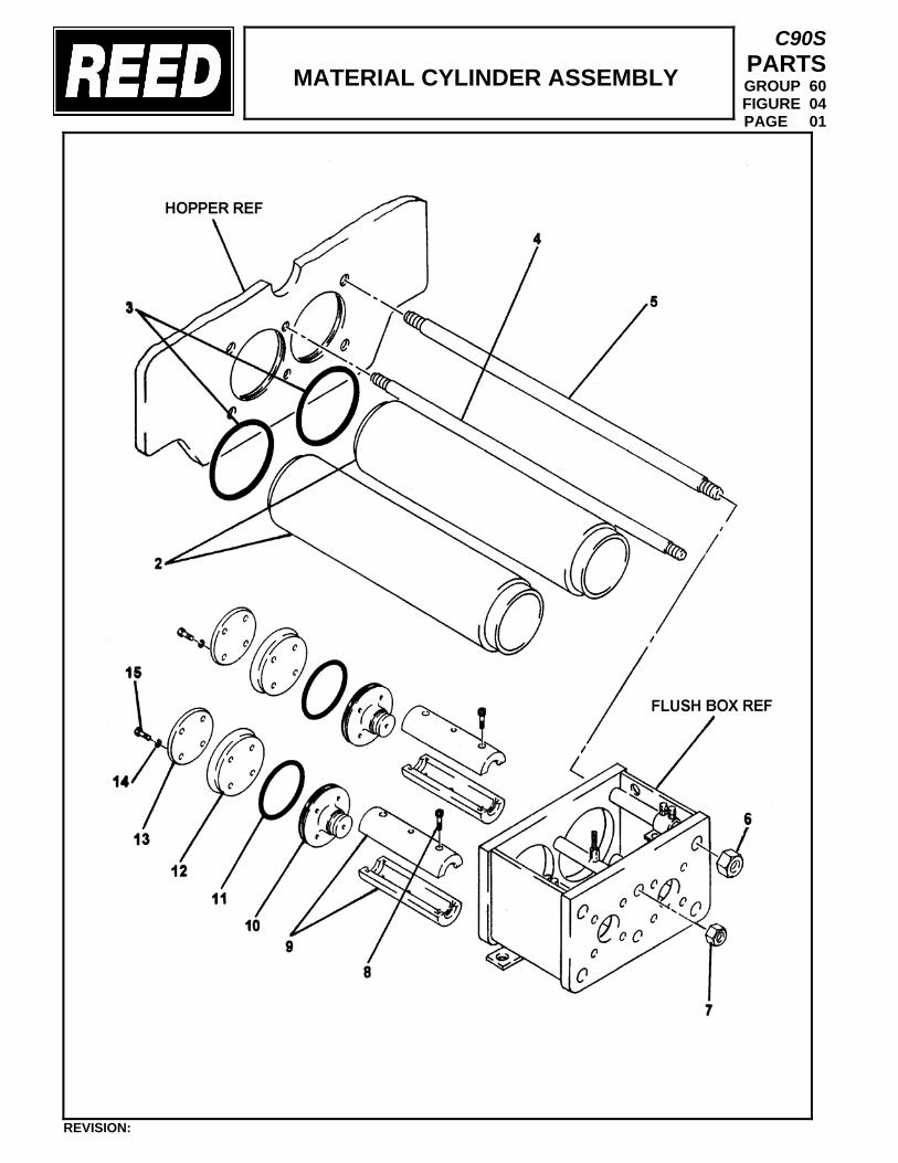
MATERIAL CYLINDER ASSEMBLY
C90S PARTS GROUP 60 FIGURE 04 PAGE 01
REVISION:
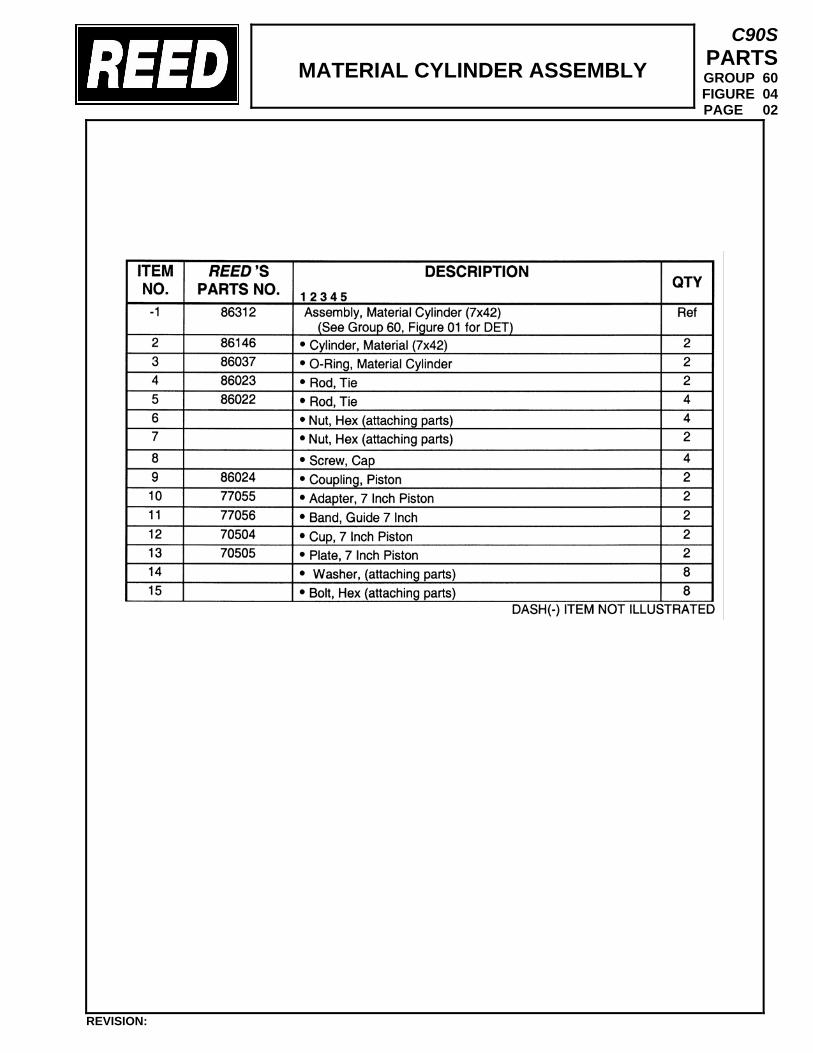
MATERIAL CYLINDER ASSEMBLY
C90S PARTS GROUP 60 FIGURE 04 PAGE 02
REVISION:
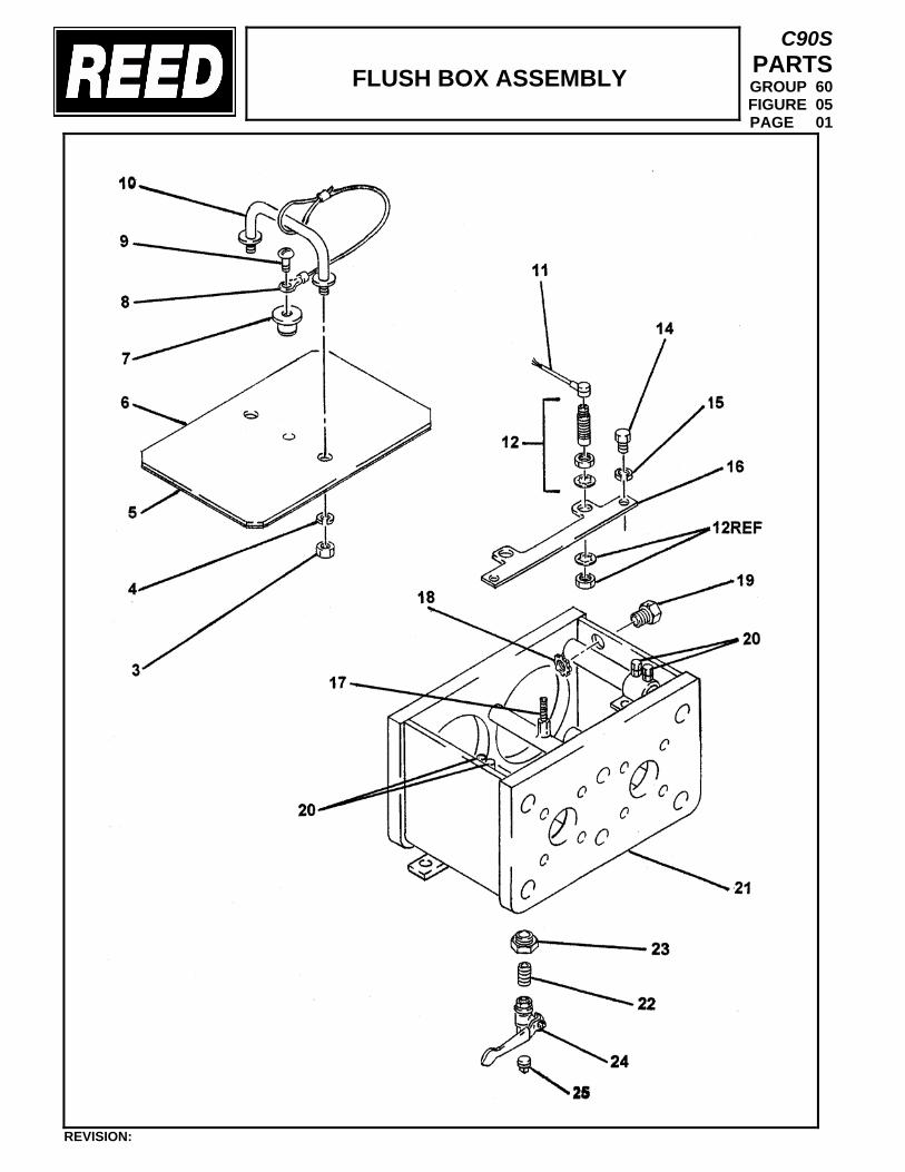
FLUSH BOX ASSEMBLY
C90S PARTS GROUP 60 FIGURE 05 PAGE 01
REVISION:
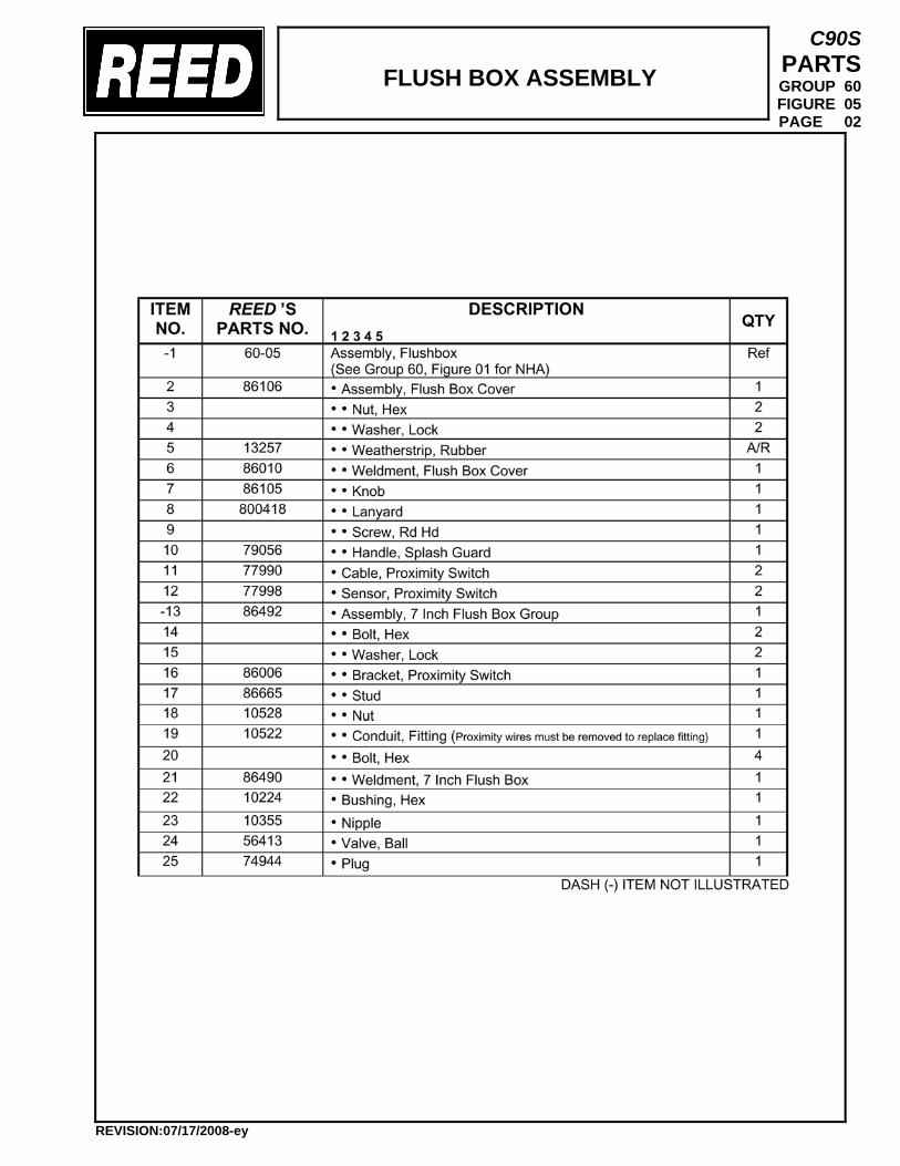
FLUSH BOX ASSEMBLY
C90S PARTS GROUP 60 FIGURE 05 PAGE 02
REVISION:07/17/2008-ey
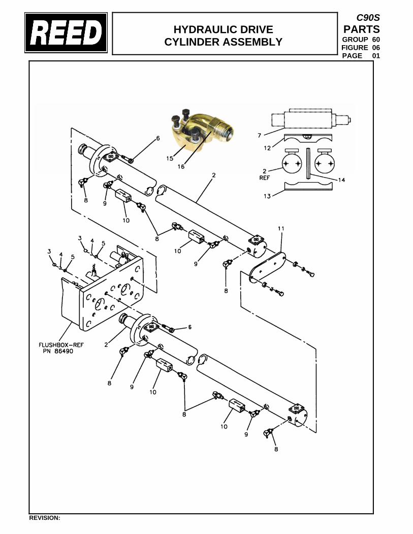
HYDRAULIC DRIVE
CYLINDER ASSEMBLY
C90S PARTS GROUP 60 FIGURE 06 PAGE 01
REVISION:
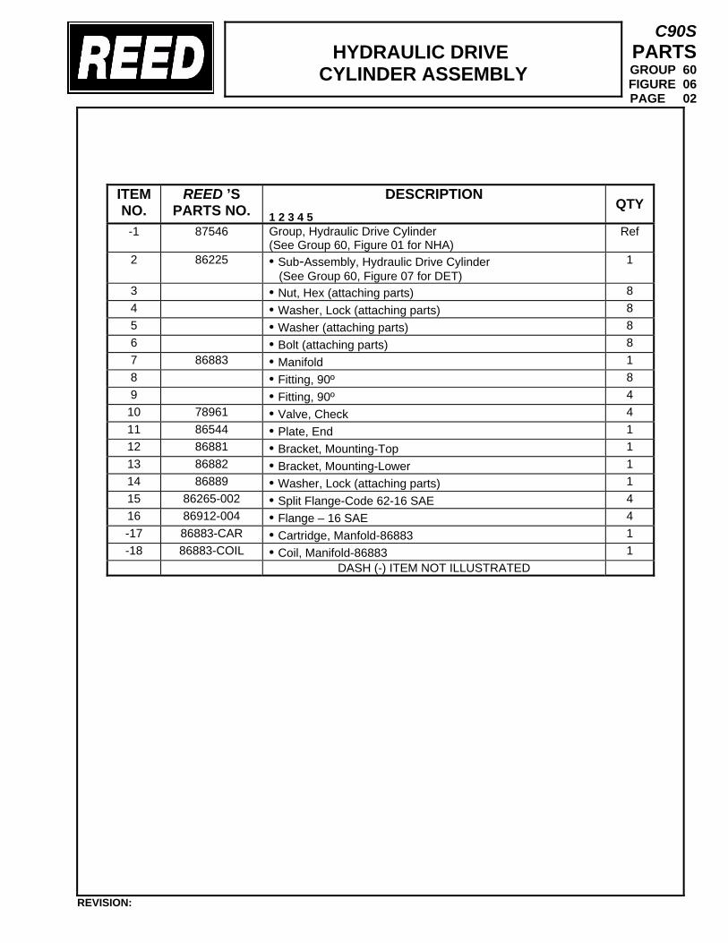
HYDRAULIC DRIVE
CYLINDER ASSEMBLY
C90S PARTS GROUP 60 FIGURE 06 PAGE 02
ITEM NO.
REED ’S PARTS NO.
DESCRIPTION 1 2 3 4 5
QTY
-1 87546
Group, Hydraulic Drive Cylinder (See Group 60, Figure 01 for NHA)
Ref
2 86225 • Sub-Assembly, Hydraulic Drive Cylinder (See Group 60, Figure 07 for DET)
1
3 • Nut, Hex (attaching parts) 8 4 • Washer, Lock (attaching parts) 8 5 • Washer (attaching parts) 8 6 • Bolt (attaching parts) 8 7 86883 • Manifold 1 8 • Fitting, 90º 8 9 • Fitting, 90º 4 10 78961 • Valve, Check 4 11 86544 • Plate, End 1 12 86881 • Bracket, Mounting-Top 1 13 86882 • Bracket, Mounting-Lower 1 14 86889 • Washer, Lock (attaching parts) 1 15 86265-002 • Split Flange-Code 62-16 SAE 4 16 86912-004 • Flange – 16 SAE 4 -17 86883-CAR • Cartridge, Manfold-86883 1 -18 86883-COIL • Coil, Manifold-86883 1
DASH (-) ITEM NOT ILLUSTRATED
REVISION:
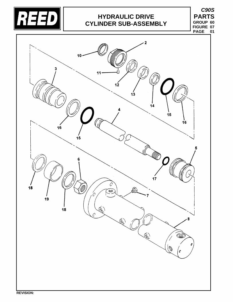
HYDRAULIC DRIVE
CYLINDER SUB-ASSEMBLY
C90S PARTS GROUP 60 FIGURE 07 PAGE 01
REVISION:
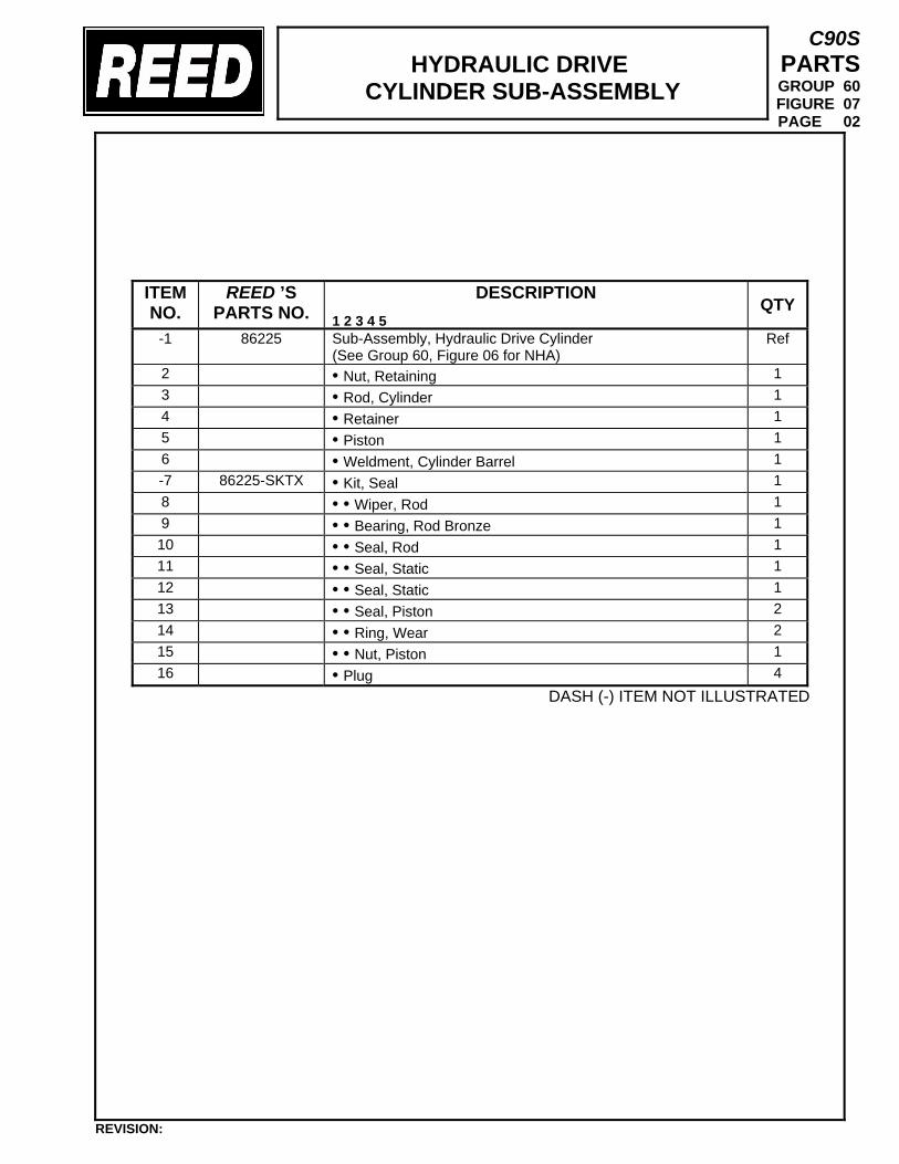
HYDRAULIC DRIVE
CYLINDER SUB-ASSEMBLY
C90S PARTS GROUP 60 FIGURE 07 PAGE 02
DASH (-) ITEM NOT ILLUSTRATED
ITEM NO.
REED ’S PARTS NO.
DESCRIPTION 1 2 3 4 5
QTY
-1 86225 Sub-Assembly, Hydraulic Drive Cylinder (See Group 60, Figure 06 for NHA)
Ref
2 • Nut, Retaining 1 3 • Rod, Cylinder 1 4 • Retainer 1 5 • Piston 1 6 • Weldment, Cylinder Barrel 1 -7 86225-SKTX • Kit, Seal 1 8 • • Wiper, Rod 1 9 • • Bearing, Rod Bronze 1 10 • • Seal, Rod 1 11 • • Seal, Static 1 12 • • Seal, Static 1 13 • • Seal, Piston 2 14 • • Ring, Wear 2 15 • • Nut, Piston 1 16 • Plug 4
REVISION:

TRAILER MOUNTED PUMP 01 MODEL C90S ILLUSTRATED PARTS MANUAL
C90S PARTS GROUP 60 FIGURE 08 PAGE 01
REVISION:
THIS PAGE INTENTIONALLY LEFT BLANK.
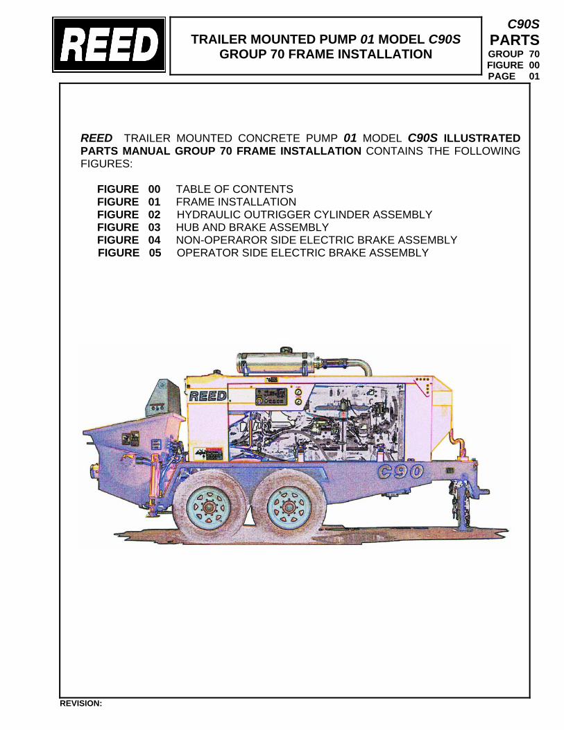
TRAILER MOUNTED PUMP 01 MODEL C90S
GROUP 70 FRAME INSTALLATION
C90S PARTS GROUP 70 FIGURE 00 PAGE 01
REED TRAILER MOUNTED CONCRETE PUMP 01 MODEL C90S ILLUSTRATED PARTS MANUAL GROUP 70 FRAME INSTALLATION CONTAINS THE FOLLOWING FIGURES:
FIGURE 00 TABLE OF CONTENTS FIGURE 01 FRAME INSTALLATION FIGURE 02 HYDRAULIC OUTRIGGER CYLINDER ASSEMBLY FIGURE 03 HUB AND BRAKE ASSEMBLY FIGURE 04 NON-OPERAROR SIDE ELECTRIC BRAKE ASSEMBLY
FIGURE 05 OPERATOR SIDE ELECTRIC BRAKE ASSEMBLY
REVISION:
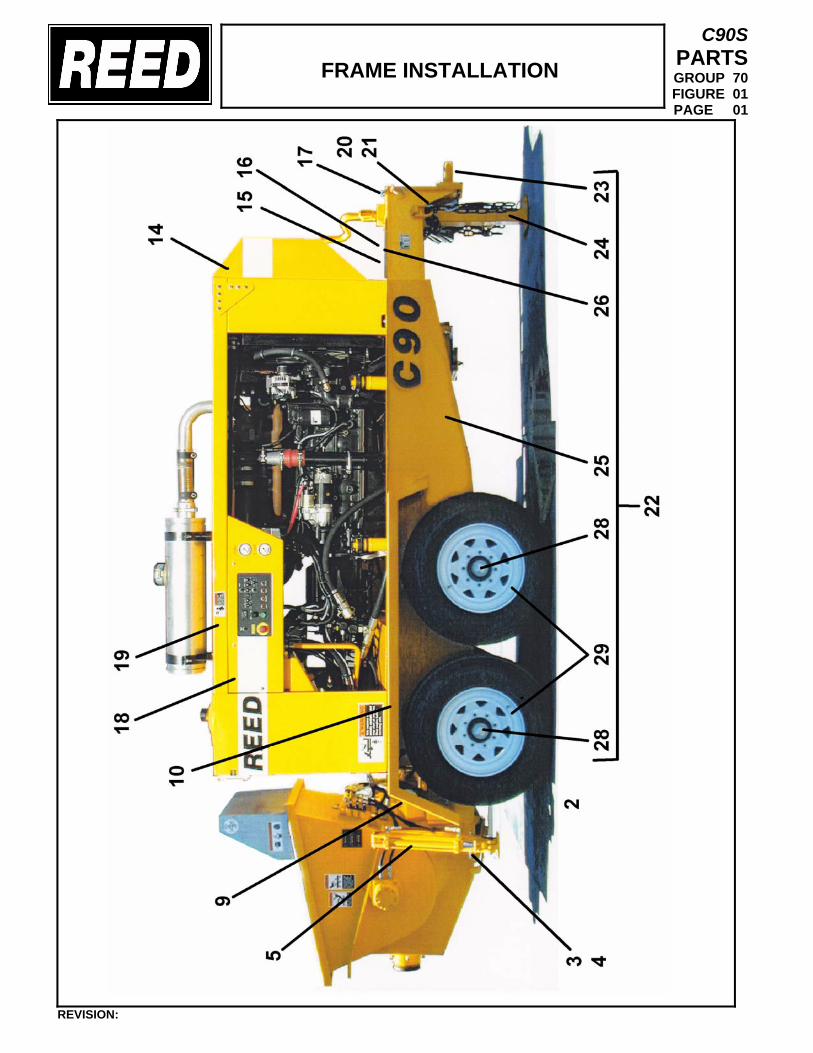
FRAME INSTALLATION
C90S PARTS GROUP 70 FIGURE 01 PAGE 01
REVISION:
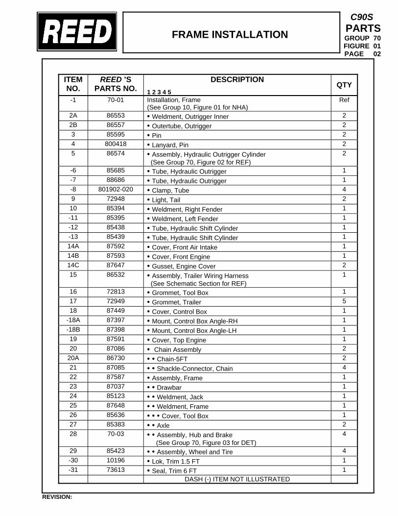
FRAME INSTALLATION
C90S PARTS GROUP 70 FIGURE 01 PAGE 02
ITEM NO.
REED ’S PARTS NO.
DESCRIPTION 1 2 3 4 5
QTY
-1 70-01 Installation, Frame (See Group 10, Figure 01 for NHA)
Ref
2A 86553 • Weldment, Outrigger Inner 2 2B 86557 • Outertube, Outrigger 2 3 85595 • Pin 2 4 800418 • Lanyard, Pin 2 5 86574 • Assembly, Hydraulic Outrigger Cylinder
(See Group 70, Figure 02 for REF) 2
-6 85685 • Tube, Hydraulic Outrigger 1 -7 88686 • Tube, Hydraulic Outrigger 1 -8 801902-020 • Clamp, Tube 4 9 72948 • Light, Tail 2 10 85394 • Weldment, Right Fender 1 -11 85395 • Weldment, Left Fender 1 -12 85438 • Tube, Hydraulic Shift Cylinder 1 -13 85439 • Tube, Hydraulic Shift Cylinder 1 14A 87592 • Cover, Front Air Intake 1 14B 87593 • Cover, Front Engine 1 14C 87647 • Gusset, Engine Cover 2 15 86532 • Assembly, Trailer Wiring Harness
(See Schematic Section for REF) 1
16 72813 • Grommet, Tool Box 1 17 72949 • Grommet, Trailer 5 18 87449 • Cover, Control Box 1
-18A 87397 • Mount, Control Box Angle-RH 1 -18B 87398 • Mount, Control Box Angle-LH 1 19 87591 • Cover, Top Engine 1 20 87086 • Chain Assembly 2
20A 86730 • • Chain-5FT 2 21 87085 • • Shackle-Connector, Chain 4 22 87587 • Assembly, Frame 1 23 87037 • • Drawbar 1 24 85123 • • Weldment, Jack 1 25 87648 • • Weldment, Frame 1 26 85636 • • • Cover, Tool Box 1 27 85383 • • Axle 2 28 70-03 • • Assembly, Hub and Brake
(See Group 70, Figure 03 for DET) 4
29 85423 • • Assembly, Wheel and Tire 4 -30 10196 • Lok, Trim 1.5 FT 1 -31 73613 • Seal, Trim 6 FT 1
DASH (-) ITEM NOT ILLUSTRATED
REVISION:
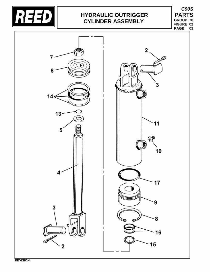
HYDRAULIC OUTRIGGER CYLINDER ASSEMBLY
C90S PARTS GROUP 70 FIGURE 02 PAGE 01
REVISION:
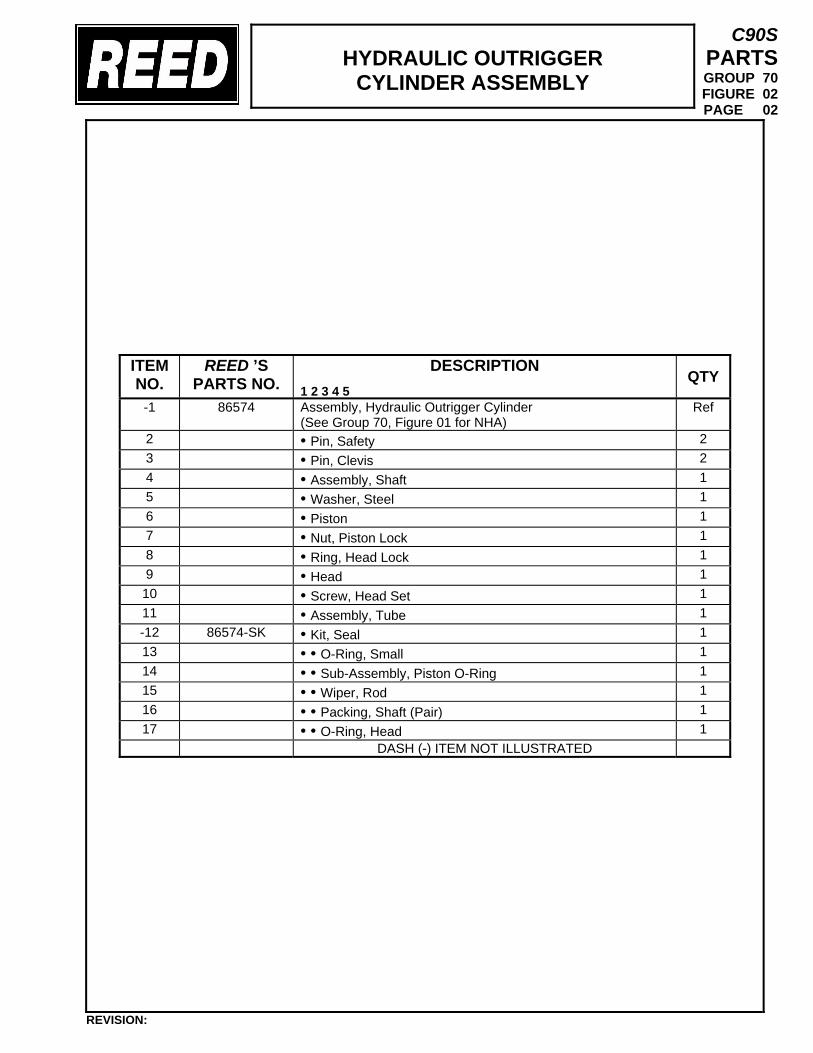
HYDRAULIC OUTRIGGER
CYLINDER ASSEMBLY
C90S PARTS GROUP 70 FIGURE 02 PAGE 02
ITEM NO.
REED ’S PARTS NO.
DESCRIPTION 1 2 3 4 5
QTY
-1 86574 Assembly, Hydraulic Outrigger Cylinder (See Group 70, Figure 01 for NHA)
Ref
2 • Pin, Safety 2 3 • Pin, Clevis 2 4 • Assembly, Shaft 1 5 • Washer, Steel 1 6 • Piston 1 7 • Nut, Piston Lock 1 8 • Ring, Head Lock 1 9 • Head 1 10 • Screw, Head Set 1 11 • Assembly, Tube 1 -12 86574-SK • Kit, Seal 1 13 • • O-Ring, Small 1 14 • • Sub-Assembly, Piston O-Ring 1 15 • • Wiper, Rod 1 16 • • Packing, Shaft (Pair) 1 17 • • O-Ring, Head 1
DASH (-) ITEM NOT ILLUSTRATED
REVISION:
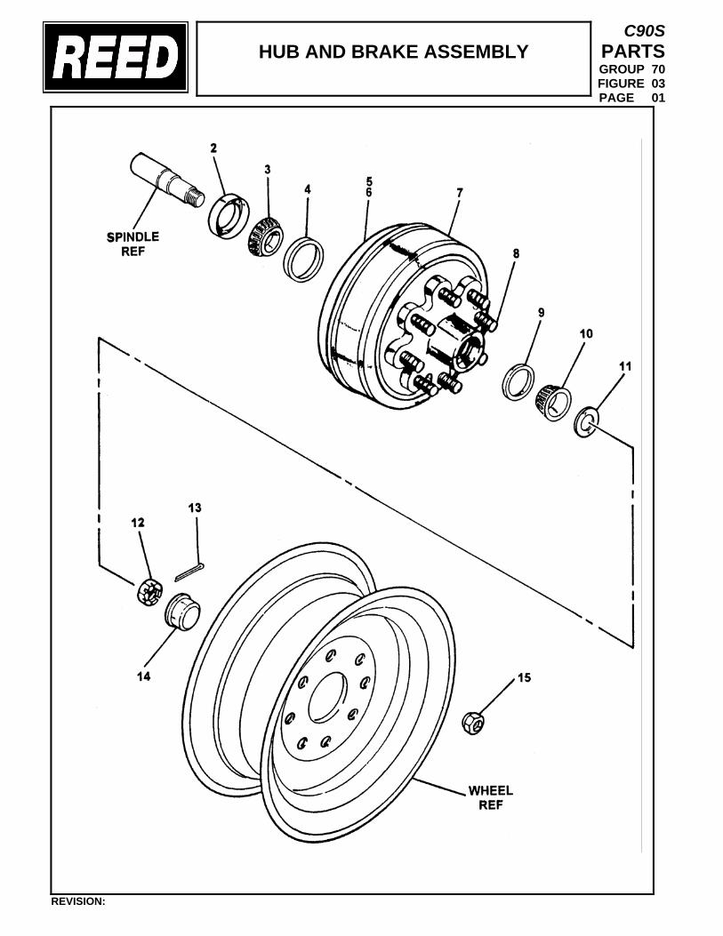
HUB AND BRAKE ASSEMBLY
C90S PARTS GROUP 70 FIGURE 03 PAGE 01
REVISION:
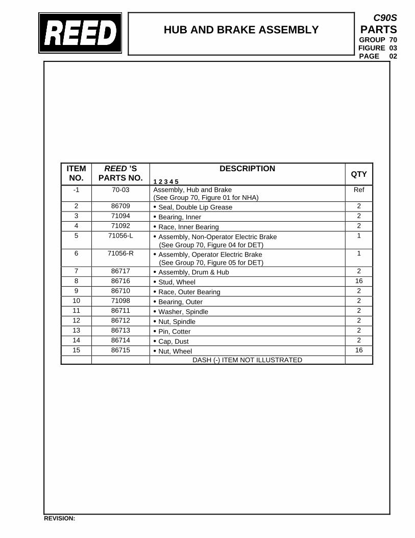
HUB AND BRAKE ASSEMBLY
C90S PARTS GROUP 70 FIGURE 03 PAGE 02
ITEM NO.
REED ’S PARTS NO.
DESCRIPTION 1 2 3 4 5
QTY
-1 70-03
Assembly, Hub and Brake (See Group 70, Figure 01 for NHA)
Ref
2 86709 • Seal, Double Lip Grease 2 3 71094 • Bearing, Inner 2 4 71092 • Race, Inner Bearing 2 5 71056-L • Assembly, Non-Operator Electric Brake
(See Group 70, Figure 04 for DET) 1
6 71056-R • Assembly, Operator Electric Brake (See Group 70, Figure 05 for DET)
1
7 86717 • Assembly, Drum & Hub 2 8 86716 • Stud, Wheel 16 9 86710 • Race, Outer Bearing 2 10 71098 • Bearing, Outer 2 11 86711 • Washer, Spindle 2 12 86712 • Nut, Spindle 2 13 86713 • Pin, Cotter 2 14 86714 • Cap, Dust 2 15 86715 • Nut, Wheel 16
DASH (-) ITEM NOT ILLUSTRATED
REVISION:
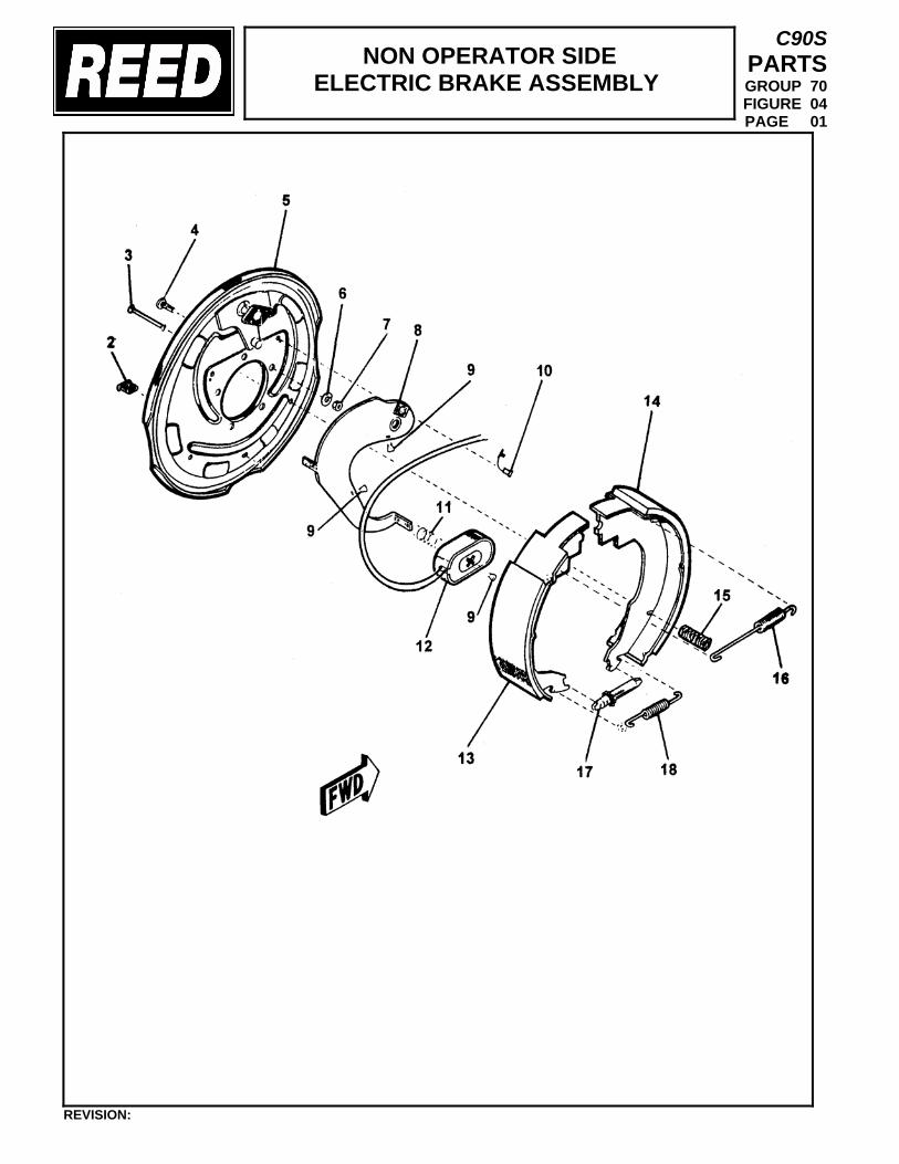
NON OPERATOR SIDE ELECTRIC BRAKE ASSEMBLY
C90S PARTS GROUP 70 FIGURE 04 PAGE 01
REVISION:
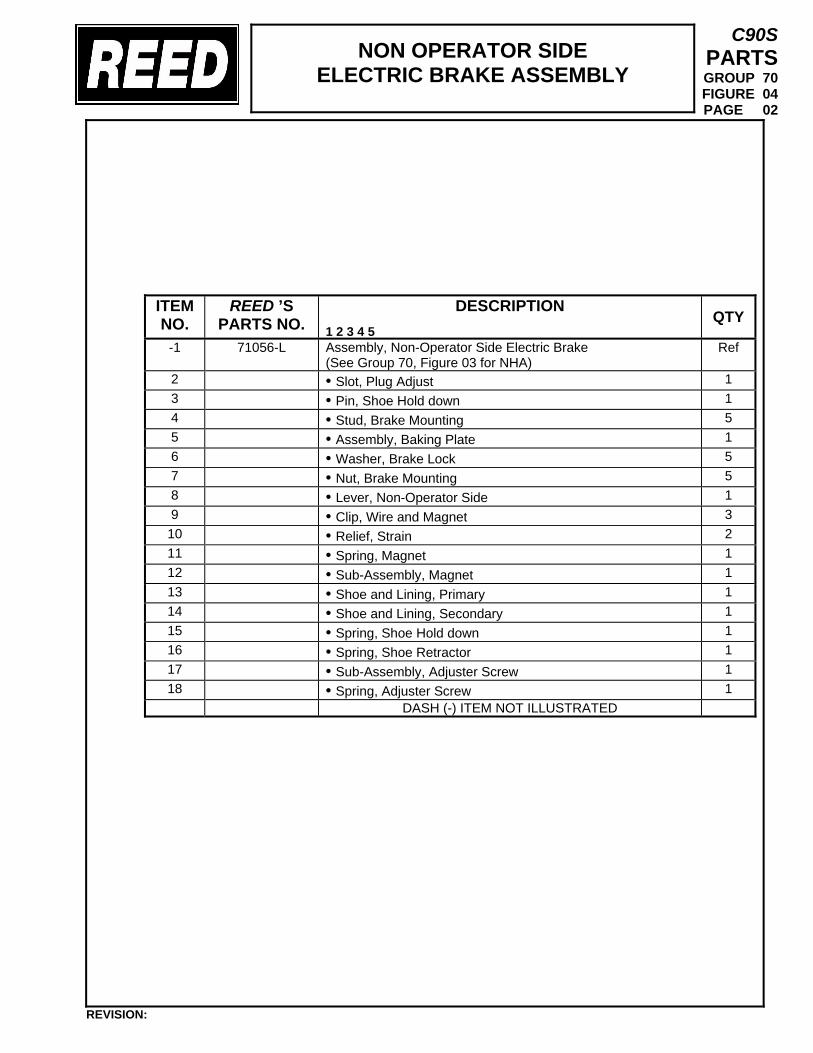
NON OPERATOR SIDE ELECTRIC BRAKE ASSEMBLY
C90S PARTS GROUP 70 FIGURE 04 PAGE 02
ITEM NO.
REED ’S PARTS NO.
DESCRIPTION 1 2 3 4 5
QTY
-1 71056-L
Assembly, Non-Operator Side Electric Brake (See Group 70, Figure 03 for NHA)
Ref
2 • Slot, Plug Adjust 1 3 • Pin, Shoe Hold down 1 4 • Stud, Brake Mounting 5 5 • Assembly, Baking Plate 1 6 • Washer, Brake Lock 5 7 • Nut, Brake Mounting 5 8 • Lever, Non-Operator Side 1 9 • Clip, Wire and Magnet 3 10 • Relief, Strain 2 11 • Spring, Magnet 1 12 • Sub-Assembly, Magnet 1 13 • Shoe and Lining, Primary 1 14 • Shoe and Lining, Secondary 1 15 • Spring, Shoe Hold down 1 16 • Spring, Shoe Retractor 1 17 • Sub-Assembly, Adjuster Screw 1 18 • Spring, Adjuster Screw 1
DASH (-) ITEM NOT ILLUSTRATED
REVISION:
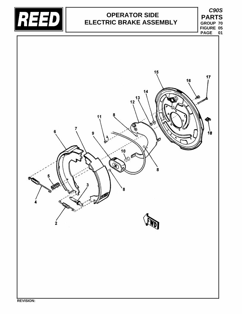
OPERATOR SIDE ELECTRIC BRAKE ASSEMBLY
C90S PARTS GROUP 70 FIGURE 05 PAGE 01
REVISION:
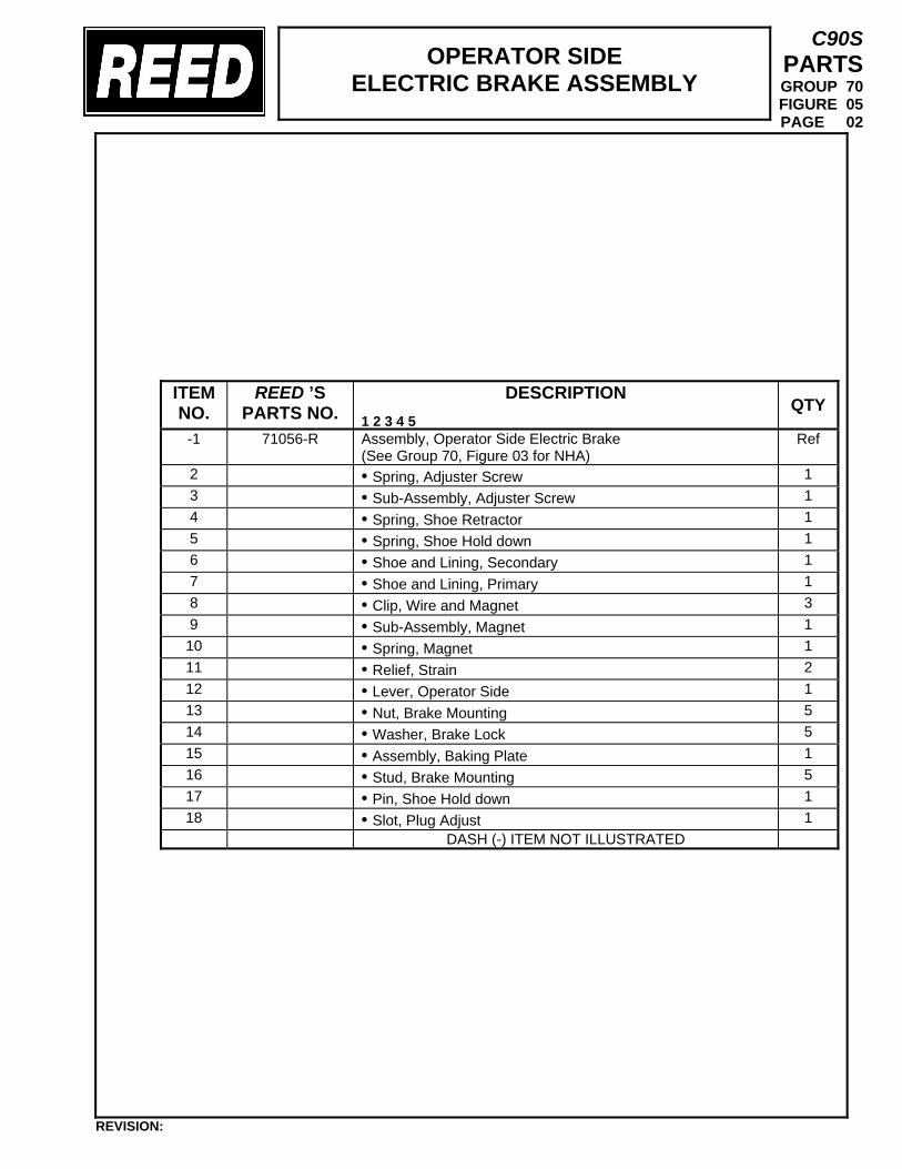
OPERATOR SIDE ELECTRIC BRAKE ASSEMBLY
C90S PARTS GROUP 70 FIGURE 05 PAGE 02
ITEM NO.
REED ’S PARTS NO.
DESCRIPTION 1 2 3 4 5
QTY
-1 71056-R
Assembly, Operator Side Electric Brake (See Group 70, Figure 03 for NHA)
Ref
2 • Spring, Adjuster Screw 1 3 • Sub-Assembly, Adjuster Screw 1 4 • Spring, Shoe Retractor 1 5 • Spring, Shoe Hold down 1 6 • Shoe and Lining, Secondary 1 7 • Shoe and Lining, Primary 1 8 • Clip, Wire and Magnet 3 9 • Sub-Assembly, Magnet 1 10 • Spring, Magnet 1 11 • Relief, Strain 2 12 • Lever, Operator Side 1 13 • Nut, Brake Mounting 5 14 • Washer, Brake Lock 5 15 • Assembly, Baking Plate 1 16 • Stud, Brake Mounting 5 17 • Pin, Shoe Hold down 1 18 • Slot, Plug Adjust 1
DASH (-) ITEM NOT ILLUSTRATED
REVISION:
TRAILER MOUNTED PUMP 01 MODEL C90S GROUP 70 FRAME INSTALLATION
C90S PARTS GROUP 70 FIGURE 06 PAGE 01
THIS PAGE INTENTIONALLY LEFT BLANK.
REVISION:
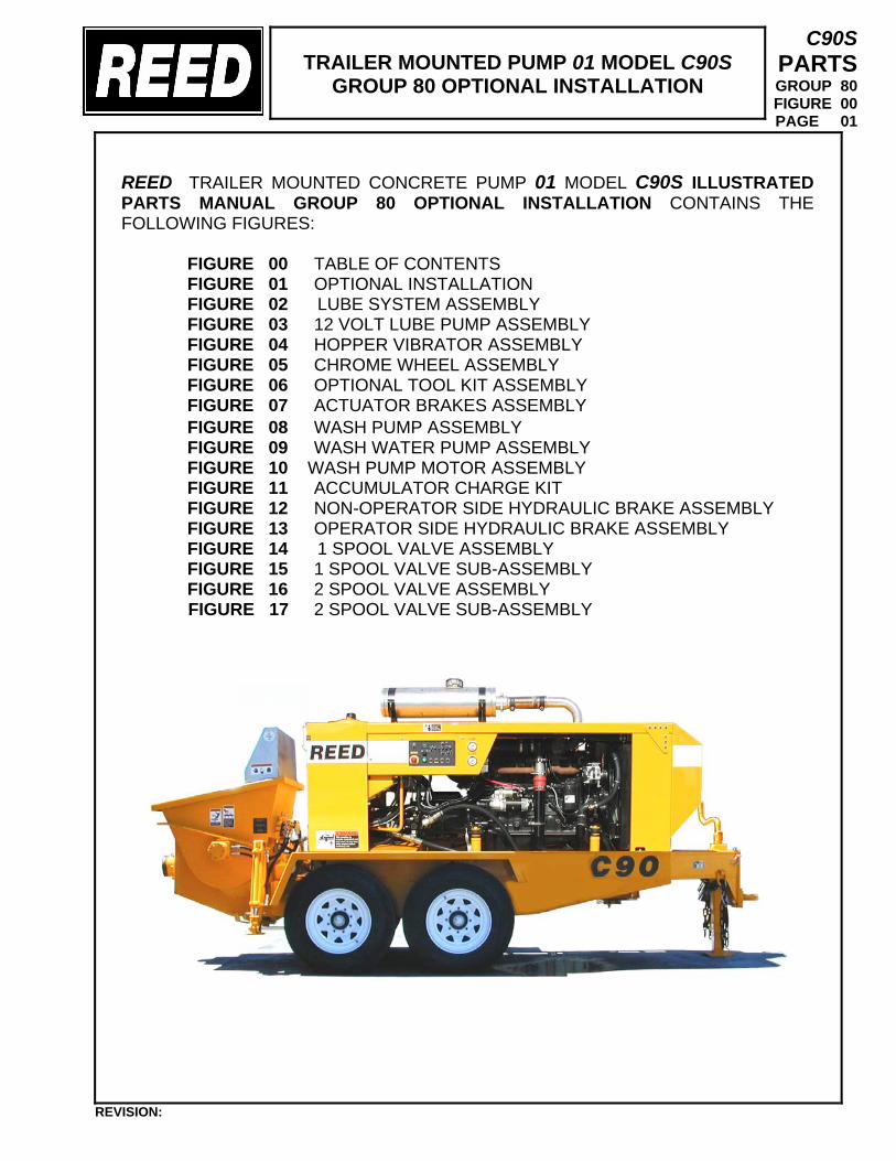
TRAILER MOUNTED PUMP 01 MODEL C90S
GROUP 80 OPTIONAL INSTALLATION
C90S PARTS GROUP 80 FIGURE 00 PAGE 01
REED TRAILER MOUNTED CONCRETE PUMP 01 MODEL C90S ILLUSTRATED PARTS MANUAL GROUP 80 OPTIONAL INSTALLATION CONTAINS THE FOLLOWING FIGURES:
FIGURE 00 TABLE OF CONTENTS FIGURE 01 OPTIONAL INSTALLATION FIGURE 02 LUBE SYSTEM ASSEMBLY FIGURE 03 12 VOLT LUBE PUMP ASSEMBLY FIGURE 04 HOPPER VIBRATOR ASSEMBLY FIGURE 05 CHROME WHEEL ASSEMBLY FIGURE 06 OPTIONAL TOOL KIT ASSEMBLY FIGURE 07 ACTUATOR BRAKES ASSEMBLY
FIGURE 08 WASH PUMP ASSEMBLY FIGURE 09 WASH WATER PUMP ASSEMBLY FIGURE 10 WASH PUMP MOTOR ASSEMBLY FIGURE 11 ACCUMULATOR CHARGE KIT FIGURE 12 NON-OPERATOR SIDE HYDRAULIC BRAKE ASSEMBLY FIGURE 13 OPERATOR SIDE HYDRAULIC BRAKE ASSEMBLY FIGURE 14 1 SPOOL VALVE ASSEMBLY FIGURE 15 1 SPOOL VALVE SUB-ASSEMBLY FIGURE 16 2 SPOOL VALVE ASSEMBLY
FIGURE 17 2 SPOOL VALVE SUB-ASSEMBLY
REVISION:
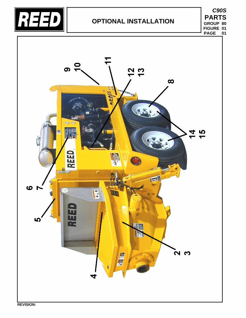
OPTIONAL INSTALLATION
C90S PARTS GROUP 80 FIGURE 01 PAGE 01
REVISION:
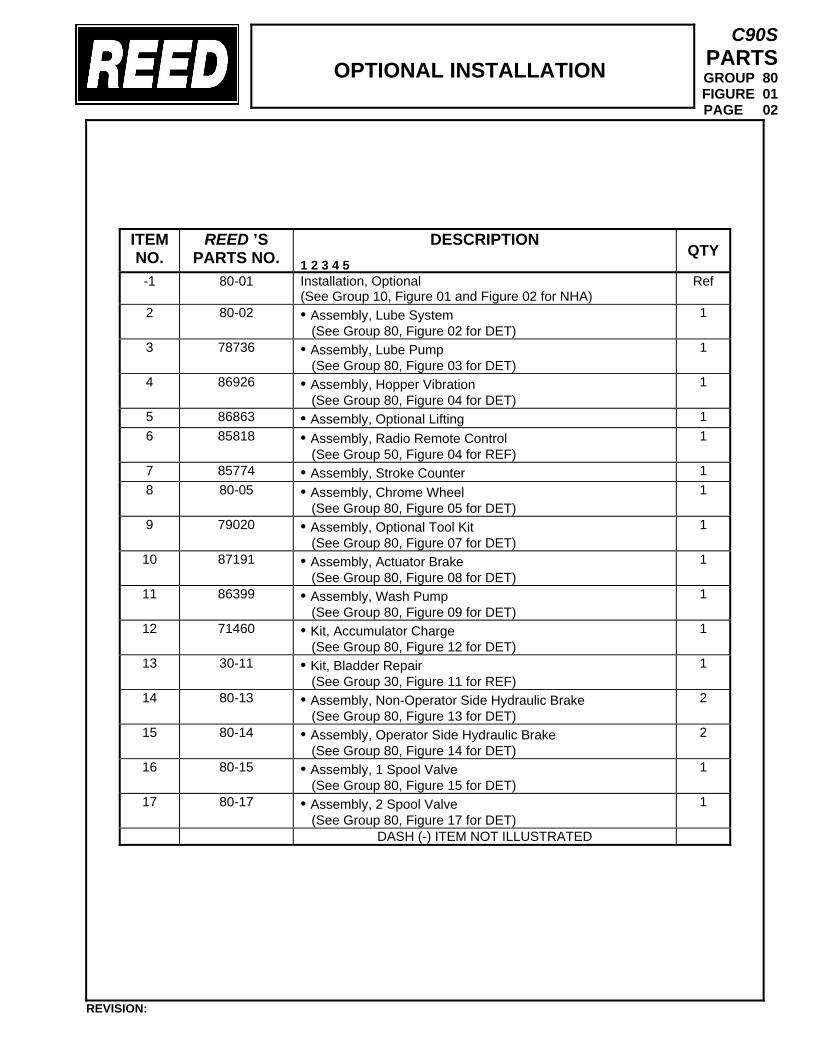
OPTIONAL INSTALLATION
C90S PARTS GROUP 80 FIGURE 01 PAGE 02
ITEM NO.
REED ’S PARTS NO.
DESCRIPTION 1 2 3 4 5
QTY
-1 80-01
Installation, Optional (See Group 10, Figure 01 and Figure 02 for NHA)
Ref
2 80-02 • Assembly, Lube System (See Group 80, Figure 02 for DET)
1
3 78736 • Assembly, Lube Pump (See Group 80, Figure 03 for DET)
1
4 86926 • Assembly, Hopper Vibration (See Group 80, Figure 04 for DET)
1
5 86863 • Assembly, Optional Lifting 1 6 85818 • Assembly, Radio Remote Control
(See Group 50, Figure 04 for REF) 1
7 85774 • Assembly, Stroke Counter 1 8 80-05 • Assembly, Chrome Wheel
(See Group 80, Figure 05 for DET) 1
9 79020 • Assembly, Optional Tool Kit (See Group 80, Figure 07 for DET)
1
10 87191 • Assembly, Actuator Brake (See Group 80, Figure 08 for DET)
1
11 86399 • Assembly, Wash Pump (See Group 80, Figure 09 for DET)
1
12 71460 • Kit, Accumulator Charge (See Group 80, Figure 12 for DET)
1
13 30-11 • Kit, Bladder Repair (See Group 30, Figure 11 for REF)
1
14 80-13 • Assembly, Non-Operator Side Hydraulic Brake (See Group 80, Figure 13 for DET)
2
15 80-14 • Assembly, Operator Side Hydraulic Brake (See Group 80, Figure 14 for DET)
2
16 80-15 • Assembly, 1 Spool Valve (See Group 80, Figure 15 for DET)
1
17 80-17 • Assembly, 2 Spool Valve (See Group 80, Figure 17 for DET)
1
DASH (-) ITEM NOT ILLUSTRATED
REVISION:
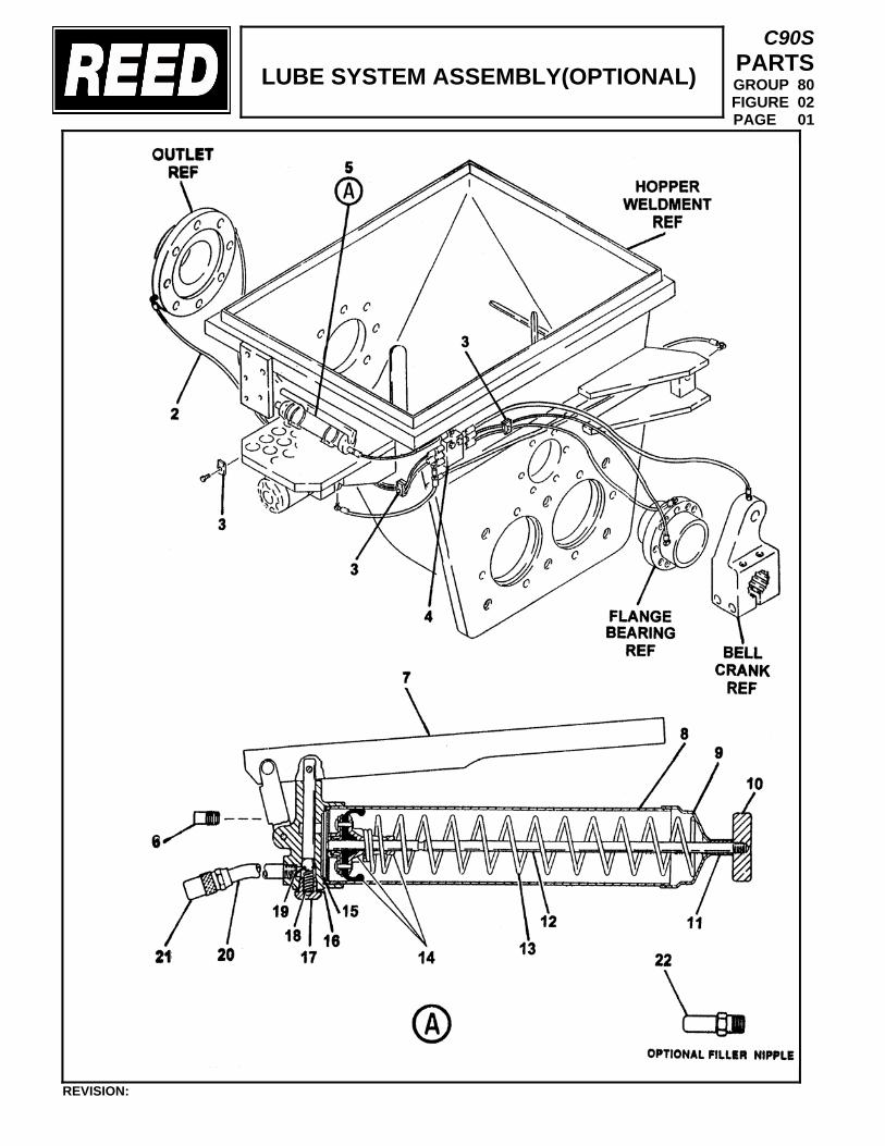
LUBE SYSTEM ASSEMBLY(OPTIONAL)
C90S PARTS GROUP 80 FIGURE 02 PAGE 01
REVISION:
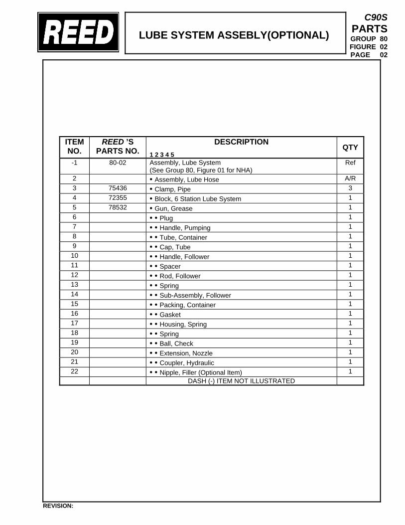
LUBE SYSTEM ASSEBLY(OPTIONAL)
C90S PARTS GROUP 80 FIGURE 02 PAGE 02
ITEM NO.
REED ’S PARTS NO.
DESCRIPTION 1 2 3 4 5
QTY
-1 80-02
Assembly, Lube System (See Group 80, Figure 01 for NHA)
Ref
2 • Assembly, Lube Hose A/R 3 75436 • Clamp, Pipe 3 4 72355 • Block, 6 Station Lube System 1 5 78532 • Gun, Grease 1 6 • • Plug 1 7 • • Handle, Pumping 1 8 • • Tube, Container 1 9 • • Cap, Tube 1 10 • • Handle, Follower 1 11 • • Spacer 1 12 • • Rod, Follower 1 13 • • Spring 1 14 • • Sub-Assembly, Follower 1 15 • • Packing, Container 1 16 • • Gasket 1 17 • • Housing, Spring 1 18 • • Spring 1 19 • • Ball, Check 1 20 • • Extension, Nozzle 1 21 • • Coupler, Hydraulic 1 22 • • Nipple, Filler (Optional Item) 1
DASH (-) ITEM NOT ILLUSTRATED
REVISION:
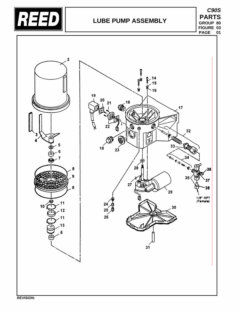
LUBE PUMP ASSEMBLY
C90S PARTS GROUP 80 FIGURE 03 PAGE 01
REVISION:
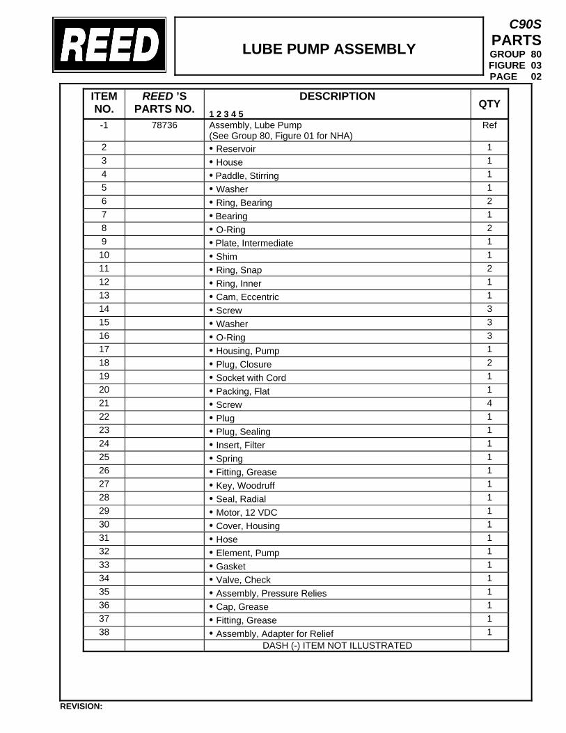
LUBE PUMP ASSEMBLY
C90S PARTS GROUP 80 FIGURE 03 PAGE 02
ITEM NO.
REED ’S PARTS NO.
DESCRIPTION 1 2 3 4 5
QTY
-1 78736
Assembly, Lube Pump (See Group 80, Figure 01 for NHA)
Ref
2 • Reservoir 1 3 • House 1 4 • Paddle, Stirring 1 5 • Washer 1 6 • Ring, Bearing 2 7 • Bearing 1 8 • O-Ring 2 9 • Plate, Intermediate 1 10 • Shim 1 11 • Ring, Snap 2 12 • Ring, Inner 1 13 • Cam, Eccentric 1 14 • Screw 3 15 • Washer 3 16 • O-Ring 3 17 • Housing, Pump 1 18 • Plug, Closure 2 19 • Socket with Cord 1 20 • Packing, Flat 1 21 • Screw 4 22 • Plug 1 23 • Plug, Sealing 1 24 • Insert, Filter 1 25 • Spring 1 26 • Fitting, Grease 1 27 • Key, Woodruff 1 28 • Seal, Radial 1 29 • Motor, 12 VDC 1 30 • Cover, Housing 1 31 • Hose 1 32 • Element, Pump 1 33 • Gasket 1 34 • Valve, Check 1 35 • Assembly, Pressure Relies 1 36 • Cap, Grease 1 37 • Fitting, Grease 1 38 • Assembly, Adapter for Relief 1
DASH (-) ITEM NOT ILLUSTRATED
REVISION:
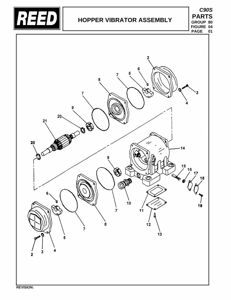
HOPPER VIBRATOR ASSEMBLY
C90S PARTS GROUP 80 FIGURE 04 PAGE 01
REVISION:
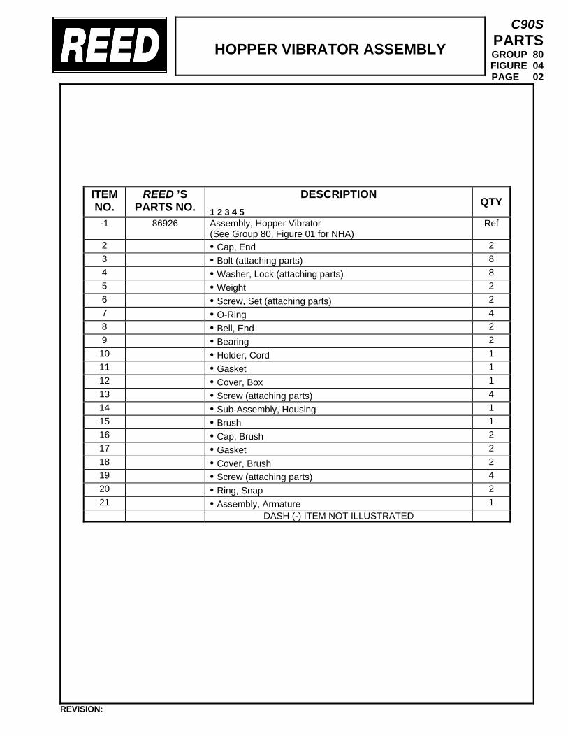
HOPPER VIBRATOR ASSEMBLY
C90S PARTS GROUP 80 FIGURE 04 PAGE 02
ITEM NO.
REED ’S PARTS NO.
DESCRIPTION 1 2 3 4 5
QTY
-1 86926
Assembly, Hopper Vibrator (See Group 80, Figure 01 for NHA)
Ref
2 • Cap, End 2 3 • Bolt (attaching parts) 8 4 • Washer, Lock (attaching parts) 8 5 • Weight 2 6 • Screw, Set (attaching parts) 2 7 • O-Ring 4 8 • Bell, End 2 9 • Bearing 2 10 • Holder, Cord 1 11 • Gasket 1 12 • Cover, Box 1 13 • Screw (attaching parts) 4 14 • Sub-Assembly, Housing 1 15 • Brush 1 16 • Cap, Brush 2 17 • Gasket 2 18 • Cover, Brush 2 19 • Screw (attaching parts) 4 20 • Ring, Snap 2 21 • Assembly, Armature 1
DASH (-) ITEM NOT ILLUSTRATED
REVISION:
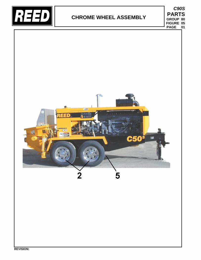
CHROME WHEEL ASSEMBLY
C90S PARTS GROUP 80 FIGURE 05 PAGE 01
REVISION:
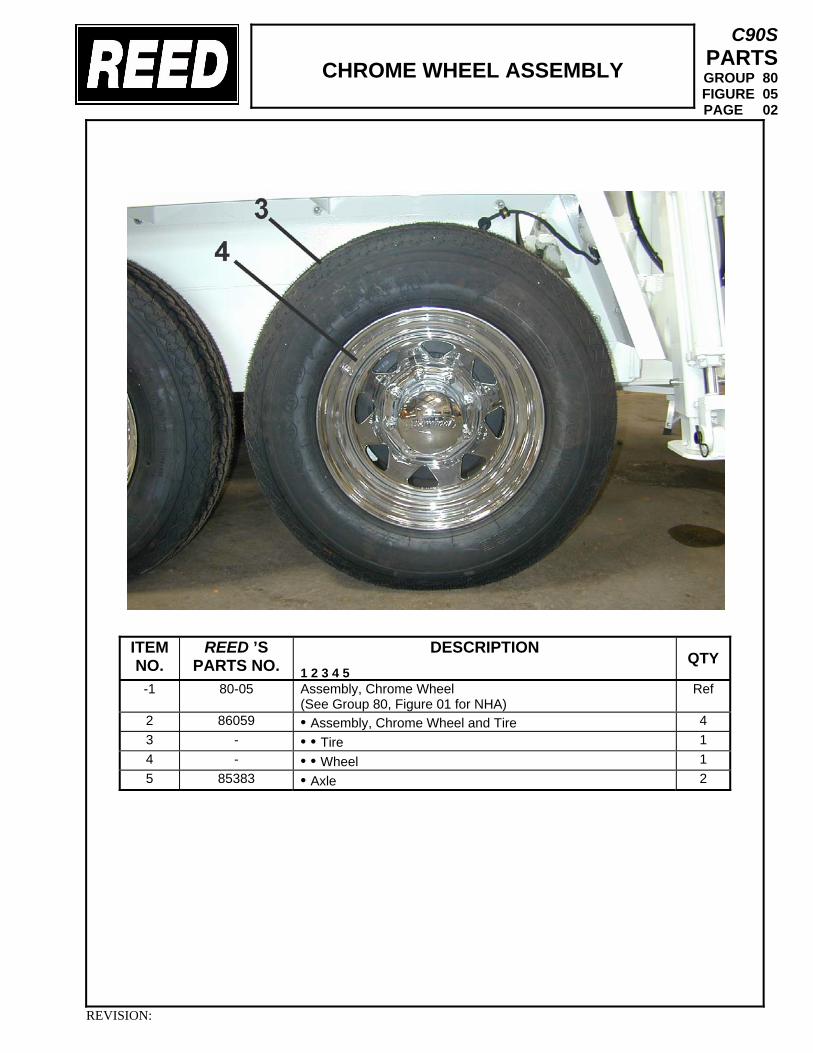
CHROME WHEEL ASSEMBLY
C90S PARTS GROUP 80 FIGURE 05 PAGE 02
ITEM NO.
REED ’S PARTS NO.
DESCRIPTION 1 2 3 4 5
QTY
-1 80-05
Assembly, Chrome Wheel (See Group 80, Figure 01 for NHA)
Ref
2 86059 • Assembly, Chrome Wheel and Tire 4 3 - • • Tire 1 4 - • • Wheel 1 5 85383 • Axle 2
REVISION:
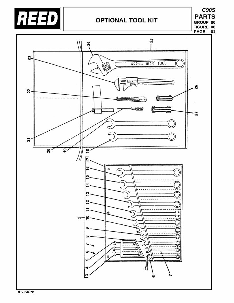
OPTIONAL TOOL KIT
C90S PARTS GROUP 80 FIGURE 06 PAGE 01
REVISION:
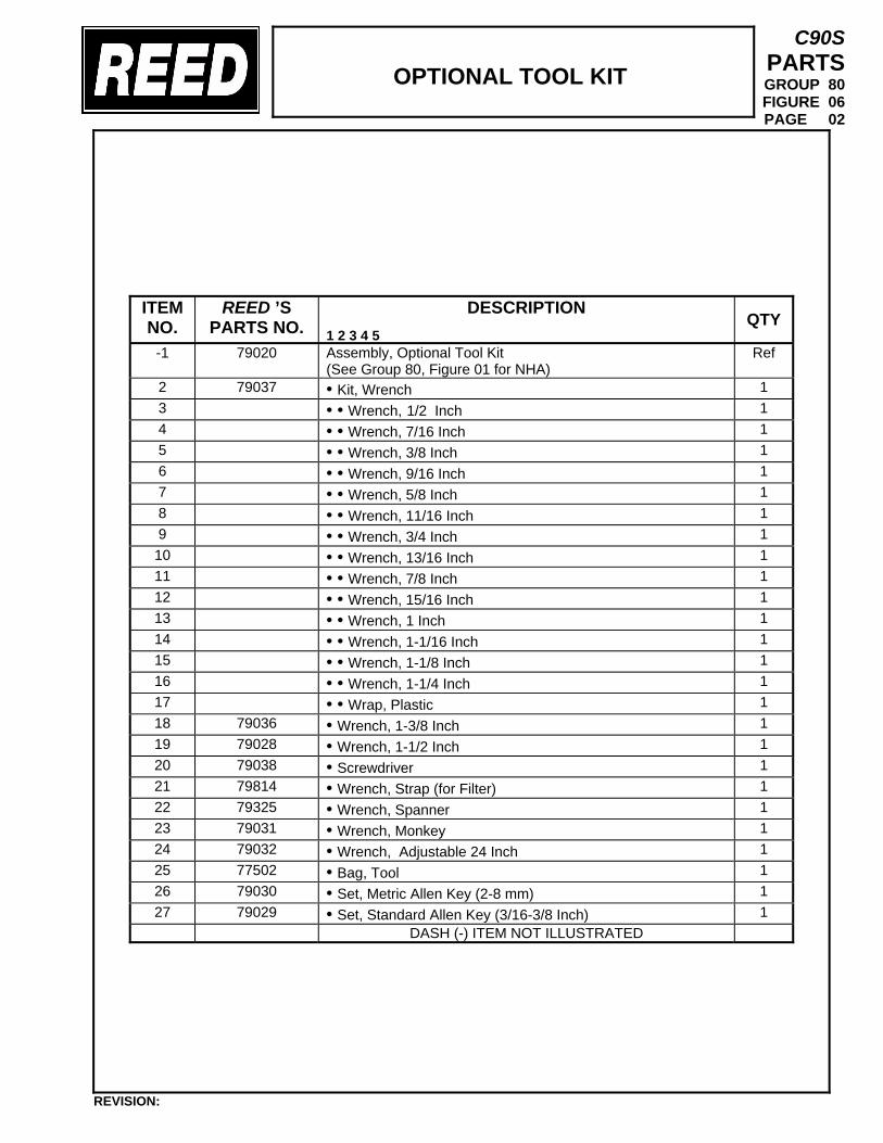
OPTIONAL TOOL KIT
C90S PARTS GROUP 80 FIGURE 06 PAGE 02
ITEM NO.
REED ’S PARTS NO.
DESCRIPTION 1 2 3 4 5
QTY
-1 79020
Assembly, Optional Tool Kit (See Group 80, Figure 01 for NHA)
Ref
2 79037 • Kit, Wrench 1 3 • • Wrench, 1/2 Inch 1 4 • • Wrench, 7/16 Inch 1 5 • • Wrench, 3/8 Inch 1 6 • • Wrench, 9/16 Inch 1 7 • • Wrench, 5/8 Inch 1 8 • • Wrench, 11/16 Inch 1 9 • • Wrench, 3/4 Inch 1 10 • • Wrench, 13/16 Inch 1 11 • • Wrench, 7/8 Inch 1 12 • • Wrench, 15/16 Inch 1 13 • • Wrench, 1 Inch 1 14 • • Wrench, 1-1/16 Inch 1 15 • • Wrench, 1-1/8 Inch 1 16 • • Wrench, 1-1/4 Inch 1 17 • • Wrap, Plastic 1 18 79036 • Wrench, 1-3/8 Inch 1 19 79028 • Wrench, 1-1/2 Inch 1 20 79038 • Screwdriver 1 21 79814 • Wrench, Strap (for Filter) 1 22 79325 • Wrench, Spanner 1 23 79031 • Wrench, Monkey 1 24 79032 • Wrench, Adjustable 24 Inch 1 25 77502 • Bag, Tool 1 26 79030 • Set, Metric Allen Key (2-8 mm) 1 27 79029 • Set, Standard Allen Key (3/16-3/8 Inch) 1
DASH (-) ITEM NOT ILLUSTRATED
REVISION:
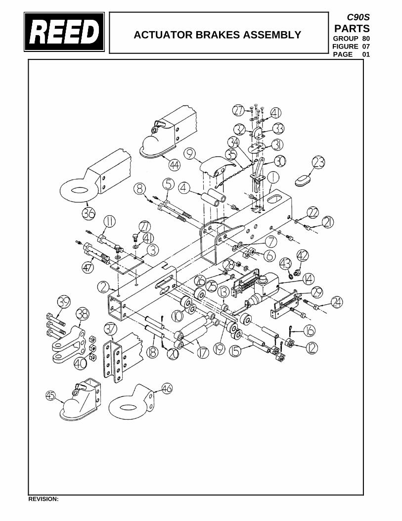
ACTUATOR BRAKES ASSEMBLY
C90S PARTS GROUP 80 FIGURE 07 PAGE 01
REVISION:
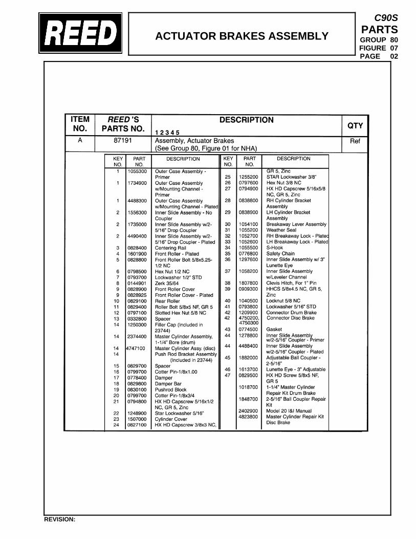
ACTUATOR BRAKES ASSEMBLY
C90S PARTS GROUP 80 FIGURE 07 PAGE 02
REVISION:
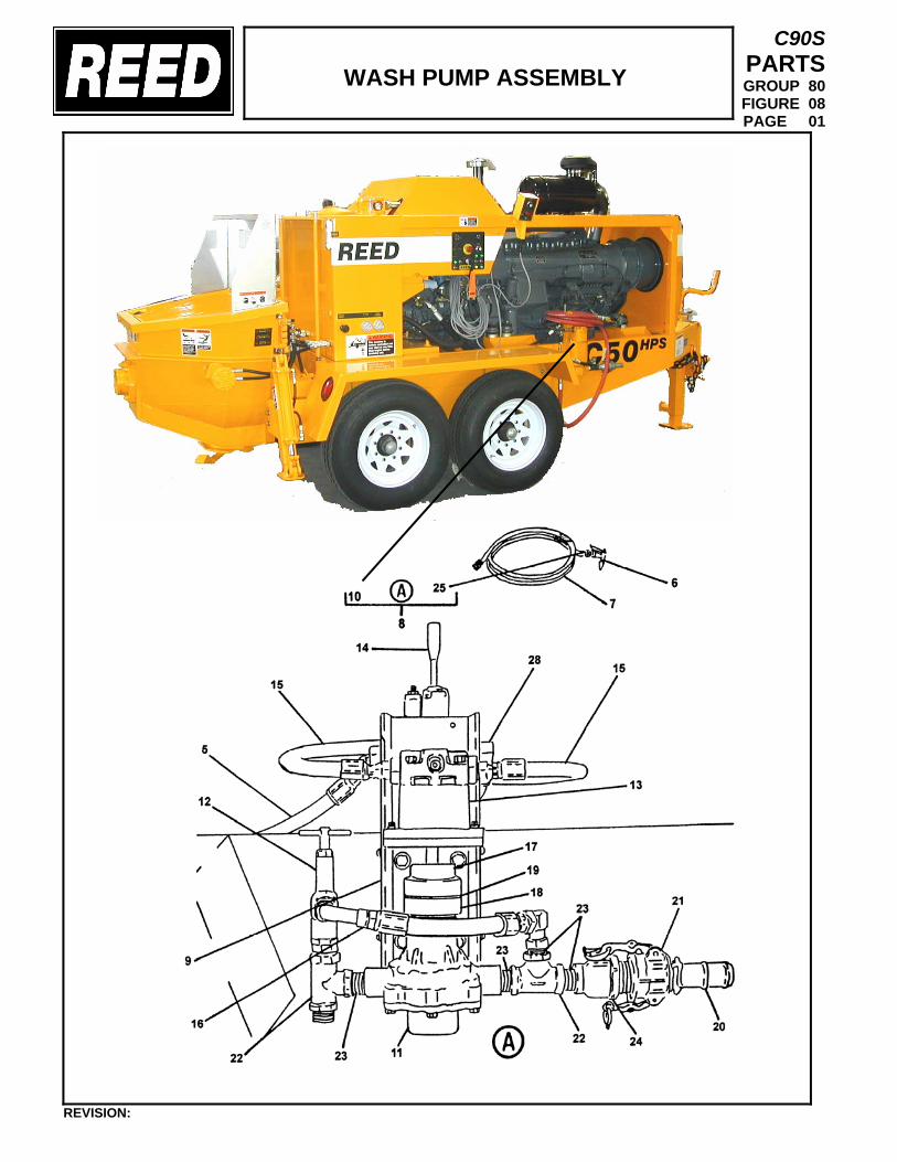
WASH PUMP ASSEMBLY
C90S PARTS GROUP 80 FIGURE 08 PAGE 01
REVISION:
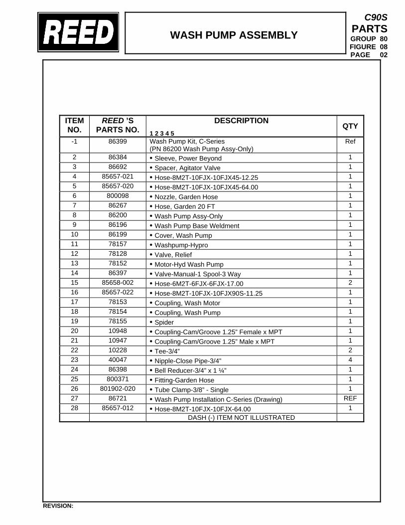
WASH PUMP ASSEMBLY
C90S PARTS GROUP 80 FIGURE 08 PAGE 02
ITEM NO.
REED ’S PARTS NO.
DESCRIPTION 1 2 3 4 5
QTY
-1 86399 Wash Pump Kit, C-Series (PN 86200 Wash Pump Assy-Only)
Ref
2 86384 • Sleeve, Power Beyond 1 3 86692 • Spacer, Agitator Valve 1 4 85657-021 • Hose-8M2T-10FJX-10FJX45-12.25 1 5 85657-020 • Hose-8M2T-10FJX-10FJX45-64.00 1 6 800098 • Nozzle, Garden Hose 1 7 86267 • Hose, Garden 20 FT 1 8 86200 • Wash Pump Assy-Only 1 9 86196 • Wash Pump Base Weldment 1 10 86199 • Cover, Wash Pump 1 11 78157 • Washpump-Hypro 1 12 78128 • Valve, Relief 1 13 78152 • Motor-Hyd Wash Pump 1 14 86397 • Valve-Manual-1 Spool-3 Way 1 15 85658-002 • Hose-6M2T-6FJX-6FJX-17.00 2 16 85657-022 • Hose-8M2T-10FJX-10FJX90S-11.25 1 17 78153 • Coupling, Wash Motor 1 18 78154 • Coupling, Wash Pump 1 19 78155 • Spider 1 20 10948 • Coupling-Cam/Groove 1.25” Female x MPT 1 21 10947 • Coupling-Cam/Groove 1.25” Male x MPT 1 22 10228 • Tee-3/4” 2 23 40047 • Nipple-Close Pipe-3/4” 4 24 86398 • Bell Reducer-3/4” x 1 ¼” 1 25 800371 • Fitting-Garden Hose 1 26 801902-020 • Tube Clamp-3/8” - Single 1 27 86721 • Wash Pump Installation C-Series (Drawing) REF 28 85657-012 • Hose-8M2T-10FJX-10FJX-64.00 1
DASH (-) ITEM NOT ILLUSTRATED
REVISION:
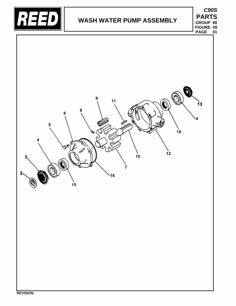
WASH WATER PUMP ASSEMBLY
C90S PARTS GROUP 80 FIGURE 09 PAGE 01
REVISION:
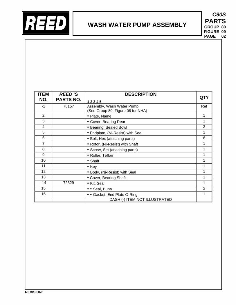
WASH WATER PUMP ASSEMBLY
C90S PARTS GROUP 80 FIGURE 09 PAGE 02
ITEM NO.
REED ’S PARTS NO.
DESCRIPTION 1 2 3 4 5
QTY
-1 78157
Assembly, Wash Water Pump (See Group 80, Figure 08 for NHA)
Ref
2 • Plate, Name 1 3 • Cover, Bearing Rear 1 4 • Bearing, Sealed Bowl 2 5 • Endplate, (Ni-Resist) with Seal 1 6 • Bolt, Hex (attaching parts) 6 7 • Rotor, (Ni-Resist) with Shaft 1 8 • Screw, Set (attaching parts) 1 9 • Roller, Teflon 1 10 • Shaft 1 11 • Key 1 12 • Body, (Ni-Resist) with Seal 1 13 • Cover, Bearing Shaft 1 -14 72329 • Kit, Seal 1 15 • • Seal, Buna 2 16 • • Gasket, End Plate O-Ring 1
DASH (-) ITEM NOT ILLUSTRATED
REVISION:
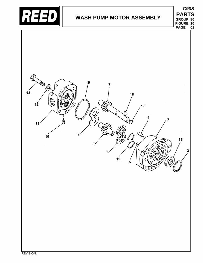
WASH PUMP MOTOR ASSEMBLY
C90S PARTS GROUP 80 FIGURE 10 PAGE 01
REVISION:
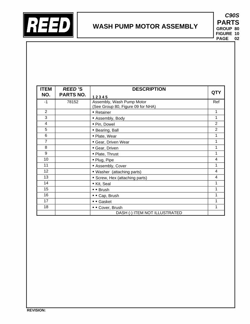
WASH PUMP MOTOR ASSEMBLY
C90S PARTS GROUP 80 FIGURE 10 PAGE 02
ITEM NO.
REED ’S PARTS NO.
DESCRIPTION 1 2 3 4 5
QTY
-1 78152
Assembly, Wash Pump Motor (See Group 80, Figure 09 for NHA)
Ref
2 • Retainer 1 3 • Assembly, Body 1 4 • Pin, Dowel 2 5 • Bearing, Ball 2 6 • Plate, Wear 1 7 • Gear, Driven Wear 1 8 • Gear, Driven 1 9 • Plate, Thrust 1 10 • Plug, Pipe 4 11 • Assembly, Cover 1 12 • Washer (attaching parts) 4 13 • Screw, Hex (attaching parts) 4 14 • Kit, Seal 1 15 • • Brush 1 16 • • Cap, Brush 1 17 • • Gasket 1 18 • • Cover, Brush 1
DASH (-) ITEM NOT ILLUSTRATED
REVISION:
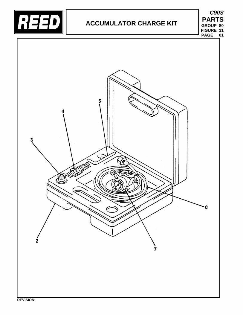
ACCUMULATOR CHARGE KIT
C90S PARTS GROUP 80 FIGURE 11 PAGE 01
REVISION:
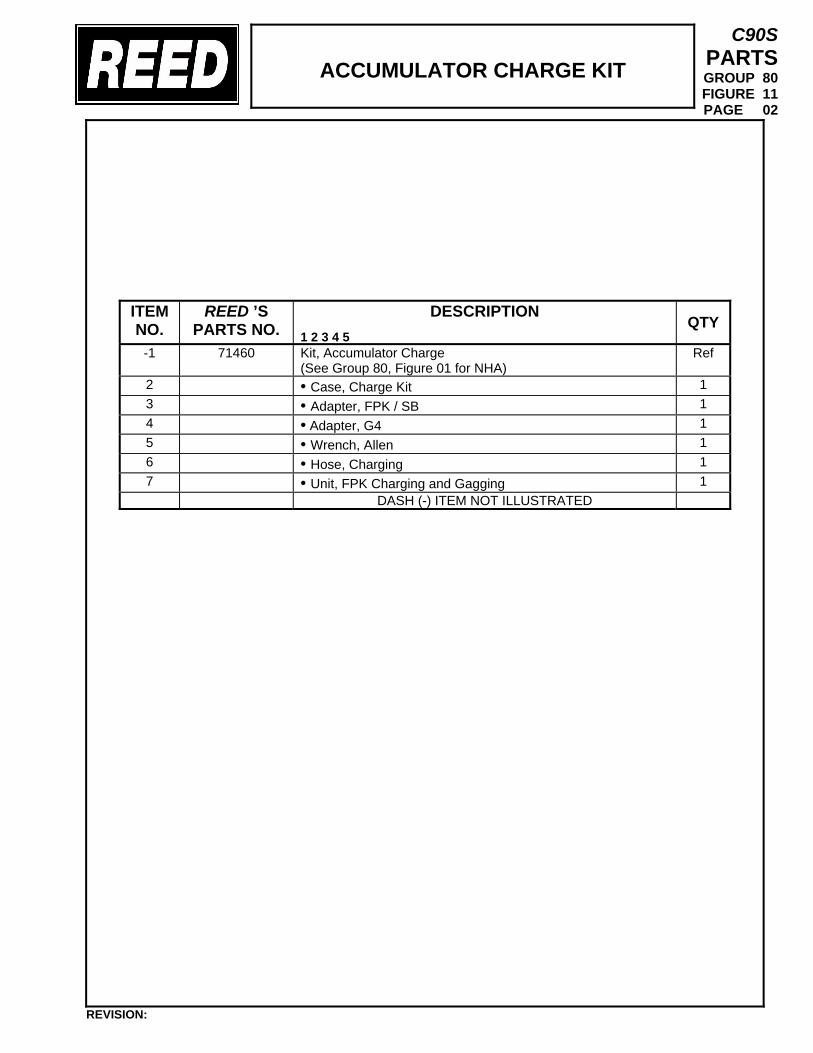
ACCUMULATOR CHARGE KIT
C90S PARTS GROUP 80 FIGURE 11 PAGE 02
ITEM NO.
REED ’S PARTS NO.
DESCRIPTION 1 2 3 4 5
QTY
-1 71460
Kit, Accumulator Charge (See Group 80, Figure 01 for NHA)
Ref
2 • Case, Charge Kit 1 3 • Adapter, FPK / SB 1 4 • Adapter, G4 1 5 • Wrench, Allen 1 6 • Hose, Charging 1 7 • Unit, FPK Charging and Gagging 1 DASH (-) ITEM NOT ILLUSTRATED
REVISION:
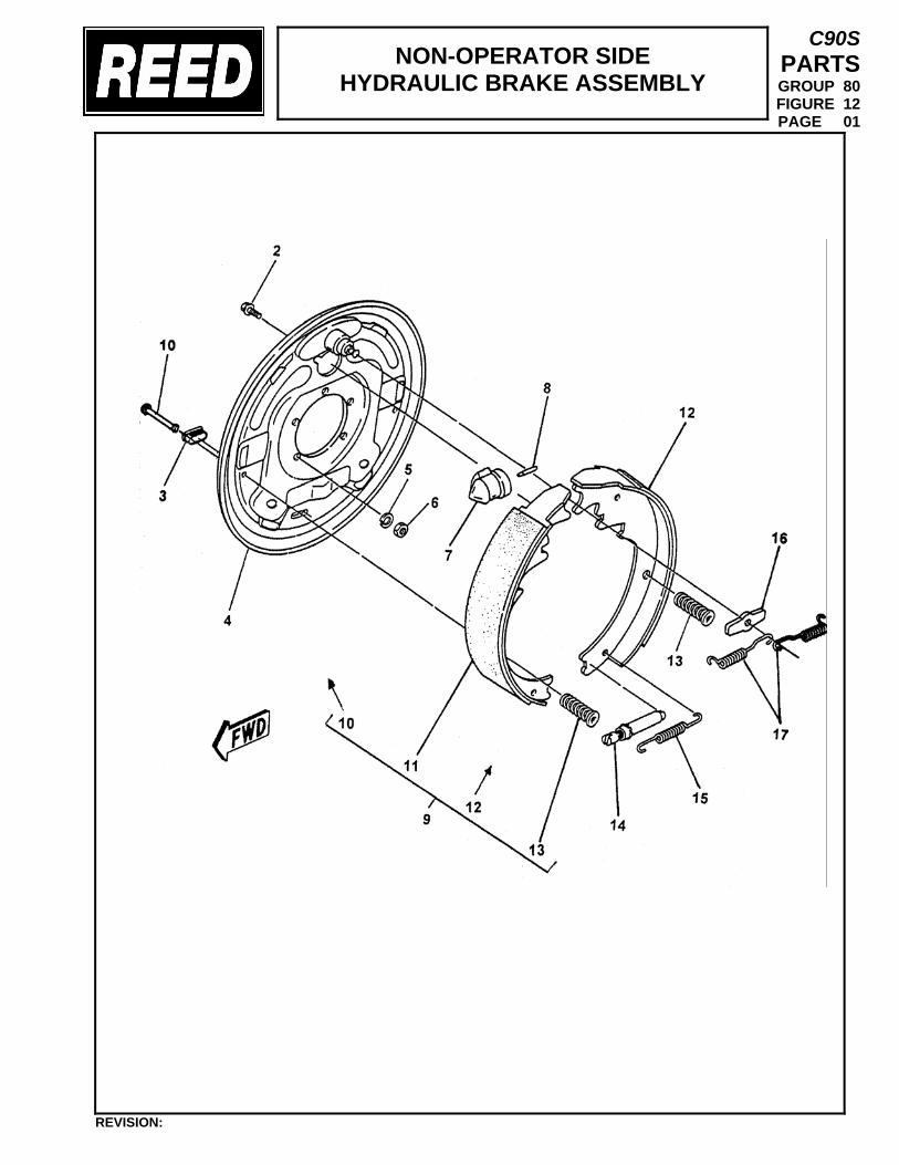
NON-OPERATOR SIDE HYDRAULIC BRAKE ASSEMBLY
C90S PARTS GROUP 80 FIGURE 12 PAGE 01
REVISION:
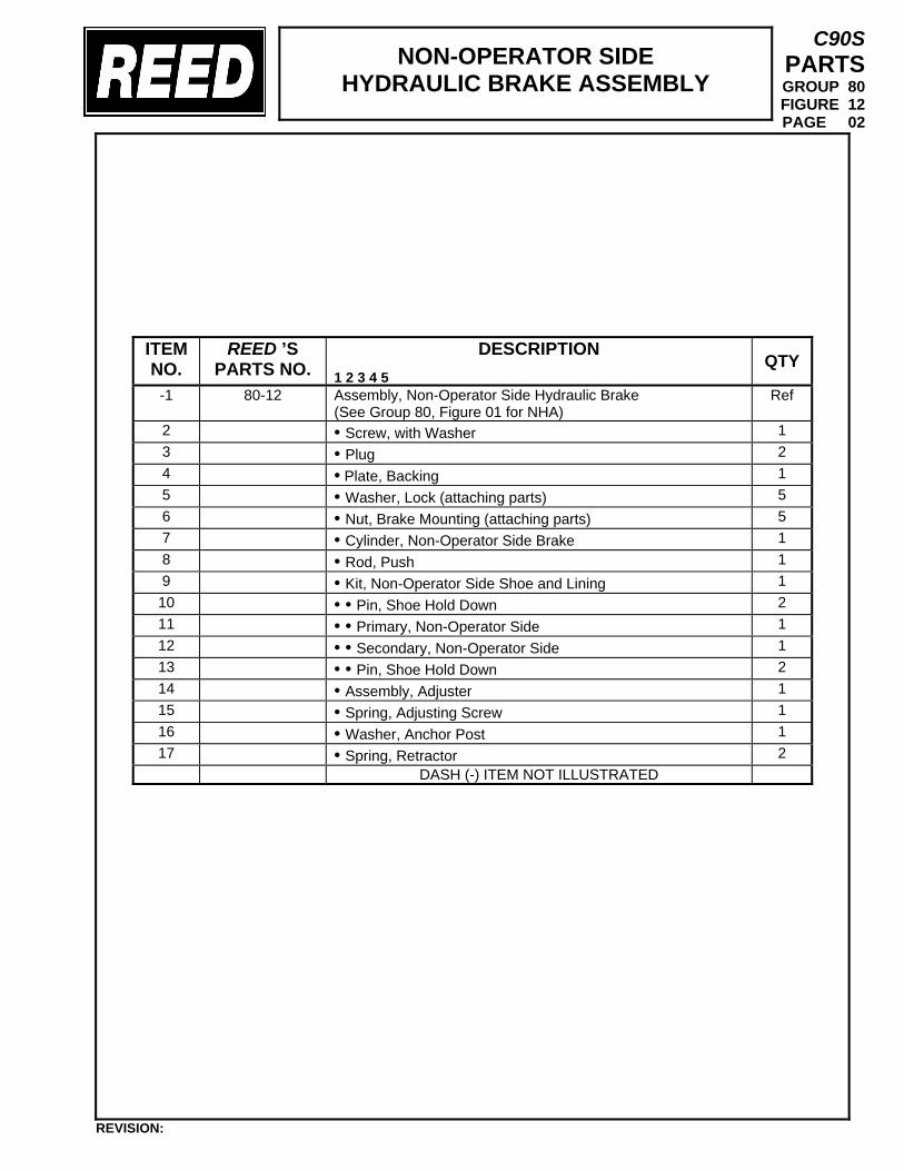
NON-OPERATOR SIDE HYDRAULIC BRAKE ASSEMBLY
C90S PARTS GROUP 80 FIGURE 12 PAGE 02
ITEM NO.
REED ’S PARTS NO.
DESCRIPTION 1 2 3 4 5
QTY
-1 80-12
Assembly, Non-Operator Side Hydraulic Brake (See Group 80, Figure 01 for NHA)
Ref
2 • Screw, with Washer 1 3 • Plug 2 4 • Plate, Backing 1 5 • Washer, Lock (attaching parts) 5 6 • Nut, Brake Mounting (attaching parts) 5 7 • Cylinder, Non-Operator Side Brake 1 8 • Rod, Push 1 9 • Kit, Non-Operator Side Shoe and Lining 1 10 • • Pin, Shoe Hold Down 2 11 • • Primary, Non-Operator Side 1 12 • • Secondary, Non-Operator Side 1 13 • • Pin, Shoe Hold Down 2 14 • Assembly, Adjuster 1 15 • Spring, Adjusting Screw 1 16 • Washer, Anchor Post 1 17 • Spring, Retractor 2
DASH (-) ITEM NOT ILLUSTRATED
REVISION:
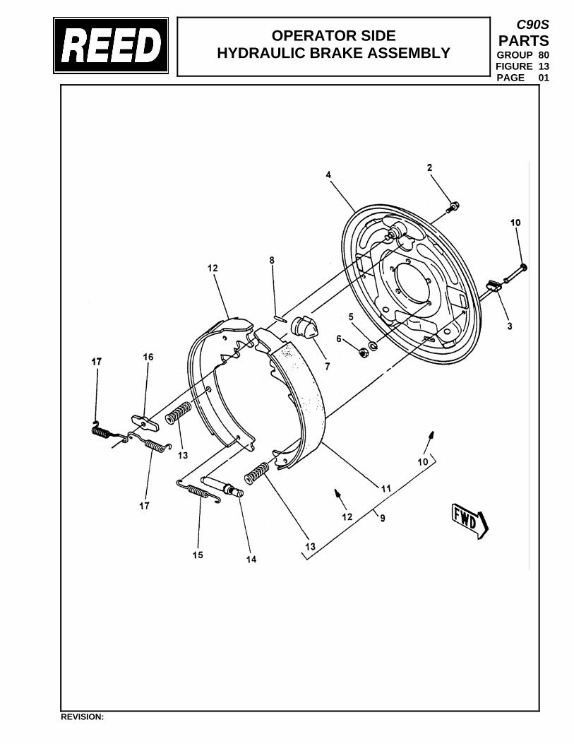
OPERATOR SIDE HYDRAULIC BRAKE ASSEMBLY
C90S PARTS GROUP 80 FIGURE 13 PAGE 01
REVISION:
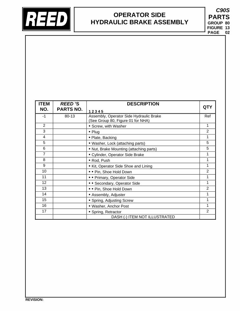
OPERATOR SIDE HYDRAULIC BRAKE ASSEMBLY
C90S PARTS GROUP 80 FIGURE 13 PAGE 02
ITEM NO.
REED ’S PARTS NO.
DESCRIPTION 1 2 3 4 5
QTY
-1 80-13
Assembly, Operator Side Hydraulic Brake (See Group 80, Figure 01 for NHA)
Ref
2 • Screw, with Washer 1 3 • Plug 2 4 • Plate, Backing 1 5 • Washer, Lock (attaching parts) 5 6 • Nut, Brake Mounting (attaching parts) 5 7 • Cylinder, Operator Side Brake 1 8 • Rod, Push 1 9 • Kit, Operator Side Shoe and Lining 1 10 • • Pin, Shoe Hold Down 2 11 • • Primary, Operator Side 1 12 • • Secondary, Operator Side 1 13 • • Pin, Shoe Hold Down 2 14 • Assembly, Adjuster 1 15 • Spring, Adjusting Screw 1 16 • Washer, Anchor Post 1 17 • Spring, Retractor 2
DASH (-) ITEM NOT ILLUSTRATED
REVISION:
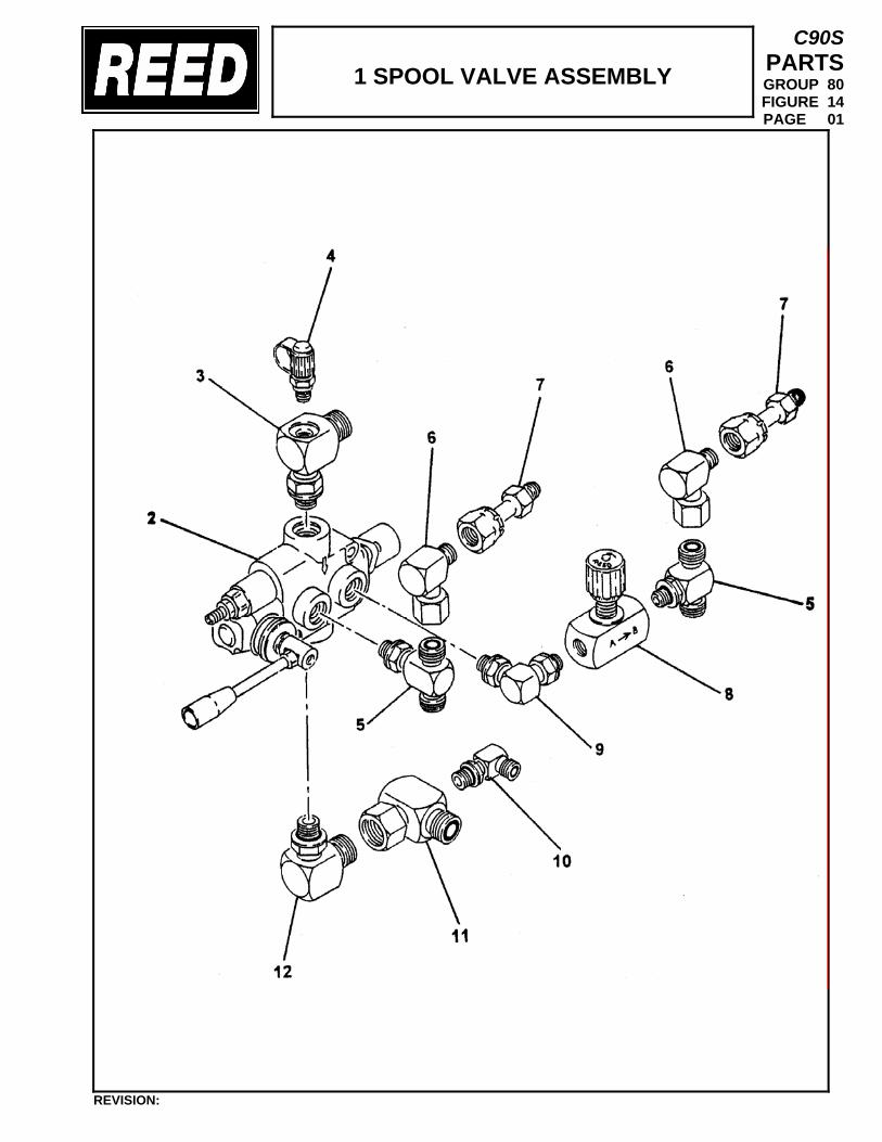
1 SPOOL VALVE ASSEMBLY
C90S PARTS GROUP 80 FIGURE 14 PAGE 01
REVISION:
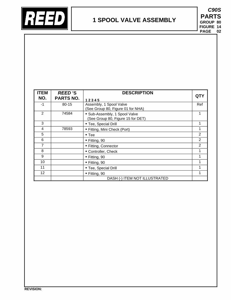
1 SPOOL VALVE ASSEMBLY
C90S PARTS GROUP 80 FIGURE 14 PAGE 02
ITEM NO.
REED ’S PARTS NO.
DESCRIPTION 1 2 3 4 5
QTY
-1 80-15 Assembly, 1 Spool Valve (See Group 80, Figure 01 for NHA)
Ref
2 74584 • Sub-Assembly, 1 Spool Valve (See Group 80, Figure 15 for DET)
1
3 • Tee, Special Drill 1 4 78593 • Fitting, Mini Check (Port) 1 5 • Tee 2 6 • Fitting, 90 2 7 • Fitting, Connector 2 8 • Controller, Check 1 9 • Fitting, 90 1 10 • Fitting, 90 1 11 • Tee, Special Drill 1 12 • Fitting, 90 1
DASH (-) ITEM NOT ILLUSTRATED
REVISION:
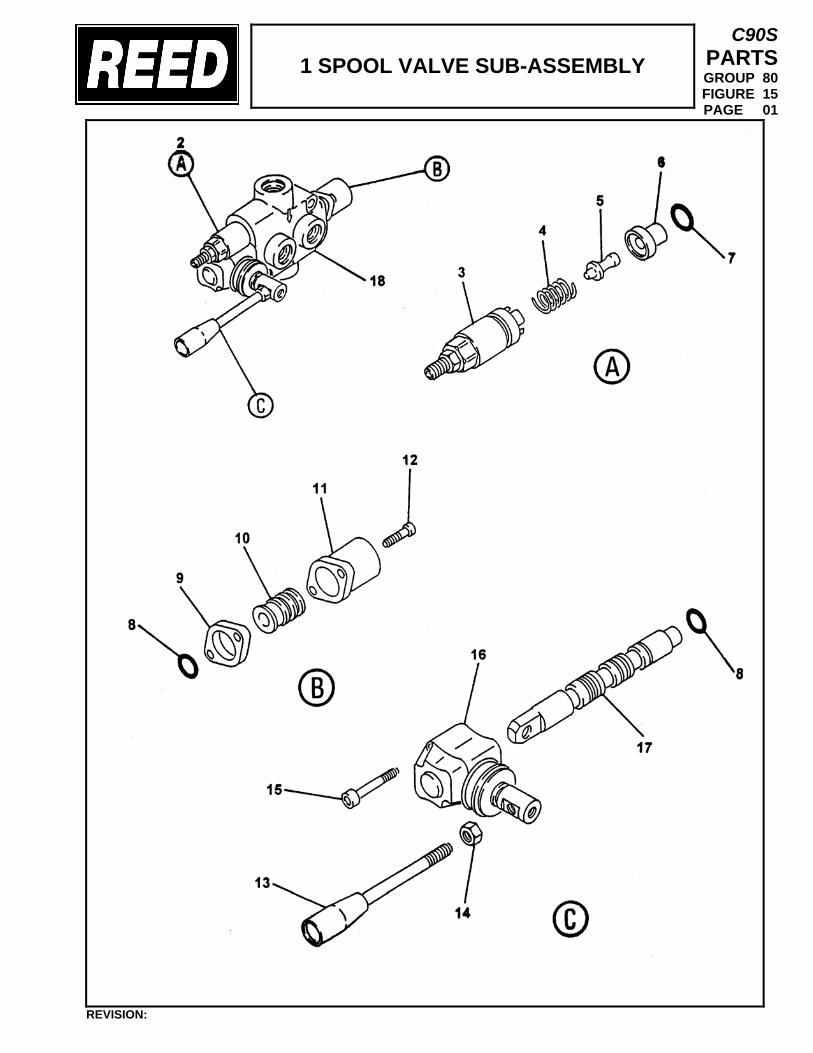
1 SPOOL VALVE SUB-ASSEMBLY
C90S PARTS GROUP 80 FIGURE 15 PAGE 01
REVISION:
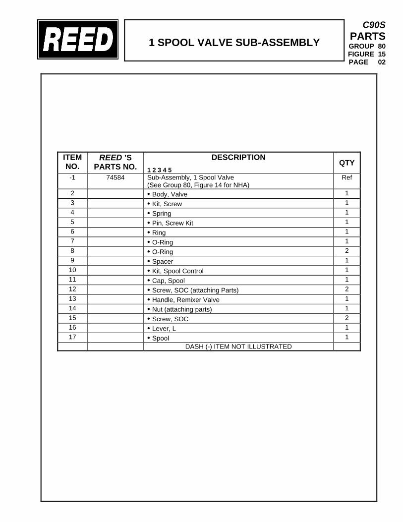
1 SPOOL VALVE SUB-ASSEMBLY
C90S PARTS GROUP 80 FIGURE 15 PAGE 02
ITEM NO.
REED ’S PARTS NO.
DESCRIPTION 1 2 3 4 5
QTY
-1 74584
Sub-Assembly, 1 Spool Valve (See Group 80, Figure 14 for NHA)
Ref
2 • Body, Valve 1 3 • Kit, Screw 1 4 • Spring 1 5 • Pin, Screw Kit 1 6 • Ring 1 7 • O-Ring 1 8 • O-Ring 2 9 • Spacer 1 10 • Kit, Spool Control 1 11 • Cap, Spool 1 12 • Screw, SOC (attaching Parts) 2 13 • Handle, Remixer Valve 1 14 • Nut (attaching parts) 1 15 • Screw, SOC 2 16 • Lever, L 1 17 • Spool 1
DASH (-) ITEM NOT ILLUSTRATED
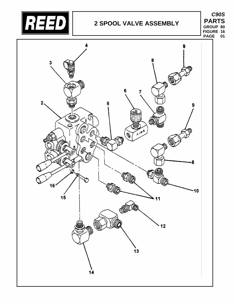
2 SPOOL VALVE ASSEMBLY
C90S PARTS GROUP 80 FIGURE 16 PAGE 01
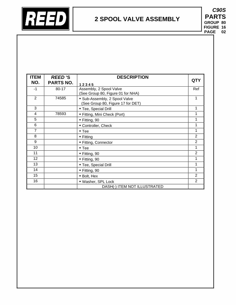
2 SPOOL VALVE ASSEMBLY
C90S PARTS GROUP 80 FIGURE 16 PAGE 02
ITEM NO.
REED ’S PARTS NO.
DESCRIPTION 1 2 3 4 5
QTY
-1 80-17
Assembly, 2 Spool Valve (See Group 80, Figure 01 for NHA)
Ref
2 74585 • Sub-Assembly, 2 Spool Valve (See Group 80, Figure 17 for DET)
1
3 • Tee, Special Drill 1 4 78593 • Fitting, Mini Check (Port) 1 5 • Fitting, 90 1 6 • Controller, Check 1 7 • Tee 1 8 • Fitting 2 9 • Fitting, Connector 2 10 • Tee 1 11 • Fitting, 90 2 12 • Fitting, 90 1 13 • Tee, Special Drill 1 14 • Fitting, 90 1 15 • Bolt, Hex 2 16 • Washer, SPL Lock 2
DASH(-) ITEM NOT ILLUSTRATED
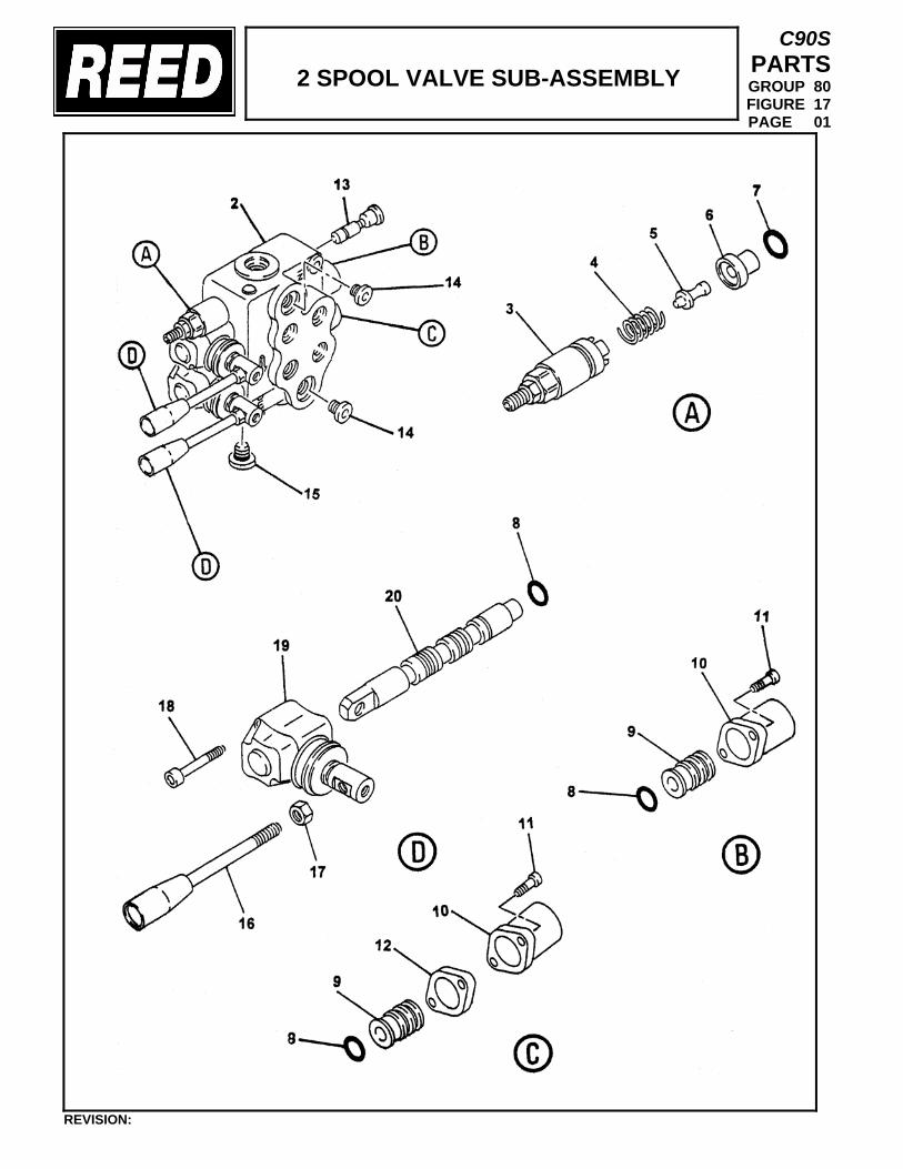
2 SPOOL VALVE SUB-ASSEMBLY
C90S PARTS GROUP 80 FIGURE 17 PAGE 01
REVISION:
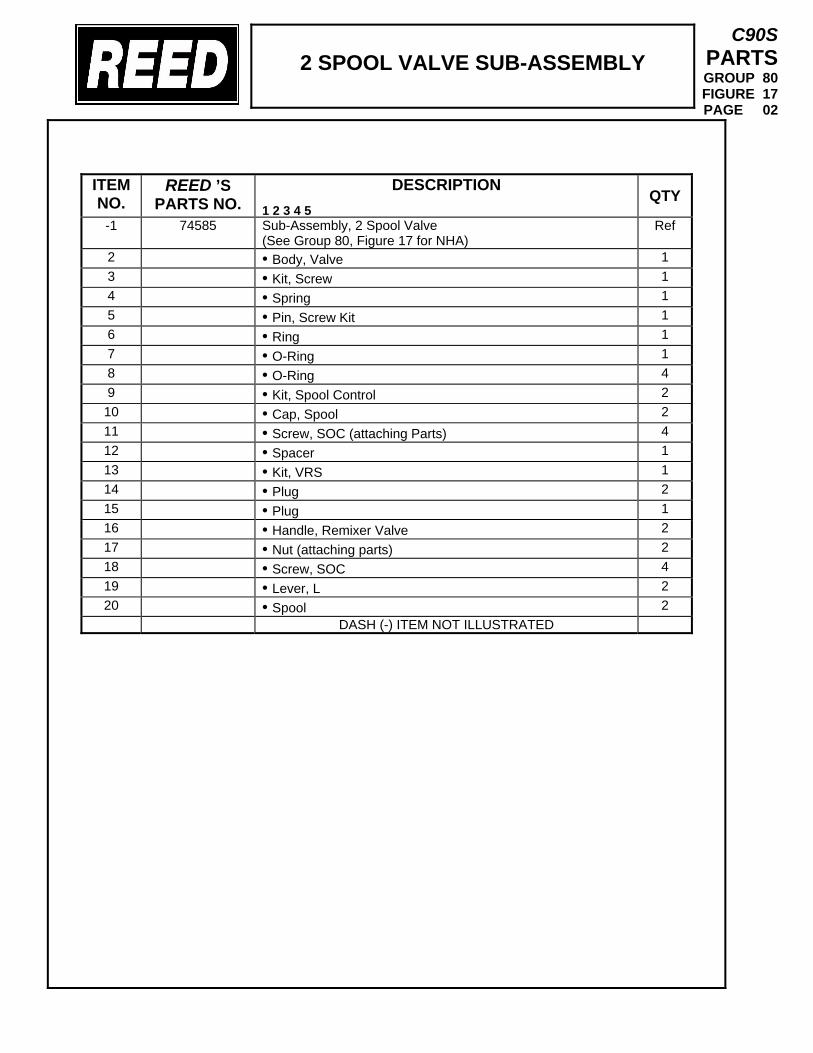
2 SPOOL VALVE SUB-ASSEMBLY
C90S PARTS GROUP 80 FIGURE 17 PAGE 02
ITEM NO.
REED ’S PARTS NO.
DESCRIPTION 1 2 3 4 5
QTY
-1 74585
Sub-Assembly, 2 Spool Valve (See Group 80, Figure 17 for NHA)
Ref
2 • Body, Valve 1 3 • Kit, Screw 1 4 • Spring 1 5 • Pin, Screw Kit 1 6 • Ring 1 7 • O-Ring 1 8 • O-Ring 4 9 • Kit, Spool Control 2 10 • Cap, Spool 2 11 • Screw, SOC (attaching Parts) 4 12 • Spacer 1 13 • Kit, VRS 1 14 • Plug 2 15 • Plug 1 16 • Handle, Remixer Valve 2 17 • Nut (attaching parts) 2 18 • Screw, SOC 4 19 • Lever, L 2 20 • Spool 2
DASH (-) ITEM NOT ILLUSTRATED
TRAILER MOUNTED PUMP 01 MODEL C90S GROUP 80 OPTIONAL INSTALLATION
C90S PARTS GROUP 80 FIGURE 18 PAGE 01
THIS PAGE INTENTIONALLY LEFT BLANK.
REVISION:
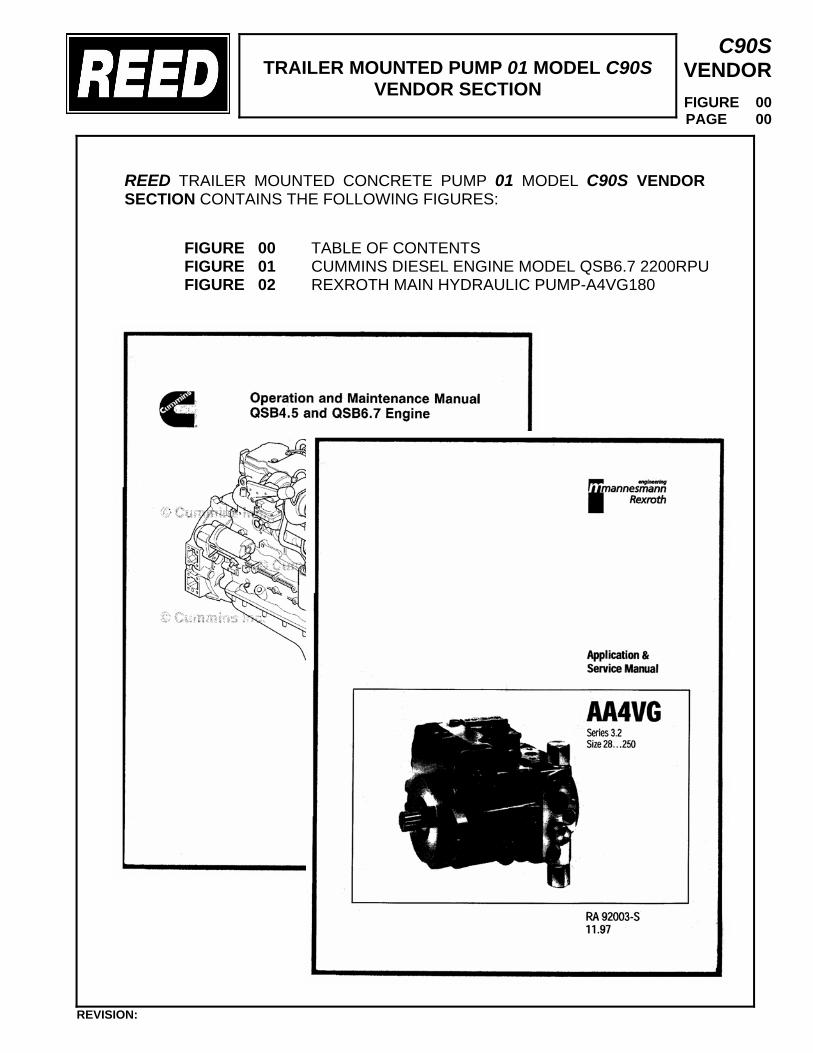
TRAILER MOUNTED PUMP 01 MODEL C90S
VENDOR SECTION
C90S VENDOR
FIGURE 00 PAGE 00
REED TRAILER MOUNTED CONCRETE PUMP 01 MODEL C90S VENDOR SECTION CONTAINS THE FOLLOWING FIGURES:
FIGURE 00 TABLE OF CONTENTS FIGURE 01 CUMMINS DIESEL ENGINE MODEL QSB6.7 2200RPU FIGURE 02 REXROTH MAIN HYDRAULIC PUMP-A4VG180
REVISION:

TRAILER MOUNTED PUMP 01 MODEL C90S
VENDOR SECTION
C90S VENDOR
FIGURE 00 PAGE 01
REVISION:
THIS PAGE INTENTIONALLY LEFT BLANK.
CUMMINS 220HP DIESEL ENGINE C90S
VENDOR SECTION
C90S VENDOR
FIGURE 01 PAGE 01
REVISION:
CUMMINS 220HP DIESEL ENGINE C90S
VENDOR SECTION
C90S VENDOR
FIGURE 01 PAGE 02
REVISION:
NOTICE
THIS MANUAL IS SUPPLIED BY CUMMINS PER EACH ENGINE THAT IS SUPPLIED TO REED.
REXROTH MAIN HYD PUMP – A4VG180
VENDOR SECTION
C90S VENDOR
FIGURE 02 PAGE 01
REVISION:

REXROTH MAIN HYD PUMP – A4VG180
VENDOR SECTION
C90S VENDOR
FIGURE 02 PAGE 02
REVISION:
THIS PAGE INTENTIONALLY LEFT BLANK.
RA 92003-S11.97
AA4VGSeries 3.2Size 28…250
Application &Service Manual
Variable Displacement Pump AA4VG, Series 3
RA 92003-S/04.97
2
Ordering of P arts
For Rexroth to supply the correct parts for your unit, please include all of the following informationalong with your parts order.
Model CodeSerial NumberUnit NumberPart Name
Part Number
Due to modifications and improvements to our products, minor changes can occur to the parts,even though the type code may not necessarily reflect these changes. The type number and serialnumber will guarantee that the correct parts for your unit are supplied.
Ordering Example
To order a replacement rotary group for an AA4VG variable displacement pump having the abovenameplate, the following information would be required.
+ Model Code AA4VG125NVD1/32LPSFN001S+ Serial Number G2014680+ Unit Number 5454-005-002* Part Name Charge Pressure Relief V alve* Part Number HU00434856
+ This information is taken from the nameplate on the pump.* This information is taken from the Application and Service Manual.
SERIAL NO. G2014680 YearAA4VG125NVD1/32L 06.95
-PSF52N001S5454-005-002 CCWPART NO. MINERAL OIL ROTATION
THE REXROTH CORP.PISTON PUMP DIVISION
FOUNTAIN INN S.C.
MADE IN USA
RA 92003-S/04.97
3
Variable Displacement Pump AA4VG, Series 3
Name Tag Information . . . . . . . . . . . . . . . . . . . . . . . . . . . . . . Page 2
Type Code . . . . . . . . . . . . . . . . . . . . . . . . . . . . . . . . . . . . 4–5
Technical Data . . . . . . . . . . . . . . . . . . . . . . . . . . . . . . . . . . 6–7
Filtration Options . . . . . . . . . . . . . . . . . . . . . . . . . . . . . . . . . 7–9
High Pressure Relief Valve . . . . . . . . . . . . . . . . . . . . . . . . . . . . . . 10
Pump Controls . . . . . . . . . . . . . . . . . . . . . . . . . . . . . . . . . 11–16
Pump Installation . . . . . . . . . . . . . . . . . . . . . . . . . . . . . . . . 17–18
Start-up Procedure . . . . . . . . . . . . . . . . . . . . . . . . . . . . . . . . . 19
Trouble Shooting Procedure . . . . . . . . . . . . . . . . . . . . . . . . . . . . 20–23
Charge Pressure Relief Adjustments . . . . . . . . . . . . . . . . . . . . . . . . . . 24
Mechanical Centering of Pump . . . . . . . . . . . . . . . . . . . . . . . . . . . . 24
Hydraulic Centering of Control Modules . . . . . . . . . . . . . . . . . . . . . . . . . 25
Adjustments of Pressure Override Valve . . . . . . . . . . . . . . . . . . . . . . . . . 26
Adjustment of High Pressure Relief Valves . . . . . . . . . . . . . . . . . . . . . . . . 27
Tow Option Engagement . . . . . . . . . . . . . . . . . . . . . . . . . . . . . . . 28
Removal an Inspection of Charge Pump . . . . . . . . . . . . . . . . . . . . . . . . . 29
Removal and Installation of Shaft Seal. . . . . . . . . . . . . . . . . . . . . . . . . . 30
Filter Replacement . . . . . . . . . . . . . . . . . . . . . . . . . . . . . . . . . 31
Routine Maintenance . . . . . . . . . . . . . . . . . . . . . . . . . . . . . . . . 32
Replacement Subassemblies and Parts . . . . . . . . . . . . . . . . . . . . . . . . 33–36
Filtration Configuration . . . . . . . . . . . . . . . . . . . . . . . . . . . . . . . 37
Index
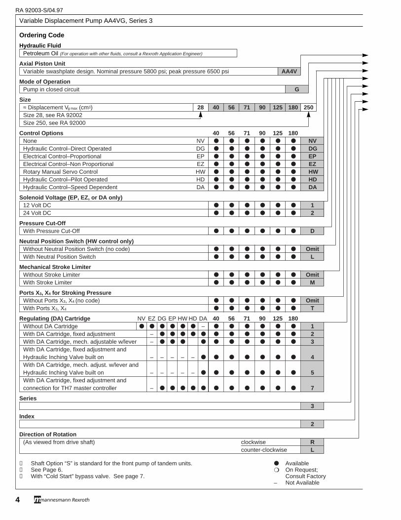
RA 92003-S/04.97
Variable Displacement Pump AA4VG, Series 3
4
Ordering Code
Hydraulic FluidPetroleum Oil (For operation with other fluids, consult a Rexroth Application Engineer)
Axial Piston UnitVariable swashplate design. Nominal pressure 5800 psi; peak pressure 6500 psi AA4V
Mode of OperationPump in closed circuit G
Size≈ Displacement Vg max (cm3) 28 40 56 71 90 125 180 250Size 28, see RA 92002Size 250, see RA 92000
Control Options 40 56 71 90 125 180None NV ● ● ● ● ● ● NVHydraulic Control–Direct Operated DG ● ● ● ● ● ● DGElectrical Control–Proportional EP ● ● ● ● ● ● EPElectrical Control–Non Proportional EZ ● ● ● ● ● ● EZRotary Manual Servo Control HW ● ● ● ● ● ● HWHydraulic Control–Pilot Operated HD ● ● ● ● ● ● HDHydraulic Control–Speed Dependent DA ● ● ● ● ● ● DA
Solenoid Voltage (EP, EZ, or DA only)12 Volt DC ● ● ● ● ● ● 124 Volt DC ● ● ● ● ● ● 2
Pressure Cut-OffWith Pressure Cut-Off ● ● ● ● ● ● D
Neutral Position Switch (HW control only)Without Neutral Position Switch (no code) ● ● ● ● ● ● OmitWith Neutral Position Switch ● ● ● ● ● ● L
Mechanical Stroke LimiterWithout Stroke Limiter ● ● ● ● ● ● OmitWith Stroke Limiter ● ● ● ● ● ● M
Ports X 3, X4 for Stroking PressureWithout Ports X3, X4 (no code) ● ● ● ● ● ● OmitWith Ports X3, X4 ● ● ● ● ● ● T
Regulating (DA) Cartridge NV EZ DG EP HW HD DA 40 56 71 90 125 180Without DA Cartridge ● ● ● ● ● ● – ● ● ● ● ● ● 1With DA Cartridge, fixed adjustment – ● ● ● ● ● ● ● ● ● ● ● 2With DA Cartridge, mech. adjustable w/lever – ● ● ● ● ● ● ● ● ● ● 3With DA Cartridge, fixed adjustment andHydraulic Inching Valve built on – – – – – ● ● ● ● ● ● ● 4With DA Cartridge, mech. adjust. w/lever andHydraulic Inching Valve built on – – – – – ● ● ● ● ● ● ● 5With DA Cartridge, fixed adjustment andconnection for TH7 master controller – ● ● ● ● ● ● ● ● ● ● ● 7
Series 3
Index2
Direction of Rotation(As viewed from drive shaft) clockwise R
counter-clockwise L
➀ Shaft Option “S” is standard for the front pump of tandem units. ● Available➁ See Page 6. ❍ On Request; ➂ With “Cold Start” bypass valve. See page 7. Consult Factory
– Not Available
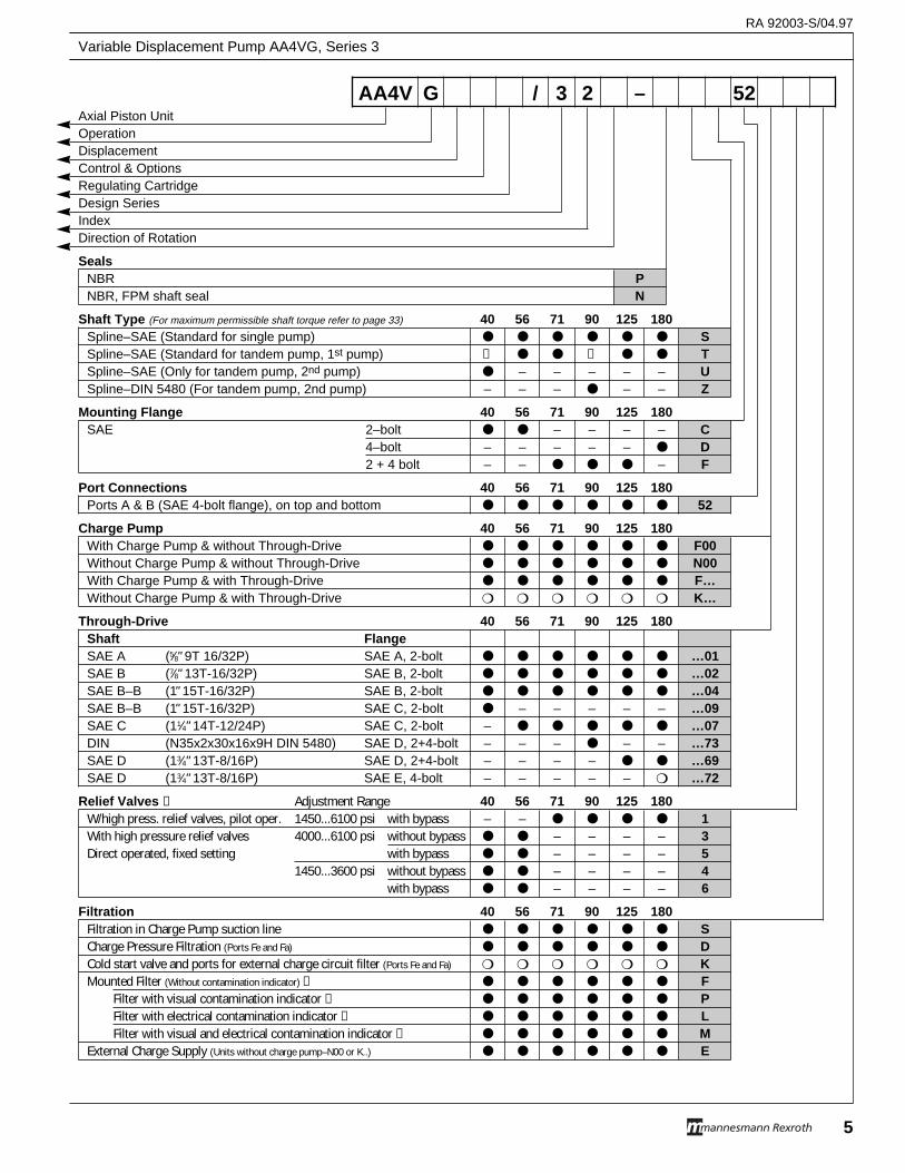
Axial Piston UnitOperationDisplacementControl & OptionsRegulating CartridgeDesign SeriesIndexDirection of Rotation
SealsNBR PNBR, FPM shaft seal N
Shaft Type (For maximum permissible shaft torque refer to page 33) 40 56 71 90 125 180Spline–SAE (Standard for single pump) ● ● ● ● ● ● SSpline–SAE (Standard for tandem pump, 1st pump) ➀ ● ● ➀ ● ● TSpline–SAE (Only for tandem pump, 2nd pump) ● – – – – – USpline–DIN 5480 (For tandem pump, 2nd pump) – – – ● – – Z
Mounting Flange 40 56 71 90 125 180SAE 2–bolt ● ● – – – – C
4–bolt – – – – – ● D2 + 4 bolt – – ● ● ● – F
Port Connections 40 56 71 90 125 180Ports A & B (SAE 4-bolt flange), on top and bottom ● ● ● ● ● ● 52
Charge Pump 40 56 71 90 125 180With Charge Pump & without Through-Drive ● ● ● ● ● ● F00Without Charge Pump & without Through-Drive ● ● ● ● ● ● N00With Charge Pump & with Through-Drive ● ● ● ● ● ● F…Without Charge Pump & with Through-Drive ❍ ❍ ❍ ❍ ❍ ❍ K…
Through-Drive 40 56 71 90 125 180Shaft FlangeSAE A (5⁄8" 9T 16/32P) SAE A, 2-bolt ● ● ● ● ● ● …01SAE B (7⁄8" 13T-16/32P) SAE B, 2-bolt ● ● ● ● ● ● …02SAE B–B (1" 15T-16/32P) SAE B, 2-bolt ● ● ● ● ● ● …04SAE B–B (1" 15T-16/32P) SAE C, 2-bolt ● – – – – – …09SAE C (11⁄4" 14T-12/24P) SAE C, 2-bolt – ● ● ● ● ● …07DIN (N35x2x30x16x9H DIN 5480) SAE D, 2+4-bolt – – – ● – – …73SAE D (13⁄4" 13T-8/16P) SAE D, 2+4-bolt – – – – ● ● …69SAE D (13⁄4" 13T-8/16P) SAE E, 4-bolt – – – – – ❍ …72
Relief Valves ➁ Adjustment Range 40 56 71 90 125 180W/high press. relief valves, pilot oper. 1450...6100 psi with bypass – – ● ● ● ● 1With high pressure relief valves 4000...6100 psi without bypass ● ● – – – – 3Direct operated, fixed setting with bypass ● ● – – – – 5
1450...3600 psi without bypass ● ● – – – – 4with bypass ● ● – – – – 6
Filtration 40 56 71 90 125 180Filtration in Charge Pump suction line ● ● ● ● ● ● SCharge Pressure Filtration (Ports Fe and Fa) ● ● ● ● ● ● DCold start valve and ports for external charge circuit filter (Ports Fe and Fa) ❍ ❍ ❍ ❍ ❍ ❍ KMounted Filter (Without contamination indicator) ➂ ● ● ● ● ● ● F
Filter with visual contamination indicator ➂ ● ● ● ● ● ● PFilter with electrical contamination indicator ➂ ● ● ● ● ● ● LFilter with visual and electrical contamination indicator ➂ ● ● ● ● ● ● M
External Charge Supply (Units without charge pump–N00 or K..) ● ● ● ● ● ● E
AA4V G / 3 2 – 52
RA 92003-S/04.97
Variable Displacement Pump AA4VG, Series 3
5
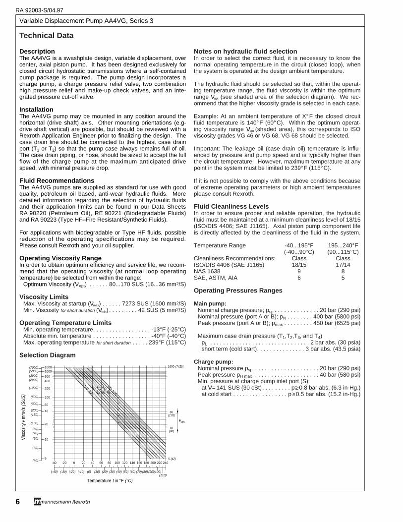
Variable Displacement Pump AA4VG, Series 3
RA 92003-S/04.97
6
DescriptionThe AA4VG is a swashplate design, variable displacement, overcenter, axial piston pump. It has been designed exclusively forclosed circuit hydrostatic transmissions where a self-containedpump package is required. The pump design incorporates acharge pump, a charge pressure relief valve, two combinationhigh pressure relief and make-up check valves, and an inte-grated pressure cut-off valve.
InstallationThe AA4VG pump may be mounted in any position around thehorizontal (drive shaft) axis. Other mounting orientations (e.g-drive shaft vertical) are possible, but should be reviewed with aRexroth Application Engineer prior to finalizing the design. Thecase drain line should be connected to the highest case drainport (T1 or T2) so that the pump case always remains full of oil.The case drain piping, or hose, should be sized to accept the fullflow of the charge pump at the maximum anticipated drivespeed, with minimal pressure drop.
Fluid RecommendationsThe AA4VG pumps are supplied as standard for use with goodquality, petroleum oil based, anti-wear hydraulic fluids. Moredetailed information regarding the selection of hydraulic fluidsand their application limits can be found in our Data SheetsRA 90220 (Petroleum Oil), RE 90221 (Biodegradable Fluids)and RA 90223 (Type HF–Fire Resistant/Synthetic Fluids).
For applications with biodegradable or Type HF fluids, possiblereduction of the operating specifications may be required.Please consult Rexroth and your oil supplier.
Operating Viscosity RangeIn order to obtain optimum efficiency and service life, we recom-mend that the operating viscosity (at normal loop operatingtemperature) be selected from within the range:
Optimum Viscosity (νopt) . . . . . . 80...170 SUS (16...36 mm2/S)
Viscosity LimitsMax. Viscosity at startup (νmax) . . . . . . 7273 SUS (1600 mm2/S)Min. Viscosity for short duration (νmin) . . . . . . . . . 42 SUS (5 mm2/S)
Operating Temperature LimitsMin. operating temperature. . . . . . . . . . . . . . . . . . -13°F (-25°C)Absolute min. temperature . . . . . . . . . . . . . . . . . . -40°F (-40°C)Max. operating temperature for short duration . . . . . 239°F (115°C)
Selection Diagram
Notes on hydraulic fluid selectionIn order to select the correct fluid, it is necessary to know thenormal operating temperature in the circuit (closed loop), whenthe system is operated at the design ambient temperature.
The hydraulic fluid should be selected so that, within the operat-ing temperature range, the fluid viscosity is within the optimumrange νopt (see shaded area of the selection diagram). We rec-ommend that the higher viscosity grade is selected in each case.
Example: At an ambient temperature of X°F the closed circuitfluid temperature is 140°F (60°C). Within the optimum operat-ing viscosity range νopt (shaded area), this corresponds to ISOviscosity grades VG 46 or VG 68. VG 68 should be selected.
Important: The leakage oil (case drain oil) temperature is influ-enced by pressure and pump speed and is typically higher thanthe circuit temperature. However, maximum temperature at anypoint in the system must be limited to 239°F (115°C).
If it is not possible to comply with the above conditions becauseof extreme operating parameters or high ambient temperaturesplease consult Rexroth.
Fluid Cleanliness LevelsIn order to ensure proper and reliable operation, the hydraulicfluid must be maintained at a minimum cleanliness level of 18/15(ISO/DIS 4406; SAE J1165). Axial piston pump component lifeis directly affected by the cleanliness of the fluid in the system.
Temperature Range -40...195°F 195...240°F(-40...90°C) (90...115°C)
Cleanliness Recommendations: Class ClassISO/DIS 4406 (SAE J1165) 18/15 17/14NAS 1638 9 8SAE, ASTM, AIA 6 5
Operating Pressures Ranges
Main pump:Nominal charge pressure; psp . . . . . . . . . . . . . . 20 bar (290 psi)Nominal pressure (port A or B); pN . . . . . . . . 400 bar (5800 psi)Peak pressure (port A or B); pmax . . . . . . . . . 450 bar (6525 psi)
Maximum case drain pressure (T1,T2,T3, and T4)pL . . . . . . . . . . . . . . . . . . . . . . . . . . . . . . . 2 bar abs. (30 psia)short term (cold start). . . . . . . . . . . . . . . 3 bar abs. (43.5 psia)
Charge pump:Nominal pressure psp . . . . . . . . . . . . . . . . . . . . 20 bar (290 psi)Peak pressure pH max . . . . . . . . . . . . . . . . . . . . 40 bar (580 psi)Min. pressure at charge pump inlet port (S):
at ν= 141 SUS (30 cSt) . . . . . . . . . p≥0.8 bar abs. (6.3 in-Hg.)at cold start . . . . . . . . . . . . . . . . . p≥0.5 bar abs. (15.2 in-Hg.)
Vis
cosi
ty v
mm
2 /s (S
US
)
16(80)
36(170)
5 (42)
1600 (7425)
vopt.
�����������������������������������������������������������������
VG 22
VG 32
VG 46
VG 68
Temperature t in °F (°C)
VG 100
(-40) (-30) (-20) (-10) (0) (10) (20) (30) (40) (50) (60) (70) (80) (90)(100)(110)
-40 -20 100 120 1400 20 40 60 80 160 180 200 220 240
16001000
600400
200
100
60
40
20
10
5
(7000)(5000)(3000)(2000)
(1000)
(500)
(300)
(150)(200)
(100)
(80)(70)
(60)
(50)
(40)
Technical Data
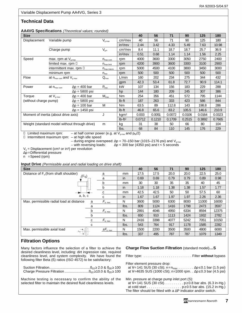
Technical Data
AA4VG Specifications (Theoretical values; rounded)Size 40 56 71 90 125 180Displacement Variable pump Vg max cm3/rev 40 56 71 90 125 180
in3/rev 2.44 3.42 4.33 5.49 7.63 10.98Charge pump VgH cm3/rev 8.4 11.1 18.7 18.7 25.7 36.9
in3/rev 0.51 0.68 1.14 1.14 1.56 2.25Speed max. rpm at Vg max nmax cont rpm 4000 3600 3300 3050 2750 2400
limited max. rpm ➀ nmax limit rpm 4200 3900 3600 3300 3100 2900intermittent max. rpm ➁ nmax Interm rpm 5000 4500 4100 3800 3450 3000minimum rpm nmin rpm 500 500 500 500 500 500
Flow at nmax cont and Vg max Qmax L/min 160 202 234 275 344 432gpm 42.3 53.4 61.8 72.7 90.9 114.1
Power at nmax cont ∆p = 400 bar Pmax kW 107 134 156 183 229 288∆p = 5800 psi hp 144 180 209 245 307 386
Torque at Vg max ∆p = 400 bar Mmax Nm 254 356 451 572 795 1144(without charge pump) ∆p = 5800 psi lb-ft 187 263 333 423 586 844
∆p = 100 bar M Nm 63.5 89 112.8 143 198.8 286∆p = 1450 psi lb-ft 46.8 65.6 83.2 105.5 146.6 210.9
Moment of inertia (about drive axis) J kgm2 0.003 0.0051 0.0072 0.0106 0.0164 0.0323lb-ft2 0.0712 0.1210 0.1709 0.2515 0.3892 0.7665
Weight (standard model without through drive) m kg 31 38 50 66 80 104lbs. 68 84 110 145 176 229
➀ Limited maximum rpm: – at half corner power (e.g. at Vg max and pN/2)➁ Intermittent maximum rpm: – at high idle speed
– during engine overspeed: ∆p = 70–150 bar (1015–2176 psi) and Vg max
– with reversing loads: ∆p < 300 bar (4350 psi) and t < 5 secondsVg = Displacement (cm3 or in3) per revolution∆p =Differential pressuren =Speed (rpm)
Input Drive (Permissible axial and radial loading on drive shaft)Size 40 56 71 90 125 180Distance of Fq (from shaft shoulder) a mm 17.5 17.5 20.0 20.0 22.5 25.0
a in 0.69 0.69 0.79 0.79 0.89 0.98b mm 30 30 35 35 40 45b in 1.18 1.18 1.38 1.38 1.57 1.77c mm 42.5 42.5 50 50 57.5 60c in 1.67 1.67 1.97 1.97 2.26 2.36
Max. permissible radial load at distance a Fq max N 3600 5000 6300 8000 11000 16000a lbs. 809 1124 1416 1798 2473 3597b Fq max N 2891 4046 4950 6334 8594 12375b lbs. 650 910 1113 1424 1932 2782c Fq max N 2416 3398 4077 5242 7051 10150c lbs. 543 764 917 1178 1585 2282
Max. permissible axial load ±Fq max N 1500 2200 3500 3500 4800 6000lbs. 337 495 787 787 1079 1349
(Fq)
a, b, c
Fax
Many factors influence the selection of a filter to achieve thedesired cleanliness level, including: dirt ingression rate, requiredcleanliness level, and system complexity. We have found thefollowing filter Beta (ß) ratios (ISO 4572) to be satisfactory:
Suction Filtration..........................................ß10≥ 2.0 & ß30≥ 100Charge Pressure Filtration .........................ß10 ≥10.0 & ß20≥ 100
Machine testing is necessary to confirm the ability of theselected filter to maintain the desired fluid cleanliness levels.
Charge Flow Suction Filtration (standard model)…S
Filter type: . . . . . . . . . . . . . . . . . . . . . . . . . Filter without bypass
Filter element pressure drop:at ν= 141 SUS (30 cSt); n=nmax . . . . . . . . ∆p≤0.1 bar (1.5 psi)at ν=4635 SUS (1000 cSt); n=1000 rpm. . ∆p≤0.3 bar (4.5 psi)
Min. pressure at charge pump inlet port (S):at ν= 141 SUS (30 cSt) . . . . . . . . . . p≥0.8 bar abs. (6.3 in-Hg.)at cold start . . . . . . . . . . . . . . . . . . p≥0.5 bar abs. (15.2 in-Hg.)
The filter should be fitted with a ∆P indicator and/or switch.
Filtration Options
RA 92003-S/04.97
7
Variable Displacement Pump AA4VG, Series 3
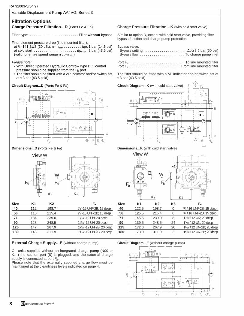
Variable Displacement Pump AA4VG, Series 3
RA 92003-S/04.97
8
Charge Pressure Filtration…D (Ports Fe & Fa)
Filter type: . . . . . . . . . . . . . . . . . . . . . . . . . Filter without bypass
Filter element pressure drop (line mounted filter):at ν=141 SUS (30 cSt); n=nmax . . . . . . . . . ∆p≤1 bar (14.5 psi)at cold start . . . . . . . . . . . . . . . . . . . . . . ∆pmax=3 bar (43.5 psi)(valid for entire speed range nmin–nmax)
Please note:• With Direct Operated Hydraulic Control–Type DG, control
pressure should be supplied from the PS port.• The filter should be fitted with a ∆P indicator and/or switch set
at ≤3 bar (43.5 psid).
Circuit Diagram...D (Ports Fe & Fa)
Dimensions...D (Ports Fe & Fa)
Size K1 K2 Fe
40 112 198.7 3⁄4"-16 UNF-2B; 15 deep56 115 215.4 3⁄4"-16 UNF-2B; 15 deep71 134 239.0 11⁄16"-12 UN; 20 deep90 128 248.5 11⁄16"-12 UN; 20 deep125 147 267.9 15⁄16"-12 UN-2B; 20 deep180 148 311.9 15⁄16"-12 UN-2B; 20 deep
External Charge Supply…E (without charge pump)
On units supplied without an integrated charge pump (N00 orK…) the suction port (S) is plugged, and the external chargesupply is connected at port Fa.Please note that the externally supplied charge flow must bemaintained at the cleanliness levels indicated on page 4.
Filtration OptionsCharge Pressure Filtration…K (with cold start valve)
Similar to option D, except with cold start valve, providing filterbypass function and charge pump protection.
Bypass valve:Bypass setting . . . . . . . . . . . . . . . . . . . . . . ∆p≥ 3.5 bar (50 psi)Bypass flow . . . . . . . . . . . . . . . . . . . . . . . To charge pump inlet
Port Fe. . . . . . . . . . . . . . . . . . . . . . . . . . . . . To line mounted filterPort Fa. . . . . . . . . . . . . . . . . . . . . . . . . . . From line mounted filter
The filter should be fitted with a ∆P indicator and/or switch set at≤3 bar (43.5 psid).
Circuit Diagram...K (with cold start valve)
Dimensions...K (with cold start valve)
Size K1 K2 K3 Fe
40 122.5 198.7 0 3⁄4"-16 UNF-2B; 15 deep56 125.5 215.4 0 3⁄4"-16 UNF-2B; 15 deep71 145.5 239.0 8 11⁄16"-12 UN; 20 deep90 139.5 248.5 24 11⁄16"-12 UN; 20 deep125 172.0 267.9 20 15⁄16"-12 UN-2B; 20 deep180 173.0 311.9 3 15⁄16"-12 UN-2B; 20 deep
Circuit Diagram...E (without charge pump)
e
W
Fe
K1
Fe
K3
K2
View W
K1K2
FeFe
View W
W
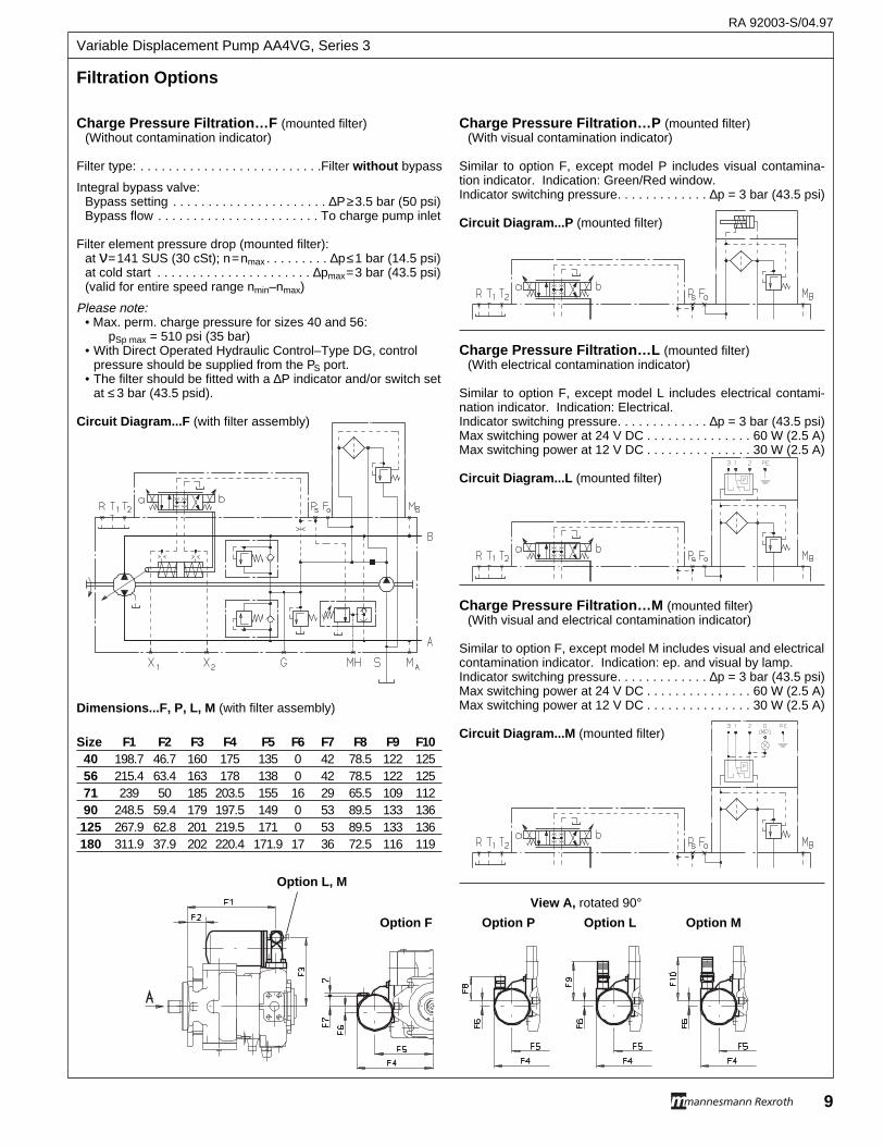
Charge Pressure Filtration…F (mounted filter)(Without contamination indicator)
Filter type: . . . . . . . . . . . . . . . . . . . . . . . . . .Filter without bypass
Integral bypass valve:Bypass setting . . . . . . . . . . . . . . . . . . . . . . ∆P≥3.5 bar (50 psi)Bypass flow . . . . . . . . . . . . . . . . . . . . . . . To charge pump inlet
Filter element pressure drop (mounted filter):at ν=141 SUS (30 cSt); n=nmax . . . . . . . . . ∆p≤1 bar (14.5 psi)at cold start . . . . . . . . . . . . . . . . . . . . . . ∆pmax=3 bar (43.5 psi)(valid for entire speed range nmin–nmax)
Please note:• Max. perm. charge pressure for sizes 40 and 56:
pSp max = 510 psi (35 bar)• With Direct Operated Hydraulic Control–Type DG, control
pressure should be supplied from the PS port.• The filter should be fitted with a ∆P indicator and/or switch set
at ≤ 3 bar (43.5 psid).
Circuit Diagram...F (with filter assembly)
Dimensions...F, P, L, M (with filter assembly)
Size F1 F2 F3 F4 F5 F6 F7 F8 F9 F1040 198.7 46.7 160 175 135 0 42 78.5 122 12556 215.4 63.4 163 178 138 0 42 78.5 122 12571 239 50 185 203.5 155 16 29 65.5 109 11290 248.5 59.4 179 197.5 149 0 53 89.5 133 136125 267.9 62.8 201 219.5 171 0 53 89.5 133 136180 311.9 37.9 202 220.4 171.9 17 36 72.5 116 119
Charge Pressure Filtration…P (mounted filter)(With visual contamination indicator)
Similar to option F, except model P includes visual contamina-tion indicator. Indication: Green/Red window.Indicator switching pressure. . . . . . . . . . . . . ∆p = 3 bar (43.5 psi)
Circuit Diagram...P (mounted filter)
Charge Pressure Filtration…L (mounted filter)(With electrical contamination indicator)
Similar to option F, except model L includes electrical contami-nation indicator. Indication: Electrical.Indicator switching pressure. . . . . . . . . . . . . ∆p = 3 bar (43.5 psi)Max switching power at 24 V DC . . . . . . . . . . . . . . . 60 W (2.5 A)Max switching power at 12 V DC . . . . . . . . . . . . . . . 30 W (2.5 A)
Circuit Diagram...L (mounted filter)
Charge Pressure Filtration…M (mounted filter)(With visual and electrical contamination indicator)
Similar to option F, except model M includes visual and electricalcontamination indicator. Indication: ep. and visual by lamp.Indicator switching pressure. . . . . . . . . . . . . ∆p = 3 bar (43.5 psi)Max switching power at 24 V DC . . . . . . . . . . . . . . . 60 W (2.5 A)Max switching power at 12 V DC . . . . . . . . . . . . . . . 30 W (2.5 A)
Circuit Diagram...M (mounted filter)
Filtration Options
Option F Option P Option L Option M
View A, rotated 90°
Option L, M
RA 92003-S/04.97
9
Variable Displacement Pump AA4VG, Series 3
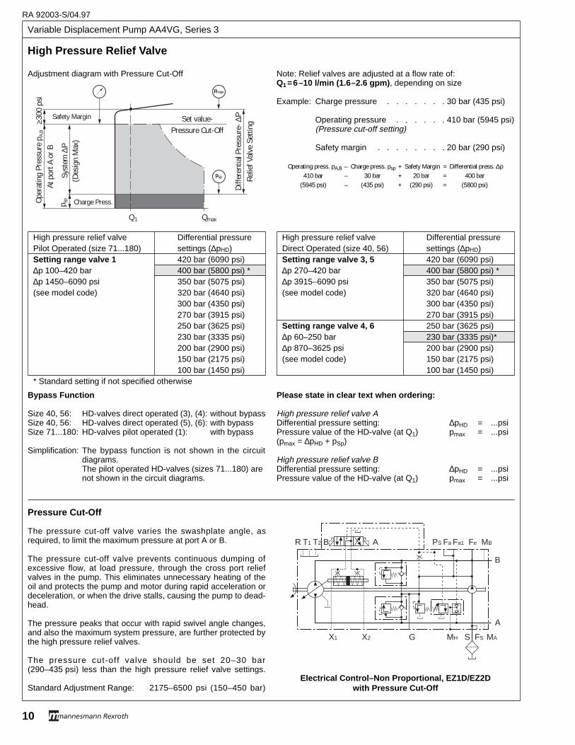
Variable Displacement Pump AA4VG, Series 3
RA 92003-S/04.97
10
Oper
atin
g Pr
essu
re p
A,B
At p
ort A
or B
p sp Charge Press.
QmaxQ 1
Set value-Pressure Cut-Off
Syst
em ∆
P(D
esig
n M
ax)
Safety Margin
≥300
psi
Diffe
rent
ial P
ress
ure-
∆P
Relie
f Val
ve S
ettin
g
pmax
psp
Adjustment diagram with Pressure Cut-Off
High Pressure Relief V alve
Bypass Function
Size 40, 56: HD-valves direct operated (3), (4): without bypassSize 40, 56: HD-valves direct operated (5), (6): with bypassSize 71...180: HD-valves pilot operated (1): with bypass
Simplification: The bypass function is not shown in the circuitdiagrams. The pilot operated HD-valves (sizes 71...180) arenot shown in the circuit diagrams.
Please state in clear text when ordering:
High pressure relief valve ADifferential pressure setting: ∆pHD = ...psiPressure value of the HD-valve (at Q1) pmax = ...psi(pmax = ∆pHD + pSp)
High pressure relief valve BDifferential pressure setting: ∆pHD = ...psiPressure value of the HD-valve (at Q1) pmax = ...psi
X1 X2 G MH S FS MA
R T1 T2 B A PS Fa Fa1 Fe MB
B
A
Pressure Cut-Off
The pressure cut-off valve varies the swashplate angle, asrequired, to limit the maximum pressure at port A or B.
The pressure cut-off valve prevents continuous dumping ofexcessive flow, at load pressure, through the cross port reliefvalves in the pump. This eliminates unnecessary heating of theoil and protects the pump and motor during rapid acceleration ordeceleration, or when the drive stalls, causing the pump to dead-head.
The pressure peaks that occur with rapid swivel angle changes,and also the maximum system pressure, are further protected bythe high pressure relief valves.
The pressure cut-off valve should be set 20–30 bar(290–435 psi) less than the high pressure relief valve settings.
Standard Adjustment Range: 2175–6500 psi (150–450 bar)Electrical Control–Non Proportional, EZ1D/EZ2D
with Pressure Cut-Off
Note: Relief valves are adjusted at a flow rate of:Q1 =6–10 l/min (1. 6–2.6 gpm) , depending on size
Example: Charge pressure . . . . . . . 30 bar (435 psi)
Operating pressure . . . . . . 410 bar (5945 psi)(Pressure cut-off setting)
Safety margin . . . . . . . . 20 bar (290 psi)
Operating press. pA,B – Charge press. psp + Safety Margin = Differential press. ∆p410 bar – 30 bar + 20 bar = 400 bar
(5945 psi) – (435 psi) + (290 psi) = (5800 psi)
High pressure relief valve Differential pressurePilot Operated (size 71...180) settings (∆pHD)Setting range valve 1 420 bar (6090 psi)∆p 100–420 bar 400 bar (5800 psi) *∆p 1450–6090 psi 350 bar (5075 psi)(see model code) 320 bar (4640 psi)
300 bar (4350 psi)270 bar (3915 psi)250 bar (3625 psi)230 bar (3335 psi)200 bar (2900 psi)150 bar (2175 psi)100 bar (1450 psi)
* Standard setting if not specified otherwise
High pressure relief valve Differential pressureDirect Operated (size 40, 56) settings (∆pHD)Setting range valve 3, 5 420 bar (6090 psi)∆p 270–420 bar 400 bar (5800 psi) *∆p 3915–6090 psi 350 bar (5075 psi)(see model code) 320 bar (4640 psi)
300 bar (4350 psi)270 bar (3915 psi)
Setting range valve 4, 6 250 bar (3625 psi)∆p 60–250 bar 230 bar (3335 psi)*∆p 870–3625 psi 200 bar (2900 psi)(see model code) 150 bar (2175 psi)
100 bar (1450 psi)
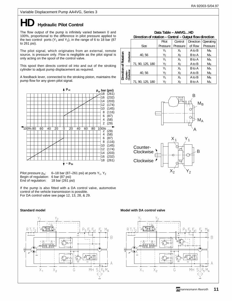
The flow output of the pump is infinitely varied between 0 and100%, proportional to the difference in pilot pressure applied tothe two control ports (Y1 and Y2), in the range of 6 to 18 bar (87to 261 psi).
The pilot signal, which originates from an external, remotesource, is pressure only. Flow is negligible as the pilot signal isonly acting on the spool of the control valve.
This spool then directs control oil into and out of the strokingcylinder to adjust pump displacement as required.
A feedback lever, connected to the stroking piston, maintains thepump flow for any given pilot signal.
Pilot pressure pst: 6–18 bar (87–261 psi) at ports Y1, Y2Begin of regulation: 6 bar (87 psi)End of regulation: 18 bar (261 psi)
If the pump is also fitted with a DA control valve, automotivecontrol of the vehicle transmission is possible.For DA control valve see page 12, 13, 28, & 29.
HD Hydraulic Pilot Control
p st
20 40 60 80 100%20406080100%
– pSt
(261)(232)(203)(174)(145)(116)(87)(58)(29)
(29)(58) (87)(116)(145)(174)(203)(232)(261)
0
18161412108642
2468
1012141618
pst bar (psi)
Standard model Model with DA control valve
Data Table – AA4VG...HDDirection of rotation – Control – Output flow direction
Pilot Control Direction OperatingSize Pressure Pressure of Flow Pressure
Y1 X1 A to B MB
40, 56 Y2 X2 B to A MA
Y1 X1 B to A MA
71, 90, 125, 180 Y2 X2 A to B MB
Y1 X1 B to A MA
40, 56 Y2 X2 A to B MB
Y1 X1 A to B MB
71, 90, 125, 180 Y2 X2 B to A MA
Dire
ctio
n of
Rot
atio
nCo
unte
r–Cl
ockw
ise
Cloc
kwis
e
B
A
MA
X2
X 1
MB
B
Y1
Y2
Counter-Clockwise
Clockwise
RA 92003-S/04.97
11
Variable Displacement Pump AA4VG, Series 3
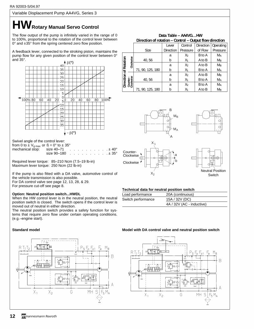
Variable Displacement Pump AA4VG, Series 3
RA 92003-S/04.97
12
HWRotar y Manual Ser vo Contr ol
The flow output of the pump is infinitely varied in the range of 0to 100%, proportional to the rotation of the control lever between0° and ±35° from the spring centered zero flow position.
A feedback lever, connected to the stroking piston, maintains thepump flow for any given position of the control lever between 0°and 35°.
Swivel angle of the control lever:from 0 to ± Vg max or ß = 0° to ± 35°mechanical stop: size 40–71 . . . . . . . . . . ± 40°
size 90–180 . . . . . . . . . . ± 35°
Required lever torque: 85–210 Ncm (7.5–19 lb-in)Maximum lever torque: 250 Ncm (22 lb-in)
If the pump is also fitted with a DA valve, automotive control ofthe vehicle transmission is also possible. For DA control valve see page 12, 13, 28, & 29.For pressure cut-off see page 8.
Option: Neutral position switch...HWDLWhen the HW control lever is in the neutral position, the neutralposition switch is closed. The switch opens if the control lever ismoved out of neutral in either direction.The neutral position switch provides a safety function for sys-tems that require zero flow under certain operating conditions.(e.g.–engine start).
( )β o
0 20 40 60 80 100%20406080100%
( )− β o
40353025201510
505
101520253035
Standard model Model with DA control valve and neutral position switch
Data Table – AA4VG...HWDirection of rotation – Control – Output flow direction
Lever Control Direction OperatingSize Direction Pressure of Flow Pressure
a X2 B to A MA
40, 56 b X1 A to B MB
a X2 A to B MB
71, 90, 125, 180 b X1 B to A MA
a X2 A to B MB
40, 56 b X1 B to A MA
a X2 B to A MA
71, 90, 125, 180 b X1 A to B MB
Dire
ctio
n of
Rot
atio
nCo
unte
r–Cl
ockw
ise
Cloc
kwis
e
B
A
MA
X2
b
a
X 1
MB
Counter-Clockwise
Clockwise
Neutral PositionSwitch
Technical data for neutral position switchLoad performance 20A (continuous)Switch performance 15A / 32V (DC)
4A / 32V (AC - inductive)
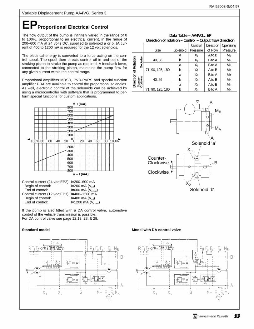
13
EPPropor tional Electrical Contr ol
The flow output of the pump is infinitely varied in the range of 0to 100%, proportional to an electrical current, in the range of200–600 mA at 24 volts DC, supplied to solenoid a or b. (A cur-rent of 400 to 1200 mA is required for the 12 volt solenoids.
The electrical energy is converted to a force acting on the con-trol spool. The spool then directs control oil in and out of thestroking piston to stroke the pump as required. A feedback lever,connected to the stroking piston, maintains the pump flow forany given current within the control range.
Proportional amplifiers MDSD, PVR-PVRS and special functionamplifier EDA are available to control the proportional solenoids. As well, electronic control of the solenoids can be achieved byusing a microcontroller with software that is programmed to per-form special functions for custom applications.
Control current (24 vdc;EP2): I=200–600 mABegin of control: I=200 mA (Vg0)End of control: I=600 mA (Vg max)
Control current (12 vdc;EP1): I=400–1200 mABegin of control: I=400 mA (Vg0)End of control: I=1200 mA (Vg max)
If the pump is also fitted with a DA control valve, automotivecontrol of the vehicle transmission is possible.For DA control valve see page 12,13, 28, & 29.
I (mA)
– I (mA)
20 40 60 80 100%406080100%
800700600500400300200100
0
200300400500600700800
020
Standard model Model with DA control valve
Data Table – AA4VG...EPDirection of rotation – Control – Output flow direction
Control Direction OperatingSize Solenoid Pressure of Flow Pressure
a X1 A to B MB
40, 56 b X2 B to A MA
a X1 B to A MA
71, 90, 125, 180 b X2 A to B MB
a X1 B to A MA
40, 56 b X2 A to B MB
a X1 A to B MB
71, 90, 125, 180 b X2 B to A MA
Dire
ctio
n of
Rot
atio
nCo
unte
r–Cl
ockw
ise
Cloc
kwis
e
B
A
MA
X2
X 1
MB
B
Solenoid ‘b’
Solenoid ‘a’
Counter-Clockwise
Clockwise
RA 92003-S/04.97
13
Variable Displacement Pump AA4VG, Series 3
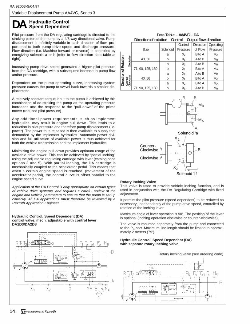
Variable Displacement Pump AA4VG, Series 3
RA 92003-S/04.97
14
DA Hydraulic Contr olSpeed Dependent
Pilot pressure from the DA regulating cartridge is directed to thestroking piston of the pump by a 4/3 way directional valve. Pumpdisplacement is infinitely variable in each direction of flow, pro-portional to both pump drive speed and discharge pressure.Flow direction (i.e.-Machine forward or reverse) is controlled byenergizing solenoid a or b (refer to flow direction data table atright).
Increasing pump drive speed generates a higher pilot pressurefrom the DA cartridge, with a subsequent increase in pump flowand/or pressure.
Dependent on the pump operating curve, increasing systempressure causes the pump to swivel back towards a smaller dis-placement.
A relatively constant torque input to the pump is achieved by thiscombination of de-stroking the pump as the operating pressureincreases and the response to the “pull-down” of the primemover (reduced pilot pressure).
Any additional power requirements, such as implementhydraulics, may result in engine pull down. This leads to areduction in pilot pressure and therefore pump displacement (i.e-power). The power thus released is then available to supply thatdemanded by the implement hydraulics. Automatic power divi-sion and full utilization of available power is thus achieved forboth the vehicle transmission and the implement hydraulics.
Minimizing the engine pull down provides optimum usage of theavailable drive power. This can be achieved by “partial inching”,using the adjustable regulating cartridge with lever (catalog codeoptions 3 and 5). With partial inching, the DA cartridge ismechanically coupled to the accelerator pedal. This means thatwhen a certain engine speed is reached, (movement of theaccelerator pedal), the control curve is offset parallel to theengine speed curve.
Application of the DA Control is only appropriate on certain typesof vehicle drive systems, and requires a careful review of theengine and vehicle parameters to ensure that the pump is set upcorrectly. All DA applications must therefore be reviewed by aRexroth Application Engineer.
Hydraulic Control, Speed Dependent (DA) control valve, mech. adjustable with control leverDA1D3/DA2D3
Hydraulic Control, Speed Dependent (DA)with separate rotary inching valve
Data Table – AA4VG...DADirection of rotation – Control – Output flow direction
Control Direction OperatingSize Solenoid Pressure of Flow Pressure
a X2 B to A MA
40, 56 b X1 A to B MB
a X2 A to B MB
71, 90, 125, 180 b X1 B to A MA
a X2 A to B MB
40, 56 b X1 B to A MA
a X2 B to A MA
71, 90, 125, 180 b X1 A to B MB
Dire
ctio
n of
Rot
atio
nCo
unte
r–Cl
ockw
ise
Cloc
kwis
e
B
A
MA
X2
X 1
MB
B
Solenoid ‘b’
Solenoid ‘a’
Counter-Clockwise
Clockwise
Rotary Inching ValveThis valve is used to provide vehicle inching function, and isused in conjunction with the DA Regulating Cartridge with fixedadjustment.
It permits the pilot pressure (speed dependent) to be reduced asnecessary, independently of the pump drive speed, controlled byrotation of the inching lever.
Maximum angle of lever operation is 90°. The position of the leveris optional (inching operation clockwise or counter-clockwise).
The valve is mounted separately from the pump and connectedto the PS port. Maximum line length should be limited to approxi-mately 2 meters (79").
Rotary inching valve (see ordering code)
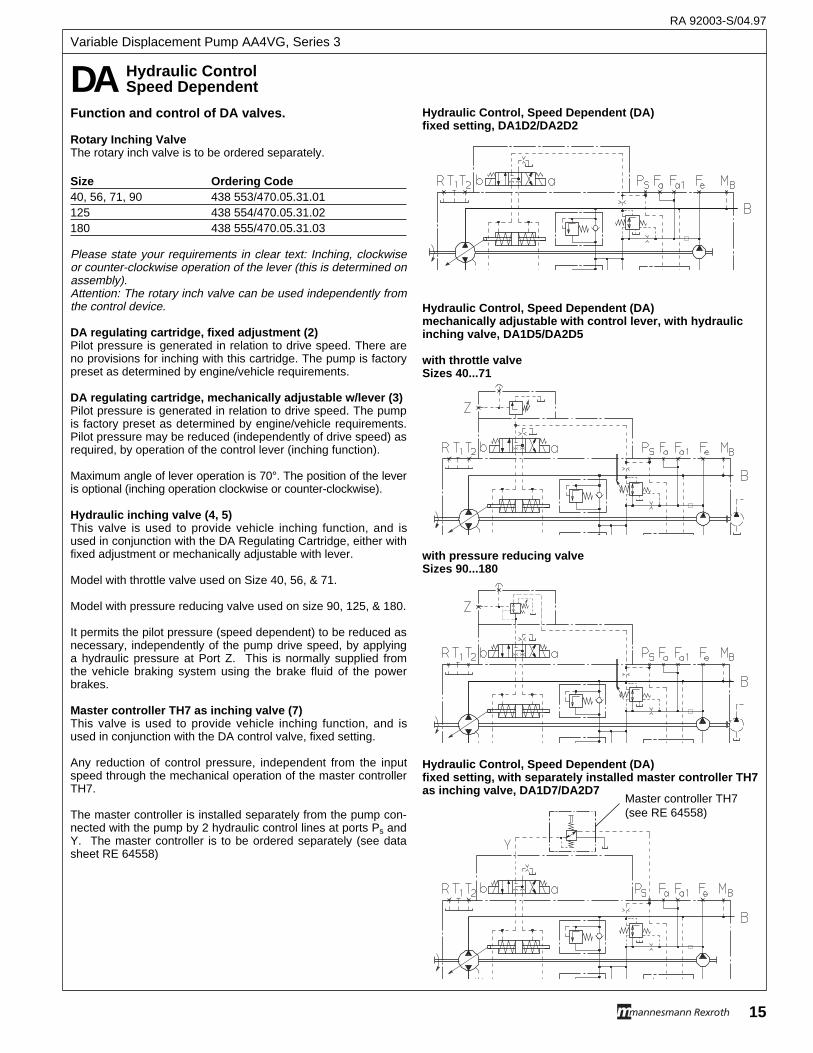
Function and control of DA valves.
Rotary Inching ValveThe rotary inch valve is to be ordered separately.
Size Ordering Code40, 56, 71, 90 438 553/470.05.31.01125 438 554/470.05.31.02180 438 555/470.05.31.03
Please state your requirements in clear text: Inching, clockwiseor counter-clockwise operation of the lever (this is determined onassembly).Attention: The rotary inch valve can be used independently fromthe control device.
DA regulating cartridge, fixed adjustment (2)Pilot pressure is generated in relation to drive speed. There areno provisions for inching with this cartridge. The pump is factorypreset as determined by engine/vehicle requirements.
DA regulating cartridge, mechanically adjustable w/lever (3)Pilot pressure is generated in relation to drive speed. The pumpis factory preset as determined by engine/vehicle requirements.Pilot pressure may be reduced (independently of drive speed) asrequired, by operation of the control lever (inching function).
Maximum angle of lever operation is 70°. The position of the leveris optional (inching operation clockwise or counter-clockwise).
Hydraulic inching valve (4, 5)This valve is used to provide vehicle inching function, and isused in conjunction with the DA Regulating Cartridge, either withfixed adjustment or mechanically adjustable with lever.
Model with throttle valve used on Size 40, 56, & 71.
Model with pressure reducing valve used on size 90, 125, & 180.
It permits the pilot pressure (speed dependent) to be reduced asnecessary, independently of the pump drive speed, by applyinga hydraulic pressure at Port Z. This is normally supplied fromthe vehicle braking system using the brake fluid of the powerbrakes.
Master controller TH7 as inching valve (7)This valve is used to provide vehicle inching function, and isused in conjunction with the DA control valve, fixed setting.
Any reduction of control pressure, independent from the inputspeed through the mechanical operation of the master controllerTH7.
The master controller is installed separately from the pump con-nected with the pump by 2 hydraulic control lines at ports Ps andY. The master controller is to be ordered separately (see datasheet RE 64558)
Hydraulic Control, Speed Dependent (DA) fixed setting, DA1D2/DA2D2
Hydraulic Control, Speed Dependent (DA) mechanically adjustable with control lever, with hydraulicinching valve, DA1D5/DA2D5
with throttle valveSizes 40...71
with pressure reducing valveSizes 90...180
Hydraulic Control, Speed Dependent (DA) fixed setting, with separately installed master controller TH7as inching valve, DA1D7/DA2D7
DA Hydraulic Contr olSpeed Dependent
Master controller TH7(see RE 64558)
RA 92003-S/04.97
15
Variable Displacement Pump AA4VG, Series 3
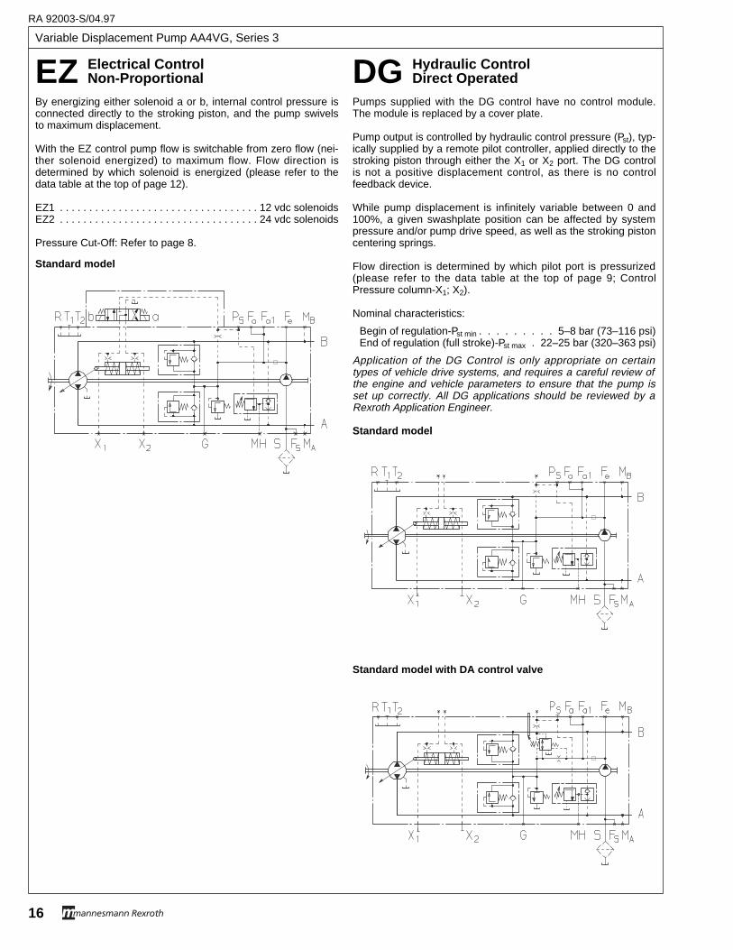
Variable Displacement Pump AA4VG, Series 3
RA 92003-S/04.97
16
EZ Electrical Contr olNon-Pr opor tional DG Hydraulic Contr ol
Direct Operated
By energizing either solenoid a or b, internal control pressure isconnected directly to the stroking piston, and the pump swivelsto maximum displacement.
With the EZ control pump flow is switchable from zero flow (nei-ther solenoid energized) to maximum flow. Flow direction isdetermined by which solenoid is energized (please refer to thedata table at the top of page 12).
EZ1 . . . . . . . . . . . . . . . . . . . . . . . . . . . . . . . . . . 12 vdc solenoidsEZ2 . . . . . . . . . . . . . . . . . . . . . . . . . . . . . . . . . . 24 vdc solenoids
Pressure Cut-Off: Refer to page 8.
Pumps supplied with the DG control have no control module.The module is replaced by a cover plate.
Pump output is controlled by hydraulic control pressure (Pst), typ-ically supplied by a remote pilot controller, applied directly to thestroking piston through either the X1 or X2 port. The DG controlis not a positive displacement control, as there is no controlfeedback device.
While pump displacement is infinitely variable between 0 and100%, a given swashplate position can be affected by systempressure and/or pump drive speed, as well as the stroking pistoncentering springs.
Flow direction is determined by which pilot port is pressurized(please refer to the data table at the top of page 9; ControlPressure column-X1; X2).
Nominal characteristics:
Begin of regulation-Pst min . . . . . . . . . 5–8 bar (73–116 psi)End of regulation (full stroke)-Pst max . 22–25 bar (320–363 psi)
Application of the DG Control is only appropriate on certaintypes of vehicle drive systems, and requires a careful review ofthe engine and vehicle parameters to ensure that the pump isset up correctly. All DG applications should be reviewed by aRexroth Application Engineer.
Standard model
Standard model
Standard model with DA control valve
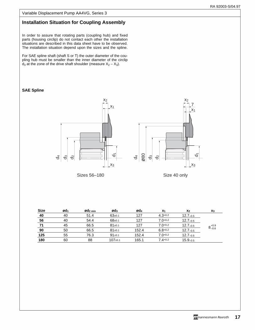
Installation Situation for Coupling Assembly
In order to assure that rotating parts (coupling hub) and fixedparts (housing circlip) do not contact each other the installationsituations are described in this data sheet have to be observed.The installation situation depend upon the sizes and the spline.
For SAE spline shaft (shaft S or T) the outer diameter of the cou-pling hub must be smaller than the inner diameter of the circlipd3 at the zone of the drive shaft shoulder (measure X2 – X3).
SAE Spline
x2
x1
x3
ø80 d 3 d 2 d 1
x2
x1
x3
d 4 d 3 d 2 d 1 d 4
7
Sizes 56–180 Size 40 only
Size ød1 ød2 min ød3 ød4 x1 x2 x3
40 40 51.4 63±0.1 127 4.3+0.2 12.7–0.5
56 40 54.4 68±0.1 127 7.0+0.2 12.7–0.5
71 45 66.5 81±0.1 127 7.0+0.2 12.7–0.5
90 50 66.5 81±0.1 152.4 6.8+0.2 12.7–0.5
125 55 76.3 91±0.1 152.4 7.0+0.2 12.7–0.5
180 60 88 107±0.1 165.1 7.4+0.2 15.9–0.5
+0.98–0.6
RA 92003-S/04.97
17
Variable Displacement Pump AA4VG, Series 3
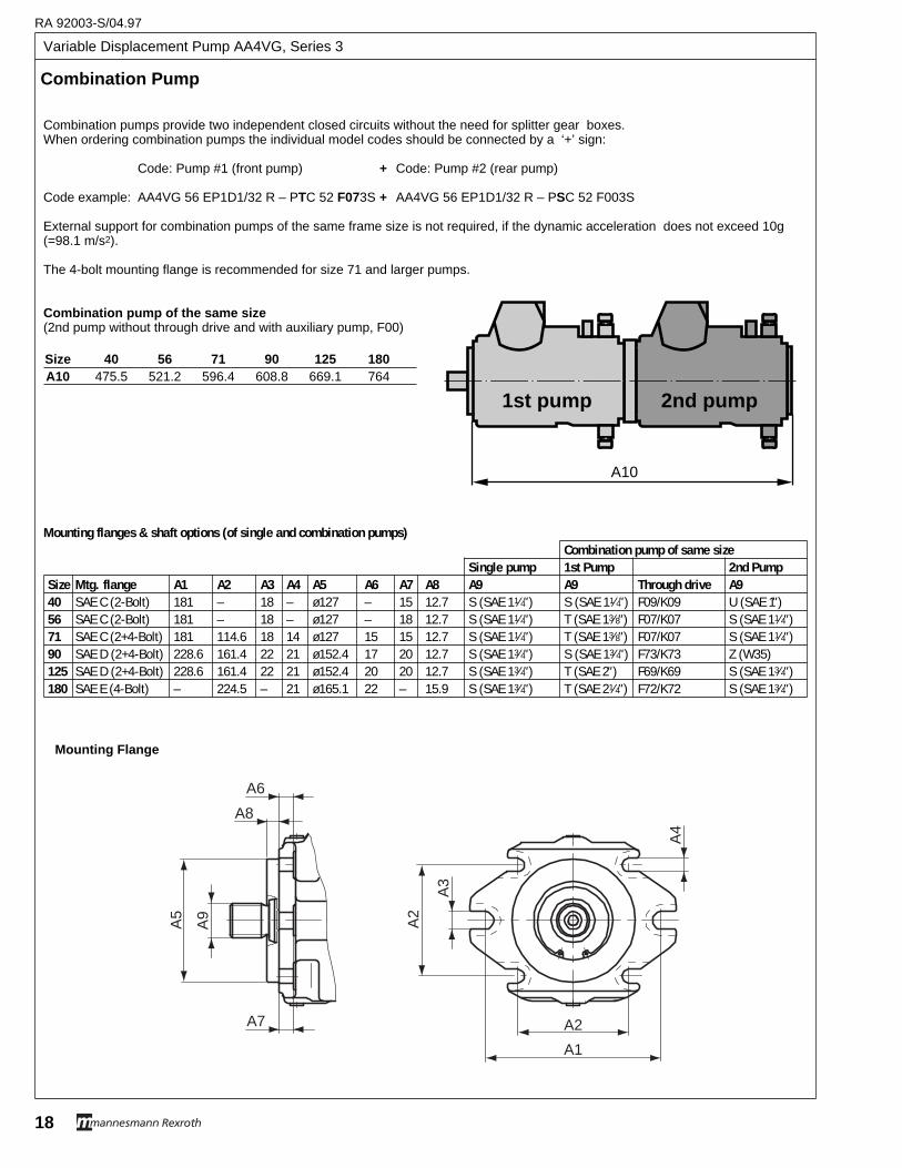
Variable Displacement Pump AA4VG, Series 3
RA 92003-S/04.97
18
Combination pumps provide two independent closed circuits without the need for splitter gear boxes.When ordering combination pumps the individual model codes should be connected by a ‘+’ sign:
Code: Pump #1 (front pump) + Code: Pump #2 (rear pump)
Code example: AA4VG 56 EP1D1/32 R – PTC 52 F073S + AA4VG 56 EP1D1/32 R – PSC 52 F003S
External support for combination pumps of the same frame size is not required, if the dynamic acceleration does not exceed 10g(=98.1 m/s2).
The 4-bolt mounting flange is recommended for size 71 and larger pumps.
Combination pump of the same size(2nd pump without through drive and with auxiliary pump, F00)
Mounting flanges & shaft options (of single and combination pumps)Combination pump of same size
Single pump 1st Pump 2nd PumpSize Mtg. flange A1 A2 A3 A4 A5 A6 A7 A8 A9 A9 Through drive A940 SAE C (2-Bolt) 181 – 18 – ø127 – 15 12.7 S (SAE 11⁄4" ) S (SAE 11⁄4" ) F09/K09 U (SAE 1" )56 SAE C (2-Bolt) 181 – 18 – ø127 – 18 12.7 S (SAE 11⁄4" ) T (SAE 13⁄8" ) F07/K07 S (SAE 11⁄4" )71 SAE C (2+4-Bolt) 181 114.6 18 14 ø127 15 15 12.7 S (SAE 11⁄4" ) T (SAE 13⁄8" ) F07/K07 S (SAE 11⁄4" )90 SAE D (2+4-Bolt) 228.6 161.4 22 21 ø152.4 17 20 12.7 S (SAE 13⁄4" ) S (SAE 13⁄4" ) F73/K73 Z (W35)125 SAE D (2+4-Bolt) 228.6 161.4 22 21 ø152.4 20 20 12.7 S (SAE 13⁄4" ) T (SAE 2" ) F69/K69 S (SAE 13⁄4" )180 SAE E (4-Bolt) – 224.5 – 21 ø165.1 22 – 15.9 S (SAE 13⁄4" ) T (SAE 21⁄4" ) F72/K72 S (SAE 13⁄4" )
A3
A7
A8
A6
A4
A2
A9
A5
A1
A2
Mounting Flange
Combination Pump
A10
2nd pump1st pump
Size 40 56 71 90 125 180A10 475.5 521.2 596.4 608.8 669.1 764
Star t-Up Pr ocedure
The following procedure has been developed based on experi-ence with most types of applications, however certainapplications may require a departure from or variation to thisprocedure.
For the start-up of new or overhauled installations.
1. If the prime mover is:
Internal combustion engine: (Diesel, gasoline or LP)-Remove the coil wire, close the injector rack or leave thegas turned off and turn the engine over until the chargepressure reaches 50 psi or more.
Electric Motor: Jog the starting circuit until the charge pres-sure reaches 50 psi or more.
2. Start the prime mover, and if possible, maintain a pumpspeed of approximately 750 rpm for 5 minutes. This willallow the system to be filled.
3. Listen for any abnormal noises.
4. Check for oil leaks.
5. Run prime mover to 1800 rpm. (Adjust to the design speedif less than 1800 rpm.)
6. Set charge and pilot pressure as required for the applica-tion. (Refer to circuit schematic)
7. For the HD control, bleed the pilot lines by loosening theconnections at Y1 and Y2 and then actuate the remote con-trol unit in both directions unti l oi l seeps from theconnections.
8. Retighten all connections.
9. Operate the control to work the hydrostatic transmission atapproximately 20% of maximum speed.
10. Deaerate system by venting a bleed valve or by crackingthe highest connection until fluid seeps out without bubbles.
11. Check fluid level and add fluid if necessary.
12. Continue operating transmission and gradually increase tofull speed, still with no load.
13. With controls neutralized, check for creep in neutral. If evi-dent, center the control in accordance with the instructionsin the pump service manual.
14. Check that the controls are connected so that the transmis-sion operates in the correct direction related to the controlinput.
15. Continue to monitor all pressure gauges and correct anyirregularities.
16. Apply brakes and set high pressure relief valves (and pres-sure override if installed) to levels required for theapplication by stroking the pump to approximately 20% ofmaximum displacement.
17. Check security of high pressure connections.
18. Check oil level and temperature.
19. Remove and inspect high pressure filter elements, if soequipped. Replace with new elements.
20. Operate transmission under no load conditions for about 15minutes to stabilize the temperature and remove any resid-ual air from the fluid.
21. Again remove and inspect high pressure filter elements, ifso equipped. If clean, the high pressure, bi-direction filtersmay be removed from the circuit. If contamination is still evi-dent, fit new elements and continue flushing until thesystem is clean.
22. Replace the elements in the charge pump suction or pres-sure filter, whichever is installed.
23. Operate the transmission under full and normal load condi-tions.
24. Erratic operation may indicate there is still air trapped in thesystem. By working the pump control to one or both sidesthe remaining air can be eliminated. The system is free ofair when all functions can be operated smoothly and whenthe oil in the reservoir is no longer aerated. (Usually lessthan 1 hour of operation).
Note: If, after following the Pre-Start and Start-up procedures, thetransmission does not perform correctly, refer to the rele-vant sections of the trouble-shooting procedures on pages20–23.
RA 92003-S/04.97
19
Variable Displacement Pump AA4VG, Series 3
Variable Displacement Pump AA4VG, Series 3
RA 92003-S/04.97
20
Troub leshooting Pr ocedure
To aid in troubleshooting, refer also to the diagnostic port con- nections for test gauge installation information. Procedure as-sumes gauges are installed.
This procedure was written to aid the troubleshooter in followinga logical approach to a system fault.
1…Transmission does not Drive with the Prime Mover Running
1.1 Is there oil in the reser-voir?
1.2 Is engine clutch en-gaged?
1.3 Is the hydraulic piping inaccordance with thehydraulic circuit?
1.4 Is the pump direction ofrotation correct?
1.5 Is there a broken pipe,loose fitt ing or bursthose?
1.6 Are the brakes re-leased?
Charge Pump & Relief Valve
1.7 Is there any chargepressure at port G?
1.8 Is the charge pressureat least 300 psi whilethe pump is running atnormal operatingspeed?
1.9 Can charge pressure beadjusted by adding orremoving relief valvespring shims or byadjusting charge pres-sure relief valve settingscrew if so equipped.
1.10 Is the suction line shut-off?
1.11 Is the charge pump suc-tion pressure within therecommended limits?(0.8 bar abs or 6.3 in-Hg.)
1.12 Is the suction filter ele-ment plugged.
1.13 Does the reservoir de-sign ensure that suctionpipe is always coveredwith oil.
No Fill reservoir.Yes Proceed to step1.2.
No Engage clutch.Yes Proceed to step 1.3.
No Correct the piping.Yes Proceed to step 1.4.
No Fit pump having thecorrect direction of rota-tion.
Yes Proceed to step 1.5.
No Proceed to step 1.6.Yes Repair the fault.
No Check brake releasecircuit or mechanism.
Yes Proceed to step 1.7.
No Proceed to step 1.10.Yes Proceed to step 1.8.
No Proceed to step 1.9.Yes Proceed to step 1.19.
No Proceed to step 1.10.Yes Adjust charge pressure
to 300 psi and proceedto step 1.19.
No Open valveYes Proceed to step 1.11.
No Proceed to step 1.12.Yes Proceed to step 1.16.
No Proceed to step 1.13.Yes Replace filter element
No Correct the reservoirdesign.
Yes Proceed to step 1.14.
1.14 Is the suction pipe size adequate for the flow?
1.15 Is the reservoir airbreather blocked orundersized?
1.16 Remove charge pres-sure relief valvecartridge and inspect.Is it damaged?
1.17 Remove and inspectcharge pump assembly.Is it damaged?
1.18 Is the charge pumpinstalled for correctdirection of rotation?
Pump Control
1.19 Is control medium con-nected to pump control?HD…pilot pressure HW…mechanical cableor linkage. EP…12 or 24 volts dc,electrical current.
1.20 If variable displacementmotors are installed, ismaximum displacementselected? (If not doneautomatically).
1.21 Actuate the control inboth directions. Doespump stroke? Does itgo to full stroke?
1.22 Remove stroking ori-f ices in X1 and X2.Stroke the pump in bothdirections. Do the pres-sures at X1 and X2Alternate between 30and 250 psi duringcycle?
No Run at lower speed andreturn to point 1.7, orrework suction piping.
Yes Proceed to step 1.15.
No Proceed to step 1.16.Yes Clean or Replace air
breather.
No Refit cartridge and pro-ceed to step 1.17.
Yes Fit a new cartridge andreturn to step 1.7.
No Proceed to step 1.18.Yes Repair or replace dam-
aged components andreturn to step 1.7.
No Refit charge pump.Return to step 1.7.
Yes With proper chargepressure, and transmis-sion sti l l does notoperate, proceed tostep 1.19.
No Connect appropriatemedium and check thatcontrol signal is actuallybeing applied to thepump control valve.
Yes Proceed to step 1.20.
No Select maximum dis-placement.
Yes Proceed to step 1.21.
No Refer to the pump ser-vice manual and thenproceed to step 1.22.
Yes Operate the transmis-sion.
No Remove control moduleand replace it with anew unit. Repeat step1.21.
Yes Proceed to step 1.23
Note: If flushing valve is used in circuit, it should set at 25 psi less than charge pump relief. Refer to data sheet onflushing valve for information and setting procedure.
2.1 Is the control medium ingood condit ion? Forexample: control me-dium is not in goodcondition if:HD…control-air in pilotlines.HW…Control-stickingcable or linkage.EP…Control-fluctuatingcontrol current.
2.2 Are the brakes fullyreleased?
2.3 Are the stroking timeorifices correctly sizedfor the application?
2.4 With HD control, is thecontrol curve of theremote pilot valve cor-rectly matched to thepump?
No Rectify the control fault.HD…Bleed pilot lines.HW…Lubricate or freethe cable or l inkage.EP…Check control cur-rent.
Yes Proceed to step 2.2.
No Check brake releasecircuit or mechanism.
Yes Proceed to step 2.3.
No Remove the plugs inports X1 and X2 andremove control orificeswith 3mm allen wrench,for size 71 and a 5mmallen wrench for size250. Try various sizesunti l desired pumpstroking rate is attained.
Yes Proceed to step 2.4.
No Change spring to suit.Yes Proceed to step 2.5.
2.5 Does the charge pres-sure f luctuate morethan 30 psi whenstroking the pump?
2.6 If the charge pump out-put is used to operateauxiliary functions, dothese other functionscause fluctuations incharge pressure?
2.7 Isolate the auxil iaryfunction and run thetransmission. Are thecharge pressure fluctu-ations reduced oreliminated?
2.8 Are there system pres-sure fluctuations whichare synchronous withthe charge pressurefluctuations?
2.9 If variable displacementmotor is used, is themotor stroking time cor-rect for the application?
No Proceed to step 2.9.Yes Proceed to step 2.6.
No Proceed to step 2.8.Yes Proceed to step 2.7.
No Proceed to step 2.8Yes Operate transmission
and return to step 2.1.
No Proceed to step 2.9.Yes Determine the cause of
system pressure fluctu-ations.
No Add motor stroking timeadjustment valve or ori-f ice to the variablemotor, or modify thecontrol circuit to providedesired stroking time.
2…Transmission Drive is Sluggish or Erratic
Troubleshooting Procedure
1.23 Is the pressure at port Rless than 2 bar abs. or30 psia?
1.24 Stroke pump in bothdirections. Does anypressure greater than350 psi alternatebetween parts MA andMB?
No Repipe pump casedrain line so that casepressure at port R isless than 8 bar abs. or30 psia. Return to step1.21.
Yes Proceed to step 1.24.
No Verify that loading ofthe pump wil l causesystem pressure toincrease above chargepressure. Proceed tostep 1.19.
Yes Proceed to step 1.25.
1.25 Is it possible to adjusthigh pressure reliefvalves using the0…10,000 psi gages atMA and MB to monitorpressure? (Refer torelief valve adjustment).
1.26 Actuate Control in bothdirections. Does trans-mission run?
No Replace high pressurerelief valve cartridgesand return to step 1.21.
Yes Adjust high pressurerelief valves to requiredor design pressure.Proceed to step 1.26.
No Check if motor sizing isadequate for applica-tion. Check formechanical faults in thedrive beyond the motorshaft.
Yes operate the transmis-sion.
1…Transmission does not Drive with the Prime Mover Running (Continued from page 20)
RA 92003-S/04.97
21
Variable Displacement Pump AA4VG, Series 3
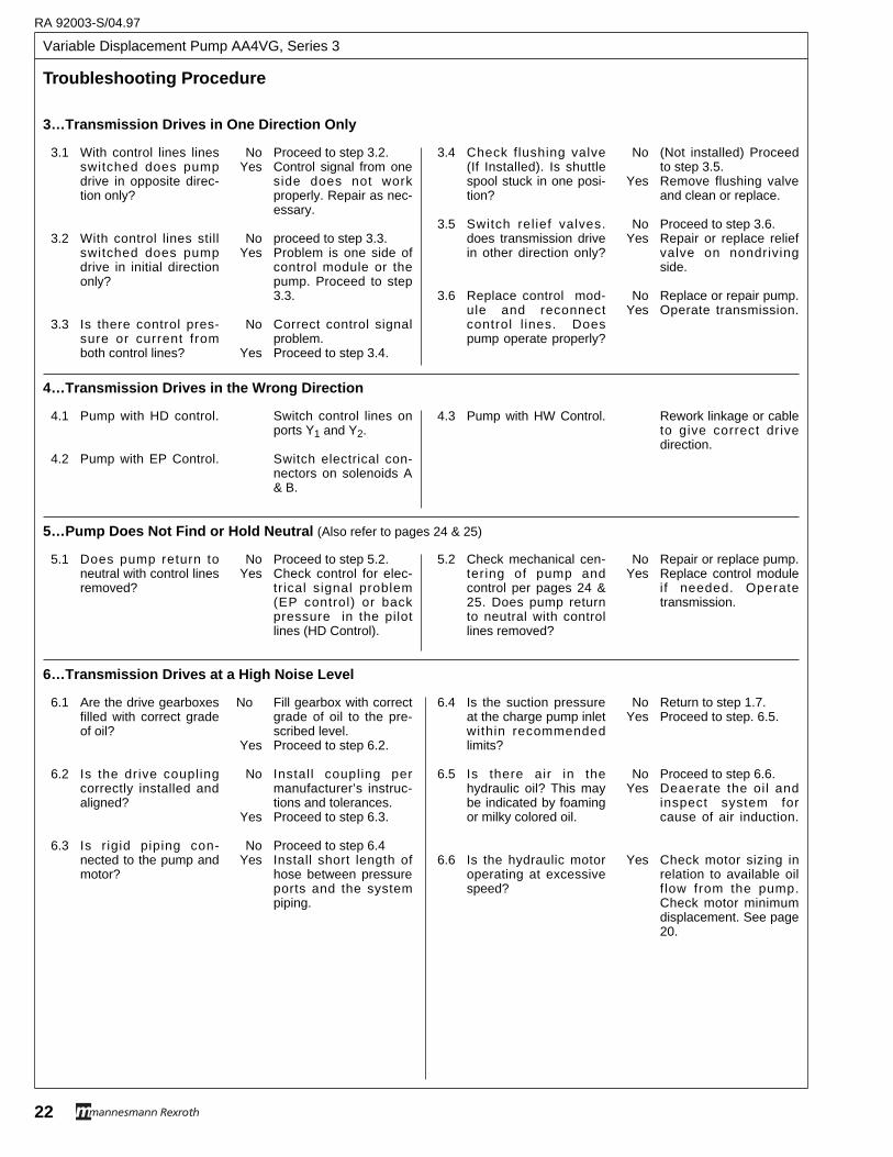
Variable Displacement Pump AA4VG, Series 3
RA 92003-S/04.97
22
Troub leshooting Pr ocedure
3.1 With control lines linesswitched does pumpdrive in opposite direc-tion only?
3.2 With control lines stillswitched does pumpdrive in initial directiononly?
3.3 Is there control pres-sure or current fromboth control lines?
No Proceed to step 3.2.Yes Control signal from one
side does not workproperly. Repair as nec-essary.
No proceed to step 3.3.Yes Problem is one side of
control module or thepump. Proceed to step3.3.
No Correct control signalproblem.
Yes Proceed to step 3.4.
3.4 Check flushing valve (If Installed). Is shuttlespool stuck in one posi-tion?
3.5 Switch relief valves.does transmission drivein other direction only?
3.6 Replace control mod-ule and reconnectcontrol l ines. Doespump operate properly?
No (Not installed) Proceedto step 3.5.
Yes Remove flushing valveand clean or replace.
No Proceed to step 3.6.Yes Repair or replace relief
valve on nondrivingside.
No Replace or repair pump.Yes Operate transmission.
4.1 Pump with HD control.
4.2 Pump with EP Control.
Switch control lines onports Y1 and Y2.
Switch electrical con-nectors on solenoids A& B.
4.3 Pump with HW Control. Rework linkage or cableto give correct drivedirection.
4…Transmission Drives in the Wrong Direction
5.1 Does pump return toneutral with control linesremoved?
No Proceed to step 5.2.Yes Check control for elec-
trical signal problem(EP control) or backpressure in the pilotlines (HD Control).
5.2 Check mechanical cen-tering of pump andcontrol per pages 24 &25. Does pump returnto neutral with controllines removed?
No Repair or replace pump.Yes Replace control module
if needed. Operatetransmission.
5…Pump Does Not Find or Hold Neutral (Also refer to pages 24 & 25)
6.1 Are the drive gearboxesfilled with correct gradeof oil?
6.2 Is the drive couplingcorrectly installed andaligned?
6.3 Is rigid piping con-nected to the pump andmotor?
No Fill gearbox with correctgrade of oil to the pre-scribed level.
Yes Proceed to step 6.2.
No Install coupling permanufacturer’s instruc-tions and tolerances.
Yes Proceed to step 6.3.
No Proceed to step 6.4Yes Install short length of
hose between pressureports and the systempiping.
6.4 Is the suction pressureat the charge pump inletwithin recommendedlimits?
6.5 Is there air in thehydraulic oil? This maybe indicated by foamingor milky colored oil.
6.6 Is the hydraulic motoroperating at excessivespeed?
No Return to step 1.7.Yes Proceed to step. 6.5.
No Proceed to step 6.6.Yes Deaerate the oil and
inspect system forcause of air induction.
Yes Check motor sizing inrelation to available oilf low from the pump.Check motor minimumdisplacement. See page20.
6…Transmission Drives at a High Noise Level
3…Transmission Drives in One Direction Only
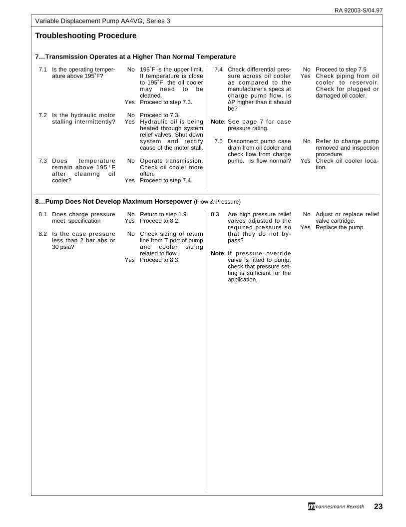
Troub leshooting Pr ocedure
7.1 Is the operating temper-ature above 195˚F?
7.2 Is the hydraulic motorstalling intermittently?
7.3 Does temperatureremain above 195˚ Fafter cleaning oilcooler?
No 195˚F is the upper limit.If temperature is closeto 195˚F, the oil coolermay need to becleaned.
Yes Proceed to step 7.3.
No Proceed to 7.3.Yes Hydraulic oil is being
heated through systemrelief valves. Shut downsystem and rectifycause of the motor stall.
No Operate transmission.Check oil cooler moreoften.
Yes Proceed to step 7.4.
7.4 Check differential pres-sure across oil cooleras compared to themanufacturer’s specs atcharge pump flow. Is∆P higher than it shouldbe?
Note: See page 7 for casepressure rating.
7.5 Disconnect pump casedrain from oil cooler andcheck flow from chargepump. Is flow normal?
No Proceed to step 7.5 Yes Check piping from oil
cooler to reservoir.Check for plugged ordamaged oil cooler.
No Refer to charge pumpremoved and inspectionprocedure.
Yes Check oil cooler loca-tion.
7…Transmission Operates at a Higher Than Normal Temperature
8…Pump Does Not Develop Maximum Horsepower (Flow & Pressure)
8.1 Does charge pressuremeet specification
8.2 Is the case pressureless than 2 bar abs or30 psia?
No Return to step 1.9.Yes Proceed to 8.2.
No Check sizing of returnline from T port of pumpand cooler sizingrelated to flow.
Yes Proceed to 8.3.
8.3 Are high pressure reliefvalves adjusted to therequired pressure sothat they do not by-pass?
Note: If pressure overridevalve is fitted to pump,check that pressure set-ting is sufficient for theapplication.
No Adjust or replace reliefvalve cartridge.
Yes Replace the pump.
RA 92003-S/04.97
23
Variable Displacement Pump AA4VG, Series 3
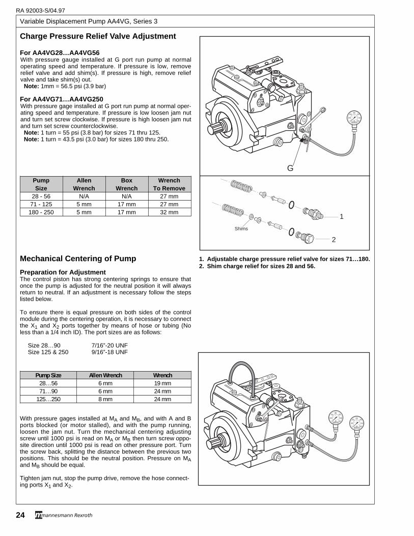
Variable Displacement Pump AA4VG, Series 3
RA 92003-S/04.97
24
For AA4VG28…AA4VG56With pressure gauge installed at G port run pump at normaloperating speed and temperature. If pressure is low, removerelief valve and add shim(s). If pressure is high, remove reliefvalve and take shim(s) out.
Note: 1mm = 56.5 psi (3.9 bar)
For AA4VG71…AA4VG250With pressure gage installed at G port run pump at normal oper-ating speed and temperature. If pressure is low loosen jam nutand turn set screw clockwise. If pressure is high loosen jam nutand turn set screw counterclockwise.
Note: 1 turn = 55 psi (3.8 bar) for sizes 71 thru 125.Note: 1 turn = 43.5 psi (3.0 bar) for sizes 180 thru 250.
Mechanical Centering of Pump
Preparation for AdjustmentThe control piston has strong centering springs to ensure thatonce the pump is adjusted for the neutral position it will alwaysreturn to neutral. If an adjustment is necessary follow the stepslisted below.
To ensure there is equal pressure on both sides of the controlmodule during the centering operation, it is necessary to connectthe X1 and X2 ports together by means of hose or tubing (Noless than a 1/4 inch ID). The port sizes are as follows:
Size 28…90 7/16”-20 UNFSize 125 & 250 9/16”-18 UNF
With pressure gages installed at MA and MB, and with A and Bports blocked (or motor stalled), and with the pump running,loosen the jam nut. Turn the mechanical centering adjustingscrew until 1000 psi is read on MA or MB then turn screw oppo-site direction until 1000 psi is read on other pressure port. Turnthe screw back, splitting the distance between the previous twopositions. This should be the neutral position. Pressure on MAand MB should be equal.
Tighten jam nut, stop the pump drive, remove the hose connect-ing ports X1 and X2.
Pump Size Allen Wrench Wrench28…56 6 mm 19 mm71…90 6 mm 24 mm
125…250 8 mm 24 mm
00
100
200300
400
500
600
1020
30
40
REXROTHpsibar
00
100
200300
400
500
600
1020
30
40
REXROTHpsibar
G
Shims
1
2
00
100
200300
400
500
600
1020
30
40
REXROTHpsibar
Charge Pressure Relief V alve Adjustment
Pump Allen Box WrenchSize Wrench Wrench To Remove
28 - 56 N/A N/A 27 mm71 - 125 5 mm 17 mm 27 mm180 - 250 5 mm 17 mm 32 mm
1. Adjustable charge pressure relief valve for sizes 71…180.2. Shim charge relief for sizes 28 and 56.
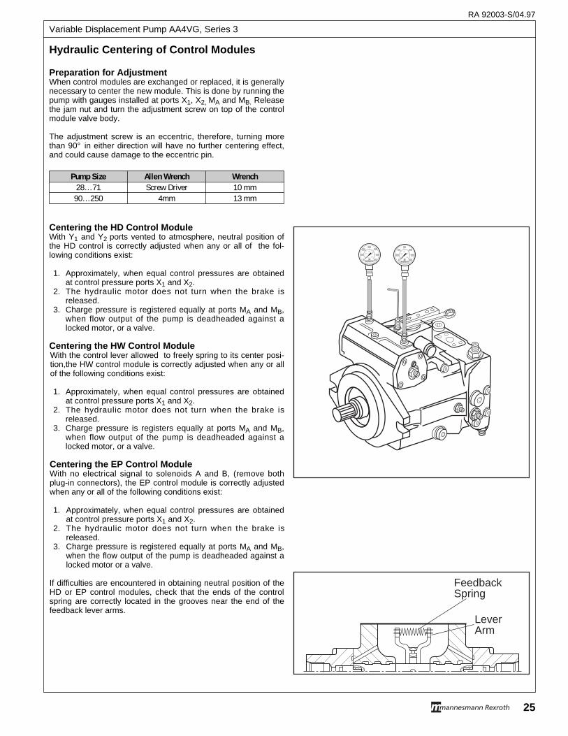
RA 92003-S/04.97
25
Variable Displacement Pump AA4VG, Series 3
Preparation for AdjustmentWhen control modules are exchanged or replaced, it is generallynecessary to center the new module. This is done by running thepump with gauges installed at ports X1, X2, MA and MB. Releasethe jam nut and turn the adjustment screw on top of the controlmodule valve body.
The adjustment screw is an eccentric, therefore, turning morethan 90° in either direction will have no further centering effect,and could cause damage to the eccentric pin.
Centering the HD Control ModuleWith Y1 and Y2 ports vented to atmosphere, neutral position ofthe HD control is correctly adjusted when any or all of the fol-lowing conditions exist:
1. Approximately, when equal control pressures are obtainedat control pressure ports X1 and X2.
2. The hydraulic motor does not turn when the brake isreleased.
3. Charge pressure is registered equally at ports MA and MB,when flow output of the pump is deadheaded against alocked motor, or a valve.
Centering the HW Control ModuleWith the control lever allowed to freely spring to its center posi-tion,the HW control module is correctly adjusted when any or allof the following conditions exist:
1. Approximately, when equal control pressures are obtainedat control pressure ports X1 and X2.
2. The hydraulic motor does not turn when the brake isreleased.
3. Charge pressure is registers equally at ports MA and MB,when flow output of the pump is deadheaded against alocked motor, or a valve.
Centering the EP Control ModuleWith no electrical signal to solenoids A and B, (remove bothplug-in connectors), the EP control module is correctly adjustedwhen any or all of the following conditions exist:
1. Approximately, when equal control pressures are obtainedat control pressure ports X1 and X2.
2. The hydraulic motor does not turn when the brake isreleased.
3. Charge pressure is registered equally at ports MA and MB,when the flow output of the pump is deadheaded against alocked motor or a valve.
If difficulties are encountered in obtaining neutral position of theHD or EP control modules, check that the ends of the controlspring are correctly located in the grooves near the end of thefeedback lever arms.
Hydraulic Centering of Contr ol Modules
Pump Size Allen Wrench Wrench28…71 Screw Driver 10 mm90…250 4mm 13 mm
00
100
200300
400
500
600
1020
30
40
REXROTHpsibar 0
0
100
200300
400
500
600
1020
30
40
REXROTHpsibar
FeedbackSpring
LeverArm
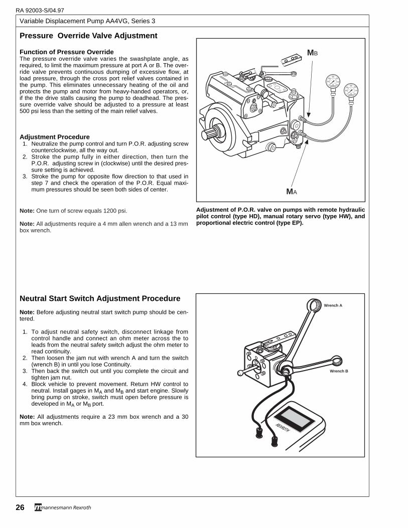
Variable Displacement Pump AA4VG, Series 3
RA 92003-S/04.97
26
Pressure Override V alve Adjustment
MA
MB
00
100
200300
400
500
600
1020
30
40
REXROTHpsibar
00
100
200300
400
500
600
1020
30
40
REXROTHpsibar
Function of Pressure OverrideThe pressure override valve varies the swashplate angle, asrequired, to limit the maximum pressure at port A or B. The over-ride valve prevents continuous dumping of excessive flow, atload pressure, through the cross port relief valves contained inthe pump. This eliminates unnecessary heating of the oil andprotects the pump and motor from heavy-handed operators, or,if the the drive stalls causing the pump to deadhead. The pres-sure override valve should be adjusted to a pressure at least500 psi less than the setting of the main relief valves.
Adjustment Procedure1. Neutralize the pump control and turn P.O.R. adjusting screw
counterclockwise, all the way out.2. Stroke the pump fully in either direction, then turn the
P.O.R. adjusting screw in (clockwise) until the desired pres-sure setting is achieved.
3. Stroke the pump for opposite flow direction to that used instep 7 and check the operation of the P.O.R. Equal maxi-mum pressures should be seen both sides of center.
Adjustment of P.O.R. valve on pumps with remote hydraulicpilot control (type HD), manual rotary servo (type HW), andproportional electric control (type EP).
Neutral Star t Switc h Adjustment Pr ocedure
Note: Before adjusting neutral start switch pump should be cen-tered.
1. To adjust neutral safety switch, disconnect linkage fromcontrol handle and connect an ohm meter across the toleads from the neutral safety switch adjust the ohm meter toread continuity.
2. Then loosen the jam nut with wrench A and turn the switch(wrench B) in until you lose Continuity.
3. Then back the switch out until you complete the circuit andtighten jam nut.
4. Block vehicle to prevent movement. Return HW control toneutral. Install gages in MA and MB and start engine. Slowlybring pump on stroke, switch must open before pressure isdeveloped in MA or MB port.
Note: All adjustments require a 23 mm box wrench and a 30mm box wrench. REXROTH
Wrenc h A
Wrenc h B
Note: One turn of screw equals 1200 psi.
Note: All adjustments require a 4 mm allen wrench and a 13 mmbox wrench.
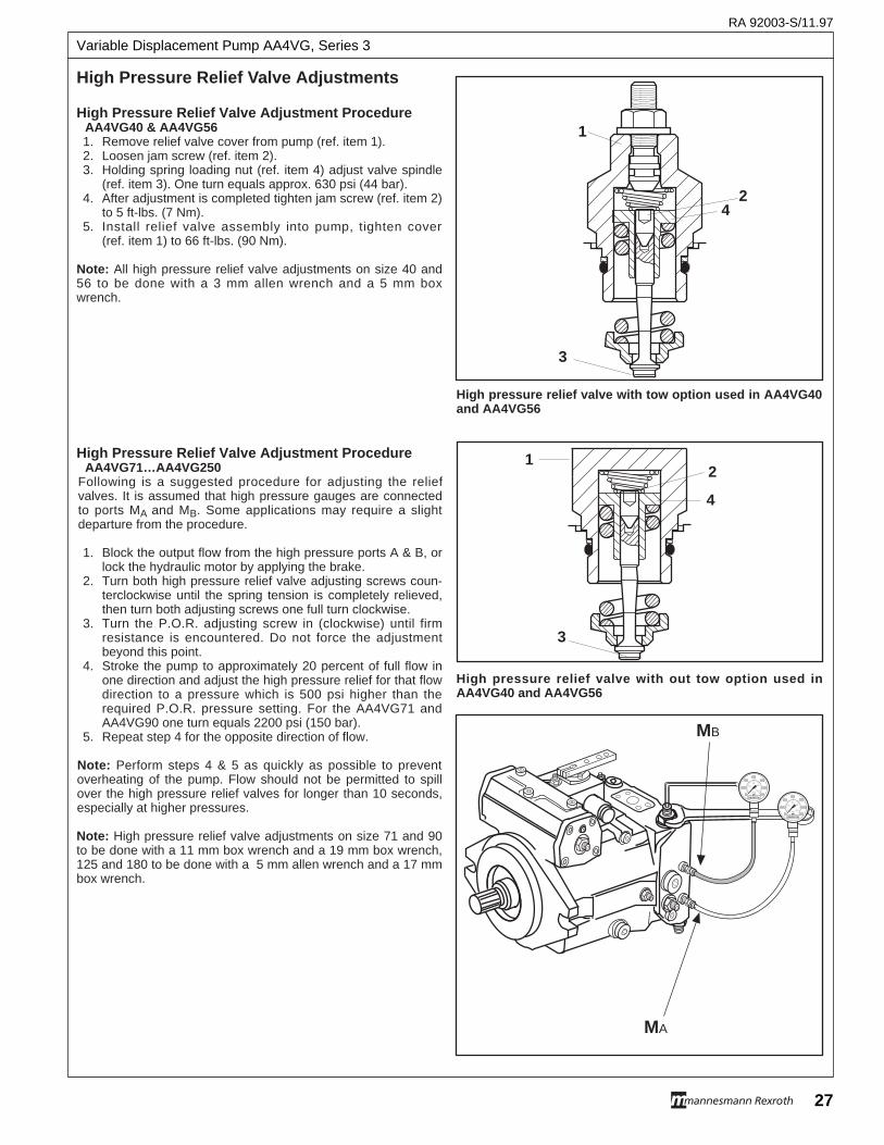
RA 92003-S/11.97
27
Variable Displacement Pump AA4VG, Series 3
MA
00
100
200300
400
500
600
1020
30
40
REXROTHpsibar
00
100
200300
400
500
600
1020
30
40
REXROTHpsibar
MB
4
1
3
2
High pressure relief valve with tow option used in AA4VG40and AA4VG56
High pressure relief valve with out tow option used inAA4VG40 and AA4VG56
4
12
3
High Pressure Relief Valve Adjustment ProcedureAA4VG40 & AA4VG561. Remove relief valve cover from pump (ref. item 1).2. Loosen jam screw (ref. item 2).3. Holding spring loading nut (ref. item 4) adjust valve spindle
(ref. item 3). One turn equals approx. 630 psi (44 bar).4. After adjustment is completed tighten jam screw (ref. item 2)
to 5 ft-lbs. (7 Nm).5. Install relief valve assembly into pump, tighten cover
(ref. item 1) to 66 ft-lbs. (90 Nm).
Note: All high pressure relief valve adjustments on size 40 and56 to be done with a 3 mm allen wrench and a 5 mm boxwrench.
High Pressure Relief Valve Adjustment ProcedureAA4VG71…AA4VG250
Following is a suggested procedure for adjusting the reliefvalves. It is assumed that high pressure gauges are connectedto ports MA and MB. Some applications may require a slightdeparture from the procedure.
1. Block the output flow from the high pressure ports A & B, orlock the hydraulic motor by applying the brake.
2. Turn both high pressure relief valve adjusting screws coun-terclockwise until the spring tension is completely relieved,then turn both adjusting screws one full turn clockwise.
3. Turn the P.O.R. adjusting screw in (clockwise) until firmresistance is encountered. Do not force the adjustmentbeyond this point.
4. Stroke the pump to approximately 20 percent of full flow inone direction and adjust the high pressure relief for that flowdirection to a pressure which is 500 psi higher than therequired P.O.R. pressure setting. For the AA4VG71 andAA4VG90 one turn equals 2200 psi (150 bar).
5. Repeat step 4 for the opposite direction of flow.
Note: Perform steps 4 & 5 as quickly as possible to preventoverheating of the pump. Flow should not be permitted to spillover the high pressure relief valves for longer than 10 seconds,especially at higher pressures.
Note: High pressure relief valve adjustments on size 71 and 90to be done with a 11 mm box wrench and a 19 mm box wrench,125 and 180 to be done with a 5 mm allen wrench and a 17 mmbox wrench.
High Pressure Relief V alve Adjustments

Variable Displacement Pump AA4VG, Series 3
RA 92003-S/11.97
28
12 3
1
12 3 4
2 3
Engagement of Relief V alve Tow Option
Relief valve for AA4VG40 and AA4VG56. 1…Nut used to torque relief valve into port block. 2…Lock nut for tow option engagement. 3…Tow option engagement screw.
Relief valve for AA4VG71 and AA4VG90. 1…Nut used to torque relief valve into port block. 2…Lock nut for high pressure relief adjustment. 3…Adjustment screw for high pressure adjustment.4…Tow option engagement screw.
Relief valve for AA4VG125 and AA4VG180. 1…Nut used to torque relief valve into port block and engage-
tow option.2…Lock nut for high pressure relief adjustment. 3…Adjustment Screw for high pressure relief adjustment.
Pump Size Wrench Size Torque28…56 32 mm 66 ft.lb. (90 Nm)71…90 32 mm 110 ft.lb. (150 Nm)
125…180 36 mm 147 ft.lb. (200 Nm)
Tow Option Engagement for AA4VG40 and AA4VG56To actuate tow option loosen lock nut (ref. item 2). Turn towoption engagement screw (ref item 3) in six turns and tightenlock nut.
To disengage tow option loosen lock nut and turn tow optionscrew all the way out until it stops.
Note: Use a 4 mm allen wrench and a 13 mm box wrench toadjust.
Tow Option Engagement for AA4VG71 and AA4VG90To actuate tow option turn tow option engagement screw (ref. item 4) out three turns.
To disengage tow option turn tow option engagement screw inuntil it stops.
Note: Use a 4 mm allen wrench to adjust.
Tow option Engagement for AA4VG125 and AA4VG180To actuate tow option turn relief valve (ref. item 1) out two turns.
To disengage tow option tighten relief valve.
Note: Use a 36 mm box wrench to adjust.
Note: Tow options are meant to be used for a short time periodonly. Tow options are not to be used for extended tows.
Torque Specs for Relief Valves into Port Block
Warning: Tow option bypasses high pressure relief valves. Catastrophic motor damage can occur ifhydraulic circuit empties or overheats.
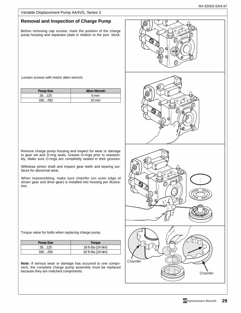
Chamfer
Chamfer
Before removing cap screws, mark the position of the chargepump housing and separator plate in relation to the port block.
Loosen screws with metric allen wrench.
Remove charge pump housing and inspect for wear or damageto gear set and O-ring seals. Grease O-rings prior to reassem-bly. Make sure O-rings are completely seated in their grooves.
Withdraw pinion shaft and inspect gear teeth and bearing sur-faces for abnormal wear.
When reassembling, make sure chamfer (on outer edge ofdriven gear and drive gear) is installed into housing per illustra-tion.
Torque value for bolts when replacing charge pump.
Note: If serious wear or damage has occurred to one compo-nent, the complete charge pump assembly must be replacedbecause they are matched components.
Pump Size Allen Wrench28…125 6 mm
180…250 10 mm
Removal and Inspection of Char ge Pump
RA 92003-S/04.97
29
Variable Displacement Pump AA4VG, Series 3
Pump Size Torque28…125 18 ft-lbs (24 Nm)
180…250 62 ft-lbs (24 Nm)
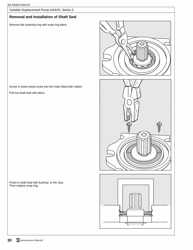
Variable Displacement Pump AA4VG, Series 3
RA 92003-S/04.97
30
Remove the retaining ring with snap ring pliers.
Screw in sheet metal screw into the holes fitted with rubber.
Pull out shaft seal with pliers.
Press-in shaft seal with bushing to the stop. Then replace snap ring.
Removal and Installation of Shaft Seal
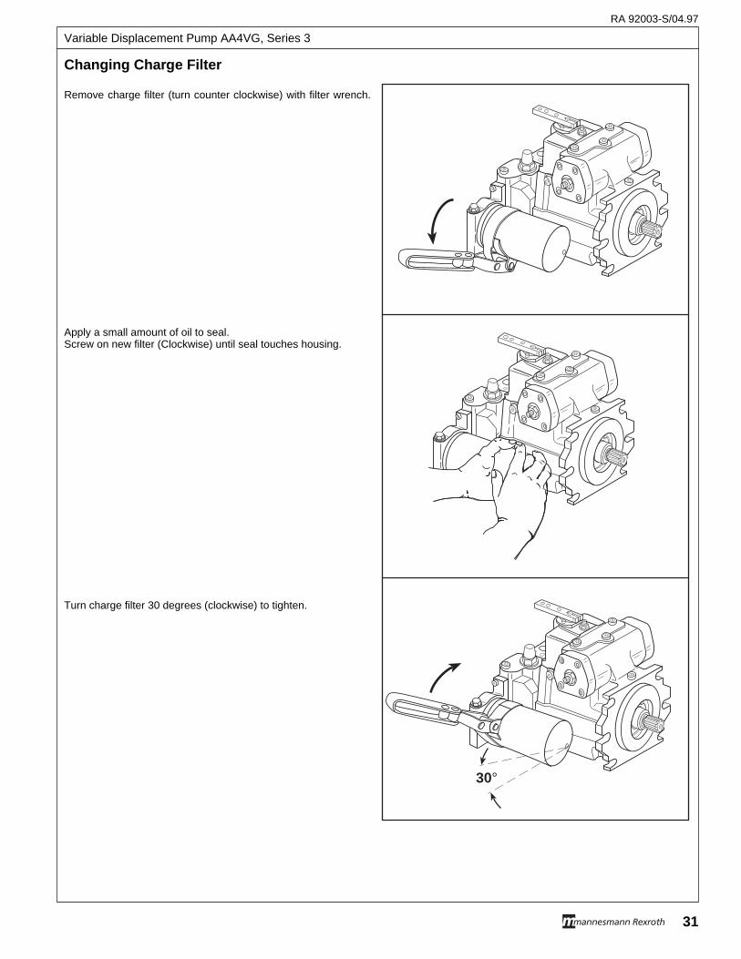
Changing Char ge Filter
RA 92003-S/04.97
31
Variable Displacement Pump AA4VG, Series 3
30°
Remove charge filter (turn counter clockwise) with filter wrench.
Apply a small amount of oil to seal.Screw on new filter (Clockwise) until seal touches housing.
Turn charge filter 30 degrees (clockwise) to tighten.
Variable Displacement Pump AA4VG, Series 3
RA 92003-S/04.97
32
The AA4VG variable pumps are relatively maintenance free.Maintenance work is confined to the system, by way of oilchanges and renewal of filter elements. Both of these mea-sures promote system cleanliness. Monitoring and periodicmaintenance of the system can prevent premature break-downs and repairs. Under normal application conditions, thefollowing maintenance intervals are suggested:
1. Renewal of Filter Elementsa. After commissioning.b. At every 500 operating hours, or when filter indicator
shows a dirty element.c. With suction filtration, the filter element should be
renewed as soon as a charge pump inlet pressure of lessthan -3.2 psi (0.8 bar absolute) becomes evident with thetransmission in warm running condition (indicates con-tamination).
d. With charge flow filtration, watch for high pressure differ-ential across the fi l ter element (Refer to f i l termanufacturer’s specifications).
Caution: Only filter elements capable of meeting or exceedingthe fluid cleanliness level requirements (reference page 9)should be used.Note: Paper inserts cannot be cleaned; use throwawaycatridges (maintain a stock).
2. Hydraulic Oil Changea. After 2000 operating hours (1st oil change).b. Thereafter every 2000 operating hours or annually irre-
spective of operating hours achieved.
The oil change should be carried out with the system in warmrunning condition. Before re-filling, the reservoir should becleaned to remove any sludge.
Caution: Rags or other threading material must not be used.
Note: The recommended interval between oil changes isbased on various factors and should be carried out accordingto the type of fluid, the degree of aging and contamination ofthe fluid. The water content is also a contributory factor.
Under application conditions with a heavy occurrence of dustor severe temperature fluctuations the intervals between oilchanges should be shortened accordingly.
Caution: Practical experience shows that most maintenanceerrors occur during an oil change due to:a. Use of an unsuitable hydraulic oil.b. Use of oil contaminated due to faulty storage.c. Failure to clean reservoir.d. Inadequate cleanliness when filling (dirty drums or con-
tainers).
3. Leakage Inspectiona. After commissioning.b. The complete transmission (pump, motor and all
pipelines, filters, valves, etc.) should be checked for leak-age at regular intervals.
Caution: Leaking joints and connections must only betighened in pressure less conditions
4. Cleanliness InspectionThe oil tank breather should be regularly cleaned of dirt and dustto prevent clogging. The cooling surfaces should be cleaned atthe same time.
Caution: If hose couplings are used in the high pressure lines, itis imperative that the utmost care be taken that no foreign bod-ies infiltrate the oil circuit when coupling and uncoupling (dangerof damage to rotary group, and even possibility of total break-down).
5. Oil level InspectionInspect oil level in reservoir after commissioning, thereafterdaily.
Caution: Top up only with specified oil type. Do not mix fluids.
Hydraulic FluidMost good quality, mineral oil based, hydraulic fluids exhibitingthe following characteristics are suitable for use in a Rexrothhydrostatic transmission.
Good antiwear performanceResistant to oxidation depredationProtection against rust and corrosionResistance to foamingAbility to separate water rapidlySuitable for widely varying temperature conditionsgood low temperature flow propertiesRetains viscosity-temperature characteristics in serviceUniversally available
The prime consideration in the selection of hydraulic fluid is theexpected oil temperature extremes that will be experienced inservice. The extremes should be considered when selecting afluid, so that the most suitable temperature-viscosity characteris-tics are obtained.
The fluid chosen should permit the system to operate within thefollowing viscosity ranges.
Maximum viscosity at start-up . . . . . . . . . . 4600 SUS (1000 cSt)Normal operating viscosity range . . . . 66–464 SUS (12–100 cSt)Optimum viscosity range . . . . . . . . . . . 81–141 SUS (16–30 cSt)Absolute minimum viscosity . . . . . . . . . . . . . . . 60 SUS (10 c St)
When the fluid viscosity is greater than 1000 SUS (216 c St) thetransmission should be operated at reduced speed until the oilhas been warmed to a temperature of 40°F (4.5°C).
For applications that will operate near the extremes of viscosityand/or temperature, the fluid manufacturer should be consultedfor assistance in selection of the most suitable type and grade offluid for your application.
Rexroth strongly recommends the selection and use of fluidsfrom reputable and established suppliers.
Routine Maintenance
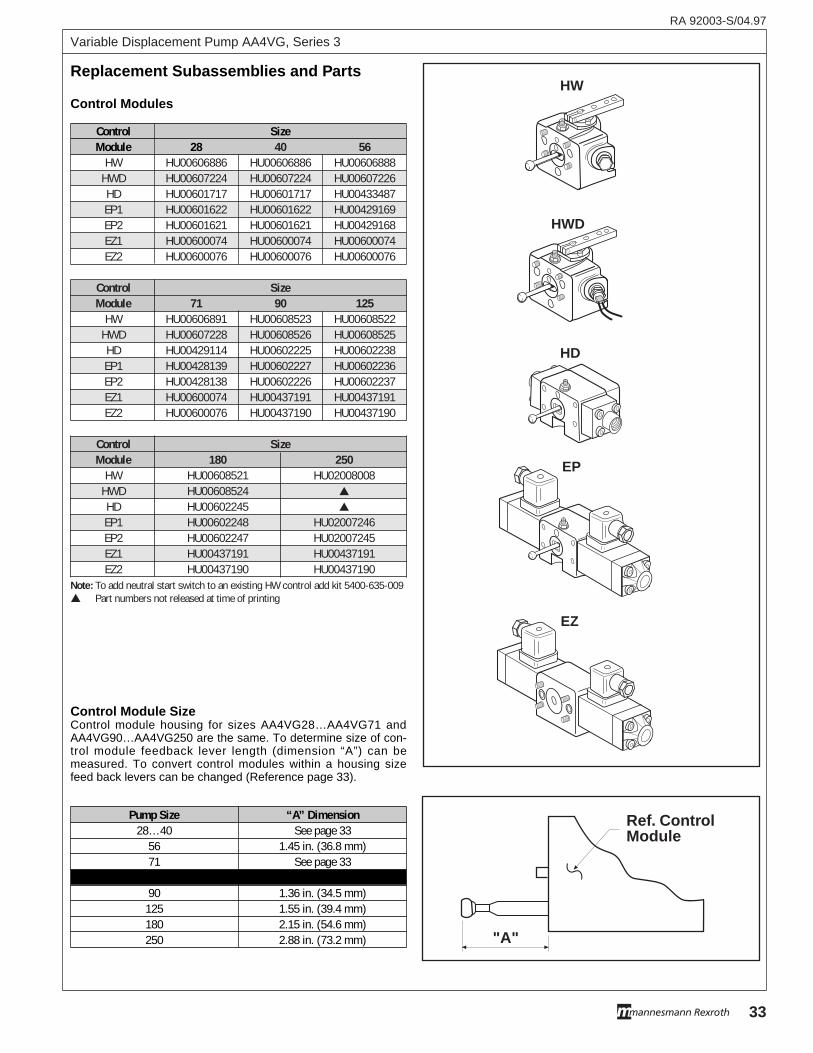
Control SizeModule 28 40 56
HW HU00606886 HU00606886 HU00606888HWD HU00607224 HU00607224 HU00607226HD HU00601717 HU00601717 HU00433487EP1 HU00601622 HU00601622 HU00429169EP2 HU00601621 HU00601621 HU00429168EZ1 HU00600074 HU00600074 HU00600074EZ2 HU00600076 HU00600076 HU00600076
Control SizeModule 71 90 125
HW HU00606891 HU00608523 HU00608522HWD HU00607228 HU00608526 HU00608525HD HU00429114 HU00602225 HU00602238EP1 HU00428139 HU00602227 HU00602236EP2 HU00428138 HU00602226 HU00602237EZ1 HU00600074 HU00437191 HU00437191EZ2 HU00600076 HU00437190 HU00437190
Control SizeModule 180 250
HW HU00608521 HU02008008HWD HU00608524 ▲
HD HU00602245 ▲
EP1 HU00602248 HU02007246EP2 HU00602247 HU02007245EZ1 HU00437191 HU00437191EZ2 HU00437190 HU00437190
Note: To add neutral start switch to an existing HW control add kit 5400-635-009▲ Part numbers not released at time of printing
RA 92003-S/04.97
33
Variable Displacement Pump AA4VG, Series 3
EP
EZ
HW
HWD
HD
Pump Size “A” Dimension28…40 See page 33
56 1.45 in. (36.8 mm)71 See page 33
90 1.36 in. (34.5 mm)125 1.55 in. (39.4 mm)180 2.15 in. (54.6 mm)250 2.88 in. (73.2 mm) "A"
Ref. Contr olModule
Control Modules
Control Module SizeControl module housing for sizes AA4VG28…AA4VG71 andAA4VG90…AA4VG250 are the same. To determine size of con-trol module feedback lever length (dimension “A”) can bemeasured. To convert control modules within a housing sizefeed back levers can be changed (Reference page 33).
Replacement Subassemb lies and P arts
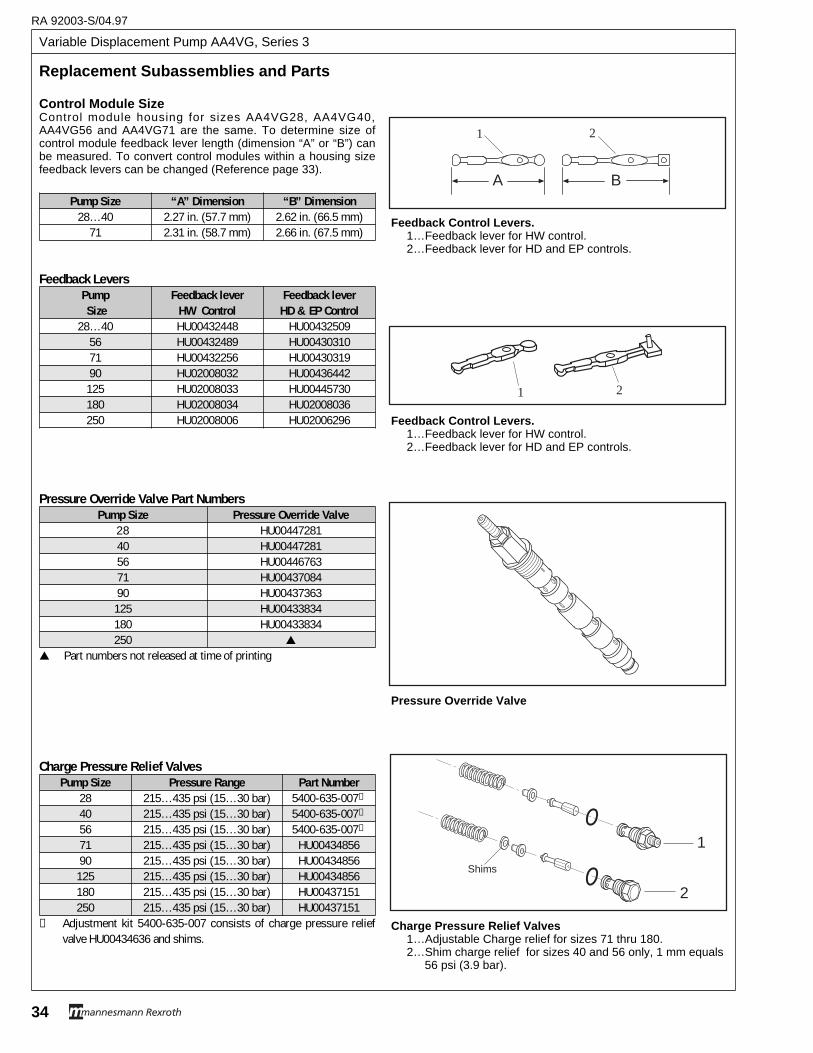
Pump Size “A” Dimension “B” Dimension28…40 2.27 in. (57.7 mm) 2.62 in. (66.5 mm)
71 2.31 in. (58.7 mm) 2.66 in. (67.5 mm)
Feedback LeversPump Feedback lever Feedback leverSize HW Control HD & EP Control
28…40 HU00432448 HU0043250956 HU00432489 HU0043031071 HU00432256 HU0043031990 HU02008032 HU00436442
125 HU02008033 HU00445730180 HU02008034 HU02008036250 HU02008006 HU02006296
Charge Pressure Relief ValvesPump Size Pressure Range Part Number
28 215…435 psi (15…30 bar) 5400-635-007➀
40 215…435 psi (15…30 bar) 5400-635-007➀
56 215…435 psi (15…30 bar) 5400-635-007➀
71 215…435 psi (15…30 bar) HU0043485690 215…435 psi (15…30 bar) HU00434856125 215…435 psi (15…30 bar) HU00434856180 215…435 psi (15…30 bar) HU00437151250 215…435 psi (15…30 bar) HU00437151
➀ Adjustment kit 5400-635-007 consists of charge pressure reliefvalve HU00434636 and shims.
Variable Displacement Pump AA4VG, Series 3
RA 92003-S/04.97
34
Pressure Override Valve Part NumbersPump Size Pressure Override Valve
28 HU0044728140 HU0044728156 HU0044676371 HU0043708490 HU00437363
125 HU00433834180 HU00433834250 ▲
▲ Part numbers not released at time of printing
Replacement Subassemb lies and P arts
Pressure Override Valve
Shims
1
2
Charge Pressure Relief Valves 1…Adjustable Charge relief for sizes 71 thru 180. 2…Shim charge relief for sizes 40 and 56 only, 1 mm equals
56 psi (3.9 bar).
1 2
Feedback Control Levers. 1…Feedback lever for HW control. 2…Feedback lever for HD and EP controls.
B
1 2
A
Control Module SizeControl module housing for sizes AA4VG28, AA4VG40,AA4VG56 and AA4VG71 are the same. To determine size ofcontrol module feedback lever length (dimension “A” or “B”) canbe measured. To convert control modules within a housing sizefeedback levers can be changed (Reference page 33).
Feedback Control Levers. 1…Feedback lever for HW control. 2…Feedback lever for HD and EP controls.
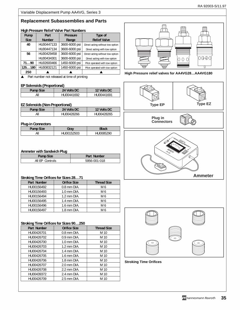
RA 92003-S/11.97
35
Variable Displacement Pump AA4VG, Series 3
Stroking Time Orifices for Sizes 90…250Part Number Orifice Size Thread SizeHU00426701 0.8 mm DIA. M 10HU00426702 0.9 mm DIA. M 10HU00426700 1.0 mm DIA. M 10HU00426703 1.2 mm DIA. M 10HU00426704 1.4 mm DIA. M 10HU00426705 1.6 mm DIA. M 10HU00426706 1.8 mm DIA. M 10HU00426707 2.0 mm DIA. M 10HU00426708 2.2 mm DIA. M 10HU00439372 2.4 mm DIA. M 10HU00426709 2.5 mm DIA. M 10
Stroking Time Orifices for Sizes 28…71Part Number Orifice Size Thread SizeHU00156492 0.8 mm DIA. M 6HU00156493 1.0 mm DIA. M 6HU00156494 1.2 mm DIA. M 6HU00156495 1.4 mm DIA. M 6HU00156496 1.6 mm DIA. M 6HU00156497 1.8 mm DIA. M 6
Ammeter
REXROTHVTB - 1532
Spannung
Magnetstr om
0 - 10V V2 4
68
10
0
5
Type EP Type EZ
Plug inConnector s
Replacement Subassemb lies and P arts
EP Solenoids (Proportional)Pump Size 24 Volts DC 12 Volts DC
All HU00441692 HU00441691
EZ Solenoids (Non-Proportional)Pump Size 24 Volts DC 12 Volts DC
All HU00428266 HU00428265
Plug-in ConnectorsPump Size Gray Black
All HU00152503 HU0085290
Ammeter with Sandwich PlugPump Size Part Number
All EP Controls 5956-001-018
Stroking Time Orifices
High Pressure relief valves for AA4VG28…AA4VG180
High Pressure Relief Valve Part NumbersPump Part Pressure Type ofSize Number Range Relief Valve40 HU00447133 3600-6000 psi Direct acting without tow option
HU00447134 3600-6000 psi Direct acting with tow option
56 HU00429458 3600-6000 psi Direct acting without tow option
HU00434301 3600-6000 psi Direct acting with tow option
71…90 HU02600466 1450-6000 psi Pilot operated with tow option
125…180 HU00832121 1450-6000 psi Pilot operated with tow option
250 ▲ ▲ ▲
▲ Part number not released at time of printing
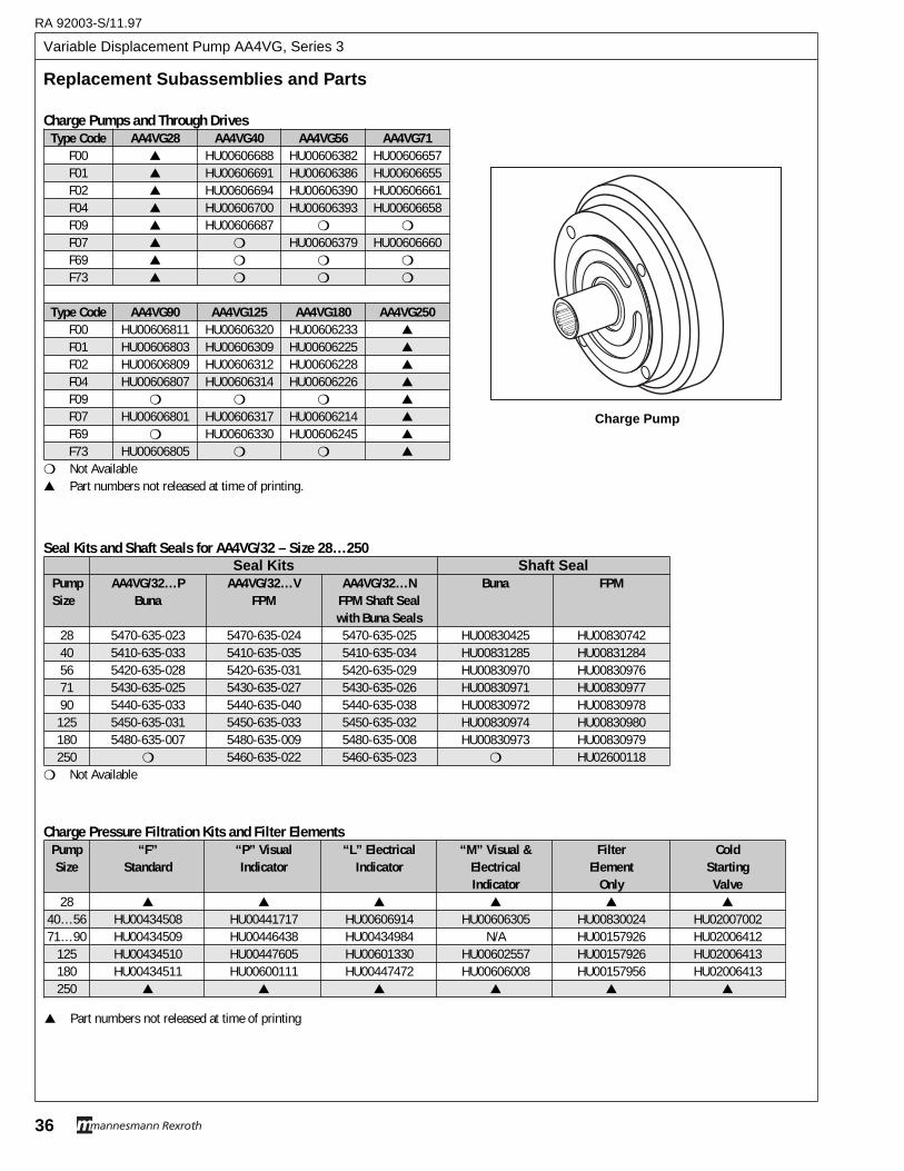
Variable Displacement Pump AA4VG, Series 3
RA 92003-S/11.97
36
Charge Pressure Filtration Kits and Filter ElementsPump “F” “P” Visual “L” Electrical “M” Visual & Filter ColdSize Standard Indicator Indicator Electrical Element Starting
Indicator Only Valve28 ▲ ▲ ▲ ▲ ▲ ▲
40…56 HU00434508 HU00441717 HU00606914 HU00606305 HU00830024 HU0200700271…90 HU00434509 HU00446438 HU00434984 N/A HU00157926 HU02006412
125 HU00434510 HU00447605 HU00601330 HU00602557 HU00157926 HU02006413180 HU00434511 HU00600111 HU00447472 HU00606008 HU00157956 HU02006413250 ▲ ▲ ▲ ▲ ▲ ▲
Seal Kits and Shaft Seals for AA4VG/32 – Size 28…250Seal Kits Shaft Seal
Pump AA4VG/32…P AA4VG/32…V AA4VG/32…N Buna FPMSize Buna FPM FPM Shaft Seal
with Buna Seals28 5470-635-023 5470-635-024 5470-635-025 HU00830425 HU0083074240 5410-635-033 5410-635-035 5410-635-034 HU00831285 HU0083128456 5420-635-028 5420-635-031 5420-635-029 HU00830970 HU0083097671 5430-635-025 5430-635-027 5430-635-026 HU00830971 HU0083097790 5440-635-033 5440-635-040 5440-635-038 HU00830972 HU00830978125 5450-635-031 5450-635-033 5450-635-032 HU00830974 HU00830980180 5480-635-007 5480-635-009 5480-635-008 HU00830973 HU00830979250 ❍ 5460-635-022 5460-635-023 ❍ HU02600118
❍ Not Available
Charge Pumps and Through DrivesType Code AA4VG28 AA4VG40 AA4VG56 AA4VG71
F00 ▲ HU00606688 HU00606382 HU00606657F01 ▲ HU00606691 HU00606386 HU00606655F02 ▲ HU00606694 HU00606390 HU00606661F04 ▲ HU00606700 HU00606393 HU00606658F09 ▲ HU00606687 ❍ ❍
F07 ▲ ❍ HU00606379 HU00606660F69 ▲ ❍ ❍ ❍
F73 ▲ ❍ ❍ ❍
Type Code AA4VG90 AA4VG125 AA4VG180 AA4VG250F00 HU00606811 HU00606320 HU00606233 ▲
F01 HU00606803 HU00606309 HU00606225 ▲
F02 HU00606809 HU00606312 HU00606228 ▲
F04 HU00606807 HU00606314 HU00606226 ▲
F09 ❍ ❍ ❍ ▲
F07 HU00606801 HU00606317 HU00606214 ▲
F69 ❍ HU00606330 HU00606245 ▲
F73 HU00606805 ❍ ❍ ▲
❍ Not Available▲ Part numbers not released at time of printing.
Replacement Subassemb lies and P arts
Charge Pump
▲ Part numbers not released at time of printing
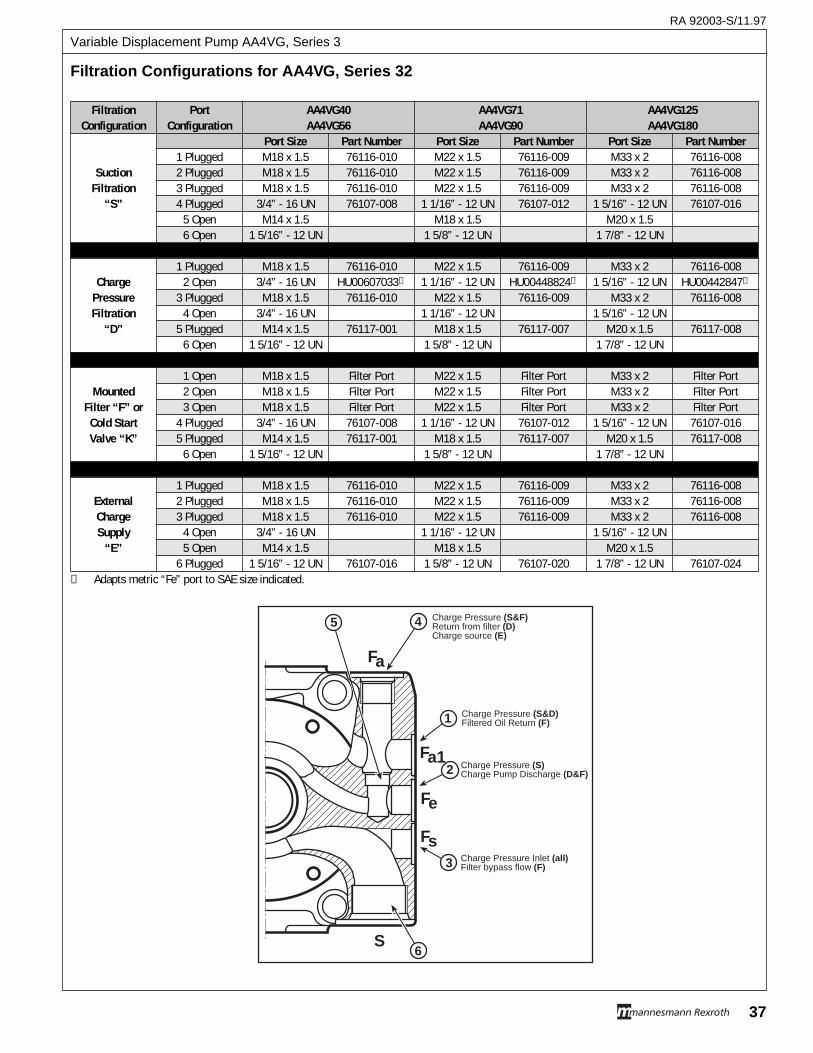
RA 92003-S/11.97
37
Variable Displacement Pump AA4VG, Series 3
Filtration Port AA4VG40 AA4VG71 AA4VG125Configuration Configuration AA4VG56 AA4VG90 AA4VG180
Port Size Part Number Port Size Part Number Port Size Part Number1 Plugged M18 x 1.5 76116-010 M22 x 1.5 76116-009 M33 x 2 76116-008
Suction 2 Plugged M18 x 1.5 76116-010 M22 x 1.5 76116-009 M33 x 2 76116-008Filtration 3 Plugged M18 x 1.5 76116-010 M22 x 1.5 76116-009 M33 x 2 76116-008
“S” 4 Plugged 3/4” - 16 UN 76107-008 1 1/16” - 12 UN 76107-012 1 5/16” - 12 UN 76107-0165 Open M14 x 1.5 M18 x 1.5 M20 x 1.56 Open 1 5/16” - 12 UN 1 5/8” - 12 UN 1 7/8” - 12 UN
1 Plugged M18 x 1.5 76116-010 M22 x 1.5 76116-009 M33 x 2 76116-008Charge 2 Open 3/4” - 16 UN HU00607033➀ 1 1/16” - 12 UN HU00448824➀ 1 5/16” - 12 UN HU00442847➀
Pressure 3 Plugged M18 x 1.5 76116-010 M22 x 1.5 76116-009 M33 x 2 76116-008Filtration 4 Open 3/4” - 16 UN 1 1/16” - 12 UN 1 5/16” - 12 UN
“D” 5 Plugged M14 x 1.5 76117-001 M18 x 1.5 76117-007 M20 x 1.5 76117-0086 Open 1 5/16” - 12 UN 1 5/8” - 12 UN 1 7/8” - 12 UN
1 Open M18 x 1.5 Filter Port M22 x 1.5 Filter Port M33 x 2 Filter PortMounted 2 Open M18 x 1.5 Filter Port M22 x 1.5 Filter Port M33 x 2 Filter Port
Filter “F” or 3 Open M18 x 1.5 Filter Port M22 x 1.5 Filter Port M33 x 2 Filter PortCold Start 4 Plugged 3/4” - 16 UN 76107-008 1 1/16” - 12 UN 76107-012 1 5/16” - 12 UN 76107-016Valve “K” 5 Plugged M14 x 1.5 76117-001 M18 x 1.5 76117-007 M20 x 1.5 76117-008
6 Open 1 5/16” - 12 UN 1 5/8” - 12 UN 1 7/8” - 12 UN
1 Plugged M18 x 1.5 76116-010 M22 x 1.5 76116-009 M33 x 2 76116-008External 2 Plugged M18 x 1.5 76116-010 M22 x 1.5 76116-009 M33 x 2 76116-008Charge 3 Plugged M18 x 1.5 76116-010 M22 x 1.5 76116-009 M33 x 2 76116-008Supply 4 Open 3/4” - 16 UN 1 1/16” - 12 UN 1 5/16” - 12 UN
“E” 5 Open M14 x 1.5 M18 x 1.5 M20 x 1.56 Plugged 1 5/16” - 12 UN 76107-016 1 5/8” - 12 UN 76107-020 1 7/8” - 12 UN 76107-024
➀ Adapts metric “Fe” port to SAE size indicated.
Filtration Configurations f or AA4V G, Series 32
Fa
Fe
S
5 4
1
2
3
6
Charge Pressure (S&F)Return from filter (D)Charge source (E)
Charge Pressure (S&D)Filtered Oil Return (F)
Charge Pressure (S)Charge Pump Discharge (D&F)
Charge Pressure Inlet (all)Filter bypass flow (F)
Fa1
Fs
Variable Displacement Pump AA4VG, Series 3
RA 92003-S/04.97
38
Note Page:
RA 92003-S/04.97
39
Variable Displacement Pump AA4VG, Series 3
Note Page:
Variable Displacement Pump AA4VG, Series 3
RA 92003-S/04.97
40
The Rexroth CorporationMobile Hydraulics Division, 1700 Old Mansfield Road, Wooster, OH 44691-0394 Tel. (330) 263-3400 Fax. (330) 263-3329Industrial Hydraulics Division, 2315 City Line Road, Bethlehem, PA 18017-2131 Tel. (610) 694-8300 Fax. (610) 694-8467
All rights reserved - Subject to revisionPrinted in U.S.A.
Specifications, descriptions, and illustrative material shown herein were as accurate asknown at the time this publication was printed. Rexroth reserves the right to discontinuemodels or options at any time or to change specifications, materials, or designs withoutnotice and without incurring obligation.
Optional equipment and accessories may add cost to the basic unit, and some options areavailable only in combination with certain models or other options.
DISTRIBUTED BY:
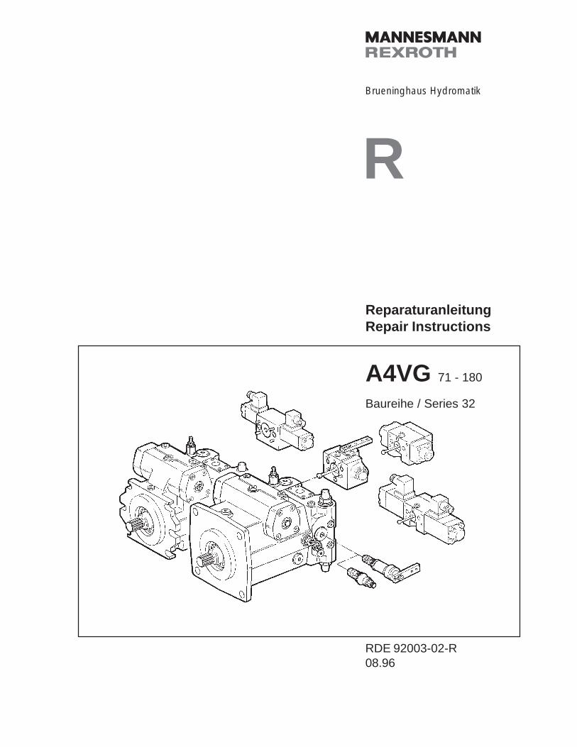
RBrueninghaus Hydromatik
RDE 92003-02-R08.96
ReparaturanleitungRepair Instructions
A4VG 71 - 180
Baureihe / Series 32
Reparaturanleitung A4VG
Repair Instructions A4VG
RDE 92003-02-R/08.96
2 Brueninghaus Hydromatik
HINWEISBezeichnungen, Beschreibungen und Darstellungenentsprechen dem Informationsstand zum Zeitpunkt derDrucklegung dieser Unterlage.
Änderungen können den Service am Produkt beein-flussen, Verpflichtungen entstehen uns daraus nicht.
Methoden und Vorrichtungen sind Empfehlungen, fürderen Resultat wir keine Haftung übernehmen können.
BRUENINGHAUS HYDROMATIK- Baugruppen, mit
Angabe der Fabrik-Nr. bestellt, sind die Basis guterReparaturen.
Einstell- und Prüfarbeiten sind bei Betriebstemperaturauf dem Teststand vorzunehmen.
Schutz von Personen und Eigentum ist durch Vor-kehrungen sicherzustellen.
Sachkenntnis, die Voraussetzung für jede Service-arbeit, vermitteln wir in unseren Schulungskursen.
INHALT Seite/Page
A4VG
Schnittbild 3-4Allgemeine Reparaturhinweise 5Dichtsätze und Baugruppen 6-8Triebwelle abdichten 9Hilfspumpe abdichten 10Stellkolbendeckel abdichten 11-12Speisedruckventil abdichten 13Druckbegrenzungsventil abdichten 14Druckabschneidung abdichten 15Ansteuergerät abdichten 16Ansteuergerät HW 17Ansteuergerät HD 18Ansteuergerät EP 19Ansteuergerät DA 20Regelventil abdichten / überprüfen 21Pumpe demontieren 22-24Verstellung demontieren 25-26Zylinder demontieren 27Überprüfungshinweise 28-29Stellkolben, Triebwerk montieren 30Triebwerk einbauen 31-32Pumpe montieren 33-35Anziehdrehmomente 36Sicherheitsbestimmungen 37-38Einstellhinweise 39-45
NOTICESpecifications, descriptions and illustrative materialshown herein were as accurate as known at the timethis publication was approved for printing.
BRUENINGHAUS HYDROMATIK reserves the right todiscontinue models or options at any time or to changespeci-fications, materials, or design without notice andwith-out incurring obligation.
Optional equipment and accessories may add cost tothe basic unit, and some options are available only incombination with certain models or other options.
For the available combinations refer to the relevantdata sheet for the basic unit and the desired option.
Adjustment and tests have to be carried out on the testbench under operating temperatures.
Protection of personnel and property has to be guar-anteed by appropriate measures.
Expert knowledge, the precondition of any servicework, can be obtained in our training courses.
CONTENTS
A4VG
Sectional viewGeneral repair instructionsSeal kits and sub assembly groupsSealing of the drive shaftSealing of the boost pumpSealing of the control piston coverSealing of the boost pressure valveSealing of the pressure relief valve HDSealing of the pressure cut-off valveSealing of the control deviceControl device HWControl device HDControl device EPControl device DASealing of the regulator valvePump disassemblyDismantling of the controlDismantling of the cylinderInspection notesPositioning piston, rotary group assemblyInstallation of the rotary groupAssembly of the pumpTightening torquesSafety regulationsAdjustment instructions
Hinweis / Inhalt
Notice / Contents
2
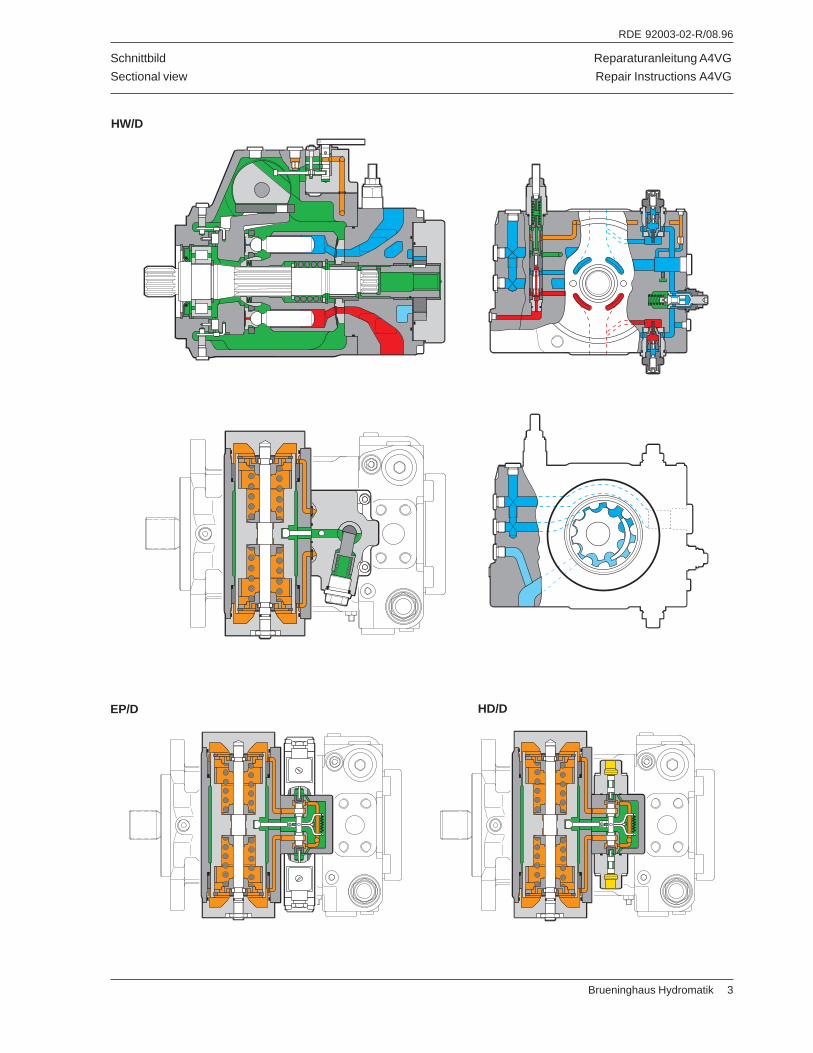
Reparaturanleitung A4VG
Repair Instructions A4VG
RDE 92003-02-R/08.96
Brueninghaus Hydromatik 3
Schnittbild
Sectional view
EP/D HD/D
HW/D
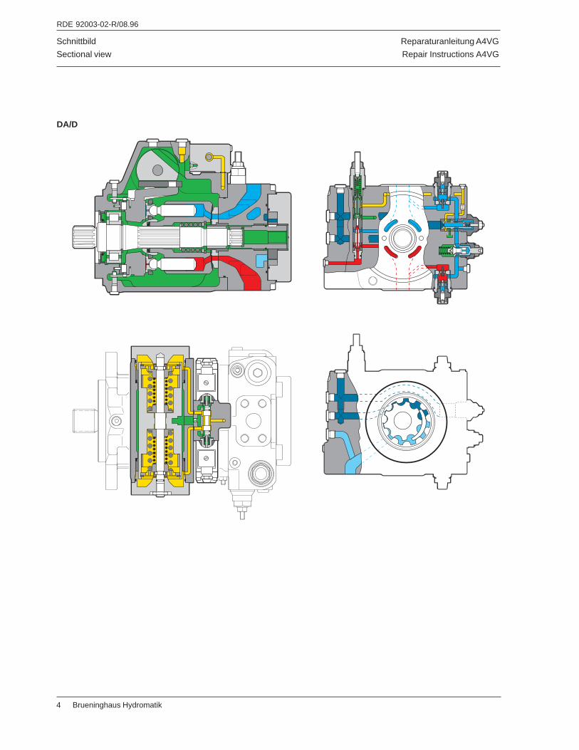
Reparaturanleitung A4VG
Repair Instructions A4VG
RDE 92003-02-R/08.96
4 Brueninghaus Hydromatik
Schnittbild
Sectional view
DA/D
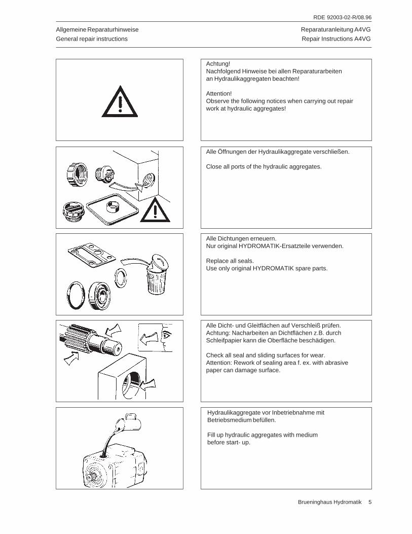
Reparaturanleitung A4VG
Repair Instructions A4VG
RDE 92003-02-R/08.96
Brueninghaus Hydromatik 5
Achtung!Nachfolgend Hinweise bei allen Reparaturarbeitenan Hydraulikaggregaten beachten!
Attention!Observe the following notices when carrying out repairwork at hydraulic aggregates!
Alle Öffnungen der Hydraulikaggregate verschließen.
Close all ports of the hydraulic aggregates.
Alle Dichtungen erneuern.Nur original HYDROMATIK-Ersatzteile verwenden.
Replace all seals.Use only original HYDROMATIK spare parts.
Alle Dicht- und Gleitflächen auf Verschleiß prüfen.Achtung: Nacharbeiten an Dichtflächen z.B. durchSchleifpapier kann die Oberfläche beschädigen.
Check all seal and sliding surfaces for wear.Attention: Rework of sealing area f. ex. with abrasivepaper can damage surface.
Hydraulikaggregate vor Inbetriebnahme mitBetriebsmedium befüllen.
Fill up hydraulic aggregates with mediumbefore start- up.
Allgemeine Reparaturhinweise
General repair instructions
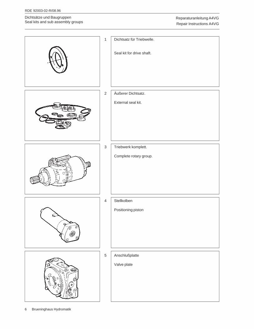
Reparaturanleitung A4VG
Repair Instructions A4VG
RDE 92003-02-R/08.96
6 Brueninghaus Hydromatik
Dichtsätze und BaugruppenSeal kits and sub assembly groups
1 Dichtsatz für Triebwelle.
Seal kit for drive shaft.
3 Triebwerk komplett.
Complete rotary group.
2 Äußerer Dichtsatz.
External seal kit.
4 Stellkolben
Positioning piston
5 Anschlußplatte
Valve plate
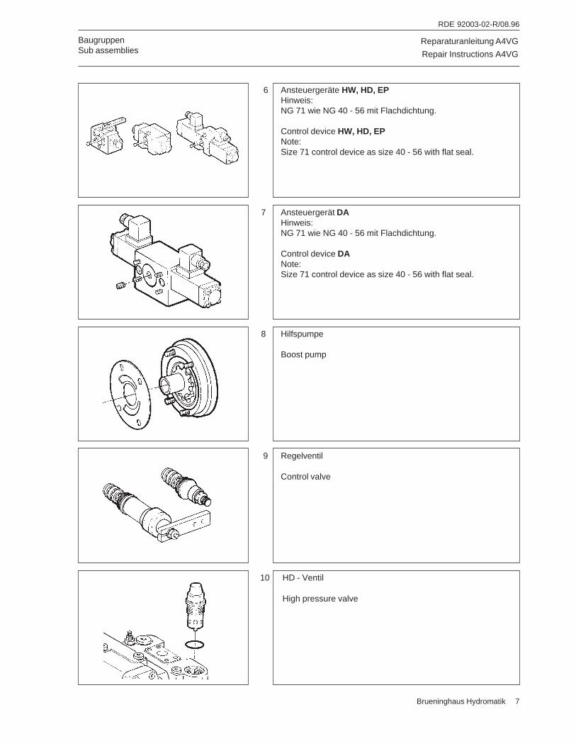
Reparaturanleitung A4VG
Repair Instructions A4VG
RDE 92003-02-R/08.96
Brueninghaus Hydromatik 7
BaugruppenSub assemblies
6 Ansteuergeräte HW, HD, EPHinweis:NG 71 wie NG 40 - 56 mit Flachdichtung.
Control device HW, HD, EPNote:Size 71 control device as size 40 - 56 with flat seal.
8 Hilfspumpe
Boost pump
7 Ansteuergerät DAHinweis:NG 71 wie NG 40 - 56 mit Flachdichtung.
Control device DANote:Size 71 control device as size 40 - 56 with flat seal.
9 Regelventil
Control valve
10 HD - Ventil
High pressure valve
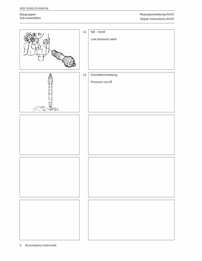
Reparaturanleitung A4VG
Repair Instructions A4VG
RDE 92003-02-R/08.96
8 Brueninghaus Hydromatik
BaugruppenSub assemblies
11 ND - Ventil
Low pressure valve
12 Druckabschneidung
Pressure cut-off
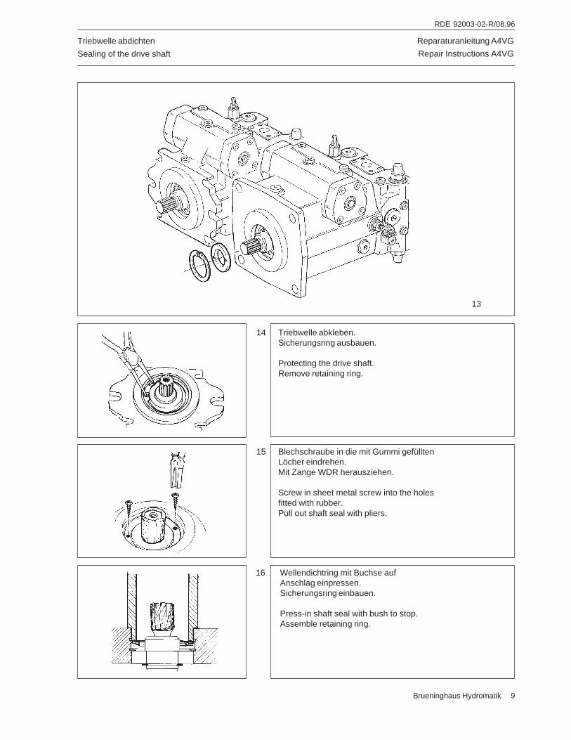
Reparaturanleitung A4VG
Repair Instructions A4VG
RDE 92003-02-R/08.96
Brueninghaus Hydromatik 9
Triebwelle abdichten
Sealing of the drive shaft
15 Blechschraube in die mit Gummi gefülltenLöcher eindrehen.Mit Zange WDR herausziehen.
Screw in sheet metal screw into the holesfitted with rubber.Pull out shaft seal with pliers.
16 Wellendichtring mit Buchse aufAnschlag einpressen.Sicherungsring einbauen.
Press-in shaft seal with bush to stop.Assemble retaining ring.
14 Triebwelle abkleben.Sicherungsring ausbauen.
Protecting the drive shaft.Remove retaining ring.
13
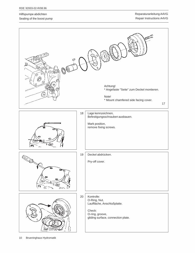
Reparaturanleitung A4VG
Repair Instructions A4VG
RDE 92003-02-R/08.96
10 Brueninghaus Hydromatik
Hilfspumpe abdichten
Sealing of the boost pump
18 Lage kennzeichnen,Befestigungsschrauben ausbauen.
Mark position,remove fixing screws.
Achtung!* Angefaste "Seite" zum Deckel montieren.
Note!* Mount chamfered side facing cover.
17
19 Deckel abdrücken.
Pry-off cover.
20 Kontrolle:O-Ring, Nut,Lauffläche, Anschlußplatte.
Check:O-ring, groove,gliding surface, connection plate.
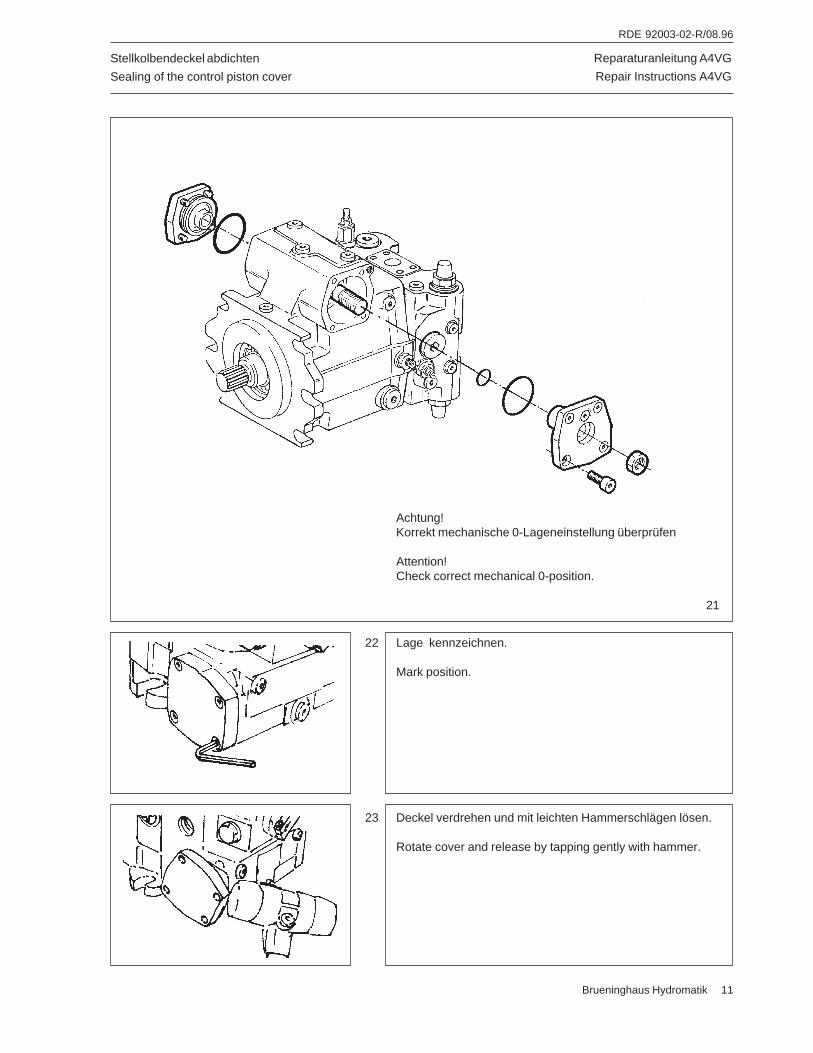
Reparaturanleitung A4VG
Repair Instructions A4VG
RDE 92003-02-R/08.96
Brueninghaus Hydromatik 11
Stellkolbendeckel abdichten
Sealing of the control piston cover
Achtung!Korrekt mechanische 0-Lageneinstellung überprüfen
Attention!Check correct mechanical 0-position.
21
22 Lage kennzeichnen.
Mark position.
23 Deckel verdrehen und mit leichten Hammerschlägen lösen.
Rotate cover and release by tapping gently with hammer.
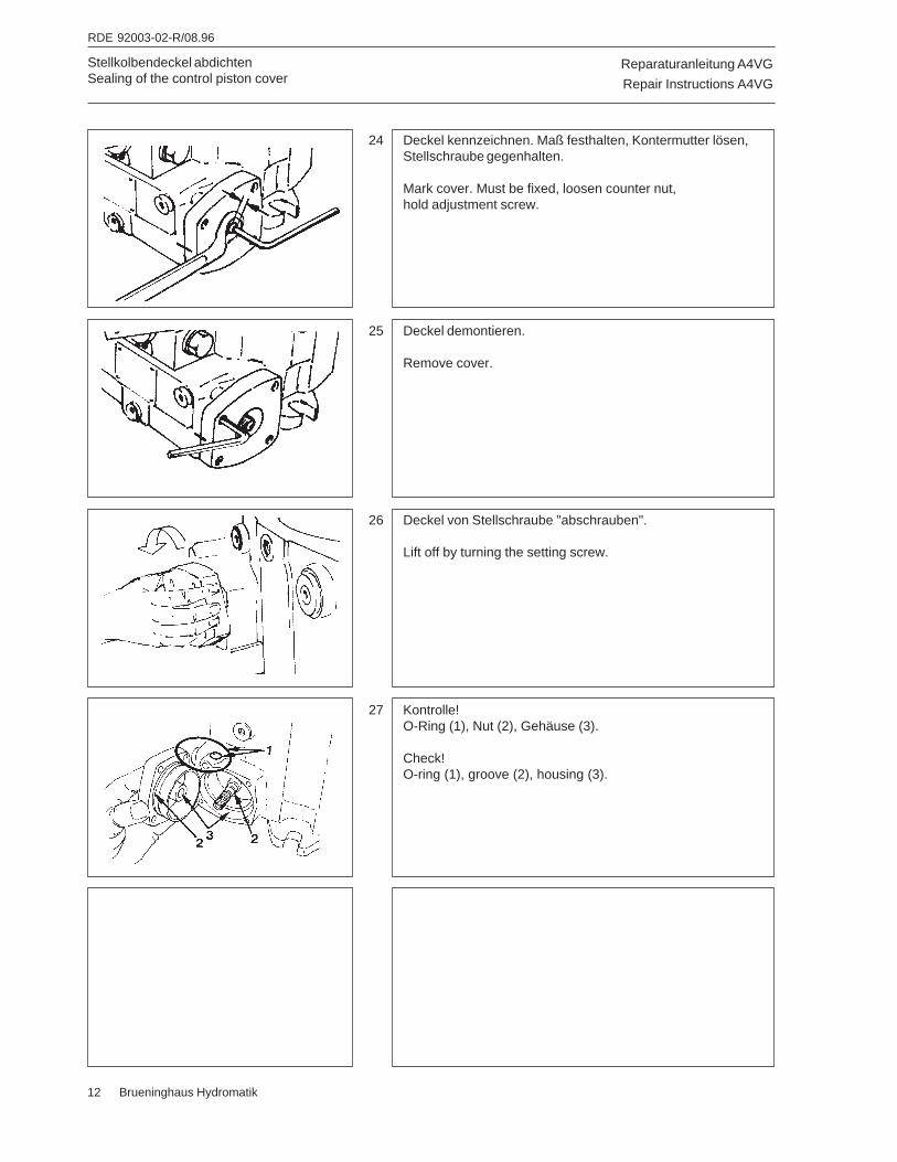
Reparaturanleitung A4VG
Repair Instructions A4VG
RDE 92003-02-R/08.96
12 Brueninghaus Hydromatik
Stellkolbendeckel abdichtenSealing of the control piston cover
24 Deckel kennzeichnen. Maß festhalten, Kontermutter lösen,Stellschraube gegenhalten.
Mark cover. Must be fixed, loosen counter nut,hold adjustment screw.
26 Deckel von Stellschraube "abschrauben".
Lift off by turning the setting screw.
25 Deckel demontieren.
Remove cover.
27 Kontrolle!O-Ring (1), Nut (2), Gehäuse (3).
Check!O-ring (1), groove (2), housing (3).
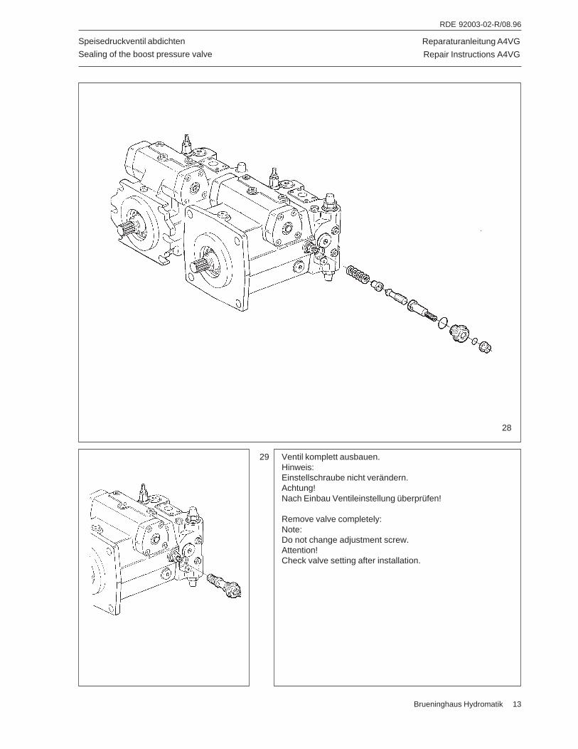
Reparaturanleitung A4VG
Repair Instructions A4VG
RDE 92003-02-R/08.96
Brueninghaus Hydromatik 13
Speisedruckventil abdichten
Sealing of the boost pressure valve
28
29 Ventil komplett ausbauen.Hinweis:Einstellschraube nicht verändern.Achtung!Nach Einbau Ventileinstellung überprüfen!
Remove valve completely:Note:Do not change adjustment screw.Attention!Check valve setting after installation.
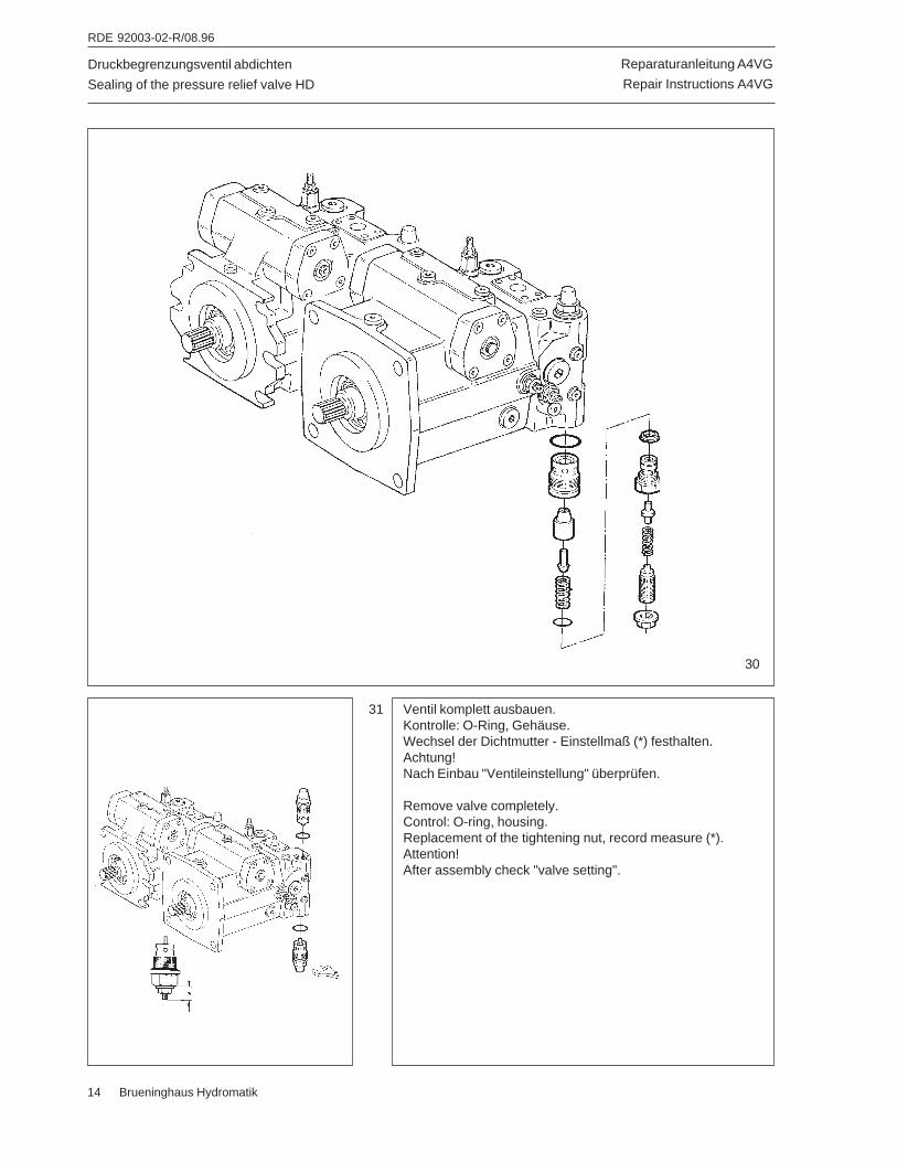
Reparaturanleitung A4VG
Repair Instructions A4VG
RDE 92003-02-R/08.96
14 Brueninghaus Hydromatik
Druckbegrenzungsventil abdichten
Sealing of the pressure relief valve HD
30
31 Ventil komplett ausbauen.Kontrolle: O-Ring, Gehäuse.Wechsel der Dichtmutter - Einstellmaß (*) festhalten.Achtung!Nach Einbau "Ventileinstellung" überprüfen.
Remove valve completely.Control: O-ring, housing.Replacement of the tightening nut, record measure (*).Attention!After assembly check "valve setting".
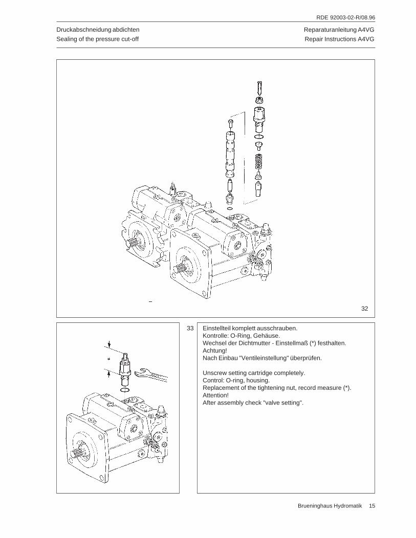
Reparaturanleitung A4VG
Repair Instructions A4VG
RDE 92003-02-R/08.96
Brueninghaus Hydromatik 15
Druckabschneidung abdichten
Sealing of the pressure cut-off
33 Einstellteil komplett ausschrauben.Kontrolle: O-Ring, Gehäuse.Wechsel der Dichtmutter - Einstellmaß (*) festhalten.Achtung!Nach Einbau "Ventileinstellung" überprüfen.
Unscrew setting cartridge completely.Control: O-ring, housing.Replacement of the tightening nut, record measure (*).Attention!After assembly check "valve setting".
32
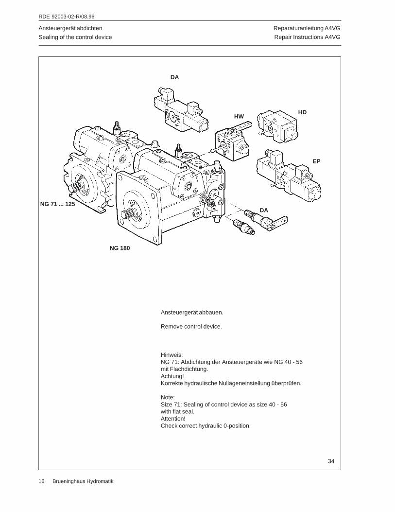
Reparaturanleitung A4VG
Repair Instructions A4VG
RDE 92003-02-R/08.96
16 Brueninghaus Hydromatik
Ansteuergerät abdichten
Sealing of the control device
Ansteuergerät abbauen.
Remove control device.
Hinweis:NG 71: Abdichtung der Ansteuergeräte wie NG 40 - 56mit Flachdichtung.Achtung!Korrekte hydraulische Nullageneinstellung überprüfen.
Note:Size 71: Sealing of control device as size 40 - 56with flat seal.Attention!Check correct hydraulic 0-position.
34
HW
DA
HD
DA
NG 180
NG 71 ... 125
EP
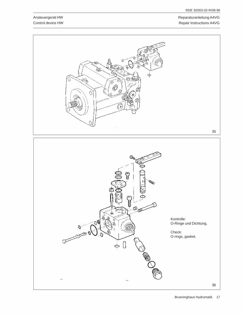
Reparaturanleitung A4VG
Repair Instructions A4VG
RDE 92003-02-R/08.96
Brueninghaus Hydromatik 17
Ansteuergerät HW
Control device HW
Kontrolle:O-Ringe und Dichtung.
Check:O-rings, gasket.
36
35
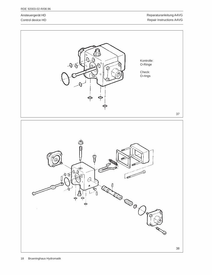
Reparaturanleitung A4VG
Repair Instructions A4VG
RDE 92003-02-R/08.96
18 Brueninghaus Hydromatik
Ansteuergerät HD
Control device HD
38
Kontrolle:O-Ringe
Check:O-rings
37
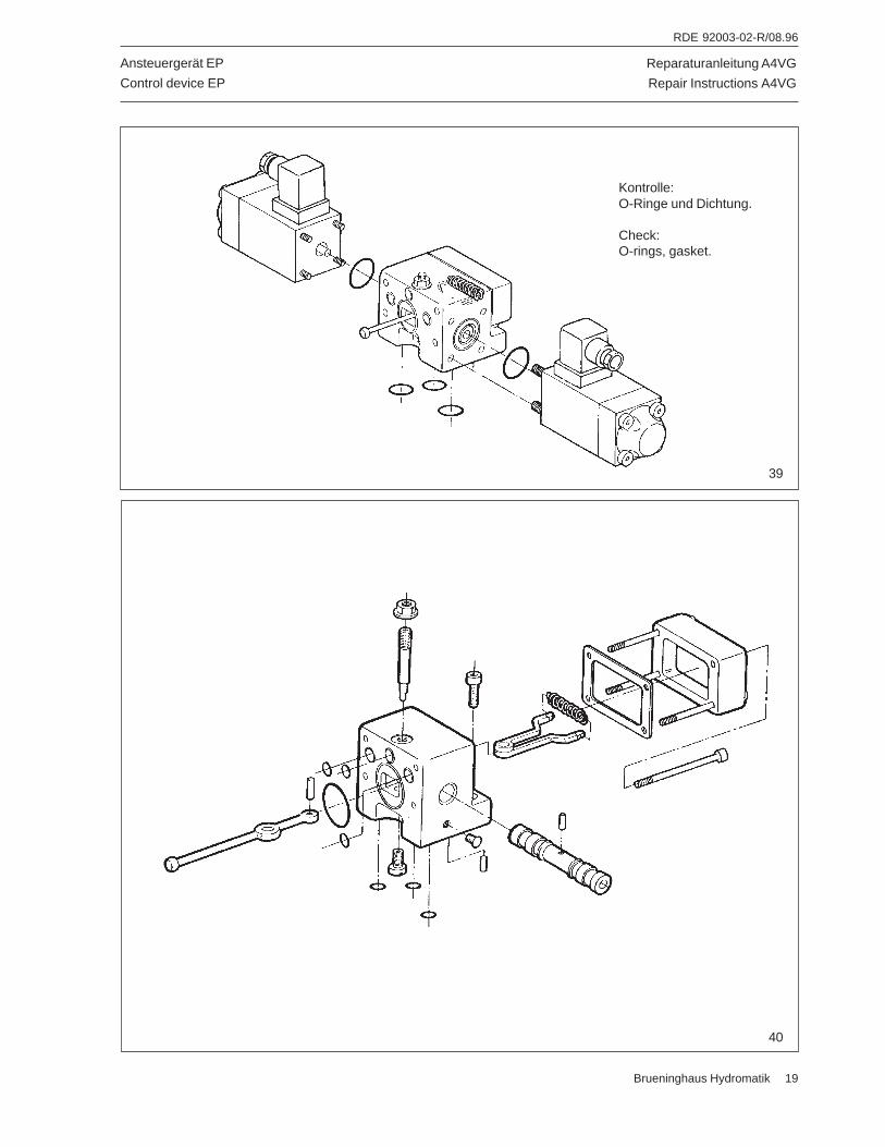
Reparaturanleitung A4VG
Repair Instructions A4VG
RDE 92003-02-R/08.96
Brueninghaus Hydromatik 19
Ansteuergerät EP
Control device EP
Kontrolle:O-Ringe und Dichtung.
Check:O-rings, gasket.
39
40
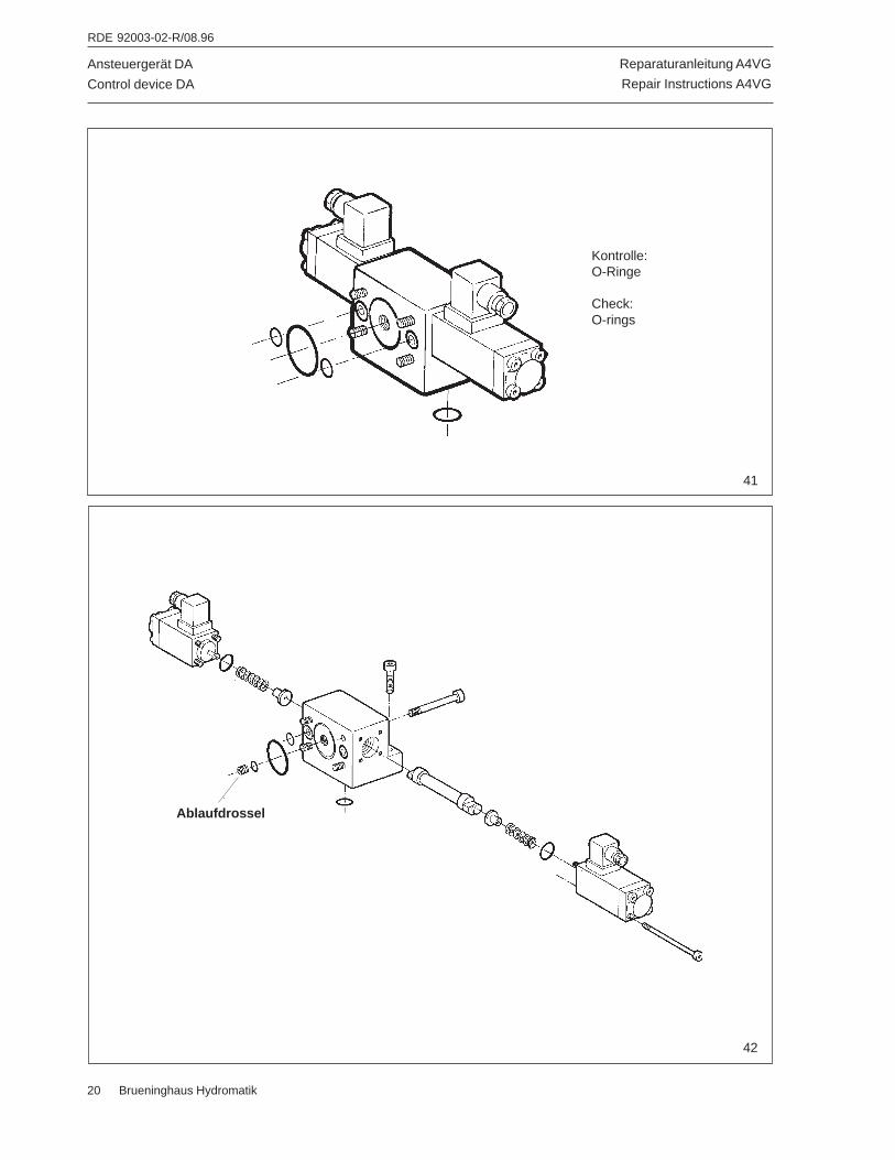
Reparaturanleitung A4VG
Repair Instructions A4VG
RDE 92003-02-R/08.96
20 Brueninghaus Hydromatik
Ansteuergerät DA
Control device DA
42
Kontrolle:O-Ringe
Check:O-rings
41
Ablaufdrossel
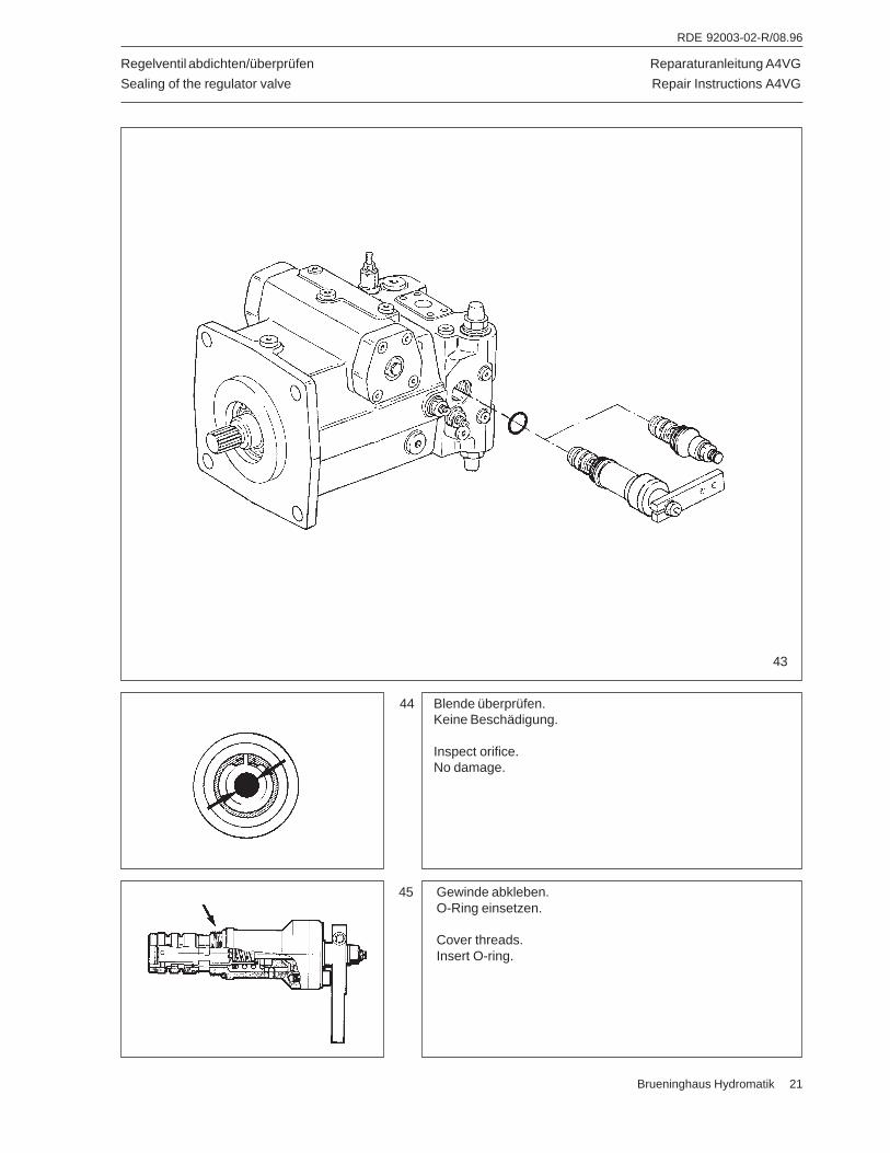
Reparaturanleitung A4VG
Repair Instructions A4VG
RDE 92003-02-R/08.96
Brueninghaus Hydromatik 21
Regelventil abdichten/überprüfen
Sealing of the regulator valve
44 Blende überprüfen.Keine Beschädigung.
Inspect orifice.No damage.
45 Gewinde abkleben.O-Ring einsetzen.
Cover threads.Insert O-ring.
43
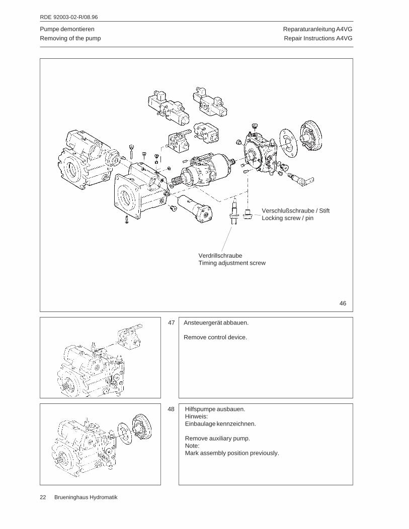
Reparaturanleitung A4VG
Repair Instructions A4VG
RDE 92003-02-R/08.96
22 Brueninghaus Hydromatik
Pumpe demontieren
Removing of the pump
47 Ansteuergerät abbauen.
Remove control device.
48 Hilfspumpe ausbauen.Hinweis:Einbaulage kennzeichnen.
Remove auxiliary pump.Note:Mark assembly position previously.
46
Verschlußschraube / StiftLocking screw / pin
VerdrillschraubeTiming adjustment screw
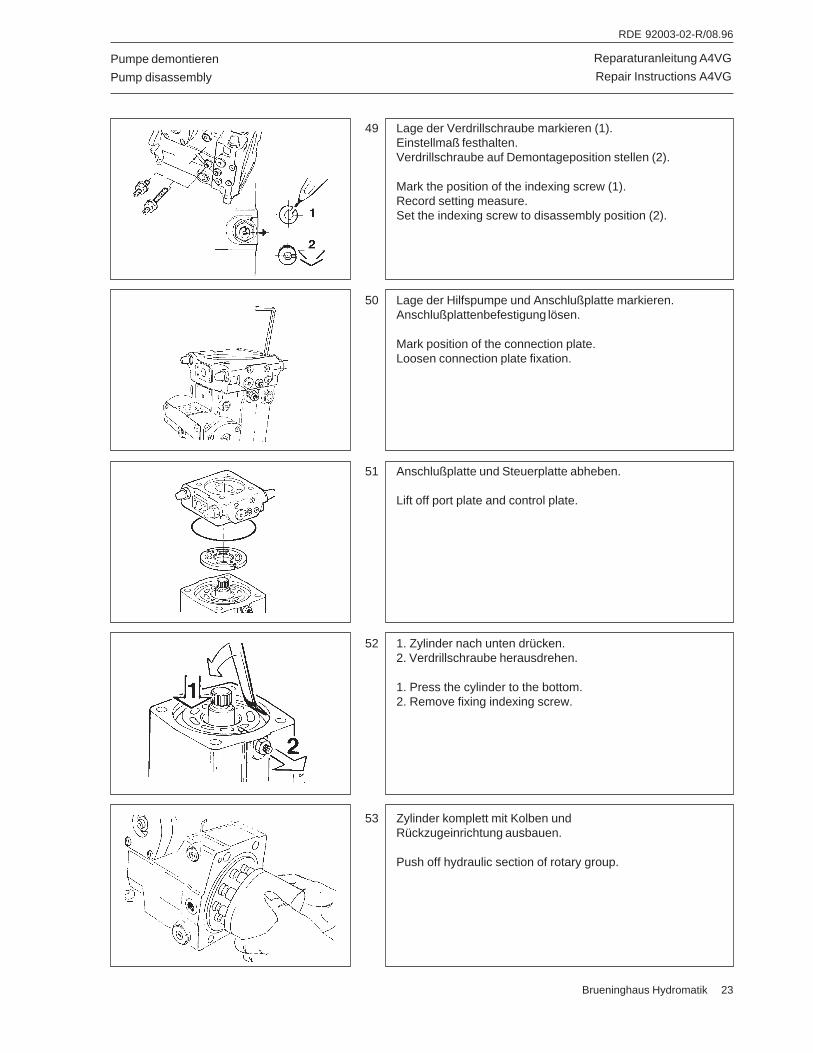
Reparaturanleitung A4VG
Repair Instructions A4VG
RDE 92003-02-R/08.96
Brueninghaus Hydromatik 23
Pumpe demontieren
Pump disassembly
51 Anschlußplatte und Steuerplatte abheben.
Lift off port plate and control plate.
52 1. Zylinder nach unten drücken.2. Verdrillschraube herausdrehen.
1. Press the cylinder to the bottom.2. Remove fixing indexing screw.
53 Zylinder komplett mit Kolben undRückzugeinrichtung ausbauen.
Push off hydraulic section of rotary group.
49 Lage der Verdrillschraube markieren (1).Einstellmaß festhalten.Verdrillschraube auf Demontageposition stellen (2).
Mark the position of the indexing screw (1).Record setting measure.Set the indexing screw to disassembly position (2).
50 Lage der Hilfspumpe und Anschlußplatte markieren.Anschlußplattenbefestigung lösen.
Mark position of the connection plate.Loosen connection plate fixation.
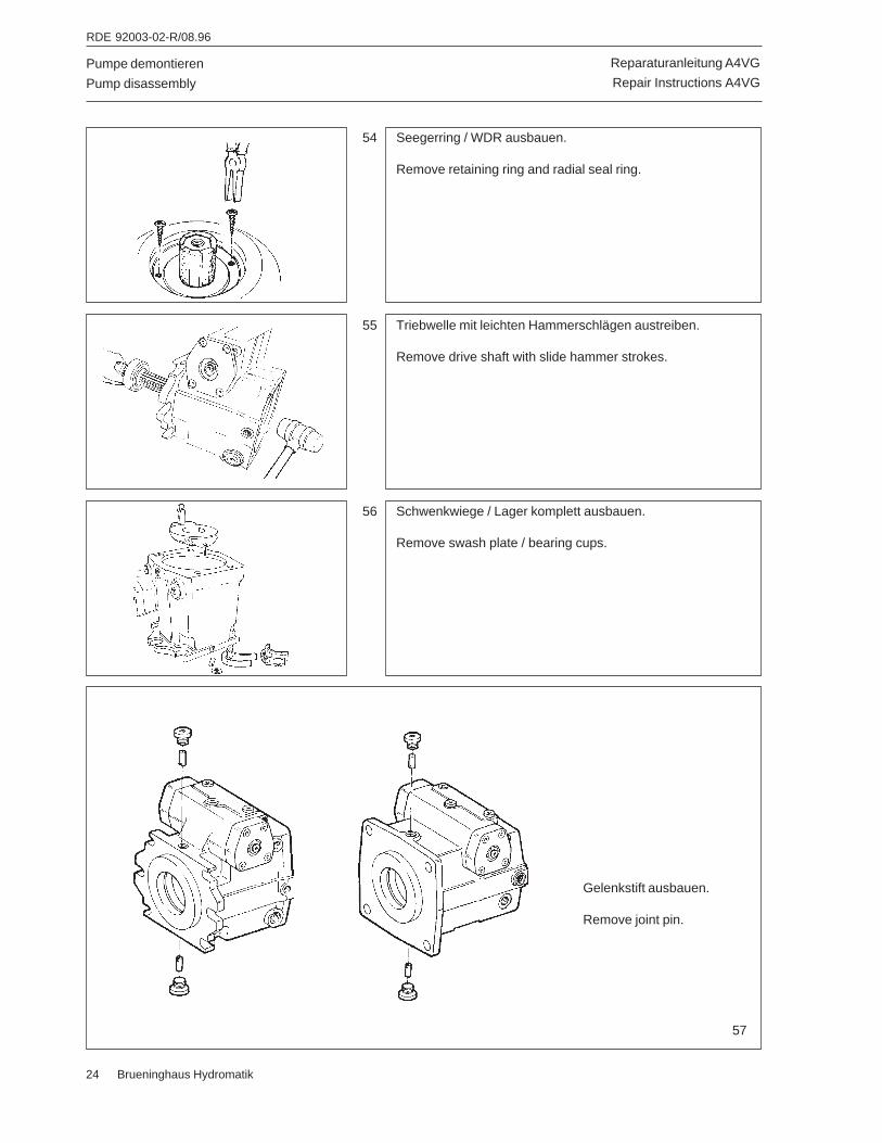
Reparaturanleitung A4VG
Repair Instructions A4VG
RDE 92003-02-R/08.96
24 Brueninghaus Hydromatik
Pumpe demontieren
Pump disassembly
54 Seegerring / WDR ausbauen.
Remove retaining ring and radial seal ring.
56 Schwenkwiege / Lager komplett ausbauen.
Remove swash plate / bearing cups.
55 Triebwelle mit leichten Hammerschlägen austreiben.
Remove drive shaft with slide hammer strokes.
Gelenkstift ausbauen.
Remove joint pin.
57
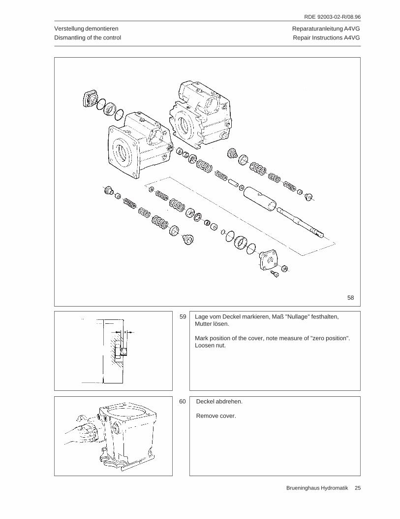
Reparaturanleitung A4VG
Repair Instructions A4VG
RDE 92003-02-R/08.96
Brueninghaus Hydromatik 25
Verstellung demontieren
Dismantling of the control
59 Lage vom Deckel markieren, Maß "Nullage" festhalten,Mutter lösen.
Mark position of the cover, note measure of "zero position".Loosen nut.
60 Deckel abdrehen.
Remove cover.
58
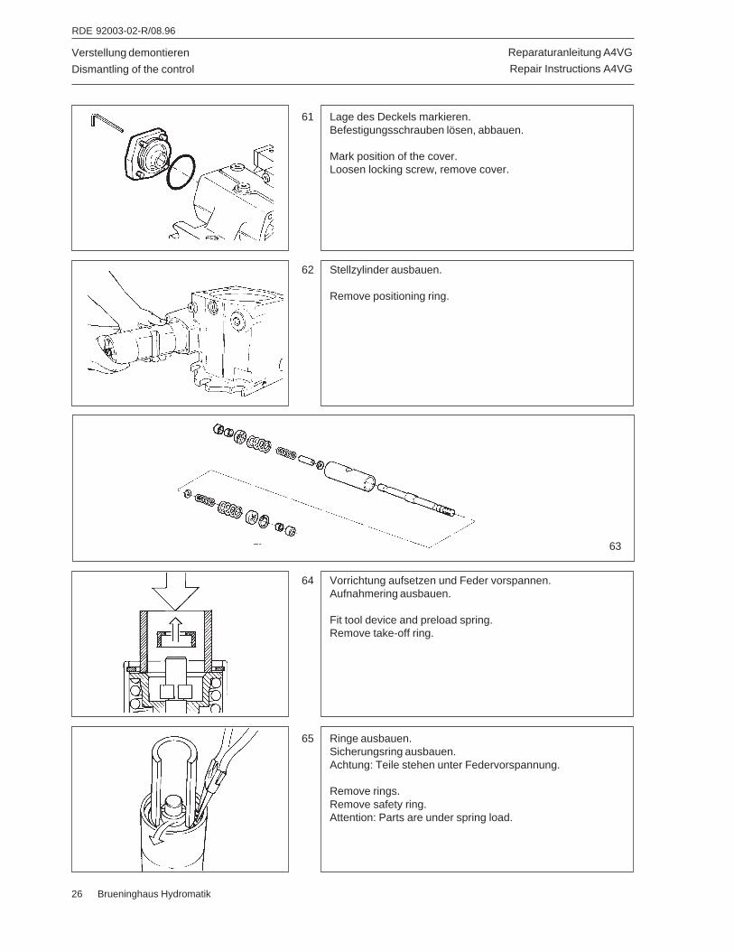
Reparaturanleitung A4VG
Repair Instructions A4VG
RDE 92003-02-R/08.96
26 Brueninghaus Hydromatik
64 Vorrichtung aufsetzen und Feder vorspannen.Aufnahmering ausbauen.
Fit tool device and preload spring.Remove take-off ring.
Verstellung demontieren
Dismantling of the control
65 Ringe ausbauen.Sicherungsring ausbauen.Achtung: Teile stehen unter Federvorspannung.
Remove rings.Remove safety ring.Attention: Parts are under spring load.
62 Stellzylinder ausbauen.
Remove positioning ring.
61 Lage des Deckels markieren.Befestigungsschrauben lösen, abbauen.
Mark position of the cover.Loosen locking screw, remove cover.
63
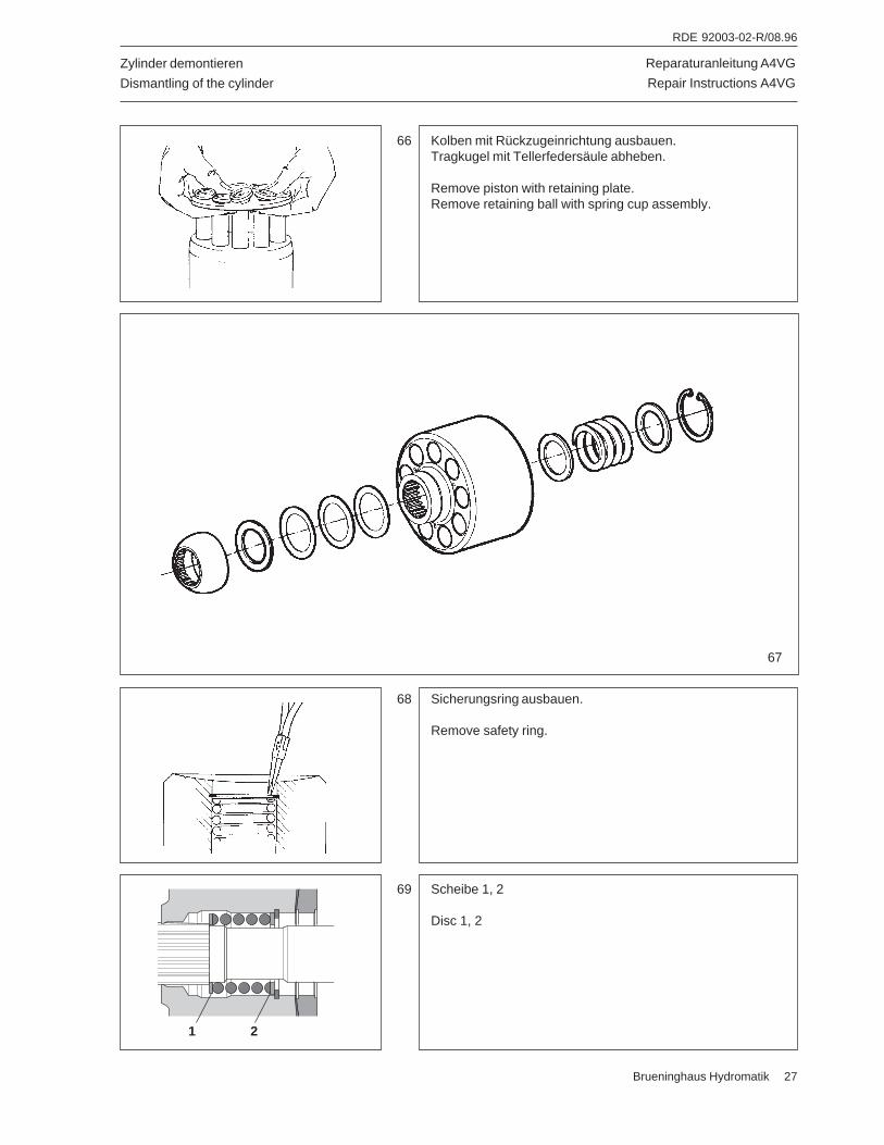
Reparaturanleitung A4VG
Repair Instructions A4VG
RDE 92003-02-R/08.96
Brueninghaus Hydromatik 27
68 Sicherungsring ausbauen.
Remove safety ring.
Zylinder demontieren
Dismantling of the cylinder
69 Scheibe 1, 2
Disc 1, 2
66 Kolben mit Rückzugeinrichtung ausbauen.Tragkugel mit Tellerfedersäule abheben.
Remove piston with retaining plate.Remove retaining ball with spring cup assembly.
67
21
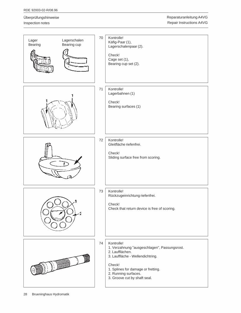
Reparaturanleitung A4VG
Repair Instructions A4VG
RDE 92003-02-R/08.96
28 Brueninghaus Hydromatik
Überprüfungshinweise
Inspection notes
70 Kontrolle!Käfig-Paar (1),Lagerschalenpaar (2).
Check!Cage set (1),Bearing cup set (2).
72 Kontrolle!Gleitfläche riefenfrei.
Check!Sliding surface free from scoring.
71 Kontrolle!Lagerbahnen (1)
Check!Bearing surfaces (1)
73 Kontrolle!Rückzugeinrichtung riefenfrei.
Check!Check that return device is free of scoring.
74 Kontrolle!1. Verzahnung "ausgeschlagen", Passungsrost.2. Laufflächen.3. Lauffläche - Wellendichtring.
Check!1. Splines for damage or fretting.2. Running surfaces.3. Groove cut by shaft seal.
LagerBearing
LagerschalenBearing cup
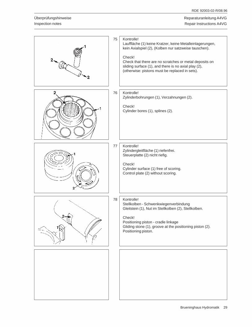
Reparaturanleitung A4VG
Repair Instructions A4VG
RDE 92003-02-R/08.96
Brueninghaus Hydromatik 29
Überprüfungshinweise
Inspection notes
75 Kontrolle!Lauffläche (1) keine Kratzer, keine Metalleinlagerungen,kein Axialspiel (2), (Kolben nur satzweise tauschen).
Check!Check that there are no scratches or metal deposits onsliding surface (1), and there is no axial play (2),(otherwise: pistons must be replaced in sets).
77 Kontrolle!Zylindergleitfläche (1) riefenfrei.Steuerplatte (2) nicht riefig.
Check!Cylinder surface (1) free of scoring.Control plate (2) without scoring.
76 Kontrolle!Zylinderbohrungen (1), Verzahnungen (2).
Check!Cylinder bores (1), splines (2).
78 Kontrolle!Stellkolben - SchwenkwiegenverbindungGleitstein (1), Nut im Stellkolben (2), Stellkolben.
Check!Positioning piston - cradle linkageGliding stone (1), groove at the positioning piston (2).Positioning piston.
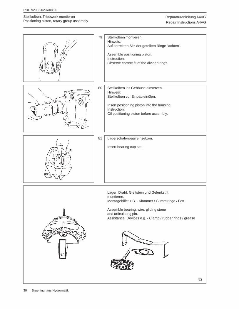
Reparaturanleitung A4VG
Repair Instructions A4VG
RDE 92003-02-R/08.96
30 Brueninghaus Hydromatik
Stellkolben, Triebwerk montierenPositioning piston, rotary group assembly
79 Stellkolben montieren.Hinweis:Auf korrekten Sitz der geteilten Ringe "achten".
Assemble positioning piston.Instruction:Observe correct fit of the divided rings.
81 Lagerschalenpaar einsetzen.
Insert bearing cup set.
80 Stellkolben ins Gehäuse einsetzen.Hinweis:Stellkolben vor Einbau einölen.
Insert positioning piston into the housing.Instruction:Oil positioning piston before assembly.
82
Lager, Draht, Gleitstein und Gelenkstiftmontieren.Montagehilfe: z.B. - Klammer / Gummiringe / Fett
Assemble bearing, wire, gliding stoneand articulating pin.Assistance: Devices e.g. - Clamp / rubber rings / grease
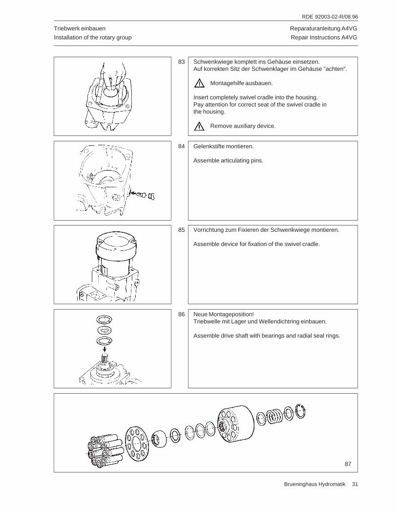
Reparaturanleitung A4VG
Repair Instructions A4VG
RDE 92003-02-R/08.96
Brueninghaus Hydromatik 31
Triebwerk einbauen
Installation of the rotary group
83 Schwenkwiege komplett ins Gehäuse einsetzen.Auf korrekten Sitz der Schwenklager im Gehäuse "achten".
Montagehilfe ausbauen.
Insert completely swivel cradle into the housing.Pay attention for correct seat of the swivel cradle inthe housing.
Remove auxiliary device.
84 Gelenkstifte montieren.
Assemble articulating pins.
87
85 Vorrichtung zum Fixieren der Schwenkwiege montieren.
Assemble device for fixation of the swivel cradle.
86 Neue Montageposition!Triebwelle mit Lager und Wellendichtring einbauen.
Assemble drive shaft with bearings and radial seal rings.
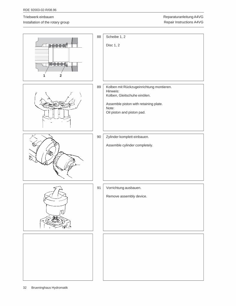
Reparaturanleitung A4VG
Repair Instructions A4VG
RDE 92003-02-R/08.96
32 Brueninghaus Hydromatik
Triebwerk einbauen
Installation of the rotary group
88 Scheibe 1, 2
Disc 1, 2
90 Zylinder komplett einbauen.
Assemble cylinder completely.
89 Kolben mit Rückzugeinrichtung montieren.Hinweis:Kolben, Gleitschuhe einölen.
Assemble piston with retaining plate.Note:Oil piston and piston pad.
91 Vorrichtung ausbauen.
Remove assembly device.
21

Reparaturanleitung A4VG
Repair Instructions A4VG
RDE 92003-02-R/08.96
Brueninghaus Hydromatik 33
92 Steuerplatte Rechtslauf - in Drehrichtung verdreht.Achtung!Geräuschkerben sind drehrichtungsbezogen eingeschliffen.
Control plate clockwise rotation - indexed in the directionof rotation.Note!Noise grooves are machined - in based on directionof rotation.
94 Grundeinstellung - VerdrillschraubeA4VG...71 * = 28 ± 0,75 mm A4VG...90 * = 29 ± 0,75 mmA4VG...125 * = 20 ± 0,75 mm A4VG...180 * = 22 ± 0,75 mm.
Basic setting - indexing screwA4VG...71 * = 28 ± 0,75 mm A4VG...90 * = 29 ± 0,75 mmA4VG...125 * = 20 ± 0,75 mm A4VG...180 * = 22 ± 0,75 mm.
93 Steuerplatte Linkslauf - in Drehrichtung verdreht.Achtung!Geräuschkerben sind drehrichtungsbezogen eingeschliffen.
Control plate counter clockwise rotation - indexedin the direction of rotation.Note!Noise grooves are machined - in based on directionof rotation.
95 Steuerplatte einsetzen - Rechtslauf.
Insert the control plate - clockwise rotation.
96 Zylinder nach unten drücken (1).Verdrillschraube einbauen (2).Kerbe in Montageposition.
Press the cylinder to the bottom (1).Screw in the indexing screw (2).Groove in mounting position.
Pumpe montieren
Assembly of the pump
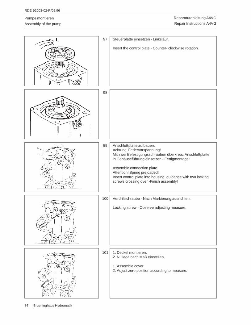
Reparaturanleitung A4VG
Repair Instructions A4VG
RDE 92003-02-R/08.96
34 Brueninghaus Hydromatik
Pumpe montieren
Assembly of the pump
97 Steuerplatte einsetzen - Linkslauf.
Insert the control plate - Counter- clockwise rotation.
99 Anschlußplatte aufbauen.Achtung! Federvorspannung!Mit zwei Befestigungsschrauben überkreuz Anschlußplattein Gehäuseführung einsetzen - Fertigmontage!
Assemble connection plate.Attention! Spring preloaded!Insert control plate into housing, guidance with two lockingscrews crossing over -Finish assembly!
98
100 Verdrillschraube - Nach Markierung ausrichten.
Locking screw - Observe adjusting measure.
101 1. Deckel montieren.2. Nullage nach Maß einstellen.
1. Assemble cover2. Adjust zero position according to measure.
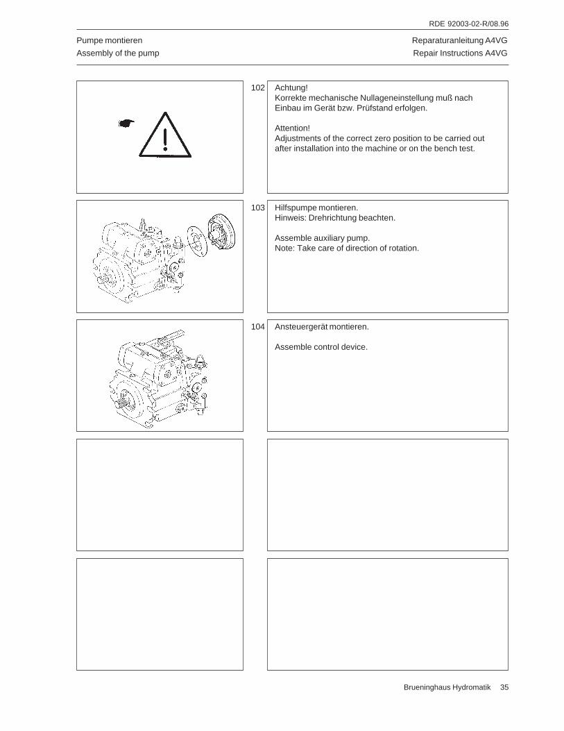
Reparaturanleitung A4VG
Repair Instructions A4VG
RDE 92003-02-R/08.96
Brueninghaus Hydromatik 35
Pumpe montieren
Assembly of the pump
102 Achtung!Korrekte mechanische Nullageneinstellung muß nachEinbau im Gerät bzw. Prüfstand erfolgen.
Attention!Adjustments of the correct zero position to be carried outafter installation into the machine or on the bench test.
104 Ansteuergerät montieren.
Assemble control device.
103 Hilfspumpe montieren.Hinweis: Drehrichtung beachten.
Assemble auxiliary pump.Note: Take care of direction of rotation.
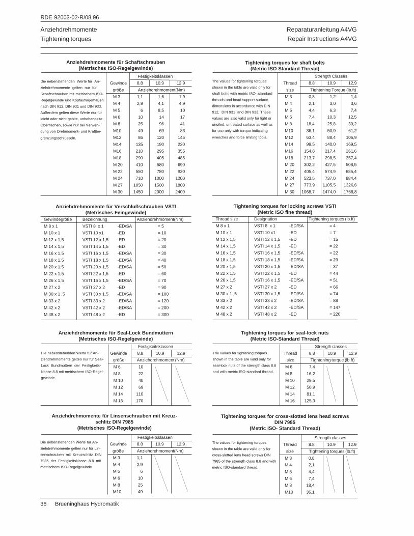
Reparaturanleitung A4VG
Repair Instructions A4VG
RDE 92003-02-R/08.96
36 Brueninghaus Hydromatik
Anziehdrehmomente
Tightening torques
Anziehdrehmomente für Schaftschrauben(Metrisches ISO-Regelgewinde)
Die nebenstehenden Werte für An-ziehdrehmomente gelten nur für
Schaftschrauben mit metrischem ISO-
Regelgewinde und Kopfauflagemaßen
nach DIN 912, DIN 931 und DIN 933.
Außerdem gelten diese Werte nur für
leicht oder nicht geölte, unbehandelte
Oberflächen, sowie nur bei Verwen-
dung von Drehmoment- und Kraftbe-
grenzungsschlüsseln.
Festigkeitsklassen
Gewinde 8.8 10.9 12.9
größe Anziehdrehmoment(Nm)
M 3 1,1 1,6 1,9
M 4 2,9 4,1 4,9
M 5 6 8,5 10
M 6 10 14 17
M 8 25 96 41
M10 49 69 83
M12 86 120 145
M14 135 190 230
M16 210 295 355
M18 290 405 485
M 20 410 580 690
M 22 550 780 930
M 24 710 1000 1200
M 27 1050 1500 1800
M 30 1450 2000 2400
Anziehdrehmomente für Verschlußschrauben VSTI(Metrisches Feingewinde)
Gewindegröße Bezeichnung Anziehdrehmoment(Nm)
M 8 x 1 VSTI 8 x 1 -ED/SA = 5
M 10 x 1 VSTI 10 x1 -ED = 10
M 12 x 1,5 VSTI 12 x 1,5 -ED = 20
M 14 x 1,5 VSTI 14 x 1,5 -ED = 30
M 16 x 1,5 VSTI 16 x 1,5 -ED/SA = 30
M 18 x 1,5 VSTI 18 x 1,5 -ED/SA = 40
M 20 x 1,5 VSTI 20 x 1,5 -ED/SA = 50
M 22 x 1,5 VSTI 22 x 1,5 -ED = 60
M 26 x 1,5 VSTI 16 x 1,5 -ED/SA = 70
M 27 x 2 VSTI 27 x 2 -ED = 90
M 30 x 1 ,5 VSTI 30 x 1,5 -ED/SA = 100
M 33 x 2 VSTI 33 x 2 -ED/SA = 120
M 42 x 2 VSTI 42 x 2 -ED/SA = 200
M 48 x 2 VSTI 48 x 2 -ED = 300
Die nebenstehenden Werte für An-
ziehdrehmomente gelten nur für Seal-
Lock Bundmuttern der Festigkeits-
klasse 8.8 mit metrischem ISO-Regel-
gewinde.
Festigkeitsklassen
Gewinde 8.8 10.9 12.9
größe Anziehdrehmoment (Nm)
M 6 10
M 8 22
M 10 40
M 12 69
M 14 110
M 16 170
Anziehdrehmomente für Seal-Lock Bundmuttern(Metrisches ISO-Regelgewinde)
Festigkeitsklassen
Gewinde 8.8 10.9 12.9
größe Anziehdrehmoment(Nm)
M 3 1,1
M 4 2,9
M 5 6
M 6 10
M 8 25
M10 49
Die nebenstehenden Werte für An-
ziehdrehmomente gelten nur für Lin-
senschrauben mit Kreuzschlitz DIN
7985 der Festigkeitsklasse 8.8 mit
metrischem ISO-Regelgewinde
Anziehdrehmomente für Linsenschrauben mit Kreuz-schlitz DIN 7985
(Metrisches ISO-Regelgewinde)
Strength Classes
Thread 8.8 10.9 12.9
size Tightening Torque (lb.ft)
M 3 0,8 1,2 1,4
M 4 2,1 3,0 3,6
M 5 4,4 6,3 7,4
M 6 7,4 10,3 12,5
M 8 18,4 25,8 30,2
M10 36,1 50,9 61,2
M12 63,4 88,4 106,9
M14 99,5 140,0 169,5
M16 154,8 217,4 261,6
M18 213,7 298,5 357,4
M 20 302,2 427,5 508,5
M 22 405,4 574,9 685,4
M 24 523,5 737,0 884,4
M 27 773,9 1105,5 1326,6
M 30 1068,7 1474,0 1768,8
Tightening torques for shaft bolts(Metric ISO Standard Thread)
The values for tightening torques
shown in the table are valid only for
shaft bolts with metric ISO- standard
threads and head support surface
dimensions in accordance with DIN
912, DIN 931 and DIN 933. These
values are also valid only for light or
unoiled, untreated surface as well as
for use only with torque-indicating
wrenches and force limiting tools.
Tightening torques for locking screws VSTI(Metric ISO fine thread)
Thread size Designation Tightening torques (lb.ft)
M 8 x 1 VSTI 8 x 1 -ED/SA = 4
M 10 x 1 VSTI 10 x1 -ED = 7
M 12 x 1,5 VSTI 12 x 1,5 -ED = 15
M 14 x 1,5 VSTI 14 x 1,5 -ED = 22
M 16 x 1,5 VSTI 16 x 1,5 -ED/SA = 22
M 18 x 1,5 VSTI 18 x 1,5 -ED/SA = 29
M 20 x 1,5 VSTI 20 x 1,5 -ED/SA = 37
M 22 x 1,5 VSTI 22 x 1,5 -ED = 44
M 26 x 1,5 VSTI 16 x 1,5 -ED/SA = 51
M 27 x 2 VSTI 27 x 2 -ED = 66
M 30 x 1 ,5 VSTI 30 x 1,5 -ED/SA = 74
M 33 x 2 VSTI 33 x 2 -ED/SA = 88
M 42 x 2 VSTI 42 x 2 -ED/SA = 147
M 48 x 2 VSTI 48 x 2 -ED = 220
The values for tightening torques
shown in the table are valid only for
seal-lock nuts of the strength class 8.8
and with metric ISO-standard thread.
Strength classes
Thread 8.8 10.9 12.9
size Tightening torque (lb.ft)
M 6 7,4
M 8 16,2
M 10 29,5
M 12 50,9
M 14 81,1
M 16 125,3
Tightening torques for seal-lock nuts(Metric ISO-Standard Thread)
Strength classes
Thread 8.8 10.9 12.9
size Tightening torques (lb.ft)
M 3 0,8
M 4 2,1
M 5 4,4
M 6 7,4
M 8 18,4
M10 36,1
The values for tightening torques
shown in the table are valid only for
cross-slotted lens head screws DIN
7985 of the strength class 8.8 and with
metric ISO-standard thread.
Tightening torques for cross-slotted lens head screwsDIN 7985
(Metric ISO- Standard Thread)
Reparaturanleitung A4VG
Repair Instructions A4VG
RDE 92003-02-R/08.96
Brueninghaus Hydromatik 37
General advice
· Make yourself familiar with the equipment of themachine.
· Only operate the machine if your are completelyfamiliar with the operating and control elements aswell as the functioning of the machine.
· Use your safety equipment like helmet, safety shoesand hearing protection.
· Make yourself familiar with your working field.· Only operate the machine for its intended purpose.
Please observe the guidelines of the ProfessionalAssociation and the machine manufacturer.
Before starting
· Observe the operating instructions before starting.· Check the machine for obvious faults.· Do not operate the machine with defective
instruments, warning lights or control elements.· All safety devices must be in a secure position.· Do not carry with you movable objects or secure
them to the machine.· Keep oily and inflammable material away from the
machine.· Before entering thc driver’s cabin, check if persons
or obstacles are beside or beneath the machine.· Be careful when entering the driver’s cabin, use
stairs and handles.· Adjust your seat before starting.
Sicherheitsbestimmungen
Safety regulations
Allgemein
· Machen Sie sich mit der Ausstattung der Maschinevertraut.
· Fahren Sie die Maschine nur, wenn Sie sich völligmit den Bedien- und Steuerelementen sowie derArbeitsweise der Maschine vertraut gemacht haben.
· Benutzen Sie Ihre Schutzausrüstung wieSchutzhelm, Sicherheitsschuhe und Gehörschutz.
· Machen Sie sich mit Ihrem Arbeitsgebiet vertraut.· Benutzen Sie die Maschine nur für den ihr zuge-
dachten Zweck.
Beachten Sie bitte die Richtlinien der Berufsge-nossenschaft und des Maschinenherstellers
Vor dem Start
· Beachten Sie die Bedienungshinweise vor demStarten.
· Prüfen Sie die Maschine auf auffällige Fehler.· Fahren Sie die Maschine nicht mit defekten
Instrumenten, Kontrolleuchten oder Steuerorganen.· Alle Schutzvorrichtungen müssen fest auf ihrem
Platz sein.· Nehmen Sie keine losen Gegenstände mit bzw.
befestigen Sie diese an der Maschine.· Halten Sie die Maschine von öligem und zünd-
fähigem Material frei.· Prüfen Sie vor dem Besteigen der Maschine, ob
sich Personen oder Hindernisse neben oder unterder Maschine befinden.
· Vorsicht beim Besteigen der Maschine, benützenSie Treppen und Griffe.
· Stellen Sie vor dem Start Ihren Sitz ein.
Reparaturanleitung A4VG
Repair Instructions A4VG
RDE 92003-02-R/08.96
38 Brueninghaus Hydromatik
Sicherheitsbestimmungen
Safety regulations
Starten· Beim Starten müssen alle Bedienhebel in “Neutral-
stellung” stehen.· Die Maschine nur vom Fahrersitz aus Starten.· Prüfen Sie die Anzeigeinstrumente nach dem Start,
um sicher zu gehen, daß alles ordnungsgemäßfunktioniert.
· Lassen Sie die Maschine nicht unbewacht, währendder Motor läuft.
· Beim Start mit Batterieverbindungskabeln verbindenSie Plus mit Plus und Minus mit Minus. Massekabel(Minus) immer zuletzt anschliesen und zuerst ab-trennen.
Vorsicht· Auspuffgase sind lebensgefährlich. Bei Start in
geschlossenen Räumen für ausreichende Luftzufuhrsorgen!
Hydraulikanlage1. Hydraulikanlage steht unter hohem Druck!
Unter hohem Druck austretende Hochdruck-
Flüssigkeiten (Kraftstoff, Hydrauliköl) könnendie Haut durchdringen und schwere Ver-letzungen verursachen. Daher sofort einenArzt aufsuchen, da anderenfalls schwereInfektionen entstehen können!
2. Bei der Suche nach Leckstellen wegen Verletzungsgefahr geeignete Hilfsmittel verwenden!
3. Vor Arbeiten an der Hydraulikanlage diese un-bedingt drucklos machen und angebaute Geräteabsenken!
4. Bei Arbeiten an der Hydraulikanlage unbedingtMotor abstellen und Maschine gegen Wegrollensichern (Feststellbremse, Unterlegkeil)!
5. Beim Anschließen von Hydraulikzylindern und-motoren ist auf vorgeschriebenen Anschluß derHydraulikschläuche zu achten!
6. Bei Vertauschen der Anschlüsse umgekehrteFunktionen (z.B. Heben/Senken) - Unfallgefahr!
7. Hydraulikschlauchleitungen regelmäßig kontrol-lieren und bei Beschädigung und Alterung aus-tauschen! Die Austauschschlauchleitungen müs-sen den technischen Anforderungen des Geräte-herstellers entsprechen!
Öle, Kraftstoffe und Filter ordnungsgemäßentsorgen!
Start· When starting all operating levers must be in
“neutral position”.· Only start the machine from the driver’s seat· Check the indicating instruments after start to
assure that all functions are in order.· Do not leave the machine unobserved when the
motor is running.· When starting with battery connection cables
connect plus with plus and minus with minus.Always connect negative (-) cable last anddisconnect negative cable first.
Attention· Exhaust gas is dangerous. Assure sufficient fresh
air when starting in closed rooms!
Hydraulic equipment1. Hydraulic equipment is standing under high
pressure.
High pressure fluids (fuel, hydraulic oil) which
escape under high pressure can penetrate theskin and cause heavy injuries.Therefore immediately consult a doctor asotherwise heavy infections can be caused.
2. When searching leakages use appropriate auxiliarydevices because of the danger of accidents.
3. Before working at the hydraulic equipment, lowerpressure to zero and lower working arms of thernachine.
4. When working at the hydraulic equipment, absolutelystop motor and secure machine against rolling away(parking brake, shim)!
5. When connecting hydraulic cylinders and motor payattention to correct connection of hydraulic flexiblehoses.
6. In case of exchanging the ports, the tunctions arevice versa (f. ex. lift-up/lower) - danger of accidents!
7. Check hydraulic flexible hoses regularly and replacethem in case of dammage or wear! The new hosepipes must comply with the technical requirementsof the machine manufacturer!
Orderly disposal or recycling of oil, fuel andfilters!
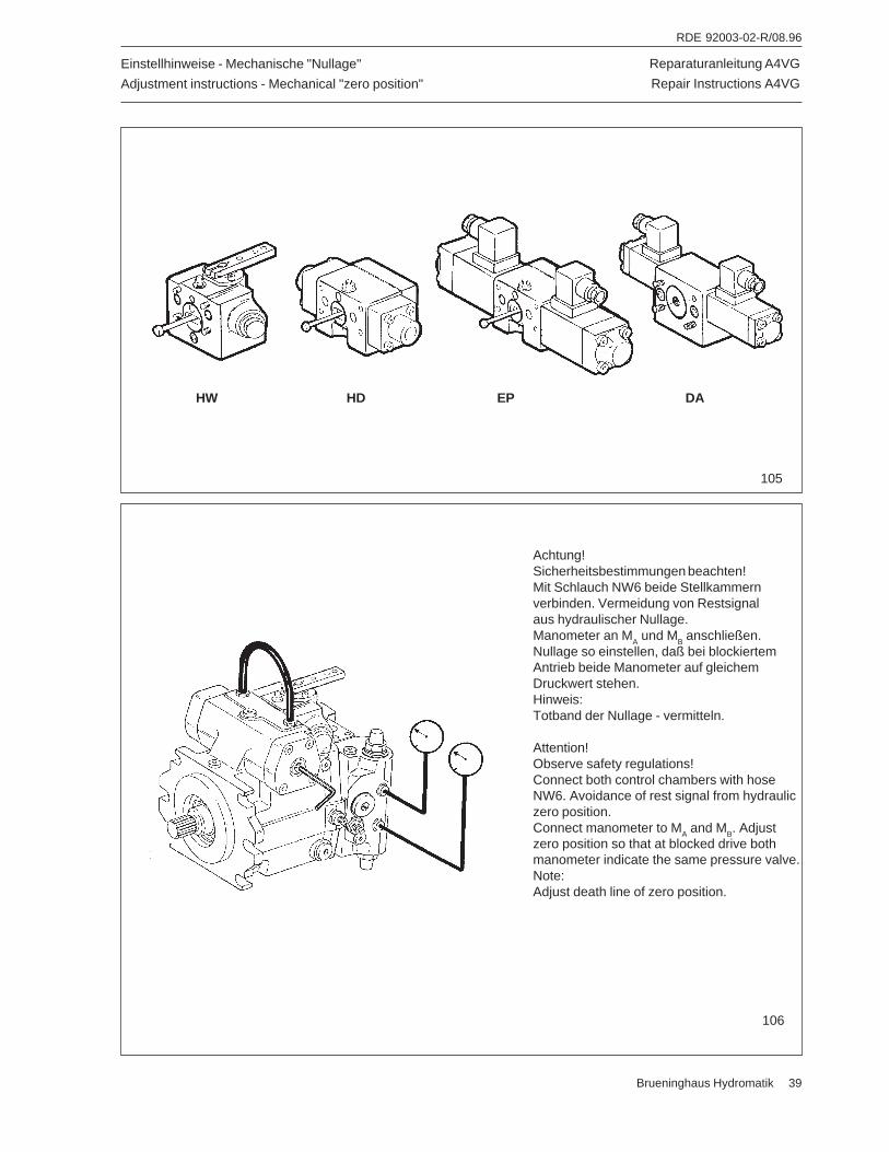
Reparaturanleitung A4VG
Repair Instructions A4VG
RDE 92003-02-R/08.96
Brueninghaus Hydromatik 39
Einstellhinweise - Mechanische "Nullage"
Adjustment instructions - Mechanical "zero position"
Achtung!Sicherheitsbestimmungen beachten!Mit Schlauch NW6 beide Stellkammernverbinden. Vermeidung von Restsignalaus hydraulischer Nullage.Manometer an M
A und M
B anschließen.
Nullage so einstellen, daß bei blockiertemAntrieb beide Manometer auf gleichemDruckwert stehen.Hinweis:Totband der Nullage - vermitteln.
Attention!Observe safety regulations!Connect both control chambers with hoseNW6. Avoidance of rest signal from hydrauliczero position.Connect manometer to MA and MB. Adjustzero position so that at blocked drive bothmanometer indicate the same pressure valve.Note:Adjust death line of zero position.
106
HW HD EP DA
105
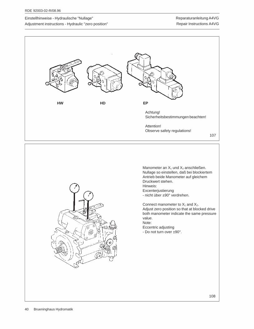
Reparaturanleitung A4VG
Repair Instructions A4VG
RDE 92003-02-R/08.96
40 Brueninghaus Hydromatik
Einstellhinweise - Hydraulische "Nullage"
Adjustment instructions - Hydraulic "zero position"
HW HD EP
Achtung!Sicherheitsbestimmungen beachten!
Attention!Observe safety regulations!
107
Manometer an X1 und X2 anschließen.Nullage so einstellen, daß bei blockiertemAntrieb beide Manometer auf gleichemDruckwert stehen.Hinweis:Excenterjustierung- nicht über ±90° verdrehen.
Connect manometer to X1 and X2.Adjust zero position so that at blocked driveboth manometer indicate the same pressurevalue.Note:Eccentric adjusting- Do not turn over ±90°.
108
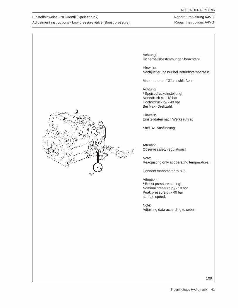
Reparaturanleitung A4VG
Repair Instructions A4VG
RDE 92003-02-R/08.96
Brueninghaus Hydromatik 41
Einstellhinweise - ND-Ventil (Speisedruck)
Adjustment instructions - Low pressure valve (Boost pressure)
Achtung!Sicherheitsbestimmungen beachten!
Hinweis:Nachjustierung nur bei Betriebstemperatur.
Manometer an "G" anschließen.
Achtung!* Speisedruckeinstellung!Nenndruck pH - 18 barHöchstdruck pH - 40 barBei Max.-Drehzahl.
Hinweis:Einstelldaten nach Werksauftrag.
* bei DA-Ausführung
Attention!Observe safety regulations!
Note:Readjusting only at operating temperature.
Connect manometer to "G".
Attention!* Boost pressure setting!Nominal pressure pH - 18 barPeak pressure pH - 40 barat max. speed.
Note:Adjusting data according to order.
109
*
"G"
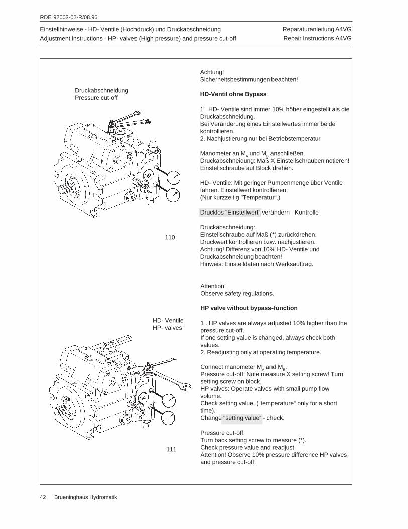
Reparaturanleitung A4VG
Repair Instructions A4VG
RDE 92003-02-R/08.96
42 Brueninghaus Hydromatik
Einstellhinweise - HD- Ventile (Hochdruck) und Druckabschneidung
Adjustment instructions - HP- valves (High pressure) and pressure cut-off
Achtung!Sicherheitsbestimmungen beachten!
HD-Ventil ohne Bypass
1 . HD- Ventile sind immer 10% höher eingestellt als dieDruckabschneidung.Bei Veränderung eines Einsteilwertes immer beidekontrollieren.2. Nachjustierung nur bei Betriebstemperatur
Manometer an MA und MB anschließen.Druckabschneidung: Maß X Einstellschrauben notieren!Einstellschraube auf Block drehen.
HD- Ventile: Mit geringer Pumpenmenge über Ventilefahren. Einstellwert kontrollieren.(Nur kurzzeitig "Temperatur“.)
Drucklos "Einstellwert“ verändern - Kontrolle
Druckabschneidung:Einstellschraube auf Maß (*) zurückdrehen.Druckwert kontrollieren bzw. nachjustieren.Achtung! Differenz von 10% HD- Ventile undDruckabschneidung beachten!Hinweis: Einstelldaten nach Werksauftrag.
DruckabschneidungPressure cut-off
HD- VentileHP- valves
111
110
Attention!Observe safety regulations.
HP valve without bypass-function
1 . HP valves are always adjusted 10% higher than thepressure cut-off.If one setting value is changed, always check bothvalues.2. Readjusting only at operating temperature.
Connect manometer MA and MB.Pressure cut-off: Note measure X setting screw! Turnsetting screw on block.HP valves: Operate valves with small pump flowvolume.Check setting value. ("temperature“ only for a shorttime).Change "setting value“ - check.
Pressure cut-off:Turn back setting screw to measure (*).Check pressure value and readjust.Attention! Observe 10% pressure difference HP valvesand pressure cut-off!
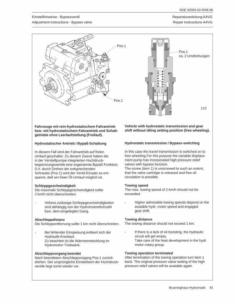
Reparaturanleitung A4VG
Repair Instructions A4VG
RDE 92003-02-R/08.96
Brueninghaus Hydromatik 43
Einstellhinweise - Bypassventil
Adjustment instructions - Bypass valve
Vehicle with hydrostatic transmission and gearshift without idling setting position (free wheeling).
Hydrostatic transmission / Bypass-switching
In this case the travel transmission is switched on tofree wheeling.For this purpose the variable displace-ment pump has incorporated high pressure reliefvalves with bypass function.The screw (item 1) is unscrewed to such an extent,that the valve cartridge is released and free oilcirculation is possible.
Towing speedThe max. towing speed of 2 km/h should not beexceeded.
- Higher admissible towing speeds depend on theavaiable hydr. motor speed and engagedgear shift.
Towing distanceThe towing distance should not exceed 1 km.
- If there is a lack of oil boosting, the hydrauliccircuit will get empty.Take care of the heat development in the hydr.motor-rotary group.
Towing operation terminatedAfter termination of the towing operation turn item 1back. The original pressure value setting of the highpressure relief valves will be avaiable again.
Fahrzeuge mit rein-hydrostatischem Fahrantriebbzw. mit hydrostatischem Fahrantrieb und Schalt-getriebe ohne Leerlaufstellung (Freilauf).
Hydrostatischer Antrieb / Bypaß-Schaltung
In diesem Fall wird der Fahrantrieb auf freienUmlauf geschaltet. Zu diesem Zweck haben diein der Verstellpumpe integrierten Hochdruck-begrenzungsventile eine sogenannte Bypaß-Funktion.D.h. durch Drehen der entsprechendenSchraube (Pos.1) wird der Ventil-Einsatz so ent-spannt, daß ein freier Öl-Umlauf möglich ist.
SchleppgeschwindigkeitDie maximale Schleppgeschwindigkeit sollte2 km/h nicht überschreiten.
- Höhere zulässige Schleppgeschwindigkeitensind abhängig von der Hydromotordrehzahlbzw. dem eingelegten Gang.
AbschleppdistanzDie Schleppentfernung sollte 1 km nicht überschreiten.
- Bei fehlender Einspeisung entleert sich derHydraulik-Kreislauf.Zu beachten ist die Wärmeentwicklung imHydromotor-Triebwerk.
Abschleppvorgang beendetNach beendetem Abschleppvorgang Pos.1 zurück-drehen. Der ursprüngliche Einstellwert der Hochdruck-ventile liegt somit wieder vor.
Pos.1
Pos.1
112
Pos.1ca. 2 Umdrehungen
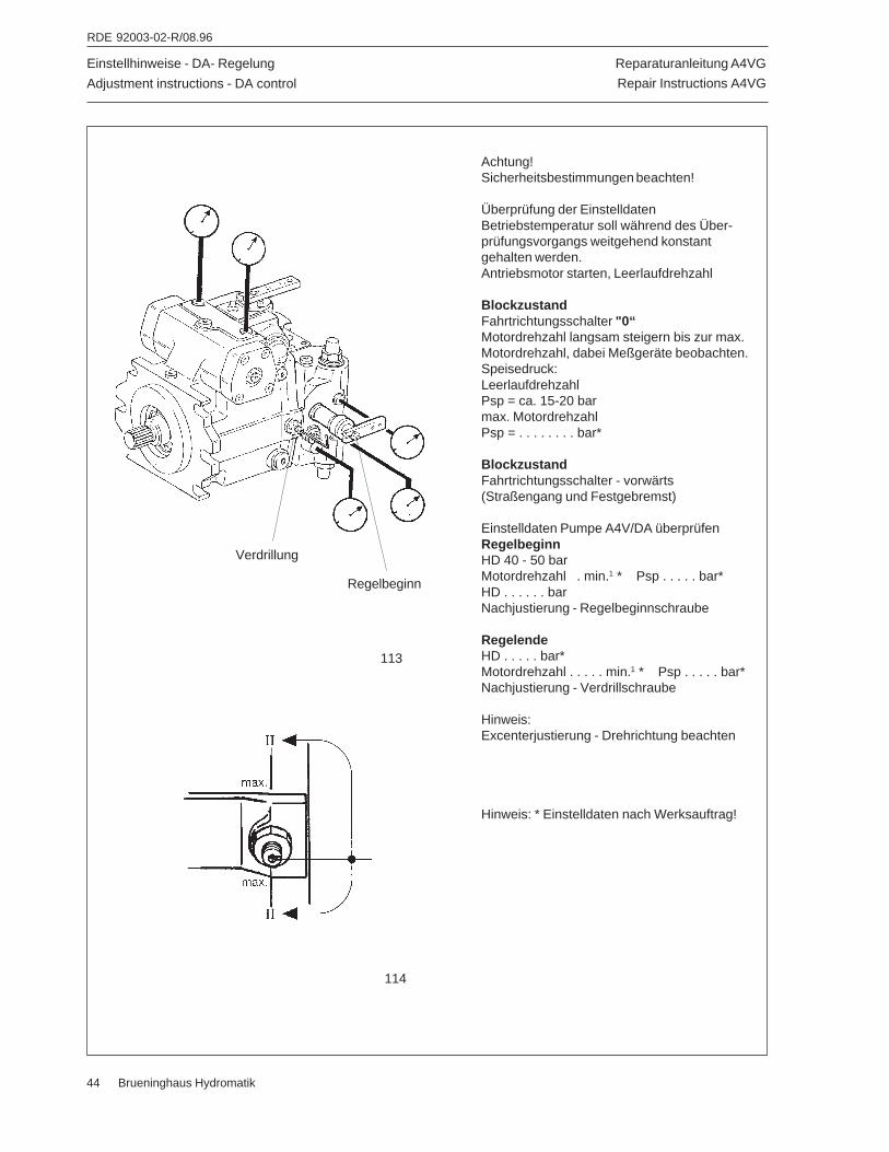
Reparaturanleitung A4VG
Repair Instructions A4VG
RDE 92003-02-R/08.96
44 Brueninghaus Hydromatik
Einstellhinweise - DA- Regelung
Adjustment instructions - DA control
Achtung!Sicherheitsbestimmungen beachten!
Überprüfung der EinstelldatenBetriebstemperatur soll während des Über-prüfungsvorgangs weitgehend konstantgehalten werden.Antriebsmotor starten, Leerlaufdrehzahl
BlockzustandFahrtrichtungsschalter "0“Motordrehzahl langsam steigern bis zur max.Motordrehzahl, dabei Meßgeräte beobachten.Speisedruck:LeerlaufdrehzahlPsp = ca. 15-20 barmax. MotordrehzahlPsp = . . . . . . . . bar*
BlockzustandFahrtrichtungsschalter - vorwärts(Straßengang und Festgebremst)
Einstelldaten Pumpe A4V/DA überprüfenRegelbeginnHD 40 - 50 barMotordrehzahl . min.1 * Psp . . . . . bar*HD . . . . . . barNachjustierung - Regelbeginnschraube
RegelendeHD . . . . . bar*Motordrehzahl . . . . . min.1 * Psp . . . . . bar*Nachjustierung - Verdrillschraube
Hinweis:Excenterjustierung - Drehrichtung beachten
Hinweis: * Einstelldaten nach Werksauftrag!
113
Verdrillung
Regelbeginn
114
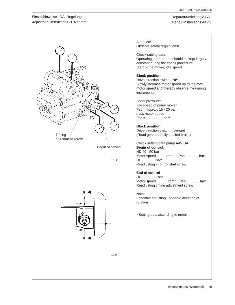
Reparaturanleitung A4VG
Repair Instructions A4VG
RDE 92003-02-R/08.96
Brueninghaus Hydromatik 45
Attention!Observe safety regulations!
Check setting data.Operating temperature should be kept largelyconstant during the check procedure.Start prime mover, idle speed.
Block positionDrive direction switch - "0“ .Slowly increase motor speed up to the max.motor speed and thereby observe measuringinstruments.
Boost pressure:Idle speed of prime moverPsp = approx. 15 - 20 barmax. motor speedPsp = . . . . . . . . . bar*
Block positionDrive direction switch - forward(Road gear and fully applied brake)
Check setting data pump A4VIDABegin of control:HD 40 - 50 barMotor speed . . . . . rpm* Psp . . . . . . . bar*HD . . . . . . . bar*Readjusting - control start screw
End of controlHD . . . . . . . . barMotor speed . . . . . . rpm* Psp . . . . . . . bar*Readjusting timing adjustment screw
Note:Eccentric adjusting - observe direction ofrotation
* Setting data according to order!
Einstellhinweise - DA- Regelung
Adjustment instructions - DA control
114
113
Timingadjustment screw
Begin of control
Reparaturanleitung A4VG
Repair Instructions A4VG
RDE 92003-02-R/08.96
46 Brueninghaus Hydromatik
Hinweis!
Um eine ordnungsgemäßeAbwicklung von Ersatzteil-Aufträgen sicherzustellen, mußdie Bestellung folgende Angabenenthalten:
TypenschlüsselTyp-Nr.Fabrikations-Nr.BaugruppePositionBenennung
Zur Reparatur des Gerätesempfehlen wir die Verwendungvon vormontierten undteilgeprüften Baugruppen.
Note!
In order to supply proper spareparts, please provide followingspecifications when orderingspares:
Type CodeType NumberSerial NumberAssembly GroupItemDesignation
In repairing the unit, werecommend the use ofpre-assembled partially testedassembly groups.
Reparaturanleitung A4VG
Repair Instructions A4VG
RDE 92003-02-R/08.96
Brueninghaus Hydromatik 47
Reparaturanleitung A4VG
Repair Instructions A4VG
RDE 92003-02-R/08.96
48 Brueninghaus Hydromatik
Brueninghaus Hydromatik GmbH, Werk Elchingen, Glockeraustraße 2, D-89275 Elchingen, Tel. (07308) 820, Telex 712538, Fax (07308) 7274
TRAILER MOUNTED PUMP 01 MODEL C90S
SERVICE BULLETIN
C90S SRVBT
PAGE 01
REVISION:
AS WE MAKE IMPROVEMENTS TO THE REED TRAILER MOUNTED CONCRETE PUMP 01 MODEL C90S,
WE LIKE TO SUPPLY YOU, THE CUSTOMER, WITH UPDATED INFORMATION WHICH APPLIES TO YOUR PUMP.
THIS SECTION IS PROVIDED AS A PLACE TO STORE SERVICE BULLETINS AS YOU RECEIVE THEM FROM
REED LLC.

TRAILER MOUNTED PUMP 01 MODEL C90S
SERVICE BULLETIN
C90S SRVBT
PAGE 02
REVISION:
THIS PAGE INTENTIONALLY LEFT BLANK.
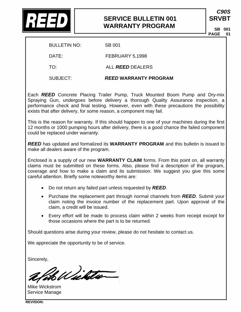
SERVICE BULLETIN 001 WARRANTY PROGRAM
C90S SRVBT
SB 001
PAGE 01
BULLETIN NO: SB 001 DATE: FEBRUARY 5,1998 TO: ALL REED DEALERS SUBJECT: REED WARRANTY PROGRAM
Each REED Concrete Placing Trailer Pump, Truck Mounted Boom Pump and Dry-mix Spraying Gun, undergoes before delivery a thorough Quality Assurance inspection, a performance check and final testing. However, even with these precautions the possibility exists that after delivery, for some reason, a component may fail. This is the reason for warranty. If this should happen to one of your machines during the first 12 months or 1000 pumping hours after delivery, there is a good chance the failed component could be replaced under warranty. REED has updated and formalized its WARRANTY PROGRAM and this bulletin is issued to make all dealers aware of the program. Enclosed is a supply of our new WARRANTY CLAIM forms. From this point on, all warranty claims must be submitted on these forms. Also, please find a description of the program, coverage and how to make a claim and its submission. We suggest you give this some careful attention. Briefly some noteworthy items are:
• Do not return any failed part unless requested by REED.
• Purchase the replacement part through normal channels from REED. Submit your claim noting the invoice number of the replacement part. Upon approval of the claim, a credit will be issued.
• Every effort will be made to process claim within 2 weeks from receipt except for those occasions where the part is to be returned.
Should questions arise during your review, please do not hesitate to contact us. We appreciate the opportunity to be of service. Sincerely,
Mike Wickstrom Service Manage
REVISION:
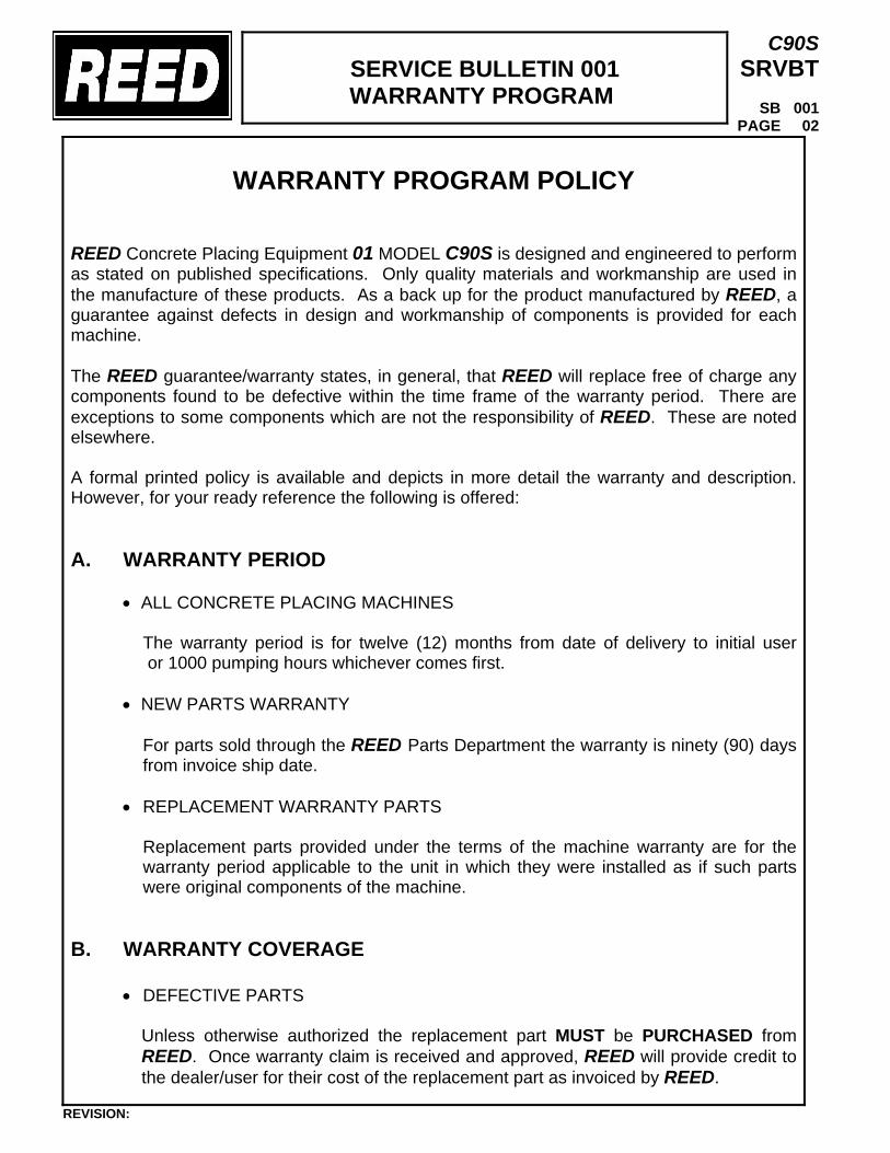
SERVICE BULLETIN 001 WARRANTY PROGRAM
C90S SRVBT
SB 001
PAGE 02
WARRANTY PROGRAM POLICY
REED Concrete Placing Equipment 01 MODEL C90S is designed and engineered to perform as stated on published specifications. Only quality materials and workmanship are used in the manufacture of these products. As a back up for the product manufactured by REED, a guarantee against defects in design and workmanship of components is provided for each machine. The REED guarantee/warranty states, in general, that REED will replace free of charge any components found to be defective within the time frame of the warranty period. There are exceptions to some components which are not the responsibility of REED. These are noted elsewhere. A formal printed policy is available and depicts in more detail the warranty and description. However, for your ready reference the following is offered: A. WARRANTY PERIOD
• ALL CONCRETE PLACING MACHINES
The warranty period is for twelve (12) months from date of delivery to initial user or 1000 pumping hours whichever comes first.
• NEW PARTS WARRANTY
For parts sold through the REED Parts Department the warranty is ninety (90) days from invoice ship date.
• REPLACEMENT WARRANTY PARTS Replacement parts provided under the terms of the machine warranty are for the warranty period applicable to the unit in which they were installed as if such parts were original components of the machine.
B. WARRANTY COVERAGE
• DEFECTIVE PARTS
Unless otherwise authorized the replacement part MUST be PURCHASED from REED. Once warranty claim is received and approved, REED will provide credit to the dealer/user for their cost of the replacement part as invoiced by REED.
REVISION:
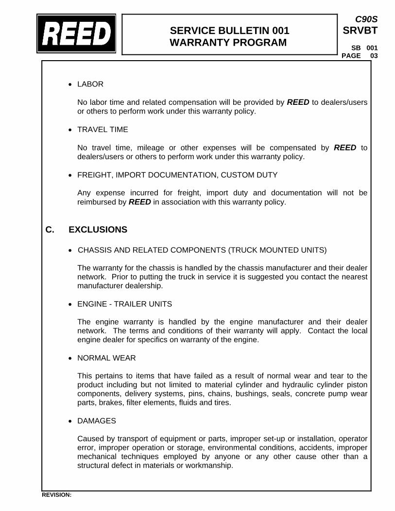
SERVICE BULLETIN 001 WARRANTY PROGRAM
C90S SRVBT
SB 001
PAGE 03
• LABOR
No labor time and related compensation will be provided by REED to dealers/users or others to perform work under this warranty policy.
• TRAVEL TIME
No travel time, mileage or other expenses will be compensated by REED to dealers/users or others to perform work under this warranty policy.
• FREIGHT, IMPORT DOCUMENTATION, CUSTOM DUTY
Any expense incurred for freight, import duty and documentation will not be reimbursed by REED in association with this warranty policy.
C. EXCLUSIONS
• CHASSIS AND RELATED COMPONENTS (TRUCK MOUNTED UNITS) The warranty for the chassis is handled by the chassis manufacturer and their dealer network. Prior to putting the truck in service it is suggested you contact the nearest manufacturer dealership.
• ENGINE - TRAILER UNITS
The engine warranty is handled by the engine manufacturer and their dealer network. The terms and conditions of their warranty will apply. Contact the local engine dealer for specifics on warranty of the engine.
• NORMAL WEAR
This pertains to items that have failed as a result of normal wear and tear to the product including but not limited to material cylinder and hydraulic cylinder piston components, delivery systems, pins, chains, bushings, seals, concrete pump wear parts, brakes, filter elements, fluids and tires.
• DAMAGES
Caused by transport of equipment or parts, improper set-up or installation, operator error, improper operation or storage, environmental conditions, accidents, improper mechanical techniques employed by anyone or any other cause other than a structural defect in materials or workmanship.
REVISION:
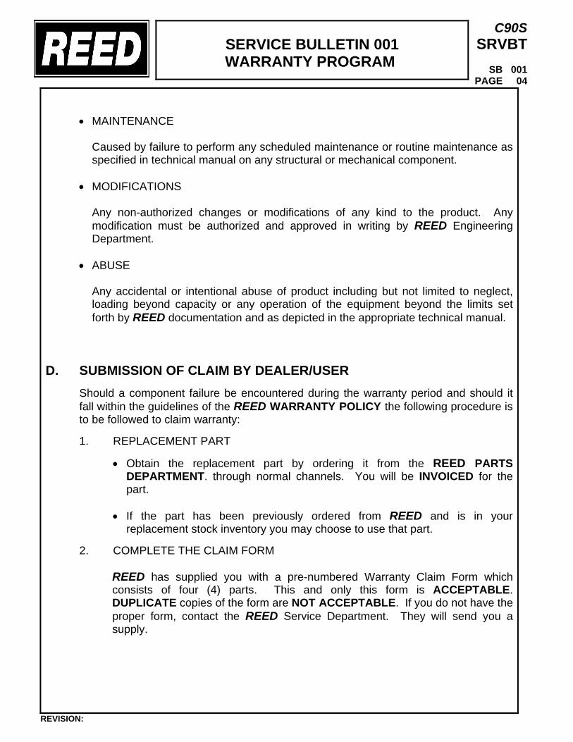
SERVICE BULLETIN 001 WARRANTY PROGRAM
C90S SRVBT
SB 001
PAGE 04
• MAINTENANCE
Caused by failure to perform any scheduled maintenance or routine maintenance as specified in technical manual on any structural or mechanical component.
• MODIFICATIONS
Any non-authorized changes or modifications of any kind to the product. Any modification must be authorized and approved in writing by REED Engineering Department.
• ABUSE
Any accidental or intentional abuse of product including but not limited to neglect, loading beyond capacity or any operation of the equipment beyond the limits set forth by REED documentation and as depicted in the appropriate technical manual.
D. SUBMISSION OF CLAIM BY DEALER/USER
Should a component failure be encountered during the warranty period and should it fall within the guidelines of the REED WARRANTY POLICY the following procedure is to be followed to claim warranty: 1. REPLACEMENT PART
• Obtain the replacement part by ordering it from the REED PARTS DEPARTMENT. through normal channels. You will be INVOICED for the part.
• If the part has been previously ordered from REED and is in your
replacement stock inventory you may choose to use that part. 2. COMPLETE THE CLAIM FORM
REED has supplied you with a pre-numbered Warranty Claim Form which consists of four (4) parts. This and only this form is ACCEPTABLE. DUPLICATE copies of the form are NOT ACCEPTABLE. If you do not have the proper form, contact the REED Service Department. They will send you a supply.
REVISION:
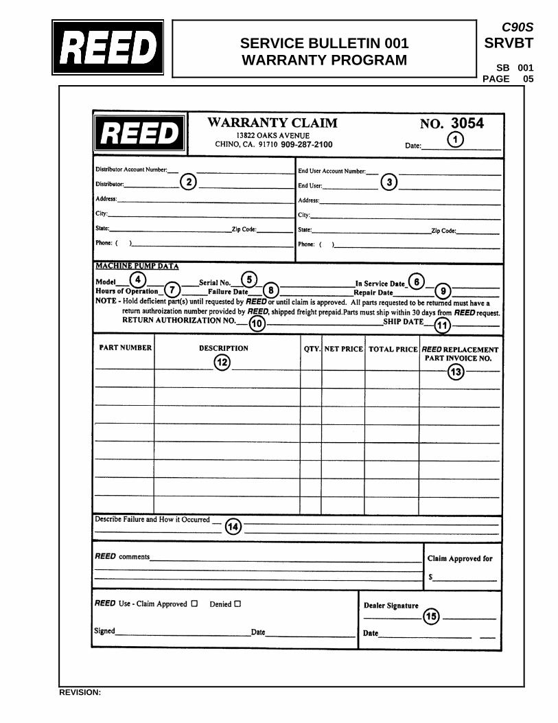
SERVICE BULLETIN 001 WARRANTY PROGRAM
C90S SRVBT
SB 001
PAGE 05
REVISION:
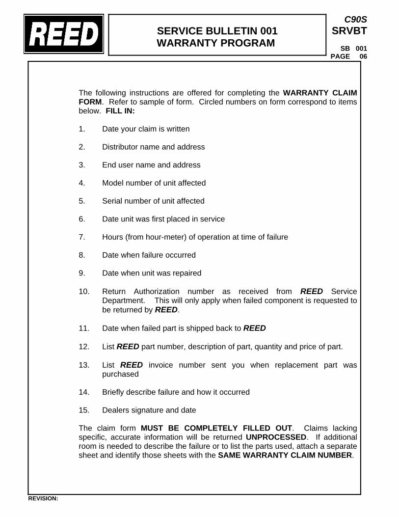
SERVICE BULLETIN 001 WARRANTY PROGRAM
C90S SRVBT
SB 001
PAGE 06
The following instructions are offered for completing the WARRANTY CLAIM FORM. Refer to sample of form. Circled numbers on form correspond to items below. FILL IN: 1. Date your claim is written 2. Distributor name and address 3. End user name and address 4. Model number of unit affected 5. Serial number of unit affected 6. Date unit was first placed in service 7. Hours (from hour-meter) of operation at time of failure 8. Date when failure occurred 9. Date when unit was repaired 10. Return Authorization number as received from REED Service
Department. This will only apply when failed component is requested to be returned by REED.
11. Date when failed part is shipped back to REED 12. List REED part number, description of part, quantity and price of part. 13. List REED invoice number sent you when replacement part was
purchased 14. Briefly describe failure and how it occurred 15. Dealers signature and date
The claim form MUST BE COMPLETELY FILLED OUT. Claims lacking specific, accurate information will be returned UNPROCESSED. If additional room is needed to describe the failure or to list the parts used, attach a separate sheet and identify those sheets with the SAME WARRANTY CLAIM NUMBER.
REVISION:
SERVICE BULLETIN 001 WARRANTY PROGRAM
C90S SRVBT
SB 001
PAGE 07
3. SUBMITTING TO REED When all appropriate data has been entered on the claim and signed, proceed as follows:
• Remove copies of form marked “DEALER” (yellow) and “RETURN AUTHORIZATION” (green). The Dealer copy is for your records and the Return Authorization copy is to be retained in the event REED requests the return of the part.
• Mail the “REED” copy (white) and “ACCOUNTING” copy (pink) along with
any back-up data such as a copy of the replacement part INVOICE to REED. DO NOT FAX COMPLETED FORM and send only FORM ORIGINALS.
E. RETURN OF FAILED COMPONENT
Depending on the type of part and circumstance surrounding the component failure, the possibility exists that REED may request that the failed part be returned to them for investigation and evaluation purposes or to apply for warranty from the manufacturer of the part. • Upon receipt of your warranty claim and before claim is approved, REED will inform
you in writing if the part is to be returned. On this correspondence a RETURN AUTHORIZATION number will be given to you.
• This number is to be written in the appropriate area on the RETURN
AUTHORIZATION copy (green) of the warranty form. Include this copy as part of your packing slip. Also write the number on a tag and attach to the part.
• Parts requested to be returned must be shipped back to REED within 30 days from
issuing of the RA number. Failure to do so will cause warranty claim to be DENIED. • Returned parts are to be properly packaged and shipped freight PREPAID.
• Any parts received by REED without the PROPER RA number will be shipped back
at DEALER/USER EXPENSE. • If claim is approved and no request to return parts from REED has been made,
then parts can be discarded.
REVISION:
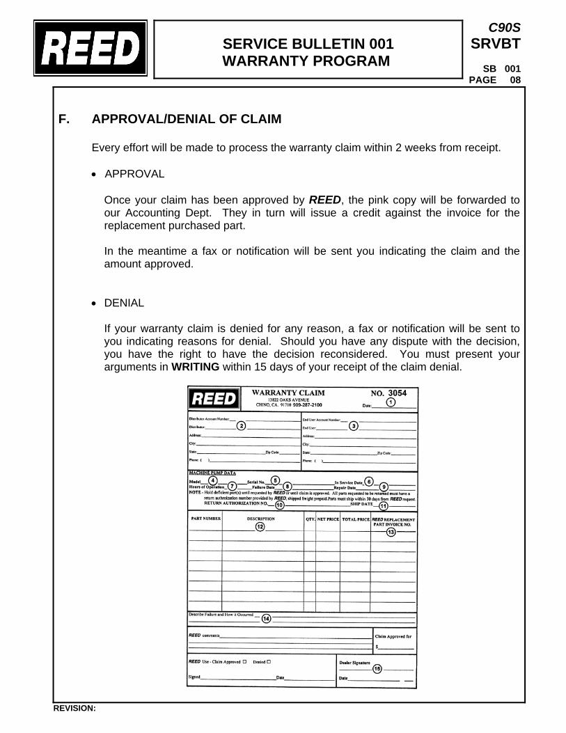
SERVICE BULLETIN 001 WARRANTY PROGRAM
C90S SRVBT
SB 001
PAGE 08
F. APPROVAL/DENIAL OF CLAIM Every effort will be made to process the warranty claim within 2 weeks from receipt.
• APPROVAL
Once your claim has been approved by REED, the pink copy will be forwarded to our Accounting Dept. They in turn will issue a credit against the invoice for the replacement purchased part. In the meantime a fax or notification will be sent you indicating the claim and the amount approved.
• DENIAL
If your warranty claim is denied for any reason, a fax or notification will be sent to you indicating reasons for denial. Should you have any dispute with the decision, you have the right to have the decision reconsidered. You must present your arguments in WRITING within 15 days of your receipt of the claim denial.
REVISION: