THE GAYLORD VENTILATOR TECHNICAL MANUAL
54
THE GAYLORD VENTILATOR TECHNICAL MANUAL FOR THE “CG3” SERIES WATER-WASH VENTILATORS WITH MODEL C-6000 COMMAND CENTER 10900 S.W. AVERY STREET • TUALATIN, OREGON 97062-1149 U.S.A. 1-800-547-9696 • 503-691-2010 • FAX: 503-692-6048 • email: [email protected] GAYLORD INDUSTRIES EFFECTIVE DATE 04-2005
-
Upload
khangminh22 -
Category
Documents
-
view
0 -
download
0
Transcript of THE GAYLORD VENTILATOR TECHNICAL MANUAL

1
THEGAYLORD VENTILATORTECHNICAL MANUAL
FOR THE “CG3” SERIESWATER-WASH VENTILATORS
WITHMODEL C-6000 COMMAND CENTER
10900 S.W. AVERY STREET • TUALATIN, OREGON 97062-1149 U.S.A.1-800-547-9696 • 503-691-2010 • FAX: 503-692-6048 • email: [email protected]
GAYLORD INDUSTRIES
EFFECTIVE DATE 04-2005
2
To Our Customers. . .
Congratulations on your recent purchase of a Gaylordkitchen exhaust hood system. We are proud to be ableto provide you with a quality product that incorporatesthe latest engineering concepts and is a result of over50 years of experience in the foodservice kitchenexhaust industry.
If you have other Gaylord equipment such as a GaylordUtility Distribution System, Quencher Fire ProtectionSystem, or Roof Top Air Handling Equipment, etc.,please refer to the corresponding supplementaryequipment manuals.
If you have further questions, please visit our web siteat: www.gaylordusa.com, or call us toll-free at 1-800-547-9696. We are more than happy to help.
Sincerely,
Gaylord Industries
STREET ADDRESS: 10900 S.W. Avery Street, Tualatin, Oregon 97062-8549 U.S.A.PHONE: 503-691-2010 • 800-547-9696 • FAX: 503-692-6048 • email: [email protected] • www.gaylordusa.com
GAYLORD INDUSTRIES10900 S.W. Avery Street • Tualatin, Oregon 97062-1149 U.S.A.
“Undisputed World Leader inEngineered Systems forCommercial Kitchens”tm
COMMERCIAL KITCHEN EXHAUST SYSTEMS • FIRE PROTECTION • UTILITY DISTRIBUTION • ROOF TOP UNITS • POLLUTION CONTROL
3
"CG3" VENTILATOR DESCRIPTIONS .................................................................................................... 4–-5"CG3" SERIES PRINCIPLE OF OPERATION ...........................................................................................6–9DAILY OPERATION .................................................................................................................................. 10PREVENTIVE MAINTENANCE ................................................................................................................. 11DETERGENT PUMP OPERATION ............................................................................................................ 12DETERGENT FOR THE WASH SYSTEM ................................................................................................. 13MODEL C-6000 SERIES COMMAND CENTER - INSTRUCTIONS........................................................ 14–17ENGINEERING DATA .......................................................................................................................... 18–19RP DEVICE INITIAL START UP................................................................................................................. 20MEASURING INLET SLOT VELOCITY ................................................................................................. 21–23OPTIONAL CONTINUOUS COLD WATER MIST ....................................................................................... 24C-6000 MODEL IDENTIFICATION.............................................................................................................. 25TROUBLE-SHOOTING:
SMOKE LOSS ............................................................................................................................. 26GREASE EXTRACTION ............................................................................................................... 26EXHAUST FAN.................................................................................................................. .. 27WASH SYSTEM ..................................................................................................................... 27–28FIRE CYCLE ..................................................................................................................... ........... 29BACKFLOW PREVENTERS ................................................................................................... 29–30VACUUM BREAKER ................................................................................................................... 29RP DEVICE .................................................................................................................................. 30DRAINS........................................................................................................................................ 30MISCELLANEOUS ....................................................................................................................... 30PLC STATUS LIGHT CHART ....................................................................................................... 31C-6000, C-6000-A AND C-6000-B TERMINAL VOLTAGES .......................................................... 32
PARTS LISTS:MODEL GPC-6000-VB SERIES CONTROL CABINET .................................................................. 33MODEL GPC-6000 SERIES CONTROL CABINET ........................................................................ 34MODEL GPC-6000-S SERIES CONTROL CABINET .................................................................... 35OPTIONAL CONTINUOUS COLD WATER MIST .......................................................................... 36MODEL C-6000 OR C-6000-A SERIES CONTROL ....................................................................... 37MODEL C-6000-B SERIES CONTROL ......................................................................................... 38DAMPER CONTROL MOTOR AND CG3-FDL WIRING ................................................................. 39DETERGENT PUMP .................................................................................................................... 40MISCELLANEOUS VENTILATOR PARTS .................................................................................... 41
WIRING DIAGRAMS ............................................................................................................................ 42–49STANDARD VENTILATOR MODELS ........................................................................................................ 50METRIC CONVERSION CHART ................................................................................................................ 51START-UP INSPECTION REPORT ........................................................................................................... 52
LIMITED WARRANTY ........................................................................................................ Inside back cover
TABLE OF CONTENTS
Patent Pending
© Copyright 2002, Gaylord Industries
ALL RIGHT RESERVED. NO PART OF THIS BOOK MAY BE REPRODUCED,STORED IN A RETRIEVAL SYSTEM, OR TRANSMITTED IN ANY FORMBY AN ELECTRONIC, MECHANICAL, PHOTOCOPYING, RECORDINGMEANS OR OTHERWISE WITHOUT THE WRITTEN PERMISSION OFGAYLORD INDUSTRIES COPYRIGHT 2005.
The manufacturer reserves the right to modify the materials and specifications resulting from a continuingprogram of product improvement or the availability of new materials.
Additional Copies $15.00
4
CG3 VENTILATOR DESCRIPTIONS
There are 5 different types of CG3 “Classic Gaylord”, water-wash ventilators. The differences involve the type and locationof fire damper and whether the ventilator has a fire damper. Thefirst part of the model number indicates the type of ventilator,see below:
Explanation of Prefixes:CG3 ........... Water-wash ventilator with three-position,
thermostatically activated (electric) damperat air inlet slot.[With Damper motor and 1or more Thermostat(s)]
CG3-FDL ... Water-wash ventilator with three-position, ther-mostatically activated (electric) damper at airinlet slot. A bracket (Fire Damper Lockout)has been added to prevent the damper fromclosing to the fire position.[With Dampermotor and 1 or more Thermostat(s)]
CG3-FDD ... Inlet damper is fixed, and there is a weightedfuse link activated fire damper located at theduct collar. [No Damper motor, No Ther-mostats]
CG3-FDT ... Inlet damper is fixed, and there is a weightedfuse link activated fire damper located at theduct collar, and there is a single thermostatto activate the fire mode in the control cabinetand ventilator. [No Belimo, One Thermo-stat]
CG3-ND Inlet damper is fixed. No Fire Damper at ductcollar. A bracket (Fire Damper Lockout) hasbeen added to show that the damper will notclose to the fire position. [No Dampermotor, No Thermostats]
Summary of CG3 Ventilators:The CG3 and CG3-FDL are very similar. Both have a dampermotor that closes the inlet damper during the wash mode andstays closed until the exhaust fan is started. Both havethermostats that can detect an “Internal Fire”. The maindifference is the CG3-FDL has a Fire Damper Lockout (FDL)bracket added that prevents the inlet damper from closing tothe fire position, so it does NOT have a fire damper.
The CG3-FDD and CG3-FDT are similar to each other. Bothhave fixed inlet dampers and do not have damper motors. Theyboth have fuse link activated fire dampers in the duct collar thatwill close when the temperature reaches 250°F. The CG3-FDThas an added thermostat that will detect an “Internal Fire” andactivate the “Internal Fire Mode”. The CG3-FDD does NOThave any thermostats.
The CG3-ND has a fixed inlet damper and does NOT have afire damper.
5
CG3 VENTILATOR DESCRIPTIONS
6
GREASE EXTRACTIONThe Gaylord “CG3” Series Ventilator extracts up to 95% of thegrease, dust and lint particles from the airstream passingthrough it, when operated and maintained in accordance withdesign specifications.
The hot, contaminant-laden air rising from the cookingsurface merges with the higher velocity air that wipes the frontof the cooking equipment and extends, like an air blanket, fromthe front edge of the cooking equipment to the air inlet of theventilator. As the air moves through the ventilator at a highspeed, it is forced to make a series of turns around threebaffles. As the high velocity air turns around each baffle, theheavier-than-air particles of grease, dust and lint are thrown outof the airstream by centrifugal force. The extracted grease,dust and lint are collected in the interior of the ventilator,remaining out of the airstream until removed daily by the washcycle.
Baffle #1This baffle, located at the air entrance of the ventilator, is athree position damper. Position 1 is the exhaust on mode asshown in Figure 1 below, position 2 is the wash mode, andposition 3 is the fire mode. When the "Start Fan" button ispushed on the control cabinet, the damper opens to theexhaust mode (position 1) to become the preliminary grease
"CG3" SERIES VENTILATOR PRINCIPLE OF OPERATION
extraction baffle. There is a small sloped grease collectinggutter on the back side of the damper which drains off liquefiedgrease, preventing it from re-entraining into the airstream.
Baffle #2This baffle is located on the interior back wall of the ventilatorand is a stainless steel pipe, equipped with brass spraynozzles on 8" to 10" centers. (Refer to Figure 1) During thewash cycle, hot detergent water is released through thenozzles. If the ventilator’s automatic fire control system isactivated, fire smothering water spray is also released throughthe spray nozzles.
Baffle #3This baffle is located on the back of the inspection doors. Thisbaffle is also a grease collecting gutter, collecting grease, dustand lint extracted by the ventilator - preventing the contaminantsfrom dropping back into the high velocity airstream.
NOTE: Some ventilators may be equipped with optional“Custom Air” baffles (shown dotted) which reduces theexhaust volume where the baffle occurs.
NOTE: Some ventilators may be equipped with optionalcontinuous cold water mist. Refer to Page 24 for details.
FIG. 1GREASE EXTRACTION
7
FIG. 2VENTILATOR CONTROL CABINET
MODEL GPC-6000 SERIES
"CG3" SERIES VENTILATOR PRINCIPLE OF OPERATION
WASH CYCLEThe wash cycle is activated each time the exhaust fan is shutoff by pushing the “Start Wash” button on the CommandCenter or as programmed on the clock. When activated theexhaust and supply fans shut off, the damper control isenergized and the damper begins closing forward to the washposition, and once closed the hot water wash sprays come on.The ventilator may be equipped with an optional second washmanifold as shown in Figure 3 and is indicated in the modelnumber, stamped on the ventilator nameplate, by the suffix“DW”. This is typically used when extra heavy duty cookingequipment is under the ventilator.
This hot detergent water washes the day’s grease, dust andlint accumulation from the interior of the ventilator flushing itdown to the main gutter which slopes to a pre-flushed drainwhich leads to the building drain system. Spray nozzles arelocated on 8" to 10" centers on the wash manifold mounted onthe interior back wall of the ventilator. At the end of the washcycle, the water automatically shuts off, and the interior of theventilator is clean - ready for the next day’s operations. Thedamper remains in the wash position until the exhaust fan isrestarted. This is to prevent conditioned air from going up theexhaust system during off hours.
The length of the wash cycle may be set between 3 minutesand 9 minutes. The length of time is dependent upon the typeof cooking equipment being used. Typical settings are 3minutes for light-duty equipment, 5 minutes for medium-dutyequipment, and 9 minutes for heavy-duty equipment. However,adequate cleaning is dependent upon water pressure, watertemperature, daily grease accumulation, the length of thewash cycle, frequency of wash cycle and the type of detergentbeing used. It may be necessary to increase the wash time toachieve proper cleaning. Refer to page 15 for details on settingthe wash time.
FIG. 3WASH CYCLE
COMMAND CENTERMODEL C-6000SERIES
8
INTERNAL FIRE MODE — For CG3 and CG3-FDT only!Automatic internal fire protection is accomplished by theaction of the thermostat(s), which are located at the pointwhere the ductwork joins the ventilator. When the temperatureof the conveying airstream, which must pass over the thermo-stats, reaches 250°F, the system is activated, and thefollowing occurs:
1. The damper begins closing back to the fire position,position 3 as shown in Fig.4—stopping the combustion-supporting, natural draft through the ventilator and creatinga fire barrier to contain the fire in the kitchen. (N/A on CG3-FDT)
2. The exhaust fan serving the ventilator is shut off. Thesupply fan is also shut off.
3. Fire-smothering water spray is released into the interior ofthe ventilator through the spray nozzles.
4. The digital display reads "Fire In Hood, Fan Off, Wash On"for approximately 5 seconds.
5. Then the digital display reads "Fire In Hood, DamperClosing" for approximately 5 seconds.
6. Then the digital display reads "Fire In Hood, Notify FireDepartment". This display stays on until the thermostatcools down below 250°F.
"CG3" SERIES VENTILATOR PRINCIPLE OF OPERATION
CAUTION:
In case of severe fire the thermostats located in the plenum willactivate. As a precautionary measure, it is recommended thatthe thermostats be replaced.
FIG. 4FIRE CYCLE
7. A red light on the Command Center illuminates.
8. If the Command Center is intertied with a building alarm ormonitoring system, a fire signal would be sent to thatsystem.
9. Upon cooling of the thermostat below 250oF, the CoolDown Cycle starts. The water continues to spray duringthe Cool Down Cycle (2 minutes). The damper moves tothe exhaust position. (N/A on CG3-FDT)
10. While in the cool down cycle the digital display reads"Cool Down Cycle, xxx sec. to end". xxx is the countdownin seconds until the wash turns off. The damper moves tothe exhaust position.
11. At the end of the cool down cycle the wash turns off andthe digital display reads "Fan Off 12:00 (actual time), StartFan>F1". The damper closes to the wash position. (N/Aon CG3-FDT)
NOTE: The water may be shut off prior to the end of the 2 minutecool down cycle by pushing the “Exit” button on the C-6000Command Center. After the water has shut off, the damperremains in the wash position until the “Start Fan” button ispushed.
9
"CG3" SERIES VENTILATOR PRINCIPLE OF OPERATION
TESTING INTERNAL FIRE MODE –FOR CG3 AND CG3-FDT ONLY!The internal fire protection system may be tested periodicallyby pushing and holding for 20 seconds, the “Fire TestSwitch” located inside the electrical compartment of thecontrol cabinet. Pushing this switch duplicates thermostaticaction. CAUTION: Before pushing the “Fire Test Switch” ,check to see if the internal fire protection system is tied to thebuilding alarm system.
TO RESUME NORMAL OPERATION
1. To discontinue the 2 minute cool down cycle at any pointduring the cycle, push the “Exit” F5 button on the C-6000Command Center.
2. Push the “Start Fan” F1 button on the Command Center.
SURFACE FIRE PROTECTIONThe National Fire Protection Association, NFPA-96 documentrequires fire extinguishing equipment over all grease producingcooking equipment such as griddles, ranges, fryers, broilers,and woks. In addition, the system must protect the interior ofthe ventilator and the exhaust duct.
The most common fire system is either a wet chemical typeor the Gaylord Quencher water spray system. In the event ofa fire this system would normally be activated and dischargedprior to the ventilator’s internal fire protection. If the fire isunusually severe or the surface fire protection system malfunc-tions, the ventilator’s internal fire protection system wouldactivate, thus providing a second level of defense. Thesesystems may be intertied with the ventilator control cabinet toactivate the External Fire Mode.
FIG. 5BREAK GLASS FIRE SWITCH
C-1357A SERIES
EXTERNAL FIRE MODEAn External Fire Mode is activated by the Ventilator’s FireSuppression (Duct, Plenum, Surface/Appliance) system’smicroswitch or contacts and/or an optional break glass fireswitch (see Figure 5). Terminals 4 & FS are used for theExternal Fire Mode, refer to wiring diagram for details. Thebreak glass fire switch, if used, would normally be located atthe exit of the kitchen. When the External Fire Mode isactivated, the following occurs:
1. The Exhaust Fan comes on immediately if it was off to helpremove smoke, heat, etc.
2. The Supply Fan shuts off immediately.
3. The digital display reads “Ext.FireActive” and alternatesbetween “Reset FireSwitch” and “Fan On, Wash On”.
4. A red light on the Command Center flashes.
5. After a 60-second delay, a fire smothering water spray isreleased into the interior of the ventilator through the spraynozzles. The 60-second delay allows the ventilator’s firesuppression system time to put out the fire, before startingthe water spray.
If the fire intensifies and the thermostat reaches 250°F, the firedamper would then close and the exhaust fan would shut off.See Internal Fire Mode.
To resume normal operations, open the fire switch and flip thetoggle switch to the position marked “normal”. Replace theglass rod and close the cover. Push either the “Start Fan” or“Start Wash” button.
INTERNAL & EXTERNAL FIRE MODES AT THE SAME TIME
It is possible that both the Internal and External Fire modes canbe activated at the same time. If this occurs, the Internal FireMode will override the External Fire mode until the thermostat(s)cool below 250°F. At this point the Cool Down Cycle will startcounting down for 2 minutes. After the Cool Down Cycle, theExternal Fire mode will start.
Special Note: If the control is in the Cool Down Cyclewhen the External Fire mode is activated, the CoolDown Cycle will finish counting down for 2 minutes,before switching to the External Fire Mode.
Summary of Both Fire Modes at the Same Time1. Internal Fire Mode (until thermostat temperature drops
below 250°F)2. Cool Down Cycle (for 2 minutes)3. External Fire Mode (until the External Fire Switch is
reset)
FIRE MODE SUMMARY:
Note: The Damper Position does not apply to CG3-FDL, CG3-FDD, or CG3-ND
INTERNAL FIRE
COOL DOWN CYCLE (for Internal Fire
Mode onl y!)
EXTERNAL FIRE
Exhaust Fan OFF OFF ONSupply Fan OFF OFF OFFDamper Position FIRE EXHAUST EXHAUST Water Spray ON ON ON
10
Starting the Exhaust FanTo start the exhaust fan push the “Start Fan” button on theCommand Center. If the Command Center is programmed tostart the fan automatically, then the start button does not needto be pushed. It is important to start the exhaust fan beforeturning on the cooking equipment.
When the exhaust fan is activated the following occurs:
1. The damper begins opening to the exhaust position.(N/A on CG3-FDD and CG3-ND)
2. A green light on the Command Center illuminates.
3. The supply fan comes on.
4. The digital display reads "Starting Fan & Damper Open-ing" for approximately 5 seconds. Then the digital displayreads "Starting Fan, xx Seconds to Fan On". xx is thecoundown in seconds until the exhaust fan comes on.
5. After the damper fully opens (elapsed time approximately45 seconds) the exhaust fan comes on.
6. The digital display then reads "Fan On 12:00" (currenttime) and "Start Wash> F2".
Stopping the Exhaust Fan andStarting the Wash CycleCAUTION: The cooking equipment must be shut off prior toshutting off the exhaust fan. Failure to do this will causeexcessive heat buildup and could cause the surface fireprotection system to discharge.
To start the wash cycle push the “Start Wash” button on theCommand Center. If the Command Center is programmed tostart the wash automatically, then the start button does notneed to be pushed. When the wash cycle is activated thefollowing occurs:
1. The exhaust and supply fans shut off.
FIG. 6VENTILATOR CONTROL CABINET
MODEL GPC-6000 SERIES
DAILY OPERATION
2. The damper begins closing forward to the wash position.(See Figure 3, page 7). This action takes approximately 45seconds. (N/A on CG3-FDD and CG3-ND)
3. The digital display reads "Starting Wash, Damper Clos-ing" for approximately 5 seconds, then the digital displayreads "Starting Wash, Wash On in xx seconds". xx is thecountdown in seconds to until the wash starts.
4. After the damper closes to the wash position, the hot,detergent injected, water sprays come on to wash awaythe grease collected during the days operation. The washcycle stays on for the length of time programmed in theCommand Center. The length of the wash cycle may beset between 3 minutes and 9 minutes. Typical settings are3 minutes for light-duty equipment, 5 minutes for medium-duty equipment and 9 minutes for heavy-duty equipment.Refer to page 15 for details on setting the wash time.
5. During the wash cycle, the digital display reads "WashOn, Wash #1 xxx seconds". xxx is the coundown inseconds until the wash system shuts off.
6. Upon completion of the wash cycle, the damper stays in theclosed wash position until the exhaust fan is re-started. Thisis to prevent conditioned air from going up the exhaust stackduring off hours.(N/A on CG3-FDD and CG3-ND)
7. The digital display now reads "Fan Off 12:00" (currenttime) and Start Fan>F1.
After the wash cycle is completed, wipe the exposed frontsurface of the damper at the air inlet slot, as well as otherexposed exterior surfaces. (Refer to Figure 7, Page 11).
In very heavy cooking operations it may be necessary to washthe ventilator(s) more than once a day. This can be donemanually by pushing the “Start Wash” button
NOTE: For proper operation of the wash system there mustbe adequate water pressure and temperature. There is apressure/temperature gauge inside the control cabinet.
Water Pressure 40 psi min. - 80 psi max.
Water temperature 140°F min. - 180°F max.
NOTE: Some control cabinets are equipped with a lowdetergent switch. If so equipped, the green light will flash if thedetergent tank is empty or if the detergent pump is malfunc-tioning and detergent is not pumping. The digital display reads"Low Detergent" and the text alternates from "Fill Tank" and"Check Pump". If the detergent tank is filled with water thedetergent switch will activate as if there is no detergent.
NOTE: The ventilator wash system is designed to remove dailyaccumulations of grease within the extractionchamber. If the ventilator is not washed a minimum of onceduring a cooking day, a grease buildup could accumulatewhich the wash system cannot remove. If this occurs, it isrecommended that the ventilator be put through several washcycles by pushing the “Start Wash” button on the CommandCenter. If this does not remove the grease, it will be necessaryto remove the grease manually by using a scraping tool, suchas a putty knife, or retain the services of a commercial hoodcleaning service to steam clean or pressure wash the system.
WARNING: Some commercial hood cleaning services blowa fire retardant chemical into hood and duct systems. Fireretardant chemicals should never be applied to any portion ofThe Gaylord Ventilator. If retardant is applied to the ventilator,it must be removed.
DAILY OPERATIONAll functions of the ventilator, such as starting the exhaust fan,starting the wash cycle, etc., are controlled by the CommandCenter located on the control cabinet. Refer to Pages 14through 17 for detailed instructions on the operation of theCommand Center.
COMMAND CENTERMODEL C-6000 SERIES
11
ELUDEHCSNOITCEPSNIMETSYSTSUAHXEsnoitarepognikoocleufdilosgnivressmetsyS ylhtnoM
snoitarepognikoocemulov-hgihgnivressmetsySkowrogniliorbrahc,gnikoocruoh-42sahcus
gnikoocylretrauQ
gnikoocemulov-etaredomgnivressmetsySsnoitarepo yllaunna-imeS
,snoitarepognikoocemulov-wolgnivressmetsySlanosaes,spmacyad,sehcruhcsahcus
sretnecroinesro,sessenisubyllaunnA
FIG. 7
PREVENTIVE MAINTENANCE
PREVENTIVE MAINTENANCEThe following should be checked periodically in order to keepThe Gaylord Ventilator operating at design efficiency:
Weekly1. The detergent tank should be checked at least weekly and
kept full with a recommended detergent. (Refer to Page 13)
Monthly1. The detergent system fittings should be checked at
least monthly. This is an airtight system and fittingsshould be tight. (For complete details refer to the Deter-gent Pump section on Page 12.)
2. At least monthly, at the conclusion of a wash cycle, openthe inspection doors of the ventilator and check to ensurethat the interior has been cleaned of grease, dust, and lint.(Refer to Figure 7) If overall cleaning appears to beinadequate, refer to “Trouble-Shooting of the Wash Sys-tem”, Page 27.
3. The main grease gutter of the ventilator should bechecked at least monthly to remove any foreign materialsuch as paper towels, order chits, etc.
Every Six Months1. Exhaust fan(s) should be checked every six months for
belt tightness, belt alignment, and lubrication of neces-sary moving parts.
NOTE: A blue lithium based grease is best suited for highheat and speed bearing lubrication.
2. Check for proper velocity at air inlet slot. Refer to Pages21 through 23 for method of checking velocity.
3. Test the "Internal Fire Mode" to check for proper damperclosure. Refer to Page 9 for instructions.
4. Detergent tank and foot valve should be cleaned every sixmonths.
INSPECTION AND CLEANING REQUIREMENTSNFPA-96 (Standard for Ventilation Control and Fire Protectionof Commercial Cooking Operations) require that hoods, ductsand exhaust fans be inspected by a properly trained, qualifiedand certified company or person(s) in accordance with thefollowing table.
Upon inspection, if found to be contaminated with depositsfrom grease-laden vapors, the entire exhaust system shall becleaned by a properly trained, qualified, and certified companyor person(s) acceptable to the authority having jurisdiction inaccordance.
When a vent cleaning service is used, a certificate showingdate of inspection or cleaning shall be maintained on thepremises. After cleaning is completed, the vent cleaningcontractor shall place or display within the kitchen area a labelindicating the date cleaned and the name of the servicingcompany. It shall also indicate areas not cleaned.
Factory trained service agencies are certified by GaylordIndustries, Inc. to perform these inspections. For the name andphone number of your nearest agent visit our web site atwww.gaylordusa.com, email at [email protected], or call1-800-547-9696.

12
TRAHCNOITPMUSNOCTNEGRETED)lairepmI(
lortnoCtenibaCeziSepiP
yrotcaFmaC
gnitteS
reP.zOta.niMISP04
retaWerusserP
HTGNELELCYCHSAW
setuniM3 setuniM5 setuniM9
.zOrePyaD
.laGreP.oM
.zOrePyaD
.laGreP.oM
.zOrePyaD
.laGreP.oM
"2/1 1# 2.3 6.9 1.2 1.61 5.3 5.22 9.4
"4/3 2# 1.5 6.51 4.3 1.62 7.5 5.63 9.7
"1 3# 0.6 8.71 9.3 6.92 5.6 4.14 1.9
"4/11"2/11&
4# 3.6 8.81 1.4 3.13 8.6 8.34 6.9
DETERGENT PUMP OPERATION
PREVENTIVE MAINTENANCE
As with any piece of fine equipment, a reasonable amount ofcare must be taken to keep it in good working order:
1. Caution should be taken not to spill detergent on theexterior of the pump.
2. A periodic check should be made of all fittingsto guarantee their tightness.
NOTE: The detergent pump motor has sealed bearings andwill not require lubrication.
The Gaylord Ventilator detergent pump is an integral part of thewash-down system of The Gaylord Ventilator. The pump islocated within the control cabinet unless otherwise specified.(Refer to schematics on Pages 33 through 35.)
OPERATIONThe detergent pump is started when the wash cycle begins.The pump draws detergent up from the detergent tank, pushingit through the copper tubing and into the hot water line servingthe ventilator.
NOTE: Some control cabinets are equipped with a lowdetergent switch. If so equipped, the green light will flash if thedetergent tank is empty or if the detergent pump is malfunc-tioning and detergent is not pumping. The digital display reads"Low Detergent" and the text alternates from "Fill Tank" and"Check Pump". If the detergent tank is filled with water thedetergent switch will activate as if there is no detergent.
Initial OperationTo prime and operate the pump for the first time, it is recom-mended that water be used instead of detergent to preventdetergent from spilling in case of leaks at the system’s fittings.
Priming The PumpThe detergent pump is self-priming. Push the pump testswitch, located on the junction box of the motor, and hold downuntil liquid climbs up the vinyl tubing and fills the pump head.The pump will be operating properly when both upper and lowerpoppet checks can be seen moving up and down slightly. If thepump does not self-prime, an air lock may have developedwithin the pump head and the following action should be taken:
1. Hold down pump test switch and loosen top cap slightlyto allow air to be pushed out. Repeat as necessary untilliquid climbs up tube and fills pump head.
Note : Do not overly tighten cap or damage to the pumphead will occur.
2. If the pump still does not work properly, check thefollowing:
A. Foot valve should be clean and immersed in the liquid.
B. Check all fittings to ensure an airtight system.
C. Poppet checks within the foot valve, pump head and brass check valve should be clean and operating freely.
D. Detergent lines should be free and clear.
DETERGENT FLOWDetergent flow is initially factory set according to the pipe size of thecontrol cabinet (refer to chart). Generally, the factory setting will besufficient to provide adequate cleaning of the ventilator. However,adequate cleaning is dependent upon a number of factors:
1. Temperature of hot water 4. Wash cycle time2. Water pressure 5. Frequency of wash cycle3. Daily grease accumulation 6. Type of detergent
Depending upon these factors, it may be necessary to adjustthe detergent flow. Adjustment may be accomplished bychanging the cam to a different size. To change the cam:
1. Loosen Allen set screw on brass cam.2. Remove cam and replace with next size as required.3. Cam #1 minimum setting. Cam #4 maximum setting.
NOTE: Cams are available from Gaylord Industries or yourGaylord Certified Service Agency.
FIG. 8
13
FORMULA G-510 is the only cleaner recommended by Gay-lord Industries for use in the washdown system of The GaylordVentilator. FORMULA G-510 is a concentrated colloid cleanerspecially formulated to remove the daily accumulation ofgrease inside The Gaylord Ventilator without damaging therubber and synthetic parts of the detergent pumping system.FORMULA G-510 is biodegradable, safe for kitchen person-nel, and has a variety of uses.
DILUTION OF FORMULA G-510 FORVENTILATOR CLEANINGNormal CleaningFor ventilators covering cooking equipment such as broilers,griddles, fryers, or any other heavy grease producing equip-ment, fill the detergent tank with full strength FORMULAG-510.
Light-Duty CleaningFor ventilators covering light grease producing equipment suchas ovens, kettles, steamers and ranges, fill the detergent tankwith a mixture of one part FORMULA G-510 to one part water.
Cleaning the Ventilator ExteriorMix one part FORMULA G-510 to twenty parts water in handspray bottle. Spray on and wipe off. NOTE: Once a day, thissame solution should be used to clean the front of the firedamper and main grease extracting baffle.
FOR OTHER CLEANING JOBSThe colloidal action of FORMULA G-510 makes it a cleanerespecially well-suited for use in kitchens. The colloids breakup dirt and grease into millions of tiny particles that constantlyrepel each other. These particles cannot recombine or rede-posit on a surface and are, therefore, easily washed away.FORMULA G-510 is biodegradable and contains no harshchemicals, yet offers outstanding performance on the tough-est cleaning jobs.
Use a mixture of one part FORMULA G-510 to twenty partswater for:
VINYL/PLASTIC/WALLS...Removes dirt, grease, food de-posits and fingerprints.REFRIGERATORS...Removes dirt, spilled milk, blood,mildew and objectionable odors.RESTROOMS...Add a disinfectant to clean all fixtures,walls, floors, etc.
Use a mixture of one part FORMULA G-510 to five parts waterfor extremely heavy grease build-up, such as on the floor andon equipment around deep-fryers. Spray on and rinse or wipeoff. For extremely soiled areas, gentle agitation, followed by asoaking period, will result in more thorough cleaning.
DON’T be afraid to experiment with FORMULA G-510 becauseit contains no phosphates, nitrates, enzymes, sulfates, sul-fonates or silicates.
DETERGENT FOR THE WASH SYSTEM
LIMITED WARRANTY
G-510 CHEMICAL DIVISION warrants that FOR-MULA G-510 will not cause cleansing agent damageto the rubber and synthetic parts of the injection pump(“O” rings, diaphragms, washers, tubing, and othersuch parts) used with The Gaylord Ventilator, HeatReclaim Unit, or Pollution Control Equipment. G-510CHEMICAL DIVISION’S obligation under this war-ranty and any warranties implied by law shall belimited to repairing or replacing, at its option, any ofsaid parts which G-510 CHEMICAL DIVISION'Sexamination shall disclose to its satisfaction to havebeen damaged by the use of FORMULA G-510 for thelife of the detergent pumping system. This warrantyshall not cover damages caused by any other deter-gent. The use of any other detergent shall void thiswarranty.
All repairs and replacement parts under this warrantyshall be F.O.B. G-510 CHEMICAL DIVISION’S fac-tory. The owner shall pay the necessary freight anddelivery charges; also removal and installationcosts. Any federal, state or local taxes are also extra.Requests for repairs or replacement parts should bemade to 20/10 Products Inc., PO Box 7609, Salem,OR 97303.
This is the sole warranty with respect to FORMULA G-510. G-510 CHEMICAL DIVISION MAKES NO OTHERWARRANTY OF ANY KIND WHATSOEVER, EX-PRESSED OR IMPLIED, AND ALL IMPLIED WAR-RANTIES OF MERCHANTABILITY AND FITNESSFOR A PARTICULAR PURPOSE WHICH EXCEEDTHE AFORESAID OBLIGATION ARE HEREBY DIS-CLAIMED AND EXCLUDED FROM THIS AGREE-MENT. G-510 CHEMICAL DIVISION SHALL NOT BERESPONSIBLE FOR INCIDENTAL OR CONSE-QUENTIAL DAMAGES RESULTING FROM ABREACH OF THIS WARRANTY.
IMPORTANTIf a cleansing agent other than FORMULA G-510 is used withThe Gaylord Ventilator injection pump, it is recommended thata warranty similar to the above be obtained from the manufac-turer of said product.
For name and address of the nearest FORMULA G-510distributor contact:
20/10 Products Inc.P.O. Box 7609Salem, OR 97303Phone: 800-286-2010FAX: 503-363-4296E-Mail: [email protected]
14
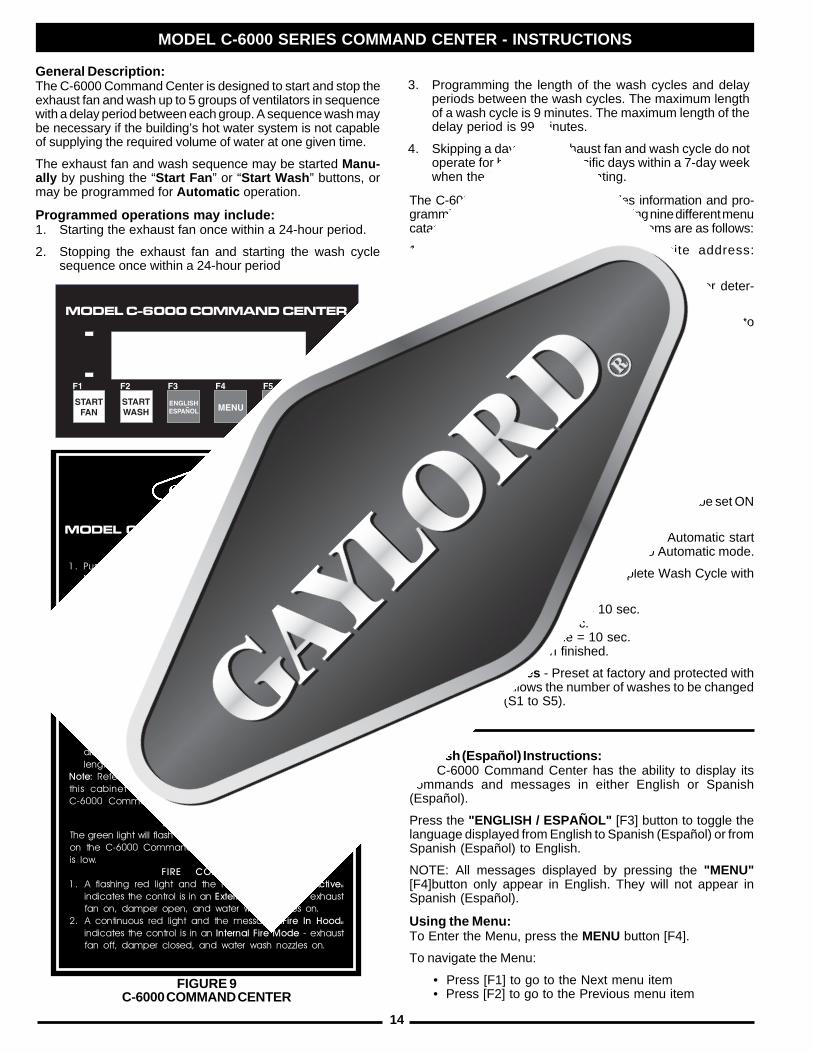
MODEL C-6000 SERIES COMMAND CENTER - INSTRUCTIONS
General Description:The C-6000 Command Center is designed to start and stop theexhaust fan and wash up to 5 groups of ventilators in sequencewith a delay period between each group. A sequence wash maybe necessary if the building’s hot water system is not capableof supplying the required volume of water at one given time.
The exhaust fan and wash sequence may be started Manu-ally by pushing the “Start Fan ” or “Start Wash ” buttons, ormay be programmed for Automatic operation.
Programmed operations may include:1. Starting the exhaust fan once within a 24-hour period.
2. Stopping the exhaust fan and starting the wash cyclesequence once within a 24-hour period
The C-6000 Command Center provides information and pro-gramming for various functions by accessing nine different menucatagories. An overview of the nine menu items are as follows:
1. Service - Displays Gaylord's website address:gaylordusa.com
2. Detergent - Displays Toll-Free Number to order deter-gent: 800-286-2010
3. Wash Length - Sets length of each wash cycle from 3 to9 minutes
4. Delay Time (for sequence wash units only) - Sets delaybetween washes from 1 minute to 99 minutes
5. Set Clock - Day, hour and minutes
6. AutoMode [M or A] - Sets the C-6000 to Manual orAutomatic modes. In Automatic mode, the C-6000 willstart the Fan and Wash at the preset times that were setusing the Set Wash Times option.
A = Automatic / M = Manual
Also allows individual days (Mon, Tues., etc.) to be set ONor OFF when Automatic mode is selected.
7. Set Wash Times - Sets Start Times for Automatic startof Fan and wash when C-6000 is set to Automatic mode.
8. Wash Test - Runs through a complete Wash Cycle withdecresed times
Damper Closing Time = 10 sec.Wash Times = 10 sec.Water Heating Time = 10 sec.Exits menu when finished.
9. Number of Washes - Preset at factory and protected witha password. Allows the number of washes to be changedfrom 1 to 5 (S1 to S5).
Spanish (Español) Instructions:The C-6000 Command Center has the ability to display itscommands and messages in either English or Spanish(Español).
Press the "ENGLISH / ESPAÑOL" [F3] button to toggle thelanguage displayed from English to Spanish (Español) or fromSpanish (Español) to English.
NOTE: All messages displayed by pressing the "MENU"[F4]button only appear in English. They will not appear inSpanish (Español).
Using the Menu:To Enter the Menu, press the MENU button [F4].
To navigate the Menu:
• Press [F1] to go to the Next menu item• Press [F2] to go to the Previous menu item
FIGURE 9C-6000 COMMAND CENTER
3. Programming the length of the wash cycles and delayperiods between the wash cycles. The maximum lengthof a wash cycle is 9 minutes. The maximum length of thedelay period is 99 minutes.
4. Skipping a day so the exhaust fan and wash cycle do notoperate for holidays or specific days within a 7-day weekwhen the kitchen is not operating.
OPERATING INSTRUCTIONS
1. Push "Start Fan" before turning on cooking equipment.Note: There is a 45 second delay after pushing the buttonbefore the fan starts to allow the damper to open to the"Exhaust" position.
2. At the end of the day, or whenever cooking is completed,push "Start Wash". This will turn off the exhaust fan andclose the damper forward to the "Wash" position.
Note: There is a 45 second delay after pushing the buttonbefore the wash cycle starts, to allow the damper, if soequipped, to close to the "Wash" position. After closing, thetimed wash cycle begins. Damper stays closed until "StartFan" is pushed. Note: 24 hour kitchens must push "Start Wash"at least once a day, or as needed for proper cleaning.3. To set the length of the time for the wash cycle, press
"Menu", then press [F1] until "Wash Length" appears on thedisplay. Follow the instructions on the display to edit thelength of washes as necessary.
Note: Refer to the programming instructions on the inside ofthis cabinet for more information on programming theC-6000 Command Center.
LOW DETERGENTThe green light will flash and "Low Detergent" will be displayedon the C-6000 Command Center indicating the detergentis low.
FIRE CONDITION1. A flashing red light and the message "Ext. Fire Active"
indicates the control is in an External Fire Mode - exhaustfan on, damper open, and water wash nozzles on.
2. A continuous red light and the message "Fire In Hood"indicates the control is in an Internal Fire Mode - exhaustfan off, damper closed, and water wash nozzles on.
MODEL C-6000 COMMAND CENTER
15
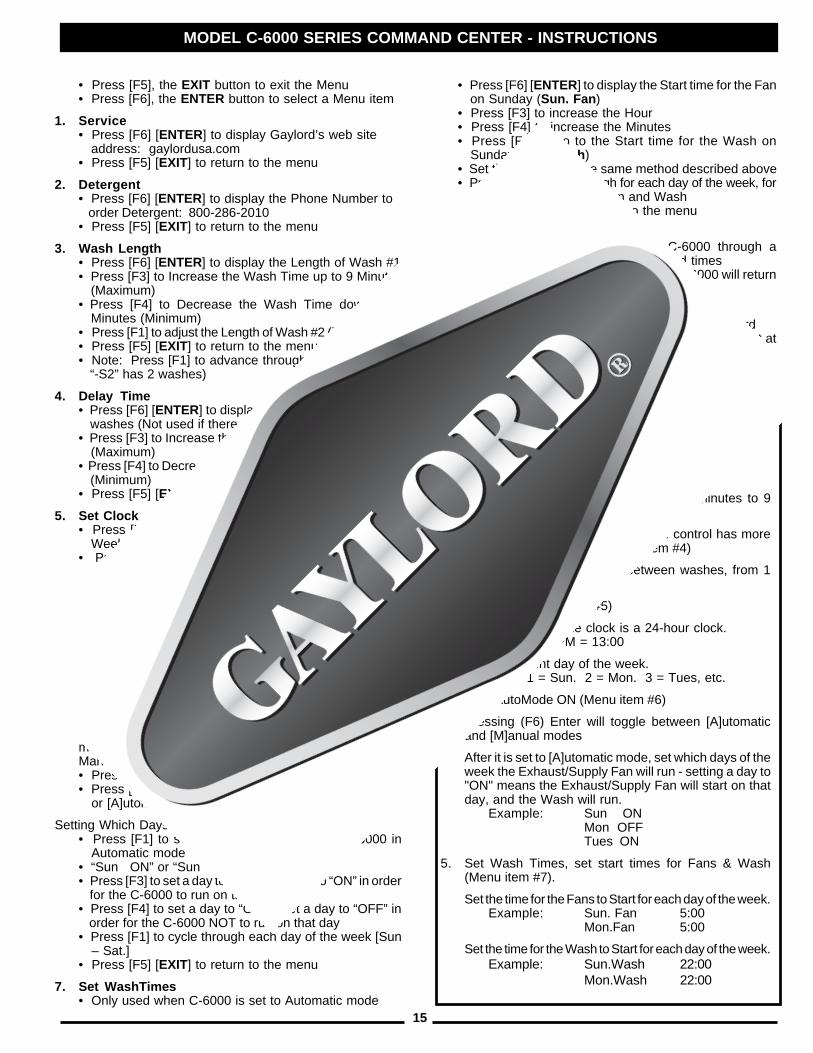
MODEL C-6000 SERIES COMMAND CENTER - INSTRUCTIONS
• Press [F6] [ENTER] to display the Start time for the Fan on Sunday (Sun. Fan )• Press [F3] to increase the Hour• Press [F4] to increase the Minutes• Press [F1] to go to the Start time for the Wash on Sunday (Sun.Wash )• Set the time, using the same method described above• Press [F1] to cycle through for each day of the week, for the Start Times for the Fan and Wash• Press [F5] [EXIT] to return to the menu
8. Wash Test• Press [F6] [ENTER] to run the C-6000 through a complete Wash cycle with decreased times• After the Wash Test is complete, the C-6000 will return to the Fan Off mode
9. Number of Washes• Pressing [F6] [ENTER] will prompt for a password It is not necessary to change this value. It is preset at the Factory.
• Press [F5], the EXIT button to exit the Menu• Press [F6], the ENTER button to select a Menu item
1. Service• Press [F6] [ENTER] to display Gaylord’s web site address: gaylordusa.com• Press [F5] [EXIT] to return to the menu
2. Detergent• Press [F6] [ENTER] to display the Phone Number to order Detergent: 800-286-2010• Press [F5] [EXIT] to return to the menu
3. Wash Length• Press [F6] [ENTER] to display the Length of Wash #1• Press [F3] to Increase the Wash Time up to 9 Minutes (Maximum)• Press [F4] to Decrease the Wash Time down to 3 Minutes (Minimum)• Press [F1] to adjust the Length of Wash #2 (if applicable)• Press [F5] [EXIT] to return to the menu• Note: Press [F1] to advance through all washes (ex.) “-S2” has 2 washes)
4. Delay Time• Press [F6] [ENTER] to display the Delay Time between washes (Not used if there is only one wash)• Press [F3] to Increase the Delay Time up to 99 Minutes (Maximum)• Press [F4] to Decrease the Delay Time down to 1 Minute (Minimum)• Press [F5] [EXIT] to return to the menu
5. Set Clock• Press [F6] [ENTER] to display the current Day of the Week (1=Sunday)• Press [F3] to change to the next Day of the Week (1=Sun, 2=Mon, 3=Tues, etc.), keep pressing [F3] to cycle around if necessary• Press [F1] to go to the current Hour• Press [F3] to increase the Hour, keep pressing [F3] to cycle around if necessary• Press [F1] to go to the current Minute• Press [F3] to increase the Minute, keep pressing [F3] to cycle around if necessary• Press [F5] [EXIT] to return to the menu
6. AutoMode [A or M]• Used to select [M]anual or [A]utomatic mode. If [A] is displayed, the C-6000 is set to operate in Automaticmode. If [M] is displayed, the C-6000 is set to operate inManual mode.• Press [F6] [ENTER] to display the “Set Mode” screen• Press [F6] [ENTER] again to toggle between [M]anual or [A]utomatic mode
Setting Which Days of the Week to Run:• Press [F1] to select which days to run the C-6000 in Automatic mode• “Sun ON” or “Sun OFF” will display• Press [F3] to set a day to “ON”. Set a day to “ON” in order for the C-6000 to run on that day• Press [F4] to set a day to “OFF”. Set a day to “OFF” in order for the C-6000 NOT to run on that day• Press [F1] to cycle through each day of the week [Sun – Sat.]• Press [F5] [EXIT] to return to the menu
7. Set WashTimes• Only used when C-6000 is set to Automatic mode
TIME CLOCK OPERATIONAutoMode is used to have C-6000 start the exhaust/supplyfans automatically, once per day. The AutoMode also stopsthe fans and starts the wash cycle, once per day.
To use the AutoMode:1. Set Wash Length(s) (Menu item #3)
Set length of each wash cycle, from 3 minutes to 9minutes
2. Set Delay Time between washes, if control has morethan one wash solenoid (Menu item #4)
Set amount of time to wait between washes, from 1minute to 99 minutes
3. Set Clock (Menu item #5)
Please note that the clock is a 24-hour clock.Example: 1:00 PM = 13:00
Set the current day of the week.Example: 1 = Sun. 2 = Mon. 3 = Tues, etc.
4. Turn AutoMode ON (Menu item #6)
Pressing (F6) Enter will toggle between [A]utomaticand [M]anual modes
After it is set to [A]utomatic mode, set which days of theweek the Exhaust/Supply Fan will run - setting a day to"ON" means the Exhaust/Supply Fan will start on thatday, and the Wash will run.
Example: Sun ONMon OFFTues ON
5. Set Wash Times, set start times for Fans & Wash(Menu item #7).
Set the time for the Fans to Start for each day of the week.Example: Sun. Fan 5:00
Mon.Fan 5:00
Set the time for the Wash to Start for each day of the week.Example: Sun.Wash 22:00
Mon.Wash 22:00
16
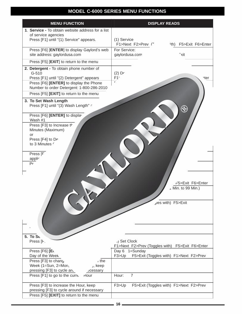
MODEL C-6000 SERIES MENU FUNCTIONS
NOITCNUFUNEM SDAERYALPSID
1. -ecivreS tsilarofsserddaetisbewniatbooTseicnegaecivresfo
.sraeppa"ecivreS)1("litnu]1F[sserP ecivreS)1(retnE>6FtixE>5F)htiwselggoT(verP>2FtxeN>1F
[]6F[sserP RETNE bews’drolyaGyalpsidot]moc.asudrolyag:sserddaetis
:ecivreSroFtixE>5F)htiwselggoT(moc.asudrolyag
[]5F[sserP TIXE unemehtotnruterot]
.2 -tnegreteD forebmunenohpniatbooT015-G
sraeppa"tnegreteD)2("litnu]1F[sserPtnegreteD)2(
retnE>6FtixE>5F)htiwselggoT(verP>2FtxeN>1F]6F[sserP ]RETNE[ enohPehtyalpsidot
0102-682-008-1:tnegreteDredrootrebmuN:tnegreteDroF
tixE>5F)htiwselggoT(0102-682-008-1
]5F[sserP ]TIXE[ unemehtotnruterot
.3 htgneLhsaWteSoTsraeppa"htgneLhsaW)3("litnu]1F[sserP htgneLhsaW)3(
retnE>6FtixE>5F)htiwselggoT(verP>2FtxeN>1F]6F[sserP ]RETNE[ fohtgneLehtyalpsidot
1#hsaW).niM9ot.niM3morfegnaR(NIM3:emiT1hsaW
9otpuemiThsaWehtesaercnIot]3F[sserP)mumixaM(setuniM
ronwodemiThsaWehtesaerceDot]4F[sserP
)muminiM(setuniM3ot
tixE>5FtxeN>1F)htiwselggoT(nwoD>4FpU>3F
fi.cte,2#hsaWtxeNotseogtxeN>1FgnisserP*lortnoclaitneuqeSasaputessilortnoc
fi(2#hsaWfohtgneLehttsujdaot]1F[sserP)elbacilppa]5F[sserP ]TIXE[ unemehtotnruterot
.4 emiTyaleDteSoTsraeppa"emiTyaleD)4("litnu]1F[sserP emiTyaleD)4(
retnE>6FtixE>5F)htiwselggoT(verP>2FtxeN>1FsserP ]6F[ ]RETNE[ emiTyaleDehtyalpsidot
ylnosierehtfidesutoN(sehsawneewteb)hsaweno
).niM99ot.niM1morfegnaR(niM1:emiTyaleD
otpuemiTyaleDehtesaercnIot]3F[sserPmumixaM(setuniM99
ronwodemiTyaleDehtesaerceDot]4F[sserP
)muminiM(etuniM1ot
tixE>5F)htiwselggoT(nwoD>4FpU>3F
]5F[sserP ]TIXE[ unemehtotnruterot
.5 kcolCteSoTsraeppa"kcolCteS)5("litnu]1F[sserP kcolCteS)5(
retnE>6FtixE>5F)htiwselggoT(verP>2FtxeN>1F]6F[sserP ]RETNE[ tnerrucehtyalpsidot
)yadnuS=1(keeWehtfoyaDyadnuS=16yaD
verP>2FtxeN>1F)htiwselggoT(tixE>5FpU>3FehtfoyaDtxenehtotegnahcot]3F[sserP
peek,).cte,seuT=3,noM=2,nuS=1(keeWyrassecenfidnuoraelcycot]3F[gnisserp
ruoHtnerrucehtotogot]1F[sserP 7:ruoH
peek,ruoHehtesaercniot]3F[sserPyrassecenfidnuoraelcycot]3F[gnisserp
verP>2FtxeN>1F)htiwselggoT(tixE>5FpU>3F
]5F[sserP ]TIXE[ unemehtotnruterot
17
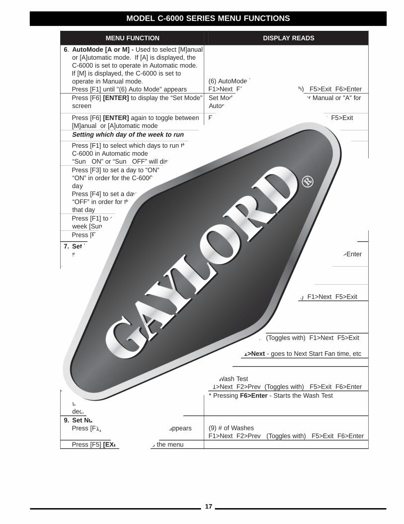
NOITCNUFUNEM SDAERYALPSID
6. -]MroA[edoMotuA launa]M[tcelesotdesUeht,deyalpsidsi]A[fI.edomcitamotu]A[ro.edomcitamotuAnietarepoottessi0006-C
ottessi0006-Ceht,deyalpsidsi]M[fI.edomlaunaMnietarepo
sraeppa"edoMotuA)6("litnu]1F[sserP]M[edoMotuA)6(verP>2FtxeN>1F retnE>6FtixE>5F)htiwselggoT(
]6F[sserP ]RETNE[ ”edoMteS“ehtyalpsidotneercs
rof"A"rolaunaMrof"M"rehtieebnaC(]M[edoMteS)citamotuA
]6F[sserP ]RETNE[ neewtebelggototniagaedomcitamotu]A[rolauna]M[
tixE>5FtxeN>1F)htiwselggoT(na]M[/otu]A[>6F
nurotkeewehtfoyadhcihwgnitteS
ehtnurotsyadhcihwtcelesot]1F[sserPedomcitamotuAni0006-C
yalpsidlliw”FFOnuS“ro”NOnuS“otyadateS.”NO“otyadatesot]3F[sserP
tahtnonurot0006-Cehtrofredroni”NO“yad
otyadateS.”FFO“otyadatesot]4F[sserPnonurotTON0006-Cehtrofredroni”FFO“
yadtahtehtfoyadhcaehguorhtelcycot]1F[sserP
].taS–nuS[keew]5F[sserP ]TIXE[ unemehtotnruterot
.7 -semiThsaWteS si0006-CnehwylnodesU.edomcitamotuAottes
sraeppa"emiThsaWteS)7("litnu]1F[sserP
semiThsaWteS)7(retnE>6FtixE>5F)htiwselggoT(verP>2FtxeN>1F
]6F[sserP ]RETNE[ emittratSehtyalpsidotyadnuSnonaFehtrof naF.nuS( ) ]42:41[naF.nuS
ruoHehtesaercniot]3F[sserPsetuniMehtesaercniot]4F[sserP tixE>5FtxeN>1F)htiwselggoT(.niM>4FruoH>3F
ehtrofemittratSehtotogot]1F[sserPyadnuSnohsaW hsaW.nuS( )
dohtememasehtgnisu,emitehtteSevobadebircsed
]42:41[hsaW.nuS
foyadhcaerofhguorhtelcycot]1F[sserPdnanaFehtrofsemiTtratSehtrof,keeweht
hsaW
tixE>5FtxeN>1F)htiwselggoT(.niM>4FruoH>3F
gnisserP* txeN>1F cte,emitnaFtratStxeNotseog-]5F[sserP ]TIXE[ unemehtotnruterot
.8 tseThsaWsraeppa"tseThsaW)8("litnu]1F[sserP tseThsaW)8(
retnE>6FtixE>5F)htiwselggoT(verP>2FtxeN>1F]6F[sserP ]RETNE[ 0006-Cehtnurot
htiwelcychsaWetelpmocahguorhtsemitdesaerced
gnisserP* retnE>6F tseThsaWehtstratS-
.9 sehsaWforebmuNteSsraeppa"sehsaWfo#)9("litnu]1F[sserP sehsaWfo#)9(
retnE>6FtixE>5F)htiwselggoT(verP>2FtxeN>1F]5F[sserP ]TIXE[ unemehtotnruterot
MODEL C-6000 SERIES MENU FUNCTIONS
18
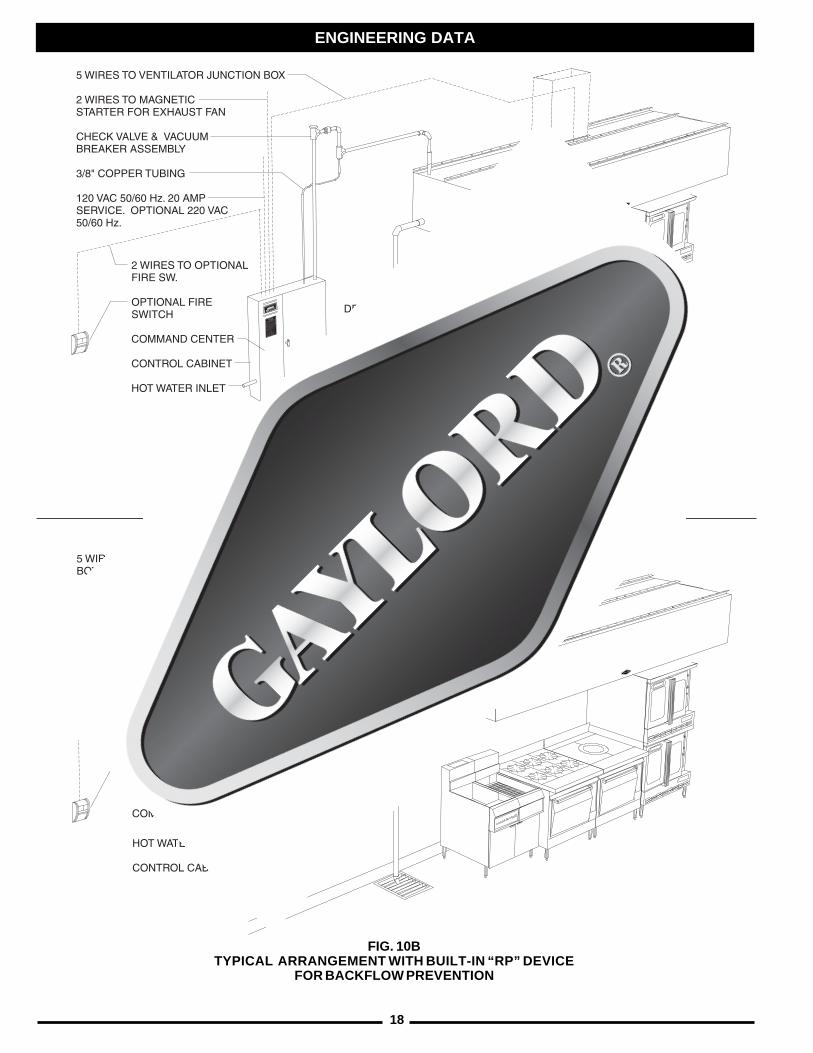
FIG. 10ATYPICAL ARRANGEMENT WITH VACUUM BREAKER/CHECK
VALVE FOR BACKFLOW PREVENTION
FIG. 10BTYPICAL ARRANGEMENT WITH BUILT-IN “RP” DEVICE
FOR BACKFLOW PREVENTION
ENGINEERING DATA
19
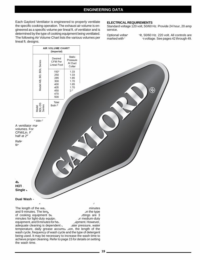
Each Gaylord Ventilator is engineered to properly ventilatethe specific cooking operation. The exhaust air volume is en-gineered as a specific volume per lineal ft. of ventilator and isdetermined by the type of cooking equipment being ventilated.The following Air Volume Chart lists the various volumes perlineal ft. designs.
A ventilator may be designed to operate at two different airvolumes. For example, half the ventilator may operate at 150CFM/Lin. Ft. by utilizing “Custom Air” Baffles, and the otherhalf at 250 CFM/Lin. Ft.
Refer to “Measuring Inlet Slot Velocity” on Page 21 for instruc-tions on how to determine the designed Air Volume/Lin. Ft.
The total exhaust volume for each ventilator is stamped on theventilator nameplate. (Refer to Figure 13 on Page 23.)
DUCT VELOCITYBased between 1700 FPM - 1900 FPM
WATER TEMPERATURE REQUIREMENTS140°F Min. - 180°F Max.
HOT WATER PRESSURE REQUIREMENTS40 PSI Min. - 80 PSI Max.HOT WATER CONSUMPTIONSingle Wash - .60 GPM/Lineal Ft. @ 40 PSI Average
.90 GPM/Lineal Ft. @ 80 PSI Average
Dual Wash - 1.14 GPM/Lineal Ft. @ 40 PSI Average1.67 GPM/Lineal Ft. @ 80 PSI Average
The length of the wash cycle may be set between 3 minutesand 9 minutes. The length of time is dependent upon the typeof cooking equipment being used. Typical settings are 3minutes for light-duty equipment, 5 minutes for medium-dutyequipment, and 9 minutes for heavy-duty equipment. However,adequate cleaning is dependent upon water pressure, watertemperature, daily grease accumulation, the length of thewash cycle, frequency of wash cycle and the type of detergentbeing used. It may be necessary to increase the wash time toachieve proper cleaning. Refer to page 15 for details on settingthe wash time.
TRAHCEMULOVRIA)lairepmI(
deriseDrePMFCtooFlaeniL
citatSerusserPtcuDtA
ralloC
*051052582003004504054074005
33.133.156.107.156.107.100.251.204.2
latoTstolShtoB
004005
56.151.2
selffaBriAmotsuChtiW*
ELECTRICAL REQUIREMENTSStandard voltage 120 volt, 50/60 Hz. Provide 24 hour, 20 ampservice.
Optional voltage 220 volt, 50/60 Hz. 220 volt. All controls aremarked with their operating voltage. See pages 42 through 49.
ENGINEERING DATA
Mod
el A
B, B
D, B
DL
Ser
ies
Mod
elB
DL-
DS
Ser
ies
20
RP DEVICE - INITIAL START UP
RP DEVICEThe reduced pressure principle device (RP) is required toprevent contaminated water from backflowing upstream topotable water. The unit provided in the Gaylord control cabinetis manufactured by Watts Regulator Co.
1. Initial Start-up - To avoid water hammer or shock damageperform the following initial start-up procedures:
A. Close the outlet hand valve.
B. Open the inlet hand valve slowly, fill the valve and bleed
the air through test cock number 2, 3, and 4.
C. When the valve is filled, open the outlet hand valveslowly and fill the remaining supply system. The initialstart-up procedure is now complete.
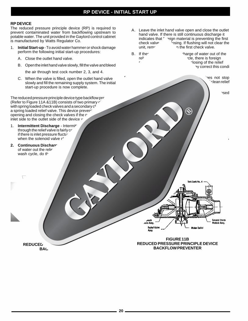
The reduced pressure principle device type backflow preventer(Refer to Figure 11A &11B) consists of two primary chamberswith spring loaded check valves and a secondary chamber witha spring loaded relief valve. This device prevents backflow byopening and closing the check valves if the pressure from theinlet side to the outlet side of the device varies.
1. Intermittent Discharge - Intermittent discharge of waterthrough the relief valve is fairly common and usually occursif there is inlet pressure fluctuations of more than 3 psi andwhen the solenoid valve closes after a wash cycle.
2. Continuous Discharge - If there is continuous dischargeof water out the relief valve when the ventilator is not in awash cycle, do the following:
A. Leave the inlet hand valve open and close the outlethand valve. If there is still continuous discharge itindicates that foreign material is preventing the firstcheck valve from closing. If flushing will not clear theunit, remove and clean the first check valve.
B. If there is continuous discharge of water out of therelief valve during a wash cycle, there is foreignmaterial preventing complete closing of the reliefvalve. Flushing the relief valve may correct this condition.
Repeat procedure if necessary. If flushing does not stopdischarge with flow through the device, remove and clean reliefvalve.
In no case should the relief valve outlet port be plugged, closedoff or restricted.
This device should be inspected occasionally for continualdischarge from the relief valve, which indicates a need formaintenance. It is recommended that the RP device beinspected and tested once a year.
NOTE: Some regulations require annual inspection and test-ing by a company certified to perform such duties.
See Instruction Manual IS-TK-DP, obtainable from your Wattsinstaller or distributor. For the name of your nearest installer ordistributor, call Watts Regulator at (978) 688-1811.
FIGURE 11AREDUCED PRESSURE PRINCIPLE DEVICE
BACKFLOW PREVENTER
FIGURE 11BREDUCED PRESSURE PRINCIPLE DEVICE
BACKFLOW PREVENTER
INLET HAND VALVE OUTLET HAND VALVE
21
*SROTALITNEVSEIRES"SD"ROF
rePMFCdengiseD.tFlaeniL
telnIegarevAderiuqeR)MPF(yticoleVtolS
latoThtoBstolS
tnorFtolS
raeRtolS
tolStnorF
.niM mumitpO .xaM
tolSraeR
.niM mumitpO .xaM
003
004
051
052
051
051
067
5731
008
0541
088
0251
595
595
526
526
556
556
TRAHCYTICOLEVRIA
SEIRES"SD"TPECXESEIRES"3GC"LLAROF
lanimoNthgieH
fotolStelnI
motsuCtuohtiWselffaBriA
motsuChtiWselffaBriA
dengiseDrepMFC.tFlaeniL
telnIegarevA)MPF(yticoleVtolS
.niM mumitpO .xaM
dengiseDrepMFC.tFlaeniL
telnIegarevA)MPF(yticoleVtolS
.niM mumitpO .xaM
"3
"4
052
072
582
003
004
0031
0631
5241
5641
0961
0831
5341
0051
5451
0871
0541
0051
5751
5261
0781
051
061
071
081
052
067
097
018
548
0401
008
038
558
088
5901
088
078
009
539
0511
MEASURING INLET SLOT VELOCITY
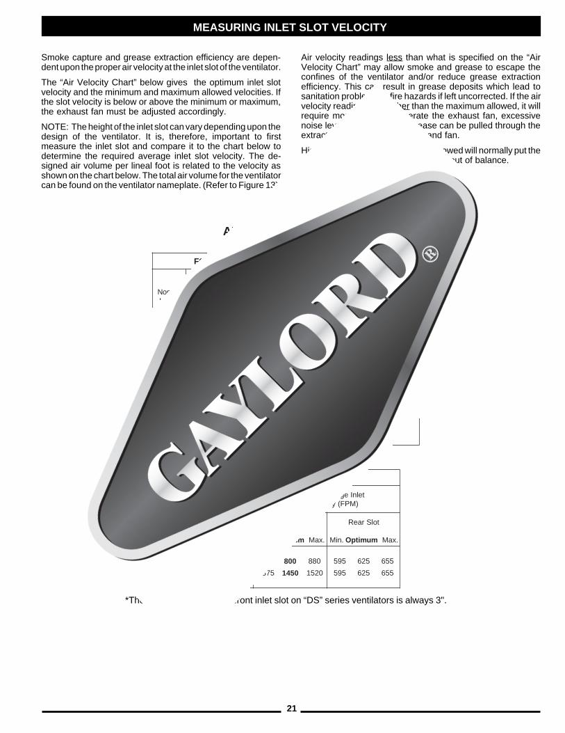
Smoke capture and grease extraction efficiency are depen-dent upon the proper air velocity at the inlet slot of the ventilator.
The “Air Velocity Chart” below gives the optimum inlet slotvelocity and the minimum and maximum allowed velocities. Ifthe slot velocity is below or above the minimum or maximum,the exhaust fan must be adjusted accordingly.
NOTE: The height of the inlet slot can vary depending upon thedesign of the ventilator. It is, therefore, important to firstmeasure the inlet slot and compare it to the chart below todetermine the required average inlet slot velocity. The de-signed air volume per lineal foot is related to the velocity asshown on the chart below. The total air volume for the ventilatorcan be found on the ventilator nameplate. (Refer to Figure 13).
Air velocity readings less than what is specified on the “AirVelocity Chart” may allow smoke and grease to escape theconfines of the ventilator and/or reduce grease extractionefficiency. This can result in grease deposits which lead tosanitation problems or fire hazards if left uncorrected. If the airvelocity readings are higher than the maximum allowed, it willrequire more energy to operate the exhaust fan, excessivenoise levels will result, and grease can be pulled through theextractor depositing in the duct and fan.
Higher or lower velocities than the allowed will normally put theentire heating and ventilating system out of balance.
*The nominal height of the front inlet slot on “DS” series ventilators is always 3".
22
MEASURING INLET SLOT VELOCITY
FIG. 12A
FIG. 12B
FIG. 12C
CROSS SECTION OF TYPICALVENTILATOR INLET SLOTS
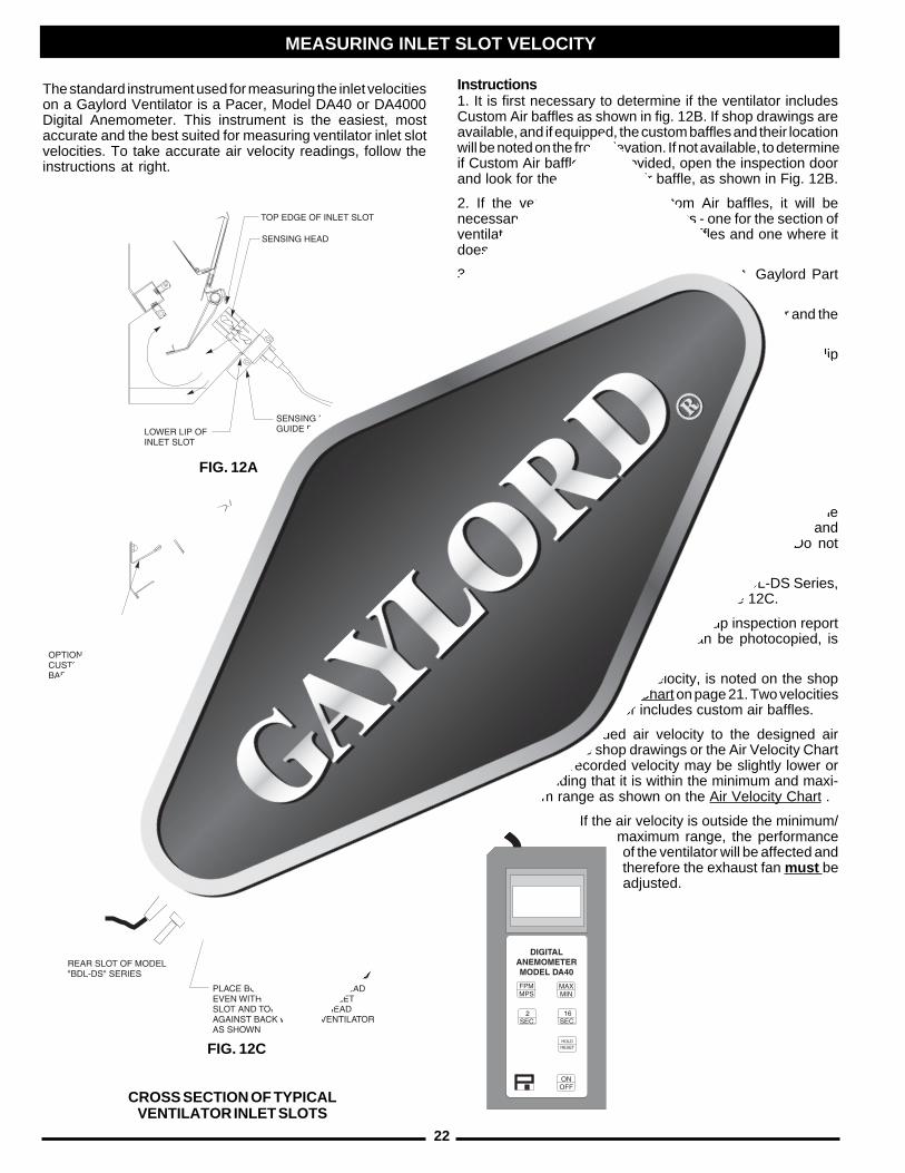
The standard instrument used for measuring the inlet velocitieson a Gaylord Ventilator is a Pacer, Model DA40 or DA4000Digital Anemometer. This instrument is the easiest, mostaccurate and the best suited for measuring ventilator inlet slotvelocities. To take accurate air velocity readings, follow theinstructions at right.
Instructions1. It is first necessary to determine if the ventilator includesCustom Air baffles as shown in fig. 12B. If shop drawings areavailable, and if equipped, the custom baffles and their locationwill be noted on the front elevation. If not available, to determineif Custom Air baffles are provided, open the inspection doorand look for the top custom air baffle, as shown in Fig. 12B.
2. If the ventilator includes Custom Air baffles, it will benecessary to take two sets of readings - one for the section ofventilator that includes Custom Air baffles and one where itdoes not.
3. Attached the sensing head guide bracket, Gaylord PartNumber 18408, to the sensing head.
4. Attach the cable from the sensing head to the meter and thehandle sections to the sensing head.
5. Place the sensing head guide bracket against the lower lipof the inlet slot as illustrated.
6. Using the 16 second averaging feature on the meter, slidethe sensing head along the slot, back and forth, for a 3'-0" to4'-0" distance, and record the velocity at the end of the 16second mark. Continue this process for the full length of theventilator.
Imortant Note: If the ventilator includes custom air baffles asillustrated in Fig. 12B, always take separate readings on thesection of the ventilator that includes custom air from thesection that does not have the baffles. Non custom air andcustom air readings must be recorded seperately. Do notaverage them together.
Important Note: On the rear slot of a Model BDL-DS Series,do not use the guide bracket. Refer to Figure 12C.
7. Record the velocity (fpm) on the start up inspection reportform. A sample report form, which can be photocopied, isprovided on page 52.
8. The designed, or optimum velocity, is noted on the shopdrawings and the Air Velocity Chart on page 21. Two velocitieswill be noted if the ventilator includes custom air baffles.
9. Compare the recorded air velocity to the designed airvelocity shown on the shop drawings or the Air Velocity Charton page 21. The recorded velocity may be slightly lower or
higher providing that it is within the minimum and maxi-mum range as shown on the Air Velocity Chart .
If the air velocity is outside the minimum/maximum range, the performanceof the ventilator will be affected andtherefore the exhaust fan must beadjusted.
23
1. MINIMUM TOTAL EXHAUSTVOLUME FOR THIS HOOD SECTION
2. MAXIMUM TOTAL SUPPLYVOLUME FOR THIS HOOD SECTION
3. EXHAUST STATIC PRESSURE ATDUCT COLLAR
4. SUPPLY STATIC PRESSURE ATDUCT COLLAR
5. THIS HOOD SECTION SUITABLE FOR APPLIANCES WITH MAXIMUM COOKINGSURFACE TEMPERATURE OF:
°F FOR LINEAL FT. OF HOOD
°F FOR LINEAL FT. OF HOOD
6. REFER TO GAYLORD VENTILATOR TECHNICAL MANUAL FOR INLET SLOTVELOCITY REQUIREMENTS AND METHOD OF CHECKING VELOCITY
7. ELECTRICAL RATING OF LIGHT FIXTURES: 120 VOLT, 60 HZ. OR 220 VOLT, 50 HZ.OVERALL RATING - 12 AMPS OR LESS
8. VENTILATOR ELECTRICAL CONTROL CIRCUIT MUST BE FUSED SEPARATELY
9. IF HOOD IS EQUIPPED WITH INTEGRAL MAKE-UP AIR WITH FUSE LINK OPER-ATED FIRE DAMPER USE ONLY 165° F, RATED 30 LBS. MIN. UL LISTED FUSIBLELINKS FOR REPLACEMENT
10. DUCTWORK AND EXHAUST FANA. STATIC PRESSURE OF DUCT SYSTEM MUST BE ADDED TO VENTILATOR
STATIC FOR TOTAL SYSTEM STATICB. ALL DUCTWORK MUST BE WELDED LIQUIDTIGHT
o SUPPLIED WITH FACTORY INSTALLED UL LISTED GRINNELL CORP. EA-1,
1/4" ORIFICE, 65 DEGREE DEFLECTOR SPRINKLER(S) FOR THE PROTEC-TION OF UNLIMITED LENGTH OF GREASE DUCT HAVING A MAXIMUMDUCT PERIMETER OF 50 INCHES PER SPRINKLER. CONNECT TO NFPA 13SPRINKLER SYSTEM WATER SUPPLY ONLY.
SERIAL NO:MODEL NO:
HOOD MOUNTING REQUIREMENTS
W.G.
W.G.
ENGINEERING DATA
EXHAUST HOOD WITHEXHAUST DAMPER
LISTED370Y
UL-CG3 1001
THIS EXHAUST HOOD IS ALSO LISTEDAS AN EXHAUST HOOD WITHOUTEXHAUST DAMPER WHEN EQUIPPEDWITH FIRE DAMPER LOCKOUT PARTNUMBER FDL.
FOR USE ONLY WITH GAYLORD INDUS-TRIES LISTED SUB-ASSEMBLY CONTROLCABINET MODEL NUMBER GPC-5000-99OR GPC-6000 SERIES
THIS EXHAUST HOOD HAS BEEN TESTEDTO STANDARD UL 710 "EXHAUST HOODSFOR COMMERCIAL COOKING EQUIPMENT"
THIS EXHAUST HOOD IS LISTED UNDER ULFILE NUMBER MH11403
THIS EXHAUST HOOD MEETS ALL REQUIRE-MENTS OF THE LATEST EDITION OFNFPA-96 AND THE IMC (INTERNATIONALMECHANICAL CODE)
PATENT PENDING
MINIMUM DISTANCE FROM COOKING SURFACE TO FRONTLOWER EDGE OF HOOD
MAXIMUM DISTANCE FROM COOKING SURFACE TO FRONTLOWER EDGE OF HOOD
MINIMUM OVERHANG FROM FRONT OF HOOD CAVITY TOFRONT OF COOKING SURFACE
MAXIMUM SETBACK FROM FRONT OF HOOD CAVITY TOFRONT OF COOKING SURFACE
MINIMUM OVERHANG FROM SIDE OF HOOD TO EDGE OFCOOKING SURFACE
C.F.M.
C.F.M.
WORLD HEADQUARTERS
GAYLORD INDUSTRIES, INC.10900 S.W. AVERY STREET
TUALATIN, OR 97062-8549 USA
PHONE: 1-503-691-2010FAX: 1-503-692-6048
EMAIL: [email protected]
FIG. 13VENTILATOR NAME PLATE
MEASURING INLET SLOT VELOCITY
TOTAL SUPPLY CFM HERE
TOTAL EXHAUST CFM HERE

24
FIG. 14CONTINUOUS COLD WATER MIST
OPTIONAL CONTINUOUS COLD WATER MIST
GENERAL
Continuous cold water mist is an option on all “CG3” Seriesventilators and is typically used on ventilators that cover solidfuel burning appliances such as mesquite broilers.Continuous cold water mist ventilators incorporate a watermanifold with spray nozzles, located at the lower edge of theair inlet slot. (Refer to Figure 14) When the exhaust fan isstarted, the solenoid valve in the cold water loop in the Gaylordcontrol cabinet opens (refer to illustration on Page 36), turningon the mist nozzles which remain on as long as the exhaust fanis on. The nozzles produce a very find mist and are located sothat the entire air stream passes through the mist. The purposeof the mist is to knock down any hot embers, produced by thesolid fuel, that may be drawn up into the ventilator and to cooldown the exhaust air.
ENGINEERING1. Pipe Size - 1/2" cold water supply required to the control
cabinet.
2. Water Pressure - 40 psi flow pressure. The control cabinetis equipped with an adjustable pressure regulator.
3. Water Consumption - .66 gph/lineal ft. of ventilator.
MAINTENANCEEvery six months check the following:
1. Water Pressure - Turn on the exhaust fan, opening thecontrol cabinet door and check the water pressure gaugein the cold water loop. Water flow pressure should be at 40psi. If it is not, adjust the pressure regulator until 40 psi isachieved.
2. Mist Nozzles - Turn on the exhaust fan, look into the airinlet slot and check each mist nozzle for proper spray.Remove and clean the nozzle if necessary.
TROUBLE-SHOOTING1. If the mist nozzles do not come on when the fan is started,
check the following:
A. Open the electrical compartment of the control cabinetand check to ensure that the cold water mist overrideswitch is in the “On” position.
B. Check the cold water mist hand valve in the controlcabinet to ensure that it is in the “Open” position.
C. Check the cold water mist solenoid coil for voltage.Also check the coil for continuity.
D. Foreign material in the cold water supply line may haveclogged the solenoid valve and prevented its opening.If this is the case, a alight tap on the solenoid valvehousing should release the valve.
2. If water mist is spraying out of the air inlet slot, check thefollowing:
A. With the cold water mist on, open the control cabinetand check the pressure gauge to ensure that the flowpressure is not above 40 psi. Adjust the pressurereducing valve if necessary.
B. With the cold water mist on, check the mist nozzlesfor even spray. Foreign particles in the nozzle couldcause an erratic mist causing it to come out the airinlet slot.
25
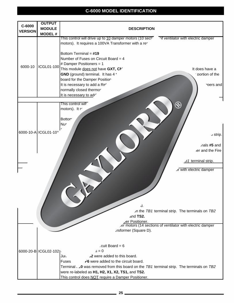
C-6000 MODEL IDENTIFICATION
C-6000 VERSION
OUTPUT MODULE MODEL #
DESCRIPTION
6000-10 ICGL01-100
This control will drive up to 10 damper motors (10 sections of ventilator with electric damper motors). It requires a 100VA Transformer with a reset button.
Bottom Terminal = #19Number of Fuses on Circuit Board = 4# Damper Positioners = 1This module does not have GXT, CM, or #20 terminals on terminal strip TB1 . It does have a GND (ground) terminal. It has 4 terminals on the TB2 terminal strip on the lower portion of the board for the Damper Positioner.It is necessary to add a Relay and a terminal GXT for GX2 ventilators with Electric Dampers and normally closed thermostats, if required. It is necessary to add a terminal CM for Cold Water Mist if required, it would be tied into #8.
6000-10-A ICGL01-101
This control will drive up to 10 damper motors (10 sections of ventilator with electric damper motors). It requires a 100VA Transformer with a reset button.
Bottom Terminal = GXTNumber of Fuses on Circuit Board = 4# Damper Positioners = 1GXT, CM, and #20 terminals were added to and GND was removed from the TB1 terminal strip. Relay #8 was added to accommodate GX2 (normally closed) thermostats.It has 6 terminals on the TB2 terminal strip on the lower portion of the board. Terminals #5 and #6 were added to the TB2 terminal strip to accommodate a 2nd Damper Positioner and the Fire Test Switch.** A Jumper is required from #6 from the TB2 terminal strip to #3 on the TB1 terminal strip.
6000-10-B ICGL02-102
This control will drive up to 10 damper motors (10 sections of ventilator with electric damper motors). It requires a 100VA Transformer (Square D).
Bottom Terminal = GXTNumber of Fuses on Circuit Board = 6# Damper Positioners = 0Jumpers J1 and J2 were added to this board.Fuses F5 and F6 were added to the circuit board.Terminal #20 was removed from this board on the TB1 terminal strip. The terminals on TB2 were re-labeled as H1, H2, X1, X2, TS1, and TS2.This control does NOT require a Damper Positioner.
6000-20-B ICGL02-102
This control will drive up to 14 damper motors (14 sections of ventilator with electric damper motors). It requires a 250VA Transformer (Square D).
Bottom Terminal = GXTNumber of Fuses on Circuit Board = 6# Damper Positioners = 0Jumpers J1 and J2 were added to this board.Fuses F5 and F6 were added to the circuit board.Terminal #20 was removed from this board on the TB1 terminal strip. The terminals on TB2 were re-labeled as H1, H2, X1, X2, TS1, and TS2.This control does NOT require a Damper Positioner.
26
TROUBLE-SHOOTING
MOTPMYS MELBORPELBISSOP NOITCAEVITCERROCSSOLEKOMS
.1 tonsirotalitneV-ssoLekomS.ylreporpgnitsuahxe
.A
.B
.C
.D
.E
.F
yticolevriaegarevA-yticolevriawoLniebdluohstolsyrtneriaehthguorhttrahCyticoleVriAehthtiwecnadroccafodohtemreporproF.12egapno
egapotrefer,yticolevriaehtgnirusaemehtkcehcwolsiyticolevehtfI.22
.gniwollof
stievahtsumrotalitneVdrolyaGehTrehtoondnametsystsuahxenwo,sdoohrehsawhsidsahcus,tsuahxe
.tiotnideitebdluohsriapu-ekamdecalpylreporpmI
.sresuffid
.riapu-ekametauqedanI
.egrahcsidnaftsuahxE
gnitarepotcerrocotnepotonrepmaD,TDF-3GC,DDF-3GCnoA/N(.noitisop
)DN-3GCdna
.1
.2
.3
.4
.5
.1
.1
.2
.3
.1
.2
.1
.2
.1
.2
.naftsuahxeehtnotlebgnippilsronekorB
.leehwnaftsuahxeehtfonoitatorreporP
reviledtsumnaf(naftsuahxefoezisreporP.)gnitaretalpeman
.nepotfellenapnoitcepsnikrowtcuD
.noitisopreporpnironepotonrepmaD
oneraerehttahtyfirevdnametsystcudtcepsnIyehtosfI.nideitsmetsysrotalitnevnonrehto
.devomerebtsum
ylekillliwrotalitnevehttadetceridriapu-ekaMehtotniwolfriaehtgnitpursidstfardssorcetaerc-ekamehttceridotsrevuolehttsujdA.rotalitnev
.rotalitnevehtmorfyawariapu
hguorhtdereviledebdluohsriapu-ekaMdetubirtsiddna,thgiehgniliectasretsiger
.aeranehctikehttuohguorht
,rotalitnevehtraendetacolsretsigerriapu-ekaMriaehttceridotdetsujdaebdluohssrevuolehtgnicrofrognitceriD.rotalitnevehtmorfyawasetaercyllacipytrotalitnevehttariapu-ekam
.ssolekomsnignitluserstfardssorc
fotnemecalperrofdeilppusebtsumriapu-ekaMtsuahxenehctikllahguorhtdetsuahxeria
.smetsys
fo%08ot%57tahtsi"bmuhtfoelur"larenegA,denoitidnoc,hserfebdluohsriatnemecalpereht
nehctikehtotnithguorbria)deloocrodetaeh(otdewolla%52ot%02gniniamerehthtiw,aera
.saeratnecajdamorfnehctikehtotniwolf
fI.egrahcsidehtrevoneercsonebdluohserehT.devomerebdluohsti,dnuofsieno
ehtotniebtondluohsegrahcsidfonoitceridehTA.foorehtotnodrawnwodronsdniwgniliaverp
.dednemmocerylhgihsiegrahcsidlacitrev
lamroNrof05ot)s(renoitisoPrepmaDehtteS.noitarepo
ehtnielihwgnineporepmadehterusaeM.noitisopgnitarepo
"61/512otteS-taorhT"3"4/33otteS-taorhT"4
fitub,05ottesebdluohsrenoitisoPrepmadehTehtesaerced,ruccotonseodgninepoderisedehtesaercniotgnittesrenoitisoPrepmaD
.gninepo
NOITCARTXEESAERG.1 .noitcartxEesaerGrooP .A rotalitneVseireS"3GC"drolyaGehT
tsud,esaergehtfo%59otpustcartxemaertsriaehtmorfselcitraptnildnadetareponehw,tihguorhtgnissaphtiwecnadroccanideniatniamdnasraeppatifI.snoitacificepsngisedgnitcartxetonsirotalitnevehttahtemulovtsuahxeehtyllacipyt,ylreporp
.wolsi
.1 nodebircsedsayticolevtolstelniehtkcehCnihtiwtonsiyticolevehtfI.32hguorht12segapnafehtecuderroesaercni,egnarderiuqereht
.deriuqersadeeps
27
TROUBLE-SHOOTING
MOTPMYS MELBORPELBISSOP NOITCAEVITCERROCNAFTSUAHXE
.1
.2
.3
nottub"naFtratS"ehtnehWthgilneergeht,dehsupsiehtdna,noemoctonseodehtotevomtonseodrepmad
.noitisoptsuahxe
nottub"naFtratS"ehtnehwfIthgilneergeht,dehsupsirepmadehtdnanosemocnoitsoptsuahxeehtotsevomtonseodnaftsuahxeehttub
.noemoc
nottub"naFtratS"ehtnehW54ehtretfadnadehsupsinaftsuahxeeht,yaleddnocesrepmadehttubnosemoc
.nepotonseod
.A
.B
.A
.B
.C
.D
.A
.B
.C
.D
.tenibaclortnocehtnirewopoN
.edoMeriFlanretnInanisilortnocehT
retratscitengamnorotcetorpdaolrevO.deppirt
epyt)citamotuA/nOsdnaH(AOHnafIeht,desusihctiwsretratscitengamdevomneebevahyamhctiwsrotceles
noitisopcitamotuaehtmorf
.deppirtrekaerbtiucricnaftsuahxE
ahtiwdeppiuqesimetsysehtfIa,naftsuahxeehtrofhctiwstcennocsid
.tuonwolbevahyamsesufroesuf
tiucricetelpmocninaebyamerehTehtdnarotomrepmadehtneewteb,DDF-3GCnoA/N(.lortnoc0006-C
)DN-3GCdna,TDF-3GC
CLPehthtiwmelborpaebyamerehTehtni)rellortnoCcigoLelbammargorP(
.retnecdnammoc
ereht,tuokcehcsthgilsutatsCLPehtfIrepmadehthtiwmelborpaebyamrepmadehtotgnioggniriwehtrorotom
.rotom
tesebyam)s(renoitisoPrepmaDehT.A-0006-Cro0006-Cnoyltcerrocni A/N(
DN-3GCdna,TDF-3GC,DDF-3GCno
.1
.1
.1
.1
.1
.1
.1
.2
.3
.1
.1
.1
lortnocehtgnivresrekaerbtiucricehtkcehCebdluohs"CLP"ehtnothgil"nuR"ehT.tenibacrewoponsetacidnitinotonsitifI.semitllatanoedisnisesufehtllakcehC.lortnocehtotgnittegsilanimret,eludomtuptuonotenibaclortnoceht
.remrofsnartdna,skcolb
#neewtebytiunitnocrofkcehC 51 dna TXG fI.neewtebytiunitnoconsiereht 51# dna TXG refer,
GNITOOHS-ELBUORTehtniELCYCERIFot.noitces
retratscitengamehtnonottub"teseR"ehthsuPehtnonottub"naFtratS"ehthsupehtdna
.retnecdnammoc
citamotuaehtotrotcelesnrutdnahctiwskcehC.noitisop
rekaerbtiucricteseR
fiecalperdnasesuffoytiunitnockcehC.yrassecen
egatlovrof0006-Cno,91&71#stuptuokcehC.)CAV42(
.egatlovrof,0006-Cno,81&71#stuptuokcehCA-0006-Cro0006-C
B-0006-C
-JrotalitnevehttasnoitcennocgniriwkcehCnidebircsedsasrebmuneriwgniwollofsexob
.evoba2/A&.1/A
CLPehtnothgilsutatsetairporppaehtkcehC).13egaPnotrahcthgilsutatsCLPehtotrefeR(
metsysehtnorotalitnevenonahteromsierehtfIowtfotuoenoylnofI.repmadhcaekcehcyllausivroflortnocehtkcehc,desolcsisrepmaderomrostnenopmoclacinahcemfI.eruliaflacinahcemsenilkcehcdnalenapnoitcepsnievomer,koera
91&71
lamroNrof05ot)s(renoitisoPrepmaDehtteS.noitarepO
METSYSHSAW.1
.2
"hsaWtratS"ehtnehWneergeht,dehsupsinottubdna,noemoctonseodthgilotevomtonseodrepmadeht
.noitisophsaweht
gnihsawtonsirotalitnevehT.ylreporp
.A
.A
.B
.C
.edoMeriFlanretnInanisilortnocehT
.noyllaitraproffodenrutylppusretaW
.erusserpretawwoL
erutarepmetretawwoL
.1
.1
.2
.1
.1
#neewtebytiunitnocrofkcehC 51 dna TXG fI.neewtebytiunitnoconsiereht 51# dna TXG refer,
GNITOOHS-ELBUORTehtniELCYCERIFot.noitces
.tenibaclortnocehtedisnievlavdnahehtkcehC
.tenibaclortnocehtfomaertspusevlavynakcehC
ehtedisnieguagerusserpretawehtkcehC.nimISP04ebdluohserusserP.tenibaclortnoc
.gnihsawerasrotalitnevehtelihw
lortnocehtedisnieguagerutarepmetehtkcehC-F°041neewtebebdluohserutarepmetehT.tenibac
.desaercniebtsumtierutarepmetwolebfI.F°081
Fan On = approx.6 VDCFan Off = approx. 14 VDCFan On = approx. 0 VACFan Off = approx. 24 VAC
28
TROUBLE-SHOOTING
MOTPMYS MELBORPELBISSOP NOITCAEVITCERROC
.TNOCMETSYSHSAW
.2
.3
.4
.ylreporpgnihsawtonsirotalitnevehT
tratS"nehwnoemoctonseodretaWsnrutnaftsuahxetub,dehsupsi"hsaWhsawehtot,sesolcrepmaddnaffo
noitisop
sirotalitnevehtnehwnosyarpsretaWton"nOhsaW"(elcychsawaniton
.)retnecdnammocnodeyalpsid
.D
.E
.F
.G
.H
.I
.A
.B
.C
.D
.A
.B
.C
emithsawetauqedanI
.selzzonyarpsdeggolC
roemirpstitsolpmuptnegreteD.ylreporpgnipmupton
.ytpmeknattnegreteD
.tnegretedreporpmI
.ycneuqerfhsawetauqedanI
ffodenrutylppusretaW
fI.evlavdionelosgninoitcnuflaMasierehtgnitareposipmupehtevlavroevlavehthtiwmelborp
.gniriw
.CLPgninoitcnuflaM
dionelosotnoitcennocesooL.evlav
nodeyalpsidsi"dooHnieriF"fIdnaretnecdnammoc0006-CehtA/N(.suounitnocnosithgildereht
)DN-3GCdnaDDF-3GCno
nodeyalpsidsi"evitcAeriF.txE"fIdnaretnecdnammoc0006-Ceht
.gnihsalfsithgildereht
.evlavdionelosnikcutssirbeD
.1
.1
.1
.1
.1
.1
.1
.2
.1
.2
.3
.1
.1
.1
.1
.1
fohtgnelehT.emithsawfohtgnelesaercnIdna3neewtebtesebyamelcychsaweht3:erasemitdednemmoceR.setunim9setunim5,tnempiuqeytud-thgilrofsetunim-yvaehrofsetunim9dnaytudmuidemrofgnimithsawotrefeR(.tnempiuqeytudhtgnelehttsujdaot51egaPnosnoitcurtsni
).elcychsawfo
ehtnepo,nosielcychsawehtelihWkcehcyllausivdnaylthgilsroodnoitcepsni,deggolcsielzzonafI.selzzonfoyarps
eriwllamsagninnurybnaelcdna,evomer.tihguorht
gnitoohselbuortrof21egaPotrefeR.pmuptnegreted
.ylkeewtnegretedllifdnakcehC
dednemmocerrof31egaPotrefeR.tnegreted
anideriuqersihsawenoylnoyllamroNgnikoocehtfi,revewoH.yadgnikoocrahcsahcus,yvaehylemertxesinoitarepoebyamtignikoockowdnareliorb.yadgnikoocanieciwthsawotyrassecen
.tenibaclortnocedisnievlavdnahkcehC
lortnocfomaertspuevlavdnahynakcehC.tenibac
.ytiunitnockcehC.tuodenrubebyamlioC
enilylppusretawtohehtnilairetamngieroFdnaevlavdionelosehtdeggolcevahyama,esacehtsisihtfI.gninepostidetneverplliwgnisuohevlavdionelosehtnopatthgil
.evlavehtesaeler
31-9#eriwreporprofmargaidgniriwkcehC.hsawgnirudstlov021rofkcehcdna
ehtnothgilsutatsetairporppaehtkcehCnotrahcthgilsutatsCLPotrefeR(CLPtonsithgilsutatsetaiporppaehtfI.)13egaProdemmargorperebotsdeenCLPeht,no
.decalperylbissop
.noitcennocnethgiT
detavitcaneebsahedomeriflanretniehTsihtni"elcyCeriF"otrefeR.statsomrehtaiv
.noitcesgnitoohs-elbuort
.dellupneebsahhctiwserifetomerehTgnitoohs-elbuortsihtni"elcyCeriF"otrefeR
.noitces
dioneloselbmessasiddnaretawehtffonruT.elbmessaerdnasirbedevomeR.evlav
29
TROUBLE-SHOOTING
MOTPMYS MELBORPELBISSOP NOITCAEVITCERROCELCYCERIF
.1
.2
.3
eriflanretninanisirotalitnevehtfIdnadeyalpsidsi"dooHnieriF",elcycretaw,suounitnocnosithgilderehtotsesolcrepmadehtdnanosyarps.erifatonsierehttub,noitisoperifeht
)DN-3GCdnaDDF-3GCnoA/N(
eriflanretxenanisirotalitnevehtfIdnadeyalpsid"evitcAeriF.txE"edomnosyarpsretaw,sehsalfthgildereht.erifonsierehttubnonaftsuahxedna
tubnoitisoperifehtnisirepmadehtfIedomeriflanretninanitonsitinuehtretaw,deyalpsid"dooHnieriF"(dnaDDF-3GCnoA/N().nosyarps
)DN-3GC
.A
.A
.B
.A
.B
.C
nikaerbro,tatsomrehtytluaF.tiucrictatsomreht
)dedivorpfI(hctiwSeriFetomerehT.dellupneebsah
evahyamedomeriflanretxeehT,ecruosrehtonamorfdetaitinineeb,metsysmralagnidliubasahcus
erifdereenigne-erp,metsysCDD.ctemetsys
CLPehthtiwmelborpaebyamerehTni)rellortnoCcigoLelbammargorP(
.retnecdnammoceht
,tuokcehcsthgiltuptuoCLPehtfIehthtiwmelborpaebyamerehtotgnioggniriwehtrorotomrepmad
.rotomrepmadeht
0006-CanorenoitisoPrepmaDehT.yltcerrocnitesebyamA-0006-Cro
.1
.1
.1
.1
.1
.1
.tiucricdnastatsomrehtfoytiunitnockcehC
.94-24segaPnomargaidgniriwotrefeR
.lellarapnideriwerastatsomrehT:etoNkcehC.deriuqerfi)s(tatsomrehtecalpeR2XGfI.51dnaTXGneewtebrepmujrofytiunitnocrofkcehc,detcennocerasdoohtuoecart,tonfI.51dnaTXGneewteb
.kaerbdnifdnatiucric
elggotehtpilfdnahctiwSeriFehtnepOotrefeR(."noitisoplamroN"ehtothctiws
)noitartsullirof9egaP
SFdna4slanimretmorfseriwtcennocsiDeriflanretxefI.secruoslanretxeetalosiotsecruoslanretxeetagitsevnispotsedom
.esuacevomerdna
ehtnothgilsutatsetairporppaehtkcehCnotrahcthgilsutatsCLPehtotrefeR(CLPeht,notonsithgiltuptuoehtfI.)13egaProdemmargorperebotsdeenCLP
.decalperylbissop
ehtnorotalitnevenonahteromsierehtfIylnofI.repmadhcaekcehcyllausivmetsys,desolcsisrepmaderomroowtfotuoeno,eruliaflacinahcemroflortnocehtkcehc,koerastnenopmoclacinahcemfI.cte
dnalenapsseccarotautcarepmadevomersierehtfI.rewoprof91dna71senilkcehcebtsumrotomrepmadehtneht,rewop
.decalper
ro0006-CanorenoitisoPrepmaDehtteS.noitarepolamroNrof05otA-0006-C
SRETNEVERPWOLFKCAB
.1
lortnocseireSBV-0006-CPGledoMmuucavaesustenibacrofylbmessaevlavkcehc/rekaerb-CPGledoM.noitneverpwolfkcabaesustenibaclortnocseireS0006ecivedelpicnirperusserpdecuderotrefeR.noitneverpwolfkcabrof)PR(snoitartsullirof53hguorht33segaPwolfkcabfoepytehT.hcaefo,etatsybdetatcidsidesuretneverp
.edocyticroytnuoc
SREKAERBMUUCAVrehtiestipsroskaelrekaerbmuucaVhsawehtfodnerogninnigebehtta
.elcyc
.A
.B
.C
.noitallatsnIreporpmI
.evlavkcehcgnikcitS
.srehsawevlavkcehcdetaroireteD
.1
.1
.1
"6detnuomebtsumrekaerbmuucaV.rotalitnevehtotgniogenilnahtrehgih
.)81egaPnonoitartsullieeS(
rekaerbmuucavehtfopacpotehtevomeRkcehcnolynehterusekamotkcehcdnaediugehtnonwoddnapusedilsevlav.thgiartssimetsehttahtdna,ylreporpmets
.yrassecensanethgiartsrometsnaelC
rehsawrebburehttahterusekamotkcehCylreporpstaeskcehcnolynehtfopotnoehttahtdna,ecafrusdenihcamehttsniagaehtdnarehsawrebburehthtobfosecafrusecalpeR.htoomseraecafrusdenihcam
.yrassecenfikcehc
30
TROUBLE-SHOOTING
MOTPMYS MELBORPELBISSOP NOITCAEVITCERROC
.TNOCSRETNEVERPWOLFKCAB
.2
.3
.4
ECIVEDPR.retawfoegrahcsidtnettimretnI
nehwretawfoegrahcsidsuounitnoC.elcychsawanitonsirotalitnev
feilertuoretawfoegrahcsidsuounitnoC.gnihsawsirotalitnevnehwevlav
.A
.A
.A
retawfoegrahcsidtnettimretnIylriafsievlavfeilerehthguorhtsierehtfisruccoyllausudnanommoceromfosnoitautculferusserptelnidionelosehtnehwdnaisp3naht
.elcychsawaretfasesolcevlav
.evlavkcehcehtnilairetamngieroF
.evlavfeilernilairetamngieroF
.1
.1
.1
.yrassecennoitcaoN
dnanepoevlavdnahtelniehtevaeLsierehtfI.evlavdnahteltuoehtesolcsetacidnitiegrahcsidsuounitnocllitsehtgnitneverpsilairetamngieroftahtgnihsulffI.gnisolcmorfevlavkcehctsrifnaelcdnaevomer,tinuehtraelctonlliwotrefeR(.evlavkcehctsrifeht
)02egaPnonoitartsulli
etelpmocgnitneverplairetamngieroFehtgnihsulF.evlavfeilerehtfognisolc.noitidnocsihttcerrocyamevlavfeilerfI.yrassecenfierudecorptaepeRhtiwegrahcsidpotstonseodgnihsulfnaelcdnaevomer,ecivedhguorhtwolffeilerehtdluohsesaconnI.evlavfeilerffodesolc,deggulpebtropteltuoevlav
.detcirtserro
SNIARD
.1 swolfevoretawelcychsawagnirudfI.tolstelnituosemocdnarettugeht
.A
.B
.C
.D
hcaE:etoN(teltuoniarddeggolCniardnwostisahnoitcesrotalitnev
.)teltuo
nahteromfI(deggolcmetsysniarDtigniniardtonsimetsysrotalitnevenosimetsysniardehttahtsetacidni
.deggolc
.gnineponiardnitonenilhsulf-erP
partesaergllufrodeggolC
.1
.1
.2
.1
.1
ehtfotolstelniehthguorhtnihcaeRngieroffieesotkcehcdnarotalitnev,slewotrepap,sgarsahcuslairetamniardehtdeggolcevah,.cte,stihcredro
.gninepo
repsadeilpparenaelcniardlacimehcA.egappotsevlossidyamsnoitcurtsnitarettugesaergniamotnirenaelcruoP
.gnineponiard
raelcotecivresretoorniardaeriH.metsyseritne
dnarotalitnevehtnidetacolsienilsihTehtotdlofinamyarpsehtmorfsnurerusekamotkcehC.niardrotalitnevehtotnidemiasienilhsulf-erpehttahtniardehtsegruptitahtosgnineponiard
.ylreporp
sedocevahseitnuocdnaseiticemoSesaergafI.spartesaergeriuqerhcihwsititahterusneotkcehc,esunisipart
.deggolcton
SUOENALLECSIM
.1
.2
0006-Cnodeyalpsid"edoCretnE".retneCdnammoC
0006-CnodeyalpsidegaugnalgnorW.retneCdnammoC
.1
.2
taderetneneebtonsahedoCelbanE.yrotcaf
neebsahnottub"lonapsE/hsilgnE".desserp
.1
.2
.yrotcaFtcatnoC
otnottub"lonapsE/hsilgnE"ehtsserPneewtebdeyalpsidegaugnalehtelggot
.)lonapsE(hsinapSdnahsilgnE

31
X (Inputs)
STANDARD (SINGLE OR SEQUENTIAL WASH) DESCRIPTION - PLC
0On while “Fire Test Switch” is pushed and held, or hood is in Internal Fire Mode. Off during "Cool Down Cycle"
1 On when Remote Fire Switch is activated, or when hood is in External Fire Mode.
2On normally. It shuts off if cabinet is equipped with Low Detergent alert feature and the detergent is low.
3Off normally. On when Jumper is installed to disable Wash Solenoids from opening during Internal Fire Mode and External Fire Modes.
4 Wash permission signal (if so equipped)5 Not Used6 Not Used7 Not UsedY
(Outputs) STANDARD (SINGLE OR SEQUENTIAL WASH) DESCRIPTION - PLC
0 On when Wash Solenoid # 1 should be open.1 On during an Internal or External Fire Mode. On during "Cool Down Cycle".2 On when Detergent Pump should be on.3 On when Exhaust Fan should be on.
COM Never comes on4 On when Supply Fan should be on.
COM Never comes on5 On when damper is in "Wash" position, or while damper is moving to "Wash" position
Y (Outputs)
(SEQUENTIAL WASH "S2-S5") DESCRIPTION - EXPANSION MODULE
0 On when Wash Solenoid # 2 should be open.1 On when Wash Solenoid # 3 should be open.2 On when Wash Solenoid # 4 should be open.3 On when Wash Solenoid # 5 should be open.4 Not Used5 Not Used6 Not Used7 Not Used
PLC
EX
PA
NS
ION
MO
DU
LE
SE
QU
EN
TIA
L "S
2-S
5"
TROUBLE-SHOOTING
PLC STATUS LIGHT CHARTS
The following is a list of how the status lights will appear on the PLC (Programmable Logic Controller) that is operating correctly.
32
TERMINAL DESCRIPTION FAN OFF FAN ON WASH ON INT. FIRE EXT. FIREL1 Main Power Connection : Hot 120 VAC 120 VAC 120 VAC 120 VAC 120 VACL2 Main Power Connection : Neutral1 Output to Supply Fan Motor Starter 0 VAC 120 VAC 0 VAC 0 VAC 0 VAC2 Output to Detergent Pump 0 VAC 0 VAC 120 VAC 0 VAC 0 VAC3 Thermostat Return 0 VAC 0 VAC 0 VAC 24 VAC 0 VAC4 Fused Supply to PLC Outputs & Etc. 120 VAC 120 VAC 120 VAC 120 VAC 120 VAC5 120 VAC Neutral Leg8 Output to Exhaust Fan Motor Starter 0 VAC 120 VAC 0 VAC 0 VAC 120 VAC
CM Output to Cold Water Mist Solenoid 0 VAC 120 VAC 0 VAC 0 VAC 120 VAC9 Output to Wash Solenoid Valve #1 0 VAC 0 VAC 120 VAC 120 VAC 120 VAC10 Output to Wash Solenoid Valve #2 0 VAC 0 VAC 120 VAC 120 VAC 120 VAC11 Output to Wash Solenoid Valve #3 0 VAC 0 VAC 120 VAC 120 VAC 120 VAC12 Output to Wash Solenoid Valve #4 0 VAC 0 VAC 120 VAC 120 VAC 120 VAC13 Output to Wash Solenoid Valve #5 0 VAC 0 VAC 120 VAC 120 VAC 120 VAC
SF1SF2
N.O. Dry Contacts for Supply FanRemote Control Center
Open Closed Open Open Open
EF1EF2
N.O. Dry Contacts for Exhaust FanRemote Control Center
Open Closed Open Open Closed
A1A2
N.O. Dry Contacts for Interface toBuilding Fire Alarm / Monitor System
Open Open Open Closed Closed
Q1Q2
N.C. Dry Contacts for Interface toFire System Fuel Shutoff Control
Closed Closed Closed Open Open
FS Input from Remote Fire Switch 0 VAC 0 VAC 0 VAC 0 VAC 120 VAC
120 VAC 120 VAC 120 VAC 120 VAC 120 VAC
0 VAC 0 VAC 0 VAC 0 VAC 0 VACGX Power for GX2 Damper Actuators 0 VAC 24 VAC 0 VAC 0 VAC 24 VAC15 Output to Thermostat(s) 24 VAC 24 VAC 24 VAC 24 VAC 24 VAC17 24 VAC Common
14 VDC 6 VDC 14 VDC 6 VDC 6VDC
24 VAC 0 VAC 24 VAC 0 VAC 0 VAC19 Power for CG3 Damper Actuators 24 VAC 24 VAC 24 VAC 0 VAC 24 VAC
(3) 20 CG3 Damper Drive Signal [11-20] 14 VDC 6 VDC 14 VDC 6 VDC 6VDCGXT Thermostat Return for GX2 Hoods 24 VAC 24 VAC 24 VAC 24 VAC 24 VAC
(1)
(2)
(3)#20 only has voltage when there are 2 Damper Positioners present (C-6000-20), otherwise voltage is 0 VAC
18
18
C-6000 or C-6000-A
C-6000-B
CG3 Damper Drive Signal [1-10]
CG3 Damper Drive Signal
0 VAC - LD (Detergent Flow Switch) is installed and Detergent Pump is running and Detergent is NOT present
#20 is only present on the C-6000-A control
120 VAC - LD (Detergent Flow Switch) is installed and Detergent Pump is running and Detergent is present
120 VAC - A jumper is installed between LD and #4 or Jumper J1 is present (No LD/Detergent Flow Switch Present)
Low Voltage Common
High Voltage Common
Common
NO Low Detergent Sensor (Jumper J1 is present)
Low Detergent Sensor (Jumper J1 is cut or NOT present)
(1)
(2) Input from Detergent Flow Switch
Input from Detergent Flow SwitchLD
LD
TROUBLE-SHOOTING
C-6000, C-6000-A and C-6000-B Terminal Voltages(See page no. 25 to determine which model is present)
33
MODEL "GPC-6000-VB" SERIESCONTROL CABINET
This Control Cabinet Is Used When A Reduced Pressure Principle Device Backflow Preventer Is Not Required AndA Vacuum Breaker Is Allowed For Backflow Prevention
MODEL GPC-6000-VB SERIES CONTROL CABINET
PC.NO.
1. Ball Valve ...................................................................... (Specify Size)2. Solenoid Valve
A. Replacement Coil (120 Volt) ................................ 10156 (220 Volt) ................................ 10157
B. Solenoid Valve Repair Kit ............ Pipe Size: 3/4" 14388....................................................... Pipe Size: 1" 14389................................................. Pipe Size: 1-1/4" 14390................................................. Pipe Size: 1-1/2" 14391
3. Detergent Tank (2 Gallon) .............................................. 102214. Pressure / Temperature Gauge...................................... 101755. Detergent, Brass Check Valve ...................................... 102656. FS-4 Series Detergent Flow Switch (Optional) ............... 168927. Detergent Pump ............................................. (120 Volt) 10222
............................................. (220 Volt) 102238. Command Center Model C-6000 Series ......................... (Refer to Page 37-38)9. Vacuum Breaker ............................................................ (Specify Size)
A. Vacuum Breaker Repair Kit .................................. (Specify Size)10. Water Check Valve ....................................................... (Specify Size)11. 3/8" O.D. Copper Tubing ............................................... 1320912. Line Strainer .................................................................. (Specify Size)13. C-6000 Faceplate .......................................................... 1889914. 4" Pull Handle Kit (2) ..................................................... 75587
GAYLORDPART NO.
TYPICAL VACUUM BREAKERCHECK VALVE ARRANGEMENT
DESCRIPTION
34
MODEL "GPC-6000"SERIES CONTROL CABINET
MODEL GPC-6000 SERIES CONTROL CABINET
This Control Cabinet Is Used When A Reduced Pressure Principle Device Backflow Preventer Is Required.
PC.NO.
1. Solenoid Valve (Specify Size)A. Replacement Coil (120 Volt) ................................ 10156
(220 Volt) ................................ 10157B. Solenoid Valve Repair Kit ............ Pipe Size: 3/4" 14388
....................................................... Pipe Size: 1" 14389
................................................. Pipe Size: 1-1/4" 14390
................................................. Pipe Size: 1-1/2" 143912. Detergent Tank (2 Gallon) .............................................. 102213. Pressure / Temperature Gauge...................................... 101754. Detergent, Brass Check Valve ...................................... 102645. FS-4 Series Detergent Flow Switch (Optional) ............... 168926. Detergent Pump ............................................. (120 Volt) 10222
............................................................. (220 Volt) 102237. Command Center Model C-6000 Series ......................... (Refer to Page 37-38)8. Backflow Preventer “RP” Device Type........................... (Specify Size)9. Line Strainer .................................................................. (Specify Size)10. C-6000 Faceplate .......................................................... 1889911. 4"Pull Handle Kit (2) ...................................................... 75587
GAYLORDPART NO.DESCRIPTION
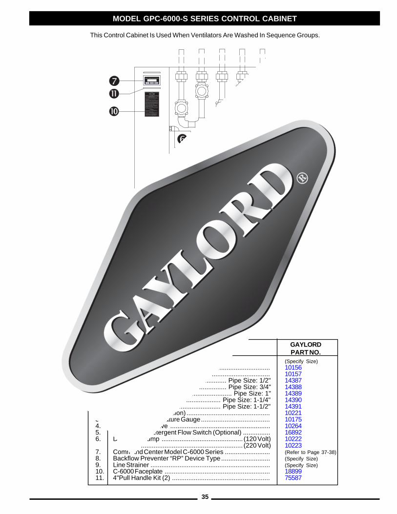
35
This Control Cabinet Is Used When Ventilators Are Washed In Sequence Groups.
MODEL "GPC-6000-S" SERIESCONTROL CABINET
MODEL GPC-6000-S SERIES CONTROL CABINET
PC.NO.1. Solenoid Valve (Specify Size)
A. Replacement Coil (120 Volt) ................................ 10156 (220 Volt) ................................ 10157
B. Solenoid Valve Repair Kit ............ Pipe Size: 1/2" 14387.................................................... Pipe Size: 3/4" 14388....................................................... Pipe Size: 1" 14389................................................. Pipe Size: 1-1/4" 14390................................................. Pipe Size: 1-1/2" 14391
2. Detergent Tank (2 Gallon) .............................................. 102213. Pressure / Temperature Gauge...................................... 101754. Brass Check Valve ....................................................... 102645. FS-4 Series Detergent Flow Switch (Optional) ............... 168926. Detergent Pump ............................................. (120 Volt) 10222
............................................................. (220 Volt) 102237. Command Center Model C-6000 Series ......................... (Refer to Page 37-38)8. Backflow Preventer “RP” Device Type........................... (Specify Size)9. Line Strainer .................................................................. (Specify Size)10. C-6000 Faceplate .......................................................... 1889911. 4"Pull Handle Kit (2) ...................................................... 75587
GAYLORDPART NO.
DESCRIPTION
36
WITH OPTIONAL CONTINUOUS COLD WATER MIST
MODEL GPC-6000-CM SERIES CONTROL CABINET
PC. DESCRIPTIONNO.
MODEL "GPC-6000-CM" SERIESCONTROL CABINET
This illustration shows the cold water mistloop only. Parts for the hot water loop areshown on pages 33, 34 and 35.
1. 1/2" Ball Valve .............................................................. 112582. 1/2" Solenoid Valve NC ................................................. 10135
A. Replacement Coil (120 Volt) ................................ 10156(220 Volt) ................................ 10157
B. Solenoid Valve Repair Kit ............ Pipe Size: 1/2" 143873. Pressure Gauge ............................................................ 102764. 1/2" Water Pressure Reducing Valve ............................. 109245. 1/2" Vacuum Breaker .................................................... 10177
A. Vacuum Breaker Repair Kit .................................. 101786. 1/2" Water Check Valve ................................................ 101957. 1/2" Line Strainer ........................................................... 10151
GAYLORDPART NO.
37
PC. NO. DESCRIPTION
GAYLORD PART NO. MFG PART NO.
1 Programmable Logic Controller (PLC) w/ Program 756342 24VDC Power Supply 188633 Fire Test Switch 168944 Damper Positioner 188765 Output Module 187796 PLC to Operator Interface Cable 188687 Operator Interface 756368 100 VA Transformer 188619 Fuse (F1) - 2 Amp 24VDC Power Supply 13062 BUSS AGC-210 Fuse (F2) - 4 Amp PLC - 120 VAC 10039 BUSS AGC-411 Fuse (F3) - 1 Amp Supply Fan Mag. Starter 19027 BUSS MDL-112 Fuse (F4) - 1 Amp Exhaust Fan Mag. Starter 19027 BUSS MDL-113 Expansion Module (Optional - used for S2-S5) 1886714 Flash Guard (Not Shown) 18877
MODEL C-6000 OR C-6000-A SERIES CONTROL
38
MODEL C-6000-B SERIES CONTROL
P C . N O . D E S C R I P T I O N
G A Y L O R D P A R T N O .
1 P ro g ra m m a b le L o g ic C o n t ro l le r (P L C ) w / P ro g ra m 7 5 6 3 4* 2 E x p a n s io n M o d u le 1 8 8 6 6
3 2 4 V D C P o w e r S u p p ly 1 8 8 6 34 F u s e (F 7 ) - S iz e V a rie s5 F ire Te s t S w it c h 1 6 8 9 46 C -6 0 0 0 -B O u t p u t M o d u le 1 8 9 8 37 P L C t o O p e ra t o r In t e rfa c e C a b le 1 8 8 6 88 O p e ra t o r In t e r fa c e w / p ro g ra m & M y la r la b e l 7 5 8 7 19 O p e ra t o r In t e r fa c e M y la r L a b e l 1 9 0 1 0
1 0 1 0 0 V A Tra n s fo rm e r [ C -6 0 0 0 -1 0 ] 1 8 9 8 1C o n t ro l R e la y - S P D T (C R 9 ) E S P F i r e S i g n a l 1 1 3 9 9S o c k e t - S P D T 1 1 , 1 2 , 1 3 , 1 4 , 1 7 , 1 8 , 2 0 1 1 4 1 3C o n t ro l R e la y - S P D T (C R 1 0 ) 1 1 3 9 9S o c k e t - S P D T 1 1 4 1 3C o n t ro l R e la y -S P D T (C R 1 1 ) 1 1 3 9 9S o c k e t - S P D T 1 1 4 1 3C o n t ro l R e la y - S P D T (C R 1 2 ) 1 1 3 9 9
C -6 0 0 0 -E S P -S C o m p o n e n t S c h e d u l e (1 -3 T ra n sfo rm e rs/ H i g h V o l ta g e P o w e r S u p p l y s )
1 1
1 2
1 3
1 4
1
2
3
4
5
6
7
89
10
11
12
13
14
15
39
DAMPER CONTROL MOTOR AND CG3-FDL WIRING
P C. NO .
DES CRIP TIONG AYLO RD P ART NO.
1For C-6000 or C-6000-A :Dam per Control M otor - A F24-S R (24 V olt) ------------------------------------
30204
1For C-6000-B :
Dam per Control M otor - A F24-M FT P -10050 (24 V olt) ----------------------------------- or A F24-M FT S -0001 (24 V olt)
-----------------------------------
18979
Used in CG3, CG3-FDL, and CG3-FDT only
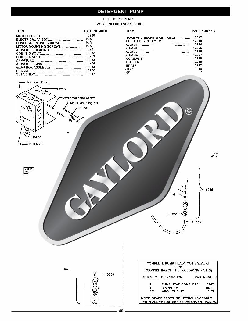
40
DETERGENT PUMP
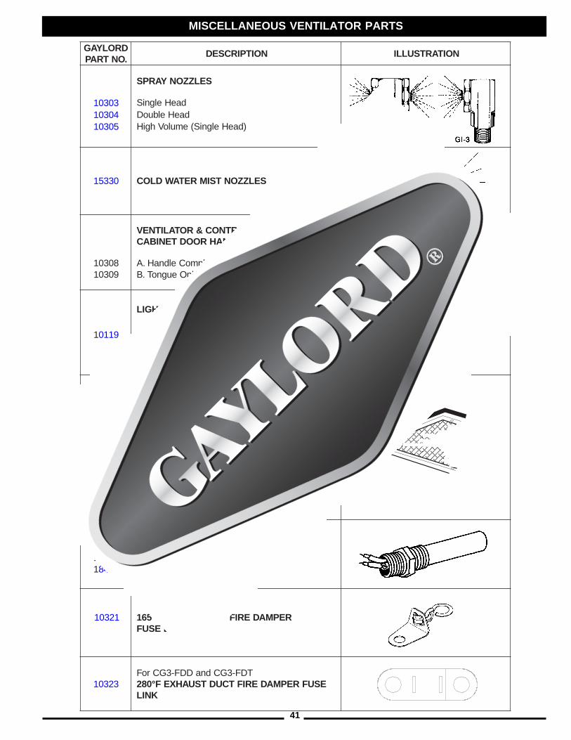
41
DROLYAG.ONTRAP
NOITPIRCSED NOITARTSULLI
SELZZONYARPS
30301 daeHelgniS40301 daeHelbuoD50301 )daeHelgniS(emuloVhgiH
03351 SELZZONTSIMRETAWDLOC
LORTNOC&ROTALITNEVSELDNAHROODTENIBAC
80301 etelpmoCeldnaH.A90301 ylnOeugnoT.B
EBOLGTHGIL
91101 nosaK
11231
EMARF&SNELTHGILTNECSEDNACNI
reniateR&sneLthgiLdesseceR"21x"21
EMARF&SNELTHGILTNECSEROULF
01231 reniateR&sneLthgiLdesseceR.tF211101 reniateR&sneLthgiLdesseceR.tF321101 reniateR&sneLthgiLdesseceR.tF4
STATSOMREHTTCUDTSUAHXE
56481 F°052htgneL"2166481 F°052htgneL"51
12301 REPMADERIFTCUDYLPPUSF°561KNILESUF
32301TDF-3GCdnaDDF-3GCroF
ESUFREPMADERIFTCUDTSUAHXEF°082KNIL
MISCELLANEOUS VENTILATOR PARTS
A. B.
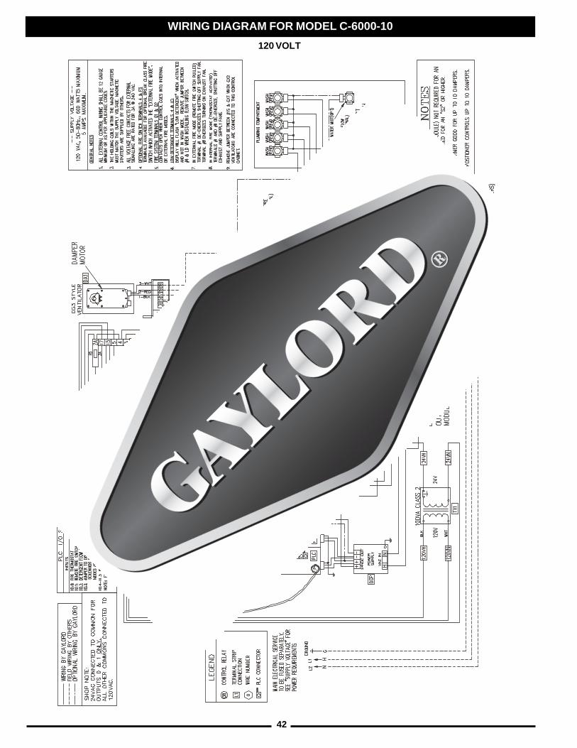
42
WIRING DIAGRAM FOR MODEL C-6000-10
120 VOLT

43
WIRING DIAGRAM FOR MODEL C-6000-10
220 VOLT
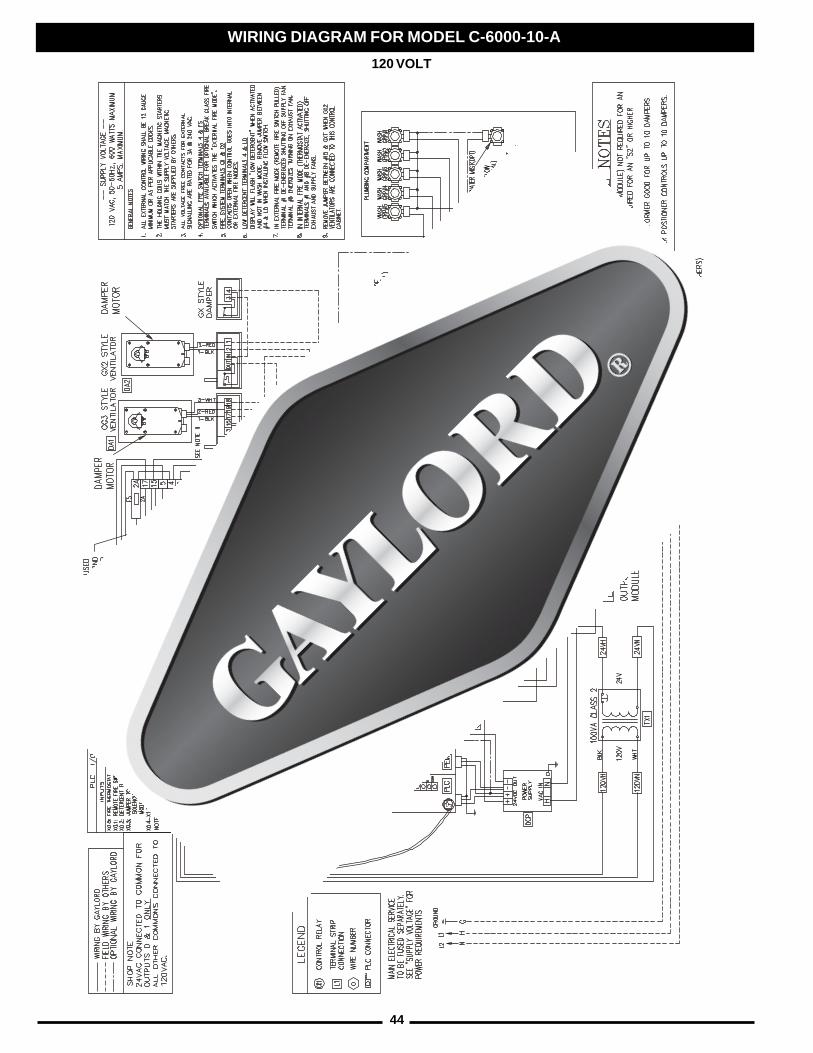
44
WIRING DIAGRAM FOR MODEL C-6000-10-A
120 VOLT

45
WIRING DIAGRAM FOR MODEL C-6000-10-A
220 VOLT
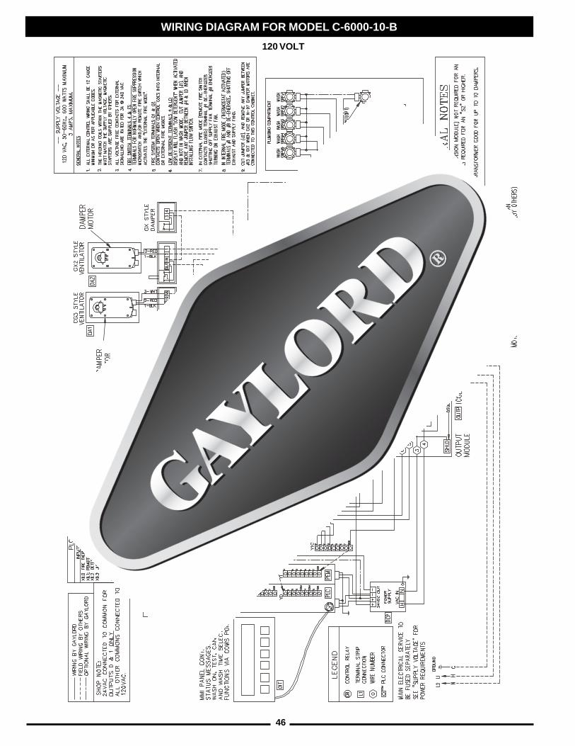
46
WIRING DIAGRAM FOR MODEL C-6000-10-B
120 VOLT
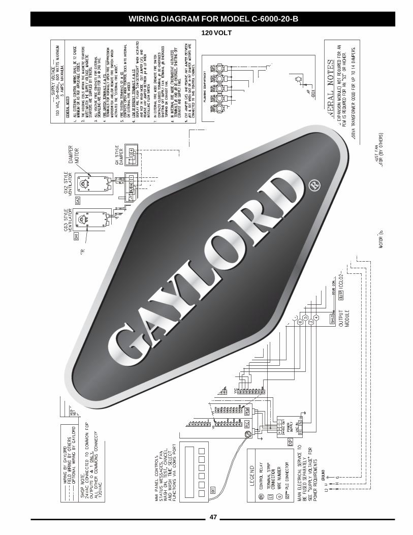
47
WIRING DIAGRAM FOR MODEL C-6000-20-B
120 VOLT
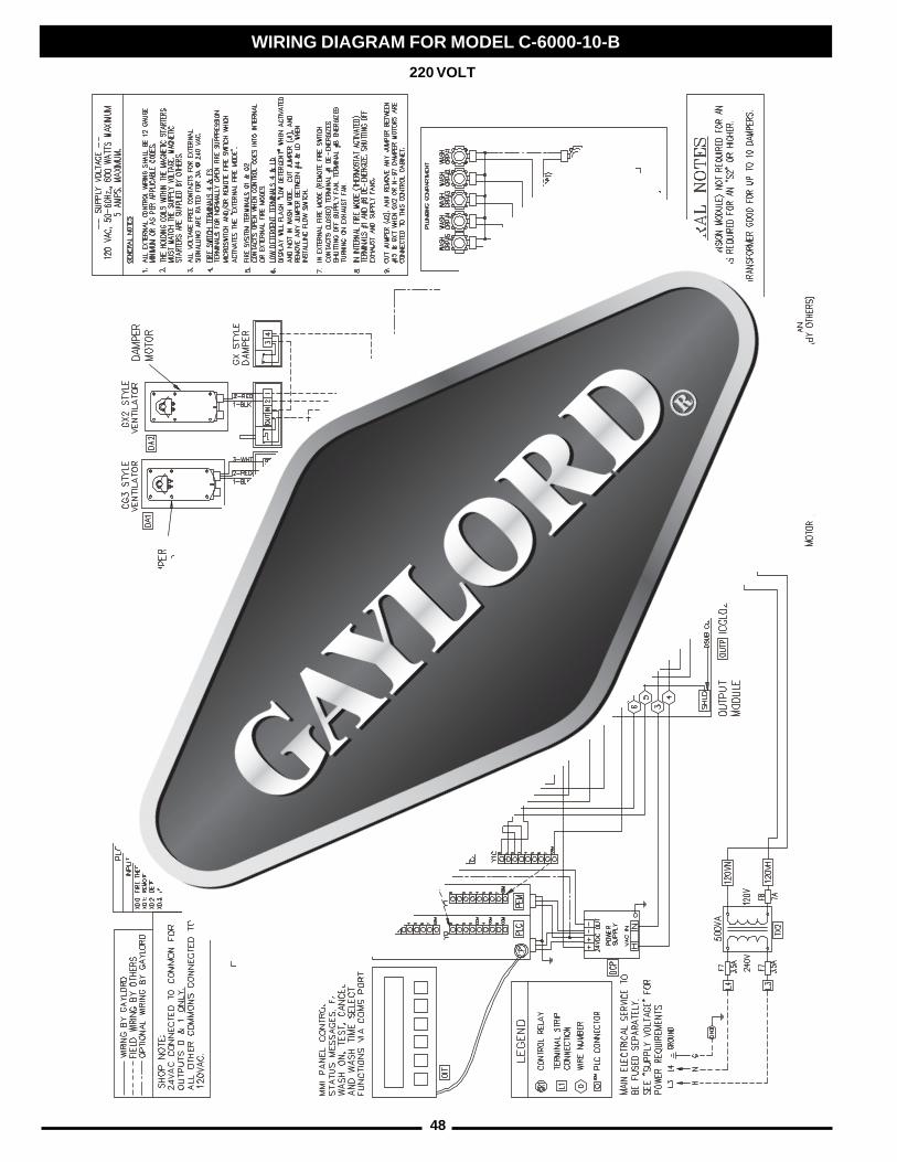
48
WIRING DIAGRAM FOR MODEL C-6000-10-B
220 VOLT
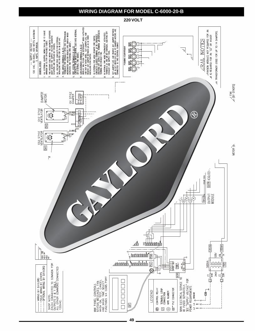
49
WIRING DIAGRAM FOR MODEL C-6000-20-B
220 VOLT
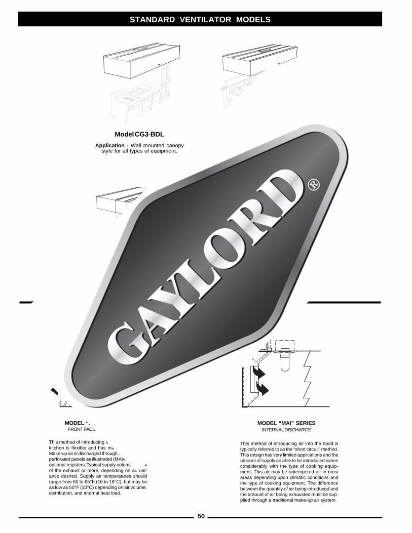
50
STANDARD VENTILATOR MODELS
STANDARD MAKE-UP AIR OPTIONSThe make-up air options shown below are available on all BDL Series Ventilators.
Except the MAI Series is not available on the CG3-BDL-CL.
This method of introducing air into the hood istypically referred to as the “short circuit” method.This design has very limited applications and theamount of supply air able to be introduced variesconsiderably with the type of cooking equip-ment. This air may be untempered air in mostareas depending upon climatic conditions andthe type of cooking equipment. The differencebetween the quantity of air being introduced andthe amount of air being exhausted must be sup-plied through a traditional make-up air system.
This method of introducing make-up air into thekitchen is flexible and has many advantages.Make-up air is discharged through stainless steelperforated panels as illustrated (MAW Series) oroptional registers. Typical supply volume is 80%of the exhaust or more, depending on air bal-ance desired. Supply air temperatures shouldrange from 60 to 65°F (16 to 18°C), but may beas low as 50°F (10°C) depending on air volume,distribution, and internal heat load.
MODEL “MAW” SERIESFRONT FACE DISCHARGE
MODEL “MAI” SERIESINTERNAL DISCHARGE
Model CG3-BDL
Application - Wall mounted canopystyle for all types of equipment.
Model CG3-BDL-BB
Application - For island stylecooking arrangements over all
duties of equipment.
Model CG3-BDL-DS
Application - For island stylecooking arrangements where one side
of the cooking line is light duty equipmentand the other side medium duty equipment.
Model CG3-BDL-CL
Application - For single islandarrangements
51
DIMENSIONS (Feet and Inches)TO CONVERT TO MULTIPLY BY
in ............................ mm .............. 25.4in ............................ cm ................. 2.54mm .......................... in ................... 0.03937cm .......................... in ................... 0.3937ft ............................. cm ............... 30.48ft ............................. m ................... 0.3048cm .......................... ft ................... 0.0328m ............................ ft ................... 3.2808
STANDARD CONVERSIONS
One meter = 10 dm one in. = 25.40 mmOne meter = 100 cm one ft. = 304.80 mmOne meter = 1000 mm
AIR VELOCITYTO CONVERT TO MULTIPLY BY
FPM ........................ m/s .................... 0.00508m/s ......................... FPM ............... 196.85
AIR VOLUMETO CONVERT TO MULTIPLY BY
CFM ........................ m3/sec .............. 0.000472
CFM ........................ m3/min ............... 0.02832
CFM ........................ m3/hr ................. 1.70
CFM ........................ Ltrs/sec ............. 0.472
m3/sec ................... CFM ............. 2118.88
m3/min .................... CFM ................. 35.31
m3/hr ...................... CFM ................... 0.5886
STATIC PRESSURETO CONVERT TO MULTIPLY BY
in. W.G ................... N/m2 .............. 248.84
N/m2 ....................... in. W.G. ............. 0.004
STANDARD CONVERSIONS
1.00" W.G. = 248.84 N/m2
or 248.84 Pascals (Pa)
or 2.49 Millibars
1.33" W.G. = 331 N/m2 or 331 Pa
1.50" W.G. = 373 N/m2 or 373 Pa
1.65" W.G. = 411 N/m2 or 411 Pa 1.70" W.G. = 423 N/m2 or 423 Pa
METRIC CONVERSION CHART
LEGEND
in. = inches Pa. = Pascals FPM = feet per minute
ft. = feet U.S. gal. = U.S. gallon m/s = meters per secondmm = milimeters GPM = gallons per minute in. W.G. = inches water gaugecm = centimeters L/s = liters per second N = Newtonsdm = decimeters Kpa = 1000 Pascals N/m2 = Newtons per square meterCFM = cubic feet per minute psi = pounds per square inch ° C. = degrees Celsiusm3/s = cubic meters per second kg/m2 = kilograms per square meter BAR = one atmospheric pressure meterL = Liters ° F. = degrees Fahrenheit (1000 millibars = 14.7 psi)
WATER FLOW/VOLUMETO CONVERT TO MULTIPLY BY
U.S. ounce ............. Liters ................... .02958U.S. gal .................. Liters ................. 3.785Liters ...................... U.S. gal ............. 0.2642GPM ....................... L/s ..................... 0.0631L/s .......................... GPM ................ 15.850
STANDARD CONVERSIONS
one U.S. gal. .......... = ............... 3.785 Litersone Liter ................. = ............... 0.2642 U.S. Gal.one GPM/ft. ............ = ............... 0.063 L/s/ft.
or .............. 0.207 L/s/mone U.S. gal. .......... = ............... 0.833 Imperial Gal.one Imperial Gal. .... = ............... 4.546 Liters
WATER PRESSURETO CONVERT TO MULTIPLY BY
psi .......................... kg/m2 ............ 703.1
psi .......................... kg/cm2 .............. 0.0703
kg/m2 ..................... psi ..................... 0.0014
kg/cm2 ................... psi ................... 14.223
STANDARD CONVERSIONS
40 psi = 2.8 kg/cm2 80 psi = 5.6 kg/cm2
= 275.8 Kpa = 551.6 Kpa= 2.758 BAR = 5.516 BAR
TEMPERATURETO CONVERT TO USE FORMULA° C .......................... ° F ............ ° F = (° C • 1.8) + 32
° F .......................... ° C ........... ° C = (° F - 32) 1.8
STANDARD CONVERSIONS
140° F. to 180° F. = 60° C. to 82° C.
WEIGHTTO CONVERT TO MULTIPLY BY
lbs. ......................... N ....................... 4.448lbs. ......................... kg ...................... 0.4536N............................. lbs ..................... 0.2248kg ........................... lbs ..................... 2.2046
PIPE SIZEU.S. STANDARD STANDARD METRIC
PIPE SIZES EQUIVALENT PIPE SIZE
1/2" ................ = ...................... 15 mm 3/4" ................ = ...................... 20 mm1" ........................ = ...................... 25 mm1-1/4" .................. = ...................... 32 mm1-1/2" .................. = ...................... 40 mm2" ........................ = ...................... 50 mm

52
MAKE-UP AIR1. Kitchen make-up air supply is turned on______Yes______No2. Type of make-up air¨ Ceiling Registers ¨ Built into Hood¨ Ceiling Linear Diffusers ¨ Other
3. If ceiling register or linear diffusers approximate distance from face of hood
_____________________________________________________________
AIR VOLUME READINGSPush “Start Fan” and take velocities. Record as follows: Exhaust record in the “EX” row, Exhaust at CustomAir baffles (if applicable) record in the “CA” row, and Make-up Air record in the “MA” row.
WASH MODE TEST:1. Model of Control Cabinet _______________________________________________2. Push “START WASH” on Control Cabinet. Check the following:
A. Exhaust fan off_____Yes_____No F. Detergent pump operating ____Yes ___ NoB. Damper closes to the front of the hood after G. Length of wash cycle ________Minutes
approx. 70 sec.____Yes ____No H. Water pressure_________________PSIC. Water turned on_____Yes_____No I. Water temperature_____________°FD. All nozzles spraying_____Yes_____No J. Any ventilator leaks_____Yes_____NoE. Green light is on and “Wash On” is displayed on K. Drains free and clear_____Yes_____No
C-6000 command center____Yes ____No L. Brand of detergent used______________3. At the conclusion of check A through L above, push the “EXIT” button on the C-6000 command center.
Check the following: A. Did the water shut off ___Yes ___NoB. Did the damper stay closed ___Yes ___No4. Push “START FAN”. Check the following:
A. Green light comes on and “Fan On” is displayed on C-6000 command center___Yes ___NoB. Damper fully opens after approx. 45 seconds ___Yes ___No
.ONMETI .ONLAIRESDOOHTHGIROTTFELMORF)MPF(SEITICOLEVRIA
RIAPU-EKAMROKNABRETLIF,TOLSDOOHEGRAHCSID
EGAREVA
XE
AC
AM
XE
AC
AM
XE
AC
AM
VENTILATOR START-UP INSPECTION REPORTFor Model “CG3” Series Ventilators with C-6000 Series Control
Job Name ______________________________________________________________________________ Gaylord Representative ____________________________________________________________
Address ________________________________________________________________________________ Representative Company Name ______________________________________________________
______________________________________________________________________________________ File Number _______________________________________________ Date _________________
City/State Zip
Facility Contact Name _________________________________________ Phone # ____________________ CSA Contacted __________________________________________________________________
FIRE MODE TEST:CAUTION: Before any fire tests are performed, check with building superintendent to see if Gaylord controlcabinet is tied into building alarm, monitoring system and/or Fire Department.
THERMOSTAT TEST (For CG3, CG3-FDL, and CG3-FDT)With the exhaust fan on, open electrical compartment on Control Cabinet and push and hold for 20 secondsthe “Fire Test Switch”. The following should occur:1. Damper closed to rear_____Yes_____No 3. Exhaust fan shut off_____Yes_____No
(N/A on CG3-FDL and CG3-FDT) 4. Steady red light on and “Fire In Hood” displayed.2. Water turned on_____Yes_____No on C-6000 Command Center ____Yes ___No
NOTE: Water will continue to run for 5 minutes after the “Fire Test Switch” button is released. The water may beshut off prior to the end of the cool down cycle by pushing the “EXIT” button on the C-6000 command center.
Upon completion of the thermostat test push the “EXIT” button on the C-6000 command center. The followingshould occur:
A. Water shut off ___Yes ___No C. Steady red light turned off and “Fan Off”B. Damper closes to front ___Yes ___No displayed on C-6000 Command Center___Yes ___No
(N/A on CG3-FDL and CG3-FDT)
REMOTE FIRE SWITCH TEST (Optional Equipment):______Equipped______Not EquippedOpen fire switch and flip toggle switch to the “ALARM” or “TEST” position. The following should occur:
1. Water spray turned on_____Yes_____No 4. Flashing red light on and “Ext. Fire Active”
2. Damper remained open (or opens) ____Yes____No displayed on C-6000 Command Center
3. Exhaust fan remained on (or turned on)____Yes____No _____Yes_____No
INSTALLATION INCLUDES THE FOLLOWING:¨ Gaylord Heat Reclaim Unit (HRU) ¨ The Gaylord “Quencher” Fire Protection System
¨ Gaylord Clearair Pollution Control Unit (RSPC) ¨ Gaylord Rooftop Unit (GRT)
¨ Gaylord Distributor (UDS) ¨ Wet Chemical Fire Protection System
¨ Gaylord Recirculating Wash System (GRW)
Personnel provided with ventilator technical manual________Yes________No
Inspection Witnessed By (Print Name) ______________________________________________________
Signature ________________________________________________ Date _______________________
Comments ____________________________________________________________________________
____________________________________________________________________________________
____________________________________________________________________________________
__________________________________________________________________________________________________
__________________________________________________________________________________________________
Distribution: WHITE-Gaylord Industries, Inc. YELLOW-Customer PINK-Dealer GOLDENROD-Sales Rep Litho U.S.A.GAYLORD INDUSTRIES, 10900 S.W. Avery Street • Tualatin, OR 97062-1149
PHONE:1-800-547-9696 • FAX: 1-503-692-6048 • email:[email protected] No. CG36000SUR
53
LIMITED WARRANTY
THE GAYLORD WATER-WASH VENTILATOR LIMITED WARRANTY
August 2000
The Gaylord Ventilator and component parts furnished with The Gaylord Ventilator are warranted tobe free from defects of material and workmanship under normal use when installed, operated andserviced in accordance with factory recommendation. Rubber and synthetic rubber parts such as “O”rings, diaphragms and poppet checks are perishable when caustic cleaning solutions are used and,therefore, are not covered by this warranty.
The Manufacturer’s obligation under this warranty and any warranties implied by law shall be limitedto repairing or replacing at its option any part of said equipment when either Gaylord Industries, Inc.or the Licensed Gaylord Manufacturer’s examination shall disclose to its satisfaction to be thusdefective, for a period of one (1) year from the date of beneficial use, or eighteen months from dateof shipment, whichever occurs first, provided proper and acceptable evidence of such is recorded atthe factory. GAYLORD INDUSTRIES, INC. AND THE LICENSED GAYLORD MANUFACTURERSHALL NOT BE RESPONSIBLE FOR INCIDENTAL OR CONSEQUENTIAL DAMAGES RESULT-ING FROM A BREACH OF THIS WARRANTY.
In the United States, the labor required to make repairs and replacements under this warranty shallbe furnished by Gaylord Industries, Inc. or the Licensed Gaylord Manufacturer or its authorizedrepresentative. Such labor shall only be provided Mondays through Fridays during the hours between8 a.m. and 4 p.m. Requests for repairs or replacement parts should be made to GAYLORDINDUSTRIES, P.O. Box 1149, Tualatin, Oregon 97062-1149.
Outside the United States, all replacement parts furnished under this warranty shall be F.O.B.Gaylord Industries, Inc., Tualatin, Oregon U.S.A. The owner shall pay the necessary freight deliverycharges, and necessary labor for removal and installation of parts, and any tariffs, duties or taxes.
Component parts not manufactured by Gaylord Industries, Inc., such as electrical switches, solenoidcoils, relays, etc., shall be warranted under the terms and conditions of the warranty published bythe manufacturer of said component parts.
This warranty does not cover routine maintenance such as detergent replacement and inspection ofthe cleaning system as spelled out in The Gaylord Ventilator Technical Manual. This warranty alsodoes not cover malfunctions or improper operation caused by inadequate hot water, low waterpressure, fluctuating electrical power or power surges, waste stoppages, and improper exhaust fanoperation.
This is the sole warranty with respect to the aforesaid items. NEITHER GAYLORD INDUSTRIES, INC.OR THE GAYLORD LICENSED MANUFACTURER OR ANY OTHER PARTY MAKES ANY OTHERWARRANTY OF ANY KIND WHATSOEVER, EXPRESSED OR IMPLIED, AND ALL IMPLIEDWARRANTIES OF MERCHANTABILITY AND FITNESS FOR A PARTICULAR PURPOSE WHICHEXCEED THE AFORESAID OBLIGATIONS ARE HEREBY DISCLAIMED AND EXCLUDED FROMTHIS AGREEMENT.

54
WORLDWIDE SALES, MANUFACTURING AND SERVICEFOR THE NAME AND LOCATION OF THE NEAREST
CERTIFIED SERVICE AGENCY, VISIT OUR WEB SITE:
WWW.GAYLORDUSA.COMOR CONTACT US AT:
GAYLORD INDUSTRIES10900 S.W. AVERY STREET
TUALATIN, OREGON 97062-1149 U.S.APhone: 503-691-2010
1-800-547-9696Fax: 503-692-6048email: [email protected]
LOCAL SERVICE AGENCY
FORM NO. TM-CG3 0304/30507 © COPYRIGHT 2005, GAYLORD INDUSTRIES LITHO IN U.S.A.