
ESO 2 Emergency Ventilator User Manual - HCE Healthcare ...
72
ESO 2 Emergency Ventilator User Manual VENTILATION SOLUTIONS
-
Upload
khangminh22 -
Category
Documents
-
view
0 -
download
0
Transcript of ESO 2 Emergency Ventilator User Manual - HCE Healthcare ...

ESO 2 Emergency Ventilator User ManualV E N T I L AT I O N S O LU T I O N S


ESO 2 ICU Ventilator i User Manual
Important
Servicing and RepairsIn order to ensure the full operational life of this ventilator, servicing by an engineer trained by the manufacturer should be undertaken periodically.
The ventilator must be serviced to the following schedule:
1. Six monthly service - inspection and function testing.
2. Annual / two year / four year service - inspection and function testing, and component replacement.
Details of these operations are given in the Service Manual for this ventilator, available only for engineers trained by the manufacturer.
For any enquiry regarding the servicing or repair of this product, contact Penlon Ltd:
Technical Support Penlon Limited Abingdon Science Park Abingdon OX14 3NB, UK
Tel: +44 (0) 1235 547060 Fax: +44 (0) 1235 547061 E-mail: [email protected]
Always give as much of the following information as possible:
1. Type of equipment
2. Product name
3. Serial number (refer to the device ID label)
4. Approximate date of purchase
5. Apparent fault

ESO 2 ICU Ventilator ii User Manual
This manual has been produced to provide authorised personnel with information on the function, routine performance and maintenance checks applicable to the ESO 2 Emergency Ventilator.
Information contained in this manual is correct at the date of publication. The policy of the manufacturer is one of continued improvement to its products. Because of this policy, the manufacturer reserves the right to make any changes which may affect instructions in this manual, without giving prior notice.
Personnel must make themselves familiar with the contents of this manual and the machine’s function before using the apparatus.
The Importance of Patient Monitoring
WARNINGPatient monitors are very desirable aids but are not true clinical monitors as the condition of the patient is also dependent on his respiration and the functioning of his cardio-vascular system.
IT IS ESSENTIAL THAT THESE ELEMENTS ARE MONITORED FREQUENTLY AND REGULARLY AND THAT ANY OBSERVATIONS ARE GIVEN PRECEDENCE OVER MACHINE CONTROL PARAMETERS IN JUDGING THE STATE OF A CLINICAL PROCEDURE.
Before using any monitoring system or device, the user must check that it conforms to the relevant standards.
Foreword

ESO 2 ICU Ventilator iii User Manual
Contents
Servicing and Repairs . . . . . . . . . . . . . . . . . . . . . . . . . . . . . . . . . . . . . . . . . . . . . . . . . . . . . . . . . . . . . . . . . . . . . . . . . . . . . . . . . . . . . . . . . . iThe Importance of Patient Monitoring . . . . . . . . . . . . . . . . . . . . . . . . . . . . . . . . . . . . . . . . . . . . . . . . . . . . . . . . . . . . . . . . . . . . . . . . . . . . ii
1. Warnings and Cautions . . . . . . . . . . . . . . . . . . . . . . . . . . . . . . . . . . . . . . . . . . . . . . . . . . . . . . . . . . . . . . . . . . . . . . . . . . . . . . . . . . . . . 2
2. Purpose . . . . . . . . . . . . . . . . . . . . . . . . . . . . . . . . . . . . . . . . . . . . . . . . . . . . . . . . . . . . . . . . . . . . . . . . . . . . . . . . . . . . . . . . . . . . . . . . . . 5
3. Description . . . . . . . . . . . . . . . . . . . . . . . . . . . . . . . . . . . . . . . . . . . . . . . . . . . . . . . . . . . . . . . . . . . . . . . . . . . . . . . . . . . . . . . . . . . . . . . 63 .1 ESO 2 System Description . . . . . . . . . . . . . . . . . . . . . . . . . . . . . . . . . . . . . . . . . . . . . . . . . . . . . . . . . . . . . . . . . . . . . . . . . . . . . . . . . . 63 .2 Ventilator . . . . . . . . . . . . . . . . . . . . . . . . . . . . . . . . . . . . . . . . . . . . . . . . . . . . . . . . . . . . . . . . . . . . . . . . . . . . . . . . . . . . . . . . . . . 73 .3 Spirometry . . . . . . . . . . . . . . . . . . . . . . . . . . . . . . . . . . . . . . . . . . . . . . . . . . . . . . . . . . . . . . . . . . . . . . . . . . . . . . . . . . . . . . . . . 193 .4 Display Waveforms . . . . . . . . . . . . . . . . . . . . . . . . . . . . . . . . . . . . . . . . . . . . . . . . . . . . . . . . . . . . . . . . . . . . . . . . . . . . . . . . . . . 203 .5 Alarms . . . . . . . . . . . . . . . . . . . . . . . . . . . . . . . . . . . . . . . . . . . . . . . . . . . . . . . . . . . . . . . . . . . . . . . . . . . . . . . . . . . . . . . . . . . . . 213 .6 Oxygen Monitor . . . . . . . . . . . . . . . . . . . . . . . . . . . . . . . . . . . . . . . . . . . . . . . . . . . . . . . . . . . . . . . . . . . . . . . . . . . . . . . . . . . . . . 22
4. Pre-operation Procedures . . . . . . . . . . . . . . . . . . . . . . . . . . . . . . . . . . . . . . . . . . . . . . . . . . . . . . . . . . . . . . . . . . . . . . . . . . . . . . . . . 254 .1 Ventilator Set-up . . . . . . . . . . . . . . . . . . . . . . . . . . . . . . . . . . . . . . . . . . . . . . . . . . . . . . . . . . . . . . . . . . . . . . . . . . . . . . . . . . . . 254 .2 Pre-use Checklist . . . . . . . . . . . . . . . . . . . . . . . . . . . . . . . . . . . . . . . . . . . . . . . . . . . . . . . . . . . . . . . . . . . . . . . . . . . . . . . . . . . . 304 .3 Oxygen Monitor System Set-up . . . . . . . . . . . . . . . . . . . . . . . . . . . . . . . . . . . . . . . . . . . . . . . . . . . . . . . . . . . . . . . . . . . . . . . . . 32
5. Start-up and operating instructions . . . . . . . . . . . . . . . . . . . . . . . . . . . . . . . . . . . . . . . . . . . . . . . . . . . . . . . . . . . . . . . . . . . . 345 .1 Pre-use checks and components . . . . . . . . . . . . . . . . . . . . . . . . . . . . . . . . . . . . . . . . . . . . . . . . . . . . . . . . . . . . . . . . . . . . . . . 345 .2 Start-up . . . . . . . . . . . . . . . . . . . . . . . . . . . . . . . . . . . . . . . . . . . . . . . . . . . . . . . . . . . . . . . . . . . . . . . . . . . . . . . . . . . . . . . . . . . . 34
5 .3 Suggested protocol for closed endotracheal suction in Volume or Pressure Mode: . . . . . . . . . . . . . . . . . . . . . . . . . . . . . . . . . . . 355 .4 Oxygen monitor . . . . . . . . . . . . . . . . . . . . . . . . . . . . . . . . . . . . . . . . . . . . . . . . . . . . . . . . . . . . . . . . . . . . . . . . . . . . . . . . . . . . . 36
6. Maintenance . . . . . . . . . . . . . . . . . . . . . . . . . . . . . . . . . . . . . . . . . . . . . . . . . . . . . . . . . . . . . . . . . . . . . . . . . . . . . . . . . . . . . . . . . . . . . 376 .1 Service Schedule . . . . . . . . . . . . . . . . . . . . . . . . . . . . . . . . . . . . . . . . . . . . . . . . . . . . . . . . . . . . . . . . . . . . . . . . . . . . . . . . . . . . 376 .2 Cleaning and Disinfection . . . . . . . . . . . . . . . . . . . . . . . . . . . . . . . . . . . . . . . . . . . . . . . . . . . . . . . . . . . . . . . . . . . . . . . . . . . . . 376 .3 Sterilisation . . . . . . . . . . . . . . . . . . . . . . . . . . . . . . . . . . . . . . . . . . . . . . . . . . . . . . . . . . . . . . . . . . . . . . . . . . . . . . . . . . . . . . . . 396 .4 Oxygen Sensor Replacement . . . . . . . . . . . . . . . . . . . . . . . . . . . . . . . . . . . . . . . . . . . . . . . . . . . . . . . . . . . . . . . . . . . . . . . . . . 406 .5 Electrical Interface, Cables, Tubing . . . . . . . . . . . . . . . . . . . . . . . . . . . . . . . . . . . . . . . . . . . . . . . . . . . . . . . . . . . . . . . . . . . . . 416 .6 Bellows Assembly - Removal and Cleaning . . . . . . . . . . . . . . . . . . . . . . . . . . . . . . . . . . . . . . . . . . . . . . . . . . . . . . . . . . . . . . . 416 .7 Sterilisation and Disinfectant Treatment Table . . . . . . . . . . . . . . . . . . . . . . . . . . . . . . . . . . . . . . . . . . . . . . . . . . . . . . . . . . . 42
7. Appendix . . . . . . . . . . . . . . . . . . . . . . . . . . . . . . . . . . . . . . . . . . . . . . . . . . . . . . . . . . . . . . . . . . . . . . . . . . . . . . . . . . . . . . . . . . . . . . . . 43APPENDIX 1 Care of Back-up Battery . . . . . . . . . . . . . . . . . . . . . . . . . . . . . . . . . . . . . . . . . . . . . . . . . . . . . . . . . . . . . . . . . . . . . . . . . . . . . . .43APPENDIX 2 Disposal at end of useful life - risk assessment . . . . . . . . . . . . . . . . . . . . . . . . . . . . . . . . . . . . . . . . . . . . . . . . . . . . . . . . . .43APPENDIX 3 Optional extras and approved accessories . . . . . . . . . . . . . . . . . . . . . . . . . . . . . . . . . . . . . . . . . . . . . . . . . . . . . . . . . . . . . . . .43APPENDIX 4 Operating system . . . . . . . . . . . . . . . . . . . . . . . . . . . . . . . . . . . . . . . . . . . . . . . . . . . . . . . . . . . . . . . . . . . . . . . . . . . . . . . . . 44APPENDIX 5 Patient Support Modes . . . . . . . . . . . . . . . . . . . . . . . . . . . . . . . . . . . . . . . . . . . . . . . . . . . . . . . . . . . . . . . . . . . . . . . . . . . . 50APPENDIX 6 Specification . . . . . . . . . . . . . . . . . . . . . . . . . . . . . . . . . . . . . . . . . . . . . . . . . . . . . . . . . . . . . . . . . . . . . . . . . . . . . . . . . . . . . . . . . . . . 53Application . . . . . . . . . . . . . . . . . . . . . . . . . . . . . . . . . . . . . . . . . . . . . . . . . . . . . . . . . . . . . . . . . . . . . . . . . . . . . . . . . . . . . . . . . . . . . . . . . 53Internal Compliance . . . . . . . . . . . . . . . . . . . . . . . . . . . . . . . . . . . . . . . . . . . . . . . . . . . . . . . . . . . . . . . . . . . . . . . . . . . . . . . . . . . . . . . . . 53Physical 53Alarms 53Functional . . . . . . . . . . . . . . . . . . . . . . . . . . . . . . . . . . . . . . . . . . . . . . . . . . . . . . . . . . . . . . . . . . . . . . . . . . . . . . . . . . . . . . . . . . . . . . . . . . 54Advanced Spontaneous Breathing Modes (SIMV, SMMV, PSV) . . . . . . . . . . . . . . . . . . . . . . . . . . . . . . . . . . . . . . . . . . . . . . . . . . . . . . . 55Disinfection and Sterilisation . . . . . . . . . . . . . . . . . . . . . . . . . . . . . . . . . . . . . . . . . . . . . . . . . . . . . . . . . . . . . . . . . . . . . . . . . . . . . . . . . . 55Bacterial Filter . . . . . . . . . . . . . . . . . . . . . . . . . . . . . . . . . . . . . . . . . . . . . . . . . . . . . . . . . . . . . . . . . . . . . . . . . . . . . . . . . . . . . . . . . . . . . . 55Fail Safe Mechanism . . . . . . . . . . . . . . . . . . . . . . . . . . . . . . . . . . . . . . . . . . . . . . . . . . . . . . . . . . . . . . . . . . . . . . . . . . . . . . . . . . . . . . . . . 55Reliability . . . . . . . . . . . . . . . . . . . . . . . . . . . . . . . . . . . . . . . . . . . . . . . . . . . . . . . . . . . . . . . . . . . . . . . . . . . . . . . . . . . . . . . . . . . . . . . . . . 55Waveform Tests . . . . . . . . . . . . . . . . . . . . . . . . . . . . . . . . . . . . . . . . . . . . . . . . . . . . . . . . . . . . . . . . . . . . . . . . . . . . . . . . . . . . . . . . . . . . . 55

ESO 2 ICU Ventilator iv User Manual
Contents
Page No.
Volume Tests . . . . . . . . . . . . . . . . . . . . . . . . . . . . . . . . . . . . . . . . . . . . . . . . . . . . . . . . . . . . . . . . . . . . . . . . . . . . . . . . . . . . . . . . . . . . . . . 55Mobility and Mounting . . . . . . . . . . . . . . . . . . . . . . . . . . . . . . . . . . . . . . . . . . . . . . . . . . . . . . . . . . . . . . . . . . . . . . . . . . . . . . . . . . . . . . . . 55Device Classification and Labelling . . . . . . . . . . . . . . . . . . . . . . . . . . . . . . . . . . . . . . . . . . . . . . . . . . . . . . . . . . . . . . . . . . . . . . . . . . . . . 56Oxygen Monitor . . . . . . . . . . . . . . . . . . . . . . . . . . . . . . . . . . . . . . . . . . . . . . . . . . . . . . . . . . . . . . . . . . . . . . . . . . . . . . . . . . . . . . . . . . . . . 57APPENDIX 7 On-screen Menus . . . . . . . . . . . . . . . . . . . . . . . . . . . . . . . . . . . . . . . . . . . . . . . . . . . . . . . . . . . . . . . . . . . . . . . . . . . . . . . . 58APPENDIX 8 . Symbols . . . . . . . . . . . . . . . . . . . . . . . . . . . . . . . . . . . . . . . . . . . . . . . . . . . . . . . . . . . . . . . . . . . . . . . . . . . . . . . . . . . . . . . 60APPENDIX 9 References . . . . . . . . . . . . . . . . . . . . . . . . . . . . . . . . . . . . . . . . . . . . . . . . . . . . . . . . . . . . . . . . . . . . . . . . . . . . . . . . . . . . . . . . . .61APPENDIX 10 . Electromagnetic compatibility (EMC) . . . . . . . . . . . . . . . . . . . . . . . . . . . . . . . . . . . . . . . . . . . . . . . . . . . . . . . . . . . . . . . 61

ESO 2 ICU Ventilator 1 User Manual
User Responsibility
This ventilator has been built to conform with the specification and operating procedures stated in this manual and/or accompanying labels and notices when checked, assembled, operated, maintained and serviced in accordance with these instructions.
To ensure the safety of this device it must be checked and serviced to at least the minimum standards laid out in this manual. A defective, or suspected defective, product must not under any circumstances be used.
The user must accept responsibility for any malfunction which results from non-compliance with the servicing requirements detailed in this manual.
Additionally, the user must accept responsibility for any malfunction which may result from misuse of any kind or non-compliance with other requirements detailed in this manual.
Worn, broken, distorted, contaminated or missing components must be replaced immediately. Should such a repair become necessary it is recommended that a request for service advice be made to Penlon Ltd.
This device and any of its constituent parts must be repaired only in accordance with written instructions issued by the manufacturer and must not be altered or modified in any way without the written approval of the manufacturer. The user of this equipment shall have the sole responsibility for any malfunction which results from improper use, maintenance, repair, damage or alteration by anyone other than the manufacturer.
USA and Canada: Federal Law restricts the sale and use of this device to, or on the order of, a licensed practitioner.
Statements in this manual preceded by the following words are of special significance:
WARNING means there is a possibility of injury to the user or others.
CAUTION means there is a possibility of damage to the apparatus or other property.
NOTE indicates points of particular interest for more efficient and convenient operation.
Always take particular notice of the warnings, cautions and notes provided throughout this manual.

ESO 2 ICU Ventilator 2 User Manual
1. Warnings and Cautions
The following WARNINGS and CAUTIONS must be read and understood before using this ventilator.
WARNINGSImportant Delivering high fresh gas flows
1. High fresh gas flows when using closed endotracheal suction: This ventilator is configured to deliver flows of oxygen in excess of the maximum shown on the flowmeter tube in order to fill the ventilator bellows during closed endotracheal suction. Up to approximately 30 L/min can be delivered. Delivering O2 flows in excess of the maximum value shown on the calibrated flow tube will temporarily negate accurate volume delivery and measurement. Once the ventilator bellows is full the O2 flow should be reduced to a value within the range marked on the flow tube. Accurate volume delivery and measurement will then resume. See section 5.3 for application protocol.
General Information
2. Users must make themselves familiar with the contents of this manual and the machine’s function before using the ventilator.
Before Using the Ventilator
3. Before the ventilator is used clinically for the first time a Calibration Check and Output Check must be successfully completed. Checks must be carried out by a Penlon-trained engineer.
4. Connect the ventilator to a mains supply with a protective earth. Before first clinical use, verify that the hospital engineering department has carried out an earth continuity test. If the integrity of the protective conductor is in doubt, do not use the ventilator.
5. Excessive electronic noise caused by other poorly regulated devices, such as an electrocautery unit, may adversely interfere the functioning of the ventilator. Do not connect the ventilator’s power cord into the same electrical outlet as an electrocautery unit.
6. If used with a mains extension cord, the unit may be subject to electro-magnetic interference.
7. Portable RF communications equipment (including peripherals such as antenna cables and external antennas) should be used no closer than 30 cm (12 inches) to any part of the ventilator, including cables specified by the manufacturer. Otherwise, degradation of the performance of this equipment could result.
8. The driving gas supply must be clean and dry to prevent ventilator malfunction.
9. This ventilator is designed to be driven by medical air only. The drive gas is set during manufacture and the ventilator is calibrated for that gas. Before the ventilator is used clinically for the first time, the commissioning engineer must confirm that the air/oxygen selection is set correctly to Air.
The use of any other gas will cause inaccurate operation and may damage the ventilator, resulting in potential injury to the patient.
10. The driving gas is discharged through the exhaust valve port at the back of the ventilator control unit. The discharged gas may contaminate the environment. Connect to an AGSS system if available.
11. The bellows can only support approximately 1 kPa (10 cmH2O) differential positive pressure, above which it may be dislodged from the mounting ring, resulting in dangerous malfunction of the ventilator.
12. The data output, VGA, and printer ports must only be connected to equipment complying with IEC safety standards (e.g. IEC 60950) which are then configured to comply with IEC 60601-1 (Medical Systems).
13. Breathing System The breathing system which conveys gases from the ventilator to the patient, and disposes of expired gases, must conform to the requirements of ISO 80601-2-13. Because breathing systems require frequent cleaning and disinfection they are not a permanent part of the ventilator and therefore cannot be directly under the control of the manufacturer. However, we strongly recommend that only breathing systems which have been approved and authorised by the manufacturer for use with the ventilator should be employed.
14. Do not use conductive breathing system hoses.
15. The spirometer sensors are mounted within the absorber. Do not fit a spirometer sensor to any other location. The device will not measure exhaled volumes in any other position.
16. Verify the operation of each alarm function daily. Periodically check the alarms at clinically suitable intervals. If the audible alarm or the visual indicator of any alarm function fails to activate during any alarm condition or fails to reset after the alarm has been cleared, refer the unit to an authorised service engineer.
17. Before using the ventilator check that all hose connections are correct, and verify that there are no leaks. Patient circuit disconnects are a hazard to the patient. Extreme care should be taken to prevent such occurrences.
Using the Ventilator
18. Do not use Spontaneous (SPONT) mode.
19. Before each clinical procedure, carry out pre-use function checks on the ventilator (see section 4.2.1.3).
20. This apparatus must not be used with, or in close proximity to, flammable anaesthetic agents. There is a possible fire or explosion hazard.
21. Do not use the ventilator in an oxygen-rich environment.
22. Mains power supply isolation: Disconnect the mains supply cable from the socket at the back of the ventilator control unit (see 3.2.2) or at the mains power outlet.

ESO 2 ICU Ventilator 3 User Manual
Warnings and Cautions
23. When the ventilator is connected to a patient, it is recommended that a qualified practitioner is in attendance at all times to react to an alarm or other indication of a problem.
24. An alternative means of ventilation must be available whenever the ventilator is in use.
25. It is recommended that the patient oxygen concentration should be monitored continuously.
26. If the drive gas supply pressure drops below a nominal 241 kPa (35 psi), the LOW DRIVE GAS SUPPLY alarm will activate both audibly and visually. Patient minute volume may be reduced due to lowered flow rates.
27. An audible alarm indicates an anomalous condition and should never go unheeded.
28. The characteristics of the breathing circuit connected between the ventilator and the patient can modify or change patient ventilation. To assist in the maintenance of the delivered patient tidal volume, the ventilator control system software includes: a) a compliance compensation algorithm, b) a fresh gas compensation algorithm However, patient ventilation must be monitored independently from the ventilator. It is the responsibility of the user to monitor patient ventilation.
29. The Vent Inop (ventilator inoperative) alarm indicates that one of the following conditions has occurred:
a) The drive gas solenoid has failed.
b) The flow control valve has failed.
c) Internal electronic fault.
d) Internal electrical fault.
e) Software error.
30. Note that if a ventilator error is detected, ‘Ventilator Inoperative’ will be displayed on the front control panel display.
31. The High and Low airway pressure alarms are important for patient care. It is important that the sensor is properly located in the expiratory limb of the circuit - refer to section 4.1.7.
32. The patient must be continuously attended and monitored, even when advanced breathing modes are in use.
33. Do not touch any electrical device cable or connector at the same time as the patient.
User Maintenance
34. User maintenance is restricted to cleaning the outside surfaces of the ventilator, see section 6. Other procedures detailed in this manual must be carried out by trained engineers.
35. Service and repair operations must only be carried out by an engineer trained by the manufacturer. The warranty for this product is void if the product is not maintained in accordance with the service schedule detailed in section 6.1, and the procedures published in the Service Manual for this product.
36. The ventilator must not be modified or disassembled by any unauthorised person.
Control Unit
37. Opening the control unit by unauthorised personnel automatically voids all warranties and specifications. Prevention of tampering with the control unit is exclusively the user’s responsibility. If the control unit seal is broken, the manufacturer assumes no liability for any malfunction or failure of the ventilator.
38. For continued protection against fire hazards, any replacement fuses must be the identical type and rating as the original components. Replacement must be carried out by a trained engineer. See Appendiix 6 for fuse rating.
39. If the internal battery is fully discharged, the ventilator will not function in the event of mains power failure. The battery must be recharged before the ventilator is used clinically, otherwise backup cannot be guaranteed. See Appendix 1 for battery maintenance. See also, Caution 6 below. Used or defective batteries must be disposed of according to hospital, local, state, and federal regulations.
40. No oil, grease or other flammable lubricant or sealant must be used on any part of the ventilator in close proximity to medical gas distribution components. There is a risk of fire or explosion.
41. Exterior panels must not be removed by unauthorised personnel and the apparatus must not be operated with such panels missing. There is a possible electric shock hazard.
42. The ventilator has pipeline-only gas supply connections. Note that a malfunction of the central gas supply within your facility may cause immediate cessation of gas delivery and total anaesthesia system failure.
Bellows Assembly
43. The valve seat on the patient gas exhalation diaphragm valve in the base of the bellows assembly must be cleaned regularly. See section 6.6. Failure to keep the valve seat clean could result in the diaphragm sticking, thus preventing exhalation. Great care must be taken not to damage the precision surface of the valve seat on the patient gas exhalation diaphragm valve in the base of the bellows assembly. Never use any hard object or abrasive detergent to clean the valve seat; use only a soft cloth. If the valve seat is damaged, the valve will leak and may cause serious ventilator malfunction.

ESO 2 ICU Ventilator 4 User Manual
Warnings and Cautions
CAUTIONS1. Do not sterilise the ventilator control unit.
Internal components (apart from the patient block assembly) are not compatible with sterilisation techniques and damage may result. The patient block assembly must be removed from the control unit before sterilisation (see section 6.2.7). After cleaning and sterilisation, the patient block assembly must be refitted to the original control unit. Refer to section 6.2.7.5.
2. For ventilator components which require sterilisation, peak sterilisation temperatures should not exceed 134oC (275oF) to prevent possible damage. (See section 6).
3. Care must be taken not to let any liquid run into the control unit; serious damage may result.
4. The exhalation valve located in the bellows base assembly and the paediatric bellows adaptor must be cleaned and sterilised separately. Note that the bellows assembly is built into the Breathing module.
5. Always check for correct fitment, and carry out a full function test (4.2.1.3 ) before clinical use, if the bellows has been removed and refitted for any reason. .
6. Damage will occur to the battery if it is allowed to remain in a discharged state. Check the battery frequently if the ventilator is in storage (see Appendix 1).
7. Fresh gas compensation is disabled if:
a) The spirometry system is turned OFF through the menu system, or
b) The spirometry system is not functioning correctly.
8. Fresh gas mixture compensation is disabled if:
a) The spirometry system is turned OFF through the menu system, or the spirometry system is not functioning correctly.
b) The oxygen monitor is switched OFF. Refer to section 3.2.8.
9. Circuit compliance is not activated until Fresh Gas Compensation is switched OFF. Refer to section 3.2..8
OxYGEN MONITOR
WARNINGS1. We recommend a calibration check of the oxygen
monitor every time the system is turned on, as a safety precaution.
2. Do not attempt to open the fuel cell. The sensor contains small quantities of electrolyte, classified as a harmful irritant which is potentially hazardous, and lead. Used or defective cells must be disposed of according to hospital, local, state, and federal regulations.
3. ALWAYS check the integrity of the sensor assembly before use.
4. Once exhausted, the sensor must be disposed of according to hospital, local, state and federal regulations.
5. The sensor measures oxygen partial pressure, and its output will rise and fall due to pressure change. An increase in pressure of 10% at the sensor inlet will produce a 10% increase in sensor output.
6. The oxygen sensor is not suitable for sterilisation. If contamination is suspected, fit a new sensor (see section 6.4) and dispose of the contaminated unit according to hospital, local, state and federal regulations.
CAUTIONS1. Do not sterilise any oxygen monitor component.
2. Do not autoclave or expose the sensor to high temperatures.
3. If the sensor shows signs of being affected by condensation, dry the sensor with soft tissue. Do not use heat to dry the sensor.
NOTES1. The O2 SENSOR FAULT alarm indicates that one of the
following conditions has occurred.
a) Internal electrical fault
b) Software/electronics fault
c) Oxygen sensor fault.
2. The concentration read-out may, in certain conditions of excess pressure, show a value above 100%. To accommodate these conditions it is possible to set the high alarm value up to 105% (see section 5.4).
3. To maintain maximum sensor life:
a) Always switch off the gas delivery switch after use, to ensure that the basal flow ceases.
b) Disconnect the breathing circuit after use.
4. The accuracy of flow and volume measurements may be reduced if the oxygen monitor is not in use.
5. Fresh gas mixture compensation is disabled if the oxygen monitor is switched ‘off’ in the menu.

ESO 2 ICU Ventilator 5 User Manual
Restricted device
Only for use in COVID-19 pandemic
Only to be used for emergency ventilation
All adverse incidents must be reported to MHRA on 0800 731 6789.
The device is intended to provide controlled concentrations and flows of gases to the patient.
The ventilator assembly is a pneumatically driven, software controlled, multi-mode ventilator, designed for mechanical ventilation of adult and paediatric patients
EnvironmentThe device is suitable for use by a professional operator in a professional healthcare facility and must be continuously attended when in use.
Do not use the device near HF surgical equipment, or outside the RF shielded room of a medical system for magnetic resonance imaging where the intensity of EM disturbances is high.
Indications for use of the deviceThe device is intended to provide continuous mechanical ventilatory support. The device is a restricted medical device intended for use by qualified trained personnel under the direction of a physician. Specifically the ventilator is applicable for adult and paediatric patients.
The device is intended for use by healthcare providers, i.e. Physicians and Nurses, in intensive care applications.
Oxygen MonitorThe Oxygen Monitor is intended to continuously measure and display the concentration of oxygen in breathing gas mixtures, and is intended for adult and paediatric patients. The oxygen monitor is an integral part of the ventilator.
The oxygen monitor is intended for use by health care providers, i.e. Physicians and Nurses, for use with patients in intensive care applications.
2. Purpose

ESO 2 ICU Ventilator 6 User Manual
3. Description
3.1 ESO 2 System Description
WARNINGImportant: Delivering high fresh gas flows when using closed endotracheal suction. This ventilator is configured to deliver flows of oxygen in excess of the maximum shown on the flowmeter tube in order to fill the ventilator bellows during closed endotracheal suction. Up to approximately 30 L/min can be delivered. Delivering O2 flows in excess of the maximum value shown on the calibrated flow tube will temporarily negate accurate volume delivery and measurement. Once the ventilator bellows is full the O2 flow should be reduced to a value within the range marked on the flow tube. Accurate volume delivery and measurement will then resume. See section 5.3 for application protocol.
3.1.1 Major sub-systems
1. Ventilator display screen 210 mm (8.4 inch) high definition, colour TFT screen, with single/dual waveform display.
2. Ventilator control unit Pneumatically driven, software controlled, multi-mode ventilator. Drive gas supply: Air at 280 to 600 kPa (41 to 87 psi). See also section 3.2
3. Gas flowmeter system Oxygen and Air
4. Frame assembly Frame construction: Aluminium WARNING: KEEP UPRIGHT The device must be level and secure. If the unit is not mounted on a trolley, do not stand on the floor. Place on a flat, stable surface to minimize the risk of impact or accidental movement.
5. Breathing circuit module Transfers the gas mixture to and from the patient.
6. Bellows Autoclavable, latex-free bellows
7. Inspiratory and expiratory hose connectors
8. Inspiratory and Expiratory non-return valves (NRV) The valves a control the direction of the gas flow through the system. Each valve consists of a disc located over a valve seat. The discs operate by gravity and are retained by guides to prevent lateral movement.
9. Oxygen monitor sensor
10. Gas delivery On/Off switch
11. Oxygen supply failure indicator Green indicates OK Red indicates oxygen supply failure
5
4
3
1
6
8
71011
9
2

ESO 2 ICU Ventilator 7 User Manual
Description
3.2 Ventilator
3.2.1 Description•The AV-S Ventilator is a pneumatically driven, software
controlled, multi-mode ventilator.
•The ventilator is time-cycled, volume/pressure controlled, and pressure limited.
•The ventilator has compliance compensation and fresh gas compensation.
•User-selectable gas mixture compensation is a standard feature, plus a user-selectable variable inspiratory pause and sigh option.
Ventilation Modes•Volume Mode: continuous mandatory ventilation
•Pressure Mode: pressure controlled mandatory ventilation
•PEEP: available in volume and pressure modes
•Spontaneous and advanced patient support: SIMV, SMMV, PSV. Refer to Appendix 5
Patient Monitoring•Airway pressure, measured from the expiratory limb of the
breathing circuit.
•Tidal Volume and Minute Volume display is provided by a dual spirometry system.
•An integral oxygen monitor system measures oxygen concentration in the breathing circuit inspiratory limb.
•The print function provides a permanent record of ventilator function activity for up to eight hours procedure, or can be used to record waveforms.
Drive gas supply
WARNING1. The ventilator is designed to be driven by medical air
only. The drive gas is set during manufacture and the ventilator is calibrated for that gas. Before the ventilator is used clinically for the first time, the commissioning engineer must confirm that the drive gas setting is set correctly to Air. The use of any other gas will cause inaccurate operation and may damage the ventilator, resulting in potential injury to the patient.
1. The driving gas supply must be clean and dry to prevent ventilator malfunction.
•Supply pressure: Air at 280 to 600 kPa (41 to 87 psi).

ESO 2 ICU Ventilator 8 User Manual
Description
3.2.2 Electrical SystemThe ventilator has a single connection (1) to a mains power supply, and an integral battery backup.
WARNING1. Always use a mains power outlet socket that can be
easily accessed.
2. To isolate the ventilator from the mains power supply: Disconnect the mains cable from the hospital power outlet.
Mains SupplyThe mains supply inlet is designed for connection to the following mains voltage supplies:
200 to 240 VAC, 50 to 60 Hz, 0.6 A max
110 to 120 VAC, 50 to 60 Hz, 1.2 A max
Note that the ventilator adjusts automatically to the supply voltage range.
The connector is a standard IEC type.
Back-up BatteryIn the event of mains electrical failure, the back-up battery cuts in automatically. The back-up battery will power the ventilator for the period listed below if the battery has been maintained in a fully charged condition.
NOTEManual Delivery of Fresh Gas is not possible.
Battery back-up periodA fully charged battery will power the ventilator for approximately 60 minutes (depending on ventilator settings).
Charging the batteryBattery charging takes place automatically when the ventilator mains lead is connected to a ‘live’ mains supply.
The power on/off indicator on the ventilator front control panel will show an amber light during charging (see section 3.2.3).
NOTE1. The stated battery back-up period will only be available if
the battery is kept fully charged.
2. If the battery has been allowed to discharge below the LOW BATTERY condition, the ventilator will not function correctly until the voltage raises above the LOW BATTERY level.
3. A fourteen hours recharge will be necessary to bring the battery to full charge.
Battery careSee Appendix 1 for battery care procedures.
1

ESO 2 ICU Ventilator 9 User Manual
Description
3.2.3 User InterfaceControl Panel and TouchscreenControl Panel1. On/Off control
Switch On: Short internal test sequence. Switch Off: Power down sequence with progress indicator .
2. Status indicators for electrical power (mains/battery supply) Amber indicator - illuminated whenever power is applied to the unit and internal battery is being charged. Green indicator - illuminates when the unit is switched on.
3. Menu switch Press to gain access to the main menu. All available menus can be accessed through the main menu system when the ventilator is in Standby mode. Selection and modification of menu options is through the navigator wheel (see 3.2.4). Menu options are context sensitive. Limited access is provided in other modes.
4. Alarm mute switch 30 second or 20 second alarm silence, depending on alarm status. Note also that some alarms are not mutable.
5. Navigator Wheel and Press Button Turn the wheel. Select a function or parameter, alter the value of an active parameter. Press to confirm the setting.
Touchscreen6. Active Tabs
Touch the screen at the appropriate tab area to activate the required function/parameter.
7. Fast-access Menus Use the touchscreen to access the menus in the active touch-selectable areas (A to E):
Sub menu: Touch the waveform area (A)
Waveform : Touch the waveform area (A)
Alarms: Touch the alarm display area (B)
Gas Mixture: Touch the gas mixture display (C)
Oxygen alarm: Touch the oxygen monitor area (D): Note: the monitor must be ‘on’.
Breathing modes: Touch the mode icon area (E)
VT SET TPS INT
VT SET TPS INT SET SET PEEP LIMIT
STANDBY
SPONT
VOLUME
Area A Menu and sub-menu window Waveform display, pause and print symbols
Area B Alarm values window
Area C Gas mixture selection window
Area D Oxygen monitor values window
Area E Breathing mode symbols
6
PRESS
PSV
SIMV
SMMV
Area A
Area C
Area D
Area B Area E
7
SET SET PEEP LIMIT
STANDBY
SPONT
VOLUME
PRESS
PSV
SIMV
SMMV
5
3 2 1 4

ESO 2 ICU Ventilator 10 User Manual
Description
Parameter Display Identification1. Active Mode
Black text on Grey (see, for example, 1A) Note: in Standby Mode the last used mode is shown with an underline (see, for example, 1B)
2. Active Parameters Active parameters that can be set for use in the current mode are displayed as: White text on Blue
3. Inactive Parameters Inactive parameters that can be set for any non-current mode are displayed as: White text on Blue Label (3A) White values on Black (3B)
4. Measured Parameters Yellow values on Black
5. Breathing mode information symbols
Paediatric mode Inspiratory pause
Ventilator modeAdult mode Sigh
Bag mode - not configueable
1B
5
2
1A
3A
3B
4
4
Parameters
ESO 2 ICU Ventilator 11 User Manual
Description
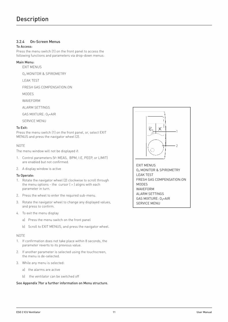
3.2.4 On-Screen MenusTo Access:Press the menu switch (1) on the front panel to access the following functions and parameters via drop-down menus:
Main Menu: EXIT MENUS
O2 MONITOR & SPIROMETRY
LEAK TEST
FRESH GAS COMPENSATION:ON
MODES
WAVEFORM
ALARM SETTINGS
GAS MIXTURE: O2+AIR
SERVICE MENU
To Exit:Press the menu switch (1) on the front panel, or, select EXIT MENUS and press the navigator wheel (2).
NOTEThe menu window will not be displayed if:
1. Control parameters (VT MEAS, BPM, I:E, PEEP, or LIMIT) are enabled but not confirmed.
2. A display window is active
To Operate:1. Rotate the navigator wheel (2) clockwise to scroll through
the menu options - the cursor ( > ) aligns with each parameter in turn.
2. Press the wheel to enter the required sub-menu.
3. Rotate the navigator wheel to change any displayed values, and press to confirm.
4. To exit the menu display
a) Press the menu switch on the front panel
b) Scroll to EXIT MENUS, and press the navigator wheel.
NOTE1. If confirmation does not take place within 8 seconds, the
parameter reverts to its previous value.
2. If another parameter is selected using the touchscreen, the menu is de-selected.
3. While any menu is selected:
a) the alarms are active
b) the ventilator can be switched off
See Appendix 7for a further information on Menu structure.
EXIT MENUSO2 MONITOR & SPIROMETRY LEAK TESTFRESH GAS COMPENSATION:ON MODESWAVEFORM ALARM SETTINGSGAS MIXTURE: O2+AIR SERVICE MENU
2
1

ESO 2 ICU Ventilator 12 User Manual
Description
3.2.5 Start-up Screens1. Start-up
a) At start-up, the software version is displayed.
b) The introduction screen allows the user to select one of three default settings: ADULT DEFAULTS PAEDIATRIC DEFAULTS SITE DEFAULTS
NOTEa) The user must select one of the
above default groups before the ventilator will switch to standby in that default mode.
b) SITE DEFAULT is editable in standby mode (see below).
c) Settings can be saved via the service menu to create a new site default.
2. Default Settings Selection The user can select ADULT, or PAEDIATRIC, or SITE, and view the default parameter settings. The options will remain, even after the ventilator is turned off. Site Default Settings (NOTE: The values listed are examples ) Adjust the parameter values from within the Service menu (SITE DEFAULTS). Press to confirm the new settings for site defaults.
3. Touch Screen Calibration Reconfigure the touch screen operating system.
<Adult Defaults< VT Set : 600 mL VM Set : 6.0 Litres T+PS INT : 10 cmH2O Set BPM : 10 I : E : 1: 2.0 PEEP : OFF Limit : 38 cmH2O Trigger : 1.0 L/min Apnoea Alarm Limit : 15 secs Volume Type: Tidal
SITE DEFAULTS
VIEW
<Paediatric Defaults< VT Set : 150 mL VM Set : 2.2 Litres T+PS INT : 10 cmH2O Set BPM : 15 I : E : 1: 2.0 PEEP : OFF Limit : 38 cmH2O Trigger : 1.0 L/min Apnoea Alarm Limit : 15 secs Volume Type: Tidal
CALIBRATE TOUCH SCREEN
CALIBRATE TOUCH SCREEN
<Site Defaults< VT Set : 800 mL VM Set : 6.0 Litres T+PS INT : 10 cmH2O Set BPM : 10 I : E : 1: 2.0 PEEP : OFF Limit : 38 cmH2O Trigger : 1.0 L/min Apnoea Alarm Limit : 15 secs Volume Type: Tidal
CALIBRATE TOUCH SCREEN
PAEDIATRIC DEFAULTS
VIEW
ADULT DEFAULTS
VIEW
SITE DEFAULTS
PRESS TO CONFIRM
PAEDIATRIC DEFAULTS
PRESS TO CONFIRM
ADULT DEFAULTS
VIEW
SITE DEFAULTS
VIEW
PAEDIATRIC DEFAULTS
VIEW
ADULT DEFAULTS
PRESS TO CONFIRM

ESO 2 ICU Ventilator 13 User Manual
Description
3.2.6 Selecting Functions and Parameters Functions/parameters shown on screen can be activated as follows:
1. Touch the screen at the appropriate tab area (see 3.2.3), or Rotate the navigator wheel and press it when the indicator arrow is on the required parameter tab
Note that unless Site Defaults are selected (see above) parameters default to factory-set values for Adult or Paediatric patients when the ventilator is switched on from OFF, and no further user selection is made.
3.2.7 User Adjustable ParametersTo alter a variable parameter, rotate the navigator wheel. When the required value is displayed, press the active tab, or the wheel, to confirm the setting.
•Tidal Volume Range 20 - 1600 ml
•Rate 4 -100 bpm
• I:E Ratio 1:0.2 to 1:8
•PEEP 4 - 20 cmH2O (option: 4 - 30 cmH2O) PEEP can be set to OFF
•Pressure limit - Volume mode: 10 - 80 cmH2O
•Pressure range - Pressure mode: 5 - 70 cmH2O
•Alarm limits (user adjustable alarms only - see 3.5)
•T+PS INIT (target and pressure support initial value):
The initial pressure value can be changed so that when entering either PRESSURE mode or PSV (pressure supported ventilation) mode the TARGET value (or PSUPP value) is pre-selected. Note that changing either of these limits in their active modes will maintain the value when changing between PSV, PRESSURE, and STANDBY modes.
3.2.8 Output Compensation Functions
WARNINGThe ventilator automatically compensates for fresh gas flow (spirometry On), fresh gas mixture (spirometry and oxygen monitor On), and altitude. However, the actual tidal volume delivered to the patient may be different to the ventilation parameters set by the user, due to:
1. Compliance effect 2. A substantial system leak 3. Patient circuit resistance effects 4. Extreme fresh gas flows
In addition, high fresh gas flows will lead to an increased VT being delivered to the patient. The patient must be monitored independently from the ventilator. It is the responsibility of the user to monitor the patient for adequate ventilation.
WARNINGImportant: Delivering high fresh gas flows when using closed endotracheal suction
This ventilator is configured to deliver flows of oxygen in excess of the maximum shown on the flowmeter tube in order to fill the ventilator bellows during closed endotracheal suction. Up to approximately 30 L/min can be delivered. Delivering O2 flows in excess of the maximum value shown on the calibrated flow tube will temporarily negate accurate volume delivery and measurement. Once the ventilator bellows is full the O2 flow should be reduced to a value within the range marked on the flow tube. Accurate volume delivery and measurement will then resume. See section 5.3 for application protocol.
ESO 2 ICU Ventilator 14 User Manual
Description
3.2.8.1 Fresh Gas CompensationAdjusts delivered volume up to 60% An alarm is triggered if measured volume varies by 50% from the set volume. This function is user adjustable (3.2.9).
NOTEFresh gas compensation is disabled if: The spirometry system is turned OFF through the menu system, or the spirometry system is malfunctioning.
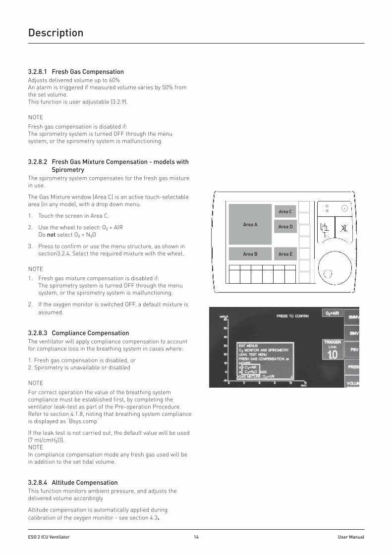
3.2.8.2 Fresh Gas Mixture Compensation - models with Spirometry
The spirometry system compensates for the fresh gas mixture in use.
The Gas Mixture window (Area C) is an active touch-selectable area (in any mode), with a drop down menu.
1. Touch the screen in Area C.
2. Use the wheel to select: O2 + AIR Do not select O2 + N2O
3. Press to confirm or use the menu structure, as shown in section3.2.4. Select the required mixture with the wheel.
NOTE 1. Fresh gas mixture compensation is disabled if:
The spirometry system is turned OFF through the menu system, or the spirometry system is malfunctioning.
2. If the oxygen monitor is switched OFF, a default mixture is assumed.
3.2.8.3 Compliance CompensationThe ventilator will apply compliance compensation to account for compliance loss in the breathing system in cases where:
1. Fresh gas compensation is disabled, or 2. Spirometry is unavailable or disabled
NOTEFor correct operation the value of the breathing system compliance must be established first, by completing the ventilator leak-test as part of the Pre-operation Procedure. Refer to section 4.1.8, noting that breathing system compliance is displayed as ‘Bsys.comp’
If the leak test is not carried out, the default value will be used (7 ml/cmH2O). NOTE In compliance compensation mode any fresh gas used will be in addition to the set tidal volume.
3.2.8.4 Altitude CompensationThis function monitors ambient pressure, and adjusts the delivered volume accordingly
Altitude compensation is automatically applied during calibration of the oxygen monitor - see section 4.3.
Area A
Area C
Area D
Area B Area E

ESO 2 ICU Ventilator 15 User Manual
Description
3.2.9 Ventilation Modes
3.2.9.1 Standby Mode1. Allows parameters to be set.
2. Some patient alarms are active:
•High airway pressure (at 80 cmH2O)
• High/Low oxygen
•Negative pressure
• Incorrect Rate/Ratio
• Continuous high pressure
•Target and pressure support
3. Access to Support modes is available in Standby mode (depending on the support mode options on the ventilator):
•PSV
•SIMV
•SMMV
•SIGH ENABLE SIGH TO BREATH RATIO
• INSP PAUSE INSP PAUSE %
WARNINGPSV, SIMV, and SMMV are only available when spirometry is enabled, refer to Apendix 5.
4. Displayed information
•Standby mode at ventilator start-up: The last used Volume mode settings will be displayed - the underline (1) indicates the last used ventilation mode.
•Standby mode selected while the ventilator is in use: The screen will display the previous ventilation mode, highlighted in yellow, within the relevant box. The last used parameters will also be displayed.
1

ESO 2 ICU Ventilator 16 User Manual
Description
3.2.9.2 Volume Mode
WARNINGImportant: Delivering high fresh gas flows when using closed endotracheal suction.
This ventilator is configured to deliver flows of oxygen in excess of the maximum shown on the flowmeter tube in order to fill the ventilator bellows during closed endotracheal suction. Up to approximately 30 L/min can be delivered.
Delivering O2 flows in excess of the maximum value shown on the calibrated flow tube will temporarily negate accurate volume delivery and measurement. Once the ventilator bellows is full the O2 flow should be reduced to a value within the range marked on the flow tube. Accurate volume delivery and measurement will then resume. See section 5.3 for additional information.
Volume mode
The ventilator delivers a mandatory set volume of gas at preset, fixed breath intervals. The patient is making no respiratory effort.
3.2.9.3 Fresh Gas CompensationThe delivered volume is adjusted by up to 60%. This delivered volume will consist of the volume delivered from the ventilator bellows, plus the fresh gas flow from the anaesthetic machine fresh gas supply, minus any compliance loss and minus any leak. This gives a total actual inspired tidal volume. An alarm is triggered if the measured volume is 50% above or below the set volume. This function is user adjustable.
Compliance Compensation: Refer to section 3.2.8.3Altitude Compensation: Refer to section 3.2.8.4
3.2.9.4 Select Volume ModeVolume Mode selected from Standby Mode:1. Press the screen tab: ‘VOLUME CONTROL’
Volume Mode selected from Pressure Mode:1. Press the screen tab: ‘VOLUME CONTROL’ The ventilator
continues to ventilate in Pressure Mode.
2. The Volume Set display shows the previous setting, or default setting.
3. A new Volume value can be set if required.
WARNING: Set appropriate values for the clinical procedure in progress. Take note of all on-screen symbols and display messages.4. Press to confirm change of mode and new setting.
NOTE: Pressure limit will default to the previous Pressure Target value + 5 cmH2O
5. At confirmation, the ventilator will switch to Volume Mode.
NOTE: Volume mode will commence at the beginning of an exhalation phase.
Volume Mode ParametersTidal volume 20 - 1600 mLRate 4 - 100 bpmI:E ratio 1:0.2 to 1:8PEEP ‘Off’ or adjustable
4 - 20 cmH2O (option, 4 - 30 cmH2O)
Pressure limit 10 to 80 cmH2O To set, touch the ‘LIMIT’ screen tab area, turn the navigator wheel to select the required value, press to confirm.
Inspiratory pause Variable: 0 - 60% of inspiratory (does not affect I:E ratio) time
Sigh Approximately 1.5 x set VT is delivered every 10 to 100 breaths (sigh to breath ratio is user selectable)

ESO 2 ICU Ventilator 17 User Manual
Description
3.2.9.5 Volume Type SelectionTouch the screen tab to switch between Tidal Volume and Minute Volume.
NOTE: Minute Volume is derived from a rolling average during a 30 second period.
3.2.9.6 Volume Mode Operating Functions1. Inspiratory Pause function:
Inspiratory pause can be varied in the menu from 0 - 60%. The inspiratory pause menu can also be accessed by touching the icon area of the screen. WARNING : This can affect the maximum Tidal Volume.
Select Inspiratory Pause:
•Press the menu switch (1), turn the wheel (2) to scroll through the menus
•Select Modes
•Select percentage time value (0 - 60%)
•Exit menus
The symbol for inspiratory pause will appear on the display
Note: Inspiratory pause is cancelled when Standby is selected
2. Sigh function:
• ‘Sigh’ option is available in Volume Cycle mode. Sigh to breath ratio is 1:n, where n has a range of 10 - 100. The Sigh menu can also be accessed by touching the icon area of the screen.
NOTEa) A sigh to breath ratio of 1:10 indicates 1 breath with
sigh, then 10 breaths without sigh The extra volume will be approximately 50% above the tidal volume set by the user (1.5 x set VT).
b) The High Volume Alarm is not triggered when ‘Sigh’ is selected.
• Select Sigh function:
•Press the Menu switch (1), turn the wheel (2) to scroll through the menus
•Select Modes
•Select Sigh Enable on/off
•Select Sigh-to-Breath Ratio
•Rotate the wheel to select the required value
•Press wheel to confirm, and exit menus
The legend for Sigh will appear on the display
NOTE: Sigh is cancelled when standby is selected.
EXIT MENUSO2 MONITOR & SPIROMETRY LEAK TESTFRESH GAS COMPENSATION:ON MODESWAVEFORM ALARM SETTINGSGAS MIXTURE: O2+AIR SERVICE MENU
2
1
3. Volume measurement
Volumes are measured if the Spirometry function is selected. Automatic High or Low volume alarms are triggered if the measured volume is 50% above or below the set volume.
4. User adjustable option
If the maximum pressure limit is achieved, the ventilator cycles to the expiratory phase.
3.9.2.5 Touchscreen Access to Mode Configuration OptionsTouch the screen in the area containing the green icons to access mode configuration options (including INSP PAUSE, SIGH, and APNOEA ALARM mute/inhibit).
VMEAS
VT MEAS

ESO 2 ICU Ventilator 18 User Manual
Description
3.2.10 Pressure Mode
3.2.10.1 ParametersIn pressure mode the ventilator delivers a variable flow of gas to achieve a set pressure at fixed breath intervals. The patient is making no respiratory effort.
Pressure range 5 - 70 cmH2O Note that the pressure limit is 5 cmH2O, or 10%, above the set target pressure, whichever is greater.
Rate 4 - 100 bpm
I:E ratio 1:0.2 - 1:8
PEEP 'Off' or adjustable: 4 - 20 cmH2O (option, 4 -30 cmH2O)
Inspiratory decelerating flow is controlled by the ventilator according to the pressure setting.
3.2.10.2 Selecting Pressure ModePressure Mode selected from Standby Mode:1. Select by touching the screen tab: ‘PRESS’.
Pressure Mode selected from Volume Mode:1. Select by touching the screen tab: ‘PRESS’.
The ventilator continues to ventilate in Volume Mode.
2. The target pressure button flashes (the display shows the previous setting of target pressure, or default setting).
3. The user can set a new Target Pressure if required
WARNINGSet appropriate values for the clinical procedure in progress. Take note of all on-screen symbols and display messages.
4. Press to confirm change of mode and new target pressure.
5. At confirmation of the new mode, the ventilator will switch to Pressure Mode. NOTE Pressure Mode will commence at the beginning of an exhalation phase.
3.2.10.3 Pressure Mode Operating Functions Pressure mode defaults to a target pressure of 10 cmH2O at switch on, unless Site Defaults have been selected with preset values.
•A high inspiratory flow is used to achieve and maintain the target pressure.
•The exhaust valve operates to prevent excess pressure.
•There is no Inspiratory Pause function in pressure mode.
PRESS
AV-S

ESO 2 ICU Ventilator 19 User Manual
Description
3.2.11 Spontaneous Mode and Patient Support ModesCAUTION: No absorber in the rebreathing module!!
Spontaneous Mode
Default trigger level for ventilator support is 1.0 L/min.
Patient Support Modes
•SIMV: Synchronised Intermittent Mandatory Ventilation • SMMV: Synchronised Mandatory Minute Ventilation • PSV: Pressure Supported Ventilation For further information, see Appendix 5.
3.2.12 PEEP (Positive End Expiratory Pressure)The AV-S ventilator includes a microprocessor-controlled, electronically integrated PEEP system, regulated by the secondary pressure on the exhaust diaphragm (see Appendix 4, Ventilation cycle).
The ventilator controls PEEP by allowing flow from, or delivering flow into, the bellows drive circuit. This maintains the set pressure
NOTE1. PEEP is electronically controlled.
2. PEEP is variable from 4 - 20 cmH2O (or optional 4 - 30 cmH2O), in increments of 1 cmH2O.
3. PEEP maximum limit is 20 cmH2O (or optional 30 cmH2O).
4. The display shows “OFF” when PEEP is not in use.
5. PEEP is switched off when the ventilator is switched off.
6. PEEP is switched off in Standby or ‘Spont’ mode to ensure minimal patient breathing effort.
Selecting PEEP1. Select by touching the screen tab PEEP, or using the navigator wheel. The setting will
flash.
2. Rotate the navigator wheel to set the required PEEP pressure. A confirm message will be displayed. Press the Screen Tab, or Wheel to confirm.
3. Note that PEEP does not function in Spontaneous Mode or in any Patient Support Mode.
3.3 SpirometryEnable or disable via the on-screen menu system. If the spirometry system is turned OFF: Fresh gas / fresh gas mixture compensation is disabled. Support Modes are disabled.
Spirometry MenusON/OFF1. Turn the navigator wheel to switch between ON and OFF.
2. Press to confirm.
3. Scroll to EXIT MENUS and press the wheel to exit.
Calibration1. Press the navigator wheel to initiate the calibration procedure
(see section 4.1.6 for full procedure).
2. To exit the menu, scroll to EXIT MENUS and press the wheel.
Spirometry sub-menu - On/Off
O2 Monitor & Spiro ESCAPE FROM MENU O2 MONITOR: on CALIBRATION: 100% HIGH ALARM SET: 105 LOW ALARM SET: 18 > SPIROMETER: on SPIRO CALIBRATION: 0 L/min

ESO 2 ICU Ventilator 20 User Manual
Description
3.4 Display WaveformsThe default waveform is always Pressure vs. Time (cmH2O vs. seconds)
Wave Freeze is available when ventilation is in progress.
1. Waveform Pause and Print
•Waveform pause and print icons (1) are located to the left hand side of the waveform displays.
•Ensure that a compatible printer is connected, and switched On (see section 4.1.4).
•To print the waveform information, press the pause icon. The print icon will be displayed.
•Press the icon to print.
•Press the pause icon to unfreeze the waveform.
2. Waveform Freeze Loop The FREEZE LOOP icon (2) is located at the left hand side of the top waveform.
3. Second waveform
The second waveform can be displayed by using the menu control or by touching the waveform on screen. Select from:
• Volume vs. Time (litres vs. seconds)
• Volume vs. Pressure (litres vs. cmH2O)
- Compliance loop waveform
- First loop can be frozen
- Subsequent loops overlaid
4. Display Functions Automatic scale adjustment
Y axis1. In Pressure vs. Time mode the scale adjusts as Plimit is
changed (-20 to 40, 60, 80 cmH2O)
2. In Volume vs. Time and Volume vs. Pressure modes the scale adjusts as VT is changed (0 to 0.5 L, 1.0 L, 2.0 L)
x axis1. In Pressure vs. Time and Volume vs. Time modes the scale
adjusts as Rate is changed (0 to 15 sec, 5 sec, 3 sec)
2. In Volume vs. Pressure mode the scale adjusts as Plimit is changed (-20 to 40, 60, 80 cmH2O).
1
2

ESO 2 ICU Ventilator 21 User Manual
Description
3.5 AlarmsUser adjustable alarms: Use the menu systems to set the required limits. Press the menu switch on the front panel (see 3.5.2), and select ALARM SETTING, or touch the alarm area on screen (see 3.2.3, Area B).
Alarm Priority Trigger Mute time
Set by:
Ventilator inoperative (vent inop)
High Internal system failure. Check error log for key zero Automatic
Outlet blocked High Positive pressure on PEEP sensor exceeds 122 cmH2O, due to blocked exhaust valve outlet
zero Automatic
Low supply pressure High Supplied drive gas pressure on pressure switch is less than 235 kPa (35 ±1 psi) zero Automatic
Low airway pressure High Bellows drive gas pressure sensor fails to see at least 75% of set target level (pressure control)
120 s Automatic
Low drive gas pressure High Airway and drive gas pressure fails to reach minimum level (volume control) 30 s Automatic
High drive gas pressure High Airway and drive gas pressure exceeds calculated target level 120 s Automatic
High continuous pressure High PEEP +10 cmH2O for 1 cycle, or PEEP +5 cmH2O for 3 cycles. A PEEP value of 4 cmH2O is used for PEEP values ≤4. Standby: the alarm triggers after 15 seconds
120 s Automatic
High airway pressure High Airway pressure sensor: Pressure reaches set limit (10 to 80 cmH2O adjustable) 30 s User/Default
Negative airway pressure High Airway pressure sensor: Breathing system pressure exceeds (-)10 cmH2O 120 s Automatic
Check pressure sensing High Airway pressure sensor: Breathing system pressure exceeds (-)10 cmH2O 120 s Automatic
Low tidal volume (VT) High a) Expiratory spirometer sensor: Measured VT less than 50% of volume set b) Expiratory spirometer sensor: disconnected
120 s User/Default
Low minute volume (VM) High Expiratory spirometer sensor: Calculated volume lower than -50% of volume set
120 s User/Default
Apnoea High Breath not detected within 15 seconds in spontaneous mode. 15-120 s Automatic
High tidal volume (VT) High Inspiratory spirometer sensor - measured value exceeds 150% of set value 120 s User/Default
High minute volume (VM) High Inspiratory spirometer sensor - calculated value exceeds 150% of set value 120 s User/Default
High O2 concentration % High Oxygen monitor : Measured O2 % exceeds set value 120 s User/Default
Low O2 concentration % High Oxygen monitor: Measured O2 % lower than set value 120 s User/Default
O2 sensor low output Low Oxygen monitor: Output voltage low, sensor life exhausted / sensor not calibrated
zero Automatic
Oxygen sensor fault High Oxygen monitor sensor disconnected 120 s Automatic
Rate or ratio error Medium Ventilator parameter settings unachievable 120 s Automatic
AC power failure Low Mains power fails. Note: A fully charged battery gives 60 minutes use. zero Automatic
Battery power fail Medium Ventilator is running on mains power, but: (a) Battery is disconnected or not fitted. (b) Battery is discharged below critical level
120 s Automatic
Low battery Low Ventilator is running on mains power or battery power, but battery charge is approaching a critical level. Note that if the ventilator is running on battery power, less than 20 minutes battery life remains.
zero Automatic
Power about to fail High Ventilator is running on battery power and is about to shut down because battery power is depleted to a critical level. Note: (a) Less than 5 minutes battery life remains. (b) When total power failure is imminent, the shutdown procedure starts automatically.
zero Automatic
Cable fault Low Disconnection or short circuit zero Automatic
Primary alarm fault Low Primary alarm circuit not functioning. Note that incidence of this alarm is accompanied by a continuous tone from the secondary alarm system while any other alarm condition is in effect.
zero Automatic
Printer not available Low Printer disconnected, or has no power, or has no paper. zero Automatic
Priority level:
1. High priority: Five ascending tones - repeated.
2. Medium priority: Three ascending tones - repeated.
3. Low priority: Single tone

ESO 2 ICU Ventilator 22 User Manual
Description: Oxygen Monitor
3.6 Oxygen MonitorThe oxygen monitor continuously measures and indicates the concentration of oxygen in the breathing system, and triggers an alarm when the concentration varies from the set levels.
3.6.1 System DescriptionThe oxygen monitor uses a fast-responding, oxygen-specific, self powered sensor that achieves 90% of final value in less than 10 seconds. The sensor (1), is fitted to the breathing module.
The system has user-adjustable high-level and low-level alarms with visual and audible indication of alarm conditions.
Bacterial FilterAlways use a breathing system bacterial filter in the expiratory limb of the breathing circuit to protect the oxygen sensor and breathing system components from contamination (see Appendix 4, BreathingSchematic. Replacement/Disposal - always follow the instructions supplied with the filter, and always replace at the recommended interval.
3.6.2 The Oxygen SensorThe oxygen sensor provides quick response, linear output over the entire 0 - 100% oxygen range, and long service life.
The sensor is a self-powered galvanic cell that generates a current proportional to oxygen concentration. The cell has a highly stable output over its operating life. Significant output loss is only shown at the very end of its life.
Typical sensor drift rates are less than 1% per month when the sensor is exposed to gas in typical applications.
Sensor life:Sensor life is approximately 1500 000 O2% hours at 20°C (minimum one year in most normal applications).
Sensor lifetime is governed by the mass of lead available to react with the oxygen and its rate of consumption. High oxygen partial pressure and high temperature will increase the sensor output current, thus shortening the operation life.
At the point where all lead has been consumed, the output will fall very quickly to zero over a period of two to three weeks.
Sensor replacement: see section 6.4.
3.6.3 Oxygen Monitor MenuSelect: O2 MONITOR ‘on’To access Calibration and Alarm Set functions, the monitor must first be set to ‘on’ in the sub menu (1).
Scroll to O2 MONITOR, rotate the wheel to ‘on’, press the wheel to confirm.
NOTE1. The oxygen monitor defaults to the previous values for
high and low alarm settings.
1
O2 Monitor & Spiro ESCAPE FROM MENU > O2 MONITOR: on CALIBRATION: 100% HIGH ALARM SET: 105 LOW ALARM SET: 18 SPIROMETER: on SPIRO CALIBRATION: 0 L/min
1

ESO 2 ICU Ventilator 23 User Manual
Description: Oxygen Monitor
O2 Monitor sub-menu - calibration
O2 Monitor & Spiro ESCAPE FROM MENU O2 MONITOR: on > CALIBRATION: 100% HIGH ALARM SET: 105 LOW ALARM SET: 18 SPIROMETER: on SPIRO CALIBRATION: 0 L/min
O2 Monitor & Spiro
ESCAPE FROM MENU O2 MONITOR: on CALIBRATION: 100% > HIGH ALARM SET: 105 LOW ALARM SET: 18 SPIROMETER: on SPIRO CALIBRATION: 0 L/min
O2 Monitor sub-menu - alarms
2. Fresh gas mixture compensation is disabled if the monitor is switched OFF.
3. The monitor must be switched ON to allow calibration and setting of the alarm levels.
4. At ventilator power-up, the status ‘O2 monitor off’ is indicated onscreen by a red oxygen concentration window (2). If the window is not visible, contact Penlon Technical Support - see rear cover for contact details.
CALIBRATIONScroll to CALIBRATION, and press the navigator wheel to initiate the calibration procedure (see section 4.3 for full procedure). Scroll to EXIT MENUS and press the wheel to exit.
HIGH ALARM SET LOW ALARM SETOxygen limits are accessed by touching the screen at area D (see section 3.2.3), or through the menu system.
Fast access through touchscreen1. Touch the screen at area D to access the High/Low Alarm
set value tab at area D.
2. Turn the navigator wheel to select the required value.
3. Press the wheel to confirm the value selected.
NOTEIf you do not want the new value to be confirmed, touch another tab area to cancel the resetting operation.
Access through Menu System1. Scroll to the required parameter and press the navigator
wheel to activate.
2. Rotate the navigator wheel again to change the displayed value. High Alarm range: 19% - 105% Low Alarm range 18% - 99%
3. The displayed figure will flash on and off.
4. Press to confirm.
5. Scroll to EXIT MENUS, press the wheel to exit.
3.6.4 DisplayHigh-set, low-set, and %O2 readings are displayed on screen. Touch the tab to activate the O2 menu.
Oxygen Concentration (1)The display provides a direct readout of measured oxygen concentrations in the range 0 - 100%.
Low Alarm Set (2) - limited within 18 - 99%The oxygen percentage, set by the user, at which the low alarm will be activated. To set the low oxygen alarm, see section 4.3.
High Alarm Set (3) - limited within 19 - 105%The oxygen percentage, set by the user, which the high alarm will be activated.
%O2OFF2
%O233
100
20
42
31

ESO 2 ICU Ventilator 24 User Manual
Description: Oxygen Monitor
Note that in certain conditions of excess pressure, the readout may show a value above 100%. To set the high alarm, see section 4.3.3.
3.6.5 Oxygen Monitor AlarmsHIGH O2 ALARMThe high O2 alarm is triggered when the oxygen concentration is 1% above the set value.
The high O2 Alarm visual indicator will illuminate. A high priority audible alarm will sound.
To cancel this alarm, the high alarm setting must be equal to, or above the oxygen concentration. The alarm can be muted for 120 seconds.
LOW O2 ALARMThe low alarm is triggered when the oxygen concentration is 1% below the set value.The Low O2 Alarm visual indicator will illuminate. A high priority audible alarm will sound.
To cancel this alarm, the low alarm setting must be equal to, or below the oxygen concentration. The alarm can be muted for 120 seconds.
O2 SENSOR FAULTThe alarm is triggered:
1. When either the oxygen sensor is disconnected or approaching the end of its life.
2. If the O2 concentration exceeds 110%. The message O2 SENSOR FAULT will be displayed. A high priority audible alarm will sound.
To cancel, check the sensor connection or replace the sensor. The alarm can be muted for 120 seconds.
O2 SENSOR LOW
Indicates the sensor has approached the end of its life.
The legend O2 SENSOR LOW will be displayed, and a low priority alarm (single note) will sound.
The sensor must be replaced as the output will fall very quickly to zero within two to three weeks of normal usage. See section 6.4 for sensor replacement.
3.6.6 Oxygen Monitor Alarm Mute In an alarm condition, pressing the ALARM MUTE button (4)will deactivate the audible alarm, but the alarm message display will remain on screen.
The switch will illuminate, and a single note will sound.
The alarm mute can not be operated:
1. Until the mute time is over, or the alarm condition has been rectified.
2. When oxygen concentration drops below 18%..
%O233
100
20
4

ESO 2 ICU Ventilator 25 User Manual
4. Pre-operation Procedures
4.1 Ventilator Set-up
WARNINGSBefore the ventilator is used clinically for the first time a Calibration Check and Output Check must be successfully completed. This work must be carried out by a Penlon-trained technician, following the procedure in section 6.6 in the AV-S service manual.
4.1.1 Electrical Power ConnectionBefore connecting the ventilator to the mains supply check that the power supply is within the correct rating as stated on the label on the rear of the control unit.
WARNINGExcessive electronic noise caused by other, poorly regulated devices, such as electrocautery, may adversely interfere with the proper functioning of the ventilator. Do not connect the ventilator power cord into the same electrical wall outlet or strip into which an electrocautery unit is connected.
Connection
Connect the mains cable to the socket (1) and plug into the mains supply outlet.
WARNING
Check that the power cord can be easily disconnected. Refer also to Section1, Warning 22.Isolation from mains supplyDisconnect the cable from the mains supply outlet.
4.1.2 Ventilator Gas Supply1. Check the drive gas supply (2) is air.
Always use Air.
2. Gas supply pressure range: 280 to 600 kPa (41 to 87 psi) Supply pressure should be monitored by a separate means, e.g. pressure gauge on the supply line.
1
2

ESO 2 ICU Ventilator 26 User Manual
Pre-operation Procedures
4.1.3 Ventilator Screen
WARNINGCheck that the cable (1) between the control unit and remote display screen unit is securely connected before use.
Always switch the ventilator OFF before disconnecting the cable. Disconnect from the control unit, then disconnect from the display.
4.1.4 PrinterAttach a printer (HPL2 compatible) to the printer port if a printed output of the ventilator function is required.
4.1.5 Breathing System1. Use a breathing system bacterial filter in the expiratory limb
of the breathing circuit to protect the oxygen sensor.
2. Use a heat and moisture exchanger (HME) at the patient Y-piece. A combined HME / bacterial filter can also be used, but note that the expiratory limb bacterial filter is still required)
CAUTION: Replacement/Disposal - Fit new filters at the recommended interval. Follow the manufacturer’s instructions.
4.1.6 Spirometer1. Use breathing system bacterial filters.
CAUTION: Replacement/Disposal - always follow the instructions supplied with the filter. Always renew components at the recommended interval.
2. The spirometry flow sensors are mounted within the breathing module in the inspiratory and expiratory airways.
3. Check the spirometer cable (2) for secure connection.
NOTE 1. Incorrect connections will trigger the LOW TIDAL VOLUME or
HIGH TIDAL VOLUME alarm.
2. To allow the ventilator to be used in the event of damage, or non-functioning of the spirometer sensors, turn off the spirometry function - see MENU function, section 3.3. If the spirometer is switched OFF: a) Fresh gas compensation and fresh gas mixture compensation are disabled. b) Patient support function is disabled.
Spirometer Zero Calibration
NOTE1. The spirometry system must be calibrated with zero flow
going through.
2. The individual spirometers must be matched to the specific ventilator by a qualified service engineer as part of commissioning or a subsequent service visit.
The following calibration instructions must be performed by the user as part of the daily check procedure.
1. Turn the flow off at the Gas Delivery on/off switch. This will
1
2

ESO 2 ICU Ventilator 27 User Manual
Pre-operation Procedures
stop all gas flows (including the basal flow). This will also turn the ventilator off.
2. Turn the ventilator switch on (1) (do not use the gas delivery switch).
3. Remove the breathing circuit hoses from the inspiratory and expiratory connectors on the breathing module.
4. Ensure that the ventilator bellows is empty,
5. Calibrate the spirometer via the ventilator menu procedure.
6. Press the menu switch (2) on the front panel.
7. Scroll down the main menu and select O2 MONITOR & SPIROMETRY.
8. Select SPIRO CALIBRATION.
9. Press the wheel (3) to initiate calibration.
10. Calibration is completed.
11. Scroll to ESCAPE FROM MENU.
12. Press the wheel to confirm.
4.1.7 Pressure Monitor Connections
WARNING: The High and Low Airway Pressure Alarms are important for patient care.1. Check the pressure monitor tubing assembly connections (1).
2. Push-fit, self-sealing connectors (2):
•Push in the tube as far as possible
•Do not use excessive force.
•The connector end piece ‘X’ will also move inwards.
•Pull the tube carefully outwards. The end piece ‘X’ will be pulled outwards to the ‘locked’ position.
Tubing disconnection or sensor malfunctionMessage displayed: ‘Check pressure sensing’ Action by user:
1. Check the condition of the tubing, and the connections (1) at the ventilator and the rear of the breathing module .
2. If the tubing is undamaged and the connections are secure, the operation of the sensors must be checked by a service engineer
CAUTION The ventilator will apply compliance compensation to account for compliance loss in the breathing system in cases where:
1. Fresh gas compensation is disabled, or
2. Spirometry is unavailable or disabled
The ventilator will continue to function, although the target pressure may be exceeded by up to 10 cmH2O.
4.1.8 Leak Test / Compliance Value CalculationX
X
21
1
O2 Monitor & Spiro ESCAPE FROM MENU O2 MONITOR: on CALIBRATION: 100% HIGH ALARM SET: 105 LOW ALARM SET: 18 SPIROMETER: on > SPIRO CALIBRATION: 0 L/min
3
2
1

ESO 2 ICU Ventilator 28 User Manual
Pre-operation Procedures
Leak Test1. Select LEAK TEST through the Menu in Standby Mode.
2. Check for a leak using an occluded breathing system.
3. Disconnect gas sampling modules connected to patient monitoring equipment during this test.
This procedure checks the breathing system for pressure leakage, and calculates and displays Leak Level and Breathing System Compliance.
1. Occlude the breathing circuit at the patient Y-piece
2. Ensure that the bellows are fully inflated.
3. Turn the gas delivery switch (1) off. This will stop all gas flows (including oxygen basal flow) and will also turn the AVS off. Then switch the AV-S on (2) - at the ventilator (do not use the gas delivery switch).
4. Press the menu switch (3). Select LEAK TEST from the main menu. Select <START/STOP LEAK TEST> to start the leak test. The ventilator will now drive gas into the absorber until a pressure of 30 cmH2O is obtained, and then hold that pressure for approximately 25 seconds before releasing the pressure and completing the test.
5. The menu will display the leak test results:
a) Leak Level: Leak rate is displayed
NOTEDuring the test, any pressure drop discovered once the 30 cmH2O level is reached will be displayed as a possible leak by the ventilator self-test.
This includes pressure drop due to the relaxation of any elastic components in the breathing system (e.g. a breathing bag)
b) (b) BSys Comp: Compliance BSys Comp is the compliance of the breathing system and is the value that will be used in providing the default compliance compensation for volume delivery.
NOTEa) Default value is 7.0 cmH2O.
b) Upper limit is 18 cmH2O (sufficient for normal breathing system capacities).
c) The ventilator will continue to operate, irrespective of any detected leak.
d) It is the responsibility of the user to determine if the detected leak is significant.
Leak Test
ESCAPE FROM MENU < START/STOP LEAK TEST> LEAK LEVEL: 0 mL/min BSYS COMP 7.0 mL/cmH2O
2
3
1

ESO 2 ICU Ventilator 29 User Manual
Pre-operation Procedures
4.1.9 Bellows Assemblies
CAUTIONAlways ensure correct fitment of bellows (see illustration above), and carry out a full function test before clinical use, if a bellows is removed and refitted.
Remove and refit
1. Remove the bellows housing (1). Twist carefully counterclockwise until the bayonet tabs become free, then lift up from the base (2).
2. Remove the bellows (3).
3. Refit the bellows and check for correct assembly, as illustrated (4).
4. Fit the bellows housing (1) by pushing down, then twisting clockwise until the bayonet tabs completely engage.
5. Function test the ventilator - section 4.2.1.3.
NOTEIf there is any malfunction, the ventilator must NOT be used. If the problem cannot be rectified, the ventilator must be checked by an engineer trained by the manufacturer.
Fitting a Paediatric Bellows Assembly1. Remove the adult bellows housing (1) - twist carefully
counterclockwise until the bayonet tabs become free, then lift up from the base (2). Remove the bellows (3).
2. Fit the paediatric adaptor (5). Press the adaptor firmly into the ventilator bellows assembly base (2).
3. Fit the paediatric bellows (6) to the adaptor. Check for correct assembly, as illustrated (4).
4. Fit the paediatric bellows housing (7) to the base by pushing down, then twisting clockwise until the bayonet tabs completely engage.
5. Function test the ventilator - section 4.2.1.3.
2
3
1
4
7
5
6

ESO 2 ICU Ventilator 30 User Manual
Pre-operation Procedures
9
8
4.2 Pre-use Checklist
4.2.1 Daily Checklist 4.2.1.1 Hose and Cable ConnectionsCheck for correct connections:
1. Ventilator drive gas inlet (1).
2. Oxygen (2) and Air (3) pipeline supply.
3. Bellows drive gas port on the control unit (4) and the bellows assembly.
4. Exhaled gas port (5). The discharged gas may contaminate the environment. Connect to an AGSS system if available.
5. Pressure monitor port and breathing circuit (6). Check that the port on the rear of the control unit is correctly connected to the port on the rear of the absorber assembly.
6. Spirometer cable (7).
4.2.1.2 Ventilator Internal TestTurn on the gas delivery switch (8), a short self-test is initiated:
1. The bellows is filled.
2. The ‘power -up’ screen is displayed.
3. The audible alarm sounds (two tones).
4. The ventilator displays the start-up selection screen.
NOTE: While machine power is ON, the Ventilator can be turned OFF and ON, using the ventilator On/Off switch (9).
4.2.1.3 Function Test1. Select Adult default settings using the touchscreen:
VT : 600 ml / BPM: 10 / I:E Ratio 1:2.0 Airway pressure limit: 38 cmH2O (fresh gas compensation on).
2. Connect a 2-litre breathing bag to the patient connection as a test lung.
3. Set a basal flow only (anaesthetic machine).
4. Select VOLUME CYCLE mode.
5. After 10 breaths check that the bellows returns to the top of the housing. Failure to return to the top of the housing indicates a leak in the breathing circuit. Rectify the leak before clinical use.
6. Check the delivered tidal volume as indicated on the scale printed on the bellows housing. The value should be between 600 ml and 800 ml. If the delivered tidal volume is outside this range, refer the ventilator to a trained engineer.
7. Check that spirometer readings, once settled, show correct delivery of 600 ±20 ml.
5
6
2
3
14
6
7

ESO 2 ICU Ventilator 31 User Manual
Pre-operation Procedures
8. Remove the breathing bag and occlude the patient ‘Y’ piece. The HIGH AIRWAY PRESSURE alarm should be activated. The peak pressure, as displayed on the breathing system pressure gauge, is the maximum working airway pressure limit and should agree with the set value.
9. Open the patient ‘Y’ piece to ambient pressure. At second cycle, the LOW AIRWAY PRESSURE alarm should activate.
10. If the ventilator passes all the above tests: select the required settings for use.
11. Select STANDBY mode. Before using the ventilator clinically, check that all system connections are correct, and verify that there are no leaks.
12. If the ventilator fails any of the tests: Do not use the system. Contact a service engineer.
High O2 flows are required during application of closed suction.
13. Fully open the O2 flowmeter slowly and check that a high flow of oxygen is available (up to approximately 30 L/min at the inspiratory port of the breathing system)
14. Set gas flows back to minimum
15. Start-up screen will appear after approximately ten seconds
16. Calibrate the touch-screen (3)
17. Select ‘ADULT DEFAULTS’
18. Set system switch to OFF and allow ventilator to boot down.
19. Check for High flows of O2 Note that high O2 flows are required during application of closed suction. Fully open the O2 flowmeter slowly and check that a high flow of oxygen is available (up to approximately 30 L/min at the inspiratory port of the breathing system)
NOTE: Do not use the ventilator if there is any malfunction. If the problem cannot be rectified, the ventilator must be checked by a trained engineer.IMPORTANTIf the ‘Ventilator Inoperative’ alarm is activated, disconnect the ventilator and ventilate the patient by other means.
4.2.1.4 Weekly ChecklistAlarms1. Select STANDBY MODE.
2. Unplug the mains power cable from the AC outlet. The MAINS FAILURE alarm should activate.
3. Reconnect the mains power cable to the AC outlet. The alarm should turn off
4. Disconnect the drive gas supply hose. The LOW SUPPLY PRESSURE alarm should activate.
NOTEDo not use the ventilator if there is any malfunction. If the problem cannot be rectified, the ventilator must be checked by a trained engineer.
BellowsCheck the condition of the bellows and exhalation diaphragm valve (section 6.6).

ESO 2 ICU Ventilator 32 User Manual
Pre-operation Procedures: Oxygen Monitor
4.3 Oxygen Monitor System Set-up
WARNINGThe sensor (1) contains a small quantity of electrolyte, classified as a harmful irritant. Do not open a cell.
To maintain maximum sensor life, always disconnect the breathing circuit after use, and switch off the gas delivery switch machine to stop the basal flow through the system.
Bacterial FilterUse a breathing system bacterial filter in the expiratory limb of the breathing circuit to protect the oxygen sensor.
4.3.1 CalibrationCalibrate a new sensor before clinical use.
We recommend calibration of the unit every time the system is switched on.
Calibration must also be performed when point-of-use elevation changes by more than 160 m (500 ft). Note that altitude compensation is automatically applied during calibration.
The calibration process requires calibration at the primary point of 100% oxygen. To provide enhanced accuracy there is an optional secondary point at 21% oxygen (using room air), which can be carried out after the primary calibration in 100% oxygen.
Calibration - Using 100% Oxygen Calibrate with the sensor in position within the absorber.
1. Turn the gas delivery switch (2) to ON.
2. Remove the breathing circuit hoses from the inspiratory and expiratory connectors (3) on the breathing module to give a free flow of oxygen through the sensor.
3. Select O2 MONITOR ‘on’ in the O2 MONITOR AND SPIROMETRY submenu (see 3.6)
4. Apply 100% oxygen at 5 L/min. Allow the oxygen sensor to stabilise for 15 minutes (check that the reading (4) remains constant over a 30 seconds period). Calibrate the sensor following the onscreen menu procedure, as follows.
5. Press the menu switch (5) and select the O2 MONITOR AND SPIROMETRY submenu.
6. Scroll to CALIBRATION and press the navigation wheel (6) to select the calibration option.
7. The % value (4) will flash and a message - PRESS TO CONFIRM will flash. NOTE Ensure that the 100% option is displayed (rotate the navigation wheel to select this if the secondary point value of 21% is displayed). Press the wheel to confirm.
8. A message ‘Calibrated at 100% oxygen’ should be displayed. Note that ‘ERROR: CAL OUT OF RANGE’ will be displayed if the user has attempted to calibrate at 21% in 100% O2
9. Turn off the oxygen supply.
O2 Monitor & Spiro
ESCAPE FROM MENU O2 MONITOR: on > CALIBRATION: 100% HIGH ALARM SET: 105 LOW ALARM SET: 18 SPIROMETER: on SPIRO CALIBRATION: 0 L/min
%O2 XX 20
100
6
5
4
13
2

ESO 2 ICU Ventilator 33 User Manual
Pre-operation Procedures: Oxygen Monitor
Check the monitor at the secondary point10. If the oxygen monitor is not displayed, select O2 MONITOR ‘on’ in the
O2 MONITOR AND SPIROMETRY submenu.
11. Detach the sensor (1) and gently move it through the air, to allow room air to circulate, for 20 seconds.
12. Allow the oxygen sensor to stabilise for 15 minutes (check that the reading (2) remains constant for a 30 seconds period).
13. Press the menu button (3). Select the O2 monitor sub-menu.
14. Scroll to CALIBRATION Press the navigator wheel (4) to switch to 21% if the menu shows 100%.
15. A message will flash on the screen: O2 AT 21% ? Press the button to confirm. Note that the message: ERROR: CAL OUT OF RANGE will appear on screen if the user attempts to calibrate at 21% in 100% oxygen
16. A message ‘Calibrated at 21% oxygen’ should be displayed.
17. Exit the menu system by pushing the menu button (3).
18. Refit the sensor. Check by setting 100% oxygen and maintain the flow through the circuit for approximately 20 seconds. Allow the oxygen sensor to stabilise (30 seconds minimum). The measured O2 (2) must show 100% (±1%).
4.3.2 Sensor Low IndicationThe unit automatically detects when sensor life is low. Replace the sensor when the message: OXYGEN SENSOR LOW OUTPUT appears on screen. Sensor output will fall very quickly to zero over a period of two to three weeks from the first time that the alarm is activated. Sensor replacement - see section 6.4.
4.3.3 Setting the O2 Alarms
Set High AlarmThe high alarm value (1) cannot be set below 19% or above 105% (note that in certain conditions of excess pressure, the readout may show a value above 100%).
1. Touch the O2 concentration display, or press the menu switch (2) to select the O2 monitor sub-menu.
2. Scroll to HIGH ALARM SET and press the navigator wheel.
3. Rotate the wheel (3) to change the displayed alarm figure to the desired value, then press the wheel to confirm.
4. Scroll to ESCAPE FROM MENUS. Press the wheel to exit.
Set Low AlarmThe alarm value cannot be set below 18%, or above 99%.
1. Touch the O2 concentration display, or press the menu switch (2) to select the O2 monitor sub-menu.
2. Scroll to LOW ALARM SET and press the navigator wheel.
3. Rotate the wheel (3) to change the displayed alarm figure to the desired value, then press the wheel to confirm.
4. Scroll to ESCAPE FROM MENUS, press the wheel to exit.
20
100%O2 21
1
2
3
1
O2 Monitor & Spiro
ESCAPE FROM MENU O2 MONITOR: on > CALIBRATION: 21% HIGH ALARM SET: 105 LOW ALARM SET: 18 SPIROMETER: on SPIRO CALIBRATION: 0 L/min
%O2 XX 20
100
4
3
2

ESO 2 ICU Ventilator 34 User Manual
10 7 6
98
5. Start-up and operating instructions
5.1 Pre-use checks and components
WARNINGAn alternative means of ventilation must be available whenever the ventilator is in use. Check the following:
• Mains cable (1): check connection to mains supply.
• Air (2) and Oxygen (3) pipeline supply hoses
• Ventilator drive gas hose (4) - Air WARNING: Do not use O2.
• Exhaled gas outlet (5). NOTE The discharged gas may contaminate the environment. Connect to an AGSS system if available.
• Breathing circuit inspiratory hose connector (6)
• Breathing circuit expiratory hose connector (7)
NOTE For paediatric patients, always use breathing circuits and filters specifically designed for this patient group.
• Primary oxygen supply failure indicator (8): Green indicates OK, Red indicates Failure.
5.2 Start-up1. Set the gas delivery switch (9) to On.
2. Check that the oxygen flow tube (10) indicates a basal flow.
3. Set a minimum total gas flow of 12 L/min to fill the bellows.
4. Follow the start-up instructions on the label on the front panel.
5. Set the O2 flowmeter to 9 L/min and the Air flowmeter to 3 L/min, as shown on the label adjacent to the flow tubes.
6. Read the NHS Quick start leaflet and Guide to Gas Flow Settings Chart.
7. Start-up screen: Factory Default settings are displayed (11) Select ADULT DEFAULTS or PAEDIATRIC DEFAULTS NOTE The user must select one of the factory-set default groups before the ventilator will switch to Standby mode.
8. In Standby mode the user can: (a) Select the required settings and commence ventilation, or (b) Select SITE DEFAULTS and create a group of frequently used settings and save for future quick access.
11 SITE DEFAULTS
Press to view
<Adult Defaults< VT Set : 600 mL VM Set : 6.0 Litres T+PS INT : 10 cmH2O Set BPM : 10 I : E : 1: 2.0 PEEP : OFF Limit : 38 cmH2O Trigger : 1.0 L/min Apnoea Alarm Limit : 15 secs Volume Type: Tidal
PAEDIATRIC DEFAULTS
Press to view
ADULT DEFAULTS:
Press to confirm
1
5 4
3
2

ESO 2 ICU Ventilator 35 User Manual
Start-up and operating instructions
9. Volume mode Select ‘VOLUME’ (12). Set volume (VT set) to 400 ml, BPM rate to 20, I:E to 1:2, PEEP to 15.
10. Press VOLUME twice to start volume mode ventilation.
11. Check the delivered & measured volumes indicate 400 ml +/- 10% (360 to 440 ml)
NOTE Fresh Gas Compensation
The delivered volume is adjusted by up to 60% and will consist of the volume delivered from the ventilator bellows, plus the fresh gas flow from the anaesthetic machine fresh gas supply, minus any compliance loss and minus any leak. This is the actual inspired tidal volume and is displayed onscreen as the measured volume, VT MEAS.
12. Pressure mode NOTE: Always start in Volume mode.
13. Select ‘PRESS’ (13).
14. Set TARGET (14) to 35 cmH2O.
15. Start ventilation, press the wheel (15).
16. Set rate to 20, PEEP to 15, I:E to 1:2.
17. Check Oxygen reads 80%.
18. Connect patient.
19. Check tidal volume (VT MEAS).
5.3 Suggested protocol for closed endotracheal suction in Volume or Pressure Mode:
1. Pre-oxygenate on 100% at previous fresh gas flow for 5 minutes
2. SLOWLY increase oxygen to maximum flow of 30 L/min (25 L/min will be sufficient if this is the maximum achievable). Note that delivering O2 flows in excess of the maximum value shown on the calibrated flow tube will temporarily negate accurate volume delivery and measurement. The flowmeter will not read flow and the VT display will be inaccurate.
3. Use short bursts of suction even if sputum is excessive. Pause regularly to allow PEEP to recover.
4. Watch the pressure waveform on the ventilator to check PEEP is not falling below 6-10 cmH2O
5. When finished, return O2 and Air flows SLOWLY to original mixture values.
VT MEAS
12
VT MEAS
13
14
15

ESO 2 ICU Ventilator 36 User Manual
5.4 Oxygen monitorSwitch on: Select menus (1), select ‘O2 monitor & Spirometer’, select ‘O2 MONITOR: on’.
Use a bacterial filter in the breathing circuit expiratory limb to protect the O2 sensor and breathing system.
Set High O2 Alarm
1. Access the sub menu and select ‘O2 MONITOR: on’.
2. Touch the O2 concentration display (2), or press the menu switch (1) to select the O2 monitor sub-menu.
3. Scroll to HIGH ALARM SET, and press the navigator wheel (3).
4. Rotate the wheel to change the displayed setting to the desired value, press the wheel to confirm. NOTE: The high alarm value (4) cannot be set below 19% or above 105% (note that in certain conditions of excess pressure, the readout may show a value above 100%).
Set Low O2 AlarmThe alarm value (5) cannot be set below 18%, or above 99%.
1. Select the O2 monitor sub-menu.
2. Scroll to LOW ALARM SET and press the wheel.
3. Rotate the wheel (3) to change the displayed setting (5) to the desired value, press the wheel to confirm. Select ESCAPE FROM MENUS, press the wheel to exit.
O2 Monitor & Spiro ESCAPE FROM MENU > O2 MONITOR: on CALIBRATION: 100% HIGH ALARM SET: 105 LOW ALARM SET: 30 SPIROMETER: on SPIRO CALIBRATION: 0 L/min
O2 Monitor & Spiro
ESCAPE FROM MENU O2 MONITOR: on > CALIBRATION: 21% HIGH ALARM SET: 105 LOW ALARM SET: 30 SPIROMETER: on SPIRO CALIBRATION: 0 L/min
3
%O2 21 30
100
5
4
12
Start-up and operating instructions

ESO 2 ICU Ventilator 37 User Manual
6. Maintenance
6.2.2 DisinfectionUse proprietary surface disinfectants. Check active components:
Alcohol, aldehydes, and quaternary ammonium compounds are suitable.
Follow the instructions for use issued by the manufacturer.
CAUTIONDo not use strong organic acids, or compounds that release oxygen or halogen.
6.2.3 After cleaningMake sure that all cleaning agent residues are fully removed after cleaning. Always allow the ventilator to dry off thoroughly before reconnection to the mains supply.
6.2.4 Bellows AssemblyThe bellows assembly is built into the Breathing module.
6.2.5 Spirometer SensorsThe sensors are built into the Breathing module. Cleaning and sterilisation can only be carried out when the absorber assembly is removed for cleaning. Please refer to the user instructions supplied with the absorber.
6.2.6 Oxygen Monitor SensorThe sensor is built into the Breathing module (see 3.6.1).
WARNINGThe sensor is not suitable for sterilisation. If contamination is suspected, fit a new sensor (see section 6.4). Dispose of the contaminated unit according to hospital, local, state and federal regulations.
General InformationUser Maintenance Warnings1. User maintenance is restricted to cleaning the outside
surfaces of the device, as detailed in this section.
2. Procedures detailed in sections 6.2.7 and 6.3 to 6.7 must be carried out by trained technicians only.
3. Service and repair operations must only be carried out by an engineer trained by the manufacturer. The warranty for this product is void if the product is not maintained in accordance with the service schedule detailed below, and the procedures published in the Service Manual for this product.
6.1 Service ScheduleAt 6 and 12 months, and 2 years, the ventilator must be serviced by an engineer trained by the manufacturer, following the schedule given below, and the procedures given in the AV-S Service Manual. Always keep a record of any service or repair work.
Every day: Pre-use function check (see section 4.2.1.3)Every week: Check the condition of the bellows assembly diaphragm valve, and clean as required. Test the Mains Failure Alarm and the Low Supply Pressure Alarm
Every 6 months: Inspection and Function Check.Every 12 months: Repeat six month procedureEvery 2 years: Repeat 12 month procedure, plus replace listed components (supplied in the preventive maintenance kit).
6.2 Cleaning and Disinfection
6.2.1 External surfaces
WARNING1. Disconnect the unit from the electrical supply before
cleaning.
2. Ventilator: Do not sterilize, autoclave, or immerse in cleaning solutions or water. Do not pour or spray water, or any cleaning solutions into the ventilator.
3. Do not allow liquid to run into enclosed areas – gas inlet and outlet ports, and the mains electrical socket.
4. Do not clean with solvents or harsh abrasive cleaning agents.
Use a cloth dampened with a mild detergent solution. Clean all surfaces thoroughly, particularly those areas likely to have been touched during clinical procedures.
Touch screenUse a soft cloth only. Never use any harsh abrasive cleaning agent.

ESO 2 ICU Ventilator 38 User Manual
Maintenance
6.2.7 Control Unit Patient Block AssemblyThese operations must be carried out by suitably trained technicians only. 6.2.7.1 Inspection: frequency / indicationsOn a regular basis (in line with hospital procedures for infection control), and at least every six months, the patient block (1) must be removed, cleaned and sterilised. CAUTION: After cleaning and sterilisation, and/or repair, the patient block assembly must be refitted to the original control unit (see operation 4 in 6.2.7.2, below).
6.2.7.2 Disassembly1. Disconnect the drive gas and detach the hoses from the
outlets (2) on the outer face of the patient block assembly.
2. Note the different diameters for correct refitment.
3. Undo the securing knobs (3).
4. Carefully detach the assembly (1) from the control unit. Note that resistance will be felt until the metal tubes (4) and probe (5) disengage. Do not disassemble the patient block.
NOTE1. The serial number of the ventilator control unit (on the
label, 6) is also engraved on the patient block label (7).
2. The location of the ventilator control unit label (6) varies, depending on the system layout.
3. After cleaning and sterilisation, the patient block must be refitted to its original control unit.
6.2.7.3 Cleaning1. Pre-cleaning: submerge the patient block in an enzymatic
solution within an ultrasonic tank for 20 minutes.
2. Clean the block in a washer/disinfector unit with an initial cold rinse, a detergent wash, a decontamination stage at 92°C, followed by a final drying stage.
6.2.7.4 Sterilisation1. Sterilise, as recommended in section 6.3. Do not
disassemble.
6.2.7.5 Reassembly1. Important: The patient block must be refitted to the
original control unit. The serial number on the patient block label (7) must match the control unit serial number (on label, 6).
2. Position the patient block assembly (1) and push fully into the control unit, ensuring that the metal tubes (4) are engaged in their unions and the probe (5) locates in the port in the patient block. Fit the securing knobs (3).
6.2.7.6 Pre-use Checks1. Function test the ventilator before clinical use (see 4.2.1.3).
6
2 2
3
3
35
7
3
41

ESO 2 ICU Ventilator 39 User Manual
Maintenance
6.3 SterilisationThese operations must be carried out by suitably trained technicians only.
CAUTIONTo prevent possible damage to components, peak sterilisation temperatures must not exceed 134oC (275oF) for steam autoclave. Do not sterilise the ventilator control unit. Apart from the patient block assembly the internal components are not compatible with sterilisation techniques and may be damaged.
6.3.1 Recommended Sterilisation Parameters
Control Unit Patient Block Assembly1. Clean, as described in section 6.2.7
2. Autoclave at 134°C, for a holding time of 3.5 minutes, using packaging and equipment as listed below:
Packaging Pack the control unit with material which is permeable to air and steam but has an effective maximum pore size which is small enough to exclude microbial contamination. All wrapping materials must comply with EN 868: Packaging Materials for Sterilization of Wrapped Goods.
Processing Equipment The sterilizer must comply with the stated performance class BS 3970 and HTM 2010 and with additional requirements stated in Section D.
If a porous-load sterilizer is used it must conform to the specifications in BS EN 285 and the safety specifications in EN 61010 - 2-040.
Sterilization must be achieved by direct contact with good quality saturated steam.
Post-processing Following reprocessing the patient block must be kept in a sterile plastic pouch to avoid being re-contaminated prior to being fitted to the ventilator.
Refit in accordance with section 6.2.7. Function test the ventilator before clinical use - see section 4.2.1.3.
CAUTIONAfter cleaning and sterilisation, and/or repair, the patient block assembly must be refitted to the original control unit.

ESO 2 ICU Ventilator 40 User Manual
6.4 Oxygen Sensor ReplacementThese operations must be carried out by suitably trained technicians only.
WARNINGThe sensor contains:
1. A small quantity of electrolyte, classified as a harmful irritant which is potentially hazardous.
2. Lead
Do not attempt to open a cell.
ALWAYS check the integrity of the sensor assembly before use.
Once exhausted, the sensor must be disposed of according to hospital, local, state and federal regulations.
6.4.1 Sensor Unit - Remove and Refit Replacement sensor: Part No. 102714
1. Detach the cable connector (1) from the sensor (2).
2. Unscrew the sensor from the A200SP Absorber, and discard. Dispose of the used components according to hospital, local, state and federal regulations.
3. Screw the new sensor (2) into the absorber.
4. Attach the cable connector (1).
5. Calibrate the new sensor - see section 4.3.1.
12
Maintenance

ESO 2 ICU Ventilator 41 User Manual
Maintenance
6.5 Electrical Interface, Cables, Tubing1. Disconnect all cable connectors and hoses, then
remove the electrical interface unit (1). WARNING Do NOT immerse or autoclave the electrical interface unit.
6.6 Bellows Assembly - Removal and Cleaning
1. Turn the bellows housing (1) anti-clockwise, then lift it from the base.
2. Remove the bellows (2), by carefully pulling it off the base. Do not dismantle.
3. Undo the three retaining screws, then remove the exhalation valve assembly (3).
4. The valve seat (4) is now visible.
WARNINGGreat care must be taken. Do not damage the precision surface of the valve seat (4). Never use any hard object or abrasive agent to clean it; use only a soft cloth. If the valve seat is damaged, the diaphragm valve will leak and may cause serious malfunction.
5. Clean the valve seat (4) , and the metal disk (5) attached to the base of the diaphragm valve, thoroughly and remove all contamination from the surfaces of both components.
NOTE If excessive contamination is discovered, check that a bacterial filter is used in the expiratory limb of the breathing circuit (and an HME at the patient tee-piece).
6. After cleaning, check that the small O-ring (6) located in the bellows base under the diaphragm valve is in place. The ventilator will not function if the O-ring is missing.
7. Refer to section 6.7 for disinfection and sterilisation information for the bellows components.
1
2
63
1
4
5

ESO 2 ICU Ventilator 42 User Manual
6.7 Sterilisation and Disinfectant Treatment Table
NOTE1. After chemical disinfection, always rinse with warm water and dry in air.
2. Do NOT clean any component in an automatic cleaning/washing machine.
3. Before clinical use, ALWAYS carry out the Pre-use Checks listed in section 6 of this manual.
4. Refer to the instructions for use for the autoclave equipment.
AbsorberComponent Soap
waterCidex sonacid (see NOTE 1 above)
Steam autoclave
Maximum temperature°F °C
Breathing hoses (check manufacturer’s instructions) Yes Yes Yes 278 137
Safelock fittings Yes Yes Yes 278 137Manifold block (including non-return valves) and frame assembly Yes Yes Yes 255 124
PEEP valve Yes Yes Yes 278 137Electrical interface unit No No No - -
NOTE: During autoclaving, slight discolouration of the manifold block may occur. This is not an indication of component deterioration.
Ventilator BellowsItem MethodBellows Gas, liquid, autoclave (20 cycles maximum)Hoses Gas, liquid, autoclaveO-rings Gas, liquid, autoclaveBellows base Gas, liquid, autoclaveExhalation valve Gas, liquid, pasteurise, low temperature autoclaveBellows canister Liquid, autoclave
Ventilator Bellows - Reassemble
CAUTIONAfter cleaning, check that the small O-ring (1) located in the bellows base under the diaphragm valve is in place. The ventilator will not function if the O-ring is missing.
1. Refit the exhalation diaphragm valve assembly (2) to the bellows base.
2. Refit the bellows assembly (3) and housing (4).
CAUTIONCheck for correct fitment of the bellows (3). Function test the ventilator before clinical use (refer to 4.2.1.3). 1
3
34
2
Maintenance
ESO 2 ICU Ventilator 43 User Manual
7. Appendix
APPENDIx 1 Care of Back-up Battery
CAUTIONDamage may occur if the battery is allowed to remain in a discharged state.
Battery installed in ventilatorThe battery must be charged before the machine is released for use with a 14-hour charge from the ventilator’s internal power supply (ventilator connected to the mains supply, but not running).
Note that the mains power indicator on the front panel will show an amber light during charging.
Subsequently the recharge periods for a battery on a ventilator in store are similar to those in B, below.
Batteries in machines in normal use will be kept charged by the internal power supply.
Note that the Low Battery Alarm indicator may be displayed if automatic recharging is taking place when the ventilator is in use.
Battery care/storage requirements.During storage, batteries will require a periodic recharge, the frequency of which is determined by the storage temperature, which must not exceed 50oC (120oF).
Storage temperature Recharge period38 to 50°C (100 to 122°F) 1 month21 to 38°C (70 to 100°F) 3 months7 to 21°C (45 to 70°F) 6 months0 to 7°C (32 to 45°F) 9 months-5 to 0°C (23 to 32°F) 12 months
Recharge duration - a charging cycle of at least 12 hours, to ensure that the battery is kept at full capacity.
It is recommended that at each charge an updated label is affixed to the unit to indicate date of the last charge.
Disposal of used batteriesDisposal of used batteries:Do not dispose of in landfill, refer to an approved recycling facility. Follow your hospital, local, state and federal regulations.
NOTERemoval/replacement of battery must only be undertaken by a trained technician
APPENDIx 2 Disposal at end of useful life - risk assessment
Do not dispose of this product in landfill, refer to an approved recycling facility. Follow your hospital, local, state and federal regulations.
EC territories: Follow the requirements of Directive 2002/96/EC.
NOTE Disposal of used batteries - see Appendix 1.
APPENDIx 3 Optional extras and approved accessories
WARNINGOnly use accessories approved by Penlon Ltd.
57655 Compact pressure tee
57523 Pressure sensing tube
57545 Adult bellows, base, and canister
57551 Adult canister
5006441 Adult bellows
57548 Bellows base
57553 Paediatric canister
57552 Paediatric bellows
57554 Paediatric bellows adaptor
102714 O2 sensor
UK Sales Tel: 01235 547036 E-mail: [email protected]
International Sales Tel: +44 1235 547001 E-mail: [email protected]

ESO 2 ICU Ventilator 44 User Manual
Appendix
APPENDIx 4 Operating systemVentilator Control Unit Rear Panel
Gas Connections1. Ventilator drive gas inlet
- connect to medical air supply - see 5.1
2. Bellows drive gas output - connect to bellows via breathing module - see 5.1
3. Outlet - exhaled gas. The discharged gas may contaminate the environment. Connect to an AGSS system if available.
Electrical Connection4. Electrical mains input and fuse unit
Interface and Parameter Inputs5. Spirometer connection - see 5.1
6. Interface connector (not used)
7. Pressure monitor port - see 5.1
8. Input socket - oxygen monitor sensor - see 5.1
Data and Printer Ports9. Data output
10. Output to ventilator remote display - see 5.1
11. VGA
12. Printer port
WARNINGThe data output, VGA, and printer ports must only be connected to equipment complying with IEC safety standards (e.g. IEC 60950) which are then configured to comply with IEC 60601-1 (Medical Systems).
7
86 9 10 11 12
4 2 13
5

ESO 2 ICU Ventilator 45 User Manual
Appendix
Breathing System Schematic
1. Bellows
2. Ventilator control unit
3. Outlet port (no internal connection
4. Bacterial filter
5. Breathing module block
6. Heat and moisture exchanger (a combined unit with a bacterial filter can be used - see 4.1.5)
7. Patient
8. Outlet on rear of frame: fresh gas supply to item 17
9. Auxiliary outlet (Air) on rear of frame (drive gas supply to item 15, ventilator)
10. Flow sensor: expiratory
11. Flow sensor: inspiratory
12. Connectors: sensor and pressure monitor
13. Expiratory valve: breathing module
14. Inspiratory valve: breathing module
15. Inlet: from ventilator control unit
16. Inlet: breathing module: fresh gas supply
17. Drive gas (Air) inlet: ventilator
18. Drive gas outlet - ventilator control unit to bellows
19. Exhaled gas outlet The discharged gas may contaminate the environment. Connect to an AGSS system if available.
20. Inlet - bellows drive gas
21. Outlet - to breathing system
22. Input socket - oxygen monitor sensor
23. Input socket: spirometer sensor signal
24. Spirometer connection on breathing module
25. Oxygen sensor
26. Remote screen unit
27. Cable - control unit to screen.
5
1
223
22
27
261819
12
17
4
7
6
11
14
2524 15 16 12
10
13 2021
9
8
3

ESO 2 ICU Ventilator 46 User Manual
Appendix
1
35
4
Ventilation CycleThis section provides a simplified description of the ventilation cycle.
1. Inspiratory PhaseThe drive gas proportional valve (1) in the control unit opens.
Drive gas (Air) is delivered to the bellows housing inlet (2).
The patient proportional valve (3) opens, and gas flows through the bleed valve. The back pressure ensures that the exhaust valve (4) is kept closed.
Drive gas pressure builds up above the bellows (5), which starts to move down. The diaphragm (6) in the bellows assembly base is held closed, and patient gas is forced out of the bellows base (7) into the breathing system.
2. Beginning of Expiratory PhaseThe drive gas proportional valve (1) closes, and the patient proportional valve (3) closes.
The exhaust valve (4) opens
Patient gas returns to the bellows (5), and as the bellows rises, redundant drive gas is pushed out through the exhaust valve.
3. End of Expiratory PhaseWith the bellows (5) at the top of its housing, fresh gas continues to flow. To prevent a high pressure build up the exhalation diaphragm (6) lifts and allows gas to exit through the exhaust valve (4).
4. PEEP Positive End Expiratory Pressure (user selectable)At the beginning of the expiratory phase the patient proportional valve (3) applies a PEEP related pressure to the exhaust valve (4). Provided the pressure is above the required PEEP value, the bellows (5) will rise as the patient exhales.
When the bellows is fully inflated, any redundant drive gas leaves the system through the diaphragm (6).
If the pressure falls below the required PEEP value, the exhaust valve will close and the fresh gas supplied will increase the pressure maintaining PEEP.
3 5
4
6
45
6
1
6
4
2
3
7
5
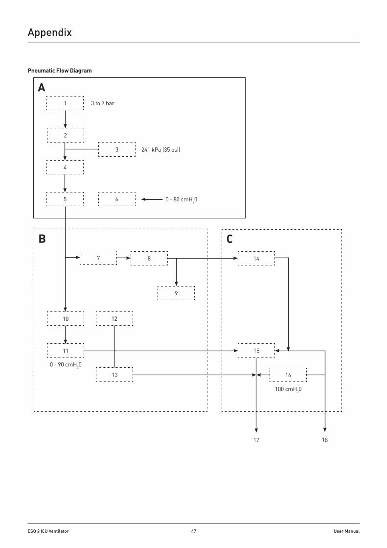
ESO 2 ICU Ventilator 47 User Manual
A1
2
3 to 7 bar
4
5
3
6
241 kPa (35 psi)
0 - 80 cmH20
B
10
11
7 8
9
C14
12
13
15
16
0 - 90 cmH20
100 cmH20
17 18
Pneumatic Flow Diagram
Appendix

ESO 2 ICU Ventilator 48 User Manual
Pneumatic SystemRefer to the pneumatic system diagram on the previous page.
A) Gas inlet manifold blockThe Ventilator is designed to operate on a drive gas supply (Air) of 280 to 600 kPa (41 to 87 psi).
1. Drive Gas Inlet Connector The gas source is connected to the DRIVE GAS SUPPLY fitting on the rear of the ventilator control unit. The gas supply should be capable of a flow rate of 60 L/min (average) and a peak flow rate of up to 200 L/min for a three second period, while maintaining a minimum pressure in excess of 310 kPa (45 psi).
2. Filter The drive gas is filtered with a 40-micron Input Gas Filter which protects the pneumatic components from incoming particulate matter.
3. The Low Supply Pressure Detector The pressure switch is set at a predetermined level to detect a loss or reduction of the input gas source pressure. When the pressure falls below 235 kPa (35 psi ± 1 psi), the LOW SUPPLY PRESSURE indicator will be displayed and the high priority audible alarm will activate.
4. Input Pressure Regulator Regulates the input drive gas to 260 kPa ± 21 kPa (38 psi ± 3 psi).
5. Cut-off Valve The valve isolates the gas supply :
a) When the ventilator is switched off
b) When a fault condition occurs.
6. Airway Pressure Sensor Connected to expiratory limb of breathing circuit.
B) Pneumatic Control Manifold Block7. Drive Gas Proportional Valve
8. Drive Gas Flow Sensor
9. Drive Gas Pressure Sensor
10. Low Pressure Regulator
11. Patient Proportional Valve
12. PEEP pressure sensor
13. Restrictor The restrictor allows a bleed flow of up to 2 L/min
C) Exhaust Manifold Block14. Check Valve
15. Diaphragm Valve
16. Pressure Relief valve - set to 100 cmH2O
17. Exhaust Port The discharged gas may contaminate the environment. Connect to an AGSS system if available.
18. Bellows drive gas outlet (to bellows assembly)
Appendix

ESO 2 ICU Ventilator 49 User Manual
Operational CapabilityTidal Volume, Rate, and I:E ratio settings are all limited by a maximum inspiratory flow of 75 L/min, and a minimum flow of 2 L/min.
The ventilator is capable of operating at the volumes and rates below each I:E ratio curve.
Example
1. Select required volume: VT = 1.0 L
2. Select rate = 20 bpm
In this example, the point of intersection X on the graph shows that an I:E ratio can be set from 1 : 0 .3 to 1 : 4, as these curves are all above the intersection point.
Similarly, a ratio of 1:5 cannot be set, as this is below the intersection point.
1:6 1:4
I:E Ratio
1:5 1:3 1:2 1:1 1:0.3
Rate (bpm)
0 10 20 30 40 50 60 70 80
Tidal volume (VT)
(litres)
0.10.2
1.0
0.6
1.4
0.4
1.2
0.8
1.6
0.3
1.1
0.7
1.5
0.5
1.3
0.9
X
Appendix

ESO 2 ICU Ventilator 50 User Manual
Appendix
APPENDIx 5 Patient Support Modes
WARNINGElectronic PEEP does not function in any Patient Support Mode.
Spontaneous Mode WARNING: Do not use Spontaneous modeNo mechanical ventilation or inspiratory pause function, or PEEP
SIMV: Synchronised Intermittent Mandatory Ventilation
NOTECheck that SIMV is an enabled option on your ventilator before attempting selection.
SIMV allows spontaneous breaths and a set mandatory breath, synchronised with the start of a patient breath
Select SIMV on the main displaySIMV will be displayed on the main screen.
NOTE1. The trigger window is pre-set to 60% of the BPM
cycle time.
2. The trigger is flow activated.
3. If Spirometry is disabled then SIMV is not available.
4. If the pressure limit and alarm are activated the inspiratory phase is terminated
SIMV Settings
NOTE:1. VT can be adjusted before SIMV is confirmed.
2. The trigger setting is adjustable between 0.7 and 4.0 L/min.
SIMV - No breathing effort by PatientA = Cycle time (set from BPM) B = Trigger window C = Flat pressure trace (no breathing effort) D = Mandatory breath at end of the trigger window at the set VT
If the patient makes no effort to breathe during a cycle, a mandatory breath, at the end of the trigger window, will still be delivered at the preset volume and rate.
A ABB
Pmax
PEEP0 cmH2O
EDC
SIMV - Spontaneously Breathing PatientA = Cycle time (set from BPM) B = Trigger Window C = Spontaneous breath D = Trigger point E = Mandatory breath at the set tidal volume (VT)Inspiratory flow in the Trigger Window (generated by the patient’s spontaneous breath) results in a synchronised mandatory breath at a preset volume and rate
A ABB
Pmax
PEEP0 cmH2O
DC

ESO 2 ICU Ventilator 51 User Manual
Appendix
SMMV Synchronised Mandatory Minute Ventilation
NOTECheck that SMMV is an enabled option on your ventilator before attempting selection.
SMMV provides a set level of minute volume ventilation.
SMMV allows spontaneous breaths, combined with a synchronised mandatory breath, to achieve the set minute volume
Select SMMV on the main displaySMMV will be displayed on the main screen.
NOTE1. The trigger window is pre-set to 60% of the BPM cycle
time.
2. The trigger is flow activated.
3. SMMV is not available if Spirometry is disabled.
4. If the pressure limit and alarm are activated the inspiratory phase is terminated.
SMMV Settings
NOTE:1. VM can be adjusted before SMMV is confirmed.
2. The trigger setting is adjustable between 0.7 and 4.0 L/min.
A ABB
Pmax
PEEP0 cmH2O
EDC
A ABB
Pmax
PEEP0 cmH2O
DC
SMMV - Spontaneously Breathing PatientA = Cycle time (set from BPM)
B = Trigger window
C = Spontaneous breath
D = Trigger point
E = Mandatory breath tidal volume. This is equal to VM/BPM, minus the volume spontaneously breathed during the cycle (this maintains the set VM)
Inspiratory flow in the trigger window (generated by the patient’s spontaneous breath) results in a synchronised mandatory breath, ensuring that the set minute volume is achieved
SMMV - No breathing effort by PatientA = Cycle time (set from BPM)
B = Trigger window
C = Flat pressure trace (no breathing effort)
D = Mandatory breath at the end of the trigger window (at the set VM)
If the patient makes no effort to breathe during a cycle, a mandatory breath, at the end of the trigger window, will still be delivered at the preset volume and rate

ESO 2 ICU Ventilator 52 User Manual
Appendix
PSV Pressure Supported Ventilation
NOTECheck that PSV is an enabled option on your ventilator before attempting selection.
PSV assists each spontaneous breath to achieve a preset pressure, thus reducing the effort required to breathe.
Inspiratory flow (generated by the patient’s spontaneous breath) results in synchronised pressure support
Select PSV on the main displayPSV will be displayed on the main screen.
NOTE1. The trigger window is pre-set to 60% of the BPM cycle
time.
2. The trigger pressure is PEEP referenced.
3. If the Spirometry system is disabled, then PSV is not available.
4. If the pressure limit and alarm are activated the inspiratory phase is terminated.
PSV Settings
NOTE:1. Support Pressure can be adjusted before PSV is
confirmed.
2. The trigger setting is adjustable between 0.7 and 4.0 L/min.
A A
Pmax
PEEP0 cmH2O
B
C C
PSV Pressure Supported VentilationA = Set inspiratory time
B = Pressure support level
C = Spontaneous breath results in a synchronised pressure supported breath
PSV is used to support spontaneously breathing patients ONLYIf the patient makes no attempt to breathe, the ventilator will not provide support and the apnoea alarm will be activated

ESO 2 ICU Ventilator 53 User Manual
Appendix
APPENDIx 6 SpecificationApplication Ventilation of adult and paediatric patients
Internal ComplianceAdult bellows Paediatric bellows
3 ml/cmH2O (nominal) 2 ml/cmH2O (nominal)
PhysicalSize (mm) - control unit only - with adult bellows
290 wide x 300 deep x 185 high 290 wide x 300 deep x 385 high
Screen Size (a) 210 mm (8.4 inches) TFT (b) 305 mm (12 inches) TFT
Weight - control unit only - with adult bellows
7.6 kg 9 kg
Bellows Adult Paediatric (Note - bellows are latex free)
20 - 1600 ml 20 - 350 ml
Electrical Power 110 - 120 VAC, 50 - 60 Hz, 1.2 A max 200 - 240 VAC, 50 - 60 Hz, 0.6 A max (automatic ranging)
Battery Back-up 12 V, 2 Ah, sealed lead-acid battery Fully charged battery provides one hour (nominal) backup
Fuse (mains supply) Type T 2AH, fused L and N 2 A, 250 V rating, 20 mm, anti surge, ceramic
Fuse (battery) 3 A fastblow, 32 V rating, 1000 A interrupt, mini-blade type 10.9 x 8.8 x 3.8mm
Drive Gas Oxygen or Air (dry, and oil free) at 280 to 600 kPa (41 to 87 psi)
AlarmsAlarm Mute 30 or 120 seconds (see 3.5)Apnoea Flow referenced (no breath detected within 15 seconds)High Continuous Airway Pressure PEEP + 10 cmH2O for 1 cycle, or PEEP + 5 cmH2O for 3 cycles
A PEEP value of 4 cmH2O is used for PEEP values ≤4 cmH2O Standby Mode: the alarm triggers after 15 seconds
Low Pressure (Pressure Control) Bellows drive gas pressure sensor fails to detect at least 75% of set target levelIncorrect Rate or Ratio Ventilator parameter settings unachievableMains Failure Fully charged battery provides one hour (nominal) backupLow Battery If the ventilator is running on battery power, less than 20 minutes battery life
remains (see also, section 3.5)Ventilator Inoperative Internal failureOutlet Blocked Exhaust valve outlet blockedAlarms - User AdjustableLow Tidal Volume Measured value is below 50% of volume set. Range: 10 - 1600 mlHigh Tidal Volume Measured value exceeds 150% of volume set. Range: 20 - 2400 mlLow Minute Volume Calculated value is 50% below volume set. Range: 0 - 50 LHigh Minute Volume Calculated value exceeds 150% of volume set. Range: 1 - 75 LLow and High O2 Concentration 18% - 105%High Airway Pressure 10 - 80 cmH2O adjustable

ESO 2 ICU Ventilator 54 User Manual
Appendix
FunctionalTidal Volume Range Adult bellows Paediatric bellows
20 to 1600 ml 20 to 350 ml
Minute Volume 2 to 50 LRate 4 - 100 bpmI:E Ratio 1 : 0.2 to 1: 8.0 (normal operation)
1 : 2.0 to 1 : 8.0 (effective in support modes)Pressure limit (volume control mode) 10 - 80 cmH2OFresh Gas Compensation Automatic tidal volume adjustmentInspiratory Flow 2 - 70 L/minInspiratory Time 0.3 – 10 seconds (normal)
0.3 – 5 seconds (effective in support modes)Expiratory Time 0.3 – 10 seconds
(effective dependent on Inspiratory time)Modes Off
Standby Volume Cycle Pressure Controlled Advanced breathing modes
Volume CycleSigh Sigh can be set from 1:n, where n has a range of 10 to 100Inspiratory Pause Inspiratory pause can be varied in the menu from 0 - 60%.Pressure range 5 - 70 cmH2O (pressure control mode)Electronic PEEP 4 - 20 cmH2O (or optional 4 - 30 cmH2O).Spontaneous Mode Do not useSpirometry Resolution ±10 mlVentilator Accuracy (at ambient temperature of 20°C (±10%) and ambient atmosphere of 101.3 kPa (±10%)):
Delivered volumes ±10% (>300 ml) ±20% (100 to 300 ml) ±50%, or ± 10 ml, whichever is greater (<100 ml)
NOTE The ventilator is designed for use with Spirometry ON. Accuracy with Spirometry OFF may vary from the figures given above High airway pressure limit ±5 cmH2O
Rate (bpm) ±10%
Sigh Tidal volume + (50±5%)

ESO 2 ICU Ventilator 55 User Manual
Advanced Spontaneous Breathing Modes (SIMV, SMMV, PSV)Trigger (PEEP referenced) 0.7 to 4 L/minTrigger window (SIMV, SMMV) Set 60% of Expiratory TimeVT and VM (SIMV, SMMV) As Volume ModeInspiratory time (Ti) 0.3 to 5 secondsSupport pressure (PSV only) 4 to 70 cmH2O
Default settings
Volume
Adult Paediatric
VT
600 ml 150 ml
BPM
10 15
I:E
1:2 1:2
Pmax
38 cmH2O 38 cmH2O
Pressure
Adult Paediatric
VT
600 ml 150 ml
BPM
10 15
I:E
1:2 1:2
P-target
10 cmH2O 10 cmH2O
SIMV
Adult Paediatric
VT
600 ml 150 ml
BPM
6 15
Insp time
2 sec 1.3 sec
Trigger
1 L/min 1 L/min
SMMV
Adult Paediatric
VM
3.6 L 2.2 L
BPM
6 15
Insp time
2 sec 1.3 sec
Trigger
1 L/min 1 L/min
PSV
Adult Paediatric
Support Pressure
10 cmH2O 10 cmH2O
Insp time
2 sec 1.3 sec
Trigger
1 L/min 1 L/min
Disinfection and Sterilisation The patient block assembly can be sterilised if necessary - see section 6.2.7 NOTE: The bellows assembly, oxygen monitor sensor, and spirometer sensors are built into the breathing module..
Bacterial Filter None (always use a bacterial filter in the breathing system to protect the oxygen sensor - see Appendix 4.
Fail Safe Mechanism Battery back-up in case of mains electricity failure Gas shut-off in the event of electronic failure
Reliability Not applicable
Waveform Tests Not applicable
Volume Tests Not applicable
Mobility and Mounting (a) Mobility (b) Mounting
Secure mounting required Control unit and remote screen are mounted on the frame. The bellows assembly is built into the breathing module.
Breathing module inspiratory and expiratory non-return valvesPressure drop across the inspiratory and expiratory non-return valves at an air flow of 60 L/min: 0.1 kPa (1 cmH2O).
Appendix
0.02 0.04 0.06 0.08 0.10
60
50
40
30
20
10
Flow(L/min)
Pressure (kPa)

ESO 2 ICU Ventilator 56 User Manual
EnvironmentalOperating:Temperature 15 to 30°C (59 to 86°F) Humidity 10 – 95% RH (relative humidity), non-condensing Altitude Up to 2775 m (9000 feet) Air pressure 70 – 106 kPa
Storage and Transport:Temperature -5 to 40°C (23 to 104°F) Note: For battery care during storage, refer to Appendix 1. Humidity 30 – 75% RH (relative humidity), non-condensing Air Pressure 11.5 – 110 kPa
Electro-magnetic compatibility:The ventilator meets the requirements of BS EN 60601-1-2. Medical electrical equipment. General requirements for safety. Collateral standard. Electromagnetic compatibility. Requirements and tests.
MRI compatibility: The ESO 2 is not suitable for use in an MRI environment.
Device Classification and LabellingPower supply Class 1 power supply with internal battery backup
Ingress Protection: Classification according to the degree of protection against ingress of water: IPX0 (not protected)
Mode of operation: Continuous
Patient Class All patient types No residual risks from phthalates that are carcinogenic, mutagenic, or toxic to reproduction.
Labelling Refer to Appendix 8
Appendix

ESO 2 ICU Ventilator 57 User Manual
Oxygen MonitorMeasurement Range: 0 - 100% Resolution: ± 1%
Accuracy and Linearity: ± 2% of full scale (at constant temperature and pressure) Response Time: 90% of final value in approximately 15 seconds (air to 100% O2)
Operating Temperature: -20 to 50°C (-4 to 112°F) Storage Temperature: -5 to 40°C (23 to 104°F) Relative Humidity Range: 0 to 99% (non-condensing)
Battery Back-up: As per ventilator, see section 3.2.2.
High Priority Alarm: Flashing, 2 x 5 audio pulses with 6 seconds repeat time. Medium Priority Alarm: Flashing, 3 audio pulses with 24 seconds repeat time Low Priority Alarm: Static with single beep sound Alarm Mute: 30 seconds for high priority alarm 120 seconds for medium priority alarm
Low Alarm Set Range: 18% - 99% (± 1%) High Alarm Set Range: 19% - 105% (± 1%) Cable length: 2 m (6 ft), fully extended
SensorType: Galvanic fuel cell sensor (0 - 100%) Life: 1500000 O2% hours at 20°C (68°F) 800000 O2% hours at 40°C (104°F)
Interference Gases and Vapours
Interference Test Gas Mixture Interference in O2%
Nitrous Oxide 80% N2O + 20% O2 1 to 1.5%
Carbon Dioxide 5% CO2 + 66.5% N2O + 28.5% O2 <1%
Helium 50% He + 50% O2 <1%
Humidity EffectsSensor output is relatively unaffected by prolonged operation in either high or very low relative humidity. If the sensor shows signs of being affected by condensation, dry the sensor with soft tissue.
CAUTION DO NOT use heat to dry the sensor.
Temperature EffectsThe sensor has a built-in temperature compensation circuit, and is relatively unaffected by temperature changes within the operating temperature range given above.
Pressure EffectsThe sensor measures O2 partial pressure, and its output will rise and fall due to pressure change (e.g. changes in barometric pressure, or breathing system pressure). An increase in pressure of 10% at the sensor inlet will produce a 10% increase in sensor output.
NOTE Altitude compensation is automatically applied during calibration.
Appendix

ESO 2 ICU Ventilator 58 User Manual
O2 Monitor & SpirometryESCAPE FROM MENU
O2 MONITOR: on off/on (Toggle option)
CALIBRATION: 100% 21 / 100% (Toggle option)
HIGH ALARM SET: 105 19 - 105 (Integer)
LOW ALARM SET: 18 18 - 99 (Integer)
SPIROMETER: ON off/on (Toggle option)
SPIRO CALIBRATION: 0 L/min 0 L/min / 10 L/min (Toggle option)
Leak TestESCAPE FROM MENU <START/STOP LEAK TEST> LEAK LEVEL: 0 mL/min BSYS COMP 7.0 mL/cmH2O
Fresh Gas Compensation
ON / OFF off/on (toggle Option)
Support Mode - see next page
Gas mixture: O2+Air
O2+AIR
O2+N2O
Service Menu - see next page
WaveformESCAPE FROM MENU
SECOND WAVEFORM off Second waveform pick listoffvol. vs. timevol. vs. pressure
Alarm settingsALARM MENU
ESCAPE FROM MENU
ALARM MODE: default default / user (Toggle option)
HIGH TIDAL VOLUME: off off / on (Toggle option)
VM MIN: 3 L 0 - 50 (Integer)
VM MAX: 9 L 1 - 25 (Integer)
VT MIN: 300 mL 10 - 1600 (Integer)
VT MAX: 900 mL 20 - 2400 (Integer)
APNOEA ALARM LIMIT: 15 secs 15 - 180 (Integer)
ALARM VOLUME: 100% 50 - 100% (Integer)
BACK LIGHT LEVEL : 0 - 100% (Integer)
Main MenuEXIT MENUS
O2 MONITOR & SPIROMETRY
LEAK TEST
FRESH GAS COMPENSATION: ON
MODES
WAVEFORM
ALARM SETTINGS
GAS MIXTURE: O2+AIR
SERVICE MENU
Appendix
APPENDIx 7 On-screen Menus
NOTE:1. Use the menu button to gain access to the main menu.
2. Menu options are context sensitive. All available menus can be accessed through the main menu system when the ventilator is in Standby mode. Limited access is provided in other modes.
3. Use the touchscreen to access sub-menus: Alarm settings: Touch the alarm display area
Modes menu: Touch the mode icon area Gas mixture: Touch the gas mix display Waveform menu: Touch the waveform display area
4. Selection and modification of menu options is through the navigator wheel (see section 3.2).
5. Selection or modification is followed by a ‘CONFIRM’ message prompt on the screen.

ESO 2 ICU Ventilator 59 User Manual
Modes MenuESCAPE FROM MENU SUPPORT MODE: SIMV, SMMV, PSV VOLUME TYPE: Tidal SIGH ENABLE: SIGH TO BREATH RATIO: INSP. PAUSE% : 0% APPLY: SITE DEFAULT
In VOLUME mode, and SIMV/ SMMV, the MODES menu (accessed by touching the mode icon area on the screen) is: ESCAPE FROM MENU VOLUME TYPE: Tidal SIGH ENABLE: SIGH TO BREATH RATIO: (2) INSP. PAUSE% : 0% (3)
In PRESSURE mode and PSV modes the MODES menu (accessed by touching the mode icon area on the screen) is: ESCAPE FROM MENU SIGH ENABLE: SIGH TO BREATH RATIO: (2) INSP. PAUSE% : 0% (3)
Notes 1) Support mode depends on configuration options. The SUPPORT MODE option will be missing from the MODE menu if: a) Options are not enabled b) ‘SPIROMETRY: off’ is displayed. The support mode sub menu can include: none / PSV / PSV, SIMV, SMMV 2) The options here are: SIGH ENABLE: on - off SIGH TO BREATH RATIO: 1:10 to 1:100 (1:10 indicates 1 breath with sigh, then 10 breaths without sigh) 3) The options here are: 0 - 60% 4) SPONT mode: Dp not use.
Appendix
Service Menu ESCAPE FROM MENU LANGUAGE: ENGLISH PATIENT LOG MENU *SITE DEFAULTS SERIAL MODE: none ABSORBER SWITCH: ON UPGRADE MENU AMBIENT PRESSURE: 988 mbar DISPLAY HISTORY **SERVICE PIN: 0 **ENGINEER MENU
NOTES*The values listed for site defaults are examples **Sub-menus for Service PIN and Engineer Menu are not accessible by users.
Upgrade Menu ESCAPE FROM MENU I/O FIRMWARE: vx.xx [Build xx] MAIN FIRMWARE: vx.xx [Build xx] REGISTRATION KEY: unknown UPGRADE FIRMWARE: unavailable ADD NEW FEATURE: unavailable DEVICE TYPE: AVS SERIAL NUMBER: xx xx xx LOCK STATE: on
Display History ESCAPE FROM MENU MANUFACTURER DATE : 03/03/05 TOTAL HOURS RUN: 100 LAST SERVICE DATE: 13/08/04 HOURS SINCE SERVICE: 100 DRIVE VALVE CYCLES: 1253 PATIENT VALVE CYCLES: 822 CUTOFF VALVE CYCLES: 72
Patient Log Menu ESCAPE FROM MENU PRINT PATIENT DATA LOGGING: off LOG STATUS: disabled CLEAR LOG DATA LOGGING WINDOW: 10 min
Site Defaults ESCAPE FROM MENU SAVE TO SITE VIEW: SITE DEFAULTS VOLUME TYPE : tidal VT SET: 550 ml VM SET: 5.5 Litres T+PS INIT: 10 cmH2O SET BPM : 10 I : E : 1:1.0 PEEP : OFF LIMIT : 38 cmH2O TRIGGER : 10 L/min APNOEA ALARM LIMIT : 15 sec
The MODES menu is context sensitive, with content dependent on current mode.
In STANDBY the MODES menu is: ESCAPE FROM MENU SUPPORT MODE: SIMV, SMMV, PSV (1) VOLUME TYPE: Tidal SIGH ENABLE: SIGH TO BREATH RATIO: (2) INSP. PAUSE% : 0% (3) APPLY: SITE DEFAULT

ESO 2 ICU Ventilator 60 User Manual
Appendix
APPENDIx 8. Symbols
Operating instructions (this user manual)
Refer to user manual
Caution (plain background)
Power status
Mass
Manufacturer
Possible EMC interference in the vicinity of equipment marked with this symbol:
Do not dispose of in landfill, refer to an approved recycling facility. Follow your hospital, local, state and federal regulations.
Alarm mute
Fuse
Menu
Rotation (controls output)
Wear a face mask
Wear a face shield
Wear eye protection
Wear protective gloves
Serial number
Max stacking weight
Keep packaging dry
Stacking limit by number of boxes
Storage temperature range
Storage humidity range
Storage pressure range
Fragile
This way up
General warning (yellow background)
Gas supply inlet
Do not sit
Do not stand on
Do not push against the machine
Auxiliary gas outlet

ESO 2 ICU Ventilator 61 User Manual
Appendix
APPENDIx 10. Electromagnetic compatibility (EMC)Electromagnetic environmentThe ESO 2 ventilator is suitable for use in the specified electromagnetic environment. The user of the ESO 2 ventilator should assure that it is used in an electromagnetic environment as described below. Changes or modifications to this ventilator, not expressly approved by Penlon Limited, could result in EMC issues with this ventilator. Contact Penlon Limited for more information. The use of phones or RF emitting equipment near this ventilator may cause interference. Always monitor ventilator operation before and during use on a patient. The essential performance of the ESO 2 ventilator is to provide mechanical ventilation of adult and paediatric patients.a.
WARNINGThe ESO 2 ventilator should not be used adjacent to or stacked with other manufacturer’s equipment. If adjacent or stacked use is necessary, the ventilator should be observed to verify normal operation in the configuration in which it will be used.
Cables, Transducers, and Accessories WARNINGThe ESO 2 ventilator is EMC-compliant with all cables, transducers and accessories supplied by Penlon Limited. The use of cables, transducers and accessories other than those specified may result in increased emissions or decreased immunity of the ventilator. The use of cables, transducers and accessories supplied by Penlon Limited on non-Penlon equipment may also result in increased emissions or decreased immunity of that equipment.
Cables supplied by Penlon Limited Category Function Length (m)
Oxygen sensor cable Connects the oxygen sensor on the breathing module to the ventilator
2 .7
Remote screen display cable Connects the ventilator control unit to the remote display
1 .5
Guidance and manufacturer’s declaration – electromagnetic emissions The ESO 2 ventilator is intended for use in the electromagnetic environment specified below. The customer or user should assure that it is used in such an environment.
Required test Compliance CommentsRF emissions
CISPR 11
Group 1Class A
Class A equipment is suitable for use in all locations other than those allocated in residential environments and those directly connected to a low voltage power supply network which supplies buildings used for domestic purposes, and may be used in domestic establishments and those directly connected to the public low-voltage power supply network that supplies buildings used for domestic purposes provided the following warning is heeded
NOTE: The EMISSIONS characteristics of this equipment make it suitable for use in industrial areas and hospitals (CISPR 11 class A). If it is used in a residential environment (for which CISPR 11 class B is normally required) this equipment might not offer adequate protection to radio-frequency communication services. The user might need to take mitigation measures, such as relocating or re-orienting the equipment.
Harmonic emissions
IEC 61000-3-2
Complies
Voltage fluctuations/flicker emissionsIEC 61000-3-3
Complies
APPENDIx 9 ReferencesStandardsThe ESO 2 ventilator has been designed in accordance with the following Standards. EN ISO 80601-2-13: Medical electrical equipment. Particular requirements for basic safety and essential performance of an anaesthetic workstation. EN 60601-1: Medical electrical equipment - Part 1: General requirements for basic safety and essential performance Trademarks Penlon and InterMed are trademarks of Penlon Limited. All other trademarks are the property of their respective owners.
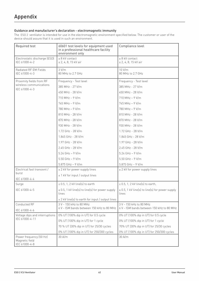
ESO 2 ICU Ventilator 62 User Manual
Appendix
Guidance and manufacturer’s declaration - electromagnetic immunityThe ESO 2 ventilator is intended for use in the electromagnetic environment specified below. The customer or user of the device should assure that it is used in such an environment.
Required test 60601 test levels for equipment used in a professional healthcare facility environment only
Compliance level
Electrostatic discharge (ESD)IEC 61000-4-2
± 8 kV contact± 2, 4, 8, 15 kV air
± 8 kV contact± 2, 4, 8, 15 kV air
Radiated RF EM FieldsIEC 61000-4-3
3 V/m80 MHz to 2 .7 GHz
10 V/m80 MHz to 2 .7 GHz
Proximity fields from RF wireless communicationsIEC 61000-4-3
Frequency - Test level
385 MHz - 27 V/m
450 MHz - 28 V/m
710 MHz – 9 V/m
745 MHz – 9 V/m
780 MHz – 9 V/m
810 MHz - 28 V/m
870 MHz - 28 V/m
930 MHz - 28 V/m
1.72 GHz - 28 V/m
1.845 GHz - 28 V/m
1.97 GHz - 28 V/m
2.45 GHz - 28 V/m
5.24 GHz – 9 V/m
5.50 GHz – 9 V/m
5.875 GHz – 9 V/m
Frequency - Test level
385 MHz - 27 V/m
450 MHz - 28 V/m
710 MHz – 9 V/m
745 MHz – 9 V/m
780 MHz – 9 V/m
810 MHz - 28 V/m
870 MHz - 28 V/m
930 MHz - 28 V/m
1.72 GHz - 28 V/m
1.845 GHz - 28 V/m
1.97 GHz - 28 V/m
2.45 GHz - 28 V/m
5.24 GHz – 9 V/m
5.50 GHz – 9 V/m
5.875 GHz – 9 V/mElectrical fast transient / burst
IEC 61000-4-4
± 2 kV for power supply lines
± 1 kV for input / output lines
± 2 kV for power supply lines
Surge
IEC 61000-4-5
± 0.5, 1, 2 kV line(s) to earth
± 0.5, 1 kV line(s) to line(s) for power supply lines
± 2 kV line(s) to earth for input / output lines
± 0.5, 1, 2 kV line(s) to earth,
± 0.5, 1 kV line(s) to line(s) for power supply lines
Conducted RF
IEC 61000-4-6
3 V - 150 kHz to 80 MHz6 V - ISM bands between 150 kHz to 80 MHz
3 V - 150 kHz to 80 MHz6 V - ISM bands between 150 kHz to 80 MHz
Voltage dips and interruptionsIEC 61000-4-11
0% UT (100% dip in UT) for 0.5 cycle
0% UT (100% dip in UT) for 1 cycle
70 % UT (30% dip in UT) for 25/30 cycles
0% UT (100% dip in UT) for 250/300 cycles
0% UT (100% dip in UT) for 0.5 cycle
0% UT (100% dip in UT) for 1 cycle
70% UT (30% dip in UT) for 25/30 cycles
0% UT (100% dip in UT) for 250/300 cyclesPower frequency (50 Hz)Magnetic fieldIEC 61000-4-8
30 A/m 30 A/m

ESO 2 ICU Ventilator 63 User Manual

ESO 2 ICU Ventilator 64 User Manual


Part of the InterMed Group © Penlon Ltd. 2020 All rights reserved. Penlon and InterMed are trademarks of Penlon Limited. All other trademarks are the property of their respective owners.
International Salest +44 (0) 1235 547001e [email protected]
UK Salest +44 (0) 1235 547036e [email protected]
Technical Supportt +44 (0) 1235 547060f +44 (0) 1235 547061 e [email protected]
Penlon LimitedAbingdon Science Park Barton Lane, Abingdon OX14 3NB, UK
5009456 ESO2-en C REF
Like us at facebook .com/PenlonGlobal Follow us at twitter .com/PenlonGlobal