Technical manual - Porsche Carrera Cup Australia
321
Technical manual 911 GT3 Cup (991) MY 2015
-
Upload
khangminh22 -
Category
Documents
-
view
0 -
download
0
Transcript of Technical manual - Porsche Carrera Cup Australia
Technical manual 911 GT3 Cup (991) MY 2015

Preface Preface
This document should give you the opportunity to look up data, settings, und
operating regulations, and to facilitate maintenance or repair of the vehicle.
We wish you many sporting successes with your 911 GT3 Cup (991).
Customer Sport
Dr. Ing. h.c. F. Porsche
Inc.
Motorsport Sales
Version: 29.01.2015 911 GT3 Cup (991) MY 2015 1

Preface
Competition Vehicle 911 GT3 Cup (991) Model 2015
The design of this vehicle is specially configured for use in one-make cup
competitions.
For understandable reasons, it cannot therefore be assumed that the standards set
by our production vehicles are relevant for the car body design.
Porsche assumes no responsibility for compliance with regulations.
The vehicle is not approved for use on public roads and does not comply with the
German Road Traffic Licensing Regulations.
Pictures, descriptions, and schematic drawings are used solely for illustrating the
text. We assume no responsibility for the completeness and conformity of the
contents with the prevailing sporting codes.
Due to the constant improvement of our products and the related documentation at
the time of your purchase, a new version of this technical manual could be available.
The latest Version is always accessible at the "Porsche Motorsport race car service
information" database (PMRSI), and can be downloaded on the following homepage.
https://motorsport.porsche.com
Version: 29.01.2015
911 GT3 Cup (991) MY 2015
2

Preface
Contact
International One-make Cup Series
Mr. Michael Dreiser Tel. +49 (0) 711 911 82684
Assistent Ms. Nicole Nagel Tel. + 49 (0) 711 911 84900
Fax. + 49 (0) 711 911 88920
Technical Support Mr. Christoph Werner Tel. + 49 (0) 711 911 82690 Hr. Stefan Rometsch Tel. +49 (0)711 911 89946 Fax. + 49 (0) 711 911 89535 Porsche Mobil 1 Supercup
Mr. Jonas Krauss Tel. + 49 (0) 711 911 84042
Assistent Fr. Olivia Wegner Tel. + 49 (0) 711 911 84096
Fax. + 49 (0) 711 911 82920 Technical Support Hr. Maximilian Müller Tel. +49 (0)711 911 86183
Fax. + 49 (0) 711 911 89535 Porsche Carrera Cup Germany
Ms. Andrea Hagenbach Tel. + 49 (0) 711 911 84041
Assistent Mr. Marco Vierkötter Tel. + 49 (0) 711 911 84074
Fax. + 49 (0) 711 911 82920 Technical Support Hr. Maximilian Müller Tel. +49 (0)711 911 86183
Fax. + 49 (0) 711 911 89535
Sports Divisions Sales Mr. Karlheinz Kienle Tel. + 49 (0) 711 911 82923
Mr. Klaus Lenzner Tel. + 49 (0) 711 911 82423
Mr. Christian Müller Tel. + 49 (0) 711 911 89175
Mr. Salvatore Scozzaro Tel. + 49 (0) 711 911 83738
Fax. + 49 (0) 711 911 82808
Version: 29.01.2015 911 GT3 Cup (991) MY 2015 3

Preface
Contents
Preface 1
1 Engine 13
1.1 General 13
1.2 Specifications 14
1.3 Engine lubrication 15 1.3.1 Engine oil circuit 16 1.3.2 Oil level measurement 17 1.3.3 Refilling engine oil 17 1.3.4 Engine oil 17
1.4 Engine cooling system 18 1.4.1 Schematic diagram 18 1.4.2 Thermostat 18 1.4.3 Coolant 19 1.4.4 Filling the cooling system 19 1.4.5 Races at low temperatures 19
1.5 Intake system 20 1.5.1 Resonance flaps 20 1.5.2 Throttle 21
1.6 Work on the engine 22 1.6.1 Cylinder head installation 22 1.6.2 Flywheel tightening instructions 23 1.6.3 Setting the valve timing 23 1.6.4 Removing and installing the crankshaft seal – pulley side 24 1.6.5 Removing and installing the crankshaft seal – flywheel side 29
1.7 Engine tightening torque overview 36
1.8 Exhaust system 38
1.9 Fixation pre-silencer 39
Version: 29.01.2015
911 GT3 Cup (991) MY 2015
4

Preface
1.10 Engine run time 40 1.10.1 Behavior when exceeding the maximum speed 40
2 Powertrain 41
2.1 General 41
2.2 Clutch 42 2.2.1 Installation instructions 42 2.2.2 Clutch wear 43 2.2.3 Fluid for clutch actuation 43 2.2.4 Central release mechanism 44
2.3 Sequential six-speed gearbox 45 2.3.1 Overview 45 2.3.2 Technical specifications 46 2.3.3 Gear set 47 2.3.4 Drive 50 2.3.5 Oil circuit 52
2.4 Gear shift mechanism 53 2.4.1 Gear shifting 54 2.4.2 Gear recognition 56 2.4.3 „Emergency gearbox“ switch 56 2.4.4 Maintenance 57
2.5 Drive shafts 58 2.5.1 Tightening instructions 58
2.6 Gearbox run time 59
2.7 Gearbox tightening torques 59
Version: 29.01.2015 911 GT3 Cup (991) MY 2015 5

Preface
2.8 Transmission dismantling 61 2.8.1 Dismantling of hang-on parts 61 2.8.2 Gear housing dismantling 62 2.8.3 Gear set removal 63 2.8.4 Dismantling the shift drum 64 2.8.5 Dismantling the locking sleeve 64 2.8.6 Oil supply 65 2.8.7 Cross shaft dismantling 66 2.8.8 Pinion shaft dismantling 69 2.8.9 Differential removal 70 2.8.10 Central clutch operator removal 71 2.8.11 Connecting shaft dismantling 71 2.8.12 Drive shaft dismantling 72 2.8.13 Bearing dismantling 73
2.9 Transmission assembly 75 2.9.1 Gearbox housing pre-assembly 75 2.9.2 Gear housing pre-assembly 86 2.9.3 Differential lid pre-assembly 92 2.9.4 Pinion shaft bearing assembly 93 2.9.5 Pinion shaft 94 2.9.6 Pinion shaft position adjustment 96 2.9.7 Assembly of gear sets 98 2.9.8 Vormontage Schaltwalze 104 2.9.9 Oil pump assembly 105 2.9.10 Reverse idler gear 106 2.9.11 Locking sleeve 107 2.9.12 Shift rod and shift forks 108 2.9.13 Suction tube assembly 109 2.9.14 Central clutch operator assembly 111 2.9.15 Cutted gear housing assembly 111 2.9.16 Determining cross shaft bearing adjusting disk Q1 113 2.9.17 Cross shaft setup 114 2.9.18 Cross shaft assembly 115 2.9.19 Differential setup 119 2.9.20 Gear housing assembly 126
2.10 Overview gearbox settings 130
Version: 29.01.2015
911 GT3 Cup (991) MY 2015
6

Preface
3 Chassis 131
3.1 General 131 3.1.1 Wheel bearing 132 3.1.2 Wheel hub 133 3.1.3 Wheel nut 134 3.1.4 Locking piece 135
3.2 Front axle 136 3.2.1 Front axle cross member 137 3.2.2 Front axle transverse control arm 138 3.2.3 Longitudinal control arm 139 3.2.4 Front axle wheel mount 140 3.2.5 Front axle shock absorber 141 3.2.6 Front axle anti-roll bar 142
3.3 Rear axle 144 3.3.1 Rear axle control arm and tie rod 145 3.3.2 Fixation trailing arm bracket 146 3.3.3 Rear axle transverse control arm 147 3.3.4 Rear axle wheel mount 148 3.3.5 Rear axle shock absorber 149 3.3.6 Rear axle anti-roll bar 150 3.3.7 Rear axle side part 152
3.4 Wheel alignment 152 3.4.1 Preparatory measures 153 3.4.2 Vehicle ride height measuring points 154
3.5 Steering system 155 3.5.1 Bleeding the steering system 157
3.6 Rims and tire 158 3.6.1 Rim 158 3.6.2 Tires 158
3.7 Brake system 159 3.7.1 General 159 3.7.2 Front axle brake 161 3.7.3 Rear axle brake 162 3.7.4 Master cylinders 163 3.7.5 Changing the brake fluid 164
Version: 29.01.2015 911 GT3 Cup (991) MY 2015 7

Preface
3.8 Brake pressure distribution 165 3.8.1 Balance beam basic setting 166 3.8.2 Calculating the brake power 168
3.9 Balance bar replacement kit 169 3.9.1 Replacing the trunnion 169 3.9.2 Replacing the balance bar 169
3.10 Performance setup 170
4 Bodywork 171
4.1 General 171
4.2 Front and side view 172
4.3 Rear view 174
4.4 Body shell 175 4.4.1 General 175 4.4.2 Weight distribution 177 4.4.3 Weight percentage of the Body -in-White 177 4.4.4 Body aluminum parts 178 4.4.5 Body features 179 4.4.6 Body steel parts 180 4.4.7 Materials overview 181 4.4.8 Roll cage 182 4.4.9 Recovery device 183
4.5 Aerodynamics 184 4.5.1 General 184 4.5.2 Rear wing 184 4.5.3 Additional aerodynamic improvements 184
4.6 Exterior mirrors 185
4.7 Roof 185
4.8 Air jack system 186
4.9 Doors 188
Version: 29.01.2015
911 GT3 Cup (991) MY 2015
8

Preface
4.10 Trunk and engine lid 188 4.10.1 Trunk lid 188 4.10.2 Engine lid 188
4.11 Windows 189 4.11.1 Installing and removing the windshield 189 4.11.2 Preparing the window cutout for installation 193 4.11.3 Preparing the windshield for installation 194 4.11.4 Installing the windshield 195
4.12 Fenders 197
4.13 Wheel cover 197
4.14 Fuel system 198 4.14.1 Fuel 199 4.14.2 Defueling 199 4.14.3 Tank installation 200
4.15 Repairing the body 200 4.15.1 Repairing the front section 201 4.15.2 Replacing the front strut mount 215 4.15.3 Repairing the rear end 223
4.16 Thread repair kit 227 4.16.1 Thread repair of chassis bolt connections 229
4.17 Installing roof assembly 245
5 Interior 247
5.1 General 247
5.2 Drivers safety 248 5.2.1 Seat 248 5.2.2 Seat rail tightening torques 249 5.2.3 Bucket seat tightening torques 250 5.2.4 Padding system 251
5.3 Steering wheel 252
5.4 Cockpit ventilation 253
Version: 29.01.2015 911 GT3 Cup (991) MY 2015 9

Preface
6 Electrical system 255
6.1 General 255
6.2 Power supply 255 6.2.1 Battery 255 6.2.2 Generator 255 6.2.3 Battery master switch 256
6.3 Electrical system protection 257 6.3.1 Electrical system control unit IPS32 257 6.3.2 Fuse holder hydraulic pump 258
6.4 DME engine electronics 258 6.4.1 DME control unit 259 6.4.2 DME diagnosis 260 6.4.3 Carburation 260 6.4.4 Ignition system 260
6.5 Sensors 261 6.5.1 Sensor rated values 262 6.5.2 Optional sensors 263
6.6 ICD Display 264 6.6.1 General 264 6.6.2 Race page 266 6.6.3 Practice page 269 6.6.4 Warmup page 271 6.6.5 Vitals page 272 6.6.6 Pedals page 275 6.6.7 Additional information 277
6.7 Lights 283
6.8 Data bus system 284
6.9 Wiring harness 285
6.10 Ground connection roof antenna 285
6.11 Fire extinguisher 286 6.11.1 Testing the trigger switch 287 6.11.2 Battery change 287
Version: 29.01.2015
911 GT3 Cup (991) MY 2015
10

Preface
6.12 Driver Control Systems 288 6.12.1 Steering wheel 288 6.12.2 Center console 289 6.12.3 Windscreen wiper 290 6.12.4 Interior fan switch 290
7 Maintenance 291
7.1 Engine 291 7.1.1 Oil level measurement using the dipstick 291 7.1.2 Oil level measurement with display 292 7.1.3 Changing the engine oil 292 7.1.4 Refilling engine oil 293 7.1.5 Oil specification 293 7.1.6 Engine cooling system 294 7.1.7 Setting the valve timing 296 7.1.8 Engine tightening torques 297 7.1.9 Engine runtime 297
7.2 Fuel system 298 7.2.1 Fuel 298 7.2.2 Fuel pump 298 7.2.3 Fuel extraction 298
7.3 Power transmission 300 7.3.1 Gearbox 300 7.3.2 Clutch 301 7.3.3 Paddle shift 303 7.3.4 Drive shafts 304
7.4 Chassis 305 7.4.1 Wheel nut 305 7.4.2 Locking piece 306 7.4.3 Wheel bearings 307 7.4.4 Wheel hub 307 7.4.5 Wheel rim 307 7.4.6 Brake system 308 7.4.7 Replacing the piston seal rings 308 7.4.8 Shock absorber/spring 310 7.4.9 Anti-roll bar 310 7.4.10 Steering system 311
7.5 Body 313 7.5.1 Airjack system 313
Version: 29.01.2015 911 GT3 Cup (991) MY 2015 11

Preface
7.6 Electrical system 314 7.6.1 Checks after wet races 314
7.7 Maintenance intervals 315 7.7.1 After 200 km (124 mi) or first test drive 315 7.7.2 After each session 315 7.7.3 After each weekend (sprint race) 316 7.7.4 After 3 – 4 race weekends (sprint races) 316 7.7.5 After 30 hours run time 316 7.7.6 After 50 hours run time 316
7.8 Special tools 911 GT3 Cup (991) 317
7.9 Partner contacts 319
Version: 29.01.2015
911 GT3 Cup (991) MY 2015
12

Engine
911 GT3 Cup (991) MY 2015
1 Engine
1.1 General
The engine of the new 911 GT3 Cup (991) is based on the proven drive unit of the
street-legal 911 GT3 RS and has been redesigned especially for use in motor sports.
New features include the electronic accelerator and the accompanying throttle.
Furthermore, the Bosch Motronic MS4.6 controller has been used as engine control.
The engine has a dry sump lubrication system including an engine-mounted oil tank.
An oil-water heat exchanger integrated in the cooling circuit is used for oil cooling.
1.1.1
Version: 29.01.2015 13

Engine
911 GT3 Cup (991) MY 2015
1.2 Specifications
Full load curves (key: red=torque, blue=power)
1.2.1
Engine specifications
Number of cylinders 6
Type six-cylinder boxer engine
Valves/cylinders 4
Displacement 3,797 cm3
Hole 102.7 mm
Stroke 76.4 mm
Compression approx. 12 : 1
Maximum speed 8,500 rpm
Intake valve diameter 41 mm
Intake valve stroke 12.0 mm
Intake valve lobe center line 110° after TDC
Exhaust valve diameter 35.5 mm
Exhaust valve stroke 12.0 mm
Exhaust valve lobe center line 110° before TDC
Cooling water-cooled
Lubrication dry sump lubrication
Oil/water-heat exchanger
Version: 29.01.2015
14

Engine
911 GT3 Cup (991) MY 2015
1.3 Engine lubrication
The 911 GT3 Cup (991) is provided with dry sump lubrication. This type of lubrication
system design ensures a consistant pressure oil supply to the engine components
requiring lubrication in any driving situation. The oil tank, which is installed separately
on the front side of the engine, always contains enough oil to supply the oil pump.
For regulation of the engine thermal conditions, an oil/water heat exchanger has
been integrated in the engine’s oil/water system.
Version: 29.01.2015 15

Engine
911 GT3 Cup (991) MY 2015
1.3.1 Engine oil circuit
1 – Oil tank
2 – Positive displacement pump
3 – Safety valve
4 – Oil filter
5 – Pressure sensor
6 – Oil/water heat exchanger
7 – Pressure relief valve
8 – Crankshaft
9 – Injector
10 – Chain tensioner
11 – Camshaft
12 – Hydraulic valve lifter
13 – Suction pump, camshaft housing
14 – Crankcase vacuum pump
15 – Intermediate shaft
1.3.1.1
Version: 29.01.2015
16

Engine
911 GT3 Cup (991) MY 2015
1.3.2 Oil level measurement
On the 911 GT3 Cup (991), the oil level is measured in the conventional way using
the dipstick. The engine must be at operating temperature (80°C (176°F)) in order to
ensure a correct measurement of the filling quantity.
See chapter 7.1
If the oil level is too high, oil may penetrate into the
intake system and damage the engine.
When refilling engine oil, it should be taken into account
that this oil only runs slowly through the dipstick guide
tube into the oil tank. Therefore, wait a few minutes
before measuring the oil level again.
1.3.3 Refilling engine oil
• New engine: 11.0 liter (11.6 qts.)
• With oil filter change: 8.3 liter (8.8 qts.)
• Without oil filter change: 8.1 liter (8.8 qts.)
1.3.4 Engine oil
When the engine is inspected by Porsche, the engine oil is always changed. The
following specification is used for this purpose:
• Mobil 1 0W – 40
NOTE
NOTE
Version: 29.01.2015 17

Engine
911 GT3 Cup (991) MY 2015
1.4 Engine cooling system
The cooling system ensures the engine’s temperature during operation. The heat
produced by combustion is released in a controlled way to the environment via three
water radiators installed in the front, thus protecting the engine from overheating.
Furthermore, two oil/water-heat exchangers are installed in the cooling circuit. These
heat exchangers for the engine and the gearbox are used to set the oil temperatures
of the assemblies to the operating temperature and to keep this temperature stable.
The lid of the water expansion tank is equipped with a pressure regulating valve
which opens at 1,4 bar. Check the system if there is a coolant loss or leaks are
suspected. The adapter required for the test has to be screwed to the compensating
tank; it can be obtained from Hazet.
Adapter: Hazet 4800-12A.
1.4.1 Schematic diagram
1.4.2 Thermostat
The thermostat integrated in the engine opens at a water temperature of 60° C
(140° F). At approx. 72° C (162° F), the thermostat is fully open.
thermostat 1 Side radiator, left
2 Central radiator
3 Side radiator, right
4 Gearbox heat exchanger
5 Engine heat exchanger
6 Cooling water compensating tank
di – Exhaust throttle
1.4.1.1
Version: 29.01.2015
18

Engine
911 GT3 Cup (991) MY 2015
1.4.3 Coolant
Upon delivery, the cooling system is filled with 11 liters (11.6 qts.) of water and 11
liters (11.6 qts.) of low temperature/freezing protection, ensuring a low
temperature/freezing protection up to -30° C (-22° F).
For all racing events, Porsche Motorsport recommends substituting the factory filled
coolant with 20 liters (21 qts.) of water and 2 liters (2.1 qts.) of corrosion protection
(spare part no. 997.106.907.90). Corrosion protection protects the water-carrying
parts from corrosion, reduces cavitation, lubricates the water pump and raises the
boiling point of the coolant.
For support races to the Formula 1 world
championship, the coolant has to be substituted as
described below.
Approx. 20 liters (21 qts.) of water plus at least 2 liters
(2.1 qts.) of corrosion protection, spare part no.
997.106.907.90
Filling quantity: 22 liter (23.2 qts.)
1.4.4 Filling the cooling system
Refer to chapter 7 „Maintenance“.
1.4.5 Races at low temperatures
For operations at low temperatures, the radiators much be masked in order to
operate the engine at optimum operating temperature. The following procedure must
be observed:
First, cover the central radiator with masking tape (starting from the top). If this is not
sufficient, cover up to 2/3 of the two outer radiators (starting from the top). It is not
permitted to cover the side radiators completely, as their exhaust is used for cooling
the brakes.
NOTE
Version: 29.01.2015 19

Engine
911 GT3 Cup (991) MY 2015
1.5 Intake system
1.5.1
1.5.1 Resonance flaps
• Four-stage resonance intake system
• Resonance flaps controlled by vacuum cells (2x)
The resonance flaps open and close depending on the speed of the engine and
thereby have a positive influence on the airflow within the intake system, thus
contributing to a power/torque increase. For functional testing, the vacuum cells (1)
and (2) can be tested using the RaceCon software during vehicle standstill and
activated separately by the computer.
The buttons to be used are Check Reso1 & Check Reso2.
1 – Vacuum cell (large flap)
2 – Vacuum cell (small flap)
Version: 29.01.2015
20

Engine
911 GT3 Cup (991) MY 2015
1.5.2 Throttle
The electronic throttle controls the air supply to the engine by means of an integrated
electric motor. The use of a mechanical operator such as throttle cable is therefore
not required.
1.5.2.1
• Electronic throttle
• Redundant design by using 2 potentiometers
Throttle Setting
There is no mechanical connection between the throttle and accelerator pedal. The
electrical signal from the accelerator pedal is converted by an electric servo-motor in
the throttle into an opening angle.
A calibration of the throttle is not required. After switching on the ignition, the throttle
opens and closes automatically to determine its limits.
After switching on the ignition the starter button is
deactivated for 3 seconds as the throttle blade is going
through its calibration cycle.
NOTE
Version: 29.01.2015 21

Engine
911 GT3 Cup (991) MY 2015
1.6 Work on the engine
1.6.1 Cylinder head installation
Follow the steps below for cylinder head installation:
1. Lightly oil the threads and contact surfaces
2. Pre-tighten to 30 Nm (22 ft-lb) in the specified order
3. Wait for 15 minutes
1.6.1.1
4. Completely untighten the bolts in the reverse order
5. Tighten all bolts first to 20 Nm (14.75 ft-lb), then with 120° rotation angle.
Version: 29.01.2015
22

Engine
911 GT3 Cup (991) MY 2015
1.6.2 Flywheel tightening instructions
The following procedure is to be observed when mounting the flywheel.
Used flywheel:
1. Use new bolts, spare part no. 930.102.206.00
2. Tighten the bolts crosswise to 30 Nm (22 ft-lb)
3. Retighten the bolts to 30 Nm (22 ft-lb) and tighten
them crosswise with a 45° rotation angle
New flywheel:
Due to the settling behavior, a new flywheel should first
be mounted using used bolts as described above
under point 2 and 3.
1. Untighten the bolts
2. Replace by new bolts, spare part no.
930.102.206.00
3. Tighten the bolts crosswise to 30 Nm (22 ft-lb)
4. Retighten the bolts to 30 Nm (22 ft-lb) and tighten
them crosswise with a 45° rotation angle
1.6.3 Setting the valve timing
Porsche Motorsport recommends using the special tools indicated on the right for
setting the valve timing on the 911 GT3 Cup (991).
Valve timing
• Intake valve lobe center line 110° after TDC
• Exhaust valve lobe center line 110° before TDC
NOTE
NOTE
Cylinder base plate 1: 996.721.549.90
Cylinder base plate 2: 996.721.550.90
Guide element intake/
exhaust valve lobe center line 110/110:
996.721.551.9A
Crankshaft graduated disk:
996.450.131.00
Chain tensioner: 000.721.940.10
Setting gauge, TDC detection:
996.721.511.9A
Sprocket wheel holding key:
996.721.513.90
Version: 29.01.2015 23

Engine
911 GT3 Cup (991) MY 2015
1.6.4 Removing and installing the crankshaft seal – pulley side
Special tools
Porsche Motorsport recommends using the following special tools for installing or
removing the crankshaft seal on the pulley side:
• Pulley holding key: Porsche ET-No.: 000.721.973.20
• Pulley holding key insert: Porsche ET-No.: 000.721.973.21
• Crankshaft seal fitting tool: Porsche ET-No.: 000.721.216.40
• Fitting tool spacer ring: Porsche ET-No.: 000.721.979.71
• Crankshaft protective cap: Porsche ET-No.: 000.721.979.70
Removal
1. Remove the pulley of the crankshaft, using special tool Porsche ET-No.:
000.721.973.20 with holding key lengthening Porsche ET-No.: 000.721.873.20
2. Check dowel pin on pulley for damage, replace if required
3. Punch-mark steel ring in two different locations offset by 180°
1.6.4.1
Version: 29.01.2015
24

Engine
911 GT3 Cup (991) MY 2015
4. Drill holes at the punch-marked locations using a drill (Ø 2 mm)
1.6.4.2
5. Screw in the screw head of a commercially available slide hammer puller (1)
alternately into the holes and carefully in an alternating way remove the sealing
ring (2).
1.6.4.3
Version: 29.01.2015 25

Engine
911 GT3 Cup (991) MY 2015
6. Create a drilling template according to the sketch below (cardboard or thick
paper), all dimensions indicated in millimeters (50=1.97”, 30=1.18”, 23=0.91”,
2=0.08”)
1.6.4.4
7. Push and position the template on the crankshaft flange up to the sealing ring
8. Wet the drill (Ø 2mm) sufficiently with heavy-duty grease
9. Drill holes at the specified locations
10. Screw in the screw head of the slide hammer puller alternately in both holes and
pull out the sealing ring
11. Remove shavings
12. Thoroughly clean the flange with cleaning solvent or acetone
Version: 29.01.2015
26

Engine
911 GT3 Cup (991) MY 2015
Installation
1. Put together fitting tool (1) Porsche ET-No.: 000.721.216.40 with spacer ring
(2) 000.721.979.71
1.6.4.5
2. Always dry mount the crankshaft seal, do not use grease
3. Push protective cap (1) Porsche ET-No.: 000.721.979.70 onto crankshaft
flange
1.6.4.6
Version: 29.01.2015 27

Engine
911 GT3 Cup (991) MY 2015
4. Slide the new crankshaft seal (1) on the crankshaft flange (mounting position:
steel disk towards belt side)
1.6.4.7
5. Slide the fitting tool (see 1.) on the crankshaft flange and screw in hexagon bolt
(3) (wrench width SW17)
6. Tighten hexagon nut (4) until spacer ring (2) fits snugly on the crankshaft flange
1.6.4.8
7. Leave the tool mounted for approx. two minutes so that the sealing ring can
assume its correct position
8. Untighten hexagon bolt (4), unscrew hexagon bolt (3) and remove the tool
9. Remove the protective cap from the crankshaft flange
Version: 29.01.2015
28

Engine
911 GT3 Cup (991) MY 2015
1.6.5 Removing and installing the crankshaft seal – flywheel side
Special tools
Porsche Motorsport recommends using the following special tools for installing or
removing the crankshaft seal on the flywheel side:
• Pressure piece: Porsche ET-No.: 000.721.912.60
• Seal fitting tool: Porsche ET-No.: 000.721.971.90
The tools may be ordered at your Porsche Center.
Removal
1. Centrally drill two holes on the crankshaft seal metal ring (Ø 2.5 mm).
Never pry out the seal!
1.6.5.1
NOTE
Version: 29.01.2015 29

Engine
911 GT3 Cup (991) MY 2015
2. Alternately screw in the screw head of a commercially available slide hammer
puller in the holes and uniformly pull out the metal ring.
3. After removing the metal ring, the real seal remains in the crankcase.
Never pry it out!
4. Thoroughly remove the drilling shavings
5. Drill two more holes (arrows) using a 0.2 mm drill. Place these holes carefully as
possible in the corners (metal body) of the seal
6. A support ring that is provided to prevent a possible inclined position of the seal
is fitted behind the crankshaft seal. Therefore, drilling shvaings may occur,
which have to be thoroughly removed.
NOTE
1.6.5.2
Version: 29.01.2015
30

Engine
911 GT3 Cup (991) MY 2015
7. Remove the seal. Use one of the two procedures
a.) Alternately screw in the screw head of the slide hammer puller in the holes
and uniformly pull out the seal.
1.6.5.3
b.) Screw in two tapping screws and pull out the seal using the claw-type
sleeve of a slide hammer puller.
1.6.5.4
8. Thoroughly remove shavings and oil residues from the crankshaft hole.
Version: 29.01.2015 31

Engine
911 GT3 Cup (991) MY 2015
Installation
Carefully remove any small edges or burrs on the beveled edge of the crankshaft
flange using an oil stone, then thoroughly clean the crankpin and the crankshaft bore
(use cleaning solvent or acetone with a clean, lint-free cloth).
Under no circumstances should the crankshaft flange sealing surface be treated with
emery cloth or brushes with metal bristles. Remove corrosion on the crankshaft
flange only using a special metal-polishing pad. Then clean the crankshaft flange
thoroughly with acetone or cleaning solvent.
1. Uniformly attach (hand-tight) the fitting tool base plate Porsche ET-No.:
000.721.971.90 to the crankshaft flange using the socket head screws
Only dry mount the crankshaft seal. Never touch the
micro lip seal.
During mounting, the steel ring should point towards
the viewer
NOTE
1.6.5.5
Version: 29.01.2015
32

Engine
911 GT3 Cup (991) MY 2015
2. Place the magnetic cone of the fitting tool on the base plate, attach the
crankshaft seal on the cone and slide it carefully onto the base plate
3. Remove the magnetic cone and slide the crankshaft seal in a plane-parallel
position using the pressure piece Porsche ET-No.: 000.721.912.60
1.6.5.7
1.6.5.6
Version: 29.01.2015 33

Engine
911 GT3 Cup (991) MY 2015
4. Attach the fitting tool mounting bell Porsche ET-No.: 000.721.971.90 to the
base plate by tightening the mounting bell hexagon bolt (hand-tight)
1.6.5.8
5. Pull the crankshaft seal on the crankshaft flange by turning clockwise the fitting
nut until the mounting bell fits snugly and completely on the crankcase contact
surface
6. Leave the fitting tool in the final position for one to two minutes to allow the seal
and lip seal to sit correctly in position
7. Untighten the fitting nut and unscrew the fitting tool hexagon bolt and the base
plate
1.6.5.9
Version: 29.01.2015
34

Engine
911 GT3 Cup (991) MY 2015
8. Check the seal mounting position. For this purpose, measure at four points from
the crankshaft flange to the steel ring flat surface (arrows) using a vernier
caliper
Measuring depth approx. 5 mm (0.2”)
Maximum allowable tilt is 0.5 mm (0.2”)
9. If the comparative values exceed the maximum difference, press in the seal
again using the fitting tool
NOTE
1.6.5.10
Version: 29.01.2015 35

Engine
911 GT3 Cup (991) MY 2015
1.7 Engine tightening torque overview
Component Screw dimensions
Tighening torque [Nm]
Engine
Engine mount to body M10 65 (48 ft-lb)
Crankshaft and crankcase
Connecting rod M10 x 1.25 *1
Oil pump M8 23 (17 ft-lb)
Crankcase bolt/nut M8 23 (23 ft-lb)
Pulley to crankshaft M14 x 1.5 170 (125.4 ft-lb)
Sealing screw, pressure control and safety valve M18 x 1.5 40 (29.5 ft-lb)
Crankcase oil drain plug M20 x 1.5 50 (37 ft-lb)
Water drain plug cyl. 1-3 M10 x 1 10 (7.4 ft-lb)
Water drain plug cyl. 4-6 M10 x 1 10 (7.4 ft-lb)
Flywheel M10 refer to 1.6.2
Cylinder head
Cylinder head bolt M10 refer to 1.6.1
Camshaft housing
Camshaft housing to cylinder head M8
Pre-tightening: 23 (17 ft-lb) Final tightening: 28 (20.7 ft-lb)
Knock sensor M8 23 (17 ft-lb)
Spark plugs M12 x 1.25 22 (16.23 ft-lb)
Install the same spark plugs not more than five times
Camshaft sprocket on camshaft M12 x 1.5 30 (22 ft-lb) + 90°
Chain case on crankshaft M8 23 (17 ft-lb)
Valve cover on camshaft housing M6 9.7 (7.2 ft-lb)
Camshaft bearing cover M6 13 (9.6 ft-lb)
Version: 29.01.2015
36

Engine
911 GT3 Cup (991) MY 2015
*1= Pre-tightening 30 +/- 3 Nm (22.1 ± 2.2 ft-lb)
Final tightening 62 (45.7 ft-lb) +/-2° rotation angle
Expansion resulting from tightening 0.200 +/-0.015 mm (0.008 ± 0.0006”)
Auxiliary Units
Pulley on generator 55 (40.6 ft-lb)
Lambda sensor M18 x 1.5 50 (37 ft-lb)
Flywheel coupling M8 x 45 33 (24.3 ft-lb)
Oil drain plug on oil tank M20 x 1.5 60 (44.3 ft-lb)
Version: 29.01.2015 37

Engine
911 GT3 Cup (991) MY 2015
1.8 Exhaust system
In the course of the different engine modifications, the exhaust system has also been
refined. A version with muffler and a version without muffler are available. Both
versions are equipped with exhaust manifold including catalysts (100 cells).
System with muffler:
1.8.1
System without muffler:
1.8.2
System with pre muffler:
1.8.3
Version: 29.01.2015
38

Engine
911 GT3 Cup (991) MY 2015
The damping performance of the pre-muffler decreases
with increasing runtime. Possibly the pre-muffler have
to be insulated additionally (refilled) with available
insulation material. Porsche ET-No.: 991.111.811.9A.
The picture beside shows the service opening for
refilling.
Make use of an air gun to proper refill the insulation material (figure 1.8.5)
Torque service bolt: 60 Nm
1.9 Fixation pre-silencer
Porsche Motorsport points out that the fixation of the pre silencers makes the
following changes necessary.
Part list:
Pos Part number Name Item per car
1 991.111.147.9A Pre silencer left 1
2 991.111.148.9A Pre silencer right 1
3 991.111.247.9A Bracket pre silencer left 1
4 991.111.248.9A Bracket pre silencer right 1
5 900.385.009.01 6-RD bolt M6 4
6 999.500.130.02 Rivet nut M6 4
Removing studs
Remove the studs shown in the picture on both sides. (figure 1.9.1).
Mounting of riveting nut (M5)
Drill bores (7 mm) at the position of the studs and bring in riveting nuts M5 (figure
1.9.2).
NOTE
1.8.4
1.8.5
1.9.2
1.9.1
Version: 29.01.2015 39

Engine
911 GT3 Cup (991) MY 2015
Fixation of bracket
Cut out approximately 50 mm of the heat shield in the middle between the stud
positions and open the screw to fix the middle piece of the bracket (figure 1.9.3).
Mounting of the pre silencer
Mount the bracket of the pre silencer to the chassis and then mount the pre silencer
to the bracket (figure 1.9.4).
1.10 Engine run time
The 911 GT3 Cup (991) engine based on the 997 drive unit is designed for a
maximum speed of 8,500 rpm so that an inspection interval of 50 hours is
recommended.
If an engine speed above 8,500 rpm is recorded,
Porsche Motorsport will not accept any good-will
claims.
1.10.1 Behavior when exceeding the maximum speed
When the maximum speed of 8,500 rpm is exceeded, the insepction interval changes
according to the table below.
Speed Duration Inspection
< 9,000 rpm - After 50 hours
9,000 – 9,500 rpm Over 6 seconds Immediate check on the test bench
> 9,500 rpm Over 2 seconds Immediate engine inspection
> 10,000 rpm When exceeded for the first time
Immediate engine inspection
NOTE
1.9.4
1.9.3
Version: 29.01.2015
40

Powertrain 2 Powertrain
2.1 General
The 911 GT3 Cup (991) integrates a sequential six-speed gearbox specially
developed for use in motor sports. The shift mechanism has been designed for
optimal efficiency, taking into account the pneumatic actuation by means of the
compressed air system. In addition, the gearbox is equipped with a limited-slip
differential, an oil filter and an oil/water heat exchanger for cooling. Despite the
compact design of the gearbox, accessibility to the individual components has been
enhanced. This is a significant improvement, especially, for facilitating any required
maintenance work.
2.1.1
Version: 29.01.2015 41 911 GT3 Cup (991) MY 2015

Powertrain
2.2 Clutch
A Sachs three-disk sintered metal clutch is used in the 911 GT3 Cup (991). The
clutch has been designed particularly for the loads in motor sports and combines
high performance and temperature durability with reduced weight and low moment of
inertia.
2.2.1
Do not drive the vehicle with slipping clutch. This will
cause excessive wear or overheating (maneuvering,
loading and unloading, etc.).
2.2.1 Installation instructions
Make sure that the wings of the multiple-disk clutch sintered disks (1) are stacked
and aligned (A) if possible. Lightly grease the gear teeth of the hub (B) and move the
clutch disks back and forth on the connecting shaft gear teeth until the hub moves
smoothly on the shaft. If required, remove excess grease.
No grease should get on the clutch linings.
NOTE
NOTE
1 Clutch disk
2 Intermediate plates
3 Pressure plate
4 Housing
A Wings of sintered disks
B Hub gear teeth
C Clutch housing
2.2.1.1
Version: 29.01.2015
42 911 GT3 Cup (991)
MY 2015

Powertrain
2.2.2 Clutch wear
New sintered lining 3.40 mm (0.13“)
Replace at 3.00 mm (0.12“)
The contact pressure of the cup spring remains constant up to this dimension (3
mm). Use "Racing Fluid-325 °C" from Performance Friction Brakes as clutch fluid. If it
falls below the limit above, the clutch disk should be replaced.
2.2.3 Fluid for clutch actuation
Racing Brake Fluid-325° from Performance Friction Brakes is used as clutch fluid.
Porsche spare part No.: 991.355.960.8A
Porsche recommends to vent the system after each session and to change the fluid
after each race weekend.
Venting:
• Depress the clutch pedal 2 to 3 times and keep it depressed
• Shortly open the vent valve (illustration 2.2.3.1) – the clutch pedal has to be depressed and should not be released
• Close the vent valve again
• Repeat this procedure 2 to 3 times
• Check the fluid level on the fluid reservoir and replenish fluid, if required
Replacement:
• Remove the old fluid from the reservoir and fill with new fluid
• Then proceed as for venting, perform approx. 10 times the steps mentioned above and replenish fluid in the reservoir if required.
2.2.3.1
Version: 29.01.2015 43 911 GT3 Cup (991) MY 2015

Powertrain
2.2.4 Central release mechanism
The hydraulically actuated piston is controlled by the clutch pedal and the master
cylinder and thereby acts as a slave cylinder. The thrust bearing integrated into the
release piston transfers the force to the diaphragm spring of the clutch housing,
thereby separating the positive engagement between engine and gearbox.
When handling the central release mechanism seal,
make sure to avoid any contact with transmission oil.
Otherwise, the seal may swell, which in the worst case
may lead to a loss of function. Only use the Sachs
special tool to fit the seal.
Also make sure to remove oil residues from your hands and the working environment
before handling the seal (this also applies to engine oil and other oils).
According to the manufacturer, the seal is compatible only with hydraulic fluids with
DOT4 and DOT5.1 specifications.
NOTE
2.2.4.1
External mounting tool
997.450.371.9A
Internal mounting tool
997.450.372.9A
Release mechanism seal mounting tool
997.450.373.9A
Version: 29.01.2015
44 911 GT3 Cup (991)
MY 2015

Powertrain
2.3 Sequential six-speed gearbox
2.3.1 Overview
2.3.1.1
2
1
4
5 6 3
7
1 Limited-slip differential
2 Connecting shaft
3 Drive shaft
4 Gear shift drum
5 Cross shaft
6 Pinion shaft
7 Gear shift cylinder
Version: 29.01.2015 45 911 GT3 Cup (991) MY 2015

Powertrain
2.3.2 Technical specifications
Gearbox type G91/72
Design sequential
Number of forward gears 6
Fill quantity 3.0 l (3.17 qt.)
Weight 70 kg (154 lb.)
Gear Teeth i_gear i_const. i_bevel/crown gear
i_total
1 13 / 41 3.154 2.412 1.571 11.951
2 17 / 40 2.353 2.412 1.571 8.916
3 19 / 36 1.895 2.412 1.571 7.181
4 19 / 29 1.526 2.412 1.571 5.782
5 24 / 30 1.250 2.412 1.571 4.737
6 34 / 35 1.029 2.412 1.571 3.899
Reverse 16 / 37 2.313 2.412 1.571 8.765
Constant 17 / 41 2.412 3.789
bevel/ crown gear
14 / 22 1.571 3.789
Version: 29.01.2015
46 911 GT3 Cup (991)
MY 2015

Powertrain
2.3.3 Gear set
2.3.3.1
The gear set consists of the drive shaft (3) with fixed gears, the pinion shaft (6) with
idlers, a cross shaft with constant ratio (5) and the limited-slip differential (1).
Connecting shaft
The connecting shaft (1) is the element that connects the clutch to the drive shaft. It
transfers the torque generated by the engine directly to the fixed gears of the drive
shaft.
1
2.3.3.2
1
5 6 3
Version: 29.01.2015 47 911 GT3 Cup (991) MY 2015

Powertrain
Drive shaft design
The drive shaft is located above the pinion shaft and is mounted with two bearings in the gearbox housing. As typically found in motor sports, the fixed gears of the gear pairs are all located on this shaft.
2.3.3.3
Pinion shaft design
The pinion shaft is located below the drive shaft and is mounted with three bearings in the gearbox housing. A special feature is the combination of cylindrical rollers and angular contact ball bearings directly in front of the bevel gear. This bearing arrangement directs the occuring forces into the housing in the best possible way. The pinion shaft accommodates all idlers of the gear pairs as well as the sliding sleeves, which are responsible for positive engagement.
2.3.3.4
1 Idler, 1st gear
2 Idler, 2nd gear
3 Idler, 3rd gear
4 Idler, 4th gear
5 Idler, 5th gear
6 Idler, 6th gear
1 Fixed gear, 1st gear
2 Fixed gear, 2nd gear
3 Fixed gear, 3rd gear
4 Fixed gear, 4th gear
5 Fixed gear, 5th gear
6 Fixed gear, 6th gear
1 2 3 4 5 6
2 1
4 3 5
6
Version: 29.01.2015
48 911 GT3 Cup (991)
MY 2015

Powertrain
Cross shaft design
The cross shaft (1), offset by 90°, is located behind the pinion shaft and is used for
changing the direction of the torque. The crown gear of the cross shaft is driven by
the bevel gear of the pinion shaft. The torque is transmitted by means of the
opposing spur gear teeth to the limited-slip differential located above it.
2.3.3.5
1
Version: 29.01.2015 49 911 GT3 Cup (991) MY 2015

Powertrain
2.3.4 Drive
2.3.4.1
The torque is transmitted from the engine through the connecting shaft and drive
shaft to the gearbox and then through the corresponding gear ratio from the drive
shaft to the pinion shaft. The direction of the torque/speed is changed from the
longitudinal to transverse direction by means of the cross shaft with constant ratio.
The final drive ratio transmits the torque through the limited-slip differential to the axle
flanges and finally through the axle shafts to the driving wheels.
Direction of rotation, traction
Shaft movement, traction
Shaft movement, coast
Driving direction
Version: 29.01.2015
50 911 GT3 Cup (991)
MY 2015

Powertrain
Limited-slip differential
The limited-slip differential is provided with 12 friction disks. The ramp angle of the
pressure pieces is 52° on the traction side and 30° on the coast side. When fitting,
pay attention to the correct orientation of the pressure pieces (illustration No.
2.3.4.2).
Operation
The pressure pieces (1) driven by the differential cage transmit the torque to the two
cross pin bolts (2). The differential gears pivoted on these bolts drive the output shaft
flanges by means of the lateral bevel gears. Depending on the torque gradient
(traction/thrust), the cross pin bolts move the pressure pieces out and press the
clutch disks (4), the pressure plates (3) and the cup springs (5) together.
Component overview
2.3.4.3
Basic blocking torque
The basic blocking torque of the limited slip differential is approx. 100 Nm (74 ft-lb)
when new.
3 1 4
2 6
5
1 Pressure piece
2 Cross pin bolt
3 Pressure plate
4 Clutch disk
5 Cup spring
6 Drive shaft flange
2.3.4.2
Version: 29.01.2015 51 911 GT3 Cup (991) MY 2015

Powertrain
2.3.5 Oil circuit
Oil grades and fill quantity
The gearbox fill quantity is 3.0 liters (3,17 qts) of Mobilube 1SHC75W90. When
filling, make sure that the gearbox is placed on a flat surface. Viewed in the driving
direction, the inclined oil filler neck (1) is located on the right side of the gearbox.
Oil cooling
The gearbox is provided with a separate oil/water heat exchanger (2) for heating and
cooling the gear set oil.
The heat exchanger is fitted externally on the upper side of the gearbox. The internal
oil pump is driven by the idler of the 1st gear on the pinion shaft, the cooling oil
supply depends on the engine speed. An oil filter located in the gear housing purifies
the oil before it is directed into the supply channels. This filter can be replaced
separately and is easily accessible through the left side of the gearbox.
2 1 2.3.5.1
Version: 29.01.2015
52 911 GT3 Cup (991)
MY 2015

Powertrain
2.4 Gear shift mechanism
The G91/72 is a sequential gearbox with six forward gears and one reverse gear.
Gear shifting is performed using two shift paddles located on the steering wheel and
a pushbutton on the instrument panel connected to the steering wheel. Pull the right
paddle to up-shift and the left paddle to down-shift. The reverse gear is engaged by
pressing the “Reverse” pushbutton on the steering wheel.
The „Emergency Gearbox“ switch is located on the
center console. This switch is used to continue
operation in case of sensor failure. Refer to chapter
2.4.3.
Paddle Shift
The paddle shift system is used by the driver to change gears and to protect the
drive train against incorrect handling. Shift paddles on the steering wheel, pass
electrical signals to the Bosch engine control unit when they are actuated. The shift
request is evaluated in the Bosch ECU and transferred to the APS control unit. The
compressor integrated in the APS unit generates compressed air and stores it in the
unit's pressure reservoir. When the shift request from the paddle is transferred to the
valve block by the controller, the gear shift cylinder engages the required gears. The
system pressure is between 6 and 6.7 bar (87.0 – 97.2 psi). If system pressure falls
below 6 bar (87.0 psi), the compressor is switched on automatically.
NOTE
2.4.2
2.4.1
2.4.3
Version: 29.01.2015 53 911 GT3 Cup (991) MY 2015

Powertrain
Advantages of the system
• Gear shifting with both hands on the steering wheel
• Automatic double de-clutching when down-shifting
• Focusing on braking and steering
• Over-revving of the engine is less probably*
• Gearbox protection due to consistent gear shifting
*Blocking of the rear wheels during the braking process, may still allow over-revving.
Therefore avoid blocked wheels.
Connenction of the components
Valve block (2.4.3):
1 = Upshift
2 = Downshift
Shift cylinder (2.4.4):
1 = Upshift
2 = Downshift
2.4.1 Gear shifting
Gear shifting is initiated by the paddles on the steering wheel. Different parameters
(e.g. velocity, rpm) are checked by means of the CAN bus to determine whether gear
shifting is possible. If this is the case, the pneumatic gear shift cylinder on the
gearbox is actuated. The gear shift drum turns, actuates the shift forks and engages
the desired gear.
2.4.5
2
1
1
2
2.4.4
Version: 29.01.2015
54 911 GT3 Cup (991)
MY 2015

Powertrain
Gear shift conditions
Observe the following handling conditions to ensure the correct operation of the gear-
shift system.
Example of how to read the diagram: Engaging the reverse gear
• No actuation of the shift paddle
• The throttle must be < 17% (neutral position)
• Pressing the clutch pedal is required
• REVERSE pushbutton on the steering wheel
• The reverse gear is engaged
Downshifting
A down shift is possible only in thrust condition. In addition, the following conditions
must be met: accelerator pedal = 0 % and the throttle position must be less than 20
%.
Up-shifting Down-shifting
R -> N N -> 1 1 -> 6 6 -> 1 1 -> N N -> R
Paddle/ pushb. Right Right Right Left Left Reverse
button
Throttle Not actuated
Not actuated >20% <20% Not
actuated <17%
Clutch Actuated Actuated - - Actuated Actuated
Double de-
clutching - - - Autom. - -
Engine speed - - >3.000
rpm - - <3.000
rpm
v vehicle - - - - - <5 km/h (3 mph)
System pressure >3,2 bar >3,2 bar >3,2 bar >3,2 bar >3,2 bar >3,2 bar
Functional testing at standstill:
When performing a functional test, the following conditions have to be met:
• Engine at standstill (neng = 0)
• Vehicle velocity < 5 km/h (3 mph)
Up-/down-shifting with and without clutch is possible.
Version: 29.01.2015 55 911 GT3 Cup (991) MY 2015

Powertrain
2.4.2 Gear recognition
For electronic recognition of the engaged gear, a potentiometer is installed on the
gearbox. The potentiometer outputs a defined voltage depending on the gear
currently engaged. Gear recognition is necessary for the interruption of the power
flow when up-shifting.
Basic setting
The basic setting of the potentiometer must be performed in 6th gear. The
corresponding potentiometer voltage at the "Vitals Page" on the display has to be 4.5
volts. Elongated holes at the potentiometer housing allow a fine adjustment.
Note: The cable of the potentiometer has to point to the bottom position, when
mounted correctly.
2.4.3 „Emergency gearbox“ switch
In case of failure of certain sensors that normally ensure the correct operation of the
gear shift system, an emergency program may be enabled by pressing the
„Emergency Gearbox” switch.
The emergency program is automatically enabled in case of the following
malfunctions:
1. Clutch pressure sensor defective or incorrect pressure signal
2. Gearbox potentiometer defective or incorrect pressure signal
3. Speed sensors defective or incorrect signals
All safety functions are disabled when the „Emergency
Gearbox” switch is enabled. This means that all gear-
shift requirements are carried out. It is therefore
possible to damage the system or assemblies in case
of improper operation!
NOTE
2.4.3.1
Version: 29.01.2015
56 911 GT3 Cup (991)
MY 2015

Powertrain
2.4.4 Maintenance
Small Service:
• Once p.a.
• Max. 10.000 km
• Max. 10 h compressor run time
Big Service:
• Every two years
• Max. 20.000 km
• Max. 20 h compressor run time
Contact data
MEGA-Line Racing ELECTRONIC GmbH
Haunersdorf Str. 3
D-93342 Saal a.d. Donau
Phone.: +49 9441 6866-0
Fax: +49 9441 6866-11
E-Mail: [email protected]
Version: 29.01.2015 57 911 GT3 Cup (991) MY 2015

Powertrain
2.5 Drive shafts
It is recommended to run in drive shafts on new vehicles or newly fitted drive shafts
for about 50 km (31 miles) with reduced load and at max. 200 km/h (124 mph).
• Only use HT 1 LF grease for lubrication when overhauling the drive shafts
• Do not interchange used drive shafts left-right
Grease quantity for joint on wheel side: 150 g (5.3 ounces)
Grease quantity for joint on gearbox side: 120 g (4.2 ounces)
Porsche spare part No. (100 g (3.5 ounce) tube): 000.043.110.01
2.5.1 Tightening instructions
1. Tighten all bolts to 30 Nm (22.1 ft-lb) in the specified order
2. Tighten all bolts to 60 Nm (44.3 ft-lb) in the specified order
3. Tighten all bolts to 90 Nm (66.4 ft-lb) in the specified order
Lightly oil the bolts. Follow these tightening instructions whenever the drive shaft bolt
connections have been untightened.
2
1 3
6
4
5
2.5.1
Version: 29.01.2015
58 911 GT3 Cup (991)
MY 2015

Powertrain
2.6 Gearbox run time
The gearbox running time is 30 hours.
2.7 Gearbox tightening torques
Place Designation Number per gearbox
Tightening torque/Comment
Coupling on engine/flywheel ZYL-SHR M8x45 8 pre-tightening8 Nm final tightening 33 Nm
Gearbox on engine 6KT-MU M10 4
Gearbox on body/carrier3/top 6KT-SHR AM10X75 2 65 Nm
Gearbox on body/carrier3/bottom 6KT-SHR M10X50 2 65 Nm
Gearbox housing cover cross shaft 6KT-MU M8 11 25 Nm
Gearbox housing cover differential 6KT-MU M8 8 25 Nm
Gearbox housing-gear housing 6KT-MU M8 16 25 Nm
Gearbox housing carrier frame 4-point bearing 6KT-MU M8 11 33 Nm
Gearbox housing carrier frame 4-point bearing Countersunk bolt M8x30 1 33 Nm
Gearbox housing-oil pump 6KT-MU M6 4 9.7 Nm
Gearbox housing-oil suction pipe 6KT-MU M6 1 9.7 Nm
Gearbox housing-gear shift drum 6KT-MU M6 2 9.7 Nm
Gearbox housing-thrust bearing with stop 6KT-MU M8 1 25 Nm
Gearbox housing-thrust bearing with stop 6KT-MU M6 1 9.7 Nm
Gearbox housing-oil bore cap VSHL-SHR M10x1 3 15 Nm
Gearbox housing-oil bore cap VSHL-SHR M12x1.5 3 9 Nm
Gearbox housing-central release mechanism 6KT-MU M6 4 9.7 Nm
Gear housing-heat exchanger 6KT-MU M6 5 9.7 Nm
Gear housing-oil filler opening VSHL-SHR M22x1.5 1 40 Nm
Gear housing-bearing retaining plate 6KT-MU M5 4 5.6 Nm
Gear housing-baffle plate 6KT-MU M5 3 5.6 Nm
Gear housing-Z shift mechanism 6KT-MU M6 3 9.7 Nm
Gear housing-air conditioning compressor cover 6KT-MU M6 3 9.7 Nm
Gear housing-gearbox carrier 6KT-MU M10 4 45 Nm
Gear housing-water bore cap VSHL-SHR M16x1.5 1 20 Nm
Gear housing-oil bore cap VSHL-SHR M12x1.5 1 9 Nm
Gear housing-oil drain opening VSHL-SHR M22x1.5 1 40 Nm
Version: 29.01.2015 59 911 GT3 Cup (991) MY 2015

Powertrain
Place Designatio Number per gearbox
Tightening torque/Comment
Pinion shaft-shaft end lock nut M32x1.25 1 30 Nm +60°, then untighten 30 Nm + 60°
Reverse gear-intermediate gear-thrust bearing with stop 6KT-SHR AM8x75 1 25 Nm
Gear shift drum-shaft end groove nut M30x1.25 1 60 Nm
Cross shaft-shaft end 4-point bearing lock nut M32x1.25 1 50 Nm +60°, then untighten 50 Nm + 60°°
Gearbox housing-oil spray pipe ZYL-SHR M5x10 3 5.6 Nm
Gearbox housing-oil spray pipe ZYL-SHR M5x15 3 5.6 Nm
Gearbox housing-oil spray pipe ZYL-SHR M5x15 2 5.6 Nm
Gearbox housing-oil spray pipe 6KT-MU M6 1 9.7 Nm
Gearbox housing-oil spray pipe spring support
M16x1.5 2 35 Nm
Gearbox housing-oil spray pipe 6KT-MU M6 1 9.7 Nm
Z differential housing ZYL-SHR M6x40 24 15 Nm
6KT-MU = hexagon nut
ZYL-SHR = socket head screw
VSHL-SHR = sealing screw
6KT-SHR = hexagon bolt
Version: 29.01.2015
60 911 GT3 Cup (991)
MY 2015

Powertrain
2.8 Transmission dismantling
General: After dismantling, the individual components should be cleaned thoroughly
and inspected visually for damage. The transmission is generally dismantled in the
opposite order to that described for mounting. But some procedures and work steps
are different and will be addressed in detail in the following. Any changes to the
sequence can lead to component damage.
Preliminary work
Drain transmission oil
2.8.1 Dismantling of hang-on parts
Dismantle axle shaft flanges with panel puller (1) (Figure 2.8.1.1)
Remove the shaft sealing ring of the input flanges with the assembly lever (Figure
2.8.1.2)
Remove gear potentiometer (2)
Remove shift control (3)
Remove the nuts of the pinion shaft lid and drive out the pinion shaft lid with panel
puller and tool no. 38 (M6) (Figure 2.8.1.3)
Remove the hydraulic lines of the central clutch operator (Figure 2.8.1.4)
2.8.1.1
2.8.1.2
2.8.1.3
2.8.1.4
Version: 29.01.2015 61 911 GT3 Cup (991) MY 2015

Powertrain
Remove the heat exchanger
The system may be pressurized. There is a scalding
hazard. The pressure must be reduced in a controlled
manner via the connecting couplings (arrow).
2.8.2 Gear housing dismantling
Remove the locking ring (1) of pinion shaft and rotation prevention (Figure 2.8.2.1)
By twisting the pinion shaft, engage gear 1 and fix the drive shaft in place with tool
no. 19 (Figure 2.8.2.2)
Loosen the pinion shaft nut with socket SW 38 Porsche spare part No.:
9R6.450.304.00 (do not remove the pinion shaft nut)
WARNING
2.8.2.3
2.8.1.5
2.8.2.2
2.8.1.1
Version: 29.01.2015
62 911 GT3 Cup (991)
MY 2015

Powertrain
Loosen the nuts of the gear housing flanging
Remove the gear housing. Use a rubber hammer, if necessary (Figure 2.8.2.4)
2.8.3 Gear set removal
Remove the O ring from the shift rod (Figure 2.8.3.1)
Pull out the shift rod toward the top; ensure that the shift forks do not drop out of the
sleeves.
Remove the shift forks
Remove the reverse gear shift fork
Remove the locking ring drive shaft
Remove the pinion shaft nut
Remove gearwheels, needle bearing and guide sleeves, mark the installation position
and rotational direction of the gearwheels and sleeves
2.8.2.1
2.8.2.4
Version: 29.01.2015 63 911 GT3 Cup (991) MY 2015

Powertrain
2.8.4 Dismantling the shift drum
Loosen the fastening nut for the bushing (4)
Remove the shift drum (7) with the bushing (4)
Secure the shift drum against twisting with an open-end wrench and loosen the shift
drum nut with socket Porsche spare part No.: 997.450.306.00 (Figure 2.8.4.2)
2.8.5 Dismantling the locking sleeve
Loosen the nut (2) and (3) and the screw (1) of the locking sleeve and remove the
locking sleeve (Figure 2.8.5.1)
Remove the reverse idler gear (3) with the axle (4) (Figure 2.8.5.2)
2.8.4.1
2.8.4.2
2.8.5.1
2.8.5.2
Version: 29.01.2015
64 911 GT3 Cup (991)
MY 2015

Powertrain
2.8.6 Oil supply
Suction tube
Loosen the nut (1) and remove the suction tube (3) (Figure 2.8.6.1)
Injection tube
Loosen the nut (4) and remove the injection tube (2) with the panel puller (M6) (Figure
2.8.6.2)
The injection tube must be removed before taking out
the shift module because the shift module cannot be
pulled out otherwise
Oil pump
Remove the locking ring (1) of the oil pump gearwheel (Figure 2.8.6.3)
Pull off the gearwheel. Keep in mind the insert washers between shaft and gearwheel!
Loosen the fastening nuts of the oil pump and pull off the oil pump
Oil filter element
Remove the locking ring (5)
Remove the closure cap (3) with a panel puller
Remove the oil filter element (2)
NOTE
2.8.6.1
2.8.6.2
2.8.6.3
2.8.6.4
Version: 29.01.2015 65 911 GT3 Cup (991) MY 2015

Powertrain
2.8.7 Cross shaft dismantling
Remove the locking ring of the cross shaft lid (Figure 2.8.7.1)
Pull the closure cap with the panel puller (Figure 2.8.7.1)
Remove the cross shaft lid catch
Open the cross shaft lid with the assembly lever (Figure 2.8.7.2)
Remove adjusting disk P2 of the anti-lash plate (Figure 2.8.7.3)
Clamp tool no. 49 into the vice and insert the cross shaft (Figure 2.8.7.4)
Fix the cross shaft in place with the nut (arrow)
2.8.7.1
2.8.7.4
2.8.7.3
2.8.7.2
Version: 29.01.2015
66 911 GT3 Cup (991)
MY 2015

Powertrain
Take out locking ring and rotation prevention (3)
Loosen the nut of the cross shaft with socket Porsche spare part No.:
9R6.450.304.00
Be careful when removing the cross shaft nut. The
bearing shell of the four-point bearing is behind it.
Remove the bearing shell of the four-point bearing
Carefully tap out the shaft of the cross shaft lid with a rubber hammer
Press the ring gear out with the hydraulic press. Put the ring gear on aluminum plates
(Figure 2.8.7.6)
NOTE
2.8.7.5
2.8.7.6
Version: 29.01.2015 67 911 GT3 Cup (991) MY 2015

Powertrain
Insert the cross shaft in tool no. 44. Ensure the correct seat of the two insert
washers! The insert washers are supported by the cylinder rolls of the bearing (Figure
2.8.7.7)
Push the cage out of the cylinder roll bearing (cross shaft) with tool no. 44 (Figure
2.8.7.8)
Heat the cross shaft lid (1) at 130 °C (266 F) for 30 minutes
Take the outer ring of the cylinder roll bearing (2) out of the cross shaft lid (1)
(without applying great force)
2.8.7.8
2.8.7.9
2.8.7.7
Version: 29.01.2015
68 911 GT3 Cup (991)
MY 2015

Powertrain
2.8.8 Pinion shaft dismantling
Remove locking ring and mounting lid (arrow) of the pinion shaft in the transmission
shell (Figure 2.8.8.1)
Take out the pinion shaft through the assembly opening
Press out the cylinder roll bearing of the pinion shaft with tool no. 44 (Figure 2.8.8.2)
See 2.8.7 cross shaft dismantling
2.8.8.2
2.8.8.1
Version: 29.01.2015 69 911 GT3 Cup (991) MY 2015

Powertrain
2.8.9 Differential removal
Loosen the differential lid catch evenly using a crisscross pattern and remove it
Remove the differential lid with the assembly lever (Figure 2.8.9.1)
Remove the locking ring of the cylinder roll bearing differential lid
Heat the differential lid at 130 °C (266 F) for 30 minutes
Remove the bearing (2) without applying great force
Remove the differential from the gearbox housing (Figure 2.8.9.3)
Loosen the differential lid screws evenly using a crisscross pattern
Screw two panel pullers on the differential lid and separate the lid from the housing
The inner threads in the differential lid must be cut with
a die and degreased before the reconstruction.
NOTE
2.8.9.2
2.8.9.1
2.8.9.4
2.8.9.3
Version: 29.01.2015
70 911 GT3 Cup (991)
MY 2015

Powertrain
Remove snap ring and needle cage from the differential housing (Figure 2.8.9.5)
2.8.10 Central clutch operator removal
Remove the central clutch operator (Figure 2.8.10.1)
2.8.11 Connecting shaft dismantling
Drive out the connecting shaft with the panel puller (Figure 2.8.11.1)
2.8.9.1
2.8.10.2
2.8.11.1
Version: 29.01.2015 71 911 GT3 Cup (991) MY 2015

Powertrain
2.8.12 Drive shaft dismantling
Take out the drive shaft locking ring (1)
Use the shortened locking ring pliers (Figure 2.8.12.2). The handles of the pliers are
shortened so that the pliers can be used inside the gearbox housing.
Take out the thrust plate (2)
Remove the drive shaft (3) from the gearbox housing
2.8.12.1
2.8.12.2
Version: 29.01.2015
72 911 GT3 Cup (991)
MY 2015

Powertrain
2.8.13 Bearing dismantling
Gearbox housing
Remove the needle bearing of the cross shaft with puller HAZET 788-37 (Figure
2.8.13.1)
The pulling off motion requires the utmost care. The
gearbox housing could be damaged in the process!
Clean the gearbox housing and remove any oil
Heat the gearbox housing at 130 °C (266 F) for 30 minutes
Remove the outer rings of the bearings in the housing. The outer rings of the bearing
can be dismantled without applying great force.
Outer ring of the drive shaft bearing (Figure 2.8.13.2)
Screw the pinion shaft retaining frame (4) off the gearbox housing
Take out the four-point bearing (2)
Remove the outer ring of the pinion shaft cylinder roll bearing (Figure 2.8.13.4)
NOTE
2.8.13.1
2.8.13.2
2.8.13.3
2.8.13.4
Version: 29.01.2015 73 911 GT3 Cup (991) MY 2015

Powertrain
Outer ring of the axle shaft flange needle bearing, left side (arrow)
Drive out the differential cylinder roll bearing (Figure 2.8.13.5) with removal tool
HAZET 788 – 70 (3) and panel puller
Press out the connecting shaft needle bush in the direction of the arrow with tool no.
46 (Figure 2.8.13.7)
Gear housing
Remove the baffle of the bearings (4)
Heat the gear housing at 130 °C (266 F) for 30 minutes
Push out the outer ring of the drive shaft (2)
Push out the outer ring of the pinion shaft (3)
Push out the ball bearing of the shift drum (1)
2.8.13.7
2.8.13.5
2.8.13.8
2.8.13.6
Version: 29.01.2015
74 911 GT3 Cup (991)
MY 2015

Powertrain
2.9 Transmission assembly
2.9.1 Gearbox housing pre-assembly
Before putting together the transmission, all components of the transmission must
be cleaned and degreased thoroughly. In addition, a visual inspection must be carried
out. Especially the visual check of the oil holes is necessary to ensure perfect
function of the transmission. Because some work processes in these instructions are
linked with each other, completing individual work processes is possible only keeping
the complete assembly instructions in mind.
Mounting studs
Before mounting the studs, the thread holes must first be cleaned thoroughly with
petroleum benzine (brake cleaner) and afterwards with acetone. The gearbox housing
and the gear housing must finally be blown out with oil-free compressed air. A special
installation tool must be used to screw in the studs. The studs are not tightened with
a turning torque. After the studs are inserted, the adhesive connections have to set in
an oven at 130°C (266 F) for approx. 40 minutes. The heat of the housing can be
used for the next work step (inserting the bearings).
Cross shift lid studs
Dimensions: M8x30
Porsche spare part No.: 999.062.044.01
Projection: 30 mm (1.18”)
Adhesive: Loctite 2701 green
Thread position: Screw in short thread
2.9.1.1
2.9.1.2
Version: 29.01.2015 75 911 GT3 Cup (991) MY 2015

Powertrain
Differential lid studs (red)
Dimensions: M8x30
Porsche spare part No.: 999.062.044.01
Projection: 30 mm (1.18”)
Adhesive: Loctite 2701 green
Thread position: Screw in short thread
Starter studs (1)
Dimensions: M10x22
Porsche spare part No.: 999.062.014.01
Projection: 24 mm (0.94”)
Adhesive: Loctite 2701 green
Thread position: Screw in short thread
Gear housing connection studs (green)
Dimensions: M8x50
Porsche spare part No.: 999.062.012.01
Projection: 50 mm (1.97”)
Adhesive: Loctite 2701 green
Thread position: Screw in short thread
2.9.1.3
2.9.1.4
2.9.1.5
Version: 29.01.2015
76 911 GT3 Cup (991)
MY 2015

Powertrain
Retaining frame pinion shaft studs (light blue)
Dimensions: M8x26
Porsche spare part No.: 999.062.311.01
Projection: 14.5 mm (5.71”)
Adhesive: Loctite 2701 green
Thread position: Screw in long thread
Oil pump studs (2)
Dimensions: M6x28
Porsche spare part No.: 999.062.100.02
Projection: 27 mm (1.06”)
Adhesive: Loctite 2701 green
Thread position: Screw in short thread
Screw in suction tube screw stud (1)
Dimensions: M6x10
Porsche spare part No.: 999.062.001.01
Projection: 9 mm (0.35”)
Adhesive: Loctite 2701 green
Thread position: Screw in long thread
2.9.1.6
Version: 29.01.2015 77 911 GT3 Cup (991) MY 2015

Powertrain
Shift drum stud (1)
Dimensions: M6x10
Porsche spare part No.: 999.062.001.01
Projection: 11 mm (0.43”)
Adhesive: Loctite 2701 green
Thread position: Screw in long thread
Shift drum stud (2)
Bushing Porsche spare part No.: 991.303.498.9B
must first be pressed in.
Dimensions: M6x35
Porsche spare part No.: 999.062.093.01
Projection: 29 mm (1.14”)
Adhesive: Loctite 2701 green
Thread position: Screw in long thread
Locking sleeve screw connection stud
Dimensions: M8x30
Porsche spare part No.: 999.062.044.01
Projection: 27.5 mm (1.083”)
Adhesive: Loctite 2701 green
Thread position: Screw in long thread
NOTE
2.9.1.7
Version: 29.01.2015
78 911 GT3 Cup (991)
MY 2015

Powertrain
Central clutch operator screw connection stud (arrow)
Dimensions: M6x18
Porsche spare part No.: 999.062.003.01
Projection: 19 mm (0.75”)
Adhesive: Loctite 2701 green
Thread position: Screw in long thread
Injection tube stud
Dimensions: M6x10
Porsche spare part No.: 999.062.001.01
Projection: 10 mm (0.39”)
Adhesive: Loctite 2701 green
Thread position: Screw in long thread
2.9.1.9
2.9.1.8
Version: 29.01.2015 79 911 GT3 Cup (991) MY 2015

Powertrain
Bearing assembly
Inserting the bearings requires the heating of the gearbox housing analogous to the
setting of the adhesive connection (see above). All bearings must be inserted quickly
before the housing has cooled off. To ensure the proper seat of the bearings, all
bearings must be tapped with an appropriate tool after the housing has cooled off.
Heat-resistant gloves must be worn for any work with
hot items because of the risk of burning.
Drive shaft bearing
Dimensions: 34x62x17
Type: Cylinder roll bearing
Porsche spare part No.: 991.302.283.9A
Tool: No. 1
Pinion shaft cylinder roll bearing (outer ring)
Dimensions: 40x90x23
Type: Cylinder roll bearing
Porsche spare part No.: 991.302.295.9B
Tool: No. 3
Input shaft / connecting shaft bearing
Dimensions: 30x37x16
Type: Needle bearing
Porsche spare part No.: 999.201.210.00
Tool: No. 14
WARNING
2.9.1.12
2.9.1.10
2.9.1.11
Version: 29.01.2015
80 911 GT3 Cup (991)
MY 2015

Powertrain
Cross shaft bearing
Dimensions: 28x37x30
Type: Needle bearing
Porsche spare part No.: 991.302.491.9A
Tool: No. 5
Insert locking ring (37x1.5) Porsche spare part No.: 991.302.781.9A
Insert locking ring (1) at a 180° offset to the opening
(2)!
Outer ring of cross shaft bearing
Dimensions: 50x90x20
Type: Cylinder roll bearing
Porsche spare part No.: 991.302.492.9A
Tool: No. 6
Locking ring (90x2.5) Porsche spare part No.: 999.152.095.01
Insert locking ring at a 90° offset to the opening!
Needle bearing for long axle flange (1)
Dimensions: 40x55x22
Type: Needle bearing
Porsche spare part No.: 991.332.643.9A
Tool: No. 9
Press in all the way to the stop.
NOTE
NOTE
2.9.1.14
2.9.1.13
2.9.1.15
Version: 29.01.2015 81 911 GT3 Cup (991) MY 2015

Powertrain
Differential cylinder roll bearing in the gearbox housing
Dimensions: 59,5x90x23
Type: Cylinder roll bearing
Porsche spare part No.: 991.332.645.9A
Tool: No. 8b
With locking ring Porsche spare part No.: 999.152.138.01
Insert locking ring at a 90° offset to the opening!
NOTE
2.9.1.16
Version: 29.01.2015
82 911 GT3 Cup (991)
MY 2015

Powertrain
Pressing in the bushings
Pressing in the bushings requires heating the housing (see 2.9.1 Pre-assembly /
bearing assembly).
Heat-resistant gloves must be worn for any work with
hot items because of the risk of burning.
Pressing in the bushing for the oil filter (1)
Porsche spare part No.: 991.301.307.9A
Adhesive: Loctite 638
Press in up to the limit
Gearbox housing-gear housing screw connection bushing (12x6x16)
Press in fitting sleeve Porsche spare part No.: 991.301.643.9A
Pinion shaft retaining frame locating pins
Porsche spare part No.: 991.301.645.9B
Press in up to the limit
Attach perforated panel of clutch bleeding Porsche spare part No.: 991.116.710.9A
and secure with locking ring Porsche spare part No.: 991.302.781.9A
2.9.1.17
WARNING
2.9.1.8
Version: 29.01.2015 83 911 GT3 Cup (991) MY 2015

Powertrain
Screwing in the sealing plug:
General
All sealing plugs must be sealed with surface sealant Loctite 574. Apply sealant thinly
on the thread surface for this.
Oil hole closure
Dimensions: M12x1.5 alu
Porsche spare part No.: 900.219.006.30
Torque: 9 Nm (6.6 ft-lb)
Attach with sealing ring Porsche spare part No.: 900.123.101.30 (12x18).
Plug without pressure sensor
Dimensions: M10x1
Porsche spare part No.: 900.219.007.01
Torque: 9 Nm (6.6 ft-lb)
Use sealing ring 10x14x1 Porsche spare part No.: 900.123.003.20.
2.9.1.20
2.9.1.19
Version: 29.01.2015
84 911 GT3 Cup (991)
MY 2015

Powertrain
Mounting hydraulic connections for the clutch:
Use Loctite 574 orange.
Bleeding (2)
Porsche spare part No.: 962.355.522.00
Sealing ring Porsche spare part No.: 900.123.003.20
Pressure line (1)
Porsche spare part No.: 999.105.027.30
Sealing ring Porsche spare part No.: 900.123.003.30
NOTE
2.9.1.21
Version: 29.01.2015 85 911 GT3 Cup (991) MY 2015

Powertrain
2.9.2 Gear housing pre-assembly
General
Before assembling the gear housing, all components must be cleaned and degreased
thoroughly. Furthermore, a visual inspection must be carried out. Especially all oil
holes must be checked to ensure the perfect running of the transmission. The gear
housing must finally be blown out with compressed air.
The studs must be cleaned thoroughly with petroleum benzine. After the studs are
inserted, the gear housing has to set in an oven for approx. 40 minutes at 130°C
(266 F).
Heat-resistant gloves must be worn for any work with
hot items because of the risk of burning.
Screwing in the gear housing studs
Heat exchanger studs (green)
Dimensions: M6x15
Porsche spare part No.: 999.062.002.02
Projection: 14 mm (0.55”)
Adhesive: Loctite 2701 green
Thread position: Screw in long thread
2.9.2.1
WARNING
Version: 29.01.2015
86 911 GT3 Cup (991)
MY 2015

Powertrain
Bearing baffle studs
Dimensions: M5x10
Porsche spare part No.: 999.062.136.01
Projection: 10 mm (0.39”)
Adhesive: Loctite 2701 green
Thread position: Screw in long thread
Threaded pin of the baffle
Dimensions: M5x20 12.9
Porsche spare part No.: 999.069.005.09
Projection: 7 mm (0.27”)
Adhesive: Loctite 2701 green
Shift module screw connection stud (26)
Dimensions: M6x18
Porsche spare part No.: 999.062.003.01
Projection: 17 mm (0.67”)
Adhesive: Loctite 2701 green
Thread position: Screw in long thread
One hole (top right) is left for one bushing (27).
NOTE
2.9.2.1
2.9.2.2
2.9.2.3
Version: 29.01.2015 87 911 GT3 Cup (991) MY 2015

Powertrain
Closure cap / pinion shaft stud (22)
Dimensions: M6x10
Porsche spare part No.: 999.062.001.01
Projection: 11mm (0.433”)
Adhesive: Loctite 2701 green
Thread position: Screw in long thread
Gearbox bracket stud (2)
• Top:
Dimensions: M10x52 10.9
Porsche spare part No.: 900.060.107.01
Projection: 45 mm (1.77”)
Adhesive: Loctite 2701 green
Thread position: Screw in short thread
Press in fitting sleeve (1) Porsche spare part No.:
991.301.641.9B up to the limit
• Bottom:
Dimensions: M10x45 10.9
Porsche spare part No.: 999.062.292.01
Projection: 45 mm (1.77”)
Adhesive: Loctite 2701 green
Thread position: Screw in short thread
NOTE
2.9.2.5
2.9.2.4
Version: 29.01.2015
88 911 GT3 Cup (991)
MY 2015

Powertrain
Pressing in gear housing bearings and bushings
After the studs are inserted, the gear housing has to set in an oven for approx. 40
minutes at 130°C (266 F). The heat is also required for the next work step (inserting
the bearings).
All bearings must be inserted quickly before the housing has cooled off. To ensure
the proper seat of the bearings, all bearings must be tapped with an appropriate tool
after the housing has cooled off.
Heat-resistant gloves must be worn for any work with
hot items because of the risk of burning.
Labels of outer and inner bearing rings generally point in the direction of the pressing
tools during the pressing in process!
Gearbox bleeding bushing
Porsche spare part No.: 02A.301.473
Adhesive: Loctite 638
Press in up to the limit
Drive shaft cylinder roll bearing (2)
Dimensions: 34x62x17
Porsche spare part No.: 991.302.283.9A
Tool: No. 1
WARNING
2.9.2.6
Version: 29.01.2015 89 911 GT3 Cup (991) MY 2015

Powertrain
Pinion shaft cylinder roll bearing (3)
Dimensions: 44x72x17
Porsche spare part No.: 991.302.291.9A
Tool: No. 4
Grooved ball bearing of the shift drum (1)
Dimensions: 50x65x7
Porsche spare part No.: 900.052.225.00
Tool: No. 31
Screw connection of baffle M5
Porsche spare part No.: 900.817.005.02
Torque: 6 Nm (4.4 ft-lb)
Shift module bushing (27)
Dimensions: 6x8x8
Porsche spare part No.: 991.301.357.9B
Press in up to the limit
2.9.2.7
2.9.2.8
Version: 29.01.2015
90 911 GT3 Cup (991)
MY 2015

Powertrain
Gearbox bracket bushing (1)
Dimensions: 13x6x13.5
Porsche spare part No.: 991.301.641.9A
Press in up to the limit
Top sealing plug
Dimensions: M16x1.5
Porsche spare part No.: 900.219.004.30
Torque: 20 Nm (14.8 ft-lb)
Adhesive: Loctite 574 orange
Sealing ring Porsche spare part No.: 900.123.018.30
Sealing plug
Dimensions: M12x1.5
Porsche spare part No.: 900.219.006.30
Torque: 9 Nm (6.6 ft-lb)
Adhesive: Loctite 574 orange
Sealing ring Porsche spare part No.: 900.123.101.30
Temperature sensor (arrow)
Porsche spare part No.: 996.606.224.9A
Torque: 15 Nm (11 ft-lb)
Screw in the sealing ring included in the scope of delivery with Loctite 574
2.9.2.10
2.9.2.9
Version: 29.01.2015 91 911 GT3 Cup (991) MY 2015

Powertrain
2.9.3 Differential lid pre-assembly
Heat the lid in the oven to 130°C (266 F) for 40 minutes
Heat-resistant gloves must be worn for any work with
hot items because of the risk of burning.
Cylinder roll bearing (2)
Dimensions: 54,5x85x19
Porsche spare part No.: 991.332.641.9A
Tool: No.8/8a
Point the label to the top and secure with snap ring
Porsche spare part No.: 999.152.117.01. Mount the
locking ring at a 180° offset to the housing opening.
NOTE
2.9.3.1
WARNING
Version: 29.01.2015
92 911 GT3 Cup (991)
MY 2015

Powertrain
2.9.4 Pinion shaft bearing assembly
Place spacing washer (1) H1 2 mm on the gearbox housing with the oil grooves; the
oil grooves must be on the side of the four-point bearing (2).
The oil grooves serve to lubricate the bearing. A
reversal of the installation direction leads to bearing
damage from lack of lubrication.
Put on the four-point bearing (2) with the label in the direction of the retaining frame
pinion shaft (4)
Screw the pinion shaft retaining frame in place on the gearbox housing with 4 nuts (5)
The adjusting disk H2 (3) is not inserted yet because
its thickness is not determined until the next step.
Determining adjusting disk H2
The four-point bearing must be fitted with a compression of 0.03 mm in the retaining
frame of the pinion shaft. The compression is calculated as follows:
Fix the probe indicator (1) in place on the retaining frame with bracket (3) no. 37.
Apply probe indicator needle (2) to four-point bearing with prestressing through the
hole in the retaining frame.
Check the clearance between retaining frame and bearing; move the bearing evenly
from the bottom stop to the upper stop (retaining frame) for that (direction of the
arrow).
Add the measured free travel to the compression (0.03-0.05) and insert an
appropriate adjusting disk H2 (3) between retaining frame and four-point bearing.
Base washer H2 has a thickness of 2.18 mm.
Put on the retaining frame
Loosely put on the nut!
Do not tighten the retaining frame nuts yet. The four-
point bearing must first be centered (see chapter
2.9.5)!
NOTE
NOTE
NOTE
2.9.4.2
2.9.4.1
Version: 29.01.2015 93 911 GT3 Cup (991) MY 2015

Powertrain
2.9.5 Pinion shaft
Heat the interior of the cylinder roll bearing at 130° C (266 F) for 20 minutes
Press the inner ring on the pinion shaft up to the limit (Figure 2.9.5.1)
Insert the base adjusting disk (1) (2.00 mm P1) (Figure 2.9.5.1)
Put on the bottom inner ring of the four-point bearing
Insert the pinion shaft through the gearbox housing
Put on the top inner ring of the four-point bearing
Put on mounting ring no. 25 (reverse gear replacement)
The mounting ring no. 25 in this case only serves as a
substitute and is replaced with the reverse gear wheel
(spur gear) during final assembly (2.9.7 Assembly of
gear sets).
Put on the three guide sleeves (1), the position of the sleeves is not relevant here
(Figure 2.9.5.2)
Use tool no. 27 (counter torque wrench) for the outer guide sleeve
Lubricate the inner ring of the pinion shaft (1) well and put it on (Figure 2.9.5.3)
Lubricate the pinion shaft nut well and put it on loosely (do not tighten yet)
NOTE
2.9.5.3
2.9.5.1
2.9.5.2
Version: 29.01.2015
94 911 GT3 Cup (991)
MY 2015

Powertrain
Put on the cutted gear housing and fix it in place with 4 nuts (Figure 2.9.5.5)
Tightening the pinion shaft nut:
The counter torque wrench no. 27 touches the cutted
gear housing and thus fixes the pinion shaft in place.
(Figure 2.9.5.5)
Tightening instructions:
Use tool no. 20 (Figure 2.9.5.4)
Pre-tightening: 30 Nm (22 ft-lb) + 60° angle of rotation
Loosening
Final tightening: 30 Nm (22 ft-lb) + 60° angle of rotation
Tighten the pinion shaft retaining frame with 11 nuts using a crisscross pattern
Porsche spare part No.: 900.817.002.02
Torque: 33 Nm (24.3 ft-lb)
Adhesive: Loctite 243
The four-point bearing is now centered.
NOTE
2.9.5.4
2.9.5.4
Version: 29.01.2015 95 911 GT3 Cup (991) MY 2015

Powertrain
2.9.6 Pinion shaft position adjustment
Adjustment is done in two steps. In the first step, the distance between the top of the
bevel gear and the projection of the gearbox housing opening (blue arrow) is
determined. This is the measurement that the pinion shaft must ultimately be set to.
The actual distance between gearbox housing opening and the top of the bevel gear
is measured in the second step. The difference between the two measurements is
adjusting measurement P1.
Adjusting disk P1 is used to precisely adjust the position of the bevel gear in relation
to the ring gear. There is a manufacturing dimension (2), e.g. 75.002, measured by
the manufacturer on the gearbox housing. This measurement is the distance between
the gearbox housing opening and the shift module axis (red dotted line). The
measurement from the bevel gear top to the shift module axis (red dotted line) is
always 43 mm (no tolerance) which also enters into the calculation. Measurement
requires a magnetic disc (thickness = 5mm) and a measuring plate (thickness =
20mm); the resulting thickness of 15 mm also enters into the calculation. (Measuring
plate 20mm – magnetic disc 5 mm = 15 mm).
Calculation process
Calculation example: 75.002 + 15 + 43 = 133.002 mm. This calculated
measurement of the installation position of the pinion shaft must now be compared
with the actual measured distance and then adjusted accordingly.
2.9.6.2
2.9.6.1
Version: 29.01.2015
96 911 GT3 Cup (991)
MY 2015

Powertrain
Measurement process
Put the transmission in an upright position
Put magnetic disc (Figure 2.9.5.4) (5 mm) no. 28 on the pinion shaft head (bevel
gear). Put measuring plate (1) (20 mm) no. 23 on the gearbox housing. With the
depth gauge (2), measure the distance (green arrow in the diagram) e.g. 132.98
mm. This value corresponds to the measurement actually taken and must be
compared with the measurement calculated above.
133.002 mm -132.98 mm = 0.022 mm (difference) i.e. the measurement is not
within the tolerance and disk P1 must be exchanged.
Tolerance = 0.00 to +0.02
The adjusting disk P1 is inserted between cylinder roll bearing and four-point bearing
(see Figure 2.9.5.3.) Observe the assembly of the pinion shaft in 2.9.5. The basic P1
disk used in chapter 2.9.5 is then replaced with the calculated P1 disk.
Subsequently repeat the measurement process
Loosening the pinion shaft nut
Remove the cutted gear housing
Remove the pinion shaft
After correctly adjusting the pinion shaft position, the process for the assembly of the
retaining frame described in chapter 2.9.4 must be repeated.
Finally tighten the retaining frame of the pinion shaft (3) with nuts (2) and flathead
screw (1) with 33 Nm (24.3 ft-lb) and use Loctite 270
During the loosening of the pinion shaft, the auxiliary
housing must always be tightened firmly. The bearing
could be damaged otherwise .
NOTE
2.9.6.3
2.9.6.4
2.9.6.5
Version: 29.01.2015 97 911 GT3 Cup (991) MY 2015

Powertrain
2.9.7 Assembly of gear sets
During the fitting of the gear sets, the gearbox housing is in the position where the
upper side of the transmission points to the right.
Lubricate the drive shaft bearing running surfaces (3) well
Insert the drive shaft (3) in the gearbox housing
Push on thrust plate (2) Porsche spare part No.: 991.302.381.9C
Secure with locking ring (1) (30x1.5) Porsche spare part No.: 900.041.015.01; use
the shortened snap ring pliers (Figure 2.9.6.2).
Moisten the pinion shaft with oil and insert it with the bottom inner ring of the four-
point bearing through the assembly opening in the transmission shell (Figure 2.9.7.3)
Put on the top inner ring of the four-point bearing (arrow)
2.9.7.1
2.9.7.3
2.9.7.2
Version: 29.01.2015
98 911 GT3 Cup (991)
MY 2015

Powertrain
Push the spur gear of the reverse gear (2) on pinion shaft Porsche spare part No.:
991.302.225.9A. In doing so, point the labeled side in the direction of idler gear 1st
gear, the conically beveled side points in the direction of the gearbox housing (Figure
2.9.7.5)
Insert idler gear 1st gear (3) without the bearing, the claws then point away from the
pinion head (Figure 2.9.7.5)
Insert idler gear bearing (needle cage) (4) (Figure 2.9.76)
Moisten the guide sleeve running surface (5) with oil
Insert the guide sleeve (5) (Figure 2.9.7.7) (maintain the rotational direction for reuse)
Porsche spare part No.: 991.304.221.9B. In doing so, please ensure that the oil
holes of pinion shaft and guide sleeve are not directly on top of each other (extensive
oil supply).
2.9.7.5
2.9.7.4
2.9.7.6
2.9.7.7
Version: 29.01.2015 99 911 GT3 Cup (991) MY 2015

Powertrain
Insert selector sleeve (6) Porsche spare part No.: 991.304.631.9A with the label
facing outward (Figure 2.9.7.10)
Insert the 2nd gear idler gear (8) with the idler gear bearing (7), the claws point
toward the selector sleeve (6) here (Figure 2.9.7.11)
Push the fixed gear 3rd gear (B) on the drive shaft (A) (Figure 2.9.7.11)
2.9.7.9
2.9.7.8
2.9.7.10
2.9.7.11
Version: 29.01.2015
100 911 GT3 Cup (991)
MY 2015

Powertrain
Push the idler gear 3rd gear (9) with idler gear bearing (10) on the guide sleeve (11)
(claws toward 4th gear) and thread onto the pinion shaft (Figure 2.9.7.14). Please
ensure in doing so that the oil holes of pinion shaft and guide sleeve are not directly
on top of each other (extensive oil supply).
Push on selector sleeve 3rd/4th gear (12) with the label facing outward (Figure
2.9.7.15)
Push the idler gear 4th gear (14) with idler gear bearing (13) (claws in the direction of
the 3rd gear) onto the guide sleeve (Figure 2.9.7.15)
Push on fixed gear 4th gear (C) (installation direction toward fixed gear: label of fixed
gear (C) and label of idler gear (14) on the same side) (Figure 2.9.7.15)
2.9.7.12
2.9.7.13
2.9.7.14
2.9.7.15
Version: 29.01.2015 101 911 GT3 Cup (991) MY 2015

Powertrain
Push on guide sleeve 5th/6th gear (17) with idler gear 5th gear (15) and idler gear
bearing (16) (claws pointing toward 6th gear) (Figure 2.9.7.18)
Push on fixed gear (D) gear 5 (installation direction: label of fixed gear (D) and idler
gear (15) on the same side) (Figure 2.9.7.18). In doing so, please ensure that the oil
holes of pinion shaft and guide sleeve are not placed directly on top of each other
(extensive oil supply).
Put on the selector sleeve (18) (Figure 2.9.7.18)
Push the spacer sleeve (E) between 5th and 6th gear fixed gears Porsche spare part
No.: 991.302.268.9B (Figure 2.9.7.18)
Push on idler gear 6th gear (20) with idler gear bearing (19) (claws pointing toward 5th
gear) (Figure 2.9.7.19)
Push on fixed gear 6th gear (F) (installation direction: label of idler gear (20) and fixed
gear (F) on the same side) (Figure 2.9.7.19)
Moisten the pinion shaft end with oil
2.9.7.17
2.9.7.16
2.9.7.18
2.9.7.19
Version: 29.01.2015
102 911 GT3 Cup (991)
MY 2015

Powertrain
Secure locking ring (G) Porsche spare part No.: 900.041.039.01 of the drive shaft
(Figure 2.9.7.22)
Put on the inner ring of the pinion shaft (21)
Put the nut (22) loosely on the pinion shaft
Do not tighten the nut (22), final tightening is not done
until step 2.9.20 Putting on the gear housing .
NOTE
2.9.7.20
2.9.7.21
Version: 29.01.2015 103 911 GT3 Cup (991) MY 2015

Powertrain
2.9.8 Vormontage Schaltwalze
Put adjusting disk (6) Basic Porsche spare part No.: 991.303.297.09 (1.4 mm) on
the shift drum (7)
Insert the grooved ball bearing (5)
Put on the bushing (4) (observe installation position)
Insert the gearshift shaft spacing washer (3)
Insert the grooved ball bearing (2)
Screw on the nut (1) (flattened side in the direction of the grooved ball bearing (2))
and tighten with 60 Nm (44.3 ft-lb) with tool no. 21 (Figure 2.9.8.2) Use Loctite 243.
Moisten the bushing (4) with oil
Insert the shift drum (7)
The bushing (4) and locking sleeve are not screwed onto the gearbox housing until
chapter 2.9.11 Locking sleeve.
2.9.8.2
2.9.8.1
Version: 29.01.2015
104 911 GT3 Cup (991)
MY 2015

Powertrain
2.9.9 Oil pump assembly
Grease O rings (1) Porsche spare part No.: 999.707.146.40 and insert them in the
oil pump housing
Remove the drive gear
Put on the oil pump and four nuts Porsche spare part No.: 900.817.001.02 and then
tighten with 4 Nm (3 ft-lb) using a crisscross pattern. Check whether the shaft can be
spun smoothly at that.
Final tightening of the oil pump with 10 Nm (7.4 ft-lb)
Put on the oil pump gearwheel; ensure that the feather key is inserted in the shaft
here
The label the gearwheel must point toward the oil pump
because the oil pump gearwheel is not fully covered
with idler gear 1st gear otherwise.
Insert locking ring (1) 10x1 (Figure 2.9.9.2)
NOTE
2.9.9.1
2.9.9.2
Version: 29.01.2015 105 911 GT3 Cup (991) MY 2015

Powertrain
2.9.10 Reverse idler gear
The needle bearing sleeve (2) must be assembled first during reconstruction. Heat
the reverse idler gear (3) to 130° (266 F) C for 30 minutes and press in the needle
bearing sleeve with tool no. 32
Heat-resistant gloves must be worn for any work with
hot items because of the risk of burning.
Secure the needle bearing sleeve (2) with the locking ring (1)
Insert reverse idler gear (3) with bearing spindle (4) and shift fork (Figure 2.9.9.2);
the gearshift shaft must be in the neutral position to allow sufficient space for
inserting
WARNING
2.9.10.2
2.9.10.1
Version: 29.01.2015
106 911 GT3 Cup (991)
MY 2015

Powertrain
2.9.11 Locking sleeve
Abutment assembly:
Insert the lever (1) into bearing spindle abutment (4) Porsche spare part No.:
991.303.493.9A
Press in bushing (2) Porsche spare part No.: 991.303.497.9A
Insert the compression spring (3) between housing and lever
The bushing (2) must be flush with the housing (4)
Tension the lever with a slot screwdriver and insert the locking sleeve in the gearbox
housing
Put on Simmonds nuts (3) and tighten with 10 Nm (7.4 ft-lb)
Put on the screw (1) with adhesive Loctite 243 and tighten with 25 Nm (18.4 ft-lb)
Tighten Simmonds nut M8 (2) with 25 Nm (18.4 ft-lb)
2.9.11.2
2.9.11.3
2.9.11.1
Version: 29.01.2015 107 911 GT3 Cup (991) MY 2015

Powertrain
2.9.12 Shift rod and shift forks
Put the shift drum in the neutral position
Insert shift forks Porsche spare part No.: 991.303.111.9A
Grease two O rings (1) (11x2) Porsche spare part No.: 999.701.948.40 with Optimol
Paste MP3 and put on the shift rod (1)
Lubricate the shift rod and put it in all the way to the stop
Do not insert the upper O ring (arrow) of the shift rod
until the final assembly. See 2.9.20
NOTE
2.9.12.1
2.9.12.2
Version: 29.01.2015
108 911 GT3 Cup (991)
MY 2015

Powertrain
2.9.13 Suction tube assembly
Put greased suction tube (2) and O ring (1) Porsche spare part No.: 999.701.809.40
(15x2.5) on the gearbox housing
Put on nut (4) Porsche spare part No.: 900.817.001.02 and tighten with 10 Nm (7,4
ft-lb)
Oil filter
Insert the oil filter element (2) in the gear housing (without a specific installation
direction), put on closure cap (3) with greased O ring (4) and secure with the locking
ring (5)
2.9.13.2
2.9.13.1
Version: 29.01.2015 109 911 GT3 Cup (991) MY 2015

Powertrain
Inserting the connecting shaft
Press snap ring Porsche spare part No.: 900.906.039.00 onto the shaft
Center the snap ring (Figure 2.9.13.3) with grease to facilitate shaft assembly
Insert the connecting shaft in the drive shaft until it engages clearly
Put guide ring (connecting shaft) Porsche spare part No.: 991.301.119.9B on the
bearing
Grease shaft sealing ring (connecting shaft) (26x41x6) Porsche spare part No.:
997.302.351.9A with Optimol and drive in with tools no. 12 and 13. Tool no. 12
serves as a guide and prevents damage to the shaft sealing ring.
2.9.13.3
2.9.13.5
2.9.13.6
2.9.13.4
Version: 29.01.2015
110 911 GT3 Cup (991)
MY 2015

Powertrain
2.9.14 Central clutch operator assembly
Put in grease O rings (1)
Tighten the central clutch operator with 10 Nm (7.4 ft-lb) on the gearbox housing,
use nut Porsche spare part No.: 900.817.001.02.
2.9.15 Cutted gear housing assembly
The cutted gear housing is assembled to check the
backlash of bevel gear to ring gear. The gear housing
is fitted only after a check and possibly a correction.
Push on the cutted gear housing and fix in place with four nuts
Engage the 1st gear (by turning the shift drum)
Fix drive shaft in place with tool no. 19 (Figure 2.9.15.1)
Pre-tighten the pinion shaft with 30 Nm (22 ft-lb)
Put on the angle disk and rotate the nut (drive shaft) 60° (Figure 2.9.15.2)
Loosen the nut and repeat the tightening process (30 Nm (22 ft-lb) + 60° angle of
rotation)
NOTE
2.9.14.1
2.9.15.1
2.9.15.2
Version: 29.01.2015 111 911 GT3 Cup (991) MY 2015

Powertrain
Check the gearshift clearance
Put the transmission in the installation position
The selector sleeves must be centered and move freely
Check the shifting of all gears while rotating drive shaft / pinion shaft
Check the clearance of the reverse gear shift fork
Check the backlash of the gearwheel pairings
Check the position of the gearwheel pairings
Check the free movement of the shift fork
The necessary consistent axial clearance of the shift forks in all gears can be
achieved only with correct adjustment of the shift drum:
Engage any gear and pull the idler gear to the guide sleeve (1)
Press the sliding sleeve on the engaged gearwheel (2) and check the clearance (3) of
the shift fork in the groove of the sliding sleeve
Carry out this check for all shift forks in all gears
3
2 1
2.9.15.3
Version: 29.01.2015
112 911 GT3 Cup (991)
MY 2015

Powertrain
2.9.16 Determining cross shaft bearing adjusting disk Q1
The bearing unit in the cross shaft lid is installed using adjusting disk Q1 with
compression. Determining adjusting disk Q1 requires measurement device Porsche
spare part No.: 991.450.348.9A.
Measurement process
Insert measurement device Porsche spare part No.: 991.450.348.9A in the cross
shaft lid. The touching surfaces of the components must be free from dirt.
The measurement device is clamped in with locking ring Porsche spare part No.:
900.042.049.01. The locking ring that is also ultimately used for installation must be
used (Figure 2.9.16.1)
Aligning the depth caliper
Carry out the distance measurement (Figure 2.9.16.2) from stamp end to ring disk
(1). Carry out three reference measurements (20.10 mm)
Measure the total length of the measurement device (2) (62.09 mm)
Measure the total length of both bearings (Figure 2.9.16.4) (39.95 mm)
Calculating the Q1 measurement
Total length of the measurement device – total length of the bearings – distance
measurement + compression (0.15 mm) = adjusting disk Q1
Example:
62.09 – 39.95 – 20.10 + 0.15 = 2.19
As a consequence, an adjusting disk with a thickness of 2.19 mm must be inserted.
2.9.16.1
2.9.16.2
2.9.16.4
2.9.16.3
Version: 29.01.2015 113 911 GT3 Cup (991) MY 2015

Powertrain
2.9.17 Cross shaft setup
Heat the cylinder roll bearing inner ring on a hot plate for 30 minutes at 130° C (266
F)
Heat-resistant gloves must be worn for any work with
hot items because of the risk of burning.
Lubricate the shaft
Press the heated bearing (1) quickly onto the shaft. It must be possible to mount the
bearing without applying great force.
Put the bushing on the shaft (2)
Put on the ring gear (3) (observe installation position)
WARNING
2.9.17.1
Version: 29.01.2015
114 911 GT3 Cup (991)
MY 2015

Powertrain
2.9.18 Cross shaft assembly
In the first step, the four-point bearing must be centered in the housing lid. Housing
lid and four-point bearing are pre-assembled with an auxiliary shaft (tool no. 36) for
that. The four-point bearing is fixed in place with the locking ring. The cross shaft is
inserted in the housing lid in the second step.
Heat the housing lid (1) at 140 °C (284 F) for 30 minutes
Heat-resistant gloves must be worn for any work with
hot items because of the risk of burning.
Insert the cylinder roll bearing (2) in the housing with tool no. 7 (bearing label must
face toward the top)
Clamp tool no. 36 (auxiliary shaft) into the vice
Put the housing lid (1) on auxiliary shaft no. 36
Insert the bottom inner ring of the four-point bearing (3) in the housing lid
Insert the four-point bearing (3) (label toward the top)
Insert the top ring of the four-point bearing (3)
Lubricate and put on the nut (1)
Pre-tighten the shaft by tightening the nut (1)
WARNING
2.9.18.1
2.9.18.3
2.9.18.2
Version: 29.01.2015 115 911 GT3 Cup (991) MY 2015

Powertrain
Insert the calculated adjusting disk Q1 (4)
Insert the locking ring (5). The oil hole must stay open (Figure pos.)
Drive in ring with copper drift (four-point bearing is fixed in place)
Use compressed air to blow out any chippings
Loosen the nut and take the housing lid of the centering tool (auxiliary shaft)
Lubricate the inner bearing ring of the cylinder roll bearing
Put the housing lid on the cross shaft
Loosely put on the nut
Clamp tool no. 49 into the vice
Insert shaft with lid in tool no. 49 (Figure 2.9.18.6) and fix in place with the nut
(arrow)
Tighten the nut for the cross shaft, 50 Nm (36.9 ft-lb) + 60°, loosen and tighten
finally with 50 Nm (36.9 ft-lb) +60°
2.9.18.5
2.9.18.6
2.9.18.4
Version: 29.01.2015
116 911 GT3 Cup (991)
MY 2015

Powertrain
Check the ease of movement of the bearing
Attach locking ring (3) Porsche spare part No.: 991.302.793.9A for the nut
Attach locking ring Porsche spare part No.: 999.042.313.01
Place the greased O ring (130x2.5) on the lid, Porsche spare part No.:
999.701.580.40
Visually check the gearbox housing
Put on the adjusting disk (basic 1.4) P2
Insert the shaft with the lid (rotate shaft slightly to prevent two teeth of ring gear and
bevel gear from touching directly)
Tighten the lid with every second nut using a crisscross pattern (25 Nm (18.4 ft-lb))
2.9.18.7
2.9.18.8
Version: 29.01.2015 117 911 GT3 Cup (991) MY 2015

Powertrain
Checking the backlash of the angle drive
Clamp tool no. 15 onto the shaft
Screw tool no. 26 onto the housing
Attach the probe indicator; the needle (1) must touch tool no. 26 pre-tightened
Block the pinion shaft in the position „drive“ with tool no. 18, fix the tool well in place
on the cutted gear housing to allow a precise measurement.
Rotate the cross shaft from stop to stop
Adjustment value: 0.15 to 0.19 mm
Loosen tools and rotate the cross shaft 90°; repeat the measurement process three
more times..
If the clearance is too big, a thinner adjusting disk P2
must be inserted. If the clearance is too little, use a
thicker adjusting disk.
Block the pinion shaft in the position „coast“ with tool no. 18, fix the tool well in place
on the cutted gear housing to allow a precise measurement.
Rotate the cross shaft from stop to stop
Adjustment value: 0.10 to 0.14 mm
Loosen tools and rotate the cross shaft 90°; repeat the measurement process three
more times.
If the clearance is too big, a thinner adjusting disk P2
must be inserted. If the clearance is too little, use a
thicker adjusting disk.
NOTE
NOTE
2.9.18.9
2.9.18.11
2.9.18.10
Nr.18
Version: 29.01.2015
118 911 GT3 Cup (991)
MY 2015

Powertrain
2.9.19 Differential setup
The differential can be replaced even if the transmission is filled with oil. The oil level
should still always be checked after working on the transmission. Friction disks, bevel
gears, bevel pinions, axial bearings, and ramps must be lubricated well before the
assembly. The measure of the assembly of pressure plates (external geared), clutch
disks (internal geared), thrust rings, thrust pieces and cross pins has to be within a
specified dimension. The actual dimension has to be measured during reassembly
and must be corrected to the specified dimension by using a variety of pressure
plates in different sizes.
Grease the axial needle bearing (6), mount into the ring (7) and assemble into the
differential housing (round side of the bearing is pointing to the outside).
Insert disk spring (8) and thrust ring (9) (observe installation position) with the thrust
ring label towards the top (Figure 2.9.19.2)
Disk package (10):
The teeth of the disks must be centered on the housing
mark (zero) (3).
Insert outer disk 1
Insert inner disk 1
Insert outer disk 2
Insert inner disk 2
Insert outer disk 3
Insert inner disk 3
NOTE
2.9.19.1 2.9.19.2
2.9.19.3
Version: 29.01.2015 119 911 GT3 Cup (991) MY 2015

Powertrain
Insert the pressure piece (11); keep in mind rotational direction and 0 mark (Figure
2.9.19.4)
Insert bevel gear (12)
Insert cross pin (13) with bevel pinion (14)
Insert bevel gear (12)
Insert pressure piece (11), keep in mind rotational direction / mark!
Disk package (10):
Insert inner disk 3
Insert outer disk 3
Insert inner disk 2
Insert outer disk 2
Insert inner disk 1
Insert outer disk 1
Insert pressure plate (9) + disk spring (8) (observe installation position)
Insert ring (7)
Grease the axial needle bearing (6), mount into the ring and assemble into the
differential housing (round side of the bearing is pointing to the outside).
2.9.19.4
2.9.19.5
Version: 29.01.2015
120 911 GT3 Cup (991)
MY 2015

Powertrain
Measure the friction package
Measurement of the differential housing depth from the bottom surface to the top
face of the gearing (A) - measurement of the step within the diff cap (B) = C +
tolerance (0.1 - 0.3 mm)
Measurement without springs!
The measurement of the friction package has to be 0.1- 0.3 mm less than the
measurement (A-B). In case the measurement of the friction package is not within the
tolerance it must be corrected by reassembling with pressure plates of different
thickness.
A
Measurement:
A – B = C + (0,1- 0,3 mm) B
C
2.9.19.6
2.9.19.7
Version: 29.01.2015 121 911 GT3 Cup (991) MY 2015

Powertrain
Symmetry of the cross pin
During the assembly of the friction package please note, that the cross pin has to be
in symmetric position of the friction package as otherwise the axle flanges might be
pushed out of their latching position within the thrust pieces. Therefore the layered
arrangement of the friction package has to be measured from the differential housing
face / the differential housing cap face to the cross pin (marked red) and the
difference between the sides may not exceed 0.2 mm. In case the difference is
bigger, the friction package must be reassembled with a different arrangement of the
clutch disks and pressure plates (thickness).
D E
D = E ± 0.2 mm
2.9.19.8
Version: 29.01.2015
122 911 GT3 Cup (991)
MY 2015

Powertrain
Check the differential lid / differential housing pairing!
Lubricate the edge and put on the lid (2)
The inner threads must be free from residue of the screw locking device agent. All
screws (1) and threads must be degreased.
Bolting differential lid (2):
• Tighten lid with 4 assembly bolts with 15 Nm Sequence 1, 11, 6, 16
Check the basic locking action
Clamp tool no. 52 into the vice (Figure 2.9.19.10)
Put on tool no. 53
Check the locking action with drag torque wrench no. 59
• Tighten 16 bolts with torque 15Nm+70° (apply Loctite 262 on thread) Sequence 2, 12, 7, 17, 3, 13, 8, 18, 4, 14, 9, 19, 5, 15, 10, 20
• Remove assembly bolts
• Tighten 4 bolts with torque 15Nm+70° (apply Loctite 262 on thread) Sequence 1, 11, 6, 16
1
2.9.19.9
2
2.9.19.10
2.9.19.11
Version: 29.01.2015 123 911 GT3 Cup (991) MY 2015

Powertrain
Differential installation
Insert needle cage (3) Porsche spare part No.: 999.201.128.00
Dimensions: 35x40x17
Put on snap ring (4) Porsche spare part No.: 999.332.997.9A
Insert the differential in the gearbox housing (Figure 2.9.19.13)
Put on differential lid with greased O ring and tighten with 25 Nm (18.4 ft-lb)
2.9.19.13
2.9.19.12
Version: 29.01.2015
124 911 GT3 Cup (991)
MY 2015

Powertrain
Checking the backlash of cross shaft / differential
The backlash of cross shaft / differential cannot be adjusted due to the design. It
must still be checked though whether the clearance is within the specified
measurement value.
Attach tool no. 16 on the lateral differential lid
Attach the probe indicator
Attach stop no. 26 on the differential lid catch (Figure 2.9.19.14)
Block the cross shaft with tool no. 15 (Figure 2.9.19.15)
Check the measured value by rotating the differential (measured value: 0.10 – 0.20
mm)
Check the test device on four points at an offset of 90°
Put the needle cage into the differential (Figure 2.9.19.16)
Insert the snap ring
Insert the shaft sealing ring into the differential lid
2.9.19.16
2.9.19.14
2.9.19.15
Version: 29.01.2015 125 911 GT3 Cup (991) MY 2015

Powertrain
2.9.20 Gear housing assembly
Insert the greased top O ring of the shift rod into the groove (Figure 2.9.20.1)
Grease the O ring (1) and insert it in the gearbox housing (Figure 2.9.20.2)
The cutted gear housing can be replaced with the gear housing after all settings have
been made. Drive shaft and pinion shaft are already mounted in this section.
Put on the housing and tighten evenly (25 Nm (18.4 ft-lb))
2.9.20.1
2.9.20.2
2.9.20.3
Version: 29.01.2015
126 911 GT3 Cup (991)
MY 2015

Powertrain
Tighten the pinion shaft nut with 30 Nm (22 ft-lb)+60°, loosen and then tighten again
with 30 Nm (22 ft-lb) +60° (Figure 2.9.20.4)
Put on the pinion shaft lid (23) with greased sealing ring (24) and tighten the nuts (25)
with 10 Nm (7.4 ft-lb) (Figure 2.9.20.5)
Put on the cross shaft lid cover with greased O ring and fix in place with a locking
ring (Figure 2.9.20.6)
2.9.20.4
2.9.20.5
2.9.20.6
Version: 29.01.2015 127 911 GT3 Cup (991) MY 2015

Powertrain
Put on the transmission shell assembly opening cover (arrow) with greased O ring
and fix in place with a locking ring (Figure 2.9.20.6)
Put on the shift control (3) and tighten with 10 Nm (7.4 ft-lb)
Put the shift control potentiometer (2) on the shift control
Calibrate the shift control potentiometer (6th gear, 4.5 V)
Gearbox to gearbox bracket 65 Nm (48 ft-ib)
Shift cylinder to gearbox bracket and shift control tighten with 12 Nm (8,9 ft-lb)
The installation position of the shift cylinder (see figure
2.9.20.9). The groove must point to the rolex shaft.
Mount the hydraulic lines of the central clutch operator
NOTE
2.9.20.7
2.9.20.8
2.9.20.10
2.9.20.9
Version: 29.01.2015
128 911 GT3 Cup (991)
MY 2015

Powertrain
Insert the greased sealing rings (2) of the oil / water heat exchanger, put on
reinforcement plate (3) and heat exchanger (1)
Tighten the heat exchanger with 10 Nm (7.4 ft-lb)
Insert the oil injection tube (2) for the pinion shaft into the gearbox housing with
greased sealing ring (1) and tighten the nut (4) with 10 Nm (7.4 ft-lb) tightening
torque and Loctite 2701
Fill transmission with 3 liters (3.17 qts) of oil (see chapter 2.3.5 Oil circuit)
Insert drive shaft flanges (arrow)
2.9.20.12
2.9.20.13
2.9.20.11
Version: 29.01.2015 129 911 GT3 Cup (991) MY 2015

Powertrain
2.10 Overview gearbox settings
Pinion shaft
Preload 4-point-bearing
Set valve: 0.03 – 0.05 mm (Figure 2.9.4.2) via adjustment disk H1
Axial backlash 4-point-bearing
Set valve: 0.02 – 0.05 mm via adjustment disk H2
Pinion shaft position
Offset: 0.00 - 0.02 mm via adjustment disk P1
Cross shaft
Preload 4-point-bearing
Set valve (Pressung): 0.15mm via adjustment disk Q1 (Figure 2.9.20.13)
Backlash pinion/crownwheel “drive”
Set valve: 0.15 – 0.19 mm via adjustment disk P2 (Figure 2.9.18.9)
Backlash pinion/crownwheel “coast”
Set value: 0.10 – 0.14 mm (Figure 2.9.18.9)
Differential
Backlash shift cross shaft/diff
Set valve: 0.10 – 0.20 mm (not adjustable) (Figure 2.9.19.11)
2.9.4.2
2.9.18.9
2.9.19.11
2.9.20.13
Version: 29.01.2015
130 911 GT3 Cup (991)
MY 2015

Chassis 3 Chassis
3.1 General
The front and rear axles have been overhauled to suit the requirements of
competition and to allow for easy and accurate setting of camber, toe, and vehicle
height. Compared to the previous model, the shock absorber and spring
characteristics have once more been optimized. This adjustment results in a more
neutral handling.
The front axle design is a MacPherson strut-type axle with aluminum transverse
control arms. The rear axle is a multi-link axle.
3.1.1
Based on the previous model, the following major development objectives were set
and implemented in the chassis for the new 911 GT3 Cup (991):
• Extension of the wheel base by 100 mm (3.94 inches)
• Front and rear axle redesign with optimized kinematics
• All joints in Uniball design for maximum system stiffness
• Brake system improvement
• Increase in axle stiffness
• Improved brake balance setting
Version: 29.01.2015 131 911 GT3 Cup (991) MY 2015

Chassis
3.1.1 Wheel bearing
The wheel bearing is attached separately on the wheel mount using four bolts.
Compared to the pressed-in variant, this advanced bearing integration has the
advantage that the bearing can be replaced faster and easier on the vehicle.
Moreover, the wheel bearing is insensitive to temperature changes.
3.1.1.1
Version: 29.01.2015
132 911 GT3 Cup (991)
MY 2015

Chassis
3.1.2 Wheel hub
The wheel hub is a reinforced racing wheel hub with central lock. The central lock nut
is protected by a locking mechanism integrated in the hub to prevent it from
accidental loosening. The correct functioning of the retaining keys has to be checked
regularly.
3.1.2.1
Version: 29.01.2015 133 911 GT3 Cup (991) MY 2015

Chassis
3.1.3 Wheel nut
The aluminum wheel nuts can be distinguished as follows:
Right vehicle side = left-hand thread, blue color
Left vehicle side = right-hand thread, red color
Porsche Motorsport recommends also replacing the wheel nuts during a long-
distance race (after approx. 6 hours running time) to verify and regenerate them.
Clean the threads, judge them by visual inspection and re-grease them with Optimol
Paste TA Porsche spare part no.: 000.043.020.00. Also grease the contact surface
nut-rim.
Proceed as follows in order to prevent the wheel nuts from settling:
Tighten the new part 3 to 4 times using an impact wrench (500 – 520 Nm) (369-384
ft-lb), then loosen and re-grease it.
Version: 29.01.2015
134 911 GT3 Cup (991)
MY 2015

Chassis
3.1.4 Locking piece
The locking pieces are used as wheel nut locking mechanism and to prevent the
wheel from loosening.
3.1.4.1
1 Locking Piece
Version: 29.01.2015 135 911 GT3 Cup (991) MY 2015

Chassis
3.2 Front axle
3.2.1
A MacPherson strut with gas pressure shock absorbers is installed on the front axle
and attached to the body by a Uniball joint in the strut bearing. A blade-type anti-roll
bar that is adjustable on both ends has a controlled impact on the vehicle’s rolling
behavior. The double shear connection of the control arm and tie rod to the wheel
mount as well as a stiffer shock absorber clamp increase the wheel mount’s overall
stiffness. The use of high performance joint bearings in all control arms minimizes
play, and unwanted elastokinematic effects are greatly reduced.
The spring assembly, arranged concentrically on the MacPherson strut, consists of a
main spring and a helper spring. The vehicle height can be adjusted continuously
using the thread adjustment of the lower spring seat.
Version: 29.01.2015
136 911 GT3 Cup (991)
MY 2015

Chassis
3.2.1 Front axle cross member
The cross member made of cast aluminum is used as connecting element between
the transverse control arms and the body. Transverse control arm, anti-roll bar
bearing, longitudinal control arm and steering unit are attached to the cross member.
3.2.1.2
List of tightening torques for front axle cross member
Item Dimensions Tightening torque in Nm/Comments 3 M12 x 1,5 x 50 120 Nm (88.5 ft-lb) 5 M12 x 1,5 120 Nm (88.5 ft-lb) 7 M12 x 1,5 x 60 120 Nm (88.5 ft-lb) 8 M10 65 Nm (48 ft-lb) 11 M6 10 Nm (7.4 ft-lb) 14 Stud 10 Nm (7.4 ft-lb) + Loctite 276 15 M8 25 ± 2 Nm (18.4 ± 1.5 ft-lb) 20 M5 5 Nm (3.7 ft-lb) 22 M12 x 1,5 x 90 120 Nm (88,5 ft-lb) 23 M12 x 1,5 120 Nm (88.5 ft-lb) 26 M14 x 1,5 160 Nm (118 ft-lb)
27 M14 x 1,5 x 105 Initial installation: 140 Nm (103 ft-lb) then180 ° loosening then 140 Nm. Otherwise 140 Nm
3.2.1.1
Version: 29.01.2015 137 911 GT3 Cup (991) MY 2015

Chassis
3.2.2 Front axle transverse control arm
The two-piece forged aluminum transverse control arm of the front axle allows for
continuous camber adjustment.
Camber adjustment can be done in two different places: The rough initial adjustment
is achieved with different spacers in the transverse control arm. For fine adjustment
of the camber, slots in the front axle dome allow displacement of the strut mount.
The following adjustment washers can be purchased at Porsche Motorsport:
0.30 mm 996.341.543.96 2.00 mm 996.341.543.91
0.60 mm 996.341.543.97 7.00 mm 996.341.543.93
0,80 mm 996.341.543.98 10.0 mm 996.341.543.95
1.00 mm 996.341.543.90
The maximum permitted spacer width that can be achieved by combining individual
spacers (2) is 18 mm on the front axle. The transverse control arm must be installed
in such a way that the screw connection of the camber adjustment washer is
accessible from below. The longitudinal control arm has to be screwed to the inner
hole of the strut bearing. The mounting screw of the transverse control arm and
longitudinal control arm has to be inserted from above (1).
When inserting the spacers it´s important to use as
less spacers as possible to get to the desired length.
This prevents potential clamping force loss caused by
settling process.
Thinner shims have to be mounted on the inside of the
wishbone (side of the fixed bearing). This will avoid a
clamping of the shims on the tapered area of the stud
(see red colour, picture 3.2.2.3). The picture shows a
section of the left wishbone assembly.
NOTE 3.2.2.2
3.2.2.1
3.2.2.3
Version: 29.01.2015
138 911 GT3 Cup (991)
MY 2015

Chassis
Adjust the strut mount inwardly in order to ensure a
sufficient screwing depth of the tie rod threads for high
camber values (>4.5°).
The maximum tie rod length is 430 mm.
3.2.2.5
3.2.3 Longitudinal control arm
The longitudinal control arms are stiffness-optimized forged control arms.
When working on the suspension, care must be taken
to see that the wheel mount is not inclined when
abutting the transverse control arm joint, as this might
damage the joint.
NOTE
NOTE
3.2.2.4
Version: 29.01.2015 139 911 GT3 Cup (991) MY 2015

Chassis
3.2.4 Front axle wheel mount
The aluminum wheel mount is still made of torsion-proof and bending-resistant hollow
casting. To optimize the cooling air supply to the brake, the geometry in the area of
the “steering arms” has been significantly improved.
3.2.4.1
List of tightening torques front axle wheel mount
Item Dimensions Tightening torque in Nm/Comments 2 lubricate winding with Optimol HT-paste 4 M12 x 1,25 x 45 80 Nm (60 ft-lb) + 120° 7 M8 x 32 35 Nm (26 ft-lb)
8 M22 x 1,5 470 Nm (347 ft-lb) then free (ca.90°) then 470 Nm (347 ft-lb)
15 500-525 Nm (369/387 ft-lb) (lubricate with Alupaste)
17 M6 x 16 10 Nm (7 ft-lb)
19 M12 x 1,5 + M10 x 1,5
After demounting replace, microencapsulation! 21 Nm (15 ft-lb)
20 M8 x 35 23 Nm (17 ft-lb) 21 M12 85 Nm (63 ft-lb) 24 M6 10 Nm (7 ft_lb)
The air blade of the side radiator exhaust air duct as well as the brake air deflectors
fitted on the longitudinal control arm ensure that the radiator air is transported almost
without any flow losses to the brake disk.
Version: 29.01.2015
140 911 GT3 Cup (991)
MY 2015

Chassis
3.2.5 Front axle shock absorber
The new lightweight strut consists of a high performance gas pressure racing shock
absorber in two-tube design. Compared to the previous model, it is provided with an
additional bottom valve. A coil spring assembly consisting of a main and a helper
spring is arranged concentrically on the shock absorber. For stroke limitation and
protection of the shock absorber, the latter is equipped with an integrated bump
stop.
3.2.5.1
List of tightening torques for front axle shock absorber
Item Dimensions Tightening torque in Nm/Comments 9 M14 x 1,5 75 Nm (55 ft-lb) 10 M8 33 Nm (24 ft-lb)
Spring characteristic values (spring rate/diameter/length):
Helper spring 75/60/43 Porsche spare part No.: 996.343.537.90
Main spring 240/60/120 Porsche spare part No.: 991.343.531.8C
Version: 29.01.2015 141 911 GT3 Cup (991) MY 2015

Chassis
3.2.6 Front axle anti-roll bar
The adjustable double blade-type anti-roll bar on the front axle can be adjusted in
seven positions each on both ends, any position resulting in a 15° change of the
bending lever. Maximum stiffness is achieved when the bending lever is arranged
parallel to the anti-roll bar link. Minimum stiffness is achieved when the bending lever
is at a 90° angle to the anti-roll bar link.
3.2.6.1
List of tightening torques front axle anti roll bar
Item Dimensions Tightening torque in Nm/Comments 2 M6 10 Nm (7 ft-lb) 8 M8 x 18 Set 0.25mm (0.0098 inch) gap 9 M4 x 10 3 Nm (2,2 ft-lb) 12 M8 10 Nm (7 ft-lb) 13 M8 10 Nm (7 ft-lb) 15 M6 13 Nm (10 ft-lb) 19 M10 65 Nm (48 ft-lb)
An asymmetric adjustment (different blade position
left/right) of the anti-roll bar will result in different
driving behaviors in left or right turns.
NOTE
Version: 29.01.2015
142 911 GT3 Cup (991)
MY 2015

Chassis
The following chart shows the wheel-related stiffness of the anti-roll bar depending on
the blade position. The left and the right blade are always in the same position:
Overall stiffness related to blade angle, front axle
3.2.6.3
Coupling rod setting
When adjusting the coupling rods, make sure to exclude any collision between the
anti-roll bar and other components over the entire suspension travel. On the front
axle, there is a risk of collision with the transverse control arm or the tie rod if the
setting is incorrect. A distance of 12 mm (0.47 inches) towards the control arm is
recommended when the axle is decompressed (figure 3.2.6.2).
When rotating the bending levers (7), do not damage
them by using improper tools. Notches or other
damages may result in breakage of the bending lever.
NOTE
3.2.6.4
3.2.6.2
Version: 29.01.2015 143 911 GT3 Cup (991) MY 2015

Chassis
3.3 Rear axle
3.3.1
The longitudinal and transverse control arms of the multi-link rear axle are attached
separately to the wheel mount. The beads attached to the mounting points of the
upper transverse control arm identify the correct mounting position. When installed,
they should be facing upwards. The upper and lower transverse control arm are
screwed to the body by means of the side part. The lower longitudinal control arm is
connected to the body by means of a forged bracket. A blade-type anti-roll bar that is
adjustable on both sides has a controlled impact on the vehicle’s rolling behavior.
Separate cooling air channels, which are supplied with air through a NACA duct in the
underbody, are provided on the left and on the right for cooling the inner universal
joint shaft bearings.
3.3.4
3.3.3
Top
3.3.2
Version: 29.01.2015
144 911 GT3 Cup (991)
MY 2015

Chassis
3.3.1 Rear axle control arm and tie rod
The use of high-performance joint bearings in all control arms minimizes play and
greatly reduces unwanted elastokinematic effects.
3.3.1.1
List of tightening torques and tie rod
Item Dimensions Tightening torque in Nm/Comments 2 Stud: 10 Nm + Loctite 276 7 M12 120 Nm (88.5 ft-lb) 19 M6 x 20 10 Nm (7.4 ft-lb) 20 M12 x 75 16 Nm (11.8 ft-lb) 24 M10 65 Nm (48 ft-lb) 25 M10 x 50 65 Nm (48 ft-lb) 4 M10 65 Nm (48 ft-il)
The rear screw of the trailing arm bracket, consisting
of the screw Porsche spare part no.: 999.072.836.01
and the spacer sleeve Porsche spare part no.:
999.331.781.8A (figure 3.3.1.2) must be tightened to
65 Nm (48 ft-lb).
NOTE 3.3.1.2
Version: 29.01.2015 145 911 GT3 Cup (991) MY 2015

Chassis
3.3.2 Fixation trailing arm bracket
Porsche Motorsport points out that a technical change of the sub frame 3 makes it
necessary to use different bolts to attach the bracket for the trailing arm on both
sides, according to the version of the sub frame 3.
Sub frame versions
Version number on the bottom of sub frame 3 (red circle).
Part specification
Sub frames with version number 009:
Pos Part number Name Pcs. per car
1+2 999.072.055.01 hex screw M10X80 4
3 999.072.836.01 hex screw M10X60 2
4 991.331.781.8A sleeve 2
Sub frames with version number 011 and on:
Pos Part number Name Pcs. per car
1+2 999.072.055.01 hex screw M10X80 4
3 999.061.124.01 stud M10 2
3.3.2.2
3.3.2.1
Version: 29.01.2015
146 911 GT3 Cup (991)
MY 2015

Chassis
3.3.3 Rear axle transverse control arm
The two-piece, forged aluminum rear axle transverse control arm allows for camber
adjustment.
The camber is adjusted on the transverse control arm (1) using spacers. The
maximum permitted spacer width is 15 mm (0.59 inches) on the rear axle.
3.3.3.1
The following adjustment washers can be purchased at Porsche Motorsport:
0.50 mm 996.341.543.80
1.00 mm 996.341.543.81
2.00 mm 996.341.543.82
4.00 mm 996.341.543.83
8.00 mm 996.341.543.84
The maximum permissible adjustment washer width to be achieved by combining the
individual washers (1) is 15 mm on the rear axle.
When inserting the spacers it´s important to use as
less spacers as possible to get to the desired length.
This prevents potential clamping force loss caused by
settling process.
Thinner shims have to be mounted on the inside of the
wishbone (side of the fixed bearing). This will avoid a
clamping of the shims on the tapered area of the stud
(see red colour, picture 3.3.3.2). The picture shows a
section of the left wishbone assembly.
NOTE
3.3.3.2
Version: 29.01.2015 147 911 GT3 Cup (991) MY 2015

Chassis
3.3.4 Rear axle wheel mount
The aluminum rear axle wheel mount is still made as a torsion-proof and bending-
resistant hollow casting part.
3.3.4.1
List of tightening torques rear axle wheel mount
Item Dimensions Tightening torque in Nm/Comments 3 M12 x 1,25 x 45 80 Nm (60 ft-lb) + 120° 6 M8 x 32 35 Nm (26 ft-lb)
7 M22 x 1,5 470 Nm (347 ft-lb) then free (ca.90°) then 470 Nm (347 ft-lb)
14 500-525 Nm (369/387 ft-lb ft-lb) (lubricate with Alupaste)
17 M6 x 16 10 Nm (7 ft-lb)
15 M10 x 1,5 After demounting replace, microencapsulation! 21 Nm (15 ft-lb)
Version: 29.01.2015
148 911 GT3 Cup (991)
MY 2015

Chassis
3.3.5 Rear axle shock absorber
The rear axle shock absorber is a high performance gas pressure racing shock
absorber in two-tube design that is provided with an additional bottom valve. A coil
spring assembly consisting of a main and a helper spring is arranged concentrically
on the damper. For stroke limitation and protection of the shock absorber, the latter
is equipped with an integrated bump stop.
3.3.5.1
List of tightening torques for rear axle shock absorber
Item Dimensions Tightening torque in Nm/Comments 12 M8 33 Nm (24.3 ft-lb)
13 M12 Lower nut 40 Nm/upper nut 35 Nm (29.5/25.8 ft-lb)
When tightening the upper nut (13), the lower nut (13) should be locked.
Spring characteristic values (spring rate/diameter/length):
Helper spring 80/60/60 Porsche spare part No.: 997.333.537.90
Main spring 260/60/130 Porsche spare part No.: 991.333.531.8C
Version: 29.01.2015 149 911 GT3 Cup (991) MY 2015

Chassis
3.3.6 Rear axle anti-roll bar
Like the front anti-roll bar, the rear anti-roll bar can be adjusted in seven positions,
each position resulting in a 15° change of the bending lever. Maximum stiffness of
the anti-roll bar is achieved when the bending lever is arranged parallel to the anti-roll
bar link. Minimum stiffness is achieved when the bending lever is at a 90° angle to
the anti-roll bar link.
3.3.6.1
List of tightening torques rear axle anti-roll bar
Item Dimensions Tightening torque in Nm / Comment 2 M6 10 Nm (7.4 ft-lb) 8 M8 x 18 Set 0.25mm (0.0098 inch) gap 9 M4 x 10 3 Nm (2.2 ft-lb) 12 M8 10 Nm (7.4 ft-lb) 13 M8 10 Nm (7.4 ft-lb) 15 M6 13 Nm (10 ft-lb) 18 M8 23 Nm (17 ft-lb) 21 M8 25 Nm (18.4 ft-lb)
An asymmetric adjustment (different blade position
left/right) of the anti-roll bar will result in different
driving behaviors in left or right turns.
NOTE
Version: 29.01.2015
150 911 GT3 Cup (991)
MY 2015

Chassis
The following chart shows the wheel-related component stiffness of the anti-roll bar
depending on the blade position. The left and the right blade are always in the same
position:
Overall stiffness related to sword angle, rear axle
3.3.6.2
Coupling rod setting
When adjusting the coupling rods, make sure to exclude any collision between the
anti-roll bar and other components over the entire suspension travel. On the rear
axle, there is a risk of collision with the longitudinal control arm or the rim if the
setting is incorrect. A distance of 12 mm (0.47 inches) towards the control arm is
recommended when the axle is decompressed (figure 3.3.5.3).
Axial clearance compensation
In order to counteract a possible backlash of the stabilizer, Porsche Motorsport offer
two different spacers (pink).
Spacer 1mm Porsche spare part No.: 991.343.761.8A
Spacer 2 mm Porsche spare part No.: 991.343.761.8B
When rotating the bending levers (7), do not damage
them by using improper tools. Notches or other
damages may result in breakage of the bending lever.
NOTE
3.3.6.4
3.3.6.3
3.3.6.5
Version: 29.01.2015 151 911 GT3 Cup (991) MY 2015

Chassis
3.3.7 Rear axle side part
The side parts made of cast aluminum are used as connecting elements between
control arms and body.
3.3.7.1
List of tightening torques for rear axle side part
Item Dimensions Tightening torque in Nm/Comments 2 M12 x 1.5 x 95 120 Nm (88.5 ft-lb) 4 M12 120 Nm (88.5 ft-lb) 7 M12 x 1.5 120 Nm (88.5 ft-lb) 11 M12 x 45 120 Nm (88.5 ft-lb 12 M12 x 45 120 Nm (88.5 ft-lb) 14 M8 x 25 23 Nm (17 ft-lb) 15 M6 x 16 10 Nm (7.4 ft-lb) 17 4.8 x 13 3.2 Nm (2.3 ft-lb)
Items 16 and 19 are cooling air ducts that lead to the drive shafts.
3.4 Wheel alignment
Precise wheel alignment is essential for achieving the optimum vehicle performance.
Porsche Motorsport recommends proceeding as described below.
Version: 29.01.2015
152 911 GT3 Cup (991)
MY 2015

Chassis
3.4.1 Preparatory measures
The conditions prevailing while driving have to be produced as far as possible under
static conditions. Porsche Motorsport recommends using the set up wheels
mentioned below for the 911 GT3 Cup (991).
Pos Part number Description Pcs per car
1 997.450.230.91 set up wheel (rolling wheel) 2
2 997.450.229.91 set up wheel (fixed wheel) 2
3 997.450.335.9A adapter for set up wheel 4
For this purpose, the following measures have proven to be extremely helpful:
• Place driver’s compensation weight on the driver’s seat
• Set air pressure to 2.0 bar (29 psi)
• Fill the tank with 50 % of the fuel quantity necessary for the race/practice
The following work order is recommended when performing a complete vehicle
alignment:
1. Unhook the anti-roll bars
2. Preset vehicle height
3. Rear axle: set the camber first, then the toe
4. Front axle: set the camber first, then the toe
5. Set vehicle height and wheel loads
6. Wheel loads are set by changing the vehicle height; you should try to reach the
lowest possible wheel load deviation per axle (left to right)
7. Hook up the anti-roll bars without tension
Version: 29.01.2015 153 911 GT3 Cup (991) MY 2015

Chassis
3.4.2 Vehicle ride height measuring points
For ride height measuring, the vehicle should be on a flat surface (setup plate). Front
and rear axle have to be compressed and decompressed several times.
Measuring point, front axle:
The vehicle front ride height is measured on the front mounting screw of the front
axle cross member.
3.4.2.2
Measuring point, rear axle:
The vehicle rear ride hight is measured at a surface specially milled for this purpose
on the rear axle side part.
3.4.2.4
3.4.2.1
3.4.2.3
Version: 29.01.2015
154 911 GT3 Cup (991)
MY 2015

Chassis
3.5 Steering system
The hydraulic power steering is derived from the 911 GT3 Cup (997) while the power
steering pump has its origins in the 911 GT3 R. The power steering pump unit is
located in the front-end and consists of an electrically driven pressure pump and an
integrated hydraulic oil tank installed on top of it.
Hydraulic oil filling quantity: 0.65 liters (0.69 qts)
System pressure: 96 bar (1,392 psi)
3.5.2
List of tightening torques for steering system
Item Dimensions Tightening torque in Nm/Comments 3 M8 x 30 20 Nm (14.75 ft-lb) + 90° 4 M8 23 Nm (17 ft-lb) 6 M8 23 Nm (17 ft-lb) 7 M10 x 65 70 Nm (51.6 ft-lb) 8 M14 x 1.5 50 Nm (37 ft-lb) (hold tie rod) 9 M6 x 20 16 Nm (11.8 ft-lb) 10 12 x 1,5 120 Nm (88.5 ft-lb)
When adjusting the tie rod on the front axle,
make sure to maintain a sufficient screwing
depth. It is recommended to perform first a
rough adjustment on the inner axial joint and
then to set the precise value by means of the
outer ball joint with fine threads. The
maximum thread projection is 20 mm (0.79
inches) on the inside and 18 mm (0.71
inches) on the outside. Adjust the strut mount
inwardly in order to ensure a sufficient
screwing depth of the tie rod threads for high
camber values (>4.5°).
Refer to illustration 3.2.2.2
3.5.1
Version: 29.01.2015 155 911 GT3 Cup (991) MY 2015

Chassis
The components and the assembly sequence of the steering wheel quick release are
shown in the illustration below.
List of tightening torques
Item Dimensions Tightening torque in Nm/Comments 2 M5 x 16 6 Nm (4.4 ft-lb) 5 M5 x 35 6 Nm (4.4 ft-lb) 7 M18 x 26 50 ±5 Nm (37 ± 3.7 ft-lb)
3.5.3
Version: 29.01.2015
156 911 GT3 Cup (991)
MY 2015

Chassis
3.5.1 Bleeding the steering system
Bleeding should be performed by two persons.
For filling the entire system, e.g. after replacing the steering system or lines or after
a high loss of fluid, the engine has to be started briefly and stopped again right
afterwards. The fluid level in the container drops rapidly and it must be ensured that
“Pentosin” Porsche spare part No.: (000.043.206.56) is continuously replenished
while the engine is running. During this procedure, the reservoir should never run dry.
The electric hydraulic pump operates only while the engine is running. The
compensating tank must be filled before starting the engine to vent the system. The
fluid level in the tank has to be checked immediately after starting the engine.
Turn the steering wheel quickly from one stop to the other, allowing the air in the
cylinders to escape. Do not turn the steering wheel with increased force against the
end stop to prevent unnecessary pressure peaks in the system.
The fluid level must be constantly monitored during venting. If the fluid level drops,
"Pentosin" has to be replenished until the level no longer changes and no air bubbles
are visible on the surface of the fluid when setting the steering.
The fluid level is checked with the dipstick located in the container lid, while the pump
is running.
Under no circumstances should the rack and pinion
steering and the power steering pump be repaired or
dismantled. Damage to the steering system can occur
due to a lack of oil in the circuit of the hydraulic
system. Even small oil leaks may cause damage to the
power steering pump due to the high system pressure.
NOTE
Version: 29.01.2015 157 911 GT3 Cup (991) MY 2015

Chassis
3.6 Rims and tire
3.6.1 Rim
Dimensions of the stiffness-optimized, one-piece forged aluminum rim in Porsche
design:
Front axle: 10.5’’x18’’ (one piece) Tire size: 27/65-18
Rear axle: 12’’x18’’ (one piece) Tire size: 31/71-18
3.6.1.1
3.6.2 Tires
The new 911 GT3 Cup (991) is delivered by Porsche Motorsport only with rain tires.
A sticker provided on the windshield (figure 3.6.2.1) will indicate this restriction in use
of the tires upon delivery of the vehicle.
Tire dimensions:
Tire dimensions on the front axle: 27/65-18
Tire dimensions on the rear axle: 31/71-18
Only use the tires mounted at the time of delivery for
vehicle transportation. They must not be used for
testing or racing.
NOTE
3.6.2.1
Version: 29.01.2015
158 911 GT3 Cup (991)
MY 2015

Chassis
3.7 Brake system
3.7.1 General
3.7.1.1
The 911 GT3 Cup (991) is equipped with a dual-circuit brake system with two
separate master cylinders. Brake balance between front and rear axle can be
adjusted with the help of a balance beam using a knob in the vehicle’s interior.
The brake is a racing brake by “Performance Friction Brakes” (caliper, internally
vented disks and pad) which is suitable for long-distance driving and was developed
by Porsche Motorsport. Six piston fixed calipers are provided on the front axle, four
piston fixed calipers in monoblock design on the rear axle. Brake pistons of different
sizes are in use on the brake caliper, which prevent diagonal wear of the brake pads.
The brake disks are vented and slotted steel brake disks.
Dimensions
Front axle: 380x32 mm (14.96 x 1.26 inches)
Rear axle: 380x30 mm (14.96 x 1.18 inches)
Version: 29.01.2015 159 911 GT3 Cup (991) MY 2015

Chassis
Brake disk wear limit
The wear limit is reached when the disk has been worn down to the bottom of the
slot (figure 3.7.1.2). The disk should also be replaced if there are cracks up to the
edge of the disk that are caused by increased thermal stress.
Brake pad wear limit
The wear limit is reached when the disk has been worn down to the bottom of the
slot. In addition, the pads should also be replaced if excessive diagonal wear is
detected. In this case, the brake pistons of the caliper have to be checked
immediately to find out the cause.
Repair instructions
A repair kit with seals and pistons is available, as well as a repair kit containing only
seals. Pistons have to be replaced only if they are mechanically damaged. The
service life of the seals is 60 hours before they have to be replaced. Under extreme
temperature load, they may have to be replaced even earlier. This is indicated by
sluggishly moving wheels or stuck pistons. Repair kits can be purchased at Porsche
Motorsport.
Refer to the maintenance section, chapter 7.4.7 „Replacing the piston seal rings”
3.7.1.3
3.7.1.2
Version: 29.01.2015
160 911 GT3 Cup (991)
MY 2015

Chassis
3.7.2 Front axle brake
3.7.2.2
List of tightening torques for front axle brake
Item Dimensions Tightening torque in Nm/Comments
2 20 Nm (14.75 ft-lb)
3 20 Nm (14.75 ft-lb)
4 5 Nm (3,7 ft-lb)
14 16 Nm (11.8 ft-lb)
9 M10 65 Nm (48 ft-lb)
11 M6X12 10 Nm (7.4ft-lb) + Loctite 243
3.7.2.1
Version: 29.01.2015 161 911 GT3 Cup (991) MY 2015

Chassis
3.7.3 Rear axle brake
3.7.3.2
List of tightening torques for rear axle brake
Item Dimensions Tightening torque in Nm/Comments 4 20 Nm (14.75 ft-lb) 2 20 Nm (14.75 ft-lb) 3 5 Nm (3,7 ft-lb) 14 16 Nm (11.8 ft-lb) 9 M10 65 Nm (48 ft-lb) 11 M6 x 12 10 Nm (7.4 ft-lb) + Loctite 243
3.7.3.1
Version: 29.01.2015
162 911 GT3 Cup (991)
MY 2015

Chassis
3.7.4 Master cylinders
Both master cylinders supplied by AP Racing have a diameter of 17.8 mm (0.7
inches). An AP Racing ID-Number on the master cylinder can be used to designate the
cylinder. Porsche spare part No.: 991.355.170.8C
3.7.4.1
List of tightening torques for master cylinders
Item Dimensions Tightening torque in Nm/Comments 4 M8 x 30 23 Nm (17 ft-lb) 9 Insert the bolt from the right! 10 M8 23 Nm (17 ft-lb) 16 M8 x 200 23 Nm (17 ft-lb)
Insert the bolt (item 9) from the right as otherwise
there is a risk of collision. The arrow indicates the
driving direction.
NOTE
Version: 29.01.2015 163 911 GT3 Cup (991) MY 2015

Chassis
3.7.5 Changing the brake fluid
Racing Brake Fluid-325° (DOT 4) supplied by Performance Friction Brakes should be
used. Proceed as follows when changing the brake fluid.
• Remove the brake fluid from the brake fluid reservoir of the two master cylinders using a syringe.
• Replenish new brake fluid.
Flushing
1. Build up pressure with the brake pedal
2. Open the front axle and rear axle brake bleeder valves simultaneously and close
them again
3. Only release the brake pedal when the bleeder valves have been closed. Build up
new pressure with the brake pedal.
4. Repeat the process and make sure that there is enough fluid in the reservoir.
5. Perform flushing operation on both valves of a caliper (Order: inside then outside
and inside again )
It is recommended to bleed the system after every session and to change the brake
fluid after every race.
Version: 29.01.2015
164 911 GT3 Cup (991)
MY 2015

Chassis
3.8 Brake pressure distribution
The brake pressure distribution between front and rear axle is set by means of a
balance beam adjustment. Turning the dial below the dashboard changes the balance
beam lever ratio. The rotations of the knob are recorded using a potentiometer and
stored in the display.
Turning the brake power adjustment dial in the “R“ direction increases the rear axle
brake pressure in relation to the front axle. In the “F” direction, the situation is
correspondingly reversed.
Brake Pressure Distribution 911 GT3 CUP (991)
Bremsdruckverteilung = brake pressure distribution
Bremsdruck = brake pressure
Bremsdruck VA = brake pressure front axle
Bremsdruck HA = brake pressure rear axle
Balance beam adjustment [mm] one turn on brake balance potentiometer = 1 mm =
3.8.1
3.8.2
Version: 29.01.2015 165 911 GT3 Cup (991) MY 2015

Chassis
3.8.1 Balance beam basic setting
In the basic position, the potentiometer should be in position “zero”. The distance
between the push rod and master cylinders is symmetrical and amounts to 11.8 mm
(0.465 inches). In the default setting, the balance beam should be perpendicular to
the push rod at a pedal load of 40 bar (580 psi).
If the adjusting wheel potentiometer is in "zero" position, a voltage of 2.5 V can be
measured. When setting the balance beam, a calibration should also be carried out in
the display; i.e. with the balance beam in “zero” position, the display should also be
calibrated so that “zero” appears in the display.
3.8.1.1
Driving direction
Front
Axle
Rear
Axle
11.8 mm 11.8 mm
Version: 29.01.2015
166 911 GT3 Cup (991)
MY 2015

Chassis
Set a clearance of approx. 5 mm between joint thread base and master cylinder
threaded rod at the connection of the balance beam to the front axle master cylinder.
This ensures that the balance beam is perpendicular to the push rod under load. The
thread length to the lock nut can be between 56 mm to 64 mm.
3.8.1.2
Front
Axle
Rear
Axle
Version: 29.01.2015 167 911 GT3 Cup (991) MY 2015

Chassis
3.8.2 Calculating the brake power
The braking power of the front axle brake and the rear axle brake can be calculated
as follows:
3.8.2.1
HABremskraftPedalkraftVABremskraftl
xPedalkraftHABremskraft
__
_
−=
•=
3.8.2.2
3.8.2.3
Front Axle Rear Axle
y
y
Key:
Pedalkraft = pedal force,
Bremskraft = brake power
HA = rear axle
VA = front axle
Version: 29.01.2015
168 911 GT3 Cup (991)
MY 2015

Chassis
3.9 Balance bar replacement kit
3.9.1 Replacing the trunnion
• Remove balance bar see chapter 3.9.2
• Remove both circlipses from either end
• Remove the trunnion and both bearings by using a light press
• Clean the bore of any dirt
• Replace the lower circlip
• Push the lower bearing down the bore
• Drop the trunnion into the bearing
• Push the bearing and the circlip down until the circlip pops into the groove, the trunnions should have axial clearance and should not be tight
3.9.2 Replacing the balance bar
• Remove the R-clips, spacers, circlips and clevises from the balance bar
• Remove the balance bar
The retaining ring and circlip should be replaced after each dismantling
• Screw the new balance bar fully into the trunnion in the housing
• Push a new retaining ring on the balance bar
Do not over stress the retaining ring, if it deforms it will
not perform correctly
• Set the balance bar back to center (see chapter “balance bar setup” 3.8.1)
• The installation is carried out in reverse order
After each race or training to prevent from dirt the needle bearing should be covered with a doughy fat
NOTE
NOTE
NOTE
3.8.2.3
3.8.2.1
3.8.2.2
Version: 29.01.2015 169 911 GT3 Cup (991) MY 2015

Chassis
3.10 Performance setup
Fuel 50 liters (13.2 gal)
Tires Slick
Air pressure Front axle left 1.85 bar (26.8 psi) Front axle right 1.85 bar
Rear axle left 1.9 bar (27.6 psi) Rear axle right 1.9 bar
Lip GT3
Height in Front axle left 78 mm (3,07“) Front axle right 78 mm
Rear axle left 100 mm (3.93“) Rear axle right 100 mm
Anti-roll bar pos. Front axle 3 Rear axle 6
Camber Front axle left 4°50 Front axle right 4°50
Rear axle left 4° Rear axle right 4°
Toe Front axle left -5‘ Front axle right -5‘ Rear axle left 17‘ Rear axle right 17‘
Brake balance Cyl. front axle 17.8 mm Cyl. Rear axle 17.8 mm
Balance beam Display 50/55
Spring Front axle main 240-60-120 Front axle help 75/60-43
Rear axle main 260-60-130 Rear axle help 80/60-60
Wheel base Left 2,463 mm (8’1“) Right 2,463 mm (8’1“)
Overhang Front 1,043 mm (3’5“) Rear 1,045 mm (3’5“)
Vehicle width Front 1,848 mm (6’1“) Rear 1,862 mm (6’1“)
Wing Depth 296 mm (11.65“) Width 1,802 mm (5’11“)
Height 1,228 mm (4’) Position P6
Tires (Slick) Front axle 27/65-18 S8H Rear axle 31/71-18 S8G
Version: 29.01.2015
170 911 GT3 Cup (991)
MY 2015

Bodywork
911 GT3 Cup (991) MY 2015
4 Bodywork
4.1 General
The exterior of the 911 GT3 Cup (991) is characterized by a clear distinction from
the previous models, taking into account the typical 911 design. As its predecessor
to reduce weight, the 911 GT3 Cup (991) is provided with a reduced sealing and
sound insulation package.
The fundamental changes compared to the 997 based racecar are:
• Larger air intakes
• New LED front lights
• Compact overhangs
• Exterior mirrors on door sill
• Narrow LED tail lights
• Repositioned reflectors in the tail section
4.1.1
Version: 29.01.2015 171

Bodywork
911 GT3 Cup (991) MY 2015
4.2 Front and side view
Front bumper
The lateral air intakes of the front bumper have been redesigned and enlarged. The
newly developed daytime running lights are integrated and include LED direction
indicators. The front bumper is made of PUR GF 18 (polyurethane).
4.2.1
Version: 29.01.2015
172

Bodywork
911 GT3 Cup (991) MY 2015
Side view
At first glance, it is striking that the wheel base has been extended by 100 mm
(3.94”). At the same time, the typical compact exterior dimensions of a sports car
were retained. The increase in length is only +56 mm (2.2”). To achieve this, the
overhangs were shortened by 32 mm (1.26”) at the front and by 12 mm (0.47”) at
the rear. The noticeably more curved windshield gives the vehicle an even more
dynamic, coupé-like character.
4.2.2
Version: 29.01.2015 173

Bodywork
911 GT3 Cup (991) MY 2015
4.3 Rear view
The rear end cover has been redesigned, taking into account the aerodynamic and
thermodynamic requirements:
• The tail lights are completely designed in LED technology
• The narrower shape integrates perfectly in the rear panel
The rear end cover is made of PUR GF18 (polyurethane).
4.3.1
Version: 29.01.2015
174

Bodywork
911 GT3 Cup (991) MY 2015
4.4 Body shell
4.4.1 General
In the development of the body of the new 911 GT3 Cup (991), the following
objectives were pursued, in order to further enhance the safety and performance:
• Weight reduction combined with improved strength/stiffness
• Intelligent multi-material selection
• State-of-the-art joining technologies
• Aluminum–steel hybrid construction
4.4.1.1
The new 911 GT3 Cup (991) has a completely newly developed body in aluminum-
steel hybrid construction. The idea behind this concept of intelligent lightweight
construction is to use the “right material in the right place”. This means:
• Large-scale use of aluminum to reduce the vehicle weight
• Use of ultra-high strength steel to increase body stiffness and to optimize occupant safety
• Improved weight distribution
• Well-adjusted balance
Version: 29.01.2015 175

Bodywork
911 GT3 Cup (991) MY 2015
When looking in detail at the body of the 911 GT3 Cup (991), the following material
mix can be found:
Material Scope
Aluminum Trunk lid and fender, roof, front section, floor assembly, rear section
Steel Rear side panels and side wall structure
Front and rear roof cross members
Reinforced dash panel cross member
Reinforcements in the side skirts
High-strength A-/B-pillars
Reinforcements on front and rear section
Roll cage
CFRP (carbon fiber reinforced plastic)
Doors
Trunk lid
Rescue opening in the roof
PC (polycarbonate) Door windows
Rear side windows
Rear window
Version: 29.01.2015
176

Bodywork
911 GT3 Cup (991) MY 2015
4.4.2 Weight distribution
The body shell is divided into the body-in-white and the attachment parts. The
following chart illustrate the respective percentages of weight of the individual
components.
4.4.3 Weight percentage of the Body -in-White
4.4.3.1
36.2 % aluminum
63.8 % steel
Version: 29.01.2015 177

Bodywork
911 GT3 Cup (991) MY 2015
4.4.4 Body aluminum parts
In addition to the extensive use of aluminum sheet parts in the assemblies of the
platform (front section, floor center, rear section), more cast aluminum parts and
extruded sections are specifically used.
4.4.4.1
4.4.4.2
Sheet aluminum
Cast aluminum
Aluminum extruded section
Sheet steel
Version: 29.01.2015
178

Bodywork
911 GT3 Cup (991) MY 2015
4.4.5 Body features
In addition to a very good power to weight ratio, the body stiffness also contributes
significantly to the driving performance. Increased stiffness usually means more
weight and is consequently in conflict with the goal of reducing weight. The intelligent
lightweight construction in multi-material design is the solution to this problem:
• Increased torsional stiffness
• Increased torsional and bending natural frequencies
• Additional body stiffness due to the welded roll cage
Version: 29.01.2015 179

Bodywork
911 GT3 Cup (991) MY 2015
4.4.6 Body steel parts
A further challenge in the body development of the new 911 GT3 Cup (991)
consisted in connecting the floor assembly largely made up of aluminum parts to the
steel assemblies of the body. Bonded joints are used in addition to pierce-riveted,
clinch and flow drill connections. The benefit of bonded joints is the force
transmission over the entire surface, increasing the strength of the joint.
Further developments in steel processing allow using ultra-high strength and
extremely thin-walled steels that are tailored to the individual field of application of the
body. They provide very high stiffness values and safety while reducing material
usage to the maximum.
4.4.6.1
Deep drawing steel
(soft grade)
High-strength steel
(micro-alloyed steel)
Higher-strength steel
(multi-phase steel)
Ultra-high strength steel
(hot formed, boron-alloyed)
Version: 29.01.2015
180
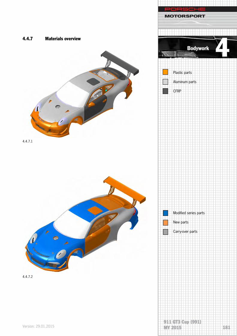
Bodywork
911 GT3 Cup (991) MY 2015
4.4.7 Materials overview
4.4.7.1
4.4.7.2
Plastic parts
Aluminum parts
CFRP
Modified series parts
New parts
Carry-over parts
Version: 29.01.2015 181

Bodywork
911 GT3 Cup (991) MY 2015
4.4.8 Roll cage
The roll cage is firmly welded into the body. Any
modifications to the roll cage will result in non-
certification or disqualification of the vehicle. In the
event of an accident, an inspection of the rollcage and
an approval by a technical scrutineer is mandatory.
4.4.8.1
WARNING
Version: 29.01.2015
182

Bodywork
911 GT3 Cup (991) MY 2015
4.4.9 Recovery device
One tow hook is provided both at the front and the rear
section (4.4.9.1 and 4.4.9.2). When towing, make sure
to avoid any jerky towing, otherwise there is a risk of
damaging the body.
Two connections for attaching recovery eyebolts (4.4.9.3) are provided on the top of
the rollcage. The vehicle may then be lifted using a special frame (recovery bar). The
recovery eyebolts are clipped into the connections by pushing the red button on top.
Four lock balls in the shaft securing the connection as soon as the eyebolt is under
tension. Press the red push-buttons to remove the eyebolts. To do so, the eyebolts
are not allowed to be under tension.
4.4.9.3
NOTE
1. Push-button
2. Lock ball
1
2
4.4.9.4
4.4.9.1
4.4.9.2
4.4.9.5
Version: 29.01.2015 183

Bodywork
911 GT3 Cup (991) MY 2015
4.5 Aerodynamics
4.5.1 General
Compared to the previous models, the new 911 GT3 Cup (991) has been significantly
improved in terms of its aerodynamic performance.
4.5.2 Rear wing
The rear wing is 1,800 mm (5’11”) wide and adjustable in nine steps; its support
brackets are directly attached to the body.
4.5.3 Additional aerodynamic improvements
Further aerodynamic improvements were made by implementing the following
measures:
• Improved cooling air circulation by optimizing air intake and outlet cross sections
• Improved brake cooling due to optimized brake air spoiler
• Aerodynamically optimized exterior mirrors
• Optimized underbody paneling (fully closed)
• Improved flow performance at the front wheels due to optimized inflow frames
Version: 29.01.2015
184

Bodywork
911 GT3 Cup (991) MY 2015
4.6 Exterior mirrors
The streamlined design of the exterior mirrors benefit the aerodynamics. Electric
mirror adjustment and mirror heating are not installed.
4.7 Roof
The roof skin is made of aluminum sheet and connected to the body via a bonded
joint. A rescue opening made of CFRP that may be released by camlock bolts is
provided above the driver’s seat. It is much easier to insert the KED system for
stabilizing the driver using the rescue opening.
Version: 29.01.2015 185

Bodywork
911 GT3 Cup (991) MY 2015
4.8 Air jack system
The air jack system is supplied by Krontec. The vehicle has three lifting jacks, one in
the middle of the front section and two in the area of the B-pillars, firmly attached to
the body. The lifting jacks are not adjustable for height and must not be adjusted to a
ride height change. The compressed air supply valve is installed in the area of the
passenger’s B-pillar (rear side window). The maximum working pressure is about 35-
38 bar (508-551 psi).
Important notes
Never work below the vehicle lifted with the air jack
system without protecting it against accidental
lowering.
Never open the air jack. The system is under pressure
even in the retracted position!
To prevent damage to the air jack end stops, never let
the air jacks extend freely (i.e. without vehicle load).
NOTE
WARNING
WARNING
Version: 29.01.2015
186

Bodywork
911 GT3 Cup (991) MY 2015
Further notes
• While driving, the drain valve (4.8.1) should be open (pulled out) to ensure that the air jacks are completely retracted.
• A separate vent is accessible via a tappet in the drain valve for slowly lowering a lifted vehicle. By pressing this tappet, the pneumatic system can be vented in a controlled manner.
• Never use mineral oil-based cleaning agents.
• Porsche Motorsport recommends having an overhaul carried out by Krontec after two years or 2,000 lifts.
• Check the tightening torque of the grooved nut (air jack tightness) during normal vehicle checks.
Tightening torque grooved nut, rear 45 ± 5 Nm (33 ± 3.7 ft-lb)
Tightening torque grooved nut, front 45 ± 5 Nm (33 ± 3.7 ft-lb)
Position of the rear air jack in the mounting tube (4.8.2)
If a loose or improperly mounted air jack is detected, it must be replaced
immediately as internal damage cannot be excluded.
For further safety regulations, please refer to the manufacturer's product description
(Krontec) addition 6.
KRONTEC
Maschinenbau GmbH
Pommernstraße 33
93073 Neutraubling
www.krontec.de
4.8.1
4.8.2
42 mm
Version: 29.01.2015 187

Bodywork
911 GT3 Cup (991) MY 2015
4.9 Doors
To further reduce vehicle weight, the doors are made of CFRP.
4.10 Trunk and engine lid
Greatest care should be taken when closing the quick
releases (4.10.2.1) of the trunk and engine lids. The lid
pins must be inserted and locked (4.10.2.1). There is a
risk that the hood or trunk lid might accidentally open
when driving and tear off!
Gas pressure springs are mounted on trunk and engine lids.
4.10.1 Trunk lid
The trunk lid is made of aluminum sheet and optimized for the special motorsport
requirements. It is provided with NACA intakes on the left and right providing air
supply to the interior. The lid is closed by two lid pins.
4.10.2 Engine lid
The engine lid is made of carbon fiber reinforced plastic (CFRP) and is connected by
two hinges to the body. Opening is supported by a gas pressure spring so that work
can be carried out with the lid open without requiring additional support. As with the
front trunk lid, two lid pins are used as a lock.
4.10.2.1
WARNING
Version: 29.01.2015
188

Bodywork
911 GT3 Cup (991) MY 2015
4.11 Windows
The front window is made of laminated safety glass and glued to the body; the rear
side windows and rear windows are made of PC (polycarbonate). The rear side
windows are removable and are clipped into the frame by means of ball heads. The
rear window is glued. When replacing the rear window, the new part’s adhesive
surface should be roughened.
4.11.1 Installing and removing the windshield
Tools
Designation Item No.
Electric special cutter – Fein ASE 481 202 00 000
Suction lifter – Stahlwille ASE 481 161 00 000
Double cartridge gun VAS 5237 ASE 416 161 00 000
Cut system for glued panes - VAS 6452 ASE 481 261 01 000
The tools can be ordered at your Porsche Center. As an alternative for the cut
system VAS 6452 (4.11.1.1), KSA Toolsystems offer a cutting device “Single Cut
System” (4.11.1.2). The two systems differ. VAS 5237 uses a wire for cutting, the
Single Cut System a polyethylene cord. The manual describes cutting with the VAS
6452, but the procedure with the KSA system is identical.
Consumables
Designation Item No.
Gluing set 000 043 301 14
Cord 000 043 300 96
Wire for (VAS) 000 043 303 32
4.11.1.2
4.11.1.1
Version: 29.01.2015 189

Bodywork
911 GT3 Cup (991) MY 2015
Preparation
1. Remove the windshield wiper arm
2. Remove the interior rear-view mirror
• Improper installation and removal of vehicle windows may cause cuts and (eye) injuries
• Wear your personal protective equipment
• Only change cutting blades when the power supply is disconnected
Wetting the suction cup increases the fixing force.
3. Install the Stahlwille WE1140 suction lifter on the outside of the windshield
4. Unwind the cutting wire and cut it with a side cutter, length 6 m (19.7’)
NOTE
WARNING
Version: 29.01.2015
190

Bodywork
911 GT3 Cup (991) MY 2015
The cutting cord has to be below the window edge, as
otherwise the seal will be damaged.
5. Insert the cutting wire into the window gap, WE1480 cutting system for glued
windows - VAS 6452.
• Wet the windshield sealing (1) with soapy water on the entire circumference.
• Pull the cutting wire (2) into the gap between windshield and body (note the arrows) on the entire circumference.
• Clamp the free end of the cutting wire to the wiper mechanics. Introduce the cutting wire.
6. Pull the cutting wire through to the inside.
• Cut adhesive bead from the inside to the outside using piercing awl (1) arrow A.
• Insert cutting wire (2) into the piercing awl and pull it into the interior arrow B.
• Pull the cutting wire through to the inside. Length: Insert 1 m (3’3.4”) cutting wire.
It is recommended to clean the windshield before
installation in order to ensure optimum adhesion of the
suction cups.
NOTE
NOTE
4.11.1.3
4.11.1.4
Version: 29.01.2015 191

Bodywork
911 GT3 Cup (991) MY 2015
7. Cut out the windshield.
• Introduce the cutting wire (1) in the hole of the rewinding device (2).
• Align the rewinding device (2) in the window center and press the suction lifter firmly against the windshield (3).
• Fix the suction lifter on the windshield by moving the operating lever.
To avoid damage, insert the protective film (2) supplied
with the cutting system between windshield and vehicle
ID-number (1).
When cutting, lead the cutting wire (3) over the
protective film.
Removing the windshield
8. Cut out the windshield by winding up the cutting wire on the rewinding device in
the direction of the arrow.
Move the rewinding device to reduce the cutting wire traction force during glass
removal.
9. Remove the windshield.
NOTE
4.11.1.5
4.11.1.6
Version: 29.01.2015
192

Bodywork
911 GT3 Cup (991) MY 2015
4.11.2 Preparing the window cutout for installation
1. Remove glue on the body.
• Remove residual glue (1) with (electric special cutter) WE1137 electric special cutter Fein and scraper (U shape 639.031.130.22) on the body so that a glue residue remains on the entire area (2).
The area-wide glue residue serves as primer for the
new glue material. Keep cut surfaces clean and free of
grease and do not clean with cleaning solution.
2. Clean and prime paint damages resp. newly built-up paint surfaces in the window
cutout of the body.
A flash-off time of at least 10 minutes should be
observed between cleaning of the gluing surface and
application of the primer! The body must be free of any
cleaning solution residues.
• Clean and activate the gluing surface of the window cutout.
NOTE
NOTE
4.11.2.1
4.11.2.2
Version: 29.01.2015 193
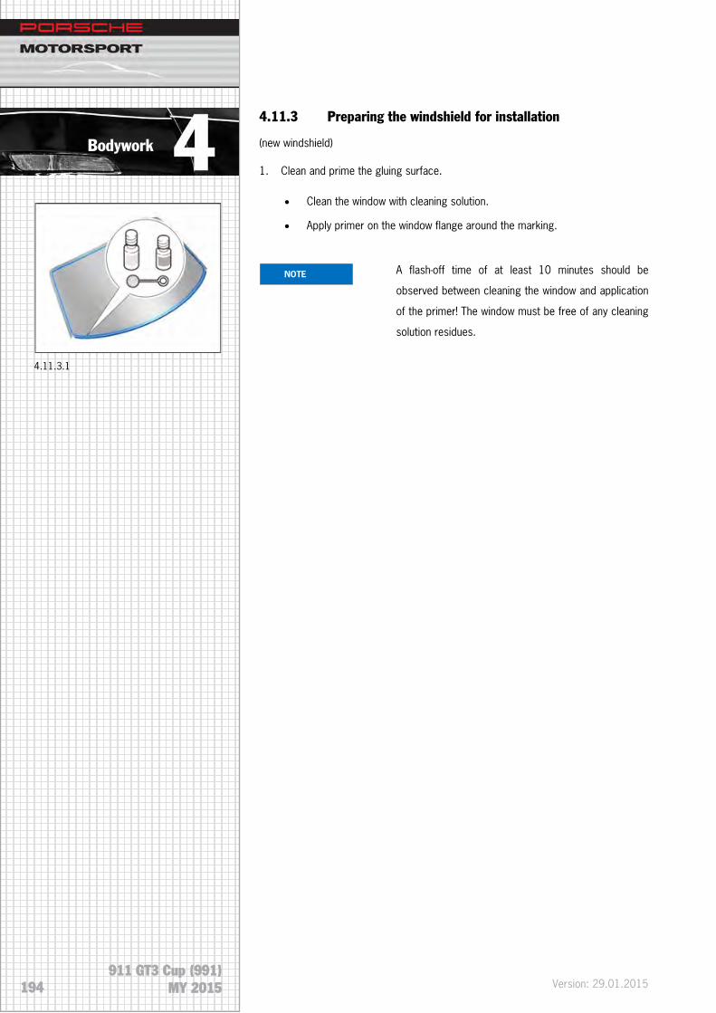
Bodywork
911 GT3 Cup (991) MY 2015
4.11.3 Preparing the windshield for installation
(new windshield)
1. Clean and prime the gluing surface.
• Clean the window with cleaning solution.
• Apply primer on the window flange around the marking.
A flash-off time of at least 10 minutes should be
observed between cleaning the window and application
of the primer! The window must be free of any cleaning
solution residues.
NOTE
4.11.3.1
Version: 29.01.2015
194

Bodywork
911 GT3 Cup (991) MY 2015
4.11.4 Installing the windshield
Risk of material damage if the predetermined curing
time of the glue is not observed! In order to ensure
proper bonding, the following conditions have to be
met:
• Do not put the vehicle into operation before the end of the curing time!
• Curing time: two hours
• Temperature: at least 10 °C (50 °F)
• Fixing time: about one hour
The glue material has an open time of 15 minutes. This
means that the glue should be applied and the part be
joined within this time.
To ensure complete mixing, squeeze an approx. 30
mm (1.2”) long adhesive bead of fresh material on a
piece of cardboard.
• Check the depth stops.
• Replace damaged or missing depth stops.
1. Prepare two-component glue for processing.
NOTE
NOTE
CAUTION
4.11.4.1
Version: 29.01.2015 195

Bodywork
911 GT3 Cup (991) MY 2015
When applying the glue material, make sure that the
adhesive bead overlaps by approx. 30 mm (1.2”) at the
beginning and end.
2. Apply glue on the windshield using the double cartridge gun VAS 5237.
• Use the glue gun and apply two-component glue on the windshield along the pre-coating or on the primer in form of a triangular adhesive bead with dimension (X) application height: 15 mm (0.6”).
Two persons are required to insert position and fix the
windshield!
3. Install the windshield in the body.
• Place the suction lifter on the windshield.
• Insert the windshield into the window cutout.
• Position the windshield at the bottom edge (arrows A) and tilt it down into the frame (arrow B)
NOTE
NOTE
4.11.4.2
4.11.4.3
Version: 29.01.2015
196

Bodywork
911 GT3 Cup (991) MY 2015
4. Set the windshield gap dimension.
• Move the windshield to set gap dimension (X). Gap dimension: 3.0 mm (0.12“) on the entire circumference.
• Remove the suction lifter.
• Secure the windshield with adhesive tape (1) to prevent it from slipping.
5. Clean the vision areas.
• Immediately remove the glue that has oozed out and clean the respective vision areas with cleaning solution.
6. Mount the interior rear-view mirror.
4.12 Fenders
The fenders are made of aluminum sheet and screwed on with bolted connections to
the body. The wheel arch liner integrates a stone guard, protecting the side radiators
against possible damage by stones and rubber abrasions. Removable separation
edges are mounted at the wheel arch.
4.13 Wheel cover
The wheel covers are made of PU (polyurethane). They are bolted and glued to the
body and can be replaced.
4.11.4.4
4.11.4.5
Version: 29.01.2015 197

Bodywork
911 GT3 Cup (991) MY 2015
4.14 Fuel system
A FT3 safety fuel tank (100 liters (26.4 gal) with return-free fuel system is used in the
911 GT3 Cup (991). The tank consists of a fuel cell which provides maximum safety
and meets the current FIA standard, and a protective shell made of carbon. The tank
integrates two fuel pumps. The main pump is surrounded by fuel baffles with one-way
valves, witch collect the fuel around the main pump. The pumps supply the fuel via a
pressure regulator (5 bar/72.5 psi) to the fuel gallery on the engine side. From there,
the fuel is delivered via the main pump to the injection valves. Defueling takes place
via a defueling coupling. Underneath the tank, there is an underride guard that
protects the tank against impacts from the bottom. The fueling system (4.14.1) can
be obtained at the company Sobek. Contact address, see chapter 7.9.
The following components are installed:
1 Level indicator
2 Roll-over valve
3 Defueling coupling
4 Fuel pressure regulator
5 Fuel pump
6 Fuel cut off valve
7 Pre fuel pump
8 Catch tank
Function of the FIA Roll Over Valve
The valve is allocated in the breather line. It fulfills three functions:
Closing of the breather line in case of a roll-over.
Over pressure safety function; in case of a roll over, the valve opens at a over
pressure of 200 mbar compared to ambient pressure to prevent the fuel cell from
damage caused by too high over pressure.
Float valve to close the valve when gasoline exits through the breather line.
Function of the fuel cut off valve
The fuel cut off valve is a safety valve to protect from gasoline leakage with damaged
gasoline lines. The valve closes the gasoline support line in case of a leakage.
1
2 3
4
5
4.14.1
4.14.3
4.14.2
6
8 7
Version: 29.01.2015
198

Bodywork
911 GT3 Cup (991) MY 2015
4.14.1 Fuel
Superplus unleaded (at least 98 ROZ)
The ethanol content in the fuel may not exceed 26 % (E26).
4.14.2 Defueling
A defueling valve is installed to empty the fuel tank. To start the procedure, the fuel
pump switch located in the central console must be in position "Fuel Pump Service".
The fuel pump is then activated for 120 seconds. If this time is not sufficient to
completely drain the fuel tank, the switch has to be set again from the center position
(fuel pump off) to "Service". Keep the fuel only in suitable containers! The switch
Intank Pump Service has no function.
Switching logic of the fuel pump switches (center console):
Switch position up Defueling mode
Switch position center Off
Switch position down Normal mode
The fuel pump should not run dry as this may cause
damage to the pump.
Danger – risk of fire and explosion!
Fuel may evaporate into the air!
• No smoking!
• Identify safety area
NOTE 4.14.2.1
DANGER
Version: 29.01.2015 199

Bodywork
911 GT3 Cup (991) MY 2015
4.14.3 Tank installation
A steel underride protection is provided beneath the tank, protecting it against
external impacts.
Part Item Dimensions Tightening torque in Nm
Hexagon nut 1 M6 10 Nm (7.4 ft-lb)
Combi SHR 2 M8X40 20 Nm (14.75 ft-lb)
Hexagon nut 3 M6 10 Nm (7.4 ft-lb)
4.15 Repairing the body
Because of its hybrid design, it is absolutely essential to check the body in case of an
accident. The body of the new 911 GT3 Cup (991) is an aluminum steel hybrid
construction. This design allows extensive repair work within a defined amount of
time. For this purpose, a special tool kit, suitable body spare parts as well as tools
and consumables are available.
Safety measures
Always wear the indicated protective equipment to prevent injuries caused by heat or
flying debris.
• Goggles
• Safety shoes
• Protective gloves
• Hearing protection
4.15.1
4.14.3.1
Version: 29.01.2015
200

Bodywork
911 GT3 Cup (991) MY 2015
4.15.1 Repairing the front section
A tool kit has been set up especially for performing repair work on the aluminum
parts. The tool kit may only be used on aluminum parts.
Required tools by Wieländer+Schill
Description Item No. Qty
Body saw WPS 2010 230V 120020 1
W+S special central punch F2 (for self-pierce rivets) 628006 2
Slide hammer with hook 5 kg 511300 1
Dead blow bumping hammer 511029 1
Separating chisel incl. handle, body 512001 1
Anvil dolly, half-round 511113 1
File with grip, medium cut 1 521201 1
Manual deburrer 541030 1
Spare blade for manual deburrer 547030 1
Teroson spatula 541010 1
Circular brush, stainless steel ø 75 mm knotted 541202 2
Wire brush, V-shape INOX 541212 1
Mity-Bite clip, large 511312 1
Grip pliers 145 U-format 12" 561151 2
Grip pliers 144 561152 2
Fastener ø 6.35mm 20 pcs 577107 1
Cartridge gun 3M EPX for 50 ml. 831101 1
Blind riveting tool Taurus 4 571110 1
Pressure reduction valve PLF80/90/PS1/Taurus4 194000 1
Reduction nipple long: G 1/8" axG 1/4" i 194001 1
Version: 29.01.2015 201

Bodywork
911 GT3 Cup (991) MY 2015
Consumables
Solid carbide drill ø 6.7 mm 627010
3M 2K glue DP 490 (Porsche) 999.915.323.40
Blind rivet (long) 5.0-8.5 (Porsche) 999.190.230
Blind rivet (short) 3.0-6.5 (Porsche) 999.190.227.01
Wieländer + Schill
Siederstr. 50
78054 Villingen-Schwenningen
Phone: +49 (0)7720-83 17 0
E-Mail: [email protected]
Version: 29.01.2015
202

Bodywork
911 GT3 Cup (991) MY 2015
HAZET
Designation Item No. Qty
Tool trolley 179-6-RAL 4000896148851 1
Door RAL 9006 179-21 4000896146246 1
Can holder 179-35 4000896141074 2
Attachable box 179-28 400089141234 1
Paper roll holder 180-34 4000896120840 1
Set of separating plates 173-31/5 4000896090150 2
Set of separating plates 173-32/5 400089120796 2
Cable drum 161-3D 4000896048878 1
Anti-slip mat 180-38 400089120819 6
Flat scraper 824 4000896033881 1
Heat gun 1990-2/6 4000896141586 1
Wire brush 2130-1 4000896012527 2
Ball-peen hammer 2140-5 4000896012695 1
Magnetic finder 1976-1 4000896009749 1
Replacement heads 1953-050 4000896008612 1
Drill 9030-1 4000896109470 1
Angle drill 9030-5 4000896132379 1
Keyhole saw 9034-1 4000896132362 1
Grinder, straight 9032-1 4000896117055 1
Grinder, bent 9032-5 4000896117062 1
HAZET-WERK
Postfach 100461
42804 Remscheid
Phone: +49 (0)2191-79 23 75
E-Mail: [email protected]
Version: 29.01.2015 203

Bodywork
911 GT3 Cup (991) MY 2015
Preparation for repairing the front section
These instructions describe how to repair the front section. Individual operations are
shown on one side and have to be carried out inversely on the other side. In case of
deviations, the steps are described separately. The estimated time for the described
repair is approximately five hours.
Remove the following parts:
• Fender left/right
• Headlights left/right
• Wheel arch liners left/right
• Underbody, front
• Chassis left/right
• Front apron
• Front bumper
• Fuel tank
• Brake lines left
• Draining the coolant, front
• Water cooler and cooling hoses left/right
• Steering gear
• Air jack, front and cross member
• Master cylinder, remove if required
Version: 29.01.2015
204

Bodywork
911 GT3 Cup (991) MY 2015
Removing the front section
The front section (Z front section Cup) is available as spare part. Porsche spare part
number: 991.501.991.8A
4.15.1.1
Together with the front section are consumables such as glue and blind rivets.
Where possible, drill out the self-pierce rivets (1) from the rivets head.
To do this deeply mark the rivets (1) with a center punch and drill using a solid
carbide drill (Ø 6.7 mm).
4.15.1.2
Version: 29.01.2015 205

Bodywork
911 GT3 Cup (991) MY 2015
Heat the glued joint (2) with the heating gun and pry apart the sheet to the top using
a separating chisel.
Bore the marked rivets (1) only through the first sheet. Aluminum extruded sections
are in the carrier frame. The aluminum profile is behind the saw line (2). This cut
allows removing the front section, a more precise cut will follow in a later step.
Do not bore through the carrier frame. The carrier frame is not replaced now.
If the carrier is damaged behind the cutoff line (2), it is not possible to carry out the
repair work.
4.15.1.3
4.15.1.4
Version: 29.01.2015
206

Bodywork
911 GT3 Cup (991) MY 2015
The illustration shows the saw line on the right outside.
Cut through the carrier frame at the line (1) using the electric saw (saw blade 14).
Starting from the center of the oval cutout, carry out the separation cut directly
behind the two threads.
Heat glued joints along the pierced rivets using a heat gun.
The illustration shows the left side, with the arrow pointing in the direction of travel.
Drill out the three rivets (1).
Do not drill into the carrier.
Separate the sheet’s glued joints using a separating chisel. Where necessary, heat
the glued joint using a hot air blower.
4.15.1.5
4.15.1.6
Version: 29.01.2015 207

Bodywork
911 GT3 Cup (991) MY 2015
Together with a second person, remove the front section towards the front of the
vehicle, using the slide hammer with hook if necessary.
The illustration shows the cut off front section from the right.
Adapting carrier frame to new part
Carry out grinding operations using a stainless steel wire brush. Always use special
grinding wheels for grinding aluminum. Use grinding wheels with grain size P80 to
P200. Observe corrosion protection measures.
Sawing template, right
Place the sawing template (1) on the carrier frame. The threaded bolt (2) is used as
fixing. Transfer the saw line (3) on the template’s front end onto the carrier from the
top to the bottom.
4.15.1.7
4.15.1.8
Version: 29.01.2015
208

Bodywork
911 GT3 Cup (991) MY 2015
Sawing template, left
The three threaded holes (1) are used as fixing point.
Transfer the saw line (1) on the template’s front end onto the carrier from the top to
the bottom and align centrally to the rivet hole.
The saw cut is described for the right carrier frame.
The distance from the rear end to the saw line is 511 mm (20.12”) (measure from
inner side of the carrier).
The external saw cut only cuts through the outer sheet.
NOTE
4.15.1.9
4.15.1.11
4.15.1.10
Version: 29.01.2015 209

Bodywork
911 GT3 Cup (991) MY 2015
Heat the upper section (hatched) of the two carrier sheets and open with the
separating chisel.
Carry out the inner saw cut (hatched)
A = outer sheet
B = inner sheet
Saw the carrier upper section (1).
Remove glue residues in the hatched area.
Remove the burr on the saw line.
4.15.1.12
4.15.1.13
4.15.1.14
Version: 29.01.2015
210

Bodywork
911 GT3 Cup (991) MY 2015
The illustration shows the new part’s right outside.
The new part is riveted to the old carrier frame. Item (1) shows where the holes for
the rivets have to be provided.
The illustration shows the right carrier from the inside.
Transfer the three holes onto the old carrier stub (1). Diameter 6.7 mm (0.26“).
The illustration shows the right side
Saw the new front section’s upper part (1) (hatched) on the left and right (2).
In this way, it can be placed more easily into the body.
4.15.1.15
4.15.1.16
4.15.1.17
Version: 29.01.2015 211

Bodywork
911 GT3 Cup (991) MY 2015
Mounting the new part
The bottom cross member and the rivets at the upper end next to the strut dome are
used for positioning.
All surfaces that are riveted have also to be bonded with two-component glue.
Place and rivet the blind rivets connecting the new part to the body.
Make sure that two different rivet lengths are available.
Rivet connections through two sheets:
short rivets 3.0-6.5
Rivet connections through three sheets:
long rivets 5.0-8.5
The riveting points are shown below
4.15.1.18
NOTE
Version: 29.01.2015
212

Bodywork
911 GT3 Cup (991) MY 2015
The illustration shows the new front section and the old carrier stub
4.15.1.19
The illustration shows the front section on the left side
4.15.1.20
The illustration shows left inside of the front section
Version: 29.01.2015 213

Bodywork
911 GT3 Cup (991) MY 2015
4.15.1.21
The illustration shows the front section from the top, near the strut dome
4.15.1.22
The illustration shows the front section’s left rear panel from below
Version: 29.01.2015
214

Bodywork
911 GT3 Cup (991) MY 2015
4.15.2 Replacing the front strut mount
Safety measures
Always wear the indicated protective equipment to prevent injuries caused by heat or
flying debris.
• Goggles
• Safety shoes
• Protective gloves
• Hearing protection
4.15.2.1
Version: 29.01.2015 215

Bodywork
911 GT3 Cup (991) MY 2015
Required tools by Wieländer+Schill
Designation Item No. Qty
Body saw WPS 2010 230 V 120020 1
W+S special central punch F2 (for self-pierce rivets) 628006 2
Slide hammer with hook 5 kg 511300 1
Dead blow bumping hammer 511029 1
Separating chisel incl. handle, body 512001 1
Anvil dolly, half-round 511113 1
File with grip, medium cut 1 521201 1
Manual deburrer 541030 1
Spare blade for manual deburrer 547030 1
Teroson spatula 541010 1
Circular brush, stainless steel ø 75 mm knotted 541202 2
Wire brush, V-shape INOX 541212 1
Mity-Bite clip, large 511312 1
Grip pliers 145 U-format 12" 561151 2
Grip pliers 144 561152 2
Fastener ø 6.35 mm 20 pcs 577107 1
Cartridge gun 3M EPX for 50 ml. 831101 1
Blind riveting tool Taurus 4 571110 1
Pressure reduction valve PLF80/90/PS1/Taurus4 194000 1
Reduction nipple long: G 1/8" axG 1/4" i 194001 1
Version: 29.01.2015
216

Bodywork
911 GT3 Cup (991) MY 2015
Consumables
Solid carbide drill ø 6.7 mm 627010
3M 2K glue DP 490 (Porsche) 999.915.323.40
Blind rivet (long) 5.0-8.5 (Porsche) 999.190.230
Blind rivet (short) 3.0-6.5 (Porsche) 999.190.227.01
Wieländer + Schill
Siederstr. 50
78054 Villingen-Schwenningen
Phone: +49 (0)7720-83 17 0
E-Mail: [email protected]
Version: 29.01.2015 217

Bodywork
911 GT3 Cup (991) MY 2015
HAZET
Designation Item No. Qty
Tool trolley 179-6-RAL 4000896148851 1
Door RAL 9006 179-21 4000896146246 1
Can holder 179-35 4000896141074 2
Attachable box 179-28 400089141234 1
Paper roll holder 180-34 4000896120840 1
Set of separating plates 173-31/5 4000896090150 2
Set of separating plates 173-32/5 400089120796 2
Cable drum 161-3D 4000896048878 1
Anti-slip mat 180-38 400089120819 6
Flat scraper 824 4000896033881 1
Heat gun 1990-2/6 4000896141586 1
Wire brush 2130-1 4000896012527 2
Ball-peen hammer 2140-5 4000896012695 1
Magnetic finder 1976-1 4000896009749 1
Replacement heads 1953-050 4000896008612 1
Drill 9030-1 4000896109470 1
Angle drill 9030-5 4000896132379 1
Keyhole saw 9034-1 4000896132362 1
Grinder, straight 9032-1 4000896117055 1
Grinder, bent 9032-5 4000896117062 1
HAZET-WERK
Postfach 100461
42804 Remscheid
Phone: +49 (0)2191-79 23 75
E-Mail: [email protected]
Version: 29.01.2015
218

Bodywork
911 GT3 Cup (991) MY 2015
Preparation for replacing the strut dome
These instructions describe how to remove the left front strut dome. Perform the
operations on the right side inversely. The estimated time for the described repair is
approximately three hours.
Remove the following parts:
• Fender left
• Headlight left
• Wheel arch liners left
• Underbody, front
• Chassis left
• Front bumper
• Fuel tank
• Brake lines left
• Draining the coolant, front
• Water cooler and cooling hoses left
• Steering gear
• Air jack, front and cross member
• Master cylinder, remove if required
Removing/drilling out the strut dome
The service life of a drill is about 14 to 20 rivets.
Deeply mark the rivets (1) with the center.
Drilling out the rivets from the rear makes the process much easier.
Use drilling fluid to prolong the drill’s service life.
4.15.2.2
Version: 29.01.2015 219

Bodywork
911 GT3 Cup (991) MY 2015
Deeply mark the self-pierce rivets and pierce them using a solid carbide drill (Ø 6.7
mm).
• Saw the defective dome using an air saw (2)
• Pierce the rivet in the direction of the arrow
• Heat the glued joints between dome and body using a hot air blower
Remove the damaged dome.
Preparation for the installation
Carry out grinding operations using a stainless steel wire brush. Always use special
grinding wheels for grinding aluminum. Use grinding wheels with grain size P80 to
P200. Observe corrosion protection measures.
Thoroughly remove paint from the glued joints (hatched) using an angle grinder.
4.15.2.3
4.15.2.4
4.15.2.5
Version: 29.01.2015
220

Bodywork
911 GT3 Cup (991) MY 2015
Do not remove the beads on the carrier inside; they are part of the body!
Debur the bore holes on both sides of the body.
Creating a drilling template
Only a drilling template ensures exact positioning of the holes.
Make a drilling template from the defective strut mount. A body air saw is suitable for
sawing. Align the drilling template exactly and drill the 7 marked rivet holes.
Then deburr the holes.
Aligning the new part
Grind the gluing surfaces on the new part and on the body down to the bare metal
using P100 sandpaper and grease with acetone.
• Apply evenly two-component glue on the new part
• Curing time 2-3 hours at 60 °C (140 °F)
• Install the new part with caution and fix it using fasteners.
• Fit all rivets.
Pay attention to the correct rivet length!
4.15.2.6
4.15.2.7
4.15.2.8
Version: 29.01.2015 221

Bodywork
911 GT3 Cup (991) MY 2015
Riveting the new part
The hidden row of rivets (1) should be riveted from the bottom, as the row is hidden
by the body.
4.15.2.9
Rivet the first row of rivets (1).
4.15.2.10
Drill the holes for the rivets using a solid carbide drill (Ø 6,7 mm). On the bottom part
of the dome, another rivet is fitted in addition to the existing one.
Version: 29.01.2015
222

Bodywork
911 GT3 Cup (991) MY 2015
4.15.3 Repairing the rear end
Required tools (Wieländer & Schill)
DL drill Item No. 999960
Solid carbide drill, 6.7 mm diameter Item No. 627010
Ball-peen hammer heavy, 600 gr. Item No. 999950
Slide hammer with hook 5 Kg Item No. 511300
Separating chisel incl. handle for body Item No. 512001
W+S special central punch 2F for self-pierce rivets Item No. 628006
Taurus 4 blind riveting tool (pneumatic) Item No. 571110
Cut-off grinder/angle grinder (pneumatic)
cartridge gun 3M Item No. 831101
Manual deburrer Item No. 541030
4 parallel clamps body grip pliers
Body saw WPS 2010 220V Item No. 120020
Hot air blower 3000 W Item No. 801200
Consumable supplies Porsche
Rivets (short) 3.0-6.5 Item No. 999.190.227.01
Rivets (long) 5.0-8.5 Item No. 999.190.230
3M 2K glue DP 490 Item No. 999.915.323.40
Preparation for removing the rear section
Remove bumpers
Remove drive unit
Version: 29.01.2015 223

Bodywork
911 GT3 Cup (991) MY 2015
Removing the rear section
The standard bolts will be replaced by rivets.
Remove the Torx bolts from the carrier frame.
Fit the clamping claw to the carrier frame assembly and knock it loose from the
body.
Carry out grinding operations using a stainless steel wire brush. Always use special
grinding wheels for grinding aluminum. Use grinding wheels with grain size P80 to
P200. Observe corrosion protection measures.
Thoroughly remove paint from the glued joints (hatched).
4.15.3.1
Smooth any roughness on the lower rim that occurs during removal.
Version: 29.01.2015
224

Bodywork
911 GT3 Cup (991) MY 2015
Installing the new part
Apply evenly two-component glue on the old bonded joints.
The illustration shows the rivets (1) from the outside on the left. Place the new part,
fit the rivets and rivet them.
The illustration shows the rivets (1) from the inside on the right.
The illustration shows the rivets (1) from below on the right.
4.15.3.2
4.15.3.3
4.15.3.4
Version: 29.01.2015 225

Bodywork
911 GT3 Cup (991) MY 2015
The illustration shows the rivets (1) on the rear engine mount (bumper) on the left.
The curing time of two-component glue is 2-3 hours at 60 °C (140 °F).
4.15.3.5
Version: 29.01.2015
226

Bodywork
911 GT3 Cup (991) MY 2015
4.16 Thread repair kit
The chassis and the assembly carriers are bolted to the aluminum cast parts of the
body. To meet these special requirements, the threads are provided with Helicoil
threads. A repair kit is available for replacing these Helicoil threads. When opening a
bolted connection, it is absolutely necessary to replace the bolt. This also applies to
the assembly mounts. If the thread is damaged, replace the thread insert and fit a
new Time-Sert thread insert.
Defective Helicoil threads of the bolted connections of
chassis and assembly carrier have to be replaced by
Time-Sert thread inserts. It is not allowed to replace a
defective Helicoil thread by a new Helicoil.
Two systems are available for thread repair. The Helicoil repair system supplied by
Böllhoff and Time-Sert thread inserts supplied by Würth. Porsche recommends
special thread repair kits for particular thread sizes.
It is important that the corresponding tightening torque of the bolted connection can
be achieved after repair.
NOTE
4.16.1
Version: 29.01.2015 227

Bodywork
911 GT3 Cup (991) MY 2015
Basic method for repairing threads with thread inserts:
1. Remove the defective thread insert
2. Drill a core hole using a special core hole drill
3. Cut a thread using a tap (two-piece/three-piece), use a cutting agent.
4. Insert the new thread insert with a special inserter
Thread repair kits can be ordered at the following companies:
Wilhelm Böllhoff GmbH & Co. KG
Archimedesstr. 1–4
33649 Bielefeld
Germany
Phone: + 49 (0)521-44 82 01
Fax: + 49 (0)521-44 93 64
Adolf Würth GmbH & Co. KG
Reinhold-Würth-Straße 12-17
74653 Künzelsau-Gaisbach
Germany
Phone: +49 (0)7940-15 0
Fax: +49 (0)7940-15 10 00
Version: 29.01.2015
228

Bodywork
911 GT3 Cup (991) MY 2015
4.16.1 Thread repair of chassis bolt connections
Threaded bushings without collar
Tools:
• Hot air blower V.A.G. 1416 (WE1119)
• Thread repair kit 9843
• Thread repair kit 9843/1
• Thread repair kit 9843/2
• Thread repair kit 9843/3
• Time-Sert thread repair No.122-1 Item.1
• Time-Sert thread repair No.122-1 Item.2
4.16.1.1
4.16.1.2
4.16.1.3
4.16.1.4
Version: 29.01.2015 229

Bodywork
911 GT3 Cup (991) MY 2015
Repair of threaded bushings without collar
• Remove standard wire thread inserts/Helicoil before drilling
• Release the wire thread insert /Helicoil (1) with a suitable screwdriver
• Pull out the wire thread insert/Helicoil (1)
• Drill out the old thread completely using a special three-fluted drill (included in the kit) (B)
4.16.1.5
4.16.1.6
4.16.1.7
Version: 29.01.2015
230

Bodywork
911 GT3 Cup (991) MY 2015
Cut the thread to the dimension (Y) with a cutting tool
• Clean the thread: Blow out chips from the thread with compressed air, flush the thread with brake cleaner, dry the thread with compressed air
• Screw the threaded bushing (1) on the inserter (2)
• Unscrew the inserter (E) from the threaded bushing (A)
4.16.1.8
4.16.1.9
4.16.1.10
Version: 29.01.2015 231

Bodywork
911 GT3 Cup (991) MY 2015
Make sure that the threaded bushing (1) is screwed completely on the inserter (2) –
arrows
• Insert the threaded bushing (1) completely with the inserter (2)
• Briefly heat the thread insert with a WE1119 hot air blower, Leister-Electron/V.A.G. 1416. Time: 2 minutes, temperature: 80 °C (176 °F). Alternatively, do not screw the repaired thread for approx. 3-4 hours.
The heating or waiting time is required to prevent the
thread insert from turning when screwing in the bolt.
NOTE
4.16.1.11
4.16.1.12
Version: 29.01.2015
232

Bodywork
911 GT3 Cup (991) MY 2015
Threaded bushings with collar
• Remove the standard wire thread inserts (Helicoil) before drilling
• Drill out the old thread completely using the drill (included in the kit) (B)
The repair bushing has to be fitted more deeply. Use the tool included in the tool kit
for milling the appropriate recess
• Mill the recess with the core drill (C)
Use an electronically controlled drill for milling and set a speed of approx. 250 rpm
4.16.1.13
4.16.1.14
Version: 29.01.2015 233

Bodywork
911 GT3 Cup (991) MY 2015
Cut the thread to the dimension (Y) with a cutting tool
• Place the threaded bushing on the inserter
• Oil the inserter (E)
• Manually screw the threaded bushing (A) on the inserter (E)
During press fitting in the basic thread, forming the internal thread requires
perceptibly more force on the inserter. Press fitting is completed as soon as the
inserter turns again more easily.
Unscrew the inserter (E) from the threaded bushing.
4.16.1.15
4.16.1.16
4.16.1.17
Version: 29.01.2015
234
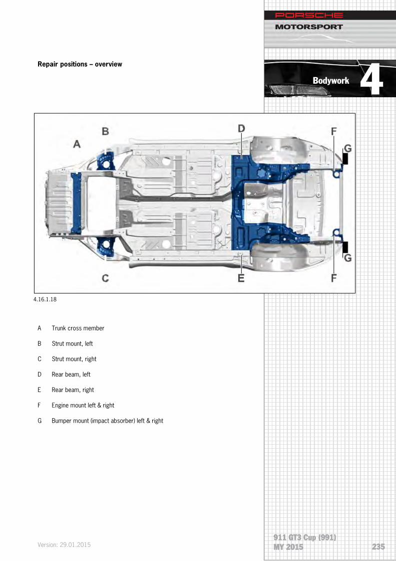
Bodywork
911 GT3 Cup (991) MY 2015
Repair positions – overview
A Trunk cross member
B Strut mount, left
C Strut mount, right
D Rear beam, left
E Rear beam, right
F Engine mount left & right
G Bumper mount (impact absorber) left & right
4.16.1.18
Version: 29.01.2015 235

Bodywork
911 GT3 Cup (991) MY 2015
Threads – cross member
Thread 1; front axle mounting (Helicoil) M12x1.5x30
Thread 2; axle support mounting (Helicoil) M12x1.5x30
Threads 1 / 2:
Use Explanation Type Basic value
Threads 1 and 2 Dimension Y Length 33 mm
Threads 1 and 2 Dimension X Length 5 mm
Use repair kit 9843 with threaded bushings 999.504.266.01.
4.16.1.19
4.16.1.20
Version: 29.01.2015
236

Bodywork
911 GT3 Cup (991) MY 2015
Threads – strut mount
Thread 1; diagonal brace mounting (Helicoil) M8x16
Thread 2; alarm horn mounting (only on the left strut mount) (Helicoil)
M8x16
Thread 3, sensor mounting Thread M6
Thread 1:
Use Explanation Type Basic value
Thread 1 Dimension Y Length 20 mm
Thread 1 Dimension X Length 5 mm
Use repair kit 9843/3 with threaded bushing 999.504.262.01.
4.16.1.21
4.16.1.22
Version: 29.01.2015 237

Bodywork
911 GT3 Cup (991) MY 2015
Thread 2:
Use Explanation Type Basic value
Thread 2 Dimension Y Length 20 mm
Thread 2 Dimension X Length 5 mm
Use repair kit 9843/3 with threaded bushing 999.504.262.01.
.
Thread 3:
Use Explanation Type Basic value
Thread 3 Dimension Y Length 9.4 mm
Use repair kit No.122-1 Item 1 Time-Sert with short threaded bushing.
4.16.1.23
4.16.1.24
Version: 29.01.2015
238

Bodywork
911 GT3 Cup (991) MY 2015
Longitudinal beam, rear
Left beam:
Thread 1; chassis mounting (Helicoil) M12x1.5x24 (3x)
Thread 2; chassis mounting (Helicoil) M10x20 (3x)
Thread 3; (Helicoil) M10x20 (4x)
Thread 4; gearbox mounting (Helicoil) M10x20 (1x)
Thread 5; M10 (1x)
Right beam:
Thread 1; chassis mounting (Helicoil) M12x1.5x24 (3x)
Thread 2; chassis mounting (Helicoil) M10x20 (3x)
Thread 3; (Helicoil) M10x20 (4x)
Thread 4; gearbox mounting (Helicoil) M10x20 (1x)
Thread 5; M10 (1x)
Thread 6; ground cable mounting M8 (1x)
4.16.1.25
4.16.1.26
Version: 29.01.2015 239

Bodywork
911 GT3 Cup (991) MY 2015
Thread 1:
Use Explanation Type Basic value
Thread 1 Dimension Y Length 27 mm
Thread 1 Dimension X Length 5 mm
Use thread repair kit 9843 with threaded bushing 999.504.263.01.
Thread 2/3:
Use Explanation Type Basic value
Thread 2 and 3 Dimension Y Length 25 mm
Thread 2 and 3 Dimension X Length 5 mm
Use thread repair kit 9843-1 with threaded bushing 999.504.268.01.
4.16.1.27
4.16.1.28
Version: 29.01.2015
240
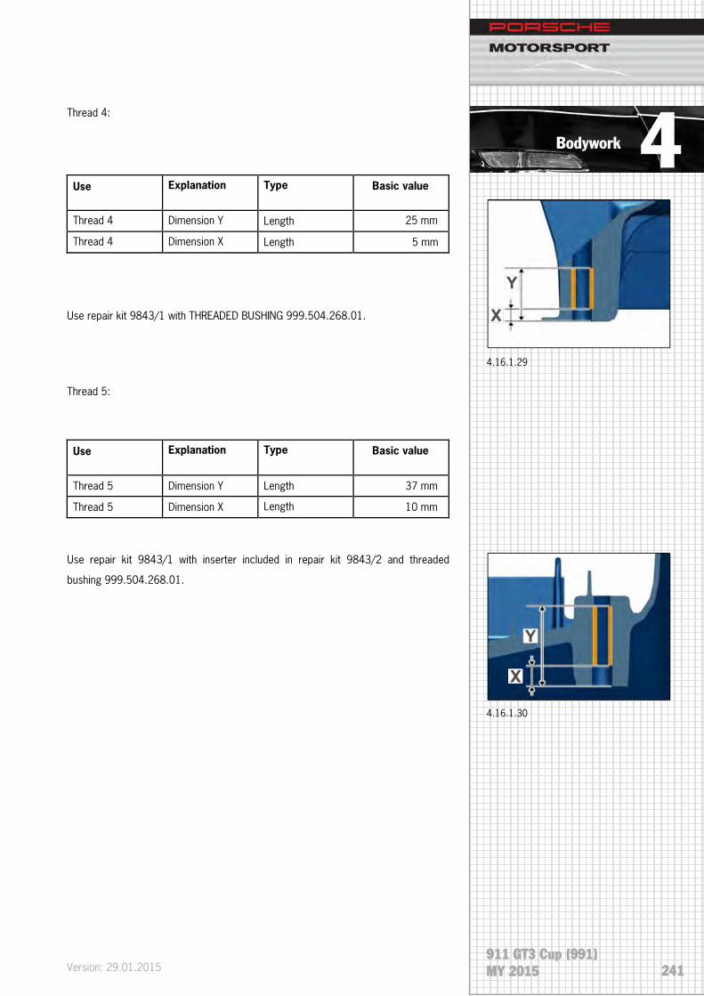
Bodywork
911 GT3 Cup (991) MY 2015
Thread 4:
Use Explanation Type Basic value
Thread 4 Dimension Y Length 25 mm
Thread 4 Dimension X Length 5 mm
Use repair kit 9843/1 with THREADED BUSHING 999.504.268.01.
Thread 5:
Use Explanation Type Basic value
Thread 5 Dimension Y Length 37 mm
Thread 5 Dimension X Length 10 mm
Use repair kit 9843/1 with inserter included in repair kit 9843/2 and threaded
bushing 999.504.268.01.
4.16.1.29
4.16.1.30
Version: 29.01.2015 241

Bodywork
911 GT3 Cup (991) MY 2015
Thread 6:
Use Explanation Type Basic value
Thread 6 Dimension Y Length 16.2 mm
Thread repair 6 only for the right beam.
Use repair kit No. 122-1 Item 2 Time-Sert thread repair with long threaded bushing.
Cross beam, rear (engine mount)
Thread 1; in cast part Thread M8 (2x)
Thread 2; in cast part, air filter mounting Thread M6x10
4.16.1.31
4.16.1.32
Version: 29.01.2015
242

Bodywork
911 GT3 Cup (991) MY 2015
Thread 1:
Use Explanation Type Basic value
Thread 1 Dimension Y Length 16.2 mm
Use repair kit No. 122-1 Item 2 Time-Sert with long threaded bushing.
Thread 2:
Use Explanation Type Basic value
Thread 2 Dimension Y Length 9.4 mm
Use repair kit No.122-1 Item 1 Time-Sert with short threaded bushing.
4.16.1.33
4.16.1.34
Version: 29.01.2015 243

Bodywork
911 GT3 Cup (991) MY 2015
Longitudinal beam, rear (impact absorber mount)
Thread M8 in cast part
Use Explanation Type Basic value
Thread 1 Dimension Y Length 16.2 mm
Use repair kit No. 122-1 Item 2 Time-Sert with long threaded bushing.
4.16.1.36
4.16.1.35
Version: 29.01.2015
244

Bodywork
911 GT3 Cup (991) MY 2015
4.17 Installing roof assembly
Preparation measure
Danger of material damage if specified curing time of
adhesive is not observed! In order to ensure that the
bonded joint is sufficiently strong, the following
conditions must be adhered to:
• The vehicle must not be used until the curing time has
• Curing time: 2 hours
• Temperature: at least 10 °C (50 °F)
• Fixing time: approx. 1 hour
A drying time of at least 10 minutes must be observed between cleaning the frame
and applying primer! No cleaning solution residue may remain on the frame.
• The adhesive has an open time of 15 min, which means that the adhesive must be applied and the component affixed within this period of time.
• To ensure that the substance is completely mixed, apply a 30 mm long bead of fresh adhesive to a piece of cardboard before processing.
NOTE
4.17.1
Version: 29.01.2015 245

Bodywork
911 GT3 Cup (991) MY 2015
Installation:
Two people are needed in order to insert, position and
secure the roof assembly.
1. Clean bonding surfaces (1) with cleaning solution.
2. Prime bonding surfaces (1).
3. Apply adhesive on the primer.
4. Do not apply adhesive in areas (A) 50 mm and (B) 30 mm.
5. Apply a triangular bead of adhesive measuring X = approx. 15 mm (4.17.3).
6. Position roof assembly
Gap from front roof pillar to roof Gap dimension 5.5 mm -1 mm
Offset from front roof pillar to roof Gap dimension 0 mm -1 mm
Gap from rear roof pillar to roof Gap dimension 5.5 mm -1 mm
Offset from rear roof pillar to roof Gap dimension 0 mm -1 mm
7. Screw on and tighten fastening nuts (1) on the ⇒ Tightening torque 10
Nm (7.5 ftlb.) roof assembly at front and rear (4.17.4).
NOTE
4.17.2
4.17.3
4.17.4
Version: 29.01.2015
246

Interior 5 Interior
5.1 General
The interior design of the new 911 GT3 Cup (991) focuses on ergonomics and
driver´s safety. The center console is tilted towards the driver in order to improve
accessibility of the control elements. Appearance improvements feature colored
controls and a Cosworth data logger with colored display. Noise insulation is omitted
for weight reduction reasons. The starter battery and the new fire extinguishing
system using gaseous extinguishing agent are installed in the passenger footwell.
5.1.1
Version: 29.01.2015 911 GT3 Cup (991) MJ 2015 247

Interior
5.2 Drivers safety
The substantial occupant safety system of the 911 GT3 Cup (991) primarily includes
the following components:
• Certified safety cage
• FIA homologated racing bucket seat with longitudinal adjustment
• Six-point safety belt connected to safety cage
• Safety steering column
5.2.1 Seat
The new developed Recaro racing bucket seat offers a high degree of safety and
individual comfort to the driver. Compared to standard safety seats, this combination
of seat and seat console provides considerable adjustment options. The height- and
longitudinal adjustment allows setting the best possible seat position for the driver. In
addition, the seat padding may be optimally adapted to the driver’s body shape by
means of seat cushions in different thicknesses.
5.2.1.2
An adjusting lever on the left side of the seat console allows a longitudinal adjustment
of the seat position (5.2.1.1).
5.2.1.1
Version: 29.01.2015
911 GT3 Cup (991) MJ 2015
248

Interior
5.2.2 Seat rail tightening torques
Tighten all bolts to a tightening torque 28 Nm ±2 Nm.
Use medium-strength thread locker.
5.2.2.1
1 M10x16
2 7/16“ UNFx16
Version: 29.01.2015 911 GT3 Cup (991) MJ 2015 249

Interior
5.2.3 Bucket seat tightening torques
Tighten all bolts to a tightening torque 23 Nm ±2 Nm.
Use medium-strength thread locker.
5.2.3.1
1 M10x16
2 7/16“ UNFx16
Version: 29.01.2015
911 GT3 Cup (991) MJ 2015
250

Interior
5.2.4 Padding system
Different seat pads are available and may be ordered in three sizes (S, M, L). The
seat pads can be purchased at Recaro. On delivery, the bucket seat is equipped with
standard padding in medium size (M).
Seat pad thickness
S = 30 mm (1.2“)
M = 20 mm (0.8“)
L = 10 mm (0.4“)
Contact address
RECARO Automotive GmbH & Co. KG
Stuttgarter Straße 73
D-73230 Kirchheim unter Teck
Phone: +49 (0) 70 21-93 50 00
Fax: +49 (0) 70 21-93 53 39
E-Mail: [email protected]
Internet: www.recaro-automotive.com
5.2.4.1
Version: 29.01.2015 911 GT3 Cup (991) MJ 2015 251

Interior
5.3 Steering wheel
Particular attention was paid to the steering wheel as a central control element. All
necessary functions which are typical used during driving may be operated by
switches and pushbuttons on the steering wheel, without removing the hands from
the steering wheel.
5.3.1
The flattened bottom part of the steering wheel rim provides ample legroom during
driving and when getting into and out of the car. In order to provide additional space
for getting in and out, the steering wheel is attached to the steering column by using
quick release coupling. If required, the steering wheel may be disconnected from the
steering column.
5.3.2 Quick release coupling closed
5.3.3 Quick release coupling open
Version: 29.01.2015
911 GT3 Cup (991) MJ 2015
252

Interior
5.4 Cockpit ventilation
Two NACA air intakes have been integrated into the front bonnet in order to ensure a
fresh air supply to the vehicle interior. The left intake – as seen in the driving direction
– provides fresh air through a flexible aluminum hose directly onto the driver (yellow
arrow). The right intake, leads the air into the blower unit below the dashboard. A
switch in the center console allows changing the outlet of the airflow. It is possible to
guide the fresh air directly onto the windshield or through openings in the dashboard
onto the driver.
5.4.2
5.4.1
Version: 29.01.2015 911 GT3 Cup (991) MJ 2015 253

Interior
Version: 29.01.2015
911 GT3 Cup (991) MJ 2015
254

Electrical System 6 Electrical system
6.1 General
The 911 GT3 Cup (991) has been significantly improved in terms of operating
comfort and functionality. Compared to previous models, the electrical equipment
has been upgraded and new and attractive features are available. The integration of
an electro-pneumatic gear shift system, the innovative electrical system control unit,
and the color display all improve the operating comfort. Moreover, the center
console is now oriented towards the driver so that the operating ergonomics are
considerably improved.
6.2 Power supply
6.2.1 Battery
An AGM battery (Absorbent Glass Material) with 80Ah is used in the 911 GT3 Cup
(991) (6.2.1.1). Special micro-fiber glass mats are inserted tightly between the
positive and negative lead plates, binding the entire battery acid. In demanding
situations, higher amounts of energy can be delivered by the fast reaction between
the acid and the plate material. The battery is maintenance-free and sealed. To
optimize the vehicle’s weight distribution, the battery is installed inside the vehicle in
the passenger foot well.
The maintenance-free AGM battery offers the following advantages:
• Sealed, valve-controlled battery with high cycle stability
• High cold start performance
• No acid leaks in case of damage, vibration-, leak- and tilt-proof
• Flexible installation and safe handling
• High capacity and longer service life
6.2.2 Generator
In addition to the battery, the generator ensures the power supply to the electrical
consumers while the engine is running. The rated current of the generator is 150
amps.
The battery is designed for a cut-off
voltage of 14.5 to 14.8 V
The generator cut-off voltage is 13.8 V
6.2.1.1
Version: 29.01.2015 255 911 GT3 Cup (991) MY 2015

Electrical System
6.2.3 Battery master switch
The battery master switch (6.2.3.1) cuts off all electrical circuits (battery, generator,
lights, ignition and electrical controls, etc.) as well as the engine.
The battery master switch (Pos.2 in picture 6.2.3.2) is installed right next to the
battery. It´s located on the center tunnel and covered by the battery cover, as well as
the battery itself.
The battery master switch can be operated in two different ways:
Inside operation
The “Main” switch (1) which is located in the center console is used as the inside
actuator.
Outside operation
Another release mechanism for the battery master switch is located outside the
vehicle on the driver’s side at the bottom of the windshield. Pulling the red loop
activates the switch installed below the cowl and disconnects the battery from the
electrical system immediately.
1 Acceleration sensor
2 Battery master switch
3 Battery
4 Electrical system control unit
1
6.2.3.1
6.2.3.3
6.2.3.2
6.2.3.4
Version: 29.01.2015
256 911 GT3 Cup (991)
MY 2015

Electrical System
6.3 Electrical system protection
6.3.1 Electrical system control unit IPS32
In the 911 GT3 Cup (991), the IPS32 electrical system control unit takes over the
functions of fuses and relays. The IPS32 also ensures the power supply to the
electrical consumers. The free programmability allows the unit to respond to the
individual needs of the consumers. Therefor a channel-selective, separately secured
control is carried out. A diagnosis of the module is possible using the appropriate
software. The diagnostic connection is located on the B-pillar on the passenger side.
The following components are connected to the IPS32:
• Paddle Shift
• Display (ICD)
• Engine control unit
• Steering
• Interior fan
Connections
3 4
1 2
1 Power supply
2 HI output
3 LOW input
4 Input switch
6.3.1.1
Version: 29.01.2015 257 911 GT3 Cup (991) MY 2015

Electrical System
6.3.2 Fuse holder hydraulic pump
A fuse holder is provided below the battery cover in the passenger foot well. The
holder is equipped with an 80 A fuse and protects the hydraulic pump of the
electrohydraulic steering system.
6.4 DME engine electronics
CAN network
In addition to the sensors and actuators that are directly connected to the DME
control unit, the DME control unit has access to additional data provided by other
ECUs as input or output variables. These external data are accessed via the internal
high-speed network, the so-called CAN bus (Controller Area Network).
Pin No. Part name Part name Pin No. 1 Display & option plug Windscreenwiper 17
2
Transponder
Flasher right (front & rear) 18 ID-Lights Frontlight Generator
3 Option AC Unit Low beam left 19 4 LED daytime driving light Low beam right 20 5 Flasher left (front & rear) Starter 21 6 Brakelight (right & left) Intakepumps 3 & 4 22
7
Option ABS ct. 15 Shiftec compressor
23 Stater button Shiftec ct. 15
Shiftec valveblock MS4.6 ECU ct. 15
8 Fog light (left) Option (heated windscreen) 24 9 Center brakelight High beam left 25
10 Option fan engine compartment Intakepumps 1 & 2 26 11 Taillight (right) High beam right 27 12 Taillight (left) Option (additional lights) 28 13 Option (electric powersteering) Option (reserve fuel pump 29 14 Heating flap Main fuel pump 30
15
Lambda 1-3 & 4-6
Cockpit ventilation fan 31 Data logger MSA Box Sensor option Yaw rate sensor
16
Option ABS ct. 30 ECU MS4.6
32
Camshaft sensor Zyl. 1
MS4.6 Oil level
Intake flaps 1 & 2
Brakelight switch Injection valves 1-3 & 4-6
Ignition coils 1-6 6.3.1.2
Version: 29.01.2015
258 911 GT3 Cup (991)
MY 2015
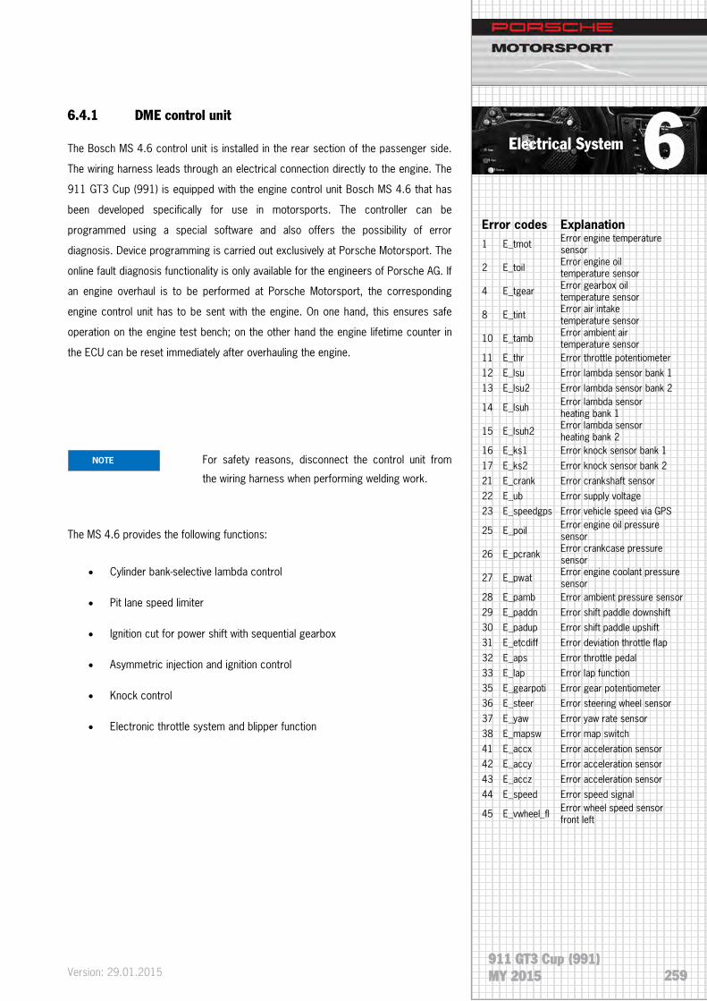
Electrical System
6.4.1 DME control unit
The Bosch MS 4.6 control unit is installed in the rear section of the passenger side.
The wiring harness leads through an electrical connection directly to the engine. The
911 GT3 Cup (991) is equipped with the engine control unit Bosch MS 4.6 that has
been developed specifically for use in motorsports. The controller can be
programmed using a special software and also offers the possibility of error
diagnosis. Device programming is carried out exclusively at Porsche Motorsport. The
online fault diagnosis functionality is only available for the engineers of Porsche AG. If
an engine overhaul is to be performed at Porsche Motorsport, the corresponding
engine control unit has to be sent with the engine. On one hand, this ensures safe
operation on the engine test bench; on the other hand the engine lifetime counter in
the ECU can be reset immediately after overhauling the engine.
For safety reasons, disconnect the control unit from
the wiring harness when performing welding work.
The MS 4.6 provides the following functions:
• Cylinder bank-selective lambda control
• Pit lane speed limiter
• Ignition cut for power shift with sequential gearbox
• Asymmetric injection and ignition control
• Knock control
• Electronic throttle system and blipper function
Error codes Explanation 1 E_tmot Error engine temperature
sensor
2 E_toil Error engine oil temperature sensor
4 E_tgear Error gearbox oil temperature sensor
8 E_tint Error air intake temperature sensor
10 E_tamb Error ambient air temperature sensor
11 E_thr Error throttle potentiometer 12 E_lsu Error lambda sensor bank 1 13 E_lsu2 Error lambda sensor bank 2
14 E_lsuh Error lambda sensor heating bank 1
15 E_lsuh2 Error lambda sensor heating bank 2
16 E_ks1 Error knock sensor bank 1
17 E_ks2 Error knock sensor bank 2 21 E_crank Error crankshaft sensor 22 E_ub Error supply voltage 23 E_speedgps Error vehicle speed via GPS
25 E_poil Error engine oil pressure sensor
26 E_pcrank Error crankcase pressure sensor
27 E_pwat Error engine coolant pressure sensor
28 E_pamb Error ambient pressure sensor 29 E_paddn Error shift paddle downshift 30 E_padup Error shift paddle upshift 31 E_etcdiff Error deviation throttle flap
32 E_aps Error throttle pedal 33 E_lap Error lap function 35 E_gearpoti Error gear potentiometer 36 E_steer Error steering wheel sensor
37 E_yaw Error yaw rate sensor 38 E_mapsw Error map switch 41 E_accx Error acceleration sensor 42 E_accy Error acceleration sensor
43 E_accz Error acceleration sensor 44 E_speed Error speed signal
45 E_vwheel_fl Error wheel speed sensor front left
NOTE
Version: 29.01.2015 259 911 GT3 Cup (991) MY 2015

Electrical System
6.4.2 DME diagnosis
For Bosch component diagnosis, a separate connector is provided on the wiring
harness, which is located on the B-pillar of the passenger side. This connection
allows communication between the ECU and a computer using an interface cable.
The Bosch MS4.6 engine control unit originates from the GT3 Series (MED17). A
software tool called RaceCon is available for diagnosis. This software is used to
display certain parameters and provides the opportunity to delete error entries in the
control unit.
RaceCon (USB drive):
Porsche part number: 991.618.815.8A
6.4.3 Carburation
Carburation is cylinder-selective and is created by injecting fuel into the intake ducts.
The fuel pressure sensor of the 911 GT3 Cup (991), is located at the supply line in
the engine compartment.
6.4.4 Ignition system
A fully electronic ignition system is used on the 911 GT3 Cup (991) engine. This
means that the ignition coils receive the ignition signals directly from the ECU. The
direct-ignition coils which mounted on top of the spark plugs are extremely rugged
and temperature-resistant. Even under extreme conditions the coils provide the
required ignition energy.
46 E_vwheel_fr Error wheel speed sensor front right
47 E_vwheel_rl Error wheel speed sensor rear left
48 E_vwheel_rr Error wheel speed sensor rear right
49 E_pclutch Error clutch pressure sensor
51 E_pfuel Error fuel pressure sensor
53 E_pgear Error gearbox pressure sensor
54 E_brev Error reverse gear switch
61 E_psdia_fpump Error fuel pump
62 E_psdia_mil Error MIL (malfunction indicator lamp)
63 E_psdia_oillamp Error oil pressure warning
66 E_psdia_etc Error throttle flap
67 E_psdia_intake- manifoldflap Error resonance flap 1
68 E_psdia_intake- manifoldflap2 Error resonance flap 2
71 E_can1 Error CAN 1 72 E_can2 Error CAN 2 73 E_can3 Error CAN 3
77 E_psdia_vlvdn Error shift valve downshift
78 E_psdia_vlvup Error shift valve upshift 79 E_cam Error camshaft sensor
84 E_gearpoti2 Error gear potentiometer 2
85 E_ecusply Error voltage supply ECU 86 E_ignition_bank1 Error ignition bank 1 87 E_ignition_bank2 Error ignition bank 2 88 E_ignition_cyl1 Error ignition cylinder 1
89 E_ignition_cyl2 Error ignition cylinder 2 90 E_ignition_cyl3 Error ignition cylinder 3 91 E_ignition_cyl4 Error ignition cylinder 4 92 E_ignition_cyl5 Error ignition cylinder 5
93 E_ignition_cyl6 Error ignition cylinder 6 94 E_injection_cyl1 Error injection cylinder 1 95 E_injection_cyl2 Error injection cylinder 2 96 E_injection_cyl3 Error injection cylinder 3
97 E_injection_cyl4 Error injection cylinder 4 98 E_injection_cyl5 Error injection cylinder 5 99 E_injection_cyl6 Error injection cylinder 6 100 E_nvram Error NVRAM
101 E_ssply1 Error sensor voltage supply 1
102 E_ssply2 Error sensor voltage supply 2
103 E_ssply3 Error sensor voltage supply 3
Version: 29.01.2015
260 911 GT3 Cup (991)
MY 2015

Electrical System
6.5 Sensors
Upon delivery, the following sensors are used in the vehicle:
Parameter Label in the PI Cosworth ICD Display
Label in Bosch RaceCon
Engine
Oil temperature Oil Temp toil
Water temperature Water Temp tmot
Oil pressure Oil Pressure poil
Water pressure Eng Coolant Pres pwat
Fuel pressure Fuel Pres pfuel
Accelerator pedal position APS aps
Throttle angle ATH ath
Air pressure Air Pressure - Airbox pu
Air temperature Air Temp - Intake tans
Crankcase pressure (relative) --- pcrank_rel
Camshaft phase sensor --- phspos_w
Flywheel speed sensor RPM nmot
Cooling water level switch Water Level Switch ---
Gearbox
Gearbox potentiometer Gear Pos Volts ugearp
Clutch pressure Pressure clutch pclutch
Gearbox oil temperature Gearbox Oil Temp tgear
Entire vehicle
Wheel speed sensor (4x) Wheel Speed Vwheel_xx
Battery voltage Battery Voltage at Dash ub
Acceleration sensor (x,y,z) G Lat
G Long
G Force Vert
accy
accx
Brake bias potentiometer Brake Bias Setting ---
Brake light switch Brake Status ---
104 E_etccal Error calibration throttle
105 E_canmsg_ dyno_0 Error can message
106 E_canmsg_ dyno_1 Error can message
107 E_canmsg_ dyno_2 Error can message
108 E_canmsg_ icd_0 Error can message
109 E_canmsg_ icd_1 Error can message
110 E_canmsg_ icd_2 Error can message
111 E_canmsg_ shiftec_1 Error can message
112 E_canmsg_ shiftec_2 Error can message
113 E_icmpr Error compressor current 114 E_tcmpr Error compressor temp.
115 E_ucmpr Error compressor voltage 116 E_accx_can Error acceleration sensor 117 E_accy_can Error acceleration sensor 118 E_accz_can Error acceleration sensor
119 E_steer_can Error steerangle sensor 120 E_yaw_can Error yaw rate sensor 121 E_paccu Error compressor pressure 123 E_etccal_abort Error calibration throttle
Version: 29.01.2015 261 911 GT3 Cup (991) MY 2015

Electrical System
6.5.1 Sensor rated values
Parameter Bosch label Rated value Comment
Engine idle speed nmot 2000 +/-100 rpm At operating temperature (oil 80 °C (176 °F)
Throttle angle idle ath 6.5 +/- 1.0°
Throttle angle full power
ath 80 +/- 2 ° Bosch value => corresponds to 100% at PI Dash
Lambda cyl. 1-3/4-6 Lambda / 2 0.9 +/- 0.1 Throttle > 10°
Lambda control factor Frc / 2 1.0 +/- 0.2
Battery voltage ub 13 +/- 1 V
Water pressure pwat > 0.2 bar (2.9 psi)
Fuel pressure pfuel 4.6 - 0.3 bar (66.7 – 4.3 psi)
Averaged over a full lap
Clutch pressure pclutch > 30 bar (435 psi) Clutch completely pressed
Gearbox potentiometer voltage
ugearp
Version: 29.01.2015
262 911 GT3 Cup (991)
MY 2015

Electrical System
6.5.2 Optional sensors
Porsche Motorsport optionally offers a steering angle sensor and brake pressure
sensors. In addition, a memory extension is recommended when fitting optional
sensors. See chapter 6.6.1
Version: 29.01.2015 263 911 GT3 Cup (991) MY 2015

Electrical System
6.6 ICD Display
6.6.1 General
6.6.1.1
The ICD (Intelligent color display) supplied by PI Cosworth is a universal display unit
with integrated data storage. The 6.2” TFT color display provides the driver with
substantial information. 8 LEDs acting as shift lights (green - yellow - red) are located
on top of the display. The four LEDs arranged on either side are used as alarm
indicators. The data saved in the internal memory (32MB) can be downloaded using
an interface cable via the diagnostic connector on the passenger side.
The display contains five main pages that are configured in accordance with the
respective requirements.
During driving, only the following two pages configured for the intended purpose are
available:
• Race
• Practice
When the vehicle speed is less than 10 kph (6.2 mph), three additional diagnosis
pages are visible.
Version: 29.01.2015
264 911 GT3 Cup (991)
MY 2015

Electrical System
The yellow button (1) on the right side of the steering wheel is used to navigate
through the different pages. A long press changes the page number; a short press
navigates to the main page (Race).
When adjusting the brake bias, activating the pit speed or when an alarm is active,
the corresponding displays have priority and overlay other pages.
Extension option
An upgrade kit for the display is available at Cosworth:
Cosworth part number: 01D-032953-P-CUP
The kit includes the following extensions:
• Storage extension from 32 MB to 128 MB
• The logging rate is increased from 50 to 200 Hz
• Extension of five analog inputs to nine analog inputs. The inputs are available for steering angle, brake pressures and engine compartment temperature.
• Real-time lap time calculation
Contact address:
Brookfield Technology Centre
Twentypence Road
Cottenham
Cambridge
CB24 8PS
United Kingdom
Phone: +44 (0)19 54-25 36 00
Fax: +44 (0)19 54-25 36 01
E-Mail: [email protected]
1
6.6.1.2
6.6.1.3
Version: 29.01.2015 265 911 GT3 Cup (991) MY 2015

Electrical System
6.6.2 Race page
The “Race” page configured for races is divided into three information areas.
6.6.2.1
1 Engine speed
2 Channel information
3 Alarm information
Engine speed is sent from the Bosch ECU to the display and is displayed from 1500
to 10,000 rpm. The speed area is divided into three sections:
• Green from 1,500 to 7,000 rpm
• Yellow from 7,000 to 8,500 rpm
• Red from 8,500 to 10,000 rpm
The shift lights located on top of the display are linked to the speed signal and are
activated according to the above mentioned thresholds.
1
2
3
6.6.2.2
Version: 29.01.2015
266 911 GT3 Cup (991)
MY 2015

Electrical System
The display is divided into three main areas.
6.6.2.3
1 Channel pairs to be selected by a switch on the steering wheel
2 Fixed display of RPM, gear number and speed
3 Fixed display of Fuel level (after power on), if you start the engine you see
the Fuel Press for 3 seconds and after 3 seconds the Fuel Press switches
to Fuel Cons. Below qualifying mode and lap time is shown.
Left panel
The left panel (6.6.2.4) displays a rotating pair of parameters:
Order Display name
Channel Description PI Toolbox
channel name
1 Water T
Oil T
Water temperature
Oil temperature
MS4 tmot
MS4 toil
2 Oil P
Fuel P
Oil pressure
Fuel pressure
MS4 poil
M pfuel
3 Fuel lap
Fuel Used
Fuel usage per lap
Total fuel usage
MS4 fuellap old
MS4 fueltotal
4 Fuel Level
Oil level
Fuel level
Oil level
Fuel Level
5 Brake bias
Brake bal
Brake bias acc. to potentiometer
Brake balance from brake pressure sensors
Brake Bias
Brake Balance
1 2 3
6.6.2.4
Version: 29.01.2015 267 911 GT3 Cup (991) MY 2015

Electrical System
Center panel/fixed display
The top value is related to the engine speed. The large “N” in the middle indicates the
gear number and the lower number displays the vehicle speed.
Display Description
- Indicates a gear position between 2 valid gear numbers
R Reverse
N Neutral
F An unrecognized value is being sent from the Bosch ECU
1,2,3,4,5,6 Valid gear numbers
Right panel
The first value indicates the fuel level, but fuel pressure will be displayed for a short
time during the engine start procedure. In normal running the Fuel Cons is shown. To
reset the fuel consumption number, press and hold the Mark button for more than
1.5 seconds.
Display PI Toolbox
Channel
Description
Fuel Pressure MS4 pfuel Shown for 3 seconds after the engine has started to turn over (MS4 tmot > 0)
Fuel Level Fuel Level The fuel sensor in the fuel tank has to be calibrated to show exact values.
“Time Diff” shows gain or loss compared to a reference lap.
Display Example Description
Minus number -0.25 0.25 seconds quicker compared to the previous lap
Positive number +0.3 0.3 seconds slower compared to the previous lap
Lap Time Display (two options)
Display PI Toolbox
Channel
Description
Fixed time Lap Time After the car passes the finish line, the lap time is displayed for 30 seconds
Rolling time Rolling Stopwatch time for the current lap, updated after passing the finish line
Alarm information
The lower area shows system warnings and alarms, when they occur.
6.6.2.5
6.6.2.6
6.6.2.8
6.6.2.7
Version: 29.01.2015
268 911 GT3 Cup (991)
MY 2015

Electrical System
6.6.3 Practice page
The relevant practice data are configured on the “Pract” page of the display. The
layout is similar to the “Race” page but with different channel information.
6.6.3.1
1 Engine speed
2 Channel information
3 Alarm information
Left panel
Two different times can be displayed on the left panel (6.6.3.2). The time is always
shown in the following format:
m:SS.ss
Display Description
Lap Time The lap time from the lap just completed is shown for 30 seconds.
Rolling Time The time for the current lap is updated when passing the finish line.
Lap #: Number of completed laps
Speed: Speed information from engine ECU
1
2
3
6.6.3.2
Version: 29.01.2015 269 911 GT3 Cup (991) MY 2015

Electrical System
Right panel
Time Diff: This is the time difference calculated in “qualifying mode“ between
the current lap and a reference lap.
The upper image (6.6.3.3) shows a negative value, indicating that the driver is
currently 0.11 seconds faster than the reference lap. The green bar also shows the
same value. The range of the bar graph is from -1 to +1 second.
The lower image (6.6.3.4) shows a slower lap by 0.54 seconds.
6.6.3.3
6.6.3.4
Version: 29.01.2015
270 911 GT3 Cup (991)
MY 2015

Electrical System
6.6.4 Warmup page
Enlarged letters and numbers of Rpm, water temperature, and oil temperature are
displayed on the “warmup” page (6.6.4.1). This allows the page and the different
parameters to be visible from outside the car.
6.6.4.1
1 Engine speed
2 Channel information
3 Alarm information
The engine warmup speed range is shown in a smaller scale on the bargraph. The
following rpm range is sufficient for warming up the engine:
RPM from 0 to 5,000 rpm are indicated in yellow.
The scales of the bargraph for water and oil temperature shows 0 to 120 °C (32° -
248 °F), with all values over 100 °C (212 °F) in red.
The gear number is also displayed in the middle of the “Warmup” page.
6.6.4.2
1
2
3
Version: 29.01.2015 271 911 GT3 Cup (991) MY 2015

Electrical System
6.6.5 Vitals page
The „Vitals“ page (6.6.5.1) gives an overview of the vital functions of the engine and
the vehicle. The important channels are all displayed on one page. The displays and
values on this page are fixed and cannot be changed.
1 Channel information
2 Alarm information
Left panel
Oil display (6.6.5.2)
Label PI Toolbox channel
Resolution Unit Scale
Oil Press MS4 poil 0.05 bar 12.75 (185 psi)
Oil Temp MS4 toil 1 Grad C
Degrees C
-40 to 215 (-40 to 419 °F)
Steering (6.6.5.3)
1
2
6.6.5.2
6.6.5.1
6.6.5.3
Version: 29.01.2015
272 911 GT3 Cup (991)
MY 2015

Electrical System
Odometer (6.6.5.4)
To reset the Odometer press and hold the Mark button for more than 1.5 seconds.
Label Resolution Unit Scale Description
Total Distance
0.1 km 0 - 999999.9 (0-621371 mi)
Cumulative channel
Trip Distance
0.001 km 0 - 9999.999 (0-6213.71 mi)
Trip resets
Middle panel
Water display (6.6.5.5)
Fuel tank display (6.6.5.6)
Label PI Toolbox channel
Resolution Unit Scale Description
Fuel Level
Fuel Level 0.1 Liter 0 - 110.0 (0 – 29 gal)
Calibrated sensor, so min and max could change.
Bargraph Fuel Level 1 Non-linear display
Fuel Press
MS4 pfuel 0.05 bar 12.75 (185 psi)
Label PI Toolbox channel
Resolution Unit Scale Description
Water Press
MS4 pwat 0.05 bar 12.75 (185 psi)
Water Temp
MS4 tmot 1 Deg C -40 to 215 (-40 to 419 °F)
Water Level
SW09 Water Level Button
1 Digital 0 - 1 Value of 1 indicates “level sensor is immersed”.
6.6.5.4
6.6.5.5
6.6.5.6
Version: 29.01.2015 273 911 GT3 Cup (991) MY 2015

Electrical System
Right panel
Gear Pot (6.6.5.7)
Label PI Toolbox channel
Resolution Unit Scale
Gear Voltage
MS4 ugearp 0.001 V 65.535
Battery display (6.6.5.8)
Label PI Toolbox channel
Resolution Unit Scale Description
ICD Voltage
Battery Voltage 0.1 V 0 - 99.9 Voltage seen by the ICD
Power system (6.6.5.9)
Display PI Toolbox channel Unit Description
Trip IPS Error Alarm Bit Will show “active” if there is a faulty current on any of the 32 IPS channels.
Over current
IPS Output Current Alarm
Bit Will show “active” if the IPS power system has seen more than its rated current.
Over Temp IPS Temp Alarm Bit Will show “active” if the IPS power system maximum operating temperature is exceeded.
6.6.5.8
6.6.5.7
6.6.5.9
Version: 29.01.2015
274 911 GT3 Cup (991)
MY 2015

Electrical System
6.6.6 Pedals page
The “Pedals” page (6.6.6.1) displays all important pedal information. Brake pressures
as well as the position/function of the accelerator pedal and the electronic throttle
can be checked.
Left panel
A graphical interpration of front and rear brake pressures and of the balance and the
brake bias is displayed (6.6.6.2)
Display PI Toolbox channel
Resolution Unit Scale Description
BP F Brake Press Front
1 bar 0 – 100 (0 -1450 psi)
Balance Brake Balance
1 % 0 - 100 Per-cent value
BP R Brake Press Rear
1 Bar 0 – 100 (0 -1450 psi)
Brake Bias
Brake Bias 1 -10 to +10 Mechanical bias position
6.6.6.1
6.6.6.2
Version: 29.01.2015 275 911 GT3 Cup (991) MY 2015

Electrical System
Middle panel
Shows numerical values for brake and throttle
Display PI Toolbox channel
Resolution Unit Scale Description
Brake P Front
Brake Press Front 0.1 bar 0 – 280 (0- 4,061 psi)
250 bar sensor
Brake P Rear
Brake Press Rear 0.1 Bar 0 – 280 (0 – 4,061 psi)
250 bar sensor
Brake Balance
Brake Balance 0.1 % 0 - 100 Mathematical calculation of balance
Brake Bias
Brake Bias 1 -10 to +10 Mechanical bias position
ATH MS4 ATH 0.1 % 0 - 127.4 Engine throttle sensor
APS MS4 APS 0.1 % 0 - 127.4 Pedal sensor
Right panel
Graphical representation of the fly-by-wire sensors
Display PI Toolbox channel
Resolution Unit Scale Description
MS4 ATH 0.1 % 0 - 127.4 Numerical engine throttle sensor
MS4 APS 0.1 % 0 - 127.4 Numerical pedal sensor
ATH MS4 ATH 10 % 0 - 100 Bargraph engine throttle sensor
APS MS4 APS 10 % 0 - 100 Bargraph pedal sensor
6.6.6.4
6.6.6.3
Version: 29.01.2015
276 911 GT3 Cup (991)
MY 2015

Electrical System
6.6.7 Additional information
Overlays
Additional information of higher priority will overlay all other displays for a limited
period.
Brake bias:
While adjusting the mechanical brake bias, values in steps of 0.25 will be displayed.
The display will keep this setting change one second and returns afterwards to the
previous display (6.6.7.1).
6.6.7.1
Version: 29.01.2015 277 911 GT3 Cup (991) MY 2015

Electrical System
Pit speed
“Pit Speed” is enabled with the orange switch (1) on the steering wheel (6.6.7.2).
Activating the “Pit speed” mode only possible above 10 kph (6.2 mph)
There are two types of pit speed display:
The green background is displayed as long as the target speed of 60 kph (37 mph)
is not exceeded (6.6.7.3).
The red background is displayed as soon as the target speed of 60 kph has been
exceeded (6.6.7.4).
6.6.7.3
6.6.7.4
6.6.7.2
1
Version: 29.01.2015
278 911 GT3 Cup (991)
MY 2015

Electrical System
Alarm displays
There are three types of alarm displays:
Alarm level
Where Text Lights
1 Middle display panel ALARM 4 flashing lights
2 Lower information area ALARM/WARN Continuous lights
3 Lower information area ALARM/WARN Continuous lights
Level 1 alarms
The main alarm page is triggered by only a few parameters. This alarm page has the
highest priority and will always be displayed in the foreground.
Any alarm can be cancelled manually but if the error is not sporadic and remains
active, the alarm re-appears on the display.
Priority Alarm Channel Conditions Description
1 Water Temp.
MS4 tmot >110°C (230 °F) more than 2 sec.
Can be cancelled, re-trigger after 2 seconds
2 Oil Press MS4 B oillamp
Bit is active This alarm is displayed at least 1 sec. (by means of calculated channel “Alarm Oil Press Display“)
Alarm with highest priority:
the two upper LEDs of the
display are flashing.
6.6.7.6
6.6.7.5
Version: 29.01.2015 279 911 GT3 Cup (991) MY 2015

Electrical System
Level 2 alarms
Every level 2 ALARM is labeled as ALARM. If the message has lower priority “WARN”
appears in the display, together with the error description.
Priority Alarm Channel Conditions Description
3 Fuel pressure
MS4 pfuel <2.5 bar (36 psi) for 5 sec.
Engine speed more than 2000 rpm
4 Oil temperature
MS4 toil >140°C (284 °F) for 5 sec.
5 Water pressure
MS4 pwat <0.35 bar (5 psi) for 10 sec.
Engine speed more than 5000 rpm
Water temperature at least 68 °C (154 °F)
Vehicle is moving
6 Battery Battery Voltage
<11.5 V for 5 sec. Engine speed more than 2000 rpm
7 Water level Engine Sensor on Digital 15
After 5 sec.
Alarm/warning with lower
priority:
The two lower LEDs of the
display are lit.
6.6.7.7
6.6.7.8
Version: 29.01.2015
280 911 GT3 Cup (991)
MY 2015

Electrical System
Level 3 alarms
Any additional level 3 warning or information message is shown in the display with a
short description.
Priority Alarm Channel Conditions Description
8 Pit Speed
SW03 Pit Speed Button
Active for 0.5 sec.
9 Gearbox MS4 B emsw
Active for 1 sec. Gearbox emergency switch for manual shift without querying relevant parameters (no autom. double de-clutching, no rev matching)
10 Low fuel Fuel Level <7 liters (1.8 gal) for 12 seconds
Engine speed more than 2000 rpm
11 Ignition on
Condition Ignition
Ignition is active Engine rpm 0 (e.g. after engine stop)
12 Low RPM Engine cranking
Active for 0.5 sec.
Warning/information:
The upper left LED of the display
is lit.
6.6.7.9
Version: 29.01.2015 281 911 GT3 Cup (991) MY 2015

Electrical System
Wheel lock lights
This function is provided to help the driver to prevent unnecessary tire wear caused
by locking front wheels.
A potential lock up of the front wheels are indicated by a flashing LED on the display.
If the front brake pressure is more than 10 bar (145 psi) and the speed of the left
front wheel is less than that of the left rear wheel by 20 kph (12 mph), the top left
warning light comes on (6.6.7.10).
If the front brake pressure is more than 10 bar (145 psi) and the speed of the right
front wheel is less than the speed of the right rear wheel by 20 kph (12 mph), the top
right warning light comes on (6.6.7.11).
Other indicator lights on the display
• Left indicator: the green LED (1) flashes.
• Right indicator: the green LED (3) flashes.
• Warning lights: the green LED´s (1) and (3) flash.
• Driving lights: the blue LED (4) lights, the LED (4) flashes in case of a malfunction e.g. the right headlight is defective.
• Engine control lamp: the yellow LED (2) will appear in case of an error. The information comes directly from the engine ECU
Map Page
The map is a bmp-file of 800x480 aspect ratio and is configured by Pi Toolset. If a
new bmp-file is loaded then this is displayed when the ICD is next power cycled. This
feature is to allow maps or other instructions to be displayed to the driver.
6.6.7.10
6.6.7.11
6.6.7.12
6.6.7.13
Version: 29.01.2015
282 911 GT3 Cup (991)
MY 2015

Electrical System
6.7 Lights
The 911 GT3 Cup (991) is equipped with xenon headlights and front lights incl.
daytime running lights, position, and indicator lights in LED technology. The headlight
leveling control is without function. The headlight leveling control motor is only used
for fixing the xenon lens.
The rear lights are also designed in LED technology. The fog lamps are also without
function.
Caution when working on xenon lights. The system is
under high voltage.
The system has to be de-energized before working on
xenon lights. Risk of electric shock.
6.7.2
Xenon (low beam light)
6.7.3
Middle rear light
The middle rear light is used as rain lights. It is actuated by the “Rear Fog” switch in
the center console.
WARNING
6.7.1
Version: 29.01.2015 283 911 GT3 Cup (991) MY 2015

Electrical System
6.8 Data bus system
Four CAN bus systems and two LIN bus systems are used in the vehicle.
Data bus overview:
6.8.1
CAN 1 (highspeed) Communication between engine ECU and display
(1Mbit/s)
CAN 2 (highspeed) Communication between electrical system control
unit and display (1 Mbit/s)
CAN 3 (lowspeed) Communication between engine ECU and
Paddleshift
CAN 4 (highspeed) Acceleration and yaw sensor (500 kbit/s)
LIN 1 Fan activation (screen or driver) on the display
LIN 2 Wiper activation via electrical system control unit
Version: 29.01.2015
284 911 GT3 Cup (991)
MY 2015

Electrical System
6.9 Wiring harness
For the 911 GT3 Cup (991), a wiring harness that runs along the center tunnel from
the front to the back has been specially developed for racing use. The wiring harness
is separated as follows:
Engine Porsche Spare part number: 997 607 012 99
Vehicle cable harness Porsche Spare part number: 991 612 101 8A
Front axle wheel carrier Porsche Spare part number: 991 612 946 8A
Rear axle wheel carrier Porsche Spare part number: 991 612 948 8A
Front section Porsche Spare part number: 991 612 301 8A
Fuel tank Porsche Spare part number: 991 201 697 8A
Starter cable B+ Porsche Spare part number: 991 612 395 8A
Steering Porsche Spare part number: 991 612 830 8A
6.10 Ground connection roof antenna
Since the roof panel is bonded to the body, there is no electrically conductive
connection with the bodywork. If an antenna is mounted on the roof, a ground
connection must be made from the roof to the body. Therefore, you can use the stud
in the back strut. (Figure 6.10.1).
6.10.1
Version: 29.01.2015 285 911 GT3 Cup (991) MY 2015

Electrical System
6.11 Fire extinguisher
The fire-extinguishing system uses a liquid extinguishing agent. It consists of a two-
chamber reservoir that stores the liquid extinguishing agent and turns it into gas
when it is activated. This allows residue-free extinguishing. Two gas cartridges that
are activated by a control unit are used as propellant. The contents of the
extinguishing agent container have a mass of 2.25 kg (5 lb), which helps to keep the
overall vehicle weight low. The extinguishing agent passes through three nozzles into
the cockpit and through another three nozzles into the engine compartment. The
system can be activated from the outside (6.11.2) and from the center console
(6.11.3) by a pushbutton. The switch function can be tested. The system is powered
by a 9 V block battery.
Contact address:
Fire Extinguisher Valve Company Ltd (FEV)
Unit 10 Ford Lane Business Park
Ford Nr Arundel West Sussex
BN18 OUZ
United Kingdom
Phone: +44(0) 12 43-55 55 66
Extinguishing nozzle positions
6.11.4
1 Driver‘s footwell
2 Interior B-pillar top
3 Engine compartment front
middle
4 Engine compartment rear
left/right
6.11.1
6.11.2
6.11.3
Version: 29.01.2015
286 911 GT3 Cup (991)
MY 2015

Electrical System
6.11.1 Testing the trigger switch
The switch test is performed on the fire extinguishing system control unit. Always
follow the steps below to prevent unintended triggering of the system. The switch (2)
has three positions.
Upper position: = Battery/Circuit test
Central position: = (OFF) The system is switched off
Lower position: = (ARMED if ON) The system is armed if the red LED will be ON. If
either the wiring or firing detonator is faulty or the detonator is
either not there or has already fired, then the LED will not light.
Testing the trigger switch:
Set the switch on the control unit to the upper position
The green LED lights up 1 sec. (battery is OK)
The system is in test mode and not active. The trigger switch on the center console
and the outside trigger switch can now be actuated.
When pressing the switch inside/outside the yellow LED should be off. The LED lights
steadily and goes out when you press the switch.
6.11.2 Battery change
The battery is located behind a cover in the control unit (1). It is a 9 V block battery.
Turn off the system when changing the batter.
1
2
6.11.1.1
Version: 29.01.2015 287 911 GT3 Cup (991) MY 2015

Electrical System
6.12 Driver Control Systems
6.12.1 Steering wheel
The most important functions can be comfortably carried out with the press of a
button directly from the steering wheel.
6.12.1.2
The steering wheel is attached to the steering column by means of a quick release
coupling.
Pushbutton functions on the steering wheel:
Wiper = Push button for the wipers, 2-stage
High Beam = High beam flash
Radio = Radio system
Mark = Marking for data recording
Reverse = Reverse gear
Alarm = Acknowledge button to confirm display messages
Display = Selection of individual display pages
Pit Speed = Pit speed
6.12.1.1
Version: 29.01.2015
288 911 GT3 Cup (991)
MY 2015

Electrical System
6.12.2 Center console
Switches and pushbuttons are located in the center console. Their functions are
described below.
Main = Power supply 4 to 6 sec. overrun
Fuel Pump Service = High pressure pump switch
Intank Pump Service = Intank pump switch
Ignition = Ignition
Light = Low beam light with daytime running light
Rear Fog Light = Middle rear light
Flasher = Flasher left/right
Fan = Fan
Screen/Driver = Fan position windshield/driver
Emergency Gear Box = Press only if shifting gears is no longer possible.
Pressing the button activates an emergency mode to
drive to the pit
Hazard = Warning lights
Fire Ex. = Fire extinguishing system
6.12.2.1
Version: 29.01.2015 289 911 GT3 Cup (991) MY 2015

Electrical System
6.12.3 Windscreen wiper
The wiper motor is activated by the display via the LIN.
A green push button is provided on the steering wheel. The wiper motor has two
stages: slow and fast.
Switching logic:
Press once short: one time on
Press once longer 1,5 second: continuity wiping
Press once short: off
6.12.4 Interior fan switch
The On/Off switch is located in the center console. The fan speed is not adjustable.
Another switch in the center console controls the air distribution. There are two
options: “Screen” (windscreen) and “Driver”. The fan is used to cool the driver or to
ensure a clear view when the windshield is misting up.
6.12.3.1
6.12.4.1
Version: 29.01.2015
290 911 GT3 Cup (991)
MY 2015

Maintenance 7 Maintenance
7.1 Engine
7.1.1 Oil level measurement using the dipstick
Conditions for the correct measurement:
• The vehicle should be on a flat, even surface
• Engine at operating temperature, oil temperature 80 °C (176 °F)
• Idle speed
Follow the steps below for correct measuring:
• Remove filler neck cap (7.1.1.1)
The dipstick (7.1.1.2) is located behind the cap in the
filler neck
• Pull the dipstick out of the filler neck and wipe the oil off the dipstick using a clean cloth
• Introduce the dipstick again into the filler neck
• Pull the dipstick again out of the oil reservoir and read the oil level
The difference between MIN and MAX is 1 liter (1.06
qt). (7.1.1.3) Fill in half liters (0.53 qt) of engine oil!
NOTE
NOTE
7.1.1.1
7.1.1.2
7.1.1.3
Version: 29.01.2015 291 911 GT3 Cup (991) MY 2015

Maintenance
7.1.2 Oil level measurement with display
A digital oil level indicator (7.1.2.1) is optionally available Porsche spare parts
number: 997.641.139.9A. Adapter cable Porsche spare parts number:
991:612:334.8A
The vehicle cable harness is already prepared for this indicator. On the vehicle itself,
the connector for the oil level indicator is provided near the rear side window on the
right side of the vehicle.
According to the digital display, the system filling level
should not exceed 90 %.
7.1.3 Changing the engine oil
Warm up the engine to an oil temperature of 80 °C (176 °F) and then turn off the
engine.
• When changing the oil filter: Open the oil filler
neck cover & release and pull out the oil filter housing slightly.
• Without changing the oil filter: Open the oil filler neck cover.
This guarantees that the oil flows out without bubbles
and the oil system is sufficiently drained.
• Remove the drain plugs on the oil tank and on the crankcase (item 2 in picture 7.1.3.1)
• Allow the oil to run into a suitable container
• Use new sealing rings and tighten the drain plugs (50 Nm (37 lb-ft) tightening torque)
• Change the oil filter
• Fill in oil -> see filling quantities
NOTE
WARNING
7.1.3.1
7.1.2.1
Version: 29.01.2015
292 911 GT3 Cup (991)
MY 2015

Maintenance
7.1.4 Refilling engine oil
• New engine: 11.0 l (11.6 qt)
• Incl. oil filter change: 8.3 l (8.8 qt)
• Without oil filter change: 8.1 l (8.6 qt)
Consumables:
Porsche spare part number: 996.107.225.53 Oil filter element
Porsche spare part number: 900.123.010.20 Oil tank seal ring
Porsche spare part number: 900.123.118.30 Crankcase seal ring
7.1.5 Oil specification
Mobil 1 0W – 40
Version: 29.01.2015 293 911 GT3 Cup (991) MY 2015

Maintenance
7.1.6 Engine cooling system
Periodically remove dirt from the radiators and carry out a visual inspection for
damage.
For support races to the FIA Formula 1
Worldchampionship, the coolant is to be substituted as
described below: approx. 20 liters (21.1 qt) of water
plus min. 2 liters (2.1 qt) of corrosion protection, spare
part no. 997.106.907.90
Filling quantity: 22 liters (23.2 qts.)
Draining the coolant system
• Open the coolant compensating tank cover
• Remove the drain plugs (item 1 in picture 7.1.6.1)
• Allow the coolant to run into suitable containers
• Provide the drain plugs with new seal rings and screw tight (10 Nm (7.4 lb-ft) tightening torque)
Consumables:
Porsche spare part number: 900.123.144.30 Coolant circuit seal ring
NOTE
7.1.6.1
Version: 29.01.2015
294 911 GT3 Cup (991)
MY 2015

Maintenance
Filling the cooling system
• Disconnect the quick coupling in the engine compartment and connect the open ends to the two couplings of the filling device
• Switch on the pump; the system is being filled
• The device should be turned on for ten minutes to ensure proper filling and venting
• Allow the engine to warm up (80 °C / 176 °F) and, if required, fill the container up to the maximum level using the connected filling device
• The compensating tank cover must be closed during the entire procedure
Never open the cover of the coolant compensating
tank after reaching the operating temperature. The
system pressure would escape and will not be built up
again as the operating temperature has already been
reached. This pressure is, however, required to
increase the boiling point of the cooling water.
A special filling device should be used for filling the water system (7.1.6.2). This
device is distributed by Sobek. The filling device includes an electric pump that
pumps the cooling water from a tank into the system.
NOTE
7.1.6.2
SOBEK Motorsporttechnik GmbH & Co.KG
Industriestraße 8
68542 Heddesheim
Tel.: +49 (0)62 03-40 43 90 0
Fax: +49 (0)62 03-40 43 91 8
E-Mail: [email protected]
Version: 29.01.2015 295 911 GT3 Cup (991) MY 2015

Maintenance
Checking the coolant level
If possible, open the compensating tank cap (1) only when the engine is cold. When
opening the system while the engine is hot, air may penetrate into the system and
impair the function. A float (2) indicating the fluid level is provided behind the cap.
When the engine is cold, the fluid level should be between min and max. Place the
vehicle on a flat surface to ensure proper measurement.
Caution when opening the system when the engine is
hot. The system is under pressure! Risk of scalding!
Put a cloth over the cap and carefully open the cap.
7.1.7 Setting the valve timing
• Inlet camshaft timing 110° after TDC
• Exhaust camshaft timing 110° before TDC
WARNiNG
7.1.6.3
Version: 29.01.2015
296 911 GT3 Cup (991)
MY 2015

Maintenance
7.1.8 Engine tightening torques
*1=Pre-tightening 30 Nm +/- 3 Nm (22 ± 3 lb-ft)
Final tightening 62° +/-2° rotation angle
Resulting expansion 0.200 +/- 0.015 mm (0.008 ± 0.0006”)
7.1.9 Engine runtime
The 911 GT3 Cup (991) engine is designed for a
maximum speed of 8500 rpm, the service interval is
50 hours.
Component Screw dimensions
Tightening torque [Nm]
Engine Engine mount to body M10 65 (48 lb-ft) Crankshaft and crankcase Connecting rod M10 x 1.25 *1 Oil pump M8 23 (17 lb-ft) Crankshaft bolt/nut M8 23 (17 lb-ft) Pulley to crankshaft M14 x 1.5 170 (125.4 lb-ft) Sealing screw, pressure control and safety valve
M18 x 1.5 40 (29.5 lb-ft)
Crankcase oil drain plug M20 x 1.5 50 (37 lb-ft) Water drain plug cyl. 1-3 M10 x 1 10 (7.4 lb-ft) Water drain plug cyl. 4-6 M10 x 1 10 (7.4 lb-ft) Flywheel M10 Refer to 1.8 Cylinder head Cylinder head bolt M10 Refer to 1.7 Camshaft housing Camshaft housing to cylinder head M8 Pre-tightening: 23 (17
lb-ft) Final tightening: 28 (20.7 lb-ft)
Knock sensor M8 23 (17 lb-ft) Spark plugs M12 x 1.25 22 (16.2 lb-ft) Do not install spark plugs more than five times Camshaft sprocket to camshaft M12 x 1.5 30 (22 lb-ft) + 90° Chain case on crankcase M8 23 (17 lb-ft) Valve cover on camshaft housing M6 9.7 (7.2 lb-ft) Camshaft bearing cover M6 13 (9.6 lb-ft) Auxiliary units
Pulley on generator 55 (40.6 lb-ft) Lambda sensor M18 x 1.5 50 (37 lb-ft) Flywheel coupling M8 x 45 33 (24.3 lb-ft) Oil drain plug on oil tank M20 x 1.5 60 (44.3 lb-ft)
NOTE
Version: 29.01.2015 297 911 GT3 Cup (991) MY 2015

Maintenance
7.2 Fuel system
7.2.1 Fuel
Superplus, unleaded (min. 98 ROZ)
The ethanol content in the fuel may not exceed 26 %
(E26).
7.2.2 Fuel pump
The fuel pump is located in the tank.
7.2.3 Fuel extraction
A defueling valve is provided close to the tank filler neck to empty the fuel tank. Use
a special hose with a quick disconnect coupling for defueling. Connect the quick
disconnect coupling to the nipple of the tank filler neck in the front section. To start
the process, the fuel pump switches located on the center console have to be in
position „Fuel Pump Service”. The fuel pumps are is then powered for 120
seconds. If this is not enough time to completely drain the fuel tank, turn the switches
again from the middle position (pump off) to the “Service” position. Keep the fuel in
suitable containers!
NOTE
7.2.1.1
Version: 29.01.2015
298 911 GT3 Cup (991)
MY 2015

Maintenance
Switching logic of the fuel pump switches (center console):
Switch position up Defueling position
Switch position center Off
Switch position down Normal operation
Auxiliary material:
Porsche spare part number: 997.110.355.91 Fuel extraction hose
The fuel pump should not run dry as this may cause
damage to the pump.
Ensure that the coupling fits tightly. The hose end has
to lead into a suitable container.
NOTE
NOTE
7.2.3.1
Version: 29.01.2015 299 911 GT3 Cup (991) MY 2015

Maintenance
7.3 Power transmission
7.3.1 Gearbox
The running time is 30 hours.
Transmission oil fill quantity
For a rebuild, the fill quantity is 3 liters (3.2 qt).
Filling:
• Place the gearbox on a flat and even surface
• Slowly fill transmission oil in the inclined filler neck
Oil specifications
Mobilube 1SHC75W90
7.3.1.1
Version: 29.01.2015
300 911 GT3 Cup (991)
MY 2015

Maintenance
7.3.2 Clutch
Check the following during any inspection:
• Check clutch basket, hub, sintered disk for cracks
• Check spring tongues for wear
• Check housing lugs for wear
• New sintered lining 3.40 mm (0.13”)
• Replace at 3.00 mm (0.12”)
Installation
• Make sure that the star shapes of the multiple-disk clutch sintered disks are aligned if possible.
• Lightly grease the gear teeth and move the clutch disks back and forth on the drive shaft until the hub moves smoothly on the shaft, remove excess grease.
• No grease should get on the clutch linings.
7.3.2.1
Version: 29.01.2015 301 911 GT3 Cup (991) MY 2015

Maintenance
Clutch actuation
Racing Brake Fluid-325° from Performance Friction Brakes is used as clutch fluid.
Consumables:
Porsche spare part number: 991.355.960.8A Brake fluid
Porsche recommends bleeding the system after each practice and changing the fluid
after each race.
• Fill quantity: approx. 500 ml (17 oz)
Bleeding procedure:
• Depress the clutch pedal 2 to 3 times and keep it depressed
• Shortly open the vent valve – the clutch pedal has to be depressed and should not be released
• Close the vent valve again
• Repeat this procedure 2 to 3 times
• Check the fluid level on the fluid reservoir
Replacement:
• Remove the old fluid out of the reservoir and fill with new fluid
• Then proceed as for venting, perform the steps approx. 10 times and make sure that there is enough fluid in the reservoir
Version: 29.01.2015
302 911 GT3 Cup (991)
MY 2015

Maintenance
Central release mechanism
When handling the central release mechanism seal, be
sure to avoid any contact with transmission oil.
Otherwise, the seal may swell, which, in the worst
case, may cause a loss of function. Only use the Sachs
special tool to fit the seal.
• Also be sure to remove oil residues from your hands and the working
environment before handling the seal (this also applies to engine oil and
other oils).
• According to the manufacturer, the seal is compatible with hydraulic fluids
with DOT4 and DOT5.1 specifications.
7.3.3 Paddle shift
Small Service:
• Once p.a.
• Max. 10.000 km
• Max. 10 h compressor run time
Big Service:
• Every two years
• Max 20.000 km
• Max. 20 h compressor run time
NOTE
1 Thrust bearing
2 Piston
3 Housing
4 Seal
5 Dust protection ring
1 2 5 4 3
7.3.2.2
Version: 29.01.2015 303 911 GT3 Cup (991) MY 2015

Maintenance
7.3.4 Drive shafts
It is recommended breaking in drive shafts on new vehicles or newly fitted drive
shafts for about 50 km (31 miles) with reduced load and at max. 200 km/h (124
mph). The load on the drive shaft should be continuously increased, this helps to
prolong the lifetime of the joints.
Due the extremely high load on the drive shaft, these
should be checked regularly
• The clearance can be checked by turning the
drive shaft from hand. If the clearance
obviously gone up the cage is heavily worn. In
this case the drive shaft should be replaced.
• The easy movement of the joints is checked
by push and pulls the drive shaft. If the drive
shaft moves tight it might degrees the joint
temperature and the shaft is to replace.
• Only use HT 1 LF grease for lubrication when overhauling the drive shafts
• Do not interchange used drive shafts left-right
Grease quantity for joint on wheel side: 150 g (5.3 oz)
Grease quantity for joint on gearbox side: 120 g (4.2 oz)
Porsche spare part no.: 000.043.110.01 grease (100 g / 3.5 oz)
Torque Tightening Specifications
1 Tighten all bolts to 30 Nm (22.1 lb-ft) in the specified order
2 Tighten all bolts to 60 Nm (44.3 lb-ft) in the specified order
3 Tighten all bolts to 90 Nm (66.4 lb-ft) in the specified order
4 Lightly oil the bolts. Follow these tightening instructions whenever the drive
shaft bolt connections have been untightened.
Note
2
1 3
6
4
5
7.3.4.1
Version: 29.01.2015
304 911 GT3 Cup (991)
MY 2015

Maintenance
7.4 Chassis
7.4.1 Wheel nut
Porsche Motorsport also recommends replacing the wheel nuts during a long
distance race (approx. 6 hours run time). The replacement is required for checking
and regenerating the used wheel bolts. Regenerating includes cleaning of the
threads, visual inspection for damage and re-greasing with aluminum paste. Also
grease the nut-rim contact surface. Proceed as follows to prevent the wheel nuts
from settling: Tighten the new part 3 to 4 times using an impact wrench (500 – 520
Nm (368.8 – 383.5 lb-ft)), then untighten and regrease.
Consumables:
Porsche spare part no.: 000.043.020.00 Optimol Paste TA
Version: 29.01.2015 305 911 GT3 Cup (991) MY 2015

Maintenance
7.4.2 Locking piece
The locking pieces are used as the locking mechanism for the wheel nuts. Make sure
that they can be moved freely. Grease the mechanism using “Optimol Paste”.
Consumables:
Porsche spare part no.: 000.043.004.00 Optimol Paste HAT
The locking mechanism may be removed from the hub for maintenance and cleaning.
Proceed as follows:
• Press the locking pieces into the hub (blue arrow)
• Press the locking pins into the hub using a thin object (yellow arrow)
• Pull the mechanism approx. 5 mm (0.2”) out of the hub
Before completely removing the unit, put a stable bag
or a strong cloth around the hub, providing protection
against flying parts!
• Put the protection over the hub
• Completely remove the mechanism from the hub
Risk of injury when removing the unit due to the strong
spring preload.
NOTE
WARNING
7.4.2.1
Version: 29.01.2015
306 911 GT3 Cup (991)
MY 2015

Maintenance
7.4.3 Wheel bearings
Regularly check the tolerance in the wheel bearings. While one person holds the
steering wheel, a second person turns the wheel as shown in the illustration below.
• Horizontal tolerance
• Vertical tolerance
Proceed in the same way to check the dome bearing and the suspension arm. Check
the dome bearing by means of vertical movements.
7.4.3.1
7.4.4 Wheel hub
The wheel hub is a reinforced racing wheel hub with a central locking mechanism.
Make sure that the retaining keys of the central lock are free to move.
7.4.5 Wheel rim
Visual inspection for cracks and deformation
Version: 29.01.2015 307 911 GT3 Cup (991) MY 2015

Maintenance
7.4.6 Brake system
Brake pad wear limit:
The wear limit is reached when the pad has been worn down to the bottom of the slot
(7.4.6.1).
Brake Disk Wear Limit:
The wear limit is reached when the disk has been worn down to the bottom of the
slot (7.4.6.2). The disk should also be replaced if there are cracks up to the edge of
the disk.
7.4.7 Replacing the piston seal rings
Dismounting
• Remove the caliper from the wheel carrier
• Place a piece of wood in the caliper to prevent the piston from falling out
• Press the brake piston outwards with low air pressure
Do not put your fingers between the brake pistons.
Risk of crushing!
• Completely pull the brake pistons out of the caliper by hand
• Clean all components and remove any dirt (brake dust)
• Check the holes and sealing grooves for damage. Replace the caliper if any damage is detected
WARNING
7.4.7.1
7.4.6.1
7.4.6.2
Version: 29.01.2015
308 911 GT3 Cup (991)
MY 2015

Maintenance
Installation
• The brake fluid can be used as assembly lubricant; wet pistons and seals with brake fluid
• When inserting the pistons into the holes, a slight resistance is caused by the seals (normal)
• Place the piece of wood again in the caliper
• Pressurize the brake caliper with low air pressure a few times to ensure that the seals are properly seated
• Mount the caliper again on the wheel carrier
• Vent the brake system
Brake system cooling channels
Carry out a visual inspection for damage and remove any impurities and foreign
particles in the channels.
Brake fluid
• It is recommended venting the system after each practice and changing the fluid after each race
• Use the brake fluid from Performance Friction Brakes, Racing Brake Fluid-325° (DOT 4)
• Three persons are required.
• Fill quantity: approx. 1,000 ml (1.06 qt)
Version: 29.01.2015 309 911 GT3 Cup (991) MY 2015

Maintenance
Proceed as follows for changing the brake fluid:
1. Remove the brake fluid from the brake fluid reservoir of the two master cylinders
using a syringe
2. Pour in new brake fluid
Flushing:
3. Build up pressure with the brake pedal
4. Open the front axle and rear axle brake bleeder valves simultaneously and close
them again
5. Only release the brake pedal when the bleeder valves have been closed. Build up
new pressure with the brake pedal.
6. Repeat the process and make sure that there is enough brake fluid in the
reservoir.
7. Perform flushing operation on both valves of a caliper (order of no importance)
7.4.8 Shock absorber/spring
Clean the shock absorber/spring unit after each practice or race and carry out a
visual inspection for damage and leaks.
7.4.9 Anti-roll bar
Check all moving components for free movement. Check the bearings of the anti-roll
bar connection and suspension for inadmissible play.
Version: 29.01.2015
310 911 GT3 Cup (991)
MY 2015

Maintenance
7.4.10 Steering system
Reservoir capacity: 0.65 liter (0.7 qt)
Bleeding the steering system
Venting should be performed by two persons.
For filling the entire system, e.g. after replacing the steering system, lines or a high
loss of fluid, start the engine and stop it again immediately. The fluid level in the
container drops rapidly and it should be ensured that “Pentosin” (000.043.206.56) is
continuously replenished while the engine is running. During this procedure, the
reservoir should never run dry.
The electric hydraulic pump operates only while the engine is running. The
compensating tank must be filled before starting the engine to vent the system.
Check the fluid level in the tank immediately after starting the engine.
Turn the steering wheel quickly from one stop to the other, allowing the air in the
cylinders to escape. Do not turn the steering wheel with increased force against the
end stop, in order to prevent unnecessary pressure peaks in the system.
The fluid level should be constantly monitored during venting. If the fluid level drops,
"Pentosin" has to be replenished until the level no longer changes and no air bubbles
are visible on the surface of the fluid when setting the steering.
Checking the fluid level
The fluid level is checked with the dipstick located in the container lid, while the pump
is running.
Version: 29.01.2015 311 911 GT3 Cup (991) MY 2015

Maintenance
Quick release coupling
• Check the steering wheel for play
• Clean and grease the mounting points of the quick release coupling
The picture (7.4.10.1) shows the locking pins of the quick release coupling.
7.4.10.1
The picture (7.4.10.2) shows the open quick release coupling (coupling ring pulled
out). Clean and grease the lateral sliding surfaces.
7.4.10.2
Version: 29.01.2015
312 911 GT3 Cup (991)
MY 2015

Maintenance
7.5 Body
• Check the body for cracks and damage near the suspension and engine/gearbox mounting points
• Check wing support brackets for cracks and damage
• Check seat and seat rail for damage, tightness and function
7.5.1 Airjack system
Porsche Motorsport recommends overhauling after two years or 2,000 strokes.
• Only clean air jack piston with silicone grease or spray
• Regularly check the air jacks for mechanical damage
Other maintenance work is only to be performed by the manufacturer! Refer to the
appendix for the manufacturer’s detailed information material.
7.5.1
Version: 29.01.2015 313 911 GT3 Cup (991) MY 2015

Maintenance
7.6 Electrical system
• Regularly check connectors for tight fit and corrosion
7.6.1 Checks after wet races
• Remove moisture from the interior
• Check electrical connectors for moisture, remove if required
Version: 29.01.2015
314 911 GT3 Cup (991)
MY 2015

Maintenance
7.7 Maintenance intervals
7.7.1 After 200 km (124 mi) or first test drive
• Visual inspection of all systems, lines, etc. for leaks, damage or chafing
• Check the specified tightening torque of all safety critical bolts
• Check all wheel suspension bolts
• Check the drive shafts
• Check the engine suspension
• Check the gearbox suspension
7.7.2 After each session
• Visual inspection of all systems, lines, etc. for leaks, damage or chafing
• Check the specified tightening torque of all safety critical bolts
• Check the shock absorbers for leaks
• Fuel extraction and determination of fuel consumption
• Check all wheel suspension joints for play
• Clean the radiators
• Remove dust and rubber abrasion from the brake disks and calipers
• Vent the brake system
• Vent the clutch (1x per race weekend)
• Clean driver’s foot space and check for functionality
• Clean and check wheel nut lock
• Check the oil level
• Check drive shaft sleeve for damage
• Check steering system sleeve for damage
• Check all systems for leaks
Version: 29.01.2015 315 911 GT3 Cup (991) MY 2015

Maintenance
7.7.3 After each weekend (sprint race)
In addition to 7.7.2:
• Engine oil and filter change (after „heat race“ engine oil temperature > 140 °C (284 °F))
• Check compression and pressure loss of the individual cylinders
• Clean/replace air filter
• Change brake fluid
• Check balance beam setting
• Clean balance beam system
• Change clutch fluid
• Check clutch wear
• Check wheel bearing clearance
• Check air jacks for tightness and leaks
• Check seats and seat belt
• Check fire extinguishing system
• Check Simmerring seal for leaks on flywheel and pulley side
7.7.4 After 3 – 4 race weekends (sprint races)
• Revise calipers
• Replace fuel filter and pump
• Have the shock absorbers overhauled
• Check drive shaft joints
7.7.5 After 30 hours run time
• Gearbox overhaul
7.7.6 After 50 hours run time
• Engine overhaul
Version: 29.01.2015
316 911 GT3 Cup (991)
MY 2015

Maintenance
7.8 Special tools 911 GT3 Cup (991)
Designation Use Company Part number
Motor
Angle-controlled wrench 3-60 Nm (2.2 – 44.25 lb-ft)
Stahlwille 96501606
Angle-controlled wrench 20-200 Nm (14.75 – 147.5 lb-ft)
Hazet 7292-2eTAC
Angle-controlled wrench 40-400 Nm (29.5 -295 lb-ft)
Hazet 7294-2eTAC
Cooling system adapter Cooling system checking
Hazet 4800-12A
Power transmission
Chassis
Axle shaft pressing-off tool 9454 PAG 000.721.947.00
Axle shaft nut wrench socket 9471
PAG 000.721.947.10
Fork ring wrench ¼“ Brake nipple
Hazet
Polygon head socket ¼“ Brake disk chamber
Hazet
Unlock plier T40024 Brake pedal linkage
Matra T40024
Hook wrench Shocks Sachs 00 1795 000 149
Hook wrench Shocks Sachs 00 1795 00 150
Exterior car body
Air jack lock, front axle Locking Krontec LL-91
Air jack lock, rear axle Locking Krontec LL-90
Version: 29.01.2015 317 911 GT3 Cup (991) MY 2015

Maintenance Front axle Carlift Vehicle
lifting Krontec LL-30_CL_PP
Rear axle Carlift Vehicle lifting
Krontec LL-20_CL
Air gun Krontec LL-03
Tank filler neck Sobek
Fuel bottle Krontec
Windshield cutting tool KSA KSA Toolsystems
SCS-500
Riveting tongs M5 + M6 Threaded nuts, threaded pins
Förch
Rivet tongs 9399/1 threaded bolt, rough
PAG 000.721.939.91
Mouthpiece + threaded mandrel 9399/2
PAG 000.721.939.92
Rep. Tool for threaded bushes M12 x 1.25
PAG 000.721.984.33
Rep. Tool for threaded bushes M14 x 1.5
PAG 000.721.984.31
Rep. Tool for threaded bushes M14 x 1.5 10 mm deep
PAG 000.721.984.32
Rep. Tool for threaded bushes M16 x 1.5
PAG 000.721.984.30
Version: 29.01.2015
318 911 GT3 Cup (991)
MY 2015

Maintenance
7.9 Partner contacts
EDUARD WILLE GmbH & Co.KG
Lindenallee 27
42349 Wuppertal
Phone: +49 (0)202-47 91-0
Fax: +49 (0)202-47 91-200
E-Mail: [email protected]
HAZET-WERK
Postfach 100461
42804 Remscheid
Phone: +49 (0)21 91-79 23 75
E-Mail: [email protected]
SOBEK Motorsporttechnik GmbH & Co.KG
Industriestraße 8
68542 Heddesheim
Phone: +49 (0)62 03-40 43 90 0
Fax: +49 (0)62 03-40 43 91 8
E-Mail: [email protected]
MATRA-Werke GmbH
Dieselstraße 6
63512 Hainburg
Phone: +49 (0)61 82-78 33-55 24
Fax: +49 (0)61 82-78 33-55 07
E-Mail: [email protected]
Krontec Maschinenbau GmbH
Pommernstraße 33
93073 Neutraubling
www.krontec.de
Sachs
ZF Friedrichshafen AG
Röntgenstraße 2
97424 Schweinfurt
Version: 29.01.2015 319 911 GT3 Cup (991) MY 2015

Maintenance
KSA Toolsystems GmbH
Werkstr. 14
77815 Bühl
Phone: +49 (0)72 23-28 18 24 7
Fax: +49 (0)72 23-28 18 24 6
E-Mail: [email protected]
Theo Förch GmbH & Co. KG
Theo-Förch-Straße 11-15
74196 NEUENSTADT
Phone: +49 71 39 95 18 0
Fax: +49 80 0-36 37 24 6
Internet www.foerch.com
Cosworth
Brookfield Technology Centre
Twentypence Road
Cottenham
Cambridge
CB24 8PS
United Kingdom
Telefon:
Porsche UK Support (Mobil Team): +44 1604 598814
Porsche UK Support (Non Business Hours): +44 1604 598809
Porsche US Support: +1 (424) 250-1290 X 1290
Fax: +44 (0)19 54-25 36 01
E-Mail: [email protected]
MEGA-Line Racing ELECTRONIC GmbH
Haunersdorf Str. 3
D-93342 Saal a.d. Donau
Phone: +49 9441 6866-0
Fax: +49 9441 6866-11
E-Mail: [email protected]
Version: 29.01.2015
320 911 GT3 Cup (991)
MY 2015