Technical Manual CL-S6621 - Mironet
227
Technical Manual CL-S6621 Thermal Transfer Barcode & Label Printer PZY90003-00 1.00E-1304
-
Upload
khangminh22 -
Category
Documents
-
view
1 -
download
0
Transcript of Technical Manual CL-S6621 - Mironet

Technical Manual CL-S6621
Thermal Transfer Barcode & Label Printer
PZY90003-00 1.00E-1304

CL-S6621 ii
Copyright © 2013 by CITIZEN SYSTEMS JAPAN CO., LTD.
iii CL-S6621
CHAPTER 1 SPECIFICATIONS
CHAPTER 2 OPERATING PRINCIPLE
CHAPTER 3 DISASSEMBLY AND MAINTENANCE
CHAPTER 4 TROUBLESHOOTING
CHAPTER 5 PARTS LISTS
CHAPTER 6 CIRCUIT DIAGRAMS
APPENDICES
CL-S6621 iv
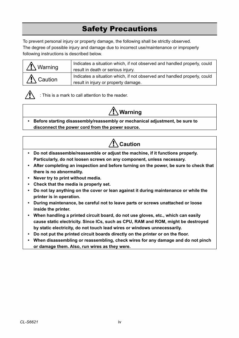
Safety Precautions To prevent personal injury or property damage, the following shall be strictly observed. The degree of possible injury and damage due to incorrect use/maintenance or improperly following instructions is described below.
Indicates a situation which, if not observed and handled properly, could result in death or serious injury.
Indicates a situation which, if not observed and handled properly, could result in injury or property damage.
: This is a mark to call attention to the reader.
• Before starting disassembly/reassembly or mechanical adjustment, be sure to disconnect the power cord from the power source.
• Do not disassemble/reassemble or adjust the machine, if it functions properly. Particularly, do not loosen screws on any component, unless necessary. • After completing an inspection and before turning on the power, be sure to check that
there is no abnormality. • Never try to print without media. • Check that the media is properly set. • Do not lay anything on the cover or lean against it during maintenance or while the
printer is in operation. • During maintenance, be careful not to leave parts or screws unattached or loose
inside the printer. • When handling a printed circuit board, do not use gloves, etc., which can easily
cause static electricity. Since ICs, such as CPU, RAM and ROM, might be destroyed by static electricity, do not touch lead wires or windows unnecessarily.
• Do not put the printed circuit boards directly on the printer or on the floor. • When disassembling or reassembling, check wires for any damage and do not pinch
or damage them. Also, run wires as they were.
Warning
Caution
Warning
Caution
1-1 CL-S6621
CHAPTER 1 SPECIFICATIONS
CL-S6621 1-2
CHAPTER 1 SPECIFICATIONS
TABLE OF CONTENTS 1-1. General Specifications.................................................................................................... 1-3 1-2. Printable Area .................................................................................................................1-8 1-3. Printing Position Accuracy .............................................................................................. 1-9 1-4. Adjustable Sensors......................................................................................................... 1-10
General Specifications
1-3 CL-S6621
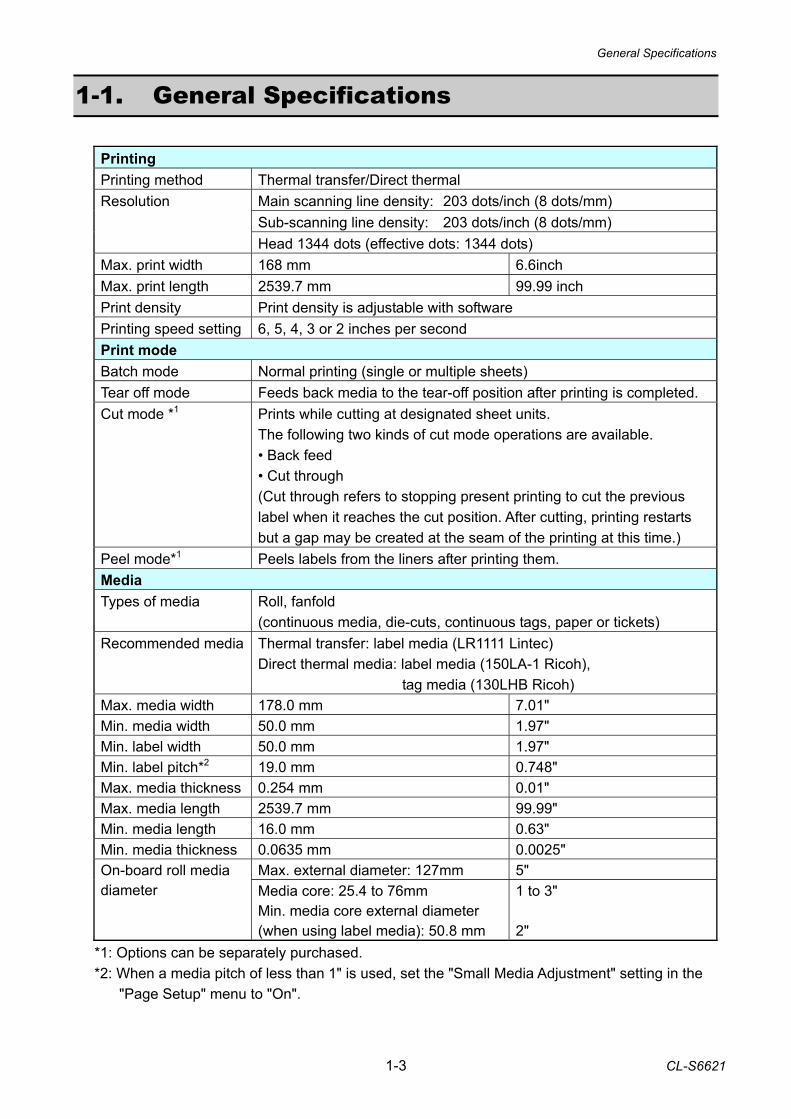
1-1. General Specifications
Printing Printing method Thermal transfer/Direct thermal
Main scanning line density: 203 dots/inch (8 dots/mm) Sub-scanning line density: 203 dots/inch (8 dots/mm)
Resolution
Head 1344 dots (effective dots: 1344 dots) Max. print width 168 mm 6.6inch Max. print length 2539.7 mm 99.99 inch Print density Print density is adjustable with software Printing speed setting 6, 5, 4, 3 or 2 inches per second Print mode Batch mode Normal printing (single or multiple sheets) Tear off mode Feeds back media to the tear-off position after printing is completed. Cut mode *1 Prints while cutting at designated sheet units.
The following two kinds of cut mode operations are available. • Back feed • Cut through (Cut through refers to stopping present printing to cut the previous label when it reaches the cut position. After cutting, printing restarts but a gap may be created at the seam of the printing at this time.)
Peel mode*1 Peels labels from the liners after printing them. Media Types of media Roll, fanfold
(continuous media, die-cuts, continuous tags, paper or tickets) Recommended media Thermal transfer: label media (LR1111 Lintec)
Direct thermal media: label media (150LA-1 Ricoh), tag media (130LHB Ricoh)
Max. media width 178.0 mm 7.01" Min. media width 50.0 mm 1.97" Min. label width 50.0 mm 1.97" Min. label pitch*2 19.0 mm 0.748" Max. media thickness 0.254 mm 0.01" Max. media length 2539.7 mm 99.99" Min. media length 16.0 mm 0.63" Min. media thickness 0.0635 mm 0.0025"
Max. external diameter: 127mm 5" On-board roll media diameter Media core: 25.4 to 76mm
Min. media core external diameter (when using label media): 50.8 mm
1 to 3" 2"
*1: Options can be separately purchased. *2: When a media pitch of less than 1" is used, set the "Small Media Adjustment" setting in the
"Page Setup" menu to "On".
General Specifications
CL-S6621 1-4
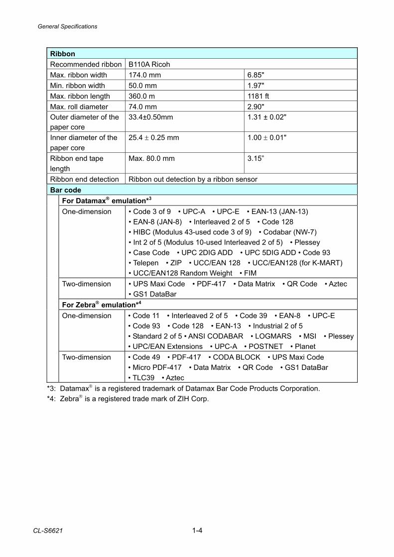
Ribbon Recommended ribbon B110A Ricoh Max. ribbon width 174.0 mm 6.85" Min. ribbon width 50.0 mm 1.97" Max. ribbon length 360.0 m 1181 ft Max. roll diameter 74.0 mm 2.90" Outer diameter of the paper core
33.4±0.50mm 1.31 ± 0.02"
Inner diameter of the paper core
25.4 ± 0.25 mm 1.00 ± 0.01"
Ribbon end tape length
Max. 80.0 mm 3.15”
Ribbon end detection Ribbon out detection by a ribbon sensor Bar code
For Datamax® emulation*3 One-dimension • Code 3 of 9 • UPC-A • UPC-E • EAN-13 (JAN-13)
• EAN-8 (JAN-8) • Interleaved 2 of 5 • Code 128 • HIBC (Modulus 43-used code 3 of 9) • Codabar (NW-7) • Int 2 of 5 (Modulus 10-used Interleaved 2 of 5) • Plessey • Case Code • UPC 2DIG ADD • UPC 5DIG ADD • Code 93 • Telepen • ZIP • UCC/EAN 128 • UCC/EAN128 (for K-MART) • UCC/EAN128 Random Weight • FIM
Two-dimension • UPS Maxi Code • PDF-417 • Data Matrix • QR Code • Aztec • GS1 DataBar
For Zebra® emulation*4 One-dimension • Code 11 • Interleaved 2 of 5 • Code 39 • EAN-8 • UPC-E
• Code 93 • Code 128 • EAN-13 • Industrial 2 of 5 • Standard 2 of 5 • ANSI CODABAR • LOGMARS • MSI • Plessey • UPC/EAN Extensions • UPC-A • POSTNET • Planet
Two-dimension • Code 49 • PDF-417 • CODA BLOCK • UPS Maxi Code • Micro PDF-417 • Data Matrix • QR Code • GS1 DataBar • TLC39 • Aztec
*3: Datamax® is a registered trademark of Datamax Bar Code Products Corporation. *4: Zebra® is a registered trade mark of ZIH Corp.
General Specifications
1-5 CL-S6621
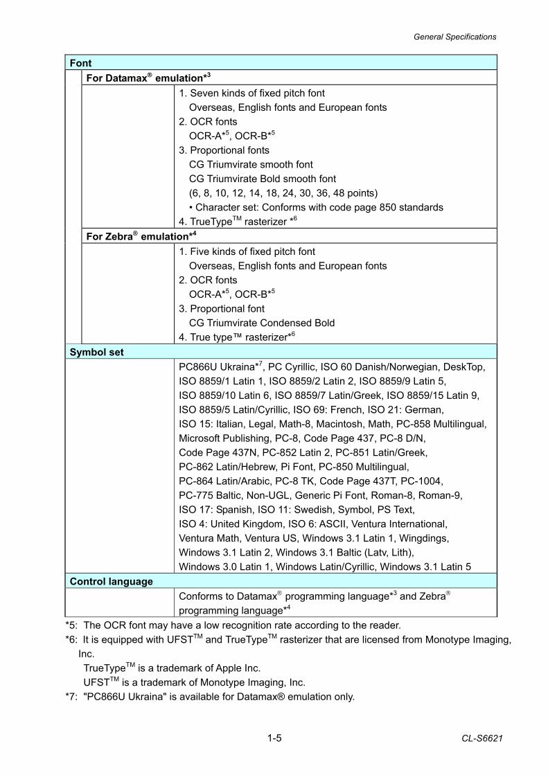
Font
For Datamax® emulation*3 1. Seven kinds of fixed pitch font
Overseas, English fonts and European fonts 2. OCR fonts OCR-A*5, OCR-B*5 3. Proportional fonts CG Triumvirate smooth font CG Triumvirate Bold smooth font (6, 8, 10, 12, 14, 18, 24, 30, 36, 48 points) • Character set: Conforms with code page 850 standards 4. TrueTypeTM rasterizer *6
For Zebra® emulation*4
1. Five kinds of fixed pitch font Overseas, English fonts and European fonts 2. OCR fonts OCR-A*5, OCR-B*5 3. Proportional font CG Triumvirate Condensed Bold 4. True type™ rasterizer*6
Symbol set PC866U Ukraina*7, PC Cyrillic, ISO 60 Danish/Norwegian, DeskTop,
ISO 8859/1 Latin 1, ISO 8859/2 Latin 2, ISO 8859/9 Latin 5, ISO 8859/10 Latin 6, ISO 8859/7 Latin/Greek, ISO 8859/15 Latin 9, ISO 8859/5 Latin/Cyrillic, ISO 69: French, ISO 21: German, ISO 15: Italian, Legal, Math-8, Macintosh, Math, PC-858 Multilingual, Microsoft Publishing, PC-8, Code Page 437, PC-8 D/N, Code Page 437N, PC-852 Latin 2, PC-851 Latin/Greek, PC-862 Latin/Hebrew, Pi Font, PC-850 Multilingual, PC-864 Latin/Arabic, PC-8 TK, Code Page 437T, PC-1004, PC-775 Baltic, Non-UGL, Generic Pi Font, Roman-8, Roman-9, ISO 17: Spanish, ISO 11: Swedish, Symbol, PS Text, ISO 4: United Kingdom, ISO 6: ASCII, Ventura International, Ventura Math, Ventura US, Windows 3.1 Latin 1, Wingdings, Windows 3.1 Latin 2, Windows 3.1 Baltic (Latv, Lith), Windows 3.0 Latin 1, Windows Latin/Cyrillic, Windows 3.1 Latin 5
Control language Conforms to Datamax® programming language*3 and Zebra®
programming language*4 *5: The OCR font may have a low recognition rate according to the reader. *6: It is equipped with UFSTTM and TrueTypeTM rasterizer that are licensed from Monotype Imaging,
Inc. TrueTypeTM is a trademark of Apple Inc. UFSTTM is a trademark of Monotype Imaging, Inc. *7: "PC866U Ukraina" is available for Datamax® emulation only.
General Specifications
CL-S6621 1-6
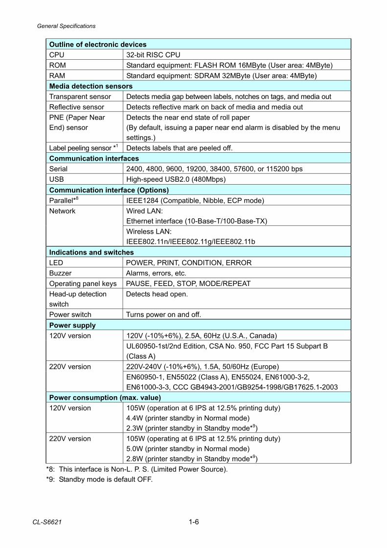
Outline of electronic devices CPU 32-bit RISC CPU ROM Standard equipment: FLASH ROM 16MByte (User area: 4MByte) RAM Standard equipment: SDRAM 32MByte (User area: 4MByte) Media detection sensors Transparent sensor Detects media gap between labels, notches on tags, and media out Reflective sensor Detects reflective mark on back of media and media out PNE (Paper Near End) sensor
Detects the near end state of roll paper (By default, issuing a paper near end alarm is disabled by the menu settings.)
Label peeling sensor *1 Detects labels that are peeled off. Communication interfaces Serial 2400, 4800, 9600, 19200, 38400, 57600, or 115200 bps USB High-speed USB2.0 (480Mbps) Communication interface (Options) Parallel*8 IEEE1284 (Compatible, Nibble, ECP mode)
Wired LAN: Ethernet interface (10-Base-T/100-Base-TX)
Network
Wireless LAN: IEEE802.11n/IEEE802.11g/IEEE802.11b
Indications and switches LED POWER, PRINT, CONDITION, ERROR Buzzer Alarms, errors, etc. Operating panel keys PAUSE, FEED, STOP, MODE/REPEAT Head-up detection switch
Detects head open.
Power switch Turns power on and off. Power supply
120V (-10%+6%), 2.5A, 60Hz (U.S.A., Canada) 120V version UL60950-1st/2nd Edition, CSA No. 950, FCC Part 15 Subpart B (Class A) 220V-240V (-10%+6%), 1.5A, 50/60Hz (Europe) 220V version EN60950-1, EN55022 (Class A), EN55024, EN61000-3-2, EN61000-3-3, CCC GB4943-2001/GB9254-1998/GB17625.1-2003
Power consumption (max. value) 120V version 105W (operation at 6 IPS at 12.5% printing duty)
4.4W (printer standby in Normal mode) 2.3W (printer standby in Standby mode*9)
220V version 105W (operating at 6 IPS at 12.5% printing duty) 5.0W (printer standby in Normal mode) 2.8W (printer standby in Standby mode*9)
*8: This interface is Non-L. P. S. (Limited Power Source). *9: Standby mode is default OFF.
General Specifications
1-7 CL-S6621
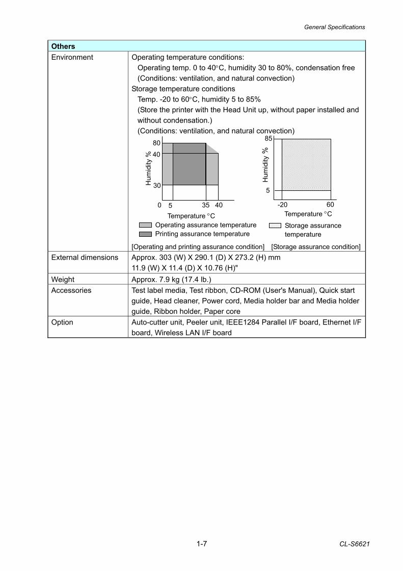
Others Environment Operating temperature conditions:
Operating temp. 0 to 40°C, humidity 30 to 80%, condensation free (Conditions: ventilation, and natural convection)
Storage temperature conditions Temp. -20 to 60°C, humidity 5 to 85% (Store the printer with the Head Unit up, without paper installed and without condensation.) (Conditions: ventilation, and natural convection)
[Operating and printing assurance condition] [Storage assurance condition]
External dimensions Approx. 303 (W) X 290.1 (D) X 273.2 (H) mm 11.9 (W) X 11.4 (D) X 10.76 (H)"
Weight Approx. 7.9 kg (17.4 lb.) Accessories Test label media, Test ribbon, CD-ROM (User's Manual), Quick start
guide, Head cleaner, Power cord, Media holder bar and Media holder guide, Ribbon holder, Paper core
Option Auto-cutter unit, Peeler unit, IEEE1284 Parallel I/F board, Ethernet I/F board, Wireless LAN I/F board
-20 60
5
85
Hum
idity
%
Temperature °C Operating assurance temperature Printing assurance temperature
0 5 35 40
30
40
80 H
umid
ity %
Temperature °CStorage assurance temperature
Printable Area
CL-S6621 1-8
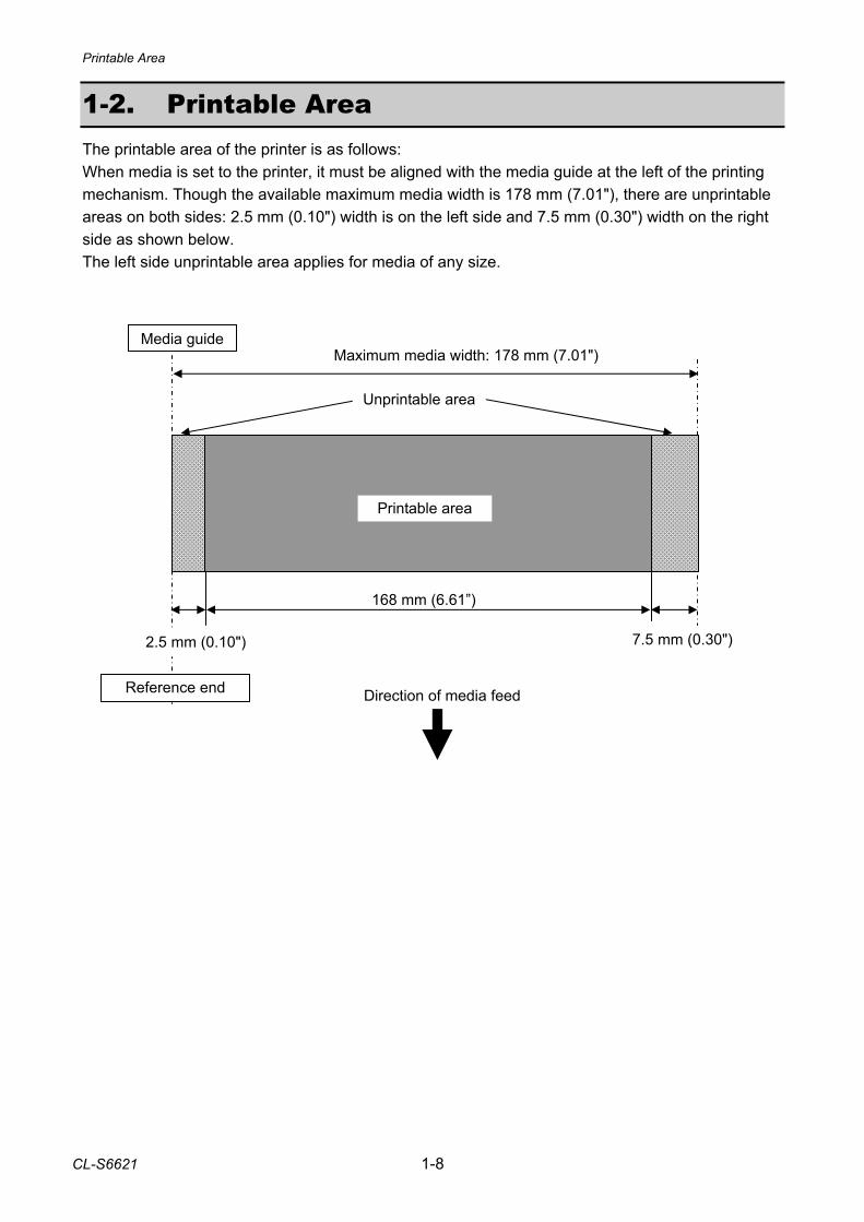
1-2. Printable Area The printable area of the printer is as follows: When media is set to the printer, it must be aligned with the media guide at the left of the printing mechanism. Though the available maximum media width is 178 mm (7.01"), there are unprintable areas on both sides: 2.5 mm (0.10") width is on the left side and 7.5 mm (0.30") width on the right side as shown below. The left side unprintable area applies for media of any size.
Maximum media width: 178 mm (7.01")
168 mm (6.61”)
Reference end
Unprintable area
Printable area
Media guide
Direction of media feed
2.5 mm (0.10") 7.5 mm (0.30")
Printing Position Accuracy
1-9 CL-S6621
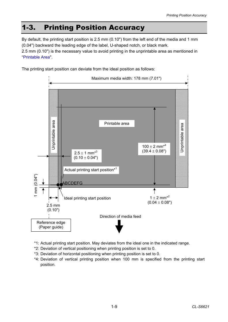
1-3. Printing Position Accuracy By default, the printing start position is 2.5 mm (0.10") from the left end of the media and 1 mm (0.04") backward the leading edge of the label, U-shaped notch, or black mark. 2.5 mm (0.10") is the necessary value to avoid printing in the unprintable area as mentioned in “Printable Area". The printing start position can deviate from the ideal position as follows:
*1: Actual printing start position. May deviates from the ideal one in the indicated range. *2: Deviation of vertical positioning when printing position is set to 0. *3: Deviation of horizontal positioning when printing position is set to 0. *4: Deviation of vertical printing position when 100 mm is specified from the printing start
position.
1 ± 2 mm*2
(0.04 ± 0.08")
Reference edge (Paper guide)
Printable area
Direction of media feed
Ideal printing start position
Actual printing start position*1
2.5 ± 1 mm*3 (0.10 ± 0.04")
100 ± 2 mm*4 (39.4 ± 0.08")
Maximum media width: 178 mm (7.01")
Unp
rinta
ble
area
2.5 mm (0.10")
1 m
m (0
.04"
)
Unp
rinta
ble
area
ABCDEFG
Adjustable Sensors
CL-S6621 1-10
(Moveable range of the transparent sensor)
4.8 to 88.9 mm (0.19 to 3.5")
2.7 to 86.8 mm (0.11 to 3.42")
(Moveable range of the reflective sensor)
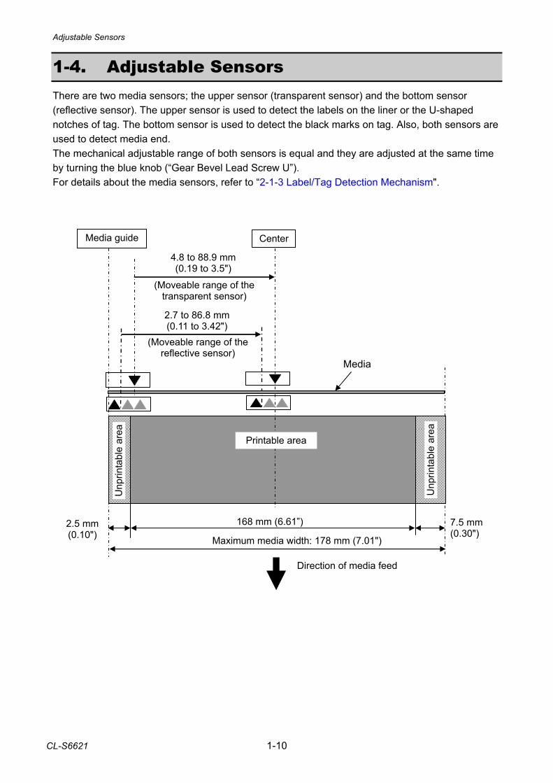
1-4. Adjustable Sensors There are two media sensors; the upper sensor (transparent sensor) and the bottom sensor (reflective sensor). The upper sensor is used to detect the labels on the liner or the U-shaped notches of tag. The bottom sensor is used to detect the black marks on tag. Also, both sensors are used to detect media end. The mechanical adjustable range of both sensors is equal and they are adjusted at the same time by turning the blue knob (“Gear Bevel Lead Screw U”). For details about the media sensors, refer to “2-1-3 Label/Tag Detection Mechanism".
Maximum media width: 178 mm (7.01")
168 mm (6.61”)
Media guide
Direction of media feed
2.5 mm (0.10")
Unp
rinta
ble
area
Unp
rinta
ble
area
Center
Printable area
Media
7.5 mm (0.30")

2-1 CL-S6621
CHAPTER 2
OPERATING PRINCIPLES
CL-S6621 2-2
CHAPTER 2 OPERATING PRINCIPLES
TABLE OF CONTENTS
2-1. Operation of Each Mechanism ....................................................................................... 2-4 2-1-1. Locations and Functions of Motors, Sensors and Thermal Head ...................... 2-4
(1) “Unit, Ribbon” section ................................................................................ 2-4 (2) Printing section .......................................................................................... 2-5
2-1-2. Media Feed Mechanism..................................................................................... 2-6 2-1-3. Label/Tag Detection Mechanism ........................................................................ 2-7 2-1-4. Printing and Ribbon Feed Mechanism ............................................................... 2-10 2-1-5. Print Head Up/Down Detection Mechanism....................................................... 2-13 2-1-6. Paper Near End Detection Mechanism.............................................................. 2-14 2-1-7. Head Balance Adjustment Mechanism .............................................................. 2-15 2-1-8. Media Offset Adjustment Mechanism................................................................. 2-16 2-1-9. Transparent/Reflective Sensor Travelling Mechanism ....................................... 2-17
2-2. Operation of Control Parts .............................................................................................. 2-18 2-2-1. Configuration of Printer ...................................................................................... 2-18
(1) AC power supply ....................................................................................... 2-19 (2) SA, Main PCB............................................................................................ 2-19 (3) Operation panel (SA, Opepane PCB)........................................................ 2-20 (4) Thermal print head (SA, Head).................................................................. 2-20 (5) Sensors ..................................................................................................... 2-20 (6) Motors........................................................................................................ 2-20 (7) SA, Ribbon PCB ........................................................................................ 2-20 (8) SA, Relay PCB .......................................................................................... 2-21 (9) Optional I/F ................................................................................................ 2-21
2-2-2. Memory map ...................................................................................................... 2-22 2-2-3. Sensors .............................................................................................................. 2-23
(1) Head up switch .......................................................................................... 2-23 (2) Transparent sensor and reflective sensor ................................................. 2-24 (3) Ribbon Sensor F/R .................................................................................... 2-26 (4) Head temperature sensor.......................................................................... 2-27 (5) PF motor temperature sensor.................................................................... 2-28 (6) Ribbon motor temperature sensor............................................................. 2-29 (7) Paper Near End sensor ............................................................................. 2-30
2-2-4. Drivers................................................................................................................ 2-31 (1) PF motor driver.......................................................................................... 2-31 (2) Ribbon motor driver ................................................................................... 2-32 (3) Head driver ................................................................................................ 2-33 (4) Buzzer driver ............................................................................................. 2-35 (5) Fan driver .................................................................................................. 2-35
2-2-5. Other circuits ...................................................................................................... 2-36 (1) Power supply circuit................................................................................... 2-36 (2) Reset circuit............................................................................................... 2-37 (3) Clock circuit ............................................................................................... 2-37
2-3 CL-S6621
(4) Ope-pane circuit ........................................................................................ 2-38 (5) USB I/F control circuit................................................................................ 2-38 (6) RS232C I/F circuit ..................................................................................... 2-39 (7) Option I/F circuit ........................................................................................ 2-39 (8) Peeler circuit (for optional peeler).............................................................. 2-40 (9) Cutter control circuit (for optional cutter) ................................................... 2-41
2-3. Operation Panel.............................................................................................................. 2-43 2-3-1. External view...................................................................................................... 2-43
(1) Keys........................................................................................................... 2-43 (2) LEDs.......................................................................................................... 2-43
2-3-2. Operation using the keys ................................................................................... 2-44 (1) Normal operation ....................................................................................... 2-44
(1-1) Sensor adjustment mode .................................................................. 2-44 (1-2) Menu setting mode ........................................................................... 2-45
(2) Test mode .................................................................................................. 2-46 (2-1) Self print mode.................................................................................. 2-46 (2-2) Hex dump mode................................................................................ 2-47
(3) Factory/Service mode................................................................................ 2-47 (3-1) General ............................................................................................. 2-47 (3-2) How to enter the Factory/Service Mode............................................ 2-48 (3-3) Factory/Service Mode menu table .................................................... 2-54
2-4. Interface.......................................................................................................................... 2-59 2-4-1. Serial Interface ................................................................................................... 2-59
(1) Specifications............................................................................................. 2-59 (2) Signal line and pin assignment.................................................................. 2-59 (3) Protocol ..................................................................................................... 2-60
2-4-2. USB Interface..................................................................................................... 2-61 (1) Specifications............................................................................................. 2-61 (2) Signal line and pin arrangement................................................................ 2-61
2-4-3. Parallel Interface (Option) .................................................................................. 2-61 (1) Specifications............................................................................................. 2-61 (2) Signal line and pin assignment.................................................................. 2-62 (3) Parallel port status signals when an error occurs ...................................... 2-62 (4) Compatible timing specification ................................................................. 2-63
Operation of Each Mechanism
CL-S6621 2-4
SA Ribbon Motor R
SA Ribbon Motor F
Ribbon Sensor F("SA, Ribbon Sensor" on the front side)
Ribbon Sensor R("SA, Ribbon Sensor" on the rear side)
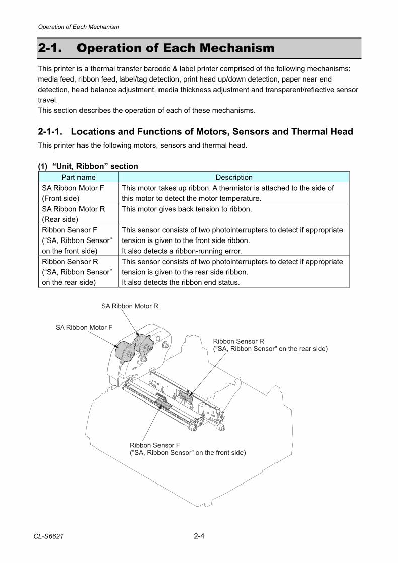
2-1. Operation of Each Mechanism This printer is a thermal transfer barcode & label printer comprised of the following mechanisms: media feed, ribbon feed, label/tag detection, print head up/down detection, paper near end detection, head balance adjustment, media thickness adjustment and transparent/reflective sensor travel. This section describes the operation of each of these mechanisms. 2-1-1. Locations and Functions of Motors, Sensors and Thermal Head This printer has the following motors, sensors and thermal head. (1) “Unit, Ribbon” section
Part name Description SA Ribbon Motor F (Front side)
This motor takes up ribbon. A thermistor is attached to the side of this motor to detect the motor temperature.
SA Ribbon Motor R (Rear side)
This motor gives back tension to ribbon.
Ribbon Sensor F (“SA, Ribbon Sensor” on the front side)
This sensor consists of two photointerrupters to detect if appropriate tension is given to the front side ribbon. It also detects a ribbon-running error.
Ribbon Sensor R (“SA, Ribbon Sensor” on the rear side)
This sensor consists of two photointerrupters to detect if appropriate tension is given to the rear side ribbon. It also detects the ribbon end status.
Operation of Each Mechanism
2-5 CL-S6621
��� ����
��� ���� �������� �� ��� ����
�� �� ����
��� ���� � ������
�� ��� �����
��� ����!� �������� ��� ��� ����
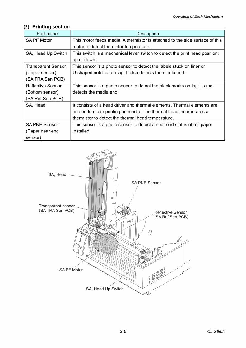
(2) Printing section Part name Description
SA PF Motor This motor feeds media. A thermistor is attached to the side surface of this motor to detect the motor temperature.
SA, Head Up Switch This switch is a mechanical lever switch to detect the print head position; up or down.
Transparent Sensor (Upper sensor) (SA TRA Sen PCB)
This sensor is a photo sensor to detect the labels stuck on liner or U-shaped notches on tag. It also detects the media end.
Reflective Sensor (Bottom sensor) (SA Ref Sen PCB)
This sensor is a photo sensor to detect the black marks on tag. It also detects the media end.
SA, Head It consists of a head driver and thermal elements. Thermal elements are heated to make printing on media. The thermal head incorporates a thermistor to detect the thermal head temperature.
SA PNE Sensor (Paper near end sensor)
This sensor is a photo sensor to detect a near end status of roll paper installed.
Operation of Each Mechanism
CL-S6621 2-6
Ribbon
SA PF Motor
Motor Gear
Gear Reduction PF 1
Gear Reduction PF 2
Gear Idle PF
SA2_Platen
Thermal Elements
[Right side view]
SA, Head
Media
12
34
5
66
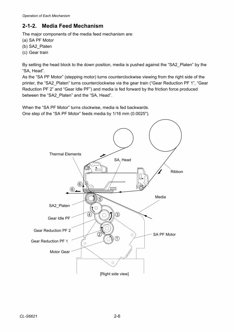
2-1-2. Media Feed Mechanism The major components of the media feed mechanism are: (a) SA PF Motor (b) SA2_Platen (c) Gear train By setting the head block to the down position, media is pushed against the “SA2_Platen” by the “SA, Head”. As the “SA PF Motor” (stepping motor) turns counterclockwise viewing from the right side of the printer, the “SA2_Platen” turns counterclockwise via the gear train (“Gear Reduction PF 1”, “Gear Reduction PF 2” and “Gear Idle PF”) and media is fed forward by the friction force produced between the “SA2_Platen” and the “SA, Head”. When the “SA PF Motor” turns clockwise, media is fed backwards. One step of the “SA PF Motor” feeds media by 1/16 mm (0.0025").
Operation of Each Mechanism
2-7 CL-S6621
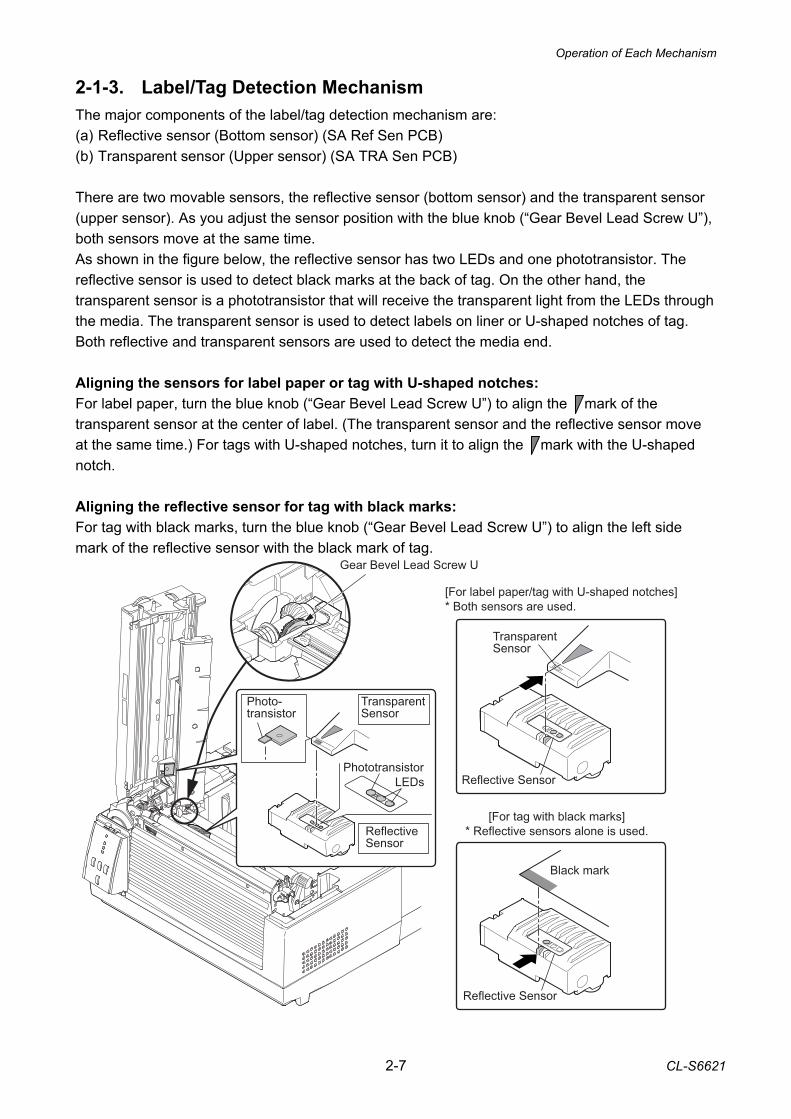
2-1-3. Label/Tag Detection Mechanism The major components of the label/tag detection mechanism are: (a) Reflective sensor (Bottom sensor) (SA Ref Sen PCB) (b) Transparent sensor (Upper sensor) (SA TRA Sen PCB) There are two movable sensors, the reflective sensor (bottom sensor) and the transparent sensor (upper sensor). As you adjust the sensor position with the blue knob (“Gear Bevel Lead Screw U”), both sensors move at the same time. As shown in the figure below, the reflective sensor has two LEDs and one phototransistor. The reflective sensor is used to detect black marks at the back of tag. On the other hand, the transparent sensor is a phototransistor that will receive the transparent light from the LEDs through the media. The transparent sensor is used to detect labels on liner or U-shaped notches of tag. Both reflective and transparent sensors are used to detect the media end. Aligning the sensors for label paper or tag with U-shaped notches: For label paper, turn the blue knob (“Gear Bevel Lead Screw U”) to align the mark of the transparent sensor at the center of label. (The transparent sensor and the reflective sensor move at the same time.) For tags with U-shaped notches, turn it to align the mark with the U-shaped notch. Aligning the reflective sensor for tag with black marks: For tag with black marks, turn the blue knob (“Gear Bevel Lead Screw U”) to align the left side mark of the reflective sensor with the black mark of tag.
���� ���� ����� ���� ������ �������
� ���� ������ �� ����
���� �� ���� ����� ������
� ������ ������ ���� �� ����
����� ����
!��������������
"#$�
!���������������
%��������&����
������ &����
'�� � � "�� &��� �
%��������&����
������ &����
������ &����
Operation of Each Mechanism
CL-S6621 2-8
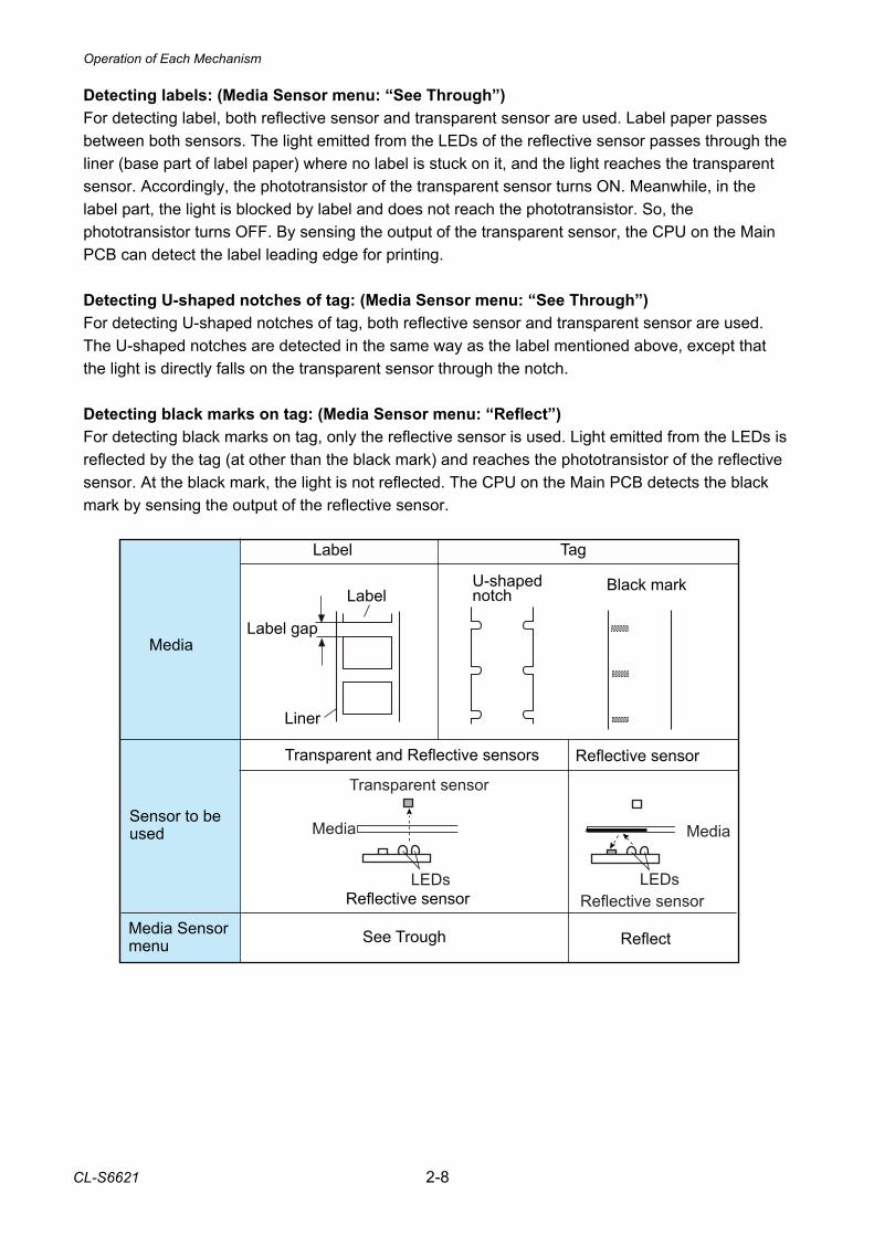
Detecting labels: (Media Sensor menu: “See Through”) For detecting label, both reflective sensor and transparent sensor are used. Label paper passes between both sensors. The light emitted from the LEDs of the reflective sensor passes through the liner (base part of label paper) where no label is stuck on it, and the light reaches the transparent sensor. Accordingly, the phototransistor of the transparent sensor turns ON. Meanwhile, in the label part, the light is blocked by label and does not reach the phototransistor. So, the phototransistor turns OFF. By sensing the output of the transparent sensor, the CPU on the Main PCB can detect the label leading edge for printing. Detecting U-shaped notches of tag: (Media Sensor menu: “See Through”) For detecting U-shaped notches of tag, both reflective sensor and transparent sensor are used. The U-shaped notches are detected in the same way as the label mentioned above, except that the light is directly falls on the transparent sensor through the notch. Detecting black marks on tag: (Media Sensor menu: “Reflect”) For detecting black marks on tag, only the reflective sensor is used. Light emitted from the LEDs is reflected by the tag (at other than the black mark) and reaches the phototransistor of the reflective sensor. At the black mark, the light is not reflected. The CPU on the Main PCB detects the black mark by sensing the output of the reflective sensor.
Reflective sensorLEDs
Transparent sensor
Media
LEDs
Media
Label
U-shaped notch
Black mark
Tag
Label
Liner
Label gap
Transparent and Reflective sensors Reflective sensor
Media
Sensor to be used
Reflective sensor
Media Sensor menu See Trough Reflect

Operation of Each Mechanism
2-9 CL-S6621
Detecting continuous media: (Media Sensor menu: “None”) For detecting continuous media, only the reflective sensor is used. In this case, only media end is detected by the reflective sensor. LED light amount control: According to the media selected by the Media Sensor menu (“See Through”, “Reflect”, or “None”), the amount of light is well controlled to detect the label/U-shaped notch, black mark, or continuous media. The amount of light is as follows (the largest amount is for “See Through): • Continuous media (None) < Black mark (Reflect) < Label/U-shaped notch (See Through)
Operation of Each Mechanism
CL-S6621 2-10
SA2_PlatenMedia
RibbonThermal Head
SA, Ribbon Tension Shaft F
SA, Ribbon Tension Shaft R
Take-up Side Supply Side
Gear Ribbon Shaft RGear Ribbon Shaft F SA Ribbon Motor R
SA Ribbon Motor F
Gear Reduction Ribbon 1
Gear Reduction Ribbon 1
Gear Reduction Ribbon 2
Gear Reduction Ribbon 2
Gear Reduction Ribbon 3
Gear Reduction Ribbon 3
Gear Idle RibbonGear Idle Ribbon
[Front]
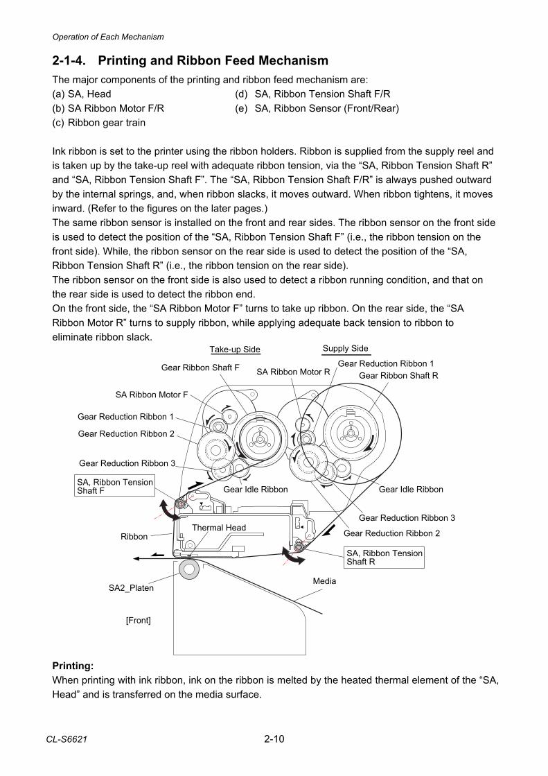
2-1-4. Printing and Ribbon Feed Mechanism The major components of the printing and ribbon feed mechanism are: (a) SA, Head (d) SA, Ribbon Tension Shaft F/R (b) SA Ribbon Motor F/R (e) SA, Ribbon Sensor (Front/Rear) (c) Ribbon gear train Ink ribbon is set to the printer using the ribbon holders. Ribbon is supplied from the supply reel and is taken up by the take-up reel with adequate ribbon tension, via the “SA, Ribbon Tension Shaft R” and “SA, Ribbon Tension Shaft F”. The “SA, Ribbon Tension Shaft F/R” is always pushed outward by the internal springs, and, when ribbon slacks, it moves outward. When ribbon tightens, it moves inward. (Refer to the figures on the later pages.) The same ribbon sensor is installed on the front and rear sides. The ribbon sensor on the front side is used to detect the position of the “SA, Ribbon Tension Shaft F” (i.e., the ribbon tension on the front side). While, the ribbon sensor on the rear side is used to detect the position of the “SA, Ribbon Tension Shaft R” (i.e., the ribbon tension on the rear side). The ribbon sensor on the front side is also used to detect a ribbon running condition, and that on the rear side is used to detect the ribbon end. On the front side, the “SA Ribbon Motor F” turns to take up ribbon. On the rear side, the “SA Ribbon Motor R” turns to supply ribbon, while applying adequate back tension to ribbon to eliminate ribbon slack. Printing: When printing with ink ribbon, ink on the ribbon is melted by the heated thermal element of the “SA, Head” and is transferred on the media surface.
Operation of Each Mechanism
2-11 CL-S6621
Taking up Ribbon: Ribbon will be taken up on the front side as follows: (1) As media is fed, ribbon is also fed by the friction force produced between media and the “SA,
Head”. (2) Ribbon slacks and the ribbon sensor on the front side turns OFF as the “SA, Ribbon Tension
Shaft F” is pushed outward. (3) The “SA Ribbon Motor F” starts to turn and ribbon is taken up. (4) Ribbon tightens and the ribbon sensor on the front side turns ON. Then, the “SA Ribbon Motor
F” stops. Supplying Ribbon: On the rear side, the “SA Ribbon Motor R” turns to supply ribbon, while applying adequate back tension. In the same way as on the front side, the ribbon sensor on the rear side detects the ribbon tension to keep the ribbon tension constant. However, when printing is made and ribbon is fed, the ribbon sensor on the rear side turns ON since ribbon is tightened at this time. Reel Drive Mechanism: Though the ribbon holders are directly installed in the reels, ribbon is connected to the reels via the spring mechanism of the ribbon holders. This means that ribbon is taken up via the spring mechanism when the “SA Ribbon Motor F”/”SA Ribbon Motor R” turns. On the front side, the “SA Ribbon Motor F” turns in the clockwise direction viewing from the right side of the printer, and the “Gear Ribbon Shaft F” (take-up reel) turns in the counterclockwise direction via the “Gear Reduction Ribbon 1”, “Gear Reduction Ribbon 2”, “Gear Reduction Ribbon 3” and “Gear Idle Ribbon”. Thus, ribbon is taken up. On the rear side, the “SA Ribbon Motor R” turns in the counterclockwise direction, and the “Gear Ribbon Shaft R” (supply reel) turns in the clockwise direction via the “Gear Reduction Ribbon 1”, “Gear Reduction Ribbon 2”, “Gear Reduction Ribbon 3” and “Gear Idle Ribbon”, Ribbon”. Thus, ribbon is supplied.
Operation of Each Mechanism
CL-S6621 2-12
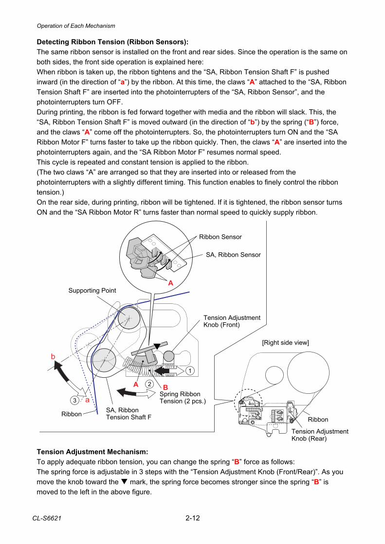
Detecting Ribbon Tension (Ribbon Sensors): The same ribbon sensor is installed on the front and rear sides. Since the operation is the same on both sides, the front side operation is explained here: When ribbon is taken up, the ribbon tightens and the “SA, Ribbon Tension Shaft F” is pushed inward (in the direction of “a”) by the ribbon. At this time, the claws “A” attached to the “SA, Ribbon Tension Shaft F” are inserted into the photointerrupters of the “SA, Ribbon Sensor”, and the photointerrupters turn OFF. During printing, the ribbon is fed forward together with media and the ribbon will slack. This, the “SA, Ribbon Tension Shaft F” is moved outward (in the direction of “b”) by the spring (“B”) force, and the claws “A” come off the photointerrupters. So, the photointerrupters turn ON and the “SA Ribbon Motor F” turns faster to take up the ribbon quickly. Then, the claws “A” are inserted into the photointerrupters again, and the “SA Ribbon Motor F” resumes normal speed. This cycle is repeated and constant tension is applied to the ribbon. (The two claws “A” are arranged so that they are inserted into or released from the photointerrupters with a slightly different timing. This function enables to finely control the ribbon tension.) On the rear side, during printing, ribbon will be tightened. If it is tightened, the ribbon sensor turns ON and the “SA Ribbon Motor R” turns faster than normal speed to quickly supply ribbon.
Tension Adjustment Mechanism: To apply adequate ribbon tension, you can change the spring “B” force as follows: The spring force is adjustable in 3 steps with the “Tension Adjustment Knob (Front/Rear)”. As you move the knob toward the mark, the spring force becomes stronger since the spring “B” is moved to the left in the above figure.
Tension Adjustment Knob (Front)
SA, Ribbon Sensor
Supporting Point
SA, Ribbon Tension Shaft F Ribbon
Spring Ribbon Tension (2 pcs.)
Ribbon
A
Tension Adjustment Knob (Rear)
[Right side view]
a
b
B
Ribbon Sensor
A
Operation of Each Mechanism
2-13 CL-S6621
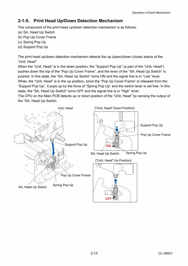
2-1-5. Print Head Up/Down Detection Mechanism The component of the print head up/down detection mechanism is as follows: (a) SA, Head Up Switch (b) Pop Up Cover Frame (c) Spring Pop Up (d) Support Pop Up The print head up/down detection mechanism detects the up (open)/down (close) status of the “Unit, Head”. When the “Unit, Head” is in the down position, the “Support Pop Up” (a part of the “Unit, Head”) pushes down the top of the “Pop Up Cover Frame”, and the lever of the “SA, Head Up Switch” is pushed. In this state, the “SA, Head Up Switch” turns ON and the signal line is in “Low” level. While, the “Unit, Head” is in the up position, since the “Pop Up Cover Frame” is released from the “Support Pop Up”, it pops up by the force of “Spring Pop Up” and the switch lever is set free. In this state, the “SA, Head Up Switch” turns OFF and the signal line is in “High” level. The CPU on the Main PCB detects up or down position of the “Unit, Head” by sensing the output of the “SA, Head Up Switch.
SA, Head Up Switch Spring Pop Up
Support Pop Up
Pop Up Cover Frame
Unit, Head
["Unit, Head" Up Position]
["Unit, Head" Down Position]
ON
OFF
Pop Up Cover Frame
Support Pop Up
SA, Head Up Switch Spring Pop Up
Operation of Each Mechanism
CL-S6621 2-14
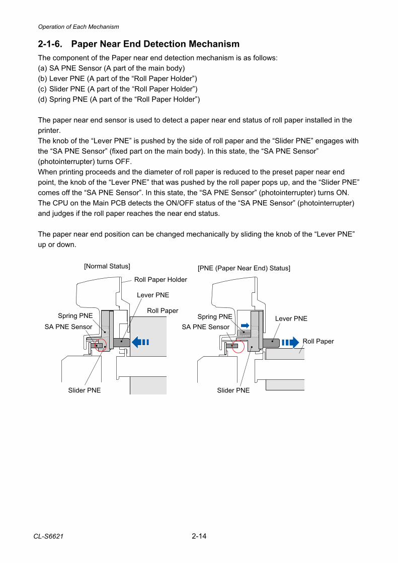
2-1-6. Paper Near End Detection Mechanism The component of the Paper near end detection mechanism is as follows: (a) SA PNE Sensor (A part of the main body) (b) Lever PNE (A part of the “Roll Paper Holder”) (c) Slider PNE (A part of the “Roll Paper Holder”) (d) Spring PNE (A part of the “Roll Paper Holder”) The paper near end sensor is used to detect a paper near end status of roll paper installed in the printer. The knob of the “Lever PNE” is pushed by the side of roll paper and the “Slider PNE” engages with the “SA PNE Sensor” (fixed part on the main body). In this state, the “SA PNE Sensor” (photointerrupter) turns OFF. When printing proceeds and the diameter of roll paper is reduced to the preset paper near end point, the knob of the “Lever PNE” that was pushed by the roll paper pops up, and the “Slider PNE” comes off the “SA PNE Sensor”. In this state, the “SA PNE Sensor” (photointerrupter) turns ON. The CPU on the Main PCB detects the ON/OFF status of the “SA PNE Sensor” (photointerrupter) and judges if the roll paper reaches the near end status. The paper near end position can be changed mechanically by sliding the knob of the “Lever PNE” up or down.
Lever PNE
Spring PNESA PNE Sensor
Slider PNE
Roll Paper
Roll Paper Holder
[Normal Status]
Lever PNESpring PNESA PNE Sensor
Slider PNE
Roll Paper
[PNE (Paper Near End) Status]
Operation of Each Mechanism
2-15 CL-S6621
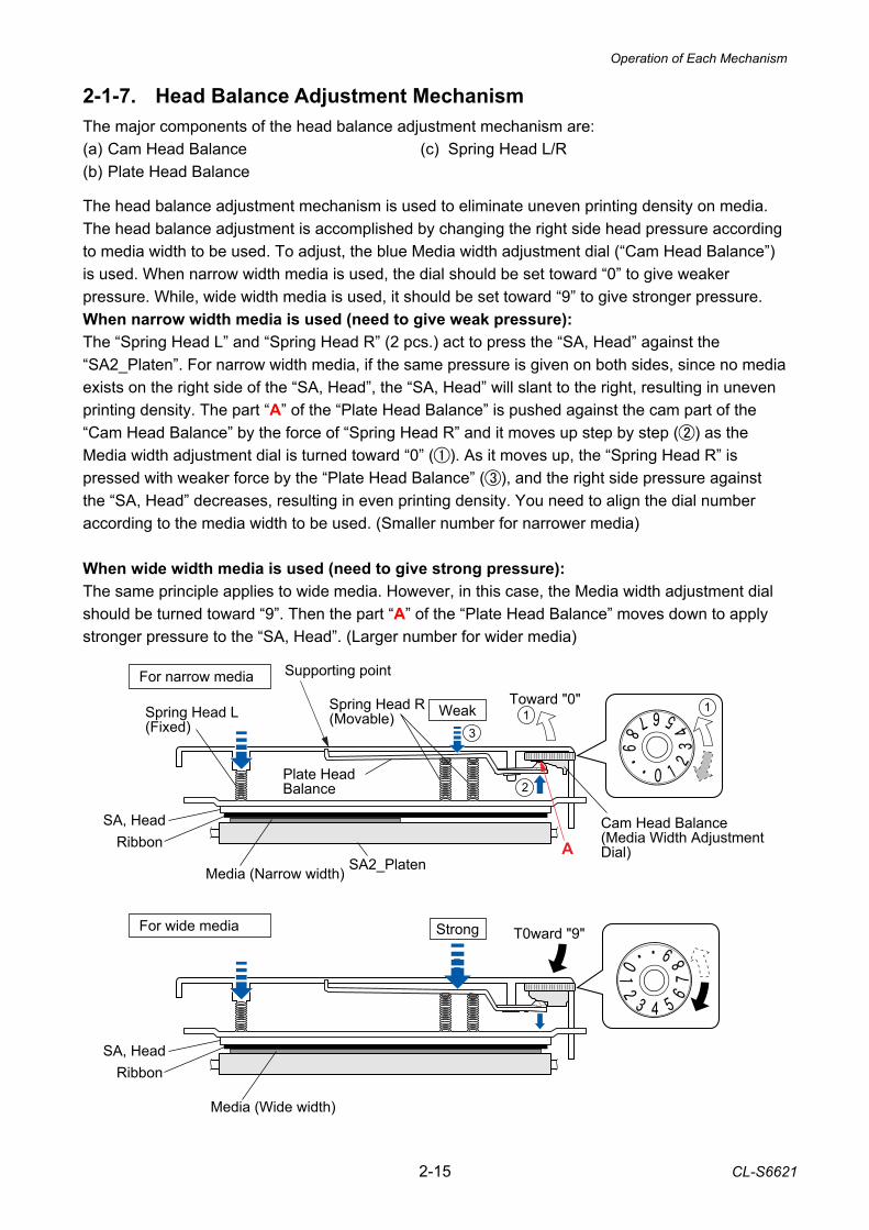
2-1-7. Head Balance Adjustment Mechanism The major components of the head balance adjustment mechanism are: (a) Cam Head Balance (c) Spring Head L/R (b) Plate Head Balance The head balance adjustment mechanism is used to eliminate uneven printing density on media. The head balance adjustment is accomplished by changing the right side head pressure according to media width to be used. To adjust, the blue Media width adjustment dial (“Cam Head Balance”) is used. When narrow width media is used, the dial should be set toward “0” to give weaker pressure. While, wide width media is used, it should be set toward “9” to give stronger pressure. When narrow width media is used (need to give weak pressure): The “Spring Head L” and “Spring Head R” (2 pcs.) act to press the “SA, Head” against the “SA2_Platen”. For narrow width media, if the same pressure is given on both sides, since no media exists on the right side of the “SA, Head”, the “SA, Head” will slant to the right, resulting in uneven printing density. The part “A” of the “Plate Head Balance” is pushed against the cam part of the “Cam Head Balance” by the force of “Spring Head R” and it moves up step by step () as the Media width adjustment dial is turned toward “0” (). As it moves up, the “Spring Head R” is pressed with weaker force by the “Plate Head Balance” (), and the right side pressure against the “SA, Head” decreases, resulting in even printing density. You need to align the dial number according to the media width to be used. (Smaller number for narrower media) When wide width media is used (need to give strong pressure): The same principle applies to wide media. However, in this case, the Media width adjustment dial should be turned toward “9”. Then the part “A” of the “Plate Head Balance” moves down to apply stronger pressure to the “SA, Head”. (Larger number for wider media)
Weak
Strong
Toward "0"
Cam Head Balance(Media Width Adjustment Dial)
T0ward "9"
SA2_PlatenA
SA, Head
Media (Narrow width)
Media (Wide width)
Ribbon
SA, HeadRibbon
Plate HeadBalance
Spring Head R (Movable)Spring Head L
(Fixed)
For narrow media
For wide media
Supporting point
Operation of Each Mechanism
CL-S6621 2-16
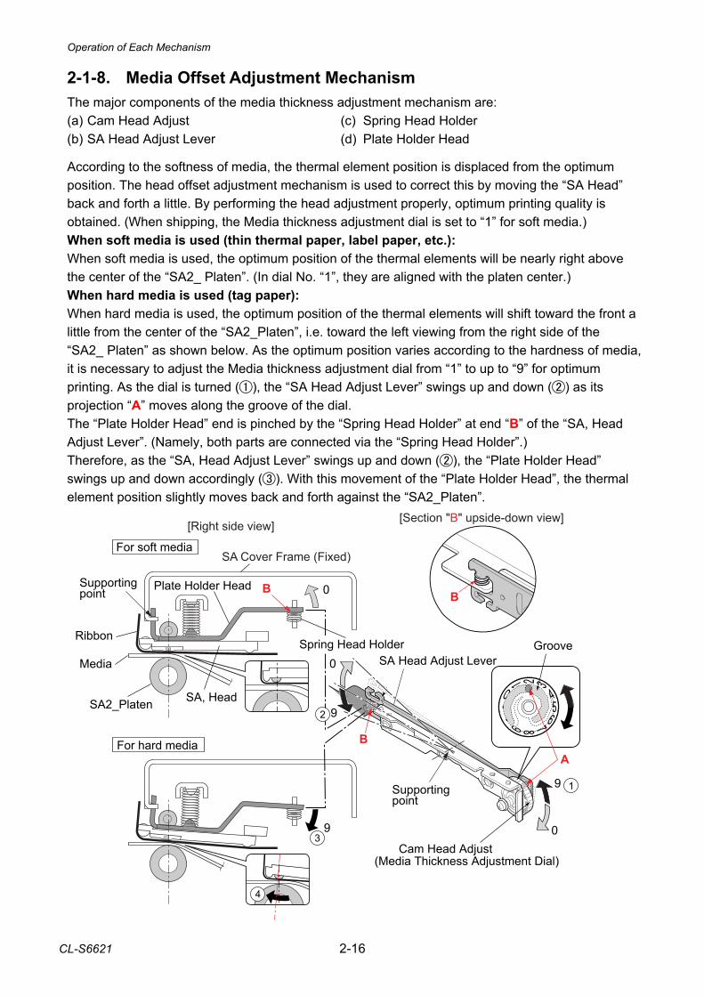
2-1-8. Media Offset Adjustment Mechanism The major components of the media thickness adjustment mechanism are: (a) Cam Head Adjust (c) Spring Head Holder (b) SA Head Adjust Lever (d) Plate Holder Head According to the softness of media, the thermal element position is displaced from the optimum position. The head offset adjustment mechanism is used to correct this by moving the “SA Head” back and forth a little. By performing the head adjustment properly, optimum printing quality is obtained. (When shipping, the Media thickness adjustment dial is set to “1” for soft media.) When soft media is used (thin thermal paper, label paper, etc.): When soft media is used, the optimum position of the thermal elements will be nearly right above the center of the “SA2_ Platen”. (In dial No. “1”, they are aligned with the platen center.) When hard media is used (tag paper): When hard media is used, the optimum position of the thermal elements will shift toward the front a little from the center of the “SA2_Platen”, i.e. toward the left viewing from the right side of the “SA2_ Platen” as shown below. As the optimum position varies according to the hardness of media, it is necessary to adjust the Media thickness adjustment dial from “1” to up to “9” for optimum printing. As the dial is turned (), the “SA Head Adjust Lever” swings up and down () as its projection “A” moves along the groove of the dial. The “Plate Holder Head” end is pinched by the “Spring Head Holder” at end “B” of the “SA, Head Adjust Lever”. (Namely, both parts are connected via the “Spring Head Holder”.) Therefore, as the “SA, Head Adjust Lever” swings up and down (), the “Plate Holder Head” swings up and down accordingly (). With this movement of the “Plate Holder Head”, the thermal element position slightly moves back and forth against the “SA2_Platen”.
0
0
0
9
9
9
For soft media
For hard media
Ribbon
SA2_Platen
Media
SA, Head
(Media Thickness Adjustment Dial)
Plate Holder Head
SA Cover Frame (Fixed)
Supporting point
Supporting point
Groove
B
[Right side view]
B
Spring Head Holder
Cam Head Adjust
A
B
SA Head Adjust Lever
[Section "B" upside-down view]
Operation of Each Mechanism
2-17 CL-S6621
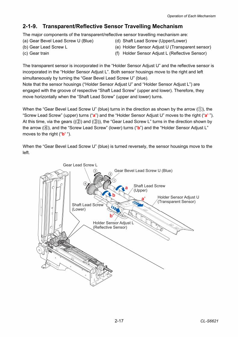
2-1-9. Transparent/Reflective Sensor Travelling Mechanism The major components of the transparent/reflective sensor travelling mechanism are: (a) Gear Bevel Lead Screw U (Blue) (d) Shaft Lead Screw (Upper/Lower) (b) Gear Lead Screw L (e) Holder Sensor Adjust U (Transparent sensor) (c) Gear train (f) Holder Sensor Adjust L (Reflective Sensor) The transparent sensor is incorporated in the “Holder Sensor Adjust U” and the reflective sensor is incorporated in the “Holder Sensor Adjust L”. Both sensor housings move to the right and left simultaneously by turning the “Gear Bevel Lead Screw U” (blue). Note that the sensor housings (“Holder Sensor Adjust U” and “Holder Sensor Adjust L”) are engaged with the groove of respective “Shaft Lead Screw” (upper and lower). Therefore, they move horizontally when the “Shaft Lead Screw” (upper and lower) turns. When the “Gear Bevel Lead Screw U” (blue) turns in the direction as shown by the arrow (), the “Screw Lead Screw” (upper) turns (“a”) and the “Holder Sensor Adjust U” moves to the right (“a’ ”). At this time, via the gears (() and ()), the “Gear Lead Screw L” turns in the direction shown by the arrow (), and the “Screw Lead Screw” (lower) turns (“b”) and the “Holder Sensor Adjust L” moves to the right (“b’ “). When the “Gear Bevel Lead Screw U” (blue) is turned reversely, the sensor housings move to the left.
Shaft Lead Screw(Upper)
Shaft Lead Screw(Lower)
a
a’b
b’
Holder Sensor Adjust U(Transparent Sensor)
Holder Sensor Adjust L(Reflective Sensor)
Gear Bevel Lead Screw U (Blue)Gear Lead Screw L
Operation of Control Parts
CL-S6621 2-18
CPU
UPD703111BGJ-13-UEV-A128MHz
Buzzer
Head Up Switch[SA, Head Up Switch]
AC Power Supply PWT20005-* (100V)PWT20006-* (200V)
S-DRAM (256Mbits)
Control / C.G. F-ROM (64Mbits)
SA PF MotorStepping MotorDriver
Adjustable Paper SensorsTransparent Sensor [SA TRA Sen PCB]
Reflective Sensor [SA Ref Sen PCB]
Thermal Print Head (203dpi)
[SA, Head]FPGA
EP2C5F256C8N Operation Panel(SWx4/LEDx4)
[SA, Opepane PCB](JM66720-*)
RS232C
IEEE1284
USB 2.0 (High Speed)
SA, MAIN PCB (PPS00058-*) Peel Sensor
(Option) Peeler
Thermal Head Temp. Sensor[SA, Head]
PF Motor Temp. Sensor[SA PF Motor]
RS232CDriver/Receiver
CutterPositionSensor
DC Motor Driver
(Option) Auto Cutter
Cutter Motor
Ethernet I/F (Standard type)
(Option)Interface Board
C.G.F-ROM (64Mbits)
Cutter MotorTemp. Sensor
Paper Near End Sensor[SA PNE Sensor]
Ethernet I/F (Multi-function type)
Ribbon Sensor F[SA, Ribbon Sensor]
Ribbon Sensor R[SA, Ribbon Sensor]
SA Ribbon Motor FSA Ribbon Motor R
Stepping MotorDriver x 2
SA, Ribbon PCB(PPS00059-*)
Ribbon Motor Temp. Sensor[SA Ribbon Motor F]
SA, Relay PCB(PPS00060-*)
RS232C
USB2.0Controller
CUTTER PCB(PPS00065-*)
Wi-Fi I/F
Fan Fan Driver
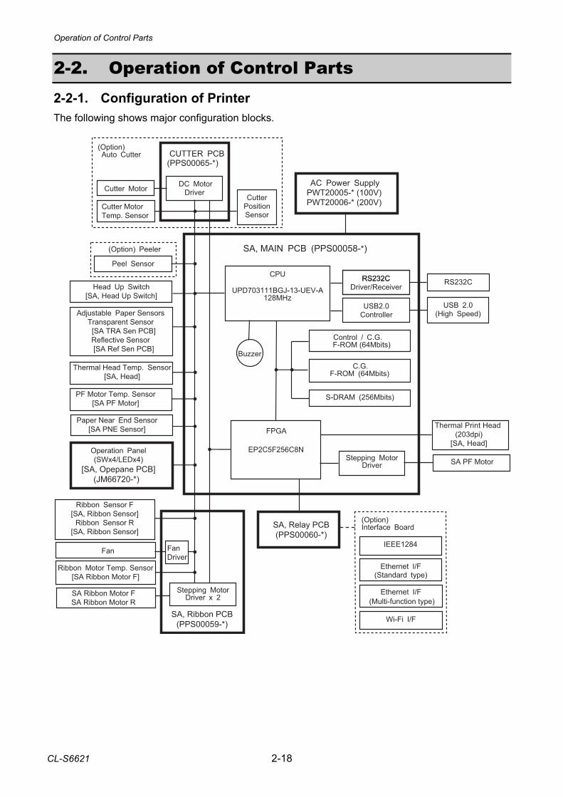
2-2. Operation of Control Parts 2-2-1. Configuration of Printer The following shows major configuration blocks.
Operation of Control Parts
2-19 CL-S6621
Major functions of individual components are described below: (1) AC power supply
Consists of a fuse, a filter circuit to eliminate external electric noise, and a switching type regulator to transform an AC input to +24V DC output required to drive the printer.
(2) SA, Main PCB
Controls the entire operations of the printer. It consists of CPU, Flash ROM, S-DRAM, FPGA (Field-Programmable Gate Array), driver circuits, etc. (a) CPU
The CPU is a microprocessor with 32-bit architecture. The clock fed to the CPU is 16 MHz. The CPU internally multiplies this 16 MHz by 8 times and uses 128 MHz clock. The CPU includes cache memory, RAMs, DMA controller, serial I/F, USB function controller, A/D converter, etc.
(b) Flash ROM A flash ROM of 64M bits (8M bytes) that stores the firmware and CG (character generator)
(c) S-DRAM (Synchronous dynamic RAM) An S-DRAM of 256M bits (32M bytes) that is used as working area, input buffer and download buffer.
(d) FPGA The FPGA (Field-Programmable Gate Array) incorporates a control circuit for the interface I/O port, motors, print head, etc.
(e) Serial I/F (RS-232C Driver/Receiver) This is a circuit to transmit and receive serial data between the printer and the host. Serial I/F, USB I/F, Parallel I/F (Option), Wired LAN (Option) or Wireless LAN (Option) is automatically selected when data is received.
(f) USB I/F (High-speed USB2.0 Controller)
This is a circuit to transmit and receive serial data between the printer and the host using the high-speed USB2.0 I/F. Serial I/F, USB I/F, Parallel I/F (Option), Wired LAN (Option) or Wireless LAN (Option) is automatically selected when data is received.
(g) Stepping motor driver This is a circuit to drive the “SA PF Motor”. The “SA PF Motor” is a stepping motor.
(h) Buzzer The buzzer is driven when an alarm, etc. occurs.
Operation of Control Parts
CL-S6621 2-20
(3) Operation panel (SA, Opepane PCB) Used to indicate the operating status of the printer and to set specifications. It consists of 4 keys and 4 LEDs.
(4) Thermal print head (SA, Head)
Makes printing on paper. The number of thermal elements (dots) is as follows. The thermal print head includes the print head driver circuit. •1344 dots
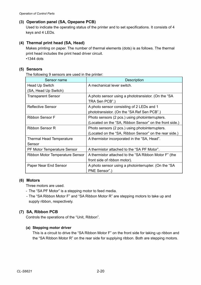
(5) Sensors The following 9 sensors are used in the printer:
Sensor name Description Head Up Switch (SA, Head Up Switch)
A mechanical lever switch.
Transparent Sensor A photo sensor using a phototransistor. (On the “SA TRA Sen PCB”.)
Reflective Sensor A photo sensor consisting of 2 LEDs and 1 phototransistor. (On the “SA Ref Sen PCB”.)
Ribbon Sensor F Photo sensors (2 pcs.) using photointerrupters. (Located on the “SA, Ribbon Sensor” on the front side.)
Ribbon Sensor R Photo sensors (2 pcs.) using photointerrupters. (Located on the “SA, Ribbon Sensor” on the rear side.)
Thermal Head Temperature Sensor
A thermistor incorporated in the “SA, Head”.
PF Motor Temperature Sensor A thermistor attached to the “SA PF Motor”. Ribbon Motor Temperature Sensor A thermistor attached to the “SA Ribbon Motor F” (the
front side of ribbon motor). Paper Near End Sensor A photo sensor using a photointerrupter. (On the “SA
PNE Sensor”.) (6) Motors
Three motors are used. - The “SA PF Motor” is a stepping motor to feed media. - The “SA Ribbon Motor F” and “SA Ribbon Motor R” are stepping motors to take up and
supply ribbon, respectively. (7) SA, Ribbon PCB
Controls the operations of the “Unit, Ribbon”. (a) Stepping motor driver
This is a circuit to drive the “SA Ribbon Motor F” on the front side for taking up ribbon and the “SA Ribbon Motor R” on the rear side for supplying ribbon. Both are stepping motors.
Operation of Control Parts
2-21 CL-S6621
(b) Fan driver This is a fan drive circuit. The fan is used to cool both “SA Ribbon Motor F” and “SA Ribbon Motor R”. When the temperature of the “SA Ribbon Motor F” exceeds a certain value, the fan starts to rotate.
(8) SA, Relay PCB
Relays the signals between the “SA, Main PCB” and an optional I/F board. (9) Optional I/F
(a) Parallel I/F (IEEE1284) (Option) This is the parallel I/F to transmit and receive parallel data between the printer and the host. It supports Centronics Compatible mode, NIBBLE mode and ECP mode. Parallel I/F, serial I/F, or USB I/F is automatically selected when data is received.
(b) Wired LAN I/F (Option)
This is a circuit which supports Ethernet protocol. LAN connection is possible. (c) Wireless LAN I/F (Option)
This is a circuit which supports wireless LAN protocol (IEEE802.11n/IEEE802.11g/ EEE802.11b).
Operation of Control Parts
CL-S6621 2-22
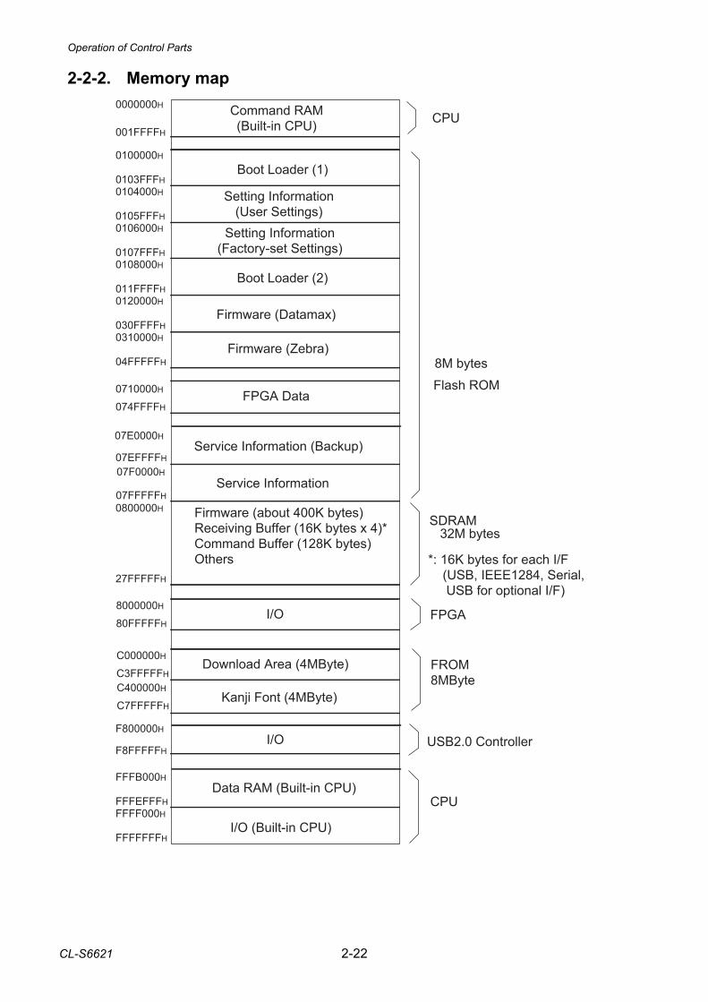
Command RAM(Built-in CPU)
0000000H
001FFFFH
Flash ROM
8M bytes
0100000H
0103FFFH0104000H
0105FFFH0106000H
0107FFFH0108000H
011FFFFH0120000H
030FFFFH0310000H
04FFFFFH
07E0000H
07EFFFFH
FPGA
SDRAM0800000H
32M bytes
27FFFFFH
CPU
FFFB000H
FFFEFFFHFFFF000H
FFFFFFFH
CPU
Boot Loader (1)
Setting Information(User Settings)
Setting Information(Factory-set Settings)
Boot Loader (2)
Firmware (Datamax)
Firmware (Zebra)
Service Information (Backup)
Firmware (about 400K bytes)Receiving Buffer (16K bytes x 4)*Command Buffer (128K bytes)Others *: 16K bytes for each I/F
(USB, IEEE1284, Serial, � USB for optional I/F)
I/O (Built-in CPU)
Data RAM (Built-in CPU)
07F0000H
07FFFFFHService Information
F800000H
F8FFFFFH
0710000H
074FFFFHFPGA Data
USB2.0 Controller
FROM8MByte
C000000H
C3FFFFFHDownload Area (4MByte)
Kanji Font (4MByte)C400000H
C7FFFFFH
I/O
8000000H
80FFFFFHI/O
2-2-2. Memory map
Operation of Control Parts
2-23 CL-S6621
J11Head Up Switch(Blue)
+3.3V
2
R78HDUSW
U1A CPU
PDH3117
C99
R80
SA, Head Up Switch
1
Head Up: HighHead Down: Low [SA, Main PCB]
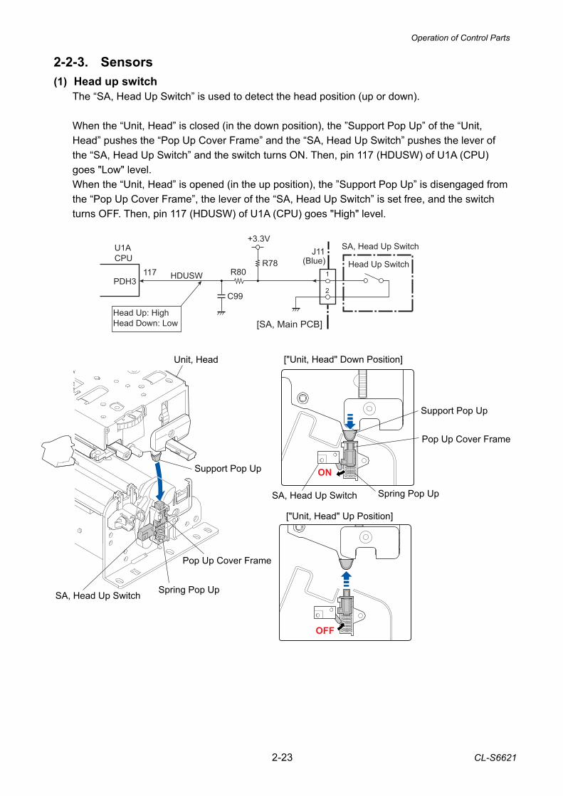
2-2-3. Sensors (1) Head up switch
The “SA, Head Up Switch” is used to detect the head position (up or down). When the “Unit, Head” is closed (in the down position), the ”Support Pop Up” of the “Unit, Head” pushes the “Pop Up Cover Frame” and the “SA, Head Up Switch” pushes the lever of the “SA, Head Up Switch” and the switch turns ON. Then, pin 117 (HDUSW) of U1A (CPU) goes "Low" level. When the “Unit, Head” is opened (in the up position), the ”Support Pop Up” is disengaged from the “Pop Up Cover Frame”, the lever of the “SA, Head Up Switch” is set free, and the switch turns OFF. Then, pin 117 (HDUSW) of U1A (CPU) goes "High" level.
SA, Head Up Switch Spring Pop Up
Support Pop Up
Pop Up Cover Frame
Unit, Head
["Unit, Head" Up Position]
["Unit, Head" Down Position]
ON
OFF
Pop Up Cover Frame
Support Pop Up
SA, Head Up Switch Spring Pop Up
Operation of Control Parts
CL-S6621 2-24
R70
R66U20B
BA2904
-+ 5
67
C96
R76
R73U20A
-+ 3
21
C97BA2904
R65
R72
Q9DTC114EM
Q10DTC114EM
R71
R67Q62SC5658
+5V
Media
Transparent Sensor
Reflective Sensor
3
2
3
4
1
45
J9
2
1 [SA TRA Sen PCB]
[SA Ref Sen PCB]
U7D/A Converter
CSB
DI1211 CK10
PSNSLEDSCLKDACCS
SDATAFrom U1A CPU
BH2227
Transparent sensor output sensing terminal
J8
+3.3V
REFMON
TRAMONANI0 5
ANI16
U1A CPU
Reflective sensor output sensing terminal
R75
R74
R14
R13
TSNSCTL1
TSNSCTL0
AO1AO2AO3AO4
(White)
2
B4_34
B4_33
U14 FPGA
(White)
R69
R68
Q7DTC114EM
Q8DTC114EM
[SA, Main PCB]
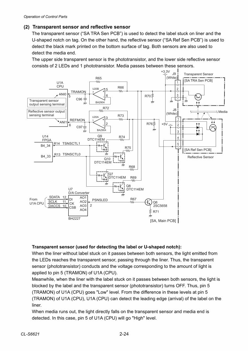
(2) Transparent sensor and reflective sensor The transparent sensor (“SA TRA Sen PCB”) is used to detect the label stuck on liner and the U-shaped notch on tag. On the other hand, the reflective sensor (“SA Ref Sen PCB”) is used to detect the black mark printed on the bottom surface of tag. Both sensors are also used to detect the media end. The upper side transparent sensor is the phototransistor, and the lower side reflective sensor consists of 2 LEDs and 1 phototransistor. Media passes between these sensors. Transparent sensor (used for detecting the label or U-shaped notch): When the liner without label stuck on it passes between both sensors, the light emitted from the LEDs reaches the transparent sensor, passing through the liner. Thus, the transparent sensor (phototransistor) conducts and the voltage corresponding to the amount of light is applied to pin 5 (TRAMON) of U1A (CPU). Meanwhile, when the liner with the label stuck on it passes between both sensors, the light is blocked by the label and the transparent sensor (phototransistor) turns OFF. Thus, pin 5 (TRAMON) of U1A (CPU) goes "Low" level. From the difference in these levels at pin 5 (TRAMON) of U1A (CPU), U1A (CPU) can detect the leading edge (arrival) of the label on the liner. When media runs out, the light directly falls on the transparent sensor and media end is detected. In this case, pin 5 of U1A (CPU) will go "High" level.
Operation of Control Parts
2-25 CL-S6621
When the transparent sensor is conducted, the voltage at pin 5 (TRAMON) varies depending on the characteristics of the light receiving element (phototransistor) of the transparent sensor and other factors. To solve this problem, U14 (FPGA) outputs TSNSCTL0 (pin R13) and TSNSCTL1 (pin R14) signals to turn ON/OFF Q8 and Q7 to connect/disconnect R69 and R68 (voltage dividing resistors) to minimize the difference in level at pin5 (TRAMON). The current flowing into the LEDs is determined by the data sent from the CPU to the digital-to-analog converter (U7). The digital-to-analog converter converts the data received from the CPU, and then outputs a resoultant level at pin 2. The base current of the transistor Q6 is determined by this level. This means that the current flowing into the LEDs is also determined by this level. In the actual control, the CPU changes data (for controlling the LED current) to keep the level at pin 5 (TRAMON) of CPU constant. Reflective sensor (used for detecting the black mark on tag): When tag with black marks is used, light is reflected by the tag. In the place where no black mark is there, the phototransistor of the reflective sensor conducts and the voltage corresponding to the amount of light is applied to pin 6 (REFMON) of U1A (CPU). When the light falls on the black mark, no light is reflected. In this case, the lower phototransistor turns OFF and pin 6 (REFMON) of U1A (CPU) will go “Low” level. When media runs out, the light is not reflected and no light falls on the reflective sensor. In this case, pin 6 (REFMON) of CPU will go “Low” level and media end is detected. When the reflective sensor is conducted, the voltage at pin 6 (REFMON) varies depending on the characteristics of the light receiving element (phototransistor) of the reflective sensor and other factors. To solve this problem, U14 (FPGA) outputs TSNSCTL0 (pin R13) and TSNSCTL1 (pin R14) signals to turn ON/OFF Q10 and Q9 to connect/disconnect R75 and R74 (voltage dividing resistors) to minimize the difference in level at pin6 (REFMON). As to the current control of the LEDs, the operation is the same as for the transparent sensor mentioned above.
Operation of Control Parts
CL-S6621 2-26
(SA, Ribbon Sensor)
Ribbon Sensor1
2
3
1
PT501PS501
R501
4
Front (Take-up side)
2
3
1
4
Rear (Supply side)
2
3
1J104
4
(Same as above circuit)
PT501
2
3
1J105
4
[SA, Ribbon PCB]
+3.3V
14
13
J102U1ACPU
34PCM0
14
13
32PCM2
J19
16
1531
PCM316
15
29PCM5
Ribbon Sensor2PS502
R502
(SA, Ribbon Sensor)
+3.3V
11+3.3V
+3.3V
SENS_A1
SENS_A2
SENS_B1
SENS_B2C
175
RIBSENS_A1RA20
56U21C
C17
6C
177
C17
8
R13
6R
137
R13
8R
139
98
U21D
1110
U21E1312
U21F
RIBSENS_A2
RIBSENS_B1
RIBSENS_B2
U2A
U2B
U2C
U2D
235
69
812
11
[SA, Main PCB]
18-20 18-20
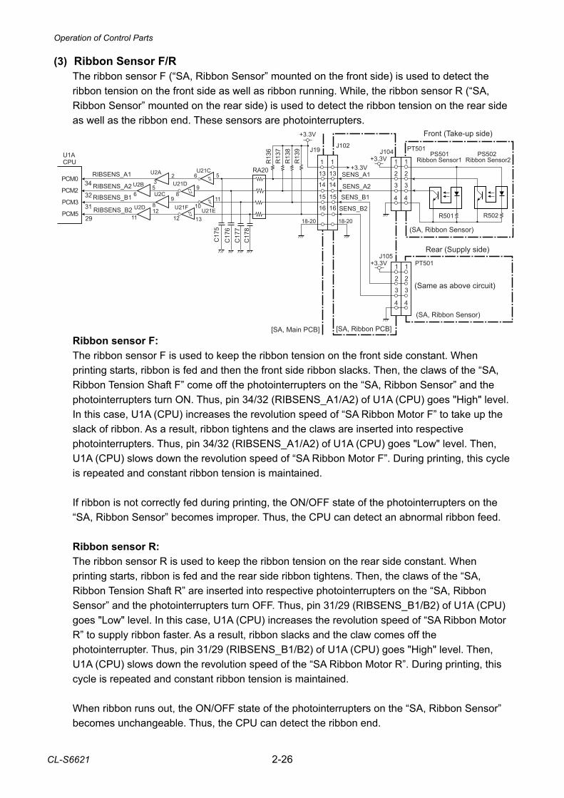
(3) Ribbon Sensor F/R The ribbon sensor F (“SA, Ribbon Sensor” mounted on the front side) is used to detect the ribbon tension on the front side as well as ribbon running. While, the ribbon sensor R (“SA, Ribbon Sensor” mounted on the rear side) is used to detect the ribbon tension on the rear side as well as the ribbon end. These sensors are photointerrupters. Ribbon sensor F: The ribbon sensor F is used to keep the ribbon tension on the front side constant. When printing starts, ribbon is fed and then the front side ribbon slacks. Then, the claws of the “SA, Ribbon Tension Shaft F” come off the photointerrupters on the “SA, Ribbon Sensor” and the photointerrupters turn ON. Thus, pin 34/32 (RIBSENS_A1/A2) of U1A (CPU) goes "High" level. In this case, U1A (CPU) increases the revolution speed of “SA Ribbon Motor F” to take up the slack of ribbon. As a result, ribbon tightens and the claws are inserted into respective photointerrupters. Thus, pin 34/32 (RIBSENS_A1/A2) of U1A (CPU) goes "Low" level. Then, U1A (CPU) slows down the revolution speed of “SA Ribbon Motor F”. During printing, this cycle is repeated and constant ribbon tension is maintained. If ribbon is not correctly fed during printing, the ON/OFF state of the photointerrupters on the “SA, Ribbon Sensor” becomes improper. Thus, the CPU can detect an abnormal ribbon feed. Ribbon sensor R: The ribbon sensor R is used to keep the ribbon tension on the rear side constant. When printing starts, ribbon is fed and the rear side ribbon tightens. Then, the claws of the “SA, Ribbon Tension Shaft R” are inserted into respective photointerrupters on the “SA, Ribbon Sensor” and the photointerrupters turn OFF. Thus, pin 31/29 (RIBSENS_B1/B2) of U1A (CPU) goes "Low" level. In this case, U1A (CPU) increases the revolution speed of “SA Ribbon Motor R” to supply ribbon faster. As a result, ribbon slacks and the claw comes off the photointerrupter. Thus, pin 31/29 (RIBSENS_B1/B2) of U1A (CPU) goes "High" level. Then, U1A (CPU) slows down the revolution speed of the “SA Ribbon Motor R”. During printing, this cycle is repeated and constant ribbon tension is maintained. When ribbon runs out, the ON/OFF state of the photointerrupters on the “SA, Ribbon Sensor” becomes unchangeable. Thus, the CPU can detect the ribbon end.
Operation of Control Parts
2-27 CL-S6621
J5
SA, Head+3.3V
5
R53HDTMP
U1A CPU
ANI27
Head Temp.Thermistor
C82
R54
U16B
BA2903SFV
-
+56
7
+3.3V
R39
+3.3V
R40
C41
R41
R42
HDTMP
C11
C6
B2_28
B2_27
U14 FPGA
nTEMP_ERROR
nTEMP_ENABLE
HDTMP
Error: Low
8
[SA, Main PCB]
TEMP ERROR Detection
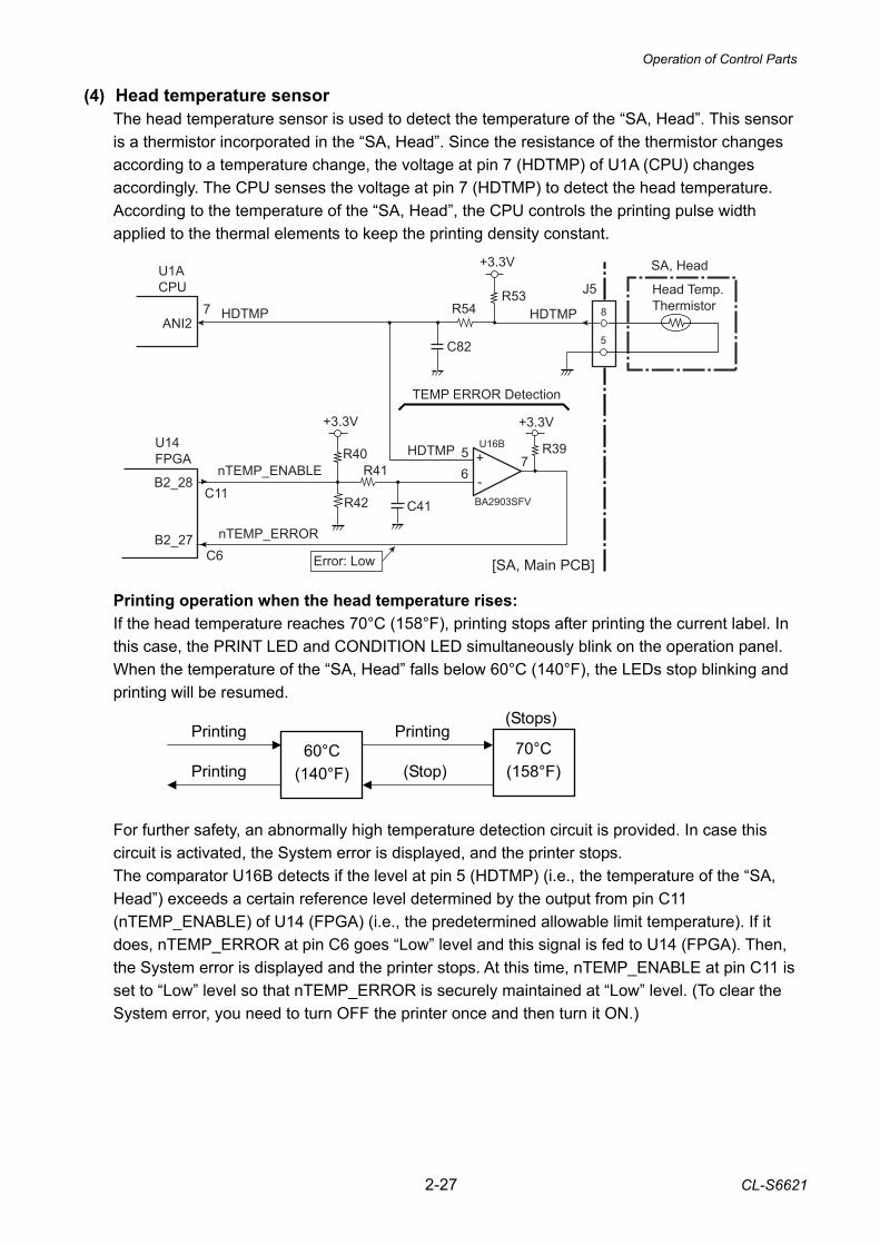
(4) Head temperature sensor The head temperature sensor is used to detect the temperature of the “SA, Head”. This sensor is a thermistor incorporated in the “SA, Head”. Since the resistance of the thermistor changes according to a temperature change, the voltage at pin 7 (HDTMP) of U1A (CPU) changes accordingly. The CPU senses the voltage at pin 7 (HDTMP) to detect the head temperature. According to the temperature of the “SA, Head”, the CPU controls the printing pulse width applied to the thermal elements to keep the printing density constant. Printing operation when the head temperature rises: If the head temperature reaches 70°C (158°F), printing stops after printing the current label. In this case, the PRINT LED and CONDITION LED simultaneously blink on the operation panel. When the temperature of the “SA, Head” falls below 60°C (140°F), the LEDs stop blinking and printing will be resumed. For further safety, an abnormally high temperature detection circuit is provided. In case this circuit is activated, the System error is displayed, and the printer stops. The comparator U16B detects if the level at pin 5 (HDTMP) (i.e., the temperature of the “SA, Head”) exceeds a certain reference level determined by the output from pin C11 (nTEMP_ENABLE) of U14 (FPGA) (i.e., the predetermined allowable limit temperature). If it does, nTEMP_ERROR at pin C6 goes “Low” level and this signal is fed to U14 (FPGA). Then, the System error is displayed and the printer stops. At this time, nTEMP_ENABLE at pin C11 is set to “Low” level so that nTEMP_ERROR is securely maintained at “Low” level. (To clear the System error, you need to turn OFF the printer once and then turn it ON.)
60°C (140°F)
70°C (158°F)
Printing (Stops)
(Stop)
Printing
Printing
Operation of Control Parts
CL-S6621 2-28
85°C (185°F)
90°C (194°F)
Normal speed
(Stop)
Normal speed
Normal speed 95°C
(203°F)
Low speed (Stops)
(Stop)
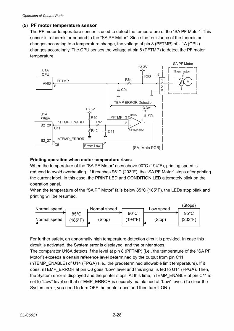
(5) PF motor temperature sensor The PF motor temperature sensor is used to detect the temperature of the “SA PF Motor”. This sensor is a thermistor bonded to the “SA PF Motor”. Since the resistance of the thermistor changes according to a temperature change, the voltage at pin 8 (PFTMP) of U1A (CPU) changes accordingly. The CPU senses the voltage at pin 8 (PFTMP) to detect the PF motor temperature. Printing operation when motor temperature rises: When the temperature of the “SA PF Motor” rises above 90°C (194°F), printing speed is reduced to avoid overheating. If it reaches 95°C (203°F), the “SA PF Motor” stops after printing the current label. In this case, the PRINT LED and CONDITION LED alternately blink on the operation panel. When the temperature of the “SA PF Motor” falls below 85°C (185°F), the LEDs stop blink and printing will be resumed. For further safety, an abnormally high temperature detection circuit is provided. In case this circuit is activated, the System error is displayed, and the printer stops. The comparator U16A detects if the level at pin 8 (PFTMP) (i.e., the temperature of the “SA PF Motor”) exceeds a certain reference level determined by the output from pin C11 (nTEMP_ENABLE) of U14 (FPGA) (i.e., the predetermined allowable limit temperature). If it does, nTEMP_ERROR at pin C6 goes “Low” level and this signal is fed to U14 (FPGA). Then, the System error is displayed and the printer stops. At this time, nTEMP_ENABLE at pin C11 is set to “Low” level so that nTEMP_ERROR is securely maintained at “Low” level. (To clear the System error, you need to turn OFF the printer once and then turn it ON.)
1J7
M
SA PF Motor
2
ThermistorR63
C94
R64PFTMP
U1A CPU
ANI38
U16A
BA2903SFV
-
+32
1
+3.3V
R39
+3.3V
R40
C41
R41
R42C11
C6
B2_28
B2_27
U14FPGA
nTEMP_ERROR
nTEMP_ENABLEPFTMP
+3.3V
[SA, Main PCB]
TEMP ERROR Detection
Error: Low
Operation of Control Parts
2-29 CL-S6621
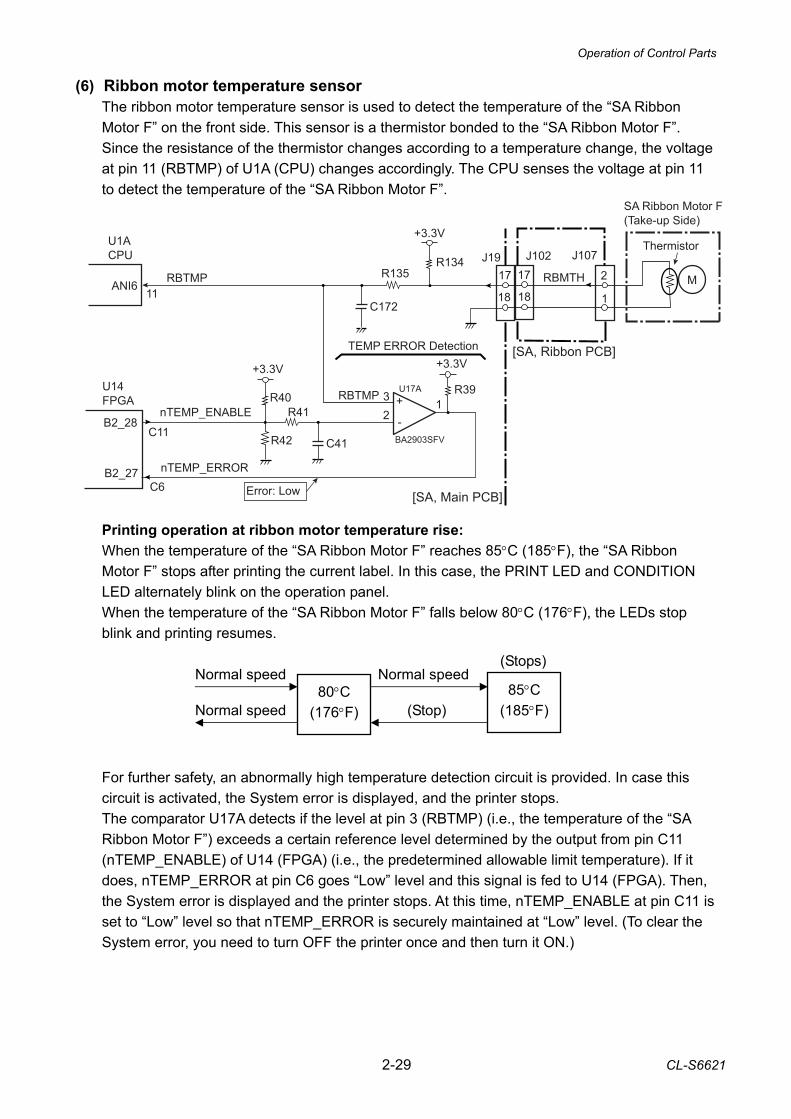
(6) Ribbon motor temperature sensor The ribbon motor temperature sensor is used to detect the temperature of the “SA Ribbon Motor F” on the front side. This sensor is a thermistor bonded to the “SA Ribbon Motor F”. Since the resistance of the thermistor changes according to a temperature change, the voltage at pin 11 (RBTMP) of U1A (CPU) changes accordingly. The CPU senses the voltage at pin 11 to detect the temperature of the “SA Ribbon Motor F”. Printing operation at ribbon motor temperature rise: When the temperature of the “SA Ribbon Motor F” reaches 85°C (185°F), the “SA Ribbon Motor F” stops after printing the current label. In this case, the PRINT LED and CONDITION LED alternately blink on the operation panel. When the temperature of the “SA Ribbon Motor F” falls below 80°C (176°F), the LEDs stop blink and printing resumes.
For further safety, an abnormally high temperature detection circuit is provided. In case this circuit is activated, the System error is displayed, and the printer stops. The comparator U17A detects if the level at pin 3 (RBTMP) (i.e., the temperature of the “SA Ribbon Motor F”) exceeds a certain reference level determined by the output from pin C11 (nTEMP_ENABLE) of U14 (FPGA) (i.e., the predetermined allowable limit temperature). If it does, nTEMP_ERROR at pin C6 goes “Low” level and this signal is fed to U14 (FPGA). Then, the System error is displayed and the printer stops. At this time, nTEMP_ENABLE at pin C11 is set to “Low” level so that nTEMP_ERROR is securely maintained at “Low” level. (To clear the System error, you need to turn OFF the printer once and then turn it ON.)
80°C (176°F)
85°C (185°F)
Normal speed
(Stop)
Normal speed
Normal speed
(Stops)
17J19
M18
ThermistorR134
C172
R135
U1A CPU
ANI611
U17A
BA2903SFV
-
+32
1
+3.3V
R39
+3.3V
R40
C41
R41
R42C11
C6
B2_28
B2_27
U14 FPGA
nTEMP_ERROR
nTEMP_ENABLE
SA Ribbon Motor F(Take-up Side)
RBTMP
+3.3V
1
J107
2
[SA, Ribbon PCB]
17J102
18RBMTH
RBTMP
[SA, Main PCB]
TEMP ERROR Detection
Error: Low
Operation of Control Parts
CL-S6621 2-30
R90C103
R89
R91
[SA, Main PCB]
3
2
J12
1
2U21A
Paper Near End Sensor(SA PNE Sensor)
Q13DTC115EM
PWRSAVE
U1ACPU
D18 114
L: Power Saving modeH: Normal mode
+3.3V
Q12DTA114EM
(White)
1PNESNSPCT7
77 3
2
1PT301
PS301
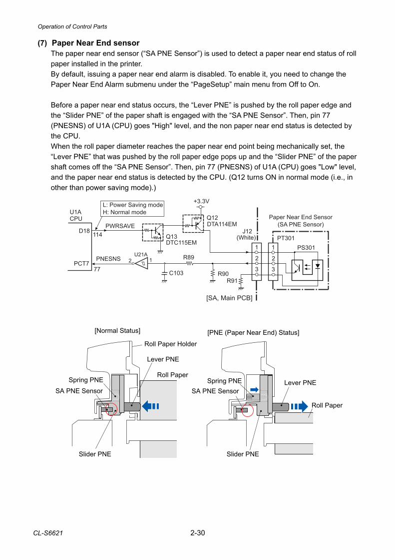
(7) Paper Near End sensor The paper near end sensor (“SA PNE Sensor”) is used to detect a paper near end status of roll paper installed in the printer. By default, issuing a paper near end alarm is disabled. To enable it, you need to change the Paper Near End Alarm submenu under the “PageSetup” main menu from Off to On. Before a paper near end status occurs, the “Lever PNE” is pushed by the roll paper edge and the “Slider PNE” of the paper shaft is engaged with the “SA PNE Sensor”. Then, pin 77 (PNESNS) of U1A (CPU) goes "High" level, and the non paper near end status is detected by the CPU. When the roll paper diameter reaches the paper near end point being mechanically set, the “Lever PNE” that was pushed by the roll paper edge pops up and the “Slider PNE” of the paper shaft comes off the “SA PNE Sensor”. Then, pin 77 (PNESNS) of U1A (CPU) goes "Low" level, and the paper near end status is detected by the CPU. (Q12 turns ON in normal mode (i.e., in other than power saving mode).)
Lever PNE
Spring PNESA PNE Sensor
Slider PNE
Roll Paper
Roll Paper Holder
[Normal Status]
Lever PNESpring PNESA PNE Sensor
Slider PNE
Roll Paper
[PNE (Paper Near End) Status]
Operation of Control Parts
2-31 CL-S6621
2-2-4. Drivers (1) PF motor driver
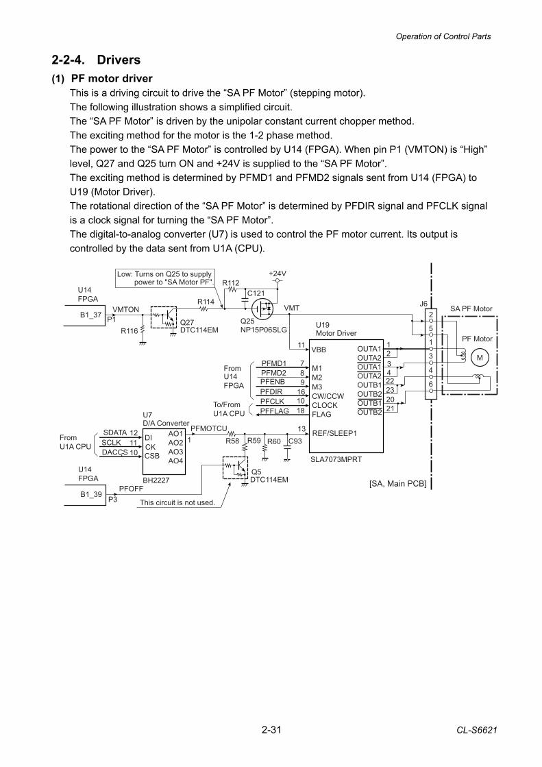
This is a driving circuit to drive the “SA PF Motor” (stepping motor). The following illustration shows a simplified circuit. The “SA PF Motor” is driven by the unipolar constant current chopper method. The exciting method for the motor is the 1-2 phase method. The power to the “SA PF Motor” is controlled by U14 (FPGA). When pin P1 (VMTON) is “High” level, Q27 and Q25 turn ON and +24V is supplied to the “SA PF Motor”. The exciting method is determined by PFMD1 and PFMD2 signals sent from U14 (FPGA) to U19 (Motor Driver). The rotational direction of the “SA PF Motor” is determined by PFDIR signal and PFCLK signal is a clock signal for turning the “SA PF Motor”. The digital-to-analog converter (U7) is used to control the PF motor current. Its output is controlled by the data sent from U1A (CPU).
7
11
98
10
VBB
M1M2M3CW/CCWCLOCKFLAG
U19Motor Driver 5
1
3
4
6
J6
OUTA1OUTA2OUTA1OUTA2OUTB1OUTB2OUTB1OUTB2
12
2322
Q27DTC114EM
Q25NP15P06SLG
REF/SLEEP1C93R60
PFMOTCU
Low: Turns on Q25 to supply
PFMD1PFMD2PFENB
PFCLK
13
2
M
PF Motor
VMT
SLA7073MPRT
1
power to "SA Motor PF".
SA PF Motor
34
2120
16
18
PFDIR
PFFLAG
Q5DTC114EM
R59R58
PFOFF
U7D/A Converter
CSB
DI1211 CK10
SCLKDACCS
SDATAFrom U1A CPU
BH2227
AO1AO2AO3AO4
C121
VMTONB1_37
U14 FPGA
B1_39
U14FPGA
P3
FromU14 FPGA
To/From U1A CPU
This circuit is not used.
+24VR112
R114
R116P1
[SA, Main PCB]
Operation of Control Parts
CL-S6621 2-32
24
17
19VBB1VBB2
DIR
STEP
U101Motor Driver
3
4
2
1
J101
OUT1A
OUT1B
OUT2A
OUT2B
M18
21
1
22
U15BMonostableMultivibrator
CLR
A9
10 B11
Q 5
From U1A CPU
RIBTRG
nGRESET
74VHC123
REFRBMOTCU_A 15
145
6
7
8
J102
9
3,4
3
4
2
1
J103
M
SA Ribbon Motor R(Supply Side)
(Same as above circuit)
RIBDIR_A
RIBSTEP_AVMT
U14 FPGA
D24 122
U1A CPU
126D28
N13B3_37
B3_38
5
6
7
8
9
J19
[SA, Ribbon PCB]
12
4U29
nTEMP_ERROR
A4984SES-T
ENABLE2RIBDIR_B
RIBSTEP_B
10
11
RBMOTCU_B
MOT_EN
10U7D/A Converter
CSB
DI1211 CK10
RBMOTCU_ASCLKDACCS
SDATA
From U1A CPU
BH2227
AO1AO2AO3AO4 5 RBMOTCU_B
6
N14
RIBDIR_A
RIBSTEP_A
RIBDIR_B
RIBSTEP_B
(From Ribbon MotorTemperature Sensor)
U102Motor Driver
3,4
11
[SA, Main PCB]
From U14 FPGA
Normally "High".Error: Low
(24V)VMTVMT
(24V)
R144
SA Ribbon Motor F(Take-up Side)
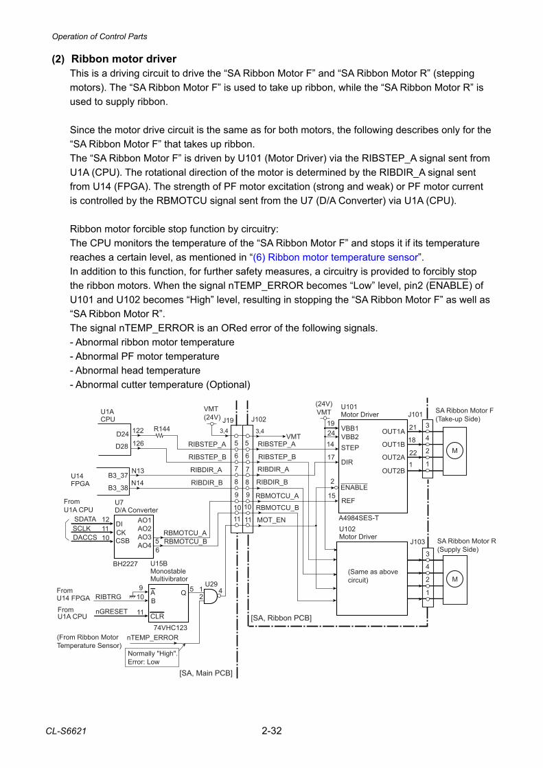
(2) Ribbon motor driver This is a driving circuit to drive the “SA Ribbon Motor F” and “SA Ribbon Motor R” (stepping motors). The “SA Ribbon Motor F” is used to take up ribbon, while the “SA Ribbon Motor R” is used to supply ribbon. Since the motor drive circuit is the same as for both motors, the following describes only for the “SA Ribbon Motor F” that takes up ribbon. The “SA Ribbon Motor F” is driven by U101 (Motor Driver) via the RIBSTEP_A signal sent from U1A (CPU). The rotational direction of the motor is determined by the RIBDIR_A signal sent from U14 (FPGA). The strength of PF motor excitation (strong and weak) or PF motor current is controlled by the RBMOTCU signal sent from the U7 (D/A Converter) via U1A (CPU). Ribbon motor forcible stop function by circuitry: The CPU monitors the temperature of the “SA Ribbon Motor F” and stops it if its temperature reaches a certain level, as mentioned in “(6) Ribbon motor temperature sensor”. In addition to this function, for further safety measures, a circuitry is provided to forcibly stop the ribbon motors. When the signal nTEMP_ERROR becomes “Low” level, pin2 (ENABLE) of U101 and U102 becomes “High” level, resulting in stopping the “SA Ribbon Motor F” as well as “SA Ribbon Motor R”. The signal nTEMP_ERROR is an ORed error of the following signals. - Abnormal ribbon motor temperature - Abnormal PF motor temperature - Abnormal head temperature - Abnormal cutter temperature (Optional)
Operation of Control Parts
2-33 CL-S6621
J3
SA, Head(Thermal Head)
nHDSTBHDCLKnHDLAT
16
18
1-5
U14FPGA
B3_41 P14
B3_40 N16
B3_39 N15
VHDON
nHCVON
B3_43P16
B3_42 P15
+24VR113
R115
Q26Q28DTC114EM
D2
2SJ505S
D3
+3.3V U1A CPU
D1+3.3V
R46
R47
R49
R48
Head supply voltage ON/OFF
Thermal element abnormality check ON
Head power supply monitor: Not used.
Thermal element abnormality check
[SA, Main PCB]
nHDSTBHDCLKnHDLAT
+3.3V
B3_33 M14
B3-27 K16
B3_35 M16
B3-26 K15 HD1HD2HD3HD4
17,21,22
10
R52 L1
C75
C74
Q1DTA114EM
+3.3V
R45
J5
VHD
VHD
R117
C122
When checking: +3.3V
When printing: +24V
5,19,20
HD1HD2HD3HD4
GND
GND
2,15
VDDR55
+3.3V
VHDMON
HDRES
ANI49
ANI510
VHD
6-10
12
13
14
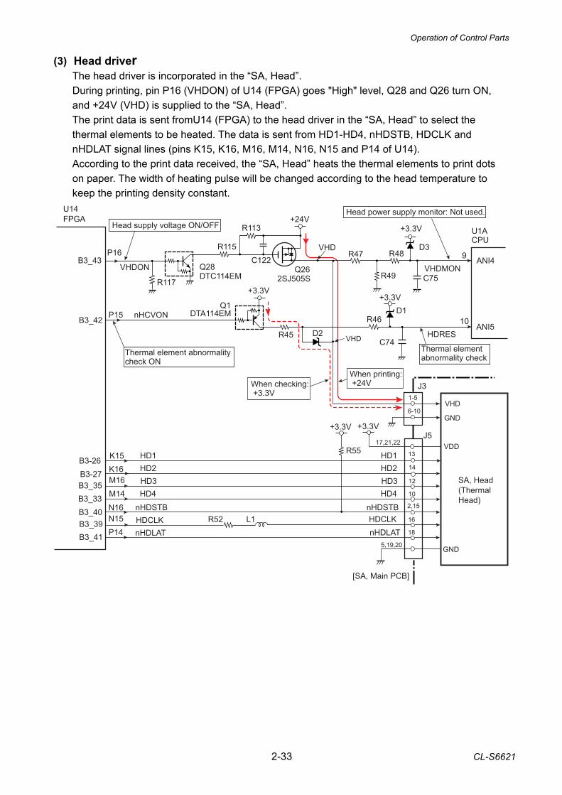
(3) Head driver The head driver is incorporated in the “SA, Head”. During printing, pin P16 (VHDON) of U14 (FPGA) goes "High" level, Q28 and Q26 turn ON, and +24V (VHD) is supplied to the “SA, Head”. The print data is sent fromU14 (FPGA) to the head driver in the “SA, Head” to select the thermal elements to be heated. The data is sent from HD1-HD4, nHDSTB, HDCLK and nHDLAT signal lines (pins K15, K16, M16, M14, N16, N15 and P14 of U14). According to the print data received, the “SA, Head” heats the thermal elements to print dots on paper. The width of heating pulse will be changed according to the head temperature to keep the printing density constant.
Operation of Control Parts
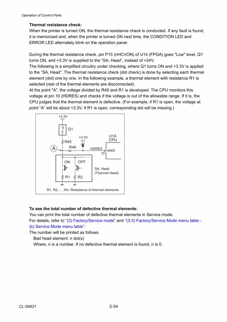
CL-S6621 2-34
Thermal resistance check: When the printer is turned ON, the thermal resistance check is conducted. If any fault is found, it is memorized and, when the printer is turned ON next time, the CONDITION LED and ERROR LED alternately blink on the operation panel. During the thermal resistance check, pin P15 (nHCVON) of U14 (FPGA) goes "Low" level, Q1 turns ON, and +3.3V is supplied to the “SA, Head”, instead of +24V. The following is a simplified circuitry under checking, where Q1 turns ON and +3.3V is applied to the “SA, Head”. The thermal resistance check (dot check) is done by selecting each thermal element (dot) one by one. In the following example, a thermal element with resistance R1 is selected (rest of the thermal elements are disconnected). At the point "A", the voltage divided by R45 and R1 is developed. The CPU monitors this voltage at pin 10 (HDRES) and checks if the voltage is out of the allowable range. If it is, the CPU judges that the thermal element is defective. (For example, if R1 is open, the voltage at point “A” will be about +3.3V. If R1 is open, corresponding dot will be missing.)
To see the total number of defective thermal elements: You can print the total number of defective thermal elements in Service mode. For details, refer to “(3) Factory/Service mode” and “(3-3) Factory/Service Mode menu table - (b) Service Mode menu table”. The number will be printed as follows. Bad head element: n dot(s) Where, n is a number. If no defective thermal element is found, n is 0.
+3.3V
U1ACPUR45
R1
A
R1, R2, ... ,Rn: Resistance of thermal elements
Q1
SA, Head(Thermal Head)
R46 HDRES ANI510
+3.3V
R2
ON OFF
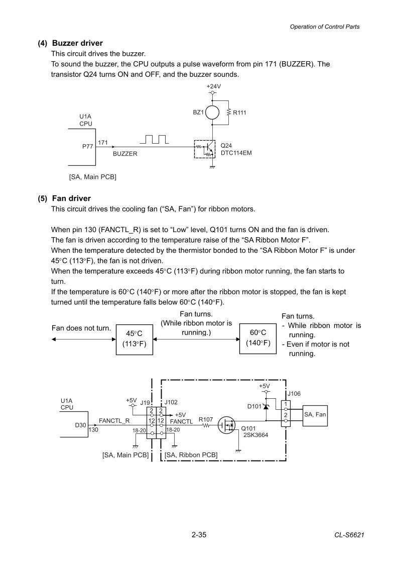
Operation of Control Parts
2-35 CL-S6621
1
2
J106
[SA, Main PCB]
U1ACPU
D30130
FANCTL_R 122
J102
[SA, Ribbon PCB]
FANCTL12
2
18-2018-20
SA, Fan
+5V
D101+5V
J19+5V
Q101R107
2SK3664
(4) Buzzer driver This circuit drives the buzzer. To sound the buzzer, the CPU outputs a pulse waveform from pin 171 (BUZZER). The transistor Q24 turns ON and OFF, and the buzzer sounds.
(5) Fan driver
This circuit drives the cooling fan (“SA, Fan”) for ribbon motors. When pin 130 (FANCTL_R) is set to “Low” level, Q101 turns ON and the fan is driven. The fan is driven according to the temperature raise of the “SA Ribbon Motor F”. When the temperature detected by the thermistor bonded to the “SA Ribbon Motor F” is under 45°C (113°F), the fan is not driven. When the temperature exceeds 45°C (113°F) during ribbon motor running, the fan starts to turn. If the temperature is 60°C (140°F) or more after the ribbon motor is stopped, the fan is kept turned until the temperature falls below 60°C (140°F).
U1A CPU
BUZZER
+24V
[SA, Main PCB]
P77 171
R111
Q24DTC114EM
BZ1
Fan turns.(While ribbon motor is
running.)Fan does not turn. Fan turns. - While ribbon motor is
running. - Even if motor is not
running.
60°C (140°F)
45°C (113°F)
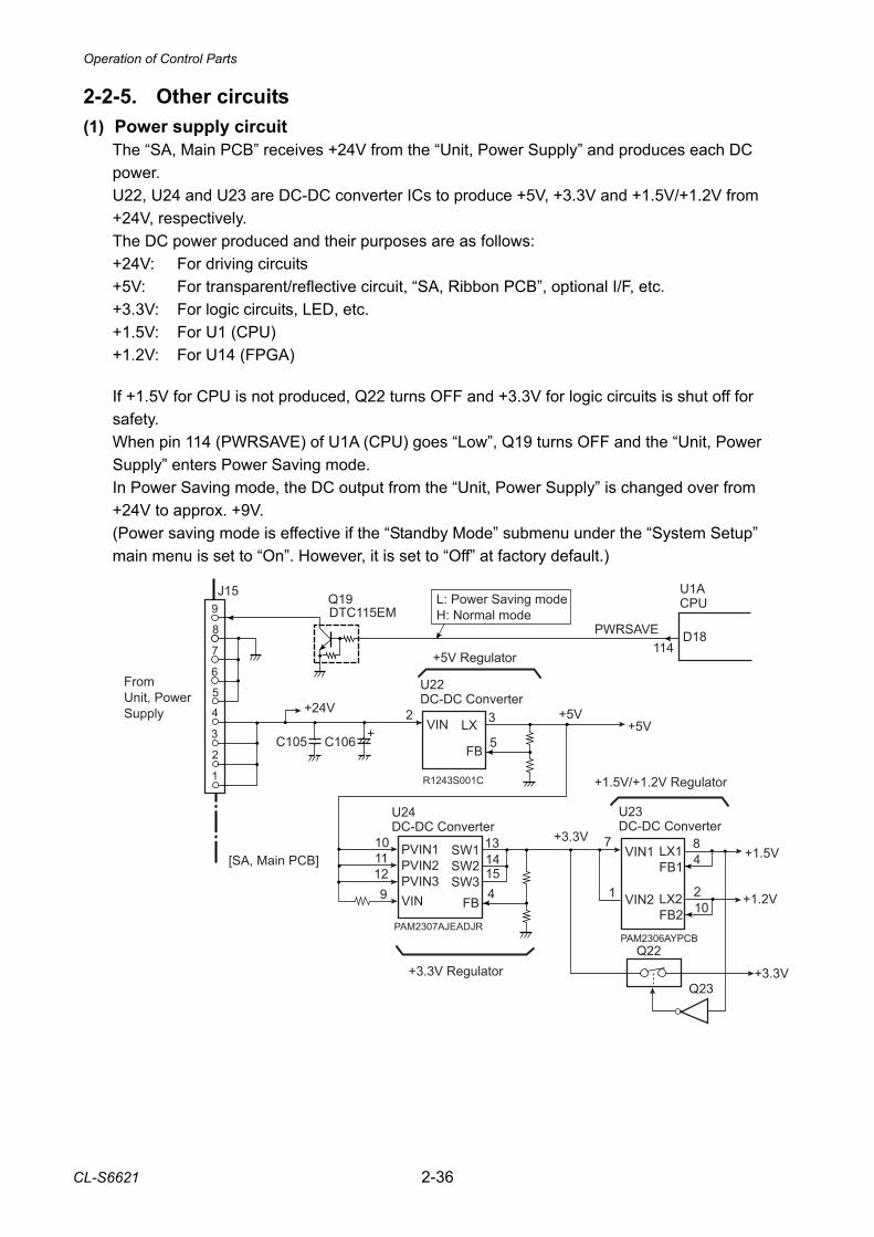
Operation of Control Parts
CL-S6621 2-36
7
6
9
45
8
J15
4
3
+24V
+1.5V+3.3V
[SA, Main PCB]
Q19DTC115EM
U1ACPU
D18114
+5V
C106C105 +VIN LX
FB
3
5
2
U22DC-DC Converter
R1243S001C
VIN
SW1SW2SW3
FB
13
4
10
U24DC-DC Converter
PAM2307AJEADJR
VIN1
VIN2
LX1FB1
LX2FB2
84
7
U23DC-DC Converter
PAM2306AYPCB
1 210
+1.2V
Q22
+3.3VQ23
+5V Regulator
+3.3V Regulator
+1.5V/+1.2V Regulator
+5V
PWRSAVE
2
1
L: Power Saving modeH: Normal mode
PVIN1PVIN2PVIN3
11129
1514
FromUnit, PowerSupply
2-2-5. Other circuits (1) Power supply circuit
The “SA, Main PCB” receives +24V from the “Unit, Power Supply” and produces each DC power. U22, U24 and U23 are DC-DC converter ICs to produce +5V, +3.3V and +1.5V/+1.2V from +24V, respectively. The DC power produced and their purposes are as follows: +24V: For driving circuits +5V: For transparent/reflective circuit, “SA, Ribbon PCB”, optional I/F, etc. +3.3V: For logic circuits, LED, etc. +1.5V: For U1 (CPU) +1.2V: For U14 (FPGA) If +1.5V for CPU is not produced, Q22 turns OFF and +3.3V for logic circuits is shut off for safety. When pin 114 (PWRSAVE) of U1A (CPU) goes “Low”, Q19 turns OFF and the “Unit, Power Supply” enters Power Saving mode. In Power Saving mode, the DC output from the “Unit, Power Supply” is changed over from +24V to approx. +9V. (Power saving mode is effective if the “Standby Mode” submenu under the “System Setup” main menu is set to “On”. However, it is set to “Off” at factory default.)
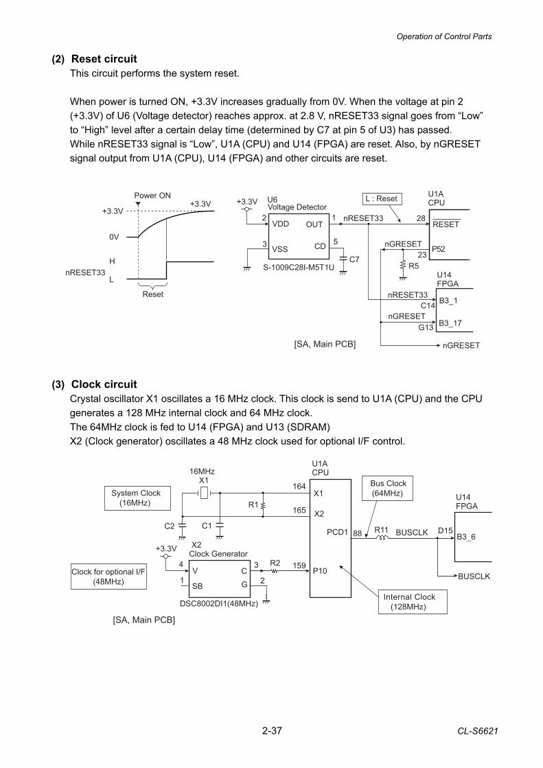
Operation of Control Parts
2-37 CL-S6621
(2) Reset circuit This circuit performs the system reset. When power is turned ON, +3.3V increases gradually from 0V. When the voltage at pin 2 (+3.3V) of U6 (Voltage detector) reaches approx. at 2.8 V, nRESET33 signal goes from “Low” to “High” level after a certain delay time (determined by C7 at pin 5 of U3) has passed. While nRESET33 signal is “Low”, U1A (CPU) and U14 (FPGA) are reset. Also, by nGRESET signal output from U1A (CPU), U14 (FPGA) and other circuits are reset.
(3) Clock circuit Crystal oscillator X1 oscillates a 16 MHz clock. This clock is send to U1A (CPU) and the CPU generates a 128 MHz internal clock and 64 MHz clock. The 64MHz clock is fed to U14 (FPGA) and U13 (SDRAM) X2 (Clock generator) oscillates a 48 MHz clock used for optional I/F control.
VSS
+3.3V
53
1Voltage Detector
nRESET33RESET
L : Reset
G13
U1ACPU
B3_17
U14FPGA
Power ON
Reset
+3.3V+3.3V
H
L
0VP52nGRESET
nGRESET
C14 B3_1nRESET33
nGRESET
nRESET33
U6
S-1009C28I-M5T1U
OUT
CD
VDD2 28
23C7R5
[SA, Main PCB]
U1ACPU
U14FPGA
X1
R1
C2
System Clock(16MHz)
BUSCLKPCD1 88 B3_6D15
G
+3.3V Clock Generator
Clock for optional I/F(48MHz)
X2
V
DSC8002DI1(48MHz)
SB
C
Bus Clock(64MHz)
Internal Clock(128MHz)
P10159
C1
BUSCLK
[SA, Main PCB]
4
1
3
2
R11
R2
16MHz
X1164
X2165
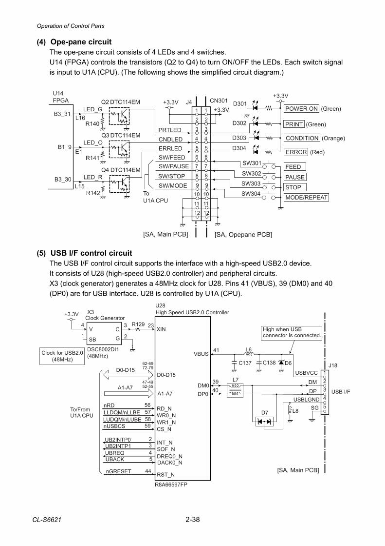
Operation of Control Parts
CL-S6621 2-38
(4) Ope-pane circuit The ope-pane circuit consists of 4 LEDs and 4 switches. U14 (FPGA) controls the transistors (Q2 to Q4) to turn ON/OFF the LEDs. Each switch signal is input to U1A (CPU). (The following shows the simplified circuit diagram.)
(5) USB I/F control circuit
The USB I/F control circuit supports the interface with a high-speed USB2.0 device. It consists of U28 (high-speed USB2.0 controller) and peripheral circuits. X3 (clock generator) generates a 48MHz clock for U28. Pins 41 (VBUS), 39 (DM0) and 40 (DP0) are for USB interface. U28 is controlled by U1A (CPU).
3
4
1
45
2
J4
6
7
8
+3.3V
[SA, Main PCB]
9
10
11
12
PRTLEDCNDLEDERRLED
SW/STOPSW/MODE
SW/PAUSESW/FEED
+3.3V
[SA, Opepane PCB]
POWER ON (Green)
PRINT (Green)
CONDITION (Orange)
ERROR (Red)
FEED
PAUSE
STOP
MODE/REPEAT
+3.3V
D304
D303
D302
SW302
SW303
SW304
SW301
D301
3
4
1
45
2
CN301
6
7
8
9
10
11
12
ToU1A CPU
B1_9
U14 FPGA
Q4 DTC114EMLED_R
R142
E1
Q3 DTC114EMLED_O
R141
Q2 DTC114EMLED_G
R140
B3_31L16
B3_30L15
12345
D7
L7
J18
L8
C137
L6
SG
USBVCC
USBLGNDDP
DM
USB I/F
[SA, Main PCB]
C138 D6
RD_NWR0_NWR1_NCS_N
U28
R8A66597FP
To/FromU1A CPU
D0-D15
A1-A7
High Speed USB2.0 Controller
SOF_NDREQ0_N
RST_N
DACK0_N
62-6972-79
47-4952-55
D0-D15
A1-A7
INT_N
G
+3.3VClock Generator
Clock for USB2.0(48MHz)
X3
V
SB
C234
1
3
2
R129
DSC8002DI1(48MHz)
XIN
nRD 565758
nUSBCS 59
LLDQM/nLLBE
2
LUDQM/nLUBE
3UBREQ 4UBACK 5
nGRESET 44
UB2INTP0UB2INTP1
41VBUS
39DM0
40DP0
High when USB connector is connected.
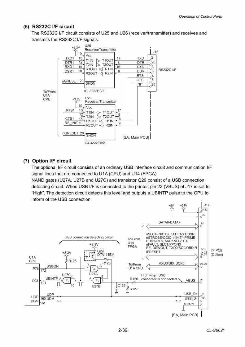
Operation of Control Parts
2-39 CL-S6621
To/FromU14FPGA
23
2221
nSLCT-IN/CTS, nATFD-XT/DSRnSTROBE/OCIO, nINIT/nPRIMEBUSY/RTS, nACKNLG/DTRnFAULT, SLCT/PPON0PE, DSWOUT, TXD0/SO0/OBDIRIFRESET
RXD0/SI0, SCK0
VBUS
I/F PCB(Option)
DATA0-DATA7
+24V+5V
To/FromU1A CPU
J1728-32
20
4-11
1-312-1824,27
25,26
[SA, Main PCB]
USB_D+USB_D-
33-38,40
R125
R127
Q29DTA114EM
C133
R126UBINTP 46598
10
1 32
+3.3V
+3.3V
U1ACPU
USBONP76 172
D23 121
UDPUDM
USB connection detecting circuit
R128
U27C U27A
U27B
UDPUDM160
161
High when USB connector is connected.
(6) RS232C I/F circuit The RS232C I/F circuit consists of U25 and U26 (receiver/transmitter) and receives and transmits the RS232C I/F signals.
(7) Option I/F circuit The optional I/F circuit consists of an ordinary USB interface circuit and communication I/F signal lines that are connected to U1A (CPU) and U14 (FPGA). NAND gates (U27A, U27B and U27C) and transistor Q29 consist of a USB connection detecting circuit. When USB I/F is connected to the printer, pin 23 (VBUS) of J17 is set to “High”. The detection circuit detects this level and outputs a UBINTP pulse to the CPU to inform of the USB connection.
13
1512
10
VccT1INT2INR1OUTR2OUT
U25Receiver/Transmitter
22036
J16
817
169
TXD1DTR1RXD1DSR1
19
+3.3V
[SA, Main PCB]
ICL3222EIVZ
20nGRESET SHDN
To/FromU1ACPU
4525
T1OUTT2OUT
R1INR2IN
13
1512
10
VccT1INT2INR1OUTR2OUT
U26
817
169
RTS1
CTS1RS_INIT
19
+3.3V
ICL3222EIVZ
20nGRESET SHDN
T1OUTT2OUT
R1INR2IN
TXDDTRRXDDSRRTSCTSINIT
RS232C I/F
Receiver/Transmitter
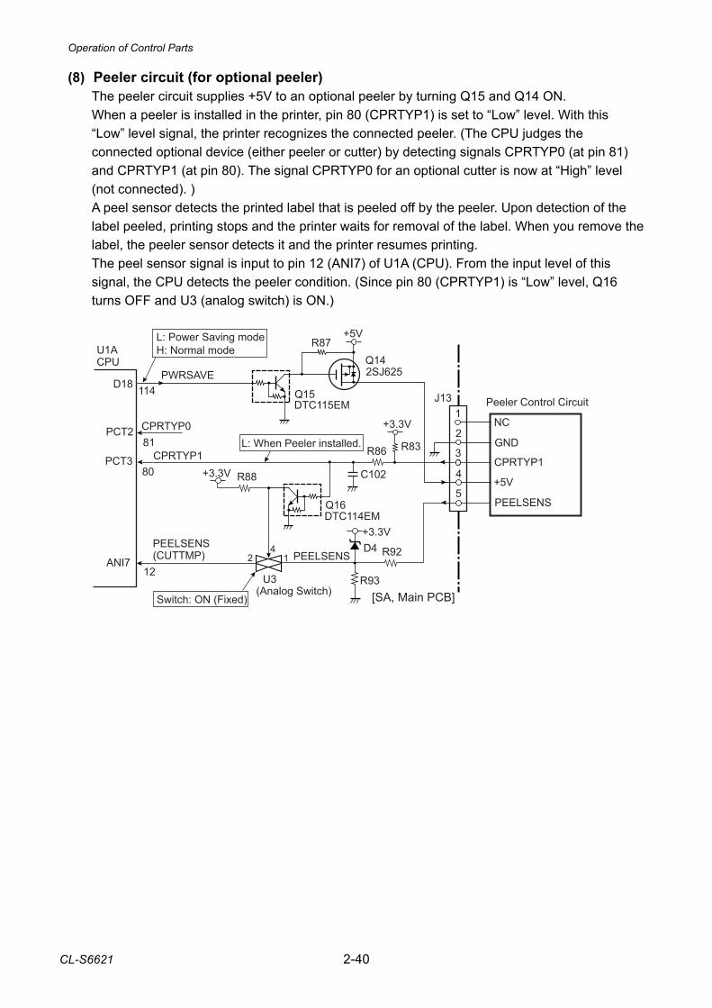
Operation of Control Parts
CL-S6621 2-40
[SA, Main PCB]
3
2
J131
Peeler Control CircuitQ15DTC115EM
PWRSAVE
U1ACPU
D18 114
L: Power Saving modeH: Normal mode
+5V
Q142SJ625
CPRTYP1PCT380
5
4
R83
C102
R86
+3.3V
D4
R87
R92
+3.3V
R93
PEELSENS(CUTTMP)ANI7
12
Q16DTC114EM
(Analog Switch)
412
U3
R88+3.3V
L: When Peeler installed.
Switch: ON (Fixed)
NC
GND
CPRTYP1
+5V
PEELSENS
PEELSENS
CPRTYP0PCT281
(8) Peeler circuit (for optional peeler) The peeler circuit supplies +5V to an optional peeler by turning Q15 and Q14 ON. When a peeler is installed in the printer, pin 80 (CPRTYP1) is set to “Low” level. With this “Low” level signal, the printer recognizes the connected peeler. (The CPU judges the connected optional device (either peeler or cutter) by detecting signals CPRTYP0 (at pin 81) and CPRTYP1 (at pin 80). The signal CPRTYP0 for an optional cutter is now at “High” level (not connected). ) A peel sensor detects the printed label that is peeled off by the peeler. Upon detection of the label peeled, printing stops and the printer waits for removal of the label. When you remove the label, the peeler sensor detects it and the printer resumes printing. The peel sensor signal is input to pin 12 (ANI7) of U1A (CPU). From the input level of this signal, the CPU detects the peeler condition. (Since pin 80 (CPRTYP1) is “Low” level, Q16 turns OFF and U3 (analog switch) is ON.)
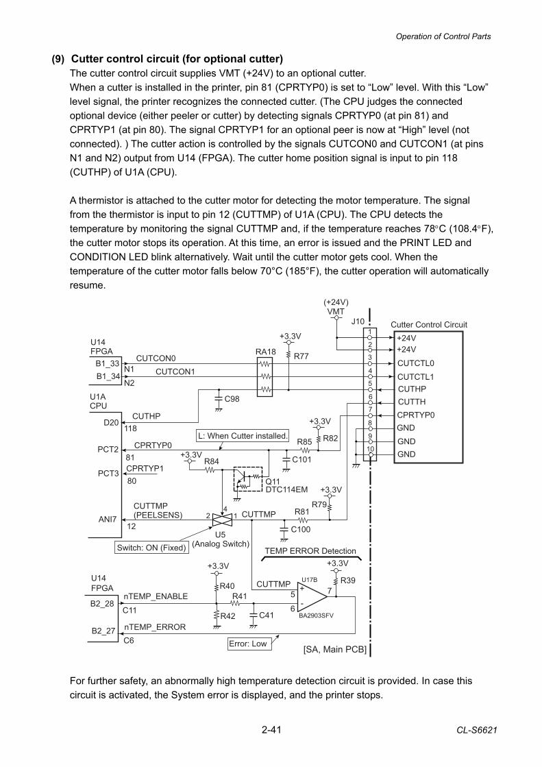
Operation of Control Parts
2-41 CL-S6621
J10 Cutter Control Circuit
3
2
1
5
4
7
6
8
10
9
VMT
U1ACPU
D20
CPRTYP0PCT281
R82
C101
R85
+3.3V
CUTTMP(PEELSENS)ANI7
12
Q11DTC114EM
(Analog Switch)
412
U5
R84+3.3V
L: When Cutter installed.
Switch: ON (Fixed)
R77
+3.3V
C98
R79
C100
R81
+3.3V
U14FPGA RA18
N2
CUTCON0N1
B1_33B1_34 CUTCON1
+24V+24V
CUTCTL0
CUTCTL1CUTHPCUTTH
GND
GNDGND
CPRTYP0CUTHP118
U17B
BA2903SFV
-
+5
6
7
+3.3V
R39
+3.3V
R40
C41
R41
R42C11
C6
B2_28
B2_27
U14 FPGA
nTEMP_ERROR
nTEMP_ENABLECUTTMP
[SA, Main PCB]
TEMP ERROR Detection
CUTTMP
(+24V)
Error: Low
CPRTYP1PCT380
(9) Cutter control circuit (for optional cutter) The cutter control circuit supplies VMT (+24V) to an optional cutter. When a cutter is installed in the printer, pin 81 (CPRTYP0) is set to “Low” level. With this “Low” level signal, the printer recognizes the connected cutter. (The CPU judges the connected optional device (either peeler or cutter) by detecting signals CPRTYP0 (at pin 81) and CPRTYP1 (at pin 80). The signal CPRTYP1 for an optional peer is now at “High” level (not connected). ) The cutter action is controlled by the signals CUTCON0 and CUTCON1 (at pins N1 and N2) output from U14 (FPGA). The cutter home position signal is input to pin 118 (CUTHP) of U1A (CPU). A thermistor is attached to the cutter motor for detecting the motor temperature. The signal from the thermistor is input to pin 12 (CUTTMP) of U1A (CPU). The CPU detects the temperature by monitoring the signal CUTTMP and, if the temperature reaches 78°C (108.4°F), the cutter motor stops its operation. At this time, an error is issued and the PRINT LED and CONDITION LED blink alternatively. Wait until the cutter motor gets cool. When the temperature of the cutter motor falls below 70°C (185°F), the cutter operation will automatically resume. For further safety, an abnormally high temperature detection circuit is provided. In case this circuit is activated, the System error is displayed, and the printer stops.

Operation of Control Parts
CL-S6621 2-42
The comparator U17B detects if the level at pin 5 (CUTTMP) exceeds a certain reference level determined by the output from pin C11 (nTEMP_ENABLE) of U14 (FPGA) (i.e., the predetermined allowable limit temperature). If it does, the signal nTEMP_ERROR at pin C6 of U14 (FPGA) goes “Low” level. Then, the System error is displayed and the printer stops. At this time, nTEMP_ENABLE at pin C11 is set to “Low” level so that nTEMP_ERROR is securely maintained at “Low” level. (To clear the System error, you need to turn OFF the printer once and then turn it ON.)
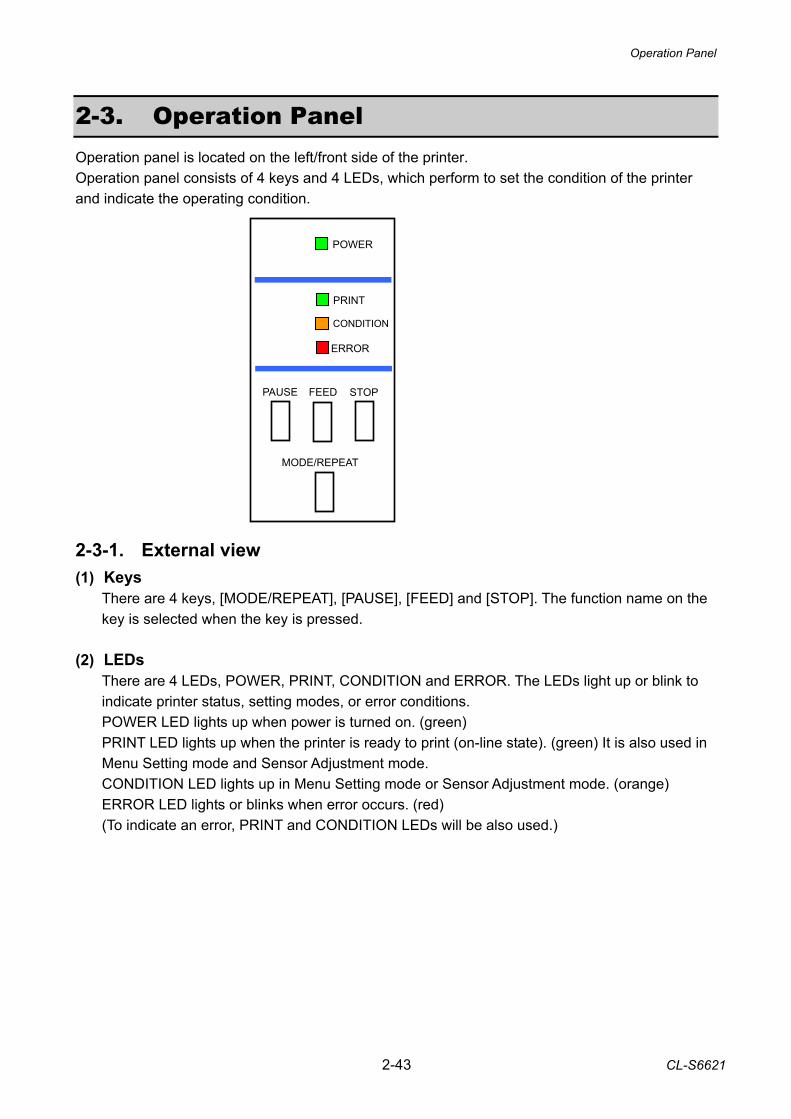
Operation Panel
2-43 CL-S6621
2-3. Operation Panel Operation panel is located on the left/front side of the printer. Operation panel consists of 4 keys and 4 LEDs, which perform to set the condition of the printer and indicate the operating condition. 2-3-1. External view (1) Keys
There are 4 keys, [MODE/REPEAT], [PAUSE], [FEED] and [STOP]. The function name on the key is selected when the key is pressed.
(2) LEDs
There are 4 LEDs, POWER, PRINT, CONDITION and ERROR. The LEDs light up or blink to indicate printer status, setting modes, or error conditions. POWER LED lights up when power is turned on. (green) PRINT LED lights up when the printer is ready to print (on-line state). (green) It is also used in Menu Setting mode and Sensor Adjustment mode. CONDITION LED lights up in Menu Setting mode or Sensor Adjustment mode. (orange) ERROR LED lights or blinks when error occurs. (red) (To indicate an error, PRINT and CONDITION LEDs will be also used.)
PAUSE STOPFEED
MODE/REPEAT
ERROR
CONDITION
POWER
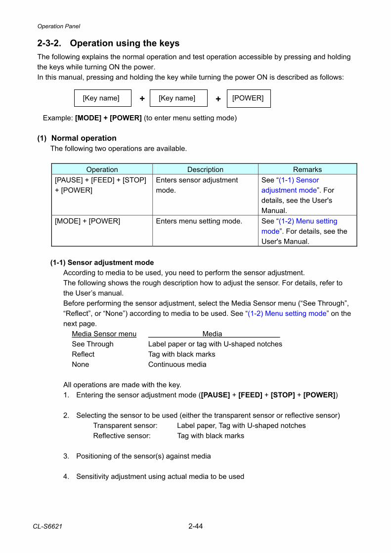
Operation Panel
CL-S6621 2-44
2-3-2. Operation using the keys The following explains the normal operation and test operation accessible by pressing and holding the keys while turning ON the power. In this manual, pressing and holding the key while turning the power ON is described as follows: Example: [MODE] + [POWER] (to enter menu setting mode) (1) Normal operation
The following two operations are available.
Operation Description Remarks [PAUSE] + [FEED] + [STOP] + [POWER]
Enters sensor adjustment mode.
See “(1-1) Sensor adjustment mode”. For details, see the User's Manual.
[MODE] + [POWER] Enters menu setting mode.
See “(1-2) Menu setting mode”. For details, see the User's Manual.
(1-1) Sensor adjustment mode
According to media to be used, you need to perform the sensor adjustment. The following shows the rough description how to adjust the sensor. For details, refer to the User’s manual. Before performing the sensor adjustment, select the Media Sensor menu (“See Through”, “Reflect”, or “None”) according to media to be used. See “(1-2) Menu setting mode” on the next page. Media Sensor menu Media See Through Label paper or tag with U-shaped notches Reflect Tag with black marks None Continuous media
All operations are made with the key. 1. Entering the sensor adjustment mode ([PAUSE] + [FEED] + [STOP] + [POWER])
2. Selecting the sensor to be used (either the transparent sensor or reflective sensor)
Transparent sensor: Label paper, Tag with U-shaped notches Reflective sensor: Tag with black marks
3. Positioning of the sensor(s) against media 4. Sensitivity adjustment using actual media to be used
[Key name] + [POWER] + [Key name]
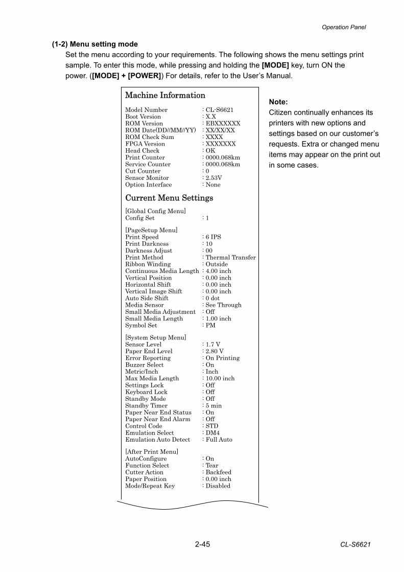
Operation Panel
2-45 CL-S6621
(1-2) Menu setting mode Set the menu according to your requirements. The following shows the menu settings print sample. To enter this mode, while pressing and holding the [MODE] key, turn ON the power. ([MODE] + [POWER]) For details, refer to the User’s Manual.
Machine Information Model Number : CL-S6621 Boot Version : X.X ROM Version : EBXXXXXX ROM Date(DD//MM//YY) : XX/XX/XX ROM Check Sum : XXXX FPGA Version : XXXXXXX Head Check : OK Print Counter : 0000.068km Service Counter : 0000.068km Cut Counter : 0 Sensor Monitor : 2.53V Option Interface : None Current Menu Settings [Global Config Menu] Config Set : 1 [PageSetup Menu] Print Speed : 6 IPS Print Darkness : 10 Darkness Adjust : 00 Print Method : Thermal Transfer Ribbon Winding : Outside Continuous Media Length : 4.00 inch Vertical Position : 0.00 inch Horizontal Shift : 0.00 inch Vertical Image Shift : 0.00 inch Auto Side Shift : 0 dot Media Sensor : See Through Small Media Adjustment : Off Small Media Length : 1.00 inch Symbol Set : PM [System Setup Menu] Sensor Level : 1.7 V Paper End Level : 2.80 V Error Reporting : On Printing Buzzer Select : On Metric/Inch : Inch Max Media Length : 10.00 inch Settings Lock : Off Keyboard Lock : Off Standby Mode : Off Standby Timer : 5 min Paper Near End Status : On Paper Near End Alarm : Off Control Code : STD Emulation Select : DM4 Emulation Auto Detect : Full Auto [After Print Menu] AutoConfigure : On Function Select : Tear Cutter Action : Backfeed Paper Position : 0.00 inch Mode/Repeat Key : Disabled
Note: Citizen continually enhances its printers with new options and settings based on our customer’s requests. Extra or changed menu items may appear on the print out in some cases.
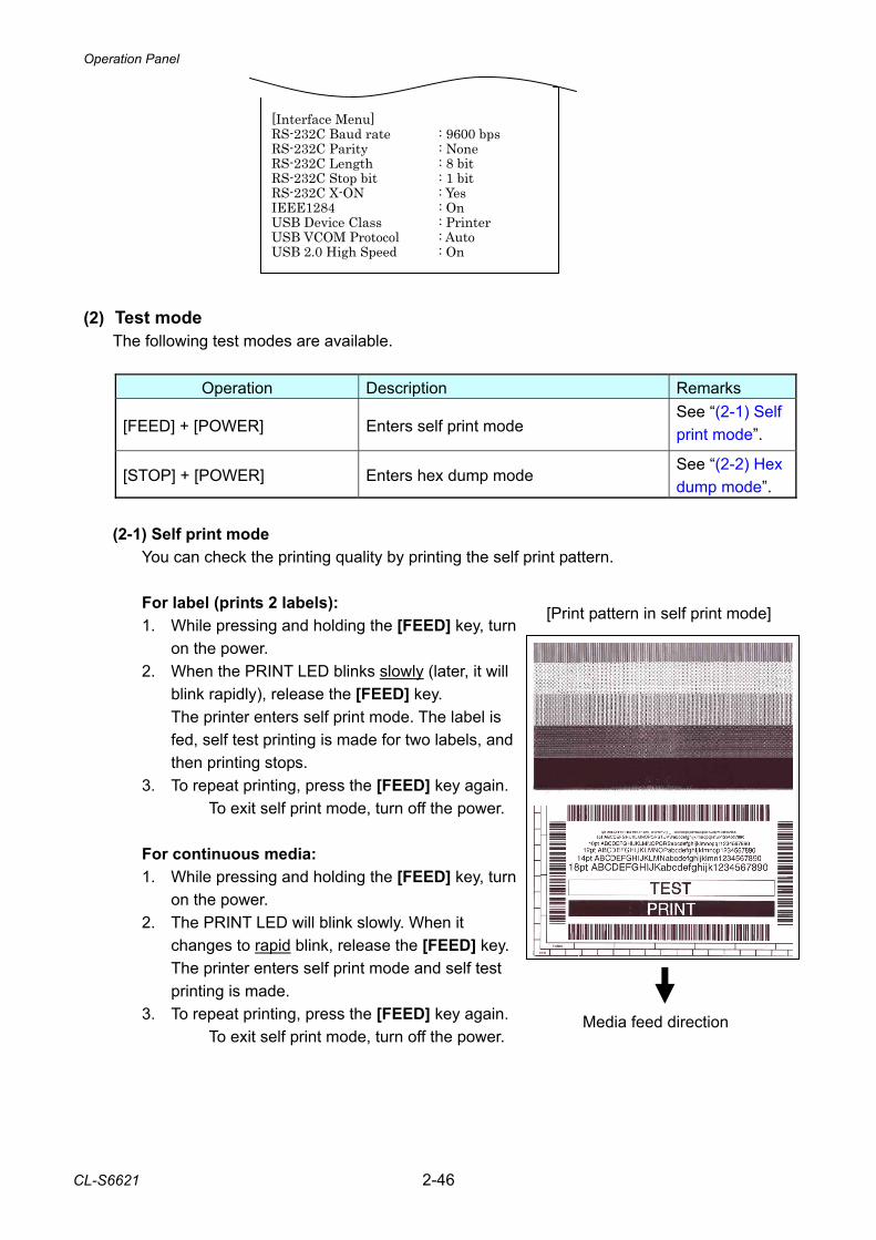
Operation Panel
CL-S6621 2-46
[Interface Menu] RS-232C Baud rate : 9600 bps RS-232C Parity : None RS-232C Length : 8 bit RS-232C Stop bit : 1 bit RS-232C X-ON : Yes IEEE1284 : On USB Device Class : Printer USB VCOM Protocol : Auto USB 2.0 High Speed : On
(2) Test mode
The following test modes are available.
Operation Description Remarks
[FEED] + [POWER] Enters self print mode See “(2-1) Self print mode”.
[STOP] + [POWER] Enters hex dump mode See “(2-2) Hex dump mode”.
(2-1) Self print mode
You can check the printing quality by printing the self print pattern.
For label (prints 2 labels): 1. While pressing and holding the [FEED] key, turn
on the power. 2. When the PRINT LED blinks slowly (later, it will
blink rapidly), release the [FEED] key. The printer enters self print mode. The label is fed, self test printing is made for two labels, and then printing stops.
3. To repeat printing, press the [FEED] key again. To exit self print mode, turn off the power.
For continuous media: 1. While pressing and holding the [FEED] key, turn
on the power. 2. The PRINT LED will blink slowly. When it
changes to rapid blink, release the [FEED] key. The printer enters self print mode and self test printing is made.
3. To repeat printing, press the [FEED] key again. To exit self print mode, turn off the power.
Media feed direction
[Print pattern in self print mode]
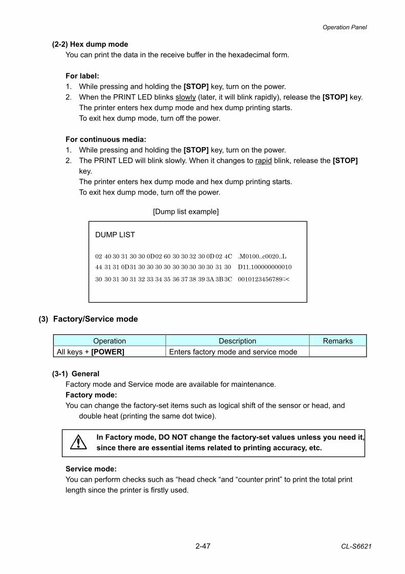
Operation Panel
2-47 CL-S6621
(2-2) Hex dump mode You can print the data in the receive buffer in the hexadecimal form.
For label: 1. While pressing and holding the [STOP] key, turn on the power. 2. When the PRINT LED blinks slowly (later, it will blink rapidly), release the [STOP] key.
The printer enters hex dump mode and hex dump printing starts. To exit hex dump mode, turn off the power.
For continuous media: 1. While pressing and holding the [STOP] key, turn on the power. 2. The PRINT LED will blink slowly. When it changes to rapid blink, release the [STOP]
key. The printer enters hex dump mode and hex dump printing starts. To exit hex dump mode, turn off the power.
(3) Factory/Service mode
Operation Description Remarks All keys + [POWER] Enters factory mode and service mode
(3-1) General
Factory mode and Service mode are available for maintenance. Factory mode: You can change the factory-set items such as logical shift of the sensor or head, and
double heat (printing the same dot twice).
In Factory mode, DO NOT change the factory-set values unless you need it, since there are essential items related to printing accuracy, etc.
Service mode: You can perform checks such as “head check “and “counter print” to print the total print length since the printer is firstly used.
DUMP LIST 02 40 30 31 30 30 0D 02 60 30 30 32 30 0D 02 4C .M0100..c0020..L 44 31 31 0D 31 30 30 30 30 30 30 30 30 30 31 30 D11.100000000010
30 30 31 30 31 32 33 34 35 36 37 38 39 3A 3B 3C 0010123456789:;<
[Dump list example]
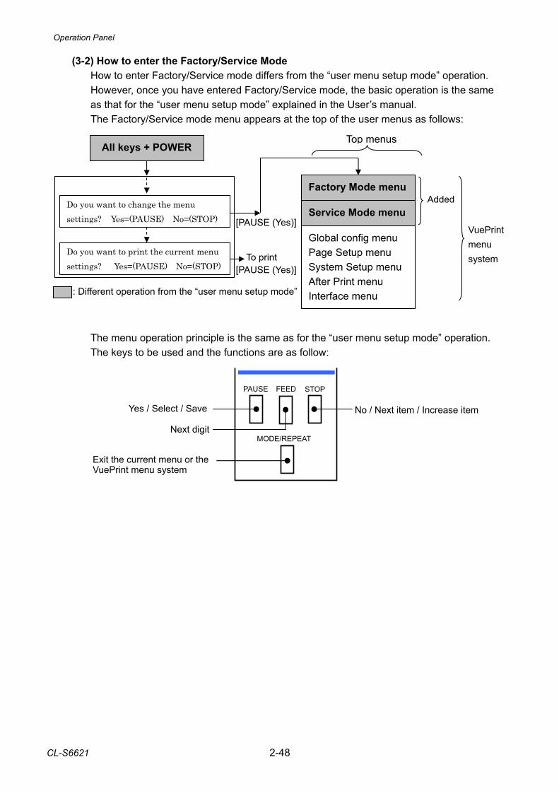
Operation Panel
CL-S6621 2-48
PAUSE STOPFEED
MODE/REPEAT
No / Next item / Increase itemYes / Select / Save
Next digit
Exit the current menu or the VuePrint menu system
(3-2) How to enter the Factory/Service Mode How to enter Factory/Service mode differs from the “user menu setup mode” operation. However, once you have entered Factory/Service mode, the basic operation is the same as that for the “user menu setup mode” explained in the User’s manual. The Factory/Service mode menu appears at the top of the user menus as follows:
The menu operation principle is the same as for the “user menu setup mode” operation. The keys to be used and the functions are as follow:
All keys + POWER
Factory Mode menu
Service Mode menu
Global config menu Page Setup menu System Setup menu After Print menu Interface menu
Do you want to change the menu settings? Yes=(PAUSE) No=(STOP) [PAUSE (Yes)]
: Different operation from the “user menu setup mode”
Added
Top menus
Do you want to print the current menu settings? Yes=(PAUSE) No=(STOP) [PAUSE (Yes)]
To print
VuePrint menu system
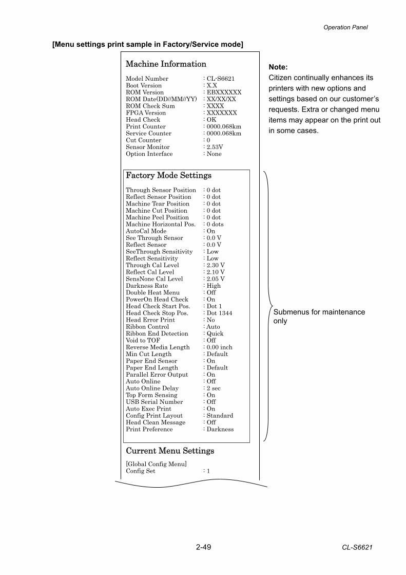
Operation Panel
2-49 CL-S6621
[Menu settings print sample in Factory/Service mode]
Machine Information Model Number : CL-S6621 Boot Version : X.X ROM Version : EBXXXXXX ROM Date(DD//MM//YY) : XX/XX/XX ROM Check Sum : XXXX FPGA Version : XXXXXXX Head Check : OK Print Counter : 0000.068km Service Counter : 0000.068km Cut Counter : 0 Sensor Monitor : 2.53V Option Interface : None Factory Mode Settings Through Sensor Position : 0 dot Reflect Sensor Position : 0 dot Machine Tear Position : 0 dot Machine Cut Position : 0 dot Machine Peel Position : 0 dot Machine Horizontal Pos. : 0 dots AutoCal Mode : On See Through Sensor : 0.0 V Reflect Sensor : 0.0 V SeeThrough Sensitivity : Low Reflect Sensitivity : Low Through Cal Level : 2.30 V Reflect Cal Level : 2.10 V SensNone Cal Level : 2.05 V Darkness Rate : High Double Heat Menu : Off PowerOn Head Check : On Head Check Start Pos. : Dot 1 Head Check Stop Pos. : Dot 1344 Head Error Print : No Ribbon Control : Auto Ribbon End Detection : Quick Void to TOF : Off Reverse Media Length : 0.00 inch Min Cut Length : Default Paper End Sensor : On Paper End Length : Default Parallel Error Output : On Auto Online : Off Auto Online Delay : 2 sec Top Form Sensing : On USB Serial Number : Off Auto Exec Print : On Config Print Layout : Standard Head Clean Message : Off Print Preference : Darkness Current Menu Settings [Global Config Menu] Config Set : 1
Submenus for maintenance only
Note: Citizen continually enhances its printers with new options and settings based on our customer’s requests. Extra or changed menu items may appear on the print out in some cases.
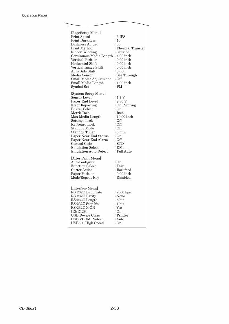
Operation Panel
CL-S6621 2-50
[PageSetup Menu] Print Speed : 6 IPS Print Darkness : 10 Darkness Adjust : 00 Print Method : Thermal Transfer Ribbon Winding : Outside Continuous Media Length : 4.00 inch Vertical Position : 0.00 inch Horizontal Shift : 0.00 inch Vertical Image Shift : 0.00 inch Auto Side Shift : 0 dot Media Sensor : See Through Small Media Adjustment : Off Small Media Length : 1.00 inch Symbol Set : PM [System Setup Menu] Sensor Level : 1.7 V Paper End Level : 2.80 V Error Reporting : On Printing Buzzer Select : On Metric/Inch : Inch Max Media Length : 10.00 inch Settings Lock : Off Keyboard Lock : Off Standby Mode : Off Standby Timer : 5 min Paper Near End Status : On Paper Near End Alarm : Off Control Code : STD Emulation Select : DM4 Emulation Auto Detect : Full Auto [After Print Menu] AutoConfigure : On Function Select : Tear Cutter Action : Backfeed Paper Position : 0.00 inch Mode/Repeat Key : Disabled [Interface Menu] RS-232C Baud rate : 9600 bps RS-232C Parity : None RS-232C Length : 8 bit RS-232C Stop bit : 1 bit RS-232C X-ON : Yes IEEE1284 : On USB Device Class : Printer USB VCOM Protocol : Auto USB 2.0 High Speed : On
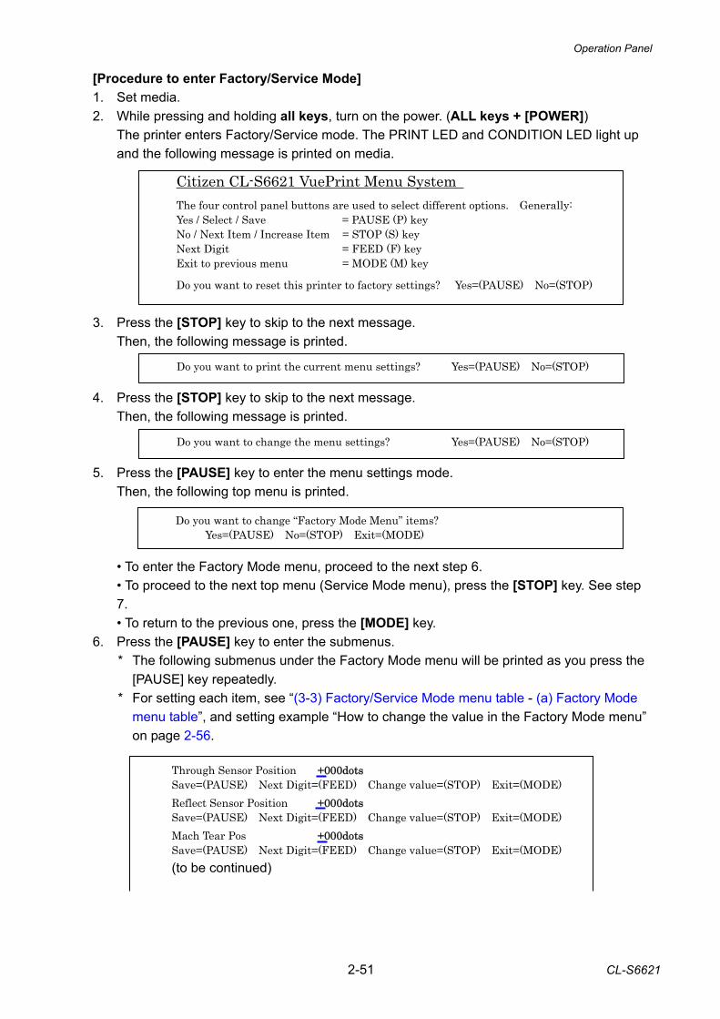
Operation Panel
2-51 CL-S6621
[Procedure to enter Factory/Service Mode] 1. Set media. 2. While pressing and holding all keys, turn on the power. (ALL keys + [POWER]) The printer enters Factory/Service mode. The PRINT LED and CONDITION LED light up
and the following message is printed on media.
3. Press the [STOP] key to skip to the next message. Then, the following message is printed.
4. Press the [STOP] key to skip to the next message. Then, the following message is printed.
5. Press the [PAUSE] key to enter the menu settings mode. Then, the following top menu is printed.
• To enter the Factory Mode menu, proceed to the next step 6. • To proceed to the next top menu (Service Mode menu), press the [STOP] key. See step
7. • To return to the previous one, press the [MODE] key. 6. Press the [PAUSE] key to enter the submenus.
* The following submenus under the Factory Mode menu will be printed as you press the [PAUSE] key repeatedly.
* For setting each item, see “(3-3) Factory/Service Mode menu table - (a) Factory Mode menu table”, and setting example “How to change the value in the Factory Mode menu” on page 2-56.
Through Sensor Position +000dots Save=(PAUSE) Next Digit=(FEED) Change value=(STOP) Exit=(MODE) Reflect Sensor Position +000dots Save=(PAUSE) Next Digit=(FEED) Change value=(STOP) Exit=(MODE) Mach Tear Pos +000dots Save=(PAUSE) Next Digit=(FEED) Change value=(STOP) Exit=(MODE) (to be continued)
Citizen CL-S6621 VuePrint Menu System
The four control panel buttons are used to select different options. Generally: Yes / Select / Save = PAUSE (P) key No / Next Item / Increase Item = STOP (S) key Next Digit = FEED (F) key Exit to previous menu = MODE (M) key Do you want to reset this printer to factory settings? Yes=(PAUSE) No=(STOP)
Do you want to print the current menu settings? Yes=(PAUSE) No=(STOP)
Do you want to change the menu settings? Yes=(PAUSE) No=(STOP)
Do you want to change “Factory Mode Menu” items? Yes=(PAUSE) No=(STOP) Exit=(MODE)
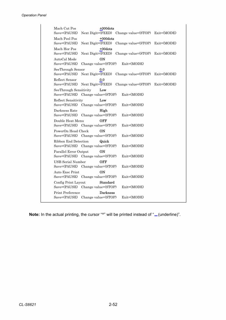
Operation Panel
CL-S6621 2-52
Mach Cut Pos +000dots Save=(PAUSE) Next Digit=(FEED) Change value=(STOP) Exit=(MODE) Mach Peel Pos +000dots Save=(PAUSE) Next Digit=(FEED) Change value=(STOP) Exit=(MODE) Mach Hor Pos +00dots Save=(PAUSE) Next Digit=(FEED) Change value=(STOP) Exit=(MODE) AutoCal Mode ON Save=(PAUSE) Change value=(STOP) Exit=(MODE) SeeThrough Sensor 0.0 Save=(PAUSE) Next Digit=(FEED) Change value=(STOP) Exit=(MODE) Reflect Sensor 0.0 Save=(PAUSE) Next Digit=(FEED) Change value=(STOP) Exit=(MODE) SeeThrough Sensitivity Low Save=(PAUSE) Change value=(STOP) Exit=(MODE) Reflect Sensitivity Low Save=(PAUSE) Change value=(STOP) Exit=(MODE) Darkness Rate High Save=(PAUSE) Change value=(STOP) Exit=(MODE) Double Heat Menu OFF Save=(PAUSE) Change value=(STOP) Exit=(MODE) PowerOn Head Check ON Save=(PAUSE) Change value=(STOP) Exit=(MODE) Ribbon End Detection Quick Save=(PAUSE) Change value=(STOP) Exit=(MODE) Parallel Error Output ON Save=(PAUSE) Change value=(STOP) Exit=(MODE) USB Serial Number OFF Save=(PAUSE) Change value=(STOP) Exit=(MODE) Auto Exec Print ON Save=(PAUSE) Change value=(STOP) Exit=(MODE) Config Print Layout Standard Save=(PAUSE) Change value=(STOP) Exit=(MODE) Print Preference Darkness Save=(PAUSE) Change value=(STOP) Exit=(MODE)
Note: In the actual printing, the cursor “^” will be printed instead of “ (underline)”.
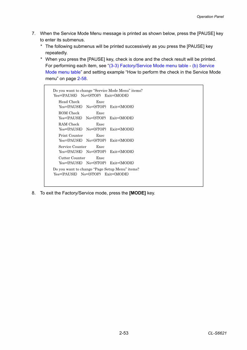
Operation Panel
2-53 CL-S6621
7. When the Service Mode Menu message is printed as shown below, press the [PAUSE] key
to enter its submenus. * The following submenus will be printed successively as you press the [PAUSE] key
repeatedly. * When you press the [PAUSE] key, check is done and the check result will be printed.
For performing each item, see “(3-3) Factory/Service Mode menu table - (b) Service Mode menu table” and setting example “How to perform the check in the Service Mode menu” on page 2-58.
Do you want to change “Service Mode Menu” items? Yes=(PAUSE) No=(STOP) Exit=(MODE)
Head Check Exec Yes=(PAUSE) No=(STOP) Exit=(MODE) ROM Check Exec Yes=(PAUSE) No=(STOP) Exit=(MODE) RAM Check Exec Yes=(PAUSE) No=(STOP) Exit=(MODE) Print Counter Exec Yes=(PAUSE) No=(STOP) Exit=(MODE) Service Counter Exec Yes=(PAUSE) No=(STOP) Exit=(MODE) Cutter Counter Exec Yes=(PAUSE) No=(STOP) Exit=(MODE)
Do you want to change “Page Setup Menu” items? Yes=(PAUSE) No=(STOP) Exit=(MODE)
8. To exit the Factory/Service mode, press the [MODE] key.
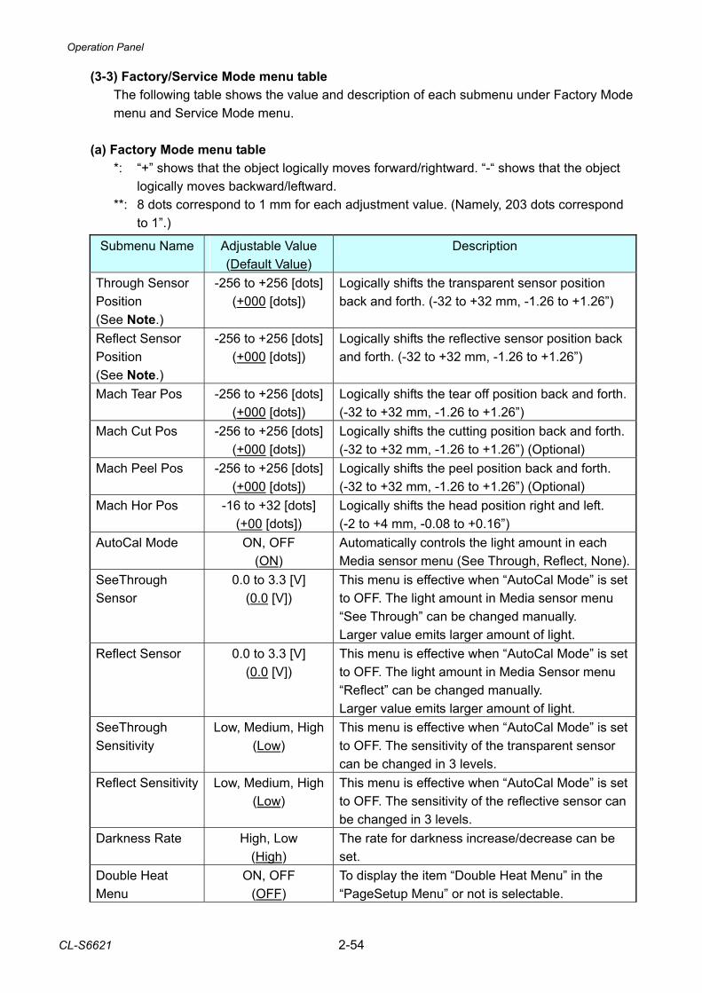
Operation Panel
CL-S6621 2-54
(3-3) Factory/Service Mode menu table The following table shows the value and description of each submenu under Factory Mode menu and Service Mode menu.
(a) Factory Mode menu table *: “+” shows that the object logically moves forward/rightward. “-“ shows that the object
logically moves backward/leftward. **: 8 dots correspond to 1 mm for each adjustment value. (Namely, 203 dots correspond
to 1”.) Submenu Name Adjustable Value
(Default Value) Description
Through Sensor Position (See Note.)
-256 to +256 [dots](+000 [dots])
Logically shifts the transparent sensor position back and forth. (-32 to +32 mm, -1.26 to +1.26”)
Reflect Sensor Position (See Note.)
-256 to +256 [dots] (+000 [dots])
Logically shifts the reflective sensor position back and forth. (-32 to +32 mm, -1.26 to +1.26”)
Mach Tear Pos -256 to +256 [dots](+000 [dots])
Logically shifts the tear off position back and forth. (-32 to +32 mm, -1.26 to +1.26”)
Mach Cut Pos -256 to +256 [dots](+000 [dots])
Logically shifts the cutting position back and forth. (-32 to +32 mm, -1.26 to +1.26”) (Optional)
Mach Peel Pos -256 to +256 [dots](+000 [dots])
Logically shifts the peel position back and forth. (-32 to +32 mm, -1.26 to +1.26”) (Optional)
Mach Hor Pos -16 to +32 [dots] (+00 [dots])
Logically shifts the head position right and left. (-2 to +4 mm, -0.08 to +0.16”)
AutoCal Mode ON, OFF (ON)
Automatically controls the light amount in each Media sensor menu (See Through, Reflect, None).
SeeThrough Sensor
0.0 to 3.3 [V] (0.0 [V])
This menu is effective when “AutoCal Mode” is set to OFF. The light amount in Media sensor menu “See Through” can be changed manually. Larger value emits larger amount of light.
Reflect Sensor 0.0 to 3.3 [V] (0.0 [V])
This menu is effective when “AutoCal Mode” is set to OFF. The light amount in Media Sensor menu “Reflect” can be changed manually. Larger value emits larger amount of light.
SeeThrough Sensitivity
Low, Medium, High(Low)
This menu is effective when “AutoCal Mode” is set to OFF. The sensitivity of the transparent sensor can be changed in 3 levels.
Reflect Sensitivity Low, Medium, High(Low)
This menu is effective when “AutoCal Mode” is set to OFF. The sensitivity of the reflective sensor can be changed in 3 levels.
Darkness Rate High, Low (High)
The rate for darkness increase/decrease can be set.
Double Heat Menu
ON, OFF (OFF)
To display the item “Double Heat Menu” in the “PageSetup Menu” or not is selectable.
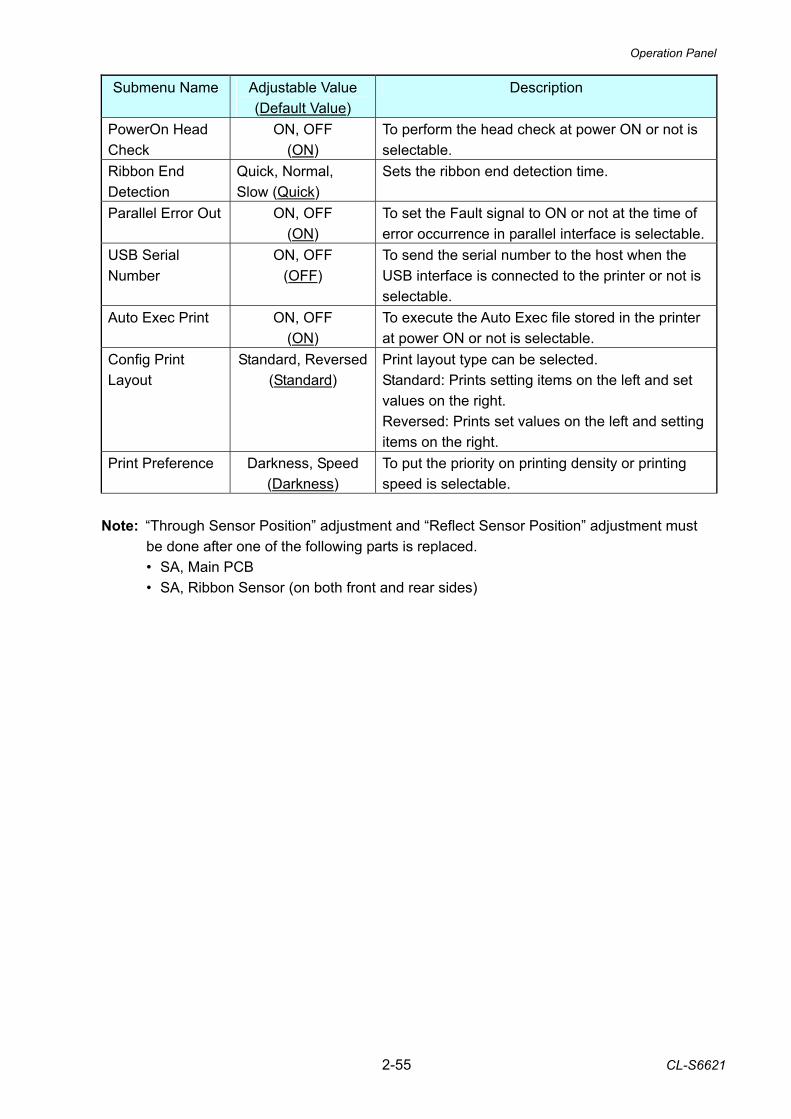
Operation Panel
2-55 CL-S6621
Submenu Name Adjustable Value (Default Value)
Description
PowerOn Head Check
ON, OFF (ON)
To perform the head check at power ON or not is selectable.
Ribbon End Detection
Quick, Normal, Slow (Quick)
Sets the ribbon end detection time.
Parallel Error Out ON, OFF (ON)
To set the Fault signal to ON or not at the time of error occurrence in parallel interface is selectable.
USB Serial Number
ON, OFF (OFF)
To send the serial number to the host when the USB interface is connected to the printer or not is selectable.
Auto Exec Print ON, OFF (ON)
To execute the Auto Exec file stored in the printer at power ON or not is selectable.
Config Print Layout
Standard, Reversed(Standard)
Print layout type can be selected. Standard: Prints setting items on the left and set values on the right. Reversed: Prints set values on the left and setting items on the right.
Print Preference Darkness, Speed (Darkness)
To put the priority on printing density or printing speed is selectable.
Note: “Through Sensor Position” adjustment and “Reflect Sensor Position” adjustment must
be done after one of the following parts is replaced. • SA, Main PCB • SA, Ribbon Sensor (on both front and rear sides)
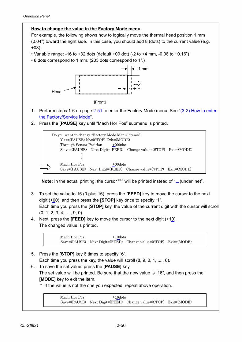
Operation Panel
CL-S6621 2-56
How to change the value in the Factory Mode menu For example, the following shows how to logically move the thermal head position 1 mm (0.04”) toward the right side. In this case, you should add 8 (dots) to the current value (e.g. +08). • Variable range: -16 to +32 dots (default +00 dot) (-2 to +4 mm, -0.08 to +0.16”) • 8 dots correspond to 1 mm. (203 dots correspond to 1”.) 1. Perform steps 1-6 on page 2-51 to enter the Factory Mode menu. See “(3-2) How to enter
the Factory/Service Mode”. 2. Press the [PAUSE] key until “Mach Hor Pos” submenu is printed.
Do you want to change “Factory Mode Menu” items? Y es=(PAUSE) No=(STOP) Exit=(MODE) Through Sensor Position +000dos S ave=(PAUSE) Next Digit=(FEED) Change value=(STOP) Exit=(MODE) : : Mach Hor Pos +00dots Save=(PAUSE) Next Digit=(FEED) Change value=(STOP) Exit=(MODE)
Note: In the actual printing, the cursor “^” will be printed instead of “ (underline)”. 3. To set the value to 16 (0 plus 16), press the [FEED] key to move the cursor to the next
digit (+00), and then press the [STOP] key once to specify “1”. Each time you press the [STOP] key, the value of the current digit with the cursor will scroll
(0, 1, 2, 3, 4, ...., 9, 0). 4. Next, press the [FEED] key to move the cursor to the next digit (+10). The changed value is printed.
Mach Hor Pos +10dots Save=(PAUSE) Next Digit=(FEED) Change value=(STOP) Exit=(MODE)
5. Press the [STOP] key 6 times to specify “6”. Each time you press the key, the value will scroll (8, 9, 0, 1, ...., 6). 6. To save the set value, press the [PAUSE] key. The set value will be printed. Be sure that the new value is “16”, and then press the
[MODE] key to exit the item. * If the value is not the one you expected, repeat above operation.
Mach Hor Pos +16dots Save=(PAUSE) Next Digit=(FEED) Change value=(STOP) Exit=(MODE)
1 mm
[Front]
Head +
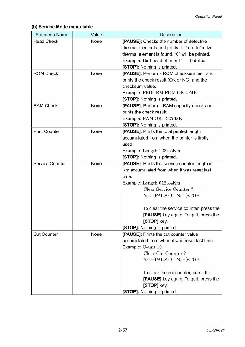
Operation Panel
2-57 CL-S6621
(b) Service Mode menu table Submenu Name Value Description
Head Check None [PAUSE]: Checks the number of defective thermal elements and prints it. If no defective thermal element is found, “0” will be printed. Example: Bad head element: 0 dot(s) [STOP]: Nothing is printed.
ROM Check None [PAUSE]: Performs ROM checksum test, and prints the check result (OK or NG) and the checksum value. Example: PROGRM ROM OK 4F4E [STOP]: Nothing is printed.
RAM Check None [PAUSE]: Performs RAM capacity check and prints the check result. Example: RAM OK 32768K [STOP]: Nothing is printed.
Print Counter None [PAUSE]: Prints the total printed length accumulated from when the printer is firstly used. Example: Length 1234.5Km [STOP]: Nothing is printed.
Service Counter None [PAUSE]: Prints the service counter length in Km accumulated from when it was reset last time. Example: Length 0123.4Km
Clear Service Counter ? Yes=(PAUSE) No=(STOP)
To clear the service counter, press the [PAUSE] key again. To quit, press the [STOP] key.
[STOP]: Nothing is printed. Cut Counter None [PAUSE]: Prints the cut counter value
accumulated from when it was reset last time. Example: Count 10
Clear Cut Counter ? Yes=(PAUSE) No=(STOP)
To clear the cut counter, press the [PAUSE] key again. To quit, press the [STOP] key.
[STOP]: Nothing is printed.
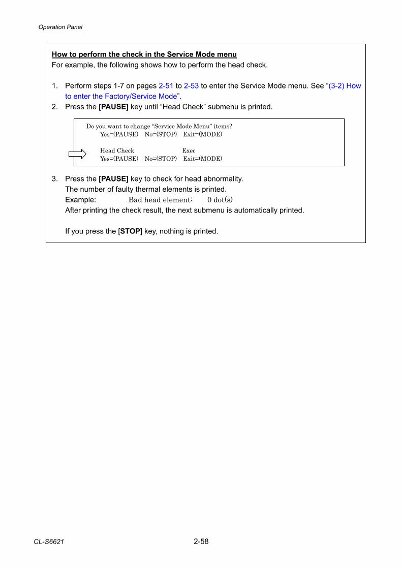
Operation Panel
CL-S6621 2-58
1How to perform the check in the Service Mode menu For example, the following shows how to perform the head check. 1. Perform steps 1-7 on pages 2-51 to 2-53 to enter the Service Mode menu. See “(3-2) How
to enter the Factory/Service Mode”. 2. Press the [PAUSE] key until “Head Check” submenu is printed.
Do you want to change “Service Mode Menu” items? Yes=(PAUSE) No=(STOP) Exit=(MODE) Head Check Exec Yes=(PAUSE) No=(STOP) Exit=(MODE)
3. Press the [PAUSE] key to check for head abnormality. The number of faulty thermal elements is printed. Example: Bad head element: 0 dot(s) After printing the check result, the next submenu is automatically printed. If you press the [STOP] key, nothing is printed.
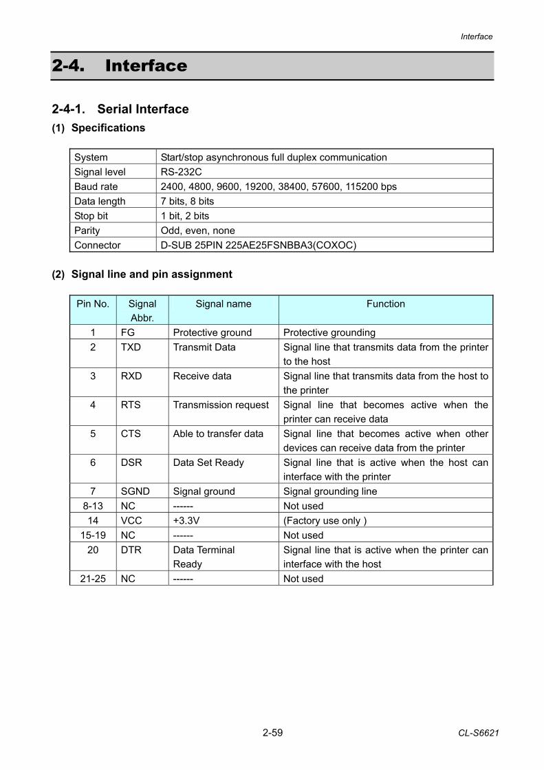
Interface
2-59 CL-S6621
2-4. Interface 2-4-1. Serial Interface (1) Specifications
System Start/stop asynchronous full duplex communication Signal level RS-232C Baud rate 2400, 4800, 9600, 19200, 38400, 57600, 115200 bps Data length 7 bits, 8 bits Stop bit 1 bit, 2 bits Parity Odd, even, none Connector D-SUB 25PIN 225AE25FSNBBA3(COXOC)
(2) Signal line and pin assignment
Pin No. Signal Abbr.
Signal name Function
1 FG Protective ground Protective grounding 2 TXD Transmit Data Signal line that transmits data from the printer
to the host 3 RXD Receive data Signal line that transmits data from the host to
the printer 4 RTS Transmission request Signal line that becomes active when the
printer can receive data 5 CTS Able to transfer data Signal line that becomes active when other
devices can receive data from the printer 6 DSR Data Set Ready Signal line that is active when the host can
interface with the printer 7 SGND Signal ground Signal grounding line
8-13 NC ------ Not used 14 VCC +3.3V (Factory use only )
15-19 NC ------ Not used 20 DTR Data Terminal
Ready Signal line that is active when the printer can interface with the host
21-25 NC ------ Not used
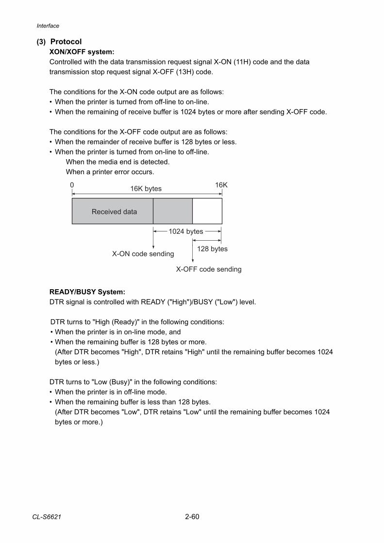
Interface
CL-S6621 2-60
X-ON code sending
X-OFF code sending
16K bytes
1024 bytes
128 bytes
Received data
0 16K
(3) Protocol XON/XOFF system: Controlled with the data transmission request signal X-ON (11H) code and the data transmission stop request signal X-OFF (13H) code.
The conditions for the X-ON code output are as follows: • When the printer is turned from off-line to on-line. • When the remaining of receive buffer is 1024 bytes or more after sending X-OFF code. The conditions for the X-OFF code output are as follows: • When the remainder of receive buffer is 128 bytes or less. • When the printer is turned from on-line to off-line. When the media end is detected. When a printer error occurs. READY/BUSY System: DTR signal is controlled with READY ("High")/BUSY ("Low") level. DTR turns to "High (Ready)" in the following conditions: • When the printer is in on-line mode, and • When the remaining buffer is 128 bytes or more.
(After DTR becomes "High", DTR retains "High" until the remaining buffer becomes 1024 bytes or less.)
DTR turns to "Low (Busy)" in the following conditions: • When the printer is in off-line mode. • When the remaining buffer is less than 128 bytes.
(After DTR becomes "Low", DTR retains "Low" until the remaining buffer becomes 1024 bytes or more.)
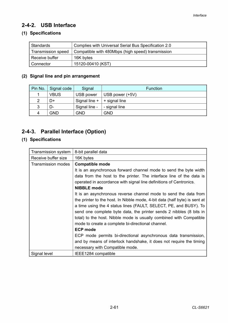
Interface
2-61 CL-S6621
2-4-2. USB Interface (1) Specifications
Standards Complies with Universal Serial Bus Specification 2.0 Transmission speed Compatible with 480Mbps (high speed) transmission Receive buffer 16K bytes Connector 15120-00410 (KST)
(2) Signal line and pin arrangement
Pin No. Signal code Signal Function 1 VBUS USB power USB power (+5V) 2 D+ Signal line + + signal line 3 D- Signal line - - signal line 4 GND GND GND
2-4-3. Parallel Interface (Option) (1) Specifications
Transmission system 8-bit parallel data Receive buffer size 16K bytes Transmission modes Compatible mode
It is an asynchronous forward channel mode to send the byte width data from the host to the printer. The interface line of the data is operated in accordance with signal line definitions of Centronics. NIBBLE mode It is an asynchronous reverse channel mode to send the data from the printer to the host. In Nibble mode, 4-bit data (half byte) is sent at a time using the 4 status lines (FAULT, SELECT, PE, and BUSY). To send one complete byte data, the printer sends 2 nibbles (8 bits in total) to the host. Nibble mode is usually combined with Compatible mode to create a complete bi-directional channel. ECP mode ECP mode permits bi-directional asynchronous data transmission, and by means of interlock handshake, it does not require the timing necessary with Compatible mode.
Signal level IEEE1284 compatible
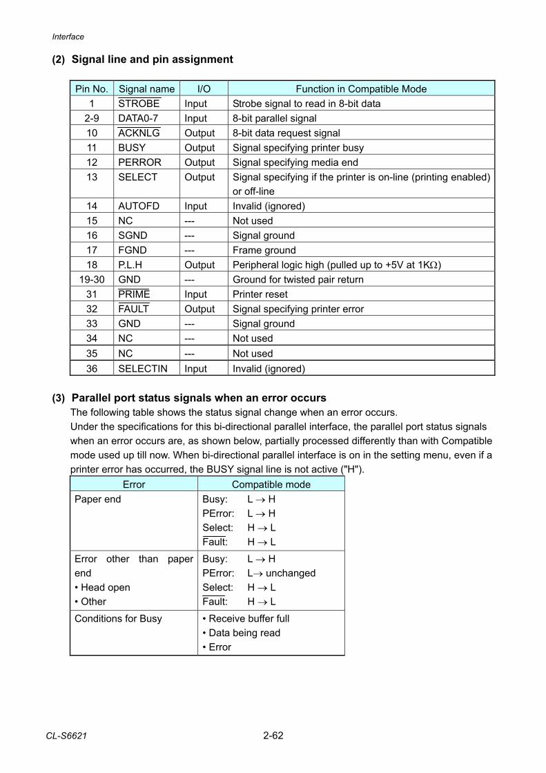
Interface
CL-S6621 2-62
(2) Signal line and pin assignment
Pin No. Signal name I/O Function in Compatible Mode 1 STROBE Input Strobe signal to read in 8-bit data
2-9 DATA0-7 Input 8-bit parallel signal 10 ACKNLG Output 8-bit data request signal 11 BUSY Output Signal specifying printer busy 12 PERROR Output Signal specifying media end 13 SELECT Output Signal specifying if the printer is on-line (printing enabled)
or off-line 14 AUTOFD Input Invalid (ignored) 15 NC --- Not used 16 SGND --- Signal ground 17 FGND --- Frame ground 18 P.L.H Output Peripheral logic high (pulled up to +5V at 1KΩ)
19-30 GND --- Ground for twisted pair return 31 PRIME Input Printer reset 32 FAULT Output Signal specifying printer error 33 GND --- Signal ground 34 NC --- Not used 35 NC --- Not used 36 SELECTIN Input Invalid (ignored)
(3) Parallel port status signals when an error occurs
The following table shows the status signal change when an error occurs. Under the specifications for this bi-directional parallel interface, the parallel port status signals when an error occurs are, as shown below, partially processed differently than with Compatible mode used up till now. When bi-directional parallel interface is on in the setting menu, even if a printer error has occurred, the BUSY signal line is not active ("H").
Error Compatible mode Paper end Busy:
PError: Select: Fault:
L → H L → H H → L H → L
Error other than paper end • Head open • Other
Busy: PError: Select: Fault:
L → H L→ unchanged H → L H → L
Conditions for Busy • Receive buffer full • Data being read • Error
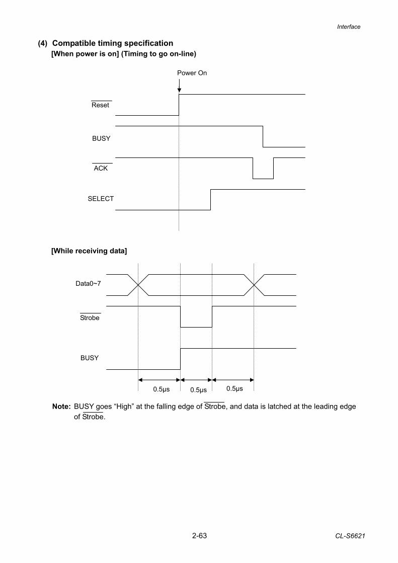
Interface
2-63 CL-S6621
(4) Compatible timing specification [When power is on] (Timing to go on-line) [While receiving data] Note: BUSY goes “High” at the falling edge of Strobe, and data is latched at the leading edge
of Strobe.
BUSY
SELECT
Power On
ACK
Reset
Data0~7
BUSY
0.5µs 0.5µs 0.5µs
Strobe
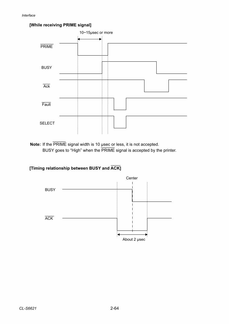
Interface
CL-S6621 2-64
[While receiving PRIME signal] Note: If the PRIME signal width is 10 µsec or less, it is not accepted.
BUSY goes to “High” when the PRIME signal is accepted by the printer. [Timing relationship between BUSY and ACK]
BUSY
PRIME
SELECT
10~15µsec or more
Ack
Fault
About 2 µsec
BUSY
ACK
Center
3-1 CL-S6621
CHAPTER 3 DISASSEMBLY AND MAINTENANCE
CL-S6621 3-2
CHAPTER 3 DISASSEMBLY AND MAINTENANCE
TABLE OF CONTENTS
3-1. Maintenance Precautions ............................................................................................... 3-4 3-2. Cleaning.......................................................................................................................... 3-5 3-3. Lubrication ...................................................................................................................... 3-5
3-3-1. Lubrication frequency......................................................................................... 3-5 3-3-2. Types of lubricant ............................................................................................... 3-5 3-3-3. Quantity of lubricant ........................................................................................... 3-5 3-3-4. Adhesive ............................................................................................................ 3-5
3-4. Maintenance Tools List ................................................................................................... 3-6 3-5. Quick Detachment of Major Parts................................................................................... 3-7
3-5-1. SA, Head............................................................................................................ 3-7 3-5-2. SA2 Platen ......................................................................................................... 3-8
3-6. Disassembly, Reassembly and Lubrication .................................................................... 3-9 3-6-1. “Cover Top” and “Support Top Cover” ................................................................ 3-10
(1) Removing the “Cover Top” Block............................................................... 3-10 (2) Removing the “Cover Top” and “Support Top Cover” ................................ 3-11
3-6-2. Unit, Ribbon ....................................................................................................... 3-12 3-6-3. Case U ............................................................................................................... 3-14
(1) Removing the “Case U” Block ................................................................... 3-14 (2) Removing the “Case U” ............................................................................. 3-17
3-6-4. SA, Fan .............................................................................................................. 3-18 (1) Removing the ribbon covers...................................................................... 3-18 (2) Removing the “SA, Fan” ............................................................................ 3-18
3-6-5. Ribbon Gears ..................................................................................................... 3-19 3-6-6. “SA Ribbon Motor F/R” and “SA, Ribbon PCB”.................................................. 3-21 3-6-7. “Holder, Ribbon Shaft” and “Holder 2 Tension Spring” ....................................... 3-22 3-6-8. “Unit, Ribbon Sensor F/R” and “SA Ribbon Frame” ........................................... 3-23 3-6-9. “SA, Ribbon Tension Shaft F” and “SA, Ribbon Sensor” on the front side ......... 3-25 3-6-10. “SA, Ribbon Tension Shaft R” and “SA, Tension Sensor” on the rear side ........ 3-26 3-6-11. “Unit, Control Panel”, “SA PNE Sensor”, “SA, Relay PCB” and “SA, Main PCB” ............................................................................................................. 3-27
(1) Unit, Control Panel .................................................................................... 3-27 (2) SA PNE Sensor ......................................................................................... 3-27 (3) “SA, Relay PCB” and “SA, Main PCB” ...................................................... 3-28
3-6-12. SA, Opepane PCB ............................................................................................. 3-30 3-6-13. “Unit, Mechanism”, “Unit, Power Supply” and “Case L” ..................................... 3-31
(1) Unit, Mechanism........................................................................................ 3-31 (2) Unit, Power Supply .................................................................................... 3-32 (3) Case L ....................................................................................................... 3-34
3-6-14. SA2 Platen ......................................................................................................... 3-35 3-6-15. Unit, Sensor U.................................................................................................... 3-36 3-6-16. “SA TRA Sen PCB” and “Gear Bevel Lead Screw U”......................................... 3-38 3-6-17. Unit, Head .......................................................................................................... 3-41
3-3 CL-S6621
3-6-18. “SA, Head”, “Cam Head Balance” and “Cam Head Adjust”................................ 3-42 (1) SA, Head ................................................................................................... 3-42 (2) Cam Head Balance ................................................................................... 3-43 (3) Cam Head Adjust....................................................................................... 3-45
3-6-19. SA PF Motor....................................................................................................... 3-47 3-6-20. “Carriage Adjust Sensor L”, “SA, Head Up Switch” and “SA Ref Sen PCB”....... 3-47
(1) “Carriage Adjust Sensor L” and “SA, Head Up Switch” ............................. 3-47 (2) SA Ref Sen PCB........................................................................................ 3-50
3-6-21. Gears ................................................................................................................. 3-51 3-6-22. “Lever Head Lock” and “SA Main Frame R”....................................................... 3-52 3-6-23. “Frame Main”, “SA Main Frame L” and “Plate Peel Guide” ................................ 3-53 3-6-24. Disassembling the “Roll Paper Shaft” ................................................................ 3-54
3-7. Adjustments ....................................................................................................................3-55 3-7-1. Transparent/Reflective Sensor Position Adjustment .......................................... 3-55
(1) Sensor position adjustment (factory mode) ............................................... 3-55 (2) Sensor sensitivity adjustment (maintenance mode) .................................. 3-55
3-7-2. Ribbon Slant Elimination Adjustment ................................................................. 3-60 (1) Ribbon slant elimination adjustment.......................................................... 3-60
Maintenance Precautions
CL-S6621 3-4
3-1. Maintenance Precautions
• Before starting disassembly/reassembly or mechanical adjustment, be sure to disconnect the power cord from the power source.
• Do not disassemble/reassemble or adjust the machine, if it functions properly. Particularly, do not loosen screws on any component, unless necessary. • After completing an inspection and before turning on the power, be sure to check that
there is no abnormality. • Never try to print without media. • Check that the media is properly set. • Do not lay anything on the cover or lean against it during maintenance or while the
printer is in operation. • During maintenance, be careful not to leave parts or screws unattached or loose
inside the printer. • When handling a printed circuit board, do not use gloves, etc., which can easily
cause static electricity. Since ICs, such as CPU, RAM and ROM, might be destroyed by static electricity, do not touch lead wires or windows unnecessarily.
• Do not put the printed circuit boards directly on the printer or on the floor. • When disassembling or reassembling, check wires for any damage and do not pinch
or damage them. Also, run wires as they were.
Warning
Caution
Cleaning, Lubrication
3-5 CL-S6621
3-2. Cleaning Cleaning spots are listed below.
Cleaning Position Description Cabinet Wipe soiled parts of the printer with a clean dry cloth. Remove bits
of media, etc., using tweezers. Note: When cleaning, be careful not to scratch the equipment or to
bend parts, etc. SA, Head Clean the thermal head with the head cleaner only. SA2 Platen Clean the platen with a soft cloth. Media running surface Wipe off media refuse, etc., on and around the media running
surface including the “SA2 Platen”.
Clean inside the printer in accordance with the following: • Cleaning frequency: Every 6 months or 300 hours of operation. (Whichever comes first) • Materials: Dry cloth (gauze or soft cloth) and thermal head cleaner
3-3. Lubrication 3-3-1. Lubrication frequency
This is a maintenance-free machine and requires no lubrication under normal use. However, the machine should be lubricated whenever it is disassembled and reassembled, or when lubricated parts are cleaned. The parts to be lubricated are indicated in the disassemble procedure with the mark .
3-3-2. Types of lubricant • Floil G-311S (by Kanto Chemical Co., Ltd.) • Floil G-474C (by Kanto Chemical Co., Ltd.)
3-3-3. Quantity of lubricant Small quantity.......... ............. About 1 drop. Ordinary quantity .... ......... About 3 to 4 drops. About 0.2 mm thick for grease. Large quantity.......... ....... Apply sufficiently.
3-3-4. Adhesive • LOCTITE263 (by Henkel AG & Co. KGaA)
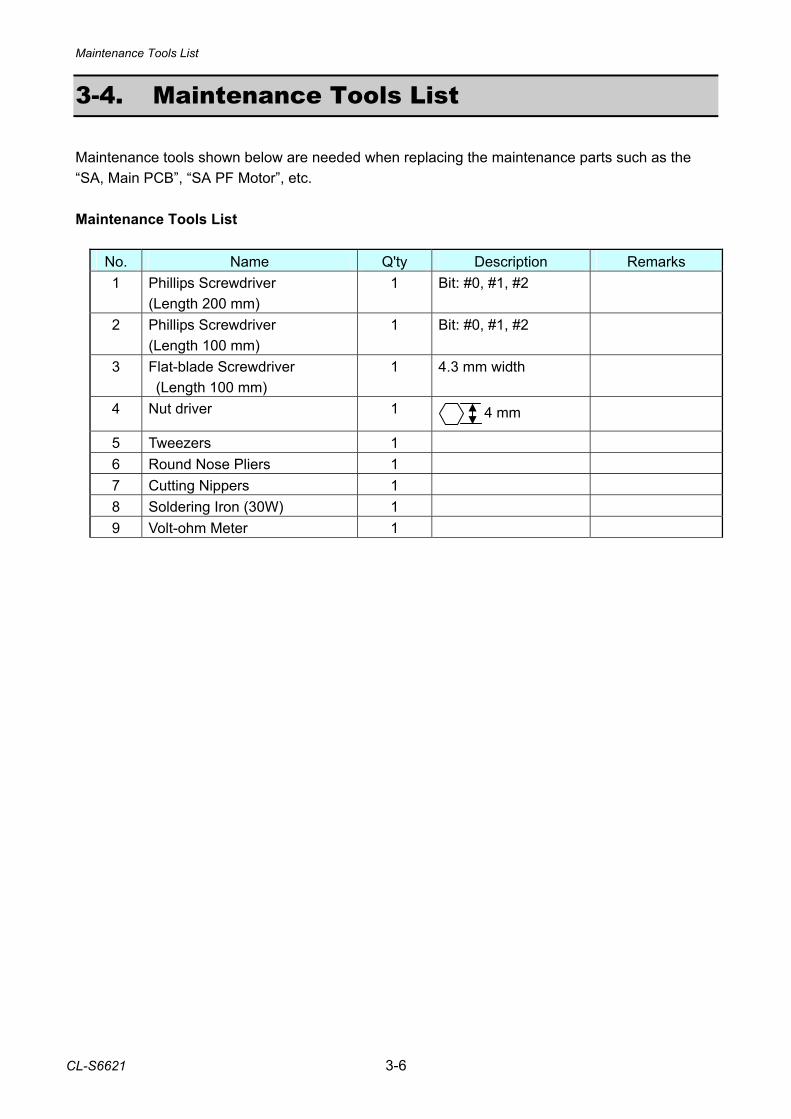
Maintenance Tools List
CL-S6621 3-6
3-4. Maintenance Tools List Maintenance tools shown below are needed when replacing the maintenance parts such as the “SA, Main PCB”, “SA PF Motor”, etc. Maintenance Tools List
No. Name Q'ty Description Remarks 1 Phillips Screwdriver
(Length 200 mm) 1 Bit: #0, #1, #2
2 Phillips Screwdriver (Length 100 mm)
1 Bit: #0, #1, #2
3 Flat-blade Screwdriver (Length 100 mm)
1 4.3 mm width
4 Nut driver 1
5 Tweezers 1 6 Round Nose Pliers 1 7 Cutting Nippers 1 8 Soldering Iron (30W) 1 9 Volt-ohm Meter 1
4 mm
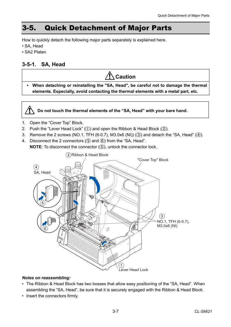
Quick Detachment of Major Parts
3-7 CL-S6621
3-5. Quick Detachment of Major Parts How to quickly detach the following major parts separately is explained here. • SA, Head • SA2 Platen 3-5-1. SA, Head
• When detaching or reinstalling the "SA, Head", be careful not to damage the thermal elements. Especially, avoid contacting the thermal elements with a metal part, etc.
Do not touch the thermal elements of the “SA, Head” with your bare hand. 1. Open the “Cover Top” Block. 2. Push the “Lever Head Lock” () and open the Ribbon & Head Block (). 3. Remove the 2 screws (NO.1, TFH (6-0.7), M3.0x6 (NI)) () and detach the “SA, Head” (). 4. Disconnect the 2 connectors ( and ) from the “SA, Head”.
NOTE: To disconnect the connector (), unlock the connector lock.
Notes on reassembling: • The Ribbon & Head Block has two bosses that allow easy positioning of the “SA, Head”. When
assembling the “SA, Head”, be sure that it is securely engaged with the Ribbon & Head Block. • Insert the connectors firmly.
Caution
Lever Head Lock
NO.1, TFH (6-0.7), M3.0x6 (NI)
SA, Head
Ribbon & Head Block"Cover Top" Block
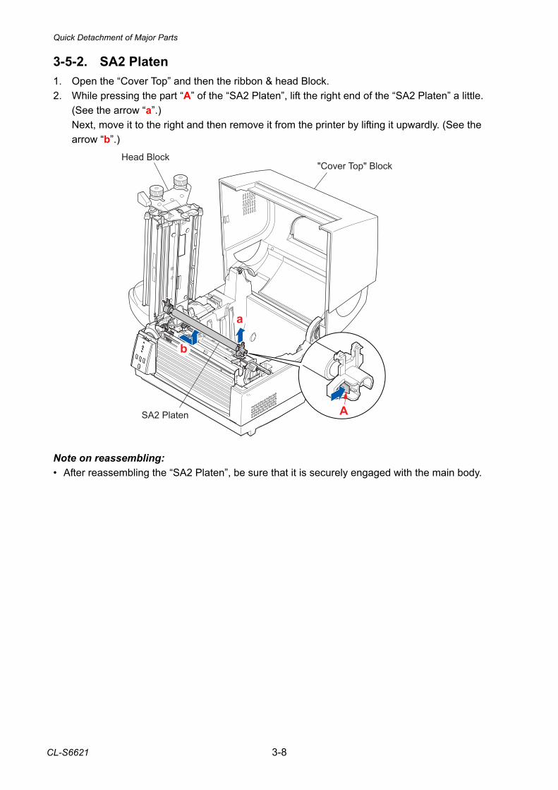
Quick Detachment of Major Parts
CL-S6621 3-8
3-5-2. SA2 Platen 1. Open the “Cover Top” and then the ribbon & head Block. 2. While pressing the part “A” of the “SA2 Platen”, lift the right end of the “SA2 Platen” a little.
(See the arrow “a”.) Next, move it to the right and then remove it from the printer by lifting it upwardly. (See the arrow “b”.)
Note on reassembling: • After reassembling the “SA2 Platen”, be sure that it is securely engaged with the main body.
�
�
�
���� ������ �� ���� ���
��� ������
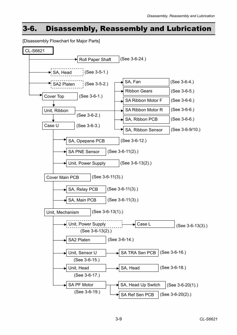
Disassembly, Reassembly and Lubrication
3-9 CL-S6621
3-6. Disassembly, Reassembly and Lubrication [Disassembly Flowchart for Major Parts]
Roll Paper Shaft
SA, Head
SA2 Platen
Cover Top
Unit, Ribbon SA Ribbon Motor R
SA Ribbon Motor F
SA, Ribbon Sensor
SA, Ribbon PCB
Ribbon Gears
Case U
SA, Opepane PCB
Unit, Power Supply
Cover Main PCB
SA PNE Sensor
SA, Relay PCB
SA, Main PCB
CL-S6621
Unit, Mechanism
SA2 Platen
Unit, Sensor U SA TRA Sen PCB
(See 3-5-1.)
(See 3-5-2.)
(See 3-6-1.) (See 3-6-5.)
(See 3-6-6.)
(See 3-6-6.)
(See 3-6-9/10.)
(See 3-6-6.)
(See 3-6-13(2).)
(See 3-6-3.)
(See 3-6-12.)
(See 3-6-2.)
(See 3-6-11(2).)
(See 3-6-11(3).)
(See 3-6-11(3).)
(See 3-6-11(3).)
(See 3-6-13(1).)
(See 3-6-14.)
(See 3-6-13(3).)
SA PF Motor
SA Ref Sen PCB
SA, Head Up Switch
(See 3-6-20(2).)
(See 3-6-20(1).) (See 3-6-19.)
(See 3-6-15.)
(See 3-6-16.)
Unit, Power Supply Case L (See 3-6-13(2).)
(See 3-6-17.)Unit, Head SA, Head (See 3-6-18.)
(See 3-6-24.)
SA, Fan (See 3-6-4.)
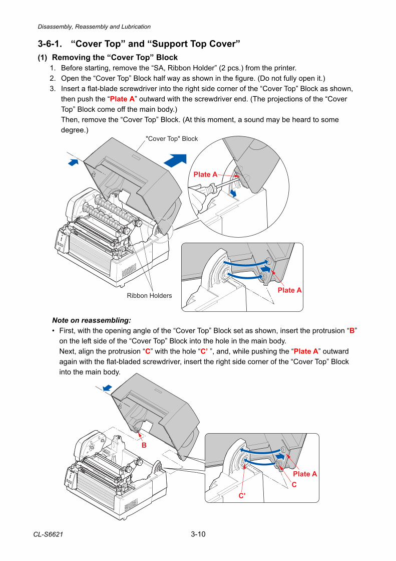
Disassembly, Reassembly and Lubrication
CL-S6621 3-10
3-6-1. “Cover Top” and “Support Top Cover” (1) Removing the “Cover Top” Block
1. Before starting, remove the “SA, Ribbon Holder” (2 pcs.) from the printer. 2. Open the “Cover Top” Block half way as shown in the figure. (Do not fully open it.) 3. Insert a flat-blade screwdriver into the right side corner of the “Cover Top” Block as shown,
then push the “Plate A” outward with the screwdriver end. (The projections of the “Cover Top” Block come off the main body.) Then, remove the “Cover Top” Block. (At this moment, a sound may be heard to some degree.)
Note on reassembling: • First, with the opening angle of the “Cover Top” Block set as shown, insert the protrusion “B”
on the left side of the “Cover Top” Block into the hole in the main body. Next, align the protrusion “C” with the hole “C’ ”, and, while pushing the “Plate A” outward
again with the flat-bladed screwdriver, insert the right side corner of the “Cover Top” Block into the main body.
����� �
����� ������� �����
���� ��� �����
�
��
�
�����
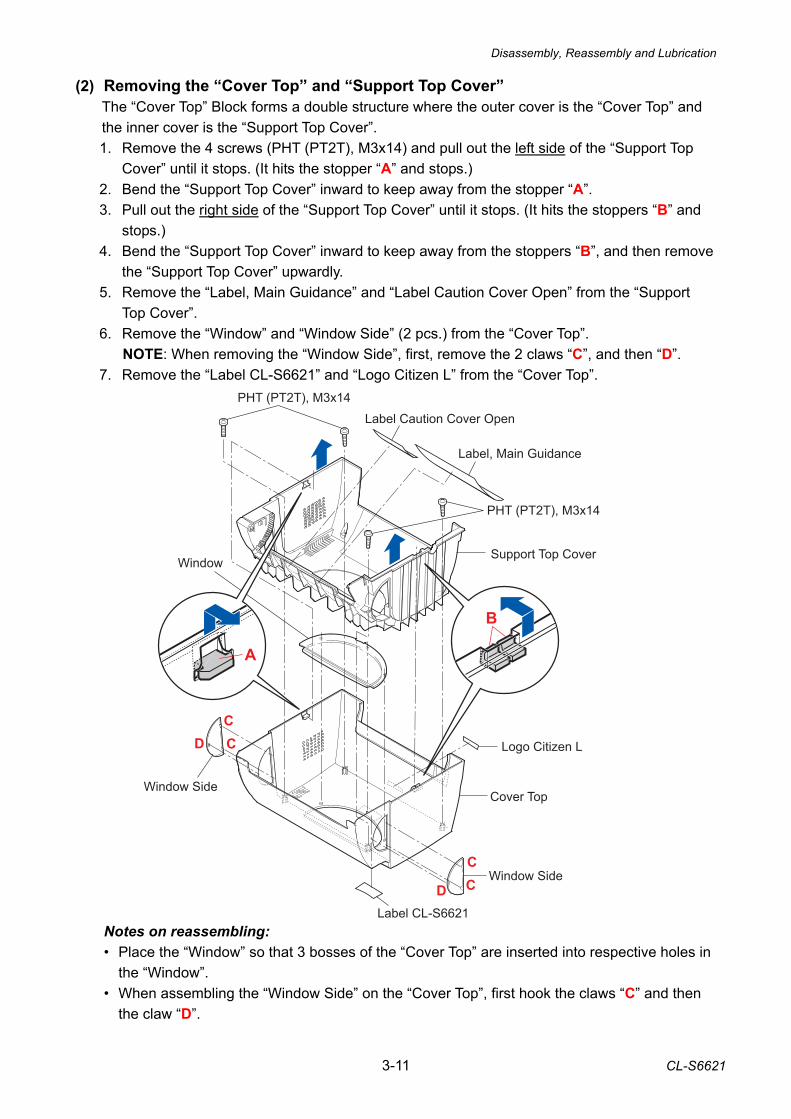
Disassembly, Reassembly and Lubrication
3-11 CL-S6621
PHT (PT2T), M3x14
PHT (PT2T), M3x14
Support Top Cover
Cover Top
Label, Main Guidance
Label Caution Cover Open
Window Side
Label CL-S6621
Logo Citizen L
Window Side
Window
B
A
CCD
CCD
(2) Removing the “Cover Top” and “Support Top Cover” The “Cover Top” Block forms a double structure where the outer cover is the “Cover Top” and the inner cover is the “Support Top Cover”. 1. Remove the 4 screws (PHT (PT2T), M3x14) and pull out the left side of the “Support Top
Cover” until it stops. (It hits the stopper “A” and stops.) 2. Bend the “Support Top Cover” inward to keep away from the stopper “A”. 3. Pull out the right side of the “Support Top Cover” until it stops. (It hits the stoppers “B” and
stops.) 4. Bend the “Support Top Cover” inward to keep away from the stoppers “B”, and then remove
the “Support Top Cover” upwardly. 5. Remove the “Label, Main Guidance” and “Label Caution Cover Open” from the “Support
Top Cover”. 6. Remove the “Window” and “Window Side” (2 pcs.) from the “Cover Top”.
NOTE: When removing the “Window Side”, first, remove the 2 claws “C”, and then “D”. 7. Remove the “Label CL-S6621” and “Logo Citizen L” from the “Cover Top”. Notes on reassembling: • Place the “Window” so that 3 bosses of the “Cover Top” are inserted into respective holes in
the “Window”. • When assembling the “Window Side” on the “Cover Top”, first hook the claws “C” and then
the claw “D”.
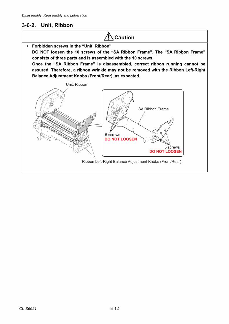
Disassembly, Reassembly and Lubrication
CL-S6621 3-12
3-6-2. Unit, Ribbon
• Forbidden screws in the “Unit, Ribbon” DO NOT loosen the 10 screws of the “SA Ribbon Frame”. The “SA Ribbon Frame” consists of three parts and is assembled with the 10 screws. Once the “SA Ribbon Frame” is disassembled, correct ribbon running cannot be assured. Therefore, a ribbon wrinkle may not be removed with the Ribbon Left-Right Balance Adjustment Knobs (Front/Rear), as expected.
Caution
� �������� ��� ������
�� ��� ������
� ������
� ��� � �����
��� � ��������� ������� ��������� �� �� ��� ������
!���" ��� �
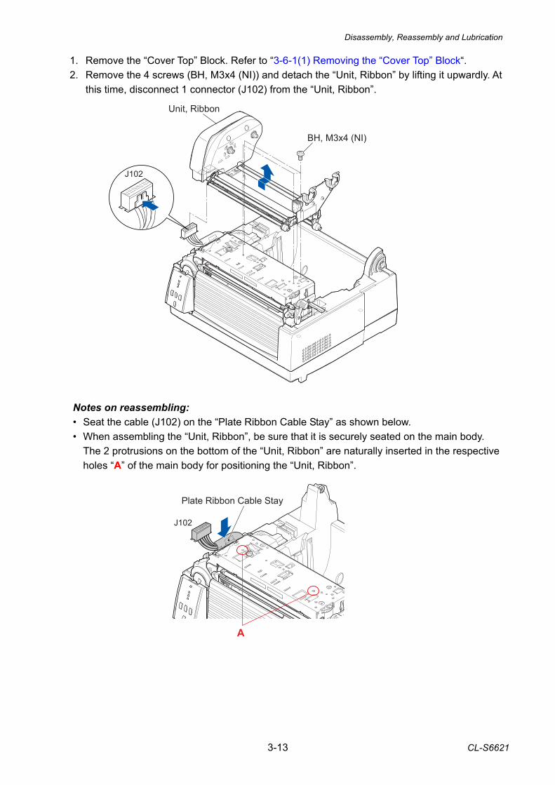
Disassembly, Reassembly and Lubrication
3-13 CL-S6621
1. Remove the “Cover Top” Block. Refer to “3-6-1(1) Removing the “Cover Top” Block“. 2. Remove the 4 screws (BH, M3x4 (NI)) and detach the “Unit, Ribbon” by lifting it upwardly. At
this time, disconnect 1 connector (J102) from the “Unit, Ribbon”. Notes on reassembling: • Seat the cable (J102) on the “Plate Ribbon Cable Stay” as shown below. • When assembling the “Unit, Ribbon”, be sure that it is securely seated on the main body.
The 2 protrusions on the bottom of the “Unit, Ribbon” are naturally inserted in the respective holes “A” of the main body for positioning the “Unit, Ribbon”.
A
J102
Plate Ribbon Cable Stay
BH, M3x4 (NI)
Unit, Ribbon
J102
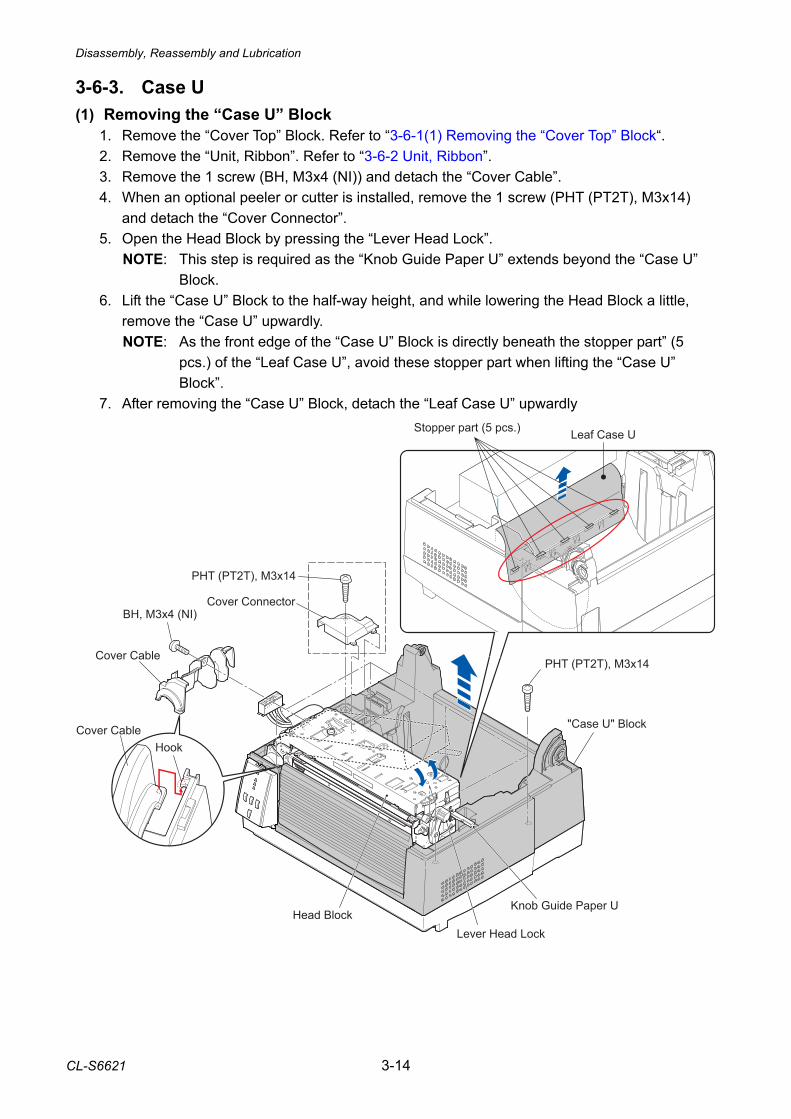
Disassembly, Reassembly and Lubrication
CL-S6621 3-14
BH, M3x4 (NI)
PHT (PT2T), M3x14
Cover Connector
PHT (PT2T), M3x14Cover Cable
Knob Guide Paper U
Lever Head LockHead Block
"Case U" Block
HookCover Cable
Stopper part (5 pcs.) Leaf Case U
3-6-3. Case U (1) Removing the “Case U” Block
1. Remove the “Cover Top” Block. Refer to “3-6-1(1) Removing the “Cover Top” Block“. 2. Remove the “Unit, Ribbon”. Refer to “3-6-2 Unit, Ribbon”. 3. Remove the 1 screw (BH, M3x4 (NI)) and detach the “Cover Cable”. 4. When an optional peeler or cutter is installed, remove the 1 screw (PHT (PT2T), M3x14)
and detach the “Cover Connector”. 5. Open the Head Block by pressing the “Lever Head Lock”.
NOTE: This step is required as the “Knob Guide Paper U” extends beyond the “Case U” Block.
6. Lift the “Case U” Block to the half-way height, and while lowering the Head Block a little, remove the “Case U” upwardly. NOTE: As the front edge of the “Case U” Block is directly beneath the stopper part” (5
pcs.) of the “Leaf Case U”, avoid these stopper part when lifting the “Case U” Block”.
7. After removing the “Case U” Block, detach the “Leaf Case U” upwardly
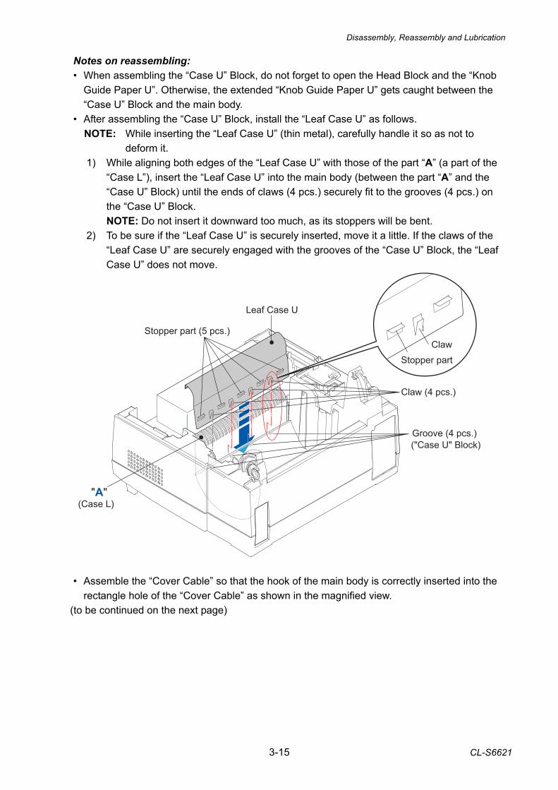
Disassembly, Reassembly and Lubrication
3-15 CL-S6621
Notes on reassembling: • When assembling the “Case U” Block, do not forget to open the Head Block and the “Knob
Guide Paper U”. Otherwise, the extended “Knob Guide Paper U” gets caught between the “Case U” Block and the main body.
• After assembling the “Case U” Block, install the “Leaf Case U” as follows. NOTE: While inserting the “Leaf Case U” (thin metal), carefully handle it so as not to
deform it. 1) While aligning both edges of the “Leaf Case U” with those of the part “A” (a part of the
“Case L”), insert the “Leaf Case U” into the main body (between the part “A” and the “Case U” Block) until the ends of claws (4 pcs.) securely fit to the grooves (4 pcs.) on the “Case U” Block. NOTE: Do not insert it downward too much, as its stoppers will be bent.
2) To be sure if the “Leaf Case U” is securely inserted, move it a little. If the claws of the “Leaf Case U” are securely engaged with the grooves of the “Case U” Block, the “Leaf Case U” does not move.
ase U
Stopper part (5 pcs.)
Leaf Case U
Claw (4 pcs.)
Groove (4 pcs.)
"A"
ClawStopper part
("Case U" Block)
(Case L)
• Assemble the “Cover Cable” so that the hook of the main body is correctly inserted into the
rectangle hole of the “Cover Cable” as shown in the magnified view. (to be continued on the next page)
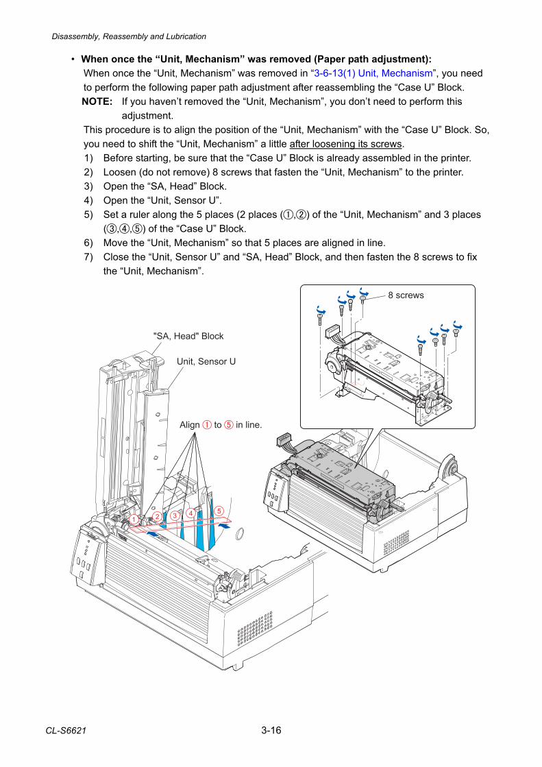
Disassembly, Reassembly and Lubrication
CL-S6621 3-16
• When once the “Unit, Mechanism” was removed (Paper path adjustment): When once the “Unit, Mechanism” was removed in “3-6-13(1) Unit, Mechanism”, you need
to perform the following paper path adjustment after reassembling the “Case U” Block. NOTE: If you haven’t removed the “Unit, Mechanism”, you don’t need to perform this
adjustment. This procedure is to align the position of the “Unit, Mechanism” with the “Case U” Block. So,
you need to shift the “Unit, Mechanism” a little after loosening its screws. 1) Before starting, be sure that the “Case U” Block is already assembled in the printer. 2) Loosen (do not remove) 8 screws that fasten the “Unit, Mechanism” to the printer. 3) Open the “SA, Head” Block. 4) Open the “Unit, Sensor U”. 5) Set a ruler along the 5 places (2 places (,) of the “Unit, Mechanism” and 3 places
(,,) of the “Case U” Block. 6) Move the “Unit, Mechanism” so that 5 places are aligned in line. 7) Close the “Unit, Sensor U” and “SA, Head” Block, and then fasten the 8 screws to fix
the “Unit, Mechanism”.
"SA, Head" Block
Unit, Sensor U
8 screws
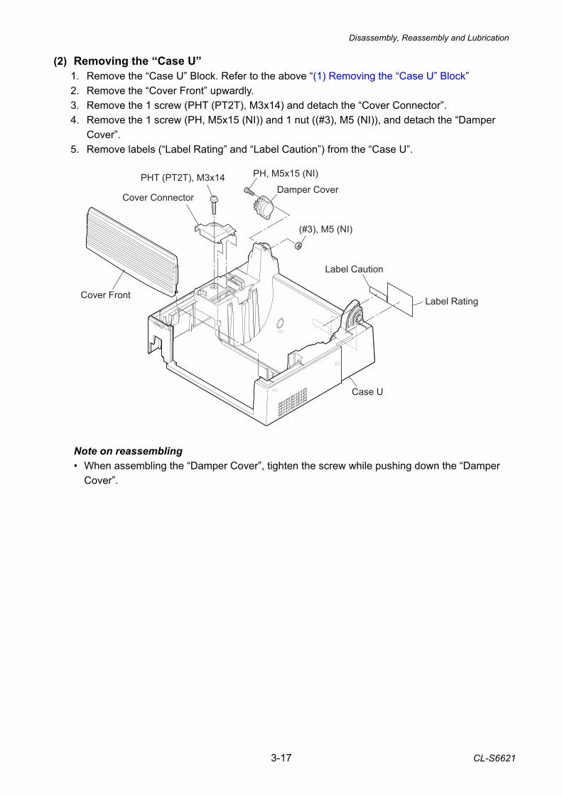
Disassembly, Reassembly and Lubrication
3-17 CL-S6621
(2) Removing the “Case U” 1. Remove the “Case U” Block. Refer to the above “(1) Removing the “Case U” Block” 2. Remove the “Cover Front” upwardly. 3. Remove the 1 screw (PHT (PT2T), M3x14) and detach the “Cover Connector”. 4. Remove the 1 screw (PH, M5x15 (NI)) and 1 nut ((#3), M5 (NI)), and detach the “Damper
Cover”. 5. Remove labels (“Label Rating” and “Label Caution”) from the “Case U”.
Note on reassembling • When assembling the “Damper Cover”, tighten the screw while pushing down the “Damper
Cover”.
Damper Cover
Case U
PHT (PT2T), M3x14
Cover Connector
(#3), M5 (NI)
PH, M5x15 (NI)
Cover Front
Label Caution
Label Rating
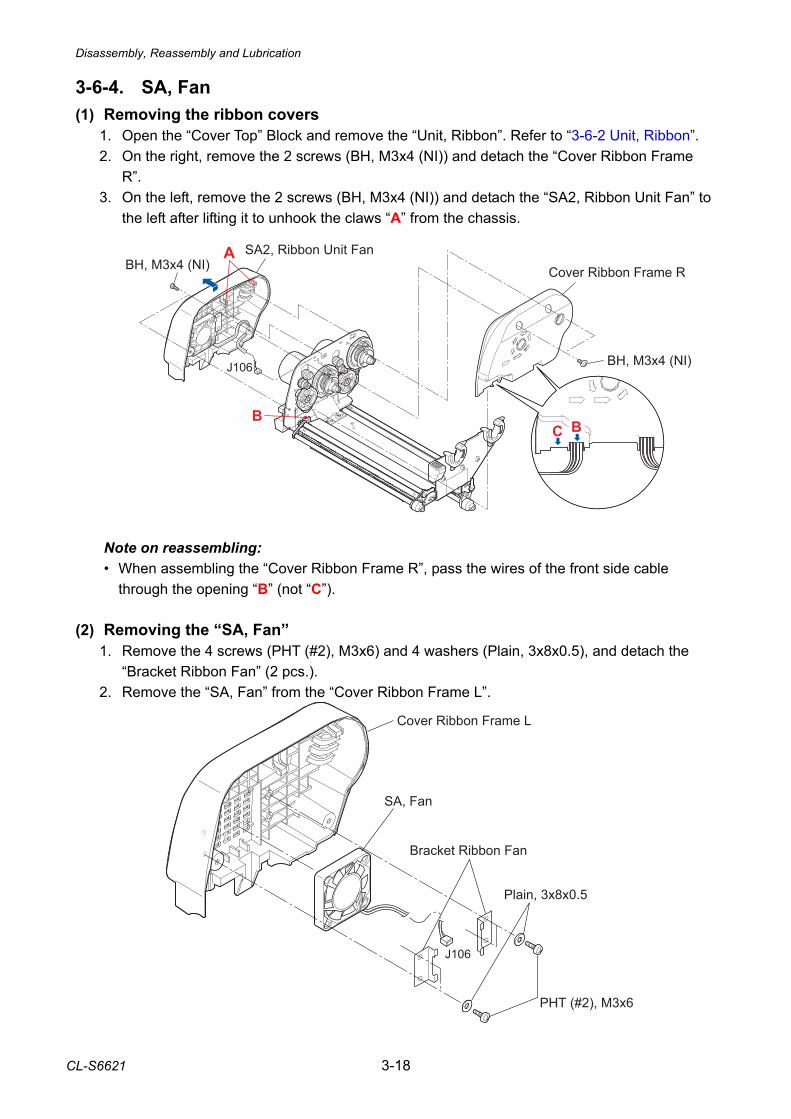
Disassembly, Reassembly and Lubrication
CL-S6621 3-18
3-6-4. SA, Fan (1) Removing the ribbon covers
1. Open the “Cover Top” Block and remove the “Unit, Ribbon”. Refer to “3-6-2 Unit, Ribbon”. 2. On the right, remove the 2 screws (BH, M3x4 (NI)) and detach the “Cover Ribbon Frame
R”. 3. On the left, remove the 2 screws (BH, M3x4 (NI)) and detach the “SA2, Ribbon Unit Fan” to
the left after lifting it to unhook the claws “A” from the chassis.
Note on reassembling: • When assembling the “Cover Ribbon Frame R”, pass the wires of the front side cable
through the opening “B” (not “C”). (2) Removing the “SA, Fan”
1. Remove the 4 screws (PHT (#2), M3x6) and 4 washers (Plain, 3x8x0.5), and detach the “Bracket Ribbon Fan” (2 pcs.).
2. Remove the “SA, Fan” from the “Cover Ribbon Frame L”.
SA, Fan
Cover Ribbon Frame L
Bracket Ribbon Fan
Plain, 3x8x0.5
PHT (#2), M3x6
J106
����
�
�
��� �� ������� ������ ���� ���
���� ������ � �!� �
��� �� ���
��
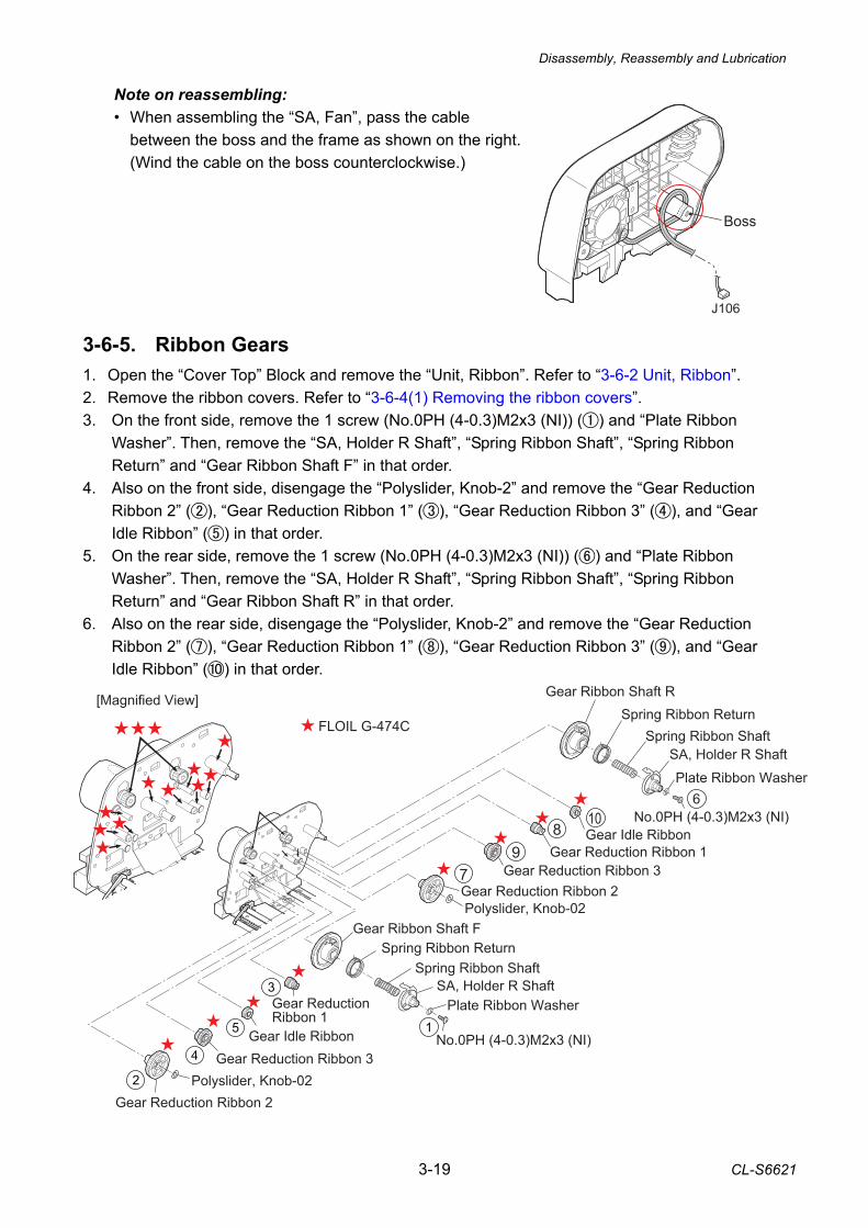
Disassembly, Reassembly and Lubrication
3-19 CL-S6621
Note on reassembling: • When assembling the “SA, Fan”, pass the cable
between the boss and the frame as shown on the right. (Wind the cable on the boss counterclockwise.)
3-6-5. Ribbon Gears 1. Open the “Cover Top” Block and remove the “Unit, Ribbon”. Refer to “3-6-2 Unit, Ribbon”. 2. Remove the ribbon covers. Refer to “3-6-4(1) Removing the ribbon covers”. 3. On the front side, remove the 1 screw (No.0PH (4-0.3)M2x3 (NI)) () and “Plate Ribbon
Washer”. Then, remove the “SA, Holder R Shaft”, “Spring Ribbon Shaft”, “Spring Ribbon Return” and “Gear Ribbon Shaft F” in that order.
4. Also on the front side, disengage the “Polyslider, Knob-2” and remove the “Gear Reduction Ribbon 2” (), “Gear Reduction Ribbon 1” (), “Gear Reduction Ribbon 3” (), and “Gear Idle Ribbon” () in that order.
5. On the rear side, remove the 1 screw (No.0PH (4-0.3)M2x3 (NI)) () and “Plate Ribbon Washer”. Then, remove the “SA, Holder R Shaft”, “Spring Ribbon Shaft”, “Spring Ribbon Return” and “Gear Ribbon Shaft R” in that order.
6. Also on the rear side, disengage the “Polyslider, Knob-2” and remove the “Gear Reduction Ribbon 2” (), “Gear Reduction Ribbon 1” (), “Gear Reduction Ribbon 3” (), and “Gear Idle Ribbon” () in that order.
Gear Ribbon Shaft FSpring Ribbon Return
SA, Holder R ShaftGear Reduction Ribbon 1
Gear Idle RibbonGear Reduction Ribbon 3
Polyslider, Knob-02Gear Reduction Ribbon 2
Plate Ribbon Washer
No.0PH (4-0.3)M2x3 (NI)
Polyslider, Knob-02
Gear Reduction Ribbon 3Gear Reduction Ribbon 1
Gear Idle Ribbon
Gear Ribbon Shaft R
SA, Holder R Shaft
No.0PH (4-0.3)M2x3 (NI)
Spring Ribbon Shaft
Spring Ribbon Shaft
Gear Reduction Ribbon 2
Plate Ribbon Washer
Spring Ribbon ReturnFLOIL G-474C
[Magnified View]
8
79
10
����
����
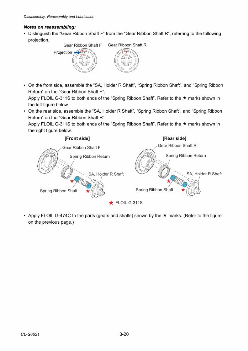
Disassembly, Reassembly and Lubrication
CL-S6621 3-20
Notes on reassembling: • Distinguish the “Gear Ribbon Shaft F” from the “Gear Ribbon Shaft R”, referring to the following
projection. • On the front side, assemble the “SA, Holder R Shaft”, “Spring Ribbon Shaft”, and “Spring Ribbon
Return” on the “Gear Ribbon Shaft F”. Apply FLOIL G-311S to both ends of the “Spring Ribbon Shaft”. Refer to the marks shown in the left figure below.
• On the rear side, assemble the “SA, Holder R Shaft”, “Spring Ribbon Shaft”, and “Spring Ribbon Return” on the “Gear Ribbon Shaft R”. Apply FLOIL G-311S to both ends of the “Spring Ribbon Shaft”. Refer to the marks shown in the right figure below.
• Apply FLOIL G-474C to the parts (gears and shafts) shown by the marks. (Refer to the figure
on the previous page.)
[Front side] [Rear side]
Gear Ribbon Shaft F Gear Ribbon Shaft R
Projection
SA, Holder R Shaft
Spring Ribbon Return
Spring Ribbon Shaft
Gear Ribbon Shaft F
Spring Ribbon Shaft
Gear Ribbon Shaft R
Spring Ribbon Return
SA, Holder R Shaft
FLOIL G-311S
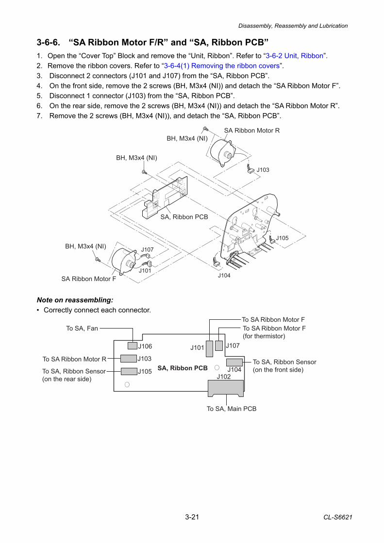
Disassembly, Reassembly and Lubrication
3-21 CL-S6621
J106
J103
J105
J101 J107
J104J102
To SA Ribbon Motor F(for thermistor)
To SA, Main PCB
To SA Ribbon Motor F
To SA, Ribbon Sensor(on the front side)To SA, Ribbon Sensor
(on the rear side)
To SA Ribbon Motor R
To SA, Fan
SA, Ribbon PCB
3-6-6. “SA Ribbon Motor F/R” and “SA, Ribbon PCB” 1. Open the “Cover Top” Block and remove the “Unit, Ribbon”. Refer to “3-6-2 Unit, Ribbon”. 2. Remove the ribbon covers. Refer to “3-6-4(1) Removing the ribbon covers”. 3. Disconnect 2 connectors (J101 and J107) from the “SA, Ribbon PCB”. 4. On the front side, remove the 2 screws (BH, M3x4 (NI)) and detach the “SA Ribbon Motor F”. 5. Disconnect 1 connector (J103) from the “SA, Ribbon PCB”. 6. On the rear side, remove the 2 screws (BH, M3x4 (NI)) and detach the “SA Ribbon Motor R”. 7. Remove the 2 screws (BH, M3x4 (NI)), and detach the “SA, Ribbon PCB”.
Note on reassembling: • Correctly connect each connector.
BH, M3x4 (NI)SA Ribbon Motor R
SA, Ribbon PCB
BH, M3x4 (NI)
SA Ribbon Motor F
J103
J107
J101J104
J105
BH, M3x4 (NI)
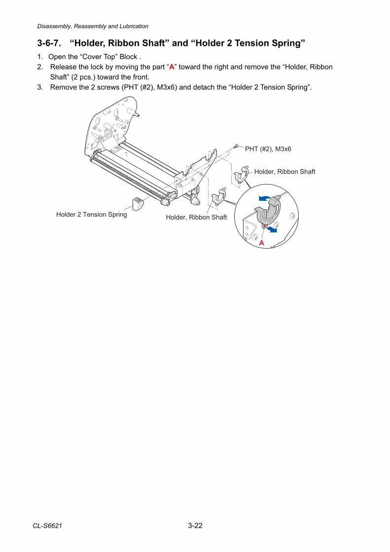
Disassembly, Reassembly and Lubrication
CL-S6621 3-22
3-6-7. “Holder, Ribbon Shaft” and “Holder 2 Tension Spring” 1. Open the “Cover Top” Block . 2. Release the lock by moving the part “A” toward the right and remove the “Holder, Ribbon
Shaft” (2 pcs.) toward the front. 3. Remove the 2 screws (PHT (#2), M3x6) and detach the “Holder 2 Tension Spring”.
�
��� ���� ��
������ ������ �����
������ ������ ����������� � ������� ������
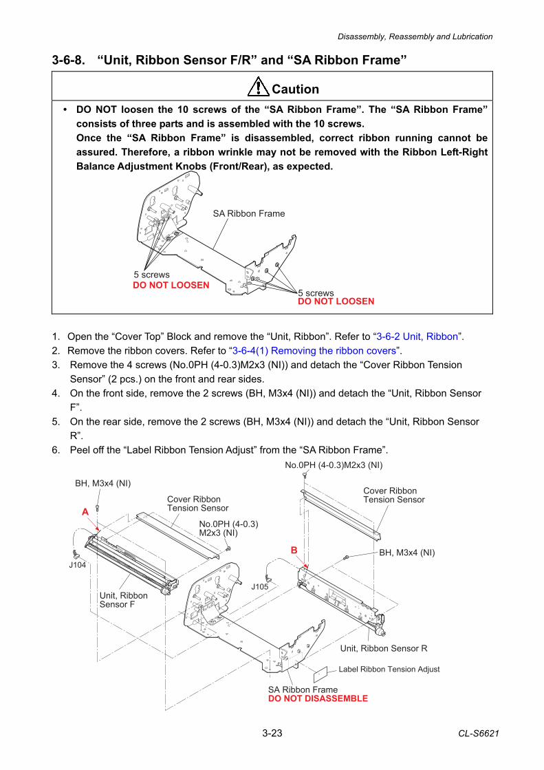
Disassembly, Reassembly and Lubrication
3-23 CL-S6621
A
B
BH, M3x4 (NI)
Unit, Ribbon Sensor F
Cover Ribbon Tension Sensor
No.0PH (4-0.3)M2x3 (NI)
Cover Ribbon Tension Sensor
No.0PH (4-0.3)M2x3 (NI)
J104
J105
Label Ribbon Tension Adjust
Unit, Ribbon Sensor R
SA Ribbon FrameDO NOT DISASSEMBLE
BH, M3x4 (NI)
3-6-8. “Unit, Ribbon Sensor F/R” and “SA Ribbon Frame”
• DO NOT loosen the 10 screws of the “SA Ribbon Frame”. The “SA Ribbon Frame” consists of three parts and is assembled with the 10 screws. Once the “SA Ribbon Frame” is disassembled, correct ribbon running cannot be assured. Therefore, a ribbon wrinkle may not be removed with the Ribbon Left-Right Balance Adjustment Knobs (Front/Rear), as expected.
1. Open the “Cover Top” Block and remove the “Unit, Ribbon”. Refer to “3-6-2 Unit, Ribbon”. 2. Remove the ribbon covers. Refer to “3-6-4(1) Removing the ribbon covers”. 3. Remove the 4 screws (No.0PH (4-0.3)M2x3 (NI)) and detach the “Cover Ribbon Tension
Sensor” (2 pcs.) on the front and rear sides. 4. On the front side, remove the 2 screws (BH, M3x4 (NI)) and detach the “Unit, Ribbon Sensor
F”. 5. On the rear side, remove the 2 screws (BH, M3x4 (NI)) and detach the “Unit, Ribbon Sensor
R”. 6. Peel off the “Label Ribbon Tension Adjust” from the “SA Ribbon Frame”.
Caution
5 screwsDO NOT LOOSEN
DO NOT LOOSEN5 screws
SA Ribbon Frame
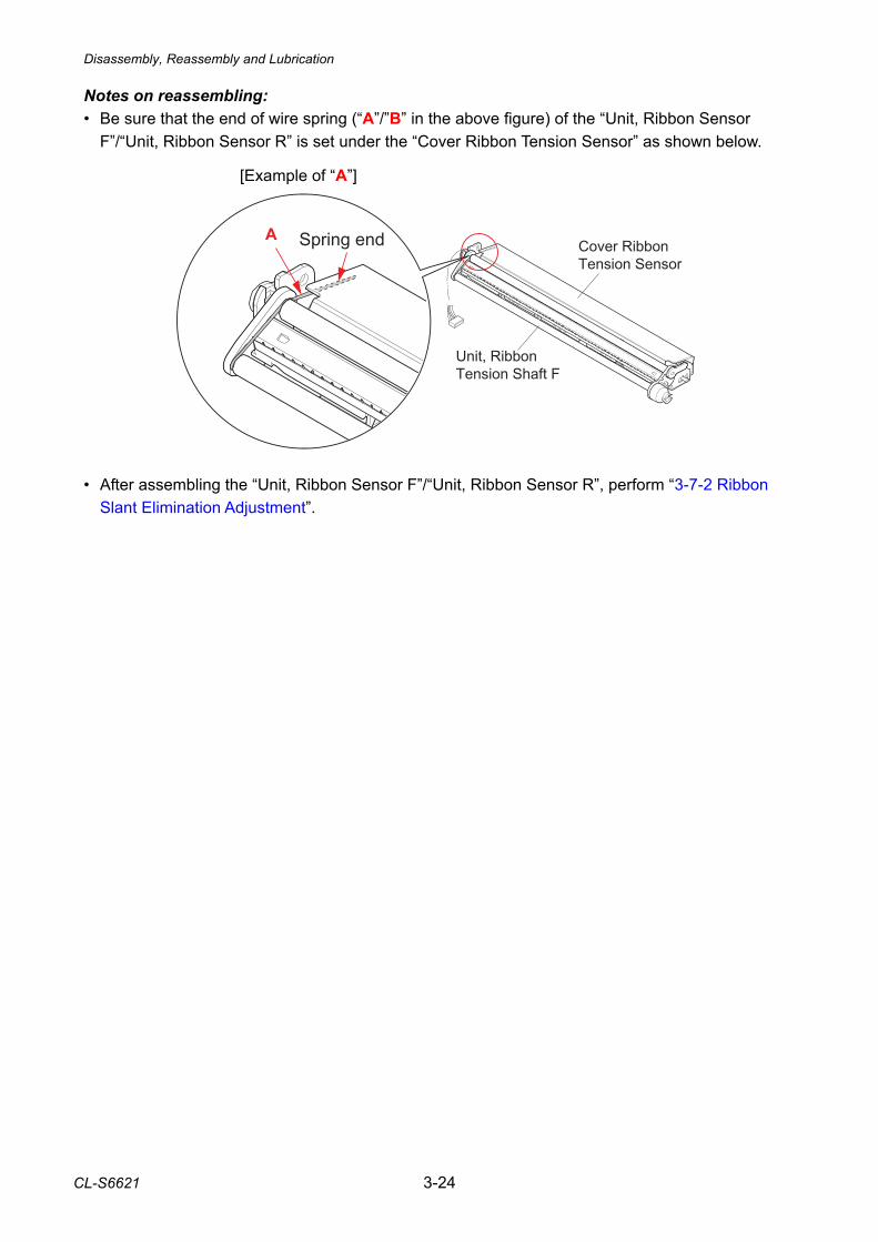
Disassembly, Reassembly and Lubrication
CL-S6621 3-24
Notes on reassembling: • Be sure that the end of wire spring (“A”/”B” in the above figure) of the “Unit, Ribbon Sensor
F”/“Unit, Ribbon Sensor R” is set under the “Cover Ribbon Tension Sensor” as shown below. • After assembling the “Unit, Ribbon Sensor F”/“Unit, Ribbon Sensor R”, perform “3-7-2 Ribbon
Slant Elimination Adjustment”.
Unit, Ribbon Tension Shaft F
Cover Ribbon Tension Sensor
A Spring end
[Example of “A”]
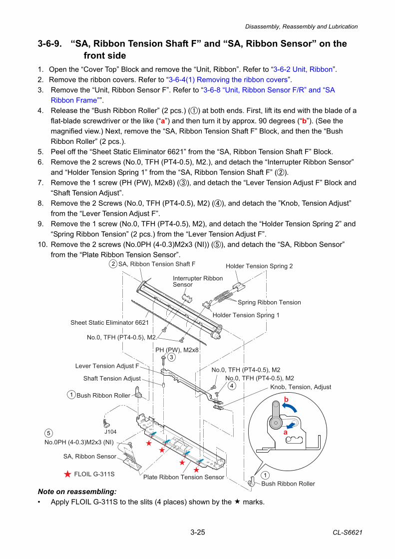
Disassembly, Reassembly and Lubrication
3-25 CL-S6621
3-6-9. “SA, Ribbon Tension Shaft F” and “SA, Ribbon Sensor” on the front side
1. Open the “Cover Top” Block and remove the “Unit, Ribbon”. Refer to “3-6-2 Unit, Ribbon”. 2. Remove the ribbon covers. Refer to “3-6-4(1) Removing the ribbon covers”. 3. Remove the “Unit, Ribbon Sensor F”. Refer to “3-6-8 “Unit, Ribbon Sensor F/R” and “SA
Ribbon Frame””. 4. Release the “Bush Ribbon Roller” (2 pcs.) () at both ends. First, lift its end with the blade of a
flat-blade screwdriver or the like (“a”) and then turn it by approx. 90 degrees (“b”). (See the magnified view.) Next, remove the “SA, Ribbon Tension Shaft F” Block, and then the “Bush Ribbon Roller” (2 pcs.).
5. Peel off the “Sheet Static Eliminator 6621” from the “SA, Ribbon Tension Shaft F” Block. 6. Remove the 2 screws (No.0, TFH (PT4-0.5), M2.), and detach the “Interrupter Ribbon Sensor”
and “Holder Tension Spring 1” from the “SA, Ribbon Tension Shaft F” (). 7. Remove the 1 screw (PH (PW), M2x8) (), and detach the “Lever Tension Adjust F” Block and
“Shaft Tension Adjust”. 8. Remove the 2 Screws (No.0, TFH (PT4-0.5), M2) (), and detach the ”Knob, Tension Adjust”
from the “Lever Tension Adjust F”. 9. Remove the 1 screw (No.0, TFH (PT4-0.5), M2), and detach the “Holder Tension Spring 2” and
“Spring Ribbon Tension” (2 pcs.) from the “Lever Tension Adjust F”. 10. Remove the 2 screws (No.0PH (4-0.3)M2x3 (NI)) (), and detach the “SA, Ribbon Sensor”
from the “Plate Ribbon Tension Sensor”. Note on reassembling: • Apply FLOIL G-311S to the slits (4 places) shown by the marks.
FLOIL G-311S
PH (PW), M2x8
No.0, TFH (PT4-0.5), M2Lever Tension Adjust F
Shaft Tension Adjust
Bush Ribbon Roller
No.0PH (4-0.3)M2x3 (NI)
SA, Ribbon Sensor
J104
Plate Ribbon Tension SensorBush Ribbon Roller
SA, Ribbon Tension Shaft F
Sheet Static Eliminator 6621
No.0, TFH (PT4-0.5), M2.
Interrupter Ribbon Sensor
Holder Tension Spring 1
Spring Ribbon Tension
Holder Tension Spring 2
a
b
No.0, TFH (PT4-0.5), M2Knob, Tension, Adjust
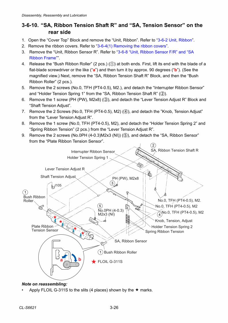
Disassembly, Reassembly and Lubrication
CL-S6621 3-26
3-6-10. “SA, Ribbon Tension Shaft R” and “SA, Tension Sensor” on the rear side
1. Open the “Cover Top” Block and remove the “Unit, Ribbon”. Refer to “3-6-2 Unit, Ribbon”. 2. Remove the ribbon covers. Refer to “3-6-4(1) Removing the ribbon covers”. 3. Remove the “Unit, Ribbon Sensor R”. Refer to “3-6-8 “Unit, Ribbon Sensor F/R” and “SA
Ribbon Frame””. 4. Release the “Bush Ribbon Roller” (2 pcs.) () at both ends. First, lift its end with the blade of a
flat-blade screwdriver or the like (“a”) and then turn it by approx. 90 degrees (“b”). (See the magnified view.) Next, remove the “SA, Ribbon Tension Shaft R” Block, and then the “Bush Ribbon Roller” (2 pcs.).
5. Remove the 2 screws (No.0, TFH (PT4-0.5), M2.), and detach the “Interrupter Ribbon Sensor” and “Holder Tension Spring 1” from the “SA, Ribbon Tension Shaft R” ().
6. Remove the 1 screw (PH (PW), M2x8) (), and detach the “Lever Tension Adjust R” Block and “Shaft Tension Adjust”.
7. Remove the 2 Screws (No.0, TFH (PT4-0.5), M2) (), and detach the ”Knob, Tension Adjust” from the “Lever Tension Adjust R”.
8. Remove the 1 screw (No.0, TFH (PT4-0.5), M2), and detach the “Holder Tension Spring 2” and “Spring Ribbon Tension” (2 pcs.) from the “Lever Tension Adjust R”.
9. Remove the 2 screws (No.0PH (4-0.3)M2x3 (NI)) (), and detach the “SA, Ribbon Sensor” from the “Plate Ribbon Tension Sensor”.
Note on reassembling: • Apply FLOIL G-311S to the slits (4 places) shown by the marks.
FLOIL G-311S
Bush Ribbon Roller
Bush Ribbon Roller
J105
Holder Tension Spring 1Interrupter Ribbon Sensor
No.0, TFH (PT4-0.5), M2.
Shaft Tension Adjust PH (PW), M2x8
Lever Tension Adjust R
No.0, TFH (PT4-0.5), M2
Spring Ribbon TensionHolder Tension Spring 2
No.0PH (4-0.3)M2x3 (NI)
SA, Ribbon Sensor
Plate Ribbon Tension Sensor
SA, Ribbon Tension Shaft R
a b
No.0, TFH (PT4-0.5), M2
Knob, Tension, Adjust
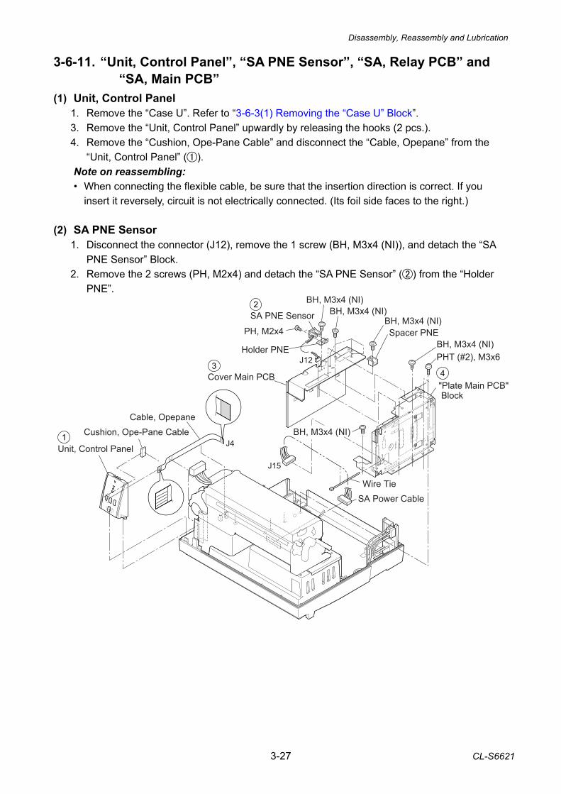
Disassembly, Reassembly and Lubrication
3-27 CL-S6621
3-6-11. “Unit, Control Panel”, “SA PNE Sensor”, “SA, Relay PCB” and “SA, Main PCB”
(1) Unit, Control Panel 1. Remove the “Case U”. Refer to “3-6-3(1) Removing the “Case U” Block”. 3. Remove the “Unit, Control Panel” upwardly by releasing the hooks (2 pcs.). 4. Remove the “Cushion, Ope-Pane Cable” and disconnect the “Cable, Opepane” from the
“Unit, Control Panel” (). Note on reassembling: • When connecting the flexible cable, be sure that the insertion direction is correct. If you
insert it reversely, circuit is not electrically connected. (Its foil side faces to the right.)
(2) SA PNE Sensor 1. Disconnect the connector (J12), remove the 1 screw (BH, M3x4 (NI)), and detach the “SA
PNE Sensor” Block. 2. Remove the 2 screws (PH, M2x4) and detach the “SA PNE Sensor” () from the “Holder
PNE”.
Wire Tie
Cushion, Ope-Pane CableCable, Opepane
Holder PNE
SA PNE Sensor
BH, M3x4 (NI)
BH, M3x4 (NI)BH, M3x4 (NI)
BH, M3x4 (NI)PHT (#2), M3x6
"Plate Main PCB" Block
Cover Main PCB
SA Power Cable
Unit, Control Panel
J12
J15
J4
PH, M2x4
BH, M3x4 (NI)
Spacer PNE
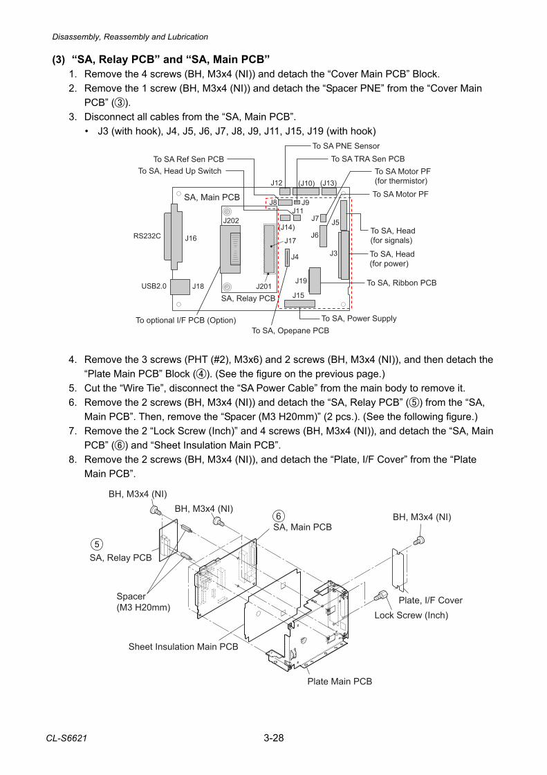
Disassembly, Reassembly and Lubrication
CL-S6621 3-28
(3) “SA, Relay PCB” and “SA, Main PCB” 1. Remove the 4 screws (BH, M3x4 (NI)) and detach the “Cover Main PCB” Block. 2. Remove the 1 screw (BH, M3x4 (NI)) and detach the “Spacer PNE” from the “Cover Main
PCB” (). 3. Disconnect all cables from the “SA, Main PCB”.
• J3 (with hook), J4, J5, J6, J7, J8, J9, J11, J15, J19 (with hook)
4. Remove the 3 screws (PHT (#2), M3x6) and 2 screws (BH, M3x4 (NI)), and then detach the
“Plate Main PCB” Block (). (See the figure on the previous page.) 5. Cut the “Wire Tie”, disconnect the “SA Power Cable” from the main body to remove it. 6. Remove the 2 screws (BH, M3x4 (NI)) and detach the “SA, Relay PCB” () from the “SA,
Main PCB”. Then, remove the “Spacer (M3 H20mm)” (2 pcs.). (See the following figure.) 7. Remove the 2 “Lock Screw (Inch)” and 4 screws (BH, M3x4 (NI)), and detach the “SA, Main
PCB” () and “Sheet Insulation Main PCB”. 8. Remove the 2 screws (BH, M3x4 (NI)), and detach the “Plate, I/F Cover” from the “Plate
Main PCB”.
J12 (J10) (J13)
J5
J3
J7
J6
J4
J19
J15
J17
J201
J202(J14)
J16
J18USB2.0
RS232C
J8 J9J11
SA, Main PCB
To SA Motor PF(for thermistor)
To SA, Power SupplyTo SA, Opepane PCB
To SA, Head(for signals)
To SA TRA Sen PCBTo SA Ref Sen PCBTo SA, Head Up Switch
To SA, Ribbon PCB
To optional I/F PCB (Option)
To SA, Head(for power)
To SA Motor PF
To SA PNE Sensor
SA, Relay PCB
Plate Main PCB
Lock Screw (Inch)
BH, M3x4 (NI)
Plate, I/F Cover
Sheet Insulation Main PCB
SA, Main PCB
BH, M3x4 (NI)
Spacer (M3 H20mm)
SA, Relay PCB
BH, M3x4 (NI)
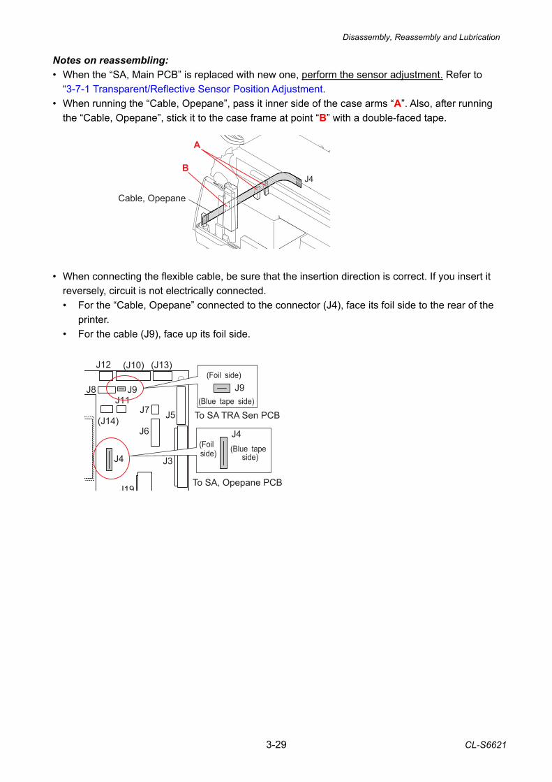
Disassembly, Reassembly and Lubrication
3-29 CL-S6621
Notes on reassembling: • When the “SA, Main PCB” is replaced with new one, perform the sensor adjustment. Refer to
“3-7-1 Transparent/Reflective Sensor Position Adjustment. • When running the “Cable, Opepane”, pass it inner side of the case arms “A”. Also, after running
the “Cable, Opepane”, stick it to the case frame at point “B” with a double-faced tape. • When connecting the flexible cable, be sure that the insertion direction is correct. If you insert it
reversely, circuit is not electrically connected. • For the “Cable, Opepane” connected to the connector (J4), face its foil side to the rear of the
printer. • For the cable (J9), face up its foil side.
A
Cable, Opepane
J4B
J12 (J10) (J13)
J5
J3
J7
J6
J4
J19
(J14)
J8 J9J11
To SA, Opepane PCB
To SA TRA Sen PCB
(Foil side)J9
J4(Foil side) (Blue tape
side)
(Blue tape side)
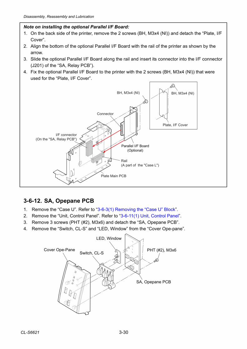
Disassembly, Reassembly and Lubrication
CL-S6621 3-30
BH, M3x4 (NI)
Plate, I/F Cover
Parallel I/F Board(Optional)
Plate Main PCB
BH, M3x4 (NI)
I/F connector(On the "SA, Relay PCB")
Rail(A part of the "Case L")
Connector
Note on installing the optional Parallel I/F Board: 1. On the back side of the printer, remove the 2 screws (BH, M3x4 (NI)) and detach the “Plate, I/F
Cover”. 2. Align the bottom of the optional Parallel I/F Board with the rail of the printer as shown by the
arrow. 3. Slide the optional Parallel I/F Board along the rail and insert its connector into the I/F connector
(J201) of the “SA, Relay PCB”). 4. Fix the optional Parallel I/F Board to the printer with the 2 screws (BH, M3x4 (NI)) that were
used for the “Plate, I/F Cover”. 3-6-12. SA, Opepane PCB 1. Remove the “Case U”. Refer to “3-6-3(1) Removing the “Case U” Block”. 2. Remove the “Unit, Control Panel”. Refer to “3-6-11(1) Unit, Control Panel”. 3. Remove 3 screws (PHT (#2), M3x6) and detach the “SA, Opepane PCB”. 4. Remove the “Switch, CL-S” and “LED, Window” from the “Cover Ope-pane”.
SA, Opepane PCB
LED, Window
Switch, CL-SCover Ope-Pane PHT (#2), M3x6
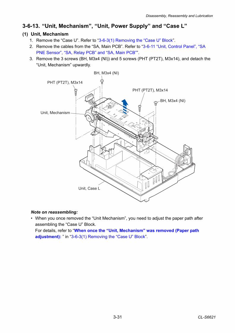
Disassembly, Reassembly and Lubrication
3-31 CL-S6621
3-6-13. “Unit, Mechanism”, “Unit, Power Supply” and “Case L” (1) Unit, Mechanism
1. Remove the “Case U”. Refer to “3-6-3(1) Removing the “Case U” Block”. 2. Remove the cables from the “SA, Main PCB”. Refer to “3-6-11 “Unit, Control Panel”, “SA
PNE Sensor”, “SA, Relay PCB” and “SA, Main PCB””. 3. Remove the 3 screws (BH, M3x4 (NI)) and 5 screws (PHT (PT2T), M3x14), and detach the
“Unit, Mechanism” upwardly. Note on reassembling: • When you once removed the “Unit Mechanism”, you need to adjust the paper path after
assembling the “Case U” Block. For details, refer to “When once the “Unit, Mechanism” was removed (Paper path adjustment): 1 ” in “3-6-3(1) Removing the “Case U” Block”.
BH, M3x4 (NI)
Unit, Mechanism
PHT (PT2T), M3x14
BH, M3x4 (NI)
PHT (PT2T), M3x14
Unit, Case L
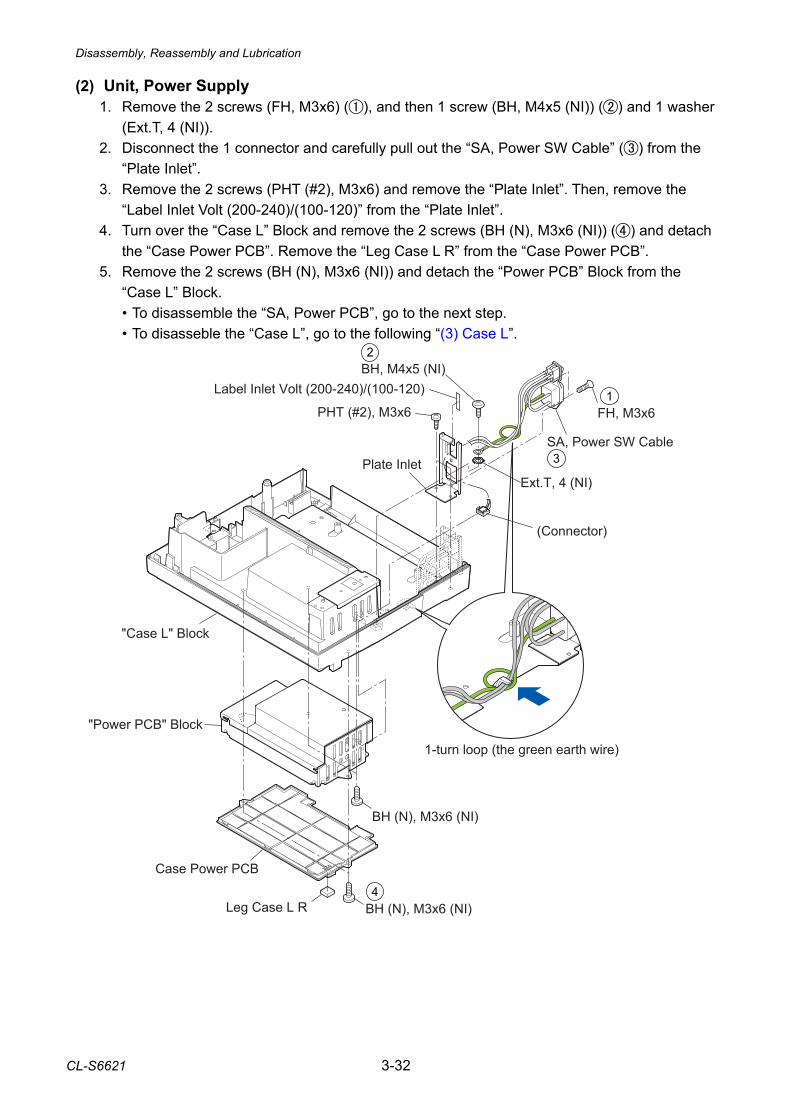
Disassembly, Reassembly and Lubrication
CL-S6621 3-32
(2) Unit, Power Supply 1. Remove the 2 screws (FH, M3x6) (), and then 1 screw (BH, M4x5 (NI)) () and 1 washer
(Ext.T, 4 (NI)). 2. Disconnect the 1 connector and carefully pull out the “SA, Power SW Cable” () from the
“Plate Inlet”. 3. Remove the 2 screws (PHT (#2), M3x6) and remove the “Plate Inlet”. Then, remove the
“Label Inlet Volt (200-240)/(100-120)” from the “Plate Inlet”. 4. Turn over the “Case L” Block and remove the 2 screws (BH (N), M3x6 (NI)) () and detach
the “Case Power PCB”. Remove the “Leg Case L R” from the “Case Power PCB”. 5. Remove the 2 screws (BH (N), M3x6 (NI)) and detach the “Power PCB” Block from the
“Case L” Block. • To disassemble the “SA, Power PCB”, go to the next step. • To disasseble the “Case L”, go to the following “(3) Case L”.
Leg Case L R
Case Power PCB
BH (N), M3x6 (NI)
BH (N), M3x6 (NI)
PHT (#2), M3x6
Label Inlet Volt (200-240)/(100-120)
Plate Inlet
BH, M4x5 (NI)
"Power PCB" Block
Ext.T, 4 (NI)
SA, Power SW Cable
FH, M3x6
1-turn loop (the green earth wire)
(Connector)
"Case L" Block
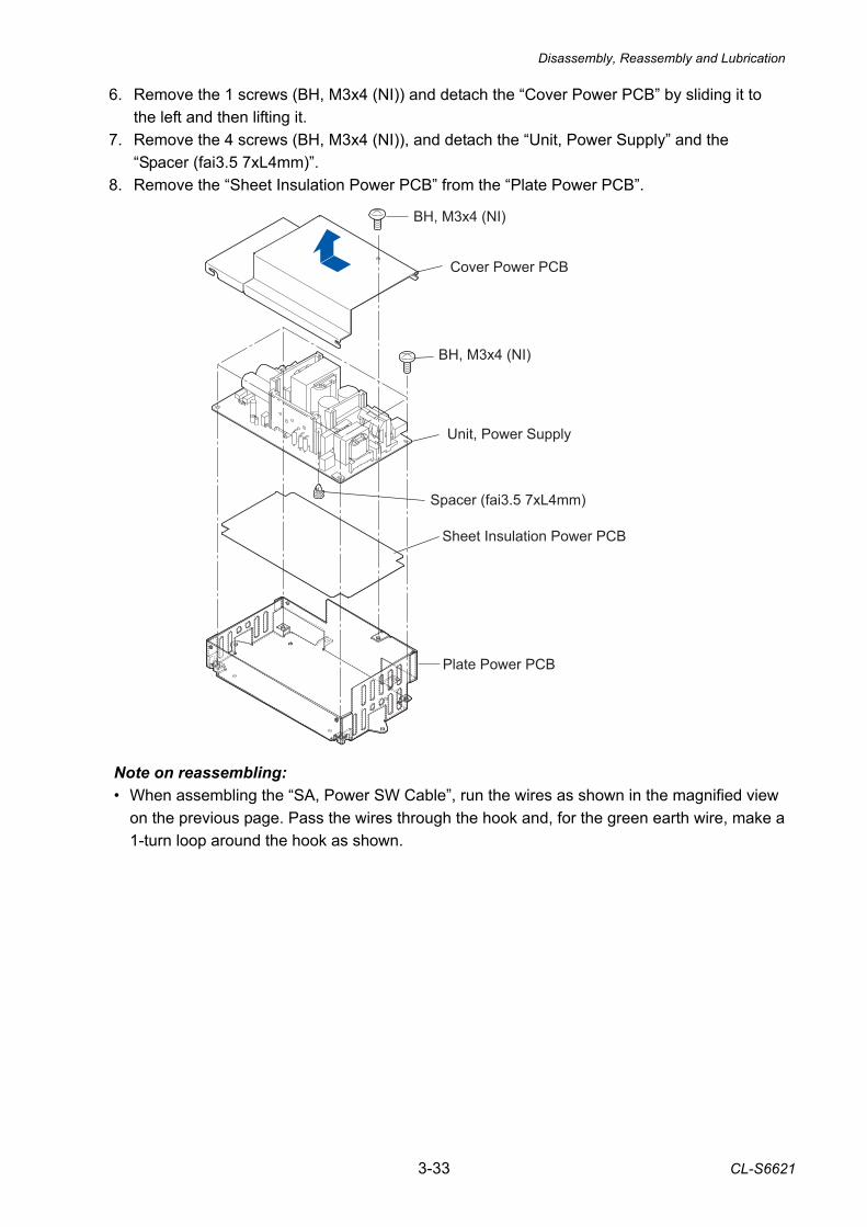
Disassembly, Reassembly and Lubrication
3-33 CL-S6621
BH, M3x4 (NI)
BH, M3x4 (NI)
Sheet Insulation Power PCB
Unit, Power Supply
Cover Power PCB
Plate Power PCB
Spacer (fai3.5 7xL4mm)
6. Remove the 1 screws (BH, M3x4 (NI)) and detach the “Cover Power PCB” by sliding it to the left and then lifting it.
7. Remove the 4 screws (BH, M3x4 (NI)), and detach the “Unit, Power Supply” and the “Spacer (fai3.5 7xL4mm)”.
8. Remove the “Sheet Insulation Power PCB” from the “Plate Power PCB”.
Note on reassembling: • When assembling the “SA, Power SW Cable”, run the wires as shown in the magnified view
on the previous page. Pass the wires through the hook and, for the green earth wire, make a 1-turn loop around the hook as shown.
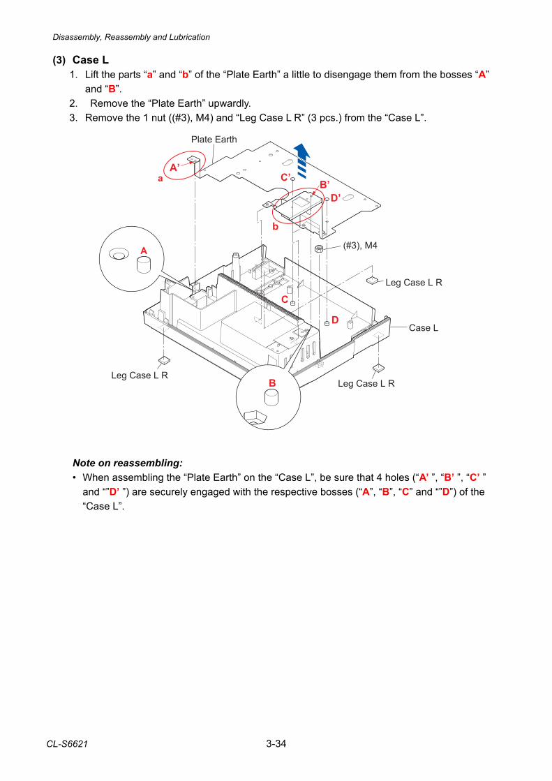
Disassembly, Reassembly and Lubrication
CL-S6621 3-34
(3) Case L 1. Lift the parts “a” and “b” of the “Plate Earth” a little to disengage them from the bosses “A”
and “B”. 2. Remove the “Plate Earth” upwardly. 3. Remove the 1 nut ((#3), M4) and “Leg Case L R” (3 pcs.) from the “Case L”. Note on reassembling: • When assembling the “Plate Earth” on the “Case L”, be sure that 4 holes (“A’ ”, “B’ ”, “C’ ”
and “”D’ ”) are securely engaged with the respective bosses (“A”, “B”, “C” and “”D”) of the “Case L”.
Leg Case L R
Case L
Leg Case L R
Leg Case L R
(#3), M4
Plate Earth
B
A
B’C’
D’
C
D
A’
b
a
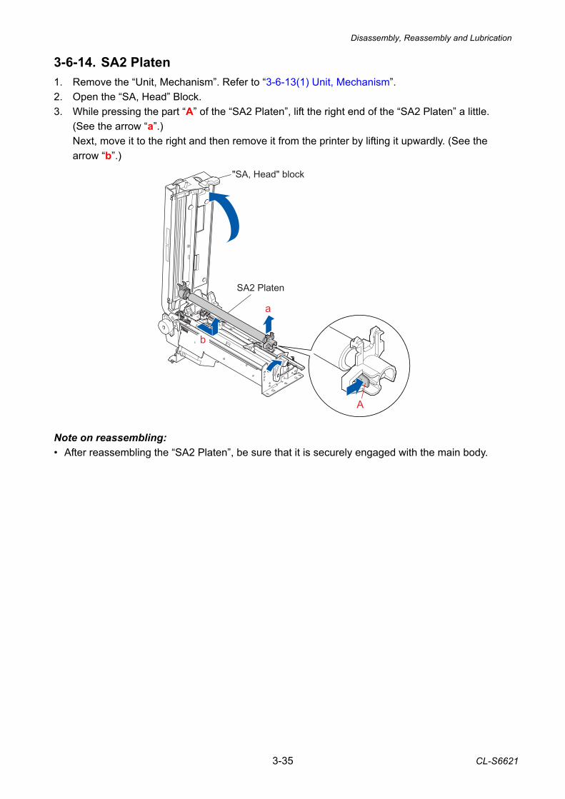
Disassembly, Reassembly and Lubrication
3-35 CL-S6621
3-6-14. SA2 Platen 1. Remove the “Unit, Mechanism”. Refer to “3-6-13(1) Unit, Mechanism”. 2. Open the “SA, Head” Block. 3. While pressing the part “A” of the “SA2 Platen”, lift the right end of the “SA2 Platen” a little.
(See the arrow “a”.) Next, move it to the right and then remove it from the printer by lifting it upwardly. (See the arrow “b”.)
Note on reassembling: • After reassembling the “SA2 Platen”, be sure that it is securely engaged with the main body.
b
a
A
"SA, Head" block
SA2 Platen
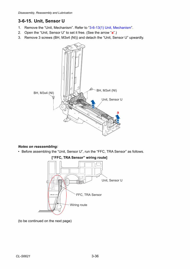
Disassembly, Reassembly and Lubrication
CL-S6621 3-36
3-6-15. Unit, Sensor U 1. Remove the “Unit, Mechanism”. Refer to “3-6-13(1) Unit, Mechanism”. 2. Open the “Unit, Sensor U” to set it free. (See the arrow “a”.) 3. Remove 3 screws (BH, M3x4 (NI)) and detach the “Unit, Sensor U” upwardly.
Notes on reassembling: • Before assembling the “Unit, Sensor U”, run the “FFC, TRA Sensor” as follows. (to be continued on the next page)
[“FFC, TRA Sensor” wiring route]
FFC, TRA Sensor
Wiring route
Unit, Sensor U
BH, M3x4 (NI)BH, M3x4 (NI)
Unit, Sensor U
a
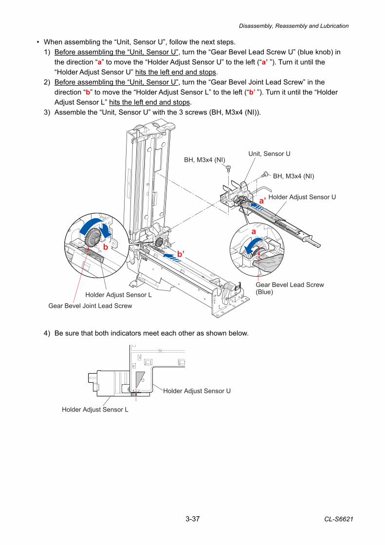
Disassembly, Reassembly and Lubrication
3-37 CL-S6621
• When assembling the “Unit, Sensor U”, follow the next steps. 1) Before assembling the “Unit, Sensor U”, turn the “Gear Bevel Lead Screw U” (blue knob) in
the direction “a” to move the “Holder Adjust Sensor U” to the left (“a’ ”). Turn it until the “Holder Adjust Sensor U” hits the left end and stops.
2) Before assembling the “Unit, Sensor U”, turn the “Gear Bevel Joint Lead Screw” in the direction “b” to move the “Holder Adjust Sensor L” to the left (“b’ ”). Turn it until the “Holder Adjust Sensor L” hits the left end and stops.
3) Assemble the “Unit, Sensor U” with the 3 screws (BH, M3x4 (NI)).
4) Be sure that both indicators meet each other as shown below.
Holder Adjust Sensor U
Holder Adjust Sensor L
Holder Adjust Sensor U
BH, M3x4 (NI)
BH, M3x4 (NI)
a
b
a’
b’
Unit, Sensor U
Gear Bevel Lead Screw(Blue)
Gear Bevel Joint Lead Screw
Holder Adjust Sensor L
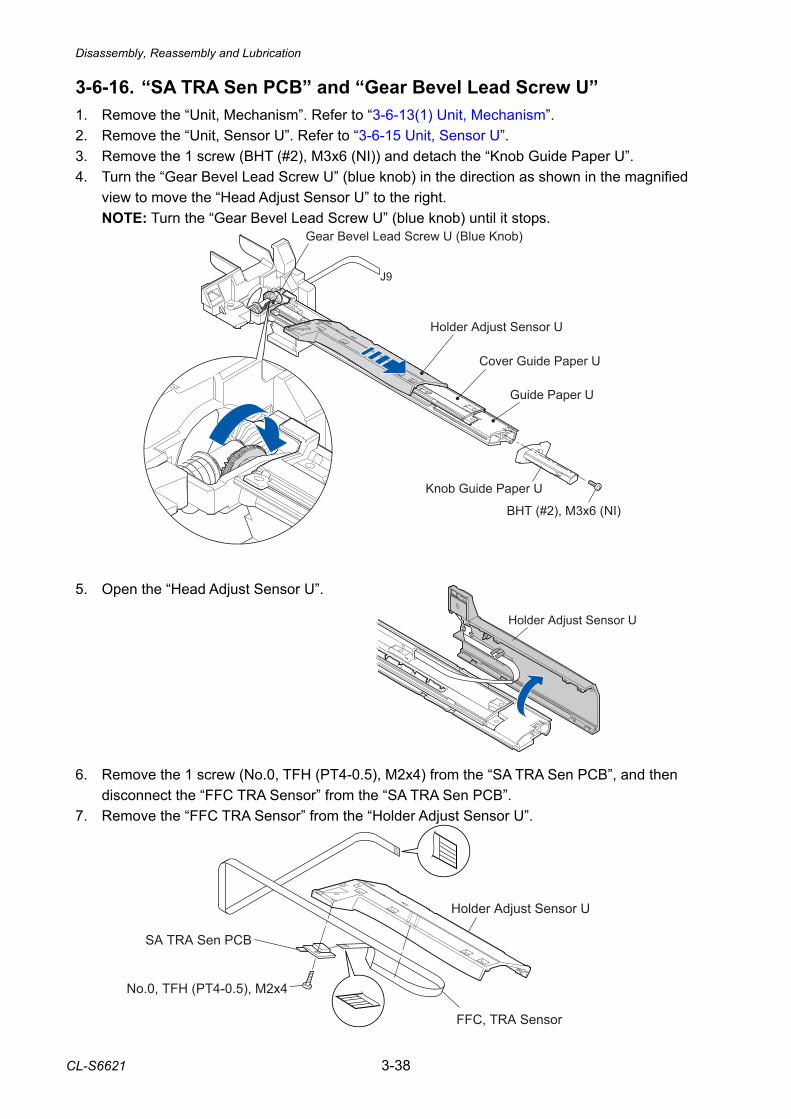
Disassembly, Reassembly and Lubrication
CL-S6621 3-38
3-6-16. “SA TRA Sen PCB” and “Gear Bevel Lead Screw U” 1. Remove the “Unit, Mechanism”. Refer to “3-6-13(1) Unit, Mechanism”. 2. Remove the “Unit, Sensor U”. Refer to “3-6-15 Unit, Sensor U”. 3. Remove the 1 screw (BHT (#2), M3x6 (NI)) and detach the “Knob Guide Paper U”. 4. Turn the “Gear Bevel Lead Screw U” (blue knob) in the direction as shown in the magnified
view to move the “Head Adjust Sensor U” to the right. NOTE: Turn the “Gear Bevel Lead Screw U” (blue knob) until it stops.
5. Open the “Head Adjust Sensor U”. 6. Remove the 1 screw (No.0, TFH (PT4-0.5), M2x4) from the “SA TRA Sen PCB”, and then
disconnect the “FFC TRA Sensor” from the “SA TRA Sen PCB”. 7. Remove the “FFC TRA Sensor” from the “Holder Adjust Sensor U”.
Holder Adjust Sensor U
Knob Guide Paper U
Guide Paper U
Cover Guide Paper U
Holder Adjust Sensor U
Gear Bevel Lead Screw U (Blue Knob)
BHT (#2), M3x6 (NI)
J9
Holder Adjust Sensor U
No.0, TFH (PT4-0.5), M2x4
SA TRA Sen PCB
FFC, TRA Sensor
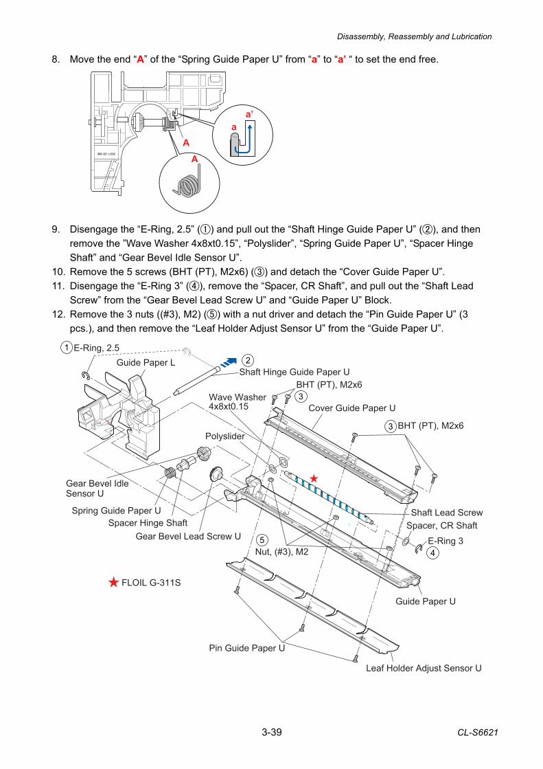
Disassembly, Reassembly and Lubrication
3-39 CL-S6621
FLOIL G-311S
BHT (PT), M2x6
BHT (PT), M2x6
Spacer, CR Shaft
E-Ring 3
Guide Paper U
Leaf Holder Adjust Sensor U
Nut, (#3), M2
Wave Washer 4x8xt0.15 Cover Guide Paper U
Shaft Lead Screw
Gear Bevel Lead Screw U
Gear Bevel Idle Sensor U
Spacer Hinge ShaftSpring Guide Paper U
Shaft Hinge Guide Paper U
E-Ring, 2.5Guide Paper L
Pin Guide Paper U
Polyslider
8. Move the end “A” of the “Spring Guide Paper U” from “a” to “a’ “ to set the end free. 9. Disengage the “E-Ring, 2.5” () and pull out the “Shaft Hinge Guide Paper U” (), and then
remove the ”Wave Washer 4x8xt0.15”, “Polyslider”, “Spring Guide Paper U”, “Spacer Hinge Shaft” and “Gear Bevel Idle Sensor U”.
10. Remove the 5 screws (BHT (PT), M2x6) () and detach the “Cover Guide Paper U”. 11. Disengage the “E-Ring 3” (), remove the “Spacer, CR Shaft”, and pull out the “Shaft Lead
Screw” from the “Gear Bevel Lead Screw U” and “Guide Paper U” Block. 12. Remove the 3 nuts ((#3), M2) () with a nut driver and detach the “Pin Guide Paper U” (3
pcs.), and then remove the “Leaf Holder Adjust Sensor U” from the “Guide Paper U”.
aA
A
a’
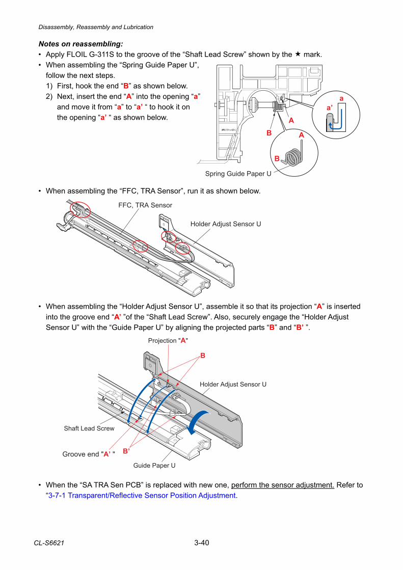
Disassembly, Reassembly and Lubrication
CL-S6621 3-40
Notes on reassembling: • Apply FLOIL G-311S to the groove of the “Shaft Lead Screw” shown by the mark. • When assembling the “Spring Guide Paper U”,
follow the next steps. 1) First, hook the end “B” as shown below. 2) Next, insert the end “A” into the opening “a”
and move it from “a” to “a’ “ to hook it on the opening “a’ “ as shown below.
• When assembling the “FFC, TRA Sensor”, run it as shown below. • When assembling the “Holder Adjust Sensor U”, assemble it so that its projection “A” is inserted
into the groove end “A’ ”of the “Shaft Lead Screw”. Also, securely engage the “Holder Adjust Sensor U” with the “Guide Paper U” by aligning the projected parts “B” and “B’ ”.
• When the “SA TRA Sen PCB” is replaced with new one, perform the sensor adjustment. Refer to
“3-7-1 Transparent/Reflective Sensor Position Adjustment.
Holder Adjust Sensor U
FFC, TRA Sensor
A
aa’
B
B
A
Spring Guide Paper U
Groove end "A’ " B’
Shaft Lead Screw
Projection "A"
B
Holder Adjust Sensor U
Guide Paper U
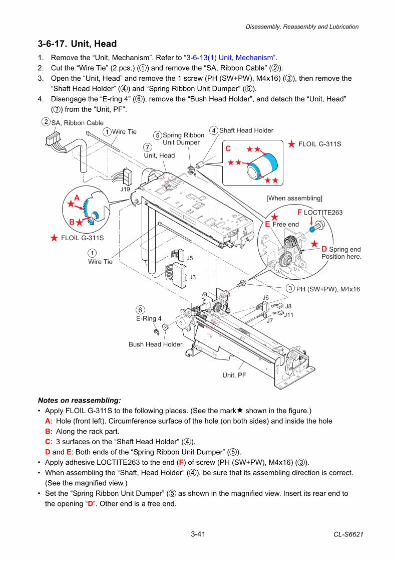
Disassembly, Reassembly and Lubrication
3-41 CL-S6621
3-6-17. Unit, Head 1. Remove the “Unit, Mechanism”. Refer to “3-6-13(1) Unit, Mechanism”. 2. Cut the “Wire Tie” (2 pcs.) () and remove the “SA, Ribbon Cable” (). 3. Open the “Unit, Head” and remove the 1 screw (PH (SW+PW), M4x16) (), then remove the
“Shaft Head Holder” () and “Spring Ribbon Unit Dumper” (). 4. Disengage the “E-ring 4” (), remove the “Bush Head Holder”, and detach the “Unit, Head”
() from the “Unit, PF”.
Notes on reassembling: • Apply FLOIL G-311S to the following places. (See the mark shown in the figure.)
A: Hole (front left). Circumference surface of the hole (on both sides) and inside the hole B: Along the rack part. C: 3 surfaces on the “Shaft Head Holder” (). D and E: Both ends of the “Spring Ribbon Unit Dumper” ().
• Apply adhesive LOCTITE263 to the end (F) of screw (PH (SW+PW), M4x16) (). • When assembling the “Shaft, Head Holder” (), be sure that its assembling direction is correct.
(See the magnified view.) • Set the “Spring Ribbon Unit Dumper” ( as shown in the magnified view. Insert its rear end to
the opening “D”. Other end is a free end.
Wire Tie
Wire Tie
SA, Ribbon CableShaft Head Holder
Spring Ribbon Unit Dumper
PH (SW+PW), M4x16
E-Ring 4
Position here.
Free end
Unit, Head
Unit, PF
FLOIL G-311S
FLOIL G-311S
[When assembling]
Bush Head Holder
Spring endJ5
J3
J6
J7
J8J11
J19
C
A
B
D
LOCTITE263
EF
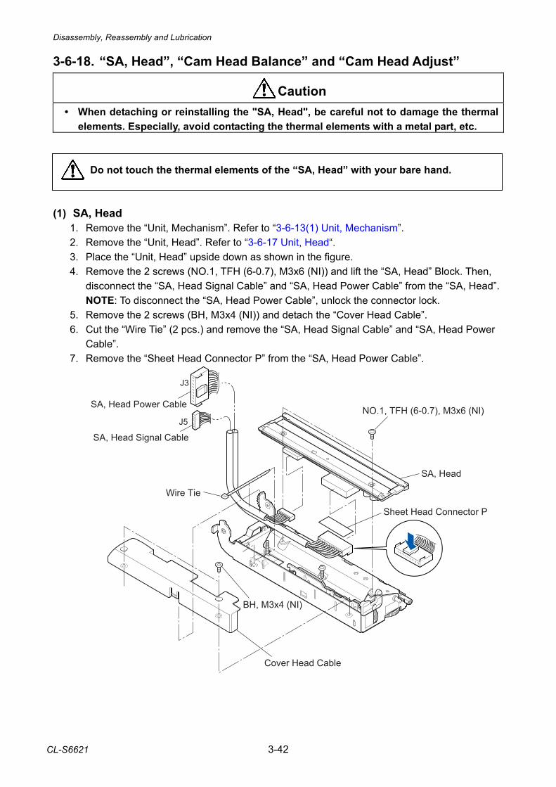
Disassembly, Reassembly and Lubrication
CL-S6621 3-42
3-6-18. “SA, Head”, “Cam Head Balance” and “Cam Head Adjust”
• When detaching or reinstalling the "SA, Head", be careful not to damage the thermal elements. Especially, avoid contacting the thermal elements with a metal part, etc.
Do not touch the thermal elements of the “SA, Head” with your bare hand. (1) SA, Head
1. Remove the “Unit, Mechanism”. Refer to “3-6-13(1) Unit, Mechanism”. 2. Remove the “Unit, Head”. Refer to “3-6-17 Unit, Head“. 3. Place the “Unit, Head” upside down as shown in the figure. 4. Remove the 2 screws (NO.1, TFH (6-0.7), M3x6 (NI)) and lift the “SA, Head” Block. Then,
disconnect the “SA, Head Signal Cable” and “SA, Head Power Cable” from the “SA, Head”. NOTE: To disconnect the “SA, Head Power Cable”, unlock the connector lock. 5. Remove the 2 screws (BH, M3x4 (NI)) and detach the “Cover Head Cable”. 6. Cut the “Wire Tie” (2 pcs.) and remove the “SA, Head Signal Cable” and “SA, Head Power
Cable”. 7. Remove the “Sheet Head Connector P” from the “SA, Head Power Cable”.
Caution
NO.1, TFH (6-0.7), M3x6 (NI)
SA, Head
SA, Head Signal Cable
BH, M3x4 (NI)
Wire Tie
Cover Head Cable
SA, Head Power Cable
J3
J5
Sheet Head Connector P
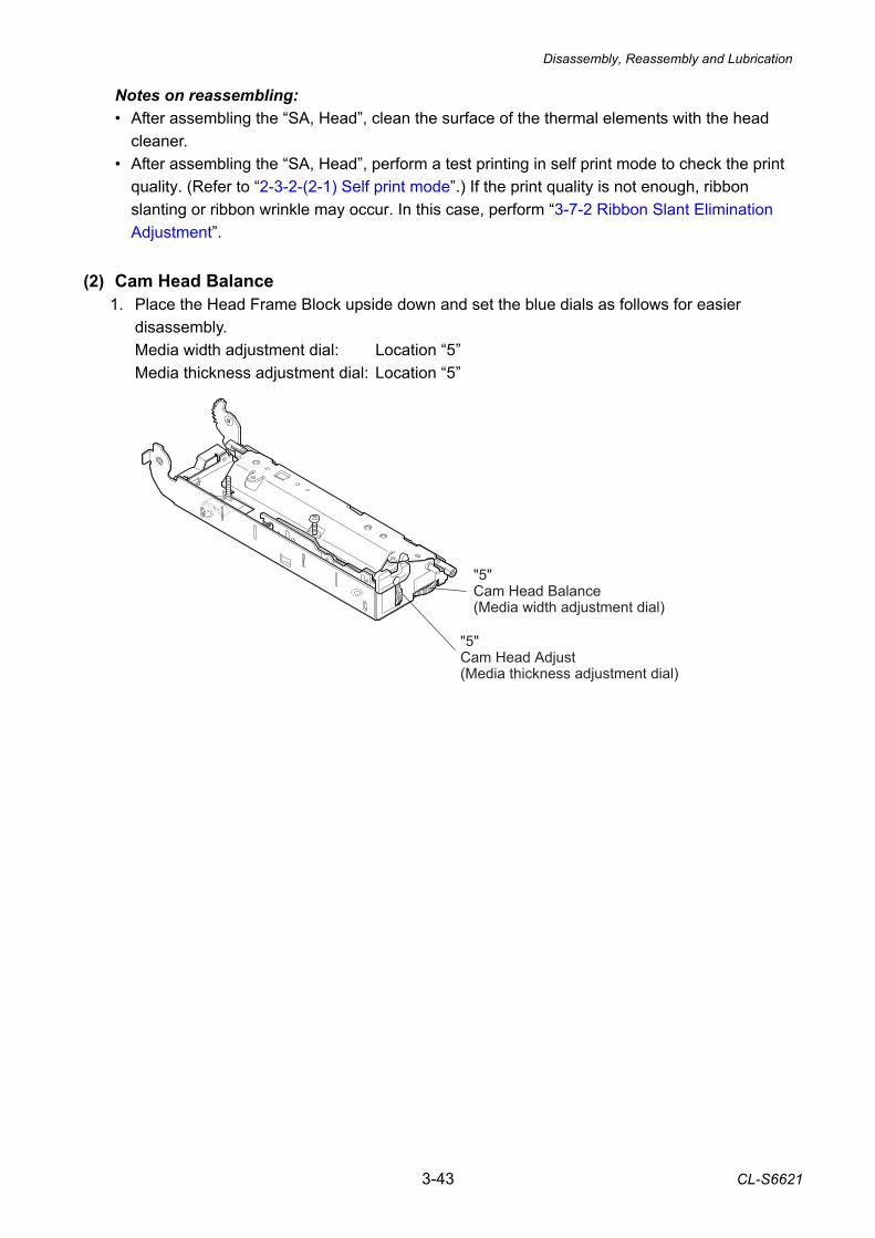
Disassembly, Reassembly and Lubrication
3-43 CL-S6621
Notes on reassembling: • After assembling the “SA, Head”, clean the surface of the thermal elements with the head
cleaner. • After assembling the “SA, Head”, perform a test printing in self print mode to check the print
quality. (Refer to “2-3-2-(2-1) Self print mode”.) If the print quality is not enough, ribbon slanting or ribbon wrinkle may occur. In this case, perform “3-7-2 Ribbon Slant Elimination Adjustment”.
(2) Cam Head Balance
1. Place the Head Frame Block upside down and set the blue dials as follows for easier disassembly.
Media width adjustment dial: Location “5” Media thickness adjustment dial: Location “5”
"5"Cam Head Balance(Media width adjustment dial)
"5"Cam Head Adjust(Media thickness adjustment dial)
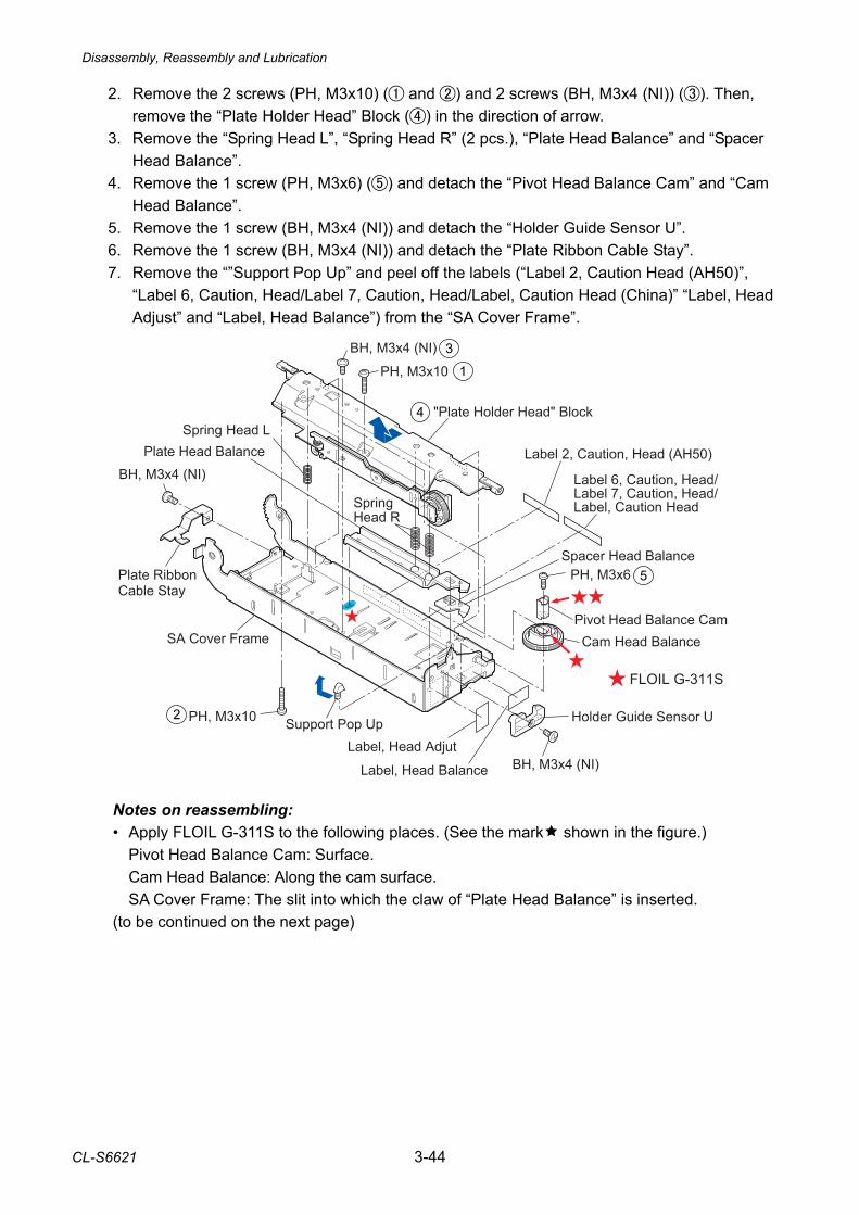
Disassembly, Reassembly and Lubrication
CL-S6621 3-44
2. Remove the 2 screws (PH, M3x10) ( and ) and 2 screws (BH, M3x4 (NI)) (). Then, remove the “Plate Holder Head” Block () in the direction of arrow.
3. Remove the “Spring Head L”, “Spring Head R” (2 pcs.), “Plate Head Balance” and “Spacer Head Balance”.
4. Remove the 1 screw (PH, M3x6) () and detach the “Pivot Head Balance Cam” and “Cam Head Balance”.
5. Remove the 1 screw (BH, M3x4 (NI)) and detach the “Holder Guide Sensor U”. 6. Remove the 1 screw (BH, M3x4 (NI)) and detach the “Plate Ribbon Cable Stay”. 7. Remove the “”Support Pop Up” and peel off the labels (“Label 2, Caution Head (AH50)”,
“Label 6, Caution, Head/Label 7, Caution, Head/Label, Caution Head (China)” “Label, Head Adjust” and “Label, Head Balance”) from the “SA Cover Frame”.
Notes on reassembling: • Apply FLOIL G-311S to the following places. (See the mark shown in the figure.)
Pivot Head Balance Cam: Surface. Cam Head Balance: Along the cam surface. SA Cover Frame: The slit into which the claw of “Plate Head Balance” is inserted.
(to be continued on the next page)
BH, M3x4 (NI)
PH, M3x10
"Plate Holder Head" Block
Label 2, Caution, Head (AH50)
Label 6, Caution, Head/Label 7, Caution, Head/Label, Caution Head
PH, M3x6
Pivot Head Balance CamCam Head Balance
Label, Head Balance
Holder Guide Sensor U
BH, M3x4 (NI)Label, Head Adjut
Support Pop Up
Plate Ribbon Cable Stay
SA Cover Frame
Spring Head R
Spring Head L
BH, M3x4 (NI)
PH, M3x10
Spacer Head Balance
Plate Head Balance
FLOIL G-311S
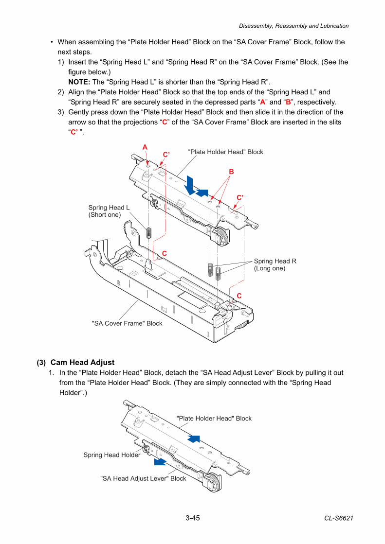
Disassembly, Reassembly and Lubrication
3-45 CL-S6621
• When assembling the “Plate Holder Head” Block on the “SA Cover Frame” Block, follow the next steps. 1) Insert the “Spring Head L” and “Spring Head R” on the “SA Cover Frame” Block. (See the
figure below.) NOTE: The “Spring Head L” is shorter than the “Spring Head R”.
2) Align the “Plate Holder Head” Block so that the top ends of the “Spring Head L” and “Spring Head R” are securely seated in the depressed parts “A” and “B”, respectively.
3) Gently press down the “Plate Holder Head” Block and then slide it in the direction of the arrow so that the projections “C” of the “SA Cover Frame” Block are inserted in the slits “C’ ”.
(3) Cam Head Adjust 1. In the “Plate Holder Head” Block, detach the “SA Head Adjust Lever” Block by pulling it out
from the “Plate Holder Head” Block. (They are simply connected with the “Spring Head Holder”.)
Spring Head L(Short one)
Spring Head R(Long one)
A
B
C
C’
C
C’
"Plate Holder Head" Block
"SA Cover Frame" Block
Spring Head Holder
"SA Head Adjust Lever" Block
"Plate Holder Head" Block
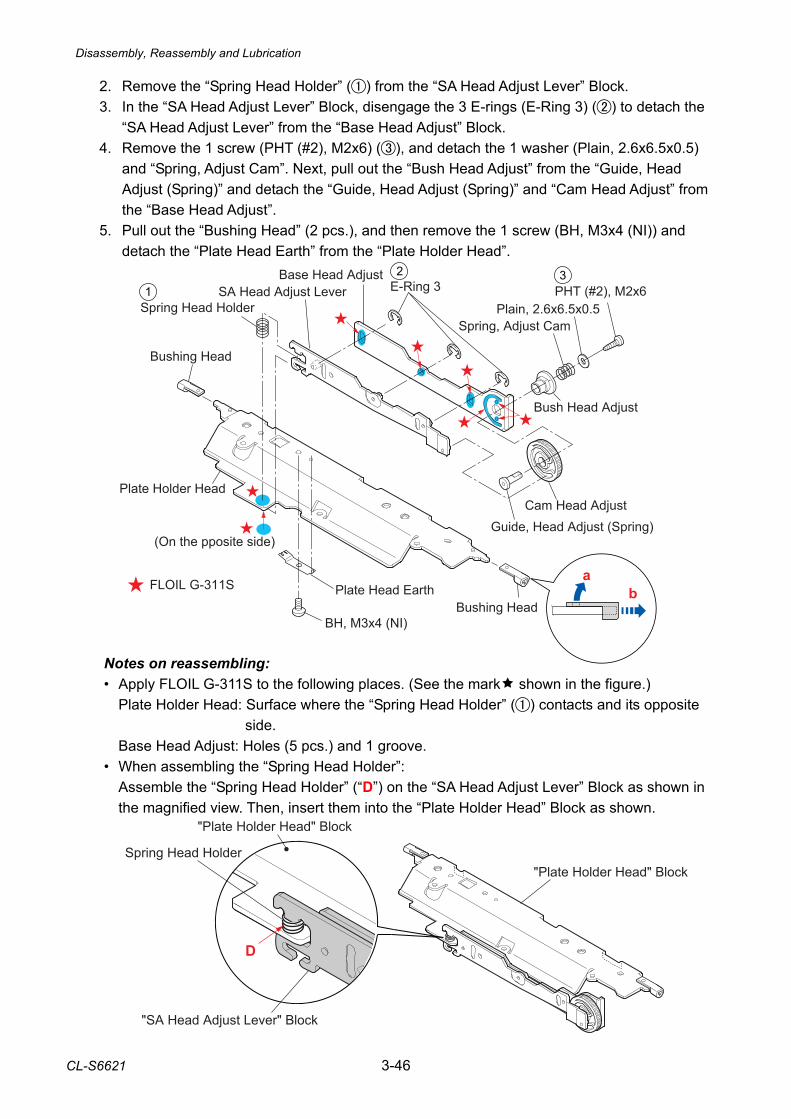
Disassembly, Reassembly and Lubrication
CL-S6621 3-46
2. Remove the “Spring Head Holder” () from the “SA Head Adjust Lever” Block. 3. In the “SA Head Adjust Lever” Block, disengage the 3 E-rings (E-Ring 3) () to detach the
“SA Head Adjust Lever” from the “Base Head Adjust” Block. 4. Remove the 1 screw (PHT (#2), M2x6) (), and detach the 1 washer (Plain, 2.6x6.5x0.5)
and “Spring, Adjust Cam”. Next, pull out the “Bush Head Adjust” from the “Guide, Head Adjust (Spring)” and detach the “Guide, Head Adjust (Spring)” and “Cam Head Adjust” from the “Base Head Adjust”.
5. Pull out the “Bushing Head” (2 pcs.), and then remove the 1 screw (BH, M3x4 (NI)) and detach the “Plate Head Earth” from the “Plate Holder Head”.
Notes on reassembling: • Apply FLOIL G-311S to the following places. (See the mark shown in the figure.)
Plate Holder Head: Surface where the “Spring Head Holder” () contacts and its opposite side.
Base Head Adjust: Holes (5 pcs.) and 1 groove. • When assembling the “Spring Head Holder”:
Assemble the “Spring Head Holder” (“D”) on the “SA Head Adjust Lever” Block as shown in the magnified view. Then, insert them into the “Plate Holder Head” Block as shown.
D
"Plate Holder Head" Block Spring Head Holder
"SA Head Adjust Lever" Block
"Plate Holder Head" Block
FLOIL G-311S
Spring Head Holder
Base Head AdjustSA Head Adjust Lever E-Ring 3 PHT (#2), M2x6
Plain, 2.6x6.5x0.5Spring, Adjust Cam
Bush Head Adjust
Cam Head AdjustGuide, Head Adjust (Spring)
Bushing HeadPlate Head Earth
BH, M3x4 (NI)
Bushing Head
Plate Holder Head
(On the pposite side)
ab
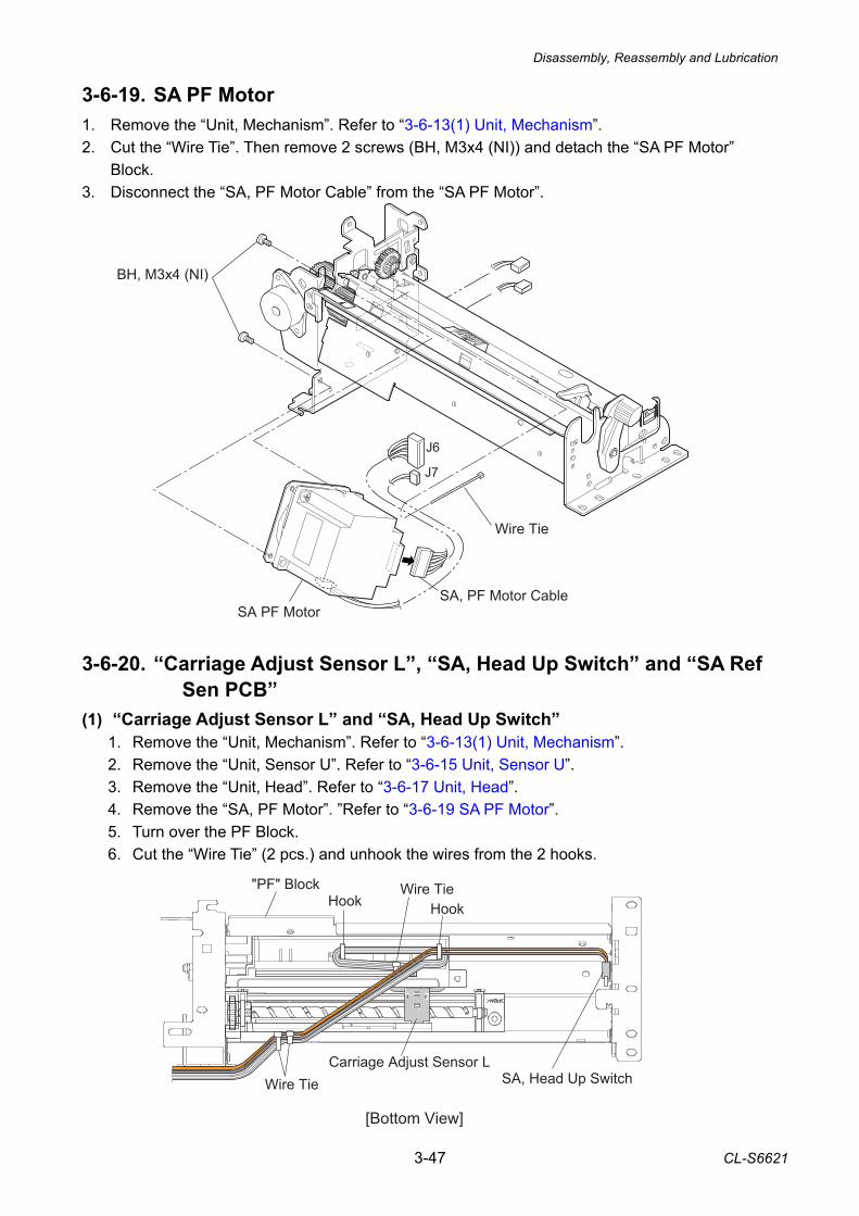
Disassembly, Reassembly and Lubrication
3-47 CL-S6621
BH, M3x4 (NI)
SA, PF Motor CableSA PF Motor
Wire Tie
J7
J6
3-6-19. SA PF Motor 1. Remove the “Unit, Mechanism”. Refer to “3-6-13(1) Unit, Mechanism”. 2. Cut the “Wire Tie”. Then remove 2 screws (BH, M3x4 (NI)) and detach the “SA PF Motor”
Block. 3. Disconnect the “SA, PF Motor Cable” from the “SA PF Motor”. 3-6-20. “Carriage Adjust Sensor L”, “SA, Head Up Switch” and “SA Ref
Sen PCB” (1) “Carriage Adjust Sensor L” and “SA, Head Up Switch”
1. Remove the “Unit, Mechanism”. Refer to “3-6-13(1) Unit, Mechanism”. 2. Remove the “Unit, Sensor U”. Refer to “3-6-15 Unit, Sensor U”. 3. Remove the “Unit, Head”. Refer to “3-6-17 Unit, Head”. 4. Remove the “SA, PF Motor”. ”Refer to “3-6-19 SA PF Motor”. 5. Turn over the PF Block. 6. Cut the “Wire Tie” (2 pcs.) and unhook the wires from the 2 hooks. SA, Head Up SwitchWire Tie
Hook
Carriage Adjust Sensor L
[Bottom View]
"PF" Block
HookWire Tie
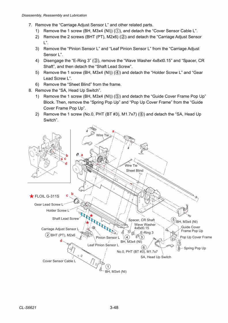
Disassembly, Reassembly and Lubrication
CL-S6621 3-48
7. Remove the “Carriage Adjust Sensor L” and other related parts. 1) Remove the 1 screw (BH, M3x4 (NI)) (), and detach the “Cover Sensor Cable L”. 2) Remove the 2 screws (BHT (PT), M2x6) () and detach the “Carriage Adjust Sensor
L”. 3) Remove the “Pinion Sensor L” and “Leaf Pinion Sensor L” from the “Carriage Adjust
Sensor L”. 4) Disengage the “E-Ring 3” (), remove the “Wave Washer 4x8xt0.15” and “Spacer, CR
Shaft”, and then detach the “Shaft Lead Screw”. 5) Remove the 1 screw (BH, M3x4 (NI)) () and detach the “Holder Screw L” and “Gear
Lead Screw L”. 6) Remove the “Sheet Blind” from the frame.
8. Remove the “SA, Head Up Switch”. 1) Remove the 1 screw (BH, M3x4 (NI)) () and detach the “Guide Cover Frame Pop Up”
Block. Then, remove the “Spring Pop Up” and “Pop Up Cover Frame” from the “Guide Cover Frame Pop Up”.
2) Remove the 1 screw (No.0, PHT (BT #3), M1.7x7) () and detach the “SA, Head Up Switch”.
FLOIL G-311S
a
Sheet Blind
Spring Pop Up
Pop Up Cover Frame
Guide Cover Frame Pop Up
No.0, PHT (BT #3), M1.7x7SA, Head Up Switch
BH, M3x4 (NI)
Cover Sensor Cable L
BH, M3x4 (NI)
Holder Screw L
Gear Lead Screw L
E-Ring 3
Wave Washer 4x8xt0.15
BH, M3x4 (NI)
Shaft Lead Screw
Pinion Sensor LBHT (PT), M2x6
Leaf Pinion Sensor L
Carriage Adjust Sensor L
b
b
c
c
a
a
d
d
Wire Tie
Wire Tie
Spacer, CR Shaft
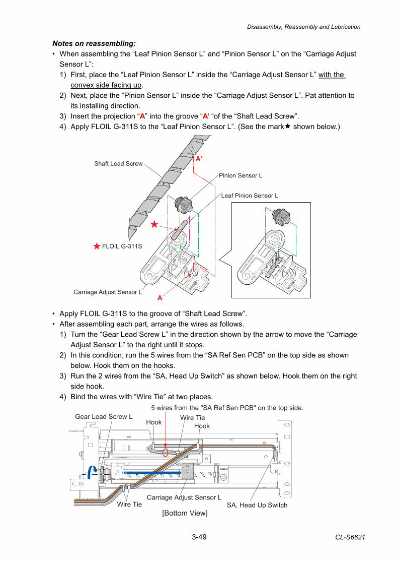
Disassembly, Reassembly and Lubrication
3-49 CL-S6621
FLOIL G-311S
Pinion Sensor L
Leaf Pinion Sensor L
Carriage Adjust Sensor LA
Shaft Lead ScrewA’
Notes on reassembling: • When assembling the “Leaf Pinion Sensor L” and “Pinion Sensor L” on the “Carriage Adjust
Sensor L”: 1) First, place the “Leaf Pinion Sensor L” inside the “Carriage Adjust Sensor L” with the
convex side facing up. 2) Next, place the “Pinion Sensor L” inside the “Carriage Adjust Sensor L”. Pat attention to
its installing direction. 3) Insert the projection “A” into the groove “A’ “of the “Shaft Lead Screw”. 4) Apply FLOIL G-311S to the “Leaf Pinion Sensor L”. (See the mark shown below.)
• Apply FLOIL G-311S to the groove of “Shaft Lead Screw”. • After assembling each part, arrange the wires as follows.
1) Turn the “Gear Lead Screw L” in the direction shown by the arrow to move the “Carriage Adjust Sensor L” to the right until it stops.
2) In this condition, run the 5 wires from the “SA Ref Sen PCB” on the top side as shown below. Hook them on the hooks.
3) Run the 2 wires from the “SA, Head Up Switch” as shown below. Hook them on the right side hook.
4) Bind the wires with “Wire Tie” at two places. SA, Head Up SwitchWire Tie
Gear Lead Screw L
Carriage Adjust Sensor L
[Bottom View]
5 wires from the "SA Ref Sen PCB" on the top side.
Hook HookWire Tie
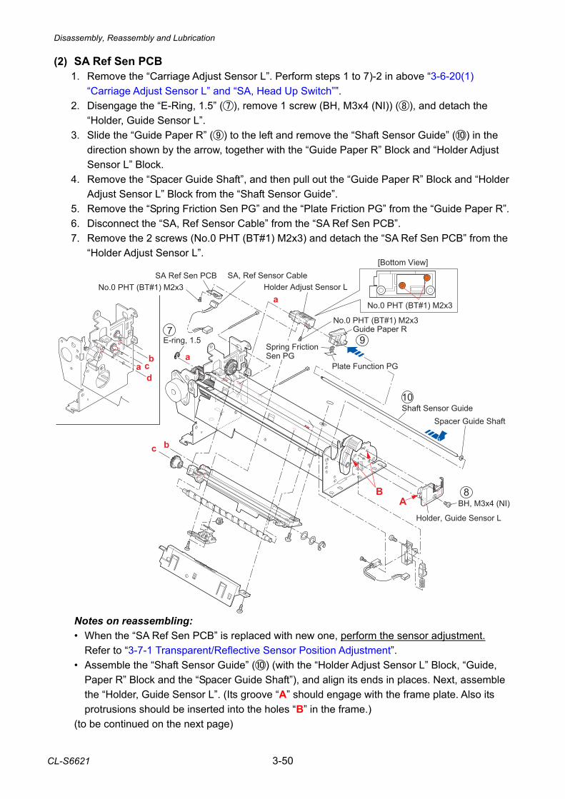
Disassembly, Reassembly and Lubrication
CL-S6621 3-50
Shaft Sensor Guide
Holder Adjust Sensor L
Guide Paper R
SA Ref Sen PCBNo.0 PHT (BT#1) M2x3
No.0 PHT (BT#1) M2x3
SA, Ref Sensor Cable
Spring Friction Sen PG
Plate Function PGb
b
c
c
aa
d
BH, M3x4 (NI)
Spacer Guide Shaft
Holder, Guide Sensor L
E-ring, 1.5
a
[Bottom View]
No.0 PHT (BT#1) M2x3
8
9
AB
10
7
(2) SA Ref Sen PCB 1. Remove the “Carriage Adjust Sensor L”. Perform steps 1 to 7)-2 in above “3-6-20(1)
“Carriage Adjust Sensor L” and “SA, Head Up Switch””. 2. Disengage the “E-Ring, 1.5” (), remove 1 screw (BH, M3x4 (NI)) (), and detach the
“Holder, Guide Sensor L”. 3. Slide the “Guide Paper R” () to the left and remove the “Shaft Sensor Guide” () in the
direction shown by the arrow, together with the “Guide Paper R” Block and “Holder Adjust Sensor L” Block.
4. Remove the “Spacer Guide Shaft”, and then pull out the “Guide Paper R” Block and “Holder Adjust Sensor L” Block from the “Shaft Sensor Guide”.
5. Remove the “Spring Friction Sen PG” and the “Plate Friction PG” from the “Guide Paper R”. 6. Disconnect the “SA, Ref Sensor Cable” from the “SA Ref Sen PCB”. 7. Remove the 2 screws (No.0 PHT (BT#1) M2x3) and detach the “SA Ref Sen PCB” from the
“Holder Adjust Sensor L”.
Notes on reassembling: • When the “SA Ref Sen PCB” is replaced with new one, perform the sensor adjustment.
Refer to “3-7-1 Transparent/Reflective Sensor Position Adjustment”. • Assemble the “Shaft Sensor Guide” () (with the “Holder Adjust Sensor L” Block, “Guide,
Paper R” Block and the “Spacer Guide Shaft”), and align its ends in places. Next, assemble the “Holder, Guide Sensor L”. (Its groove “A” should engage with the frame plate. Also its protrusions should be inserted into the holes “B” in the frame.)
(to be continued on the next page)
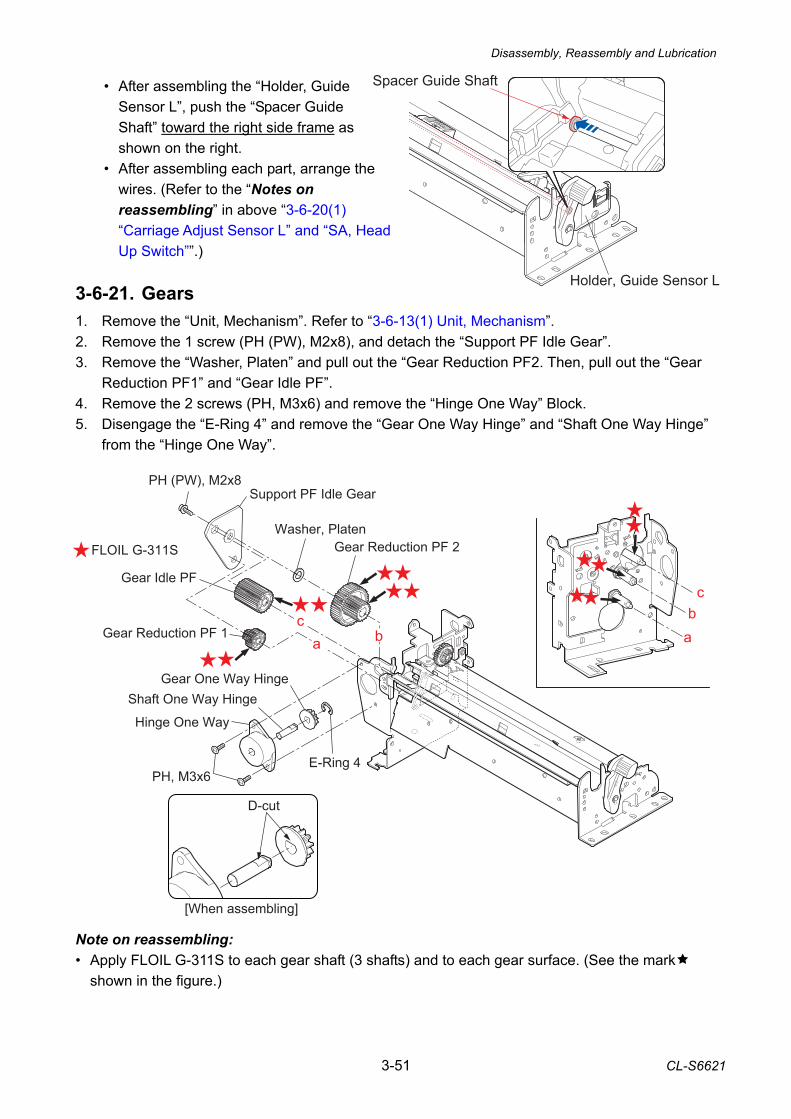
Disassembly, Reassembly and Lubrication
3-51 CL-S6621
• After assembling the “Holder, Guide Sensor L”, push the “Spacer Guide Shaft” toward the right side frame as shown on the right.
• After assembling each part, arrange the wires. (Refer to the “Notes on reassembling” in above “3-6-20(1) “Carriage Adjust Sensor L” and “SA, Head Up Switch””.)
3-6-21. Gears 1. Remove the “Unit, Mechanism”. Refer to “3-6-13(1) Unit, Mechanism”. 2. Remove the 1 screw (PH (PW), M2x8), and detach the “Support PF Idle Gear”. 3. Remove the “Washer, Platen” and pull out the “Gear Reduction PF2. Then, pull out the “Gear
Reduction PF1” and “Gear Idle PF”. 4. Remove the 2 screws (PH, M3x6) and remove the “Hinge One Way” Block. 5. Disengage the “E-Ring 4” and remove the “Gear One Way Hinge” and “Shaft One Way Hinge”
from the “Hinge One Way”. Note on reassembling: • Apply FLOIL G-311S to each gear shaft (3 shafts) and to each gear surface. (See the mark
shown in the figure.)
PH, M3x6
Hinge One Way
Shaft One Way HingeGear One Way Hinge
E-Ring 4
Gear Reduction PF 1
Gear Idle PF
Washer, PlatenGear Reduction PF 2
[When assembling]
D-cut
FLOIL G-311S
PH (PW), M2x8Support PF Idle Gear
a ab
c
bc
Holder, Guide Sensor L
Spacer Guide Shaft
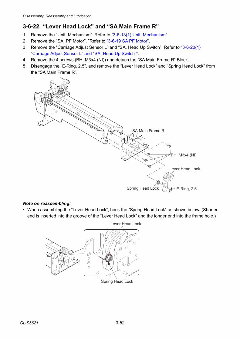
Disassembly, Reassembly and Lubrication
CL-S6621 3-52
3-6-22. “Lever Head Lock” and “SA Main Frame R” 1. Remove the “Unit, Mechanism”. Refer to “3-6-13(1) Unit, Mechanism”. 2. Remove the “SA, PF Motor”. ”Refer to “3-6-19 SA PF Motor”. 3. Remove the “Carriage Adjust Sensor L” and “SA, Head Up Switch”. Refer to “3-6-20(1)
“Carriage Adjust Sensor L” and “SA, Head Up Switch””. 4. Remove the 4 screws (BH, M3x4 (NI)) and detach the “SA Main Frame R” Block. 5. Disengage the “E-Ring, 2.5”, and remove the “Lever Head Lock” and “Spring Head Lock” from
the “SA Main Frame R”. Note on reassembling: • When assembling the “Lever Head Lock”, hook the “Spring Head Lock” as shown below. (Shorter
end is inserted into the groove of the “Lever Head Lock” and the longer end into the frame hole.)
Lever Head Lock
Spring Head Lock
SA Main Frame R
BH, M3x4 (NI)
Lever Head Lock
Spring Head Lock E-Ring, 2.5
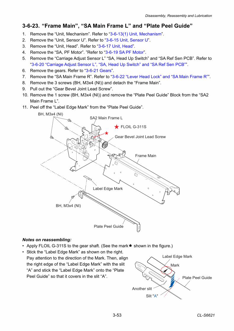
Disassembly, Reassembly and Lubrication
3-53 CL-S6621
Label Edge Mark
Mark
Slit "A"
Another slit
Plate Peel Guide
3-6-23. “Frame Main”, “SA Main Frame L” and “Plate Peel Guide” 1. Remove the “Unit, Mechanism”. Refer to “3-6-13(1) Unit, Mechanism”. 2. Remove the “Unit, Sensor U”. Refer to “3-6-15 Unit, Sensor U”. 3. Remove the “Unit, Head”. Refer to “3-6-17 Unit, Head”. 4. Remove the “SA, PF Motor”. ”Refer to “3-6-19 SA PF Motor”. 5. Remove the “Carriage Adjust Sensor L” “SA, Head Up Switch” and “SA Ref Sen PCB”. Refer to
“3-6-20 “Carriage Adjust Sensor L”, “SA, Head Up Switch” and “SA Ref Sen PCB””. 6. Remove the gears. Refer to “3-6-21 Gears”. 7. Remove the “SA Main Frame R”. Refer to “3-6-22 “Lever Head Lock” and “SA Main Frame R””. 8. Remove the 3 screws (BH, M3x4 (NI)) and detach the “Frame Main”. 9. Pull out the “Gear Bevel Joint Lead Screw”. 10. Remove the 1 screw (BH, M3x4 (NI)) and remove the “Plate Peel Guide” Block from the “SA2
Main Frame L”. 11. Peel off the “Label Edge Mark” from the “Plate Peel Guide”.
Notes on reassembling: • Apply FLOIL G-311S to the gear shaft. (See the mark shown in the figure.) • Stick the “Label Edge Mark” as shown on the right.
Pay attention to the direction of the Mark. Then, align the right edge of the “Label Edge Mark” with the slit “A” and stick the “Label Edge Mark” onto the “Plate Peel Guide” so that it covers in the slit “A”.
BH, M3x4 (NI)
Plate Peel Guide
Frame Main
SA2 Main Frame LBH, M3x4 (NI)
Gear Bevel Joint Lead Screw
Label Edge Mark
FLOIL G-311S
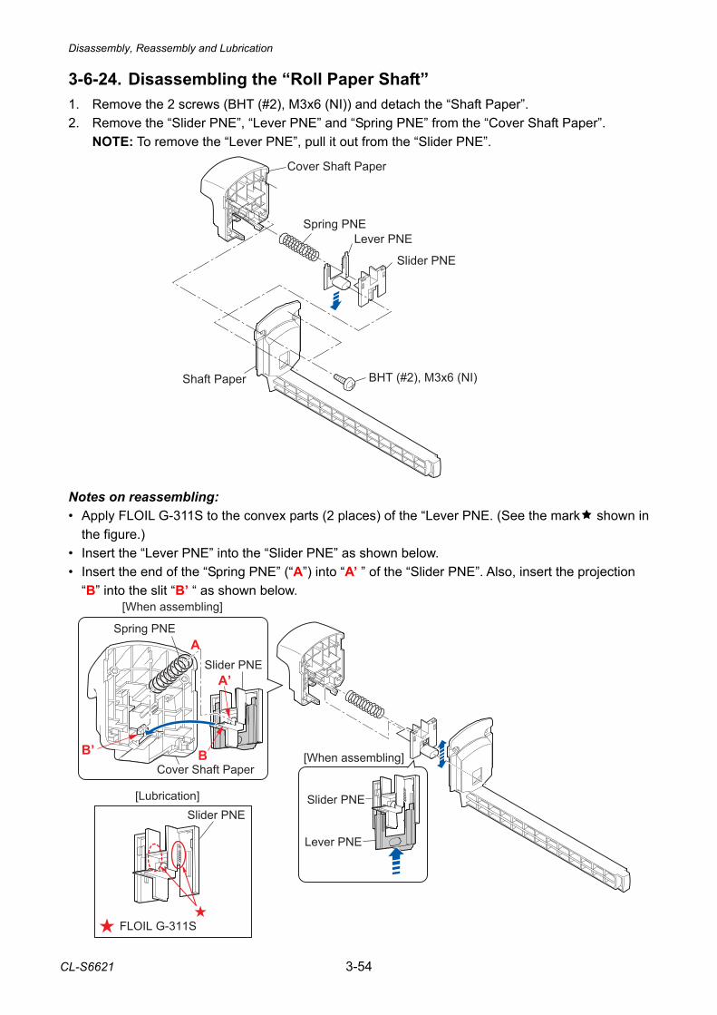
Disassembly, Reassembly and Lubrication
CL-S6621 3-54
3-6-24. Disassembling the “Roll Paper Shaft” 1. Remove the 2 screws (BHT (#2), M3x6 (NI)) and detach the “Shaft Paper”. 2. Remove the “Slider PNE”, “Lever PNE” and “Spring PNE” from the “Cover Shaft Paper”.
NOTE: To remove the “Lever PNE”, pull it out from the “Slider PNE”. Notes on reassembling: • Apply FLOIL G-311S to the convex parts (2 places) of the “Lever PNE. (See the mark shown in
the figure.) • Insert the “Lever PNE” into the “Slider PNE” as shown below. • Insert the end of the “Spring PNE” (“A”) into “A’ ” of the “Slider PNE”. Also, insert the projection
“B” into the slit “B’ “ as shown below.
Cover Shaft Paper
Spring PNELever PNE
Slider PNE
Shaft Paper BHT (#2), M3x6 (NI)
Lever PNE
Slider PNE
Slider PNE
Spring PNE
Cover Shaft Paper
Slider PNE
[When assembling]
[When assembling]
A’
B’
A
B
FLOIL G-311S
[Lubrication]
Adjustments
3-55 CL-S6621
3-7. Adjustments 3-7-1. Transparent/Reflective Sensor Position Adjustment When you replace one of the following parts, perform both sensor position adjustment and sensor sensitivity adjustment. • SA, Main PCB • SA TRA Sen PCB • SA Ref Sen PCB (1) Sensor position adjustment (factory mode)
After entering Factory mode, adjust the following submenu items: • Through Sensor Position • Reflect Sensor Position For details, refer to “2-3-2-(3-3)-(a) Factory mode menu table”.
(2) Sensor sensitivity adjustment (maintenance mode)
In this adjustment, since the printer has not a display, PC is used instead. All operations will be done with the keys on the printer’s control panel. Communication between the printer and a PC is made through the serial port.
(2-1) Preparation
Before starting adjustment, prepare the following items: • Media (both label paper and tag) (recommended media or media you use) • RS-232C serial cable • PC which is installed Terminal software such as HyperTerminal and TeraTerm.
Windows normally comes with the HyperTerminal. If the software is not installed, you need to install it.
* Windows® is a registered trademark of Microsoft Corporation in the United States and/or other countries.
Setting on the PC side: Make the following settings on the PC beforehand: 1. Connect the RS-232C serial cable between the printer and the PC. 2. On the PC, start the Terminal software. 3 Set the transmission conditions on the Terminal software so that they are identical to
those on the printer side. Default values of the printer: • Transmission speed (baud rate): 9,600 bps • Data length: 8 bits • Stop bit: 1 bit • Protocol: XON/XOFF
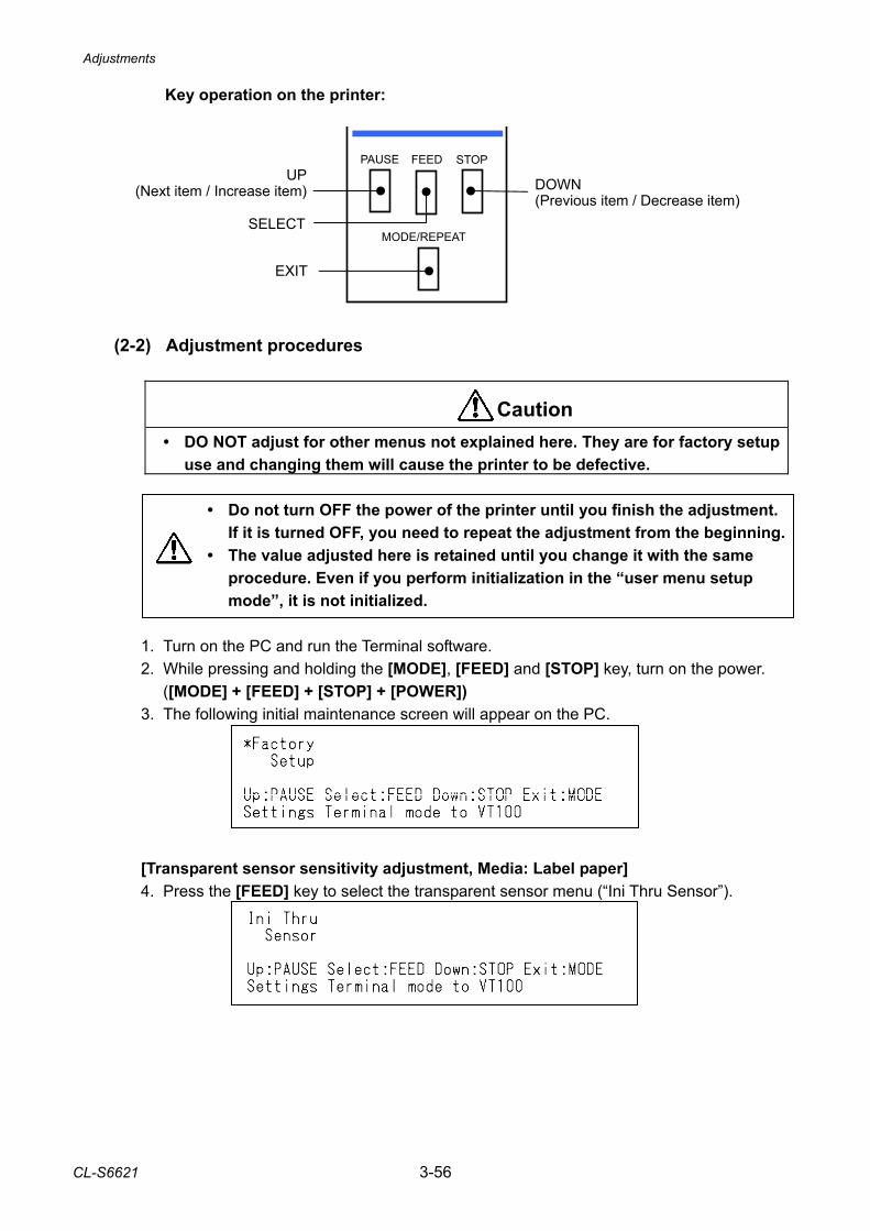
Adjustments
CL-S6621 3-56
Key operation on the printer:
(2-2) Adjustment procedures
• DO NOT adjust for other menus not explained here. They are for factory setup use and changing them will cause the printer to be defective.
• Do not turn OFF the power of the printer until you finish the adjustment.
If it is turned OFF, you need to repeat the adjustment from the beginning. • The value adjusted here is retained until you change it with the same
procedure. Even if you perform initialization in the “user menu setup mode”, it is not initialized.
1. Turn on the PC and run the Terminal software. 2. While pressing and holding the [MODE], [FEED] and [STOP] key, turn on the power. ([MODE] + [FEED] + [STOP] + [POWER]) 3. The following initial maintenance screen will appear on the PC.
[Transparent sensor sensitivity adjustment, Media: Label paper] 4. Press the [FEED] key to select the transparent sensor menu (“Ini Thru Sensor”).
PAUSE STOPFEED
MODE/REPEAT
DOWN(Previous item / Decrease item)
EXIT
UP(Next item / Increase item)
SELECT
Caution
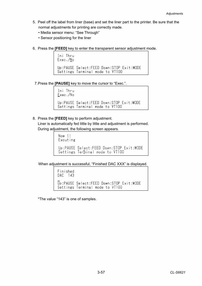
Adjustments
3-57 CL-S6621
5. Peel off the label from liner (base) and set the liner part to the printer. Be sure that the normal adjustments for printing are correctly made. • Media sensor menu: “See Through” • Sensor positioning for the liner
6. Press the [FEED] key to enter the transparent sensor adjustment mode.
7. Press the [PAUSE] key to move the cursor to “Exec.”.
8. Press the [FEED] key to perform adjustment. Liner is automatically fed little by little and adjustment is performed. During adjustment, the following screen appears.
When adjustment is successful, “Finished DAC XXX” is displayed.
*The value “143” is one of samples.
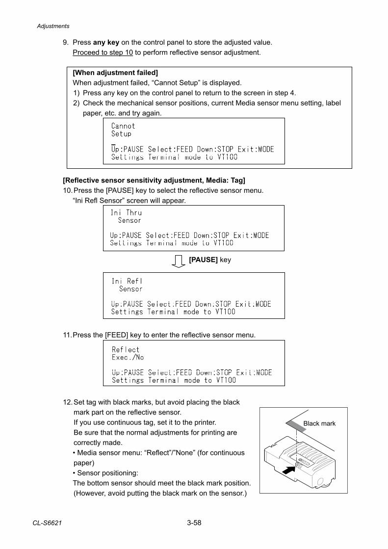
Adjustments
CL-S6621 3-58
9. Press any key on the control panel to store the adjusted value. Proceed to step 10 to perform reflective sensor adjustment. [When adjustment failed] When adjustment failed, “Cannot Setup” is displayed.
1) Press any key on the control panel to return to the screen in step 4. 2) Check the mechanical sensor positions, current Media sensor menu setting, label
paper, etc. and try again.
[Reflective sensor sensitivity adjustment, Media: Tag] 10. Press the [PAUSE] key to select the reflective sensor menu. “Ini Refl Sensor” screen will appear.
11. Press the [FEED] key to enter the reflective sensor menu.
12. Set tag with black marks, but avoid placing the black
mark part on the reflective sensor. If you use continuous tag, set it to the printer. Be sure that the normal adjustments for printing are correctly made.
• Media sensor menu: “Reflect”/”None” (for continuous paper)
• Sensor positioning: The bottom sensor should meet the black mark position.
(However, avoid putting the black mark on the sensor.)
[PAUSE] key
Black mark
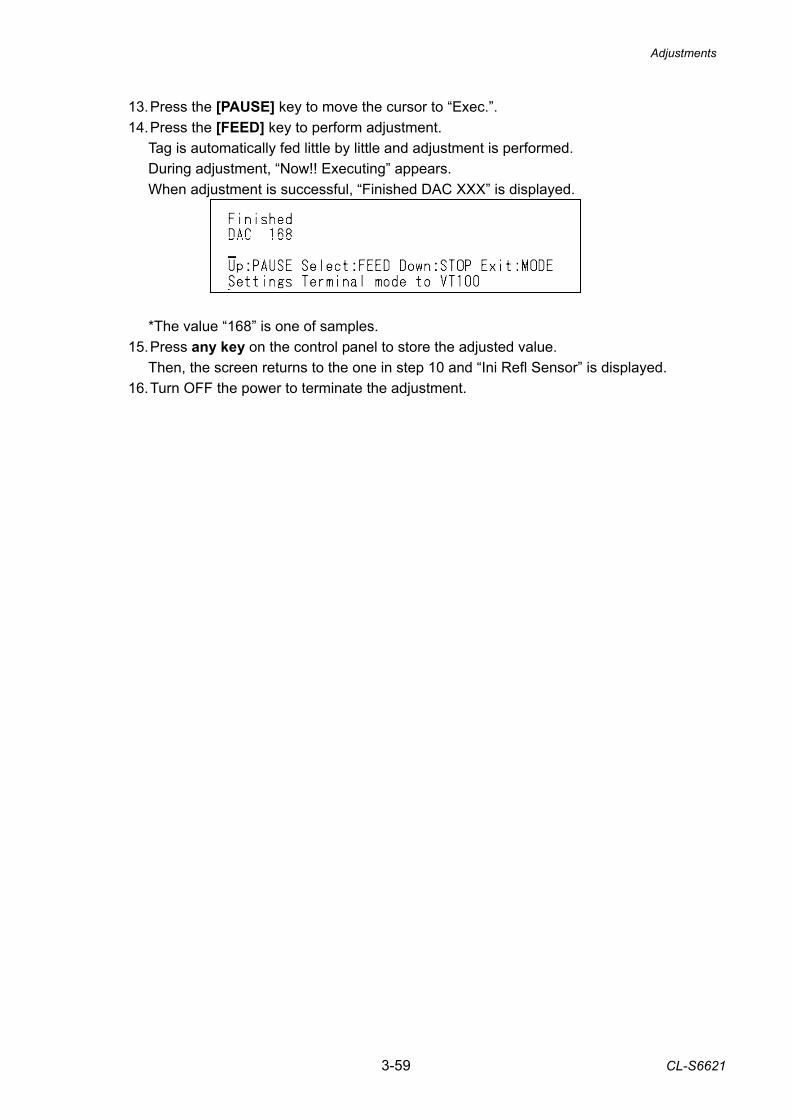
Adjustments
3-59 CL-S6621
13. Press the [PAUSE] key to move the cursor to “Exec.”. 14. Press the [FEED] key to perform adjustment. Tag is automatically fed little by little and adjustment is performed. During adjustment, “Now!! Executing” appears. When adjustment is successful, “Finished DAC XXX” is displayed.
*The value “168” is one of samples. 15. Press any key on the control panel to store the adjusted value. Then, the screen returns to the one in step 10 and “Ini Refl Sensor” is displayed. 16. Turn OFF the power to terminate the adjustment.
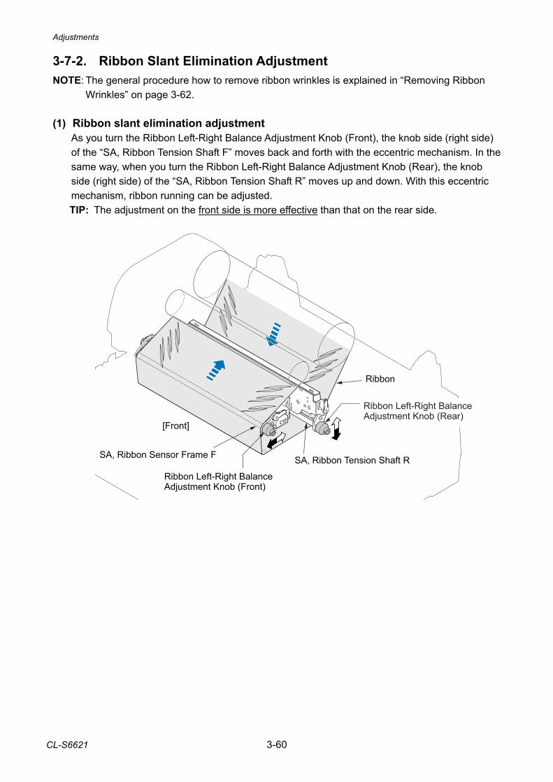
Adjustments
CL-S6621 3-60
3-7-2. Ribbon Slant Elimination Adjustment NOTE: The general procedure how to remove ribbon wrinkles is explained in “Removing Ribbon
Wrinkles2” on page 3-62.
(1) Ribbon slant elimination adjustment As you turn the Ribbon Left-Right Balance Adjustment Knob (Front), the knob side (right side) of the “SA, Ribbon Tension Shaft F” moves back and forth with the eccentric mechanism. In the same way, when you turn the Ribbon Left-Right Balance Adjustment Knob (Rear), the knob side (right side) of the “SA, Ribbon Tension Shaft R” moves up and down. With this eccentric mechanism, ribbon running can be adjusted. TIP: The adjustment on the front side is more effective than that on the rear side.
Ribbon
SA, Ribbon Tension Shaft R
Ribbon Left-Right Balance Adjustment Knob (Front)
Ribbon Left-Right BalanceAdjustment Knob (Rear)
SA, Ribbon Sensor Frame F
[Front]
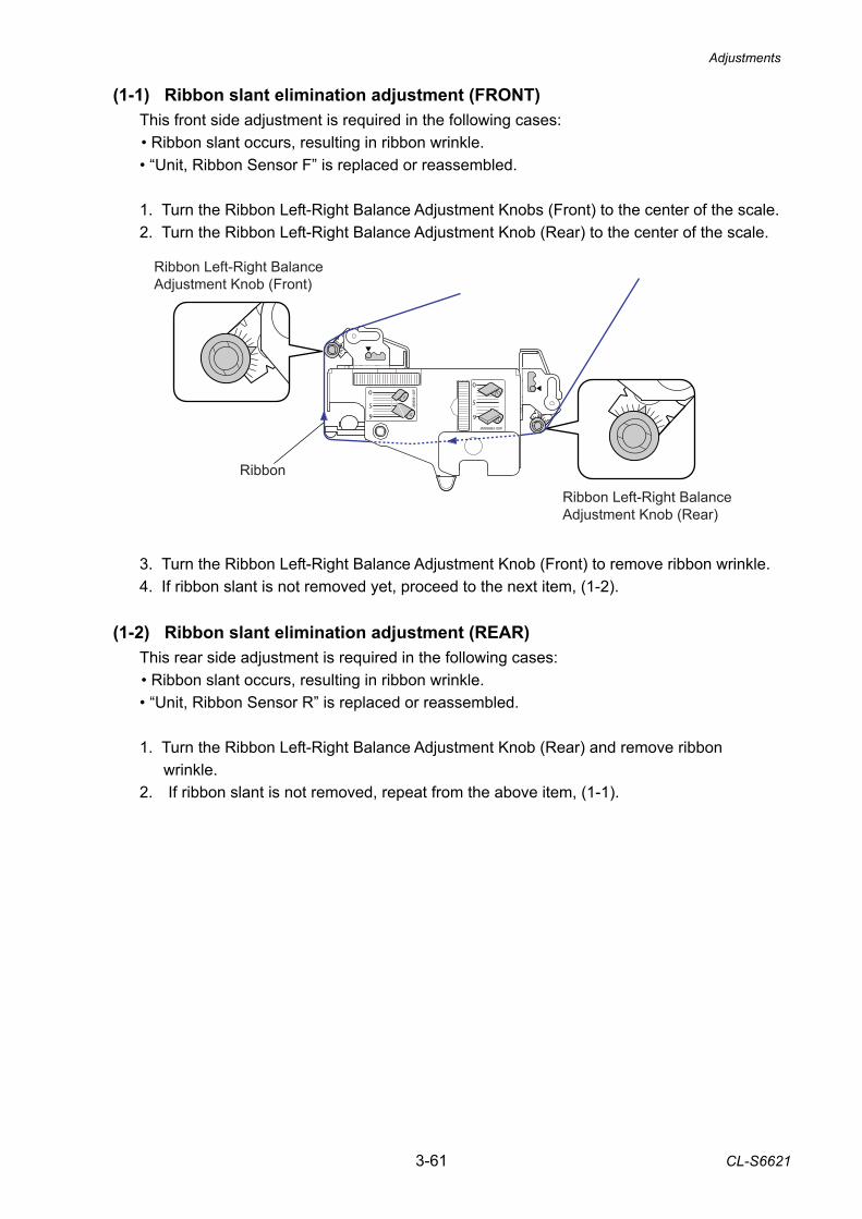
Adjustments
3-61 CL-S6621
(1-1) Ribbon slant elimination adjustment (FRONT) This front side adjustment is required in the following cases: • Ribbon slant occurs, resulting in ribbon wrinkle. • “Unit, Ribbon Sensor F” is replaced or reassembled. 1. Turn the Ribbon Left-Right Balance Adjustment Knobs (Front) to the center of the scale. 2. Turn the Ribbon Left-Right Balance Adjustment Knob (Rear) to the center of the scale.
3. Turn the Ribbon Left-Right Balance Adjustment Knob (Front) to remove ribbon wrinkle. 4. If ribbon slant is not removed yet, proceed to the next item, (1-2).
(1-2) Ribbon slant elimination adjustment (REAR) This rear side adjustment is required in the following cases: • Ribbon slant occurs, resulting in ribbon wrinkle. • “Unit, Ribbon Sensor R” is replaced or reassembled. 1. Turn the Ribbon Left-Right Balance Adjustment Knob (Rear) and remove ribbon
wrinkle. 2. If ribbon slant is not removed, repeat from the above item, (1-1).
Ribbon Left-Right Balance Adjustment Knob (Front)
Ribbon Left-Right Balance Adjustment Knob (Rear)
Ribbon
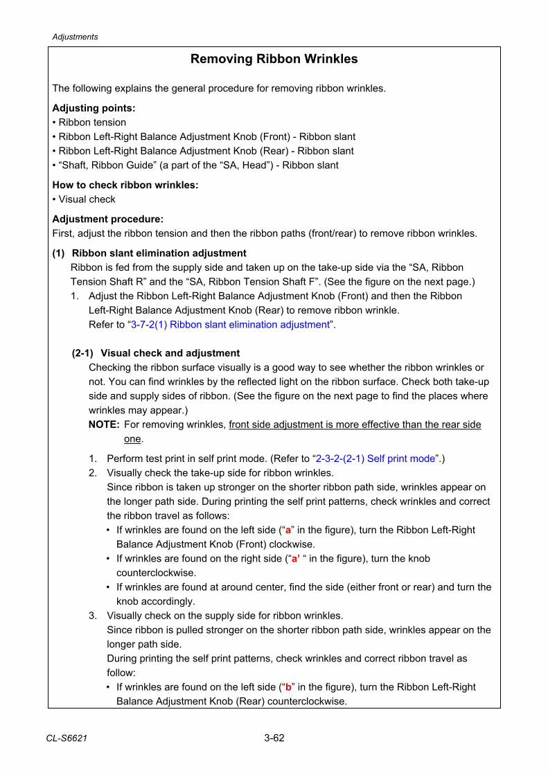
Adjustments
CL-S6621 3-62
Removing Ribbon Wrinkles
The following explains the general procedure for removing ribbon wrinkles. Adjusting points: • Ribbon tension • Ribbon Left-Right Balance Adjustment Knob (Front) - Ribbon slant • Ribbon Left-Right Balance Adjustment Knob (Rear) - Ribbon slant • “Shaft, Ribbon Guide” (a part of the “SA, Head”) - Ribbon slant How to check ribbon wrinkles: • Visual check Adjustment procedure: First, adjust the ribbon tension and then the ribbon paths (front/rear) to remove ribbon wrinkles. (1) Ribbon slant elimination adjustment
Ribbon is fed from the supply side and taken up on the take-up side via the “SA, Ribbon Tension Shaft R” and the “SA, Ribbon Tension Shaft F”. (See the figure on the next page.) 1. Adjust the Ribbon Left-Right Balance Adjustment Knob (Front) and then the Ribbon
Left-Right Balance Adjustment Knob (Rear) to remove ribbon wrinkle. Refer to “3-7-2(1) Ribbon slant elimination adjustment”.
(2-1) Visual check and adjustment
Checking the ribbon surface visually is a good way to see whether the ribbon wrinkles or not. You can find wrinkles by the reflected light on the ribbon surface. Check both take-up side and supply sides of ribbon. (See the figure on the next page to find the places where wrinkles may appear.) NOTE: For removing wrinkles, front side adjustment is more effective than the rear side
one.
1. Perform test print in self print mode. (Refer to “2-3-2-(2-1) Self print mode”.) 2. Visually check the take-up side for ribbon wrinkles.
Since ribbon is taken up stronger on the shorter ribbon path side, wrinkles appear on the longer path side. During printing the self print patterns, check wrinkles and correct the ribbon travel as follows: • If wrinkles are found on the left side (“a” in the figure), turn the Ribbon Left-Right
Balance Adjustment Knob (Front) clockwise. • If wrinkles are found on the right side (“a’ “ in the figure), turn the knob
counterclockwise. • If wrinkles are found at around center, find the side (either front or rear) and turn the
knob accordingly. 3. Visually check on the supply side for ribbon wrinkles.
Since ribbon is pulled stronger on the shorter ribbon path side, wrinkles appear on the longer path side. During printing the self print patterns, check wrinkles and correct ribbon travel as follow: • If wrinkles are found on the left side (“b” in the figure), turn the Ribbon Left-Right
Balance Adjustment Knob (Rear) counterclockwise.
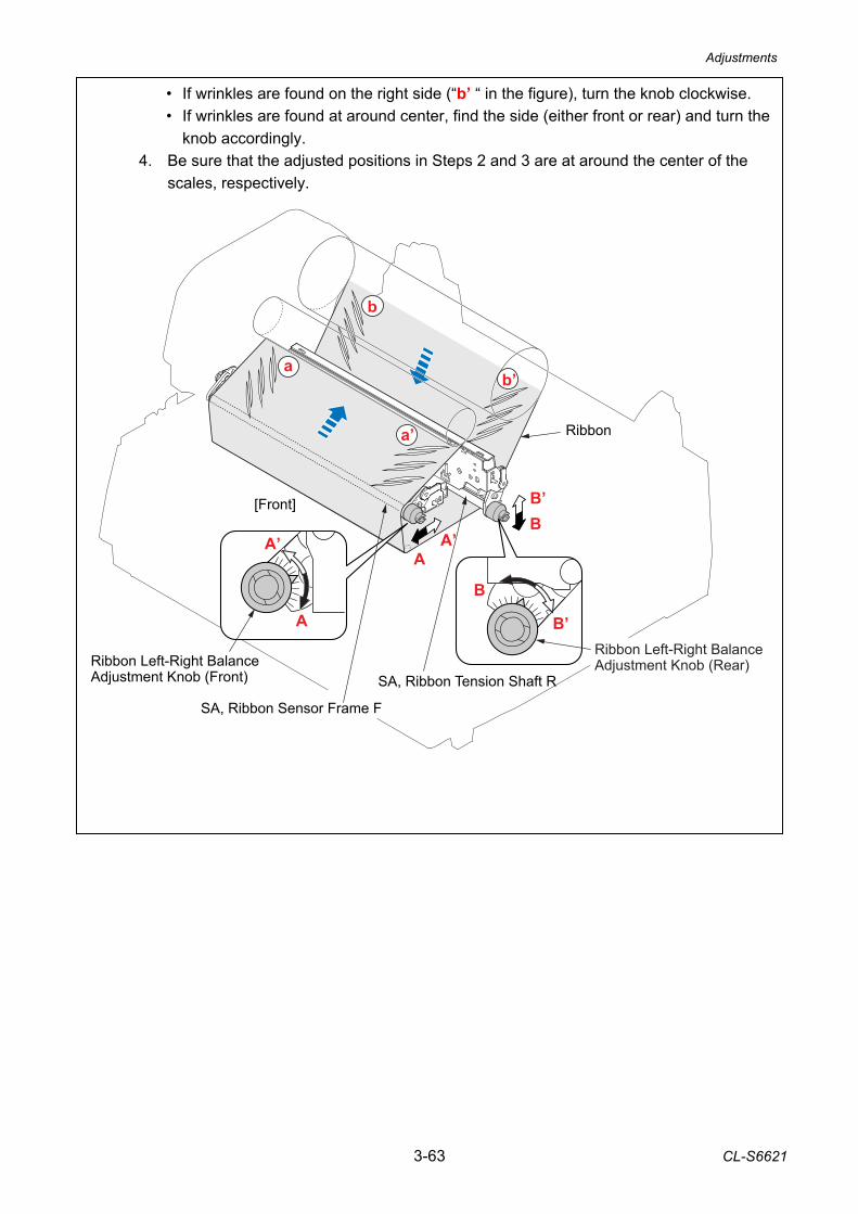
Adjustments
3-63 CL-S6621
b
a’
a
AA’
BB’
A
A’
B
B’
SA, Ribbon Sensor Frame F
SA, Ribbon Tension Shaft R
Ribbon Left-Right BalanceAdjustment Knob (Rear)Ribbon Left-Right Balance
Adjustment Knob (Front)
[Front]
b’
Ribbon
• If wrinkles are found on the right side (“b’ “ in the figure), turn the knob clockwise. • If wrinkles are found at around center, find the side (either front or rear) and turn the
knob accordingly. 4. Be sure that the adjusted positions in Steps 2 and 3 are at around the center of the
scales, respectively.
4-1 CL-S6621
CHAPTER 4 TROUBLESHOOTING
CL-S6621 4-2
CHAPTER 4 TROUBLESHOOTING
TABLE OF CONTENTS 4-1. Error Message and Corrective Actions ........................................................................... 4-3 4-2. Troubleshooting .............................................................................................................. 4-5
4-2-1. Problems in Powering Up the Printer ................................................................. 4-5 4-2-2. Media-feed Problems ......................................................................................... 4-6 4-2-3. Problems in Printing ........................................................................................... 4-7 4-2-4. Ribbon-feed Problem ......................................................................................... 4-8 4-2-5. Sensor Problems................................................................................................ 4-10 4-2-6. Operation Panel Problems ................................................................................. 4-12 4-2-7. Connector Location ............................................................................................ 4-13
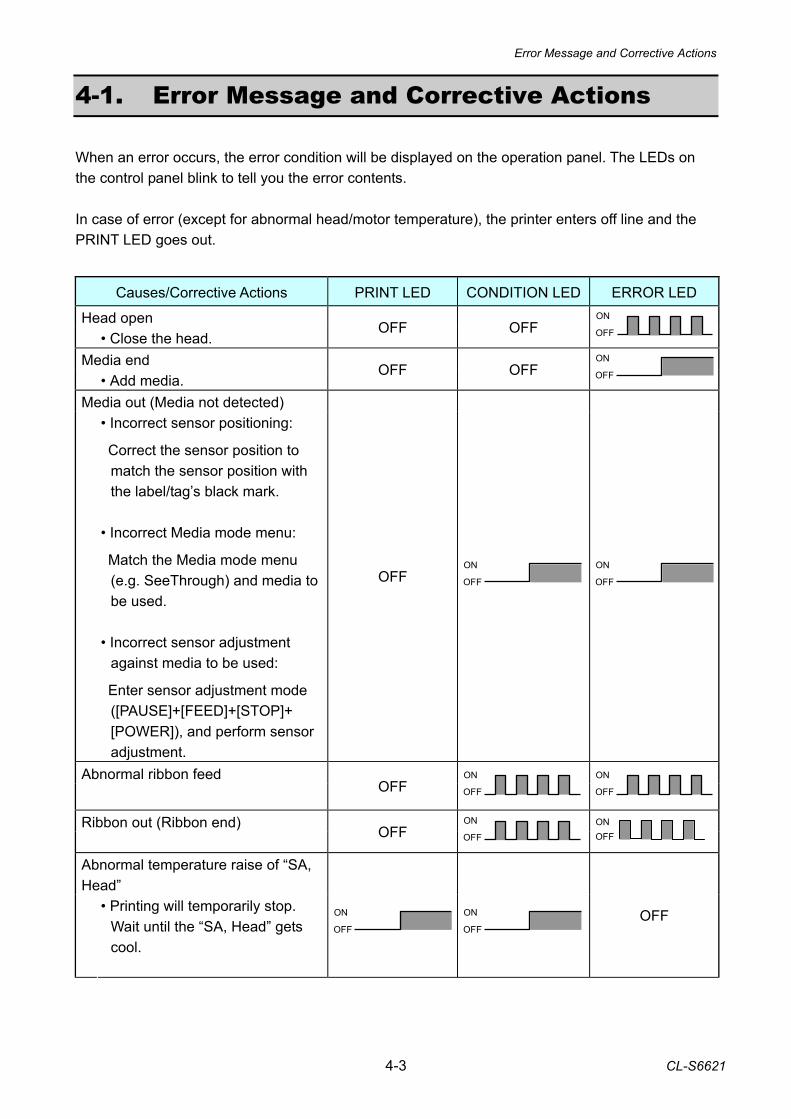
Error Message and Corrective Actions
4-3 CL-S6621
4-1. Error Message and Corrective Actions When an error occurs, the error condition will be displayed on the operation panel. The LEDs on the control panel blink to tell you the error contents. In case of error (except for abnormal head/motor temperature), the printer enters off line and the PRINT LED goes out.
Causes/Corrective Actions PRINT LED CONDITION LED ERROR LED
Head open • Close the head.
OFF OFF OFF
ON
Media end • Add media.
OFF OFF OFF
ON
Media out (Media not detected)
• Incorrect sensor positioning: Correct the sensor position to
match the sensor position with the label/tag’s black mark.
• Incorrect Media mode menu: Match the Media mode menu
(e.g. SeeThrough) and media to be used.
• Incorrect sensor adjustment
against media to be used: Enter sensor adjustment mode
([PAUSE]+[FEED]+[STOP]+ [POWER]), and perform sensor adjustment.
OFF OFF
ON
OFF
ON
Abnormal ribbon feed
OFF OFF
ON
OFF
ON
Ribbon out (Ribbon end)
OFF OFF
ON
OFF ON
Abnormal temperature raise of “SA, Head”
• Printing will temporarily stop. Wait until the “SA, Head” gets cool.
OFF
ON OFF
ON
OFF
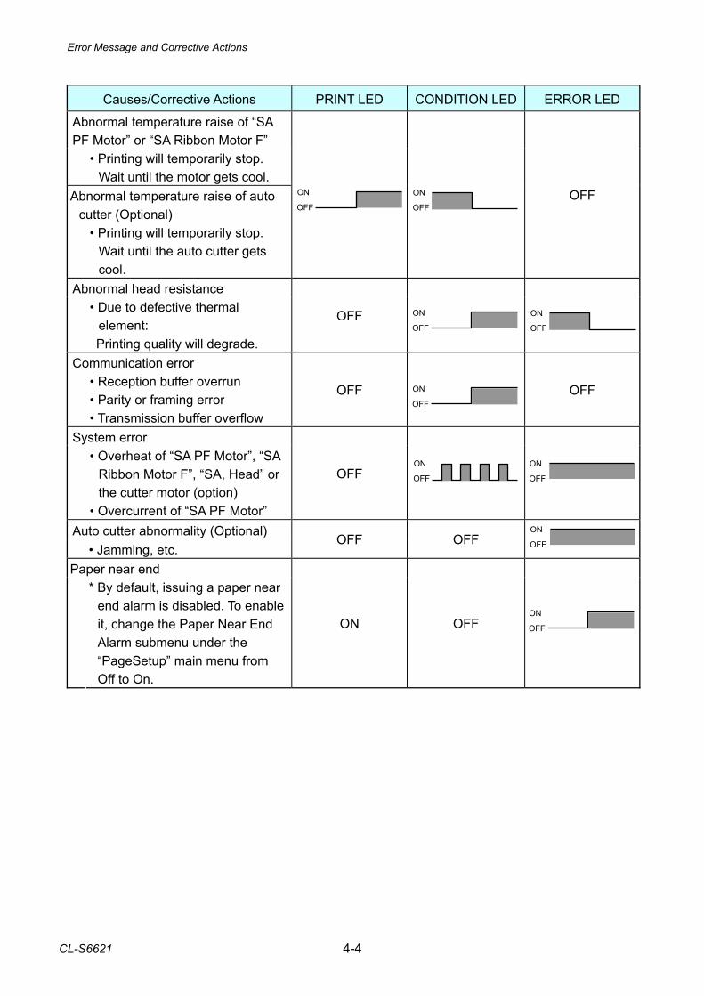
Error Message and Corrective Actions
CL-S6621 4-4
Causes/Corrective Actions PRINT LED CONDITION LED ERROR LED
Abnormal temperature raise of “SA PF Motor” or “SA Ribbon Motor F”
• Printing will temporarily stop. Wait until the motor gets cool.
Abnormal temperature raise of auto cutter (Optional)
• Printing will temporarily stop.
Wait until the auto cutter gets cool.
OFF
ON OFF
ON
OFF
Abnormal head resistance
• Due to defective thermal element:
Printing quality will degrade.
OFF OFF
ON
OFF
ON
Communication error
• Reception buffer overrun • Parity or framing error • Transmission buffer overflow
OFF
OFF
ON
OFF
System error
• Overheat of “SA PF Motor”, “SA Ribbon Motor F”, “SA, Head” or the cutter motor (option)
• Overcurrent of “SA PF Motor”
OFF OFF
ON
OFF
ON
Auto cutter abnormality (Optional) • Jamming, etc.
OFF OFF OFF
ON
Paper near end
* By default, issuing a paper near end alarm is disabled. To enable it, change the Paper Near End Alarm submenu under the “PageSetup” main menu from Off to On.
ON OFF OFF
ON
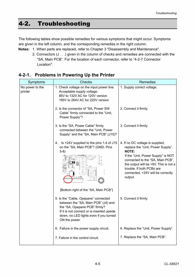
Troubleshooting
4-5 CL-S6621
4-2. Troubleshooting The following tables show possible remedies for various symptoms that might occur. Symptoms are given in the left column, and the corresponding remedies in the right column. Notes: 1. When parts are replaced, refer to Chapter 3 "Disassembly and Maintenance". 2. Connectors (J . . .) given in the column of checks and remedies are connected with the
“SA, Main PCB”. For the location of each connector, refer to “4-2-7 Connector Location".
4-2-1. Problems in Powering Up the Printer
Symptoms Checks Remedies No power to the printer
1. Check voltage on the input power line. Acceptable supply voltage: 85V to 132V AC for 120V version 185V to 264V AC for 220V version
2. Is the connector of “SA, Power SW
Cable” firmly connected to the “Unit, Power Supply”?
3. Is the “SA, Power Cable” firmly
connected between the “Unit, Power Supply” and the “SA, Main PCB” (J15)?
4. Is +24V supplied to the pins 1-4 of J15
on the “SA, Main PCB”? (GND: Pins 5-8)
[Bottom right of the “SA, Main PCB”] 5. Is the “Cable, Opepane” connected
between the “SA, Main PCB” (J4) and the “SA, Opepane PCB” firmly? If it is not connect or is inserted upside down, no LED lights even if you turned ON the power.
6. Failure in the power supply circuit.
7. Failure in the control circuit.
1. Supply correct voltage. 2. Connect it firmly. 3. Connect it firmly. 4. If no DC voltage is supplied,
replace the “Unit, Power Supply”. NOTE: If the “Unit, Power Supply” is NOT connected to the “SA, Main PCB”, the output will be +9V. This is not a trouble. If both PCBs are connected, +24V will be correctly output.
5. Connect it firmly. 6. Replace the “Unit, Power Supply”. 7. Replace the “SA, Main PCB”.
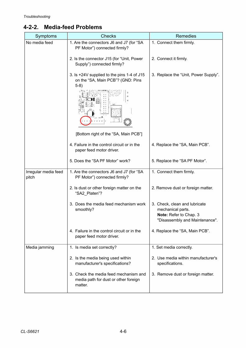
Troubleshooting
CL-S6621 4-6
4-2-2. Media-feed Problems Symptoms Checks Remedies
No media feed
1. Are the connectors J6 and J7 (for “SA PF Motor”) connected firmly?
2. Is the connector J15 (for “Unit, Power
Supply”) connected firmly? 3. Is +24V supplied to the pins 1-4 of J15
on the “SA, Main PCB”? (GND: Pins 5-8)
[Bottom right of the “SA, Main PCB”] 4. Failure in the control circuit or in the
paper feed motor driver. 5. Does the “SA PF Motor” work?
1. Connect them firmly. 2. Connect it firmly. 3. Replace the “Unit, Power Supply”. 4. Replace the “SA, Main PCB”. 5. Replace the “SA PF Motor”.
Irregular media feed pitch
1. Are the connectors J6 and J7 (for “SA PF Motor”) connected firmly?
2. Is dust or other foreign matter on the
“SA2_Platen”? 3. Does the media feed mechanism work
smoothly? 4. Failure in the control circuit or in the
paper feed motor driver.
1. Connect them firmly. 2. Remove dust or foreign matter. 3. Check, clean and lubricate
mechanical parts. Note: Refer to Chap. 3
"Disassembly and Maintenance". 4. Replace the “SA, Main PCB”.
Media jamming 1. Is media set correctly? 2. Is the media being used within
manufacturer's specifications? 3. Check the media feed mechanism and
media path for dust or other foreign matter.
1. Set media correctly. 2. Use media within manufacturer's
specifications. 3. Remove dust or foreign matter.
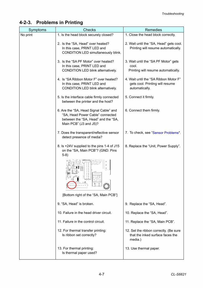
Troubleshooting
4-7 CL-S6621
4-2-3. Problems in Printing Symptoms Checks Remedies
No print
1. Is the head block securely closed? 2. Is the “SA, Head” over heated?
In this case, PRINT LED and CONDITION LED simultaneously blink.
3. Is the “SA PF Motor” over heated?
In this case, PRINT LED and CONDITION LED blink alternatively.
4. Is “SA Ribbon Motor F” over heated?
In this case, PRINT LED and CONDITION LED blink alternatively.
5. Is the interface cable firmly connected
between the printer and the host? 6. Are the “SA, Head Signal Cable” and
“SA, Head Power Cable” connected between the “SA, Head” and the “SA, Main PCB” (J3 and J5)?
7. Does the transparent/reflective sensor
detect presence of media? 8. Is +24V supplied to the pins 1-4 of J15
on the “SA, Main PCB”? (GND: Pins 5-8)
[Bottom right of the “SA, Main PCB”] 9. “SA, Head” is broken. 10. Failure in the head driver circuit. 11. Failure in the control circuit. 12. For thermal transfer printing:
Is ribbon set correctly? 13. For thermal printing:
Is thermal paper used?
1. Close the head block correctly. 2. Wait until the “SA, Head” gets cool.
Printing will resume automatically. 3. Wait until the “SA PF Motor” gets
cool. Printing will resume automatically. 4. Wait until the “SA Ribbon Motor F”
gets cool. Printing will resume automatically.
5. Connect it firmly. 6. Connect them firmly. 7. To check, see “Sensor Problems". 8. Replace the “Unit, Power Supply”. 9. Replace the “SA, Head”. 10. Replace the “SA, Head”. 11. Replace the “SA, Main PCB”. 12. Set the ribbon correctly. (Be sure
that the inked surface faces the media.)
13. Use thermal paper.
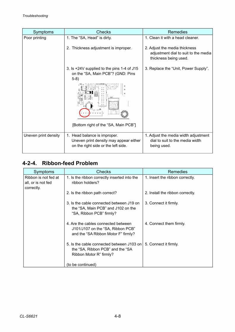
Troubleshooting
CL-S6621 4-8
Symptoms Checks Remedies
Poor printing 1. The “SA, Head” is dirty. 2. Thickness adjustment is improper. 3. Is +24V supplied to the pins 1-4 of J15
on the “SA, Main PCB”? (GND: Pins 5-8)
[Bottom right of the “SA, Main PCB”]
1. Clean it with a head cleaner. 2. Adjust the media thickness
adjustment dial to suit to the media thickness being used.
3. Replace the “Unit, Power Supply”.
Uneven print density 1. Head balance is improper. Uneven print density may appear either
on the right side or the left side.
1. Adjust the media width adjustment dial to suit to the media width being used.
4-2-4. Ribbon-feed Problem
Symptoms Checks Remedies Ribbon is not fed at all, or is not fed correctly.
1. Is the ribbon correctly inserted into the ribbon holders?
2. Is the ribbon path correct? 3. Is the cable connected between J19 on
the “SA, Main PCB” and J102 on the “SA, Ribbon PCB” firmly?
4. Are the cables connected between
J101/J107 on the “SA, Ribbon PCB” and the “SA Ribbon Motor F” firmly?
5. Is the cable connected between J103 on
the “SA, Ribbon PCB” and the “SA Ribbon Motor R” firmly?
(to be continued)
1. Insert the ribbon correctly. 2. Install the ribbon correctly. 3. Connect it firmly. 4. Connect them firmly. 5. Connect it firmly.
Troubleshooting
4-9 CL-S6621
Symptoms Checks Remedies Ribbon is not fed at all, or is not fed correctly.
6. Does the ribbon cooling fan work correctly for cooling the ribbon motors? If not, check if the cable of the “SA, Fan” is firmly connected to the “SA, Ribbon PCB” (J106). Note: The fan does not turn all the time. It turns when the temperature of the “SA Ribbon Motor F” on the front side exceeds a certain value.
7. Do the ribbon sensors on the front and
rear sides work correctly? See “4-2-5 Sensor Problems”.
8. Do the ribbon drive gears work
correctly? 9. Does the “SA Ribbon Motor F”/“SA
Ribbon Motor R” work correctly? 10. Failure in the ribbon motor drive circuit. 11. Failure in the ribbon motor control
circuit.
6. Connect the cable firmly. 7. Replace the “SA, Ribbon Sensor”
on the front/rear side. 8. Replace a defective ribbon gear. 9. Replace the “SA Ribbon Motor F”/
“SA Ribbon Motor R”. 10. Replace the “SA, Ribbon PCB”. 11. Replace the “SA, Main PCB”.
Ribbon slants.
1. Is the ribbon correctly inserted into the ribbon holders?
2. Is the ribbon path correct? 3. Is the ribbon slant elimination
adjustment made?
1. Insert the ribbon correctly. 2. Install the ribbon correctly. 3. Adjust it according to “3-7-2 Ribbon
Slant Elimination Adjustment”.
Troubleshooting
CL-S6621 4-10
4-2-5. Sensor Problems Symptoms Checks Remedies
Head block is closed, but head open error is indicated by LEDs. (Head up switch problem)
1. Is the connector of “SA, Head Up Switch” firmly connected to the “SA, Main PCB” (J11)?
2. Does the head up switch activating
mechanism push the switch lever and the switch turn ON properly?
3. Failure in the control circuit.
1. Connect it firmly. 2. Replace the “SA, Head Up
Switch”. 3. Replace the “SA, Main PCB”.
Ribbon tension is not correctly controlled. (Front/rear side of “SA, Ribbon Sensor” problem)
1. Is the connector of “SA, Ribbon Sensor”on the front side firmly connected to the “SA, Ribbon PCB” (J104)?
2. Is the connector of “SA, Ribbon Sensor”
on the rear side firmly connected to the “SA, Ribbon PCB” (J105)?
3. Does the “SA, Ribbon Sensor” on the
front/rear side work correctly?
4. Failure in the control circuit.
1. Connect it firmly. 2. Connect it firmly. 3. Replace the “SA, Ribbon Sensor”
on the front/rear side.
4. Replace the “SA, Ribbon PCB” or the “SA, Main PCB”.
Ribbon end is not correctly detected. (Rear side of “SA, Ribbon Sensor” problem)
1. Is the connector of the “SA, Ribbon Sensor” on the rear side firmly connected to the “SA, Ribbon PCB” (J105)?
2. Does the “SA, Ribbon Sensor” on the
rear side work correctly? 3. Failure in the control circuit.
1. Connect it firmly. 2. Replace the “SA, Ribbon Sensor”
on the rear side.
3. Replace the “SA, Ribbon PCB” or the “SA, Main PCB”.
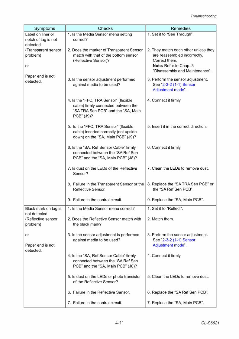
Troubleshooting
4-11 CL-S6621
Symptoms Checks Remedies
Label on liner or notch of tag is not detected. (Transparent sensor problem) or Paper end is not detected.
1. Is the Media Sensor menu setting correct?
2. Does the marker of Transparent Sensor
match with that of the bottom sensor (Reflective Sensor)?
3. Is the sensor adjustment performed
against media to be used? 4. Is the “FFC, TRA Sensor” (flexible
cable) firmly connected between the “SA TRA Sen PCB” and the “SA, Main PCB” (J9)?
5. Is the “FFC, TRA Sensor” (flexible
cable) inserted correctly (not upside down) on the “SA, Main PCB” (J9)?
6. Is the “SA, Ref Sensor Cable” firmly
connected between the “SA Ref Sen PCB” and the “SA, Main PCB” (J8)?
7. Is dust on the LEDs of the Reflective
Sensor? 8. Failure in the Transparent Sensor or the
Reflective Sensor. 9. Failure in the control circuit.
1. Set it to “See Through”. 2. They match each other unless they
are reassembled incorrectly. Correct them.
Note: Refer to Chap. 3 "Disassembly and Maintenance".
3. Perform the sensor adjustment.
See “2-3-2 (1-1) Sensor Adjustment mode”.
4. Connect it firmly. 5. Insert it in the correct direction. 6. Connect it firmly. 7. Clean the LEDs to remove dust. 8. Replace the “SA TRA Sen PCB” or
the “SA Ref Sen PCB”. 9. Replace the “SA, Main PCB”.
Black mark on tag is not detected. (Reflective sensor problem) or Paper end is not detected.
1. Is the Media Sensor menu correct? 2. Does the Reflective Sensor match with
the black mark? 3. Is the sensor adjustment is performed
against media to be used? 4. Is the “SA, Ref Sensor Cable” firmly
connected between the “SA Ref Sen PCB” and the “SA, Main PCB” (J8)?
5. Is dust on the LEDs or photo transistor
of the Reflective Sensor? 6. Failure in the Reflective Sensor. 7. Failure in the control circuit.
1. Set it to “Reflect”. 2. Match them. 3. Perform the sensor adjustment.
See “2-3-2 (1-1) Sensor Adjustment mode”.
4. Connect it firmly. 5. Clean the LEDs to remove dust. 6. Replace the “SA Ref Sen PCB”. 7. Replace the “SA, Main PCB”.
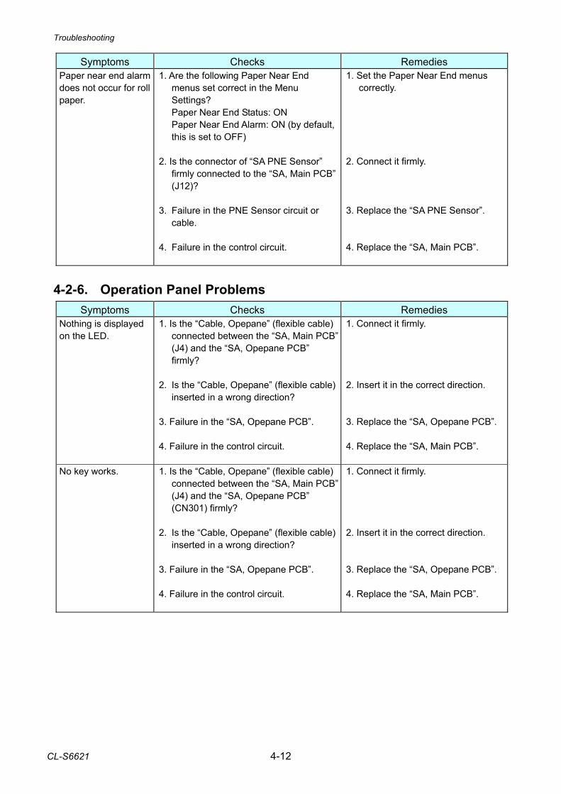
Troubleshooting
CL-S6621 4-12
Symptoms Checks Remedies Paper near end alarm does not occur for roll paper.
1. Are the following Paper Near End menus set correct in the Menu Settings? Paper Near End Status: ON Paper Near End Alarm: ON (by default, this is set to OFF)
2. Is the connector of “SA PNE Sensor”
firmly connected to the “SA, Main PCB” (J12)?
3. Failure in the PNE Sensor circuit or
cable. 4. Failure in the control circuit.
1. Set the Paper Near End menus correctly.
2. Connect it firmly. 3. Replace the “SA PNE Sensor”. 4. Replace the “SA, Main PCB”.
4-2-6. Operation Panel Problems
Symptoms Checks Remedies Nothing is displayed on the LED.
1. Is the “Cable, Opepane” (flexible cable) connected between the “SA, Main PCB”(J4) and the “SA, Opepane PCB” firmly?
2. Is the “Cable, Opepane” (flexible cable)
inserted in a wrong direction? 3. Failure in the “SA, Opepane PCB”. 4. Failure in the control circuit.
1. Connect it firmly. 2. Insert it in the correct direction. 3. Replace the “SA, Opepane PCB”. 4. Replace the “SA, Main PCB”.
No key works.
1. Is the “Cable, Opepane” (flexible cable) connected between the “SA, Main PCB”(J4) and the “SA, Opepane PCB” (CN301) firmly?
2. Is the “Cable, Opepane” (flexible cable)
inserted in a wrong direction? 3. Failure in the “SA, Opepane PCB”. 4. Failure in the control circuit.
1. Connect it firmly. 2. Insert it in the correct direction. 3. Replace the “SA, Opepane PCB”. 4. Replace the “SA, Main PCB”.
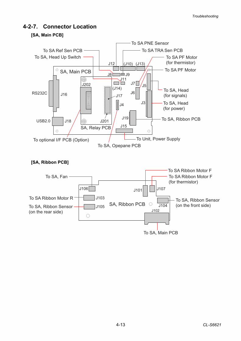
Troubleshooting
4-13 CL-S6621
J106
J103
J105
J101 J107
J104J102
To SA Ribbon Motor F(for thermistor)
To SA, Main PCB
To SA Ribbon Motor F
To SA, Ribbon Sensor(on the front side)To SA, Ribbon Sensor
(on the rear side)
To SA Ribbon Motor R
To SA, Fan
SA, Ribbon PCB
J12 (J10) (J13)
J5
J3
J7
J6
J4
J19
J15
J17
J201
J202(J14)
J16
J18USB2.0
RS232C
J8 J9J11
SA, Main PCB
To SA PF Motor(for thermistor)
To Unit, Power SupplyTo SA, Opepane PCB
To SA, Head(for signals)
To SA TRA Sen PCBTo SA Ref Sen PCBTo SA, Head Up Switch
To SA, Ribbon PCB
To optional I/F PCB (Option)
To SA, Head(for power)
To SA PF Motor
To SA PNE Sensor
SA, Relay PCB
4-2-7. Connector Location [SA, Main PCB]
[SA, Ribbon PCB]
5-1 CL-S6621
CHAPTER 5 PARTS LISTS
CL-S6621 5-2
CHAPTER 5 PARTS LIST
TABLE OF CONTENTS
Recommended Spare Parts List .............................................................................................. 5-3 Mechanical Section
General Assembly (Drawing No. 1) ................................................................................ 5-5 Unit, Base (Drawing No. 2) ............................................................................................. 5-9 Unit, Mechanism (Drawing No. 3)................................................................................... 5-14 Unit, Head (Drawing No. 4)............................................................................................. 5-17 Unit, PF (Drawing No. 5)................................................................................................. 5-21 Unit, Sensor U (Drawing No. 6) ...................................................................................... 5-26 Unit, Control Panel (Drawing No. 7) ............................................................................... 5-30 Unit, Ribbon (Drawing No. 8).......................................................................................... 5-33 SA2, Ribbon Unit Fan (Drawing No. 9)........................................................................... 5-37 Accessories (Drawing No. 10) ........................................................................................ 5-40
Chapter 5. Parts Lists
CL-S6621 5-3
CL-S6621
Recommended Spare Parts List
Revision Up List
Sheet No. Rev. No. Date
1/1 0 Mar. 12, 2013
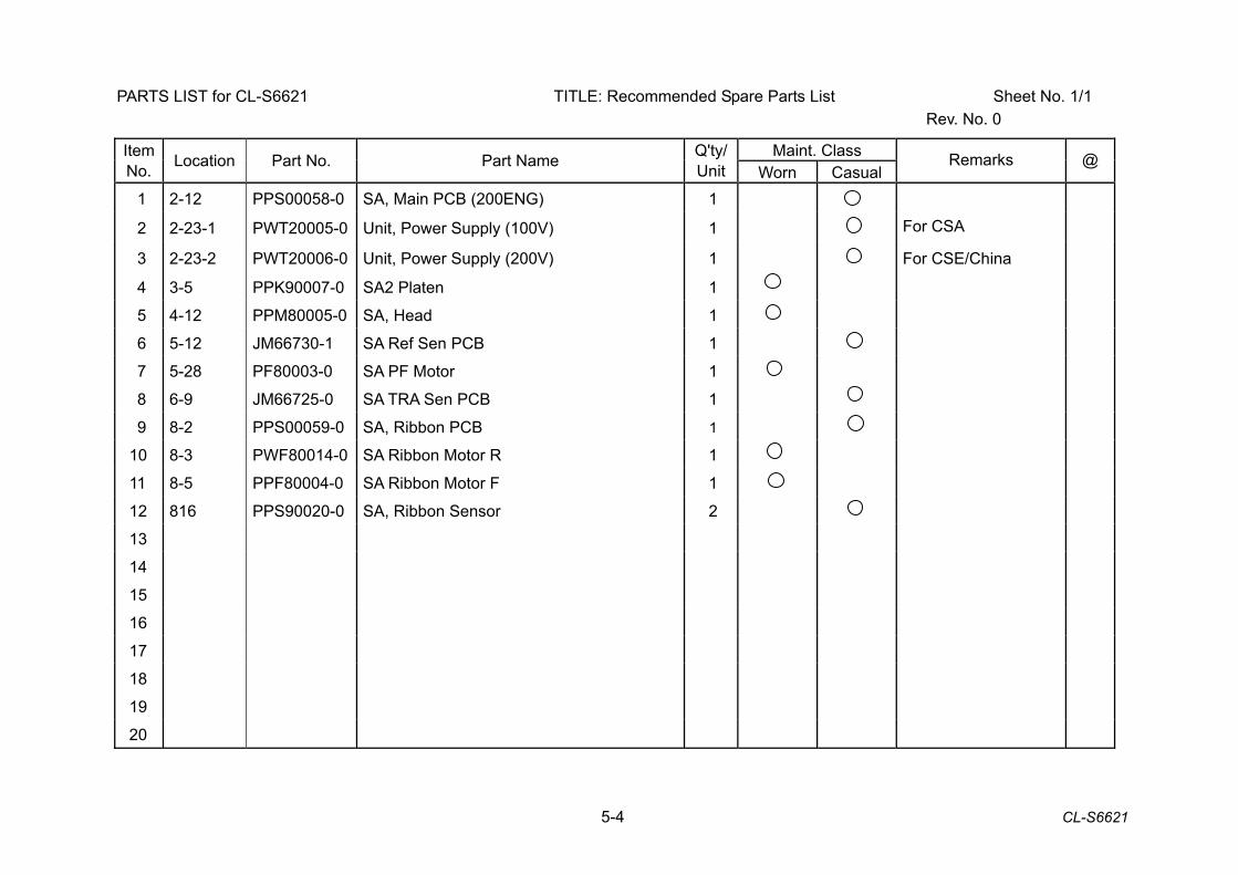
5-4 CL-S6621
PARTS LIST for CL-S6621 TITLE: Recommended Spare Parts List Sheet No. 1/1 Rev. No. 0
Maint. Class Item No. Location Part No. Part Name Q'ty/
Unit Worn Casual Remarks @
1 2-12 PPS00058-0 SA, Main PCB (200ENG) 1
2 2-23-1 PWT20005-0 Unit, Power Supply (100V) 1 For CSA
3 2-23-2 PWT20006-0 Unit, Power Supply (200V) 1 For CSE/China
4 3-5 PPK90007-0 SA2 Platen 1
5 4-12 PPM80005-0 SA, Head 1
6 5-12 JM66730-1 SA Ref Sen PCB 1
7 5-28 PF80003-0 SA PF Motor 1
8 6-9 JM66725-0 SA TRA Sen PCB 1
9 8-2 PPS00059-0 SA, Ribbon PCB 1
10 8-3 PWF80014-0 SA Ribbon Motor R 1
11 8-5 PPF80004-0 SA Ribbon Motor F 1
12 816 PPS90020-0 SA, Ribbon Sensor 2
13
14
15
16
17
18
19
20

Chapter 5. Parts Lists
CL-S6621 5-5
CL-S6621 Drawing No. 1 Parts List & Location for General Assembly
Revision Up List
Sheet No. Rev. No. Date
1/2 0 Mar. 12, 2013
2/2 0 Mar. 12, 2013
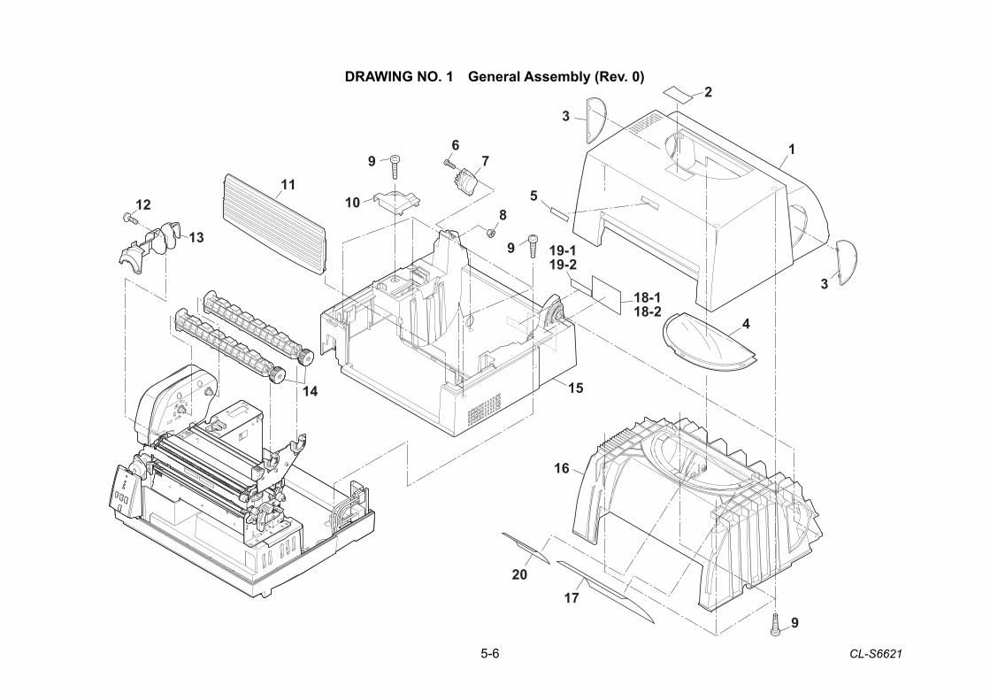
5-6 CL-S6621
DRAWING NO. 1 General Assembly (Rev. 0)
12
13
119
67
8
9
10
14
4
1720
9
16
23
3
1
15
5
19-119-2
18-118-2
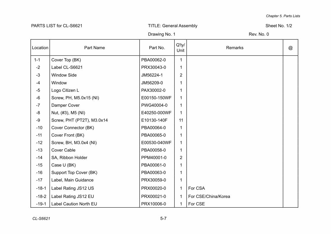
Chapter 5. Parts Lists
CL-S6621 5-7
PARTS LIST for CL-S6621 TITLE: General Assembly Sheet No. 1/2
Drawing No. 1 Rev. No. 0
Location Part Name Part No. Q'ty/ Unit Remarks @
1-1 Cover Top (BK) PBA00062-0 1
-2 Label CL-S6621 PRX30043-0 1
-3 Window Side JM56224-1 2
-4 Window JM56209-0 1
-5 Logo Citizen L PAX30002-0 1
-6 Screw, PH, M5.0x15 (NI) E00150-150WF 1
-7 Damper Cover PWG40004-0 1
-8 Nut, (#3), M5 (NI) E40250-000WF 1
-9 Screw, PHT (PT2T), M3.0x14 E10130-140F 11
-10 Cover Connector (BK) PBA00064-0 1
-11 Cover Front (BK) PBA00065-0 1
-12 Screw, BH, M3.0x4 (NI) E00530-040WF 1
-13 Cover Cable PBA00058-0 1
-14 SA, Ribbon Holder PPM40001-0 2
-15 Case U (BK) PBA00061-0 1
-16 Support Top Cover (BK) PBA00063-0 1
-17 Label, Main Guidance PRX30059-0 1
-18-1 Label Rating JS12 US PRX00020-0 1 For CSA
-18-2 Label Rating JS12 EU PRX00021-0 1 For CSE/China/Korea
-19-1 Label Caution North EU PRX10006-0 1 For CSE
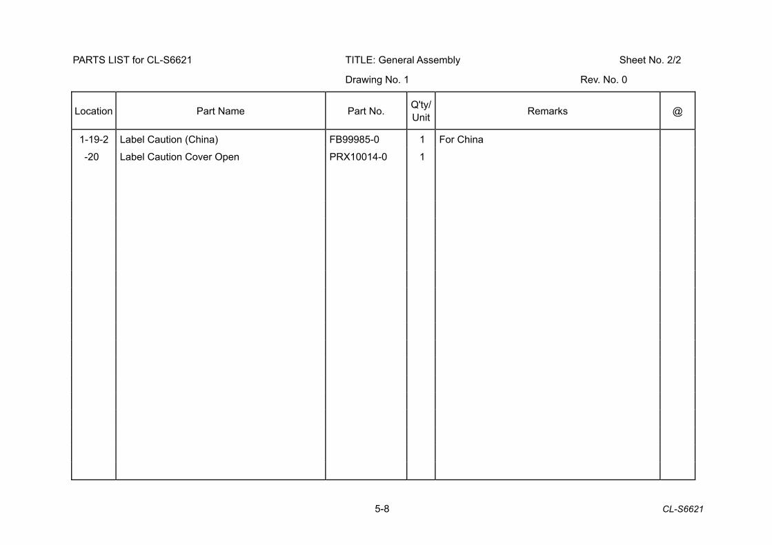
5-8 CL-S6621
PARTS LIST for CL-S6621 TITLE: General Assembly Sheet No. 2/2
Drawing No. 1 Rev. No. 0
Location Part Name Part No. Q'ty/ Unit Remarks @
1-19-2 Label Caution (China) FB99985-0 1 For China
-20 Label Caution Cover Open PRX10014-0 1

Chapter 5. Parts Lists
CL-S6621 5-9
CL-S6621 Drawing No. 2 Parts List & Location for Unit, Base
Revision Up List
Sheet No. Rev. No. Date
1/3 0 Mar. 12, 2013
2/3 0 Mar. 12, 2013
3/3 0 Mar. 12, 2013
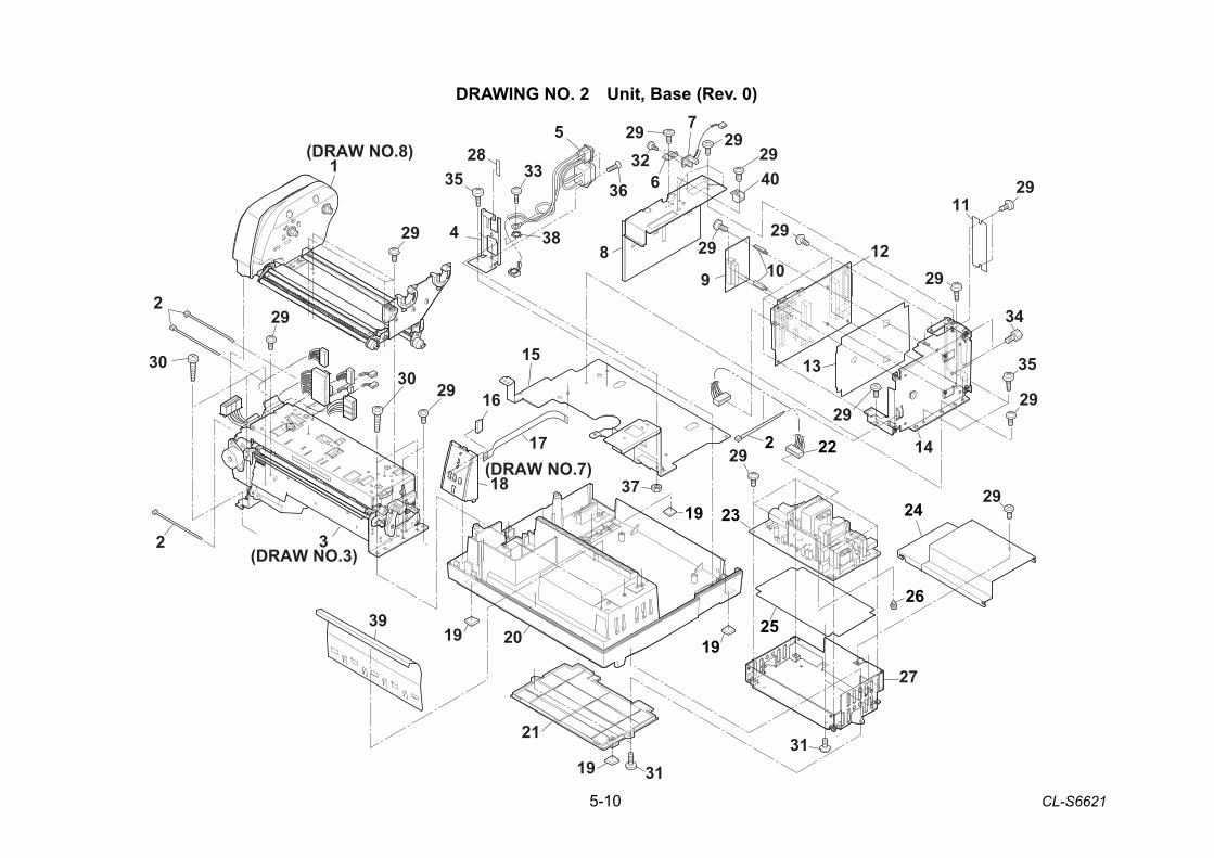
5-10 CL-S6621
DRAWING NO. 2 Unit, Base (Rev. 0)
29
2
2
30
29
2930
1939
20
3
1
19
21
19
19
15
16
17
18
22
29
24
25
27
23
35
29
13
12109
84
33
38
5 292940
729
326
14(DRAW NO.7)
(DRAW NO.8)
(DRAW NO.3)
26
11
34
29
36
2
28
37 29
29
2929
29
31 31
35
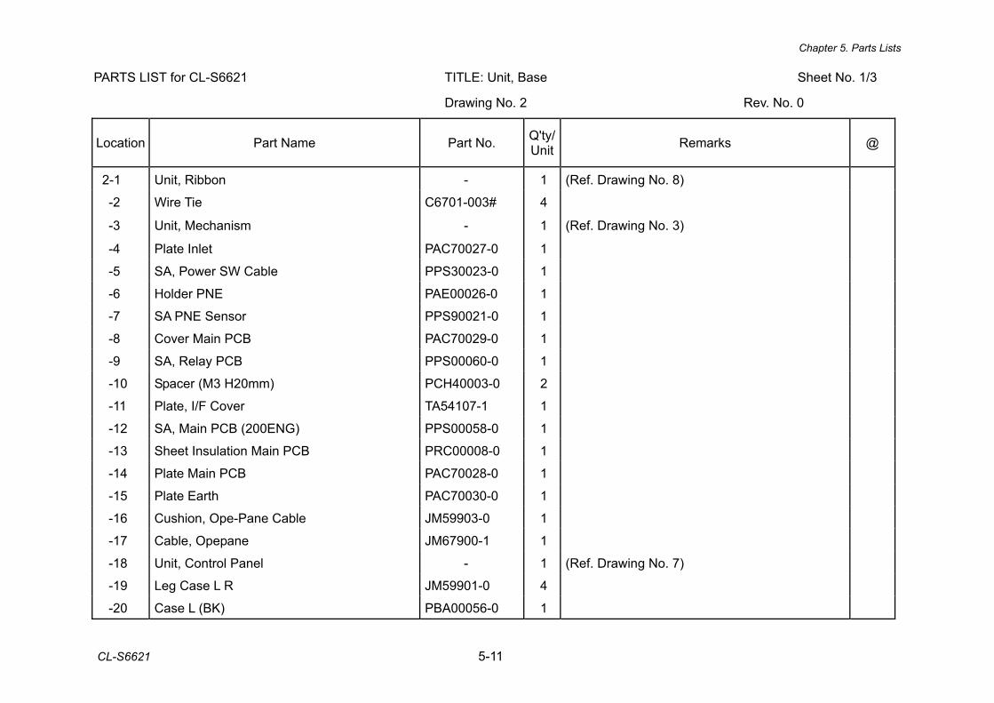
Chapter 5. Parts Lists
CL-S6621 5-11
PARTS LIST for CL-S6621 TITLE: Unit, Base Sheet No. 1/3
Drawing No. 2 Rev. No. 0
Location Part Name Part No. Q'ty/ Unit Remarks @
2-1 Unit, Ribbon - 1 (Ref. Drawing No. 8)
-2 Wire Tie C6701-003# 4
-3 Unit, Mechanism - 1 (Ref. Drawing No. 3)
-4 Plate Inlet PAC70027-0 1
-5 SA, Power SW Cable PPS30023-0 1
-6 Holder PNE PAE00026-0 1
-7 SA PNE Sensor PPS90021-0 1
-8 Cover Main PCB PAC70029-0 1
-9 SA, Relay PCB PPS00060-0 1
-10 Spacer (M3 H20mm) PCH40003-0 2
-11 Plate, I/F Cover TA54107-1 1
-12 SA, Main PCB (200ENG) PPS00058-0 1
-13 Sheet Insulation Main PCB PRC00008-0 1
-14 Plate Main PCB PAC70028-0 1
-15 Plate Earth PAC70030-0 1
-16 Cushion, Ope-Pane Cable JM59903-0 1
-17 Cable, Opepane JM67900-1 1
-18 Unit, Control Panel - 1 (Ref. Drawing No. 7)
-19 Leg Case L R JM59901-0 4
-20 Case L (BK) PBA00056-0 1
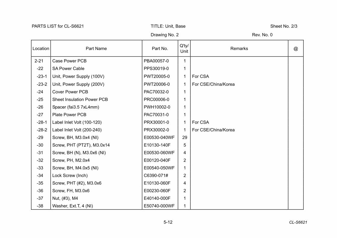
5-12 CL-S6621
PARTS LIST for CL-S6621 TITLE: Unit, Base Sheet No. 2/3
Drawing No. 2 Rev. No. 0
Location Part Name Part No. Q'ty/ Unit Remarks @
2-21 Case Power PCB PBA00057-0 1
-22 SA Power Cable PPS30019-0 1
-23-1 Unit, Power Supply (100V) PWT20005-0 1 For CSA
-23-2 Unit, Power Supply (200V) PWT20006-0 1 For CSE/China/Korea
-24 Cover Power PCB PAC70032-0 1
-25 Sheet Insulation Power PCB PRC00006-0 1
-26 Spacer (fai3.5 7xL4mm) PWH10002-0 1
-27 Plate Power PCB PAC70031-0 1
-28-1 Label Inlet Volt (100-120) PRX30001-0 1 For CSA
-28-2 Label Inlet Volt (200-240) PRX30002-0 1 For CSE/China/Korea
-29 Screw, BH, M3.0x4 (NI) E00530-040WF 29
-30 Screw, PHT (PT2T), M3.0x14 E10130-140F 5
-31 Screw, BH (N), M3.0x6 (NI) E00530-060WF 4
-32 Screw, PH, M2.0x4 E00120-040F 2
-33 Screw, BH, M4.0x5 (NI) E00540-050WF 1
-34 Lock Screw (Inch) C6390-071# 2
-35 Screw, PHT (#2), M3.0x6 E10130-060F 4
-36 Screw, FH, M3.0x6 E00230-060F 2
-37 Nut, (#3), M4 E40140-000F 1
-38 Washer, Ext.T, 4 (NI) E50740-000WF 1
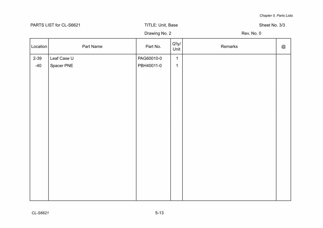
Chapter 5. Parts Lists
CL-S6621 5-13
PARTS LIST for CL-S6621 TITLE: Unit, Base Sheet No. 3/3
Drawing No. 2 Rev. No. 0
Location Part Name Part No. Q'ty/ Unit Remarks @
2-39 Leaf Case U PAG60010-0 1
-40 Spacer PNE PBH40011-0 1
5-14 CL-S6621
CL-S6621 Drawing No. 3 Parts List & Location for Unit, Mechanism
Revision Up List
Sheet No. Rev. No. Date
1/1 0 Mar. 12, 2013
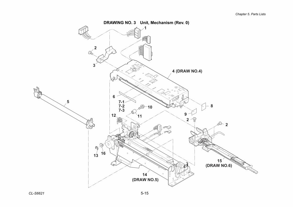
Chapter 5. Parts Lists
CL-S6621 5-15
DRAWING NO. 3 Unit, Mechanism (Rev. 0) 1
2
3
5
13
12
67-17-27-3
9
4
14
10
112
8
2
15(DRAW NO.6)
(DRAW NO.5)
(DRAW NO.4)
16
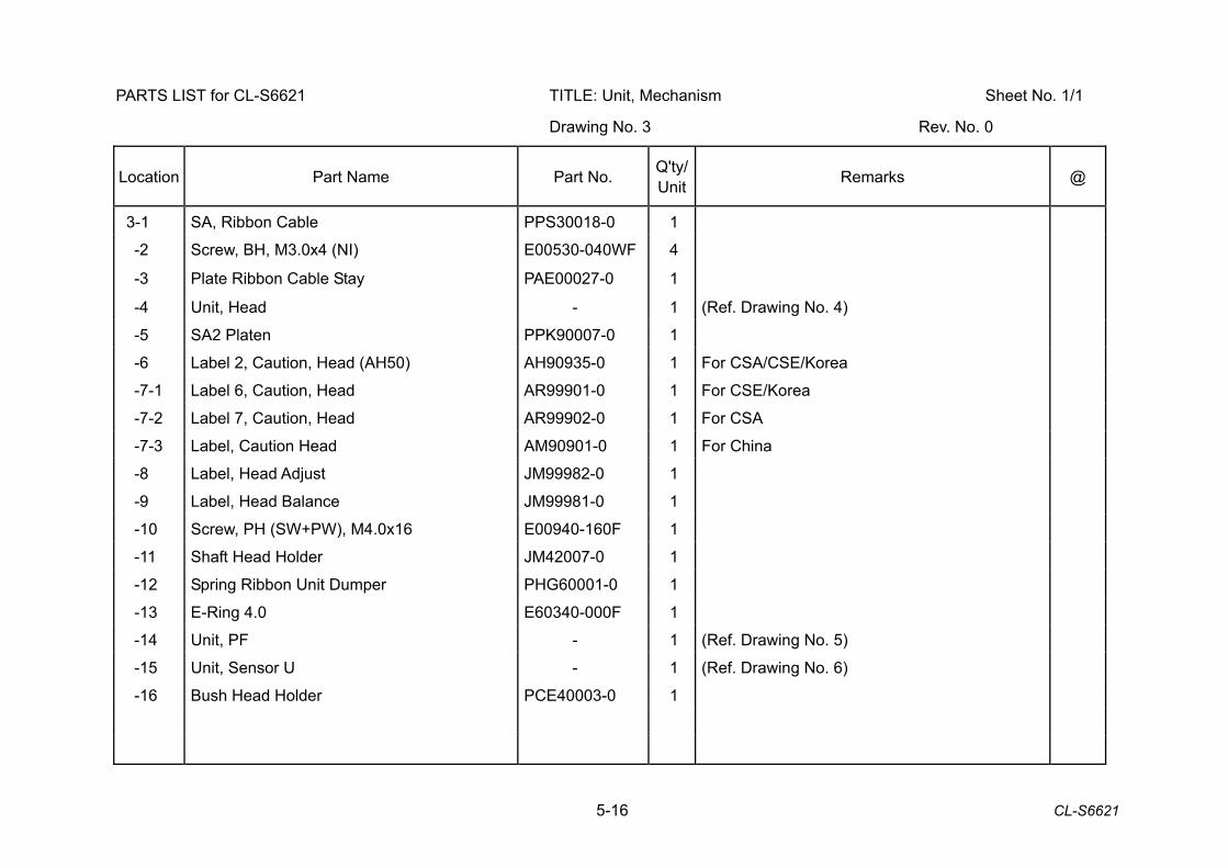
5-16 CL-S6621
PARTS LIST for CL-S6621 TITLE: Unit, Mechanism Sheet No. 1/1
Drawing No. 3 Rev. No. 0
Location Part Name Part No. Q'ty/ Unit Remarks @
3-1 SA, Ribbon Cable PPS30018-0 1
-2 Screw, BH, M3.0x4 (NI) E00530-040WF 4
-3 Plate Ribbon Cable Stay PAE00027-0 1
-4 Unit, Head - 1 (Ref. Drawing No. 4)
-5 SA2 Platen PPK90007-0 1
-6 Label 2, Caution, Head (AH50) AH90935-0 1 For CSA/CSE/Korea
-7-1 Label 6, Caution, Head AR99901-0 1 For CSE/Korea
-7-2 Label 7, Caution, Head AR99902-0 1 For CSA
-7-3 Label, Caution Head AM90901-0 1 For China
-8 Label, Head Adjust JM99982-0 1
-9 Label, Head Balance JM99981-0 1
-10 Screw, PH (SW+PW), M4.0x16 E00940-160F 1
-11 Shaft Head Holder JM42007-0 1
-12 Spring Ribbon Unit Dumper PHG60001-0 1
-13 E-Ring 4.0 E60340-000F 1
-14 Unit, PF - 1 (Ref. Drawing No. 5)
-15 Unit, Sensor U - 1 (Ref. Drawing No. 6)
-16 Bush Head Holder PCE40003-0 1
Chapter 5. Parts Lists
CL-S6621 5-17
CL-S6621 Drawing No. 4 Parts List & Location for Unit, Head
Revision Up List
Sheet No. Rev. No. Date
1/2 0 Mar. 12, 2013
2/2 0 Mar. 12, 2013
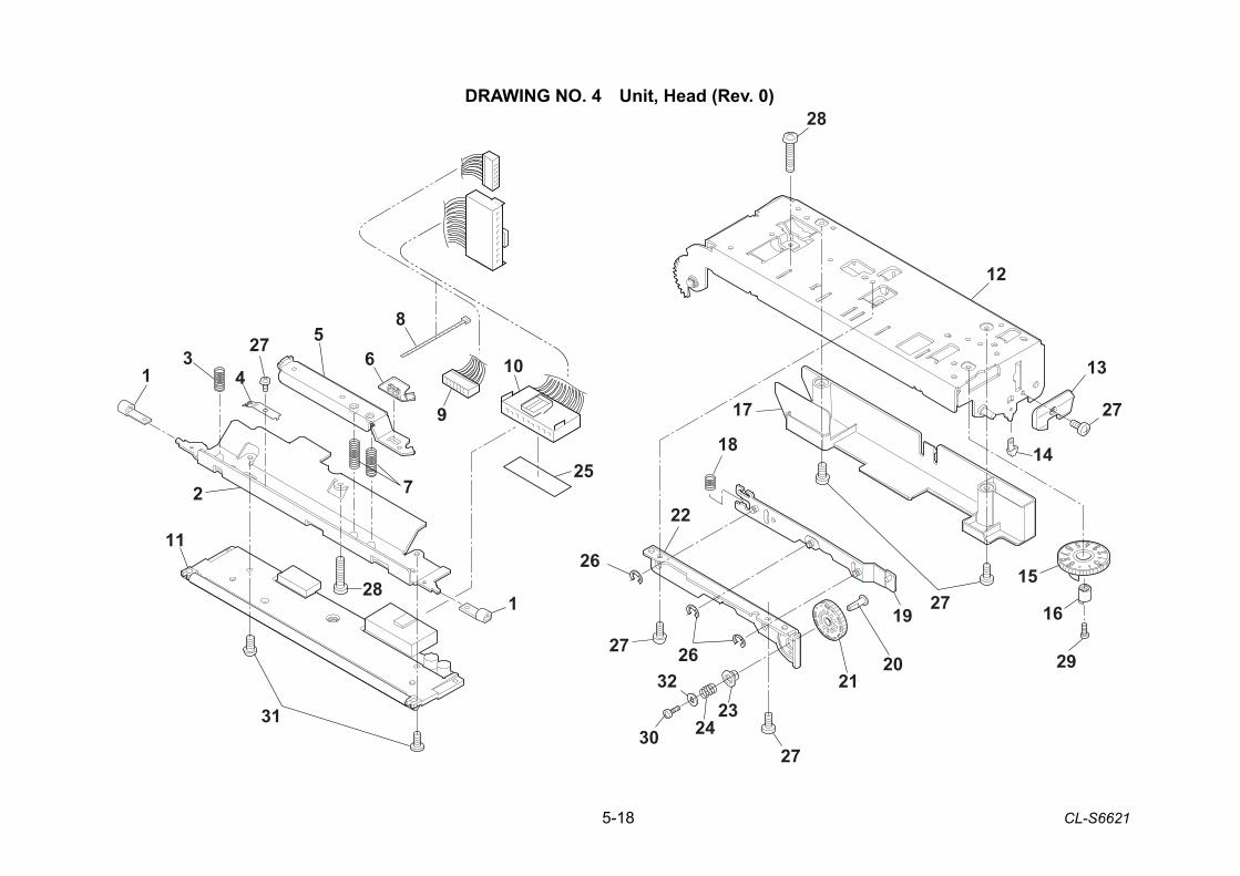
5-18 CL-S6621
DRAWING NO. 4 Unit, Head (Rev. 0) 28
10
8
9
563
41
1
2
11
31
26
26
22
2324
32
30
2021
19
15
16
29
27
13
12
18
17
14
7
28
25
27
27
27
27
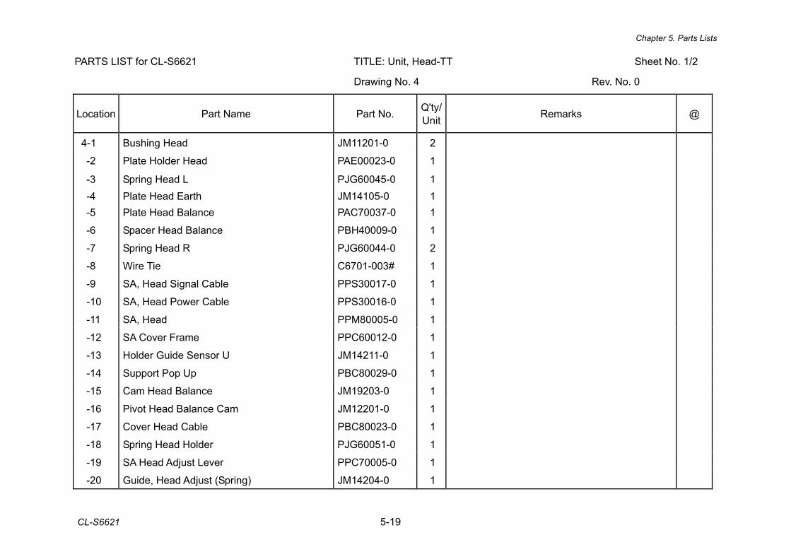
Chapter 5. Parts Lists
CL-S6621 5-19
PARTS LIST for CL-S6621 TITLE: Unit, Head-TT Sheet No. 1/2
Drawing No. 4 Rev. No. 0
Location Part Name Part No. Q'ty/ Unit Remarks @
4-1 Bushing Head JM11201-0 2
-2 Plate Holder Head PAE00023-0 1
-3 Spring Head L PJG60045-0 1 -4 Plate Head Earth JM14105-0 1 -5 Plate Head Balance PAC70037-0 1
-6 Spacer Head Balance PBH40009-0 1
-7 Spring Head R PJG60044-0 2
-8 Wire Tie C6701-003# 1
-9 SA, Head Signal Cable PPS30017-0 1
-10 SA, Head Power Cable PPS30016-0 1
-11 SA, Head PPM80005-0 1
-12 SA Cover Frame PPC60012-0 1
-13 Holder Guide Sensor U JM14211-0 1
-14 Support Pop Up PBC80029-0 1
-15 Cam Head Balance JM19203-0 1
-16 Pivot Head Balance Cam JM12201-0 1
-17 Cover Head Cable PBC80023-0 1
-18 Spring Head Holder PJG60051-0 1
-19 SA Head Adjust Lever PPC70005-0 1
-20 Guide, Head Adjust (Spring) JM14204-0 1
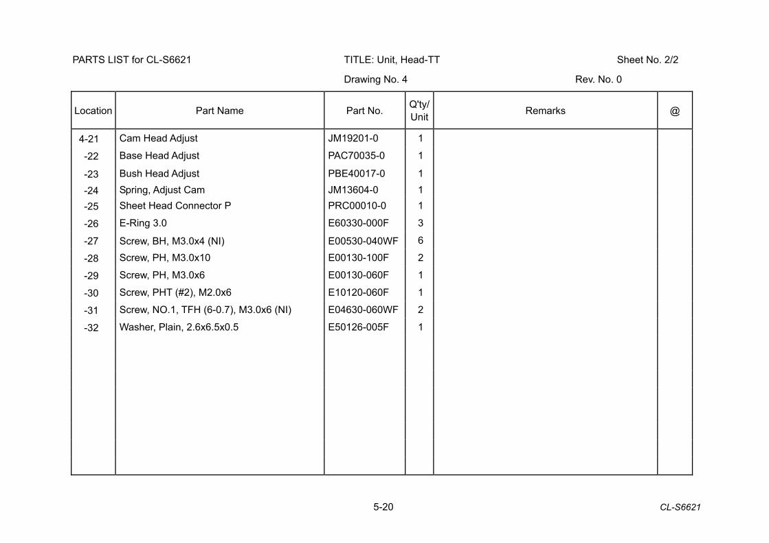
5-20 CL-S6621
PARTS LIST for CL-S6621 TITLE: Unit, Head-TT Sheet No. 2/2
Drawing No. 4 Rev. No. 0
Location Part Name Part No. Q'ty/ Unit Remarks @
4-21 Cam Head Adjust JM19201-0 1
-22 Base Head Adjust PAC70035-0 1
-23 Bush Head Adjust PBE40017-0 1 -24 Spring, Adjust Cam JM13604-0 1 -25 Sheet Head Connector P PRC00010-0 1
-26 E-Ring 3.0 E60330-000F 3
-27 Screw, BH, M3.0x4 (NI) E00530-040WF 6
-28 Screw, PH, M3.0x10 E00130-100F 2
-29 Screw, PH, M3.0x6 E00130-060F 1
-30 Screw, PHT (#2), M2.0x6 E10120-060F 1
-31 Screw, NO.1, TFH (6-0.7), M3.0x6 (NI) E04630-060WF 2
-32 Washer, Plain, 2.6x6.5x0.5 E50126-005F 1
Chapter 5. Parts Lists
CL-S6621 5-21
CL-S6621 Drawing No. 5 Parts List & Location for Unit, PF
Revision Up List
Sheet No. Rev. No. Date
1/3 0 Mar. 12, 2013
2/3 0 Mar. 12, 2013
3/3 0 Mar. 12, 2013
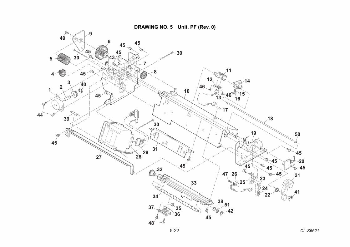
5-22 CL-S6621
DRAWING NO. 5 Unit, PF (Rev. 0)
11
141246
461315
16
1718
50
10
19
20
21
22 4124
2325
47 26
33
32
425138
45
34
35
48
3637
27
44
1 23
4
5
49 6
78
29
30
2831
45
4545
4545
454545
45
45
45
45
3030
45 45
9
39
43
40
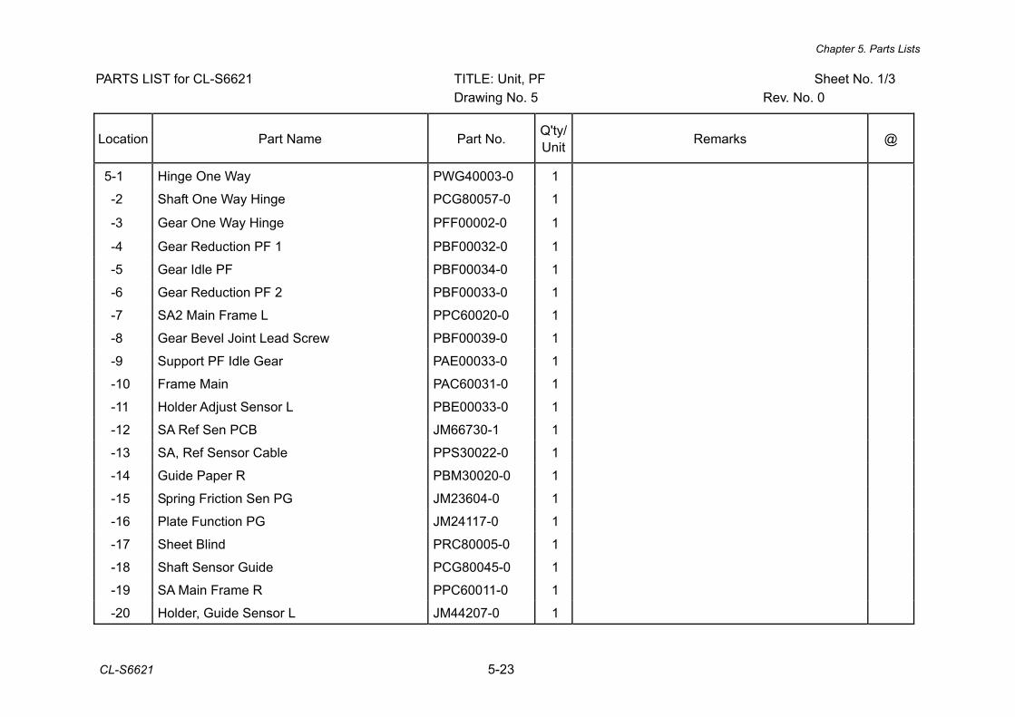
Chapter 5. Parts Lists
CL-S6621 5-23
PARTS LIST for CL-S6621 TITLE: Unit, PF Sheet No. 1/3 Drawing No. 5 Rev. No. 0
Location Part Name Part No. Q'ty/ Unit Remarks @
5-1 Hinge One Way PWG40003-0 1
-2 Shaft One Way Hinge PCG80057-0 1
-3 Gear One Way Hinge PFF00002-0 1
-4 Gear Reduction PF 1 PBF00032-0 1
-5 Gear Idle PF PBF00034-0 1
-6 Gear Reduction PF 2 PBF00033-0 1
-7 SA2 Main Frame L PPC60020-0 1
-8 Gear Bevel Joint Lead Screw PBF00039-0 1
-9 Support PF Idle Gear PAE00033-0 1
-10 Frame Main PAC60031-0 1
-11 Holder Adjust Sensor L PBE00033-0 1
-12 SA Ref Sen PCB JM66730-1 1
-13 SA, Ref Sensor Cable PPS30022-0 1
-14 Guide Paper R PBM30020-0 1
-15 Spring Friction Sen PG JM23604-0 1
-16 Plate Function PG JM24117-0 1
-17 Sheet Blind PRC80005-0 1
-18 Shaft Sensor Guide PCG80045-0 1
-19 SA Main Frame R PPC60011-0 1
-20 Holder, Guide Sensor L JM44207-0 1
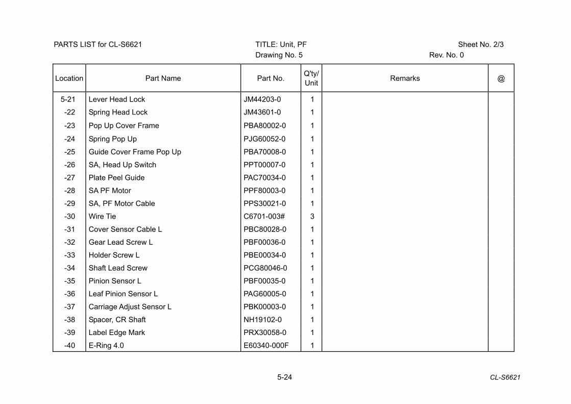
5-24 CL-S6621
PARTS LIST for CL-S6621 TITLE: Unit, PF Sheet No. 2/3 Drawing No. 5 Rev. No. 0
Location Part Name Part No. Q'ty/ Unit Remarks @
5-21 Lever Head Lock JM44203-0 1
-22 Spring Head Lock JM43601-0 1
-23 Pop Up Cover Frame PBA80002-0 1
-24 Spring Pop Up PJG60052-0 1
-25 Guide Cover Frame Pop Up PBA70008-0 1
-26 SA, Head Up Switch PPT00007-0 1
-27 Plate Peel Guide PAC70034-0 1
-28 SA PF Motor PPF80003-0 1
-29 SA, PF Motor Cable PPS30021-0 1
-30 Wire Tie C6701-003# 3
-31 Cover Sensor Cable L PBC80028-0 1
-32 Gear Lead Screw L PBF00036-0 1
-33 Holder Screw L PBE00034-0 1
-34 Shaft Lead Screw PCG80046-0 1
-35 Pinion Sensor L PBF00035-0 1
-36 Leaf Pinion Sensor L PAG60005-0 1
-37 Carriage Adjust Sensor L PBK00003-0 1
-38 Spacer, CR Shaft NH19102-0 1
-39 Label Edge Mark PRX30058-0 1
-40 E-Ring 4.0 E60340-000F 1
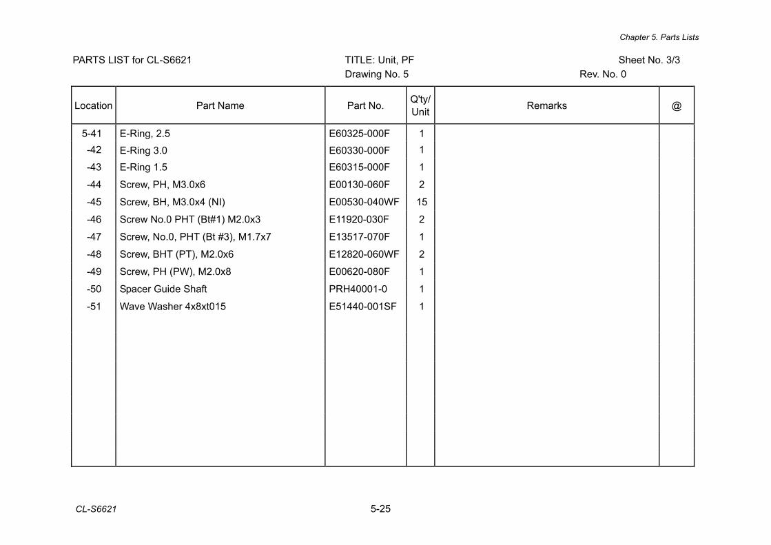
Chapter 5. Parts Lists
CL-S6621 5-25
PARTS LIST for CL-S6621 TITLE: Unit, PF Sheet No. 3/3 Drawing No. 5 Rev. No. 0
Location Part Name Part No. Q'ty/ Unit Remarks @
5-41 E-Ring, 2.5 E60325-000F 1 -42 E-Ring 3.0 E60330-000F 1 -43 E-Ring 1.5 E60315-000F 1 -44 Screw, PH, M3.0x6 E00130-060F 2 -45 Screw, BH, M3.0x4 (NI) E00530-040WF 15 -46 Screw No.0 PHT (Bt#1) M2.0x3 E11920-030F 2 -47 Screw, No.0, PHT (Bt #3), M1.7x7 E13517-070F 1 -48 Screw, BHT (PT), M2.0x6 E12820-060WF 2 -49 Screw, PH (PW), M2.0x8 E00620-080F 1 -50 Spacer Guide Shaft PRH40001-0 1 -51 Wave Washer 4x8xt015 E51440-001SF 1

5-26 CL-S6621
CL-S6621 Drawing No. 6 Parts List & Location for Unit, Sensor U
Revision Up List
Sheet No. Rev. No. Date
1/2 0 Mar. 12, 2013
2/2 0 Mar. 12, 2013
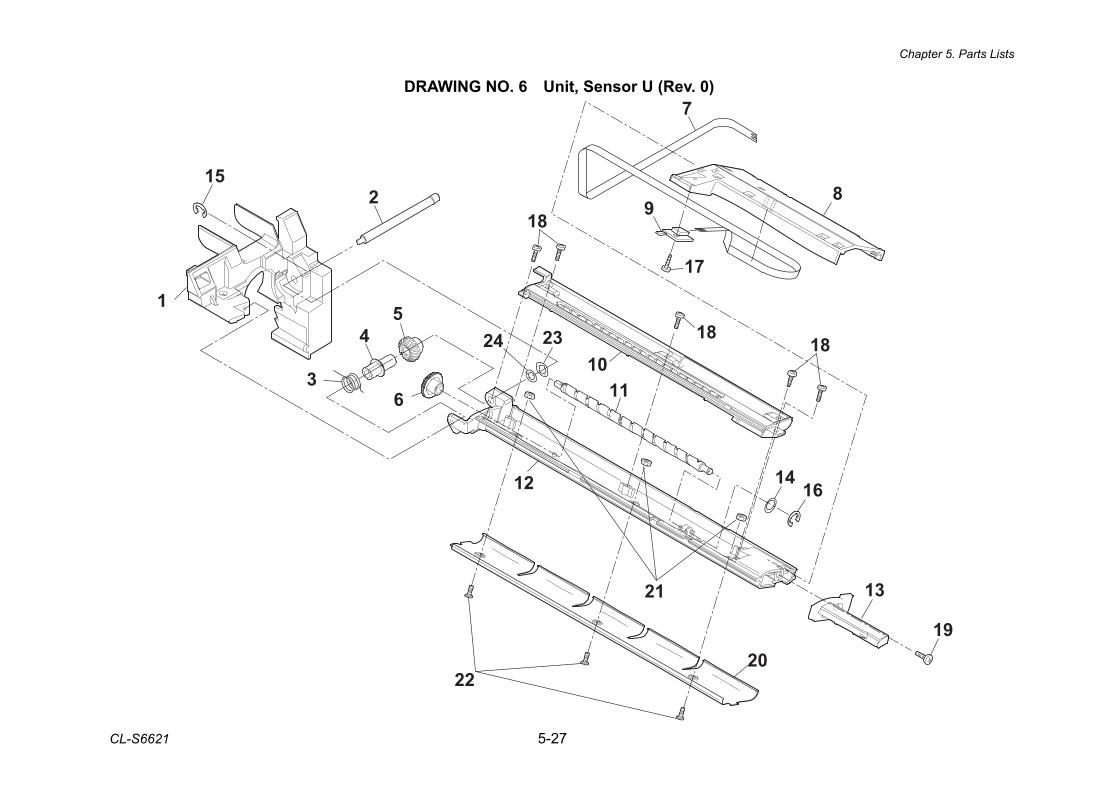
Chapter 5. Parts Lists
CL-S6621 5-27
DRAWING NO. 6 Unit, Sensor U (Rev. 0)
20
21
22
24
7
8
17
18
1818
1416
13
19
12
1023
116
54
3
2
1
9
15
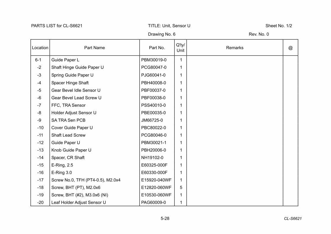
5-28 CL-S6621
PARTS LIST for CL-S6621 TITLE: Unit, Sensor U Sheet No. 1/2
Drawing No. 6 Rev. No. 0
Location Part Name Part No. Q'ty/ Unit Remarks @
6-1 Guide Paper L PBM30019-0 1
-2 Shaft Hinge Guide Paper U PCG80047-0 1
-3 Spring Guide Paper U PJG60041-0 1
-4 Spacer Hinge Shaft PBH40008-0 1
-5 Gear Bevel Idle Sensor U PBF00037-0 1
-6 Gear Bevel Lead Screw U PBF00038-0 1
-7 FFC, TRA Sensor PSS40010-0 1
-8 Holder Adjust Sensor U PBE00035-0 1
-9 SA TRA Sen PCB JM66725-0 1
-10 Cover Guide Paper U PBC80022-0 1
-11 Shaft Lead Screw PCG80046-0 1
-12 Guide Paper U PBM30021-1 1
-13 Knob Guide Paper U PBH20006-0 1
-14 Spacer, CR Shaft NH19102-0 1
-15 E-Ring, 2.5 E60325-000F 1
-16 E-Ring 3.0 E60330-000F 1
-17 Screw No.0, TFH (PT4-0.5), M2.0x4 E15920-040WF 1
-18 Screw, BHT (PT), M2.0x6 E12820-060WF 5
-19 Screw, BHT (#2), M3.0x6 (NI) E10530-060WF 1
-20 Leaf Holder Adjust Sensor U PAG60009-0 1
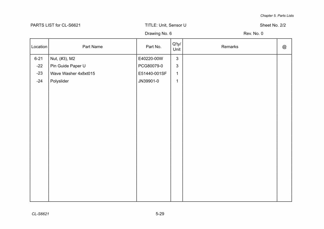
Chapter 5. Parts Lists
CL-S6621 5-29
PARTS LIST for CL-S6621 TITLE: Unit, Sensor U Sheet No. 2/2
Drawing No. 6 Rev. No. 0
Location Part Name Part No. Q'ty/ Unit Remarks @
6-21 Nut, (#3), M2 E40220-00W 3
-22 Pin Guide Paper U PCG80079-0 3
-23 Wave Washer 4x8xt015 E51440-001SF 1
-24 Polyslider JN39901-0 1
5-30 CL-S6621
CL-S6621 Drawing No. 7 Parts List & Location for Unit, Control Panel
Revision Up List
Sheet No. Rev. No. Date
1/1 0 Mar. 12, 2013
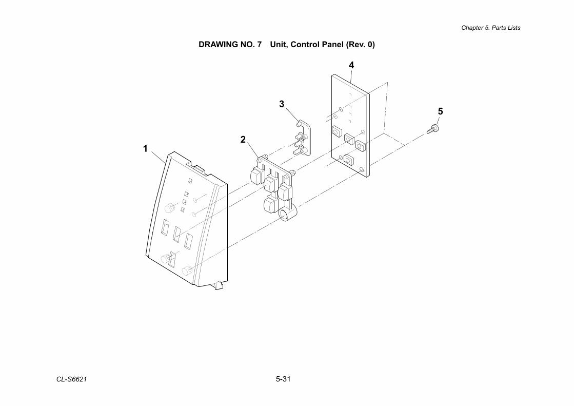
Chapter 5. Parts Lists
CL-S6621 5-31
DRAWING NO. 7 Unit, Control Panel (Rev. 0)
4
3
21
5
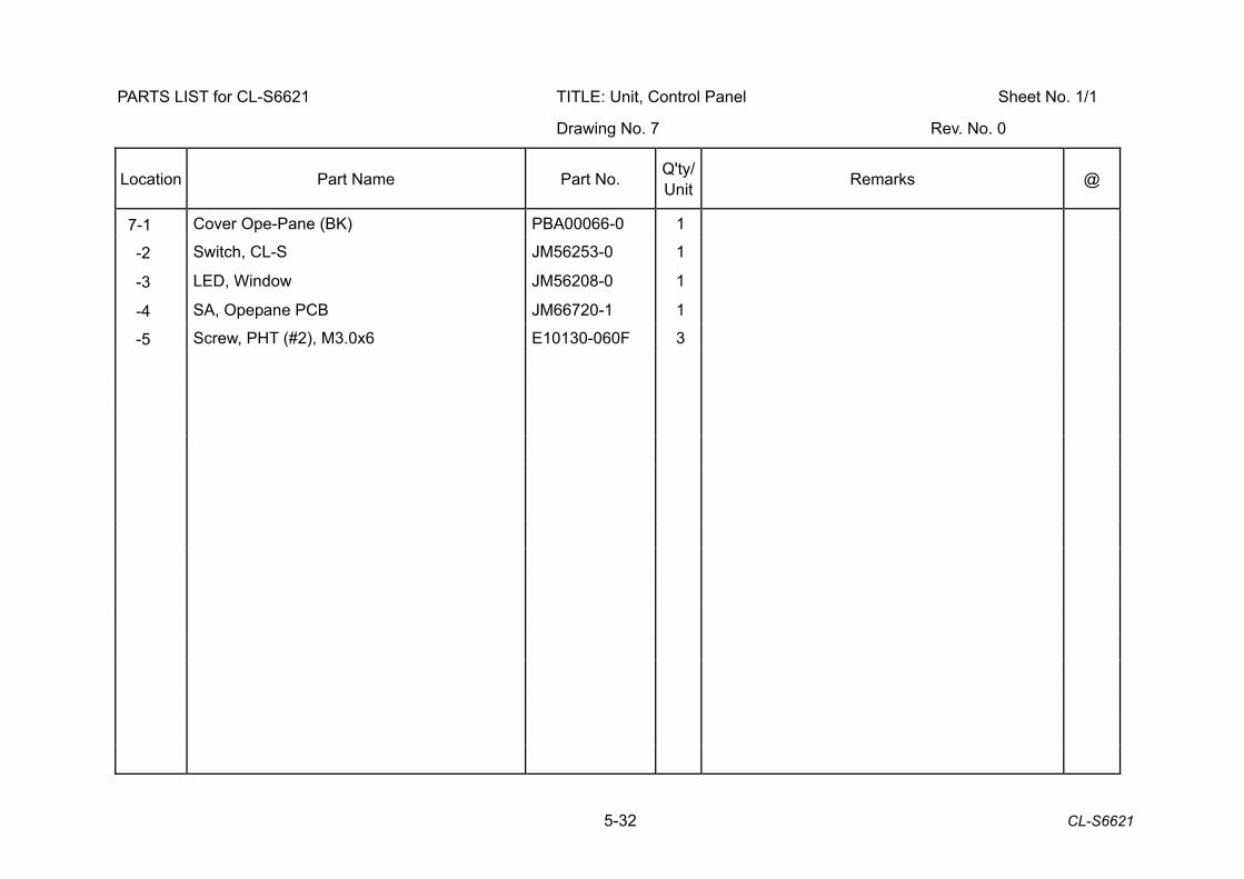
5-32 CL-S6621
PARTS LIST for CL-S6621 TITLE: Unit, Control Panel Sheet No. 1/1
Drawing No. 7 Rev. No. 0
Location Part Name Part No. Q'ty/ Unit Remarks @
7-1 Cover Ope-Pane (BK) PBA00066-0 1
-2 Switch, CL-S JM56253-0 1
-3 LED, Window JM56208-0 1
-4 SA, Opepane PCB JM66720-1 1
-5 Screw, PHT (#2), M3.0x6 E10130-060F 3

Chapter 5. Parts Lists
CL-S6621 5-33
CL-S6621 Drawing No. 8 Parts List & Location for Unit, Ribbon
Revision Up List
Sheet No. Rev. No. Date
1/2 0 Mar. 12, 2013
2/2 0 Mar. 12, 2013
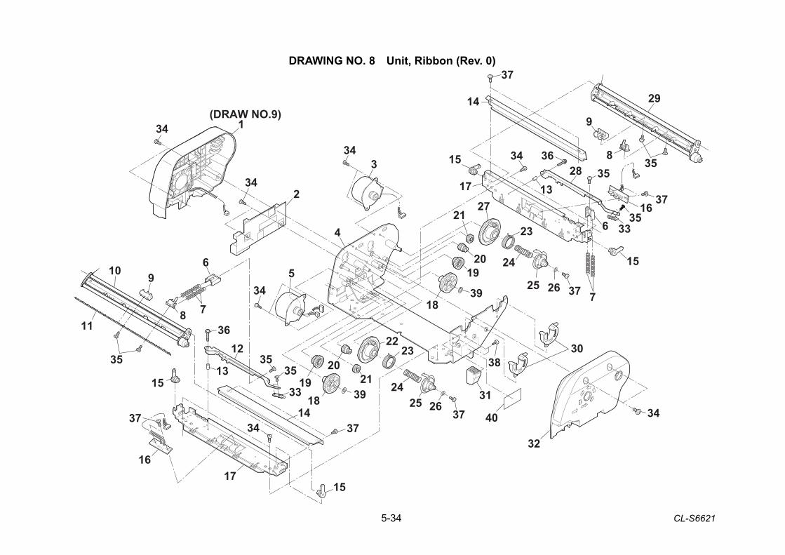
5-34 CL-S6621
DRAWING NO. 8 Unit, Ribbon (Rev. 0)
134
2
334
10
11
35
9
8 7
6
34
534
36
3512
1315
37
1617
34
15
37
391819
2021
2223
24
24
25 2637
31
40
3830
3918
1920
2127
23
17
25 26 37 7
15
6
13
15 34
37
14
3628 35
1637
9
835
29
34
32
14
4
(DRAW NO.9)
33
33
35
35
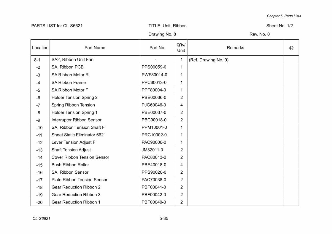
Chapter 5. Parts Lists
CL-S6621 5-35
PARTS LIST for CL-S6621 TITLE: Unit, Ribbon Sheet No. 1/2
Drawing No. 8 Rev. No. 0
Location Part Name Part No. Q'ty/ Unit Remarks @
8-1 SA2, Ribbon Unit Fan - 1 (Ref. Drawing No. 9)
-2 SA, Ribbon PCB PPS00059-0 1
-3 SA Ribbon Motor R PWF80014-0 1
-4 SA Ribbon Frame PPC60013-0 1
-5 SA Ribbon Motor F PPF80004-0 1
-6 Holder Tension Spring 2 PBE00036-0 2
-7 Spring Ribbon Tension PJG60046-0 4
-8 Holder Tension Spring 1 PBE00037-0 2
-9 Interrupter Ribbon Sensor PBC90018-0 2
-10 SA, Ribbon Tension Shaft F PPM10001-0 1
-11 Sheet Static Eliminator 6621 PRC10002-0 1
-12 Lever Tension Adjust F PAC90006-0 1
-13 Shaft Tension Adjust JM32011-0 2
-14 Cover Ribbon Tension Sensor PAC80013-0 2
-15 Bush Ribbon Roller PBE40018-0 4
-16 SA, Ribbon Sensor PPS90020-0 2
-17 Plate Ribbon Tension Sensor PAC70038-0 2
-18 Gear Reduction Ribbon 2 PBF00041-0 2
-19 Gear Reduction Ribbon 3 PBF00042-0 2
-20 Gear Reduction Ribbon 1 PBF00040-0 2
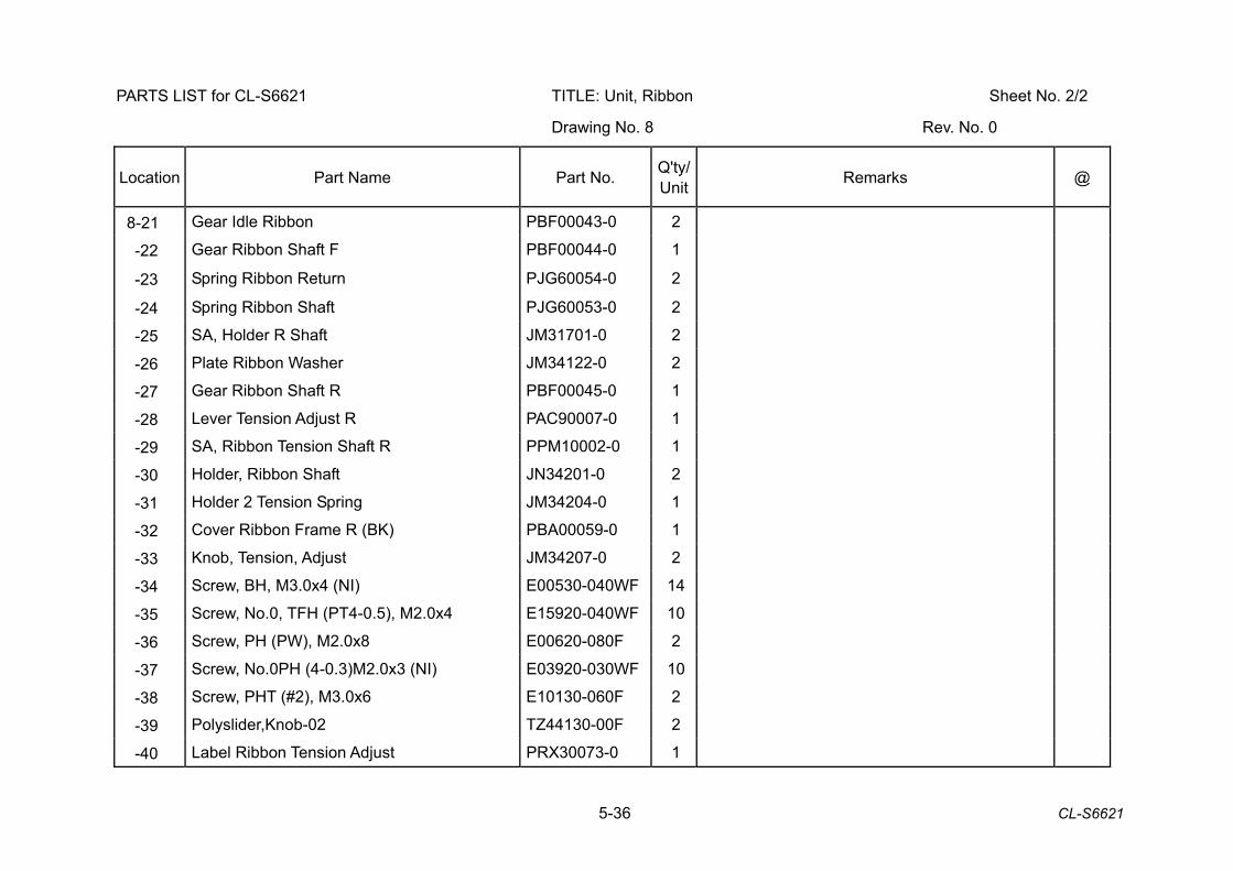
5-36 CL-S6621
PARTS LIST for CL-S6621 TITLE: Unit, Ribbon Sheet No. 2/2
Drawing No. 8 Rev. No. 0
Location Part Name Part No. Q'ty/ Unit Remarks @
8-21 Gear Idle Ribbon PBF00043-0 2
-22 Gear Ribbon Shaft F PBF00044-0 1
-23 Spring Ribbon Return PJG60054-0 2
-24 Spring Ribbon Shaft PJG60053-0 2
-25 SA, Holder R Shaft JM31701-0 2
-26 Plate Ribbon Washer JM34122-0 2
-27 Gear Ribbon Shaft R PBF00045-0 1
-28 Lever Tension Adjust R PAC90007-0 1
-29 SA, Ribbon Tension Shaft R PPM10002-0 1
-30 Holder, Ribbon Shaft JN34201-0 2
-31 Holder 2 Tension Spring JM34204-0 1
-32 Cover Ribbon Frame R (BK) PBA00059-0 1
-33 Knob, Tension, Adjust JM34207-0 2
-34 Screw, BH, M3.0x4 (NI) E00530-040WF 14
-35 Screw, No.0, TFH (PT4-0.5), M2.0x4 E15920-040WF 10
-36 Screw, PH (PW), M2.0x8 E00620-080F 2
-37 Screw, No.0PH (4-0.3)M2.0x3 (NI) E03920-030WF 10
-38 Screw, PHT (#2), M3.0x6 E10130-060F 2
-39 Polyslider,Knob-02 TZ44130-00F 2
-40 Label Ribbon Tension Adjust PRX30073-0 1
Chapter 5. Parts Lists
CL-S6621 5-37
CL-S6621 Drawing No. 9 Parts List & Location for SA2, Ribbon Unit Fan
Revision Up List
Sheet No. Rev. No. Date
1/1 0 Mar. 12, 2013
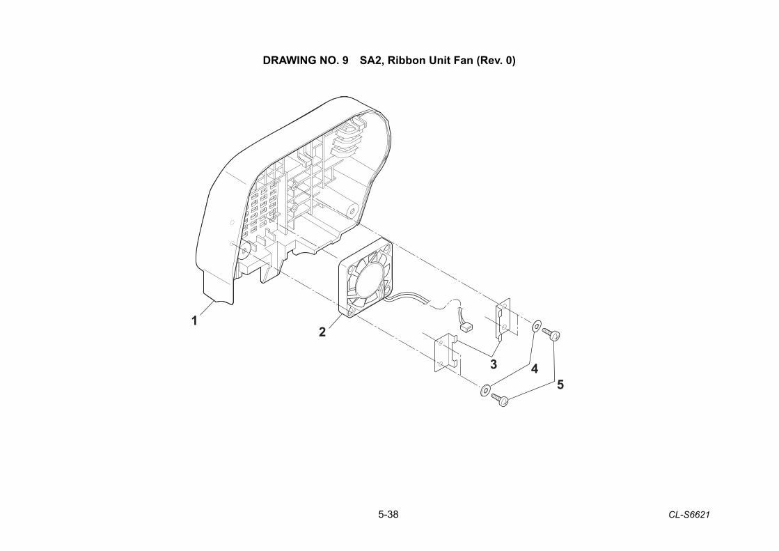
5-38 CL-S6621
DRAWING NO. 9 SA2, Ribbon Unit Fan (Rev. 0)
2
3 45
1
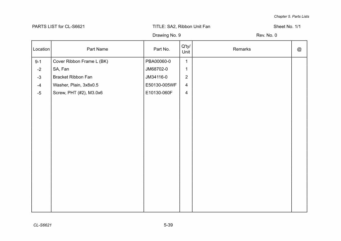
Chapter 5. Parts Lists
CL-S6621 5-39
PARTS LIST for CL-S6621 TITLE: SA2, Ribbon Unit Fan Sheet No. 1/1
Drawing No. 9 Rev. No. 0
Location Part Name Part No. Q'ty/ Unit Remarks @
9-1 Cover Ribbon Frame L (BK) PBA00060-0 1
-2 SA, Fan JM68702-0 1
-3 Bracket Ribbon Fan JM34116-0 2
-4 Washer, Plain, 3x8x0.5 E50130-005WF 4
-5 Screw, PHT (#2), M3.0x6 E10130-060F 4
5-40 CL-S6621
CL-S6621 Drawing No. 10 Parts List & Location for Accessories
Revision Up List
Sheet No. Rev. No. Date
1/2 0 Mar. 12, 2013
2/2 0 Mar. 12, 2013
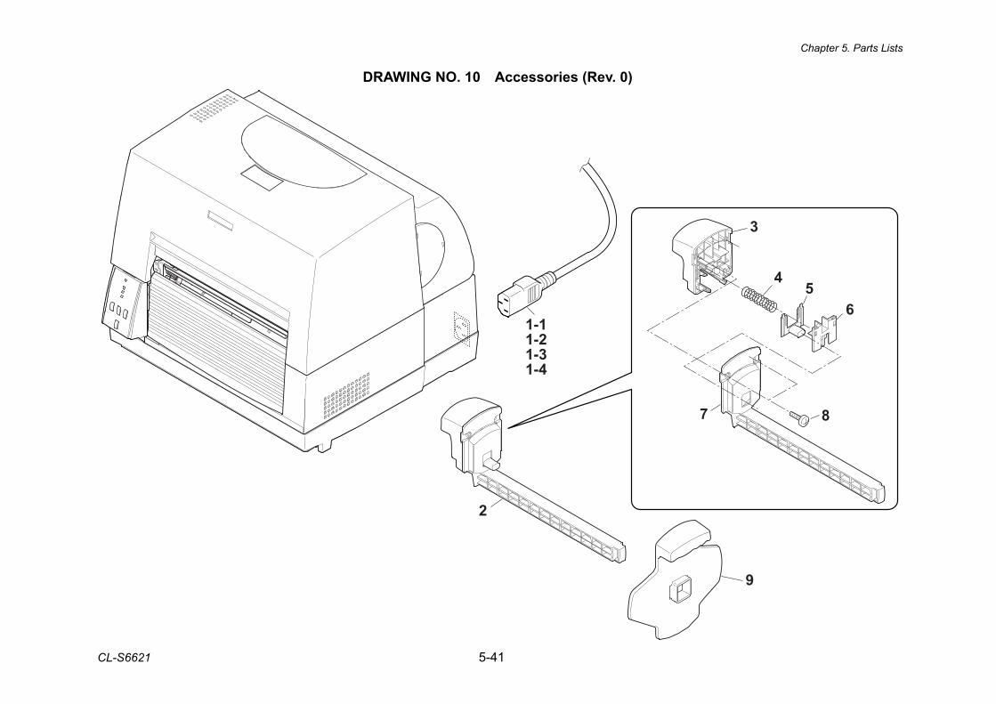
Chapter 5. Parts Lists
CL-S6621 5-41
DRAWING NO. 10 Accessories (Rev. 0)
1-11-21-31-4
9
3
45
6
7 8
2
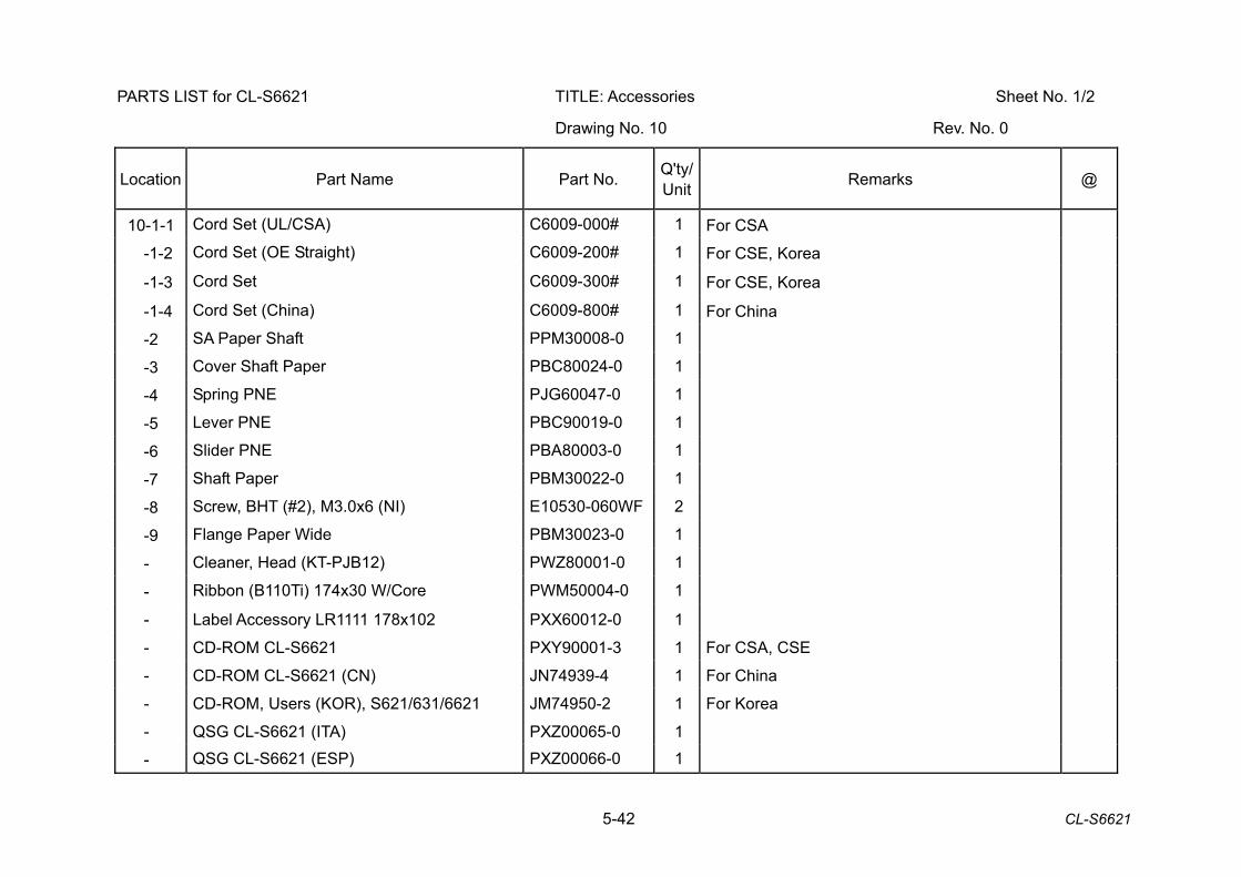
5-42 CL-S6621
PARTS LIST for CL-S6621 TITLE: Accessories Sheet No. 1/2
Drawing No. 10 Rev. No. 0
Location Part Name Part No. Q'ty/ Unit Remarks @
10-1-1 Cord Set (UL/CSA) C6009-000# 1 For CSA
-1-2 Cord Set (OE Straight) C6009-200# 1 For CSE, Korea
-1-3 Cord Set C6009-300# 1 For CSE, Korea
-1-4 Cord Set (China) C6009-800# 1 For China
-2 SA Paper Shaft PPM30008-0 1
-3 Cover Shaft Paper PBC80024-0 1
-4 Spring PNE PJG60047-0 1
-5 Lever PNE PBC90019-0 1
-6 Slider PNE PBA80003-0 1
-7 Shaft Paper PBM30022-0 1
-8 Screw, BHT (#2), M3.0x6 (NI) E10530-060WF 2
-9 Flange Paper Wide PBM30023-0 1
- Cleaner, Head (KT-PJB12) PWZ80001-0 1
- Ribbon (B110Ti) 174x30 W/Core PWM50004-0 1
- Label Accessory LR1111 178x102 PXX60012-0 1
- CD-ROM CL-S6621 PXY90001-3 1 For CSA, CSE
- CD-ROM CL-S6621 (CN) JN74939-4 1 For China
- CD-ROM, Users (KOR), S621/631/6621 JM74950-2 1 For Korea
- QSG CL-S6621 (ITA) PXZ00065-0 1
- QSG CL-S6621 (ESP) PXZ00066-0 1
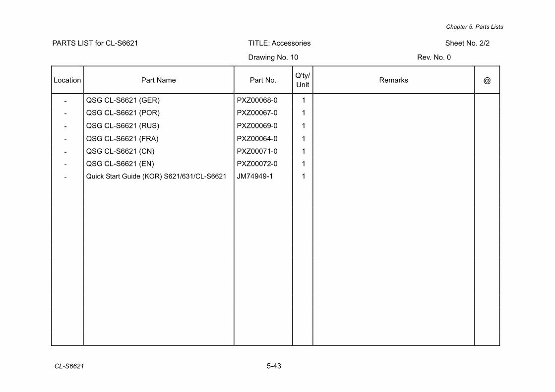
Chapter 5. Parts Lists
CL-S6621 5-43
PARTS LIST for CL-S6621 TITLE: Accessories Sheet No. 2/2
Drawing No. 10 Rev. No. 0
Location Part Name Part No. Q'ty/ Unit Remarks @
- QSG CL-S6621 (GER) PXZ00068-0 1
- QSG CL-S6621 (POR) PXZ00067-0 1
- QSG CL-S6621 (RUS) PXZ00069-0 1
- QSG CL-S6621 (FRA) PXZ00064-0 1
- QSG CL-S6621 (CN) PXZ00071-0 1
- QSG CL-S6621 (EN) PXZ00072-0 1
- Quick Start Guide (KOR) S621/631/CL-S6621 JM74949-1 1
6-1 CL-S6621
CHAPTER 6 CIRCUIT DIAGRAMS
CL-S6621 6-2
CHAPTER 6 CIRCUIT DIAGRAMS
TABLE OF CONTENTS
Inter Connection ................................................................................................................... 6-3 SA, Main PCB (1,2/13) [CPU (1)] ......................................................................................... 6-4 SA, Main PCB (3/13) [CPU (2), DAC] .................................................................................. 6-5 SA, Main PCB (4/13) [ROM]................................................................................................. 6-6 SA, Main PCB (5/13) [RAM] ................................................................................................. 6-7 SA, Main PCB (6/13) [FPGA] ............................................................................................... 6-8 SA, Main PCB (7/13) [Head, Opepane]................................................................................ 6-9 SA, Main PCB (8/13) [PF Motor] .......................................................................................... 6-10 SA, Main PCB (9/13) [Sensor, Option] ................................................................................. 6-11 SA, Main PCB (10/13) [Power, Buzzer] ................................................................................ 6-12 SA, Main PCB (11/13) [I/F (RS232C, Option)]...................................................................... 6-13 SA, Main PCB (12/13) [I/F (USB2.0)] ................................................................................... 6-14 SA Main PCB (13/13) [Ribbon]............................................................................................. 6-15 SA, Opepane PCB ............................................................................................................... 6-16 SA Ref Sen PCB .................................................................................................................. 6-17 SA TRA Sen PCB)................................................................................................................6-18 SA, Relay PCB ..................................................................................................................... 6-19 SA, Ribbon PCB................................................................................................................... 6-20 SA, Ribbon Sensor............................................................................................................... 6-21 SA PNE Sensor.................................................................................................................... 6-22
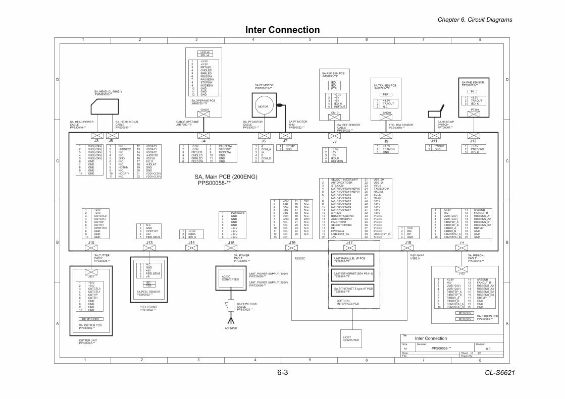
Chapter 6. Circuit Diagrams
6-3 CL-S6621
1
3DNG.C.N
1PYTRPC
J8
J18
J3 J9
J13
J11
5V5+
J16J10
2
J6
MHTDH
211TADDH
7181
.C.N
DNG
2
.C.N
1
.C.N
31
1BTSDHn4
DNG
.C.N
02.C.N
41
61
12
7
2TADDH
4TADDH
56
351
3TADDH
9)V3.3+(DDV
11
.C.N
DNG
.C.N
.O.E.BTALDHn
KLCDH
01
2BTSDHn
)V3.3+(DDV
91
22
8
)1266S-LC( DAEH,AS**-50008MWP
SA PF MOTOR
**-31008FWP
ROTOM
2
B_MOCB
65
A_MOC34
A
A/
B/
1
NOMFERK_DEI
V5+V3.3+
V5+
V3.3+1
ROSNES FER ,ASELBAC
**-22003SPP
V5+2
101NC
3
DEI
BCP NES FER,ASF**-03766MJ
V5+
2
43
5
1
45
K_DEITUOFER
ROSNES ART ,CFF**-01004SSP
V3.3+1
DNGNOMART2
3DNG
TUOWS12
DEIRTP
45
1LTCTUC
6PHTUC
DNG
0LTCTUC
1
DNG0PYTRPC
V42+3
V42+
98
HTTUC7
2
RETTUC,ASELBAC
**-82003SPP
104J
BCP RETTUC ,AS**-56000SPP
TINU RETTUC**-70000NPP
DNG
5
V42+
6
3
1
1LTCTUC
2
DNG9
0LTCTUC
87
4
V42+
DNG
PHTUCHTTUC
VRD RTM CD
DNG1
RV
TINU RELEEP**-20001SPP
23
RTP
ROSNES LEEP,AS**-20009SSP
SNESLEEP4
WSESUAP
21
WSPOTS
DELDNC
1
DNG11WSDEEF
4
6
WSEDOM
DELRRE
DELTRP2
9DNG
V3.3+3
7V3.3+
01
8
5DNG
4x DEL
BCP ENAPEPO,ASF**-02766MJ
104NC
ENAPEPO,ELBACF**-00976MJ
4x WS
5
01
7
3
DNG
9
21
V3.3+
DNGWSEDOM
WSESUAP
DELRRE
WSPOTS
1
DELTRPV3.3+
DELDNC
11
6
DNG
WSDEEF
4
2
8
4
21
DNG
MDCCV
PD3
12
STR
.C.N
.C.N
11
DNG
.C.N
51
02
31
DXR
.C.N
.C.NRSD
52
.C.N
5
.C.N
2
7
V5+
.C.N.C.N
01
.C.N21
STC91
.C.N
1
3
DNG6
329
.C.N
.C.N
.C.N
DXT61
.C.N
41
8
481
22
RTD
71
.C.N42
TSOHRETUPMOC
0.2BSUdeeps hgiH
C232SR
TUOARTV3.3+
BCP NES ART,ASF**-52766MJ
102NC
1
.C.N2
RTP
3
DNG01
DNG01
4SNESLEEP
V5+
J4
LANGIS DAEH ,ASELBAC
**-71003SPP
REWOP DAEH ,ASELBAC
**-61003SPP
J5
DNG
21
DNG
)V42+(DHV4
765
3
9
DNG
)V42+(DHV
)V42+(DHV)V42+(DHV
8
DNG01DNG
)V42+(DHV
ROTOM FP ,ASELBAC
**-12003SPP
J7
DNG2PMTFP1
MHT**-22009SPP
PU DAEH,ASHCTIWS
**-70000TPP
ROSNES ENP AS**-12009SPP
V3.3+TUOART
1
103TP
K_DEI2
IP
3
1SNESENP2
K_DEI
V3.3+
3
J12
DEI
5
.C.N
DNG54
V42+
DNG6
1
DNG3DNG
V42+V42+
V42+
89
EVASRWP2
7
J15
UNIT, POWER SUPPLY (100V)**-50002TWP
REWOP ,ASELBAC
**-91003SPP
CD/CAVERTERNOC
WS REWOP,ASELBAC
**-32003SPP
TUPNI CA
**-60002TWP
DNG.S
10PEh/1WSPID/1ATAD
V42+V42+V42+V42+
DNG.PDNG.PDNG.PDNG.PDNG.P
RSD/TXDFOTUA
10PEp/RTD/KCA
2
13
5WSPID/5ATADV42+
62
SUBV
1
DNG.P
11
93
0ICO/BTS
TNIp/TSC/NI-TCELES
3WSPID/3ATAD
41
KLCS
31
2WSPID/2ATAD
TNIh/TLUAF
-D_TSOHBSU
23
-D_BSU
IS/DXR
33
+D_BSU
tuoWSWD
45
12
02
82
7WSPID/7ATAD
43
3
TESER6
51
92
7
21
83
00PEp/STR/YSUB
4200PEh/0WSPID/0ATAD
22
52
V5+
32
EP63
03
4WSPID/4ATAD
61
EMIRPn
73
72
0NOPP/TCELES
RID/OS/DXT
8
53
81
6WSPID/6ATAD
+D_TSOHBSU91
019
71
04
J17
BCP F/I LELLARAP,TINUF**-20866ZT
)411SP HES(TENREHTIE,TINUF**-10966ZT
BCP F/I epyt E TENREHTIE,ASF**-50866ZT
)NOITPO(BCP ECAFRETNI
J19
201J
NOBBIR ,ASELBAC
**-81003SPP
VRD RTM
VRD RTMBCP NOBBIR,AS
**-95000SPP
71
DNG8
V3.3+
)V42+(TMV
PMTBR
91
A_PETSBIR
A_UCTOMBR
)V42+(TMV
DNG
R_TLCNAF
1B_SNESBIR
2
2B_SNESBIR
31
A_RIDBIR
51
B_UCTOMBR
52A_SNESBIR
01
1
B_PETSBIR6
21
02
3
7
41
V5+
B_RIDBIR
1A_SNESBIR
DNG
11
4
9
61
81
BNEBRn
DNG81
)V42+(TMV
V3.3+
891
PMTBR
)V42+(TMV
A_UCTOMBR
2B_SNESBIRA_PETSBIR
R_TLCNAF
DNG
3B_SNESBIR
2
61A_RIDBIR
415
B_UCTOMBR01
3A_SNESBIR
B_PETSBIR
1
02
31
67
3
B_RIDBIR
V5+
51
21
DNG
2A_SNESBIR4
71
9
BNEBRn11
J14
AIDIR2V3.3+1
K_DEI3
UNIT, POWER SUPPLY (200V)
SA PF MOTOR
1 2 3 4 5 6 7 8
A
B
C
D
87654321
D
C
B
A
Title
Number RevisionSize
A4
Date: Sheet of File: Drawn By:
1/10.0PPS00058-**
Inter Connection
SA, Main PCB (200ENG) PPS00058-**
Inter Connection
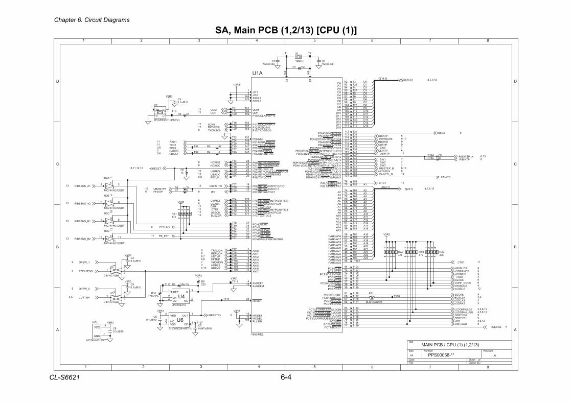
Chapter 6. Circuit Diagrams
CL-S6621 6-4
SA, Main PCB (1,2/13) [CPU (1)]
1 2 3 4 5 6 7 8
A
B
C
D
87654321
D
C
B
A
Title
Number RevisionSize
A4
Date: Sheet of File: Drawn By:
APPS00058-**
MAIN PCB / CPU (1) (1,2/13)
0R3V
]1:42[A
]0:51[D
42A32A22A12A02A91A81A71A61A
51A41A31A21A11A01A
9A8A7A6A5A4A3A2A
1A
51D41D31D21D11D01D
9D8D7D6D5D4D3D2D1D0D
3R3V
3R3V3R3V
3R3V
3R3V
3R3V
3R3V
3R3V
0R5V
0R5V
0_WSPO9
1_WSPO9
PMTTUC9,6
SNESLEEP9
PTNIDH 6
WSUDH 9PHTUC 9
PTNIEC 6
SUTATSn 6
1PTNI2BU21
PMTFP8,6
0PYTRPC 91PYTRPC 9
1RSD11
0PTNI2BU211A_SNESBIR31
2A_SNESBIR31
1B_SNESBIR31
2B_SNESBIR31
1STC 11
ENOD_FNOC 6
PTNIFP6
SNSENP 9
GALFFP8
QERBU21
QERDH6
NOMART9NOMFER9
PMTDH7,6
NOMDHV7
PMTBR31,6
0IS/0DXR11
PTNIBU 11
SERDH7
1WS 72WS 73WS 7
1DXR11
3SCn 4
QEREC6
0WS 7
TINI_SR11
MDU11PDU11
21,6,5,4]0:51[D
TESERGn31,21,11,6
EKCDS 5
VTI6
KLCS6,3
KLCFP8,6
ATADS6,3
KCABU21
KCADH6
DRn 21,6,4
SACDSn 5SARDSn 5
KLCSUB 6,5
EBLLn/MQDLL 21,6,5,4EBULn/MQDUL 21,6,5,4
RWn/EWn 5
]1:42[A 21,6,5,4
0OS/0DXT6
SC1MORn 4
SCAGn 6
0KCS11
33TESERn 6
SCMARDSn 5GIFNOCn 6
SC2MORn 4
SCCAD3
NOBSU11REZZUB01
EVASRWP 01,9
1DXT11
1RTD11
R_LTCNAF 31
SCBSUn 21
KCAEC6
A_PETSBIR 31,6
B_PETSBIR 31,6
1STR 11
LTCNAF
AIDBR 9
PTNIBIR 6
13T
72T
48T
A1U
2EM/058V
1CIT/01CPTNI/56PTNI/56P91
1COT/76PTNI/76P71 11CPTNI/66PTNI/66P81
2CIT/02CPTNI/2QRAMD/27P671
12CPTNI/2KAAMD/37P571
2COT/2CT/47P471
3CIT/03CPTNI/3QRAMD/57P371
13CPTNI/3KAAMD/67P271
3COT/3CT/77P171
TIAW/0MCP43
1MCP33
KADLH/2MCP23
QRDLH/3MCP13
QRFER/4MCP03
GRTDA/FERFLES/5MCP92
TESER82
0INA5
1INA6
2INA7
3INA8
4INA9
5INA01
6INA11
7INA21
PFERVA4
MFERVA31
PDU061 MDU161
1EDOM51
0EDOM61
LESLLP651
TSYCB/7TCP77RW/EW/5TCP87DR/4TCP97MQDUU/EBUU/RWUU/3TCP08MQDLU/EBLU/RWLU/2TCP18MQDUL/EBUL/RWUL/1TCP28MQDLL/EBLL/RWLL/0TCP38
SARDS/3DCP68SACDS/2DCP78KLCSUB/1DCP88EKCDS/0DCP19
0D29
1D39
2D49
3D59
4D69
5D79
6D89
7D99
8D401
9D501
01D601
11D701
21D801
31D901
41D011
51D111
0DPTNI/61D/0HDP211
1DPTNI/71D/1HDP311
4COT/2DPTNI/81D/2HDP411
3DPTNI/91D/3HDP711
4DPTNI/02D/4HDP811
5COT/5DPTNI/12D/5HDP911
01DUCT/001PTNI/6DPTNI/22D/6HDP021
01RLCT/101PTNI/7DPTNI/32D/7HDP121
01OT/8DPTNI/42D/8HDP221
01DUIT/9DPTNI/52D/9HDP321
11DUCT/011PTNI/01DPTNI/62D/01HDP421
11RLCT/111PTNI/11DPTNI/72D/11HDP521
11OT/21DPTNI/82D/21HDP621
11DUIT/31DPTNI/92D/31HDP721
0MWP/41DPTNI/03D/41HDP031
1MWP/51DPTNI/13D/51HDP131
0A/0LPTNI/0LAP67
1A/1LPTNI/1LAP57
2A47
3A37
4A27
5A96
6A86
7A76
8A66
9A56
01A46
11A36
21A26
31A16
41A06
51A95
61A/0HAP85
71A/1HAP75
81A/2HAP25
91A/3HAP15
02A/4HAP05
12A/5HAP94
22A/6HAP84
32A/7HAP74
42A/8HAP64
52A/9HAP54
0SC/0SCP44
1SC/1SCP34
RWOI/2SC/2SCP24
3SC/3SCP14
4SC/4SCP04
DROI/5SC/5SCP73
6SC/6SCP63
7SC/7SCP53
1CT/0COT/55P02 1KAAMD/10CPTNI/45P12 1QRAMD/0CIT/00CPTNI/35P22 0CT/25PTNI/25P32 0KAAMD/15PTNI/15P42 0QRAMD/05PTNI/05P52
52PTNI/1OS/52P541 42PTNI/1IS/42P641 32PTNI/1KCS/32P741 22PTNI/1DXT/22P841 12PTNI/1DXR/12P941 IMN/02P251
0OS/0DXT/31P351 0IS/0DXR/21P451 11PTNI/0KCS/11P551
01PTNI/KLCU/01P951
X1
164
X2
165
1TIJ1
0TIJ2
1LESS961
0LESS071
92T
601T
6C01B/u1.0
5U
66G1CHV47
1 23
4 5
93T
79T
82T
49T
521T
68T
921T
18T
901T
411T
03T
05T
201T
17T
99T
11R
121GA51MLB
62T
0*6R
04T
75T
D2U
TD621CHV47CM
21 11
13
69T
78T
2T
47T27T
16T
65T
4ARk74
1 2 3 45678
8R022
26T
7T
2X
)zHM84(1ID2008CSD
BS V
G C
23T
8C01B/u1.0
35T
22T
711T
73T
621T
7C61B/u740.0
5C01B/u1.0
07T
221T
36T
41T
121T
111T
6UU1T5M-I82C9001-S
TUO1
DDV2
CN4
SSV3
DC5
67T
021T
3C01B/u1.0
742R
24T
A2U
TD621CHV47CM
2 3
1
101T
M11R
311T
34T
89T
85T
3U
66G1CHV47
1 23
4 5
3T
53T
5T
721T
87T
86T
1X
zHM61
3ARk74
1 2 3 45678
56T
06T
54T
95T
14T
01T
97T
45T
801T
01R%1/k001
011T
12T
28T
37T
52T
71T
74T
02T
4C01B/u1.0
911T
0541R
B2U
TD621CHV47CM
5 6
411T
301T
83T
08T
81T
32T
4T
61T
66T
821T
58T
2ARk74
1 2 3 45678
76T
55T25T
42T
31T
E2U
TD621CHV47CM
CCV41
DNG7
1T
8T
07R
511T
94T
19T
63T
51T
09T
2C05HC/p51
46T
9T
39T
4UAT3901CPu
1A2
FER1
K3
2A4
CN5
04R
98T
44T
001T
321T
38T
C2U
TD621CHV47CM
9 8
10
401T
84T
29T
64T
1C05HC/p51
6T
96T
211T
77T
59T
88T
701T
421T
21T
5Rk1
743R
57T
33T
1ARk74
1 2 3 45678
%1/k029R
15T
811T
0*441R
91T
611T
43T
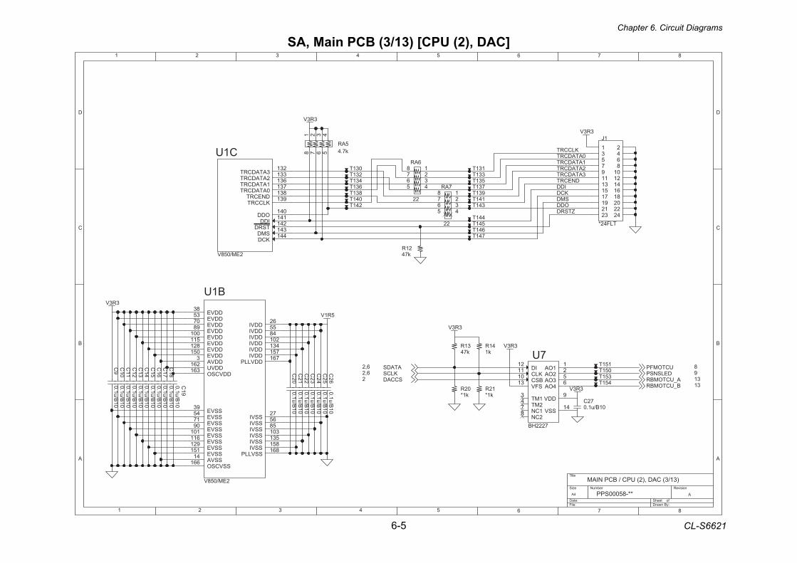
Chapter 6. Circuit Diagrams
6-5 CL-S6621
1 2 3 4 5 6 7 8
A
B
C
D
87654321
D
C
B
A
Title
Number RevisionSize
A4
Date: Sheet of File: Drawn By:
APPS00058-**
MAIN PCB / CPU (2), DAC (3/13)
ODD
2ATADCRT
0ATADCRT
DNECRT
ZTSRD
KLCCRT
KCDIDD
SMD
1ATADCRT
3ATADCRT
5R1V
3R3V
3R3V
3R3V
3R3V
3R3V
3R3V
SCCAD2
ATADS6,2KLCS6,2
UCTOMFP 8DELSNSP 9
A_UCTOMBR 31B_UCTOMBR 31
C23
0.1u/B10
831T
12Rk1*
C21
0.1u/B10
41Rk1
641T
C18
0.1u/B10
151T
1J
TLF42*
1 23 45 67 89 0111 2131 4151 6171 8191 0212 2232 42
241T 341T
02Rk1*
C16
0.1u/B10
141T
231T
C14
0.1u/B10 72C
01B/u1.0
351T
C12
0.1u/B10
6AR
22
12345
678
C26
0.1u/B10
C10
0.1u/B10
451T
931T
741T
631T
C24
0.1u/B10
5ARk7.4
1 2 3 45678
531T
21Rk74
31Rk74
441T
C22
0.1u/B10
7U
7222HB
BSC01
ID21
KLC11
1MT3
SSV41
DDV9
1OA1
2OA2
2MT4
3OA5
4OA6
1CN7
SFV31
2CN8
C20
0.1u/B10
041T
C19
0.1u/B10
C17
0.1u/B10
7AR
22
12345
678
031T 131T
731T
331T
C15
0.1u/B10
C13
0.1u/B10
541T
C1U
2EM/058V
3ATADCRT231
2ATADCRT331
1ATADCRT631
0ATADCRT731
DNECRT831
KLCCRT931
ODD041
IDD141
TSRD241
SMD341
KCD441
C11
0.1u/B10
431T
051TC25
0.1u/B10
C9
0.1u/B10
B1U
2EM/058V
DDVI62
DDVI55
DDVI48
DDVI201
DDVI431
DDVI751
DDVLLP761
SSVI72
SSVI65
SSVI58
SSVI301
SSVI531
SSVI851
SSVLLP861
DDVE83
DDVE35
DDVE07
DDVE98
DDVE001
DDVE511
DDVE821
DDVE051
DDVA3
DDVCSO361
SSVE93
SSVE45
SSVE17
SSVE09
SSVE101
SSVE611
SSVE921
SSVE151
SSVA41
SSVCSO661
DDVU261
SA, Main PCB (3/13) [CPU (2), DAC]
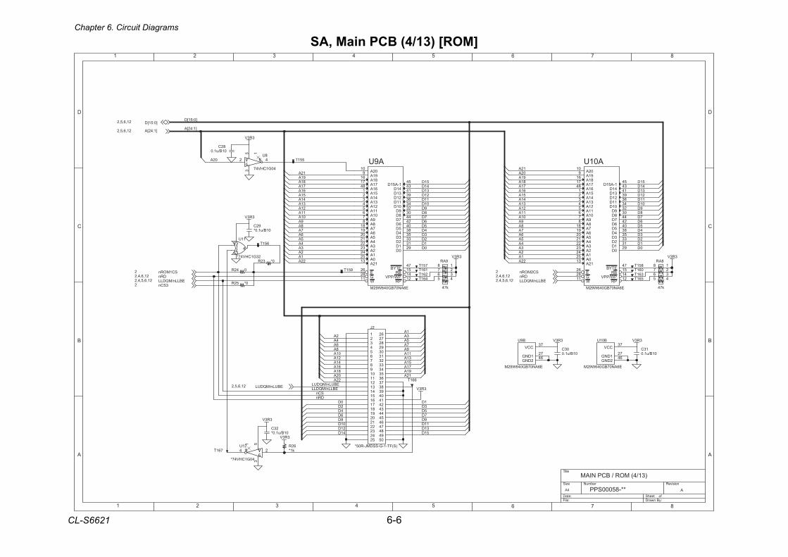
Chapter 6. Circuit Diagrams
CL-S6621 6-6
SA, Main PCB (4/13) [ROM]
1 2 3 4 5 6 7 8
A
B
C
D
87654321
D
C
B
A
Title
Number RevisionSize
A4
Date: Sheet of File: Drawn By:
APPS00058-**
MAIN PCB / ROM (4/13)
1A22A22A
1A
]0:51[D
EBULn/MQDULEBLLn/MQDLL
SCn
12A
1A3A5A7A
51A
9A11A31A
71A91A
41A
8A
21A
02A
2A4A6A
81A
01A
61A
41D21D01D
8D6D4D2D0D
51D
8A7A
9D11D31D
5D
1D
6A5A
7D
3D
DRn
4A3A
51D
5D
11D
9D8D
4D
41D
7D
2D3D
6D
31D
01D
21D
1D0D
91A81A
11A
31A41A
01A
51A
9A
61A
21A
71A
2A
6D
9D01D
21D
51D
5D4D3D
8D
41D
7D
2D
31D
11D
1D
02A
]1:42[A
0D2A
8A9A
6A7A
4A5A
02A
41A
21A
91A
51A
01A
61A
11A
81A
31A
71A
3A
12A12A
22A
3R3V
3R3V
3R3V
3R3V
3R3V
3R3V
3R3V
3R3V 3R3V
]1:42[A21,6,5,2
DRn21,6,4,2EBLLn/MQDLL21,6,5,4,2
EBULn/MQDUL21,6,5,2
SC2MORn2
EBLLn/MQDLL21,6,5,4,2DRn21,6,4,2
SC1MORn2
3SCn2
]0:51[D21,6,5,2
561T
21U
40G1CHV47*
24
51
39AR
k74
12345
678
13C01B/u1.0
8AR
k74
12345
678
161T
761T
92C01B/u1.0*
461T0*52R
B01U
E6AN07BG046W92M2DNG
64
CCV73
1DNG72
551T
042R751T
951T 061T
A9U
E6AN07BG046W92M
1-A51D54
0A52 1A42 2A32 3A22 4A12 5A02 6A91 7A81 8A8 9A7 01A6 11A5 21A4 31A3 41A2 51A1 61A84 71A71
E62
G82
ETYB74
0D921D132D333D534D835D046D247D44
W11
PR21
BR51
81A61
41D34
31D14
21D93
11D63
01D43
9D23
8D03
91A9 02A01
12A31
PW/PPV41
62Rk1*
A01U
E6AN07BG046W92M
1-A51D54
0A52 1A42 2A32 3A22 4A12 5A02 6A91 7A81 8A8 9A7 01A6 11A5 21A4 31A3 41A2 51A1 61A84 71A71
E62
G82
ETYB74
0D921D132D333D534D835D046D247D44
W11
PR21
BR51
81A61
41D34
31D14
21D93
11D63
01D43
9D23
8D03
91A9 02A01
12A31
PW/PPV41
82C01B/u1.0
261T
03C01B/u1.0
361T
651T
23C01B/u1.0*
8U
40G1CHV47
2 4
5 1
3
2J
)S(FT-1-G-SSDMJ-R05*
1234567
0198
112131415161718191021222324252
62728292031323334353637383930414243444546474849405
0*32R
661T
11U
23G1CHV47*
851T
B9U
E6AN07BG046W92M2DNG
64
CCV73
1DNG72
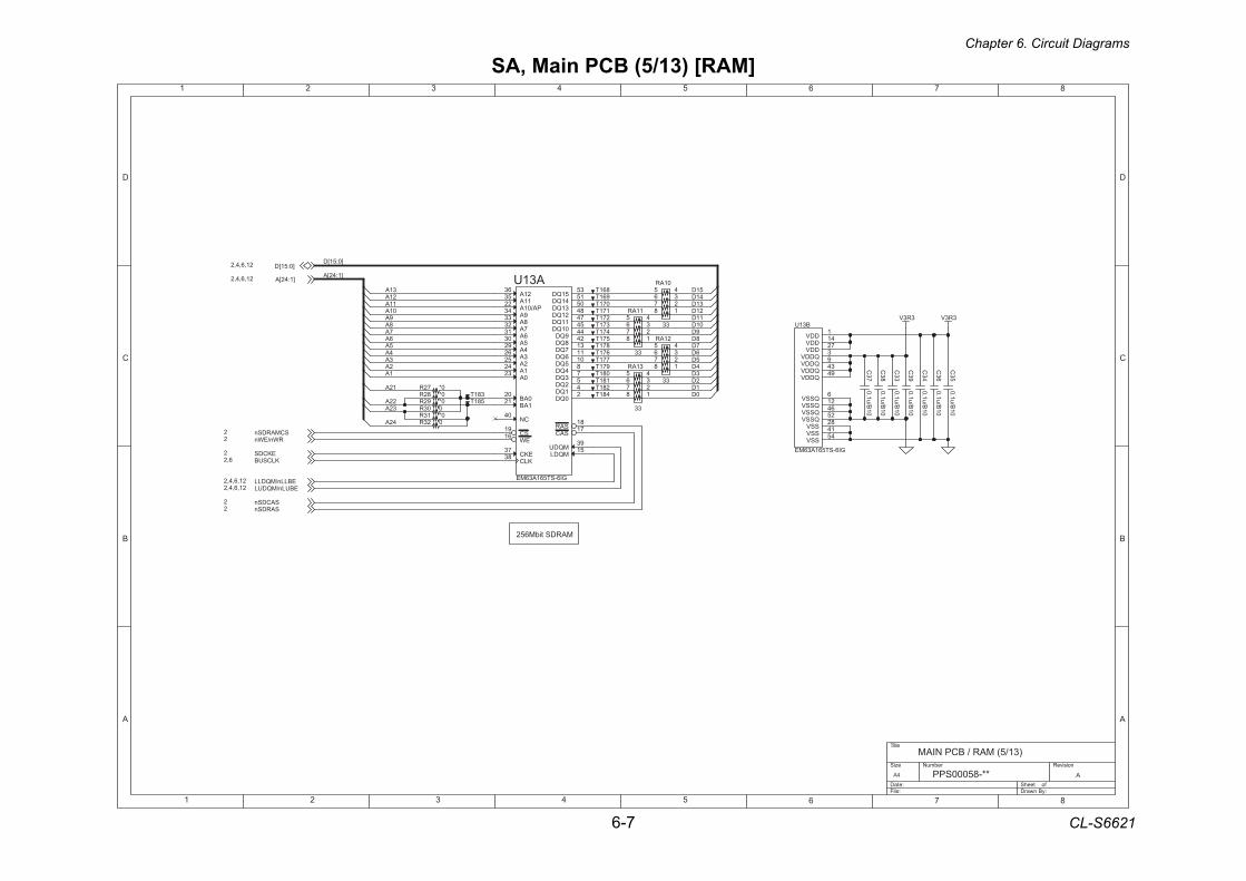
Chapter 6. Circuit Diagrams
6-7 CL-S6621
SA, Main PCB (5/13) [RAM]
1 2 3 4 5 6 7 8
A
B
C
D
87654321
D
C
B
A
Title
Number RevisionSize
A4
Date: Sheet of File: Drawn By:
APPS00058-**
MAIN PCB / RAM (5/13)
MARDS tibM652
0D
5D
1D2D
]0:51[D
3D4D
6D7D
1A
8D9D01D11D21D31D41D
32A22A
51D
42A
21A11A01A
9A8A7A6A5A4A
]1:42[A
3A2A
12A
31A
3R3V3R3V
SCMARDSn2RWn/EWn2
KLCSUB6,2
]1:42[A21,6,4,2
SARDSn2
EKCDS2
SACDSn2
EBULn/MQDUL21,6,4,2EBLLn/MQDLL21,6,4,2
]0:51[D21,6,4,2
471T
0*72R
961T
31AR
33
12345
678
0*92R
181T
C35
0.1u/B10
871T
0*13R
C34
0.1u/B10
171T
C33
0.1u/B10
481T
861T
21AR
33
12345
678
B31U
GI6-ST561A36ME
QDDV9
QSSV25
DDV1
DDV41
DDV72
QDDV3
QDDV34
QSSV6
QSSV21
QSSV64
SSV82
SSV14
QDDV94
SSV45
771T
C37
0.1u/B10
371T
581T
01AR
33
12345
67811AR
33
12345
678
A31U
GI6-ST561A36ME
0QD21QD42QD53QD74QD85QD
016QD117QD318QD24
0A32 1A42 2A52 3A62 4A92 5A03 6A13 7A23 8A33 9A43 PA/01A22 11A53
9QD4401QD5411QD7421QD8431QD0541QD1551QD35
KLC83 EKC73
SAC71SAR81
MQDL51MQDU93EW
61 SC91
0AB02
1AB12
21A63
CN04
0*82R
081T
381T
571T
003R
071T
023R
C36
0.1u/B10
281T
C39
0.1u/B10
671T
C38
0.1u/B10
271T
971T
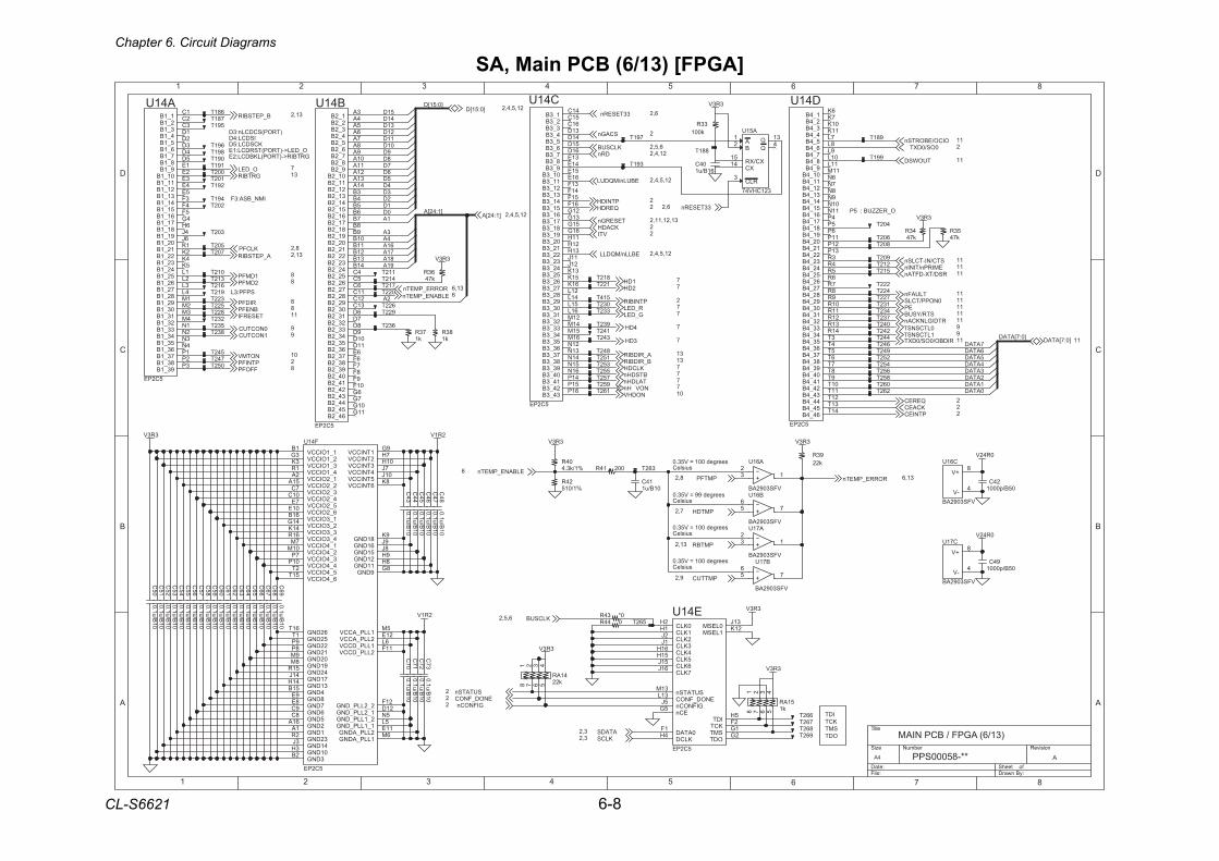
Chapter 6. Circuit Diagrams
CL-S6621 6-8
SA, Main PCB (6/13) [FPGA]
1 2 3 4 5 6 7 8
A
B
C
D
87654321
D
C
B
A
Title
Number RevisionSize
A4
Date: Sheet of File: Drawn By:
APPS00058-**
MAIN PCB / FPGA (6/13)
O_REZZUB : 5P
IMN_BSA:3F
)TROP(SCDCLn:3DISDCL:4D
KCSDCL:5DO_DEL>-)TROP(TSRDCL:1EGRTBIR>-)TROP(LKBDCL:2E
SPFP:3L2A
6ATAD5ATAD
7ATAD
3ATAD2ATAD1ATAD0ATAD
4A61A71A81A91A
1A
3A
]1:42[A
4ATAD
]0:7[ATAD
0D1D2D3D
41D51D
4D5D6D7D
]0:51[D
8D9D01D11D21D31D
2R1V3R3V
2R1V
3R3V
3R3V
3R3V
3R3V
0R42V
3R3V
3R3V
3R3V
3R3V
0R42V
0OS/0DXT 2
RORRE_PMETn 31,6
KLCSUB 6,5,2
VTI 2
DRn 21,4,2
]1:42[A 21,5,4,2TESERGn 31,21,11,2
KCADH 2
KLCFP 8,2
33TESERn 6,2
SCAGn 2
KLCSUB6,5,2
KCAEC 2
OICO/EBORTSn 11
STC/NI-TCLSn 11
RSD/TX-DFTAn 11EMIRPn/TINIn 11
GIFNOCn2
EBULn/MQDUL 21,5,4,2
EBLLn/MQDLL 21,5,4,2
TUOWSD 11
PMTFP8,2ELBANE_PMETn6
33TESERn6,2
PMTDH7,2
ATADS3,2KLCS3,2
PMTBR31,2
PMTTUC9,2
]0:51[D 21,5,4,2
11]0:7[ATAD
B_RIDBIR 31
TALDHn 7
BNEFP 8
FFOFP 8
1DMFP 8
0NOPP/TCLS 11
QEREC 2
PTNIEC 2
TLUAFn 11
RTD/GLNKCAn 11
EP 11STR/YSUB 11
RIDBO/0OS/0DXT 11
0NOCTUC 91NOCTUC 9
SUTATSn2ENOD_FNOC2
KLCDH 7
NOTMV 01
PTNIDH 2
2DMFP 8
RIDFP 8
NODHV 01
QERDH 2
1DH 7
ELBANE_PMETn 6
A_RIDBIR 31
BTSDHn 7
NOVC Hn 7
RORRE_PMETn 31,6
1LTCSNST 90LTCSNST 9
2DH 7
R_DEL 7G_DEL 7
PTNIFP 2
GRTBIR 31O_DEL 7
3DH 7
4DH 7
A_PETSBIR 31,2
TESERFI 11
B_PETSBIR 31,2
PTNIBIR 2
112T
33Rk001
B61U
VFS3092AB
756
A71U
VFS3092AB
23 1
791T
612T
C56
0.1u/B10
232T
C53
0.1u/B10 044R 562T
A61U
VFS3092AB
23 1
C61
0.1u/B10
C51
0.1u/B10
902T
552T
942T
422T
032T
862T
142T
891T
B71U
VFS3092AB
756
41ARk22
1 2 3 45678
652T
802T
742T
C70
0.1u/B10
102T
51ARk1
1 2 3 45678
94C05B/p0001
262T
732T
C71
0.1u/B10
24R%1/015
14C01B/u1
24C05B/p0001
302T
242T
312T
622T822T
352T
602T
991T
222T
162T
C71U
VFS3092AB
+V8
-V4
762T
53Rk74
691T
C44
0.1u/B10
542T
C69
0.1u/B10
C62
0.1u/B10
002T
C72
0.1u/B10
342T
252T
432T
C65
0.1u/B10
F41U
5C2PE
1_2OICCV2A
2_2OICCV51A
1DNG1A 2DNG61A
4DNG51B
3DNG2B
1_3OICCV61B
1_1OICCV1B
1TNICCV9G
2_1OICCV3G
2_3OICCV41G
9DNG8G
6DNG9C
5DNG8C
4_2OICCV01C 3_2OICCV7C
1_2LLP_DNG21D
2LLP_ADNG11E
2LLP_ACCV21E
8DNG9E
7DNG8E
6_2OICCV01E 5_2OICCV7E
2_2LLP_DNG21F
2LLP_DCCV11F
01DNG3H
11DNG8H21DNG9H
31DNG41H
2TNICCV7H
3TNICCV01H
4TNICCV7J
5TNICCV01J
41DNG3J
51DNG8J61DNG9J
71DNG41J
6TNICCV8K
3_1OICCV3K
3_3OICCV41K
81DNG9K
1LLP_DCCV6L
1_1LLP_DNG5L
1LLP_ACCV5M
1LLP_ADNG6M
1_4OICCV7M
2_4OICCV01M
91DNG8M 02DNG9M
2_1LLP_DNG5N
3_4OICCV7P
4_4OICCV01P
12DNG8P 22DNG9P
4_1OICCV1R
4_3OICCV61R
32DNG2R
42DNG51R
5_4OICCV2T
6_4OICCV51T
52DNG1T 62DNG61T
012T
C64
0.1u/B10
852T
C57
0.1u/B10
122T
362T
202T
C54
0.1u/B10
63Rk74
D41U
5C2PE64_4B
41T54_4B31T44_4B21T34_4B11T24_4B01T14_4B
9T04_4B8T93_4B7T83_4B6T73_4B5T63_4B4T53_4B3T43_4B
41R33_4B31R23_4B21R13_4B11R03_4B01R92_4B
9R82_4B8R72_4B7R62_4B6R52_4B5R42_4B4R32_4B3R22_4B31P12_4B21P02_4B11P91_4B
6P81_4B5P71_4B4P61_4B
11N51_4B01N41_4B
9N31_4B8N21_4B7N11_4B6N01_4B
11M9_4B11L8_4B01L7_4B
9L6_4B8L5_4B7L4_4B
11K3_4B01K2_4B
7K1_4B6K
502T
C66
0.1u/B10
702T
C68
0.1u/B10
522T
632T
912T
591T
152T
832T
402T
E41U
5C2PE
SMT1G
ODT2G
ECn5G
KCT2F
0ATAD1F
KLCD4H
IDT5H
GIFNOCn5J
0LESM31J
1LESM21K
ENOD_FNOC31L SUTATSn31M
0KLC2H
1KLC1H
2KLC2J
3KLC1J
4KLC61H
5KLC51H
6KLC51J
7KLC61J
512T
952T
83Rk1
662T
C63
0.1u/B10
00214R
812T
C67
0.1u/B10
C47
0.1u/B10
C41U
5C2PE34_3B
61P24_3B51P14_3B41P04_3B61N93_3B51N83_3B41N73_3B31N63_3B21N53_3B61M43_3B51M33_3B41M23_3B21M13_3B
61L03_3B51L92_3B41L82_3B21L72_3B61K62_3B51K52_3B31K42_3B21J32_3B11J22_3B31H12_3B21H02_3B11H91_3B61G81_3B51G71_3B31G61_3B21G51_3B61F41_3B51F31_3B41F21_3B31F11_3B61E01_3B51E9_3B41E8_3B31E7_3B61D6_3B51D5_3B41D4_3B31D3_3B61C2_3B51C1_3B41C
191T
C61U
VFS3092AB
+V8
-V4
73Rk1
C45
0.1u/B10
781T
93Rk22
132T922T
642T
712T
C55
0.1u/B10
491T
C58
0.1u/B10
842T
452T
022T
0*34R
391T
322T
932T
681T
C43
0.1u/B10
532T
981T
212T
752T062T
042T
C52
0.1u/B10
881T
C73
0.1u/B10
962T
A51U
321CHV47
A1
B2
RLC3
XC41 XC/XR51
Q4Q 31
091T
C59
0.1u/B10
43Rk74
052T
722T
332T
514T
C60
0.1u/B10
C46
0.1u/B10
B41U
5C2PE
1_2B3A
2_2B4A
3_2B5A
4_2B6A
5_2B7A
6_2B8A
7_2B9A
8_2B01A
9_2B11A
01_2B21A
11_2B31A
21_2B41A
31_2B3B
41_2B4B
51_2B5B
61_2B6B
71_2B7B
81_2B8B
91_2B9B
02_2B01B
12_2B11B
22_2B21B
32_2B31B
42_2B41B
52_2B4C
62_2B5C
72_2B6C
82_2B11C
92_2B21C
03_2B31C
13_2B6D
23_2B7D
33_2B8D
43_2B9D
53_2B01D
63_2B11D
73_2B6E
83_2B6F
93_2B7F
04_2B8F
14_2B9F
24_2B01F
34_2B6G
44_2B7G
54_2B01G
64_2B11G
442T
04C61B/u1
412T
A41U
5C2PE
1_1B1C
2_1B2C
3_1B3C
4_1B1D
5_1B2D
6_1B3D
7_1B4D
8_1B5D
9_1B1E
01_1B2E
11_1B3E
21_1B4E
31_1B5E
41_1B3F
51_1B4F
61_1B5F
71_1B4G
81_1B6H
91_1B4J
02_1B6J
12_1B1K
22_1B2K
32_1B4K
42_1B5K
52_1B1L
62_1B2L
72_1B3L
82_1B4L
92_1B1M
03_1B2M
13_1B3M
23_1B4M
33_1B1N
43_1B2N
53_1B3N
63_1B4N
73_1B1P
83_1B2P
93_1B3P
C48
0.1u/B10
C50
0.1u/B10
04R%1/k3.4
291T
TDITCKTMSTDO
0.35V = 100 degrees Celsius
0.35V = 100 degrees Celsius
0.35V = 99 degrees Celsius
0.35V = 100 degrees Celsius
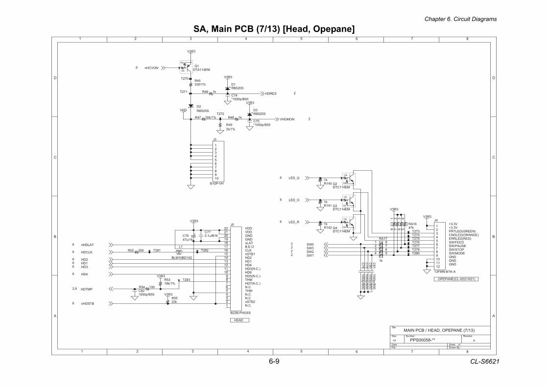
Chapter 6. Circuit Diagrams
6-9 CL-S6621
SA, Main PCB (7/13) [Head, Opepane]
1 2 3 4 5 6 7 8
A
B
C
D
87654321
D
C
B
A
Title
Number RevisionSize
A4
Date: Sheet of File: Drawn By:
APPS00058-**
MAIN PCB / HEAD, OPEPANE (7/13)
DDV
DAEH
DDVDNGDNG
O.E.BTALn
1BTSn
2BTSn
KLC
1DH2DH
).C.N(3DH4DH
).C.N(5DH6DH
).C.N(7DHMHT
MHT.C.N
.C.N
.C.N
.C.N
V3.3+V3.3+
)NEERG(DELTRP)EGNARO(DELDNC
)DER(DELRREDEEF/WS
ESUAP/WSPOTS/WSEDOM/WS
DNGDNGDNG
)126/125S-LC(ENAPEPO
DHV
3R3V
3R3V
3R3V
3R3V
3R3V
3R3V
3R3V
3R3V
NOVCHn6
BTSDHn6
KLCDH6
TALDHn6
2DH6
3DH61DH6
4DH6
R_DEL6
O_DEL6
G_DEL6
SERDH 2
PMTDH6,2
NOMDHV 2
3WS22WS21WS2
0WS2
54R%1/033
35R%1/k81
1DS025BR
382T
94R%1/k2
572T
3DS025BR
772T672T
1L
201DB51MLB
472T
2QME411CTD
241Rk1
C79
1000p/B50
71AR
k1
1234 5
678
%1/k0374R
372T
55Rk22
3J
HV-P01B
123456789
01
1QME411ATD
00225R
61ARk74
1 2 3 45678
k184R
00145R
47C05B/p0001*
141Rk1
k164R
182T
072T
041Rk1
28C05B/p0001
2DS025BR
282T
57C05B/p0001*
5J
SSDHP-B22B
12345678901112131415161718191021222
C81
1000p/B50
082T
C80
1000p/B50
872T
4J
A-KTB-NMF21
123456789
011121
77C61B/u1.0
C78
1000p/B50
172T
4QME411CTD
272T
3QME411CTD
+67C61/u74
10k
10k
10k
10k
10k
10k
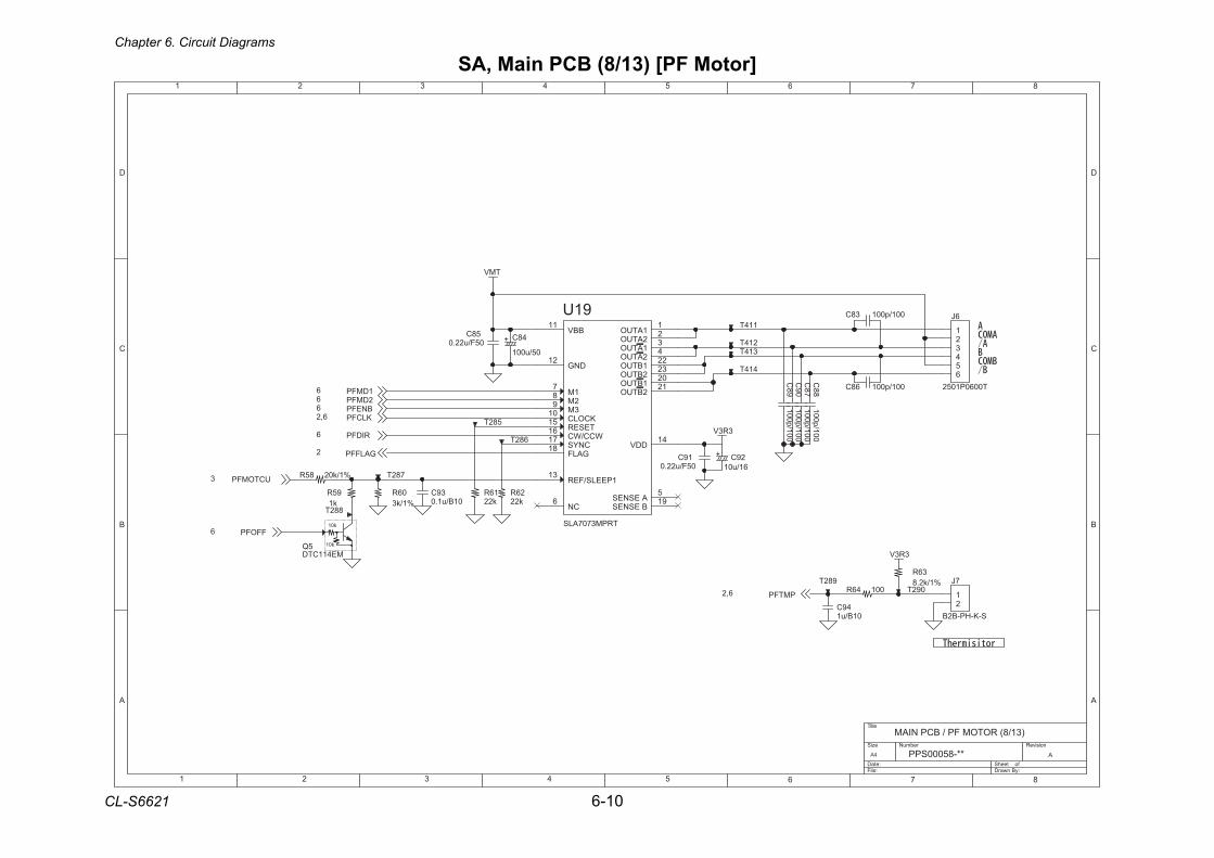
Chapter 6. Circuit Diagrams
CL-S6621 6-10
SA, Main PCB (8/13) [PF Motor]
1 2 3 4 5 6 7 8
A
B
C
D
87654321
D
C
B
A
Title
Number RevisionSize
A4
Date: Sheet of File: Drawn By:
APPS00058-**
MAIN PCB / PF MOTOR (8/13)
3R3V
TMV
3R3V
UCTOMFP3
2DMFP61DMFP6
KLCFP6,2
RIDFP6
BNEFP6
FFOFP6
PMTFP6,2
GALFFP2
58C05F/u22.0
+ 29C61/u01
49C01B/u1
%1/k0285R
114T
782T
092T
214T
C89
100p/100682T
314T
C90
100p/100
6J
T0060P1052
123456
36R%1/k2.8
91U
TRPM3707ALS
BBV11
1PEELS/FER31
DDV41
1ATUO1
2ATUO2
1ATUO3
2ATUO4
A ESNES5
B ESNES91
DNG21
KCOLC01
GALF81
TESER51
CNYS71
3M9
WCC/WC61
1M7
2M8
CN6
1BTUO22
2BTUO32
1BTUO02
2BTUO12
001/p00138C
95Rk1
19C05F/u22.0
39C01B/u1.0
5QME411CTD
882T
7J
S-K-HP-B2B
12
26Rk22
414T
582T
C87
100p/100
16Rk22
00146R
001/p00168C
+ 48C
05/u001
06R%1/k3
982T
C88
100p/100
10k
10k
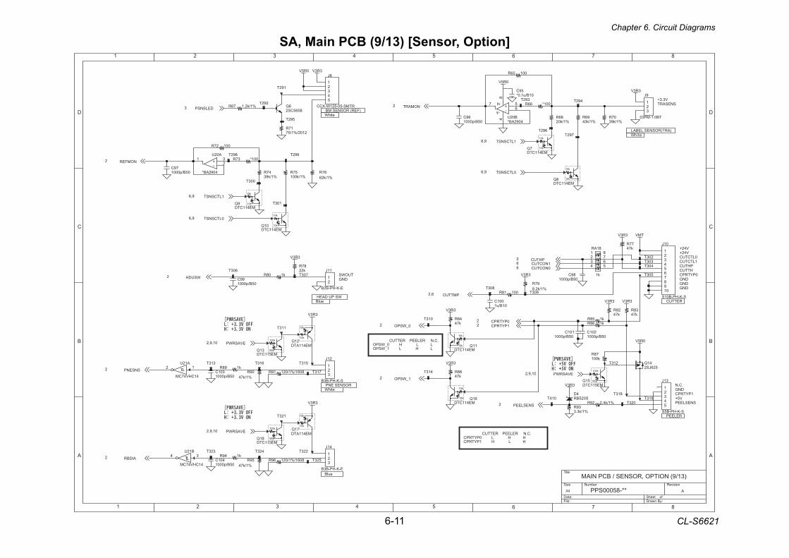
Chapter 6. Circuit Diagrams
6-11 CL-S6621
SA, Main PCB (9/13) [Sensor, Option]
1 2 3 4 5 6 7 8
A
B
C
D
87654321
D
C
B
A
Title
Number RevisionSize
A4
Date: Sheet of File: Drawn By:
APPS00058-**
MAIN PCB / SENSOR, OPTION (9/13)
)FER( ROSNES MBSNESART
)ART(ROSNES LEBAL
eulBWS PU DAEH
V42+V42+
0LTCTUC
RETTUC
RELEEP
1LTCTUCPHTUCHTTUC
0PYTRPCDNGDNGDNG
DNG.C.N
1PYTRPCV5+
SNESLEEP
.C.N RELEEP RETTUC L L H 0_WSPOL H L 1_WSPO
V3.3+
etihW
etihW
TUOWSDNG
ROSNES ENPetihW
.C.N RELEEP RETTUC H H L 0PYTRPCH L H 1PYTRPC
eulB
3R3V
3R3V
3R3V
3R3V
3R3V TMV
3R3V
3R3V
0R5V
0R5V
0R5V
3R3V
3R3V3R3V
3R3V
3R3V
0NOCTUC61NOCTUC6
EVASRWP01,9,2
DELSNSP3
0LTCSNST9,6
1LTCSNST9,6
0LTCSNST9,6
1LTCSNST9,6
SNESLEEP2
PHTUC2
PMTTUC6,2
0_WSPO2
1_WSPO2
1PYTRPC20PYTRPC2
NOMFER2
NOMART2
WSUDH2
SNSENP2
EVASRWP01,9,2
AIDBR2
EVASRWP01,9,2
013T
303T
67R%1/k26
A12U
41CHV47CM
12
k168R
21QME411ATD
31QME511CTD
023T
A02U
4092AB*
231
%1/k4.229R
99C05B/p0001
613T
001C01B/u1
61QME411CTD
17R2102/%1/57
603T
59R%1/k74
592T 86R%1/k02
07R%1/k93
892T
00118R
292T
4DS025BR
9QME411CTD
81QME511CTD
513T
103T
57R%1/k001
8061/%1/02119R 88Rk74
992T
k108R
79C05B/p0001
%1/k2.176R492T
11QME411CTD
8J
RTMS-50-521W-XCC
12345
00156R
09R%1/k74
813T
01J
S-K-HP-B01S
123456789
01
39R%1/k3.3
6Q8565CS2
01QME411CTD
28Rk74
48Rk74
201C05B/p0001
001*37R
97R%1/k2.8
77Rk74
123T
7QME411CTD
11J
E-K-HP-B2B
12
703T
41J
E-K-HP-B3B
123
21J
S-K-HP-B3B
123
41Q526JS2
78Rk001
392T
59C01B/u1.0*
423Tk149R
8QME411CTD
81AR
k1
1234 5
678
89C05B/p0001
71QME411ATD
B02U4092AB*
8
7 56
4
213T
87Rk22
31J
S-K-HP-B5S
12345
014T
B12U
41CHV47CM
34
503T
913T
69C05B/p0001
223T
51QME511CTD
47R%1/k93
00127R
203T
903T
413T
113T
38Rk74
9J
TB0.1-MF30
123
803T
403T
301C05B/p0001
713T
792T
401C05B/p0001
001*66R
8061/%1/02169R
692T
96R%1/k34
101C05B/p0001
003T
k198R
323T
k158R
523T
313T
192T
10k
10k
10k
10k
10k
10k
10k
10k
10k
10k
10k
10k
100k
100k
100k
100k
100k
100k10k
10k
10k
10k
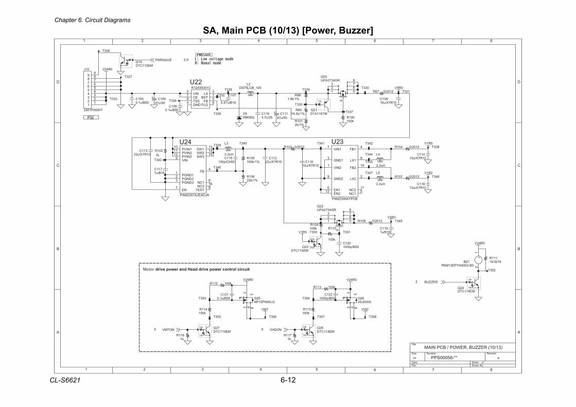
Chapter 6. Circuit Diagrams
CL-S6621 6-12
SA, Main PCB (10/13) [Power, Buzzer]
1 2 3 4 5 6 7 8
A
B
C
D
87654321
D
C
B
A
Title
Number RevisionSize
A4
Date: Sheet of File: Drawn By:
APPS00058-**
MAIN PCB / POWER, BUZZER (10/13)
tiucric lortnoc rewop evird daeH dna rewop evird rotoM
0R42V
0R42V
TMV DHV
0R42V
0R42V
5R1V
2R1V
0R5V
3R3V
5R1V
EVASRWP 9,2
NODHV6NOTMV6
REZZUB2
02QRG4372APU
4
5167
23
8
923T
743T711C
61B/u1
99R%1/k2.61
623T
823T
111R6123/k1
101R%1/k2
k001211R
601R%1/k22
411C01R7X/u01
2102/0701R
2102/0301R243T
2102/079R
811C01R7X/u01
253T
733T
411Rk001
853T
453T
+ 111C05/u74
89R%1/k8.1
343T
2L001_BCL57SD
52QGLS60P51PN
1
23
4
72QME411CTD
5DL050BR 001R
k001
043T
51J
T0090P10521
12233445566778899
133T
911C61B/u1
2102/0401R
22QRG4372APU
4
5167
23
8
611Rk1
901C05B/u1.0
233T
501R%1/k001
011C52/u7.4
443T
62QS505JS2
1
23
4511Rk001
12QMT511ATD
643T
42QME411CTD
3L
Hu2.2
933T
753T
533T
843T
943T
153T
143T
91QME511CTD
053T
k001311R
701C
61B/u74.0
22UC100S3421R
NIV2
DNG4 BF
5XL
3
TSB1
GLF6
EC7
SST8
011R
k001
611C01R7X/u01
42U
RJDAEJA7032MAP
1NIVP01
1DNGP1
NIV9
1WS31
2DNGP2
TSET82CN61
NE7
1CN6
BF4
2NIVP11
3NIVP21
3DNGP3
2WS41
3WS51
633T
311C01R7X/u22
543T
221C05B/p0001
511C05HC/p001
801C01R7X/u01
833T
723T
353T
82QME411CTD
901Rk001
333T
653T
201Rk1
32U
BCPYA6032MAP
1NIV7
1DNG3
1XL8
2NIV1
1BF4
2DNG9
1CN52CN11
2NE21 1NE6
2XL2
2BF01
+
1ZB0B-2004HYPE31MKP
12
211C01R7X/u22
711Rk1
32QME511CTD
021C05B/p0001
5L
Hu2.2
121C05B/u1.0
4L
Hu2.2
2102/0801R
433T501C05B/u1.0
+ 601C05/u74
033T
553T
10k
10k
10k
10k
10k
10k
100k
100k
10k
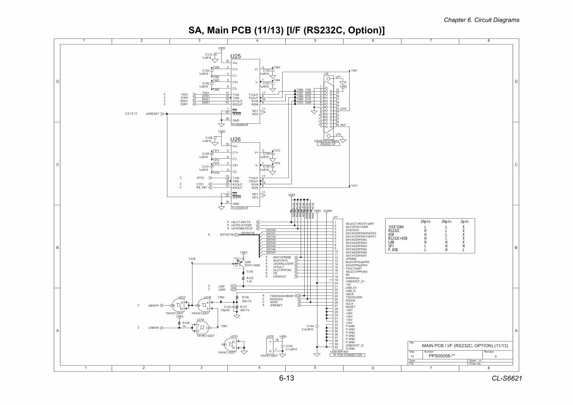
Chapter 6. Circuit Diagrams
6-13 CL-S6621
SA, Main PCB (11/13) [I/F (RS232C, Option)]
1 2 3 4 5 6 7 8
A
B
C
D
87654321
D
C
B
A
Title
Number RevisionSize
A4
Date: Sheet of File: Drawn By:
APPS00058-**
MAIN PCB / I/F (RS232C, OPTION) (11/13)
ROTCENNOC BCP F/I
TNIp/TSC/NI-TCELESRSD/TXDFOTUA
0ICO/BTS00PEh/0WSPID/0ATAD10PEh/1WSPID/1ATAD
2WSPID/2ATAD3WSPID/3ATAD4WSPID/4ATAD5WSPID/5ATAD6WSPID/6ATAD7WSPID/7ATAD
EMIRPn00PEp/STR/YSUB
10PEp/RTD/KCATNIh/TLUAF
0NOPP/TCELESEP
tuoWSWD+D_TSOHBSU
V5++D_BSU-D_BSU
SUBV
IS/DXRRID/OS/DXT
TESERV42+V42+V42+V42+V42+
DNG.PDNG.PDNG.P
DNG.PDNG.P
DNG.P-D_TSOHBSU
DNG.S
KLCS
1RSD1DXR
1DXT1RTD
F/I C232SR
]0:7[ATAD2ATAD
5ATAD6ATAD
3ATAD
0ATAD
4ATAD
7ATAD
1ATAD
DXT
STCSTRDXR
RSD
RTD
TINI
0R5V
3R3V
3R3V
3R3V
3R3V
0R42V
3R3V
3R3V
3R3V
TESERGn31,21,6,2
0KCS2TESERFI6
TUOWSD6
STR/YSUB6RTD/GLNKCAn6
TLUAFn60NOPP/TCLS6
EP6
1DXT21RTD2
1STR2
NOBSU2
]0:7[ATAD6
RIDBO/0OS/0DXT6
PDU2MDU2
0IS/0DXR2
PTNIBU2
STC/NI-TCLSn6RSD/TX-DFTAn6OICO/EBORTSn6
EMIRPn/TINIn6
1DXR21RSD2
1STC2TINI_SR2
61J
3ABBTGF52EA522
52423222
0212
91
1234 61
5141
3121110198765
8171
1PL
2PL
R122
300k
331C05/p33
62U
ZVIE2223LCI
+1C2
NI1R61
NE1
+V3
-1C4
TUO1R51
-V7
TUO2T8
NI2R9
TUO2R01
1CN11
NI2T21 NI1T31
2CN41
+2C5
-2C6
ccV91
TUO1T71
DNG81
NDHS02
873T
52U
ZVIE2223LCI
+1C2
NI1R61
NE1
+V3
-1C4
TUO1R51
-V7
TUO2T8
NI2R9
TUO2R01
1CN11
NI2T21 NI1T31
2CN41
+2C5
-2C6
ccV91
TUO1T71
DNG81
NDHS02
A72U
TD231CHV47
973T
573T
263T
673T
563T
C72U
TD231CHV47
R121
22k
463T
183T
131C61B/u1
B72U
TD231CHV47
163T953T
821C61B/u1
431C01B/u2.2
763T
R124
300k
373T
621C61B/u1
R120
22k
321C61B/u1
663T
063T521C
61B/u1
073T
621R%1/k02
473T
521Rk5.1
R123
300k
R118
22k
083T
231C61B/u1
821Rk1
963T
773T
D72U
TD231CHV47
921C61B/u1
721R%1/k03
863T
71J
TS8-P04-52XT
03
1
92
2
82
3
72
4
62
5
52
6
42
7
32
8
22
9
12
01
02
11
91
21
81
31
71
41
6151
13233343536373839304
273T
E72U
TD231CHV47
V41
G7
031C61B/u1
363T
R119
22k
721C61B/u1
531C01B/u1.0
92QME411ATD
173T
421C61B/u1
10k
10k
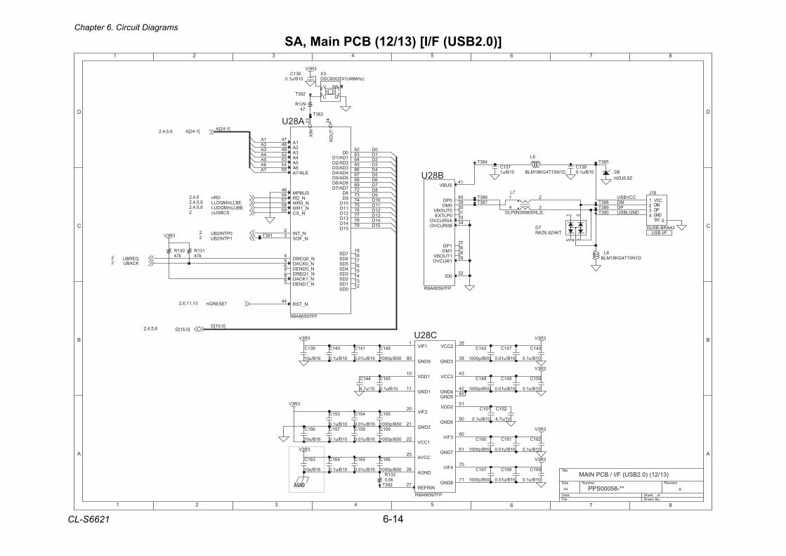
Chapter 6. Circuit Diagrams
CL-S6621 6-14
SA, Main PCB (12/13) [I/F (USB2.0)]
1 2 3 4 5 6 7 8
A
B
C
D
87654321
D
C
B
A
Title
Number RevisionSize
A4
Date: Sheet of File: Drawn By:
APPS00058-**
MAIN PCB / I/F (USB2.0) (12/13)
F/I BSU
MDPD
DNGLBSU
]1:42[A
1A2A3A4A5A6A7A
]0:51[D
0D1D2D3D4D5D6D7D8D9D
01D11D21D31D41D51D
CCVBSU
3R3V
3R3V
3R3V
3R3V
3R3V
3R3V
3R3V
3R3V
3R3V
TESERGn31,11,6,2
KCABU2QERBU2
0PTNI2BU21PTNI2BU2
SCBSUn2
]1:42[A6,5,4,2
EBULn/MQDUL6,5,4,2EBLLn/MQDLL6,5,4,2
DRn6,4,2
]0:51[D6,5,4,2
351C
01B/u1.0
093T
451C
61B/u10.0651C
61B/u01
A82U
PF79566A8R
N_TNI2
N_FOS3
N_0QERD4
N_0KCAD5
N_0DNED6
N_1QERD7
N_1KCAD8
N_1DNED9
0DS211DS312DS413DS514DS615DS716DS817DS91
XIN
23
XO
UT
24
N_TSR44
SUBPM64
1A74
2A84
3A94
4A25
5A35
6A45
ELA/7A55
N_DR65
N_0RW75
N_1RW85
N_SC95
1DA/1D36
2DA/2D46
3DA/3D56
4DA/4D66
5DA/5D76
6DA/6D86
7DA/7D96
8D27
9D37
01D47
11D57
21D67
31D77
41D87
51D97
0D26
641C
05B/p0001
741C
61B/u10.0
731C01B/u1
583T
061C
05B/p0001
931C
61B/u01
951C
05B/p0001
941C
61B/u10.0
761C
05B/p0001
CCVMDPDDNG
GS
81J
24ARB-BSUD
1234
5
293T
561C
61B/u10.0
483T
8LD1NS174GK81MLB
C82U
PF79566A8R
1FIV1
1DDV01
1DNG11
2DNG12
2FIV02
1CCV22
CCVA52
DNGA62
2CCV53
3DNG83
4DNG24
3CCV34
5DNG54
6DNG05
2DDV15
3FIV06
7DNG16
4FIV07
8DNG17
9DNG08
NIRFER72
461C
01B/u1.0
B82U
PF79566A8R
SUBV14
0PD04
0MD93
0TUOBV03
0PLTXE13
A0RUCVO33
B0RUCVO43
1PD73
1MD63
1TUOBV82
1RUCVO92
0DI23
661C
05B/p0001
7DTK4Z8.6ZKR
215 4 3
441C
01/u7.4
231Rk6.5
831C01B/u1.0
983T
051C
01B/u1.0
151C
01B/u1.0
921R74
551C
05B/p0001
241C
05B/p0001
193T
851C
61B/u10.0 261C
01B/u1.0
161C
61B/u10.0
031Rk74
841C
05B/p0001
883T
861C
61B/u10.0
283T
6L
D1NS174GK81MLB
7L
L2LH009NSN0PLD
21
34783T
961C
01B/u1.0
141C
61B/u10.0
6DZ8.6UZH
131Rk74
251C
01/u7.4
631C01B/u1.0
751C
01B/u1.0
341C
01B/u1.0
683T
361C
61B/u01
3X)zHM84(1ID2008CSD
BSV
GC
541C
01B/u1.0
041C
01B/u1.0
383T
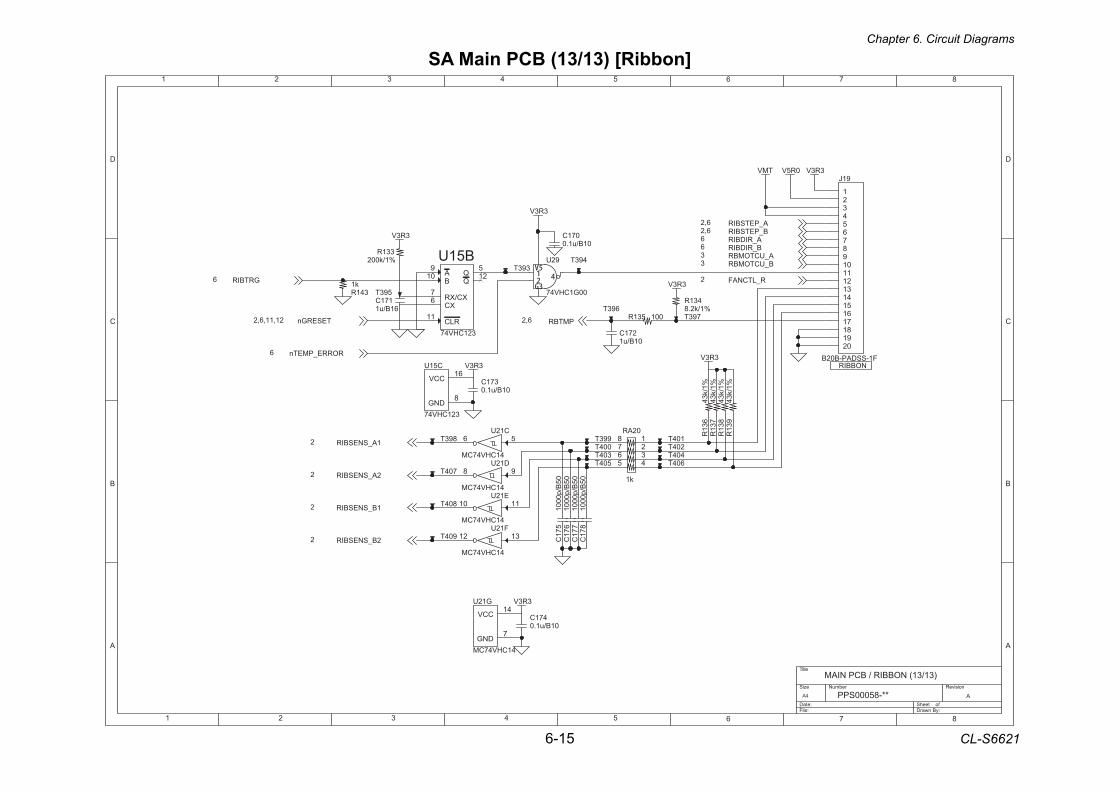
Chapter 6. Circuit Diagrams
6-15 CL-S6621
SA Main PCB (13/13) [Ribbon]
1 2 3 4 5 6 7 8
A
B
C
D
87654321
D
C
B
A
Title
Number RevisionSize
A4
Date: Sheet of File: Drawn By:
APPS00058-**
MAIN PCB / RIBBON (13/13)
NOBBIR3R3V
3R3V
3R3V0R5VTMV
3R3V
3R3V
3R3V
3R3VRORRE_PMETn6
R_LTCNAF2
A_PETSBIR6,2B_PETSBIR6,2
A_RIDBIR6B_RIDBIR6
A_UCTOMBR3B_UCTOMBR3
GRTBIR6
TESERGn21,11,6,2 PMTBR6,2
1A_SNESBIR2
2A_SNESBIR2
1B_SNESBIR2
2B_SNESBIR2
431R%1/k2.8
471C01B/u1.0
393T
271C01B/u1
B51U
321CHV47
A9
B01
RLC11
XC6 XC/XR7
Q21Q
5
993T
404T
R13
943
k/1%
001531R
G12U
41CHV47CM
CCV41
DNG7
C51U
321CHV47DNG
8
CCV61
R13
743
k/1%
893T
91J
F1-SSDAP-B02B
12345678901
02
11
91
21
81
31
71
41
6151
793T
92U
00G1CHV47
C12U
41CHV47CM
56
593T
R13
643
k/1%
804T
02AR
k1
12345
678
693T
C17
810
00p/
B50
904T C17
610
00p/
B50
504T
493T
604T304T
F12U
41CHV47CM
3121
204T104T
371C01B/u1.0
004T
E12U
41CHV47CM
1101
R13
843
k/1%
C17
510
00p/
B50
341Rk1
D12U
41CHV47CM
8 9
071C01B/u1.0
331R%1/k002
171C61B/u1
C17
710
00p/
B50
704T
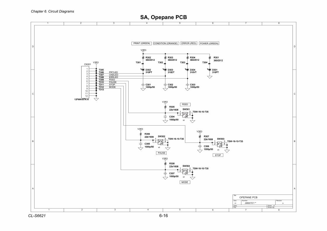
Chapter 6. Circuit Diagrams
CL-S6621 6-16
SA, Opepane PCB
1 2 3 4 5 6 7 8
A
B
C
D
87654321
D
C
B
A
Title
Number RevisionSize
A4
Date: Sheet of File: Drawn By:
AJM66707-**
OPEPANE PCB
DELTRPDELDNCDELRRE
EDOMPOTS
ESUAPDEEF
3R3V
3R3V
3R3V
3R3V3R3V
3R3V
103DTP013
103DTP013
103T 103T
103R2102/063
103R2102/063
603R8061/k22
603R8061/k22 703R
8061/k22703R
8061/k22
403R2102/063
403R2102/063
103C05/p0001
103C05/p0001
503C05/p0001
503C05/p0001 603C
05/p0001603C
05/p0001
403C05/p0001
403C05/p0001
303T 303T
203DTP013
203DTP013
313T 313T
903T 903T
303DTD013
303DTD013
103WS53T-01-61-WST
103WS53T-01-61-WST1
234
5
213T 213T113T 113T 203C
05/p0001203C
05/p0001
803T 803T
013T 013T
303WS53T-01-61-WST
303WS53T-01-61-WST1
234
5
803R8061/k22
803R8061/k22
503T 503T
403T 403T
703T 703T
203R2102/063
203R2102/063
203WS53T-01-61-WST
203WS53T-01-61-WST1
234
5
703C05/p0001
703C05/p0001
403DTV013
403DTV013
403WS53T-01-61-WST
403WS53T-01-61-WST1
234
5
303R2102/063
303R2102/063
603T 603T
A-KTB-NMF21
CN301
A-KTB-NMF21
123456789011121
503R8061/k22
503R8061/k22
303C05/p0001
303C05/p0001
203T 203T
PRINT (GREEN) CONDITION (ORANGE) ERROR (RED) POWER (GREEN)
MODE
STOPPAUSE
FEED
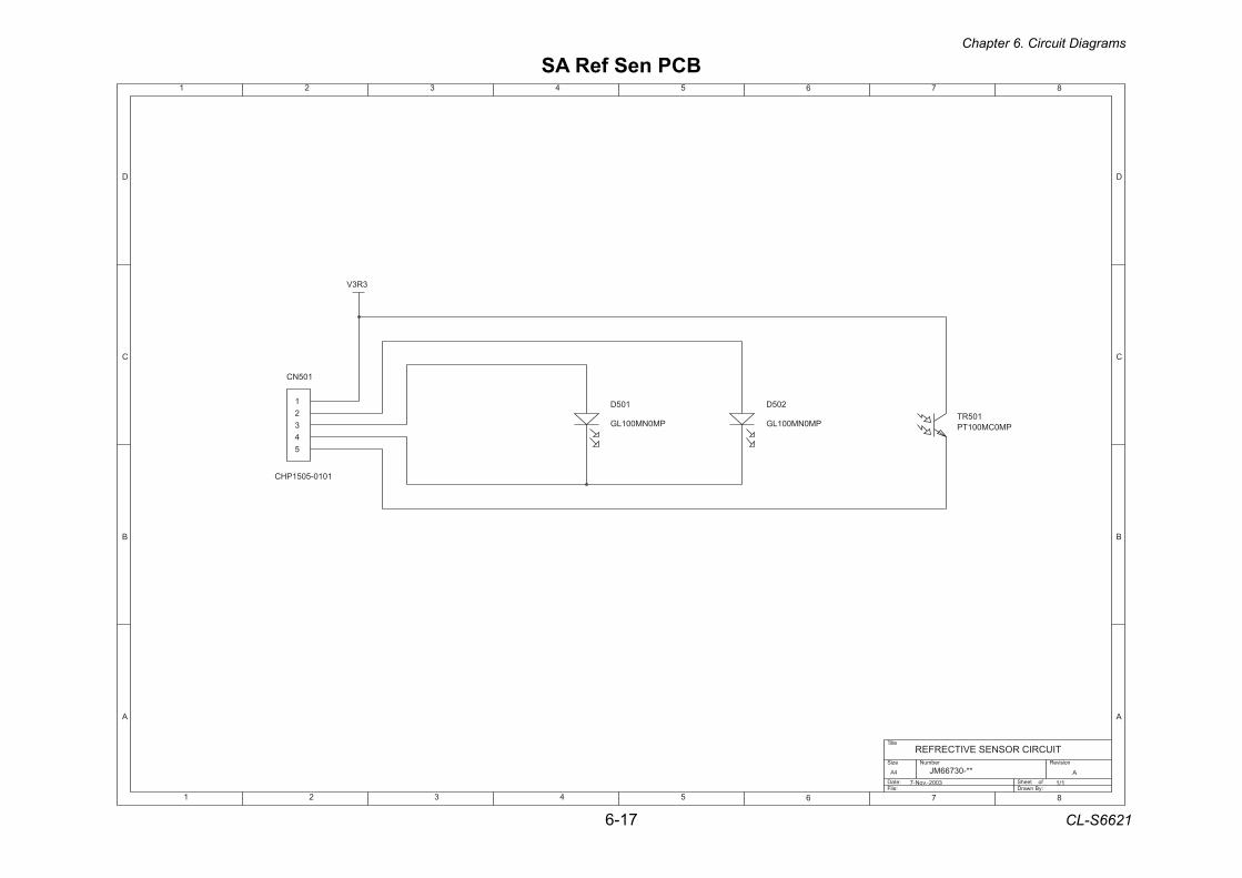
Chapter 6. Circuit Diagrams
6-17 CL-S6621
SA Ref Sen PCB
1 2 3 4 5 6 7 8
A
B
C
D
87654321
D
C
B
A
Title
Number RevisionSize
A4
Date: Sheet of File: Drawn By:
A
REFRECTIVE SENSOR CIRCUIT
1/1
JM66730-**7-Nov.-2003
CN501
CHP1505-0101
D502
GL100MN0MP
D501
GL100MN0MPTR501PT100MC0MP
V3R3
12345
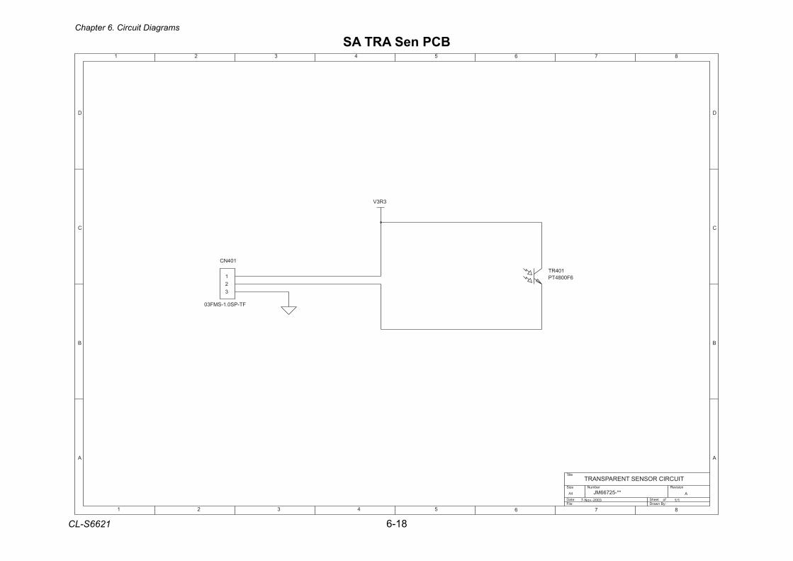
Chapter 6. Circuit Diagrams
CL-S6621 6-18
SA TRA Sen PCB
1 2 3 4 5 6 7 8
A
B
C
D
87654321
D
C
B
A
Title
Number RevisionSize
A4
Date: Sheet of File: Drawn By:
A
TRANSPARENT SENSOR CIRCUIT
1/1
JM66725-**7-Nov.-2003
TR401PT4800F6
CN401
03FMS-1.0SP-TF
V3R3
123
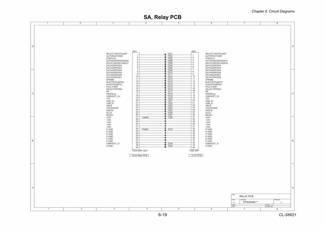
Chapter 6. Circuit Diagrams
6-19 CL-S6621
SA, Relay PCB
1 2 3 4 5 6 7 8
A
B
C
D
87654321
D
C
B
A
Title
Number RevisionSize
A4
Date: Sheet of File: Drawn By:
APPS00060-**
RELAY PCB
V42+V42+
DNG.PDNG.PDNG.P
DNG.PDNG.P
KLCS
DNG.P-D_TSOHBSU
TNIp/TSC/NI-TCELES
DNG.S
RSD/TXDFOTUA0ICO/BTS
00PEh/0WSPID/0ATAD10PEh/1WSPID/1ATAD
2WSPID/2ATAD3WSPID/3ATAD4WSPID/4ATAD5WSPID/5ATAD6WSPID/6ATAD7WSPID/7ATAD
EMIRPn00PEp/STR/YSUB
10PEp/RTD/KCATNIh/TLUAF
0NOPP/TCELESEP
tuoWSWD+D_TSOHBSU
V5++D_BSU-D_BSU
SUBV
IS/DXRRID/OS/DXT
TESERV42+V42+V42+
DNG.PV42+V42+
KLCS
DNG.PDNG.P
DNG.PDNG.P
1ICO/BTSRSD/TXDFOTUA
DNG.S
TNIp/TSC/NI-TCELES
-D_TSOHBSUDNG.P
5WSPID/4ATAD4WSPID/3ATAD3WSPID/2ATAD
20PEh/1WSPID/1ATAD10PEh/0WSPID/0ATAD
8WSPID/7ATAD7WSPID/6ATAD6WSPID/5ATAD
EMIRPn
EP1NOPP/TCELES
TNIh/TLUAF20PEp/RTD/KCA
10PEp/STR/YSUB
SUBV-D_BSU+D_BSU
V5++D_TSOHBSU
tuoWSWD
V42+V42+
TESER
RID/OS/DXTIS/DXR
V42+
BCP F/I oTBCP niaM morF
0R42V
DNGP
722T
112T
412T
812T
932T
222T
902T
622T
012T
102J
TS21-R04-42XT
03
1
92
2
82
3
72
4
62
5
52
6
42
7
32
8
22
9
12
01
02
11
91
21
81
31
71
41
6151
13233343536373839304
312T
712T
122T
802T
522T
202J
P04-52XT
03
1
92
2
82
3
72
4
62
5
52
6
42
7
32
8
22
9
12
01
02
11
91
21
81
31
71
41
6151
13233343536373839304
602T
212T
332T
612T
302T
022T
422T
502T
702T
822T
512T
912T
202T102T
042T
322T
402T
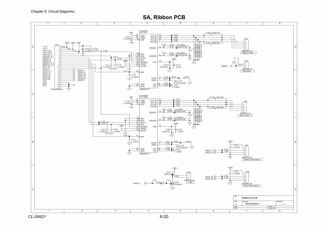
Chapter 6. Circuit Diagrams
CL-S6621 6-20
SA, Ribbon PCB
1 2 3 4 5 6 7 8
A
B
C
D
87654321
D
C
B
A
Title
Number RevisionSize
A4
Date: Sheet of File: Drawn By:
APPS00059-**
RIBBON PCB
V3.3+V0.5+
)V42+(TMV
B_RIDBIRA_UCTOMBRB_UCTOMBR
NE_TOMLTCNAF
PMTTBIR
1A_SNES2A_SNES1B_SNES2B_SNES
DNGDNGDNG
A_PETSBIR
A_RIDBIRB_PETSBIR
rotom dniweR
rotom dneS
NAF
rosnes edis dneS
rosnes edis dniweR
)V42+(TMV
rotsimrehT
3R3V3R3V
TMV
3R3V3R3V
TMV
3R3V
3R3V0R5V
3R3V 0R5V TMV
1A_SNES
1B_SNES
HTMBR
2A_SNES
2B_SNES
LTCNAF
1A_SNES
LTCNAF
1B_SNES2B_SNES
2A_SNES
HTMBR
301J
S-K-HP-B4B
1234
61B/u1.0401C
531C61B/u1.0
611C05F/u22.0
631C05F/u22.0
001/p001811C
221T
211T
311C05F/u22.0
101Q4663KS2
+ 031C61/u01
011T
511T
731T
911T
431T
131T
61B/u1.0621C
C125
100p/100
711C05B/u1.0
301C05B/u1.0
2102/301R
421T
511C61B/u1.0
C109
100p/100
631T
201J
1-SSDAP-B02S
12345678901
02
11
91
21
81
31
71
41
6151
101U
T-SES4894A
RID71
TESER01
2SM9
ELBANE2
1SM8
PETS41
A1TUO12
A2TUO22B1TUO81
B2TUO1
1ESNES02
2ESNES32
1PC4
2PC5
PEELS21
FER51
PCV6
1BBV91
2BBV42
DNG3
DNG61
GERV7CSOR11
DDV31
601J
E-K-HP-B2B
12
921T
k1701R
111C61B/u1.0
001/p001201C
001/p001021C
111T
121T
901T
531T
711T
801T
701T
501T
721C61B/u1.0
C122
100p/100
C124
100p/100
331T
831T
611T
101J
S-K-HP-B4B
1234
61B/u1.0011C
211C61B/u1.0
321T
031T
301T
61B/u1.0121C
231C05F/u22.0
+ 411C61/u01
501J
R-K-HP-B4B
1234
401J
K-K-HP-B4B
1234
721TW1/%1/22.0501R
921C05F/u22.0
701J
S-K-HP-B2B
12
W1/%1/22.0401R
C105
100p/100C
106100p/100
431C05B/u1.0
911C05B/u1.0
2102/601R
401T
101T
021T
W1/%1/22.0201R
101DV155BR
131C61B/u1.0
+ 801C05/u74
001/p001101C
931T
201U
T-SES4894A
RID71
TESER01
2SM9
ELBANE2
1SM8
PETS41
A1TUO12
A2TUO22B1TUO81
B2TUO1
1ESNES02
2ESNES32
1PC4
2PC5
PEELS21
FER51
PCV6
1BBV91
2BBV42
DNG3
DNG61
GERV7CSOR11
DDV31
W1/%1/22.0101R
C123
100p/100
311T
141T
411T
621T
231T
041T
811T
331C61B/u1.0
821C61B/u1.0
C107
100p/100
521T
201T
821T
601T
0
0
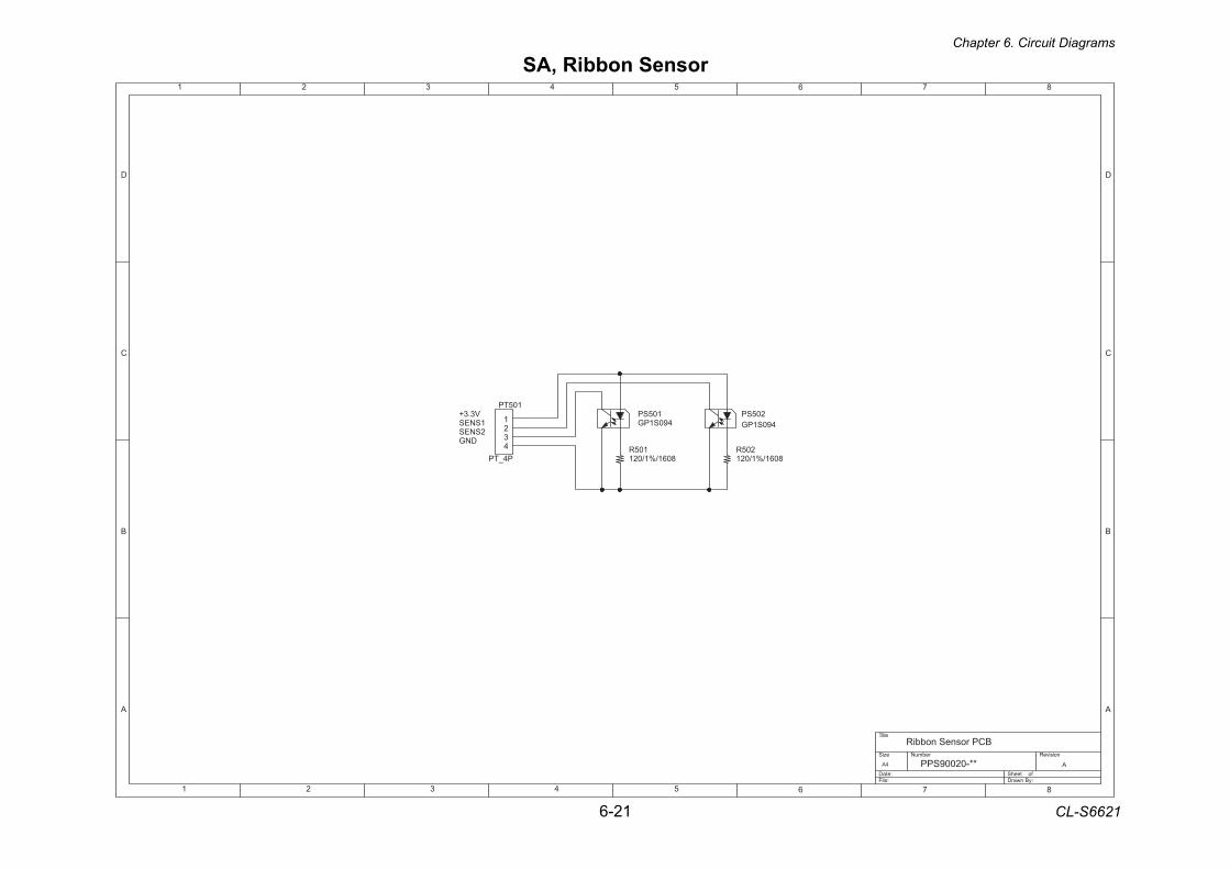
Chapter 6. Circuit Diagrams
6-21 CL-S6621
SA, Ribbon Sensor
1 2 3 4 5 6 7 8
A
B
C
D
87654321
D
C
B
A
Title
Number RevisionSize
A4
Date: Sheet of File: Drawn By:
APPS90020-**
Ribbon Sensor PCB
V3.3+1SNES2SNES
DNG
205SP490S1PG
205R8061/%1/021
105R8061/%1/021
105SP490S1PG
105TP
P4_TP
1234
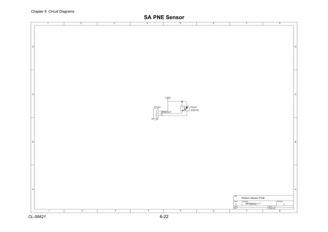
Chapter 6. Circuit Diagrams
CL-S6621 6-22
SA PNE Sensor
1 2 3 4 5 6 7 8
A
B
C
D
87654321
D
C
B
A
Title
Number RevisionSize
A4
Date: Sheet of File: Drawn By:
APPS90021-**
Ribbon Sensor PCB
KTUOSNES
3R3V
103SP50C2GS
103TP
P3_TP
123

AP-1 CL-S6621
APPENDICES
CL-S6621 AP-2
APPENDICES
TABLE OF CONTENTS
A. Mounting Diagrams.........................................................................................................AP-3 A-1. SA, Main PCB ....................................................................................................AP-3 A-2. SA, Opepane PCB .............................................................................................AP-5 A-3. SA Ref Sen PCB ................................................................................................AP-5 A-4. SA TRA Sen PCB...............................................................................................AP-5 A-5. SA, Relay PCB...................................................................................................AP-6 A-6. SA, Ribbon PCB.................................................................................................AP-6 A-7. SA, Ribbon Sensor.............................................................................................AP-7 A-8. SA PNE Sensor..................................................................................................AP-7
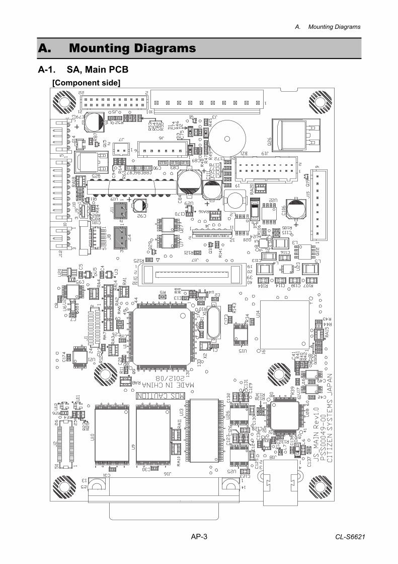
A. Mounting Diagrams
AP-3 CL-S6621
A. Mounting Diagrams A-1. SA, Main PCB [Component side]
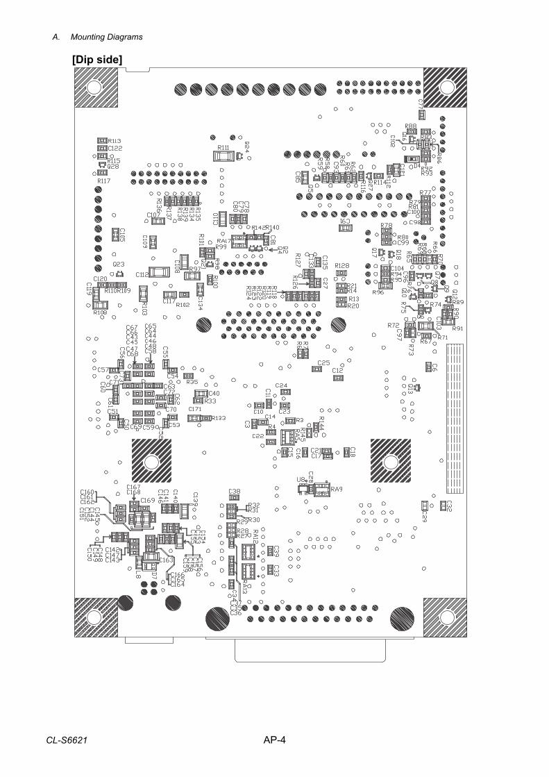
A. Mounting Diagrams
CL-S6621 AP-4
[Dip side]
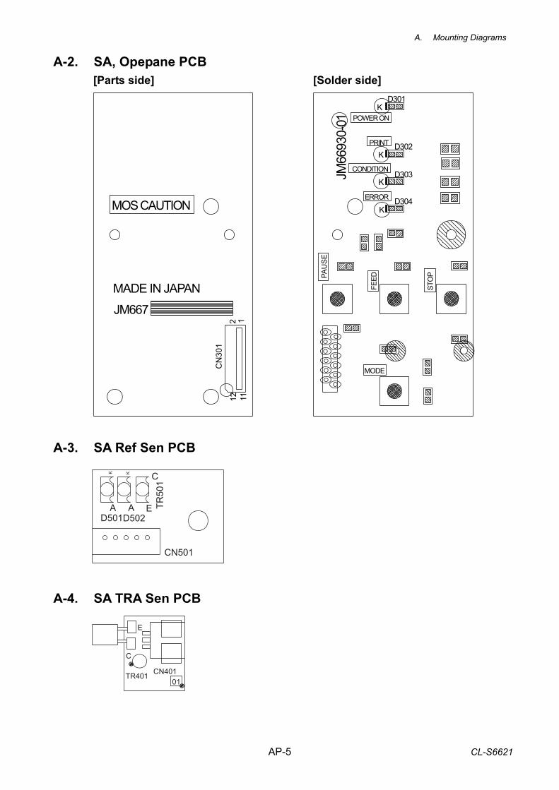
A. Mounting Diagrams
AP-5 CL-S6621
D502D501
TR50
1
AA
CK K
E
CN501
A-2. SA, Opepane PCB [Parts side] [Solder side]
A-3. SA Ref Sen PCB A-4. SA TRA Sen PCB
C
TR401 CN401
E
01
POWER ONK
K
K
K
CONDITION
ERROR
JM667
MADE IN JAPAN
MOS CAUTION
JM66
930-
01PA
US
E
FEED
STO
P
MODECN
301
12 1112
D301
D302
D303
D304
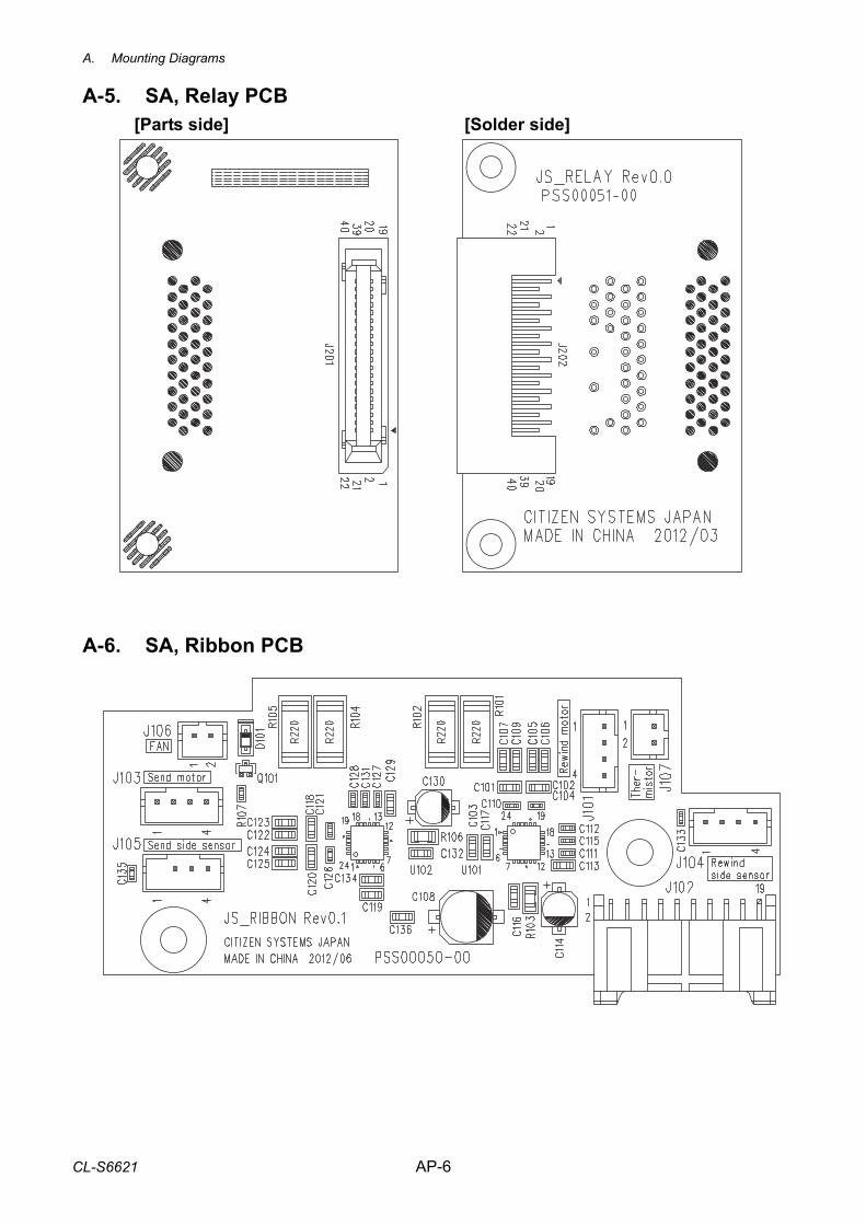
A. Mounting Diagrams
CL-S6621 AP-6
A-5. SA, Relay PCB
[Parts side] [Solder side] A-6. SA, Ribbon PCB
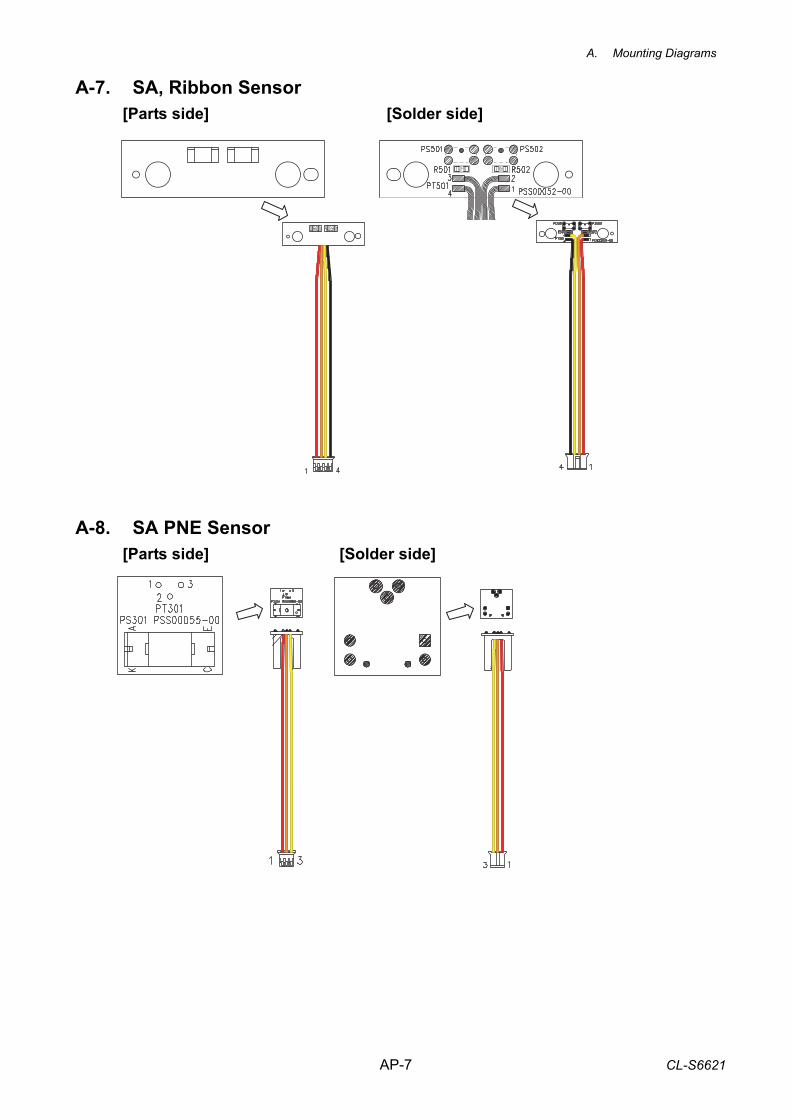
A. Mounting Diagrams
AP-7 CL-S6621
A-7. SA, Ribbon Sensor
[Parts side] [Solder side] A-8. SA PNE Sensor
[Parts side] [Solder side]