
Hydraulic Setting Tool Technical Manual
22
Hydraulic Setting Tool Technical Manual 4.500 inch HST MAN-HST-006 (R02) 12001 Cr 1000 Godley, Texas, 76044, USA Phone: +1 (817) 551-0540 Fax: +1 (817) 551-1674 www.corelab.com/owen Warning: use of owen equipment contrary to manufacturer’s specifications or operating instructions may result in property damage, serious injury or fatality. If you are not trained in the handling and use of explosive devices, do not attempt to use or assemble any owen perforating systems or owen firing devices. This technology is regulated by and, if exported, was exported from the united states in accordance with the export administration regulations (EAR). Diversion contrary to U.S. Law is prohibited. Export and/or re-export of this technology may require issuance of a license by the bureau of industry and security (BIS), U.S. Department of Commerce. Consult the BIS, the EAR, and/or Owen Compliance Services, Inc. To determine licensing requirements for export or re-export of this technology. This document contains confidential information of Owen Oil Tools LP (Owen) and is furnished to the customer for information purposes only. This document must not be reproduced in any way whatsoever, in part or in whole, or distributed outside the customer organization, without first obtaining the express written authorization of owen. This document is the property of owen and returnable upon request of Owen. ©2013, 2019 Owen Oil Tools All rights reserved MAN-HST-006.indd 1 7/15/19 3:04 PM
-
Upload
khangminh22 -
Category
Documents
-
view
5 -
download
0
Transcript of Hydraulic Setting Tool Technical Manual
Hydraulic Setting ToolTechnical Manual
4.500 inch HST
MAN-HST-006 (R02)
12001 Cr 1000Godley, Texas, 76044, USAPhone: +1 (817) 551-0540Fax: +1 (817) 551-1674www.corelab.com/owen
Warning: use of owen equipment contrary to manufacturer’s specifications or operating instructions may result in property damage, serious injury or fatality. If you are not trained in the handling and use of explosive devices, do not attempt to use or assemble any owen perforating systems or owen firing devices.This technology is regulated by and, if exported, was exported from the united states in accordance with the export administration regulations (EAR). Diversion contrary to U.S. Law is prohibited. Export and/or re-export of this technology may require issuance of a license by the bureau of industry and security (BIS), U.S. Department of Commerce. Consult the BIS, the EAR, and/or Owen Compliance Services, Inc. To determine licensing requirements for export or re-export of this technology.This document contains confidential information of Owen Oil Tools LP (Owen) and is furnished to the customer for information purposes only. This document must not be reproduced in any way whatsoever, in part or in whole, or distributed outside the customer organization, without first obtaining the express written authorization of owen. This document is the property of owen and returnable upon request of Owen.
©2013, 2019 Owen Oil Tools All rights reserved
MAN-HST-006.indd 1 7/15/19 3:04 PM
2 I MAN-HST-006 (R02) ©2013, 2019 Owen Oil Tools All rights reserved
4.50 HST Tech Manual
Table Of Contents1.0 Description .............................................................................................3
2.0 Benefits/Capabilities ..............................................................................3
3.0 Operation ...............................................................................................3
4.0 Bill of Materials ......................................................................................4
5.0 Schematic / SET-4500-010 ....................................................................5
6.0 Pressure / Shear Charts ........................................................................6
7.0 Inspection Dimensions ..........................................................................7
8.0 Fishing Dimensions ...............................................................................9
9.0 Pre-Assembly ......................................................................................10
10.0 Assembly ...........................................................................................14
11.0 Disassembly ......................................................................................20
MAN-HST-006.indd 2 7/15/19 3:04 PM
4.50 HST Tech Manual
©2013, 2019 Owen Oil Tools All rights reserved MAN-HST-006 (R02) I 3
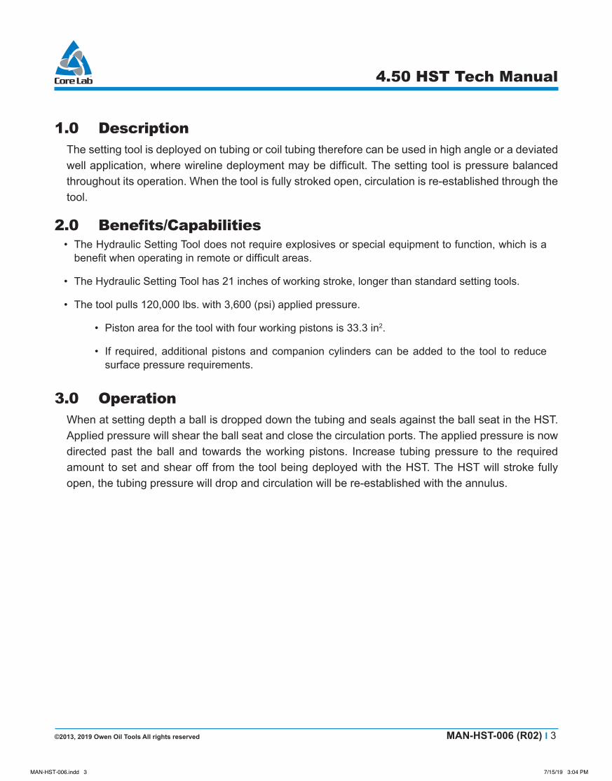
1.0 DescriptionThe setting tool is deployed on tubing or coil tubing therefore can be used in high angle or a deviated well application, where wireline deployment may be difficult. The setting tool is pressure balanced throughout its operation. When the tool is fully stroked open, circulation is re-established through the tool.
2.0 Benefits/Capabilities• The Hydraulic Setting Tool does not require explosives or special equipment to function, which is a
benefit when operating in remote or difficult areas.
• The Hydraulic Setting Tool has 21 inches of working stroke, longer than standard setting tools.
• The tool pulls 120,000 lbs. with 3,600 (psi) applied pressure.
• Piston area for the tool with four working pistons is 33.3 in2.
• If required, additional pistons and companion cylinders can be added to the tool to reduce surface pressure requirements.
3.0 OperationWhen at setting depth a ball is dropped down the tubing and seals against the ball seat in the HST. Applied pressure will shear the ball seat and close the circulation ports. The applied pressure is now directed past the ball and towards the working pistons. Increase tubing pressure to the required amount to set and shear off from the tool being deployed with the HST. The HST will stroke fully open, the tubing pressure will drop and circulation will be re-established with the annulus.
MAN-HST-006.indd 3 7/15/19 3:04 PM

4.50 HST Tech Manual
4 I MAN-HST-006 (R02) ©2013, 2019 Owen Oil Tools All rights reserved
Warning:
4.0 Bill of MaterialsITEM NO. QTY. DESCRIPTION PART NUMBER
1 8 SHEAR PIN - 3-1/2IN BRASS SET. TOOL SET-3500-0222 1 UPPER CIRCULATION SUB SET-4500-0113 1 CIRCULATION SUB SET-4500-0124 3 TANDEM SUB SET-4500-0175 1 SHEAR SUB SET-4500-0186 1 SNORKEL CYLINDER SET-4500-1147 1 STROKE COMPENSATION HOUSING SET-4500-1158 1 SNORKEL TUBE SET-4500-1219 1 STROKE COMPENSATION PISTON SET-4500-122
10 1 TOP SUB SET-4500-12311 1 BOTTOM PISTON SET-4500-12412 4 WORKING CYLINDER SET-4500-12613 3 WORKING PISTON SUB SET-4500-12914 4 WORKING PISTON SET-4500-13015 1 DUMP SUB SET-4500-13216 1 SCREEN HOUSING SET-4500-13517 1 DUMP PISTON SET-4500-13618 1 NO-GO SET-4500-14019 1 CIRCULATION PISTON 4-3/4” HYD. SETTING TOOL SET-4750-02020 1 SCREEN SET-4750-03621 1 O-RING, VITON OOO-V569-11722 6 O-RING, VITON OOO-V569-21023 2 O-RING BACKUP OBU-V569-21024 8 O-RING, VITON OOO-V569-22525 18 O-RING, VITON OOO-V569-23826 1 O-RING, VITON OOO-V569-22827 2 O-RING, VITON OOO-V569-22728 2 O-RING, VITON OOO-V569-32329 1 O-RING, VITON OOO-V569-32530 1 O-RING, VITON OOO-V569-33231 8 SLOTTED BRASS SHEAR SCREW 5/16IN 18 X 1/2IN SBSS-0031-18-005032 8 BRASS SHEAR SCREW 1/4” - 20 X 7/16” SBSS-0025-20-004433 1 1 00 BALL PUR-0514-01534 1 1 25 BALL PUR-0514-00935 1 LOCK RING SET-4500-029-- -- REDRESS KIT SET-4500-116A 1 SNORKLE PISTON INSERT SET-4500-440B 1 SUPPORT SLEEVE SET-4500-441C 1 PISTON SUPPORT ADAPTER SET-4500-442
MAN-HST-006.indd 4 7/15/19 3:04 PM

©2013, 2019 Owen Oil Tools All rights reserved MAN-HST-006 (R02) I 5
4.50 HST Tech Manual
5.0 Schematic/SET-4500-010
MAN-HST-006.indd 5 7/15/19 3:04 PM
6 I MAN-HST-006 (R02) ©2013, 2019 Owen Oil Tools All rights reserved
4.50 HST Tech Manual
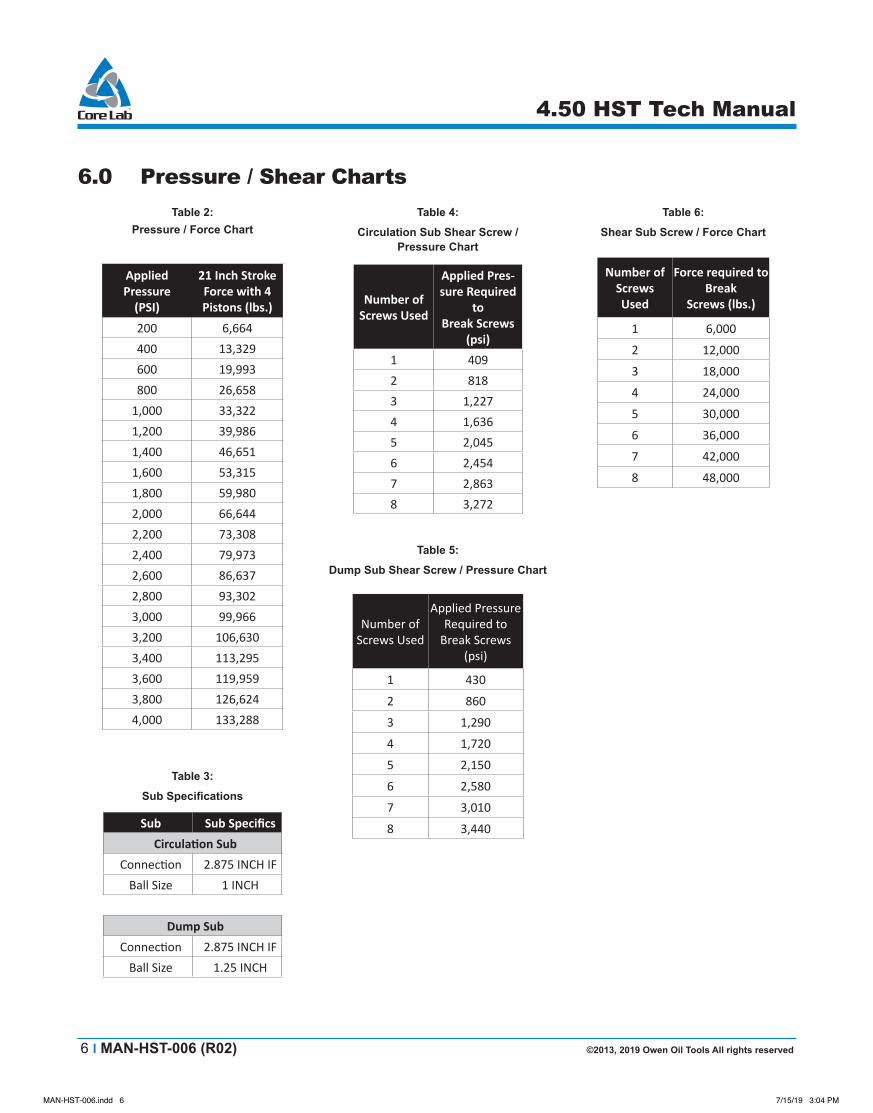
Table 2: Pressure / Force Chart
Applied Pressure
(PSI)
21 Inch Stroke Force with 4 Pistons (lbs.)
200 6,664400 13,329600 19,993800 26,658
1,000 33,3221,200 39,9861,400 46,6511,600 53,3151,800 59,9802,000 66,6442,200 73,3082,400 79,9732,600 86,6372,800 93,3023,000 99,9663,200 106,6303,400 113,2953,600 119,9593,800 126,6244,000 133,288
Table 3:
Sub Specifications
Sub Sub SpecificsCirculation Sub
Connection 2.875 INCH IFBall Size 1 INCH
Dump SubConnection 2.875 INCH IF
Ball Size 1.25 INCH
Table 4:
Circulation Sub Shear Screw / Pressure Chart
Number of Screws Used
Applied Pres-sure Required
to Break Screws
(psi)1 4092 8183 1,2274 1,6365 2,0456 2,4547 2,8638 3,272
Table 5:
Dump Sub Shear Screw / Pressure Chart
Number of Screws Used
Applied Pressure Required to
Break Screws (psi)
1 430
2 860
3 1,290
4 1,720
5 2,150
6 2,580
7 3,010
8 3,440
Table 6:
Shear Sub Screw / Force Chart
Number of Screws Used
Force required to Break
Screws (lbs.)
1 6,000
2 12,000
3 18,000
4 24,000
5 30,000
6 36,000
7 42,000
8 48,000
6.0 Pressure/ShearCharts
MAN-HST-006.indd 6 7/15/19 3:04 PM

©2013, 2019 Owen Oil Tools All rights reserved MAN-HST-006 (R02) I 7
4.50 HST Tech Manual
7.0 Inspection Dimensions
Note: Inspect all sealing surfaces for corrosion or any other damage.
2.5152.500
2.3792.375
15
2.5002.498 18
26
2.3742.372
27
17
27
1.8791.877
2
30
1.8751.871
1.6851.683
1.6851.683
29
19
28
28
2.7512.748
1.6901.687
3
25
3.6453.625
16
1.0031.000
3.7473.745
10
.996.994
.939.934
.996.994
21
8
22
23
23
22
MAN-HST-006.indd 7 7/15/19 3:04 PM
8 I MAN-HST-006 (R02) ©2013, 2019 Owen Oil Tools All rights reserved
4.50 HST Tech Manual
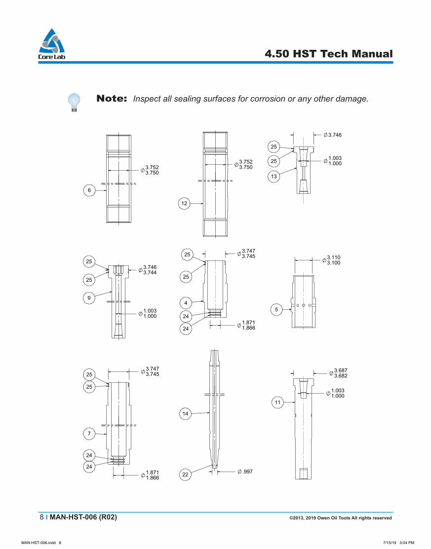
Note: Inspect all sealing surfaces for corrosion or any other damage.
1.0031.000
3.7463.744
9
25
25
1.8711.866
3.7473.745
24
7
24
25
25
3.7523.750
6
3.7523.750
12
.997
14
22
3.746
1.0031.000
13
25
25
3.7473.745
1.8711.866
4
24
25
25
24
3.1103.100
5
3.6873.682
1.0031.000
11
MAN-HST-006.indd 8 7/15/19 3:04 PM

©2013, 2019 Owen Oil Tools All rights reserved MAN-HST-006 (R02) I 9
4.50 HST Tech Manual
8.0 Fishing Dimensions
Figure 4: Fishing Dimensions
Table 7: Connection StrengthConnection Tensile Strength (lbf, N)
1 580,000 2,579,840
2 350,000 1,556,800
3 75,000 333,600
4 160,000 711,680
5 300,000 1,334,400
MAN-HST-006.indd 9 7/15/19 3:04 PM

10 I MAN-HST-006 (R02) ©2013, 2019 Owen Oil Tools All rights reserved
4.50 HST Tech Manual
9.0 Pre-Assembly
Warning: Make sure all tool parts and components have been thoroughly cleaned or serious damage and/or injury could occur!
Warning: Personal Protective Equipment (PPE) should be worn at all times!
Caution: Make sure to wrench only on wrenching surfaces (knurled areas) provided! Always file wrench marks and burrs and clean off debris!
Note: Verify that the correct O-ring redress kit and quantities are used as specified on the Bill of Materials (for example, 5 each etc.). Lay out all redress kit components on a clean surface.
Note: This tool takes at least two people to assemble and disassemble. Also, you need at least one each of the following to work on this tool: vise and work stand. Four roller stands are required to support the tool.
Note: Make sure to lubricate all O-rings and threaded surfaces.
Note: It is strongly recommended that MEMAC wrenches be used for assembly. These wrenches will not leave wrench marks when used on the knurled areas.
9.1 Place each O-ring in the appropriate groove as shown in the tool schematics in (Figures 1-3).
9.2 Place the top sub, (item #10) in a vice.
9.3 Attach the top sub to the snorkel tube, (item #8).
25
13
22
14
25
1314
9 7 12
C
A B
25
21
10 8
23 22 23 22
10 8
Figure 5: Assembly Procedures (9.1-9.3)
MAN-HST-006.indd 10 7/15/19 3:04 PM
©2013, 2019 Owen Oil Tools All rights reserved MAN-HST-006 (R02) I 11
4.50 HST Tech Manual
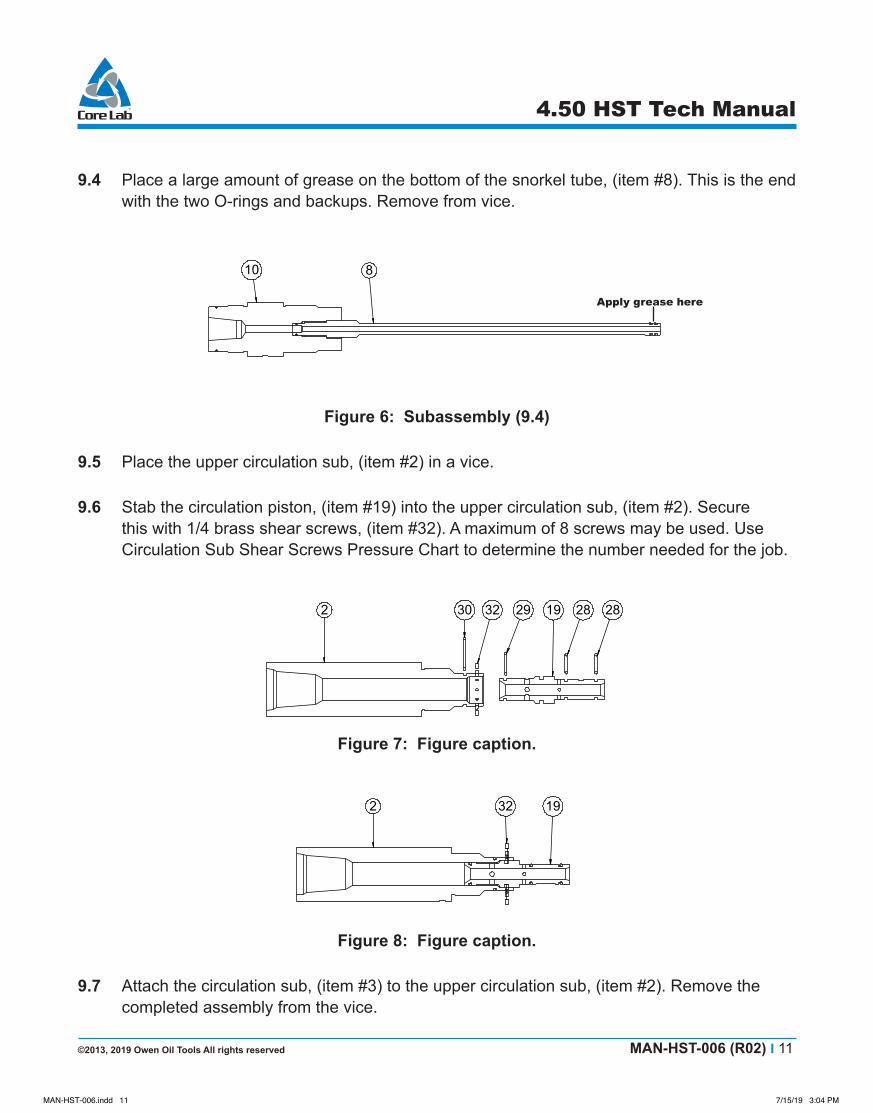
9.4 Place a large amount of grease on the bottom of the snorkel tube, (item #8). This is the end with the two O-rings and backups. Remove from vice.
25
13
22
14
25
1314
9 7 12
C
A B
25
21
10 8
23 22 23 22
10 8
Figure 6: Subassembly (9.4)
9.5 Place the upper circulation sub, (item #2) in a vice.
9.6 Stab the circulation piston, (item #19) into the upper circulation sub, (item #2). Secure this with 1/4 brass shear screws, (item #32). A maximum of 8 screws may be used. Use Circulation Sub Shear Screws Pressure Chart to determine the number needed for the job.
2 30 32 29 19 28 28
2 32 19
232
19 3 25
26 27 27
18
15 31
15173118
1518 1731
27 2726
2 319
Figure 7: Figure caption.
2 30 32 29 19 28 28
2 32 19
232
19 3 25
26 27 27
18
15 31
15173118
1518 1731
27 2726
2 319
Figure 8: Figure caption.
9.7 Attach the circulation sub, (item #3) to the upper circulation sub, (item #2). Remove the completed assembly from the vice.
Applygreasehere
MAN-HST-006.indd 11 7/15/19 3:04 PM
12 I MAN-HST-006 (R02) ©2013, 2019 Owen Oil Tools All rights reserved
4.50 HST Tech Manual
2 30 32 29 19 28 28
2 32 19
232
19 3 25
26 27 27
18
15 31
15173118
1518 1731
27 2726
2 319
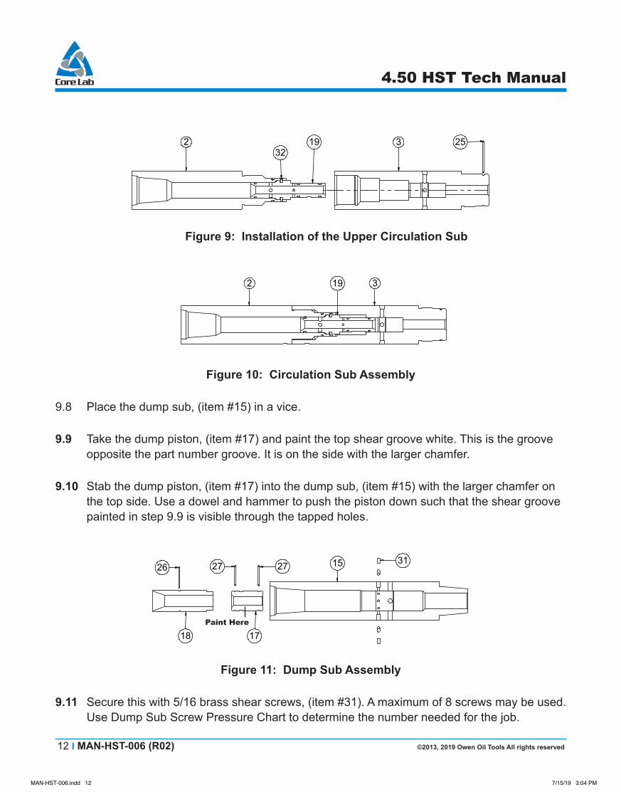
Figure 9: Installation of the Upper Circulation Sub
2 30 32 29 19 28 28
2 32 19
232
19 3 25
26 27 27
18
15 31
15173118
1518 1731
27 2726
2 319
Figure 10: Circulation Sub Assembly
9.8 Place the dump sub, (item #15) in a vice.
9.9 Take the dump piston, (item #17) and paint the top shear groove white. This is the groove opposite the part number groove. It is on the side with the larger chamfer.
9.10 Stab the dump piston, (item #17) into the dump sub, (item #15) with the larger chamfer on the top side. Use a dowel and hammer to push the piston down such that the shear groove painted in step 9.9 is visible through the tapped holes.
2 ? 32 29 19 28 28
2 32 19
232
19 3 25
26 27 27
18
15 31
17
15173118
1518 1731
27 2726
2 319
Figure 11: Dump Sub Assembly
9.11 Secure this with 5/16 brass shear screws, (item #31). A maximum of 8 screws may be used. Use Dump Sub Screw Pressure Chart to determine the number needed for the job.
Paint Here
MAN-HST-006.indd 12 7/15/19 3:04 PM

©2013, 2019 Owen Oil Tools All rights reserved MAN-HST-006 (R02) I 13
4.50 HST Tech Manual
2 30 32 29 19 28 28
2 32 19
232
19 3 25
26 27 27
18
15 31
15173118
1518 1731
27 2726
2 319
Figure 12: Piston Placement
9.12 Install the No-Go Sleeve (item #18) by pushing it in as shown below until it is bottomed out in the Dump Sub (item #15).
2 30 32 29 19 28 28
2 32 19
232
19 3 25
26 27 27
18
15 31
15173118
1518 1731
27 2726
2 319
Figure 13: Dump Sub Assembly
9.13 Attach each working piston sub (item #13) to each working piston (item #14).
9.13.1 This piston assembly utilizes a 1-1/4 American MT tapered thread that required a recommended makeup torque of 660 ft.-lbs. Equivalent load would be a 36 inch pipe wrench with 220 lbf applied.
25
13
22
14
25
1314
9 7 12
C
A B
25
21
10 8
23 22 23 22
10 8
Figure 14: Working Piston Assembly
9.14 Place the working cylinder, (item #12) in a vice. Apply grease to the working cylinder as shown in figure 15
MAN-HST-006.indd 13 7/15/19 3:04 PM

14 I MAN-HST-006 (R02) ©2013, 2019 Owen Oil Tools All rights reserved
4.50 HST Tech Manual
Figure 15: Grease Application
9.15 Take the pistons assembled in step 9.13 and drive them in to the working cylinders, (item #12) as shown. One man should stand on the pin side of the piston and centralize the piston as the other man drives the piston into the cylinder with a rubber mallet. Repeat this procedure for each working piston.
12
14
132225 25
14
7
14
7
9
BA 4 1214 5
C9 7
413 1114
413 111412
Figure 16: Piston / Cylinder Assembly
Caution: Fluid holes in the working cylinders must be on the opposite side of the working piston subs. Failure to do this will prevent the tool from properly stroking!
10.0Assembly10.1 Place the stroke compensation housing, (item #7) in to a vice.
10.2 Stab the cylinder/piston assembled in (Step 9.15) in to the stroke compensation housing as shown. Support the cylinder with a roller stand.
Note: Fluid hole location
MAN-HST-006.indd 14 7/15/19 3:04 PM
©2013, 2019 Owen Oil Tools All rights reserved MAN-HST-006 (R02) I 15
4.50 HST Tech Manual
12
14
132225 25
14
7
14
7
9
BA 4 1214 5
C9 7
413 1114
413 111412
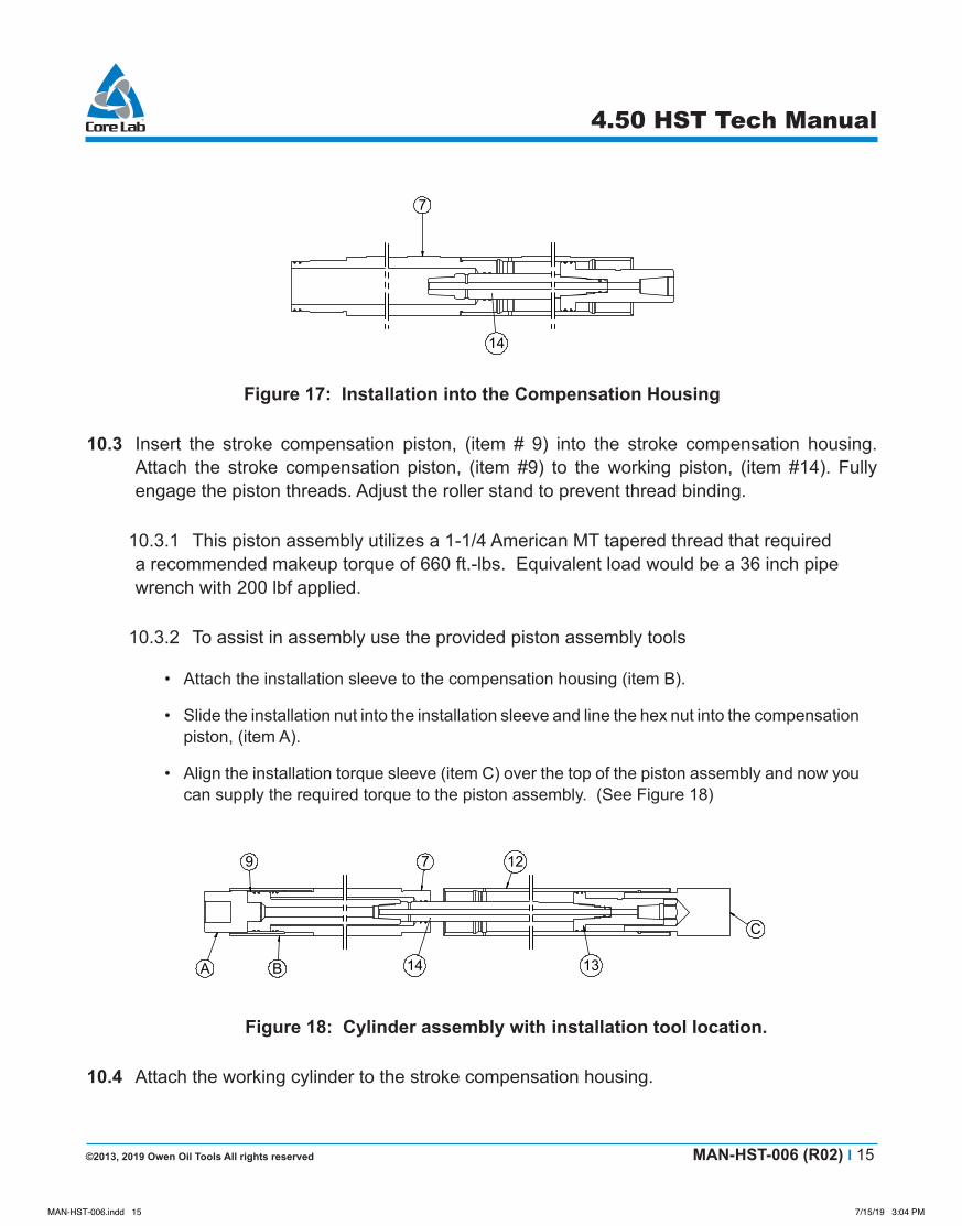
Figure 17: Installation into the Compensation Housing
10.3 Insert the stroke compensation piston, (item # 9) into the stroke compensation housing. Attach the stroke compensation piston, (item #9) to the working piston, (item #14). Fully engage the piston threads. Adjust the roller stand to prevent thread binding.
10.3.1 This piston assembly utilizes a 1-1/4 American MT tapered thread that required a recommended makeup torque of 660 ft.-lbs. Equivalent load would be a 36 inch pipe wrench with 200 lbf applied.
10.3.2 To assist in assembly use the provided piston assembly tools
• Attach the installation sleeve to the compensation housing (item B).
• Slide the installation nut into the installation sleeve and line the hex nut into the compensation piston, (item A).
• Align the installation torque sleeve (item C) over the top of the piston assembly and now you can supply the required torque to the piston assembly. (See Figure 18)
25
13
22
14
25
1314
9 7 12
C
A B
25
21
10 8
23 22 23 22
10 8
Figure 18: Cylinder assembly with installation tool location.
10.4 Attach the working cylinder to the stroke compensation housing.
MAN-HST-006.indd 15 7/15/19 3:04 PM

16 I MAN-HST-006 (R02) ©2013, 2019 Owen Oil Tools All rights reserved
4.50 HST Tech Manual
10.5 Attach the tandem sub (item #4) to the working cylinder (item #12).
12
14
132225 25
14
7
14
7
9
BA 4 1214 5
C9 7
413 1114
413 111412
Figure 19: Cylinder assembly with installation tool location.
10.6 Take the next piston cylinder combination assembled in step 9.15 and attach the working piston to the working piston sub. Support the cylinder with a roller stand as shown in Figure 20. When the threads have started on the piston, begin attaching the working cylinder (item #12) to the tandem sub (item #4). Once the cylinder and sub has been fully made up, continue tightening the working piston.
10.6.1 This piston assembly utilizes a 1-1/4 American MT tapered thread that required a recommended makeup torque of 660 ft.-lbs. Equivalent load would be a 36 inch pipe wrench with 220 lbf applied.
Figure 20: Working Cylinder Make-Up
Caution: Steps 10.5 – 10.6 should be repeated 2 times! (Steps 10.7 - 10.10)!
10.7 Attach the tandem sub (item #4) to the working cylinder (item #12).
10.8 Stab the working piston assembly into the tandem sub as shown in Figure 21. Use a roller stand to support the piston.
MAN-HST-006.indd 16 7/15/19 3:04 PM
©2013, 2019 Owen Oil Tools All rights reserved MAN-HST-006 (R02) I 17
4.50 HST Tech Manual
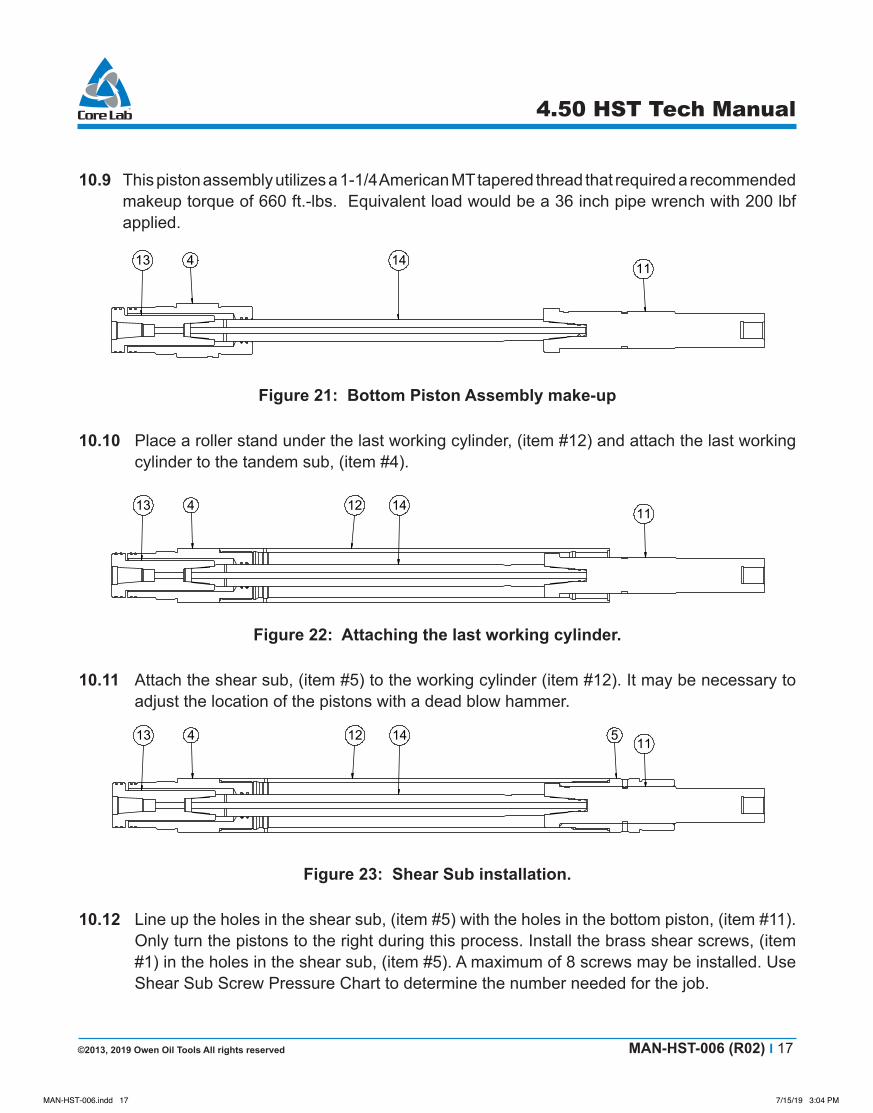
10.9 This piston assembly utilizes a 1-1/4 American MT tapered thread that required a recommended makeup torque of 660 ft.-lbs. Equivalent load would be a 36 inch pipe wrench with 200 lbf applied.
12
14
132225 25
14
7
14
7
9
BA 4 1214 5
C9 7
413 1114
413 111412
Figure 21: Bottom Piston Assembly make-up
10.10 Place a roller stand under the last working cylinder, (item #12) and attach the last working cylinder to the tandem sub, (item #4).
12
14
132225 25
14
7
14
7
9
BA 4 1214 5
C9 7
413 1114
413 111412
Figure 22: Attaching the last working cylinder.
10.11 Attach the shear sub, (item #5) to the working cylinder (item #12). It may be necessary to adjust the location of the pistons with a dead blow hammer.
413 111412 5
413 111412 5 1
6 9 7
10 8 6 9
10 8 620
10 8 62016
Figure 23: Shear Sub installation.
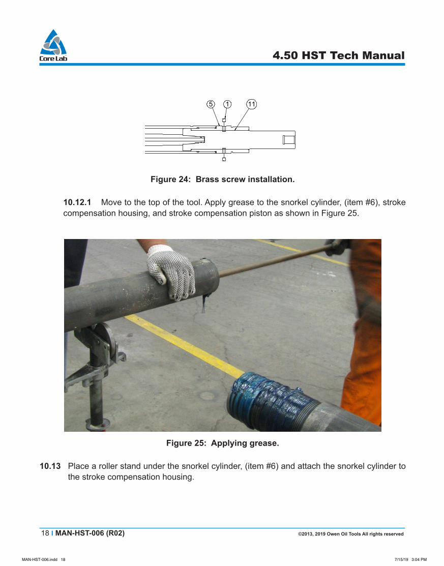
10.12 Line up the holes in the shear sub, (item #5) with the holes in the bottom piston, (item #11). Only turn the pistons to the right during this process. Install the brass shear screws, (item #1) in the holes in the shear sub, (item #5). A maximum of 8 screws may be installed. Use Shear Sub Screw Pressure Chart to determine the number needed for the job.
MAN-HST-006.indd 17 7/15/19 3:04 PM
18 I MAN-HST-006 (R02) ©2013, 2019 Owen Oil Tools All rights reserved
4.50 HST Tech Manual
413 111412 5
413 111412 5 1
6 9 7
10 8 6 9
10 8 620
10 8 62016
Figure 24: Brass screw installation.
10.12.1 Move to the top of the tool. Apply grease to the snorkel cylinder, (item #6), stroke compensation housing, and stroke compensation piston as shown in Figure 25.
Figure 25: Applying grease.
10.13 Place a roller stand under the snorkel cylinder, (item #6) and attach the snorkel cylinder to the stroke compensation housing.
MAN-HST-006.indd 18 7/15/19 3:04 PM
©2013, 2019 Owen Oil Tools All rights reserved MAN-HST-006 (R02) I 19
4.50 HST Tech Manual
413 111412 5
413 111412 5 1
6 9 7
10 8 6 9
10 8 620
10 8 62016
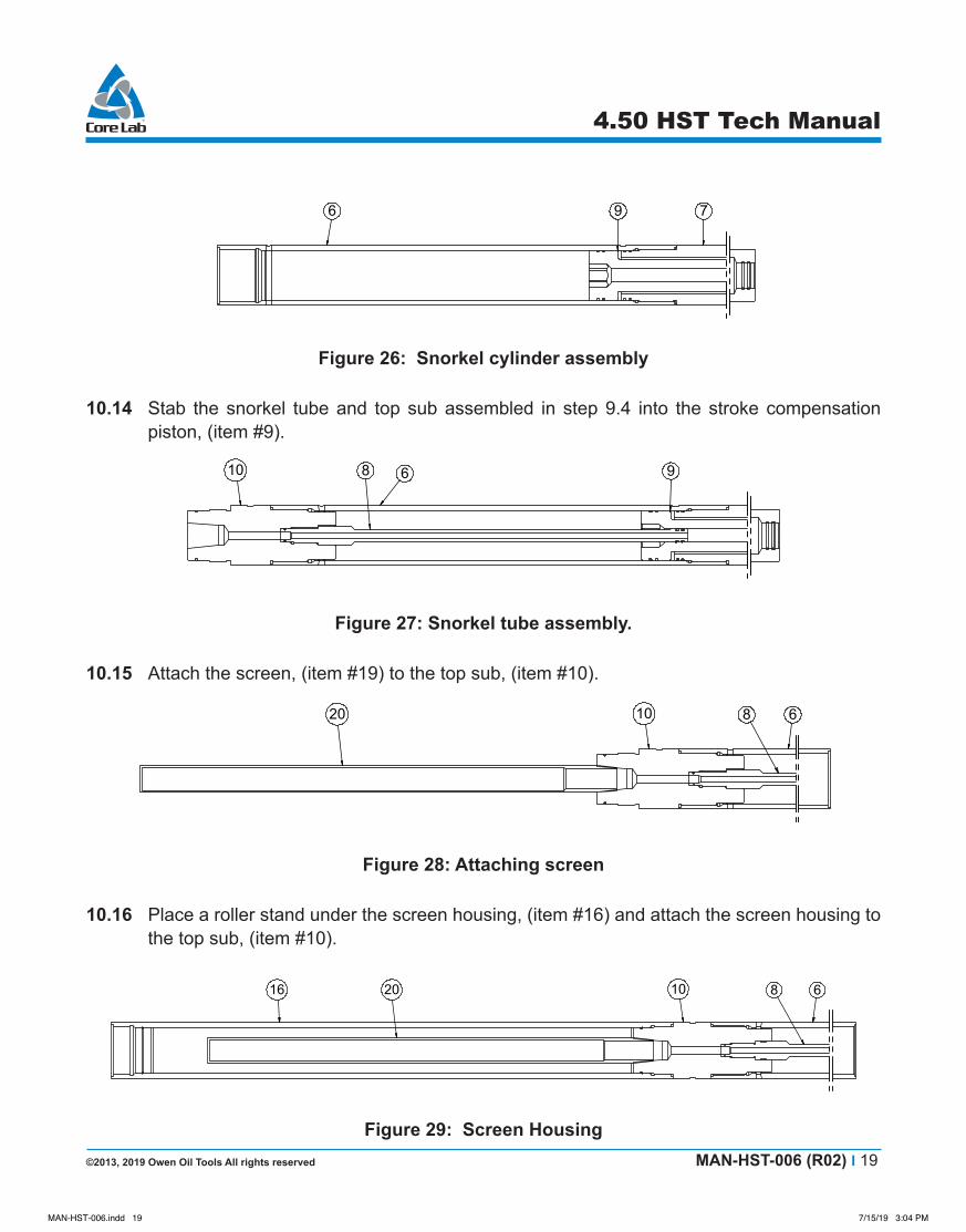
Figure 26: Snorkel cylinder assembly
10.14 Stab the snorkel tube and top sub assembled in step 9.4 into the stroke compensation piston, (item #9).
413 111412 5
413 111412 5 1
6 9 7
10 8 6 9
10 8 620
10 8 62016
Figure 27: Snorkel tube assembly.
10.15 Attach the screen, (item #19) to the top sub, (item #10).
413 111412 5
413 111412 5 1
6 9 7
10 8 6 9
10 8 620
10 8 62016
Figure 28: Attaching screen
10.16 Place a roller stand under the screen housing, (item #16) and attach the screen housing to the top sub, (item #10).
413 111412 5
413 111412 5 1
6 9 7
10 8 6 9
10 8 620
10 8 62016
Figure 29: Screen Housing
MAN-HST-006.indd 19 7/15/19 3:04 PM
20 I MAN-HST-006 (R02) ©2013, 2019 Owen Oil Tools All rights reserved
4.50 HST Tech Manual
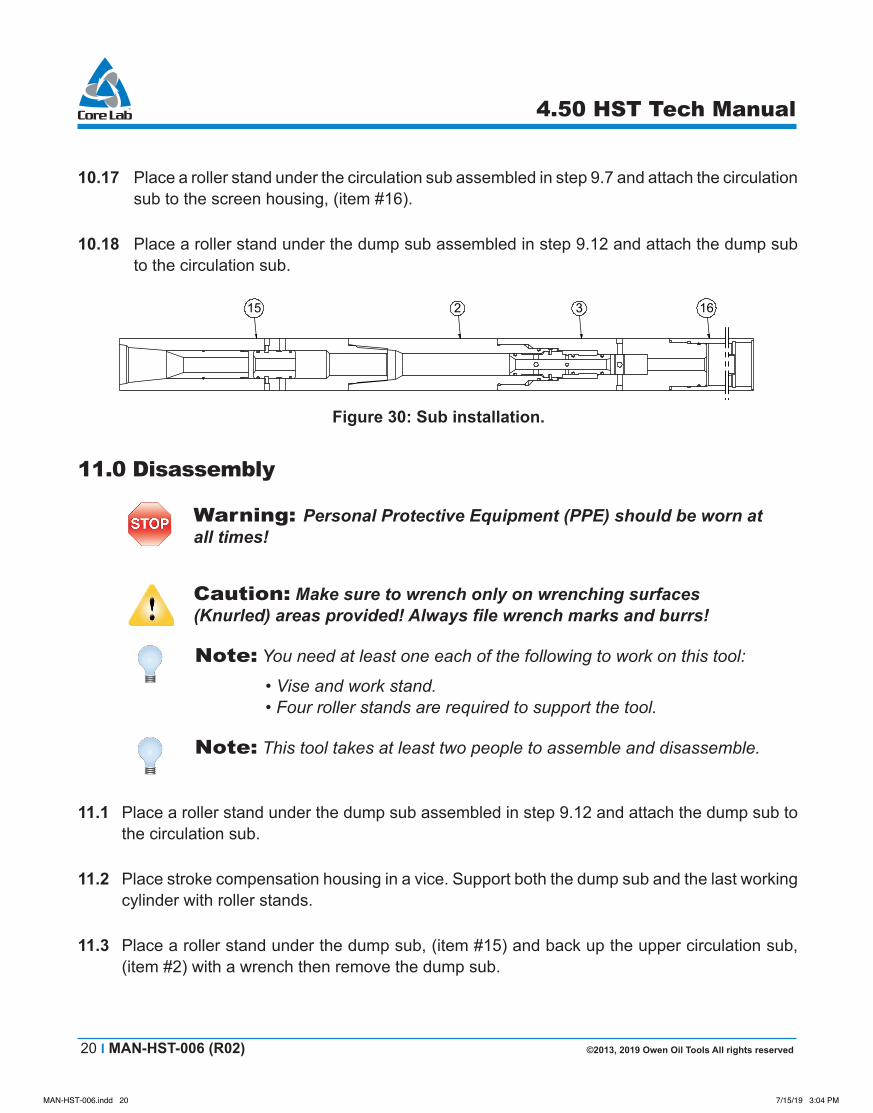
10.17 Place a roller stand under the circulation sub assembled in step 9.7 and attach the circulation sub to the screen housing, (item #16).
10.18 Place a roller stand under the dump sub assembled in step 9.12 and attach the dump sub to the circulation sub.
2016
15 2 3 16
Figure 30: Sub installation.
11.0Disassembly
Warning: Personal Protective Equipment (PPE) should be worn at all times!
Caution: Make sure to wrench only on wrenching surfaces (Knurled) areas provided! Always file wrench marks and burrs!
Note: You need at least one each of the following to work on this tool:
• Vise and work stand. • Four roller stands are required to support the tool.
Note: This tool takes at least two people to assemble and disassemble.
11.1 Place a roller stand under the dump sub assembled in step 9.12 and attach the dump sub to the circulation sub.
11.2 Place stroke compensation housing in a vice. Support both the dump sub and the last working cylinder with roller stands.
11.3 Place a roller stand under the dump sub, (item #15) and back up the upper circulation sub, (item #2) with a wrench then remove the dump sub.
MAN-HST-006.indd 20 7/15/19 3:04 PM

©2013, 2019 Owen Oil Tools All rights reserved MAN-HST-006 (R02) I 21
4.50 HST Tech Manual
11.4 Place a roller stand under the lower circulation sub, (item #3) and back up the screen housing, (item #16) with a wrench then remove the upper and lower circulation subs.
11.5 Move roller stand under the screen housing and back up the top sub, (item #10) with a wrench and remove the screen housing.
11.6 Back up the top sub with a wrench and remove the screen, (item #19).
11.7 Back up the snorkel cylinder, (item # 6) and remove the top sub. The snorkel tube will still be attached to the top sub.
11.8 Place roller stand under the stroke compensation piston, (item #9) and remove the stroke compensation piston from the working piston.
11.9 Move to the bottom of the tool. Ensure that a roller stand is under the bottom working cylinder.
11.10 Back up the working cylinder and remove the shear sub, (item #5).
11.11 Place roller stand under the last working cylinder and back up the tandem sub then remove the working cylinder.
11.12 Place a roller stand under the bottom piston, (item #11) and remove the bottom piston from the working piston.
11.13 Back up the next working cylinder and remove the tandem sub, (item #4).
11.14 Place a roller stand under the next working cylinder.
11.15 Back up the tandem sub and remove the working cylinder. The cylinder will have two working pistons and a piston sub attached. Knock the pistons out of the cylinder and then disassemble the all these parts.
11.16 Back up the next working cylinder and remove the tandem sub.
11.17 Place a roller stand under the next working cylinder
11.18 Back up the tandem sub and remove the working cylinder. The cylinder will have a working piston and a piston sub attached. Knock the piston out of the cylinder and then disassemble the all these parts.
MAN-HST-006.indd 21 7/15/19 3:04 PM
22 I MAN-HST-006 (R02) ©2013, 2019 Owen Oil Tools All rights reserved
4.50 HST Tech Manual
11.19 Back up the next working cylinder and remove the tandem sub.
11.20 Place a roller stand under the next working cylinder.
11.21 Remove the last working cylinder. The cylinder will have a working piston and a piston sub attached. Knock the piston out of the cylinder and then disassemble the all these parts.
11.22 Remove the compensation housing from the vice.
11.23 Knock the dump piston, (item #17) out of the dump sub, (item #15) using a dead blow hammer and a wooden dowel.
11.24 Remove the upper circulation sub, (item #2) from the circulation sub, (item #3).
11.25 On a tool that has been run, remove the circulation piston, (item #18) from the circulation sub, (item #3).
11.26 On a tool that has not been run, remove the circulation piston from the upper circulation sub, (item #2).
11.27 Take a screwdriver and remove all sheared brass screws.
MAN-HST-006.indd 22 7/15/19 3:04 PM