Aquifer Technical and Maintenance Reference Manual
73
AkulfE12- BRISBANE CITY COUNCIL SUPPLY OF BORE PUMP & ACCESSORIES ORDER NO: H63364 HP Aquifer Technical and Maintenance Reference Manual Q-Pulse Id TMS615 Active 29/01/2014 Page 1 of 73
-
Upload
khangminh22 -
Category
Documents
-
view
1 -
download
0
Transcript of Aquifer Technical and Maintenance Reference Manual

AkulfE12-
BRISBANE CITY COUNCIL
SUPPLY OF BORE PUMP & ACCESSORIES
ORDER NO: H63364 HP
Aquifer Technical and Maintenance Reference Manual
Q-Pulse Id TMS615 Active 29/01/2014 Page 1 of 73

filbiffe
4
TABLE OF CONTENTS
CONTRACT DESCRIPTION CONTACT POINTS I`.
PUMP DETAILS 2.
FITTING DEMOUNTABLE CABLE JOINT 3.
PUMP & MOTOR INSTALL DETAIL 4.
FITTING HOSE & HOSE BASED INSTALL DATA
9PRIME" HUGHES
PUMPCO. Centriat 7103101.110 Specialising in design, supply and installation of
industnal and commercial pumping systems and accessones
II
As
ilo '
'I II al I
Aquifer Technical and Maintenance Reference Manual
Q-Pulse Id TMS615 Active 29/01/2014 Page 2 of 73

q;PR/ME PUMPCO.
21st September 2006
Prime Pump Co. Pty Ltd were awarded an order to provide an SP30-6 bore pump with accessories to the Brisbane City Council.
The award included:-
Pump Motor Electric Cable Stainless Support Cable Hose Assembly
Various accessories are also supplied.
Please contact our office at any time as per the accompanying sheet 'Contact Points'.
AUSTRALIA & PNG
D BRISBANE (HEAD OFFICE) PO Box 5118, Brendale Q 4500 Unit 1/60 Kremzow Rd, Brendale Q 4500
41111T ISA 10 Ryan Rd, Mt Isa Q 4825 (PO Box 114) 0WNSVILLE 34 Reward Crt, The Bohle Q 4818
D MACKAY PO Box 1943, North Mackay Q 4740 M 0439 441 CI LAE PO Box 871, Morobe Province, Papua New Guinea
111
Ph 61 7 3889 7877 Ph 61 7 4743 3416 Ph 61 7 4774 7511 Ph 61 7 4952 2980 Ph 675 475 7499
Fx 61 7 3889 7700 Fx 61 7 4743 0150 Fx 61 7 4774 5166 Fx 61 7 4952 2750 Fx 675 475 7520
E sales @primepump.com.au E mtisa @primepump.com.au E tville @primepump.com.au E [email protected] E ppump @online.net.pg
Prime Pump Co. PL-y_Ltd ABN.'71 053 104 840
Aquifer Technical and Maintenance Reference Manual
Q-Pulse Id TMS615 Active 29/01/2014 Page 3 of 73

CONTACT POINTS
The following personnel are available to provide technical information and service.
Brisbane
Mark Tisdell Phone (all hours): 07 3889 7877 Mobile: 0418 726 445 Fax: 07 3889 7700
Nick Ringenoldus
Phone : 07 3889 7877 Mobile: Fax: 07 3889 7700
General service 1800 810 568
Nearest Service Depot
Prime Pump Co. 1/60 Kremzow Road Brendale Q 4500
Aquifer Technical and Maintenance Reference Manual
Q-Pulse Id TMS615 Active 29/01/2014 Page 4 of 73

Company name: Created by: Phone: GRUIVDFOS® Fax: Date: 21/09/2006
Description Product name: Product No: EAN number:
Technical: Speed for pump data: Rated flow: Rated head: Pump No: Stages: Model: Valve:
Materials: Material, pump:
Material, impeller:
Material, motor:
Installation: Size, pump outlet: Motor diameter:
Liquid: Max liquid t at 0.15 m/sec:
Electrical data: Motor type: Applic. motor: P2: Mains frequency: Rated voltage: Starting method: Rated current: Cos phi - power factor: Rated speed: Enclosure class (IEC 34-5): Insulation class (IEC 85): Motor protec: Thermal protec: Built-in temp. transmitter: Motor No:
Others: Net weight: Gross weight Shipping volume:
Value SP 30-6 13A01906 5700390381103
2900 rpm 30 m3/h 46 m 13A00006 6 A pump with built-in non-return valve
Stainless steel 1.4301 DIN W.-Nr. 304 AISI Stainless steel 1.4301 DIN W.-Nr. 304 AISI Stainless steel 1.4301 DIN W.-Nr. 304 AISI
Rp 3
4 inch
40 °C
MS4000 NEMA 5.5 kW 50 Hz 3 x 380-400-415 V direct-on-line 13,0-13,0-13,4 A 0,85-0,81-0,76 2850-2860-2870 rpm IP58 F
NONE external yes 79195511
39 kg 41 kg 0.04 m3
H
(m)
60
50
40
30
20
10
00 5 10
SP 30-6 eta (%)
ISO 9906 Annex A Q =29.6 (26.6 .. 32.5) m3/h H =45.5 (41.8 .. 49.1) m P2 = 4.96 ( .. 5.57) kW P1 = 6.19 ( .. 6.95) kW Eta pump = 73.8 ( .. 66.3 ) % Eta pump+motor = 59.2 ( .. 53.2 ) % Es = 0.2093 kWh/m3 NPSH = 3.55 m n = 2881 rpm
P
(kW)
6
5
4
3
2
1
1 5 20 25 30
80
70
60
50
40
30
20
10
4
2
1/4
Aquifer Technical and Maintenance Reference Manual
Q-Pulse Id TMS615 Active 29/01/2014 Page 5 of 73

Company name: Ts/Created by: Phone: GrtuNpross.... Fax: Date: 21/09/2006
13A01906 SP 30-6
H
(m) 70
60
50
ISO 9906 Annex A Q =29.6 (26.6 .. 32.5) m3/h H =45.5 (41.8 .. 49.1) m P2 = 4.96 ( .. 5.57) kW P1 = 6.19 ( .. 6.95) kW Eta pump = 73.8 ( .. 66.3 ) % Eta pump+motor = 59.2 ( .. 53.2 ) % Es = 0.2093 kWh/m3 NPSH = 3.55 m n = 2881 rpm
SP 30-6 eta ( %)
2/4
Aquifer Technical and Maintenance Reference Manual
Q-Pulse Id TMS615 Active 29/01/2014 Page 6 of 73

Company name: Created by: Phone: GRUN ID FOS ' AO % Fax: Date: 21/09/2006
13A01906 SP 30-6
cos phi eta
1
0.8
0.6
0.4
0.2
n
(rpm)
2800
2600
2400
2200
2000
1800
SP 30-6 + MS4000 5.5 kW 3* 400 V, 50 Hz
r 0.5 1 1.5 2 2.5 3.5 4 4.5
cos phi
eta
I
(A)
20
16
12
8
4
P2 = 4.96 kW cos phi = 0.78 eta = 80.1 % I = 11.5 A
5.5 6 P2(kW) 0
n
P1
P1
(kW)
12
10
8
6
4
2 P1 =6.19 kW n = 2880 rpm 0
3/4
Aquifer Technical and Maintenance Reference Manual
Q-Pulse Id TMS615 Active 29/01/2014 Page 7 of 73

GRUNDFOS Company name: Created by: Phone: Fax: Date: 21/09/2006
13A01906 SP 30-6
131
Rp 3
N 00
95
Cv) O T'
Note! All units are in [mm] unless others are stated.
4/4
Aquifer Technical and Maintenance Reference Manual
Q-Pulse Id TMS615 Active 29/01/2014 Page 8 of 73

GRUNDFOS INSTRUCTIONS
KMA O Installation and operating instructions 10 Montage- and Betriebsanleitung CD PyKOBOACTBO no moH-rawy N 3KalflyaTaLIMI1
OF Notice d'installation et d'entretien Istruzioni di installazione e funzionamento Instrucciones de instalacion y funcionamiento Instrugoes de instalagdo e funcionamento
NL Installatie- en bedieningsinstructies sO Monterings-*och driftsinstruktion
Asennus- ja kayttdohjeet DK Monterings- og driftsinstruktion
BE )THINK> INNOVATE > GRUIVIFOS ®.
Aquifer Technical and Maintenance Reference Manual
Q-Pulse Id TMS615 Active 29/01/2014 Page 9 of 73

1. Applications Grundfos cable termination kits, type KMA, are specially de- signed to join the motor cable and the submersible drop cable, both single-core and multicore cables, during installation of sub- mersible pumps. The Grundfos cable termination kit can be used for cables made
. of polyethylene, PVC, synthetic or natural rubber, etc. for volt- ages up to 1000 V and ranging in size from 1.5 mm2 to 120 mm2.
2.A Cable termination kit with detachable plug This kit is available in several versions, depending on the number of leads and the cable size. Furthermore, the kit is available with a built-in overvoltage protective device. The figures referred to in the following text can be found at the end of these instructions. Where two drawings are shoWn, the drawing to the right illustrates a cable joint with overvoltage pro- tective device, e.g. fig. 1.
2.1A Preparation - Make sure that the submersible drop cable is not connected to
the mains. - Unscrew the tube (A) from the plug (B), fig. 1.
- Strip the submersible drop cable (D), fig. 2, and cut off the leads in a staggered manner so that they correspond with the leads on the motor plug (B), fig. 1.
- Both cable sheath and.leads must be completely dry.
- Clean and sandpaper the stripped leads and that part of the in- sulation which will be covered by resin. Dirt or grease must not' get into contact with the sandpapered surfaces.
- Push the tube (A) over the submersible"dropcable, fig. 2, mak- ing sure that the threaded end is pointing towards the stripped cable end.
- Pull the insulators (F) off the con-hectors (S) and fit them on the leads of the submersible drop cable, fig. 2.
- Fit the appropriate lead of the-submersible drop cable into each of the connectors (S), fig. 3.
Push the insulators (F) over the connectors, making sure that they are properly covered and insulated, fig. 4.
- Arrange leade, connectors and overvoltage protective devices, if fitted:so that the tube (A) can easily be pushed over the joint.
- Push the tube (A) over the joint and screw it firmly onto the plug (B), fig. 4.
- Make sure that the submersible drop cable sheath is at least 50'mm inside the tube (A), fig. 4.
- Suspend the submersible drop cable with the joint vertically, making sure that the connectors are arranged correctly inside the tube and that the drop cable is central. The tube can now be filled with resin.
2.B Cable termination kit without detachable plug . -
This kit is available in several versions, depending on the number of leads and the cable size. The figures referred to in the following text can be found at the end of these instructions.
2.1B Preparation - Make sure that the submersible drop cable is not connected to
the mains. - Make sure that the motor cable is long enough to reach above
the pump connection so that the cable joint can be fastened to the riser-pipe.
- Cut off the tapered end of the tube (A) until the tube diameter and the drop cable diameter are identical. .
Cut off and strip the motor cable (M) and the submereible drop cable (D) in a staggered manner, fig. 6.
Make sure that both cable sheaths are at least 50 mm inside the.tube when this is pushed over the joint, fig. 8.
Both cable sheath and leads must be completely dry.'
- Clean and sandpaper the stripped leads and that part of the in-
sulation which will be covered by resin. Dirt or grease must not get into contact with the sandpapered surfaces.
- Push the tube (A) over the submersible drop cable, tapered end first, so that it is free of the stripped cable end, fig. 6. Fit the rubber plug (G), if supplied, on the motor cable and push it upwards. The cylindrical plug end must point towards the stripped cable end.
- Push an insulator (F) over each motor.cable lead, fig. 6.
- Fit and tighten the connectors (S), fig. 7.
- Push the insulators over the connectors, making sure that they are properly covered and insulated, fig. 8.
- Tie up the leads by thin strings between the first and the sec- ' and and between the third and the fourth connectors, to ensure
that the leads are centred in the tube. - Push the tube (A) over the joints until these are positioned in
the middle of the tube. Both cable sheaths should be at least 50 mm inside the tube, fig. 8.
- Wind one piece of the adhesive tape tightly around the tapered end of the tube and the submersible drop cable and press firmly to ensure a perfect seal.
- Suspend the motor cable with the joint vertically, making sure that the connectors are arranged correctly inside the tube and that the drop cable is central. The tube can now be filled with resin.
3. Filling with resin - Check the date stamping on the resin mixture.-
- The resin (two-component mass) is supplied in a plastic bag. At ambient temperatures below +10°C, the contents must be warmed to-about +20°C before the two components are mixed.
- Remove the rubber seal and the metal strip separating the contents of the bag
- Mix the resin carefully by kneading the contents.together until it becomes a thin liquid and a rise in temperature can be felt on the bag.
- Immediately cut off one corner of the bag and pour the con- tents slowly into the tube until it is full, figs. 4 and 9. Note: The whole procedure should be finished within approx. 3 minutes. Slide the rubber plug, if supplied, down the motor cable and push it securely into the top of the tube so that resin is expelled from the tube between the motor cable and the plug.
- Remove any excess resin from the outside of the tube. - Wind the other pike of adhesive tape tightly around the tube,
starting 15 mm to 20 mm from the top.end of the tube and con- tinue over the drop/motor cable, figs. 5 and 10. Wind carefully to ensure a perfect seal and make sure that the drop/motor ca- ble is central in the tube.
- As it will take the resin 24 hours to harden, the submersible drop cable and the joint should not be twisted in relation to each other. If you get resin on your hands, wash it off immediately with soap.
3.1 Checking the joint The hardened resin must have a dark, grey colour - almost black. Check visually that the seal is perfect.
3.2 Possible defects If there is a colour difference of the resin in the tube, the lightly coloured resin has not been mixed properly. Renew the joint. If the resin foams and gets the consistency of foam rubber, this indicates that the resin contains water. The cable has not been completely dry. Renew the joint.
If the resin does not stick properly to the cable, the cable surfaces have not been clean, free from grease or sandpapered suffi- ciently or the cable has not been completely dry. Renew the joint.
Subject to alterations.
3
Aquifer Technical and Maintenance Reference Manual
Q-Pulse Id TMS615 Active 29/01/2014 Page 10 of 73

1. Verwendungszweck Die Grundfos Kabelkupplungen, Typ KMA, werden zur Verbin- dung des Motorkabels mit dem Unterwasserkabel; sowohl als Einzelleiter- als auch als Mehrleiterkabel, bei der Installation von Unterwasserpumpen verwendet. Die Grundfos Kabelkupplung ist geeignet fur Kabel aus Poly- ethylen, PVC, synthetischem GummiNaturgummi o.a. fur Span- nungen bis 1000 V und mit einem Leiterquerschnitt von 1,5 mm2 bis 120 mm2.
2.A Kabelkupplung mit trennbarem Stecker Diese Kabelkupplung ist, abhangig von Leiterzahl und Leiterquer- schnitt, in mehreren Ausfuhrungen erhaltlich. AuBerdem kann eine Kabelkupplung mit eingebauter Uberspannungs- Schutzein- richtung geliefert werden. Am Ende dieser Anleitung linden Sie die im Text erwahntenAb- bildungen. Wo zwei Zeichnungen gezeigt sind, stellt die rechte Zeichnung die Ausfuhrung mit Oberspannungs-Schutzeinrichtung dar, z.B. Abb. 1.
2.1A Vorbereitung - Sicherstellen, daB das Unterwasserkabel nicht ans Netz ange-
schlossen ist.
- VerguBmuffe (A) voMStecker (B) abschrauben, Abb. 1.
- Unterwasserkabel (D), Abb. 2, abmanteln und die einzelnen Leiter so abschneiden, daB sie zu den im Stecker (B) versetzt angeordneten Leitern passen, Abb. 1.
- Es ist zu beachten, daB der Kabelmantel sowie die Leiter un- bedingt trocken sein mussen.
- Die abgemantelten Leiter und den Teil des Mantels, der einge- gossen wird, reinigen und durch Sandpapier anrauhen. Die an- gerauhten Flachen .clurfen mit Schmutz oder Fett nicht in Be- ruhrung kommen. VerguBmuffe (A) auf das Unterwasserkabel schieben,.Abb. 2. Das Gewinde muB zum abgemantelten Kabelende zeigen.
- isolierschlauche (F) von den Kupplungsklemmen (S) abziehen und Ober die Leiter des Unterwasserkabels schieben, Abb. 2
- Die Leiter des Unterwasserkabels in die Kupplungsklemmen (S) stecken und fest anziehen, Abb. 3.
- Isollerschlauche (F) so Ober die Kupplungsklemmen schieben, daB die Klemmen vollstandig gedeckt sind,'Abb. 4.
- Leiter, Kupplungsklemmen und Oberspannungs-Schutzeinrich- tungen (falls vorhanden) so ausrichten und sammeln, daB die VerguBmuffe (A) leicht passieren kann.
- VerguBmuffe (A) Ober die Kupplung schieben und auf den Stecker (B) aufschrauben, Abb. 4:
- Sicherstellen;daB das ummantelte Unterwasserkabel minde- stens 50 mm in die VerguBmuffe (A) ragt, Abb. 4.
- Unterwasserkabel mit der Kupplung senkrecht aufhangen und in der VerguBmuffe einmitteln. Das GieBverfahren kann jetzt beginnen.:
2.B Kabelkupplung ohne trennbaren Stecker Diese Kabelkupplung ist, abhangig von Leiterzahl und Leiterquer- schnitt, in mehreren Ausfuhrungen erhaltlich. AuBerdem kann eine Kabelkupplung mit eingebaUter Uberspannungs- Schutzein- richtung geliefert werden. Am Ende dieser Anleitung finden Sie die im Text erwahnten Ab- bildungen.
2.1B Vorbereitung - Sicherstellen, daB das UnterWasserkabel nicht ans Netz ange-
schlossen ist.
- PrOfen, daB das Motorkabel Ober den PumpenanschluB reicht, damit die Kabelkupplung am Steigrohr befestigt werden kann.
- Spitzenende der VerguBmuffe (A) abschneiden, bis der Durch- messer des Loches dem des Unterwasserkabels entspricht.
- Motorkabel (M) und, Unterwasserkabel (D) so-abschneiden und abmanteln, daB die Leiter zueinander versetzt sind, Abb. 6. Es ist zu beachten, daB die beiden ummantelten Kabel minde- stens 50 mm in die Vergul3nnuffe (A) ragen mussen, wenn die Muffe Ober die Kupplung geschoben wird, Abb. 8.
- Es ist zu beachten, daB der Kabelmantel sowie die Leiter un- bedingt trocken sein mussen.
- Die abgemantelten Leiter und den Tell des Mantels, der einge- gossen wird, reinigen und durch Sandpapier anrauhen. Die an- gerauhten Flachen dOrfen mit Schmutz oder Fett nicht in Be- ruhrung kommen.
4
- Die VerguBmuffe (A) mit dem abgeschnittenen Ende auf das Unterwasserkabel schieben and vom abgemantelten Teil frei- schieben, Abb. 6. Den evtl. mitgelieferten Gummistopfen (G) auf das Motorkabel setzen und etwas hochschieben. Das zylindrische Ende des -
Stopfens muB zum abgemantelten Kabelende zeigen. - Isolierschlauche (F) Ober die einzelnen Leiter des Motorkabels
schieben, Abb. 6.
- Kupplungsklemmen (S) aufsetzen und fest anziehen, Abb. 7.
- Isolierschlauche so Ober die Kupplungsklemmen schieben,- daB diese gedeckt sind, Abb. 8.
- .Um die Leiter in der VerguBmuffe einzumitteln, dOnne SchnOre urn die Leiter in den2wischenraumen zwischen der ersten und der zweiten sowie zwischen der dritten und der vierten Klemme binden.
- VerguBmuffe (A) Ober die Kupplungen schieben, bis diese sich in der Mitte der Muffe befinden, d.h. daB die beiden ummantel- ten Kabel mindestens 50 mm in die VerguBmuffe ragen, Abb. 8.
- Ein Stuck des selbstklebenden Dichtungsbandes straff urn das Spitzenende der VerguBmuffe und das Unterwasserkabel wik-
- keln und zur vollstandigen Abdichtung zusammendrucken. Motorkabel mit der Kupplung senkrecht aufhangen und in der VerguBmuffe einmitteln. Das GieBverfahren kann jetzt beginnen.
3. GieBen Bitte Datumstempel auf der VerguBmasse beachten.
- Die VerguBmasse (zwei Komponenten), die in einer zweiteili- gen Kunststofftute geliefert wird, soli bei Lufttemperaturen un- ter +10°C auf etwa +20°C erwarmt werden, bevor die beiden Komponenten gemischt werden.-
- Gummischnur und Metallschiene, die den Inhalt der 'Rite tren- nen, entfernen.
- Die Masse dadurch mischen, daB der Inhalt der -lute hin und her gedruckt wird. Die Masse mischen, bis eine dunne keit festgestellt werden kann und eine Temperatursteigerung an der Tule zu verspOren ist.
- Eine Ecke der TOte sofort abschneiden and den Inhalt langsam in die VerguBmuffe gieBen, bis diese gefullt.ist, Abb. 4 und 9. Achtung:- Das genze GieBverfahren muB in etwa 3 Min. been- det werden. Gummistopfen (falls vorhanden) in die VerguBrnuffe drOcken, bis die Masse zwischen dem Motorkabel und dem Gummistop- fen austritt. ,
- Uberlaufende VerguBmasse entfernen. - Das andere Dichtungsband straff urn die VerguBmuffe
wobei man 15-20 mm vom-Flande der Muffe anfangt und Ober das Unterwasserkabel-/Motorkabel weiterwickelt, Abb..5 und 10. Das Band muB sorgfaltig gewickelt werden, damit die Wick- lung fest und dicht wird. Das Unterwasser-/ Motorkabel muB in der VerguBmuffe eingemittelt bleiben.
- Das Unterwasserkabel und die Kabelkupplung &Men nicht zu- einander gedreht werden, da die VerguBmasse erst nach 24 Stunden erhartet ist. Achtung: Haben Sie VerguBmasse mit den Handen !per-Wirt, mussen Sie diese-sofort mit Wasser und Seife abwaschen.
3.1 Oberprtifung der VerguBmasse . -
Die erhartete Masse muB eine dunkelgraue - fast schwarze -
Farbe haben. Visuell priffen, ob die VerguBmasse einwandfrei am Kabel fest- klebt.
3.2 Mogliche Fahler Falls die Farbe der Masse in der VerguBmuffe nicht gleichmaBig ist, sind die hellgefarbten Teile der Masse nicht korrekt gemischt worden. Neue Kupplung ausfuhren. Eine aufschaumende Masse mit einer Konsistenz wie Schaum- gummi deutet auf eine wasserhaltige VerguBmasse hin. Dieses ist auf ein nasses Kabel zurOckzuffihren. Neue Kupplung ausfOh- ren.
Fall6 die Masse nicht einwandfrei am Kabel festklebt, waren die Kabeloberflachen nicht sauber oder fettfrei, die Oberflachen wur- den nicht richtig angerauht oder das Kabel war nicht vollstandig trocken. Neue Kupplung ausfOhren.
Technische Anderungen vorbehalten.
Aquifer Technical and Maintenance Reference Manual
Q-Pulse Id TMS615 Active 29/01/2014 Page 11 of 73

A$156
CE
1. flpHmeHeHme Ka6enbHbie coegmHeHmsi Grundfos Tmna KMA npt4meHsuoTcq npm
yCTaHOBKe norpy>tcHsix HaCOCOB gnri coegmHeHms Ka 6enst PB141aTef151
HaCOCa C 1101PY>KHbIM Ka6ertem - KaK C ORHO>K14fIbHb1M, TaK 14
MHOW>K1411bHb1M.
Ka6enbHoe coegmHeHme Grundfos nogxortmT gnsi xabenn 143
1-10f1143T14.11eHa PVC, ClIFITeT144eCK01-4 peamHbi, HaTypahbH0171 pe314Hbl
npv HanpsoKeHmm go 1000 B N nonepegHom ceveHmm npoBoga OT
1,5 MM2 go 120 MM2.
2.A Ka6enbHoe coegiiiieHme c paybemHbum wTeKepom .
3To COM4Hel-114e, B 3aB1404MOCT14 OT gmcna npoBogoB nonepeHHoro cegeHmR, MO)KeT flOCTaBINITbCfl B pa3HbIX
140-1011HeHl4fIX. Kpome TOM, MO>KeT6b1Tb npegnoxeHo Ka6erwHoe coegmHeHme C ycTpok-rBom, npegoxpai-moulvm OT neperpyaxm.
B KOHL* TeKCTa 3T010 PyKOBOACTBa Bbl HaOgere cooTBeTcrBytoulme 14111110CTpaL11414. Ha cTpaHvue, rge noKa3aHbl pea pmcyHxa, Ha npaBom 143.HMX npegcraBneHo coegmHeHme C ycrpokrBom, npegoxpaHntommm OT neperpyaxm, HanpvMep, pvic. 1.
2.1A nOgrOTOBKa
- flpoBepbre,t-rro norpyxHoPi Ka6enb He npvicoegmHeH K ce-fm.
- OTBVIHTI4Te 3af114BHy10 Tpy6Hp0 myc6Ty (A) OT wTeKepa (B), pvc. 1
- YpanvTe obonoqxy C norpyxHoro Ka6erm, pvc. 2, 14 oTpexbre npoBoga TaK,4T06131 OHM nogxogvnm K COOTBeTCTBy101414M
npoBopaM, nopcoepvHeHHblM K WTeKepy, pvc. 1.
06paTInTe BH14MaHl4e Ha TO, 4T061,1 060f104Ka xabens M npoBog 6binm a6COMOTHO cyxmmm.
- 0414CT14Te M o6pa6oTaCtTe Ha>KPa4H01;16yMar01-4 3a4141LieHHble
npoBoga M LlaCTb 060.11041(14Ka6ensi, KoTopbie 6yRyT 3a1-114BaTbCR.
3a4migeHHbie noBepxHocTm He gOIDKHIDI KOHTaKTMPOBaTb C
1p5131310 141114 xonpom. - - HaRBI4HbTe Tpy6Hyto mydDry (A) Ha norpy)KHoV xabenb, pvc. 2.
Pe3b66Ba1 4aCTb myclprbi gOIDKHa 6bITb otipameHa K
aawigeHHomy KOHLty Kabef151.
CHmmWre 1430.115:1T0pb1(F) C xnemm coegmHeHmst (S) v nepemecrwre mx Ha npoBoga norpyx(Horo Kafteng, CM. pvc. 2.
- BCTaBbTe B KfleMMbl coegvHeHop (5) npoBopa norpyx<Horo xa6ens3 M Hage>KHO 3a)KM14Te, CM. pmc. 3.
rIp0ABWHbTe mactrulropbi (F) Ha KfleMMbl coegmHeHmrt TaK, 4T06131
KfleMMbl 6binm coBepweHHo 3aKpbITbl, CM. pmc. 4.
flpoBopa, xnemmbi H yCTp011CTBO 3a11.114-11,1 OT neperpyaox (ecnv 14MeeTCSI) BbIpaBH14Te 14 co6epvre TaK, 4TO6bIrpy6Ha5 mycOra
(A) flerK0 MOrna npoxogwrb HaCKBO3b.
HaP1314HbTe aartmeHylo rpy6Hylo mytrry (A) Ha coegmHeHme C
KfleMMaM14 14 HaBMHT14Te Ha weep (B), CM. pmc. 4.
ObecneHbTe, 4T06b1 o6ono4ma norpy>t(Horo Ka6ensi aaxogmna B
mycOTy (A) KaK mmHmmym Ha 50 MM., cm: pmc. 4.
flopBeCbTe norpyxHoV Ka6enb C coegmHeHmem H myc6ToV
nocepegmHe BepTl4KaflbH0.
Tenepb MO)KHO Ha414HaTb 3a1114BKy.
2.B Ka6enbHoe coe,w4HeHme 6e3 pa3bemHoro ' wTeKepa
3To coegmHeHme, B 3aBl4C11MOCT14 OT 414C1la nposogoB 14 14X Ce4eH1451,
flOCTaBflileTCR BO MH0114X mogmcfmKat.imsx. KpoMe TOM, npegnaraeTcsIxa6enbHoe coegmHeHme C ycTpoFic-rBom
npegoxpaHmoumm OT neperpy3oK.
B KOHLIe 3T010 pyKoBogcl-Ba HaVgmTe B rexcTe coorBercTraytoulme mnntocrpaumw
2.1B nOgrOTOBKa
- flpoBepbre, He npvtoegmHeH nN norpyx<Hoct Ka6enb K ce-rm.
[6151 TOM, 4To6bi Ka6enbHoe coegmeHme MO)KHO 61,1110
npmxpenwrb Ha HailleTaTellbH0k rpy6e, y6egm-recb B TOM, 4T0 Ka6enb glatiraTen2 gocTtiraer mecTa nogx.rnoLleHms Hacoca.
OTpexcbTe.KoHeu mycizabi (A) q0 gmamerpa oreepc-rmg coorBerc-rByrou.iero gmameTpy norpyx(Horo Ka6enn.
- 0-rpex<bTe M 3.3414CTI4Te Ka6env gew-a-renn H norpy)oloV TaK,
4TO6b1npoBoga coegmFarnicb ppyr C ppyroM, pHC. 6.
flpi4M14Te BO BH14MaHl4e, LITO 0601104Ka 06014X KatteneCi g011>KHa
KaK mmHvmym Ha 50 MM. 3aX0/414Tb B 3a.1114BHy10 MYCIDTY.(A), Korga myc6-ra HagemHyra Ha coegmeHme, pmc. 8.
- YHTKre, LITO 060.1104Ka Ka6enst H nposop g011)KHbl OCTaBaTbCSI
a6C0.1110THO cyxmmm.
- 3a4NweHHbie npoBoga N LlaCTb 060f104K14, Koropue 36111413a1OTCR,
0414CT14Te 14 o6pa6oTaVre HaxgaHHoci OyMaroH. 3a4mtgeHHbte
noBepxHocm He ROMKHbl KOHTaKT14p0BaTb C fp53b10 Nnv xo4pom.-
OcBo6ogwre aat-mtgeHHylo LlaCTb Ka6ensi,-cgm4Hys myc6Ty (A) C
oTpeaaHHbimm KOHLOM14 Ha norpyx(Hom Ka6ene, pvc. 6.
110CTaBbTe peamHoByto npo6xy HaKa6e.flb giatiraTenn N HeMH01-0
CRI314HbTe ee Beepx. 1.1141114HR0144eCK14171 KOHell npoOtui TIOMKeH
61,1Tb o6patgeH B cTopoHy 3a4vutieHHoro KOHL1a Ka6e.1191..
CpBMHbTe 1430.1151-10pb1 (F) Ha npoeopa xabensi gevraTenn, pvc. 6.
- YCTaHOB14Te14 Hape)KHO 3a)KM14Te KfleMMbl coegmHeHmsi (S), pmc.
7. .
- 1/1301151T0pblTaK npogsmHbTe Ha KfleMMbl coegmHeHfrsi, 4TO6b10H14
61,11114 3aKpbITbl, pmc. 8.
LIT06bi npoeopa 8 3aJ114BH01;1-rpy6Ho0 mycOTe 61,11114 noCepepvHe, 06BRXI4Te TOHKHM WHypOM B 3a3ope Boxpyr npoBogoB mex(AY
nepBoR M BTopoO, M mexcrty TperbeFt m HeTeeproct xnemmamm.
- HagemHbTe Tpy6Hyto myctrry (A) Ha coegmkeHme p0 Tex nop, noxa myc6Ta He oxaxerc9 nocepegmHe, T.e. o6ono4xa o6omx Ka6eneV ROJDKHa 3aX0,0,14Tb B mycipTy KaK minHmmym Ha 50 MM., pvc. 8.
- Tyro 06moraVre KyCKOM CaMOKI1e101.1461CSI fleHTbl Boxpyr KOHL
mycipTbi M norpyx(Horo xaberul N 3a)KMI4Te Tine 11011H010
ynnorHeHm9.
KatterwHoe coegvHeHme C MytT01.4 nogBecbTe BepT14KallbH0.
Tenepb MO)KHO HaLitnHarb aanmsxy.
5
Gl!)
Aquifer Technical and Maintenance Reference Manual
Q-Pulse Id TMS615 Active 29/01/2014 Page 12 of 73

3 3a1111BKa
- lloxanyckTa, o6pa-rm-re BHvimaHme Ha gaHHbie urramna 3,3111413041101;1 MaCCbl.
- 3a11141304Haq Macca (LByXKOM110HeHTHaA), nocTaBnqemaq B
nnacTmKoBom naKeTe, gonxHa 6b1Tb Harpei-a go TeMflepaTypbl OK0110 +20°C (ecnv nepeoHamanbHo Temnepa-rypa (mina H14)Ke
+10°C), npexge Hem o6a KomnoHeHTa 6ygy-rcmewaHbi.
Yga11vre.pe3mHoBbiM wHyp V1 meTannw-iecKylo HaflpaBBA10111Y10,
KoTopme pa3gensuoT HaXOTIALLIMeCA B naKeTe KOM110HeHTbl.
CmewaM-re cogepxymoe naKeTa ero cxa-rviem B pa3HbIX mecTax. Maccy cmeunneaMTe go Tex nop, noKa He nonyLwiTcq TeKyHaq
cmecb V1 He nogyecTeyeTe noebiweHme TemnepaTypbi B naKe-re.
flocne 3Tor0 Hagpe>KbTe Kpai;i naKeTa N megneHHo 3anmeaM-re
cogepxmmoe B mycl)Ty go ee HanonHeHmq, pVc. 4 m 9.
13Hmmamme: BCA npouegypa 3a.f1MBKVIROIDKHa 6b1Tb3aBepweHa B
TegeHmm npvimepHo TpeX MI1HyT.
Pe3k1HOBble npo6Km (ecnm mmeioTcB) BRaBl4Te B mycl)Ty go Tex
nop,. noKa 3anmBo4Haq macca He BbicTynviT mexgy Ka6enem npo6KoM. '
Yganvrre BblnaBlleHHy10 3.31111BO4Hy10 Maccy.
RpyroM nevrroM Tyro o6moTaMTeBoKpyr mytn-bi, HaLIVIHaSI B 15- 20 MM. OT Kpaq mydpTbi H npogonxaci HaMaTblBaTb Ha
norpy>KHoM KaOenb N Ka6enb gBwraTenci, pmc. 5 m 10. J1eHTa
gon>KHa 6b1Tb TIl4aTenbH0 HaMOTaHa, 4TO6b1 06MOTKa 661.11a
TBep,q0c11,111510TH014. FlorpyxHoM KaOenb N Ka6e11b gBmraTeng /10f1)KHbl OCTaBaTbCA B cepegmHe mycloTbi.
Hel1b3A KpyT1,11-1, Ka6env1 Vl coegmHeHme, T.K. 3a111,113HaA cmecb Teepgeer TOTI6K0 4epe3 24 Haca.
Bvimmatime: EC.1114 Bbl KaCallliCb myctrrbi pyKamm, HemegneHHo o6moMTe NX BogoM C Mb1.110M.
3.1 nposepka 3a111BHOR maccbu
3aTBepgeBwaR macca gonxHa mme-rb TemHo-cepbiM, noLiTm LiepHuM"
UBeT.
E1v13ya11bHo npoKoHTpo11vipy0Te, xopowo rim 3anv1nna macca OK0110
Ka6eng.
3.2 BO3MOAHble 1gect3eKTbi
Ecnvi LtBeT maccbi B myclo-re He paBHomepHbM, macca (bina HenpaBvinbHo nepemewaHa.3ameHm-re Ha HOBOe coegmHeHme.
BcneHeHHaV MaCCa C KovicmcTeHumeM, KaK y nevikoM pe3mHb1
o3HaHaeT HallmLivie BOTUDI B 3af11,1BHOCI macce. 3To npow3ow110
BcnegcTBme Toro, LITO KaOenb bun 1311,3)KH611;1. 3aMeHVTe Ha HOBOe
coegmHeHme.
Ecnm macca He mgeanbHo 3anvinna OK0110 Ka6erm, 3T0 3Ha4v1r, LiTo
noBepxHocTm 6bu1m HenpaBmnbHo 3,341,111.1e0b1 t41114 Ka6e11b 6bin He
coBceM cyxmm. B 3TOMcnymae ycTaHoBmTe HOBOe coegmHeHme.
CoxpavmeTcq flpaBO Ha BHeceHme TexHvigecKmx vomeHevimM.
6
Aquifer Technical and Maintenance Reference Manual
Q-Pulse Id TMS615 Active 29/01/2014 Page 13 of 73

1. Applications -
Les kits d'assemblage de cables Grundfos, type KMA, sont spe- cialement congus pour raccorder le cable du moteur et le cable submersible - cables monoconducteurs aussi bien que cables multiconducteurs - pendant ('installation de pompes immergees. Le kit d'assemblage de cables Grundfos peut etre utilise pour ca- bles en polyethylene, en PVC, en caoutchouc naturel ou syntheti- que etc. pour des tensions allant jusqu'a 1000 V et des sections de 1,5 mm2 a 120 mm2.
2.A Kit d'assemblage de cables avec fiche detachable
Ce kit est disponible en differentes versions selon le nombre de conducteurs et la section du cable. D'autre part, ce kit peut etre li- vre avec'un dispositif protecteur contre surtension incorpore. Les figures indiquees dans le texte ci-apres se trouvent a la fin des presentes instructions. Le ou it y a deux dessins, celui droite montre un assemblage de cables equipe d'un dispositif protecteur contre surtension, p.ex. fig. 1.
2.1A Preparation - Assurez-vous que le cable submersible n'est pas raccorde au
reseau. '
- Devissez le tube (A) de la fiche (B), fig. 1.
- Denudez le cable submersible (D), fig. 2, et-coupez les con: ducteurs en quinconce pour qu'ils correspondent aux conduc- teurs sur la fiche du moteur (B),
- Les gaines et les conducteurs doivent etre parfaitement secs.
- Nettoyez les conducteurs et, les passez au papier de verre fourni, ainsi que la partie de l'isolation qui sera couverte de re- sine. Les surfaces passees au papier de verre ne devront pas, etre souillees de graisse ou de saletes.
- Poussez le tube (A) sur le cable submersible, fig. 2, en vous assurant que l'extremite filetee est dirigee vers l'extremite de- nudee du cable.
- Retirez les isolants (F) des connecteurs (S) et les adaptez sur les conducteurs du cable submersible, fig. 2.
- Adaptez le conducteur approprie du cable submersible sur le connecteur correspondent (S), fig. 3. - Poussez les isolants (F) sur les connecteurs pour qu'ils les couvrent et isolent correctement, fig. 4.
Arrangez les conducteurs, les connecteurs et le dispositif pro- tecteur contre surtension - si monte - de maniere a pouvoir aisement passer le tube (A) sur l'assemblage.
- Passez le tube (A) sur l'assemblage et le vissez fermement sur la fiche (B), fig. 4.
- Assurez-vous que la gaine du cable submersible est introduite d'au moing. 50 mm dans le tube (A), fig. 4.
- Suspendez verticalement le cable submersible avec l'assem- blage en verifiant que les connecteurs sont montes correcte- ment dans le tube et que le cable est au centre. Maintenant on peut remplir Le tube avec de la resine..
2.B Kit d'assemblage de cables sans fiche detachable
Ce kit est disponible en differentes versions selon le nombre de conducteurs et la section du cable. Les figures indiquees dans le texte ci-apres se trouvent a la fin des presentes instructions.
2.1B Preparation - Verifiez que le cable submersible nest pas raccorde au re-
seau. - Assurez-vous que le cable du moteur est suffisamment long
pour arriver au dessus de la connexion de la pompe de ma- niere que l'assemblage de cables puisse etre fixe au tuyau de montee.
- Enlevez,l'extremite conique du tube (A) pour que le diametre dutube et le diametre du cable soient identiques.
- Coupez et denudez le cable du moteur (M) et le cable submer- sible (D) en quinconce, fig. 6.
Assurez-vous que les deux gaines de cable soient entrées au
moins 50 mm dans le tube lorsque le tube est pousse sur l'as- semblage, fig. 8.
- La gaine de cable et les conducteurs doivent etre parfaite- ment secs.
- Nettoyez les conducteurs denudes et les passez au papier de verre fourni, ainsi que la partie de l'isolation qui sera couverte par la resine. Les surfaces passees au papier de verre ne de- vront pas etre souillee de graisse ou de saletes.
Poussez le tube (A) sur le cable submersible, la partie conique en premier; de maniere qu'il soit degage de l'extremite du ca- ble denude, fig. 6. Adaptez le bouchon en caoutchok (G) - si fourni - sur le cable du moteur et le poussez vers le haut. L'extremite -cylindrique du bouchon doit etre dirigee vers l'extremite denudee du cable. Poussez un isolant (F) sur cheque conducteur du cable du mo- teur, fig. 6.
- -Adaptez et serrez les connecteurs (S), fig. 7.
- Poussez les isolants sur les connecteurs en vous assurant que ceux-ci soient correctement couverts et isoles, fig. 8.
- Reliez les conducteurs par de fins cordons entre le premier et le second et entre le troisieme et le quatrieme connecteur pour assurer que les conducteurs sont centres dans le tube.
- Poussez le tube (A) sur les assemblages jusqu'a ce que ces derniers soient positionnes dans le centre du tube. Les deux gaines de cable devraient etre au moins 50 mm a l'interieur du tube, fig. 8.
- Passez un bout de la bande adhesive fermement autour de la partie conique du tube et le cable submersible, appuyez ferme- ment pour assurer letancheite parfaite. Suspendez le cable du moteur verticalement en vous assurant que les connecteurs soient correctement disposes a l'interieur du tube et que le cable soit au centre. Maintenant on peut remplir le tube avec de la resine.
3. Remplissage avec de la resine - Verifiez la date limite d'utilisation figurant sur le recipient du
mélange de resine.. - La resine (a deux composants) est livree dans un sachet plas-
tique. A temperature ambiante inferieure a +10°C, it faut re- chauffer le contenu du sachet a env. +20°C avant de melange!: los deux composants.
- Enlevez le scellement en caoutchouc et le ruban metallique separant les deux composants dans le sachet. Melangez soigneusement la resine en malaxant les compo- sants dans le sachet jusqu'a obtenir un liquide fluide et qu'un echauffement puisse etre constate sur le sachet.
- Coupez immediatennent un coin du sachet et versez le contenu lentementjusqu'au remplissage du tube, figs. 4 et 9. Nota: Toute cette operation devrait etre terminee en-3 minutes environ. Glissez le bouchon en caoutchouc - si fourni - le long du cable du moteur et le poussez fermement dans la tete du tube pour. faire sortir Ia resine dans le tube entre le cable du moteur et le bouchon.
- Enlevez tout exces de resine de la surface exterieure du tube.
- Enroulez I'autre morceau de band& adhesive fermement autour du tube en commengant 15 a 20 mm de la tete du tube et en continuant au dessus du cable submersible/cable du mo- teur, figs. 5 et 10. Effectuez I'enroulement avec soin pour as- surer une etaricheite parfaite, en verifiant que le cable soit au Centre du tube.
- Le durcissement de Ia resine prend 24 heures; faire attention a ne pas entortiller le cable et l'assemblage. En cas de contact de Ia resine avec la peau, lavez-vous im- mediatement avec du savon.
3:1 Verification de l'assemblage La resine durcie doit etre de couleur grise toncee, presque noire. Verifiez par un examen visuel que le scellement est parfait.
3.2 Defauts possibles Lorsqu'on constate une difference de couleur de la resine dans le tube, la resine de couleur plus claire n'a pas ete melangee cor- rectement. II faut refaire le scellement. Si la resine mousse et prend la consistance d'un caoutchouc mousse, cela indique que la resine contient de ('eau. Le cable netait pas completement sec. II faut refaire le scellement. Si la resine n'adhere pas correctement au cable, les surfaces du cable netaient pas propres, exemptes de graisse ou poncees suffisamment, ou alors le cable netait pas completement sec. II
faut refaire le scellement.
Nous nous reservons tout droit de modifications.
7
Aquifer Technical and Maintenance Reference Manual
Q-Pulse Id TMS615 Active 29/01/2014 Page 14 of 73

1. Applicazioni I corredi di giunzione tipo KMA sono stati progettati per la giun- zione del cavo elettrico di prolunga ed tl cavo elettrico del motore del tipo multipolare o a conduttori singoli. I corredi di giunzione possono essere usati per cavi in polietilene, PVC, gomr-na sintetica o'naturale, etc., per tensioni fino a 1000 V e nelle sezioni da 1,5 mm2 a 120 mm2.
2.A Corredo di giunzione con spinotto separabile
I corredi sono disponibili in diverse versioni in funzione del nu- mero dei conduttori o della sezione del cavo. E' anche disponibile una versione dotata di protezione contro i fulmini. Le figure citate nel testo si trovano alla fine di queste istruzioni. Dove appaiono due figure, quella di destra si riferisce al giunto con protezione-Contro i fulmini, es. fig:1.
2.1A Preparazione Accertatevi che it cavo di prolunga non sia collegato alla rete.
- Svitate tl tubetto (A) della spina (B), fig. 1.
- Spellate tl cavo di prolunga (D), fig. 2, e tagliate i conduttori con lunghezze diverse in modo di combinarsi ai cavi corrispon- denti nella spina (B), fig. 1:
- Conduttore e guaina devono essere completamente asciutti. - Pulite e trattate Con carta vetrata tulle le parti che andranno a
contatto con la resina. Dopo questo-trattamento non sporcare o ungere le superfici.
- Fate scorrere it tubetto (A) sopra tl cavo di prolunga, fig. 2, ac- certandovi che la parte filettata sia rivolta verso l'estremita del .
cavo da giuntare. . - Sfilate i connettori (S) dagli isolatori (F) e fate scorrere questi
ultimi sui conduttori del cavo di prolunga, fig. 2.
- Inserite correttamente i conduttori del cavo di prolunga nei sin- goli connettori (S), fig. 3.
- Infilate gli isolatori (F) sopra i connettori, verificando la giusta copertura ed isolamento, fig. 4.
- Sistemate i conduttori, connettore e peotezioni antifulmine, se previste, in modo che it tubo A si colleghi facilmente sopra it
giunto. - Inserite tl tubo (A) sopra it giunto ed avvitate a fondo nella
spina (B), fig. 4. .
- Verificate che la guaina del cavo di discesa sia - almeno 50 mm all'interno del tubo (A), fig. 4.
- Appendete it cavo con la giunzione in posizione verticale verifi- cando la corretta posizione dei connettori dentro tl tubo e la posizione centrale del cavo., II tubo put) ora essere riempito con la resina.,
2.B Corredo di giunzione senza spinotto separabile
Questd-corredo a disponibile in diverse versioni in funzione del numero dei conduttori .o della sezione del cavo. Le figure'citate nel testo che segue sono raccoltealla fine di que- ste istruzioni.
2.1B Preparazione - Accertatevi che il.cavo di prolunga non sia collegato alla rete. - Verificate che tl cavo motore siasufficientemente lungo affin-
che it giunto possa essere affrancato al tubo di mandata sopra la pompa.
- Tagliate l'estremita conica dettubo in modo che it diametro sia uguale a quello del cavo di prolunga.
- Tagliate e spellate i conduttori del cavo motore (M) e del cavo di prolunga (D) a scalare come indicato in fig. 6. Verificate che le guaine esterne dei due cavi siano per almeno 50 mm all'interno del tubetto una volta che questo a centrato sopra la giunzione, fig. 8.
Le guaine del cavo ed i singoli conduttori devono essere com- pletamente asciutti.
- Putite'e trattate con carta vetrata tutte le parti che andranno a contatto con la resina. Dopo questo trattamento non sporcare o ungere le superfici.
- Spingete tl tubetto (A) sopra it cavo di prolunga scoprendo le parti da giuntare, fig. 6. Inserite it tappo in gomma (G), se fornito, sul cavo motore te- nendo l'estremita cilindrica verso la parte da giuntare.
- Posizionate I'isolatore (F) sopra ogni conduttore, fig. 6.
8
- Inserite e serrate i connettori (S), fig. 7.
- Posizionate ora gli isolatori sopra i connettori verificando la co- pertura complete, fig. 8. t
- Per una equilibratura dei conduttori-ed it loro centraggio asso- ciare opportunamente i conduttori, primo e secondo, secondo e terzo, tutti e quattro con un filo di dotazione.
- Posizionate it tubetto (A) -nella mezzeria dei giunti. La guaina dei due cavi dovranno essere all'interno del tubetto per almeno 50 mm, fig. 8.
- Avvolgete strettamente un pezzo di nastro adesivo garantendo la tenuta fra l'estremita tagliata a misura del tubetto ed it cavo di prolunga.
- Appendete it cavo motore con la giunzione in verticale, verifi- cando una corretta posizione delle parti interne ed it loro cen- traggio rispetto al tubetto. II tubo pub ora essere riempito con la resina.
3. Riempimento con resina. - Verificate la data di produzione sulle confezioni contenenti la
resina. - La resina (in due componenti) a fornita in contenitore di pla-
stica. In presenza di temperatura ambiente inferiore a +10°C i
contenitori devono essere riscaldati a circa +20°C prima di me- scolare i due componenti.
- Asportate le tenute in gornma e la striscia`metallica che separa i contenitori. Miscelate attentamente le due resine componenti premendo continuamente fino ad avvertire I'aumento di temperatura del composto.
- Tagliate immediatamente un angolo del contenitore e versate la miscela nel tubetto fino al suo riempimento, figg. 4 e 9. Nota: Tale operazione in complesso ha una durata di circa 3 minuti. Fate scorrere it tappo in gomma, se fornito, lungo ilcavo mo- tore ed innestatelo a pressione nella cima del tubetto fino a che la resina viene,espulsa dal tubetto passando fra tappo in gomma e cavo motore. Asportate la resina eccedente fuoriuscita dal tubetto. Avvolgete parte del nastro adesivo attorno al tubetto partendo da 15-20 mm dall'estremita del tubetto, continuando sopra tl
cavo motore / cavo di prolunga, figg. 5 e 10. Avvolgete con cura al fine di ottenere una perfetta tenuta e di mantenere i
cavi motore e di prolunga al centro del tubetto. Essendo necessarie 24 ore per un perfetto,indurimento della resina, i cavi non dovranno essere movimentati per tutto que- sto periodo. Lavate immediatamente le mani in caso di contatto con la resina.
3.1 Controllo del giunto La resina indurita deve avere un colore grigio scuro, quasi nero. Controllate visivamente che la tenuta sia perfetta.
3.2 Difetti possibili Se appaiono differenti colon della resina nel tubetto, la parte piu chiara non 6 stata miscelata bene. Rifate tl giunto. Se la resina presents formazione di schiuma e la consistenza della gomma, cio indica presenza di acqua o che tl cavo non 6 stato ben asciugato. Rifate it giunto. Se la resina non aderisce bene ai cavi significa che gli stessi sono coperti di grasso e non sono stati sufficientemente puliti e passati con carta vetrata o che il.cavo non era sufficientemente astiutto. Rifate tl giunto.
Soggetto a modifiche.
Aquifer Technical and Maintenance Reference Manual
Q-Pulse Id TMS615 Active 29/01/2014 Page 15 of 73

1. Aplicaciones .
Los kits de terminacion de cable Grundfos, tipo KMA, estan espe- cialmente disefiados para unir el cable del motor y el cable de in- mersiOn, sean de uno como de varios nOcleos, durante la instalaciOn de bombas sumergibles. El kit de terminacion de cable Grundfos puede utilizarse para ca- bles de polietileno, PVC, goma natural o sintetica, etc. para volta- jes de hasta 1000 V y unas medidas desde 1,5 mm2 a 120 mm2.
2.A Kit de terminacion de cable con enchufe desmontable
Este kit este disponible en varias versiones, dependiendo del nu- mero de hilos y el tamano del cable. Ademas, este disponible con un mecanismo incorporado que protege contra sobrevoltaje. Las figuras mencionadas en el siguiente texto pueden encon- trarse al final de estas instrucciones. Donde aparecen dos dibu- jos, el dibujo de la derecha corresponde a una uniOn de cable con mecanismo de protecci6n contra sobrevoltaje, p.e. fig. 1.
2.1A Preparacion - Asegurarse de que el cable de inmersion no esta conectado.a.
la red.
Destornillar el tubo (A) del enchufe B), fig. 1.
- Pelar el cable de inmersion (D), fig. 2, y cortar los hilos escalo- nadamente de forma que se-correspondan con-los hilos del _
enchufe del motor (B), fig. 1.
- Tanto la funda como los hilos del cable deben estar completa- mente secos.
- Limpiar y lijar los hilos pelados y la parte de aislamiento que va a ser cubierta con resina. Las superficies lijadas no deben entrar en contacto con suciedades ni grasas.
- Empujar el cable (A) sobre el cable de inmersiOn, fig.. 2, asegu- randose de que el extremo roscado este mirando hacia el ex- tremo peladp del cable.
- Quite!' los aislantes (F) de los conectores (S) y ajustarlos a los hilos del cable de inmersiOn, fig. 2.
Ajustar el hilo conveniente del cable de inmersion a cada uno de los conectores (S), fig. 3.
- Empujar los aislantes (F) sobre los conectores, asegurandose de que estan perfectamente cubiertos y aislados, fig. 4.
- Disponer los hilos, conectores y el mecanismo protector contra sobrevoltaje, si este instalado, de forma que el tubo (A) pueda empujarse facilmente sobre la uniOn.
- Empujar el-tubo (A) sobre la union y atornillarlo firmemente al enchufe (B), fig. 4.
Asegurarse de que por lo menos hay 50 mm de la funda del cable de inmersion dentro del tubo (A), fig. 4.
- Colgar el cable de inmersiOn con la junta verticalrnente, asegu- randose de que los conectores ester' correctamente dispues- tos dentro del tubo y que el cable colgante este en el centro. ,EI tubo puede ahora Ilenarse con resina.
2.B Kit de terminacion de cable sin enchufe desmontable -
Este kit este disponible en varias versiones, dependiendo del nO- mero de hilos y el tamano del cable. Las figuras mencionadas en el siguiente texto pueden encon- trarse al final de estas instrucciones.
2.1B Preparacion - Asegurarse de que el cable de inmersion no este conectado a
la red.
- Asegurarse de que el cable del motor es suficientemente largo para alcanzar la conexi6n de la bomba de forma que la uniOn del cable se pueda sujetar a la tuberfa ascendente.
- Cortar la punta estrecha del tubo (A) hasta que el diametro del tubo ye! diametro del cable de inmersiOn sean identicos.
Cortar y pelar el cable del motor (M) y el cable de inmersiOn (D) escalonadamente,-fig. 6.
Asegurarse de que al menos hay 50 mm de la funda de ambos cables dentro del tubo cuando este se empuja sobre la junta, fig. 8.
- Los hilos y-las fundas de los dos cables deben estar completa- mente secas.
- Limpiar y lijar los hilos pelados y la parte de aislamiento que va a ser cubierta con resina. Las superficies lijadas no deben entrar en contacto con suciedades ni grasas.
- Empujar el cable (A) sobre el cable de inmersion, primero la punta estrecha, de forma que se suelte del extremo pelado del cable, fig. 6. Colocar el tapOn de goma (G), si se suministra, en el cable del motor y empujarlo hacia arriba. El extremo cilindrico del tapOn debe apuntar hacia'el externo pelado del cable.
- Empujar un aislante (F) sobre cada hilo del cable del motor, fig. 6.
- Fijar'y apretar los conectores (S), fig. 7.
- Empujar los aislantes sobre los conectores, asegurandose de que estan perfectamente cubiertos y aislados, fig. 8.
- Atar los hilos con un cordel fino, entre los conectores primero y segundo y entre el tercero y el cuarto, para asegurarse de que los hilos estan centrados en el tubo.
- Empujar el tubo (A) sobre las uniones hasta que estas esten posicionadas en el medio del tubo. Debe haber al menos 50 mm de las dos fundas del cable dentro del tube, fig. 8.
- Enrollar una pieza de la cinta adhesiva fuertemente alrededor de la punta estrecha del tubo y el cable de inmersion y apre- tarlo firmemente para asegurar un sellado perfecto.
- Colgar el cable del motor con la junta verticalmente, aseguran- dose de que los -conectores ester' correctamente dispuestos dentro del tube y que el cable colgante este en el centro. El tubo puede ahora Ilenarse con resina.
3. Relleno con resina - Comprobar la fecha de la mezcla de la resina... - La resina(masa de dos componentee) se suministra en una
bolsa de plastic°. A una temperature ambiente inferior a +10°C, el contenido debera calentarse a +20°C aprox. antes de mezclar los dos componentes.
- Retirar el sello de goma y el fleje metalico separando el conte- nido de la bblsa.
- Mezclar cuidadosamente la resina amasando juntos los conte- nidos haste que se vuelvan un Iiquido poco..denso y se note un aumento de tennperatura en Ia bolsa. -
- Inmediatamente cortar una de las esquinas de la bolsa y verter el contenido lentamente dentro del tubo hasta que se Ilerie, figs. 4 y 9. Nota: El "procedimiento completo debe acabarse en 3 minutos aproximadamente. Deslizar el tapOn de goma,.si se suministra, por debajo del ca- ble del motor y empujarlo de manera segura dentro de la parte superior del tubo de forma-que la resina sea expulsade del tubo entre el cable del motor y el tapon.
- Retirar Ia resina sobrante del exterior del tube. - Enrollar la otra pieza de cinta adhesiva fuertemente alrededor
del tubo, primero de 15 mm a 20 mm del extremo superior del tube y continuando sobre el cable del motor/cable de inmer- siOn, figs. 5 y 10. Enrollarla cuidadosamente para asegurar un sellado perfecto y asegurarse de que el cable del motor/cable de inmersion este centrado en el tubo.
- Como la resina tarda 24 horas en endurecerse, el cable de in- mersion y la uniOn no deben estar torcidos en relaciOrtel uno con el otro. Si se mancha las manos de resina, lavarselas inmediata- mente con jab6n.
3.1 Comprobacion de la union La resina endurecida debe tener un color gris oscuro - casi negro: Corriprobar visualmente que el sello es correcto.
3.2 Posibles defectos Si hay una diferencie de color. de la resina del tubo, la resina lige- ramenta coloreada no se ha mezclado correctamente. Renovar la uniOn..
Si la resina hace espuma y toma la consistencia de la goma es- puma, es serial de que la resina contiene ague. El cable no se ha secado completamente. Renovar la uniOn.
Si la resina no se mantiene adecuadamente en el cable es por - que las superficies del cable no se han limpiado, no estan exen- tas de grasa o no se han lijado suficientemente o el cable no se ha secado completamente. Renovar la uniOn..
Nos reservamos el derecho a modificaciones.
9
Aquifer Technical and Maintenance Reference Manual
Q-Pulse Id TMS615 Active 29/01/2014 Page 16 of 73

1. Aplicacties Os kits de ligacao de cabo Grundfos, tipo KMA, estao especial- mente desenhados para unir o cabo do motor e o cabo de ali: mentacao, seja de urn condutor ou de varios condutores, durante a instalacao de bombas.submersiveis. O kit de ligacao de cabo Grundfos, pode utilizar-se em cabos de polietileno, PVC, borracha natural ou sintetica, etc. para tensties ate 1000 V e corn seccaes desde 1 ,5 mm2 a 120 mm2.
2.A Kit de ligagao de cabo corn ficha desmontavel
Este kit este disponivel em varies versoes, dependendo do nu- -mero de condutores e da seccao do cabo. Tambern este disponi- vel corn urn mecanismo incorporado que protege contra sobre- tensao. As figuras mencionadas no seguimento do texto encontram-se no final destas instrugoes. Onde aparece os desenhos, o desenho da direita corresponde a uma ligacao de cabo corn mecanismo
'de proteccao contra sobretensao, p.e. fig. 1.
2.1A Preparacao - Assegure-se de que o cabo de alimentacao nao este ligado
rede.
- Desenroscar o tubo (A) da fixa (B), fig. 1.
- Descarnar o cabo de alimentagao (D), fig. 2, e cortar os condu- tores escalonamento de forma que correspondam corn os con- dutores da fixa do motor (B), fig. 1.
- Tanto os ligadores como os condutores devem estar comple- ' temente secos.
- Limpar e lixar os condutores descarnados e a parte de ligacao que vai ser coberta corn resina. As superficies lixadas nao de- vem de estar em contacto corn sujidades ou gorduras.
- Empurrar o tubo (A) sobre o cabo de alimentacao, fig. 2, asse- gurando-se de que o extremo roscado este metido ate ao ex- tremo descarnado do cabo.
- Retirar as mangas isolantes (F) dos ligadores (S) e ajustar os condutores do cabo de alimentacao, fig. 2.
- Ajustar os condutores do cabo de alimentacao a cada urn dos ligadores convenientes (S), fig. 3.
- Empurrar as mangas isolantes (F) sobre os condutores, asse- gurando-se de que estao perfeitamente cobertos e isolados, fig. 4.
- Ajustar os condutores, ligadores e o mecanismo de proteccao contra sobretensao, - se este instalado - de forma que o,tubo (A) se possa empurrar facilmente sobre a ligacao.
- Passe o tubo (A) sobre a ligacao e aperte-o firmemente na.fixa (B), fig. 4.
- Certifique-se de que a bainha do cabo de alimentacao a intro- duzido no minim° 50 mm dentro do tubo (A), fig. 4.
- Colocar o cabo de alimentacao verticalmente, assegurando-se de que os ligadores estao correctamente dispostos dentro do tubo e que o cabo de alimentacao este ao centro. 0 tubo pode agora encher-se corn resina.
2.B Kit de ligagao do cabo sem ficha desmontavel
O kit este disponivel em 'varies versoes, dependendo do numero de condutores e da seccao do cabo. As figuras mencionadas no seguimento do texto podem encon- trar-se no final destas instrucOes.
2.1 B Preparacao - Assegure-se de que o cabo de alimentacao nao este ligado
rede. '
Assegure-se de que o cabo do motor é suficientemente cum- prido para alcangar a fixa da bomba de forma que a ligagao do cabo se possa ajustar a tubagem ascendente..
- Cortar a extremidade do tubo (A) ate que o diametro do tubo, e
,o diametro do cabo de alimentacao sejam identicos. -
- Cortar e descarnar o cabo do motor (M) e o cabo de alimenta- cao (D) escaionadamente, fig. 6. Certifique-se de que as duas bainhas dos cabos, estao no mi- nimo 50 mm dentro do tubo, quando o tubo este colocado so- bre a ligagao, fig. 8.
- As bainhas e os condutores dos cabos devem estar complete- mente secos.
10
- Limpar e lixar os condutores descarnados e a parte de ligacao que vai ser coberta corn resina. As superficies lixadas nao de- vem estar em contacto com sujidades nem gorduras. Empurrar o tubo (A) sobre o cabo de alimentagao, primeiro a parte estreita, de maneira que fique livre a extremidade do cabo descarnado, fig. 6.
Colocar o tampao de borracha (G) - se possivel - no cabo do motor e puxa-lo para cima. 0 extremo cilindrico do tampao deve ajustar-se ate ao extremo do cabo descarnado. Colocar uma manga isolante (F) sobre cada condutor do cabo do motor, fig. 6.
- Fixar e apertar os ligadores (S), fig. 7.
- Colocar as mangas isolantes sobre os ligadores, assegurando- se de que estao perfeitamente cobertos e isolados, fig. 8.
- Atar os condutores corn urn cordao fino, entre o,prinneiro e o segundo e entre o terceiro e o quarto ligadores, para assegu- rar-se, a centralizacao dos condutores no tubo. Empurrar o.tubo (A) sobre as ligacfies ate que estejam posici- onadas no centro do tubo. As duas bainhas do cabo devem entrar pelo menos 50 mm, no interior do tubo, fig. 8.
- Enrolar uma ponta de fita adesiva, fortemente em volta da ponta extremidade do tubo e do cabo de alimentacao, e aperta-lo firmemente para garantir urn vedacao perfeita.
- Suspenda o cabo do motor verticalmente e certifique-se de que os ligadores estao correctamente colocados no interior do tubo e o cabo esteja ao centro. O tubo pode agora encher-se.com resina.
3. Enchimento corn resina Verifique a data limite de utilizacao que figura na bolsa da re- sina.
- A resina (massa de dois componentes) encontra-se numa bolsa de plastico, a uma temperatura ambiente inferior a +10°C. E necessario aquecer-se o conteudo da bolsa'a +20°C aprox., afim.de misturar os dois componentes.
- Retirar a borracha e a fita metalica que separa os dois compo- -nentes na bolsa.
- Misturar cuidadosamente a resina, amassando os componen- tes dentro da bolsa, ate obter urn fluido liquido pouco denso a que se note urn aumento de temperatura na bolsa. Cortar imediatamente urn canto da bolsa e deite lentamente o conteudo dentro do tubo ate este estar cheio, fig. 4 e 9. Nota: Toda esta operacao deve estar terminada em aproxima- damente 3 minutos. Deslizar o tampao de borracha, - se necessario - por debaixo. do cabo'do motor e empurrar de maneira.segura dentro da parte superkir do tubo, de forma que a resina seja exputsa do tubo, entre o cabo do motor e do tampao.
- Retirar todo o,excesso de resina da superficie exterior do tubo. - Enrolar a outra ponta de fita adesiva firmemente em volta do
tubo, primeiro de 15 a 20 mm do extremo superior do tubo, continuando sobre o cabo do motor/cabo de alimentacao, fig. 5 e 10. Enrolar cuidadosamente para aseegurar uma vedacao perfeita e certifique-se.de que o cabo do motor/cabo de all- mentagao este no centro do tubo.
- Como a resina demora 24 horas a endurecer, o cabo de ali- mentacao e a ligacao nao devem de estar torcidos em relacao um ao outro. Em caso de contacto da resina com a pele, lave imediata- mente corn agua e sabio.
3.1 Comprovagao da mistura A resina endurecida deve ter uma cor verde escuro, quase negro. Verifique atraves de urn exame visual, que a ligacao este per - feita.
3.2 Possfveis defeitos Quando constatar uma diferenca de cor da resina no tubo (resina de cor mais clara) é sinal que a resina nao foi misturada correcta- mente. Renovar a ligacao.
Se a resina faz espuma e torna a consistencia da borracha espu- mosa, é sinal de que a resina contem ague. 0 cabo nao foi corn- pletamente seco. Renovar a ligacao. Se a resina nao aderir correctamente ao cabo, as superficies do cabo nao estao limpas (livres de gorduras, sujidades) ou o cabo nao este completamente seco. Renovar a ligacao.
Sujeito a alteracoes.
Aquifer Technical and Maintenance Reference Manual
Q-Pulse Id TMS615 Active 29/01/2014 Page 17 of 73

1. Toepassingen De Grundfos- kabelverbindingssets van het type KMA zijn spe- ciaal ontworpen om motorkabels en onderwaterkabels (een- en meeraderige) tijdens de installatie van onderwaterpompen met elkaar te verbinden. De Grundfos-kabelverbindingssets zijn o.a. geschikt voor PE- en PVC-kabels en voor kabels van synthetisch of natuurlijk rubber (max. 1000 V; 1 ,5 mm2 - 120 mm2).
2.A Kabelverbindingsset.met afneembare plug Deze set is verkrijgbaar;in diverse versies, afhankelijk van het aantal aders en de kabeldiameter. De set is tevens verkrijgbaar met een geIntegreerde overspanningsbeveiliging. De afbeeldingen waarnaar in onderstaande tekst wordt verwe- zen, vindt u aan het slot van deze instructie. Wanneer er twee af- beeldingen te zien zijn, stelt de rechter een kabelverbinding voor met overspanningsbeveiliging (bijv. afb. 1).
2.1A Voorbereidingen .
- Vergewis u ervan dat de onderwaterkabel niet op het elektrici- teitsnet is aangesloten.
- Schroef de koker (A) van de plug (B) (afb. 1).
Strip de onderwaterkabel (D) (afb. 2) en snijd de aders traps- gewijs af, zodat deze precies aansluiten op de draden van de motorplug (B) (afb. 1). _ _
- De niet gestripte kabeluiteinden en de aders dienen volkomen droog te zijn.
- Maak de gestripte aders schoon en schuur ze met schuurpa- pier. Doe dit ook met het gedeelte van de isolatie dat met hars bedekt wordt. De geschuurde oppervlakken mogen niet in aan- raking komen met vuil of vet.
- Duw koker (A) over de onderwaterkabel (afb. 2). Zorg ervoor dat het uiteinde met de schroefdraad in de richting van het ge- stripte kabeluiteinde wijst.
- Trek de isolatiebusjes (F) van de connectors (S) en breng deze aan op de draden van de onderwaterkabel (afb. 2).
- Breng de draden van de onderwaterkabel aan op de bijbeho- rende connectors (S) (afb. 3).
- Duw de isolatiebusjes (F) over de connectors en zorg ervoor dat deze goed worden afgedekt en geIsoleerd (afb. 4).
- Rangschik de draden, connectors en overspanningsbeveiligin-- gen (indien bijgeleverd) zodanig dat de koker (A) gemakkelijk over de verbinding kan worden geduwd.
- Duw de koker (A) over de verbinding en schroef de koker ste- vig aan de plug (B) (afb. 4).
- Zorg ervoor dat het niet gestripte uiteinde van de onderwater- kabel tenminste 50 mm in de koker (A) zit (afb. 4).
- Hang de onderwaterkabel met de verbinding verticaal omlaag'. Let erop dat de connectors op de juiste wijze in de koker zijn gerangschikt en dat de onderwaterkabel goed in het midden zit. De koker kan nu met hars worden gevuld.
2.B Kabelverbindingsset zonder afneembare plug
Deze set is verkrijgbaar in diverse versies, afhankelijk van het aantal aders en de kabeldiameter. De afbeeldingen waarnaar in onderstaande tekst wordt verwe- zen, vindt u aan het slot van deze handleiding.
2.1B Voorbereidingen - Vergewis u ervan dat de onderwaterkabel niet op het elektrici-
teitsnet is aangesloten. Vergewis u ervan dat de motorkabel lang genoeg is om boven de aansluiting van de persleiding uit te steken. Dan kan name- lijk de kabelverbinding aan de stijgbuis worden bevestigd.
7 Snijd het taps toelopende uiteinde van de koker (A) zodanig of dat de diameter van de buis en de onderwaterkabel aan elkaar gelijk zijn.
- Snijd de motorkabel (M) en de onderwaterkabel (D) trapsge- wijs of en strip deze (afb. 6). Zorg ervoor dat de nietgestripte uiteinden van beide kabels tenminste 50 mm in de koker steken wanneer deze over de verbinding wordt geduwd (afb. 8).
- Het kabeluiteinde en de aders dienen volkomen droog te zijn.
Maak de gestripte draden schoon en schuur ze met schuurpa- pier. Doe dit ook met het gedeelte van de isolatie dat met hars
bedekt wordt. De geschuurde opperVlakken mogen niet in aan- raking komen met vuil of vet.
- Duw koker (A), met het taps toelopende uiteinde eerst, over de onderwaterkabel, zodat deze niet in aanraking kan komen met het gestripte kabeluiteinde (afb. 6). Breng de rubber plug (G) (indien bijgeleverd) aan op de motor- kabel en duw de plug naar boven. Het cilindervormige uiteinde van de plug dient in de richting van het gestripte kabeluiteinde te wijzen.
- Duw een isolatiebusje (F) over elke ader van de motorkabel (afb. 6).
- Breng de connectors (S) aan en draai.ze vast (afb. 7). - Duw de isolatiebusjes over de connectors en zorg ervoor dat
deze goed worden afgedekt en geIsoleerd (afb. 8).
- Bind de aders met dunne draadjes vast tussen de eerste en de tweede en tussen de derde en de vierde connector om ervoor te zorgen dat de draden midden in de koker blijven zitten. Duw de koker (A) over de verbindingen en zorg ervoor dat deze zich midden in de koker bevinden. Beide niet gestripte kabel- uiteinden dienen tenminste 50 mm in de koker te steken (afb. 8).
- Wikkel een stuk tapestrak om het taps toelopende uiteinde van de koker en de onderwaterkabel. Druk de tape stevig aan om een goede afdichting te verkrijgen.
- Hang de motorkabel met de verbinding verticaal omlaag. Let erop dat de connectors op de juiste wijze in de koker zijn ge- rangschikt en dat de onderwaterkabel zich in het-midden be- vindt. De koker kan nu met hars worden gevuld.
3. Vullen met hars - Controleer de datum op de verpakking van het harsmengsel. - De hars (twee componenten) wordt geleverd in een plastic bui-
deltje. Is de omgevingstemperatuur lager dan +10°C, dan dient de inhoud tot ca. +20°C te worden opgewarmd alvorens de twee componenten met elkaar kunnen worden vermengd.
- Verwijder de rubber afdichting en de metalen strip die de twee componenten van elkaar scheidt.
- Vermeng de hars zorgvuldig door de componenten iri het bui- deltje door elkaar te kneden totdat zich een vloeistof vormt en de temperatuur van het buideltje merkbaar stijgt.
- Knip nu onmiddellijk een hoekje van het buideltje en giet de in- houd langzaam in de koker totdat deze vol is (afb. 4 en 9). N.B. De gehele procedure mag niet !anger dan 3 minuten in beslag nemen. Schuif de rubber plug (indien bijgeleverd) over de motorkabel omlaag en duw de plug derrnate stevig in de bovenzijde van de koker dat tussen de motorkabel en de plug hars naar buiteri wordt geperst.
- Verwijder overtollige hars aan de buitenzijde van de koker. - Wikkel een ander stuk tape rond de koker. Begin 15-20 min'
van het bovenste uiteinde van de koker en ga verder over de onderwater-/motorkabel (afb. 5 en 10). Wikkel de tape stevig rond de koker. Druk de tape stevig aan om een goede afdich- ting te verkrijgen.
- De uithardingstijd van de hars bedraagt 24 uur. Gedurende deze periode mogen de onderwaterkabel en de verbinding niet ten opzichte van elkaar worden verdraaid. Indien u hars op uw handen krijgt, dient u dit onmiddellijk met zeep of te wassen.
3.1 Controleren van de verbinding De kleur van de uitgeharde hars dient donkergrijs/bijna zwart te -
zijn. Kijk of de afdichting perfect sluit.
3.2 Mogelijke defecten Wanneer de hars niet goed is gemengd, vertoont deze een kleur- verschil. Maak een nieuwe verbinding. Hers die schuimt en een schuimrubberachtige consistentie krijgt, bevat water. In dat geval was de kabel niet goed droog. Maak een nieuwe verbinding. Wanneer de hars niet goed aan de kabel hecht, was het kabel- oppervlak niet goed schoon, niet vetvrij of niet goed geschuurd. Ook in dit geval kan het zijn dat de kabel niet goed droog was. Maak een nieuwe verbinding.
Wijzigingen voorbehouden.
11
Aquifer Technical and Maintenance Reference Manual
Q-Pulse Id TMS615 Active 29/01/2014 Page 18 of 73
1. Anvandning Grundfos kabelskarvningssats typ KMA ar speciellt aysedd f6r skarvning av motorkablar och undervattenskablar, bade enkel- och flerledare, vid installation av drankbara pumpar.
Grundfos kabelskarvningssats kan anvandas tillsammans med kablar tillverkade av polyetylen, PVC, konst-/naturgummi m.m. fOr
spanningar upp till 1000 V och ledartvarsnitt fran 1,5 mm2 till 120 mm2.
2.A Kabelskarvningssats med forlangningskontakt
Satsen levereras i flera varianter, beroende pa ledarnas antal och tvarsnitt. Dessutom kan kabelskarvhingssatsen leverera med in- byggt overspanningsskydd. Figurer till vilka hanvisning g6rs i texten, aterfinns langst bak i in- struktionen. Om tva teckningar visas ar den till huger fOrsedd med overspanningsskydd,t.ex. fig. 1.
2.1A Forberedelser - Kontrollera att undervattenskabeln inte är ansluten till natet.
- Skruva av gjutmuffen (A) frari kontaktdonet (B), fig. 1.
- Avisolera undervattenskabeln (D), fig. 2, och kapa de enskilda ledarna till en fri langd som motsvarar langden pa ledarna i
kontaktdonet (B), fig. 1.
Kontrollera att bade kabelholje och ledare,ar helt torra.
- Reng6r och rugga upp-de avisolerade ledarna och den del av kabeln som skall gjutas in, med det medfOljande sandpappe- ret. Smuts eller fett far inte komma i kontakt med gjutytorna.
- F6r in gjutmuffen (A) aver undervattenskabeln, fig. 2. Vand gangan mot den avisolerade kabelandan.
- Dra bort isoleringshylsorna (F) fran skarvmuffarna (S) och satt dem pa undervattenskabelns ledare, fig. 2.
- Montera och dra fast undervattenskabelhs ledare i skarvmuf- farna (S), fig. 3.
- Skjut ner isoleringshylsorna (F) Over skarvmuffarna sa att dessa tacks, fig. 4.
- Ordna och samla ledare, skarvmuffar och ev. overspannings- skydd sa att gjutmuffen (A) latt kan passera.
- Skjut ner gjutmuffen (A) over skarven och skruva den pa kon- taktdonet (B), fig. 4.
- Kontrollera att undervattenskabelns holje ar minst 50 mm innanfOr gjutmuffens.anda (A), fig. 4.
.
- Undervattenskabeln med skarven hangs lodratt och centreras i
gjutmuffen. Nu, kan gjutmassa fyllas.
2.B Kabelskarvningssats utan forlangningskontakt
Satsen levereras i flera olika varianter, beroende pa ledarnas an- tal och tvarsnitt. Figurer till vilka hanvisning gars i texten aterfinns langst bak i in- struktionen.
2.1 B Forberedelser - Kontrollera att undervattenskabeln inte ar ansluten till natet.
- Kontrollera att motorkabeln kan na upp Over pumpens anslut- ning, sa att kabelskarven kan g6ras fast vid stigrOret.
- Avkorta gjutmuffens (A) spetsiga anda tills haldiametern och undervattenskabelns diameter stammer overens.
- Kapa och avisolera motorkabeln (M) och undervattenskabeln .(D) sa att ledarna forskjuts gentemot varandra, fig. 6. Observera att Pada kabelholjena skall vara minst 50 mm innanfor andarna pa gjutmuffen nar denna fOrs in aver skarven, fig. 8.
- Kontrollera att bade kabelholje och ledare ar helt torra.
- Reng6r och rugga upp de avisolerade ledarna och den del.av kabeln som skall gjutas in, med det medfOljande sandpappe- ret. Smuts eller fett far inte komnna i kontakt med gjutytorna.
- Sad gjurtnuffen (A) pa undervattenskabeln med den spetsiga andan fOrst och skjut den fri fran avisoleringen, fig. 6.
Omen gumniipropp (G) medfoljer sails denna pa motorkabeln och skjuts upp ett stycke. Proppens cylindriska anda skall vara vand mot den avisolerade kabelandan.
- Skjut in isoleringshylsan (F) Over varje ledare pa motorkabeln, fig. 6.
- Montera och dra at skarvmuffarna (S), fig. 7.
12
- Skjut ner isoleringshylsan Over skarvmuffarna sa att dessa tacks, fig. 8.
- Knyt ett tunt snore kring ledarna under den Ovre skarven och ovanfOr den undre skarven sa att ledarna centreras i gjutmuf- fen.
Skjut upp gjutmuffen (A) Over skarvarna tills dessa Or mitt i
muffen. Bada kabelholjena skall da vara minst 50 mm innanfor-' kabelmuffens andar. Linda det ena stycket sjalvhaftande isoleringsband stramt runt gjutmuffens spetsiga anda och undervattenskabeln, och pressa ihop till fullstandig tatning. Motorkabeln med skarven hangs upp lodratt och centreras i
gjutmuffen. Nu kan gjutmassa fyllas.
3. Gjutning Kontrollera gjutmassans datunnmarkning. Gjutmassan (2 komponenter), som levereras i en tvadelad plastpase, skall vid lufttemperaturei under +10°C varmas till ca. +20°C innan de bade komponenterna blandas. Avlagsna gummibanden och metallskenan som hailer isar pa- sans innehall. - Sammanfbr pasens tva massor genom alt skrapa'ihop dem. Knada innehallet tills en tunnflytande vatska erhalls och en temperaturstegring kan kannas utanpa pasen. Klipp utan drojsmal av ett horn pa pasen och hall innehallet jamnt och i en tunn strale i gjutmuffen tills denna Or helt fylld, fig. 4 och 9. OBS: Hela proceduren skall vara klar pa ca. 3 min. Om en gummipropP finns medlevererad skjuts denna ned i
gjutmassan, sa att gjutmassan pressas upp mellan motorka- beln och gummiproppen. Ta bort eventuall gjutmassa som hamnat utanpa gjutmuffen. Tatningsbandet lindas nu stramt runt andan pa gjutmuffen, med borjan 15-20 mm fran muffens kant och vidare upp runt undervattens- /motorkabeln, fig. 5 och 10. Lindningen skall ut- f6ras omsorgsfullt sa Ott den blir fast och tat. Undervattens-/ motorkabeln skall hallas centreead i gjutmuffen. Under gjutmassans hardning, som tar 24 timmar, far undervat- tenskabeln och kabelskarven inte vridas i fOrhallande till varan- dra. Gjutmassa som hamnat ph handerna skall genast tvattas bort med tval och vatten.
3.1 Konteoll av gjutning Den gjutna och hardade massan skall ha en murk, gra farg -
'nastan svart. Kontrollera visuellt att vidhaftningen till kabeln ar god.
3.2 Felmojligheter Om massan i gjutmuffen uppvisar fargskillnader Or den massa som har den Ijusare fargen inte Ordentligt blandad. G6r en ny skarv. Om massan "kokar" och far en konsistens som skumgummi an
detta ett tecken pa att det finns vatten i gjutmassan. Orsaken kan vara en vat kabel. Gar en ny skarv. Om massans vidhaftning vid kabeln ar dalig har kabelytorna inte varit tillrackligt rena, fettfria och uppruggade, eller kabeln har inte varit hell torr. G6r en ny skarv.
Ratt till andringar forbehalles.
Aquifer Technical and Maintenance Reference Manual
Q-Pulse Id TMS615 Active 29/01/2014 Page 19 of 73

1. Kaytto Grundfos kaapeliliitossarjaa, tyyppi KMA, kaytetaan uppopump- pujen moottorikaapelin ja uppokaapelin Iiittamiseen seka yksietta monijohdinkaapeleilla. Grundfos kaapeliliitossarjaa voidaan kayttaa PE-, PVC-, synt./ luonnonkumi y.m. -kaapeleille 1000 V jannitteille asti ja johdiri- poikkipinnoille 1,5 mm2 aina 120 mm2 saakka.
2.A Kaapeliliitossarja jatkopistokkeella Liitossarjaa toimitetaan monena muunnoksena riippuen johdin- maarasta ja -poikkipinta-alasta. Lisaksi Iiitossarja voidaan toimit- taa sisaanrakennetulla ylijannitesuojalla. Kuvat, joihin jaljempana tekstissa viitataan, loytyvat ohjeen vii-
.meiselta sivulta. Jos viitekuvia on kaksi, on oikeanpuoleinen va- rustettu ylijannitesuojalla, esim. kuva 1.
2.1A Valmistelu - Varmista, etta uppokaapeli ei ole Iiitetty verkkoon. - Kierra valuholkki (A) irti pistokkeesta (B), kuva 1.
- Poista eristys uppokaapelista (D), kuva 2, ja lyhenna yksittai- set johtimet pituuksiin, jotka vastaavat pistokkeen (B) ) johti- mia, kuva 1.
- Huomioi, etta kaapelipinnan ja johtimien on oltava taysin kui- via.
- Puhdista ja hio paljastetut johtimet seka kaapelin valumassaan jaava osa Iiitossarjaan kuuluvalla hiekkapaperilla. Hiottujen pintojen kanssa kosketuksiin ei saa tulla likaa eika rasvapitoi- sia aineita.
-. Tyonna valuholkki (A) uppokaapelin paalle, kuva 2. Kierrepaan tulee osoittaa eristeista puhdistettujen johtimien suuntaan.
- Siirra eristyssukka (F) liittimien (S) paalta uppokaapelin johti- mille, kuva 2.
- Kytke ja kirista uppokaapelin johtimet liittimiin (S), kuva 3.
- Skit eristyssukka (F) liittimien (S) paalle, niin etta narna peit- tyvat, kuva 4.
- Suorista ja kokoa johtimet, liittimet ja mand. ylijannitesuojat, niin etta valuholkki (A) mahtuu hyvin paalle.
- Skit valuholkki (A) johdinnipun paalle ja kierra se pistokkee- seen (B), kuva 4.
- Tarkista, etta uppokaapelin vaippa on vahintaan 50 mm valu- holkin (A) paan sisapuolella, kuVa 4.
- Uppokaapeli liitoksineen ripustetaan pystysuoraan ja keskite- taan valuholkkiin. Valuholkki voidaan nyt tayttaa valumassalla.
2.B Kaapeliliitossarja ilman jatkopistoketta Liitossarjaa toimitetaan.monena muunnoksena riippuen johdin- maarasta ja -poikkipinta-alasta. Kuvat, joihin jaljempana tekstissa viitataan, loytyvat ohjeen vii- meiselta sivulta.
2.1.13 Valmistelu - Varmista, etta uppokaapeli ei ole Iiitetty verkkoon. - Tarkista, etta moottorikaapeli ylettyy yli pumpun paineyhteen,
niin etta kaapeliliitos voidaan kiinnittad nousuputkeen. - Lyhenna valuholkin (A) kartiopaata, kunnes reign koko vastaa
kaapelin paksuutta. - Katkaise ja poista eriste moottorikaapelista (M) ja uppokaape-
lista (D), niin etta johtimien Oat sivuuttavat toisensa kuvan 6 mukaisesti. Huomioi, etta molempien kaapeleiden vaippojen paitten on si- jaittava vahintaan 50 mm valuholkin sisalla, kun se sijoitetaan Iiitoksen paalle, kuva 8.
- Huomioi, etta kaapelipintojen ja johtimien on oltava taysin kui- via.
- Puhdista ja hio paljastetut johtimet seka kaapelin valumassaan jaava osa Iiitossarjaan kuuluvalla hiekkapaperilla. Hiottujen pintojen kanssa kosketuksiin ei saa tulla likaa eika rasvapitoi- sia aineita.
- Tyonna valuholkki (A) uppokaapelin (D) paalle kartiopad edella - eristevapaan kohdan ohi, kuva 6.
Jos toimitukseen sisaltyy kumiholkki (G), sijoitetaan tams moottorikaapelin paalle ja siirretaan etaammalle. Kumiholkin lieriornaisen paan tulee osoittaa eristevapaata kaapelinpaata kohti.
- Sijoita eristyssukka (F) moottorikaapelin jokaiseen johtimeen, kuva 6.
Asenna ja kirista johtimien liittimet (S), kuva 7.
- Siirra eristyssukat (F) liittimien (S) paalle, niin etta narna peitty- vat, kuva 8.
- Sido ohut lanka johdinnippujen ympari seka ylhaalla etta al- haalla, niin etta johtimet sijoittuvat keskelle valuholkkia.
- Siirra valuholkki (A) johtimien paalle, niin etta nama ovat kes- kella valuholkkia seka niin etta molempien kaapelivaippojen past ovat vahintaa 50 mm valuholkin paitten sisapuolella.
- Kierra toinen itseliimautuva tiivistysnauha tiiviisti valuholkin kartiopaan ja uppokaapelin ympari ja purista liitos tiiviiksi. Moottorikaapeli liitoksineen ripustetaan pystysuoraan ja keski- tefaan valuholkkiin. Valuholkki voidaan nyt taytt55 valumassalla.
3. Valun suorittaminen - Tarkista valumassan paivays. - Valumassa (2-komponenttinen).toimitetaan 2-osaisessa muo-
vipakkauksessa ja se tulee ymparistolampotilan ollessa alle +10°C lammittaa +20°C lampOtilaan, ennenkuin kaksi kompo- nenttia sekoitetaan keskenaan.
- Poista kumirengas ja metallikisko, joka eroittaa pakkauksen si- sallon.
- Sekoita pakkauksen komponentit kaapimalla ne yhteen. Vat- kaa pussin sisalto5, kunnes se tuntuu kevytjuoksuiselta nes- teelta ja sisallon huomataan.lampenevan..
- Leikkaa pussin kulma auki ja kaada sisalto tasaisena ohuena virtana valUholkkiin, kunnes tams on kokonaan tayttynyt, kuvat 4 ja 9. Huom. Toimenpiteet tulee suorittaa n. 3 min. aikana. Jos toimitukseen sisaltyy kumiholkki (G), tyonnetaan tams alas valumassaan, niin etta valumassaa pursuaa ulos moottorikaa- pelin ja kumiholkin valista.
- Poista mand. ulkopuolinen valumassa valuholkista. - Tiivitysnauha kaarnitaan nyt kireasti valuholkin paan ympari al-
kaen 15-20 mm hblkin reunasta lukien ja jatkamalla uppo-/ moottorikaapelin p5511e, kuvat 5 ja 10. Kaarniminen on suori-' tettava huolellisesti, niin etta siita tulee kiinted ja tiivis. Uppo-/ moottorikaapelin on pysyttava keskitettyna valuholkissa.
- Koska valumassa ei ole kovettunut ennenkuin 24 tunnin kulut- tua valamisesta, ei uppokaapelia ja kaapeliliitosta saa rasittaa tai altistaa vaannOille ennen sits: Jos !cadet ovat tahriutuneet valumassasta, tulee ne pests heti vedella ja saippualla.
3.1 Valun tarkastus Valetun ja kovettuneen valumassan.tulee olla variltaan tumman- harmaa - lahes musta. Tarkista silmamaaraisesti, etta valun tartunta kaapeliin on hyva.
3.2 Virheellisyyksia Kun valuholkin valumassassa esiintyy varieroavaisuuksia, tarkoit- tavat vaaleammat laiskat sits, etta valumassa ei ole sekoittunut .
kunnolla. Valuliitos on tehtava uudestaan. Jos valumassa kuplii ja on vaahtomuovin kaltaista koostumuksel- taan, on se osoituksena siita, etta valumassassa on vetta. Tama johtuu marasta kaapelista. Valuliitos on tehtava uudestaan.
.
Jos valumassa ei ole kiinnittynyt kunnolla kaapeliin, eivat kaapeli- pinnat ole olleet puhtaita, rasvattomia ja riittavasti hiottuja/puhdis- tettuja tai kaapeli ei ole ollut taysin kuiva. Valuliitos on tehtava uudestaan.
Oikeudet muutoksiin pidatetaan..
13
Aquifer Technical and Maintenance Reference Manual
Q-Pulse Id TMS615 Active 29/01/2014 Page 20 of 73

1. Anvendelse Grundfos kabelsamleset, type KMA, er specielt egnet til samling af motorkabel og dykkabel, bade enkelt- og flerlederkabler, ved installation af dykpumper. Grundfos kabelsamlesettet kan anvendes i forbindelse med kab- ler fremstillet af polyethylen, PVC, kunst-/naturgummi my. med spendinger op til 1000 V og'et ledertversnit fra 1,5 mm2 til 120 mm2.
2.A Kabelsamlesmt med forlmngerstik Settet leveres i flere varianter, afhengig of lederantal og leder- tversnit. Desuden kan kabelsamlesettet leveres med indbyg- gede overspendingsbeskyttere. Figurerne, der henvises til i folgende tekst, finder bagest i in- struktionen. Hvor to tegninger vises, viser tegningen til hojre ud- forelsen med overspendingsbeskytter, f.eks. fig. 1.
. 2.1A Klargoring - Kontroller, at dykkablet ikke er tilsluttet nettet.
- Skru stobemuffen (A) af stikket (B), fig. 1.
- Afisoler dykkablet (D), fig: 2, og afkort de enkelte ledere i en fri lengde, der modsvarer lengden pa lederne.i stikket (B), fig. 1.
- Veer opmerksom pa, at-bade kabelkappe og ledere skal vere fuldstendig torre.
- Rens og opkrads de afisolerede ledere og den del af kablet, som bliver indstobt, med det medleverede sandpapir. Snays eller fedtede emner ma ikke komme i kontakt med de slebne overflader.
- Set stobemuffeh (A) ind over dykkablet, fig. 2. Vend gevindet mod den afisolerede kabelende. Trek isoleringsflex (F) af samlemufferne (S), og set det pa dykkablets ledere, fig. 2.
- Monter og fastspend dykkablets ledere I samlemufferne (S); fig. 3.
- Skub isoleringsflex (F) ned over samlemufferne, sa disse er dekket, fig. 4.
Ret og saml ledere, samlemuffer og evt-overspandingsbe- skyttere, saledes at stobemuffen (A) let kan passere.
- Skyd stobemuffen (A) ned over samlingen, og skru den pa stik- ket-(B), fig. 4.
- Kontroller, at dykkablets kappe er mindst 50 mm inden for en- den af stobemuffen (A), fig. 4.
- Dykkablet med samlingen ophanges lodret og centreres i sto- bemuffen. Stobemasse kan nu pafyldes:
2.B Kabelsamlesmt uden forleengerstik Settet leveres i flere varianter, afhengig af lederantal og leder- tversnit. Figurerne, der henvises til i folgende tekst, findes bagest i in- struktionen.
2.1 B Klargoring - Kontroller, at dykkablet ikke er tilsluttet nettet.
. - Kontroller, at motorkablet kan na op over ptimpens tilslutning, sa kabelsamlingen kan fastgores til stigeroret.
- Afkort spidsenden pa stobemuffen (A), indtil huldianneteren og .
dykkabeldiameteren er ens.
- Afklip og disoler motorkabel (M) og'dykkabel (D), saledes at lederne bliver foeskudt for hinanden, fig. 6. Ver opmerksom pa, at begge kabelkapper skal vere mindst 50 mm inden for enderne af stobemuffen, nar denne fares hen over samlingen, fig. 8.
- Ver opmerksom pa, at bade kabelkappe og ledere skal vere fuldstendig torre. Rens og opkrads de afisolerede ledere og den del af kablet, som bliver indstebt, med det medleverede sandpapir. Snays eller fedtede emner ma ikke komme kontakt med de slebne overflader.
- Seat stobemuffen (A) pa dykkablet med spidsenden forst, og skyd den fri af afisoleringen, fig. 6. Hvisder er medleveret en gummiprop (G), settes denne pa motorkablet og skubbes et stykke op. Den cylindriske ende af proppen skal vende mod den afisolerede kabelende.
- Skyd isoleringsflex (F) ind over hver leder pa motorkablet, fig..6.
- Monter og fa'stspend samlemufferne (S), fig. 7.
1'4
- Skub isoleringsflex ned over samlemufferne, sa disse er dek- ket, fig. 8.
- Bind en tynd snor om lederne under eiverste samling samt over nederste samling, saledes at lederne centreres i stobemuffen.
- Skub stobemuffen (A) op over samlingerne, indtil disse er midt - i stobemuffen. Dette svarer til, at begge kabelkapper er mindst
50 mm inden for enderne af stobemuffen, fig. 8.
Vikl det ene stykke selvklebende tetningsband stramt om sto- bemuffens spidsende og dykkabel, og sammentryk det til fuld- stendig tetning.
- Motorkablet med samlingen ophenges.lodret og centreres i
stobemuffen. Stobemasse kan nu pafyldes.
3. Stobning - Kontroller datomarkningen pa stobemassen. - Stobemassen (2-komponent), som leveres i en todelt plast-
pose, skal ved Iiifttemperaturer under +10°C opvarmes til ca. +20 °C, fear de to komponenter blandest Fjern gummisnoren og metalskinnen, som deler posens ind- hold.
- Bland posens to masser ved at skrabe dem sammen. fElt po- sens indhold, indtil der konstateres en tyndtflydende vaske, og en temperaturstigning kan foles pa posen.
- Klip straks et hjorne af posen, og held indholdet javnt i en tynd strale i stobemuffen, indtil denne er helt fyldt, fig. 4 og 9. Bemmrk: Hele proceduren skal foretages pa ca. 3 min. Er der medleveret en gummiprop, skubbes denne ned i stobe- massen, sa stobemassen presses op mellem motorkabel og gummiprop.
- Fjern eventuel stobemase udvendig pa stobemuffen. - Tatningsbandet vikles nu stramt om enden af stobemuffen,
idet der begyndes 15-20 mm fra muffens kant og fortsettes op omkring dyk-/motorkablet, fig. 5 og 10. Viklingen skal udfores omhyggeligt, sa denne bliver fast og tat. Dyk-/motorkablet skal holdes centreret i stobemuffen.
- Da stobemassen ikke er herdet for 24 timer efter stobningen, ma dykkablet og kabelsarnligen ikke vrides i forhold til hinan- den.: Har De Met stobemasse pa hmnderne, afvask straks med vend og smbe.
3.1 Kontrol af stobning Den udstobte og herdede masse skal have en murk, gra terve -- nesten sort. Kontroller visuelt, at der en god vedhaftning til kablet.
3.2 Fejlmuligheder Hvis der er farveforskelle pa massen i stobemuffen, er den lysere farvede masse ikke blandet ordentligt. Lay en ny samling. Hvis massen koger op og far en konsistens som skumgummi, er det tegn pa, at der er vand i solve stobemassen. Dette er forarsa- get af et vadt kabel. Lay en ny samling. .
Hvis massen ikke har en ordentlig vedheafthing-til kablet, har ka- beloverfladerne ikke veret rene, fedtfrie og opkradset tilstrekke- ligt, eller kablet har ikke veret helt tor. Lay en ny samling.
Ret til endringer forbeholdes.
Aquifer Technical and Maintenance Reference Manual
Q-Pulse Id TMS615 Active 29/01/2014 Page 21 of 73

Fig. 1
Fig. 6
Fig. 2
Fig. 7
Fig. 3 Fig. 4 Fig. 5
Fig. 8 Fig. 9 Fig. 10
15 16
Aquifer Technical and Maintenance Reference Manual
Q-Pulse Id TMS615 Active 29/01/2014 Page 22 of 73

Denmark -
GRUNDFOS DK A/S Poul Due Jensens Vej 7A DK-8850 Bjerringbro TIC: +45-87 50 50 50 Telefax: +45-87 50 51 51
E-mail: info [email protected] www.gruricgos.com/DK
Argentina -
Bombas GRUNDFOS de Argentina S.A.
Ruta Panamericana km. 37.500 Lote 34A 1619 - Garin Pcia. de Buenos Aires Phone: +54-3327 414 444 Telefax: +54-3327 411 111
Australia GRUNDFOS Pumps Pty. Ltd. P.O. Box 2040 Regency Park South Australia 5942 Phone: +61-8-8461:4611 Telefax: +61-8-8340 0155
Austria GRUNDFOS Pumpen Vertrieb Ges.m.b.H. Grundfosstra6e 2
A-5082 Grodig/Salzburg Tel.: +43- 6246 -883 -0 Telefax: +43-6246-883-30
Belgium N.V. GRUNDFOS Bellux S.A. Boomsesteenweg 81-43 B-2630 Aartselaar Tel.: +32-3-870 7300 Telecopie: +32-3-870 7301
Brazil GRUNDFOS do Brasil Ltda. Rua Tomazina 106 CEP 83325 - 040
- Pinhais - PR
Phone: +55-41 668 3555 Telefax: +55-41 668 3554
Canada GRUNDFOS Canada Inc. 2941 Brighton Road
-.Oakville, Ontario L6H 6C9
0 Phone: +1-905 829 9533 .
-Telefax: +1:905 829 9512
. China GRUNDFOS Pumps (Shanghai)Co.,Ltd.- 22 Floor, Xin Hua Lian Building 755-775 Huai Hai Rd, (M) Shanghai 200020' PRC
Phone: +86-512-67 61-11 80 Telefax: +86-512-67 61 81 67
Czech Republic GRUNDFOS s.r.o. Cajkovskeho 21
779 00 Olomouc Phone: +420-585-716 111
Telefax: +420-585-438 906
Finland. '
OY GRUNDFOS Pumput AB, Mestarintie 11
Piispankyla FIN-01730 Vantaa (Helsinki) Phone: +358-9 878 9150 Telefax: +358-9 878 91550
France Pompes GRUNDFOS Distribution S.A.
Parc d'Activites de Chesnes 57, rue de Malacombe F-38290 St. Quentin Fallavier (Lyon) Tel.: +33-474 82 15 15
Telecopie: +33-4 74 94 10 51
Germany - .
GRUNDFOS GMBH Schliiterstr. 33
40699 Erkrath Tel.: +49 -(0) 211 929 69-0 Telefax: +49-(0) 211 929 69-3799 e-mail: [email protected] Service in Deutschland: '
e-mail: [email protected]
Greece GRUNDFOS Hellas A.E.B.E. 20th km. Athinon-Markopoulou Av. P.O. Box 71
GR-19002 Peania Phone: +0030-210-66 83 400 Telefax: +0030-210-66 46 273
Hong Kong GRUNDFOS Pumps (Hong Kong) Ltd. Unit 1, Ground floor Siu Wai Industrial Centre 29-33 Wing Hong Street & 68 King Lam Street, Cheung Sha Wan Kowloon Phone: +852-27861706/27861741 Telefax: +852-27858664
Hungary GRUNDFOS Hungaria Kft. Park u. 8
H-2045 Throkbalint, Phone: +36-34 520 100 Telefax: +36-34 520 200
India GRUNDFOS Pumps India Private Limited Flat A, Ground Floor 61/62 Chamiers Aptmt Chamiers Road Chennai 600 028 Phone: +91-44 432 3487 Telefax: +91-44 432 3489
Indonesia PT GRUNDFOS Pompy 11. Rawa Sumur III, Blok III / CC-1
Kawasan Industri, Pulogadung Jakarta 13930 Phone: +62-21-460 6909 Telefax: +62-21-460 6910/460 6901
Ireland GRUNDFOS (Ireland) Ltd. Unit 34, Stillorgan Industrial Park Blackrock County Dublin Phone: +353-1-2954926 Telefax: +353-1-2954739
Italy GRUNDFOS Pompe Italia S.r.l. Via Gran Sasso 4 1-20060 Truccazzano (Milano) Tel.: +39-02-95838112 Telefax: +39-02-95309290/95838461
Japan GRUNDFOS Pumps. K.K. 1-2-3, Shin Miyakoda Hamamatsu City Shizuoka pref. 431-21 Phone: +81-53-428 4760 Telefax: +81-53-484 1014
Korea GRUNDFOS Pumps Korea Ltd. 6th Floor, Aju Building 679-5 Yeoksam-dong, Kangnam-ku, 135-916 Seoul Korea Phone: +82-2-5317 600 Telefax: +82-2-5633 725
Malaysia. GRUNDFOS Pumps Sdn. Bhd. 7 Jalan Peguam U1/25 Glenmarie Industrial Park 40150 Shah Alam Selangor Phone: +60-3-5569 2922 Telefax: +60-3-5569 2866
Mexico - Bombas GRUNDFOS de Mexico S.A. de C.V.
Boulevard TLC No.15 Parque Industrial Stiva Aeropuerto Apodaca, N.L. 66600 Mexico Phone: +52-81-8144 4000 Telefax: +52-81-8144 4010
Netherlands GRUNDFOS Nederland B.V.
Postbus 104 NL-1380 AC Weesp Tel.: +31-294-492 211 Telefax: +31-294-492244/492299
New Zealand GRUNDFOS Pumps NZ Ltd. 17 Beatrice Tinsley Crescent North Harbour Industrial Estate. Albany, Auckland Phone: +64-9-415 3240 Telefax: +64-9-415 3250
Norway GRUNDFOS Pumper A/S Stromsveien 344 Postboks 235, Leirdal N-1011 Oslo TIf.: +47-22 90 47 00 Telefax: +47-22 32 21 50
Poland GRUNDFOS Pompy Sp. z o.o. ul. Klonowa 23
Baranowo k. Poznania PL-62-081 Przezmierowo Phone: +48-61-65013 00 Telefax: +48-61-650 13 50
Portugal 'Bombas GRUNDFOS Portugal, S.A.
Rua Calvet de Magalhaes, 241 Apartado 1079 P-2770-153 Paco de Arcos Tel.: +351-21-440 76 00 Telefax: +351-21-440 76 90
Russia 000 GRUNDFOS Shkolnaya 39 RUS-109544 Moscow Phone: +7-095 564 88 06, +7-095 737 30 00 Telefax: +7-095 564 88 11, +7-095 737 75 36 e-mail: grundfos.moscow @grundfos.com
Singapore GRUNDFOS (Singapore) Pte. Ltd. 24 Tuas West Road Jurong Town- Singapore 638381 Phone: +65-6865 1222 Telefax: +65-6861 8402
Spain Bombas GRUNDFOS Espana S.A.
Camino de la Fuentecilla, sin E-28110 Algete (Madrid) Tel.: +34-91-848 8800 Telefax: +34-91-628 0465
Sweden GRUNDFOS AB Box 63, Angeredsvinkeln 9
S-424 22 Angered Tel.: +46-771-32 23 00 Telefax: +46-31 331 94 60
Switzerland GRUNDFOS Pumpen AG Bruggacherstrasse 10 CH-8117 Fallanden/ZH Tel.: +41-1-806 8111 Telefax: +41-1-806 8115
Taiwan GRUNDFOS Pumps (Taiwan) Ltd. 14, Min-Yu Road Tunglo Industrial Park Tunglo, Miao-Li County Taiwan, R.O.C.
Phone: +886-37-98 05 57
Telefax: +886-37-98 05 70
Thailand GRUNDFOS (Thailand) Ltd. 947/168 Moo 12, Bangna-Trad Rd., K.M. 3,
Bangna, Phrakanong Bangkok 10260 Phone: +66-2-744 1785 ... 91 Telefax: +66-2-744 1775 ... 6
'Turkey GRUNDFOS POMPA SAN. ye TIC. LTD. STI
Bulgurlu Caddesi no. 32
TR -81190 Oskijdar Istanbul ,Phone: +90 - 216-4280 306 Telefax: +90 - 216-3279 988
United Arab Emirates GRUNDFOS Gulf Distribution P.O. Box 16768 Jebel Ali Free Zone Dubai Phone: +971-4- 8815 166 Telefax: +971-4-8815 136
United Kingdom GRUNDFOS Pumps Ltd. Grovebury Road Leighton Buzzard/Beds. LU7 8TL
Phone: +44-1525-850000 Telefax: +44-1525-850011
U.S.A. GRUNDFOS Pumps Corporation 17100 West 118th Terrace Olathe, Kansas 66061 Phone: +1-913-227-3400 Telefax: +1- 913 -227 -3500
Addresses revised 06.11.2003
BE>THINK>INNOVATE) Being responsible is our foundation
Thinking ahead makes it possible Innovation is the essence
79 49 10 0604
Rept. 79 49 10 0204 173
www.grundfos.com GRILJNEDIFC)5°A)<
Aquifer Technical and Maintenance Reference Manual
Q-Pulse Id TMS615 Active 29/01/2014 Page 23 of 73

PREPARING SUBMERSIBLE PUMP AND MOTOR
When preparing the submersible pump and motor for installation please be aware that the following has been completed.
The submersible motor has been filled to the correct level with fluid. The pump and motor have been correctly coupled together
- The pump and motor assembly have been tested.
Please be aware that the fitted motor is of the water lubricated type.
It is meant to be filled with water and a Glycol additive for extra cooling and lubrication efficiency.
Do not attempt to empty the water out of the motor.
Please ensure that at all times the following is observed.
The motor and pump assembly must not be dropped or impacted on The motor and pump assembly must not be bent
- The electric drop cable must not be trodden on, pierced or in any other way subjected to damage The bore hose must be stored out of the sun The correct amount of cable slack must be allowed between cable straps in the bore, this should be 5% .
IT IS ESSENTIAL THAT THE MANUFACTURERS INSTALLATION INSTRUCTIONS ARE READ AND FULLY UNDERSTOOD.
IF IN DOUBT, ASIO
Aquifer Technical and Maintenance Reference Manual
Q-Pulse Id TMS615 Active 29/01/2014 Page 24 of 73

GRUNDFOS INSTRUCTIONS
SP installation and Operating Instuctions
L
7 )
'
r
10.
111
r
r
f
A1111111 II HIP 11111111111
11111
9111111 F .1111111
.111111J II 1111
11111111111111 11111
WI 11111111 11111
411.111111111 11111
41,111111111111111
BE 0-10N1I0OlikgRIOVATE scmuzzIng.irpcpz.V\
Aquifer Technical and Maintenance Reference Manual
Q-Pulse Id TMS615 Active 29/01/2014 Page 25 of 73

CONTENTS
1. Delivery and storage 2
1.1 Delivery 2
1.2 Storage and handling 2
S
2. General data 2
2.1 Applications 2
2.2 Pumped liquids 2
2.3 Sound pressure level 2
3. Preparation 3
3.1 Checking of liquid in motor 3
3.2 Positional requirements 4 3.3 Diameter of pump/motor 5
3.4 Liquid temperatures /cooling 5
4. Electrical connection 5
4.1 General 5
4.2 Motor protection 6
4.3 Lightning Protection 6
4.4 Cable sizing 6 4.5 Control of single-phase MS 402 6 4.6 Connection of single-phase motors 7
4.7 Connection of three-phase motors 7
5. Pump installation 7
5.1 Fitting the motor to the pump 8
5.2 Removal and fitting of cable guard 8
5.3 Fitting of motor cable 8
5.4 Riser pipe 8
5.5 Maximum installation depth below water level 9 5.6 Lowering the pump 9 5.7 Installation depth 9
6. Start-up and operation 9 6.1 Start-up 9 6.2 Operation 9
7. Maintenance and service 9
8. Fault finding chart 10
9. Checking of motor and cable 11
10. Connection Diagrams Grundfos 2 wire Single Phase 12
Grundfos 3 wire Single Phase 13
Grundfos Three Phase 14
Franklin 2 wire Single Phase 15
Franklin 3 wire Single Phase 16
1
Aquifer Technical and Maintenance Reference Manual
Q-Pulse Id TMS615 Active 29/01/2014 Page 26 of 73

Before beginning installation procedures, these installation and operating instructions should be studied carefully. The installation and operation should also be in accordance with local regulations and accepted codes of good practice.
These instructions apply to GRUNDFOS submersible motors, types MS and MMS, and GRUNDFOS submersible pumps, type SP, fitted with submersible motors, types GRUNDFOS MS or MMS.
If the pump is fitted with a motor of another motor make than GRUNDFOS MS or MMS, please note that the motor data may differ from the data stated in these instructions.
1. Delivery and storage
1.1 Delivery
GRUNDFOS submersible pumps are supplied from the factory in proper packing in which they should remain until they are to be
installed.
During unpacking and prior to installation, care must be taken when handling the pump to ensure that misalignment does not occur due to bending.
Note: The pumps should remain in the packing until they are placed in vertical position during installation. When the pump part and motor are supplied as separate units (long pumps), fit the motor to the pump as described in section 5.1 Fitting the motor to the pump.
The loose data plate supplied with the pump should be fixed close to the installation site.
The pump should not be exposed to unnecessary impact and shocks.
1.2 Storage and handling
Storage temperature: Pump: -20°C to +60°C. Motor: -20°C to +70°C.
The motors must be stored in a closed, dry and well ventilated room.
Note: If MMS motors are stored for more than one year, the shaft must be turned by hand at least once a month. If a motor has been stored for more than one year before installation, the rotating parts of the motor must be dismantled and checked before use.
The pump should not be exposed to direct sunlight.
If the pump has been unpacked, it should be stored horizontally, adequately supported, or vertically to prevent misalignment of the pump. Make sure that the pump cannot roll or fall over. During storage, the pump can be supported as shown in fig. 1.
Fig 1
1.2.1 Frost Protection
If the pump has to be stored after use, it must be stored in a frost- free location, or it must be ensured that the motor liquid is frost- proof.
2
2. General data
2.1 Applications GRUNDFOS submersible pumps, type SP, are designed for a wide range of water supply and liquid transfer applications, such as
the supply of fresh water to private homes or waterworks, water supply to gardens or farms, dewatering of groundwater and pressure boosting, and various industrial jobs.
The pump must be installed so that it is completely submerged in the liquid. The pump can be installed either horizontally or vertically, see also section 3.2 Positional requirements.
2.2 Pumped liquids Clean, thin, non-explosive liquids without solid particles or fibres.
The maximum sand content of the water must not exceed 50 g/m3 A larger sand content will reduce the life of the pump and increase the risk of blocking.
Note: When pumping liquids with a density higher than that of water, motors with correspondingly higher outputs must be used.
If liquids with a viscosity higher than that of water are to be pumped, please contact GRUNDFOS.
The special SP(A)N, SP(A)R, SP N, SP R and SPE types are designed to accommodate liquids with higher aggressiveness than drinking water.
The maximum liquid temperature appears from section 3.4 Liquid temperatures/cooling.
2.3 Sound pressure level
The sound pressure level has been measured in accordance with the rules laid down in the EC machinery directive 98/37/EEC.
Sound pressure level of pumps:
Applies to pumps submerged in water, without external regulating valve.
Pump Type LpA [dB(A)]
SP 1A <70
SP 2A <70
SP 3A <70
SP 5A <70
SP 8A <70
SP 14A <70
SP 17 <70
SP 30 <70
SP 46 <70
SP 60 <70
SP 77 <70
SP 95 <70
SP 125 79
SP 160 79
SP 215 82
Sound pressure level of motors:
The sound pressure level of GRUNDFOS MS and MMS motors is
lower than 70 dB(A).
Other motor makes: See installation and operating instructions for these motors.
Aquifer Technical and Maintenance Reference Manual
Q-Pulse Id TMS615 Active 29/01/2014 Page 27 of 73

3. Preparation
Before starting work on the pump, make sure that the electricity supply has been switched off and that it cannot be accidentally switched on.
3.1 Checking liquid in motor The submersible motors are factory-filled with a special non- poisonous liquid, which is frost-proof down to -209C.
Note: The level of the liquid in the motor must be checked and the motor must be refilled if required.
Note: If there is a risk of frost, special GRUNDFOS liquid must be used to refill the motor. Otherwise clean water may be used for refilling (however, never use distilled water).
Refilling of liquid is carried out as described below.
3.1.1 GRUNDFOS submersible motors MS 4000 and MS 402
The filling hole for motor liquid is placed in the following positions:
MS 4000: in one of the staybolts. MS 402: in the bottom of the motor.
1. Position the submersible pump as shown in fig. 2. The filling screw must be at the highest point of the motor.
2. Remove the screw from the filling hole 3. Inject liquid into the motor with the filling syringe, fig.
2, until the liquid runs back out of the filling hole. 4. Replace the screw in the filling hole and tighten securely
before changing the position of the pump.
Torques:
MS 4000: 0.5 Nm.
MS 402: 2.0 Nm.
The submersible pump is now ready for installation.
Fig 2
The filling hole for motor liquid is placed at the top of the motor. 1. Position the submersible pump as shown in fig. 3. The
filling screw must be at the highest point of the motor.
2. Remove the screw from the filling hole.
3. Inject liquid into the motor with the filling syringe, fig. 3, until the liquid runs back out of the filling hole.
4. Replace the screw in the filling hole and tighten securely before changing the position of the pump.
Torque: 3.0 Nm.
The submersible pump is now ready for installation.
Fig 3
1 2 3
3.1.3 GRUNDFOS submersible motors MMS 6000, MMS 8000, MMS 10000 and MMS 12000
To refill the motor, proceed as follows:
1. Position the submersible pump as shown in fig. 4.
2. Remove the screw (A) from the filling hole and fit the nipple with pipe and funnel supplied with the motor.
3. Remove the air vent screw (B) to allow possible air in the MS 4000 MS 402 motor to escape.
3.1.2 GRUNDFOS submersible motors MS 6000
If the motor is delivered from stock, the liquid level must be checked before the motor is fitted to the pump, see fig. 3.
On pumps delivered directly from GRUNDFOS, the liquid level has already been checked.
In the case of service the liquid level must be checked, see fig. 3.
4. Hold thefunnel higherthanthevent hole and pour clean water into the motor until the liquid starts dripping out of the motor.
5. Stop pouring water into the motor. Refit the screw (B)
to the vent hole and remove pipe and funnel. Replace the screw (A) in the filling hole and tighten securely.
The submersible pump is now ready for installation.
3
Aquifer Technical and Maintenance Reference Manual
Q-Pulse Id TMS615 Active 29/01/2014 Page 28 of 73

Fig 4 If the distance is not correct, carry out an adjustment as described in Section 3.1.5 FRANKLIN submersible motors.
3.1.4 FRANKLIN submersible motors from 3 kW and up
The level of the motor liquid in FRANKLIN 4" and 6" submersible motors is checked by measuring the distance from the bottom plate to the built-in rubber diaphragm. This distance can be measured by inserting a rule or a small rod through the hole until it touches the diaphragm, fig. 5.
Note: Take care not to damage the diaphragm.
Fig 5
The following table shows the correct distance from the outside of the bottom plate to the diaphragm.
Motor Dimension Distance
FRANKLIN 4", 0.25 to 3 kW (see fig. 6a)
8 mm
FRANKLIN 4", 0.25 to 3 kW (see fig. 6a) B 16 mm
FRANKLIN 4", 0.25 to 3 kW (see fig. 6a) Cl 35 mm
FRANKLIN 4", 0.25 to 3 kW (see fig. 6a) C2 59 mm
Fig. 6
6a
4
6b
6d
3.1.5 FRANKLIN submersible motors
The level of the motor liquid in FRANKLIN 8" submersible motors is checked as follows:
1. Prise out the filter in front of the valve at the top of the motor using a screwdriver. If the filter is slotted, unscrew. The position of the filling valve is shown in fig. 7.
2. Press the filling syringe against the valve and inject the liquid, fig. 7. If the valve cone is depressed too far, it may be damaged thus causing the valve to leak.
3. Remove any air in the motor by pressing the point of the filling syringe lightly against the valve.
4. Repeat the process of injecting liquid and releasing air until the liquid starts running out or the diaphragm is in its correct position (FRANKLIN 4" and 6").
5. Reinstall the filter after refilling with liquid.
The submersible pump is now ready for installation.
Fig 7
Dr" ry 11 I/ t NY
dr/
3.2 Positional requirements
If the pump is to be installed in a position where it is accessible, the coupling must be suitably isolated from human touch. The pump can for instance be built into a flow sleeve.
Depending on motor type, the pump can be installed either vertically or horizontally. A complete list of motor types suitable for horizontal installation is shown in Section 3.2.1.
If the pump is installed horizontally, the discharge port should never fall below the horizontal plane, see fig. 8.
Fig 8
Not allowed
g
0
If the pump is to be installed horizontally, e.g. in a tank, it is
recommended to fit a flow sleeve.
Aquifer Technical and Maintenance Reference Manual
Q-Pulse Id TMS615 Active 29/01/2014 Page 29 of 73

3.2.1 Motors suitable for horizontal installation
Motor type Power output
50 Hz
Power output 60 Hz
[kW] [kW]
MS All sizes All sizes
MMS 6000 3.7 to 30.0 3.7 to 30.0
MMS 8000 22.0 to 63.0 22.0 to 63.0
MMS 10000 75.0 to 110.0 75.0 to 110.0
MMS 12000 147.0 to 190.0
When FRANKLIN 4" submersible motors up to and including 2.2
kW are started more than 10 times a day, it is recommended to incline the motor at least 15° above the horizontal plane in order to minimize wearing of the upthrust disc.
Note: During operation, the suction interconnector of the pump must always be completely submerged in the liquid.
Note: If the pump is used for pumping hot liquids (40°C to 60°C), care should be taken to ensure that persons cannot come into contact with the pump and the installation, e.g. by installing a
guard.
3.3 Diameter of pump/motor It is recommended to check the borehole with an inside calliper to ensure unobstructed passage.
3.4 Liquid temperatures/cooling The maximum liquid temperature and the minimum liquid velocity over the motor appear from the following table.
It is recommended to install the motor above the well screen in order to achieve proper motor cooling.
Note: In cases where the stated liquid velocity cannot be achieved, a flow sleeve must be installed.
If there is a risk of sediment built-up, such as sand, around the motor, a flow sleeve should be used in order to ensure proper cooling of the motor.
3.4.1 Maximum liquid temperature
Out of consideration for the rubber parts in pump and motor, the liquid temperature must not exceed 40°C (-105°F). See also the following table.
For liquid temperatures >40°C please contact a Grundfos Sales Office for information on our high temperature rubber options.
Motor
Installation
Flow past the motor Vertical Horizontal
GRUNDFOS MS
0.15 m/s 40°C ('105 °F)
40°C (105°F)
GRUNDFOS MS I *
0.15 m/s
60°C (-140°F)
Flow sleeve recommended
60°C
(-140°F) Flow sleeve
recommended
GRUNDFOS MMS
0.15 m/s 40°C + 40°C +
FRANKLIN 4"
0.08 m/s 30°C
-85° ( "85 °F)
30°C
(-85°F)
FRANKLIN 6" and 8"
0.16 m/s 30°C
(-85°F) 30°C
(-85°F)
* At an ambient pressure of minimum 1 bar (1 Mpa) + May vary with motor kW, contact Grundfos Sales Office
4. Electrical connection
Before starting work on the pump, make sure that the electricity supply has been switched off and that it cannot be accidentally switched on.
4.1 General
The electrical connection should be carried out by an authorised electrician in accordance with local regulations.
The supply voltage, rated maximum current and cos y appear on the motor nameplate.
The required voltage for GRUNDFOS MS and MMS submersible motors, measured at the motor terminals, is -10%/+6% of the nominal voltage during continuous operation (including variation in the supply voltage and losses in cables).
Furthermore, it must be checked that there is voltage symmetry in the electricity supply lines, i.e. same difference of voltage between the individual phases, see also section 9. Checking of motor and cable, point 2.
The pump must be earthed.
The pump must be connected to an external mains switch.
In order that the GRUNDFOS MS motors with a built-in and operational temperature transmitter can meet the EC EMC
Directive (89/336/EEC), a 0.47g capacitor (in accordance with IEC
384-14) must always be connected over the two phases to which the temperature transmitter is connected, see fig. 9.
Fig 9
1. Grey 2. Black 3. Yellow/Green 4. Brown
The motors are wound for direct-on-line starting and the starting current is between 4 and 6 times the full load current of the motor.
The run-up time of the pump is only about 0.1 second and Direct- on-line may be possible, contact the local Electricity Supplier.
4.1.1 Frequency converter operation
GRUNDFOS motors: Three-phase GRUNDFOS motors can be connected to a frequency converter.
Note: If a GRUNDFOS MS motor with temperature transmitter is connected to a frequency converter, a fuse incorporated in the transmitter will melt and the transmitter will be inactive. The transmitter cannot be reactivated. This means that the motor will operate like a motor without a temperature transmitter.
5
Aquifer Technical and Maintenance Reference Manual
Q-Pulse Id TMS615 Active 29/01/2014 Page 30 of 73

If a temperature transmitter is required, a Pt100 sensor for fitting to the submersible motor can be ordered from GRUNDFOS.
During frequency converter operation, it is not advisable to run the motor at a frequency higher than the nominal frequency (50 or 60 Hz). In connection with pump operation, it is important never to reduce the frequency (and consequently the speed) to such a
level that the necessary flow of cooling liquid past the motor is no longer ensured.
To avoid damage to the pump part, it must be ensured that the motor stops when the pump flow falls below 0.1 x nominal flow.
Depending on the frequency converter type, it may expose the motor to detrimental voltage peaks.
Motors, type MS 402, for supply voltages up to and including 440 V (see motor nameplate) must be protected against voltage peaks higher than 650 V
(peak-value) between the supply terminals.
It is recommended to protect other motors against voltage peaks higher than 850 V.
The above disturbance can be abated by installing an RC filter between the frequency converter and the motor.
Possible increased acoustic noise from the motor can be abated by installing an LC filter which will also eliminate voltage peaks from the frequency converter.
For further details please contact your frequency converter supplier or GRUNDFOS.
Other motor makes than GRUNDFOS:
Please contact GRUNDFOS or the motor manufacturer.
4.2 Motor protection
4.2.1 Single-phase motors
Single-phase submersible motors, type MS 402, incorporate a
thermal switch and require no additional motor protection.
When the motor has been thermally switched off, the motor terminals are still live.
When the motor has cooled sufficiently, it will restart automatically.
Single-phase submersible motors, type MS 4000, must be protected. A protective device can either be incorporated in a
control box or be separate.
FRANKLIN 4" PSC motors must be connected to a motor starter.
4.2.2 Three-phase motors
GRUNDFOS MS motors 2.2 kW and above are supplied with a built- in temperature transmitter.
Motors with a built-in and operational temperature transmitter must be protected by means of:
a motor starter with thermal relay or
a CU/3MP204 and contactor(s).
Motors without or with a non-operational temperaturetransmitter must be protected by means of:
a motor starter with thermal relay or
a CU/3MP204 and contactor(s).
GRUNDFOS MMS motors have no built-in temperaturetransmitter. A Pt100 sensor is available as an accessory.
Motors with a Pt100 sensor must be protected by means of:
a motor starter with thermal relay or
a CU/3MP204 and contactor(s).
6
4.2.3 Required motor starter settings.
For cold motors, the tripping time for the motor starter must be less than 10 seconds at 5 times the rated maximum current of the motor.
Note: If this requirement is not met, the motor warranty will be invalidated.
In order to ensure the optimum protection of the submersible motor, the starter overload unit should be set in accordance with the following guidelines:
1. Set the starter overload to the rated maximum current of the motor.
2. Start the pump and let it run for half an hour at normal performance.
3. Slowly turn down the scale indicator until the motor trip point is reached.
4. Increase the overload setting by 5%
4.3 Lightning protection
The installation should be fitted with a special overvoltage protective device to protect the motor from voltage surge in the electricity supply lines when lightning strikes somewhere in the area, see fig.10.
Fig 10
LI L2 L3 PE
'IH
L
N - pE ...-
H
82 SO 45
1/4
Three-Phase
82 50 17
1/4 1 Single-Phase
The overvoltage protective device will not, however, protect the motor against a direct strike of lightning.
The overvoltage protective device should be connected to the installation as close as possible to the motor and always in accordance with local regulations.
Ask GRUNDFOS for lightning protective devices.
4.4. Cable sizing
Make sure that the submersible drop cable is approved for permanent submersion in the actual liquid and at the actual temperature.
GRUNDFOS can supply submersible drop cables for a wide range of installations.
The cross-section (q) of the cable should meet the following requirements:
1. The submersible drop cable should be dimensioned to the rated maximum current of the motor.
2. The cross-section should be sufficient to minimize voltage drop over the total cable run.
Use the largest of the cross-sections found under points land 2.
4.5 Control of single-phase MS 402
The single phase MS 402 submersible motor incorporates motor protection which cuts out the motor in case of excessive winding temperatures while the motor is still supplied with voltage. Allow for this, when the motor forms part of a
control system.
Aquifer Technical and Maintenance Reference Manual
Q-Pulse Id TMS615 Active 29/01/2014 Page 31 of 73

4.6 Connection of single-phase motors
4.6.1 2-wire motors
Grundfos MS 402-2 wire motors incorporate motor protection and a starter device and can therefore be connected directly to the mains, see fig.11.
Fig 11
4.6.2 PSC motors
The PSC motors are connected to the mains via an operating capacitor which should be dimensioned for continuous operation.
Fig. 12
4.6.3 3-wire motors
Grundfos MS 402 3 -wire motors incorporate motor protection and should be connected to the mains via a GRUNDFOS control box SA-SPM 2 or 3 without motor protection.
4.7 Connection of three-phase motors
Three-phase submersible motors must be protected, see section 4.2.2 Three-phase motors.
For electrical connection by means of the CU 3/MP 204 see the separate installation and operating instructions for'this unit.
When a conventional motor starter is being used, the electrical connection should be carried out as described below.
4.7.1 Checking of direction of rotation
Note: The pump must not be started until the pump has been
completely submerged in the liquid.
When the pump has been connected to the electricity supply, determine the correct direction of rotation as follows:
1. Start the pump and check the quantity of water and head developed.
2. Stop the pump and interchange two of the phase connections.
3. Start the pump and check the quantity of water and head developed.
4. Stop the pump.
5. Compare the results taken under points 1 and 3. The connection which gives the larger quantity of water and the higher head is the correct connection.
4.7.2 GRUNDFOS motors, direct-on-line starting
The connection of the GRUNDFOS submersible motors wound for direct-on-line starting appears from the following table and fig. 14.
Mains Cable/connection
GRUNDFOS 4" and 6" Motors
L1 U
L2 V
L3 W
PE PE
Check the direction of rotation as described in section 4.7.1Checking
of direction of rotation.
Fig. 14
1.1 L2 L3 PE
U V W PE.
4.7.3 Cable Termination
The short motor lead supplied with the pump unit should be con- nected to the main drop cable by an approved cable termination kit. Resin or heat shrink are the most common type of jointing system.
The purpose of the cable joint is to provide both a mechanical and
waterproof connection between the pump cable and the drop cable. Care should be taken to ensure that the instructions con-
cerning cable preparation are followed and that the joint is cured
before installation in the bore.
4.7.4 Motor Cable
The short motor cable should not be exposed to the sun and must remain submerged at all times while the pump is in operation.
5. Pump Installation Before starting any work on the pump/motor, make sure that the electricity supply has been
switched off and that it cannot be accidentally switched on.
7
Aquifer Technical and Maintenance Reference Manual
Q-Pulse Id TMS615 Active 29/01/2014 Page 32 of 73

5.1 Fitting the motor to the pump
When the pump part and the motor are supplied as separate units (long pumps), fit the motor to the pump as follows:
1. Use pipe clamps when handling the motor.
2. Place the motor in vertical position at the borehole seal, see fig. 18.
Fig 18
3. Lift the pump part by means of pipe clamps fitted to the extension pipe, see fig. 19.
Fig 19
01 0 kr1
<0
0 I-
4. Place the pump part on top of the motor.
5. Fit and tighten the nuts, see the following table:
The bolts and nuts securing the straps to the pump must be tightened diagonally to the torques stated in the following table:
8
Straps bolt/nut
Torque [Nm]
M8 18
M10 . 35
M12 45
M16 120
SP 215, 50 Hz, with more than 8 stages SP 215, 60 Hz, with more than 5 stages
150
Make sure that the coupling between the pump and motor engages properly.
When fitting the motor to the pump part, the nuts must be tightened diagonally to the torques stated in the following table:
Pump/motor staybolt diameter
Torque [Nm]
M8 18
M12 70
M16 150
M20 280
Note: Make sure that the pump chambers are aligned when assembly has been completed.
5.2 Removal and fitting of cable guard
If the cable guard is screwed on to the pump, such as the SP 215
and sleeved pumps, the cable guard should be removed and fitted by means of screws.
Note: Make sure that the pump chambers are aligned when the cable guard has been fitted.
5.3 Fitting of Motor Cable
5.3.1. GRUNDFOS MS submersible motors
Before fitting the motor cable, make sure that the cable socket is
clean and dry.
To facilitate the fitting of the cable, lubricate the rubber parts of the cable plug with non-conducting silicone paste.
Tighten the screws holding the cable to the torques stated:
MS 4000: MS 402: MS 6000: MMS 6000: MMS 12000:
2.0 Nm 2.0 Nm 5.0 Nm 10 Nm 15 Nm
5.4 Riser Pipe
If a tool, e.g. a chain pipe wrench, is used when the riser pipe is
fitted to the pump, the pump must only be gripped by the pump discharge changer.
The threaded joints on the riser pipe must all be well cut and fit together to ensure that they do not work loose when subjected to torque reaction caused by the starting and stopping of the pump.
The thread on the first section of the riser pipe which is to be screwed into the pump should not be longer than the threads in the pump.
When plastic pipes are used, the pump should be secured by a
safety cable fastened to the discharge chamber of the pump. The pump/motor weight should be taken by the pipe, not the safety cable. See fig. 20.
Aquifer Technical and Maintenance Reference Manual
Q-Pulse Id TMS615 Active 29/01/2014 Page 33 of 73

Fig 20 Fig. 22
5.5 Maximum installation depth below water level
GRUNDFOS MS 4000: 600 m
GRUNDFOS MS 402 150 m GRUNDFOS MS 6000: 600 m GRUNDFOS MMS: 250 m FRANKLIN motors 350 m
5.6 Lowering the pump
It is recommended to check the borehole by means of an inside calliper before lowering the pump to ensure unobstructed passage.
Lower the pump carefully into the borehole, taking care not to damage the motor cable and the submersible drop cable.
Note: Do not lower or lift the pump by means of the motor cable.
5.7 Installation depth
The dynamic water level should always be above the pump, see section 3.2 Positional requirements and fig. 22.
Minimum inlet pressure is indicated in the NPSH curve for the pump.
The minimum safety margin should be 1 metre head.
It is recommended to install the pump so that the motor part is
above the well screen in order to ensure optimum cooling, see section 3.4 Liquid temperatures/cooling.
6. Start-up and operation
6.1 Start-up
When the pump has been connected correctly and it is submerged in the liquid to be pumped, it should be started with the discharge valve closed off to approx.1/3 of its maximum volume of water.
Check the direction of rotation as described in section 4.7.1 checking of direction of rotation.
If there are impurities in the water, the valve should be opened gradually as the water becomes clearer. The pump should not be stopped until the water is completely clean, as otherwise the pump parts and the non-return valve may choke up.
As the valve is being opened, the drawdown of the water level should be checked to ensure that the pump always remains submerged.
The dynamic water level should always be above the pump, see section 3.2 Positional requirements and fig. 22.
Minimum installation depth below dynamic water level. Minimum 1 metre is recommended.
L2: Depth to dynamic water level.
L3: Depth to static water level.
L4: Drawdown. This is the difference between the dynamic and the static water levels.
L5: Installation depth.
If the pump can pump more than the yield of the bore, it is
recommended to fit the GRUNDFOS control unit, type CU3/MP204, or some other type of dry-running protection.
If no water level electrodes or a flow switch is installed the water level may be drawn down to the suction interconnector of the pump and the pump will then draw in air.
Operation with water containing air may damage the pump and cause insufficient cooling of the motor.
6.2 Operation
6.2.1 Minimum flow rate
To ensure the necessary cooling of the motor, the pump should never be operated at a flow rate below the cooling requirements specified in Section 3.4 Liquid temperatures/cooling cannot be met.
7. Maintenance and service
The pumps are maintenance-free.
All pumps are easy to service.
Service kits and service tools are available from GRUNDFOS. The GRUNDFOS Service Manual is available on request.
The pumps can be serviced at a GRUNDFOS service centre.
If a pump has been used for a liquid which is
injurious to health or toxic, the pump will be classified as contaminated.
If GRUNDFOS is requested to service the pump, GRUNDFOS must be contacted with details about the pumped liquid, etc. before the pump is returned for service. Otherwise GRUNDFOS can refuse to accept the pump for service.
Possible costs of returning the pump are paid by the customer.
9
Aquifer Technical and Maintenance Reference Manual
Q-Pulse Id TMS615 Active 29/01/2014 Page 34 of 73

8. Fault finding chart
Fault Cause Remedy
1. The pump does not run. a) The circuit breaker trips Replace the blown fuses. lithe new ones blow too, the electric installation and the submersible drop cable should be checked.
b) The ELCB has tripped out. Reset the circuit breaker.
c) No electricity supply. Contact the electricity supply authorities.
d) The motor starter overload has tripped out. Reset the motor starter overload (automatically or possibly manually). If it trips out again, check the voltage. Is the voltage OK, see items e) - h)
e) Motor starter/contacter is defective. Replace the motor starter/contactor.
f) Starter device is defective. Repair/replace the starter device.
g) The control circuit has been interrupted or is defective.
Check the electric installation.
h) The dry-running protection has cut off the electric ity supply to the pump, due to low water level.
Check the water level. If it is OK , check the water level alectrodes/level switch.
i) The pump/submersible drop cable is defective. Repair/replace the pump/cable.
2.The pump runs but gives no water.
a) The discharge valve is closed. Open the valve.
b) No water or too low water level in borehole. See item 3 a).
c) The non-return valve is stuck in its shut position. Pull out the pump and replace the valve.
d) The inlet strainer is choked up. Pull out the pump and clean the strainer
e) The pump is defective. Repair/replace the pump.
3.The pump runs at reduced capacity.
a) The drawdown is larger than anticipated. Increase the installation depth of the pump, throttle the pump or replace it by a smaller model to obtain a smaller capacity.
b) Wrong direction of rotation. See section 4.Z 1 Checking of direction of rotation.
c) The valves in the discharge pipe are partly closed/ blocked.
Check and clean/replace the valves, if necessary.
d) The discharge pipe is partly choked by impurities (ochre).
Clean/replace the discharge pipe.
e) The non-return valve of the pump is partly blocked.
Pull out the pump and check/replace valve.
f) The pump and the riser pipe are partly choked by impurities (ochre).
Pull out the pump. Check and clean or replace the pump, if necessary. Clean the pipes.
g) The pump is defective. Repair/replace the pump.
h) Leakage in the pipework. Check and repair the pipework.
i) The riser pipe is defective. Replace the riser pipe.
4.Frequent starts and stops a) The differential of the pressure switch between the start and stop pressures is too small.
Increase the differential. However, the stop pressure must not exceed the operating pressure of the pressure tank, and the start pressure should be high enough to ensure sufficient water supply.
b) The water level electrodes or level switches in the reservoir have not been installed correctly.
Adjust the intervals of the electrodes/level switches to en- sure suitable time betwen the cutting-in and cutting-out of the pump. See installation and operating instructions for the automatic devices used. lithe intervals between stop/start cannot be changed via the automatics, the pump may be reduced by throttling the discharge valve.
c) The non-return valve is leaking or stuck half-open. Pull out the pump and clean/replace the non-return valve.
d) The volume of air in the pressure tank is too small.
Adjust the volume of air in the pressure/diaphragm tank in accordance with its installation and operating instructions.
e) The pressure tank is too small. Increase the capacity of the pressure/diaphragm tank by replacing or supplementing with another tank.
f) The diaghram of the diaphragm tank is defective. Check the diaphragm tank.
10
Aquifer Technical and Maintenance Reference Manual
Q-Pulse Id TMS615 Active 29/01/2014 Page 35 of 73

9. Checking of motor and cable
1. Supply Voltage
(11)
1
Measure the voltage between the phases by means of a voltmeter. On single-phase motors, measure between phase and neutral or between two phases, depending on the type of supply. Connect the voltmeter to the terminals in the motor starter.
The voltage should, when the motor is loaded, be within the range specified in section 4.1 General. The motor may burn if there are larger variations in voltage. Large variations in voltage indicate poor electricity supply, and the pump should be stopped until the defect has been remedied.
'i
2. Current consumption
ill
Measure the amps of each phase while the pump is operating at a constant discharge head (if possiible, at the capacity where the motor is most heavily loaded). For maximum operating current, see nameplate.
On three-phase motors, the difference between the current in th phase with the highest consumption and the current in the phase with the lowest consumption should not exceed 5%. If so, or if the current exceeds the ful lload current, there are the following possible faults:
The contacts of the motor starter burnt. Replace the contacts or the control box for single-phase operation. Poor connection in leads, possibly in the cable joint. See item 3.
Too high or too low supply voltage. See item 1.
The motor windings are short-circuited or partly disjointed. See item 3.
Damaged pump is causing the motor to be overloaded. Pull out the pump for overhaul.
The resistence value of the motor wiindings deviates too much (three-phase). Move the phases in phase order to a
more uniform load. If this does not help, see item 3.
Items 3 and 4: Measuring is not necessary when the supply voltage and the current consumption are normal
3. Winding Resistance
,----. 111Po".11 11
Disconnect the submersible drop cable at the motor starter. measure the winding resistance between the leads of the drop cable.
For three-phase motors, the deviation between the highest and the lowest value should not exceed 10%. If the deviation is higher, pull out the pump. Measure motor, motor cable and drop cable separately, and repair/replace defective parts. Note: On single-phase, 3 wire motors, the operating winding will assume the lowest resistance value.
0 - (1.0 r
4. Insulation resistance Disconnect the submersible drop cable at the motor starter. Measure the insulation resistance from each phase to earth (frame). Make sure that the earth connection is made carefully.
If the insulation resistance is less than 0.5 MO, the pump should be pulled out for motor or cable repair. Local regulations may specify other values for the insulation resistance.
o r 4
11
Aquifer Technical and Maintenance Reference Manual
Q-Pulse Id TMS615 Active 29/01/2014 Page 36 of 73

A B C
1 I
2 I
3 4
5 6
CO
NT
RO
L
PA
NE
L
AC
TIV
E
M1 0 M3
NE
UT
RA
L
0 E 0
EA
RT
H
WIR
ING
IN
ST
RU
CT
ION
S
GR
UN
DF
OS
240
VO
LT 1
P
HA
SE
2 W
IRE
50
CY
CLE
, N
O C
ON
TR
OL
BO
X R
EQ
UIR
ED
DR
OP
CA
BLE
O
PT
ION
S
RE
D/
BLA
CK
PV
C/P
VC
BR
OW
N/
UG
HT
B
LUE
VE
RS
OF
LEX
RE
D
BR
OW
N
BLA
CK
LI
GH
T
BLU
E
GR
EE
N/Y
EL
GR
EE
N/Y
EL
CA
T
I 0 \
FA
ILU
RE
T
O
CO
MP
LY
WIT
H
CO
LOU
R
CO
DE
IN
ST
RU
CT
ION
S
CA
N
RE
SU
LT
IN
MO
TO
R
AN
D
ST
AR
TE
R
DA
MA
GE
S
ER
IOU
S
DA
MA
GE
T
O
TH
IS
EQ
UIP
ME
NT
C
AN
R
ES
ULT
F
RO
M
INC
OR
RE
CT
W
IRIN
G
IT
IS
ES
SE
NT
IAL
TO
S
ELE
CT
T
HE
C
OR
RE
CT
S
TA
RT
ER
T
O
SU
IT
TH
E
SU
BM
ER
SIB
LE
MO
TO
R
TE
RM
INA
TIO
N
MO
TO
R
CA
BLE
BR
OW
N
GR
UN
DF
OS
MO
TO
R
O
BLU
E
NO
T
US
ED
BLA
CK
ST
AR
T
WIN
DIN
G
GR
EE
N/Y
EL
. /
RU
N
WIN
DIN
G
EA
RT
H
L J
is
ALL
D
IME
NS
ION
S
IN
MIW
ME
TR
ES
DR
N:
JG
DA
TE
: 01
/03/
06
AP
PD
: D
AT
E:
GI;u
ND
FO
S®
.1)(
T
EL.
08
84
61
4611
F
AX
. 08
83
40
0155
A
CN
. 00
7 92
0 76
5
TIT
LE:
SIZ
E:
A
JOB
N
O:
SC
ALE
: 1:
1 G
RU
ND
FO
S
240
VO
LT
2 W
IRE
M
OT
OR
S
21s6
rauT
AH
EA
NP
DIF
IET
RT
YN
E GRUNDFOS
E
PUMPS
CO
MM
UN
ICA
TE
D
TO
A
T
HIR
D
PA
RT
Y
UN
LES
S
I
DR
G
SE
RV
ICE
A
UT
HO
RIZ
ED
IN
W
RIT
ING
B
Y
GR
UN
DF
OS
P
UM
PS
N
O:
4 I
5 I
6 D
AT
E
DE
SC
RIP
TIO
N
DR
N
ISS
UE
3
IISS
UE
: A
2
B
C
Aquifer Technical and Maintenance Reference Manual
Q-Pulse Id TMS615 Active 29/01/2014 Page 37 of 73

I 2
3 1
4 1
5 I
6
A B
C
SA
-SP
M2/
3 S
TA
RT
ER
2 0 3 0
WIR
ING
IN
ST
RU
CT
ION
S
GR
UN
DF
OS
240
VO
LT 1
P
HA
SE
3 W
IRE
50
CY
CLE
MS
402,
MS
4000
, S
A-S
PM
2/3
ST
AR
TE
R A
ND
CO
NT
RO
L P
AN
EL
0 E
0 0
0
0 0
CO
NT
RO
L
PA
NE
L
RU
N
M1 0
ST
AR
T
M2 0 M3
NE
UT
RA
L
0 E 0
EA
RT
H
DR
OP
CA
BLE
OP
TIO
NS
RE
D/W
HIT
E/
BLU
E
PV
C/P
VC
RE
D/N
AT
UR
AL/
BLU
E
VE
RS
OF
LEX
BR
OW
N /B
LAC
K/
UG
HT
B
LUE
VE
RS
OF
LEX
RE
D
RE
D
BR
OW
N
BLU
E
BLU
E
BLA
CK
WH
ITE
N
AT
UR
AL
BLU
E
GR
EE
N/Y
EL
GR
EE
N/Y
EL
GR
EE
N/Y
EL
C A
T
I 0 \
FA
ILU
RE
T
O
CO
MP
LY
WIT
H
CO
LOU
R
CO
DE
IN
ST
RU
CT
ION
S
CA
N
RE
SU
LT
IN
MO
TO
R
AN
D
ST
AR
TE
R
DA
MA
GE
S
ER
IOU
S
DA
MA
GE
T
O
TH
IS
EQ
UIP
ME
NT
C
AN
R
ES
ULT
F
RO
M
INC
OR
RE
CT
W
IRIN
G
IT
IS
ES
SE
NT
IAL
TO
S
ELE
CT
T
HE
C
OR
RE
CT
S
TA
RT
ER
T
O
SU
IT
TH
E
SU
BM
ER
SIB
LE
MO
TO
R
TE
RM
INA
TIO
N
I
/ N
.
MO
TO
R
CA
BLE
BR
OW
N
BR
OW
N
(OLD
)
GR
UN
DF
OS
M
OT
OR
0-1
BLA
CK
BLU
E
(OLD
)
GR
EY
BLA
CK
(O
LD)
j ST
AR
T
WIN
DIN
G
0 G
RE
EN
/YE
L
RU
N
WIN
DIN
G
-_-
EA
RT
H
ALL
D
IME
NS
ION
S
IN
MIW
ME
TR
ES
DR
N:
JG
DA
TE
: 01
/03/
06
AP
PD
: D
AT
E:
JOB
N
O:
SC
ALE
: 1:
1
GR
IJN
DF
OS
® N
T
EL.
08
84
61
4611
F
AX
. 08
83
40
0155
A
CN
. 00
7 92
0 76
5
DA
TE
D
ES
CR
IPT
ION
D
RN
2 IS
SU
E
3
TH
IS
IS
TH
E _
PR
OP
ER
TY
O
F
GR
UN
DF
OS
P
UM
PS
A
US
TR
AU
A A
ND
M
US
T N
OT
B
E
CO
PIE
D
OR
C
OM
MU
NIC
AT
ED
T
O
A
TH
IRD
P
AR
TY
U
NLE
SS
A
UT
HO
RIZ
ED
IN
W
RIT
ING
B
Y
GR
UN
DF
OS
P
UM
PS
TIT
LE' G
RU
ND
FO
S
240
VO
LT
3 W
IRE
M
OT
OR
S
SIZ
E:
A3
I E
NT
S
ER
VIC
E
I IS
SU
E:
D
I 4
I 5
I 6
B C
Aquifer Technical and Maintenance Reference Manual
Q-Pulse Id TMS615 Active 29/01/2014 Page 38 of 73

1 I
2 1
3 I
4.
5 I
6
CO
NT
RO
L
PA
NE
L
W 0 V U
WIR
ING
IN
ST
RU
CT
ION
S
GR
UN
DF
OS
3 X
415,
50
CY
CLE
MS
4000
,MS
600
0
E 0
EA
RT
H
If us
ed
Fit
MT
P75
co
mpo
nenn
ts a
s sh
own
DR
OP
CA
BLE
OP
TIO
NS
RE
D/W
HIT
E/
BL
UE
PV
C/P
VC
RE
D/N
AT
UR
AL
/
BL
UE
VE
RS
OF
LEX
BR
OW
N/B
LA
CK
/
UG
HT
B
WE
VE
RS
OF
LEX
RE
D
RE
D
BR
OW
N
BLU
E
BLU
E
BLA
CK
WH
ITE
N
AT
UR
AL
BLU
E
GR
EE
N/Y
EL
GR
EE
N/Y
EL
GR
EE
N/Y
EL
CA
T
I 0 \
FA
ILU
RE
T
O
CO
MP
LY
WIT
H
CO
LOU
R
CO
DE
IN
ST
RU
CT
ION
S
CA
N
RE
SU
LT
IN
MO
TO
R
AN
D
ST
AR
TE
R
DA
MA
GE
S
ER
IOU
S
DA
MA
GE
T
O
TH
IS
EQ
UIP
ME
NT
C
AN
R
ES
ULT
F
RO
M
INC
OR
RE
CT
W
IRIN
G
IT
IS
ES
SE
NT
IAL
TO
S
ELE
CT
T
HE
C
OR
RE
CT
S
TA
RT
ER
T
O
SU
IT
TH
E
SU
BM
ER
SIB
LE
MO
TO
R
TE
RM
INA
TIO
N
I
/
\
0
MO
TO
R
CA
BLE
MO
TO
R
BR
OW
N
BLA
CK
GR
EY
GR
EE
N/Y
EL
AL
L
DIM
EN
SIO
NS
DIM
EN
SIO
NS
IN
MIW
ME
TR
ES
DR
N:
JG
DA
TE
: 01
/03/
06
APP
D:
DA
TE
:
LIP
12
vas
e
TE
L.
08
8461
46
11
FA
X.
08
8340
01
55
AC
N.
007
920
765
JOB
N
O:
SCA
LE
: 1:
1
DA
TE
D
ES
CR
IPT
ION
D
RN
IS
SU
E
TH
ISA
S T
HE
PR
OPM
Y NO
T
PUM
PS
LIA
A
ND
M
UST
N
OT
B
E
CO
PIE
D O
R
CO
MM
UN
ICA
TE
D
TO
A
T
HIR
D
PAR
TY
U
NL
ESS
A
UT
HO
RIZ
ED
IN
W
OR
KIN
G B
Y
GR
UN
DFO
S PU
MPS
TIT
LE: G
RU
ND
FO
S
3x41
5 V
OLT
M
OT
OR
S
SIZ
E:
A3
DR
S
ER
VIC
E
NO
: II
SSU
E:
0
Aquifer Technical and Maintenance Reference Manual
Q-Pulse Id TMS615 Active 29/01/2014 Page 39 of 73

1 2
3 4
5 6
A
B C
D
CO
NT
RO
L
PAN
EL
AC
TIV
E
M1
.O
M3
NE
UT
RA
L
0 E 0
EA
RT
H
WIR
ING
IN
ST
RU
CT
ION
S
FR
AN
KLI
N 2
40 V
OLT
1
PH
AS
E 2
WIR
E 5
0 C
YC
LE,
NO
CO
NT
RO
L B
OX
RE
QU
IRE
D
DR
OP
CA
BLE
OP
TIO
NS
RE
D/
BLA
CK
PVC
/PV
C
BR
OW
N/
UG
HT
B
LUE
VE
Rs0
FLE
x
RE
D
BR
OW
N
BLA
CK
U
GH
T
BLU
E
GR
EE
N/Y
EL
GR
EE
N/Y
EL
CA
T 0
\ F
AIL
UR
E
TO
C
OM
PLY
WIT
H
CO
LOU
R
CO
DE
IN
ST
RU
CT
ION
S
CA
N
RE
SU
LT
IN
MO
TO
R
AN
D
ST
AR
TE
R
DA
MA
GE
S
ER
IOU
S
DA
MA
GE
T
O
TH
IS
EQ
UIP
ME
NT
C
AN
R
ES
ULT
F
RO
M
INC
OR
RE
CT
W
IRIN
G
IT
IS
ES
SE
NT
IAL
TO
S
ELE
CT
T
HE
C
OR
RE
CT
S
TA
RT
ER
T
O
SU
IT
TH
E
SU
BM
ER
SIB
LE
MO
TO
R
nmmmmnoN
I
I
1
MO
TO
R
CA
BL
E
BR
OW
N
r-
FRA
NK
LIN
MO
TO
R
O
BLA
CK
NO
T
US
ED
BLU
E
ST
AR
T
WIN
DIN
G
GR
EE
N/Y
EL
RU
N
WIN
DIN
G
-.7.
E
AR
TH
L
-
J
ALL
D
IME
NS
ION
S
OR
R:
JG
AP
PD
:
JOB
N
O:
IN
MIL
LIM
ET
RE
S
DA
TE
: 01
/03/
06
DA
TE
:
SC
ALE
: 1:
1
GI
ILI I
NI C
O F
iCh
S,
TE
L.
08
8461
46
11
FA
X.
08
8340
01
55
AC
N.
007
920
765
DA
TE
D
ES
CR
IPT
ION
D
RN
1 2
ISS
UE
3
TH
IS __
1$
TH
E
PR
OP
ER
TY
OF
G
RU
ND
FO
S
PU
MP
S
AN
D
MU
ST
N
OT
B
E
CO
PIE
D
OR
C
OM
MU
NIC
AT
ED
T
O
A
TH
IRD
P
AR
TY
U
NLE
SS
A
UT
HO
RIZ
ED
IN
W
RM
NG
B
Y
GR
UN
DF
OS
P
UM
PS
TIT
LE: F
RA
NK
LIN
24
0 V
OLT
2
WIR
E
MO
TO
RS
sze
A3
;,),F
ot?
SE
RV
ICE
I 4
I
5
ISSU
E:
A
6
A B
C
Aquifer Technical and Maintenance Reference Manual
Q-Pulse Id TMS615 Active 29/01/2014 Page 40 of 73

4:5
A
B
C
2 3
4 5
1 6
FR
AN
KLI
N
CO
NT
RO
L B
OX
BLU
E
0
BLA
CK
0
BR
OW
N
0 E 0
L
_o
0 0 0 0
CO
NT
RO
L P
AN
EL
RU
N
M1 0
ST
AR
T
M2 0 M3
NE
UT
RA
L
0 E 0
EA
RT
H
WIR
ING
IN
ST
RU
CT
ION
S
FR
AN
KLI
N 2
40 V
OLT
1
PH
AS
E 3
WIR
E 5
0 C
YC
LE,
DR
OP
CA
BLE
OP
TIO
NS
RE
D/W
HIT
E/
BLU
E
PV
C/P
VC
RE
D/N
AT
UR
AL/
BLU
E
VE
RS
OF
LEX
BR
OW
N/B
LAC
K/
UG
HT
B
LUE
VE
RS
OF
LEX
BLU
E
BLU
E
BLU
E
WH
ITE
N
AT
UR
AL
BLA
CK
RE
D
RE
D
BR
OW
N
GR
EE
N/Y
EL
GR
EE
N/Y
EL
GR
EE
N/Y
EL
CA
. T
I 0 \
FA
ILU
RE
T
O
CO
MP
LY
WIT
H
CO
LOU
R
CO
DE
IN
ST
RU
CT
ION
S
CA
N
RE
SU
LT
IN
MO
TO
R
AN
D
ST
AR
TE
R
DA
MA
GE
S
ER
IOU
S
DA
MA
GE
T
O
TH
IS
EQ
UIP
ME
NT
C
AN
R
ES
ULT
F
RO
M
INC
OR
RE
CT
WIR
ING
IT
IS
E
SS
EN
TIA
L T
O
SE
LEC
T
TH
E
CO
RR
EC
T
ST
AR
TE
R
TO
S
UIT
T
HE
S
UB
ME
RS
IBLE
M
OT
OR
TE
RM
INA
TIO
N
0 0
MO
TO
R
CA
BLE
BLU
E
FR
AN
KLI
N
MO
TO
R
BLA
CK
BR
OW
N
A
B
j ST
AR
T
WIN
DIN
G
GR
EE
N/Y
EL
RU
N
WIN
DIN
G
C
EA
RT
H
L J
ALL
D
IME
NS
ION
S
OR
N:
JG
AP
PO
:
C7
N
MIW
ME
TR
ES
DA
TE
: 01
/03/
06
DA
TE
:
e IR
IUP
INI E
P IF
CO
T
EL.
08
84
61
4611
F
AX
. 08
83
40
0155
A
CN
. 00
7 92
0 76
5
JOB
N
O:
SC
ALE
: 1:
1
DA
TE
D
ES
CR
IPT
ION
D
RN
IS
SU
E
TH
IS
TH
E
PR
OP
ER
TY
O
F
GR
UN
DK
ILS
P
UM
PS
A
US
TR
ALI
A
AN
D
MU
ST
N
OT
B
E
CO
PIE
D
OR
C
OM
MU
NIC
AT
ED
T
O
A
TH
IRD
P
AR
TY
U
NLE
SS
A
UT
HO
RIZ
ED
IN
W
RM
NG
B
Y
GR
UN
DF
OS
P
UM
PS
TIT
LE: F
RA
NK
LIN
24
0 V
OLT
3
WIR
E
MO
TO
RS
S
IZE
: A
3 D
RG
S
ER
VIC
E
NO
:
1 I
2 1
3 I
4 5
ISS
UE
: A
I 6
Aquifer Technical and Maintenance Reference Manual
Q-Pulse Id TMS615 Active 29/01/2014 Page 41 of 73

BE )THINK)INNOVATE Being responsible is our foundation
Thinking ahead makes it possible Innovation is the essence
INST0008 0306
www.grundfos.com G R Ul NI ED FC115* 11.4><
Aquifer Technical and Maintenance Reference Manual
Q-Pulse Id TMS615 Active 29/01/2014 Page 42 of 73

BORE LOG SHEET
Bore Name:
Date:
Time:
Operator:
SECTION 1 ARRIVE
Pump Running Yes U j No U Fault Showing Yes U j No U j Fault Cause
Time Since Fault
SECTION 2 MOTOR
Motor Run Temperature
Motor Current Draw
Starts in Previous 24hrs
SECTION 3 PUMP
oc
Amps
Bore Water Level While Pumping
Bore Flow Rate at Flow Meter
System Pressure Prior to Sustaining Valve
System Pressure After Sustaining Valve
SECTION 4 GENERAL
Are there any leaks? Yes L_ j No
If so Where?
Does the system sound different? Yes I___I No 1__.
If so, How?
Are all valves and gauges in good condition? Yes U j No
If not, Why?
Aquifer Technical and Maintenance Reference Manual
Q-Pulse Id TMS615 Active 29/01/2014 Page 43 of 73

FITTING OF STAINLESS SAFETY CABLE
Stainless steel cable has been supplied with this pump assembly.
Even though the hose is capable of providing all tensile and ductile requirements to safely support the pump in the bore and under pressure there have been numerous incidents in which incorrect fitting of hose tails to the hose or to the pump has led to the submersible pump dropping from the column.
It must be stated that this is extremely rare, but, that all hose manufacturers have experienced this issue at some time.
To allow for retrieval of the system in the highly unlikely event that the pump and hose become separated it is wise to fit the stainless safety cable.
The cable is fitted by taking a loop through either the pump suction inter connector or through the loop facility integral to some pump discharge bowls.
When the cable is fitted it must have sufficient slack allowed such that during normal operation with hose enlongation there is nil weight on the stainless cable.
If weight is left on the stainless cable it is possible that the hose may not be able to stretch as required and damage will occur to the hose or the pump.
Allow 7% extra stainless cable length to hose length in the bore and recheck to ensure there is no weight on the cable once the pump has been commissioned and run.
Allow a loop that can be accessed at surface for retrieval in the remote event that the pump does drop off the hose.
Aquifer Technical and Maintenance Reference Manual
Q-Pulse Id TMS615 Active 29/01/2014 Page 44 of 73

Index
introduction & Product Benefits
Specifications
General Installation Instructions
Technote 1- Construction
2- Couplings
3 - Straps
4 - Installation
5 - Installation Equip
6 - Coupling Assembly
7 - Re-installation
8 - Checkvalve
9 - Safety Cable
Head Loss Charts
Aquifer Technical and Maintenance Reference Manual
Q-Pulse Id TMS615 Active 29/01/2014 Page 45 of 73

Introduction
Flexibore Flexible Rising Main is a hose that is
manufactured from a woven textile reinforcement encapsulated by polyurethane. This combination forms a pipeline from which submersible pumps can be suspended, down many metres, in
boreholes.
Flexibore is a proven alterative to steel, H.D.P.E.
( poly pipe ), PVC and ridgid fibreglass which are
also used for ground water extraction.
The main benefits of using Flexibore are;
1. Installation Flexibore can installed in much less time than steel, fibreglass and most other pipes. One also does not require expensive machinery such as cranes for the installation and removal. There is generally less
labour required for a pump installation.
2. Packaging and Handling Flexibore is fraction of the weight of steel or other rigid rising mains. A 200m length is rolled and
packed on a standard pallet. It is therefore easy to
transport around on a small pick-up truck or ute.
A comparable roll of poly pipe would need to be
transported on a truck with a specialised reel.
Flexibore therefore provides enormous savings on
freight and handling.
Aquifer Technical and Maintenance Reference Manual
Q-Pulse Id TMS615 Active 29/01/2014 Page 46 of 73

3. Resistance to Corrosion Flexibore has complete resistance to corrosion and microbiological damage due to a specifically formulated grade of polyurethane. The internal lining and cover is formed from extruded polyurethane. Flexibore will not rust like steel and can be used in areas where the borewater is extremely corrosive. The PH range is from 4 - 9.
4. Resistance to Internal Scaling Flexibore, due to the stretch properties of the textile 'sock', has a built-in swell characteristic. Every time the pressure builds up in the column, the hose swells slightly. The maximum diametral swell is 15%. This swelling ensures that little or no scaling builds up inside the pipe and hence flow rates are maintained throughout the product's life. Due to the improved hydraulic performance less strain is put on the pump, helping keep operating costs down.
5. Suitable for Potable Water Flexibore is AS4020 (Int) - 1994 approved. Test certificate included. Testing was done using Flexibore in contact with water intended for human consumption. When used for community water supplies, no harmful chemicals or impurities can bleach out of the hose to contaminate the water.
fb For a full test report, please contact the manufacturer.
Aquifer Technical and Maintenance Reference Manual
Q-Pulse Id TMS615 Active 29/01/2014 Page 47 of 73

6. High Tensile Strength and Pressure Whilst light and easy to handle, Flexibore can
support an exceptionally high tensile load. It can
also handle high-pressure pumps
7. Warranty Each length of Flexibore is tested at the factory prior to despatch. Each hose has a serial number and comes with a 5 year pro-rata warranty. Refer
to warranty certificate and test certificate for full details.
- Other Benefits
1 Continuous lengths up to 200m Long efficient operating life Absorption of water hammer & start-up torque Australian made Local distribution, technical and installation support
"ff E-I
Aquifer Technical and Maintenance Reference Manual
Q-Pulse Id TMS615 Active 29/01/2014 Page 48 of 73

Spe
cific
atio
n / C
hara
cter
istic
s
Nom
inal
siz
e 1.
5"
Insi
de d
iam
eter
38
mm
Max
imum
rec
omm
ende
d co
ntin
uous
15
0m
wor
king
pre
ssur
e S
hort
len
gth
burs
t pr
essu
re
38 b
ar
2"
3"
4"
6"
50m
m
76m
m
102m
m
152m
m
300m
20
0m
200m
20
0m
74 b
ar
58 b
ar
50 b
ar
44 b
ar
Ten
sile
str
engt
h 2.
1t
3.2t
8.
3t
10.0
t 12
.4t
Saf
ety
fact
or
2.5
: 1
Max
imum
ext
ensi
on
5%
Ave
rage
dia
met
er s
wel
l at
ope
ratin
g co
nditi
ons
8 %
Max
imum
ope
ratin
g te
mpe
ratu
re
55 °
C
Wat
er p
H
4 -9
Aquifer Technical and Maintenance Reference Manual
Q-Pulse Id TMS615 Active 29/01/2014 Page 49 of 73
Technote 1 Construction
Flexibore consists of a woven high tenacity strength polyester yarn "sock", totally encapsulated in
polyurethane.
The internal sock is woven on a circular loom which forms a continuous length of fabric.
The woven fabric is then covered internally and externally with a polyurethane during an extrusion process.
The tough polyurethane not only seals, it also protects the fabric against abrasion damage.
Along the length of Flexibore, is a strip which serves as a cable anchoring point ( See Diagram 4 in
General Installation Instructions ). At every lm interval, or 2m for smaller sizes, the strip is lifted off the hose and it is at these points that the electrical cable strap is secured.
Aquifer Technical and Maintenance Reference Manual
Q-Pulse Id TMS615 Active 29/01/2014 Page 50 of 73
Technote 2 - Couplings
Flexibore couplings are high quality engineered fittings consisting of a double rib tailpiece with 2 x
3 part clamps locking the hose immovably to the tailpiece.
Couplings are constructed of 316 stainless steel,
zinc free bronze or high tensile polymer. Threads are standard B.S.P. male tapered with other types and sizes. available on request.
Thread sizes on couplings correspond to hose size. i.e. the 4inch coupling has a 4 inch thread
Adaptors from the standard B.S.P. male coupling thread to alternative configurations are also available on request.
Aquifer Technical and Maintenance Reference Manual
Q-Pulse Id TMS615 Active 29/01/2014 Page 51 of 73

Technote 3 - Straps
There are 2 types of approved cable straps for use with
Flexibore.
1. Polyurethane straps with cam-locking nylon
buckles. 2. Nylon electrical cable ties supplied by Crusader
Hose.
Loops along the length of hose, from which to attach the
straps, are at 1m ( 2m for 11/2 & 2 inch hose) intervals
using Flexibore's unique retainer tab.
Polyurethane straps Straps are : Thickness 2.0mm Nom.
Width 18.0mm Nom.
approx Length 2" Length 3" Length 4" Length 5" Length 6"
440 mm 595 mm 670 mm 795 mm 800 mm
No steel parts are used and this prevents damage to
the pump in case of accidental strap breakage.
The strap should wrap around the riser and the electric
cable securely. Refer to the " Instructions for fitting the
power cable " supplied with each hose. The correct
positioning of the buckle ensures that it will not be
crushed when going over roller during installation.
Aquifer Technical and Maintenance Reference Manual
Q-Pulse Id TMS615 Active 29/01/2014 Page 52 of 73

Technote 3 - continued
The strap should also be firm ensuring that the cable is
securely fastened to the hose.
Important Due to Flexibore's extension and swell
characteristics, allow a minimum of 2% extra electrical
cable. This extra slack in the power cable compensates
for the stretch in the hose due to the weight of the
pump. The precise extension of the hose can be
predicted accurately. For this figure to be determined,
the weight of the pump, cable and pressures need to be
entered into the "Flexibore hose calculator"
As a general rule, the extension will not exceed 2%
overall, within normal operating conditions. However, it
is important that the power cable is snaked correctly.
See figure 5 from the "Instructions for fitting the power
cable" which shows the correct amount of slack
(average 5%) along the length of the hose.
Note If too little slack is put along the hose (i.e no snaking),
the cable can pull out of the pump.
If too much cable slack is put along the hose, the cable
can get jammed between the pump assembly and the
bore casing.
Therefore it is very important to follow the fitting
instructions carefully.
Aquifer Technical and Maintenance Reference Manual
Q-Pulse Id TMS615 Active 29/01/2014 Page 53 of 73

AUSTRALIAN MADE
FLEX I INSTRUCTIONS FOR FITTING THE POWER CABLE
3. Tightening the power cable y The power cable should not be able to slip
through the knot so pull it up tightly.
5. Snake the cable to allow for stretch Allow approx 5% slack in the power cable to compensate for the stretch in the hose due to the weight of the pump and water etc. (Refer to manual)
A Quality
Endorsed Company
44 I. Preparation Thread the strap under each loop on the strip along the hose
length. Maximum 2m intervals.
10'
2. Securing the power cable
Ensure that the
power cable is
secured firmly to the strap
using a clove-
hitch knot shown.
10"
4. Buckle position
Keep the buckle
on the same side
as the power
cable to prevent it being crushed
when going over
the installation roller.
Securing the cable correctly to the hose makes for trouble-free pumping.
RUSADER HOSE
Further information can be obtained from our web site www. crusaderhose.com.au or call 03 9720 1100
Aquifer Technical and Maintenance Reference Manual
Q-Pulse Id TMS615 Active 29/01/2014 Page 54 of 73
Technote 3 - continued
Nylon electrical cable ties Note It is imperative that only the approved nylon electrical cable ties are used or the warranty will be void.
When fitting this type of tie, 2 ties must be used for each loop along the length of the hose.
Pull the tie up tightly ensuring that the cable cannot slide through.
Remember to keep the cable snaked along the length of hose to compensate for the stretch in the hose. See note above.
Aquifer Technical and Maintenance Reference Manual
Q-Pulse Id TMS615 Active 29/01/2014 Page 55 of 73

Technote 4 - Installation
There are three typical methods for installing Flexibore.
1. Vehicle assisted 2. Crane assisted 3. Hand assisted
Depending on the bore depth, pump weight and
access space, a decision must be made on which installation method will be used.
The equipment required for a typical vehicle assisted installation include the following;
1. 2 Flexibore hose clamps Light or heavy duty depending on pump weight ( See Technote 5 )
2. Roller
3. Tripod with chain block attached
Steps to follow;
A. Erect the tripod and chainblock directly over the borehole at height sufficient for the suspended pump to clear the top of the casing.
Aquifer Technical and Maintenance Reference Manual
Q-Pulse Id TMS615 Active 29/01/2014 Page 56 of 73
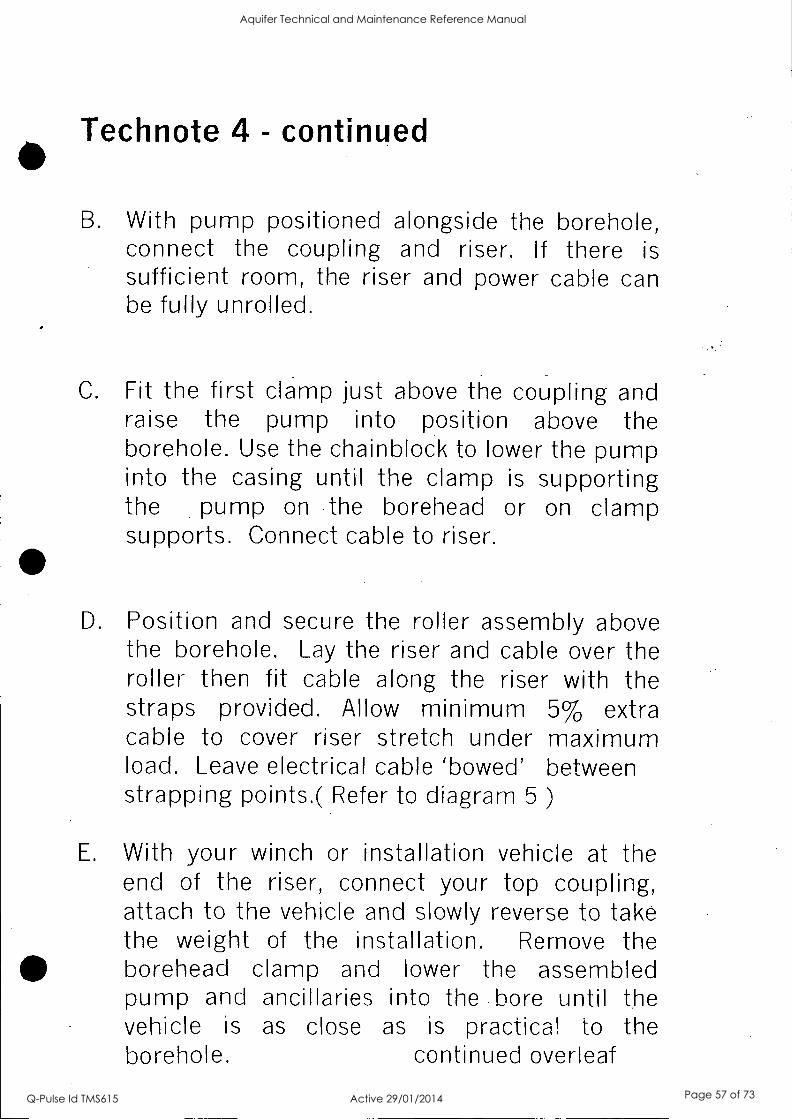
Technote 4 - continued
B. With pump positioned alongside the borehole, connect the coupling and riser. If there is sufficient room, the riser and power cable can be fully unrolled.
C. Fit the first clamp just above the coupling and raise the pump into position above the borehole. Use the chainblock to lower the pump into the casing until the clamp is supporting the pump on the borehead or on clamp supports. Connect cable to riser.
D. Position and secure the roller assembly above the borehole. Lay the riser and cable over the roller then fit cable along the riser with the straps provided. Allow minimum 5% extra cable to cover riser stretch under maximum load. Leave electrical cable 'bowed' between strapping points.( Refer to diagram 5 )
E. With your winch or installation vehicle at the end of the riser, connect your top coupling, attach to the vehicle and slowly reverse to take the weight of the installation. Remove the borehead clamp and lower the assembled pump and ancillaries into the bore until the vehicle is as close as is practical to the borehole. continued overleaf
Aquifer Technical and Maintenance Reference Manual
Q-Pulse Id TMS615 Active 29/01/2014 Page 57 of 73

Technote 4 - continued
Secure the riser with the second clamp, remove the clamp from the vehicle and transfer it to the chainblock. Ensure the chainblock has the weight support before lowering the pump to its final setting.
F. Fit the final borehead discharge assembly.
Note 1. A combination of methods can be used to achieve the installation where space is limited please contact the manufacturer for details.
2. To remove an installation, simply reverse the procedure.
* Note - Do not run clamps or couplings over the roller.
Aquifer Technical and Maintenance Reference Manual
Q-Pulse Id TMS615 Active 29/01/2014 Page 58 of 73

Technote 5 - Installation Equipment
Your Flexibore dealer can supply installation equipment on request.
1. Light duty clamps suitable for a maximum load of 3.5 tonnes.
- -
2. Heavy duty clamps suitable for a maximum load of 5 tonnes.
3. Flexibore installation roller
In most situations, these devices are used in
conjunction with a winch or vehicle of suitable rating to perform the duty.
Refer to diagram 2 in general installation instructions
Aquifer Technical and Maintenance Reference Manual
Q-Pulse Id TMS615 Active 29/01/2014 Page 59 of 73

Technote 6 - Assembly of coupling
Installation of Flexibore couplings is a simple procedure requiring minimal tools.( Refer diag 3)
1. If uneven, trim the end of the riser so a clean, square end results.
2. Push the riser onto the tail piece until it butts cleanly against the shoulder. This does not require lubricant ,which should not be used.
3. If it is difficult to push the riser onto the hose tail, two slits can be cut at the end of the riser. The slits should not be more than 10 mm and should be at 180' from each other.
4. In turn, fit first the bottom three piece clamp ring, then the top. As these are designed to fit face to face, a feeler gauge is not required. 6 - 7mm of hose should show below the bottom clamp.
5. Tighten up the cap screws until an even gap results between each clamp. The size of each gap should be approximately 2mm. The riser cover should not be trapped between. the three sections of the clamp.
Aquifer Technical and Maintenance Reference Manual
Q-Pulse Id TMS615 Active 29/01/2014 Page 60 of 73

6. When fitting the top clamp ensure that the gaps do not line up with those of the bottom clamp. The top clamp should have its gaps at 60" from the bottom clamp.
Note The clamps can be fitted to the coupling without need to file down the orange strip.
Aquifer Technical and Maintenance Reference Manual
Q-Pulse Id TMS615 Active 29/01/2014 Page 61 of 73

Technote 7 - Reinstallation
Reinstallation of couplings with diametral swell.
It may be necessary to re-couple Flexibore which has an increased diameter as a result of its designed swell characteristics.
For minor diametral swell
1. Follow the same procedures as in Technote 5.
2. The gap between the clamps should be approx 1.5mm.
For major diametral swell
1. Make four V shaped cuts into the hose tail at 90' intervals. These cuts should enable the end of the hose to be folded in towards each other thus reducing the diameter of the hose. When tightening up the clamps, ensure that the clamps do not close up over any folded hose as this will not allow the clamping force to be exerted evenly around the hose tail.
2. The gap between the sections of clamp ring should be even.
Aquifer Technical and Maintenance Reference Manual
Q-Pulse Id TMS615 Active 29/01/2014 Page 62 of 73

Technote 8 - Check-valve
When it comes time to remove the pump, all the water
needs to be drained out of the hose. There are a couple
of ways of doing this;
A 5 - 6mm hole can be pre-drilled through the check-
valve on the pump to allow the riser to drain & flatten on
removal.
An alternative drainage system is using a 'break-off
valve'. This needs to be pre fitted to the bottom coupling
prior to installation. To activate the valve, one needs to
lower a steel weight gently down the inside of the hose
as far down as the bottom coupling. This is where the
break off valve has been installed. The break off valve
comprises of a brass shaft machined into the inside of
the coupling. When lowering the weight, stop when it
touches the protruding shaft. One then raises the weight
approx 3 m and lets it drop so that the steel weight
snaps the shaft. Once the shaft is broken, the water will
flow out through the inside of it.
Further details are available upon request.
A suitable check-valve should be fitted to the bore head
discharge assembly. This is in order to reduce water
hammer inside the column
Aquifer Technical and Maintenance Reference Manual
Q-Pulse Id TMS615 Active 29/01/2014 Page 63 of 73

SINGER VALVE Result-Based Solutions. Globally:
12850-87th Avenue Surrey, BC. Canada. V3W 3H9
Ph: 604-594-5404 Fx: 604-594-8845
www.singervalve.com
SINGER MODEL 106/206-RPS-C
Pressure SUstaining and Check Valve Installation, Operating and Maintenance Instructions
V2" - 6" 106/ 4" - 8" 206 Schematic A-0425D 8" 106/10" 206 & Larger Schematic A-0425D1
DESCRIPTION:
Model 106/206-RPS-C is a pilot operated pressure sustaining valve designed to open when the inlet pressure exceeds a predetermined setting. When required, the valve modulates to keep the inlet pressure from dropping below the setting. If pressure reversal occurs, the valve
. closes to prevent reverse flow".
Unless otherwise specified, the valve will be assembled for service temperatures to 180°F (80°C).
DESCRIPTION OF OPERATION:
_N/lain Valve (1) is normally open when pressure is applied to the valve inlet. When the 'same pressure, is applied to the bonnet, the Main Valve closes tight because the area of the diaphragm is greater than the area of the seat. Pressure above the diaphragm determines-the 'position of the Main Valve - whether it be 'ripen, cicised or in
intermediate position. .
The bonnet pressure is controlled with a pilot circuit consisting primarily of Closing Speed Control (5) and Relief/Sustaining Pilot (6). Pilot (6) senses the upstream pressure of the Main Valve. When this pressure is less than the setting of Pilot (6), Pilot (6) is closed. Upstream pressure is directed to the bonnet through Closing Speed Control (5), keeping the Main Valve closed. When the, upstream pressure is greater than the setting of Pilot (6), Pilot (6) opens to allow flow. As this flow is greater than the flow coming through Closing Speed Control (5), pressure in the bonnet of the, Main Valve is reduced, causing the Main Valve to oPen.'
On back pressure service, where the valve is to maintain a constant inlet pressure, Pilot (6) will modulate its flow so that the bonnet pressure is varied. This, in turn, will modulate the Main Valve. If the inlet pressure rises slightly, Pilot (6) opens more, allowing the Main Valve to open further. If the inlet pressure decreases, Pilot (6) closes slightly and the Main Valve closes slightly. The upstream pressure is maintained with varying flows.
If pressure reversal occurs, Check Valve (10) allows the higher pressure into the bonnet and Check Valve (9) keeps the high pressure in the bonnet to close the valve.
INSTALLATION:
1. See 106/206-PG "Installation". 2. Model 106/206-RPS-C is normally factory assembled
so that Pilot (6) senses the pressure directly at the inlet of the Main Valve. At high flows the valve will provide better accuracy of control if the sensing line of Pilot (6) is connected to the header or piping ahead of the Main Valve.
3. Pressurize the valve slowly and bleed air from the bonnet of the Main Valve. See 106/206-PG Instructions:,
ADJUSTING PROCEDURE:
1. Set Closing Speed Control (5) half to one turn open. 2. Slowly open main inlet stop valve wide:
The following methods are suggested to set pilot valve; use the most convenient method:
A. Turn adjusting screw on Pilot* (6) clockwise until it
stops. Establish desired pressure at valve inlet. Turn adjusting screw slowly counterclockwise until valve begins to open. Valve is now set to relieve at the desired pressure. Lock adjusting screw in place.
B. Turn adjusting screw on Pilot (6) counterclockwise until spring is free. Apply pressure to valve inlet. Valve -should be wide open. Turn adjusting screw slowly clockwise until pressure at the valve inlet reaches desired set point. Lock adjusting screw in place. Valve is now set to relieve at the desired pressure.
TEST PROCEDURES:
1. Main. Valve should be closed tight if inlet pressure of Main Valve (1) is less than the setting of Pilot (6).
Increase pressure in the upstream line gradually past the set point of Pilot (6). Valve should open slowly and modulate to maintain the set pressure.
3. Increase pressure in the upstream line suddenly past the set point of Pilot (6). Valve should open further immediately and close slowly as pressure is restored to set point.
4. Repeat this procedure several times. Valve must function smoothly, opening and closing at the same pressure each time.
2.
IOM A-0425D Page 1 of 1 July 2005
Aquifer Technical and Maintenance Reference Manual
Q-Pulse Id TMS615 Active 29/01/2014 Page 64 of 73

270 3c
0.
Aquifer Technical and Maintenance Reference Manual
Q-Pulse Id TMS615 Active 29/01/2014 Page 65 of 73

Sheet 00 I
2 3 4 5 13 -7 a 10 11 13 10
/EL
BORE 01
A MOO APPROWD FOR CONSTRUCTION
No
0606 23SLED FOR TENDER ILL
r
_.
J
NOMINAL INSTANCE
BORE TO LOADOUT - 40 METRES
DRAFTED
PULSE
r - 1Z,
-1
12114r. AHD
I 0/ROW I "II AHD
IVOR AHD -
DRAFTING CHEM
kU. Woad Signed bi NTITHOFT
DESIGN
L
R.P.E13. CATE
aw- V02
PARTTIME ! RELAYS
Rill ---- WWI II
TANK 01 ROMA
11.0W
1010
I re 20.006 AHD
vo4 1-X
TANK 02 IU&L
Odelrai Signed by F. FO0NASER 0603
PRINCPAL DESIGN WAGER DATE
CAD FIE 4033123-25A
APD. Rolmince Chwabig. MC. FIE No.
OrleVNI Scrod by R JANFADA 5192 M:5
OW RP.E.CL P DATE DELEGATE 11
'DATE awn
TRUCK LOADOUT
SYMBOL LEGEND
HAND VALVE
NON EMI VALVE
MAW OR AR BLOWER
FLOWMETER
PRESSURE SUSTAINS
/ DICE VALVE
FLOW UJUNG - 1111 /CHEM VALVE .
PROJECT BRISBANE ACAJIFIER PROJECT
GROUND WATER TANKER STIE
DARRA 2
10
(3 PLC MUNN
SWITOILOARD
COMMOLAISPLAT
prewar am* NSTRUMENT/LOCIL
MIME
- - - ELECTRIC SENA
11 12
intE TANKER LOADOUT PROCESS & INSTRUMENTATION P & ID DIAGRAM
TO SEWER
ABBREVIATIONS
R ROW INDICATOR
RI ROW INDICATION CONTROL
FT ROW TRANSMITTER
SWITOROAFplICIEATING WIT IN HAND SWIM
IN RAM LEVEL
LAN LEVEL ALARM 1101
LAL LEVEL ALARM LOW
LSII 1101 LEVEL SEINOR
LSL LOW LEVEL SENSOR
190 PORN LEVEL SENSOR
MOTORSED
MC MOTOR OWTROL
WC NORMAL ELOSED
IVO. NORMAL OPEN
ZC POSITION CONTROL
ZI POST= MOTOR J
FOR CONSTRUCTION SHEET145.
BRISBINE WATER ORWANO1b.
486/4/9-33123/20 A
13 14 15 16
Aquifer Technical and Maintenance Reference Manual
Q-Pulse Id TMS615 Active 29/01/2014 Page 66 of 73

-. Nev.
11:0
CP
0 \ \ 1 gn
133 rn
kw 110
ti co
c Er
- Is 4 y 119
212 7
-44 59 310
151141kab .9* 313 314
crt, 0 B'
° ts
13 214
107 196
ISLAND SETOUT DETAIL SCALE 190
OUTSIDE EDGE SETOUT CO-ORDINATES
POINT N' EASTING NORTHING ELEVATION
101 45148.364 146456.216 19654
102 45152.483 1434137.135 15374
103 45158.602 148488.054 18116
101 40160.721 141458.972 16.507
105 45164941 141489.891 18.634
106 45168.960 148490903 10.507
107 45170.560 148491977 10.413
108 45173.515 148495.478 18.90
OM 45178.757 145496903 18248
110 45179980 143501.439 18203
111 45183.251 143501959 99.955 .
112 45117914 148503.951 11992
113 45191.837 143534.942 181322
114 45103.130 140505.934 17.944
115 45200.424 148506525 17260
116 45204.717 148507.917 17.777
117 4.010 143508.036 17.694
118 45212564 148509.164 17.624
119 68216.080 148508193 ' 1796 120 45291332 148506.730 17.400
III 45324.585 148505267 97.244
in 45728.349 148503293 17.524
ASHRIDGE
c Z= C= =C
Cc c Gs q (z) q 46
-1- ci c, BUSRIESS tams, ci
LOT 1
c ..- e4
RP135130
INSIDE EDGE SETOUT CO-ORDINATES
EASTING NORTHING ELEVATION POINT N'
201 451111183 148492.737 18.032
202 45179.312 146492.152 10.122
203 45170.713 146491114 18.097
204 45180.418 143495710 18661
205 45111955 446496746 15.049
45113.746 148493965 15.634
45101070 141499.505 17.992
208 45190.477 148501523 17936
209 45194.375 141601.423 17.830
MO 45198.272 1411502323 17.758
MI - 45202170 sasossos 17.664
212 45208007 141504.124 17511
213 45208.183 145934612 17.574
214 45211.365 148504.697 17.493
215 45212997 146504.261 17.438
216 452161337 141502966 17295
217 . 45220.033 146501.459 17.295
ISLAND SETOUT CO-ORDINATES
POINT N' EASTING .
ELEVATION
501 45201905 10008.912 17.857
502 45198202 143308.056 17.929
503 45197.75 148507.335 ' 17.920
504 45197244 146526.946 17920
SOS 45196.563 145508496 17.896
- 505 4520220.3 148507.353 17925
507 45202.715 148506972 17925
508 45202.626 148938.461 172,3
SETOUT PLAN SCALE 1230
I
11. UNE A .
N
ROAD
0 GI al C:3 C:11
MANESS No 216 6 Cii I.01 s- 1 co
RP29723
DRAIN SETOUT CO-ORDINATES
POINT N' EASING. NORTHING ELEVATION
301 45171544 148491919 15.295
302 45178128 948e3= 16.107
303 49182.710 146194.136 17939
304 45167]98 146495244 Bios WS 45191.077 148496.353 17911
306 45196.461 143497.461 17.595
307 4401945 145498570 17.511
303 45205.128 148499.678 17.443
are 45210211 148500.737 17.373
310 4s21L794 148501.896 17.314
311. 45219378 145503034 17264
312 148504.113 77.524
313 45228.545 141505221 17.188
314 oszniss 148508330 17.153
315 45237.711 148507.438 99000
CONCRETE PAVEMENT.
POSITION OF DESIGN L_ EVELS & SET OUT NT.S.
CONTROL POINT SETOUT CO-ORDINATES
POINT N' EASTING NORTHING ELEVATION
AWI 4.244 14644.639 20015
CPI 45249E01 948491.792 17.472
CF2 4910027 141529535 24.926
CONTROL LINE A SETOUT CO-ORDINATES
POINT N' EASING NORTHING CHAINAGE
401 45146191 148479.011 0900
45237238 148000.104 96.460
.s to IS 2D
I....1 I t SCALE :250 tautstte 9E041=40
° ?\" SHEET Ka. 18 OF 27
BRiSRANE WATER RRAWIRR Nu
awn-33123-18
City Design Brisbane City Council
LA113 MOW. Um 315 Ilmsola 51441. Falba Valoy. 0 109
Tavnens 0744033949 Factilit 074490551 404 a1oogegtektor4949.1.
07T J104
101.1104130RESI Wow 94164g 6996
Alb'. Old 4010
boa
A
Desa3169
CONSTRUC1X44 ISSUE
059
319/6
Dom Pah.
AOC
PRELI
Issuo
INARY
0414 Dom Ault sommera....memeano ma....,......44....44..peo... .........444castratsecwomom.ft. ..oftr ...... ......... a.m..; to*, ..... .........................` .
4....................... ............. Com011.011.1. .1.n
9944/1119.1.
SURVEY DAMN CPU CP2 SCUM 90011002
YMCA. DAnsi A110 0 CPI 81.17.472 CM 4182492e
IFa1Rf59098846 REOUIREDOONTPCT ALECWALTERS .
BOY MOM= 564.
AHD.
Fiero=
Fleld Book
BRISBANE WATER DARRA AQUIFER FILLING STATION
LEVELS PLAN & SETOUT
TABLES
04901
AOC
31.8.06
dam
Adt 319.06
7041441004 It4 IMO
area Na
Rekomot Sob
1250
P0.40:1 Moto 'Sheet
CD 060754 / 1031
Aquifer Technical and Maintenance Reference Manual
Q-Pulse Id TMS615 Active 29/01/2014 Page 67 of 73

42v1150410Ck
/312 UPC° REIN.IRED
&WI CUT RISEIENT =IOW X4E161
083.10ITIN MRS OF RACENENT
FOR COGTRUCTION JOINT FINN STAB
!ERE VIM 1E91 I VP GOAL Lair. =maw /WM ANT.
11 11 BP= 116333 OEM Of ACCESS ROPD AND RLOIG POINT.
COGIRUCT elms 815060 .E.4.10 TOO:WREN RgEft MEAL 4.
a
EDGING DETAIL CONTRACTION JOINT SOLE 110 SCALE t-10
-S a
- e
Ep OH
8 * E wv...s..se 0.1.t .3% .11 AI I ttrNae.
1, 0 utsvfaw \ \
, GAG
ROAD - \ . , .
s
w \ CM\ EXPANSION JOINT Watt°
'CO eUMESS Ma 57 0
[011
RP135130
C! INGRESS NA 208 0
LOT 1- RP29723
LEGEND
AREA TO ER0011 RIMED CONROE
PEW GRAMM (REFER TO PAVEMENT DEM)
LI - GWAT011 =TT
- - CONTRACTION JOINT
OPANSION JOINT
LARD3 TO WITCH ECM
AIWA MEE TURFED 187IE MERE =TOG PAVB1ENT OCCURS INTIM TIESE MEAGRE AG MIRFACING 83 TO IE IMAM TO WHIN 262m0 OF
DE KERB 1110 UNDERLYING PAVENOR SCARFED 70 A DEPTH OF Nam Mom CP TOMO TO 3E PLACED PRIOR TO WRENN
GENERAL NOTES
01. REFER TO BMSSAKE CITY COHN= UREIAN MANAGE/ENT ONISICN STAN AM= 111 FOR LIPE STYLES AND UMS 112 Fal WANG SYMBOLS.
02. THE PAVBIENT MOMS SHOWN 01111E OPAMVIGS MAY BE was) BY DIRECTION, 14 %WRING,
OF 1HE SUPERINTBMENT AFTER THE EIMMIP44111011 MAYOR TEMPE OF DE ROOD SUBORADE
THE CONTRACTOR SIVIL M ALL CASES CONFIRM DE PAWIENT THEMESS BEFCIRE PROCEEDING
%WHINE FINN. FORMATION OF THE ROAD SUBC*VDE
GS. THE OUNITITY FOR EMTINIORICS TO SPOIL GIVEN IN TIE SCtEDULE !SINE VOLUME IN TIE SOLID
BEFORE MR/LIM G4. NOT WITHSTAWING THAT THE PRESBITPKVOR PROPOSED POSIDONS OF RIBUC MUTES,
FITTINGS. PIPES, POLES, &WHOLES, ETC, MAY BE INDICATED ON TOE DRAYMIGS, NO
RESPCUSIBLITY WILL BE ACCEPTED BY DE PRMCPAL FORME ACCURACY OF DE REPRESENTATION OR THE OliSSION1HEFEOF.
G5. CONTACT 'MD DV/ BEFORE YOU DIGi ON PHONE 1100 FOR DE EXACT
LocAncw OF SERVKE AUTHORITIES' ASSETS.
G13. ALL taw WORK IS TO BE JOIED NEATLY TO EXISTING.
SIGNS AND PAVEMENT MARKING NOTES
SI. LANE WIDTH MAYBE VARIED F NECESSARY TO WIT ACIWL CROSS SECTION.
S2. ALL SIGNS AND PAVEMENT MARKING 51 ACCORDANCE %MTH THE MANUAL OF UNFORM TRAM CONTROL DEVICES
MONS ARE TO BE ERECTED OFFSET Nem FROM ECGE CF PLATE TO KERB FACE WISE POSSIBLE MESS 83- ariewnsE NOM. S4. PANT 100aua WOE 111LOVI 040 SOPPING LIE ALONG LP OR Um OFFSET FROM KERS ONLY
0
I 1 I I 1
10 15
SCALE : 250 GEFORE REDUCTION)
20
1
25 METRES
LAYOUT & SERVICES PLAN SOLE1260
ENVIRONMENTAL NOTES
MECT R1-2
ALL CONSTRUCTION PC1111111ES ARE TO BE CARRIED OUT IN
ACCORDMICE WITH THE
- GUMLIKE FOR MANAGING BOAROMENTAL RISKS
ASSOCIATED wrna cowsiwucncw ACTIVIIES;
*IENMIONIATENTPL BEST atamcluerr PRACTICE FOR MOWN AND SEDIMENT CONTROL MO - D.C.C. EROSION PAD SNTNGLSTN4.W 11511 RMK OF BREAMS DIM SITE M TN A HIGH RISK FIRE Mr /MAW THE WORM ME *HIGH IVSIC FOR DE eifinalBUTIONISPREA011113 OF REMIT& ALL WONG CM DE SITE ME 700354LY WITH THE CORPIOJE
PROCEDURE FOR FIRE ANTS MOH INCLUDES SITE SURVEY FOR
FRE MITS TREATMENT F NECESSARY, UASON WITH DPI AND
CONTROL ON RECEIPT AND DISPOSPL OF HIGH RISK MATERIAL.
ONZLUDDIG SOL. EARTINOVING among ETC.)
CONTAMINATED SOILS
0145 10 PRESENCE OF CONFAIMMTED SMUT IN AND MOUND
03NSTR45TVISITE. PROOR TO COMMENCEMBIT OF
cONSTRUCTTON. SUPERIN1SONT TO COMMISSION
CONTAMINATION SURVEY 10 DETERMINE WIEDER DERE NE REI,MINING CONTAMINANTS FROM PREVIOUS INDUSTRY
NCLUDING RADIATION. CONTACT AIR GREG MCPHERSON ON PH
WO OUT 10 ORGANISE STUDY CF ENTIRE CONSTRUCTION MEP,
CONCRETE
PAVEMENT DETAILS
20686
Ilarm INC TWEE ORPIEL
I/CC TYPE 3 OOTIDOIE
CONCRETE PAVBENT .
20=11160432 Cal 50031:003i
MIA TOTIL13100083
103192
i TIE PROPOSED WORKNOULD 10 011 TO IDPOEE TIE EIGE ODE 02311110
RVARENT ATOM ONLY MIT AOPINST
D E BM OF DE 19051013 WORM
2. DOME TO BOX LEWL MIT rEWM/G ORGANICIITEE ROOTS NOLO WOAD MO RERACED 1611151.036E MEMEL
a. we wio FOR SUMMFACE MANGE TO
OE REASESEECI ATTIE OE OF
comnalcnoN.
CONCRETE NOTES
ci- N.L waswAvor we wawa saga N mccalwoonani P3.11MNID met RELEVANT AUSIRALIM 011110ARDS.
ca CONCRETE OWL NAVE A CLOP OF 0011160, A WM= MTG.:T.87E 2372 OF 20061 NO
so
STRENGTH OWE N38
83 FORIAVORK NALL COIPLY MTN A.I.WILL
ITIRIPPINO CP FORIMORK NOLL 0010LYVAIN MONO.
cs IMAM CLEAR COVER 10 REINFOICEIENT MOS NOTED ORERMSE 8361 EIE 45088.
GRANULAR
PAVEMENT DETAILS
GRANUTM PAVBENI
ports( MO) AC SURFACNO
POSER OR PRIER 5EN.
BCC TWO 1 100113..
EICC 1WE ORGEL
BCC 1WE 3 =TINGE
vim 100/1310006
1. DE PROPOSED WNW= BE OJT D I TO OPOSE 11E EDGE OF ITE Dane MOW MO M WIPLYOUTTPOIMST TIE EDCE OF TIE 10651103 NONCE
I. MAMIE TO 003 LEM MGREWM110 083MICTIREE110013 SOLD BE MOM NO REPLACED WITHEUITME MEM%
3. DIE NEED FOR SUOSUTFACE ORMICE TO
O E RIMMED AT DE DE OF
001151RUVEM.
SERVICES LEGEND
S- ---C E-
T 7- C
-w w
= = = ;:;= - - -
OBTERAGE
EXISTINO UM ELECTRICITY
1135TRA
GAS
MIEN WM OVER HEAD POWER
MOOG FOORINGIER
ISOLATION JOINT IMUM-10BECOMMTEMOMITAM13001011080 SOLE RIO
W5-26(Mod.)
ISLAND DETAIL SCALE 1:81
WATER
TAMERS
ACCEPTED
1I.JR (Mod.)
SHEET No. 17 OF 27
IMISRAIE WATER (PAVAN° No.
10ee-33123-17
City Design Brisbane City Cound Lowl TO Mnearie 318 Oftwokke 161.
WOO VdmO MO
Wm, OT- NO Mb Fmk* W4103 OM mai 336061831601411wm
a
hua A
S
C
0
COGIRUCTEN MOUE
ORM.= & KERBING ACCED
PAVEMENT DETAILS NAMED
JIM 31.814
89.01
Owe
N2(
/OR
AOC
NM.
GED
GED
Imo Own IMMMMIMILM0MIM
Year
011.1=10.000m 0M1MGyrof embotlik0MMUM
000311M1.
Ism 31160631
SURVEY DATUM CP110.2 rke MD 000K MO
VERT= DOW *OD CPI WW2 012 wawa IF CLARFNATIONS MOORED COITACT NEC VOLTER8
8C01 ON 001213
AHD.
Rome
FIN 1100
BRISBANE WATER DARRA AQUIFER FIWNG STATION
LAYOUT SERVICES PLAN &
DETAILS
owIal
WX 311111
ACk 31.5211,
0.031
OED &OS
Soloisd brims ORIGINAL GOOD BY:
OMER 5116 R.PF-0. No. 3N6
Mims No. Sob
1250
e.oda-g-riaid
CD 060754 / 1030
Imo
Aquifer Technical and Maintenance Reference Manual
Q-Pulse Id TMS615 Active 29/01/2014 Page 68 of 73

2- 4 6 10 11 17 1.3 I - 14 16
PNBO !WICK Ftf LEASE DAMOCH FITT11 t
REMOTE CUNT ROI. PAWL 3.513v200 DEEP
10124 01.3 RH 100x110x3 5140.
CAM GOT (GAPF CO.
300
. .
! POO .PVC ELECTRICAL . . 100 C0.0 UI T TT ON] TOTT00/4113
E TANK CO POUT CPO CAPPED AS SHITI n . ; CACILIT V
1300 1330
SECTIONAL ELEVATION SCALE 1.25
ELEVATION
CAMLDCK FITTING SUPPORT DETAIL MALL 1410
SO 3.0.5 COITAL ANCLG WEL91E0 TO S'S TO SAT CONTROL PAK 1
5tAZN.5 E01.14. ANStE 1ELCIE0 TO Ma TO SUIT C00001. PANS,
421
I-vg7
coacil,?IrAPPEC. weLoco TO 045C EXIT IC
14 Enk 8%1'bl WEN
go? N SNRINK
e NO BST 22 OLT. uOuC5 10 SUIT FAD CHEM MEM RS
ELEVAFLON
2 741 On' 14 01 .1. HOLei TO SUIT IT12 SILTS 1TVP_T
SFCTIGN F-.
CONTROL PANEL SUPPORT DETAIL SC AL e 30.0
INFORMATION ONLY
210 1 eoo ore 633 ass L771 . 100 0 401 200 300 .00 200 !III AG COMMUC1111
R.OTTS0 CCAIC Q NILLINGTIL CCLC Ur 146.1.1KTREC
1 25 FULL 312E Al 31-1E7 SLIT_ 312t Al OK ST arum Dole
OATS
' . 140NOINfo CRAFIEII 8 0.8 .
.TI'rTO '`.7 1.IE PUNCTUAL 3110v 1.447.401Z4ST
... 041C
PFCLECT
BRISBANE AQUIFER PROJECT GRCIUND WA1ER TANKER 5 I 1 E
DARRA 2
TITLE
TANKER FILLING FACILITY CETA1L 5
satr No a Cr 7 SteEIS
OGSG7v MID NO pp)(16872 071.S/TG 0.60< Ai G L. CESTON ERSSAWE N4TER (RAMC a ' AM /4/9. 33123/15
tMENO.
CONSTRICION WO N. CAC, FIE t91312115.0 TA
Rfot.E1 No loft CI -ENT DEIEMATE - :- -DATE J.- -rr ,
BATE MAN AN!' FuNGED BY BCC. L/1 EXTERNAL c i BCC TIE NID 08 /OW IIIS PSI CESEN !ZACK
aP LB 3S1 Ale
Aquifer Technical and Maintenance Reference Manual
Q-Pulse Id TMS615 Active 29/01/2014 Page 69 of 73

01
°:
B
V
1
n
3
S 9 40 11 12 LB 16
L9OPNE;ru IBINC,NIS:11CITTHC
CPOLNO 11142_
EL EC I. JUNCTION BOX ON PROM WALL
API T.
slANDAR3 TWELPART TRATFICAR E
COVER L T RCt AYE BOLES TO CONCRETE PIT 91=19 191 NO- .6o /A,23 -1'16.014
41096x6M. CLEAR Of f /CUP
LINGO HS FLANGED SPOIL PIECE -(--10) E 15INIER;1 06 -FPI
BIND .1100 P/112.5 I In NITU sru RAIQ 6 0 ACK LP Rlna
ON. Z50 6171113
CW110-0410 CLM780T1/31111 &CI MCA
1:0116 .1100 44173 OILEVG1n/ 77P-IPE TO 9TORA.DE 161 E
60IF0 &L./GIFU:CAL C.CN3I ITO 101 13..GGT SIC ; COS ...NCI TCON
NI EARTH CABLES TO -ekisEt
D ras [LANK fLinalr 917n ONBO- CL AJASSO BSI ANC. OR M. OCT AIL]
1150.652 INTERNAL FRI- CAS7 CONDYELE PIT Wrn17 II :SOO OPENING IN BA SE
COURSE GRAVEL FIR DRAINAGE
ENS PPE SUPPORT BIACKE T
irecrea DETAIL]
_ ON25 0-1SO 0I ECM/RUC REDUCER 0 maw DI C R c CONICC7311
134170 .UPY . .412 1301.13 C/04.G. 014 77.2 CAS1471-5E RIES 2-VINYL IR014 )
ON75 WELLMASTER. OR EGUIVA LE NT LAYILA1 RISE
SECTION A ICLLC 110
COUPLING
OGNTGR]NQ 0.1,1101
CTAINLECt LICE L 1131,41
SUING OW& E PUMP W10 .1M-011
ON110 .STAIN-11.1 S7111 043 CAP
3.414 Cn!,-%. cIND. I
ISa
1130
1152 l&D
4.110
0/33. I
0430 P IPE
3111 PC111 8112.5 0REV2RT '
PIPC 16 1111311A0C TANK
PR SSLRE P PE ro Rprilikr..;14C"" A7 /1421 1177 MOM"-
w1Tri -PU311 ON 1/111 Mt. TO
Bet= AD.FLANdE
'-751:AN OF FLANGE
410 Co0.10 CLAN° 1POD- 145)
TLAIHE moo Inn b FLANS DNE10
»1FL
balls1IH -,1 -0420 MCOW 01261014
410 LAM C OLAND]
i214251 PN16 BLNIK FLANGE ICTO 11760 .LANCED BRAND!,
SECT ION B
BORE HEAD FLANGE DETAIL SCALE 15
BOSSED
BORE 0/0311E1E
ett5VCR REMOVE01
PLAN SCALE 1.10
HI Al
C ruin( 119 ROTC 09111_113 10 SUIT CAM FN16 PLATER
15 TFC WELDED TB BASE RATE
15} ELATE
1.14 DIA. ISLES TO Sti T 410 CHEW ANV-ORO
*Firth' gi9NiTtr°
.850 .PVC CLCCT. CONSJIT6
MO 13 A 0,6A1I/C CD3J1 TR LEI AFER PEPE IC TA L LAT1CN
TTUTCIRONAOil
SUPPORT BRACKET DETAILS SGAIC 10
MATERIAL LIST ITEN01Y. DESCRIPTION MATERIAL COATING
1 01130 11_044:9 A SOCK Fr C1S,OCC100 - UNI.INCD DUCT 1M IIM I/11.1 (11..,1_0 1POW
2 1 Bla-r5WEVE t FLANGE EOCENTIM CAICTILE IIDN 111H BULB EPDXY
1 1101 am OWEGO GLANCE NIL 0 CTLEI. I ICU EJLO C 00 XV-
4 1 04250 BLANK FLANGE NM, ONO. FLAN MO BRANCH 16 PC0 OSTACL
NIL 0 STEEL =1IGH BOLO EPDXY
5 1 0180 90. FUNGE S F1 NYSE BEAU WITH 10 THICK 1.1F1-]NC ETC NUN 30 III. 000_1E0 110_1
NILO STEEL 1I6H D.11.1] EPDXY
6 1 0100 PLAICE 1 FLA NGE 111004.. PIECE 150 LON3 NIL 0 STEEL 11014 BULB EPDXY
VOCE. 6n51275 ALI BOLT .".3 NOT ingLuaro
INFORMATION ONLY
50 I 50 100 151 206 251 100 I 100 200 300 400 500 1 I I I 1,-.1 I I I I
1CNE Or NIL 1.3.171E3 1 L LULL LIZ[ Al CLIC LT
6CALC OP LULL 4/4e1R1A 1 io CELL CIZE Al COCCI
AT CONSITLIC111:1
0.1317TO
CHECKED
DATE
OAT
R/NOIN a 616F1E0 LOB .. ... _
.1PGD N. a .rC -
PGasOnAl. 1:0 3164 NANAGGra
.. DAM , 41.
PFOJEcr
BRISBANE' AQUIFER. PROJECT GROUND WATER TANKER SITE DARRA p,
TITLE '
PRCOLICI ION DETAILS
BORE
see 1- No 7 Or 7 9-CETS
MSON WO No p6006872 134.1746 011104 IA GL Cr.S/D4 6493ANE
.usa,.'",
TER °RAYNE N
33]23/16 NAN O.-
I CONSTAUSCN WO N. CAD FLE 19 $012316.DIA - .. - - .
RPEO. NO INT -----40's -. ... _ ... .....
DENT GELEGUE DA E...,
_al/. -fir '..s
OATE PAAEACIPAENT PVT FUNDED BY BCC 4.40 EXTEINAL 4 I ALCC. RE NO 4014.0 /111.2 5/.31,,,CESEN OECK
30
Aquifer Technical and Maintenance Reference Manual
Q-Pulse Id TMS615 Active 29/01/2014 Page 70 of 73
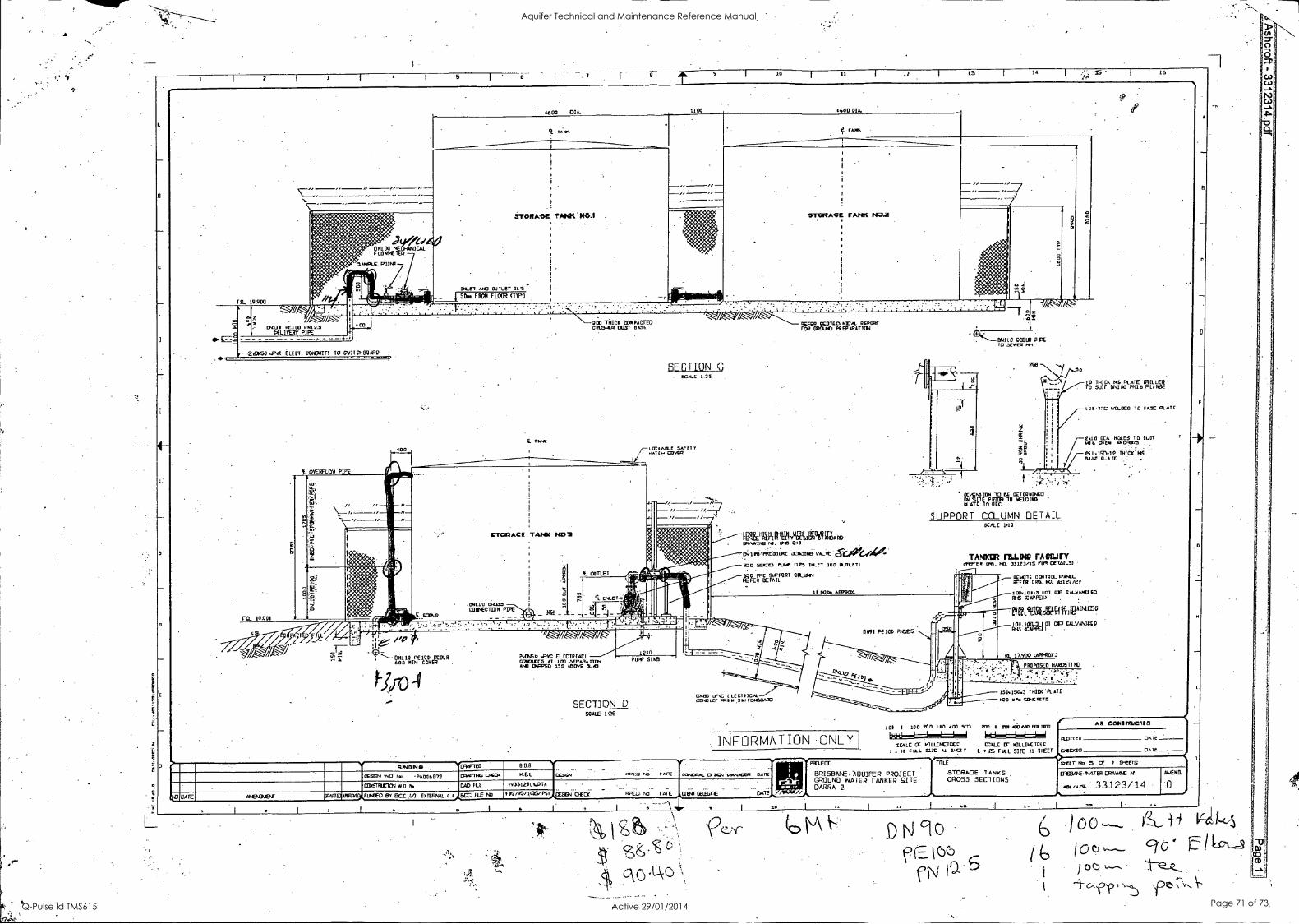
7 8 9 I 10 II I 11 13 14 . lr
16
5L 9.900
RIP ..°6.=
a2
Y /
4600 DIA. 1100 1600 DIA.
`Y i441 P [A VfmE T
iffl SANPLE POINT
EN1-11 11E100 01112.5 DELIVERY PIPE
403
r:220160 ELECT. CONNITS TO SUIT CH BO ARP
OVERCLUA PIPE
TANN.
STORA*C TANWROA .
INLE1 Alp OUTLET IL5 5Das I RCM FLOOR ITTP)
20u0 THICK DOH PA eTED CE115.412 (2.131 0A55
TUNE
SECTION SCALE 1.25
A00 ,,/-L.E.,c,cfs1LE 5AP ET 7
/
TAAsk
*TCNA,crE TANK I
:L7
1//A7' MKS EEDTECI1NEAL SEPORT FOR MOUND PREP /SUTTON
CIONACE TANK ND2
6
et F_ Cal TLET
.
.N11. _ _
.00110 0211521 ECHAECTION PIPE
ro_ 10 A DI COMM
Ole& RVYWIRIPM AND / RD WANING NI. UPC 243
Iro-Pmccoacc O N0 CNOI VP-VC pa CAr U/044 4 2:10 SERIES PLIAS. 1125 DA-E7 100 OLfTLE-T1
M PE TEEmr° RT COLUMN
i
" g -1/
Ei9110 CCM) 0)Y To SEWER 1111
OCVENSION TO OETCPIIINCO
tTLA-71IOR RRCCl 1O MELDING
SUPPORT COLUMN DETAIL SCALE 1.10
TANKER MUNI) FA CILIrY cTffER OM. NO. 2314]/15 ripe OE 1.51L5/
11 DOG. &SPEW
11fiV0-1G CCM 222- PANEL REF ER ORO NO. 38123/29
19
1g ItlIP`btaDOPLa6 [LA
1111.11,2 14CLECO TO IMSE PLATE
4.113 ECA HOLES TD SUIT P16 Encl. AN01025
. . .
es I .131.12 TlifC.X. RATE
100.10183 101 011 CALVANDLO RI-5 CCAPPEI)
RE2LSIDFAWiEmt16
/2 ie //a 600 [N LOVER a jR
HONDA/ 6/
OESGN WO No PAM 6 1372
CONSTRUE-1EN W O N.
SATE AMENEMEAr DRAFT FUMED El BCC I.' EXTERNAL
2.AAhO .PVC EL EE TR LAE L CONDUCTS AT 100 SEPAPIA ANT CNsPEO 150 ABOVE 51-415
101.14CAPPE00-0 I
01 OP CALVANILL I
RL 17.900 (APPROX.,
PRO PO 5E0 HARDS-T1 .
SECIJON D SCALE 125
mom uhC L Lecmcu.--77 COMO UV' CP ON .5 1-041110A170
150. 150.3 THICK' PL ATE
N20 11Po C.OPLUIS
101 I lob POO 110 400 Doi 200 e Ex LOD 660 001 11133 AB CONSTRIJC110
INFORMATION 1.11111
ONLY COLE CC IOLLENCTOCC EOL SIZE
CCALL IT HILLIK IQ( E
12131TE0 DATE
Al 51E1T L F HAL SIZE Al SHEET 111 CNECSEE1 DATE
016F1E0 ELBA PROJECT TOLE 9E1T No 5 17 7 94ETS
[PACING I:KO< tEL aPE0 PA; DATE SaNCVAL 01312.1 1.4.1AGER Derr BRISBANE..APUIFER PROJECT STORAGE TANKS EFISBANE MEER ORAWNS PME
CAD FLE 1993123i. 1.111A GROUND WATER TANKER SITE CROSS SECTIONS DARPA 2. AEU /4/9- 33123/14
F LE NO VHS /95/10S, PSTAFEEEN OfCE Rag ND IATE CLEM- GELE-GAIE
Al 12
A
0
D N clo .) oo 441-)
t) (0e),--- 90 fficeN.-__
oo c-fr \-43 ft)
CD
Aquifer Technical and Maintenance Reference Manual
Q-Pulse Id TMS615 Active 29/01/2014 Page 71 of 73

A a
7 8 9 I 10 11 I 11 l3 I 14 16
r PN" 1E LEg FROM CURE A PPROX LI WITH
13051
I/ I/
1500 HIGH SECURITY FENcE
1,110 PCI2
203 MIRE 0015101 RAO MALL 50 MIN. INTO Ncll RAI licOLITO
// ,--e/--10- II-1/ I/ // I/
era. 10.900
E ,...
iii co
.---
- 04110 P:mo PI112 S Che 4,4cm ANO 31501R PIPE
woo PVC OVERFLOW TO 3COLR P000
1,:il tap Buzau' :.,..-Z. :1'.0
N N g P! .
a ',1
DNB° ,PVC OVERFLOW R TO SCOUR PIPE ,- II
RI, W tludairta I 4-..ii:',, ..-- ..
- _-1 ,::37,-.;,....
. ''.`,
\:`- s:
I
t .111443
1.
1
1 \:,:,, I
I ' s 1 ..
6 1 S. 11.80D \s`l:
`,11
ill .11
1E' ' o 1
001110 -01163 SCO_E WITH O215 00 PALL VALVE F ER 3.1:LING of
i .
I 0100 II rrEPT Lr .
4 1210 VALVE 1LDIGEC0
f ...4
STORAGE TANK MG I
404PAC1TY- 47,950 LI
\Hr5
STORAGE co, 1 I PE5:7I ILAPACIT Y. -a OR17 _, et
TANK NO2 47,910 LI
-
II , ., ;
111
- :.. . 1
1' I 6cr4.44011CAL
PQ PQ Ti tVirliTt - k plUaag 7)
FLCNNETER t
C04100 BUTTERFLY VALVE ILL100E0, ar. i
I
2000 i
411 unito , '
,
a .:
R ::: .9 ...,
la t ,,,,,,, s_. MOO i
h set) 2 I"
, .-z,
I
i
Hrcirt:SvtrE."
ON100 ELECT RO 1111 REIM
150 i
4 I , 1
8 ;;; :
f. ICAL
5o ER 304 fit 19.950
I mp.
re-Ti. All
c .__..__ c___
-
ith111:2: /1-
_f,
, , =.7
n
LOOLASLE SAFE TT 11 ll, .+A Tem OCNCO i ;it
a, I , :
,I! ,
.9, ',, :
c ___- e -W- E --TT 13.50
c c c._. 2
e E --C"-- e - -r-e
.ii. - - FLOWNETER
MI-6 - a !I :
000 OCOICP PUMP AND 4.1. LAOT00 e : 1 1
a , I. .s - I 1
VIIP InRIPMIJ:1,KV-vE .), ' RIII-_. . 1 Ili' 150 T nI0c N50 .10 Tierecize-re .
MCA ET L SLAB i
... 0N160 BUT TERFLY VAL VE IL IACE 02
c c c -- otr
a..
eb IL L.t.r0C1 e- e e e
Pk 014114 RE100 PNtE.S '
dir - __._ _._ _._ _ 2 A, 4 .11
.
... . "'
ALL CO.OuiT3 AT 100 SEPARATION AID CAPPED 151 ABOVE 51.51 tTYPJ
Aso^.
Jai/yr
//- //-- /I 2300
gS
111A,
:1 :1;2 III N
4.ftpi.diP'71(mG
/1- I/- /----- I/
GFNERAL ARRANGEMENT SCALE 1.25
INFORMATION ONLY
( ° IC)
L-, "
130 r 1)
4r0Le 0 6aLLILV7ItED
6, O 110,
1 125 CLLL suc Al suc Er
AS CONS11515110
CLUITECI
CMCX03
DATE
[SATE
451401410 CR4FIE0 BOB ... _ ... ... 1N't pruicom. 01:1124 ~JAGER
.
OATC 4 . PROJECT
.
BRISBANE AQUIFER PROJECT GROUND WATER FANKER SITE DARRA I.
TITLE
STORAGE TANKS GENERAL ARRANGEMENT .
Soar No 4 CF 7 0,,EETS
OETTA WO 04. PA0061372 CRFTNG (3.140e H.G.L. 1.1-'00 04, ERSBANE TOTER DRAWING N
,a, ,..v. 33123/12 NANO.
COBSTFIUMN WO N. CAD FLE 193312717.01A
- ...
1 ATEABTENT DELE641E DATE
_IN, "CP
BATE . AMENONOS X141-1014,1T51/11),F11440ED BY BCC. 1.1 EX1114441. C I .6,13,1X. RE No 185/95/ 515R01A0ESIGN CHECK FIFER NO
11 1 1 316 16
Aquifer Technical and Maintenance Reference Manual
Q-Pulse Id TMS615 Active 29/01/2014 Page 72 of 73

Aquifer Technical and Maintenance Reference Manual
Q-Pulse Id TMS615 Active 29/01/2014 Page 73 of 73