Reference List
65
70 Reference List [1] Shokrieh M. M. and Rahmat M. (2006), “On the reinforcement of concrete sleepers by composite materials”,Composite Structures, pp. 326-337. [2] Telford T., Concrete railway sleepers, London. [3] Taylor H. P. J. (August 1993), “The railway sleeper: 50 years of pretensioned, prestressed concrete”, The Structural Engineeer, vol. 71.No 16/17, pp. 281-295. [4] Sadeghi J. M. and Babaee A. (2006), “Structural Optimization of B70 Railway Prestressed Concrete Sleepers”,Iranian Journal of Science & Technology, Transaction B, Engineering, Vol. 30, No. B4, Printed in the Islamic Republic of Iran. [5] Kaewunruen S. and Remennikov A. M. (2008), “Effect of a large asymmetrical wheel burden on flexural response and failure of railway concrete sleepers in track systems”, Engineering Failure Analysis. [6] Standards Australia,Australian Standard AS1085.14 Railway Track Materials, Part 14: Railway Prestressed Concrete Sleepers, Australia, 2003. [7] Agro R. (1986) Railway Track Engineering,Delhi,Khanna Publishers. [8] Gupta B. L. (1982) Text Book of Railway Engineering, Delhi, Standards Publishers. [9] De Silva P. (December 2007), Air, Maritime and rail Transportation in Sri Lanka, Centenary commemoration Publications. [10] http://www.railwaymuseum.lk/[accessed on 20/05/2012] [11] Kaewunruen S. and Remennikov A. M. (2008), “Reliability Assessment of Railway Prestressed Concrete Sleepers”,Australian Structural Engineering Conference (ASEC), 26-27 June 2008, Melbourne, Australia. [12] Manalo A., Aravinthan T., Karunasena W. and Ticoalu A. (2010), “A Review of alternative materials for replacing existing timber sleepers”,composite structures, pp 603-611. [13] Manual of special rules railways: Part1, Permanent Way, Way and works Department, 4 th ed. State Printing Corporation, 2004. [14] Mundrey J. S. (2000), Railway trackEngineeering. Tata McGraw-Hill Publishing Company Limited, New Delhi. [15] Kaewunruen S. and Remennikov A. M. (2009), “Impact capacity of railway prestressed concrete sleepers”, Engineering Failure Analysis.
-
Upload
khangminh22 -
Category
Documents
-
view
1 -
download
0
Transcript of Reference List

70
Reference List
[1] Shokrieh M. M. and Rahmat M. (2006), “On the reinforcement of concrete
sleepers by composite materials”,Composite Structures, pp. 326-337.
[2] Telford T., Concrete railway sleepers, London.
[3] Taylor H. P. J. (August 1993), “The railway sleeper: 50 years of pretensioned,
prestressed concrete”, The Structural Engineeer, vol. 71.No 16/17, pp. 281-295.
[4] Sadeghi J. M. and Babaee A. (2006), “Structural Optimization of B70 Railway
Prestressed Concrete Sleepers”,Iranian Journal of Science & Technology,
Transaction B, Engineering, Vol. 30, No. B4, Printed in the Islamic Republic of Iran.
[5] Kaewunruen S. and Remennikov A. M. (2008), “Effect of a large asymmetrical
wheel burden on flexural response and failure of railway concrete sleepers in track
systems”, Engineering Failure Analysis.
[6] Standards Australia,Australian Standard AS1085.14 Railway Track Materials,
Part 14: Railway Prestressed Concrete Sleepers, Australia, 2003.
[7] Agro R. (1986) Railway Track Engineering,Delhi,Khanna Publishers.
[8] Gupta B. L. (1982) Text Book of Railway Engineering, Delhi, Standards
Publishers.
[9] De Silva P. (December 2007), Air, Maritime and rail Transportation in Sri
Lanka, Centenary commemoration Publications.
[10] http://www.railwaymuseum.lk/[accessed on 20/05/2012]
[11] Kaewunruen S. and Remennikov A. M. (2008), “Reliability Assessment of
Railway Prestressed Concrete Sleepers”,Australian Structural Engineering
Conference (ASEC), 26-27 June 2008, Melbourne, Australia.
[12] Manalo A., Aravinthan T., Karunasena W. and Ticoalu A. (2010), “A Review of
alternative materials for replacing existing timber sleepers”,composite structures, pp
603-611.
[13] Manual of special rules railways: Part1, Permanent Way, Way and works
Department, 4th ed. State Printing Corporation, 2004.
[14] Mundrey J. S. (2000), Railway trackEngineeering. Tata McGraw-Hill
Publishing Company Limited, New Delhi.
[15] Kaewunruen S. and Remennikov A. M. (2009), “Impact capacity of railway
prestressed concrete sleepers”, Engineering Failure Analysis.

71
[16] Remennikov A. M., Murray M. H. and Kaewunruen S. (2007), Conversion of
AS 1085.14 for prestressed concrete sleepers to limit states design format, Sydney.
[17] Kaewunruen S. and Remennikov A. (2006), “Rotational capacity of railway
prestressed concrete sleeper under static hogging moment”, The tenth East Asia-
Pacific Conference on Structural Engineering and construction, August 3-5, 2006,
Bankok, Thailand.
[18] Kaewunruen S. and Remennikov A. M. (2006), “Sensitivity analysis of free
vibration characteristics of an in situ railway concrete sleeper to variations of rail pad
parameters”, Journal of Sound and Vibration, pp. 453-461.
[19] www.railway.gov.lk[accessed on 20/05/2012]

1

72
Appendix 1: Prestressed concrete sleeper produced at Ekala with grade 50 N/mm2
concrete

73
Table of Contents
1.0 Notation
2.0 Design Criteria
2.1 Design codes and manuals
2.2 Design loads
2.3 Design velocity
2.4 Design life
2.5 Track details
2.6 Material properties
2.6.1 Concrete
2.6.2 Prestressing steel
3.0 Calculations
3.1 Analysis of the concrete sections
3.1.1 Section at rail seat
3.1.2 Area of the section
3.1.3 Centre of Gravity
3.1.4 Moment of inertia
3.1.5 Section modulus
3.1.6 Section at sleeper centre
3.1.7 Area of the section
3.1.8 Centre of Gravity
3.1.9 Moment of inertia
3.1.10 Section modulus
3.2 Load calculations
3.2.1 Load calculations according to AS 1085.14 - 2003
3.2.2 Sleeper design bending moments
3.3 Permissible stresses
3.3.1 Stress at transfer
3.3.2 Stress at service
3.4 Adequacy of the section
3.5 Basic equations for rail seat
3.5.1 Positive bending moment
3.5.2 Negative bending moment
3.6 Basic equations for rail centre
3.6.1 Positive bending moment
3.6.2 Negative bending moment
3.7 Number of tendons
3.8 Possible tendon arrangement
3.9 Losses
3.9.1 Losses at transfer stage
3.9.2 Losses at service stage
3.9.3 Total prestress loss
74
1.0 Notation
A - Sectional area of sleeper
Aps - Area of tendons
e - Eccentricity (Measured upward from the Neutral Axis)
Es - Modulus of elasticity of steel
Ec - Modulus of elasticity of concrete
fci - Concrete strength at transfer
fpu - Characteristic strength of prestressing tendons
fb - Stress at bottom fibre
ft - Stress at top fibre
I - Second moment of area
Md - Bending moment (BM) due to self weight of sleeper
MR+ - Positive BM (bottom fibres are under tension) at the rail seat
MR- - Negative BM (bottom fibres are under compression) at the rail seat
MC+ - Positive BM (bottom fibres are under tension) at the mid span of the sleeper
MC- - Negative BM (bottom fibres are under compression) at the mid span of the
sleeper
Yb - Distance to the bottom most fibre from neutral axis
Yt - Distance to the top most fibre from neutral axis
Zt - Sectioanl modulus of the top fibre of sleeper
Zb - Sectioanl modulus of the bottom fibre of sleeper
P - Prestressing force in the tendon at the jacking end
yst - Centre of prestressing force
75
2.0 Design Criteria
2.1 Design codes and manuals
AS 1085.14-2003 Railway Track Material, Prestressed Concrete
Sleepers
BS 8110 Part 1-1985 : Structural use of concrete, Code of practice
for Design and construction
BS 5896-1980: Specification for High Tensile Steel Wire and
Strand for Prestressing of Concrete
BS 5400-Part 4-1990: Steel, Concrete and Composite Bridges,
Code of Practice for Design of Concrete Bridges
2.2 Design loads
Axle load - 200 kN
Combined vertical design load factor - 2.5 (Clause 4.2.1.3 and
Appendix F of AS 1085.14 - 2003)
2.3 Design velocity
Maximum train velocity - 80 km/h (F4 of AS 2003.14 - 2003)
2.4 Design life
Design life - 50 years
2.5 Track details
Rail type - Rails are assumed heavier than 47 kg/m
Gauge - 1676 mm
Sleeper spacing - 600 mm
2.6 Material properties
2.6.1 Concrete
Compressive strength at 28 days = 50 N/mm2
Compressive strength at load transfer = 25 N/mm2
Density = 24 kN/m3
Modulus of elasticity = 34 kN/mm2
2.6.2 Pre stressing steel
Cold – drawn wire, Relaxation class 2.
Nominal tensile strength = 1670 N/mm2
Tendon diameter = 5 mm
Tendon area = 4
52=19.63 mm2
76
Initial pre stressing force per tendon = 310
75.06.191670
=24.58 kN
Number of tendons per sleeper = 14
Modulus of elasticity = 205 10 kN/mm2

77
Reference Calculations Out put
3.0 Calculations
3.1 Analysis of the concrete sections
3.1.1 Section at rail seat
Figure 1: Dimensions at rail seat
a = 200 mm
b = 250 mm
h = 225 mm
3.1.2 Area of the section
A = 2
)( bah
= 50625 mm2
3.1.3 Centre of Gravity
Yb = )(
)2(
3 ba
bah
= 108.3 mm
Yt = h - Yb = 116.7 mm
3.1.4 Moment of inertia
I = )(
)4(
36
223
ba
babah
= 212.69 x 106 mm4
3.1.5 Section modulus
Zt = tY
I= 1.822 x 106 mm3
Zb = bY
I= 1.963 x 106 mm3
3.1.6 Section at sleeper centre
Figure 2: Dimensions at rail centre
A=50625
mm2
Yb=108.3
mm
Yt=116.7
mm
I=212.69
x106mm4
Zt= 1.822
x106mm3
Zb=1.963
x106mm3
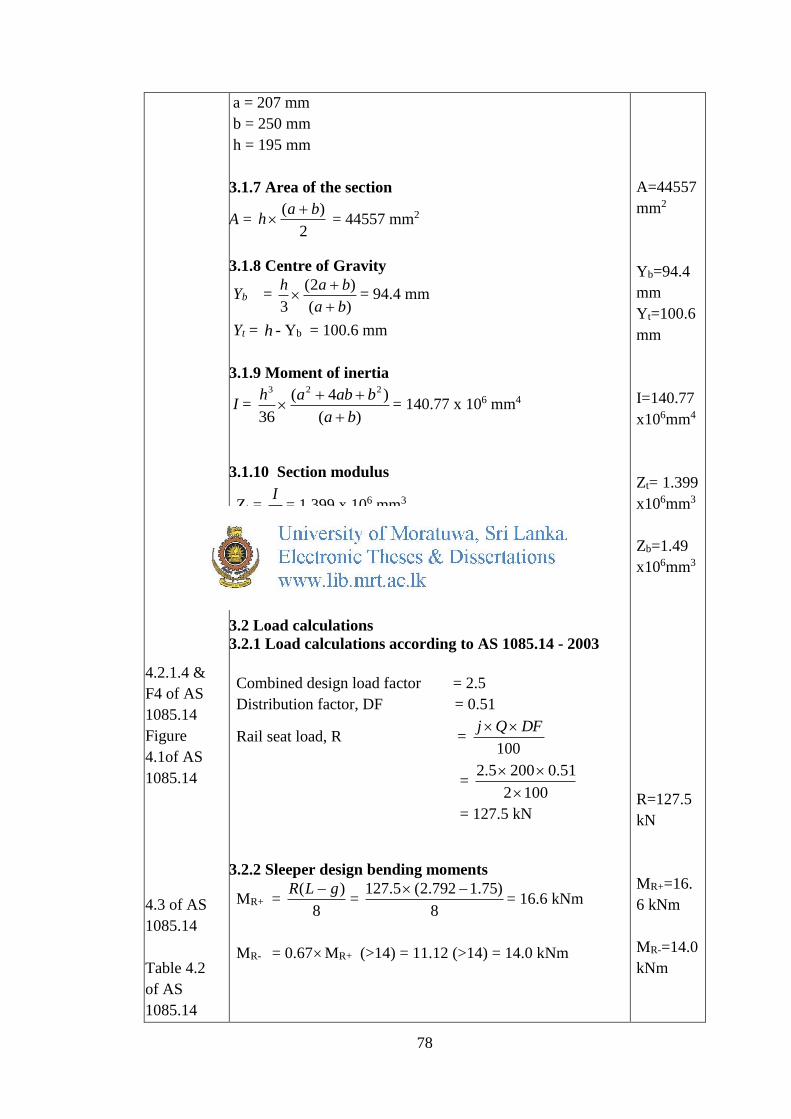
78
4.2.1.4 &
F4 of AS
1085.14
Figure
4.1of AS
1085.14
4.3 of AS
1085.14
Table 4.2
of AS
1085.14
a = 207 mm
b = 250 mm
h = 195 mm
3.1.7 Area of the section
A = 2
)( bah
= 44557 mm2
3.1.8 Centre of Gravity
Yb = )(
)2(
3 ba
bah
= 94.4 mm
Yt = h - Yb = 100.6 mm
3.1.9 Moment of inertia
I = )(
)4(
36
223
ba
babah
= 140.77 x 106 mm4
3.1.10 Section modulus
Zt = tY
I= 1.399 x 106 mm3
Zb = bY
I= 1.49 x 106 mm3
3.2 Load calculations
3.2.1 Load calculations according to AS 1085.14 - 2003
Combined design load factor = 2.5
Distribution factor, DF = 0.51
Rail seat load, R = 100
DFQj
= 1002
51.02005.2
= 127.5 kN
3.2.2 Sleeper design bending moments
MR+ = 8
)( gLR =
8
)75.1792.2(5.127 = 16.6 kNm
MR- = 0.67MR+ (>14) = 11.12 (>14) = 14.0 kNm
A=44557
mm2
Yb=94.4
mm
Yt=100.6
mm
I=140.77
x106mm4
Zt= 1.399
x106mm3
Zb=1.49
x106mm3
R=127.5
kN
MR+=16.
6 kNm
MR-=14.0
kNm

79
BS 8110:
Part 1
BS 5896
Table 6
BS 8110:
Part 1
Clause
4.8.5.2
MC+ = 0.05 )( gLR = 0.05 )75.1792.2(5.127
= 6.64 kNm
MC- = 8
)2()(5.0
2LgWgLWgRg
W = )23(
4
gL
R
=
)75.12792.23(
5.1274
= 104.6 kN/m
MC- = 12.91 kNm
3.3 Permissible stresses
fc = 50 N/mm2
fcp = 25 N/mm2
3.3.1 Stress at transfer
fa,maxt = 0.5 fcp = 25 N/mm2
fa,mint = 0
3.3.2 Stress at service
fa,max = 0.45 f’c = 22.5 N/mm2
fa,min = -0.4 (f’c)0.5 = -2.83 N/mm2
3.4 Adequacy of the section
min,max,
,aa
RRbt
ff
MMZZ
)83.2(5.22
10)146.16(,
6
bt ZZ
Zt, Zb > 1.208 x 106 mm3
Zt actual = 1.399 x 106 mm3 > 1.208 x 106 mm3 OK
Zb actual = 1.49 x 106 mm3 > 1.208 x 106 mm3 OK
MC+=6.6
4 kNm
MC-=12.9
kNm
Section
is OK

80
3.5 Basic equations for rail seat
3.5.1 Positive bending moment
A
Pe t
e
Z
eP .
t
R
Z
M
_ +
+ _
A
Pe b
e
Z
eP .
b
R
Z
M
Bottom Fibre
A
Pe + b
e
Z
eP .-
b
R
Z
M fa,min
Rab
b
MfZ
eAZ
Pe min,
/1
Substitute the suitable values;
66
6
106.16)83.2(10963.1
50625/)10963.1(1
e
Pe
ePe
06.9351101 8
(RS PB)
Top Fibre
A
Pe - t
e
Z
eP .+
t
R
Z
M fa,max
Rat
b
MfZ
eAZ
Pe min,
/1
Substitute the suitable values;
66
6
106.165.2210822.1
50625/)10822.1(1
e
Pe
ePe
09.45.147101 8
(RS PT)
+

81
3.5.2 Negative bending moment
A
Pe t
e
Z
eP .
t
R
Z
M
_ _
+ +
A
Pe b
e
Z
eP .
b
R
Z
M
Bottom Fibre
A
Pe + b
e
Z
eP .+
b
R
Z
M fa,max
Rab
b
MfZ
eAZ
Pe max,
/1
Substitute the suitable values;
66
6
100.145.2210963.1
50625/)10963.1(1
e
Pe
ePe
31.3128101 8
(RS NB)
Top Fibre
A
Pe - t
e
Z
eP .-
t
R
Z
M fa,min
Rat
t
MfZ
eAZ
Pe min,
/1
Substitute the suitable values;
66
6
100.14)83.2(10822.1
50625/)10822.1(1
e
Pe
ePe
31.110.407101 8
(RS NT)
+

82
3.6 Basic equations for rail centre
3.6.1 Positive bending moment
A
Pe t
e
Z
eP .
t
C
Z
M
_ +
+ _
A
Pe b
e
Z
eP .
b
C
Z
M
Bottom Fibre
A
Pe + b
e
Z
eP .-
b
C
Z
M fa,min
Cab
b
MfZ
eAZ
Pe min,
/1
Substitute the suitable values;
66
6
1064.6)83.2(10491.1
44557/)10491.1(1
e
Pe
ePe
57.491659101 8
(RC PB)
Top Fibre
A
Pe - t
e
Z
eP .+
t
C
Z
M fa,max
Cat
b
MfZ
eAZ
Pe max,
/1
Substitute the suitable values;
66
6
1064.65.2210399.1
44557/)10399.1(1
e
Pe
ePe
21.38.100101 8
(RC PT)
+

83
3.6.2 Negative bending moment
A
Pe t
e
Z
eP .
t
C
Z
M
_ _
+ +
A
Pe b
e
Z
eP .
b
C
Z
M
Bottom Fibre
A
Pe + b
e
Z
eP .+
b
R
Z
M fa,max
Cab
b
MfZ
eAZ
Pe max,
/1
Substitute the suitable values;
66
6
1091.125.2210491.1
44557/)10491.1(1
e
Pe
ePe
65.33.122101 8
(RC NB)
Top Fibre
A
Pe - t
e
Z
eP .-
t
C
Z
M fa,min
Cat
t
MfZ
eAZ
Pe min,
/1
Substitute the suitable values;
66
6
1091.12)83.2(10399.1
44557/)10399.1(1
e
Pe
ePe
67.115.366101 8
(RC NT)
Draw combined Magnel diagram using equations. Effective
prestressing force can be calculated using Magnel diagram.
+

84
Figure 3: Combined Magnel diagram for prestressed
concrete sleepers produced at Ekala with grade 50 N/mm2
concrete
According to the combined Magnel diagram;
375101
max
8
eP at e=2.85 mm
267375
101 8
eP
Pe = 267 kN
3.7 Number of tendons
Diameter of a tendon = 5 mm
Area per prestressing tendon = 4
52= 19.63 mm2
Nominal tensile strength = 1670 N/mm2
Initial prestressing force per tendon
=310
75.063.191670 = 24.58 kN
Effective prestressing force (15% losses)
= 85.085.24 =20.89 kN
Number of tendonss required =89.20
267= 12.78 Nos.
= 14 Nos.
Because of the symmetry 14 nos. of tendons to be used.
Therefore number of tendons can be reduced to 14 with
grade 50 N/mm2 concrete. It is clear that it can be further
reduced with grade 60 N/mm2 concrete.
e=2.85
mm
Pe=267
kN
Tendons
14 Nos.
0
100
200
300
400
500
600
700
-60 -40 -20 0 20 40 60
1x10⁸/Pe(N)
e(mm)
RS PB RS NB RS PT RS NT
RC PB RC NB RC PT RC NT

85
Limiting range for ‘e’ value
Rail seat; -0.5<e<5.5
Rail centre; -25<e<1.0
3.8 Possible tendon arrangement
Figure 4: Possible tendon arrangement (i) Rail seat, (ii) Rail
centre
Centre of prestressing tendons - yst
From Figure 4;
15521259565414 sty
mmyst 57.103
Centre of tendons are within the limiting range for ‘e’ value.
Figure 5: Centre of prestressing tendons
3.9 Losses
3.9.1 Losses at transfer stage
Elastic deformation loss
% load apply to prestress = 75%
Number of bars = 14
Initial prestressing force psyi AfnP
= 310
63.1916701475.0 = 344 kN
Concrete stress, I
eP
A
Pf i
c
icoj
2
yst=103.5
7 mm

86
I = 212695369 mm4
e = 108.33-106.42 = 1.91 mm
Ac = 50625 mm2
212695369
91.110344
50625
10344 233
cojf = 6.795 + 0.006
= 6.801 N/mm2
At the level of steel;
Strain in concrete = strain in steel
s
ps
c
coj
E
f
E
f
)7(
coj
c
sps f
E
Ef
)7(
Es = 195 kN/mm2
Ec(7) = 36 kN/mm2
Loss of prestress = psps Af
= 801.636
195 = 36.83 N/mm2
Percentage loss = %10010344
1463.1983.363
= 2.94%
3.9.2 Losses at service stage
Shrinkage loss
Shrinkage strain = ɛs = 610100
Loss of prestress = sps EA s
= )10195()1463.19()10100( 36 = 5359 N
Percentage loss = %10010344
53593
= 1.56%
Loss due to relaxation
Maximum relaxation after 1000h = 3.5 %
Relaxation factor = 1.2
Loss due to relaxation = 2.1100
96
100
5.3 iP
= 2.1100
9610344
100
5.3 3 = 13870 N
Percentage loss = %10010344
138703
= 4.03%
Loss due to creep of concrete
Creep coefficient = ϕ = 1.8
Specific creep strain )7(c
ccE
31036
8.1

87
= 5100.5 mm
Loss of stress in steel = pscoj Ef cc
I
eP
A
Pf i
c
icoj
2
= 6.801 N/mm2
= )10195(801.6)100.5( 35 = 66.31 N/mm2
Loss due to creep = 1463.1931.66 = 18223 N
Percentage loss = %10010344
182233
= 5.29%
3.9.3 Total prestress loss
Total prestress loss = Elastic deformation loss + Loss due to
shrinkage + Loss due to relaxation of steel + Loss due to
creep of concrete = (2.94 + 1.56 + 4.03 + 5.29)% = 13.82 %
= 15.0 % (say)
Total
losses
15%
88
Reference Calculations Out put

89

88
Appendix 2: Prestressed concrete sleeper produced at Ekala with grade 60 N/mm2
concrete

89
Table of Contents
1.0 Notation
2.0 Design Criteria
2.1 Design codes and manuals
2.2 Design loads
2.3 Design velocity
2.4 Design life
2.5 Track details
2.6 Material properties
2.6.1 Concrete
2.6.2 Prestressing steel
3.0 Calculations
3.1 Analysis of the concrete sections
3.1.1 Section at rail seat
3.1.2 Area of the section
3.1.3 Centre of Gravity
3.1.4 Moment of inertia
3.1.5 Section modulus
3.1.6 Section at sleeper centre
3.1.7 Area of the section
3.1.8 Centre of Gravity
3.1.9 Moment of inertia
3.1.10 Section modulus
3.2 Load calculations
3.2.1 Load calculations according to AS 1085.14 - 2003
3.2.2 Sleeper design bending moments
3.3 Permissible stresses
3.3.1 Stress at transfer
3.3.2 Stress at service
3.4 Adequacy of the section
3.5 Basic equations for rail seat
3.5.1 Positive bending moment
3.5.2 Negative bending moment
3.6 Basic equations for rail centre
3.6.1 Positive bending moment
3.6.2 Negative bending moment
3.7 Number of tendons
3.8 Possible tendon arrangement
3.9 Losses
3.9.1 Losses at transfer stage
3.9.2 Losses at service stage
3.9.3 Total prestress loss
90
1.0 Notation
A - Sectional area of sleeper
Aps - Area of tendons
e - Eccentricity (Measured upward from the Neutral Axis)
Es - Modulus of elasticity of steel
Ec - Modulus of elasticity of concrete
fci - Concrete strength at transfer
fpu - Characteristic strength of prestressing tendons
fb - Stress at bottom fibre
ft - Stress at top fibre
I - Second moment of area
Md - Bending moment (BM) due to self weight of sleeper
MR+ - Positive BM (bottom fibres are under tension) at the rail seat
MR- - Negative BM (bottom fibres are under compression) at the rail seat
MC+ - Positive BM (bottom fibres are under tension) at the mid span of the sleeper
MC- - Negative BM (bottom fibres are under compression) at the mid span of the
sleeper
Yb - Distance to the bottom most fibre from neutral axis
Yt - Distance to the top most fibre from neutral axis
Zt - Sectioanl modulus of the top fibre of sleeper
Zb - Sectioanl modulus of the bottom fibre of sleeper
P - Prestressing force in the tendon at the jacking end
yst - Centre of prestressing force

91
2.0 Design Criteria
2.1 Design codes and manuals
AS 1085.14-2003 Railway Track Material, Prestressed Concrete
Sleepers
BS 8110 Part 1-1985 : Structural use of concrete, Code of practice
for Design and construction
BS 5896-1980: Specification for High Tensile Steel Wire and
Strand for Prestressing of Concrete
BS 5400-Part 4-1990: Steel, Concrete and Composite Bridges,
Code of Practice for Design of Concrete Bridges
2.2 Design loads
Axle load - 220 kN
Combined vertical design load factor - 2.5 (Clause 4.2.1.3 and
Appendix F of AS 1085.14 - 2003)
2.3 Design velocity
Maximum train velocity - 80 km/h (F4 of AS 2003.14 - 2003)
2.4 Design life
Design life - 50 years
2.5 Track details
Rail type - Rails are assumed heavier than 47 kg/m
Gauge - 1676 mm
Sleeper spacing - 600 mm
2.6 Material properties
2.6.1 Concrete
Compressive strength at 28 days = 60 N/mm2
Compressive strength at load transfer = 30 N/mm2
Density = 24 kN/m3
Modulus of elasticity = 36 kN/mm2
2.6.2 Prestressing steel
Cold – drawn wire, Relaxation class 2.
Nominal tensile strength = 1670 N/mm2
Tendon diameter = 5 mm

92
Tendon area = 4
52=19.63 mm2
Initial pre stressing force per tendon = 310
75.06.191670 =24.58 kN
Number of tendons per sleeper = 14
Modulus of elasticity = 205 10 kN/mm2

93
Reference Calculations Out put
3.0 Calculations
3.1 Analysis of the concrete sections
3.1.1 Section at rail seat
Figure 1: Dimensions at rail seat
a = 200 mm
b = 250 mm
h = 225 mm
3.1.2 Area of the section
A = 2
)( bah
= 50625 mm2
3.1.3 Centre of Gravity
Yb = )(
)2(
3 ba
bah
= 108.3 mm
Yt = h - Yb = 116.7 mm
3.1.4 Moment of inertia
I = )(
)4(
36
223
ba
babah
= 212.69 x 106 mm4
3.1.5 Section modulus
Zt = tY
I= 1.822 x 106 mm3
Zb = bY
I= 1.963 x 106 mm3
3.1.6 Section at sleeper centre
Figure 2: Dimensions at rail centre
A=50625
mm2
Yb=108.3
mm
Yt=116.7
mm
I=212.69
x106mm4
Zt=1.822
x106mm3
Zb=1.963
x106mm3

94
4.2.1.4 &
F4 of AS
1085.14
Figure
4.1of AS
1085.14
4.3 of AS
1085.14
Table 4.2
of AS
1085.14
a = 207 mm
b = 250 mm
h = 195 mm
3.1.7 Area of the section
A = 2
)( bah
= 44557 mm2
3.1.8 Centre of Gravity
Yb = )(
)2(
3 ba
bah
= 94.4 mm
Yt = h - Yb = 100.6 mm
3.1.9 Moment of inertia
I = )(
)4(
36
223
ba
babah
= 140.77 x 106 mm4
3.1.10 Section modulus
Zt = tY
I= 1.399 x 106 mm3
Zb = bY
I= 1.49 x 106 mm3
3.2 Load calculations
3.2.1 Load calculations according to AS 1085.14: 2003
Combined design load factor = 2.5
Distribution factor, DF = 0.51
Rail seat load, R = 100
DFQj
= 1002
51.02205.2
= 140.25 kN
3.2.2 Sleeper design bending moments
MR+ = 8
)( gLR =
8
)75.1792.2(25.140 = 18.32 kNm
MR- = 0.67MR+ (>14) = 11.12 (>14) = 14.0 kNm
A=44557
mm2
Yb=94.4
mm
Yt=100.6
mm
I=140.77
x106mm4
Zt=1.399
x106mm3
Zb=1.49x
106mm3
R=140.3
kN
MR+=18.
3 kNm
MR=14.0
kNm

95
BS 8110:
Part 1
BS 5896
Table 6
BS 8110:
Part 1
Clause
4.8.5.2
MC+ = 0.05 )( gLR = 0.05 )75.1792.2(25.140
= 7.33 kNm
MC- = 8
)2()(5.0
2LgWgLWgRg
W = )23(
4
gL
R
=
)75.12792.23(
25.1404
= 114.84 kN/m
MC- = 14.15 kNm
3.3 Permissible stresses
fc = 60 N/mm2
fcp = 30 N/mm2
3.3.1 Stress at transfer
fa,maxt = 0.5 fcp = 30 N/mm2
fa,mint = 0
3.3.2 Stress at service
fa,max = 0.45 f’c = 27.0 N/mm2
fa,min = -0.4 (f’c)0.5 = -3.1 N/mm2
3.4 Adequacy of the section
min,max,
,aa
RRbt
ff
MMZZ
)1.3(0.27
10)143.18(,
6
bt ZZ
Zt, Zb > 1.074 x 106 mm3
Zt actual = 1.399 x 106 mm3 > 1.074 x 106 mm3 OK
Zb actual = 1.49 x 106 mm3 > 1.074 x 106 mm3 OK
MC+=7.3
3 kNm
MC=14.2
kNm
Section
is OK

96
3.5 Basic equations for rail seat
3.5.1 Positive bending moment
A
Pe t
e
Z
eP .
t
R
Z
M
_ +
+ _
A
Pe b
e
Z
eP .
b
R
Z
M
Bottom Fibre
A
Pe + b
e
Z
eP .-
b
R
Z
M fa,min
Rab
b
MfZ
eAZ
Pe min,
/1
Substitute the suitable values;
66
6
1032.18)1.3(10963.1
50625/)10963.1(1
e
Pe
ePe
18.8317101 8
(RS PB)
Top Fibre
A
Pe - t
e
Z
eP .+
t
R
Z
M fa,max
Rat
b
MfZ
eAZ
Pe min,
/1
Substitute the suitable values;
66
6
1032.180.2710822.1
50625/)10822.1(1
e
Pe
ePe
24.35.116101 8
(RS PT)
+
97
3.5.2 Negative bending moment
A
Pe t
e
Z
eP .
t
R
Z
M
_ _
+ +
A
Pe b
e
Z
eP .
b
R
Z
M
Bottom Fibre
A
Pe + b
e
Z
eP .+
b
R
Z
M fa,max
Rab
b
MfZ
eAZ
Pe max,
/1
Substitute the suitable values;
66
6
100.140.2710963.1
50625/)10963.1(1
e
Pe
ePe
56.239.99101 8
(RS NB)
Top Fibre
A
Pe - t
e
Z
eP .-
t
R
Z
M fa,min
Rat
t
MfZ
eAZ
Pe min,
/1
Substitute the suitable values;
66
6
100.14)1.3(10822.1
50625/)10822.1(1
e
Pe
ePe
97.110.431101 8
(RS NT)
+

98
3.6 Basic equations for rail centre
3.6.1 Positive bending moment
A
Pe t
e
Z
eP .
t
C
Z
M
_ +
_
+
A
Pe b
e
Z
eP .
b
C
Z
M
Bottom Fibre
A
Pe + b
e
Z
eP .-
b
C
Z
M fa,min
Cab
b
MfZ
eAZ
Pe min,
/1
Substitute the suitable values;
66
6
1033.7)1.3(10491.1
44557/)10491.1(1
e
Pe
ePe
9.361236101 8
(RC PB)
Top Fibre
A
Pe - t
e
Z
eP .+
t
C
Z
M fa,max
Cat
b
MfZ
eAZ
Pe max,
/1
Substitute the suitable values;
66
6
1033.70.2710399.1
44557/)10399.1(1
e
Pe
ePe
28.31.103101 8
(RC PT)
+

99
3.6.2 Negative bending moment
A
Pe t
e
Z
eP .
t
C
Z
M
_ _
+ +
A
Pe b
e
Z
eP .
b
C
Z
M
Bottom Fibre
A
Pe + b
e
Z
eP .+
b
R
Z
M fa,max
Cab
b
MfZ
eAZ
Pe max,
/1
Substitute the suitable values;
66
6
1015.140.2710491.1
44557/)10491.1(1
e
Pe
ePe
83.30.128101 8
(RC NB)
Top Fibre
A
Pe - t
e
Z
eP .-
t
C
Z
M fa,min
Cat
t
MfZ
eAZ
Pe min,
/1
Substitute the suitable values;
66
6
1015.14)1.3(10399.1
44557/)10399.1(1
e
Pe
ePe
19.100.320101 8
(RC NT)
Draw combined Magnel diagram using equations. Effective
prestressing force can be calculated using Magnel diagram.
+

100
Figure 3: Combined Magnel diagram for prestressed
concrete sleepers produced at Ekala with grade 60 N/mm2
concrete and axle load of 22 tonnes
According to the combined Magnel diagram;
361101
max
8
eP at e = +5.5 mm
277361
101 8
eP
Pe = 277 kN
3.7 Number of tendons
Diameter of a tendon = 5 mm
Area per prestressing tendon = 4
52= 19.63 mm2
Nominal tensile strength = 1670 N/mm2
Initial prestressing force per tendon
=310
75.063.191670 = 24.58 kN
Effective prestressing force (15% losses)
= 85.085.24 =20.89 kN
Number of tendons required =89.20
277= 13.25 Nos.
= 14 Nos.
e=5.5
mm
Pe=277
kN
Tendons
14 Nos.
0
100
200
300
400
500
600
700
-60 -40 -20 0 20 40 60
1x10⁸/pe(N)
e(mm)
RS PB RS NB RS PT RS NT
RC PB RC NB RC PT RC NT
101
Even though the number of tendons are 13.25, 14 nos. to be
provided because of the symmetry of the section. Therefore
axle load can be increased to 22 tonnes for the sleepers
produced at Ekala site with reduced number of tendons and
with grade 60 N/mm2 concrete.
Limiting range for ‘e’ value
Rail seat; 4<e<7
Rail centre; -24<e<-2.5
3.8 Possible tendon arrangement
Figure 4: Possible tendon arrangement (i) Rail seat, (ii) Rail
centre
Centre of prestressing tendons - yst
From Figure 4;
15521259565414 sty
mmyst 57.103
Centre of prestressing tendons are within the limiting range
for ‘e’ value.
Figure 5: Centre of prestressing tendons
3.9 Losses
3.9.1 Losses at transfer stage
Elastic deformation loss
% load apply to prestress = 75%
Number of bars = 14
yst=103.5
7 mm

102
Initial prestressing force psyi AfnP
= 310
63.1916701475.0 = 344 kN
Concrete stress, I
eP
A
Pf i
c
icoj
2
I = 212695369 mm4
e = 4.91 mm
Ac = 50625 mm2
212695369
91.410344
50625
10344 233
cojf = 6.795 + 0.039
= 6.83 N/mm2
At the level of steel;
Strain in concrete = strain in steel
s
ps
c
coj
E
f
E
f
)7(
coj
c
sps f
E
Ef
)7(
Es = 195 kN/mm2
Ec(7) = 36 kN/mm2
Loss of prestress = psps Af
Loss of stress = 83.636
195 = 36.99 N/mm2
Percentage loss = %10010344
1463.1999.363
= 2.96%
3.9.2 Losses at service stage
Shrinkage loss
Shrinkage strain = ɛs = 610100
Loss of prestress = sps EA s
= )10195()1463.19()10100( 36 = 5359 N
Percentage loss = %10010344
53593
= 1.56%
Loss due to relaxation
Maximum relaxation after 1000h = 3.5 %
Relaxation factor = 1.2
Loss due to relaxation = 2.1100
96
100
5.3 iP
= 2.1100
9610344
100
5.3 3 = 13870 N
Percentage loss= %10010344
138703
= 4.03%

103
Loss due to creep of concrete
Creep coefficient = ϕ = 1.8
Specific creep strain )7(c
ccE
31036
8.1
= 5100.5 mm
Loss of stress in steel = pscoj Ef cc
I
eP
A
Pf i
c
icoj
2
= 6.83 N/mm2
= )10195(83.6)100.5( 35 = 66.59 N/mm2
Loss due to creep = 1463.1959.66 = 18300 N
Percentage loss = %10010344
183003
= 5.32%
3.9.3 Total prestress loss
Total prestress loss = Elastic deformation loss + Loss due to
shrinkage + Loss due to relaxation of steel + Loss due to
creep of concrete = (2.96 + 1.56 + 4.03 + 5.32)% = 13.87 %
= 15.0 % (say)
Total
losses
15%

104
Reference Calculations Out put
105

104
Appendix 3: Optimized pre stressed concrete sleeper – Option 1

105
Table of Contents
1.0 Notation
2.0 Design Criteria
2.1 Design codes and manuals
2.2 Design loads
2.3 Design velocity
2.4 Design life
2.5 Track details
2.6 Material properties
2.6.1 Concrete
2.6.2 Prestressing steel
3.0 Calculations
3.1 Analysis of the concrete sections
3.1.1 Section at rail seat
3.1.2 Area of the section
3.1.3 Centre of Gravity
3.1.4 Moment of inertia
3.1.5 Section modulus
3.1.6 Section at sleeper centre
3.1.7 Area of the section
3.1.8 Centre of Gravity
3.1.9 Moment of inertia
3.1.10 Section modulus
3.2 Load calculations
3.2.1 Load calculations according to AS 1085.14 - 2003
3.2.2 Sleeper design bending moments
3.3 Permissible stresses
3.3.1 Stress at transfer
3.3.2 Stress at service
3.4 Adequacy of the section
3.5 Basic equations for rail seat
3.5.1 Positive bending moment
3.5.2 Negative bending moment
2.6 Basic equations for rail centre
2.6.1 Positive bending moment
2.6.2 Negative bending moment
2.7 Number of tendons
2.8 Possible tendon arrangement
2.9 Losses
2.9.1 Losses at transfer stage
2.9.2 Losses at service stage
2.9.3 Total prestress loss

106
1.0 Notation
A - Sectional area of sleeper
Aps - Area of tendons
e - Eccentricity (Measured upward from the Neutral Axis)
Es - Modulus of elasticity of steel
Ec - Modulus of elasticity of concrete
fci - Concrete strength at transfer
fpu - Characteristic strength of prestressing tendons
fb - Stress at bottom fibre
ft - Stress at top fibre
I - Second moment of area
Md - Bending moment (BM) due to self weight of sleeper
MR+ - Positive BM (bottom fibres are under tension) at the rail seat
MR- - Negative BM (bottom fibres are under compression) at the rail seat
MC+ - Positive BM (bottom fibres are under tension) at the mid span of the sleeper
MC- - Negative BM (bottom fibres are under compression) at the mid span of the
sleeper
Yb - Distance to the bottom most fibre from neutral axis
Yt - Distance to the top most fibre from neutral axis
Zt - Sectioanl modulus of the top fibre of sleeper
Zb - Sectioanl modulus of the bottom fibre of sleeper
P - Prestressing force in the tendon at the jacking end
yst - Centre of prestressing force
107
2.0 Design Criteria
2.1 Design codes and manuals
AS 1085.14-2003 Railway Track Material, Prestressed Concrete
Sleepers
BS 8110 Part 1-1985 : Structural use of concrete, Code of practice
for Design and construction
BS 5896-1980: Specification for High Tensile Steel Wire and
Strand for Prestressing of Concrete
BS 5400-Part 4-1990: Steel, Concrete and Composite Bridges,
Code of Practice for Design of Concrete Bridges
2.2 Design loads
Axle load - 200 kN
Combined vertical design load factor - 2.5 (Clause 4.2.1.3 and
Appendix F of AS 1085.14-2003)
2.3 Design velocity
Maximum train velocity - 80 km/h (F4 of AS 2003.14 - 2003)
2.4 Design life
Design life - 50 years
2.5 Track details
Rail type - Rails are assumed heavier than 47 kg/m
Gauge - 1676 mm
Sleeper spacing - 600 mm
2.6 Material properties
2.6.1 Concrete
Compressive strength at 28 days = 60 N/mm2
Compressive strength at load transfer = 30 N/mm2
Density = 24 kN/m3
Modulus of elasticity = 36 kN/mm2
2.6.2 Prestressing steel
Cold – drawn wire, Relaxation class 2.
Nominal tensile strength = 1670 N/mm2
Tendon diameter = 5 mm
108
Tendon area = 4
52=19.63 mm2
Initial pre stressing force per tendon = 310
75.06.191670
=24.58 kN
Number of tendons per sleeper = 16
Modulus of elasticity = 205 10 kN/mm2

109
Reference Calculations Out put
2.0 3.0 Calculations for Option 1
3.1 Analysis of the concrete sections
3.1.1 Section at rail seat
Figure 1: Dimensions at rail seat
a = 150 mm
b = 160 mm
c = 240 mm
h1 = 110 mm
h2 = 90 mm
3.1.2 Area of the section
2
)(11
bahA
=17050 mm2
2
)(22
cbhA
=18000 mm2
A = 21 AA = 35050 mm2
3.1.3 Centre of Gravity
ba
bahhY
)2(121 =144.4 mm
)(
)2(
3
22
cb
cbhY
=42 mm
Yb = A
YAYA )2211( = 91.82 mm
Yt = bYhh )21( = 108.18 mm
3.1.4 Moment of inertia
I1 = )(
)4(
36
1 223
ba
babah
= 17.18 x 106 mm4
I 2= )(
)4(
36
2 223
cb
cbcbh
= 11.99 x 106 mm4
A=35050
mm2
Yb=91.82
mm
Yt=108.2
mm

110
I=22
21 )2(2)1(1)( YYAYYAII bb =121.00 x 106 mm4
3.1.5 Section modulus
Zt = tY
I= 1.12 x 106 mm3
Zb = bY
I= 1.32 x 106 mm3
3.1.6 Section at sleeper centre
Figure 2: Dimensions at rail centre
a = 150 mm
b = 160 mm
c = 220 mm
h1 = 105 mm
h2 = 90 mm
3.1.7 Area of the section
2
)(11
bahA
=16275 mm2
2
)(22
cbhA
=17100 mm2
A = 21 AA = 33375 mm2
3.1.8 Centre of Gravity
ba
bahhY
)2(121 =141.94 mm
)(
)2(
3
22
cb
cbhY
=42.63 mm
Yb = A
YAYA )2211( = 91.06 mm
Yt = bYhh )21( = 103.94 mm
I=121.00
x106 mm4
Zt=1.12x
106 mm3
Zb=1.32x
106 mm3
A =33375
mm2
Yb=91.06
mm
Yt=103.9
4 mm

111
4.2.1.4 &
F4 of AS
1085.14
Figure
4.1of AS
1085.14
4.3 of AS
1085.14
Table 4.2
of AS
1085.14
3.1.9 Moment of inertia
I1 = )(
)4(
36
1 223
ba
babah
= 14.94 x 106 mm4
I 2= )(
)4(
36
2 223
cb
cbcbh
= 11.44 x 106 mm4
I=22
21 )2(2)1(1)( YYAYYAII bb =108.62 x 106 mm4
3.1.10 Section modulus
Zt = tY
I= 1.045 x 106 mm3
Zb = bY
I= 1.193 x 106 mm3
3.2 Load calculations
3.2.1 Load calculations according to AS 1085.14: 2003
Combined design load factor = 2.5
Distribution factor, DF = 0.51
Rail seat load, R = 100
DFQj
= 1002
51.02005.2
= 127.5 kN
3.2.2 Sleeper design bending moments
MR+ = 8
)( gLR =
8
)75.1792.2(5.127 = 16.6 kNm
MR- = 0.67MR+ (>14) = 11.12 (>14) = 14.0 kNm
MC+ = 0.05 )( gLR = 0.05 )75.1792.2(5.127
= 6.64 kNm
MC- = 8
)2()(5.0
2LgWgLWgRg
W = )23(
4
gL
R
=
)75.12792.23(
5.1274
= 104.6 kN/m
MC- = 12.91 kN
I =108.62
x106 mm4
Zt=1.045
x106 mm3
Zb=1.193
x106 mm3
R = 127.5
kN
MR+=16.6
kNm
MR- =14.0
kNm
MC+=6.64
kNm
MC-=12.9
kNm

112
BS 8110:
Part 1
BS 5896
Table 6
BS 8110:
Part 1
Clause
4.8.5.2
3.3 Permissible stresses
fc = 60 N/mm2
fcp = 30 N/mm2
3.3.1 Stress at transfer
fa,maxt = 0.5 fcp = 15 N/mm2
fa,mint = 0
3.3.2 Stress at service
fa,max = 0.45 f’c = 27.0 N/mm2
fa,min = -0.4 (f’c)0.5 = -3.1 N/mm2
3.4 Adequacy of the section
min,max,
,aa
RRbt
ff
MMZZ
)1.3(0.27
10)146.16(,
6
bt ZZ
Zt, Zb > 1.018 x 106 mm3
Zt actual = 1.073 x 106 mm3 > 1.018 x 106 mm3 OK
Zb actual = 1.073 x106 mm3 > 1.018 x 106 mm3 OK
Section is
OK
113
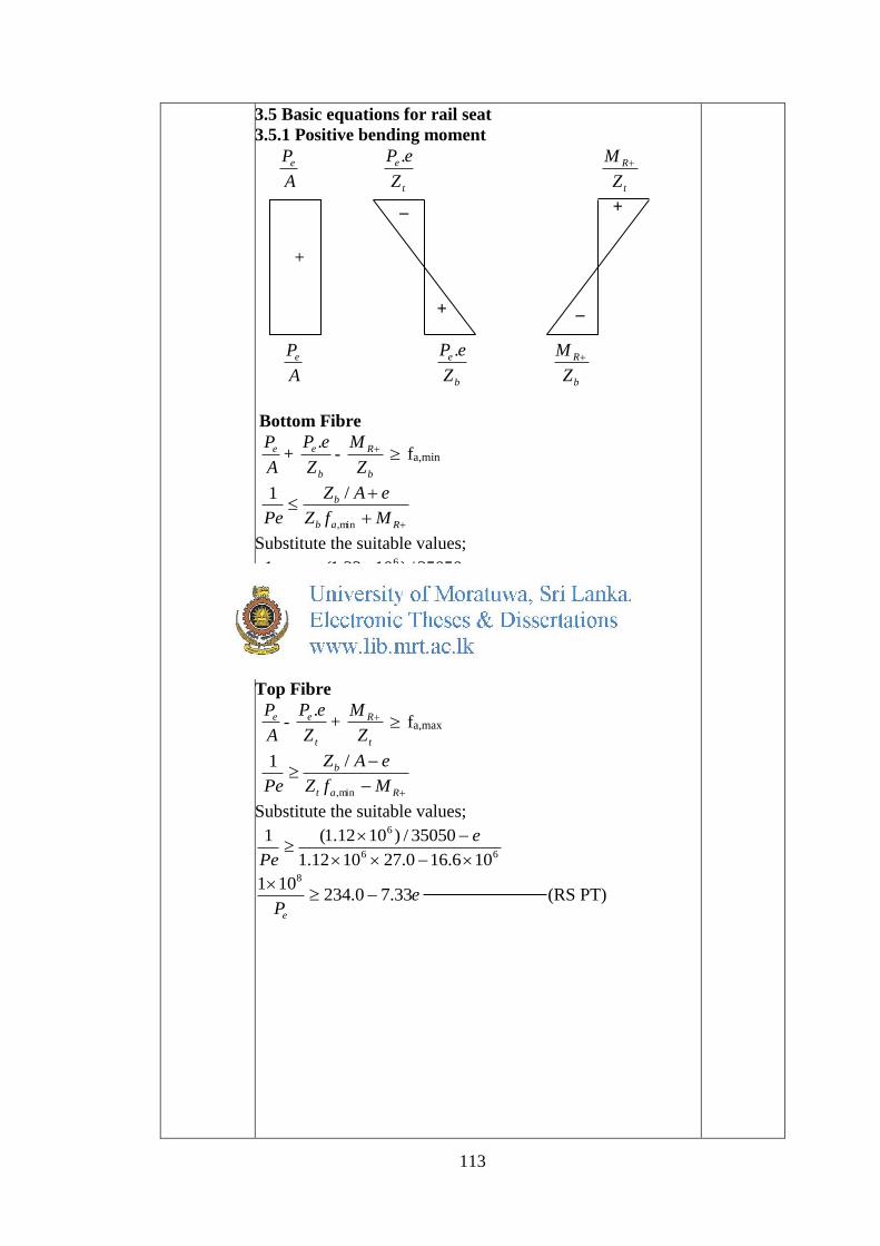
3.5 Basic equations for rail seat
3.5.1 Positive bending moment
A
Pe t
e
Z
eP .
t
R
Z
M
_ +
+ _
A
Pe b
e
Z
eP .
b
R
Z
M
Bottom Fibre
A
Pe + b
e
Z
eP .-
b
R
Z
M fa,min
Rab
b
MfZ
eAZ
Pe min,
/1
Substitute the suitable values;
66
6
106.16)1.3(1032.1
35050/)1032.1(1
e
Pe
ePe
0.8301101 8
(RS PB)
Top Fibre
A
Pe - t
e
Z
eP .+
t
R
Z
M fa,max
Rat
b
MfZ
eAZ
Pe min,
/1
Substitute the suitable values;
66
6
106.160.271012.1
35050/)1012.1(1
e
Pe
ePe
33.70.234101 8
(RS PT)
+

114
3.5.2 Negative bending moment
A
Pe t
e
Z
eP .
t
R
Z
M
_ _
+ +
A
Pe b
e
Z
eP .
b
R
Z
M
Bottom Fibre
A
Pe + b
e
Z
eP .+
b
R
Z
M fa,max
Rab
b
MfZ
eAZ
Pe max,
/1
Substitute the suitable values;
66
6
100.140.271032.1
35050/)1032.1(1
e
Pe
ePe
62.4174101 8
(RS NB)
Top Fibre
A
Pe - t
e
Z
eP .-
t
R
Z
M fa,min
Rat
t
MfZ
eAZ
Pe min,
/1
Substitute the suitable values;
66
6
100.14)1.3(1012.1
35050/)1012.1(1
e
Pe
ePe
5.90.303101 8
(RS NT)
+

115
3.6 Basic equations for rail centre
3.6.1 Positive bending moment
A
Pe t
e
Z
eP .
t
C
Z
M
_ +
+ _
A
Pe b
e
Z
eP .
b
C
Z
M
Bottom Fibre
A
Pe + b
e
Z
eP .-
b
C
Z
M fa,min
Cab
b
MfZ
eAZ
Pe min,
/1
Substitute the suitable values;
66
6
1064.6)1.3(10193.1
33375/)10193.1(1
e
Pe
ePe
0.341215101 8
(RC PB)
Top Fibre
A
Pe - t
e
Z
eP .+
t
C
Z
M fa,max
Cat
b
MfZ
eAZ
Pe max,
/1
Substitute the suitable values;
66
6
1064.60.2710045.1
33375/)10045.1(1
e
Pe
ePe
63.40.145101 8
(RC PT)
+

116
3.6.2 Negative bending moment
A
Pe t
e
Z
eP .
t
C
Z
M
_ _
+ +
A
Pe b
e
Z
eP .
b
C
Z
M
Bottom Fibre
A
Pe + b
e
Z
eP .+
b
R
Z
M fa,max
Cab
b
MfZ
eAZ
Pe max,
/1
Substitute the suitable values;
66
6
1091.120.2710193.1
33375/)10193.1(1
e
Pe
ePe
18.52.185101 8
(RC NB)
Top Fibre
A
Pe - t
e
Z
eP .-
t
C
Z
M fa,min
Cat
t
MfZ
eAZ
Pe min,
/1
Substitute the suitable values;
66
6
1091.12)1.3(10045.1
33375/)10045.1(1
e
Pe
ePe
3.100.324101 8
(RC NT)
Draw combined Magnel diagram using equations. Effective
prestressing force can be calculated using Magnel diagram.
+

117
Figure 3: Combined Magnel diagram for option 1
According to the combined Magnel diagram;
314101
max
8
eP at e=0.0 mm
318314
101 8
eP
Pe = 318 kN
3.7 Number of tendons
Diameter of a tendon = 5 mm
Area per prestressing tendon = 4
52= 19.63 mm2
Nominal tensile strength = 1670 N/mm2
Initial prestressing force per tendon
=310
75.063.191670 = 24.58 kN
Effective prestressing force (20% losses)
= 80.085.24 =20.89 kN
Number of tendons required =88.19
318= 15.99 Nos.
= 16 Nos.
Because of the symmetry 16 nos. of tendons to be used for
option 1.
e=0.0
mm
Pe=318
kN
Tendons
16 Nos.
0
100
200
300
400
500
600
-60 -40 -20 0 20 40 60
1x10⁸/Pe(N
)
e(mm)
RS PB RS NB RS PT RS NTRC PB RC NB RC PT RC NT

118
Limiting range for ‘e’ value
Rail seat; 0<e<0.5
Rail centre; -27<e<2.0
3.8 Possible tendon arrangement
Figure 4: Possible tendon arrangement(i) Rail seat, (ii) Rail
centre
Centre of prestressing tendons – yst
From Figure 2;
5.1365.1065.765.46416 sty
mmyst 5.91
Centre of prestressing tendons are within the limiting range
for ‘e’ value.
Figure 5: Centre of prestressing tendons
3.9 Losses
3.9.1 Losses at transfer stage
Elastic deformation loss
% load apply to prestress = 75%
Number of bars = 16
Initial prestressing force psyi AfnP
= 310
63.1916701675.0 = 393.4 kN
yst=91.5
mm

119
Concrete stress, I
eP
A
Pf i
c
icoj
2
I = 121003519 mm4
e = 91.82-91.5 = 0.32 mm
Ac = 35050 mm2
121003519
32.0104.393
35050
104.393 233
cojf = 11.22 + 0.00033
= 11.22 N/mm2
At the level of steel;
Strain in concrete = strain in steel
s
ps
c
coj
E
f
E
f
)7(
coj
c
sps f
E
Ef
)7(
Es = 195 kN/mm2
Ec(7) = 36 kN/mm2
Loss of prestress = psps Af
= 22.1136
195 = 60.77 N/mm2
Percentage loss = %100104.393
1663.1977.603
= 4.85%
3.9.2 Losses at service stage
Shrinkage loss
Shrinkage strain = ɛs = 610100
Loss of prestress = sps EA s
= )10195()1663.19()10100( 36 = 6124 N
Percentage loss = %100104.393
61243
= 1.56%
Loss due to relaxation
Maximum relaxation after 1000h = 3.5 %
Relaxation factor = 1.2
Loss due to relaxation = 2.1100
96
100
5.3 iP
= 2.1100
96104.393
100
5.3 3 = 15862 N
Percentage loss= %100104.393
158623
= 4.03%
Loss due to creep of concrete
Creep coefficient = ϕ = 1.8

120
Specific creep strain )7(c
ccE
31036
8.1
= 5100.5 mm
Loss of stress in steel = pscoj Ef cc
I
eP
A
Pf i
c
icoj
2
= 11.22 N/mm2
= )10195(22.11)100.5( 35 = 109.4 N/mm2
Loss due to creep = 1663.194.109 = 34360 N
Percentage loss = %100104.393
343603
= 8.73%
3.9.3 Total prestress loss
Total prestress loss= Elastic deformation loss + Loss due to
shrinkage + Loss due to relaxation of steel + Loss due to
creep of concrete = (4.85 + 1.56 + 4.03 + 8.73)% = 19.17 %
= 20.0 % (say)
Total
losses
20%

121
Reference Calculations Out put

121
Appendix 4: Cost calculation for Option 1

122
Table of Contents
1.0 Introduction - Option 1
2.0 Cost calculation for option 1
2.1 Volume of sleeper
2.2 Cost of concrete per kilometre
2.3 Volume of prestressing wires per sleeper
2.4 Volume of prestressing tendons per sleeper
2.5 Volume of ballast per kilometre
2.6 Cost of ballast per kilometre
2.7 Total cost per one kilometre
123
Reference Calculations Out put
1.0 Introduction - Option 1
For the comparison purpose three options were selected. The
most economical design was selected and calculations
presented.
2.0 Cost calculation for option 1
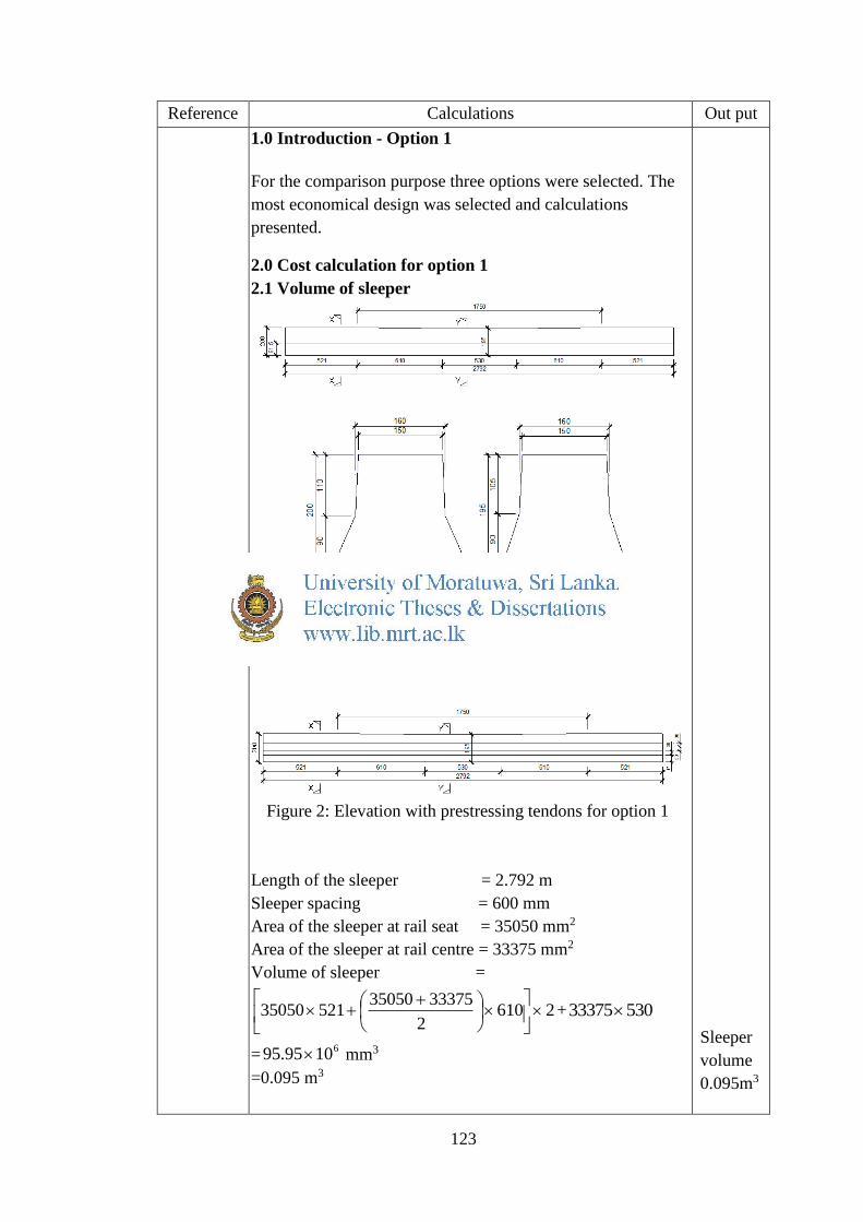
2.1 Volume of sleeper
Figure 1: Elevation and sections for option 1
Figure 2: Elevation with prestressing tendons for option 1
Length of the sleeper = 2.792 m
Sleeper spacing = 600 mm
Area of the sleeper at rail seat = 35050 mm2
Area of the sleeper at rail centre = 33375 mm2
Volume of sleeper =
26102
333753505052135050
+ 53033375
=61095.95 mm3
=0.095 m3
Sleeper
volume
0.095m3

124
2.2 Cost of concrete per kilometre
Density of concrete = 2400 kg/m3
Unit weight of sleeper = 095.02400
= 230.3 kg
Number of sleepers per km = 600
101000 3= 1667.67
Total weight of sleepers/km = 67.16663.230
= 383834 kg
Total volume of sleepers/km = 2400
383834= 159.93 m3
Grade of concrete = 60 N/mm2
Concrete cost per m3 = Rs 17,000
Total concrete cost/km = 000,1793.159
= Rs 2,718,825
2.3 Volume of prestressing tendons per sleeper
Figure 3: Possible tendon arrangement for option 1 (i) Rail
seat, (ii) Rail centre
Number of tendons/Sleeper = 16
Diameter of a ten = 5 mm
Area per prestressing tendon = 4
52= 19.63 mm2
Length of a tendon per sleeper = Length of sleeper
= 2792 mm
Volume per one tendon = 279263.19
= 54820.8mm3
2.4 Cost of prestressing steel per kilometre
Density of steel = 7850 kg/m3
Weight per tendon = 910
8.548207850

125
= 0.43 kg
Total steel weight per sleeper = 1643.0 = 6.88 kg
Total steel weight/km = 67.166688.6
= 11475.8 kg
Cost per one unit of steel = Rs 160,000
Total steel cost/km = 000,1608.11475
= Rs 1,836,128
2.5 Volume of ballast per kilometre
Figure 4: Section through ballast
Where;
G – Gauge
S – Shoulder width
L – Width of the shoulder ballast
d – Depth of the ballast
h – Total depth of the ballast
For broad gauge top width of the ballast is 3350 mm.
Assumption: Top line of the ballast section shall be at the
same level as the top of the sleeper.
Width of the base of the sleeper = 250 mm
Depth of ballast , d = 2
wS =
2
250600
= 175 (mm)
Depth of sleeper at rail seat = 200 mm
h = d + Depth of sleeper at rail seat= 175+200 = 375 mm
Width of the ballast at the base = 23753350
= 4100 mm
Area through section =
910
1375
2
41003350
= 1.396 m2
Volume per one kilometre = 1396.9 m3
Net volume per one km = 1396.9 - 159.93
= 1237 m3
126
2.6 Cost of ballast per kilometre
Cost of ballast per one m3 = Rs 2,500
Total ballast cost/km = 500,21237
= Rs 3,092,500
2.7 Total cost per one kilometre
Total cost per one kilometre =
Cost of concrete/km + Cost of steel/km + Cost of ballast/km
= Rs (2,718,825 + 1,836,128 + 3,092,500)
= Rs 7,647,453

127
Reference Out put

128