
Polyester Technical Manual - PlasticPortal
80
Polyester Technical Manual Polyester Products Celanex ® PBT Impet ® PET Vandar ® PBT
-
Upload
khangminh22 -
Category
Documents
-
view
2 -
download
0
Transcript of Polyester Technical Manual - PlasticPortal
Polyester Technical
Manual
Polyester ProductsCelanex® PBT
Impet® PET
Vandar® PBT

Polyester Technical Manual
1. Overview 4
1.1 Product Description 4
1.1.1 Crystallinity 5
1.2 Available Grades 5
1.2.1 Applications 8
1.3 Regulatory/Agency Compliance 8
1.3.1 UL 8
1.3.2 FDA – Food Contact 9
1.3.3 FDA – Drug Master File 9
1.3.4 FDA – Device Master File 9
1.3.5 USP 9
1.3.6 CSA 9
1.3.7 NSF 9
1.3.8 USDOT 9
1.3.9 MIL-Spec and Other 10
1.3.10 ASTM 10
1.4 Product Support 11
1.5 General Safety and Health 11
1.6 Reference Publications 11
2. Properties 12
2.1 Properties of Polyester Resins 12
2.2 Temperature Effects 20
2.3 Stress-Strain Curves and Temperature 20
2.4 Chemical Resistance 31
2.4.1 Application-related Chemical Testing 36
2.4.2 Chemical Stress Cracking 36
2.5 Other Environmental Considerations 37
2.6 Time-dependent Mechanical Properties 39
2.6.1 Static Stress 39
2.6.2 Fatigue 41
2.7 Surface Properties 41
2.8 Thickness and Time Dependence
of Electrical Properties 43
Table of Contents
3. Processing 44
3.1 General 44
3.1.1 Resin Storage 44
3.1.2 Recycling Scrap 44
3.1.3 Ventilation 44
3.1.4 Startup and Shutdown 44
3.1.5 Changing Feedstocks 44
3.2 The Molding Process 45
3.2.1 Plastication 45
3.2.2 Injection 46
3.3 Molding Equipment 46
3.3.1 Screw Design 46
3.3.2 Nozzle 47
3.3.3 Non-return Valves 47
3.3.4 Clamping Systems 47
3.3.5 Mold Construction 47
3.4 Drying 47
3.4.1 Drying Equipment 48
3.4.2 Drying Process 49
3.5 Drying Guidelines 49
3.6 Injection Molding 49
3.6.1 Safety and Health 49
3.6.2 Processing Conditions 49
3.6.3 Mold Temperature 50
3.6.4 Injection and Holding Pressure 50
3.6.5 Injection Speed 50
3.6.6 Screw Speed and Cushion 50
3.6.7 Trouble Shooting 50
3.7 Extrusion 53
3.7.1 Safety and Health Information 53
3.7.2 Equipment Construction 53
3.7.3 Extruder Barrel 53
3.7.4 Screw Design 53
3.7.5 Breaker Plate and Screens 53
3.7.6 Dies 53
3.7.7 Processing Conditions 54
3.7.8 Processing Procedures 54
3.7.9 Startup 55
3.7.10 Purging and Shutdown 55
3.7.11 Wire Coating 55
3.7.12 Tube Extrusion 56
3.7.13 Sheet Extrusion 57
3.7.14 Extrusion Trouble Shooting 58
3.7.15 Monofilament 58
3.7.16 Meltblown Media 60
3.7.17 Spunbond Webs 60
2

3
4. Part and Mold Design 62
4.1 Introduction 62
4.1.1 Material Selection 62
4.1.2 Wall Thickness 62
4.1.3 Ribs 63
4.1.4 Bosses and Studs 63
4.1.5 Fillets and Radii 63
4.1.6 Tolerances 63
4.1.7 Threads 64
4.1.8 Holes 64
4.1.9 Draft 64
4.1.10 Surface Finish 64
4.1.11 Molded-in Inserts 65
4.2 Mold Design 65
4.2.1 Mold Materials and Construction 65
4.2.2 Mold Surface Finish 65
4.2.3 Sprue Bushings 66
4.2.4 Conventional Runners 66
4.2.5 Runnerless Molds 66
4.2.6 Gates 67
4.2.7 Venting 69
4.2.8 Mold Cooling 69
4.2.9 Melt Flow 69
4.2.10 Mold Shrinkage 69
5. Post-Processing 70
5.1 Assembly 70
5.1.1 Snap-fit Joints 70
5.1.2 Strain Limits in Snap-fit Applications 71
5.1.3 Snap-on/Snap-in Fits 71
5.1.4 Self-Tapping Screws 71
5.1.5 Threaded Metal Inserts 73
5.2 Welding Techniques 73
5.2.1 Spin Welding 73
5.2.2 Thermal Fusion Welding 74
5.2.3 Ultrasonic Welding 76
5.2.4 Adhesive Bonding 77
5.3 Machining 78
5.3.1 Sawing 78
5.3.2 Drilling 78
5.3.3 Turning 78
5.3.4 Milling 78
5.3.5 Rotary Power Filing 78
5.4 Surface Treatment 79
5.4.1 Painting 79
5.4.2 Hot Stamping 79
5.4.3 Printing 79
5.4.4 Laser Marking 79
5.4.5 Sterilization 79
Polyester Technical Manual
1
2
3
4
5
Oven handles maintain gloss
and color even under high
heat exposure with little or
no blooming.
Outstanding high crystallinity
makes Celanex® PBT 2008 good
for use in meltblown nonwovens
with very fine structures, such as
laminated fuel filter media.
Properties
Inhalers for asthma sufferers
– Complex mechanics
ensure optimum safety and
precision. The components
are made of Hostaform®
POM and Celanex® PBT.
Processing
Celanex® XFR® PBT
meets international
halogen-free,
V-0 standards.
Part and Mold Design
Appearance grades, such
as metallic-effect PBT,
add style and functionality
to applications.
Post-Processing

1. Overview
1.1 Product Description
Thermoplastic polyesters are among the most important
of engineering resins. They combine a wide range of desir-
able physical, mechanical and electrical properties with
excellent chemical and environmental resistance. Polyes-
ter materials can be found in almost every application area
calling for reliable and predictable engineering properties.
Celanese plays a leading role in product and application
development of thermoplastic polyesters and offers a
broad product portfolio backed by deep experience.
Celanese’s polyester product lineup includes Celanex®
polybutylene terephthalate (PBT), Impet® polyethylene
terephthalate (PET) and Vandar® polyester alloys (PBT).
Celanese also offers Riteflex® thermoplastic polyester
elastomers (TPC-ETs). A comprehensive technical manual,
TPE-001, is available separately for these materials.
The basic PBT and PET polymers in Celanese’s polyester
products are strong, stiff, semi-crystalline materials. They
deliver good surface hardness and excellent resistance to
many organic and inorganic chemicals, particularly those
found in the automotive underhood environment. Build-
ing on these basic strengths, Celanese engineered a
comprehensive product family including numerous
polymer variants, reinforced and filled grades covering the
practical range of compositions, and impact-modified
compounds. Flame-retarded products are also available in
both Celanex PBT and Vandar PBT alloy product families.
The desirable attributes of Celanese’s thermoplastic
polyesters provide many application benefits including:
High strength, stiffness and toughness to perform in
mechanically demanding applications
Low creep to retain key dimensions over time, even
well above room temperature
High temperature resistance to withstand long-term
exposure to hot environments
Minimal moisture absorption for dimensional stability
under high humidity
Superior chemical resistance to tolerate exposure to
chemicals and solvents, oils and greases
Easy colorability and good surface gloss for attractive
aesthetics in appearance parts
Alloying compatibility to enable creation of highly
flexible, high impact products
The thermoplastic polyesters can perform over a broad
temperature range, going from grades having impact
resistance down to -40°C (-40°F) to those with deflection
temperatures under load above 200°C (392°F). Being excel-
lent insulators, they have superior electrical properties
with high dielectric resistance and low dielectric loss. High
crystallinity and low moisture absorption provide parts
with good dimensional stability and high creep resistance,
even at higher temperatures.
While the three product families share the advantages
provided by their basic polyester chemistry, each has its
own functional focus:
The Celanex PBT product family has the broadest prod-
uct line and widest extent of uses, going from tiny
watch parts to large automotive body components
and from injection molding to extrusion and blow
molding. It provides an extremely capable range of
engineering materials.
Impet PET products are targeted to injection molding
applications and offer somewhat higher mechanical
properties than those of their Celanex PBT counter-
parts. The higher melting point of the base polymer
also enables these resins to withstand higher tempera-
ture exposures. To meet industry requirements for
recycle content, certain Impet PET grades are available
with a minimum level of 25% recycled polymer.
Vandar PBT alloy resins are much tougher and more
flexible than the other products, and have high practi-
cal impact down to very low temperatures, while still
retaining functional stiffness at higher temperatures.
These attributes have won them important automotive
applications, particularly in the area of safety.
Celanese’s polyesters can be colored to match almost any
specification. A wide spectrum of standard and custom
colors is available, including numerous automotive
standard colors. Many code and agency approvals and
ratings are also available for the various members of this
adaptable product family, including those of Underwriters
Laboratories (UL), the National Sanitation Foundation
(NSF), the Canadian Standards Agency (CSA) and the US
Food and Drug Administration (FDA). Celanese’s polyester
resins also meet the requirements of many DIN and ISO
standards, and certification to relevant military specifica-
tions is available for certain grades.
Polyester Technical Manual
4

1
Conventional thermoplastics processing methods, partic-
ularly injection molding and extrusion, may be used with
Celanese’s thermoplastic polyester materials. Processing
temperatures range between about 230°C and 300°C
(446°F and 572°F), depending on the specific process and
the grade chosen. Good thermal stability and low melt
viscosity make for easy processing and fast molding cycles.
Special extrusion grades are available to meet the needs of
very specific end-use applications. All grades should be
appropriately predried prior to melt processing. In every
case, the appropriate Material Safety Data Sheet (MSDS)
should be consulted before processing any Celanex® PBT,
Impet® PET or Vandar® PBT alloy resin.
1.1.1 Crystallinity
Polyester polymers can be processed to have high crystal-
linity – typically as high as 60% – giving them such useful
properties as high hardness, stiffness, strength and chemi-
cal resistance. PBT polymers exhibit almost instantaneous
crystallization from the melt, enabling them, and
compounds based on them, to be molded with short
cycles in cooler tooling. The immediate high crystallinity
also contributes to reduced post-molding shrinkage,
thereby enhancing dimensional stability.
As the crystallization rate of PET polymers is temperature
dependent, fully crystalline parts are obtained in faster
cycles with warmer molds. Overly cool tooling may inhibit
full development of crystallinity and should therefore be
avoided.
1.2 Available Grades
The extensive array of desirable properties provided by
Celanese‘s polyester resins derives from nearly 50 years’
experience in developing and manufacturing polyester
polymers. This fundamental competency has been
augmented with a background in polyester compound
technology extending from Celanese‘s launch of the first
commercial PBT resin in 1970 up to the present day. As
shown in Figure 1.1, these skills interact constructively
with each other to yield the whole range of thermoplastic
polyester products. As well as the compositions described
above, Celanese’s polyester materials can incorporate
additives to enhance mold release, increase resistance to
ultraviolet (UV) radiation, facilitate laser marking and
increase thermal and hydrolysis resistance. A full range of
colors is also available. Table 1.1 lists available grades by
product family, type, grade and description.
Polyester Technical Manual
5
Polyester
Polymer
Technology
Formulation &
Compounding
Knowledge
Reinforcement
Polymer
Alloys
Impact
Modification
Flame
Retardant
Flame
Retardant
Warpage
Control
Hydrolysis
Resistance
Elastomeric
Aesthetics
Base
Resins
Special
Polymers
Figure 1.1 • Polyester Product Relationships

Polyester Technical Manual
6
Table 1.1 • Available Polyester Grades
Product Description
Celanex® PBT
Unreinforced
1400A General purpose, high flow
1600A Extrusion grade, standard flow
1700A Extrusion grade, high viscosity
2001 Extrusion grade, standard flow,
hydrolysis restraint
2002-2 General purpose, standard flow,
high-gloss appearance
2008 Meltblown grade, ultrahigh flow
2025 Specialty grade, ultrahigh flow, high melt point
2401MT Medical technology grade, standard flow
2402MT Medical technology grade, standard flow,
fast cycling
2403MT Medical technology grade, high flow fast
cycling
2404MT Medical technology grade, standard flow,
low wear
Glass Reinforced
3100-2 7.5% Glass reinforced
3200/3200-2 15% Glass reinforced
3202 20% Glass reinforced
3300/3300-2 20% Glass reinforced
3400-2 40% Glass reinforced
Glass Reinforced Improved Impact
4202 15% Glass reinforced
4300 30% Glass reinforced
4302 30% Glass reinforced, lower warpage
Flame Retardant
2016 Unfilled, high flow
3116 7.5% Glass reinforced
3216 15% Glass reinforced, high flow
3226 20% Glass reinforced, high flow
3314 30% Glass reinforced
3316 30% Glass reinforced, high flow
4016 Unfilled, high flow, improved toughness
7716 35% filled/reinforced, low warp, high flow
XFR 6842 GF30 30% Glass reinforced, non-halogenated
XFR 6842 GF20 20% Glass reinforced, non-halogenated
XFR 6842 GF15 15% Glass reinforced, non-halogenated
XFR 6842 GF10 10% Glass reinforced, non-halogenated
XFR 4840 Unfilled, non-halogenated
Table 1.1 • Available Polyester Grades
Product Description
Celanex® PBT
Glass Reinforced Surface Finish
5202 15% Glass reinforced
5202HF 15% Glass reinforced, high flow
5205HG 15% Glass reinforced, super high gloss,
gas assist/injection molding
5214HF 15% Glass reinforced, flame retardant
5300 30% Glass reinforced
5314 30% Glass reinforced, flame retardant
Glass/Mineral
J600 40% filled/reinforced
6200 15% filled/reinforced
6402R 40% filled/reinforced with 25% post-consumer
recycle content
6407 30% filled/reinforced
6500 30% filled/reinforced, higher strength
6500HF 30% filled/reinforced, higher strength, high flow
Hydrolysis Resistance
2003 HR Unreinforced
3209 HR 15% Glass reinforced
3309 HR 30% Glass reinforced
3309 HRHF 30% Glass reinforced, high flow
3309 HRT 30% Glass reinforced, improved toughness
3316 HR 30% Glass reinforced, V-0
3425 HRT 40% Glass reinforced, improved toughness,
high flow
4309AR 30% Hydrolysis- and alkaline-resistant
JKX-1153 30% Filled/reinforced, high flow
Laser Markable
3300LM 30% Glass reinforced
6500LM 30% Filled/reinforced, higher strength
J600LM 40% Filled/reinforced
Heat Shock
4302HS 30% Glass reinforced, low warp
531HS 30% Glass reinforced
Other Special
6035GB20 20% Glass bead
6035UVGB20 20% Glass bead, UV resistance
LW2333R 50% Glass reinforced, low warp
Polyester Technical Manual
7
Table 1.1 • Available Polyester Grades
Product Description
Impet® PET
Glass Reinforced
330R 30% Glass Reinforced
(≥25% post-consumer recycle content)
340R 45% Glass Reinforced
(≥25% post-consumer recycle content)
830R 35% filled/reinforced
(≥25% post-consumer recycle content)
2700 GV1/20 20% Glass reinforced (Europe)
2700 GV1/30 30% Glass reinforced (Europe)
2700 GV1/45 45% Glass reinforced (Europe)
Table 1.1 • Available Polyester Grades
Product Description
Vandar® PBT Alloys
Unreinforced
2100 General purpose, low-temperature impact,
paintable, printable
2500 General purpose, good colorability, paintable
4602Z General purpose, good chemical resistance,
weather resistance
6000 Good low-temperature impact, low shrinkage
8000 Flame retardant
Glass Reinforced General Purpose
4361 30% Glass reinforced, improved toughness
4612R 7% Glass reinforced
4632Z 15% Glass reinforced
4662Z 30% Glass reinforced
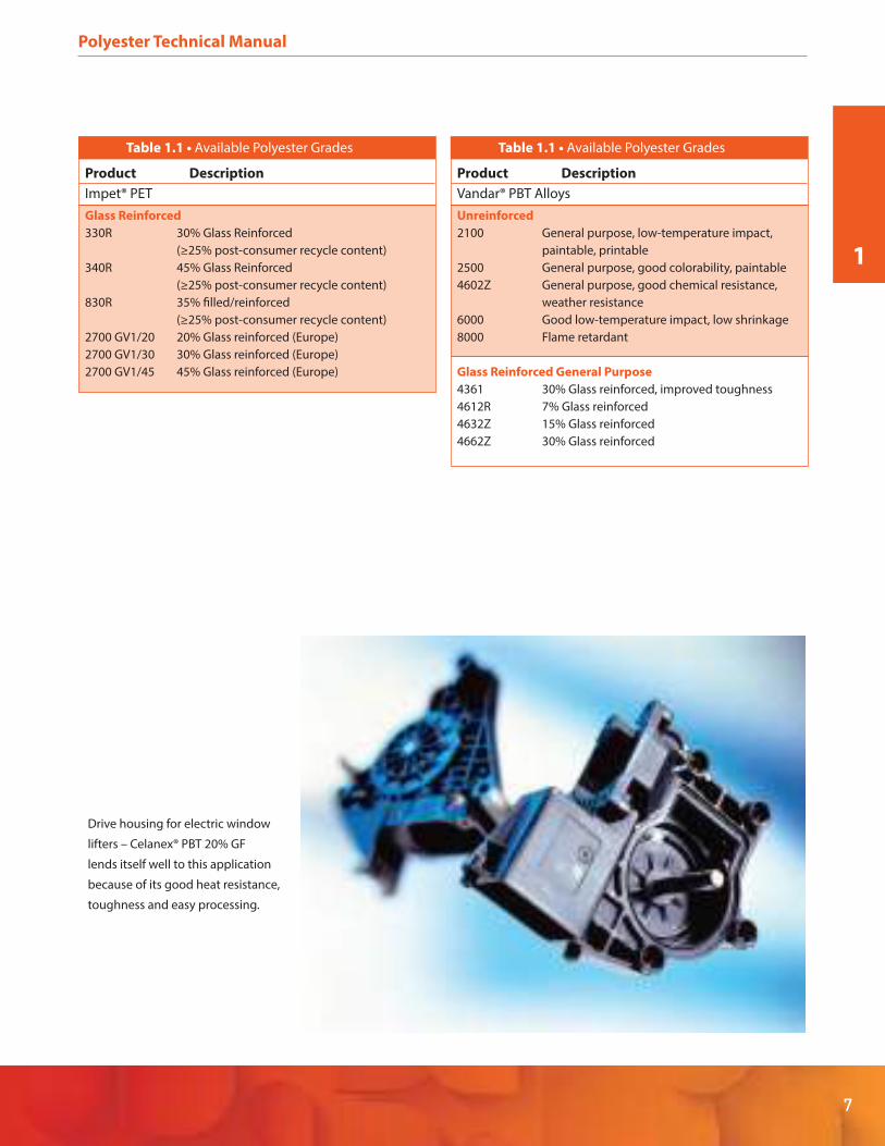
Drive housing for electric window
lifters – Celanex® PBT 20% GF
lends itself well to this application
because of its good heat resistance,
toughness and easy processing.
1

Polyester Technical Manual
8
1.2.1 Applications
The extensive range of properties and easy processing
offered by Celanese’s polyester resins enables them to
serve a highly diverse spectrum of engineering applica-
tions distributed across many markets. Table 1.2 lists some
examples of these applications by product family and
type.
1.3 Regulatory/Agency Compliance
Not all grades are covered by all regulatory codes and
agencies. Call Product Information Services at
1-800-833-4882 for current information. Celanese’s polyes-
ter resins are in compliance with or have ratings under the
standards of many regulatory codes and agencies includ-
ing:
Underwriters Laboratories (UL)
United States Food and Drug Administration (FDA)
United States Pharmacopoeia (USP)
Canadian Standards Association (CSA)
National Sanitation Foundation (NSF)
United States Department of Transportation (USDOT)
Military Specifications (MIL-Spec)
American Society for Testing and Materials (ASTM)
EU Restricted Hazardous Substance (RoHS)
Waste Electrical and Electronic Equipment Directive
(WEEE)
1.3.1 UL
Most major polyester formulations have UL recognition
covering electrical, mechanical and thermal characteris-
tics. The ratings apply to burning behavior as a function of
part thickness and to relative thermal indices for electrical
properties, mechanical properties with impact and
mechanical properties without impact. In general,
Celanese’s polyester products other than those specifically
rated V-0 are rated HB on burning behavior in the UL-94
test. Depending on the specific grade, electrical and
mechanical relative thermal index (RTI) ratings range from
a low of 75ºC (167ºF) to highs of 140ºC (284ºF) for mechani-
cal and 150ºC (302ºF) for electrical properties. These
ratings are published under UL’s yellow card system.
Yellow cards are readily available detailing UL recognition
of Celanex® PBT, Impet® PET and Vandar® PBT alloy prod-
ucts. See Table 2.1 in Chapter 2 for UL-94 and RTI ratings by
product grade. UL approvals have also been granted for
the use of many grades of Celanex PBT in certain bobbin
insulation systems under File No. E60824. Information
from this file can be released to customers by UL on
request from Celanese. See Table 1.3 for a list of grades
with bobbin approval.
Table 1.2 • Some Applications for Polyester Materials
Product Description
Celanex® PBT
Unreinforced Monofilament, Films, Fibers, Cable Jacketing,
Coatings, Netting, Keycaps, Fiber Optic Buffer
Tubes, Paint Brush Bristles, Hot-Melt Adhesives,
Performance Additive (for Fibers/Films), Oil/Fuel
Filtration, Blood Filtration, Binder Fiber for
Headliners and Hoodliners, Non-Woven Filter
Media, Hinged Connectors, Appearance Parts
Glass Reinforced Motor Housings; Automotive Underhood, Interior
and Exterior Components; Coil Bobbins and Cases;
Connectors, Sensors, Switches, Relays; Appliance
Housings, Hardware, Vents and Trim
Glass Reinforced Pump Housings and Impellers, Power Tool
Improved Impact Components, Connectors with Snap-Fits
Flame Retardant Connectors, DIP Sockets, Motor Components,
Stator Insulation, Bobbins, Switches, Brush Holders,
CRT Sockets, Terminal Boards, Lighting
Glass Reinforced Appliance Housings, Handles and Bases,
Surface Finish Oven Handles
Glass/Mineral Fan Blades, Shrouds and Housings; Electrical
Low Warp Housings; Air Mass Flow Sensors, Automotive
HVAC Veins
Hydrolysis Automotive Connectors and Sensor Housings,
Resistance Automotive Under-Hood Components
Laser Markable Components Requiring Indelible Markings for
Identification and Traceability
Heat Shock Pencil Coil, Other Ignition System Components,
Sealed Connectors, Housings with Metal Inserts
Metallic Effects Appliance, Pool and Spa, Kitchen and Bath,
Automotive, Hand Tools, Knobs, Buttons and Trim
Other Special Automotive Seat Belt Latch Covers, Coat Hooks,
Interior Door Handles
Impet® PET
Glass Reinforced Windshield Wiper Brackets, Heater and Air
General Purpose Conditioning, Doors and Vents, Rigid Parts
Requiring Use of Recycle
Low Warp Grille Opening Panels and Retainers, Throttle
General Purpose Body Covers, Rigid Parts Requiring Recycle Content
Vandar® PBT Alloy
High Flexibility Air Bag Covers, Ski Bindings, Conveyor Element
Linkage, Protective Equipment, Clips and Fasteners,
Reusable Dunnage
Reinforced/ Telephone Line Splice Cases, Small-Appliance
General Purpose Housings, Power Tool Housings

1
9
1.3.2 FDA – Food Contact
Many Celanese polyester grades are compliant for food
contact according to USA FDA and EU food contact regula-
tions.
Natural Celanex PBT grades designated “MT®” comply with
the requirements of FDA regulation 21 CFR177.1660 and
applicable EU regulations for use in food contact applica-
tions. See Table 1.3 for a list of other compliant grades.
1.3.3 FDA – Drug Master File
All MT grades of Celanex® PBT natural are listed in
Celanese’s FDA Drug Master File (DMF) #10047.
1.3.4 FDA – Device Master File
All MT grades of Celanex PBT are listed in Celanese’s FDA
Device Master File (MAF) #1078.
1.3.5 USP
Celanex PBT grades designated “MT®” meet the require-
ments of USP Class VI and ISO 10993. See Table 1.3 for
other compliant grades.
1.3.6 CSA
Many of Celanese’s polyester products have flammability
ratings from the CSA. See Table 1.3 for a list of grades
having CSA ratings.
1.3.7 NSF
The NSF classification listings include Celanex PBT grades
in both natural and black colors. See Table 1.3 for a list of
grades. The NSF website can be checked for updates.
1.3.8 USDOT
Testing of 0.04-inch specimens according to specification
MVSS 302 classifies flame-retarded Celanex PBT rades as
self-extinguishing. Burn rates for various other polyester
grades are given in Table 2.1.
Polyester Technical Manual
Table 1.3 • Polyester Code Compliance
Agency Code Grade(s)
CSA
FDA
NSF/ANSI
UL
USP
PBTP Flammability and Thermal Index
21 CFR 177.1660
Potable Water Standard 61
Bobbin Insulation Class 130 (Class B)
Bobbin Insulation Class 155 (Class F)
Class VI / ISO 10933 Biocompatibility
Celanex PBT 2016, 3116, 3200-2, 3216, 3226, 3300-2, 3316, 4300
Vandar® PBT Alloy 8000
Contact Technical Information (800) 833-4882 or email [email protected] for
certification letters.
Celanex PBT 1462Z Natural, 2000-2 Black, 2000-3 Natural, 2002-2 Natural, 2002-3
Natural, 2003-2 Natural & Black, 3200-2 Natural & Black, 3300-2 Natural & Black
Celanex PBT 1602Z, 2004-2, 3200-2
Celanex PBT 1462Z, 2016, 3116, 3216, 3226, 3300-2, 3314, 3316, 5200, 5300, 6400
Natural Celanex “MT” Grades
Table 1.4 • Military and Government Specifications for Celanex PBT
Code Specification Grade(s) Classification
MIL-P-46161 (MR)
MIL-E-5272C (ASG)
MIL-STD-810b-508
Conforming to
CCC-T-191b-5762
MIL-M-24519 (Navy)
3200, 3200-2
3300, 3300-2
3300, 3300-2
3300
3314, 3316
Grade B, Class 2
Grade A, Class 3
Pass
Pass
GPT-30F
Plastics Molding Material, Polyterephthalate
Thermoplastics, Glass Fiber Reinforced
Fungus Resistance Test
Fungus Resistance Test Meeting
Soil Burial Government Specification
CCC-T-191b-5762
Molding Plastics,
Electrical Thermoplastics

Polyester Technical Manual
10
1.3.9 MIL-Spec and Other
Table 1.4 lists military and government specification
compliance information for Celanex® PBT grades. Table 1.3
lists specific grades recognized or approved under the UL,
FDA, USP, CSA and NSF codes.
1.3.10 ASTM
ASTM specifications for automotive applications are given
in Table 1.5.
Table 1.5 • ASTM Specifications
Product
Celanex® PBT
Description Specification ID
1462Z Natural, Black, ASTM D5927 TPES 011G30
High Carbon Black
1600A Natural ASTM D5927 TPES 0112
1602Z Natural, Black ASTM D5927 TPES 0113
1632Z Natural, Black ASTM D5927 TPES 011
1700A Natural ASTM D5927 TPES 0111
2000-2 Natural, Black ASTM D5927 TPES 0116
2001 Natural ASTM D5927 TPES 0112
2002-2 Color per drawing ASTM D5927 TPES 0114
2002-2 Natural, Black ASTM D5927 TPES 0114
2002-3 Natural ASTM D5927 TPES 0114
2003-2 Natural, Black ASTM D5927 TPES 0115
2003-3 Natural ASTM D5927 TPES 0115
2016 Natural, Black ASTM D5927 TPES B45100
3200 Natural ASTM D5927 TPES 011G15
3200-2 Natural, Black ASTM D5927 TPES 011G15
3216 Natural, Black ASTM D5927 TPES 061R30
3216 Colors ASTM D5927 TPES 0610 A3515
3300 Colors ASTM D5927 TPES 011G30
3300 Natural ASTM D5927 TPES 011G30
3300-2 Natural, Black ASTM D5927 TPES 011G30
3300D Black ASTM D5927 TPES 011G30
Table 1.5 • ASTM Specifications
Product
Celanex® PBT
Description Specification ID
3300HR Natural, Black ASTM D5927 TPES 011G30 A45350
3300LM Black ASTM D5927 TPES
0110G30A46550
3309HR Black ASTM D5927 TPES 011G30
3309HRT Black ASTM D5927 TPES 0110 A4545
3314 Black ASTM D5927 TPES 013G30
3316 Natural, Black, Blue ASTM D5927 TPES 013G30
3400-2 Natural, Black ASTM D5927 011G40
4016 Natural, Black ASTM D5927 TPES 0131
4300 Natural, Black ASTM D5927 TPES 011G30
4302 Black ASTM D5927 TPES 010 A4550
4305 Natural ASTM D5927 TPES 0120G33 A4550
5200-2 Black ASTM D5927 TPES 011G15
5300-2 Black ASTM D4000 TPES 0610 G31
6407 Black ASTM D5927 TPES 062R30
6500 Natural, Black ASTM D5927 TPES 061R30
J600 Natural, Black ASTM D5927 TPES 061R40
Impet® PBT
2700A GV 1/45
Natural, Black ASTM D5927 TPES 021G45
330R Natural, Black ASTM D5927 TPES 021G30
340R Natural, Black ASTM D5927 TPES 021G45
1
11
1.4 Product Support
Celanese provides its customers with comprehensive
product support beginning with application assessment
and going all the way to on-site molding assistance and
part testing as shown in Figure 1.2. The technical expertise
available from Celanese’s engineering staff is backed up by
the most modern computer technology for part design
and processing. Stress and strain data under various
scenarios are provided by finite element analyses and
processing variables are modeled using proprietary
software. Input data for these programs are also available
to our customers if they wish to run their own analyses.
Please contact your Celanese representative to arrange for
these services.
1.5 General Safety and Health
Standard precautions when working with hot molten
plastics must be observed when processing any of
Celanese’s polyester resins. Before handling or processing
any of the polyester materials, please obtain and read the
appropriate Material Safety Data Sheet (MSDS) for detailed
safety, health and environmental information. Use process
controls, work practices and protective measures as
described in the MSDS to control workplace exposure to
dust and volatiles.
MSDS documentation can be obtained by contacting your
Celanese representative, from Celanese Product Informa-
tion Services at 1-800-833-4882 or on the Celanese web
site: www.celanese .com.
1.6 Reference Publications
More information on plastics and on Celanese’s polyester
products is available on Celanese’s web site and in the
following Celanese publications:
Designing with Plastics: The Fundamentals (TDM-1)
Designing and Producing Plastic Gears
Riteflex® TPE Technical Manual (TPE-001)
Polyester Technical Manual
Figure 1.2 • Celanese Application Support Services
Application Assessment
Material
Recommendation
Part Design
Advice
Specification
Development
Product
Technical Data
Color Matching
Processing
Recommendations
Safety & Health
Advice
On-site
Processing
Assistance
Part Testing
Quality Process
Support
Material Analysis

2. Properties
Celanese’s extensive polyester product portfolio provides
a very broad range of physical, mechanical and other prop-
erties. The various grades are in general characterized by
excellent electrical properties and good chemical
resistance. The following tables present typical short-term
properties, grouped by product family and type, for repre-
sentative products in the three product families. Data are
presented for tests according to ISO (International Organi-
zation for Standardization) standards. Test data in accor-
dance with ASTM (American Society for Testing and Mate-
rials) standards may be found on the Celanese web site,
www.celanese .com.
Results of these standard tests conducted on laboratory
specimens are guide values and are most useful for
comparing different materials under the standardized test
conditions. They are not necessarily representative of the
properties of finished end-user parts, which are affected
by part design and processing conditions. This is particu-
larly the case for glass-reinforced materials where flow
orientation of the reinforcing fibers can cause significant
anisotropy in molded parts.
2.1 Properties of Polyester Resins
Table 2.1 lists physical, mechanical, thermal and electrical
properties of Celanese’s polyester resins, Celanex® PBT,
Impet® PET and Vandar® PBT alloys.
Polyester Technical Manual
12
*Not equivalent to ASTM D149
n/a = not available
Method Units
Physical Properties
Density ISO 1183 kg/m 3
nim 01/g3311 OSI)RFM( etar wolf tleM
C°3311 OSIerutarepmet tset RFM
MFR test load ISO 1133 Kg
Mold shrinkage – parallel ISO 294-4 %
Mold shrinkage – normal ISO 294-4 %
Humidity absorption (23°C/50%RH)
– 24 hr ISO 62 %
– Saturation ISO 62
ISO 868
%
Shore hardness D scale 15 sec value
Mechanical Properties
Tensile modulus (1mm/min) ISO 527-2/1A MPa
Tensile stress at yield (50mm/min) ISO 527-2/1A MPa
Tensile strain at yield (50mm/min) ISO 527-2/1A
ISO 527-2/1A
ISO 527-2/1A
ISO 527-2/1A
ISO 527-2/1A
%
Nominal strain at break (50mm/min) %
Tensile stress at 50% strain (50mm/min) MPa
Tensile stress at break (50mm/min) MPa
Tensile strain at break (50mm/min) %
Tensile stress at break (5mm/min) ISO 527-2/1A MPa
Tensile strain at break (5mm/min) ISO 527-2/1A %
Flexural modulus (23°C) ISO 178 MPa
Flexural strength (23°C) ISO 178 MPa
Charpy impact strength @ 23°C ISO 179/1eU KJ/m 2
Charpy impact strength @ -30°C ISO 179/1eU
ISO 179/1eA
ISO 179/1eA
ISO 180/1A
KJ/m 2
Charpy notched impact strength @ 23°C 2
Charpy notched impact strength @ -30°C KJ/m
KJ/m2
Notched impact strength (Izod) @ 23°C KJ/m 2
Thermal Properties
Melting temperature (10°C/min) ISO 11357-1,-2,-3 °C
ISO 11357-1,-2,-3 °CGlass transition temperature (10°C/min)
DTUL @ 1.8 MPa ISO 75-1, -2 °C
DTUL @ 0.45 MPa ISO 75-1, -2
ISO 11359-2
ISO 11359-2
°C
Coeff. of linear therm expansion – parallel E-4/°C
Coeff. of linear therm expansion – normal E-4/°C
Flammability at thickness h
thickness tested (h) UL94 mm
Electrical Properties
Relative permittivity
– 100Hz (dielectric constant) IEC 60250
– 1MHz (dielectric constant) IEC 60250
Dissipation factor – 100Hz IEC 60250 E-4
Dissipation factor – 1MHz IEC 60250 E-4
Volume resistivity IEC 60093 ohm-m
Surface resistivity IEC 60093 ohm
Dielectric Strength* IEC 60243-1 KV/mm
Comparative tracking index CTI IEC 60112 —
UL94 Class
Table 2.1 • Physical, Mechanical,

13
Polyester Technical Manual
Celanex®PBT
UNREINFORCED GLASS REINFORCED GLASS REINFORCEDIMPROVED IMP ACT
1600A 1700A 2001 2002-2 2008 3200 3300 3400-2 4202 4300
1310 1310 1310 1310 1310 1410 1530 1610 1380 1530
6.5 4.5 7.4 18 175 26.0 17.0 8.0 4.5 8.0
250 250 250 250 250 250 250 250 250 250
2.16 2.16 2.16 2.16 2.16 2.16 2.16 2.16 2.16 2.16
1.8-2.0 1.8-2.0 1.8-2.0 1.8-2.0 1.8-2.0 0.1 0.3-0.5 0.3-0.5 0.4 0.3-0.5
1.8 -2.0 1.8 to 2.0 1.8 -2.0 1.8-2.0 1.8-2.0 0.9 0.7-0.9 0.7 0.9 0.8
0.06 0.06 0.06 0.06 0.04 0.04 0.04 0.04 0.06 0.05
0.19 0.19 0.19 0.19 0.17 0.17 0.16 0.12 0.16 0.14
77 80 79 78 81 82 84 85 79 83
2550 2500 2600 2600 2600 5800 9200 12100 5200 9300
60 60 60 60 n/a n/a n/a n/a n/a n/a
5 6 6 4 n/a n/a n/a n/a n/a n/a
>50 >50 >50 >50 n/a n/a n/a n/a n/a n/a
28 28 33 30 n/a n/a n/a n/a n/a n/a
33 35 37 35 47 n/a n/a n/a n/a n/a
115 120 200 220 2 n/a n/a n/a n/a n/a
n/a n/a n/a n/a 60 100 130 140 86 130
n/a n/a n/a n/a 5 3.5 2.5 2.4 4.4 3.1
2200 2200 2500 2500 2200 5200 9700 11000 5100 9000
80 80 80 80 80 150 210 215 141 205
NB NB NB NB 38 20 46 47 52 40
210 220 NB 190 44 20 45 45 37 51
7 7.5 7.0 6 2.8 5.5 8.5 11 11 11
6.5 7.0 4.2 6 2.1 5 8.5 9.5 5.7 8.5
5.5 5.5 5.5 5.0 3.1 5 7.5 10 12 12
225 225 225 225 225 225 225 225 225 225
60 60 60 60 60 60 60 n/a 44 41
50 50 50 55 57 195 205 212 183 200
150 150 150 150 155 215 225 225 216 220
1.1 1.1 1.3 1.1 1.1 0.40 0.25 0.15 0.36 0.24
1.0 0.92 0.88 1.4 1 1.1 1.0 1.01 1.0 0.8
HB HB n/a HB n/a HB HB HB n/a HB
0.75 0.75 n/a 0.71 n/a 0.71 0.71 0.71 n/a 0.71
4.0 4.0 3 4 3.3 4.2 4.5 3.5 3.4 2.8
3.5 3.6 3.2 3.5 3.2 3.8 4.1 3.4 3.2 3.9
14 14 <10 14 <10 16 22 <10 <10 <10
210 210 200 220 200 200 160 130 200 220
>1E13 >1E13 >1E13 >1E14 >1E13 >1E14 >1E15 >1E15 >1E14 >1E15
>1E15 >1E15 >1E15 1E15 >1E15 >1E15 >1E15 1E15 1.10E+17 1E15
22 22 15 30 15 30 44 44 22 44
600 600 600 600 350 350 425 n/a >600 400
Thermal and Electrical Properties of Polyester Resins
2

FLAME RETARDANT
Method Units 2016 4016 3216 3316 7716 XFR 6842GF30
Physical Properties
Density ISO 1183 kg/m 3 1440 1450 1540 1660 1690 1530
Melt flow rate (MFR) ISO 1133 g/10 min 25.0 8.7 18 12 6.3 34
MFR test temperature ISO 1133 °C 250 250 250 250 250 250
MFR test load ISO 1133 Kg 2.16 2.16 2.16 2.16 2.16 2.16
Mold shrinkage – parallel ISO 294-4 % ~2.8 -1.7 ~0.5 ~0.4 ~0.3 ~0.4
Mold shrinkage – normal ISO 294-4 % ~1.6 -1.9 ~1.1 ~0.8 ~0.7 ~1.1
Humidity absorption (23°C/50%RH)
– 24 hr ISO 62 % 0.05 0.07 0.04 0.04 0.03 n/a
– Saturation ISO 62
ISO 868
% 0.17 0.16 0.17 0.16 0.1 n/a
Shore hardness D scale 15 sec value 81 80 82 85 83 n/a
Mechanical Properties
Tensile modulus (1mm/min) ISO 527-2/1A MPa 3000 2800 6700 10700 10800 10800
Tensile stress at yield (50mm/min) ISO 527-2/1A MPa 60 55 n/a 55 n/a n/a
Tensile strain at yield (50mm/min) ISO 527-2/1A
ISO 527-2/1A
% 3 3.7 n/a 3.7 n/a n/a
Nominal strain at break (50mm/min) % 10 38 n/a 38 n/a n/a
Tensile stress at break (5mm/min) ISO 527-2/1A MPa n/a n/a 100 135 83 100
Tensile strain at break (5mm/min) ISO 527-2/1A % n/a n/a 2.5 2.5 1.6 2.1
Flexural modulus (23°C) ISO 178 MPa 3100 2630 6000 10300 11650 n/a
Flexural strength (23°C) ISO 178 MPa 95 76 155 200 140 n/a
Charpy impact strength @ 23°C ISO 179/1eU KJ/m 2 55 245 28 42 22 35
Charpy impact strength @-30°C ISO 179/1eU
ISO 179/1eA
ISO 179/1eA
ISO 180/1A
KJ/m 2 55 105 28 42 n/a n/a
Charpy notched impact strength @ 23°C KJ/m 2 4.0 8.1 6 8.5 5 6.8
Charpy notched impact strength @-30°C KJ/m 2 4.5 8.1 6 8.5 5 n/a
Notched impact strength (Izod) @ 23°C KJ/m 2 4.5 7.7 5.5 7.7 4.9 n/a
Thermal Properties
Melting temperature (10°C/min) ISO 11357-1,-2,-3 °C
ISO 11357-1,-2,-3 °C
225 225 225 225 225 225
Glass transition temperature (10°C/min) 60 48 60 48 60 n/a
DTUL @ 1.8 MPa ISO 75-1, -2 °C 68 62 200 208 194 203
DTUL @ 0.45 MPa ISO 75-1, -2
ISO 11359-2
ISO 11359-2
°C 165 159 217 220 222 n/a
Coeff. of linear therm expansion – parallel E-4/°C 0.63 1.0 0.36 0.25 0.31 n/a
Coeff. of linear therm expansion – normal E-4/°C 0.77 1.0 1.0 0.77 0.46 n/a
Flammability at thickness h
thickness tested (h) UL94 mm 0.75 0.85 0.38 0.38 0.90 0.8
Electrical Properties
Relative permittivity
– 100Hz (dielectric constant) IEC 60250 3.6 3.1 3.7 3.6 4.2 n/a
– 1MHz (dielectric constant) IEC 60250 3.5 3.1 3.5 2.9 3.9 n/a
Dissipation factor – 100Hz IEC 60250 E-4 47 <10 33 33 <10 n/a
Dissipation factor – 1MHz IEC 60250 E-4 185 200 160 145 190 n/a
Volume resistivity IEC 60093 ohm-m >1E16 >1E14 >1E16 >1E16 >1E14 >1E17
Surface resistivity IEC 60093 ohm >1E15 >1E15 >1E15 >1E15 >1E16 n/a
Dielectric strength* IEC 60243-1 KV/mm 39 27 23 23 26 27
Comparative tracking index CTI IEC 60112 — 250 250 250 250 200 500
UL94 Class V-0 V-0 V-0 V-0 V-0 V-0
Table 2.1 • Physical, Mechanical,
Polyester Technical Manual
14
*Not equivalent to ASTM D149
n/a = not available

2
15
Polyester Technical Manual
Celanex®PBT
NON-HALOGENATED FLAME RETARDANT GLASS REINFORCED – SURFACE FINISH GLASS/MINERAL
XFR 6842 XFR 6842 XFR 6842 XFR 4840 5202 5202HF 5205HG 5214HF 5300 5314 J600 6500 6500HFGF20 GF15 GF10
1450 1420 1400 1340 1440 1450 1450 1580 1540 1720 1620 1550 1550
10 18 10 11 25 48 n/a 36 23 n/a 11.0 22.0 42
250 250 250 250 265 265 n/a 265 265 250 265 265 265
2.16 2.16 2.16 2.16 2.16 2.16 n/a 2.16 2.16 2.16 2.16 2.16 2.16
~0.5 ~0.6 ~1.0 ~2.2 0.1 0.4 - 0.6 0.4 - 0.6 0.1 - 0.6 0.3 - 0.5 0 - 0.5 0.4 - 0.9 0 - 0.5 0 - 0.5
~1.2 ~1.1 ~1.5 ~1.8 0.7 0.1 n/a 0.6 0 - 0.5 0.1 - 0.6 0.6 - 1.2 0.5 - 0.8 0.5 - 0.8
n/a n/a n/a n/a 0.06 0.04 n/a 0.04 0.06 0.03 0.06 0.06 0.06
n/a n/a n/a n/a 0.17 0.15 n/a 0.15 0.17 0.1 0.19 0.19 0.19
n/a n/a n/a n/a 83 84 n/a 83 85 86 84 85 85
8100 6900 5900 3300 6100 6300 6400 7200 10000 11400 11000 9700 9700
n/a n/a n/a n/a n/a n/a n/a n/a n/a n/a n/a n/a n/a
n/a n/a n/a n/a n/a n/a n/a n/a n/a n/a n/a n/a n/a
n/a n/a n/a n/a n/a n/a n/a n/a n/a n/a n/a n/a n/a
88 79 70 45 100 82 95 77 135 125 104 125 125
2.7 3.1 3.3 13.3 2.5 1.5 1.8 1.3 3 1.6 1.9 2.2 2.2
n/a n/a n/a n/a 5300 5900 6300 6440 9000 10500 11000 9500 9500
n/a n/a n/a n/a 150 140 135 109 200 182 155 180 180.0
35 32 30 32 15 16 n/a 17 49 29 38 30 27
n/a n/a n/a n/a 17 16 n/a 15 48 23 40 30 24
6.2 5.5 4.2 3 4.7 4.5 4.7 4.5 9.5 7.0 6.5 7.1 6.7
n/a n/a n/a n/a 4.5 4.8 n/a 4.5 9 7.3 6.5 6.4 7.2
n/a n/a n/a n/a 4.4 4.5 4.5 4.4 8.3 7.6 5.1 5.3 5.3
225 225 225 225 225 225 265 225 225 225 225 225 225
n/a n/a n/a n/a 50 n/a n/a n/a 60 n/a 54 54 54
196 194 173 70 180 182 180 155 200 202 190 202 202
n/a n/a n/a n/a 215 219 220 206 220 222 220 223 223
n/a n/a n/a n/a 0.42 n/a n/a n/a 0.2 n/a 0.20 0.28 0.28
n/a n/a n/a n/a 0.73 n/a n/a n/a n/a n/a 0.68 0.85 0.85
V-0 V-0 V-0 V-0 HB n/a HB V-0 HB V-0 HB n/a n/a
0.8 0.8 0.8 0.8 0.8 n/a 0.8 0.8 0.71 0.8 0.82 n/a n/a
n/a n/a n/a n/a 2.7 3.5 n/a 3.3 3.6 4 5.1 3.5 3.3
n/a n/a n/a n/a 2.7 3.6 n/a 3.6 12 3.9 4.4 3.8 3.1
n/a n/a n/a n/a <10 <10 n/a <10 <10 <10 100 <10 <10
n/a n/a n/a n/a 140 190 n/a 200 120 170 220 400 120
>1E14 >1E14 >1E15 >1E16 >1E15 >1E15 n/a >1E14 >1E13 >1E14 >1E13 >1E14 >1E14
n/a n/a n/a n/a >1E15 >1E17 n/a >1E15 >1E15 >1E17 >1E15 >1E16 >1E16
24 21 23 17 17 30 n/a 15 30 17 35 22 31
425 450 450 600 225 225 n/a 275 350 n/a 350 325 325
Thermal and Electrical Properties of Polyester Resins

HYDROLYSIS RESISTANCE
Method Units 2003HR 3209HR 3309HR 3309HRHF 3309HRT 3316HR
Physical Properties
Density ISO 1183 kg/m 3 1310 1410 1540 1530 1500 1607
Melt flow rate (MFR) ISO 1133 g/10 min 44 30.0 17.0 9.7 22 6
MFR test temperature ISO 1133 °C 250 250 250 250 250 250
MFR test load ISO 1133 Kg 2.16 2.16 2.16 2.16 2.16 2.16
Mold shrinkage – parallel ISO 294-4 % 1.8-2.0 0.1 0.3-0.5 0 - .5 0 - 0.5 n/a
Mold shrinkage – normal ISO 294-4 % 1.8-2.0 0.9 0.7-0.9 0.5 - 0.8 0.7 n/a
Humidity absorption (23°C/50%RH)
– 24 hr ISO 62 % 0.04 0.04 0.04 0.04 0.04 0.04
– Saturation ISO 62
ISO 868
% 0.14 0.17 0.16 0.16 0.16 0.16
Shore hardness D scale 15 sec value 78 82 85 85 82 n/a
Mechanical Properties
Tensile modulus (1mm/min) ISO 527-2/1A MPa 2700 5800 9200 10400 8700 9850
Tensile stress at yield (50mm/min) ISO 527-2/1A MPa 60 n/a n/a n/a n/a n/a
Tensile strain at yield (50mm/min) ISO 527-2/1A
ISO 527-2/1A
ISO 527-2/1A
ISO 527-2/1A
ISO 527-2/1A
% 4 n/a n/a n/a n/a n/a
Nominal strain at break (50mm/min) % 40 n/a n/a n/a n/a n/a
Tensile stress at 50% strain (50mm/min) MPa n/a n/a n/a n/a n/a n/a
Tensile stress at break (50mm/min) MPa 55 n/a n/a n/a n/a n/a
Tensile strain at break (50mm/min) % 25 n/a n/a n/a n/a n/a
Tensile stress at break (5mm/min) ISO 527-2/1A MPa n/a 100 139 150 115 115
Tensile strain at break (5mm/min) ISO 527-2/1A % n/a 3.5 2.7 2.6 2.8 2.5
Flexural modulus (23°C) ISO 178 MPa 2550 5300 9700 9700 9000 8950
Flexural strength (23°C) ISO 178 MPa 80 150.0 210 220.0 190 175
Charpy impact strength @ 23°C ISO 179/1eU KJ/m 2 111 22 46 44 53 n/a
Charpy impact strength @-30C ISO 179/1eU
ISO 179/1eA
ISO 179/1eA
ISO 180/1A
KJ/m 2 35 22 45 39 38 n/a
Charpy notched impact strength @ 23°C KJ/m 2 4.3 5.5 8.5 8.0 10 8.5
Charpy notched impact strength @-30°C KJ/m 2 4.3 4 8.5 9.1 10 n/a
Notched impact strength (Izod) @ 23°C KJ/m 2 4.0 5.3 12 9.0 10 n/a
Thermal Properties
Melting temperature (10°C/min) ISO 11357-1,-2,-3 °C
ISO 11357-1,-2,-3 °C
225 225 225 225 225 225
Glass transition temperature (10°C/min) n/a 60 60 60 n/a n/a
DTUL @ 1.8 MPa ISO 75-1, -2 °C 55 180 205 210 208 202
DTUL @ 0.45 MPa ISO 75-1, -2
ISO 11359-2
ISO 11359-2
°C 150 220 225 222 222 n/a
Coeff. of linear therm expansion (parallel) E-4/°C 1.2 0.36 0.25 0.19 n/a n/a
Coeff. of linear therm expansion (normal) E-4/°C 1.1 1 1.0 1.0 n/a n/a
Flammability at thickness h UL94 Class HB HB HB HB HB V-0/0.75
Electrical Properties
Relative permittivity
– 100Hz (dielectric constant) IEC 60250 3.1 3.7 4.5 2.8 2.8 n/a
– 1MHz (dielectric constant) IEC 60250 3.2 2.9 4.1 3.2 2.8 2.9
Dissipation factor – 100Hz IEC 60250 E-4 <10 <10 22 <10 <10 n/a
Dissipation factor – 1MHz IEC 60250 E-4 200 240 160 140 110 145
Volume resistivity IEC 60093 ohm-m >1E13 4.05E+14 >1E13 1.80E+15 1.20E+15 >1E13
Surface resistivity IEC 60093 ohm >1E15 1.5E+16 >1E15 1.60E+15 1.90E+17 >1E15
Dielectric strength* IEC 60243-1 KV/mm 15 17 31 22 38 n/A
Comparative tracking index CTI IEC 60112 — 600 325 425 425 450 250
*Not equivalent to ASTM D149
n/a = not available
Polyester Technical Manual
16
Table 2.1 • Physical, Mechanical,

Celanex®PBT
HEAT SHOCK OTHER SPECIAL
4309AR 3425HRT 4302HS 531HS JKX1151 6035GB20 LW233R
1440 1580 1490 1470 1480 1460 1640
13 25 8.0 16 5 15.0 10
265 250 250 250 250 250 265
5.0 2.16 2.16 2.16 5 2.16 2.16
n/a 0 - 0.5 0.2-0.4 0 - 0.5 0.2 1.5 0.1
n/a 0.6 - 0.9 .4-.6 0.7 0.5 1.5 0.4
0.04 0.04 0.06 0.06 0.06 0.06 0.06
0.16 0.12 0.15 0.19 0.19 0.19 0.19
n/a 81 81 80 78 80 77
8100 9100 8500 8300 n/a 3300 4100
n/a n/a n/a n/a n/a n/a n/a
n/a n/a n/a n/a n/a n/a n/a
n/a n/a n/a n/a n/a n/a n/a
n/a n/a n/a n/a n/a n/a n/a
n/a n/a n/a n/a n/a n/a n/a
n/a n/a n/a n/a n/a n/a n/a
100 107 120 105 57 46 40
3 3 2.8 3.5 3.6 8.5 3
7600 8500 8700 7400 5880 3300 4609
150 165 190 175.0 95 80.0 68
45 53 56 47 34 22 22
n/a 44 41 38 33 19 54
10 11 9.9 11.0 6.9 1.7 7.0
n/a 9.4 8.3 8 5.4 2.8 3.1
9 11 14 13.0 7.9 3.5 7.3
225 225 225 225 225 225 225
n/a n/a n/a n/a n/a n/a n/a
191 175 173 204 170 72 95
217 202 218 221 211 168 193
0.23 n/a 0.23 n/a n/a n/a n/a
0.95 n/a 0.24 n/a n/a n/a n/a
HB HB HB HB HB HB HB
n/a 4.2 3.2 2.8 3.4 3.7 n/a
n/a 4.1 2.5 3 3.4 3.5 n/a
n/a <10 <10 <10 n/a <10 n/a
n/a 200 100 130 n/a 170 n/a
n/a 1.2E+14 1.90E+14 1.90E+13 4.20E+13 3.20E+14 7.20E+12
n/a 3.2E+17 1.30E+17 8.90E+15 2.20E+16 9.50E+16 9.70E+15
n/a 31 19 32 32 30 28
n/a 375 300 n/a n/a 275 n/a
Thermal and Electrical Properties of Polyester Resins
2
17
Polyester Technical Manual

Impet® PET
GLASS REINFORCED
Method Units 330R 340R 830R
Physical Properties
Density ISO 1183 kg/m 3 1580 1700 1600
Melt flow rate (MFR) ISO 1133 g/10 min 6.1 2.7
MFR test temperature ISO 1133 °C 280 280
MFR test load ISO 1133 Kg 2.16 2.16
Mold shrinkage – parallel ISO 294-4 % 0.1-0.3 0.1-0.2 0.1-0.3
Mechanical Properties
Tensile modulus (1mm/min) ISO 527-2/1A MPa 11000 16800 10700
Tensile stress at break (5mm/min) ISO 527-2/1A MPa 170 190 118
Tensile strain at break (5mm/min) ISO 527-2/1A % 2.6 2.1 2.1
Flexural modulus (23°C) ISO 178 MPa 11000 15000 11000
Flexural strength (23°C) ISO 178 MPa 270 290 190
Charpy impact strength @ 23°C ISO 179/1eU KJ/m 2 48
Charpy impact strength @-30°C ISO 179/1eU KJ/m
ISO 179/1eA KJ/m
ISO 179/1eA KJ/m
2 45
Charpy notched impact strength @ 23°C 2 10 14.5 7
Charpy notched impact strength @-30°C 2 10
Thermal Properties
Melting temperature (10°C/min) ISO 11357-1,-2,-3 °C 250 250
DTUL @ 1.8 MPa ISO 75-1, -2 °C 224 229 216
DTUL @ 0.45 MPa ISO 75-1, -2 °C 240 252 235
Coeff. of linear therm expansion – parallel ISO 11359-2 E-4/°C 0.32 0.68 0.31
Coeff. of linear therm expansion – normal 0.65 0.72
Melting point (peak) ISO 3146 °C 252
Table 2.1 • Physical, Mechanical, Thermal and Electrical Properties of Polyester Resins
ISO 11359-2 E-4/°C 0.77
Polyester Technical Manual
18

2
19
Polyester Technical Manual
Table 2.1 • Physical, Mechanical, Thermal and Electrical Properties of Polyester Resins
Vandar® PBT Alloys
UNREINFORCED GLASS REINFORCED
Method Units 2100 2500 4602Z 8000 4632Z 4662Z
Physical Properties
Density ISO 1183 kg/m 3 1230 1250 1250 1310 1340 1470
a/na/na/na/n31a/nnim 01/g3311 OSI)RFM( etar wolf tleM
MFR test temperature
MFR test load ISO 1133 Kg n/a 5 n/a n/a n/a n/a
Mold shrinkage – parallel ISO 294-4 % 1.7-2.2 1.7-2.2 1.7-2.2 2.5-2.8 0.4-0.6 0.3-0.5
Mold shrinkage – normal ISO 294-4 % 1.7-2.2 1.7-2.2 1.7-2.2 1.2-1.4 1.2-1.4
Humidity Absorption (23°C/50% RH) % 0.2 n/a 0.2 0.2 0.2 0.2
Shore hardness D scale 15 sec value n/a 75 n/a n/a n/a n/a
Mechanical Properties
Tensile modulus (1mm/min) ISO 527-2/1A MPa 1600 1450 1500 1700 4000 7000
Tensile stress at yield (50mm/min) 30 n/a n/a
Tensile strain at yield (50mm/min) ISO 527-2/1A % 4 5 6 4.5 n/a n/a
Nominal strain at break (50mm/min) >50 n/a n/a
Tensile stress at 50% strain (50mm/min) 32 n/a n/a
Tensile stress at break (50mm/min) n/a n/a n/a
Tensile strain at break (50mm/min) 50 n/a n/a
Flexural modulus (23°C) ISO 178 MPa 1800 1500 1400 1650 3800 6700
Flexural strength (23°C) ISO 178 MPa 60 50 45 50 100 130
Charpy impact strength @ 23°C ISO 179/1eU KJ/m 2 n/a 203 n/a n/a 65 70
Charpy impact strength @ -30°C ISO 179/1eU KJ/m 2 n/a 168 n/a n/a 62 70
Charpy notched impact strength @ 23°C 2 70 88 70 75 18 20
Charpy notched impact strength @ -30°C 2 16 9 10 15 8 10
Notched impact strength (Izod) @ 23°C 2 n/a n/a n/a n/a 17 21
Thermal Properties
Melting temperature (10°C/min) ISO 11357-1,-2,-3 °C 225 225 225 225 225 225
Glass transition temperature (10°C/min) n/a 60 60
DTUL @ 1.8 MPa ISO 75-1, -2 °C 50 50 48 52 154 175
DTUL @ 0.45 MPa ISO 75-1, -2 °C 110 125 110 127 210 218
Coeff. of linear therm expansion – parallel ISO 11359-2 E-4/°C 1.3 1.3 1.3 1.1 0.25 0.15
Coeff. of linear therm expansion – normal ISO 11359-2 E-4/°C n/a 1.34 n/a n/a 1.41 1.27
Flammability at thickness h
thickness tested (h) UL94 mm 1.6 n/a 0.85 0.85 1.5 1.5
Melting point (peak) ISO 3146 °C 225 n/a n/a n/a n/a n/a
Electrical Properties
Relative permittivity
– 100Hz / dielectric constant IEC 60250 4 3.08 4.4 4 4.6 4.9
– 1MHz/ dielectric constant IEC 60250 3.6 3.9 3.6 4.1 4.3
Dissipation factor – 100Hz IEC 60250 E-4 70 0.019 75 45 70 70
Dissipation factor – 1MHz IEC 60250 E-4 200 310 170 290 260
Volume resistivity IEC 60093 ohm-m 1.00E+12 1.70E+13 1.00E+12 1.00E+12 >1E12 >1E12
Surface resistivity IEC 60093 ohm 1.00E+14 1.20E+16 1.00E+14 1.00E+14 >1E14 >1E14
Dielectric strength IEC 60243-1 KV/mm 24 15 24 24 30 33
Comparative tracking index CTI IEC 60112 — 600 600 425 425
°C n/a 250 n/a n/a n/a n/aISO 1133
ISO 62
ISO 868
ISO 527-2/1A MPa 40 35 40
ISO 527-2/1A % >50 >50 >50
ISO 527-2/1A MPa 26 n/a 26
ISO 527-2/1A MPa 28 35 n/a
ISO 527-2/1A % n/a n/a n/a
ISO 179/1eA KJ/m
ISO 179/1eA KJ/m
ISO 180/1A KJ/m
ISO 11357-1,-2,-3 °C 60 n/a 60
UL94 Class HB n/a HB V-0 HB HB

Polyester Technical Manual
20
2.2 Temperature Effects
The mechanical properties of materials typically decrease
with increasing temperature. The strength and stiffness of
semi-crystalline materials such as Celanese’s PBT and PET
polyester product lines fall off slowly with temperature
until they reach their glass transition temperatures (Tg),
above which their amorphous regions become rubbery
and behave accordingly. Incorporation of reinforcements
such as glass fibers significantly reduces this drop-off in
mechanical properties so that glass-reinforced Celanex®
PBT, Impet® PET and Vandar® PBT Alloy resins retain their
outstanding mechanical properties at elevated tempera-
tures.
Figure 2.1 shows a semi-log plot of normalized flexural
modulus values measured by Dynamic Mechanical Analy-
sis (DMA) for neat PBT polymer and 30% glass-reinforced
grades. The point at which the final downward curvature of
the plot occurs is often considered the highest useful
temperature of the material, i.e., the temperature at which
a part made from the material will still exhibit useful form
retention under some degree of load.
Designers should exercise extreme care and evaluate proto-
type parts whenever operating requirements call for thermal
exposure close to the DMA temperature of final downward
property curvature.
Flexural strength and stiffness curves for various
reinforced grades of Celanex PBT are shown in Figures 2.2
through 2.5. Figure 2.6 shows similar curves for the tensile
strength of two unfilled high-impact grades of Vandar PBT
alloy.
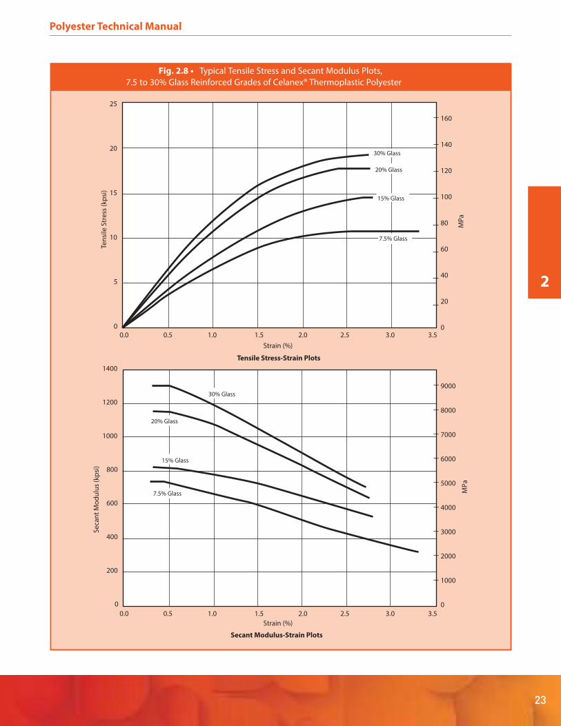
2.3 Stress-Strain Curves and Temperature
Just as strength and initial modulus values fall off with
temperature, so also do stress values associated with given
levels of strain. Ambient temperature stressstrain and
secant modulus-strain curves are shown in Figures 2.7
through 2.9 for unreinforced grades of Celanex PBT and
Vandar PBT Alloy, 7.5% to 30% glass-reinforced grades of
Celanex PBT and glass/mineral reinforced grades of Impet
PET.
The influence of temperature on unreinforced Celanex PBT
2002-2 may be seen in Figure 2.10, which presents data at
temperatures between -40°C and 120°C for tensile
stress-strain and secant modulus-strain properties. The
divergence between values at 23°C and 80°C reflects
passage through Tg. A similar divergence is found in
reinforced grades, although of course the absolute values
are higher. This is shown in Figures 2.11 through 2.15,
illustrating the behavior of Celanex PBT with 15% and 30%
glass reinforcement, Celanex PBT with different glass/min-
eral reinforcements and Impet PET with different
glass/mineral reinforcements.
-150 -100 -50 0 50 100 150 200 250
Unfilled PBT
30% Glass-Reinforced PBT
10
1
0.1
0.01
Temperature (°C)
No
rma
liz
ed
Mo
du
lus
(MP
a)
Fig. 2.1 • Typical Normalized DMA for Celanex® PBT

2
21
Polyester Technical Manual
150 200100500-50
0
5000
10000
15000
Temperature (°F)
Ten
sile
Str
en
gth
(p
si) 2100
4602Z
0
20
40
60
80
MP
a100
Fig. 2.6 • Tensile Strength vs. Temperature for Vandar® PBT Alloy
300
Temperature, °F
002 05250 150100-50 0
Fle
xura
l Mo
du
lus,
psi
x 1
06
Celanex 3400
2.0
1.6
1.2
0.8
0.4
0
Celanex 3300Celanex 3200
Fig. 2.2 • Flexural Modulus vs. Temperature
for Glass Reinforced, General Purpose
Grades of Celanex® Thermoplastic Polyester
300
Temperature, °F
002 05250 150100-50 0
Fle
xura
l Mo
du
lus,
psi
x 1
06
Celanex 5300
2.0
1.6
1.2
0.8
0.4
0
Celanex 4300
Fig. 2.3 • Flexural Modulus vs. Temperature
for Glass Reinforced, Improved Impact/Surface Finish
Grades of Celanex® Thermoplastic Polyester
300
Temperature, °F
002 05250 150100-50 0
Fle
xura
l Str
en
gth
, psi
x 1
03
45.0
20.0
15.0
10.0
5.0
0
Celanex 3400
40.0
35.0
30.0
25.0
Celanex 3200Celanex 3300
Fig. 2.4 • Flexural Strength vs. Temperature
for Glass Reinforced, General Purpose
Grades of Celanex® Thermoplastic Polyester
Fle
xura
l Str
en
gth
, psi
x 1
03
40.0
35.0
30.0
25.0
20.0
15.0
10.0
5.0
0-50 0 50 100 150 200 250 300
Temperature, °F
Celanex 5300
Celanex 4300
Fig. 2.5 • Flexural Strength vs. Temperature
for Glass Reinforced, Improved Impact/Surface Finish
Grades of Celanex® Thermoplastic Polyester

22
Polyester Technical Manual
Tensile Stress-Strain Plots
12.0 14.010.08.06.04.02.00.0
0
1
2
3
4
5
6
7
8
Vandar 8000
Celanex 1600A
Strain (%)
Ten
sile
Str
ess
(kp
si)
Secant Modulus-Strain Plots
12.0 14.010.08.06.04.02.00.0
0
50
100
150
200
250
300
350
Vandar 8000
Celanex 1600A
Strain (%)
Se
can
t M
od
ulu
s (k
psi
)
0
10
20
30
40
50
MP
a
0
500
1000
1500
2000
MP
a
Fig. 2.7 • Typical Tensile Stress and Secant Modulus Plots for Some Unreinforced Grades
of Celanex® Thermoplastic Polyester and Vandar® PBT Alloy
2
23
Polyester Technical Manual
Tensile Stress-Strain Plots
3.0 3.52.52.01.51.00.50.0
3.0 3.52.52.01.51.00.50.0
25
20
15
10
5
0
1400
1200
1000
800
600
400
200
0
Strain (%)
Ten
sile
Str
ess
(kp
si)
Secant Modulus-Strain Plots
Strain (%)
Se
can
t M
od
ulu
s (k
psi
)
160
140
120
100
80
60
40
20
0
9000
8000
7000
6000
5000
4000
3000
2000
1000
0
30% Glass
30% Glass
7.5% Glass
7.5% Glass
15% Glass
15% Glass
20% Glass
20% Glass
MP
aM
Pa
Fig. 2.8 • Typical Tensile Stress and Secant Modulus Plots,
7.5 to 30% Glass Reinforced Grades of Celanex® Thermoplastic Polyester

24
Polyester Technical Manual
Tensile Stress-Strain Plots
3.0 3.52.52.01.51.00.50.0
0
5
10
15
20
25
340R
Strain (%)
Ten
sile
Str
ess
(kp
si)
Secant Modulus-Strain Plots
3.0 3.52.52.01.51.00.50
0
500
1000
1500
2000
2500
3000
Strain (%)
Se
can
t M
od
ulu
s (k
psi
)
330R
830R
30
340R
330R
830R
0
50
100
150
200
MP
a
0
5000
10000
15000
20000
MP
a
Fig. 2.9 • Typical Tensile Stress and Secant Modulus Plots for
Glass and Glass/Mineral Reinforced Grades of Impet® Thermoplastic Polyester

2
25
Polyester Technical Manual
Secant Modulus-Strain Plots
0
50
100
150
200
250
300
350
Strain (%)
Se
can
t M
od
ulu
s (k
psi
)
-40°C (-40°F)
0°C (32°F)
23°C (73°F)
80°C (176°F)
120°C (248°F)
9.0 10.08.07.06.04.03.0 0.50.0 1.0 2.0
400
450
Tensile Stress-Strain Plots
0
2
4
6
8
10
12
14
16
Strain (%)
Ten
sile
Str
ess
(kp
si)
0°C (32°F)
23°C (73°F)
80°C (176°F)
120°C (248°F)
9.0 10.08.07.06.04.03.0 0.50.0 1.0 2.0
-40°C (-40°F)
0
20
40
60
80
MP
a
100
0
500
1000
1500
2000
MP
a
2500
3000
Fig. 2.10 • Typical Tensile Stress and Secant Modulus Plots
at Different Temperatures for Unreinforced Celanex® 2002-2

26
Polyester Technical Manual
Secant Modulus-Strain Plots
0
100
200
300
400
500
600
700
Strain (%)
Se
can
t M
od
ulu
s (k
psi
)
-40°C (-40°F)
0°C (32°F)
23°C (73°F)
80°C (176°F)
120°C (248°F)
7.06.04.03.0 0.50.0 1.0 2.0
800
900
Tensile Stress-Strain Plots
0
2.0
4.0
6.0
8.0
10.0
12.0
14.0
16.0
Strain (%)
Ten
sile
Str
ess
(kp
si)
0°C (32°F)
23°C (73°F)
80°C (176°F)
120°C (248°F)
7.06.04.03.0 0.50 1.0 2.0
-40°C (-40°F)
18.0
1000
0
20
40
60
80
MP
a
100
120
0
1000
2000
3000
4000M
Pa
5000
6000
Fig. 2.11 • Typical Tensile Stress and Secant Modulus Plots
at Different Temperatures for 15% Glass Reinforced Celanex® 3200
2
27
Polyester Technical Manual
Tensile Stress-Strain Plots
0
5
10
15
20
25
30
Strain (%)
Ten
sile
Str
ess
(kp
si)
0°C (32°F)
23°C (73°F)
80°C (176°F)
120°C (248°F)
4.5 5.04.03.53.02.01.5 5.20.0 0.5 1.0
-40°C (-40°F)
Secant Modulus-Strain Plots
0
200
400
600
800
1000
1200
1400
Strain (%)
Se
can
t M
od
ulu
s (k
psi
)
-40°C (-40°F)
0°C (32°F)23°C (73°F)
80°C (176°F)
120°C (248°F)
4.5 5.04.03.53.02.01.5 5.20.0 0.5 1.0
1600
1800
0
50
100
150
200
MP
a
0
2000
4000
6000
8000M
Pa
10000
12000
Fig. 2.12 • Typical Tensile Stress and Secant Modulus Plots
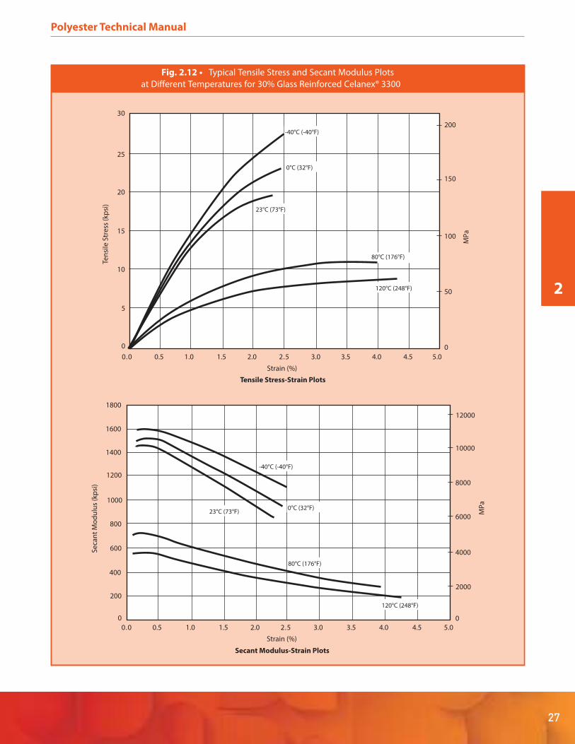
at Different Temperatures for 30% Glass Reinforced Celanex® 3300

28
Polyester Technical Manual
Tensile Stress-Strain Plots
0
2
4
6
8
10
12
14
16
Strain (%)
Ten
sile
Str
ess
(kp
si)
40°C (104°F)
23°C
4.54.03.02.5 5.30.0 1.5 2.0
-40°C (-40°F)
18
120°C (248°F)
93°C (200°F)
0.5 1.0
20
Secant Modulus-Strain Plots
0
200
400
600
800
1000
1200
1400
Strain (%)
Se
can
t M
od
ulu
s (k
psi
)
-40°C (-40°F)
40°C (104°F)
23°C (73°F)
4.54.03.02.50 3.51.5 2.0
1600
1800
2000
93°C (200°F)
1.00.5
120°C (248°F)
0
20
40
60
80
MP
a
100
120
0
2000
4000
6000
8000
MP
a
10000
12000
Fig. 2.13 • Typical Tensile Stress and Secant Modulus Plots
at Different Temperatures for Glass/Mineral Reinforced Celanex® J600

2
29
Polyester Technical Manual
Tensile Stress-Strain Plots
0
5
10
15
20
25
Strain (%)
Ten
sile
Str
ess
(kp
si)
0°C (32°F)
23°C (73°F)
80°C (176°F)
90°C (194°F)
4.5 5.04.03.53.02.01.5 5.20.0 0.5 1.0
-30°C (-22°F)
Secant Modulus-Strain Plots
0
200
400
600
800
1000
1200
1400
Strain (%)
Se
can
t M
od
ulu
s (k
psi
)
-30°C (-22°F)
0°C (32°F)
23°C (73°F)
80°C (176°F)
90°C (194°F)
4.5 5.04.03.53.02.01.5 5.20.0 0.5 1.0
1600
1800
0
20
40
60
80 MP
a
100
120
140
160
0
2000
4000
6000
8000
MP
a
10000
12000
Fig. 2.14 • Typical Tensile Stress and Secant Modulus Plots
at Different Temperatures for Glass/Mineral Reinforced Celanex® 6500

30
Polyester Technical Manual
Tensile Stress-Strain Plots
30
25
20
15
10
5
0
2500
2000
1500
1000
500
0
Strain (%)
0.0 1.0 2.0 3.0 4.0 5.0 6.0 7.0
0.0 1.0 2.0 3.0 4.0 5.0 6.0 7.0
Ten
sile
Str
ess
(kp
si)
-40°C (-40°F)
-40°C (-40°F)
23°C (73°F)
23°C (73°F)
93°C (200°F)
93°C (200°F)
149°C (300°F)
149°C (300°F)
Secant Modulus-Strain Plots
Strain (%)
Se
can
t M
od
ulu
s (k
psi
)
MP
a
200
150
100
50
0
16000
14000
12000
10000
8000
6000
4000
2000
0
MP
a
Fig. 2.15 • Typical Tensile Stress and Secant Modulus Plots
at Different Temperatures for Glass/Mineral Reinforced Impet® 830R
2
31
Polyester Technical Manual
2.4 Chemical Resistance
The chemical resistance of a polymeric material depends
on the chemical and polymer in question and on the
temperature and exposure time as well as on the possible
involvement of other factors such as for instance ultravio-
let or other high energy radiation. Some reagents are
absorbed and swell the polymer, while others may dissolve
it or cause embrittlement or even decomposition.
Semi-crystalline thermoplastic polymers have generally
excellent chemical resistance, being dissolved by only a
few aggressive organic solvents. Other solvents may cause
some swelling as they are absorbed into the amorphous
portion of the polymer. Polyesters may also be subject to
hydrolysis by extended exposure to high temperature
acidic aqueous solutions or attack by strong mineral acids.
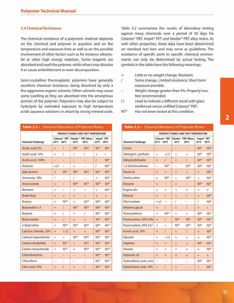
Table 2.2 summarizes the results of laboratory testing
against many chemicals over a period of 30 days for
Celanex® PBT, Impet® PET and Vandar® PBT alloy resins. As
with other properties, these data have been determined
on standard test bars and may serve as guidelines. The
resistance of specific parts to specific chemical environ-
ments can only be determined by actual testing. The
symbols in the table have the following meanings:
+ Little or no weight change. Resistant.
/ Some change. Limited resistance. Short term
exposure possible.
– Weight change greater than 5%. Property loss.
Not recommended.
( ) Used to indicate a different result with glass
reinforced versus unfilled Celanex® PBT.
NT* Has not been tested at this condition.
Table 2.2 • Chemical Resistance of Polyester Resins
PRODUCT FAMILY AND TEST TEMPERATURE
Celanex® PBT Vandar® PBT Alloys Impet® PET
Chemical Challenge 23°C 60°C 23°C 60°C 23°C 60°C
Acetic acid, 5%
Acetic acid, 10%
Acetic acid, 100%
Acetone
Allyl alcohol
Ammonia, 10%
Amyl acetate
Benzene
Brake fluid
Butane
Butanediol-1,4
Butanol
Butyl acetate
n-Butyl ether
Calcium chloride, 10%
Calcium hypochlorite
Carbon disulphide
Carbon tetrachloride
Chlorobenzene
Chloroform
Citric acid, 10%
+
+
–
+(/)
+
/
+
+
+
+
+
+
+
+
+
+
+
+
–
–
+
/
/
–
–
NT*
–
–
–
+
NT*
/
/
+
NT*
+ (/)
+
NT*
NT*
–
–
/
NT*
/
–
+
NT*
/
NT*
+
+
+
NT*
+
+
NT*
+
NT*
+
+
–
–
+
NT*
/
–
–
NT*
–
NT*
–
+
NT*
NT*
/
+
NT*
+
NT*
NT*
NT*
–
–
/
NT*
+
/
/
NT*
+
NT*
+
+
NT*
NT*
NT*
NT*
NT*
NT*
NT*
NT*
NT*
NT*
NT*
NT*
NT*
/
NT*
NT*
NT*
NT*
NT*
NT*
+
NT*
NT*
NT*
NT*
NT*
NT*
NT*
NT*
NT*
NT*
NT*
NT*
Table 2.2 • Chemical Resistance of Polyester Resins
PRODUCT FAMILY AND TEST TEMPERATURE
Celanex® PBT Vandar® PBT Alloys Impet® PET
Chemical Challenge 23°C 60°C 23°C 60°C 23°C 60°C
Cresol
Detergent, synthetic
Dibutyl phthalate
1,2-Dichloroethane
Diesel oil
Diethyl ether
Dioxane
Engine oils
Ethanol
Ethyl acetate
Ethylene glycol
Fluorocarbons
Fluorocarbon, HFA134a
Fluorocarbon, HFA 227
Formic acid, 10%
Glycerol
Heptane
Hexane
Hydraulic oil
Hydrochloric acid, conc.
Hydrochloric acid, 10%
–
+
+
–
+
+
+
+
+
+ (/)
+
+
+
+
+
+
+
+
+
–
+
–
+ (/)
/
NT*
+
NT*
–
+
/
–
/
NT*
/
+
/
+ (/)
+
+
+
–
/
–
+
+
–
+
+
+
+
+
/
+
+
NT*
NT*
+
+
+
+
+
–
+
–
+
/
NT*
+
NT*
–
+
/
–
/
+
NT*
NT*
/
+
+
+
+
–
–
NT*
NT*
NT*
NT*
+
+
NT*
+
+
/
+
NT*
NT*
NT*
+
+
NT*
+
+
NT*
+
NT*
NT*
NT*
NT*
NT*
NT*
NT*
+
NT*
NT*
/
NT*
NT*
NT*
NT*
NT*
NT*
NT*
+
NT*
NT*

Because of its extensive use in many engineering applica-
tions involving potentially challenging chemical environ-
ments, glass-reinforced Celanex PBT has also been
thoroughly tested under different exposure conditions
and careful measurements made on weight change,
dimensional stability and tensile strength retention. These
results are given in Table 2.3.
32
Polyester Technical Manual
Table 2.2 • Chemical Resistance of Polyester Resins
PRODUCT FAMILY AND TEST TEMPERATURE
Celanex® PBT Vandar® PBT Alloys Impet® PET
Chemical Challenge 23°C 60°C 23°C 60°C 23°C 60°C
Hydrofluoric acid, 10%
Hydrofluoric acid, 5%
Hydrogen peroxide,35%
Hydrogen peroxide, 5%
Isopropanol
Kerosene
Linseed oil
Lubricating grease
Methanol
Methyl ethyl ketone
Methylene chloride
Mineral oil
Nitric acid 10%
Nitric acid, conc.
Octane
Olive oil
Paraffin oil
Perchloroethylene
Gasoline, premium
Gasoline, regular
Petroleum
Phenol, 10%
Phosphoric acid, 20%
Potassium chloride, 10%
Potassium
dichromate, 10%
Potassium hydroxide,1%
Potassium
hydroxide, 10%
/ (–)
+ (–)
+
+
+
+
+
+
+
+ (–)
–
+
+
–
+
+
+
/
+
+
+
–
+
+
+
+ (–)
/ (–)
/ (–)
/ (–)
/
/
/
+
+
+
/
/
NT*
+
/
–
+
+
+
/
/
/
+
–
/
+ (/)
+
/(–)
–
/
NT*
NT*
NT*
+
+
+
+
+
+
–
+
+
–
+
+
+
/
+
+
+
–
+
+
+
NT*
–
/
NT*
NT*
NT*
/
+
+
+
/
/
NT*
+
/
–
+
+
+
–
/
/
+
–
/
+
+
NT*
–
NT*
NT*
NT*
NT*
+
NT*
NT*
+
+
NT*
–
NT*
NT*
NT*
NT*
NT*
NT*
NT*
+
+
NT*
NT*
NT*
NT*
NT*
NT*
–
NT*
NT*
NT*
NT*
NT*
NT*
NT*
+
/
NT*
NT*
NT*
NT*
NT*
NT*
NT*
NT*
NT*
/
/
NT*
NT*
NT*
NT*
NT*
NT*
NT*
Table 2.2 • Chemical Resistance of Polyester Resins
PRODUCT FAMILY AND TEST TEMPERATURE
Celanex® PBT Vandar® PBT Alloys Impet® PET
Chemical Challenge 23°C 60°C 23°C 60°C 23°C 60°C
Potassium
permanganate, 10%
Silicone oils
Soap solution, 10%
Sodium bisulphate, 10%
Sodium carbonate, 10%
Sodium chloride, 10%
Sodium hydroxide, 1%
Sodium hydroxide, 10%
Sodium
hypochlorite, 10%
Sulfuric acid, conc.
Sulfuric acid, 10%
Tetrahydrofuran
Toluene
Transformer oil
Trichloroethylene
Turpentine oil
Vaseline
Vegetable oil
Washing soap
Water
Xylene
+
+
+
+
+
+
+
/ (–)
+
–
+
/
+
+
/
+
+
+
+
+
+
/
+
+ (–)
+
+
+
/ (–)
–
+ (/)
–
–
NT*
–
+
–
NT*
+
+
+
NT*
–
+
+
+
+
+
+
NT*
–
NT*
–
+
–
/
+
/
+
+
+
+
NT*
/
/
+
/
+
+
+
NT*
–
NT*
–
–
NT*
–
+
–
NT*
+
+
+
NT*
–
NT*
NT*
NT*
NT*
+
NT*
NT*
NT*
NT*
NT*
+
NT*
+
NT*
NT*
NT*
NT*
NT*
NT*
+
+
NT*
NT*
NT*
NT*
+
NT*
NT*
NT*
NT*
NT*
NT*
NT*
NT*
NT*
NT*
NT*
NT*
NT*
NT*
+
NT*

2
33
Polyester Technical Manual
Table 2.3 • Chemical Resistance of Glass Reinforced Celanex® Thermoplastic Polyesters
% Change
Material Time (Days) Temperature °C (°F) Tensile Strength Weight Diameter*
ACIDS, BASES AND DILUTE SALT SOLUTIONS
10% Ammonium Hydroxide 90 23 (73) -13.0 +0.6 +0.3
180 23 (73) -58.0 +0.3 0.0
360 23 (73) -73.5 +0.9 +0.6
9 82 (180) -92.0 +2.1 +0.3
24 82 (180) -99.0 -4.2 +0.1
1% Sodium Hydroxide 90 23 (73) -47.0 +0.8 +0.6
180 23 (73) -72.0 +0.5 +0.1
360 23 (73) -84.0 +0.3 +0.7
24 82 (180) -96.0 -1.9 0.0
10% Sodium Chloride 90 23 (73) -6.0 +0.3 +0.2
180 23 (73) -6.0 +0.4 +0.2
360 23 (73) -4.0 +0.4 +0.2
10% Hydrochloric Acid 90 23 (73) -4.0 -0.1 +0.2
180 23 (73) -12.0 +0.1 +0.1
360 23 (73) -20.0 +0.2 +0.1
24 82 (180) -24.0 -0.6 0.0
64 82 (180) -68.0 -2.4 -0.1
3% Sulfuric Acid 90 23 (73) -7.0 +0.2 +0.2
180 23 (73) -10.0 +0.2 -0.1
360 23 (73) -8.0 +0.2 +0.1
24 82 (180) -25.0 +0.2 +0.1
64 82 (180) -65.0 +0.2 +0.1
40% Sulfuric Acid 90 23 (73) -2.0 +0.4 0.0
180 23 (73) -4.0 +0.0 +0.1
360 23 (73) -4.0 +0.1 +0.1
Water (Tap) 90 23 (73) -5.0 -0.3 +0.1
180 23 (73) -3.0 +0.3 +0.1
360 23 (73) -5.0 +0.3 +0.1
60 38 (100) -3.0 — —
Buffer, pH 10 90 23 (73) -6.0 +0.3 +0.1
180 23 (73) -9.0 0.0 +0.2
360 23 (73) -9.0 +0.7 +0.2
Buffer, pH 4 90 23 (73) -4.0 +0.3 +0.1
180 23 (73) -7.0 +0.3 +0.1
360 23 (73) -8.0 +0.4 +0.1
1% Soap Solution 180 23 (73) -5.0 — —
360 23 (73) -24.0 — +0.1
Presoak Solution (Axion) 180 23 (73) -4.0 — —
360
180
23 (73) -5.0 — +0.1
Calgon Water Softener Solution 23 (73) -6.0 —
360 23 (73) -8.0 — +0.1
Buffer, pH 7 180 23 (73) -5.0 +0.3 +0.1
360 23 (73) -9.0 +0.3 +0.1
Calgonite Dishwasher Solution 180 23 (73) -3.0 — —
360 23 (73) -23.0 +1.3 +0.2
* 1/8” thick x 2” diameter disc.
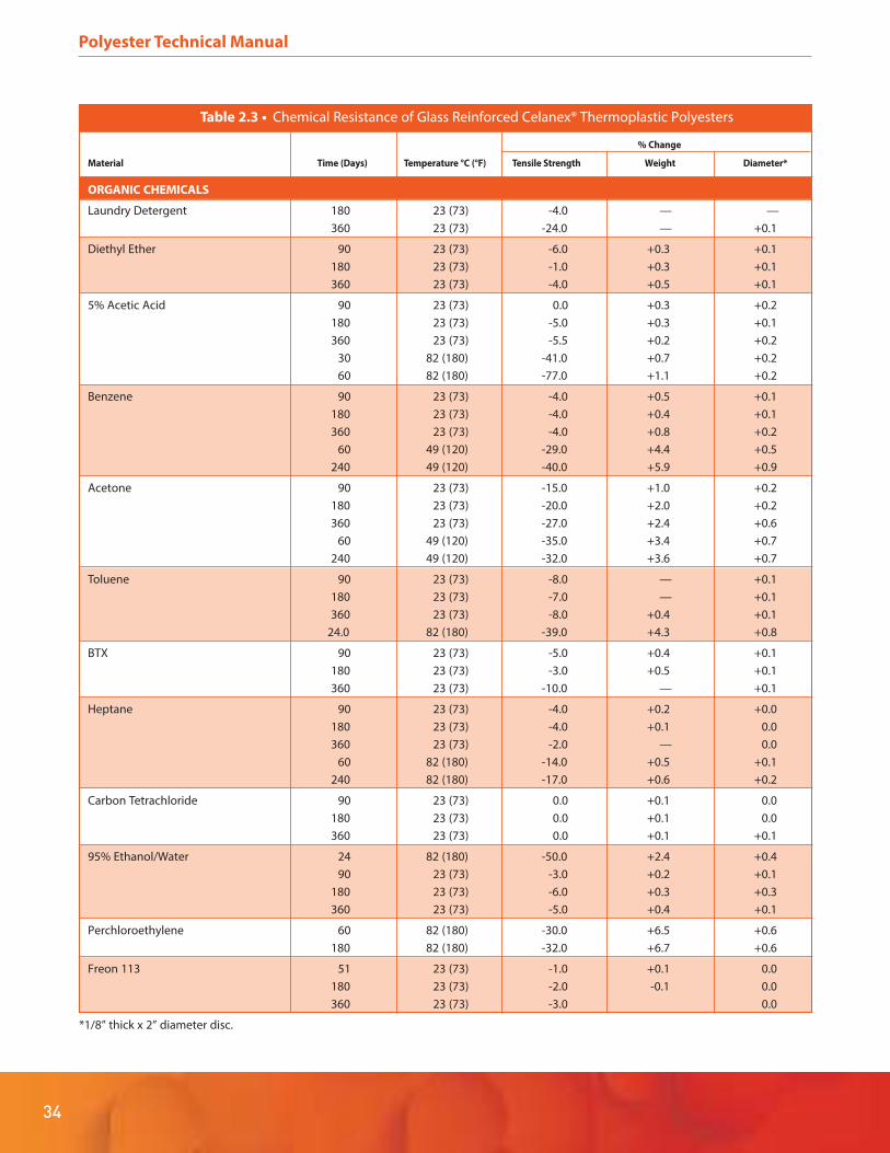
Table 2.3 • Chemical Resistance of Glass Reinforced Celanex® Thermoplastic Polyesters
% Change
Material Time (Days) Temperature °C (°F) Tensile Strength Weight Diameter*
ORGANIC CHEMICALS
Laundry Detergent 180 23 (73) -4.0 — —
360 23 (73) -24.0 — +0.1
Diethyl Ether 90 23 (73) -6.0 +0.3 +0.1
180 23 (73) -1.0 +0.3 +0.1
360 23 (73) -4.0 +0.5 +0.1
5% Acetic Acid 90 23 (73) 0.0 +0.3 +0.2
180 23 (73) -5.0 +0.3 +0.1
360 23 (73) -5.5 +0.2 +0.2
30 82 (180) -41.0 +0.7 +0.2
60 82 (180) -77.0 +1.1 +0.2
Benzene 90 23 (73) -4.0 +0.5 +0.1
180 23 (73) -4.0 +0.4 +0.1
360 23 (73) -4.0 +0.8 +0.2
60 49 (120) -29.0 +4.4 +0.5
240 49 (120) -40.0 +5.9 +0.9
Acetone 90 23 (73) -15.0 +1.0 +0.2
180 23 (73) -20.0 +2.0 +0.2
360 23 (73) -27.0 +2.4 +0.6
60 49 (120) -35.0 +3.4 +0.7
240 49 (120) -32.0 +3.6 +0.7
Toluene 90 23 (73) -8.0 — +0.1
180 23 (73) -7.0 — +0.1
360 23 (73) -8.0 +0.4 +0.1
24.0 82 (180) -39.0 +4.3 +0.8
BTX 90 23 (73) -5.0 +0.4 +0.1
180 23 (73) -3.0 +0.5 +0.1
360 23 (73) -10.0 — +0.1
Heptane 90 23 (73) -4.0 +0.2 +0.0
180 23 (73) -4.0 +0.1 0.0
360 23 (73) -2.0 — 0.0
60 82 (180) -14.0 +0.5 +0.1
240 82 (180) -17.0 +0.6 +0.2
Carbon Tetrachloride 90 23 (73) 0.0 +0.1 0.0
180 23 (73) 0.0 +0.1 0.0
360 23 (73) 0.0 +0.1 +0.1
95% Ethanol/Water 24 82 (180) -50.0 +2.4 +0.4
90 23 (73) -3.0 +0.2 +0.1
180 23 (73) -6.0 +0.3 +0.3
360 23 (73) -5.0 +0.4 +0.1
Perchloroethylene 60 82 (180) -30.0 +6.5 +0.6
180 82 (180) -32.0 +6.7 +0.6
Freon 113 51 23 (73) -1.0 +0.1 0.0
180 23 (73) -2.0 -0.1 0.0
360 23 (73) -3.0 0.0
*1/8” thick x 2” diameter disc.
34
Polyester Technical Manual

2
35
Polyester Technical Manual
Table 2.3 • Chemical Resistance of Glass Reinforced Celanex® Thermoplastic Polyesters
% Change
Material Time (Days) Temperature °C (°F) Tensile Strength Weight Diameter*
AUTOMOTIVE CHEMICALS
50% Ethylene Glycol/Water 90 23 (73) -3.0 +0.3 +0.1
180 23 (73) -3.0 +0.4 +0.1
360 23 (73) -3.0 +0.3 +0.1
Gasoline (Amoco Unleaded) 180 23 (73) -1.6 +0.2 0.0
360 23 (73) -2.2 +0.2 +0.1
135 60 (140) -7.4 +1.4 +0.3
240 60 (140) -16.4 +1.9 +0.3
Automatic Transmission Fluid 180 23 (73) -1.0 +0.1 +0.1
(Type B) 360 23 (73) -3.0 — +0.1
30 93 (200) -31.0 +0.3 0.0
48 93 (200) -51.0 +0.4 +0.1
Delco 222 Brake Fluid 180 23 (73) +1.0 0.0 0.0
360 23 (73) -1.0 +0.1
30 93 (200) -43.0 +2.0 +0.3
48 93 (200) -60.0 -2.2 +0.4
Motor Oil (10W-40) 180 23 (73) -3.0 +0.1 +0.1
360 23 (73) -3.0 — +0.1
60 93 (200) -43.0 +0.2 0.0
100 93 (200) -61.0 +0.2 -0.1
Lubricating Grease 180 23 (73) -6.0 — +0.2
360 23 (73) -4.0 +0.1 +0.1
60 93 (200) -34.0 +0.1 -0.1
100 93 (200) -64.0 +0.3 -0.1
Hydraulic Fluid (Skydrol 500B) 180 23 (73) 0.0 0.0 0.0
360 23 (73) -4.0 +0.1 +0.1
60 93 (200) -34.0 +0.1 -0.1
240 82 (180) -5.5 +0.5 +0.1
Turbine Lubricating Oil 180 23 (73) -0.5 -0.1 +0.1
(Texaco Sato 15) 360 23 (73) -17.3 — +0.1
Houghton-Cosmolubric 2425 180 23 (73) +1.0 0.0 0.0
360 23 (73) -16.7 — 0.0
* 1/8” thick x 2” diameter disc.

2.4.1 Application-related Chemical Testing
As well as the tests summarized in Tables 2.2 and 2.3, other
chemical exposure tests directed toward specific end-use
areas have also been carried out. Celanex® PBT resins have
been shown to withstand short-term exposure to steam
and water under pressure at temperatures up to 150°C. For
long-term hot water exposure of both Celanex PBT and
Vandar® PBT alloys a temperature limit of 40°C should be
observed. Impet® PET resins should not be used in applica-
tions requiring prolonged exposure to hot water.
Celanese’s Celcon® acetal copolymer is recommended
where continuous hot water use is expected.
Thermal shock tests at high relative humidity (RH) are
important qualification criteria for the automotive indus-
try. The U.S. Council for Automotive Research (USCAR) test
calls for finished components to be subjected to 40
temperature and humidity cycles reaching up to 95% RH,
after which the component is tested for mechanical and
electrical performance. Parts made from standard PBT
resins usually meet the requirements for lower tempera-
ture classes (up to 80°C and up to 100°C). The Celanex
hydrolyis-resistant portfolio is currently the most extensive
in the market.
Very short term exposures (such as for example temporary
surface wetting) of Celanex PBT parts shows excellent
resistance to chemicals likely to be found in the automo-
tive environment including gasoline, engine oil, transmis-
sion fluid, brake fluid, engine coolant and windshield
washer solution. Except for battery acid, no surface
damage to parts is observed even in a 5 cycle test requir-
ing wetting followed by 48 hours storage at 80°C. Satisfac-
tory performance in this test is found even for engine
coolant, an aqueous solution of ethylene or propylene
glycol to which polyester resins are not resistant in high
temperature continuous exposure. As shown in Table 2.4,
no significant change was seen in strength and elongation
of 30% glass-reinforced PBT (Celanex PBT 3300) after an
ethylene glycol dip followed by six months of hot air expo-
sure at 120°C.
2.4.2 Chemical Stress Cracking
Semi-crystalline resins such as polyesters are generally not
susceptible to environmental stress cracking such as
affects many amorphous resins under certain conditions.
After a 5-hour exposure to different automotive chemicals,
no surface cracking was detectable in stressed test speci-
mens of Celanex PBT 3300-2 even under 30x magnifica-
tion. The test conditions and results are shown in Table 2.5.
Electrical engineering components are sometimes
exposed to the oxidative attack of ozone generated by
arcing. Celanex PBT 3300-2 has been shown to retain 70%
tensile impact strength after 50 hours at 121°C (250°F) in
an atmosphere containing 1.7% ozone.
Polyester Technical Manual
36
Table 2.4 • Ethylene Glycol Dip Test
– 30% Glass Filled PBT
Time Tensile Strength % of(Days) MPa (psi) Elongation
Exposure Conditions – Immersed in Ethylene Glycol at 120°C (248°F)
0 125 (18,200) 3.0
16 29 (4,270) 0.5
Exposure Conditions – Dipped in Ethylene Glycol at 23°C (73°F).
Exposure to circulating air at 120°C (248°F)
0 125 (18,200) 3.0
16 134 (19,500) 2.0
177 122 (17,800) 2.0
Re
lati
ve
te
nsi
le s
tre
ng
th
100
80
60
40
20
00 40 20
Number cycles
3300 HRPBT GF30
Fig. 2.16 • Change in the Tensile Strength
at Break of Celanex® Specimens Tested According
to USCAR Class III
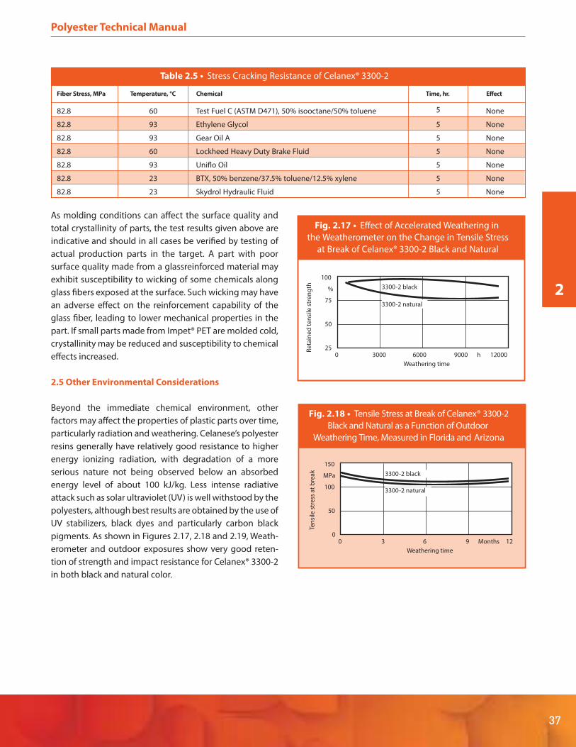
2
37
Polyester Technical Manual
As molding conditions can affect the surface quality and
total crystallinity of parts, the test results given above are
indicative and should in all cases be verified by testing of
actual production parts in the target. A part with poor
surface quality made from a glassreinforced material may
exhibit susceptibility to wicking of some chemicals along
glass fibers exposed at the surface. Such wicking may have
an adverse effect on the reinforcement capability of the
glass fiber, leading to lower mechanical properties in the
part. If small parts made from Impet® PET are molded cold,
crystallinity may be reduced and susceptibility to chemical
effects increased.
2.5 Other Environmental Considerations
Beyond the immediate chemical environment, other
factors may affect the properties of plastic parts over time,
particularly radiation and weathering. Celanese’s polyester
resins generally have relatively good resistance to higher
energy ionizing radiation, with degradation of a more
serious nature not being observed below an absorbed
energy level of about 100 kJ/kg. Less intense radiative
attack such as solar ultraviolet (UV) is well withstood by the
polyesters, although best results are obtained by the use of
UV stabilizers, black dyes and particularly carbon black
pigments. As shown in Figures 2.17, 2.18 and 2.19, Weath-
erometer and outdoor exposures show very good reten-
tion of strength and impact resistance for Celanex® 3300-2
in both black and natural color.
Table 2.5 • Stress Cracking Resistance of Celanex® 3300-2
Fiber Stress, MPa Temperature, °C Chemical Time, hr. Effect
82.8 60 Test Fuel C (ASTM D471), 50% isooctane/50% toluene None
82.8 93 Ethylene Glycol 5
5
None
82.8 93 Gear Oil A 5 None
82.8 60 Lockheed Heavy Duty Brake Fluid 5 None
82.8 93 Uniflo Oil 5 None
82.8 23 BTX, 50% benzene/37.5% toluene/12.5% xylene 5 None
82.8 23 Skydrol Hydraulic Fluid 5 None
Ten
sile
str
ess
at
bre
ak
150
MPa
100
50
00 3 6 9 Months 12
Weathering time
3300-2 black
3300-2 natural
Fig. 2.18 • Tensile Stress at Break of Celanex® 3300-2
Black and Natural as a Function of Outdoor
Weathering Time, Measured in Florida and Arizona
Re
tain
ed
te
nsi
le s
tre
ng
th
100
%
75
50
250 3000 6000 9000 h 12000
Weathering time
3300-2 black
3300-2 natural
Fig. 2.17 • Effect of Accelerated Weathering in
the Weatherometer on the Change in Tensile Stress
at Break of Celanex® 3300-2 Black and Natural

Xenon Arc testing of end-user automotive exterior parts
made from other grades also demonstrates good reten-
tion of surface quality and mechanical properties. Tables
2.6 and 2.7 show the results of testing done on
actual parts according to Society of Automotive Engineers
(SAE) standard J1960. Color difference and gloss effects
after xenon arc exposure of 2500kJ/m2 are given in Table
2.6 while mechanical property effects are given in Table
2.7.
Please consult Celanese’s Product Information Services for
more specific information on weatherable grades of
Celanex® PBT, Impet® PET and Vandar® PBT alloys.
For automotive interior use, UV-stabilized Celanex PBT and
Vandar PBT alloy grade are available as olormatched
formulation for applications such as seat belt buckles, door
handles and knobs/levers, among others.
Polyester Technical Manual
38
Table 2.7 • Mechanical Property Retention After Exposure – Xenon Arc; 2500 kJ/m2; SAE J1960
Properties Units Celanex 6500 BK225 Celanex 6407 ED 3807
Tensile Strength @ Break % 97 97
Elongation @ Break % 94 93
Notched Izod % 102 89
Flexural Strength % 94 92
Flexural Modulus % 101 100
Table 2.6 • Prototype Parts Xenon Arc; 2500 kJ/m2; SAE J1960 – Color Difference and Gloss
Celanex® Grades Part Description Surface Condition DL* Da* Db* DE*
6500 BK225 F-Car Wiper Airfoil Textured As Is -1.96 0.27 1.61 2.55
Washed 1.70 -0.01 0.27 1.72
Washed & Polished 0.16 0.02 0.32 0.36
2002-2 ED3807 F-Car Wiper Cover Textured As Is 0.87 -0.73 2.50 2.82
Washed 3.77 -0.06 0.16 3.77
6407 ED3807 Luggage Rack Rail Smooth As Is 0.15 0.19 0.77 0.81
Washed -0.81 -0.49 -0.01 0.94
No
tch
ed
imp
act
str
en
gh
75
J/m
65
60
55
50
450 3 6 9 Months 12
Weathering time
3300-2 black
3300-2 natural
Fig. 2.19 • Notched Impact Strength (Izod)
of Celanex® 3300-2 Black and Natural as a
Function of Outdoor Weathering Time, Measured
in Florida and Arizona

2
39
Polyester Technical Manual
2.6 Time-dependent Mechanical Properties
2.6.1 Static Stress
Long Term Mechanical Properties
Adequate consideration of long term loads, especially
based on creep and stress relaxation, is critical to the
design of parts made from thermoplastic polyesters. This
can avoid such issues as incorrect estimates of in-use
performance capability, part warranty and loss of custom-
er satisfaction.
Fatigue effects, usually considered by parts designers,
must be carefully addressed to properly model the real
end-use environment. Improperly designed tests can
produce erroneous results which may be artifacts and may
not reflect real end-use performance.
Creep
The instant any material (including metals) is loaded, it
begins to creep. The viscoelastic properties of plastics
require that creep behavior be considered, even for room
temperature plastics parts design.
When dealing with creep, several points should be consid-
ered. Often, parts are subjected to relatively low loads
where deflection is a factor but stress is not. In other cases,
the primary concern is mechanical failure of the part under
long term loads with minimum consideration of deflec-
tion. Deflection recovery after removal of long term loads
is important in some applications. In general, semicrystal-
line polyesters withstand creep stress better than amor-
phous resins. Glass reinforcement generally improves the
creep resistance of a plastic material.
Creep Deflection
Creep modulus may be substituted for flexural or tensile
modulus in standard equations of linear elasticity used in
engineering design. Typical creep modulus curves (at
different temperatures) for glass and glass/mineral
reinforced grades of Impet are shown in Figure 2.20.
There is considerable variation in creep deflection of
plastic assemblies in actual end-use. This is due to varia-
tions in wall thicknesses, dimensional variations and mate-
rial property variability in the molded parts. To compen-
sate for these factors, use a safety factor of 2 whenever
creep deflection is important in the end-use application.
1000001000100101100000
1000000
Time (hours)
Cre
ep
Mo
du
lus
(psi
)
10000000
23°C
60°C
125°C
10000
Fig. 2.20 • Flexural Creep Modulus for Glass/Mineral Reinforced Impet® 330R at 4,000 psi

Polyester Technical Manual
40
Creep Resistance
Glass reinforced Celanex® resins demonstrate outstanding
flexural creep properties. Because of their extremely low
moisture absorption and high rigidity, very little creep is
experienced at room temperature. Creep resistance at
elevated temperatures up to 180°C (356°F) and under
heavy loads (2000 psi) is also excellent.
Figure 2.21 shows creep results when tested by ASTM
methods which call for 24-hour conditioning at test
temperatures before applying the load. Figures 2.22
through 2.24 show creep results when test bars are
pre-loaded at room temperature and then immediately
brought up to test temperature.
Relaxation
Stress relaxation is similar to creep. In creep, a constant
stress is imposed and the strain gradually ncreases. When
a constant strain is imposed, there is an initial stress which
gradually decays or relaxes with time. Relaxation data are
not as common as creep data. Fortunately, creep data give
a good approximation of the relaxation phenomenon.
1.0
0.5
0100 1000 2000 3000 4000 5000
Str
ain
, %
Time, Hours
500 psi
2000 psi
Fig. 2.21 • Flexural Creep at 105°C
for Glass Reinforced Celanex® 3300
5000
Time, Hours
3000100 20001000
Str
ain
, %
1.0
0.5
0
180°C (356°F)
140 °C (284 °F)
95°C (203°F)
38°C (100° F)
Fig. 2.22 • Flexural Creep at 500 psi Maximum
Stress for Glass Reinforced Celanex® 3300
5000
Time, Hours
40003000100 20001000
Str
ain
, %
3.0
1.0
0
180°C (356°F)
140°C (284°F)
95°C (203°F)
38°C (100°F)
2.0
Fig. 2.23 • Flexural Creep at 2000 psi
Maximum Stress for Glass Reinforced Celanex® 3300
2000
Time, Hours
100 1000
Str
ain
, %
5.0
0
180°C (356°F)
140°C (284°F)
95°C (203°F) 38°C (100°F)
4.0
1.0
2.0
3.0
Fig. 2.24 • Flexural Creep at 2000 psi
Maximum Stress for Glass Reinforced Celanex® 3200
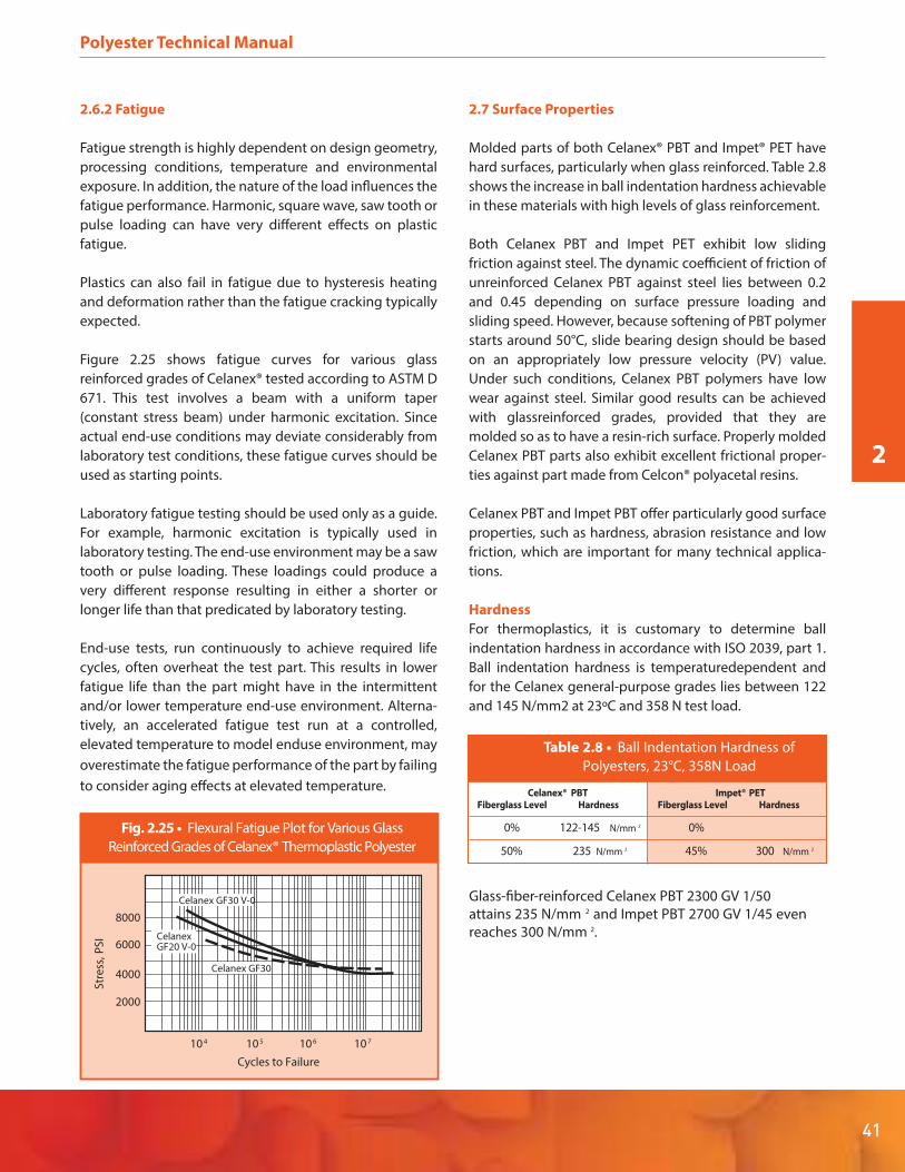
2
41
Polyester Technical Manual
2.6.2 Fatigue
Fatigue strength is highly dependent on design geometry,
processing conditions, temperature and environmental
exposure. In addition, the nature of the load influences the
fatigue performance. Harmonic, square wave, saw tooth or
pulse loading can have very different effects on plastic
fatigue.
Plastics can also fail in fatigue due to hysteresis heating
and deformation rather than the fatigue cracking typically
expected.
Figure 2.25 shows fatigue curves for various glass
reinforced grades of Celanex® tested according to ASTM D
671. This test involves a beam with a uniform taper
(constant stress beam) under harmonic excitation. Since
actual end-use conditions may deviate considerably from
laboratory test conditions, these fatigue curves should be
used as starting points.
Laboratory fatigue testing should be used only as a guide.
For example, harmonic excitation is typically used in
laboratory testing. The end-use environment may be a saw
tooth or pulse loading. These loadings could produce a
very different response resulting in either a shorter or
longer life than that predicated by laboratory testing.
End-use tests, run continuously to achieve required life
cycles, often overheat the test part. This results in lower
fatigue life than the part might have in the intermittent
and/or lower temperature end-use environment. Alterna-
tively, an accelerated fatigue test run at a controlled,
elevated temperature to model enduse environment, may
overestimate the fatigue performance of the part by failing
to consider aging effects at elevated temperature.
2.7 Surface Properties
Molded parts of both Celanex® PBT and Impet® PET have
hard surfaces, particularly when glass reinforced. Table 2.8
shows the increase in ball indentation hardness achievable
in these materials with high levels of glass reinforcement.
Both Celanex PBT and Impet PET exhibit low sliding
friction against steel. The dynamic coefficient of friction of
unreinforced Celanex PBT against steel lies between 0.2
and 0.45 depending on surface pressure loading and
sliding speed. However, because softening of PBT polymer
starts around 50°C, slide bearing design should be based
on an appropriately low pressure velocity (PV) value.
Under such conditions, Celanex PBT polymers have low
wear against steel. Similar good results can be achieved
with glassreinforced grades, provided that they are
molded so as to have a resin-rich surface. Properly molded
Celanex PBT parts also exhibit excellent frictional proper-
ties against part made from Celcon® polyacetal resins.
Celanex PBT and Impet PBT offer particularly good surface
properties, such as hardness, abrasion resistance and low
friction, which are important for many technical applica-
tions.
Hardness
For thermoplastics, it is customary to determine ball
indentation hardness in accordance with ISO 2039, part 1.
Ball indentation hardness is temperaturedependent and
for the Celanex general-purpose grades lies between 122
and 145 N/mm2 at 23ºC and 358 N test load.
Table 2.8 • Ball Indentation Hardness of
Polyesters, 23°C, 358N Load
Celanex® PBT Impet® PETFiberglass Level Hardness Fiberglass Level Hardness
0% 122-145 N/mm 2 0%
50% 235 N/mm 2 45% 300 N/mm 2
Glass-fiber-reinforced Celanex PBT 2300 GV 1/50
attains 235 N/mm 2 and Impet PBT 2700 GV 1/45 even
reaches 300 N/mm 2.
10 7
Cycles to Failure
Str
ess
,P
SI
8000
4000
6000
Celanex GF30 V-0
Celanex GF30
CelanexGF20 V-0
10 610 510 4
2000
Fig. 2.25 • Flexural Fatigue Plot for Various Glass
Reinforced Grades of Celanex® Thermoplastic Polyester

Polyester Technical Manual
Low-friction properties
Celanex PBT and Impet PBT both have good low-friction
properties similar to those of Celcon®/Hostaform® acetal
copolymer.
The dynamic friction coefficient of unreinforced Celanex
PBT 2500 in sliding contact with steel lies between 0.2 and
0.45, depending on surface pressure loading p and sliding
speed v. However, because the softening range of Celanex
PBT starts at 50ºC, the p · v value used in the design of slide
bearings is lower than for Hostaform acetal copolymer. For
this reason, the glass-fiber-reinforced products are normal-
ly used if relatively high operating temperatures – due to
frictional heat or the ambient temperature – are expected.
This is possible because in injection molding – assuming
high mold cavity temperatures – a surface layer with low
glass fiber content and good friction properties is formed.
If – after prolonged periods of service – glass fibers are
exposed in the sliding surface, stick slip and noisy opera-
tion must be expected with Celanex PBT in sliding contact
with steel. Glass-sphere-filled products behave in a similar
way to the glass-fiberreinforced grades and offer no
advantages in terms of noise development.
Wear of Celanex® PBT
Unreinforced Celanex PBT has good wear properties if
surface pressure p and sliding speed v are limited to values
that preclude a noticeable increase in sliding surface
temperature. Generally speaking, PBT is regarded as suffer-
ing somewhat greater wear in contact with smooth steel
shafts (RZ << 2 μm) and somewhat less wear in contact
with rough steel shafts (RZ > 2 μm) than POM, Figure 2.26.
In tests with the pin/shaft system in contact with steel (RZ
= 0.8 μm) both the unreinforced Celanex PBT 2500 and
some glass-fiberreinforced Celanex grades showed higher
wear resistance than unmodified Hostaform® acetal copo-
lymer C 9021, see Figure 2.27.
For information and/or recommendations on polyester
gear and bearing design criteria and on special wear
resistant grades, please consult Celanese’s Product
Information Services at 1-800-833-4882, prodinfo@cel-
anese.com, or as shown on the back cover of this brochure.
42
low
high
PA 6 PA 66 PA 46 POM PBT PEEK PPS
Stick-slip tendency
low
high
PA 6 PA 66 PA 46 POM PBT PEEK PPS
Coefficient of friction
low
high
PA 6 PA 66 PA 46 POM PBT PEEK PPS
Tendency to wear (roughness of steel > 2 µm)
low
high
PA 6 PA 66 PA 46 POM PBT PEEK PPS
Tendency to wear (roughness of steel << 2 µm)
low
high
PA 6 PA 66 PA 46 POM PBT PEEK PPS
Permissible surface pressure
no
da
ta
Fig. 2.26 • Typical behavior of some
unfilled thermoplastic polymers when used in
plain bearings sliding at low velocity against steel,
without lubrication (relative comparison)

2
43
Polyester Technical Manual
2.8 Thickness and Time Dependence of Electrical
Properties
The generation of internal electrical stress is affected by
part homogeneity. In general, the thicker a part, the more
susceptible it is to microvoiding and the localization of
high dielectric stress at those points. As a result, dielectric
strength diminishes with increasing part thickness as
shown in Figure 2.28 for Celanex® PBT grades 3300 and
5300.
Although polyesters are not hygroscopic, they do absorb a
small amount of moisture after extended humidity expo-
sure. That this does not significantly impair insulating
properties is shown for Celanex PBT 3300 in Figure 2.29.
Resistance to dielectric breakthrough is also well sustained
under high temperature exposure with more than 50%
being retained even after four months at 170ºC as shown
in Figure 2.30.
We
ar
vo
lum
e (
mm
3)
2500
0
2300
10% GR
2300
20% GR
C 90212300
30% GR
2
4
12
6
8
10
Fig. 2.27 • Wear properties of various Celanex® PBT
grades compared with Hostaform® acetal copolymer
in dry sliding contact; pin/shaft system
in contact with steel (RZ = 0.8 μm,
v = 136 m/min., F = 3 N, test duration 60 h.)
140
Thickness, mils
12010006 0804
Die
lect
ric
Str
en
gth
, vo
lt/m
il
1200
800
0
1000
600
200
400
0 20
Celanex 3300
Celanex 5300
Fig. 2.28 • Dielectric Strength Versus Thickness,
Reinforced Grades of Celanex® Thermoplastic Polyester
600
Hours of Exposure
400200
Vo
lum
e R
esi
stiv
ity,
oh
m-c
m
1012
0
Celanex 3300
1000800
*Measured at 73°F and 50% R.H.after 40 hours conditioning (D618, Proc. A)
1013
1014
1015
1016
Fig. 2.29 • Volume Resistivity of Reinforced Grades
of Celanex® Thermoplastic Polyester as a
Function of Time at 70°C (158°F) and 100% Humidity
140
Days at 338°F (170°C)
001 02106 0804
Pe
r C
en
t R
ete
nti
on
100
80
50
90
70
60
0 20
Celanex 3300
061 081
Celanex 5300
Fig. 2.30 • Heat Aging Effects on
Dielectric Strength, Reinforced Grades of Celanex®
Thermoplastic Polyester – 0.8 mm Thickness

Polyester Technical Manual
44
3. Processing
3.1 General
Celanese’s thermoplastic polyesters are typically
processed not only by injection molding and related meth-
ods, but also by various other extrusion-related processes.
Among the latter may be counted profile and tube extru-
sion, monofilament extrusion, melt blowing and other
fiber-oriented processes.
Processing conditions are determined in a general way by
the chemistry of the base polymer such that process
temperatures for Impet® PET resins are commonly higher
than those for Celanex® PBT resins. Vandar® PBT alloy
processing conditions are somewhat more grade-driven,
being influenced by the specific components of each alloy
grade. However, beyond these broad prescriptions, gener-
al processing and handling procedures are similar, differ-
ing more in degree than in kind.
3.1.1 Resin Storage
Resin should be stored so as to prevent damage to packag-
ing and possible subsequent contamination. During
storage, care should be taken to avoid extremes of
temperature and humidity, which could lead to excessive
moisture condensation and/or surface adsorption. These
precautions are particularly important with regard to open
containers of resin. Because the large surface area of
regrind can facilitate moisture pickup, proper storage is
essential for reground material intended for re-use. In any
case, both virgin and reground materials must be dried to
the recommended moisture levels before processing
begins. Proper drying is important for all polyester resins,
but crucial for Impet PET grades.
3.1.2 Recycling Scrap
Properly dried polyester materials have excellent thermal
stability during melt processing. This enables use of up to
25% regrind subject to the requirements that it be free of
contamination and be properly dried together with the
virgin resin before processing. For certain grades of
Celanex PBT, performance in conformity with Underwriters
Laboratory (UL) standards has been demonstrated at the
50% regrind level. This attribute is particularly valuable
where small parts are being molded with a relatively large
portion of the total shot volume going into sprues and
runners.
3.1.3 Ventilation
The overall processing area should be adequately ventilat-
ed. Exhaust vents should be located over molding
machines or extruders, preferably close to the nozzles or
dies, to remove any gas or dust. Vented air quality should
be in compliance with applicable State and Federal regula-
tions.
3.1.4 Startup and Shutdown
Before feeding any polyester resin to the processing equip-
ment, the machine should be adequately purged to
remove any other type of plastic previously run on it. Feed
lines should also be thoroughly cleaned. Suitable purge
materials include polyethylene, polypropylene and
polystyrene. For parts intended for subsequent painting, a
final purge with a low molecular weight PBT such as
Celanex PBT grade 1400 may be used to clear residual
olefin resin from the machine. Temperatures should then
be adjusted to the appropriate settings for the actual
grade that is to be run.
When a machine is being shut down after processing a
polyester resin, the barrel and nozzle or die heaters should
be maintained at their processing setpoints and the
machine purged with polyethylene or polypropylene. The
machine may then be shut down when only the polyolefin
purge material issues from the nozzle or die.
3.1.5 Changing Feedstocks
Somewhat different processing temperatures may be
required for different polyester resins. For example, Impet
PET materials have higher melting temperatures than the
various Celanex PBT grades and so will usually need to be
processed at higher machine temperatures. To change
from one of Celanese’s polyester products to another,
machine settings should if necessary be adjusted to the
proper levels for the new grade and the process then run
for a sufficient time for the melt inventory to be converted
to the new material. If the material change is to a different
(non-polyester) resin, the machine should be fully purged
as described in paragraph 3.1.4 before introduction of the
new material.
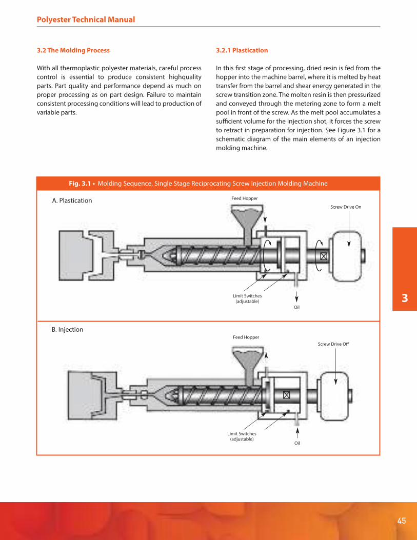
45
Polyester Technical Manual
3.2 The Molding Process
With all thermoplastic polyester materials, careful process
control is essential to produce consistent highquality
parts. Part quality and performance depend as much on
proper processing as on part design. Failure to maintain
consistent processing conditions will lead to production of
variable parts.
3.2.1 Plastication
In this first stage of processing, dried resin is fed from the
hopper into the machine barrel, where it is melted by heat
transfer from the barrel and shear energy generated in the
screw transition zone. The molten resin is then pressurized
and conveyed through the metering zone to form a melt
pool in front of the screw. As the melt pool accumulates a
sufficient volume for the injection shot, it forces the screw
to retract in preparation for injection. See Figure 3.1 for a
schematic diagram of the main elements of an injection
molding machine.
Feed Hopper
Screw Drive On
A. Plastication
Limit Switches(adjustable)
Oil
�
Feed Hopper
Screw Drive Off
B. Injection
Limit Switches(adjustable)
�
Oil
Fig. 3.1 • Molding Sequence, Single Stage Reciprocating Screw Injection Molding Machine
3

Polyester Technical Manual
46
3.2.2 Injection
Screw rotation ceases and the screw is driven forward,
seating the check ring at its forward end. This forces the
polymer melt through the sprue and runner system of the
mold to then pass through the cavity gate(s) and fill the
mold cavity. The injected material solidifies in the cooled
mold, from which it is ejected (usually by ejector pins)
when the mold opens.
3.3 Molding Equipment
As shown in Figure 3.1, a typical reciprocating screw
injection molding machine consists primarily of a barrel
with a screw inside it and a drive motor. The barrel
temperature is controlled by external heaters and the
screw may be both rotated and moved backward and
forward. A feed hopper is located on an aperture in the top
rear of the barrel. The mold, also called a tool or die, is
attached to the front end of the barrel. Ancillary equip-
ment such as mold heating/cooling apparatus is externally
connected to the machine.
3.3.1 Screw Design
A three-stage screw is commonly employed to process
resins having crystalline melting points. Figure 3.2 shows
such a screw. The first feed or conveying stage of the screw
has a uniform screw root diameter and flight depth. It
serves to move the dry resin pellets forward to the transi-
tion zone, heating the feed as it does so. In the transition
zone, the screw root diameter increases and the screw
flight depth decreases to accommodate the change from a
low bulk density feed to a higher density melt. Shear
heating and homogenization of the melt is accomplished
in this stage. The metering zone at the front end of the
screw also has a uniform flight depth, shallower than that
of the feed zone. This stage acts as a melt pump to meter
the melt into the space in front of the screw, where it is
held until the screw moves forward, forcing the molten
resin through a nozzle into the die.
For processing materials with crystalline melting points
and relatively low melt viscosities such as Celanese’s
polyester resins, the screw L/D ratio should be in the range
of 16:1 to 24:1 with a metering zone of 3 or 4 flights. The
feed zone should account for about half the screw length,
with the remaining half equally divided between transition
and metering zones. The screw compression ratio, i.e., the
ratio of flight depth in the feed zone to that in the meter-
ing zone, should be in the range of 3:1 to 4:1.
Fig. 3.3 • Recommended extruder screw
– Feed zone LE
LK
LA
tE
tA
tA
= (0.25 to 0.33) · L
– Compression zone = (0.25 to 0.33) · L
– Metering zone = (0.33 to 0.5) · L
– Flight depth ratio= 3.5 to 4
(or compression ratio)
– Flight depth = 2.5 mm
Fig. 3.2 • Injection molding conditions
Basic Reinforced Celanex 2302/
Grades Grades 2303 GV/xx
1= 240-250°C 250-260°C 250-260°C
2= 240-250°C 250-260°C 250-260°C
3= 245-255°C 255-265°C 260-270°C
4= 245-255°C 255-265°C 260-270°C
D= 250-260°C 260-270°C 265-275°C
M= 250-260°C 260-270°C 265-275°C
W1,
W2= 75-85°C 75-100°C 90-120°C
Maximum residence time in the cylinder: 5-10 min
PSp
= 600-1000 bar N
= 400-800 bar St
= 10-30 bar
Injection rate: high
Nozzle design: preferably free-flow
Predrying
Dr = 120 -140°C, 2-4 h, res. humidity < 0.02%
Predrying with dry-air drier
1,
2-
D°C Cylinder temperatures, nozzle temperature
M°C Melt temperature
W1,
W2°C Tool temperature
ns
min -1 Screw speed
PSt
bar Back pressure
PSp
bar Injection pressure
PN
bar Holding pressure
P P
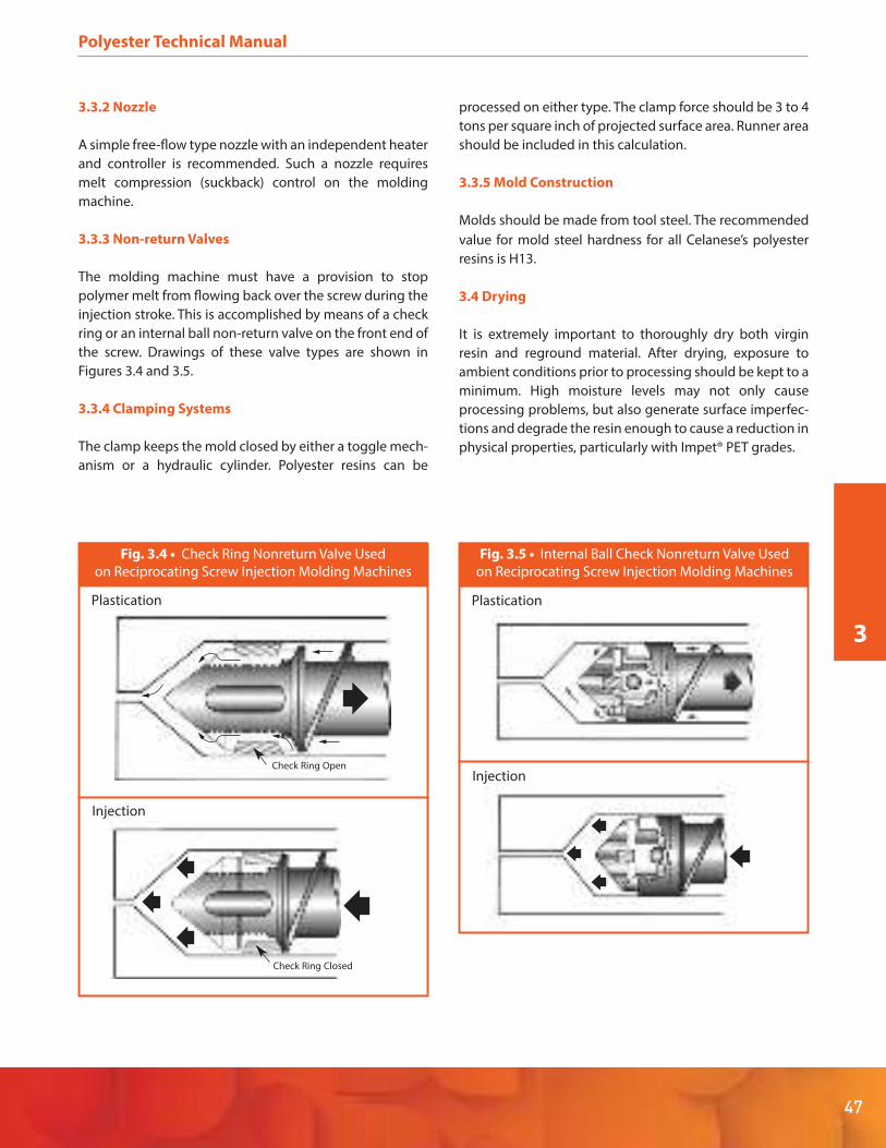
47
Polyester Technical Manual
3.3.2 Nozzle
A simple free-flow type nozzle with an independent heater
and controller is recommended. Such a nozzle requires
melt compression (suckback) control on the molding
machine.
3.3.3 Non-return Valves
The molding machine must have a provision to stop
polymer melt from flowing back over the screw during the
injection stroke. This is accomplished by means of a check
ring or an internal ball non-return valve on the front end of
the screw. Drawings of these valve types are shown in
Figures 3.4 and 3.5.
3.3.4 Clamping Systems
The clamp keeps the mold closed by either a toggle mech-
anism or a hydraulic cylinder. Polyester resins can be
processed on either type. The clamp force should be 3 to 4
tons per square inch of projected surface area. Runner area
should be included in this calculation.
3.3.5 Mold Construction
Molds should be made from tool steel. The recommended
value for mold steel hardness for all Celanese’s polyester
resins is H13.
3.4 Drying
It is extremely important to thoroughly dry both virgin
resin and reground material. After drying, exposure to
ambient conditions prior to processing should be kept to a
minimum. High moisture levels may not only cause
processing problems, but also generate surface imperfec-
tions and degrade the resin enough to cause a reduction in
physical properties, particularly with Impet® PET grades.
3
Plastication
Check Ring Open
Check Ring Closed
Injection
Plastication
Injection
Fig. 3.4 • Check Ring Nonreturn Valve Used
on Reciprocating Screw Injection Molding Machines
Fig. 3.5 • Internal Ball Check Nonreturn Valve Used
on Reciprocating Screw Injection Molding Machines

Polyester Technical Manual
48
3.4.1 Drying Equipment
Polyester resins should be properly dried in a dehumidify-
ing hopper drier, such as is shown in Figure 3.6. Drying in a
hot air oven is not recommended because:
A bed depth greater than about 1 to 1.5 inches can
result in inadequate drying
Poor heat transfer causes long drying times and possi-
ble discoloration
There is a risk of contamination from other material
being dried in the oven at the same time or by residue
from a previous job
If there is no option but to use a hot air oven, trays should
be thoroughly cleaned, as should their racking supports,
and bed depth should be kept below 1 to 1.5 inches.
Fig. 3.6 • Hopper Dryer Unit
(Reprinted with permission of Novatec™, Inc. Baltimore MD)
1. Vacuum Loader
2. Drying Hopper
3. Filter
4. Process Air Blower
5. Desiccant Cartridge
6. Dehumidified Air Reheater
7. Regeneration Blower
8. Regeneration Heater

49
Polyester Technical Manual
3.4.2 Drying Process
In hopper dryer operation, the vacuum loader drops resin
into the insulated drying hopper on demand. Heated
dehumidified air enters the hopper, picks up moisture as it
passes through the resin bed and exits via the return line
port. It is then filtered and sent through the desiccant
cartridge before going to the reheater and thence back to
the hopper. So that the dryer can operate continuously,
ambient air is taken in and pumped by the regeneration
blower through a separate heater and then fed through
the exhausted desiccant cartridge, drying it out to be
placed back on stream when needed. It is most important
to keep the return air filter clean. If it becomes clogged, air
flow through the resin bed will diminish and the resin will
not be adequately dried.
3.5 Drying Guidelines
Acceptable moisture levels for virgin or reground polyester
resins are 0.02% for Vandar® PBT alloys and Celanex® PBT,
and 0.01% for Impet® PET. To achieve these levels, drying
times and temperatures should be as shown in Table 3.1.
However, if the material is to be dried overnight, tempera-
tures can be reduced to 93ºC (200°F). For best results, the
recommended moisture levels must be achieved and
maintained while processing the polyester resins.
3.6 Injection Molding
Injection molding is a superficially simple, but operational-
ly complex process. To obtain consistent high-quality
parts, molding parameters must be carefully controlled.
While material processing guidelines provide general
molding recommendations, the molder should determine
optimum conditions for each specific part and the mold
and machine combination being used to make it.
3.6.1 Safety and Health
Before starting to mold parts from any of Celanese’s
polyester resins, obtain and review the appropriate Materi-
al Safety Data Sheet (MSDS) for that material. An MSDS for
each available grade can be found on Celanese’s web site,
www.celanese.com, or obtained by calling Celanese
Product Information Services at 1-800-833-4882.
3.6.2 Processing Conditions
The polyester product line offers an exceptionally diverse
performance range. To obtain best results from an individ-
ual grade, the material should be processed at the condi-
tions appropriate for that grade. To obtain processing
recommendations for any product, please see the relevant
data sheet on Celanese’s web site (www.celanese.com), or
call Celanese Product Information Services at
1-800-833-4882. 3Table 3.1 • Drying Guidelines for Polyester Resins
Resin Family Time, hr. Temperature, °C (°F)
Celanex PBT 4 121 (250)
Vandar PBT Alloys 3-4 107 (225)
Impet PET 4 135 (275)
Table 3.2 • Typical Injection Molding Parameters for Polyester
Polyester Product Family
Celanex PBT Vandar PBT Alloys Impet PET
Molding Parameter
Mold Temperature °C (°F)
Melt Temp °C (°F) 238-260 (460-500) 238-282 (460-540) 271-299 (520-570)
Screw Speed, rpm 60-125 60-125 50-125
Back pressure, psi 0-50 0-100 0-25
Injection Speed Fast Medium – Fast Medium – Fast
Cushion, in (mm) 0.125 (3) 0.125 (3) 0.125 (3)
Barrel Settings °C (°F)
Feed Zone 232-249 (450-480) 232-254 (450-490) 260-271 (500-520)
Center Zone 238-254 (460-490) 238-260 (460-500) 271-277 (520-530)
Front Zone 243-260 (470-500) 243-266 (470-510) 277-282 (530-540)
Nozzle 249-260 (480-500) 249-271 (480-520) 277-288 (530-550)
38-121 (100-250) 38-121 (100-250) 110-121 (230-250)

Polyester Technical Manual
50
3.6.3 Mold Temperature
Mold temperatures are generally kept to the lower end of
the range, typically 38-66°C (100-150°F) for unfilled materi-
als. Unlike many other glass-reinforced resins, Celanex PBT
can be molded to have a smooth glossy surface even in a
relatively cool mold. Higher tool temperatures are used to
obtain the ultimate in surface gloss and uniformity, to
maximize crystallinity and to minimize molding and
post-molding shrinkage. To obtain good crystallinity,
higher mold temperatures should be employed with
Impet® PET, especially when molding small parts.
3.6.4 Injection and Holding Pressure
Keep injection pressure low when starting the molding
cycle in order to produce short shots. Gradually increase
pressure by 50-100 psi until the cavity fills completely. As
complete parts are ejected from the mold, raise injection
pressure approximately 100 psi, making sure the material
does not flash. Because of their ease of flow, Celanese’s
polyester resins require only moderate injection pressures,
generally in the range of 50% to 70% of machine maxi-
mum.
3.6.5 Injection Speed
Celanex PBT resins are very fast cycling materials that set
up quickly, so a high fill speed is generally desirable. Never-
theless, in some cases slowing down the injection speed
may reduce warpage due to flow orientation of the glass
fibers in the material.
3.6.6 Screw Speed and Cushion
For glass-reinforced grades, screw speed should be kept to
the lower end of the range to minimize glass fiber break-
age and possible reduction in properties.
3.6.7 Trouble Shooting
Many processing problems are caused by easily corrected
conditions such as inadequate resin drying, incorrect
temperatures and/or pressures, etc. Often, solutions to
these problems can be found by following the trouble-
shooting recommendations in Table 3.4. Try them in the
order in which they are listed under each problem catego-
ry.
Short Shots, Poor Surface Finish
Increase injection pressure
Decrease cushion
Raise cylinder temperature
Raise mold temperature
Increases size sprue/runners/gates
Increase injection speed
Increase/decrease feed to maintain proper cushion
Check cavity vents for blockage
Increase booster time
Increase screw speed (unfilled grades only)
Increase back pressure (unfilled grades only)
Use lubricated resin
Flashing
Lower material temperature by:
Lowering cylinder temperature
Decreasing screw rotational speed
Lowering back pressure
Decrease injection pressure
Decrease overall cycle time
Check mold closure for possible obstruction on parting surface line
Check machine platens for parallelism
Check parting line of mold for wear
Table 3.4 • Trouble Shooting Guide
– Injection Molding
Molding Parameter Setting
Mold Temperature °C (°F)
Melt Temperature °C (°F)
Screw Speed, rpm 60-125
238-249 (460-480)
66-93 (150-200)
Back pressure, psi 0-25
Injection Speed Fast
Injection Pressure As needed to fill mold
Cushion, in (mm) 0.125 (3)
Barrel Settings °C (°F)
Feed Zone 238-249 (460-480)
Center Zone 242-254 (4/0-490)
Front Zone 243-254 (470-490)
062-942 elzzoN (480-500)
Table 3.3 • Injection Molding Parameters
for Celanex® PBT grades 3126, 3216 and 3316
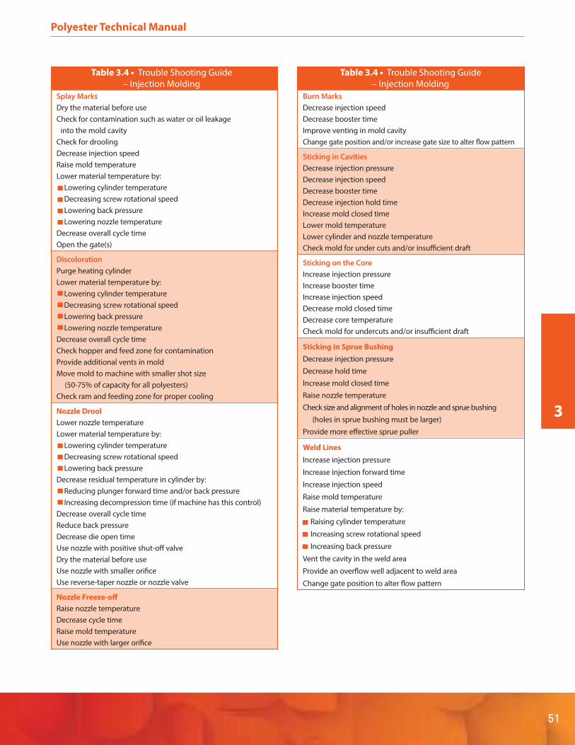
51
Polyester Technical Manual
3
Splay Marks
Dry the material before use
Check for contamination such as water or oil leakage
into the mold cavity
Check for drooling
Decrease injection speed
Raise mold temperature
Lower material temperature by:
Lowering cylinder temperature
Decreasing screw rotational speed
Lowering back pressure
Lowering nozzle temperature
Decrease overall cycle time
Open the gate(s)
Discoloration
Purge heating cylinder
Lower material temperature by:
Lowering cylinder temperature
Decreasing screw rotational speed
Lowering back pressure
Lowering nozzle temperature
Decrease overall cycle time
Check hopper and feed zone for contamination
Provide additional vents in mold
Move mold to machine with smaller shot size
(50-75% of capacity for all polyesters)
Check ram and feeding zone for proper cooling
Nozzle Drool
Lower nozzle temperature
Lower material temperature by:
Lowering cylinder temperature
Decreasing screw rotational speed
Lowering back pressure
Decrease residual temperature in cylinder by:
Reducing plunger forward time and/or back pressure
Increasing decompression time (if machine has this control)
Decrease overall cycle time
Reduce back pressure
Decrease die open time
Use nozzle with positive shut-off valve
Dry the material before use
Use nozzle with smaller orifice
Use reverse-taper nozzle or nozzle valve
Nozzle Freeze-off
Raise nozzle temperature
Decrease cycle time
Raise mold temperature
Use nozzle with larger orifice
Table 3.4 • Trouble Shooting Guide
– Injection Molding
Burn Marks
Decrease injection speed
Decrease booster time
Improve venting in mold cavity
Change gate position and/or increase gate size to alter flow pattern
Sticking in Cavities
Decrease injection pressure
Decrease injection speed
Decrease booster time
Decrease injection hold time
Increase mold closed time
Lower mold temperature
Lower cylinder and nozzle temperature
Check mold for under cuts and/or insufficient draft
Sticking on the Core
Increase injection pressure
Increase booster time
Increase injection speed
Decrease mold closed time
Decrease core temperature
Check mold for undercuts and/or insufficient draft
Sticking in Sprue Bushing
Decrease injection pressure
Decrease hold time
Increase mold closed time
Raise nozzle temperature
Check size and alignment of holes in nozzle and sprue bushing
(holes in sprue bushing must be larger)
Provide more effective sprue puller
Weld Lines
Increase injection pressure
Increase injection forward time
Increase injection speed
Raise mold temperature
Raise material temperature by:
Raising cylinder temperature
Increasing screw rotational speed
Increasing back pressure
Vent the cavity in the weld area
Provide an overflow well adjacent to weld area
Change gate position to alter flow pattern
Table 3.4 • Trouble Shooting Guide
– Injection Molding

Unmelted Pellets
Increase melt temperature
Increase back pressure
Dry/preheat the resin
Use a press with proper screw design (see “Screw Design”
above for guidelines)
Check to be sure that the nonreturn check valve is working
properly to prevent back flow
Move the mold to a press with a larger shot capacity
Sinks and Voids
Increase injection pressure
Increase injection hold time
Use booster and maximum ram speed
Raise mold temperature (for voids only)
Lower mold temperature (for sinks only)
Decrease cushion
Increase size of sprue/runners/gates
Relocate gates closer to heavy sections
Warpage, Part Distortion
Equalize temperature in both halves of the mold (eliminate hot spots)
Check mold for uniform part ejection
Check for proper handling of parts after ejection
Increase ejection hold time
Try increased pressure and decreased pressure
Increase mold closed time
Lower material temperature by:
Lowering cylinder temperature
Decreasing screw rotational speed
Lowering back pressure
Try differential mold temperatures to counteract warp
Fixture the part and cool uniformly
Check for contamination
Brittleness
Dry the material before use
Check for contamination
Lower material temperature by:
Lowering cylinder temperature
Decreasing screw rotational speed
Lowering back pressure
Reduce amount of regrind in feed
Delamination
Raise temperature of mold and/or material
Check for and eliminate any contamination
Dry the material before use
Increase injection speed
Poor Dimensional Control
Set uniform cycle times
Maintain uniform feed and cushion from cycle-to-cycle
Fill the mold as rapidly as possible
Check machine’s hydraulic and electrical systems
for erratic performance
Increase gate size
Add vents
Polyester Technical Manual
52
Table 3.4 • Trouble Shooting Guide
– Injection Molding
Table 3.4 • Trouble Shooting Guide
– Injection Molding

53
Polyester Technical Manual
3
3.7 Extrusion
Like injection molding, the extrusion process involves
using a screw and barrel assembly to melting polymer. The
melt is then continuously pumped through a die to form
an extrudate of consistent cross-section such as film, sheet
or tubing. When extruding an unfamiliar grade or if prob-
lems arise during processing that cannot be corrected
using the trouble shooting guide following below, contact
your local Celanese representative or call Celanese Product
Information Services at 1-800-833-4882.
3.7.1 Safety and Health Information
Before starting the extrusion process, obtain and read the
appropriate polyester Material Safety Data Sheet (MSDS)
for detailed safety and health information. They may be
found on Celanese’s web site, www.celanese.com, or by
calling Celanese Product Information Services at
1-800-833-4882. Use process controls, work practices and
protective measures described in the MSDS to control
workplace exposure to dust, volatiles or vapors.
3.7.2 Equipment Construction
For maximum resistance to abrasion and corrosion,
extruder screws, breaker plates, screens, adapters and dies
should all be made of corrosion-resistant metals.
3.7.3 Extruder Barrel
Standard extruders, having barrel length-to-diameter
ratios equal to or greater than 30:1, are recommended for
processing polyester resins. These higher L/D ratios
provide a more homogenous melt and a higher through-
put for a given extruder size.
3.7.4 Screw Design
Screw designs for polyester extrusion should have a
compression ratio between 3:1 and 4:1 (the ratio between
the feed zone channel depth and the metering zone chan-
nel depth). As shown in Fig. 3.7, the feed zone screw chan-
nel should be approximately 0.4 inch deep, while the
metering zone screw channel should gradually reduce to
approximately 0.1 inch, with the overall length-to-diame-
ter ratio being 30: 1 or greater. Feed zone length should
comprise one-third of the total screw length. A long and
gradual transition section of a further third of the screw
length is also recommended, since sharp or short transi-
tion sections can cause high barrel pressures and higher
melt temperatures due to high shear (especially at higher
screw speeds).
Length of the metering zone and the screw depth are
important to maintain optimum control of melt tempera-
ture and output consistency. Too long or too shallow a
metering zone increases the melt temperature due to
shear, while short and deep metering zones can result in
pressure fluctuations (surging) and nonuniform output. A
typical “polyethylene type” screw design meets the
requirements for extrusion processing of polyesters, as do
screws designed for nylon 6,6, provided that the transition
zone is of sufficient length.
3.7.5 Breaker Plate and Screens
Screens (usually 80-100 mesh) are recommended for
unfilled polyesters. Screens are used to protect the die
from being damaged by foreign matter and to increase
backpressure, especially when mixing fillers or pigments. A
breaker plate, usually incorporated at the end of the screw,
is used to support the screens.
3.7.6 Dies
Dies must be streamlined, having no areas where material
can be trapped or hung up. Thermoplastic materials
exposed to high temperatures for prolonged periods
degrade and not only contaminate subsequent extruded
product with black or brown specks, but also affect
uniform machine operation.
MeteringSection
TransitionSection
FeedSection
Screw depth0.100 inch
Screw depth0.400 inch
Fig. 3.7 • Typical Screw Design
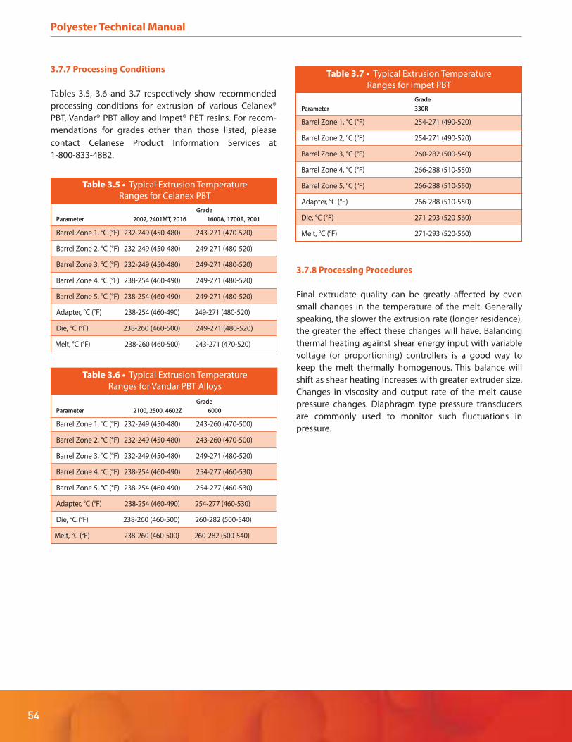
Polyester Technical Manual
54
3.7.7 Processing Conditions
Tables 3.5, 3.6 and 3.7 respectively show recommended
processing conditions for extrusion of various Celanex®
PBT, Vandar® PBT alloy and Impet® PET resins. For recom-
mendations for grades other than those listed, please
contact Celanese Product Information Services at
1-800-833-4882.
3.7.8 Processing Procedures
Final extrudate quality can be greatly affected by even
small changes in the temperature of the melt. Generally
speaking, the slower the extrusion rate (longer residence),
the greater the effect these changes will have. Balancing
thermal heating against shear energy input with variable
voltage (or proportioning) controllers is a good way to
keep the melt thermally homogenous. This balance will
shift as shear heating increases with greater extruder size.
Changes in viscosity and output rate of the melt cause
pressure changes. Diaphragm type pressure transducers
are commonly used to monitor such fluctuations in
pressure.
Grade
Parameter 330R
Barrel Zone 1, °C (°F) 254-271 (490-520)
Barrel Zone 2, °C (°F) 254-271 (490-520)
Barrel Zone 3, °C (°F) 260-282 (500-540)
Barrel Zone 4, °C (°F) 266-288 (510-550)
Barrel Zone 5, °C (°F) 266-288 (510-550)
Adapter, °C (°F) 266-288 (510-550)
Die, °C (°F) 271-293 (520-560)
Melt, °C (°F) 271-293 (520-560)
Table 3.7 • Typical Extrusion Temperature
Ranges for Impet PBT
Grade
Parameter 2002, 2401MT, 2016 1600A, 1700A, 2001
Barrel Zone 1, °C (°F) 232-249 (450-480) 243-271 (470-520)
Barrel Zone 2, °C (°F) 232-249 (450-480) 249-271 (480-520)
Barrel Zone 3, °C (°F) 232-249 (450-480) 249-271 (480-520)
Barrel Zone 4, °C (°F) 238-254 (460-490) 249-271 (480-520)
Barrel Zone 5, °C (°F) 238-254 (460-490) 249-271 (480-520)
Adapter, °C (°F) 238-254 (460-490) 249-271 (480-520)
Die, °C (°F) 238-260 (460-500) 249-271 (480-520)
Melt, °C (°F) 238-260 (460-500) 243-271 (470-520)
Table 3.5 • Typical Extrusion Temperature
Ranges for Celanex PBT
Grade
Parameter 2100, 2500, 4602Z 6000
Barrel Zone 1, °C (°F) 232-249 (450-480) 243-260 (470-500)
Barrel Zone 2, °C (°F) 232-249 (450-480) 243-260 (470-500)
Barrel Zone 3, °C (°F) 232-249 (450-480) 249-271 (480-520)
Barrel Zone 4, °C (°F) 238-254 (460-490) 254-277 (460-530)
Barrel Zone 5, °C (°F) 238-254 (460-490) 254-277 (460-530)
Adapter, °C (°F) 238-254 (460-490) 254-277 (460-530)
Die, °C (°F) 238-260 (460-500) 260-282 (500-540)
Melt, °C (°F) 238-260 (460-500) 260-282 (500-540)
Table 3.6 • Typical Extrusion Temperature
Ranges for Vandar PBT Alloys
55
Polyester Technical Manual
3
3.7.9 Startup
When starting up an empty machine, set the temperature
controllers for the die, adapter and barrel using the appro-
priate temperatures shown in Table 3.3. When these reach
their operating temperatures, bring the remaining barrel
temperatures up to the proper settings. After tempera-
tures have been stable for 20 to 30 minutes, begin screw
rotation at low RPM and start feeding resin into the
hopper. Carefully check both the ammeter and pressure
gauges. As melt appears at the die, it may be hazy initially
as air is cleared from the system. Die temperature and head
pressure should start to stabilize as melt flow smooths out.
3.7.10 Purging and Shutdown
A machine should never be shut down while polyester
remains in it. As recommended in section 3.1.4, medi-
um-to-high density polyethylene should be used to purge
the extruder. Temperature controllers should remain set at
running conditions. Purge all of the polyester from the
extruder. Continue running until all purge material is out of
the machine and then shut down.
3.7.11 Wire Coating
In wire coating, an extruded tube of polyester forms a cone
at the die, into which the wire passes. The wire is complete-
ly coated as it passes through the crosshead.
As shown in Figure 3.8, the drawdown ratio is the ratio
between the cross-sectional area of the tube wall at the die
face to the cross-sectional area of the finished coating.
Draw down ratio for polyester polymers should be
between 6:1 and 10:1.
Since streamline design is critical to avoid degradation, the
die face must have no areas where material can hang up.
Cone length (the distance between the die face and the
point where the polymer coats the wire) is very important.
It is generally between 1.5 and 2 inches (37 and 50 cm),
and is best defined precisely by trial and error, as too long
a cone may sag and set before drawing is complete, while
too short a cone can lead to pinholes and tearing.
Cooling Trough
The coated wire is air cooled to shrink the coating onto the
wire and then passes into a water-cooling bath to harden
the coating. Air cooling and cone length should be
balanced to obtain the best adhesion to the wire and
ensure integrity of the coating. Water temperature in the
cooling trough is critical. If the water is too cold (below
about 16°C (60°F) for Celanex® PBT and most Vandar® PBT
alloy grades), the coating can be frozen into an amorphous
state. The amorphous material can later crystallize, possi-
bly causing the wire to take a set on a spool or winding
reel. A water temperature between about 40°C and 60°C
(100 -130°F) avoids post-crystallization and eliminates or
minimizes spoolset, giving better mechanical properties to
the wire.
A
Cone
Wire
Cross Head
A
aDraw-down ratio =
a
Fig. 3.8 • Polyester in Wire Coating

Polyester Technical Manual
56
3.7.12 Tube Extrusion
Polyester resins can be readily extruded into tubing up to
3/8" (9.5 mm) diameter without requiring special equip-
ment. Melt temperature control is important. If the
temperature is too high, low melt strength can cause
irregular wall thickness, while if it is too low, poor tube
finish, uneven dimensions and weld lines can result. Use
the temperatures given in Tables 3.5 through 3.7 as
starting points. Dies like those used in wire coating are
employed in free extrusion of tubing, with a general set-up
as shown in Figure 3.9. Inside the water trough, the extrud-
ed tube of resin is pulled through one or more sizing rings
to control the outer diameter.
Vacuum Tank
For tubing of diameter greater than 0.5" (12.7 mm), a
vacuum sizing tank is generally employed. The vacuum in
the water-cooling trough causes the tube to expand to the
sizing die set to control the outside diameter of the tube.
As with all tube extrusion, control of melt and vacuum tank
temperatures is important because the semi-crystalline
nature of polyester polymers gives them a relatively
narrow range between melting and freezing.
Take-up Reel Unit
Haul-off Unit
Water Trough
Sizing Dies
Die
Low-pressure
Air Supply
Fig. 3.9 • Polyester in Tube Extrusion

57
Polyester Technical Manual
3
3.7.13 Sheet Extrusion
As shown in Figure 3.10, polyester sheet may be extruded
with standard equipment, typically including an extruder,
sheet die, polishing rolls, pull rolls, edge trim knives and
winder. A flex lip coat-hanger die is best suited for sheet
extrusion, as it does not have the stagnant areas found in
“T” dies. As with other melt processing equipment for
polyesters, such stagnant areas can cause melt hang-up
and material degradation. The die flex lip is adjusted to
provide uniform melt flow across the face of the die. Good
temperature control across the die face is also necessary.
The air gap should be as small as possible and the melt
bank (between the nip rolls) should also be as small as
possible. Too large a melt bank causes stress in the sheet-
ing while too small a bank results in non-uniform sheet
thickness.
Polishing Rolls
These rolls are used to improve the surface finish of the
sheet. Normal temperature settings for a three-roll stack
are 38-77°C (100-170°F) for the top roll, 38-71°C
(100-160°F) for the middle roll and 36-71°C (100- 160°F) for
the bottom roll. Bear in mind that internal cleanliness is a
key factor in roll heat transfer.
Edge-Trim or Slitting
Tension Rolls
Take-up Unit
Pull Rolls
Die
PolishingRoll Stand
MeltBank
Die
Fig. 3.10 • Polyester Sheet Extrusion
Polyester Technical Manual
58
3.7.14 Extrusion Trouble Shooting
As with injection molding, many extrusion processing
problems are caused by easily corrected conditions such
as inadequate resin drying, incorrect temperature and/or
pressures and so on. Often solutions to these problems can
be found by following the generalized recommendations
in Table 3.8. Try them in the order in which they are listed
under each problem type, having regard for both the
specific process and the material being processed. For
example, glass-reinforced Impet® PET grades are not used
in wire coating, so cone length and other wire coating
recommendations would be inapplicable to them.
3.7.15 Monofilament
Unfilled Celanex® PBT resins can be used to prepare mono-
filaments with a range of properties. The final monofila-
ment properties depend greatly on drawing equipment
and conditions. While initial extruder conditions should be
as recommended in Table 3.5, subsequent adjustments
should be made to optimize drawing and other monofila-
ment processing steps to suit the equipment and process
of the monofilament manufacturer.
Table 3.8 • Trouble Shooting Guide – Extrusion
Problem Typical Cause Corrective Action
Blistering Moisture in feedstock Dry feed to proper moisture
level before use
Cooling too quickly Slow down the
cooling rate
Bubbles Trapped air Use correct screw
For Vandar® PBT alloys,
increase back pressure
Check controllers for
proper functioning
Resin degraded by Lower temperatures
heat or hold-up time Increase extrusion rate
Use correct screw
Check for hang-ups in
barrel and die
Check heaters, thermo-
couples and controllers
Resin moisture too high Dry feed to proper level
before use
Breaks, Excessive draw-down Reduce draw-down ratio
tears, Short cone, Lengthen cone, reduce pinholes draw too fast draw rate
Material too cold Raise melt or die
temperature
Poor blend of Blend more thoroughly
pigments or fillers before use
Use correct screw
Reduce filler or
pigment loading
Coatings Cooling too fast Lengthen air gap
don’t stick Reduce extrusion rate
Resin degraded See “Bubbles” above
Cone too long Shorten cone
Table 3.8 • Trouble Shooting Guide – Extrusion
Problem Typical Cause Corrective Action
Contaminated Poor handling of feed Protect resin, keep clean
extrudate Dirty extruder Remove all resin, clean
machine thoroughly
Extruder corrosion Use corrosion-resistant
metals for melt contact
Dirty regrind Clean extruder
Use clean regrind,
dried to proper level
Diameter Take-off speed Check tension control
fluctuates variation Increase pressure on
tractor heads
Surging Increase screw speed
Increase back pressure
with screen pack
Temperature cycling Use variable transformers
with time proportioning
controllers. Make sure
controllers are mostly “ON”
Draw rate too low Reduce cone length
Excessive tension Shorten sizing die length
on tubing sizing (eliminate a plate or two)
plates or die Use water or water and soap
to lubricate sizing die
Uneven feed to extruder Lower rear barrel
– Non-uniform temperature
extrusion rate and Cool hopper throathead pressure
Moisture in feed Dry material to proper level
before use

59
Polyester Technical Manual
3
Table 3.8 • Troubleshooting Guide – Extrusion
Problem Typical Cause Corrective Action
Out of round Misshapen die Replace die
(deformed or Correct guider tip
nonconcentric) Varying cooling rate Adjust water
submersion depth
Center the die
Coating sags and sets Lower melt temperature
Increase drawdown rate
(increase extruder speed,
increase drawdown ratio,
or shorten cone length)
Cool faster (reduce air
gap or increase output)
Excessive take-up Put slack in wire line
pressure Reduce capstan tension
Lengthen cooling so
extrudate sets before
take-up
Die off-center Center die
Guider tip too flexible Remove all resin(s)
and clean
Extruder corrosion Use corrosion-resistant
metals for melt contact
Dirty regrind Clean extruder
Use clean regrind, dried to
proper level
Out of round Hang-up on die face Remove imperfections
(buckling or guider tip
or folding) Melt tension varies Make hole in guider tip
smaller or center the die
Draw rate too fast Lengthen cone
(reduce vacuum)
Draw-down ratio Reduce draw-down ratio
too high
Ratio of die size to Increase draw ratio
coated wire size is too
low in comparison with
ratio of guider tip size
to wire size
Extruder Feed section flights Use screw with
overloaded too deep shallower feed
Use lubricant
Rear temperature Increase rear temperature
too low Check rear zone
thermocouple and controller
Pellets wedge between Increase rear temperature
flight land and barrel
Table 3.8 • Troubleshooting Guide – Extrusion
Problem Typical Cause Corrective Action
Shrink-back Wire stretching Reduce tension on wire
Too much orientation Preheat the wire
during drawdown Increase draw rate
(shorter cone)
Reduce draw-down ratio
Enlarge air gap or reduce
quench rate
Increase die and melt
temperatures
Rough Finish Contamination See “Contaminated
Extrudate”
Dirty/poorly Inspect die and tip.
finished die Remove burrs
Melt fracture caused Increase die temperature
by excessive shear Widen die opening
Reduce extrusion rate
Increase melt temperature
Wrong draw rate Adjust cone length
Material on die face Clean die face
Wire vibrating Use damping pads
or guides
Surging Slipping drive belts Secure belts
Inadequate melt Change screw
reservoir Reduce screw speed
Check for temperature
cycling
Decrease die opening
Increase back pressure
Bridging in Check feed zone controller
feed section Reduce rear temperature
Increase cooling water to
feed throat
Bridging in Switch to screw with longer
transition zone feed section
Increase temperature in
rear zone
Unmelted Barrel temperature Increase temperature
material in too low settings
extrudate Compression ratio Increase back pressure
of screw too low Change screw
Heater watt density Increase wattage
too low Change heater bands
Cold spots in More heat to area from
extruder sections barrel extension to die neck
Check thermocouples and
controllers for accuracy
Insulate exposed areas to
cut heat loss
Sheet sticking Roll too hot Reduce roll temperature
to roll Material too hot Reduce material
temperature
Check controller heaters
and thermocouples

Polyester Technical Manual
60
3.7.16 Meltblown Media
High-performance meltblown media can be prepared
from Celanex® PBT polymers. Such media are more
thermally stable and exhibit significantly lower shrinkage
than those made from PET. By selecting the appropriate
grade of Celanex PBT and adjusting process conditions, a
processor can obtain a wide range of fiber diameters.
Initial extruder conditions as recommended in Table 3.5
may be used to start the process.
To achieve best web integrity and minimize fly generation,
subsequent adjustments should be made to optimize
extrusion, blowing and other processing steps to suit the
equipment and process of the manufacturer. Celanese
offers special grades of Celanex PBT with less fly genera-
tion. For further information on these grades and specific
recommended process conditions for meltblowing appli-
cations, please call Celanese Product Information Services
at 1-800-833-4882.
3.7.17 Spunbond Webs
Celanex PBT polymer and copolymer grades can be used
for making monocomponent and bicomponent spunbond
webs with a desirable range of properties. The final web
properties depend greatly on the
spinning, take-off and laydown conditions of the spun-
bond machine. As with all extrusion-based processes,
initial extruder conditions should be as recommended in
Table 3.5, with subsequent adjustment optimized to suit
the spinning and other spunbond process steps. For
further information and specific recommended process
conditions for spunbond applications, please call Celanese
Product Information Services at 1-800-833-4882.
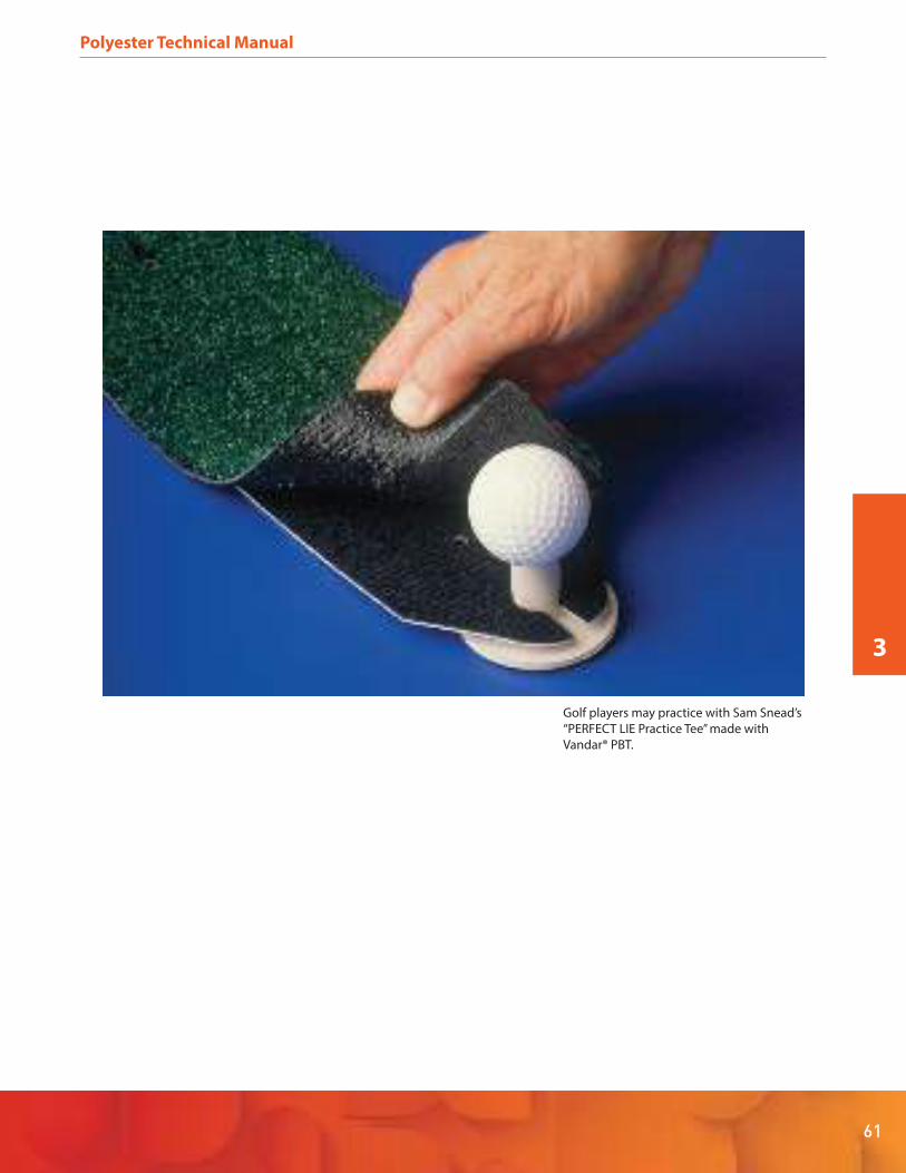
61
Polyester Technical Manual
3
Golf players may practice with Sam Snead’s
“PERFECT LIE Practice Tee” made with
Vandar® PBT.
Polyester Technical Manual
62
4. Part and Mold Design
4.1 Introduction
There is a complex interplay between material selection,
part design and mold design. The right choice of material
is driven by a focus on those intrinsic properties that are
needed for satisfactory performance of the final part as a
system component. As polyester resins are stiff semi-crys-
talline materials, care needs to be taken with such areas as
corner radii and undercut tolerances. While the greater
flexibility of Vandar® PBT alloys may allow somewhat less
stringent requirements, typical plastics design principles
for rigid plastics should still be followed with these resins.
A first step in any design is to establish performance
criteria for the final part and whatever system of which it
may be a component. Factors to be considered include, for
example:
Functional requirements of part and system
Ability to simplify design or eliminate parts by using
moldable plastics
Environmental stresses to be withstood – chemical,
thermal, radiation
Time-dependent criteria – fatigue, creep and compres-
sion set
Aesthetic requirements – color, surface finish, possible
decoration
Regulatory constraints to be met
Any post-molding processing or assembly steps
Projected cost of part and system
Each of these factors can be expanded in such detail as
best fits the application and a design then drawn. It is
always preferable to go from the first design to making a
prototype part by machining or prototype molding in an
inexpensive mold cut from aluminum or a suitable alloy.
Molding is preferable to machining in that it not only
avoids machining marks, but also enables gate location to
be investigated. Parts from this step can then be tested in
situations as close to the intended use as possible and
specifications developed from the results.
4.1.1 Material Selection
Once it is determined that part performance requirements
will be met by a polyester resin or alloy, a specific grade can
be selected. The broad property range available from
Celanese polyester product line enables the best balance
of properties for the application to be readily achieved.
4.1.2 Wall Thickness
Wall thickness, particularly in semi-crystalline resins,
should be kept to the minimum required for satisfactory
part performance. Apart from higher material cost and
processing time and cost, thick walls can introduce prob-
lems such as internal voids and external sink marks. While
thick-walled parts up to 0.5 in (12.7 mm) can of course be
molded from polyesters with appropriate sprue, runner
and gate design, such sections should be cored to reduce
the effective thickness as much as possible to be consis-
tent with retaining adequate properties. For small and
medium-sized parts, a practical wall thickness can be as
low as 0.03 in (0.7 mm), but for larger parts, wall thickness-
es of 0.06 in (1.5 mm) or greater are recommended.
In addition to being as thin as possible, the wall thickness
should also be uniform. Thick and thin sections in the same
part can result in slight differences in density in different
sections. This, combined with differences in cooling rate
between thick and thin areas, can cause voids, sinks and
warpage. If for some reason the thicker sections cannot be
cored out, a gradual transition should be made from thick
to thin walls.

63
Polyester Technical Manual
4
4.1.3 Ribs
Ribbing is frequently used to reduce part wall thickness,
weight and cost. It is also used to increase part strength
and stiffness, improve flow paths and prevent warpage.
However, ribs can cause sink marks and induce warpage if
not well designed and properly located in the part.
Ribbing should therefore be employed only when the
benefit is reasonably certain.
Where ribs are required, the thickness should not exceed
50% of the adjacent wall thickness to prevent voids, sink
marks or other distortions. To further minimize sink marks,
the rib contour should match the exterior contour of the
part, and rib height should be no more than 0.75 in (19
mm). Where sink marks are not a concern, rib thickness
may be 75% to 100% of the adjacent wall thickness, and
they may be located in areas where extra strength is
desired. However, ribs of this thickness can change the
final shape and/or dimensions of the part due to shrinkage
in the rib. Fillets should be used where ribs join the part
wall to minimize stress concentration and provide
additional strength. To facilitate part ejection from the
tool, adequate draft should be provided on both sides of
the rib.
4.1.4 Bosses and Studs
Bosses and studs are frequently used to reinforce around
holes or to provide mounting or fastening points. Guide-
lines to be considered when designing a boss or stud
include the following:
The height should not b e more than twice the diame-
ter.
Adequate draft is needed for easy part ejection.
Where the boss joins the wall filleting eases fill,
strengthens the part and helps disguise sink.
For a solid boss, the diameter should be less than the
thickness of the wall from which it protrudes. For this
reason, bosses should be cored out so the boss
sidewall thickness is less than the main wall thickness.
Core pin ends should be radiused to eliminate sharp
corners and minimize sink tendency.
Bosses and studs are best located where the surface
contour changes sharply. A bubbler on the cavity side
of the mold opposite the boss will often eliminate or
minimize sink in the outside wall.
For longer bosses and studs, venting should be provid-
ed to release air at the bottom of the cavity.
For autobody components, the length of the mounting
boss(es) should not provide more than .125 in (3.2 mm)
clearance between the end of the boss and the mount-
ing bracket or auto frame. This will avoid “dimpling” of
the part by the boss being pulled inward.
Mounting bosses adjacent to a side wall should be
cored out to avoid unnecessarily thick sections.
Ribs can be used to reinforce free-standing bosses and
facilitate material flow into the boss.
Ejector sleeves should be employed to prevent boss
hang up in the mold cavity. To effectively prevent
hang-up the stroke of the ejector sleeve should be at
least three-quarters of the length of the boss.
4.1.5 Fillets and Radii
Sharp corners should always be avoided in molded plastic
parts, even in the more ductile Vandar® PBT alloy materials.
Such sharp corners cause poor flow patterns and can lead
to high molded-in stresses and consequent reduction of
mechanical properties. Radiusing and filleting are recom-
mended for all corners to facilitate resin flow in the part,
minimize stress concentration and enable easier part
ejection. Inside and outside corners should be rounded
with a radius of 25% to 75% of the adjacent wall thickness.
4.1.6 Tolerances
Because there may be variability in either the material or
the molding process, or because of changes in the operat-
ing environment, injection molded thermoplastic parts are
subject to dimensional variations greater than those found
with machined metal parts. To avoid excessive molding
and processing costs without sacrificing product perfor-
mance, part designers should determine whether very
tight tolerances are really necessary and if they can be
economically justified. In particular, since tempera-
ture-driven dimensional changes can be many times
greater than specified tolerances, it may be unreasonable
to specify close tolerances on a part that will be exposed to
a wide
temperature range. In general, dimensional tolerances
that can routinely be held with Celanex® PBT and Impet®
PET thermoplastic polyester resins are:
± 0.002 in/in (mm/mm) on the first inch (25 mm)
± 0.001 in/in (mm/mm) on each subsequent inch (25
mm)

Polyester Technical Manual
64
Similar dimensional tolerances may be held with certain
Vandar® PBT alloy resins. However, because different
Vandar PBT alloy grades may have substantially different
compositions, please consult Celanese Product Informa-
tion Services at 1-800-833-4882 for gradespecific tolerance
recommendations.
4.1.7 Threads
Standard thread systems such as Unified or Acme can be
used in designing threads for Celanese’s polyester resins.
Because plastics have lower shear strength than metals,
less torque is required to strip a plastic thread in any given
design. On the other hand, most metal threads are greatly
over-designed and the exceptionally high stripping
torques thus obtained will far exceed actual performance
requirements. Accordingly, with proper thread design,
polyester resin components can be designed with high
stripping torques which are high enough for many
demanding applications.
Internal or external threads can be molded in all polyester
resins, but it may be difficult to machine threads in softer
Vandar PBT alloy grades because of material “squirm.”
Threads may be machined with standard metalworking
tools in Celanex® PBT, Impet® PET and higher modulus
grades of Vandar PBT alloy. This approach is generally
recommended for threads below 6.4 mm (0.25 in) in diam-
eter. To prevent chipping during tapping, cored holes for
post-molding machine-tapping should be provided with a
chamfer starting from a shallow counterbore as shown in
Figure 4.1. Larger internal threads may be formed by a
threaded core pin that is unscrewed either manually or
automatically. External threads can be formed in the mold
by splitting the thread along its axis or by unscrewing the
part from the mold. The latter method must be used in
cases where a parting line or mold flashing are unaccept-
able.
Standard thread systems can be used, but coarse threads
are preferable to fine. Threads finer than 28 pitch or closer
than Class 2 should not be specified. Roots and crests of all
threads should be rounded to reduce stress concentration
and provide increased strength. A rounding radius of
0.005-0.10 in (0.1-0.3 mm) is recommended. The bearing
area for the screw head should be chamfered to match the
screw profile.
4.1.8 Holes
Through or blind holes may be readily produced in any
shape. However, through holes are easier to produce
because the core pin can be supported at both ends. As a
core pin supported at only one end can be deflected by
forces exerted in molding, the depth of a blind hole should
be limited to about twice its diameter.
4.1.9 Draft
Plastic parts must generally be designed with some degree
of taper in the direction of mold movement to facilitate
ejection from the tool. This taper is called draft in the line
of draw. The deeper the draw, i.e., the greater the depth of
the cavity, the more draft will be required. Although parts
with zero draft have been successfully molded, a draft
angle of at least .5° per side is recommended for Celanex
PBT, Impet PET and higher modulus grades of Vandar PBT
alloy, and a draft of 1° is suggested for best results. For the
softer grades of Vandar PBT alloy, a draft angle of as much
as 2° per side may be needed.
4.1.10 Surface Finish
Because Celanese’s polyester resins flow well and possess a
substantial degree of crystallinity, they can provide excel-
lent replication of surface features, enabling a wide variety
of surface finishes to be achieved. The corollary to this is
that if a high gloss is required, mold surfaces must be
highly polished.
Fig. 4.1 • Chamfered Hole for Machine Tapping
0.016”
Recommended
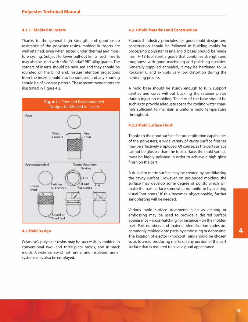
65
Polyester Technical Manual
4
4.1.11 Molded-in Inserts
Thanks to the general high strength and good creep
resistance of the polyester resins, molded-in inserts are
well retained, even when tested under thermal and mois-
ture cycling. Subject to lower pull-out limits, such inserts
may also be used with softer Vandar® PBT alloy grades. The
corners of inserts should be radiused and they should be
rounded on the blind end. Torque retention projections
from the insert should also be radiused and any knurling
should be of a coarse pattern. These recommendations are
illustrated in Figure 4.2.
4.2 Mold Design
Celanese’s polyester resins may be successfully molded in
conventional two- and three-plate molds, and in stack
molds. A wide variety of hot runner and insulated runner
systems may also be employed.
4.2.1 Mold Materials and Construction
Standard industry principles for good mold design and
construction should be followed in building molds for
processing polyester resins. Mold bases should be made
from H-13 tool steel, a grade that combines strength and
toughness with good machining and polishing qualities.
Generally supplied annealed, it may be hardened to 54
Rockwell C and exhibits very low distortion during the
hardening process.
A mold base should be sturdy enough to fully support
cavities and cores without buckling the retainer plates
during injection molding. The size of the base should be
such as to provide adequate space for cooling water chan-
nels sufficient to maintain a uniform mold temperature
throughout.
4.2.2 Mold Surface Finish
Thanks to the good surface feature replication capabilities
of the polyesters, a wide variety of cavity surface finishes
may be effectively employed. Of course, as the part surface
cannot be glossier than the tool surface, the mold surface
must be highly polished in order to achieve a high gloss
finish on the part.
A dulled or matte surface may be created by sandblasting
the cavity surface. However, on prolonged molding, the
surface may develop some degree of polish, which will
make the part surface somewhat nonuniform by creating
visual “hot spots.” If this becomes objectionable, further
sandblasting will be needed.
Various mold surface treatments such as etching or
embossing may be used to provide a desired surface
appearance – cross-hatching, for instance – on the molded
part. Part numbers and material identification codes are
commonly molded onto parts by embossing or debossing.
The location of ejector (knockout) pins should be chosen
so as to avoid producing marks on any portion of the part
surface that is required to have a good appearance.
Fig. 4.2 • Poor and Recommended
Designs for Molded-In Inserts
SharpCorners
FineKnurl
Torque RetentionDevices
Flat
Flute
Pull-OutResistanceCoarse
Knurl
Round onBlind End
Radii onAll Corners
Poor
Recommended
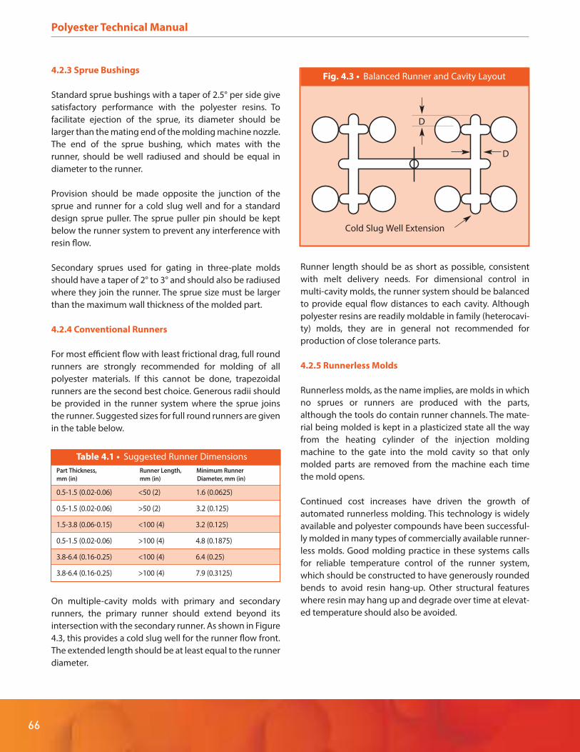
Polyester Technical Manual
66
4.2.3 Sprue Bushings
Standard sprue bushings with a taper of 2.5° per side give
satisfactory performance with the polyester resins. To
facilitate ejection of the sprue, its diameter should be
larger than the mating end of the molding machine nozzle.
The end of the sprue bushing, which mates with the
runner, should be well radiused and should be equal in
diameter to the runner.
Provision should be made opposite the junction of the
sprue and runner for a cold slug well and for a standard
design sprue puller. The sprue puller pin should be kept
below the runner system to prevent any interference with
resin flow.
Secondary sprues used for gating in three-plate molds
should have a taper of 2° to 3° and should also be radiused
where they join the runner. The sprue size must be larger
than the maximum wall thickness of the molded part.
4.2.4 Conventional Runners
For most efficient flow with least frictional drag, full round
runners are strongly recommended for molding of all
polyester materials. If this cannot be done, trapezoidal
runners are the second best choice. Generous radii should
be provided in the runner system where the sprue joins
the runner. Suggested sizes for full round runners are given
in the table below.
On multiple-cavity molds with primary and secondary
runners, the primary runner should extend beyond its
intersection with the secondary runner. As shown in Figure
4.3, this provides a cold slug well for the runner flow front.
The extended length should be at least equal to the runner
diameter.
Runner length should be as short as possible, consistent
with melt delivery needs. For dimensional control in
multi-cavity molds, the runner system should be balanced
to provide equal flow distances to each cavity. Although
polyester resins are readily moldable in family (heterocavi-
ty) molds, they are in general not recommended for
production of close tolerance parts.
4.2.5 Runnerless Molds
Runnerless molds, as the name implies, are molds in which
no sprues or runners are produced with the parts,
although the tools do contain runner channels. The mate-
rial being molded is kept in a plasticized state all the way
from the heating cylinder of the injection molding
machine to the gate into the mold cavity so that only
molded parts are removed from the machine each time
the mold opens.
Continued cost increases have driven the growth of
automated runnerless molding. This technology is widely
available and polyester compounds have been successful-
ly molded in many types of commercially available runner-
less molds. Good molding practice in these systems calls
for reliable temperature control of the runner system,
which should be constructed to have generously rounded
bends to avoid resin hang-up. Other structural features
where resin may hang up and degrade over time at elevat-
ed temperature should also be avoided.
Table 4.1 • Suggested Runner Dimensions
Part Thickness, Runner Length, Minimum Runner
mm (in) mm (in) Diameter, mm (in)
0.5-1.5 (0.02-0.06) <50 (2) 1.6 (0.0625)
0.5-1.5 (0.02-0.06) >50 (2) 3.2 (0.125)
1.5-3.8 (0.06-0.15) <100 (4) 3.2 (0.125)
0.5-1.5 (0.02-0.06) >100 (4) 4.8 (0.1875)
3.8-6.4 (0.16-0.25) <100 (4) 6.4 (0.25)
3.8-6.4 (0.16-0.25) >100 (4) 7.9 (0.3125)
Fig. 4.3 • Balanced Runner and Cavity Layout
Cold Slug Well Extension
D
D
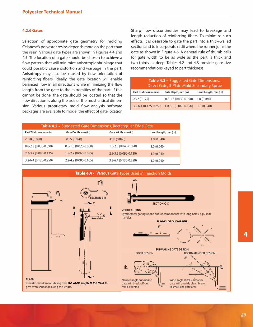
67
Polyester Technical Manual
4
4.2.6 Gates
Selection of appropriate gate geometry for molding
Celanese’s polyester resins depends more on the part than
the resin. Various gate types are shown in Figures 4.4 and
4.5. The location of a gate should be chosen to achieve a
flow pattern that will minimize anisotropic shrinkage that
could possibly cause distortion and warpage in the part.
Anisotropy may also be caused by flow orientation of
reinforcing fibers. Ideally, the gate location will enable
balanced flow in all directions while minimizing the flow
length from the gate to the extremities of the part. If this
cannot be done, the gate should be located so that the
flow direction is along the axis of the most critical dimen-
sion. Various proprietary mold flow analysis software
packages are available to model the effect of gate location.
Sharp flow discontinuities may lead to breakage and
length reduction of reinforcing fibers. To minimize such
effects, it is desirable to gate the part into a thick-walled
section and to incorporate radii where the runner joins the
gate as shown in Figure 4.6. A general rule of thumb calls
for gate width to be as wide as the part is thick and
two-thirds as deep. Tables 4.2 and 4.3 provide gate size
recommendations keyed to part thickness.
Table 4.3 • Suggested Gate Dimensions,
Direct Gate, 3-Plate Mold Secondary Sprue
Part Thickness, mm (in) Gate Depth, mm (in) Land Length, mm (in)
<3.2 (0.125) 0.8-1.3 (0.030-0.050) 1.0 (0.040)
3.2-6.4 (0.125-0.250) 1.0-3.1 (0.040-0.120) 1.0 (0.040)
Table 4.2 • Suggested Gate Dimensions, Rectangular Edge Gate
Part Thickness, mm (in) Gate Depth, mm (in) Gate Width, mm (in) Land Length, mm (in)
< 0.8 (0.030) #0.5 (0.020) #1.0 (0.040) 1.0 (0.040)
0.8-2.3 (0.030-0.090) 0.5-1.5 (0.020-0.060)
2.3-3.2 (0.090-0.125) 1.5-2.2 (0.060-0.085)
3.2-6.4 (0.125-0.250) 2.2-4.2 (0.085-0.165)
1.0-2.3 (0.040-0.090) 1.0 (0.040)
2.3-3.3 (0.090-0.130) 1.0 (0.040)
3.3-6.4 (0.130-0.250) 1.0 (0.040)
Table 4.4 • Various Gate Types Used in Injection Molds
FLASH
Provides simultaneous filling over the whole length of the mold to
give even shrinkage along the length.
VERTICAL RING
Symmetrical gating at one end of components with long holes, e.g., knife
handles.
TUNNEL OR SUBMARINE
SUBMARINE GATE DESIGN
Narrow angle submarinegate will break off onmold opening
POOR DESIGN
Wide angle (60°) submarinegate will provide clean breakin small size gate area.
RECOMMENDED DESIGN
C
BB
C
PL PL
45°
60°30°
V V V
SECTION B-B
SECTION C-C

SPRUE: A simple design for single cavity molds and
symmetry on circular shapes. Suitable for thick
sections.
PIN (3 plate tool): Used to minimize finishing where
edge gating is undesirable and for automatic
degating. Only suitable for thin sections.
TAB: Used to stop jetting when other means are not
available and when a restricted gate is desired. Also
enables area of greatest strain to be removed from the
molding.
INTERNAL RING: Similar to diaphragm gate. Used for
molds with large internal diameters or to reduce
(sprue/runner) to molding ratio.
SIDE or EDGE: A simple design for multicavity molds.
Suitable for medium and thick sections.
RESTRICTED or PIN: Provides simple degating and
finishing. Only suitable for thin sections.
DIAPHRAGM: Used for single cavity concentric
moldings of ring shape with medium or small
internal diameter.
EXTERNAL RING: Used for multicavity concentric
moldings of ring shape or where diaphragm gate
cannot be used.
Fig. 4.5 • Various Gate Types Used in Injection Molds
Polyester Technical Manual
68

69
Polyester Technical Manual
4
4.2.7 Venting
The high injection speeds achievable with polyester resins
enable rapid mold filling. In such circumstances, the air in
the cavity can be rapidly compressed and thereby heated
to a high temperature, causing burning along the flow
front of the advancing polymer melt. Adequate venting is
needed to prevent this. The vent(s) should be located at
the edge of the cavity furthest from the gates. The
suggested vent size is 0.025 mm (0.001 in) deep by 3.2 mm
(0.125 in) wide. Vents should be cut in the mold parting
line from the edge of the cavity to the outside of the mold
and should be deepened beginning 3.2 mm (0.125 in) from
the cavity. Proper venting is particularly critical at knit lines
and in that portion of the cavity that is last to fill.
4.2.8 Mold Cooling
Inadequate or ill-designed mold cooling can significantly
affect machine productivity and part quality. The
semi-crystalline nature of Celanese’s polyester resins
enables them to solidify quickly from the melt, permitting
achievement of fast cycle times. Removal of the heat of
crystallization requires a well-designed mold cooling
system that provides a uniform temperature with cooling
channels near thicker part sections, and (when possible) in
mold insets and cores. Separate controllers for cavity and
core are recommended for best results. Sufficient range for
most polyester molding applications will be provided by
temperature controllers capable of reaching 121°C (250ºF).
4.2.9 Melt Flow
Low melt viscosity and rapid crystallization are among the
desirable properties of Celanese’s polyester resins, provid-
ing quick mold filling and fast molding cycles. However,
rapid crystallization does impose limits on how far the
melt can flow when filling a mold. Melt temperature, mold
temperature and injection pressure are the main process
variables affecting melt flow length. Wall thickness also
influences resin flow, with thicker sections affording great-
er flow lengths than thinner sections. Figure 4.6 shows the
effect of wall thickness on flow length for Celanex® PBT
grade 3300, a 30% glass reinforced resin.
4.2.10 Mold Shrinkage
Shrinkage values measured on standard ASTM or ISO test
bars should only be used for material comparison and not
for tool design. For accurate mold design, it is strongly
recommended that shrinkage values be determined on
actual parts made in prototype tooling before making the
final tool. Measurements on the material to be used should
be made on parts having the same geometry as the
designed part. A range of molding conditions should be
tested to establish how shrinkage may change with mold-
ing variables as well as tooling variations such as mold
cooling and gating and weld line locations. Consult
Celanese Product Information Services at 1-800-833-4882
for further information on part shrinkage before final mold
sizing.
Fig. 4.6 • Flow Versus Wall Thickness
for Celanex 3300
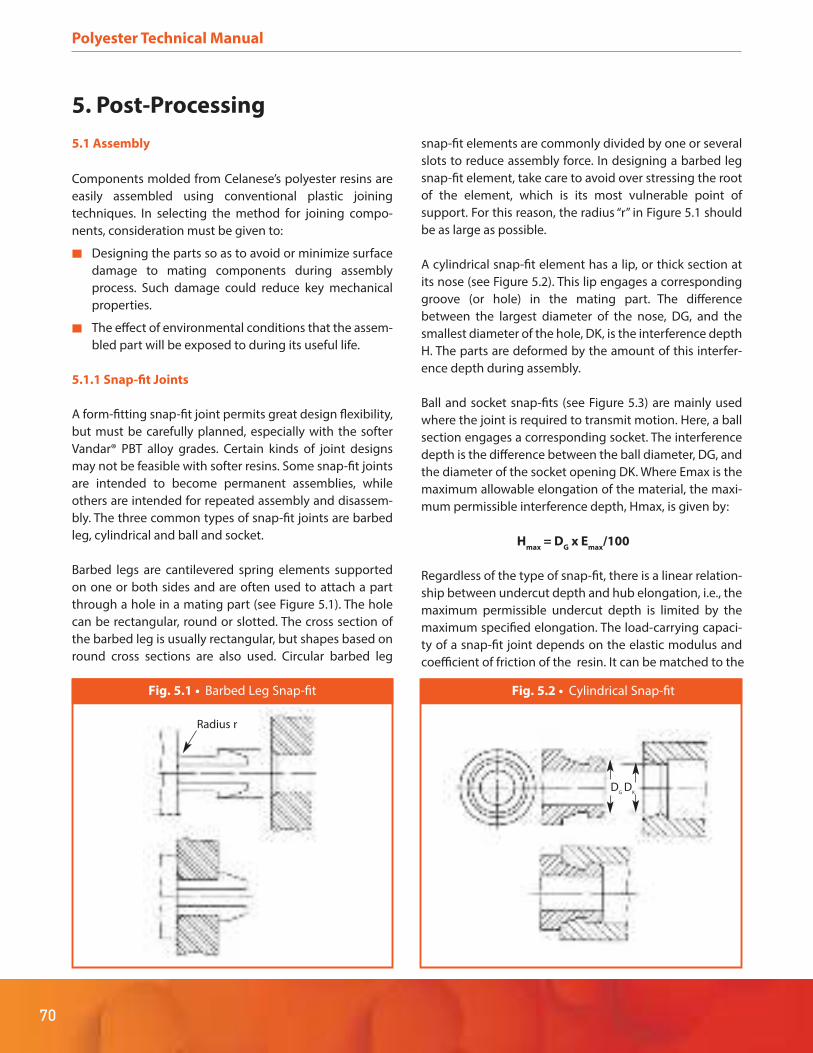
Polyester Technical Manual
70
5. Post-Processing
5.1 Assembly
Components molded from Celanese’s polyester resins are
easily assembled using conventional plastic joining
techniques. In selecting the method for joining compo-
nents, consideration must be given to:
Designing the parts so as to avoid or minimize surface
damage to mating components during assembly
process. Such damage could reduce key mechanical
properties.
The effect of environmental conditions that the assem-
bled part will be exposed to during its useful life.
5.1.1 Snap-fit Joints
A form-fitting snap-fit joint permits great design flexibility,
but must be carefully planned, especially with the softer
Vandar® PBT alloy grades. Certain kinds of joint designs
may not be feasible with softer resins. Some snap-fit joints
are intended to become permanent assemblies, while
others are intended for repeated assembly and disassem-
bly. The three common types of snap-fit joints are barbed
leg, cylindrical and ball and socket.
Barbed legs are cantilevered spring elements supported
on one or both sides and are often used to attach a part
through a hole in a mating part (see Figure 5.1). The hole
can be rectangular, round or slotted. The cross section of
the barbed leg is usually rectangular, but shapes based on
round cross sections are also used. Circular barbed leg
snap-fit elements are commonly divided by one or several
slots to reduce assembly force. In designing a barbed leg
snap-fit element, take care to avoid over stressing the root
of the element, which is its most vulnerable point of
support. For this reason, the radius “r” in Figure 5.1 should
be as large as possible.
A cylindrical snap-fit element has a lip, or thick section at
its nose (see Figure 5.2). This lip engages a corresponding
groove (or hole) in the mating part. The difference
between the largest diameter of the nose, DG, and the
smallest diameter of the hole, DK, is the interference depth
H. The parts are deformed by the amount of this interfer-
ence depth during assembly.
Ball and socket snap-fits (see Figure 5.3) are mainly used
where the joint is required to transmit motion. Here, a ball
section engages a corresponding socket. The interference
depth is the difference between the ball diameter, DG, and
the diameter of the socket opening DK. Where Emax is the
maximum allowable elongation of the material, the maxi-
mum permissible interference depth, Hmax, is given by:
Hmax
= DG x E
max/100
Regardless of the type of snap-fit, there is a linear relation-
ship between undercut depth and hub elongation, i.e., the
maximum permissible undercut depth is limited by the
maximum specified elongation. The load-carrying capaci-
ty of a snap-fit joint depends on the elastic modulus and
coefficient of friction of the resin. It can be matched to the
Fig. 5.1 • Barbed Leg Snap-fit
Radius r
Fig. 5.2 • Cylindrical Snap-fit
DG
DK

71
Polyester Technical Manual
functional requirements of the joint by adjusting the
undercut depth and the assembly retaining angle.
5.1.2 Strain Limits in Snap-fit Applications
Because a snap-fit join tends to load parts in flexure, it is
most appropriate to use flexural strain data in design
calculations. However, tensile data may also be used if that
is all there is available. Snap-fit design recommendations
for the various polyester materials take account of the
failure mode of the resin, i.e., whether it is by yield or break.
Unfilled and unreinforced grades of Celanex® PBT and
Vandar® PBT alloy typically show yield points. The follow-
ing recommendations apply to such grades.
If the flexural strain at break is less than 5.5%, then the
maximum allowable strain should be 50% of the flexur-
al break strain. If testing was stopped at 5.5% strain (as
is generally the case in ISO testing) without showing a
break, tensile test data may be used.
For materials with a clear tensile yield, the maximum
allowable strain should be 70% of the yield strain for
single snap applications and 40% of the yield strain for
repeated snap use.
The filled and/or reinforced polyester resins typically have
low elongation and generally break without showing a
clear yield point. For such materials, the single-snap maxi-
mum strain should be 50% of the break strain and the
multiple-use maximum strain should be 30% of the break
strain.
5.1.3 Snap-on/Snap-in Fits
As shown in see Figure 5.4, this type of snap-fit can some-
times be molded into the part. The main advantage of this
approach, which is most often used with rounded parts, is
that some or all of the entire part flexes during the fitting
operation, so that the actual local deflection is small and
well below the yield strain. Snap-ons are also amenable to
release of the assembled part by means of a special tool.
This may occur when repeated servicing is needed of the
operating equipment inside the plastic assembly.
5.1.4 Self-Tapping Screws
Both thread-cutting and thread-forming screws may be
used to join parts made from Celanese’s polyester resins.
Combinations of both designs may also be used and have
the advantage of good holding power and minimized
stress during thread forming. An appropriate pilot hole
should be either molded in or drilled through the part
before screw insertion. To maximize pull-out resistance,
pilot hole diameter should in general be slightly less than
screw diameter. As threads may not cut or form adequately
in softer Vandar PBT alloy grades, pull-out forces may be
low and other methods of joining should be considered.
Extensive driving and stripping torque measurements
have been made on Celanex PBT 3300. These data are
presented in Table 5.1 which also includes pull-out
strength values.
5
Fig. 5.3 • Ball and Socket Snap-fit
DG
DK
Fig. 5.4 • Snap-on/Snap-in Fits
Snap-on fit
Pronged Snap-in
Prongs

Polyester Technical Manual
72
Penetration Pilot Hole Stripping Strip/Drive Pull Out
Depth Diameter Drive Torque Strip/Drive Differential Strength
Screw Size mm (in.) mm (in.) Torque in-lb in-lb Ratio in-lb kg (lb)
Thread Forming
2-28 4.8 (.188) 1.9 (.073) 1 5 5:1 4 —
6.4 (.250) 1.9 (.073) 2 7 3.5:1 5 —
4-20 4.8 (.188) 2.5 (.098) 2 10 5:1 8 —
6.4 (.250) 2.5 (.098) 3 13 4.2:1 10 —
6-19 6.4 (.250) 2.9 (.116) 4 22 5.5:1 18 159 (350)
11.1 (.438) 2.9 (.116) 7 48 7:1 41 386 (850)
8-16 8.0 (.313) 3.8 (.149) 9 40 4.14:1 31 295 (650)
12.7 (.500) 3.8 (.149) 12 75 6.2:1 63 590 (1300)
10-14 8.0 (.313) 4.4 (.173) 11 55 5:1 44 340 (750)
12.7 (.500) 4.4 (.173) 17 100 6:1 83 658 (1450)
Thread Cutting (Shank Slotted)
8-18 8.0 (.313) 3.3 (.130) 4 20 5:1 16 154 (340)
12.7 (.500) 3.3 (.130) 6 36 6:1 30 —
9/32-16 12.7 (.500) 5.8 (.230) 11 54 5:1 43 318 (700)
12.7 (.500) 5.8 (.230) 15 105 7:1 90 567 (1250)
Thread Forming (Blunt Point)
8-18 8.0 (.313) 3.3 (.130) 7 28 4:1 21 195 (430)
12.7 (.500) 3.3 (.130) 10 45 4.5:1 35 —
9/32-16 8.0 (.313) 5.8 (.230) 25 80 3:1 55 422 (930)
12.7 (.500) 5.8 (.230) 30 132 4.4:1 102 771 (1700)
Thread Cutting
4-24 8.0 (.313) 2.4 (.093) 4 11 3:1 7 195 (430)
12.7 (.500) 2.4 (.093) 4 15 4:1 11 231 (510)
6-20 9.5 (.375) 3.1 (.120) 4 16 4:1 12 240 (530)
12.7 (.500) 3.1 (.120) 4 28 7:1 24 286 (630)
8-18 9.5 (.375) 3.7 (.144) 5 26 5:1 21 304 (670)
12.7 (.500) 3.7 (.144) 6 35 6:1 29 381 (840)
10-16 9.5 (.375) 4.3 (.169) 6 30 5:1 24 363 (800)
12.7 (.500) 4.3 (.169) 9 43 5:1 35 454 (1000)
Thread Forming
4-24 8.0 (.313) 2.4 (.093) 2.5 9 3.5:1 6 159 (350)
12.7 (.500) 2.4 (.093) 2.5 16 6:1 13 177 (390)
6-20 9.5 (.375) 3.1 (.120) 3 18 6:1 15 268 (590)
12.7 (.500) 3.1 (.120) 4 24 6:1 20 272 (600)
8-18 9.5 (.375) 3.7 (.144) 5 22 4.5:1 17 349 (770)
12.7 (.500) 3.7 (.144) 8 28 3.5:1 20 358 (790)
10-16 9.5 (.375) 4.3 (.169) 6 23 4:1 17 354 (780)
12.7 (.500) 4.3 (.169) 9.5 30 3:1 20 431 (950)
Table 5.1 • Driving and Stripping Torques and Pull-Out Strengths of Self-Tapping Screws for Celanex® 3300

73
Polyester Technical Manual
5
5.1.5 Threaded Metal Inserts
Where a screw connection is to be used, a threaded metal
insert may give a stronger joint than could be obtained
with a self-tapping screw. It is important to design the
insert to minimize creation of molded-in stresses while
maximizing pull-out resistance. See paragraph 4.1.11
Molded-in Inserts for advice on knurling of inserts and
avoidance of sharp corners and edges.
5.2 Welding Techniques
Most conventional plastic welding techniques may be
successfully employed with Celanese’s polyester resins,
including spin welding, thermal fusion or hot plate weld-
ing and ultrasonic welding.
5.2.1 Spin Welding
Spin welding is a simple technique in which parts are
bonded by a melt layer formed between them by the
friction resulting from spinning one part against the
intended mating surface of the other. While the weld
produced is round, the parts may be of any shape. The
equipment used may be very simple, or it can be made
quite complex by the mechanical implementation of
production requirements. Schematic drawings of a spin
welding apparatus and driving tools are shown in Figures
5.5 through 5.7.
Regardless of the complexity of the equipment, general
operating principles for spin welding call for the stationary
part to be positioned with the weld area on the same axis
as the mating part and at a level that will allow the mating
part to be brought down into firm contact with it. The
raising and lowering mechanism should be checked for
proper alignment before commencing spinning. As
melting can be achieved in less than one second with
proper alignment and contact pressure, it is important to
stop spinning quickly and hold slightly greater pressure on
the joined parts immediately thereafter.
Fig. 5.5 • Simple Spin Welding Apparatus
Drive Belt
MotorPulley
Motor
Drill Press
Spindle Pulley
Up-Down SwitchAir Outlet
PressureRegulator
PressureGaugeAir Inlet
Pneumatic Spindle
Spindle Chuck
Press Bed
Fig. 5.6 • Pivot Tool with Flash Trimmer
Pneumatic SpindleAnd Chuck
Spin Welding Tool
Pivot Pin
Flash Trimmer
Container
Fig. 5.7 • Driving Tools for Spin Welding
Pneumatic SpindleAnd Chuck
Coil Spring
Driving Lugs
Aerosol Bottom
Aerosol Body
Pressure Pin ToRetain Momentary
Pressure on WeldAfter Drill Spindle
Retracts

Polyester Technical Manual
74
Spin welded joints may have other than flat 90° mating
surfaces. The joint surface may be angled, stepped or
profiled. Some examples of possible joint configurations
for hollow structures are shown in Figure 5.8. Angled or
profiled joints can retain flash and provide added weld
surface for greater strength.
5.2.2 Thermal Fusion Welding
Also called hot plate welding, this technique may be used
for parts in a wide range of sizes. As shown in Figure 5.9,
this process involves contacting the parts to be mated with
a heated platen until melting occurs and then bringing the
parts together under pressure until the melt solidifies. As
in spin welding, equipment can range from a simple
manual process to one that is complicated and automated.
Thermal fusion welding generates flash at the joint line
and its removal by special equipment or concealment by
joint design may be necessary. Figure 5.10 shows some
typical joint designs, including several indicating how flash
may be concealed. If a flash trap is to be used, its volume
should be great enough for flash collection. The amount of
material to be displaced by the joint must be decided
during initial part design and adequate allowance made to
achieve the desired dimensions of the final assembly.
Generally, about 0.5 mm (0.02 in) per side of displacement
may be expected. The mating part surfaces should be flat,
clean of foreign material and dry. Typical platen tempera-
tures for
Fig. 5.9 • Thermal Fusion Welding
Fig. 5.8 • Typical Joint Configurations
for Spin Welding (Hollow Members)
aaa
aa
Straight Butt Flange
if a = b andd > b,weld flashmoves
if a > b,maximum flashoccurs indirection
if a > b,maximum flashoccurs indirection

5.2.2 Thermal Fusion Welding
Also called hot plate welding, this technique may be used
for parts in a wide range of sizes. As shown in Figure 5.9,
this process involves contacting the parts to be mated with
a heated platen until melting occurs and then bringing the
parts together under pressure until the melt solidifies. As
in spin welding, equipment can range from a simple
manual process to one that is complicated and automated.
Thermal fusion welding generates flash at the joint line
and its removal by special equipment or concealment by
joint design may be necessary. Figure 5.10 shows some
typical joint designs, including several indicating how flash
may be concealed. If a flash trap is to be used, its volume
should be great enough for flash collection. The amount of
material to be displaced by the joint must be decided
during initial part design and adequate allowance made to
achieve the desired dimensions of the final assembly.
Generally, about 0.5 mm (0.02 in) per side of displacement
may be expected. The mating part surfaces should be flat,
clean of foreign material and dry. Typical platen tempera-
tures for
75
Polyester Technical Manual
5
Recessed Bead
Recessed WeldFlange Joint
Enclosed BeadCovered Bead
Butt Joint
Fig. 5.10 • Typical Thermal Fusion Weld Joint Designs
Fig. 5.11 • Heating the Plastic Resin for Welding
Displaced Material
Part to be Welded
Heating Platen
1. Part is brought into intimatecontact with the heated platen.
2. After approximately 0.010 inchesis displaced the movement stopswhile an additional 0.012-0.018inches of resin is melted.
0.012/0.018 inches
Additional displaced material each side
0.005 inches molten material
each side
3. The heating platen isremoved and the two partsare rapidly brought together.
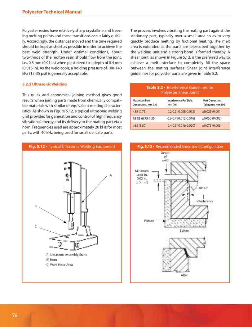
Polyester Technical Manual
76
Polyester resins have relatively sharp crystalline and freez-
ing melting points and these transitions occur fairly quick-
ly. Accordingly, the distances moved and the time required
should be kept as short as possible in order to achieve the
best weld strength. Under optimal conditions, about
two-thirds of the molten resin should flow from the joint,
i.e., 0.3 mm (0.01 in) when plasticized to a depth of 0.4 mm
(0.015 in). As the weld cools, a holding pressure of 100-140
kPa (15-35 psi) is generally acceptable.
5.2.3 Ultrasonic Welding
This quick and economical joining method gives good
results when joining parts made from chemically compati-
ble materials with similar or equivalent melting character-
istics. As shown in Figure 5.12, a typical ultrasonic welding
unit provides for generation and control of high frequency
vibrational energy and its delivery to the mating part via a
horn. Frequencies used are approximately 20 kHz for most
parts, with 40 kHz being used for small delicate parts.
The process involves vibrating the mating part against the
stationary part, typically over a small area so as to very
quickly produce melting by frictional heating. The melt
area is extended as the parts are telescoped together by
the welding unit and a strong bond is formed thereby. A
shear joint, as shown in Figure 5.13, is the preferred way to
achieve a melt interface to completely fill the space
between the mating surfaces. Shear joint interference
guidelines for polyester parts are given in Table 5.2.
Fig. 5.12 • Typical Ultrasonic Welding Equipment
(A) Ultrasonic Assembly Stand
(B) Horn
(C) Work Piece Area
C
B
A
Fig. 5.13 • Recommended Shear Joint Configuration
After
Before
Fixture
Depthof
weld
Interference
30°-45°
MinimumLead-in.0.02 in.
(0.5 mm)
Table 5.2 • Interference Guidelines for
Polyester Shear Joints
Maximum Part Interference Per Side, Part Dimension
mm (in)Dimensions, mm (in) Tolerance, mm (in)
<18 (0.75) 0.2-0.3 (0.008-0.012) ±0.025 (0.001)
18-35 (0.75-1.50)
>35 (1.50) 0.4-0.5 (0.016-0.020) ±0.075 (0.003)
0.3-0.4 (0.012-0.016) ±0.050 (0.002)

77
Polyester Technical Manual
5
To obtain satisfactory high-quality welded joints, take
account of the following factors:
Initial contact between the mating surfaces should be
small to concentrate the applied energy and decrease
the time and total energy needed. In some cases, the
ultrasonic energy should be applied prior to part
contact in order to avoid fracture.
Mating surfaces surrounding the entire joint interface
should be uniform and in intimate contact with each
other. If possible the joint area should be all in one
plane.
Mating parts must be well designed, molded to dimen-
sion and precisely aligned. Use support fixtures, pins
and sockets, tongues and grooves or other features to
hold parts in place. Do not rely on pressure from the
horn for this purpose.
Make sure that the mating surfaces are clean and dry.
Holes and other openings in the mating surfaces
should be avoided because they can interrupt energy
transmission and compromise the weld integrity. For
the same reason, bosses or other projecting surfaces
on the part surface should be well radiused to avoid
fracture due to mechanical vibration.
Bowing of flat circular parts may sometimes occur during
ultrasonic welding. This can usually be eliminated by
increasing wall thickness or by adding internal support
ribs. Minimizing weld time may also help. For ultrasonic
welding as for all welding processes where polymeric
materials are melted, adequate ventilation should be
provided at the welding station(s) to remove any fumes
generated during processing.
Ultrasonic energy applications are not limited only to part
welding. As shown in Figure 5.14, this technique may also
be employed for staking, swaging and spot welding. In
each case, the ultrasonic horn is provided with an appro-
priately shaped forming die or tip. These methods of
attachment also have the advantage of very short cycle
times, capability to handle tight assembly and ability to
perform multiple operations with one machine. A further
use of the technology is for driving of metal inserts into the
plastic parts for subsequent mechanical assembly.
5.2.4 Adhesive Bonding
Parts molded from Celanese’s polyester resins may be
bonded to each other or to dissimilar materials with
commercially available adhesives. Though such bonds will
not in general be as strong as those obtainable by welding,
they can be quite satisfactory, especially where the bond
area is large. The good chemical resistance of PBT and PET
polymers inhibits attack by most solvents, so mechanical
roughening of the surfaces to be joined is required. The
mating surfaces should be sanded and cleaned with a
solvent such as, e.g., acetone, before applying the adhe-
sive. As with adhesive bonding of materials in general, the
surfaces should be closely mated so that the adhesive layer
is thin. Common adhesives that may be used to bond parts
made from Celanex® PBT, Impet® PET and Vandar® PBT
alloys include cyanoacrylates, methacrylates, epoxies and
polyurethanes. When using any such adhesive system, be
sure to read and follow the use instructions and safety
precautions provided by its manufacturer.
Fig. 5.14 • Ultrasonic Staking,
Swaging and Spot Welding
Forming Die
Staking
AttachmentPlasticPart
Swaging
Spot Welding
Welded Area
Spot WeldHorn Tip
Forming Die
PlasticPart
Attachment

Polyester Technical Manual
78
5.3 Machining
Parts made from Celanese’s polyester resins may be
finished by most conventional processes, subject to a few
limitations on mechanical processing of the softer grades.
Machining, sawing, drilling, turning, milling and similar
operations may all be accomplished on standard equip-
ment with appropriate procedures as described below.
Use only sharp tools
Provide adequate chip clearance
Support the work properly, especially for softer grades
Provide adequate cooling, especially for softer grades
Carbide tools may last longer when machining
glass-reinforced or filled grades
5.3.1 Sawing
Use sharp-tooth blade with adequate offset to prevent
binding
Use a coarse-toothed blade, such as for example 6 tpi,
rather than a fine-toothed one
For smoother cuts, run at high speed, 3,000 to 4,000
rpm, for instance
Feed at 10-15 fpm (3.0-4.5 m/min)
Use extra-wide gullets for chip clearance
For sections less than .5 inch (12.7 mm), cool the
cutting area with air, water or oil
Back up thin sections with cardboard or chipboard
For sections thicker than .5 inch (12.7 mm), use water
cooling on the cutting area
For softer Vandar® PBT alloy grades, cool the surface
and hold the cut open if required
5.3.2 Drilling
Run at 1,000-3,000 rpm and feed as fast as possible.
Speeds above 3,000 rpm may melt the plastic
Support the workpiece firmly during drilling
Clear deep holes frequently – every .25 inch (6.4 mm)
of bit travel
Cool with an air jet or water-based coolant aimed into
the hole
For softer Vandar PBT alloy grades, using oversized bits
at low rpm or undersized bits at high rpm may help
maintain tolerances
Drill test holes at the intended speed to determine the
right bit size for target diameter
5.3.3 Turning
In general, feeds and speeds depend on the nature of
the cut and finish desired
Make rough cuts at 1500-2500 rpm with feeds of 20
in/min (51 cm/min)
Faster speeds may give a better finish, but cooling may
be required
Rough cuts in softer Vandar PBT alloy grades may cause
stringing
For the soft grades a slower speed may give a better
finish
Keep cutting tools well sharpened
Allow enough clearance to avoid overheating the
workpiece
5.3.4 Milling
Keep the flute count as low as possible (2-4) to
minimize overheating the workpiece
Run cutter at 2000-4000 rpm and feed as fast as possi-
ble consistent with surface finish
Use an air-jet to keep flutes from clogging
5.3.5 Rotary Power Filing
For better chip clearance, use ground burrs rather than
hand-cut rotary files
Use high speed steel burrs (medium cut) or carbide
burrs (medium or diamond cut)
Operate steel burrs at 800-1000 surface fpm (245-305
m/min) and carbide burrs at around 2000 fpm (610
m/min)

79
Polyester Technical Manual
5
5.4 Surface Treatment
A variety of surface treatments may be used with the
polyester materials, including dyeing, painting, hot stamp-
ing, in-mold decorating, sublimation printing and laser
marking.
5.4.1 Painting
Painting may be done with commercially available coating
systems. Bake temperatures should be adjusted down-
ward for the softer Vandar® PBT alloy grades. Some small
amount of further shrinkage or warpage may occur during
baking. Coating systems typically employ a primer and a
top coat, which may be specified by the end-user, particu-
larly in automotive applications. In such a case, contact the
end-user or Celanese for detailed information.
5.4.2 Hot Stamping
The hot stamping process uses a wide range of foils with
pigmented and/or metallized coatings and provides
high-gloss, semi-gloss or matte finishes. The choice of foil
must match both the aesthetic and functional require-
ments of the application and be processable onto the
specific polyester grade being used. Each application
should therefore be discussed with the foil manufacturer
to ensure that the final product meets the end-use require-
ments. Foils, films and labels may also be applied by
in-mold decorating. In such cases, part geometry must be
fairly simple and molding cycles may be somewhat length-
ened.
5.4.3 Printing
Various printing methods can be used to apply graphics,
serial numbers, bar codes and the like to parts made from
Celanese’s polyester resins. These methods include offset
printing, silk screening, pad printing, sublimation printing
and laser marking. Because of the wide range of composi-
tions available from the three polyester product families,
any printing method should be evaluated by printing a
test plaque before committing to a production method.
5.4.4 Laser Marking
Laser marking can be used to produce graphics to a depth
of several thousandths of an inch without using inks, dyes
or paints. This method is well adapted to matte or glossy
finishes and to flat or curved parts. White markings can be
placed on dark surfaces and vice versa. Both Neodymi-
um:Yttrium Aluminum Garnet (Nd:YAG) and excimer lasers
have been used, the latter for making dark marks on white
parts. Colors such as yellow, tan, blue and gray have all
been used successfully in laser marking applications. As
presented in Table 1.1, special grades are available for laser
marking use.
5.4.5 Sterilization
Standard sterilization processes such as gamma radiation,
ethylene oxide and steam autoclave may be used with
Celanese’s polyester resins. Sample testing should be done
prior to exposure to autoclave temperatures of mechani-
cally loaded parts made from unfilled resin grades.

ENGINEERED MATERIALS
celanese.com/engineered-materials
Engineered Materials
• Celanex® thermoplastic polyester (PBT)
• Hostaform® and Celcon® acetal copolymer (POM)
• Celstran,® Compel® and Factor® long fiber
reinforced thermoplastic (LFRT)
• Celstran® continuous fiber reinforced
thermoplastic (CFR-TP)
• Fortron® polyphenylene sulfide (PPS)
• GUR® ultra-high molecular
weight polyethylene (UHMW-PE)
• Impet® thermoplastic polyester (PET)
• Riteflex® thermoplastic polyester elastomer (TPC-ET)
• Thermx® polycyclohexylene-dimethylene
terephthalate (PCT)
• Vandar® thermoplastic polyester alloy (PBT)
• Vectra® and Zenite® liquid crystal polymer (LCP)
Contact Information
Americas
8040 Dixie Highway, Florence, KY 41042 USA
Product Information Service
t: +1-800-833-4882 t: +1-859-372-3244
Customer Service
t: +1-800-526-4960 t: +1-859-372-3214
Europe
Am Unisys-Park 1, 65843 Sulzbach, Germany
Product Information Service
t: +(00)-800-86427-531 t: +49-(0)-69-45009-1011
Asia
4560 Jinke Road, Zhang Jiang Hi Tech Park
Shanghai 201203 PRC
Customer Service
t: +86 21 3861 9266 f: +86 21 3861 9599
Copyright © 2013 Celanese or its affiliates. All rights reserved.
This publication was printed on 19 September 2013 based on Celanese’s present state of knowledge, and Celanese undertakes no obligation to update it. Because conditions of product use are outside Celanese’s control, Celanese makes no warranties, express or implied, and assumes no liability in connection with any use of this information. Nothing herein is intended as a license to operate under or a recommendation to infringe any patents.
PBT-010R2_Polyester_TiconaPolyesterTechBro_AM_1112