technical manual operator manual for tactical water ...
848
ARMY TM 10-4610-309-10 MARINE CORPS TM 10802A-OI/1A VOL 1 PCN 184 108020 00 TECHNICAL MANUAL OPERATOR MANUAL FOR TACTICAL WATER PURIFICATION SYSTEM (TWPS) ARMY NSN 4610-01-488-9656 MARINE CORPS NSN 4610-01-488-6961 *This manual along with TM 10-4610-309-23 dated 15 May 2008 supersedes TM 10-4610-309-14, dated 1 May 2005 including all changes. DISTRIBUTION STATEMENT A - Approved for public release; distribution is unlimited. HEADQUARTERS, DEPARTMENT OF THE ARMY HEADQUARTERS, U.S. MARINE CORPS MAY 2008
-
Upload
khangminh22 -
Category
Documents
-
view
0 -
download
0
Transcript of technical manual operator manual for tactical water ...

ARMY TM 10-4610-309-10 MARINE CORPS TM 10802A-OI/1A VOL 1
PCN 184 108020 00
TECHNICAL MANUAL
OPERATOR MANUAL FOR
TACTICAL WATER PURIFICATION SYSTEM (TWPS)
ARMY NSN 4610-01-488-9656 MARINE CORPS NSN 4610-01-488-6961
*This manual along with TM 10-4610-309-23 dated 15 May 2008 supersedes TM 10-4610-309-14, dated 1 May 2005 including all changes.
DISTRIBUTION STATEMENT A - Approved for public release; distribution is unlimited.
HEADQUARTERS, DEPARTMENT OF THE ARMY HEADQUARTERS, U.S. MARINE CORPS MAY 2008


ARMY TM 10-4610-309-10
a/b Blank
WARNING SUMMARY
This warning summary contains general safety warnings and hazardous materials warnings that must be understood and applied during operation and maintenance of this equipment. Failure to observe these warnings could result in serious injury or death to personnel.
HOT SURFACES The muffler/exhaust system may be hot. Do not touch the muffler/exhaust system if it is hot. Failure to observe this warning can result in burns.
TWO PERSON LIFT Two-person lift. Two persons must move the diesel engine assembly. Lift with your legs, not your back. Failure to observe this warning may result in back injury.
FIRE HAZARD If the engine has been running, it may be hot enough to ignite fuel as it is drained from the fuel tank. Make sure that the engine and its parts are cool to the touch before draining fuel from the fuel tank. Failure to observe this warning can result in a fire.
PROJECTILE HAZARD When it is necessary to perform the next step, be sure to reinstall the retaining plate and nuts. If they are not reinstalled, the compression from the engine could cause the fuel injection valve to fly out forcefully and could result in injury.
ELECTRICAL/MECHANICAL HAZARD The pump motor must be turned off and disconnected from its source of electrical power in a specific order before performing maintenance on the pump. Failure to observe this warning may result in serious injury or death from electrocution or injury from moving parts.
FIRST AID
First Aid instructions are given in FM 4-25.11, First Aid.
WARNING
WARNING
WARNING
WARNING
WARNING


ARMY TM 10-4610-309-10
A
LIST OF EFFECTIVE PAGES/WORK PACKAGES
NOTE: This manual supersedes TM 10-4610-309-14, dated 1 May 2005. Zero in the “Change No.” column indicates an original page or work package.
Date of issue for the original manual is:
Original . . . 0 . . . 15 May 2008
TOTAL NUMBER OF PAGES FOR FRONT AND REAR MATTER IS 26 AND TOTAL NUMBER OF WORK PACKAGES IS 52 CONSISTING OF THE FOLLOWING:
Page/WP No. Change No. Page/WP No. Change No.
Front Cover ............................................0
Warning Summary ..................................0
i – iv .........................................................0
Chp 1 title page .......................................0
WP 0001 00 ............................................0
WP 0002 00 ...........................................0
WP 0003 00 ............................................0
Chp 2 title page .......................................0
WP 0004 00 ...........................................0
WP 0005 00 ............................................0
WP 0006 00 ............................................0
WP 0007 00 ............................................0
WP 0008 00 ...........................................0
WP 0009 00 ............................................0
WP 0010 00 ............................................0
WP 0011 00 ...........................................0
WP 0012 00 ............................................0
WP 0013 00 ............................................0
WP 0014 00 ............................................0
WP 0015 00 ............................................0
WP 0019 00 ............................................0
WP 0020 00 ............................................ 0
WP 0021 00 ............................................ 0
WP 0022 00 ............................................ 0
WP 0023 00 ............................................ 0
WP 0024 00 ........................................... 0
WP 0025 00 ........................................... 0
WP 0026 00 ........................................... 0
WP 0027 00 ........................................... 0
WP 0028 00 ........................................... 0
WP 0029 00 ............................................ 0
WP 0030 00 ........................................... 0
WP 0031 00 ........................................... 0
WP 0032 00 ............................................ 0
WP 0033 00 ........................................... 0
Chp 3 title page ...................................... 0
WP 0034 00 ........................................... 0
Chp 4 title page ...................................... 0
WP 0035 00 ............................................ 0
WP 0036 00 ............................................ 0
WP 0037 00 ............................................ 0
WP 0038 00 ............................................ 0
WP 0016 00 ............................................0
WP 0017 00 ............................................0
WP 0018 00 ............................................0

ARMY TM 10-4610-309-10
Page/WP No. Change No.
WP 0039 00 ............................................0
WP 0040 00 ............................................0
WP 0041 00 ............................................0
WP 0042 00 ............................................0
WP 0043 00 ............................................0
Chp 5 title page .......................................0
WP 0044 00 ............................................0
WP 0045 00 ............................................0
WP 0046 00 ............................................0
WP 0047 00 ............................................0
WP 0048 00 ............................................0
WP 0049 00 ............................................0
WP 0050 00 ............................................0
WP 0051 00 ............................................0
WP 0052 00 ............................................0
WP 0053 00 ............................................0
Glossary ..................................................0
Index........................................................0
Warranty..................................................0
B

ARMY TM 10-4610-309-10 MARINE CORPS TM 10802A-OI/1A VOL 1
HEADQUARTERS, DEPARTMENT OF THE ARMY
U.S. MARINE CORPS WASHINGTON, DC, 15 MAY 2008
TECHNICAL MANUAL
OPERATOR MANUAL FOR
TACTICAL WATER PURIFICATION SYSTEM ARMY NSN 4610-01-488-9656
MARINE CORPS NSN 4610-01-488-6961
REPORTING ERRORS AND RECOMMENDING IMPROVEMENTS
You can help improve this publication. If you find any mistakes or if you know of a way to improve the procedures, please let us know. Submit your DA Form 2028 (Recommended Changes to Equipment Technical Publications), through the Internet, on the Army Electronic Product Support (AEPS) website. The Internet address is https://aeps.ria.army.mil. The DA Form 2028 is located under the Public Applications section in the AEPS Public Home Page. Fill out the form and click on SUBMIT. Using this form on the AEPS will enable us to respond quicker to your comments and better manage the DA Form 2028 program. You may also mail, fax or e-mail your letter or DA Form 2028 directly to: AMSTA-LC-LMPP/TECH PUBS, TACOM-RI, 1 Rock Island Arsenal, Rock Island, IL 61299-7630. The e-mail address is [email protected]. The fax number is DSN 793-0726 or Commercial (309) 782-0726.
*This manual along with TM 10-4610-309-23 dated 15 May 2008 supersedes TM 10-4610-309-14, dated 1 May 2005 including all changes.
DISTRIBUTION STATEMENT A - Approved for public release; distribution is unlimited.


ARMY TM 10-4610-309-10
TABLE OF CONTENTS
WP Sequence No.
i
WARNING SUMMARY
HOW TO USE THIS MANUAL
CHAPTER 1 – GENERAL INFORMATION, EQUIPMENT DESCRIPTION AND THEORY OF OPERATION
General Information..................................................................................................................... 0001 00
Equipment Description and Data.......................................................................................................... 0002 00
Theory of Operation ............................................................................................................................... 0003 00
CHAPTER 2 – OPERATOR INSTRUCTIONS Description and Use of Operator Controls and Indicators ................................................................ 0004 00
Site Selection and Component Location ............................................................................................. 0005 00
Equipment Off-Loading – Army Unit ................................................................................................... 0006 00
Equipment Off-Loading – Marine Corps Unit...................................................................................... 0007 00
Set-Up – Operation Under Usual Conditions...................................................................................... 0008 00
Recirculation Tank Set-Up and Operation................................................................................... 0009 00
Establishing Electrical Power – Operation Under Usual Conditions ............................................... 0010 00
Pre-Operational Diagnostic Self-Tests – Operation Under Usual Conditions ............................... 0011 00
Initial Start-Up or Start-Up with the System Fully Drained – Operation Under Usual
Conditions ................................................................................................................................................ 0012 00
Start-Up After a Short Term or Standby Shut-Down Without Draining – Operation Under
Usual Conditions..................................................................................................................................... 0013 00
Maintaining Normal Operation Under Usual Conditions ................................................................... 0014 00
Standby or Short Term Shut-Down – Operation Under Usual Conditions ..................................... 0015 00
Extended Shut-Down During Deployment – Operation Under Usual Conditions ......................... 0016 00
Emergency Shut-Down .......................................................................................................................... 0017 00
Cleaning, Preservation, and Cleaning Waste Neutralization and Pump-Out ................................ 0018 00
Micro-Filtration System Cleaning – Operation Under Usual Conditions ..................................... 0019 00
Reverse Osmosis System Acid Cleaning – Operation Under Usual Conditions......................... 0020 00
Reverse Osmosis System Detergent Cleaning – Operation Under Usual Conditions................ 0021 00
Micro-Filtration System Cleaning with Reverse Osmosis System Acid Cleaning – Operation
Under Usual Conditions............................................................................................................... 0022 00
Reverse Osmosis System Preservation – Operation Under Usual Conditions........................... 0023 00
Micro-Filtration System Preservation – Operation Under Usual Conditions ............................... 0024 00
Operation Under Unusual Conditions .................................................................................................. 0025 00
Ocean Intake Structure System (OISS) Set-Up – Operation Under Unusual Conditions ........... 0026 00

ARMY TM 10-4610-309-10
TABLE OF CONTENTS - Continued
WP Sequence No.
ii
Cold Weather Set-Up – Operation Under Unusual Conditions ........................................................ 0027 00
Other Set-Ups – Operation Under Unusual Conditions .............................................................. 0028 00
Preparation for Movement – Army Unit ............................................................................................... 0029 00
Preparation for Movement – Marine Corps Unit ......................................................................... 0030 00
Preparation for Movement – Marine Corps Extended Capability Modules ................................ 0031 00
Preparation for Storage – Army Unit .......................................................................................... 0032 00
Preparation for Storage – Marine Corps Unit ..................................................................................... 0033 00
CHAPTER 3 – TROUBLESHOOTING PROCEDURES Operator/Crew Troubleshooting Procedures...................................................................................... 0034 00
CHAPTER 4 – OPERATOR MAINTENANCE PROCEDURESPreventive Maintenance Checks and Services (PMCS) Introduction............................................. 0035 00
Preventive Maintenance Checks and Services (PMCS)................................................................... 0036 00
Raw Water System Operator Maintenance Procedures ............................................................. 0037 00
Micro-Filtration System Operator Maintenance Procedures ....................................................... 0038 00
Reverse Osmosis System Operator Maintenance Procedures................................................... 0039 00
Air System Operator Maintenance Procedures........................................................................... 0040 00
Control Instruments Operator Maintenance Procedures............................................................. 0041 00
Cold Weather System Operator Maintenance Procedures ......................................................... 0042 00
General Operator Maintenance Procedures .............................................................................. 0043 00
CHAPTER 5 - SUPPORTING INFORMATION References............................................................................................................................................... 0044 00
Components Of End Item (COEI) and Basic Issue Items (BII) – Army .......................................... 0045 00
Components Of End Item (COEI) and Basic Issue Items (BII) – Marine Corps.......................... 0046 00
Components Of End Item (COEI) and Basic Issue Items (BII) – Marine Corps Extended Capability
Modules ....................................................................................................................................... 0047 00
Expendable and Durable Items List ..................................................................................................... 0048 00
Additional Authorization List (AAL) .............................................................................................. 0049 00
Operating Data Log .................................................................................................................... 0050 00
Operator Maintenance Log ......................................................................................................... 0051 00
Reverse Osmosis Element Performance Log ............................................................................. 0052 00
Reverse Osmosis % Clean Calculation....................................................................................... 0053 00
Glossary................................................................................................................................Glossary – 1
Index .......................................................................................................................................... Index – 1
Warranty .............................................................................................................................. Warranty – 1

ARMY TM 10-4610-309-10
iii/iv blank
HOW TO USE THIS MANUAL
This manual contains general information, operating instructions, Preventive Maintenance Checks and Services (PMCS), and maintenance/repair instructions for the Tactical Water Purification System (TWPS).
Front matter consists of a warning summary, table of contents, and instructions on how to use this manual. Chapter 1 provides general information on the TWPS equipment including maintenance forms, records and reports; instructions for recommending equipment improvements; corrosion prevention and control; ozone depleting substances and procedures for material destruction to prevent enemy use, a TWPS equipment description and theory of operation. Chapter 2 contains Operator instructions for operating, cleaning, and preparing to move or store the TWPS equipment. Chapter 3 contains troubleshooting procedures. Chapter 4 contains Operator Maintenance procedures. Chapter 5 contains the Components of End Items (COEI) and Basic Issue Items (BII), lists of Expendable and Durable Items, Additional Authorization List (AAL) and other supporting information. Rear matter consists of the alphabetical index, DA Form 2028, authentication page and back cover.
Manual Organization and Page Numbering
This manual is divided into five major chapters that detail the topics mentioned above. Within each chapter are work packages covering a wide range of topics. Each work package is numbered sequentially starting with WP 0001 and has its own page numbering scheme that is independent of the page numbering used by other work packages. Each page of a work package has a page number of the form “XXXX YY-ZZ”, where “XXXX YY” is the work package number (e.g. 0010 00 is work package 10) and “ZZ” represents the number of the page within that work package. A page number such as “0010 00-1/2 Blank” means that page 1 of that work package contains information but page 2 has been intentionally left blank.
Finding Information
The Table of Contents permits the reader to quickly find information in the manual. The reader should start here first when looking for a specific topic. The Table of Contents lists the topics contained within each chapter and the work package sequence number where it can be found. The index, located at the back of the manual, lists topics in alphabetical order and identifies the work packages where the information is located.


ARMY TM 10-4610-309-10
CHAPTER 1
GENERAL INFORMATION,
EQUIPMENT DESCRIPTION AND
THEORY OF OPERATION
FOR
TACTICAL WATER PURIFICATION SYSTEM (TWPS)


ARMY TM 10-4610-309-10
TACTICAL WATER PURIFICATION SYSTEM (TWPS) GENERAL INFORMATION
0001 00
0001 00-1
SCOPE
Equipment Covered
This technical manual contains instructions for the operation, preventive maintenance and Operator corrective maintenance for the 1500 Tactical Water Purification System (TWPS) and its associated equipment for both the Army version (A-TWPS) and the Marine Corps version (MC-TWPS).
Figure 1. Army Tactical Water Purification System (A-TWPS).
Figure 2. Marine Corps Tactical Water Purification System (MC-TWPS).
Type of Manual
Operator’s Manual along with a separate Field Maintenance Manual, TM 10-4610-309-23 (Army), TM 10802A-OI/1A Vol 2 (Marine Corps). The Repair Parts and Special Tools List is included in a separate manual, TM 10-4610-309-23P, TM 10802A-OI/2A (Marine Corps).
Equipment Name and Model Number
Tactical Water Purification System. This manual covers two models: � A-TWPS, NSN 4610-01-488-9656 � MC-TWPS, NSN 4610-01-488-6961

ARMY TM 10-4610-309-10
TACTICAL WATER PURIFICATION SYSTEM (TWPS) GENERAL INFORMATION
0001 00
0001 00-2
The information in this manual applies to both models. When information applies to only one model or the other, a statement similar to “A-TWPS ONLY” or “MC-TWPS ONLY” is placed with the applicable statement.
Purpose of Equipment
The 1500 Gallons Per Hour (GPH) Tactical Water Purification System (1500 TWPS) is a fully contained mobile water purification system capable of purifying, storing and dispensing water meeting Tri-Service Field Water Quality Standards for long term consumption. The TWPS is intended to supply potable water to ground, amphibious and air-mobile units of the U.S. Army and Marine Corps. It can also be used to provide potable water support to civilian agencies or host nations for emergencies, disaster relief, humanitarian efforts and peacekeeping missions.
The TWPS can produce drinking water from a broad range of water sources including: � Fresh water containing dirt (suspended solids) and micro-organisms � Brackish water containing dirt, micro-organisms and salt � Seawater containing dirt, micro-organisms and a high concentration of salt � Freshwater containing nuclear, biological or chemical warfare (NBC) agents
MAINTENANCE FORMS, RECORDS, REPORTS
Department of the Army forms and procedures used for the equipment maintenance will be those prescribed by DA PAM 738-750, Functional Users Manual for the Army Maintenance Management System.
REPORTING EQUIPMENT IMPROVEMENT RECOMMENDATIONS (EIR)
If the TWPS needs improvement, let us know. Send us an EIR. You, the user, are the only one who can tell us what you don’t like about your equipment. Let us know why you don’t like the design or performance. Put it on a SF 368 (Product Quality Deficiency Report). Mail it to the address specified in DA PAM 738-750, Functional Users Manual for the Army Maintenance Management System (TAMMS) or as specified by the acquiring activity. We will send you a reply.
CORROSION PREVENTION AND CONTROL (CPC)
Corrosion Prevention and Control (CPC) of Army material is a continuing concern. It is important that any corrosion problems with this item be reported so that the problem can be corrected and improvements can be made to prevent the problem in future items.
While corrosion is typically associated with rusting of metals, it can also include deterioration of other material, such as rubber and plastic. Unusual cracking, softening, swelling or breaking of these materials may be a corrosion problem.
If a corrosion problem is identified, it can be reported using SF 368, Product Quality Deficiency Report. Use of key words such as “corrosion”, “rust”, “deterioration” or “cracking” will ensure that the information is identified as a CPC problem. The form should be submitted to the address specified in DA PAM 738-750, Functional Users Manual for the Army Maintenance Management System (TAMMS).

ARMY TM 10-4610-309-10
TACTICAL WATER PURIFICATION SYSTEM (TWPS) GENERAL INFORMATION
0001 00
0001 00-3/4 BLANK
OZONE DEPLETING SUBSTANCES (ODS)
The continued use of ODS has been prohibited by Executive Order 12856 of 3 August 1993. The use of ODS in Army IETMs is prohibited. A listing of these substances will be provided by the acquiring activity.
DESTRUCTION OF ARMY MATERIAL TO PREVENT ENEMY USE
For general destruction procedures for this equipment, refer to TM 750-224-3, Procedures for Destruction of Army Equipment to Prevent Enemy Use.
PREPARATION FOR STORAGE OR SHIPMENT
Refer to work packages 0029 through 0033 of this manual for preparation for movement and preparation for storage instructions.
WARRANTY INFORMATION
Refer to the Warranty Terms and Procedure included in the back of this manual.
LIST OF ABBREVIATIONS/ACRONYMS
The following abbreviations/acronyms are used in this manual:
TERM DEFINITION TERM DEFINITION AC Alternating Current NSN National Stock Number amp ampere OISS Ocean Intake Structure System BII Basic Issue Item OCP Operator Control Panel CAGEC Commercial and Government Entity
Code ODS
OMOzone Depleting Substances Operator Maintenance
COEI Components of End Item PDP Power Distribution Panel CPC Corrosion Prevention and Control PLC Programmable Logic Controller EIR Equipment Improvement
Recommendation PMCS Preventive Maintenance Checks
and Services ft.gal.
foot, feetgallon (U.S.)
P/N psig
Part Number pounds per square inch gauge
gpm gallons per minute Qty RO
QuantityReverse Osmosis
HP High Pressure RPSTL Repair Parts & Special Tools List in. inch, inches TDS Total Dissolved Solids lb. pound TQG Tactical Quiet Generator MAC Maintenance Allocation Chart TWPS Tactical Water Purification System MF Micro-Filtration or Micro-Filter uS/cm Conductivity unit of measurement,
microSiemens per centimeter NBC Nuclear, Biological and Chemical v Volts
END OF WORK PACKAGE


ARMY TM 10-4610-309-10
TACTICAL WATER PURIFICATION SYSTEM (TWPS) DESCRIPTION AND THEORY OF OPERATION EQUIPMENT DESCRIPTION AND DATA
0002 00
0002 00-1
EQUIPMENT CHARACTERISTICS, CAPABILITIES, AND FEATURES
The 1500 Gallons Per Hour (GPH) Tactical Water Purification System (1500 TWPS) is a fully contained mobile water purification system capable of purifying, storing and dispensing water meeting Tri-Service Field Water Quality Standards for long term consumption. The TWPS is intended to supply potable water to ground, amphibious and air-mobile units of the U.S. Army and Marine Corps. It can also be used to provide potable water support to civilian agencies or host nations for emergencies, disaster relief, humanitarian efforts and peacekeeping missions.
The TWPS can produce drinking water from a broad range of water sources including: � Fresh water containing dirt (suspended solids) and micro-organisms � Brackish water containing dirt, micro-organisms and salt � Seawater containing dirt, micro-organisms and a high concentration of salt � Freshwater containing nuclear, biological, or chemical warfare (NBC) agents
The TWPS is designed to produce as much as 1500 gallons per hour (35 GPM) of potable water from a fresh or brackish water source and 1200 gallons per hour (25 GPM) from a seawater source. The TWPS design point of reference is 1500 GPH of potable water from a fresh or brackish water source at 50˚ F that contains up to 5,000 mg/l TDS (total dissolved solids) and 1200 GPH from a seawater source at 50˚F that contains 45,000 mg/l TDS. Because water production is a function of water temperature and the type of water being processed, water production will vary with the characteristics of the water source. A summary of production performance with various raw water sources is shown in Table 1.
Table 1. TWPS Water Production Performance Characteristics.
RAW WATER CHARACTERISTICS Source Composition Temperature
POTABLE WATER PRODUCTION
(normal)Surface water Up to 20,000 mg/l TDS and up to 150 NTU 32 to 95� F 1500 GPH Ground water Up to 2500 mg/l TDS 32 to 95� F 1500 GPH Ground water Over 2500 mg/l TDS and up to 150 NTU 50 to 95� F 1200 GPH Seawater 35,000 mg/l TDS 32 to 95� F 1200 GPH Seawater 45,000 mg/l TDS 50 to 95� F 1200 GPH Seawater 45,000 mg/l TDS 32 to 50� F 1000 GPH Seawater 60,000 mg/l TDS 77� F 950 GPH
The TWPS is fielded in two versions: a Marine Corps version designated MC-TWPS and an Army version designated A-TWPS.
MC-TWPS
The MC-TWPS (shown packed out for deployment, Figure 1) is a basic skid-mounted unit with all BII and a 6,000-gallon water storage and distribution capability. The MC-TWPS may be powered by a 60 kW Tactical Quiet Generator (TQG), Model 806B, NSN 6115-01-462-0291 or a power distribution grid. It is capable of transport by the MTVR truck (MK 23 or MK 25, NSN 2320-01-465-2174, NSN 2320-01-465-2176). Forklift pockets and weight allow handling with the standard 5-ton forklift. The MC-TWPS is typically transported with its General Purpose Cover installed (Figure 2). Roof support sheets are installed on top of the TWPS under the cover to prevent the cover from sagging from accumulations of rain or snow.

ARMY TM 10-4610-309-10
TACTICAL WATER PURIFICATION SYSTEM (TWPS) DESCRIPTION AND THEORY OF OPERATION EQUIPMENT DESCRIPTION AND DATA
0002 00
0002 00-2
Do not walk on the roof support sheets. They are not designed to support the weight of a person. Failure to observe this warning may result in injury or damage to equipment.
For helicopter transportation, the General Purpose Cover and roof support sheets are removed and cargo nets are installed (Figure 3).
Figure 1. Left End and Front Views of the MC-TWPS Packed Out.
Figure 2. MC-TWPS with Roof Support Sheets and General Purpose Cover Installed.
Figure 3. Left End and Front Views of MC-TWPS with Cargo Nets Installed.
ROOFSUPPORT SHEETS
WITH STRAPS
WARNING

ARMY TM 10-4610-309-10
TACTICAL WATER PURIFICATION SYSTEM (TWPS) DESCRIPTION AND THEORY OF OPERATION EQUIPMENT DESCRIPTION AND DATA
0002 00
0002 00-3
The MC-TWPS General Purpose Cover is a single piece, water-proof, fabric covering that can be used during deployment to shield the equipment from precipitation and blowing dust and sand (Figure 4). Straps inside and outside the cover are used to secure the cover to the TWPS frame. Zippered and hook and loop seams at the four corners and in two locations at the front (1) make it possible to separate and roll up and secure individual wall panels for access or ventilation. By releasing snaps and straps around the top of the cover over the operator station, the top can be expanded at that end so that a roof over the operator station can be raised without removing the cover. Sleeves with a hook and loop seam and cinch cord are incorporated to provide access for connecting power cables (2) and inlet (3) and discharge (4) hoses to the TWPS. Hook and loop panels are incorporated to provide access to four rail transport tie-down rings (5). A fifth panel (6) provides access to lift and tie-down instruction plates.
Figure 4. MC-TWPS General Purpose Cover.
FRONT VIEW WITH OPERATOR STATION ROOF RAISED
1
2
3
4
REAR VIEW WITHOPERATOR STATION ROOF LOWERED
5
55
6
5

ARMY TM 10-4610-309-10
TACTICAL WATER PURIFICATION SYSTEM (TWPS) DESCRIPTION AND THEORY OF OPERATION EQUIPMENT DESCRIPTION AND DATA
0002 00
0002 00-4
Five extended capability modules are available for issue and deployment separately as required by the mission profile. The five extended capability Marine Corps modules are:
� Cold Weather Module: deployed for operating environments below 32˚ F.� Supplemental Cleaning Waste Storage Module: used to temporarily store the wastes that
result from cleaning the micro-filters (MF) and the reverse osmosis (RO) elements. � Ocean Intake Structure System (OISS) Module: deployed at beach locations exposed to wave
action and at ocean locations with significant tidal variations. � NBC Water Treatment Module: contains the filter media required for final treatment of a raw
water source that is contaminated with nuclear, biological or chemical warfare agents. � NBC Survivability Module: contains a contamination avoidance cover (CAC) to protect the
TWPS from NBC agent contamination. The components of each of the five extended capability modules are identified in this work package.
A-TWPS
The A-TWPS (shown packed out for deployment closed and open, Figure 5) is mounted within an 8 x 8 x 20 ISO load handling shelter referred to as the “flat rack”. The A-TWPS includes the basic TWPS skid, all BII, all of the features provided by the five extended capability modules described for the Marine Corps version, a 60 kW Tactical Quiet Generator (TQG) Model 806B, NSN 6115-01-462-0291 and an extended distribution kit. The extended distribution kit makes it possible to increase potable water storage capacity from the standard 6,000 gallons to a total capacity of 15,000 gallons and increase total distribution flow from 125 gpm through two nozzles to 250 gpm through four nozzles. The A-TWPS is compatible with the Palletized Load System truck (M1074, M1075), HEMTT LHS truck (M1120) and PLS trailer (M1076) for transport.
Figure 5. A-TWPS Packed Out for Deployment.

ARMY TM 10-4610-309-10
TACTICAL WATER PURIFICATION SYSTEM (TWPS) DESCRIPTION AND THEORY OF OPERATION EQUIPMENT DESCRIPTION AND DATA
0002 00
0002 00-5
A-TWPS Flat Rack and Fabric Wall
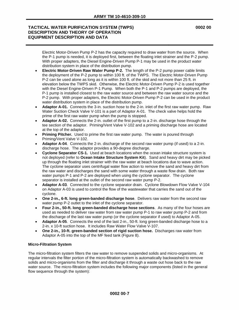
The A-TWPS flat rack (Figure 6) has two panels in front that are opened during deployment. When opened, the top panel serves as a roof/overhang (1) and the bottom panel serves as a floor (2). Two panels at both ends of the flat rack (3 through 6) and three panels at the back (7 through 9) are removable for access or ventilation. Hinged doors in three of the panels allow easy access for connecting power cables (10) or for operating valves (12). A shipping cover with hook and loop material (13) is secured over the opening below the product water access door (11) to keep the elements out during storage. A return air cover plate (14) in one of the left end panels can be removed when needed during cold weather so that a cold air return duct in the heating system can be hooked up to the panel. Folding steps (15) are incorporated in the back panel closest to the TQG area for access to the top of the flat rack. Two rollers (16) are stored at the TQG end of the flat rack near a bail bar (17). The rollers are installed at the opposite end of the flat rack when loading the flat rack onto an MTVR trailer. The bail bar is used to lift and pull the flat rack onto an MTVR.
The A-TWPS is equipped with a single piece, waterproof, fabric wall (18) that can be installed around the front of the open TWPS to shield the operator and the equipment from the weather. Straps and hook and loop material are used to secure the fabric wall to the opened top and floor panels of the flat rack. A zippered, hook and loop door (19) is provided at the front of the fabric wall for easy access. Sleeves with a hook and looped seam and a cinch cord are incorporated to provide access for connecting a hot air duct (20) and inlet (21) and discharge (22) hoses to the TWPS.
Figure 6. A-TWPS Flat Rack and Fabric Wall.
63 4 5
1
2
7 8
17
910
12 16
11
15
2220
18
19
21
14
13

ARMY TM 10-4610-309-10
TACTICAL WATER PURIFICATION SYSTEM (TWPS) DESCRIPTION AND THEORY OF OPERATION EQUIPMENT DESCRIPTION AND DATA
0002 00
0002 00-6
ADAPTOR A-01
RAW WATER SUCTION CHECK
VALVE V-101
PRIMING/VENT VALVE V-102
ADAPTOR A-02 CYCLONE BLOWDOWN FLOW VALVE V-104
LOCATION AND DESCRIPTION OF MAJOR COMPONENTS
Both the MC-TWPS and the A-TWPS versions are fully contained mobile water purification systems consisting of the following systems and extended capability kits:
Raw Water Supply System (Figure 7)
The raw water system draws water from a lake, river, ocean or other raw water source and discharges it into a storage tank called the Micro-Filtration (MF) feed tank. The raw water system includes the following major components (shown in the general flow sequence through the system):
Figure 7. Major Components of the Raw Water Supply System.
� Floating Inlet Strainer FS-1. Holds the raw water intake hose off the bottom of the water source and screens out leaves, sticks, fish and other large objects. It is connected by sections of rigid suction hose to the raw water pump.
� Anchor, pulley and rope system. Used to deploy the floating inlet strainer and hold it in place. � Thirteen sections of 3-in., 10-ft. long green-banded suction hose. These are the raw water
intake hoses. These hoses deliver raw water from the inlet strainer to the raw water pump. The number of hose sections used depends on site conditions.
� Diesel Engine Driven Raw Water Pump P-1. In normal deployment, Raw Water Pump P-1 draws water through the intake strainer and discharges it to the suction side of an Electric Motor-Driven Raw Water Pump P-2. The Diesel Engine-Driven Pump P-1 is not normally used if the
RAW WATER PUMP P-1
CYCLONE SEPARATOR CS-1
2 X 6 D-HOSE
3 X 10 S-HOSES
FLOATING INLET STRAINER FS-1
ANCHOR, PULLEY AND ROPE
PRIMINGPITCHER
ADAPTORA-03ADAPTOR
A-04
RAW WATER FLOW VALVE V-107
ADAPTOR A-05
2 X 50 D-HOSES
ELECTRIC MOTOR-DRIVEN PUMP P-2
2 X 10 S-HOSE
2 X 50 D-HOSES
ARMY TM 10-4610-309-10
TACTICAL WATER PURIFICATION SYSTEM (TWPS) DESCRIPTION AND THEORY OF OPERATION EQUIPMENT DESCRIPTION AND DATA
0002 00
0002 00-7
Electric Motor-Driven Pump P-2 has the capacity required to draw water from the source. When the P-1 pump is needed, it is deployed first, between the floating inlet strainer and the P-2 pump. With proper adapters, the Diesel Engine-Driven Pump P-1 may be used in the product water distribution system in place of the distribution pump.
� Electric Motor-Driven Raw Water Pump P-2. The length of the P-2 pump power cable limits the deployment of the P-2 pump to within 100 ft. of the TWPS. The Electric Motor-Driven Pump P-2 can be used alone as long as it is within 100 ft. of the skid and not more than 25 ft. in elevation below the TWPS skid. Otherwise, the Electric Motor-Driven Pump P-2 is used together with the Diesel Engine-Driven P-1 Pump. When both the P-1 and P-2 pumps are deployed, the P-1 pump is installed closest to the raw water source and between the raw water source and the P-2 pump. With proper adapters, the Electric Motor-Driven Pump P-2 can be used in the product water distribution system in place of the distribution pump.
� Adaptor A-01. Connects the 3-in. suction hose to the 2-in. inlet of the first raw water pump. Raw Water Suction Check Valve V-101 is a part of Adaptor A-01. The check valve helps hold the prime of the first raw water pump when the pump is stopped.
� Adaptor A-02. Connects the 2-in. outlet of the first pump to a 2-in. discharge hose through the tee section of the adaptor. Priming/Vent Valve V-102 and a priming discharge hose are located at the top of the adaptor.
� Priming Pitcher. Used to prime the first raw water pump. The water is poured through Priming/Vent Valve V-102.
� Adaptor A-04. Connects the 2-in. discharge of the second raw water pump (if used) to a 2-in. discharge hose. The adaptor provides a 90-degree discharge.
� Cyclone Separator CS-1. Used at beach locations when the ocean intake structure system is not deployed (refer to Ocean Intake Structure System Kit). Sand and heavy dirt may be picked up through the floating inlet strainer with the raw water at beach locations due to wave action. The cyclone separator uses centrifugal water flow action to remove the sand and heavy dirt from the raw water and discharges the sand with some water through a waste flow drain. Both raw water pumps P-1 and P-2 are deployed when using the cyclone separator. The cyclone separator is installed at the outlet of the second raw water pump P-2.
� Adaptor A-03. Connected to the cyclone separator drain. Cyclone Blowdown Flow Valve V-104 on Adaptor A-03 is used to control the flow of the wastewater that carries the sand out of the cyclone.
� One 2-in., 6-ft. long green-banded discharge hose. Delivers raw water from the second raw water pump P-2 outlet to the inlet of the cyclone separator.
� Four 2-in., 50-ft. long green-banded discharge hose sections. As many of the four hoses are used as needed to deliver raw water from raw water pump P-1 to raw water pump P-2 and from the discharge of the last raw water pump (or the cyclone separator if used) to Adaptor A-05.
� Adaptor A-05. Connects the end of the last 2-in., 50-ft. long green-banded discharge hose to a 2-in. x 10-ft suction hose. It includes Raw Water Flow Valve V-107.
� One 2-in., 10-ft. green-banded section of rigid suction hose. Discharges raw water from Adaptor A-05 into the top of the MF feed tank (Figure 8).
Micro-Filtration System
The micro-filtration system filters the raw water to remove suspended solids and micro-organisms. At regular intervals the filter portion of the micro-filtration system is automatically backwashed to remove solids and micro-organisms from the filter and discharge it through a waste out hose back to the raw water source. The micro-filtration system includes the following major components (listed in the general flow sequence through the system):

ARMY TM 10-4610-309-10
TACTICAL WATER PURIFICATION SYSTEM (TWPS) DESCRIPTION AND THEORY OF OPERATION EQUIPMENT DESCRIPTION AND DATA
0002 00
0002 00-8
MF System: MF Feed Tank to TWPS Skid (Figure 8)
� MF Feed Tank T-1. A 1000-gallon collapsible tank to hold a sufficient reserve of raw water to support regular, automatic filter backwash operations.
� MF Feed Tank Bag Filter S-1. A cloth mesh filter bag that fits inside the MF feed tank and prevents seaweed, algae and other larger material from being drawn out of the tank with the raw water. Two spare filters are provided in the BII. Water drawn from the MF feed tank is referred to as “MF feed water”.
� Tripod Assembly. Supports the 2x10 hose that delivers water to the MF feed tank so that the hose does not push down on the tank causing it to collapse.
� MF Feed Pump P-3. An electric motor-driven pump used to draw water from the MF feed tank and deliver it to the TWPS skid. The pump is deployed off of the TWPS skid near the MF feed tank.
� One 3-in., 3-ft. long suction hose. Connects the MF feed tank to the MF Feed Pump P-3. � Two 3-in., 10-ft. long discharge hose. Connect the MF Feed Pump P-3 discharge hose to the
TWPS skid connection at Basket Strainer S-2 (Figure 9 for Basket Strainer S-2).
Figure 8. MF System: MF Feed Tank to TWPS Skid.
MF System: Strainer S-2 to MF Modules (Figure 9)
� Basket Strainer S-2. Removes material larger than 600 microns from the MF feed water. The internal basket is removed for cleaning.
� Drain Valve V-109. Basket Strainer S-2 drain valve. � Vent/Sample Valve V-110. Used to vent the pipe run above the basket strainer when draining
the strainer. Also used as a sample valve for measuring the raw water conductivity. � MF Main Feed Valve V-111. Operates automatically to prevent feed water from flowing back into
the MF feed tank when the MF filters are backwashed (during the backwash cycle). � Pressure Gauge PI-101. Measures pressure of the MF feed supplied to the micro-filter (MF)
assembly. The pressure indication is for operator reference.
MF FEED PUMP P-3
BAG FILTER S-1
MF FEED TANK T-1
TOP VIEW OF TWPS
ELECTRIC MOTOR-DRIVEN PUMP P-2
2 X 10 S-HOSE
2 X 50 D-HOSES
3 X 3 S-HOSE 3 X 10 D-HOSES
TRIPOD ADAPTOR A-05

ARMY TM 10-4610-309-10
TACTICAL WATER PURIFICATION SYSTEM (TWPS) DESCRIPTION AND THEORY OF OPERATION EQUIPMENT DESCRIPTION AND DATA
0002 00
0002 00-9
� Flow Element FE-101 and Flow Transmitter FT-101. (FT-101 is not shown in Figure 9. It is located in the instrument/solenoid panel box shown in Figure 23). FE-101 and FT-101 measure the MF flow (feed flow to the MF assembly when filtering, backwash flow to the MF assembly during backwash). This flow is displayed at the operator control panel (OCP).
� Upper Feed Valve V-112 and Lower Feed Valve V-113. The two valves open and close automatically as required to direct the flow of MF feed water to the MF filter assembly during normal filtering operation and during backwash operations.
� Pressure Transmitter PT-101. Measures feed pressure to the Micro-Filtration Assembly. � Micro-Filtration (MF) Assembly. Consists of 12 parallel filter modules, MF-1 through MF-12,
that remove suspended solids and microorganisms from the MF feed water. Each filter module contains a filter element that is composed of a bundle of hollow, porous fibers. MF feed water enters the MF assembly, passes through the porous wall of each fiber and exits the hollow core of each fiber as filtrate (filtered MF feed water). The suspended solids and microorganisms that accumulate on the fibers are removed from the fibers during regular automatic backwashes.
� Check Valve V-911. Allows 15 psig air into the MF Assembly to drain the MF fibers just before backwash and for drain-down. Prevents water from backflowing into the air system.
� MF Vent Valve V-114. Vents the MF Assembly during cleaning stages and TWPS shut-down.
Figure 9. MF System: Strainer S-2 to MF Modules.
MF System: MF Modules to Discharge to RO Feed Tank (Figure 10)
� Upper Filtrate Outlet Valve V-201. V-201 is open during normal filtering operation and is actuated closed or open as required during backwash operations.
� Filtrate Flow Control Valve V-202. Controls the filtrate flow to the RO feed tank during normal filtering operation and closes or opens as required during backwash operations.
MF MAIN FEED VALVE V-111
FLOW ELEMENT
FE-101UPPER FEED VALVE V-112
PRESSURE GAUGE PI-101
VENT/SAMPLEVALVE V-110
DRAIN VALVE V-109
BASKETSTRAINER
S-2
PRESSURETRANSMITTER
PT-101
LOWER FEED VALVE V-113
FILTRATE OUT
MF MODULE
FILTRATE OUT
WASTEOUT
WASTEOUT
CHECK VALVE V-911
MF VENT VALVE V-114
MF ASSEMBLY

ARMY TM 10-4610-309-10
TACTICAL WATER PURIFICATION SYSTEM (TWPS) DESCRIPTION AND THEORY OF OPERATION EQUIPMENT DESCRIPTION AND DATA
0002 00
0002 00-10
� Pressure Transmitter PT-102. Measures filtrate pressure. The difference between the feed pressure measured by PT-101 (Figure 9) and the filtrate pressure is the trans-membrane pressure (TMP pressure drop across the membranes or filter element fibers of the MF assembly). TMP (pressure drop) is displayed at the operator control panel (OCP) and is an indication of how porous or how clogged the fibers are. A high TMP indicates that the MF fibers are becoming clogged with material and need to be cleaned.
� MF Filtrate Pressure Gauge PI-201. Measures the filtrate pressure in the line between the micro-filter (MF) assembly and the RO feed tank. The pressure indication is for operator reference. The operator can compare the PI-101 feed pressure gauge reading with the PI-201 filtrate pressure gauge reading as a manual check against the TMP that is measured automatically by Pressure Transmitters PT-101 and PT-102.
� Check Valve V-912. Allows 15 psig air into the MF Assembly to drain the MF fibers just before backwash and for drain-down. Allows 100 psig air into the MF Assembly to backwash the MF fibers. Prevents water from backflowing into the air system.
� MF Filtrate Sample/Drain Valve V-204. Used to sample filtrate and as a drain. � MF Filtrate Drain Valve V-203. Used to drain the filtrate channels of the MF Assembly.
Figure 10. MF System: MF Modules to Discharge to RO Feed Tank.
MF System: MF Modules to Waste Outlet (Figure 11 and Figure 12)
� Shell Backwash Upper Outlet Valve V-401. Opens to discharge the backwash flow from the upper shell of the MF Assembly.
� Shell Backwash Lower Outlet Valve V-402. Opens for the air pressure pulse during backwash and when draining the MF.
UPPER FILTRATE OUTLET VALVE V-201
MF FILTRATE PRESSURE GAUGE PI-201
FILTRATE FLOW CONTROL VALVE V-202
PRESSURE TRANSMITTER PT-102
CHECK VALVE V-912
MF FILTRATE SAMPLE/DRAIN VALVE V-204
MF FILTRATE DRAIN VALVE V-203
DISCHARGE TO RO FEED TANK

ARMY TM 10-4610-309-10
TACTICAL WATER PURIFICATION SYSTEM (TWPS) DESCRIPTION AND THEORY OF OPERATION EQUIPMENT DESCRIPTION AND DATA
0002 00
0002 00-11
� Rupture Disk RD-401. Rated for 75 psig. The backwash operation creates a sudden and very high velocity surge in the waste out piping and hose. In the event that the waste out hoses are blocked in any manner, the rupture disk will rupture when pressure exceeds 75 psig to release the pressure and protect the TWPS equipment.
� MF Shell Drain Valve V-403. Used to drain the shell/waste outlet channels of the MF Assembly.
Figure 11. MF System: MF Modules to Waste Outlet.
� One 4-in., 5-ft. long rigid suction hose. Connects to the waste outlet on the TWPS skid and discharges the backwash flow and RO reject off the TWPS unit.
� Adaptor A-09. Connects the 4-in. diameter waste out suction hose to a 6-in. diameter flexible waste out discharge hose.
� One 6-in., 50-ft. long discharge hose. Discharges the backwash flow and RO reject away from the TWPS.
Figure 12. TWPS Waste Discharge.
SHELL BACKWASH LOWER OUTLET VALVE V-402
SHELL BACKWASH UPPER OUTLET VALVE V-401
WASTE OUTLET
RUPTURE DISK RD-401
MF SHELL DRAIN VALVE V-403
4 X 5 S-HOSE 6 X 50 D-HOSE ADAPTOR A-09
TWPS
TWPS WASTE OUTLET CONNECTION

ARMY TM 10-4610-309-10
TACTICAL WATER PURIFICATION SYSTEM (TWPS) DESCRIPTION AND THEORY OF OPERATION EQUIPMENT DESCRIPTION AND DATA
0002 00
0002 00-12
Reverse Osmosis (RO) System
The MF filtrate becomes the RO feed water. The RO feed water is pressurized in the RO system to flow through the RO elements. A portion of the feed water passes through the RO membranes and is collected as product water that contains only a small amount of dissolved salts (total dissolved solids TDS). Most of the salts do not pass through the membranes. The remaining water and salts that do not pass through the RO membranes are called “reject”. The reject water is discharged through the waste out hoses back to the raw water source. The reverse osmosis system includes the following major components (listed in the general flow sequence through the system):
RO System: RO Feed Tank to High Pressure Pumps (Figure 13)
� RO Feed Tank T-2. Stores a sufficient supply of filtrate (for RO feed water) to allow the production of product water to continue uninterrupted during the intervals when the MF modules are being backwashed. Also used for cleaning solutions when cleaning the RO and MF assemblies.
� Tank Heaters H-1 and H-2. Submersible heating elements used for heating cleaning solutions and, if needed, to provide added generator load to avoid wet stacking during normal operation. (Wet stacking is the collection of condensation in the generator exhaust system that can occur when operated at low loads. Wet stacking over a period of time can corrode the generator exhaust system.)
� Temperature Indicator TI-202. A dial thermometer that indicates the temperature of the fluid inside the RO feed tank. Used primarily for certain cleaning procedures.
� RO Feed Tank Main Drain Valve V-412 and Auxiliary Drain Valve V-210. Used to drain the tank.
� Level Transmitter LT-201. Provides a level measurement that is used by a PLC to control the level in the RO feed tank.
� RO Feed Tank Pump Inlet Strainer S-3. A removable, coarse strainer that is positioned inside the RO feed tank over the tank outlet to the RO feed pump P-4 suction. This strainer prevents coarse objects, which may fall into the tank, from entering the pump.
� RO Feed Pump P-4. Draws RO feed water from the RO feed tank and provides the pressure needed by the HP (high pressure) pumps. This pump also circulates the cleaning solutions used when cleaning either one of the MF or RO systems.
� Antiscalant Injection Check Valve V-623. Injection point for an antiscalant chemical solution that inhibits salt scale formation on the RO membranes.
� RO Feed Temperature Transmitter TT-201. Provides a temperature measurement that is used by the PLC to indicate when the feed water temperature exceeds 110� F and to indicate if the RO feed tank heaters are turned off during cleaning.
� High Pressure Pump Feed Valve V-212. Used for various cleaning and maintenance procedures.
� Inline Strainer S-4 and Drain Valve V-213. Protects the HP pumps. Catches sand and dirt that may have entered the RO feed tank before it reached the HP pumps.
� RO Feed Pressure Gauge PI-202. Indicates the pressure from the RO feed pump. Usual pressure is 40 to 45 psig.
� RO Feed Pressure Transmitter PT-201. Provides a pressure measurement that is used by the PLC to shut down the HP pumps when the pressure from the RO feed pump drops below 35 psig.
� High Pressure Pump (HPP) Inlet Drain Valve V-214. Used to drain water from the HPP inlet pipes and hoses.

ARMY TM 10-4610-309-10
TACTICAL WATER PURIFICATION SYSTEM (TWPS) DESCRIPTION AND THEORY OF OPERATION EQUIPMENT DESCRIPTION AND DATA
0002 00
0002 00-13
Figure 13. RO System: RO Feed Pump to High Pressure Pumps.
RO System: High Pressure Pumps (Figure 14)
� High Pressure (HP) Pumps P-5 and P-6. The reverse osmosis process is pressure driven. Water only moves through the RO membrane pores if it is under pressure. Higher feed water salt content requires higher pressure to force water through the RO membrane pores and produce water than feed water with lower salt content. The high pressure pumps provide the operating pressure required by the RO elements to produce the desired product water flow.
� HPP Lubricant Return Lines. A portion of the feed water that is delivered to the pumps is used to lubricate the pumps and is discharged at low pressure back to the RO feed tank.
� HPP Case Drain Valve V-215. Used to drain the high pressure pumps.
Figure 14. RO System: High Pressure Pumps.
ANTISCALANTINJECTION CHECK
VALVE V-623
RO FEED PRESSURE GAUGE PI-202 RO FEED PRESSURE TRANSMITTER PT-201
STRAINER S-4
TANK HEATERS H-1 H-2
LEVEL TRANSMITTER LT-201
TEMPERATUREINDICATOR TI-202
S-4 DRAIN VALVE V-213
HP PUMP FEED VALVE V-212
RO FEED TANK T-2
STRAINERS-3
RO FEED PUMP P-4 HPP INLET DRAIN
VALVE V-214
RO FEED TANK MAIN DRAIN VALVE V-412
RO FEED TANK AUXILIARY DRAIN VALVE V-210
RO FEED TEMPERATURE
TRANSMITTER TT-201
HIGH PRESSURE PUMPS P-5 P-6
HPP LUBRICANT RETURN LINE
HPP DISCHARGE PRESSURE GAUGE PI-301
HPP INLET HPP OUTLET
HPP OUTLET PRESSURE RELIEF VALVE RV-301
DISCHARGE TO TURBOCHARGER
HPP CASE DRAIN VALVE V-215

ARMY TM 10-4610-309-10
TACTICAL WATER PURIFICATION SYSTEM (TWPS) DESCRIPTION AND THEORY OF OPERATION EQUIPMENT DESCRIPTION AND DATA
0002 00
0002 00-14
RO System: High Pressure Pumps to RO Vessels (Figure 15)
� HPP Outlet Drain Valve V-301. Used to drain the HPP outlet hoses and pipe. � HPP Discharge Pressure Gauge PI-301. Indicates the HP pump discharge pressure. � HPP Outlet Pressure Relief Valve RV-301. Rated to withstand up to 1050 psig. Protects the
HP pumps from over pressure in excess of 1050 psig. � HPP Outlet Drain Valve V-302. Used to drain high pressure pump outlet hoses and piping. � Pressure Recovery Turbocharger PRT-1. Uses pressure energy from the reject water coming
out of the RO vessels to boost the pressure of the RO feed water going into the RO vessels. � Turbocharger Feed Drain Valve V-303. Used to drain the feed water from the turbocharger. � Turbocharger Reject Drain Valve V-410. Used to drain the reject water from the turbocharger. � Feed Piping Drain Valve V-304. Used to drain the feed piping going to RO Vessel #1 and other
pipes that are part of the chemical cleaning system. � RO Feed Pressure Transmitter PT-302. Provides a measurement of the pressure to the RO
vessels that is displayed at the operator control panel (OCP). If the pressure exceeds 1225 psig, a high-pressure alarm sounds.
� RO Feed Pressure Gauge PI-304. Provides a direct reading of the RO feed pressure. � RO Feed Pressure Relief Valve RV-302. Rated to withstand up to 1250 psig. Protects the RO
vessels from over pressure in excess of 1250 psig. � Air Purge Valve V-913. After an air hose is connected from the air system to Air Purge Valve V-
913, the purge valve is opened so that air can be used to purge water or cleaning solution from the RO system.
� RO Vessels ROV-1 through ROV-5. Each vessel contains two RO filter membrane elements. Feed water flows through each of the vessels in series. A portion of the feed water passes through the RO membrane within each element. The RO membranes reject most of the salt producing potable product water. Product water exits the RO element at both ends of each vessel and flows to a header. The feed water that does not pass through the membranes is concentrated with salt and is discharged from the last vessel as reject water.
Figure 15. RO System: High Pressure Pumps to RO Vessels.
PRESSURE RECOVERY TURBOCHARGER PRT-1
RO FEED PRESSURE TRANSMITTER PT-302
RO FEED PRESSURE GAUGE PI-304
ROV-1
HPP DISCHARGE PRESSURE GAUGE
PI-301
HPP OUTLET
HPP OUTLET PRESSURE RELIEF
VALVE RV-301
RO FEED PRESSURE RELIEF VALVE RV-302
AIR PURGE VALVE V-913
ROV-2
ROV-3
ROV-4
ROV-5HPP OUTLET DRAIN VALVE V-302
TURBOCHARGER FEED DRAIN VALVE V-303
TURBOCHARGER REJECT DRAIN VALVE V-410
FEED PIPING DRAIN VALVE V-304
HPP OUTLET DRAIN VALVE V-301

ARMY TM 10-4610-309-10
TACTICAL WATER PURIFICATION SYSTEM (TWPS) DESCRIPTION AND THEORY OF OPERATION EQUIPMENT DESCRIPTION AND DATA
0002 00
0002 00-15
RO System: RO Vessels to Waste Out (Figure 16)
� RO Vessel Drain Valve V-408. Used to drain water out of the RO vessels.� RO Reject Pressure Gage PI-401. This pressure gage is located in the reject line between
pressure control valve HCV-401 and the turbocharger. The gage indicates the reject pressure in the line from the RO vessel ROV-5 reject outlet to the turbocharger.
� Main Pressure Control Valve HCV-401 and Auxiliary Pressure Control Valve HCV-401A.Enables the operator to control the pressure boost that the turbocharger delivers to the RO feed by adjusting how much of the reject flow from the RO vessels is bypassed around the turbocharger directly to waste.
� Reject Check Valve V-411. Prevents waste water from backing up into the RO system especially during backwash surges.
� RO Reject Flow Element FE-401 and Flow Transmitter FT-401. (FT-401 is not shown in Figure 16. It is located in the instrument/solenoid panel box shown in Figure 23). FE-401 and FT-401 measure the reject flow. Reject flow is displayed at the operator control panel (OCP).
Figure 16. RO System: RO Vessels to Waste Out.
RO System: RO Vessels to Product Out (Figure 17)
� RO Product Flow Three-Way Valves V-501 through V-510. One three-way valve at the product water out port of each of the ten RO elements. The valve can be positioned to direct product water flow from the element to the product manifold, to a sample/drain port that is used for flow rate and conductivity measurements, or to drain.
� Low Range Conductivity Element CE-501A and High Range Conductivity Element CE-501B. Measure product water conductivity and are connected to Conductivity Indicating Transmitter (Analyzer) CIT-501.
REJECT OUT
TURBOCHARGER
TOWASTE OUT
MAIN PRESSURE CONTROL VALVE
HCV-401
RO REJECT PRESSURE GAUGE PI-401
TURBOCHARGER BYPASS
WASTE OUT
REJECTCHECK VALVE
V-411
RO REJECT FLOW ELEMENT FE-401
AUXILIARY PRESSURE CONTROL VALVE HCV-401A
RO VESSEL DRAIN VALVE V-408

ARMY TM 10-4610-309-10
TACTICAL WATER PURIFICATION SYSTEM (TWPS) DESCRIPTION AND THEORY OF OPERATION EQUIPMENT DESCRIPTION AND DATA
0002 00
0002 00-16
� Conductivity Indicating Transmitter (Analyzer) CIT-501. (CIT-501 is not shown in Figure 16. It is located in the instrument/solenoid panel box shown in Figure 23). Using inputs from CE-501A and CE-501B, provides an output to the PLC which displays the measurement on the OCP as mg/l total dissolve solids (TDS). TDS is an indication of how much salt is in the product water. A high alarm indicates when the TDS is greater than 1000 mg/L or when the PLC calculates that the RO membrane salt rejection has become too low.
� Product Pressure Gauge PI-501. Indicates the product water discharge pressure. � Product Relief Valve RV-501. Rated for 20 psig. In the event that the product water lines or
hoses are blocked in any manner, the relief valve will release pressure from the line when it exceeds 20 psig to protect the RO vessels and elements.
� Product Vacuum Breaker VB-501. Prevents chlorinated water from being siphoned from the product water distribution system back into the RO vessels when the TWPS is not in operation. Chlorinated water will damage the RO membranes.
� Product Utility Valve V-511 and Hose. Used to deliver product water to the RO feed tank for certain chemical cleaning procedures, also a product water source for general use.
� Product Flow Element FE-501 and Product Flow Transmitter FT-501. (FT-501 is not shown in Figure 16. It is located in the instrument/solenoid panel box shown in Figure 23). FE-501 and FT-501 measure product flow. The flow is displayed at the OCP.
� Product Water Check Valve V-512. Prevents chlorinated product water from flowing back into the RO vessels when the TWPS is not in operation. Chlorinated water will damage the RO membranes.
� Hypochlorite Injection Check Valve V-633. Injection point for a hypochlorite chemical solution into the product water to prevent microbial growth and contamination.

ARMY TM 10-4610-309-10
TACTICAL WATER PURIFICATION SYSTEM (TWPS) DESCRIPTION AND THEORY OF OPERATION EQUIPMENT DESCRIPTION AND DATA
0002 00
0002 00-17
Figure 17. RO System: RO Vessels to Product Out.
Air System
The air system provides pressurized air to operate automatic valves and to blow filtered material loose from the micro-filter elements during backwash. The air system includes the following major components (listed in the general flow sequence through the system):
Air System: Air Compressor Assembly and Two-Stage Air Filtration System (Figure 18)
� Air Compressor AC-1. A 3-stage air compressor that discharges air at approximately 5 cubic ft. per minute and 1800 psig. The compressor is operated by a five horse-power electric motor.
� Temperature Switch TSH-901. Shuts down the compressor if the compressor third-stage temperature is too high.
� Automatic Drain Valve XV-910. Opens automatically at 15-minute intervals to blow water from the intermediate filter.
� Coalescer CO-1. Located at the discharge of the compressor, CO-1 removes most of the water and oil that may be contained within the air.
� Drain Shutoff Valve V-902. Manual valve for shutting off coalescer automatic drain if solenoid malfunctions.
3-WAY VALVE
PRODUCT RELIEF VALVE RV-501
PRODUCT VACUUM BREAKER VB-501
PRODUCT FLOW ELEMENT FE-501
HYPOCHLORITE INJECTION CHECK
VALVE V-633
PRODUCT WATER CHECK VALVE V-512
PRODUCT MANIFOLD
PRODUCT UTILITY VALVE V-511
HIGH RANGE CONDUCTIVITY ELEMENT CE-501B
LOW RANGE CONDUCTIVITY ELEMENT CE-501A
PRODUCT OUT
PRODUCT PRESSURE GAUGE PI-501

ARMY TM 10-4610-309-10
TACTICAL WATER PURIFICATION SYSTEM (TWPS) DESCRIPTION AND THEORY OF OPERATION EQUIPMENT DESCRIPTION AND DATA
0002 00
0002 00-18
� Drain Shutoff Valve V-901. Manual valve for shutting off coalescer automatic drain if solenoid malfunctions.
� Automatic Drain Valve XV-911. Opens automatically at 15-minute intervals to blow water and oil from the coalescer.
� High-Pressure Air Relief Valve RV-901. Releases air when the air pressure exceeds 2200 psig to protect the compressor and other high-pressure air system components.
� Check Valve V-903. Prevents filtered air from flowing back toward the compressor when the compressor has cycled off.
� Air Purification Filter AF-2. Removes any water and oil remaining in the air. � High-Pressure Air Vent Valve V-904. Used to vent high-pressure air before servicing the air
compressor or the two-stage air filtration system (CO-1 and AF-2).
Figure 18. Air System: Air Compressor Assembly and Two-Stage Filtration System.
Air System: Section 1, Air Receiver Tank R-1 and Pressure Switch PSL/PSH-901 (Figure 19)
� Pressure Maintaining Valve V-905. Maintains approximately 1800 psig in the system between the compressor and itself to ensure proper loading of the compressor cylinder valves.
� Check Valve V-906. Maintains pressure to the input side of Pressure Regulating Valve PRV-901.
COMPRESSOR MOTOR
AUTOMATIC DRAIN VALVE
XV-910
INTERMEDIATE FILTER
TEMPERATURE SWITCH TSH-901
COALESCER CO-1
DRAIN SHUTOFF VALVE V-902
HIGH PRESSURE AIR RELIEF VALVE RV-901
AIR PURIFICATION FILTER AF-2
HIGH PRESSURE AIR VENT VALVE
V-904
CHECK VALVE V-903TO SECTION 1
AIR FROM COMPRESSOR
AUTOMATIC DRAIN VALVE XV-911
AIR COMPRESSOR AC-1
DRAIN SHUT OFF VALVE V-901

ARMY TM 10-4610-309-10
TACTICAL WATER PURIFICATION SYSTEM (TWPS) DESCRIPTION AND THEORY OF OPERATION EQUIPMENT DESCRIPTION AND DATA
0002 00
0002 00-19
� Air Receiver Tank R-1. Provides a supply of clean, dry, compressed air as needed to operate automatic valves and to blow filtered material loose from the micro-filter elements during backwash.
� Pressure Switch Assembly PSL/PSH-901. Turns the compressor on when the air tank pressure drops below 800 psig and off when the air tank pressure exceeds 950 psig.
� Pressure Gauge PI-901. Indicates the air receiver tank pressure. � Pressure Regulating Valve PRV-901. Reduces the high pressure air from the air receiver tank /
compressor to 100 psig. � Pressure Gauge PI-902. Indicates the pressure as regulated by PRV-901. � Relief Valve RV-902. Rated at 125 psig. In the event that regulator PRV-901 fails to function
properly, the relief valve will release air when the air pressure exceeds 125 psig to protect the air system components downstream.
Figure 19. Air System: Section 1, Air Receiver Tank R-1, and Pressure Switch PSL/PSH-901.
Air System: Section 3 (Figure 20)
� Solenoid Valve XV-901. Opens to provide 100 psig air to the upper filtrate outlet of the MF Assembly for MF backwash.
� Pressure Regulating Valve PRV-902. Reduces 100 psig air to 15 psig.
PRESSURE MAINTAINING VALVE V-905
CHECK VALVE V-906
PRESSURE REGULATING VALVE PRV-901
TO LOW PRESSURE SWITCH PSL-901 AND
HIGH PRESSURE SWITCH PSH-901
PRESSURE GAUGE PI-902
PRESSURE GAUGE PI-901
TO AIR RECEIVER TANK R-1
RELIEF VALVE RV-902
TO SECTION 3
FROM 2-STAGE AIR FILTRATION SYSTEM
AIR RECEIVER TANK R-1
PRESSURE SWITCH ASSEMBLY PSL/PSH-901
AIR SYSTEM SECTION 1

ARMY TM 10-4610-309-10
TACTICAL WATER PURIFICATION SYSTEM (TWPS) DESCRIPTION AND THEORY OF OPERATION EQUIPMENT DESCRIPTION AND DATA
0002 00
0002 00-20
� Low Pressure Air Vent Valve V-915. Opened to vent air when it is necessary to adjust pressure PRV-902 to provide a 15 psig reading at PI-903.
� Pressure Gauge PI-903. Indicates the pressure as regulated by PRV-902. � Solenoid Valve XV-903. Opens to provide 15 psig air to the feed inlet of the MF Assembly to
drain the MF assembly shell during drain-down procedures.
Figure 20. Air System: Section 3.
Air System: Section 4 (Figure 21)
� Solenoid Valve XV-902. Opens to provide 15 psig air from Air System Section 3 to the upper filtrate outlet of the MF Assembly to drain the MF fibers before backwash.
� Check Valve V-908. Prevents 100 psig air from entering the MF through the 15 psig air system and Air System Section 3.
SOLENOID VALVE XV-901
100 PSIG AIR THROUGH SECTION 4 TO UPPER FILTRATE OUTLET OF
MF ASSEMBLY
100 PSIG AIR TO SECTION 6
PRESSURE REGULATING VALVE PRV-902
15 PSIG AIR TO MF FEED INLET
15 PSIG AIR THROUGH SECTION 4 TO UPPER FILTRATE OUTLET OF MF ASSEMBLYSOLENOID VALVE XV-903
PRESSURE GAUGE PI-903
100 PSIG AIR FROM SECTION 1 AIR SYSTEM SECTION 3
LOW PRESSURE AIR VENT VALVE V-915

ARMY TM 10-4610-309-10
TACTICAL WATER PURIFICATION SYSTEM (TWPS) DESCRIPTION AND THEORY OF OPERATION EQUIPMENT DESCRIPTION AND DATA
0002 00
0002 00-21
Figure 21. Air System: Section 4.
Air System: Section 6 (Figure 22)
� Coalescer CO-2. Removes any remaining moisture from the 100 psig air that is coming directly through Air System Section 3 from Air System Section 1. Air leaving CO-2 goes to the Feed Flow Control Panel, Filtrate Flow Control Valve V-202 and the Air Manifold Assembly in the Instrument/Solenoid Panel Box.
� Low Pressure Air Shutoff Valve V-909. Used to shut off 100 psig air so maintenance can be performed on the Feed Flow Control Panel, Filtrate Flow Control Valve V-202 or the Air Manifold Assembly.
� Low Pressure Air Vent Valve V-910. Opened as needed to bleed the air from the entire air system.
Figure 22. Air System: Section 6.
Air System: Instrument/Solenoid Panel Box (Figure 23)
The Instrument/Solenoid Panel Box houses three flow transmitters, one conductivity transmitter and the air manifold assembly. The transmitters are not part of the air system, but perform functions in the MF and RO system as follows:
100 PSIG AIR FROM SECTION 3
CHECK VALVE V-908
15 PSIG AIR FROM SECTION 3 SOLENOID VALVE XV-902
100 PSIG OR 15 PSIG AIR TO MF ASSEMBLY UPPER FILTRATE OUTLET
100 PSIG AIR FROM SECTION 1 DIRECTLY THROUGH SECTION 3
COALESCER CO-2 LOW PRESSURE AIR SHUT-OFF VALVE V-909
100 PSIG AIR TO FEED FLOW CONTROL PANEL, FILTRATE FLOW CONTROL VALVE V-202,
AND THE AIR MANIFOLD ASSEMBLY
LOW PRESSURE AIR VENT VALVE V-910
AIR SYSTEM SECTION 6

ARMY TM 10-4610-309-10
TACTICAL WATER PURIFICATION SYSTEM (TWPS) DESCRIPTION AND THEORY OF OPERATION EQUIPMENT DESCRIPTION AND DATA
0002 00
0002 00-22
� MF Feed Flow Transmitter FT-101. Works with Flow Element FE-101 in the MF System to measure the MF flow (feed flow to the MF assembly when filtering, backwash flow to the MF assembly during backwash). This flow is displayed at the operator control panel (OCP).
� RO Reject Flow Transmitter FT-401. Works with Flow Element FE-401 in the RO System to measure the reject flow from the RO vessels. Reject flow is displayed at the OCP.
� Conductivity Indicating Transmitter (Analyzer) CIT-501. Uses inputs from Conductivity Elements CE-501A and CE-501B in the RO System and provides an output to the PLC to determine TDS in the product water. Product TDS is displayed at the OCP.
� Conductivity Transmitter ON/OFF switch. Used to turn the conductivity transmitter on and off. � Product Flow Transmitter FT-501. Works with Flow Element FE-501 in the RO System to
measure product flow. The flow is displayed at the OCP.
The Air Manifold Assembly is housed behind the transmitters. It is comprised of six solenoid valves that are activated by the PLC to operate automatic valves in the TWPS. The solenoid valves and the automatic valves that they control are as follows:
� Solenoid Valve XV-904. Controls 100 psig air to MF Main Feed Valve V-111. � Solenoid Valve XV-905. Controls 100 psig air to MF Upper Feed Inlet Valve V-112. � Solenoid Valve XV-906. Controls 100 psig air to MF Lower Feed Inlet Valve V-113. � Solenoid Valve XV-907. Controls 100 psig air to MF Upper Shell Outlet Valve V-401. � Solenoid Valve XV-908. Controls 100 psig air to MF Lower Shell Outlet Valve V-402. � Solenoid Valve XV-909. Controls 100 psig air to MF Upper Filtrate Outlet Valve V-201.
Figure 23. Air System: Instrument/Solenoid Panel Box.
Chemical Injection System
The chemical injection system is composed of three independent chemical systems: the sodium bisulfite, antiscalant and calcium hypochlorite chemical injection systems.
CONDUCTIVITY INDICATING
TRANSMITTERCIT-501
RO REJECT FLOW TRANSMITTER
FT-401
MF FEED FLOW TRANSMITTER
FT-101
PRODUCT FLOW TRANSMITTER
FT-501
100 PSIG AIR FROM AIR SYSTEM SECTION 6
AIR MANIFOLD ASSEMBLY
INSTRUMENT/SOLENOID PANEL BOX
CONDUCTIVITY TRANSMITTER
ON/OFF SWITCH

ARMY TM 10-4610-309-10
TACTICAL WATER PURIFICATION SYSTEM (TWPS) DESCRIPTION AND THEORY OF OPERATION EQUIPMENT DESCRIPTION AND DATA
0002 00
0002 00-23
The sodium bisulfite chemical injection system is used only if the raw water source is chlorinated water. Chlorinated water will rapidly destroy the fibers in the micro-filter elements and the membranes in the reverse osmosis elements. Sodium bisulfite is injected into chlorinated raw water before the water is discharged into the MF Feed Tank to neutralize the chlorine.
The antiscalant chemical injection system inhibits salt scale formation on the RO membranes.
The calcium hypochlorite chemical injection system prevents microbial growth in the product water.
Each of the three chemical systems consists of the following components (Figure 24): � Chemical Injection Pump CP-1, CP-2 or CP-3 � Four Function Valve V-612, V-622 or V-632 � Refillable five gallon bucket to hold the chemical solution � Foot Valve V-611, V-621 or V-631, strainer and ceramic weight � 3/8 in. suction tubing � 3/8 in. discharge tubing � 1/4 in. return/priming tubing. � Injection Check Valve V-613, V-623 or V-633 (Figure 25)
An eye wash station is located in the operator station just above the chemical pumps (Figure 24).
Figure 24. Chemical Injection System Components.
The chemical bucket covers are color-coded to match labels on the buckets as follows: � Sodium bisulfite chemical bucket cover BLUE� Antiscalant chemical bucket cover YELLOW
CP-1 BISULFITE PUMP
CP-2 ANTI-SCALANT PUMP
CP-3 HYPOCHLORITE PUMP SPEED CONTROL DIAL
STROKE CONTROL DIAL
FOUR-FUNCTION VALVE
FOOT VALVE STRAINER
CERAMICWEIGHT
RETURN/PRIMING TUBING
SUCTION TUBING
DISCHARGE TO INJECTION POINT
5-GALLON BUCKET
COLOR-CODED COVER SUCTION TUBING
RETURN/PRIMING TUBING
EYE WASH STATION

ARMY TM 10-4610-309-10
TACTICAL WATER PURIFICATION SYSTEM (TWPS) DESCRIPTION AND THEORY OF OPERATION EQUIPMENT DESCRIPTION AND DATA
0002 00
0002 00-24
� Calcium hypochlorite chemical bucket cover RED
The injection points for the chemicals are as follows: � Sodium bisulfite is injected through Adaptor A-11 in the raw water line to the MF feed tank (Figure
25).
Figure 25. Sodium Bisulfite Chemical Injection Point.
� Antiscalant is injected in the RO feed pump discharge line to mix with the feed water as it is pumped to the high-pressure pumps and on to the RO vessels (Figure 26).
Figure 26. Antiscalant Chemical Injection Point.
� Calcium hypochlorite is injected in the product water discharge line (Figure 27).
Figure 27. Calcium Hypochlorite Chemical Injection Point.
SODIUM BISULFITE CHECK VALVE AND INJECTOR V-613
TWPS
ANTISCALANT CHECK VALVE AND INJECTOR V-623
CALCIUM HYPOCHLORITE CHECK VALVE AND INJECTOR V-633
MF FEED TANK ADAPTOR A-11
RO FEED PUMP

ARMY TM 10-4610-309-10
TACTICAL WATER PURIFICATION SYSTEM (TWPS) DESCRIPTION AND THEORY OF OPERATION EQUIPMENT DESCRIPTION AND DATA
0002 00
0002 00-25
Standard Product Water Distribution System (MC-TWPS and A-TWPS) (Figure 28)
The standard product water distribution system stores the potable product water produced by the TWPS in two 3000-gallon storage tanks and provides up to 125 gpm total distribution capacity through two distribution nozzles. The standard product water distribution system includes the following major components (listed in the general flow sequence through the system):
� Four 1½ in. x 10-ft. blue-banded suction hoses. Discharge the product water from the TWPS to the one of the distribution tanks or to the NBC system if used.
� Adaptor A-15. Connects the product water suction hose to the inlet of one of the product water distribution storage tanks. Adaptor A-15 includes a shut-off valve.
� Two 3000-gallon collapsible storage tanks T-3 and T-4. Stores chlorinated product water produced by TWPS.
� Two 2-in. x 5-ft. blue-banded suction hoses and Adaptor A-07. Connect the storage tanks to each other and to the distribution pump. Adaptor A-07 includes a shut-off valve.
� Motor-Driven Distribution Pump P-7. Distribution Pump P-7 is interchangeable with the Motor-Driven Raw Water Pump P-2.
� Adaptor A-08. Connects the P-7 pump outlet to the distribution hoses. � Two 2-in. x 65-ft. blue-banded discharge distribution hoses. Connects distribution pump
outlet to dispensing nozzle. � Two Dispensing Nozzles V-523A and V-523B. Connect to the end of the distribution hoses and
are used to dispense product water as needed. � One 5/8-in. x 50-ft. auxiliary hose. Can be connected Pump Outlet Adaptor A-08 in place of
one of the distribution hoses to provide water back to the TWPS for MF and RO cleaning and for general purpose potable water use.
� Auxiliary Hose Valve V-522. Connected at the end of the auxiliary hose. Used to turn on or shut off the flow of water as needed.
Figure 28. Major Components of the Standard Product Water Distribution System.
ADAPTOR A-15
1 ½ X 10 S-HOSE
5/8 X 50 AUXILIARY HOSE
2 X 65 D-HOSE
NOZZLE V-523B
AUXILIARY HOSE VALVE V-522
ADAPTORA-082 X 5 S-HOSE
2 X 5 S-HOSE
STORAGE TANK T-4
MOTOR-DRIVEN DISTRIBUTION PUMP P-7
ADAPTORA-07
SHUT-OFF VALVE
STORAGE TANK T-3
SHUT-OFF VALVE

ARMY TM 10-4610-309-10
TACTICAL WATER PURIFICATION SYSTEM (TWPS) DESCRIPTION AND THEORY OF OPERATION EQUIPMENT DESCRIPTION AND DATA
0002 00
0002 00-26
Extended Product Water Distribution System (A-TWPS) (Figure 29)
The extended product water distribution system provides an additional 9000 gallons of product water storage and increases distribution capacity from 125 gpm to 250 gpm when deployed with the basic product water distribution system. The extended system is supplied with the A-TWPS. The extended product water distribution system includes the following major components (these components are inaddition to the components in the basic product water distribution system; the components are listed in the general flow sequence through the system):
� Three 3000-gallon collapsible storage tanks T-5, T-6, and T-7. � Adaptor A-15. Connects the product water suction hose to the inlet of one of the product water
distribution storage tanks. Adaptor A-15 includes a shut-off valve. � Three 2-in. x 5-ft. suction hoses and Adaptor A-07. Connect the storage tanks to each other
and to the distribution pump. � Diesel Engine-Driven Distribution Pump P-8. Distribution Pump P-8 is interchangeable with
the Diesel Engine-Driven Raw Water Pump P-1. � Adaptor A-08. Connects the P-8 pump outlet to the distribution hoses. � Two 2-in. x 65-ft. blue-banded discharge distribution hoses. Connects distribution pump
outlet to dispensing nozzle.� Two Dispensing Nozzles V-523C and V-523D. Connect to the end of the distribution hoses.
Used to dispense product water as needed.
Figure 29. Major Components of the Extended Product Water Distribution System.
STORAGE TANK T-5
A-07
SHUT-OFF VALVE
2 X 65 D-HOSE NOZZLE V-523C
ADAPTOR A-08
P-8 FUEL TANK ASSEMBLY
DIESEL ENGINE-DRIVEN PUMP P-8
ADAPTOR A-15
SHUT-OFF VALVE
STORAGE TANK T-6
STORAGE TANK T-7
2 X 5 S-HOSE

ARMY TM 10-4610-309-10
TACTICAL WATER PURIFICATION SYSTEM (TWPS) DESCRIPTION AND THEORY OF OPERATION EQUIPMENT DESCRIPTION AND DATA
0002 00
0002 00-27
Operating Controls
The Operating Controls include the Operator Control Panel (OCP), the Feed Flow Control Panel, the Programmable Logic Controller (PLC) and several indicators and controls off of the OCP that require occasional adjustment and monitoring for manual operation.
The OCP provides all of the push buttons, switches, alarm lights and displays needed for operator control and monitoring of the system (Figure 30).
Figure 30. Operator Control Panel (OCP).
The Feed Flow Control Panel (Figure 31) controls the operation of Filtrate Flow Control Valve V-202 (Figure 10) which controls the flow of filtrate from the MF system to the RO feed tank.
Figure 31. Feed Flow Control Panel.
The PLC provides automated control after operator startup and in response to operator switch selections. The indicators and controls off of the OCP provide the operator with local indications of system conditions and manual controls for certain operating functions of the TWPS. All the Operating Controls are identified and described in detail in WP 0004, Description and Use of Operator Controls and Indicators.

ARMY TM 10-4610-309-10
TACTICAL WATER PURIFICATION SYSTEM (TWPS) DESCRIPTION AND THEORY OF OPERATION EQUIPMENT DESCRIPTION AND DATA
0002 00
0002 00-28
Power Distribution System (Figure 32)
The Power Distribution System distributes electrical power to components within the TWPS and to the pumps deployed off of the skid during operation. The power distribution system includes the following major components:
� 60 kW TQG (Tactical Quiet Generator). Provided with the A-TWPS. The MC-TWPS comes without the TQG and may be powered by a separately provided TQG or by an alternative 416 Volt AC, 3-phase power source.
� Power Distribution Panel (PDP). Contains the circuit breakers and motor starters needed to provide power to all of the electrical devices included in the TWPS.
Figure 32. Major Components of the Power Distribution System.
PDP DOOR
PDP INTERNAL COMPONENTS
A-TWPS TQG

ARMY TM 10-4610-309-10
TACTICAL WATER PURIFICATION SYSTEM (TWPS) DESCRIPTION AND THEORY OF OPERATION EQUIPMENT DESCRIPTION AND DATA
0002 00
0002 00-29
Cold Weather Kit
The Cold Weather Kit is employed during cold weather operations (temperatures below 32� F to -25� F) to prevent water in the TWPS from freezing. The Cold Weather Kit is provided with the A-TWPS or as an extended capability module for the MC-TWPS. The following components are provided with both the A-TWPS and the Cold Weather Kit for the MC-TWPS (Figure 33):
� Diesel-Fuel Fired Forced Hot Air Space Heater. Produces heat to heat the enclosed TWPS.� General Purpose Transformer. Provides the power required to run the electrical components of
the diesel fuel-fired forced hot air space heater. The transformer hangs over the TWPS frame next to the eye-wash station and is plugged into the right side of the PDP.
� 12-in. x 20-ft. Duct. Delivers warm air from the heater to the TWPS and returns cold air from the TWPS to the heater.
� Main Plenum. Distributes warm air from supply duct from heater to 3 locations on the TWPS.� Two 8-in. x 6-ft. Ducts. Deliver warm air from the main plenum to the operator station and the
compressor areas of the TWPS.� Right Plenum. A heat register that distributes the warm air from the second 8-in. x 6-ft. duct to
the compressor area of the TWPS.� Two Right Plenum Hanging Straps. Hang the right plenum above the air compressor motor.
The TWPS is provided with the straps installed and are left in place.� 4-in. x 5-ft 8-in. Duct. Connects to the right side of the right plenum and delivers warm air from
the right plenum to the lower right end of the RO vessels and MF Assembly.� Pump Insulating Platforms. Placed under the raw water, MF and distribution pump skids to
insulate the pumps/motors/engines from the ground. � 24V DC Starting Cable. Connects the TQG battery terminals to an electric starter on the diesel-
driven pump skid. Used to start the diesel-driven pump in cold weather. Stays with the TWPS and is stored in Box #1 when not in use.
� Pump Heating Collars. Wrap around a pump. Contain electric heat trace that provides enough heat to prevent water from freezing in the pump.
� Pump Insulating Covers. Enclose the pump skids. Insulate and protect the pump skid components from the weather.
� Diesel Engine Exhaust Hose. Metal hose that directs diesel-driven pump engine exhaust through a fitting in the pump’s insulating cover.
� Adaptor A-02 Heating Blanket. Insulating blanket that is wrapped around Adaptor A-02. Adaptor A-02 is used for priming the first raw water pump. The blanket contains electric heat trace that provides enough heat to prevent water from freezing in the adaptor.
� Hose Heating Blankets. Insulating blankets that are wrapped around raw water and distribution hoses. Contain electric heat trace that provides enough heat to prevent water from freezing in the hoses
� P-1 Pump Power Cable. Delivers electricity from the PDP to the P-1 pump skid to power Adaptor A-02 and hose heating blankets.
� Ice Hole Auger and Handle. Used to drill a hole in the ice to access frozen raw water source. � A-02 Collar. Wraps around the discharge of adaptor A-02. Insulates the adaptor discharge. � Ice Intake Strainer. Inserted with suction hoses through a hole in an iced-over water source.
Used in place of the floating inlet strainer. � Heat Gun. Electric heat gun used to blow hot air on hoses, pumps or other components that may
have iced up. � 100-ft. Extension Cord. Used with the heat gun to reach components that are off the main skid.

ARMY TM 10-4610-309-10
TACTICAL WATER PURIFICATION SYSTEM (TWPS) DESCRIPTION AND THEORY OF OPERATION EQUIPMENT DESCRIPTION AND DATA
0002 00
0002 00-30
Figure 33. Major Components of the Cold Weather Kit.
DIESEL FUEL-FIRED SPACE HEATER
RIGHT PLENUM HANGING STRAP
12 IN. X 20 FT. DUCT (COMPRESSED)
8 IN. X 6 FT. DUCT
4 IN. X 5 FT. 8 IN DUCT
PUMP INSULATING PLATFORM
DIESEL ENGINE EXHAUST HOSE
24V DC STARTING CABLE P-1 INSULATING COVER P-2/P-7 INSULATING COVER
P-3 INSULATING COVER
PUMP HEATING COLLAR
HOSE HEATING BLANKET A-02 HEATING BLANKET P-1 PUMP POWER CABLE ICE AUGER AND HANDLE
ICE INTAKE STRAINER HEAT GUN
MAIN PLENUM RIGHT PLENUM GENERAL PURPOSE TRANSFORMER
A-02 COLLAR EXTENSION CORD

ARMY TM 10-4610-309-10
TACTICAL WATER PURIFICATION SYSTEM (TWPS) DESCRIPTION AND THEORY OF OPERATION EQUIPMENT DESCRIPTION AND DATA
0002 00
0002 00-31
The following cold weather components are provided only with the A-TWPS (Figure 34): � Return Air Connector Assembly. Connects the diesel heater cold air return duct to a flat rack
panel on the operator side of the flat rack.� Pump Insulating Platform. Platform for the diesel-driven pump in the extended distribution
system.� P-8 Insulating Cover. Cover for the diesel-driven pump in the extended distribution system.� Diesel Engine Exhaust Hose. Exhaust hose for the diesel-driven pump in the extended
distribution system.� P-8 Pump Power Cable. Provides power for heating blankets that are connected at the P-8 skid. � Hose Heating Blankets. Heating blankets for the hoses in the extended distribution system.� PDP Access Opening Cover. Closes opening at the side of the PDP. Pump skid power cords
are fed through a slit in the cover and connected to the PDP.� Product Water Door Access Cover. Allows for the product hose and RO element drain tubes to
extend outside the TWPS while closing the opening below the product water door in the flat rack panel at the right end of the TWPS.
Figure 34. Additional Cold Weather Components for the A-TWPS.
The following cold weather components are provided only with the MC-TWPS (Figure 35): � Return Air Adapter. Provides a connecting point for the diesel heater cold air return duct at the
operator end of the MC-TWPS.� Winter Cover. Protects MC-TWPS and personnel from cold weather elements.
Figure 35. MC-TWPS Return Air Adapter and Winter Cover.
PUMP INSULATING PLATFORM
P-8 INSULATING COVER DIESEL ENGINE EXHAUST HOSE
P-8 PUMP POWER CABLE
HOSE HEATING BLANKET RETURN AIR CONNECTOR ASSEMBLY
PDP ACCESSOPENING COVER
PRODUCT WATER DOOR ACCESS COVER
RETURN AIR ADAPTER
WINTER COVER

ARMY TM 10-4610-309-10
TACTICAL WATER PURIFICATION SYSTEM (TWPS) DESCRIPTION AND THEORY OF OPERATION EQUIPMENT DESCRIPTION AND DATA
0002 00
0002 00-32
Cleaning Waste Discharge Components (Figure 36)
The cleaning waste storage discharge components are used to discharge MF or RO element cleaning solutions and rinse water waste away from the TWPS. The following components are included as normal issue with both the A-TWPS and the MC-TWPS:
� Adaptor A-10. Replaces waste discharge Adaptor A-09. Connects the 4-in. x 5-ft. waste hose to a 2-in. x 10-ft., red-banded suction cleaning waste hose.
� Three 2-in. x 10-ft. red-banded, suction cleaning waste hose. Replaces the 6 x 50 waste out hose. Discharges cleaning waste from the TWPS either to the ground or to a cleaning waste storage tank.
� Hose End Valve Assembly Adaptor A-12. Connected to the end of the 2 x 10 cleaning waste hose. The adaptor includes Cleaning Waste Outlet Valve V-705 that is closed after use to allow safe draining of the hose.
Cleaning Waste Storage Kit (Figure 36)
The cleaning waste storage kit is used where required to store MF or RO element cleaning solutions and rinse water waste until the waste can be removed for discharge to a sanitary sewer or other designated point of waste discharge. All of the waste storage components are provided as standard issue with the A-TWPS and are available as an extended capability module for the MC-TWPS. The cleaning waste storage kit includes the following components:
� One 1500-Gallon Cleaning Waste Storage Tank. Used to store low pH and high pH cleaning waste and the water that is used to rinse the MF fibers, the RO vessels and the RO feed tank after certain cleaning procedures.
� Three shutoff valve assemblies Adaptor A-16. Used as tank shut-off valves to keep the waste in the tank when it is necessary to disconnect and reconfigure the cleaning waste hoses for waste neutralization and disposal procedures.
Figure 36. Cleaning Waste Discharge and Storage Components.
ADAPTOR A-10
ADAPTOR A-12
2 X 10 S-HOSE
ADAPTOR A-16
1500 GALCLEANING WASTE TANK
SHUT-OFF VALVE V-706 CLEANING WASTE OUTLET
VALVE V-705
ADAPTOR A-16

ARMY TM 10-4610-309-10
TACTICAL WATER PURIFICATION SYSTEM (TWPS) DESCRIPTION AND THEORY OF OPERATION EQUIPMENT DESCRIPTION AND DATA
0002 00
0002 00-33
Ocean Intake Structure System (OISS) Kit (Figure 37)
The OISS is used for seawater intake from beach locations when surf conditions or tide extremes make it difficult or impossible to use the floating inlet strainer. The OISS draws raw water from under the sand. It is provided as standard issue with the A-TWPS and as an extended capability module for the MC-TWPS. The OISS includes the following major components:
� Four well points. The well points are slotted and screened to keep sand out of the well points and risers.
� Four 60-in. and four 24-in. riser pipes. � Two end well point 90-degree elbow assemblies with gaskets for the female fittings. � Two middle well point top 2-in. straight tee assemblies with gaskets for the female fittings. � Six two-in., 10-ft. long yellow-banded suction hoses with gaskets for the female fittings. � One middle 3-in. tee assembly with a gasket for the female fitting.
Figure 37. Major Components of the Ocean Intake Structure System (OISS) Kit.
Nuclear, Biological, Chemical (NBC) Water Treatment System (Figure 38)
The NBC water treatment system is setup as a final product water treatment step when the raw water source is contaminated with nuclear, biological or chemical warfare agents. The NBC filter is set up in the product line between the TWPS and the product water storage tanks. The NBC water treatment system includes the following major components:
WELLPOINT
60-IN. OR 24-IN. RISER PIPE
90 DEGREE ELBOW
GASKET YELLOW-BANDED 2 X 10 SUCTION HOSE
2-IN. STRAIGHT TEE 3-IN. TEE

ARMY TM 10-4610-309-10
TACTICAL WATER PURIFICATION SYSTEM (TWPS) DESCRIPTION AND THEORY OF OPERATION EQUIPMENT DESCRIPTION AND DATA
0002 00
0002 00-34
� NBC filter tank. Supplied as standard issue for both the A-TWPS and the MC-TWPS. � Hypochlorite injection tube, injector and straps. The injection tube is used to connect the
TWPS hypochlorite tube to the injection point on the NBC filter tank. The straps are used to secure the tube to the product water hose between the NBC tank and the TWPS product water outlet. Supplied as standard issue for both the A-TWPS and the MC-TWPS and is packed inside the NBC tank.
� Six bags of ion exchange resin. Used for removing nuclear and chemical agents. This filter media is packed inside the filter tank on the A-TWPS and is provided as an extended capability module for the MC-TWPS.
� Four bags of carbon. Used for removing chemical and biological agents. This filter media is packed inside the filter tank on the A-TWPS and is provided as an extended capability module for the MC-TWPS.
Figure 38. Major Components of the NBC Water Treatment System.
NBC Survivability Kit (Figure 39)
The NBC survivability kit consists of a contamination avoidance cover (CAC) and three ropes with which to secure the CAC around the TWPS when it is deployed. The CAC is deployed prior to NBC exposure to protect the TWPS from NBC warfare agent contamination. It is provided as standard issue on the A-TWPS or as an extended capability module for the MC-TWPS.
CARBON
NBC FILTER TANK ION EXCHANGE RESIN
HYPOCHLORITE INEJCTION TUBE
STRAP
INJECTOR
NBC OUTLET

ARMY TM 10-4610-309-10
TACTICAL WATER PURIFICATION SYSTEM (TWPS) DESCRIPTION AND THEORY OF OPERATION EQUIPMENT DESCRIPTION AND DATA
0002 00
0002 00-35
Figure 39. NBC Survivability Kit – CAC and Ropes.
DIFFERENCES BETWEEN MODELS
The TWPS is fielded in two versions: a Marine Corps version designated MC-TWPS and an Army version designated A-TWPS. The differences between the two models centers primarily on the extended capability modules that are optional and packaged separately for the MC-TWPS but that are standard and packed with the A-TWPS. There are only minor differences in setup and no differences in operation of the TWPS between the two versions. The major differences between the MC-TWPS and the A-TWPS are identified in Table 2.
ROPES CONTAMINATION AVOIDANCE COVER
(CAC)

ARMY TM 10-4610-309-10
TACTICAL WATER PURIFICATION SYSTEM (TWPS) DESCRIPTION AND THEORY OF OPERATION EQUIPMENT DESCRIPTION AND DATA
0002 00
0002 00-36
Table 2. Major Differences Between the MC-TWPS and the A-TWPS.
Feature MC-TWPS Characteristic A-TWPS Characteristic
Mounting Basic skid Basic skid in an ISO load handling shelter
Dimensions 13’9” L x 6’ ½” H x 7’2” W 20’ L x 8’ H x 8’ W
Weight 9,552 lbs. fully packed out less fuel (without extended capability modules)
22,588 lbs. fully packed out less fuel
Power Cable 50-ft. cable. Hard-wired to the Power Distribution Panel at one end. Stripped, soldered wires at the other end. Feeds out under the PDP into the Operator Station area.
24-ft. cable. Hard-wired to the Power Distribution Panel at one end. Stripped, soldered wires at the other end. Feeds out the right end of the TWPS into the TQG area of the flat rack.
Cold Weather Module
Optional; separately packaged in reusable box – 2191 lbs.
Standard; packaged with TWPS – 693 lbs.
Cleaning Waste Storage Module
Optional; separately packaged in reusable box – 220 lbs.
Standard; packaged with TWPS – 60 lbs.
Ocean Intake Structure System (OISS)
Optional; separately packaged in reusable bags – 206 lbs.
Standard; packaged with TWPS – 259 lbs.
NBC Water Treatment Module
Optional; separately packaged in reusable box – 500 lbs.
Standard; packaged with TWPS – 432 lbs.
NBCSurvivabilityModule
Optional; separately packaged in reusable bag – 34 lbs.
Standard; packaged with TWPS – 58 lbs.
ExtendedDistribution Kit
Not Available Standard; packaged with TWPS – 498 lbs.

ARMY TM 10-4610-309-10
TACTICAL WATER PURIFICATION SYSTEM (TWPS) DESCRIPTION AND THEORY OF OPERATION EQUIPMENT DESCRIPTION AND DATA
0002 00
0002 00-37/38 BLANK
EQUIPMENT DATA
Performance:
Water Source Water Production(minimum)
Surface water containing up to 20,000 mg/l TDS and up to 150 NTU @ 32 to 95 F 1500 GPH Ground water containing up to 2500 mg/l TDS @ 32 to 95 F 1500 GPH Ground water containing over 2500 mg/l TDS and up to 150 NTU, @ 50 to 95 F 1200 GPH Normal Seawater containing 35, 000 mg/l TDS, 32 to 95 F 1200 GPH Seawater containing 45,000 mg/l TDS, 50 to 95 F 1200 GPH Seawater containing 45,000 mg/l TDS, 32 to 50 F 1000 GPH Seawater containing 60,000 mg/l TDS @ 77 F 950 GPH
Dimensions: MC-TWPS: 13’9” L x 6’ ½” H x 7’2” W A-TWPS: 20’ L x 8’ H x 8’ W
Weight: MC-TWPS: 9,552 lbs fully packed out for deployment less fuel (w/out extended capability modules) A-TWPS: 22,588 lbs. fully packed out for deployment less fuel
Basic Metals: MF System Piping: 70-30 Copper-Nickel RO System: Low Pressure Piping: 70-30 Copper-Nickel High Pressure Piping: 254 SMO Product Piping: 316L Stainless Steel Air System Piping: 316 Stainless Steel Skid: 6061 Aluminum Flat Rack Frame: ASTM A500 Carbon Steel
Operating Temperature Range: -25� F to 120� F (cold weather kit required if operating temperature is below 32� F)
Storage temperature range: - 28� F to 160� F
Maximum water temperature: 100� F
Maximum slope of unit when deployed for operation: 2 degrees front to back (curbside), 1 ½ degrees side to side
Power source requirement: 416 VAC, 3 phase, 60 Hz, 60 kW
Fuel Type (60 kW TQG): DF2, DFA, JP8
Fuel Capacity (60 kW TQG): 43 gallons
END OF WORK PACKAGE


ARMY TM 10-4610-309-10
TACTICAL WATER PURIFICATION SYSTEM (TWPS) DESCRIPTION AND THEORY OF OPERATION THEORY OF OPERATION
0003 00
0003 00-1
INTRODUCTION
Raw water contains suspended solids, which make it look turbid (cloudy or muddy). Suspended solids include silt, dirt, small particles, microorganisms, algae and plant and animal products. Raw water also contains dissolved solids, which cause poor taste and can make water unfit to drink. The Tactical Water Purification System (TWPS) removes all suspended solids and reduces the dissolved solids to produce water that tastes good and is safe to drink. The TWPS can also produce drinking water from seawater containing high concentrations of salt and freshwater contaminated with nuclear, biological and chemical warfare (NBC) agents.
This section provides a detailed theory of operation of the Tactical Water Purification System including: 1. Raw Water System 2. Micro-Filtration (MF) System 3. Reverse Osmosis (RO) System 4. Air System 5. Chemical Injection System 6. Standard Product Water Distribution System 7. Extended Product Water Distribution System 8. Nuclear, Chemical and Biological (NBC) System 9. Operating Controls 10. Power Distribution System 11. Cleaning and Preservation Operations 12. Cold Weather Module
Both the Army A-TWPS and the Marine Corps MC-TWPS versions are set on the ground at the water point for operation. There are only minor differences in setup and no difference in operation of the TWPS between the two configurations.
The basic water flow through the TWPS is illustrated in Figure 1. Raw water is pumped from the water source and into a micro-filter (MF) feed tank. One or two pumps may be used depending on the distance and elevation change from the source to the MF feed tank. A cyclone separator is used at beach locations to remove sand and silt. Water is then pumped from the MF feed tank through strainer S-2 to the micro-filter (MF) assembly. Strainer S-2 removes material larger than 600 microns from the water stream. The MF assembly removes suspended solids (dirt) and microorganisms down to 0.2 microns. Filtered water, called “filtrate” flows from the MF assembly into the reverse osmosis (RO) feed tank. Every 15 minutes a “backwash” operation is automatically performed. The backwash operation forces air through the MF elements to blow accumulated dirt and material off the filter elements. The dirt is flushed out of the MF assembly to a waste outlet. Continuing with the water purification process, feed water is pumped from the RO feed tank to two high-pressure pumps. The high-pressure pumps force some of the water though membranes in the RO vessels. Salts are rejected by the RO membranes and the water that passes through the membranes exits the TWPS as product water. The product water is stored in 3000-gallon tanks. Water that does not pass through the RO membranes is discharged as “reject” water to the waste outlet. The reject water passes through a turbocharger which transfers energy from the reject water to boost the feed water pressure to the RO vessels. Product water is pumped from the 3000-gallon tanks as needed for distribution. Two 3000-gallon tanks are provided with the standard distribution system. Three additional 3000-gallon tanks and an additional pump are provided with the extended distribution system.

ARMY TM 10-4610-309-10
TACTICAL WATER PURIFICATION SYSTEM (TWPS) DESCRIPTION AND THEORY OF OPERATION THEORY OF OPERATION
0003 00
0003 00-2
Figure 1. TWPS Water Flow Diagram.
The detailed information of the TWPS operational process in the following paragraphs provides process, control instrumentation and control logic information in a manner that will provide an understanding of the water purification process.
RAW WATER SYSTEM
The raw water system pumps raw water from the water source to the TWPS (Figure 2). The main components of the raw water system are the floating inlet strainer with an anchor and rope, raw water suction and discharge hoses, a diesel engine-driven pump, an electric motor-driven pump, a cyclone separator, a static mixer and various adapters that connect the hoses to the components of the raw water system. Some of the adapters also include a valve.
The raw water inlet strainer is connected to the end of a green-banded suction hose. The strainer floats just under the water, but still above the bottom of the water source. This keeps the TWPS from picking up bottom mud. The strainer contains a perforated screen that keeps out large surface debris and fish. An anchor is used to deploy the strainer and hold it in place. A 300 ft. rope secures the anchor to the strainer and is used to deploy and retrieve the anchor and the inlet strainer. A second, non-floating strainer is included with the cold weather module for use with ice holes.

ARMY TM 10-4610-309-10
TACTICAL WATER PURIFICATION SYSTEM (TWPS) DESCRIPTION AND THEORY OF OPERATION THEORY OF OPERATION
0003 00
0003 00-3
ADAPTOR A-01
RAW WATER SUCTION CHECK
VALVE V-101
PRIMING/ VENT VALVE V-102
ADAPTOR A-02 CYCLONE BLOWDOWN FLOW VALVE V-104
Figure 2. Main Components of the Raw Water System.
ICE INTAKE STRAINER
OCEAN INTAKE STRUCTURE SYSTEM (OISS)
P-1 PUMP DRAIN VALVE V-103 AND
P-2 PUMP DRAIN VALVE V-105
WELL POINT
RISERYELLOW-BANDED HOSES
DIESEL ENGINE-DRIVEN PUMP P-1
CYCLONE SEPARATOR CS-1
2 X 6 D-HOSE
3 X 10 S-HOSES
FLOATING INLET STRAINER S-1
ADAPTORA-03ADAPTOR
A-04
ADAPTOR A-05
2 X 50 D-HOSES
ELECTRIC MOTOR-DRIVEN PUMP P-2
2 X 10 S-HOSE
2 X 50 D-HOSES
RAW WATER FLOW VALVE V-107

ARMY TM 10-4610-309-10
TACTICAL WATER PURIFICATION SYSTEM (TWPS) DESCRIPTION AND THEORY OF OPERATION THEORY OF OPERATION
0003 00
0003 00-4
The ocean intake structure system (OISS) is used for drawing raw water through beach well point intakes for raw water sources with surf or extreme tidal conditions. The OISS consists of four well points with risers connected to a header by yellow-banded hoses. The well points are slotted and screened to keep the beach sand out of the well points and risers. The well points and risers are jetted into the sand using one of the raw water pumps to draw water from the source and discharge it through a riser and wellpoint. Once the riser/wellpoint assemblies are installed, the pumps are set up as usual with the suction attached to the header end of the OISS. Water is drawn up through the well points and pumped through the raw water system.
Thirteen sections of 3 in. diameter, 10 ft. long suction (rigid) green-banded hose come with the TWPS. These hose sections are used as needed to transport raw water from the inlet strainer or OISS to one of the two raw water pumps. The number used depends on site conditions.
The TWPS is equipped with two raw water pumps: an Electric Motor-Driven Pump P-2 and a Diesel Engine-Driven Pump P-1. If the elevation of the MF feed tank is 25 ft. or less above the pump location and within 200 ft. of the source, the Motor-Driven Pump P-2 is normally deployed without the P-1 pump. The P-1 pump may also be used by itself in this situation. If the MF feed tank is more than 25 ft. above the pump location or further than 200 ft. from the source, then both the Diesel Engine-Driven Pump P-1 and the Motor-Driven Pump P-2 are deployed. The engine-driven pump is deployed closest to the source and the motor-driven pump is deployed between the engine-driven pump and the MF feed tank. Figure 2 shows both pumps deployed. Valve V-103 is connected at the bottom of the Diesel Engine-Driven Pump P-1 and is used to drain the pump when needed such as for transportation, storage or maintenance. Valve V-105 is a drain valve at the bottom of the Electric Motor-Driven Pump P-2 and serves the same function as V-103.
Adaptor Assembly A-01 connects the 3 in., green-banded suction hose from the water source to the suction inlet of the first pump. Adaptor Assembly A-01 includes Raw Water Suction Check Valve V-101, which helps hold the prime when the pump is stopped. A strap on the adaptor is secured to the pump frame to support the adaptor and the hose that is connected to the adaptor.
The cyclone separator is used at ocean beach water sites when the floating strainer is used. Both Raw Water Pumps P-1 and P-2 are deployed when the cyclone separator is used. The separator is positioned at the discharge of Electric Motor-Driven Pump P-2. As water enters the cyclone separator, a high-speed swirl is formed. The heavier dirt and/or sand is thrown to the outside and drops to the bottom of the separator where it is carried out by a small amount of water underflow. The required underflow is 5 gallons per minute (gpm). The main water flow leaves the cyclone separator at the center of the top of the separator to a discharge hose.
Adaptor Assembly A-03 connects the cyclone separator underflow outlet to a 1 in. diameter, 5 ft. long, braided flexible hose. Adaptor Assembly A-03 includes Cyclone Blowdown Flow Valve V-104, which is manually set to provide an underflow of 5 gpm. The nominal TWPS flow requirement is 65 gpm. When the cyclone separator is deployed, the raw water pumps will deliver 70 gpm and the net flow from the raw water system will be 65 gpm.
Adaptor Assembly A-02 connects the discharge outlet of the first pump to the appropriate discharge pressure (flexible) hose. The “appropriate” hose is determined by the deployment arrangement used. The list below identifies the possible raw water pump, cyclone, adaptor and hose arrangements.
� Diesel Engine-Driven Pump P-1 � Adaptor Assembly A-02 � up to four sections of 2 in. dia., 50 ft. long, discharge hose

ARMY TM 10-4610-309-10
TACTICAL WATER PURIFICATION SYSTEM (TWPS) DESCRIPTION AND THEORY OF OPERATION THEORY OF OPERATION
0003 00
0003 00-5
� Electric Motor-Driven Pump P-2 � Adaptor Assembly A-02 � up to two sections of 2 in. dia., 50 ft. long, discharge hose
� Diesel Engine-Driven Pump P-1 � Adaptor Assembly A-02 � up to four sections of 2 in. dia., 50 ft. long, discharge hose � Electric Motor-Driven Pump P-2 � Adaptor Assembly A-04 � 2 in. dia., 6 ft. long, discharge hose � cyclone separator � up to two sections of 2 in. dia., 50 ft. long discharge hose
Adaptor Assembly A-02 includes Priming (Vent) Valve V-102 and a priming discharge hose.
Adaptor Assembly A-05 is connected to the discharge end of the last section of 2 in. dia., 50 ft. long hose. A 2 in. dia., 10 ft. long, suction (rigid) hose is connected at the discharge end of Adaptor Assembly A-05 and discharges into the MF feed tank. Adaptor Assembly A-05 includes Raw Water Flow Valve V-107. Raw Water Flow Valve V-107 is manually set to adjust the flow of raw water to a rate that will maintain the proper MF feed tank level.
After the raw water system is deployed, the first raw water pump (the pump closest to the source) is primed by removing the priming hose from Adaptor Assembly A-02, opening the Priming Valve V-102, and filling the pump with water from the priming pitcher. The priming hose is then reconnected and the first pump is started. Depending on the suction lift and the condition of the pump, the pump will evacuate air from the suction hose and lift water from the source in as little as a few minutes to as long as 15 minutes. Once the air is evacuated from the suction hose and water is observed, Priming Valve V-102 is closed. If a second pump is used, the second pump is started after the first pump (P-1) has pressurized the discharge hose to the second pump (P2). Raw water flows from the pump discharge to the MF feed tank. The operator adjusts flow to the MF feed tank as needed to keep the tank at least half full, but not overflowing. Flow is set by adjusting Raw Water Flow Valve V-107. If flow is temporarily not needed, the motor-driven pump is stopped. If the engine-driven pump is used, this pump may be left running at idle, but the Priming (Vent) Valve V-102 at the discharge of the pump is opened to prevent the pump from overheating.
If raw water is drawn from a chlorinated water source, a static mixer is installed between the suction hose and the inlet of Adaptor Assembly A-05. The static mixer becomes the injection point for sodium bisulfite from a chemical injection system. Chlorinated water will rapidly damage the MF filter membranes and slowly degrade the RO elements. Sodium bisulfite is injected into and thoroughly mixed with the raw water in the static mixer before the water is discharged into the MF feed tank. Sodium bisulfite neutralizes chlorine and protects the MF filters and RO elements. The chemical injection system is described in more detail in this WP under the heading Chemical Injection System.
MICRO-FILTRATION (MF) SYSTEM
The Micro-Filtration system removes suspended solids (dirt) and microorganisms down to 0.2 micron, which would foul the RO membranes possibly leading to mission failure. The MF system consist of the MF feed tank, the MF feed tank strainer bag, the MF feed pump, the basket strainer, the MF assembly, automatic valves to direct and control the flow through the filters for normal filtration, backwash and cleaning and instrumentation. The MF assembly consists of 12 filter modules attached together to form a single assembly. All of the water discharged to the MF passes through the filter fibers and is filtered. The filtered water is called Filtrate.

ARMY TM 10-4610-309-10
TACTICAL WATER PURIFICATION SYSTEM (TWPS) DESCRIPTION AND THEORY OF OPERATION THEORY OF OPERATION
0003 00
0003 00-6
The raw feed water discharges into the inside of the MF feed tank bag filter S-1 (Figure 3). This is a cloth-type filter that is sized to trap seaweed fragments, which would quickly plug the basket strainer if not removed first. The MF Feed Pump (P-3) is a motor-driven pump deployed off of the skid near the MF feed tank. Connected at the bottom of pump P-3 is Drain Valve V-108, which is used to drain the pump for maintenance or at the end of the mission. The MF feed pump draws water from the tank through the bag filter and discharges the water to the TWPS skid connection at the inlet to basket strainer S-2.
Figure 3. MF System: MF Feed Tank to TWPS Skid.
From the skid inlet connection, the MF feed water passes through basket strainer S-2, which removes material larger than 600 micron (Figure 4). The need to clean the strainer is indicated by the clean strainer alarm which is activated by low-pressure or low flow during the high flow shell sweep step of backwash. Vent Valve V-110, mounted between strainer S-2 and valve V-111, is used as a vent when draining the basket strainer. Valve V-110 is also used as a sample valve for measuring the raw water conductivity. From the strainer, water flows through Automatic Valve V-111, which is open during normal processing to provide water flow as required. Pressure Gauge PI-101 measures the feed pressure to the MF assembly. Flow Element, FE-101, measures the MF feed flow. MF Feed Flow Transmitter FT-101 (Figure 5) receives the flow element output and sends flow information for display on the Operator Control Panel (OCP). The MF feed flow splits to the upper and lower MF Feed Valves V-112 and 113 and into the MF assembly feed channels. During operation, the Upper Feed Valve V-112 is de-energized full open while the Lower Feed Valve V-113 is de-energized closed to an adjustable stop. The stop is set to provide similar flow rates to the top and bottom feed channels.
MF FEED PUMP P-3
DRAIN VALVE V-108 TOP VIEW OF TWPS
MF FEED TANK BAG FILTER S-1
MF FEED TANK T-1

ARMY TM 10-4610-309-10
TACTICAL WATER PURIFICATION SYSTEM (TWPS) DESCRIPTION AND THEORY OF OPERATION THEORY OF OPERATION
0003 00
0003 00-7
Figure 4. MF System: Strainer S-2 to MF Modules.
Figure 5. Instrument/Solenoid Panel Box.
The feed water flows into the top and bottom shell of each of the 12 MF elements and around the outside of the MF filtration fibers contained within each element (Figure 6). The feed water then flows through the fiber pores and into the hollow center of each fiber. Dirt and organic materials in the feed water build up on the outside of the fibers until removed through the waste outlets by the next backwash. The filtered feed (filtrate) flows out the hollow center of the MF fibers and into filtrate collection channels. The channels collect the filtrate from the modules and direct the flow out the upper and lower filtrate outlets of the MF assembly.
MF MAIN FEED VALVE V-111
FLOW ELEMENT
FE-101
UPPER FEED VALVE V-112 PRESSURE
GAUGE PI-101
VENT VALVE V-110
DRAIN VALVE V-109
S-2
PRESSURETRANSMITTER
PT-101
LOWER FEED VALVE V-113
FILTRATE OUT
MF MODULE
FILTRATE OUT
WASTEOUT
WASTEOUT
CONDUCTIVITY TRANSMITTER CIT-501
RO REJECT FLOW TRANSMITTER FT-401
MF FEED FLOW TRANSMITTER FT-101
PRODUCT FLOW TRANSMITTER FT-501
INSTRUMENT/SOLENOID PANEL BOX

ARMY TM 10-4610-309-10
TACTICAL WATER PURIFICATION SYSTEM (TWPS) DESCRIPTION AND THEORY OF OPERATION THEORY OF OPERATION
0003 00
0003 00-8
Figure 6. Micro-Filtration (MF) Process.
Filtrate that flows out the upper end of the MF assembly flows through Upper Filtrate Outlet Valve V-201 ( Figure 7). During normal operation V-201 is de-energized open to allow normal flow to Filtrate Flow Control Valve V-202. Filtrate that flows out the lower end of the assembly flows directly to Valve V-202. MF Filtrate Pressure Gauge PI-201 measures the filtrate pressure in the line between the Micro-filter (MF) assembly and Filtrate Flow Control Valve V-202. Piping directs the filtrate through the automatic Filtrate Flow Control Valve V-202 and into the RO feed tank.
Pressure Transmitters PT-101 (4) and PT-102 ( Figure 7) measure the feed and filtrate pressures. The difference between the feed pressure and the filtrate pressure is the trans-membrane pressure (TMP pressure drop across the membranes or filter element fibers of the MF assembly). TMP is displayed at the operator control panel (OCP) and is an indication of how clogged the fibers are. A high TMP indicates that the MF fibers are becoming clogged with material and need to be cleaned. A high alarm indicates the need to clean the MF. The Operator can also compare the PI-101 feed pressure gauge reading with the PI-201 filtrate pressure gauge reading as a manual check against the automatically measured and calculated TMP.
Figure 7. MF System: MF Modules to Discharge to RO Feed Tank.
MF FIBERS
FILTRATE COLLECTION CHANNEL
FEEDWATER CHANNEL
UPPER FILTRATE OUTLET VALVE V-201
MF FILTRATE PRESSURE
GAUGE PI-201
FILTRATE FLOW CONTROL
VALVE V-202
PRESSURETRANSMITTER PT-102

ARMY TM 10-4610-309-10
TACTICAL WATER PURIFICATION SYSTEM (TWPS) DESCRIPTION AND THEORY OF OPERATION THEORY OF OPERATION
0003 00
0003 00-9
MICRO-FILTRATION SYSTEM BACKWASH OPERATION
Valve sequencing for backwash is handled by the Programmable Logic Controller (PLC). The PLC program fixes the frequency at 15-minute intervals. If the RO Feed Tank level has not reached 100%, the tank will fill to 100% before backwash begins. THE OPERATOR MUST MANUALLY START THE FIRST BACKWASH SEQUENCE.
The backwash operation is run automatically through the following stages (Figure 8; also refer to AIRSYSTEM for air system/solenoid valve theory of operation and illustrations):
1. Drain fibers: 15 psig air pushes water out of the MF fibers to the RO feed tank a. Valves V-111, V-112 and V-201 close. Valves V-113 and V-202 open. b. Air System Solenoid Valve XV-902 opens to allow low-pressure air through Check Valve
V-912 and into the upper filtrate outlet channel of the MF system. This low-pressure air purges the filtrate out of the MF fibers to the RO feed tank.
2. Pressurize fibers: 100 psig air pressurizes the inside of the MF fibers a. XV-902 and V-202 close. b. With all valves now closed, including MF Upper Filtrate Outlet Valve V-201, Solenoid
Valve XV-901 opens allowing 100 psig air through Check Valve V-912 to pressurize the filtrate side (inside) of the MF fibers.
3. Blow-back: the MF shell outlet valves are opened to allow the100 psig air in the MF fibers to blow suddenly through the fibers to the MF shell
The Shell Backwash Upper and Shell Lower Outlet Valves V-401 and V-402 open quickly to provide a sudden release of pressurized air. This rapid expansion of air through the fiber pores blows the dirt layer from the outer surfaces of the fibers.
4. Scrub: air and feed water flushes dirt out of the MF shell With the backwash air still on, Main Feed Valve V-111 de-energizes open. This allows feed water to flush the dirt out of the MF shell, through the Backwash Upper Outlet Valve V-401 and out the TWPS waste outlet.
5. Sweep (or shell sweep): feed water only flushes dirt out of the MF shell Backwash Air Valve XV-901 closes and the feed water continues to sweep the dirt out of the MF shell.
6. Fill fibers: feed water flows into the MF shell and into the fibers a. Normal flow conditions are reset. b. Upper and Lower Feed Valves V-112 and V-113, Upper Filtrate Outlet Valve V-201 and
Check Valve V-111 are all de-energized open. c. Upper and Lower Backwash Outlet Valves V-401 and V-402 de-energize closed and the
feed water is pushed into the fiber walls and into the fiber cores. 7. Rewet 1: air is used to force water into the fibers, then the air pressure is released
a. The Main Feed Valve V-111 and the Filtrate Flow Control Valve V-202 close. b. The Backwash Upper Outlet Valve V-401 opens to exhaust pressure from the shell. c. The Backwash Upper Outlet Valve closes and the Backwash Air Valve XV-901 opens to
pressurize the water in the fibers through Check Valve V-912. d. XV-901 closes, the Filtrate Flow Control Valve V-202 opens and, after a momentary
delay, the Backwash Upper Outlet Valve V-401 opens to blow off the air pressure. This step is noted by the sound of air and water discharge into the RO feed tank.
8. Rewet 2 The Rewet 1 stage is repeated.
9. Return to normal The MF filtration system returns to normal operation.

ARMY TM 10-4610-309-10
TACTICAL WATER PURIFICATION SYSTEM (TWPS) DESCRIPTION AND THEORY OF OPERATION THEORY OF OPERATION
0003 00
0003 00-10
CHECK VALVE V-911
Figure 8. MF Backwash Operation.
SHELL BACKWASH LOWER OUTLET VALVE V-402
MAIN FEED VALVE V-111
UPPER FEED VALVE V-112
LOWER FEED VALVE V-113
UPPER FILTRATE OUTLET VALVE
V-201
FILTRATE FLOW CONTROL VALVE V-202
SHELL BACKWASH UPPER OUTLET VALVE V-401
CHECK VALVE V-912
WASTE OUTLET
PRESSURETRANSMITTER PT-102
PRESSURE TRANSMITTER
PT-101

ARMY TM 10-4610-309-10
TACTICAL WATER PURIFICATION SYSTEM (TWPS) DESCRIPTION AND THEORY OF OPERATION THEORY OF OPERATION
0003 00
0003 00-11
The total time off-line for backwash and rewet is 3 minutes. During this time, water continues to be drawn from the RO feed tank and processed through the rest of the TWPS to provide a continuous flow of product water. Since filtrate is temporarily stopped from flowing to the RO feed tank during backwash, the RO feed tank level drops to approximately 1/4 full during this time. The MF feed tank level will drop approximately 125 gallons during the shell sweep stage and will be low by approximately 90 gallons after backwash is completed. If Flow Control Valve V-107 is properly adjusted, the raw water flow will replace this loss by the next backwash. The MF feed tank holds 1000 gallons full and is normally kept between half and three quarters full by adjusting the raw water flow.
The blow-back stage results in a sudden and very high velocity surge in the waste out piping and hose, which must be allowed to pass easily. The red-banded, waste out hose is a 6-in. discharge hose, large enough that it will not fill with water and can expand to pass the blow-back air. This hose should be set to slope steadily back to the water source.
The backwash removes all of the loose dirt. However, some material sticks or gets trapped inside the pores of the fibers. As a result, the pressure drop (TMP) across the fibers increases over time. To measure this, pressure transmitters PT-101 and PT-102 measure the MF feed water and filtrate pressures. The pressure drop, trans-membrane pressure (TMP) is calculated by the PLC and displayed at the OCP. When it reaches a set maximum, a high TMP alarm indicates the need to schedule cleaning within the next 40 hours. Typically, the interval between cleanings will be at least 300 hours of operation and could be as long as 1000 hours.
The filtrate typically is very low in suspended solids content and is free of micro-organisms. Broken fibers, however, may allow a flow of raw water directly into the filtrate. A high number of broken fibers will lead to enough material in the filtrate to foul the RO elements with dirt and bacterial slime. Broken fibers can be detected by a pressure hold (integrity) test, which is conducted automatically after operator selection. A test fail light indicates that the leakage detected is too high. The alarm is set well below the point where serious RO fouling would occur. The air test is conducted at the beginning and end of each mission and every 300 hours to indicate fiber condition and the need for scheduled maintenance.
Once a system fails the pressure integrity test, the Silt Density Index (SDI) test kit is used to determine if the quality of water is suitable for feeding to the RO elements. This test is also conducted whenever performing a microfilter integrity test. Changing TWPS microfilters only when needed increases readiness and reduces cost. A microfiltered water SDI of greater than 5.0 is an indication of a failed microfilter. An SDI lower than 5.0 indicates a properly functioning microfilter, but SDI’s less than 3.0 are common. If an SDI of 5.0 or greater is measured, the test should be repeated twice to confirm results. If the SDI is 5.0 or greater in the repeated tests, a SONIC TEST should be performed to identify which microfilters to replace or isolate.
The distribution of broken fibers among the 12 elements is determined by using a sound probe leak detector during a sonic test to determine the point of leakage. Defective elements can be individually replaced and may also be individually isolated by closing the individual module filtrate valves.

ARMY TM 10-4610-309-10
TACTICAL WATER PURIFICATION SYSTEM (TWPS) DESCRIPTION AND THEORY OF OPERATION THEORY OF OPERATION
0003 00
0003 00-12
REVERSE OSMOSIS (RO) SYSTEM
The RO process is pressure driven. Pressure moves water through the pores of the RO membranes while most of the salts are rejected by molecular level electrical charges in the pores. Only a portion of the feed water is forced through the membranes, becoming product water. The water that does not pass through the membranes contains concentrated salts and is discharged as reject. Increasing the pressure increases the product water flow. Feed water with a higher salt content requires higher pressure to force water through the RO membranes and produce water than feed water with a lower salt content. For example, low salt river water may require only 300 psig to produce 35 gpm, while normal seawater may require 800 psig to produce 25 gpm. The maximum pressure available is 1200 psig. Colder feed water also requires higher pressure than warmer feed water. Fouling, biological films and salt scale also restrict water flow through the membrane and force operation at higher than normal pressures.
Filtrate from the MF system is stored in RO Feed Tank T-2 (Figure 9). The RO feed tank stores a sufficient supply of filtrate to allow the production of product water to continue uninterrupted during the intervals when the MF modules are being backwashed. This tank is also used for cleaning solutions when cleaning the RO and MF.
Level Transmitter LT-201 provides the level measurement for PLC control of the tank level. After a backwash, the filtrate flows at approximately 62 gpm to refill the tank until the level reaches the high level point. After reaching the high level point, the level is controlled to remain at this point until the next backwash. The tank level is displayed on the OCP as percent of high level.
Temperature Indicator TI-202 is a dial thermometer threaded into the RO feed tank.
Tank Heaters H-1 and H-2 are used for heating cleaning solutions and, if needed, to provide added generator load to avoid wet stacking during normal operation.
Strainer S-3 sits inside the tank over the RO feed pump suction to prevent objects, which may fall into the tank, from entering the pump.
RO Feed Pump P-4 draws filtrate from the tank as RO feed water and provides the pressure needed by the HP Pumps. With cleaning bypass valves properly set, this pump also circulates the cleaning solutions used when cleaning either the MF or RO.
Antiscalant Injection Check Valve V-623 is connected between the RO Feed Pump and HPP Feed Valve V-212. The injection check valve injects a measured amount of antiscalant into the RO feed water leaving the feed pump. This antiscalant inhibits salt scale formation on the RO membranes. (See Chemical Injection System for further explanation.)
High Pressure Pump (HPP) Feed Valve V-212 is open for normal operation and is manually closed for cleaning and when removing the Inline Strainer S-4.
Inline Strainer S-4 protects the HP pumps by removing sand and dirt, which may blow into the RO feed tank. S-4 Drain Valve V-213, at the bottom of Strainer S-4, is used to drain the strainer.
RO Feed Pressure Gauge PI-202 indicates the pressure from the RO feed pump for operator reference. Usual pressure is 40 to 45 psig.

ARMY TM 10-4610-309-10
TACTICAL WATER PURIFICATION SYSTEM (TWPS) DESCRIPTION AND THEORY OF OPERATION THEORY OF OPERATION
0003 00
0003 00-13
RO Feed Pressure Transmitter PT-201 provides a pressure measurement that is used by the PLC to protect the HP pumps. The transmitter and PLC set off an alarm and shut down the HP pumps when the pressure from the RO feed pump drops below 35 psig.
Figure 9. RO System: RO Feed Tank to High Pressure Pump Inlets.
Two High Pressure Pumps (HPP) P-5 and P-6 provide the operating pressure required by the RO elements to produce the desired product water flow (Figure 10). A portion of the feed water to the pumps acts as a lubricant and is discharged at low pressure back to the RO feed tank near the pumps.
HPP Discharge Pressure Gauge PI-301 shows the High Pressure Pump discharge pressure. HPP Outlet Pressure Relief Valve RV-301, set at 1050 psig, protects the HP pumps from over pressure.
ANTISCALANTINJECTION CHECK
VALVE V-623
RO FEED PRESSURE GAUGE PI-202 RO FEED PRESSURE TRANSMITTER PT-201
STRAINER S-4
LEVEL TRANSMITTER LT-201
TEMPERATUREINDICATOR TI-202
S-4 DRAIN VALVE V-213
HPP FEED VALVE V-212RO FEED TANK T-2
STRAINER S-3
RO FEED PUMP P-4 HIGH PRESSURE PUMP INLET CONNECTION FLANGES
RO FEED TANK MAIN DRAIN VALVE V-412
RO FEED TANK AUXILIARY DRAIN VALVE V-210
TANKHEATERSH-1 H-2

ARMY TM 10-4610-309-10
TACTICAL WATER PURIFICATION SYSTEM (TWPS) DESCRIPTION AND THEORY OF OPERATION THEORY OF OPERATION
0003 00
0003 00-14
Figure 10. RO System: High Pressure Pumps.
The Pressure Recovery Turbocharger PRT-1 consists of a pump and a turbine connected together on a common shaft within a common casing (Figure 11). RO feed water from the HP pumps is received at the turbocharger pump inlet. The turbocharger pump boosts the water pressure and discharges to the RO vessels. RO reject from the RO vessels passes through the turbocharger turbine. Pressure energy from the RO reject water is transferred from the turbocharger turbine to the turbocharger pump through the common shaft.
RO Feed Pressure Transmitter PT-302 provides RO feed pressure (pressure to the RO vessels) display at the OCP and a high-pressure alarm if the pressure exceeds 1225 psig. RO Feed Pressure Gauge PI-304 provides a direct alternative reading of the pressure.
RO Feed Pressure Relief Valve RV-302, set at 1250 psig, protects the RO vessels from over pressure and Air Purge Valve V-913 is opened to purge water or cleaning solution from the RO system.
HIGH PRESSURE PUMPS P-5 P-6
HPP LUBRICANT RETURN LINE
HPP DISCHARGE PRESSURE GAUGE PI-301
HPP INLET HPP OUTLET
HPP OUTLET PRESSURE RELIEF VALVE RV-301
DISCHARGE TO TURBOCHARGER

ARMY TM 10-4610-309-10
TACTICAL WATER PURIFICATION SYSTEM (TWPS) DESCRIPTION AND THEORY OF OPERATION THEORY OF OPERATION
0003 00
0003 00-15
Figure 11. RO System: High Pressure Pumps to RO Vessels.
Five RO vessels, each containing two RO elements, remove dissolved solids (salts) to produce product water through a process called reverse osmosis. In this process, pressurized RO feed water is delivered to the RO elements in the RO vessels. In the RO elements, the feed water flows across sheets of membrane material (Figure 12). Some of the water passes through the membrane sheets and is collected to become product water. Most of the dissolved solids are blocked from passing through the membranes. Only 1/3 to 1/2 of the RO feed water passes through the membrane sheets to become product water. The rest of the water containing most of the dissolved solids continues flowing past the membranes and exits the RO vessels as reject. The RO feed water enters the top vessel and flows through each of the vessels in series and exits the bottom RO vessel as reject. The portion of feed water that passes through the RO membranes exits as product water from the outer end of both elements in each RO vessel. The product water collects in a manifold and flows out to the distribution system.
HPP DISCHARGE PRESSURE GAUGE PI-301
HPP OUTLET
HPP PRESSURE RELIEF VALVE
RV-301
TURBOCHARGER PRT-1
PRT-1 FEED WATER INLET
PRT-1 FEED WATER DISCHARGE
RO FEED PRESSURE TRANSMITTER PT-302
RO FEED PRESSURE GAUGE PI-304
RO FEED PRESSURE RELIEF VALVE RV-302
AIR PURGE VALVE V-913
RO VESSEL
HPP OUTLET DRAIN VALVE V-301

ARMY TM 10-4610-309-10
TACTICAL WATER PURIFICATION SYSTEM (TWPS) DESCRIPTION AND THEORY OF OPERATION THEORY OF OPERATION
0003 00
0003 00-16
Figure 12. Reverse Osmosis Process.
Main Pressure Control Valve HCV-401 and Auxiliary Pressure Control Valve HCV-401A are used to bypass some of the reject flow around the turbocharger and directly to waste (Figure 13). This enables the operator to reduce the flow of reject through the turbocharger and, in turn, reduce the pressure boost that the turbine delivers to the RO feed.
RO Reject Pressure Gauge PI-401 indicates the reject pressure leaving the RO vessels.
Reject Check Valve V-411 prevents back flow into the RO elements when cleaning the MF. Reject Flow Element FE-401 measures the reject flow. RO Reject Flow Transmitter FT-401 (Figure 5) receives the flow element output and sends flow information for display on the OCP.
BRINE SEAL THRUST RING PRODUCT WATER RO END CAP FEED WATER
PRODUCT WATER RO REJECT
MEMBRANE
PRODUCT WATER (PERMEATE) CARRIER
MEMBRANE

ARMY TM 10-4610-309-10
TACTICAL WATER PURIFICATION SYSTEM (TWPS) DESCRIPTION AND THEORY OF OPERATION THEORY OF OPERATION
0003 00
0003 00-17
Figure 13. RO System: RO Vessels to Waste Out.
At both ends of each RO vessel, three-way valves direct product flow from each element to the product manifold or to the sample/drain hose for flow rate and conductivity measurement or for draining (Figure 14). A Low Range Conductivity Element, CE-501A and a High Range Conductivity Element, CE-501B, measure the product water conductivity. These are connected to the Conductivity Analyzer CIT-501, which is mounted in the instrument/solenoid panel (Figure 5). The conductivity analyzer provides an output to the PLC which displays the measurement as mg/l TDS on the OCP. This indicates how much salt is in the product water. A high alarm indicates when the TDS is greater than 1000mg/L or when the calculated % Salt Rejection is too low.
Product Pressure Gauge PI-501 reads the product pressure. Product Relief Valve RV-501 is set to relieve if pressure exceeds 20 psig.
Product Vacuum Breaker VB-501 eliminates siphoning, which could pull chlorinated product water back into the RO when not in operation.
Product Flow Element FE-501 (mounted in the piping) and Product Flow Transmitter FT-501 (mounted in the instrument/solenoid panel, Figure 5) measures product flow. This flow is displayed at the OCP.
Product Utility Valve V-511 is used for filling chemical buckets and general use.
Hypochlorite Injection Check Valve V-633 injects a measured amount of calcium hypochlorite into the product water flowing to the product water distribution system. This chemical chlorinates the product water to kill and prevent the growth of algae and bacteria in the product water. (See Chemical Injection System for further explanation.)
Product Water Check Valve V-512 prevents the flow of chlorinated product water back into the RO when not in operation.
REJECT OUT
TURBOCHARGER
TOWASTE OUT
MAIN PRESSURE CONTROL VALVE
HCV-401
RO REJECT PRESSURE GAUGE PI-401
TURBOCHARGER BYPASS
WASTE OUT
REJECTCHECK VALVE
V-411
REJECT FLOW ELEMENT FE-401
AUXILIARY PRESSURE CONTROL VALVE HCV-401A

ARMY TM 10-4610-309-10
TACTICAL WATER PURIFICATION SYSTEM (TWPS) DESCRIPTION AND THEORY OF OPERATION THEORY OF OPERATION
0003 00
0003 00-18
Four 10-ft. sections of blue-banded suction hose are connected to the product water outlet to discharge product water to a distribution tank.
Figure 14. RO System: RO Vessels to Product Out.
AIR SYSTEM
Air System Operation Overview
The air system provides air needed to backwash and drain the MF and to operate the TWPS Automatic Valves. The air system is composed of a high-pressure, three-stage compressor assembly, a two-stage outlet air filtration system, an air receiver tank and a series of safety valves and regulating valves that are either manually or solenoid-operated. A simplified representation of the air system is illustrated in Figure 15.
3-WAY VALVE
PRODUCT RELIEF VALVE RV-501 PRODUCT VACUUM BREAKER VB-501
PRODUCT FLOW ELEMENT FE-501
HYPOCHLORITE INJECTION CHECK
VALVE V-633
PRODUCT WATER CHECK VALVE V-512
PRODUCT MANIFOLD
PRODUCT UTILITY VALVE V-511
HIGH RANGE CONDUCTIVITY ELEMENT CE-501B
LOW RANGE CONDUCTIVITY
ELEMENT CE-501A
PRODUCT OUT
PRODUCT PRESSURE GAUGE PI-5O1

ARMY TM 10-4610-309-10
TACTICAL WATER PURIFICATION SYSTEM (TWPS) DESCRIPTION AND THEORY OF OPERATION THEORY OF OPERATION
0003 00
0003 00-19
The compressor supplies high pressure air, up to 1800 psig, through a two-stage air filtration system to Air System Section 1. From Air System Section 1, Air Receiver Tank R-1 is charged to about 800 to 1000 psig so that the air system has a sufficient reserve of pressurized air when needed for various TWPS operations. Pressure switch assembly PSL/PSH-901 turns the compressor on when the pressure falls below 800 psig and turns the compressor off when the pressure exceeds 950 psig. The high-pressure air is reduced to 100 psig as it flows through Air System Section 1 to Air System Section 3.
Air System Section 3 further reduces the air pressure to 15 psig that is used for draining the MF fibers before backwash and for draining the MF assembly shell during drain-down. As indicated in Figure 15, 15 psig air flows from point A in Section 3 to point B at the upper feed inlet of the MF Assembly and from point C in Section 3 through Air System Section 4 to point D at the filtrate outlet of the MF Assembly. To backwash the MF fibers, 100 psig air flows from point E in Section 3 through Air System Section 4 to point D at the filtrate outlet of the MF Assembly.
One-hundred psig air also flows from Section 3 to Air System Section 6. Any remaining oil/water is removed from the air as it flows through Section 6 to the Feed Flow Control Panel to Filtrate Flow Control Valve V-202 and to an air manifold assembly in the Instrument/Solenoid Panel Box.
The Feed Flow Control Panel controls the operation of Filtrate Flow Control Valve V-202, which controls the flow of filtrate from the MF system to the RO feed tank. The Feed Flow Control Panel is described in more detail in WP 0004, Description and Use of Operator Controls and Indicators.
The Air Manifold Assembly is described in more detail a little later in this work package under the heading Air Manifold Assembly.

ARMY TM 10-4610-309-10
TACTICAL WATER PURIFICATION SYSTEM (TWPS) DESCRIPTION AND THEORY OF OPERATION THEORY OF OPERATION
0003 00
0003 00-20
Figure 15. Air System Overview.
TO FF PANEL
INSTRUMENT/SOLENOID PANEL BOX
2-STAGE AIR FILTRATION SYSTEM
AIR RECEIVER TANK R-1
MFASSEMBLY
SECTION 6
COMPRESSOR
PSL/PSH-901
TO V-202
SECTION 3
SECTION 4
SECTION 1
E
B
C
D
A

ARMY TM 10-4610-309-10
TACTICAL WATER PURIFICATION SYSTEM (TWPS) DESCRIPTION AND THEORY OF OPERATION THEORY OF OPERATION
0003 00
0003 00-21
Air Compressor and PSL/PSH-901 Assembly
During operation, the belt-driven, three-stage compressor is powered by a five horsepower, 416 vac, 60Hz motor (Figure 16). Low-Pressure Switch PSL-901 turns the compressor motor on through the programmable logic controller (PLC) in the OCP when air pressure falls below 800 psig. High-Pressure Switch PSH-901 turns the compressor motor off through the PLC when pressure exceeds 950 psig. PSL-901 and PSH-901 are parts of a single pressure switch device. A safety valve on the air compressor first stage head and on the intermediate filter protect the 1st and 2nd stage compressor valves from over pressurization. Automatic Drain Valve XV-910, which is located between the second and third stages of the compressor and which is controlled by the PLC, removes oil and water from the compressor intermediate filter at 15-minute intervals. Temperature Switch TSH-901 shuts down the compressor if the compressor third-stage temperature is too high.
Figure 16. Air Compressor Assembly and High and Low Pressure Switch Assembly.
COMPRESSOR MOTOR
AUTOMATIC DRAIN VALVE
XV-910
LOW PRESSURE SWITCH PSL-901 / HIGH PRESSURE SWITCH PSH-901
ASSEMBLY INTERMEDIATE FILTER
TEMPERATURE SWITCH TSH-901
SAFETY VALVE ON COMPRESSOR 1ST STAGE HEAD
SAFETY VALVE ON INTERMEDIATE FILTER

ARMY TM 10-4610-309-10
TACTICAL WATER PURIFICATION SYSTEM (TWPS) DESCRIPTION AND THEORY OF OPERATION THEORY OF OPERATION
0003 00
0003 00-22
Two-Stage Air Filtration System
The high-pressure air, up to 1800 psig, produced by the compressor is sent to the two-stage filtration assembly. The filtration assembly consists of the following components (Figure 17):
� Coalescer CO-1 � Drain Shutoff Valve V-902 � Automatic Drain Valve XV-911 � High Pressure Air Relief Valve RV-901 � Check Valve V-903 � Air Purification Filter AF-2 � High-Pressure Air Vent Valve V-904.
Coalescer CO-1 removes oil and water from the high-pressure air. The oil and water is automatically drained from the coalescer at 15-minute intervals by Automatic Drain Valve XV-911, which is controlled by the PLC. Relief Valve RV-901 is mounted on the coalescer and relieves air pressure if pressure in the coalescer exceeds 2200 psig. The high-pressure air then passes through a one-way Check Valve V-903 and into Air Purification Filter AF-2, which removes additional oil and water from the air. High-Pressure Air Vent Valve V-904 is used to drain the high-pressure air from the air system for maintenance.
Figure 17. Coalescer CO-1 and Air Purification Filter AF-2.
Air System Section 1
Air System Section 1 contains the following main components (Figure 18): � Pressure Maintaining Valve V-905 � Check Valve V-906 � Pressure Gauge PI-901 � Pressure Regulating Valve PRV-901
COALESCER CO-1
DRAIN SHUTOFF VALVE V-902
HIGH PRESSURE AIR RELIEF VALVE RV-901
AIR PURIFICATION FILTER AF-2
HIGH PRESSURE AIR VENT VALVE V-904
AUTOMATIC DRAIN VALVE XV-911
CHECK VALVE V-903
TO SECTION 1
FROM COMPRESSOR

ARMY TM 10-4610-309-10
TACTICAL WATER PURIFICATION SYSTEM (TWPS) DESCRIPTION AND THEORY OF OPERATION THEORY OF OPERATION
0003 00
0003 00-23
� Pressure Gauge PI-902 � Relief Valve RV-902
Pressure Maintaining Valve V-905 maintains a pressure of approximately 1800 psig in the system between the compressor and itself to ensure proper loading of the compressor cylinder valves. One-way Check Valve V-906 maintains pressure to the input side of Pressure Regulating Valve PRV-901. Pressure Gauge PI-901 indicates the air pressure in Air Receiver Tank R-1. Pressure Regulating Valve PRV-901 reduces the high-pressure air from the air compressor to 100 psig. The reduced pressure is indicated by Pressure Gauge PI-902. Relief Valve RV-902 will relieve system pressure on the reduced-pressure side of Pressure Regulating Valve PRV-901 if the system pressure exceeds 125 psig.
Figure 18. Air System Section 1.
Air System Section 3
Air System Section 3 contains the following components (Figure 19): � Pressure Regulating Valve PRV-902 � Pressure Gauge PI-903 � Low Pressure Air Vent Valve V-915 � Solenoid Valve XV-903 � Solenoid Valve XV-901
Pressure Regulating Valve PRV-902 reduces the 100 psig air to 15 psig air used for draining the MF fibers before backwash and for draining the MF assembly shell during drain-down. The reduced pressure is indicated by Pressure Gauge PI-903. Low Pressure Air Vent Valve V-915 is opened manually to vent air when it is necessary to adjust pressure PRV-902 to provide a 15 psig reading at PI-903. Solenoid Valve XV-903 is activated by the PLC to control the flow of 15 psig air to the MF feed inlet for draining the MF assembly shell during drain-down. Solenoid Valve XV-901 is activated by the PLC to control the flow of 100 psig air through Air System Section 4 to the MF filtrate outlet to backwash the MF fibers.
PRESSURE MAINTAINING VALVE V-905
CHECK VALVE V-906
PRESSURE REGULATING VALVE PRV-901
TO LOW PRESSURE SWITCH PSL-901 AND
HIGH PRESSURE SWITCH PSH-901
PRESSURE GAUGE PI-902
PRESSURE GAUGE PI-901
TO AIR RECEIVER TANK R-1
RELIEF VALVE RV-902
TO SECTION 3
FROM 2-STAGE AIR FILTRATION SYSTEM

ARMY TM 10-4610-309-10
TACTICAL WATER PURIFICATION SYSTEM (TWPS) DESCRIPTION AND THEORY OF OPERATION THEORY OF OPERATION
0003 00
0003 00-24
Figure 19. Air System Section 3.
Air System Section 4
Air System Section 4 contains the following components (Figure 20): � Solenoid Valve XV-902 � Check Valve V-908
Solenoid Valve XV-902 is activated by the PLC to control the flow of 15 psig air to the MF filtrate outlet for draining the MF fibers before backwash. One-way Check Valve V-908 prevents 100 psig backwash air from flowing through Solenoid Valve XV-902 and the 15 psig air system.
SOLENOID VALVE XV-901
TO SECTION 4
TO SECTION 6
PRESSURE REGULATING VALVE PRV-902
TO MF FEED INLET
TO SECTION 4 SOLENOID VALVE XV-903
PRESSURE GAUGE PI-903
FROM SECTION 1
LOW PRESSURE AIR VENT VALVE V-915

ARMY TM 10-4610-309-10
TACTICAL WATER PURIFICATION SYSTEM (TWPS) DESCRIPTION AND THEORY OF OPERATION THEORY OF OPERATION
0003 00
0003 00-25
Figure 20. Air System Section 4.
Air System Section 6
Air System Section 6 contains the following components ( Figure 21):
� Coalescer CO-2 � Low Pressure Air Shut-Off Valve V-909 � Low Pressure Air Vent Valve V-910
Oil/Water Coalescer CO-2 removes any remaining oil/water from the 100 psig air before it reaches the Feed Flow Control Panel, Filtrate Flow Control Valve V-202 and the Air Manifold Assembly. Low Pressure Air Shut-Off Valve V-909 is used to shut off the 100 psig air so that maintenance can be performed on the Feed Flow Control Panel, Filtrate Flow Control Valve V-202 or the Air Manifold Assembly. Low Pressure Air Vent Valve V-910 is used to bleed the air from the air system.
TO MF FILTRATE OUTLET
FROM SECTION 3
CHECK VALVE V-908
FROM SECTION 3
SOLENOID VALVE XV-902

ARMY TM 10-4610-309-10
TACTICAL WATER PURIFICATION SYSTEM (TWPS) DESCRIPTION AND THEORY OF OPERATION THEORY OF OPERATION
0003 00
0003 00-26
Figure 21. Air System Section 6.
Air Manifold Assembly
The Air Manifold Assembly is located in the Instrument/Solenoid Panel Box. The manifold is comprised of six solenoid valves that are activated by the PLC to operate automatic valves in the TWPS. The solenoid valves and the automatic valves that they control are as follows (Figure 22):
- Solenoid Valve XV-904 controls 100 psig air to MF Main Feed Valve V-111 - Solenoid Valve XV-905 controls 100 psig air to MF Upper Feed Inlet Valve V-112 - Solenoid Valve VX-906 controls 100 psig air to MF Lower Feed Inlet Valve V-113 - Solenoid Valve XV-907 controls 100 psig air to MF Upper Shell Outlet Valve V-401 - Solenoid Valve XV-908 controls 100 psig air to MF Lower Shell Outlet Valve V-402 - Solenoid Valve XV-909 controls 100 psig air to MF Upper Filtrate Outlet Valve V-201
FROM SECTION 3
COALESCER CO-2
LOW PRESSURE AIR SHUT-OFF VALVE V-909
TO AIR MANIFOLD ASSEMBLY
LOW PRESSURE AIR VENT VALVE V-910

ARMY TM 10-4610-309-10
TACTICAL WATER PURIFICATION SYSTEM (TWPS) DESCRIPTION AND THEORY OF OPERATION THEORY OF OPERATION
0003 00
0003 00-27
Figure 22. Air Manifold Assembly.
CHEMICAL INJECTION SYSTEM
The chemical injection system is composed of three independent chemical systems: the sodium bisulfite chemical injection system, the antiscalant chemical injection system and the calcium hypochlorite chemical injection system.
The sodium bisulfite chemical injection system is used only if the raw water source is chlorinated water. Chlorinated water will rapidly destroy the fibers in the micro-filter elements and the membranes in the reverse osmosis elements. Sodium bisulfite is injected into chlorinated raw water before the water is discharged into the MF Feed Tank to neutralize the chlorine.
MF UPPER FEED INLET VALVE V-112
MF LOWER FEED INLET VALVE V-113
MF MAIN FEED VALVE V-111
MF UPPER SHELL OUTLET VALVE V-401
MF LOWER SHELL OUTLET VALVE V-402
MF UPPER FILTRATE OUTLET VALVE V-201
FILTRATE FLOW CONTROL VALVE V-202
FEED FLOW CONTROL PANEL
100 PSIG AIR FROM SECTION 6
EXHAUST
INSTRUMENT/SOLENOID PANEL BOX
AIR MANIFOLD ASSEMBLY

ARMY TM 10-4610-309-10
TACTICAL WATER PURIFICATION SYSTEM (TWPS) DESCRIPTION AND THEORY OF OPERATION THEORY OF OPERATION
0003 00
0003 00-28
SPEED CONTROL DIAL
STROKE CONTROL DIAL
FOUR-FUNCTION VALVE
MF BASKET STRAINER S-2
CERAMIC WEIGHT
RETURN/PRIMING TUBING SUCTION TUBING
DISCHARGE TUBING (TO INJECTION POINT)
5-GALLON BUCKET
The antiscalant chemical injection system inhibits salt scale formation on the RO membranes.
The calcium hypochlorite chemical injection system prevents microbial growth and contamination in the product water.
Each of the three chemical systems consists of (Figure 23): � Chemical Injection Pump CP-1, CP-2, or CP-3 � Four-Function Valve V-612, V-622 or V-632 � Refillable five gallon bucket to hold the chemical solution � Foot Valve V-611, V-621 or V-631, strainer and ceramic weight � 3/8 in. suction tubing � 3/8 in. discharge tubing � 1/4 in. return/priming tubing � Injection Check Valve V-613, V-623 or V-633
Figure 23. Chemical Injection System Components.
The refillable five-gallon buckets have a different color cover for each of the three chemical systems to help ensure that the right chemical is used with the right system:
1. Sodium bisulfite chemical injection system has a refillable five gallon bucket with BLUE COVER.2. Antiscalant chemical injection system has a refillable five gallon bucket with YELLOW COVER.3. Calcium Hypochlorite chemical injection system has a refillable five gallon bucket with RED
COVER.
CP-1 BISULFITE PUMP
CP-2 ANTI-SCALANT PUMP
CP-3 HYPOCHLORITE PUMP
FOOT VALVE
STRAINER

ARMY TM 10-4610-309-10
TACTICAL WATER PURIFICATION SYSTEM (TWPS) DESCRIPTION AND THEORY OF OPERATION THEORY OF OPERATION
0003 00
0003 00-29
The three chemical pumps are mounted next to the MF Basket Strainer S-2. Operation of all three pumps is the same. Only the type of chemical pumped, rate of injection and location of injection differs. The sodium bisulfite and antiscalant pumps are set to pump approximately 4 gallons every 10 hours of operation. This allows refilling of these chemical buckets at the beginning of each shift. The calcium hypochlorite pump is set according to the product flow rate and the desired amount of free chlorine.
During process operation, chemical from the refillable bucket is drawn up the suction line to the chemical pump. From the suction side of the pump, the chemical passes to the discharge side through the four-function valve. The four-function valve prevents anti-siphoning of the chemical when the pump is not running, allows for priming of the discharge line if the prime has been lost during maintenance or shutdown and allows for draining of the discharge line for maintenance or disassembly. From the four-function valve, the chemical is pumped into the discharge line and then injected into the system by the injection check valve. The purpose of the check valve is to prevent water in the piping from entering the injection system.
Sodium bisulfite is injected into Adaptor A-11 (Figure 24), which contains a static mixer. The static mixer uses non-moving baffles to thoroughly mix the sodium bisulfite solution into the raw water stream before the raw water is discharged into the MF feed tank.
Figure 24. Adaptor A-11 Sodium Bisulfite Injection Point.
Antiscalant is injected into the RO feed water just after if discharges from the RO feed pump and before it reaches the HP pumps (Figure 9).
MF FEED TANK
RAW WATER PUMP
MF FEED PUMP P-3 TOP VIEW
OF TWPS
ADAPTOR A-11
STATIC MIXER INJECTION CHECK VALVE V-613
CP-1 BISULFITE PUMP DISCHARGE TUBING

ARMY TM 10-4610-309-10
TACTICAL WATER PURIFICATION SYSTEM (TWPS) DESCRIPTION AND THEORY OF OPERATION THEORY OF OPERATION
0003 00
0003 00-30
Calcium hypochlorite is injected into the product water just after Check Valve V-512 and before product water enters distribution tanks (Figure 14). When the NBC System is deployed, the calcium hypochlorite is injected in the product water after it discharges from the NBC tank and before the product water enters the distribution tanks (Figure 26). This is accomplished by disconnecting the normal operation discharge tube and connecting the NBC discharge tube that is then connected to the outlet of the NBC filter.
STANDARD PRODUCT WATER DISTRIBUTION SYSTEM
The standard distribution system stores potable product water in two 3000-gallon, self-supporting fabric Storage Tanks T-3 and T-4 (Figure 25). The tanks are connected together using Adapter A-07 and one 2-in. dia., 5-ft. long suction hose at the lower output side of the storage tanks. A 2-in. dia., 5-ft. suction hose connects from the adapter to Electric Motor-Driven Pump P-7. Product water is delivered to the inlet of one of the tanks through the 1½-in. dia. suction hoses connected to the tank by Adaptor A-15. Electric Motor-Driven Pump P-7 draws the product water from the storage tank outlets and discharges it through Adaptor A-08 and two 2-in. dia., 65-ft. long discharge hoses to two distribution Nozzles V-523A and V523B. A 5/8-in. x 50-ft. Auxiliary Hose and Valve V-522 can be connected to pump outlet Adapter A-08 in place of one of the distribution hoses to provide water back to the TWPS for MF and RO cleaning and general purpose potable water use. The distribution system provides up to 125 gpm total distribution capacity through the two distribution nozzles. Distribution nozzles are flushed for 30 seconds at full flow prior to distributing water. The raw water pumps and distribution pump are interchangeable by changing the pump suction fittings.
Figure 25. Product Water and Extended Product Water Distribution Systems.
2 X 5 S-HOSE
5/8 X 50 AUXILIARY HOSE
2 X 5 S-HOSE
2 X 65 D-HOSE
NOZZLE V-523B
ADAPTORA-08
STORAGE TANK T-4
STORAGE TANK T-3
STORAGE TANK T-5 ELECTRIC MOTOR-
DRIVEN PUMP P-7
DIESEL ENGINE-DRIVEN PUMP P-8
2 X 65 D-HOSE
ADAPTOR A-15
ADAPTOR A-07
ADAPTOR A-07
ADAPTOR A-15
EXTENDED DISTRIBUTI0N SYSTEM
AUXILIARY HOSE VALVE V-522
STORAGE TANK T-6
STORAGE TANK T-7
1½ X 10 S-HOSE

ARMY TM 10-4610-309-10
TACTICAL WATER PURIFICATION SYSTEM (TWPS) DESCRIPTION AND THEORY OF OPERATION THEORY OF OPERATION
0003 00
0003 00-31
EXTENDED PRODUCT WATER DISTRIBUTION SYSTEM (A-TWPS ONLY)
The extended product water distribution system provides an additional 9000 gallons of product water storage with the use of three additional 3000-gallon Storage Tanks T-5, T-6 and T-7 (Figure 25). Tanks are connected using 2-in. dia., 5-ft. long, blue-banded hoses. Adapter A-07 is installed in line between two of the three tanks. A 2-in. dia., 5-ft. long, blue-banded suction hose connects from Adaptor A-07 to Diesel Engine-Driven Pump P-8. Product water is delivered to the inlet of one of the tanks through the 1½-in. dia. suction hoses that are disconnected from the standard distribution system storage tank and connected to an extended distribution system storage tank by Adaptor A-15. Diesel Engine-Driven Pump P-8 draws the product water from the storage tank outlets and discharges it through Adaptor A-08 and two 2-in. dia., 65-ft. long discharge hoses to two Distribution Nozzles V-523C and V-523D. The extended product water distribution system, combined with the standard product water distribution system, provides up to 250 gpm total distribution capacity through the four distribution nozzles.
NUCLEAR, BIOLOGICAL, CHEMICAL (NBC) SYSTEM
The NBC system is deployed as a final product water treatment step when the water source is contaminated with nuclear, biological or chemical warfare agents (Figure 26). The RO system will remove most, if not all, of the NBC agent material. The NBC system provides final removal and added assurance that all NBC agents have been removed from the water. The system consists of an NBC filter tank and media consisting of ion exchange resin and carbon. When used, it is removed from the TWPS skid and deployed near the distribution tanks. The media is loaded after the filter tank is in place. Product water is directed to the top of the filter. The water flows down through the media, out the bottom of the filter, to the distribution tanks. The calcium hypochlorite is injected in the product water after it discharges from the NBC filter outlet. The injector is located in the filter outlet pipe. After 100 hrs. of water production, the resin and carbon will be exhausted. The tank is disconnected and left for later disposal. A new tank, resin and carbon are used to continue the mission.
Figure 26. NBC System.
CARBON
NBC HYPOCHLORITE TUBE
TWPS
NBC FILTER TANK
STORAGE TANK T-3
ION EXCHANGE RESIN
INJECTOR
NBC OUTLET

ARMY TM 10-4610-309-10
TACTICAL WATER PURIFICATION SYSTEM (TWPS) DESCRIPTION AND THEORY OF OPERATION THEORY OF OPERATION
0003 00
0003 00-32
OPERATING CONTROLS
The Operating Controls include the Operator Control Panel (OCP), the Feed Flow (FF) Control Panel and the Programmable Logic Controller (PLC) (Figure 27). It also includes several indicators and controls off of the OCP that require occasional adjustment and monitoring for manual operation. The OCP provides all of the pushbuttons, switches, alarm lights and displays needed for operator control and monitoring of the system. The FF Control Panel controls the operation of Flow Control Valve V-202, which controls the flow of filtrate from the MF system to the RO feed tank. The feed flow control panel has a manual mode of operation to allow operator control of the MF feed flow. In manual mode, the pressure must never exceed 15 psi on the feed flow control panel gauge. The PLC provides automated control after operator startup and in response to operator switch selections. Indicators and controls throughout the TWPS MF and RO systems provide the operator with local indications of system conditions and manual controls for certain operating functions of the TWPS.
Figure 27. Operator Control Panel and Feed Flow Control Panel.
POWER DISTRIBUTION SYSTEM
The Power Distribution System distributes electrical power to components within the TWPS and to the pumps deployed off of the skid during operation. The power distribution system includes the following major components:
� 60 kW TQG (Tactical Quiet Generator) or (for the MC-TWPS) alternative 416 Volt AC, 3-phase power source. The TQG is provided with the A-TWPS. The MC-TWPS comes without the TQG.
� Power distribution panel. The power distribution panel is located below the operator control panel and behind the lower panel door (Figure 28). It contains the circuit breakers and motor starters needed to provide power to all of the electrical devices included in the TWPS.
FEED FLOW CONTROL PANEL
OPERATOR CONTROL PANEL
PROGRAMMABLE LOGIC CONTROLLER (PLC)

ARMY TM 10-4610-309-10
TACTICAL WATER PURIFICATION SYSTEM (TWPS) DESCRIPTION AND THEORY OF OPERATION THEORY OF OPERATION
0003 00
0003 00-33
Figure 28. Power Distribution Panel.
CLEANING AND PRESERVATION OPERATIONS
The MF element fibers require periodic chemical cleaning to remove dirt and organic material that is not fully removed by the backwash. The need to clean is indicated by the “Clean MF” alarm. The MF fibers are always cleaned first with the low pH cleaning solution and then with a high pH cleaning solution. The RO feed tank is used to mix and store the cleaning solutions and the RO feed pump is used to circulate the solutions. Heaters mounted to the RO feed tank heat the cleaning solutions to improve effectiveness. Cleaning valves direct the cleaning solution as required for mixing, circulation and pump out to waste. The 6-in., red-banded waste out hose is removed and replaced with 2 x 10 cleaning waste hoses that are normally connected to a cleaning waste storage tank. Adaptor A-12 with Cleaning Waste Outlet Valve V-705 is connected to the end of the cleaning waste hoses (Figure 29). A 1500-gallon cleaning waste storage tank holds the cleaning and rinse wastes. Connected to both sides of the waste tank is Adaptor A-16 with Shut-Off Valve V-706.
Figure 29. Cleaning Waste Storage Tank Set-Up.
ADAPTOR A-10
ADAPTOR A-12
2 X 10 S-HOSE
ADAPTOR A-16
1500 GALCLEANING WASTE TANK
SHUT-OFF VALVE V-706 CLEANING WASTE OUTLET VALVE V-705
ADAPTOR A-16

ARMY TM 10-4610-309-10
TACTICAL WATER PURIFICATION SYSTEM (TWPS) DESCRIPTION AND THEORY OF OPERATION THEORY OF OPERATION
0003 00
0003 00-34
TO CLEANING WASTE OUTLET VALVE V-705 (OFF THE TWPS)
Cleaning the MF is summarized below (Figure 30):
1. Install 2 x 10, red-banded, cleaning waste hoses with Adaptor A-10 Cleaning Waste Outlet Valve V-705 closed (Figure 29) and cleaning waste tank with Adaptors A-16 shut-off valves V-706 closed.
2. Mixing the cleaning solution. a. The RO feed tank is partially filled with product water. b. HP Pump Feed Valve V-212 is closed and Clean Mixing Valve V-703 is opened. c. With the RO feed pump on, the water circulates from the RO tank and back in again
through the mixing valve. The membrane cleaner is slowly added through the open tank cover and mixes with the water as the solution circulates.
3. Circulation and rinse. a. Clean Mixing Valve V-703 is closed. MF Clean Feed Valve V-704 and Clean Return
Valve V-702 are opened. This directs the circulation through the MF assembly and back through the waste out piping and the Clean Return Valve V-702 to the RO feed tank.
b. When cleaning is complete, Cleaning Waste Outlet Valve V-705 and the Shut-Off Valve V-706 next to V-705 are opened to direct the cleaning waste to the cleaning waste tank.
c. The element fibers are rinsed with product water that is added to the RO feed tank. The rinse water is directed to the cleaning waste tank.
Figure 30. MF Cleaning Operation.
MF CLEAN FEED VALVE V-704
CLEAN RETURN VALVE V-702
CLEAN MIXING VALVE V-703
HPP FEED VALVE V-212 RO CLEAN FEED
VALVE V-701
RO FEED TANK
RO FEED PUMP
MF ASSEMBLY
WASTE OUT PIPING

ARMY TM 10-4610-309-10
TACTICAL WATER PURIFICATION SYSTEM (TWPS) DESCRIPTION AND THEORY OF OPERATION THEORY OF OPERATION
0003 00
0003 00-35
The RO membranes do not require regular cleaning. When required, cleaning is similar to that for the MF. For RO cleaning, the RO Clean Feed Valve V-701 is opened to direct the circulation through the RO.
When shut down for more than 96 hrs., both the MF fibers and RO membranes require preservation to avoid growth of biological material on the fiber and membrane surfaces. The MF fibers are preserved with a high pH cleaning solution. The RO membranes are preserved with sodium bisulfite, which is either flushed through the RO elements or circulated as a cleaning solution. These solutions are drained, but not flushed.
COLD WEATHER MODULE
The Cold Weather Module is employed during cold weather operations (temperatures below 32�F to-25�F) to prevent the water in the TWPS from freezing. The Cold Weather Module is provided with the A-TWPS or as an extended capability module for the MC-TWPS and includes the following main components (Figure 31) (ref. WP 0002 for a complete listing and illustrations of all the major parts):
� Diesel-fired forced hot air space heater provides heat to the enclosed TWPS. � General purpose transformer provides power for the electrical components of the heater. � Motor-driven raw water pump heating collars wrap around the pumps that are deployed off the
TWPS skid and keep the water in the pump from freezing.

ARMY TM 10-4610-309-10
TACTICAL WATER PURIFICATION SYSTEM (TWPS) DESCRIPTION AND THEORY OF OPERATION THEORY OF OPERATION
0003 00
0003 00-36
� Insulating pump covers cover the pump skids that are deployed off the TWPS skid and insulate the pumps and motors/diesel engines from the elements.
� Non-floating ice intake strainer. This strainer is used for ice hole operation in place of the floating inlet strainer.
� Ice hole auger. Used to drill a hole in the ice. � Insulating platforms are placed under each pump skid deployed off the TWPS skid. � Electric hose heating blankets cover each hose deployed off the TWPS skid and prevent the
water in the hoses from freezing. � A winter cover is provided as an extended capability module for the MC-TWPS. The cover
encloses the TWPS skid and protects the TWPS from the elements. The A-TWPS comes supplied with a fabric wall that encloses the front of the flat rack containing the TWPS skid.
Figure 31. A-TWPS Cold Weather Diesel Heater Deployment.
RETURN AIR DUCT
HOT AIR DUCT
DIESEL HEATER
GENERAL PURPOSE TRANSFORMER
TRANSFORMER OUTLETS
FABRIC WALL

ARMY TM 10-4610-309-10
CHAPTER 2
OPERATOR INSTRUCTIONS
FOR
TACTICAL WATER PURIFICATION SYSTEM (TWPS)


ARMY TM 10-4610-309-10
TACTICAL WATER PURIFICATION SYSTEM (TWPS) OPERATOR INSTRUCTIONS DESCRIPTION & USE OF OPERATOR CONTROLS & INDICATORS
0004 00
0004 00-1
GENERAL
This section describes the controls and indicators available to the TWPS operator. Beginning on the next page, a table listing the controls and their function with a figure showing the location of the controls is provided for each of the following control panels and systems:
� Operator Control Panel � Power Distribution Panel Door � Power Distribution Panel � Feed Flow Control Panel � Chemical Injection Pump Controls � Air System Controls and Indicators � Instrument/Solenoid Panel � Raw Water System Controls and Indicators � Micro-Filtration System Controls and Indicators � Reverse Osmosis System Controls and Indicators � Standard Product Water Distribution System Controls � Extended Product Water Distribution System � Cold Weather Kit Controls � Tactical Quiet Generator Controls and Indicators

ARMY TM 10-4610-309-10
TACTICAL WATER PURIFICATION SYSTEM (TWPS) OPERATOR INSTRUCTIONS DESCRIPTION & USE OF OPERATOR CONTROLS & INDICATORS
0004 00
0004 00-2
OPERATOR CONTROL PANEL (OCP)
Figure 1. Location of Switches on the Operator Control Panel.
Table 1. Operator Control Panel (OCP) Switches. ITEM CONTROL FUNCTION
1 FEED WATER TDS SET Dial provides operator input of feed water TDS reading obtained from the portable TDS meter.
2 SYSTEM MODE Provides TWPS operating mode control: � Standby � MF Fill/Hold � Run � RO Clean � MF Drain
3 MF CLEAN Provides control of the MF cleaning operation: � Off � Backwash � Drain #1 � Fill/Recirc � Soak � Drain #2 � Drain #3 � Rinse
1
9
10
11
12 13 14 15 16 17 18 19
2
3
4
5
6
7
8

ARMY TM 10-4610-309-10
TACTICAL WATER PURIFICATION SYSTEM (TWPS) OPERATOR INSTRUCTIONS DESCRIPTION & USE OF OPERATOR CONTROLS & INDICATORS
0004 00
0004 00-3
OPERATOR CONTROL PANEL (OCP) - continued
Table 1. Operator Control Panel (OCP) – continued.
4 RAW WATER PUMP # 2 Provides pushbutton start/stop control; stop switch red light comes on if protective circuit breaker trips or motor relay goes into overload condition.
5 MF FEED PUMP Provides pushbutton start/stop control; stop switch red light comes on if protective circuit breaker trips or motor relay goes into overload condition.
6 RO FEED PUMP Provides pushbutton start/stop control; stop switch red light comes on if protective circuit breaker trips or motor relay goes into overload condition.
7 HIGH PRESSURE PUMPS Provides pushbutton start/stop control; stop switch red light comes on if protective circuit breaker trips or motor relay goes into overload condition.
8 DISTRIBUTION PUMP Provides pushbutton start/stop control; stop switch red light comes on if protective circuit breaker trips or motor relay goes into overload condition.
9 TANK HEATERS Provides control of the MF tank heaters: � Off � Auto – 1 (one heater) � Auto – 2 (two heaters)
10 HOSE/PUMP HEATERS Provides control of Cold Weather Kit Electric Heaters: � On � Off
11 ALARM Provides control of function reset: � Neutral � Silence � Reset
12 EMERGENCY STOP (PUSH TO STOP) (PULL/TWIST TO RESET)
Provides emergency stop of all TWPS operations.
13 AIR COMPRESSOR Provides control of compressor: � Off � Auto
Switch light comes on if protective circuit breaker trips or motor relay goes into overload condition
14 BISULFITE PUMP SWITCH Provides manual/automatic control of bisulfite chemical pump: � Off � Auto � On
15 ANTISCALE/CHLORINE Provides manual/automatic control of antiscale/chlorine chemical pumps: � Auto � On
16 MF BACKWASH Provides pushbutton start of backwash cycle. 17 MF TEST Provides test control of the MF system:
� Off � Pressure Hold Test � Sonic Test
18 MF TRANS-MEMBRANE ZER0 ADJUST Permits calibration zero adjustment of trans-membrane pressure. 19 TEST Multi-sequencing BIT testing of OCP and PLC functions.

ARMY TM 10-4610-309-10
TACTICAL WATER PURIFICATION SYSTEM (TWPS) OPERATOR INSTRUCTIONS DESCRIPTION & USE OF OPERATOR CONTROLS & INDICATORS
0004 00
0004 00-4
OPERATOR CONTROL PANEL (OCP) - continued
Figure 2. Location of LED Displays On Operator Control Panel.
Table 2. Operator Control Panel (OCP) LED Displays. ITEM LED DISPLAY FUNCTION
1 OPERATING TIME Provides a current indication of cumulative operating time based on the HP Pumps.
2 FEED WATER TDS, MG/L X 1000 Displays the total dissolved solids in the raw feed water as set by the operator. 3 MF FLOW (GPM) Presents a measurement of the rate of MF flow during filtration cycle or rate of
backwash flow. 4 MF TRANS-MEMBRANE PRESSURE
(PSI)Presents a measurement of MF differential pressure (TMP).
5 RO FEED FLOW (GPM) Displays a PLC calculation of the rate of RO feed flow. 6 RO FEED PRESSURE (PSIG) Displays output pressure of the turbocharger. 7 RO REJECT FLOW (GPM) Displays the flow rate of reject water from the RO vessels. 8 RO FEED TANK LEVEL (%) Displays the level in the RO Feed Tank. Normal operating level is 95-105%. 9 RO % SALT REJECTION Presents a PLC calculation of the percentage of salt that is rejected by the RO
elements.10 PRODUCT FLOW (GPM) Presents a measurement of the product water flow in GPM. 11 PRODUCT TDS (MG/L) Displays the amount of total dissolved solids (TDS) in the product water. 12 TOTAL PRODUCT WATER
(GALLONS)/TEST BIT CODE Presents a PLC calculation of totalized water production.
1
2 3 4 5 6
7
8
910
11
12

ARMY TM 10-4610-309-10
TACTICAL WATER PURIFICATION SYSTEM (TWPS) OPERATOR INSTRUCTIONS DESCRIPTION & USE OF OPERATOR CONTROLS & INDICATORS
0004 00
0004 00-5
OPERATOR CONTROL PANEL (OCP) - continued
Figure 3. Location of Indicators On Operator Control Panel.
Table 3. Operator Control Panel (OCP) Indicators. ITEM INDICATOR FUNCTION
1 POWER ON (green) Indicates power has been applied to the unit. 2 STANDBY (yellow) Indicates unit in standby mode with no water production. 3 RUN (green) Indicates unit is in one of the operating modes. 4 MF CLEAN (yellow) Indicates unit is sequencing through the MF clean cycle, stays on during cycle. 5 CHECK MF INTEGRITY (red) Not used. 6 MF INTEGRITY TEST (yellow) Lights when integrity test is complete. Flashing light indicates test failure. 7 CLEAN STRAINER (red) Indicates a warning during the high flow shell sweep step that strainer is fouled
restricting water flow. Alarms below 210 gpm but above 190 gpm. 8 MF BACKWASH CYCLE FAIL (red) Indicates a system failure during the backwash step. 9 MF BACKWASH FLOW LOW (red) Indicates less than 190 gpm during high flow shell sweep step.
10 AIR PRESSURE LOW (red) Indicates MF backwash is called for while compressor is running. 11 MF TRANS-MEMBRANE PRESSURE
HIGH (red) Indicates Trans-Membrane Pressure high, indicating need to clean MF within the next 40 operating hrs.
12 RO FEED TANK LEVEL LOW (red) Indicates RO feed tank level is low. Stops RO feed pump and heaters if on. 13 RO TEMPERATURE HIGH (red) Indicates temperature of RO feed water is above 110� F and that during cleaning
heaters have been turned off. 14 RO FEED PRESSURE LOW (red) Indicates low feed pump pressure in the RUN mode. HP pumps are stopped. 15 RO OPERATING PRESSURE HIGH
(red)Indicates high RO pressure above 1225 psig at the output of the turbocharger. HP pumps are stopped.
16 PRODUCT TDS HIGH (red) Indicates the amount of TDS in the product water exceeds 1000 mg/l. May also indicate a low % Salt Rejection value.
1
2 3 4 5 6 7
8
9
10
11
12
15
16
14
13

ARMY TM 10-4610-309-10
TACTICAL WATER PURIFICATION SYSTEM (TWPS) OPERATOR INSTRUCTIONS DESCRIPTION & USE OF OPERATOR CONTROLS & INDICATORS
0004 00
0004 00-6
POWER DISTRIBUTION PANEL DOOR
Figure 4. Location of Power Distribution Panel Door Controls.
Table 4. Power Distribution Panel Door Controls. ITEM CONTROL/INDICATOR FUNCTION
1 120-VOLT/4 AMP UTILITY OUTLET General purpose and diesel fueled heater power 2 LIGHT SWITCH General purpose light ON/OFF 3 LIGHT ELECTRICAL CONNECTION Power for general purpose light 4 LIGHT SWITCH General purpose light ON/OFF 5 LIGHT ELECTRICAL CONNECTION Power for general purpose light 6 MAIN CIRCUIT BREAKER 416-volt power to TWPS ON/OFF
1
4 5
32
6

ARMY TM 10-4610-309-10
TACTICAL WATER PURIFICATION SYSTEM (TWPS) OPERATOR INSTRUCTIONS DESCRIPTION & USE OF OPERATOR CONTROLS & INDICATORS
0004 00
0004 00-7
POWER DISTRIBUTION PANEL (PDP)
Figure 5. Power Distribution Panel Controls and Indicators.
3 4 5 6 7 8 9
1
10 11 12 13 14 15 16 17 18
19 20 2 21 22 23
29 24 25 26 27 28 31 30

ARMY TM 10-4610-309-10
TACTICAL WATER PURIFICATION SYSTEM (TWPS) OPERATOR INSTRUCTIONS DESCRIPTION & USE OF OPERATOR CONTROLS & INDICATORS
0004 00
0004 00-8
POWER DISTRIBUTION PANEL - continued
Table 5. Power Distribution Panel Controls and Indicators. ITEM CONTROL/INDICATOR FUNCTION
1 MAIN CIRCUIT BREAKER Main power (125-amp) � On � Off
2 CIRCUIT BREAKER 102 OCP Space heater circuit breaker (2-amp, 1-pole) 3 CIRCUIT BREAKER 106 Raw Water Pump P-2 circuit breaker (63-amp, 3-pole) 4 GROUND FAULT BREAKER 106 Raw Water Pump P-2 ground fault breaker (300-mA, 4-pole) 5 CIRCUIT BREAKER 111 MF Feed Pump P-3 circuit breaker (20-amp, 3-pole) 6 GROUND FAULT BREAKER 111 MF Feed Pump ground fault breaker (300-mA, 4-pole) 7 CIRCUIT BREAKER 116 RO Feed Pump P-4 circuit breaker (16-amp, 3-pole) 8 CIRCUIT BREAKER 122 HP Feed Pump P-5 circuit breaker (63-amp, 3-pole) 9 CIRCUIT BREAKER 125 HP Feed Pump P-6 circuit breaker (63-amp, 3-pole)
10 CIRCUIT BREAKER 128 Distribution Pump P-7 circuit breaker (10-amp, 3-pole) 11 GROUND FAULT BREAKER 128 Distribution Pump P-7 ground fault breaker (300-mA, 4-pole) 12 CIRCUIT BREAKER 133 Air Compressor circuit breaker (16-amp, 3-pole) 13 CIRCUIT BREAKER 201 RO Feed Tank Heater 1 circuit breaker (25-amp, 3-pole) 14 CIRCUIT BREAKER 204 RO Feed Tank Heater 2 circuit breaker (25-amp, 3-pole) 15 CIRCUIT BREAKER 207 Distribution Pump Skid P-7 hose heating blanket and pump heating collar
circuit breaker (16-amp, 2-pole) 16 GROUND FAULT BREAKER 207 Distribution Pump Skid P-7 hose heating blanket and pump heating collar
ground fault breaker (30-mA, 2-pole) 17 CIRCUIT BREAKER 209 MF Feed Pump Skid P-3 hose heating blanket and pump heating collar and
(A-TWPS only) extended distribution system Diesel-Driven Pump Skid P-8 hose heating blanket circuit breaker (16-amp, 2-pole)
18 GROUND FAULT BREAKER 209 MF Feed Pump Skid P-3 hose heating blanket and pump heating collar and (A-TWPS only) extended distribution system Diesel-Driven Pump Skid P-8 hose heating blanket ground fault breaker (30-mA, 2-pole)
19 CIRCUIT BREAKER 211 Raw Water Pump Skids P-1 and P-2 hose heating blanket and pump heating collar circuit breaker (16-amp, 2-pole)
20 GROUND FAULT BREAKER 211 Raw Water Pump Skids P-1 and P-2 hose heating blanket and pump heating collar ground fault breaker (30-mA, 2-pole)
21 CIRCUIT BREAKER 214 120-volt transformer primary circuit breaker (4-amp, 2-pole) 22 CIRCUIT BREAKER 215 120-volt outlets circuit breaker (20-amp, 1-pole) 23 CIRCUIT BREAKER 216 120-volt transformer secondary circuit breaker (4-amp, 1-pole) 24 CONTACTOR M501 OVERLOAD RESET Raw Water Pump P-2 overload reset push button on contactor (5-HP, 3-pole) 25 CONTACTOR M502 OVERLOAD RESET MF Feed Pump P-3 overload reset push button on contactor (7½-HP, 3-pole) 26 CONTACTOR M503 OVERLOAD RESET RO Feed Pump P-4 overload reset push button on contactor (5-HP, 3-pole) 27 CONTACTOR M506 OVERLOAD RESET Distribution Pump P-7 overload reset push button on contactor (4-HP, 3-pole) 28 CONTACTOR M510 OVERLOAD RESET Air Compressor overload reset push button on contactor (4-HP, 3-pole) 29 CONTACTOR M504 OVERLOAD RESET HP Feed Pump P-5 overload reset push button on contactor (20-HP, 3-pole) 30 CONTACTOR M505 OVERLOAD RESET HP Feed Pump P-6 overload reset push button on contactor (20-HP, 3-pole) 31 CIRCUIT BREAKER 137 General Purpose Transformer circuit breaker (6-amp. 2-pole)

ARMY TM 10-4610-309-10
TACTICAL WATER PURIFICATION SYSTEM (TWPS) OPERATOR INSTRUCTIONS DESCRIPTION & USE OF OPERATOR CONTROLS & INDICATORS
0004 00
0004 00-9
FEED FLOW CONTROL PANEL
Figure 6. Feed Flow Control Panel Controls and Indicators.
Table 6. Feed Flow Control Panel Controls and Indicators. ITEM CONTROL/INDICATOR FUNCTION
1 V-914 FEED CONTROL SELECTOR Allows selection between manual and automatic control of Feed Flow Control Valve V-202
2 PRV-904 MANUAL FEED CONTROL Manual control for Feed Flow Control Valve V-202. Operator must not exceed 15 psi when adjusting.
3 PRESSURE GAUGE PI-904 Displays the amount of pressure 0-15 psig going to Feed Flow Control Valve V-202
3
1
2

ARMY TM 10-4610-309-10
TACTICAL WATER PURIFICATION SYSTEM (TWPS) OPERATOR INSTRUCTIONS DESCRIPTION & USE OF OPERATOR CONTROLS & INDICATORS
0004 00
0004 00-10
CHEMICAL INJECTION PUMP CONTROLS
The TWPS uses three identical chemical injection pumps, one for each of three different purposes. The controls on each of the three pumps are the same. The three pumps are:
- Sodium Bisulfite Chemical Pump - dispenses a measured amount of Sodium Bisulfite into the raw water before it is discharged into the MF feed tank when the raw water contains chlorine in order to neutralize the chlorine.
- Antiscalant Chemical Pump - dispenses a measured amount of Antiscalant into the filtrate to inhibit salt scale formation on the RO membranes.
- Calcium Hypochlorite Chemical Pump - dispenses a measured amount of Calcium Hypochlorite into the product water before it is discharged to the distribution tanks to kill and prevent microbial growth and contamination in the product water.
Figure 7. Chemical Injection Pump Controls.
Table 7. Chemical Injection Pump Controls. ITEM CONTROLS FUNCTION
1 FOUR FUNCTION VALVE Valve provides Pressure relief, priming, backpressure and anti-siphoning function.
2 SPEED CONTROL/ON OFF KNOB Turns pump on and off and provides adjustment of the percent of maximum strokes per minute. Turn clockwise to increase and counter clockwise to decrease strokes per minute.
3 STROKE CONTROL KNOB Provides adjustment of the percent of maximum solution discharged during each pump actuation. Turn the knob clockwise increases solution displacement and counter clockwise to decrease.
2
3
1
CP-1BISULFITE
CP-2ANTISCALANT
CP-3HYPOCHLORITE

ARMY TM 10-4610-309-10
TACTICAL WATER PURIFICATION SYSTEM (TWPS) OPERATOR INSTRUCTIONS DESCRIPTION & USE OF OPERATOR CONTROLS & INDICATORS
0004 00
0004 00-11
4
21
3
5
67
AIR SYSTEM CONTROLS AND INDICATORS
Figure 8. Air System Controls and Indicators.
Table 8. Air System Controls and Indicators. ITEM CONTROLS AND INDICATORS FUNCTION
1 AIR COMPRESSOR INTERMEDIATE FILTER MANUAL DRAIN VALVE V-901
Normally open. Used during operation if automatic Drain Valve XV-910 is defective.
2 AIR COMPRESSOR INTERMEDIATE FILTER AUTOMATIC DRAIN VALVE XV-910
Automatically drains the intermediate filter every 15 min.
3 AIR COMPRESSOR OIL DRAIN PLUG Allows for draining of air compressor oil. 4 AIR COMPRESSOR OIL LEVEL DIP STICK Indicates air compressor oil level. 5 COALESCER CO1 MANUAL DRAIN VALVE V-
902Normally open. Used during operation if automatic Drain Valve XV-911 is defective.
6 COALESCER CO1 AUTOMATIC DRAIN VALVE XV-911
Automatically drains Coalescer CO1 every 15 min.
7 HIGH PRESSURE VENT VALVE V-904 Opened to drain high-pressure air system and before replacing filter AF2 or CO1 coalescer.
8 AIR TANK SHUT OFF VALVE V-907 Closed to retain air pressure in tank during shutdown. 9 PRESSURE GAUGE PI-901 Indicates air tank pressure.
10 PRESSURE REGULATING VALVE PRV-901 Regulates air pressure to 100 psig for backwash and automatic valve operation.
11 PRESSURE GAUGE PI-902 Indicates setting of PRV-901. 12 AIR MANIFOLD MAINTENANCE SHUT OFF
VALVE V-909 Used to shut off 100 psig air to the air manifold assembly and V-202 for maintenance.
13 LOW PRESSURE VENT VALVE V-910 Open to drain LP air system. 14 PRESSURE REGULATING VALVE PRV-902 Regulates 100 psig air pressure to 15 psig for MF shell purge steps. 15 PRESSURE GAUGE PI-903 Indicates the setting of PRV-902. 16 LOW PRESSURE VENT VALVE V-915 Opens manually to vent air when it is necessary to adjust pressure
PRV-902 to provide a 15 psig reading at PI-903.
8
9
10
11
14
1512
13 16

ARMY TM 10-4610-309-10
TACTICAL WATER PURIFICATION SYSTEM (TWPS) OPERATOR INSTRUCTIONS DESCRIPTION & USE OF OPERATOR CONTROLS & INDICATORS
0004 00
0004 00-12
INSTRUMENT/SOLENOID PANEL
Figure 9. Instrument/Solenoid Panel.
Table 9. Instrument/Solenoid Panel. ITEM CONTROLS AND INDICATORS FUNCTION
1 RO Reject Flow Transmitter FT-401 Works with Flow Element FE-401 in the RO System to measure the reject flow from the RO vessels. Reject flow is displayed at the operator control panel (OCP).
2 Conductivity Indicating Transmitter (Analyzer) CIT-501
Uses inputs from Conductivity Elements CE-501A and CE-501B in the RO System and provides an output to the PLC to determine TDS in the product water. Product TDS is displayed at the OCP.
3 Conductivity Transmitter ON/OFF switch Used to turn the conductivity transmitter off for deployments requiring low EMI and to turn the transmitter on as required for conductivity data collection.
4 MF Feed Flow Transmitter FT-101 Works with Flow Element FE-101 in the MF System to measure the MF flow (feed flow to the MF assembly when filtering, backwash flow to the MF assembly during backwash). This flow is displayed at the operator control panel (OCP).
5 Product Flow Transmitter FT-501 Works with Flow Element FE-501 in the RO System to measure product flow. The flow is displayed at the OCP.
1
5
4
2
3

ARMY TM 10-4610-309-10
TACTICAL WATER PURIFICATION SYSTEM (TWPS) OPERATOR INSTRUCTIONS DESCRIPTION & USE OF OPERATOR CONTROLS & INDICATORS
0004 00
0004 00-13
RAW WATER SYSTEM CONTROLS AND INDICATORS
Figure 10. Raw Water System Controls and Indicators.
Table 10. Raw Water System Controls. ITEM CONTROLS AND INDICATORS FUNCTION
1 PRIMING VALVE V-102 Part of Adapter A-02. Used to vent air when priming the raw water pump. 2 DRAIN VALVE V-103 (P-1 DIESEL PUMP) Used to Drain P-1 Pump for maintenance and at the end of the mission. 3 DRAIN VALVE V-105 (P-2 MOTOR-
DRIVEN RAW WATER PUMP) Allows for draining the P-2 Motor-Driven Raw Water Pump for maintenance or at the end of the mission.
4 CYCLONE SEPARATOR FLOW CONTROL VALVE V-104
Controls the flow of the raw water carrying sand from the separator. Part of Adapter A-03.
5 MANUAL FLOW CONTROL VALVE V-107 Raw water flow valve. Manually adjusted to maintain proper level of raw water in the MF feed tank. Part of Adapter A-05.
67891011121314
P-1 DIESEL PUMP ENGINE FUEL CAP FUEL COCK FUEL DRAIN PLUG OIL LEVEL DIP STICK RECOIL STARTER HANDLE ENGINE DECOMPRESSION LEVER ENGINE CONTROL LEVER OIL DRAIN PLUG
First pump in the raw water system when two pumps are required. Allows for adding diesel fuel to P-1 Diesel Engine. Allows for opening and closing of the fuel flow to P-1 Diesel Engine. Allows for removing diesel fuel from P-1 Diesel Engine Fuel Tank. Displays oil level in P-1 Pump Diesel Engine. Allows for manual starting of P-1 Diesel Engine. Relieves P-1 Diesel Engine compression for starting. Controls the engine speed of P-1 Diesel Engine. Allows for draining oil in P-1 Pump Diesel Engine.
1
4
23
5
1113
10
12
14
7
8
9
6

ARMY TM 10-4610-309-10
TACTICAL WATER PURIFICATION SYSTEM (TWPS) OPERATOR INSTRUCTIONS DESCRIPTION & USE OF OPERATOR CONTROLS & INDICATORS
0004 00
0004 00-14
2
MICRO-FILTRATION SYSTEM CONTROLS AND INDICATORS
Figure 11. Location of Controls and Indicators in the Micro-Filtration System.
1
6
3
4 57
8
9
16
15
1314
10
12
11

ARMY TM 10-4610-309-10
TACTICAL WATER PURIFICATION SYSTEM (TWPS) OPERATOR INSTRUCTIONS DESCRIPTION & USE OF OPERATOR CONTROLS & INDICATORS
0004 00
0004 00-15
Table 11. Micro-Filtration System Controls and Indicators. ITEM CONTROLS AND INDICATORS FUNCTION
1 DRAIN VALVE V-108 (P-3 MOTOR-DRIVEN MF FEED PUMP)
Used to drain the MF Pump P-3 for maintenance or at end of mission.
2 STRAINER DRAIN VALVE V-109 Drains Strainer Basket S-2. 3 VENT VALVE V-110 Used as vent when Draining Strainer S-2 and as sample valve for
measuring raw water conductivity. 4 AUTOMATIC MF INLET FEED VALVE V-111 Prevents feed water from flowing back into feed tank during
backwash. Normal de-energized valve position is open. Energized valve position is closed. Arrow indicates valve position.
5 PRESSURE INDICATOR PI-101 Indicates feed pressure to the MF micro-filter assembly. 6 AUTOMATIC MF UPPER FEED INLET VALVE
V-112Opens and closes automatically to control feed flow to MF filters and for backwash. Normal de-energized valve position is open. Energized valve position is closed. Arrow indicates valve position.
7 MF VENT VALVE V-114 Open for shutdown drain. 8 AUTOMATIC MF LOWER FEED INLET VALVE
V-113Opens and closes automatically to control feed flow to MF filters and for backwash. Normal de-energized valve position is closed to a preset stop. Energized valve position is open. Arrow indicates valve position.
9 FILTRATE DRAIN VALVE V-203 Open for shut down drain. 10 AUTOMATIC MF UPPER FILTRATE VALVE
V-201Opens and closes automatically to control filtrate flow from MF filters and for backwash. Normal de-energized valve position is open.Energized valve position is closed. Arrow indicates valve position.
11 PRESSURE INDICATOR PI-201 Indicates the filtrate pressure leaving MF filters. 12 FILTRATE SAMPLE VALVE V-204 Allows for sampling filtrate flow 13 AUTOMATIC FILTRATE FLOW CONTROL
VALVE V-202 Controls filtrate flow to RO Tank to fill the tank and maintain RO tank normal level after filling. Arrow indicates valve position.
14 AUTOMATIC MF UPPER BACKWASH OUT VALVE V-401
Opens and closes automatically to control backwash flow from MF filters. Normal de-energized valve position is closed. Energized valve position is open. Arrow indicates valve position.
15 AUTOMATIC MF LOWER SHELL OUT VALVE V-402
Opens and closes automatically to control backwash flow from MF filters. Normal de-energized valve position is closed. Energized valve position is open. Arrow indicates valve position.
16 SHELL DRAIN VALVE V-403 Opened for shutdown drain.

ARMY TM 10-4610-309-10
TACTICAL WATER PURIFICATION SYSTEM (TWPS) OPERATOR INSTRUCTIONS DESCRIPTION & USE OF OPERATOR CONTROLS & INDICATORS
0004 00
0004 00-16
REVERSE OSMOSIS SYSTEM CONTROLS AND INDICATORS
Figure 12. Location of Controls and Indicators in the Reverse Osmosis System (Sheet 1 of 2).
1
7
6
54
3
2
8
8
11
9
12
13
14
1517
19
18
16
10 20
10

ARMY TM 10-4610-309-10
TACTICAL WATER PURIFICATION SYSTEM (TWPS) OPERATOR INSTRUCTIONS DESCRIPTION & USE OF OPERATOR CONTROLS & INDICATORS
0004 00
0004 00-17
Figure 12. Location of Controls and Indicators in the Reverse Osmosis System (Sheet 2 of 2).
27
26
24
25
21
2322

ARMY TM 10-4610-309-10
TACTICAL WATER PURIFICATION SYSTEM (TWPS) OPERATOR INSTRUCTIONS DESCRIPTION & USE OF OPERATOR CONTROLS & INDICATORS
0004 00
0004 00-18
Table 12. Reverse Osmosis System Controls and Indicators. ITEM CONTROLS AND INDICATORS FUNCTION
1 RO FEED TANK TEMPERATURE INDICATOR TI-202
Indicates the temperature of the fluid inside the RO feed tank. Used to monitor cleaning solution temperature during cleaning operations.
2 RO FEED TANK AUX DRAIN V-210 Normally closed. Opened for shutdown drain. 3 RO FEED PUMP DRAIN VALVE V-
211Normally closed. Opened for shutdown drain.
4 HIGH PRESSURE PUMP INLET VALVE V-212
Normally open. Closed for cleaning.
5 S-4 STRAINER DRAIN VALVE V-213 Normally closed. Opened to drain strainer S-4. 6 PRESSURE INDICATOR PI-202 Indicates pressure from RO feed pump. 7 RO FEED TANK DRAIN TO WASTE
VALVE V-412 Normally closed. Opened to drain cleaning solutions and for shutdown.
8 HIGH PRESSURE PUMP INLET DRAIN VALVE V-214
Normally closed. Opened for shutdown drain.
9 HIGH PRESSURE PUMP CASE DRAIN VALVE V-215
Normally closed. Opened for pump maintenance and shutdown drain.
10 HIGH PRESSURE PUMP OUTLET DRAIN VALVE V-301
Normally closed. Opened for shutdown drain.
11 PRESSURE INDICATOR PI-301 Indicates HP pump discharge pressure. 12 HP PUMP OUTLET DRAIN VALVE
V-302Normally closed. Opened for shutdown drain.
13 FEED PIPING DRAIN VALVE V-304 Normally closed. Opened for shutdown drain. 14 TURBOCHARGER FEED SIDE
DRAIN VALVE V-303 Normally closed. Opened for shutdown drain.
15 TURBOCHARGER REJECT SIDE DRAIN VALVE V-410
Normally closed. Opened for shutdown drain.
16 MAIN PRESSURE CONTROL VALVE HCV-401
Manual valve used to bypass some of the reject water around the turbocharger to waste outlet and thus adjust the pressure boost to the RO feed.
17 AUXILIARY PRESSURE CONTROL VALVE HCV-401A
Manual valve used to bypass some of the reject water around the turbocharger to waste outlet and thus adjust the pressure boost to the RO feed.
18 REJECT PRESSURE GAGE PI-401 Indicates the reject pressure in the line from the RO vessel reject outlet to the turbocharger.
19 RO VESSEL DRAIN VALVE V-408 Used to drain water out of the RO vessels. 20 RO FEED PRESSURE GAGE PI-304 Indicates RO feed pressure. 21 THREE-WAY RO PRODUCT VALVES
V-501 TO V-510 Normal position, directs flow to manifold. Sample position, directs flow to sample port. Drain position, drains to sample port.
22 RO PRODUCT PRESSURE GAUGE PI-501
Indicates product water discharge pressure.
23 PRODUCT UTILITY VALVE V-511 Provides utility water for filling chemical tanks and general use. 24 CLEAN MIXING VALVE V-703 Normally closed. Opened to circulate from RO feed pump directly back to RO
feed tank to mix cleaning solution. 25 MF CLEAN FEED VALVE V-704 Normally closed. Opened to circulate cleaning solution to MF. 26 RO CLEAN FEED VALVE V-701 Normally closed. Opened for circulate cleaning solution to RO. 27 RO CLEAN RETURN VALVE V-702 Normally closed. Opened for cleaning recirculate to RO feed tank.

ARMY TM 10-4610-309-10
TACTICAL WATER PURIFICATION SYSTEM (TWPS) OPERATOR INSTRUCTIONS DESCRIPTION & USE OF OPERATOR CONTROLS & INDICATORS
0004 00
0004 00-19
STANDARD PRODUCT WATER DISTRIBUTION SYSTEM CONTROLS
Figure 13. Standard Product Water Distribution System Controls.
Table 13. Standard Product Water Distribution System Controls. ITEM CONTROL FUNCTION
1 ADAPTOR A-07 SHUT-OFF VALVE V-521
Normally open. Closed when needed to stop flow from distribution tanks, such as to replace a distribution hose with the auxiliary hose.
2 P-7 MOTOR-DRIVEN RAW WATER PUMP DRAIN VALVE V-520
Normally closed. Open for shutdown. Drain requires screwdriver to operate.
3 DISTRIBUTION NOZZLES V-523A AND V-523B
Used for distribution of product water.
4 AUX HOSE VALVE V-522 Used for RO feed tank fill for cleaning and general purpose water use.
2
3
4
1

ARMY TM 10-4610-309-10
TACTICAL WATER PURIFICATION SYSTEM (TWPS) OPERATOR INSTRUCTIONS DESCRIPTION & USE OF OPERATOR CONTROLS & INDICATORS
0004 00
0004 00-20
10
EXTENDED PRODUCT WATER DISTRIBUTION SYSTEM CONTROLS
Figure 14. Extended Product Water Distribution System Controls.
Table 14. Extended Product Water Distribution System (9000 Gallon) Controls. ITEM CONTROLS AND INDICATORS FUNCTION
123456789
P-8 DIESEL PUMP ENGINE FUEL CAP FUEL COCK FUEL DRAIN PLUG OIL LEVEL DIP STICK RECOIL STARTER HANDLE ENGINE DECOMPRESSION LEVER ENGINE CONTROL LEVER OIL DRAIN PLUG
First pump in the raw water system when two pumps are required. Allows for adding diesel fuel to P-8 Diesel Engine. Allows for opening and closing of the fuel flow to P-8 Diesel Engine. Allows for removing diesel fuel from P-8 Diesel Engine fuel tank. Displays oil level in P-8 Pump Diesel Engine. Allows for manual starting of P-8 Diesel Engine. Relieves P-8 diesel engine compression for starting. Controls the engine speed of P-8 Diesel Engine. Allows for draining oil in P-8 Pump Diesel Engine.
10 DISTRIBUTION NOZZLES V-523C AND V-523D
Used for distribution of product water.
11 P8 DIESEL PUMP DRAIN VALVE V-524 Normally closed. Open for shutdown. Drain requires screwdriver to operate.
12 ADAPTOR A-07 SHUT-OFF VALVE V-521 Normally open. Closed when needed to stop flow from distribution tanks, such as to replace a distribution hose with the auxiliary hose.
6
8
5
7
9
2
3
4
1
11
10
12

ARMY TM 10-4610-309-10
TACTICAL WATER PURIFICATION SYSTEM (TWPS) OPERATOR INSTRUCTIONS DESCRIPTION & USE OF OPERATOR CONTROLS & INDICATORS
0004 00
0004 00-21
COLD WEATHER KIT CONTROLS
Figure 15. Cold Weather Kit Controls.
Table 15. Cold Weather Kit Controls. ITEM CONTROLS AND INDICATORS FUNCTION
1 SAFETY CONTROL RESET Resets the control circuits after an automatic space heater shut-down due to failure of the heater to ignite, the flame going out, duct temperature in excess of about 275˚ F or the heater tilting more than 30 degrees from level.
2 ELAPSED TIME METER Meters the time that the diesel heater is in operation. 3 CIRCUIT BREAKER, 7 AMP Protects the space heater circuits from excessive current. 4 THERMOSTAT ON/OFF In the ON position, thermostat controls space heater on and off to hold set
temperature. In the OFF position, the space heater runs continuously. 5 POWER ON/OFF SWITCH Starts and stops the diesel-fired space heater. 6 THERMOSTAT Controls operation of the space heater to maintain temperature inside the TWPS. 7 TEMPERATURE GAUGE Indicates air temperature inside the TWPS. Standard on both A-TWPS and MC-
TWPS.
1 2 45
6
3
7

ARMY TM 10-4610-309-10
TACTICAL WATER PURIFICATION SYSTEM (TWPS) OPERATOR INSTRUCTIONS DESCRIPTION & USE OF OPERATOR CONTROLS & INDICATORS
0004 00
0004 00-22
TACTICAL QUIET GENERATOR CONTROLS AND INDICATORS
See Army TM 9-6115-672-14 for Operator Controls and Indicators.
END OF WORK PACKAGE

ARMY TM 10-4610-309-10
TACTICAL WATER PURIFICATION SYSTEM (TWPS) OPERATOR INSTRUCTIONS SITE SELECTION AND COMPONENT LOCATION
0005 00
0005 00-1
SITE SELECTION
The site selection for TWPS must be carefully planned to assure the safety of crew members and the reliable operation of water production. The following items must be considered in selecting a site for TWPS operations:
� Source of water � Operating space � Local ordinances
If a stream is to be used as the raw water source, pick a site for the TWPS upstream from the general population and ensure the site provides downstream wastewater drainage away from the water source. Avoid wells which are encased with steel or which use steel piping. Iron will rapidly foul the RO elements. Also avoid wells that smell of sulfur. Any well water observed to leave significant residue of salts should, if possible, be avoided.
If the raw water source is from a sandy beach location and if surf conditions or tide extremes make it difficult or impossible to use the floating inlet strainer, the OISS should be deployed instead of the floating inlet strainer. For OISS setup, reference WP 0026.
Consider variable weather conditions when choosing a site and avoid areas subject to flash flooding, high tides, etc. In hot weather, take advantage of available forest cover. In freezing weather, take advantage of existing shelters and windbreaks.
NOTE
Before setup, refer to manuals FM 10-52-I Water Supply Point Equipment and Operations and TB MED 577 Sanitary Control and Surveillance of Field Water Supplies for specifications covering water reconnaissance, water source and water point development.
TWPS COMPONENT LOCATION
Table 1 provides a list of site considerations and site dimensions for each consideration. Figure 1 provides a graphic illustration of typical TWPS work site dimensions and a sample layout. Use the Table and Figure as a guideline for selecting a site and for laying out the TWPS components at a site.

ARMY TM 10-4610-309-10
TACTICAL WATER PURIFICATION SYSTEM (TWPS) OPERATOR INSTRUCTIONS SITE SELECTION AND COMPONENT LOCATION
0005 00
0005 00-2
Table 1. TWPS Site Consideration and Dimension Guidelines. SITE CONSIDERATION SITE DIMENSION
Drive-in access for on-road equipment. At least 12 ft. wide Work area required for equipment maneuvering and set-up. At least 75 ft. x 100 ft. Ground fairly smooth, level and clear. Grade not to exceed 2� crosswise (front to back) and
1½� lengthwise (side to side) Cleared path to water source. At least 12 ft. wide Work area elevation above water source with P-1 and P-2 pumps. 73 ft. maximum (limited by total pump capacity) Elevation of 1st raw water pump above water source. 23 ft. maximum (limited by pump capacity) Distance of 1st raw water pump from inlet strainer location in water source. 130 ft. maximum (limited by thirteen 10 ft. hoses) Distance of cyclone separator from raw water pump. About 6 ft. (limited by 6 ft. hose) Distance of diesel-driven raw water pump from TWPS skid. 200 ft. max (limited by four 50 ft. hoses and pump
capacity)Water depth from inlet strainer to the bottom of the raw water source. 3 ft. minimum; 5 ft. or more preferred Distance of motor-driven raw water pump from TWPS. 100 ft. maximum (limited by power cord length) Distance of MF feed pump (P-3) from TWPS. About 20 ft. (limited by 20 ft. hose) Distance of MF feed tank from MF feed pump. About 3 ft. (limited by 3 ft. hose and adaptor) Distance of distribution tanks from TWPS. 15 to 30 ft. (limited by four 10 ft. hoses) Distance of distribution tank from adjacent distribution tank. About 5 ft. (limited by 5 ft. hose and adaptor) Distance of distribution pump (P-7 and P-8) from tee adaptors. About 5 ft. (limited by 5 ft. hose) Cleaning waste storage tank (if used). At an elevation below the TWPS
Less than 30 ft. from the waste out connection

ARMY TM 10-4610-309-10
TACTICAL WATER PURIFICATION SYSTEM (TWPS) OPERATOR INSTRUCTIONS SITE SELECTION AND COMPONENT LOCATION
0005 00
0005 00-3
Figure 1. Typical TWPS Work Site Dimensions.
The use and placement of the raw water pumps and the cyclone separator in the raw water system depends on the distance of the TWPS platform from the water and the height above the water. Three possible raw water pump, cyclone, adaptor and hose configurations are shown in Figure 2 through Figure 4 along with general rules for determining when to use the given configuration. Use these figures to help determine where to place the raw water pumps and cyclone separator (if used) for the elevation and distance characteristics of the site.
30 ft

ARMY TM 10-4610-309-10
TACTICAL WATER PURIFICATION SYSTEM (TWPS) OPERATOR INSTRUCTIONS SITE SELECTION AND COMPONENT LOCATION
0005 00
0005 00-4
P-2 Pump Only Raw Water System Configuration (Figure 2)
Motor-driven pump P-2 can be used by itself when the elevation from the pump to the TWPS platform is less than 25 ft. and the distance from the TWPS platform to the pump is less than 100 ft. The P-2 electrical power cable restricts the location of the motor-driven pump to no more than 100 ft. from the TWPS platform. The main components used in this configuration include the Motor-Driven Pump P-2, Adaptor Assembly A-02 and up to two sections of 2 in. diameter by 50 ft. long discharge hose.
TOP VIEW
SIDE VIEW
Figure 2. P-2 Pump Only Raw Water System Configuration.
P-2 PUMP
2 X 50 D-HOSE
A-02

ARMY TM 10-4610-309-10
TACTICAL WATER PURIFICATION SYSTEM (TWPS) OPERATOR INSTRUCTIONS SITE SELECTION AND COMPONENT LOCATION
0005 00
0005 00-5
P-1 PUMP
2 X 50 D-HOSE
A-02
P-1 Pump Only Raw Water System Configuration (Figure 3)
Diesel-driven pump P-1 can be used by itself when the elevation from the pump to the TWPS platform is less than 25 ft. and the distance from the TWPS platform to the pump is less than 200 ft. The suction lift is reduced below 23 ft. at temperatures above 70 ˚F. The main components used in this configuration include the Diesel-Driven Pump P-1, Adaptor Assembly A-02 and up to four sections of 2 in. diameter by 50 ft. long discharge hose.
TOP VIEW
SIDE VIEW
Figure 3. P-1 Pump Only Raw Water System Configuration.

ARMY TM 10-4610-309-10
TACTICAL WATER PURIFICATION SYSTEM (TWPS) OPERATOR INSTRUCTIONS SITE SELECTION AND COMPONENT LOCATION
0005 00
0005 00-6
P-1 Pump to P-2 Pump to Cyclone Separator Raw Water System Configuration (Figure 4)
When both raw water pumps and the cyclone separator are used, the cyclone separator should be placed at the discharge of the second raw water pump. The main components used in this configuration include Diesel-Driven Pump P-1, Adaptor Assembly A-02, two 2 in. dia., 50 ft. long discharge hoses, Motor-Driven Pump P-2, Adaptor Assembly A-04, one 2 in. dia., 6 ft. long discharge hose, the cyclone separator and two 2 in. dia., 50 ft. long discharge hoses.
TOP VIEW
SIDE VIEW
Figure 4. P-1 Pump to P-2 Pump to Cyclone Separator Raw Water System Configuration.
The location of the MF feed tank, the MF feed pump skid and the components used in the product water distribution system is dependent primarily on the length of the hoses used with these components. The following general rules apply for planning the MF tank, MF feed pump and product water distribution system layout:
P-1 PUMP P-2 PUMP
A-02
2 X 50 D-HOSE
2 X 6 D-HOSE 2 X 50 D-HOSE
A-04 CYCLONE SEPARATOR

ARMY TM 10-4610-309-10
TACTICAL WATER PURIFICATION SYSTEM (TWPS) OPERATOR INSTRUCTIONS SITE SELECTION AND COMPONENT LOCATION
0005 00
0005 00-7/8 BLANK
� Locate the MF feed tank within 20 ft. of the TWPS platform and in a position where the water level of the tank can be observed during operation (Figure 1).
� Locate the MF feed pump skid within 3 ft. of the MF feed tank. � Locate the distribution tank that is closest to the TWPS 15 to 30 ft. from the TWPS product water
discharge. (Note: The A-TWPS set-up must allow the product hose to reach one tank of the standard 6K distribution system and one tank of the 9K extended distribution system.)
� Locate additional distribution tanks about 5 ft. apart from each other. � Locate the product water distribution pump about 5 ft. from the tee and hose that connect two
distribution tanks.
ADDITIONAL COMPONENT LOCATION CONSIDERATIONS
Check that the ground is solid and fairly level. Clear the area as needed. Take advantage of finished roads. They can provide a solid level surface.
Locate the MF feed tank in a position where the water level of the tank can be observed during operation.
Locate the product water distribution storage tanks in an area where the distribution nozzles will be accessible to water trucks and other vehicles.
If the TWPS is deployed on an NBC decontamination mission, locate the NBC tank in the discharge line between the TWPS product water discharge and the first distribution tank.
If the cleaning waste storage tank is to be used, it should be positioned within 30 ft. of the TWPS waste out connection. Since the waste out flow is gravity fed, the waste tank should be at an elevation below the TWPS if at all possible.
END OF WORK PACKAGE


ARMY TM 10-4610-309-10
TACTICAL WATER PURIFICATION SYSTEM (TWPS) OPERATOR INSTRUCTIONS EQUIPMENT OFF-LOADING – ARMY UNIT
0006 00
0006 00-1
INITIAL SETUP:
Personnel Required: Three Equipment Condition: TWPS packed out and container (flat rack) closed
GENERAL
This work package provides instructions for setting up the container (flat rack) and off-loading equipment and components for operation at a deployed site. Before performing setup and off-loading procedures, the site and the terrain must be evaluated and the component locations and layout established as described in WP 0005 00.
Depending on the operating configuration and the existing or expected environmental conditions at the deployment site, many packed-out components may not be used. For example, none of the components of the Cold Weather Kit will be needed unless freezing conditions are expected. However, most of the unused components must still be off-loaded so they are not in the way during operation. Only the following items should be left on the skid:
� Ocean Intake Structure System (OISS) wellpoint assemblies, riser assemblies and hoses (stored on top of the skid frame)
� Nuclear, Biological and Chemical (NBC) tank � OISS tee assembly, ice intake strainer, adaptor A11, ice auger and handle and operator station
entry overhead support beam (stored under the high pressure pumps) � RO element pusher (strapped to the vertical pipe to the left of the MF filters) � Bisulfite and low pH cleaner (stored in the equipment area) � Operator's tool kit
Before starting off-load, select an area at the deployment site for storing unused components so they are readily available, if needed, and are all together to reduce the chance of items being lost. The area should be nearby but out of the way so it doesn't interfere with operation or personnel and vehicle traffic. If possible, the unused items should be stored in a tent or covered with a tarp so they are protected.
A-TWPS REMOVAL FROM PLS TRAILER
If the A-TWPS was transported on a Palletized Load System (PLS) Trailer, rollers were installed on the flat rack in order to roll the A-TWPS onto the trailer from the PLS Truck. After the PLS Truck is unloaded, the A-TWPS is rolled off the trailer and onto the truck using the arm on the PLS Truck. Before the A-TWPS is set on the ground from the PLS Truck, the rollers must be removed from the in-use brackets and installed in the storage brackets as follows:
1. Remove both rollers from the in-use brackets at the operator station end of the flat rack as follows (Figure 1):
a. Remove the retaining pins. b. Pull out the roller axle. c. Lift the roller out of the in-use bracket.
2. Install both rollers in the storage brackets at the bail bar end of the flat rack as follows (Figure 1): a. Position the roller in the storage bracket.
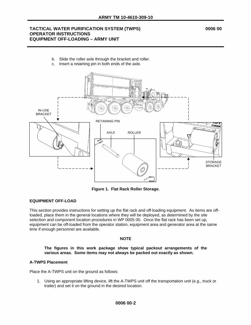
ARMY TM 10-4610-309-10
TACTICAL WATER PURIFICATION SYSTEM (TWPS) OPERATOR INSTRUCTIONS EQUIPMENT OFF-LOADING – ARMY UNIT
0006 00
0006 00-2
b. Slide the roller axle through the bracket and roller. c. Insert a retaining pin in both ends of the axle.
Figure 1. Flat Rack Roller Storage.
EQUIPMENT OFF-LOAD
This section provides instructions for setting up the flat rack and off-loading equipment. As items are off-loaded, place them in the general locations where they will be deployed, as determined by the site selection and component location procedures in WP 0005 00. Once the flat rack has been set up, equipment can be off-loaded from the operator station, equipment area and generator area at the same time if enough personnel are available.
NOTE
The figures in this work package show typical packout arrangements of the various areas. Some items may not always be packed out exactly as shown.
A-TWPS Placement
Place the A-TWPS unit on the ground as follows:
1. Using an appropriate lifting device, lift the A-TWPS unit off the transportation unit (e.g., truck or trailer) and set it on the ground in the desired location.
RETAINING PIN
AXLE ROLLER
IN-USEBRACKET
STORAGE BRACKET

ARMY TM 10-4610-309-10
TACTICAL WATER PURIFICATION SYSTEM (TWPS) OPERATOR INSTRUCTIONS EQUIPMENT OFF-LOADING – ARMY UNIT
0006 00
0006 00-3
2. Remove the left, back end panel from the flat rack and remove the protractor (level) provided with the unit from its holder on the frame at the operator end of the TWPS unit (Figure 2).
3. Place the protractor (level) on any horizontal surface of the TWPS and check the following levels: a. No more than 2 degrees cross-wise (front to back) (Figure 2). b. No more than 1 ½ degrees length-wise (side to side) (Figure 2).
4. If the levels exceed the recommended values, the site must be graded or the TWPS unit moved to a site that meets the level requirements.
Figure 2. Leveling the A-TWPS.
LEVEL TO WITHIN 2 DEGREES FRONT TO BACK
LEVEL TO WITHIN 1 ½ DEGREES SIDE TO SIDE
PROTRACTOR (LEVEL)

ARMY TM 10-4610-309-10
TACTICAL WATER PURIFICATION SYSTEM (TWPS) OPERATOR INSTRUCTIONS EQUIPMENT OFF-LOADING – ARMY UNIT
0006 00
0006 00-4
Preparation for Equipment Off-Load
Two person lift. Two people are required to safely move the flat rack panels. Lift with your legs, not your back. Failure to observe this warning may result in back injury.
1. Unlatch and remove flat rack rear panels #3 and #4 (Figure 3).
NOTE
Leave panel #5 in place so the folding steps can be used to climb onto the roof of the flat rack for off-loading items packed in the generator area.
Figure 3. Flat Rack Rear Panels.
WARNING
345
FOLDING STEP

ARMY TM 10-4610-309-10
TACTICAL WATER PURIFICATION SYSTEM (TWPS) OPERATOR INSTRUCTIONS EQUIPMENT OFF-LOADING – ARMY UNIT
0006 00
0006 00-5
2. Unlatch and remove operator station end panels #1 and #2 (Figure 4).
Figure 4. Operator Station End Panels.
12

ARMY TM 10-4610-309-10
TACTICAL WATER PURIFICATION SYSTEM (TWPS) OPERATOR INSTRUCTIONS EQUIPMENT OFF-LOADING – ARMY UNIT
0006 00
0006 00-6
CAUTION
Do not stand on the deck until all of the support assemblies are in place or equipment damage may result.
3. At the front of the flat rack, unlatch the deck and carefully lower it to the ground (Figure 5).
Figure 5. Flat Rack Top Panel and Deck.
4. Retrieve the four pad sections and four horizontal sections of the deck support assemblies from the storage locations in the equipment area (Figure 6).
Figure 6. Deck Support Assembly Components.
DECK TOP PANEL
PAD SECTIONS
HORIZONTAL SECTIONS
PINS

ARMY TM 10-4610-309-10
TACTICAL WATER PURIFICATION SYSTEM (TWPS) OPERATOR INSTRUCTIONS EQUIPMENT OFF-LOADING – ARMY UNIT
0006 00
0006 00-7
5. Assemble the deck supports by sliding a horizontal section onto each pad section and securing it with the retaining pin (Figure 7).
Figure 7. Deck Support Assembly.
6. With another person lifting up on the deck, slide the support assemblies into the brackets on the deck and secure them with the retaining pins.
7. Lower the deck until the support assembly pads are on the ground. Adjust the height of individual assemblies as necessary until the deck is level and all four pads are on the ground.
Packed-out items can shift during transport and may fall out when the top panel is opened. To prevent personal injury, be careful when opening the panel.
8. Unlatch and lift up the top panel. With another person holding the panel open and horizontal, insert the retaining pins into the panel supports to lock in position.
9. Remove the tie-down straps securing the packed-out items on the skid and flat rack.
NOTE
Do not remove the two straps that secure the NBC tank.
10. Remove the cargo cover from the generator area.
WARNING
HORIZONTAL SECTION
PAD SECTION
RETAINING PIN

ARMY TM 10-4610-309-10
TACTICAL WATER PURIFICATION SYSTEM (TWPS) OPERATOR INSTRUCTIONS EQUIPMENT OFF-LOADING – ARMY UNIT
0006 00
0006 00-8
Operator Station Off-load
A typical packout of the operator station area is shown in Figure 8. Unpack the area as follows:
Figure 8. Typical Operator Station Area Packout.
1. Remove the items packed out on top of the four BII boxes.
PUMP SKIDS (2)
BII BOXES (4)
HOSE HEATING BLANKET
FLOATING INLET STRAINER
MAIN VENTILATION PLENUM
OPERATOR'S TOOL BOX
UPPER RETAINING ROD
LOWER RETAINING ROD
WQAS-P
1000-GALLON MF FEED TANK

ARMY TM 10-4610-309-10
TACTICAL WATER PURIFICATION SYSTEM (TWPS) OPERATOR INSTRUCTIONS EQUIPMENT OFF-LOADING – ARMY UNIT
0006 00
0006 00-9
Two person lift. Two people are required to safely move the BII boxes and pump skids. Lift with your legs, not your back. Failure to observe this warning may result in back injury.
Chemical dust. If any chemical buckets or chemical packets are broken and chemical dust is present, wear a dust mask, a protective face shield and chemical gloves when handling. Avoid inhaling chemical dust or fumes. Failure to observe this warning may result in mild irritation of the nose, throat, eyes and skin.
Liquid chemicals. If any liquid chemical containers are broken, wear a protective face shield, chemical gloves and a chemical apron when handling. Keep water ready when handling. Avoid contact with the liquid. Failure to observe this warning may result in chemical burns or severe irritation of the nose, throat, eyes and skin.
2. Remove the four BII boxes. 3. Remove the hose heating blankets and pump skid covers. 4. Remove the priming pitcher from inside the pump skid. 5. Remove the pump skid retaining rods. Store in the framework at the end of the flat rack. 6. Remove the pump skids. 7. Remove the remaining items from the operator station area.
WARNING

ARMY TM 10-4610-309-10
TACTICAL WATER PURIFICATION SYSTEM (TWPS) OPERATOR INSTRUCTIONS EQUIPMENT OFF-LOADING – ARMY UNIT
0006 00
0006 00-10
Equipment Area Off-load
A typical packout of the equipment area is shown in Figure 9. Unpack the area as follows:
Figure 9. Typical Equipment Area Packout.
1. If they are to be used, remove the following items from underneath the high pressure pumps (Figure 9):
� Ice intake strainer attached to adaptor A-13 � Adaptor A-11 � Ice auger and handle � OISS tee assembly
2. Remove the items packed on and around the MF pump skid. 3. Remove adaptor A-09 from inside the MF pump skid. 4. Remove the MF pump skid retaining rod and store it in the framework at the operator station end
of the flat rack.
STORAGE TANKS
MF PUMP SKID
POWER CABLES
CHEMICAL BUCKETS
AUXILIARY HOSE
NBC TANK
SUCTION HOSES
ICE AUGER AND HANDLE
OISS TEE
OPERATOR STATION SUPPORT BEAM
RIGHT HOT AIR PLENUM
ADAPTOR A-13
ADAPTOR A-11
ICE INTAKE STRAINER
ADAPTOR A-09
RETAINING ROD
TRIPOD

ARMY TM 10-4610-309-10
TACTICAL WATER PURIFICATION SYSTEM (TWPS) OPERATOR INSTRUCTIONS EQUIPMENT OFF-LOADING – ARMY UNIT
0006 00
0006 00-11
Three person lift. Three people are required to safely move the MF pump skid. Lift with your legs, not your back. Failure to observe this warning may result in back injury.
5. Remove the MF pump skid (Figure 10).
Two person lift. Two people are required to safely move the cyclone separator assembly. Lift with your legs, not your back. Failure to observe this warning may result in back injury.
6. Remove the cyclone separator assembly. 7. Remove the discharge hoses, fuel can and anchor from behind the NBC tank. 8. Remove any items remaining in the equipment area.
Figure 10. MF Pump Skid Removal.
WARNING
ANCHOR
DISCHARGE HOSES
FUEL CAN
CYCLONE SEPARATOR ASSEMBLY
WARNING

ARMY TM 10-4610-309-10
TACTICAL WATER PURIFICATION SYSTEM (TWPS) OPERATOR INSTRUCTIONS EQUIPMENT OFF-LOADING – ARMY UNIT
0006 00
0006 00-12
Generator Area Off-Load
A typical packout of the generator area is shown in Figure 11 and Figure 12. If desired, items that are not going to be used, such as insulating blankets, may be placed on top of the TWPS flat rack. Unpack the generator area as follows:
1. From the front of the flat rack, remove the fuel tank assembly and hose heating blankets packed on top of the generator and the diesel-fired heater.
Two person lift. Two people are required to safely move the diesel-fired heater. Lift with your legs, not your back. Failure to observe this warning may result in back injury.
Three person lift. Three people are required to safely move the diesel pump skids. Lift with your legs, not your back. Failure to observe this warning may result in back injury.
2. Remove the diesel-fired heater and the pump skids.
Figure 11. Typical Generator Area Packout - Front.
DIESEL-FIRED HEATER
PUMP SKIDS (2)
HOSE HEATING BLANKETS
FUEL TANK ASSEMBLY
WARNING
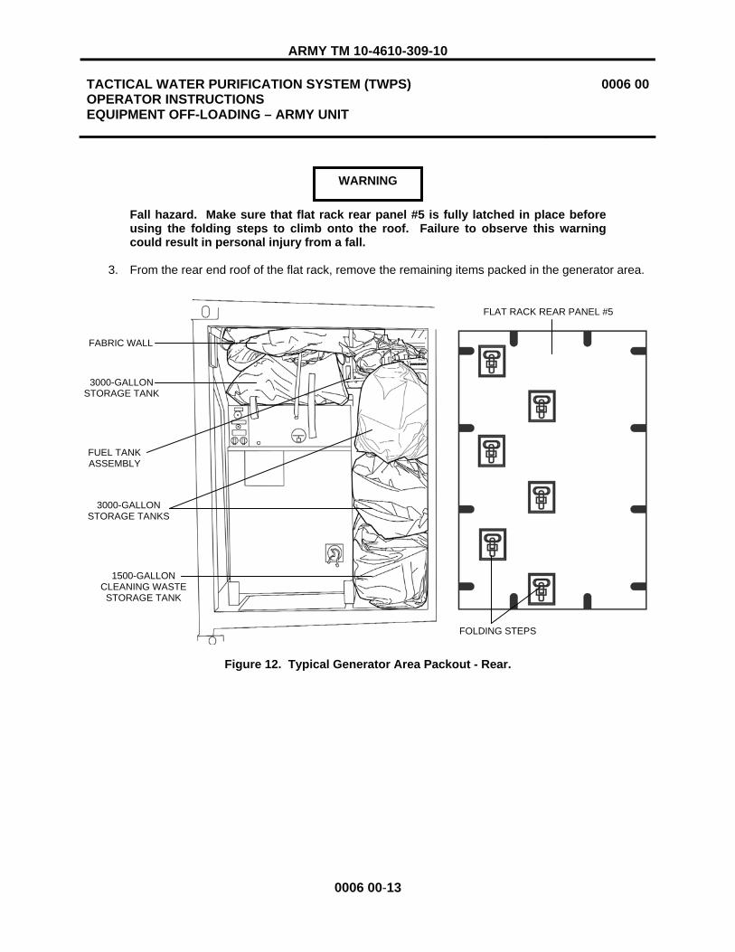
ARMY TM 10-4610-309-10
TACTICAL WATER PURIFICATION SYSTEM (TWPS) OPERATOR INSTRUCTIONS EQUIPMENT OFF-LOADING – ARMY UNIT
0006 00
0006 00-13
Fall hazard. Make sure that flat rack rear panel #5 is fully latched in place before using the folding steps to climb onto the roof. Failure to observe this warning could result in personal injury from a fall.
3. From the rear end roof of the flat rack, remove the remaining items packed in the generator area.
Figure 12. Typical Generator Area Packout - Rear.
3000-GALLON STORAGE TANK
FUEL TANK ASSEMBLY
FABRIC WALL
3000-GALLON STORAGE TANKS
WARNING
FLAT RACK REAR PANEL #5
FOLDING STEPS
1500-GALLON CLEANING WASTE STORAGE TANK

ARMY TM 10-4610-309-10
TACTICAL WATER PURIFICATION SYSTEM (TWPS) OPERATOR INSTRUCTIONS EQUIPMENT OFF-LOADING – ARMY UNIT
0006 00
0006 00-14
Flat Rack Panel, Duct, Suction Hose and OISS Off-Load
Two person lift. Two people are required to safely move the flat rack panels. Lift with your legs, not your back. Failure to observe this warning may result in back injury.
Unpack the remaining items (Figure 13).
Figure 13. Flat Rack Panel, Duct, Suction Hose and OISS Off-Load
1. Unlatch and remove flat rack end panels #6 and #7, located next to the generator. 2. Remove the three ventilation ducts stored on top of the RO feed tank. 3. Unlatch and remove flat rack rear panel #5. 4. Unstrap and remove the suction hoses packed on top of the skid frame.
NOTE
The OISS hoses are color coded yellow. The hoses, along with the OISS risers and wellpoint assemblies, are separately strapped down on top of the skid frame, behind the rest of the hoses. The OISS components can be left in place unless the OISS will be used.
WARNING
OISS HOSES, RISERS AND WELLPOINT ASSEMBLIES
PANEL #6
PANEL #7
SUCTION HOSE
DUCT

ARMY TM 10-4610-309-10
TACTICAL WATER PURIFICATION SYSTEM (TWPS) OPERATOR INSTRUCTIONS EQUIPMENT OFF-LOADING – ARMY UNIT
0006 00
0006 00-15/16 BLANK
5. Group the suction hoses together and distribute them to the deployed locations in accordance with the following color coding:
a. Green – Raw Water b. Blue – Product Water c. Red – Waste and Chemical Cleaning.
6. Reinstall all the flat rack panels if weather conditions such as rain, snow or blowing sand require it. Otherwise, leave the panels off until the TWPS has been started and is operating.
END OF WORK PACKAGE


ARMY TM 10-4610-309-10
TACTICAL WATER PURIFICATION SYSTEM (TWPS) OPERATOR INSTRUCTIONS EQUIPMENT OFF-LOADING – MARINE CORPS UNIT
0007 00
0007 00-1
INITIAL SETUP:
Personnel Required: Three Equipment Condition: Skid packed out with the cargo cover removed.
GENERAL
This work package provides instructions for off-loading equipment and components for operation at a deployed site. Before performing any off-loading procedures, the site and its terrain must be evaluated and the component locations and layout established as described in WP 0005 00.
Depending on the selected operating configuration, some packed-out items may not be used. For example, all of the hose assemblies may not be needed. However, most unused items must be off-loaded so they are not in the way during operation. Only the following items should be left on the skid:
� Nuclear, Biological, and Chemical (NBC) tank � Chemical Injection System Adaptor A-11 (strapped to a pipe near the air compressor) � Reverse Osmosis (RO) element pusher (strapped to a pipe to the left of the MF filters) � Bisulfite and low pH cleaner (stored in the equipment area) � Operator's tool kit
Before starting off-load, select an area for storing the unused items so they are readily available if needed and are all together to reduce the chance of items being lost. The area should be nearby but out of the way so it doesn't interfere with operation or personnel and vehicle traffic. If possible, the unused items should be stored in a tent or covered with a tarp for protection.
Extended Capability Modules
Depending on tactical and environmental conditions and the layout of the deployment site, various extended capability modules may be used. These include:
� Cold Weather Module � Supplemental Cleaning Waste Storage Module � Ocean Intake Structure System Module � NBC Water Treatment Module � NBC Survivability Module � Extended Product Water Distribution Kit
The components of these modules are packed out and transported in their own containers.
Hose Identification
To make hoses easier to identify, all suction and discharge hoses are coded with colored bands at each end as follows:
� Raw Water – green � Product Water – blue � Cleaning and Waste - red

ARMY TM 10-4610-309-10
TACTICAL WATER PURIFICATION SYSTEM (TWPS) OPERATOR INSTRUCTIONS EQUIPMENT OFF-LOADING – MARINE CORPS UNIT
0007 00
0007 00-2
EQUIPMENT OFF-LOAD
This section provides instructions for off-loading equipment. As items are off-loaded, place them in the general locations where they will be used as determined by the site selection and component location procedures in WP 0005 00. Equipment can be off-loaded from the operator station and equipment area at the same time if enough personnel are available.
NOTE
The figures in this work package show typical packout arrangements. Some items may not always be packed out exactly as shown.
MC-TWPS Placement
Place the MC-TWPS unit on the ground as follows:
CAUTION
Do not lift the MC-TWPS from the back where the MF assembly is located. Lift the MC-TWPS from the front. Failure to observe this caution may result in significant damage to the MF assembly.
1. Using an appropriate lifting device, lift the MC-TWPS unit off the transportation unit (e.g., truck or trailer) and set it on the ground in the desired location.
2. Remove the protractor (level) provided with the unit from its holder on the frame at the operator end of the TWPS unit (Figure 1).
3. Place the protractor (level) on any horizontal surface of the TWPS and check the following levels: a. No more than 2 degrees cross-wise (front to back) (Figure 1). b. No more than 1 ½ degrees length-wise (side to side) (Figure 1).
4. If the levels exceed the recommended values, the site must be graded or the TWPS unit moved to a site that meets the level requirements.

ARMY TM 10-4610-309-10
TACTICAL WATER PURIFICATION SYSTEM (TWPS) OPERATOR INSTRUCTIONS EQUIPMENT OFF-LOADING – MARINE CORPS UNIT
0007 00
0007 00-3
Figure 1. Leveling the MC-TWPS.
LEVEL TO WITHIN 2 DEGREES FRONT TO BACK
LEVEL TO WITHIN 1 ½ DEGREES SIDE TO SIDE
LEVEL
MF ASSEMBLY

ARMY TM 10-4610-309-10
TACTICAL WATER PURIFICATION SYSTEM (TWPS) OPERATOR INSTRUCTIONS EQUIPMENT OFF-LOADING – MARINE CORPS UNIT
0007 00
0007 00-4
Operator Station Off-Load
A typical packout of the operator station area is shown in Figure 2 and Figure 3.
Figure 2. Typical Operator Station Packout – Front View.
MF FEED TANK
BII BOXES (3)
MOTOR-DRIVEN PUMP SKIDS (2)
FUEL TANK ASSEMBLY
TDS/pH METER KIT (NOT VISIBLE)

ARMY TM 10-4610-309-10
TACTICAL WATER PURIFICATION SYSTEM (TWPS) OPERATOR INSTRUCTIONS EQUIPMENT OFF-LOADING – MARINE CORPS UNIT
0007 00
0007 00-5
Figure 3. Typical Operator Station Packout – Side View.
Off-load the operator station as follows:
1. Remove the tie-down straps. 2. Remove the 1000-gallon MF feed tank, the TDS/pH Meter Kit located under the MF feed tank and
the fuel tank assembly.
Two person lift. Two people are required to safely move the BII boxes and motor-driven pump skids. Lift with your legs, not your back. Failure to observe this warning may result in back injury.
3. Remove the priming pitcher, Adaptor A09 and distribution nozzles from inside the pump skids. 4. Remove the three BII boxes from on top of the pump skids. 5. Remove the motor-driven pump skid retaining rods and the pump skids. 6. Remove the discharge hoses, power cables and BII Box #4 from on top of the diesel pump skid.
1000-GALLON MF FEED TANK
3000-GALLON DISTRIBUTION TANK DISCHARGE HOSES
POWER CABLE
BII BOX #5 DIESEL-DRIVENPUMP SKID
ADAPTOR A09 DISTRIBUTION NOZZLES
MOTOR-DRIVEN PUMP SKIDS
WARNING
BII BOX #4

ARMY TM 10-4610-309-10
TACTICAL WATER PURIFICATION SYSTEM (TWPS) OPERATOR INSTRUCTIONS EQUIPMENT OFF-LOADING – MARINE CORPS UNIT
0007 00
0007 00-6
Three person lift. Three people are required to safely move the diesel pump skid. Lift with your legs, not your back. Failure to observe this warning may result in back injury.
Two person lift. Two people are required to safely move the distribution tank, power cable and BII box #5. Lift with your legs, not your back. Failure to observe this warning may result in back injury.
7. Remove the diesel pump skid retaining rods and the pump skid. 8. Remove the 3000-gallon distribution tank. 9. With another person assisting, uncoil the power cable and route it out the end of the skid. 10. Remove BII Box #5.
Chemical dust. If any chemical buckets or chemical packets are broken and chemical dust is present, wear a dust mask, a protective face shield and chemical gloves when handling. Avoid inhaling chemical dust or fumes. Failure to observe this warning may result in mild irritation of the nose, throat, eyes and skin.
Liquid chemicals. If any liquid chemical containers are broken, wear a protective face shield, chemical gloves and a chemical apron when handling. Keep water ready when handling. Avoid contact with the liquid. Failure to observe this warning may result in chemical burns or severe irritation of the nose, throat, eyes and skin.
11. Remove the chemical buckets and lids.
Operator Station Roof Raising
Raise the operator station roof as follows:
1. If the general purpose cover is installed over the TWPS unit, unfasten the straps (three at one end) and snaps (six in front and six in back) around the expandable end of the cover above the operator station roof (Figure 4).
WARNING
WARNING

ARMY TM 10-4610-309-10
TACTICAL WATER PURIFICATION SYSTEM (TWPS) OPERATOR INSTRUCTIONS EQUIPMENT OFF-LOADING – MARINE CORPS UNIT
0007 00
0007 00-7
Figure 4. General Purpose Cover Straps and Snaps Over the Operator Station.
2. If the winter cover is installed over the TWPS unit, unfasten the straps around the expandable end of the cover above the operator station roof (Figure 5).
Figure 5. Winter Cover Straps Over the Operator Station.
3. Unfasten the operator station overhead support beam padding hook and loop seam. Remove the padding from the support beam.
4. Store the padding in a BII Box after other components are unpacked from the boxes. 5. Remove the eight bolts and lock washers from the operator station overhead support beam and
remove the beam (Figure 6). 6. Reinstall the bolts and washers in the TWPS frame. 7. Store the beam under the high-pressure pumps. 8. Remove the retaining pins from the operator station roof and TWPS frame.
EXPANDABLE END OF GENERAL PURPOSE COVER
STRAPS
SNAPS
STRAPS
STRAPSEXPANDABLE END OF WINTER COVER

ARMY TM 10-4610-309-10
TACTICAL WATER PURIFICATION SYSTEM (TWPS) OPERATOR INSTRUCTIONS EQUIPMENT OFF-LOADING – MARINE CORPS UNIT
0007 00
0007 00-8
9. Raise the roof. 10. Install the pins through the bottom holes in the legs of the roof and through the holes in the TWPS
frame to secure the roof in the raised position (Figure 6).
Figure 6. Operator Station Overhead Support Beam Removal and Roof Raising.
BOLTS AND WASHERS
ROOF
SUPPORT BEAM
RETAINING PIN
SUPPORT BEAM PAD
GENERAL PURPOSE COVER WINTER COVER

ARMY TM 10-4610-309-10
TACTICAL WATER PURIFICATION SYSTEM (TWPS) OPERATOR INSTRUCTIONS EQUIPMENT OFF-LOADING – MARINE CORPS UNIT
0007 00
0007 00-9
Equipment Area Off-Load
A typical packout of the equipment area is shown in Figure 7.
Figure 7. Typical Equipment Area Packout.
Off-load the equipment area as follows:
1. Remove the two transport reinforcing chains. 2. Remove the tie-down straps.
NOTE
Do not remove the two tie-down straps that secure the NBC tank. The tank will not be off-loaded.
3. Remove the following items from on top of and behind the distribution tank: � Three 3-in. x 10-ft. green-banded raw water suction hoses � 4-in. x 5-ft. red-banded cleaning suction hose � 5/8-in. x 50-ft. auxiliary hose assembly P06 � Two 2-in. x 5-ft. product water suction hoses (not visible in Figure 7) � 3-in. x 3-ft. MF suction hose (not visible in Figure 7) � Floating inlet strainer � 6-in. x 50-ft. red-banded waste discharge hose � Tripod
TRANSPORT REINFORCING CHAIN WITH
PLASTICSHEATH
4 X 5 CLEANING SUCTION HOSE
AUXILIARY HOSE
2 X 5 PRODUCT WATER SUCTION HOSES 3 X 3 MF SUCTION HOSE
FLOATING INLET STRAINER (HIDDEN) TRIPOD (HIDDEN)
3000-GALLON DISTRIBUTION TANK
6 X 50 WASTE DISCHARGE HOSE
NBC TANK
3 X 10 RAW WATER SUCTION HOSES

ARMY TM 10-4610-309-10
TACTICAL WATER PURIFICATION SYSTEM (TWPS) OPERATOR INSTRUCTIONS EQUIPMENT OFF-LOADING – MARINE CORPS UNIT
0007 00
0007 00-10
WARNING
Two person lift. Two people are required to safely move the distribution tank. Lift with your legs, not your back. Failure to observe this warning may result in back injury.
4. Remove the 3000-gallon distribution tank. 5. Remove the following items (Figure 8):
� Discharge hoses (3), packed inside the MF pump skid � Fuel can � Operator’s tool kit � Bisulfite and low ph cleaner � MF pump skid retaining rod
Figure 8. Equipment Area Off-Load 1.
FUEL CAN HOSES (3) RETAINING ROD MF PUMP SKID
CHEMICAL BUCKETS (2) TOOL KIT

ARMY TM 10-4610-309-10
TACTICAL WATER PURIFICATION SYSTEM (TWPS) OPERATOR INSTRUCTIONS EQUIPMENT OFF-LOADING – MARINE CORPS UNIT
0007 00
0007 00-11
Three person lift. Three people are required to safely move the MF pump skid. Lift with your legs, not your back. Failure to observe this warning may result in back injury.
6. Remove the MF pump skid. 7. Remove the suction hoses packed on top of the cyclone separator and behind the NBC tank
(Figure 9).
Figure 9. Equipment Area Off-Load 2.
WARNING
SUCTION HOSES
CYCLONE SEPARATOR

ARMY TM 10-4610-309-10
TACTICAL WATER PURIFICATION SYSTEM (TWPS) OPERATOR INSTRUCTIONS EQUIPMENT OFF-LOADING – MARINE CORPS UNIT
0007 00
0007 00-12
Two person lift. Two people are required to safely move the cyclone separator assembly. Lift with your legs, not your back. Failure to observe this warning may result in back injury.
8. Remove the cyclone separator assembly. 9. Remove the ten, green-banded raw water suction hoses from on top of the RO feed tank.
Do not walk on the roof support sheets. They are not designed to support the weight of a person. Failure to observe this warning may result in injury or damage to equipment.
10. Check the position of the roof support sheets (Figure 10). If they have shifted, space them equally over the top of the TWPS, but still under the general purpose cover or the winter cover, whichever is in use.
Figure 10. Roof Support Sheet Positioning.
END OF WORK PACKAGE
WARNING
ROOF SUPPORT SHEETS
WARNING

ARMY TM 10-4610-309-10
TACTICAL WATER PURIFICATION SYSTEM (TWPS) OPERATOR INSTRUCTIONS SET-UP – OPERATION UNDER USUAL CONDITIONS
0008 00
0008 00-1
INITIAL SETUP
Tools:Torque Wrench (WP 0045, Item 128) Reference: Refer to WP 0036 – PMCS for “Before” PMCS checks Refer to TM 5-6115-672-14 - Tactical Quiet Generator Operating Procedures for generator start up. Refer to Army TM 10-5430-237-12&P for collapsible water tank set up and operation or Refer to Marine Corps TM 01034E-12&P/1 for collapsible water tank set up and operation. Personnel Required: Three Operator/Crew Equipment Condition: TWPS skid removed from transport vehicle and set on level ground. Loose items unpacked (off-loaded) from the TWPS skid and placed in general operational position.
GENERAL
This work package contains procedures to fully set up the TWPS for initial operation under usual operational conditions. Before performing set up procedures, the site and terrain must be evaluated and the component locations and layout established as described in WP 0005 00.
Refer to WP 0027 00, Cold Weather Set-Up – Operation Under Unusual Conditions, if the existing outdoor temperature is below 32˚ F or expected to be below 32˚ F within the next 24 hours.
Refer to WP 0028 00, Other Set-Ups – Operation Under Unusual Conditions, if the TWPS is deployed on a mission with any of the following unusual conditions:
- Chlorinated raw water source - NBC decontamination mission - Existing temperatures are above 90º F or expected to go above 90º F within the next 24 hours - Sandy or dusty environment
The procedures covered in this work package include: � Planning and Organization � Locate Fire Extinguisher � Establish Electrical Power � Air Compressor Start-Up � P-1 Pump to P-2 Pump to Cyclone Separator Configuration Deployment � P-2 Pump or P-1 Pump Only Configuration Deployment � Sodium Bisulfite System Set-Up � Floating Inlet Strainer and Anchor Deployment � Micro-Filtration (MF) Equipment Set-Up � Waste Outlet Connections � Making Power Cable Connections to the TWPS � Establishing Raw Water Flow � Standard Distribution System Set-Up � Pre-Operational Checks � Fabric Wall Set-Up (A-TWPS) � Extended Distribution System Set-Up (A-TWPS) � Lowering and Raising the Bail Bar (A-TWPS)

ARMY TM 10-4610-309-10
TACTICAL WATER PURIFICATION SYSTEM (TWPS) OPERATOR INSTRUCTIONS SET-UP – OPERATION UNDER USUAL CONDITIONS
0008 00
0008 00-2
PLANNING AND ORGANIZATION
Table 1 is a recommended team approach for establishing the various water and electrical connections and performing the initial checks and inspections to get the TWPS ready for operation. The procedures are in the general order of activity. While setting up the ground-operated equipment, keep in mind the overall work site dimensions as described in the Site Selection and Component Location WP 0005 00.
Table 1. Set-up Procedure for Usual Conditions
OPERATORPROCEDURE 1 2 3
Locate fire extinguisher x Establish electrical power x Start-up air compressor x Move raw water pump skids into position x x Move raw water hoses/power cables into position x x Connect raw water hoses x x Connect cyclone separator/raw water hoses x x Deploy the raw water strainer/anchor/OISS x x Move micro-filtration pump skid & water tank into position x x Connect micro-filtration water hoses x x Connect waste outlet drain hose x Connect raw water and MF feed pump skid power cables x Establish raw water flow x x Move distribution pump skid and water tanks into position x x Connect distribution water hoses x x Connect distribution power cable x Perform pre-operational checks x Start the TWPS x Set up the fabric wall (A-TWPS) x x x Set up the extended distribution system (A-TWPS) x x x
LOCATE FIRE EXTINGUISHER
Remove the fire extinguisher from the mounting bracket located below the MF Feed Strainer S-2. Set the fire extinguisher on the ground in the general location where the ground rod will be placed.
ESTABLISH ELECTRICAL POWER
For the most efficient use of time, one person can be establishing power to the TWPS while the other two people are setting up the equipment. To ensure each other’s safety, all three people should coordinate their activities so that no one is put in danger when electrical connections and operations are made.
Refer to WP 0010 00, Establishing Electrical Power, for the specific procedures for establishing electrical power to the TWPS.

ARMY TM 10-4610-309-10
TACTICAL WATER PURIFICATION SYSTEM (TWPS) OPERATOR INSTRUCTIONS SET-UP – OPERATION UNDER USUAL CONDITIONS
0008 00
0008 00-3
AIR COMPRESSOR START-UP
As soon as electrical power is established at the TWPS and the PDP is energized, it is recommended that the air compressor be started up. A minimum air pressure is required for the automatic backwash operation before the TWPS can be operated. Starting the compressor as early as possible during set up allows the compressor to pressurize the air supply tank (in about 30 minutes) while other set up steps are performed.
Instructions for starting up the air compressor are described in WP 0012 00, Initial Start-Up or Start-Up with the System Fully Drained.
SET UP THE RAW WATER SYSTEM
Two possible raw water system configuration set-ups are described here: - P-1 Pump to P-2 Pump to Cyclone Separator Configuration Deployment - P-2 Pump or P-1 Pump Only Configuration Deployment
NOTE
As the discharge hoses are laid out and connected, any excess length must be taken up in long smooth curves to avoid kinking of the hose when pressurized.
P-1 PUMP TO P-2 PUMP TO CYCLONE SEPARATOR CONFIGURATION DEPLOYMENT
CAUTION
Potential water damage to equipment. Note potential tidal or river flood conditions and keep the raw water pumps located beyond the reach of the water. Failure to observe this caution may result in water damage to the pump and diesel engine or motor.
1. Position the raw water pumps and cyclone separator as follows (Figure 1):
Three person lift. Three people are required to safely lift Diesel-Driven Pump Skid P-1. Lift with your legs, not your back. Failure to observe this warning may result in back injury.
Two person lift. Two people are required to safely lift the cyclone separator and Motor-Driven Pump Skid P-2. Lift with your legs, not your back. Failure to observe this warning may result in back injury.
a. Move Diesel-Driven Pump Skid P-1 and Motor-Driven Pump Skid P-2 into place. b. Place the pump skids on solid footing and as level as possible. c. Move the cyclone separator into place. Make sure the location selected for the separator
will hold the weight of the cyclone when filled with water without the cyclone tipping over. d. Place an absorbent pad under Diesel-Driven Pump Skid P-1 for environmental protection
in the event of a fuel spill.
WARNING

ARMY TM 10-4610-309-10
TACTICAL WATER PURIFICATION SYSTEM (TWPS) OPERATOR INSTRUCTIONS SET-UP – OPERATION UNDER USUAL CONDITIONS
0008 00
0008 00-4
Figure 1. P-1 Pump to P-2 Pump to Cyclone Separator Configuration Deployment.
e. Install the fuel tank on Diesel-Driven Pump Skid P-1 as follows (Figure 2): 1) Set the fuel tank assembly on the pump skid. 2) Connect the red-banded fuel tank fuel supply hose to the red-banded engine fuel
supply hose with the quick-connect fittings. 3) Connect the yellow-banded fuel tank return hose to the yellow-banded engine
fuel return hose with the quick-connect fittings.
Figure 2. Diesel-Driven Pump Fuel Tank Installation.
A-01 A-02 A-04
P-2
P-1
A-03A-05
CYCLONE SEPARATOR
2 X 6 D-HOSE
2 X 50 D-HOSE
2 X 50 D-HOSE
2 X 10 S-HOSE
PRIMINGVENT HOSE
WASTE HOSE
YELLOW-BANDED FUEL RETURN HOSE
RED-BANDED FUEL SUPPLY HOSE
YELLOW-BANDED FUEL RETURN HOSE
RED-BANDED FUEL SUPPLY HOSE
FUEL TANK ASSEMBLY
DIESEL ENGINE-DRIVEN PUMP SKID

ARMY TM 10-4610-309-10
TACTICAL WATER PURIFICATION SYSTEM (TWPS) OPERATOR INSTRUCTIONS SET-UP – OPERATION UNDER USUAL CONDITIONS
0008 00
0008 00-5
2. Connect the raw water adaptors and hoses as follows:
Health hazard. Do not attempt to use product water hoses to handle raw water or raw water hoses to handle product water. When installed with the proper adaptors as directed, the hoses cannot be interchanged. Failure to observe this warning and mixing hoses could cause contamination of water resulting in serious illness.
a. Collect the following hoses and adaptor assemblies: 1) One 2 in. x 6 ft., green-banded raw water discharge hose. 2) Two to four 2 in. x 50 ft., green-banded raw water discharge hoses. 3) One 2 in. x 10 ft., green-banded raw water suction hose. 4) Adaptor assemblies A-01, A-02, A-03, A-04 and A-05. 5) One 1 in. x 5 ft., clear plastic priming vent hose. 6) One 1 in. x 5 ft., clear plastic cyclone separator waste hose.
b. Inspect gaskets in the female ends of the hoses. Replace any damaged or missing gaskets.
c. Check the inlet, outlet and waste openings of the cyclone separator for any foreign matter that may have entered during transit and clear it out of the openings.
NOTE
When installing Adaptor A-01, the bolt on the check valve must be oriented in a vertical position. Failure to observe this note may limit the effectiveness of the check valve and result in an inability to maintain prime.
The support strap on Adaptor A-01 must be oriented near the top of the adaptor and firmly secured to the pump frame to make sure air does not leak into the adaptor. Failure to observe this note may result in a reduced pumping capacity or an inability to maintain prime.
d. Attach Adaptor A-01 to the suction inlet of the diesel-driven pump. Loop the strap over the pump frame crossbar and tighten to a slight tension.
e. Attach Adaptor A-02 to the discharge outlet of the diesel-driven pump. f. Connect the priming vent hose to Adaptor A-02. g. Attach Adaptor A-03 to the wastewater outlet of the cyclone separator and then attach
the cyclone separator waste hose. h. Attach Adaptor A-04 to the discharge outlet of the motor-driven pump. i. Connect, as needed, one or two 2 in. x 50 ft., green-banded discharge hoses to Adaptor
A-02 at the discharge outlet of Diesel-Driven Pump P-1 and to the suction inlet of the Motor-Driven Pump P-2.
j. Connect the 2 in. x 6 ft., green-banded discharge hose to Adaptor A-04 at the discharge outlet of Motor-Driven Pump P-2 and to the inlet of the cyclone separator.
k. Connect, as needed to reach the MF Feed Tank, one or two 2 in. x 50 ft., green-banded discharge hoses to the cyclone separator outlet.
l. Connect Adaptor A-05 to the end of the discharge hose that is coming from the cyclone separator.
m. Connect the 2 in. x 10 ft., green-banded suction hose to Adaptor A-05.
WARNING

ARMY TM 10-4610-309-10
TACTICAL WATER PURIFICATION SYSTEM (TWPS) OPERATOR INSTRUCTIONS SET-UP – OPERATION UNDER USUAL CONDITIONS
0008 00
0008 00-6
Electrical hazard. The TWPS operates on 416 Volts AC. Making electrical connections to the TWPS power distribution panel must be coordinated with the procedures for establishing electrical power to the TWPS. DO NOT connect the Motor-Driven Pump P-2 electrical power cable at this time. Failure to observe this warning may result in serious injury or death from electrocution.
P-2 PUMP OR P-1 PUMP ONLY CONFIGURATION DEPLOYMENT
CAUTION
Potential water damage to equipment. Note potential tidal or river flood conditions and keep the raw water pump located beyond the reach of the water. Failure to observe this caution may result in water damage to the pump and motor.
1. Position the raw water pump as follows (Figure 3 or Figure 4):
Three person lift. Three people are required to safely lift Diesel-Driven Raw Water Pump Skid P-1. Lift with your legs, not your back. Failure to observe this warning may result in back injury.
Two person lift. Two people are required to safely lift Motor-Driven Raw Water Pump Skid P-2. Lift with your legs, not your back. Failure to observe this warning may result in back injury.
a. Move Motor-Driven Pump Skid P-2 or Diesel-Driven Pump Skid P-1 into place. b. Place the pump skid on solid footing and as level as possible.
Figure 3. P-2 Pump Only Configuration Deployment.
WARNING
A-01 A-02 A-05
P-2
2 X 10 S-HOSE
2 X 50 D-HOSE
WARNING
PRIMINGVENT HOSE

ARMY TM 10-4610-309-10
TACTICAL WATER PURIFICATION SYSTEM (TWPS) OPERATOR INSTRUCTIONS SET-UP – OPERATION UNDER USUAL CONDITIONS
0008 00
0008 00-7
Figure 4. P-1 Pump Only Configuration Deployment.
c. If Diesel-Driven Pump P-1 is used, place an absorbent pad under it for environmental protection in the event of a fuel spill and install the fuel tank as follows (Figure 2):
1) Set the fuel tank assembly on the pump skid 2) Connect the red-banded fuel tank fuel supply hose to the red-banded engine fuel
supply hose with the quick-connect fittings. 3) Connect the yellow-banded fuel tank return hose to the yellow-banded engine
fuel return hose with the quick-connect fittings. 2. Connect the raw water adaptors and hoses as follows:
Health hazard. Do not attempt to use product water hoses to handle raw water or raw water hoses to handle product water. When installed with the proper adaptors as directed, the hoses cannot be interchanged. Failure to observe this warning and mixing hoses could cause contamination of water resulting in serious illness.
a. Collect the following hoses and adaptor assemblies: 1) One to two 2 in. x 50 ft., green-banded raw water discharge hoses. 2) One 2 in. x 10 ft., green-banded raw water suction hose. 3) Adaptor assemblies A-01, A-02 and A-05. 4) One 1 in. x 5 ft., clear plastic priming vent hose.
b. Inspect gaskets in the female ends of the hoses. Replace damaged or missing gaskets.
WARNING
A-01
A-02A-05
2 X 50 D-HOSE
2 X 10 S-HOSE
P-1
PRIMINGVENT HOSE

ARMY TM 10-4610-309-10
TACTICAL WATER PURIFICATION SYSTEM (TWPS) OPERATOR INSTRUCTIONS SET-UP – OPERATION UNDER USUAL CONDITIONS
0008 00
0008 00-8
NOTE
When installing Adaptor A-01, the bolt on the check valve must be oriented in a vertical position. Failure to observe this note may limit the effectiveness of the check valve and result in an inability to maintain prime.
The support strap on Adaptor A-01 must be oriented near the top of the adaptor and firmly secured to the pump frame to make sure air does not leak into the adaptor. Failure to observe this note may result in a reduced pumping capacity or an inability to maintain prime.
c. Attach Adaptor A-01 to the suction inlet of the raw water pump. Loop the strap over the pump frame crossbar and tighten to a slight tension.
d. Attach Adaptor A-02 to the discharge outlet of the raw water pump. e. Connect the priming vent hose to Adaptor A-02. f. Connect, as needed to reach the MF Feed Tank, one or two 2 in. x 50 ft., green-banded
discharge hoses to Adaptor A-02 at the discharge outlet of the raw water pump. g. Connect Adaptor A-05 to the end of the discharge hose coming from Adaptor A-02. h. Connect the 2 in. x 10 ft., green-banded suction hose to Adaptor A-05.
Electrical hazard. The TWPS operates on 416 Volts AC. Making electrical connections to the TWPS power distribution panel must be coordinated with the procedures for establishing electrical power to the TWPS. If Motor-Driven Pump P-2 is used, DO NOT connect its electrical power cable at this time. Failure to observe this warning may result in serious injury or death from electrocution.
SODIUM BISULFITE SYSTEM SET-UP
CAUTION
Potential for damage to the MF elements and RO membranes. Chlorine will destroy the MF elements and RO membranes. If the raw water source is chlorinated, sodium bisulfite must be mixed into the raw water before it is pumped into the MF feed tank. Sodium bisulfite neutralizes the chlorine. Failure to observe this caution will result in the destruction of the MF elements and RO membranes.
The sodium bisulfite system MUST be set up before chlorinated raw water is pumped into the MF Feed Tank. Instructions for setting up the sodium bisulfite system are described in WP 0028 00, Other Set-Ups – Operation Under Unusual Conditions.
WARNING

ARMY TM 10-4610-309-10
TACTICAL WATER PURIFICATION SYSTEM (TWPS) OPERATOR INSTRUCTIONS SET-UP – OPERATION UNDER USUAL CONDITIONS
0008 00
0008 00-9
FLOATING INLET STRAINER AND ANCHOR DEPLOYMENT
If the raw water source is from a sandy beach location and if surf conditions or tide extremes make it difficult or impossible to use the floating inlet strainer, the OISS should be deployed instead of the floating inlet strainer. For OISS setup see WP 0026 00.
Deploy the floating inlet strainer and anchor as follows: 1. Carry the following items to the first raw water pump skid:
a. Floating inlet strainer b. The number of raw water suction hoses required to deploy the inlet strainer to the desired
location in the raw water source (up to thirteen 3 in. x 10 ft., green-banded suction hoses) c. Anchor d. Anchor tie-down rope
Health hazard. Do not attempt to use product water hoses to handle raw water or raw water hoses to handle product water. When installed with the proper adaptors as directed, the hoses cannot be interchanged. Failure to observe this warning and mixing hoses could cause contamination of water resulting in serious illness.
NOTE
The floating strainer and anchor may be used in conjunction with the Ocean Intake Structure System (OISS). If the OISS is to be used, refer to WP 0026 00 for procedures for installing the OISS.
When deploying the floating inlet strainer, keep the following in mind: - Two persons are required to deploy the inlet strainer. - Place the inlet strainer in deep water at the center of narrow rivers. - Place the inlet strainer as far from shore as possible in wide rivers. - Place the inlet strainer as far out as possible at ocean beaches. - Flat tidal beaches may require moving the pump according to tide conditions.
2. Assemble the anchor, rope, inlet strainer and hoses on-shore as follows (Figure 5): a. Attach the shackle and pulley to the anchor eye and double the rope back so that the
rope length from the anchor to the free end is at least 150 ft.b. Inspect gaskets in the female ends of the hoses. Replace any damaged or missing
gaskets. c. Always rinse off the hose ends with water to remove dirt and sand. d. Connect the number of 10 ft., green-banded suction hoses to each other that will be
required to deploy the inlet strainer to the desired location in the raw water source. e. Connect one end of the hose assembly to the inlet strainer. Install the 3 in. plug in the
other end of the raw water hose assembly. This traps air inside the hose allowing the hose to float until the inlet strainer is positioned at the desired location in the raw water source.
f. Shackle the end of the rope to the inlet strainer eye and tie the free end to the suction hose.
g. Carefully coil the rope to prevent it from tangling when the anchor is deployed.
WARNING

ARMY TM 10-4610-309-10
TACTICAL WATER PURIFICATION SYSTEM (TWPS) OPERATOR INSTRUCTIONS SET-UP – OPERATION UNDER USUAL CONDITIONS
0008 00
0008 00-10
Figure 5. Anchor, Rope, Inlet Strainer and Hoses Assembled On-Shore.
3. Deploy the anchor as follows:
Potential for physical injury. Crew members, other than those deploying the anchor, must stand clear when the anchor is being deployed. Failure to observe this warning may result in serious injury if a person is hit with the anchor.
a. Gain good footing near the water’s edge. b. Make sure the rope is free to play out. c. Throw the anchor underhand into the water source. d. At beach sites, walk or carry the anchor to the desired location about 30 ft. past the
desired location of the inlet strainer. e. Pull slowly on the rope and feel for the anchor to grab. If it does not grab, repeat the
anchor deployment throwing it into an adjacent location.
NOTE
The anchor may be deployed by boat if available and if water conditions allow. Appropriate water safety precautions, such as the use of life jackets or vests, must be observed.
4. Complete the raw water hose connections as follows (Figure 6): a. Untie the free end of the rope from the suction hose. b. One crew-member pulls the free end of the rope as another feeds out the inlet strainer
and suction hose into the water. c. When the inlet strainer is in the desired position, uncap the hose end and the hose will
sink. d. Tie the free end of the anchor rope to the raw water pump frame to secure the anchor. e. Connect the uncapped end of the raw water suction hose to Adaptor A-01 at the raw
water pump inlet.
WARNING
SHACKLE
ANCHOR
PULLEY
FLOATING INLET STRAINER
3 X 10 S-HOSE
3 IN. PLUG
SHACKLE

ARMY TM 10-4610-309-10
TACTICAL WATER PURIFICATION SYSTEM (TWPS) OPERATOR INSTRUCTIONS SET-UP – OPERATION UNDER USUAL CONDITIONS
0008 00
0008 00-11
NOTE
If it is necessary to elevate the pump off the ground, such as at locations with significant tidal variations, it will also be necessary to stake up the inlet hose at the raw water pump inlet to limit the strain on the A-01 adaptor and to ensure a tight seal (no air leaks) at the adaptor. Failure to observe this note may result in a reduced pumping capacity or an inability to maintain prime.
Figure 6. Raw Water Inlet System Deployment.
MICRO-FILTRATION (MF) EQUIPMENT SET-UP
Deploy the MF system equipment as follows: (Figure 7)
Two person lift. Two people are required to lift the MF feed tank. Lift with your legs, not your back. Failure to observe this warning may result in back injury.
Three person lift. Three people are required to lift the MF feed pump. Lift with your legs, not your back. Failure to observe this warning may result in back injury.
1. Position the MF feed tank, tripod and MF feed pump as follows: a. Place the MF feed tank in its rough location (about 20 ft. from the TWPS). b. Unfold the ground cloth from around the tank and unfold the tank on the ground cloth. c. Spread the tank out to its final shape and eliminate any ridges in the bottom. d. Insert the MF feed tank Bag Strainer S-1 inside the MF feed tank. Overlap the top of the
strainer over the open lip of the feed tank. e. Tighten the strainer draw rope to take up the slack and place it under a little tension. f. Pull the tank inlet and outlet connections out away from the tank bottom so that they will
be clear when the tank is filled. g. Set up the tripod at the side of the tank where the 2 x 10 raw water hose will be inserted. h. Move Motor-Driven MF Feed Pump Skid P-3 roughly in place as shown in Figure 7. i. Place the pump skid on solid footing and as nearly level as possible.
WARNING
ANCHOR
FLOATING INLET STRAINER
RAW WATER PUMP
3 X 10 S-HOSE
A-01

ARMY TM 10-4610-309-10
TACTICAL WATER PURIFICATION SYSTEM (TWPS) OPERATOR INSTRUCTIONS SET-UP – OPERATION UNDER USUAL CONDITIONS
0008 00
0008 00-12
3 X 10 D-HOSE
Figure 7. MF Equipment Deployment.
2. Connect the hoses as follows (Figure 7):
Health hazard. Do not attempt to use product water hoses to handle raw water or raw water hoses to handle product water. When installed with the proper adaptors as directed, the hoses cannot be interchanged. Failure to observe this warning and mixing hoses could cause contamination of water resulting in serious illness.
a. Collect the following hoses: 1) One 3 in. x 3 ft., green-banded raw water suction hose. 2) One or two 3 in. x 10 ft., green-banded raw water discharge hoses.
b. Inspect the gaskets in the female ends of the hoses. Replace any damaged or missing gaskets. (Wash both ends with water before connecting).
c. Connect one or two 3 in. x 10 ft., green-banded discharge hose to the raw water inlet connection at the TWPS and to the discharge outlet of the MF feed pump (Figure 7).
d. Move the pump as needed to give a long smooth curve in the 3 in. discharge hose. e. Connect the 3 in. x 3 ft., green-banded suction hose to the outlet of the MF feed tank and
to the suction inlet of MF Feed Pump P-3. Move the tank as needed to allow the connection.
f. Place the open end of the 2 in. x 10 ft., green-banded raw water suction into the MF feed tank as far as it will go. Place the middle of the hose on top of the tripod and secure the hose to the tripod with a hook and loop strap.
WARNING
P-2
2 X 10 S-HOSE
A-05
P-3
TWPS
GROUND CLOTH
MF FEED TANK
3 X 3 S-HOSE
2 X 50 D-HOSE
BAG STRAINER S-1
TWPS INLET CONNECTION
3 X 10 D-HOSE
TRIPOD

ARMY TM 10-4610-309-10
TACTICAL WATER PURIFICATION SYSTEM (TWPS) OPERATOR INSTRUCTIONS SET-UP – OPERATION UNDER USUAL CONDITIONS
0008 00
0008 00-13
Electrical hazard. The TWPS operates on 416 Volts AC. Making electrical connections to the TWPS power distribution panel must be coordinated with the procedures for establishing electrical power to the TWPS. DO NOT connect the MF Feed Pump P-3 electrical power cable at this time. Failure to observe this warning may result in serious injury or death from electrocution.
WASTE OUTLET CONNECTIONS
Install the waste outlet connections as follows (Figure 8): 1. Collect the following adaptor and hoses.
a. One 4 in. x 5 ft., red-banded suction hose b. Waste out Adaptor A-09 c. One 6 in. x 50 ft., red-banded discharge hose
2. Connect the hoses and adaptor as follows:
Under certain conditions, air may be pushed out of the waste hose causing the end to whip. Do not make any waste hose connections while the TWPS is operating. Stand clear of the waste hose end by at least 20 ft. while the TWPS is operating. Failure to observe this warning may result in serious injury.
a. Connect the 4 in. x 5 ft., red-banded suction hose to the waste outlet at the TWPS. (Wash the ends with water before connecting)
b. Connect Adaptor A-09 to the end of the 4 in. x 5 ft. suction hose. c. Connect the 6 in. x 50 ft., red-banded discharge hose to the other end of Adaptor A-09. d. Place the other end of the waste hose so that it discharges as far downstream from the
raw water inlet as possible. Remove any sharp kinks or bends in the hose.
Figure 8. Waste Outlet and Drain Connections.
WARNING
WARNING
4 X 5 S-HOSE 6 X 50 D-HOSE
A-09
TWPS
TWPS WASTE OUTLET CONNECTION

ARMY TM 10-4610-309-10
TACTICAL WATER PURIFICATION SYSTEM (TWPS) OPERATOR INSTRUCTIONS SET-UP – OPERATION UNDER USUAL CONDITIONS
0008 00
0008 00-14
MAKING POWER CABLE CONNECTIONS TO THE TWPS
Potential electrical hazard to other personnel. The crew member who is establishing electrical power to the TWPS should make the cable connections from the pumps to the Power Distribution Panel (PDP). Before making the power cable connections, notify all crew members. DO NOT continue with these procedures until all crew members are notified. Failure to observe this warning may result in injury or death due to electrocution.
1. Connect the Motor-Driven Pump Skid P-2 and MF Pump Skid P-3 electrical power cables to the PDP as follows (Figure 9):
Electrical hazard. The TWPS operates on 416 volts AC. FIRST connect the pump skid power cables to the respective pump skid junction box. NEXT, make sure the Main Breaker on the PDP is switched to OFF. LAST, connect the pump skid power cables to the PDP power outlet. Failure to observe this warning may result in serious injury or death from electrocution.
CAUTION
Connector damage or poor electrical connection. Use a fine brush to clean dust and sand out of connectors, terminals and dust caps before making or capping a connection. Install the dust cap provided with connectors and terminals whenever a connector is disconnected from its terminal. Failure to observe this caution may result in connector damage or a poor electrical connection.
a. The crew member who is establishing electrical power to the TWPS should make the cable connections from the pumps to the PDP. Do NOT continue with these procedures until all crew members are notified.
b. Uncoil the electrical power cables for the P-2 and P-3 skid junction boxes. c. FIRST, connect the power cables to the power input terminal on the P-2 and P-3 skid
junction boxes. d. NEXT, switch the Main Breaker on the PDP to OFF. (Typically at this stage, the Main
Breaker will be ON and the air compressor will be running). e. LAST, connect the power cables to the power source connector terminal at the PDP.
WARNING
WARNING
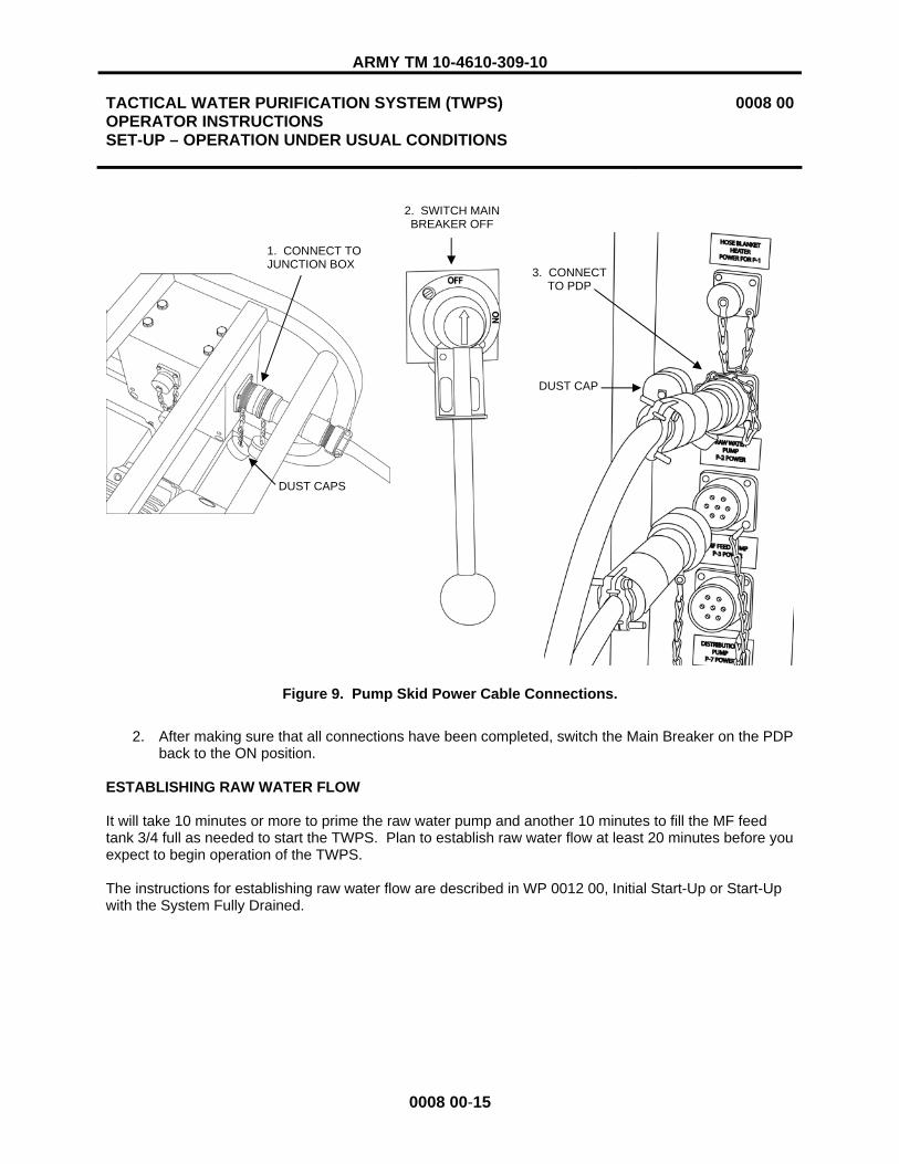
ARMY TM 10-4610-309-10
TACTICAL WATER PURIFICATION SYSTEM (TWPS) OPERATOR INSTRUCTIONS SET-UP – OPERATION UNDER USUAL CONDITIONS
0008 00
0008 00-15
Figure 9. Pump Skid Power Cable Connections.
2. After making sure that all connections have been completed, switch the Main Breaker on the PDP back to the ON position.
ESTABLISHING RAW WATER FLOW
It will take 10 minutes or more to prime the raw water pump and another 10 minutes to fill the MF feed tank 3/4 full as needed to start the TWPS. Plan to establish raw water flow at least 20 minutes before you expect to begin operation of the TWPS.
The instructions for establishing raw water flow are described in WP 0012 00, Initial Start-Up or Start-Up with the System Fully Drained.
1. CONNECT TO JUNCTION BOX
2. SWITCH MAIN BREAKER OFF
3. CONNECT TO PDP
DUST CAPS
DUST CAP

ARMY TM 10-4610-309-10
TACTICAL WATER PURIFICATION SYSTEM (TWPS) OPERATOR INSTRUCTIONS SET-UP – OPERATION UNDER USUAL CONDITIONS
0008 00
0008 00-16
STANDARD DISTRIBUTION SYSTEM SET-UP
NOTE
All of the distribution hoses and adaptors are provided with caps or plugs for the couplings to keep the inside of the hoses and adaptors clean. The caps and plugs are not chained. They are to be removed as each hose and Adaptor is installed and placed into Storage Box #3.
Deploy the standard product water distribution system equipment as follows (Figure 10):
Figure 10. Standard Distribution System Equipment Deployment.
Two person lift. Two people are required to safely lift the product water distribution water tanks and Motor-Driven Product Water Distribution Pump P-7. Lift with your legs, not your back. Failure to observe this warning may result in back injury.
1. Position Product Water Distribution Tanks T-3 and T-4 and Product Water Distribution Pump P-7 as follows:
a. Place the distribution tanks in their rough locations, making sure that the first tank is within 30 ft. of the TWPS product water outlet.
b. Unfold the ground cloth from around each tank and unfold each tank on its ground cloth. c. Spread the tanks out to their final shape and eliminate any ridges in the bottoms. d. Position the tanks about 6 ft. apart with the connections facing each other. e. Pull the tank inlet and outlet connections out away from the tank bottoms so that they will
be clear when the tanks are filled.
WARNING
2 X 65 D-HOSE
NOZZLE V-523B
A-08
A-15
A-07
2 X 5 S-HOSE
T-4T-3
2 X 5 S-HOSE
1 ½ X 10 S-HOSE
P-7
PRODUCT WATER DISCHARGE OUTLET HOSE

ARMY TM 10-4610-309-10
TACTICAL WATER PURIFICATION SYSTEM (TWPS) OPERATOR INSTRUCTIONS SET-UP – OPERATION UNDER USUAL CONDITIONS
0008 00
0008 00-17
f. Move the Motor-Driven Product Water Distribution Pump Skid P-7 roughly into place. g. Place the pump skid on solid footing and as level as possible.
2. Connect the hoses as follows:
Health hazard. Do not attempt to use product water hoses to handle raw water or raw water hoses to handle product water. When installed with the proper adaptors as directed, the hoses cannot be interchanged. Failure to observe this warning and mixing hoses could cause contamination of water resulting in serious illness.
a. Collect the following adaptors, hoses, and dispensing nozzles: 1) Four 1½ in. x 10 ft, blue-banded product water suction hoses 2) Adaptor A-15 3) Adaptor A-07 4) One 2 in. x 5 ft., blue-banded product water suction hose with male couplings at
each end 5) One 2 in. x 5 ft., blue-banded product water suction hose with female couplings
at each end 6) Pump outlet tee Adaptor A-08 7) Two 2 in. x 65 ft., blue-banded product water distribution discharge hoses 8) Two Dispensing Nozzles V-523A and V-523B
b. Inspect the gaskets in the female ends of the hoses and adaptors. Replace any damaged or missing gaskets.
c. Connect the four 1½ in. x 10 ft., blue-banded product water suction hoses to each other.d. Remove the plug from the TWPS product water discharge outlet hose and connect the
assembled blue-banded product water suction hoses to the discharge hose. Put the plug in Storage Box #3.
e. Connect Adaptor A-15 to an outside inlet (not an inlet between tanks) of the product water distribution tank that is closest to the TWPS product water outlet.
Health hazard. Do not connect the product water hose from the TWPS to Adaptor A-15 at the product water distribution tank at this time. Initial product water discharge from the product water outlet of the TWPS will not be of adequate purity. Product water is not discharged into the product water tanks until after clean product water flow is established. Failure to observe this warning could cause contamination of the product water.
f. Connect the male end of the straight section of Adaptor A-07 directly to the female outlet of one of the distribution tanks.
g. Connect the male-male 2 in. x 5 ft., blue-banded product water suction hose to the other end of the straight section of Adaptor A-07.
h. Connect the other end of the 2 in. x 5 ft. suction hose to the outlet of the other distribution tank.
i. Connect the female-female 2 in. x 5 ft., blue-banded suction hose to the remaining Adaptor A-07 connection and to the suction inlet of Product Water Distribution Pump P-7. Move the pump as needed to connect to the hose.
WARNING
WARNING

ARMY TM 10-4610-309-10
TACTICAL WATER PURIFICATION SYSTEM (TWPS) OPERATOR INSTRUCTIONS SET-UP – OPERATION UNDER USUAL CONDITIONS
0008 00
0008 00-18
j. Connect the pump outlet tee Adaptor A-08 to the discharge outlet of the product water distribution pump.
k. Connect one 2 in. x 65 ft., blue-banded product water distribution hose to each end of the straight section of Adaptor A-08. (A 5/8 in. x 50 ft. auxiliary hose and Valve V-522 may be connected in place of a distribution hose and nozzle for certain cleaning operations.)
l. Connect a dispensing nozzle to the end of both of the product water distribution hoses. m. Lay dispensing nozzles on top of the pump frame. Do not leave nozzles on the ground.
3. Connect the Motor-Driven Product Water Distribution Pump P-7 electrical power cable as follows:
Electrical hazard. The TWPS operates on 416 volts AC. Make sure Product Water Distribution Pump P-7 is shut off (push the distribution pump STOP button on the OCP) and then ensure the panel cover is closed and secured. Connect the power cable to the P-7 pump skid before connecting it to the PDP power outlet. Failure to observe this warning may result in serious injury or death from electrocution.
CAUTION
Connector damage or poor electrical connection. Use a fine brush to clean dust and sand out of connectors, terminals and dust caps before making or capping a connection. Install the dust cap provided with connectors and terminals whenever a connector is disconnected from its terminal. Failure to observe this caution may result in connector damage or a poor electrical connection.
a. Make sure that Distribution Pump P-7 is shut off (push the distribution pump STOP button on the PDP).
b. Close and secure the OCP cover. c. Uncoil the electrical power cable for Motor-Driven Distribution Pump P-7. d. Connect the power cable to the P-7 skid junction box. e. Connect the power cable to the P-7 power source connector at the PDP. f. Open the OCP cover and continue with start-up and normal operation.
PRE-OPERATIONAL CHECKS
Before starting the TWPS to begin producing potable water, perform the following checks: 1. Check all hose couplings and verify that the camlock connectors are locked in place. 2. Check that the ground rod has been installed and that ground connections are tight at both ends. 3. Check that all raw water, MF feed pump and product water distribution pump power cables are
properly connected.
WARNING

ARMY TM 10-4610-309-10
TACTICAL WATER PURIFICATION SYSTEM (TWPS) OPERATOR INSTRUCTIONS SET-UP – OPERATION UNDER USUAL CONDITIONS
0008 00
0008 00-19
CAUTION
The high pressure pump mounting flange drain tube must be positioned lower than the flange and must be free of obstructions so that the tube drains freely. Failure to observe this caution may result in water accumulating in the flange, which can lead to pump shaft and bearing corrosion and failure.
4. Check that the HP pump mounting flange drain tube is directed off the TWPS and is free of any obstructions.
a. The drain tube on the MC-TWPS extends to the edge of the TWPS frame (Figure 11). b. The drain tube on the A-TWPS is slightly longer so that the end can be directed down
between the right edge of the deck and the fabric wall.
Figure 11. High Pressure Pump Mounting Flange Drain Tube.
NOTE
For the most efficient use of time, it is recommended that you proceed to WP 0011 00 for pre-operational diagnostic self-tests and then the appropriate start-up procedures WP before performing the Fabric Wall Set-Up and Extended Distribution System Set-Up procedures. Return to these two procedures after performing the electrical pre-operational procedures and the appropriate start-up procedures.
HPP MOUNTING FLANGE DRAIN TUBE
HPP MOUNTING FLANGE

ARMY TM 10-4610-309-10
TACTICAL WATER PURIFICATION SYSTEM (TWPS) OPERATOR INSTRUCTIONS SET-UP – OPERATION UNDER USUAL CONDITIONS
0008 00
0008 00-20
FABRIC WALL SET-UP (A-TWPS)
After the TWPS is running and producing product water and delivering it to the product water distribution tanks, set up the fabric wall as follows (Figure 12):
1. Unfold the fabric wall and lay it on the ground oriented as follows: a. The outside of the wall on the ground and the inside of the wall facing up b. The bottom of the zippered, roll-up door closest to the TWPS c. The 3 in. hose feed-through opposite the raw water inlet of the TWPS d. The 4 in. hose feed-through opposite the waste water outlet of the TWPS e. Straps laid out for easy access
Figure 12. Fabric Wall Set-Up (A-TWPS).
Potential for head injury. Hold the top panel while removing the pins from the top panel supports. Failure to do so could result serious head injuries.
2. Two people carefully remove the pins from the top panel supports and lower the top panel to about a 45� angle with about 18 in. of the supports extended. Insert the pins to hold this position.
3. Attach the top, front and side edges of the wall to the top panel as follows: a. Lift the fabric wall by the top, front edge.
PIN
STRAP
FOOTMAN LOOP
TOP PANEL
TIE CORD
SUPPORT LEG
WARNING

ARMY TM 10-4610-309-10
TACTICAL WATER PURIFICATION SYSTEM (TWPS) OPERATOR INSTRUCTIONS SET-UP – OPERATION UNDER USUAL CONDITIONS
0008 00
0008 00-21
b. Secure the hook and loop strip on the top edge of the wall to the hook and loop strip on the top panel.
c. Loop each of the straps through the corresponding footman loop on the top panel and secure each strap in its buckle.
4. Two people raise the top panel with the attached fabric wall into position. 5. The third person inserts the pins in the top panel supports to secure the top panel. 6. Attach the side edge of both end walls as follows:
a. Match and smooth the hook and loop strip on the side edge of the wall side flap to the hook and loop strip on the TWPS frame.
b. Loop each side wall strap through its corresponding footman loop on the end panel and secure the strap in its buckle.
7. Attach the bottom edge of both wall side flaps to the bottom panel as follows: a. Fit the opening in the wall side flap for the support leg over the support leg. b. Match and smooth the hook and loop strip on the bottom edge of the wall side flap to the
hook and loop strip on the bottom panel. c. Loop both of the straps on the bottom of one wall side flap through its corresponding
footman loop on the bottom panel and secure each strap in its buckle. 8. Attach the bottom, front edge of the wall to the deck as follows:
a. Fit the openings in the wall front for the support legs over the support legs. b. Fit the sleeves in the wall front for the raw water hose and the waste-water hose over the
hoses. Close the sleeves snug around the hoses using the hook and loop strip at the bottom of the sleeve and with the tie cord.
c. Match and smooth the hook and loop strip on the bottom edge of the wall to the hook and loop strip on the bottom panel.
d. Loop each of the straps on the bottom, front edge of the wall through its corresponding footman loop on the bottom panel and secure each strap in its buckle.
EXTENDED DISTRIBUTION SYSTEM SET-UP (A-TWPS)
Deploy the extended product water distribution system equipment as follows (Figure 13):
Two person lift. Two people are required to safely lift the product water distribution water tanks. Lift with your legs, not your back. Failure to observe this warning may result in back injury.
Three person lift. Three people are required to lift Diesel-Driven Distribution Pump P-8. Lift with your legs, not your back. Failure to observe this warning may result in back injury.
1. Position Product Water Distribution Tanks T-5, T-6 and T-7 and Product Water Distribution Pump P-8 as follows:
a. Place the distribution tanks in their rough locations. One of the three tanks must be within 30 ft. of the TWPS product water outlet and within reach of the distribution hoses that are set out for connection to the tanks in the standard distribution system.
b. Unfold the ground cloth from around each tank and unfold each tank on its ground cloth. c. Spread the tanks out to their final shape and eliminate any ridges in the bottoms.
Position the tanks about 6 ft. apart with the connections facing each other.
WARNING

ARMY TM 10-4610-309-10
TACTICAL WATER PURIFICATION SYSTEM (TWPS) OPERATOR INSTRUCTIONS SET-UP – OPERATION UNDER USUAL CONDITIONS
0008 00
0008 00-22
d. Pull the tank inlet and outlet connections out away from the tank bottoms so that they will be clear when tanks are filled.
e. Move Diesel-Driven Product Water Distribution Pump Skid P-8 roughly into place. 1) Place the pump skid on solid footing and as nearly level as possible. 2) Place an absorbent pad under the diesel-driven pump skid for environmental
protection in the event of a fuel spill.
Figure 13. Extended Product Water Distribution System Equipment Deployment.
2. Connect the hoses as follows:
Health hazard. Do not attempt to use product water hoses to handle raw water or raw water hoses to handle product water. When installed with the proper adaptors as directed, the hoses cannot be interchanged. Failure to observe this warning and mixing hoses could cause water contamination and result in serious illness.
a. Collect the following adaptors, hoses and dispensing nozzles:
WARNING
T-72 X 5 S-HOSE T-6
P-8
T-5
A-15
A-07
2 X 5 S-HOSE
2 X 65 D-HOSE
NOZZLE V-523D
A-08
TWPS

ARMY TM 10-4610-309-10
TACTICAL WATER PURIFICATION SYSTEM (TWPS) OPERATOR INSTRUCTIONS SET-UP – OPERATION UNDER USUAL CONDITIONS
0008 00
0008 00-23
1) Adaptor A-15 2) Tee Adaptor A-07 3) Two 2 in. x 5 ft., blue-banded product water suction hoses with male couplings at
each end 4) One 2 in. x 5 ft., blue-banded product water suction hose with female couplings
at each end 5) Pump outlet tee Adaptor A-08 6) Two 2 in. x 65 ft., blue-banded product water distribution discharge hoses 7) Two Dispensing Nozzles V-523C and V-523D
b. Inspect gaskets in the female ends of the hoses and adaptors. Replace any damaged or missing gaskets.
c. Connect Adaptor A-15 to the inlet of one of the extended product water distribution tanks. d. Connect the male end of the straight section of Adaptor A-07 directly to the female outlet
of one of the extended distribution system tanks. e. Connect one of the male-male 2 in. x 5 ft., blue-banded product water suction hoses to
the other end of the straight section of Adaptor A-07. f. Connect the other end of the 5 ft. suction hose to the outlet of a second extended
distribution system tank. g. Connect the female-female 5 ft., blue-banded suction hose to the remaining Adaptor A-07
connection and to the suction inlet of Product Water Distribution Pump P-8. h. Connect the second male-male 5 ft., blue-banded suction hose from the middle tank to
the third tank. i. Connect the pump outlet tee Adaptor A-08 to the discharge outlet of Product Water
Distribution Pump P-8. j. Connect one 2 in. x 65 ft., blue-banded product water distribution discharge hose to each
end of the straight section of pump outlet tee Adaptor A-08. k. Connect one dispensing nozzle to the end of each of the product water distribution
discharge hoses. l. Lay the dispensing nozzles on top of the pump frame. Do not leave them on the ground.
CAUTION
If the TWPS is operating, disconnect the product hose from Adaptor A-15 at the standard distribution system tank before closing Adaptor A-15. Make sure that the A-15 Adaptor valve on the extended distribution system tank is open before connecting the product hose to it. Failure to observe this caution will cause the relief valve RV-501 to vent.
m. When Distribution Tanks T-3 and T-4 of the standard water distribution system are filled, the suction hose can be disconnected from Adaptor A-15 of the standard system and connected to Adaptor A-15 in the extended distribution system.
1) Open the A-15 Adaptor valve on the extended distribution system tank. 2) Disconnect the product hose from Adaptor A-15 at the standard distribution
system tank, then close the valve on that adaptor. 3) Connect product hose to Adaptor A-15 on the extended distribution system tank.

ARMY TM 10-4610-309-10
TACTICAL WATER PURIFICATION SYSTEM (TWPS) OPERATOR INSTRUCTIONS SET-UP – OPERATION UNDER USUAL CONDITIONS
0008 00
0008 00-24
LOWERING AND RAISING THE BAIL BAR (A-TWPS)
The A-TWPS Flat Rack Bail is lowered as required for access to the Tactical Quiet Generator (TQG), such as may be needed to perform TQG PMCS.
Tool: Wrench, Bail Bar, aluminum (WP 0045 00, Item 124) Equipment Condition: Tactical Quiet Generator shut down
1. Lower the flat rack bail bar as follows:
Crushing hazard. Always attach the winch cable hook to the bail bar ring before removing any bolts from the bail bar. Failure to observe this warning could result in the bail bar falling down unrestrained, killing anyone underneath it.
a. Attach the winch cable hook onto the ring near the top of the bail bar (Figure 14).
Figure 14. Winch Cable Hook Attached to Bail Bar Ring.
WARNING
CABLE
WINCH
WINCH HANDLE
HOOKRING
BAIL BAR

ARMY TM 10-4610-309-10
TACTICAL WATER PURIFICATION SYSTEM (TWPS) OPERATOR INSTRUCTIONS SET-UP – OPERATION UNDER USUAL CONDITIONS
0008 00
0008 00-25
b. Remove the hardware that secures the bail bar to the flat rack as follows (Figure 15): 1) Remove eleven bolts, lockwashers and flat washers that secure the bail bar to
the top horizontal beam of the flat rack. 2) Remove four bolts, eight flat washers, four lock washers and four nuts that
secure the bail bar to the diagonal beam of the flat rack. 3) Insert the flat end of the pinch bar between the large back nut and the flat rack
frame at the bottom of the flat rack. 4) Unscrew the bolt out of the nut using the bail bar socket wrench. Retain the bolt,
lock washer and nut. 5) Remove the back bolt, lock washer and nut at the other side of the bail bar in the
same manner.
Figure 15. Removing Bolts from the Bail Bar.
c. Turn the winch crank handle to lower the bail bar to the desired position (Figure 16). d. Disconnect the cable and move it out of the way so it is not a hazard.
TOP FRAME OF FLAT RACK BAIL BAR BOLT, LOCK WASHER, FLAT WASHER
LOCK WASHER
BOLT AND FLAT WASHER
DIAGONAL FRAME OF FLAT RACK
PINCH BAR
BAIL BAR SOCKET WRENCH
BOLT, LOCK WASHER, NUT
NUT FLAT WASHER

ARMY TM 10-4610-309-10
TACTICAL WATER PURIFICATION SYSTEM (TWPS) OPERATOR INSTRUCTIONS SET-UP – OPERATION UNDER USUAL CONDITIONS
0008 00
0008 00-26
Figure 16. Flat Rack Bail Bar Lowered.
2. Raise and secure the bail bar as follows: a. Connect the cable to the bail bar. b. Turn the winch crank handle to raise the bail bar.
NOTE
Install the two large bolts, lockwashers and nuts at the bottom of the bail bar first to help align the holes for the other bolts and make the other bolts easier to install.
c. Install the two large bolts, lock washers and nuts that secure the bottom of the bail bar to the flat rack (Figure 15).
A minimum of six bolts in the front of the top horizontal beam of the flat rack and a minimum of three bolts in the underside of the top horizontal beam are required in order to safely lift the flat rack by the bail bar. Failure to observe this warning may result in equipment damage and severe injury or death.
NOTE
The middle and upper bail bar bolts must be installed in the proper locations to ensure that the bail bar is properly secured. Three different length bolts are used. The longest of the three is used with washers and nuts to secure the bail bar to the diagonal beam of the flat rack. The two shorter bolts thread into rivet nuts, which are threaded inserts that are welded in the top horizontal beam of the flat rack.
WARNING

ARMY TM 10-4610-309-10
TACTICAL WATER PURIFICATION SYSTEM (TWPS) OPERATOR INSTRUCTIONS SET-UP – OPERATION UNDER USUAL CONDITIONS
0008 00
0008 00-27/28 BLANK
d. Separate the three different size bolts that are used to secure the middle of the bail bar to the diagonal beam of the flat rack and the top of the bail bar to the top horizontal flat rack beam (Figure 17).
e. Loosely secure the top part of the bail bar to the front of the top horizontal flat rack beam using the seven short bolts with their lock washers and flat washers. Do NOT tighten yet.
f. Loosely secure the top part of the bail bar to the underside of the top horizontal flat rack beam using the four longer bolts with their lock washers and flat washers. Do NOT tighten yet.
g. Secure the middle of the bail bar to the diagonal flat rack beams using the four longest bolts with eight flat washers, four lock washers and four nuts.
h. Tighten all 15 bolts. Torque to 250 in-lbs.
Figure 17. Correct Bail Bar Bolt Installation Locations.
END OF WORK PACKAGE
SHORT BOLT
LONGER BOLT
LONGEST BOLT
TOP HORIZONTAL FLAT RACK BEAM
DIAGONAL FLAT RACK BEAM


ARMY TM 10-4610-309-10
TACTICAL WATER PURIFICATION SYSTEM (TWPS) OPERATOR INSTRUCTIONS RECIRCULATION TANK SETUP AND OPERATION
0009 00
0009 00-1
INITIAL SETUP:
Materials/Parts: Sodium bisulfite, 1 pkg. (Box #4) (WP 0048, Item 44) Measuring bottle for bisulfite (Box #4) (WP 0045, Item 5) Antiseize tape (WP 0048, Items 49 & 50) One recirculation tank kit (WP 0049, item 1) including following parts (ref. Figure 1, for item numbers):
NOTE
Items 1, 2, 4, 5, 6 and 7 may already be installed on the 1200 gallon low profile tank if the Recirculation Tank Kit has already been used.
Item 1: 1-1/2" male quick disconnect by thread (1) Item 2: 1-1/2" threaded PVC (1) Item 3: 1200 gallon low profile tank with ground cloth, zipper top lid, 3 poles and repair kit inside shipping box (1) Item 4: 3" threaded PVC (1) Item 5: 3" female quick disconnect by thread (1) Item 6: 4" threaded PVC (1) Item 7: 4" female quick disconnect by thread (1) Item 8: 4" by 10’ discharge hose with quick disconnects (2)
Personnel Required: Two Operators/Crew Equipment Condition: TWPS operational and fully drained. Preservative solutions have already been flushed from the TWPS in accordance with WP 0012 00. At least 1500 gallons of RO product water or tap water must be available to fill the MF feed tank and recirculation tank.
GENERAL:
The recirculation tank is setup to allow recirculation of the product water (from 1-1/2" product hose) and wastewater (from 4" waste out connection) back to the raw water pump (3" inlet). By using the recirculation tank, it is possible to operate the TWPS in order to verify system performance or to train operators without having to go to a field water source. The recirculation tank system is the only approved method of operating the TWPS in a recirculation mode.
RECIRCULATION TANK SYSTEM SETUP:
1. The recirculation tank can be used to operate the TWPS after first flushing any preservatives from the TWPS following procedures in WP 0012 00.
2. Remove tank and components from the shipping box. Inventory parts to make sure items 1 through 8 shown in the figure have been provided.
3. Position tank on top of ground cloth within 20 ft. of TWPS. Rotate tank so 4” threaded adaptor faces the 4” waste outlet on the TWPS.
4. Install zipper top lid onto the tank after first assembling the three tent poles and routing through the loops on the inside of the lid.

ARMY TM 10-4610-309-10
TACTICAL WATER PURIFICATION SYSTEM (TWPS) OPERATOR INSTRUCTIONS RECIRCULATION TANK SETUP AND OPERATION
0009 00
0009 00-2
NOTE
If the Recirculation Tank Kit has already been used, the PVC pipes and couplers may already be assembled and installed on the 1200 gallon low profile tank. If already installed, skip step 5.
5. If the recirculation tank system is new, attach the quick disconnect couplers to the PVC threaded pieces and then to the tank adaptors as follows:
a. Apply Teflon tape to both sides of the three PVC threaded pipes (figure 1, items 2, 4 and 6). b. Install appropriate size quick disconnect coupler (figure 1, items 1, 5 and 7) to the matching sized
PVC threaded pipe. c. Screw assemblies into tank adaptor fittings on the tank.
6. Attach 4” discharge hose or hoses (8) to the TWPS 4” waste out suction hose. Reposition tank so that the discharge hoses are completely straight with no bends or kinks.
7. Connect TWPS product hose (blue) to the 1-1/2” connection on tank. 8. Connect TWPS raw water suction hose (green) or hoses to the 3” connection on tank. Connect the other
end to the A-01 adapter on TWPS motor driven raw water pump (P-2). 9. Setup other TWPS components including MF feed tank, MF feed pump, appropriate adapters (A-02, A-05),
tripod and interconnecting hoses referring to figure 1 and WP 0008 00.

ARMY TM 10-4610-309-10
TACTICAL WATER PURIFICATION SYSTEM (TWPS) OPERATOR INSTRUCTIONS RECIRCULATION TANK SETUP AND OPERATION
0009 00
0009 00-3
Figure 1. Overall Setup of Recirculation Tank with TWPS.
TWPS OPERATION WITH RECIRCULATION TANK
1. Fill the MF feed tank completely full with tap water or RO product water. Add one measuring bottle capful of sodium bisulfite to dechlorinate the water.
2. Fill the recirculation tank with approximately 1 ft. of water. Add one measuring bottle capful of sodium bisulfite to dechlorinate the water.
3. Perform startup of the TWPS following all normal startup procedures in WP 0012 00 but do not operate chemical feed pumps with chlorine or antiscalant.
4. Prior to initiating the first backwash, be sure there is only about 6” of water remaining in the recirculation tank. The level in the tank is adjusted by regulating the raw water pump flow with valve V-107 on adaptor
A-05.

ARMY TM 10-4610-309-10
TACTICAL WATER PURIFICATION SYSTEM (TWPS) OPERATOR INSTRUCTIONS RECIRCULATION TANK SETUP AND OPERATION
0009 00
0009 00-4
CAUTION
If the water level in the recirculation tank is too high, it will cause excessive back- pressure in the TWPS waste line causing the rupture disc to blow.
CAUTION
If the water level in the recirculation tank is too low, the raw pump may lose prime causing it to possibly overheat.
5. To maintain normal operation, adjust raw water flow so that prior to an automated backwash there is only 6” of water in the recirculation tank.
6. To shutdown the TWPS, follow the shutdown procedures in WP 0015 00.
SYSTEM TEARDOWN
CAUTION
When draining the recirculation tank, remove the lid first, otherwise you may break the tent poles on the lid.
1. After operating the TWPS with the recirculation tank, discharge the water from the tank in accordance with local regulations. The water may be saved for other TWPS operations by transferring the water to a temporary storage tank or putting caps and plugs on the tank connections.
2. Dry all components before putting them back into the shipping box. 3. Preserve the RO elements and MF modules following the procedures in WP 0023 00 and WP 0024 00.
END OF WORK PACKAGE

ARMY TM 10-4610-309-10
TACTICAL WATER PURIFICATION SYSTEM (TWPS) OPERATOR INSTRUCTIONS ESTABLISHING ELECTRICAL POWER – OPERATION UNDER USUAL CONDITIONS
0010 00
0010 00-1
INITIAL SETUP
Personnel Required: One Operator/Crew Reference: TM 9-6115-672-14 Equipment Condition: TWPS skid removed from transport vehicle and set on level ground. Loose items unpacked (off-loaded) from the TWPS skid and placed in general operational position. Set-up started.
GENERAL:
Electrical power to the TWPS must be established as early as possible during TWPS set-up. The reason for this is the time required to fill the MF feed tank and the time required to pressurize the air tank. A sufficient MF feed water supply is required to support potable water production and the automatic backwash operation before water can be processed through the TWPS. If the motor-operated raw water pump is used, electrical power is required to run the pump. A minimum air pressure is required for the automatic backwash operation before the TWPS can be operated. Electrical power is required to run the compressor that pressurizes the air tank. For these reasons, in order to get the TWPS producing clean water in the shortest time possible, it is recommended that one person perform the steps described in this WP for establishing electrical power while others set up the equipment. Refer to the planning guide provided in WP 0008 00.
This WP contains procedures for establishing electrical power at the TWPS. The procedures covered in this work package include:
� Generator Voltage Selection and Cable Connection � Ground Rod Assembly Installation � Preparing the TWPS for Power � Tactical Quiet Generator Start-Up � Energizing the TWPS Power Distribution Panel
GENERATOR VOLTAGE SELECTION AND CABLE CONNECTION
CAUTION
Potential electrical component damage. The generator must be set up to provide 416-volts. If set for 220-volts, electrical controls and motors will be damaged.
1. Refer to Tactical Quiet Generator (TQG) TM 9-6115-672-14 for TQG Model 806B and move the output voltage selector plate to 416-Volts (High Wye).
2. Connect the TWPS power cable leads to the L1, L2, L3 lugs according to the labels. 3. Connect TWPS power cable white lead to the Neutral lug and the green lead to the Ground lug. 4. When the air compressor is started, check the direction of rotation. The correct rotation is
counter-clockwise.

ARMY TM 10-4610-309-10
TACTICAL WATER PURIFICATION SYSTEM (TWPS) OPERATOR INSTRUCTIONS ESTABLISHING ELECTRICAL POWER – OPERATION UNDER USUAL CONDITIONS
0010 00
0010 00-2
GROUND ROD ASSEMBLY INSTALLATION
The ground rod assembly is used to ground the TQG and the TWPS to protect operators and equipment. Ground the TQG and TWPS using the ground rod assembly as follows:
Electrical hazard. The TWPS operates on 416 volts AC. A good ground is required to protect operators and equipment. The ground rod must be driven into the ground at least 8 ft. and the grounding cable must be securely attached to the grounding lugs to ensure a good electrical ground. Failure to properly ground the generator and the TWPS container could result in injury or death from electrical shock.
1. Gather the following components (Figure 1): a. Three ground-rod sections with three collars and one cable clamp b. Slide rod c. Slide hammer d. Ground rod installation hardware package (striker plate, two nuts and one lock washer) e. One ground cable
Figure 1. Ground Rod Assembly Components.
2. Select a location to install the ground rod assembly that meets the following criteria: a. The assembled ground rods can be sunk into the earth at least 8 ft. b. The ground cables will not be ripped loose by vehicle travel. c. The ground rods and cables will not present a safety hazard to personnel.
3. Assemble the slide hammer assembly as follows (Figure 2): a. Thread the striker plate completely on to one end of the slide rod. b. Secure the striker plate to the slide rod with a lock washer and nut. Thread the nut all the
way onto the rod. c. Slide the hammer down over the other end of the slide rod. d. Thread the second nut onto the end of the slide rod. (The hammer should be able to
slide freely up and down the slide rod between the striker plate on one end and the nut on the other end.)
WARNING
GROUND CABLE
LOCK WASHER
STRIKER PLATE
SLIDE ROD
NUTGROUND RODS
SLIDE HAMMER
CABLE CLAMP
NUT
COLLAR

ARMY TM 10-4610-309-10
TACTICAL WATER PURIFICATION SYSTEM (TWPS) OPERATOR INSTRUCTIONS ESTABLISHING ELECTRICAL POWER – OPERATION UNDER USUAL CONDITIONS
0010 00
0010 00-3
Figure 2. Slide Hammer Assembled to Drive the First Ground Rod.
CAUTION
To prevent damage to the slide rod, ground rod or collar threads, make sure that the slide rod and ground rods bottom out against each other (threaded completely together). Any slop in the connection will lead to damaged threads.
4. Drive the first ground rod into the ground as follows: a. Thread the striker plate end of the slide hammer assembly all the way into the collar of
the first ground rod until the slide rod bottoms out against the ground rod. b. Using the slide hammer, drive the first ground rod into the ground leaving about 3 in.
exposed.5. Thread a second ground rod onto the first ground rod and drive both into the ground as follows:
a. Unthread the slide hammer assembly from the collar of the first ground rod. b. Thread a second ground rod all the way into the collar of the first ground rod that is
already in the ground. c. Thread the slide hammer assembly all the way into the collar at the top of the second
ground rod until the slide rod bottoms out against the ground rod. d. Drive the assembled first and second rods into the ground leaving approximately 3 in. of
the second ground rod exposed. 6. Thread a third ground rod onto the second ground rod and drive into the ground as follows:
a. Unthread the slide hammer assembly from the collar of the second ground rod. b. Thread a third ground rod all the way into the collar at the top of the second ground rod. c. Thread the slide hammer assembly all the way into the collar at the top of the third
ground rod until the slide rod bottoms out against the ground rod. d. Drive the assembled first, second and third ground rods into the ground leaving
approximately 1 ft. of the third ground rod exposed. 7. Uncoil the ground cable. Secure one end of the cable to the rod using the cable clamp. Unscrew
the nut from the grounding lug to expose the slot in the lug. 8. Connect the other end of the ground cable to the generator ground lug and tighten lug nut
securely.
STRIKER PLATE
LOCK WASHER
NUT
COLLAR GROUND ROD
SLIDE ROD
SLIDE HAMMER
NUT

ARMY TM 10-4610-309-10
TACTICAL WATER PURIFICATION SYSTEM (TWPS) OPERATOR INSTRUCTIONS ESTABLISHING ELECTRICAL POWER – OPERATION UNDER USUAL CONDITIONS
0010 00
0010 00-4
PREPARING THE TWPS FOR POWER
Perform the following steps before starting the TQG:
1. (A-TWPS only) Make sure the bail bar is lowered (WP 0008 00). 2. Perform all “BEFORE” PMCS (preventive maintenance checks and services) listed in WP 0036. 3. Place the fire extinguisher near the ground rod if not already moved to this location. 4. Set the Main Circuit Breaker (lever on the front of the Power Distribution Panel) to OFF (Figure
3).
Figure 3. Main Circuit Breaker OFF.
5. Set the following Operator Control Panel switches to positions indicated: a. Mode to STANDBY b. MF Clean to OFF c. Emergency Stop to OUT d. Air Compressor to OFF e. Bisulfite Pump to OFF f. Antiscale/Chlorine to AUTO g. MF Test to OFF h. Hose/Pump Heaters to OFF i. Tank Heaters to OFF
6. Open the instrument/solenoid panel. Ensure the conductivity transmitter ON/OFF switch is at the ON position (Figure 3).
TACTICAL QUIET GENERATOR START-UP
High voltage electrical hazard. Do not attempt to start the generator set if it has not been properly grounded. Failure to observe this warning could result in electrocution.
High voltage electrical hazard. High voltage is produced when the generator set is in operation. Improper operation could result in personal injury or death.
WARNING
CONDUCTIVITY TRANSMITTER ON/OFF SWITCH
MAIN CIRCUIT BREAKER

ARMY TM 10-4610-309-10
TACTICAL WATER PURIFICATION SYSTEM (TWPS) OPERATOR INSTRUCTIONS ESTABLISHING ELECTRICAL POWER – OPERATION UNDER USUAL CONDITIONS
0010 00
0010 00-5/6 BLANK
CAUTION
Potential starter damage. Do not crank the generator engine in excess of fifteen seconds. Allow the starter to cool at least fifteen seconds between attempted starts. Failure to observe this caution could result in damage to the starter.
1. Make sure all generator set access doors, except the control panel access door, are closed. 2. Start up the TQG as described TM 9-6115-672-14 for Model 806B.
ENERGIZING THE TWPS POWER DISTRIBUTION PANEL
Potential electrical hazard. Other personnel are setting up the raw water system of the TWPS. Part of this set-up includes connecting raw water and MF feed pump skid power cords to the PDP. Let the other set-up personnel know when you are ready to make any pump power cable connections to the PDP. The panel may be energized to power the air compressor (and the heater during cold weather deployment) before the pump power cable connections are completed. The PDP must be de-energized by switching the Main Breaker to OFF before making pump power cable connections. Failure to observe this warning may result in injury or death due to electrocution.
Energize the PDP as follows:
1. Perform the following notifications and checks: a. Tell the other set-up personnel that you are ready to establish electrical power. b. If the pump power cables are connected, check that the raw water and MF feed pump
power cable(s) has/have been properly connected at the pump skid(s) and at the PDP. 2. Energize the PDP as follows:
a. Switch the Main Circuit Breaker on the PDP to ON. b. Check that the Power On light on the Operator Control Panel (OCP) is on. If it is not on,
check that the Emergency Stop button is pulled out. c. If the alarm horn goes on, toggle the Alarm Switch to RESET to clear the power-up
alarms, then set the switch to SILENCE. 3. Notify the other set-up personnel that the PDP has been energized.
END OF WORK PACKAGE
WARNING


ARMY TM 10-4610-309-10
TACTICAL WATER PURIFICATION SYSTEM (TWPS) OPERATOR INSTRUCTIONS PRE-OPERATIONAL DIAGNOSTIC SELF TEST PROCEDURES – OPERATION UNDER USUAL CONDITIONS
0011 00
0011 00-1
INITIAL SETUP
Personnel Required: One Operator/Crew Equipment Condition: Electrical power to the TWPS has been established. The air compressor has been started. Pressure gauge PI-902 reads over 90 psig.
GENERAL
This section describes the TWPS Electrical Pre-Operational Diagnostic Self Test Procedures. These built-in-tests (BIT) check the operation of the lamps, displays and alarm horn on the Operator Control Panel (OCP). The tests also check the operation of automatic (PLC operated) valves on the TWPS. It is not necessary for water to be in the TWPS to perform the Diagnostic Self-Tests, but a minimum air pressure of 90 psig is required for the TWPS to operate the automatic valves.
A single-page summary of diagnostic self-tests is included in Table 1.
DIAGNOSTIC SELF-TESTS
Perform the diagnostic self-tests as follows:
1. Make sure electrical power to the TWPS has been established as described in WP 0010 00. 2. Make sure the Air Compressor had been started as described in WP 0012 00 3. Check the pressure reading at backwash and actuator air pressure gauge PI-902 (Figure 1). The
pressure must read over 90 psig before the diagnostic self-tests can be run. If the pressure is not over 90 psig, make sure the air compressor is on and wait until gauge PI-902 reads over 90 psig.
Figure 1. Pressure Gauge PI-902 Location.
4. Make sure the SYSTEM MODE SWITCH on the OCP is switched to STANDBY. 5. Perform Test # 1 (Lamp Test) as follows:
a. Press the TEST button on the OCP and hold until the number one (1) is displayed at the Test BIT Code LCD (about 5 seconds).
PRESSURE GAUGE PI-902

ARMY TM 10-4610-309-10
TACTICAL WATER PURIFICATION SYSTEM (TWPS) OPERATOR INSTRUCTIONS PRE-OPERATIONAL DIAGNOSTIC SELF TEST PROCEDURES – OPERATION UNDER USUAL CONDITIONS
0011 00
0011 00-2
b. Check the expected result shown below. If the test fails, perform the “Action on Failure” instructions and notify Field Maintenance about the failed lamp(s).
TEST # TEST EXPECTED RESULT ACTION ON FAILURE 1 Lamp All indicator lamps along the top two rows of the OCP
and the MF Backwash Start pushbutton lamp in the bottom row and the compressor switch should be lit.
Continue with operation. Notify Field Maintenance about failed lamp.
6. Perform Test #2 (Display Test) as follows: a. Press the test button to advance the test sequence number at the Test BIT Code LCD to
the number two (2). b. Check the expected result shown below for each LCD display. If the test fails, perform
the “Action on Failure” instructions and notify Field Maintenance about the failed LCD.
TEST # TEST EXPECTED RESULT ACTION ON FAILURE 2 Feed Water TDS LCD
Display Display should count up from zero. Continue with operation. Use portable TDS
meter. MF Flow LCD Display Display should count up from zero. Continue with operation. MF Trans-Membrane
Pressure LCD Display Display should count up from zero. Continue with operation. Subtract MF Filtrate
Pressure Gauge PI-201 reading from MF Feed Pressure Gauge PI-101 reading to calculate the TMP.
RO Feed Flow LCD Display
Display should count up from zero. Continue with operation.
RO Feed Pressure LCD Display
Display should count up from zero. Continue with operation. Use RO Feed Pressure Gauge PI-304 when RO feed pressure is needed during operation.
RO Reject Flow LCD Display
Display should count up from zero. Continue with operation.
RO Feed Tank Level % LCD Display
Display should count up from zero. Continue with operation.
RO % Salt Rejection LCD Display
Display should count up from zero. Continue with operation.
Product Flow LCD Display
Display should count up from zero. Continue with operation. Subtract reject flow reading from 56 (feed flow) to obtain an estimate of the product flow when product flow is needed during operation.
Product TDS LCD Display
Display should count up from zero. Continue with operation. Use portable TDS meter when TDS readings are needed.
Total Product Water LCD Display
Display shows test sequence number. Continue with operation.
7. Check that each of the following automatic valves is in the indicated de-energized position (Figure 2 for valve location). If valves are not in the correct position, refer to troubleshooting: � V-111 De-energized Open (yellow arrow on top of actuator points inline with pipe) � V-112 De-energized Open (yellow arrow on top of actuator points inline with pipe) � V-113 De-energized partially closed (yellow arrow on top of actuator not quite inline with pipe) � V-201 De-energized Open (yellow arrow on top of actuator points inline with pipe) � V-202 De-energized Open (window on top of actuator is yellow) � V-401 De-energized Closed (yellow arrow on top of actuator points away from pipe) � V-402 De-energized Closed (yellow arrow on top of actuator points away from pipe)

ARMY TM 10-4610-309-10
TACTICAL WATER PURIFICATION SYSTEM (TWPS) OPERATOR INSTRUCTIONS PRE-OPERATIONAL DIAGNOSTIC SELF TEST PROCEDURES – OPERATION UNDER USUAL CONDITIONS
0011 00
0011 00-3
Figure 2. Automatic Valves.
8. Perform Test #3 (Alarm Horn Test) as follows: a. Press the test button to advance the test sequence number at the Test BIT Code LCD to
the number three (3). b. Check the expected result shown below. If the test fails, perform the “Action on Failure”
instructions and notify Field Maintenance about the failed alarm horn.
TEST # TEST EXPECTED RESULT ACTION ON FAILURE 3 Alarm Horn Alarm horn sounds until BIT Test 4 is started. Continue with operation.
9. Perform Test #4 (V-111 Valve Cycle Test) as follows (Figure 2): a. Press the test button to silence the alarm and advance the test sequence number at the
Test BIT Code LCD to the number four (4). b. Check the expected result shown below. If the test fails, perform the “Action on Failure”
instructions.
TEST # TEST EXPECTED RESULT ACTION ON FAILURE 4 V-111 Valve Cycle V-111 closes (yellow arrow on top of
actuator points away from pipe) Refer to troubleshooting.
MF MAIN FEED VALVE
V-111
UPPER FEED VALVE V-112
LOWER BACKWASH VALVE V-402
FILTRATE FLOW CONTROL VALVE
V-202
UPPER FILTRATE OUTLET VALVE
V-201
UPPER BACKWASH VALVE V-401
OPEN
CLOSED
WINDOW
LOWER FEED VALVE V-113

ARMY TM 10-4610-309-10
TACTICAL WATER PURIFICATION SYSTEM (TWPS) OPERATOR INSTRUCTIONS PRE-OPERATIONAL DIAGNOSTIC SELF TEST PROCEDURES – OPERATION UNDER USUAL CONDITIONS
0011 00
0011 00-4
10. Perform Test #5 (V-112 Valve Cycle Test) as follows (Figure 2): a. Press the test button to advance the test sequence number at the Test BIT Code LCD to
the number five (5). b. Check the expected result shown below. If the test fails, perform the “Action on Failure”
instructions.
TEST # TEST EXPECTED RESULT ACTION ON FAILURE 5 V-112 Valve Cycle V-112 closes (yellow arrow on top of
actuator points away from pipe) Refer to troubleshooting.
11. Perform Test #6 (V-113 Valve Cycle Test) as follows (Figure 2): a. Press the test button to advance the test sequence number at the Test BIT Code LCD to
the number six (6). b. Check the expected result shown below. If the test fails, perform the “Action on Failure”
instructions.
TEST # TEST EXPECTED RESULT ACTION ON FAILURE 6 V-113 Valve Cycle V-113 opens (yellow arrow on top of
actuator points inline with pipe) Refer to troubleshooting.
12. Perform Test #7 (V-201 Valve Cycle Test) as follows (Figure 2): a. Press the test button to advance the test sequence number at the Test BIT Code LCD to
the number seven (7). b. Check the expected result shown below. If the test fails, perform the “Action on Failure”
instructions.
TEST # TEST EXPECTED RESULT ACTION ON FAILURE 7 V-201 Valve Cycle V-201 closes (yellow arrow on top of
actuator points away from pipe) Refer to troubleshooting.
13. Perform Test #8 (V-202 Valve Cycle Test) as follows (Figure 2): a. Press the test button to advance the test sequence number at the Test BIT Code LCD to
the number eight (8). b. Check the expected result shown below. If the test fails, perform the “Action on Failure”
instructions.
TEST # TEST EXPECTED RESULT ACTION ON FAILURE 8 V-202 Valve Cycle V-202 closes (window on top of
actuator is black) Refer to troubleshooting.
14. Perform Test #9 (V-401 Valve Cycle Test) as follows (Figure 2): a. Press the test button to advance the test sequence number at the Test BIT Code LCD to
the number nine (9). b. Check the expected result shown below. If the test fails, perform the “Action on Failure”
instructions.
TEST # TEST EXPECTED RESULT ACTION ON FAILURE 9 V-401 Valve Cycle V-401 opens (yellow arrow on top of
actuator points inline with pipe) Refer to troubleshooting.

ARMY TM 10-4610-309-10
TACTICAL WATER PURIFICATION SYSTEM (TWPS) OPERATOR INSTRUCTIONS PRE-OPERATIONAL DIAGNOSTIC SELF TEST PROCEDURES – OPERATION UNDER USUAL CONDITIONS
0011 00
0011 00-5
15. Perform Test #10 (V-402 Valve Cycle Test) as follows (Figure 2): a. Press the test button to advance the test sequence number at the Test BIT Code LCD to
the number ten (10). b. Check the expected result shown below. If the test fails, perform the “Action on Failure”
instructions.
TEST # TEST EXPECTED RESULT ACTION ON FAILURE 10 V-402 Valve Cycle V-402 opens (yellow arrow on top of
actuator points inline with pipe) Refer to troubleshooting
16. Perform Test #11 (XV-901 Valve Cycle Test) as follows (Figure 3): a. Press the test button to advance the test sequence number at the Test BIT Code LCD to
the number eleven (11). b. Check the expected result shown below. If the test fails, perform the “Action on Failure”
instructions.
TEST # TEST EXPECTED RESULT ACTION ON FAILURE 11 XV-901 Valve Cycle XV-901 cycles on and off three times Refer to troubleshooting
17. Perform Test #12 (XV-902 Valve Cycle Test) as follows (Figure 3): a. Press the test button to advance the test sequence number at the Test BIT Code LCD to
the number twelve (12). b. Check the expected result shown below. If the test fails, perform the “Action on Failure”
instructions.
TEST # TEST EXPECTED RESULT ACTION ON FAILURE 12 XV-902 Valve Cycle XV-902 cycles on and off three times Refer to troubleshooting
18. Perform Test #13 (XV-903 Valve Cycle Test) as follows (Figure 3): a. Press the test button to advance the test sequence number at the Test BIT Code LCD to
the number thirteen (13). b. Check the expected result shown below. If the test fails, perform the “Action on Failure”
instructions.
TEST # TEST EXPECTED RESULT ACTION ON FAILURE 13 XV-903 Valve Cycle XV-903 cycles on and off three times Refer to troubleshooting
19. Press the test button to exit the diagnostics. All valves return to the de-energized positions and the BIT Code LCD returns to the number zero (0).

ARMY TM 10-4610-309-10
TACTICAL WATER PURIFICATION SYSTEM (TWPS) OPERATOR INSTRUCTIONS PRE-OPERATIONAL DIAGNOSTIC SELF TEST PROCEDURES – OPERATION UNDER USUAL CONDITIONS
0011 00
0011 00-6
Figure 3. Solenoid Valves XV-901, XV-902 and XV-903 Location.
START-UP PROCEDURES
If this is an initial start-up or if the TWPS has been shut down for more than 96 hours with the unit fully drained and preserved, refer to WP 0012 00 to start the TWPS. If the TWPS has been shut down for less than 96 hours without being drained, refer to WP 0013 00 to start the TWPS.
SOLENOID VALVE XV-903
SOLENOID VALVE XV-901
SOLENOID VALVE XV-902
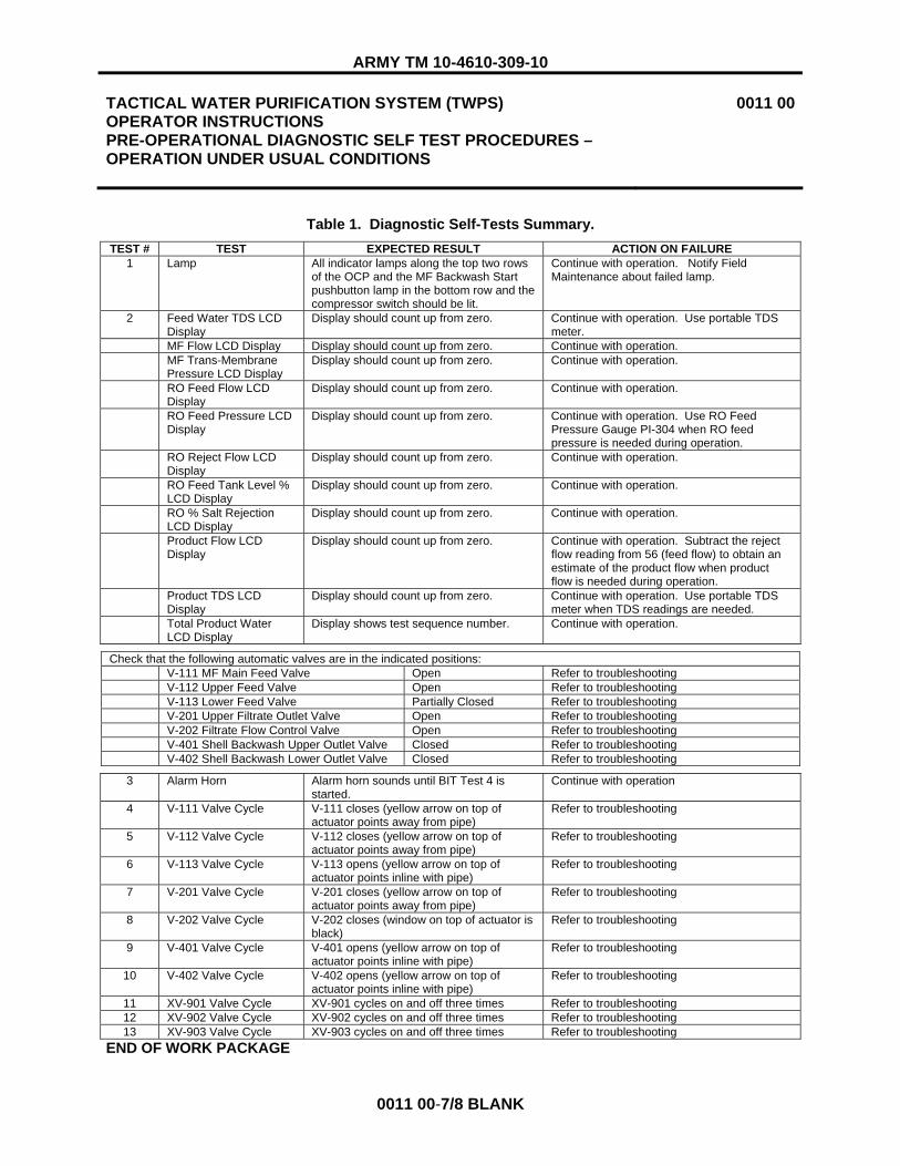
ARMY TM 10-4610-309-10
TACTICAL WATER PURIFICATION SYSTEM (TWPS) OPERATOR INSTRUCTIONS PRE-OPERATIONAL DIAGNOSTIC SELF TEST PROCEDURES – OPERATION UNDER USUAL CONDITIONS
0011 00
0011 00-7/8 BLANK
Table 1. Diagnostic Self-Tests Summary. TEST # TEST EXPECTED RESULT ACTION ON FAILURE
1 Lamp All indicator lamps along the top two rows of the OCP and the MF Backwash Start pushbutton lamp in the bottom row and the compressor switch should be lit.
Continue with operation. Notify Field Maintenance about failed lamp.
2 Feed Water TDS LCD Display
Display should count up from zero. Continue with operation. Use portable TDS meter.
MF Flow LCD Display Display should count up from zero. Continue with operation. MF Trans-Membrane
Pressure LCD Display Display should count up from zero. Continue with operation.
RO Feed Flow LCD Display
Display should count up from zero. Continue with operation.
RO Feed Pressure LCD Display
Display should count up from zero. Continue with operation. Use RO Feed Pressure Gauge PI-304 when RO feed pressure is needed during operation.
RO Reject Flow LCD Display
Display should count up from zero. Continue with operation.
RO Feed Tank Level % LCD Display
Display should count up from zero. Continue with operation.
RO % Salt Rejection LCD Display
Display should count up from zero. Continue with operation.
Product Flow LCD Display
Display should count up from zero. Continue with operation. Subtract the reject flow reading from 56 (feed flow) to obtain an estimate of the product flow when product flow is needed during operation.
Product TDS LCD Display
Display should count up from zero. Continue with operation. Use portable TDS meter when TDS readings are needed.
Total Product Water LCD Display
Display shows test sequence number. Continue with operation.
Check that the following automatic valves are in the indicated positions: V-111 MF Main Feed Valve Open Refer to troubleshooting V-112 Upper Feed Valve Open Refer to troubleshooting V-113 Lower Feed Valve Partially Closed Refer to troubleshooting V-201 Upper Filtrate Outlet Valve Open Refer to troubleshooting V-202 Filtrate Flow Control Valve Open Refer to troubleshooting V-401 Shell Backwash Upper Outlet Valve Closed Refer to troubleshooting V-402 Shell Backwash Lower Outlet Valve Closed Refer to troubleshooting
3 Alarm Horn Alarm horn sounds until BIT Test 4 is started.
Continue with operation
4 V-111 Valve Cycle V-111 closes (yellow arrow on top of actuator points away from pipe)
Refer to troubleshooting
5 V-112 Valve Cycle V-112 closes (yellow arrow on top of actuator points away from pipe)
Refer to troubleshooting
6 V-113 Valve Cycle V-113 opens (yellow arrow on top of actuator points inline with pipe)
Refer to troubleshooting
7 V-201 Valve Cycle V-201 closes (yellow arrow on top of actuator points away from pipe)
Refer to troubleshooting
8 V-202 Valve Cycle V-202 closes (window on top of actuator is black)
Refer to troubleshooting
9 V-401 Valve Cycle V-401 opens (yellow arrow on top of actuator points inline with pipe)
Refer to troubleshooting
10 V-402 Valve Cycle V-402 opens (yellow arrow on top of actuator points inline with pipe)
Refer to troubleshooting
11 XV-901 Valve Cycle XV-901 cycles on and off three times Refer to troubleshooting 12 XV-902 Valve Cycle XV-902 cycles on and off three times Refer to troubleshooting 13 XV-903 Valve Cycle XV-903 cycles on and off three times Refer to troubleshooting
END OF WORK PACKAGE


ARMY TM 10-4610-309-10
TACTICAL WATER PURIFICATION SYSTEM (TWPS) OPERATOR INSTRUCTIONS INITIAL START-UP OR START-UP WITH THE SYSTEM FULLY DRAINED – OPERATION UNDER USUAL CONDITIONS
0012 00
0012 00-1
INITIAL SETUP
Materials/Parts: Low pH cleaner (WP 0048 00, Item 29) Faceshield (WP 0045 00, Item 33) Chemical gloves (WP 0045 00, Item 52) Air filtering mask (WP 0048 00, Item 32) Apron (WP 0045 00, Item 1) Reference: A-TWPS WQAS-P TM 10-6630-222-12&P Personnel Required One Operator/Crew Equipment Condition: System fully set up and drained. All applicable PMCS has been performed.
INTRODUCTION
This work package contains the procedures for the initial start-up of the TWPS unit or the start-up of the TWPS unit when the system is fully drained. The procedures describe start-up under usual conditions using one or both raw water pumps and either the floating intake or the OISS.
The procedures covered in this work package include: � PMCS (WP 0036 00) � Establishing Electrical Power (WP 0010 00) � Air Compressor Start-Up � Initial Inspections, Checks and Adjustments � Performing Pre-Operational Diagnostic Self-Tests (WP 0011 00) � Sodium Bisulfite Chemical System Start-Up � Establishing Raw Water Flow with Both Raw Water Pumps � Establishing Raw Water Flow with Only the Motor-Driven Raw Water Pump � Flushing Preservative/Cleaning Solution � Micro-Filtration System Start-Up � RO System Start-Up � Antiscalant and Hypochlorite Chemical Systems Start-Up � Completing Start-Up
INITIAL INSPECTIONS, CHECKS AND ADJUSTMENTS
Make sure the applicable Preventive Maintenance Checks and Services (PMCS) have been performed in accordance with WP 0036 00.
ESTABLISHING ELECTRICAL POWER
Make sure that electrical power to the TWPS has been established as described in WP 0010 00.
AIR COMPRESSOR START-UP
Start up the compressor as follows:
1. Check the oil level dipstick. If the oil level is below the add oil mark, add oil to the top of the mark.

ARMY TM 10-4610-309-10
TACTICAL WATER PURIFICATION SYSTEM (TWPS) OPERATOR INSTRUCTIONS INITIAL START-UP OR START-UP WITH THE SYSTEM FULLY DRAINED – OPERATION UNDER USUAL CONDITIONS
0012 00
0012 00-2
2. Start the air compressor as follows: a. Make sure LP Air Vent Valve V-910 is closed. b. Make sure High Pressure Air Vent Valve V-904 is closed. c. Make sure Air Receiver Tank Valve V-907 is open. d. Turn the AIR COMPRESSOR SWITCH on the OCP to AUTO.
INITIAL INSPECTIONS, CHECKS AND ADJUSTMENTS
1. Make sure the product water hose is disconnected from the product water distribution tank. 2. Using Table 1 and Figure 2, check that the valves are in the indicated start-up position. On the
TWPS skid, valves are listed starting from the Operator Control Station, moving counter clockwise around the skid.
NOTE
Direct all drain hose ends off the TWPS when checking the position of drain valves.
The Product RO Element 3-Way Valves are in the normal position when the middle pointer on the valve handle is pointing to the black product hose (Figure 1). The handle itself may be pointing toward or away from the product pipe depending on the RO vessel.
Figure 1. RO Element 3-Way Valve in the Normal Position.
BLACK PRODUCT HOSE
VALVE HANDLE
MIDDLE POINTER
PRODUCT PIPE

ARMY TM 10-4610-309-10
TACTICAL WATER PURIFICATION SYSTEM (TWPS) OPERATOR INSTRUCTIONS INITIAL START-UP OR START-UP WITH THE SYSTEM FULLY DRAINED – OPERATION UNDER USUAL CONDITIONS
0012 00
0012 00-3
Table 1. Valve Start-Up Position – Initial Startup or Fully Drained.
� VALVE NAME AND NUMBER POSITION P-1 Diesel Pump Drain Valve V-103 Closed P-2 Electric Pump Drain Valve V-105 Closed P-3 Electric MF Feed Pump Drain Valve V-108 Closed MF Vent Valve V-114 Closed Product RO Element 3-Way Valves, left end, V-502, 503, 506, 507, 510 Normal RO Vessel Drain Valve V-408 Closed Main Pressure Control Valve HCV-401 Full Open Auxiliary Pressure Control Valve HCV-401A Open RO Feed Tank Auxiliary Drain Valve V-210 Closed Turbocharger Reject Drain Valve V-410 Closed Turbocharger Feed Drain Valve V-303 Closed Feed Control Selector Valve V-914 Auto Strainer S-2 Vent /Sample Valve V-110 Closed Strainer S-2 Drain Valve V-109 Closed MF Cleaning Feed Valve V-704 Closed Clean Mixing Valve V-703 Closed RO Clean Feed Valve V-701 Closed Clean Return Valve V-702 Closed Product Utility Valve V-511 Closed Feed Piping Drain Valve V-304 Closed HP Pump Outlet Drain Valve V-302 Closed HP Pump Inlet Valve V-212 Open Strainer S-4 Drain Valve V-213 Closed RO Feed pump P-4 Drain Valve V-211 Closed Low Pressure Air Vent Valve V-915 Closed LP Air Shutoff Valve V-909 Open Low Press Air Vent Valve V-910 Closed High Press Air Vent Valve V-904 Closed Coalescer CO1 Drain Shutoff Valve V-902 Open HP Pumps Case Drain Valve V-215 Closed HP Pump P-5 and P-6 Inlet Drain Valve V-214 Closed HP Pump P-5 and P-6 Outlet Drain Valve V-301 Closed Air Compressor Intermediate Filter Drain Valve V-901 Open Product RO Element 3-Way Valves, right end, V-501, 504, 505, 508, 509 Normal Air Receiver Tank Valve V-907 Open RO Feed Tank Main Drain Valve V-412 Closed RO Air Purge Valve V-913 Closed MF Filtrate Sample/Drain Valve V-204 Closed MF Filtrate Drain Valve V-203 Closed MF Shell Drain Valve V-403 Closed P-7 Electric Pump Drain Valve V-520 Closed Auxiliary Hose Valve V-522 (If attached) Closed Distribution Nozzles V-523 A&B Closed P-8 Diesel Pump Drain Valve V-524 Closed Distribution Nozzles V-523 C&D Closed

ARMY TM 10-4610-309-10
TACTICAL WATER PURIFICATION SYSTEM (TWPS) OPERATOR INSTRUCTIONS INITIAL START-UP OR START-UP WITH THE SYSTEM FULLY DRAINED – OPERATION UNDER USUAL CONDITIONS
0012 00
0012 00-4
Figure 2. Location of Valves for Start-Up.
V-103V-105V-108V-520V-524
V-109
V-110
V-914
V-210
V-704
V-703
V-702
V-701
V-410
V-303
V-304 V-302V-511
V-212
V-213
V-211
V-904
V-902V-910
V-909
V-214
V-215
V-901
V-501
V-504
V-505
V-508
V-509
V-907V-412
V-403
V-204
V-913
V-523 A V-523 B V-523 C V-523 D
V-522
V-114
V-203
V-408
HCV-401
V-510V-507
V-506
V-503
V-502
HCV-401A
SEEFIGURE 1 AND NOTE WITH FIGURE FOR VALVE POSITION DESCRIPTION
SEE FIGURE 1 AND NOTE WITH FIGURE FOR VALVE POSITION DESCRIPTION
V-915V-301

ARMY TM 10-4610-309-10
TACTICAL WATER PURIFICATION SYSTEM (TWPS) OPERATOR INSTRUCTIONS INITIAL START-UP OR START-UP WITH THE SYSTEM FULLY DRAINED – OPERATION UNDER USUAL CONDITIONS
0012 00
0012 00-5
PERFORMING PRE-OPERATIONAL DIAGNOSTIC SELF-TESTS
Perform pre-operational diagnostic self-test procedure (built-in-tests or BIT) as described in WP 0011 00.
SODIUM BISULFITE CHEMICAL SYSTEM START-UP
CAUTION
If the raw water source is chlorinated water or well water, the sodium bisulfite chemical system must be set up and started before raw water flow is established. Failure to provide sodium bisulfite injection will result in the destruction of the MF and RO membranes.
NOTE
If the raw water source is NOT chlorinated water or well water, skip this procedure and move on to ESTABLISHING RAW WATER FLOW WITH BOTH RAW WATER PUMPS or ESTABLISHING RAW WATER FLOW WITH ONLY THE MOTOR-DRIVEN RAW WATER PUMP, depending on how you set up the raw water system.
If the raw water source is chlorinated water or well water, start-up the sodium bisulfite chemical system as follows:
1. Make sure that the sodium bisulfite injection system has been deployed as described in the procedures for SODIUM BISULFITE INJECTION SYSTEM DEPLOYMENT in WP 0028 00.
2. Set the Bisulfite Pump switch on the OCP to ON. 3. Make sure the speed dial on the sodium bisulfite chemical pump is set to OFF (fully
counterclockwise) (Figure 3). 4. Fill the bucket with the blue cover with raw water to the 5-gallon level.
Hazardous chemical dust and/or fumes. Wear the protective face shield, chemical gloves and a dust mask when handling sodium bisulfite. Avoid inhaling chemical dust or fumes. Failure to observe this warning may result in irritation of the nose, throat, eyes and skin.
5. Rinse the mixing paddle with raw water. 6. Pour one 12-ounce packet of sodium bisulfite into the bucket and mix with the water using the
mixing paddle. If using sodium bisulfite from bulk, measure out 240 ml with the measuring cup and add to bucket.
7. Place the chemical injection pump suction tube and return line hose through the cover hole and into the chemical bucket. Be sure the suction hose inlet rests near the bottom of the bucket, but not flat on the bottom.
8. Turn the speed dial on the chemical pump to 80, note that the pump has started and then rotate the stroke dial to 80.
9. Rotate the black knob on the priming valve one-half turn. 10. Note that the chemical solution is drawing up the suction tube and entering the pump housing. 11. Rotate the black knob on the priming valve back to its original position when discharge is noted
back to the tank and air is not noted in the suction tube or the pump head. The pump is now primed.
WARNING

ARMY TM 10-4610-309-10
TACTICAL WATER PURIFICATION SYSTEM (TWPS) OPERATOR INSTRUCTIONS INITIAL START-UP OR START-UP WITH THE SYSTEM FULLY DRAINED – OPERATION UNDER USUAL CONDITIONS
0012 00
0012 00-6
12. Set the speed dial to 70%. 13. Set the stroke dial to 60%. 14. Turn the Bisulfite Pump switch on the OCP to AUTO.
Figure 3. Chemical Pump Controls.
ESTABLISHING RAW WATER FLOW WITH BOTH RAW WATER PUMPS
NOTE
If only the electric raw water pump is deployed, see the procedures for “Establishing Raw Water Flow with Only the Motor-Driven Raw Water Pump” that immediately follow these procedures.
1. Set valve positions as follows (Figure 4): a. Partially OPEN Raw Water Flow Control Valve V-107 on Adaptor A-05. b. Fully OPEN Vent Valve V-102 on Adaptor A-02. c. Check that pump Drain Valve V-103 on the diesel-driven pump skid is closed.
2. Disconnect the pump vent hose from the top of Adaptor A-02. 3. Use the priming pitcher to pour water through Vent Valve V-102 until the pump case is full. 4. Reconnect the vent hose.
BLACK KNOB
SPEED DIAL
STROKE DIAL
PRIMING VALVE

ARMY TM 10-4610-309-10
TACTICAL WATER PURIFICATION SYSTEM (TWPS) OPERATOR INSTRUCTIONS INITIAL START-UP OR START-UP WITH THE SYSTEM FULLY DRAINED – OPERATION UNDER USUAL CONDITIONS
0012 00
0012 00-7
Figure 4. Raw Water System with Both Raw Water Pumps.
Combustion hazard. Fuel the diesel engine in a well ventilated area with the engine stopped. Do not smoke or allow flames or sparks in the area where the engine is fueled or where the fuel is stored. Failure to observe this warning may result in fire and severe injury.
Combustion hazard. Do not overfill the fuel tank. Make sure the filler cap is securely closed after fueling. Be careful not to spill fuel when fueling. If any fuel is spilled, make sure the area is dry before starting the engine. Failure to observe this warning may result in fire and severe injury.
CAUTION
Potential for engine damage. The diesel engine may be damaged if operated with insufficient lube oil. It is also dangerous to supply too much lube oil to the engine because a sudden increase in engine rpm could be caused by its combustion. Failure to observe this caution may result in engine damage.
Potential for engine damage. Only use the correct diesel fuel. Use of the wrong fuel may cause engine damage.
When adding fuel to the fuel tank, be careful not to push the fuel screen filter into the tank.
5. Before starting the diesel engine pump, check the diesel fuel level and engine oil levels in accordance with the PMCS schedule, WP 0036 00. When checking the oil level, make sure the engine is on a level surface with the engine stopped.
6. Start the diesel engine using the following procedure (Figure 5).
WARNING
VENT VALVE V-102
DRAIN VALVE V-103 RAW WATER FLOW CONTROL VALVE V-107
ADAPTOR A-02
ADAPTOR A-05
PUMP VENT HOSE
V-104
ADAPTOR A-01 CHECK VALVE

ARMY TM 10-4610-309-10
TACTICAL WATER PURIFICATION SYSTEM (TWPS) OPERATOR INSTRUCTIONS INITIAL START-UP OR START-UP WITH THE SYSTEM FULLY DRAINED – OPERATION UNDER USUAL CONDITIONS
0012 00
0012 00-8
a. Set the fuel cock clockwise to the OPEN position. b. Put the engine speed lever in the START Position. c. Slowly pull out the recoil-starting handle until you feel strong resistance, then return it to
the initial position. d. Push down the decompression lever. If the lever does not stay down by itself, it may be
necessary to pull the recoil starting handle out a little more. The decompression lever will return to the up position automatically when the recoil starter is pulled all the way out to start the engine.
e. Pull out the recoil starting handle briskly with both hands to start the engine. f. If engine fails to start, return to step c (initial start of a new engine may require 6 or more
pulls to clear the air from the fuel lines.) g. Move the engine speed lever to a middle position to reduce the engine speed to idle.
7. Warm up the engine at idle for about three (3) minutes. Then set the speed lever to START. 8. The pump will draw the air out of the suction hose and pump it through the open Vent Valve V-
102 and the vent hose. As the air is removed, the water follows. 9. When pressurized water is observed discharging from the vent hose, the pump is primed. Close
Vent Valve V-102.
Figure 5. Diesel Engine Controls.
CAUTION
Potential for overheating. While the pump is evacuating air from the suction hose, the priming water circulates in the pump. After a period of time, the water and pump may get hot. Check the pump regularly with your hand for heating. If the pump starts getting hot, remove the vent hose, add more water to the pump, then reinstall the vent hose. Repeat as needed to keep the pump cool until it begins pumping water. Failure to observe this caution may result in overheating and damage to the pump.
NOTE
The time required to prime the pump will depend on the elevation of the pump (suction lift) and on the length of hose out of the water. The listing below provides typical times to be expected with 30 ft. of hose out of water.
RECOIL STARTING HANDLE
ENGINE SPEED LEVER
DECOMPRESSION LEVER
FUEL COCK
OPEN

ARMY TM 10-4610-309-10
TACTICAL WATER PURIFICATION SYSTEM (TWPS) OPERATOR INSTRUCTIONS INITIAL START-UP OR START-UP WITH THE SYSTEM FULLY DRAINED – OPERATION UNDER USUAL CONDITIONS
0012 00
0012 00-9
Suction Lift (Ft) Priming Time (Minutes)5 3 to 5 10 5 to 10 15 10 to 15 20 15 to 20
10. If the expected time for priming is exceeded, stop the pump and check all of the hose couplings that are out of the water. Specifically check the gaskets to be certain that they are free of sand and dirt. Remove Check Valve Adaptor A-01 (Figure 4) from the pump skid and make certain that the flapper seat is clean. Install and fill the pump again and repeat. If after 20 minutes, the pump has not primed, refer to WP 0034 00, Troubleshooting.
11. When using both pumps, start the Motor-Driven Pump P-2 after the discharge hose from P-1 pump is pressurized. Start the P-2 pump by pushing the Raw Water Pump #2 START button on the OCP.
12. Once the P-1 and P-2 pumps are operating and the system is primed, adjust Raw Water Flow Control Valve V-107 (Figure 4) about half open to provide a steady flow of raw water into the MF Feed Tank. Depending on the elevation, if the valve is opened too much initially, the pump could lose prime.
13. If the Cyclone Separator is in use, adjust the Cyclone Separator Flow Control Valve V-104 on adaptor A-03 (Figure 4) to at least 5 gpm. A 5-gallon chemical bucket can be used to provide measurement. Check the cyclone drain periodically to ensure there is good flow coming out the cyclone drain.
CAUTION
Do not leave the P-1 pump running with V-107 closed without cracking open the Vent Valve V-102. Failure to observe this caution will cause the pump to overheat and damage the shaft seal.
14. If the MF Feed Tank reaches 3/4 full and you are not ready to continue with start-up, close Raw Water Flow Control Valve V-107, stop motor driven raw water pump P-2 (if in use as the second pump), crack open Vent Valve V-102 and leave the Diesel-Driven Raw Water Pump P-1 running at idle.
15. Take a raw water sample from the MF Feed Tank and measure the TDS using the TDS meter provided with the MC-TWPS or from the WQAS-P on the A-TWPS. Refer to Water Quality Measurement in WP 0014 00. Adjust the feed water TDS Set Dial on the OCP until the Feed Water TDS display indicates the measured TDS.
ESTABLISHING RAW WATER FLOW WITH ONLY THE MOTOR-DRIVEN RAW WATER PUMP
1. Set valve positions as follows (Figure 6): a. Partially OPEN Raw Water Flow Control Valve V-107 on Adaptor A-05. b. Fully OPEN Vent Valve V-102 on Adaptor A-02. c. Check that the pump Drain Valve V-105 on Motor-Driven Pump P-2 is closed.

ARMY TM 10-4610-309-10
TACTICAL WATER PURIFICATION SYSTEM (TWPS) OPERATOR INSTRUCTIONS INITIAL START-UP OR START-UP WITH THE SYSTEM FULLY DRAINED – OPERATION UNDER USUAL CONDITIONS
0012 00
0012 00-10
Figure 6. Raw Water System with Only the Motor-Driven Raw Water Pump.
2. Disconnect the pump vent hose from the top of Adaptor A-02. 3. Use the priming pitcher to pour water through Vent Valve V-102 until pump case is full. Connect
vent hose after priming. 4. Start the P-2 pump by pushing the Raw Water Pump #2 START button on the OCP. 5. The pump will draw the air out of the suction hose and pump it through the open Vent Valve V-
102 and the vent hose. As the air is removed, the water follows. 6. When pressurized water is observed discharging from the vent hose, the pump is primed. Close
Vent Valve V-102.
CAUTION
Potential for overheating. While the pump is evacuating air from the suction hose, the priming water circulates in the pump. After a period of time, the water and pump may get hot. Check the pump regularly with your hand for heating. If the pump starts getting hot, remove the vent hose, add more water to the pump, then reinstall the vent hose. Repeat as needed to keep the pump cool until it begins pumping water. Failure to observe this caution may result in overheating and damage to the pump.
NOTE
The time required to prime the pump will depend on the elevation of the pump (suction lift) and on the length of hose out of the water. The listing below provides typical times to be expected with 30 ft. of hose out of water.
Suction Lift (Ft) Priming Time (Minutes)5 3 to 5 10 5 to 10 15 10 to 15 20 15 to 20
DRAIN VALVE V-105
VENT VALVE V-102
ADAPTOR A-02
RAW WATER FLOW CONTROL VALVE V-107
ADAPTOR A-05
PUMP VENT HOSE ADAPTOR A-01 CHECK VALVE

ARMY TM 10-4610-309-10
TACTICAL WATER PURIFICATION SYSTEM (TWPS) OPERATOR INSTRUCTIONS INITIAL START-UP OR START-UP WITH THE SYSTEM FULLY DRAINED – OPERATION UNDER USUAL CONDITIONS
0012 00
0012 00-11
7. If the expected priming time is exceeded, stop the pump and check all the hose couplings that are out of the water. Specifically, check the gaskets to be certain that they are free of sand and dirt. Remove Check Valve Adaptor A-01 (Figure 6) from the pump skid and make certain that the flapper seat is clean. Install and fill the pump again and repeat. If after 20 minutes the pump has not primed, refer to WP 0034 00, Troubleshooting.
8. Once P-2 is operating and system is primed, adjust Raw Water Flow Control Valve V-107 (Figure 6) about half open to provide a steady flow of raw water into the MF Feed Tank. Depending on the elevation, if the valve is opened too much initially, the pump could lose prime.
9. Take a raw water sample from the MF Feed Tank and measure the TDS using the TDS meter provided with the MC-TWPS or from the WQAS-P on the A-TWPS. Refer to Water Quality Measurement in WP 0014 00. Adjust the feed water TDS Set Dial on the OCP until the Feed Water TDS display indicates the measured TDS.

ARMY TM 10-4610-309-10
TACTICAL WATER PURIFICATION SYSTEM (TWPS) OPERATOR INSTRUCTIONS INITIAL START-UP OR START-UP WITH THE SYSTEM FULLY DRAINED – OPERATION UNDER USUAL CONDITIONS
0012 00
0012 00-12
FLUSHING PRESERVATIVE/CLEANING SOLUTION
If the TWPS unit was preserved (longer than 96 hours) for an extended shut-down the MF contains high pH cleaner. High pH cleaner must be flushed from the MF before starting up the MF system.
NOTE
If the MF does NOT contain preservative or cleaning solution, skip this procedure and move on to MICRO-FILTRATION SYSTEM START-UP.
NOTE
The following are common mistakes made during start-up: - MODE switch is put in the wrong position. - MF feed pump manually started or stopped at the wrong time. - MF feed tank runs out of water during initial startup or during a backwash. - Air Pressure Low alarm sounds during initial backwash. - RO feed tank runs out of water during initial startup or during a backwash. - RO Feed Pressure Low alarm sounds during initial startup or during a backwash.
If any of the above or similar errors occur, perform the following steps to re-initialize (or reset) the PLC. - Return the system mode switch to STANDBY. - Drain the RO feed tank. - Power down the system by opening the MAIN Circuit Breaker at the PDP (switch to OFF). - Power up the system by closing the MAIN Circuit Breaker at the PDP (switch to ON). - Wait for the air compressor to stop. - Proceed with a normal startup.
Flush preservative/cleaning solution from the MF as follows:
1. Collect the following items if using: � 1500-gallon cleaning waste storage tank � Three 2 in. x 10 ft., red-banded, suction cleaning waste hoses � Adaptor A-10 � Adaptor A-12 � Two A-16 Adaptors
2. Set up the Cleaning Waste Storage Tank if using (Figure 7). a. Set up the Waste Tank within 30 ft. of the TWPS waste out connection. Face the female
tank connection toward the TWPS skid. b. If the terrain allows, set the tank at an elevation so that the top of the full tank will be
below the bottom of the RO Feed Tank. c. Connect an A-16 Adaptor to both connections on the waste tank.

ARMY TM 10-4610-309-10
TACTICAL WATER PURIFICATION SYSTEM (TWPS) OPERATOR INSTRUCTIONS INITIAL START-UP OR START-UP WITH THE SYSTEM FULLY DRAINED – OPERATION UNDER USUAL CONDITIONS
0012 00
0012 00-13
3. Put low pH cleaner in the tank for neutralizing the preservative/cleaning solution when the solution is flushed into the tank as follows:
Acid chemical. Wear a protective face shield, chemical gloves and a chemical apron when handling low pH cleaner. Avoid inhaling chemical fumes. If low pH cleaner spills, immediately flush the area with water from the auxiliary hose. Failure to observe this warning may result in mild irritation of the nose, throat, eyes and skin.
a. Make sure a bucket of water is placed near the cleaning waste tank to rinse any area of skin or clothing that comes in contact with low pH cleaner.
b. Open the cleaning waste tank zipper. c. Open the low pH cleaner. Using the priming pitcher, measure out 2 lbs (600 mL) of low
pH cleaner and pour it into the cleaning waste tank. d. Close the cleaning waste tank zipper. e. Rinse the pitcher and chemical gloves in the bucket of water before removing the gloves.
4. Set up the waste hoses as follows (Figure 7): a. Disconnect 4 in. x 6 in. Adaptor A-09 and the 6 in. red-banded waste out hose from the 4
in x 5 ft. waste outlet hose of the TWPS.b. Connect 4 in. x 2 in. Adaptor A-10 to the 4 in x 5 ft. waste outlet hose. c. If using the cleaning waste storage tank, set up the hoses as follows (Figure 7):
1) Connect a 2 in. x 10 ft., red-banded cleaning waste hose to Adaptor A-10. 2) Connect one or two additional 2 in. x 10 ft., red-banded hoses as needed to
reach the waste tank. 3) Connect Adaptor A-12 to the end of the last hose. 4) Connect Adaptor A-12 to the A-16 Adaptor on the waste tank with the female end
exposed and open these two valves. 5) Leave Valve V-706 on the other Adaptor A-16 closed.
Figure 7. Cleaning Waste Hose Set-Up With the Cleaning Waste Tank.
CLEANING WASTE TANK
A-16A-12
A-10
4 X 5 S-HOSE
2 X 10 S-HOSES TOPVIEW OF
TWPSA-16
WARNING

ARMY TM 10-4610-309-10
TACTICAL WATER PURIFICATION SYSTEM (TWPS) OPERATOR INSTRUCTIONS INITIAL START-UP OR START-UP WITH THE SYSTEM FULLY DRAINED – OPERATION UNDER USUAL CONDITIONS
0012 00
0012 00-14
d. If not using the cleaning waste tank, set up the cleaning waste hoses as follows (Figure 8):
1) Connect a 2 x 10, red-banded, cleaning waste suction hose to Adaptor A-10. 2) Connect one 50-foot, green banded, raw water discharge hose to the 2 x 10, red-
banded cleaning waste hose. 3) Connect one 2 x 10, red-banded, cleaning waste suction hose to the other end of
the 50-foot hose. 4) Connect Adaptor A-12 to the end of the second cleaning waste hose. 5) Open Adaptor A-12 Valve V-705. 6) Direct A-12 discharge into a depression in the ground away from the TWPS.
Figure 8. Cleaning Waste Hose Set-Up Without the Cleaning Waste Tank.
5. Ready the Micro-filter assembly as follows: a. Make sure Strainer S-2 Drain Valve V-109 is closed (Figure 2). b. Check the MF Trans-Membrane Pressure reading on the OCP. If it is not 0.0, turn the
MF Trans-Membrane Zero adjust dial until a reading of 0.0 is obtained. c. Check to be sure that the SYSTEM MODE SWITCH is set to STANDBY
6. If raw water flow has stopped, re-establish raw water flow and partially open the Raw Water Flow Control Valve V-107 (Figure 4).
NOTE
The PLC automatic control moves through the cycle steps and controls the MF feed pump as needed to fill and flush the MF modules. Time required is 45 seconds. The blinking STANDBY light indicates cycle completion. The MF feed pump will shut down.
After the MF feed pump comes on, check the MF filtrate flow indicator to make sure flow is indicated. If no flow, refer to troubleshooting, WP 0034 00.
7. Set the SYSTEM MODE SWITCH to MF FILL/HOLD. Adjust the Raw Water Flow Control Valve as necessary to maintain the MF Feed Tank about 3/4 full.
8. When Fill/Hold is complete (MF Feed Pump “START” button light goes off), set the SYSTEM MODE SWITCH back to STANDBY.
9. After the Standby light comes on, set the SYSTEM MODE SWITCH to MF FILL/HOLD for a second fill. This procedure will flush most of the preservative solution out of the MF.
10. Repeat steps 6 and 7 one more time. 11. Open Main RO Feed Tank Drain Valve V-412 (Figure 2). Close when drained.
4 X 5 S-HOSE
TOPVIEW OF
TWPS
2 X 10 S-HOSE
2 X 10 S-HOSE
2 X 50 D-HOSE
A-12 VALVE V-705
A-10

ARMY TM 10-4610-309-10
TACTICAL WATER PURIFICATION SYSTEM (TWPS) OPERATOR INSTRUCTIONS INITIAL START-UP OR START-UP WITH THE SYSTEM FULLY DRAINED – OPERATION UNDER USUAL CONDITIONS
0012 00
0012 00-15
12. After the RO Feed Tank is drained, replace the cleaning waste hoses as follows: a. If using the cleaning waste tank, perform the following steps:
1) Close the Adaptor A-16 valve at the waste tank and then Adaptor A-12 valve at the end of the waste hose.
2) Disconnect Adaptor A-12 from Adaptor A-16. 3) Direct the cleaning waste hose into an empty bucket, open Adaptor A-12 Valve
V-705 and drain the contents of the hose into the bucket.4) When drained, disconnect the cleaning waste hose. 5) Remove Adaptor A-10. 6) Install Adaptor A-09 and the 6” red-banded waste out hose. 7) Open the top of the waste tank and empty the bucket into the waste tank.
b. If not using the cleaning waste tank, perform the following steps: 1) Remove Adaptor A-10, the cleaning waste hoses and Adaptor A-12. 2) Install Adaptor A-09 and the 6” red-banded waste out hose.
13. Refer to WP 0018 00 for the procedures to neutralize the waste water and pump it out of the cleaning waste storage tank.
14. Fill, Flush and Fill RO Feed Tank: a. Set the SYSTEM MODE SWITCH to MF Fill/Hold. b. When Fill/Hold is complete (MF Feed Pump “START” button light goes off), set the
SYSTEM MODE SWITCH to RUN. c. After the RUN light comes on, start the MF Feed Pump.
NOTE
The pump will not start if the MF FILL/HOLD step has not been completed.
d. Be sure RO Feed Tank Drain Valve V-412 is closed. When the RO Feed Tank level reaches the high level setting, the MF Feed Pump will stop. Wait for this before continuing.
e. Open RO Feed Tank Drain Valve V-412. Close when drained. f. Set the SYSTEM MODE SWITCH back to STANDBY. g. Set the SYSTEM MODE SWITCH to FILL/HOLD. When Fill/Hold is complete (MF Feed
Pump “START” button light goes off), set the SYSTEM MODE SWITCH to RUN. h. After the RUN light comes on, start the MF Feed Pump. i. Be sure RO Feed Tank Drain Valve V-412 is closed. When the RO Feed Tank level
reaches the high level setting, the MF Feed Pump will stop. Wait for this before continuing.
j. Continue with RO System startup.
NOTE
If you performed the preceding FLUSHING PRESERVATIVE/CLEANING SOLUTION procedures, the necessary MF start-up steps were included. Skip the MICRO-FILTRATION SYSTEM START-UP procedures that follow and continue with the procedures for RO SYSTEM START-UP.
If you did NOT need to perform the FLUSHING PRESERVATIVE/CLEANING SOLUTION procedures, continue with the MICRO-FILTRATION SYSTEM START-UP procedures that follow.

ARMY TM 10-4610-309-10
TACTICAL WATER PURIFICATION SYSTEM (TWPS) OPERATOR INSTRUCTIONS INITIAL START-UP OR START-UP WITH THE SYSTEM FULLY DRAINED – OPERATION UNDER USUAL CONDITIONS
0012 00
0012 00-16
MICRO-FILTRATION SYSTEM START-UP
NOTE
The following are common mistakes made during start-up: - MODE switch is put in the wrong position. - MF feed pump manually started or stopped at the wrong time. - MF feed tank runs out of water during initial startup or during a backwash. - Air Pressure Low alarm sounds during initial backwash. - RO feed tank runs out of water during initial startup or during a backwash. - RO Feed Pressure Low alarm sounds during initial startup or during a backwash.
If any of the above or similar errors occur, perform the following steps to re-initialize (or reset) the PLC: - Return the system mode switch to STANDBY. - Drain the RO feed tank. - Power down the system by opening the MAIN Circuit Breaker at the PDP (switch to OFF). - Power up the system by closing the MAIN Circuit Breaker at the PDP (switch to ON). - Wait for the air compressor to stop. - Proceed with a normal startup.
1. Ready the Micro-filter assembly as follows: a. Make sure Strainer S-2 Drain Valve V-109 is closed (Figure 2). b. Check to be sure that the SYSTEM MODE SWITCH is set to STANDBY. c. Check the MF Trans-Membrane Pressure reading. If it is not 0.0, turn the MF Trans-
Membrane Zero adjust dial until a reading of 0.0 is obtained. 2. If stopped, re-establish raw water flow and partially open the Raw Water Flow Control Valve V-
107 (Figure 4).
NOTE
The PLC automatic control moves through the cycle steps and controls the MF feed pump as needed to fill and flush the MF modules. The time required is 45 seconds. The blinking STANDBY light indicates cycle completion. The MF feed pump will shut down.
After the MF feed pump comes on, check the MF filtrate flow indicator to make sure flow is indicated. If no flow, refer to troubleshooting, WP 0034 00.
3. Set the SYSTEM MODE SWITCH to MF FILL/HOLD. Adjust Raw Water Flow Control Valve V-107 as necessary to maintain the MF feed tank about 3/4 full.
4. When the Fill/Hold is complete (MF Feed Pump “START” button light goes off), set the SYSTEM MODE SWITCH to RUN.
5. After the RUN light comes on, start the MF feed pump.
NOTE
The pump will not start if the MF FILL/HOLD step has not been completed.
6. Be sure to close RO Feed Tank Drain Valve V-412. When the RO feed tank level reaches the high level setting, the MF feed pump will stop. Wait for this before continuing to RO System Start-Up.

ARMY TM 10-4610-309-10
TACTICAL WATER PURIFICATION SYSTEM (TWPS) OPERATOR INSTRUCTIONS INITIAL START-UP OR START-UP WITH THE SYSTEM FULLY DRAINED – OPERATION UNDER USUAL CONDITIONS
0012 00
0012 00-17
RO SYSTEM START-UP
1. At the antiscalant and hypochlorite chemical pumps, set the SPEED switches fully counter clockwise to OFF (Figure 3). When starting with empty chemical buckets, the chemical pumps are switched OFF until the chemical buckets are setup.
2. Check to make sure that Main Pressure Control Valve HVC-401 and the Auxiliary Pressure Control Valve HCV-401A are fully open (Figure 2).
3. Toggle the ALARM switch to RESET to clear the RO Feed Tank Level Low Alarm. 4. Make sure the MF feed pump has stopped (the MF Pump indicator light should go off). 5. Make sure HP pump valve V-212 is open.
NOTE
If the TWPS has the metal-body high-pressure pumps instead of the segmented, composite-body high-pressure pumps, it is important to note that water does not flow through the pumps unless they are on and rotating. Therefore, when starting up the RO system with the metal-body pumps, RO Clean Feed Valve V-701 must be opened before starting the RO feed pump to provide a flow path through the RO vessels and obtain an RO Reject Flow rate greater than 10 gpm and a steady RO Feed Pressure. After the RO feed pump is started and the Reject Flow rate and RO Feed Pressure stabilize, RO Clean Feed Valve V-701 is closed and the high-pressure pumps are immediately started.
If a TWPS unit with the metal-body pumps is being operated with the RO simulators installed instead of RO elements, care must be taken when starting the RO feed pumps to prevent an automatic shutdown. Partially open V-701 while watching RO Feed Pressure indicator PI-202. Operate the valve as needed to keep the pressure reading above 40 psig. Opening the valve too quickly will result in a lower pressure, an alarm and shutdown back to standby.
6. If the TWPS has the metal-body high-pressure pumps rather than the segmented, composite-body high-pressure pumps, open RO Clean Feed Valve V-701.
7. Start the RO feed pump. 8. Wait until a steady RO Reject Flow rate greater than 10 gpm is indicated and the RO Feed
Pressure is steady. If, while waiting, the RO Feed Tank level drops below 85%, start the MF Feed Pump.
NOTE
HP Pump P-5 starts first followed by Pump P-6 after a 10 second time delay. It is normal for a high product TDS alarm to sound after the high pressure pumps are started.
9. START the MF Feed Pump if not already on. 10. If the TWPS has the metal-body high-pressure pumps, close the RO Clean Feed Valve V-701. 11. Immediately START the High Pressure Pumps.

ARMY TM 10-4610-309-10
TACTICAL WATER PURIFICATION SYSTEM (TWPS) OPERATOR INSTRUCTIONS INITIAL START-UP OR START-UP WITH THE SYSTEM FULLY DRAINED – OPERATION UNDER USUAL CONDITIONS
0012 00
0012 00-18
CAUTION
The MF will not begin the automatic timing of the backwash interval until the first backwash is manually initiated. Failure to do this will lead to rapid fouling of the MF membrane, which will require chemical cleaning to restore.
12. Make sure the MF feed tank is at least ¾ full, then push the MF Backwash Start button to manually initiate the first backwash cycle. (The Backwash Start button green light will stay lit until the PLC detects that the air compressor is off and the RO tank level is at 100 to 105%. Then the PLC will start the backwash and establish the normal automatic backwash timing. The green light will flash on and off during the backwash then stay off when the backwash cycle is done.)
NOTE
Several HCV-401 valve adjustments will be required to obtain the correct product flow. Allow up to several minutes between valve adjustments for flow and pressure to stabilize. Normal product flow is 20.5 to 21 gpm on seawater and 25.5 to 26 gpm on freshwater and brackish water up to 20,000 mg/l TDS surface water or 2500 mg/l TDS ground water.
13. Set the Pressure Control valves to obtain the normal product flow rate as follows: a. For seawater, fully close Auxiliary Pressure Control Valve V-401A, then slowly CLOSE
Main RO Pressure Control Valve HCV-401 until the normal product flow rate is obtained or the RO feed pressure reaches 1200 psig or the valve is closed.
b. For fresh or brackish waters, set Auxiliary Pressure Control Valve V-401A to 50% closed, then slowly CLOSE Main RO Pressure Control Valve HCV-401 until the normal product flow rate is obtained. If HCV-401 is fully closed and the normal product flow is not obtained, open HCV-401, fully close HCV-401A and then adjust HCV-401.
14. Reset the high TDS alarm if on. If the alarm won’t reset, refer to RESPONDING TO NORMAL OPERATION ALARMS in WP 0014 00.
15. Check the TQG voltage and adjust to 416 volts if needed (TM 9-6115-672-14, TQG Model 806B).
ANTISCALANT AND HYPOCHLORITE CHEMICAL SYSTEMS START-UP
1. Set the Antiscale/Chlorine switch on the OCP to ON. 2. Make sure the SPEED dial on each pump is set to OFF (dial turned fully counterclockwise)
(Figure 3). 3. Make sure the chemical buckets are properly located for operation in front of the chemical pumps
in the Operator Station (Figure 9). Make sure the color coded covers match the labels on the chemical buckets.
a. Sodium Bisulfite bucket cover BLUEb. Antiscalant bucket cover YELLOWc. Calcium Hypochlorite bucket cover RED

ARMY TM 10-4610-309-10
TACTICAL WATER PURIFICATION SYSTEM (TWPS) OPERATOR INSTRUCTIONS INITIAL START-UP OR START-UP WITH THE SYSTEM FULLY DRAINED – OPERATION UNDER USUAL CONDITIONS
0012 00
0012 00-19
Figure 9. Chemical Buckets Located for Operation.
4. Set up the Antiscalant System as follows:
Irritant. Wear a protective face shield and chemical gloves when handling antiscalant chemical. Avoid inhaling chemical fumes. Failure to observe this warning may result in irritation of the nose, throat, eyes and skin.
a. With the product utility hose, fill the Antiscalant bucket with product water to the 5-gallon level.
b. Rinse the mixing paddle with product water from the product utility hose. c. Fill the measuring cup with antiscalant to the 650 milliliter level. Slowly pour into the
antiscalant chemical bucket and then mix with the paddle. d. Place the chemical injection pump suction tube and return line hose through the cover
hole and into the chemical bucket. Be sure the suction hose inlet rests near the bottom of the bucket, but not flat on the bottom.
e. Turn the speed dial on the chemical pump to 80, note that the pump has started, then rotate the stroke dial to 80.
f. Rotate the black knob on the priming valve one-half turn. g. Note that the chemical solution is drawing up the suction tube and entering the pump
housing. h. Rotate the black knob on the priming valve back to its original position when discharge is
noted back to the tank and air is not noted in the suction tube or the pump head. The pump is now primed.
i. Set the speed dial to 70%. j. Set the stroke dial to 60%.
WARNING
RETURN LINE
SUCTION LINE ANTISCALANTBUCKET COVER
(YELLOW) BISULFITE
BUCKET COVER (BLUE) HYPOCHLORITE
BUCKET COVER (RED)
BISULFITEPUMP CP-1
ANTISCALANTPUMP CP-2
HYPOCHLORITE PUMP CP-3

ARMY TM 10-4610-309-10
TACTICAL WATER PURIFICATION SYSTEM (TWPS) OPERATOR INSTRUCTIONS INITIAL START-UP OR START-UP WITH THE SYSTEM FULLY DRAINED – OPERATION UNDER USUAL CONDITIONS
0012 00
0012 00-20
5. Set up the Hypochlorite System as follows:
Hazardous chemical dust and/or fumes. Wear the protective face shield, chemical gloves and dust mask when handling calcium hypochlorite. Avoid inhaling chemical dust or fumes. Hypochlorite will give off chlorine vapor, which will burn your nose, throat and lungs if breathed directly. Keep your head away from the top of the bucket while filling. Inhalation of calcium hypochlorite dust may cause severe chemical burns. Direct contact with the eyes may cause severe eye damage.
NOTE
When operating on fresh water and brackish water that contains up to 20,000 mg/L TDS (total dissolved salts) surface water or 2500 mg/L TDS ground water, the product water flow can initially be assumed to be 25.5 to 26 gpm.
When operating on seawater or brackish water that contains over 20,000 mg/L TDS (total dissolved salts) surface water or over 2500 mg/L TDS ground water, the product water flow can initially be assumed to be 20.5 to 21 gpm
Refer to Table 2 for the required free chlorine concentration to be established in the product water with a product water flow of 25.5 or 21 gpm (depending on the source water and its TDS as described in the NOTE above). The calcium hypochlorite is mixed in 4 gallons of water in the hypochlorite bucket.
Refer to Table 3 through Table 5 for additional information on the correct chemical injection pump stroke and speed settings for given product flow rates and free chlorine required.
Table 2. Free Chlorine Required, mg/L
Free Chlorine Required, mg/L Milliliters Required 0.05 – 1.5 mg/L 100 ml 2.0 – 3.0 mg/L 200 ml
5.0 mg/L 400 ml 10.0 mg/L 600 ml
a. With the product utility hose, fill the Hypochlorite bucket with product water to the 4 gallon level.
b. Rinse the mixing paddle with product water from the product utility hose. c. Pour the required quantity of hypochlorite into the hypochlorite bucket and mix using the
mixing paddle. Mix until the hypochlorite is dissolved. d. Place the chemical injection pump suction tube and return line hose through the cover
hole and into the chemical bucket. Be sure the suction hose inlet rests near the bottom of the bucket, but not flat on the bottom.
e. Turn the speed dial on the chemical pump to 80, note that the pump has started and then rotate the stroke dial to 80.
f. Rotate the black knob on the priming valve one-half turn.
WARNING

ARMY TM 10-4610-309-10
TACTICAL WATER PURIFICATION SYSTEM (TWPS) OPERATOR INSTRUCTIONS INITIAL START-UP OR START-UP WITH THE SYSTEM FULLY DRAINED – OPERATION UNDER USUAL CONDITIONS
0012 00
0012 00-21
g. Note that the chemical solution is drawing up the suction tube and entering the pump housing.
h. Rotate the black knob on the priming valve back to its original position when discharge is noted back to the tank and air is not noted in the suction tube or the pump head. The pump is now primed.
i. Set the stroke and speed as listed in Table 3 through Table 5 for the expected product flow rate and the free chlorine concentration required.
j. Turn the Antiscale/Chlorine switch on the OCP to AUTO.
COMPLETING START-UP
1. If the product flow is less than the normal 20.5 to 21 gpm or 25.5 to 26 gpm and cannot be adjusted to the normal product flow rate, refer to Table 3 through Table 5 and change the hypochlorite pump speed (strokes/min) and stroke length settings as listed for the flow rate and required free chlorine concentration. If the flow is between two listed flows, use the higher flow setting.
2. Before connecting the product hose to the distribution tank, refer to WATER QUALITY MEASUREMENT in WP 0014 00. Verify the free chlorine residual in the product water using the Portable Chlorine Test Meter (MC-TWPS) or the WQAS-P chlorine test kit (A-TWPS).
3. Connect product water hose (from the TWPS product water discharge) to the distribution tank. 4. Check the MF feed tank. Right before a backwash, it should be approximately 3/4 full. If low,
slightly open raw water flow Valve V-107. 5. Refer to WP 0014 00, complete the Operator’s Data Log and check that all readings are within
normal values.

ARMY TM 10-4610-309-10
TACTICAL WATER PURIFICATION SYSTEM (TWPS) OPERATOR INSTRUCTIONS INITIAL START-UP OR START-UP WITH THE SYSTEM FULLY DRAINED – OPERATION UNDER USUAL CONDITIONS
0012 00
0012 00-22
Table 3. Hypochlorite System Setup 100 ml Hypochlorite Mixed in 4 Gallons
Free Chlorine Required, mg/L 0.5 1.0 1.5
ProductFlow, gpm
GPH Stroke Speed GPH Stroke Speed GPH Stroke Speed
12.0 0.069 30 23 0.137 40 34 0.206 50 41 12.5 0.071 30 24 0.143 40 36 0.214 50 43 13.0 0.074 30 25 0.149 40 37 0.223 50 45 13.5 0.077 30 26 0.154 40 39 0.231 50 46 14.0 0.080 30 27 0.160 40 40 0.240 50 48 14.5 0.083 30 28 0.166 40 41 0.249 50 50 15.0 0.086 30 29 0.171 40 43 0.257 50 51 15.5 0.089 30 30 0.177 40 44 0.266 50 53 16.0 0.091 30 30 0.183 40 46 0.274 50 55 16.5 0.094 30 31 0.189 40 47 0.283 50 57 17.0 0.097 30 32 0.194 40 49 0.291 50 58 17.5 0.100 30 33 0.200 40 50 0.300 50 60 18.0 0.103 30 34 0.206 40 51 0.309 50 62 18.5 0.106 30 35 0.211 40 53 0.317 50 63 19.0 0.109 30 36 0.217 40 54 0.326 50 65 19.5 0.111 30 37 0.223 40 56 0.334 50 67 20.0 0.114 30 38 0.229 40 57 0.343 50 69 20.5 0.117 30 39 0.234 40 59 0.351 50 70 21.0 0.120 30 40 0.240 40 60 0.360 50 72 21.5 0.123 30 41 0.246 40 61 0.369 50 74 22.0 0.126 30 42 0.251 40 63 0.377 50 75 22.5 0.129 30 43 0.257 40 64 0.386 50 77 23.0 0.131 30 44 0.263 40 66 0.394 50 79 23.5 0.134 30 45 0.269 40 67 0.403 50 81 24.0 0.137 30 46 0.274 40 69 0.411 50 82 24.5 0.140 30 47 0.280 40 70 0.420 50 84 25.0 0.143 30 48 0.286 40 71 0.429 50 86 25.5 0.146 30 49 0.291 40 73 0.437 50 87 26.0 0.149 30 50 0.297 40 74 0.446 50 89

ARMY TM 10-4610-309-10
TACTICAL WATER PURIFICATION SYSTEM (TWPS) OPERATOR INSTRUCTIONS INITIAL START-UP OR START-UP WITH THE SYSTEM FULLY DRAINED – OPERATION UNDER USUAL CONDITIONS
0012 00
0012 00-23
Table 4. Hypochlorite System Setup 200 ml Hypochlorite Mixed in 4 Gallons
Free Chlorine Required, mg/L 2.0 3.0 ProductFlow, gpm GPH Speed Stroke GPH Speed Stroke
12.0 0.137 34 40 0.206 41 50 12.5 0.143 36 40 0.214 43 50 13.0 0.149 37 40 0.223 45 50 13.5 0.154 39 40 0.231 46 50 14.0 0.160 40 40 0.240 48 50 14.5 0.166 41 40 0.249 50 50 15.0 0.171 43 40 0.257 51 50 15.5 0.177 44 40 0.266 53 50 16.0 0.183 46 40 0.274 55 50 16.5 0.189 47 40 0.283 57 50 17.0 0.194 49 40 0.291 58 50 17.5 0.200 50 40 0.300 60 50 18.0 0.206 51 40 0.309 62 50 18.5 0.211 53 40 0.317 63 50 19.0 0.217 54 40 0.326 65 50 19.5 0.223 56 40 0.334 67 50 20.0 0.229 57 40 0.343 69 50 20.5 0.234 59 40 0.351 70 50 21.0 0.240 60 40 0.360 72 50 21.5 0.246 61 40 0.369 74 50 22.0 0.251 63 40 0.377 75 50 22.5 0.257 64 40 0.386 77 50 23.0 0.263 66 40 0.394 79 50 23.5 0.269 67 40 0.403 81 50 24.0 0.274 69 40 0.411 82 50 24.5 0.280 70 40 0.420 84 50 25.0 0.286 71 40 0.429 86 50 25.5 0.291 73 40 0.437 87 50 26.0 0.297 74 40 0.446 89 50

ARMY TM 10-4610-309-10
TACTICAL WATER PURIFICATION SYSTEM (TWPS) OPERATOR INSTRUCTIONS INITIAL START-UP OR START-UP WITH THE SYSTEM FULLY DRAINED – OPERATION UNDER USUAL CONDITIONS
0012 00
0012 00-24
Table 5. Hypochlorite System Setup. 400 ml or 600 ml Hypochlorite Mixed in 4 Gallons
400 ml Hypochlorite Mixed in 4 Gallons
600 ml Hypochlorite Mixed in 4 Gallons
Free Chlorine Required, mg/L Free Chlorine Required, mg/L 5.0 10.0
ProductFlow, gpm
GPH Speed Stroke GPH Speed Stroke
12.0 0.171 34 50 0.229 46 50 12.5 0.179 36 50 0.238 48 50 13.0 0.186 37 50 0.248 50 50 13.5 0.193 39 50 0.257 51 50 14.0 0.200 40 50 0.267 53 50 14.5 0.207 41 50 0.276 55 50 15.0 0.214 43 50 0.286 57 50 15.5 0.221 44 50 0.295 59 50 16.0 0.229 46 50 0.305 61 50 16.5 0.236 47 50 0.314 63 50 17.0 0.243 49 50 0.324 65 50 17.5 0.250 50 50 0.333 67 50 18.0 0.257 51 50 0.343 69 50 18.5 0.264 53 50 0.352 70 50 19.0 0.271 54 50 0.362 72 50 19.5 0.279 56 50 0.371 74 50 20.0 0.286 57 50 0.381 76 50 20.5 0.293 59 50 0.390 78 50 21.0 0.300 60 50 0.400 80 50 21.5 0.307 61 50 0.410 82 50 22.0 0.314 63 50 0.419 84 50 22.5 0.321 64 50 0.429 86 50 23.0 0.329 66 50 0.438 88 50 23.5 0.336 67 50 0.448 90 50 24.0 0.343 69 50 0.457 90 51 24.5 0.350 70 50 0.467 90 52 25.0 0.357 71 50 0.476 90 53 25.5 0.364 73 50 0.486 90 54 26.0 0.371 74 50 0.495 90 55
END OF WORK PACKAGE

ARMY TM 10-4610-309-10
TACTICAL WATER PURIFICATION SYSTEM (TWPS) OPERATOR INSTRUCTIONS START-UP AFTER A SHORT TERM OR STANDBY SHUTDOWN WITHOUT DRAINING – OPERATION UNDER USUAL CONDITIONS
0013 00
0013 00-1
INITIAL SETUP
References: A-TWPS: WQAS-P TM 10-6630-222-12&P Personnel Required:One Operator/Crew Equipment Condition: System fully set up. MF feed tank is 3/4 full. Chemical systems are set up and ready to operate. TWPS has been operated and a short term or standby shutdown without draining has been performed.
GENERAL
The procedures covered in this work package include: � Initial Inspections, Checks and Adjustments � Establishing Electrical Power (WP 0010 00) � Air Compressor Start-Up � Establishing Raw Water Flow with Both Raw Water Pumps � Establishing Raw Water Flow with Only the Motor-Driven Raw Water Pump � Micro-Filtration System Start-Up � RO System Start-Up � Completing Start-Up
INITIAL INSPECTIONS, CHECKS AND ADJUSTMENTS
1. Using Table 1 and Figure 2 check that the valves are in the indicated start-up position.
NOTE
The Product RO Element 3-Way Valves are in the normal position when the middle pointer on the valve handle is pointing to the black product hose (Figure 1). The handle itself may be pointing toward or away from the product pipe depending on the RO vessel.
Figure 1. RO Element 3-Way Valve in the Normal Position.
2. Make sure the product water hose is disconnected from the product water distribution tank.
BLACK PRODUCT HOSE
VALVE HANDLE
MIDDLE POINTER
PRODUCT PIPE

ARMY TM 10-4610-309-10
TACTICAL WATER PURIFICATION SYSTEM (TWPS) OPERATOR INSTRUCTIONS START-UP AFTER A SHORT TERM OR STANDBY SHUTDOWN WITHOUT DRAINING – OPERATION UNDER USUAL CONDITIONS
0013 00
0013 00-2
Table 1. Valve Start-Up Position – Start-Up After Short Term or Standby Shutdown.
� VALVE NAME AND NUMBER POSITION P-1 Diesel Pump Drain Valve V-103 Closed P-2 Electric Pump Drain Valve V-105 Closed P-3 Electric MF Feed Pump Drain Valve V-108 Closed MF Vent Valve V-114 Closed Product RO Element 3-Way Valves, left end, V-502, 503, 506, 507, 510 Normal RO Vessel Drain Valve V-408 Closed Main Pressure Control Valve HCV-401 Full Open Auxiliary Pressure Control Valve HCV-401A Open RO Feed Tank Auxiliary Drain Valve V-210 Closed Turbocharger Reject Drain Valve V-410 Closed Turbocharger Feed Drain Valve V-303 Closed Feed Control Selector Valve V-914 Auto Strainer S-2 Vent /Sample Valve V-110 Closed Strainer S-2 Drain Valve V-109 Closed MF Cleaning Feed Valve V-704 Closed Clean Mixing Valve V-703 Closed RO Clean Feed Valve V-701 Closed Clean Return Valve V-702 Closed Product Utility Valve V-511 Closed Feed Piping Drain Valve V-304 Closed HP Pump Outlet Drain Valve V-302 Closed HP Pump Inlet Valve V-212 Open Strainer S-4 Drain Valve V-213 Closed RO Feed pump P-4 Drain Valve V-211 Closed Low Pressure Air Vent Valve V-915 Closed LP Air Shutoff Valve V-909 Open Low Press Air Vent Valve V-910 Closed High Press Air Vent Valve V-904 Closed Coalescer CO1 Drain Shutoff Valve V-902 Open HP Pumps Case Drain Valve V-215 Closed HP Pump P-5 and P-6 Inlet Drain Valve V-214 Closed HP Pump P-5 and P-6 Outlet Drain Valve V-301 Closed Air Compressor Intermediate Filter Drain Valve V-901 Open Product RO Element 3-Way Valves, right end, V-501, 504, 505, 508, 509 Normal Air Receiver Tank Valve V-907 Open RO Feed Tank Main Drain Valve V-412 Closed RO Air Purge Valve V-913 Closed MF Filtrate Sample/Drain Valve V-204 Closed MF Filtrate Drain Valve V-203 Closed MF Shell Drain Valve V-403 Closed P-7 Electric Pump Drain Valve V-520 Closed Auxiliary Hose Valve V-522 (If attached) Closed Distribution Nozzles V-523 A&B Closed P-8 Diesel Pump Drain Valve V-524 Closed Distribution Nozzles V-523 C&D Closed

ARMY TM 10-4610-309-10
TACTICAL WATER PURIFICATION SYSTEM (TWPS) OPERATOR INSTRUCTIONS START-UP AFTER A SHORT TERM OR STANDBY SHUTDOWN WITHOUT DRAINING – OPERATION UNDER USUAL CONDITIONS
0013 00
0013 00-3
Figure 2. Location of Valves for Start-Up.
V-103V-105V-108V-520V-524
V-109
V-110
V-901
V-501
V-504
V-505
V-508
V-509
V-907V-412
V-403
V-204
V-913
V-523 A V-523 B V-523 C V-523 D
V-522
V-114
V-203
SEE FIGURE 1 AND NOTE WITH FIGURE FOR VALVE POSITION DESCRIPTION
V-408
HCV-401
V-510V-507
V-506
V-503
V-502
HCV-401A V-914
V-210
V-410
V-303
SEE FIGURE 1 AND NOTE WITH FIGURE FOR VALVE POSITION DESCRIPTION
V-511
V-212
V-213
V-211
V-704
V-703
V-702
V-701
V-904
V-902V-910
V-909
V-215V-915
V-304 V-302
V-214
V-301

ARMY TM 10-4610-309-10
TACTICAL WATER PURIFICATION SYSTEM (TWPS) OPERATOR INSTRUCTIONS START-UP AFTER A SHORT TERM OR STANDBY SHUTDOWN WITHOUT DRAINING – OPERATION UNDER USUAL CONDITIONS
0013 00
0013 00-4
ESTABLISHING ELECTRICAL POWER
Make sure that electrical power to the TWPS has been established as described in WP 0010 00.
AIR COMPRESSOR START-UP
Start up the air compressor as follows:
1. Check the oil level dipstick. If the oil level is below the add oil mark, add oil to the top of the mark. 2. Start the air compressor as follows:
a. Make sure LP Air Vent Valve V-910 is closed. b. Make sure High Pressure Air Vent Valve V-904 is closed. c. Turn the AIR COMPRESSOR SWITCH on the OCP to AUTO.
ESTABLISHING RAW WATER FLOW WITH BOTH RAW WATER PUMPS
NOTE
If only the motor-driven raw water pump is deployed, see the procedures for “Establishing Raw Water Flow with Only the Motor-Driven Raw Water Pump” immediately following these procedures.
1. Set valve positions as follows (Figure 3): a. Partially OPEN Raw Water Flow Control Valve V-107 on Adaptor A-05. b. Fully OPEN Vent Valve V-102 on Adaptor A-02. c. Check that pump Drain Valve V-103 on the diesel-driven pump skid is closed.
2. If the pump has lost prime, disconnect the pump vent hose from the top of Adaptor A-02, use the priming pitcher to pour water through Vent Valve V-102 until the pump case is full, then reconnect the vent hose.
3. Disconnect the pump vent hose from the top of Adaptor A-02.
Figure 3. Raw Water System with Both Raw Water Pumps.
VENT VALVE V-102
CYCLONE BLOWDOWN FLOW VALVE V-104
RAW WATER FLOW CONTROL VALVE V-107
ADAPTOR A-01 CHECK VALVE
DRAIN VALVE V-103 AND
DRAIN VALVE V-105

ARMY TM 10-4610-309-10
TACTICAL WATER PURIFICATION SYSTEM (TWPS) OPERATOR INSTRUCTIONS START-UP AFTER A SHORT TERM OR STANDBY SHUTDOWN WITHOUT DRAINING – OPERATION UNDER USUAL CONDITIONS
0013 00
0013 00-5
Combustion hazard. Fuel the diesel engine in well ventilated area with engine stopped. Do not smoke or allow flames or sparks in the area where the engine is fueled or where fuel is stored. Failure to observe this warning may result in fire and severe injury.
Combustion hazard. Do not overfill fuel tank. Make sure filler cap is secure after fueling. Be careful not to spill fuel when fueling. If any fuel is spilled, make sure area is dry before starting engine. Failure to observe this warning may result in fire and severe injury.
CAUTION
The diesel engine may be damaged if operated with insufficient oil. It is dangerous to supply too much lube oil to the engine because a sudden increase in engine rpm could be caused by its combustion. Failure to observe this caution may result in engine damage.
Only use the correct diesel fuel. Use of the wrong fuel may cause engine damage.
When adding fuel to the fuel tank, be careful not to push the fuel screen filter into the tank causing equipment damage.
4. Before starting the diesel-driven pump, the diesel fuel tank may be topped off. For short term shutdown, there is no need to check the oil level.
5. Start the diesel engine using the following procedures (Figure 4): a. Set the fuel cock clockwise to the OPEN position. b. Put the engine speed lever in the START position. c. Slowly pull out start handle until you feel strong resistance, then return to initial position. d. Push down decompression lever. If lever does not stay down, pull start handle out a little
more. The decompression lever will return to the up position automatically when the start handle is pulled all the way out to start the engine.
e. Pull start handle briskly with both hands to start the engine. f. If engine fails to start, return to step c. (initial start of a new engine may require 6 or more
pulls to clear the air from the fuel lines). g. Reposition engine speed lever to a middle position to reduce engine speed to idle.
WARNING

ARMY TM 10-4610-309-10
TACTICAL WATER PURIFICATION SYSTEM (TWPS) OPERATOR INSTRUCTIONS START-UP AFTER A SHORT TERM OR STANDBY SHUTDOWN WITHOUT DRAINING – OPERATION UNDER USUAL CONDITIONS
0013 00
0013 00-6
Figure 4. Diesel Engine Controls.
6. Warm up the engine at idle for about 3 minutes. Then set the speed lever to START. 7. If the pump had lost its prime, it will draw the air out of the suction hose and pump it through the
open Vent Valve V-102 and the vent hose. As the air is removed, the water follows. 8. When pressurized water is observed discharging from the vent hose, the pump is primed. Close
Vent Valve V-102.
NOTE
Time required to prime the pump will depend on the elevation of the pump (suction lift), the length of hose out of the water and how much water remained in the hose during the short term or standby shutdown. The listing below provides typical times to be expected with 30 ft. of hose out of water and with no water in the raw water hose.
Suction Lift (Ft) Priming Time (Minutes)5 3 to 5
10 5 to 10 15 10 to 15 20 15 to 20
CAUTION
Potential for overheating. While the pump is evacuating air from the suction hose, the priming water circulates in the pump. After a period of time, the water and pump may get hot. Check the pump regularly with your hand for heating. If the pump starts getting hot, remove the vent hose, add more water to the pump, then reinstall the vent hose. Repeat as needed to keep the pump cool until it begins pumping water. Failure to observe this caution may result in overheating and damage to the pump.
START HANDLE
ENGINE SPEED LEVER
DECOMPRESSION LEVER
FUEL COCK
OPEN

ARMY TM 10-4610-309-10
TACTICAL WATER PURIFICATION SYSTEM (TWPS) OPERATOR INSTRUCTIONS START-UP AFTER A SHORT TERM OR STANDBY SHUTDOWN WITHOUT DRAINING – OPERATION UNDER USUAL CONDITIONS
0013 00
0013 00-7
9. If the expected time for priming is exceeded, stop the pump and check all the hose couplings that are out of the water. Specifically check the gaskets to be certain that they are free of sand and dirt. Remove Check Valve Adapter (A-01) from the pump skid and make certain that the flapper seat is clean (Figure 3). Install and fill the pump again and repeat. If after 20 minutes, the pump has not primed, refer to WP 0034 00, Troubleshooting.
10. When using both pumps, start the Motor-Driven Pump P-2 after the discharge hose from P-1 pump is pressurized. Start the P-2 pump by pushing the Raw Water Pump #2 START button.
CAUTION
Do not leave the pump running with V-107 closed without opening Vent Valve V-102. Failure to observe this caution will cause the pump to overheat and damage the shaft seal.
11. If the MF Feed Tank reaches 3/4 full and you are not ready to continue with start-up, close Raw Water Flow Control Valve V-107, stop Motor-Driven Raw Water Pump P-2 (if in use as the second pump), crack open Vent Valve V-102 and leave the Diesel-Driven Raw Water Pump P-1 running at idle.
ESTABLISHING RAW WATER FLOW WITH ONLY THE MOTOR-DRIVEN RAW WATER PUMP
1. Set valve positions as follows (Figure 5): a. Partially OPEN Raw Water Flow Control Valve V-107 on Adapter A-05. b. Fully OPEN Vent Valve V-102 on Adaptor A-02. c. Check that the pump Drain Valve V-105 on Motor-Driven Raw Water Pump P-2 is closed.
2. If the pump had lost its prime, perform the following: a. Disconnect the pump vent hose from the top of Adaptor A-02. b. Use the priming pitcher to pour water through Vent Valve V-102 until pump case is full. c. Connect the vent hose after priming.
3. Start the P-2 pump by pushing the Raw Water Pump #2 START button on the OCP. 4. The pump will draw the air out of the suction hose and pump it through the open Vent Valve V-
102 and the vent hose. As the air is removed, the water follows. 5. When pressurized water is observed discharging from the vent hose, the pump is primed. Close
Vent Valve V-102.
NOTE
The time required to prime the pump will depend on the elevation of the pump (suction lift), the length of hose out of the water and how much water remained in the hose during the short term or standby shutdown. The listing below provides typical times to be expected with 30 ft. of hose out of water and with no water in the raw water hose.
Suction Lift (Ft) Priming Time (Minutes)5 3 to 5
10 5 to 10 15 10 to 15 20 15 to 20

ARMY TM 10-4610-309-10
TACTICAL WATER PURIFICATION SYSTEM (TWPS) OPERATOR INSTRUCTIONS START-UP AFTER A SHORT TERM OR STANDBY SHUTDOWN WITHOUT DRAINING – OPERATION UNDER USUAL CONDITIONS
0013 00
0013 00-8
CAUTION
Potential for overheating. While the pump is evacuating air from the suction hose, the priming water circulates in the pump. After a period of time, the water and pump may get hot. Check the pump regularly with your hand for heating. If the pump starts getting hot, remove the vent hose, add more water to the pump, then reinstall the vent hose. Repeat as needed to keep the pump cool until it begins pumping water. Failure to observe this caution may result in overheating and damage to the pump.
6. If the expected time for priming is exceeded, stop the pump and check all of the hose couplings that are out of the water. Specifically check the gaskets to be certain they are free of sand and dirt. Remove Check Valve Adaptor A-01 from the pump skid and make certain that the flapper seat is clean (Figure 3). Install and fill the pump again and repeat. If after 20 minutes, the pump has not primed, refer to WP 0034 00, Troubleshooting.
CAUTION
Do not leave the pump running with V-107 closed without opening Vent Valve V-102. Failure to observe this caution will cause the pump to overheat and damage the shaft seal.
7. If the MF Feed Tank reaches 3/4 full and you are not ready to continue with start-up, close raw water flow control valve V-107 and stop Motor-Driven Raw Water Pump P-2.
Figure 5. Raw Water System with Only the Motor-Driven Raw Water Pump.
DRAIN VALVE V-103
VENT VALVE V-102
ADAPTOR A-02
ADAPTOR A-05
PUMP VENT HOSE ADAPTOR A-01 CHECK VALVE
RAW WATER FLOW CONTROL VALVE V-107

ARMY TM 10-4610-309-10
TACTICAL WATER PURIFICATION SYSTEM (TWPS) OPERATOR INSTRUCTIONS START-UP AFTER A SHORT TERM OR STANDBY SHUTDOWN WITHOUT DRAINING – OPERATION UNDER USUAL CONDITIONS
0013 00
0013 00-9
MICRO-FILTRATION SYSTEM START-UP
NOTE
The following are common mistakes made during start-up: - MODE switch is put in the wrong position - MF feed pump manually started or stopped at the wrong time - MF feed tank runs out of water during initial startup or during a backwash - Air Pressure Low alarm sounds during initial backwash - RO feed tank runs out of water during initial startup or during a backwash - RO Feed Pressure Low alarm sounds during initial startup or during a backwash
If any of the above or similar errors occur, perform the following steps to re-initialize (or reset) the PLC: - Return the system mode switch to STANDBY - Drain the RO feed tank - Power down the system by opening the MAIN Circuit Breaker at the PDP (switch to OFF) - Power up the system by closing the MAIN Circuit Breaker at the PDP (switch to ON) - Wait for the air compressor to stop - Proceed with a normal startup
1. Ready the Micro-filter assembly as follows: a. Make sure Strainer S-2 Drain Valve V-109 is closed (Figure 2). b. Check the MF Trans-Membrane Pressure reading. If it is not 0.0, turn the MF Trans-
Membrane Zero adjust dial until a reading of 0.0 is obtained. c. Check to be sure that the SYSTEM MODE SWITCH is set to STANDBY
2. If stopped, re-establish raw water flow and partially open the Raw Water Flow Control Valve V-107 (Figure 3).
NOTE
The PLC automatic control moves through the cycle steps and controls the MF feed pump as needed to fill and flush the MF modules. Time required is 45 seconds. The blinking STANDBY light indicates cycle completion. The MF feed pump will shut down.
After the MF feed pump comes on, check the MF filtrate flow indicator to make sure flow is indicated. If no flow, refer to Troubleshooting, WP 0034 00.
3. Set the SYSTEM MODE SWITCH to MF FILL/HOLD. Adjust Raw Water Flow Control Valve V-107 as necessary to maintain the MF feed tank about 3/4 full.
4. When the Fill/Hold is complete (MF Feed Pump “START” button light goes off), set the SYSTEM MODE SWITCH to RUN.
5. After the RUN light comes on, start the MF feed pump.

ARMY TM 10-4610-309-10
TACTICAL WATER PURIFICATION SYSTEM (TWPS) OPERATOR INSTRUCTIONS START-UP AFTER A SHORT TERM OR STANDBY SHUTDOWN WITHOUT DRAINING – OPERATION UNDER USUAL CONDITIONS
0013 00
0013 00-10
NOTE
The pump will not start if the MF FILL/HOLD step has not been completed.
6. Be sure to close RO Feed Tank Drain Valve V-412 (Figure 2). When the RO feed tank level reaches the high level setting, the MF feed pump will stop. Wait for this before continuing to RO System Start-Up.
RO SYSTEM START-UP
1. Check to make sure that Main Pressure Control Valve HVC-401 is fully open (Figure 2). 2. Toggle the ALARM switch to RESET to clear the RO Feed Tank Level Low Alarm. 3. Make sure the MF feed pump has stopped (the MF Pump indicator light should go off). 4. Make sure HP pump valve V-212 is open.
NOTE
If the TWPS has the metal-body high-pressure pumps, it is important to note that water does not flow through the pumps unless they are on and rotating. Therefore, when starting up the RO system with the metal-body high-pressure pumps, RO Clean Feed Valve V-701 must be opened before starting the RO feed pump to provide a flow path through the RO vessels and obtain an RO Reject Flow rate greater than 10 gpm and a steady RO Feed Pressure. After the RO feed pump is started and the Reject Flow rate and RO Feed Pressure stabilized, the RO Clean Feed Valve V-701 is closed and the high-pressure pumps are immediately started.
NOTE
If a TWPS unit with metal-body pumps is being operated with the RO simulators installed instead of RO elements, care must be taken when starting the RO feed pumps to prevent an automatic shutdown. Partially open V-701 while watching RO Feed Pressure indicator PI-202. Operate the valve as needed to keep the pressure reading above 40 psig. Opening the valve too quickly will result in a lower pressure, an alarm and shutdown back to standby.
5. If the TWPS has the metal-body high-pressure pumps, open RO Clean Feed Valve V-701. 6. Start the RO feed pump. 7. Wait until a steady RO Reject Flow rate greater than 10 gpm is indicated and the RO Feed
Pressure is steady. If, while waiting, the RO Feed Tank level drops below 85%, start the MF Feed Pump.
NOTE
HP Pump P-5 starts first followed by Pump P-6 after a 10 second time delay. It is normal for a high product TDS alarm to sound after the high pressure pumps are started.
8. START the MF Feed Pump if not already on. 9. If the TWPS has the metal-body high-pressure pumps rather than the segmented, composite-
body high-pressure pumps, close the RO Clean Feed Valve V-701.

ARMY TM 10-4610-309-10
TACTICAL WATER PURIFICATION SYSTEM (TWPS) OPERATOR INSTRUCTIONS START-UP AFTER A SHORT TERM OR STANDBY SHUTDOWN WITHOUT DRAINING – OPERATION UNDER USUAL CONDITIONS
0013 00
0013 00-11/12 BLANK
10. Immediately START the High Pressure Pumps.
CAUTION
The MF will not begin the automatic timing of the backwash interval until the first backwash is manually initiated. Failure to do this will lead to rapid fouling of the MF membrane, which will require chemical cleaning to restore.
11. Make sure the MF feed tank is at least ¾ full, then push the MF Backwash Start button to manually initiate the first backwash cycle. (The Backwash Start button green light will stay lit until the PLC detects that the air compressor is off and the RO tank level is at 100 to 105%. Then the PLC will start the backwash and establish the normal automatic backwash timing. The green light will flash on and off during the backwash then stay off when the backwash cycle is done.)
NOTE
Several HCV-401 valve adjustments will be required to obtain the correct product flow. Allow up to several minutes between valve adjustments for flow and pressure to stabilize. Normal product flow is 20.5 to 21 gpm on seawater and 25.5 to 26 gpm on freshwater and brackish water up to 20,000 mg/l TDS surface water or 2500 mg/l TDS ground water.
12. Set the Pressure Control valves. a. For seawater, fully close Auxiliary Pressure Control Valve V-401A, then slowly CLOSE
Main RO Pressure Control Valve HCV-401 until the normal product flow rate is obtained or the RO feed pressure reaches 1200 psig or the valve is closed.
b. For fresh or brackish waters, set Auxiliary Pressure Control Valve V-401A to 50% closed, then slowly CLOSE Main RO Pressure Control Valve HCV-401 until the normal product flow rate is obtained. If HCV-401 is fully closed and the normal product flow is not obtained, open HCV-401, fully close HCV-401A and then adjust HCV-401.
13. Reset the high TDS alarm if on. If the alarm won’t reset, refer to RESPONDING TO NORMAL OPERATION ALARMS in WP 0014 00.
14. Check the TQG voltage and adjust to 416 volts if needed (TM 9-6115-672-14, TQG Model 806B).
COMPLETING START-UP
1. Check that the chemical pumps are pumping properly by turning each black priming valve knob ½ turn. Flow should be observed discharging through the return line hose in the chemical solution bucket. Return the black priming valve knob to normal position. Note the chemical tank levels and approximate time when they will require filling.
2. Connect the product water hose (from the TWPS product water discharge) to the distribution tank.
3. Check the MF Feed Tank. Just before a backwash, the level in the tank should be approximately 3/4 full. If low, slightly open raw water flow valve V-107. If the level is too high, slightly close Raw Water Flow Valve V-107.
4. Refer to WP 0014 00, complete the Operator’s Data Log and check that all readings are within normal values.
END OF WORK PACKAGE


ARMY TM 10-4610-309-10
TACTICAL WATER PURIFICATION SYSTEM (TWPS) OPERATOR INSTRUCTIONS MAINTAINING NORMAL OPERATION UNDER USUAL CONDITIONS
0014 00
0014 00-1
INITIAL SETUP:
References WQAS-P TM 10-6630-222-12&P Personnel One operator/crew Equipment ConditionUnit is fully operational and making product water at the required production rate. Product water is being discharged to the distribution tanks.
GENERAL
This work package describes how to maintain the TWPS during normal operation once the unit is up and running. The TWPS is capable of sustained operation without routine shut down. However, the TQG that powers the TWPS requires routine PMCS shut down. Therefore, it is necessary to shut down the TWPS as required to support the generator PMCS schedule. It is also necessary to shut down the TWPS if it becomes necessary to interchange chemical pumps or raw water and distribution pumps.
The procedures covered in this work package include: � Performing Routine Schedule Services
o Schedule of Routine Crew Operational Services o Maintaining Product Flow o Product Distribution o Making Entries in the Operating Data Log o Water Quality Measurement o Checking and Refilling the Antiscalant Chemical System o Checking and Refilling the Hypochlorite Chemical System o Checking and Refilling the Bisulfite Chemical System o Evaluating RO% Clean and RO% Salt Rejection o Determining RO Cleaning Requirements o MF Pressure Integrity, Silt Density Index and Sonic Tests o RO Element Product Flow and Conductivity Tests o Manual Flow Control
� Responding to Normal Operation Alarms � Normal Instrument Readings and Response to Changes � Interchanging Chemical Pumps � Interchanging Raw Water and Distribution Pumps

ARMY TM 10-4610-309-10
TACTICAL WATER PURIFICATION SYSTEM (TWPS) OPERATOR INSTRUCTIONS MAINTAINING NORMAL OPERATION UNDER USUAL CONDITIONS
0014 00
0014 00-2
PERFORMING ROUTINE SCHEDULE SERVICES
Table 1. Schedule of Routine Crew Operational Services. Operational Service Reference Frequency or Alert
Check TQG voltage and adjust to 416 volts as needed.
Operating Data Log entries Check instrument readings Feed water TDS measurement Adjust OCP Feed Water TDS Set for new reading Check and record product water chlorine level Calculate RO% Clean
TM 9-6115- 672-14(Model 806B)
WP0049Table 6 WP 0014 WP 0014 WP 0014 WP 0053
Hourly.
Hourly. Hourly. Hourly for operating log Hourly before taking operating log data Hourly when taking operating data Daily
Check Product Water Flow. Change pressure as needed to maintain proper flow: - 20.5 to 21 gpm on seawater, or brackish surface water over 20,000 mg/l or brackish ground water over 2500 mg/l - 25.5 to 26 gpm on fresh and brackish surface water up to 20,000 mg/l or ground water up to 2500 mg/l.
WP 0012 Hourly before taking data for operating data log
Check chemical tank levels to assure that chemical is being pumped and to determine if refill is needed. Check chemical pump flow rate.
WP 0014 Hourly when taking data for the operating data log
Refill when the remaining level is between the 1/2 and 1-gallon marks on the pail. Troubleshoot chemical pump if level does not drop from one hour to the next.
Check cyclone separator underflow rate. WP 0012 Hourly. More frequently if the cyclone is clogging with sand more quickly
Replace air system filters. WP 0051 WP 0040 WP 0040 WP 0040 WP 0051
Note filter log and current Operating Time Meter reading Intake air filter, AF-1, rotate every 300 hrs. Intake air filter, AF-1, replace every 900 hrs. AF-2 Purifier Filter Cartridge, replace every 300 hrs. Record filter maintenance in the filter log
Replace pump diesel engine filters. WP 0051
WP 0051
Note maintenance log and current Operating Time Meter reading.
Replace air filter every 500 hours. Notify Field Maintenance to:
� Replace lube oil and fuel filters every 1000 hrs. Record in the maintenance log
Change pump diesel engine oil. WP 0051
WP 0051
Note maintenance log and current Operating Time Meter readingNotify Field Maintenance to change oil every 100 hrs. of operationRecord in the maintenance log

ARMY TM 10-4610-309-10
TACTICAL WATER PURIFICATION SYSTEM (TWPS) OPERATOR INSTRUCTIONS MAINTAINING NORMAL OPERATION UNDER USUAL CONDITIONS
0014 00
0014 00-3
Table 1. Schedule of Routine Crew Operational Services – Continued. Operational Service Reference Frequency or Alert
Clean MF WP 0019 Schedule within 40 hrs. of MF TMP High Alarm. Typically 300 hrs. or more between cleanings
Determine and record RO % Clean WP 0053 Daily
Clean RO WP 0020 WP 0021
When indicated by performance
Remove and clean MF Feed Tank Bag Strainer S-1 WP 0038 Check daily. Each 100 hrs. of operation at a minimum during normal PMCS shutdown
Distribute Product water WP 0014 As needed. The distribution nozzles are flushed for 30 seconds at full flow prior to distributing water.
Check MF Integrity (MF Integrity Test) WP 0014 At the first PMCS shutdown for the TQG. After every 300 hrs. of operation.
Perform SDI test WP 0014 At the first PMCS shutdown for the TQG. After every 300 hrs. of operation.
RO Elements WP 0014 WP 0052
Perform RO element product flow and conductivity test at beginning of deployment and every 500 hrs. of operation. Record data for reference and note elements with unusual performance. Ref. WP 0014 for interpretation of results and WP 0052 for examples.
MAINTAINING PRODUCT FLOW
NOTE
To assure mission water production requirements are met, the flow should be adjusted 0.5 to 1 gpm higher than the normal flow rate. Do not set the water flow more than 1 gpm higher than the normal flow listed. The high TDS concentration in the reject may result in scaling of the RO elements, which will require acid cleaning to remove.
1. If the product flow rate is less than that shown in 2. 3. Table 2, increase the RO Feed pressure by slowly closing Main Pressure Control Valve HCV-401
until the flow is obtained, the RO Feed Pressure reaches 1200 psig or the valve is closed. 4. Adjustments will not be frequent but will be needed if the water temperature changes or wind and
tide change the TDS of the raw water source.
NOTE
Below 500˚ F, the full 1200 gph water production on a seawater source may not be reached at 1200 psig, especially with older RO elements.
Do not exceed 15 gpm when operating on seawater over 50,000 mg/l, even if a higher flow can be obtained.

ARMY TM 10-4610-309-10
TACTICAL WATER PURIFICATION SYSTEM (TWPS) OPERATOR INSTRUCTIONS MAINTAINING NORMAL OPERATION UNDER USUAL CONDITIONS
0014 00
0014 00-4
Table 2. Normal Product Flow Rates. WATER SOURCE NORMAL PRODUCT FLOW TEMPERATURE RANGE
Surface water to 20,000 mg/l 35 gpm, 1500 gph 32 to 950FGround (well) water to 2500 mg/l 35 gpm, 1500 gph 32 to 950FSurface water over 20,000 mg/l Ground water over 2500 mg/l
20 gpm, 1200 gph 32 to 950F
Normal seawater at 35,000 mg/l 25 gpm, 1200 gph 32 to 950FSeawater at 45,000 mg/l (See note 1 above) 25 gpm, 1200 gph
17 gpm, 1020 gph 50 to 950F32 to 500F
Seawater at 60,000 mg/l (See note 2 above) 15 gpm, 960 gph 77 to 950F
PRODUCT DISTRIBUTION
Complete the chlorine and TDS measurement checks described under WATER QUALITY MEASUREMENT before distributing product water after initial startup. To distribute water, start the Distribution Pump P-7 and use the distribution hoses and nozzles to dispense the water. The distribution nozzles are flushed for 30 seconds at full flow prior to distributing water. The water level in the tanks must be at least 12” above the outlet to deliver the full flow rate through the nozzles. For the A-TWPS, fill the standard 6000-gallon distribution system at least half full before beginning to fill the 9000-gallon system. If supply demands allow, wait until the 6000-gallon system is full before filling the 9000-gallon system.
MAKING ENTRIES IN THE OPERATING DATA LOG
Complete the data entries in the Operating Data Log once each hour (WP 0050 00). Refer to work package for sample operating log and two examples of completed operating logs.
WATER QUALITY MEASUREMENT
General
The raw feed water TDS, the product water TDS and the product water free chlorine level are measured hourly and results are entered into the Operating Data Log (WP 0050 00).
1. After measuring the raw feed water TDS, use the Feed Water TDS Set adjustment on the OCP to set the Feed Water TDS display to the value measured for the raw feed water.
2. Open the instrument/solenoid panel and make sure the conductivity transmitter ON/OFF switch is at the ON position (Figure 1).
Figure 1. Instrument / Solenoid Panel.
3. Compare the measured product water TDS with the value displayed by the OCP. a. If significantly different, calibrate the TWPS conductivity transmitter CIT-501 during the
PMCS shutdown. b. The % Salt Rejection based on the measured value can be estimated as follows:
100 – (100 – OCP %Salt Rejection) x (Measured TDS/OCP TDS)

ARMY TM 10-4610-309-10
TACTICAL WATER PURIFICATION SYSTEM (TWPS) OPERATOR INSTRUCTIONS MAINTAINING NORMAL OPERATION UNDER USUAL CONDITIONS
0014 00
0014 00-5
4. If the mission requires low EMI emissions, move the conductivity transmitter ON/OFF switch on the instrument/solenoid panel to the OFF position.
5. Compare the measured free chlorine level with the requirement established for the mission. Adjust the hypochlorite pump if needed by changing the speed setting as follows:
CM = measured chlorine level CR = required chlorine level S1 = pump speed dial setting S2 = new pump speed dial setting required S2 = S1 x CR/CM
A-TWPS Water Quality Measurement
Water quality measurements are conducted using the WQAS-P, refer to TM 10-6630-222-12&P.
MC-TWPS Water Quality Measurement
Water quality measurements (TDS, pH and chlorine) are conducted using the pH/TDS Meter Kit (Figure 2). Refer to WQAS-P TM 10-6630-222-12&P for meter operation, calibration and maintenance.
Figure 2. MC-TWPS pH/TDS Meter Kit.

ARMY TM 10-4610-309-10
TACTICAL WATER PURIFICATION SYSTEM (TWPS) OPERATOR INSTRUCTIONS MAINTAINING NORMAL OPERATION UNDER USUAL CONDITIONS
0014 00
0014 00-6
MC-TWPS pH Measurement
pH measurements are conducted using the pH/TDS Meter Kit (Figure 2). Refer to WQAS-P TM 10-6630-222-12&P for meter operation, calibration and maintenance.
MC-TWPS Free Chlorine Measurement
Free chlorine measurements are conducted using the Chlorine Photometer Set or using free chlorine test strips (Figure 3). Refer to WQAS-P TM 10-6630-222-12&P for meter operation, calibration and maintenance.
Figure 3. MC-TWPS Chlorine Photometer Set and Free Chlorine Test Strips.
CHECKING AND REFILLING THE ANTISCALANT CHEMICAL SYSTEM
Irritant. Wear a protective face shield and chemical gloves when handling antiscalant chemical. Avoid inhaling chemical fumes. Failure to observe this warning may result in irritation of the nose, throat, eyes and skin.
1. Check: a. The chemical pump is set to pump 4.2 to 5 gallons during a 10 hr. operating shift.
WARNING

ARMY TM 10-4610-309-10
TACTICAL WATER PURIFICATION SYSTEM (TWPS) OPERATOR INSTRUCTIONS MAINTAINING NORMAL OPERATION UNDER USUAL CONDITIONS
0014 00
0014 00-7
b. The chemical level in the bucket should be observed to make sure that it drops a little less than 1/2 gph. If this is not observed, refer to troubleshooting in WP 0034 00.
2. Refill: a. Refill when the remaining level is between the 1/2 and 1-gallon marks on the bucket. b. Fill the measuring cup with antiscalant to the 650 milliliter level. c. Using the product utility hose, open valve V-511 to slowly fill the bucket to the 5-gallon
level. At the same time, slowly add the antiscalant. d. Rinse the paddle with water from the product utility hose. Stir the water in the bucket with
the mixing paddle to thoroughly mix in the antiscalant. Be careful not to damage the suction strainer. Rinse the paddle again when finished.
3. Pump Settings: The pump settings are the same for all conditions. a. Speed 70
CAUTION
The stroke length should only be adjusted when the pump is running.
b. Stroke 60 4. Check the pump prime:
a. Check that the pump return line hose is directed into the tank. b. Rotate the black knob on the priming valve counter-clockwise one half turn and check
that the chemical is discharging through the pump return line hose. If not observed, refer to troubleshooting in WP 0034 00.
c. Return the black knob on the priming valve to its normal position.
CHECKING AND REFILLING THE HYPOCHLORITE CHEMICAL SYSTEM
Hazardous chemical dust and/or fumes. Wear the protective face shield, chemical gloves, and dust mask when handling calcium hypochlorite. Avoid inhaling chemical dust or fumes. Hypochlorite will give off chlorine vapor, which will burn your nose, throat and lungs if breathed directly. Keep your head away from top of the bucket while filling. Inhalation of calcium hypochlorite dust may cause severe chemical burns. Direct contact with the eyes may cause severe eye damage.
NOTE
At very low pump flows, it may require 2 hrs. to clearly observe a drop in hypochlorite level in the chemical bucket.
1. Check: a. The pump flow rate is set based on the product flow rate and the amount of free chlorine
required as listed in Tables 3 through 5 in WP 0012 00. b. The drop in hypochlorite level in the bucket varies, but should always be clearly observed
to drop from one hour to the next. c. If a drop is not observed, refer to troubleshooting in WP 0034 00.
WARNING

ARMY TM 10-4610-309-10
TACTICAL WATER PURIFICATION SYSTEM (TWPS) OPERATOR INSTRUCTIONS MAINTAINING NORMAL OPERATION UNDER USUAL CONDITIONS
0014 00
0014 00-8
2. Refill: a. Refill when the remaining level is between the 1/2 and 1-gallon marks inside the bucket. b. Using the product utility hose, open valve V-511 to slowly fill the bucket to the 5-gallon
level.c. Slowly add the number of millimeters of hypochlorite required for the desired free chlorine
level and product flow rate as indicated in Tables 3 through 5 in WP 0012 00. d. Rinse the paddle with water from the product utility hose. Stir the water in the bucket with
the mixing paddle to thoroughly mix in the hypochlorite. Be careful not to damage the suction strainer. Rinse the paddle again when finished.
3. Pump Settings vary with the product water flow and the free chlorine required as indicated in Tables 3 through 5 in WP 0012 00.
4. Check the Prime: a. Check that the pump return line hose is directed into the bucket. b. Rotate the black knob on the priming valve counter-clockwise one half turn and check
that the chemical is discharging through the pump return line hose. If not observed, refer to troubleshooting in WP 0034 00.
c. Return the black knob on the priming valve to its normal position.
CHECKING AND REFILLING THE BISULFITE CHEMICAL SYSTEM
Chemical dust. Wear the protective face shield, chemical gloves and a dust mask when handling sodium bisulfite. Avoid inhaling chemical dust or fumes. Failure to observe this warning may result in mild irritation of the nose, throat, eyes and skin.
CAUTION
Failure to use bisulfite when operating on a chlorinated water source will lead to destructive failure of the MF and RO membranes.
NOTE
The Bisulfite System is only used when the raw water source is chlorinated, as is always the case with municipal water. When in use, the Bisulfite Pump Switch is set to AUTO.
1. Check: a. The chemical pump is set to pump 4.2 to 5 gallons during a 10 hr. operating shift b. The chemical level in the bucket should be observed to make sure that it drops a little
less than 1/2 gph. If this is not observed, refer to troubleshooting in WP 0034 00. 2. Refill:
a. Refill when the remaining level is between the 1/2 and 1-gallon marks on the bucket. b. Using the product utility hose, open valve V-511 to slowly fill the bucket to the 5-gallon
level. At the same time, slowly add one 12 oz. packet of bisulfite. If using sodium bisulfite from bulk, measure out 240 ml with the measuring cup and add to bucket.
c. Rinse the paddle with water from the product utility hose. Stir the water in the bucket with the mixing paddle to thoroughly mix in the bisulfite. Be careful not to damage the suction strainer. Rinse the paddle again when finished.
WARNING

ARMY TM 10-4610-309-10
TACTICAL WATER PURIFICATION SYSTEM (TWPS) OPERATOR INSTRUCTIONS MAINTAINING NORMAL OPERATION UNDER USUAL CONDITIONS
0014 00
0014 00-9
3. Pump Settings are the same for all conditions: a. Speed 70
CAUTION
The stroke length should only be adjusted when the pump is running.
b. Stroke 60 5. Check the Prime:
a. Check that the pump return line hose is directed into the tank. b. Rotate the black knob on the priming valve counter-clockwise one half turn and check
that the chemical is discharging through the pump return line hose. If not observed, refer to troubleshooting in WP 0034 00.
c. Return the black knob on the priming valve to its normal position.
EVALUATING RO % CLEAN AND RO % SALT REJECTION
The evaluation of the RO clean and salt rejection percentages indicates the condition of the RO membranes and the need to clean or replace the RO elements.
1. RO % Clean: a. The RO % Clean is obtained from the operating data using the procedure provided in WP
0053 00. b. RO % Clean shows the openness (permeability) of the RO membranes to water flow as a
percentage of the new membrane openness. c. As the RO% Clean value decreases (as the membranes become fouled), the pressure
required to produce the same water flow increases. d. RO % Clean decreases as the RO elements age, especially when operated at high
pressures with warm source waters. e. RO % Clean also decreases if salt scale, dirt or biological growth build up on the
membrane surface. f. A decrease of 10% or more in RO % Clean during operation indicates that the RO needs
to be cleaned. g. Water production listed in Table 2 can be obtained with RO % Clean values which equal
or exceed the values listed below.
Table 2. Water Production. Fresh water and brackish water to 5000 mg/l 50% Normal seawater (35,000 mg/l) 70% 45,000 mg/l sea water 79% 60,000 mg/l sea water 79%
h. With lower RO% Clean values, the maximum operating pressure will be reached before reaching the listed water production.
2. % Salt Rejection a. The % Salt Rejection value is displayed on the OCP. It shows the percentage of salt that
is rejected from the feed water as the water passes through the membrane to become product water. This value is calculated by the PLC using the feed water TDS entered by the operator, the product measured TDS, the feed water temperature and the product flow rate.

ARMY TM 10-4610-309-10
TACTICAL WATER PURIFICATION SYSTEM (TWPS) OPERATOR INSTRUCTIONS MAINTAINING NORMAL OPERATION UNDER USUAL CONDITIONS
0014 00
0014 00-10
b. The % Salt Rejection decreases with increasing temperature. c. The % Salt Rejection decreases as the RO membrane ages and if salt scale builds on
the membrane surface during operation. d. Compare the % Salt Rejection readings with the values listed in Table 3. If a reading is
close to the minimum and dropping, schedule the checks and corrective action listed in Table 5 under “Product TDS High” Alarm. When % Salt Rejection falls below the minimum, the alarm will come on. The alarm also comes on if the measured TDS is greater than 1000 mg/l.
Table 3. Expected Salt Rejection Readings.
Raw Water Expected Minimum Seawater and other sources over 20,000 mg/l 99.2% or higher 98.5% Brackish water 5000 to 20,000 mg/l 99.2% or higher 98% Fresh water and brackish water to 5000 mg/l 99.2% or higher 95%
3. RO Cleaning Indication: a. The need to schedule cleaning of the RO and the type of cleaning required, is indicated
by changes in the RO % Clean and % Salt Rejection values. Refer to Table 4. b. If the % Salt Rejection is close to the minimum value, refer to Table 5, under the heading
“Product TDS High”.
DETERMINING RO CLEANING REQUIREMENTS
NOTE
If you are not certain which RO cleaning procedure is needed, complete both the low pH acid and high pH detergent cleaning.
Table 4. RO Cleaning Schedule. RO % Clean % Salt
Rejection ProblemIndicated
Cleaning Required
Less than 90% and a decrease of 10% or more since beginning the mission or last cleaning
Unchanged Silt fouling or biological film growth from inadequate preservation
RO Detergent Cleaning (High pH cleaner)
Less than 90% and a decrease of 10% or more since beginning the mission or last cleaning
Decreased Scale RO Acid Cleaning (Low pH cleaner)
Refer to WP 0018 00 for cleaning procedures.
MF PRESSURE INTEGRITY, SILT DENSITY INDEX AND SONIC TESTS
MF Pressure Integrity Test
This is an automated self-test. From STANDBY with the MF full of water, the filtrate is drained and purged with air. An air pressure of approximately 15 psig is then applied to the MF modules and shut off. Broken membrane fibers will leak air out the open ends of the fibers into the feed water (shell) side of the modules. As the air leaks out, the air pressure will decrease. The PLC notes the air pressure after 2 minutes and again after 2 additional minutes. The PLC compares the pressures to determine if the leakage is excessive. If MF Filtrate Pressure Transmitter PT-102 is not functioning properly (TMP cannot be zeroed), the automatic test will give a fail indication. In this event, the MF Pressure Integrity can be checked manually using readings from MF Filtrate Pressure Gauge PI-201.

ARMY TM 10-4610-309-10
TACTICAL WATER PURIFICATION SYSTEM (TWPS) OPERATOR INSTRUCTIONS MAINTAINING NORMAL OPERATION UNDER USUAL CONDITIONS
0014 00
0014 00-11
NOTE
New MF membranes will not be fully wetted until they have been operated for 50 - 200 hrs. Without full wetting, they will not pass the integrity test. This does not indicate a problem.
Perform the automatic MF Pressure Integrity Test as follows: 1. Shutdown the TWPS to STANDBY. 2. Set the MF Test Switch to PRESSURE.
a. The test automatically sequences. b. The MF Integrity Test indicator light is on during the test.
3. At the end of the test the same indicator light indicates pass/fail. a. Light off – Pass. b. Light flashing – Fail.
4. If the test indicates failure, continue with the Sonic Test. Perform the MF Pressure Integrity Test manually using MF Filtrate Pressure Gauge PI-201 as follows:
1. Shutdown the TWPS to STANDBY. 2. Set the MF Test Switch to PRESSURE. 3. Wait 2½ minutes, then record the reading from MF Filtrate Pressure Gauge PI-201. A reading of
less than 10 psig indicates failure. 4. If the reading is 10 psig or higher, wait an additional 2 minutes, then record the reading again. 5. Subtract the second reading from the first reading. A result greater than 6 psig indicates failure.
Silt Density Index (SDI) Test
The SDI measures the quality of water produced by the microfilters and is conducted with the TWPS fully operational producing potable water. This test is conducted whenever performing a microfilter integrity test or when failing an integrity test. The integrity test provides a very early indication of potential microfilter failure. The SDI test however determines whether the microfilters are producing acceptable quality water to feed the reverse osmosis elements to prevent fouling. Changing TWPS microfilters onlywhen needed increases readiness and reduces cost.
A microfiltered water SDI of greater than 5.0 is an indication of a failed microfilter. An SDI lower than 5.0 indicates a properly functioning microfilter but SDI’s less than 3.0 are common. If an SDI of 5.0 or greater is measured, the test should be repeated twice to confirm results. If the SDI is 5.0 or greater in the repeated tests, a sonic test should be performed to identify which microfilters to replace.
The overall test procedure requires: 1. The TWPS to be in normal operation producing potable water. 2. Connecting the kit to the TWPS S-4 inline strainer drain valve hose. 3. Flushing the test kit, presetting the pressure to 30 psi and installing a test filter (0.45 micron
rated).4. Initial timing of how long it takes to fill a 150 ml cylinder. 5. Final timing of how long it takes to fill a 150 ml cylinder after 15 minutes of continuous flow
through the filter. 6. Using the chart provided in the kit to determine the SDI from the initial and final times.
Detailed procedures for conducting the test are included in the operating instructions provided with the test kit.

ARMY TM 10-4610-309-10
TACTICAL WATER PURIFICATION SYSTEM (TWPS) OPERATOR INSTRUCTIONS MAINTAINING NORMAL OPERATION UNDER USUAL CONDITIONS
0014 00
0014 00-12
MF Sonic Test
The sonic test is performed if failing integrity and the SDI is greater than 5. The sonic test holds the air pressure by leaving the air valve open. Leakage may be a result of leaking filtrate valve V-202 or O-rings as well as broken fibers.
Perform the MF Sonic Test as follows: 1. Set the System Mode Switch to Fill/Hold. 2. When the Fill/Hold cycle is completed, set the System Mode Switch back to Standby. 3. Set the MF Test Switch to SONIC. 4. Listen for the sound of air bubbling through water as follows (Figure 4):
a. Remove the Mechanic’s Stethoscope from the toolbox. b. Place the end on the body of the Filtrate Flow Control Valve V-202. Leakage is noted by
noise heard with the stethoscope. c. If the leak is at V-202, notify Field Maintenance and continue operation. There is no
problem with the MF elements. d. If the leakage is not at V-202, continue and listen to each MF module starting at the top
collar and moving down to the bottom collar.
Figure 4. Performing the MF Sonic Test.
5. If the leak is limited to one or two MF modules, isolate the modules by turning both the top and bottom filtrate valves off as follows (Figure 5):
a. Remove the MF Valve Tool from the toolbox. b. Press in the Tee handle to open the jaws of the tool. The jaws fit over the valve stem. c. Push the tool up through the hole in the TWPS frame below the module to be isolated. d. Engage the valve stem with the valve tool jaws. e. Turn the valve stem ¼ turn clockwise. f. Pull the valve outwards, then turn the valve ¼ turn counter-clockwise. g. Repeat for the valve at the top of the module.
FILTRATE FLOW CONTROL VALVE
V-202MECHANIC’S
STETHOSCOPE

ARMY TM 10-4610-309-10
TACTICAL WATER PURIFICATION SYSTEM (TWPS) OPERATOR INSTRUCTIONS MAINTAINING NORMAL OPERATION UNDER USUAL CONDITIONS
0014 00
0014 00-13
6. Note the position of the module for identification. a. If more than two are leaking, isolate the two with the most noise. b. Continue operation. Notify Field Maintenance to replace the damaged MF elements or
O-rings. 1) If the leakage noise is only at the top or bottom of a module, the problem is
most likely a damaged O-ring. 2) If the leakage is observed along the column, the MF element probably requires
replacement. c. Set the MF Test Switch to OFF after completing the sonic test and isolating the damaged
MF modules.
Figure 5. Isolating an MF Module.
RO ELEMENT PRODUCT FLOW AND CONDUCTIVITY TESTS
A product TDS high alarm at startup and a TDS reading that does not drop below 1000 mg/L after a few minutes of operation is an indication of a damaged RO vessel O-ring or RO element failure. If you get a high TDS alarm, perform a conductivity test and correct as indicated.
RO product water flow and conductivity tests are also performed at the beginning of deployment and after 500 hrs. of operation. Product water flow tests and conductivity tests are typically performed at the same time. The product water flow test is performed for a given element first and is immediately followed with the conductivity test for the element.
VALVE STEM
VALVE STEM (VIEW FROM UNDER AN MF MODULE)
MF VALVE TOOL MF VALVE TOOL ENGAGED ONTO VALVE STEM

ARMY TM 10-4610-309-10
TACTICAL WATER PURIFICATION SYSTEM (TWPS) OPERATOR INSTRUCTIONS MAINTAINING NORMAL OPERATION UNDER USUAL CONDITIONS
0014 00
0014 00-14
RO vessels are designed so that product water from each element is discharged separately to the Product Manifold through a 3-way valve (Figure 6). The 3-way valve can be positioned one of the following three ways:
Position Name Physical Positioning Direction of Water Flow Normal Position Middle pointer points toward black product hose. From RO vessel to distribution system. Drain Position Middle pointer points toward RO Vessel. From RO vessel and black product hose (and product
manifold) to clear drain hose. Sample Position Middle pointer points toward clear drain hose. To clear drain hose.
Figure 6. RO Vessel 3-Way Valve Positions.
Perform the RO element product flow and conductivity tests as follows: 1. Collect the following items:
a. RO Element Product Flow Tester b. (MC-TWPS) Portable TDS Meter Kit with TDS Meter and Calibration Solutions c. (A-TWPS) WQAS-P with TDS Meter and Calibration Solutions
2. Check/calibrate the Portable TDS Meter (if not calibrated within the last 30 days) as described in the WQAS-P TM 10-6630-222-12&P.
3. Test RO element product flow as follows (Figure 6): a. Connect the RO Element Product Flow Tester to the end of the drain/sample tube for the
RO element to be tested. Direct the free end away from the unit.
VALVE NORMAL POSITION VALVE DRAIN POSITION
FROM RO VESSEL TO
DISTRIBUTION SYSTEM
FROM RO VESSEL TO
CLEAR DRAIN HOSEFROM BLACK PRODUCT HOSE
TOCLEAR DRAIN HOSE
VALVE SAMPLE POSITION
PRODUCT MANIFOLD
3-WAY VALVE
FROM RO VESSEL TO
CLEAR DRAIN HOSE
RO VESSEL
MIDDLE POINTER
MIDDLE POINTER
MIDDLE POINTER

ARMY TM 10-4610-309-10
TACTICAL WATER PURIFICATION SYSTEM (TWPS) OPERATOR INSTRUCTIONS MAINTAINING NORMAL OPERATION UNDER USUAL CONDITIONS
0014 00
0014 00-15
b. Turn the 3-way RO valve to direct product flow to sample (Figure 7).
NOTE
The flow tester turns off automatically.
c. Push and release the DISPLAY button on the flow tester until FLOWRATE appears in the lower left of the display. Wait until the reading stabilizes and record in the RO Element Performance Log (WP 0052 00, GPM column).
Figure 7. RO Element Product Water Flow Test Setup.
4. Test RO element conductivity as follows (Figure 8): a. Rinse the TDS Meter cup 3 times with water from the end of the sample tube, then fill. b. If the TDS reference (far left of display) is set to “NaCl”, press “TDS” and record the
reading in the RO Element Performance Log (WP 0052 00, TDS column). c. If the TDS reference (far left of display) is not set to “NaCl”, press “TDS” and then press
and hold CAL until the “SEL” is displayed. d. Use the up/down arrows to change the TDS reference to “NaCl” e. Press CAL again. Press TDS and record the reading. f. Press TDS to measure the Total Dissolved Solids. The reading will be in Parts Per
Million (PPM), which is equivalent to milligram per liter (mg/l). g. Record the reading in the RO Element Performance Log (WP 0052 00, TDS column).
DRAIN/SAMPLE TUBE 3-WAY VALVE IN TEST POSITION
FLOW TESTER
TEST CONNECTION

ARMY TM 10-4610-309-10
TACTICAL WATER PURIFICATION SYSTEM (TWPS) OPERATOR INSTRUCTIONS MAINTAINING NORMAL OPERATION UNDER USUAL CONDITIONS
0014 00
0014 00-16
Figure 8. RO Element Product Water Conductivity Test Setup.
5. Repeat the product flow and conductivity tests for each of the RO elements.
INTERPRETING RO ELEMENT PRODUCT FLOW AND CONDUCTIVITY TESTS
Prior to interpreting the results of the RO element product flow and conductivity tests, rule out that any observed changes in RO performance are not caused by faulty instrument readings from flowmeters, pressure transmitters or TDS meters.
1. There are no correct flows or TDS numbers for individual RO element flow and TDS tests. Flows and TDS readings will vary depending on the feed TDS, water temperature and operating pressure. Look for abnormal readings that do not follow some general trends: a. Flow should decrease from element 1 to 10. b. TDS should increase from element 1 to 10. c. For freshwater operation, changes from element 1 to 10 will be gradual. d. For seawater operation, changes will be more significant from element 1 to 10. e. Any elements in sequence that do not follow the general trends should be suspect. 2. To assist in interpreting results, review examples in WP 0052 00, Reverse Osmosis Element Performance Log.
MANUAL FLOW CONTROL
CAUTION
Do not exceed 15 PSI in manual flow. Set regulator to 3 PSI when not using for control.
Manual flow control is used as a backup control procedure if the automatic control fails to properly fill the RO Feed Tank or if the automatic control overflows the tank.
1. At the Feed Flow Control Panel, turn the Feed Control Selector handle from the Auto position to the Manual position.
2. Use the Manual Feed Control to adjust the MF Feed Flow. Turning the control dial clockwise will decrease the flow. Turning the control counter-clockwise will increase the flow.
3. If the RO Feed Tank Level display is not working, open the RO Feed Tank cover to observe the level.
TDS METER CUP
TDS METER
SAMPLE TUBE

ARMY TM 10-4610-309-10
TACTICAL WATER PURIFICATION SYSTEM (TWPS) OPERATOR INSTRUCTIONS MAINTAINING NORMAL OPERATION UNDER USUAL CONDITIONS
0014 00
0014 00-17
4. While operating, set the MF flow to approximately 65 gpm until the level is within 4” of the top. The tank must be refilled before the backwash begins. Then reduce the MF flow to approximately 55 gpm or as needed to hold the level at or above 4” from the top without overflowing until backwash begins.
5. As soon as the backwash is complete, increase the MF flow to fill the tank again.
RESPONDING TO NORMAL OPERATION ALARMS
NOTE
When an alarm sounds and a red alarm light comes on, unless the unit automatically shuts itself down, continue operation and follow the applicable instructions in Table 5.
1. When an alarm sounds, turn the Alarm Switch to SILENCE. 2. After correcting the cause of the alarm or after shutdown to standby to correct the cause of the
alarm, turn the Alarm Switch to RESET. 3. For alarms during normal operation, refer to Table 5 to determine the corrective action to take. 4. For alarms during startup and cleaning, refer to the specific startup or cleaning procedures.

ARMY TM 10-4610-309-10
TACTICAL WATER PURIFICATION SYSTEM (TWPS) OPERATOR INSTRUCTIONS MAINTAINING NORMAL OPERATION UNDER USUAL CONDITIONS
0014 00
0014 00-18
Table 5. Normal Alarms and Alarm Responses. Alarm Immediate
Response Problem Test or Inspection Corrective Actions
Check MF Integrity
Note: This alarm is not connected, but is available for future product improvement.
MFBackwash Cycle Fail
- Return System Mode to Standby. - Drain the RO feed tank.- Power down the system by opening the MAIN circuit breaker at the PDP (OFF position) - Then power up the system, thus resetting the PLC by closing the MAIN circuit breaker at the PDP (ON position) - Troubleshoot.
(1) One or more automatic valves have failed to cycle as required during backwash.
(2) Solenoid valve XV-901 has failed to operate
(3) Pressure transmitter PT-102 failure
(4) Other causes
(1) Step through the BIT self-tests to identify if an automatic valve fails to cycle (WP 0011 00).
(2) Step through the BIT self-tests to identify if XV-901 fails to energize (WP 0011 00).
(3) Continue operation. Observe pressure gage PI-201. If pressure during the backwash pressurization step is at least 80 psig, pressure transmitter PT-102 has failed.
1) If a valve fails to operate, notify Field Maintenance. Do not continue operation.
(2) If XV-901 fails to energize, replace the coil with the spare coil from the BII. Repeat the BIT test. If XV-901 again fails to energize, notify Field Maintenance. Do not continue operation
(3) If PT-102 has failed, continue operation. Notify Field Maintenance
Notify Field Maintenance
Air Pressure Low (compressoris on when backwash is initiated)
Backwash continues. Reset the alarm. When backwash ends, perform the following: - Set Mode to Standby. - Drain RO feed tank. - Open the MAIN circuit breaker at the PDP (OFF position).- Then close the MAIN circuit breaker (ON). - Start the compressor. - Wait until air pressure is 900 psig, then restart the TWPS.- When the compressor stops, push Backwash Start.(If compressor does not stop before the pressure reaches 1025 psig, see Problem #2.)
If the alarm repeats during a later backwash, troubleshoot during the next PMCS shutdown.
(1) Air leakage
(2) Pressure switch PSL/PSH-901 out of adjustment or failed
(3) Worn compressor valves or piston rings
(1) Stop the generator and listen for air leaks. (WP 0034 00 Table 9)
(2) Start the compressor. If the compressor does not stop before the pressure reaches 1025 psig, the pressure switch is out of adjustment or has failed.
(3) Open the LP Air Vent valve V-910 until air flow stops. Close the valve and start the compressor. Note the time required to reach full pressure and stop. If longer than 30 minutes, the compressor valves or rings are worn.
(1) WP 0034 00 Table 9
(2) Continue operation. Notify Field Maintenance to adjust or replace PSL/PSH-901.
(3) Continue operation. Notify Field Maintenance.

ARMY TM 10-4610-309-10
TACTICAL WATER PURIFICATION SYSTEM (TWPS) OPERATOR INSTRUCTIONS MAINTAINING NORMAL OPERATION UNDER USUAL CONDITIONS
0014 00
0014 00-19
Table 5. Normal Alarms and Alarm Responses – Continued. Alarm Immediate
Response Problem Test or Inspection Corrective Actions
CleanStrainer(210 to 190 gpmbackwash flow)
- Set Mode to Standby. - Drain RO feed tank. - Open the MAIN circuit breaker at the PDP (OFF position).- Then close the MAIN circuit breaker (ON). - Follow normal startup procedures.- Troubleshoot if alarm reoccurs.
(1) MF Feed Strainer S-2 fouled.
(2) Debris in MF Feed Pump.
(3) MF Feed Pump worn.
(1) Check strainer basket.
(2) Remove the hoses and adaptor. Check for debris in the pump inlet or outlet.
(1) Clean.
(2) Remove any debris found.
(3) Continue operation. Notify Field Maintenance.
MFBackwash Flow Low (Backwash flow less than 190 gpm)
- Set Mode to Standby. - Drain RO feed tank. - Open the MAIN circuit breaker at the PDP (OFF position).- Then close the MAIN circuit breaker (ON). - Follow normal startup procedures.- Troubleshoot if alarm reoccurs.
(1) MF Feed tank out of water.
(2) Automatic valve failure.
(3) Flow measurement loop failure.
(4) Severely fouled strainer S-2 or MF Feed Pump.
(1) Check MF Feed Tank Level. Should not be less than 25% full at end of backwash.
(2) Step through the BIT self-tests to identify if an automatic valve fails to cycle or fails to cycle fully (WP 0011 00).
(3) Resume operation. Note the backwash flow. If it is less than 190 gpm, the flow measurement loop may have failed.
(4) See Clean Strainer (1) and (2)
(1) Open flow control valve.
(2) If a valve fails to operate or cycle fully, notify Field Maintenance. Do not continue operation.
(3) Continue operation. Notify Field Maintenance.
(4) See Clean Strainer (1) and (2). Check MF Feed Tank Strainer S-1 for breaks.
MF TMP High
Continue operation. Note operating hour reading on hour meter.
(1) Pressure transmitter PT-102 failure
(2) MF TMP Zero out of adjustment.
(3) MF fouled and ready for routine cleaning.
(1) Compare TMP with Operating Data Log entries. If it is much higher than previous entries, PT-102 may have failed. Compare the difference between pressure gages PI-101 and PI-201 with the TMP display. If the pressure gages show a lower TMP, this also confirms PT-102 failure.
(2) Check TMP for zero at next PMCS shutdown.
(3) Schedule routine cleaning within 40 hrs. Do not exceed maximum pressures listed for various temperatures in Table 6. Clean sooner if required.
(1) Continue operation. Use pressure gages PI-101 and PI-201 to determine the TMP. Notify Field maintenance.
(2) Adjust Zero if needed.
(3) Clean MF (WP 0022 00).

ARMY TM 10-4610-309-10
TACTICAL WATER PURIFICATION SYSTEM (TWPS) OPERATOR INSTRUCTIONS MAINTAINING NORMAL OPERATION UNDER USUAL CONDITIONS
0014 00
0014 00-20
Table 5. Normal Alarms and Alarm Responses – Continued. Alarm Immediate
Response Problem Test or Inspection Corrective Actions
RO Feed Tank Level Low
HP pumps stop automatically. - Set Mode to Standby. - Drain RO feed tank. - Open the MAIN circuit breaker at the PDP (OFF position). - Then close the MAIN circuit breaker (ON). - Follow normal startup procedures.- Troubleshoot if alarm reoccurs.
1) MF Feed Tank almost empty
(2) Level measurement loop failure
(3) MF Filtrate Flow control failure
(1) Check level in MF Feed Tank. It should never be less than one-third full.
(2) Open the RO Feed Tank cover. If the actual level is not almost empty, the level measure loop has failed.
(3) Restart. After the first backwash, the level should be back between 95% and 105% when the next backwash begins.
(1) Troubleshoot raw water system. (WP 0034 00)
(2) Notify Field Maintenance.
(3) If the level is not reached and the alarm repeats, switch to manual flow control and continue operation. Notify Field maintenance. If the flow cannot be controlled in manual, shutdown until the problem is corrected.
RO Temp High
Cleaning only. Heaters shut off automatically.
Cleaning solution over 110�F.
Turn Tank Heater Switch to OFF.
RO Feed Pressure Low (during normaloperation)
HP Pumps stop automatically (or will not start). RO Feed Pump remains on.
If the system was in backwash and the RO tank level is low, see response for RO feed tank low level alarm.
- Set Mode to Standby. - Drain RO feed tank. - Open the MAIN circuit breaker at the PDP (OFF position).- Then close the MAIN circuit breaker (ON). - Follow normal startup procedures.- Watch HP Pump Feed Pressure gage PI-202.- Troubleshoot if alarm reoccurs.
(1) Pressure transmitter PT-201 failure
(2) PT-201 measurement loop electrical failure
Pressure gage PI-202 does not drop below 35 psig and alarm repeats.
(1) See corrective action.
(2) After replacing PT-201, continue operation. If the alarm repeats, the failure is in the measurement loop electrical system.
Perform steps 1 and 2.
(1) Replace PT-201 with the spare located in the BII.Continue operation.
(2) Notify Field Maintenance.

ARMY TM 10-4610-309-10
TACTICAL WATER PURIFICATION SYSTEM (TWPS) OPERATOR INSTRUCTIONS MAINTAINING NORMAL OPERATION UNDER USUAL CONDITIONS
0014 00
0014 00-21
Table 5. Normal Alarms and Alarm Responses – Continued. Alarm Immediate
Response Problem Test or Inspection Corrective Actions
RO Feed Pressure Low (during normaloperationcontinued)
(3) In-line Strainer S-4 plugged.
(4) RO Feed Tank Strainer S-3 plugged.
(5) RO feed pump worn.
Pressure gage PI-202 drops below 35 psig.
(3) Remove and inspect In-line strainer S-4.
(4) Remove/inspect RO Feed Tank Strainer S-3.
(5) Previous inspections
Perform steps 3, 4 and 5.
(3) Clean if dirty.
(4) Clean if dirty.
(5) Notify Field Maintenance.
ROOperating Pressure High (while in operation)
HP Pumps automatically stop. - Set Mode to Standby. - Drain RO feed tank. - Open the MAIN circuit breaker at the PDP (OFF position).- Then close the MAIN circuit breaker (ON). - Follow normal startup procedures.- Watch RO feed pressure gage PI-304. - Troubleshoot if alarm reoccurs.
(1) Pressure control valve HCV-401 out of adjustment.
(2) Pressure transmitter PT-302 failure.
(1) Fully open valve, start HP Pumps and adjust valve. Observe pressure at panel display. Do not exceed 1200 psig.
(2) Observe pressure gage PI-304 to ensure it is the same as the panel display.
(1) Do not let pressure drift above 1200 psig.
(2) Disconnect electrical connector at the transmitter. Continue operation using PI-304 as the indication for RO feed pressure. Notify Field Maintenance.
Product TDS High
Set product hose to discharge back to the water source and troubleshoot.
(1) Conductivity sensor or transmitter failure.
(2) Feed Water TDS not correctly set
(3) Leaking O-ring or damaged membrane.
(1) Check conductivity using portable TDS Meter.
(2) Check feed water TDS using portable TDS meter.
(3) Check individual RO element performance (see RO Element Product Flow Test procedure in this WP).
(1) Make sure conductivity transmitter is turned ON. If portable TDS meter reads significantly lower than the TDS on the OCP display, check the configuration of the transmitter and recalibrate (WP 0041).
(2) Be sure OCP display has been adjusted with the TDS Set dial to agree with the measurement.
(3) Follow guidelines and examples in WP 0052 to interpret test results. If removing or replacing elements, insure the thrust ring is only installed on the downstream end, all o-rings are in excellent condition and that the correct number of spacers are installed on the end cap side of the upstream element adapter.

ARMY TM 10-4610-309-10
TACTICAL WATER PURIFICATION SYSTEM (TWPS) OPERATOR INSTRUCTIONS MAINTAINING NORMAL OPERATION UNDER USUAL CONDITIONS
0014 00
0014 00-22
Table 5. Normal Alarms and Alarm Responses – Continued. Alarm Immediate
Response Problem Test or Inspection Corrective Actions
Product TDS High(continued)
Cleaning or element replacement can be delayed by setting the 3-way valve V-510 for element #10 to the sample position. This will divert the highest TDS water. If the product water TDS alarm will not reset, set 3-way valve V-509 for element #9 to the sample position to divert this water also. Adjust HCV-401 to maintain required product flow.
(4) RO membrane scaled.
(5) Old membranes.
(4) Restored performance after cleaning.
(5) Acid cleaning fails to improve % Salt rejection.
(Note: This action may be deferred to the next PMCS shutdown by setting the 3-way valve V-510 and possibly V-509 to the Sample position to divert the product from the problem elements)
(4) Low pH cleaning. Extend recirculation period to 4 hrs.If % Salt rejection is improved after cleaning, but still close to the minimum, repeat cleaning.
(5) Replace all RO elements.
Pump red stop button is on.
Pump stops.
Set System Mode Switch to Standby.
(1) Circuit breaker has tripped.
(2) Contactor thermal overload has tripped.
See WP 0034 00
See WP 0034 00
See WP 0034 00
See WP 0034 00
Aircompressor switch is red.
Compressor stops.
Set System Mode Switch to Standby
(1) Circuit breaker has tripped.
(2) Contactor thermal overload has tripped.
(3) Air compressor has over heated.
See WP 0034 00
See WP 0034 00
See WP 0034 00
See WP 0034 00
See WP 0034 00
See WP 0034 00

ARMY TM 10-4610-309-10
TACTICAL WATER PURIFICATION SYSTEM (TWPS) OPERATOR INSTRUCTIONS MAINTAINING NORMAL OPERATION UNDER USUAL CONDITIONS
0014 00
0014 00-23
NORMAL INSTRUMENT READINGS AND RESPONSE TO CHANGES
Table 6 provides the normal readings to be expected from the OCP displays and the operator response to changes in the readings.
Table 6. Normal Instrument Readings and Response to Changes.Normal Reading Reading Changes Response to Changes
Feed Water TDS
Steady reading as input by the operator through the Feed Water TDS Set adjustment.
Change in reading without operator adjustment.
Notify Field Maintenance. Note that the % Salt Rejection display will not be correct and the Product TDS High alarm may come on without actual high TDS (or % Salt Rejection).
MF Flow
210 to 225 gpm during MF Fill/Hold.
Over 210 gpm during shell sweep step of backwash.
60 to 70 gpm filling the RO Feed Tank, 50 to 60 gpm after reaching 95 to 105% level.
Decreasing flow during mission.
Decreasing flow during mission.
Much higher flow and the RO Feed Tank overflows.
Inspect and clean the MF Feed Strainer S-2 at the next PMCS shutdown.
Inspect and clean the MF Feed Strainer S-2 at the next PMCS shutdown. (MF Backwash Flow Low Alarm will come on at 200 gpm).
Switch to Manual Flow Control and continue operation. If manual flow control does not work, shut down and notify Field Maintenance.
MF Trans-Membrane Pressure
3 to 5 psi at 50 to 60 gpm MF Feed Flow after cleaning. The alarm setting and the maximum allowable pressure (psi) depend on the water temperature (0F).
Temp Alarm psi Max psi 32455565758595
28252118161413
30282522201816
Sudden increase and MF Trans-Membrane Pressure High alarm is on.
See alarm response.
RO Feed Flow
52 to 58 gpm after startup and stabilization. 54 to 56 gpm most usual range.
Operating data shows a noticeable decrease over an extended period of time.
Reading is very low or all zeros.
HP pumps are wearing. Notify Field Maintenance to repair pumps at next opportunity within mission requirements.
Notify Field Maintenance.

ARMY TM 10-4610-309-10
TACTICAL WATER PURIFICATION SYSTEM (TWPS) OPERATOR INSTRUCTIONS MAINTAINING NORMAL OPERATION UNDER USUAL CONDITIONS
0014 00
0014 00-24
Table 6. Normal Instrument Readings and Response to Changes – Continued.Normal Reading Reading Changes Response to Changes
RO Feed Pressure
This changes with the water TDS and the water temperature.
Wind and tide may change the TDS of seawater and brackish water sources which will require a change in operation pressure.
Any increase in pressure which is associated with RO element fouling will be noted by the RO %Clean calculation.
RO Reject Flow
12 to 20 gpm at start up before starting the HP pumps.
At 20 gpm product flow � 32 to 38 gpm range � 34 to 36 gpm normal
At 25 gpm product flow � 27 to 33 gpm range � 29 to 31 gpm normal
RO Feed Tank Level %
15% or higher at the end of each backwash.
95 to 105% for several minutes before the start of a backwash.
If near 0%, the RO Feed Tank Level Low alarm will come on.
At 115%, the RO Feed tank overflows.
Notify Field Maintenance.
Switch to Manual Flow Control and continue operation. If manual flow control does not work, shut down and notify Field Maintenance.
RO %Salt Rejection
99% or higher. The minimum value which initiates the Product TDS High alarm is listed below.
Seawater and other sources over 20,000 mg/l
98.5%
Brackish water 5000 to 20,000 mg/l
98%
Fresh water and brackish water to 5000 mg/l
95%
Operating data log shows a continuing decrease over time.
Schedule RO cleaning before the minimum %Salt Rejection value is reached.

ARMY TM 10-4610-309-10
TACTICAL WATER PURIFICATION SYSTEM (TWPS) OPERATOR INSTRUCTIONS MAINTAINING NORMAL OPERATION UNDER USUAL CONDITIONS
0014 00
0014 00-25
Table 6. Normal Instrument Readings and Response to Changes – Continued.Normal Reading Reading Changes Response to Changes
Product Flow
See Table 2. Increase to more than 1 gpm over normal.
Decrease to less than 0.5 gpm over normal.
Slowly open the Main Pressure Control Valve V-401 to decrease the flow.
Slowly close the Main Pressure Control Valve V-401 to increase the flow
Product TDS
The product TDS changes with the raw water TDS. Normal ranges are as listed.
Raw Water Prod mg/l
Fresh water 1 to 2
Brackish water 50 to 300
Normal seawater 400 to 600
High TDS Seawater 600 to 900
The % Salt Rejection display provides the information for operator response to adverse changes in the product TDS.
For Product TDS High alarm, refer to Table 5.
Total Product Water
120,000 to 126,000 gallons on high brackish and seawater sources over 100 hour (5 day) mission.
150,000 to 156,000 gallons on low brackish and freshwater sources over 100 hour (5 day) mission.
Run TWPS to assure the minimum 100-hour mission product total is produced.
High Pressure Air PI-902
Nominal air pressure of 100 psig. Acceptable pressure range of 90-110 psig.
Adjust PRV-901 if pressure reading is outside of the acceptable range. Refer to WP 0040.
Low Pressure Air PI-903
Nominal air pressure of 15 psig. Acceptable pressure range of 14-16 psig. Adjust PRV-902 if pressure reading is outside of the acceptable range. Refer to WP 0040.

ARMY TM 10-4610-309-10
TACTICAL WATER PURIFICATION SYSTEM (TWPS) OPERATOR INSTRUCTIONS MAINTAINING NORMAL OPERATION UNDER USUAL CONDITIONS
0014 00
0014 00-26
INTERCHANGING CHEMICAL PUMPS
The antiscalant and the hypochlorite chemical pumps are used routinely for all TWPS deployments. The bisulfite pump is only used when the raw water is taken from a chlorinated source. If the bisulfite chemical pump is not being used, it is available as a spare in the event that one of the other two pumps fails.
Interchange chemical pumps as follows:
1. Perform a Standby Shutdown without Draining Down. Refer to WP 0013 00. 2. Do not shut off the TQG. 3. Do not shut off the air compressor.
Irritant. Wear a protective face shield and chemical gloves when handling antiscalant chemical. Avoid inhaling chemical fumes. Failure to observe this warning may result in irritation of the nose, throat, eyes and skin.
Hazardous chemical dust and/or fumes. Wear the protective face shield, chemical gloves and dust mask when handling calcium hypochlorite. Avoid inhaling chemical dust or fumes. Hypochlorite will give off chlorine vapor, which will burn your nose, throat and lungs if breathed directly. Inhalation of calcium hypochlorite dust may cause severe chemical burns. Direct contact with the eyes may cause severe eye damage.
4. Flush the replacement chemical pump to remove any chemical residue that may remain from previous use as follows:
a. Rinse the priming pitcher with product water from the distribution auxiliary hose then fill the pitcher with product water.
b. Set the pitcher down in the operator station area in front of the bisulfite pump. c. Place the chemical pump suction tube into the pitcher of water. Be sure the suction tube
inlet rests near the bottom of the pitcher. d. Direct the return tube so that it drains to the ground. Do not place it in the pitcher. e. Make sure that the chemical pump SPEED control dial is set to OFF (turned fully
counterclockwise, Figure 9). f. Set the Bisulfite Pump switch on the OCP to ON. g. Prime the Bisulfite pump as follows:
1) Turn the speed dial to 80. 2) Note that the Bisulfite pump has started, then turn the stroke dial to 80. 3) Rotate the black knob on the priming valve one-half turn. Note that the chemical
solution is drawing up the suction tube, entering the pump housing and flowing out the return tube.
h. Operate the Bisulfite pump in the priming mode for an additional 2 minutes after the pump is primed.
i. After 2 minutes, turn the priming knob to its original position, turn the stroke dial to zero and turn the speed dial to zero.
j. Set the Bisulfite Pump switch on the OCP to OFF.
WARNING

ARMY TM 10-4610-309-10
TACTICAL WATER PURIFICATION SYSTEM (TWPS) OPERATOR INSTRUCTIONS MAINTAINING NORMAL OPERATION UNDER USUAL CONDITIONS
0014 00
0014 00-27
Figure 9. Chemical Pumps.
5. Switch the Bisulfite pump with the chemical pump to be replaced as follows (Figure 9): a. Disconnect discharge tube from both the Bisulfite pump and the pump to be changed out. b. Connect the discharge tube for the pump being changed out to the discharge outlet of the
Bisulfite pump. c. Set the speed switch on the pump being changed out to the OFF position.
NOTE
The Bisulfite pump does not start and stop with the HP Pumps. Therefore, the operator will need to set the Bisulfite switch to ON immediately after starting the HP pumps and to OFF immediately after setting the Mode Switch to Standby. If the HP pumps stop due to an alarm shutdown, the operator must also set the Bisulfite switch to OFF as soon as possible.
6. Set the Bisulfite switch to ON. Prime the replacement chemical pump following the procedure in WP 0012 00. Refer to ANTISCALANT AND HYPOCHLORITE CHEMICAL SYSTEMS START-UP in WP 0012 00 for the proper settings for the Speed and Stroke after the pump is primed.
7. Tape a note on the Bisulfite pump stating current use (antiscalant or hypochlorite). Tape a similar note on the OCP near the Bisulfite pump switch.
8. Start up the TWPS. Refer to WP 0013 00. Remember to set the Bisulfite switch to ON after starting the HP pumps.
INTERCHANGING RAW WATER AND DISTRIBUTION PUMPS
If a raw water or distribution pump is not required for a given deployment, it is available as a spare in the event that one of the raw water or distribution pumps becomes inoperable. Interchange raw water and/or distribution pumps as follows:
DISCHARGE TUBES
CP-1BISULFITE
CP-2ANTI-SCALANT
CP-3HYPOCHLORITE
SPEED CONTROL
STROKE CONTROL

ARMY TM 10-4610-309-10
TACTICAL WATER PURIFICATION SYSTEM (TWPS) OPERATOR INSTRUCTIONS MAINTAINING NORMAL OPERATION UNDER USUAL CONDITIONS
0014 00
0014 00-28
1. Perform a Standby Shutdown without Draining Down. Refer to WP 0015 00. 2. Shut down the raw water diesel engine if it is to be changed out. Refer to Raw Water Diesel
Engine Shutdown in WP 0015 00. 3. If the pump to be replaced is a motor-driven pump or if cold weather heating blankets or pump
heaters are used, perform the following steps in order before removing the pump: a. STOP the air compressor by turning the OCP Air Compressor switch to OFF. b. Switch the OCP Hose/Pump Heaters switch to OFF.
Electrical hazard. The TWPS operates on 416 volts AC. Pump skid electrical power cables must be removed in a specific order. FIRST, the Main Breaker on the PDP is switched to OFF. NEXT, the pump skid power cable is disconnected from the PDP power outlet. LAST, the pump skid power cable is disconnected from the pump skid junction box. Failure to observe this warning may result in serious injury or death from electrocution.
c. Switch the Main Circuit Breaker on the power distribution panel (PDP) to OFF. d. Disconnect the pump skid power cable from its PDP outlet. e. Disconnect the pump skid power cable from the junction box on the pump skid.
4. If removing a distribution pump, close the valve on Adaptor A-07 (Figure 10).
Figure 10. Distribution System.
5. Remove the pump to be replaced from the system. 6. Remove the threaded inlet and outlet fittings from the replacement pump.
5/8 X 50 AUXILIARY HOSE
2 X 65 D-HOSE
NOZZLE V-523B
V-522
A-08
MOTOR-DRIVEN PUMP P-7
A-07
UNSCREW THREADED INLET AND OUTLET FITTINGS HERE
WARNING

ARMY TM 10-4610-309-10
TACTICAL WATER PURIFICATION SYSTEM (TWPS) OPERATOR INSTRUCTIONS MAINTAINING NORMAL OPERATION UNDER USUAL CONDITIONS
0014 00
0014 00-29
7. Remove the threaded inlet and outlet fittings from the inoperable pump and install on the replacement pump.
8. Connect the system hoses and adaptor to the pump inlet and outlet.
Electrical hazard. The TWPS operates on 416 volts AC. Pump skid electrical power cables must be connected in a specific order. FIRST connect the pump skid power cable to its pump skid junction box. NEXT, make sure the Main Breaker on the PDP is switched to OFF. LAST, connect the pump skid power cable to its PDP power outlet. Failure to observe this warning may result in serious injury or death from electrocution.
NOTE
Use the pump power cable appropriate for the function that the replacement pump is serving. For example, if the P-7 distribution pump is being used in place of the P-2 pump for raw water, use the power cable ordinarily used for the P-2 pump and plug the cable into the P-2 terminal at the PDP. This ensures that the pump can be operated using the Raw Water Pump button on the control panel.
If heating blankets are used, the replacement pump/motor assembly must be removed from its skid and installed on the skid for the pump being replaced. This is necessary because only the junction box on the original pump skid has the proper number of connectors for the heating blankets used at its location. For example, the P-7 pump skid junction box does not have the number of heater connectors that the P-2 pump skid junction box has. The P-8 pump does not have the same number of heater connectors as the P-1 pump.
9. Connect the pump skid power cable to the junction box on the pump skid. Use the power cable for the proper service.
10. Make sure the Main Breaker on the PDP is switched to OFF. 11. Connect the pump skid power cable to its PDP outlet. 12. Sanitize the raw water pump as follows if using it as a replacement for a distribution pump (Figure
10):a. Install Adaptor A-08 on the pump discharge. b. Disconnect and cap the distribution hoses from the adaptor. c. Install the auxiliary hose and Valve V-522 assembly to one side of Adaptor A-08 and cap
the other side of the adaptor. d. Open Valve V-522 and the valve on Adaptor A-07. e. Switch the Main Circuit Breaker on the PDP to ON. f. Start the pump and flush it with product water for 5 minutes. g. Stop the pump. h. Close the valve on Adaptor A-07. i. Remove Adaptor A-08 from the pump discharge.
WARNING

ARMY TM 10-4610-309-10
TACTICAL WATER PURIFICATION SYSTEM (TWPS) OPERATOR INSTRUCTIONS MAINTAINING NORMAL OPERATION UNDER USUAL CONDITIONS
0014 00
0014 00-30
Hazardous chemical and/or fumes. Wear the protective face shield and chemical gloves when handling calcium hypochlorite solution. Avoid inhaling chemical fumes. Hypochlorite will give off chlorine vapor, which will burn your nose, throat and lungs if breathed directly. Direct contact with the eyes may cause severe eye damage.
j. Drain the pump. k. Take solution from the hypochlorite bucket and pour it into the pump discharge until the
pump is filled. l. Reinstall Adaptor A-08 on the pump discharge. m. Allow the pump to sit for 30 minutes. n. Open the valve on Adaptor A-07. o. Start the pump and flush it with product water for about 1 minute. p. Stop the pump. q. Close the valve on Adaptor A-07. r. Install the distribution hoses and nozzles on Adaptor A-08.
Health hazard. If a distribution pump is used in the raw water system, it must be sanitized according to the sanitizing step above before it can used in the distribution system. Failure to observe this warning could result in illness from contamination of the product water.
13. Start up the TWPS. Refer to WP 0013 00.
END OF WORK PACKAGE
WARNING
WARNING

ARMY TM 10-4610-309-10
TACTICAL WATER PURIFICATION SYSTEM (TWPS) OPERATOR INSTRUCTIONS STANDBY OR SHORT-TERM SHUTDOWN – OPERATION UNDER USUAL CONDITIONS
0015 00
0015 00-1
INITIAL SETUP:
Materials/Parts: Sodium bisulfite (WP 0048 00, Item 7) Faceshield (WP 0045 00, Item 33) Chemical gloves (WP 0045 00, Item 52) Air filtering mask (WP 0048 00, Item 32) Reference: TM 9-6115-672-14 Personnel Required:One Operator/Crew Equipment Condition: TWPS is fully operational and making product water at the required production rate. Product water is filling the product distribution tanks. Cold weather system may or may not be deployed.
GENERAL:
There are several types of shutdowns for the TWPS that are defined by the duration of the shutdown and the purpose of the shutdown. The shutdown types include: standby, short-term, extended and long-term.
Standby shutdown applies when the shutdown period is not expected to exceed 12 hours.
Short-term shutdown applies when the shutdown period is expected to be greater than 12 hours but no more than 96 hours.
Extended shutdown applies when the shutdown is expected to last longer than 96 hours during deployment. An extended shutdown includes preservation of the RO and MF membranes. Extended shutdown procedures are described in WP 0016 00.
Long-term shutdown applies when the shutdown is performed in preparation for storage. A long-term shutdown requires cleaning and preservation of the RO and MF membranes. Long-term shutdown procedures are described in WP 0032 00, Preparation for Storage – Army Unit and in WP 0033 00, Preparation for Storage – Marine Corps Unit.
This work package describes the procedures for standby and short-term shutdown during both normal and cold weather operation. (“Cold weather” is defined in WP 0027 00.)

ARMY TM 10-4610-309-10
TACTICAL WATER PURIFICATION SYSTEM (TWPS) OPERATOR INSTRUCTIONS STANDBY OR SHORT-TERM SHUTDOWN – OPERATION UNDER USUAL CONDITIONS
0015 00
0015 00-2
Table 1 provides a summary of standby and short-term shutdown requirements.
Table 1. Summary of Standby and Short-Term Shutdown Requirements.
Shutdown Type
Operating Conditions
Shutdown Duration
Shutdown Requirements
Normal Operation Twelve hours or less Shutdown without drain down or with drain down as required.
Standby shutdown
Cold Weather 30 minutes or less with TQG in operation
15 minutes or less with TQG secured
Shutdown without drain down. TQG, heat blankets, pump heat collars and diesel fuel fired space heater remain on.
Shutdown without drain down.
Normal operation 96 hours or less Double product water backwash of the MF and product water flush of the RO.
Short term shutdown
Cold weather 30 minutes to 96 hours and whenever TQG is secured for more than 15 minutes
Shutdown with complete drain down including multiple drain of MF and air purge drain of the RO. Flushing is not required.
The standby and short-term shutdown procedures covered in this work package include: � Standby Shutdown Without Draining Down � Standby Shutdown - Cold Weather Operation � Standby Shutdown with Drain-Down � Short Term Shutdown - Normal Operation � Short Term Shutdown - Cold Weather Operation � Raw Water Diesel Engine Shutdown
STANDBY SHUTDOWN WITHOUT DRAINING DOWN
This procedure applies to routine shutdown during a mission for periods not exceeding 12 hours for normal operations and 30 minutes for cold weather operation. The system is not drained, but remains ready for operation. For cold weather operations proceed to Standby Shutdown – Cold Weather Operation in this work package.
The procedures for standby shutdown without draining down are as follows:
1. Fully OPEN Main Pressure Control Valve HCV-401 and then Auxiliary Pressure Control Valve HCV-401A (Figure 1).

ARMY TM 10-4610-309-10
TACTICAL WATER PURIFICATION SYSTEM (TWPS) OPERATOR INSTRUCTIONS STANDBY OR SHORT-TERM SHUTDOWN – OPERATION UNDER USUAL CONDITIONS
0015 00
0015 00-3
NOTE
When the System Mode Switch is set to Standby, the PLC automatically performs the following actions: a) HP pumps stop, b) MF feed pump stops, c) automatic valves cycle to standby position, d) RO feed pump stays ON to flush the RO membranes and empty the RO feed tank. If the TWPS has the metal-body high-pressure pumps instead of the segmented, composite-body high-pressure pumps, water will not flow through the new pumps after they stop. So RO Clean Feed Valve V-701 must be opened to provide a flow path from the RO tank, through the RO vessels and out to waste. When the tank empties, the low level alarm will sound and the RO feed pump will stop.
2. Turn the SYSTEM MODE SWITCH to STANDBY. 3. If the TWPS has the metal-body high-pressure pumps, immediately open RO Clean Feed Valve
V-701.4. Stop Motor-Driven Raw Water Pump P-2 if in use. 5. If Diesel Engine-Driven Pump P-1 is used, it may remain running for short shutdowns.
a. Reduce the engine speed to idle b. Crack open Vent Valve V-102 on Adaptor A-02 at the pump discharge and leave the
pump running for short shutdowns (Figure 1). (If the cyclone separator is in use, the vent valve need not be opened. The cyclone drain provides the needed flow discharge.)
Figure 1. Valves to Operate for Standby Shutdown without Draining Down.
6. If it is necessary to stop Diesel Engine-Driven Raw Water Pump P-1, proceed to Raw Water Diesel Engine Shutdown at the end of this work package.
7. If the TQG (diesel tactical quiet generator) is to be shut down, perform the following steps in order:
a. STOP the air compressor by turning the Air Compressor switch to OFF. b. Switch the Main Circuit Breaker on the power distribution panel (PDP) to OFF. c. A-TWPS only. Shut down the TQG as described in TM 9-6115-672-14.
8. If the TWPS has metal-body high-pressure pumps, close RO Clean Feed Valve V-701 after the RO feed pump stops.
HCV-401
A-05V-107V-102
A-02
RAW WATER PUMP P-1 OR P-2
HCV-401A

ARMY TM 10-4610-309-10
TACTICAL WATER PURIFICATION SYSTEM (TWPS) OPERATOR INSTRUCTIONS STANDBY OR SHORT-TERM SHUTDOWN – OPERATION UNDER USUAL CONDITIONS
0015 00
0015 00-4
STANDBY SHUTDOWN – COLD WEATHER OPERATION
Use this procedure during cold weather deployment under the following conditions: � The TWPS is to be shut down for less than 30 minutes, the TQG is to remain running, and the diesel-
fired heater remains on. � Or, the TWPS and the TQG are both to be shut down for no more than 15 minutes.
1. Fully OPEN Main Pressure Control Valve HCV-401 and then Auxiliary Pressure Control Valve HCV-401A (Figure 1).
NOTE
When the System Mode Switch is set to Standby, the PLC automatically performs the following actions: a) HP pumps stop, b) MF feed pump stops, c) automatic valves cycle to standby position, d) RO feed pump stays ON to flush the RO membranes and empty the RO feed tank. If the TWPS has the metal-body, high-pressure pumps instead of the segmented, composite-body, high-pressure pumps, water will not flow through the new pumps after they stop. RO Clean Feed Valve V-701 must be opened to provide a flow path from the RO tank, through the RO vessels and out to waste. When the tank empties, the low level alarm will sound and the RO feed pump will stop.
2. Turn the SYSTEM MODE SWITCH to STANDBY. 3. If the TWPS has the metal-body high-pressure pumps, immediately open RO Clean Feed Valve
V-701.4. Stop Motor-Driven Raw Water Pump P-2 if in use. 5. If Diesel Engine-Driven Raw Water Pump P-1 is used, reduce the speed to idle, leave Vent Valve
V-102 on Adaptor A-02 at the pump discharge closed and leave the pump running for short shutdowns not exceeding 30 minutes (Figure 1).
6. If it is necessary to stop Diesel Engine-Driven Raw Water Pump P-1, proceed to Raw Water Diesel Engine Shutdown in this work package, then drain the raw water system to prevent freezing.
7. Leave the hose heating blankets and pump heating collars installed and the Hose/Pump Heater Switch set to ON.
8. If the TWPS has metal-body, high-pressure pumps, close RO Clean Feed Valve V-701 after the RO feed pump stops.
STANDBY SHUTDOWN WITH DRAIN-DOWN
Follow this procedure when an operational situation requires a system drain-down. For Cold Weather applications proceed to Short Term Shutdown – Cold Weather Operation in this work package.
1. Complete the procedure for Standby Shutdown Without Drain Down. Leave the TQG in operation.
2. Set The SYSTEM MODE SWITCH to MF Drain. a. The PLC automatic control purges the water from the MF using air. b. The automatic valves return to Standby positions at completion.
3. After one minute, return the SYSTEM MODE SWITCH to STANDBY. 4. Move the drain and vent valves to the position listed in Table 2 (refer to Figure 3 to locate valves).

ARMY TM 10-4610-309-10
TACTICAL WATER PURIFICATION SYSTEM (TWPS) OPERATOR INSTRUCTIONS STANDBY OR SHORT-TERM SHUTDOWN – OPERATION UNDER USUAL CONDITIONS
0015 00
0015 00-5
Table 2. Drain and Vent Valve Position for Drain-Down.
� VALVE NAME AND NUMBER POSITION MF Vent Valve V-114 Open Product RO Element 3-Way Valves, left end, V-502, 503, 506, 507, 510 Drain RO Vessel Drain Valve V-408 Open Main Pressure Control Valve HCV-401 Full Open Auxiliary Pressure Control Valve HCV-401A Open RO Feed Tank Auxiliary Drain Valve V-210 Open Turbocharger Reject Drain Valve V-410 Open Turbocharger Feed Drain Valve V-303 Open Strainer S-2 Vent /Sample Valve V-110 Open Strainer S-2 Drain Valve V-109 Open MF Cleaning Feed Valve V-704 Open Clean Mixing Valve V-703 Open RO Clean Feed Valve V-701 Open Clean Return Valve V-702 Open Product Utility Valve V-511 Open Feed Piping Drain Valve V-304 Open HP Pump Outlet Drain Valve V-302 Open Strainer S-4 Drain Valve V-213 Open RO Feed pump P-4 Drain Valve V-211 Open HP Pumps Case Drain Valve V-215 Open HP Pump P-5 and P-6 Inlet Drain Valve V-214 Open HP Pump P-5 and P-6 Outlet Drain Valve V-301 Open Product RO Element 3-Way Valves, right end, V-501, 504, 505, 508, 509 Drain RO Feed Tank Main Drain Valve V-412 Open MF Filtrate Sample/Drain Valve V-204 Open MF Filtrate Drain Valve V-203 Open MF Shell Drain Valve V-403 Open
NOTE
The Product RO Element 3-Way Valves are in the drain position when the middle pointer on the valve handle is pointing toward the RO Vessel (Figure 2).
Figure 2. RO Element 3-Way Valve in the Drain Position.
MIDDLE POINTER PRODUCT WATER DISCHARGE PIPE
FROM RO VESSEL

ARMY TM 10-4610-309-10
TACTICAL WATER PURIFICATION SYSTEM (TWPS) OPERATOR INSTRUCTIONS STANDBY OR SHORT-TERM SHUTDOWN – OPERATION UNDER USUAL CONDITIONS
0015 00
0015 00-6
Figure 3. Location of Valves for Drain-Down.
NOTECheck for visible drainage in the drain hoses from valves V-214, V-301 and V-215. Continue with step 5 below when draining is complete and no visible drainage can be seen.
5. If the TWPS has the metal-body, high-pressure pumps, perform the following steps: a. Make sure the System Mode Switch is in Standby. b. Make sure the RO Feed Pump is off.
V-110
V-210
V-410
V-303
V-511
V-213
V-211
V-215
V-501
V-504
V-505
V-508
V-509
V-412 V-403
V-203
V-114
V-204
SEE FIGURE 2 AND NOTE WITH FIGURE FOR VALVE POSITION DESCRIPTION
SEE FIGURE 2 AND NOTE WITH FIGURE FOR VALVE POSITION DESCRIPTION
V-408
HCV-401
V-510V-507
V-506
V-503
V-502
HCV-401A
V-109V-704
V-703
V-702
V-701
V-304 V-302
V-214
V-301

ARMY TM 10-4610-309-10
TACTICAL WATER PURIFICATION SYSTEM (TWPS) OPERATOR INSTRUCTIONS STANDBY OR SHORT-TERM SHUTDOWN – OPERATION UNDER USUAL CONDITIONS
0015 00
0015 00-7
CAUTION
Do not perform the following step with the segmented, composite body high pressure pumps. Catastrophic damage to the pumps will occur.
c. Hold the Alarm switch in the Reset position and at the same time press the High-Pressure Pump Start button. Pump P-5 and then pump P-6 will each run for about 1 second to purge water out of the pump, then the pump will stop.
6. Continue draining the Raw Water and Distribution Systems as required. 7. If the TQG is to be shut down, perform the following steps in order:
a. STOP the air compressor by turning the Air Compressor switch to OFF. b. Switch the Main Circuit Breaker on the PDP to OFF. c. A-TWPS only. Shut down the TQG as described in TM 9-6115-672-14.
SHORT TERM SHUTDOWN - NORMAL OPERATION
This procedure applies to any shutdown anticipated to be over 12 hours but less than 96 hours.
1. Shutdown to Standby as follows: a. Fully OPEN Main Pressure Control Valve HCV-401 and then Auxiliary Pressure Control
Valve HCV-401A (Figure 1).
NOTE
When the System Mode Switch is set to Standby, the PLC automatically performs the following actions: a) HP pumps stop, b) MF feed pump stops, c) automatic valves cycle to standby position, d) RO feed pump stays ON to flush the RO membranes and empty the RO feed tank. If the TWPS has the metal-body high-pressure pumps instead of the segmented, composite-body high-pressure pumps, water will not flow through the new pumps after they stop. So RO Clean Feed Valve V-701 must be opened to provide a flow path from the RO tank, through the RO vessels, and out to waste. When the tank empties, the low level alarm will sound and the RO feed pump will stop.
b. Turn the SYSTEM MODE SWITCH to STANDBY. c. If the TWPS has the metal-body high-pressure pumps, immediately open RO Clean Feed
Valve V-701. d. Stop Motor-Driven Raw Water Pump P-2 if in use. e. If the TWPS has the metal-body, high-pressure pumps, close RO Clean Feed Valve V-
701 after the RO feed pump stops. f. Open RO Feed Tank Drain Valve V-412 after the RO feed pump shuts off (Figure 4).
Close the valve when the tank is drained. g. Stop Diesel Engine-Driven Raw Water Pump P-1 if in use as described in Raw Water
Diesel Engine Shutdown in this work package.

ARMY TM 10-4610-309-10
TACTICAL WATER PURIFICATION SYSTEM (TWPS) OPERATOR INSTRUCTIONS STANDBY OR SHORT-TERM SHUTDOWN – OPERATION UNDER USUAL CONDITIONS
0015 00
0015 00-8
Figure 4. RO Feed Tank Drain Valve V-412.
2. Backwash the MF with product water as follows: a. Drain the MF Feed Tank. Disconnect the MF feed pump suction hose from the tank and
lift the MF feed tank to drain as much remaining water as possible. b. Reconnect the MF feed pump suction hose to the tank.
Chemical dust. Wear the protective face shield, chemical gloves and a dust mask when handling sodium bisulfite. Avoid inhaling chemical dust or fumes. Failure to observe this warning may result in mild irritation of the nose, throat, eyes, and skin.
CAUTION
Failure to add sodium bisulfite to the chlorinated product water that is used for flushing will result in MF membrane failure.
NOTE
Open one of the 12 oz. sodium bisulfite packets and pour it into the bottle provided in the BII since only a capful is used for dechlorination. The bisulfite powder will be used to neutralize the chlorine in the product water when product water is required for flushing or cleaning.
c. Fill the MF feed tank with product water from the product water distribution system by connecting the end of a blue-banded product distribution hose to raw water Adapter A-05 and opening V-107.
d. Using the bottle of bisulfite, fill the bottle cap with bisulfite twice and empty it into the MF feed tank while it is filling with product water.
e. When ready, set the SYSTEM MODE SWITCH to MF Fill/Hold.f. When the Standby Light comes on again, set the SYSTEM MODE SWITCH to Run. g. When the air compressor stops (or if already stopped), start the MF feed pump. h. Wait a few seconds and then push MF Backwash Start to manually initiate a backwash
using product water from the MF feed tank. i. When the backwash is complete, STOP the MF feed pump. j. Set the SYSTEM MODE SWITCH back to Standby.
WARNING
RO FEED TANK DRAIN VALVE V-412

ARMY TM 10-4610-309-10
TACTICAL WATER PURIFICATION SYSTEM (TWPS) OPERATOR INSTRUCTIONS STANDBY OR SHORT-TERM SHUTDOWN – OPERATION UNDER USUAL CONDITIONS
0015 00
0015 00-9
NOTE
Make sure the RO Feed Tank level is at or below 40% before continuing. If it is not, open RO feed tank main drain valve V-412 and drain water from the tank until the level drops to less than 40%. If you proceed to the second backwash with too high of an RO feed tank level, the RO tank will overflow during the second backwash.
3. Backwash the MF with product water a second time and fill the RO feed tank as follows: a. When the air compressor stops again, set the SYSTEM MODE SWITCH to MF Fill/Hold. b. When the Standby Light comes on again, set the SYSTEM MODE SWITCH to Run. c. Start the MF Feed Pump, wait a few seconds and push MF Backwash Start to manually
initiate a second backwash. d. When the second backwash is complete, leave the MF feed pump on. It will stop
automatically when the RO feed tank is filled. 4. Flush the RO with potable water as follows:
a. Reset any alarms. b. If the TWPS has the metal-body high-pressure pumps, open RO Clean Feed Valve V-
701.c. Start the RO feed pump. d. Turn the SYSTEM MODE SWITCH to STANDBY. The PLC automatically performs the
following actions: 1) The automatic valves are cycled to the standby position. 2) The RO feed pump remains ON to flush the membranes until the RO feed tank
empties. The low level alarm will sound when the tank is empty and the pump will stop.
e. If the TWPS has the metal-body high-pressure pumps, close RO Clean Feed Valve V-701.
5. Complete the drain-down after the RO feed pump turns off as follows: a. Set SYSTEM MODE SWITCH to MF DRAIN.
1) The PLC automatic control purges the water from the MF using air. 2) The automatic valves return to Standby position at completion.
b. After one minute, return the SYSTEM MODE SWITCH to STANDBY. c. Move the drain and vent valves to the position listed in Table 2 (refer to Figure 3 to locate
the valves).
CAUTION
Do not perform the following step with the segmented, composite body high pressure pumps. Catastrophic damage to the pumps will occur.
NOTE
Check for visible drainage in drain hoses from valves V-214, V-301 and V-215. Continue with step 6 below when draining is complete and no drainage is visible.
d. If the TWPS has the metal-body, high-pressure pumps, perform the following steps: 1) Make sure the System Mode Switch is in Standby.
ARMY TM 10-4610-309-10
TACTICAL WATER PURIFICATION SYSTEM (TWPS) OPERATOR INSTRUCTIONS STANDBY OR SHORT-TERM SHUTDOWN – OPERATION UNDER USUAL CONDITIONS
0015 00
0015 00-10
2) Make sure the RO feed pump is off. 3) Hold the Alarm switch in the Reset position and at the same time press the High-
Pressure Pump Start button. Pump P-5 and then Pump P-6 will each run for about 1 second to purge water out of the pump, then the pump will stop.
e. Continue with the draining of the Raw Water and Distribution Systems as required.
6. If the TQG is to be shut down, perform the following steps in order: a. STOP the air compressor by turning the Air Compressor switch to OFF. b. Switch the Main Circuit Breaker on the PDP to OFF. c. A-TWPS only. Shut down the TQG as described in TM 9-6115-672-14.
SHORT TERM SHUTDOWN - COLD WEATHER OPERATION
The following procedure should be followed if the TWPS is to be shut down for more than 30 minutes but less than 96 hours or if the TQG is to be shutdown.
1. Follow the standby shutdown procedures in “Standby Shutdown - Cold Weather Operation. 2. Complete MF Drain as follows:
a. From Standby, set the SYSTEM MODE SWITCH to MF DRAIN. (The drain cycle lasts 90 seconds.)
b. When complete, set the SYSTEM MODE SWITCH to STANDBY. c. Wait 10 seconds, then set the SYSTEM MODE SWITCH back to MF DRAIN to initiate
the second drain. Repeat for a total of 4 drains. d. When complete, set the SYSTEM MODE SWITCH to STANDBY again. e. Open the following valves (Figure 5):
1) MF Vent Valve V-114. Use the priming pitcher to catch the small amount of water that will flow from this valve.
2) MF Cleaning Valve V-704 3) Clean Mixing valve V-703 4) MF Filtrate Drain Valve V-203 5) MF Shell Drain Valve V-403

ARMY TM 10-4610-309-10
TACTICAL WATER PURIFICATION SYSTEM (TWPS) OPERATOR INSTRUCTIONS STANDBY OR SHORT-TERM SHUTDOWN – OPERATION UNDER USUAL CONDITIONS
0015 00
0015 00-11
Figure 5. Valves to Operate MF Drain – Cold Weather Operations.
f. Drain into buckets if required to prevent freezing at the hose ends or the hose ends from becoming frozen to the ground. (Use the heat gun to thaw any hose end that becomes blocked with ice. Note that the heat gun must be plugged into the generator 110-volt outlet and not the TWPS PDP 110-volt outlet.)
3. Leave the diesel-fired space heater on if not moving or as long as possible if moving. 4. Leave the TQG running until all draining has been completed. 5. Open RO Feed Tank Drains V-412 and V-210 (see Figure 3 and Figure 4 for valve locations).
CAUTION
Do not disconnect the hose heater blanket and pump heater collar electrical power cables at this time.
6. Drain the MF Tank and strainer as follows: a. Open the Strainer S-2 Drain Valve V-109 and the Vent Valve V-110 (Figure 6). b. Disconnect the 3 in. x 3 ft. hose from the P-3 MF feed pump suction. c. Remove the 2 in. x 10 ft., green-banded raw water suction hose from the MF feed tank
and disconnect it from Adaptor A-05. d. Disconnect the 2 in. x 50 ft., green-banded raw water discharge hose from Adapter A-05.
V-704V-114
V-403
V-203
V-701
V-703

ARMY TM 10-4610-309-10
TACTICAL WATER PURIFICATION SYSTEM (TWPS) OPERATOR INSTRUCTIONS STANDBY OR SHORT-TERM SHUTDOWN – OPERATION UNDER USUAL CONDITIONS
0015 00
0015 00-12
S-2 DRAIN VALVE V-109
S-2 VENT VALVE V-110
Figure 6. Strainer S-2 Drain Valve V-109 and Vent Valve V-110.
e. Disconnect the green-banded, 3 in. x 3 ft. suction hose from the MF feed tank outlet. Lift the MF feed tank on the side opposite the tank discharge connection to drain as much water out of the tank as possible.
f. Remove the hoses from the MF feed pump and drain. g. Open the MF feed pump drain.
7. Drain the raw water system as soon as possible after draining the MF feed tank as follows: a. Remove the discharge hose at the first raw water pump, then, at the suction of the
second pump. Drain hose. b. Leave the hose heater blanket and pump heater collar electrical power cables connected. c. Remove the discharge hose from the second pump and drain. d. Do not disconnect hose heater blanket and pump heater collar electrical power cables. e. If not yet shut down, stop the P-1 diesel driven pump as described in Raw Water Diesel
Engine Shutdown in this work package. Open the pump drain valve. f. If in use, open the Raw Water Pump P-2 drain valve. g. Remove the suction hose at the suction inlet of the first raw water pump. h. Pull the hose out of the water source and drain it. Disconnect the ice hole strainer. i. Remove Adaptor A-01. j. Do not disconnect hose heater blanket and pump heater collar electrical power cables.
8. Drain the RO System as follows: a. Open RO Vessel Drain Valve V-408. Direct the hose off the skid and into a bucket to
avoid freezing of the hose end. b. Force-air drain the RO elements and feed/reject piping as follows (Figure 7):
1) Connect one end of the auxiliary air hose (from BII) to the quick-disconnect fitting above the compressor and opposite Pressure Gauge PI-902.
2) Connect the other end of the auxiliary air hose to the quick-disconnect fitting at the RO Air Purge Valve V-913 in the feed inlet to RO vessel #1.
3) Partially open Air Purge Valve V-913.

ARMY TM 10-4610-309-10
TACTICAL WATER PURIFICATION SYSTEM (TWPS) OPERATOR INSTRUCTIONS STANDBY OR SHORT-TERM SHUTDOWN – OPERATION UNDER USUAL CONDITIONS
0015 00
0015 00-13
Figure 7. Auxiliary Air Hose Quick Disconnect Connections.
c. Set the Product RO Element 3-way Valves V-501 through V-510 to the drain position while force air draining the RO elements. Position each 3-way valve handle so that the middle pointer points toward the RO Vessel. (Figure 8.)
Figure 8. RO Element Three Way Valve in the Drain Position.
d. While purging, open RO drain valves V-302, 303, 304 and 410 until air is noted. Then close until purge is completed.
e. Close RO Air Purge Valve V-913 when only a trickle of water is draining out the RO Vessel Drain Valve V-408.
f. Disconnect the auxiliary air hose at the V-913 end and connect the air gun (from Tool Box) to the air hose.
g. Blow the water out of the HP pumps as follows (Figure 9): 1) Open valve V-215 under the HP Pumps. 2) Disconnect the HP Pump cooling water return tubes from the RO Feed Tank. 3) Connect one end of the auxiliary air hose to the quick-disconnect fitting above
the compressor opposite Pressure Gauge PI-902. 4) Connect the auxiliary air gun to the other end of the auxiliary air hose.
QUICK-DISCONNECT FITTINGS
RO AIR PURGE VALVE V-913 3-WAY VALVE
PI-902
MIDDLE POINTER PRODUCT WATER DISCHARGE PIPE FROM RO VESSEL

ARMY TM 10-4610-309-10
TACTICAL WATER PURIFICATION SYSTEM (TWPS) OPERATOR INSTRUCTIONS STANDBY OR SHORT-TERM SHUTDOWN – OPERATION UNDER USUAL CONDITIONS
0015 00
0015 00-14
5) Using the air gun, blow air into each of the cooling water return tubes to push water out of the pumps and out the tube at valve V-215.
6) Reconnect the HP Pump cooling water return tubes after pumps are drained.
Figure 9. High Pressure Pump Drain Valve and Cooling Water Return Tubes.
NOTE
Before opening a drain valve, if the temperature is cold enough to freeze water, set the end of the drain hose into a bucket so that water does not drain onto the ground around the TWPS where it can freeze into ice and create a hazard.
Use the heat gun to thaw any drain tube end that is blocked with ice. Note that the heat gun must be plugged into the generator 110-volt outlet and not the TWPS PDP 110-volt outlet.
h. Set all valves to the Drain-Down position as listed in Table 2 and shown in Figure 2 and Figure 3. Be sure to open valves V-302, 303, 304 and 410 that were closed in step d.
i. When water stops draining from a drain tube, disconnect the tube from its valve and hold the end up to drain residual water from the tube. Reconnect the tube to its valve. (It is not necessary to perform this step for a drain tube that is secured to its valve with a hose clamp.)
9. Drain the chemical system as follows: a. Disconnect the chemical pump discharge tubes at both ends and drain. Use the air hose
if needed to blow them dry. b. Disconnect the chemical pump suction tubes from the pump and from the foot valves. Be
sure that they drain. Use the air hose, if needed, to blow them dry. c. With tubes removed, turn the black knob on the 4-function valves to the prime position. d. Set the Bisulfite and Antiscalant/Chlorine switches to ON to pump the solutions from the
pump heads back into the chemical buckets.
V-215
COOLING WATER RETURN TUBES
AUXILIARY AIR HOSE AUXILIARY AIR GUN
PI-902
QUICK-DISCONNECT FITTING

ARMY TM 10-4610-309-10
TACTICAL WATER PURIFICATION SYSTEM (TWPS) OPERATOR INSTRUCTIONS STANDBY OR SHORT-TERM SHUTDOWN – OPERATION UNDER USUAL CONDITIONS
0015 00
0015 00-15
e. Turn the pumps OFF when no more water is coming out of the pumps. f. Disconnect the air hose at the PI-902 end and store.
10. Drain the product water distribution system (and the extended distribution system as applicable)as follows:
a. Remove distribution nozzles from the distribution hoses. b. Pump the distribution tanks out through the distribution hoses. c. Lift each distribution tank on the side opposite the tank discharge connection to allow the
distribution pump to pump as much water out of the tanks as possible. d. Stop the distribution pump. e. Disconnect and drain distribution hoses from the distribution pump and from the
distribution tanks. f. Do not disconnect the hose heater blanket and pump heater collar electrical power
cables. g. Open the distribution pump drain. h. Finish emptying the distribution tanks.
Electrical hazard. To prevent an electrical hazard, do not disconnect the hose heater blanket and pump heater collar electrical power cables until the Hose/Pump Heater switch has been turned OFF and the Main Breaker has been switched to the OFF position. Failure to observe this warning may result in injury or death from electrocution.
11. Drain the hoses as follows:
a. Open up all of the hose heating blankets. Do not disconnect the electrical connectors.
b. Without delay, walk the raw water and distribution hoses to complete the draining (lift the hose at one end and walk along the length of the hose, raising the hose as you go along to cause all the water to drain out of the hose). Roll the hose up if the unit is to be packed. Continue until all hoses have been drained and, if required, rolled up.
c. If not packing up, and if hoses have not been rolled up, close blankets over the hoses. d. Remove all adapters and place inside the TWPS.
WARNING

ARMY TM 10-4610-309-10
TACTICAL WATER PURIFICATION SYSTEM (TWPS) OPERATOR INSTRUCTIONS STANDBY OR SHORT-TERM SHUTDOWN – OPERATION UNDER USUAL CONDITIONS
0015 00
0015 00-16
12. Secure electrical power as follows: a. Wait until the TWPS skid drains have stopped flowing. b. Switch the diesel fueled heater switch to OFF. c. Turn the Hose/Pump Heat Switch OFF. d. Stop the air compressor by turning the Air Compressor switch to OFF. e. Switch the Main Breaker to the OFF position. f. A-TWPS only. Shut down the TQG as described in TM 9-6115-672-14.
RAW WATER DIESEL ENGINE SHUTDOWN
Shut down the Raw Water pump as follows: 1. Before stopping the engine, move the engine speed lever to the idle mark and run the engine for
about 3 minutes. 2. Move the engine speed lever to the STOP position. The engine should turn off. (If it does not,
the engine will stop when the next step is performed). 3. (Except for a standby shutdown) turn the fuel cock lever counter clockwise to the closed position. 4. (Except for a standby shutdown) slowly pull out the recoil handle until pressure is felt and leave
the handle in this position. This step sets the engine so that the intake and exhaust valves are closed and helps prevent rust from forming while the engine is not in use.
END OF WORK PACKAGE

ARMY TM 10-4610-309-10
TACTICAL WATER PURIFICATION SYSTEM (TWPS) OPERATOR INSTRUCTIONS EXTENDED SHUT-DOWN DURING DEPLOYMENT – OPERATION UNDER USUAL CONDITIONS
0016 00
0016 00-1
INITIAL SETUP
Materials/Parts: Sodium Bisulfite, 10 lb. (WP 0048 00, Item 43) Measuring Bottle for Bisulfite (Box #4) (WP 0045 00, Item 5) Chemical scoop (Box #4) (WP 0045 00, Item 83) High pH cleaner (WP 0048 00, Item 27) Three 2-in. x 10 ft. Cleaning Waste Hoses Adaptor A-10 (Box #1) Adaptor A-12 (Box #1) Cleaning Waste Storage Module if used
� One 1500 gallon cleaning waste storage tank � Two Adaptors A-16 (A-TWPS, Box #1)
One 2 in. x 50 ft., green-banded raw water discharge hose if cleaning waste storage module not used Personal protective gear (Box #1)
� Two chemical aprons (WP 0045 00, Item 1) � One faceshield (WP 0045 00, Item 33) � Two chemical gloves (WP 0045 00, Item 52) � One dust mask (WP 0048 00, Item 32)
Personnel Required: Two Operators/Crew
GENERAL
During deployment, if the TWPS needs to be shut down for longer than 96 hours, an extended shut-down is performed. An extended shut down includes the following steps:
- The TWPS is shut down. - The RO elements and the MF modules are flushed with product water. - The RO elements are preserved by flushing once with a sodium bisulfite solution. - The MF modules are preserved by flushing once with a high pH cleaning solution.
Preservation is necessary to ensure that biological growth does not become established on the RO membrane and MF fiber surfaces during the shutdown period. If they are not preserved and a biological film grows on the membranes and fibers, the TWPS will not meet performance requirements when placed back in operation. If the biological growth is severe enough, the RO elements and MF modules will require extensive cleaning/soaking and may need to be replaced.
NOTE
If the daily high temperatures are lower than 40˚ F and the TWPS is shaded from direct sun exposure, biological growth is unlikely to occur. Under these conditions, it would not be necessary to preserve the RO membranes and MF fibers during an extended shut-down.
If the TWPS is to be shut down during deployment for longer than 96 hours and it is uncertain how long the TWPS will be shut down before it is started up again, a long-term shutdown should be performed. Long-term shut down procedures are described in WP 0032 00, Preparation for Storage – Army Unit or WP 0033 00, Preparation for Storage - Marine Corps Unit.

ARMY TM 10-4610-309-10
TACTICAL WATER PURIFICATION SYSTEM (TWPS) OPERATOR INSTRUCTIONS EXTENDED SHUT-DOWN DURING DEPLOYMENT – OPERATION UNDER USUAL CONDITIONS
0016 00
0016 00-2
EXTENDED SHUTDOWN PROCEDURE
Perform an extended shutdown as follows:
1. Shutdown the TWPS following the Short Term Shutdown procedure described in WP 0015 00. 2. After the draining is completed, using Table 1 and Figure 2, return all valves to the indicated
start-up position.
NOTE
The Product RO Element 3-Way Valves are in the normal position when the middle pointer on the valve handle points to the black product hose (Figure 1). The handle itself may be pointing toward or away from the product pipe depending on the RO vessel.
Figure 1. RO Element 3-Way Valve in the Normal Position.
3. Clean the MF Feed Strainer S-2 (WP 0038 00). 4. Perform RO Preservation Flush for Extended Shutdown procedures described in WP 0023 00.
BLACK PRODUCT HOSE
VALVE HANDLE
MIDDLE POINTER
PRODUCT PIPE

ARMY TM 10-4610-309-10
TACTICAL WATER PURIFICATION SYSTEM (TWPS) OPERATOR INSTRUCTIONS EXTENDED SHUT-DOWN DURING DEPLOYMENT – OPERATION UNDER USUAL CONDITIONS
0016 00
0016 00-3
Table 1. Valve Start-Up Position – Initial Startup or Fully Drained.
� VALVE NAME AND NUMBER POSITION P-1 Diesel Pump Drain Valve V-103 Closed P-2 Electric Pump Drain Valve V-105 Closed P-3 Electric MF Feed Pump Drain Valve V-108 Closed MF Vent Valve V-114 Closed Product RO Element 3-Way Valves, left end, V-502, 503, 506, 507, 510 Normal RO Vessel Drain Valve V-408 Closed Main Pressure Control Valve HCV-401 Full Open Auxiliary Pressure Control Valve HCV-401A Open RO Feed Tank Auxiliary Drain Valve V-210 Closed Turbocharger Reject Drain Valve V-410 Closed Turbocharger Feed Drain Valve V-303 Closed Feed Control Selector Valve V-914 Auto Strainer S-2 Vent /Sample Valve V-110 Closed Strainer S-2 Drain Valve V-109 Closed MF Cleaning Feed Valve V-704 Closed Clean Mixing Valve V-703 Closed RO Clean Feed Valve V-701 Closed Clean Return Valve V-702 Closed Product Utility Valve V-511 Closed Feed Piping Drain Valve V-304 Closed HP Pump Outlet Drain Valve V-302 Closed HP Pump Inlet Valve V-212 Open Strainer S-4 Drain Valve V-213 Closed RO Feed pump P-4 Drain Valve V-211 Closed Low Pressure Air Vent Valve V-915 Closed LP Air Shutoff Valve V-909 Open Low Press Air Vent Valve V-910 Closed High Press Air Vent Valve V-904 Closed Coalescer CO1 Drain Shutoff Valve V-902 Open HP Pumps Case Drain Valve V-215 Closed HP Pump P-5 and P-6 Inlet Drain Valve V-214 Closed HP Pump P-5 and P-6 Outlet Drain Valve V-301 Closed Air Compressor Intermediate Filter Drain Valve V-901 Open Product RO Element 3-Way Valves, right end, V-501, 504, 505, 508, 509 Normal Air Receiver Tank Valve V-907 Open RO Feed Tank Main Drain Valve V-412 Closed RO Air Purge Valve V-913 Closed MF Filtrate Sample/Drain Valve V-204 Closed MF Filtrate Drain Valve V-203 Closed MF Shell Drain Valve V-403 Closed P-7 Electric Pump Drain Valve V-520 Closed Auxiliary Hose Valve V-522 (If attached) Closed Distribution Nozzles V-523 A&B Closed P-8 Diesel Pump Drain Valve V-524 Closed Distribution Nozzles V-523 C&D Closed

ARMY TM 10-4610-309-10
TACTICAL WATER PURIFICATION SYSTEM (TWPS) OPERATOR INSTRUCTIONS EXTENDED SHUT-DOWN DURING DEPLOYMENT – OPERATION UNDER USUAL CONDITIONS
0016 00
0016 00-4
Figure 2. Location of Valves for Start-Up.
V-103V-105V-108V-520V-524
V-109
V-110
V-901
V-501
V-504
V-505
V-508
V-509
V-907V-412
V-403
V-204
V-913
V-523 A V-523 B V-523 C V-523 D
V-522
V-114
V-203
SEE FIGURE 1 AND NOTE WITH FIGURE FOR VALVE POSITION DESCRIPTION
V-408
HCV-401
V-510V-507
V-506
V-503
V-502
HCV-401A V-914
V-210
V-410
V-303
SEE FIGURE 1 AND NOTE WITH FIGURE FOR VALVE POSITION DESCRIPTION
V-511
V-212
V-213
V-211
V-704
V-703
V-702
V-701
V-904
V-902V-910
V-909
V-215V-915
V-304 V-302
V-214
V-301

ARMY TM 10-4610-309-10
TACTICAL WATER PURIFICATION SYSTEM (TWPS) OPERATOR INSTRUCTIONS EXTENDED SHUT-DOWN DURING DEPLOYMENT – OPERATION UNDER USUAL CONDITIONS
0016 00
0016 00-5
5. Using Table 1 and Figure 2, return all valves to the indicated start-up position. 6. Perform MF Preservation Flush for Extended Shutdown procedures described in WP 0024 00.
NOTE
Before opening a drain valve, if the temperature is cold enough to freeze water, set the end of the drain hose into a bucket so that water does not drain onto the ground around the TWPS where it can freeze into ice and create a hazard.
Use the heat gun to thaw any drain tube end that becomes blocked with ice. Note that the heat gun must be plugged into the generator 110-volt outlet and not the TWPS PDP 110-volt outlet.
7. Using Table 2 and Figure 4, move the valves to the indicated ending position for Extended Shut-Down. The valves are listed starting from the Operator Control Station moving counter-clockwise around the TWPS skid. (The illustrations in Figure 4 are included to help you locate the valves.The valves are not necessarily shown in their ending position for Extended Shut-Down).
8. When water stops draining from a drain tube, disconnect the tube from its valve and hold the end up to drain residual water from the tube. Then reconnect the tube to its valve. (It is not necessary to perform this step for a drain tube that is secured to its valve with a hose clamp.)
NOTE
The Product RO Element 3-Way Valves are in the drain position when the middle pointer on the valve handle is pointing toward the RO Vessel (Figure 3).
Figure 3. RO Element 3-Way Valve in the Drain Position.
MIDDLE POINTER PRODUCT WATER DISCHARGE PIPE
FROM RO VESSEL

ARMY TM 10-4610-309-10
TACTICAL WATER PURIFICATION SYSTEM (TWPS) OPERATOR INSTRUCTIONS EXTENDED SHUT-DOWN DURING DEPLOYMENT – OPERATION UNDER USUAL CONDITIONS
0016 00
0016 00-6
Table 2. Valve Ending Position – Extended Shut-Down.
� VALVE NAME AND NUMBER POSITION P-1 Diesel Pump Drain Valve V-103 Open P-2 Electric Pump Drain Valve V-105 Open P-3 Electric MF Feed Pump Drain Valve V-108 Open MF Vent Valve V-114 Open Product RO Element 3-Way Valves, left end, V-502, 503, 506, 507, 510 Drain RO Vessel Drain Valve V-408 Open Main Pressure Control Valve HCV-401 Full Open Auxiliary Pressure Control Valve HCV-401A Open RO Feed Tank Auxiliary Drain Valve V-210 Open Turbocharger Reject Drain Valve V-410 Open Turbocharger Feed Drain Valve V-303 Open Feed Control Selector Valve V-914 Auto Strainer S-2 Vent /Sample Valve V-110 Open Strainer S-2 Drain Valve V-109 Open MF Cleaning Feed Valve V-704 Open Clean Mixing Valve V-703 Open RO Clean Feed Valve V-701 Open Clean Return Valve V-702 Open Product Utility Valve V-511 Open Feed Piping Drain Valve V-304 Open HP Pump Outlet Drain Valve V-302 Open HP Pump Inlet Valve V-212 Open Strainer S-4 Drain Valve V-213 Open RO Feed pump P-4 Drain Valve V-211 Open Low Pressure Air Vent Valve V-915 Closed LP Air Shutoff Valve V-909 Open Low Press Air Vent Valve V-910 Open High Press Air Vent Valve V-904 Open Coalescer CO1 Drain Shutoff Valve V-902 Open HP Pumps Case Drain Valve V-215 Open HP Pump P-5 and P-6 Inlet Drain Valve V-214 Open HP Pump P-5 and P-6 Outlet Drain Valve V-301 Open Air Compressor Intermediate Filter Drain Valve V-901 Open Product RO Element 3-Way Valves, right end, V-501, 504, 505, 508, 509 Drain Air Receiver Tank Valve V-907 Open RO Feed Tank Main Drain Valve V-412 Open RO Air Purge Valve V-913 Closed MF Filtrate Sample/Drain Valve V-204 Open MF Filtrate Drain Valve V-203 Open MF Shell Drain Valve V-403 Open P-7 Electric Pump Drain Valve V-520 Open P-8 Diesel Pump Drain Valve V-524 Open

ARMY TM 10-4610-309-10
TACTICAL WATER PURIFICATION SYSTEM (TWPS) OPERATOR INSTRUCTIONS EXTENDED SHUT-DOWN DURING DEPLOYMENT – OPERATION UNDER USUAL CONDITIONS
0016 00
0016 00-7/8 BLANK
Figure 4. Location of Valves for Extended Shut-Down.
END OF WORK PACKAGE
V-103V-105V-108V-520V-524
V-109
V-110
V-914
V-210
V-410
V-303
V-901
V-501
V-504
V-505
V-508
V-509
V-907V-412
V-403
V-204
V-913
V-114
V-203
V-408
HCV-401
V-510V-507
V-506
V-503
V-502
HCV-401A
SEE FIGURE 3 AND NOTE WITH FIGURE FOR VALVE POSITION DESCRIPTION
SEE FIGURE 3 AND NOTE WITH FIGURE FOR VALVE POSITION DESCRIPTION
V-511
V-212
V-213
V-211
V-704
V-703
V-702
V-701
V-904
V-902V-910
V-909
V-215V-915
V-304 V-302
V-214
V-301


ARMY TM 10-4610-309-10
TACTICAL WATER PURIFICATION SYSTEM (TWPS) OPERATOR INSTRUCTIONS EMERGENCY SHUT-DOWN
0017 00
0017 00-1
INITIAL SETUP
Personnel:One Operator/Crew Equipment Condition The emergency stop can be used at any phase of TWPS operation.
GENERAL
During mission operation of the TWPS, emergency conditions can arise which will call for immediate shut-down of the TWPS.
The following procedure describes how to perform a TWPS emergency shut-down (Figure 1).
1. Push in the EMERGENCY STOP button. a. All electrical devices are electrically disconnected when the button is pushed in. b. The OCP is de-energized when the button is pushed in.
2. If Diesel-Driven Raw Water Pump P-1 is used, it may remain running for short shut-downs. a. Reduce the engine speed to idle. b. Crack open Vent Valve V-102 on Adaptor A-02 at the pump discharge and leave the
pump running for short shutdowns. (If the cyclone separator is in use, the vent valve need not be opened. The cyclone drain provides the needed flow discharge.)
3. If Diesel-Driven Raw Water Pump P-1 is used and shut down will not be for a short time, shut down the P-1 pump as follows:
a. Move the engine speed lever to the idle mark and run the engine for about 3 minutes. b. Move the engine speed lever to the STOP position. The engine should turn off. (If it
does not, the engine will stop when the next step is performed). c. Set the fuel cock lever to the closed position (horizontal). d. Slowly pull out the recoil handle until pressure is felt and leave the handle in this position.
This step sets the engine so that the intake and exhaust valves are closed and helps prevent rust from forming while the engine is not in use.
4. Close Raw Water Flow Control Valve V-107 at the inlet to the MF feed tank. 5. Open Main Pressure Control Valve HCV-401 and Auxiliary Pressure Control Valve HCV-0401A. 6. After the emergency condition has been corrected, the TWPS may be restarted following the
procedures in WP 0013 00.

ARMY TM 10-4610-309-10
TACTICAL WATER PURIFICATION SYSTEM (TWPS) OPERATOR INSTRUCTIONS EMERGENCY SHUT-DOWN
0017 00
0017 00-2
Figure 1. Emergency Shut-Down Controls.
END OF WORK PACKAGE
A-05
RAW WATER FLOW CONTROL VALVE V-107
VENT VALVE V-102
A-02
RAW WATER PUMP P-1 OR P-2
HCV-401
HCV-401A

ARMY TM 10-4610-309-10
TACTICAL WATER PURIFICATION SYSTEM (TWPS) OPERATOR INSTRUCTIONS CLEANING, PRESERVATION, AND CLEANING WASTE NEUTRALIZATION AND PUMP-OUT
0018 00
0018 00-1
GENERAL
The MF modules and the RO elements are cleaned and/or preserved at specific times for specific reasons. The cleaning and preservation procedures vary depending on the purpose of the procedure. The types of cleaning and preservation that are performed on the MF and RO are as follows:
� MF Cleaning � RO Acid Cleaning � RO Detergent Cleaning � MF Cleaning with RO Acid Cleaning � RO Preservation � MF Preservation
This work package briefly describes the purpose and basic principle of each type of cleaning and preservation procedure. The specific steps for each procedure are described in work packages WP 0018 00 through WP 0022 00.
This work package also provides procedures for neutralizing and pumping out cleaning wastes when using the Cleaning Waste Storage Tank.
MF CLEANING
The MF fibers filter suspended solids (dirt) and microorganisms out of raw water. The dirt and micro-organism materials collect on the outside of the MF fibers. Fibers are automatically backwashed at 15 minute intervals during normal TWPS operation to remove most of the material. However, backwash alone is not sufficient to remove all of the material that collects on the fibers. Some of the material sticks on the fibers or gets trapped inside the pores of the fibers. Over a period of time the fiber pores become clogged and need to be cleaned.
MF cleaning, then, is a fairly routine procedure. The time interval between cleanings depends on the water source characteristics. Typically, the interval between cleanings will be at least 300 hrs. of operation and could be as long as 1000 hrs. The need for routine cleaning is indicated by an MF Trans-Membrane Pressure (TMP) High alarm. MF cleaning should be performed within 40 hrs. after the alarm first indicates a high TMP. (Refer to Table 6, WP 0014 00, for a TMP chart that correlates TMP High alarms with varying temperatures.)
MF cleaning consists of two cleaning stages. In the first stage, the MF fibers are cleaned with a low pH solution. In the second stage, the MF fibers are cleaned with a high pH solution. Both cleaning stages are required to properly clean the MF fibers.
Extended cleaning is required if the operator has chosen to wait 40 hrs. after the first TMP alarm, the maximum TMP has been exceeded (WP 0021 00), the water temperature does not reach at least 100� F during the cleaning cycle or the TMP is higher than the normal reading after cleaning (3 to 5 psi at 50 to 60 gpm MF Feed Flow). Extended cleaning steps are included in the regular MF Cleaning procedures and would be performed at the next cleaning. MF cleaning procedures are described in WP 0019 00 and WP 0020 00.

ARMY TM 10-4610-309-10
TACTICAL WATER PURIFICATION SYSTEM (TWPS) OPERATOR INSTRUCTIONS CLEANING, PRESERVATION, AND CLEANING WASTE NEUTRALIZATION AND PUMP-OUT
0018 00
0018 00-2
RO ACID CLEANING
Filtered water or filtrate from the MF modules is pumped under pressure through the RO vessels. The RO element membranes reject dissolved solids (salts) in the filtrate. Antiscalant is injected into the filtrate during normal TWPS operation to prevent salt scale from forming on the RO membranes. If the antiscalant is not properly injected or if the source water is well or seawater in Middle Eastern countries, the RO membranes can gradually become clogged with salt scale. If the RO is not properly preserved, the membranes can become clogged with a biological film. If some of the MF fibers are damaged or broken, silt or dirt can pass through and clog the RO membranes.
When the TWPS is operated properly, scaling, biological growth and silt accumulation in the RO element membranes are very unlikely. Therefore, acid cleaning of the RO is seldom required. If cleaning does become necessary, the need for RO acid cleaning is indicated by the % Clean calculation and the % Salt Rejection display on the OCP. Table 1 identifies the % Clean and % Salt Rejection criteria that indicates that RO acid cleaning is needed. RO % Clean and RO % Salt Rejection are described in more detail in WP 0014 00. If you are unsure whether your % Clean and % Salt Rejection data indicates scaling or silt or biological fouling, an RO acid cleaning should be performed followed by an RO detergent cleaning.
Table 1. RO Acid Cleaning Schedule. RO % Clean % Salt
Rejection ProblemIndicated
Cleaning Required
Less than 90% and a decrease of 10% or more since beginning the mission or last cleaning.
Decreased Scale RO Acid Cleaning (Low pH cleaner)
RO Acid Cleaning procedures are described in WP 0020 00.
RO DETERGENT CLEANING
Like RO Acid Cleaning, RO Detergent Cleaning is seldom required. The excellent RO feed water provided by the MF avoids most of the RO fouling typically associated with dirt and biological material.
If cleaning does become necessary, the need for RO detergent cleaning is indicated by the % Clean calculation and the % Salt Rejection display on the OCP. Table 2 identifies the % Clean and % Salt Rejection criteria that indicates that RO detergent cleaning is needed. RO % Clean and RO % Salt Rejection are described in more detail in WP 0014 00. If you are unsure whether your % Clean and % Salt Rejection data indicates scaling, silt or biological fouling, an RO acid cleaning should be performed followed by an RO detergent cleaning.
Table 2. RO Detergent Cleaning Schedule. RO % Clean % Salt
Rejection ProblemIndicated
Cleaning Required
Less than 90% and a decrease of 10% or more since beginning the mission or last cleaning.
Unchanged Silt or biological fouling RO Detergent Cleaning (High pH cleaner)
High pH cleaner is used for RO detergent cleaning. RO Detergent Cleaning procedures are described in WP 0021 00. If the RO % Clean is less than 60% when first operating after a long shutdown period, extend the detergent cleaning time to 4 hrs. to try to restore the RO elements. They are probably severely fouled due to improper preservation.

ARMY TM 10-4610-309-10
TACTICAL WATER PURIFICATION SYSTEM (TWPS) OPERATOR INSTRUCTIONS CLEANING, PRESERVATION, AND CLEANING WASTE NEUTRALIZATION AND PUMP-OUT
0018 00
0018 00-3
MF CLEANING WITH RO ACID CLEANING
MF Cleaning with RO Acid Cleaning is performed whenever the TWPS is placed in a long-term term shut-down in preparation for storage. It should also be performed if the TWPS is to be shut down during deployment for longer than 96 hrs. and it is uncertain how long the TWPS will be shut down before it is started up again. Cleaning in preparation for storage is performed regardless of the TMP, RO % Clean and RO % Salt Rejection values. The purpose of cleaning in preparation for storage is to preserve and extend the useful life of the MF modules and RO elements.
MF cleaning with RO acid cleaning combines the MF cleaning and RO acid cleaning procedures in the following order:
- MF Backwash (with product water) - Low pH Cleaning Solution Preparation - MF Drain - RO Acid Cleaning - MF Acid Cleaning - MF High pH Cleaning
The MF Cleaning with RO Acid Cleaning procedures are described in WP 0020 00.
RO PRESERVATION
The purpose of RO preservation is to prevent biological growth on the RO element membranes when the TWPS is not being used. If the RO membranes are not preserved, biological growth will clog the membranes and the TWPS will not meet performance requirements when it is placed back in service.
RO preservation is performed for an extended shut-down during deployment (shut-down greater than 96 hrs.) and at the end of deployment in preparation for long term storage. The RO membranes are preserved with sodium bisulfite.
RO preservation for an extended shut-down during deployment involves flushing the RO membranes once with the bisulfite solution.
RO preservation in preparation for long term storage is performed after the MF Cleaning and RO Acid Cleaning procedures are performed. RO preservation involves recirculation of the bisulfite solution through the RO for an hour, then draining the RO system.
The RO Preservation procedures are described in WP 0023 00.
MF PRESERVATION
The purpose of MF preservation is to prevent biological growth on the MF module fibers when the TWPS is not being used. If the MF fibers are not preserved, biological growth will clog the fibers and the TWPS will not meet performance requirements when it is placed back in service.
MF preservation is performed for an extended shut-down during deployment (shut-down greater than 96 hrs.) and at the end of deployment in preparation for long term storage.

ARMY TM 10-4610-309-10
TACTICAL WATER PURIFICATION SYSTEM (TWPS) OPERATOR INSTRUCTIONS CLEANING, PRESERVATION, AND CLEANING WASTE NEUTRALIZATION AND PUMP-OUT
0018 00
0018 00-4
MF preservation for an extended shut-down during deployment involves flushing the MF module fibers once with a high pH cleaner. The MF Preservation procedures for extended shut-down during deployment are described in WP 0024 00.
MF preservation in preparation for long term storage is performed as part of the MF Cleaning with RO Acid Cleaning procedure described in WP 0022 00. The high pH cleaner used in the procedure is not rinsed from the MF system.
CLEANING WASTE NEUTRALIZATION AND PUMP-OUT
This procedure applies whenever the cleaning waste storage tank is used. Table 1 lists the various cleanings and the approximate neutralization chemical usage.
Table 3. Neutralization Chemicals Required per Cleaning Type.
Cleaning Type WP Total Waste Volume(gals.)
Cleaning Waste Storage Tank Initial Charge
Additional Amount for Neutralization *
FinalpH
Flushing Preservative/ Cleaning Solution from MF at start-up after extended shutdown
0012 250 1 lb Low pH cleaner 0 lb low pH cleaner 0.5 lb low pH cleaner
pH 9.0 pH 7.0
MF Cleaning 0019 870 None None pH 7.0
Reverse Osmosis System Acid Cleaning
0020 130 25 lb high pH cleaner 0 lb high pH cleaner pH 7.0
Reverse Osmosis System Detergent Cleaning
0021 130 10 lb or 3 level scoops low pH cleaner
0 lb low pH cleaner pH 7.0
Micro-FiltrationSystem Cleaning with Reverse Osmosis System Acid Cleaning
0022 870 None 0 lb low pH cleaner pH 7.0
Reverse Osmosis System Preservation
0023 130 Always combined with micro-filtration system preservation
Micro-FiltrationSystem Preservation
0024 130 None None pH 7.0

ARMY TM 10-4610-309-10
TACTICAL WATER PURIFICATION SYSTEM (TWPS) OPERATOR INSTRUCTIONS CLEANING, PRESERVATION, AND CLEANING WASTE NEUTRALIZATION AND PUMP-OUT
0018 00
0018 00-5
When using the cleaning waste storage tank to handle wastes from Flushing Preservative/Cleaning Solution (WP 0012 00) or RO Detergent Cleaning (WP 0021 00). Low pH cleaner is poured into the tank as an initial charge when the tank is set up. Procedures for adding low pH cleaner is given in the referenced work packages. After the cleaning wastes have been discharged into the tank, further neutralization may be accomplished as described. This section provides the procedures to complete the waste neutralization and for pumping the cleaning wastewater out of the tank for disposal.
Material: Low pH cleaner (WP 0048 00, Item 29) Personal protective gear (Box #1)
� Chemical apron, 2 (WP 0045 00, Item 1) � Face shield, 1 (WP 0045 00, Item 33) � Chemical gloves, 2 pair (WP 0045 00, Item 52) � Dust mask, 1 (WP 0048 00, Item 32)
Personnel: Two Operators/Crew Equipment Condition: TWPS Operational
Chemical hazard. Wear a protective face shield, chemical gloves and a chemical apron when handling cleaning wastewater. Avoid inhaling chemical fumes. If wastewater spills, immediately flush the area with water from the auxiliary hose. Failure to observe this warning may result in mild irritation of the nose, throat, eyes and skin. Promptly change contaminated clothing after accidental chemical exposure.
1. Setup to recirculate the cleaning wastewater and low pH cleaner (Figure 1). a. Cleaning waste hoses from the TWPS (1) should have been disconnected from the
cleaning waste storage tank and Adaptor A-10 before beginning this procedure. Refer to the applicable cleaning or preservation work package.
b. Move the P-1 diesel-driven raw water pump to a position near the tank. The P-2 raw water pump may be used if the P-1 pump is not available.
c. Connect the female end of one red-banded waste hose (2) to the male end of an A-16 adaptor already on the cleaning waste tank (3).
d. Connect the male end of the waste hose (2) to the P-1 pump inlet. e. Connect Adaptor A-04 to the pump outlet. f. Connect the female end of one or more red-banded waste hose(s) as desired (4) to the
male end of Adaptor A-04. g. Connect the female end of another A-16 adaptor (5) to the male end of the hose(s) (4). h. Connect the male end of the A-16 adaptor (5) to the female end of an A-16 adaptor
already on the cleaning waste tank (6).
WARNING

ARMY TM 10-4610-309-10
TACTICAL WATER PURIFICATION SYSTEM (TWPS) OPERATOR INSTRUCTIONS CLEANING, PRESERVATION, AND CLEANING WASTE NEUTRALIZATION AND PUMP-OUT
0018 00
0018 00-6
Figure 1. Cleaning Waste Recirculation Set-Up.
Chemical hazard. Wear a protective face shield, chemical gloves and a chemical apron when handling cleaning wastewater or neutralizing chemicals. Avoid inhaling chemical fumes or chemical powder. If chemical wastewater or chemical powder spills, immediately flush the area with water from the auxiliary hose. Failure to observe this warning may result in mild irritation of the nose, throat, eyes, and skin.
2. Mix and neutralize the cleaning wastewater and neutralizing chemical (Figure 1). a. Open the three A-16 adaptor valves V-706. b. Start the P-1 pump and run for 10 minutes to mix the cleaning wastewater and
neutralizing chemical. c. Stop the P-1 pump. d. Partially unzip the tank top and obtain a wastewater sample.
P-1 PUMP
1
2
3
ADAPTORA-16
ADAPTOR A-04
4
5
ADAPTORA-16
ADAPTOR A-16
TWPS
6
VALVE V-706
VALVE V-706
CLEANING WASTE STORAGE TANK
ADAPTORA-10
WARNING

ARMY TM 10-4610-309-10
TACTICAL WATER PURIFICATION SYSTEM (TWPS) OPERATOR INSTRUCTIONS CLEANING, PRESERVATION, AND CLEANING WASTE NEUTRALIZATION AND PUMP-OUT
0018 00
0018 00-7
e. Measure the pH of the wastewater sample using the pH meter from the WQAS-P (Army) or the Portable TDS Meter Kit (Marine Corps). Most wastewater treatment plants accept wastewater with a pH between 6 and 9.
f. If pH must be reduced, use the priming pitcher to measure 500 ml of low pH cleaner and pour into the tank. Close the zipper, start the pump and mix for 10 minutes. Repeat steps c through f until pH is within the desired range.
g. RO acid cleaning waste will be at a pH of approximately 4. High pH cleaner is used to neutralize the low pH cleaning solution. Approximately 25 lbs. of high pH cleaner will be required to neutralize the acid cleaning waste. Use the priming pitcher to add 1000 ml at a time. Close the zipper, start the pump and mix for 10 minutes. Repeat steps c, d, e, and g until pH is within the desired range.
3. Pump out the cleaning wastewater (Figure 2). a. Stop the P-1 pump if running. b. Close the A-16 adaptor valve V-706 on the cleaning waste storage tank outlet to the
pump suction (3). c. Close the discharge hose A-16 adaptor valve V-706 (5) and the mating A-16 adaptor
valve V-706 on the tank inlet (6). d. Disconnect the hose A-16 Adaptor (5) from the A-16 adaptor on the tank inlet (6). e. Hold the discharge hose end (4) above pump level to prevent wastewater spillage and
remove the A-16 adaptor (5) from the end of the hose. f. Add hoses to the discharge hose as needed to reach the waste-hauling tank. Connect
the A-16 adaptor (5) to the end of the last hose. Leave the V-706 valve closed. g. Open the A-16 adaptor valve V-706 on the cleaning waste tank outlet (3). h. Start the P-1 pump. Reduce the speed to about half throttle initially. i. Direct the discharge hose A-16 adaptor (5) into the waste hauling tank and slowly open
the valve V-706 to discharge the wastewater into the waste-hauling tank. j. As the cleaning waste storage tank nears empty, lift the tank to shift the wastewater to
the outlet. k. Drain the final amount of cleaning wastewater from the hoses and pump into buckets and
empty into the waste-hauling tank.
Figure 2. Cleaning Waste Pump-Out Set-Up.
P-1 PUMP
3
ADAPTORA-16
4
ADAPTORA-16
ADAPTOR A-16
VALVE V-706
5
6
CLEANING WASTE STORAGE TANK VALVE V-706
TWPS

ARMY TM 10-4610-309-10
TACTICAL WATER PURIFICATION SYSTEM (TWPS) OPERATOR INSTRUCTIONS CLEANING, PRESERVATION, AND CLEANING WASTE NEUTRALIZATION AND PUMP-OUT
0018 00
0018 00-8
4. Reset P-1 pump for normal operation if it is to be used. 5. Follow the return to normal operation procedural steps in this work package. 6. If not returning to normal operations, rinse the pump out with water.
END OF WORK PACKAGE

ARMY TM 10-4610-309-10
TACTICAL WATER PURIFICATION SYSTEM (TWPS) OPERATOR INSTRUCTIONS MICRO-FILTRATION SYSTEM CLEANING – OPERATION UNDER USUAL CONDITIONS
0019 00
0019 00-1
INITIAL SETUP
Materials/Parts: Bisulfite, Sodium (WP 0048 00, Item 7) Measuring Bottle for bisulfite (Box #4) (WP 0045 00, Item 5) Chemical scoop (Box #4) (WP 0045 00, Item 83) Low pH cleaner (WP 0048 00, Item 29) High pH cleaner (WP 0048 00, Item 27) Three 2 x 10, Red-Banded, Cleaning Waste Hoses Adaptor A-10 (Box #1) Adaptor A-12 (Box #1) Cleaning Waste Storage Module if used
� One 1500-gallon cleaning waste storage tank � Two Adaptors A-16 (A-TWPS, Box #1)
One 2 x 50, green-banded, raw water hose if the cleaning waste storage module is not used Personal protective gear (Box #1)
� Chemical apron, 2 (WP 0045 00, Item 1) � Faceshield (WP 0045 00, Item 33) � Chemical gloves, 2 pr. (WP 0045 00, Item 52) � Dust mask (WP 0048 00, Item 32)
Personnel RequiredTwo Operators/Crew Equipment Condition TWPS OperationalAt least 2000 gallons of useable product water must be available in the distribution tanks
GENERAL
MF cleaning is performed when indicated by an MF Trans-Membrane Pressure High alarm. TMP is typically 3 to 5 psi at 50 to 60 gpm MF Feed Flow after cleaning. The alarm setting and the maximum allowable pressure (psi) are dependent on the water temperature (0F) as indicated in the chart below.
Temp TMP Alarm psi TMP Max psi 32455565758595
28252118161413
30282522201816
CAUTION
Excessive pressure will damage the MF elements.
MF cleaning should be performed within 40 hrs. after the alarm first indicates a high TMP. Do not exceed the maximum pressure listed for various temperatures in the chart above. Clean sooner if required.

ARMY TM 10-4610-309-10
TACTICAL WATER PURIFICATION SYSTEM (TWPS) OPERATOR INSTRUCTIONS MICRO-FILTRATION SYSTEM CLEANING – OPERATION UNDER USUAL CONDITIONS
0019 00
0019 00-2
MF cleaning consists of two cleaning stages. In the first stage, the MF fibers are cleaned with a low pH, acid solution. In the second stage, the MF fibers are cleaned with a high pH solution. Both cleaning stages are required to properly clean the MF fibers.
Extended cleaning is required if the operator has chosen to wait 40 hrs. after the first TMP alarm, the maximum TMP has been exceeded, the water temperature does not reach at least 100� F during the cleaning cycle or the TMP is higher than the normal reading after cleaning (3 to 5 psi at 50 to 60 gpm MF Feed Flow). It is best to perform extended cleaning if the operator has available time. There is nothing more dissatisfying than spending 4 hrs. to perform a cleaning and discovering that the cleaning has not been effective.
MF CLEANING
The procedures that follow describe the steps for performing MF Cleaning.
MF Backwash
1. Set up the Cleaning Waste Storage Tank if needed as follows (Figure 1): a. Set up the Waste Tank within 30’ of the TWPS waste out connection. Face the female
tank connection toward the TWPS skid. b. If the terrain allows, set the tank at an elevation so that the top of the full tank will be
below the bottom of the RO Feed Tank. c. Connect an A-16 Adaptor to both connections on the waste tank. Close shut-off valve V-
706 on both of the A-16 adaptors. d. Be sure that the zipper on the waste tank is zipped closed.
Figure 1. Cleaning Waste Storage Tank Set-Up.
e. In combat deployment, the waste may be discharged into a depression in the ground located at an elevation below the TWPS.
2. Shutdown the TWPS to the Standby condition as follows (Figure 2): a. Perform a Standby Shutdown Without Draining Down as described by WP 0015 00. b. Do not shut off the TQG and leave the air compressor on. c. Stop the raw water pumps when the MF feed tank is 1/2 to 3/4 full.
ADAPTOR A-16
CLEANING WASTE TANK STORAGE TANK
6 X 50 WASTE HOSE
4 X 5 S-HOSE
ADAPTOR A-16
TOPVIEW OF
TWPS
ADAPTOR A-09
SHUT-OFF VALVE V-706

ARMY TM 10-4610-309-10
TACTICAL WATER PURIFICATION SYSTEM (TWPS) OPERATOR INSTRUCTIONS MICRO-FILTRATION SYSTEM CLEANING – OPERATION UNDER USUAL CONDITIONS
0019 00
0019 00-3
CAUTION
Do not open Main RO Feed Tank Drain Valve V-412. Failure to observe this warning will result in high-pressure backwash air and water discharging back into the tank when the MF is backwashed.
d. Open RO Feed Tank Auxiliary Drain Valve V-210 located at the operating station end of the RO Feed Tank.
e. Open RO Feed Pump Drain Valve V-211.
Figure 2. Valves for Shutdown to Standby for MF Acid Cleaning.
3. Backwash the MF as follows: a. Backwash the MF in the MF CLEAN MODE.
1) When the compressor stops (if running), set the MF CLEAN MODE SWITCH to BACKWASH.
2) When the Clean light flashes, start the MF feed pump. 3) Then push the MF BACKWASH START.
a) The automatic backwash cycles but ends without the rewet step. b) The backwash light flashes while the backwash is in progress. When
finished, the backwash light is off. c) When the backwash is completed, the MF feed pump will stop.
4) Drain the MF Feed Tank. a) Disconnect the MF feed pump suction hose from the MF feed tank. Pull
the pump back. b) Lift the tank to drain it as completely as possible.
5) Reconnect the MF feed pump suction hose to the MF feed tank. 6) Fill the MF Feed tank with product water from the product water distribution
system by connecting the end of the product distribution hose to raw water Adaptor A-05 and opening V-107.
RO FEED TANK MAIN DRAIN VALVE V-412 RO FEED TANK AUXILIARY
DRAIN VALVE V-210
RO FEED PUMP DRAIN VALVE V-211

ARMY TM 10-4610-309-10
TACTICAL WATER PURIFICATION SYSTEM (TWPS) OPERATOR INSTRUCTIONS MICRO-FILTRATION SYSTEM CLEANING – OPERATION UNDER USUAL CONDITIONS
0019 00
0019 00-4
Chemical dust. Wear a protective face shield, chemical gloves and dust mask when handling sodium bisulfite. Avoid inhaling chemical dust or fumes. Failure to observe this warning may result in mild irritation of nose, throat, eyes and skin.
CAUTION
Failure to add sodium bisulfite to the chlorinated product water that is used for cleaning will result in MF membrane failure.
NOTE
Open one of the 12 oz. sodium bisulfite packets and pour it into the bottle provided in the BII. The bisulfite powder will be used to neutralize chlorine in the product water when product water is required for cleaning.
7) Using the bottle of bisulfite, fill the bottle cap with bisulfite twice and empty it into the MF feed tank while it is filling with product water. This neutralizes chlorine in the product water that will be used for the second backwash and the MF rinse after MF acid cleaning.
b. Backwash the MF a second time but with product water as follows: 1) When the compressor stops, start the MF feed pump. 2) Immediately push MF BACKWASH START for second backwash using product
water from the MF feed tank. a) The automatic backwash cycles but ends without the rewet step. b) The backwash light flashes while the backwash is in progress. When
finished, the light is off. c) The MF feed pump stops when the backwash is completed.
Acid Cleaning Solution Preparation
1. Remove the 3-in. hose from the TWPS inlet and cap the inlet. 2. Prepare water for the MF acid clean as follows (Figure 3):
a. Begin this step as soon as the second backwash is complete. b. Make sure the RO feed tank is drained. c. Close RO Feed Tank Drain Valves V-210 and V-412. d. Open Clean Mixing Valve V-703. e. Close HP Pump Inlet Valve V-212. f. Close RO Feed Pump Drain Valve V-211.
WARNING

ARMY TM 10-4610-309-10
TACTICAL WATER PURIFICATION SYSTEM (TWPS) OPERATOR INSTRUCTIONS MICRO-FILTRATION SYSTEM CLEANING – OPERATION UNDER USUAL CONDITIONS
0019 00
0019 00-5
Figure 3. Valves for Preparing Acid Cleaning Solution for MF Acid Cleaning.
g. Using the distribution system auxiliary hose, fill the RO Feed Tank to just over the top of the baffle plate (90-95% level) with product water from the distribution system.
RO FEED TANK AUXILIARY DRAIN VALVE V-210
RO FEED TANK MAIN DRAIN VALVE V-412
CLEAN MIXING VALVE V-703
HPP INLET VALVE V-212
RO FEED PUMP DRAIN VALVE V-211

ARMY TM 10-4610-309-10
TACTICAL WATER PURIFICATION SYSTEM (TWPS) OPERATOR INSTRUCTIONS MICRO-FILTRATION SYSTEM CLEANING – OPERATION UNDER USUAL CONDITIONS
0019 00
0019 00-6
Chemical dust. Wear a dust mask, a protective face shield and chemical gloves when handling sodium bisulfite. Avoid inhaling chemical dust or fumes. Failure to observe this warning may result in mild irritation of the nose, throat, eyes and skin.
CAUTION
Failure to add sodium bisulfite to the chlorinated product water that is used for cleaning will result in MF membrane failure.
h. Add one cap of sodium bisulfite from the sodium bisulfite bottle to the RO feed tank while filling the tank to neutralize the chlorine in the product water.
i. Set the System Mode switch to RO CLEAN. j. Reset the RO Feed Tank Low Alarm. k. Start the RO feed pump. This circulates the solution from the RO feed tank, through the
RO feed pump, through Clean Mixing Valve V-703 and back into the tank to provide mixing when low pH cleaner is added to the water. Silence any alarms.
l. Set the Tank Heater Switch to AUTO 2. 3. Prepare the acid cleaning solution as follows:
Acid chemical. Wear a dust mask, a protective face shield, chemical gloves and a chemical apron when handling citric acid. Avoid inhaling chemical fumes. If acid spills, immediately flush the area with water from the auxiliary hose. Failure to observe this warning may result in mild irritation of the nose, throat, eyes and skin.
4. Make sure a bucket of product water is placed in the operator station and also near the wastewater tanks to rinse any area of skin or clothing that comes in contact with acid cleaner.
5. Hook the RO feed tank cover open. 6. Open the low pH cleaner. Pour 10 lbs. or 3 level scoops of the low pH cleaner into the RO tank
to ensure that it is mixed thoroughly with the water and to avoid splashing chemicals. Maintain recirculation until solution reaches at least 100°.
7. Close the RO feed tank cover. 8. Rinse the scoop and then the chemical gloves with product water in the bucket before removing.
WARNING
WARNING

ARMY TM 10-4610-309-10
TACTICAL WATER PURIFICATION SYSTEM (TWPS) OPERATOR INSTRUCTIONS MICRO-FILTRATION SYSTEM CLEANING – OPERATION UNDER USUAL CONDITIONS
0019 00
0019 00-7
MF Drain
1. Drain Down #1: Drain water from the MF as follows: a. Stop the RO feed pump. b. Set the Tank Heater Switch to OFF. c. Set the System Mode switch to STANDBY. d. Set the MF Clean Switch to DRAIN #1.
1) After a 5 second delay, the PLC automatic control purges water from the MF with air.
2) The PLC automatically cycles valves back to Standby at the end of the drain down.
3) The MF CLEAN light flashes during operation and turns off when the drain down is complete.
2. Open the following MF system vents/drains (Figure 4): a. Open MF Vent Valve V-114. b. Open MF Filtrate Drain Valve V-203. c. Open MF Shell Drain Valve V-403.
Figure 4. MF Vent/Drain Valve Location.
MF Acid Cleaning
1. Set the waste hoses for acid cleaning as follows (Figure 5): a. Disconnect 4 x 6 in. Adaptor A-09 and the 6 in. red-banded waste out hose from the 4 in.
x 5 ft. waste outlet hose of the TWPSb. Check Adaptors A-10, A-12 and A-16 to make sure that there are gaskets inside the
female ends and that the gaskets are in good condition to ensure leak-tight connections. c. Connect 4 x 2 in. Adaptor A-10 to the 4 in. x 5 ft. waste outlet hose. d. If using the cleaning waste storage tank, set up the hoses as follows (Figure 5):
1) Connect a 2 in. x 10 ft., red-banded cleaning waste hose to Adaptor A-10. 2) Connect one or two additional 2 in. x 10 ft., red-banded hoses as needed to
reach the waste tank. 3) Connect Adaptor A-12 to the end of the last hose. 4) Connect Adaptor A-12 to the A-16 Adaptor on the waste tank with the female end
exposed and close the valves on these two adaptors. 5) Make sure Valve V-706 on the other Adaptor A-16 on the waste tank is closed.
MF VENT VALVE V-114 MF SHELL DRAIN VALVE V-403
MF FILTRATE DRAIN VALVE V-203

ARMY TM 10-4610-309-10
TACTICAL WATER PURIFICATION SYSTEM (TWPS) OPERATOR INSTRUCTIONS MICRO-FILTRATION SYSTEM CLEANING – OPERATION UNDER USUAL CONDITIONS
0019 00
0019 00-8
Figure 5. MF Acid Cleaning Waste Hose Set-Up with the Cleaning Waste Tank.
e. If not using the cleaning waste tank, set up cleaning waste hoses as follows (Figure 6): 1) Connect a 2 x 10, red-banded, cleaning waste suction hose to Adaptor A-10. 2) Connect one 50’, green banded, raw water discharge hose to the 2 x10, red-
banded cleaning waste hose. 3) Connect one 2 x 10, red-banded, cleaning waste suction hose to the other end of
the 50’ hose. 4) Connect Adaptor A-12 to the end of the second cleaning waste hose. 5) Close Adaptor A-12 Valve V-705. 6) Direct A-12 discharge into a depression in the ground away from the TWPS.
Figure 6. MF Acid Cleaning Waste Hose Set-Up Without the Cleaning Waste Tank.
2. Set valves for MF acid cleaning as follows (Figure 7): a. Close MF Vent Valve V-114. b. Open MF Clean Feed Valve V-704. c. Be sure that Clean Return Valve V-702 is open. d. Be sure that Clean Mixing Valve V-703 is closed. e. Close MF Filtrate Drain Valve V-203. f. Close MF Shell Drain Valve V-403. g. Be sure that Adaptor A-12 Valve V-705 on the cleaning waste hose is closed (Figure 5 or
Figure 6).
CLEANING WASTE TANK A-10
4 X 5 S-HOSE
2 X 10 S-HOSES TOPVIEW OF
TWPS
A-16VALVE V-706
4 X 5 S-HOSE
TOPVIEW OF
TWPS
2 X 10 S-HOSE
2 X 10 S-HOSE
2 X 50 D-HOSE
A-12 VALVE V-705
A-10
A-16VALVE V-706
A-12VALVE V-705

ARMY TM 10-4610-309-10
TACTICAL WATER PURIFICATION SYSTEM (TWPS) OPERATOR INSTRUCTIONS MICRO-FILTRATION SYSTEM CLEANING – OPERATION UNDER USUAL CONDITIONS
0019 00
0019 00-9
Figure 7. Valves for MF Acid Cleaning.
3. Recirculate the acid cleaning solution through the MF as follows: a. Set the MF Clean Switch to FILL/RECIRC. The RO pump starts to automatically fill the
MF modules and establish recirculation through the MF modules. b. Turn the Tank Heater Switch to AUTO 2. Heaters heat the cleaning solution and
automatically cut off when the temperature reaches 110˚ F.c. Check that there is an indication of MF Flow at the OCP display. If not, make sure the
valves are properly positioned.
MF CLEAN FEED VALVE V-704
CLEAN RETURN VALVE V-702
CLEAN MIXING VALVE V-703
MF VENT VALVE V-114
MF FILTRATE DRAIN VALVE V-203
MF SHELL DRAIN VALVE V-403

ARMY TM 10-4610-309-10
TACTICAL WATER PURIFICATION SYSTEM (TWPS) OPERATOR INSTRUCTIONS MICRO-FILTRATION SYSTEM CLEANING – OPERATION UNDER USUAL CONDITIONS
0019 00
0019 00-10
NOTE
The CLEAN light flashes during the cleaning cycle and turns off when the cycle is completed (approximately 26 minutes). The RO pump stops. If the heaters were on, they also turn off at the completion of the cleaning cycle.
Extended cleaning is required if the operator has chosen to wait 40 hrs. after the first TMP alarm, the maximum TMP has been exceeded, the water temperature does not reach at least 100� F during the cleaning cycle or the TMP is higher than the normal reading after cleaning (3 to 5 psi at 50 to 60 gpm MF Feed Flow). It is best to perform the extended cleaning if the operator has time available. There is nothing more dissatisfying than spending 4 hrs. performing a cleaning and then discovering the cleaning has not been effective.
d. If extended cleaning is required, perform the following steps: 1) Set the MF CLEAN switch to SOAK. This interrupts the clean cycle and leaves
the cleaning solution in the MF modules to soak. 2) Soak for 15 minutes. 3) Set the MF Clean switch back to FILL/RECIRC for one minute. 4) Repeat the SOAK/FILL/RECIRC sequence for a total of one hour.
e. Set the MF Clean switch back to FILL/RECIRC to continue with the normal cycle and timing to completion.
f. While cleaning the MF modules, refill the MF feed tank with product water from the distribution system. This water will be used to rinse the MF system.
Chemical dust. Wear a protective face shield, chemical gloves and a dust mask when handling sodium bisulfite. Avoid inhaling chemical dust or fumes. Failure to observe this warning may result in mild irritation of the nose, throat, eyes and skin.
CAUTION
Failure to add sodium bisulfite to the chlorinated product water used for cleaning will result in MF membrane failure.
g. Add two caps of bisulfite from the bisulfite bottle to the MF feed tank while refilling. 4. Drain #2: Drain the acid cleaning solution from the RO feed tank and MF modules as follows:
a. Set the Tank Heater Switch to OFF. b. Close Clean Return Valve V-702 (Figure 7). c. If the cleaning waste tank is used, open valves V-705 and V-706 on Adaptors A-12 and
A-16 that are connected together on the cleaning waste tank (Figure 5). d. Make sure the A-16 adaptor valve V-706 on the other side of the waste tank is closed. e. If the cleaning waste tank is not used, open valve V-705 on Adaptor A-12 at the end of
the cleaning waste hoses (Figure 6). f. Set the MF Clean Switch to Drain #2. The RO feed pump starts and flushes the cleaning
solution from the tank through the MF and out the waste hose.
WARNING

ARMY TM 10-4610-309-10
TACTICAL WATER PURIFICATION SYSTEM (TWPS) OPERATOR INSTRUCTIONS MICRO-FILTRATION SYSTEM CLEANING – OPERATION UNDER USUAL CONDITIONS
0019 00
0019 00-11
CAUTION
Failure to close MF Clean Feed Valve V-704 at this point will result in water flow back into the RO feed tank rather than out as required.
NOTE
When the RO feed tank level reaches the Low Level Switch, the alarm sounds and the RO feed pump stops.
g. Wait for the RO feed pump to stop, then close MF Clean Feed Valve V-704 (Figure 7). 5. Drain #3: Set the MF Clean switch to Drain #3 to purge the remaining acid cleaning solution from
the MF modules with air as follows: a. A normal air purge drain down cycle automatically sequences. b. Cleaning solution drains out through the cleaning waste hoses. c. During the Drain #3 cycle, slightly open MF Clean Feed Valve V-704 for just a moment to
push cleaning solution out of the cleaning bypass piping. d. The Clean light flashes during operation and turns off when complete.
6. Rinse the MF system with product water as follows: a. Remove the cap from the MF inlet and reconnect the 3” TWPS inlet hose. b. Set the MF Clean switch to RINSE.
1) This initiates an automatic rinse cycle using product water from the MF feed tank. The Clean light flashes during this cycle.
2) The MF Feed Pump starts automatically. 3) The MF Feed Pump stops. 4) The Clean Light turns off at the end of the cycle.
c. The cycle ends in STANDBY (the standby light comes on.) 7. Repeat a Drain #3 cycle by placing the MF Clean switch to Drain #3. After the Clean light stops
flashing (indicating the cycle is complete), set the MF Clean switch to OFF.
Acid chemical. Wear a protective face shield, chemical gloves and a chemical apron when there is a potential for contact with citric acid solution. Avoid inhaling chemical fumes. If low pH cleaner spills, immediately flush the area with water from the auxiliary hose. Failure to observe this warning may result in mild irritation of the nose, throat, eyes and skin.
8. Flush the RO feed tank with product water as follows (Figure 8): a. Open Main RO Feed Tank Drain Valve V-412 to drain the remaining solution. b. Flush the RO feed tank with water using the distribution system auxiliary hose to remove
residual cleaning solution. c. While flushing the RO feed tank, place the hose from RO Feed Pump Drain Valve V-211
into a bucket. Open the valve just long enough to flush the pump, then close the valve. d. Empty the bucket into the 1500-gallon cleaning waste tank. e. After flushing the RO tank, allow the tank to drain then close RO Tank Drain Valve V-412.
WARNING

ARMY TM 10-4610-309-10
TACTICAL WATER PURIFICATION SYSTEM (TWPS) OPERATOR INSTRUCTIONS MICRO-FILTRATION SYSTEM CLEANING – OPERATION UNDER USUAL CONDITIONS
0019 00
0019 00-12
Figure 8. Valves for Flushing the RO Feed Tank.
MF High pH Cleaning
The MF high pH cleaning procedure is to be performed as a continuation of the MF low pH cleaning procedure. Perform the MF high pH cleaning as follows:
1. Prepare water for MF high pH cleaning as follows: a. If using the cleaning waste tank, close valves V-705 and V-706 on Adaptors A-12 and A-
16 that are connected together on the cleaning waste tank (Figure 5). b. Make sure the A-16 adaptor valve V-706 on the other side of the waste tank is closed. c. If not using the cleaning waste tank, close valve V-705 at the end of the waste hoses
(Figure 6). d. Remove the 3” hose from the TWPS inlet connection and cap the inlet connection on the
TWPS.e. Be sure RO Feed Tank Drain Valve V-412 is closed (Figure 8). f. Open Clean Mixing Valve V-703 (Figure 9). g. Using the distribution system auxiliary hose, fill the RO feed tank to just over the top of
the baffle plate (90-95% level) with product water from the distribution system.
Chemical dust. Wear a protective face shield, chemical gloves and a dust mask when handling sodium bisulfite. Avoid inhaling chemical dust or fumes. Failure to observe this warning may result in mild irritation of the nose, throat, eyes and skin.
CAUTION
Failure to add sodium bisulfite to the chlorinated product water that is used for cleaning will result in MF membrane failure.
h. Add one cap of sodium bisulfite from the bisulfite bottle to the RO feed tank while filling the tank to neutralize the chlorine in the product water.
i. Set the System Mode switch to RO CLEAN.
WARNING
RO FEED TANK MAIN DRAIN VALVE V-412
RO FEED PUMP DRAIN VALVE V-211

ARMY TM 10-4610-309-10
TACTICAL WATER PURIFICATION SYSTEM (TWPS) OPERATOR INSTRUCTIONS MICRO-FILTRATION SYSTEM CLEANING – OPERATION UNDER USUAL CONDITIONS
0019 00
0019 00-13
j. Reset the RO Feed Tank Low Alarm. k. Start the RO feed pump. This circulates the solution from the RO feed tank, through the
RO feed pump, through Clean Mixing Valve V-703 and back into the tank to provide mixing when the high pH cleaner is added to the water.
l. Silence any alarms. m. Set the Tank Heater switch to AUTO 2.
2. Prepare the high pH cleaning solution as follows:
High pH chemical. Wear a protective face shield, chemical gloves and chemical apron when handling high pH cleaner. Keep water ready when handling. Avoid inhaling chemical fumes. If high pH cleaner spills, immediately flush the area with water from the auxiliary hose.
NOTE
Rapid pouring of high pH cleaner into the tank will cause the cleaner to stick to the tank bottom and not mix. Unmixed cleaner may be drawn to the pump and interrupt pumping.
a. Make sure a bucket of product water is placed in the operator station to rinse any area of skin or clothing that comes in contact with high pH cleaner.
b. Hook the RO feed tank cover open. c. VERY SLOWLY add high pH cleaner into the RO feed tank as follows:
Open a container of high pH cleaner and very slowly pour it into the RO feed tank. Pour into the area of water flow from the mixing recirculation water flow until 25 lbs. or 6 scoops have been added.
d. Close the RO feed tank cover. e. Rinse the chemical gloves in the bucket containing clean water before removing. f. After mixing and the solution has reached at least 100°F, stop the RO feed pump. g. Turn the Tank Heater Switch to OFF. h. Set System Mode switch to STANDBY.
WARNING

ARMY TM 10-4610-309-10
TACTICAL WATER PURIFICATION SYSTEM (TWPS) OPERATOR INSTRUCTIONS MICRO-FILTRATION SYSTEM CLEANING – OPERATION UNDER USUAL CONDITIONS
0019 00
0019 00-14
3. Set valves for MF high pH cleaning as follows (Figure 9): a. Open MF Clean Feed Valve V-704. b. Open Clean Return Valve V-702. c. Close Clean Mixing Valve V-703. d. Be sure that Valve V-705 on Adaptor A-12 is closed (Figure 5 or Figure 6).
Figure 9. Valves for MF High pH Cleaning.
4. Recirculate the high pH cleaning solution through the MF modules as follows: a. Set the MF Clean switch to FILL/RECIRC. The RO pump starts to automatically fill the
MF modules and establish recirculation through the MF modules. b. Turn the Tank Heater switch to AUTO 2. The heaters heat the cleaning solution and
automatically cut off when the temperature reaches 110˚ F. c. Check that there is an indication of MF Flow at the OCP display. If not, make sure valves
are properly positioned.
NOTE
The CLEAN light flashes during the cleaning cycle and turns off when the cycle is completed (approximately 26 minutes). The RO pump stops. If the heaters were on, they also turn off at the completion of the cleaning cycle.
Extended cleaning is required if the operator has chosen to wait 40 hrs. after the first TMP alarm, the maximum TMP has been exceeded, the water temperature does not reach at least 100˚F during the cleaning cycle or the TMP is higher than the normal reading after cleaning (3 to 5 psi at 50 to 60 gpm MF Feed Flow). It is best to perform extended cleaning if the operator has time available. There is nothing more dissatisfying than spending 4 hrs. performing a cleaning and then discovering it has not been effective.
MF CLEAN FEED VALVE V-704
CLEAN RETURN VALVE V-702
CLEAN MIXING VALVE V-703

ARMY TM 10-4610-309-10
TACTICAL WATER PURIFICATION SYSTEM (TWPS) OPERATOR INSTRUCTIONS MICRO-FILTRATION SYSTEM CLEANING – OPERATION UNDER USUAL CONDITIONS
0019 00
0019 00-15
5. If extended cleaning is required, soak the MF module fibers in the cleaning solution as follows: a. Set the MF Clean switch to SOAK. This interrupts the clean cycle and leaves the
cleaning solution in the MF modules to soak. b. Turn the Tank Heater Switch to OFF. c. Soak for 15 minutes. d. Set the MF Clean switch back to FILL/RECIRC for one minute. e. Repeat the SOAK/FILL/RECIRC sequence for a total of up to one hour. f. Set the MF Clean switch back to FILL/RECIRC to continue with the normal cycle and
timing to completion. g. While cleaning the MF modules, refill the MF feed tank with product water from the
distribution system. This water will be used to rinse the MF system. 6. Drain #2: Drain the high pH cleaning solution from the RO feed tank and MF modules as follows
(Figure 9): a. Set the Tank Heater switch to OFF. b. Close Clean Return Valve V-702. c. If using the cleaning waste storage tank, open valves V-705 and V-706 on Adaptors A-12
and A-16 that are connected together on the cleaning waste tank (Figure 5). d. Make sure the A-16 adaptor valve V-706 on the other side of the waste tank is closed. e. If not using the waste tank, open valve V-705 on Adaptor A-12 at the end of the cleaning
waste hoses (Figure 6). f. Set the MF Clean switch to DRAIN #2. The RO feed pump starts and flushes the
cleaning solution from the tank through the MF and out the waste hose.
CAUTION
Failure to close MF Clean Feed Valve V-704 will result in water flow back into the RO feed tank rather than out as required causing damage.
NOTE
When the tank level reaches the Low Level Switch, the alarm sounds and the RO feed pump stops. Occasionally the RO pump will lose prime before reaching the low level. In this case, if the RO pump does not stop within 15 seconds from when the tank level reads zero, stop the RO pump.
g. After the RO feed pump is stopped, close MF Clean Feed Valve V-704. 7. Drain #3: Set Clean switch to Drain #3 to purge the remaining high pH cleaning solution from the
MF modules with air as follows: a. A normal air purge drain down cycle automatically sequences. b. Cleaning solution drains out through the cleaning waste hoses. c. During the drain #3 cycle, slightly open MF Clean Feed Valve V-704 for just a moment to
push cleaning solution out of the cleaning bypass piping. d. The Clean light flashes during operation and turns off when complete.

ARMY TM 10-4610-309-10
TACTICAL WATER PURIFICATION SYSTEM (TWPS) OPERATOR INSTRUCTIONS MICRO-FILTRATION SYSTEM CLEANING – OPERATION UNDER USUAL CONDITIONS
0019 00
0019 00-16
8. Rinse the MF system with product water as follows:
Chemical dust. Wear a protective face shield, chemical gloves and dust mask when handling sodium bisulfite. Avoid inhaling chemical dust or fumes. Failure to observe this warning may result in mild irritation of the nose, throat, eyes and skin.
CAUTION
Failure to add sodium bisulfite to the chlorinated product water used for cleaning will result in MF membrane failure.
a. Remove the TWPS inlet cap and connect the 3-in. inlet hose to the TWPS inlet. b. Add product water to the MF feed tank until the tank is ½ full. c. Add one cap of sodium bisulfite to the MF feed tank while filling to neutralize the chlorine
in the product water. d. Set the CLEAN switch to RINSE.
1) This turns on the MF feed pump and initiates an automatic rinse cycle using product water from the MF feed tank.
2) The MF feed pump stops at the end of the cycle. 3) The CLEAN light flashes during the cycle and turns off at the end of the cycle. 4) The cycle ends in STANDBY.
9. Flush the RO feed tank with product water as follows (Figure 10): a. Open Main RO Feed Tank Drain Valve V-412 to drain any remaining high pH cleaning
solution from the tank to the waste out hose. b. Flush the tank with water using the distribution system auxiliary hose to remove residual
cleaning solution. c. While flushing the RO feed tank:
1) Place the hose from RO Feed Pump Drain Valve V-211 into a bucket. Open the valve just long enough to flush the pump, then close the valve.
2) Empty the bucket into the 1500-gallon cleaning waste tank.
Figure 10. Valves for Flushing RO Feed Tank.
d. After flushing the RO tank, allow the tank to drain then close RO Tank Drain Valve V-412.
WARNING
RO FEED TANK MAIN DRAIN VALVE V-412
RO FEED PUMP DRAIN VALVE V-211

ARMY TM 10-4610-309-10
TACTICAL WATER PURIFICATION SYSTEM (TWPS) OPERATOR INSTRUCTIONS MICRO-FILTRATION SYSTEM CLEANING – OPERATION UNDER USUAL CONDITIONS
0019 00
0019 00-17/18 BLANK
10. End the MF high pH Cleaning as follows (Figure 5): a. Set MF Clean switch to OFF.
High pH chemical. Wear a protective face shield, chemical gloves and a chemical apron when handling the cleaning and drain hoses. Failure to observe this warning may result in mild irritation of the nose, throat, eyes and skin.
b. If using the cleaning waste tank perform the following steps: 1) Close valves V-705 and V-706 on Adaptors A-12 and A-16 that are connected
together on the cleaning waste tank (Figure 5). 2) Make sure the A-16 adaptor valve V-706 on the other side of the waste tank is
closed. 3) Disconnect Adaptor A-12 from the Adaptor A-16. 4) Direct the cleaning waste hose into an empty bucket, open Adaptor A-12 Valve
V-705 and drain contents of the hose into the bucket. 5) Open the top of the waste tank and empty the bucket into the waste tank. Then
close the tank. c. If not using the cleaning waste tank, simply leave valve V-705 on Adaptor A-12 open
(Figure 6). d. When drained, disconnect the cleaning waste hose from Adaptor A-10.
11. Refer to WP 0018 00, for the procedures to neutralize the wastewater and pump it out of the cleaning waste storage tank.
12. Return to normal operation as follows: a. Remove Adaptor A-10 from the 4 x 5 waste hose at the waste discharge of the TWPS. b. Connect Adaptor A-09 and the 6” x 50’ red-banded waste out hose to the 4 x 5 waste
hose (Figure 1) for hose layout. c. Follow the procedure in WP 0013 00 to return to normal operation. d. If the RO was also cleaned, discharge the product on the ground for 10 minutes before
connecting the product hose to the distribution tank.
END OF WORK PACKAGE
WARNING


ARMY TM 10-4610-309-10
TACTICAL WATER PURIFICATION SYSTEM (TWPS) OPERATOR INSTRUCTIONS REVERSE OSMOSIS SYSTEM ACID CLEANING – OPERATION UNDER USUAL CONDITIONS
0020 00
0020 00-1
INITIAL SETUP
Materials/Parts: Bisulfite, Sodium (WP 0048 00, Item 7) Measuring Bottle for bisulfite (WP 0045 00, Item 5) Low pH cleaner (WP 0048 00, Item 29) Three 2 in. x 10 ft. Cleaning Waste Hoses Adaptor A-10 (Box #1) Adaptor A-12 (Box #1) Cleaning Waste Storage Module if used
� One 1500 gallon cleaning waste storage tank � Two Adaptors A-16 (Box #1)
One 2-in. x 50-ft. raw water hose if cleaning waste storage module is not used Personal protective gear (Box #1)
� Chemical apron (WP 0045 00, Item 1) � Faceshield (WP 0045 00, Item 33) � Chemical gloves, 2 pr. (WP 0045 00, Item 52) � Dust mask (WP 0048 00, Item 32)
Personnel RequiredTwo Operators/Crew Equipment Condition TWPS Operational At least 500 gallons of useable product water must be available in the distribution tanks
GENERAL
RO acid cleaning is performed when indicated by the % Clean calculation and the % Salt Rejection display on the OCP. Table 1 identifies the % Clean and % Salt Rejection criteria that indicates that RO acid cleaning is needed. RO % Clean and RO % Salt Rejection are described in more detail in WP 0014 00.
Table 1. RO Acid Cleaning Schedule. RO % Clean % Salt
Rejection ProblemIndicated
Cleaning Required
Less than 90% and a decrease of 10% or more since beginning the mission or last cleaning.
Decreased Scale RO Acid Cleaning (Low pH cleaner)
RO ACID CLEANING
The procedures that follow describe the steps for performing RO Acid Cleaning.
1. Set up the Cleaning Waste Storage Tank if needed as follows (Figure 1): a. Set up the Waste Tank within 30 ft. of the TWPS waste out connection. Face the female
tank connection toward the TWPS skid. b. If the terrain allows, set the tank at an elevation so that the top of the full tank will be
below the bottom of the RO Feed Tank. c. Connect an A-16 Adaptor to both connections on the waste tank. Close shut-off valve V-
706 on both of the A-16 adaptors.

ARMY TM 10-4610-309-10
TACTICAL WATER PURIFICATION SYSTEM (TWPS) OPERATOR INSTRUCTIONS REVERSE OSMOSIS SYSTEM ACID CLEANING – OPERATION UNDER USUAL CONDITIONS
0020 00
0020 00-2
d. Add 25 lbs. or 6 scoops of high pH cleaner to the cleaning waste tank to neutralize the low pH cleaner. It may be preferable to perform an RO detergent cleaning (WP 0021 00) rather than waste 25 lbs. just to neutralize the acid cleaning waste.
e. Be sure the zipper on the waste tank is zipped closed.
Figure 1. Cleaning Waste Storage Tank Set-Up.
f. In combat deployment, waste may be discharged into a depression in the ground located at an elevation below the TWPS.
2. Shutdown the TWPS to Standby condition and drain the TWPS as follows (Figure 2): a. Perform a Standby Shutdown Without Draining Down as described in WP 0015 00. b. Do not shut off the TQG and leave the air compressor on. c. Open main RO Feed Tank Drain Valve V-412 to drain the RO feed tank. d. Open RO Vessel Drain Valve V-408. e. Open HP Pump Outlet Drain Valves V-301 and V-302. f. Open RO Feed Piping Drain Valve V-304. g. Open RO Feed Pump Drain Valve V-211. h. Close Main RO Feed Tank Drain Valve V-412 and RO Feed Pump Drain Valve V-211
when the tank is drained. i. Close valves V-408, V-301, V-302 and V-304 when the RO vessels are drained.
ADAPTOR A-16
CLEANING WASTE TANK STORAGE TANK
6 X 50 WASTE HOSE
4 X 5 S-HOSE
ADAPTOR A-16
TOPVIEW OF
TWPS
ADAPTOR A-09
SHUT-OFF VALVE V-706

ARMY TM 10-4610-309-10
TACTICAL WATER PURIFICATION SYSTEM (TWPS) OPERATOR INSTRUCTIONS REVERSE OSMOSIS SYSTEM ACID CLEANING – OPERATION UNDER USUAL CONDITIONS
0020 00
0020 00-3
Figure 2. Valves for Shutdown to Standby and Drain for RO Acid Clean.
3. Set the waste hoses for acid cleaning as follows (Figure 3): a. Disconnect 4 x 6 in. Adaptor A-09 and the 6 in. red-banded waste out hose from the 4 in.
x 5 ft. waste outlet hose of the TWPSb. Check Adaptors A-10, A-12 and A-16 to make sure that there are gaskets inside the
female ends and that the gaskets are in good condition to ensure leak-tight connections. c. Connect 4 x 2 in. Adaptor A-10 to the 4 in. x 5 ft. waste outlet hose. d. If using the cleaning waste storage tank, set up the hoses as follows (Figure 3):
1) Connect a 2 in. x 10 ft., red-banded cleaning waste hose to Adaptor A-10. 2) Connect one or two additional 2 in. x 10 ft., red-banded hoses as needed to
reach the waste tank. 3) Connect Adaptor A-12 to the end of the last hose. 4) Connect Adaptor A-12 to the A-16 Adaptor on the waste tank with the female end
exposed and close the valves on these two adaptors. 5) Make sure Valve V-706 on the other Adaptor A-16 on the waste tank is closed.
RO FEED TANK MAIN DRAIN VALVE V-412
HPP OUTLET DRAIN VALVE V-302
RO FEED PIPING DRAIN VALVE V-304
RO FEED PUMP DRAIN VALVE V-211
RO VESSEL DRAIN VALVE V-408
HP PUMP OUTLET DRAIN VALVE V-301

ARMY TM 10-4610-309-10
TACTICAL WATER PURIFICATION SYSTEM (TWPS) OPERATOR INSTRUCTIONS REVERSE OSMOSIS SYSTEM ACID CLEANING – OPERATION UNDER USUAL CONDITIONS
0020 00
0020 00-4
Figure 3. Cleaning Waste Hose Set-Up with the Cleaning Waste Tank.
e. If not using the cleaning waste tank, set up the cleaning waste hoses as follows (Figure 4):
1) Connect a 2 x 10, red-banded, cleaning waste suction hose to Adaptor A-10. 2) Connect one 50 ft., green banded, raw water discharge hose to the 2 x10, red-
banded cleaning waste hose. 3) Connect one 2 x 10, red-banded, cleaning waste suction hose to the other end of
the 50 ft. hose. 4) Connect Adaptor A-12 to the end of the second cleaning waste hose. 5) Open Adaptor A-12 Valve V-705. 6) Direct A-12 discharge into a depression in the ground away from the TWPS.
Figure 4. Cleaning Waste Hose Set-Up Without the Cleaning Waste Tank.
4. Remove the 3 in. hose from the TWPS inlet and cap the inlet. 5. Prepare water for RO acid cleaning as follows (Figure 5):
a. Be sure Main RO Feed Tank Drain Valve V-412 is closed. b. Open Clean Mixing Valve V-703. c. Close HP Pump Inlet Valve V-212.
CLEANING WASTE TANK A-10
4 X 5 S-HOSE
TOPVIEW OF
TWPS
4 X 5 S-HOSE
TOPVIEW OF
TWPS
2 X 10 S-HOSE
2 X 10 S-HOSE
2 X 50 D-HOSE
A-12 VALVE V-705
A-10
2 X 10 CLEANING WASTE S-HOSES
A-16VALVE V-706
A-16VALVE V-706
A-12VALVE V-705

ARMY TM 10-4610-309-10
TACTICAL WATER PURIFICATION SYSTEM (TWPS) OPERATOR INSTRUCTIONS REVERSE OSMOSIS SYSTEM ACID CLEANING – OPERATION UNDER USUAL CONDITIONS
0020 00
0020 00-5
Figure 5. Valves for Preparing Water for RO Acid Cleaning.
d. Set the SYSTEM MODE SWITCH to RO CLEAN. e. Using the distribution system auxiliary hose, fill the RO feed tank to just over the top of
the baffle plate (90-95% level) with product water from the distribution system.
RO FEED TANK AUXILIARY DRAIN VALVE V-210 RO FEED TANK MAIN DRAIN VALVE V-412
CLEAN MIXING VALVE V-703
HPP INLET VALVE V-212

ARMY TM 10-4610-309-10
TACTICAL WATER PURIFICATION SYSTEM (TWPS) OPERATOR INSTRUCTIONS REVERSE OSMOSIS SYSTEM ACID CLEANING – OPERATION UNDER USUAL CONDITIONS
0020 00
0020 00-6
Chemical dust. Wear a dust mask, a protective face shield and chemical gloves when handling sodium bisulfite. Avoid inhaling chemical dust or fumes. Failure to observe this warning may result in mild irritation of the nose, throat, eyes and skin. Promptly change contaminated clothing after accidental chemical exposure.
CAUTION
Failure to add sodium bisulfite to the chlorinated product water that is used for cleaning will result in RO membrane failure.
NOTE
Open one of the 12 oz. sodium bisulfite packets and pour it into the bottle provided in the BII. The bisulfite powder will be used to neutralize the chlorine in the product water when product water is required for cleaning.
f. Add one cap of sodium bisulfite from the sodium bisulfite bottle to the RO feed tank while filling the tank to neutralize the chlorine in the product water.
g. Reset the RO Feed Tank Low Alarm. h. Start the RO feed pump. This circulates the solution from the RO feed tank, through the
RO feed pump, through Clean Mixing Valve V-703 and back into the tank to provide mixing when the low pH cleaner is added to the water. Silence any alarms.
i. Set the Tank Heater Switch to AUTO 2. 6. Prepare the RO low pH cleaning solution as follows:
Acid chemical. Wear a dust mask, a protective face shield, chemical gloves and a chemical apron when handling low pH cleaner. Avoid inhaling chemical fumes. If low pH cleaner spills, immediately flush the area with water from the auxiliary hose. Failure to observe this warning may result in mild irritation of the nose, throat, eyes and skin.
NOTE
Rapid pouring of low pH cleaner into the tank will cause the cleaner to stick to the tank bottom and not mix. Unmixed cleaner may be drawn to the pump and interrupt pumping.
a. Make sure a bucket of product water is placed in the operator station and also near the wastewater tanks to rinse any area of skin or clothing that comes in contact with low pH cleaner.
b. Hook the RO feed tank cover open.
WARNING
WARNING

ARMY TM 10-4610-309-10
TACTICAL WATER PURIFICATION SYSTEM (TWPS) OPERATOR INSTRUCTIONS REVERSE OSMOSIS SYSTEM ACID CLEANING – OPERATION UNDER USUAL CONDITIONS
0020 00
0020 00-7
c. Open the low pH cleaner. Use the chemical scoop and VERY SLOWLY pour 10 lbs. or 3 level scoops of low pH cleaner into the RO tank to ensure that it is mixed thoroughly with the water and to avoid splashing chemicals. Maintain recirculation and continue mixing and heating until the solution temperature reaches 100°F.
d. Close the RO feed tank cover. e. Rinse the scoop and then the chemical gloves with product water in the bucket before
removing. 7. Set valves to recirculate the acid cleaning solution from the RO feed tank, through the RO feed
pump, through the RO elements and back to the RO feed tank as follows: a. Be sure that Adaptor A-12 Valve V-705 on the 2 x 10 cleaning waste (suction) hoses is
closed (Figure 6).
Figure 6. Adaptor A-12 Valve V-705 in Cleaning Waste Hose Line.
b. Close the Distribution Tank Adaptor A-15 Valve V-525 and disconnect the product hose (Figure 7).
Figure 7. Distribution Tank Adaptor A-15 Valve V-525.
A-15
DISTRIBUTION TANKS
V-525
A-10
4 X 5 S-HOSE
2 X 10 CLEANING WASTE S-HOSES
TOPVIEW OF
TWPS
CLEANING WASTE TANK A-16
VALVE V-706 A-16
VALVE V-706
A-12VALVE V-705

ARMY TM 10-4610-309-10
TACTICAL WATER PURIFICATION SYSTEM (TWPS) OPERATOR INSTRUCTIONS REVERSE OSMOSIS SYSTEM ACID CLEANING – OPERATION UNDER USUAL CONDITIONS
0020 00
0020 00-8
c. Direct the product utility hose to discharge into the RO feed tank through the open tank cover (Figure 8).
d. Open Product Utility Valve V-511. e. Open RO Clean Feed Valve V-701. f. Open Clean Return Valve V-702. g. Close Clean Mixing Valve V-703. h. Continue recirculation for one hour.
Figure 8. Valves for RO Acid Cleaning.
8. Drain the RO vessels and RO feed tank as follows: a. Stop the RO feed pump and set the heater switch to OFF. b. Close Clean Return Valve V-702. c. Open valves V-705 and V-706 on Adaptors A-12 and A-16 that are connected together
on the cleaning waste tank (Figure 6). d. Make sure the A-16 adaptor valve V-706 on the other side of the waste tank is closed. e. Start the RO feed pump.
1) The cleaning solution is pumped from the tank through the RO and out through the waste hose.
2) When the low level is reached, the pump stops and the alarm sounds. Silence the alarm.
f. Open Main RO Feed Tank Drain Valve V-412. g. When drained, rinse the tank with product water from the distribution system auxiliary
hose.9. Flush the RO vessels with product water as follows:
a. Close Main RO Feed Tank Drain Valve V-412. b. Using the distribution system auxiliary hose, fill the RO feed tank to the top of the baffle
plate (90-95% level) with product water from the distribution system.
CLEAN RETURN VALVE V-702
PRODUCT UTILITY VALVE V-511
RO TANK COVER
CLEAN MIXING VALVE V-703
RO CLEAN FEED VALVE V-701
PRODUCT UTILITY HOSE

ARMY TM 10-4610-309-10
TACTICAL WATER PURIFICATION SYSTEM (TWPS) OPERATOR INSTRUCTIONS REVERSE OSMOSIS SYSTEM ACID CLEANING – OPERATION UNDER USUAL CONDITIONS
0020 00
0020 00-9
Chemical dust. Wear a protective face shield, chemical gloves and a dust mask when handling sodium bisulfite. Avoid inhaling chemical dust or fumes. Failure to observe this warning may result in mild irritation of the nose, throat, eyes and skin.
CAUTION
Failure to add sodium bisulfite to the chlorinated product water that is used for cleaning will result in RO membrane failure.
c. Add one cap of sodium bisulfite to the RO feed tank while filling the tank to neutralize the chlorine in the product water.
d. Reset the RO Feed Tank Low Alarm. e. Start the RO Feed Pump. Silence any alarms.
1) This flushes product water through the RO vessels and out the waste hose. 2) When the low level is reached, the pump stops and the alarm sounds.
10. Repeat the product water flush of the RO vessels (steps 9b through 9e). a. While repeating the product water flush of the RO vessels, momentarily open the
following drain valves (Figure 9): 1) RO Feed Pump Drain Valve V-211 2) High Pressure Pump Outlet Drain Valves V-301 and V-302 3) Feed Piping Drain Valve V-304 4) Turbocharger Feed Side Drain Valve V-303 5) Turbocharger Reject Side Drain Valve V-410
b. Momentarily opening and closing these valves allows enough water through the valves to flush them. Leave the valves in the closed position when completing the flushing process.
WARNING

ARMY TM 10-4610-309-10
TACTICAL WATER PURIFICATION SYSTEM (TWPS) OPERATOR INSTRUCTIONS REVERSE OSMOSIS SYSTEM ACID CLEANING – OPERATION UNDER USUAL CONDITIONS
0020 00
0020 00-10
Figure 9. Valves for Second RO Product Water Flush.
11. End the RO Acid Cleaning as follows: a. Set SYSTEM MODE SWITCH to Standby. b. Close RO Clean Feed Valve V-701 (Figure 8).
Acid chemical. Wear a protective face shield, chemical gloves and a chemical apron when handling low pH cleaning. Avoid inhaling chemical fumes. If low pH cleaner spills, immediately flush the area with water from the auxiliary hose. Failure to observe this warning may result in mild irritation of the nose, throat, eyes and skin.
c. Open the HP Pump Inlet Valve V-212 (Figure 9). d. If using the cleaning waste storage tank, perform the following steps:
1) Close valves V-705 and V-706 on Adaptors A-12 and A-16 that are connected together on the cleaning waste tank (Figure 6).
2) Make sure the A-16 adaptor valve V-706 on the other side of the waste tank is closed.
3) Disconnect Adaptor A-12 from the Adaptor A-16. 4) Direct the cleaning waste hose into an empty bucket, open Adaptor A-12 Valve
V-705 and drain the contents of the hose into the bucket.
WARNING
RO FEED PUMP DRAIN VALVE V-211
TURBOCHARGER FEED SIDE DRAIN VALVE V-303 TURBOCHARGER REJECT SIDE DRAIN VALVE V-410
HP PUMP INLET VALVE V-212
HPP OUTLET DRAIN VALVE V-302
RO FEED PIPING DRAIN VALVE V-304
HP PUMP OUTLET DRAIN VALVE V-301

ARMY TM 10-4610-309-10
TACTICAL WATER PURIFICATION SYSTEM (TWPS) OPERATOR INSTRUCTIONS REVERSE OSMOSIS SYSTEM ACID CLEANING – OPERATION UNDER USUAL CONDITIONS
0020 00
0020 00-11/12 BLANK
5) Open the top of the waste tank and empty the bucket into the waste tank. Then close the tank.
e. If not using the cleaning waste tank, simply leave valve V-705 on Adaptor A-12 open (Figure 4).
f. When drained, disconnect the cleaning waste hose from Adaptor A-10. g. Close Product Utility Hose Valve V-511 and remove the hose from the RO feed tank.
12. Refer to WP 0018 00 for procedures to neutralize the wastewater and pump it out of the cleaning waste storage tank.
13. Return to normal operation as follows: a. Remove Adaptor A-10 from the 4 x 5 waste out hose at the waste discharge of the
TWPS.b. Remove the cap from the MF inlet and reconnect the 3 in. TPWS inlet hose. c. Connect Adaptor A-09 and the 6 in. x 50 ft. red-banded waste out hose to the 4 x 5 waste
hose (Figure 1). d. Follow the procedure for Startup After Short Term Shutdown in WP 0013 00 to return to
normal operation. e. Discharge product on the ground for 10 minutes before connecting the product hose to
the distribution tank.
END OF WORK PACKAGE


ARMY TM 10-4610-309-10
TACTICAL WATER PURIFICATION SYSTEM (TWPS) OPERATOR INSTRUCTIONS REVERSE OSMOSIS SYSTEM DETERGENT CLEANING – OPERATION UNDER USUAL CONDITIONS
0021 00
0021 00-1
INITIAL SETUP
Materials/Parts: Bisulfite, Sodium (WP 0048 00, Item 7) Measuring Bottle for bisulfite (WP 0045 00, Item 5) High pH Cleaner (WP 0048 00, Item 27) Three 2 in. x 10 ft. Cleaning Waste Hoses Adaptor A-10 (Box #1) Adaptor A-12 (Box #1) Cleaning Waste Storage Module if used
� One 1500 gallon cleaning waste storage tank � Two Adaptors A-16 (Box #1)
One 2-in. x 50-ft. raw water hose if cleaning waste storage module is not used Personal protective gear (Box #1)
� Chemical apron, 2 (WP 0045 00, Item 1) � Faceshield (WP 0045 00, Item 33) � Chemical gloves, 2 pr. (WP 0045 00, Item 52) � Dust mask (WP 0048 00, Item 32)
Personnel RequiredTwo Operators/Crew Equipment Condition TWPS Operational At least 500 gallons of useable product water must be available in the distribution tanks
GENERAL
RO detergent cleaning is performed when indicated by the % Clean calculation and the % Salt Rejection display on the OCP. Table 1 identifies the % Clean and % Salt Rejection criteria that indicates that RO detergent cleaning is needed. RO % Clean and RO % Salt Rejection are described in more detail in WP 0016, Maintaining Normal Operation.
Table 1. RO Detergent Cleaning Schedule. RO % Clean % Salt
Rejection ProblemIndicated
Cleaning Required
Less than 90% and a decrease of 10% or more since beginning the mission or last cleaning.
Unchanged Silt or biological fouling RO Detergent Cleaning (High pH cleaner)
High pH cleaner is used for the RO detergent cleaning.
RO DETERGENT CLEANING
The following procedures describe the steps for performing RO Detergent Cleaning.
1. Set up the cleaning waste storage tank if needed as follows (Figure 1): a. Set up the Waste Tank within 30 ft. of the TWPS waste out connection. Face the female
tank connection toward the TWPS skid. b. If the terrain allows, set the tank at an elevation so that the top of the full tank will be
below the bottom of the RO Feed Tank.
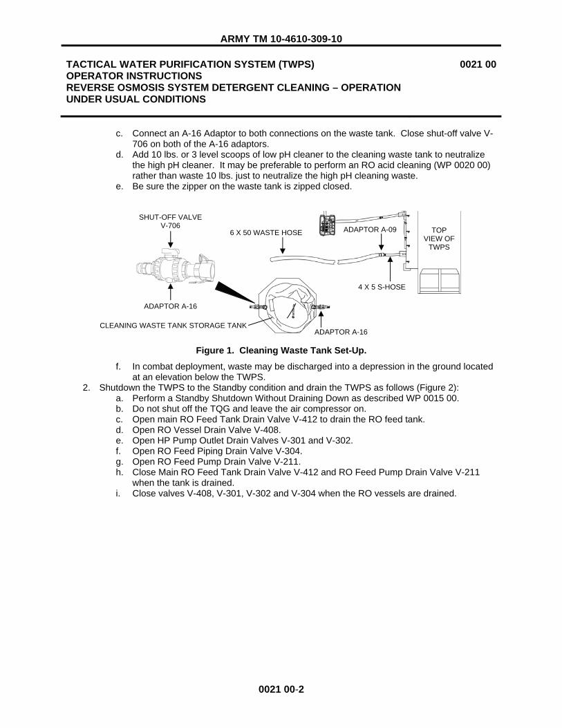
ARMY TM 10-4610-309-10
TACTICAL WATER PURIFICATION SYSTEM (TWPS) OPERATOR INSTRUCTIONS REVERSE OSMOSIS SYSTEM DETERGENT CLEANING – OPERATION UNDER USUAL CONDITIONS
0021 00
0021 00-2
c. Connect an A-16 Adaptor to both connections on the waste tank. Close shut-off valve V-706 on both of the A-16 adaptors.
d. Add 10 lbs. or 3 level scoops of low pH cleaner to the cleaning waste tank to neutralize the high pH cleaner. It may be preferable to perform an RO acid cleaning (WP 0020 00) rather than waste 10 lbs. just to neutralize the high pH cleaning waste.
e. Be sure the zipper on the waste tank is zipped closed.
Figure 1. Cleaning Waste Tank Set-Up.
f. In combat deployment, waste may be discharged into a depression in the ground located at an elevation below the TWPS.
2. Shutdown the TWPS to the Standby condition and drain the TWPS as follows (Figure 2): a. Perform a Standby Shutdown Without Draining Down as described WP 0015 00. b. Do not shut off the TQG and leave the air compressor on. c. Open main RO Feed Tank Drain Valve V-412 to drain the RO feed tank. d. Open RO Vessel Drain Valve V-408. e. Open HP Pump Outlet Drain Valves V-301 and V-302. f. Open RO Feed Piping Drain Valve V-304. g. Open RO Feed Pump Drain Valve V-211. h. Close Main RO Feed Tank Drain Valve V-412 and RO Feed Pump Drain Valve V-211
when the tank is drained. i. Close valves V-408, V-301, V-302 and V-304 when the RO vessels are drained.
ADAPTOR A-16
CLEANING WASTE TANK STORAGE TANK
6 X 50 WASTE HOSE
4 X 5 S-HOSE
ADAPTOR A-16
TOPVIEW OF
TWPS
ADAPTOR A-09
SHUT-OFF VALVE V-706

ARMY TM 10-4610-309-10
TACTICAL WATER PURIFICATION SYSTEM (TWPS) OPERATOR INSTRUCTIONS REVERSE OSMOSIS SYSTEM DETERGENT CLEANING – OPERATION UNDER USUAL CONDITIONS
0021 00
0021 00-3
Figure 2. Valves for Shutdown to Standby and Drain for RO Detergent Cleaning.
3. Set the waste hoses for RO detergent cleaning as follows (Figure 3): a. Disconnect 4 x 6 in. Adaptor A-09 and the 6 in. red-banded waste out hose from the 4 in.
x 5 ft. waste outlet hose of the TWPSb. Check Adaptors A-10, A-12 and A-16 to make sure that there are gaskets inside the
female ends and that the gaskets are in good condition to ensure leak-tight connections. c. Connect 4 x 2 in. Adaptor A-10 to the 4 in. x 5 ft. waste outlet hose. d. If using the cleaning waste storage tank, set up the hoses as follows (Figure 3):
1) Connect a 2 in. x 10 ft., red-banded cleaning waste hose to Adaptor A-10. 2) Connect one or two additional 2 in. x 10 ft., red-banded hoses as needed to
reach the waste tank. 3) Connect Adaptor A-12 to the end of the last hose. 4) Connect Adaptor A-12 to the A-16 Adaptor on the waste tank with the female end
exposed and close the valves on these two adaptors. 5) Make sure Valve V-706 on the other Adaptor A-16 on the waste tank is closed.
RO FEED TANK MAIN DRAIN VALVE V-412
RO FEED PUMP DRAIN VALVE V-211
RO VESSEL DRAIN VALVE V-408
HPP OUTLET DRAIN VALVE V-302
RO FEED PIPING DRAIN VALVE V-304
HP PUMP OUTLET DRAIN VALVE V-301

ARMY TM 10-4610-309-10
TACTICAL WATER PURIFICATION SYSTEM (TWPS) OPERATOR INSTRUCTIONS REVERSE OSMOSIS SYSTEM DETERGENT CLEANING – OPERATION UNDER USUAL CONDITIONS
0021 00
0021 00-4
Figure 3. RO Detergent Cleaning Waste Hose Set-Up with the Cleaning Waste Tank.
e. If not using the cleaning waste tank, set up the cleaning waste hoses as follows (Figure 4):
1) Connect a 2 x 10, red-banded, cleaning waste suction hose to Adaptor A-10. 2) Connect one 50 ft., green banded, raw water discharge hose to the 2 x10, red-
banded cleaning waste hose. 3) Connect one 2 x 10, red-banded, cleaning waste suction hose to the other end of
the 50 ft. hose. 4) Connect Adaptor A-12 to the end of the second cleaning waste hose. 5) Close Adaptor A-12 Valve V-705. 6) Direct A-12 discharge into a depression in the ground away from the TWPS.
Figure 4. RO Detergent Cleaning Waste Hose Set-Up Without the Cleaning Waste Tank.
4. Remove the 3 in.hose from the TWPS inlet and cap the inlet. 5. Prepare water for RO detergent cleaning as follows (Figure 5):
a. Be sure Main RO Feed Tank Drain Valve V-412 is closed. b. Open Clean Mixing Valve V-703. c. Close HP Pump Inlet Valve V-212.
CLEANING WASTE TANK A-10
4 X 5 S-HOSE
2 X 10 S-HOSES TOPVIEW OF
TWPS
4 X 5 S-HOSE
TOPVIEW OF
TWPS
2 X 10 S-HOSE
2 X 10 S-HOSE
2 X 50 D-HOSE
A-12 VALVE V-705
A-10
A-16VALVE V-706
A-16VALVE V-706
A-12VALVE V-705

ARMY TM 10-4610-309-10
TACTICAL WATER PURIFICATION SYSTEM (TWPS) OPERATOR INSTRUCTIONS REVERSE OSMOSIS SYSTEM DETERGENT CLEANING – OPERATION UNDER USUAL CONDITIONS
0021 00
0021 00-5
Figure 5. Valves for Preparing Water for RO Detergent Cleaning.
d. Set the SYSTEM MODE SWITCH to RO CLEAN. e. Using the distribution system auxiliary hose, fill the RO feed tank to just over the top of
the baffle plate (90-95% level) with product water from the distribution system.
RO FEED TANK AUXILIARY DRAIN VALVE V-210 RO FEED TANK MAIN DRAIN VALVE V-412
CLEAN MIXING VALVE V-703
HPP INLET VALVE V-212

ARMY TM 10-4610-309-10
TACTICAL WATER PURIFICATION SYSTEM (TWPS) OPERATOR INSTRUCTIONS REVERSE OSMOSIS SYSTEM DETERGENT CLEANING – OPERATION UNDER USUAL CONDITIONS
0021 00
0021 00-6
Chemical dust. Wear a dust mask, a protective face shield and chemical gloves when handling sodium bisulfite. Avoid inhaling chemical dust or fumes. Failure to observe this warning may result in mild irritation of the nose, throat, eyes and skin. Promptly change contaminated clothing after accidental chemical exposure.
CAUTION
Failure to add sodium bisulfite to the chlorinated product water that is used for cleaning will result in RO membrane failure.
NOTE
Open one of the 12 oz. sodium bisulfite packets and pour it into the bottle provided in the BII. The bisulfite powder will be used to neutralize the chlorine in the product water when product water is required for cleaning.
f. Add one cap of sodium bisulfite from the sodium bisulfite bottle to the RO feed tank while filling the tank to neutralize the chlorine in the product water.
g. Reset the RO Feed Tank Low Alarm. h. Start the RO feed pump. This circulates the solution from the RO feed tank, through the
RO feed pump, through Clean Mixing Valve V-703, and back into the tank to provide mixing when the membrane detergent cleaner is added to the water. Silence any alarms.
i. Set the Tank Heater Switch to AUTO 2. 6. Prepare the RO detergent cleaning solution as follows:
Chemical hazard. Wear a dust mask, a protective face shield, chemical gloves and a chemical apron when handling detergent cleaner. Avoid eye and skin contact. Keep water ready when handling. Avoid inhaling or ingesting dust. Wash thoroughly after handling. Failure to observe this warning may result in mild irritation of the nose, throat, eyes and skin.
NOTE
Rapid pouring of membrane detergent cleaner into the tank will cause the cleaner to stick to the tank bottom and not mix. Unmixed cleaner may be drawn to the pump and interrupt pumping.
a. Make sure a bucket of product water is placed in the operator station and also near the wastewater tanks to rinse any area of skin or clothing that comes in contact with acid cleaner.
b. Hook the RO feed tank cover open.
WARNING
WARNING

ARMY TM 10-4610-309-10
TACTICAL WATER PURIFICATION SYSTEM (TWPS) OPERATOR INSTRUCTIONS REVERSE OSMOSIS SYSTEM DETERGENT CLEANING – OPERATION UNDER USUAL CONDITIONS
0021 00
0021 00-7
c. VERY SLOWLY add 25 lbs. or 6 scoops of high pH cleaner into the RO tank to ensure it is mixed thoroughly with the water and to avoid splashing chemicals. Maintain recirculation and continue mixing and heating until the solution temperature reaches 100°F.
d. Close the RO feed tank cover. e. Rinse the chemical gloves with product water in the bucket before removing.
7. Set valves to recirculate the detergent cleaning solution from the RO feed tank, through the RO feed pump, through the RO elements and back to the RO feed tank as follows:
a. Be sure Adaptor A-12 Valve V-705 on the 2 x 10 cleaning waste (suction) hoses is closed (Figure 6).
Figure 6. Adaptor A-12 Valve V-705 in Cleaning Waste Hose Line.
b. Close the Distribution Tank Adaptor A-15 Valve V-525 and disconnect the product hose (Figure 7).
Figure 7. Distribution Tank Adaptor A-15 Valve V-525.
c. Direct the product utility hose to discharge into the RO feed tank through the open tank cover (Figure 8).
d. Open Product Utility Valve V-511. e. Open RO Clean Feed Valve V-701. f. Open Clean Return Valve V-702.
A-15
DISTRIBUTION TANKS
V-525
A-10
4 X 5 S-HOSE
2 X 10 CLEANING WASTE S-HOSES
TOPVIEW OF
TWPS
CLEANING WASTE TANK A-16
VALVE V-706 A-16
VALVE V-706
A-12VALVE V-705

ARMY TM 10-4610-309-10
TACTICAL WATER PURIFICATION SYSTEM (TWPS) OPERATOR INSTRUCTIONS REVERSE OSMOSIS SYSTEM DETERGENT CLEANING – OPERATION UNDER USUAL CONDITIONS
0021 00
0021 00-8
g. Close Clean Mixing Valve V-703. h. Continue recirculation for one hour. If extended cleaning is required, continue for up to 4
hrs. total. Refer to WP 0014 00.
Figure 8. Valves for RO Detergent Cleaning.
8. Drain the RO vessels and RO feed tank as follows: a. Stop the RO feed pump. b. Close Clean Return Valve V-702. c. If using the cleaning waste storage tank, open valves V-705 and V-706 on Adaptors A-12
and A-16 that are connected together on the cleaning waste tank (Figure 6). d. Make sure the A-16 adaptor valve V-706 on the other side of the waste tank is closed. e. If not using the cleaning waste storage tank, open valve V-705 on Adaptor A-12 at the
end of the cleaning waste hoses (Figure 4). f. Start the RO feed pump.
1) The cleaning solution is pumped from the tank through the RO and out through the waste hose.
2) When the low level is reached, the pump stops and the alarm sounds. Silence the alarm.
g. Open Main RO Feed Tank Drain Valve V-412. h. When drained, rinse the tank with product water from the distribution system auxiliary
hose.9. Flush the RO vessels with product water as follows:
a. Close Main RO Feed Tank Drain Valve V-412. b. Using the distribution system auxiliary hose, fill the RO feed tank to the top of the baffle
plate (90-95% level) with product water from the distribution system.
CLEAN RETURN VALVE V-702
PRODUCT UTILITY VALVE V-511
RO TANK COVER
CLEAN MIXING VALVE V-703
RO CLEAN FEED VALVE V-701
PRODUCT UTILITY HOSE

ARMY TM 10-4610-309-10
TACTICAL WATER PURIFICATION SYSTEM (TWPS) OPERATOR INSTRUCTIONS REVERSE OSMOSIS SYSTEM DETERGENT CLEANING – OPERATION UNDER USUAL CONDITIONS
0021 00
0021 00-9
Chemical dust. Wear a protective face shield, chemical gloves and a dust mask when handling sodium bisulfite. Avoid inhaling chemical dust or fumes. Failure to observe this warning may result in mild irritation of the nose, throat, eyes and skin.
CAUTION
Failure to add sodium bisulfite to the chlorinated product water that is used for cleaning will result in RO membrane failure.
c. Add one cap of sodium bisulfite to the RO feed tank while filling the tank to neutralize the chlorine in the product water.
d. Reset the RO Feed Tank Low Alarm. e. Start the RO Feed Pump. Silence any alarms.
1) This flushes product water through the RO vessels and out the waste hose. 2) When the low level is reached, the pump stops and the alarm sounds.
10. Repeat the product water flush of the RO vessels (steps 9b through 9e). a. While repeating the product water flush of the RO vessels, momentarily open the
following drain valves (Figure 9): 1) RO Feed Pump Drain Valve V-211 2) High Pressure Pump Outlet Drain Valves V-301 and V-302 3) Feed Piping Drain Valve V-304 4) Turbocharger Feed Side Drain Valve V-303 5) Turbocharger Reject Side Drain Valve V-410
b. Momentarily opening and closing these valves allows enough water through the valves to flush them. Leave the valves in the closed position when completing the flushing process.
WARNING

ARMY TM 10-4610-309-10
TACTICAL WATER PURIFICATION SYSTEM (TWPS) OPERATOR INSTRUCTIONS REVERSE OSMOSIS SYSTEM DETERGENT CLEANING – OPERATION UNDER USUAL CONDITIONS
0021 00
0021 00-10
Figure 9. Valves for Second RO Product Water Flush.
11. End the RO Detergent Cleaning as follows: a. Set SYSTEM MODE SWITCH to Standby. b. Close RO Clean Feed Valve V-701 (Figure 8).
Chemical hazard. Wear a protective face shield, chemical gloves and a chemical apron when handling detergent cleaner. Avoid eye and skin contact. Keep water ready when handling. Avoid inhaling or ingesting dust. Wash thoroughly after handling. Failure to observe this warning may result in mild irritation of the nose, throat, eyes and skin.
c. Open the HP Pump Inlet Valve V-212 (Figure 9). d. If using the cleaning waste storage tank, perform the following steps:
1) Close valves V-705 and V-706 on Adaptors A-12 and A-16 that are connected together on the cleaning waste tank (Figure 6).
2) Make sure the A-16 adaptor valve V-706 on the other side of the waste tank is closed.
3) Disconnect Adaptor A-12 from the Adaptor A-16. 4) Direct the cleaning waste hose into an empty bucket, open Adaptor A-12 Valve
V-705 and drain the contents of the hose into the bucket.
WARNING
RO FEED PUMP DRAIN VALVE V-211
HP PUMP INLET VALVE V-212
TURBOCHARGER FEED SIDE DRAIN VALVE V-303 TURBOCHARGER REJECT SIDE DRAIN VALVE V-410
HPP OUTLET DRAIN VALVE V-302
RO FEED PIPING DRAIN VALVE V-304
HP PUMP OUTLET DRAIN VALVE V-301

ARMY TM 10-4610-309-10
TACTICAL WATER PURIFICATION SYSTEM (TWPS) OPERATOR INSTRUCTIONS REVERSE OSMOSIS SYSTEM DETERGENT CLEANING – OPERATION UNDER USUAL CONDITIONS
0021 00
0021 00-11/12 BLANK
5) Open the top of the waste tank and empty the bucket into the waste tank. Then close the tank.
e. If not using the cleaning waste storage tank, simply leave valve V-705 on Adaptor A-12 at the end of the cleaning waste hoses open (Figure 4).
f. When drained, disconnect the cleaning waste hose from 4 x 2 Adaptor A-10. g. Rinse the inside of the hose sections with water from the distribution system auxiliary
hose.h. Close Product Utility Hose Valve V-511 and remove the hose from the RO feed tank.
12. Refer to WP 0018 00, for the procedures to neutralize the wastewater and pump it out of the cleaning waste storage tank.
13. Return to normal operation as follows: a. Remove the cap from the MF inlet and reconnect the 3 in. TPWS inlet hose. b. Remove Adaptor A-10 from the 4 x 5 waste out hose and rinse. c. Connect Adaptor A-09 and the 6 in. x 50 ft. red-banded waste out hose to the 4 x 5 waste
hose (Figure 1). d. Follow the procedure for Startup After Short Term Shutdown in WP 0013 00 to return to
normal operation. e. Discharge the product on the ground for 10 minutes before connecting the product hose
to the distribution tank. This will flush any remaining cleaning chemicals from the product side of the RO.
END OF WORK PACKAGE


ARMY TM 10-4610-309-10
TACTICAL WATER PURIFICATION SYSTEM (TWPS) OPERATOR INSTRUCTIONS MICRO-FILTRATION SYSTEM CLEANING WITH REVERSE OSMOSIS SYSTEM ACID CLEANING – OPERATION UNDER USUAL CONDITIONS
0022 00
0022 00-1
INITIAL SETUP
Materials/Parts: Bisulfite, Sodium (WP 0048 00, Item 7) Plastic Jar for bisulfite (Box #4) (WP 0045 00, Item 5) Chemical scoop (Box #4) (WP 0045 00, Item 83) Low pH cleaner (WP 0048 00, Item 29) High pH cleaner (WP 0048 00, Item 27) Three 2” x 10’ Cleaning Waste Hoses Adaptor A-10 (Box #1) Adaptor A-12 (Box #1) Cleaning Waste Storage Module if used
� One 1500 gallon rinse waste tank � Two Adaptors A-16 (A-TWPS, Box #1)
One 2-in. x 50-ft. raw water hose if cleaning waste storage module is not used Personal protective gear (Box #1)
� Chemical apron, 2 (WP 0045 00, Item 1) � Faceshield (WP 0045 00, Item 33) � Chemical gloves, 2 pr. (WP 0045 00, Item 52) � Dust mask (WP 0048 00, Item 32)
Personnel RequiredTwo Operator/Crew Equipment Condition TWPS Operational At least 2000 gallons of useable product water must be available in the distribution tanks
GENERAL
MF Cleaning with RO Acid Cleaning is performed whenever the TWPS is placed in a long-term term shut-down in preparation for storage. It should also be performed if the TWPS is to be shut down during deployment for longer than 96 hrs. and it is not certain how long the TWPS will be shut down before it is started up again. Cleaning in preparation for storage is performed regardless of the TMP, % Clean and % Salt Rejection values. The purpose of cleaning in preparation for storage is to preserve and extend the useful life of the MF modules and RO elements.
MF cleaning with RO acid cleaning combines the MF cleaning and RO acid cleaning procedures in the following order:
- MF Backwash - Acid Cleaning Solution Preparation - MF Drain - RO Acid Cleaning - MF Acid Cleaning - MF High pH Cleaning

ARMY TM 10-4610-309-10
TACTICAL WATER PURIFICATION SYSTEM (TWPS) OPERATOR INSTRUCTIONS MICRO-FILTRATION SYSTEM CLEANING WITH REVERSE OSMOSIS SYSTEM ACID CLEANING – OPERATION UNDER USUAL CONDITIONS
0022 00
0022 00-2
MF CLEANING WITH RO ACID CLEANING
The procedures that follow describe the steps for performing MF Cleaning with RO Acid Cleaning.
MF Backwash
1. Set up the cleaning waste storage tank if needed as follows (Figure 1): a. Set up the Waste Tank within 30 ft. of the TWPS waste out connection. Face the female
tank connection toward the TWPS skid. b. If the terrain allows, set the tank at an elevation so that the top of the full tank will be
below the bottom of the RO Feed Tank. c. Connect an A-16 Adaptor to both connections on the waste tank. Close shut-off valve V-
706 on both of the A-16 adaptors. d. Be sure that the zipper on the waste tank is zipped closed.
Figure 1. Cleaning Waste Tank Set-Up.
e. In combat deployment, the waste may be discharged into a depression in the ground located at an elevation below the TWPS.
2. Shutdown the TWPS to the Standby condition as follows (Figure 2): a. Perform a Standby Shutdown Without Draining Down as described by WP 0015 00. b. Do not shut off the TQG and leave the air compressor on. c. Stop the raw water pumps when the MF feed tank is 1/2 to 3/4 full.
Do not open Main RO Feed Tank Drain Valve V-412. Failure to observe this warning will result in high-pressure backwash air and water discharging back into the tank when the MF is backwashed.
d. Open RO Feed Tank Auxiliary Drain Valve V-210. e. Open RO Vessel Drain Valve V-408. f. Open Feed Piping Drain Valve V-304. g. Open HP Pump Outlet Drain Valves V-301 and V-302. h. Open RO Feed Pump Drain Valve V-211.
WARNING
ADAPTOR A-16
CLEANING WASTE TANK STORAGE TANK
6 X 50 WASTE HOSE
4 X 5 S-HOSE
ADAPTOR A-16
TOPVIEW OF
TWPS
ADAPTOR A-09
SHUT-OFF VALVE V-706

ARMY TM 10-4610-309-10
TACTICAL WATER PURIFICATION SYSTEM (TWPS) OPERATOR INSTRUCTIONS MICRO-FILTRATION SYSTEM CLEANING WITH REVERSE OSMOSIS SYSTEM ACID CLEANING – OPERATION UNDER USUAL CONDITIONS
0022 00
0022 00-3
Figure 2. Valves for Shutdown to Standby for MF and RO Acid Cleaning.
3. Backwash the MF as follows: a. Backwash the MF in the MF CLEAN MODE.
1) When the compressor stops (if running), set the MF CLEAN MODE SWITCH to BACKWASH.
2) When the Clean light flashes, start the MF feed pump. 3) Then push MF BACKWASH START.
a) The automatic backwash cycles but ends without the rewet step. b) The backwash light flashes while the backwash is in progress. When
finished, the backwash light is off. c) When the backwash is completed, the MF feed pump will stop.
4) Drain the MF feed tank. a) Disconnect the MF feed pump suction hose from the MF feed tank. Pull
the pump back. b) Lift the tank to drain it as completely as possible.
5) Reconnect the MF feed pump suction hose to the MF feed tank. 6) Fill the MF feed tank with product water from the product water distribution
system by connecting the end of the product distribution hose to raw water Adaptor A-05 and opening V-107.
RO FEED TANK MAIN DRAIN VALVE V-412
RO VESSEL DRAIN VALVE V-408
RO FEED TANK AUXILIARY DRAIN VALVE V-210
RO FEED PUMP DRAIN VALVE V-211
HPP OUTLET DRAIN VALVE V-302
RO FEED PIPING DRAIN VALVE V-304
HP PUMP OUTLET DRAIN VALVE V-301

ARMY TM 10-4610-309-10
TACTICAL WATER PURIFICATION SYSTEM (TWPS) OPERATOR INSTRUCTIONS MICRO-FILTRATION SYSTEM CLEANING WITH REVERSE OSMOSIS SYSTEM ACID CLEANING – OPERATION UNDER USUAL CONDITIONS
0022 00
0022 00-4
Chemical dust. Wear a protective face shield, chemical gloves and a dust mask when handling sodium bisulfite. Avoid inhaling chemical dust or fumes. Failure to observe this warning may result in mild irritation of the nose, throat, eyes and skin.
CAUTION
Failure to add sodium bisulfite to the chlorinated product water that is used for cleaning will result in MF membrane failure.
NOTE
Open one of the 12 oz. sodium bisulfite packets and pour it into the bottle provided in the BII. The bisulfite powder will be used to neutralize the chlorine in the product water when product water is required for cleaning.
7) Using the bottle of bisulfite, fill the bottle cap with bisulfite twice and empty it into the MF feed tank while it is filling with product water. This neutralizes the chlorine in the product water that will be used for the second backwash and the MF rinse after MF acid cleaning.
b. Backwash the MF a second time but with product water as follows: 1) When the compressor stops, start the MF feed pump. 2) Immediately push MF BACKWASH START for a second backwash using product
water from the MF feed tank. a) The automatic backwash cycles but ends without the rewet step. b) The backwash light flashes while the backwash is in progress. When
finished, the light is off. c) The MF feed pump stops when the backwash is completed.
Acid Cleaning Solution Preparation
1. Remove the 3-in.hose from the TWPS inlet and cap the inlet. 2. Prepare water for the RO and MF acid clean as follows (Figure 3):
a. Begin this step as soon as the second backwash is complete. b. Make sure the RO feed tank is drained. c. Close RO Vessel Drain Valve V-408. d. Close RO Feed Tank Drain Valves V-210 and V-412. e. Open Clean Mixing Valve V-703 f. Close RO Feed Piping Drain Valve V-304. g. Close HPP Outlet Drain Valves V-301 and V-302. h. Close RO Feed Pump Drain Valve V-211. i. Close HPP Inlet Valve V-212.
WARNING

ARMY TM 10-4610-309-10
TACTICAL WATER PURIFICATION SYSTEM (TWPS) OPERATOR INSTRUCTIONS MICRO-FILTRATION SYSTEM CLEANING WITH REVERSE OSMOSIS SYSTEM ACID CLEANING – OPERATION UNDER USUAL CONDITIONS
0022 00
0022 00-5
Figure 3. Valves for Preparing Acid Cleaning Solution for MF and RO Acid Cleaning.
j. Using the distribution system auxiliary hose, fill the RO feed tank to just over the top of the baffle plate (90-95% level) with product water from the distribution system.
Chemical dust. Wear a dust mask, a protective face shield and chemical gloves when handling sodium bisulfite. Avoid inhaling chemical dust or fumes. Failure to observe this warning may result in mild irritation of the nose, throat, eyes and skin.
CAUTION
Failure to add sodium bisulfite to the chlorinated product water that is used for cleaning will result in MF membrane failure.
WARNING
RO FEED TANK AUXILIARY DRAIN VALVE V-210
RO FEED TANK MAIN DRAIN VALVE V-412
CLEAN MIXING VALVE V-703
HPP INLET VALVE V-212
RO FEED PUMP DRAIN VALVE V-211
RO VESSEL DRAIN VALVE V-408
RO FEED PIPING DRAIN VALVE V-304
HPP OUTLET DRAIN VALVE V-302
HP PUMP OUTLET DRAIN VALVE V-301

ARMY TM 10-4610-309-10
TACTICAL WATER PURIFICATION SYSTEM (TWPS) OPERATOR INSTRUCTIONS MICRO-FILTRATION SYSTEM CLEANING WITH REVERSE OSMOSIS SYSTEM ACID CLEANING – OPERATION UNDER USUAL CONDITIONS
0022 00
0022 00-6
k. Add one cap of sodium bisulfite from the sodium bisulfite bottle to the RO feed tank while filling the tank to neutralize the chlorine in the product water.
l. Set the System Mode switch to RO CLEAN. m. Reset the RO Feed Tank Low Alarm. n. Start the RO feed pump. This circulates the solution from the RO feed tank, through the
RO feed pump, through Clean Mixing Valve V-703 and back into the tank to provide mixing when the low pH cleaner is added to the water. Silence any alarms.
o. Set the Tank Heater Switch to AUTO 2. 3. Prepare the low pH cleaning solution as follows:
Acid chemical. Wear a dust mask, a protective face shield, chemical gloves and a chemical apron when handling low pH cleaner. Avoid inhaling chemical fumes. If low pH cleaner spills, immediately flush the area with water from the auxiliary hose. Failure to observe this warning may result in mild irritation of the nose, throat, eyes and skin.
a. Make sure a bucket of product water is placed in the operator station and also near the wastewater tanks to rinse any skin or clothing that comes in contact with low pH cleaner.
b. Hook the RO feed tank cover open. c. Open the low pH cleaner. Use the chemical scoop and VERY SLOWLY pour 10 lbs. or 3
level scoops of the low pH cleaner into the RO tank to ensure that it is mixed thoroughly with the water and to avoid splashing chemicals. Maintain recirculation and continue mixing and heating until solution temperature reaches 100°F.
d. Close the RO feed tank cover. e. Rinse the scoop and then the chemical gloves with product water in the bucket before
removing.
MF Drain
After preparing the acid cleaning solution, check that the MF Backwash light is off indicating that the 2nd
backwash is done. Then continue as follows: 1. Drain Down #1: Drain the water from the MF modules as follows:
a. Stop the RO feed pump. b. Set the Tank Heater Switch to OFF. c. Set the System Mode switch to STANDBY. d. Set the MF CLEAN Switch to DRAIN #1.
1) After a 5 second delay, PLC automatic control purges water from the MF with air. 2) The PLC automatically cycles valves back to Standby at the end of drain down. 3) The MF CLEAN light flashes during operation and turns off when the drain down
is complete. 2. When complete, set the MF CLEAN switch to OFF. 3. Open the following MF vents/ drains (Figure 4):
a. Open MF Vent Valve V-114. b. Open MF Filtrate Drain Valve V-203. c. Open MF Shell Drain Valve V-403.
WARNING

ARMY TM 10-4610-309-10
TACTICAL WATER PURIFICATION SYSTEM (TWPS) OPERATOR INSTRUCTIONS MICRO-FILTRATION SYSTEM CLEANING WITH REVERSE OSMOSIS SYSTEM ACID CLEANING – OPERATION UNDER USUAL CONDITIONS
0022 00
0022 00-7
Figure 4. MF Vent / Drain Valve Location.
RO Acid Cleaning
1. Set the waste hoses for acid cleaning as follows (Figure 5). a. Disconnect the 6 in. waste out hose with 4 x 6 Adaptor A-09 from the 4 in. x 5 ft. waste
outlet hose at the waste outlet of the TWPS. b. Check Adaptors A-10, A-12 and A-16 to make sure that there are gaskets inside the
female ends and that the gaskets are in good condition to ensure leak-tight connections. c. Connect 4 x 2 Adaptor A-10 to the 4 in. x 5 ft. waste outlet hose. d. If using the cleaning waste storage tank, set up the hoses as follows (see Figure 5):
1) Connect a 2 in. x 10 ft., red-banded cleaning waste hose to Adaptor A-10. 2) Connect one or two additional 2 in. x 10 ft., red-banded hoses as needed to
reach the waste tank. 3) Connect Adaptor A-12 to the end of the last hose. 4) Connect Adaptor A-12 to the A-16 Adaptor on the waste tank with the female end
exposed and close the valves on these two adaptors. 5) Make sure Valve V-706 on the other Adaptor A-16 on the waste tank is closed.
Figure 5. MF Acid Cleaning Waste Hose Set-Up with the Cleaning Waste Tank.
d. If not using the cleaning waste tank, set up the cleaning waste hoses as follows (Figure 6):
1) Connect a 2 x 10, red-banded, cleaning waste suction hose to Adaptor A-10. 2) Connect one 50-foot, green banded, raw water discharge hose to the 2 x 10, red-
banded cleaning waste hose. 3) Connect one 2 x 10, red-banded, cleaning waste suction hose to the other end of
the 50-foot hose. 4) Connect Adaptor A-12 to the end of the second cleaning waste hose. 5) Close Adaptor A-12 Valve V-705. 6) Direct A-12 discharge into a depression in the ground away from the TWPS.
MF VENT VALVE V-114
MF SHELL DRAIN VALVE V-403
MF FILTRATE DRAIN VALVE V-203
CLEANING WASTE TANK A-10
4 X 5 S-HOSE
2 X 10 S-HOSES TOPVIEW OF
TWPS
A-16VALVE V-706
A-16VALVE V-706
A-12VALVE V-705

ARMY TM 10-4610-309-10
TACTICAL WATER PURIFICATION SYSTEM (TWPS) OPERATOR INSTRUCTIONS MICRO-FILTRATION SYSTEM CLEANING WITH REVERSE OSMOSIS SYSTEM ACID CLEANING – OPERATION UNDER USUAL CONDITIONS
0022 00
0022 00-8
Figure 6. MF Acid Cleaning Waste Hose Set-Up Without the Cleaning Waste Tank.
NOTE
When cleaning in preparation for storage (stand down from deployment), the acid cleaning solution is first used to clean the RO. Following the RO acid cleaning, the acid cleaning solution is then used to acid clean the MF.
2. Set valves for RO acid cleaning as follows: a. Make sure the RO feed pump is off. b. Be sure that Adaptor A-12 Valve V-705 on the 2 x 10 cleaning waste (suction) hoses is
closed (Figure 5 or Figure 6). c. Close the distribution tank Adaptor A-15 valve V-525 and disconnect the product hose
(Figure 7).
Figure 7. Distribution Tank Adaptor A-15 Valve V-525.
d. Direct the product utility hose to discharge into the RO feed tank through the open tank cover (see Figure 8).
e. Open the Product Utility Valve V-511. f. Open RO Clean Feed Valve V-701.
A-15
DISTRIBUTION TANKS TWPS
PRODUCT HOSE
V-525
4 X 5 S-HOSE
TOPVIEW OF
TWPS
2 X 10 S-HOSE
2 X 10 S-HOSE
2 X 50 D-HOSE
A-12 VALVE V-705
A-10

ARMY TM 10-4610-309-10
TACTICAL WATER PURIFICATION SYSTEM (TWPS) OPERATOR INSTRUCTIONS MICRO-FILTRATION SYSTEM CLEANING WITH REVERSE OSMOSIS SYSTEM ACID CLEANING – OPERATION UNDER USUAL CONDITIONS
0022 00
0022 00-9
g. Open Clean Return Valve V-702. h. Close Clean Mixing Valve V-703.
Figure 8. Valves For RO Acid Cleaning.
3. Recirculate the RO acid cleaning solution from the RO feed tank, through the RO feed pump, through the RO elements, and back to the RO feed tank as follows:
a. Set the SYSTEM MODE SWITCH to RO CLEAN. b. Start the RO feed pump. c. Set the Tank Heater switch to AUTO 2. d. The RO reject flow indicates whether or not cleaning solution is recirculating. e. Continue recirculation for one hour.
4. Force-air drain the RO elements as follows: a. Stop the RO feed pump. b. Turn the Tank Heater switch to OFF. c. Close RO Clean Feed Valve V-701. d. Close Product Utility Valve V-511 e. Make sure RO Air Purge Valve V-913 is closed (Figure 9). f. Connect one end of the auxiliary air hose (from BII) to the quick-disconnect fitting in Air
System Section 1 above the compressor opposite Pressure Gauge PI-902. g. Connect the other end of the auxiliary air hose to the quick-disconnect fitting at RO Air
Purge Valve V-913 in the feed inlet to RO vessel #1. h. Slowly and only partially open RO Purge Valve V-913. This will force most of the
cleaning solution out of the RO, back through Clean Return Valve V-702, and into the RO feed tank so that it can be used to clean the MF.
i. Close Valve V-913 when air is observed to be discharging into the RO feed tank. j. Disconnect the auxiliary air hose first at Valve V-913 then at Air System Section 1.
Return the auxiliary air hose to the BII.
CLEAN RETURN VALVE V-702
PRODUCT UTILITY VALVE V-511
RO TANK COVER
CLEAN MIXING VALVE V-703
RO CLEAN FEED VALVE V-701
PRODUCT UTILITY HOSE

ARMY TM 10-4610-309-10
TACTICAL WATER PURIFICATION SYSTEM (TWPS) OPERATOR INSTRUCTIONS MICRO-FILTRATION SYSTEM CLEANING WITH REVERSE OSMOSIS SYSTEM ACID CLEANING – OPERATION UNDER USUAL CONDITIONS
0022 00
0022 00-10
Figure 9. Auxliary Air Hose Connections for Force-Air Draining the RO Elements.
5. End the RO acid cleaning as follows: a. Set the SYSTEM MODE SWITCH to STANDBY. b. Place the hose from RO Vessel Drain Valve V-408 into a bucket. Open the valve. Drain
the remaining solution into the bucket. Close the valve when draining is completed. c. Place the hose from HP Pump Outlet Drain Valve V-302 into a bucket. Open the valve.
Drain the remaining solution into the bucket. Close the valve when draining is completed. d. Place the hose from RO Feed Piping Drain Valve V-304 into a bucket. Open V-304.
Drain the remaining solution into the bucket. Close the valve when draining is completed. e. Empty the bucket(s) into the RO feed tank.
MF Acid Cleaning
1. Set valves for MF acid cleaning as follows (Figure 10): a. Close MF Vent Valve V-114. b. Open MF Clean Feed Valve V-704. c. Be sure that Clean Return Valve V-702 is open. d. Be sure that Clean Mixing Valve V-703 is closed. e. Close MF Filtrate Drain Valve V-203. f. Close MF Shell Drain Valve V-403. g. Be sure that Adaptor A-12 Valve V-705 on the cleaning waste hose is closed (Figure 5 or
Figure 6).
RO PURGE VALVE V-913
AUXILIARY AIR HOSE
AIR SYSTEM SECTION 1

ARMY TM 10-4610-309-10
TACTICAL WATER PURIFICATION SYSTEM (TWPS) OPERATOR INSTRUCTIONS MICRO-FILTRATION SYSTEM CLEANING WITH REVERSE OSMOSIS SYSTEM ACID CLEANING – OPERATION UNDER USUAL CONDITIONS
0022 00
0022 00-11
Figure 10. Valves for MF Acid Cleaning.
2. Recirculate the acid cleaning solution through the MF as follows: a. Set the MF Clean Switch to FILL/RECIRC. The RO pump starts to automatically fill the
MF modules and establish recirculation through the MF modules. b. Turn the Tank Heater Switch to AUTO 2. The heaters heat the cleaning solution and
automatically cut off when the temperature reaches 110˚ F.c. Check that there is an indication of MF Flow at the OCP display. If not, make sure that
the valves are properly positioned.
NOTE
The CLEAN light flashes during the cleaning cycle and turns off when the cycle is completed (approximately 26 minutes). The RO pump stops. If the heaters were on, they also turn off at the completion of the cleaning cycle.
MF CLEAN FEED VALVE V-704
CLEAN RETURN VALVE V-702
CLEAN MIXING VALVE V-703
MF VENT VALVE V-114
MF FILTRATE DRAIN VALVE V-203
MF SHELL DRAIN VALVE V-403

ARMY TM 10-4610-309-10
TACTICAL WATER PURIFICATION SYSTEM (TWPS) OPERATOR INSTRUCTIONS MICRO-FILTRATION SYSTEM CLEANING WITH REVERSE OSMOSIS SYSTEM ACID CLEANING – OPERATION UNDER USUAL CONDITIONS
0022 00
0022 00-12
NOTE
Extended cleaning is required if the operator has chosen to wait 40 hrs. after the first TMP alarm, the maximum TMP has been exceeded, the water temperature does not reach at least 100�F during the cleaning cycle or the TMP is higher than the normal reading after cleaning (3 to 5 psi at 50 to 60 gpm MF Feed Flow). It is best to perform the extended cleaning if the operator has time available. There is nothing more dissatisfying than spending 4 hrs. performing a cleaning then discovering the cleaning has not been effective.
d. If extended cleaning is required, perform the following steps: 1) Set the MF Clean switch to SOAK. This interrupts the clean cycle and leaves the
cleaning solution in the MF modules to soak. 2) Soak for 15 minutes. 3) Set the MF Clean switch back to FILL/RECIRC for one minute. 4) Repeat the SOAK / FILL/RECIRC sequence for a total of one hour.
e. Set the MF Clean switch back to FILL/RECIRC to continue with the normal cycle and timing to completion.
f. While cleaning the MF modules, refill the MF feed tank with product water using the distribution system auxiliary hose. This water will be used to rinse the MF system.
Chemical dust. Wear a protective face shield, chemical gloves and a dust mask when handling sodium bisulfite. Avoid inhaling chemical dust or fumes. Failure to observe this warning may result in mild irritation of the nose, throat, eyes and skin.
CAUTION
Failure to add sodium bisulfite to the chlorinated product water that is used for cleaning will result in MF membrane failure.
g. Add two caps of bisulfite from the bisulfite bottle to the MF feed tank while refilling. 3. Drain #2: Drain the acid cleaning solution from the RO feed tank and MF modules as follows:
a. Set the Tank Heater Switch to OFF. b. Close Clean Return Valve V-702 (Figure 10). c. If using the cleaning waste storage tank, open valves V-705 and V-706 on Adaptors A-12
and A-16 that are connected together on the cleaning waste tank (Figure 5). d. Make sure the A-16 adaptor valve V-706 on the other side of the waste tank is closed. e. If not using the cleaning waste storage tank, open valve V-705 on Adaptor A-12 at the
end of the cleaning waste hoses (Figure 6). f. Set the MF Clean Switch to Drain #2. The RO feed pump starts and flushes the cleaning
solution from the tank through the MF and out the waste hose.
WARNING

ARMY TM 10-4610-309-10
TACTICAL WATER PURIFICATION SYSTEM (TWPS) OPERATOR INSTRUCTIONS MICRO-FILTRATION SYSTEM CLEANING WITH REVERSE OSMOSIS SYSTEM ACID CLEANING – OPERATION UNDER USUAL CONDITIONS
0022 00
0022 00-13
CAUTION
Failure to close MF Clean Feed Valve V-704 at this point will result in water flow back into the RO feed tank rather than out as required.
NOTE
When the RO feed tank level reaches the Low Level Switch, the alarm sounds and the RO feed pump stops. Occasionally the RO pump will lose prime before reaching the low level. In this case, if the RO pump does not stop within 15 seconds from when the tank level reads zero, stop the RO pump.
g. Wait for the RO feed pump to stop, then close MF Clean Feed Valve V-704 (Figure 10). 4. Drain #3: Set the MF Clean switch to Drain #3 to purge the remaining acid cleaning solution from
the MF modules with air as follows: a. A normal air purge drain down cycle automatically sequences. b. Cleaning solution drains out through the cleaning waste hoses. c. During the Drain #3 cycle, slightly open MF Clean Feed Valve V-704 for just a moment to
push cleaning solution out of the cleaning bypass piping. d. The Clean light flashes during the cycle and turns off when complete.
5. Rinse the MF system with product water as follows: a. Remove the cap from the MF inlet and reconnect the 3-in. TPWS inlet hose. b. Set the MF Clean switch to RINSE.
1) This initiates an automatic rinse cycle using product water from the MF feed tank. The Clean light flashes during this cycle.
2) The MF feed pump starts automatically. 3) The MF feed pump stops. 4) The Clean Light turns off at the end of the cycle.
c. The cycle ends in STANDBY (the standby light comes on.) 6. Repeat a Drain #3 cycle by placing the MF Clean switch to Drain #3. After the Clean light stops
flashing (indicating the cycle is complete), set the MF Clean switch to OFF.
Acid chemical. Wear a protective face shield, chemical gloves and a chemical apron when there is a potential for contact with low pH cleaner. Avoid inhaling chemical fumes. If low pH cleaner spills, immediately flush the area with water from the auxiliary hose. Failure to observe this warning may result in mild irritation of the nose, throat, eyes and skin.
7. Flush the RO feed tank with product water as follows (Figure 11): a. Open Main RO Feed Tank Drain Valve V-412 to drain the remaining solution. b. Flush the RO feed tank with water using the distribution system auxiliary hose to remove
residual cleaning solution.
WARNING

ARMY TM 10-4610-309-10
TACTICAL WATER PURIFICATION SYSTEM (TWPS) OPERATOR INSTRUCTIONS MICRO-FILTRATION SYSTEM CLEANING WITH REVERSE OSMOSIS SYSTEM ACID CLEANING – OPERATION UNDER USUAL CONDITIONS
0022 00
0022 00-14
c. While flushing the RO feed tank: 1) Place the hose from RO Feed Pump Drain Valve V-211 into a bucket. Open the
valve just long enough to flush the pump, then close the valve. 2) Place the hose from HP Pump Outlet Drain Valve V-301 into a bucket. Open the
valve. Drain the remaining solution into the bucket. Close the valve when draining is completed.
3) Place the hose from RO Feed Piping Drain Valve V-304 into a bucket. Open V-304 and V-701. Drain the remaining solution into the bucket. Close both valve when draining is completed.
4) Place the hose from HP Pump Outlet Drain Valve V-302 into a bucket. Open the valve. Drain the remaining solution into the bucket. Close the valve when draining is completed.
5) Empty the bucket(s) into the 1500-gallon cleaning waste storage tank. d. After flushing the RO tank, allow the tank to drain then close RO Tank Drain Valve V-412.
Figure 11. Valves for Flushing the RO Feed Tank.
MF High pH Cleaning
1. Close Adaptor A-12 valve V-705 on the cleaning waste hoses. 2. Prepare water for MF high pH cleaning as follows:
a. Remove the 3-in. hose from the TWPS inlet connection and cap the inlet connection. b. Be sure RO Feed Tank Drain Valve V-412 is closed (Figure 11). c. Open Clean Mixing Valve V-703 (Figure 10). d. Using the distribution system auxiliary hose, fill the RO feed tank to just over the top of
the baffle plate (90-95% level) with product water from the distribution system.
RO FEED TANK MAIN DRAIN VALVE V-412
RO FEED PUMP DRAIN VALVE V-211
RO FEED PIPE DRAIN VALVE V-304
HP PUMP OUTLET DRAIN VALVE V-302
HP PUMP OUTLET DRAIN VALVE V-301
RO CLEAN FEED VALVE V-701

ARMY TM 10-4610-309-10
TACTICAL WATER PURIFICATION SYSTEM (TWPS) OPERATOR INSTRUCTIONS MICRO-FILTRATION SYSTEM CLEANING WITH REVERSE OSMOSIS SYSTEM ACID CLEANING – OPERATION UNDER USUAL CONDITIONS
0022 00
0022 00-15
Chemical dust. Wear a protective face shield, chemical gloves and a dust mask when handling sodium bisulfite. Avoid inhaling chemical dust or fumes. Failure to observe this warning may result in mild irritation of the nose, throat, eyes and skin.
CAUTION
Failure to add sodium bisulfite to the chlorinated product water that is used for cleaning will result in MF membrane failure.
e. Add one cap of sodium bisulfite from the bisulfite bottle to the RO feed tank while filling the tank to neutralize the chlorine in the product water.
f. Set the System Mode switch to RO CLEAN. g. Reset the RO Feed Tank Low Alarm. h. Start the RO feed pump. This circulates the solution from the RO feed tank, through the
RO feed pump, through clean mixing valve V-703 and back into the tank to provide mixing when the high pH cleaner is added to the water.
i. Silence any alarms. j. Set the Tank Heater switch to AUTO 2.
3. Prepare the high pH cleaning solution as follows:
High pH chemical. Wear a protective face shield, chemical gloves and chemical apron when handling caustic solution. Keep water ready when handling. Avoid inhaling chemical fumes. If high pH cleaner spills, immediately flush the area with water from the auxiliary hose. Failure to observe this warning may result in severe irritation of the nose, throat and eyes. Contact with skin will result in irritation if not rinsed immediately.
NOTE
Rapid pouring of high pH cleaner into the tank will cause the cleaner to stick to the tank bottom and not mix. Unmixed detergent may be drawn to the pump and interrupt pumping.
a. Make sure a bucket of product water is placed in the operator station to rinse any area of skin or clothing that comes in contact with high pH cleaner.
b. Hook the RO feed tank cover open. c. VERY SLOWLY add high pH cleaner into the RO feed tank by opening the high pH
cleaner and very slowly pouring 25 lbs. or 6 scoops into the RO feed tank. Pour into the area of water flow from the mixing recirculation water flow.
d. Close the RO feed tank cover. e. Rinse the chemical gloves in the bucket of product water before removing.
WARNING
WARNING

ARMY TM 10-4610-309-10
TACTICAL WATER PURIFICATION SYSTEM (TWPS) OPERATOR INSTRUCTIONS MICRO-FILTRATION SYSTEM CLEANING WITH REVERSE OSMOSIS SYSTEM ACID CLEANING – OPERATION UNDER USUAL CONDITIONS
0022 00
0022 00-16
f. After mixing and the solution has reached 100°F, stop the RO feed pump. g. Turn the Tank Heater Switch to OFF. h. Set System Mode switch to STANDBY.
4. Set valves for MF high pH cleaning as follows (Figure 12): a. Open MF Clean Feed Valve V-704. b. Open Clean Return Valve V-702. c. Close Clean Mixing Valve V-703. d. Be sure that Valve V-705 on Adaptor A-12 on the cleaning waste hoses is closed (Figure
5 or Figure 6).
Figure 12. Valves for MF High pH Cleaning.
5. Recirculate the high pH cleaning solution through the MF modules as follows: a. Set the MF Clean switch to FILL/RECIRC. The RO pump starts to automatically fill the
MF modules and establish recirculation through the MF modules. b. Turn the Tank Heater switch to AUTO 2. The heaters heat the cleaning solution and
automatically cut off when the temperature reaches 110˚ F. c. Check that there is an indication of MF flow. If not, make sure that the valves are
properly positioned.
MF CLEAN FEED VALVE V-704
CLEAN RETURN VALVE V-702
CLEAN MIXING VALVE V-703

ARMY TM 10-4610-309-10
TACTICAL WATER PURIFICATION SYSTEM (TWPS) OPERATOR INSTRUCTIONS MICRO-FILTRATION SYSTEM CLEANING WITH REVERSE OSMOSIS SYSTEM ACID CLEANING – OPERATION UNDER USUAL CONDITIONS
0022 00
0022 00-17
NOTE
The CLEAN light flashes during the cleaning cycle and turns off when the cycle is completed (approximately 26 minutes). The RO pump stops. If the heaters were on, they also turn off at the completion of the cleaning cycle.
Extended cleaning is required if the operator has chosen to wait 40 hrs. after the TMP alarm, the maximum TMP has been exceeded, the water temperature does not reach at least 100� F during the cleaning cycle, or the TMP is higher than the normal reading after cleaning (3 to 5 psi at 50 to 60 gpm MF Feed Flow). It is best to perform the extended cleaning if the operator has time available. Nothing is more dissatisfying than spending 4 hrs. performing cleaning and discovering that it has not been effective.
d. If extended cleaning is required, perform the following steps: 1) Set the MF Clean switch to SOAK. This interrupts the clean cycle and leaves the
cleaning solution in the MF modules to soak. 2) Soak for 15 minutes. 3) Set the MF Clean switch back to FILL/RECIRC for one minute. 4) Repeat the SOAK / FILL/RECIRC sequence for a total of one hour.
e. Set the MF Clean switch back to FILL/RECIRC to continue with the normal cycle and timing to completion.
6. Drain #2: Drain the high pH cleaning solution from the RO feed tank and MF modules as follows (Figure 12):
a. Set the Tank Heater switch to OFF. b. Close Clean Return Valve V-702. c. If using the cleaning waste storage tank, open valves V-705 and V-706 on Adaptors A-12
and A-16 that are connected together on the cleaning waste tank (Figure 5). d. Make sure the A-16 adaptor valve V-706 on the other side of the waste tank is closed. e. If not using the cleaning waste storage tank, open valve V-705 on Adaptor A-12 at the
end of the cleaning waste hoses (Figure 6). f. Set the MF Clean switch to DRAIN #2. The RO feed pump starts and flushes the
cleaning solution from the tank through the MF and out the waste hose.
CAUTION
Failure to close MF Clean Feed Valve V-704 will result in water flow back into the RO feed tank rather than out as required.
NOTE
When the tank level reaches the Low Level Switch, the alarm sounds and the RO feed pump stops. Occasionally the RO pump will lose prime before reaching the low level. In this case, if the RO pump does not stop within 15 seconds from when the tank level reads zero, stop the RO pump.
g. Wait for the RO feed pump to stop, then close MF Clean Feed Valve V-704.

ARMY TM 10-4610-309-10
TACTICAL WATER PURIFICATION SYSTEM (TWPS) OPERATOR INSTRUCTIONS MICRO-FILTRATION SYSTEM CLEANING WITH REVERSE OSMOSIS SYSTEM ACID CLEANING – OPERATION UNDER USUAL CONDITIONS
0022 00
0022 00-18
7. Drain #3: Set the Clean switch to Drain #3 to purge the remaining high pH cleaning solution from the MF modules with air as follows:
a. A normal air purge drain down cycle automatically sequences. b. Cleaning solution drains out through the cleaning waste hoses. c. During the Drain #3 cycle, slightly open MF Clean Feed Valve V-704 for just a moment to
push cleaning solution out of the cleaning bypass piping. d. The Clean light flashes during operation and turns off when complete.
8. Flush the RO feed tank with product water as follows (Figure 13): a. Open Main RO Feed Tank Drain Valve V-412 to drain any remaining high pH cleaning
solution from the tank to the waste out hose. b. Flush the tank with water using the distribution system auxiliary hose to remove residual
cleaning solution. c. While flushing the RO Feed Tank:
1) Place the hose from RO Feed Pump Drain Valve V-211 into a bucket. Open the valve just long enough to flush the pump, then close the valve.
Figure 13. Valves for Flushing RO Feed Tank.
2) Place the hoses from MF Filtrate Drain Valve V-203 and MF Shell Drain Valve V-403 into a bucket (Figure 14). Open the valves and drain the remaining solution into the bucket. Close the valves when draining is complete.
Figure 14. MF Filtrate and Shell Drain Valves.
3) When water stops draining from a drain tube, disconnect the tube from its valve and hold the end up to drain the residual water from the tube. Then reconnect the tube to its valve. (It is not necessary to perform this step for a drain tube that is secured to its valve with a hose clamp.)
4) Empty the bucket into the 1500-gallon cleaning waste storage tank. d. After flushing the RO tank, allow the tank to drain then close RO Tank Drain Valve V-412.
9. Set the MF Clean switch to OFF.
RO FEED TANK MAIN DRAIN VALVE V-412 RO FEED PUMP
DRAIN VALVE V-211
MF FILTRATE DRAIN VALVE V-203
MF SHELL DRAIN VALVE V-403

ARMY TM 10-4610-309-10
TACTICAL WATER PURIFICATION SYSTEM (TWPS) OPERATOR INSTRUCTIONS MICRO-FILTRATION SYSTEM CLEANING WITH REVERSE OSMOSIS SYSTEM ACID CLEANING – OPERATION UNDER USUAL CONDITIONS
0022 00
0022 00-19/20 BLANK
PRESERVATION
1. Perform the RO preservation procedures as described in WP 0023 00. 2. The MF is preserved as a result of the high pH cleaning steps in this procedure. At the end of the
MF high pH cleaning, the cleaning solution was drained and then air-purged from the MF modules. The MF modules are NOT rinsed with product water. Residual cleaning solution left in the MF fibers serves to preserve the fibers until the next time the TWPS is deployed.
END OF WORK PACKAGE


ARMY TM 10-4610-309-10
TACTICAL WATER PURIFICATION SYSTEM (TWPS) OPERATOR INSTRUCTIONS REVERSE OSMOSIS SYSTEM PRESERVATION – OPERATION UNDER USUAL CONDITIONS
0023 00
0023 00-1
INITIAL SETUP
Materials/Parts:
Sodium Bisulfite (WP 0048 00, Item 7) Measuring Bottle for Bisulfite (Box #4) (WP 0045 00, Item 5) Chemical scoop (Box #4) (WP 0045 00, Item 83) Three 2-in. x 10 ft. Cleaning Waste Hoses Adaptor A-10 (Box #1) Adaptor A-12 (Box #1) Cleaning Waste Storage Module if used
� One 1500 gallon cleaning waste storage tank � Two adaptors A-16 (A-TWPS, Box #1)
One 2 in. x 50 ft. raw water discharge hose if cleaning waste storage module not used Personal protective gear (Box #1)
� Two chemical aprons (WP 0045 00, Item 1) � One faceshield (WP 0045 00, Item 33) � Chemical gloves, 2 pr. (WP 0045 00, Item 52) � One dust mask (WP 0048 00, Item 32)
Personnel Required: Two Operators/Crew Equipment Condition:
Short Term Shutdown, WP 0015 00, has been performed, the TQG and Air Compressor are left on. All drain and vent valves closed as instructed in WP 0016 00. Product 3-way valves set to normal operating position as instructed in WP 0016 00. WP 0022 00 must be completed prior to performing RO Preservation in Preparation for Storage.
At least 150 gallons of useable product water must be available in the distribution tanks
GENERAL
RO preservation procedures are performed when the TWPS is placed in an extended shutdown (shutdown longer than 96 hrs. during deployment) or when the TWPS is shutdown in preparation for storage (stand down from deployment). Preservation is necessary to ensure that biological growth does not become established on the RO element membrane surfaces during the shutdown period. If they are not preserved and a biological film grows on the membranes, the TWPS will not meet performance requirements when placed back in operation. If the biological growth is severe enough, the RO elements will require extensive cleaning/soaking and may need to be replaced.
Sodium bisulfite is used as the preservative for the RO membranes. For an extended shutdown, a bisulfite preservative solution is flushed through the RO elements once and discharged into a waste tank. For a shutdown in preparation for storage, the bisulfite preservative solution is recirculated through the RO elements for a period of one hour, then discharged into a waste tank.
The procedures covered in this work package include: � RO Preservation Flush for Extended Shutdown � RO Preservation in Preparation for Storage (WP 0022 00 procedures must first be performed)

ARMY TM 10-4610-309-10
TACTICAL WATER PURIFICATION SYSTEM (TWPS) OPERATOR INSTRUCTIONS REVERSE OSMOSIS SYSTEM PRESERVATION – OPERATION UNDER USUAL CONDITIONS
0023 00
0023 00-2
RO PRESERVATION FLUSH FOR EXTENDED SHUTDOWN
NOTE
If the daily high temperatures are lower than 40˚ F and the TWPS is shaded from direct sun exposure, biological growth is unlikely to occur. Under these conditions, it would not be necessary to preserve the RO membranes and MF fibers during an extended shutdown.
This procedure is a part of the extended shutdown procedure (WP 0016 00). Follow the extended shutdown procedure and complete the preservation in sequence as instructed.
1. Make sure the cleaning waste storage tank is set up as follows (Figure 1): a. Set up the Waste Tank within 30 ft. of the TWPS waste out connection. Face the female
tank connection toward the TWPS skid. b. If the terrain allows, set the tank at an elevation so that the top of the full tank will be
below the bottom of the RO Feed Tank. c. Connect an A-16 Adaptor to both connections on the waste tank. Close shut-off valve V-
706 on both of the A-16 adaptors. d. Be sure the zipper on the waste tank is zipped closed.
Figure 1. Cleaning Waste Storage Tank Set-Up.
2. Make sure the cleaning waste hoses are set up as follows (Figure 2): a. Disconnect 4 x 6 in. Adaptor A-09 and the 6 in. red-banded waste out hose from the 4 in.
x 5 ft. waste outlet hose of the TWPSb. Connect 4 x 2 in. Adaptor A-10 to the 4 in x 5 ft. waste outlet hose. c. If using the cleaning waste storage tank, set up the hoses as follows (Figure 2):
1) Connect a 2 in. x 10 ft., red-banded cleaning waste hose to Adaptor A-10. 2) Connect one or two additional 2 in. x 10 ft., red-banded hoses as needed to
reach the waste tank. 3) Connect Adaptor A-12 to the end of the last hose. 4) Connect Adaptor A-12 to the A-16 Adaptor on the waste tank with the female end
exposed and open the valves on these two adaptors. 5) Make sure Valve V-706 on the other Adaptor A-16 on the waste tank is closed.
ADAPTOR A-16
CLEANING WASTE TANK STORAGE TANK
6 X 50 WASTE HOSE
4 X 5 S-HOSE
ADAPTOR A-16
TOPVIEW OF
TWPS
ADAPTOR A-09
SHUT-OFF VALVE V-706

ARMY TM 10-4610-309-10
TACTICAL WATER PURIFICATION SYSTEM (TWPS) OPERATOR INSTRUCTIONS REVERSE OSMOSIS SYSTEM PRESERVATION – OPERATION UNDER USUAL CONDITIONS
0023 00
0023 00-3
Figure 2. Cleaning Waste Hose Set-Up with the Cleaning Waste Tank.
d. If not using the cleaning waste tank, set up the cleaning waste hoses as follows (Figure 3):
1) Connect a 2 x 10, red-banded, cleaning waste suction hose to Adaptor A-10. 2) Connect one 50 ft., green banded, raw water discharge hose to the 2 x 10, red-
banded cleaning waste hose. 3) Connect one 2 x 10, red-banded, cleaning waste suction hose to the other end of
the 50 ft. hose. 4) Connect Adaptor A-12 to the end of the second cleaning waste hose. 5) Open Adaptor A-12 Valve V-705. 6) Direct A-12 discharge into a depression in the ground away from the TWPS.
Figure 3. Cleaning Waste Hose Set-Up Without the Cleaning Waste Tank.
e. Check Adaptor A-10, A-12 and A-16 connections to make sure that there are gaskets inside the female ends and that connections are tight to prevent solutions from leaking at the adaptor connections.
3. Prepare water for the RO preservation flush as follows (Figure 4): a. Make sure Main RO Feed Tank Drain Valve V-412 is closed. b. Close MF Clean Feed Valve V-704. c. Open Clean Mixing Valve V-703. d. Close RO Clean Feed Valve V-701. e. Close HP Pump Inlet Valve V-212. f. Close Clean Return Valve V-702.
CLEANING WASTE TANK A-10
4 X 5 S-HOSE
2 X 10 S-HOSES TOPVIEW OF
TWPS
4 X 5 S-HOSE
TOPVIEW OF
TWPS
2 X 10 S-HOSE
2 X 10 S-HOSE
2 X 50 D-HOSE
A-12 VALVE V-705
A-10
A-16VALVE V-706
A-16VALVE V-706
A-12VALVE V-705

ARMY TM 10-4610-309-10
TACTICAL WATER PURIFICATION SYSTEM (TWPS) OPERATOR INSTRUCTIONS REVERSE OSMOSIS SYSTEM PRESERVATION – OPERATION UNDER USUAL CONDITIONS
0023 00
0023 00-4
Figure 4. Valves for Preparing Water for RO Preservation Flush.
g. Set the SYSTEM MODE SWITCH to RO CLEAN. h. Using the distribution system auxiliary hose, fill the RO feed tank to about 3 in. above the
bottom of the baffle plate (about the 45% level). i. Reset the RO feed tank low alarm. j. Start the RO feed pump. This circulates solution through the RO feed pump and back
into the RO feed tank through Clean Mixing Valve V-703 to provide mixing when bisulfite is added to the water.
4. Prepare the bisulfite preservation solution as follows:
Hazardous chemical dust and/or fumes. Wear a protective face shield, chemical gloves and a dust mask when handling sodium bisulfite. Avoid inhaling chemical dust or fumes. Failure to observe this warning may result in irritation of the nose, throat, eyes and skin. Promptly change contaminated clothing after accidental chemical exposure.
a. Make sure a bucket of product water is placed in the operator station to rinse hands and face if needed.
WARNING
RO FEED TANK MAIN DRAIN VALVE V-412
CLEAN MIXING VALVE V-703
HPP INLET VALVE V-212
MF CLEAN FEED VALVE V-704
CLEAN RETURN VALVE V-702
RO CLEAN FEED VALVE V-701

ARMY TM 10-4610-309-10
TACTICAL WATER PURIFICATION SYSTEM (TWPS) OPERATOR INSTRUCTIONS REVERSE OSMOSIS SYSTEM PRESERVATION – OPERATION UNDER USUAL CONDITIONS
0023 00
0023 00-5
b. Hook the RO feed tank cover open. c. Open the sodium bisulfite bucket. Use the chemical scoop and VERY SLOWLY pour the
bisulfite into the RO feed tank. Repeat until approximately 1/2 of the bisulfite has been added. If using bisulfite from bulk, measure out 1 level scoop and add to tank. Maintain recirculation.
d. Rinse the chemical scoop and chemical gloves in the bucket containing product water before removing.
5. Set the valves to flush the bisulfite preservation solution through the RO elements and out the waste hose to the cleaning waste tank follows:
a. Close the distribution tank Adaptor A-15 valve V-525 (Figure 5). b. Disconnect the product hose from the adaptor.
Figure 5. Distribution Tank Adaptor A-15 Valve V-525.
c. Direct the product utility hose to discharge into the RO feed tank through the open tank cover (Figure 6).
d. Open Product Utility Valve V-511. e. Open RO Clean Feed Valve V-701. f. Close Clean Mixing Valve V-703.
1) The preservation solution is pumped from the RO feed tank through the RO and out through the waste hose into the cleaning waste tank.
2) When the low level is reached in the RO feed tank, the pump stops and the alarm sounds.
A-15
DISTRIBUTION TANKS
V-525

ARMY TM 10-4610-309-10
TACTICAL WATER PURIFICATION SYSTEM (TWPS) OPERATOR INSTRUCTIONS REVERSE OSMOSIS SYSTEM PRESERVATION – OPERATION UNDER USUAL CONDITIONS
0023 00
0023 00-6
Figure 6. Valves for RO Preservation Flush
6. Set the SYSTEM MODE SWITCH to Standby. 7. Open Main Tank Drain Valve V-412 (Figure 7). 8. When drained, flush the RO feed tank with product water from the distribution auxiliary hose. 9. Open all RO system drain valves as follows (Figure 7):
a. RO Vessel Drain Valve V-408 b. RO Feed Tank Auxiliary Drain Valve V-210 c. Turbocharger Reject Side Drain Valve V-410 d. Turbocharger Feed Side Drain Valve V-303 e. Feed Piping Drain Valve V-304 f. HP Pump Outlet Drain Valves V-301 and V-302 g. RO Feed Pump Drain Valve V-211
CLEAN RETURN VALVE V-702
PRODUCT UTILITY VALVE V-511
RO TANK COVER
CLEAN MIXING VALVE V-703
RO CLEAN FEED VALVE V-701
PRODUCT UTILITY HOSE

ARMY TM 10-4610-309-10
TACTICAL WATER PURIFICATION SYSTEM (TWPS) OPERATOR INSTRUCTIONS REVERSE OSMOSIS SYSTEM PRESERVATION – OPERATION UNDER USUAL CONDITIONS
0023 00
0023 00-7
Figure 7. Valves to Operate at the End of RO Preservation Flush.
RO VESSEL DRAIN VALVE V-408
RO FEED PUMP DRAIN VALVE V-211
HP PUMP FEED VALVE V-212
RO FEED TANK MAIN DRAIN VALVE V-412RO FEED TANK AUXILIARY
DRAIN VALVE V-210
TURBOCHARGER FEED SIDE DRAIN VALVE V-303 TURBOCHARGER REJECT SIDE DRAIN VALVE V-410
HPP OUTLET DRAIN VALVE V-302
RO FEED PIPING DRAIN VALVE V-304
HP PUMP OUTLET DRAIN VALVE V-301

ARMY TM 10-4610-309-10
TACTICAL WATER PURIFICATION SYSTEM (TWPS) OPERATOR INSTRUCTIONS REVERSE OSMOSIS SYSTEM PRESERVATION – OPERATION UNDER USUAL CONDITIONS
0023 00
0023 00-8
10. Set the RO product 3-way valves to the drain position (Figure 8).
Figure 8. Product RO Element Three Way Valve in the Drain Position.
11. When water stops draining from a drain tube, disconnect the tube from its valve and hold the end up to drain the residual water from the tube. Then reconnect the tube to its valve. (It is not necessary to perform this step for a drain tube that is secured to its valve with a hose clamp.)
12. This completes the RO Preservation Flush for Extended Shutdown.
RO PRESERVATION IN PREPARATION FOR STORAGE
NOTE
This procedure is only used for long-term indefinite shutdown or at the end of the current mission deployment. This procedure immediately follows completion of MF high pH cleaning from WP 0022 00.
1. Make sure the cleaning waste storage tank is set up as follows (Figure 9): a. Set up the Waste Tank within 30 ft. of the TWPS waste out connection. Face the female
tank connection toward the TWPS skid. b. If the terrain allows, set the tank at an elevation so that the top of the full tank will be
below the bottom of the RO Feed Tank. c. Connect an A-16 Adaptor to both connections on the waste tank. Close shut-off valve V-
706 on both of the A-16 adaptors. d. Be sure the zipper on the waste tank is zipped closed.
TO DRAIN PRODUCT FROM THE MANIFOLD AND RO ELEMENT
FROM AN RO VESSEL TO THE DRAIN
FROM A MANIFOLD TO
THE DRAIN
CLEAR DRAIN HOSE BLACK PRODUCT HOSE

ARMY TM 10-4610-309-10
TACTICAL WATER PURIFICATION SYSTEM (TWPS) OPERATOR INSTRUCTIONS REVERSE OSMOSIS SYSTEM PRESERVATION – OPERATION UNDER USUAL CONDITIONS
0023 00
0023 00-9
Figure 9. Cleaning Waste Storage Tank Set-Up.
2. Make sure the cleaning waste hoses are set up as follows (Figure 10): a. Disconnect 4 x 6 in. Adaptor A-09 and the 6 in. red-banded waste out hose from the 4 in.
x 5 ft. waste outlet hose of the TWPSb. Check Adaptors A-10, A-12 and A-16 to make sure that there are gaskets inside the
female ends and that the gaskets are in good condition to ensure leak-tight connections. c. Connect 4 x 2 in. Adaptor A-10 to the 4 in. x 5 ft. waste outlet hose. d. If using the cleaning waste storage tank, set up the hoses as follows (Figure 10):
1) Connect a 2 in. x 10 ft., red-banded cleaning waste hose to Adaptor A-10. 2) Connect one or two additional 2 in. x 10 ft., red-banded hoses as needed to
reach the waste tank. 3) Connect Adaptor A-12 to the end of the last hose. 4) Connect Adaptor A-12 to the A-16 Adaptor on the waste tank with the female end
exposed and open the valves on these two adaptors. 5) Make sure Valve V-706 on the other Adaptor A-16 on the waste tank is closed.
Figure 10. Cleaning Waste Hose Set-Up with the Cleaning Waste Tank.
e. If not using the cleaning waste tank, set up the cleaning waste hoses as follows (Figure 11):
1) Connect a 2 x 10, red-banded, cleaning waste suction hose to Adaptor A-10. 2) Connect one 50 ft., green banded, raw water discharge hose to the 2 x10, red-
banded cleaning waste hose.
ADAPTOR A-16
CLEANING WASTE TANK STORAGE TANK
6 X 50 WASTE HOSE
4 X 5 S-HOSE
ADAPTOR A-16
TOPVIEW OF
TWPS
ADAPTOR A-09
SHUT-OFF VALVE V-706
CLEANING WASTE TANK A-10
4 X 5 S-HOSE
2 X 10 S-HOSES TOPVIEW OF
TWPS
A-16VALVE V-706
A-16VALVE V-706
A-12VALVE V-705

ARMY TM 10-4610-309-10
TACTICAL WATER PURIFICATION SYSTEM (TWPS) OPERATOR INSTRUCTIONS REVERSE OSMOSIS SYSTEM PRESERVATION – OPERATION UNDER USUAL CONDITIONS
0023 00
0023 00-10
3) Connect one 2 x 10, red-banded, cleaning waste suction hose to the other end of the 50 ft. hose.
4) Connect Adaptor A-12 to the end of the second cleaning waste hose. 5) Open Adaptor A-12 Valve V-705. 6) Direct A-12 discharge into a depression in the ground away from the TWPS.
Figure 11. Cleaning Waste Hose Set-Up Without the Cleaning Waste Tank.
3. Prepare water for RO preservation as follows (Figure 12): a. Make sure Main RO Feed Tank Drain Valve V-412 and RO Feed Tank Auxiliary Drain
Valve V-210 are closed. b. Close MF Clean Feed Valve V-704. c. Open Clean Mixing Valve V-703. d. Close RO Clean Feed Valve V-701. e. Close HP Pump Inlet Valve V-212. f. Close Clean Return Valve V-702.
4 X 5 S-HOSE
TOPVIEW OF
TWPS
2 X 10 S-HOSE
2 X 10 S-HOSE
2 X 50 D-HOSE
A-12 VALVE V-705
A-10

ARMY TM 10-4610-309-10
TACTICAL WATER PURIFICATION SYSTEM (TWPS) OPERATOR INSTRUCTIONS REVERSE OSMOSIS SYSTEM PRESERVATION – OPERATION UNDER USUAL CONDITIONS
0023 00
0023 00-11
Figure 12. Valves for Preparing Water for RO Preservation.
g. Set the SYSTEM MODE SWITCH to RO CLEAN. h. Using the distribution system auxiliary hose, fill the RO feed tank to just over the top of
the baffle plate (90-95% level) with product water from the distribution system. i. Reset the RO feed tank low alarm. j. Start the RO feed pump. This circulates water through the RO feed pump and back into
the RO feed tank through Clean Mixing Valve V-703 to provide mixing when bisulfite is added to the water.
k. Silence any alarms.
4. Prepare the bisulfite preservation solution.
Chemical dust. Wear a protective face shield, chemical gloves and a dust mask when handling sodium bisulfite. Avoid inhaling chemical dust or fumes. Failure to observe this warning may result in mild irritation of the nose, throat, eyes and skin.
a. Make sure a bucket of product water is placed in the operator station to rinse hands and face if needed.
WARNING
RO FEED TANK MAIN DRAIN VALVE V-412
CLEAN MIXING VALVE V-703
HPP INLET VALVE V-212
MF CLEAN FEED VALVE V-704
CLEAN RETURN VALVE V-702
RO CLEAN FEED VALVE V-701
RO FEED TANK AUXILIARY DRAIN VALVE V-210

ARMY TM 10-4610-309-10
TACTICAL WATER PURIFICATION SYSTEM (TWPS) OPERATOR INSTRUCTIONS REVERSE OSMOSIS SYSTEM PRESERVATION – OPERATION UNDER USUAL CONDITIONS
0023 00
0023 00-12
b. Hook the RO feed tank cover open c. Open the bisulfite bucket. Use the chemical scoop and VERY SLOWLY pour the bisulfite
into the RO feed tank. Repeat until the bucket is empty. If using bisulfite from bulk, measure out 2 level scoops and add to tank. Maintain recirculation.
d. Rinse the chemical scoop and chemical gloves in the bucket containing product water before removing.
5. Set valves to recirculate the bisulfite preservation solution from the RO feed tank, through the RO feed pump, through the RO elements and back to the RO feed tank.
a. Make sure that Adaptor A-12 Valve V-705 on the cleaning waste hoses is closed (Figure 10 or Figure 11).
b. Close Distribution Tank Adaptor A-15 Valve V-525 (Figure 13). c. Disconnect the product hose from the adaptor.
Figure 13. Distribution Tank Adaptor A-15 Valve V-525.
d. Direct the product utility hose to discharge into the RO feed tank through the open tank cover (Figure 14).
e. Open Product Utility Valve V-511. f. Open RO Clean Feed Valve V-701. g. Open Clean Return Valve V-702. h. Close Clean Mixing Valve V-703. i. Continue recirculation for one hour.
A-15
DISTRIBUTION TANKS
V-525

ARMY TM 10-4610-309-10
TACTICAL WATER PURIFICATION SYSTEM (TWPS) OPERATOR INSTRUCTIONS REVERSE OSMOSIS SYSTEM PRESERVATION – OPERATION UNDER USUAL CONDITIONS
0023 00
0023 00-13
Figure 14. Valves for RO Preservation.
6. Drain the RO vessels and RO feed tank as follows: a. Stop the RO feed pump. b. Close Clean Return Valve V-702. c. Open Adaptor A-12 Valve V-705 on the cleaning waste hoses (Figure 10 or Figure 11. d. Start the RO Feed Pump.
1) The preservation solution is pumped from the tank through the RO and out through the waste hose into the cleaning waste tank.
2) When the low level is reached, the pump stops and the alarm sounds. e. Open Main Tank Drain Valve V-412 (Figure 15). f. When drained, flush the tank with product water from the distribution auxiliary hose. g. Open all RO system drain valves (Figure 15).
1) RO Vessel Drain Valve V-408 2) RO Feed Tank Auxiliary Drain Valve V-210 3) Turbocharger Reject Side Drain Valve V-410 4) Turbocharger Feed Side Drain Valve V-303 5) Feed Piping Drain Valve V-304 6) HP Pump Outlet Drain Valves V-301 and V-302 7) RO Feed Pump Drain Valve V-211
CLEAN RETURN VALVE V-702
PRODUCT UTILITY VALVE V-511
RO TANK COVER
CLEAN MIXING VALVE V-703
RO CLEAN FEED VALVE V-701
PRODUCT UTILITY HOSE

ARMY TM 10-4610-309-10
TACTICAL WATER PURIFICATION SYSTEM (TWPS) OPERATOR INSTRUCTIONS REVERSE OSMOSIS SYSTEM PRESERVATION – OPERATION UNDER USUAL CONDITIONS
0023 00
0023 00-14
Figure 15. Valves to Operate at the End of RO Preservation for Storage.
7. End the RO Preservation in Preparation for Storage as follows: a. Set the SYSTEM MODE SWITCH to Standby. b. If using the cleaning waste storage tank, perform the following steps:
1) Close valves V-705 and V-706 on Adaptors A-12 and A-16 that are connected together on the cleaning waste tank (Figure 10).
RO VESSEL DRAIN VALVE V-408
RO FEED PUMP DRAIN VALVE V-211
HP PUMP FEED VALVE V-212
RO FEED TANK MAIN DRAIN VALVE V-412RO FEED TANK AUXILIARY
DRAIN VALVE V-210
TURBOCHARGER FEED SIDE DRAIN VALVE V-303 TURBOCHARGER REJECT SIDE DRAIN VALVE V-410
HPP OUTLET DRAIN VALVE V-302
RO FEED PIPING DRAIN VALVE V-304
HP PUMP OUTLET DRAIN VALVE V-301

ARMY TM 10-4610-309-10
TACTICAL WATER PURIFICATION SYSTEM (TWPS) OPERATOR INSTRUCTIONS REVERSE OSMOSIS SYSTEM PRESERVATION – OPERATION UNDER USUAL CONDITIONS
0023 00
0023 00-15/16 BLANK
2) Make sure the A-16 adaptor valve V-706 on the other side of the waste tank is closed.
3) Disconnect Adaptor A-12 from the Adaptor A-16. 4) Direct the cleaning waste hose into an empty bucket, open Adaptor A-12 Valve
V-705 and drain the contents of the hose into the bucket.5) Open the top of the waste tank and empty the bucket into the waste tank. Then
close the tank. c. When drained, disconnect the cleaning waste hose from 4 x 2 Adaptor A-10. d. Rinse the inside of the hose sections with water from the distribution system auxiliary
hose.e. Remove 4 x 2 Adaptor A-10 from the 4 in. x 5 ft. waste out hose and rinse. f. Remove the 4 in. x 5 ft. waste out hose from the waste discharge of the TPWS and rinse. g. Remove the product utility hose from the RO feed tank.
PREPARATION FOR STORAGE
Perform the Preparation for Storage procedures as described in WP 0032 00, for the Army Unit or as described in WP 0033 00, for the Marine Corps Unit.
END OF WORK PACKAGE


ARMY TM 10-4610-309-10
TACTICAL WATER PURIFICATION SYSTEM (TWPS) OPERATOR INSTRUCTIONS MICRO-FILTRATION SYSTEM PRESERVATION – OPERATION UNDER USUAL CONDITIONS
0024 00
0024 00-1
INITIAL SETUP
Materials/Parts: Sodium Bisulfite (WP 0048 00, Item 7) Measuring Bottle for Bisulfite (Box #4) (WP 0045 00, Item 5) Chemical scoop (Box #4) (WP 0045 00, Item 83) Low pH cleaner (WP 0048 00, Item 29) High pH cleaner (WP 0048 00, Item 27) Three 2 in. x 10 ft. Cleaning Waste Hoses Adaptor A-10 (Box #1) Adaptor A-12 (Box #1) Cleaning Waste Storage Module if used
� One 1500 gallon cleaning waste storage tank � Two adaptors A-16 (A-TWPS, Box #1)
One 2 in. x 50 ft. raw water discharge hose if cleaning waste storage module not used Personal protective gear (Box #1)
� Two chemical aprons (WP 0045 00, Item 1) � One faceshield (WP 0045 00, Item 33) � Chemical gloves, 2 pr. (WP 0045 00, Item 52) � One dust mask (WP 0048 00, Item 32)
Personnel Required: Two Operators/Crew Equipment Condition:
Short Term Shutdown WP 0015 00 has been performed, the TQG and Air Compressor are left on All drain and vent valves closed as instructed in WP 0016 00. All product 3-way valves set to normal operating position as instructed in WP 0016 00. WP 0022 00 must be completed prior to performing MF Preservation in Preparation for Storage.
GENERAL
MF preservation procedures are performed when the TWPS is placed in an extended shutdown (shut down longer than 96 hrs. during deployment) or when the TWPS is shut down in preparation for storage (stand down from deployment).
Preservation is necessary to ensure that biological growth does not become established on the MF fiber surfaces during the shutdown period. If they are not preserved and a biological film grows on the fibers, the TWPS will not meet performance requirements when placed back in operation. If the biological growth is severe enough, the MF modules will require extensive cleaning/soaking and may need to be replaced.
The high pH cleaner is used as the preservative for the MF. For an extended shutdown, the high pH cleaner is flushed through the MF module fibers once and discharged into a cleaning waste holding tank. For a shutdown in preparation for storage, residual high pH cleaning solution left in the MF modules after the completion of the MF high pH Clean procedure serves to preserve the fibers until the next time the TWPS is deployed.
The procedures covered in this work package include: � MF Preservation Flush for Extended Shutdown � MF Preservation in Preparation for Storage (WP 0022 00 procedures must first be performed)

ARMY TM 10-4610-309-10
TACTICAL WATER PURIFICATION SYSTEM (TWPS) OPERATOR INSTRUCTIONS MICRO-FILTRATION SYSTEM PRESERVATION – OPERATION UNDER USUAL CONDITIONS
0024 00
0024 00-2
MF PRESERVATION FLUSH FOR EXTENDED SHUTDOWN
NOTE
This procedure is part of the extended shutdown procedure (WP 0016 00). Follow the extended shutdown procedure and complete the preservation in sequence as instructed.
1. Make sure the cleaning waste storage tank is set up as follows (Figure 1): a. Set up the Waste Tank within 30 ft. of the TWPS waste out connection. Face the female
tank connection toward the TWPS skid. b. If the terrain allows, set the tank at an elevation so that the top of the full tank will be
below the bottom of the RO Feed Tank. c. Connect an A-16 Adaptor to both connections on the waste tank. Close shut-off valve V-
706 on both of the A-16 adaptors. d. Be sure the zipper on the waste tank is zipped closed.
Figure 1. Cleaning Waste Storage Tank Set-Up.
2. Make sure the cleaning waste hoses are set up as follows (Figure 2): a. Disconnect 4 x 6 in. Adaptor A-09 and the 6 in. red-banded waste out hose from the 4 in.
x 5 ft. waste outlet hose of the TWPSb. Check Adaptors A-10, A-12 and A-16 to make sure that there are gaskets inside the
female ends and that the gaskets are in good condition to ensure leak-tight connections. c. Connect 4 x 2 in. Adaptor A-10 to the 4 in. x 5 ft. waste outlet hose. d. If using the cleaning waste storage tank, set up the hoses as follows (Figure 2):
1) Connect a 2 in. x 10 ft., red-banded cleaning waste hose to Adaptor A-10. 2) Connect one or two additional 2 in. x 10 ft., red-banded hoses as needed to
reach the waste tank. 3) Connect Adaptor A-12 to the end of the last hose. 4) Connect Adaptor A-12 to the A-16 Adaptor on the waste tank with the female end
exposed and open the valves on these two adaptors. 5) Make sure Valve V-706 on the other Adaptor A-16 on the waste tank is closed.
ADAPTOR A-16
CLEANING WASTE TANK STORAGE TANK
6 X 50 WASTE HOSE
4 X 5 S-HOSE
ADAPTOR A-16
TOPVIEW OF
TWPS
ADAPTOR A-09
SHUT-OFF VALVE V-706

ARMY TM 10-4610-309-10
TACTICAL WATER PURIFICATION SYSTEM (TWPS) OPERATOR INSTRUCTIONS MICRO-FILTRATION SYSTEM PRESERVATION – OPERATION UNDER USUAL CONDITIONS
0024 00
0024 00-3
Figure 2. Cleaning Waste Hose Set-Up with the Cleaning Waste Tank.
e. If not using the cleaning waste tank, set up the cleaning waste hoses as follows (Figure 3):
1) Connect a 2 x 10, red-banded, cleaning waste suction hose to Adaptor A-10. 2) Connect one 50 ft., green banded, raw water discharge hose to the 2 x10, red-
banded cleaning waste hose. 3) Connect one 2 x 10, red-banded, cleaning waste suction hose to the other end of
the 50 ft. hose. 4) Connect Adaptor A-12 to the end of the second cleaning waste hose. 5) Open Adaptor A-12 Valve V-705. 6) Direct A-12 discharge into a depression in the ground away from the TWPS.
Figure 3. Cleaning Waste Hose Set-Up Without the Cleaning Waste Tank.
3. Prepare water for MF preservation solution as follows (Figure 4): a. Make sure main RO Feed Tank Drain Valve V-412 is closed. b. Close MF Clean Feed Valve V-704. c. Open Clean Mixing Valve V-703. d. Close RO Clean Feed Valve V-701. e. Be sure HP Pump Inlet Valve V-212 is closed. f. Close Clean Return Valve V-702.
CLEANING WASTE TANK A-10
4 X 5 S-HOSE 2 X 10 S-HOSES
TOPVIEW OF
TWPS
4 X 5 S-HOSE
TOPVIEW OF
TWPS
2 X 10 S-HOSE
2 X 10 S-HOSE
2 X 50 D-HOSE
A-12 VALVE V-705
A-10
A-16 VALVE V-706
A-12VALVE V-705
A-16 VALVE V-706

ARMY TM 10-4610-309-10
TACTICAL WATER PURIFICATION SYSTEM (TWPS) OPERATOR INSTRUCTIONS MICRO-FILTRATION SYSTEM PRESERVATION – OPERATION UNDER USUAL CONDITIONS
0024 00
0024 00-4
Figure 4. Valves for Preparing Water for MF Preservation Flush.
g. Remove the 3 in. hose from the TWPS inlet connection and cap the inlet connection. h. Using the distribution system auxiliary fill hose, fill the RO feed tank to about 3 in. above
the bottom of the baffle plate. i. Set the SYSTEM MODE SWITCH to RO CLEAN.
Chemical dust. Wear a protective face shield, chemical gloves and a dust mask when handling sodium bisulfite. Avoid inhaling chemical dust or fumes. Failure to observe this warning may result in mild irritation of the nose, throat, eyes and skin.
CAUTION
Failure to add sodium bisulfite to the chlorinated product water that is used for MF preservation will result in MF membrane failure.
WARNING
RO FEED TANK MAIN DRAIN VALVE V-412
CLEAN MIXING VALVE V-703
HPP INLET VALVE V-212
MF CLEAN FEED VALVE V-704 CLEAN RETURN VALVE V-702
RO CLEAN FEED VALVE V-701

ARMY TM 10-4610-309-10
TACTICAL WATER PURIFICATION SYSTEM (TWPS) OPERATOR INSTRUCTIONS MICRO-FILTRATION SYSTEM PRESERVATION – OPERATION UNDER USUAL CONDITIONS
0024 00
0024 00-5
NOTE
If a bottle of bisulfite powder has not already been prepared, open one of the 12 oz. sodium bisulfite packets and pour it into the bottle provided in the BII. The bisulfite powder will be used to neutralize the chlorine in the product water that is used for preparing the MF preservation solution.
j. Using the bottle of bisulfite, add one capful of sodium bisulfite to the RO feed tank while filling the tank to neutralize the chlorine in the product water.
k. Reset the RO Feed Tank Low Alarm. l. Start the RO feed pump. This circulates solution through the RO feed pump and back
into the RO feed tank through Clean Mixing Valve V-703 to provide mixing when high pH cleaner is added to the water. Silence any alarms.
m. Place a bucket of product water in the operator station for rinsing. 4. Prepare the high pH preservation solution as follows:
High pH chemical. Wear a protective face shield, chemical gloves and a chemical apron when handling caustic solution. Keep water ready when handling. Avoid inhaling chemical fumes. If the high pH cleaner spills, immediately flush the area with water from the auxiliary hose. Failure to observe this warning may result in severe irritation of the nose, throat and eyes. Contact with skin will result in irritation if not immediately rinsed off.
a. Hook the RO feed tank cover open. b. Add 12 lbs. or 3 scoops of high pH cleaner used for MF cleaning. c. Close the RO feed tank cover. d. Rinse the chemical gloves in the bucket containing product water before removing. e. Rinse any areas where spills are noted.
NOTE
If the SYSTEM MODE SWITCH has not been set to STANDBY, nothing will happen when the MF Clean Switch is set to FILL/RECIRC.
5. Stop the RO feed pump. 6. Set the SYSTEM MODE SWITCH to STANDBY. 7. Set valves to flush the high pH solution through the MF modules and out the waste hose into the
cleaning waste storage tank as follows (Figure 2 and Figure 4): a. Open MF Clean Feed Valve V-704. b. Close Clean Mixing Valve V-703. c. If the cleaning waste tank is used, make sure valves V-705 and V-706 on Adaptors A-12
and A-16 that are connected together on the cleaning waste tank are open (Figure 2). d. Make sure the A-16 adaptor valve V-706 on the other side of the waste tank is closed.e. If the waste tank is not used, open valve V-705 on Adaptor A-12 at the end of the waste
hoses (Figure 3).
WARNING

ARMY TM 10-4610-309-10
TACTICAL WATER PURIFICATION SYSTEM (TWPS) OPERATOR INSTRUCTIONS MICRO-FILTRATION SYSTEM PRESERVATION – OPERATION UNDER USUAL CONDITIONS
0024 00
0024 00-6
8. Set the MF Clean switch to FILL/RECIRC a. After a 5 second delay, the RO feed pump comes on automatically. b. The MF goes through a fill cycle with water supplied by the RO feed pump from the RO
feed tank. c. The RO feed pump remains on to flush the solution through the MF shell and out the
cleaning waste hose until the RO feed tank empties. d. Silence the alarm. e. When the RO Feed Tank Level % indicator on the Operator Control Panel shows 0%,
wait 15 seconds, then set the MF Clean switch to OFF. Wait 5 seconds and the RO feed pump will stop.
f. Close MF Clean Feed Valve V-704.
High pH chemical. Wear a protective face shield, chemical gloves and a chemical apron when handling the drain valves, cleaning waste hoses and adaptor. Keep water ready when handling. Failure to observe this warning may result in severe irritation of the nose, throat and eyes. Contact with high pH cleaner will result in irritation if not immediately rinsed off.
9. Drain the remaining high pH cleaning solution from the MF modules as follows: a. Set the SYSTEM MODE SWITCH to MF DRAIN. b. Air purges the high pH cleaner from the MF and out the waste hose. c. When complete (after about one minute), open MF drain valves V-203 and V-403 and
drain into buckets. d. When water stops draining, disconnect each tube from its valve and hold the end up to
drain residual water from the tube. Then reconnect the tube to its valve (Figure 5).
Figure 5. MF Drain Valves V-203 and V-403.
e. Empty the buckets into the cleaning waste tank if in use. Then close the tank. f. Close the drains unless preparations are being made to move the TWPS. g. Set the SYSTEM MODE SWITCH to Standby.
10. Flush the RO feed tank with product water as follows (Figure 6): a. Open Main RO Feed Tank Drain Valve V-412. b. Flush the RO feed tank with product water from the distribution system auxiliary hose. c. While flushing the RO feed tank:
1) Place the drain hose from RO Feed Pump Drain Valve V-211 in a bucket. Open the valve long enough for water from the RO feed tank to flow through and flush the pump. Close the valve.
WARNING
V-203
V-204

ARMY TM 10-4610-309-10
TACTICAL WATER PURIFICATION SYSTEM (TWPS) OPERATOR INSTRUCTIONS MICRO-FILTRATION SYSTEM PRESERVATION – OPERATION UNDER USUAL CONDITIONS
0024 00
0024 00-7
2) Place the drain hose from RO Feed Tank Auxiliary Drain Valve V-210 in a bucket. Open the valve long enough for water from the RO feed tank to flow through flush the valve. Close the valve.
3) Place the drain hose from RO Feed Pipe Drain Valve V-304 in a bucket. Open the valve and drain water from the RO feed pipe into the bucket. Close the valve when draining is done.
4) Stop flushing the RO feed tank with product water. d. Perform the following steps for each of the valves V-211, V-210 and V-304:
1) Place the drain tube in a bucket. 2) Disconnect the drain tube from its valve and hold the end up to drain residual
water from the tube into the bucket. 3) Reconnect the tube to its valve.
e. Empty the bucket into the cleaning waste tank. Then close the waste tank.
Figure 6. Valves to Flush RO Feed Tank After MF Preservation Flush.
RO FEED TANK AUXILIARY DRAIN VALVE
V-210
RO FEED TANK MAIN DRAIN VALVE V-412
RO FEED PUMP DRAIN VALVE V-211
RO FEED PIPING DRAIN VALVE V-304
HPP OUTLET DRAIN VALVE V-302

ARMY TM 10-4610-309-10
TACTICAL WATER PURIFICATION SYSTEM (TWPS) OPERATOR INSTRUCTIONS MICRO-FILTRATION SYSTEM PRESERVATION – OPERATION UNDER USUAL CONDITIONS
0024 00
0024 00-8
11. End the MF High pH Preservation Flush for Extended Shutdown as follows: a. If using the cleaning waste storage tank, perform the following steps:
1) Close valves V-705 and V-706 on Adaptors A-12 and A-16 that are connected together on the cleaning waste tank (Figure 2).
2) Make sure the A-16 adaptor valve V-706 on the other side of the waste tank is closed.
3) Disconnect Adaptor A-12 from the Adaptor A-16. 4) Direct the cleaning waste hose into an empty bucket, open Adaptor A-12 Valve
V-705 and drain the contents of the hose into the bucket.5) Open the top of the waste tank and empty the bucket into the waste tank. Then
close the tank. b. If not using the cleaning waste tank, simply leave valve V-705 on Adaptor A-12 open
(Figure 3). c. Disconnect the cleaning waste hose from 4 x 2 Adaptor A-10. d. Rinse the inside of the hose sections and adaptors with product water from the
distribution system auxiliary hose. e. Remove Adaptor A-10 from the 4 x 5 waste out hose and rinse with product water from
one of the distribution nozzles. f. Remove the 4 x 5 waste out hose from the waste discharge of the TWPS and rinse with
product water from the distribution system auxiliary hose. g. This completes the MF Preservation Flush for Extended Shutdown.
12. Refer to WP 0018 00, for the procedures to neutralize and dispose of the waste in the cleaning waste storage tank.
MF PRESERVATION IN PREPARATION FOR STORAGE
MF Preservation in Preparation for Storage has already been accomplished with the completion of the procedures that were performed for MF Cleaning with RO Acid Cleaning, WP 0022 00. MF Cleaning with RO Acid Cleaning is performed whenever the TWPS is placed in a long-term term shutdown in preparation for storage. It should also be performed if the TWPS is to be shut down during deployment for longer than 96 hrs. and it is not certain how long the TWPS will be shut down before it is started up again.
The last steps of the MF Cleaning with RO Acid Cleaning procedure are MF High pH Cleaning steps. At the end of the MF High pH Cleaning, the high pH cleaning solution is drained and then air-purged from the MF modules. The MF modules are NOT rinsed with product water. Residual high pH cleaning solution left in the MF modules serves to preserve the fibers until the next time the TWPS is deployed.
As a consequence, when MF Cleaning with RO Acid Cleaning is performed on the TWPS in preparation for storage, no additional MF Preservation steps are required.
END OF WORK PACKAGE

ARMY TM 10-4610-309-10
TACTICAL WATER PURIFICATION SYSTEM (TWPS) OPERATOR INSTRUCTIONS OPERATION UNDER UNUSUAL CONDITIONS
0025 00
0025 00-1
INITIAL SETUP:
Materials/Parts: Faceshield (WP 0045 00, Item 33) Chemical gloves (WP 0045 00, Item 52) Apron, chemical (WP 0045 00, Item 1) Air filtering mask (WP 0048 00, Item 32) Personnel RequiredThree Operators/Crew
GENERAL:
This work package contains instructions for operation under the following unusual conditions: � Cold Weather Operation
o Cold Weather Startup from Standby o Cold Weather Initial Startup or Startup with the System Fully Drained o Cold Weather Standby or Short Term Shutdown o Cold Weather Emergency Shutdown on Loss of Power
� NBC Decontamination Water Purification Mission � Equipment Decontamination After an NBC Water Purification Mission
o Nuclear Decontamination o Chemical/Biological Decontamination
� NBC Survivability � Low EMI Emissions Missions
COLD WEATHER OPERATION
Setup the TWPS for cold weather and observe cold weather operation procedures under the conditions listed in Table 1.
Table 1. Conditions for Cold Weather Operation Procedures. Air Temperature (degrees F) Water Temperature
(degrees F) Less than 15�F 15-20�F 20-25�F Over 25�FLess than 35�F Yes Yes Yes Yes 35-40�F Yes Yes No No Over 40�F Yes No No No
Cold Weather Startup from Standby
Cold weather shutdown to standby (WP 0015 00) requires that the TQG and the diesel heater remain on. The TWPS equipment, therefore, remains warm and may be started following the normal Startup fromStandby without Draining procedures (WP 0013 00). If the diesel-driven raw water pump P-1 (or the 9000 gallon extended distribution system diesel-driven pump P-8) is used, follow the procedures described in WP 0009 00 to warm and start the pump without freeze up.
Cold Weather Initial Startup or Startup with the System Fully Drained
This procedure covers startup with the TWPS fully drained and cold.

ARMY TM 10-4610-309-10
TACTICAL WATER PURIFICATION SYSTEM (TWPS) OPERATOR INSTRUCTIONS OPERATION UNDER UNUSUAL CONDITIONS
0025 00
0025 00-2
1. For initial startup, complete the procedures provided by WP 0012 00, Cold Weather Set-Up Instructions. These procedures bring the TWPS to the point of ready to begin raw water flow. The heating blankets have warmed the hoses. The diesel heater has warmed the TWPS to the minimum temperature of 60˚ F. The air compressor has been started.
2. For startup with the system fully drained and cold, complete the following procedures. a. Establish electrical power (WP 0010 00). b. Set the Hose/Pump Heater switch to ON. c. Start the diesel fuel-fired heater as follows:
1) Check the fuel supply gauge. Add fuel as needed. 2) Make sure the power switch on the heater electrical panel is in the OFF position. 3) If the remote thermostat is used, set the thermostat toggle switch on the heater
electrical panel to the ON position. Then set the dial on the remote thermostat to 70˚ F.
4) If you are not using the remote thermostat, set the thermostat toggle switch on the heater electrical panel to the OFF position. This will cause the heater to operate continuously once it is started.
5) Move the power switch on the heater electrical panel to the ON position. The heater should start up immediately (unless the remote thermostat is used and is set at a higher temperature than the surrounding air).
d. Allow the heater to run for at least one hour or longer if needed to reach a temperature of at least 60˚ F. A temperature gauge is mounted on the frame between the High Pressure Pumps (Figure 1). Do not continue until the temperature is at least 60˚ F.
Figure 1. Temperature Gauge Between the High Pressure Pumps.
e. After reaching 60˚ F, check the air compressor oil. If it seems normal (not syrupy), start the air compressor as described by WP 0012 00. If the air compressor belt slips or screeches, stop the compressor and wait another 30 minutes for the compressor oil to warm further. If the oil is syrupy when checked, wait 30 minutes and check again.
f. After air pressure is available, complete the Pre-Operational Diagnostic Self-Tests (WP 0011 00).
g. Set the valves to start-up positions as described in WP 0012 00, Table 1. Some drain valves may be frozen open. Remove the Heat Gun and extension cord from BII box #8. Plug it into the generator 110-volt outlet (do not plug into the TWPS PDP outlet). The heat gun can be used to thaw any valves that cannot be closed.
3. Heat up the TWPS systems as follows (Figure 2): a. Start the raw water pumps. b. When the MF feed tank is about one-third full, close Raw Water Flow Valve V-107 in
Adaptor A-05 until only a small flow is discharged from the hose into the MF feed tank.
TEMPERATURE GAUGE

ARMY TM 10-4610-309-10
TACTICAL WATER PURIFICATION SYSTEM (TWPS) OPERATOR INSTRUCTIONS OPERATION UNDER UNUSUAL CONDITIONS
0025 00
0025 00-3
c. Set the Mode Switch to MF FILL/HOLD. (If flow is not observed during the FILL/HOLD cycle, set the Mode Switch back to Standby and repeat the FILL/HOLD).
d. When the FILL cycle is complete, set the Mode Switch to RUN and start the MF feed pump.
e. When the RO Feed Tank Level reaches 20%, set the Tank Heater switch to AUTO 2. f. When the MF feed pump stops after filling the RO feed tank, set the Mode Switch to
Standby for 10 seconds and then to RO Clean. g. Remove the 4 in. waste hose from the TWPS waste outlet. Install the cap on the outlet.
(On the A-TWPS, the 4 in. waste hose can be capped instead of the TWPS connection as long as the hose is brought inside the enclosure.)
h. Close HP Pump Valve V-212. i. Open Clean Mixing Valve V-703. j. Reset to clear any alarms. k. Start the RO feed pump to mix the water as it is heated by the RO feed tank (electric
immersion) heaters. l. When the water temperature reaches approximately 90˚ F (as indicated on RO tank
Temperature Indicator TI-202 at the left end of the tank), circulate warm water through the RO to remove ice from within the RO system before full startup as follows:
1) Open Clean Return Valve V-702.
NOTE
If the TWPS has the metal-body high-pressure pumps instead of segmented, composite-body high-pressure pumps, it is important to note that water does not flow through the pumps unless they are on and rotating. Therefore, in order to circulate warm water through the RO system with the metal-body high-pressure pumps, RO Clean Feed Valve V-701 must be opened instead of HP Pump Inlet Valve V-212. Carefully observe the following steps according to the type of high-pressure pumps on the TWPS unit.
2) If the TWPS has the segmented, composite-body high-pressure pumps, open HP Pump Inlet Valve V-212. If the TWPS has the metal-body high-pressure pumps, open RO Clean Feed Valve V-701.
3) Close Clean Mixing Valve V-703. 4) If the TWPS has the segmented, composite-body high-pressure pumps, slightly
open HP Pump Drain Valve V-215 under the HP pumps. Direct the drain tube into a bucket and fill the bucket. Then close valve V-215. (The HP pump cases may leak slightly at the segments until warmed). If the TWPS has the metal-body high-pressure pumps, skip this step.
5) Allow the water to circulate for at least 20 minutes or until the RO reject pipe feels warm. The tank level should initially drop to 60 - 70% and flow should be displayed on the reject flow meter. Note that some product water may be produced. Stop recirculation before the level drops below 20%.
6) Stop the RO Feed Pump. 7) Set the System Mode Switch to Standby.
m. Circulate warm water through the MF to remove ice from within the MF system before full startup as follows:
1) Open MF Cleaning Feed Valve V-704.

ARMY TM 10-4610-309-10
TACTICAL WATER PURIFICATION SYSTEM (TWPS) OPERATOR INSTRUCTIONS OPERATION UNDER UNUSUAL CONDITIONS
0025 00
0025 00-4
2) If the TWPS has the segmented, composite-body high-pressure pumps, close HP Pump Inlet Valve V-212. If the TWPS has the metal-body high-pressure pumps, close RO Clean Feed Valve V-701.
3) Set the MF Clean Switch to FILL/RECIRC. 4) After 15 minutes, set the MF Clean Switch to OFF.
n. Stop the RO feed pump. o. Set the Tank Heater switch to OFF. p. Close MF Cleaning Feed Valve V-704. q. Close Clean Return Valve V-702. r. Remove the cap from the TWPS waste outlet and connect the 4 in., red-banded waste
out hose. s. Open RO Feed Tank Main Drain Valve V-412 to drain the tank. Close the valve when the
tank is drained.

ARMY TM 10-4610-309-10
TACTICAL WATER PURIFICATION SYSTEM (TWPS) OPERATOR INSTRUCTIONS OPERATION UNDER UNUSUAL CONDITIONS
0025 00
0025 00-5
Figure 2. Valves Operated to Heat Up the TWPS Systems.
4. Continue with Initial Start-Up or Start-Up with the System Fully Drained (WP 0012 00) 5. After adjusting the product flow, check the TQG power meter.
RO FEED TANK MAIN DRAIN VALVE V-412
CLEAN MIXING VALVE V-703
HPP INLET VALVE V-212
MF CLEAN FEED VALVE V-704 CLEAN RETURN VALVE V-702
P-2
A-05 RAW WATER FLOW VALVE V-107
P-3TWPS
MF FEED TANK
RO CLEAN FEED VALVE V-701

ARMY TM 10-4610-309-10
TACTICAL WATER PURIFICATION SYSTEM (TWPS) OPERATOR INSTRUCTIONS OPERATION UNDER UNUSUAL CONDITIONS
0025 00
0025 00-6
a. If 30 kW is available, set the Tank Heater switch to Auto 2. b. If less than 30 kW but at least 15 kW is available, set the Tank Heater switch to AUTO 1. c. If less than 15 kW is available, leave the heaters off.
NOTE
In very cold weather, the MF modules may shrink and leak. If this happens, place the TWPS in Short Term Shutdown – Cold Weather Operation (WP 0015 00). Then torque the 4 nuts at the top and 4 nuts at the bottom of one end of the MF assembly to 22.5 ft-lbs. (Figure 3).
Figure 3. MF Assembly.
Cold Weather Standby or Short Term Shutdown
Refer to WP 0015 00.
NUTS

ARMY TM 10-4610-309-10
TACTICAL WATER PURIFICATION SYSTEM (TWPS) OPERATOR INSTRUCTIONS OPERATION UNDER UNUSUAL CONDITIONS
0025 00
0025 00-7
Cold Weather Emergency Shutdown on Loss of Power
1. Open all drain valves on the TWPS (Table 2 and Figure 5).
Table 2. TWPS Drain Valves.
� VALVE NAME AND NUMBER POSITION Product RO Element 3-Way Valves, left end, V-502, 503, 506, 507, 510 Drain RO Vessel Drain Valve V-408 Open RO Feed Tank Auxiliary Drain Valve V-210 Open Turbocharger Reject Drain Valve V-410 Open Turbocharger Feed Drain Valve V-303 Open Strainer S-2 Vent /Sample Valve V-110 Open Strainer S-2 Drain Valve V-109 Open Feed Piping Drain Valve V-304 Open HP Pump Outlet Drain Valve V-302 Open Strainer S-4 Drain Valve V-213 Open RO Feed pump P-4 Drain Valve V-211 Open Coalescer CO1 Drain Shutoff Valve V-902 Open HP Pumps Case Drain Valve V-215 Open HP Pump P-5 and P-6 Inlet Drain Valve V-214 Open HP Pump P-5 and P-6 Outlet Drain Valve V-301 Open Air Compressor Intermediate Filter Drain Valve V-901 Open RO Feed Tank Main Drain Valve V-412 Open Product RO Element 3-Way Valves, right end, V-501, 504, 505, 508, 509 Drain MF Filtrate Sample/Drain Valve V-204 Open MF Filtrate Drain Valve V-203 Open MF Shell Drain Valve V-403 Open
NOTE
The Product RO Element 3-Way Valves are in the drain position when the middle pointer on the valve handle is pointing toward the RO Vessel (Figure 4).
Figure 4. RO Element 3-Way Valve in the Drain Position.
MIDDLE POINTER PRODUCT WATER DISCHARGE PIPE
FROM RO VESSEL

ARMY TM 10-4610-309-10
TACTICAL WATER PURIFICATION SYSTEM (TWPS) OPERATOR INSTRUCTIONS OPERATION UNDER UNUSUAL CONDITIONS
0025 00
0025 00-8
Figure 5. Drains to Open for Cold Weather Emergency Shutdown.
2. Connect the air hose to the air manifold and to RO Air Purge Valve V-913. Partly open the valve. a. When air is observed at drain valves V-302, V-303, V-304 or V-410, close these valves. b. When air is observed at drain valve V-408, shut off the air purge valve V-913. c. Open valves V-302, 303, 304 and 410.
3. Disconnect the HP Pump coolant return tubes from the RO Feed Tank (Figure 6). Blow air into the tubes and out the pump drains using the auxiliary air gun (from the tool box). Reconnect hoses.
Figure 6. HP Pump Coolant Return Tubes at the RO Feed Tank.
4. Disconnect the raw water hoses and walk them out to quickly drain. 5. Open the raw water pump drains. 6. Pull the suction hose in and disconnect the sections. 7. Disconnect the MF Feed Pump hoses. Open the pump drain. 8. Disconnect the chemical pump discharge tubes at both ends and drain. Use the air hose if
needed to blow them dry.
V-110V-210
V-303
V-410
V-213
V-211V-902
V-215
V-901
V-501
V-504
V-505
V-508
V-510
V-412
V-403
V-204
V-203
V-408
V-510V-507
V-506
V-503
V-502SEE FIGURE 4 AND NOTE WITH FIGURE FOR VALVE POSITION DESCRIPTION
SEE FIGURE 4 AND NOTE WITH FIGURE FOR VALVE POSITION DESCRIPTION
V-109
COOLANT RETURN LINES
DISCONNECT HERE DISCONNECT HERE
V-304 V-302
V-214
V-301

ARMY TM 10-4610-309-10
TACTICAL WATER PURIFICATION SYSTEM (TWPS) OPERATOR INSTRUCTIONS OPERATION UNDER UNUSUAL CONDITIONS
0025 00
0025 00-9
9. Disconnect the chemical pump suction tubes from the pump and from the foot valves. Be sure that they drain.
NBC DECONTAMINATION WATER PURIFICATION MISSION
Follow established doctrine for identifying the agents contaminating the raw water source and for product water quality release prior to distribution.
Single Pass NBC Filtration
The TWPS set up for a single pass through the NBC filter (WP 0028 00) will produce potable quality water from water contaminated with agents and concentrations as listed in Table 3.
Table 3. NBC Agents and Concentrations Treatable with Single Pass RO and NBC Filtration.
Agent Concentration VX, GD, GB, GA, 3 mg/l each T-2 toxins 3 mg/l Lewisite 3 mg/l BZ 3 mg/l Sulfur mustard 3 mg/l Lindane 2 mg/l
The NBC filter will provide treatment with a wide margin of safety for 100 hrs. of water production at 25 gpm. The total amount of water that the filter can process is 150,000 gallons. Note the Hour Meter reading and the Product Totalizer reading at the beginning of the mission. The hour meter provides a backup in the event that the totalizer fails during the mission. When the NBC filter life has been spent, disconnect the hoses and allow it to drain. Cap the inlet and outlet connections. If the mission requires continued operation, a new filter and new filter media will be required. At the end of the mission, the filter or filters used are to remain in place for later disposal.
Double Pass NBC Filtration
The agents listed in Table 4 are not sufficiently removed by one TWPS with a single pass through the RO system and the NBC filter. Double pass reverse osmosis is required prior to the NBC filter.
Table 4. NBC Agents and Concentrations Requiring Double Pass RO and NBC Filtration.
Agent Concentration Acceptable Quantity Cyanide 30 mg/L 2 mg/L Arsenic 2 mg/L 0.02 mg/L Radioactive iodide 167 micro-curies/L 0.05 micro-curies/L
Double pass NBC filtration may be accomplished by processing the water twice with one TWPS or by using two TWPS to provide product water to feed a third TWPS. When treating water contaminated with cyanide, the pH of the product water from the first pass is increased with caustic for use as feed water for the second pass.

ARMY TM 10-4610-309-10
TACTICAL WATER PURIFICATION SYSTEM (TWPS) OPERATOR INSTRUCTIONS OPERATION UNDER UNUSUAL CONDITIONS
0025 00
0025 00-10
Double Pass NBC Filtration Using One TWPS
1. Wear appropriate protective gear as required. 2. Perform the first filtration pass as follows:
a. Set up the unit for normal operation (WP 0008 00) except as noted below. 1) Do not set up the NBC filter at this time. Set aside two product hoses (P02) to
connect this filter when it is set up. 2) MC-TWPS: Do not interconnect the two distribution tanks. Connect the product
hose P02 (one or two hoses only) to only one of the two tanks. Connect the distribution pump to the discharge of the same tank. Physically mark this tank to identify it as “First Pass Product Water” (Figure 7).
Figure 7. MC-TWPS First Pass Set-Up for Double Pass NBC Filtration Using One TWPS.
DISTRIBUTION TANKS
PRODUCT HOSE P02 2 ONLY
DISTRIBUTION PUMP P-7
“FIRST PASS PRODUCT WATER”
MC-TWPS
MF FEED PUMP P-3
WASTE HOSE
MF FEED TANK
BAG FILTER S-1
ADAPTOR A-15

ARMY TM 10-4610-309-10
TACTICAL WATER PURIFICATION SYSTEM (TWPS) OPERATOR INSTRUCTIONS OPERATION UNDER UNUSUAL CONDITIONS
0025 00
0025 00-11
3) A-TWPS: Set up both the standard two-tank 6K distribution system and the three-tank 9K extended distribution system with their respective pumps. Connect the product hose P02 (one or two hoses only) to the 9K extended distribution system (Figure 8).
Figure 8. A-TWPS First Pass Set-Up for Double Pass NBC Filtration Using One TWPS.
b. Start up following the normal procedure (WP 0012 00) except do not set up the hypochlorite chemical system. Set the speed on the hypochlorite pump to OFF (fully counter-clockwise). The first pass water is not chlorinated.
c. If treating water contaminated with cyanide, set up the hypochlorite chemical system after water production is established (with the product hose disconnected from the A-15 adaptor) as follows:
MF FEED TANK
9K EXTENDED DISTRIBUTION SYSTEM 6K DISTRIBUTION SYSTEM
ADAPTOR A-15
PRODUCT HOSE P02 2 ONLY
MF FEED PUMP P-3
BAG FILTER S-1
WASTE HOSE
A-TWPS
MOTOR-DRIVEN PUMP P-7 DIESEL-DRIVEN PUMP P-8

ARMY TM 10-4610-309-10
TACTICAL WATER PURIFICATION SYSTEM (TWPS) OPERATOR INSTRUCTIONS OPERATION UNDER UNUSUAL CONDITIONS
0025 00
0025 00-12
1) Hypochlorite is not used. In its place, caustic is used to increase the pH of the product water to a value of 10.5 - 11. This improves the rejection of the cyanide when the product water is treated in the second pass operation.
2) Record the product water TDS and flow rate after start up. 3) Calculate the amount of caustic required in milliliters to be added when filling the
chemical bucket: Factor A = Product TDS (in mg/L) x 0.141 + 9.8 Amount = 2.97 x Factor A x Product Flow (gpm)
4) Use the Bisulfite chemical bucket (blue cover) in place of the hypochlorite bucket. Fill the bucket with product water from the utility hose to the 4.5 gallon mark.
5) Prime Chemical Pump CP-3 following the procedure for normal operation (WP 0012 00).
6) Set the chemical pump speed dial to 70 and the stroke dial to 60. 7) Wash out the 1000 ml measuring cup.
Caustic chemical. Wear a protective face shield, chemical gloves and a chemical apron when handling caustic solution. Contact with caustic will result in severe chemical burns. Keep water ready when handling. Avoid inhaling chemical fumes. If the caustic spills, immediately flush the area with water from the auxiliary hose. Failure to observe this warning may result in severe irritation of the nose, throat and eyes. Contact with skin will result in severe chemical burns if not immediately rinsed off.
8) Put on the chemical apron, the face shield and the chemical gloves. Open one container of caustic and slowly pour out the calculated amount into the measuring cup.
9) Slowly pour the measuring cup into the chemical bucket. Rinse the measuring cup in the chemical bucket and then in a bucket of clean water.
10) Mix the caustic with the chemical mixing paddle. 11) Check the product water pH (WP 0014 00). Adjust the stroke as needed to
achieve a pH between 10.5 - 11. 12) Connect the product hose to the A-15 adaptor to fill the distribution tank(s).
d. Continue to operate normally until the single MC-TWPS distribution tank or the three A-TWPS extended distribution tanks are filled.
e. Shut down to Standby with drain down (WP 0015 00). 3. Set up the MF tank for the second filtration pass as follows:
a. Drain the MF Feed tank. b. Remove Bag Filter S-1 from the MF tank and set aside for later use or disposal. c. Rinse out the MF tank with “First Pass Product Water” from the distribution system. d. Set up the MF tank for normal operation, but do NOT install bag filter S-1 (WP 0008 00). e. Fill the MF Feed Tank 1/2 full with “First Pass Product Water” using a distribution nozzle.
4. Set up the NBC system for the second filtration pass as described in WP 0028 00 except as noted below:
a. If caustic was injected, remove the CP-3 suction tube from the Bisulfite bucket used to hold the caustic. Set the bucket aside for later use when the TWPS is again used for first pass operation.
b. The hypochlorite bucket and pump will be set up using “Second Pass Product Water” from the distribution system (WP 0012 00).
WARNING

ARMY TM 10-4610-309-10
TACTICAL WATER PURIFICATION SYSTEM (TWPS) OPERATOR INSTRUCTIONS OPERATION UNDER UNUSUAL CONDITIONS
0025 00
0025 00-13
c. Set the Speed dial on the antiscalant pump to OFF (fully counterclockwise). d. MC-TWPS: move the distribution hoses as follows (Figure 9):
1) Remove Adaptor A-15 with product hose P02 from the “First Pass Product Water” distribution tank and quickly cap the tank inlet.
2) Remove adaptor A-15 and connect the product hose (P02) to the inlet at the top of the NBC tank. Up to three hoses may be used.
CAUTION
Do not connect the product hose to the second distribution tank until after verifying the product TDS and Chlorine.
3) Connect one end of the product hose set aside earlier to the outlet at the bottom of the NBC tank. Place the other end near Adaptor A-15 on the second distribution tank. If two hoses are required, use the second hose set aside earlier.
4) Do not remove the distribution pump from the “First Pass Product Water” distribution tank.
Figure 9. MC-TWPS Second Pass Set-Up for Double Pass NBC Filtration Using One TWPS.
e. A-TWPS: Move the distribution hoses as follows (Figure 10): 1) Close Adaptor A-15 on the 9K extended distribution system 2) Remove the product hose from Adaptor A-15 on the 9K system. 3) Connect the product hose to the inlet at the top of the NBC tank. Three hoses
may be used if required.
2 OR 3 PRODUCT HOSES P02
“FIRST PASS PRODUCT WATER”
MC-TWPS
MF FEED TANK REMOVE BAG
FILTER S-1
ADAPTOR A-15
NBC TANK 1 OR 2 PRODUCT
HOSES P02 NOZZLE
NBC HYPOCHLORITE TUBE
DISTRIBUTION PUMP P-7
NOTE: CONNECT HOSE TO A-15 ONLY AFTER VERIFYING
PRODUCT TDS AND CHLORINE

ARMY TM 10-4610-309-10
TACTICAL WATER PURIFICATION SYSTEM (TWPS) OPERATOR INSTRUCTIONS OPERATION UNDER UNUSUAL CONDITIONS
0025 00
0025 00-14
CAUTION
Do not connect the product hose to the second distribution tank until after verifying the product TDS and Chlorine.
4) Connect one end of a product hose set aside earlier to the outlet at the bottom of the NBC tank. Place the other end near Adaptor A-15 on the 6K standard distribution system. If two hoses are required, use the second hose set aside earlier.
Figure 10. A-TWPS Second Pass Set-Up for Double Pass NBC Filtration Using One TWPS.
5. Perform the second filtration pass as follows: a. Note the Total Product Water reading on the OCP. b. Continue with the normal initial start up and operation (WP 0012 00). Fully close HCV-
401 and HCV-401A to maximize production rate. Do not push Backwash Start. The second filtration pass operation does not require backwashing. Omitting this step makes more product water available for use.
c. Leave the antiscalant pump speed dial to OFF (fully counterclockwise). d. Batch the hypochlorite using the second pass product water following procedures under
hypochlorite chemical system startup (WP 0012 00). e. After measuring the product TDS and chlorine (WP 0015 00), connect the product water
hose to Adaptor A-15 on the distribution tank. f. Using the distribution pump, keep the MF feed tank 1/2 to 3/4 full with water from the
“First Pass Product Water” distribution tank (MC-TWPS) or the 9K extended distribution system tanks (A-TWPS).
2 OR 3 PRODUCT HOSES P02
A-TWPS
MF FEED TANK
REMOVE BAG FILTER S-1
ADAPTOR A-15
NBC TANK
1 OR 2 PRODUCT HOSES P02
NOZZLE
NBC HYPOCHLORITE TUBE
9K EXTENDED DISTRIBUTION SYSTEM 6K DISTRIBUTION SYSTEM
NOTE: CONNECT HOSE TO A-15 ONLY AFTER VERIFYING
PRODUCT TDS AND CHLORINE

ARMY TM 10-4610-309-10
TACTICAL WATER PURIFICATION SYSTEM (TWPS) OPERATOR INSTRUCTIONS OPERATION UNDER UNUSUAL CONDITIONS
0025 00
0025 00-15
g. When the last of the “First Pass Product Water” is put into the MF feed tank, allow the MF feed tank to be emptied by the MF Feed Pump. Keep the TWPS operating until it shuts down due to low RO Feed Tank level or low RO feed pressure.
6. Note the Total Product Water reading on the OCP at the end of the second filtration pass. Subtract the first reading from this reading to calculate the total water produced.
7. Repeat the double pass filtration procedures as long as the mission demand requires. Calculate the total water produced each time.
8. Replace the NBC filter when the total water produced by the second pass operation reaches 150,000 gallons.
Double Pass NBC Filtration Using Three TWPS
1. Wear appropriate protective gear as required. 2. Set up first two TWPS units for normal operation (WP 0008 00) except as noted below (Figure
11):a. Set up only one two-tank 6K standard distribution system to be shared by the two units. b. Interconnect the two distribution tanks as for normal operation. c. Do not connect a distribution pump to the tanks discharge hose. d. Connect the product hose P02 and Adaptor A-15 from one TWPS unit to one of the
distribution tanks. e. Connect the product hose P02 and Adaptor A-15 from the second TWPS unit to the other
distribution tank. f. Do not set up the NBC tanks for the first two TWPS.
3. Set up the third TWPS unit for normal operation (WP 0008 00) except as noted below (Figure 11): a. Unscrew the inlet coupling from the raw water pump for the third TWPS unit. b. Unscrew the inlet coupling from the distribution pump for one of the first two TWPS and
install it on the raw water pump. c. Connect the raw water pump to the distribution system hose P04 for the first two units
where the distribution pump would normally be connected. 4. Set up the NBC tank for the third TWPS (Figure 11) (WP 0028 00).

ARMY TM 10-4610-309-10
TACTICAL WATER PURIFICATION SYSTEM (TWPS) OPERATOR INSTRUCTIONS OPERATION UNDER UNUSUAL CONDITIONS
0025 00
0025 00-16
Figure 11. Double Pass NBC Filtration Set-Up Using Three TWPS Units.
5. Operate the first two TWPS units for the first filtration pass as follows: a. Unless treating water contaminated with cyanide, set the Speed dial on the hypochlorite
pump to OFF (fully counterclockwise). b. If treating water contaminated with cyanide, set up the hypochlorite chemical system after
water production is established (with the product hose disconnected from the A-15 adaptor) as follows:
1) Hypochlorite is not used. In its place, caustic is used to increase the pH of the product water to a value of 10.5 - 11. This improves the rejection of the cyanide when the product water is treated in the second pass operation.
2) Record the product water TDS and flow rate after start up. 3) Calculate the amount of caustic required in milliliters to be added when filling the
chemical bucket: Factor A = Product TDS (in mg/L) x 0.141 + 9.8 Amount = 2.97 x Factor A x Product Flow (gpm)
4) Use the Bisulfite chemical bucket (blue cover) in place of the hypochlorite bucket. Fill the bucket with product water from the utility hose to the 4.5 gallon mark.
5) Prime Chemical Pump CP-3 following the procedure for normal operation (WP 0014 00).
6) Set the speed to 70 and the stroke to 60. 7) Wash out the 1000 ml measuring cup.
1ST TWPS UNIT 2ND TWPS UNIT
SHARED 6K DISTRIBUTION TANKS
PRODUCT HOSE P02 PRODUCT HOSE P02
3RD TWPS UNIT RAW WATER PUMP WITH DISTRIBUTION PUMP INLET COUPLING FROM 1ST OR 2ND UNIT
DISTRIBUTION PUMP
NBC TANK
NBC HYPOCHLORITE TUBE
DISTRIBUTION SYSTEM HOSE P04
3RD TWPS UNIT
PRODUCT HOSE P02

ARMY TM 10-4610-309-10
TACTICAL WATER PURIFICATION SYSTEM (TWPS) OPERATOR INSTRUCTIONS OPERATION UNDER UNUSUAL CONDITIONS
0025 00
0025 00-17
Caustic chemical. Wear a protective face shield, chemical gloves and a chemical apron when handling caustic solution. Contact with caustic will result in severe chemical burns. Keep water ready when handling. Avoid inhaling chemical fumes. If caustic spills, immediately flush the area with water from the auxiliary hose. Failure to observe this warning may result in severe irritation of the nose, throat and eyes. Contact with skin will result in severe chemical burns if not immediately rinsed off.
8) Put on the chemical apron, the face shield and the chemical gloves. Open one container of caustic and slowly pour out the calculated amount into the measuring cup.
9) Slowly pour the measuring cup into the chemical bucket. Rinse the measuring cup in the chemical bucket and then in a bucket of clean water.
10) Mix the caustic with the chemical mixing paddle. 11) Check the product water pH (WP 0014 00). Adjust the stroke as needed to
achieve a pH between 10.5 - 11. 12) Connect the product hose to the A-15 adaptor to fill the distribution tank(s).
c. Continue with normal startup and operation. If possible, push the product flow to 29 - 30 gpm from each unit.
6. Operate the third TWPS unit for the second filtration pass as follows: a. Set the speed switch on the antiscalant pump to OFF (fully counterclockwise). b. Set up the hypochlorite pump for normal operation. c. Continue with normal startup and operation after the distribution tanks for the first two
TWPS units are at least 1/4 full. Fully close HCV-401 and HCV-401A to maximize production rate. Do not push Backwash Start. The second filtration pass operation does not require backwashing. Omitting this step makes more product water available for use.
d. Leave the antiscalant pump speed switch set to OFF (fully counterclockwise). e. Replace the NBC filter when the total water produced by the third TWPS unit reaches
150,000 gallons.
At the end of the mission, the TWPS equipment must be decontaminated or replaced as follows.
EQUIPMENT DECONTAMINATION AFTER AN NBC WATER PURIFICATION MISSION
At the conclusion of an NBC water purification mission, the TWPS must be decontaminated before moving. There are different procedures for nuclear decontamination and chemical/biological decontamination. If nuclear contamination is present together with chemical and/or biological contamination, use the chemical/biological decontamination procedures.
Nuclear Decontamination
1. Shutdown to standby. 2. Flush the MF System as follows:
a. Clean the MF feed strainer and reinstall. b. Empty the MF feed tank. Remove the bag strainer and set aside for disposal. c. Fill the MF feed tank with product water.
WARNING

ARMY TM 10-4610-309-10
TACTICAL WATER PURIFICATION SYSTEM (TWPS) OPERATOR INSTRUCTIONS OPERATION UNDER UNUSUAL CONDITIONS
0025 00
0025 00-18
d. Set the MF Clean Switch to BACKWASH. e. Complete four backwashes with product water. f. Set the MF Clean Switch to OFF.
3. Flush the RO System as follows: a. Set the product hose to discharge on the ground. b. Use the distribution nozzles to keep the MF feed tank full of product water. c. Start up normally. Do not initiate the backwash. d. Continue operation for 10 minutes. Shut down to standby.
4. Drain the TWPS as follows: a. Set the Mode Switch to MF DRAIN. b. When the drain is complete, set the Mode Switch to STANDBY and then back to MF
DRAIN for a second drain. c. Open RO Vessel Drain Valve V-408. d. Connect the auxiliary air hose to the air system connector and then to RO Air Purge
Valve V-913. Partially open V-913 and leave open until air begins to discharge from RO Vessel Drain Valve V-408.
e. Open all drains (Table 2 and Figure 5). 5. Remove the MF elements as follows:
a. Remove the MF elements including the filtrate cups and O-rings (WP 0038 00). b. Set aside for later disposal by a decontamination team.
6. Flush the Raw Water System as follows: a. Reset the raw water suction hoses to draw from the MF feed tank. b. Keep the MF feed tank full with product water from the distribution nozzles. c. Connect all of the hoses and pump(s) that were originally deployed. d. Set the discharge hoses to discharge back to the raw water source. e. Start the pump(s). f. Fully open Raw Water Flow Control Valve V-107 (Figure 2). g. Flush for approximately 10 minutes.
7. Preparation for Movement: Follow normal procedures.
Chemical/Biological Decontamination
Chemical hazard. When handling chemicals and a decontamination solution mixture, wear the protective face mask, apron and gloves. Always keep one or two chemical buckets filled with product water and ready to use. Direct contact with the decontamination solution will cause skin burns and may cause serious eye damage.
Hazardous chemical dust and/or fumes. Wear a protective face shield, chemical gloves and dust mask when handling calcium hypochlorite. Avoid inhaling chemical dust or fumes. Hypochlorite will give off chlorine vapor, which will burn the nose, throat and lungs if breathed directly. Keep your head away from the top of the bucket while filling. Inhalation of calcium hypochlorite dust may cause severe chemical burns. Direct contact with eyes may cause severe eye damage.
1. Shut down to standby. 2. Decontaminate the MF System as follows:
WARNING

ARMY TM 10-4610-309-10
TACTICAL WATER PURIFICATION SYSTEM (TWPS) OPERATOR INSTRUCTIONS OPERATION UNDER UNUSUAL CONDITIONS
0025 00
0025 00-19
a. Follow procedures for MF High pH Cleaning in WP 0019 00 with the changes stated below.
b. After adding the cleaner, slowly add 15 lbs. of calcium hypochlorite. c. Extend the soak to 4 hrs. d. Complete following the normal cleaning procedure. e. Set the MF feed tank aside for disposal. f. Decontaminate MF Feed Strainer S-2 as follows:
1) During the extended soak, vent the MF strainer (V-110 and V-109) and then remove the strainer and place it in the RO feed tank.
2) Leave the strainer in the tank until after the rinsing is complete. When filling the tank, be sure to rinse the strainer.
3) Remove the strainer from the tank, rinse and remove any remaining dirt. g. Decontaminate the MF Feed Strainer S-2 body as follows:
1) After removing the strainer, disconnect the raw water hose from the TWPS raw water inlet and install the cap on the inlet.
2) Using the raw water pump priming pitcher, collect decontamination solution through the RO Feed Tank Auxiliary Drain Valve V-210 and drain tube (Table 2 and Figure 5).
3) Pour the solution into the strainer body. Repeat until the strainer body is full. 4) At the end of the soak, drain the filter into a chemical bucket and pour back into
the RO feed tank. 3. Decontaminate the RO System as follows:
a. Follow procedures for RO Detergent Cleaning in WP 0021 00 with changes stated below. b. After adding the caustic, slowly add 15 lbs. of calcium hypochlorite. c. To establish circulation, leave RO Clean Feed Valve V-701 closed and open HP Pump
Shutoff Valve V-212 to circulate the solution through the entire system (Figure 2). d. Continue circulation for 4 hrs. e. Complete following normal cleaning procedures. f. Perform a product water flush of the system (WP 0015 00).
4. Decontaminate the raw water pump(s) as follows: a. During the extended soak, move the raw water pump(s) to the TWPS. b. Install plug(s) in the inlet connection(s). c. Using the raw water pump priming pitcher, collect decontamination solution from the RO
Feed Tank Auxiliary Drain Valve V-210 and drain tube (Table 2 and Figure 5). d. Pour the solution into the pump(s). Repeat until the pump(s) is (are) full. e. At the end of the soak, drain the pump(s) into a chemical bucket and pour back into the
RO feed tank f. Flush the pump(s) with product water from a distribution nozzle.
5. Remove the MF and RO elements as follows:
Chemical burn hazard. Wear a protective face shield, apron and gloves. The residual caustic and chlorine will cause skin burns and may cause serious eye damage if direct contact occurs.
a. Fill the chemical buckets with product water for rinsing gloves and any skin areas that may come in contact with decontamination solution.
WARNING

ARMY TM 10-4610-309-10
TACTICAL WATER PURIFICATION SYSTEM (TWPS) OPERATOR INSTRUCTIONS OPERATION UNDER UNUSUAL CONDITIONS
0025 00
0025 00-20
b. Remove the MF elements, cups and O-rings. Flush with product water and set aside for disposal.
c. Flush the MF element center tubes and the heads with product water before reinstalling the center tubes.
d. Remove the RO elements, flush the outside with product water and set aside for disposal.
6. Remove all the hoses and adaptors that were deployed and set aside for disposal.
NBC SURVIVABILITY
The CAC cover is supplied to provide equipment survival from an NBC agent attack. The doctrine assumes that a warning of a possible NBC agent attack is provided. Install the cover as described in WP 0028 00, Other Set-Ups – Operation Under Unusual Conditions.
LOW EMI EMISSIONS MISSIONS
If the mission requires low EMI emissions, pull out the conductivity transmitter ON/OFF switch on the instrument/solenoid panel and move it down to the OFF position. Move the switch to the ON position only as needed to collect conductivity data, then move the switch back to the OFF position (Error! Reference source not found.).
Figure 12. Conductivity Transmitter ON/OFF Switch.
END OF WORK PACKAGE

ARMY TM 10-4610-309-10
TACTICAL WATER PURIFICATION SYSTEM (TWPS) OPERATOR INSTRUCTIONS OCEAN INTAKE STRUCTURE SYSTEM (OISS) SET-UP – OPERATION UNDER UNUSUAL CONDITIONS
0026 00
0026 00-1
INITIAL SETUP:
Materials:Antiseize Tape (WP 0048 00, Items 49/50) Reference: Refer WP 0008 00 – Set-Up - Operation Under Usual Conditions Personnel RequiredThree Operator/Crew Equipment Condition TWPS skid removed from transport vehicle and set on level ground. Loose items unpacked (off-loaded) from the TWPS skid and placed in their general operational position.
GENERAL
The OISS is used for water intake from sandy beach locations when surf conditions or tide extremes make it difficult or impossible to use the floating inlet strainer. This work package contains procedures to set up the OISS. The procedures covered in this work package include:
� Planning � Layout OISS � Establishing a Water Source to Jet the Wellpoints � Jetting the First Wellpoint � Jetting the Second Wellpoint � Jetting the Third Wellpoint � Jetting the Fourth Wellpoint � Checking for Hydrogen Sulfide
PLANNING
The OISS uses the sand area around the wellpoint as a filter for the raw water. The sand area around where the OISS is installed will gradually plug with debris. It will be necessary to relocate the OISS once per week in order to reduce the effects of aquifer fouling and maintain sufficient water flow to operate the TWPS.
Assess the tidal and surf conditions to determine the best location for the OISS using the following guidelines:
� When there is a large horizontal tidal variation and/or water surface conditions are rough, install the OISS above the high tide position with two 5 ft. risers attached to each of the four wellpoints.
� When water surface conditions are calm or if hydrogen sulfide or iron is known to be present in the groundwater, install the OISS at a low tide position with 2 ft. risers attached to each of the four wellpoints.
The best time to install the OISS is at low tide when the wellpoints can be installed at an optimum configuration.
LAYOUT OISS
1. Connect one or two 5 ft. risers or a 2 ft. riser as required by the site to each elbow or tee and its wellpoint. Use Teflon tape when connecting the threaded sections.

ARMY TM 10-4610-309-10
TACTICAL WATER PURIFICATION SYSTEM (TWPS) OPERATOR INSTRUCTIONS OCEAN INTAKE STRUCTURE SYSTEM (OISS) SET-UP – OPERATION UNDER UNUSUAL CONDITIONS
0026 00
0026 00-2
20 FT
2. Lay out (but do not connect) the wellpoints and (yellow-banded) hoses as shown in Figure 1 in the general area where they will be assembled. If the terrain is rocky or otherwise unsuitable for driving wellpoints into the sand, the OISS can be submerged in the raw water source in a horizontal position. Note that there are two riser/wellpoint assemblies with elbow fittings and two with tee fittings.
Figure 1. Typical OISS Configuration.
3. Check the condition of the wellpoints. Notify Field Maintenance if damaged beyond use. 4. Check the gaskets inside the female ends of the elbows, tees and hoses. Replace missing or
damaged gaskets with new gaskets. 5. Rinse the camloks (locking ends of elbows, tees and hoses) in a bucket of water to remove sand
and ensure a leak-free connection.
ESTABLISHING A WATER SOURCE TO JET THE WELLPOINTS
“Jetting the Wellpoints” is a procedure to force water through the risers, out the wellpoints and into the sand. The jet of water fluidizes the sand and allows the wellpoint to easily sink down into the sand. A water source is required to jet the wellpoints. Either of the following two setups can be used to establish a water source for jetting the wellpoints:
1. If conditions permit, the floating inlet strainer and anchor can be installed as described in WP 0008 00, under the FLOATING INLET STRAINER AND ANCHOR DEPLOYMENT heading. After the OISS is installed, the floating inlet strainer can be left in place and used to provide a source of water to operate the TWPS when operational conditions permit (Figure 2).
2. If desired or if necessary due to rough water conditions, two wellpoints can be connected together and submerged horizontally in the surf (Figure 2).
a. Connect a 2 in. x 10 ft., yellow banded OISS suction hose to the 2 in. elbow fitting of one riser/wellpoint assembly.
b. Connect the other end of the hose to the 2 in. tee fitting of a second riser/wellpoint assembly.
c. Connect a second 2 in. x 10 ft., yellow-banded OISS suction hose to the other end of the 2 in. tee fitting.
d. Connect the 2 x 2 x 3 in. tee to the other end of the second hose. e. Cap the remaining 2 in. end of the 2 x 2 x 3 in. tee.
20 FT 10 FT 10 FT
2 IN. ELBOW 2 IN. TEE 2 X 2 X 3 TEE 10 FT HOSE
TWO 5-FT. RISERS OR ONE 2-FT. RISER
WELLPOINT ASSEMBLIES COUPLING

ARMY TM 10-4610-309-10
TACTICAL WATER PURIFICATION SYSTEM (TWPS) OPERATOR INSTRUCTIONS OCEAN INTAKE STRUCTURE SYSTEM (OISS) SET-UP – OPERATION UNDER UNUSUAL CONDITIONS
0026 00
0026 00-3
f. Connect 3 in. x 10 ft., green-banded suction hoses as needed to the floating inlet strainer or the 2 x 2 x 3 in. tee of two wellpoints.
g. Connect the other end of the 3 in. x 10 ft., green-banded suction hose(s) to the suction inlet of the raw water pump. Procedures here refer to the use and operation of Diesel-Driven Raw Water Pump P-1. Either Diesel-Driven Pump P-1 or Motor-Driven Pump P-2 can be used.
h. Submerge the wellpoint assembly horizontally in the surf.
Figure 2. Set-Up for Jetting a Wellpoint.
JETTING THE FIRST WELLPOINT
Each of the four wellpoints are jetted into the sand in essentially the same manner with a few changes in connections. Figure 2 illustrates how various raw water system components are assembled in order to jet a wellpoint.
1. Connect a 2 in. x 50 ft., green-banded raw water discharge hose from the discharge of the diesel-driven pump to a 2 in. x 10 ft., yellow-banded OISS suction hose connected to the elbow of the first wellpoint to be jetted.
FLOATING STRAINER WATER SOURCE OPTION
3 X 10 GREEN-BANDED SUCTION HOSEADAPTOR A-02
2 X 50 GREEN-BANDED DISCHARGE HOSE ELBOW
2 X 10 YELLOW-BANDED SUCTION HOSE
WELLPOINT TO BE JETTED
RAW WATER PUMP
2 X 2 X 3 TEE
SUBMERGED WELLPOINT WATER SOURCE OPTION
2 X 10 YELLOW-BANDED HOSES
2 X 10 YELLOW-BANDED HOSE

ARMY TM 10-4610-309-10
TACTICAL WATER PURIFICATION SYSTEM (TWPS) OPERATOR INSTRUCTIONS OCEAN INTAKE STRUCTURE SYSTEM (OISS) SET-UP – OPERATION UNDER UNUSUAL CONDITIONS
0026 00
0026 00-4
Water pressure will fluidize the sand and could create a large unstable area surrounding the wellpoint. As a result, the person inserting the wellpoint could sink below the surface of the water or under the sand. The person holding the wellpoint must wear flotation gear and be tied to a safety line. Additional personnel must be present to retrieve the individual if the individual falls or sinks into the sand as it is fluidized. Failure to observe this warning may result in death from drowning or suffocation.
2. Start the diesel-driven pump as described in WP 0012 00, under the heading ESTABLISHING RAW WATER FLOW to pump water through the hoses, the riser and out the bottom of the wellpoint.
3. For low tide installations, one person holds the safety line and a second person remains near the person installing the wellpoint. The second person holds the suction hose and assists the person installing the wellpoint in the event the person falls or sinks into the sand as it is fluidized.
4. Move the wellpoint into position in a vertical orientation and insert the bottom of the wellpoint into the sand. Do not force the wellpoint. Allow it to drive itself into the sand, raising and lowering the wellpoint to wash fine material from the well location.
5. Continue jetting the wellpoint until the elbow or tee is just above the sand level. 6. Continue pumping water into the well point for five minutes to flush fine materials from the well.
During this five minute period, raise and lower the wellpoint about one ft. every 10 seconds. 7. After flushing for five minutes, slow the diesel engine to idle speed.
JETTING THE SECOND WELLPOINT
1. Disconnect the 2 in. x 50 ft., green-banded discharge hose from the 2 in. x 10 ft., yellow-banded OISS suction hose.
2. Connect the discharge hose to another 2 in. x 10 ft., yellow-banded OISS suction hose that is connected to the 2 in. tee of a second wellpoint/riser assembly. Cap the unused port of the tee.
3. Increase the diesel engine speed to establish flow for jetting the wellpoint. 4. Connect a second 2 in. x 10 ft., yellow-banded OISS suction hose to the first hose on the jetted
wellpoint to determine where to jet the second wellpoint. 5. Jet the second wellpoint into the sand using the same procedures that were followed to jet the
first wellpoint. Observe the warning. 6. After flushing the second well point for 5 minutes, slow the diesel engine to idle speed. 7. Remove the discharge hose from the 2 in. x 10 ft., yellow-banded OISS suction hose. 8. Connect the two 10 ft., yellow-banded suction hoses from the first wellpoint to the 2nd wellpoint.
JETTING THE THIRD WELLPOINT
1. If the floating inlet strainer is used as the water source for jetting wellpoints, repeat the procedures that were followed for the first two wellpoints to jet the third and fourth wellpoints into the sand. Use the yellow-banded OISS suction hoses as a guide to determine the location of the wellpoints. Insert the 2 x 2 x 3 tee adapter between the second and third wellpoints.
WARNING
ARMY TM 10-4610-309-10
TACTICAL WATER PURIFICATION SYSTEM (TWPS) OPERATOR INSTRUCTIONS OCEAN INTAKE STRUCTURE SYSTEM (OISS) SET-UP – OPERATION UNDER UNUSUAL CONDITIONS
0026 00
0026 00-5
2. If two submerged wellpoints are used as the water source, use the two jetted wellpoints as the source of water for jetting the third and fourth wellpoints as follows:
a. Remove the submerged wellpoint assembly from the water. b. Connect one 10 ft., yellow-banded OISS suction hose to the 2 in. tee of the second
wellpoint.c. Connect the 2 x 2 x 3 in. tee adapter to the other end of the hose. d. Cap the other 2 in. end of the tee assembly. e. Connect the 2 in. discharge hose from the raw water pump to another 10 ft., yellow-
banded OISS suction hose that is connected to the 2 in. tee of the third wellpoint/riser assembly. Remove the hose from the other end of the tee and cap the tee.
f. Increase the diesel engine speed to establish flow for jetting the wellpoint. g. Using the 10 ft. suction hose on the third wellpoint as a guide, determine the location of
the third wellpoint from the 2 x 2 x 3 in. tee adapter. h. Jet the third wellpoint into the sand using the same procedures that were followed to jet
the first and second wellpoints. Observe the warning. i. After flushing the third well point for 5 minutes, slow the diesel engine to idle speed. j. Remove the discharge hose from the 10 ft. suction hose. k. Connect the suction hose to the 2 x 2 x 3 in. tee adapter. l. Connect a 10 ft. suction hose from the tee of the jetted third wellpoint and cap the other
end of the hose.
JETTING THE FOURTH WELLPOINT
1. Connect a 2 in. x 10 ft., yellow-banded OISS suction hose to the fourth wellpoint. 2. Using the 10 ft. hose on the third wellpoint and the 10 ft. hose on the fourth wellpoint, determine
where to jet the fourth wellpoint.3. Jet the fourth wellpoint into the sand using the same procedures that were followed to jet the
other three wellpoints. Observe the warning. 4. After flushing the fourth wellpoint for 5 minutes, shut down the diesel pump. 5. Remove the discharge hose from the 10 ft. suction hose. 6. Connect the two 10 ft. suction hoses between the third and fourth wellpoints. 7. If the OISS is going to be submerged at high tide, secure all camloks with plastic wire ties.
CHECKING FOR HYDROGEN SULFIDE
When first filling the MF Feed tank, smell the water. If a smell of rotten eggs is observed, hydrogen sulfide is present. Extended operation with hydrogen sulfide present will result in pump seal failures, pump impellor corrosion and eventual corrosion of the TWPS piping. Iron is often present with hydrogen sulfide. Iron will rapidly foul both the MF membranes and the RO membranes and should be avoided if possible. The hydrogen sulfide will also pass over to the product water and result in poor tasting water.
If hydrogen sulfide is present, respond as follows:
1. If the smell is weak, continue with operation, but check to make sure it does not become stronger. If the mission is planned to exceed 100 hrs., reset the OISS at low tide using the 2 ft. risers. This will draw seawater directly and avoid the hydrogen sulfide.

ARMY TM 10-4610-309-10
TACTICAL WATER PURIFICATION SYSTEM (TWPS) OPERATOR INSTRUCTIONS OCEAN INTAKE STRUCTURE SYSTEM (OISS) SET-UP – OPERATION UNDER UNUSUAL CONDITIONS
0026 00
0026 00-6
2. If the smell is strong, do not operate the TWPS. Reset the OISS at low tide using the 2 ft. risers to avoid the hydrogen sulfide. If mission water demands require immediate operation, reset the OISS as soon as the water demand allows.
END OF WORK PACKAGE

ARMY TM 10-4610-309-10
TACTICAL WATER PURIFICATION SYSTEM (TWPS) OPERATOR INSTRUCTIONS COLD WEATHER SET-UP – OPERATION UNDER UNUSUAL CONDITIONS
0027 00
0027 00-1
INITIAL SETUP
References: Refer to WP 0036 – PMCS for “Before” PMCS checks Refer to TM 5-6115-672-14 - Tactical Quiet Generator Operating Procedures for generator start up. Refer to Army TM 10-5430-237-12&P/TM 10-5430-249-13&P for collapsible water tank set up and operation or Refer to Marine Corps TM 01034E-12&P/1 for collapsible water tank set up and operation. Personnel Required: Three Operator/Crew Equipment Condition: TWPS skid removed from transport vehicle and set on level ground. Loose items unpacked (off-loaded) from the TWPS skid and placed in their general operational position.
GENERAL
This work package contains procedures to fully set up the TWPS for initial operation under cold weather conditions. “Cold weather conditions” is loosely defined as when icing could be encountered in the next 24 hrs. A more precise definition of “cold weather conditions” takes into account both water and air temperatures. Table 1 provides a general guideline that can be followed to determine when it may be appropriate to set up the TWPS for cold weather conditions and deploy the cold weather kit.
Table 1. Conditions Appropriate for Cold Weather Set-Up. Air Temperature (degrees F) Water Temperature
(degrees F) Less than 15�F 15-20�F 20-25�F Over 25�FLess than 35�F Yes Yes Yes Yes 35-40�F Yes Yes No No Over 40�F Yes No No No
If conditions do not necessitate cold weather set-up, the TWPS should be set up as described in WP 0008 00.
NOTE
If not done prior to cold weather deployment, notify Field Maintenance to replace the oil in the raw water diesel engine P-1 with 10W motor oil.
Cold weather kit components are shown in Figure 1 through Figure 3 and in Table 2 through Table 4.

ARMY TM 10-4610-309-10
TACTICAL WATER PURIFICATION SYSTEM (TWPS) OPERATOR INSTRUCTIONS COLD WEATHER SET-UP – OPERATION UNDER UNUSUAL CONDITIONS
0027 00
0027 00-2
Figure 1. Components of the Cold Weather Kit Common to A-TWPS and MC-TWPS.
DIESEL FUEL FIRED SPACE HEATER RIGHT PLENUM HANGING STRAP
12 IN. X 20 FT. DUCT (COMPRESSED)
8 IN. X 6 FT. DUCT
4 IN. X 5 FT. 8 IN DUCT
PUMP INSULATING PLATFORM
DIESEL ENGINE EXHAUST HOSE
24V DC STARTING CABLE P-1 INSULATING COVER P-2/P-7 INSULATING COVER
P-3 INSULATING COVER
PUMP HEATING COLLAR
HOSE HEATING BLANKET A-02 HEATING BLANKET P-1 PUMP POWER CABLE ICE AUGER AND HANDLE
ICE INTAKE STRAINER HEAT GUN
MAIN PLENUM RIGHT PLENUM
GENERAL PURPOSE TRANSFORMER
A-02 COLLAR EXTENSION CORD

ARMY TM 10-4610-309-10
TACTICAL WATER PURIFICATION SYSTEM (TWPS) OPERATOR INSTRUCTIONS COLD WEATHER SET-UP – OPERATION UNDER UNUSUAL CONDITIONS
0027 00
0027 00-3
Table 2. Listing of Components of the Cold Weather Kit Common to A-TWPS and MC-TWPS.
ITEM QTYDiesel Fuel Fired Space Heater 1 General Purpose Transformer 1 Plenum, Main Hot Air 1Plenum, Right Side 1Plenum, Hanging Straps, Right Side (already installed and left on the TWPS frame) 2 Duct, 12 in. X 20 ft. 2Duct, 8 in. x 6 ft. 2Duct, 4 in. x 5 ft. 8 in. 1Pump Insulating Platform 4Diesel Engine Corrugated Exhaust Hose 1 Diesel Engine 24-Volt DC Starting Cable (stays with TWPS; stored in Box #1 when not in use) 1 Insulating Cover, Diesel Pump P-1 Skid 1 Insulating Cover, MF Pump P-3 Skid 1 Insulating Cover, Raw Water Pump P-2 Skid & Distribution Pump P-7 Skid 2 Heating Collar, P-2, P-3, P-7 Pumps 3 Heating Blanket, Adaptor A-02 1 Heating Blanket F01-1, Raw Water Suction Hose, 3 in. x 5 ft., short power cable 1 Heating Blanket F01-2, Raw Water Suction Hose, 3 in. x 11 ft., long power cable 1 Heating Blanket F03-1, Raw Water Discharge Hose, 2 in. x 50½ ft., long power cable 1 Heating Blanket F03-2, Raw Water Discharge Hose, 2 in. x 50½ ft., short power cable 3 Heating Blanket F12, Raw Water Suction Hose, 2 in. x 9 ft. 1 Heating Blanket F07, MF Feed Pump Discharge Hose, 3 in. x 21 ft. 1 Heating Blanket P02, Product Outlet Hose, 1 ½ in. x 41½ ft. 1 Heating Blanket P03-1, Distribution Tank Connecting Hose, 2 in. x 6 ft., long power cable 1 Heating Blanket P04, Distribution Pump Suction Hose, 2 in. x 7.1 ft., short cable 1 Heating Blanket P05, Distribution Hose, 2 in. x 66.5 ft. 2 Raw Water Pump P-1 Heating Blanket Power Cable 1 Ice Auger and Handle 1Insulating Collar, A-02 1Ice Intake Strainer 1Heat Gun 1Cord, 100 ft., Extension 1

ARMY TM 10-4610-309-10
TACTICAL WATER PURIFICATION SYSTEM (TWPS) OPERATOR INSTRUCTIONS COLD WEATHER SET-UP – OPERATION UNDER UNUSUAL CONDITIONS
0027 00
0027 00-4
Figure 2. Additional Cold Weather Components for A-TWPS.
Table 3. Listing of Additional Cold Weather Components for A-TWPS.
ITEM QTYReturn Air Connector Assembly 1 Pump Insulating Platform 1Insulating Cover, Distribution Pump P-8 1 Diesel Engine Corrugated Exhaust Hose 1 Distribution Pump P-8 Heating Blanket Power Cable 1 PDP Access Opening Cover 1 Product Water Door Access Cover 1 Heating Blanket P03-1, Distribution Tank Connecting Hose, 2 in. x 6 ft., long power cable 1 Heating Blanket P03-2, Distribution Tank Connecting Hose, 2 in. x 6 ft., longest power cable 1 Heating Blanket P04, Distribution Pump Suction Hose, 2 in. x 7.1 ft., short power cable 1 Heating Blanket P05, Distribution Hose, 2 in. x 66.5 ft. 2
RETURN AIR CONNECTOR ASSEMBLY
PUMP INSULATING PLATFORM P-8 INSULATING COVER DIESEL ENGINE EXHAUST HOSE
P-8 PUMP POWER CABLE
HOSE HEATING BLANKET PRODUCT WATER DOOR ACCESS COVER
PDP ACCESSOPENING COVER

ARMY TM 10-4610-309-10
TACTICAL WATER PURIFICATION SYSTEM (TWPS) OPERATOR INSTRUCTIONS COLD WEATHER SET-UP – OPERATION UNDER UNUSUAL CONDITIONS
0027 00
0027 00-5
Figure 3. MC-TWPS Winter Cover.
Table 4. Listing of Additional Cold Weather Component for MC-TWPS.
ITEM QTYReturn Air Adapter 1 Winter Cover 1
Cold weather set-up procedures are very similar to the TWPS set-up under usual conditions. Some new steps are added and some other steps are changed slightly to address the cold weather conditions.
Procedures covered in this work package include: � Planning and Organization � Locate Fire Extinguisher � TWPS Skid Cover Installation � Diesel Heater Deployment � Place Items to Warm Up � Set Up the Raw Water System � P-1 Pump to P-2 Pump Configuration Deployment � P-2 Pump Only Configuration Deployment � Sodium Bisulfite System Set-Up � Micro-Filtration (MF) Equipment Set-Up � Pump, Hose and Adaptor Heaters and Pump Skid Cover Installation � Waste Outlet Connections � Making Power Cable Connections to the TWPS � Heat-Up and Operating Temperature Requirements � Air Compressor Start-Up � Standard Distribution System Set-Up � Completing P-1 Pump Setup and Establishing Raw Water Flow � Pre-Operational Checks � Extended Distribution System Set-Up (A-TWPS)
RETURN AIR ADAPTER

ARMY TM 10-4610-309-10
TACTICAL WATER PURIFICATION SYSTEM (TWPS) OPERATOR INSTRUCTIONS COLD WEATHER SET-UP – OPERATION UNDER UNUSUAL CONDITIONS
0027 00
0027 00-6
PLANNING AND ORGANIZATION
Table 5 is a recommended team approach for establishing various water and electrical connections and performing the initial checks and inspections to get the TWPS ready for operation. Procedures are listed in the general order of activity. While setting up the ground-operated equipment, keep in mind the overall work site dimensions as described in WP 0005 00. Procedures with an asterisk (*) are different from set up procedures under usual conditions.
Table 5. Set-Up Procedure for Cold Weather Conditions
PROCEDURE OPERATOR 1 2 3
*Install the winter cover (MC-TWPS) or fabric wall (A-TWPS) x x x *Install and start-up the diesel heater system x Establish electrical power x *Set Diesel-Driven P-1 Pump (if to be used) and antiscalant inside TWPS to heat up.
x x
Move Raw Water Pump Skid P-2 into position (if to be used) x x Move raw water hoses/power cables into position x x Connect raw water hoses x x Move micro-filtration pump skid and water tank into position x x Connect micro-filtration water hoses x x *Install pump, hose & adaptor heaters and pump skid covers x x x Connect waste outlet drain hose x Connect Raw Water Pump P-2 and MF feed pump skid power cables
x
Start-up the air compressor (after heat up of TWPS) x Move distribution pump skid and water tanks into position x x Connect distribution water hoses x x *Install distribution pump & hose heaters and pump skid cover x x Connect distribution pump skid power cable x *Deploy the raw water intake x x Start Diesel-Driven P-1 Pump (if used), move to position and complete installation of hose and adaptor heaters and cover
x x
Connect P-1 heater power cable x Perform initial checks x Establish raw water flow x x Start the TWPS x Set up the extended distribution system (A-TWPS) x x x
LOCATE FIRE EXTINGUISHER
Remove the fire extinguisher from the mounting bracket located below the MF Feed Strainer S-2. Set the fire extinguisher on the ground in the general location where the ground rod will be placed.

ARMY TM 10-4610-309-10
TACTICAL WATER PURIFICATION SYSTEM (TWPS) OPERATOR INSTRUCTIONS COLD WEATHER SET-UP – OPERATION UNDER UNUSUAL CONDITIONS
0027 00
0027 00-7
TWPS SKID COVER INSTALLATION
MC-TWPS Winter Cover Installation
Install the winter cover main cover section as follows (Figure 4): 1. Make sure the TWPS operator station roof is in the down position and secured prior to installing
the cover.
Do not walk on the roof support sheets. They are not designed to support the weight of a person and may become slippery when wet. Failure to observe this warning may result in injury or damage to equipment.
2. Make sure the roof support sheets are spaced evenly over the top of the TWPS and secured with the three roof sheet straps.
3. Unfold the winter cover. 4. Set aside the top and back panels of the winter cover. 5. Loosen the hook and loop strip and unzip the main cover section at the four corners. 6. Orient the cover so that the inlet and discharge flaps are at the front of the TWPS unit. 7. Make sure the straps (1) at the expandable end of the cover above the operator station roof are
secured. 8. Pull the cover over the top of the TWPS unit. 9. Align the top seams of the cover with the top of the TWPS frame. 10. Secure the three straps (2) across the top of the TWPS unit so that they hold the front and back
walls of the winter cover in place. 11. Loosen the hook and loop strip (3) and unzip the zippers (4) for each panel of the cover, secure
the inner hook and loop straps (5) inside the corners of the cover and at the inner edge of each panel to the TWPS frame, then zip the zippers and resecure the hook and loop strips adjusting the position of the cover as necessary for a proper fit at the corners.
Figure 4. Winter Cover Main Cover Section Installation (MC-TWPS).
2
2
5
4 3
1
1
WARNING
1 12
ROOF SUPPORT SHEETS AND STRAPS

ARMY TM 10-4610-309-10
TACTICAL WATER PURIFICATION SYSTEM (TWPS) OPERATOR INSTRUCTIONS COLD WEATHER SET-UP – OPERATION UNDER UNUSUAL CONDITIONS
0027 00
0027 00-8
Install the winter cover top panel as follows (Figure 5): 1. Lay the winter cover top panel (1) on the top edges of the main cover section, matching the hook
and loop strips on the top panel to the main cover section. 2. Secure each of the twelve straps on the top panel (2) to its matching strap on the top of the main
cover section (3) and tighten.
Figure 5. Winter Cover Top Panel Installation (MC-TWPS).
Install the winter cover back panel as follows (Figure 6): 1. Orient the winter cover back panel (1) so that the edge of the panel with three straps is positioned
at the top and the stenciled warning “DO NOT FORK LIFT THIS SIDE” is facing out. Attach the back panel to the back of the main cover section by matching the hook and loop strips.
2. Secure each back panel top and side strap (2) to its matching strap on the back of the main cover section (3) and tighten.
Figure 6. Winter Cover Back Panel Installation (MC-TWPS).
1 2
3
1
23

ARMY TM 10-4610-309-10
TACTICAL WATER PURIFICATION SYSTEM (TWPS) OPERATOR INSTRUCTIONS COLD WEATHER SET-UP – OPERATION UNDER UNUSUAL CONDITIONS
0027 00
0027 00-9
Secure and tighten the following straps, zippers and hook and loop strips (Figure 7): 1. The outer straps at all four corners of the winter cover (1). 2. Route the 416 VAC generator cable out under the left bottom edge of the winter cover then
secure and tighten bottom straps at the ends of the cover to the loops on the TWPS I-beam (2). 3. The bottom straps at the front and back of the cover to the TWPS I-beam (3). 4. The two zippered and hook and loop seams in front of the equipment area of the TWPS (4). 5. The hook and loop strips on the four flaps over the rail transport tie-down rings (5).
Figure 7. Winter Cover Installation Detail (MC-TWPS).
Raise the operator station roof as follows: 1. Unfasten the nine straps around the expandable end of the cover above the operator station roof
(6) (Figure 7). 2. Unfasten the hook and loop strip on the operator station overhead support beam pad and remove
the padding from the support beam. 3. Store the pad in a BII Box after other components are unpacked from the boxes. 4. Remove the eight bolts and lockwashers from the operator station overhead support beam and
remove the beam (Figure 8). 5. Reinstall the bolts and washers in the TWPS frame. 6. Store the beam under the high-pressure pumps. 7. Remove the retaining pins from the operator station roof and TWPS frame. 8. Raise the roof. 9. Install the pins through the bottom holes in the legs of the roof and through the holes in the TWPS
frame to secure the roof in the raised position (Figure 8).
1
2
3
5
4
5
56

ARMY TM 10-4610-309-10
TACTICAL WATER PURIFICATION SYSTEM (TWPS) OPERATOR INSTRUCTIONS COLD WEATHER SET-UP – OPERATION UNDER UNUSUAL CONDITIONS
0027 00
0027 00-10
Figure 8. Operator Station Overhead Support Beam Removal and Roof Raising.
A-TWPS Fabric Wall Installation
Install the fabric wall as follows (Figure 9): 1. Unfold the fabric wall and lay it on the ground oriented as follows:
a. The outside of the wall on the ground and the inside of the wall facing up. b. The bottom of the zippered, roll-up door closest to the TWPS. c. The 3 in. hose feed-through opposite the raw water inlet of the TWPS. d. The 4 in. hose feed-through opposite the waste water outlet of the TWPS. e. The straps laid out for easy access.
Potential for head injury. Hold the top panel while removing the pins from the top panel supports. Failure to do so could result in serious head injuries.
2. Two people carefully remove the pins from the top panel supports and lower the top panel to about a 45� angle. Insert the pins to hold this position.
3. Attach the top, front and side edges of the wall to the top panel as follows: a. Lift the fabric wall by the top, front edge. b. Loop each strap through the corresponding footman loop on the top panel and secure
each strap in its buckle. c. Attach the hook and loop strip on the top edge of the wall to the strip on the top panel.
4. Two people raise the top panel with the attached fabric wall into position. 5. The third person inserts the pins in the top panel supports to secure the top panel.
WARNING
BOLTS AND WASHERS
ROOF
SUPPORT BEAM
RETAINING PIN
SUPPORT BEAM PAD

ARMY TM 10-4610-309-10
TACTICAL WATER PURIFICATION SYSTEM (TWPS) OPERATOR INSTRUCTIONS COLD WEATHER SET-UP – OPERATION UNDER UNUSUAL CONDITIONS
0027 00
0027 00-11
Figure 9. Fabric Wall Installation (A-TWPS).
6. Attach the side edge of both end walls as follows: a. Loop each side wall strap through the corresponding footman loop on the end panel and
secure the strap in its buckle. b. Match and smooth the hook and loop strip on the side edge of the wall side flap to the
hook and loop strip on the TWPS frame. 7. Attach the bottom edge of both wall side flaps to the bottom panel as follows:
a. Fit the opening in the wall side flap for the support leg over the support leg. b. Loop both straps on the bottom of one wall side flap through the corresponding footman
loop on the bottom panel and secure each strap in its buckle. c. Match and smooth the hook and loop strip on the bottom edge of the wall side flap to the
hook and loop strip on the bottom panel. 8. Attach the bottom, front edge of the wall to the deck as follows:
a. Fit the openings in the wall front for the support legs over the support legs. b. Fit sleeves in the wall front for the raw water hose and the waste-water hose over the
hoses. Close sleeves snug around hoses using the hook and loop strip at the bottom of the sleeve and with the tie cord.
c. Loop each strap on the bottom, front edge of the wall through the corresponding footman loop on the bottom panel and secure each strap in its buckle.
d. Match and smooth the hook and loop strip on the bottom edge of the wall to the hook and loop strip on the bottom panel.
PIN
STRAP
FOOTMAN LOOP
TOP PANEL
TIE CORD
SUPPORT LEG

ARMY TM 10-4610-309-10
TACTICAL WATER PURIFICATION SYSTEM (TWPS) OPERATOR INSTRUCTIONS COLD WEATHER SET-UP – OPERATION UNDER UNUSUAL CONDITIONS
0027 00
0027 00-12
DIESEL HEATER DEPLOYMENT
1. Set up the diesel fuel fired heater as follows (Figure 10):
Fire hazard. Heater parts can get hot enough during operation to cause combustible materials to burn. Keep the heater at least 4 ft. away from the winter cover, fabric wall or any other combustible materials. Failure to observe this warning may result in severe injury or death and equipment damage or destruction.
Fire and explosion hazard. Use only DF2, DL2 or JP-8 in the heater. Never burn gasoline, naphtha, paint thinners, alcohol or other volatile fuels. Failure to observe this warning may result in fire, explosion, serious injury or death.
Fire and explosion hazard. Do not fill the fuel tank or move the heater while it is on. Only fill the fuel tank or move the heater when the heater is shut off. Failure to observe this warning may result in fire, explosion, serious injury or death.
Suffocation hazard. If the heater is ever used inside an enclosure, exhaust gases from the exhaust stack must be vented vertically to the outside in order to prevent carbon monoxide (CO) build-up inside. Failure to observe this warning may result in CO poisoning.
CAUTION
Failure to install heater exhaust stack extension could result in heater overheating causing damage to the heater.
a. Position the diesel heater outside the winter cover (MC-TWPS) or the fabric wall (A-TWPS) in front of the TWPS as shown in
b. Figure 10 with controls facing the TWPS. Keep the diesel heater at least 4 ft. away from the cover/wall or other combustible materials.
c. Remove the storage cap from the diesel heater inlet duct adapter. d. Install the stack extension in the heater exhaust stack. e. Attach the 12 in. air return duct to the heater inlet duct adapter (left end in Figure 10). f. A-TWPS only. Remove the return air cover plate from the left front flat rack panel and
install the return air connector assembly. g. MC-TWPS only. Hang the return air adapter on the TWPS frame inside the winter cover
return air sleeve. h. Attach the 12 in. air return duct to the return air adapter/connector assembly. i. Attach the 12 in. air outlet duct to the heater outlet duct adapter (right end in Figure 10). j. Insert the other end of the outlet duct through the front of the winter cover/fabric wall. k. Make sure ducts are free of obstructions and sharp bends. l. Hang the thermostat from one of the lower product hose clamps at a 3-way valve
opposite the OCP. Feed the cord under the front of the RO Feed Tank and out through the air duct opening in the cover/wall. Then plug the remote thermostat connector into the thermostat receptacle on the heater electrical panel.
WARNING

ARMY TM 10-4610-309-10
TACTICAL WATER PURIFICATION SYSTEM (TWPS) OPERATOR INSTRUCTIONS COLD WEATHER SET-UP – OPERATION UNDER UNUSUAL CONDITIONS
0027 00
0027 00-13
m. Make sure the power switch on the heater electrical panel is in the OFF position. n. Hang the general purpose transformer on the TWPS frame next to the eye wash station
with the transformer facing into the equipment area. o. Feed the transformer power cord under the RO feed tank and plug it into the cannon plug
outlet at the right side of the PDP. p. Feed the heater power cord alongside the thermostat cord and plug it into the general
purpose transformer outlet. 2. Install the plenum and ducts inside the TWPS enclosure as follows (Figure 10):
a. Pass an 8 in. duct between the RO feed tank and the NBC filter tank. Direct the open end to discharge at the turbocharger. Connect the other end of the duct to the top of the main plenum.
b. Place the main plenum up to the RO feed tank frame between the RO Clean Valve V-701 and the RO feed pump discharge pipe.
c. Hang the right plenum behind the air compressor with the two straps provided. The large duct inlet points toward the main plenum and the register points down.
d. Connect the 4 in. hot air duct to the right plenum and direct it down toward the corner by MF filter drain valves V-203 and V-403.
e. Connect an 8 in. duct from the main plenum to the right plenum.
Tripping hazard (A-TWPS only). After the 12 in. heater outlet duct is connected to the main plenum, the duct becomes a possible tripping hazard when entering and leaving the operator station area. Carefully step over the duct when entering and leaving the operator station area. Failure to observe this warning may result in personal injury.
f. Connect the 12 in. heater outlet duct to the front of the main plenum.
WARNING

ARMY TM 10-4610-309-10
TACTICAL WATER PURIFICATION SYSTEM (TWPS) OPERATOR INSTRUCTIONS COLD WEATHER SET-UP – OPERATION UNDER UNUSUAL CONDITIONS
0027 00
0027 00-14
Figure 10. Diesel Heater, Plenum and Duct Installation.
3. Start the diesel fuel-fired heater as follows (Figure 11):
NOTE
The heater cannot be started until electrical power is established. Start the heater as soon as electrical power is established.
a. Establish electrical power to the TWPS (WP 0010 00). b. Check the fuel level in the diesel heater. Add fuel as needed. c. Make sure the power switch on the heater electrical panel is in the OFF position. d. If the remote thermostat is used, set the thermostat toggle switch on the heater electrical
panel to the ON position. Then set the dial on the remote thermostat to 70˚ F. e. If the remote thermostat is not being used, set the thermostat toggle switch on the heater
electrical panel to the OFF position. This will cause the heater to operate continuously once it is started.
f. Move the power switch on the heater electrical panel to the ON position. The heater should start up immediately (unless the remote thermostat is used and is set at a lower temperature than the surrounding air).
MAINPLENUM
RIGHT PLENUM
4” HOT AIR DUCT
THERMOSTAT
A-TWPS RETURN AIR CONNECTOR
ASSEMBLY
DUCT AIMED AT TURBOCHARGER
GENERAL PURPOSE TRANSFORMER
CANNON PLUG OUTLET MC-TWPS
RETURN AIR ADAPTER

ARMY TM 10-4610-309-10
TACTICAL WATER PURIFICATION SYSTEM (TWPS) OPERATOR INSTRUCTIONS COLD WEATHER SET-UP – OPERATION UNDER UNUSUAL CONDITIONS
0027 00
0027 00-15
NOTE
If the heater fails to ignite or if the flame goes out during operation, the safety control will shut off all power to the heater and render the heater inoperable. The heater will automatically try to restart in 120 seconds. After three unsuccessful automatic restart attempts, the safety control will lock out. If this occurs, refer to the cold weather troubleshooting procedures in WP 0034 00.
Figure 11. Diesel Fuel-Fired Heater Controls.
PLACE ITEMS TO WARM UP
1. If the diesel engine-driven pump P-1 is to be used, place it inside the TWPS to warm up until you are ready to start the engine.
2. Place the antiscalant inside the TWPS to thaw for later use. 3. Fill the priming pitcher with raw water and place inside the TWPS to heat.
SET UP THE RAW WATER SYSTEM
NOTE
If site conditions allow, use only one pump and as few raw water hoses as possible. When only one pump is required, motor-driven P-2 pump is highly recommended. The cyclone separator is not used in cold weather conditions.
Two possible raw water system configuration cold weather set-ups are described here. They are: - P-1 Pump to P-2 Pump Configuration Deployment. - P-2 Pump Only Configuration Deployment.
NOTE
As the discharge hoses are laid out and connected, any excess length must be taken up in long smooth curves to avoid kinking the hose when pressurized.
POWER ON/OFF SWITCH THERMOSTAT SWITCH
REMOTETHERMOSTAT

ARMY TM 10-4610-309-10
TACTICAL WATER PURIFICATION SYSTEM (TWPS) OPERATOR INSTRUCTIONS COLD WEATHER SET-UP – OPERATION UNDER UNUSUAL CONDITIONS
0027 00
0027 00-16
P-1 PUMP TO P-2 PUMP CONFIGURATION DEPLOYMENT
CAUTION
Potential water damage. Make note of potential tidal or river flood conditions and locate the raw water pumps to prevent the pumps and hose heating blankets from becoming submerged. Failure to observe this caution may result in water damage to the pump and diesel engine or motor.
1. Position the raw water pumps as follows (Figure 12):
Three person lift. Three people are required to safely lift Diesel-Driven Pump Skid P-1. Lift with your legs, not your back. Failure to observe this warning may result in back injury.
Two person lift. Two people are required to safely lift Motor-Driven Pump Skid P-2. Lift with your legs, not your back. Failure to observe this warning may result in back injury.
a. Place a marker where the raw water diesel engine-driven P-1 pump skid is to be placed. Do not remove the diesel pump skid from the TWPS skid at this time. Keep it inside the heated enclosure.
b. Place a pump insulating platform on the ground where the raw water Motor-Driven Pump P-2 is to be located.
c. Move motor driven pump skid P-2 into place on top of the insulating platform.
Figure 12. P-1 Pump to P-2 Pump Configuration Deployment.
PROJECTED P-1 LOCATION
2 X 50 D-HOSE
P-2
A-04
2 X 50 D-HOSE
A-05
2 X 10 S-HOSE
WARNING

ARMY TM 10-4610-309-10
TACTICAL WATER PURIFICATION SYSTEM (TWPS) OPERATOR INSTRUCTIONS COLD WEATHER SET-UP – OPERATION UNDER UNUSUAL CONDITIONS
0027 00
0027 00-17
2. Connect the raw water adaptors and hoses as follows:
Health hazard. Do not attempt to use product water hoses to handle raw water or raw water hoses to handle product water. When installed with the proper adaptors as directed, the hoses cannot be interchanged. Failure to observe this warning and mixing hoses could cause contamination of water resulting in serious illness.
a. Collect the following hoses and adaptor assemblies: 1) Two to four 2 in. x 50 ft., green-banded raw water discharge hoses. 2) One 2 in. x 10 ft., green-banded raw water suction hose. 3) Adaptor assemblies A-04 and A-05.
b. Inspect the gaskets in the female ends of the hoses. Replace any damaged or missing gaskets.
c. Connect, as needed, one or two 2 in. x 50 ft., green-banded discharge hoses to the suction inlet of Motor-Driven Pump P-2 and lay out to the location marker for Diesel-Driven Pump P-1.
d. Attach Adaptor A-04 to the discharge outlet of the motor-driven pump. e. Connect, as needed, to reach the MF feed tank location, one or two 2 in. x 50 ft., green-
banded discharge hoses to Adaptor A-04 at the discharge of Motor-Driven Pump P-2. f. Connect Adaptor A-05 to the end of the discharge hose that is coming from P-2. g. Connect the 2 in. x 10 ft., green-banded suction hose to Adaptor A-05.
Electrical hazard. The TWPS operates on 416 Volts AC. Making electrical connections to the TWPS power distribution panel must be coordinated with the procedures for establishing electrical power to the TWPS. DO NOT connect the Motor-Driven Pump P-2 electrical power cable at this time. Failure to observe this warning may result in serious injury or death from electrocution.
P-2 PUMP ONLY CONFIGURATION DEPLOYMENT
CAUTION
Potential water damage to equipment. Make note of potential tidal or river flood conditions and locate the raw water pump to prevent the pump and hose heating blankets from becoming submerged. Failure to observe this caution may result in water damage to the pump and motor.
1. Position the raw water pump as follows (Figure 13):
WARNING
WARNING

ARMY TM 10-4610-309-10
TACTICAL WATER PURIFICATION SYSTEM (TWPS) OPERATOR INSTRUCTIONS COLD WEATHER SET-UP – OPERATION UNDER UNUSUAL CONDITIONS
0027 00
0027 00-18
Two person lift. Two people are required to safely lift Motor-Driven Pump Skid P-2. Lift with your legs, not your back. Failure to observe this warning may result in back injury.
a. Place a pump insulating platform on the ground where the raw water Motor-Driven Pump P-2 is to be located.
b. Move Motor-Driven Pump Skid P-2 into place on top of the insulating platform.
Figure 13. P-2 Pump Only Configuration Deployment.
2. Connect the raw water adaptors and hoses as follows:
Health hazard. Do not attempt to use product water hoses to handle raw water or raw water hoses to handle product water. When installed with the proper adaptors as directed, the hoses cannot be interchanged. Failure to observe this warning and mixing hoses could cause contamination of water resulting in serious illness.
a. Collect the following hoses and adaptor assemblies: 1) One or two 2 in. x 50 ft., green-banded raw water discharge hoses. 2) One 2 in. x 10 ft., green-banded raw water suction hose. 3) Adaptor assemblies A-01, A-02 and A-05. 4) One 1 in. x 5 ft. clear plastic priming vent hose.
b. Inspect the gaskets in the female ends of the hoses. Replace any damaged or missing gaskets.
c. Attach Adaptor A-01 to the suction inlet of the motor-driven pump. Position witht the bolt on the adaptor’s check valve in the vertical position. Wrap the strap around the pump frame and buckle the strap. Secure firmly to support the adaptor and hose and prevent air from entering the pump suction.
WARNING
WARNING
A-01 A-02
A-05
P-2
2 X 10 S-HOSE
2 X 50 D-HOSE

ARMY TM 10-4610-309-10
TACTICAL WATER PURIFICATION SYSTEM (TWPS) OPERATOR INSTRUCTIONS COLD WEATHER SET-UP – OPERATION UNDER UNUSUAL CONDITIONS
0027 00
0027 00-19
d. Attach Adaptor A-02 to the discharge outlet of the motor-driven pump. e. Connect the priming vent hose to Adaptor A-02. f. Connect, as needed, to reach the MF feed tank location, one or two 2 in. x 50 ft., green-
banded discharge hoses to Adaptor A-02 at the discharge of Motor-Driven Pump P-2. g. Connect Adaptor A-05 to the end of the discharge hose that is coming from A-02. h. Connect the 2 in. x 10 ft., green-banded suction hose to Adaptor A-05.
Electrical hazard. The TWPS operates on 416 Volts AC. Making electrical connections to the TWPS power distribution panel must be coordinated with procedures for establishing electrical power to the TWPS. DO NOT connect the Motor-Driven Pump P-2 electrical power cable at this time. Failure to observe this warning may result in serious injury or death from electrocution.
SODIUM BISULFITE SYSTEM SET-UP
CAUTION
Chlorine will destroy the MF elements and RO membranes. If the raw water source is chlorinated, sodium bisulfite must be mixed into the raw water before it is pumped into the MF feed tank. Sodium bisulfite neutralizes the chlorine. Failure to observe this caution will result in destruction of the MF elements and RO membranes.
The sodium bisulfite system MUST be set up before chlorinated raw water is pumped into the MF feed tank. Instructions for setting up the sodium bisulfite system are described in WP 0028 00.
MICRO-FILTRATION (MF) EQUIPMENT SET-UP
Deploy the MF system equipment as follows (Figure 14):
Two person lift. Two people are required to lift the MF feed tank. Lift with your legs, not your back. Failure to observe this warning may result in back injury.
Three person lift. Three people are required to lift the MF feed pump. Lift with your legs, not your back. Failure to observe this warning may result in back injury.
1. Position the MF feed tank and MF feed pump as follows: a. Place the MF feed tank in it’s rough location (about 20 ft. from the TWPS). b. Unfold the ground cloth from around the tank and unfold the tank on the ground cloth. c. Spread the tank out to its final shape and eliminate any ridges in the bottom. d. Insert the MF feed tank bag strainer S-1 inside the MF feed tank. Overlap the top of the
strainer over the open lip of the feed tank.
WARNING
WARNING

ARMY TM 10-4610-309-10
TACTICAL WATER PURIFICATION SYSTEM (TWPS) OPERATOR INSTRUCTIONS COLD WEATHER SET-UP – OPERATION UNDER UNUSUAL CONDITIONS
0027 00
0027 00-20
3 X 10 D-HOSE
e. Obtain the draw rope from BII and thread through the sleeves on top of the strainer. Tighten the draw rope sufficiently to take up slack and place it under a little tension.
f. Pull the tank inlet and outlet connections out away from the tank bottom so that they will be clear when the tank is filled.
g. Set up the tripod at the side of the tank where the 2 x 10 raw water hose will be inserted. h. Move motor driven MF Feed Pump Skid P-3 roughly in place as shown in Figure 14. i. Place the pump skid on solid footing and as nearly level as possible.
Figure 14. MF Equipment Deployment.
2. Connect the hoses as follows:
Health hazard. Do not attempt to use product water hoses to handle raw water or raw water hoses to handle product water. When installed with the proper adaptors as directed, hoses cannot be interchanged. Failure to observe this warning and mixing hoses could cause contamination of water resulting in serious illness.
a. Collect the following hoses: a. One 3 in. x 3 ft., green-banded raw water suction hose. b. One or two 3 in. x 10 ft., green-banded raw water discharge hose.
b. Inspect the gaskets in the female ends of the hoses. Replace any damaged or missing gaskets. Brush off any dirt before connecting.
c. Insert one end of one or two 3 in. x 10 ft., green-banded discharge hoses through the sleeve in the winter cover or fabric wall and connect it to the raw water inlet connection at the TWPS.
d. Connect the other end of the hoses to the discharge outlet of the MF feed pump.
WARNING
P-2
2 X 10 S-HOSE
A-05
P-3
TWPS
GROUND CLOTH
MF FEED TANK
3 X 3 S-HOSE
2 X 50 D-HOSE
BAG STRAINER S-1
TWPS INLET CONNECTION
3 X 10 D-HOSE
TRIPOD

ARMY TM 10-4610-309-10
TACTICAL WATER PURIFICATION SYSTEM (TWPS) OPERATOR INSTRUCTIONS COLD WEATHER SET-UP – OPERATION UNDER UNUSUAL CONDITIONS
0027 00
0027 00-21
e. Move the pump as needed to give a long smooth curve in the 3 in. discharge hose. f. Place a pump insulating platform under the pump. g. Connect the 3 in. x 3 ft. suction hose to the outlet of the MF feed tank and to the suction
inlet of MF Feed Pump P-3. Move the tank as needed to allow the connection. h. Place the open end of the 2 in. x 10 ft., green-banded raw water suction into the MF feed
tank as far as it will go. Place the hose on top of the tripod and secure the hose to the tripod with a hook and loop strap.
Electrical hazard. The TWPS operates on 416 Volts AC. Making electrical connections to the TWPS power distribution panel must be coordinated with procedures for establishing electrical power to the TWPS. DO NOT connect the MF Feed Pump P-3 electrical power cable at this time. Failure to observe this warning may result in serious injury or death from electrocution.
PUMP, HOSE AND ADAPTOR HEATERS AND PUMP SKID COVER INSTALLATION
Pump heating collars, hose heating blankets, Adaptor A-02 heating blanket and pump skid covers are installed for cold weather operation to keep the equipment from freezing. Install the pump heating collars, hose heating blankets, Adaptor A-02 heating blanket and pump skid covers as follows:
Electrical hazard. Pump heating collars, hose and adaptor heating blankets operate on 208 VAC. Complete installation of the heating collars and blankets and connect the power cables to the appropriate pump skid junction boxes. DO NOT connect the pump skid power cables to the TWPS PDP at this time. Failure to observe this warning may result in serious injury or death from electrocution.
Burn hazard. The pump heating collar gets very hot when it is operating. Do not touch the heating surfaces when the collar is operating and hot. Failure to observe this warning may result in burns.
WARNING
WARNING
WARNING

ARMY TM 10-4610-309-10
TACTICAL WATER PURIFICATION SYSTEM (TWPS) OPERATOR INSTRUCTIONS COLD WEATHER SET-UP – OPERATION UNDER UNUSUAL CONDITIONS
0027 00
0027 00-22
CAUTION
Connector damage or poor electrical connection. Use a fine brush to clean dust and sand out of connectors, terminals and dust caps before making or capping a connection. Install the dust cap provided with connectors and terminals whenever a connector is disconnected from its terminal. Failure to observe this caution may result in connector damage or a poor electrical connection.
Heat damage from pump heating collar. When operating, the pump heating collar can get hot enough to melt any part of the pump insulating cover it comes in contact with. The pump heating collar should be installed with the heating surface positioned away from the sides where it could come in contact with the cover. Failure to observe this caution may result in damage to the pump insulating cover.
1. Install a pump heating collar on the raw water Motor-Driven Pump P-2 (if used) and the MF Feed Pump P-3 as follows (Figure 15):
a. Wrap the heating collar around the pump case with the heating surface away from the sides of the pump insulating cover and secure it with its strap.
b. Connect the pump heating collar power cable to any one of the heater connections on its pump skid junction box. Do NOT connect the pump skid power cable to the TWPS PDP at this time.
Figure 15. P-2 and P-3 Pump Heating Collar Installation.
2. Install hose heating blankets as follows (Figure 16):
NOTE
There are no hose heating blankets for the hoses on the OISS assembly.
a. Refer to Table 6 for a listing of hoses that get heating blankets and the pump skid junction box to which each heating blanket power cable is connected.
b. Roll out the hose heating blanket and place the outside surface down next to the hose. c. Lift the hose and slide the heating blanket under the hose. d. Wrap the heating blanket around the hose and secure with the hook and loop strips. e. When two or more heating blankets are used on hose combinations, join the blankets at
the seams so that they overlap the hose couplings.
HEATING COLLAR HEATING SURFACE
JUNCTION BOX
CONNECTION
P-2 PUMP P-3 PUMP
JUNCTION BOX CONNECTION

ARMY TM 10-4610-309-10
TACTICAL WATER PURIFICATION SYSTEM (TWPS) OPERATOR INSTRUCTIONS COLD WEATHER SET-UP – OPERATION UNDER UNUSUAL CONDITIONS
0027 00
0027 00-23
f. Straps that are removed from the rolled up blankets can be strapped around the installed blankets at the ends.
g. Heating blankets must be positioned over the couplings at the end of the hose.
Figure 16. Hose Heating Blanket Installation.
CAUTION
Connector damage or poor electrical connection. Use the fine brush from the tool box to clean dust and sand out connectors, terminals and dust caps before making or capping a connection. Install the dust cap provided with connectors and terminals whenever a connector is disconnected from its terminal. Failure to observe this caution may result in connector damage or a poor electrical connection.
h. Clean connectors and connect the hose heating blanket power cables to the hose heater terminals on the pump skid junction boxes as identified in Table 6, Figure 17, for the P-1 to P-2 raw water system configuration and Table 7, Figure 18, for the P-2 only configuration. Do NOT connect pump skid power cables to the TWPS PDP at this time.
i. If the Diesel-Driven Pump P-1 is used, the heating blanket power cables will be connected to the P-1 junction box later.
NOTE
Lay out the hose blankets connecting to the Diesel-Driven Pump P-1 (if to be used) using the location marker as a guide. The P-1 pump will be deployed and the installation will be completed just before establishing raw water flow.
Table 6. Heating Blanket Installation List for P-1 to P-2 Raw Water Configuration.
Hose/Adaptor Heating Blanket Connect To First raw water suction hose 3 in. x 5 ft. blanket F01-1, short cable F01-2 Second raw water suction hose 3 in. x 11 ft. blanket F01-2, long cable P-1 Adaptor A-02 A-02 P-1 First raw water discharge hose One 2 in. x 50½ ft. blanket F03-1, long cable A-02Second raw water discharge hose One 2 in. x 50½ ft. blanket F03-2, short cable P-2Third raw water discharge hose One 2 in. x 50½ ft. blanket F03-2, short cable P-2Fourth raw water discharge hose One 2 in. x 50½ ft. blanket F03-2, short cable F-12A-05 and raw water suction hose One 2 in. x 9 ft. blanket, F12 P-3 MF Pump discharge hoses One 3 in. x 21 ft. blanket, F07 P-3
HOSE HEATING BLANKET
HOOK AND LOOP STRIP
HOOK AND LOOP STRIP

ARMY TM 10-4610-309-10
TACTICAL WATER PURIFICATION SYSTEM (TWPS) OPERATOR INSTRUCTIONS COLD WEATHER SET-UP – OPERATION UNDER UNUSUAL CONDITIONS
0027 00
0027 00-24
T-1
Figure 17. Heating Blanket Power Cable Connection Diagram for P-1 to P-2 Configuration.
Table 7. Heating Blanket Installation List for P-2 Only Raw Water Configuration.
Hose/Adaptor Heating Blanket Connect to First raw water suction hose 3 in. x 5 ft. blanket F01-1, short cable F01-2 Second raw water suction hose 3 in. x 11 ft. blanket F01-2, long cable P-2 Adaptor A-02 A-02 P-2 First raw water discharge hose One 2 in. x 50½ ft. blanket F03-1, long cable A-02Second raw water discharge hose One 2 in. x 50½ ft. blanket F03-2, short cable F12 A-05 and raw water suction hose One 2 in. x 9 ft. blanket, F12 P-3 MF Pump discharge hoses One 3 in. x 21 ft. blanket, F07 P-3
Figure 18. Heating Blanket Power Cable Connection Diagram for P-2 Only Configuration.
3. Install the Adaptor A-02 heating blanket and collar as follows: a. Position the Adaptor A-02 heating blanket as shown in Figure 19. b. Partially close the lower flap, slide the blanket down and fit the hole in the blanket over
the Adaptor A-02 valve handle. c. Wrap the blanket flaps around the adaptor and secure with the hook and loop straps. d. Wrap the Adaptor A-02 collar around the adaptor discharge.
CAUTION
Connector damage or poor electrical connection. Use the fine brush from the tool box to clean dust and sand out of connectors, terminals and dust caps before making or capping a connection. Install the dust cap provided with connectors and terminals whenever a connector is disconnected from its terminal. Failure to observe this caution may result in connector damage or a poor electrical connection.
FO1-2 FO3-1 FO3-2 FO3-2 FO3-2 F12 FO7
P-1 P-2 P-3 TWPS
T-1
FO1-1 A02
FO1-2 FO3-1
P-2
FO1-1 A02
P-3
FO3-2 F12 FO7
TWPS

ARMY TM 10-4610-309-10
TACTICAL WATER PURIFICATION SYSTEM (TWPS) OPERATOR INSTRUCTIONS COLD WEATHER SET-UP – OPERATION UNDER UNUSUAL CONDITIONS
0027 00
0027 00-25
e. Clean the connectors and connect one adaptor heating blanket power cable to the FO3-1 hose blanket power cord connecter. Connect the other adaptor power cable to a hose heater terminal on the pump skid junction box (junction box for P-1 if used; P-2 if P-1 is not used). Do NOT connect the pump skid power cable to the TWPS PDP at this time.
Figure 19. Adaptor A-02 Heating Blanket and Collar Installation.
4. Set out the pump power cables by pump P-2 and P-3. Set out the heat blanket power cable for pump P-1 if used. Connect the cables at the pump junction boxes (P-2 and P-3 only at this time).
Electrical hazard. The TWPS operates on 416 Volts AC. Making electrical connections to the TWPS power distribution panel must be coordinated with the procedures for establishing electrical power to the TWPS. DO NOT connect the electrical power cables to the PDP at this time. Failure to observe this warning may result in serious injury or death from electrocution.
5. Install pump skid insulating covers on pump skids P-1 (if used), P-2, and P-3 as follows (Figure 20):
a. If the P-1 pump is used, perform P-1 pump PMCS in accordance with WP 0036 00. b. For Diesel-Driven Pump Skid P-1, install the corrugated exhaust hose on the muffler
exhaust. c. Place the cover over the pump skid. d. For P-2 and P-3 pumps, run the power cable out around the cover at the bottom e. Secure the buckle to draw the bottom tight around the skid. f. Attach the hook and loop strips on the flaps at the hose inlet and outlet.
WARNING
HEATING BLANKET COLLAR
ADAPTOR DISCHARGE

ARMY TM 10-4610-309-10
TACTICAL WATER PURIFICATION SYSTEM (TWPS) OPERATOR INSTRUCTIONS COLD WEATHER SET-UP – OPERATION UNDER UNUSUAL CONDITIONS
0027 00
0027 00-26
Figure 20. Pump Skid Insulating Cover Installation.
WASTE OUTLET CONNECTIONS
Install the waste outlet connection as follows (Figure 21): 1. Collect the following adaptor and hoses.
a. One 4 in. x 5 ft., red-banded suction hose. b. Waste out Adaptor A-09. c. One 6 in. x 50 ft., red-banded discharge hose.
2. Connect the hoses and adaptor as follows:
Under certain conditions, air may be pushed out the waste hose causing the end to whip. Do not make any waste hose connections while the TWPS is operating. Stand clear of the waste hose end by at least 20 ft. while the TWPS is operating. Failure to observe this warning may result in serious injury.
a. Insert the 4 in. x 5 ft., red-banded suction hose through the sleeve in the winter cover or fabric wall and connect it to the waste outlet at the TWPS.
b. Connect Adaptor A-09 to the end of the 4 x 5, red-banded suction hose. c. Connect the 6 in. x 50 ft., red-banded discharge hose to the other end of Adaptor A-09. d. Place the other end of the waste hose so that it discharges at least 50 ft. downstream
from the raw water inlet. Remove any sharp kinks or bends in the hose.
Figure 21. Waste Outlet Connection.
WARNING
P-1
EXHAUSTHOSE
P-2
P-3
BUCKLEHOOK AND LOOP STRIP
6 X 50 RED-BANDED D-HOSE
A-09
4 X 5 RED-BANDED S-HOSE
HOOK AND LOOP STRIP
TWPS WASTE OUTLET

ARMY TM 10-4610-309-10
TACTICAL WATER PURIFICATION SYSTEM (TWPS) OPERATOR INSTRUCTIONS COLD WEATHER SET-UP – OPERATION UNDER UNUSUAL CONDITIONS
0027 00
0027 00-27
MAKING POWER CABLE CONNECTIONS TO THE TWPS
1. Uncoil the electrical power cables for the P-2 and P-3 pumps. (The P-1 heater power cable is uncoiled later, if the P-1 pump is used.)
Electrical hazard. The TWPS operates on 416 Volts AC. Making electrical connections to the TWPS power distribution panel must be coordinated with procedures for establishing electrical power to the TWPS. DO NOT connect the electrical power cables to the PDP at this time. Failure to observe this warning may result in serious injury or death from electrocution.
2. For the MC-TWPS, insert all pump power cables that are to be used through the sleeve in the winter cover at the PDP. Do NOT connect the power cables at this time.
3. For the A-TWPS, insert the power cables through the PDP access opening cover, insert the cover into the access opening and pull it flush with the flat rack panel. Do NOT connect the power cables at this time.
4. Allow the power cable ends inside the TWPS enclosure to warm for 20-30 minutes.
Potential electrical hazard. Notify all crew members that you are ready to make pump power connections to the PDP. DO NOT connect power cables until all personnel have been notified. Failure to observe this warning may result in injury or death due to electrocution.
CAUTION
Connector damage or poor electrical connection. Use a fine brush to clean dust and sand out of connectors, terminals and dust caps before making or capping a connection. Install the dust cap provided with connectors and terminals whenever a connector is disconnected from its terminal. Failure to observe this caution may result in connector damage or a poor electrical connection.
5. Connect the Motor-Driven Pump Skid P-2 and the MF Pump Skid P-3 electrical power cables to the PDP from inside the TWPS as described (Figure 22). The Diesel-Driven Pump Skid P-1 heater cable will be connected later using the same procedures.
WARNING
WARNING

ARMY TM 10-4610-309-10
TACTICAL WATER PURIFICATION SYSTEM (TWPS) OPERATOR INSTRUCTIONS COLD WEATHER SET-UP – OPERATION UNDER UNUSUAL CONDITIONS
0027 00
0027 00-28
Electrical hazard. The TWPS operates on 416 volts AC. FIRST connect the pump skid power cables to the pump skid junction box. NEXT, make sure the Main Breaker on the PDP is switched to OFF. LAST, connect the pump skid power cables to the PDP power outlet. Failure to observe this warning may result in serious injury or death from electrocution.
a. The crew member who is establishing electrical power to the TWPS should make the cable connections from the pumps to the PDP. Do NOT continue with these procedures until all crew members are notified.
b. FIRST, be sure the power cables have been connected to the pump skid junction boxes. c. Set the diesel heater switch to OFF. d. NEXT, switch the Main Breaker on the PDP to OFF. e. LAST, connect the power cables to the respective terminals on the PDP.
Figure 22. Making Pump Skid Power Cable Connections.
6. After making sure that all connections have been completed, switch the main breaker on the PDP back to the ON position.
7. Set the diesel heater switch back to the ON position and verify that it starts. 8. Set the Hose/Pump Heaters switch to ON.
WARNING
1. CONNECT TO JUNCTION BOX
2. SWITCH MAIN BREAKER OFF
3. CONNECT TO PDP
MC-TWPS WINTER COVER PDP ACCESS SLEEVE
A-TWPSPDP ACCESS OPENING COVER

ARMY TM 10-4610-309-10
TACTICAL WATER PURIFICATION SYSTEM (TWPS) OPERATOR INSTRUCTIONS COLD WEATHER SET-UP – OPERATION UNDER UNUSUAL CONDITIONS
0027 00
0027 00-29
HEAT-UP AND OPERATING TEMPERATURE REQUIREMENTS
Allow the heater to run for at least one hour or longer if needed to reach a temperature of at least 60 ˚ F.A temperature gauge is attached to the frame between the HP pumps to measure ambient temperature in the TWPS (Figure 23). Do not continue until the temperature is at least 60˚ F.
Figure 23. Temperature Gauge Between the High Pressure Pumps.
AIR COMPRESSOR START-UP
CAUTION
Do not start the compressor before the ambient temperature has reached at least 60˚ F. If not heated, the compressor oil will be too thick for safe operation. Failure to observe this caution could result in damage to the compressor.
As soon as the TWPS has been heated to the minimum temperature for startup, it is recommended that the air compressor be started up. A minimum air pressure is required for the automatic backwash operation before the TWPS can be operated. Starting the compressor as early as possible during set up allows the compressor to pressurize the air supply tank (in about 30 minutes) while other set up steps are performed.
After reaching 60˚ F, check the air compressor oil. If it seems normal and not syrupy, start the air compressor as described in WP 0012 00. If the air compressor belt slips or screeches, stop the compressor and wait another 30 minutes for the compressor oil to warm further. If the oil is syrupy when checked, wait 30 minutes and check again.
STANDARD DISTRIBUTION SET-UP
NOTE
All of the distribution hoses and adaptors are provided with caps or plugs for the couplings to keep the inside of the hoses and adaptors clean. The caps and plugs are not chained. They are to be removed and placed into Storage Box #3.
TEMPERATURE GAUGE

ARMY TM 10-4610-309-10
TACTICAL WATER PURIFICATION SYSTEM (TWPS) OPERATOR INSTRUCTIONS COLD WEATHER SET-UP – OPERATION UNDER UNUSUAL CONDITIONS
0027 00
0027 00-30
Deploy the standard distribution system equipment as follows (Figure 24):
Two person lift. Two people are required to safely lift the product water distribution water tanks and Motor-Driven Product Water Distribution Pump P-7. Lift with your legs, not your back. Failure to observe this warning may result in back injury.
1. Position the Product Water Distribution Tanks T-3 and T-4 and the product water Distribution Pump P-7 as follows:
a. Place the distribution tanks in their rough locations, making sure that the first tank is within 40 ft. of the TWPS product water outlet.
b. Unfold the ground cloth from around each tank and unfold each tank on its ground cloth. c. Spread the tanks out to their final shape and eliminate any ridges in the bottoms. d. Position the tanks about 6 ft. apart with the connections facing each other. e. Pull the tank inlet and outlet connections out away from the tank bottoms so that they will
be clear when the tanks are filled. f. Place a pump insulating platform on the ground where the motor-driven Distribution
Pump P-7 is to be located. g. Move motor driven product water Distribution Pump Skid P-7 roughly in place on top of
the insulating platform.
Figure 24. Product Water Distribution System Equipment Deployment.
WARNING
2 X 65 D-HOSE
NOZZLE V-523B
A-08
A-15
A-07
2 X 5 S-HOSE
T-4T-3
2 X 5 S-HOSE
1½ X 10 S-HOSE
P-7
PRODUCT WATER DISCHARGE OUTLET HOSE

ARMY TM 10-4610-309-10
TACTICAL WATER PURIFICATION SYSTEM (TWPS) OPERATOR INSTRUCTIONS COLD WEATHER SET-UP – OPERATION UNDER UNUSUAL CONDITIONS
0027 00
0027 00-31
2. Connect the hoses as follows:
Health hazard. Do not attempt to use product water hoses to handle raw water or raw water hoses to handle product water. When installed with the proper adaptors as directed, the hoses cannot be interchanged. Failure to observe this warning and mixing hoses could cause contamination of water resulting in serious illness.
a. Collect the following adaptors, hoses and dispensing nozzles: 1) Four 1½ in. x 10 ft., blue-banded product water suction hoses. 2) Adaptor A-15. 3) Tee Adaptor A-07. 4) One 2 in. x 5 ft., blue-banded product water suction hose with male couplings at
each end. 5) One 2 in. x 5 ft., blue-banded product water suction hose with female couplings
at each end. 6) Pump outlet tee Adaptor A-08. 7) Two 2 in. x 65 ft., blue-banded product water distribution discharge hoses. 8) Two Dispensing Nozzles V-523A and V-523B.
b. Inspect the gaskets in the female ends of the hoses and adaptors. Replace any damaged or missing gaskets.
c. Connect the four 1½ in. x 10 ft., blue-banded product water suction hoses to each other.d. (A-TWPS only) Remove the product water door shipping cover, pull the product water
hose and RO element drain tubes through the opening in the flat rack panel and install the product water door access cover (Figure 25).
Figure 25. A-TWPS Product Water Door Access Cover Installation.
e. Connect one end of the assembled 1½ in. x 10 ft., blue-banded product water suction hoses to the product water discharge outlet hose at the TWPS.
f. Connect Adaptor A-15 to an outside inlet (not an inlet between the tanks) of the product water distribution tank closest to the TWPS product water outlet.
WARNING
ACCESS COVER
SHIPPING COVER
HOSE AND TUBES OUT

ARMY TM 10-4610-309-10
TACTICAL WATER PURIFICATION SYSTEM (TWPS) OPERATOR INSTRUCTIONS COLD WEATHER SET-UP – OPERATION UNDER UNUSUAL CONDITIONS
0027 00
0027 00-32
Health hazard. Do not connect the product water hose to Adaptor A-15 at the product water distribution tank at this time. Initial product water from the TWPS will not be pure enough to use. Do not discharge product water into the tanks until after clean product water flow is established. Failure to observe this warning could cause contamination of the product water.
g. Connect the male end of the straight section of Adaptor A-07 directly to the female outlet of one of the distribution tanks.
h. Connect the male-male 2 in. x 5 ft., blue-banded product water suction hose to the other end of the straight section of Adaptor A-07.
i. Connect the other end of the 2 in. x 5 ft. hose to the outlet of the other distribution tank. j. Connect the female-female 2 in. x 5 ft., blue-banded suction hose to the remaining
Adaptor A-07 connection and to the suction inlet of Product Water Distribution Pump P-7. Move the pump as needed to connect the hose.
k. Connect the pump outlet tee adaptor A-08 to the discharge outlet of the product water distribution pump.
l. Connect one 2 in. x 65 ft., blue-banded product water distribution hose to each end of the straight section of pump Adaptor A-08. (Note: A 5/8-in. x 50 ft. auxiliary hose and Valve V-522 may be connected in place of a distribution hose if desired.)
m. Connect a dispensing nozzle to the end of both product water distribution hoses. n. Lay the dispensing nozzles on top of the pump frame. Do not leave them on the ground.
Electrical hazard. The pump heating collar and hose heating blankets operate on 220 VAC. Install the heating collar and blankets and connect power cables to the appropriate pump skid junction boxes only. DO NOT connect the pump skid power cable to the TWPS PDP at this time. Failure to observe this warning may result in serious injury or death from electrocution.
CAUTION
Connector damage or poor electrical connection. Use a fine brush to clean dust and sand out of connectors, terminals and dust caps before making or capping a connection. Install the dust cap provided with connectors and terminals whenever a connector is disconnected from its terminal. Failure to observe this caution may result in connector damage or a poor electrical connection.
3. Install a pump heating collar on Motor-Driven Product Water Distribution Pump P-7 as follows: a. Wrap the heating collar around the pump case and secure with its strap as shown in
Figure 15. Make sure the collar is positioned away from the sides of the pump insulating cover so that the collar will not come in contact with the cover when the cover is installed.
WARNING
WARNING

ARMY TM 10-4610-309-10
TACTICAL WATER PURIFICATION SYSTEM (TWPS) OPERATOR INSTRUCTIONS COLD WEATHER SET-UP – OPERATION UNDER UNUSUAL CONDITIONS
0027 00
0027 00-33
b. Clean the connectors and connect the pump heating collar power cable to the pump heater terminal on its pump skid junction box. Do NOT connect the pump skid power cable to the TWPS PDP (power distribution panel) at this time.
4. Install hose heating blankets as follows: a. Refer to Table 8 for a listing of the hoses that get heating blankets and the pump skid
junction box to which each heating blanket power cable is connected. b. Roll out the hose heating blanket and place the outside surface down next to the hose. c. Lift the hose and slide the heating blanket under the hose. d. Wrap the heating blanket around the hose and secure with the hook and loop strips. e. When using two or more blankets on multiple hoses, join the blankets at the seams. f. The straps that were removed from the rolled up blankets can be strapped around the
installed blankets at the ends. g. Heating blankets must be positioned over the couplings at the end of the hose.
CAUTION
Connector damage or poor electrical connection. Use a fine brush to clean dust and sand out of connectors, terminals and dust caps before making or capping a connection. Install the dust cap provided with connectors and terminals whenever a connector is disconnected from its terminal. Failure to observe this caution may result in connector damage or a poor electrical connection.
5. Clean the connectors and connect the hose heating blanket power cables to the hose heater terminals on the pump skid junction box as identified in Table 8 and as shown in Figure 26. Do NOT connect the pump skid power cables to the TWPS PDP at this time.
Table 8. Product Water Distribution Hose Heating Blanket Installation and Connection List. Hose Heating Blanket Connect To
Four 10 ft. product water suction hoses P02 One 1½ in. x 41½ ft. blanket P02 P-7 5 ft. product water suction hose P03 2 in. x 6 ft. blanket P03-1, long cable P-7 5 ft. product water suction hose P04 2 in. x 7.1 ft. blanket P04, short cable P-7 Two 65 ft. product water discharge hoses P05 Two 2 in. x 65.5 ft. blankets P05 P-7
Figure 26. Product Water Distribution Hose Heating Blanket Power Cable Connection Diagram.
P-7
TWPS
MOTOR PUMP P-7
T3 T4
PO4
PO2 PO3-1
PO5 PO5

ARMY TM 10-4610-309-10
TACTICAL WATER PURIFICATION SYSTEM (TWPS) OPERATOR INSTRUCTIONS COLD WEATHER SET-UP – OPERATION UNDER UNUSUAL CONDITIONS
0027 00
0027 00-34
6. Install a pump skid insulating cover on Pump Skid P-7 as follows (Figure 27): a. Unfasten the hook and loop strips on the pump cover. b. Place the cover over the pump skid. c. Secure the buckle and pull the strap tight at the base of the pump skid. d. Secure the hook and loop strips on the flap at the hose inlet and outlet.
Figure 27. Distribution Pump Skid P-7 Insulating Cover Installation.
7. Connect the Motor-Driven Product Water Distribution Pump P-7 electrical power cable as follows:
Electrical hazard. The TWPS operates on 416 volts AC. Make sure all TWPS equipment is shut off and the main circuit breaker lever on the front of the PDP is set to OFF. Connect the power cable to the P-7 pump skid before connecting it to the PDP power outlet. Failure to observe this warning may result in serious injury or death from electrocution.
CAUTION
Connector damage or poor electrical connection. Use a fine brush to clean dust and sand out of connectors, terminals and dust caps before making or capping a connection. Install the dust cap provided with connectors and terminals whenever a connector is disconnected from its terminal. Failure to observe this caution may result in connector damage or a poor electrical connection.
a. At the OCP, switch off the air compressor b. Set the diesel heater switch to OFF. c. Set the Main Circuit Breaker (lever on the front of the Power Distribution Panel) to OFF. d. Uncoil the electrical power cable for the Motor-Driven Distribution Pump P-7. e. Be sure the power cable has been connected to the P-7 Skid Junction Box. f. Clean the connectors and connect the power cable to the P-7 Power Source Connector
at the PDP. g. Set the Main Circuit Breaker (lever on the front of the Power Distribution Panel) to ON. h. Switch the Air Compressor to Auto. i. Switch the diesel fueled heater switch to ON. Check to be sure it starts. j. Set the Pump/Hose Heaters switch to ON.
WARNING
P-7 INSULATING COVER HOOK AND LOOP STRIP
BUCKLE

ARMY TM 10-4610-309-10
TACTICAL WATER PURIFICATION SYSTEM (TWPS) OPERATOR INSTRUCTIONS COLD WEATHER SET-UP – OPERATION UNDER UNUSUAL CONDITIONS
0027 00
0027 00-35
RAW WATER INTAKE DEPLOYMENT
The OISS may be used for raw water intake whenever beach conditions are suitable. The floating inlet strainer should only be used when the raw water source is free of ice or the ice is thin and the strainer can be pulled below the water surface. The ice hole strainer should be used if the raw water source is iced over and will safely support a person and the OISS is not used.
Health hazard. Do not attempt to use product water hoses to handle raw water or raw water hoses to handle product water. When installed with the proper adaptors as directed, the hoses cannot be interchanged. Failure to observe this warning and mixing hoses could cause contamination of water resulting in serious illness.
NOTE
If the OISS is to be used, refer to WP 0026 00 for the procedures to install the OISS.
If the raw water source is not frozen and the floating inlet strainer is used, refer to WP 0008 00 for the procedures to install the floating inlet strainer and anchor. Use the anchor rope to pull the strainer below the surface of the water.
If the ice hole strainer is to be used, deploy it as follows (Figure 28):
The blade of the ice auger is very sharp. Keep the blade cover on except when using the auger. Avoid touching the blade. Failure to observe this warning may result in severe injury.
NOTE
When selecting the location to open an ice hole, keep in mind that it is best to limit the hose that will be exposed out of water to two 10 ft. lengths. Also, deeper water will allow access to water that is above freezing.
Figure 28. Ice Intake Strainer Deployment.
WARNING
WARNING
HOSE
STRAINERAUGER

ARMY TM 10-4610-309-10
TACTICAL WATER PURIFICATION SYSTEM (TWPS) OPERATOR INSTRUCTIONS COLD WEATHER SET-UP – OPERATION UNDER UNUSUAL CONDITIONS
0027 00
0027 00-36
1. Use the ice auger to open a hole in the ice where the water is at least 5 ft. deep. Deeper is preferred.
2. Attach the ice intake strainer to a hose section. 3. Push the strainer and hose through the ice hole to a depth of 2 ft. from the bottom in shallow
water less than 20 ft. deep or 20 ft. if deeper. This helps provide water that is above freezing. 4. Connect the number of 10 ft. long suction hoses to each other that will be required to connect the
ice intake strainer to Adaptor A-01 at the suction of the raw water pump. No more than two hoses should be out of the water. If the ice is stable, the pump may be set out on the ice.
COMPLETING P-1 PUMP SETUP (IF IN USE) AND ESTABLISHING RAW WATER FLOW
Do not establish raw water flow until the distribution system has been set up and you are ready to complete the startup. In cold weather operation, it is important to keep water moving to avoid freezing.
Procedures for establishing raw water flow are described in WP 0012 00. If Diesel-Driven Raw Water Pump P-1 is to be used, it must first be warmed for at least an hour inside of the TWPS to avoid freezing the water when introduced into the pump. Above 0˚ F, the diesel may be moved to it’s location and started normally if it is started quickly after moving from the heated TWPS. Below 0˚ F, it will probably require use of the electric start procedure as described in steps 1 and 2 below.
1. Ready the P-1 pump as follows:
CAUTION
When adding fuel to the tank, be careful not to push the screen filter into the tank.
a. With the fuel tank removed from the diesel-engine skid and setting outside of the TWPS, add fuel as needed.
b. Take the 24-volt diesel engine starting cable out of the diesel generator battery storage compartment (A-TWPS only).
c. Lay out, but DO NOT CONNECT, the 24-volt diesel-engine starting cable from the diesel generator 24-volt slave outlet to where the diesel engine-driven pump is to be placed.
d. Place the pump insulating platform on the ground near the diesel generator 24-volt slave outlet.
Three person lift. Three people are required to lift Diesel-Driven Raw Water Pump P-1. Lift with your legs, not your back. Failure to observe this warning may result in back injury.
e. Open the flap at one end of the top of the insulating cover and the hook and loop seam at the other end and grab the frame in three places to lift the P-1 pump skid.
f. Move the P-1 pump off of the TWPS skid to the pump insulating platform. g. Set the fuel tank in place on top of the P-1 skid outside of the pump insulating cover
(Figure 29). Complete the fuel hose connections through the opening in the cover (red-banded supply hoses together and yellow-banded return hoses together).
WARNING
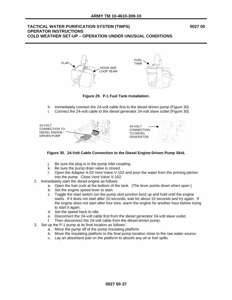
ARMY TM 10-4610-309-10
TACTICAL WATER PURIFICATION SYSTEM (TWPS) OPERATOR INSTRUCTIONS COLD WEATHER SET-UP – OPERATION UNDER UNUSUAL CONDITIONS
0027 00
0027 00-37
Figure 29. P-1 Fuel Tank Installation.
h. Immediately connect the 24-volt cable first to the diesel-driven pump (Figure 30). i. Connect the 24-volt cable to the diesel generator 24-volt slave outlet (Figure 30).
Figure 30. 24-Volt Cable Connection to the Diesel Engine-Driven Pump Skid.
j. Be sure the plug is in the pump inlet coupling.k. Be sure the pump drain valve is closed. l. Open the Adaptor A-02 Vent Valve V-102 and pour the water from the priming pitcher
into the pump. Close Vent Valve V-102. 2. Immediately start the diesel engine as follows:
a. Open the fuel cock at the bottom of the tank. (The lever points down when open.) b. Set the engine speed lever to start. c. Toggle the start switch (on the pump skid junction box) up and hold until the engine
starts. If it does not start after 10 seconds, wait for about 15 seconds and try again. If the engine does not start after four tries, warm the engine for another hour before trying to start it again.
d. Set the speed back to idle. e. Disconnect the 24-volt cable first from the diesel generator 24-volt slave outlet. f. Then disconnect the 24-volt cable from the diesel-driven pump.
3. Set up the P-1 pump at its final location as follows:’ a. Move the pump off of the pump insulating platform b. Move the insulating platform to the final pump location close to the raw water source. c. Lay an absorbent pad on the platform to absorb any oil or fuel spills.
24-VOLT CONNECTION TO DIESEL ENGINE-DRIVEN PUMP
24-VOLT CONNECTION TO DIESEL GENERATOR
FLAPHOOK AND
LOOP SEAM
FUELTANK

ARMY TM 10-4610-309-10
TACTICAL WATER PURIFICATION SYSTEM (TWPS) OPERATOR INSTRUCTIONS COLD WEATHER SET-UP – OPERATION UNDER UNUSUAL CONDITIONS
0027 00
0027 00-38
Three person lift. Three people are required to lift Diesel-Driven Distribution Pump P-8. Lift with your legs, not your back. Failure to observe this warning may result in back injury.
d. With the engine running at idle, move the pump into place onto the insulating platform. e. Attach Adaptor A-01 to the suction inlet of the motor-driven pump. Position the bolt on
the adaptor check valve in the vertical position. Wrap the strap around the pump frame and buckle the strap. Secure firmly to support the adaptor and hose and prevent air from entering the pump suction.
f. Connect the raw water suction hose to the adaptor. g. Make sure that the suction hose heat blanket extends over the exposed surfaces of
Adaptor A-01. 4. Connect the heating blanket power cables as follows:
a. Clean the connectors and connect the suction hose heat blanket cables to the pump junction box (Figure 17).
b. Be sure the unconnected Adaptor A-02 cable extends out over the top of the pump cover. c. Connect the P-1 skid power cable to the pump junction box. (Feed the cable in under the
pump insulating cover at the front.) 5. Attach the hook and loop strips on the pump insulating cover flaps and pull the bottom belt tight. 6. Connect the raw water discharge hose to Adaptor A-02. 7. Make sure that the discharge hose heating blanket extends over the exposed surfaces of the
hose couplings. Clean the connectors and connect the hose heating blanket cable to the Adaptor A-02 cable.
8. If the ice intake strainer is used, push the strainer and hose through the ice hole to a depth of 2 ft. from the bottom in shallow water (less than 20 ft. deep) or to a depth of 20 ft. if the water is deeper. This helps provide water that is above freezing.
Potential electrical hazard to other personnel. Another person is establishing electrical power at the TWPS. Let that person know that you are ready to make pump power connections to the PDP. DO NOT connect pump power cables to the PDP until the person who is establishing electrical power tells you the TWPS is ready for the connections to be made. Failure to observe this warning may result in injury or death due to electrocution.
Electrical hazard. The TWPS operates on 416 volts AC. FIRST connect the pump skid power cable to the pump skid junction box. NEXT, make sure the Main Breaker on the PDP is switched to OFF. LAST, connect the pump skid power cables to the PDP power outlet. Failure to observe this warning may result in serious injury or death from electrocution.
WARNING
WARNING

ARMY TM 10-4610-309-10
TACTICAL WATER PURIFICATION SYSTEM (TWPS) OPERATOR INSTRUCTIONS COLD WEATHER SET-UP – OPERATION UNDER UNUSUAL CONDITIONS
0027 00
0027 00-39
CAUTION
Connector damage or poor electrical connection. Use a fine brush to clean dust and sand out of connectors, terminals and dust caps before making or capping a connection. Install the dust cap provided with connectors and terminals whenever a connector is disconnected from its terminal. Failure to observe this caution may result in connector damage or a poor electrical connection.
9. Clean the connectors then connect the P-1 pump skid power cable to the TWPS PDP as follows: a. Set the diesel heater switch to OFF. b. FIRST make sure the P-1 pump skid power cable is securely connected to the P-1 skid
junction box. c. NEXT, switch the Main Breaker on the PDP to OFF. d. LAST, connect the power cable to its power source connector terminal at the PDP. e. After making sure all connections have been completed, switch the Main Breaker on the
PDP back to the ON position. 10. Set the diesel heater switch back to the ON position and verify that the heater starts. 11. Set the Hose/Pump Heaters switch to ON. 12. Leave the engine running at idle and continue with the procedures for establishing raw water flow
in WP 0012 00.
PRE-OPERATIONAL CHECKS
Before starting the TWPS to begin producing potable water, perform the following checks: 1. Check all hose couplings and verify that the camlock connectors are locked in place. 2. Check that the ground rod has been installed and the ground connections are tight at both ends. 3. Check that all raw water, MF feed pump and product water distribution pump power cables are
properly connected.
NOTE
For the most efficient use of time, proceed to WP 0011 00 for preoperational diagnostic self-tests and then the appropriate start-up procedure WP before performing the Extended Distribution System Set-Up procedures. You will be instructed to return to this procedure after performing the electrical pre-operational procedures and the appropriate start-up procedures.
EXTENDED DISTRIBUTION SYSTEM SET-UP (A-TWPS)
NOTE
Warm Diesel-Driven Distribution Pump P-8 inside the TWPS before starting. It is recommended that the extended distribution system not be deployed unless absolutely needed.
Deploy the extended product water distribution system equipment as follows (Figure 31):

ARMY TM 10-4610-309-10
TACTICAL WATER PURIFICATION SYSTEM (TWPS) OPERATOR INSTRUCTIONS COLD WEATHER SET-UP – OPERATION UNDER UNUSUAL CONDITIONS
0027 00
0027 00-40
Two person lift. Two people are required to safely lift the product water distribution water tanks. Lift with your legs, not your back. Failure to observe this warning may result in back injury.
Three person lift. Three people are required to lift Diesel-Driven Distribution Pump P-8. Lift with your legs, not your back. Failure to observe this warning may result in back injury.
1. Position Extended Product Water Distribution Tanks T-5, T-6 and T-7 as follows: a. Place the distribution tanks in their rough locations. Make sure Tank T-7 is positioned
close enough for Hose P02 and its heating blanket power cable to reach the T-7 Tank inlet (Figure 32).
b. Unfold the ground cloth from around each tank and unfold each tank on its ground cloth. c. Spread the tanks out to their final shape and eliminate any ridges in the bottoms.
Position the tanks about 6 ft. apart with the connections facing each other. d. Pull the tank inlet and outlet connections out away from the tank bottoms so that they will
be clear when the tanks are filled. e. Diesel-Driven Distribution Pump P-8 should be kept warm inside the heated TWPS
enclosure until ready to start and deploy. If it was not, it must be moved inside and warmed for at least an hour to avoid freezing of water when introduced into the pump.
Figure 31. Extended Product Water Distribution System Equipment Deployment.
WARNING
T-72 X 5 S-HOSE
T-6
P-8
T-5
A-15
A-07
2 X 5 S-HOSE
2 X 65 D-HOSE
NOZZLE V-523D
A-08
TWPS

ARMY TM 10-4610-309-10
TACTICAL WATER PURIFICATION SYSTEM (TWPS) OPERATOR INSTRUCTIONS COLD WEATHER SET-UP – OPERATION UNDER UNUSUAL CONDITIONS
0027 00
0027 00-41
2. Connect the hoses as follows:
Health hazard. Do not attempt to use product water hoses to handle raw water or raw water hoses to handle product water. When installed with the proper adaptors as directed, the hoses cannot be interchanged. Failure to observe this warning and mixing hoses could cause contamination of water resulting in serious illness.
a. Collect the following adaptors, hoses and dispensing nozzles: 1) Adaptor A-15. 2) Tee Adaptor A-07. 3) Two 2 in. x 5 ft., blue-banded product water suction hoses with male couplings
at both ends. 4) One 2 in. x 5 ft., blue-banded product water suction hose with female couplings
at both ends. 5) Pump outlet tee Adaptor A-08. 6) Two 2 in. x 65 ft., blue-banded product water distribution discharge hoses. 7) Two Dispensing Nozzles V-523C and V-523D.
b. Inspect the gaskets in the female ends of the hoses and adaptors. Replace any damaged or missing gaskets.
c. Connect Adaptor A-15 to the inlet of one of the product water distribution tanks. d. Connect the male end of the straight section of Adaptor A-07 directly to the female outlet
of one of the extended distribution tanks. e. Connect one of the male-male 2 in. x 5 ft., blue-banded product water suction hoses to
the other end of the straight section of Adaptor A-07. f. Connect the other end of the 5 ft. suction hose to the outlet of the other distribution tank. g. Connect the female-female 5 ft., blue-banded suction hose to the remaining Adaptor A-07
connection and to the suction inlet of Product Water Distribution Pump P-8. h. Connect the second male-male 5 ft., blue-banded suction hose from the middle tank to
the third tank. i. Layout the two 2 in. x 65 ft., blue-banded product water distribution discharge hoses at
the general location where the P-8 pump will be set. 3. Install the hose heating blankets as follows (Figure 16):
a. Refer to Table 9 for a listing of hoses that get heating blankets. DO NOT attempt to connect any of the power cables at this time.
b. Roll out the hose heating blanket and place the outside surface down next to the hose. c. Lift the hose and slide the heating blanket under the hose. d. Wrap the heating blanket around the hose and secure with the hook and loop strips. e. When two or more heating blankets are used on hose combinations, join the blankets at
the seams. f. The straps that were removed from the rolled up blankets can be strapped around the
installed blankets at the ends. g. Heating blankets must be positioned over the couplings at the end of the hose.
4. Lay out the hose heating blanket power cables to the spot where Diesel-Driven P-8 Pump Skid will be placed. The heating blanket power cables will be connected to the P-8 junction box later after the pump is brought out off the TWPS, started and deployed in its proper location.
WARNING

ARMY TM 10-4610-309-10
TACTICAL WATER PURIFICATION SYSTEM (TWPS) OPERATOR INSTRUCTIONS COLD WEATHER SET-UP – OPERATION UNDER UNUSUAL CONDITIONS
0027 00
0027 00-42
PO3-2
Table 9. Extended Distribution Hose Heating Blanket Installation and Connection List.
Hose Heating Blanket Connect to Pump Skid
Junction Box One 5 ft. product water suction hose P03 2 in. x 6 ft. blankets P03-1, long cable P-8 One 5 ft. product water suction hose P03 2 in. x 6 ft. blankets P03-2 longest cable P-8 One 5 ft. product water suction hose P04 2 in. x 7.1 ft. blankets P04, short cable P-8 Two 65-ft product water discharge hoses P05 Two 2 in. x 65.5 ft blankets P05 P-8
Figure 32. Extended Distribution Hose Heating Blanket Power Cable Connection Diagram.
5. Install a pump skid insulating cover on Pump Skid P-8 as follows (Figure 33): a. Install the corrugated exhaust hose on the diesel engine muffler exhaust. b. Place the cover over the pump skid. c. Secure the buckle to draw the bottom tight around the skid. d. Secure the hook and loop seams at the hose inlet and outlet.
Figure 33. P-8 Pump Skid Insulating Cover Installation.
P-8 P-7
TWPS
T5
PO4
DIESEL PUMP P-8
T6 T7 T3 T4
PO3-1
PO5
P-8 COVER
EXHAUST HOSE
HOOK AND LOOP SEAM
BUCKLE
P02
FLAP

ARMY TM 10-4610-309-10
TACTICAL WATER PURIFICATION SYSTEM (TWPS) OPERATOR INSTRUCTIONS COLD WEATHER SET-UP – OPERATION UNDER UNUSUAL CONDITIONS
0027 00
0027 00-43
NOTE
Do not deploy the Diesel-Engine Driven Pump P-8 until ready to begin filling the extended distribution tanks.
6. Ready Diesel-Driven Distribution Pump P-8.
CAUTION
When adding fuel to the tank, be careful not to push the screen filter into the tank.
a. With the fuel tank removed from the diesel-engine skid and setting outside the TWPS, add fuel as needed.
b. Take the 24-volt diesel engine starting cable out of the diesel generator battery storage compartment (A-TWPS only)
c. Lay out but DO NOT CONNECT the 24-volt diesel-engine starting cable from the diesel generator 24-volt slave outlet to where the diesel engine-driven pump is to be placed.
d. Place the pump insulating platform on the ground near the diesel generator 24-volt slave outlet.
Three person lift. Three people are required to lift Diesel-Driven Distribution Pump P-8. Lift with your legs, not your back. Failure to observe this warning may result in back injury.
e. Open the flap at one end of the top of the insulating cover and the hook and loop seam at the other end and grab the frame in three places to lift the P-8 pump skid.
f. Move the P-8 pump off of the TWPS skid to the pump insulating platform. g. Set the fuel tank in place on top of the P-8 skid outside of the pump insulating cover.
Complete the fuel hose connections through the opening in the cover (red-banded supply hoses together and yellow-banded return hoses together).
h. Immediately connect the 24-volt cable first to the diesel-driven pump (Figure 30). i. Connect the 24-volt cable to the diesel generator 24-volt slave outlet (Figure 30). j. Be sure the pump drain valve is closed. k. Be sure the pump inlet connection is capped. l. Fill the pump with product water through the outlet connection, then cap the pump outlet.
7. Immediately start the diesel engine as follows: a. Open the fuel cock at the bottom of the tank. (The lever points down when open.) b. Set the engine speed lever to start. c. Toggle the start switch up (on the pump skid junction box) and hold until the engine
starts. If it does not start after10 seconds, wait for about 15 seconds and try again. d. Set the speed back to idle. e. Disconnect the 24-volt cable first from the diesel generator 24-volt slave outlet. f. Then disconnect the 24-volt cable from the diesel-driven pump.
WARNING

ARMY TM 10-4610-309-10
TACTICAL WATER PURIFICATION SYSTEM (TWPS) OPERATOR INSTRUCTIONS COLD WEATHER SET-UP – OPERATION UNDER UNUSUAL CONDITIONS
0027 00
0027 00-44
8. Set up the P-8 pump at its final location as follows: a. Move the pump off of the pump insulating platform. b. Move the insulating platform to the final pump location. c. Lay an absorbent pad on the platform to adsorb any oil or fuel spills.
Three person lift. Three people are required to lift Diesel-Driven Distribution Pump P-8. Lift with your legs, not your back. Failure to observe this warning may result in back injury.
d. With the engine running at idle, move the pump into place on the insulating platform.
Electrical hazard. The hose heating blankets operate on 208 VAC. Complete the installation of the blankets and connect the power cables to the P-8 pump skid junction box. DO NOT connect the P-8 pump skid power cable to the TWPS PDP at this time. Failure to observe this warning may result in serious injury or death from electrocution.
CAUTION
Connector damage or poor electrical connection. Use a fine brush to clean dust and sand out of connectors, terminals and dust caps before making or capping a connection. Install the dust cap provided with connectors and terminals whenever a connector is disconnected from its terminal. Failure to observe this caution may result in connector damage or a poor electrical connection.
9. Complete the hose and blanket installation (Figure 32). a. Connect the suction hose that extends from Adaptor A-07 to the pump inlet. b. Make sure that the suction hose heat blanket extends over the exposed couplings. c. Loosen the pump insulating cover and connect the suction hose heating blanket P04
cable to the P-8 pump junction box. d. Connect the P03-1 and P03-2 hose heating blanket power cables to the pump junction
box.e. Connect the pump outlet tee Adaptor A-08 to the pump discharge. f. Connect the distribution hoses to Adaptor A-08. Pull the blankets over the couplings. g. Connect the two distribution hose blanket P05 power cables to the pump junction box. h. Connect the P-8 skid power cable to the P-8 skid junction box. Feed the cable in under
the pump insulating cover at the front. i. Attach the hook and loop strips on the pump insulating cover flaps and pull the bottom
belt tight.
WARNING
WARNING

ARMY TM 10-4610-309-10
TACTICAL WATER PURIFICATION SYSTEM (TWPS) OPERATOR INSTRUCTIONS COLD WEATHER SET-UP – OPERATION UNDER UNUSUAL CONDITIONS
0027 00
0027 00-45/46 BLANK
10. Connect the Distribution Pump Skid P-8 power cable to the PDP as follows:
Electrical hazard. The TWPS operates on 416 volts AC. FIRST, make sure the P-8 pump skid power cable is connected to the pump skid junction box. NEXT, make sure all TWPS equipment is shut off and the Main Breaker on the PDP is switched to OFF. LAST, connect the power cable to the PDP power outlet. Failure to observe this warning may result in serious injury or death from electrocution.
CAUTION
Connector damage or poor electrical connection. Use a fine brush to clean dust and sand out of connectors, terminals and dust caps before making or capping a connection. Install the dust cap provided with connectors and terminals whenever a connector is disconnected from its terminal. Failure to observe this caution may result in connector damage or a poor electrical connection.
a. The TWPS will normally be in operation when the extended distribution system setup is completed. Be ready to complete the following steps within 10 minutes. Delay may result in freeze up.
b. Shut Down to Standby – Cold Weather (WP 0015 00). c. Set the diesel heater switch to OFF. d. Set the hose/pump heaters switch on the Operator Control Panel to OFF. e. Set air compressor switch on the Operator Control Panel to OFF f. Set the Main Breaker on the PDP to OFF. g. Uncoil the junction box power cable for the Diesel Engine-Driven Distribution Pump P-8. h. Be sure the power cable is connected to the P-8 Skid Junction Box. i. Connect the power cable to the P-8 Power Source connector at the PDP. j. Set the Main Circuit Breaker (lever on the front of the Power Distribution Panel) to ON. k. Set the hose/pump heaters switch to ON. l. Set the air compressor switch to AUTO. m. Set the diesel fueled heater switch to ON. Be sure that it starts. n. Continue with Start up from Standby (WP 0013 00).
11. When Distribution Tanks T-3 and T-4 are filled, move the product water distribution hose from the standard distribution system tank to the extended distribution system tank as follows:
a. Open the A-15 Adaptor valve on the extended distribution system tank. b. Disconnect the product hose from Adaptor A-15 at the standard distribution system tank,
then close the valve on that adaptor. c. Connect the product hose to Adaptor A-15 on the extended distribution system tank. d. Leave the hose heating blanket P02 Power Cable connected to the Pump P-7 junction
box when moving the hose to the extended distribution system tank. 12. The P-8 pump remains at idle until water is to be distributed from the extended distribution
system.
END OF WORK PACKAGE
WARNING


ARMY TM 10-4610-309-10
TACTICAL WATER PURIFICATION SYSTEM (TWPS) OPERATOR INSTRUCTIONS OTHER SET-UPS - OPERATION UNDER UNUSUAL CONDITIONS
0028 00
0028 00-1
INITIAL SETUP:
Materials/Parts: Antiseize tape (WP 0048 00, Items 49/50) Personnel RequiredThree Operator/Crew Equipment Condition TWPS skid removed from transport vehicle and set on level ground. Loose items unpacked (off-loaded) from the TWPS skid and placed in their general operational position.
GENERAL:
This work package contains the procedures to set up the TWPS for initial operation if the TWPS is deployed on a mission with any of the following unusual conditions:
- Chlorinated raw water source - NBC decontamination mission - Existing temperatures are above 90˚ F or are expected to go above 90˚ F within the next 24 hours - Sandy or dusty environment
Refer to WP 0027 00 if the existing outdoor temperature is below 32˚ F or is expected to be below 32˚ F within the next 24 hours.
The procedures covered in this work package include: � Sodium Bisulfite System Deployment � Contamination Avoidance Cover (CAC) Deployment � NBC System Deployment � Hot Weather Condition Set-Up � Sandy/Dusty Condition Set-Up
SODIUM BISULFITE SYSTEM DEPLOYMENT
CAUTION
Chlorinated water will rapidly destroy the fibers in the micro-filter elements and damage the membranes in the RO elements.
If the raw water source is chlorinated, the water must be treated to neutralize the chlorine before the raw water is discharged into the MF feed tank. The sodium bisulfite chemical injection system is used to inject sodium bisulfite in the raw water just before the raw water discharges into the MF feed tank. The sodium bisulfite neutralizes the chlorine in the raw water.
The sodium bisulfite system includes dry sodium bisulfite chemical packages, a 5-gallon bucket in which the sodium bisulfite is mixed with water, a chemical pump with a suction tube, strainer and ceramic weight, 3/8-in. tubing and Adaptor A-11. Adaptor A-11 contains Chemical Injection Check Valve V-613 and a static mixer.
This procedure only describes how to deploy Adaptor A-11 and the 3/8-in. tubing. Procedures for mixing the sodium bisulfite and setting up and starting the chemical pump are described in WP 0012 00.

ARMY TM 10-4610-309-10
TACTICAL WATER PURIFICATION SYSTEM (TWPS) OPERATOR INSTRUCTIONS OTHER SET-UPS - OPERATION UNDER UNUSUAL CONDITIONS
0028 00
0028 00-2
The sodium bisulfite chemical injection system is set up during raw water system set-up and before establishing raw water flow to the MF feed tank. Deploy the sodium bisulfite chemical injection system as follows:
1. Set up the TWPS as described in WP 0008 00 or as described in WP 0027 00, Cold Weather Set-Up, if applicable. When directed in either of these two work packages, complete the sodium bisulfite chemical injection system set-up steps.
2. Obtain Adaptor A-11 from its pack-out location under the HP Pumps. 3. Install Adaptor A-11 in the raw water system between the 2 in. x 50 ft. discharge hose and
Adaptor A-05 (Figure 1).
Figure 1. Adaptor A-11 Location in the Raw Water System.
4. Remove the 3/8 in. Bisulfite Chemical Pump CP-1 tubing from its strap and uncoil. 5. Lay the tube so that it passes out of the TWPS along with the 3 in. MF pump discharge hose. For
cold weather set-up, run the tube under the hose heating blanket. 6. Position the raw water hoses and adaptors and connect the 3/8 in. tubing to the inlet of Chemical
Injection Check Valve V-613 on Adaptor A-11. (See Figure 2 for connection detail) 7. Complete the rest of the set-up procedures as described in WP 0008 00 or as described in
WP 0027 00, Cold Weather Set-Up, if applicable.
MF FEED TANK
RAW WATER PUMP
MF FEED PUMP P-3 TOP VIEW
OF TWPS
ADAPTOR A-11
STATIC MIXER INJECTION CHECK VALVE V-613
CP-1 BISULFITE PUMP DISCHARGE TUBING

ARMY TM 10-4610-309-10
TACTICAL WATER PURIFICATION SYSTEM (TWPS) OPERATOR INSTRUCTIONS OTHER SET-UPS - OPERATION UNDER UNUSUAL CONDITIONS
0028 00
0028 00-3
Figure 2. 3/8-In. Chemical Tubing Connections.
CONTAMINATION AVOIDANCE COVER (CAC) DEPLOYMENT
If an NBC attack is expected, deploy the CAC as follows (Figure 3): 1. Put the TWPS in Standby Shutdown without Draining Down (WP 0015 00) including shutting
down the Tactical Quiet Generator (TQG). If time does not permit a Standby Shutdown, press the emergency stop button on the TWPS control panel and shut down the TQG.
2. MC-TWPS only: lower and secure the operator station roof. 3. A-TWPS only: remove the fabric wall. 4. Disconnect all external hoses (and heating ducts if used) from the TWPS. 5. Pack all items to be protected inside the TWPS as time permits. 6. A-TWPS only: install all flat rack panels, close and secure the top panel and deck panel.
NOTE
For the A-TWPS, do not unfold the CAC over the back of the TWPS until the operator has come down the folding steps and is on the ground.
7. Lay out the CAC on top of the TWPS and unfold it over the sides. Make sure the bottom edge of the CAC reaches the bottom of the TWPS on all sides of the TWPS.
8. Neatly tuck the CAC in at the corners and fold the flaps around the corners. 9. Tie three CAC 3/8 in. x 60 ft. ropes all the way around the CAC; one around the top, one around
the middle and one around the bottom. 10. If an NBC attack occurs, do not remove the cover. The cover and unit must be decontaminated
in accordance with FM 3-5 prior to removing the cover and using the unit.
Figure 3. CAC Installation. ROPES CAC

ARMY TM 10-4610-309-10
TACTICAL WATER PURIFICATION SYSTEM (TWPS) OPERATOR INSTRUCTIONS OTHER SET-UPS - OPERATION UNDER UNUSUAL CONDITIONS
0028 00
0028 00-4
NUCLEAR, BIOLOGICAL, CHEMICAL (NBC) SYSTEM DEPLOYMENT
The NBC water treatment system is setup as a final product water treatment step when the raw water source is contaminated with NBC warfare agents. The NBC filter is set up in the product line between the TWPS and the product water storage tanks. The NBC water treatment system includes the following major components:
� NBC filter tank. The filter tank is supplied as standard issue for both the A-TWPS and the MC-TWPS.
� Six bags of ion exchange resin. This filter media is used for removing nuclear and chemical agents. The filter media is packed inside the filter tank on the A-TWPS and is provided in the extended capability module for the MC-TWPS.
� Four bags of carbon. This filter media is used to remove chemical and biological agents. The filter media is packed inside the filter tank on the A-TWPS and is provided in the extended capability module for the MC-TWPS.
� NBC hypochlorite injection tube, connector, injector and straps supplied inside the NBC filter tank.
The NBC system can be set up any time before start-up of the TWPS. Typically, the NBC System is set up when the product water distribution system is set up. Deploy the NBC system as follows:
1. Wear appropriate protective gear as directed. 2. Set up the TWPS as described in WP 0008 00, Set-Up – Operation Under Usual Conditions or as
described in WP 0027 00, Cold Weather Set-Up, if applicable. 3. A-TWPS only. Unclamp and remove the band holding the top of the NBC filter. Remove the top
and remove the bags of media. Set the bags between the TWPS and the first distribution tank. 4. Set up the NBC system as follows (Figure 4):
a. Remove the straps around the NBC tank.
Three person lift. Three people are required to safely lift the filter tank. Lift with your legs, not your back. Three handles are provided for this purpose. Failure to observe this warning may result in back injury.
b. Lift the NBC tank off of the TWPS skid and carry to a position between the TWPS and the distribution tanks.
c. Tip the NBC tank and remove the pack-out plate from the bottom of the filter tank. d. Connect the four 1 ½-in. x 10-ft. product water hoses to the NBC tank as follows:
1) Connect the end of the second or third product water hose from the TWPS to the top of the NBC tank.
NOTE
Be sure to check product water TDS and chlorine before connecting the product hose from the outlet of the NBC tank to the distribution tank.
2) Connect the remaining hoses from the bottom outlet of the NBC tank to the distribution tank.
e. If the NBC tank is used during cold weather, connect the NBC tank between the last product water hose and the distribution tank so the hose heating blanket can be installed.
WARNING

ARMY TM 10-4610-309-10
TACTICAL WATER PURIFICATION SYSTEM (TWPS) OPERATOR INSTRUCTIONS OTHER SET-UPS - OPERATION UNDER UNUSUAL CONDITIONS
0028 00
0028 00-5
Figure 4. NBC System Deployment.
NOTE
Do not mix calcium hypochlorite or set-up and start the calcium hypochlorite chemical pump at this time. The procedures for mixing the calcium hypochlorite and setting up and starting the chemical pump are part of system start-up and are described in WP 0012 00.
5. Load the NBC media into the NBC tank as follows: a. Slowly pour each bag of ion exchange resin into the filter. Pour the resin so the top
surface is as even as possible. There are six bags total. b. Slowly pour each bag of carbon into the filter. Pour the carbon so the top surface is as
even as possible. Smooth it out by hand after all of the bags have been emptied. There are four bags total.
c. Place the top back onto the tank and secure with the band and clamp. 6. Connect the NBC hypochlorite injection tube as follows (Figure 4):
a. Remove the TWPS hypochlorite tube from the injector at the end of the product out pipe. b. Use the tube connector supplied with the NBC hypochlorite tube to connect the NBC
hypochlorite tube to the TWPS hypochlorite tube. c. Extend the NBC hypochlorite tube along the product hose and strap in place with the four
hook and loop straps provided. d. Wrap pipe tape around the NBC hypochlorite injector threads and screw the injector into
the threaded coupling in the NBC outlet. e. Connect the end of the NBC hypochlorite tube to the injector.
CARBON
NBC HYPOCHLORITE TUBE
TWPS
NBC FILTER TANK
T-3
ION EXCHANGE RESIN
INJECTOR
NBC OUTLET
TWPS HYPOCHLORITE TUBE
NBC HYPOCHLORITE TUBE CONNECTOR
HYPOCHLORITE INJECTOR
PRODUCT OUT PIPE
NBC HYPOCHLORITE TUBE

ARMY TM 10-4610-309-10
TACTICAL WATER PURIFICATION SYSTEM (TWPS) OPERATOR INSTRUCTIONS OTHER SET-UPS - OPERATION UNDER UNUSUAL CONDITIONS
0028 00
0028 00-6
HOT WEATHER CONDITION SET-UP
Flow rates and other operational characteristics of the TWPS change when the source water temperatures exceed 85˚ F. Maximum temperatures are as follows:
� Maximum deployment temperature: 120˚ F � Maximum storage temperature: 160˚ F � Maximum RO element storage temperature: 110˚ F � Maximum source water temperature: 110˚ F
Operation in direct sunlight during extremely hot weather should be avoided. Raw water, MF feed and distribution pump motors can overheat in extreme heat conditions. To the extent possible, position the TWPS platform and pump skids in the shade or otherwise protect them from direct sunlight.
SANDY/DUSTY CONDITION SET-UP
During TWPS set up and operation in a sandy and/or dusty environment, observe the following: � Make sure the grounding rod is secure. Desert and sandy soils have a low moisture content
making low resistance grounding difficult. � Make sure the zippers on the product water distribution tanks are closed. � Keep the RO feed tank lid closed. � Keep the OCP and PDP covers closed and secured. � Keep lids on chemical containers tightly closed. � Keep all lubricants tightly sealed and all lubrication points clean. � Perform lubrication procedures more frequently than listed in the lubrication schedules. � Clean sand and dust from hose adaptors, hose connections and air fittings as often as possible. � Clean sand and dust off all components as often as possible. � Use the fine brush from the tool box to clean dust and sand out of connectors, terminals and dust
caps before making or capping a connection. � Install the dust cap provided with connectors and terminals whenever a connector is
disconnected from its terminal.
END OF WORK PACKAGE

ARMY TM 10-4610-309-10
TACTICAL WATER PURIFICATION SYSTEM (TWPS) OPERATOR INSTRUCTIONS PREPARATION FOR MOVEMENT – ARMY UNIT
0029 00
0029 00-1
INITIAL SETUP:
Reference: TM 10-5430-237-12&P Personnel Required: Three Operators/Crew Equipment Condition: TWPS set up and operating or shut down
GENERAL
This work package provides instructions for preparing and packing out the A-TWPS for movement from one deployed location to another, including short storage periods (up to 30 days) between deployments. Refer to WP 0032 00 for packout procedures if the unit will be in storage for more than 30 days.
UNIT SHUTDOWN AND PRESERVATION
Before starting equipment/component disassembly and packout, the A-TWPS must be shut down, flushed and drained with the power source secured. Preservation of the Micro-Filtration (MF) and Reverse Osmosis (RO) elements may also be necessary depending on the expected length of the shutdown.
1. Refer to WP 0015 00 and WP 0016 00 for shutdown and preservation requirements and procedures.
2. Disconnect the power and ground cables from the Tactical Quiet Generator (TQG) as follows:
High voltage electrical hazard. High voltage is produced when the generator set is in operation. Make sure the TQG has been properly shut down before attempting to disconnect the power or ground cable from the TQG. Failure to observe this warning could result in injury or death from electrical shock.
CAUTION
Connector damage or poor electrical connection. Use a fine brush to clean dust and sand out of connectors, terminals and dust caps before making or capping a connection. Install the dust cap provided with connectors and terminals whenever a connector is disconnected from its terminal. Failure to observe this caution may result in connector damage or a poor electrical connection.
NOTE
Refer to TM 9-6115-672-14 for generator operation.
a. Disconnect the TWPS power cable leads from the generator lugs labeled L1, L2 and L3. b. Disconnect the TWPS power cable white lead from the generator Neutral lug and the
green lead from the generator Ground lug.
WARNING

ARMY TM 10-4610-309-10
TACTICAL WATER PURIFICATION SYSTEM (TWPS) OPERATOR INSTRUCTIONS PREPARATION FOR MOVEMENT – ARMY UNIT
0029 00
0029 00-2
c. Tuck the TWPS power cable end inside the TWPS frame. d. Disconnect the ground cable from the generator Ground lug.
PREPARATION FOR PACKOUT
Prepare the A-TWPS for packout as described in the following steps. These steps can generally be performed at the same time and in any convenient order. Depending on the specific operating configuration and environmental conditions, some steps will not be necessary.
1. Sort by length and lay out the following straps that will be used to secure various components: � Six 12-in. hook and loop straps (4 of 6 should already be on the NBC Hypochlorite tubing) � Ten 18-in. hook and loop straps � Ten 36-in. hook and loop straps � Ten 48-in. hook and loop straps � Twelve 10-ft. ratchet straps (2 of the 12 should already be around the NBC tank) � Six 20-ft. ratchet straps
2. If heating blankets were used, sort by length and lay out the following heating blanket hook and loop straps that were stored in a separate BII box when the blankets were installed: � Two 18-in. hook and loop straps � Eleven 36-in. hook and loop straps � Twelve 48-in. hook and loop straps
3. Sort by length and lay out the following discharge hose straps that were stored in a separate BII box when the hoses were installed. (The hose straps are brown and have a carrying loop.) � Ten 25-in. straps � Two 12-in. straps � One 36-in strap
NOTE
All product water hoses have caps and plugs that should be installed on the end of the hoses during packout to keep product hoses clean.
For easy identification, all system hoses are coded with colored bands at each end as follows:
� Ocean Intake Structure System (OISS) – yellow � Raw Water – green � Product Water – blue � Cleaning and Waste - red
4. Remove the raw water, MF feed and product water distribution pump insulated covers if used. 5. Disconnect all hose and adaptor heating blanket and pump heating collar power cables. Remove
the blankets and collars if used. 6. Tightly roll up the heating blankets as follows:
a. Lay out the blanket with the air vents facing up. Open the air vents (Figure 1). b. Starting at the opposite end of the power cable, double the blanket over as shown and
roll it up as tightly as possible. c. At the power cable end, make sure the cable is rolled up inside the blanket.

ARMY TM 10-4610-309-10
TACTICAL WATER PURIFICATION SYSTEM (TWPS) OPERATOR INSTRUCTIONS PREPARATION FOR MOVEMENT – ARMY UNIT
0029 00
0029 00-3
NOTE
Be sure the blankets are rolled up as tightly as possible so they all fit in the designated packout locations.
Figure 1. Rolling Up the Hose Heating Blankets.
d. Secure each rolled-up blanket with a hook and loop strap as shown in Table 1:
Table 1. Straps to Secure Heating Blankets.
Heating Blanket Stencil
Hook and Loop Strap(s) to Use
Heating Blanket Stencil
Hook and Loop Strap(s) to Use
A02 18-in. F12 48-in. F01-1 48-in. P02 36-in + 36-in. F01-2 48-in. P03-1 36-in. F03-1 48-in. + 36-in. P03-2 36-in. F03-2 48-in. + 36-in. P04 36-in. F07 48-in. + 18-in. P05 48-in.
7. Disconnect the raw water, MF feed and product water distribution hoses and adaptors. Allow them to drain.
8. Install dust covers and caps on the product water distribution hoses. (Note: dust covers and caps are only provided for the product water hoses. Covers and caps are stored in BII Box #3 when the hoses are in use).
9. Set the hoses and adaptor aside. 10. Install dust caps on the TWPS raw water inlet, product water discharge hose and waste outlet. 11. Remove the cap from the end of each distribution discharge (collapsible) hose, tightly roll up the
discharge hoses and secure each with one brown hose strap as indicated in Table 2, then reinstall the caps on the ends of the hoses.
Table 2. Straps to Secure Discharge Hoses.
Hose Hose Qty.
Strap Hose Hose Qty.
Strap
F02 2-in. x 6-ft. 1 12-in. P05 2-in. x 65-ft. 4 25-in. F03 2-in. x 50-ft. 4 25-in. P06 5/8-in. x 50-ft. 1 12-in. F07 3-in. x 10-ft. 2 25-in. R05 6-in. x 50-ft. 1 36-in.
12. Retrieve the anchor assembly and/or OISS. Disassemble the OISS and set the parts aside. 13. Open the drain valves on the raw water, MF feed and product water distribution pumps and drain
pump casings. Close the valves after all the water has drained. Install the dust caps and covers on the pump inlet and outlet connections.
AIR VENT

ARMY TM 10-4610-309-10
TACTICAL WATER PURIFICATION SYSTEM (TWPS) OPERATOR INSTRUCTIONS PREPARATION FOR MOVEMENT – ARMY UNIT
0029 00
0029 00-4
14. Disconnect the motor-driven pump power cables at both ends and install the dust covers on the cable connectors. Tightly coil the cables and set them aside.
15. Install the dust caps on all pump skid junction box receptacles. 16. Close the fuel cock on the diesel pump fuel tank, disconnect the fuel supply and return quick
disconnect couplings.
CAUTION
Potential cause of fuel pump and injection valve failure. Do not leave the fuel lines for the diesel engine and fuel tank disconnected. Failure to observe this caution may allow sand and dirt to enter the fuel system and result in fuel pump and injection valve failure.
17. Couple the two tank fuel lines together and the two diesel engine fuel lines together. 18. Remove the fuel tank. 19. Remove the screen filter from the fuel filler port and drain the fuel from the tank into a fuel can. 20. Ventilate the fuel tank as follows (Figure 2).
a. Connect the quick-disconnect air hose (BII Box #8) to the quick-disconnect fitting in Air System Section 1.
b. Connect the air blowgun (air nozzle, Operator’s Tool Kit) to the other end of the air hose. c. Blow air into the fuel filler port to ventilate the fuel tank. d. Reinstall the screen filter and fuel cap.
Figure 2. Quick-Disconnect Air Hose Connections.
21. Remove the suction and return tubing from the chemical buckets. Dispose of the contents of the buckets in accordance with local instructions, then set the buckets and lids aside.
22. After completely draining the 3000-gallon product water distribution tanks, roll up the tanks, place one tank repair kit on each tank and wrap the tank ground cloth around the tank, refer to TM 10-5430-237-12&P. Then wrap two 48-in. hook and loop straps around each tank for additional support to keep the tanks rolled up.
23. After completely draining the 1000-gallon MF feed tank, pack up the tank, a repair kit and the ground cloth similar to the procedures for the product water distribution tanks. Wrap two 36-in. hook and loop straps around the tank for additional support to keep the tank rolled up.
24. Neutralize and dispose of the waste in the cleaning waste tank (see WP 0024 00). 25. Pack the 1500-gallon cleaning waste tank with its repair kit and ground cloth similar to the
procedures for the product distribution tanks. Wrap two 36-in. hook and loop straps around the tank for additional support to help keep the tank rolled up.
AIR SYSTEM SECTION 1 QUICK DISCONNECT AIR HOSE QUICK-DISCONNECT AIR HOSE
AIR BLOWGUN

ARMY TM 10-4610-309-10
TACTICAL WATER PURIFICATION SYSTEM (TWPS) OPERATOR INSTRUCTIONS PREPARATION FOR MOVEMENT – ARMY UNIT
0029 00
0029 00-5
26. Turn off the diesel-fired heater and allow it to cool. After the diesel-fired heater has cooled, drain and ventilate the fuel tank as follows (Figure 2):
a. Remove the drain plug from the bottom of the fuel tank and drain the fuel into a fuel can. b. Remove the fuel cap from the fuel tank. c. Connect the quick-disconnect air hose (BII Box #8) to the quick-disconnect fitting in Air
System Section 1. d. Connect the air blowgun (air nozzle, Operator’s Tool Kit) to the other end of the air hose. e. Blow air into the diesel-fired heater fuel filler port to ventilate the fuel tank. f. Clean the drain plug threads, apply antiseizing tape to the threads and reinstall the drain
plug into the bottom of the fuel tank. g. Reinstall the fuel cap.
27. Disassemble the heating ducts, plenums and registers and set them aside. 28. Disconnect the ground wire from the generator and ground rod. Coil the wire and set it aside. 29. Retrieve the ground rod. Disassemble the rod and slide hammer, then reinstall the washers and
nuts onto the slide hammer rod. 30. Empty the fuel can into the generator (TQG) fuel tank. 31. Remove the fabric wall and fold it up as follows (Figure 3):
a. Lay the wall out flat, with the white inner side facing up (Step 1). b. From both ends, fold the wall in toward the middle about halfway (Step 2). c. Fold the ends in again so they meet in the middle (Step 3). d. Fold the wall in half, then in half again (Steps 4 and 5).
Figure 3. Folding Up the Fabric Wall.
32. Fold the CAC (NBC contamination avoidance cover) as follows if it was opened, such as if it were used as a tarp:
a. Lay the CAC out flat (1). b. From both ends, fold the long sides into the middle (2). c. Fold the long sides on top of each other (3). d. From both ends, fold the short sides into the middle (4). e. Fold the short sides on top of each other (5).
Figure 4. Folding Up the CAC.
PACKOUT
Basic Issue Items Packout
Refer to the illustrations and tables on the following pages, pack out the tool box, the six numbered BII boxes, the two BII buckets and the manuals storage box and set them aside.
STEP 1 STEP 2 STEP 3 STEP 4 STEP 5
12
2
3
4 4 5

ARMY TM 10-4610-309-10
TACTICAL WATER PURIFICATION SYSTEM (TWPS) OPERATOR INSTRUCTIONS PREPARATION FOR MOVEMENT – ARMY UNIT
0029 00
0029 00-6
1
2
5
6 7
89
10
11
12
13 1415
20212223
2425262728293031323334
3536
3839
414240 43
3
44
Operator’s Tool Kit
4
16171819
37

ARMY TM 10-4610-309-10
TACTICAL WATER PURIFICATION SYSTEM (TWPS) OPERATOR INSTRUCTIONS PREPARATION FOR MOVEMENT – ARMY UNIT
0029 00
0029 00-7
Table 3. Operator’s Tool Kit.
No. Item Name Qty No. Item Name Qty 1 Tool Box 1 23 Screwdriver, Phillips Blade 1 2 Battery, D-Size, Package of 6 1 24 Socket, 1/2" 1 3 Blowgun Assy 1 25 Socket, 11/16" 1 4 Brush, Plater's 1 26 Socket, 13/16" 1 5 Detector, MF Leak 1 27 Socket, 15/16" 1 6 Driver, Nut, 5/16" 1 28 Socket, 3/4" 1 7 Flashlight, D-Size 1 29 Socket, 3/8" 1 8 Extender, Socket, 3" 1 30 Socket, 5/8" 1 9 Extender, Socket, 6" 1 31 Socket, 7/16" 1 10 Key Set, Hex, Foldup Set 1 32 Socket, 7/8" 1 11 Knife, Utility 1 33 Socket, 9/16" 1 12 Mallet, Rubber, Wood Handle 1 34 Socket, Spark Plug, 5/8" 1 13 Pliers, Channel Lock, 9.5" 1 35 Tape, Antiseizing, 1/2" Wide 1 14 Pliers, Diagonal 1 36 Tape, Antiseizing, 1/4" Wide 1 15 Ratchet, 3/8" 1 37 Tool, MF Filter Bypass 1 16 Screwdriver, Flat Blade 1 38 Wrench, Adjustable, 10" 1 17 Screwdriver, Flat Blade 1 39 Wrench, Adjustable, 8" 1
18 Screwdriver, Flat Blade 1 40 Wrench, Air Compressor Purification Chamber
1
19 Screwdriver, Flat Blade 1 41 Wrench, Pipe, 12" 1 20 Screwdriver, Phillips Blade 1 42 Wrench, Pipe, 15"-18" 1 21 Screwdriver, Phillips Blade 1 43 Wrench, Strap, 1"-5" Pipe 1 22 Screwdriver, Phillips Blade 1 44 Wrench, Torque, With Case 1

ARMY TM 10-4610-309-10
TACTICAL WATER PURIFICATION SYSTEM (TWPS) OPERATOR INSTRUCTIONS PREPARATION FOR MOVEMENT – ARMY UNIT
0029 00
0029 00-8
2
6
3
7
10
9
12
13
21
BII Box #1
4
5
8
11
14
1
15161718
1920

ARMY TM 10-4610-309-10
TACTICAL WATER PURIFICATION SYSTEM (TWPS) OPERATOR INSTRUCTIONS PREPARATION FOR MOVEMENT – ARMY UNIT
0029 00
0029 00-9
30
333435
Table 4. BII Box #1.
No. Item Name Qty No. Item Name Qty
1 Box 1 19 Gasket, C&G, 4" 1 2 Earplugs 10 20 Gasket, C&G, 6" 1
3 Belt, Air Compressor 1 21 Rupture Disk DV 1.0 in.75# Burst and Storage Box 1
4 Gloves, Chemical 2 22 Box 1 5 Respirator, Particulate 4 23 Gasket, Grooved Coupling, 1" 2 6 Shield, Face, Chemical 1 24 Gasket, Grooved Coupling, 1.5" 5 7 Apron, Chemical 2 25 Gasket, Grooved Coupling, 2.0" 2
8 Purification Cartridge, Air Compressor 1 26 Gasket, Grooved Coupling, 3.0" 1
9 Adaptor A-12 1 27 Gasket, Sanitary, 4" 1 10 Paddle, Stirring 1 28 Gasket, Sanitary, 6" 1 11 Adaptor A-10 1 29 Pressure Transmitter, PT-201 1 12 Flowmeter Assembly 1 30 Filter, Air, Diesel 1
13 Starting Cable, Diesel Engine, 24 Volt DC 1 31 Filter, Fuel, Diesel 1
14 Vest, Flotation 1 32 Inlet Air Filter, Air Compressor 1 15 Gasket, C&G, 1" 1 33 Spare Solenoid Assembly 1 16 Gasket, C&G, 1-1/2" 2 34 Spare Solenoid Assembly 1
17 Gasket, C&G, 2" 12 35 Spare Solenoid Assembly 1
18 Gasket, C&G, 3" 10
23242526
272822
31
29
32

ARMY TM 10-4610-309-10
TACTICAL WATER PURIFICATION SYSTEM (TWPS) OPERATOR INSTRUCTIONS PREPARATION FOR MOVEMENT – ARMY UNIT
0029 00
0029 00-10
BII Box #2
Table 5. BII Box #2.
No. Item Name Qty1 Box 1 2 Nozzle Assembly 4 3 Adaptor A-07 (9K System) 1 4 Adaptor A-08 (9K System) 1 5 Adaptor A-15 (9K System) 1 6 Wire Ties 100 7 Dust Cap 1 8 Extension Cord, 100 ft. 1
2
4 5
1
3
6 7
8

ARMY TM 10-4610-309-10
TACTICAL WATER PURIFICATION SYSTEM (TWPS) OPERATOR INSTRUCTIONS PREPARATION FOR MOVEMENT – ARMY UNIT
0029 00
0029 00-11
BII Box #3
Table 6. BII Box #3.
No. Item Name Qty 1 Box 12 Pad, fuel absorbent 1 3 Adaptor A-01 1 4 Adaptor A-02 15 Adaptor A-03 16 Adaptor A-04 1 7 Adaptor A-05 18 Adaptor A-07 1 9 Adaptor A-08 1 10 Adaptor A-15 1 11 Hose Assembly F-06 2 12 Plug, Hose, 3” 1 13 Strainer, MF Feed Tank 1
3
4
11
7
10
8
6
2
9
1
12
5
13

ARMY TM 10-4610-309-10
TACTICAL WATER PURIFICATION SYSTEM (TWPS) OPERATOR INSTRUCTIONS PREPARATION FOR MOVEMENT – ARMY UNIT
0029 00
0029 00-12
BII Box #4
Table 7. BII Box #4.
No. Item Name Qty 1 Box 1 2 Large Scoop 1 3 Measuring Bottle 1 4 Measuring Cup, 1000 ml 15 High pH Detergent 4 6 Bisulfite, 10 oz. Packets 1 7 Antiscalant 2 8 Strainer, MF Feed Tank 2 9 Rope, Strainer 1
1
8
2 4 5
7
3
96

ARMY TM 10-4610-309-10
TACTICAL WATER PURIFICATION SYSTEM (TWPS) OPERATOR INSTRUCTIONS PREPARATION FOR MOVEMENT – ARMY UNIT
0029 00
0029 00-13
BII Box #5
Table 8. BII Box #5.
No. Item Name Qty 1 Box 1 2 Sodium Hydroxide 4
2
1

ARMY TM 10-4610-309-10
TACTICAL WATER PURIFICATION SYSTEM (TWPS) OPERATOR INSTRUCTIONS PREPARATION FOR MOVEMENT – ARMY UNIT
0029 00
0029 00-14
BII Bucket #6
Table 9. BII Bucket #6.
No. Item Name Qty1 Bucket 1 2 Funnel 1 3 Corrosion Preventive Compound 1 4 Oil, SAE 10W-30, 1 qt. 1 5 Oil, Air Compressor, 1 qt. 1 6 Silicon Lubricant 1
42 3 5 6
1

ARMY TM 10-4610-309-10
TACTICAL WATER PURIFICATION SYSTEM (TWPS) OPERATOR INSTRUCTIONS PREPARATION FOR MOVEMENT – ARMY UNIT
0029 00
0029 00-15
BII Box #8
32
4 8
10
75
9 12
13
14
16
1
15
18
6
11
17 19

ARMY TM 10-4610-309-10
TACTICAL WATER PURIFICATION SYSTEM (TWPS) OPERATOR INSTRUCTIONS PREPARATION FOR MOVEMENT – ARMY UNIT
0029 00
0029 00-16
Table 10. BII Box #8.
No. Item Name Qty 1 Box 1 2 Light, Trouble 1 3 Light, Work 1 4 Light, Blackout 1 5 Hose, Auxiliary Air 1 6 Hose, Diesel Engine Exhaust Extension 2 7 Spout, Fuel Can 1 8 Rope Assembly, Anchor 1 9 Hammer, Slip, Ground Rod 1 10 Wire, Ground, 25 ft. 1 11 Heating Collar, Pump, Strap-On 3 12 Tool, MF Filter C-Spanner 1 13 Heat Gun 1 14 Adaptor A-16 3 15 Rope, Raw Water Hose Tie-off 1 16 Hardware, Ground Rod - Hammer 1 17 Rope, Chemical Cover, 60 ft. 3 18 Rope, F-04 Hose 1 19 Cord, 100-ft., Extension 1

ARMY TM 10-4610-309-10
TACTICAL WATER PURIFICATION SYSTEM (TWPS) OPERATOR INSTRUCTIONS PREPARATION FOR MOVEMENT – ARMY UNIT
0029 00
0029 00-17
Manuals Storage Box
Table 11. Manuals Storage Box.
No. Item Name Qty 1 Box, Storage, Manuals 1 2 TWPS Operator Manual 1 3 TWPS Field Maintenance Manual 1 4 TWPS RPSTL 1
1
42 3

ARMY TM 10-4610-309-10
TACTICAL WATER PURIFICATION SYSTEM (TWPS) OPERATOR INSTRUCTIONS PREPARATION FOR MOVEMENT – ARMY UNIT
0029 00
0029 00-18
Left End Packout
1. Coil the bisulfite pump discharge, suction and return tubing together and strap them to the TWPS frame behind the pump using a 12-in. hook and loop strap.
2. Coil the antiscalant and hypochlorite suction and return tubing together and strap them to the TWPS frame behind the pump using a 12-in. hook and loop strap.
3. Pack the ground rod sections and the slide hammer rod in the storage brackets at the left front corner of the skid and secure with an 18-in. hook and loop strap (Figure 5).
NOTE
The hammer section of the slide hammer will be packed out in BII Box #8.
Figure 5. Ground Rod and Slide Hammer Rod Storage.
4. Store the protractor (level) in the protractor (level) storage box on the cross support beam at the left side of the Power Distribution Panel (Figure 6).
Figure 6. Level Storage.
PROTRACTOR (LEVEL)
PROTRACTOR (LEVEL) STORAGE BOX
GROUND RODS
SLIDE HAMMER ROD
18-IN. HOOK AND LOOP STRAP

ARMY TM 10-4610-309-10
TACTICAL WATER PURIFICATION SYSTEM (TWPS) OPERATOR INSTRUCTIONS PREPARATION FOR MOVEMENT – ARMY UNIT
0029 00
0029 00-19
Ocean Intake Structure System (OISS) Packout
Components of the OISS, except the 2 x 2 x 3 tee assembly, are packed out lengthwise on top of the skid frame. These items are shown in Figure 7.
Be extremely careful when packing out items on top of the frame. Do not allow hose ends or any other items to bump the RO vessels, which are easily damaged. If anything bumps an RO vessel, the vessel MUST be inspected and/or replaced before putting the A-TWPS into operation. Failure to observe this warning can result in severe personal injury or death from catastrophic vessel failure when the vessels are pressurized during startup.
1. From the rear of the skid, pack the OISS components in the following order: a. Wellpoint assemblies (4). b. Riser assemblies (5). Place the tees and elbows at the Operator Station end of the skid.
Orient the riser assembly tees and elbows at the Operator Station end of the TWPS. Make sure they don't stick down and interfere with the Operator Control Panel door.
c. Hoses (6 yellow-banded). Position hoses toward the Operator Station end of the frame. 2. Group the assemblies and hoses together as compactly as possible and strap them down using
two 10-ft. ratchet straps (Figure 7). a. Secure one end of both straps to the TWPS frame in front of the hoses and assemblies. b. Cross the straps over the hoses and assemblies and hook the other ends to the spacers
at the ends of the MF filter assemblies. c. Tighten the straps using the ratchets
WARNING

ARMY TM 10-4610-309-10
TACTICAL WATER PURIFICATION SYSTEM (TWPS) OPERATOR INSTRUCTIONS PREPARATION FOR MOVEMENT – ARMY UNIT
0029 00
0029 00-20
Figure 7. OISS Component Packout.
WELLPOINTS (4)
RISER ASSEMBLIES (5)
HOSES (6)
RATCHET STRAPS ATTACHED TO FRAME IN FRONT OF PACKED OUT OISS COMPONENTS
RATCHET STRAPS (S-HOOKS) ATTACHED TO SPACERS ON MF ASSEMBLY BEHIND PACKED OUT OISS COMPONENTS

ARMY TM 10-4610-309-10
TACTICAL WATER PURIFICATION SYSTEM (TWPS) OPERATOR INSTRUCTIONS PREPARATION FOR MOVEMENT – ARMY UNIT
0029 00
0029 00-21
Suction Hose Packout
All the raw water, waste and distribution suction hoses are packed out lengthwise on top of the skid frame, in front of the OISS components. These items are shown in Figure 8.
1. Secure the long section of two 10-ft.ratchet straps to the frame just in front of the OISS components. Lay the straps back over the OISS components within reach from the ends of the frame.
2. Pack the suction hoses in the following order: � 3 in. x 10 ft., (green-banded) raw water hoses - 13 each. � 2 in. x 10-ft., (green-banded) raw water hose - 1 each. Place on top of the 3-in. hoses. � 2 in. x 10 ft., (red-banded) waste hoses - 3 each. Place on top of the 3-in. hoses. � 1½-in. x 10 ft., (blue-banded) product water hoses - 4 each. Place on top of the 3-in.
hoses.� 2 in. x 5 ft., (blue-banded) product water hoses - 5 each. Place on top of the 3-in. hoses. � 4 in. x 5 ft., (red-banded) waste hose. Place on top of 3-in. hoses. � 3-in. x 3-ft., (green-banded) raw water hose. Place on top of the 3-in. hoses.
3. Bring the two straps over the suction hoses and secure to the frame (Figure 8).
Figure 8. Suction Hose Packout.
SUCTION HOSES
STRAPS ATTACHED TO FRAME IN FRONT OF PACKED OUT SUCTION HOSES

ARMY TM 10-4610-309-10
TACTICAL WATER PURIFICATION SYSTEM (TWPS) OPERATOR INSTRUCTIONS PREPARATION FOR MOVEMENT – ARMY UNIT
0029 00
0029 00-22
Heating Duct Packout
Pack the three heating ducts as follows (Figure 9): 1. Slide the small diameter duct inside one of the large ducts. 2. Place both large ducts on top of the RO feed tank. Insert one duct from the operator station end
of the frame and the other from the generator end.
Figure 9. Heating Duct Packout.
Operator Station Packout
1. Place the TWPS Technical Manuals (TM) and the Repair Parts and Special Tools List (RPSTL) Manual in the manuals storage box and put the cover on the box.
2. Set the manuals storage box under the chemical injection pumps next to the fire extinguisher (Figure 10).
3. Place one of the Chemical Injection System buckets inside another one. Place the bottle of calcium hypochlorite inside the two buckets.
4. Place BII bucket #6 (lubricants bucket) inside the third Chemical Injection System bucket. 5. Place BII box #5 on the floor, to the left side of the Power Distribution Panel, then place the
buckets beside it (Figure 10). 6. Place the three chemical injection bucket colored lids on top of the buckets.
HEATING DUCTS

ARMY TM 10-4610-309-10
TACTICAL WATER PURIFICATION SYSTEM (TWPS) OPERATOR INSTRUCTIONS PREPARATION FOR MOVEMENT – ARMY UNIT
0029 00
0029 00-23
Figure 10. Operator Station Packout 1.
7. Place BII Box #4 in front of the buckets and BII Box #5 (Figure 11).
Figure 11. Operator Station Packout 2.
8. Stack the following items on top of BII box #5 and the buckets (Figure 12): � 50-ft. hose heating blankets (2 each) � 41-ft. hose heating blanket (1 each) � 21-ft. hose heating blanket (1 each) � 66-ft. hose heating blanket (1 each) � 11-ft. hose heating blankets (3 each) � 6-ft. hose heating blanket (2 each) � Motor-driven pump skid covers (3 each)
BII BOX #4
BII BOX #5
2 CHEMICAL INJECTION SYSTEM BUCKETS WITH CALCIUM HYPOCHLORITE BOTTLE INSIDE AND A LID ON TOP
1 CHEMICAL INJECTION SYSTEM BUCKET WITH BII BUCKET #6 INSIDE AND 2 LIDS ON TOP
MANUALS STORAGE BOX

ARMY TM 10-4610-309-10
TACTICAL WATER PURIFICATION SYSTEM (TWPS) OPERATOR INSTRUCTIONS PREPARATION FOR MOVEMENT – ARMY UNIT
0029 00
0029 00-24
Figure 12. Operator Station Packout 3
Two person lift. Two people are required to safely move the pump skids. Lift with your legs, not your back. Failure to observe this warning may result in back injury.
9. Install the fire extinguisher in its bracket on the S-2 strainer. 10. Place the motor-driven pump skids side by side in front of BII Box #4 with motors facing out
(Figure 12). 11. Install the two long pump skid retaining rods and secure them with the retaining pins (Figure 13).
WARNING
50-FT BLANKET F03 RAW WATER DISCHARGE
41-FT BLANKET P02 PRODUCT WATER
21-FT BLANKET F07 MF PUMP DISCHARGE
50-FT BLANKET F03 RAW WATER DISCHARGE
66-FT BLANKETP05 DISTRIBUTION HOSE
11-FT BLANKETS F01 RAW WATER SUCTION
6-FT BLANKET P04 DISTRIBUTION PUMP SUCTION
6-FT BLANKET P04 DISTRIBUTION PUMP SUCTION
MOTOR-DRIVEN PUMP SKID COVERS
PUMP SKIDS

ARMY TM 10-4610-309-10
TACTICAL WATER PURIFICATION SYSTEM (TWPS) OPERATOR INSTRUCTIONS PREPARATION FOR MOVEMENT – ARMY UNIT
0029 00
0029 00-25
Figure 13. Pump Skid Retaining Rods.
12. Stack the following items on top of the BII box (Figure 14) � 66-ft. hose heating blanket (2 each) � Diesel engine-driven pump skid covers (2 each) � Adaptor A02 heating blanket (not shown – pack between pump skid cover and TWPS
frame)� 6-ft. hose heating blanket
Figure 14. Operator Station Packout 4.
PUMP SKID COVER 66-FT. BLANKET
66-FT. BLANKET PUMP SKID COVER
6-FT. BLANKET
RETAINING ROD (LOWER LEFT)
RETAINING PIN
RETAINING ROD (UPPER RIGHT)
RETAINING PIN
MOTOR-DRIVEN PUMP SKIDS

ARMY TM 10-4610-309-10
TACTICAL WATER PURIFICATION SYSTEM (TWPS) OPERATOR INSTRUCTIONS PREPARATION FOR MOVEMENT – ARMY UNIT
0029 00
0029 00-26
13. Place the pump priming pitcher inside one of the pump skids and secure it with an 18-in. hook and loop strap (Figure 15).
14. Attach the long end of a 10-ft. ratchet strap to the TWPS frame above the feed flow control panel and temporarily lay it out of the way on top of the packed out heating blankets.
15. Place the following items on top of the pump skids (Figure 15): � The remaining four BII boxes � Water Quality Analysis Set: Purification (WQAS-P) � Operator's tool box � Main ventilation plenum � 1000-gallon MF feed tank � 6 ft. hose heating blanket � Floating inlet strainer
16. Retrieve the 10-ft ratchet strap from on top of the heating blankets, route it around the 1000-gallon MF feed tank and 6-ft hose heating blanket. Attach the strap to the TWPS frame and tighten (Figure 15).
Figure 15. Operator Station Packout 5.
PUMP SKIDS (2)
BII BOXES (4)
6 FT. HOSE HEATING BLANKET
FLOATING INLET STRAINER
MAIN VENTILATION PLENUM
OPERATOR’S TOOL BOX WQAS-P
1000 GALLON MF FEED TANK
10-FT RATCHET STRAP
PRIMING PITCHER
18-IN.HOOK AND
LOOP STRAP

ARMY TM 10-4610-309-10
TACTICAL WATER PURIFICATION SYSTEM (TWPS) OPERATOR INSTRUCTIONS PREPARATION FOR MOVEMENT – ARMY UNIT
0029 00
0029 00-27
Equipment Area Packout
1. Make sure the NBC tank is secured to Strainer S-2 with two 10-ft. ratchet straps. 2. Coil the product utility hose and the Strainer S-4 hoses together and secure to the TWPS using
an 18-in. hook and loop strap (Figure 16).
Figure 16. Product Utility Hose and Strainer S-4 Drain Hose.
3. Place the anchor flat on the floor behind the NBC tank. Slide it underneath the piping next to the turbocharger (Figure 17).
4. Place the 5-gallon fuel can behind the NBC tank.
Figure 17. Anchor, Fuel Can, Cyclone, Collar and Hose Packout.
ANCHOR
DISCHARGE HOSES
FUEL CAN
CYCLONE SEPARATOR NBCTANK
PRODUCT UTILITY HOSE STRAINER S-4 DRAIN HOSE

ARMY TM 10-4610-309-10
TACTICAL WATER PURIFICATION SYSTEM (TWPS) OPERATOR INSTRUCTIONS PREPARATION FOR MOVEMENT – ARMY UNIT
0029 00
0029 00-28
Two person lift. Two people are required to safely move the cyclone separator assembly. Lift with your legs, not your back. Failure to observe this warning may result in back injury.
5. Place the cyclone separator unit on the floor with the separator facing up (Figure 17). Slide it back and to the right as far as possible.
CAUTION
When packing the items in the following step, be careful not to damage the tubing, wires or sensors mounted behind the NBC tank.
6. Place as many of the following hoses as you can behind the NBC tank (Figure 17): � 2-in. x 50-ft. discharge hose (1 each) � 3-in. x 10-ft. discharge hoses (2 each) � 2-in. x 50-ft. discharge hoses (4 each) � 2-in. x 65-ft. discharge hose (4 each)
7. Place additional discharge hoses in front of the RO feed tank and to the left of the cyclone separator assembly (Figure 18).
Three person lift. Three people are required to safely move the MF pump skid. Use your legs, not your back. Failure to observe this warning may result in back injury.
8. Move the MF pump skid onto the TWPS skid (Figure 18). 9. Position the pump end inside the mounting brackets and install the retaining rod. 10. Place Adaptor A-09 inside the MF pump skid. 11. Place the bisulfite and low pH cleaner between the MF pump skid and the NBC tank.
WARNING
WARNING

ARMY TM 10-4610-309-10
TACTICAL WATER PURIFICATION SYSTEM (TWPS) OPERATOR INSTRUCTIONS PREPARATION FOR MOVEMENT – ARMY UNIT
0029 00
0029 00-29
Figure 18. Equipment Area Packout 2.
12. Place any remaining discharge hoses on top of the chemical buckets and cyclone separator. 13. Hang the right hot air plenum in the deployment straps (Figure 19). 14. Pack the following items in the order listed (Figure 19):
� 3000-gallon distribution tank � 3000-gallon distribution tank � 1500-gallon cleaning waste tank � Tripod assembly � 5/8-in. x 50-ft. auxiliary hose assembly P06 � Motor-driven pump power cables
15. Attach a 10-ft. ratchet strap from the TWPS frame, over the 1500-gallon tank to the HPP frame. 16. Attach a 10-ft. ratchet strap from the upper left TWPS frame to the HHP frame. 17. Attach a 10-ft. ratchet strap from the TWPS frame near the chemical pumps, over the 3000-gallon
tanks, to the TWPS frame above the compressor. 18. Pack the following items in the open spaces under the high pressure pumps:
� Ice intake strainer attached to adaptor A-13 � Adaptor A-11 � Ice auger and handle (secure to the HPP support frame with 18-in. hook and loop strap). � OISS tee (secure to the HPP pump support frame with two 36-in. hook and loop straps,
one through the straight part of the tee and one around the tee female connector). � Operator station entry overhead support beam.
ADAPTOR A09 MF PUMP SKID CHEMICAL BUCKETS (2)
DISCHARGE HOSES MOUNTING BRACKET
RETAINING ROD

ARMY TM 10-4610-309-10
TACTICAL WATER PURIFICATION SYSTEM (TWPS) OPERATOR INSTRUCTIONS PREPARATION FOR MOVEMENT – ARMY UNIT
0029 00
0029 00-30
Figure 19. Equipment Area Packout 3.
19. At the rear of the skid, secure the RO element pusher to the horizontal pipe to the left of the MF filters using two 18-in. hook and loop straps (Figure 20).
Figure 20. Filtrate Drain/Sample Hose and RO Element Pusher Packout.
3000-GAL TANKS
MF PUMP SKID
POWER CABLES AUXILIARY HOSE
NBC TANK
ICE AUGER AND HANDLE
OISS TEE
OPERATOR STATION SUPPORT BEAM
RIGHT HOT AIR PLENUM
ADAPTOR A-13
ADAPTOR A-11
ICE INTAKE STRAINER ADAPTOR A-09
RETAINING ROD
ELEMENT PUSHER
10-FT. RATCHET STRAPS
10-FT. RATCHET
STRAP
1500-GAL CLEANING WASTE TANK
HOOK AND LOOP STRAPS
TRIPOD

ARMY TM 10-4610-309-10
TACTICAL WATER PURIFICATION SYSTEM (TWPS) OPERATOR INSTRUCTIONS PREPARATION FOR MOVEMENT – ARMY UNIT
0029 00
0029 00-31
Generator Area Packout
1. Raise and secure the bail bar as follows: a. Connect the cable to the bail bar. b. Turn the winch crank handle to raise the bail bar.
NOTE
Install the two large bolts, lockwashers and nuts at the bottom of the bail bar first to help align the holes for the other bolts and make the other bolts easier to install.
c. Install the two large bolts, lock washers and nuts that secure the bottom of the bail bar to the flat rack (Figure 21).
A minimum of 6 bolts in the front of the top horizontal beam of the flat rack and a minimum of 3 bolts in the underside of the top horizontal beam are required in order to safely lift the flat rack by the bail bar. Failure to observe this warning may result in equipment damage and severe injury or death.
CAUTION
The middle and upper bail bar bolts must be installed in the proper locations to ensure that the bail bar is properly secured. Three different length bolts are used. The longest of the three is used with washers and nuts to secure the bail bar to the diagonal beam of the flat rack. The other two shorter bolts thread into rivet nuts, which are threaded inserts that are welded in the top horizontal beam of the flat rack.
d. Separate the three different size bolts used to secure the middle of the bail bar to the diagonal beam of the flat rack and the top of the bail bar to the top horizontal flat rack beam (Figure 21).
e. Loosely secure the top part of the bail bar to the front of the top horizontal flat rack beam using the seven short bolts with lock washers and flat washers. Do NOT tighten yet.
f. Loosely secure the top part of the bail bar to the underside of the top horizontal flat rack beam using the four longer bolts with lock washers and flat washers. Do NOT tighten yet.
g. Secure the middle of the bail bar to the diagonal flat rack beams using the four longest bolts with eight flat washers, four lock washers and four nuts.
h. Tighten all 15 bolts. Torque to 250 in-lbs.
WARNING

ARMY TM 10-4610-309-10
TACTICAL WATER PURIFICATION SYSTEM (TWPS) OPERATOR INSTRUCTIONS PREPARATION FOR MOVEMENT – ARMY UNIT
0029 00
0029 00-32
Figure 21. Correct Bail Bar Bolt Installation Locations.
SHORT BOLT
LONGER BOLT
LONGEST BOLT
TOP HORIZONTAL FLAT RACK BEAM
DIAGONAL FLAT RACK BEAM
PINCH BAR LOCK WASHER
BAIL BAR SOCKET WRENCH BOLT NUT

ARMY TM 10-4610-309-10
TACTICAL WATER PURIFICATION SYSTEM (TWPS) OPERATOR INSTRUCTIONS PREPARATION FOR MOVEMENT – ARMY UNIT
0029 00
0029 00-33
Two person lift. Two people are required to safely move the flat rack panels. Lift with your legs, not your back. Failure to observe this warning may result in personal injury.
2. Install flat rack panel #5 on the back of the TWPS and panels #6 and #7 at the generator end then latch in place (Figure 22).
Three person lift. Three people are required to safely move the diesel pump skids and the diesel-fired heater. Use your legs, not your back. Failure to observe this warning may result in back injury.
Figure 22. Flat Rack Panel #5, #6 and #7 Installation.
3. Pack the two diesel pump skids (with the fuel tank assemblies removed) and the diesel-fired heater next to the generator (Figure 23).
4. Strap the pinch bar to the front diesel pump skid using two 18-in. hook and loop straps (Figure 23).
5. Strap the bail bar socket wrench to the top of the front diesel pump skid using two 18-in. hook and loop straps (Figure 23).
6. Pack a 3000 gallon tank behind the diesel pump skids (Figure 24). 7. Attach the short end of a 20-ft. ratchet strap to each of the four tie-down rings at the rear of the
generator and lay the straps out of the way. 8. Run a 10-ft. ratchet strap from the front left tie-down ring, through both pump skid frames and
over the 3000-gallon tank to the corresponding ring at the rear. 9. Run a second 10-ft. strap from the next tie-down ring to the right, through the lower part of the
heater frame and over the 3000 gallon tank to the corresponding ring at the rear. 10. From the front, pack the following items as shown (Figure 23):
� 66-ft. hose heating blanket P05 � Fuel tank assembly (for one of the diesel-driven pumps) � 50.5-ft. hose heating blankets F03-1 and F03-2
WARNING
WARNING
567 34

ARMY TM 10-4610-309-10
TACTICAL WATER PURIFICATION SYSTEM (TWPS) OPERATOR INSTRUCTIONS PREPARATION FOR MOVEMENT – ARMY UNIT
0029 00
0029 00-34
Figure 23. Generator Area Packout 1.
Fall hazard. Make sure that flat rack rear panel #5 is fully latched in place before using the folding steps to climb onto the roof. Failure to observe this warning could result in personal injury.
11. From the rear and top, pack the following items beside and on top of the generator (Figure 24): � Pump platforms (5 each directly on top of the TQG) � 3000 gallon distribution tanks (3 each) � 6-in x 50-ft. waste outlet hose � Fuel tank assemblies (for one of the diesel-driven pumps) � Diesel-fired heater inlet and outlet ducts � Return air connector assembly � Fabric wall � Chemical agent cover
FUEL TANK ASSEMBLY
66-FT HOSE HEATING BLANKET
DIESEL-FIRED HEATER
DIESEL PUMP SKIDS (2)
50-FT HOSE HEATING BLANKETS
TIE-DOWN RINGS
WARNING
SOCKET WRENCH
PINCH BAR

ARMY TM 10-4610-309-10
TACTICAL WATER PURIFICATION SYSTEM (TWPS) OPERATOR INSTRUCTIONS PREPARATION FOR MOVEMENT – ARMY UNIT
0029 00
0029 00-35
Figure 24. Generator Area Packout 2.
12. Place the cargo net over the items in the generator area and tie it in place (Figure 25). 13. At the front of the flat rack, attach the long section of a 20-ft. ratchet strap to each of the four tie-
down rings. Run the straps over the cargo net and connect to the four short strap sections positioned earlier on the rings at the back of the flat rack generator area.
14. Attach a 20-ft. ratchet strap to each of the two rings on the side of the generator. Run straps diagonally across the top of the cargo net to the inside tie-down rings at the front and rear of the flat rack.
FUEL TANK ASSEMBLY (2)
FABRIC WALL
3000-GALLON DISTRIBUTION TANKS

ARMY TM 10-4610-309-10
TACTICAL WATER PURIFICATION SYSTEM (TWPS) OPERATOR INSTRUCTIONS PREPARATION FOR MOVEMENT – ARMY UNIT
0029 00
0029 00-36
Figure 25. Cargo Net and Strap Placement.
Flat Rack Closure
1. Inspect the entire deployment area to make sure no items have been overlooked. Inspect the skid to be sure all the packout straps are tight and all retaining rods and pins are in place.
Potential for head and eye injury. Make sure that two people are holding up the hinged top panel before removing the retaining pins from the top panel supports. Failure to observe this warning could result in the top panel falling down suddenly, resulting in head injury or the possibility of a top panel latch causing eye injury.
2. While two people hold up the hinged top panel, the third person removes the retaining pins from the top panel supports (Figure 26).
3. Carefully lower the top panel and latch it shut. Insert and secure the two retaining pins to an accessible part of the supports.
Figure 26. Flat Rack Hinged Top Panel Closure.
FRONT VIEW REAR VIEW SIDE VIEW
WARNING
TOP PANEL
RETAINING PIN TOP PANEL SUPPORT

ARMY TM 10-4610-309-10
TACTICAL WATER PURIFICATION SYSTEM (TWPS) OPERATOR INSTRUCTIONS PREPARATION FOR MOVEMENT – ARMY UNIT
0029 00
0029 00-37
4. Pack out the deck support assemblies as follows (Figure 27): a. With one person lifting the deck a few inches, remove the retaining pins and slide the
support assemblies out of the brackets on the deck. Lower the deck to the ground. b. Remove the retaining pins and separate the two sections of each deck support assembly. c. Pin two of the horizontal sections together and insert them into each of the two middle
brackets on the deck. Secure them in place with the remaining two retaining pins.
NOTE
Do not use the brackets mounted on the ends of the deck to store the horizontal sections. If you do, the deck won't close.
d. Pack the four pad sections of the support assemblies on the edge of the skid at floor level.
Figure 27. Deck Support Assembly Packout.
5. Raise the deck and latch it shut. 6. Install the remaining flat rack panels (side #1 and #2 and rear #3 and #4) and latch shut
(Figure 28). 7. Attach the product water door shipping cover over the opening below the product water door.
PAD SECTIONS HORIZONTAL
SECTIONS
PINS

ARMY TM 10-4610-309-10
TACTICAL WATER PURIFICATION SYSTEM (TWPS) OPERATOR INSTRUCTIONS PREPARATION FOR MOVEMENT – ARMY UNIT
0029 00
0029 00-38
Figure 28. Flat Rack Panel Installation.
Preparing to Load the A-TWPS on a PLS Trailer
If the A-TWPS is to be loaded onto a PLS Trailer, rollers are installed on the flat rack so that the A-TWPS can be rolled onto the trailer. After the A-TWPS has been loaded onto the PLS truck, install the flat rack rollers as follows:
6
PANELS 3, 4 & 5 (REAR)
PANELS 1 & 2 (OPERATOR STATION END) PANELS 6 & 7 (GENERATOR END)
345
12 7
SHIPPING COVER

ARMY TM 10-4610-309-10
TACTICAL WATER PURIFICATION SYSTEM (TWPS) OPERATOR INSTRUCTIONS PREPARATION FOR MOVEMENT – ARMY UNIT
0029 00
0029 00-39/40 BLANK
1. Remove both rollers from the storage brackets at the bail bar end of the flat rack as follows (Figure 29):
a. Remove the retaining pins. b. Pull out the roller axle. c. Lift the roller out of the storage bracket.
2. Install both rollers in the in-use brackets at the operator station end of the flat rack as follows (Figure 29):
a. Position the roller in the in-use bracket. b. Slide the roller axle through the bracket and roller. c. Insert a retaining pin in both ends of the axle.
Once the rollers are installed, the A-TWPS can be lifted by the bail bar using the arm on the PLS truck and rolled onto an attached PLS trailer.
Figure 29. Flat Rack Roller Installation.
END OF WORK PACKAGE
RETAINING PIN
AXLE ROLLER
IN-USEBRACKET
STORAGE BRACKET


ARMY TM 10-4610-309-10
TACTICAL WATER PURIFICATION SYSTEM (TWPS) OPERATOR INSTRUCTIONS PREPARATION FOR MOVEMENT – MARINE CORPS UNIT
0030 00
0030 00-1
INITIAL SETUP:
Reference: TM 10-5430-237-12&P Personnel Required: Three Operators/Crew Equipment Condition: MC-TWPS set up and operating or shut down
GENERAL
This work package provides instructions for packing out the MC-TWPS for movement from one deployed location to another, including short storage periods (up to 30 days) between deployments. Refer to WP 0033 00 for the procedures to pack out the unit if it will be in storage for more than 30 days.
UNIT SHUTDOWN AND PRESERVATION
Before starting equipment/component disassembly and packout, the MC-TWPS must be shut down, flushed and drained, and the power source must be secured and disconnected. Preservation of the Micro-Filtration (MF) and Reverse Osmosis (RO) elements may also be required based on the expected length of the shutdown.
1. Refer to WP 0015 00 and WP 0016 00 for shutdown, preservation requirements and procedures. 2. Disconnect the power and ground cables from the Tactical Quiet Generator (TQG) as follows:
High voltage electrical hazard. High voltage is produced when the generator set is in operation. Make sure that the Tactical Quiet Generator has been properly shut down before attempting to disconnect the power or ground cable from the TQG. Failure to observe this warning could result in injury or death from electrical shock.
CAUTION
Connector damage or poor electrical connection. Use a fine brush to clean dust and sand out of connectors, terminals and dust caps before making or capping a connection. Install the dust cap provided with connectors and terminals whenever a connector is disconnected from its terminal. Failure to observe this caution may result in connector damage or a poor electrical connection.
NOTE
Refer to TM 9-6115-672-14 for generator operation.
a. Disconnect the TWPS power cable leads from the generator lugs labeled L1, L2 and L3.
WARNING

ARMY TM 10-4610-309-10
TACTICAL WATER PURIFICATION SYSTEM (TWPS) OPERATOR INSTRUCTIONS PREPARATION FOR MOVEMENT – MARINE CORPS UNIT
0030 00
0030 00-2
b. Disconnect the TWPS power cable white lead from the generator Neutral lug and the green lead from the generator Ground lug.
c. Tuck the TWPS power cable end inside the TWPS frame. d. Disconnect the ground cable from the generator Ground lug.
EXTENDED CAPABILITY MODULES
Depending on tactical and environmental conditions and the layout of the deployment site, various extended capability modules may be in use. These include:
� Cold Weather Module � Supplemental Cleaning Waste Storage Module � Ocean Intake Structure System Module � NBC Water Treatment Module � NBC Survivability Module
The components of these modules are packed out and transported in their own containers. Before starting MC-TWPS packout, remove and pack out the extended capability module components using the procedures in WP 0031 00.
PREPARATION FOR PACKOUT
Prepare the MC-TWPS for packout as described in the following steps, which can generally be performed at the same time and in any convenient order.
1. Sort by length and lay out the following straps that will be used to secure various components: � Six 12-in. hook and loop straps (4 of the 6 should already be on the NBC Hypochlorite tubing) � Ten 18-in, hook and loop straps � Three 36-in. hook and loop straps � Four 48-in. hook and loop straps � Ten 10-ft. ratchet straps (2 of the 9 should already be around the NBC tank)
2. Sort by length and lay out the following discharge hose straps that were stored in a separate BII box when the hoses were installed. (The hose straps are brown and have a carrying loop.) � Eight 25-in. straps � Two 12-in. straps � One 36-in strap
NOTE
All product water hoses have caps and plugs that should be installed on the end of the hoses during packout to keep product hoses clean. Covers and caps are stored in BII Box #3 when hoses are in use.
For easy identification, all hoses are coded with colored bands at each end as follows:
� Ocean Intake Structure System (OISS) - yellow � Raw Water – green � Product Water – blue � Cleaning and Waste – red

ARMY TM 10-4610-309-10
TACTICAL WATER PURIFICATION SYSTEM (TWPS) OPERATOR INSTRUCTIONS PREPARATION FOR MOVEMENT – MARINE CORPS UNIT
0030 00
0030 00-3
3. Disconnect the raw water, MF feed and product water distribution hoses and adaptors. Allow them to drain.
4. Install the dust covers and caps on the product water distribution hoses. 5. Set the hoses and adaptors aside. 6. Install dust caps on the TWPS raw water inlet, product water discharge hose and waste outlet. 7. Remove the cap from the end of each distribution discharge (collapsible) hose, tightly roll up the
discharge hoses and secure each with one brown hose strap as indicated in the table below, then reinstall the caps on the ends of the hoses.
Hose Hose Qty.
Strap Hose Hose Qty.
Strap
F02 2-in. x 6-ft. 1 12-in. P05 2-in. x 65-ft. 2 25-in. F03 2-in. x 50-ft. 4 25-in. P06 5/8-in. x 50-ft. 1 12-in. F07 3-in. x 10-ft. 2 25-in. R05 6-in. x 50-ft. 1 36-in.
8. Retrieve the anchor assembly. 9. Open the drain valves on the raw water, MF feed and product water distribution pumps and drain
the pump casings. Close the valves after all the water has drained. Install the dust caps and covers on the pump inlet and outlet connections.
10. Disconnect the motor-driven pump power cables at both ends and install the dust covers on the cable connectors. Tightly coil the cables and set aside.
11. Install the dust caps on all pump skid junction box receptacles. 12. Close the fuel cock on the diesel pump fuel tank, disconnect the fuel supply and return quick
disconnect couplings.
CAUTION
Potential cause of fuel pump and injection valve failure. Do not leave the fuel lines for the diesel engine and fuel tank disconnected. Failure to observe this caution may allow sand and dirt to enter the fuel system and result in fuel pump and injection valve failure.
13. Couple the two tank fuel lines together and the two diesel engine fuel lines together. 14. Remove the fuel tank. 15. Remove the screen filter from the fuel filler port and drain fuel from the tank into a fuel can. 16. Ventilate the fuel tank as follows (Figure 1).
a. Connect the quick-disconnect air hose (BII Box #8) to the quick-disconnect fitting in Air System Section 1.
b. Connect the air blowgun (air nozzle, Operator’s Tool Kit) to the other end of the air hose. c. Blow air into the fuel filler port to ventilate the fuel tank. d. Reinstall the screen filter and the fuel cap.

ARMY TM 10-4610-309-10
TACTICAL WATER PURIFICATION SYSTEM (TWPS) OPERATOR INSTRUCTIONS PREPARATION FOR MOVEMENT – MARINE CORPS UNIT
0030 00
0030 00-4
Figure 1. Quick-Disconnect Air Hose Connections.
17. Remove the suction and return tubing from the chemical buckets. Dispose of the contents of the buckets in accordance with local instructions, then set the buckets and lids aside.
18. After completely draining the 3000-gallon product water distribution tanks, roll up the tanks, place one tank repair kit on each tank and wrap the tank ground cloth around the tank. Refer to TM 10-5430-237-12&P. Then wrap two 48-in. hook and loop straps around both distribution tanks for additional support to keep both tanks rolled up.
19. After completely draining the 1000-gallon MF feed tank, pack up the tank, a repair kit and the ground cloth similar to the procedures for the product water distribution tanks. Wrap two 36-in. hook and loop straps around the tank for additional support to keep the tank rolled up.
20. Disconnect the ground wire from the generator and ground rod. Coil the wire and set it aside. 21. Retrieve the ground rod. Disassemble the rod and slide hammer, then reinstall the washers and
nuts onto the slide hammer rod. 22. Empty the fuel can into the generator (TQG) fuel tank.
PACKOUT
Basic Issue Items Packout
Referring to the illustrations and tables on the following pages, pack out the tool box, the five numbered BII boxes, the two buckets and the manuals storage box and set aside.
NOTE
There is no BII Box #2. It is used only with the Army version of the TWPS.
AIR SYSTEM SECTION 1 QUICK DISCONNECT AIR HOSE QUICK-DISCONNECT AIR HOSE
AIR BLOWGUN

ARMY TM 10-4610-309-10
TACTICAL WATER PURIFICATION SYSTEM (TWPS) OPERATOR INSTRUCTIONS PREPARATION FOR MOVEMENT – MARINE CORPS UNIT
0030 00
0030 00-5
1
2
5
6 7
89
10
11
12
13 1415
20212223
2425262728293031323334
3536
3839
414240 43
3
44
Operator’s Tool Kit
4
16171819
37

ARMY TM 10-4610-309-10
TACTICAL WATER PURIFICATION SYSTEM (TWPS) OPERATOR INSTRUCTIONS PREPARATION FOR MOVEMENT – MARINE CORPS UNIT
0030 00
0030 00-6
Table 1. Operator’s Tool Kit.
No. Item Name Qty No. Item Name Qty 1 Tool Box 1 23 Screwdriver, Phillips Blade 1 2 Battery, D-Size, Package of 6 1 24 Socket, 1/2" 1 3 Blowgun Assy 1 25 Socket, 11/16" 1 4 Brush, Plater's 1 26 Socket, 13/16" 1 5 Detector, MF Leak 1 27 Socket, 15/16" 1 6 Driver, Nut, 5/16" 1 28 Socket, 3/4" 1 7 Flashlight, D-Size 1 29 Socket, 3/8" 1 8 Extender, Socket, 3" 1 30 Socket, 5/8" 1 9 Extender, Socket, 6" 1 31 Socket, 7/16" 1 10 Key Set, Hex, Foldup Set 1 32 Socket, 7/8" 1 11 Knife, Utility 1 33 Socket, 9/16" 1 12 Mallet, Rubber, Wood Handle 1 34 Socket, Spark Plug, 5/8" 1 13 Pliers, Channel Lock, 9.5" 1 35 Tape, Antiseizing, 1/2" Wide 1 14 Pliers, Diagonal 1 36 Tape, Antiseizing, 1/4" Wide 1 15 Ratchet, 3/8" 1 37 Tool, MF Filter Bypass 1 16 Screwdriver, Flat Blade 1 38 Wrench, Adjustable, 10" 1 17 Screwdriver, Flat Blade 1 39 Wrench, Adjustable, 8" 1
18 Screwdriver, Flat Blade 1 40 Wrench, Air Compressor Purification Chamber
1
19 Screwdriver, Flat Blade 1 41 Wrench, Pipe, 12" 1 20 Screwdriver, Phillips Blade 1 42 Wrench, Pipe, 15"-18" 1 21 Screwdriver, Phillips Blade 1 43 Wrench, Strap, 1"-5" Pipe 1 22 Screwdriver, Phillips Blade 1 44 Wrench, Torque, With Case 1

ARMY TM 10-4610-309-10
TACTICAL WATER PURIFICATION SYSTEM (TWPS) OPERATOR INSTRUCTIONS PREPARATION FOR MOVEMENT – MARINE CORPS UNIT
0030 00
0030 00-7
2
6
3
7
10
9
12
13
21
BII Box #1
4
5
8
11
14
1
15161718
1920

ARMY TM 10-4610-309-10
TACTICAL WATER PURIFICATION SYSTEM (TWPS) OPERATOR INSTRUCTIONS PREPARATION FOR MOVEMENT – MARINE CORPS UNIT
0030 00
0030 00-8
30
333435
Table 2. BII Box #1.
No. Item Name Qty No. Item Name Qty
1 Box 1 19 Gasket, C&G, 4" 1 2 Earplugs 10 20 Gasket, C&G, 6" 1
3 Belt, Air Compressor 1 21 Rupture Disk DV 1.0 in. 75# Burst and Storage Box 1
4 Gloves, Chemical 2 22 Box 1 5 Respirator, Particulate 4 23 Gasket, Grooved Coupling, 1" 2 6 Shield, Face, Chemical 1 24 Gasket, Grooved Coupling, 1.5" 5 7 Apron, Chemical 2 25 Gasket, Grooved Coupling, 2.0" 2
8 Purification Cartridge, Air Compressor 1 26 Gasket, Grooved Coupling, 3.0" 1
9 Adaptor A-12 1 27 Gasket, Sanitary, 4" 1 10 Paddle, Stirring 1 28 Gasket, Sanitary, 6" 1 11 Adaptor A-10 1 29 Pressure Transmitter, PT-201 1 12 Flowmeter Assembly 1 30 Filter, Air, Diesel 1
13 Starting Cable, Diesel Engine, 24 Volt DC 1 31 Filter, Fuel, Diesel 1
14 Vest, Flotation 1 32 Inlet Air Filter, Air Compressor 1 15 Gasket, C&G, 1" 1 33 Spare Solenoid Assembly 1 16 Gasket, C&G, 1-1/2" 2 34 Spare Solenoid Assembly 1 17 Gasket, C&G, 2" 12 35 Spare Solenoid Assembly 1 18 Gasket, C&G, 3" 10
23242526
272822
31
29
32

ARMY TM 10-4610-309-10
TACTICAL WATER PURIFICATION SYSTEM (TWPS) OPERATOR INSTRUCTIONS PREPARATION FOR MOVEMENT – MARINE CORPS UNIT
0030 00
0030 00-9
BII Box #3
Table 3. BII Box #3.
No. Item Name Qty 1 Box 12 Pad, fuel absorbent 1 3 Adaptor A-01 14 Adaptor A-02 15 Adaptor A-03 1 6 Adaptor A-04 17 Adaptor A-05 1 8 Adaptor A-07 19 Adaptor A-08 1 10 Adaptor A-15 1 11 Hose Assembly F-06 2 12 Plug, Hose, 3” 1 13 Strainer, MF Feed Tank 1
3
4
11
10
8
6
2
9
1
12 13
75

ARMY TM 10-4610-309-10
TACTICAL WATER PURIFICATION SYSTEM (TWPS) OPERATOR INSTRUCTIONS PREPARATION FOR MOVEMENT – MARINE CORPS UNIT
0030 00
0030 00-10
BII Box #4
Table 4. BII Box #4.
No. Item Name Qty 1 Box 1 2 Large Scoop 1 3 Measuring Bottle 1 4 Measuring Cup, 1000 ml 15 High PH Detergent 4 6 Bisulfite, 10 oz. Packets 1 7 Antiscalant 2 8 Strainer, MF Feed Tank 2 9 Rope, Strainer 1
1
8
2 4 5
7
3
96

ARMY TM 10-4610-309-10
TACTICAL WATER PURIFICATION SYSTEM (TWPS) OPERATOR INSTRUCTIONS PREPARATION FOR MOVEMENT – MARINE CORPS UNIT
0030 00
0030 00-11
BII Box #5
Table 5. BII Box #5.
No. Item Name Qty 1 Box 1 2 Sodium Hydroxide 4
2
1

ARMY TM 10-4610-309-10
TACTICAL WATER PURIFICATION SYSTEM (TWPS) OPERATOR INSTRUCTIONS PREPARATION FOR MOVEMENT – MARINE CORPS UNIT
0030 00
0030 00-12
BII Bucket #6
Table 6. BII Bucket #6.
No. Item Name Qty1 Bucket 1 2 Funnel 1 3 Corrosion Preventive Compound 1 4 Oil, SAE 10W-30, 1 qt. 1 5 Oil, Air Compressor, 1 qt. 1 6 Silicon Lubricant 1
42 3 5 6
1

ARMY TM 10-4610-309-10
TACTICAL WATER PURIFICATION SYSTEM (TWPS) OPERATOR INSTRUCTIONS PREPARATION FOR MOVEMENT – MARINE CORPS UNIT
0030 00
0030 00-13
BII Box #8
3, 4 2
796
5
8
10
13
1
11, 12
14
15
16 - 21
16
17
18
20
19
21

ARMY TM 10-4610-309-10
TACTICAL WATER PURIFICATION SYSTEM (TWPS) OPERATOR INSTRUCTIONS PREPARATION FOR MOVEMENT – MARINE CORPS UNIT
0030 00
0030 00-14
Table 7. BII Box #8.
No. Item Name Qty 1 Box 1 2 Light, Trouble 1 3 Light, Work 1 4 Light, Blackout 1 5 Hose, Auxiliary Air 1 6 Spout, Fuel Can 1 7 Rope Assembly, Anchor 1 8 Hammer, Slip, Ground Rod 1 9 Wire, Ground, 25 ft. 1 10 Tool, MF Filter C-Spanner 1 11 Rope, Raw Water Hose Tie-off 1 12 Rope, F-04 Hose 1 13 Hardware, Ground Rod - Hammer 1 14 Free Chlorine Test Strips, Bottle of 50 115 Chlorine Photometer Set 1 16 . Case, Chlorine Photometer Set 1 17 . Chlorine Photometer 1 18 . PPD-2 Powder Pop Dispenser, 200 Tests 2 19 . Cuvette 4 20 . Cuvette Top 4 21 . Optical Well Cover 1

ARMY TM 10-4610-309-10
TACTICAL WATER PURIFICATION SYSTEM (TWPS) OPERATOR INSTRUCTIONS PREPARATION FOR MOVEMENT – MARINE CORPS UNIT
0030 00
0030 00-15
Table 8. Manuals Storage Box.
No. Item Name Qty 1 Box, Storage, Manuals 1 2 TWPS Operator Manual 1 3 TWPS Field Maintenance Manual 1 4 TWPS RPSTL 1 5 WQAS-P Manual 10-6630-222-12&P 1
Table 9. pH/TDS Meter Kit.
No. Item Name Qty 1 pH/TDS Meter Kit 1 2 . Case, Carrying, pH/TDS Meter Kit 1 3 . Meter, pH/TDS 1 4 . Conductivity Standard, 447 uS/cm 20-ml pouches (20 pack) 1 5 . Conductivity Standard, 1413 uS/cm 20-ml pouches (20 pack) 1 6 . Conductivity Standard, 15000 uS/cm 20-ml pouches (20 pack) 1 7 . pH 7 Standard Buffer Pack, 12-ml pouches (25 pack) 1 8 . Electrode Storage Solution (475 ml bottle) 1 9 . Demineralizer Bottle Dispenser (177 ml bottle) 1
10 . Battery, 9v-DC 1 11 . Screwdriver 1
1
2 - 11
2
3
4
5
8
9
6
7
1011
1
2 543

ARMY TM 10-4610-309-10
TACTICAL WATER PURIFICATION SYSTEM (TWPS) OPERATOR INSTRUCTIONS PREPARATION FOR MOVEMENT – MARINE CORPS UNIT
0030 00
0030 00-16
Left End Packout
1. Coil the bisulfite pump discharge, suction and return tubing together and strap to the TWPS frame behind the pump using a 12-in. hook and loop strap.
2. Coil the antiscalant and hypochlorite suction and return tubing together and strap to the TWPS frame behind the pump using a 12-in. hook and loop strap.
3. Pack the ground rod sections and the slide hammer rod in the storage brackets at the left front corner of the skid and secure with an 18-in. hook and loop strap (Figure 2).
4. Store the protractor (level) in the protractor (level) storage box (Figure 2).
Figure 2. Ground and Slide Hammer Rod Storage.
Raw Water Suction Hose Packout
Pack five 3-in. x 10-ft., green-banded raw water suction hoses lengthwise on top of the RO feed tank.Slide the hoses in, male end first, from the right side of the skid. Be sure the female ends of the hoses don’t stick outside the skid frame. Wrap the right ends of the five hoses together and secure to the TWPS using a 10-ft. ratchet strap.
Pack five additional 3-in. x 10-ft., green-banded raw water suction hoses lengthwise on top of the RO feed tank. Slide hoses in, male end first, from the right side of the skid. Be sure the female ends of the hoses don’t stick outside the skid frame. Wrap the right ends of the five hoses together and secure to the TWPS using another 10-ft. ratchet strap.
GROUND RODS
SLIDE HAMMER ROD
HOOK AND LOOP STRAP
PROTRACTOR (LEVEL)
PROTRACTOR (LEVEL) STORAGE BOX

ARMY TM 10-4610-309-10
TACTICAL WATER PURIFICATION SYSTEM (TWPS) OPERATOR INSTRUCTIONS PREPARATION FOR MOVEMENT – MARINE CORPS UNIT
0030 00
0030 00-17
Operator Station Packout
1. Install the operator station overhead support beam across the front of the operator station using eight bolts and lockwashers (Figure 3).
2. Wrap the support beam pad around the support beam and secure with the hook and loop strip. 3. Lower and secure the operator station roof (Figure 3).
a. One person supports the roof while another person removes the roof support retaining pins.
b. Carefully lower the roof until it rests on the TWPS frame. c. Secure the roof in the lowered position with the roof support retaining pins.
Figure 3. Operator Station Overhead Support Beam and Roof Packout.
SUPPORT BEAM
ROOF ASSEMBLY
RETAINING PIN
SUPPORT BEAM PAD

ARMY TM 10-4610-309-10
TACTICAL WATER PURIFICATION SYSTEM (TWPS) OPERATOR INSTRUCTIONS PREPARATION FOR MOVEMENT – MARINE CORPS UNIT
0030 00
0030 00-18
4. Coil the ends of the five RO element drain hoses and the RO vessel drain hose together at the Operator Station end of the TWPS and secure to the TWPS using an 18-in. hook and loop strap (Figure 4).
Figure 4. Left End RO Element Drain Hoses and RO Vessel Drain Hose.
5. Place the TWPS Technical Manuals and the Repair Parts and Special Tools List (RPSTL) Manual in the manuals storage box and put the cover on the box.
6. Set the manuals storage box under the chemical injection pumps next to the fire extinguisher (Figure 5).
7. Place one of the Chemical Injection System buckets inside another one. Place the bottle of calcium hypochlorite inside the two buckets.
8. Place BII bucket #6 (lubricants bucket) inside the third Chemical Injection System bucket. 9. Place the buckets on the floor, to the right side of the Power Distribution Panel, then place BII
Box #5 beside them (Figure 5). 10. Place the three chemical injection bucket colored lids on top of the buckets.
Figure 5. Operator Station Packout 1.
RO ELEMENT DRAIN HOSES
RO VESSEL DRAIN
BII BOX #5
2 CHEMICAL INJECTION SYSTEM BUCKETS WITH CALCIUM HYPOCHLORITE BOTTLE INSIDE AND A LID ON TOP
1 CHEMICAL INJECTION SYSTEM BUCKET WITH BII BUCKET #6 INSIDE AND 2 LIDS ON TOP
MANUALS STORAGE BOX

ARMY TM 10-4610-309-10
TACTICAL WATER PURIFICATION SYSTEM (TWPS) OPERATOR INSTRUCTIONS PREPARATION FOR MOVEMENT – MARINE CORPS UNIT
0030 00
0030 00-19
11. With one person inside the operator station area and another outside, feed the power cable through the skid frame and coil it on top of the BII box and buckets (Figure 6). Be sure the coiled-up cable does not stick outside the skid frame.
Figure 6. Operator Station Packout 2.
12. Place one of the 3,000-gallon distribution tanks on top of the power cable (Figure 7):
Figure 7. Operator Station Packout 3.
13. Install the fire extinguisher in its bracket next to the S-2 strainer.
POWER CABLE
3000 GALLON DISTRIBUTION TANK
HOLD DOWN ROD BRACKET

ARMY TM 10-4610-309-10
TACTICAL WATER PURIFICATION SYSTEM (TWPS) OPERATOR INSTRUCTIONS PREPARATION FOR MOVEMENT – MARINE CORPS UNIT
0030 00
0030 00-20
14. Attach the long end of a 10-ft. ratchet strap to the center hole of the hold down rod bracket on the floor below the feed flow control panel and temporarily lay the strap out of the way on top of the frame above the feed flow control panel (Figure 7).
Three person lift. Three people are required to safely lift Diesel-Driven Pump Skid. Lift with your legs, not your back. Failure to observe this warning may result in back injury.
Two person lift. Two people are required to safely lift the Motor-Driven Pump Skids. Lift with your legs, not your back. Failure to observe this warning may result in back injury.
15. Place the diesel pump skid sideways on the floor in front of the BII box and buckets, with the pump end facing out (Figure 8).
16. Secure the skid with a long retaining rod. 17. Place the two distribution nozzles inside the diesel pump skid and secure with two 18-in. hook
and loop straps.
Figure 8. Operator Station Packout 4.
WARNING
DIESEL PUMP SKID
HOOK AND LOOP STRAP
RETAINING PIN
RETAINING ROD
DISTRIBUTION NOZZLES
HOOK AND LOOP STRAP

ARMY TM 10-4610-309-10
TACTICAL WATER PURIFICATION SYSTEM (TWPS) OPERATOR INSTRUCTIONS PREPARATION FOR MOVEMENT – MARINE CORPS UNIT
0030 00
0030 00-21
18. Place the two motor-driven pump skids side by side in front of the diesel pump skid, with the motor end of the skids facing out (Figure 9).
19. Secure the skids with two long retaining rods.
Figure 9. Operator Station Packout 5.
20. Place Adaptor A-09 inside the left motor-driven pump skid. Secure it with a 36-in. hook and loop strap run through the adaptor and around the pump suction (Figure 10).
Figure 10. Adaptor A-09 Packout.
21. Get the two 10-ft. ratchet straps with the plastic tubes.
RETAINING ROD (LOWER LEFT)
RETAINING PIN
RETAINING ROD (UPPER RIGHT)
RETAINING PIN
MOTOR-DRIVEN PUMP SKIDS
ADAPTOR A-09

ARMY TM 10-4610-309-10
TACTICAL WATER PURIFICATION SYSTEM (TWPS) OPERATOR INSTRUCTIONS PREPARATION FOR MOVEMENT – MARINE CORPS UNIT
0030 00
0030 00-22
22. Hook the long section of the two 10-ft. ratchet straps to the round center frame member of the diesel pump skid and temporarily lay the straps on the pump power cables (Figure 11).
23. Place BII Box #4 on top of the diesel pump skid and place the pump power cables on top of the box (Figure 11).
24. Place the remaining three BII boxes and the diesel pump fuel tank assembly on top of the motor-driven pump skids (Figure 11).
25. Place the pH/TDS Meter kit on top of the left BII box and push it all the way to the back right corner against BII Box #4 and the black BII box at the right.
26. Route one of the 10-ft. ratchet straps (one end attached to the diesel-pump skid earlier) over the boxes and through the fuel tank assembly frame. Attach the free end of the strap to the motor-driven pump skid.
NOTE
The plastic tube provided with two of the 10-ft. ratchet straps is needed to prevent the ratchet hardware from rubbing a hole in the General Purpose Cover or Winter Cover that is installed over the MC-TWPS unit.
27. Slide the plastic tube over the ratchet hardware.
Figure 11. Operator Station Packout 5 and 6.
PUMPPOWER CABLES
BII BOX #4 BII BOX
BII BOX BII BOX
DIESEL PUMP FUEL TANK ASSEMBLY
RATCHET STRAP
ROUND CENTER FRAME MEMBER
PLASTIC TUBE
pH/TDSMETER KIT

ARMY TM 10-4610-309-10
TACTICAL WATER PURIFICATION SYSTEM (TWPS) OPERATOR INSTRUCTIONS PREPARATION FOR MOVEMENT – MARINE CORPS UNIT
0030 00
0030 00-23
28. Stack the long, rolled-up discharge hoses (four 2 x 50 raw water hoses and two 2 x 65 product water distribution hoses) on top of and beside the pump power cables (Figure 12).
29. Place the MF feed tank on top of the BII boxes. 30. Retrieve the 10-ft. ratchet strap from on top of the skid frame above the feed flow control panel,
route it over the hoses and attach it to the diesel pump skid.
Figure 12. Operator Station Packout 7.
31. Retrieve the remaining ratchet strap from on top of the Operator Control Panel, route it over the MF feed tank, attach it to the motor-driven pump skid and tighten the strap (Figure 13).
32. Slide the plastic tube over the ratchet hardware. 33. Place the pump priming pitcher inside the right motor-driven pump skid and secure it with an 18-
in. hook and loop strap (Figure 13).
DISCHARGE HOSES MF FEED TANK 10-FT. RATCHET STRAP

ARMY TM 10-4610-309-10
TACTICAL WATER PURIFICATION SYSTEM (TWPS) OPERATOR INSTRUCTIONS PREPARATION FOR MOVEMENT – MARINE CORPS UNIT
0030 00
0030 00-24
Figure 13. Operator Station Packout 8.
Equipment Area Packout
1. Make sure the NBC tank is secured to Strainer S-2 with two 10-ft. ratchet straps. 2. Coil the product utility hose and Strainer S-4 drain hoses together and secure to the TWPS using
an 18-in. hook and loop strap (Figure 14). 3. Place the anchor flat on the floor behind the NBC tank. Slide it underneath the piping next to the
turbocharger (Figure 14).
RATCHET STRAP
PRIMING PITCHER
18-IN. HOOK AND LOOP STRAP
MF FEED TANK
PLASTIC TUBE

ARMY TM 10-4610-309-10
TACTICAL WATER PURIFICATION SYSTEM (TWPS) OPERATOR INSTRUCTIONS PREPARATION FOR MOVEMENT – MARINE CORPS UNIT
0030 00
0030 00-25
Two person lift. Two people are required to safely move the cyclone separator assembly. Lift with your legs, not your back. Failure to observe this warning may result in back injury.
4. Place the cyclone separator unit on the floor with the separator facing up (Figure 14). Slide it back and to the right as far as possible.
Figure 14. Equipment Area Packout 1.
CAUTION
When packing the items in the following step, be careful not to damage the tubing, wires or sensors mounted behind the NBC tank.
5. Curl the eight remaining 10-ft. suction hoses and pack behind the NBC tank and on top of the cyclone separator (Figure 15).
WARNING
ANCHOR
TURBOCHARGER
CYCLONE SEPARATOR
PRODUCT UTILITY HOSE
STRAINER S-4 DRAIN HOSE

ARMY TM 10-4610-309-10
TACTICAL WATER PURIFICATION SYSTEM (TWPS) OPERATOR INSTRUCTIONS PREPARATION FOR MOVEMENT – MARINE CORPS UNIT
0030 00
0030 00-26
Figure 15. Equipment Area Packout 2.
Three person lift. Three people are required to safely move the MF pump skid. Use your legs, not your back. Failure to observe this warning may result in back injury.
6. Move the MF pump skid onto the TWPS skid. Position the pump end inside the mounting brackets and install the retaining rod.
7. Place the three short rolled-up discharge hoses inside the pump skid (Figure 16). 8. Stack the bisulfite and low pH cleaner on top of each other next to the cyclone separator and
place the fuel can in front of them (Figure 16). 9. Place the operator’s tool kit on top of the inside high pressure pump motor (Figure 16).
WARNING
SUCTION HOSES CYCLONE SEPARATOR NBC TANK

ARMY TM 10-4610-309-10
TACTICAL WATER PURIFICATION SYSTEM (TWPS) OPERATOR INSTRUCTIONS PREPARATION FOR MOVEMENT – MARINE CORPS UNIT
0030 00
0030 00-27
Figure 16. Equipment Area Packout 3.
10. Place the remaining 3000-gallon distribution tank on top of the MF pump skid (Figure 17).
STACKED, CLOSED CHEMICAL BUCKETS
HOSE
TOOL KIT
MF PUMP SKID MOUNTING BRACKET MF PUMP SKID RETAINING ROD FUEL CAN

ARMY TM 10-4610-309-10
TACTICAL WATER PURIFICATION SYSTEM (TWPS) OPERATOR INSTRUCTIONS PREPARATION FOR MOVEMENT – MARINE CORPS UNIT
0030 00
0030 00-28
Figure 17. Equipment Area Packout 4.
CAUTION
The ratchet hardware on the ratchet straps installed over the distribution tank must not rub against the tank. Wrap the tail end of the straps around the metal ratchets after the strap is installed and tightened. Failure to observe this caution may result in the ratchet rubbing a hole in the tank during movement.
11. Attach a 10-ft. ratchet strap to the MF feed pump skid and route it over the distribution tank (Figure 18). Secure the other end around the pipe between manual valve V-212 and Strainer S-4.
a. Tighten the strap so that the tank does not stick out beyond the front of the MF feed pump skid.
b. Wrap the strap end around the metal ratchet to protect the tank from the ratchet.
3000-GALLON DISTRIBUTION TANK

ARMY TM 10-4610-309-10
TACTICAL WATER PURIFICATION SYSTEM (TWPS) OPERATOR INSTRUCTIONS PREPARATION FOR MOVEMENT – MARINE CORPS UNIT
0030 00
0030 00-29
12. Pack the following items behind and on top of the distribution tank (Figure 18): � Tripod assembly � Two 2 x 5 product water suction hoses (not shown in Figure 18) � 3 x 3 MF suction hose (not shown in Figure 18) � 5/8-in. x 50-ft. auxiliary hose assembly P06 � Floating inlet strainer � 6 in. x 50 ft., red-banded waste discharge hose � 4-in. x 5-ft., red-banded cleaning suction hose � Three 3-in. x 10-ft., green-banded raw water suction hoses
13. Attach the long section of two 10-ft. ratchet straps to the skid frame, route them over the packed-out items and attach the other ends to the MF feed pump frame (Figure 18).
14. Attach the long section of a 10-ft. ratchet strap to strainer S-2, route it in front of the fuel can and the MF feed pump skid frame and attach the other end to the pump skid frame (Figure 18).
15. Wrap the ratchet strap ends around the metal ratchet to protect the tank from the ratchet.
Figure 18. Equipment Area Packout 5.
4 X 5 CLEANING SUCTION HOSE AUXILIARY HOSE RATCHET STRAPS
2 X 5 PRODUCT WATER SUCTION HOSES 3 X 3 MF SUCTION HOSE
FLOATING INLET STRAINER (HIDDEN) TRIPOD (HIDDEN)
RATCHET STRAPS
STRAINERS-2
6 X 50 WASTE DISCHARGE HOSE
MF FEED PUMP SKID
3 X 10 RAW WATER SUCTION HOSES

ARMY TM 10-4610-309-10
TACTICAL WATER PURIFICATION SYSTEM (TWPS) OPERATOR INSTRUCTIONS PREPARATION FOR MOVEMENT – MARINE CORPS UNIT
0030 00
0030 00-30
Right End Packout
1. At the right end of the skid, strap Adaptor A-11 to the vertical pipe next to the air compressor, using an 18-in. hook and loop strap (Figure 19).
Figure 19. Adaptor A-11 Packout.
2. Gather the ends of the five RO element drain hoses and the MF filtrate sample/drain hose together at the right end of the TWPS and secure to the TWPS using an 18-in. hook and loop strap (Figure 20).
Figure 20. Right End RO Element Drain Hoses and MF Filtrate Sample/Drain Hose.
ADAPTOR A-11
HOOK AND LOOP STRAP
RO ELEMENT DRAIN HOSES
MF FILTRATE SAMPLE/DRAIN HOSE

ARMY TM 10-4610-309-10
TACTICAL WATER PURIFICATION SYSTEM (TWPS) OPERATOR INSTRUCTIONS PREPARATION FOR MOVEMENT – MARINE CORPS UNIT
0030 00
0030 00-31
3. At the right, back corner of the skid, strap the RO element pusher to the vertical pipe at the left of the MF filters, using two 18-in. hook and loop straps (Figure 21).
Figure 21. RO Element Pusher Packout.
Transport Reinforcing Chain Installation
Install the two transport reinforcing chain assemblies across the front of the equipment area and tighten the shackles to remove all slack and provide moderate tension (Figure 22).
NOTE
The two chain assemblies are not the same length. Install the longer assembly between the ring above the NBC tank and the ring below the HP pumps.
Figure 22. Transport Reinforcing Chain Installation.
SHORTER CHAIN
ELEMENT PUSHER
LONGER CHAIN
HOOK ANDLOOP STRAPS

ARMY TM 10-4610-309-10
TACTICAL WATER PURIFICATION SYSTEM (TWPS) OPERATOR INSTRUCTIONS PREPARATION FOR MOVEMENT – MARINE CORPS UNIT
0030 00
0030 00-32
General Purpose Cover Installation
If the General Purpose Cover is not installed and if the MC-TWPS is not to be transported by helicopter, install the General Purpose Cover as follows (Figure 23 and Figure 24):
1. Make sure the roof support sheets are spaced evenly over the top of the TWPS. 2. Unfold the general purpose cover. 3. Loosen the hook and loop strip and unzip the zippers at the four corners of the cover. 4. Orient the cover so that the inlet and discharge flaps are at the front of the TWPS unit. 5. Pull the cover over the top of the TWPS unit. 6. Align the top seams of the cover with the top of the TWPS frame. 7. Secure the inner hook and loop straps (1) at the corners of the cover to the TWPS frame. 8. Zip the zippers at the four corners of the cover, adjusting the position of the cover as necessary
for a proper fit at the corners. 9. Secure the hook and loop strip at the four corners of the cover. 10. Loosen the hook and loop strip and unzip the zippers for each panel of the cover, secure the
hook and loop straps (1) at each panel to the TWPS frame, then zip the zippers (2) and resecure the hook and loop strips (3).
11. Secure the outer straps at all four corners of the cover (4). 12. Make sure the straps (5) and snaps (6) at the expandable end of the cover above the operator
station roof are secured. 13. Secure the bottom straps at the ends of the cover to the loops on the TWPS I-beam (7). 14. Secure the bottom straps at the front and back of the cover to the TWPS I-beam (8). 15. Check that all zippers, hook and loop strips and flaps, snaps and straps are secured and
tightened all the way around the TWPS.
Figure 23. Roof Support Sheet Positioning.
ROOF SUPPORT SHEETS

ARMY TM 10-4610-309-10
TACTICAL WATER PURIFICATION SYSTEM (TWPS) OPERATOR INSTRUCTIONS PREPARATION FOR MOVEMENT – MARINE CORPS UNIT
0030 00
0030 00-33
Figure 24. MC-TWPS General Purpose Cover Installation.
FRONT VIEW
REAR VIEW
INLET FLAP
DISCHARGE FLAP
1 2 3
4
4
5 6
7
8
6

ARMY TM 10-4610-309-10
TACTICAL WATER PURIFICATION SYSTEM (TWPS) OPERATOR INSTRUCTIONS PREPARATION FOR MOVEMENT – MARINE CORPS UNIT
0030 00
0030 00-34
Cargo Net Installation
If the TWPS is to be transported by helicopter, the General Purpose Cover is removed from the MC-TWPS and cargo nets are installed. Install the cargo nets as follows:
1. Packout the General Purpose Cover as follows: a. Loosen the hook and loop strips and unzip the zippers at the four corners of the cover. b. Remove and fold the cover. c. Loosen the straps that secure the distribution tank and hoses in the equipment area. d. Remove the roof support sheet straps and the roof support sheets. e. Roll the three roof support sheets together as tightly as possible without damaging the
sheets and secure in a roll using the roof support sheet straps. f. Place rolled sheets on top of the hoses toward the back of the equipment area. g. Fold the General Purpose Cover and place it on top of the tank and hoses in front of the
rolled sheets and under the straps. Then tighten the straps (Figure 25). 2. Remove the two cargo net bags from under the high-pressure pumps (Figure 25).
a. Take the two cargo nets out of the bags. b. Tie the bag cinch ropes to a strap anywhere in the packed out TWPS and tuck the bags
under the strap so they will not blow off during transportation.
Figure 25. General Purpose Cover Packout and Cargo Net Storage Location.
GENERAL PURPOSE COVER
CARGO NET BAGS
ROLLED ROOF SUPPORT SHEETS (NOT VISIBLE BEHIND COVER)

ARMY TM 10-4610-309-10
TACTICAL WATER PURIFICATION SYSTEM (TWPS) OPERATOR INSTRUCTIONS PREPARATION FOR MOVEMENT – MARINE CORPS UNIT
0030 00
0030 00-35
3. Install the cargo net in front of the equipment area as follows (Figure 26): a. Open the larger of the two cargo nets and secure the buckled straps (1), (2) and (3) to
the TWPS frame in order. b. Secure the remaining buckled straps (4 thru 9) to the TWPS frame in no particular order. c. Clip the carabiners (10 thru 14) to the TWPS frame. d. Tighten the rope lock on the cinch rope and snap the lock handle down to lock it in place.
Figure 26. Front Cargo Net Storage Installation.
4. Install the cargo net at the side of the operator station as follows (Figure 27): a. Open the remaining cargo net and secure the buckled straps (1), (2) and (3) to the TWPS
frame in order. b. Secure the buckled straps (4 thru 9) to the TWPS frame in no particular order.
CARABINER
ROPE LOCK OPENED ROPE LOCK CLOSED
1 7 8652
9
3
4 10 1211 13 14

ARMY TM 10-4610-309-10
TACTICAL WATER PURIFICATION SYSTEM (TWPS) OPERATOR INSTRUCTIONS PREPARATION FOR MOVEMENT – MARINE CORPS UNIT
0030 00
0030 00-36
c. Clip the carabiners (10 thru 13) to the loops on the TWPS frame. d. Tighten the rope lock on the cinch rope and snap the lock handle down to lock it in place.
Figure 27. Side Cargo Net Installation.
Loading and Securing the MC-TWPS to an MTVR
To transport the MC-TWPS on an MK23 or MK25 Medium Tactical Vehicle Replacement (MTVR) truck, the MC-TWPS is loaded onto and secured to the MTVR as follows:
1. Remove the truck side panels and store under the truck bed.
CARABINER
ROPE LOCK OPENED ROPE LOCK CLOSED
16 7
5
2
4
8
3
9
10 11 12 13

ARMY TM 10-4610-309-10
TACTICAL WATER PURIFICATION SYSTEM (TWPS) OPERATOR INSTRUCTIONS PREPARATION FOR MOVEMENT – MARINE CORPS UNIT
0030 00
0030 00-37
2. Place a length of 4 x 4 lumber against the headboard to space the TWPS from direct contact. This avoids potential damage to the fabric cover.
CAUTION
If the MC-TWPS is set onto the MTVR using a forklift, insert the forks through the forklift pockets from the front of the TWPS. Do not insert the forks through the pockets at the back of the TWPS where the MF assembly is located. Failure to observe this caution may result in significant damage to the MF assembly.
NOTE
After positioning the TWPS onto the MTVR, check to make sure that the overhang beyond the truck bed does not exceed the authorized limit of 6 inches.
3. Position the TWPS with the operator control station end of the TWPS at the rear or the truck. 4. Push the other end of the TWPS all the way up against the 4 x 4 spacer.
NOTE
The MC-TWPS may be secured to the MTVR using standard 5K straps. The straps are looped through the TWPS D-rings and back to the truck bed rings. This doubled strap installation is required to provide proper impact rating.
Alternatively, the MC-TWPS may be secured to the MTVR using 10K straps. The 10K straps are attached directly from ring to ring. They do not need to be looped (doubled).
5. Attach straps from the TWPS tie-down rings to the cargo tie-down rings located along each side of the bed to secure the TWPS to the truck bed and prevent longitudinal movement (Figure 28).
6. Raise the ISO locks into the locked position to provide additional transverse movement security.

ARMY TM 10-4610-309-10
TACTICAL WATER PURIFICATION SYSTEM (TWPS) OPERATOR INSTRUCTIONS PREPARATION FOR MOVEMENT – MARINE CORPS UNIT
0030 00
0030 00-38
Figure 28. MC-TWPS Strapped to MTVR.
END OF WORK PACKAGE
BACK TIE-DOWN RINGS
FRONT TIE-DOWN RINGS

ARMY TM 10-4610-309-10
TACTICAL WATER PURIFICATION SYSTEM (TWPS) OPERATOR INSTRUCTIONS PREPARATION FOR MOVEMENT – MARINE CORPS EXTENDED CAPABILITY MODULES
0031 00
0031 00-1
INITIAL SETUP:
Reference TM 10-5430-237-12&P Personnel RequiredThree Operators/Crew Equipment Condition TWPS removed from service
GENERAL:
This work package provides instructions for packing out MC-TWPS extended capability module equipment for movement from one deployed location to another, including short storage periods (up to 30 days) between deployments. Packout instructions are provided for the following Marine Corps extended capability modules:
� Cold Weather Module � Cleaning Waste Storage Module � NBC Water Treatment System Module � NBC Survivability Module � Ocean Intake Structure System (OISS) Module
The extended capability module packout procedures can be performed at the same time that the MC-TWPS unit is packed out in accordance with WP 0030 00.
If the TWPS unit will be in storage for more than 30 days, refer to WP 0033 00, before performing the packout procedures described in this work package.
UNIT SHUTDOWN AND PRESERVATION
NOTE
These Unit Shutdown and Preservation procedures are also listed in WP 0030 00. If you have already performed these shutdown and preservation procedures, proceed to the desired extended capability module packout procedures in this work package.
Before starting equipment/component disassembly and packout, the MC-TWPS must be shut down, flushed and drained, and the power source must be secured and disconnected. Preservation of the MF and RO elements may also be required based on the expected length of the shutdown.
1. Refer to WP 0015 00and WP 0016 00 for shutdown, preservation requirements and procedures. 2. Disconnect the power and ground cables from the Tactical Quiet Generator (TQG) as follows:

ARMY TM 10-4610-309-10
TACTICAL WATER PURIFICATION SYSTEM (TWPS) OPERATOR INSTRUCTIONS PREPARATION FOR MOVEMENT – MARINE CORPS EXTENDED CAPABILITY MODULES
0031 00
0031 00-2
High voltage electrical hazard. High voltage is produced when the generator set is in operation. Make sure that the TQG has been properly shut down before attempting to disconnect the power or ground cable from the TQG. Failure to observe this warning could result in injury or death from electrical shock.
NOTE
Refer to TM 9-6115-672-14 for generator operation.
a. Disconnect the TWPS power cable leads from the generator lugs labeled L1, L2 and L3. b. Disconnect the TWPS power cable white lead from the generator Neutral lug and the
green lead from the generator Ground lug. c. Tuck the TWPS power cable end inside the TWPS frame. d. Disconnect the ground cable from the generator Ground lug.
COLD WEATHER MODULE PACKOUT
Preparation for Cold Weather Module Packout
NOTE
Perform the Preparation for Packout procedures described in WP 0030 00 for the MC-TWPS unit at the same time you perform the Preparation for Cold Weather Module Packout procedures. This helps ensure that water is drained from all tanks, pumps and hoses before the water has a chance to freeze.
Prepare the cold weather module for packout as follows:
1. Sort by length and lay out the following heating blanket hook and loop straps that were stored when the blankets were installed: � Two 18-in. hook and loop straps � Eight 36-in. hook and loop straps � Ten 48-in. hook and loop straps
2. Remove the raw water, MF feed and product water distribution pump covers.
CAUTION
Connector damage or poor electrical connection. Use a fine brush to clean dust and sand out of connectors, terminals and dust caps before capping a connection. Install the dust cap provided with connectors and terminals whenever a connector is disconnected from its terminal. Failure to observe this caution may result in connector damage or a poor electrical connection.
3. Disconnect and cap all hose and adaptor heating blankets and pump heating collar power cables.
WARNING

ARMY TM 10-4610-309-10
TACTICAL WATER PURIFICATION SYSTEM (TWPS) OPERATOR INSTRUCTIONS PREPARATION FOR MOVEMENT – MARINE CORPS EXTENDED CAPABILITY MODULES
0031 00
0031 00-3
4. Remove the hose heating blankets and pump heating collars. 5. Tightly roll up the heating blankets as follows:
a. Lay out the blanket with the air vents facing up. Open the air vents (Figure 1). b. Starting at the end opposite the power cable, double the blanket over as shown and roll it
up as tightly as possible. c. At the power cable end, make sure the cable is rolled up inside the blanket.
NOTE
Be sure the blankets are rolled up as tightly as possible so they all fit in the designated packout locations.
Figure 1. Rolling Up the Hose Heating Blankets.
d. Secure each rolled-up blanket with a hook and loop strap as indicated in the table below:
Table 1. Straps to Secure Heating Blankets.
Heating Blanket Stencil
Hook and Loop Strap(s) to Use
Heating Blanket Stencil
Hook and Loop Strap(s) to Use
A02 18-in. F12 48-in. F01-1 48-in. P02 36-in + 36-in. F01-2 48-in. P03-1 36-in. F03-1 48-in + 36-in. P04 36-in. F03-2 48-in + 36-in. P05 48-in. F07 48-in + 18-in.
6. Turn off the diesel-fired heater and allow it to cool. 7. Disassemble the heating ducts, plenums and registers and set them aside. 8. After the diesel-fired heater has cooled, drain and ventilate the fuel tank as follows (Figure 2):
a. Remove the drain plug from the bottom of the fuel tank and drain the fuel into a fuel can. b. Remove the fuel cap from the fuel tank. c. Connect the quick-disconnect air hose (BII Box #8) to the quick-disconnect fitting in Air
System Section 1. d. Connect the air blowgun (air nozzle, Operator’s Tool Kit) to the other end of the air hose. e. Blow air into the diesel-fired heater fuel filler port to ventilate the fuel tank. f. Clean the drain plug threads, apply antiseizing tape to the threads and reinstall the drain
plug into the bottom of the fuel tank. g. Reinstall the fuel cap.
AIR VENT

ARMY TM 10-4610-309-10
TACTICAL WATER PURIFICATION SYSTEM (TWPS) OPERATOR INSTRUCTIONS PREPARATION FOR MOVEMENT – MARINE CORPS EXTENDED CAPABILITY MODULES
0031 00
0031 00-4
Figure 2. Quick-Disconnect Air Hose Connections.
Cold Weather Module Box Packout
Obtain and packout the following cold weather components in order (Figure 3):
1. Metal Cold Weather Module Box dimensions 42.5-in. x 58.5-in. x 84.5-in.
27. Winter cover main section (fold neatly in thirds and as flat as possible with the front panel on
2. Pump insulating platform the outside) 3. Pump insulating platform 28. Winter cover top panel (fold flat as possible) 4. Pump insulating platform 29. Winter cover back panel (fold flat as possible) 5. Pump insulating platform 30. P-1 pump insulating cover 6. Diesel-fired heater 31. P-7 pump insulating cover 7. Return air connector 32. F03-2 hose heating blanket (2-in. x 50.5-ft.) 8. F07 hose heating blanket (3-in. x 21-ft.) 33. F03-2 hose heating blanket (2-in. x 50.5-ft.) 9. Ice auger blade 34. F03-1 hose heating blanket (2-in. x 50.5-ft.) 10. Ice auger handle 35. F01-1 hose heating blanket (3-in. x 5-ft.) 11. Ice intake strainer 36. F01-2 hose heating blanket (3-in. x 11-ft.) 12. Diesel engine exhaust hose 37. F03-2 hose heating blanket (2-in. x 50.5-ft.) 13. P-2 pump insulating cover 38. P05 hose heating blanket (2-in. x 66.5-ft.) 14. P-3 pump insulating cover 39. P05 hose heating blanket (2-in. x 66.5-ft.) 15. Pump heating collar (pack inside main plenum) 40. P02 hose heating blanket (1.5-in. x 41.5-ft.) 16. Pump heating collar (pack inside main plenum) 41. Diesel heater inlet or outlet duct – compressed 17. Pump heating collar (pack inside main plenum) (12-in. x 20-ft. expanded) 18. Heat gun (pack inside main plenum) 42. Diesel heater inlet or outlet duct – compressed 19. Main plenum (12-in. x 20-ft. expanded) 20. P-1 pump power cable 43. 100-ft. extension cord 21. A-02 adaptor heating blanket 44. F-12 hose heating blanket (2-in. x 9-ft.) 22. A-02 insulating collar 45. 8-in. x 6-ft. heating duct 23. P03-1 hose heating blanket (2-in. x 6-ft.) 46. 4-in. x 5-ft. 8-in. duct 24. P04 hose heating blanket (2-in. x 7.1-ft.) (pack inside second 8-in. x 6-ft. heating duct) 25. Right hot air plenum 47. 8-in. x 6-ft. heating duct 26. General purpose transformer (face down in a 48. Close and latch the front box cover metal frame) 49. Close and latch the top box cover
AIR SYSTEM SECTION 1
QUICK DISCONNECT AIR HOSE
QUICK-DISCONNECT AIR HOSE
AIR BLOWGUN

ARMY TM 10-4610-309-10
TACTICAL WATER PURIFICATION SYSTEM (TWPS) OPERATOR INSTRUCTIONS PREPARATION FOR MOVEMENT – MARINE CORPS EXTENDED CAPABILITY MODULES
0031 00
0031 00-5
Figure 3. Cold Weather Module Box Packout.
4, 5 3
6
8
7 2
9
1
1011
15, 16, 17
12
18
23, 24 19 20 21, 22
13 14
26
27
28
29
3130
34
33
32
35 36 37
39 38
40 41
42
43
44
45
47
46
48
49
25

ARMY TM 10-4610-309-10
TACTICAL WATER PURIFICATION SYSTEM (TWPS) OPERATOR INSTRUCTIONS PREPARATION FOR MOVEMENT – MARINE CORPS EXTENDED CAPABILITY MODULES
0031 00
0031 00-6
CLEANING WASTE STORAGE MODULE PACKOUT
Obtain and open the Cleaning Waste Storage Module Box (1), dimensions 36-in. x 24-in. x 20-in. and packout as follows (Figure 4):
1. Layout two 36-in. hook and loop straps. 2. Neutralize and dispose of the waste in the cleaning waste storage tank (see WP 0018 00). 3. Remove the A-16 adaptors from the tank and waste hoses. 4. Pack up the tank using the procedures in TM 10-5430-237-12&P. 5. Wrap two 36-in. hook and loop straps around the tank to help keep the tank rolled up. 6. Pack the 1500-gallon cleaning waste storage tank (2). 7. Pack the three A-16 Adaptors (3). 8. Close and latch the box cover (4).
Figure 4. Cleaning Waste Storage Module Box Packout.
1
3
4
2

ARMY TM 10-4610-309-10
TACTICAL WATER PURIFICATION SYSTEM (TWPS) OPERATOR INSTRUCTIONS PREPARATION FOR MOVEMENT – MARINE CORPS EXTENDED CAPABILITY MODULES
0031 00
0031 00-7
NBC WATER TREATMENT SYSTEM MODULE PACKOUT
The NBC Water Treatment System Module consists of filter media that is received in one wooden box and remains stored in the shipping box until it is used. The wooden shipping box contains four bags of activated carbon and six bags of ion exchange resin. Each bag is packed inside a cardboard box (Figure 5). The filter media boxes are packed in an ISO container with the TWPS unit and the other extended capability module boxes as required for a mission.
Figure 5. NBC Media and Shipping Box.

ARMY TM 10-4610-309-10
TACTICAL WATER PURIFICATION SYSTEM (TWPS) OPERATOR INSTRUCTIONS PREPARATION FOR MOVEMENT – MARINE CORPS EXTENDED CAPABILITY MODULES
0031 00
0031 00-8
NBC SURVIVABILITY MODULE PACKOUT
The NBC Survivability Module consists of one CAC cover and 3 CAC cover tie-down ropes. Packout the cover and tie-down ropes as follows (Figure 6):
1. Lay the CAC out flat, coil the three ropes and place ropes on top of the CAC (1). 2. From both ends, fold the long sides of the CAC into the middle (2). 3. Fold the long sides into the middle a second time (3). 4. Fold the long sides on top of each other (4). 5. Roll the CAC up (5) and put it in its storage bag (6). 6. Pack the cover in the bag on the high pressure pumps between the 3000-gallon distribution tank
and the air compressor assembly. 7. Connect one end of the 10-ft. ratchet strap to a lifting loop on the high pressure pump, bring the
strap over the top of the CAC bag and secure the other end to the skid of the MF feed pump. 8. Tighten the strap.
Figure 6. CAC Cover Packout.
RATCHET STRAP 3000-GALLON DISTRIBUTION TANK AIR COMPRESSOR ASSEMBLY
CAC COVER IN BAG MF FEED PUMP SKID
1
2
2
3 5
64
3

ARMY TM 10-4610-309-10
TACTICAL WATER PURIFICATION SYSTEM (TWPS) OPERATOR INSTRUCTIONS PREPARATION FOR MOVEMENT – MARINE CORPS EXTENDED CAPABILITY MODULES
0031 00
0031 00-9
OCEAN INTAKE STRUCTURE SYSTEM (OISS) MODULE PACKOUT
Packout the OISS module as follows:
NOTE
In order to retrieve the OISS, it may be necessary to jet the wellpoints while removing them from the sand. Refer to WP 0026 00 for the procedures for jetting the wellpoints. However, instead of jetting the wellpoints into the sand, the wellpoints are pulled out of the sand while jetting water through them.
1. Retrieve the OISS. 2. Disassemble the OISS. 3. Rinse the OISS components with fresh water. 4. Separate all metal pipe sections, but leave the elbows and small tees on the 60-in. riser pipes. 5. Set the OISS components aside to dry. Continue OISS packout when components are dry. 6. Pack the riser pipes and wellpoints in bags as follows (Figure 7):
a. Pack the four 24-in. riser pipes into the small storage bag. b. Pack four 60-in. risers with one tee and one elbow into both of two long storage bags that
have tie-down loops on one side of the bag. c. Pack the four wellpoints in the long storage bag that does not have tie-down loops.
Alternate the direction of the wellpoints when packing.
Figure 7. OISS Riser and Wellpoint Packout Into Bags.
24-IN. RISERS 60-IN. RISERS TEEELBOW
TIE-DOWN LOOP
WELLPOINTS

ARMY TM 10-4610-309-10
TACTICAL WATER PURIFICATION SYSTEM (TWPS) OPERATOR INSTRUCTIONS PREPARATION FOR MOVEMENT – MARINE CORPS EXTENDED CAPABILITY MODULES
0031 00
0031 00-10
7. Pack the three bags with riser pipes onto the MC-TWPS as follows (Figure 8): a. Insert the two long bags with 60-in riser pipes on top of the tanks and hoses in the
Operator Station with the bag tie-down loops facing toward the inside of the TWPS. Move the bags as close to the outer TWPS frame as possible.
b. Set the short bag with the 24-in. risers on top of the two long bags with the bag tie-down loop facing towards the inside of the TWPS. Move the bag toward the entrance to the Operator Station and as close to the outer TWPS frame as possible.
c. Feed a 6-ft. ratchet strap through the tie-down loop near the end of the two long bags and through the tie-down loop on the short bag.
d. Secure the three bags to the diagonal TWPS frame member near the front of the Operator Station (1).
e. Using a second 6-ft. ratchet strap, secure the three bags together at the other end of the short bag (2).
f. Using a third 6-ft. ratchet strap, feed the strap through the tie-down loops near the middle of the two long bags and secure the bags to the vertical TWPS frame member near the middle of the Operator Station (3).
g. Tighten all three ratchet straps. h. Attempt to shift the three bags by hand by pushing and jiggling the bags. i. Tighten the three ratchet straps again. j. Repeat the previous two steps until there is no play in the pipes inside the bags.
Figure 8. Bags with OISS Risers Packed Onto MC-TWPS.
LONG OISS PACKOUT BAGS SHORT OISS PACKOUT BAG
123

ARMY TM 10-4610-309-10
TACTICAL WATER PURIFICATION SYSTEM (TWPS) OPERATOR INSTRUCTIONS PREPARATION FOR MOVEMENT – MARINE CORPS EXTENDED CAPABILITY MODULES
0031 00
0031 00-11/12 BLANK
8. Pack the bag with the four wellpoints onto the TWPS as follows (Figure 9): a. Position the bag above the NBC tank near the front of the TWPS.
CAUTION
Do not overtighten straps when securing the wellpoint storage bag to the TWPS frame. Failure to observe this Caution may crack or break the wellpoints.
b. Using two 6-ft. ratchet straps, secure the bag to the diagonal TWPS frame members at the top of the unit (1). Do NOT overtighten the straps.
Figure 9. Bag With OISS Wellpoints Packed Onto MC-TWPS.
9. Insert the six 2 x 10 yellow-banded OISS suction hoses in the equipment area around the previously packed equipment (Figure 9). Using a 6-ft. ratchet strap, strap the upper ends of the hoses to the TWPS frame near the instrument/solenoid panel.
10. Strap the 3-in., OISS tee to a High Pressure Pump support frame as follows (Figure 9): a. Feed one 36-in hook and loop strap through the straight part of the tee and secure the
strap around the pump support frame. b. Wrap a second 36-in. hook and loop strap around the female end of the tee and the
pump support frame.
END OF WORK PACKAGE
3-IN. OISS TEE
1WELLPOINT PACKOUT BAG
OISS SUCTION HOSES
INSTRUMENT/SOLENOID PANEL


ARMY TM 10-4610-309-10
TACTICAL WATER PURIFICATION SYSTEM (TWPS) OPERATOR INSTRUCTIONS PREPARATION FOR STORAGE – ARMY UNIT
0032 00
0032 00-1
INITIAL SETUP:
Materials/Parts: Faceshield (WP 0045 00, Item 33) Chemical gloves (WP 0045 00, Item 52) Apron, chemical (WP 0045 00, Item 1) Marker Tags (WP 0048 00, Item 48) Corrosion Preventive Compound (WP 0048 00, Item 19) Lubricating Oil, Compressor (WP 0048 00, Item 33) Petroleum Jelly (WP 0048 00, Item 35) Personnel RequiredThree Operators/Crew Reference: TM 10-4610-309-23 Equipment Condition TWPS removed from service At least 1500 gallons of useable product water must be available in the distribution tanks
GENERAL:
This work package contains the operator procedures required to prepare the TWPS for storage. The procedures covered in this work package include:
� Long term shutdown � Component cleaning, flushing and drying � Diesel engine preservation � Winter heater preservation � General clean up and preservation � Distribution system cleaning, flushing and drying � RO and MF Elements � Air system preservation � Corrosion prevention � Shipping and Storage Instructions
LONG TERM SHUTDOWN
A long-term shutdown is performed when shutting down the TWPS in preparation for storage.
Long term shutdown is accomplished by completing the following procedures in the order listed: - MF Cleaning with RO Acid Cleaning. Refer to WP 0022 00. - RO Preservation (preserved with a bisulfite solution). Refer to WP 0023 00.
COMPONENT CLEANING, FLUSHING AND DRYING
NOTE
At least 1500 gallons of useable product water must be available in the distribution tanks.

ARMY TM 10-4610-309-10
TACTICAL WATER PURIFICATION SYSTEM (TWPS) OPERATOR INSTRUCTIONS PREPARATION FOR STORAGE – ARMY UNIT
0032 00
0032 00-2
Raw Water System 1. Remove the floating inlet strainer from the raw water hoses. 2. Remove debris from the floating inlet strainer and flush with product water. Set aside to dry. 3. Rinse the anchor rope with product water. Set aside to dry. 4. If used, flush inside and outside the OISS risers and intake screens with product water. Flush the
inside of the suction hoses and fittings with product water. Set aside to dry. 5. Fill the MF feed tank with product water. 6. Remove the raw water discharge hose from the tripod and the MF feed tank and direct the hose
toward the raw water source. 7. Place the open end of the raw water suction source hose into the MF feed tank as far as it will go.
Place the middle of the hose on top of the tripod and secure the hose to the tripod with a hook and loop strap (Figure 1).
Figure 1. Raw Water System Flush Layout.
NOTE
The suction hose will need to be held up to avoid collapse of the MF feed tank floatation collar as water is pumped out of the MF feed tank through the raw water hoses and out to the raw water source.
8. Start the raw water pump(s) and allow the system to flush for 2 minutes. 9. Shut down the raw water pumps. 10. Remove the raw water suction hoses and set aside to dry. 11. Remove all of the adaptors. Remove loose dirt and set adaptors aside to dry or blow dry using
air from the auxiliary air hose. 12. Remove the raw water discharge hoses and place in a clean area. Wipe the hoses clean of loose
dirt. Roll up hoses and strap. 13. Remove loose dirt from the cyclone separator. Using the auxiliary air hose, blow air into the inlet
connection and then the outlet connection at the top. 14. Open the drain on each of the pumps. Place the pump cap in the inlet connection. Using the
auxiliary air hose, blow air into the pump outlet to dry the inside of each pump. Cap the outlet connection.
DIRECT RAW WATER HOSE SOURCE END INTO MF FEED TANK
DIRECT RAW WATER HOSE DISCHARGE END TO RAW WATER SOURCE

ARMY TM 10-4610-309-10
TACTICAL WATER PURIFICATION SYSTEM (TWPS) OPERATOR INSTRUCTIONS PREPARATION FOR STORAGE – ARMY UNIT
0032 00
0032 00-3
15. Remove loose dirt from the outside of the pump assemblies.
MF Feed Tank and P-3 Pump 1. Drain the MF feed tank 2. Remove the suction hose and set aside to dry. 3. Pull the tank inside out and allow to dry. 4. Remove discharge hoses and place in a clean area. Wipe hoses clean of loose dirt. Roll hoses
up and strap. 5. Remove loose dirt from the outside of the MF Feed Pump assembly. 6. Open the pump drain. Place the plug in the inlet connection. 7. Using the auxiliary air hose, blow air into the pump outlet to dry the inside of the pump. Plug the
outlet connection.
MF Feed System 1. Turn the main circuit breaker to the OFF position. Valve V-111 will open to drain any residual MF
cleaning solution back into Strainer S-2. After 1 minute, turn the main breaker back to ON to close the valve (Figure 2).
Figure 2. Main Circuit Breaker, Valve V-111 and Strainer S-2.
Residual high pH chemical. There may be diluted, residual high pH cleaning solution in Strainer S-2. Wear a protective face shield, chemical gloves and chemical apron when removing and flushing the strainer. Keep water ready when handling. Avoid inhaling chemical fumes. Failure to observe this warning may result in irritation of the nose, throat and eyes. Skin contact with diluted high pH cleaner may result in irritation if not rinsed immediately.
2. Put on the protective face shield, chemical gloves and chemical apron. 3. Remove and clean the S-2 strainer (refer to WP 0038 00). 4. Remove the MF inlet connection cap so that rinse water drains. 5. Flush the S-2 strainer housing with product water. 6. Using the auxiliary air hose, blow the strainer and the strainer housing dry. 7. Install the strainer.
MAIN CIRCUIT BREAKER
STRAINER S-2
MF MAIN FEED VALVE V-111
WARNING

ARMY TM 10-4610-309-10
TACTICAL WATER PURIFICATION SYSTEM (TWPS) OPERATOR INSTRUCTIONS PREPARATION FOR STORAGE – ARMY UNIT
0032 00
0032 00-4
RO System 1. Remove strainer S-4 and clean (refer to WP 0039 00). 2. Install after cleaning. 3. Make sure the following RO system drain valves are open ( 4. Figure 3).
a. RO Vessel Drain Valve V-408 b. RO Feed Tank Auxiliary Drain Valve V-210 c. Turbocharger Reject Side Drain Valve V-410 d. Turbocharger Feed Side Drain Valve V-303 e. Feed Piping Drain Valve V-304 f. HP Pump Outlet Drain Valves V-301 and V-302 g. RO Feed Pump Drain Valve V-211
Figure 3. RO System Drain Valves.
HP PUMP OUTLET DRAIN VALVE V-302
FEED PIPING DRAIN VALVE V-304
TURBOCHARGER FEED SIDE DRAIN VALVE V-303
TURBOCHARGER REJECT SIDE
DRAIN VALVE V-410
RO VESSEL DRAIN VALVE V-408
RO FEED PUMP DRAIN VALVE V-211
HP PUMP FEED VALVE V-212
RO FEED TANK MAIN DRAIN VALVE V-412 RO FEED TANK AUXILIARY DRAIN VALVE V-210
HP PUMP OUTLET DRAIN VALVE V-301
STRAINER S-4

ARMY TM 10-4610-309-10
TACTICAL WATER PURIFICATION SYSTEM (TWPS) OPERATOR INSTRUCTIONS PREPARATION FOR STORAGE – ARMY UNIT
0032 00
0032 00-5
5. Set the RO product 3-way valves V-501 through V-510 to the drain position (Figure 4).
Figure 4. RO Product 3-Way Valve in the Drain Position.
6. Wait until all drainage stops, then close all drain valves opened in the previous two steps. 7. When water stops draining from the drain tubes, disconnect each tube from its valve and hold the
end up to drain residual water from the tube. Then reconnect the tube to its valve. (It is not necessary to perform this step for a drain tube that is secured to its valve with a hose clamp.)
Chemical System1. If the Bisulfite pump CP-1 has not been used, these procedures apply only to the antiscalant and
hypochlorite pumps. 2. Rinse chemical buckets with product water. Partially fill one bucket and set back in place in the
operator’s station. 3. Place the chemical pump suction tubes into the bucket. Be sure the suction tube inlets rest near
the bottom of the bucket. 4. Direct the return tube so that it drains to the ground. Do not place it in the pitcher. 5. Make sure that the speed control dial is set to OFF on each pump (turned fully counterclockwise). 6. If used, set the Bisulfite Pump switch on the OCP to ON. Set the Antiscalant/Hypochlorite Pump
switch on the OCP to ON. 7. Prime each pump as follows:
a. Turn the speed dial to 80. b. After the pump has started, turn the stroke dial to 80. c. Rotate the black knob on the priming valve one-half turn. Note that water is drawing up
the suction tube, entering the pump housing and flowing out the return tube. d. When primed, turn the black priming knob to its original position.
8. Operate each pump for 10 minutes to flush the pumps and chemical tubing with product water. 9. After 10 minutes, turn the speed dial on each pump to the OFF position (turned fully
counterclockwise). 10. Drain each system as follows (Figure 5):
a. Disconnect the suction tube from the suction valve housing at the bottom of the pump. b. Disconnect the other end of the suction tube from the foot valve housing. c. Drain the suction tube into the bucket. d. Disconnect the discharge tube from the top of the four-function valve and direct the tube
to drain into the bucket. e. Disconnect the other end of the discharge tube from the injection valve housing. f. Use the auxiliary air hose to purge water from the discharge tube and into the bucket. g. Reconnect the discharge tube to the injection valve housing.
TO DRAIN PRODUCT FROM THE MANIFOLD AND RO ELEMENT
FROM AN RO VESSEL TO THE DRAIN
FROM A MANIFOLD TO
THE DRAIN
CLEAR DRAIN HOSE BLACK PRODUCT HOSE

ARMY TM 10-4610-309-10
TACTICAL WATER PURIFICATION SYSTEM (TWPS) OPERATOR INSTRUCTIONS PREPARATION FOR STORAGE – ARMY UNIT
0032 00
0032 00-6
h. Unscrew the suction valve housing from the bottom of the pump and set aside. Be careful to keep the suction cartridge valve in the proper position.
i. Disconnect the priming/return tube from the side of the four-function valve. j. Unscrew the four-function valve from the top of the pump.k. Lift the discharge cartridge valve out of the pump case and set aside with the upside
facing up. l. Use the auxiliary air hose to blow into the top (discharge) opening of the pump to purge
any remaining water from the pump. m. Reinstall the discharge cartridge valve and the four-function valve. Make sure the
cartridge valve is properly oriented. n. Reinstall the priming/return tube and the discharge tube to the four-function valve. o. Reinstall the suction cartridge valve and suction valve housing to the bottom of the pump.
Make sure the cartridge valve is properly oriented. p. Reinstall the suction tube to the suction valve housing. q. Reinstall the suction tube to the foot valve housing.
Figure 5. Chemical System Component Removal for Draining the System.
DIESEL ENGINE PRESERVATION
1. Remove the fuel tank. 2. Remove the screen filter from the fuel filler port and fully drain the fuel tank. 3. Ventilate the fuel tank as follows (Figure 6):
a. Connect the quick-disconnect air hose (BII Box #8) to the quick-disconnect fitting in Air System Section 1.
b. Connect the air blowgun (air nozzle, Operator’s Tool Kit) to the other end of the air hose. c. Blow air into the fuel filler port to ventilate the fuel tank.
FOUR-FUNCTION VALVE
DISCHARGE TUBE
PRIMING/RETURN TUBING
COUPLING NUT INJECTION VALVE HOUSING
PROCESS PIPE
FOOT VALVE HOUSING COUPLING NUT SUCTION TUBE
SUCTION CARTRIDGE VALVE
DISCHARGE CARTRIDGE VALVE
SUCTION VALVE HOUSING

ARMY TM 10-4610-309-10
TACTICAL WATER PURIFICATION SYSTEM (TWPS) OPERATOR INSTRUCTIONS PREPARATION FOR STORAGE – ARMY UNIT
0032 00
0032 00-7
Figure 6. Quick-Disconnect Air Hose Connections.
4. Reinstall the screen filter. 5. Make sure the decompression lever is up (Figure 7). Pull recoil starter slowly until it feels tight. 6. Couple the two tank fuel lines together and the two diesel engine fuel lines together.
Figure 7. Diesel Engine Decompression Lever and Recoil Starter.
WINTER HEATER PRESERVATION
If the winter heater has been used, drain the fuel. Use the auxiliary air hose to blow remaining fuel from the tank.
GENERAL CLEAN UP AND PRESERVATION
1. Wash down the skid floor and generator area deck with potable water. Wash any area with salt accumulations. Blow all wet surfaces dry with air from the auxiliary air hose.
2. Contact Field Maintenance to prepare the TQG for long term storage. 3. Hose heating blankets.
a. Remove loose dirt. b. Layout to dry if wet. c. Place in clean area and roll up tightly. Bind with the appropriate strap (WP 0029 00).
4. Wash down the fabric wall and allow to dry. 5. Packout boxes
DECOMPRESSION LEVER
AIR SYSTEM SECTION 1 QUICK DISCONNECT AIR HOSE QUICK-DISCONNECT AIR HOSE
AIR BLOWGUN
RECOIL STARTER

ARMY TM 10-4610-309-10
TACTICAL WATER PURIFICATION SYSTEM (TWPS) OPERATOR INSTRUCTIONS PREPARATION FOR STORAGE – ARMY UNIT
0032 00
0032 00-8
a. Clean up and dry the inside of the packout boxes. b. Inventory the contents of each box against the contents list attached to the box cover and
as listed in WP 0029 00. c. Replace missing or damaged parts d. Be sure all parts are dry. Pack out all boxes except Box 5. e. Store unused chemical in accordance with Unit standard operating procedures
DISTRIBUTION SYSTEM CLEANING, FLUSHING AND DRYING
Complete this procedure after product water is no longer needed for cleaning and flushing.
1. Remove loose dirt from outside of the pump assemblies 2. Start the pumps and run until all of the water has been removed from the distribution tanks. 3. Remove the suction hoses and set aside to dry. Install caps and plugs when dry. 4. Remove all of the adaptors. Remove loose dirt and set adaptors aside to dry or blow dry using
air from the auxiliary air hose. Install caps and plugs when dry. 5. Remove discharge hoses and place in a clean area. Wipe hoses clean of loose dirt. Install caps
and plugs. Roll up the hoses and secure with straps. 6. Open the drain on each of the pumps. Place the cap in the inlet connection. Using the auxiliary
air hose, blow air into the pump outlet to dry the inside of each pump. Cap the outlet connection. 7. Open zippers on distribution tanks and pull inside out to dry. If possible, the tanks should be
hung up from the tank bottom handle.
RO AND MF ELEMENTS
Unless otherwise directed, the RO and MF elements remain in place for long-term storage after a deployment. If the RO elements are removed, the vessels may remain empty or RO simulators may be installed (WP 0039 00). Write one of the following two messages on a marker tag and tie the tag to valve V-502 at the operator control station end of the RO vessels to indicate the condition of the vessels as appropriate.
“Warning. RO simulators are installed. Remove and install RO elements to produce potable water.”
Or
“Caution. RO vessels are empty. Install RO elements before operation.”

ARMY TM 10-4610-309-10
TACTICAL WATER PURIFICATION SYSTEM (TWPS) OPERATOR INSTRUCTIONS PREPARATION FOR STORAGE – ARMY UNIT
0032 00
0032 00-9
Residual high pH chemical. There may be diluted, residual high pH cleaning solution in the MF elements. Wear a protective face shield, chemical gloves and chemical apron if removing the elements. Keep water ready when handling. Avoid inhaling chemical fumes. Failure to observe this warning may result in irritation of the nose, throat and eyes. Skin contact with diluted high pH cleaner may result in irritation if not rinsed immediately.
If the MF elements are removed (WP 0038 00), wear the protective face shield, chemical gloves and chemical apron when handling the elements to provide protection from residual high pH cleaning solution. Write the following note on a marker tag and attach the tag to the main circuit breaker handle:
“Caution. MF elements are not installed. Install before operating this equipment.”
AIR SYSTEM PRESERVATION
Complete these procedures when air is no longer needed for drying.
1. Run the compressor until hot. Stop the compressor. 2. Replace the AF-2 Purifier Filter Cartridge (WP 0040 00). 3. Loosen the screw and clamp and remove the intake filter AF-1 assembly from the compressor
first stage valve head (Figure 8) (WP 0040 00). 4. Turn on the compressor. Slowly spray 10cc (about one ounce) of compressor oil into the open
intake in the valve head. 5. Run the compressor for 5 minutes. Turn the compressor switch to OFF. 6. Tape the air inlet port of the valve head closed. 7. Tie the intake filter assembly with the filter to the air compressor.
Figure 8. Air Compressor Intake Filter.
8. Open High Pressure Vent Valve V-904. Close when vented (Figure 9). 9. Open Low Pressure Vent Valve V-910. Close when vented (Figure 9). 10. Close Low Pressure Air Shutoff Valve V-909 (Figure 9).
SCREW AND CLAMP INTAKE FILTER
FIRST STAGE VALVE HEAD
WARNING

ARMY TM 10-4610-309-10
TACTICAL WATER PURIFICATION SYSTEM (TWPS) OPERATOR INSTRUCTIONS PREPARATION FOR STORAGE – ARMY UNIT
0032 00
0032 00-10
Figure 9. Vent Valves V-904 and V-910 and Shut-Off Valve V-909.
11. Remove the AF-2 Purifier Filter Cartridge (WP 0040 00). Lubricate the filter chamber head threads with petroleum jelly. Reinstall the head. Write the following note on a marker tag and attach the tag to the filter head:
“Caution: Air purification cartridge is not installed. Install before operating equipment.”
12. Loosen the compressor belt tension (Figure 10): a. Loosen the drive motor mounting nuts. b. Turn the belt adjustment bolt counter clockwise.
Figure 10. Compressor Belt Tension Adjustment.
13. Write the following note on a marker tag and attach the tag to the belt guard:
“Caution: Tighten belt before operation. Install air inlet filter housing and filter (AF-1) before operating.”
HIGH PRESSURE VENT VALVE V-904
LOW PRESSURE VENT VALVE V-910
LOW PRESSURE AIR SHUTOFF VALVE V-909
DRIVE MOTOR MOUNTING NUT
DRIVE MOTOR
DRIVE BELT
BELT ADJUSTMENT BOLT

ARMY TM 10-4610-309-10
TACTICAL WATER PURIFICATION SYSTEM (TWPS) OPERATOR INSTRUCTIONS PREPARATION FOR STORAGE – ARMY UNIT
0032 00
0032 00-11/12 BLANK
CORROSION PREVENTION
Spray the components listed in Table 1 with the corrosion preventive compound (BII bucket 6).
Table 1. Components to Spray with Corrosion Preventive Compound.
ITEM COMPONENT TO SPRAY
P-1 and P-8 diesel engine-driven pump Throttle linkage area (Figure 11). Electric starter mounting hardware.
P-2 and P-7 electric motor-driven pumps Exposed motor shaft and shaft sleeve clamp. Turbocharger Exposed threads of turbocharger assembly
mounting studs. RO Feed Pump Exposed threads of RO feed pump assembly
mounting studs. High Pressure Pumps Exposed threads of HP pump mounting bolts. Compressor Exposed motor and compressor shafts.
Motor mounting hardware. Pipe Couplings Coupling clamps, bolts, nuts and gasket retainer.
(Figure 12 for examples). Expansion Joints Retainer wire ball slots (one at MF inlet and two at
MF outlet) Pressure Transmitters PT-101, PT-102, PT-201 and PT-302
Electrical connectors
Ratchet Straps Ratchet strap hardware A-TWPS flat rack (A-TWPS only) Hardware that secures the A-TWPS
skid to the flat rack.
Figure 11. P-1/P-8 Throttle Linkage Area. Figure 12. Examples of Pipe Couplings.
END OF WORK PACKAGE
PIPE COUPLINGS


ARMY TM 10-4610-309-10
TACTICAL WATER PURIFICATION SYSTEM (TWPS) OPERATOR INSTRUCTIONS PREPARATION FOR STORAGE – MARINE CORPS UNIT
0033 00
0033 00-1
INITIAL SETUP:
Materials/Parts: Faceshield (WP 0046 00, Item 34) Chemical Gloves (WP 0046 00, Item 53) Apron, Chemical (WP 0046 00, Item 1) Marker Tags (WP 0048 00, Item 48) Corrosion Preventive Compound (WP 0048 00, Item 19) Lubricating Oil, Compressor (WP 0048 00, Item 33) Petroleum Jelly (WP 0048 00, Item 35) Personnel RequiredThree Operators/Crew Equipment Condition TWPS removed from service At least 1500 gallons of useable product water must be available in the distribution tanks
GENERAL:
This work package contains the operator procedures required to prepare the TWPS for storage. The procedures covered in this work package include:
� Long term shutdown � Component cleaning, flushing and drying � Diesel engine preservation � Winter heater preservation � General clean up and preservation � Distribution system cleaning, flushing and drying � RO and MF Elements � Air system preservation � Corrosion prevention � Shipping and Storage Instructions
LONG TERM SHUTDOWN
A long-term shutdown is performed when shutting down the TWPS in preparation for storage.
Long term shutdown is accomplished by completing the following procedures in the order listed: - MF Cleaning with RO Acid Cleaning. Refer to WP 0022 00. - RO Preservation (preserved with a bisulfite solution). Refer to WP 0023 00.
COMPONENT CLEANING, FLUSHING AND DRYING
NOTE
At least 1500 gallons of useable product water must be available in the distribution tanks.
Raw Water System 1. Remove the floating inlet strainer from the raw water hoses. 2. Remove debris from floating inlet strainer and flush with product water. Set aside to dry. 3. Rinse the anchor rope with product water. Set aside to dry.

ARMY TM 10-4610-309-10
TACTICAL WATER PURIFICATION SYSTEM (TWPS) OPERATOR INSTRUCTIONS PREPARATION FOR STORAGE – MARINE CORPS UNIT
0033 00
0033 00-2
4. Fill the MF feed tank with product water. 5. Remove raw water discharge hose from the tripod and the MF feed tank and direct hose toward
the raw water source. 6. Place the open end of the raw water suction source hose into the MF feed tank as far as it will go.
Place the middle of the hose on top of the tripod and secure the hose to the tripod with a hook and loop strap (Figure 1)
Figure 1. Raw Water System Flush Layout.
NOTE
The suction hose will need to be held up to avoid collapse of the MF feed tank floatation collar as water is pumped out of the MF feed tank through the raw water hoses and out to the raw water source.
7. Start the raw water pump(s) and allow the system to flush for 2 minutes. 8. Shut down the raw water pumps. 9. Remove the raw water suction hoses and set aside to dry. 10. Remove all adaptors. Remove loose dirt and set aside to dry or blow dry using air from the
auxiliary air hose. 11. Remove the raw water discharge hoses and place in a clean area. Wipe the hoses clean of loose
dirt. Roll up and strap. 12. Remove loose dirt from the cyclone separator. Using the auxiliary air hose, blow air into the inlet
connection and then the outlet connection at the top. 13. Open the drain on each of the pumps. Place the pump cap in the inlet connection. Using the
auxiliary air hose, blow air into the pump outlet to dry the inside of each pump. Cap the outlet connection.
14. Remove loose dirt from outside the pump assemblies.
DIRECT RAW WATER HOSE SOURCE END INTO MF FEED TANK
DIRECT RAW WATER HOSE DISCHARGE END TO RAW WATER SOURCE

ARMY TM 10-4610-309-10
TACTICAL WATER PURIFICATION SYSTEM (TWPS) OPERATOR INSTRUCTIONS PREPARATION FOR STORAGE – MARINE CORPS UNIT
0033 00
0033 00-3
MF Feed Tank and P-3 Pump 1. Drain the MF feed tank 2. Remove the suction hose and set aside to dry. 3. Pull the tank inside out and allow to dry. 4. Remove the discharge hoses and place in a clean area. Wipe the hoses clean of loose dirt. Roll
up and strap. 5. Remove the loose dirt from the outside of the MF Feed Pump assembly. 6. Open the pump drain. Place the plug in the inlet connection. 7. Using the auxiliary air hose, blow air into the pump outlet to dry the inside of the pump. Plug the
outlet connection.
MF Feed System 1. Turn the main circuit breaker to the OFF position. Valve V-111 will open to drain any residual MF
cleaning solution back into Strainer S-2. After 1 minute, turn the main breaker back to ON to close the valve (Figure 2).
Figure 2. Main Circuit Breaker, Valve V-111, and Strainer S-2.
Residual caustic chemical. There may be diluted, residual caustic cleaning solution in Strainer S-2. Wear a protective face shield, chemical gloves and chemical apron when removing and flushing the strainer. Keep water ready when handling. Avoid inhaling chemical fumes. Failure to observe this warning may result in irritation of the nose, throat and eyes. Skin contact with diluted caustic may result in chemical burns if not rinsed immediately.
2. Put on the protective face shield, chemical gloves, and chemical apron. 3. Remove and clean the S-2 strainer (refer to WP 0038 00). 4. Remove the MF inlet connection cap so that rinse water drains. 5. Flush the S-2 strainer housing with product water. 6. Using the auxiliary air hose, blow the strainer and the strainer housing dry. 7. Install the strainer.
MAIN CIRCUIT BREAKER
STRAINER S-2
MF MAIN FEED VALVE V-111
WARNING

ARMY TM 10-4610-309-10
TACTICAL WATER PURIFICATION SYSTEM (TWPS) OPERATOR INSTRUCTIONS PREPARATION FOR STORAGE – MARINE CORPS UNIT
0033 00
0033 00-4
RO System 1. Remove strainer S-4 and clean (WP 0039 00). 2. Install after cleaning. 3. Make sure the following RO system drain valves are open (Figure 3).
a. RO Vessel Drain Valve V-408 b. RO Feed Tank Auxiliary Drain Valve V-210 c. Turbocharger Reject Side Drain Valve V-410 d. Turbocharger Feed Side Drain Valve V-303 e. Feed Piping Drain Valve V-304 f. HP Pump Outlet Drain Valves V-301 and V-302 g. RO Feed Pump Drain Valve V-211
Figure 3. RO System Drain Valves.
HP PUMP OUTLET DRAIN VALVE V-302
FEED PIPING DRAIN VALVE V-304
TURBOCHARGER FEED SIDE DRAIN VALVE V-303
TURBOCHARGER REJECT SIDE
DRAIN VALVE V-410
RO VESSEL DRAIN VALVE V-408
RO FEED PUMP DRAIN VALVE V-211
HP PUMP FEED VALVE V-212
RO FEED TANK MAIN DRAIN VALVE V-412 RO FEED TANK AUXILIARY DRAIN VALVE V-210
HP PUMP OUTLET DRAIN VALVE V-301
STRAINER S-4

ARMY TM 10-4610-309-10
TACTICAL WATER PURIFICATION SYSTEM (TWPS) OPERATOR INSTRUCTIONS PREPARATION FOR STORAGE – MARINE CORPS UNIT
0033 00
0033 00-5
4. Set the RO product 3-way valves V-501 through V-510 to the drain position (Figure 4).
Figure 4. RO Product 3-Way Valve in the Drain Position.
5. Wait until all drainage stops. Then close all drain valves that were opened in the previous two steps.
6. When water stops draining from the drain tubes, disconnect each tube from its valve and hold the end up to drain the residual water from the tube. Then reconnect the tube to its valve. (It is not necessary to perform this step for a drain tube that is secured to its valve with a hose clamp.)
Chemical System1. If the Bisulfite pump CP-1 has not been used, these procedures apply only to the antiscalant and
hypochlorite pumps. 2. Rinse the chemical buckets with product water. Partially fill one bucket and set back in place in
the operator’s station. 3. Place the chemical pump suction tubes into the bucket. Be sure the suction tube inlets rest near
the bottom of the bucket. 4. Direct the return tube so that it drains to the ground. Do not place it in the pitcher. 5. Make sure that the speed control dial is set to OFF on each pump (turned fully counterclockwise). 6. If used, set the Bisulfite Pump switch on the OCP to ON. Set the Antiscalant/Hypochlorite Pump
switch on the OCP to ON. 7. Prime each pump as follows:
a. Turn the speed dial to 80. b. After the pump has started, turn the stroke dial to 80. c. Rotate the black knob on the priming valve one-half turn. Note that the water is drawing
up the suction tube, entering the pump housing and flowing out the return tube. d. When primed, turn the black priming knob to its original position.
8. Operate each pump for 10 minutes to flush the pumps and chemical tubing with product water. 9. After 10 minutes, turn the speed dial on each pump to the OFF position (turned fully
counterclockwise). 10. Drain each system as follows (Figure 5):
a. Disconnect the suction tube from suction valve housing at the bottom of the pump. b. Disconnect the other end of the suction tube from the foot valve housing. c. Drain the suction tube into the bucket. d. Disconnect the discharge tube from the top of the four-function valve and direct the tube
to drain into the bucket. e. Disconnect the other end of the discharge tube from the injection valve housing. f. Use the auxiliary air hose to purge water from the discharge tube and out into the bucket. g. Reconnect the discharge tube to the injection valve housing.
TO DRAIN PRODUCT FROM THE MANIFOLD AND RO ELEMENT
FROM AN RO VESSEL TO THE DRAIN
FROM A MANIFOLD TO
THE DRAIN
CLEAR DRAIN HOSE BLACK PRODUCT HOSE

ARMY TM 10-4610-309-10
TACTICAL WATER PURIFICATION SYSTEM (TWPS) OPERATOR INSTRUCTIONS PREPARATION FOR STORAGE – MARINE CORPS UNIT
0033 00
0033 00-6
h. Unscrew the suction valve housing from the bottom of the pump and set aside. Be careful to keep the suction cartridge valve in the proper position.
i. Disconnect the priming/return tube from the side of the four-function valve. j. Unscrew the four-function valve from the top of the pump.k. Lift the discharge cartridge valve out of the pump case and set aside with the upside
facing up. l. Use the auxiliary air hose to blow into the top (discharge) opening of the pump to purge
any remaining water from the pump. m. Reinstall the discharge cartridge valve and the four-function valve. Make sure the
cartridge valve is properly oriented. n. Reinstall the priming/return tube and the discharge tube to the four-function valve. o. Reinstall the suction cartridge valve and suction valve housing to the bottom of the pump.
Make sure the cartridge valve is properly oriented. p. Reinstall the suction tube to the suction valve housing. q. Reinstall the suction tube to the foot valve housing.
Figure 5. Chemical System Component Removal for Draining the System.
DIESEL ENGINE PRESERVATION
1. Remove the fuel tank. 2. Remove the screen filter from the fuel filler port and fully drain the fuel tank. 3. Ventilate the fuel tank as follows (Figure 6):
a. Connect the quick-disconnect air hose (BII Box #8) to the quick-disconnect fitting in Air System Section 1.
FOUR-FUNCTION VALVE
DISCHARGE TUBE
PRIMING/RETURN TUBING
COUPLING NUT INJECTION VALVE HOUSING
PROCESS PIPE
FOOT VALVE HOUSING COUPLING NUT SUCTION TUBE
SUCTION CARTRIDGE VALVE
DISCHARGE CARTRIDGE VALVE
SUCTION VALVE HOUSING

ARMY TM 10-4610-309-10
TACTICAL WATER PURIFICATION SYSTEM (TWPS) OPERATOR INSTRUCTIONS PREPARATION FOR STORAGE – MARINE CORPS UNIT
0033 00
0033 00-7
b. Connect the air blowgun (air nozzle, Operator’s Tool Kit) to the other end of the air hose. c. Blow air into the fuel filler port to ventilate the fuel tank.
Figure 6. Quick-Disconnect Air Hose Connections.
4. Reinstall the screen filter. 5. Make sure decompression lever is up (Figure 7). Pull the recoil starter slowly until it feels tight. 6. Couple the two tank fuel lines together and the two diesel engine fuel lines together.
Figure 7. Diesel Engine Decompression Lever and Recoil Starter.
WINTER HEATER PRESERVATION
If the winter heater has been used, drain the fuel. Use the auxiliary air hose to blow remaining fuel from the tank.
GENERAL CLEAN UP AND PRESERVATION
1. Wash down the skid floor with potable water. Wash any area with salt accumulations. Blow all wet surfaces dry with air from the auxiliary air hose.
2. Hose heating blankets. a. Remove loose dirt. b. Layout to dry if wet. c. Place in clean area and roll up tightly. Bind with the appropriate strap (WP 0029 00).
3. Wash down the General Purpose Cover and allow to dry.
AIR SYSTEM SECTION 1 QUICK DISCONNECT AIR HOSE QUICK-DISCONNECT AIR HOSE
AIR BLOWGUN
DECOMPRESSION LEVER
RECOIL STARTER

ARMY TM 10-4610-309-10
TACTICAL WATER PURIFICATION SYSTEM (TWPS) OPERATOR INSTRUCTIONS PREPARATION FOR STORAGE – MARINE CORPS UNIT
0033 00
0033 00-8
4. Packout boxes a. Clean up and dry the inside of the packout boxes. b. Inventory the contents of each box against the contents list attached to the box cover and
as listed in WP 0030 00. c. Replace missing or damaged parts d. Be sure all parts are dry. Pack out all boxes except Box 5. e. Store unused chemical in accordance with Unit standard operating procedures
DISTRIBUTION SYSTEM CLEANING, FLUSHING AND DRYING
Complete this procedure after product water is no longer needed for cleaning and flushing.
1. Remove the loose dirt from the outside of the pump assemblies 2. Start the pumps and run until all of the water has been removed from the distribution tanks. 3. Remove the suction hoses and set aside to dry. Install caps and plugs when dry. 4. Remove all adaptors. Remove loose dirt and set adaptors aside to dry or blow dry using air from
the auxiliary air hose. Install caps and plugs when dry. 5. Remove discharge hoses and place in a clean area. Wipe hoses clean of loose dirt. Roll up,
install caps and plugs and strap. 6. Open the drain on each of the pumps. Place the cap in the inlet connection. Using the auxiliary
air hose, blow air into the pump outlet to dry the inside of each pump. Cap the outlet connection. 7. Open the zippers on the distribution tanks and pull inside out to dry. If possible, tanks should be
hung up from the tank bottom handle.
RO AND MF ELEMENTS
Unless otherwise directed, the RO and MF elements remain in place for long-term storage after a deployment. If the RO elements are removed, the vessels may remain empty or the RO simulators may be installed (WP 0039 00). Write one of the two messages below on a marker tag and tie the tag to valve V-502 at the operator control station end of the RO vessels to indicate the condition of the vessels as appropriate.
“Warning. RO simulators are installed. Remove and install RO elements to produce potable water.”
Or
“Caution. RO vessels are empty. Install RO elements before operation.”

ARMY TM 10-4610-309-10
TACTICAL WATER PURIFICATION SYSTEM (TWPS) OPERATOR INSTRUCTIONS PREPARATION FOR STORAGE – MARINE CORPS UNIT
0033 00
0033 00-9
Residual caustic chemical. There may be diluted, residual caustic cleaning solution in the MF elements. Wear a protective face shield, chemical gloves and chemical apron if removing the elements. Keep water ready when handling. Avoid inhaling chemical fumes. Failure to observe this warning may result in irritation of the nose, throat and eyes. Skin contact with diluted caustic may result in chemical burns if not rinsed immediately.
If MF elements are removed (WP 0038 00), wear the protective face shield, chemical gloves and chemical apron when handling elements to provide protection from residual caustic cleaning solution. Write the following note on a marker tag and attach the tag to the main circuit breaker handle:
“Caution. MF elements are not installed. Install before operating this equipment.”
AIR SYSTEM PRESERVATION
Complete these procedures when air is no longer needed for drying.
1. Run the compressor until hot. Stop the compressor. 2. Replace the AF-2 Purifier Filter Cartridge (WP 0040 00). 3. Loosen the screw and clamp and remove the intake filter AF-1 assembly from the compressor
first stage valve head (Figure 8) (WP 0040 00). 4. Turn on the compressor. Slowly spray 10cc (about one ounce) of compressor oil into the open
intake in the valve head. 5. Run the compressor for 5 minutes. Turn the compressor switch to OFF. 6. Tape the air inlet port of the valve head closed. 7. Tie the intake filter assembly with the filter to the air compressor.
Figure 8. Air Compressor Intake Filter.
8. Open High Pressure Vent Valve V-904. Close when vented (Figure 9). 9. Open Low Pressure Vent Valve V-910. Close when vented (Figure 9). 10. Close Low Pressure Air Shutoff Valve V-909 (Figure 9).
SCREW AND CLAMP INTAKE FILTER
FIRST STAGE VALVE HEAD
WARNING

ARMY TM 10-4610-309-10
TACTICAL WATER PURIFICATION SYSTEM (TWPS) OPERATOR INSTRUCTIONS PREPARATION FOR STORAGE – MARINE CORPS UNIT
0033 00
0033 00-10
Figure 9. Vent Valves V-904 and V-910 and Shut-Off Valve V-909.
11. Remove the AF-2 Purifier Filter Cartridge (WP 0040 00). Lubricate the filter chamber head threads with petroleum jelly. Reinstall the head. Write the following note on a marker tag and attach to the filter head:
“Caution: Air purification cartridge is not installed. Install before operating this equipment.”
12. Loosen the compressor belt tension (Figure 10): a. Loosen the drive motor mounting nuts. b. Turn the belt adjustment bolt counter clockwise.
Figure 10. Compressor Belt Tension Adjustment.
13. Write the following note on a marker tag and attach tag to the belt guard:
“Caution: Tighten belt before operation. Install air inlet filter housing and filter (AF-1) before operating.”
HIGH PRESSURE VENT VALVE V-904
LOW PRESSURE VENT VALVE V-910
LOW PRESSURE AIR SHUTOFF VALVE V-909
DRIVE MOTOR MOUNTING NUT
DRIVE MOTOR
DRIVE BELT
BELT ADJUSTMENT BOLT

ARMY TM 10-4610-309-10
TACTICAL WATER PURIFICATION SYSTEM (TWPS) OPERATOR INSTRUCTIONS PREPARATION FOR STORAGE – MARINE CORPS UNIT
0033 00
0033 00-11/12 BLANK
CORROSION PREVENTION
Spray the components listed in Table 1 with the corrosion preventive compound (BII bucket 6).
Table 1. Components to Spray with Corrosion Preventive Compound.
ITEM COMPONENT TO SPRAY
P-1 diesel engine-driven pump Throttle linkage area (Figure 11). Electric starter mounting hardware.
P-2 and P-7 electric motor-driven pumps Exposed motor shaft and shaft sleeve clamp. Turbocharger Exposed threads of turbocharger assembly
mounting studs. RO Feed Pump Exposed threads of RO feed pump assembly
mounting studs. High Pressure Pumps Exposed threads of HP pump mounting bolts. Compressor Exposed motor and compressor shafts.
Motor mounting hardware. Pipe Couplings Coupling clamps, bolts, nuts and gasket retainer.
(See Figure 12 for examples). Expansion Joints Retainer wire ball slots (one at MF inlet and two at
MF outlet) Pressure Transmitters PT-101, PT-102, PT-201 and PT-302
Electrical connectors
Ratchet Straps Ratchet strap hardware
Figure 11. P-1 P-8 Throttle Linkage Area. Figure 12. Examples of Pipe Couplings.
END OF WORK PACKAGE
PIPE COUPLINGS


ARMY TM 10-4610-309-10
CHAPTER 3
TROUBLESHOOTING PROCEDURES
FOR
TACTICAL WATER PURIFICATION SYSTEM (TWPS)


ARMY TM 10-4610-309-10
TACTICAL WATER PURIFICATION SYSTEM (TWPS) TROUBLESHOOTING PROCEDURES OPERATOR/CREW TROUBLESHOOTING PROCEDURES
0034 00
0034 00-1
This work package covers malfunctions of the various TWPS systems including the related electrical control provided by the OCP and the power provided by the PDP. The malfunctions and troubleshooting procedures are presented in tables as listed.
RAW WATER SYSTEM MALFUNCTIONS
TABLE 1: RAW WATER SYSTEM TROUBLESHOOTING
TABLE 2: DIESEL ENGINE TROUBLESHOOTING
MF SYSTEM MALFUNCTIONS
TABLE 3: MF FEED PUMP P-3 TROUBLESHOOTING
TABLE 4: AUTOMATIC VALVES, AIR SOLENOID VALVES TROUBLESHOOTING
TABLE 5: GENERAL MF SYSTEM TROUBLESHOOTING
TABLE 6: FEED FLOW CONTROL PANEL TROUBLESHOOTING
RO SYSTEM MALFUNCTIONS
TABLE 7: GENERAL RO SYSTEM TROUBLESHOOTING
TABLE 8: HIGH PRESSURE PUMP, TURBOCHARGER TROUBLESHOOTING
AIR SYSTEM MALFUNCTIONS
TABLE 9: GENERAL AIR SYSTEM TROUBLESHOOTING
TABLE 10: AIR COMPRESSOR TROUBLESHOOTING
CHEMICAL SYSTEM MALFUNCTIONS
TABLE 11: CHEMICAL SYSTEM TROUBLESHOOTING
PRODUCT WATER SYSTEM MALFUNCTIONS
TABLE 12: PRODUCT WATER SYSTEM TROUBLESHOOTING
COLD WEATHER SYSTEM MALFUNCTIONS
TABLE 13: COLD WEATHER SYSTEM TROUBLESHOOTING
For all electrical and control malfunctions, except as specifically addressed in the work package, notify Field Maintenance.

ARMY TM 10-4610-309-10
TACTICAL WATER PURIFICATION SYSTEM (TWPS) TROUBLESHOOTING PROCEDURES OPERATOR/CREW TROUBLESHOOTING PROCEDURES
0034 00
0034 00-2
INITIAL SETUP: TWPS Set Up Maintenance Level Operator
RAW WATER SYSTEM MALFUNCTIONS
Table 1. Raw Water System Troubleshooting.
ITEM MALFUNCTION POSSIBLE CAUSES CORRECTIVE ACTION
1 Raw Water Pump P1 or P2 (if deployed as the only raw water pump) rotates but is not pumping water.
Startup:
Missing suction hose coupling gasket.
Loss of prime.
During operation:
Water intake out of water and sucking air.
Clogged floating inlet strainer.
Pump (suction lift) is more than 23 ft. above raw water.
Check valve not closing tightly.
Leaking shaft seal assembly.
Worn pump impeller or wear plate.
Check all couplings that are out of water for coupling gasket. Install gasket in any couplings that are missing a gasket.
Open vent valve until primed again. Add water if needed.
Reset intake under water.
Pull in, clean, redeploy.
Reconfigure pump closer to water source.
Stop engine. Remove suction hose and Adaptor A-01 from pump. Inspect check valve V-101 valve seat. Remove any material preventing tight closure.
With pump stopped and primed, look for leakage at the back of the pump. Notify Field Maintenance to replace pump seal assembly if leak found.
If only one pump is in use, substitute the other pump. If both pumps are in use, interchange P-7 for P-2 (WP 0014 00) or P-8 for P-1 (A-TWPS only) to allow continued operation. Notify Field Maintenance to adjust clearance between the impeller and wear plate or replace if worn.
2 Raw Water Pump P1 or P2 runs noisy or rough.
Noise is at the pump: shaft clamp is loose, impeller is rubbing on wear plate.
P-2 only: Noise is at the motor: worn bearings.
Notify Field Maintenance to check clearance between impeller and wear plate and adjust as needed.
Notify Field Maintenance to replace the motor.

ARMY TM 10-4610-309-10
TACTICAL WATER PURIFICATION SYSTEM (TWPS) TROUBLESHOOTING PROCEDURES OPERATOR/CREW TROUBLESHOOTING PROCEDURES
0034 00
0034 00-3
Table 1. Raw Water System Troubleshooting - Continued.
ITEM MALFUNCTION POSSIBLE CAUSES CORRECTIVE ACTION
3 Raw Water Pump P2 will not run or stops after running. Green Run light is on. Red stop push button light is NOT on.
At first start up, circuit breaker CB106 manually set to OFF position (black handle down).
CB106 ground fault breaker has tripped.
Electrical Safety. The TWPS must be shut down and the Main Circuit Breaker set to OFF prior to disconnecting the power cable. Failure to observe this warning may result in serious injury or death.
Damaged or corroded power cable connections.
Damaged pump power cable.
Corroded pump skid junction box connectors, loose wire inside junction box.
Failure of M501 motor contactor – main contacts corroded.
Motor windings have failed.
Set CB to On position (black handle up) (WP 0004 00).
Open the PDP. Locate the raw water pump P-2 CB106 ground fault breaker (WP 0004 00). If the blue lever is down, push it up to reset. If the breaker trips again, isolate the fault as follows:
1) Set the Main Circuit Breaker to OFF. Remove power cable at the PDP. Check and clean the PDP connector pins. Install the connector cap. Set the Main Circuit Breaker to ON. Push the Start button. If breaker trips, notify Field Maintenance to replace the circuit breaker.
2) Set the Main Circuit Breaker to OFF. Disconnect power cable at the pump. Reconnect the cable at the PDP. Cap the cable connector and lay the cable end over the pump frame. Set the Main Circuit Breaker to ON. Push the start button. If breaker trips, the power cable or one of the connectors is damaged. Notify Field Maintenance. Operation may be continued using another power cable if available.
3) Notify Field Maintenance for further troubleshooting if the fault is not found.
Notify Field Maintenance.
Notify Field Maintenance.
Notify Field Maintenance.
Notify Field Maintenance.
Notify Field Maintenance.
WARNING

ARMY TM 10-4610-309-10
TACTICAL WATER PURIFICATION SYSTEM (TWPS) TROUBLESHOOTING PROCEDURES OPERATOR/CREW TROUBLESHOOTING PROCEDURES
0034 00
0034 00-4
Table 1. Raw Water System Troubleshooting - Continued.
ITEM MALFUNCTION POSSIBLE CAUSES CORRECTIVE ACTION
4 Raw Water Pump P2 will not run. Green Run light does not come on or pump stops while operating. Red stop push button light is NOT on.
Failure of Raw Water Pump #2 Start button or PLC Slot #1 Input card.
Failure of PLC Slot #4 Output card or failure of the motor contactor – actuating coil failure.
Failure of PLC Slot #2 Input card or M501 motor contactor auxiliary relay.
Notify Field Maintenance.
Notify Field Maintenance.
Notify Field Maintenance.
5 Raw Water Pump P-2 was running, but stops and the RED stop button light is ON.
CB106 motor circuit breaker is tripped.
Contactor M501 Thermal Overload has tripped.
Open PDP and check CB106 circuit breaker (WP 0004 00). Reset as needed. If it trips again, notify Field Maintenance to troubleshoot for short circuits.
Shut down to standby. Open the PDP and locate contactor M501 (WP 0004 00). Push in the Blue overload reset button.
Close the PDP and start the pump. If noise is heard, refer to #2.
If failure repeats, check for binding of the motor or pump. If shaft cannot be turned freely by hand, remove the hoses and adaptors. Check for and remove any debis in the pump. If debris is not found, notify Field Maintenance.
6 Raw Water Pump P1 or P2 leaks water along the shaft.
Worn shaft seal assembly. Notify Field Maintenance to replace pump seal assembly.
7 Raw Water Pump P1 or P2 leaks water at the inlet or outlet flange.
Deteriorated inlet flapper assembly or outlet flange gasket.
Notify Field Maintenance to replace inlet flapper assembly or outlet flange gasket .
8 Cyclone separator has no flow through the drain or raw water flow through the cyclone is restricted.
Cyclone is overloaded with too much sand.
Cyclone is plugged with sand.
Cyclone has an internal failure.
Operate cyclone with valve V-104 fully open.
Close Raw Water Flow Valve V-107 and fully open the Cyclone Blowdown Flow Valve V-104 to blow sand out of the cyclone. If this fails to clear the cyclone, remove cyclone drain adaptor A-03. If this doesn’t work, poke into the cyclone drain using a piece of wire to clear sand out of the cyclone. If cyclone is still plugged, pump clean water, such as product water from the distribution tanks, into the cyclone discharge and out the cyclone inlet to the ground.
Remove the cyclone from service. Continue operation. Replace the cyclone.
9 Insufficient raw water flow to maintain MF feed tank level even with flow control valve fully open.
Partially clogged floating inlet strainer.
P1/P2 pump is not running.
Clean the floating inlet strainer.
See corrective action for P1/P2 pump malfunction.

ARMY TM 10-4610-309-10
TACTICAL WATER PURIFICATION SYSTEM (TWPS) TROUBLESHOOTING PROCEDURES OPERATOR/CREW TROUBLESHOOTING PROCEDURES
0034 00
0034 00-5
Table 1. Raw Water System Troubleshooting - Continued.
ITEM MALFUNCTION POSSIBLE CAUSES CORRECTIVE ACTION
9cont
Insufficient raw water flow to maintain MF feed tank level even with flow control valve fully open (cont).
Clogged cyclone separator.
Air leakage at Adaptor A01.
Suction lift is too high.
Elevation from pumps is greater than allowed.
Debris caught in pump suction, pump impeller or Adaptor A-05 check valve V-107.
Worn pump impeller or wear plate.
See corrective action for cyclone separator malfunction.
Check gaskets and replace as needed. Be sure the support strap takes the hose weight and keeps the adaptor horizontal.
Reconfigure pump closer to water.
Establish new site in accordance with WP 0005 00.
Remove hoses and adpators. Check for debris. Remove as needed.
Notify Field Maintenance to adjust clearance between the impeller and wear plate or replace as required.

ARMY TM 10-4610-309-10
TACTICAL WATER PURIFICATION SYSTEM (TWPS) TROUBLESHOOTING PROCEDURES OPERATOR/CREW TROUBLESHOOTING PROCEDURES
0034 00
0034 00-6
INITIAL SETUP: TWPS Operating Maintenance Level Operator
DIESEL ENGINE MALFUNCTIONS
Table 2. Diesel Engine Troubleshooting.
ITEM MALFUNCTION POSSIBLE CAUSES CORRECTIVE ACTION
1 Diesel engine will not turn over using recoil starter.
Recoil starter broken.
Engine has seized.
Continue operation using the electric starter. Notify Field Maintenance to replace recoil starter.
Notify Field Maintenance to replace the diesel engine.
2 Diesel engine will not turn over using electric starter.
Power cable not connected at the diesel engine or at the power source.
Power source not energized.
Loose electrical connections to the starter magnetic switch.
Corroded electrical connections to the starter magnetic switch.
Malfunction of starter switch.
Engine has seized.
Check that power cable is firmly connected at the diesel engine and the power source.
Check that power source is energized.
Tighten electrical connections.
Clean electrical connections.
Notify Field Maintenance to replace electric starter assembly.
Notify Field Maintenance to replace diesel engine.
3 Diesel engine is hard to turn over using recoil starter.
Decompression lever not pushed down.
Lubricating oil has deteriorated.
Engine beginning to seize.
Push decompression lever down.
Notify Field Maintenance to change the oil.
Notify Field Maintenance to replace diesel engine.
4 Diesel engine turns over but will not start.
New engine or first start after storage.
Fuel cock is closed.
Fuel tank empty.
Throttle was not set to START.
Fuel lines incorrectly connected.
Air cleaner filter element is dirty.
May take up to 15 pulls to vent fuel lines. Notify Field Maintenance to bleed fuel system if required.
Open fuel cock.
Add fuel and restart.
Move the throttle to the START position.
Check for proper connection (WP 0008).
Check/replace air cleaner filter element (WP 0037).

ARMY TM 10-4610-309-10
TACTICAL WATER PURIFICATION SYSTEM (TWPS) TROUBLESHOOTING PROCEDURES OPERATOR/CREW TROUBLESHOOTING PROCEDURES
0034 00
0034 00-7
Table 2. Diesel Engine Troubleshooting – Continued.
ITEM MALFUNCTION POSSIBLE CAUSES CORRECTIVE ACTION
4cont
Diesel engine turns over but will not start (cont).
Fuel filter is clogged.
Fuel injection valve is clogged.
Fuel injection pump has failed.
Notify Field Maintenance to clean or replace fuel filter.
Notify Field Maintenance to clean or replace the fuel injection valve.
Notify Field Maintenance to replace fuel injection pump.
5 Diesel engine turns over easily, but does not start or starts with difficulty.
Fuel injection valve loose.
Incorrect valve head clearance.
Tighten nuts to the fuel injection valve retaining plate.
Notify Field Maintenance to check/adjust intake/exhaust valve clearance.
6 Diesel engine stops during operation.
Fuel tank empty.
Water in fuel.
Lube oil level low and engine seized.
Air cleaner filter element is dirty.
Fuel filter is clogged.
Fuel injection valve is clogged.
Fuel injection pump has failed.
Never add fuel when engine is running. Failure to observe this warning may result in fuel igniting causing severe burns.
Add fuel and bleed air from the fuel injection pump.
Drain fuel tank. Refill with new fuel.
Allow engine to cool. Add lube oil, then try to start the engine. If engine remains seized, notify Field Maintenance to replace engine.
Clean or replace the air cleaner filter element (WP 0037).
Notify Field Maintenance to clean or replace fuel filter.
Notify Field Maintenance to clean or replace fuel injection valve.
Notify Field Maintenance to replace fuel injection pump.
7 Diesel engine exhaust continuously emits black smoke after warming up or engine output drops.
Poor fuel quality.
Clogged air cleaner filter element.
Clogged fuel injection valve.
Drain fuel tank. Refill with new fuel.
Clean or replace air cleaner filter element (WP 0037).
Notify Field Maintenance to clean or replace the fuel injection valve.
WARNING

ARMY TM 10-4610-309-10
TACTICAL WATER PURIFICATION SYSTEM (TWPS) TROUBLESHOOTING PROCEDURES OPERATOR/CREW TROUBLESHOOTING PROCEDURES
0034 00
0034 00-8
Table 2. Diesel Engine Troubleshooting – Continued.
ITEM MALFUNCTION POSSIBLE CAUSES CORRECTIVE ACTION
8 Diesel engine exhaust continuously emits bluish white smoke after warming up or engine output drops.
Poor fuel quality.
Too much lube oil.
Oil viscosity is too low (oil is too thin).
Carbon deposits on intake/exhaust valves.
Defective valve stem seal.
Drain fuel tank. Refill with new fuel.
Notify Field Maintenance to drain oil to proper level.
Notify Field Maintenance to change lubricating oil.
Notify Field Maintenance.
Notify Field Maintenance.

ARMY TM 10-4610-309-10
TACTICAL WATER PURIFICATION SYSTEM (TWPS) TROUBLESHOOTING PROCEDURES OPERATOR/CREW TROUBLESHOOTING PROCEDURES
0034 00
0034 00-9
INITIAL SETUP: TWPS Operating Maintenance Level Operator
MF SYSTEM MALFUNCTIONS
Table 3. MF Feed Pump P-3 Troubleshooting.
ITEM MALFUNCTION POSSIBLE CAUSES CORRECTIVE ACTION
1 MF Feed Pump P-3 does not come on for Fill/Hold, but valve V-111 cycles OPEN and green Run light comes on. Red stop light is NOT on.
At first start up, circuit breaker CB111 manually set to OFF position (black handle down).
CB111 ground fault breaker has tripped.
Electrical Safety. The TWPS must be shut down and the Main Circuit Breaker set to OFF prior to disconnecting power cable. Failure to observe this warning may result in serious injury or death.
Damaged or corroded power cable connections.
Damaged pump power cable.
Corroded junction box connectors, loose wire inside junction box.
Failure of M502 motor contactor – main contacts corroded.
Motor windings have failed.
Set CB to On position (black handle up) (WP 0004).
Open the PDP. Locate the MF Feed pump P-3 CB111 ground fault breaker (WP 0004 00). If the blue lever is down, push it up to reset. If the breaker trips again, isolate the fault as follows: 1) Set the Main Circuit Breaker to OFF.
Remove the power cable at the PDP. Check and clean the PDP connector pins. Install the connector cap. Set the Main Circuit Breaker to ON. Push the Start button. If the breaker trips, notify Field Maintenance to replace the circuit breaker.
2) Set the Main Circuit Breaker to OFF. Disconnect the power cable at the pump. Reconnect the cable at the PDP. Cap the cable connector and lay the cable end over the pump frame. Set the Main Circuit Breaker to ON. Push the start button. If the breaker trips, the power cable or one of the connectors is damaged. Notify Field Maintenance. Operation may be continued using another power cable if available.
3) Notify Field Maintenance for further troubleshooting if fault is not found.
Notify Field Maintenance.
Notify Field Maintenance.
Notify Field Maintenance.
Notify Field Maintenance.
Notify Field Maintenance.
WARNING

ARMY TM 10-4610-309-10
TACTICAL WATER PURIFICATION SYSTEM (TWPS) TROUBLESHOOTING PROCEDURES OPERATOR/CREW TROUBLESHOOTING PROCEDURES
0034 00
0034 00-10
Table 3. MF Feed Pump P-3 Troubleshooting – Continued.
ITEM MALFUNCTION POSSIBLE CAUSES CORRECTIVE ACTION
2 MF Feed Pump P-3 does not come on for Fill/Hold, valve V111 cycles OPEN, but green MF Feed Pump Run light does not come on.
Failure of PLC #4 Slot Output card or failure of motor contactor – actuating coil failure.
Failure of PLC Slot #2 Input card or motor contactor auxiliary relay.
Notify Field Maintenance.
Notify Field Maintenance.
3 MF Feed Pump P-3 does not come on for Fill/Hold, valve V-111 remains CLOSED and green Run light does not come on.
Failure of System Mode Switch or PLC Slot #3 Input card.
Notify Field Maintenance.
4 MF Feed Pump P-3 will not start in RUN. Green Run light does not come on or pump stops while operating. Red stop push button light is NOT on.
Failure of MF Feed Pump Start button or PLC Slot #1 Input card.
Failure of PLC Slot #4 Output card or failure of motor contactor – actuating coil failure.
Failure of PLC Slot #2 Input card or M502 motor contactor auxiliary relay.
Notify Field Maintenance.
Notify Field Maintenance.
Notify Field Maintenance.
5 MF Feed Pump P-3 comes on for Fill/Hold but there is no MF Feed Flow reading on the OCP Feed Flow indicator and flow is not observed flowing from the waste hose.
Automatic valves have not cycled properly.
If pump was drained, the pump may be air bound.
Complete the BIT self test (WP 0011) to identify which valve is not functioning properly. Notify Field Maintenance.
With the MF Feed Tank at least 50% full, loosen the MF Feed Discharge Hose (F07) coupling at the TWPS inlet connection until water flows freely. Reconnect and repeat start up procedures.
6 MF Feed Pump P-3 was running, but stops and RED stop button light is ON.
CB111 motor circuit breaker is tripped.
Contactor M502 Thermal Overload has tripped.
Open PDP and check CB111 circuit breaker (WP 0004). Reset as needed. If it trips again, notify Field Maintenance to troubleshoot for short circuits.
Shut down to standby. Open the PDP and locate contactor M01 (WP 0004). Push in Blue overload reset button.
Close PDP and start the pump. If noise is heard, refer to #2.
If failure repeats, check for binding of the motor or pump. If shaft cannot be turned freely by hand, remove the hoses and adaptors. Check for and remove any debris in the pump. If debris is not found, notify Field Maintenance.
7 MF Feed Pump P-3 leaks water along the shaft.
Worn or damaged shaft seal. Notify Field Maintenance to replace shaft seal.

ARMY TM 10-4610-309-10
TACTICAL WATER PURIFICATION SYSTEM (TWPS) TROUBLESHOOTING PROCEDURES OPERATOR/CREW TROUBLESHOOTING PROCEDURES
0034 00
0034 00-11
Table 3. MF Feed Pump P-3 Troubleshooting – Continued.
ITEM MALFUNCTION POSSIBLE CAUSES CORRECTIVE ACTION
8 MF Feed Pump P-3 runs noisy or rough.
Missing or damaged gasket on MF pump suction.
Strainer S-1 sucked into MF feed pump suction hose when tank level dropped too low.
Worn motor bearings.
Replace gasket with one from BII (Table 2, item 41, WP 0045 or Table 2, item 42, WP 0046).
Reorient the S-1 strainer and the raw water supply hose so that the strainer is not pushed towards the tank outlet during operation.
Notify Field Maintenance to replace motor.
9 MF Fill and Hold Flow is less than 210 gpm at first startup after fully draining.
MF Feed Pump is air locked With the MF Feed Tank partially full, remove the pump discharge hose and allow the water to flow for a short time.

ARMY TM 10-4610-309-10
TACTICAL WATER PURIFICATION SYSTEM (TWPS) TROUBLESHOOTING PROCEDURES OPERATOR/CREW TROUBLESHOOTING PROCEDURES
0034 00
0034 00-12
Table 4. Automatic Valves, Air Solenoid Valves Troubleshooting.
ITEM MALFUNCTION POSSIBLE CAUSES CORRECTIVE ACTION
1 Backwash Fail Alarm comes on during backwash.
Automatic valve failed to operate.
Backwash air supply solenoid valve XV-901 solenoid coil failure.
Backwash or drain air supply solenoid valve failure.
Pressure transmitter PT-102 failure.
PLC output card #5 relay failure.
If Feed Flow Control is set to Manual, XV-912 failure.
Shut down to standby. Conduct BIT self test procedure (WP 0011). Notify Field Maintenance to troubleshoot any valve which fails to cycle.
Continue with BIT and verify operation of solenoid valve XV-901. If it does not operate, remove the spare coil from the BII and replace (WP 0043). If failure still exists, notify Field Maintenance.
Notify Field Maintenance.
Notify Field Maintenance.
Notify Field Maintenance.
Notify Field Maintenance. Continue operation in Automatic.
2 Automatic valve (exceptV-202) fails to cycle when tested during BIT self test.
Valve actuator.
PLC output card #5 relay failure.
Solenoid coil or solenoid valve failure.
Notify Field Maintenance.
Notify Field Maintenance.
Notify Field Maintenance.
3 Automatic valve does not cycle fully to the de-energized or BIT energized position.
Damaged valve liner or failed shaft bearing.
Notify Field Maintenance.
4 Filtrate Flow Control valve V202 fails to operate during BIT test.
Or
RO Feed Tank fills rapidly and overflows. The RO Feed Tank % Level indicator properly reads the increasing level and shows a level of approximately 110% at overflow.
Control loop failure.
Valve actuator or positioner failure.
Set flow control to Manual. Startup. If flow can be controlled manually, continue operation using the manual flow control (WP 0014). Notify Field Maintenance.
If the manual flow control does not work, shutdown and notify Field Maintenance.

ARMY TM 10-4610-309-10
TACTICAL WATER PURIFICATION SYSTEM (TWPS) TROUBLESHOOTING PROCEDURES OPERATOR/CREW TROUBLESHOOTING PROCEDURES
0034 00
0034 00-13
Table 5. General MF System Troubleshooting.
ITEM MALFUNCTION POSSIBLE CAUSES CORRECTIVE ACTION
1 Backwash does not initiate. Failure to push Backwash Start during startup procedures.
Failure of MF Backwash Start button or PLC Slot #2 Input card.
Follow procedures (WP 0012).
Notify Field Maintenance.
2 RO Feed Tank % Level reads 0 with water in the tank, reads a level other than actual by observation or reading changes up and down rapidly.
Level measurement loop failure. Continue operation with manual flow control. Notify Field Maintenance.
3 MF Backwash Flow Low alarm comes on during backwash (less than 190 gpm).
Clean Strainer alarm comes on during backwash (less than 210 gpm, but more than 190 gpm)
Dirty MF Feed Strainer S-2.
MF Main Feed Valve V-111, Shell Lower Feed Valve V-113 or Shell Backwash Upper Outlet Valve V-401 fails to fully open.
Debris in the MF feed pump.
Flow measurement loop failure.
Worn MF feed pump impeller or wear ring.
Check and clean the strainer (WP 0036).
Conduct BIT (WP 0011). Be sure these valves cycle fully open. If not, notify Field maintenance.
Remove the pump from the system and check for debris clogging the inlet or stuck in the impeller.
Resume operation. Note the backwash flow. If it is less than 175 gpm, the flow measurement loop may have failed. Continue operation. Notify Field Maintenance.
If backwash flow is less than 210 gpm, but not less than 190 gpm, the MF feed pump may be worn. Continue operation. Notify Field Maintenance.
4 MF TMP High Alarm. Pressure Transmitter PT-102 failure.
MF TMP Zero out of adjustment.
MF fouled and ready for routine cleaning.
Compare TMP with Operating Data Log entries. If it is much higher than previous entries, PT-101 or 102 may have failed. Compare the difference between pressure gauges PI-101 and PI-201 with the TMP display. If pressure gauges show a lower TMP, this also confirms PT-101 or 102 failure. Continue operation. Notify Field Maintenance.
Check TMP for zero at next PMCS shutdown.
Schedule routine cleaning within 40 hours.

ARMY TM 10-4610-309-10
TACTICAL WATER PURIFICATION SYSTEM (TWPS) TROUBLESHOOTING PROCEDURES OPERATOR/CREW TROUBLESHOOTING PROCEDURES
0034 00
0034 00-14
Table 5. General MF System Troubleshooting – Continued.
ITEM MALFUNCTION POSSIBLE CAUSES CORRECTIVE ACTION
5 MF Feed Flow display shows zeros when MF feed pump is on and observed to be pumping.
MF Feed Flow Measurement loop failure. Open the Instrument/Solenoid Panel door and check Flow Transmitter FT-101 (WP 0038). 1) If the display is blank, shutdown, set
the Main breaker to OFF and then back to ON. If this does not correct the problem, reprogram the transmitter (WP 0038). If this still does not correct the problem, notify Field Maintenance.
2) If the error message “E-PROM FAILURE (LOAD DEFAULTS?)” is displayed, reprogram the transmitter (WP 0038).
3) Continue operation. Notify Field Maintenance.
Table 6. Feed Flow Control Panel Troubleshooting.
ITEM MALFUNCTION POSSIBLE CAUSES CORRECTIVE ACTION
1 V-202 does not respond in manual mode, but functions properly in automatic mode.
Pressure regulating valve PRV-904 defective.
Notify Field Maintenance.
2 Pressure gauge PI-904 reading does not increase or decrease as PRV-904 is adjusted, but V-202 moves as expected.
Feed flow control panel gauge PI-904 defective.
Notify Field Maintenance.

ARMY TM 10-4610-309-10
TACTICAL WATER PURIFICATION SYSTEM (TWPS) TROUBLESHOOTING PROCEDURES OPERATOR/CREW TROUBLESHOOTING PROCEDURES
0034 00
0034 00-15
INITIAL SETUP: TWPS Operating Maintenance Level Operator
RO SYSTEM MALFUNCTIONS
Table 7. General RO System Troubleshooting.
ITEM MALFUNCTION POSSIBLE CAUSES CORRECTIVE ACTION
1 RO Feed Pump P-4 will not run or stops after running. Green Run light is on. Red stop push button light is NOT on.
At first start up, circuit breaker CB116 manually set to OFF position (black handle down).
Failure of motor contactor – main contacts corroded.
Electrical wiring or motor failure.
Set CB to On position (black handle up) (WP 0004).
Notify Field Maintenance.
Notify Field Maintenance.
2 RO Feed Pump P-4 will not run. Green Run light does not come on or pump stops while operating. Red stop push button light is NOT on.
Failure of RO Feed Pump Start button or PLC Slot #1 Input card.
Failure of PLC Slot #4 Output card or failure of the M503 motor contactor – actuating coil failure.
Failure of PLC Slot #2 Input card or M503 motor contactor auxiliary relay.
Notify Field Maintenance.
Notify Field Maintenance.
Notify Field Maintenance.
3 RO Feed Pump P-4 was running, but stops and the RED stop button light is ON.
CB116 circuit breaker has tripped.
Contactor M503 Thermal Overload has tripped.
Open PDP and check CB116 circuit breaker (WP 0004). Reset as needed. If it trips again, notify Field Maintenance to check for shorts.
Shut down to standby. Open the PDP and locate contactor M503. Push in the Blue overload reset button (WP 0004).
Close the PDP and start the pump. If the failure repeats, notify Field Maintenance.
4 RO Feed Pump P-4 leaks between pump and motor.
Worn or damaged shaft seal. Notify Field Maintenance to replace the seal.
5 RO Feed Tank Low Level Alarm and HP pump stops.
1) MF Feed Tank almost empty.
2) Level measurement loop failure.
Reset the PLC as follows: - Set Mode to Standby. - Drain RO feed tank. - Open the MAIN circuit breaker at the PDP (OFF position) - Then close the MAIN circuit breaker (ON)
(1) Check level in MF Feed Tank. It should never be less than 1/3 full. If it is, troubleshoot raw water system as described in Table 1.
(2) Open RO Feed Tank cover. If the actual level is not almost empty, the level measure loop has failed. Notify Field Maintenance.

ARMY TM 10-4610-309-10
TACTICAL WATER PURIFICATION SYSTEM (TWPS) TROUBLESHOOTING PROCEDURES OPERATOR/CREW TROUBLESHOOTING PROCEDURES
0034 00
0034 00-16
Table 7. General RO System Troubleshooting – Continued.
ITEM MALFUNCTION POSSIBLE CAUSES CORRECTIVE ACTION
5cont.
RO Feed Tank Low Level Alarm and HP pump stops. (cont)
3) MF Filtrate Flow control failure. (3) Restart. After the first backwash, the level should be back between 95% and 105% when the next backwash begins. If the level is not reached and alarm repeats, switch to manual flow control and continue operation. Notify Field Maintenance. If the flow cannot be controlled in manual, shutdown until the problem is corrected.
6 RO Feed Pressure Low alarm (during normal operation) and HP Pumps stop automatically (or will not start). RO Feed Pump remains on.
Pressure gage PI-202 does not drop below 35 psig and alarm repeats.
1) Pressure transmitter PT-201 failure.
2) After replacing PT-201, continue operation. If alarm repeats, the failure is in the measurement loop electrical system.
Pressure gage PI-202 drops below 35 psig.
1) In-line Strainer S-4 plugged.
2) RO Feed Tank Strainer S-3 plugged.
3) RO Feed Pump Impeller and/or wear ring are worn or corroded.
Reset the PLC as follows: - Set Mode to Standby. - Drain RO feed tank. - Open MAIN circuit breaker at the PDP (OFF position). - Then close MAIN circuit breaker (ON). - Follow normal startup procedures. - Watch HP Pump Feed Pressure gage PI-202.
If the system was in backwash and the RO tank level is low, see response for RO Feed Tank Low Level Alarm, item 5.
1) Replace PT-201 with the spare located in the BII (WP 0039). Continue operation.
(2) Notify Field Maintenance.
1) Remove and inspect In-line Strainer S-4. Clean if dirty.
2) Remove and inspect RO Feed Tank Strainer S-3. Clean if dirty (WP 0039).
3) Notify Field Maintenance.

ARMY TM 10-4610-309-10
TACTICAL WATER PURIFICATION SYSTEM (TWPS) TROUBLESHOOTING PROCEDURES OPERATOR/CREW TROUBLESHOOTING PROCEDURES
0034 00
0034 00-17
Table 7. General RO System Troubleshooting – Continued.
ITEM MALFUNCTION POSSIBLE CAUSES CORRECTIVE ACTION
7 Cleaning solution does not heat up with heater switch set to AUTO 2.
Or
Cleaning solution does not heat up at least 30˚ in 30 minutes with the heater switch in AUTO 2.
CB201 or CB204 Circuit Breaker tripped.
Tank Heater Switch or PLC Slot #1 Input card failure.
Failure of PLC Slot #4 Output card or failure of heater contactor – actuating coil failure.
Broken heating element(s).
Open PDP and check circuit breakers CB201 and CB204 (WP 0004). Reset as needed. If it trips again, notify Field Maintenance to check for shorts.
Notify Field Maintenance.
Notify Field Maintenance.
Notify Field Maintenance.
8 Heaters do not turn off when RO feed tank temperature rises above 110˚ F.
Temperature transmitter TT-201 or electrical wiring failure.
Temperature transmitter TT-201 or Slot 12 input card failure.
Continue operation by manually setting heater switch to OFF. Notify Field Maintenance.
Notify Field Maintenance.
9 Reject or Product Flow display shows zeros when flow is observed.
Reject or Product Flow Measurement loop failure.
Open the Instrument/Solenoid Panel door and check appropriate Flow Transmitter (WP 0039). 1) If display is blank, shutdown, set Main breaker to OFF and then back to ON. If this does not correct the problem, reprogram transmitter (WP 0039 00). If this still does not correct the problem, notify Field Maintenance.2) If error message “E-PROM ERROR (LOAD DEFAULTS?)” is displayed, re-program the transmitter (WP 0039). 3) Continue operation. Estimate product flow by subtracting the reject flow from 56. Notify Field Maintenance.
10 Product TDS high. Conductivity sensor or transmitter failure. Make sure conductivity transmitter is turned ON. If portable TDS meter reads signifi- cantly lower than the TDS on the OCP display, check configuration of transmitter and recalibrate (WP 0041).

ARMY TM 10-4610-309-10
TACTICAL WATER PURIFICATION SYSTEM (TWPS) TROUBLESHOOTING PROCEDURES OPERATOR/CREW TROUBLESHOOTING PROCEDURES
0034 00
0034 00-18
Table 8. High Pressure Pump, Turbocharger Troubleshooting.
ITEM MALFUNCTION POSSIBLE CAUSES CORRECTIVE ACTION
1 HP pumps do not start when start button is pushed. Green light does not come on. Red light does not come on. Feed Pressure Low alarm is not on.
Failure of High Pressure Pumps Start button or PLC Slot #1 Input card.
Failure of PLC Slot #4 Output card or failure of P-5 motor contactor M504 actuating coil failure.
Failure of PLC Slot #2 Input card or motor contactor auxiliary relay.
Notify Field Maintenance.
Notify Field Maintenance.
Notify Field Maintenance.
2 HP Pump P-5 starts and then stops. HP Pump P-6 does not start. Red stop push button light is not on.
Failure of PLC Slot #4 Output card or failure of motor contactor M505 actuating coil.
Failure of PLC Slot #2 Input card or failure of motor contactor M505 auxiliary contacts.
Notify Field Maintenance.
Notify Field Maintenance.
3 HP Pump #1 starts, HP pump #2 begins to start, both pumps stop and red stop push button light comes on.
Or
HP Pumps will not start or stop after running. Red stop push button light is on.
HP Pump 5 or 6 circuit breaker is tripped.
Contactor M504 or 505 Thermal Overload is tripped.
Open PDP and check CB122 and CB125 circuit breakers (WP 0004). Reset as needed. If it trips again, notify Field Maintenance to check for shorts.
Shut down to standby. Open PDP and locate contactors M504 and 505 (WP 0004). Push in the Blue overload reset button.
Close the PDP and start pumps again. If failure repeats, notify Field Maintenance.
4 One HP Pump will not run or stops after running. Green run light is on. Red stop push button light is NOT on.
At first start up, circuit breaker CB122 or CB125 manually set to OFF position (black handle down).
Failure of motor contactor M504 or M505 – main contacts corroded.
Electrical wiring or motor failure.
Set CB to On position (black handle up) (WP 0004).
Notify Field Maintenance.
Notify Field Maintenance.
5 Operating RO Feed Flow less than 52 gpm but over 48 gpm.
Worn or stuck HP Pump valve(s).
Worn HP Pump pistons and or seals.
- Fully open Main Pressure Control Valve HCV-401 and Auxiliary Pressure Control Valve HCV-401A - Press High Pressure Pump STOP button. - Press High Pressure Pump START button.- Fully close HCV-401A then slowly close HCV-401 to obtain normal product flow rate - If RO Feed Flow is not corrected, repeat the previous steps. - Do not stop and start High Pressure Pumps more than 4 times in one hour - If the RO Feed Flow is still not corrected, notify Field Maintenance.

ARMY TM 10-4610-309-10
TACTICAL WATER PURIFICATION SYSTEM (TWPS) TROUBLESHOOTING PROCEDURES OPERATOR/CREW TROUBLESHOOTING PROCEDURES
0034 00
0034 00-19
Table 8. High Pressure Pump, Turbocharger Troubleshooting – Continued.
ITEM MALFUNCTION POSSIBLE CAUSES CORRECTIVE ACTION
6 Operating RO Feed Flow less than 48 gpm.
Failed reject flow sensor FE-401 or transmitter FT-401.
Failed product flow sensor FE-501 or transmitter FT-501.
Reconfigure transmitter (WP 0039). If this does not correct the problem, notify Field Maintenance.
7 RO Feed Pressure and product flow are low even with Main Pressure Control Valve HCV-401 and Auxiliary Pressure Control Valve HCV-401A closed.
Failed Turbocharger thrust bearing. Check HP pump discharge pressure PI-301. If pressure is higher than the RO Feed Pressure, the turbocharger bearing has failed. Notify Field Maintenance.
8 HP Pumps run rough, increased pulsation.
Worn or stuck HP pump valve(s).
Worn pistons and/or seals.
- Fully open Main Pressure Control Valve HCV-401 and Auxiliary Pressure Control Valve HCV-401A - Press High Pressure Pump STOP button. - Press High Pressure Pump START button.- Fully close HCV-401A then slowly close HCV-401 to obtain normal product flow rate - If pulsation is still observed, repeat the previous steps. - Do not stop and start High Pressure Pumps more than 4 times. - If pulsation is still observed, notify Field Maintenance.
9 Leakage from HP Pump body segment.
Worn O-rings. Notify Field Maintenance.
10 Leakage from HP Pump/ motor adaptor drain tubing exceeds 200 ml/min (measure with antiscalant measuring cup).
Worn shaft seal. Continue operation. Notify Field Maintenance.

ARMY TM 10-4610-309-10
TACTICAL WATER PURIFICATION SYSTEM (TWPS) TROUBLESHOOTING PROCEDURES OPERATOR/CREW TROUBLESHOOTING PROCEDURES
0034 00
0034 00-20
INITIAL SETUP: TWPS Operating Maintenance Level Operator
AIR SYSTEM MALFUNCTIONS
Table 9. General Air System Troubleshooting.
ITEM MALFUNCTION POSSIBLE CAUSES CORRECTIVE ACTION
1 System pressure gauge PI-901 reading less than 975 psig and compressor continues to run without increasing the pressure to the shut-off pressure or compressor fails to reach shut-off pressure between backwashes.
High-pressure air (PI-901) set too high. Excessive air consumption.
System Air leakage
Oil/Water Coalescer CO1 Automatic Drain Valve XV-911 leaking.
Compressor Intermediate Filter Automatic Drain Valve XV-910 leaking.
HP Air Vent Valve V-904 (on Air Purification Filter AF-2) leaking.
Relief valve RV-901 (on Coalescer CO-1) leaking
Relief valve RV-902 (in Air System Section 1) leaking.
LP Air Vent Valve V-910 (in Air System Section 6) leaking.
Leaking air tubing or connections
If PI-901 reads over 110 psig, adjust PRV-901 to reduce pressure to about 100 psig (WP 0040).
Shut down to standby. Stop air compressor and listen for leaks. Note: Leakage at Filtrate Flow Control Valve V-202 Positioner and at IP Transducer FY-102 on Feed Flow Control Panel is normal.
Continue operation using manual Coalescer C-O1 Drain Shutoff Valve V-902. Open and close at 15-minute intervals. Notify Field Maintenance to replace XV-911 solenoid valve during next routine maintenance cycle.
Continue operation using manual Compressor Intermediate Filter Drain Valve V-901. Open and close at 15-minute intervals. Notify Field Maintenance to replace XV-910 solenoid valve during next routine maintenance cycle.
Ensure HP Air Vent Valve V-904 is completely closed. Notify Field Maintenance to replace HP Air Vent Valve V-904 if still leaking.
Relief valve is factory set. Notify Field Maintenance to replace relief valve if found to be leaking.
Manually vent RV-902 and release to see if it resets and seals. If not, check PRV-901 adjustment (WP 0040). If this still doesn’t correct the problem, notify Field Maintenance to replace RV-902.
Ensure LP vent valve is completely closed.Notify Field Maintenance to replace LP Air Vent Valve V-910 if closed and leaking.
Check tubing for leaks at connections. Push tubes in to re-establish connection. If unable to repair leak, bleed the entire air system (WP 0040) then replace leaking tubing and fittings (WP 0043).

ARMY TM 10-4610-309-10
TACTICAL WATER PURIFICATION SYSTEM (TWPS) TROUBLESHOOTING PROCEDURES OPERATOR/CREW TROUBLESHOOTING PROCEDURES
0034 00
0034 00-21
Table 9. General Air System Troubleshooting - Continued.
ITEM MALFUNCTION POSSIBLE CAUSES CORRECTIVE ACTION
1cont.
System pressure gauge PI-901 reading less than 975 psig and compressor continues to run without increasing the pressure to the shut-off pressure or compressor fails to reach shut-off pressure between backwashes (continued).
Leaking air piping or hoses
Leaking tubing or connections inside Instrument Panel.
Leaking solenoid valve XV-901 (in Air System Section 3), XV-902 (in Air System Section 4) or XV-903 (in Air System Section 3).
Air compressor safety valve on second stage head is relieving.
Leaking air compressor valves.
Bleed the entire air system (WP 0040 00) then remove the leaking fitting, replace thread tape and reinstall. Replace leaking hose (WP 0043 00).
Open the instrument panel outer and inner doors. Check for leaks. Repair as needed.
Stop the air compressor. Feel each of the three solenoid valves. If vibrating, it may be leaking. Notify Field Maintenance.
Feel for air flow from safety valve on top of the second stage head with the compressor on. If flow is noted, notify Field Maintenance to replace all three compressor valve assemblies.
Notify Field Maintenance.
2 Air system pressure regulation pressure gauge PI-902 is reading less than 90 psig. Pressure gauge PI-901 readings are normal.
Defective pressure gauge PI-902.
Pressure Regulating Valve PRV-901 (in Air System Section 1) out of adjustment or malfunctioning.
Open V-910 to bleed system air pressure. If gauge reading does not move or does not return to zero, notify Field Maintenance to replace the gauge.
Adjust the pressure regulating valve to provide a 100 psig reading at PI-902 (WP 0040 00). Notify Field Maintenance to replace PRV-901 if unable to correct.
3 Pressure gauge PI-903 pressure reading is not 15 psig.
Defective pressure gauge PI-903.
Pressure regulating valve PRV-902 out of adjustment.
Open V-910 to bleed system air pressure. If gauge reading does not move or does not return to zero, notify Field Maintenance to replace the gauge.
Adjust pressure-regulating valve PRV-902 to provide a 15 psig reading at PI-903 (WP 0040 00). Notify Field Maintenance to replace PRV-902 If unable to correct.
4 Compressor stops below 950 psig. Compressor switch light is OFF.
Defective pressure gauge PI-901.
Pressure Switch PSL/PSH-901 high-pressure shut-off setting out of adjustment.
Open V-910 to bleed system air pressure. If gauge reading does not move or does not return to zero, notify Field Maintenance to replace the gauge.
Adjust Pressure Switch PSL/PSH-901 high-pressure shut-off setting (WP 0040 00).
5 At startup, air pressure increases quickly and compressor cycles on/off.
Air Receiver Tank Outlet Valve V-907 closed.
Open Air Receiver Tank Outlet Valve V-907.
6 At first start-up or start-up after replacing Air Purification Filter AF-2, severe air leak noise is heard at the bottom of the filter.
Filter not installed or not pushed down to seat the O-ring.
Stop the air compressor. Open High Pressure Air Vent Valve V-904 to release pressure. Remove AF-2 filter cover. Install filter if missing (WP 0040 00). Make sure filter is pushed down and you feel a definite engagement of the O-ring.

ARMY TM 10-4610-309-10
TACTICAL WATER PURIFICATION SYSTEM (TWPS) TROUBLESHOOTING PROCEDURES OPERATOR/CREW TROUBLESHOOTING PROCEDURES
0034 00
0034 00-22
Table 9. General Air System Troubleshooting - Continued.
ITEM MALFUNCTION POSSIBLE CAUSES CORRECTIVE ACTION
7 Oil/water vapor coming out of solenoid or actuator exhaust ports, V-202 positioner or I/P transducer.
AF-2 purifier cartridge needs to be changed.
Missing o-rings on AF-2
Manual valves V-901 or V-902 closed.
XV-910 or XV-911 does not open automatically.
Change AF-2 (WP 0040).
Remove AF-2 and inspect for o-rings (WP 0040).
Open valves.
Solenoid valves open at 15 min. intervals during normal operation and can easily be heard by the loud blast of air. If valves are not opening, stop TWPS operation and notify Field Maintenance.
Table 10. Air Compressor Troubleshooting.
ITEM MALFUNCTION POSSIBLE CAUSES CORRECTIVE ACTION
1 Compressor does not start with switch in Auto and no pressure. Switch light is ON.
Or
Compressor was running and stopped at a pressure well below 975 psig. Switch light is ON.
CB133 circuit breaker tripped.
Thermal overload on contactor M510 tripped.
Compressor high temperature switch has tripped.
Compressor high temperature switch has failed.
Oil pump or oil pressure regulator has failed.
Open PDP and check CB133 circuit breaker (WP 0004 00). Reset as needed. If it trips again, notify Field Maintenance to check for shorts.
Push in blue button on contactor M510 (WP 0004 00). If it trips repeatedly, notify Field Maintenance.
Allow compressor to cool. Be sure airflow is not obstructed. Check oil level. After cooling, toggle RESET and start compressor. 1) Check oil sight glass for air. Bleed
lubrication system as needed (WP 0040 00).
2) If this occurs after motor replacement, check rotation. Notify Field Maintenance if not correct.
If Reset does not clear the light after compressor has cooled to the touch, the temperature switch has failed. Notify Field Maintenance.
If Reset does clear the light after cooling, notify Field Maintenance to check lubricating oil pressure and replace the pressure regulator and oil pump if necessary.

ARMY TM 10-4610-309-10
TACTICAL WATER PURIFICATION SYSTEM (TWPS) TROUBLESHOOTING PROCEDURES OPERATOR/CREW TROUBLESHOOTING PROCEDURES
0034 00
0034 00-23
Table 10. Air Compressor Troubleshooting – Continued.
ITEM MALFUNCTION POSSIBLE CAUSES CORRECTIVE ACTION
2 Compressor does not start with switch in Auto and no pressure. Switch light is OFF.
Or
Compressor was running and stopped at a pressure well below 975 psig. Switch light is OFF.
Failure of Pressure Switch PSL/PSH-901 low pressure turn-on switch or PLC Slot #2 Input card.
Failure of PLC Slot #4 Output card or failure of motor contactor M510 actuating coil.
Failure of PLC Slot #2 Input card or motor contactor auxiliary relay.
At first start up, circuit breaker CB133 manually set to OFF position (black handle down).
Motor contactor M510 failure – corroded main contacts.
Electrical wiring or motor failure.
Notify Field Maintenance.
Notify Field Maintenance.
Notify Field Maintenance.
Set CB to On position (black handle up) (WP 0004 00).
Notify Field Maintenance.
Notify Field Maintenance.
3 Safety valves between individual stages releasing pressure.
Stage head valves not closing properly. Notify Field Maintenance.
4 No flow observed in pressurized oil sight glass after oil change.
Air trapped in oil pump. Bleed lubrication system (WP 0040 00).
5 Pressurized oil sight glass exhibits air bubbles after oil change.
Air trapped in pressurized oil system. Bleed lubrication system (WP 0040 00).
6 Oil is foamy and milk colored. Water in the oil from worn cylinder rings. Notify Field Maintenance to change the oil. Continue operation. Notify Field Maintenance to replace compressor when time allows.
7 High oil consumption. Cylinder rings worn. Continue operation. Notify Field Maintenance to replace compressor when time allows.
8 Air compressor has no oil pressure.
Air trapped in oil pump. Bleed lubrication system (WP 0040).
9 Drive belt has rolled over Loose or worn belt or loose motor mount Notify Field Maintenance

ARMY TM 10-4610-309-10
TACTICAL WATER PURIFICATION SYSTEM (TWPS) TROUBLESHOOTING PROCEDURES OPERATOR/CREW TROUBLESHOOTING PROCEDURES
0034 00
0034 00-24
INITIAL SETUP: TWPS Set Up Maintenance Level Operator
CHEMICAL SYSTEM MALFUNCTIONS
Table 11. Chemical System Troubleshooting.
ITEM MALFUNCTION POSSIBLE CAUSES CORRECTIVE ACTION
1 Chemical pump runs but will not prime.
Output dials not set properly.
Four-function valve not set properly.
Foot valve not in semi-vertical position on the bottom of the chemical tank.
Suction or discharge fittings are over-tightened into pump head.
Suction cartridge valve leaking or
Pump diaphragm ruptured.
Always prime pump with speed at 80% and stroke at 80%.
Black priming knob must be turned 1/4 –turn to pull it outward.
Foot valve must be in vertical or semi-vertical position.
Loosen fittings slightly. If still not working, replace notify Field Maintenance to replace the suction or discharge valve assemblies.
If spare pump is available, interchange with inoperable pump (WP 0014). Notify Field Maintenance to replace the suction valve assembly or the pump diaphragm.
2 Chemical pump loses prime. Chemical bucket level dropped below the suction screen.
Foot valve not in semi-vertical position on the bottom of the chemical tank.
Suction or discharge fittings are over-tightened into pump head.
Suction cartridge valve leaking or
Pump diaphragm ruptured.
Refill container with solution and reprime (WP 0012).
Foot valve must be in vertical or semi-vertical position.
Loosen fittings slightly. If still not working, notify Field Maintenance to replace the suction or discharge valve assemblies.
If spare pump is available, interchange with inoperable pump (WP 0014). Notify Field Maintenance to replace the suction valve assembly or the pump diaphragm.
3 Leakage at tubing. Worn tubing ends.
Loose or cracked coupling nut.
Worn valve O-ring.
Cut about one inch off tubing and reconnect.
Notify Field Maintenance to replace suction, discharge or four-function valve assembly.
Notify Field Maintenance to replace suction, discharge or four-function valve assembly.

ARMY TM 10-4610-309-10
TACTICAL WATER PURIFICATION SYSTEM (TWPS) TROUBLESHOOTING PROCEDURES OPERATOR/CREW TROUBLESHOOTING PROCEDURES
0034 00
0034 00-25
Table 11. Chemical System Troubleshooting. – Continued.
ITEM MALFUNCTION POSSIBLE CAUSES CORRECTIVE ACTION
4 Low output or failure to pump against pressure.
Incorrect stroke length.
Clogged foot valve screen.
Pump suction tube plugged or loose.
Discharge tube or injection check valve assembly plugged.
Plugged or defective four-function valve.
Worn chemical pump suction or discharge O-rings or cartridge valves
orRuptured pump diaphragm.
Check zero on pump/rezero pump.
Remove foot valve screen and clean.
Check suction tube. If plugged, replace. If loose, tighten.
Check and clean as needed. Notify Field Maintenance to replace tube or clean or replace the injection check valve assembly.
Notify Field Maintenance to check the four function valve and replace if necessary.
Notify Field Maintenance to replace suction or discharge valve assemblies.
Notify Field Maintenance to replace pump diaphragm.
5 Bisulfite Pump CP-1 will not run with the selector switch set to either ON or AUTO.
Speed switch is in OFF position.
Electrical failure.
Set speed switch to 70%.
Notify Field Maintenance.
6 Antiscalant Pump CP-2 or Hypochlorite Pump CP-3 will not run with the selector switch to either ON or AUTO.
Speed switch is in OFF position.
Electrical failure.
Set speed switch to 70%.
Notify Field Maintenance.

ARMY TM 10-4610-309-10
TACTICAL WATER PURIFICATION SYSTEM (TWPS) TROUBLESHOOTING PROCEDURES OPERATOR/CREW TROUBLESHOOTING PROCEDURES
0034 00
0034 00-26
INITIAL SETUP: TWPS Set Up Maintenance Level Operator
PRODUCT WATER SYSTEM MALFUNCTIONS
Table 12. Product Water System Troubleshooting.
ITEM MALFUNCTION POSSIBLE CAUSES CORRECTIVE ACTION
1 Pump is rotating but is not pumping water.
Pump is air bound.
Worn pump impeller or wear plate.
Remove distribution hose at the Adaptor A-08 valve and open the valve to release air.
Notify Field Maintenance to adjust clearance between the impeller and wear plate or replace if worn.
2 Pump P-7 runs noisy or rough.
Noise is at the pump: shaft clamp is loose, impeller is rubbing on wear plate.
Noise is at the motor: worn bearings.
Notify Field Maintenance to check clearance between impeller and wear plate and adjust as needed.
Notify Field Maintenance to replace motor.
3 Distribution Pump P-7 will not run or stops after running. Green Run light is on. Red stop push button light is NOT on.
At first start up, circuit breaker CB128 manually set to OFF position (black handle down).
CB128 ground fault breaker has tripped.
Electrical Safety. The TWPS must be shut down and the Main Circuit Breaker set to OFF prior to disconnecting the power cable. Failure to observe this warning may result in serious injury or death.
Set CB to On position (black handle up) (WP 0004).
Open PDP. Locate distribution pump P-7 CB128 ground fault breaker (WP 0004). If blue lever is down, push it up to reset.
If breaker trips again, isolate the fault as follows: 1) Set the Main Circuit Breaker to OFF.
Remove the power cable at the PDP. Check and clean the PDP connector pins. Install the connector cap. Set Main Circuit Breaker to ON. Push Start button. If breaker trips, notify Field Maintenance to replace the circuit breaker.
2) Set the Main Circuit Breaker to OFF. Disconnect power cable at the pump. Reconnect cable at the PDP. Cap the cable connector and lay the cable end over the pump frame. Set Main Circuit Breaker to ON. Push the start button. If breaker trips, the power cable or a connector is damaged. Notify Field Maintenance. Continue operation using another power cable if available.
3) Notify Field Maintenance for further troubleshooting if fault is not found.
WARNING

ARMY TM 10-4610-309-10
TACTICAL WATER PURIFICATION SYSTEM (TWPS) TROUBLESHOOTING PROCEDURES OPERATOR/CREW TROUBLESHOOTING PROCEDURES
0034 00
0034 00-27
Table 12. Product Water System Troubleshooting – Continued.
ITEM MALFUNCTION POSSIBLE CAUSES CORRECTIVE ACTION
3cont.
Distribution Pump P7 will not run or stops after running. Green Run light is on. Red stop push button light is NOT on (continued).
Damaged or corroded power cable connections.
Damaged pump power cable.
Corroded pump skid junction box connectors, loose wire inside junction box.
Failure of M506 motor contactor – main contacts corroded.
Motor windings have failed.
Notify Field Maintenance
Notify Field Maintenance.
Notify Field Maintenance.
Notify Field Maintenance.
Notify Field Maintenance.
4 Distribution Pump P-7 will not run. Green Run light does not come on or pump stops while operating. Red stop push button light is NOT on.
Failure of Distribution Pump Start button or PLC Slot #1 Input card.
Failure of PLC Slot #4 Output card or failure of motor contactor M508 actuating coil.
Failure of PLC Slot #2 Input card or motor contactor auxiliary relay.
Notify Field Maintenance.
Notify Field Maintenance.
Notify Field Maintenance.
5 Distribution Pump P-7 was running, but stops and RED stop button light is ON.
CB128 motor circuit breaker is tripped.
Contactor M506 Thermal Overload is tripped.
Open PDP and check circuit breaker CB128 (WP 0004). Reset as needed. If it trips again, notify Field Maintenance to troubleshoot for short circuits.
Shut down to standby. Open PDP and locate contactor M506 (WP 0004). Push in Blue overload reset button.
Close PDP and start the pump. If noise is heard, refer to #2 above.
If failure repeats, check for binding of the motor or pump. If shaft cannot be turned freely by hand, remove the hoses and adaptors. Check for and remove any debis in the pump. If debris is not found, notify Field Maintenance.
6 Distribution Pump P-7 leaks water along the shaft.
Worn shaft seal assembly. Notify Field Maintenance.
7 Distribution Pump P-7 leaks water at the inlet or outlet flange.
Deteriorated inlet flapper assembly or outlet flange gasket.
Notify Field Maintenance.

ARMY TM 10-4610-309-10
TACTICAL WATER PURIFICATION SYSTEM (TWPS) TROUBLESHOOTING PROCEDURES OPERATOR/CREW TROUBLESHOOTING PROCEDURES
0034 00
0034 00-28
INITIAL SETUP:
TWPS Set Up Maintenance Level Operator
COLD WEATHER SYSTEM MALFUNCTIONS
Table 13. Cold Weather System Troubleshooting.
ITEM MALFUNCTION POSSIBLE CAUSES CORRECTIVE ACTION
1 Diesel heater motor does not start.
Safety control locked out.
No power or low voltage at heater.
Remote thermostat (if used) improperly set or defective.
Fan obstructed by mechanical damage or dirt.
Dirty or defective photocell.
Defective overheat switch.
Defective Safety Control.
Defective motor relay.
Defective motor.
Push and hold red reset button for 120 seconds.
Check that the heater is plugged in.
Adjust remote thermostat to a higher setting. If heater still does not start, switch thermostat switch on the electric control box to “OFF” position. If heater then functions properly, notify Field Maintenance to replace the remote thermostat assembly.
Notify Field Maintenance.
Notify Field Maintenance.
Notify Field Maintenance.
Notify Field Maintenance.
Notify Field Maintenance.
Notify Field Maintenance.
2 Heater will not ignite, but motor runs for a short time.
Fuel tank empty.
Wrong fuel type.
Water in the fuel.
Air leak at fuel filter.
Defective or damaged spark plug.
Defective transformer.
Check fuel level in tank. A minimum of one gallon is required for proper operation.
Make sure fuel is one of the following: DF2, DL2 or JP8.
Check for water in the fuel tank. If water is found, drain the tank and rinse with clean fuel. Fill tank with fresh, clean fuel.
Notify Field Maintenance.
Notify Field Maintenance.
Notify Field Maintenance.

ARMY TM 10-4610-309-10
TACTICAL WATER PURIFICATION SYSTEM (TWPS) TROUBLESHOOTING PROCEDURES OPERATOR/CREW TROUBLESHOOTING PROCEDURES
0034 00
0034 00-29
Table 13. Cold Weather System Troubleshooting – Continued.
ITEM MALFUNCTION POSSIBLE CAUSES CORRECTIVE ACTION
3 Heater burns but puffs of smoke can be seen; heater will not burn steady; heater burns with odor; heater smokes continuously.
Heater running out of fuel.
Wrong fuel.
Water in fuel.
Dirty air filters causing reduced air pressure through nozzle resulting in low fuel flow.
Dirty fuel filter.
Fuel filter loose.
Dirty fuel nozzle.
Loose output airline between pump and burner head.
Check fuel level in tank. A minimum of about one gallon is required for proper operation.
Make sure fuel is one of the following: DF2, DL2 or JP8.
Check for water in the fuel tank. If water is found, drain the tank and rinse with clean fuel. Fill tank with fresh, clean fuel.
Make sure the air intake is not blocked. Remove and clean air filters (WP 0042).
Notify Field Maintenance.
Notify Field Maintenance.
Notify Field Maintenance.
Notify Field Maintenance.
4 Flames and/or black smoke come out of stack.
Dirty fan.
Air passageway through the heater is blocked.
Pump output too high causing too much fuel to be supplied.
Fan loose or improperly located on shaft.
Bent or damaged fan.
Clean the fan (WP 0042).
Make sure the air passageway through the heater is clear.
Notify Field Maintenance.
Notify Field Maintenance.
Notify Field Maintenance.
5 Heater cycles intermittently. Remote thermostat (if used) set too low.
Defective remote thermostat (if used).
Defective electrical supply or defective electrical connections.
Defective overheat switch.
Set remote thermostat to a higher temperature for more even operation.
Set thermostat switch on the electric control box to the “ON” position. If heater runs evenly, notify Field Maintenance to replace the remote thermostat assembly.
Make sure the power cord is in good condition.
Notify Field Maintenance.
6 Heater ignites but safety control trips.
Dirty or defective photocell.
Defective overheat switch.
Notify Field Maintenance.
Notify Field Maintenance.

ARMY TM 10-4610-309-10
TACTICAL WATER PURIFICATION SYSTEM (TWPS) TROUBLESHOOTING PROCEDURES OPERATOR/CREW TROUBLESHOOTING PROCEDURES
0034 00
0034 00-30
Table 13. Cold Weather System Troubleshooting - Continued.
ITEM MALFUNCTION POSSIBLE CAUSES CORRECTIVE ACTION
7 All hose blankets and pump heat collars remain cold with Hose/Pump Heaters switch ON.
Failure of Hose/Pump Heaters switch or PLC slot #1 input card.
Failure of PLC Slot #4 Output card or failure of contactor K513 actuating coil.
Notify Field Maintenance.
Notify Field Maintenance.
8 All hose blankets and pump heat collars connected to the raw water pump junction boxes remain cold.
Circuit breaker CB211 or ground fault breaker 211 tripped.
Open PDP and check circuit breaker CB211 (WP 0004). Reset as needed. If it trips again, notify Field Maintenance to troubleshoot for short circuits or ground fault.
9 All hose blankets and pump heat collars connected to the distribution pump junction boxes remain cold.
Circuit breaker CB207 or ground fault breaker 207 tripped.
Open circuit in power cable or connector. Corroded connector.
Open PDP and check circuit breaker CB207 (WP 0004). Reset as needed. If it trips again, notify Field Maintenance to troubleshoot for short circuits or ground fault.
Notify Field Maintenance.
10 All hose blankets and pump heat collars connected to the MF Feed Pump P-3 junction box remain cold.
Circuit breaker CB209 or ground fault breaker 209 tripped.
Open circuit in power cable or connector. Corroded connector.
Open PDP and check circuit breaker CB209 (WP 0004). Reset as needed. If it trips again, notify Field Maintenance to troubleshoot for short circuits or ground fault.
Notify Field Maintenance.
11 One heat blanket or pump heating collar remains cold. All others connected to the same junction box are hot.
Failed connector or heat trace cable. Notify Field Maintenance.
END OF WORK PACKAGE

ARMY TM 10-4610-309-10
CHAPTER 4
OPERATOR MAINTENANCE PROCEDURES
FOR
TACTICAL WATER PURIFICATION SYSTEM (TWPS)


ARMY TM 10-4610-309-10
TACTICAL WATER PURIFICATION SYSTEM (TWPS) OPERATOR MAINTENANCE PROCEDURES PREVENTIVE MAINTENANCE CHECKS AND SERVICES (PMCS) INTRODUCTION
0035 00
0035 00-1
INTRODUCTION
Preventive Maintenance Checks and Services (PMCS) provide scheduled procedures to maintain the TWPS at a specified level of performance by providing systematic inspection, detection, servicing, condition monitoring, and/or replacement to prevent impending failures. The following PMCS schedules are established for:
1. Maintenance to perform PMCS reference Table 1, BEFORE start-up and operation of the TWPS. 2. Maintenance to perform PMCS reference Table 1, DURING operation of the TWPS. 3. Maintenance to perform PMCS reference Table 1, AFTER operation, shut down and cool-down of
the TWPS. Preparation for Storage is covered separately in WP 0032 00 and WP 0033 00. 4. Maintenance to perform PMCS at interval hours of operation is referenced in Table 2.
PMCS TABLE FORMAT
PMCS tables list inspection and care requirements to keep the TWPS in good operating condition. The tables are set up to allow the operating crew to make checks during a walk-around of the unit. The following describes the columns in each PMCS Table.
1. ITEM NO: Each maintenance check is identified by a separate item number. The item column is used as a source of item numbers for the “TM Number” on DA Form 2404, Equipment Inspection and Maintenance Worksheet, in recording results of PMCS.
2. INTERVAL: This column indicates when to perform the service check or maintenance. Before During AfterPeriodic (procedure for weekly, hours, quarterly, etc.)
3. ITEM TO BE CHECKED OR SERVICED: This column identifies the component, assembly or system to be checked or serviced.
4. PROCEDURE: This column identifies what check or inspection task to perform and what action to take if corrections need to be made. Appropriate work packages are also referenced here.
5. EQUIPMENT NOT READY IF: This column indicates equipment conditions that make the equipment not capable of performing its assigned mission.
GENERAL INSPECTION AND MAINTENANCE
The following general inspection and maintenance procedures can be performed at any time. It is a good practice to perform these general procedures regularly to ensure the TWPS remains in good operating condition.
1. Keep the TWPS clean. Dirt, grease, oil and debris get in the way and may cover up serious problems.
2. Rust and Corrosion. Check the TWPS body and frame for rust and corrosion. If any bare metal or corrosion exists, clean and apply a thin coat of oil, report to supervisor or prepare an SF 368, Products Quality Deficiency Report. Using key words such as “corrosion”, “rust”, “deterioration” or “cracking” will ensure the information is identified as a Corrosion Prevention and Control (CPC) problem.

ARMY TM 10-4610-309-10
TACTICAL WATER PURIFICATION SYSTEM (TWPS) OPERATOR MAINTENANCE PROCEDURES PREVENTIVE MAINTENANCE CHECKS AND SERVICES (PMCS) INTRODUCTION
0035 00
0035 00-2
3. Bolts, Nuts, Screws. Check for obvious looseness, missing, bent or broken condition. Correct or report it to the supervisor.
4. Welds. Look for loose or chipped paint, rust or gaps where parts are welded together. If a bad weld is located, report it to the supervisor.
5. Electrical Wires and Connections. Look for cracked, frayed or broken insulation, bare wires and loose or broken connections. Correct or report it to the supervisor.
6. Hoses and Fluid Lines. Look for wear, damage and leaks. Make sure clamps and fittings are tight. Wet spots or stains around fittings and connectors indicate leaks. Correct or report it to the supervisor.
7. Leakage definitions are as follows:
CAUTION
Operation is allowable with Class I and II leakage. Class II leaks should be corrected when operational demands allow. Check regularly for any increase in leakage. DO NOT continue operation with Class III leakage.
a. Class I: For oil and fuel: Seepage of fluid (as indicated by wetness) but not enough to form drops. For water: Seepage of fluid (as indicated by wetness) or leakage great enough to form drops, but not enough to cause drops to fall.
b. Class II: For oil and fuel: Leakage of fluid great enough to form drops, but not enough to cause drops to fall. For water: Leakage great enough to result in more than a slow dripping from the leaking item.
c. Class III: For oil and fuel: Leakage great enough to cause drops to fall from leaking item. For water: Rapid dripping or spray deemed to be a safety hazard or has the potential to damage other equipment.
END OF WORK PACKAGE

ARMY TM 10-4610-309-10
TACTICAL WATER PURIFICATION SYSTEM (TWPS) OPERATOR MAINTENANCE PROCEDURES PREVENTIVE MAINTENANCE CHECKS AND SERVICES (PMCS)
0036 00
0036 00-1
INITIAL SETUP: TWPS Set Up for Operation Maintenance Level Operator/Crew
Table 1. Preventive Maintenance Checks and Services (PMCS).
ITEMNO.
INTERVAL ITEM TO BE CHECKED OR SERVICED
PROCEDURE EQUIPMENT NOT READY IF:
1 Before Fire Extinguisher
Check charge. If not in the green, replace. Make sure the seal is in place.
Not in the green.
2 Before Eyewash bottle Check that at least one bottle is full and unopened and has not exceeded the expiration date.
Both bottles empty or past expiration date.
3 Before Main power cableconnections
Check that main power cable ends are properly connected to Ground, Neutral L1, L2, L3 as labeled and the connections are tight.
Not properly connected.
4 Before Ground cable Check to be sure the ground cable is tightly connected to the generator and to the ground rod lug.
Not properly connected.
5 Before Generator Perform PMCS in accordance with TM 9-6115-672-14.
6 Before Diesel engine for pump P-1 or P-8
Check for loose nuts and bolts. Tighten if loose.
Check the lube oil level. Add oil if lube oil level is low.
Check the fuel level and add fuel as necessary. Pour the fuel through the filling port filter.
Check for fuel or lube oil leakage. For class I or II leakage, notify Field Maintenance. For Class III leakage, discontinue operation of the pump.
Check fuel lines, hoses, muffler, air cleaner assembly, recoil starter assembly and other parts for damage. Notify Field Maintenance if any repairs are required.
If changing fuel type from diesel to JP-8, notify Field Maintenance to replace the filter with the spare.
Loose or missing hardware.
Lube oil low.
Insufficient fuel for expected period of operation.
Class III leakage.
Engine is unsafe to operate due to damaged parts.
Fuel oil filter not replaced before changing fuel from diesel fuel to JP-8.

ARMY TM 10-4610-309-10
TACTICAL WATER PURIFICATION SYSTEM (TWPS) OPERATOR MAINTENANCE PROCEDURES PREVENTIVE MAINTENANCE CHECKS AND SERVICES (PMCS)
0036 00
0036 00-2
Table 1. Preventive Maintenance Checks and Services (PMCS) – Cont.
ITEMNO.
INTERVAL ITEM TO BE CHECKED OR SERVICED
PROCEDURE EQUIPMENT NOT READY IF:
7 Before Raw water pumps P1 and P2, MF Feed Pump P3 and Product Water DistributionPump P7
Inspect pump for loose mounting, damaged frame, cracked housing. Tighten mountings if loose. Notify Field Maintenance if frame or housing is damaged.
Check motor/junction box connecting cable and power cable for damage. Notify Field Maintenance to replace if damage is found.
NOTE
Be sure dust caps are installed on all unused cables and electrical connectors.
Pump unsafe to operate due to loose or damaged parts.
Motor is unsafe to operate if power cable is damaged.
8 Before Cyclone separator
Check retainer chains for damage. Notify Field Maintenance to replace if broken.
Both retainer chains broken.
9 Before Raw water and distributionsuction hoses
Check for flattened hoses.
Check to be sure gaskets are in place. Use BII spare gaskets as needed.
Not enough hose assembliesavailable.
10 Before Raw water and distributiondischargehoses
Check for obvious tears.
Check to be sure gaskets are in place. Use BII spare gaskets as needed.
Not enough hose assembliesavailable.
11 Before Raw water, distribution and waste adaptors
Check for broken or cracked fittings. Damage will result in water streaming out under pressure.
12 Before Anchor Rope Check for severe fraying. Severely frayed
13 Before MF Feed Tank Strainer S-1
Check for holes and tears. Replace with spare from BII as needed.
14 Before MF Feed Strainer clamp and elbow clamps
Check to be sure the clamps were tightened after cleaning the strainer at the last shutdown.
15 Before Air compressor assembly
Check the compressor oil level. Add oil if needed.
Check for oil leakage as evidenced by oil on adjacent components. Notify Field Maintenance if leaks found. If Class III leakage, discontinue compressor operation.
Check for water in oil as evidenced by milky color on dipstick. Notify Field Maintenance if signs of water found.
Insufficient oil.
Class III leakage.
Signs of water in oil.

ARMY TM 10-4610-309-10
TACTICAL WATER PURIFICATION SYSTEM (TWPS) OPERATOR MAINTENANCE PROCEDURES PREVENTIVE MAINTENANCE CHECKS AND SERVICES (PMCS)
0036 00
0036 00-3
Table 1. Preventive Maintenance Checks and Services (PMCS) – Cont.
ITEMNO.
INTERVAL ITEM TO BE CHECKED OR SERVICED
PROCEDURE EQUIPMENT NOT READY IF:
16 Before Air compressor belt.
Check compressor belt for ¼-in. deflection, wear, cracks or if belt has rolled over (WP 0040 00). Notify Field Maintenance to adjust belt tension or replace worn belt. May run with rolled belt, but have Field Maintenance replace the belt when time permits if it has rolled over.
Belt has more than ¼ -in. deflection, is worn or has cracks.
17 Before HP Pumps (segmented,composite-body pumps)
Be sure the HP pump mounting flange drain tube is directed off the TWPS deck and the tube is free of obstructions to allow any water that may accumulate in the flange to freely drain.
Drain tube is blocked or is not laid out to allow it to drain freely.
18 Before Diesel heater Inspect for loose or missing nuts, bolts, screws.
Inspect for damaged housings, control boxes, fuel tank, electrical cables or frame.
Check fuel level and add fuel as needed. A minimum of about one gallon of fuel must be in the tank in order to operate the heater.
Check for fuel or lube oil leakage. For class I or II leakage, notify Field Maintenance. For Class III leakage, discontinue pump operation.
Inspect the air intake filter for dirt. Clean if necessary (WP 0042 00).
Missing or damaged parts that would preventoperation or make the heater unsafe to operate.
Insufficient fuel for expected period of operation.
Class III leakage.
Heater will not operate due to dirty air intake filter.
19 During Portable heater ducts
Inspect for debris or tears. Clean out any debris. Replace the ducts if torn beyond usability.
20 During Hose heating blankets.
Inspect exposed cable and connectors for damage. Notify Field Maintenance for connector replacement. Replace blanket if cable damaged.
Inspect for tears. Notify Field Maintenance if blankets need repair. Replace blanket if needed.
21 During Pump heating collars
Inspect for damage. Replace if needed.
22 During Fabric wall (A-TWPS)/ColdWeather Cover (MC-TWPS)
Inspect fabric, hook and loop material, buckles and straps for damage. Notify Field Maintenance if repair is needed.
23 During Flat Rack Check the flat rack panel latch mounting bolts for tightness. Tighten if necessary.

ARMY TM 10-4610-309-10
TACTICAL WATER PURIFICATION SYSTEM (TWPS) OPERATOR MAINTENANCE PROCEDURES PREVENTIVE MAINTENANCE CHECKS AND SERVICES (PMCS)
0036 00
0036 00-4
Table 1. Preventive Maintenance Checks and Services (PMCS) – Cont.
ITEMNO.
INTERVAL ITEM TO BE CHECKED OR SERVICED
PROCEDURE EQUIPMENT NOT READY IF:
24 During first 24 hrs. of operation
RO Element Perform RO Element Product Flow and Conductivity Test at beginning of deployment. Record data for reference. Note any element with unusual performance (WP 0014).
25 During Diesel engine
If engine has been running, the engine, its muffler and other components may be hot. Be careful not to touch hot surfaces. Failure to observe this warning can result in burns.
Check for unusual noise or excessive vibration from the engine or if engine is misfiring or running rough. If you notice any of these conditions, notify Field Maintenance.
Check color of the exhaust gas. If it is black or too white, notify Field Maintenance.
Check for fuel or lube oil leakage. For Class I or II leakage, notify Field Maintenance. For Class III leakage, discontinue pump operation.
Engine has not been repaired.
Engine has not been repaired.
Class III leakage.
26 During Raw water pump P2, MF Feed Pump P3, RO Feed Pump P4 and Product Water DistributionPump P7.
Check for unusual or excessive noise at the electric motor. Bearings may be failing. Notify Field Maintenance. Continue operation.
27 During Raw water pumps P1/P2, MF Pump P3, RO Pump P4 and Distribution Pumps P7/P8.
Check for leakage between the pump and motor or diesel engine. Leakage indicates a worn shaft seal. Notify Field Maintenance. Continue operation.
Class III leakage.
28 During Raw water, distribution and waste hoses and adaptors.
Check hoses and connections for leaks. Check plastic couplings and adaptors for leaks.
Class III leakage.
29 During Cyclone separator
Check for leaks. Check for cracks in fittings. Make sure there is a steady stream coming out of the cyclone drain.
Class III leakage.
30 During MF Feed, cleaning waste and distribution tanks
Check for leakage. If at tank fittings, tighten fittings. If fabric leaks, notify Field Maintenance.
31 During RO Vessels Check for leaking. Class II or III leakage.
WARNING

ARMY TM 10-4610-309-10
TACTICAL WATER PURIFICATION SYSTEM (TWPS) OPERATOR MAINTENANCE PROCEDURES PREVENTIVE MAINTENANCE CHECKS AND SERVICES (PMCS)
0036 00
0036 00-5
Table 1. Preventive Maintenance Checks and Services (PMCS) – Cont.
ITEMNO.
INTERVAL ITEM TO BE CHECKED OR SERVICED
PROCEDURE EQUIPMENT NOT READY IF:
32 During Air Compressor Check the duration the compressor runs after backwash. If the compressor runs longer than 14 minutes, troubleshoot the air system (WP 0034 00).
Compressor runs continuously.
33 During Air compressor intermediateseparatorautomatic drain valve XV-910; coalescerCO-1 automatic drain valveXV- 911
Check that intermediate separator and coalescer CO-1 automatic drain valves can be heard cycling while the compressor is operating. Notify Field Maintenance if a valve is not operating. Use the manual drain valve to drain the air at 15-minute intervals if automatic valve is stuck open.
Check for leakage from the drain hole opening. Notify Field Maintenance if leakage found.
Compressor runs continuously.
34 During Air System Check Gauges PI-901, PI-902 and PI-903 for proper reading when air compressor is off. Troubleshoot air system as indicated (WP 0034 00).
PI-901 not within 750-1000 psig.
PI-902 not at 90- 110 psig.
PI-903 not at 13- 16 psig.
35 During MF and RO system piping
Check for leaks. Note Class I and II leaks. Repair Class II leaks during the normal PMCS shutdown period (WP 0043 00). Do not operate with Class III leaks.
Class III leakage.
36 During HP Pumps (segmented,composite-body pumps)
Check for leakage at pump/motor adaptor drain tube. Dripping is acceptable. A steady flow indicates the shaft seal is worn. Notify Field Maintenance. Continue operation.
Water spraying out of perforations on pump/motoradapter cover.
37 During RO Elements Perform RO Element Product Flow and Conductivity Test prior to shut down at the end of deployment. Record data for reference. Note any element with unusual performance (WP 0014 00).
38 After Diesel engine
If the engine has been running, the engine, its muffler and other components may be hot. Allow the engine and its parts to cool before handling. Failure to observe this warning can result in burns.
Check for worn or damaged parts. Notify Field Maintenance if any repairs are required.
Engine is unsafe to operate due to worn or damaged parts.
39 After Connectors and Terminals with dust caps
Use the fine brush from the tool box to clean dust and sand out of connectors, terminals and dust caps before capping a connection. Spray connectors and terminals with corrosion preventive compound (WP 0048 00, Item 19). Install the dust cap provided with connectors and terminals whenever a connector is disconnected from its terminal.
Connector or terminal threads are clogged with dust or sand.
WARNING

ARMY TM 10-4610-309-10
TACTICAL WATER PURIFICATION SYSTEM (TWPS) OPERATOR MAINTENANCE PROCEDURES PREVENTIVE MAINTENANCE CHECKS AND SERVICES (PMCS)
0036 00
0036 00-6
Table 1. Preventive Maintenance Checks and Services (PMCS) – Cont.
ITEMNO.
INTERVAL ITEM TO BE CHECKED OR SERVICED
PROCEDURE EQUIPMENT NOT READY IF:
40 After MF Feed Tank Strainer S-1
Check fabric for holes and tears. Discard and order BII replacement if damaged (WP 0038 00).
41 After Air compressor belt guard
Inspect for loose or missing mounting hardware. Guard is loose or damaged.
42 After Air compressor oil level
Check oil level. Add oil if needed. Insufficient oil.
43 After Interiorelectricalcables
Check for cuts, loose connections, damaged connectors. Damage that would prevent operation.
44 After Eyewash bottle Check that at least one bottle is full and unopened and has not exceeded the expiration date.
Both bottles empty or past expiration date.
45 After Portable heater ducts
Inspect for debris or tears. Clean out debris. Replace ducts if torn beyond usability.
46 After Hose heating blankets
Inspect exposed cable and connectors for damage. Notify Field Maintenance for connector replacement. Replace blanket if cable is damaged.
Inspect for tears. Notify Field Maintenance if blankets need repair. Replace blanket if needed.
47 After Pump heating collars
Inspect for damage. Replace if needed.
48 After Fabric wall (A-TWPS)/ColdWeather Cover (MC-TWPS)
Inspect fabric, hook and loop material, buckles and straps for damage. Notify Field Maintenance if repair is needed.
49 After Frame tie down and lift provisions
Inspect for damage. Notify Field Maintenance if damage is found that may affect the integrity of the components. Do not use damaged components.
Any component is damaged.
50 After (A-TWPS only) Flat rack latches and seals
Inspect for damage. Notify Field Maintenance for repairs.

ARMY TM 10-4610-309-10
TACTICAL WATER PURIFICATION SYSTEM (TWPS) OPERATOR MAINTENANCE PROCEDURES PREVENTIVE MAINTENANCE CHECKS AND SERVICES (PMCS)
0036 00
0036 00-7
Table 2. Periodic PMCS for TWPS.
ITEMNO.
INTERVAL ITEM TO BE CHECKED OR SERVICED
PROCEDURE EQUIPMENT NOT READY IF:
1 Weekly (when in use)
Diesel heater air intake filter
Clean the air intake filter often. Clean more frequently if the heater is operated in dusty conditions (WP 0042 00).
Filter missing or damaged.
2 Weekly Diesel engine Spray throttle linkage (speed control) and plate with corrosion preventive compound (WP 0048 00, Item 19).
3 Weekly P-1, P-2, P-7 and P-8 pumps
Spray motor/diesel engine shaft, drive sleeve and clamp with corrosion preventive compound (WP 0048 00, Item 19).
4 Weekly Pipe couplings Spray around the top and bottom clamp fittings with the corrosion preventive compound (WP 0048 00, Item 19).
5 Weekly High Pressure Pumps
Remove mounting flange cover plate and spray corrosion preventive compound (WP 0048 00, Item 19) on the motor and pump shafts, shaft couplings and the coupling set screws.
6 Weekly Pressure RegulatingValves PRV- 901, PRV-902
Spray the screws that secure the pressure regulator to the tee pipe with corrosion preventive compound (WP 0048 00, Item 19).
7 Weekly Air solenoid valves XV-901,XV-902, XV-903, XV-910
Spray the four cap screws on both ends with corrosion preventive compound (WP 0048 00, Item 19).
8 Weekly MF Lower Feed Inlet ValveV-113
Spray the limit stop stop-screws and nuts and washers that secure the valve body to the actuator with corrosion preventive compound (WP 0048 00, Item 19).
9 Weekly Flexi Joint ExpansionJoints
Spray the “coil springs” and limit links (wires) on both flexi joint expansion joints (one at the MF inlet and one at the MF outlet) with corrosion preventive compound (WP 0048 00, Item 19).
10 Weekly All straps Spray all strap metal hardware, especially the ratchet strap metal hardware, with corrosion preventive compound (WP 0048 00, Item 19).
11 First 20 hr. PMCSshutdown for the TQG
MF Filter Elements
Perform the MF Pressure Integrity Test and Silt Density Index test procedures (WP 0014 00).
If the MF Pressure Integrity Test and the Silt Density Index test indicates failure, perform the MF Sonic Test (WP 0014 00).
12 First 50 hrs. of operation
Diesel engine Notify Field Maintenance to change the lube oil and clean the filter for a new engine after the first 50 hrs. of operation.
Maintenance log has no entries for these procedures after the first 50 hrs. of a new engine operation.

ARMY TM 10-4610-309-10
TACTICAL WATER PURIFICATION SYSTEM (TWPS) OPERATOR MAINTENANCE PROCEDURES PREVENTIVE MAINTENANCE CHECKS AND SERVICES (PMCS)
0036 00
0036 00-8
Table 2. Periodic PMCS for TWPS - Cont.
ITEMNO.
INTERVAL ITEM TO BE CHECKED OR SERVICED
PROCEDURE EQUIPMENT NOT READY IF:
13 100 hrs. of operation
Air compressor belt.
Check compressor belt for ¼-in. deflection, wear, cracks or if belt has rolled over (WP 0040 00). Notify Field Maintenance to adjust belt tension or replace worn belt. May run with rolled belt, but have Field Maintenance replace the belt when time permits.
Belt has more than ¼-in. deflection, is worn or has cracks.
14 100 hrs. of operation
Diesel engine Notify Field Maintenance to change the diesel engine oil. Maintenance log does not contain an entry for this procedure after each 100 hrs. of engine operation.
15 150 hrs. of operation(when in use)
Diesel heater fuel tank
Drain the fuel tank. Flush it out with clean fuel. Refill with new, clean fuel.
Heater will not operate due to clogged fuel lines or fuel filter.
16 200 hrs. of operation
Diesel engine Notify Field Maintenance to clean the fuel filter.
17 200 hrs. of operation
Diesel engine Check the air filter (WP 0036 00).
18 300 hrs. Air compressor intake filter element AF-1
Inspect, clean intake filter element (WP 0040 00).
19 300 hrs. of operation
Air compressor, motor and sheaves.
Spray motor, compressor shafts and sheave bushings with corrosion preventive compound (WP 0048 00, Item 19).
20 300 hrs. Air system AF-2 Air Purifier Filter Cartridge
Replace air purifier filter cartridge (WP 0040 00).
21 300 hrs. MF filter elements
Perform the MF Pressure Integrity Test and Silt Density Index test procedures (WP 0014 00).
If the MF Pressure Integrity Test and the Silt Density Index test indicates failure, perform the MF Sonic Test (WP 0014 00).
22 400 hrs. of operation
Diesel engine Notify Field Maintenance to replace the lube oil filter.
23 400 hrs. of operation
Diesel engine Notify Field Maintenance to replace the fuel filter.
24 400 hrs. of operation
Diesel engine Replace the air filter after every 400 hrs. of operation (more frequently in dusty conditions) (WP 0037 00).

ARMY TM 10-4610-309-10
TACTICAL WATER PURIFICATION SYSTEM (TWPS) OPERATOR MAINTENANCE PROCEDURES PREVENTIVE MAINTENANCE CHECKS AND SERVICES (PMCS)
0036 00
0036 00-9
Table 2. Periodic PMCS for TWPS – Cont.
ITEMNO.
INTERVAL ITEM TO BE CHECKED OR SERVICED
PROCEDURE EQUIPMENT NOT READY IF:
25 500 hrs. of operation
RO elements Perform RO Element Product Flow and Conductivity Test after every 500 hrs. of operation. Record data for reference. Note any element with unusual performance (WP 0014 00).
26 500 hrs. of operation of the diesel engine
Diesel engine Notify Field Maintenance to: - Clean the fuel injection valve nozzle. - Adjust the intake and exhaust valve clearance.
27 500 hrs. of operation of the diesel heater
Diesel heater fan blades
Clean heater fan blades (WP 0042 00).
28 600 hrs. Air compressor intake filter element AF-1
Inspect/clean intake filter element (WP 0040 00).
29 900 hrs. Air compressor intake filter element AF-1
Replace intake filter element (WP 0040 00).
30 1000 hrs. Air compressor Notify Field Maintenance to replace the compressor oil.
31 1000 hrs. HP Pumps (segmented,composite-body pumps)
Notify Field Maintenance to replace the inlet and outlet valve cartridges and pistons.
32 1000 hrs. Diesel engines Notify Field Maintenance to service cylinder head .
Notify Field Maintenance to replace piston rings.
33 1500 hrs. Air System Notify Field Maintenance to inspect and clean the air compressor intermediate filter and the CO-1 coalescer filter elements.
34 2000 hrs. HP Pumps (segmented,composite-body pumps)
Notify Field Maintenance to replace the cluster plate and shaft seal. This will coincide with replacement of the pistons and the valves.
35 3000 hrs. Air compressor Notify Field Maintenance to replace valve head assemblies.
36 6000 hrs. HP Pumps (solid, metal-body pumps)
Notify Field Maintenance to perform 6000 hr. preventive maintenance.
37 Quarterly when in use.
Diesel heater fuel filter
Notify Field Maintenance.

ARMY TM 10-4610-309-10
TACTICAL WATER PURIFICATION SYSTEM (TWPS) OPERATOR MAINTENANCE PROCEDURES PREVENTIVE MAINTENANCE CHECKS AND SERVICES (PMCS)
0036 00
0036 00-10
Table 2. Periodic PMCS for TWPS - Cont.
ITEMNO.
INTERVAL ITEM TO BE CHECKED OR SERVICED
PROCEDURE EQUIPMENT NOT READY IF:
38 Quarterly Miscellaneous componentsrequiringcorrosion preventionaction
Spray the following components with corrosion preventive compound (BII bucket 6) - P-1 and P-8 throttle linkage - P-1 and P-8 diesel engine electric starter mounting
hardware - P-2 and P-7 exposed motor shaft and shaft sleeve
clamp- Exposed threads of turbocharger assembly
mounting studs - Exposed threads of RO feed pump assembly
mounting studs - Exposed threads of HP pump mounting bolts - Exposed compressor and compressor motor shafts - Compressor motor mounting hardware - Clamps, bolts, nuts and gasket retainer for all
coupling clamps - Retainer wire ball slots on three expansion joints at
the microfilter inlet and outlet - Electrical connectors for pressure transmitters PT-
101, PT-102, PT-201 and PT-302 - Ratchet strap hardware - (A-TWPS only) Hardware that secures the A-TWPS
skid to the flat rack
39 Semi-annual
Diesel heater output air filter
Notify Field Maintenance to replace.
40
41
Semi-annual
Semi-annual
AF-2 filter
TWPS unit
Replace AF-2 (WP 0040 00).
Unpack, set up and operate the TWPS.
Perform all Before, During, After and Weekly PMCS.
Change oil in the air compressor and the P-1 and P-8 pump engines.
Perform preparation for storage procedures (Army WP 0032 00/Marine Corps WP 0033 00).
42 Annually HP Pump Motor, MF and RO Feed Pump Motors and Air Compressor Motors
Notify Field Maintenance to apply grease through the zirk grease fittings.
43
44
Annually
Annually
Air Receiver Tank
Electrical En- closure Vapor Capsules
Check hydro-test date (stamped on valve end of the tank). If date is close to or greater than 5 years old, notify Field Maintenance to have the air receiver tank hydro-tested.
Replace vapor capsules in the OCP, PDP and Instrument Panel. Two are required in the PDP with one each in the OCP and Instrument Panel.
The hydro-test date is 5 years old or older.
END OF WORK PACKAGE

ARMY TM 10-4610-309-10
TACTICAL WATER PURIFICATION SYSTEM (TWPS) OPERATOR MAINTENANCE PROCEDURES RAW WATER SYSTEM
0037 00
0037 00-1/2 BLANK
THIS SECTION COVERS: Replace
INITIAL SETUP:
Maintenance Level Operator/Crew ToolsOperator’s Tool Kit (BII) PartsAir cleaner filter element (TM 10-4610-309-23P) Personnel RequiredOneEquipment Condition Diesel engine-driven pump (raw water or extended distribution) removed from service.
REPLACE:
Air Cleaner Filter Element:
Replace the air cleaner filter element for the diesel engine-driven pump from the raw water or extended distribution system as follows:
If the engine has been running, the muffler/exhaust system may be hot. Do not touch to prevent burns.
1. Remove the air cleaner assembly cover nut and pull off the cover. 2. Remove the filter element and replace with a new element. 3. Reinstall the cover and secure with the nut.
Figure 1. Air Cleaner Filter Element Replacement.
END OF WORK PACKAGE
COVER
NUT
FILTER ELEMENT
WARNING


ARMY TM 10-4610-309-10
TACTICAL WATER PURIFICATION SYSTEM (TWPS) OPERATOR MAINTENANCE PROCEDURES MICRO-FILTRATION SYSTEM
0038 00
0038 00-1
THIS SECTION COVERS: Replace, Service
INITIAL SETUP:
Maintenance Level Operator/Crew ToolsOperator’s Tool Kit MF C-spanner (WP 0045 00, Item 116) References: Refer to TM 10-4610-309-23P for repair parts. Personnel RequiredTwoEquipment Condition Standby or short term shutdown with drain down as noted.
REPLACE
Micro-Filter (MF) Element Replacement:
Parts (TM 10-4610-309-23P): Module O-rings MF Element (Submodule) MF Element O-rings (supplied with MF Element) Filtrate CupClips
Materials:Valve seal lubricant (supplied with O-ring kits) (WP 0048 00, Item 30) Clean, dry, lint-free rags (WP 0048 00, Item 39)
Personnel: Two Equipment Condition: TWPS In short-term shutdown, anticipated repair less than 4 hours
NOTE
Microfilter elements are extremely expensive and are designed for long-term use with periodic chemical cleanings. Elements should only be replaced when a membrane fails integrity testings, fails a Silt Density Index test and has been isolated as a failed module using sonic test. New microfilters or ones that have been stored improperly or dried out will fail integrity but may be restored by performing an MF cleaning, letting modules soak for a week and then restarting operation. Reference WP 0019 for MF Cleaning procedures.
Replace MF elements (Submodules) MF-1 thru MF-12, including the inspection and replacement of the Submodule O-rings, filtrate cups and clips, as follows:

ARMY TM 10-4610-309-10
TACTICAL WATER PURIFICATION SYSTEM (TWPS) OPERATOR MAINTENANCE PROCEDURES MICRO-FILTRATION SYSTEM
0038 00
0038 00-2
1. MF element (Submodule) removal:
Clearance between outer sleeves of MF modules is tight. Each filter module contains gear-like ribs around the sleeves. Care must be taken not to get fingers caught between the filter module outer sleeves. Failure to observe this warning can result in injury to fingers and hands.
a. Insert the hook end of the C-spanner into one of the grooves in the outer sleeve at the top of the module to loosen; using a strap wrench rotate the sleeve clockwise to remove.
b. Remove the outer sleeve from the head and lower it. c. Remove the clips from the submodule (Figure 1).
Figure 1. MF Module Sleeve and Upper Clip Removal.
d. Screw the top outer sleeve back onto the head for a few turns to support the center tube. e. Remove the outer sleeve from the lower end of the module by turning it counter-
clockwise (Figure 2). f. Remove the clips from the submodule. g. If necessary, force the center tube downward to disengage its O-rings from the lower
outer sleeve. h. Lift and support the bottom outer sleeve and the center tube. i. Firmly push the submodule down into the bottom filtrate cup. Avoid squeezing the
submodule screen against the fibers.
WARNING
INSERT C-SPANNER HERE
SUBMODULE
CLIP
TOP FILTRATE CUP
OUTER SLEEVE
HEAD
C-SPANNER

ARMY TM 10-4610-309-10
TACTICAL WATER PURIFICATION SYSTEM (TWPS) OPERATOR MAINTENANCE PROCEDURES MICRO-FILTRATION SYSTEM
0038 00
0038 00-3
Figure 2. MF Module Sleeve and Lower Clip Removal.
NOTE
Avoid squeezing the submodule screen against fibers. Do NOT use a metal lever between the filtrate cup and the headpiece.
j. Push the top filtrate cup downward until the top filtrate cup is disengaged from the head.
Two-person lift. Two people are required to safely move the MF module. Lift with your legs, not your back. Failure to observe this warning can result in back injury.
NOTE
If the top filtrate cup reengages in the top head while lifting, the filtrate cups have not been pushed far enough onto the submodule.
k. Remove the whole assembly (submodule, filtrate cups and center tube assembly) by lifting the bottom filtrate cup until it clears the bottom head.
NOTE
Make sure there is a clean area to place the submodule. If not, lay a cloth down use as the work area. Place one end of the assembly on the ground and stand it up.
WARNING
OUTER SLEEVE
BOTTOM FILTRATE CUP
CLIPS
SUBMODULE
CENTER TUBE
CENTER TUBE O-RINGS

ARMY TM 10-4610-309-10
TACTICAL WATER PURIFICATION SYSTEM (TWPS) OPERATOR MAINTENANCE PROCEDURES MICRO-FILTRATION SYSTEM
0038 00
0038 00-4
2. Disassemble the submodule as follows (Figure 3): a. Remove the filtrate cup from both ends. b. Remove the two O-rings from one end of the submodule and slide the submodule out of
the center tube. c. Remove all O-rings from the filtrate cups, submodule, center tube and heads.
Figure 3. MF Submodule Components.
3. Inspect all components: a. O-rings and sealing surfaces must be free of defects. b. All components must be clean. c. Damaged O-rings, cups and clips must be replaced.
4. Replace the submodule as follows (Figure 3): a. Remove the new submodule from the box and open the end of the protective bag. Use
the bag to protect the submodule until it is installed. b. Remove the new submodule O-rings from the box. c. Install an O-ring on each filtrate cup in the end groove and lubricate with valve seal
lubricant. Make sure the O-ring is not twisted. Apply lubricant about 2 in. inside the cup. d. Install two new O-rings on the end of the submodule. Make sure the O-rings are not
twisted. Apply lubricant to the O-rings. e. Press a filtrate cup fully onto the submodule. The filtrate cup can be tapped lightly on the
end to assist in assembly.
NOTE
This end will be the lower end when reinstalling the module in the MF assembly.
f. Slide the submodule through the module center tube (cup end out). Record the submodule serial number etched into the O-ring groove end.
g. Roll two O-rings onto the upper end of the submodule, past the O-ring grooves and up to the exposed screen of the submodule. O-rings will be rolled down into their grooves later.
OUTER SLEEVE CENTER TUBE O-RINGS (2 EA END)
SUBMODULE O-RINGS
(2 EA END) SUBMODULE
CLIPS (2 HALVES)
FILTRATE CUP O-RING
FILTRATE CUP
CLIPS(2 HALVES)

ARMY TM 10-4610-309-10
TACTICAL WATER PURIFICATION SYSTEM (TWPS) OPERATOR MAINTENANCE PROCEDURES MICRO-FILTRATION SYSTEM
0038 00
0038 00-5
h. Place the second filtrate cup fully over this end of the submodule. The filtrate cup will loosely slide onto the submodule, allowing for easier manipulation.
i. Install the two O-rings on the bottom head, two on the top head and two at each end of the center tube. Make sure the O-rings are not twisted. Lubricate these eight O-rings.
Two-person lift. Two people are required to safely move the MF module. Lift with your legs, not your back. Failure to observe this warning can result in back injury.
5. Install the submodule into the MF assembly as follows: a. Install the center tube/submodule assembly into the unit, pushing the lower filtrate cup
into the lower head. b. Push the top filtrate cup up into the upper head. c. Roll the two O-rings on the upper end of the submodule up into their grooves. Make sure
the O-rings are not twisted. Lubricate the O-rings. d. Install a pair of clips on the upper end of the submodule and use them to lift the
submodule into the upper filtrate cup until the clips contact the filtrate cup.
Clearance between the outer sleeves of the MF modules is tight. Each filter module contains gear-like ribs around the sleeves. Care must be taken not to get fingers caught between filter module outer sleeves. Failure to observe this warning can result in injury to fingers and hands.
e. Lift the top outer sleeve and push it firmly into the upper head until O-rings engage. Screw the outer sleeve all the way onto the upper head.
f. Lift and support the lower outer sleeve to gain access to the lower filtrate cup and submodule.
g. Slide the lower filtrate cup downward.
NOTE
The filtrate cup must be low enough and the submodule must be high enough to allow correct fitting of both clips. If the submodule stretches slightly while sliding the filtrate cup, it must be lifted in order to fit the clips in place. Avoid squeezing the exposed screen against the fibers.
h. Install the clips on the lower end of the submodule.
WARNING
WARNING

ARMY TM 10-4610-309-10
TACTICAL WATER PURIFICATION SYSTEM (TWPS) OPERATOR MAINTENANCE PROCEDURES MICRO-FILTRATION SYSTEM
0038 00
0038 00-6
Clearance between the outer sleeves of the MF modules is tight. Each filter module contains gear-like ribs around the sleeves. Care must be taken not to get fingers caught between filter module outer sleeves. Failure to observe this warning can result in injury to fingers and hands.
i. Push the lower outer sleeve firmly down to fully engage the O-rings with the top outer sleeve. Screw the outer sleeve all the way onto the lower head, then back the sleeve down a little leaving a very small gap.
NOTE
Ensure that the top outer sleeve does not unscrew from the upper head while screwing the lower sleeve onto the lower head.
j. Unscrew the upper sleeve from the upper head just a little leaving a very small gap. 6. Use log sheets to record the submodule serial numbers and to note replacement of the filtrate
cups and clips. 7. Operational check
a. Return to normal operation. b. Check for leaks.
NOTE
Until the new elements have been operated for at 50-200 hrs., they will not pass the MF pressure integrity test (WP 0014 00).
SERVICE
MF Feed Tank Bag Strainer S-1 Cleaning:
Personnel: One Equipment Condition: TWPS at standby or short-term shutdown
Clean MF Feed Tank Bag Strainer S-1 as follows (Figure 4):
1. Unstrap the raw water hose from the tripod and lift the hose out of the top of the MF feed tank. 2. Loosen the bag strainer drawstring and gather the top of the strainer and pull it out of the tank. 3. Inspect the bag strainer for large holes or tears that would prevent it from serving its function.
Replace if necessary. Two spare strainer bags are supplied as BII. 4. Clean the bag strainer by hosing it off with fresh, clean water. 5. Insert the bag strainer into the MF feed tank and drape the top of the strainer over the lip of the
tank. Tighten the drawstring enough to take up the slack and place it under just a little tension. 6. Place the raw water hose back into the top of the MF feed tank. 7. Secure the hose on the tripod using the hook and loop strap.
WARNING

ARMY TM 10-4610-309-10
TACTICAL WATER PURIFICATION SYSTEM (TWPS) OPERATOR MAINTENANCE PROCEDURES MICRO-FILTRATION SYSTEM
0038 00
0038 00-7
Figure 4. MF Feed Tank Bag Strainer.
Basket Strainer S-2 Cleaning:
Personnel: One Equipment Condition: TWPS at standby or short-term shutdown
Clean MF Basket Strainer S-2 as follows (Figure 5):
1. Remove the basket strainer S-2 as follows: a. Open Basket Strainer S-2 Drain Valve V-109 to begin draining the strainer and the elbow
pipe above the strainer. b. Open Basket Strainer S-2 Vent/Sample Valve V-110 to allow air into the elbow pipe so
that the pipe and the top of the strainer can completely drain. c. Remove the smaller sanitary clamp that secures the strainer outlet to the elbow pipe. d. Remove the grooved coupling at the other end of the elbow pipe and remove the pipe. e. Remove the larger sanitary clamp that secures the top of the strainer to the strainer body. f. Lift the top of the strainer and the attached strainer basket out of the strainer body.
MF FEED TANK
BAG STRAINER S-1
RAW WATER HOSE
TRIPOD
HOOK AND LOOP STRAP

ARMY TM 10-4610-309-10
TACTICAL WATER PURIFICATION SYSTEM (TWPS) OPERATOR MAINTENANCE PROCEDURES MICRO-FILTRATION SYSTEM
0038 00
0038 00-8
Figure 5. MF Basket Strainer S-2 Removal.
2. Clean the strainer basket as follows: a. Hose the basket off with fresh, clean water. b. Brush off any debris stuck on the basket using a fiber bristle brush. c. Hose the basket off again with fresh, clean water.
3. Reinstall the basket strainer as follows: a. Lower the strainer basket back into the strainer body. b. Inspect gaskets for the grooved coupling and sanitary clamps. Replace if needed. c. Secure the top of the strainer to the strainer body using the larger sanitary clamp. Tap
the clamp lightly around the circumference with a hammer and repeat tightening. d. Secure the lower end of the elbow pipe to the top of the strainer using the smaller
sanitary clamp. Leave the clamp loose. e. Secure the upper end of the elbow pipe using the grooved coupling. Tighten the
coupling. f. Tighten the smaller sanitary clamp. Tap the clamp lightly around the circumference with
a hammer and repeat tightening. g. Close Strainer Drain Valve V-109.
DRAIN VALVE V-109
VENT/SAMPLE VALVE V-110
SANITARY CLAMPS
STRAINER BASKET
STRAINER BODY SANITARY CLAMP GASKET
SANITARY CLAMP GASKET
ELBOW PIPE
GROOVED COUPLING

ARMY TM 10-4610-309-10
TACTICAL WATER PURIFICATION SYSTEM (TWPS) OPERATOR MAINTENANCE PROCEDURES MICRO-FILTRATION SYSTEM
0038 00
0038 00-9
h. Close Strainer Vent/Sample Valve V-110. i. Start up the system and check for leaks at the valves and clamps.
Waste Out Rupture Disk RD-401 Replace:
Parts:Rupture disk (BII and TM 10-4610-309-23P)
Equipment Condition: TWPS in Standby Shutdown Without Draining Down
Army TWPS: Generator off and TWPS main breaker off Marine Corps TWPS: TWPS disconnected from power source
Replace the rupture disk in Waste Out Rupture Disk RD-401 assembly as follows (Figure 6):
High velocity discharge hazard. The blow back step of the automatic MF backwash operation results in a sudden and very high velocity surge in the waste outlet hoses. The TWPS must be in Shutdown and the TQG and TWPS main breaker must be off (Army) or the TWPS disconnected from its power source (Marine Corps) prior to removing or installing waste out rupture disk RD-401. Failure to observe this warning can result in injury.
1. Remove the rupture disk from rupture disk assembly RD-401 as follows: a. Note the position of the vent pipe for the position it needs to be in when reinstalled. b. While holding the vent pipe, unthread the nut from the inlet connection. c. Carefully lift the vent pipe and nut off of the inlet connection. The outlet connection will come out with the vent pipe and nut. d. Lift the rupture disk off of the inlet connection.
Figure 6. RD-401 Rupture Disk Replacement.
2. Install the new rupture disk as follows: a. Insert a new rupture disk in the inlet connection with the dome side of the disk facing up. b. Position the outlet connection, nut and vent pipe onto the rupture disk.
WARNING
VENT PIPE
NUT
OUTLET CONNECTIONRUPTURE DISK
INLET CONNECTION

ARMY TM 10-4610-309-10
TACTICAL WATER PURIFICATION SYSTEM (TWPS) OPERATOR MAINTENANCE PROCEDURES MICRO-FILTRATION SYSTEM
0038 00
0038 00-10
c. Thread the nut onto the inlet connection, position the vent pipe as it was before it was removed and tighten the nut.
END OF WORK PACKAGE

ARMY TM 10-4610-309-10
TACTICAL WATER PURIFICATION SYSTEM (TWPS) OPERATOR MAINTENANCE PROCEDURES REVERSE OSMOSIS SYSTEM
0039 00
0039 00-1
THIS SECTION COVERS: Clean, Inspect, Replace, Repair, Calibrate
INITIAL SETUP:
Maintenance Level Operator/Crew Tools
Operator’s Tool Kit Element pusher (WP 0045 00, Item 79)
References Refer to TM 10-4610-309-23P for repair parts information Personnel RequiredTwoEquipment Condition TWPS in Standby Shutdown with Drain-Down or Short-Term Shut-Down
RO FEED TANK PUMP INLET STRAINER S-3 CLEANING:
Equipment Condition: TWPS in Standby Shutdown Without Draining Down
Clean RO Feed Tank Pump Inlet Strainer S-3 as follows (Figure 1):
CAUTION
Do not allow screws or washers to fall into the RO feed tank. Pump inlet strainer S-3 will not prevent mounting hardware from entering the pump. Failure to observe this caution can result in severe damage to and/or failure of the RO feed pump if hardware is sucked into the pump.
1. Remove six screws and flat washers from the middle feed tank hatch cover. 2. Lift off the hatch cover. 3. Inspect the hatch cover gasket for damage or deterioration and replace if needed. 4. Lift the strainer out of the RO feed tank. 5. Clean off any debris adhering to the strainer. 6. Inspect the strainer for damage. Notify Field Maintenance to replace the strainer if damage
prevents it from keeping coarse material from entering the tank outlet to the RO feed pump. 7. Lower and position the strainer over the strainer guide at the bottom of the tank. 8. Place the hatch cover gasket and hatch cover on the RO feed tank. 9. Secure the hatch cover to the tank using the six screws and flat washers.

ARMY TM 10-4610-309-10
TACTICAL WATER PURIFICATION SYSTEM (TWPS) OPERATOR MAINTENANCE PROCEDURES REVERSE OSMOSIS SYSTEM
0039 00
0039 00-2
Figure 1. RO Feed Tank Pump Inlet Strainer S-3 Cleaning.
INLINE RO STRAINER S-4 CLEANING:
Equipment Condition: TWPS in Standby Shutdown With Drain-Down Army: Generator off and TWPS main breaker off. Marine Corps: TWPS disconnected from power source.
1. Make sure TWPS is in Standby Shutdown with Drain-Down. Refer to WP 0015 00. 2. Close HP Pump Inlet Valve V-212. 3. Open Strainer S-4 Drain Valve V-213. Close the valve when strainer has drained. 4. Remove the strainer as follows (Figure 2):
a. Remove the grooved coupling. Push the gasket back onto the pipe end. b. Remove the sanitary clamp and strainer body. If the strainer does not come out easily, it
may be necessary to loosen the pipe clamp downstream (to the right) of the strainer’s grooved coupling.
c. Remove the sanitary clamp gasket and set aside for reuse or replace if damaged. d. Remove the strainer from the body. e. Clean and reinstall the strainer into the strainer body. Set the sanitary gasket in place on
the strainer body flange. f. Inspect the grooved coupling gasket. Replace if damaged. g. Install the strainer assembly:
1) Set the strainer body in place and install the sanitary clamp. Partially tighten the clamp. Be careful to keep the gasket centered within the strainer flange.
2) Push the grooved coupling gasket back into place. Install the grooved coupling and partially tighten.
3) Tighten the sanitary clamp and then the grooved coupling. h. If the pipe clamp downstream of the coupling was loosened earlier, tighten it now. i. Open HP Pump Inlet Valve V-212 and return to normal operation.
SCREW
FLAT WASHER HATCH COVER
STRAINER GUIDE
S-3 STRAINER COVER GASKET
RO FEED TANK

ARMY TM 10-4610-309-10
TACTICAL WATER PURIFICATION SYSTEM (TWPS) OPERATOR MAINTENANCE PROCEDURES REVERSE OSMOSIS SYSTEM
0039 00
0039 00-3
Figure 2. Inline RO Strainer S-4 Removal.
RO FEED PRESSURE TRANSMITTER PT-201 REPLACEMENT:
Parts:RO Feed Pressure Transmitter PT-201 (WP 0045 00, Item 117)
Material: Five Gallon Bucket Equipment Condition: TWPS in Standby Shutdown With Drain-Down Army TWPS: Generator off and TWPS main breaker off
Marine Corps TWPS: TWPS disconnected from power source
Replace RO Feed Pressure Transmitter PT-201 as follows:
Electrical hazard. Army personnel: make sure that the generator is off and the TWPS main breaker is off before working on a transmitter. Marine Corps personnel: make sure that the TWPS is disconnected from its power source before working on a transmitter. Failure to observe this warning could result in serious injury or death from electrical shock.
1. Make sure that the TWPS is in Standby Shutdown With Drain-Down 2. Remove the transmitter from the RO system as follows (Figure 3):
a. Disconnect the electrical cable attached to the transmitter.
SANITARY CLAMP
GROOVED COUPLING
STRAINER BODY SANITARY CLAMP GASKET
STRAINER
HP PUMP INLET VALVE V-212
STRAINER S-4 DRAIN VALVE
GROOVED COUPLING GASKET
WARNING

ARMY TM 10-4610-309-10
TACTICAL WATER PURIFICATION SYSTEM (TWPS) OPERATOR MAINTENANCE PROCEDURES REVERSE OSMOSIS SYSTEM
0039 00
0039 00-4
NOTE
If possible, place a bucket under the transmitter to catch any excess fluid in the line that may run out when the transmitter is removed.
b. Remove the transmitter from the threaded pipe connection.
Figure 3. RO Feed Pressure Transmitter PT-201 Replacement.
3. Clean the area around the removed transmitter and inspect the area for corrosion, cracks or other conditions that could cause the transmitter or pipe connection to leak or malfunction.
4. Install the new transmitter as follows:
NOTE
Apply pipe tape to the external pipe thread of the transmitter following the procedures in Assembly and Pipe Tape in the WP 0043 00.
Be careful not to overtighten the transmitter or back off the transmitter after tightening as this could weaken the teflon tape and cause leakage.
a. Install the transmitter and tighten into position. b. Reconnect the electrical cable to the transmitter.
5. Operate the TWPS and check for leaks and proper operation.
FEED PRESSURE TRANSMITTER PT-201
ELECTRICALCONNECTOR

ARMY TM 10-4610-309-10
TACTICAL WATER PURIFICATION SYSTEM (TWPS) OPERATOR MAINTENANCE PROCEDURES REVERSE OSMOSIS SYSTEM
0039 00
0039 00-5
RO VESSELS INSPECTION:
RO Vessels ROV-1 thru ROV-5:
Inspect the ends of the RO Vessels for corrosion and damaged or deteriorated parts. Replace parts as necessary.
1. Check that the port nut for each vessel is snug and tighten if necessary. 2. Check that the port retainer and retaining ring for each vessel are correctly installed and in the
proper position. 3. Correct any improperly installed/positioned parts.
Potential for catastrophic failure. Any leakage indicates a potentially dangerous condition. Failure to eliminate leakage could result in vessel failure. Failure to observe this warning can result in severe equipment damage, serious injury or death.
4. Check for leakage. Determine and correct the cause of any leaks found.
RO ELEMENT REPLACEMENT:
Parts (TM 10-4610-309-23P): Two RO Element Assemblies for each vessel
Materials:Pad, Scouring (WP 0048 00, Item 34) Mild soap solution Glycerin (WP 0048 00, Item 24) Clean water Corrosion Preventive Compound (WP 0048 00, Item 19) Tape, Antiseizing (WP 0048 00, Items 49/50)
Equipment Condition: TWPS in Standby Shutdown with Drain-Down or Short-Term Shut-Down Army TWPS: Generator off and TWPS main breaker off
Marine Corps TWPS: TWPS disconnected from power source
WARNING

ARMY TM 10-4610-309-10
TACTICAL WATER PURIFICATION SYSTEM (TWPS) OPERATOR MAINTENANCE PROCEDURES REVERSE OSMOSIS SYSTEM
0039 00
0039 00-6
Replace an RO Element as follows:
The TWPS must be in Shutdown and the TQG and TWPS main breaker must be off (Army) or the TWPS disconnected from its power source (Marine Corps) prior to removing or installing an RO element. Failure to observe this warning can result in injury or death from electrocution or damage to equipment.
High pressure. The RO Vessels and RO system may be pressurized up to 1200 psig. The TWPS must be drained down to relieve RO system pressure prior to working on any part of the system. Failure to observe this warning can result in an explosive release of parts that can cause injury or death to personnel and damage to equipment.
1. Make sure the TWPS is in Standby Shutdown with Drain-Down. Refer to WP 0015 00. 2. Remove the following piping (Figure 4):
a. For RO element 10: 1) Remove the grooved coupling at the RO reject port. 2) Remove the grooved coupling in the U-shaped RO reject pipe run. 3) Disconnect the hose from Main Pressure Control Valve HCV-401. 4) Disconnect the hose from Auxiliary Pressure Control Valve HCV-401A. 5) Remove the flex strut pipe support that secures the RO reject pipe to the floor. 6) Remove the RO reject pipe run that includes Main Pressure Control Valve
HCV-401, Auxiliary Pressure Control Valve HCV-401A, Pressure Indicator PI-401 and RO Vessel Drain Valve V-408.
b. For RO Element 5: 1) Disconnect the sample/drain hose from MF Filtrate Sample Valve V-204. 2) Remove MF Filtrate Sample Valve V-204 to provide room to install the RO
elements after the RO simulator has been removed. c. For RO Element 8:
1) Remove the two sanitary clamps from the MF lower shell backwash pipe run. 2) Remove the pipe section that was secured by the two sanitary clamps and
remove the two sanitary clamp gaskets. d. For all RO Elements:
1) Tag and remove the black product water hoses from the 3-way valves. 2) Tag and remove the clear sample/drain hoses from the 3-way valves. 3) Tag and remove the grooved couplings and feed/reject pipes from the RO
vessel feed/reject ports.
WARNING

ARMY TM 10-4610-309-10
TACTICAL WATER PURIFICATION SYSTEM (TWPS) OPERATOR MAINTENANCE PROCEDURES REVERSE OSMOSIS SYSTEM
0039 00
0039 00-7
Figure 4. Parts to Remove in Order to Remove RO Simulators.
ELEMENT NUMBER
12
3
4
5
6
7 8
9
10
GROOVED COUPLING AT RO REJECT PORT
GROOVED COUPLING IN RO REJECT PIPE RUN
MAIN PRESSURE CONTROL VALVE HCV-401
HOSE AT MAIN PRESSURE CONTROL VALVE HCV-401
PRESSURE INDICATOR PI-401 RO VESSEL DRAIN VALVE V-408
RO REJECT PIPE RUN
MF LOWER SHELL BACKWASH PIPE RUN
SANITARY CLAMPS
MF FILTRATE SAMPLE VALVE V-204
MF FILTRATE SAMPLE/DRAIN HOSE
BLACK PRODUCT WATER HOSE
CLEAR SAMPLE/ DRAIN HOSE
GROOVED COUPLING
FEED/REJECT PIPE
3-WAY VALVE
HOSE AT AUXILIARY PRESSURE CONTROL VALVE HCV-401A
AUXILIARY PRESSURE CONTROL VALVE HCV-401A
FLEX STRUT PIPE SUPPORT

ARMY TM 10-4610-309-10
TACTICAL WATER PURIFICATION SYSTEM (TWPS) OPERATOR MAINTENANCE PROCEDURES REVERSE OSMOSIS SYSTEM
0039 00
0039 00-8
3. Remove the end cap from the vessel (Figure 5).
CAUTION
Avoid hitting or levering against the vessel or applying undue force when removing the retaining ring and the end cap. Failure to observe this caution may damage the vessel that could lead to a catastrophic failure.
NOTE
Before removing the end cap, a line must be marked from the end cap to the RO vessel. The line will be used to align the end cap with the vessel when the end cap is reinserted in the vessel. The end cap must be inserted so that the raw water pipes can be connected to it without having to rotate the end cap.
a. Using a grease pencil or other marker, draw a single orientation line from the end cap to the vessel.
b. Lift the end of the retaining ring up and out of the stainless steel groove. c. After starting the ring out of the groove, ease it out. d. Grasp the 3-way valve and pull the end cap straight out.
NOTE
A sharp forceful tug may be needed to start the end cap assembly moving. It may be helpful to rock the end cap slightly to break the end cap seal bond.
e. If the end cap seal remains in the vessel bore after the end cap is removed, remove the end cap seal.
f. Repeat the end cap removal steps for the end cap at the other end of the vessel.
Figure 5. RO Vessel End Cap Removal.
ORIENTATION LINE
RETAINING RING
FEED/REJECT PORT
END CAP
END CAP SEAL
RO VESSEL

ARMY TM 10-4610-309-10
TACTICAL WATER PURIFICATION SYSTEM (TWPS) OPERATOR MAINTENANCE PROCEDURES REVERSE OSMOSIS SYSTEM
0039 00
0039 00-9
NOTE
If RO simulators are still inside the RO vessels rather than RO elements, clean off any excess lubricant inside the vessels, then pull the simulators out of the vessel from the end closest to the operator station.
4. Remove the RO elements from the vessel (Figure 6).
Damage or scratches deeper than the paint can result in failure of the vessel wall during operation. Do not scratch or damage the vessel bore when removing or installing elements. Failure to observe this warning can result in injury or death or damage to equipment from catastrophic failure of the vessel under high pressure during operation.
a. Remove the thrust ring from the downstream end of the vessel.
NOTE
There is no thrust ring at the upstream end of the RO vessels.
b. Remove the adapters from the elements at both ends of the vessel. Upstream adapter may have one or two spacers on end cap side of the adapter. Take note of this and install the same adapter with the same number of spacers in the vessel from which it was removed.
c. Clean off any excess lubricant from inside the vessel before removing the elements. d. Insert the element pusher into the upstream end of the vessel and push the elements out
of the vessel in the direction of feed flow and out the downstream end of the vessel.
CAUTION
Support the element as it is pushed out of the vessel. Do not allow the element weight to be supported by the interconnector. Failure to observe this caution can result in damage to the interconnector or the outer surface of the elements.
e. Support the first element as it comes out the vessel. f. Disconnect the first element from the element interconnector. g. Remove the interconnector from the second element. h. Push the second element out of the downstream end of the vessel using the element
pusher.
WARNING

ARMY TM 10-4610-309-10
TACTICAL WATER PURIFICATION SYSTEM (TWPS) OPERATOR MAINTENANCE PROCEDURES REVERSE OSMOSIS SYSTEM
0039 00
0039 00-10
Figure 6. RO Element Removal.
RO VESSEL #1
RO VESSEL #2
RO VESSEL #3
RO VESSEL #4
RO VESSEL #5
DIRECTION OF FLOW
ELEMENT PUSHER
RO ELEMENTS
RO VESSEL
ADAPTER
ADAPTER
THRUST RING
ELEMENT SOLID INTERCONNECTOR
DIRECTION OF FLOW
SPACERS(1 OR 2)

ARMY TM 10-4610-309-10
TACTICAL WATER PURIFICATION SYSTEM (TWPS) OPERATOR MAINTENANCE PROCEDURES REVERSE OSMOSIS SYSTEM
0039 00
0039 00-11
5. Clean and inspect the inside of the vessel as follows: a. Flush out the vessel with clean water to remove any debris. b. Inspect the inside surface of the vessel for corrosion, deposits or other foreign matter. If
any are found, clean the surface as follows: 1) Using a scouring pad and a mild soap solution, clean each end of the vessel
liner surface up to 8 in. from each end of the vessel. 2) Rinse away all loosened deposits from inside the vessel.
Do not attempt to repair a fiberglass vessel. If a vessel has damage or scratches deeper than the paint, the vessel should be replaced. Failure to observe this warning can result in injury or death or damage to equipment from catastrophic failure of the vessel under high pressure during operation.
c. Examine the inside of the vessel for scratches or imperfections that may affect the sealing ability of the end cap or element seals. If severe scratches or damage are found, notify Field Maintenance to replace the vessel as described in TM 10-4610-309-23.
CAUTION
Do not attempt to repair a damaged vessel.
6. Install the new elements as follows (Figure 7): a. Lubricate inside the vessel at the ends with a 50/50 glycerin/water mixture to ease the
insertion of the elements and to reduce the chance of scratching the vessel bore. The mixture can be applied using a swab soaked in the mixture.
CAUTION
Be sure to install the thrust ring in the downstream end of the vessel. Failure to observe this caution can result in serious damage.
b. Insert a clean thrust ring into the downstream end of the vessel. The thrust ring requires no orientation; simply push it into the downstream end of the vessel.
c. Insert the end cap assembly, with the first element adapter, into the downstream end of the vessel as follows:
1) Align the orientation mark that you put on the end cap assembly during removal with the orientation mark on the vessel.
WARNING

ARMY TM 10-4610-309-10
TACTICAL WATER PURIFICATION SYSTEM (TWPS) OPERATOR MAINTENANCE PROCEDURES REVERSE OSMOSIS SYSTEM
0039 00
0039 00-12
CAUTION
Do not rotate the end cap assembly after inserting it into the vessel. Failure to observe this caution may cause the end cap seal to bind or become detached.
2) Hold the end cap assembly square to the axis of the vessel and slide it straight into the vessel until a slight resistance is felt.
3) Install the retaining ring into the groove in the vessel.
Figure 7. RO Element Installation.
NOTE
Take care not to scratch or damage the RO element during installation.
d. Load the first element into the upstream end of the vessel, inserting the brine seal end of the element last. Leave a few inches of the element sticking out to allow you to connect the next element to it.
NOTE
Apply only enough glycerin to the interconnector O-ring to give the O-ring a luster. Excessive lubricant could contaminate the elements.
e. Apply a small amount of glycerin to the interconnector O-ring. f. Assemble the interconnector to the element that was just loaded into the vessel.
RETAINING RING
END CAP
THRUST RING DOWNSTREAM END OF VESSEL
UPSTREAMEND OFVESSEL
RO ELEMENT
SOLID INTER-CONNECTOR
ELEMENT ADAPTER
END CAP SEAL BRINE SEAL BRINE SEAL
FEED FLOW DIRECTION DURING OPERATION
PERMEATE TUBE
PERMEATE TUBE
RO ELEMENT
FLOW BRINE SEAL

ARMY TM 10-4610-309-10
TACTICAL WATER PURIFICATION SYSTEM (TWPS) OPERATOR MAINTENANCE PROCEDURES REVERSE OSMOSIS SYSTEM
0039 00
0039 00-13
CAUTION
Support the second element as it is assembled to the interconnector and the first element. Do not allow the element weight to be supported by the interconnector. Failure to observe this caution can result in damage to the interconnector or the outer surface of the elements.
g. Line up the second element to be loaded and assemble the end without the brine seal to the interconnector that is already assembled on the first element.
h. Push both elements into the vessel until only a few inches of the second element are left sticking out.
i. Install an adapter to the element permeate (product water) tube at the upstream end of the vessel. Replace any spacers that were removed, only one or two should be required.
j. Push the elements into the vessel as far as they will go. 7. Install the upstream end cap assembly as follows (Figure 8):
a. Apply glycerin inside the vessel from behind the retaining ring groove to about ½ in. into the vessel.
b. Cover the entire end cap seal with a thin layer of glycerin. Make sure no dirt contaminates the glycerin.
c. Align the orientation mark that you put on the end cap assembly during removal with the orientation mark on the vessel.
CAUTION
Do not rotate the end cap assembly after inserting it into the vessel. Failure to observe this caution may cause the end cap seal to bind or become detached.
d. Hold the end cap assembly square to the axis of the vessel and slide it straight into the vessel until a slight resistance is felt.
e. Using both hands, push the end cap in as far as it will go (a forceful thrust may be needed to push the end cap seal into the vessel bore.) When the end cap is in the correct position, the entire retaining ring groove will be exposed.
f. If end cap pushes in beyond the retaining ring groove, remove the end cap, install another spacer and reinstall the end cap. If the end cap does not push in far enough to install the retaining ring, remove the end cap and one spacer, then reinstall the end cap.

ARMY TM 10-4610-309-10
TACTICAL WATER PURIFICATION SYSTEM (TWPS) OPERATOR MAINTENANCE PROCEDURES REVERSE OSMOSIS SYSTEM
0039 00
0039 00-14
Figure 8. RO Vessel End Cap and Retaining Ring Installation.
Potential catastrophic failure point. The retaining ring must be correctly installed. Failure to observe this warning can result in explosive end cap failure when the vessel is pressurized which, in turn, can cause death, serious injury and/or severe equipment damage.
g. Place the tip of the retaining ring into the groove, then slide fingers around the ring pushing it into the groove as you go until the entire ring is in the groove (Figure 8).
h. Verify that the retaining ring is fully seated in the groove before proceeding. 8. Reinstall the following piping:
a. Reinstall the feed/reject piping to the vessel feed/reject ports. b. Reinstall the black product water hoses and the clear sample/drain hoses to the vessel 3-
way valves. c. Reinstall any TWPS piping that was removed in order to remove the RO elements.
ORIENTATION LINE
RETAINING RING
FEED/REJECT PORT
END CAP
END CAP SEAL
RO VESSEL
WARNING
RETAINING RING GROOVE

ARMY TM 10-4610-309-10
TACTICAL WATER PURIFICATION SYSTEM (TWPS) OPERATOR MAINTENANCE PROCEDURES REVERSE OSMOSIS SYSTEM
0039 00
0039 00-15
Potential for catastrophic failure. Improper assembly or corrosion damage can result in mechanical failure, property damage and serious injury or death. Perform the recommended prepressurization checks before pressurizing the RO vessels. Failure to observe this warning can result in severe equipment damage and serious injury or death.
9. Perform the following prepressurization checks: a. Make sure that all the elements were installed in each vessel. b. Make sure that the element interconnector was installed in each vessel. c. Make sure that the thrust ring was installed in the downstream end of the vessels. d. Make sure that the element adapters were installed at each end of the vessels. e. Make sure that the port nut at each end of the vessels is snug. f. Make sure that the port retainers were correctly installed. g. Make sure the retaining ring is properly seated in the groove at each end of the vessels. h. Make sure all end cap assemblies are in good condition with no evidence of damage or
corrosion. i. Make sure that all piping connections will provide a leak-free seal. j. Make sure the end caps have been installed with the proper number of spacers. k. If you are unable to ensure all of the above checks or you do not understand what is
required by any of the checks, do not pressurize the vessels until proper assembly can be assured. If this means disassembling and reassembling any or all of the vessels to ensure maintenance and proper assembly is performed, then disassemble and reassemble as necessary.
10. Flush the new RO elements at initial use as follows: a. Slowly fill the vessels with feed water to allow trapped air to escape. b. Slowly pressurize the vessels to avoid damage to the elements and vessel components. c. Discharge product water to the ground for 2 hrs. to flush the new elements before
connecting to the distribution system.
RO ELEMENT SIMULATOR INSTALLATION:
Parts (TM 10-4610-309-23P): Five RO Element Simulators Materials:
Pad, Scouring (WP 0048 00, Item 34) Mild soap solution Glycerin (WP 0048 00, Item 24) Clean water Corrosion Preventive Compound (WP 0048 00, Item 19) Tape, Antiseizing (WP 0048 00, Item 49/50)
Equipment Condition: TWPS in Standby Shutdown with Drain-Down or Short-Term Shut-Down Army TWPS: Generator off and TWPS main breaker off
Marine Corps TWPS: TWPS disconnected from power source
WARNING

ARMY TM 10-4610-309-10
TACTICAL WATER PURIFICATION SYSTEM (TWPS) OPERATOR MAINTENANCE PROCEDURES REVERSE OSMOSIS SYSTEM
0039 00
0039 00-16
If a TWPS unit is to be taken out of service to use for training, the RO Elements should be removed and replaced with RO Element Simulators. Install RO Element Simulators as follows:
The TWPS must be in Shutdown and the TQG and TWPS main breaker must be off (Army) or the TWPS disconnected from its power source (Marine Corps) prior to removing or installing an RO element. Failure to observe this warning can result in injury or death from electrocution or damage to equipment.
High pressure. The RO Vessels and RO system may be pressurized up to 1200 psig. The TWPS must be drained down to relieve RO system pressure prior to working on any part of the system. Failure to observe this warning can result in an explosive release of parts causing injury or death to personnel and damage to equipment.
1. Make sure the TWPS is in Standby Shutdown with Drain-Down. Refer to WP 0015 00. 2. Refer to RO ELEMENT REPLACEMENT in this work package and perform the following steps:
a. Remove the piping from in front of the RO vessels. b. Remove the end caps from the RO vessels. c. Remove the RO elements from the RO vessels. d. Clean and inspect the inside of the RO vessels.
3. Install an RO element simulator in each RO vessel as follows (Figure 9):
NOTE
Each RO element simulator comes as an assembly. Steps 3a-3d are provided in the event that components have been separated from an RO simulator assembly.
a. Make sure a permeate port adapter is inserted over the narrower end of both of the pressure vessel adapters.
b. Lightly lubricate the O-rings on both of the pressure vessel adapters with glycerin or comparable lubricant.
c. Insert the pressure vessel adapter with the threaded pipe nipple into the end of the simulator pipe that has a small hole in it.
d. Insert the other pressure vessel adapter into the other end of the simulator pipe. e. Slide a simulator assembly into the end of each RO vessel closest to the operator station.
It does not matter which end of the simulator is inserted first.
WARNING

ARMY TM 10-4610-309-10
TACTICAL WATER PURIFICATION SYSTEM (TWPS) OPERATOR MAINTENANCE PROCEDURES REVERSE OSMOSIS SYSTEM
0039 00
0039 00-17
Figure 9. RO Element Simulator Installation.
4. Refer to RO ELEMENT REPLACEMENT in this work package and perform the following steps: a. Install the upstream end cap assembly. b. Install the downstream end cap assembly following the same procedures used for
installing the upstream end cap assembly. c. Reinstall the piping that was removed earlier from in front of the RO vessels.
Potential for catastrophic failure. Improper assembly or corrosion damage can result in mechanical failure, property damage, serious injury or death. Perform the recommended prepressurization checks before pressurizing the RO vessels. Failure to observe this warning can result in severe equipment damage, serious injury or death.
5. Perform the following pressurization checks: a. Make sure that a simulator was installed in each vessel. b. Make sure that the port nut at each end of the vessels is snug. c. Make sure that the port retainers were correctly installed. d. Make sure the retaining ring is properly seated in the groove at each end of the vessels. e. Make sure all end cap assemblies are in good condition, with no evidence of damage or
corrosion. f. Make sure that all piping connections will provide a leak-free seal. g. If unable to ensure all of the above checks or to understand what is required by any of
the checks, do not pressurize the vessels until proper assembly can be assured. If this means disassembling and reassembling any or all of the vessels to ensure maintenance and proper assembly is performed, then disassemble and reassemble as necessary.
WARNING
RO SIMULATOR RO VESSEL
PRESSURE VESSELADAPTER
THREADED PIPE NIPPLE
SMALLHOLE
PERMEATE PORT ADAPTER
O-RING

ARMY TM 10-4610-309-10
TACTICAL WATER PURIFICATION SYSTEM (TWPS) OPERATOR MAINTENANCE PROCEDURES REVERSE OSMOSIS SYSTEM
0039 00
0039 00-18
RO VESSEL REPAIR:
Parts (TM 10-4610-309-23P): Feed Port Seal O-rings Permeate Port Seal O-rings End Cap Seal Adapter Seal O-rings PWT Seal O-rings RO Element Inter-connector O-rings
Materials:Pad, scouring (WP 0048 00, Item 34) Mild soap solution Glycerin (WP 0048 00, Item 24) Clean water Corrosion preventive compound (WP 0048 00, Item 19) Tape, antiseizing (WP 0048 00, Item 49/50) Clean, dry, lint-free rags (WP 0048 00, Item 39)
Equipment Condition: TWPS in Standby Shutdown with Drain-Down or Short-Term Shut-Down Army TWPS: Generator off and TWPS main breaker off
Marine Corps TWPS: TWPS disconnected from power source
If the TWPS is showing high product water TDS (conductivity), the most likely cause is RO vessel O-ring leakage, especially with newly installed elements. Replace feed and permeate port seal O-rings, the end cap seal, adapter seal O-rings, PWT seal O-rings and element interconnector O-rings as follows:
The TWPS must be in Shutdown and the TQG and TWPS main breaker must be off (Army) or the TWPS disconnected from its power source (Marine Corps) prior to repairing an RO vessel. Failure to observe this warning can result in injury or death from electrocution or damage to equipment.
High pressure. The RO Vessels and RO system may be pressurized up to 1200 psig. The TWPS must be drained down to relieve RO system pressure prior to working on any part of the system. Failure to observe this warning can result in an explosive release of parts causing injury or death to personnel and damage to equipment.
1. Make sure the TWPS is in Standby Shutdown with Drain-Down. Refer to WP 0015 00. 2. Remove the following piping (Figure 10):
a. For RO element 10: 1) Remove the grooved coupling at the RO reject port. 2) Remove the grooved coupling in the U-shaped RO reject pipe run. 3) Disconnect the hose from Main Pressure Control Valve HCV-401. 4) Disconnect the hose from Auxiliary Pressure Control Valve HCV-401A. 5) Remove the flex strut pipe support that secures the RO reject pipe to the floor.
WARNING

ARMY TM 10-4610-309-10
TACTICAL WATER PURIFICATION SYSTEM (TWPS) OPERATOR MAINTENANCE PROCEDURES REVERSE OSMOSIS SYSTEM
0039 00
0039 00-19
6) Remove the RO reject pipe run that includes Main Pressure Control Valve HCV-401, Auxiliary Pressure Control Valve HCV-401A, Pressure Indicator PI-401 and RO Vessel Drain Valve V-408.
b. For RO Element 5: 1) Disconnect the sample/drain hose from MF Filtrate Sample Valve V-204. 2) Remove MF Filtrate Sample Valve V-204 to provide room to install the RO
elements after the RO simulator has been removed. c. For RO Element 8:
1) Remove the two sanitary clamps from the MF lower shell backwash pipe run. 2) Remove the pipe section that was secured by the two sanitary clamps and
remove the two sanitary clamp gaskets. d. For all RO Elements:
1) Tag and remove the black product water hoses from the 3-way valves. 2) Tag and remove the clear sample/drain hoses from the 3-way valves. 3) Tag and remove the grooved couplings and feed/reject pipes from the RO
vessel feed/reject ports.

ARMY TM 10-4610-309-10
TACTICAL WATER PURIFICATION SYSTEM (TWPS) OPERATOR MAINTENANCE PROCEDURES REVERSE OSMOSIS SYSTEM
0039 00
0039 00-20
Figure 10. Parts to Remove in Order to Remove RO Elements.
ELEMENT NUMBER
12
3
4
5
6
7 8
9
10
GROOVED COUPLING AT RO REJECT PORT
GROOVED COUPLING IN RO REJECT PIPE RUN
MAIN PRESSURE CONTROL VALVE HCV-401
HOSE AT MAIN PRESSURE CONTROL VALVE HCV-401
PRESSURE INDICATOR PI-401 RO VESSEL DRAIN VALVE V-408
RO REJECT PIPE RUN
MF LOWER SHELL BACKWASH PIPE RUN
SANITARY CLAMPS
MF FILTRATE SAMPLE VALVE V-204
MF FILTRATE SAMPLE/DRAIN HOSE
BLACK PRODUCT WATER HOSE
CLEAR SAMPLE/ DRAIN HOSE
GROOVED COUPLING
FEED/REJECT PIPE
3-WAY VALVE
HOSE AT AUXILIARY PRESSURE CONTROL VALVE HCV-401A
AUXILIARY PRESSURE CONTROL VALVE HCV-401A
FLEX STRUT PIPE SUPPORT

ARMY TM 10-4610-309-10
TACTICAL WATER PURIFICATION SYSTEM (TWPS) OPERATOR MAINTENANCE PROCEDURES REVERSE OSMOSIS SYSTEM
0039 00
0039 00-21
3. Remove the end cap from the vessel (Figure 11).
CAUTION
Avoid hitting or levering against the vessel or applying undue force when removing the retaining ring and the end cap. Failure to observe this caution may damage the vessel leading to a catastrophic failure.
NOTE
Before removing the end cap, a line must be marked from the end cap to the RO vessel. The line will be used to align the end cap with the vessel when the end cap is reinserted in the vessel. The end cap must be inserted so that the raw water pipes can be connected to it without having to rotate the end cap.
a. Using a grease pencil or marker, draw a single orientation line from the end cap to the vessel.
b. Lift the end of the retaining ring up and out of the stainless steel groove. c. After starting the ring out of the groove, ease it out. d. Grasp the 3-way valve and pull the end cap straight out.
NOTE
A sharp forceful tug may be needed to start the end cap assembly moving. It may be helpful to rock the end cap slightly to break the end cap seal bond.
e. If the end cap seal remains in the vessel bore after the end cap is removed, remove the end cap seal.
f. Repeat the end cap removal steps for the end cap at the other end of the vessel.
Figure 11. RO Vessel End Cap Removal.
ORIENTATION LINE
RETAINING RING
FEED/REJECT PORT
END CAP
END CAP SEAL
RO VESSEL

ARMY TM 10-4610-309-10
TACTICAL WATER PURIFICATION SYSTEM (TWPS) OPERATOR MAINTENANCE PROCEDURES REVERSE OSMOSIS SYSTEM
0039 00
0039 00-22
4. Remove the RO elements from the vessel (Figure 12).
Damage or scratches deeper than the paint can result in failure of the vessel wall during operation. Do not scratch or damage the vessel bore when removing or installing elements. Failure to observe this warning can result in injury or death or damage to equipment from catastrophic failure of the vessel under high pressure during operation.
a. Remove the thrust ring from the downstream end of the vessel.
NOTE
There is no thrust ring at the upstream end of the RO vessels.
b. Remove the adapters from the elements at both ends of the vessel. c. Clean off any excess lubricant from inside the vessel before removing the elements. d. Insert the element pusher into the upstream end of the vessel and push the elements out
of the vessel in the direction of feed flow and out the downstream end of the vessel.
CAUTION
Support the element as it is pushed out of the vessel. Do not allow the element weight to be supported by the interconnector. Failure to observe this caution can result in damage to the interconnector or the outer surface of the elements.
e. Support the first element as it comes out of the vessel. f. Disconnect the first element from the element interconnector. g. Remove the interconnector from the second element. h. Push the second element out of the downstream end of the vessel using the element
pusher.
WARNING

ARMY TM 10-4610-309-10
TACTICAL WATER PURIFICATION SYSTEM (TWPS) OPERATOR MAINTENANCE PROCEDURES REVERSE OSMOSIS SYSTEM
0039 00
0039 00-23
Figure 12. RO Element Removal.
RO VESSEL #1
RO VESSEL #2
RO VESSEL #3
RO VESSEL #4
RO VESSEL #5
DIRECTION OF FLOW
ELEMENT PUSHER
RO ELEMENTS
RO VESSEL
ADAPTER
ADAPTER
THRUST RING
ELEMENT SOLID INTERCONNECTOR
DIRECTION OF FLOW BRINE SEAL
BRINE SEAL
SPACERS(1 OR 2)

ARMY TM 10-4610-309-10
TACTICAL WATER PURIFICATION SYSTEM (TWPS) OPERATOR MAINTENANCE PROCEDURES REVERSE OSMOSIS SYSTEM
0039 00
0039 00-24
5. Clean and inspect the inside of the vessel as follows: a. Remove the 3-way ball valve and piping by unscrewing the permeate port nut. Note the
position of the 3-way valve. b. Flush out the vessel with clean water to remove any debris. c. Inspect the inside surface of the vessel for corrosion, deposits or other foreign matter. If
any are found, clean the surface as follows: 1) Using a scouring pad and a mild soap solution, clean each end of the vessel liner
surface up to 8 in. from each end of the vessel. 2) Rinse away all loosened deposits from the inside of the vessel.
Do not attempt to repair a fiberglass vessel. If a vessel has damage or scratches deeper than the paint, the vessel should be replaced. Failure to observe this warning can result in injury or death or damage to equipment from catastrophic failure of the vessel under high pressure during operation.
d. Examine inside the vessel for scratches or imperfections that may affect the sealing ability of the end cap or element seals. If severe scratches or damage are found, notify Field Maintenance to replace the vessel as described in TM 10-4610-309-23, under the headings REPLACE and RO Vessel.
CAUTION
Do not attempt to repair a damaged vessel.
6. Disassemble the end cap(s) as follows (Figure 13): a. Remove the permeate port nut by unscrewing (left-handed thread). b. Remove the permeate port by pressing the port out of the end cap from threaded end. c. Hold the feed/reject port and the bearing plate still and rotate the seal plate slightly to
break the seal. Remove the seal plate. d. Press the long, exposed end of the feed/reject port further into the bearing plate to free
the port retainer set. e. Remove the two-piece feed/reject port retainer set. f. Remove the feed/reject port from the bearing plate.
CAUTION
Be careful not to damage end cap, port, adapter or interconnector surfaces when removing O-rings and seals. Failure to observe this caution may result in leakage.
7. Remove and discard the following O-rings and seals (Figure 13): a. Feed port O-ring b. Permeate port O-ring
WARNING

ARMY TM 10-4610-309-10
TACTICAL WATER PURIFICATION SYSTEM (TWPS) OPERATOR MAINTENANCE PROCEDURES REVERSE OSMOSIS SYSTEM
0039 00
0039 00-25
c. End cap seal d. Adapter O-ring e. PWT O-rings (two at each of the two adapters) f. Interconnector O-rings (two at each end of the interconnector)
Figure 13. Element O-Ring Replacement.
RO VESSEL SHELL
INTERCONNECTOR O-RINGS
THRUST RING
SOLID INTERCONNECTOR
RO ELEMENT
END CAP RETAINING RING
PERMEATE PORT NUT
FEED / REJECT PORT
BEARING PLATE PORT RETAINER SET
PERMEATE PORT O-RING
FEED PORT O-RING
SEAL PLATE
END CAP SEAL
PERMEATE PORT
ADAPTER O-RING
ADAPTER
PWT O-RINGS
BRINE SEAL
SPACERS(1 OR 2)

ARMY TM 10-4610-309-10
TACTICAL WATER PURIFICATION SYSTEM (TWPS) OPERATOR MAINTENANCE PROCEDURES REVERSE OSMOSIS SYSTEM
0039 00
0039 00-26
8. Wash all components in fresh water. 9. Inspect all components for damage that could affect structural strength or sealing properties.
Replace parts that are unacceptable. Examples of when component replacement is required follows:
a. Feed/reject port is bent or distorted. b. Permeate port internal or external thread is stripped c. Permeate port nut is stripped. d. Bearing plate is bent or distorted or anodized coating is removed. e. Seal plate is cracked or distorted or sealing area is damaged. f. Retaining ring is bent or damaged.
Potential cause of RO vessel failure. The RO end caps must be correctly assembled. Incorrect assembly can result in catastrophic failure. Failure to observe this warning can result in severe equipment damage and serious injury or death.
10. Assemble the end cap as follows: a. Cover each of the new O-rings or seals with a thin, even layer of glycerin and install:
(1) Feed port O-ring (2) Permeate port O-ring (3) End cap seal (4) Adapter O-ring (5) PWT O-rings (two at each of the two adapters) (6) Interconnector O-rings (two at each end of the inter-connector)
b. Hold the bearing plate so that the counter bore of the off-center hole is facing you. c. From the other side, insert the smaller, machined end of the feed/reject port through the
off-center hole. d. Install the port retainer set into the groove in the machined end of the feed/reject port. e. Pull the feed/reject port back until the retainer set settles into the bottom of the bearing
plate recess. f. While holding the feed/reject port, retainer set and bearing plate together, position the
larger diameter side of the seal plate so that it faces the bearing plate and press the seal plate onto the machined end of the feed/reject port.
g. Rotate the seal plate until holes in the seal plate align with the holes in the bearing plate. h. Insert the threaded end of the permeate port through the seal plate and bearing plate.
Press firmly until the permeate port bottoms onto the seal plate.
WARNING

ARMY TM 10-4610-309-10
TACTICAL WATER PURIFICATION SYSTEM (TWPS) OPERATOR MAINTENANCE PROCEDURES REVERSE OSMOSIS SYSTEM
0039 00
0039 00-27
Potential cause of RO vessel failure. When the port nut is tightened, the sealing plate must sit flush against the bearing plate. If there is a gap between the sealing plate and bearing plate, components are not assembled correctly. Failure to observe this warning can result in severe equipment damage and serious injury or death.
i. Thread the port nut (left-hand thread) onto the permeate port. Tighten snug tight. j. Reinstall the 3-way valve and piping by screwing the piping into the permeate port nut.
The valve must be installed in the position noted at removal. 11. Reinstall the elements as follows (Figure 14):
a. Lubricate the inside of the vessel at the ends with a 50/50 glycerin/water mixture to ease insertion of the elements and reduce the chance of scratching the vessel bore. The mixture can be applied using a swab soaked in the mixture.
CAUTION
Be sure to install the thrust ring in the downstream end of the vessel. Failure to observe this caution can result in serious damage.
b. Insert a clean thrust ring into the downstream end of the vessel. The thrust ring requires no orientation; simply push it into the downstream end of the vessel.
c. Insert the end cap assembly, with the first element adapter, into the downstream end of the vessel as follows:
1) Align the orientation mark that you put on the end cap assembly during removal with the orientation mark on the vessel.
CAUTION
Do not rotate the end cap assembly after inserting it into the vessel. Failure to observe this caution may cause the end cap seal to bind or become detached.
2) Hold the end cap assembly square to the axis of the vessel and slide it straight into the vessel until a slight resistance is felt.
3) Install the retaining ring into the groove in the vessel.
WARNING

ARMY TM 10-4610-309-10
TACTICAL WATER PURIFICATION SYSTEM (TWPS) OPERATOR MAINTENANCE PROCEDURES REVERSE OSMOSIS SYSTEM
0039 00
0039 00-28
Figure 14. RO Element Installation.
NOTE
Take care not to scratch or damage the RO element during installation.
d. Load the first element into the upstream end of the vessel inserting the brine seal end last. Leave a few inches of the element sticking out to allow you to connect the next element to it.
NOTE
Apply only enough glycerin to the interconnector O-ring to give the O-ring a luster. Excessive lubricant could contaminate the elements.
e. Apply a small amount of glycerin to the interconnector O-ring. f. Assemble the interconnector to the element that was just loaded into the vessel.
CAUTION
Support the second element as it is assembled to the interconnector and the first element. Do not allow the element weight to be supported by the interconnector. Failure to observe this caution can result in damage to the interconnector or the outer surface of the elements.
g. Line up the second element to be loaded and assemble the end without the brine seal to the interconnector that is already assembled on the first element.
RETAINING RING
END CAP
THRUST RING DOWNSTREAM END OF VESSEL
UPSTREAMEND OFVESSEL
RO ELEMENT
SOLID INTER-CONNECTOR
ELEMENT ADAPTER
END CAP SEAL BRINE SEAL BRINE SEAL
FEED FLOW DIRECTION DURING OPERATION
PERMEATE TUBE
PERMEATE TUBE
RO ELEMENT
FLOW BRINE SEAL

ARMY TM 10-4610-309-10
TACTICAL WATER PURIFICATION SYSTEM (TWPS) OPERATOR MAINTENANCE PROCEDURES REVERSE OSMOSIS SYSTEM
0039 00
0039 00-29
h. Push both elements into the vessel until only a few inches of the second element are left sticking out of the vessel.
i. Install an adapter to the element permeate tube at the upstream end of the vessel. j. Push the elements into the vessel as far as they will go.
12. Install the upstream end cap assembly as follows (Figure 15): a. Apply glycerin inside the vessel from behind the retaining ring groove to about 1/2 in. into
the vessel. b. Cover the entire end cap seal with a thin layer of glycerin. Make sure no dirt
contaminates the glycerin. c. Align the orientation mark that you put on the end cap assembly during removal with the
orientation mark on the vessel.
CAUTION
Do not rotate the end cap assembly after inserting it into the vessel. Failure to observe this caution may cause the end cap seal to bind or become detached.
d. Hold the end cap assembly square to the axis of the vessel and slide it straight into the vessel until a slight resistance is felt.
e. Using both hands, push the end cap in as far as it will go (a forceful thrust may be needed to push the end cap seal into the vessel bore.) When the end cap is in the correct position, the entire retaining ring groove will be exposed.
Figure 15. RO Vessel End Cap and Retaining Ring Installation.
ORIENTATION LINE
RETAINING RING
FEED/REJECT PORT
END CAP
END CAP SEAL
RO VESSEL
RETAINING RING GROOVE

ARMY TM 10-4610-309-10
TACTICAL WATER PURIFICATION SYSTEM (TWPS) OPERATOR MAINTENANCE PROCEDURES REVERSE OSMOSIS SYSTEM
0039 00
0039 00-30
Potential catastrophic failure point. The retaining ring must be correctly installed. Failure to observe this warning can result in explosive end cap failure when the vessel is pressurized which in turn can cause death, serious injury and/or severe equipment damage.
f. Place the tip of the retaining ring into the groove, then slide your fingers around the ring pushing it into the groove as you go until the entire ring is in the groove (Figure 15).
g. Verify that the retaining ring is fully seated in the groove before proceeding. 13. Reinstall the following piping:
a. Reinstall the feed/reject piping to the vessel feed/reject ports. b. Reinstall the black product water hoses and the clear sample/drain hoses to the vessel 3-
way valves. c. Reinstall any TWPS piping that was removed in order to remove the RO elements.
Potential for catastrophic failure. Improper assembly or corrosion damage can result in mechanical failure, property damage and serious injury or death. Perform recommended prepressurization checks before pressurizing the RO vessels. Failure to observe this warning can result in severe equipment damage and serious injury or death.
14. Perform the following prepressurization checks: a. Make sure that all the elements were installed in each vessel. b. Make sure that the element interconnector was installed in each vessel. c. Make sure that the thrust ring was installed in the downstream end of the vessels. d. Make sure that the element adapters were installed at each end of the vessels. e. Make sure that the port nut at each end of the vessels is snug. f. Make sure that the port retainers were correctly installed. g. Make sure the retaining ring is properly seated in the groove at each end of the vessels. h. Make sure all end cap assemblies are in good condition, with no evidence of damage or
corrosion. i. Make sure that all piping connections will provide a leak-free seal. j. If unable to ensure all of the above checks or you do not understand what is required by
any of the checks, do not pressurize the vessels until proper assembly can be assured. If this means disassembling and reassembling any or all of the vessels to ensure that maintenance and proper assembly is performed, then disassemble and reassemble as necessary.
15. Pressurize the vessels. a. Vessels should be filled with feed water slowly to allow trapped air to escape. b. Vessels should be pressurized slowly to avoid damage to elements and vessel
components.
WARNING
WARNING

ARMY TM 10-4610-309-10
TACTICAL WATER PURIFICATION SYSTEM (TWPS) OPERATOR MAINTENANCE PROCEDURES REVERSE OSMOSIS SYSTEM
0039 00
0039 00-31/32 BLANK
MAIN PRESSURE CONTROL VALVE HCV-401 CALIBRATION:
Equipment Condition: TWPS in Standby Shutdown with Drain-Down or Short-Term Shut-Down Army TWPS: Generator off and TWPS main breaker off
Marine Corps TWPS: TWPS disconnected from power source
The TWPS must be in Shutdown and the TQG and TWPS main breaker must be off (Army) or the TWPS disconnected from its power source (Marine Corps) prior to calibrating Main Pressure Control Valve HCV-401. Failure to observe this warning can result in injury or death or damage to equipment.
High pressure. RO Vessels and RO system may be pressurized up to 1200 psig. TWPS must be drained down to relieve RO system pressure prior to working on any part of the system. Failure to observe this warning can result in an explosive release of parts causing injury or death to personnel and damage to equipment.
1. Make sure the TWPS is in Standby Shutdown with Drain-Down. Refer to WP 0015 00.
NOTE
Calibrating Main Pressure Control Valve HCV-401 consists of tightening the packing gland to eliminate leaks in the packing gland area of the valve.
2. Calibrate Main Pressure Control Valve HCV-401 as follows: a. Loosen the locking nut. b. Tighten the packing gland ¼ turn. c. Retighten the locking nut. d. If the valve still leaks, repeat the previous three steps.
Figure 16. Main Pressure Control Valve HCV-401 Calibration.
END OF WORK PACKAGE
WARNING
PACKING GLAND
LOCKING NUT
HCV-401 HANDLE


ARMY TM 10-4610-309-10
TACTICAL WATER PURIFICATION SYSTEM (TWPS) OPERATOR MAINTENANCE PROCEDURES AIR SYSTEM
0040 00
0040 00-1
THIS SECTION COVERS: Replace, Service
INITIAL SETUP:
Maintenance Level Operator/Crew ToolsOperator Tool Kit References: Refer to TM 10-4610-309-23P for repair parts information Personnel RequiredOneEquipment Condition TWPS removed from service or during operation as required
GENERAL:
This work package contains information and instructions for replacing and servicing components in the air system. The procedures covered in this work package include:
� Entire Air System Bleed Down Procedures � Compressor Intake Filter Element AF-1 Replacement � AF-2 Purifier Filter Cartridge Replacement � Pressure Switch Assembly PSL/PSH-901 Adjustment � Pressure Regulating Valve PRV-901 and PRV-902 Adjustment � Bleed the Lubrication System (Vent the Oil Pump) � Compressor Belt Tension Check

ARMY TM 10-4610-309-10
TACTICAL WATER PURIFICATION SYSTEM (TWPS) OPERATOR MAINTENANCE PROCEDURES AIR SYSTEM
0040 00
0040 00-2
ENTIRE AIR SYSTEM BLEED DOWN PROCEDURES
The TWPS must be shutdown and the TQG and TWPS main breaker must be off (Army) or the TWPS disconnected from its power source (Marine Corps) prior to performing maintenance on the TWPS Air System. Failure to observe this warning can result in injury to personnel and damage to equipment.
High pressure. The air system contains air pressure up to 1800 psig and must be bled prior to performing maintenance on components of the system. Failure to observe this warning can result in injury to personnel and damage to equipment.
Bleed the entire air system as follows:
1. Make sure TWPS is in Standby Shutdown without Draining Down (WP 0015 00). 2. Bleed the entire air system as follows (Figure 1):
a. Stop the air compressor by switching the Air Compressor control at the OCP to OFF. b. Close Air Receiver Tank Shut-Off Valve V-907. c. Make sure that Low Pressure Air Shut-Off Valve V-909 is open. d. Slowly open Low Pressure Air Vent Valve V-910 to bleed the air from the air system. e. Slowly open High Pressure Air Vent Valve V-904.
Figure 1. Valves for Bleeding the Entire Air System.
WARNING
LOW PRESSURE AIR SHUT-OFF VALVE V-909
LOW PRESSURE AIR VENT VALVE V-910
AIR RECEIVER TANK SHUT-OFF VALVE V-907
HIGH PRESSURE AIR VENT VALVE V-904

ARMY TM 10-4610-309-10
TACTICAL WATER PURIFICATION SYSTEM (TWPS) OPERATOR MAINTENANCE PROCEDURES AIR SYSTEM
0040 00
0040 00-3
REPLACE
Compressor Intake Filter Element AF-1 Replacement:
Parts (TM 10-4610-309-23P): Filter element O-ring, filter O-ring, cover
Equipment Condition: TWPS in Standby Shutdown without Drain-Down
Clean or replace the intake filter element as follows (Figure 2):
NOTE
The filter cap has spring pressure behind it. Be careful when removing the cap so the spring does not pop out and get lost.
1. Make sure TWPS is in Standby Shutdown without Draining Down (WP 0015 00). 2. Stop the air compressor by switching the Air Compressor control at the OCP to OFF. 3. Remove the filter cover and compression spring. 4. Remove the filter element and filter O-ring. inspect for damage or deterioration and replace as
necessary. 5. To clean the filter element, blow compressed air through it from the inside. 6. Install the filter element and O-ring. If reinstalling the same element, turn it 90 degrees from its
previous position so a different area of the filter is next to the air inlet. 7. Inspect the filter cover O-ring for damage or deterioration and replace it if necessary. 8. Install the spring and filter cover.
Figure 2. Intake Filter Element AF-1 Replacement.
FILTER COVER
COMPRESSION SPRING
COVER O-RING
FILTER ELEMENT
FILTER O-RING
INTAKE FILTER HOUSING
AIR INLET

ARMY TM 10-4610-309-10
TACTICAL WATER PURIFICATION SYSTEM (TWPS) OPERATOR MAINTENANCE PROCEDURES AIR SYSTEM
0040 00
0040 00-4
AF-2 Purifier Filter Cartridge Replacement:
Tools: Air Compressor Purification Chamber Wrench (WP 0045 00, Item 123) Parts (TM 10-4610-309-23P):
Purifier Cartridge Material: Valve Seal Lubricant (WP 0048 00, Item 30)Equipment Condition: TWPS in Standby Shutdown without Drain-Down
High pressure. Because the air system contains air pressure up to 1800 psig, the system must be bled prior to replacing the AF-2 Purifier Filter Cartridge. Failure to observe this warning can result in injury to personnel and damage to equipment.
Replace the AF-2 purifier cartridge as follows:
1. Make sure TWPS is in Standby Shutdown without Draining Down (WP 0015 00). 2. Bleed the air system as follows (Figure 3):
a. Stop the air compressor by switching the Air Compressor control at the OCP to OFF. b. Slowly open High Pressure Air Vent Valve V-904 to bleed high-pressure air from the air
system.
Figure 3. Valve for Bleeding the Air System.
WARNING
HIGH PRESSURE AIR VENT VALVE V-904
RETAINING STRAP
FILTER BASE
BOLTS

ARMY TM 10-4610-309-10
TACTICAL WATER PURIFICATION SYSTEM (TWPS) OPERATOR MAINTENANCE PROCEDURES AIR SYSTEM
0040 00
0040 00-5
3. Remove the purifier cartridge as follows (Figure 4): a. Unscrew the filter head using the purifier chamber wrench. b. Remove the two bolts on the bottom of the filter base (Figure 3). c. Unbolt and remove the retaining strap and tilt the filter assembly outward (Figure 3). d. Pull out the cartridge using the lifting ring on top of the cartridge.
Figure 4. AF2 Purifier Cartridge Replacement.
4. Prior to installing the new cartridge, perform the following steps: a. Dry the inside of the filter housing with a clean, lint free cloth and check for corrosion. b. Remove the protective sleeve from the new cartridge. c. Remove the protective cap from both ends of the new cartridge. Apply a small amount of
valve seal lubricant to o-rings on the nipple end. 5. Install the new cartridge. Inspect for two o-rings and back-up rings on the cartridge. Be sure the
nipple of the cartridge snaps into place (Figure 4). 6. Reinstall the two bolts into the bottom of the filter base. 7. Apply a small amount of valve seal lubricant to filter head o-ring and reinstall the filter head. 8. Reinstall the retaining strap. 9. Close High Pressure Vent Valve V-904. 10. Start up the Air Compressor. 11. Check the filter assembly for leaks.
NOTE
If air is detected bleeding out of the bottom of the purification chamber, the cartridge has not been installed properly or is missing.
TOOL POST
FILTER HEAD
BACK-UP RING
O-RING
PURIFIER CARTRIDGE
FILTER HOUSING
CHECK VALVE
O-RING
BACK-UP RING
FILTER BASE
PURIFIER CHAMBER WRENCH
LIFTING RING
NIPPLE

ARMY TM 10-4610-309-10
TACTICAL WATER PURIFICATION SYSTEM (TWPS) OPERATOR MAINTENANCE PROCEDURES AIR SYSTEM
0040 00
0040 00-6
12. If the filter assembly leaks after a new cartridge has been installed, perform the following: a. Remove the purifier cartridge following step 3. b. Inspect the O-rings, replace if necessary. c. Ensure protective caps and devices have been removed from the nipple of the cartridge. d. Inspect the inside of the filter housing and make sure no foreign objects are inside the
chamber, especially in the filter base where the nipple fits. 13. Replace the cartridge following steps 4 - 7.
SERVICE
Pressure Switch Assembly PSL/PSH-901 Adjustment:
Equipment Condition: TWPS in Standby Shutdown without Drain-Down
Adjust the Pressure Switch PSL/PSH-901 high-pressure shut-off setting as follows (Figure 5):
1. Make sure TWPS is in Standby Shutdown without Draining Down (WP 0015 00).
High pressure. Because the air system contains air pressure up to 1800 psig, the system must be bled prior to adjusting the pressure switch. Failure to observe this warning can result in injury to personnel and damage to equipment.
2. Close Air Receiver Tank Shut-Off Valve V-907. 3. Switch the Air Compressor control at the OCP to OFF. 4. Slowly open High Pressure Air Vent Valve V-904 to bleed the air from the high-pressure system.
Then close the valve. 5. Remove the screws and cover plate from the back of Pressure Switch Assembly PSL/PSH-901. 6. Keep the pressure-adjusting nut in place and loosen the lock nut.
NOTE
A small turn of the pressure-adjusting nut will result in a large change in the high-pressure shut-off setting. Make adjustments in increments of about 1/8 to 1/4 turn.
Turning the adjusting nut into the spring (clockwise) increases the high-pressure shut-off setting. Turning the nut away from the spring (counter-clockwise) reduces the high-pressure shut-off setting.
The low-pressure compressor turn-on setting is a fixed span from the high-pressure setting and cannot be adjusted independently. Adjusting the high-pressure setting changes the low-pressure setting by the same amount.
7. Turn the pressure adjusting nut 1/8 to 1/4 turn in the desired direction. 8. Open Air Receiver Tank Shut-Off Valve V-907. 9. Switch the Air Compressor control to AUTO.
WARNING

ARMY TM 10-4610-309-10
TACTICAL WATER PURIFICATION SYSTEM (TWPS) OPERATOR MAINTENANCE PROCEDURES AIR SYSTEM
0040 00
0040 00-7
10. Observe the effect of the adjustment as follows: a. If increasing the high-pressure shut-off setting, observe Pressure Gauge PI-901 while the
compressor operates. Note the pressure at which the compressor shuts off. b. If reducing the high-pressure shut-off setting, slowly open Low Pressure Air Vent Valve
V-910 to bleed the air from the air system until the compressor comes on. Observe Pressure Gauge PI-901 while the compressor operates. Note the pressure at which the compressor shuts off.
11. Repeat steps 2 through 10 until the compressor shuts off within a range of 925 to 975 psig. 12. Hold the pressure-adjusting nut in place and tighten the lock nut. 13. Reinstall the cover plate on the back of Pressure Switch Assembly PSL/PSH-901 using the
screws removed earlier.
Figure 5. Pressure Switch PSL/PSH-901 Adjustment.
PRESSURE GAUGE PI-901
LOCK NUT
PRESSURE ADJUSTING NUT INCREASE HIGH-PRESSURE SHUT-OFF SETTING REDUCE HIGH-PRESSURE SHUT-OFF SETTING
LOW PRESSURE AIR VENT VALVE V-910
HIGH PRESSURE AIR VENT VALVE V-904
AIR RECEIVER TANK SHUT-OFF VALVE V-907
PRESSURE SWITCH ASSEMBLY PSL/PSH-901

ARMY TM 10-4610-309-10
TACTICAL WATER PURIFICATION SYSTEM (TWPS) OPERATOR MAINTENANCE PROCEDURES AIR SYSTEM
0040 00
0040 00-8
Pressure Regulating Valve PRV-901 and PRV-902 Adjustment:
Equipment Condition: TWPS operating
Adjust Pressure Regulating Valve PRV-901 or PRV-902 as follows (Figure 6):
Moving parts. The compressor may operate during this procedure. Keep hands, loose clothing and other loose personal effects away from the compressor fan and fan belt. Failure to observe this warning may result in serious injury.
1. Unscrew and remove the plastic adjusting screw cap from the valve body. 2. Loosen the lock nut.
NOTE
Turning the adjusting screw clockwise increases the regulated pressure. Turning the screw counter-clockwise reduces the regulated pressure.
3. To adjust the regulated pressure at PRV-901, crack low pressure vent valve V-910 open just enough to provide minimal air flow, observe Pressure Gauge PI-902. Turn the pressure adjusting screw in the desired direction to obtain a reading of 100 psig, then close valve V-910.
4. To adjust the regulated pressure at PRV-902, crack low pressure vent valve V-915 open just enough to provide minimal air flow, observe Pressure Gauge PI-903. Turn the pressure adjusting screw in the desired direction to obtain a reading of 15 psig, then close valve V-915.
5. Hold the pressure adjusting screw in place and tighten the lock nut. 6. Reinstall the cap on the body of the pressure regulating valve.
WARNING

ARMY TM 10-4610-309-10
TACTICAL WATER PURIFICATION SYSTEM (TWPS) OPERATOR MAINTENANCE PROCEDURES AIR SYSTEM
0040 00
0040 00-9
Figure 6. Pressure Regulating Valve PRV-901 and PRV-902 Adjustment.
Bleed the Lubrication System (Vent the Oil Pump):
Equipment Condition: TWPS in Standby Shutdown without Drain-Down
Bleed the air compressor lubrication system (vent the oil pump) as follows:
1. Make sure TWPS is in Standby Shutdown without Draining Down (WP 0015 00). 2. Bleed the air from the high pressure air system as follows:
a. Switch the Air Compressor control at the OCP to OFF. b. Slowly open High Pressure Air Vent Valve V-904 to bleed the air from the high-pressure
system. Then close the valve (Figure 7).
PRESSUREREGULATING
VALVE PRV-901
PRESSURE REGULATING VALVE PRV-902
PRESSURE GAUGE PI-903
PRESSURE GAUGE PI-902
PRESSURE ADJUSTING SCREW
SCREW CAP
LOCK NUT LOW PRESSURE
VENT VALVE V-915
LOW PRESSURE VENT VALVE V-910

ARMY TM 10-4610-309-10
TACTICAL WATER PURIFICATION SYSTEM (TWPS) OPERATOR MAINTENANCE PROCEDURES AIR SYSTEM
0040 00
0040 00-10
Figure 7. Valve for Bleeding the High Pressure Air System.
High pressure. Because the air system contains air pressure up to 1800 psig the system must be bled prior to bleeding the air compressor lubrication system. Failure to observe this warning can result in injury to personnel and damage to equipment.
Moving parts. The compressor must not be allowed to operate during this procedure. Make sure the Air Compressor control at the OCP is switched to OFF before disconnecting tubing from the compressor oil pump and turning the compressor flywheel. Failure to observe this warning may result in serious injury.
3. Bleed the air compressor lubrication system (vent the oil pump) as follows (Figure 8): a. Remove 15 capscrews, 15 lockwashers and 15 flat washers from the front of the belt
guard assembly and lift the front screen off the belt guard assembly to access the flywheel.
b. Place a rag under the compressor oil pump. c. Unscrew the tube nut and disconnect the oil pump supply tubing from the bottom of the
oil pump.d. Turn the compressor flywheel counterclockwise by hand until bubble-free oil comes from
the fitting. This should only take a few turns of the flywheel. e. Reconnect the supply tubing to the oil pump. f. Reinstall the belt guard screen.
HIGH PRESSURE AIR VENT VALVE V-904
WARNING
AIR RECEIVER TANK SHUT-OFF VALVE V-907

ARMY TM 10-4610-309-10
TACTICAL WATER PURIFICATION SYSTEM (TWPS) OPERATOR MAINTENANCE PROCEDURES AIR SYSTEM
0040 00
0040 00-11
Figure 8. Air Compressor Oil Pump Supply Tubing and Flywheel.
4. Open Air Receiver Tank Shut-Off Valve V-907. 5. Switch the Air Compressor control at the OCP to OFF. 6. While the compressor is operating, check the oil sight glass for oil flow and that there are no air
bubbles visible.
OIL SIGHT GLASS
FLYWHEEL
OIL PUMP SUPPLY TUBING
TUBE NUT
OIL PUMP
BELT GUARD SCREEN
CAP SCREW, LOCK WASHER, AND FLAT WASHER
BELT GUARD ASSEMBLY

ARMY TM 10-4610-309-10
TACTICAL WATER PURIFICATION SYSTEM (TWPS) OPERATOR MAINTENANCE PROCEDURES AIR SYSTEM
0040 00
0040 00-12
Compressor Belt Tension Check:
Equipment Condition: TWPS in Standby Shutdown Without Draining Down Army TWPS: Generator off and TWPS main breaker off Marine Corps TWPS: TWPS disconnected from power source
The TWPS must be shutdown and the TQG and TWPS main breaker must be off (Army) or the TWPS disconnected from its power source (Marine Corps) prior to performing maintenance on the TWPS Air Compressor. Failure to observe this warning can result in injury to personnel and damage to equipment.
Check the air compressor drive belt tension as follows (Figure 9): 1. Make sure that electrical power to the TWPS has been shut off. 2. Reach behind the belt guard assembly and push down hard in the center of the belt with your
thumb.3. The belt should deflect about ¼ -in. 4. If the belt deflects more than or less than ¼ -in, notify Field Maintenance to adjust the belt
tension.
Figure 9. Compressor Belt Tension Check.
END OF WORK PACKAGE
WARNING
DRIVE BELT
BELT GUARD ASSEMBLY

ARMY TM 10-4610-309-10
TACTICAL WATER PURIFICATION SYSTEM (TWPS) OPERATOR MAINTENANCE PROCEDURES CONTROL INSTRUMENTS
0041 00
0041 00-1
THIS SECTION COVERS: Configuration, Calibration
INITIAL SETUP:
Maintenance Level Operator/Crew ToolsOperator’s Tool Kit Reference: Refer to TM 10-4610-309-23P for repair parts information Personnel RequiredTwoEquipment Condition TWPS removed from service
PANEL MOUNTED FLOW TRANSMITTER FT-101, FT-401, FT-501 CONFIGURATION:
Equipment Condition: Operating
Configure the flow transmitters listed below as follows: - MF Feed Flow Transmitter FT-101 - RO Reject Flow Transmitter FT-401 - Product Flow Transmitter FT-501
NOTE
The transmitter and sensor that feed information to the transmitter are configured using the following keys on the face of the transmitter (Figure 1): - Enter key: Pressing this key does two things: It displays submenu and edit/selection
screens and it enters (saves) configuration values/selections. - ESC key: Pressing this key always takes the display up one level in the menu tree. The
ESC key can also “abort” the procedure to change a value or selection. - Left and right arrow keys: Depending on the type of displayed screen, these keys do the
following: o Measure Screen: At this screen, the left and right arrow keys change the readout
(in a continuous loop sequence) to show different measurements. o Menu Screen: At this screen, the left and right arrow key are non-functional. o Edit/Selection Screens: At these screens, the left and right arrow keys move the
cursor left or right in order to select digit for adjustment with up and down arrow keys.
- Up and down arrow keys: Depending on the type of displayed screen, these keys do the following:
o Measure Screen: At this screen, the up and down arrow keys are non-functional. o Menu Screen: At this screen, the up and down arrow keys move the display up or
down between other same-level menu screens. o Edit/Selection Screens: At these screens, the up and down arrow keys adjust the
selected digit value up or down or move up or down between choices.

ARMY TM 10-4610-309-10
TACTICAL WATER PURIFICATION SYSTEM (TWPS) OPERATOR MAINTENANCE PROCEDURES CONTROL INSTRUMENTS
0041 00
0041 00-2
Figure 1. Transmitter Keypad.
Configure any of the three panel mounted flow transmitters as follows: 1. Select the language to operate the transmitter:
a. Press the MENU key to display a “MAIN MENU” screen. b. If the “MAIN MENU/CONFIGURE” screen is not showing, use the up and down arrow
keys to display it. c. Press the ENTER key to display Configure/Set Output.d. Press the down arrow key until the Configure/Language screen appears. e. Press ENTER to verify the language setting is at English. Select English if it is not, then
press ESC to exit. 2. Configure the sensor:
a. Set the Multiplier (for displayed flow rate). 1) With the Configure/Language screen displayed, press down arrow key once
to display Configure/Sensor.2) Press the ENTER key to display Sensor/Set Multiplier.3) Press ENTER key again to display a screen like Set Multiplier/(x100).4) Use the up and down arrow keys to select “x1”.5) With “x1” selected, press ENTER key to enter selection.
b. Set the Decimal (for displayed flow rate). 1) With the Sensor/Set Multiplier screen displayed, press the down arrow key
once to display Sensor/Set Decimal.2) Press the ENTER key to display a screen like Set Decimal/xxx.x. Use the up
and down arrow keys to select “xxx.x”.3) With “xxx.x” selected, press the ENTER key to enter selection.
c. Set the Filter Time. 1) With the Sensor/Set Decimal screen displayed, press the down arrow key
once to display Sensor/Set Filter.2) Press the ENTER key to display a screen like Set Filter/0 Seconds.
MF FEED FLOW TRANSMITTER FT-101
PRODUCT FLOW TRANSMITTER FT-501 RO REJECT FLOW TRANSMITTER FT-401

ARMY TM 10-4610-309-10
TACTICAL WATER PURIFICATION SYSTEM (TWPS) OPERATOR MAINTENANCE PROCEDURES CONTROL INSTRUMENTS
0041 00
0041 00-3
3) Use the up and down arrow keys to adjust the displayed value to the desired filter time of 2 seconds and press the ENTER key to enter the value.
d. Select the Flow Units (for displayed flow rates). 1) With the Sensor/Set Filter screen displayed, press the down arrow key once
to display Sensor/Flow Units.2) Press the ENTER key to display a screen like Flow Units/US GAL/MIN.3) This setting is factory default to US GAL/MIN.4) Press the ENTER key to accept this selection.
e. Select the Volume Units (for displayed volume). 1) With the Sensor/Flow Units screen displayed, press the down arrow key once
to display Sensor/Volume Units.2) Press the ENTER key to display a screen like Volume Units/US GALLONS.3) This setting is factory default to US GALLONS.4) Press the ENTER key to accept this selection
f. Select the Enter Note (top line of Measurement screen). 1) With the Sensor/Volume Units screen displayed, press the down arrow key 3
times to display Sensor/Enter Note.2) Press the ENTER key to display Enter Note/Flow.3) This setting is factory default to Flow.4) Press the ENTER key to accept this selection
g. Select the Sensor Type. 1) With the Sensor/Enter Note screen displayed. Press the down key once to
display Sensor/Select Sensor.2) Press the ENTER key to display a screen like Select Sensor/GLI PIPE
MOUNT.3) Use the up and down arrow keys to select the type of sensor and mounting
arrangement for the transmitter according to the service as follows: a) FT-101: GLI PIPE MOUNTb) FT-401: GLI PVDF Tc) FT-501: GLI PVDF T
4) With the appropriate choice displayed, press the ENTER key to enter selection. h. Set the Sensor Data.
1) Press the down arrow key once to display Sensor/Set Sensor. Pressing the ENTER key displays Set Sensor/Set Pipe ID (for FT-101) or Tee Size (for FT-401 and FT-501).
2) For FT-101 only. With the Set Sensor/Set Pipe ID screen displayed, press the ENTER key to display a screen like Set Pipe ID/(3.000 in.). Use the arrow keys to adjust the display value to 3.314 in. and press ENTER key to enter value. (Right/left keys move the cursor. Up/down keys change the value of the number at the cursor.)
3) For FT-401 and FT-501. With the Tee Size screen displayed, press the ENTER key to display a screen like Set Pipe ID/(3.000 in.). Use the up/down arrow keys to adjust the display value to 2.0 in. and press ENTER to enter value.
3. Configuring the Analog Output: a. Set the Parameter (representation)
1) Press the MENU key to display a “MAIN MENU” screen. 2) If the MAIN MENU/Configure screen is not showing, use the up and down
arrow keys to display it. 3) Press the ENTER key to display Configure/Set Output.

ARMY TM 10-4610-309-10
TACTICAL WATER PURIFICATION SYSTEM (TWPS) OPERATOR MAINTENANCE PROCEDURES CONTROL INSTRUMENTS
0041 00
0041 00-4
4) Press the ENTER key again to display Set Output/Set Parameter.5) Press the ENTER key again to display a screen like Set Parameter/(Flow).6) Use the up and down arrow keys to select desired choice “FLOW”, press
ENTER to enter selection. b. Set the 4mA and 20mA Values (range expand)
1) With the Set Output/Set Parameter screen displayed, press the down arrow key once to display Set Output/Set 4mA Value.
2) Press the ENTER key to display a screen like Set 4mA Value/(0.0 x 1GPM).Use the arrow keys to set a displayed value of “0.0” at which 4mA is desired and press ENTER to enter value.
3) After the Set Output/Set 4mA Value screen reappears, press the down arrow key once to display Set Output/Set 20ma Value.
4) Press ENTER to display a screen like Set 20mA Value. Use the arrow keys to set the display value as listed below. Press ENTER to enter value.
a) FT-101: 225b) FT-401: 55c) FT-501: 30
c. Set the Fail Level Mode (off, 4mA or 20mA). 1) Press the down arrow key twice to display Set Output/Set Fail Level.2) Press ENTER to display Set Fail Level/(OFF). Use the up and down arrow
keys to select “OFF” as the desired choice, then press ENTER to enter selection.
4. Set the Passcode (feature enabled or disabled). a. Press the MENU key to display the MAIN MENU screen. b. If the MAIN MENU/Configure screen is not showing, use the up and down arrow keys to
display it. c. Press the ENTER key to display Configure/Set Output.d. Press the down arrow key once to display Configure/Set Passcode.e. Press the ENTER key to display Set Passcode/Disabled.f. The desired choice is “Disabled”, press the ENTER key to enter selection. g. Press Menu and then Esc to return to the normal display screen.
5. Panel Mounted Flow Transmitter configuration is now complete.
PANEL MOUNTED PRODUCT CONDUCTIVITY TRANSMITTER CIT-501 CONFIGURATION
Equipment Condition: Operating
Configure Conductivity Indicating Transmitter CIT-501 as follows:
NOTE
The user interface consists of a two line LCD display and keypad with MENU, ENTER, ESC, Left and Right and Up and Down Keys (Figure 2).
The MEASURE screen is normally displayed. Pressing the MENU Key temporarily replaces the MEASURE screen with the top-level MAIN Menu-CALIBRATE branch selection screen. Use the keypad to display other screens to calibrate, configure or test the Transmitter.

ARMY TM 10-4610-309-10
TACTICAL WATER PURIFICATION SYSTEM (TWPS) OPERATOR MAINTENANCE PROCEDURES CONTROL INSTRUMENTS
0041 00
0041 00-5
NOTE
If the keypad is not used within 30 minutes, except during calibration or while using specific transmitter test/maintenance functions, the display will automatically return to the MEASURE screen.
To display the MEASURE screen at any time, press the MENU key once, then the ESC key once.
The Conductivity Transmitter KEY Pad: - MENU Key:
o Pressing this key when the MEASURE screen is displayed shows the MAIN MENU-CALIBRATE screen. To display the CONFIGURE or top-level main branch screen, press the Down key.
o Pressing the MENU key when a menu screen is displayed always shows the top-level screen in that branch.
o Pressing the MENU key also “aborts” the procedure changing values or selections. - ENTER Key: Pressing this key does two things:
o It displays submenu and edit/selection screens. o It enters (saves) configuration values/selections.
- ESC Key: o Pressing this key always takes the display up one level in the menu tree. o The ESC key can also “abort” the procedure to change a value or selection.
- Left and Right arrow keys: Depending on the type of displayed screen, these keys do the following:
o Measure Screen: At this screen, the left and right arrow keys change the readout (in a continuous loop sequence) to show different measurements.
o Menu Screen: At this screen, the left and right arrow key are non-functional. o Edit/Selection Screens: Moves cursor from digit to digit for displayed numerical
value. - Up and Down arrow keys: Depending on the type of displayed screen, these keys do the
following: o Measure Screen: At this screen, the up and down arrow keys are non-functional. o Menu Screen: At this screen, the up and down arrow keys move up or down
between other same-level menu screens. o Edit/Selection Screens: At these screens, the up and down arrow keys “Fine”
adjust the displayed numerical value (holding key down changes value faster) or moves up or down between choices.
- Measure Screen: o The measure screen can show seven different readout versions. o The standard readout used for our configuration is shown in Figure 2. o When the measure value is beyond the Transmitter’s measuring range, a series of
“+” or “-“ screen symbols appears respectively indicating that the value is above or below range.

ARMY TM 10-4610-309-10
TACTICAL WATER PURIFICATION SYSTEM (TWPS) OPERATOR MAINTENANCE PROCEDURES CONTROL INSTRUMENTS
0041 00
0041 00-6
Figure 2. CIT-501 Conductivity RO Product Measure Screen Standard Configuration.
Configure the transmitter as follows: 1. Make sure the ON/OFF switch to the left of the transmitter is ON. 2. Select the language to operate the transmitter:
a. Press the MENU key to display a “MAIN MENU” screen. b. If the “MAIN MENU/CONFIGURE” screen is not showing, use the up and down arrow
keys to display it. c. Press the ENTER key to display Configure/Set Output 1.d. Press the down arrow key until Configure/Language screen appears. e. Press ENTER key to display a language like English. f. Use the up or down key to select “English” as the language. g. Press the ENTER key to enter the language selected.
NOTE
All listed sensor configuration instructions are for Sensor A. Configure Sensor B in the same way and with the same values as Sensor A except as listed in configuration step.
3. Select Measurement a. With the Configure/Language screen displayed, press the down key once to display
Configure/Sensor A (Press down key twice to display Configure/Sensor B).b. Press ENTER key to display Sensor A/Select Measure.c. Press ENTER key again to display a screen Select Measure/(Conductivity).d. Use the up or down key to select desired measurement “Conductivity”.e. Press the ENTER key to enter the selected measurement.
A: 10.99mS, 25.3C B: 5.000mS, 100 C
CONDUCTIVITY INDICATING TRANSMITTER CIT-501
ON/OFF SWITCH

ARMY TM 10-4610-309-10
TACTICAL WATER PURIFICATION SYSTEM (TWPS) OPERATOR MAINTENANCE PROCEDURES CONTROL INSTRUMENTS
0041 00
0041 00-7
4. Select Display Formata. With the Sensor A/Select Measure screen displayed, press the down key once to
display Sensor A/Display Format.b. Press the ENTER key to display a screen like Display Format/(200.0 us/cm).c. Use the down or up keys to select a Display format.
1) Conductivity For Sensor A ENTER: 200.0 us/cm2) Conductivity For Sensor B ENTER 2000 us/cm
d. Press ENTER key to enter the selected display format.5. Select Temperature Compensation
a. With the Sensor A/Display Format screen displayed, press the down key once to display Sensor A/T-Compensation.
b. Press ENTER key to display a screen like T-Compensation/Linear.c. Use the down and up keys to select “LINEAR”.d. Press the ENTER key to enter the selection.
6. Select Config Linear a. With the Sensor A/T-Compensation screen displayed, press the down key until
Sensor A/Config Linear screen appears. b. Press ENTER key to display Config Linear/Set Slope.c. Press ENTER key again to display a screen like Set Slope/(2.00 %/�C).d. Use arrow keys to adjust to a desired slope of “2.00 %/ �C”.e. Press ENTER key to enter the slope. f. After the Config Linear/Set Slope screen reappears, press the down key once to
display Config Linear/Set Ref Temp.g. Press ENTER key to display a screen like Set Ref Temp/(25.0 �C).h. Use arrow keys to adjust to the desired reference temperature of “25.0 �C”.i. Press the ENTER key to enter the reference temperature. j. After the Config Linear/Set Ref Temp screen reappears, press ESC key once to
return to the Sensor A/Config Linear Screen. 7. Select Cell K
a. With the Sensor A/Config Linear screen displayed, press the down key until SensorA/Cell Constant screen appears.
b. Press ENTER key to display Cell Constant/Select Cell K.c. Press ENTER key again to display a screen like Select Cell K/(0.0500).d. Use the down and up keys to select the nominal cell category that corresponds to the
sensor GLI Certified “K” Value.1) For Sensor A Enter “0.0500”2) For Sensor B Enter “10”
e. Press ENTER key to enter the selected nominal cell category. f. After the Cell Constant/Select Cell K screen reappears, press the down key once to
display Cell Constant/Set Cell K.g. Press ENTER key to display a screen like Set Cell K/ (0.0500).h. Use the up or down arrow keys to adjust the display value to EXACTLY MATCH the
sensor’s GLI certified “K” value listed on the Sensor cable.i. Press ENTER key to enter the certified “K” value. j. After the Cell Constant/Set Cell K screen reappears, press ESC key once to return
to the Sensor A/Cell Constant screen.

ARMY TM 10-4610-309-10
TACTICAL WATER PURIFICATION SYSTEM (TWPS) OPERATOR MAINTENANCE PROCEDURES CONTROL INSTRUMENTS
0041 00
0041 00-8
8. Set Filter Time a. With the Sensor A/Cell Constant screen displayed, press the down key once to
display Sensor A/Set Filter.b. Press the ENTER key to display a screen like Set Filter/(0S).c. Use the arrow keys to adjust to the desired filter time of “2S”.d. Press ENTER key to enter the filter time.
9. Select Pulse Suppress (ON/OFF) a. With the Sensor A/Set Filter screen displayed, press the down key once to display
Sensor A/Pulse Suppress.b. Press the ENTER key to display a screen like Pulse Suppress/(ON).c. Use the down and up keys to select the pulse suppress mode of “ON”.d. Press the ENTER key to enter pulse suppress mode.
10. Select Temp Element Type a. With the Sensor A/Pulse Suppress screen displayed, press the down key twice to
display Sensor A/Temp Element.b. Press ENTER key to display Temp Element/Select Type.c. Press ENTER key again to display a screen like Select Type/(PT1000).d. Use the down and up keys to select PT1000 as the type of temperature element
used with the sensor to compensate the measurement. e. Press ENTER key to enter the selected temperature element.
11. Set T Factor (Sensor’s GLI-certified “T” factor) a. With the Temp Element/Select Type screen displayed, press the down key once to
display Temp Element/Set T Factor.b. Press ENTER key to display a screen like Set T Factor/(1000.0 OHMS).c. Use the arrow keys to adjust the displayed value to EXACTLY MATCH the sensor’s
GLI certified T Factor listed on the cabled. Press ENTER key to enter certified T Factor. e. After the Temp Element/Set T Factor screen reappears, press ESC key twice to
return to the Configure/Sensor A screen. 12. Set �C or �F (temperature display format)
a. With the Configure/Sensor A screen displayed, press UP key ONLY twice until the Configure/Set �C or �F screen appears.
b. Press ENTER key to display a screen like Set �C or �F/(�C).c. Use the down and up keys to select the display temperature units (�F).d. Press ENTER key to enter the selected display temperature units.
13. Set Parameter (These instructions configure Output 1. Configure Output 2 in the same way.) a. With the Configure/Set �C or �F screen displayed, press the UP key ONLY until
Configure/Set Output 1 appears. b. Press ENTER key to display Set Output 1/Set Parameter.c. Press ENTER key again to display a screen like Set Parameter/(Sensor A).d. Use the up and down keys to select the parameter the output will represent.
1) Output 1 Parameter Sensor A2) Output 2 Parameter Sensor B
e. Press ENTER key to enter the selected parameter. 14. Set 0/4mA and 20mA Values (range expand)
a. With the Set Output 1/Set Parameter screen displayed, press down key once to display Set Output 1/Set 4mA Value.
b. Press ENTER key to display a screen like Set 4mA Value/(0.0 uS/cm).

ARMY TM 10-4610-309-10
TACTICAL WATER PURIFICATION SYSTEM (TWPS) OPERATOR MAINTENANCE PROCEDURES CONTROL INSTRUMENTS
0041 00
0041 00-9
c. Use the arrow keys to set the value for which 0/4mA is desired. 1) For Output 1 Sensor A enter 0.0 uS/cm2) For Output 2 Sensor B enter 0.0 uS/cm
d. Press ENTER key to enter the desired value selected. e. After the Set Output 1 Set 4mA Value screen reappears, press down key once to
display Set Output 1/Set 20mA Value.f. Press ENTER key to display a screen like +++.+ uS/cm.g. Use arrow keys (Left key decreases value and Right key increases value) to set
value at which 20mA is desired. 1) For Output 1 Sensor A enter 100 uS/cm2) For Output 2 Sensor B enter 2000 uS/cm
h. Press ENTER key to enter the desired value selected. 15. Set Filter Time
a. With the Set Output 1/Set 20mA Value screen displayed, press down key twice to display Set Output 1/Set Filter.
b. Press ENTER key to display a screen like Set Filter/(0S).c. Use arrow keys to adjust to a filter time of “2S”.d. Press ENTER key to enter the selected filter time.
16. Set Scale 0mA/4mA(low end point) a. With the Set Output 1/Set Filter screen displayed, press down key once to display
Set Output 1/Scale 0mA/4mA.b. Press ENTER key to display a screen like Scale 0mA/4mA/(4mA).c. Use the down and up keys to select the minimum value of “4mA” for analog output. d. Press ENTER key to enter the selected minimum value.
17. Return to Measure Screen - Press the MENU key once and then the ESC key once.18. Panel Mounted Conductivity Transmitter configuration is now complete. 19. If the mission requires low EMI emissions, pull the conductivity transmitter ON/OFF switch
out and move it to the OFF position.

ARMY TM 10-4610-309-10
TACTICAL WATER PURIFICATION SYSTEM (TWPS) OPERATOR MAINTENANCE PROCEDURES CONTROL INSTRUMENTS
0041 00
0041 00-10
PANEL MOUNTED PRODUCT CONDUCTIVITY TRANSMITTER CIT-501 ZEROING AND CALIBRATION:
Tools:Portable TDS (conductivity) Meter
Equipment Condition: Standby shutdown for zeroing, operating for calibration
Zero the Product Conductivity Transmitter CIT-501 for both sensor A and B if it is being calibrated for the first time or if a sensor or transmitter was replaced. For sensor B, down arrow to sensor B in step 3.
1. Remove both sensor A and B by removing the sanitary clamp. Make sure sensors are dry before continuing.
2. Press MENU key to display MAIN MENU screen. If screen is not showing, use the up or down arrow keys.
3. Press ENTER key to display Calibrate (Sensor A).4. Press ENTER key to display Sensor A (1 Point Sample).5. Press down arrow key once to display Sensor A Zero.6. Press ENTER key to display Zero (Hold Outputs). Use the up or down arrow keys to display
Hold Outputs. Press ENTER to select Hold Outputs.7. Holding the dry sensor in the air and the Zero: In Dry Air? Screen displayed, press ENTER to
confirm and start automatic zeroing. 8. After the Zero: Confirm Zero OK? screen appears, press ENTER to end zeroing. 9. After the Zero: Confirm Active? screen appears, press ENTER to return the analog outputs and
relays to active states (MEASURE screen appears). 10. This completes zeroing for Sensor A. Repeat for Sensor B by pressing down arrow to B.
Calibrate Product Conductivity Transmitter CIT-501 as follows: 1. Make sure the ON/OFF switch to the left of the transmitter is ON. 2. Measure the product conductivity with the portable TDS meter
a. Calibrate the portable TDS meter before using (WP 0014 00). b. Open the Product Utility Valve V-511 (Figure 3). Allow the hose to flush. c. Fill the portable TDS meter cup three times to flush. Push the COND button and note the
reading with the fourth fill. 3. Open the instrument panel and locate the conductivity transmitter (Figure 2). 4. Press the MENU key to display a MAIN MENU screen. Press the down key once to display Main
Menu (Calibrate).5. Press ENTER key to display Calibrate (Sensor A). If conductivity measured with the portable
TDS meter exceeds 200 us/cm, push the down key once to display Calibrate (Sensor B).6. Press ENTER key to display Sensor A (1 Point Sample) or Sensor B (1 Point Sample) as
selected. 7. Press ENTER key again to display 1 Point Sample? (Hold Outputs).8. Press ENTER key again. The display reads 1 Point Sample: Sample Ready?9. Press ENTER key again. The display reads xxxx us/cm Reading Stable?10. When the reading is stable, press ENTER. The 1 Point Sample? xxxx us/cm screen appears
with the last reading value. 11. Use the arrow keys to adjust the display to EXACTLY match the value noted from the portable
TDS meter reading. 12. Press ENTER key to confirm the value entered. (Confirm Cal Ok?) screen appears. 13. Press ENTER key twice to return to the normal display screen. 14. Panel Mounted Conductivity Transmitter calibration is now complete.

ARMY TM 10-4610-309-10
TACTICAL WATER PURIFICATION SYSTEM (TWPS) OPERATOR MAINTENANCE PROCEDURES CONTROL INSTRUMENTS
0041 00
0041 00-11/12 BLANK
15. If the mission requires low EMI emissions, pull the conductivity transmitter ON/OFF switch out and move it to the OFF position.
Figure 3. Product Utility Valve V-511.
END OF WORK PACKAGE
PRODUCT UTILITY VALVE V-511
ON/OFF SWITCH


ARMY TM 10-4610-309-10
TACTICAL WATER PURIFICATION SYSTEM (TWPS) OPERATOR MAINTENANCE PROCEDURES COLD WEATHER SYSTEM
0042 00
0042 00-1
THIS SECTION COVERS: Replace, Service
INITIAL SETUP:
Maintenance Level: Operator/Crew Tools:Operator’s Tool Kit References: Refer to TM 10-4610-309-23P for repair parts information Personnel Required:OneEquipment Condition: TWPS set up for operation.
REPLACE
Ice Hole Intake Strainer Replacment:
Part: Ice hole intake strainer (TM 10-4610-309-23P) Equipment condition: Ice hole intake strainer taken out of service.
Inspect ice hole intake strainer for damage that can prevent it from functioning properly. Replace if necessary.
Hose Heating Blankets Replacement:
Part: Hose heating blankets (TM 10-4610-309-23P) Equipment condition: Hose heating blanket taken out of service.
Replace ripped, torn or otherwise unserviceable hose covers. Notify Field Maintenance for repairs to damaged connectors. Forward hose covers to Field Maintenance for surface repairs.
Pump Heating Collar Replacement:
Part: Pump heating collars (BII) Equipment condition: Pump heating collar taken out of service.
Replace damaged pump heating collars.

ARMY TM 10-4610-309-10
TACTICAL WATER PURIFICATION SYSTEM (TWPS) OPERATOR MAINTENANCE PROCEDURES COLD WEATHER SYSTEM
0042 00
0042 00-2
Pump Skid Insulating Cover Replacement:
Part: Pump skid insulating covers (BII) Equipment condition: Pump skid insulating covers taken out of service.
Replace ripped, torn or otherwise unserviceable pump covers. Forward pump covers to Field Maintenance for surface repairs.
SERVICE
Diesel Heater Air Intake Filter Service:
Part: Diesel heater air intake filter (TM 10-4610-309-23P) Material: Mild detergent and water Equipment condition: Diesel heater turned OFF.
Clean or change the diesel heater air intake filter as follows (Figure 1):
1. Pull the air intake filter out of the filter housing at the air intake end of the heater (it is not necessary to remove the housing).
2. If the filter is torn or deteriorated so that it cannot properly function, replace filter. Otherwise, continue with cleaning the filter.
CAUTION
Do not oil the air intake filter. Oil will block air flow and affect the heater operation.
3. Wash the filter with mild detergent and hot or cold water. 4. Dry the filter thoroughly or allow it to dry. 5. Insert the filter back into the filter housing.

ARMY TM 10-4610-309-10
TACTICAL WATER PURIFICATION SYSTEM (TWPS) OPERATOR MAINTENANCE PROCEDURES COLD WEATHER SYSTEM
0042 00
0042 00-3
Figure 1. Diesel Heater Air Intake Filter Removal.
Diesel Heater Fan Blade Service:
Material: Kerosene or solvent Wiping Rag (WP 0048 00, Item 39) Equipment condition: Diesel heater OFF and power cord disconnected from source and heater.
A build-up of dirt on the fan blades will reduce air supply and cause faulty heater operation. Clean the diesel heater fan blades as follows:
Mechanical and electrical hazard. Before opening the top cover of the heater to access the fan blades, be sure the heater switch is OFF and the power cord is unplugged from the power source and the heater. Failure to observe this warning may result in injury if the fan operates or injury or death from electrical shock.
1. Make sure the heater switch is OFF. 2. Make sure the heater power cord is unplugged from the power source and from the heater. 3. Open the top cover of the heater by unsnapping the three “screws” at the front of the cover and
lifting the cover (Figure 2). (The three “screws” do not screw out. They are actually snaps that snap in and out of clips behind the cover. Pull the cover out at the screws to unsnap the screws from the clips.)
4. Open the access panel at the top of the heater.
WARNING
FILTER HOUSING
AIR INTAKE FILTER

ARMY TM 10-4610-309-10
TACTICAL WATER PURIFICATION SYSTEM (TWPS) OPERATOR MAINTENANCE PROCEDURES COLD WEATHER SYSTEM
0042 00
0042 00-4
Figure 2. Diesel Heater Fan Blades.
CAUTION
Be careful not to bend the fan blades. A bent fan blade may reduce air supply and result in faulty heater operation.
5. Wipe the fan blades clean using a cloth moistened with kerosene or solvent. 6. Dry the fan blades thoroughly. 7. Close the access panel. 8. Close and snap the top cover.
Diesel Heater Spark Plug Service:
Equipment condition: Diesel heater OFF and power cord disconnected from source and from heater.
Adjust the diesel heater spark plug gap as follows:
Electrical hazard. The spark plug wire carries high voltage during heater operation. Before opening the top cover of the heater to access the spark plug, be sure the heater switch is OFF and the power cord is unplugged from the power source and the heater. Failure to observe this warning may result in injury or death from electrical shock.
1. Remove the diesel heater spark plug as follows (Figure 3): a. Make sure the heater switch is OFF. b. Make sure the heater power cord is unplugged from the power source and the heater. c. Open the top cover of the heater by unsnapping the three “screws” at the front of the
cover and lifting the cover.
WARNING
ACCESS PANEL
FAN

ARMY TM 10-4610-309-10
TACTICAL WATER PURIFICATION SYSTEM (TWPS) OPERATOR MAINTENANCE PROCEDURES COLD WEATHER SYSTEM
0042 00
0042 00-5
d. Open the access panel at the top of the heater. e. Disconnect the spark plug wire from the spark plug.
CAUTION
Be careful not to bend the fan blades. A bent fan blade may reduce air supply and result in faulty heater operation.
f. Remove the spark plug from the burner head using a socket wrench.
Figure 3. Diesel Heater Spark Plug Removal and Adjustment.
2. Check the gap between the spark plug electrodes. The gap should be between 0.045 and 0.055. 3. Adjust the gap between the electrodes if necessary by bending the outside electrode. 4. Reinstall the spark plug as follows:
a. Screw the spark plug into the burner head. b. Tighten snug tight using the socket wrench. (Do not overtighten.) c. Reconnect the spark plug wire to the spark plug.
5. Close the access panel. 6. Close and snap the top cover.
Diesel Heater Photocell Service:
Material: Clean, dry, soft cloth (WP 0048 00, Item 39) Equipment condition: Diesel heater OFF and power cord disconnected from source and from heater.
BEND HERE TO ADJUST GAP
SPARK PLUG
BURNER HEAD
SPARKPLUG WIRE

ARMY TM 10-4610-309-10
TACTICAL WATER PURIFICATION SYSTEM (TWPS) OPERATOR MAINTENANCE PROCEDURES COLD WEATHER SYSTEM
0042 00
0042 00-6
Clean the diesel heater photocell as follows (Figure 4):
Electrical hazard. Before opening the top cover of the heater to access the photocell, be sure the heater switch is OFF and the power cord is unplugged from the power source and the heater. Failure to observe this warning may result in injury or death from electrical shock.
1. Make sure the heater switch is OFF. 2. Make sure the heater power cord is unplugged from the power source and the heater. 3. Open the top cover of the heater by unsnapping the three “screws” at the front of the cover and
lifting the cover.4. Open the access panel at the top of the heater. 5. Gently pull the photocell out of the bracket that is attached to the burner head. 6. Inspect the glass face of the photocell. If dirty, wipe carefully with a clean soft cloth. 7. Gently reinsert the photocell all the way into its holding bracket. 8. Close the access panel. 9. Close and snap the top cover. 10. Connect the power cord first to the heater and then to the power source. 11. Start the heater. 12. If the heater ignites, but the safety control trips, notify Field Maintenance to test/replace the
photocell.
Figure 4. Diesel Heater Photocell Removal for Cleaning.
END OF WORK PACKAGE
WARNING
PHOTOCELL
HOLDING BRACKET

ARMY TM 10-4610-309-10
TACTICAL WATER PURIFICATION SYSTEM (TWPS) OPERATOR MAINTENANCE PROCEDURES GENERAL MAINTENANCE
0043 00
0043 00-1
THIS SECTION COVERS: Replace, Assembly
INITIAL SETUP:
Maintenance Level Operator/Crew ToolsOperator’s Tool Kit Reference: Refer to TM 10-4610-309-23P for repair parts information Personnel RequiredOneEquipment Condition TWPS in Standby Shutdown
REPLACE
Clamped-On Hose Replacement:
Parts:Replacement hose Replacement clamp
Equipment Condition: TWPS in Standby Shutdown with or without draining down as required.
Replace a hose that is clamped onto a fitting as follows (Figure 1):
1. When replacing a clamped-on drain hose, make sure the TWPS is in Standby Shutdown without Draining Down. Refer to WP 0015 00.
2. For all clamped-on hoses other than a drain hose, make sure the TWPS is in Standby Shutdown with Drain-Down. Refer to WP 0015 00.
3. Loosen the hose clamp and pull the clamp back down the hose from the fitting. 4. Pull or cut the hose off the fitting. 5. Remove the hose from the fitting at the other end in the same manner.
NOTE
When measuring the length of a hose to be replaced, remember to include any portions of the old hose that you cut off in the total length for the replacement hose.
The black product tubing must be cut to a length so that, when installed, it does not drop below the end connection on the 3-way valve.
6. Measure the hose length. 7. Cut new hose to length from bulk. 8. Obtain replacement clamps if existing clamps are rusted, corroded or need replacement. 9. Slide a clamp over one end of the replacement hose. 10. Push the hose all the way onto its fitting.

ARMY TM 10-4610-309-10
TACTICAL WATER PURIFICATION SYSTEM (TWPS) OPERATOR MAINTENANCE PROCEDURES GENERAL MAINTENANCE
0043 00
0043 00-2
11. Slide the clamp up the hose over the fitting and tighten the clamp. 12. Connect the other end of the new hose to its fitting in the same manner.
Figure 1. Replacing a Clamped-On Hose.
Push-On Hose Replacement:
Parts:Replacement hose
Materials: Glycerin (WP 0048 00, Item 24) Equipment Condition:
TWPS in Standby Shutdown without Draining Down Air bled from air system
Replace a hose that is pushed onto a barbed coupling as follows (Figure 2):
1. Make sure the TWPS is in Standby Shutdown without Draining Down. Refer to WP 0015 00. 2. Make sure air has been bled from the air system. Refer to WP 0040 00. 3. Cut the hose off the fitting. 4. Remove the hose from the fitting at the other end in the same manner.
NOTE
When measuring the length of a hose to be replaced, remember to include any portions of the old hose that you cut off in the total length for the replacement hose.
5. Measure the hose length. 6. Cut new hose to length from bulk.
NOTE
Failure to lubricate the inside of the hose may result in an inability to push the hose all of the way onto the hose barb.
7. Lubricate the inside of both ends of the hose with glycerin. 8. Push one end of the hose all the way onto its barbed coupling. 9. Connect the other end of the new hose to its barbed coupling in the same manner.
HOSE
SCREWCLAMP
HOSE FITTING

ARMY TM 10-4610-309-10
TACTICAL WATER PURIFICATION SYSTEM (TWPS) OPERATOR MAINTENANCE PROCEDURES GENERAL MAINTENANCE
0043 00
0043 00-3
Figure 2. Replacing a Push-On Hose.
Tube Fitting-Connected Tube Replacement:
Parts:Replacement tubing
Equipment Condition: TWPS in Standby Shutdown without Draining Down Air bled from air system
Replace a ¼-inch or a 3/8-inch tube that is pushed onto a tube fitting as follows (Figure 3):
1. Make sure the TWPS is in Standby Shutdown without Draining Down. Refer to WP 0015 00. 2. Make sure air has been bled from the air system. Refer to WP 0040 00. 3. Push the tube fitting collet in and pull the tube out of the fitting. 4. Remove the tube at the other end in the same manner. 5. Measure the tube and cut new tube to length. 6. Push ends of the new tube all the way into each of the tube fittings and twist back and forth once.
Figure 3. Disconnecting Tubing from a Tube Fitting.
HOSE BARBED COUPLING
COLLET TUBE
COLLET
TUBE

ARMY TM 10-4610-309-10
TACTICAL WATER PURIFICATION SYSTEM (TWPS) OPERATOR MAINTENANCE PROCEDURES GENERAL MAINTENANCE
0043 00
0043 00-4
Grooved Couplings Replacement:
Parts:Grooved Flexible Coupling with Vic-Plus Gasket System (TM 10-4610-309-23P) Vic-Plus Gasket System (TM 10-4610-309-23P)
Materials:Rags, Wiping (WP 0048 00, Item 39) Five-gallon container or drip pan Glycerin (WP 0048 00, Item 24)
Equipment Condition: TWPS in Standby Shutdown with Drain-Down
Replace a grooved flexible coupling and gasket as follows (Figure 4):
1. Make sure the TWPS is in Standby Shutdown with Drain-Down. Refer to WP 0015 00. 2. Remove the grooved flexible coupling as follows:
a. Place a fluid container under the coupling to catch any fluid in the line. b. Slowly loosen the nuts and bolts that hold the coupling in place. c. Completely remove the nuts and bolts and then remove the flexible coupling and gasket.
Figure 4. Grooved Flexible Coupling and Gasket.
3. Using clean, lint-free rags, clean and inspect the area where the coupling connects and check for obvious signs of cracks and damage.
4. Install the new grooved flexible coupling and gasket as follows: a. Lubricate the gasket and pipe ends with glycerin. Place the new gasket around the two
pipe halves. b. Make sure the gasket does not slide into the grooves on either of the pipe ends.
BOLT
COUPLING
GASKET
NUT
PIPE END
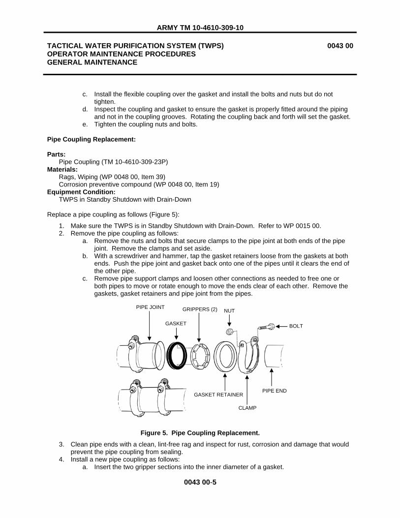
ARMY TM 10-4610-309-10
TACTICAL WATER PURIFICATION SYSTEM (TWPS) OPERATOR MAINTENANCE PROCEDURES GENERAL MAINTENANCE
0043 00
0043 00-5
c. Install the flexible coupling over the gasket and install the bolts and nuts but do not tighten.
d. Inspect the coupling and gasket to ensure the gasket is properly fitted around the piping and not in the coupling grooves. Rotating the coupling back and forth will set the gasket.
e. Tighten the coupling nuts and bolts.
Pipe Coupling Replacement:
Parts: Pipe Coupling (TM 10-4610-309-23P) Materials: Rags, Wiping (WP 0048 00, Item 39) Corrosion preventive compound (WP 0048 00, Item 19) Equipment Condition:
TWPS in Standby Shutdown with Drain-Down
Replace a pipe coupling as follows (Figure 5):
1. Make sure the TWPS is in Standby Shutdown with Drain-Down. Refer to WP 0015 00. 2. Remove the pipe coupling as follows:
a. Remove the nuts and bolts that secure clamps to the pipe joint at both ends of the pipe joint. Remove the clamps and set aside.
b. With a screwdriver and hammer, tap the gasket retainers loose from the gaskets at both ends. Push the pipe joint and gasket back onto one of the pipes until it clears the end of the other pipe.
c. Remove pipe support clamps and loosen other connections as needed to free one or both pipes to move or rotate enough to move the ends clear of each other. Remove the gaskets, gasket retainers and pipe joint from the pipes.
Figure 5. Pipe Coupling Replacement.
3. Clean pipe ends with a clean, lint-free rag and inspect for rust, corrosion and damage that would prevent the pipe coupling from sealing.
4. Install a new pipe coupling as follows: a. Insert the two gripper sections into the inner diameter of a gasket.
NUT
CLAMP
PIPE JOINT GRIPPERS (2)
PIPE END
GASKET
GASKET RETAINER
BOLT

ARMY TM 10-4610-309-10
TACTICAL WATER PURIFICATION SYSTEM (TWPS) OPERATOR MAINTENANCE PROCEDURES GENERAL MAINTENANCE
0043 00
0043 00-6
b. Insert the gasket into the gasket retainer. c. Slide the retainer, gasket and gripper assembly over one of the two pipe ends (retainer
side first). d. Repeat a, b, and c for the other pipe end. One side must be pushed far enough on to
allow the pipe joint to clear the other pipe end. e. Fit the pipe joint onto one pipe end. Move the pipes back into alignment. f. Slide the assemblies at both ends up to the pipe joint so that both gaskets fit up against
the flanges of the pipe joint. g. Position the clamps over the pipe joint flanges and gasket retainers and secure loosely
with a bolt and nut. When both are installed loosely, tighten the bolt and nut on both clamps.
h. Tighten the pipe connections and pipe support clamps which were loosened. i. Spray the gasket retainers and clamps with corrosion preventive compound. j. Run the unit and check the joint for leaks.
Sanitary Clamp and Gasket Replacement:
Parts:Sanitary Clamp (TM 10-4610-309-23P) Sanitary Clamp Gasket (TM 10-4610-309-23P)
Materials: Rags, Wiping (WP 0048 00, Item 39) Equipment Condition:
TWPS in Standby Shutdown with Drain-Down
Replace a sanitary clamp and gasket as follows (Figure 6):
1. Make sure the TWPS is in Standby Shutdown with Drain-Down. Refer to WP 0015 00. 2. Remove the sanitary clamp as follows:
a. Ensure that the section of piping where the sanitary clamp is to be replaced has been depressurized and drained.
b. Unscrew the wing nut. c. Lift the wing nut out of the notch in the clamp. d. Open and remove the clamp and gasket from the pipe ends.
3. Clean the pipe end flanges with a clean, lint-free rag and inspect the piping and pipe flange connections for rust, corrosion and damage that would prevent the sanitary clamp from sealing.
4. Install the sanitary clamp as follows: a. Insert the new sanitary clamp gasket between the two pipe ends. b. Open the new sanitary clamp and place it around the pipe end flanges and gasket. c. Flip the wing nut over and insert it in the notch in the clamp. d. Tighten the wing nut. Use a screwdriver in the slot to tighten. Tap with the hammer all
around and tighten again. e. Run the unit and check the joint for leaks.

ARMY TM 10-4610-309-10
TACTICAL WATER PURIFICATION SYSTEM (TWPS) OPERATOR MAINTENANCE PROCEDURES GENERAL MAINTENANCE
0043 00
0043 00-7
Figure 6. Sanitary Clamp and Gasket Replacement.
Solenoid Coil Replacement:
Parts:Solenoid Coil (BII) (TM 10-4610-309-23P)
Equipment Condition: TWPS in Standby Shutdown without Drain-Down
There are 6 solenoid coils on the TWPS. Three spare coils are provided in the BII that can be used to replace the 6 coils on the TWPS as follows:
Spare Solenoid Coil TWPS Coil(s) It Can Replace 276000-32-D, black body XV-912 on the Feed Flow Control Panel 238610-032D, larger green body XV-902 on air system section 4 15 psig air control valve XV-903 on air system section 3 15 psig air control valve XV-910 on air compressor intermediate filter automatic drain valve XV-911 on CO1 coalescer automatic drain valve 238210-032D, smaller green body XV-901 on air system section 3 100 psig air control valve
Each of the solenoid coils is replaced using the same procedures as follows (Figure 7):
1. Make sure TWPS is in Standby Shutdown without Draining Down (WP 0015 00). 2. Disconnect the solenoid coil wire connector. 3. Remove the plastic cap from the top of the solenoid coil. 4. Push the solenoid down, lift the slotted end of the keeper plate and slide the plate out and off the
solenoid coil. 5. Lift the solenoid coil off its valve. 6. Set the new coil in place. 7. Install the keeper plate. 8. Install the plastic cap. 9. Connect the solenoid coil wire.
GASKET SANITARY CLAMP

ARMY TM 10-4610-309-10
TACTICAL WATER PURIFICATION SYSTEM (TWPS) OPERATOR MAINTENANCE PROCEDURES GENERAL MAINTENANCE
0043 00
0043 00-8
Figure 7. Solenoid Coil Replacement.
SOLENOID COIL XV-903
SOLENOID COIL XV-901
SOLENOID COIL XV-902
PLASTIC CAP
KEEPER PLATE (LIFT AT THIS END)
CONNECTOR
SOLENOID COIL
SOLENOID COIL XV-912
SOLENOID COIL XV-910
SOLENOID COIL XV-911

ARMY TM 10-4610-309-10
TACTICAL WATER PURIFICATION SYSTEM (TWPS) OPERATOR MAINTENANCE PROCEDURES GENERAL MAINTENANCE
0043 00
0043 00-9/10 BLANK
ASSEMBLY
Antiseize Pipe Tape Installation:
Materials: Antiseize pipe tape (WP 0048 00, Item 49/50)
Install pipe tape on piping with external pipe threads as follows:
1. Select the correct pipe tape using the chart below.
FOR THIS PIPE SIZE USE THIS PIPE TAPE 1/4” – 3/8” ¼” tape
½” or larger ½” tape
NOTE
When threading piping together which has pipe tape applied, check the final position of the component before tightening. Over-tightening then backing off taped components can break the seal provided by the tape and result in leaks.
2. Wrap the external pipe threads with pipe tape as follows (Figure 8): a. Start wrapping the threads one and a half threads back from the end of the pipe. b. Completely wrap the pipe tape around the pipe snug tight in a clockwise direction facing
the end of the pipe. c. Continue a second complete turn around the pipe, but this time stretch the tape tight
without breaking it. d. Continue with a third complete turn in the same manner. e. After completing the third turn, break off the tape and smooth the end against the
threads.
Figure 8. Installing Pipe Tape on External Pipe Threads.
END OF WORK PACKAGE


ARMY TM 10-4610-309-10
CHAPTER 5
SUPPORTING INFORMATION
FOR
TACTICAL WATER PURIFICATION SYSTEM (TWPS)


ARMY TM 10-4610-309-10
TACTICAL WATER PURIFICATION SYSTEM (TWPS) REFERENCES
0044 00
0044 00-1
SCOPE
This work package lists field manuals, forms, technical manuals and miscellaneous publications that are referenced in this manual or are otherwise applicable to the operation and maintenance of the Tactical Water Purification System (TWPS).
FIELD MANUALS
Chemical and Biological Contamination Avoidance ............................................................................FM 3-3Nuclear Contamination Avoidance................................................................................................... FM 3-3-1 NBC Protection ....................................................................................................................................FM 3-4 NBC Decontamination..........................................................................................................................FM 3-5 General Fabric Repair......................................................................................................................FM 10-16 Water Supply in Theaters of Operations..........................................................................................FM 10-52 Water Supply Point Equipment and Operations .......................................................................... FM 10-52-1First Aid for Soldiers......................................................................................................................FM 4-25.11 Basic Cold Weather Manual.............................................................................................................FM 31-70
FORMS
Equipment Inspection and Maintenance Worksheet ........................................................................DA 2404 Equipment Control Record.............................................................................................................DA 2408-9 Hand Receipt/Annex Number ........................................................................................................... DA 2062 Recommended Changes to Publications and Blank Forms ............................................................. DA 2028 Transportation Discrepancy Report .................................................................................................... SF 361 Product Quality Deficiency Report ...................................................................................................... SF 368
TECHNICAL MANUALS
Procedures for the Destruction of Army Equipment to Prevent Enemy Use (Mobility Equipment Command)............................................................................................ TM 750-244-3 Administrative Storage of Equipment......................................................................................... TM 740-90-1 Preservation, Packaging, and Packing of Military Supplies and Equipment ............................. TM 38-230-2 Operator, Unit, Direct Support and General Support Maintenance Manual for Generator Set, Skid Mounted, Tactical Quiet, 60kW, 50/60 Hz, MEP-806B................. TM 9-6115-672-14 Operator and Unit Maintenance Manual (Including Repair Parts & Special Tools List) for Water Quality Analysis Set: Purification (WQAS-P) ........................................ TM 10-6630-222-12&P Operator's and Unit Maintenance Manual (Including Repair Parts & Special Tools List) for Tank, Fabric, Collapsible, Water Storage, 3,000 Gallons.................................. TM 10-5430-237-12&P Operator and Field Maintenance Manual Including Repair Parts and Special Tools List For Tank, Fabric, Collapsible, Drinking Water ........................................................ TM 10-5430-249-13&P Repair Parts and Special Tools List for Tactical Water Purification System ................TM 10-4610-309-23P Field Maintenance Manual for Tactical Water Purification System................................. TM 10-4610-309-23

ARMY TM 10-4610-309-10
TACTICAL WATER PURIFICATION SYSTEM (TWPS) REFERENCES
0044 00
0044 00-2
MISCELLANEOUS
Functional Users Manual for The Army Maintenance Management System (TAMMS).....DA PAM 738-750 Sanitary Control and Surveillance of Field Water Supplies ....................................................... TB MED 577 Expendable/Durable Items (Except Medical, Class V Repair Parts, and Heraldic Items)...........CTA 50-970 Field and Garrison Furnishings and Equipment...........................................................................CTA 50-909Army Medical Department Expendable/Durable Items..................................................................CTA 8-100

ARMY TM 10-4610-309-10
TACTICAL WATER PURIFICATION SYSTEM (TWPS) COMPONENTS OF END ITEM (COEI) AND BASIC ISSUE ITEMS (BII) - ARMY
0045 00
0045 00-1
INTRODUCTION
SCOPE
This work package lists COEI and BII for the TWPS (Tactical Water Purification System) to help you inventory items for safe and efficient operation of the equipment.
GENERAL
The COEI and BII information is divided into the following lists:
Components of End Item (COEI). This list is for information purposes only and is not authority to requisition replacements. These items are part of the TWPS. As part of the end item, these items must be with the end item whenever it is issued or transferred between property accounts. Items of COEI are removed and separately packaged for transportation or shipment only when necessary. Illustrations are furnished to help you find and identify the items.
Basic Issue Items (BII). These essential items are required to place the TWPS in operation, operate it and to do emergency repairs. Although shipped separately packaged, BII must be with the TWPS during operation and when it is transferred between property accounts. Listing these items is your authority to request/requisition them for replacement based on authorization of the end item by the TOE/MTOE. Illustrations are furnished to help you find and identify the items.
EXPLANATION OF COLUMNS IN THE COEI AND BII LIST
Column (1) - Illus Number. Gives the number of the item illustrated.
Column (2) - National Stock Number (NSN). Identifies the stock number of the item to be used for requisitioning purposes.
Column (3) – Description, Part Number/(CAGEC). Identifies the Federal item name (in all capital letters) followed by a minimum description when needed. The stowage location of COEI and BII is also included in this column. The last line below the description is the part number and the Commercial and Government Entity Code (CAGEC) (in parentheses).
Column (4) – Usable On Code. When applicable, gives you a code if the item you need is not the same for different models of equipment.
Column (5) – U/I. Unit of Issue (U/I) indicates the physical measurement or count of the item as issued per the National Stock Number shown in column (2).
Column (6) - Qty Rqr. Indicates the quantity required.

ARMY TM 10-4610-309-10
TACTICAL WATER PURIFICATION SYSTEM (TWPS) COMPONENTS OF END ITEM (COEI) AND BASIC ISSUE ITEMS (BII) - ARMY
0045 00
0045 00-2
Table 1. Components of End Item List.
(1)ILLUS
NUMBER
(2)NATIONAL
STOCK NUMBER (NSN)
(3)DESCRIPTION,
PART NUMBER/(CAGEC)
(4)USABLE
ON CODE
(5)U/I
(6)QTY RQR
1 2040-01-527-5798 ANCHOR 110091 (1B1X2)
EA 1
2 4730-01-526-0681 ASSEMBLY, ADAPTOR A01 33901085 (0U5N7)
EA 1
3 4730-01-526-0681 ASSEMBLY, ADAPTOR A02 33901086 (0U5N7)
EA 1
4 4820-01-526-0795 ASSEMBLY, ADAPTOR A03 33901089 (0U5N7)
EA 1
5 4730-01-526-0829 ASSEMBLY, ADAPTOR A04 33901087 (0U5N7)
EA 1
6 4820-01-526-1034 ASSEMBLY, ADAPTOR A05 33901088 (0U5N7)
EA 1
7 4730-01-526-3555 ASSEMBLY, ADAPTOR A07 33901093 (0U5N7)
EA 2
2 34
6 75
1

ARMY TM 10-4610-309-10
TACTICAL WATER PURIFICATION SYSTEM (TWPS) COMPONENTS OF END ITEM (COEI) AND BASIC ISSUE ITEMS (BII) - ARMY
0045 00
0045 00-3
Table 1. Components of End Item List – Continued.
(1)ILLUS
NUMBER
(2)NATIONAL
STOCK NUMBER (NSN)
(3)DESCRIPTION,
PART NUMBER/(CAGEC)
(4)USABLE
ON CODE
(5)U/I
(6)QTY RQR
8 4820-01-526-3498 ASSEMBLY, ADAPTOR A08 33901094 (0U5N7)
EA 2
9 4730-01-526-2858 ASSEMBLY, ADAPTOR A09 33901100 (0U5N7)
EA 1
10 4730-01-526-2859 ASSEMBLY, ADAPTOR A10 33901101 (0U5N7)
EA 1
11 4820-01-526-3498 ASSEMBLY, ADAPTOR A11 33901113 (0U5N7)
EA 1
12 4820-01-526-2860 ASSEMBLY, ADAPTOR A12 33901102 (0U5N7)
EA 1
13 4730-01-526-3538 ASSEMBLY, ADAPTOR A15 33901171 (0U5N7)
EA 2
8 9 10
11
12 13

ARMY TM 10-4610-309-10
TACTICAL WATER PURIFICATION SYSTEM (TWPS) COMPONENTS OF END ITEM (COEI) AND BASIC ISSUE ITEMS (BII) - ARMY
0045 00
0045 00-4
Table 1. Components of End Item List – Continued.
(1) ILLUS
NUMBER
(2)NATIONAL
STOCK NUMBER (NSN)
(3)DESCRIPTION,
PART NUMBER/(CAGEC)
(4)USABLE
ON CODE
(5)U/I
(6)QTY RQR
14 4820-01-526-0795 ASSEMBLY, ADAPTOR A16 33901187(0U5N7)
EA 3
15 9520-01-527-6158 BEAM, Operator Station Entry Support 33901194 (0U5N7)
EA 1
16 7240-01-094-4305 BUCKET, Chemical Red 33901259-3 (0U5N7)
EA 1
17 7240-01-094-4305 BUCKET, Chemical, Yellow 33901259-2 (0U5N7)
EA 1
18 7240-01-094-4305 BUCKET, Chemical, Blue 33901259-1 (0U5N7)
EA 1
19 6150-01-526-2420 CABLE, Distribution Pump, Electric, 75 ft. 33903002 (0U5N7)
EA 1
20 6150-01-526-2412 CABLE, MF Feed Pump, Electric, 35 ft. 33903001 (0U5N7)
EA 1
21 6150-01-526-1813 CABLE, Raw Water Pump, Electric, 135 ft. 33903000 (0U5N7)
EA 1
22 6150-01-526-2479 CABLE, Diesel Distribution Pump Heat Blanket 33903021 (0U5N7)
EA 1
23 6150-01-526-2419 CABLE, Raw Water Diesel Pump Heat Blanket 33903003 (0U5N7)
EA 1
192021
16, 17, 18
2223
14
15

ARMY TM 10-4610-309-10
TACTICAL WATER PURIFICATION SYSTEM (TWPS) COMPONENTS OF END ITEM (COEI) AND BASIC ISSUE ITEMS (BII) - ARMY
0045 00
0045 00-5
Table 1. Components of End Item List – Continued.
(1)ILLUS
NUMBER
(2)NATIONAL
STOCK NUMBER (NSN)
(3)DESCRIPTION,
PART NUMBER/(CAGEC)
(4)USABLE
ON CODE
(5)U/I
(6)QTY RQR
24 4730-00-200-0996 CAP, Hose, Protective (OISS) NX36 (27554)
EA 1
25 5340-01-526-3531 CAP, Hose, 1.5 in. 15V-FDAPOLY (33813)
EA 6
26 5340-01-526-4624 CAP, Hose 2 in. 20V-FDAPOLY (33813)
EA 21
27 5340-01-527-4589 COLLAR, A-02 33905065 (0U5N7)
EA 1
28 2540-01-527-6253 CONNECTOR ASSY, Return Air 33901600 (0U5N7)
EA 1
29 2540-01-527-6215 COVER, Diesel Pump 33901133 (0U5N7)
EA 2
30 2540-01-527-6248 COVER, Micro Filtration Pump 33901132 (0U5N7)
EA 1
31 2540-01-527-6250 COVER, Raw Water Pump P-2 and Distribution Pump-733901131 (0U5N7)
EA 2
27
29 3130
242526
28

ARMY TM 10-4610-309-10
TACTICAL WATER PURIFICATION SYSTEM (TWPS) COMPONENTS OF END ITEM (COEI) AND BASIC ISSUE ITEMS (BII) - ARMY
0045 00
0045 00-6
Table 1. Components of End Item List – Continued.
(1) ILLUS
NUMBER
(2)NATIONAL
STOCK NUMBER (NSN)
(3)DESCRIPTION,
PART NUMBER/(CAGEC)
(4)USABLE
ON CODE
(5)U/I
(6)QTY RQR
32 4720-01-527-6187 DUCT, Air, Flexible, 8 in. x 6 ft. 33901218 (0U5N7)
EA 2
33 4720-20-001-8512 DUCT, Air, Flexible, 12 in. x 20 ft. 632-88-1220SCJLRMW/07 (L1308)
EA 2
34 4720-01-527-6197 DUCT, Air, Flexible, 4 in. x 5.75 ft. 33901217 (0U5N7)
EA 1
35 2510-01-527-6571 FRAME ASSEMBLY, FLATRACK (A-TWPS) 33901501 (0U5N7)
EA 1
36 4930-01-527-6151 FUEL TANK ASSY, Diesel Pump 33901122 (0U5N7)
EA 2
37 6115-01-462-0291 GENERATOR SET, Diesel Engine Driven MEP-806B (30554)
EA 1
35
33
3234
37
36

ARMY TM 10-4610-309-10
TACTICAL WATER PURIFICATION SYSTEM (TWPS) COMPONENTS OF END ITEM (COEI) AND BASIC ISSUE ITEMS (BII) - ARMY
0045 00
0045 00-7
Table 1. Components of End Item List – Continued.
(1)ILLUS
NUMBER
(2)NATIONAL
STOCK NUMBER (NSN)
(3)DESCRIPTION,
PART NUMBER/(CAGEC)
(4)USABLE
ON CODE
(5)U/I
(6)QTY RQR
38 4540-01-526-3481 HEAT BLANKET ASSY, Adapter A-02 33901191 (0U5N7)
EA 1
39 4540-01-526-3346 HEAT BLANKET ASSY, Hose, 3 in. x 11 ft., F01-1 33901126-2 (0U5N7)
EA 1
40 4540-01-526-3345 HEAT BLANKET ASSY, Hose, 3 in. x 11 ft., F01-2 33901324 (0U5N7)
EA 1
41 4540-01-526-3347 HEAT BLANKET ASSY, Hose, 2 in. x 50.5 ft., F03-1 33901126-3 (0U5N7)
EA 1
42 4540-01-526-3348 HEAT BLANKET ASSY, Hose, 2 in. x 50.5 ft., F03-2 33901126-4 (0U5N7)
EA 3
43 4540-01-526-3355 HEAT BLANKET ASSY, Hose, 3 in. x 21 ft., F07 33901126-6 (0U5N7)
EA 1
44 4540-01-526-3354 HEAT BLANKET ASSY, Hose, 2 in. x 9 ft., F12 33901203 (0U5N7)
EA 1
45 4540-01-526-3472 HEAT BLANKET ASSY, Hose, 1.5 in. x 41.5 ft., P02 33901126-7 (0U5N7)
EA 1
46 4540-01-526-3474 HEAT BLANKET ASSY, Hose, 2 in. x 6 ft., P03-1 33901126-8 (0U5N7)
EA 2
47 4540-01-526-3475 HEAT BLANKET ASSY, Hose, 2 in. x 6 ft., P03-2 33901126-9 (0U5N7)
EA 1
48 4540-01-526-3476 HEAT BLANKET ASSY, Hose, 2 in. x 6 ft., P04 33901233 (0U5N7)
EA 2
49 4540-01-526-3477 HEAT BLANKET ASSY, Hose, 2 in. x 65 ft., P05 33901232 (0U5N7)
EA 4
50 4520-01-527-6260 HEATER, Portable MV60S-1 (92878)
EA 1
3940414243444546474849
38
50
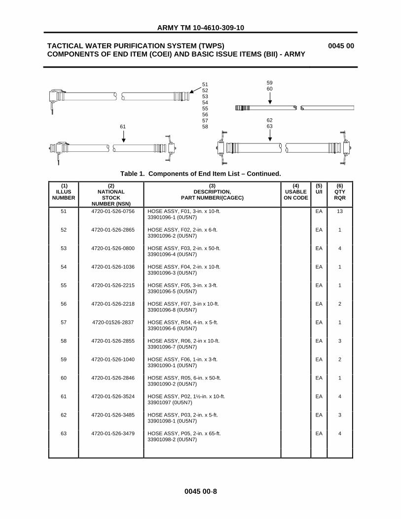
ARMY TM 10-4610-309-10
TACTICAL WATER PURIFICATION SYSTEM (TWPS) COMPONENTS OF END ITEM (COEI) AND BASIC ISSUE ITEMS (BII) - ARMY
0045 00
0045 00-8
Table 1. Components of End Item List – Continued.
(1) ILLUS
NUMBER
(2)NATIONAL
STOCK NUMBER (NSN)
(3)DESCRIPTION,
PART NUMBER/(CAGEC)
(4)USABLE
ON CODE
(5)U/I
(6)QTY RQR
51 4720-01-526-0756 HOSE ASSY, F01, 3-in. x 10-ft. 33901096-1 (0U5N7)
EA 13
52 4720-01-526-2865 HOSE ASSY, F02, 2-in. x 6-ft. 33901096-2 (0U5N7)
EA 1
53 4720-01-526-0800 HOSE ASSY, F03, 2-in. x 50-ft. 33901096-4 (0U5N7)
EA 4
54 4720-01-526-1036 HOSE ASSY, F04, 2-in. x 10-ft. 33901096-3 (0U5N7)
EA 1
55 4720-01-526-2215 HOSE ASSY, F05, 3-in. x 3-ft. 33901096-5 (0U5N7)
EA 1
56 4720-01-526-2218 HOSE ASSY, F07, 3-in x 10-ft. 33901096-8 (0U5N7)
EA 2
57 4720-01526-2837 HOSE ASSY, R04, 4-in. x 5-ft. 33901096-6 (0U5N7)
EA 1
58 4720-01-526-2855 HOSE ASSY, R06, 2-in x 10-ft. 33901096-7 (0U5N7)
EA 3
59 4720-01-526-1040 HOSE ASSY, F06, 1-in. x 3-ft. 33901090-1 (0U5N7)
EA 2
60 4720-01-526-2846 HOSE ASSY, R05, 6-in. x 50-ft. 33901090-2 (0U5N7)
EA 1
61 4720-01-526-3524 HOSE ASSY, P02, 1½-in. x 10-ft. 33901097 (0U5N7)
EA 4
62 4720-01-526-3485 HOSE ASSY, P03, 2-in. x 5-ft. 33901098-1 (0U5N7)
EA 3
63 4720-01-526-3479 HOSE ASSY, P05, 2-in. x 65-ft. 33901098-2 (0U5N7)
EA 4
5152535455565758
5960
616263

ARMY TM 10-4610-309-10
TACTICAL WATER PURIFICATION SYSTEM (TWPS) COMPONENTS OF END ITEM (COEI) AND BASIC ISSUE ITEMS (BII) - ARMY
0045 00
0045 00-9
Table 1. Components of End Item List – Continued.
(1)ILLUS
NUMBER
(2)NATIONAL
STOCK NUMBER (NSN)
(3)DESCRIPTION,
PART NUMBER/(CAGEC)
(4)USABLE
ON CODE
(5)U/I
(6)QTY RQR
64 4720-01-526-3522 HOSE ASSY, P06, 5/8-in. x 50-ft. 33901095 (0U5N7)
EA 1
65 4720-01-526-3490 HOSE ASSY, P04, 2-in. x 5-ft. 33901099 (0U5N7)
EA 2
66 4730-01-526-5657 HOSE ASSY, (OISS), 2-in. x 10-ft. 861-08399 (0EXU3)
EA 6
67 7240-01-359-0894 LID, Tank, Chemical, Yellow 33902558-1 (0U5N7)
EA 1
68 7240-01-359-0894 LID, Tank, Chemical, Blue 33902558-2 (0U5N7)
EA 1
69 7240-01-359-0894 LID, Tank, Chemical, Red 33902558-3 (0U5N7)
EA 1
70 6680-01-527-0326 METER ASSY, Flow 33901082 (0U5N7)
EA 1
71 4720-01-526-3473 NOZZLE ASSY, Distribution 33901103 (0U5N7)
EA 4
64
65
66
676869
70
71

ARMY TM 10-4610-309-10
TACTICAL WATER PURIFICATION SYSTEM (TWPS) COMPONENTS OF END ITEM (COEI) AND BASIC ISSUE ITEMS (BII) - ARMY
0045 00
0045 00-10
Table 1. Components of End Item List – Continued.
(1) ILLUS
NUMBER
(2)NATIONAL
STOCK NUMBER (NSN)
(3)DESCRIPTION,
PART NUMBER/(CAGEC)
(4)USABLE
ONCODE
(5)U/I
(6)QTY RQR
72 5340-01-527-6280 PANEL #1 ASSY 33901586 (0U5N7)
EA 1
73 5340-01-527-6288 PANEL #2 ASSY 33901553 (0U5N7)
EA 1
74 5340-01-527-6289 PANEL #3 ASSY, 33901551 (0U5N7)
EA 1
75 5340-01-527-6290 PANEL #4 ASSY 33901550 (0U5N7)
EA 1
76 5340-01-527-6292 PANEL #5 ASSY 33901597 (0U5N7)
EA 1
77 5340-01-527-6293 PANEL #6 ASSY 33901590 (0U5N7)
EA 1
78 5340-01-527-6294 PANEL #7 ASSY 33901552 (0U5N7)
EA 1
72 73 74 75
76 77 78

ARMY TM 10-4610-309-10
TACTICAL WATER PURIFICATION SYSTEM (TWPS) COMPONENTS OF END ITEM (COEI) AND BASIC ISSUE ITEMS (BII) - ARMY
0045 00
0045 00-11
Table 1. Components of End Item List - Continued.
(1)ILLUS
NUMBER
(2)NATIONAL
STOCK NUMBER (NSN)
(3)DESCRIPTION,
PART NUMBER/(CAGEC)
(4)USABLE
ON CODE
(5)U/I
(6)QTY RQR
79 4710-01-526-3796 PIPE ASSY, CPVC (OISS) 507-12400 (0EXU3)
EA 4
80 4730-01-526-3536 PIPE ASSY, ELBOW (OISS) 507-12433 (0EXU3)
EA 2
81 4730-01-526-3534 PIPE ASSY, TEE, 3-INCH (OISS) 507-12430 (0EXU3)
EA 1
82 4730-01-526-3530 PIPE ASSY, TEE, 2-INCH (OISS) 507-12431 (0EXU3)
EA 2
83 4720-01-526-3540 PIPE COUPLING (OISS) 858-07694-000 (0EXU3)
EA 4
84 4730-01-526-3571 PIPE NIPPLE, 60-INCH (OISS) 857-08404-000 (OEXU3)
EA 8
85 4730-01-526-3568 PIPE NIPPLE, 24-INCH (OISS) 857-08405-000 (OEXU3)
EA 4
86 4140-01-527-6186 PLENUM, Right Hot Air 33901273 (0U5N7)
EA 1
87 4140-01-527-6184 PLENUM, Main Hot Air 33901272 (0U5N7)
EA 1
8679
87
80 81 82
83
84
85

ARMY TM 10-4610-309-10
TACTICAL WATER PURIFICATION SYSTEM (TWPS) COMPONENTS OF END ITEM (COEI) AND BASIC ISSUE ITEMS (BII) - ARMY
0045 00
0045 00-12
Table 1. Components of End Item List – Continued.
(1)ILLUS
NUMBER
(2)NATIONAL
STOCK NUMBER (NSN)
(3)DESCRIPTION,
PART NUMBER/(CAGEC)
(4)USABLE
ON CODE
(5)U/I
(6)QTY RQR
88 5340-01-526-0665 PLUG, Hose, 1.5 in. 15W-FDAPOLY (33813)
EA 2
89 5340-01-526-2794 PLUG, Hose, 3 in. 30W-FDAPOLY (33813)
EA 2
90 5340-01-526-3564 PLUG, Hose, 2 in. 20W-FDAPOLY (33813)
EA 16
91 4320-01-527-6155 PUMP ASSY, Distribution, Electric, P7 33901110 (0U5N7)
EA 1
92 4320-01-527-6262 PUMP ASSY, Distribution, Diesel, P8 33901153 (0U5N7)
EA 1
93 4320-01-527-6156 PUMP ASSY, Micro-Filtration, P3 33901108 (0U5N7)
EA 1
94 4320-01-527-5806 PUMP ASSY, Raw Water, Diesel, P1 33901104 (0U5N7)
EA 1
95 4320-01-527-6154 PUMP ASSY, Raw Water, Electric, P2 33901106 (0U5N7)
EA 1
91
92
93 94
888990
95

ARMY TM 10-4610-309-10
TACTICAL WATER PURIFICATION SYSTEM (TWPS) COMPONENTS OF END ITEM (COEI) AND BASIC ISSUE ITEMS (BII) - ARMY
0045 00
0045 00-13
Table 1. Components of End Item List - Continued.
(1)ILLUS
NUMBER
(2)NATIONAL
STOCK NUMBER (NSN)
(3)DESCRIPTION,
PART NUMBER/(CAGEC)
(4)USABLE
ON CODE
(5)U/I
(6)QTY RQR
96 5430-01-359-1078 REPAIR KIT, COLLAPSIBLE TANK A-A-52022 (58536)
EA 1
97 4020-01-526-0755 ROPE ASSY, Anchor 33901146 (0U5N7)
EA 1
98 4020-01-526-4646 ROPE, Raw Water Hose 33902478-4 (0U5N7)
EA 1
99 4020-01-526-2214 ROPE, MF Strainer 33902478-1 (0U5N7)
EA 1
100 4020-01-527-3384 ROPE, Contamination Avoidance Cover, 60 ft. 33902478-3 (0U5N7)
EA 3
101 4320-01-527-6152 SEPARATOR ASSY, Cyclone 33901084 (0U5N7)
EA 1
102 6150-01-526-2421 STARTING CABLE, Diesel Pump P-1, P-8 33903004 (0U5N7)
EA 1
103 4730-01-527-5802 STRAINER ASSY, Raw Water, S01 33901160 (0U5N7)
EA 1
97
103
9899
102101
100
96

ARMY TM 10-4610-309-10
TACTICAL WATER PURIFICATION SYSTEM (TWPS) COMPONENTS OF END ITEM (COEI) AND BASIC ISSUE ITEMS (BII) - ARMY
0045 00
0045 00-14
107108109
Table 1. Components of End Item List – Continued.
(1)ILLUS
NUMBER
(2)NATIONAL
STOCK NUMBER (NSN)
(3)DESCRIPTION,
PART NUMBER/(CAGEC)
(4)USABLE
ON CODE
(5)U/I
(6)QTY RQR
104 4730-01-527-6258 STRAINER, ICE 33901172 (0U5N7)
EA 1
105 5340-01-527-6317 SUPPORT ASSY, Deck 33901505 (0U5N7)
EA 4
106 4230-01-526-1138 TANK ASSY, NBC 732-D-08057 (0EXU3)
EA 1
107 5430-01-526-2212 TANK, Fabric, 1000 Gallons, MF Feed 01K-OT-TNK (3NUA7)
EA 1
108 5340-01-540-5357 TANK, Fabric, 3000 Gallons, Distribution 03K-ZT-TNK-A (3NUA7)
EA 5
109 5430-01-527-0341 TANK, Fabric, 1500 Gallons, Cleaning Waste 01.5K-ZT-TNK (3NUA7)
EA 1
110 6120-01-526-3099 TRANSFORMER, General Purpose 33903044 (0U5N7)
EA 1
111 6625-01-526-9713 TRIPOD ASSEMBLY 33901322 (0U5N7)
EA 1
112 2540-01-527-6319 WALL, Fabric 33905055 (0U5N7)
EA 1
106104105
110 112
111

ARMY TM 10-4610-309-10
TACTICAL WATER PURIFICATION SYSTEM (TWPS) COMPONENTS OF END ITEM (COEI) AND BASIC ISSUE ITEMS (BII) - ARMY
0045 00
0045 00-15
Table 2. Basic Issue Items List.
(1) ILLUS
NUMBER
(2)NATIONAL
STOCK NUMBER (NSN)
(3)DESCRIPTION,
PART NUMBER/(CAGEC)
(4)USABLE
ONCODE
(5)U/I
(6)QTY RQR
1
2
8415-00-234-9253
4230-01-526-1138
APRON, LABORATORY MC111 (80063)
AUGER, Ice, with handle HD-06 (61702)
EA
EA
2
1
3 5120-01-335-1510 BAR, Pinch 2430B (55719)
EA 1
4
5
3030-00-445-4514 BELT, V, Air Compressor A76 (04NP0)
BOTTLE, Measuring, Clear PVC 77075 (27901)
EA
EA
1
1
1
3
45
2

ARMY TM 10-4610-309-10
TACTICAL WATER PURIFICATION SYSTEM (TWPS) COMPONENTS OF END ITEM (COEI) AND BASIC ISSUE ITEMS (BII) - ARMY
0045 00
0045 00-16
Table 2. Basic Issue Items List. – Continued.
(1)ILLUS
NUMBER
(2)NATIONAL
STOCK NUMBER (NSN)
(3)DESCRIPTION,
PART NUMBER/(CAGEC)
(4)USABLE
ONCODE
(5)U/I
(6)QTY RQR
6 2540-01-527-0316 BOX, Storage, BII #1 33901230-1T (0U5N7)
EA 1
7 2540-01-527-0317 BOX, Storage, BII #2 33901230-2T (0U5N7)
EA 1
8 2540-01-527-0318 BOX, Storage, BII #3 33901230-3T (0U5N7)
EA 1
9 2540-01-527-0063 BOX, Storage, BII #8 33901230-4T (0U5N7)
EA 1
10 2540-01-527-0315 BOX, Storage, BII #4 (Chemicals) 33902549 (0U5N7)
EA 1
11 2540-01-527-0314 BOX, Storage, BII #5 33901238 (0U5N7)
EA 1
12 2540-01-527-0064 BOX, Storage, BII Spare Parts 1100 (53718)
EA 1
10
1112
6789

ARMY TM 10-4610-309-10
TACTICAL WATER PURIFICATION SYSTEM (TWPS) COMPONENTS OF END ITEM (COEI) AND BASIC ISSUE ITEMS (BII) - ARMY
0045 00
0045 00-17
Table 2. Basic Issue Items List – Continued.
(1) ILLUS
NUMBER
(2)NATIONAL
STOCK NUMBER (NSN)
(3)DESCRIPTION,
PART NUMBER/(CAGEC)
(4)USABLE
ONCODE
(5)U/I
(6)QTY RQR
13 3990-01-527-4727 BOX, Storage, Manuals 33901320-1 (0U5N7)
EA 1
14 2540-01-527-0064 BOX, Tool 9-65432 (53800)
EA 1
15 7920-00-244-7431 BRUSH, Plater's 7187T8 (39428)
EA 1
16 3990-01-527-4727 BUCKET, Storage, BII #6 33902531 (0U5N7)
EA 1
13
14
1516

ARMY TM 10-4610-309-10
TACTICAL WATER PURIFICATION SYSTEM (TWPS) COMPONENTS OF END ITEM (COEI) AND BASIC ISSUE ITEMS (BII) - ARMY
0045 00
0045 00-18
Table 2. Basic Issue Items List – Continued.
(1)ILLUS
NUMBER
(2)NATIONAL
STOCK NUMBER (NSN)
(3)DESCRIPTION,
PART NUMBER/(CAGEC)
(4)USABLE
ONCODE
(5)U/I
(6)QTY RQR
17 5945-01-527-0087 CABLE ASSY, Solenoid (XV-901) 33903015-5 (0U5N7)
EA 1
18 5945-01-527-0088 CABLE ASSY, Solenoid (XV-902/903/910/911) 33903015-6 (0U5N7)
EA 1
19 5945-01-527-0089 CABLE ASSY, Solenoid (XV-912) 33903015-7 (0U5N7)
EA 1
20 4310-01-460-7980 CARTRIDGE, Purifier 058821A (0EXU3)
EA 1
21 5940-01-158-4521 CLAMP, Ground Rod L70 (56501)
EA 1
22 7240-01-337-5269 CONTAINER, Fuel, Diesel, 5 gallons 10502788 (56161)
EA 1
171819
20
21
22

ARMY TM 10-4610-309-10
TACTICAL WATER PURIFICATION SYSTEM (TWPS) COMPONENTS OF END ITEM (COEI) AND BASIC ISSUE ITEMS (BII) - ARMY
0045 00
0045 00-19
Table 2. Basic Issue Items List – Continued.
(1) ILLUS
NUMBER
(2)NATIONAL
STOCK NUMBER (NSN)
(3)DESCRIPTION,
PART NUMBER/(CAGEC)
(4)USABLE
ONCODE
(5)U/I
(6)QTY RQR
23 4130-01-457-3399 COVER, Contamination Avoidance 65503-100 (90598)
EA 1
24 8465-01-526-9820 COVER, PDP Access 33901241 (0U5N7)
EA 1
25 8465-01-526-9822 COVER, Product Water Door 33905066 (0U5N7)
EA 1
26 8465-01-526-9824 COVER, Shipping, Product Water Door 33905072 (0U5N7)
EA 1
27 6640-01-526-9844 CUP, Measuring 1000 ml 77038 (1UD63)
EA 1
28 4820-01-526-2507 DISK, Rupturable 925-07813 (0EXU3)
EA 1
23 24 25
2627 28

ARMY TM 10-4610-309-10
TACTICAL WATER PURIFICATION SYSTEM (TWPS) COMPONENTS OF END ITEM (COEI) AND BASIC ISSUE ITEMS (BII) - ARMY
0045 00
0045 00-20
Table 2. Basic Issue Items List – Continued.
(1) ILLUS
NUMBER
(2)NATIONAL
STOCK NUMBER (NSN)
(3)DESCRIPTION,
PART NUMBER/(CAGEC)
(4)USABLE
ONCODE
(5)U/I
(6)QTY RQR
29 5120-01-354-2770 DRIVER, Nut, 5/16 in. 75048140 (1F9N2)
EA 1
30 6150-01-527-0085 EXTENSION CORD, 100 ft. 7438K35 (39428)
EA 1
31 5120-01-398-7666 EXTENSION, Socket Wrench, 3 in. 9-44264 (53800)
EA 1
32 5120-01-398-7673 EXTENSION, Socket Wrench, 6 in. 9-44261 (53800)
EA 1
33 4240-01-527-0099 FACESHIELD, Industrial 10179 (01786)
EA 1
34 4310-01-460-3415 FILTER, Air Compressor Inlet N00070 (57328)
EA 1
35 2940-01-310-4495 FILTER, Air, Diesel Pump 114250-12581 (0AK42)
EA 1
36 2910-01-310-6566 FILTER, Fuel, Diesel Pump 114250-55121 (0AK42)
EA 1
37 4210-01-527-0100 FIRE EXTINGUISHER, Dry Chemical, 3A-40B 21032 (6U173)
EA 1
29 31 32 33
3435 36
37
30

ARMY TM 10-4610-309-10
TACTICAL WATER PURIFICATION SYSTEM (TWPS) COMPONENTS OF END ITEM (COEI) AND BASIC ISSUE ITEMS (BII) - ARMY
0045 00
0045 00-21
46474849
Table 2. Basic Issue Items List – Continued.
(1) ILLUS
NUMBER
(2)NATIONAL
STOCK NUMBER (NSN)
(3)DESCRIPTION,
PART NUMBER/(CAGEC)
(4)USABLE
ONCODE
(5)U/I
(6)QTY RQR
38 6230-01-527-0102 FLASHLIGHT, D-Size 01042134 (1F9N2)
EA 4
39 7240-00-404-9797 FUNNEL, 3 in. 1479T3 (39428)
EA 1
40 5330-01-526-5279 GASKET, C&G, 1 in. NW2 (33813)
EA 1
41 5330-01-526-0670 GASKET, C&G, 1-1/2 in. NW4 (33813)
EA 2
42 5330-01-349-8921 GASKET, C&G, 2 in. NW5 (33813)
EA 12
43 5330-01-349-6190 GASKET, C&G, 3 in. NW7 (33813)
EA 10
44 5330-01-526-4417 GASKET, C&G, 4 in. B08 (33813)
EA 1
45 5330-01-526-4418 GASKET, C&G, 6 in. B010 (33813)
EA 1
46 5330-01-526-4840 GASKET, Grooved Coupling, 1 in. 75-E-1.0IN (79154)
EA 2
47 5330-01-247-8525 GASKET, Grooved Coupling, 1.5 in. 75-E-1.5IN (79154)
EA 4
48 5330-01-271-5788 GASKET, Grooved Coupling, 2 in. STYLE 77/75/78-2.0IN GR E (79154)
EA 2
49 5330-01-271-5159 GASKET, Grooved Coupling, 3 in. STYLE 77/75/78-3.0IN GR E (79154)
EA 1
50 5330-01-509-7366 GASKET, Sanitary, 4 in. 853-9586 (0EXU3)
EA 1
51 5330-01-515-3904 GASKET, Sanitary 6 in. 853-9826 (0EXU3)
EA 1
4445
40414243
5051
38 39

ARMY TM 10-4610-309-10
TACTICAL WATER PURIFICATION SYSTEM (TWPS) COMPONENTS OF END ITEM (COEI) AND BASIC ISSUE ITEMS (BII) - ARMY
0045 00
0045 00-22
Table 2. Basic Issue Items List – Continued.
(1)ILLUS
NUMBER
(2)NATIONAL
STOCK NUMBER (NSN)
(3)DESCRIPTION,
PART NUMBER/(CAGEC)
(4)USABLE
ONCODE
(5)U/I
(6)QTY RQR
52 8415-01-526-9826 GLOVES, Rubber, Chemical, Pair 6B-6681-9 (6M644)
EA 2
53 4940-00-873-3651 GUN, Air Blow JT10AS (55719)
EA 1
54 5120-01-398-7647 HANDLE, Socket Wrench, 3/8 in. 9-44811 (53800)
EA 1
55 4540-01-526-5918 HEATER, Pump, Strap-On (Winter) 040150A7 (0PKE1)
EA 3
56 4940-01-526-2893 HEAT GUN 32605K44 (39428)
EA 1
52
53
55
56
54

ARMY TM 10-4610-309-10
TACTICAL WATER PURIFICATION SYSTEM (TWPS) COMPONENTS OF END ITEM (COEI) AND BASIC ISSUE ITEMS (BII) - ARMY
0045 00
0045 00-23
Table 2. Basic Issue Items List – Continued.
(1) ILLUS
NUMBER
(2)NATIONAL
STOCK NUMBER (NSN)
(3)DESCRIPTION,
PART NUMBER/(CAGEC)
(4)USABLE
ONCODE
(5)U/I
(6)QTY RQR
57 4720-01-527-0107 HOSE, Air, w/Quick Disconnect 33901165 (0U5N7)
EA 1
58 4720-01-527-6200 HOSE, Engine Exhaust, Diesel Pumps P-1, P-8 33901224 (0U5N7)
EA 2
59 5110-01-459-2663 KEY SET, Hex, Foldup Set 9-BH12589 (0TA44)
EA 1
60 5110-01-428-5225 KNIFE, Utility 10-179 (1CV05)
EA 1
61 6230-01-527-0111 LIGHT ASSY, Blackout 33903017 (0U5N7)
EA 1
62 6230-01-527-0115 LIGHT ASSY, Trouble 8407K12 (39428)
EA 1
63 6230-01-527-0117 LIGHT ASSY, Work 33903016 (0U5N7)
EA 1
5758
60
6162 63
59

ARMY TM 10-4610-309-10
TACTICAL WATER PURIFICATION SYSTEM (TWPS) COMPONENTS OF END ITEM (COEI) AND BASIC ISSUE ITEMS (BII) - ARMY
0045 00
0045 00-24
Table 2. Basic Issue Items List - Continued.
(1) ILLUS
NUMBER
(2)NATIONAL
STOCK NUMBER (NSN)
(3)DESCRIPTION
(CAGE) and PART NUMBER
(4)USABLE
ONCODE
(5)U/M
(6)QTY RQR
64 5120-01-116-6996 MALLET, Rubber, Wood Handle 9-45787 (53800)
EA 1
65 MANUAL, Operator TM 10-4610-309-10
EA 1
66 MANUAL, Field Maintenance TM 10-4610-309-23
EA 1
67 MANUAL, RPSTL TM 10-4610-309-23P
EA 1
68 2540-01-527-0125 MAT, Equipment Area Floor 33902486 (0U5N7)
EA 1
69 2540-01-527-0126 MAT, Operator Station Area Floor 33902488 (0U5N7)
EA 1
6869
64 65 66
67

ARMY TM 10-4610-309-10
TACTICAL WATER PURIFICATION SYSTEM (TWPS) COMPONENTS OF END ITEM (COEI) AND BASIC ISSUE ITEMS (BII) - ARMY
0045 00
0045 00-25
Table 2. Basic Issue Items List - Continued.
1)ILLUS
NUMBER
(2)NATIONAL
STOCK NUMBER (NSN)
(3)DESCRIPTION,
PART NUMBER/(CAGEC)
(4)USABLE
ONCODE
(5)U/I
(6)QTY RQR
70 3940-01-527-0139 NET, Cargo B9154-120144-2R (098P0)
EA 1
71 2040-01-413-1455 PADDLE, Boat (Stirring Paddle) 23092 (27901)
EA 1
72 5315-01-527-0166 PIN, Quick Release 98480A135 (39428)
EA 6
73 5315-01-526-3545 PIN, Quick Release 98416A125 (39428)
EA 2
74 7240-00-138-7985 PITCHER, Priming 80120 (27901)
EA 1
75 2540-01-527-0436 PLATFORM, Pump 33902269 (0U5N7)
EA 5
70
71 7273
74
75

ARMY TM 10-4610-309-10
TACTICAL WATER PURIFICATION SYSTEM (TWPS) COMPONENTS OF END ITEM (COEI) AND BASIC ISSUE ITEMS (BII) - ARMY
0045 00
0045 00-26
Table 2. Basic Issue Items List – Continued.
(1) ILLUS
NUMBER
(2)NATIONAL
STOCK NUMBER (NSN)
(3)DESCRIPTION,
PART NUMBER/(CAGEC)
(4)USABLE
ONCODE
(5)U/I
(6)QTY RQR
76 5120-00-069-5230 PLIERS, Slip Joint 10310-006-8 (71379)
EA 1
77 5110-01-131-7095 PLIERS, Diagonal CS9336C (43786)
EA 1
78 5210-01-462-6741 PROTRACTOR (Level) 939840 (08125)
EA 1
79 4610-01-527-0101 PUSHER, RO Element 33901222 (0U5N7)
EA 1
80 3820-00-930-6086 ROD ASSEMBLY, Ground 30162 (18990)
EA 1
81 9510-01-527-6320 ROD, Pump Skid Retaining, Long, 32.5 in. 33901229 (0U5N7)
EA 2
82 9510-01-527-6321 ROD, Pump Skid Retaining, Short 20.25 in. 33901228 (0U5N7)
EA 1
76 77 78
798182
80

ARMY TM 10-4610-309-10
TACTICAL WATER PURIFICATION SYSTEM (TWPS) COMPONENTS OF END ITEM (COEI) AND BASIC ISSUE ITEMS (BII) - ARMY
0045 00
0045 00-27
Table 2. Basic Issue Items List – Continued.
(1) ILLUS
NUMBER
(2)NATIONAL
STOCK NUMBER (NSN)
(3)DESCRIPTION,
PART NUMBER/(CAGEC)
(4)USABLE
ONCODE
(5)U/I
(6)QTY RQR
83 6640-01-035-7935 SCOOP, Large 80012 (1UD63)
EA 1
84 5120-01-398-9399 SCREWDRIVER, Flat Tip, 1/8 in. x 3 in. 9-47440 (53800)
EA 1
85 5120-01-398-9400 SCREWDRIVER, Flat Tip, 3/16 x 4 in. 9-47441 (53800)
EA 1
86 5120-01-398-9403 SCREWDRIVER, Flat Tip, 1/4 in. x 6 in. 9-47445 (53800)
EA 1
87 5120-01-398-9404 SCREWDRIVER, Flat Tip, 5/16 in. x 8 in. 9-47447 (53800)
EA 1
88 5120-01-398-9402 SCREWDRIVER, Cross Tip, #0 x 3 in. 9-47434 (53800)
EA 1
89 5120-01-398-9405 SCREWDRIVER, Cross Tip, #1 x 4 in. 9-47435 (53800)
EA 1
90 5120-01-398-9244 SCREWDRIVER, Cross Tip, #2 x 4 in. 9-47436 (53800)
EA 1
91 5120-01-398-9245 SCREWDRIVER, Cross Tip, #3 x 6 in. 9-47437 (53800)
EA 1
92 SDI Test Kit 20071301-1 (0U5N7)
EA 1
8384858687
88899091
92

ARMY TM 10-4610-309-10
TACTICAL WATER PURIFICATION SYSTEM (TWPS) COMPONENTS OF END ITEM (COEI) AND BASIC ISSUE ITEMS (BII) - ARMY
0045 00
0045 00-28
Table 2. Basic Issue Items List – Continued.
(1) ILLUS
NUMBER
(2)NATIONAL
STOCK NUMBER (NSN)
(3)DESCRIPTION,
PART NUMBER/(CAGEC)
(4)USABLE
ONCODE
(5)U/I
(6)QTY RQR
93 5120-01-013-1676 SLIDE HAMMER, Ground Rod P74-144 (45225)
EA 1
94 5120-01-431-2720 SOCKET, 1/2 in. 45116 (2K880)
EA 1
95 5120-01-431-2589 SOCKET, 11/16 in. 45022 (2K880)
EA 1
96 5120-01-431-2591 SOCKET, 13/16 in. 45026 (2K880)
EA 1
97 5120-01-431-2614 SOCKET, 15/16 in. 45030 (2K880)
EA 1
98 5120-01-431-2600 SOCKET, 3/4 in. 45024 (2K880)
EA 1
99 5120-01-431-2717 SOCKET, 3/8 in. 45112 (2K880)
EA 1
100 5120-01-431-2596 SOCKET, 5/8 in. 45020 (2K880)
EA 1
101 5120-01-431-2778 SOCKET, 7/16 in. 45114 (2K880)
EA 1
102 5120-01-431-2595 SOCKET, 7/8 in. 45028 (2K880)
EA 1
103 5120-01-431-2588 SOCKET, 9/16 in. 45118 (2K880)
EA 1
104 5120-01-431-2718 SOCKET, Spark Plug, 5/8 in. 4420 (2K880)
EA 1
949596979899100101102103104
93

ARMY TM 10-4610-309-10
TACTICAL WATER PURIFICATION SYSTEM (TWPS) COMPONENTS OF END ITEM (COEI) AND BASIC ISSUE ITEMS (BII) - ARMY
0045 00
0045 00-29
Table 2. Basic Issue Items List – Continued.
1)ILLUS
NUMBER
(2)NATIONAL
STOCK NUMBER (NSN)
(3)DESCRIPTION,
PART NUMBER/(CAGEC)
(4)USABLE
ONCODE
(5)U/I
(6)QTY RQR
105 7240-00-177-6154 SPOUT, Fuel Can 04353 (2C071)
EA 1
106 4940-00-494-1533 STETHOSCOPE, Engineer’s 2001 (78495)
EA 1
107
108
109
4730-01-526-2213 STRAINER, MF Feed Tank 923-08139 (0EXU3)
STRAP, Assembly, Loop 25 in. 33902371-3 (1FR69)
STRAP, Assembly, Loop 12 in. 33902371-4 (1FR69)
EA
EA
EA
3
9
2
110 5975-01-476-8290 STRAP, Tiedown, Hook and Loop, 12 in 3955T71 (39428)
EA 6
111 3990-01-527-0068 STRAP, Tiedown, Hook and Loop, 18 in 3955T72 (39428)
EA 8
112 3990-01-527-0070 STRAP, Tiedown, Hook and Loop, 36 in 3955T74 (39428)
EA 14
113 3990-01-527-0073 STRAP, Tiedown, Hook and Loop, 48 in 3955T75 (39428)
EA 22
110 111 112 113
105 106 107
108109
114

ARMY TM 10-4610-309-10
TACTICAL WATER PURIFICATION SYSTEM (TWPS) COMPONENTS OF END ITEM (COEI) AND BASIC ISSUE ITEMS (BII) - ARMY
0045 00
0045 00-30
Table 2. Basic Issue Items List – Continued.
(1) ILLUS
NUMBER
(2)NATIONAL
STOCK NUMBER (NSN)
(3)DESCRIPTION,
PART NUMBER/(CAGEC)
(4)USABLE
ONCODE
(5)U/I
(6)QTY RQR
114
115 5120-01-544-0022
TIES, Wire Package of 100 7130K56 (39428)
TOOL, MF Filter Bypass 843-08049 (0EXU3)
EA
EA
1
1
116 5120-01-528-0177 TOOL, MF Filter C-Spanner 33902284 (0U5N7)
EA 1
115
116

ARMY TM 10-4610-309-10
TACTICAL WATER PURIFICATION SYSTEM (TWPS) COMPONENTS OF END ITEM (COEI) AND BASIC ISSUE ITEMS (BII) - ARMY
0045 00
0045 00-31
Table 2. Basic Issue Items List – Continued.
(1) ILLUS
NUMBER
(2)NATIONAL
STOCK NUMBER (NSN)
(3)DESCRIPTION,
PART NUMBER/(CAGEC)
(4)USABLE
ONCODE
(5)U/I
(6)QTY RQR
117 6685-01-526-3457 TRANSMITTER, Pressure, 0-100 PSIG, PT-201 X317-10A-8938 (1CE49)
EA 1
118 4220-01-527-0078 VEST, Floatation 250181 (1B1X2)
EA 1
119 6630-01-477-2395 WATER QUALITY ANALYSIS SET, Purification IITC-WQAS/P-401 (04NB0)
EA 1
120 6145-01-527-0081 WIRE, Grounding 7512K611 (39428)
EA 1
121 5120-00-449-8083 WRENCH, Adjustable, 10 in. D710 (96508)
EA 1
122 5120-00-240-5328 WRENCH, Adjustable, 8 in. TL476U (80063)
EA 1
121122
117 118
119 120

ARMY TM 10-4610-309-10
TACTICAL WATER PURIFICATION SYSTEM (TWPS) COMPONENTS OF END ITEM (COEI) AND BASIC ISSUE ITEMS (BII) - ARMY
0045 00
0045 00-32
Table 2. Basic Issue Items List – Continued.
(1) ILLUS
NUMBER
(2)NATIONAL
STOCK NUMBER (NSN)
(3)DESCRIPTION,
PART NUMBER/(CAGEC)
(4)USABLE
ONCODE
(5)U/I
(6)QTY RQR
123 5120-01-486-5722 WRENCH, Air Compressor Purification Chamber WRH-0005 (57328)
EA 1
124 5120-01-528-0179 WRENCH, Flat Rack Bail Bar 33901601 (0U5N7)
EA 1
125 5120-01-335-1031 WRENCH, Pipe, 12 in. PW12C (55719)
EA 1
126 5120-01-335-1033 WRENCH, Pipe, 18 in. PW18C (55719)
EA 1
127 5120-01-334-9858 WRENCH, Strap, 1-in. to 5-in. pipe YA826A (55719)
EA 1
128 5120-00-430-8889 WRENCH, Torque, with case (0-250 in.-lb.) 4YR01 (02JD2)
EA 1
125126
123 124
127128

ARMY TM 10-4610-309-10
TACTICAL WATER PURIFICATION SYSTEM (TWPS) COMPONENT OF END ITEM (COEI) AND BASIC ISSUE ITEMS (BII) - MARINE CORPS
0046 00
0046 00-1
INTRODUCTION
SCOPE
This work package lists COEI and BII for the Tactical Water Purification System (TWPS) to help you inventory items for safe and efficient operation of the equipment.
GENERAL
The COEI and BII information is divided into the following lists:
Components of End Item (COEI). This list is for information purposes only and is not authority to requisition replacements. These items are part of the TWPS. As part of the end item, these items must be with the end item whenever it is issued or transferred between property accounts. Items of COEI are removed and separately packaged for transportation or shipment only when necessary. Illustrations are furnished to help you find and identify the items.
Basic Issue Items (BII). These essential items are required to place the TWPS in operation, operate it, and to do emergency repairs. Although shipped separately packaged, BII must be with the TWPS during operation and when it is transferred between property accounts. Listing these items is your authority to request/requisition them for replacement based on authorization of the end item by the TOE/MTOE. Illustrations are furnished to help you find and identify the items.
EXPLANATION OF COLUMNS IN THE COEI LIST AND BII LIST
Column (1) - Illus Number. Gives the number of the item illustrated.
Column (2) - National Stock Number (NSN). Identifies the stock number of the item to be used for requisitioning purposes.
Column (3) - Description, Part Number/(CAGEC). Identifies the Federal item name (in all capital letters) followed by a minimum description when needed. The stowage location of COEI and BII is also included in this column. The last line below the description is the part number and the Commercial and Government Entity Code (CAGEC) (in parentheses).
Column (4) – Usable On Code. When applicable, gives you a code if the item you need is not the same for different models of equipment.
Column (5) – U/I. Unit of Issue indicates the physical measurement or count of the item as issued per the National Stock Number shown in column (2).
Column (6) - Qty Rqr. Indicates the quantity required.

ARMY TM 10-4610-309-10
TACTICAL WATER PURIFICATION SYSTEM (TWPS) COMPONENT OF END ITEM (COEI) AND BASIC ISSUE ITEMS (BII) - MARINE CORPS
0046 00
0046 00-2
Table 1. Components of End Item List.
(1)ILLUS
NUMBER
(2)NATIONAL
STOCK NUMBER (NSN)
(3)DESCRIPTION,
PART NUMBER/(CAGEC)
(4)USABLE
ON CODE
(5)U/I
(6)QTY RQR
1 2040-01-527-5798 ANCHOR 110091 (1B1X2)
EA 1
2 4730-01-526-0681 ASSEMBLY, ADAPTOR A01 33901085 (0U5N7)
EA 1
3 4730-01-526-0681 ASSEMBLY, ADAPTOR A02 33901086 (0U5N7)
EA 1
4 4820-01-526-0795 ASSEMBLY, ADAPTOR A03 33901089 (0U5N7)
EA 1
5 4730-01-526-0829 ASSEMBLY, ADAPTOR A04 33901087 (0U5N7)
EA 1
6 4820-01-526-1034 ASSEMBLY, ADAPTOR A05 33901088 (0U5N7)
EA 1
7 4730-01-526-3555 ASSEMBLY, ADAPTOR A07 33901093 (0U5N7)
EA 1
2 34
6 75
1

ARMY TM 10-4610-309-10
TACTICAL WATER PURIFICATION SYSTEM (TWPS) COMPONENT OF END ITEM (COEI) AND BASIC ISSUE ITEMS (BII) - MARINE CORPS
0046 00
0046 00-3
Table 1. Components of End Item List – Continued.
(1)ILLUS
NUMBER
(2)NATIONAL
STOCK NUMBER (NSN)
(3)DESCRIPTION,
PART NUMBER/(CAGEC)
(4)USABLE
ON CODE
(5)U/I
(6)QTY RQR
8 4820-01-526-3498 ASSEMBLY, ADAPTOR A08 33901094 (0U5N7)
EA 1
9 4730-01-526-2858 ASSEMBLY, ADAPTOR A09 33901100 (0U5N7)
EA 1
10 4730-01-526-2859 ASSEMBLY, ADAPTOR A10 33901101 (0U5N7)
EA 1
11 4820-01-526-3498 ASSEMBLY, ADAPTOR A11 33901113 (0U5N7)
EA 1
12 4820-01-526-2860 ASSEMBLY, ADAPTOR A12 33901102 (0U5N7)
EA 1
13 4730-01-526-3538 ASSEMBLY, ADAPTOR A15 33901171 (0U5N7)
EA 1
8 9 10
11
12 13

ARMY TM 10-4610-309-10
TACTICAL WATER PURIFICATION SYSTEM (TWPS) COMPONENT OF END ITEM (COEI) AND BASIC ISSUE ITEMS (BII) - MARINE CORPS
0046 00
0046 00-4
Table 1. Components of End Item List – Continued.
(1)ILLUS
NUMBER
(2)NATIONAL
STOCK NUMBER (NSN)
(3)DESCRIPTION,
PART NUMBER/(CAGEC)
(4)USABLE
ON CODE
(5)U/I
(6)QTY RQR
14 9520-01-527-6158 BEAM, Operator Station Entry Support 33901194 (0U5N7)
EA 1
15 9520-01-527-6158 BUCKET, Chemical , Red 33901259-3 (0U5N7)
EA 1
16 7240-01-094-4305 BUCKET, Chemical, Yellow 33901259-2 (0U5N7)
EA 1
17 7240-01-094-4305 BUCKET, Chemical, Blue 33901259-1 (0U5N7)
EA 1
18 6150-01-526-2420 CABLE, Distribution Pump, Electric, 75 ft. 33903002 (0U5N7)
EA 1
19 6150-01-526-2412 CABLE, MF Feed Pump, Electric, 35ft. 33903001 (0U5N7)
EA 1
20 6150-01-526-1813 CABLE, Raw Water Pump, Electric, 135 ft. 33903000 (0U5N7)
EA 1
21 5340-01-526-3531 CAP, Hose, 1.5 in. 15V-FDAPOLY (33813)
EA 6
22 5340-01-526-4624 CAP, Hose 2 in. 20V-FDAPOLY (33813)
EA 10
23 COVER, General Purpose, Tan 33905076-1 (0U5N7)
EA 1
24 COVER, General Purpose, Green 33905076-2 (0U5N7)
EA 1
25 4930-01-527-6151 FUEL TANK ASSY, Diesel Pump 33901122 (0U5N7)
EA 1
18, 19, 20
15, 16, 17
2122
25
14 23 24

ARMY TM 10-4610-309-10
TACTICAL WATER PURIFICATION SYSTEM (TWPS) COMPONENT OF END ITEM (COEI) AND BASIC ISSUE ITEMS (BII) - MARINE CORPS
0046 00
0046 00-5
Table 1. Components of End Item List – Continued.
(1)ILLUS
NUMBER
(2)NATIONAL
STOCK NUMBER (NSN)
(3)DESCRIPTION,
PART NUMBER/(CAGEC)
(4)USABLE
ON CODE
(5)U/I
(6)QTY RQR
26 4720-01-526-0756 HOSE ASSY, F01, 3-in. x 10-ft. 33901096-1 (0U5N7)
EA 13
27 4720-01-526-2865 HOSE ASSY, F02, 2-in. x 6-ft. 33901096-2 (0U5N7)
EA 1
28 4720-01-526-0800 HOSE ASSY, F03, 2-in. x 50-ft. 33901096-4 (0U5N7)
EA 4
29 4720-01-526-1036 HOSE ASSY, F04, 2-in. x 10-ft. 33901096-3 (0U5N7)
EA 1
30 4720-01-526-2215 HOSE ASSY, F05, 3-in. x 3-ft. 33901096-5 (0U5N7)
EA 1
31 4720-01-526-2218 HOSE ASSY, F07, 3-in x 10-ft. 33901096-8 (0U5N7)
EA 2
32 4720-01-526-2837 HOSE ASSY, R04, 4-in. x 5-ft. 33901096-6 (0U5N7)
EA 1
33 4720-01-526-1040 HOSE ASSY, F06, 1-in. x 3-ft. 33901090-1 (0U5N7)
EA 2
34 4720-01-526-2846 HOSE ASSY, R05, 6-in. x 50-ft. 33901090-2 (0U5N7)
EA 1
35 4720-01-526-3524 HOSE ASSY, P02, 1½-in. x x10-ft. 33901097 (0U5N7)
EA 4
36 4720-01-526-3485 HOSE ASSY, P03, 2-in. x 5-ft. 33901098-1 (0U5N7)
EA 1
37 4720-01-526-3479 HOSE ASSY, P05, 2-in. x 65-ft. 33901098-2 (0U5N7)
EA 2
26272829303132
3334
353637

ARMY TM 10-4610-309-10
TACTICAL WATER PURIFICATION SYSTEM (TWPS) COMPONENT OF END ITEM (COEI) AND BASIC ISSUE ITEMS (BII) - MARINE CORPS
0046 00
0046 00-6
Table 1. Components of End Item List – Continued.
(1) ILLUS
NUMBER
(2)NATIONAL
STOCK NUMBER (NSN)
(3)DESCRIPTION,
PART NUMBER/(CAGEC)
(4)USABLE
ON CODE
(5)U/I
(6)QTY RQR
38 4720-01-526-3522 HOSE ASSY, P06, 5/8-in. x 50-ft. 33901095 (0U5N7)
EA 1
39 4720-01-526-3490 HOSE ASSY, P04, 2-in. x 5-ft. 33901099 (0U5N7)
EA 1
40 7240-01-359-0894 LID, Tank, Chemical, Yellow 33902558-1 (0U5N7)
EA 1
41 7240-01-359-0894 LID, Tank, Chemical, Blue 33902558-2 (0U5N7)
EA 1
42 7240-01-359-0894 LID, Tank, Chemical, Red 33902558-3 (0U5N7)
EA 1
43 6680-01-527-0326 METER ASSY, Flow 33901082 (0U5N7)
EA 1
44 4730-01-526-3473 NOZZLE ASSY, Distribution 33901103 (0U5N7)
EA 2
404142
38 39
43
44

ARMY TM 10-4610-309-10
TACTICAL WATER PURIFICATION SYSTEM (TWPS) COMPONENT OF END ITEM (COEI) AND BASIC ISSUE ITEMS (BII) - MARINE CORPS
0046 00
0046 00-7
Table 1. Components of End Item List – Continued.
(1)ILLUS
NUMBER
(2)NATIONAL
STOCK NUMBER (NSN)
(3)DESCRIPTION,
PART NUMBER/(CAGEC)
(4)USABLE
ON CODE
(5)U/I
(6)QTY RQR
45 5340-01-526-0665 PLUG, Hose, 1.5 in. 15W-FDAPOLY (0U5N7)
EA 5
46 5340-01-526-2794 PLUG, Hose, 3 in. 30W-FDAPOLY (33813)
EA 1
47 5340-01-526-3564 PLUG, Hose, 2 in. 20W-FDAPOLY (33813)
EA 8
48 4320-01-527-6155 PUMP ASSY, Distribution, Electric, P-7 33901110 (0U5N7)
EA 1
49 4320-01-527-6156 PUMP ASSY, Micro-Filtration, P-3 33901108 (0U5N7)
EA 1
50 4320-01-527-5806 PUMP ASSY, Raw Water, Diesel, P-1 33901104 (0U5N7)
EA 1
51 4320-01-527-6154 PUMP ASSY, Raw Water, Electric, P-2 33901106 (0U5N7)
EA 1
48454647
49
50
51

ARMY TM 10-4610-309-10
TACTICAL WATER PURIFICATION SYSTEM (TWPS) COMPONENT OF END ITEM (COEI) AND BASIC ISSUE ITEMS (BII) - MARINE CORPS
0046 00
0046 00-8
Table 1. Components of End Item List – Continued.
(1)ILLUS
NUMBER
(2)NATIONAL
STOCK NUMBER (NSN)
(3)DESCRIPTION,
PART NUMBER/(CAGEC)
(4)USABLE
ON CODE
(5)U/I
(6)QTY RQR
52 5430-01-359-1078 REPAIR KIT, COLLAPSIBLE TANK A-A-52022 (58536)
EA 1
53 4020-01-526-0755 ROPE ASSY, Anchor 33901146 (0U5N7)
EA 1
54 4020-01-526-4646 ROPE, Raw Water Hose 33902478-4 (0U5N7)
EA 1
55 4020-01-526-2214 ROPE, MF Strainer 33902478-1 (0U5N7)
EA 1
56 4320-01-527-6152 SEPARATOR ASSY, Cyclone 33901084 (0U5N7)
EA 1
57 6150-01-526-2421 STARTING CABLE, Diesel Pump (P-1) 33903004 (0U5N7)
EA 1
58 4730-01-527-5802 STRAINER ASSY, Raw Water, S-1 33901160 (0U5N7)
EA 1
5455
53
575856
52

ARMY TM 10-4610-309-10
TACTICAL WATER PURIFICATION SYSTEM (TWPS) COMPONENT OF END ITEM (COEI) AND BASIC ISSUE ITEMS (BII) - MARINE CORPS
0046 00
0046 00-9
Table 1. Components of End Item List – Continued.
(1)ILLUS
NUMBER
(2)NATIONAL
STOCK NUMBER (NSN)
(3)DESCRIPTION,
PART NUMBER/(CAGEC)
(4)USABLE
ON CODE
(5)U/I
(6)QTY RQR
59 STRAP, Roof Sheet 89903009 (0Z3R2)
EA 3
60 4230-01-526-1138 TANK ASSEMBLY, NBC 732-D-08057 (0EXU3)
EA 1
61 5430-01-526-2212 TANK, Fabric, 1000 Gallons, MF Feed 01K-OT-TNK (3NUA7)
EA 1
62 5340-01-540-5357 TANK, Fabric, 3000 Gallons, Distribution 03K-ZT-TNK-A (3NUA7)
EA 2
63 6625-01-526-9713 TRIPOD ASSEMBLY 33901322 (0U5N7)
EA 1
60
6162
63
59

ARMY TM 10-4610-309-10
TACTICAL WATER PURIFICATION SYSTEM (TWPS) COMPONENT OF END ITEM (COEI) AND BASIC ISSUE ITEMS (BII) - MARINE CORPS
0046 00
0046 00-10
Table 2. Basic Issue Items List.
(1)ILLUS
NUMBER
(2)NATIONAL
STOCK NUMBER (NSN)
(3)DESCRIPTION,
PART NUMBER/(CAGEC)
(4)USABLE
ONCODE
(5)U/I
(6)QTY RQR
1
2
8145-00-234-9253
8140-01-529-4682
APRON, Laboratory MC111 (80063)
BAG, Storage, Cargo Net 33905081 (0U5N7)
EA
EA
2
1
3
4
3030-00-445-4514 BELT, V, Air Compressor A76 (04NP0)
BOTTLE, Measuring, Clear PVC 77075 (27901)
EA
EA
1
1
4
1
2
3

ARMY TM 10-4610-309-10
TACTICAL WATER PURIFICATION SYSTEM (TWPS) COMPONENT OF END ITEM (COEI) AND BASIC ISSUE ITEMS (BII) - MARINE CORPS
0046 00
0046 00-11
Table 2. Basic Issue Items List - Continued.
(1)ILLUS
NUMBER
(2)NATIONAL
STOCK NUMBER (NSN)
(3)DESCRIPTION,
PART NUMBER/(CAGEC)
(4)USABLE
ONCODE
(5)U/I
(6)QTY RQR
5 2540-01-527-0316 BOX, Storage, BII #1 33901230-1T (0U5N7)
EA 1
6 2540-01-527-0318 BOX, Storage, BII #3 33901230-3T (0U5N7)
EA 1
7 2540-01-527-0063 BOX, Storage, BII #8 33901230-4T (0U5N7)
EA 1
8 2540-01-527-0315 BOX, Storage, BII #4 (Chemicals) 33902549 (0U5N7)
EA 1
9 2540-01-527-0314 BOX, Storage, BII #5 33901238 (0U5N7)
EA 1
10 2540-01-527-0064 BOX, Storage, BII Spare Parts 00071589
EA 1
11 3990-01-527-4727 BOX, Storage, Technical Manuals 33901320-1 (0U5N7)
EA 1
12 2540-01-527-0072 BOX, Tool 9-65432 (53800)
EA 1
10
8 9
567
11
12

ARMY TM 10-4610-309-10
TACTICAL WATER PURIFICATION SYSTEM (TWPS) COMPONENT OF END ITEM (COEI) AND BASIC ISSUE ITEMS (BII) - MARINE CORPS
0046 00
0046 00-12
Table 2. Basic Issue Items List – Continued.
(1)ILLUS
NUMBER
(2)NATIONAL
STOCK NUMBER (NSN)
(3)DESCRIPTION,
PART NUMBER/(CAGEC)
(4)USABLE
ONCODE
(5)U/I
(6)QTY RQR
13 3990-01-527-4727 BUCKET, Storage, BII #6 33902531 (0U5N7)
EA 1
14 7920-00-244-7431 BRUSH, Plater's 7187T8 (39428)
EA 1
15 5945-01-527-0087 CABLE ASSY, Solenoid (XV-901) 33903015-5 (0U5N7)
EA 1
16 5945-01-527-0088 CABLE ASSY, Solenoid (XV-902/903/910/911) 33903015-6 (0U5N7)
EA 1
17 5945-01-527-0089 CABLE ASSY, Solenoid (XV-912) 33903015-7 (0U5N7)
EA 1
18 4310-01-460-7980 CARTRIDGE, Purifier 058821A (57328)
EA 1
19 CASE, Chlorine Photometer Set 24106 (58177)
EA 1
20 CASE, Carrying, pH/TDS Meter Kit WQASLITECASE (1JZE2)
EA 1
151617
1413
18 19 21

ARMY TM 10-4610-309-10
TACTICAL WATER PURIFICATION SYSTEM (TWPS) COMPONENT OF END ITEM (COEI) AND BASIC ISSUE ITEMS (BII) - MARINE CORPS
0046 00
0046 00-13
Table 2. Basic Issue Items List – Continued.
(1)ILLUS
NUMBER
(2)NATIONAL
STOCK NUMBER (NSN)
(3)DESCRIPTION,
PART NUMBER/(CAGEC)
(4)USABLE
ONCODE
(5)U/I
(6)QTY RQR
21 CHAIN, Transport Reinforcement Assy 33901190-1 (0U5N7)
EA 1
22 CHAIN, Transport Reinforcement Assy 33901190-2 (0U5N7)
EA 1
23 6850-01-487-8812 CHLORINE PHOTOMETER SET 10470 (58177)
EA 1
24 6640-01-490-7587 CHLORINE TEST STRIPS (50 Strips per Bottle) 27450-50 (91224)
BT 1
25 5940-01-158-4521 CLAMP, Ground Rod L70 (56501)
EA 1
26 8305-01-526-9825 CLOTH, Drop, Fuel Absorbent 7516T48 (39428)
EA 1
2122
25 26
23
24

ARMY TM 10-4610-309-10
TACTICAL WATER PURIFICATION SYSTEM (TWPS) COMPONENT OF END ITEM (COEI) AND BASIC ISSUE ITEMS (BII) - MARINE CORPS
0046 00
0046 00-14
Table 2. Basic Issue Items List - Continued.
(1)ILLUS
NUMBER
(2)NATIONAL
STOCK NUMBER (NSN)
(3)DESCRIPTION,
PART NUMBER/(CAGEC)
(4)USABLE
ONCODE
(5)U/I
(6)QTY RQR
27 7240-01-337-5269 CONTAINER, Fuel, Diesel, 5 gallons 10502788 (56161)
EA 1
28 6640-01-526-9844 CUP, Measuring 1000 ml 77038 (1UD63)
EA 1
29 6630-01-490-7541 CUVETTE (with caps) (package of 100) (Part of Chlorine Photometer Set, BII Item #23) 10431V (58177)
EA 1
27
28 29

ARMY TM 10-4610-309-10
TACTICAL WATER PURIFICATION SYSTEM (TWPS) COMPONENT OF END ITEM (COEI) AND BASIC ISSUE ITEMS (BII) - MARINE CORPS
0046 00
0046 00-15
Table 2. Basic Issue Items List - Continued.
(1)ILLUS
NUMBER
(2)NATIONAL
STOCK NUMBER (NSN)
(3)DESCRIPTION,
PART NUMBER/(CAGEC)
(4)USABLE
ONCODE
(5)U/I
(6)QTY RQR
30 4820-01-526-2507 DISK, RUPTURABLE 925-07813 (0EXU3)
EA 1
31 5120-01-354-2770 DRIVER, Nut, 5/16 in. 75048140 (1F9N2)
EA 1
32 5120-01-398-7666 EXENSION, SOCKET WRENCH, 3 in. 9-44264 (53800)
EA 1
33 5120-01-398-7673 EXTENSION, SOCKET WRENCH, 6 in. 9-44261 (53800)
EA 1
34 4240-01-527-0099 FACESHIELD, Industrial 10179 (01786)
EA 1
35 4310-01-460-3415 FILTER, Air Compressor Inlet N00070 (57328)
EA 1
36 2940-01-310-4495 FILTER, Air, Diesel Pump 114250-12581 (0AK42)
EA 1
37 2910-01-310-6566 FILTER, Fuel, Diesel Pump 114250-55121 (0AK42)
EA 1
38 4210-01-527-0100 FIRE EXTINGUISHER, Dry Chemical, 3A-40B 21032 (6U173)
EA 1
31 3233
30
34 35 36 37
38

ARMY TM 10-4610-309-10
TACTICAL WATER PURIFICATION SYSTEM (TWPS) COMPONENT OF END ITEM (COEI) AND BASIC ISSUE ITEMS (BII) - MARINE CORPS
0046 00
0046 00-16
47484950
Table 2. Basic Issue Items List - Continued.
(1)ILLUS
NUMBER
(2)NATIONAL
STOCK NUMBER (NSN)
(3)DESCRIPTION,
PART NUMBER/(CAGEC)
(4)USABLE
ONCODE
(5)U/I
(6)QTY RQR
39 6230-01-527-0102 FLASHLIGHT, D-Size 01042134 (1F9N2)
EA 4
40 7240-00-404-9797 FUNNEL, 3 in. 1479T3 (39428)
EA 1
41 5330-01-526-5279 GASKET, C&G, 1 in. NW2 (33813)
EA 1
42 5330-01-526-0670 GASKET, C&G, 1-1/2 in. NW4 (33813)
EA 2
43 5330-01-349-8921 GASKET, C&G, 2 in. NW5 (33813)
EA 12
44 5330-01-349-6190 GASKET, C&G, 3 in. NW7 (33813)
EA 10
45 5330-01-526-4417 GASKET, C&G, 4 in. B08 (33813)
EA 1
46 5330-01-526-4418 GASKET, C&G, 6 in. B010 (33813)
EA 1
47 5330-01-526-4840 GASKET, Grooved Coupling, 1 in. 75-E-1.0IN (79154)
EA 2
48 5330-01-247-8525 GASKET, Grooved Coupling, 1.5 in. 75-E-1.5IN (79154)
EA 4
49 5330-01-271-5788 GASKET, Grooved Coupling, 2 in. STYLE 77/75/78-2.0IN GR E (79154)
EA 2
50 5330-01-271-5159 GASKET, Grooved Coupling, 3 in. STYLE 77/75/78-3.0IN GR E (79154)
EA 1
51 5330-01-509-7366 GASKET, Sanitary, 4 in. 853-9586 (0EXU3)
EA 1
52 5330-01-515-3904 GASKET, Sanitary 6 in. 853-9826 (0EXU3)
EA 1
4546
41424344
5152
3940

ARMY TM 10-4610-309-10
TACTICAL WATER PURIFICATION SYSTEM (TWPS) COMPONENT OF END ITEM (COEI) AND BASIC ISSUE ITEMS (BII) - MARINE CORPS
0046 00
0046 00-17
Table 2. Basic Issue Items List - Continued.
(1)ILLUS
NUMBER
(2)NATIONAL
STOCK NUMBER (NSN)
(3)DESCRIPTION,
PART NUMBER/(CAGEC)
(4)USABLE
ONCODE
(5)U/I
(6)QTY RQR
53 8415-01-526-9826 GLOVES, Rubber, Chemical, Pair 6B-6681-9 (6M644)
EA 2
54 4940-00-873-3651 GUN, Air Blow JT10AS (55719)
EA 1
55 5120-01-398-7647 HANDLE, Socket Wrench, 3/8 in. 9-44811 (53800)
EA 1
56 4720-01-527-0107 HOSE, Air, w/Quick Disconnect 33901165 (0U5N7)
EA 1
57 5110-01-459-2663 KEY SET, Hex, Foldup Set 9-BH12589 (53800)
EA 1
58 5110-01-428-5225 KNIFE, Utility 10-179 (1CV05)
EA 1
59 6230-01-527-0111 LIGHT ASSY, Blackout 33903017 (0U5N7)
EA 1
60 6230-01-527-0115 LIGHT ASSY, Trouble 8407K12 (39428)
EA 1
61 6230-01-527-0117 LIGHT ASSY, Work 33903016 (0U5N7)
EA 1
53 54 56
57 58
5960 61
55

ARMY TM 10-4610-309-10
TACTICAL WATER PURIFICATION SYSTEM (TWPS) COMPONENT OF END ITEM (COEI) AND BASIC ISSUE ITEMS (BII) - MARINE CORPS
0046 00
0046 00-18
Table 2. Basic Issue Items List – Continued.
1)ILLUS
NUMBER
(2)NATIONAL
STOCK NUMBER (NSN)
(3)DESCRIPTION,
PART NUMBER/(CAGEC)
(4)USABLE
ONCODE
(5)U/I
(6)QTY RQR
62 5120-01-116-6996 MALLET, Rubber, Wood Handle 9-45787 (53800)
EA 1
63 MANUAL, TWPS Operator Manual TM 10-4610-309-10
EA 1
64 MANUAL, TWPS, Field Maintenance TM 10-4610-309-23
EA 1
65 MANUAL, TWPS RPSTL TM 10-4610-309-23P
EA 1
66 MANUAL, WQAS-P TM 10-6630-222-12&P
EA 1
67 2540-01-527-0125 MAT, Equipment Area Floor 33902486 (0U5N7)
EA 1
68 2540-01-527-0126 MAT, Operator Station Area Floor 33902488 (0U5N7)
EA 1
69 3940-01-527-0139 NET, Cargo 33904205 (0U5N7)
EA 2
6768
62 63 64
69
66
65

ARMY TM 10-4610-309-10
TACTICAL WATER PURIFICATION SYSTEM (TWPS) COMPONENT OF END ITEM (COEI) AND BASIC ISSUE ITEMS (BII) - MARINE CORPS
0046 00
0046 00-19
Table 2. Basic Issue Items List - Continued.
(1)ILLUS
NUMBER
(2)NATIONAL
STOCK NUMBER (NSN)
(3)DESCRIPTION,
PART NUMBER/(CAGEC)
(4)USABLE
ONCODE
(5)U/I
(6)QTY RQR
70 6650-01-487-7411 OPTICAL WELL COVER (Part of Chlorine Photometer Set, BII Item #23) 21487 (58177)
EA 1
71 5340-01-529-4589 PAD, Support Beam 33905061 (0U5N7)
EA 1
72 2040-01-413-1455 PADDLE, Boat (Stirring Paddle) 23092 (27901)
EA 1
73 6630-01-491-2184 PH/TDS METER 6P (30053)
EA 1
74 4610-01-541-4596 PH/TDS METER KIT WQASP-LITE (1JZE2)
EA 1
75 5315-01-527-0166 PIN, Quick Release 98480A135 (39428)
EA 4
76 7240-00-138-7985 PITCHER, Priming 80120 (27901)
EA 1
72
75 76
7170
7374

ARMY TM 10-4610-309-10
TACTICAL WATER PURIFICATION SYSTEM (TWPS) COMPONENT OF END ITEM (COEI) AND BASIC ISSUE ITEMS (BII) - MARINE CORPS
0046 00
0046 00-20
Table 2. Basic Issue Items List - Continued.
(1)ILLUS
NUMBER
(2)NATIONAL
STOCK NUMBER (NSN)
(3)DESCRIPTION,
PART NUMBER/(CAGEC)
(4)USABLE
ONCODE
(5)U/I
(6)QTY RQR
77 5120-00-036-5230 PLIERS, Slip Joint 10310-006-8 (71379)
EA 1
78 5110-01-131-7095 PLIERS, Diagonal CS9336C (43786)
EA 1
79 5210-01-462-6741 PROTRACTOR (Level) 939840 (6X622)
EA 1
80 4610-01-527-0101 PUSHER, RO Element 33901222 (0U5N7)
EA 1
81 3820-00-930-6086 ROD ASSEMBLY, Ground 30162 (18990)
EA 1
82 9510-01-527-6320 ROD, Pump Skid Retaining, Long, 32.5 in. 33901219 (0U5N7)
EA 2
83 9510-01-527-6321 ROD, Pump Skid Retaining, Short 20.25 in. 33901228 (0U5N7)
EA 1
77 78
81
7980
8283

ARMY TM 10-4610-309-10
TACTICAL WATER PURIFICATION SYSTEM (TWPS) COMPONENT OF END ITEM (COEI) AND BASIC ISSUE ITEMS (BII) - MARINE CORPS
0046 00
0046 00-21
Table 2. Basic Issue Items List - Continued.
(1)ILLUS
NUMBER
(2)NATIONAL
STOCK NUMBER (NSN)
(3)DESCRIPTION,
PART NUMBER/(CAGEC)
(4)USABLE
ONCODE
(5)U/I
(6)QTY RQR
84 6640-01-035-7935 SCOOP, Large 80012 (1UD63)
EA 1
85 5120-01-490-2322 SCREWDRIVER SET, Flat Tip Combination (Part of pH/TDS Meter Kit, BII Item #74) 2H141 (OB722)
EA 1
86 5120-01-398-9399 SCREWDRIVER, Flat Tip, 1/8 in. x 3 in. 9-47440 (53800)
EA 1
87 5120-01-398-9400 SCREWDRIVER, Flat Tip, 3/16 x 4 in. 9-47441 (53800)
EA 1
88 5120-01-398-9403 SCREWDRIVER, Flat Tip, 1/4 in. x 6 in. 9-47445 (53800)
EA 1
89 5120-01-398-9404 SCREWDRIVER, Flat Tip, 5/16 in. x 8 in. 9-47447 (53800)
EA 1
90 5120-01-398-9402 SCREWDRIVER, Cross Tip, #0 x 3 in. 9-47434 (53800)
EA 1
91 5120-01-398-9405 SCREWDRIVER, Cross Tip, #1 x 4 in. 9-47435 (53800)
EA 1
92 5120-01-398-9244 SCREWDRIVER, Cross Tip, #2 x 4 in. 9-47436 (53800)
EA 1
93 5120-01-398-9245 SCREWDRIVER, Cross Tip, #3 x 6 in. 9-47437 (53800)
EA 1
94 SDI Test Kit 2007130-1-1 (0U5N7)
EA 1
95 2510-01-528-5677 SHEETS, Roof Support 33902557 (0U5N7)
EA 3
86878889
90919293
849585
94

ARMY TM 10-4610-309-10
TACTICAL WATER PURIFICATION SYSTEM (TWPS) COMPONENT OF END ITEM (COEI) AND BASIC ISSUE ITEMS (BII) - MARINE CORPS
0046 00
0046 00-22
Table 2. Basic Issue Items List - Continued.
(1)ILLUS
NUMBER
(2)NATIONAL
STOCK NUMBER (NSN)
(3)DESCRIPTION,
PART NUMBER/(CAGEC)
(4)USABLE
ONCODE
(5)U/I
(6)QTY RQR
96 5120-01-013-1676 SLIDE HAMMER, Ground Rod P74-144 (45225)
EA 1
97 5120-01-431-2720 SOCKET, 1/2 in. 45116 (2K880)
EA 1
98 5120-01-431-2589 SOCKET, 11/16 in. 45022 (2K880)
EA 1
99 5120-01-431-2591 SOCKET, 13/16 in. 45026 (2K880)
EA 1
100 5120-01-431-2614 SOCKET, 15/16 in. 45030 (2K880)
EA 1
101 5120-01-431-2600 SOCKET, 3/4 in. 45024 (2K880)
EA 1
102 5120-01-431-2717 SOCKET, 3/8 in. 45112 (2K880)
EA 1
103 5120-01-431-2596 SOCKET, 5/8 in. 45020 (2K880)
EA 1
104 5120-01-431-2778 SOCKET, 7/16 in. 45114 (2K880)
EA 1
105 5120-01-431-2595 SOCKET, 7/8 in. 45028 (2K880)
EA 1
106 5120-01-431-2588 SOCKET, 9/16 in. 45118 (2K880)
EA 1
107 5120-01-431-2718 SOCKET, Spark Plug, 5/8 in. 4420 (2K880)
EA 1
979899100101102103104105106107
96

ARMY TM 10-4610-309-10
TACTICAL WATER PURIFICATION SYSTEM (TWPS) COMPONENT OF END ITEM (COEI) AND BASIC ISSUE ITEMS (BII) - MARINE CORPS
0046 00
0046 00-23
Table 2. Basic Issue Items List – Continued.
1)ILLUS
NUMBER
(2)NATIONAL
STOCK NUMBER (NSN)
(3)DESCRIPTION,
PART NUMBER/(CAGEC)
(4)USABLE
ONCODE
(5)U/I
(6)QTY RQR
108 7240-00-177-6154 SPOUT, Fuel Can 04353 (2C071)
EA 1
109 4940-00-494-1533 STETHOSCOPE, Engineer’s 2001 (78495)
EA 1
110
111
112
4730-01-526-2213 STRAINER, MF Feed Tank 923-08139 (0EXU3)
STRAP Assembly, Loop, 25 in. 33902371-3 (1FR69)
STRAP Assembly, Loop, 12 in. 33902371-4 (1FR69)
EA
EA
EA
3
7
2
113 5975-01-476-8290 STRAP, Tiedown, Hook and Loop, 12 in 3955T71 (39428)
EA 6
114 3990-01-527-0068 STRAP, Tiedown, Hook and Loop, 18 in 3955T72 (39428)
EA 10
115 3990-01-527-0070 STRAP, Tiedown, Hook and Loop, 36 in 3955T74 (39428)
EA 2
116 3990-01-527-0073 STRAP, Tiedown, Hook and Loop, 48 in 3955T75 (39428)
EA 4
113 114 115 116
108
110
111112
109

ARMY TM 10-4610-309-10
TACTICAL WATER PURIFICATION SYSTEM (TWPS) COMPONENT OF END ITEM (COEI) AND BASIC ISSUE ITEMS (BII) - MARINE CORPS
0046 00
0046 00-24
Table 2. Basic Issue Items List – Continued.
(1)ILLUS
NUMBER
(2)NATIONAL
STOCK NUMBER (NSN)
(3)DESCRIPTION,
PART NUMBER/(CAGEC)
(4)USABLE
ONCODE
(5)U/I
(6)QTY RQR
117 5120-01-544-0022 TOOL, MF Filter Bypass 843-08049 (0EXU3)
EA 1
118 5120-01-528-0177 TOOL, MF Filter C-Spanner 33902284 (0U5N7)
EA 1
117
118

ARMY TM 10-4610-309-10
TACTICAL WATER PURIFICATION SYSTEM (TWPS) COMPONENT OF END ITEM (COEI) AND BASIC ISSUE ITEMS (BII) - MARINE CORPS
0046 00
0046 00-25
Table 2. Basic Issue Items List - Continued.
(1)ILLUS
NUMBER
(2)NATIONAL
STOCK NUMBER (NSN)
(3)DESCRIPTION,
PART NUMBER/(CAGEC)
(4)USABLE
ONCODE
(5)U/I
(6)QTY RQR
119 6685-01-526-3457 TRANSMITTER, Pressure, 0-100 PSIG, PT-201 X317-10A-8938 (1CE49)
EA 1
120 4220-01-527-0078 VEST, Floatation 250181 (1B1X2)
EA 1
121 6145-01-527-0081 WIRE, Grounding 7512K611 (39428)
EA 1
122 5120-00-449-8083 WRENCH, Adjustable, 10 in. D710 (96508)
EA 1
123 5120-00-240-5328 WRENCH, Adjustable, 8 in. TL476U (80063)
EA 1
122123
119
120 121

ARMY TM 10-4610-309-10
TACTICAL WATER PURIFICATION SYSTEM (TWPS) COMPONENT OF END ITEM (COEI) AND BASIC ISSUE ITEMS (BII) - MARINE CORPS
0046 00
0046 00-26
Table 2. Basic Issue Items List - Continued.
(1)ILLUS
NUMBER
(2)NATIONAL
STOCK NUMBER (NSN)
(3)DESCRIPTION,
PART NUMBER/(CAGEC)
(4)USABLE
ONCODE
(5)U/I
(6)QTY RQR
124 5120-01-486-5722 WRENCH, Air Compressor Purification Chamber WRH-0005 (57328)
EA 1
125 5120-01-335-1031 WRENCH, Pipe, 12 in. PW12C (55719)
EA 1
126 5120-01-335-1033 WRENCH, Pipe, 18 in. PW18C (55719)
EA 1
127 5120-01-334-9858 WRENCH, Strap, 1 in. to 5 in. pipe YA826A (55719)
EA 1
128 5120-00-430-8889 WRENCH, Torque, with case (0-250 in.-lb.) 4YRO1 (02JD2)
EA 1
125126
124 127 128

ARMY TM 10-4610-309-10
TACTICAL WATER PURIFICATION SYSTEM (TWPS) COMPONENTS OF END ITEM (COEI) AND BASIC ISSUE ITEMS (BII) - MARINE CORPS EXTENDED CAPABILITY KITS
0047 00
0047 00-1
INTRODUCTION
SCOPE
This work package lists COEI and BII for the TWPS (Tactical Water Purification System) to help you inventory items for safe and efficient operation of the equipment.
GENERAL
The COEI and BII information is divided into the following lists:
Table 1. - Cold Weather Kit Table 2. - Cleaning Waste Storage Kit Table 3. - Ocean Intake Structure System Kit Table 4. - NBC Water Treatment Kit Table 5. - NBC Survivability Kit
Components of End Item (COEI). This list is for information purposes only and is not authority to requisition replacements. These items are part of the TWPS. As part of the end item, these items must be with the end item whenever it is issued or transferred between property accounts. Items of COEI are removed and separately packaged for transportation or shipment only when necessary. Illustrations are furnished to help you find and identify the items.
Basic Issue Items (BII). These essential items are required to place the TWPS in operation, operate it, and to do emergency repairs. Although shipped separately packaged, BII must be with the TWPS during operation and when it is transferred between property accounts. Listing these items is your authority to request/requisition them for replacement based on authorization of the end item by the TOE/MTOE. Illustrations are furnished to help you find and identify the items.
EXPLANATION OF COLUMNS IN THE COEI LIST AND BII LIST
Column (1) - Illus Number. Gives the number of the item illustrated.
Column (2) - National Stock Number (NSN). Identifies the stock number of the item to be used for requisitioning purposes.
Column (3) - Description, Part Number/(CAGEC). Identifies the Federal item name (in all capital letters) followed by a minimum description when needed. The stowage location of COEI and BII is also included in this column. The last line below the description is the part number and the Commercial and Government Entity Code (CAGEC) (in parentheses).
Column (4) – Usable On Code. When applicable, gives you a code if the item you need is not the same for different models of equipment.
Column (5) – U/I. Unit of Issue indicates the physical measurement or count of the item as issued per the National Stock Number shown in column (2).
Column (6) - Qty Rqr. Indicates the quantity required.

ARMY TM 10-4610-309-10
TACTICAL WATER PURIFICATION SYSTEM (TWPS) COMPONENTS OF END ITEM (COEI) AND BASIC ISSUE ITEMS (BII) - MARINE CORPS EXTENDED CAPABILITY KITS
0047 00
0047 00-2
Table 1. Cold Weather Kit.
(1)ILLUS
NUMBER
(2)NATIONAL
STOCK NUMBER (NSN)
(3)DESCRIPTION,
PART NUMBER/(CAGEC)
(4)USABLE
ON CODE
(5)U/I
(6)QTY RQR
1 4820-01-526-2860 ADAPTER ASSEMBLY, A12 33901102 (0U5N7)
EA 1
2 ADAPTER, Return Air 33901596 (0U5N7)
EA 1
3 4230-01-526-1138 AUGER, Ice, with handle 33905017 (0U5N7)
EA 1
4 8145-01-528-5635 BOX, Cold Weather Kit Packout 33905086 (0U5N7)
EA 1
5 6150-01-526-2419 CABLE, Raw Water Diesel Pump Heat Blanket 33903003 (0U5N7)
EA 1
6 5340-01-527-4599 COLLAR, A-02 33905065 (0U5N7)
EA 1
21
3
4
5 6

ARMY TM 10-4610-309-10
TACTICAL WATER PURIFICATION SYSTEM (TWPS) COMPONENTS OF END ITEM (COEI) AND BASIC ISSUE ITEMS (BII) - MARINE CORPS EXTENDED CAPABILITY KITS
0047 00
0047 00-3
Table 1. Cold Weather Kit – Continued.
(1)ILLUS
NUMBER
(2)NATIONAL
STOCK NUMBER (NSN)
(3)DESCRIPTION,
PART NUMBER/(CAGEC)
(4)USABLE
ON CODE
(5)U/I
(6)QTY RQR
7 2540-01-527-6215 COVER, Diesel Pump 33901133 (0U5N7)
EA 2
8 2540-01-527-6248 COVER, Micro Filtration Pump 33901132 (0U5N7)
EA 1
9 2540-01-527-6250 COVER, Raw Water Pump P-2 and Distribution Pump P-733901131 (0U5N7)
EA 2
10 COVER, Winter 33905074 (0U5N7)
EA 1
11 4720-01-527-6197 DUCT, Air, Flexible, 4 in x 5.75 ft 33901217 (0U5N7)
EA 1
12 4720-01-527-6187 DUCT, Air, Flexible, 8 in x 6 ft 33901218 (0U5N7)
EA 2
13 4720-20-001-8512 DUCT, Air, Flexible, 12 in x 20 ft 632-88-1220SCJLRMN/07 (L1308)
EA 2
7 8 9
10
11
12
13

ARMY TM 10-4610-309-10
TACTICAL WATER PURIFICATION SYSTEM (TWPS) COMPONENTS OF END ITEM (COEI) AND BASIC ISSUE ITEMS (BII) - MARINE CORPS EXTENDED CAPABILITY KITS
0047 00
0047 00-4
Table 1. Cold Weather Kit – Continued.
(1)ILLUS
NUMBER
(2)NATIONAL
STOCK NUMBER (NSN)
(3)DESCRIPTION,
PART NUMBER/(CAGEC)
(4)USABLE
ON CODE
(5)U/I
(6)QTY RQR
14 6150-01-527-0085 EXTENSION CORD, 100 ft. 7438K35 (39428)
EA 1
15 4540-01-526-3481 HEAT BLANKET ASSY, Adapter A-02 33901191 (0U5N7)
EA 1
16 4540-01-526-3346 HEAT BLANKET ASSY, Hose, 3 in. x 11 ft., F01-1 33901126-2 (0U5N7)
EA 1
17 4540-01-526-3345 HEAT BLANKET ASSY, Hose, 3 in. x 11 ft., F01-2 33901324 (0U5N7)
EA 1
18 4540-01-526-3347 HEAT BLANKET ASSY, Hose, 2 in. x 50.5 ft., F03-1 33901126-3 (0U5N7)
EA 1
19 4540-01-526-3348 HEAT BLANKET ASSY, Hose, 2 in. x 50.5 ft., F03-2 33901126-4 (0U5N7)
EA 3
20 4540-01-526-3355 HEAT BLANKET ASSY, Hose, 3 in. x 21 ft., F07 33901126-6 (0U5N7)
EA 1
21 4540-01-526-3354 HEAT BLANKET ASSY, Hose, 2 in. x 9, F12 33901203 (0U5N7)
EA 1
22 4540-01-526-3472 HEAT BLANKET ASSY, Hose, 1.5 in. x 41.5 ft., P02 33901126-7 (0U5N7)
EA 1
23 4540-01-526-3474 HEAT BLANKET ASSY, Hose, 2 in. x 6 ft., P03-1 33901126-8 (0U5N7)
EA 1
24 4540-01-526-3476 HEAT BLANKET ASSY, Hose, 2 in. x 6 ft., P04 33901233 (0U5N7)
EA 1
25 4540-01-526-3477 HEAT BLANKET ASSY, Hose, 2 in. x 65 ft., P05 33901232 (0U5N7)
EA 2
16171819202122232425
14
15

ARMY TM 10-4610-309-10
TACTICAL WATER PURIFICATION SYSTEM (TWPS) COMPONENTS OF END ITEM (COEI) AND BASIC ISSUE ITEMS (BII) - MARINE CORPS EXTENDED CAPABILITY KITS
0047 00
0047 00-5
Table 1. Cold Weather Kit – Continued.
(1) ILLUS
NUMBER
(2)NATIONAL
STOCK NUMBER (NSN)
(3)DESCRIPTION,
PART NUMBER/(CAGEC)
(4)USABLE
ON CODE
(5)U/I
(6)QTY RQR
26 4520-01-527-6260 HEATER, Portable MV60S-1 (92878)
EA 1
27 4540-01-526-5918 HEATER, Pump, Strap-On (Winter) 040150A7 (0PKE1)
EA 3
28 4940-01-526-2893 HEAT GUN 32605K44 (39428)
EA 1
29 4720-01-527-6200 HOSE, Corrugated Metal 1-1/8 in. ID, 24 in. Long 33901224 (0U5N7)
EA 2
30 4140-01-527-6186 PLENUM, Right Hot Air 33901273 (0U5N7)
EA 1
31 4140-01-527-6184 PLENUM, Main Hot Air 33901272 (0U5N7)
EA 1
30
2728
26
31
29

ARMY TM 10-4610-309-10
TACTICAL WATER PURIFICATION SYSTEM (TWPS) COMPONENTS OF END ITEM (COEI) AND BASIC ISSUE ITEMS (BII) - MARINE CORPS EXTENDED CAPABILITY KITS
0047 00
0047 00-6
Table 1. Cold Weather Kit – Continued.
(1)ILLUS
NUMBER
(2)NATIONAL
STOCK NUMBER (NSN)
(3)DESCRIPTION,
PART NUMBER/(CAGEC)
(4)USABLE
ON CODE
(5)U/I
(6)QTY RQR
32 2540-01-527-0436 PLATE, Pump 33902269 (0U5N7)
EA 4
33 4730-01-527-6258 STRAINER, Ice Intake 33901172 (0U5N7)
EA 1
34 3990-01-527-0068 STRAP, Hook and Loop, 18 in. 3955T72 (39428)
EA 2
35 3990-01-527-0070 STRAP, Hook and Loop, 36 in. 3955T74 (39428)
EA 7
36 3990-01-527-0073 STRAP, Hook and Loop, 48 in. 3955T75 (39428)
EA 7
37 6120-01-526-3099 TRANSFORMER, General Purpose 33903044 (0U5N7)
EA 1
32 343536
33 37

ARMY TM 10-4610-309-10
TACTICAL WATER PURIFICATION SYSTEM (TWPS) COMPONENTS OF END ITEM (COEI) AND BASIC ISSUE ITEMS (BII) - MARINE CORPS EXTENDED CAPABILITY KITS
0047 00
0047 00-7
Table 2. Cleaning Waste Storage Kit.
(1)ILLUS
NUMBER
(2)NATIONAL
STOCK NUMBER (NSN)
(3)DESCRIPTION,
PART NUMBER/(CAGEC)
(4)USABLE
ON CODE
(5)U/I
(6)QTY RQR
1 4820-01-526-0795 ADAPTER ASSY, A16 33901187 (0U5N7)
EA 3
2 8145-01-528-5647 BOX, Cleaning Waste Storage Kit Packout 33905089 (0U5N7)
EA 1
3 4720-01-526-2855 HOSE ASSY, R06, 2-in x 10-ft. 33901096-7 (0U5N7)
EA 3
4 5430-01-359-1078 REPAIR KIT, Collapsible Tank A-A-52022 (58536)
EA 1
5 3990-01-527-0070 STRAP, Hook and Loop, 36 in. 3955T74 (39428)
EA 2
6 5430-01-527-0341 TANK, Fabric, 1500 Gallons, Chemical Waste 01.5K-ZT-TNK (3NUA7)
EA 1
1 2
3
5
6
4

ARMY TM 10-4610-309-10
TACTICAL WATER PURIFICATION SYSTEM (TWPS) COMPONENTS OF END ITEM (COEI) AND BASIC ISSUE ITEMS (BII) - MARINE CORPS EXTENDED CAPABILITY KITS
0047 00
0047 00-8
Table 3. Ocean Intake Structure System.
(1)ILLUS
NUMBER
(2)NATIONAL
STOCK NUMBER (NSN)
(3)DESCRIPTION,
PART NUMBER/(CAGEC)
(4)USABLE
ON CODE
(5)U/I
(6)QTY RQR
1 BAG, Storage, OISS Long Riser Pipes 33905077 (0U5N7)
EA 2
2 BAG, Storage, OISS Short Riser Pipes 33905079 (0U5N7)
EA 1
3 BAG, Storage, OISS Wellpoint 33905078 (0U5N7)
EA 1
4 4730-01-527-8229 CAP, Hose, Protective (OISS) 5535K44 (39428)
EA 1
1
2
3
4

ARMY TM 10-4610-309-10
TACTICAL WATER PURIFICATION SYSTEM (TWPS) COMPONENTS OF END ITEM (COEI) AND BASIC ISSUE ITEMS (BII) - MARINE CORPS EXTENDED CAPABILITY KITS
0047 00
0047 00-9
Table 3. Ocean Intake Structure System – Continued.
(1)ILLUS
NUMBER
(2)NATIONAL
STOCK NUMBER (NSN)
(3)DESCRIPTION,
PART NUMBER/(CAGEC)
(4)USABLE
ON CODE
(5)U/I
(6)QTY RQR
5 4730-01-526-5657 HOSE ASSY, (OISS), 2-in. x 10-ft. 861-08399 (0EXU3)
EA 6
6 4710-01-526-3796 PIPE ASSY, CPVC (OISS) 507-12400 (0EXU3)
EA 4
7 4730-01-526-3536 PIPE ASSY, ELBOW (OISS) 507-12433 (0EXU3)
EA 2
8 4730-01-526-3534 PIPE ASSY, TEE, 3-INCH (OISS) 507-12430 (0EXU3)
EA 1
9 4730-01-526-3530 PIPE ASSY, TEE, 2-INCH (OISS) 507-12431 (0EXU3)
EA 2
10 4730-01-526-3540 PIPE COUPLING (OISS) 858-07694-000 (0EXU3)
EA 4
11 4730-01-526-3571 PIPE NIPPLE, 60-INCH (OISS) 857-08404-000 (OEXU3)
EA 8
12 4730-01-526-3568 PIPE NIPPLE, 24-INCH (OISS) 857-08405-000 (OEXU3)
EA 4
13 5975-01-481-4977 TIES, Wire, package of 100 7130K56 (39428)
EA 1
13
5
6
7 8 9
10
11
12

ARMY TM 10-4610-309-10
TACTICAL WATER PURIFICATION SYSTEM (TWPS) COMPONENTS OF END ITEM (COEI) AND BASIC ISSUE ITEMS (BII) - MARINE CORPS EXTENDED CAPABILITY KITS
0047 00
0047 00-10
Table 4. NBC Water Treatment Kit.
(1)ILLUS
NUMBER
(2)NATIONAL
STOCK NUMBER (NSN)
(3)DESCRIPTION,
PART NUMBER/(CAGEC)
(4)USABLE
ONCODE
(5)U/I
(6)QTY RQR
1 8145-01-528-5660 BOX, NBC Media Shipping 626-08800 (0EXU3)
EA 1
2 6810-01-527-0524 MEDIA, Resin (NBC Kit) 803-07831 (0EXU3)
EA 6
3 6810-01-527-0537 MEDIA, Carbon (NBC Kit) 803-07832 (0EXU3)
EA 4
32
1

ARMY TM 10-4610-309-10
TACTICAL WATER PURIFICATION SYSTEM (TWPS) COMPONENTS OF END ITEM (COEI) AND BASIC ISSUE ITEMS (BII) - MARINE CORPS EXTENDED CAPABILITY KITS
0047 00
0047 00-11/12 BLANK
Table 5. NBC Survivability Kit.
(1)ILLUS
NUMBER
(2)NATIONAL
STOCK NUMBER (NSN)
(3)DESCRIPTION,
PART NUMBER/(CAGEC)
(4)USABLE
ONCODE
(5)U/I
(6)QTY RQR
1 BAG, Storage, Contamination Avoidance Cover 33905080 (0U5N7)
EA 1
2 8340-01-527-5970 COVER, Contamination Avoidance 33905063-2 (0U5N7)
EA 1
3 4020-01-527-3384 ROPE, Contamination Cover, 60 ft. 3390-2478-3 (0U5N7)
EA 3
1 2 3


ARMY TM 10-4610-309-10
TACTICAL WATER PURIFICATION SYSTEM (TWPS) EXPENDABLE AND DURABLE ITEMS LIST
0048 00
0048 00-1
INTRODUCTION
Scope
This work package lists expendable and durable items you will need to operate and maintain the Tactical Water Purification System (TWPS). This list is for information only and is not authority to requisition the listed items. These items are authorized to you by CTA 50-970, Expendable/Durable Items (Except Medical, Class V Repair Parts, and Heraldic Items), CTA 50-909, Field and Garrison Furnishings and Equipment or CTA 8-100, Army Medical Department Expendable/Durable Items.
Refer to TM 9-6115-672-14 for expendable and durable items for the Generator, Skid-Mounted, Tactical Quiet, 60 KW, 50/60 Hz.
Refer to TM 10-6630-222-12&P for expendable and durable items for the Water Quality Analysis Set: Purification (WQAS-P).
Explanation of Columns in the Expendable/Durable Items List
Column (1) – Item No. This number is assigned to the entry in the list and is referenced in the narrative instructions to identify the item (e.g., Use brake fluid (WP 0098 00, item 5)).
Column (2) – Level. This column identifies the lowest level of maintenance that requires the listed item (C=Operator/Crew, O=Unit Maintenance, F=Direct Support).
Column (3) – National Stock Number (NSN). This is the NSN assigned to the item which you can use to requisition the item.
Column (4) – Item Name, Description, Part Number/(CAGEC). This column provides the other information you need to identify the item. The last line below the description is the part number and the Commercial and Government Entity Code (CAGEC) (in parentheses).
Column (5) – U/I. Unit of Issue code shows the physical measurement or count of an item, such as gallon, dozen, gross, etc.
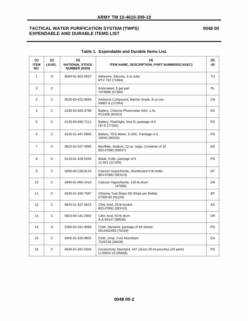
ARMY TM 10-4610-309-10
TACTICAL WATER PURIFICATION SYSTEM (TWPS) EXPENDABLE AND DURABLE ITEMS LIST
0048 00
0048 00-2
Table 1. Expendable and Durable Items List.
(1)ITEMNO.
(2)LEVEL
(3)NATIONAL STOCK
NUMBER (NSN)
(4)ITEM NAME, DESCRIPTION, PART NUMBER/(CAGEC)
(5)U/I
1 O 8040-01-501-5557 Adhesive, Silicone, 3 oz tube RTV 732 (71984)
TU
2 C Antiscalant, 5 gal pail 7078886 (57394)
PL
3 C 8030-00-422-9584 Antiseize Compound, Marine Grade, 8 oz can NMBT-8 (1Y2R4)
CN
4 C 6135-00-826-4798 Battery, Chlorine Photometer AAA, 1.5v PC2400 (90303)
EA
5 C 6135-00-835-7211 Battery, Flashlight, Size D, package of 6 HD-D (77542)
PG
6 C 6135-01-447-0949 Battery, TDS Meter, 9 VDC, Package of 2 1604A (80204)
PG
7 C 6810-01-527-4590 Bisulfate, Sodium, 12-oz. bags, Container of 10 803-07880 (09647)
EA
8 C 5110-01-428-5269 Blade, Knife, package of 5 11-921 (1CV05)
PG
9 C 6840-00-238-8115 Calcium Hypochlorite, Disinfectant 5-lb bottle 803-07882 (0EXU3)
BT
10 C 6840-01-065-2410 Calcium Hypochlorite, 100-lb drum (47695)
DR
11 C 6640-01-490-7587 Chlorine Test Strips (50 Strips per Bottle) 27450-50 (91224)
BT
12 C 6810-01-527-0515 Citric Acid, 20-lb bucket 803-07891 (0EXU3)
EA
13 C 6810-00-141-2942 Citric Acid, 50-lb drum A-A-59147 (58536)
DR
14 O 5350-00-161-9066 Cloth, Abrasive, package of 50 sheets 0514402459 (76318)
PG
15 C 8305-01-526-9825 Cloth, Drop, Fuel Absorbant 7516T48 (39428)
EA
16 C 6640-01-491-0344 Conductivity Standard, 447 uS/cm 20-ml pouches (20 pack) U-35653-10 (05668)
PG

ARMY TM 10-4610-309-10
TACTICAL WATER PURIFICATION SYSTEM (TWPS) EXPENDABLE AND DURABLE ITEMS LIST
0048 00
0048 00-3
Table 1. Expendable and Durable Items List. – Continued.
(1)ITEMNO.
(2)LEVEL
(3)NATIONAL STOCK
NUMBER (NSN)
(4)ITEM NAME, DESCRIPTION, PART NUMBER/(CAGEC)
(5)U/I
17 C 6640-01-491-0346 Conductivity Standard, 1413 uS/cm 20-ml pouches (20 pack) U-35653-11 (05668)
PG
18 C 6640-01-491-0345 Conductivity Standard, 15000 uS/cm 20-ml pouches (20 pack) U-35653-13 (05668)
PG
19 C 8030-00-414-7423 Corrosion Preventive Compound, 16 oz spray bottle, box of 12 T32CP90S6 (03GK3)
BX
20 C 6640-01-490-7584 Demineralizer Bottle (177 ml) 14299-00 (91224)
BT
21 O 6850-00-664-5685 Dry Cleaning Solvent, 1 qt can AA59601-1D (58536)
QT
22 C 6630-01-359-3467 Electrode Storage Solution, for pH meter (475 ml) 13-641-908 (22527)
EA
23 C 4510-01-496-6954 Eyewash Station Refill 5T064 (25795)
EA
24 C 6810-01-359-4919 Glycerin, 16 oz bottle 13229E0172 (97403)
BT
25 O 9150-01-197-7690 Grease, Automotive and Artillery M-10924C (81349)
CN
26 O 9150-00-053-0101 Grease, Molybdenum Disulfide, 3 lb can MOLYKOTE Z (94999)
CN
27 C 6850-01-528-9969 High pH Cleaner 2250P (17534)
EA
28 C 6850-00-569-7690 Leak Test Compound, 1 gal bottle 372E (03530)
GL
29 C 6810-01-527-0515 Low pH Cleaner DR
30 C 6850-00-294-0860 Lubricant, Silicone, Valve Seal 887-07510-000 (0EXU3)
OZ
31 C 9150-01-178-4725 Lubricating Oil, Engine, 1 qt bottle, SAE 15W-40 15W-40/QT/BT/2104 (81349)
QT
32 C 4240-01-527-0105 Mask, Air Filtering (Package of 5) 67644 (6M644)
PG
33 C 9150-01-527-0464 Oil, Air Compressor, 1 qt bottle 887-07607-000 (0EXU3)
QT
34 C 7920-00-151-6120 Pad, Scouring, package of 10 7920-00-151-6120 (83421)
PG
35 C 9150-00-250-0926 Petrolatum, Technical, 1.75 lb can 14P1 (82146)
CN

ARMY TM 10-4610-309-10
TACTICAL WATER PURIFICATION SYSTEM (TWPS) EXPENDABLE AND DURABLE ITEMS LIST
0048 00
0048 00-4
(1)ITEMNO.
(2)LEVEL
(3)NATIONAL STOCK
NUMBER (NSN)
(4)ITEM NAME, DESCRIPTION, PART NUMBER/(CAGEC)
(5)U/I
36 C 6630-01-491-0691 pH 7 Standard Buffer Pack, Package of 25 pack 13-641-275 (22527)
EA
37 C 6515-01-413-7414 Plug, Ear 0485 (3W556)
PR
38 C 6640-01-491-6490 PPD-2 Powder Pop Dispenser, 200 Tests 10445A (58177)
EA
39 C 7920-00-205-1711 Rag, Wiping 7920-00-205-1711 (80244)
BE
40 O 8030-01-025-1692 Sealing Compound, Loctite 242, 250 cc bottle 24241 (05972)
BT
41 O Sealing Compound, 1 pt can (05972)
CN
42 O 8030-01-505-0628 Sealing Compound, 6 oz tube with separate catalyst PR-1440 B-2 (83574)
CA
43 C 6810-01-527-4594 Sodium Bisulfite, 10-lb bucket 803-07892 (09647)
EA
44 C 6810-01-527-4590 Sodium Bisulfite, 12-oz bags, container of 10 803-07880 (09647)
EA
45 C Sodium Bisulfite, 50-lb bag 7128004 (57394)
BG
46 C 6810-01-386-9964 Sodium Carbonate, 50 lb container 90111 (3D914)
EA
47 C 6810-01-527-0510 Sodium Hydroxide (Caustic), 1 gal. bottle 803-07888 (09647)
GL
48 C 9905-00-537-8955 Tag, Marker, package of 50 9905-00-537-8955 (64067)
PG
49 C 8030-00-889-3535 Tape, Antiseizing, roll, 1/2” wide P5025-2R (81755)
EA
50 C 8030-00-889-3534 Tape, Antiseizing, roll, 1/4” wide P5025-1 (81755)
EA
51 C 4440-01-475-9949 Vapor Capsule, Corrosion Inhibiting VC2-1 (08TA7)
EA

ARMY TM 10-4610-309-10
TACTICAL WATER PURIFICATION SYSTEM (TWPS) ADDITIONAL AUTHORIZATION LIST (AAL)
0049 00
0049 00-1
INTRODUCTION
Scope
This work package lists additional items you are authorized for the support of the Tactical Water Purification System (TWPS).
General
This list identifies items that do not have to accompany the TWPS and that do not have to be turned in with it. These items are authorized to you by CTA, MTOE, TDA or JTA.
Explanation of Columns in the Expendable/Durable Items List
Column (1) – National Stock Number (NSN). Identifies the stock number of the item to be used for requisitioning purposes.
Column (2) – Description, Part Number/(CAGEC). Identifies the Federal item name (in all capital letters) followed by a minimum description when needed. The last line below the description is the part number and the Commercial and Government Entity Code (CAGEC) (in parentheses).
Column (3) – Usable On Code. When applicable, gives you a code if the item you need is not the same for different models of equipment. These codes are identified below:
Code Used On TWA Model A-TWPS TWM Model MC-TWPS
Column (4) – U/I. Unit of Issue (U/I) indicates the physical measurement or count of the item as issued per the National Stock Number shown in column (1).
Column (5) – Qty Recm. Indicates the quantity recommended.

ARMY TM 10-4610-309-10
TACTICAL WATER PURIFICATION SYSTEM (TWPS) EXPENDABLE AND DURABLE ITEMS LIST
0049 00
0049 00-2
Table 1. Additional Authorization List.
(1)National Stock Number (NSN)
(2)Description, Part Number/CAGEC
(3)Usable On
Code
(4)U/I
(5)Qty
Recom
4610-01-550-1768 RECIRC TANK KIT USMC-TWPS-RECI-KT-1 (79343)
TWM EA 1

ARMY TM 10-4610-309-10
TACTICAL WATER PURIFICATION SYSTEM (TWPS) SUPPORTING INFORMATION OPERATING DATA LOG
0050 00
0050 00-1/2 BLANK
OPERATING DATA LOG
An Operating Data Log is included in this work package. Entries on the data sheet are derived from instrument readings on the Operator Control Panel (OCP) and are recorded hourly. Submit the daily report according to specific operational instructions.


ARMY TM 10-4610-309-10
TACTICAL WATER PURIFICATION SYSTEM (TWPS) SUPPORTING INFORMATION OPERATING DATA LOG
0050 00
0050 00-3
UNIT SERIAL # . LOCATION . WATER SOURCE .
DATE TIME OP TIMEHRS
FEEDTDSMG/L
MFFLOW GPM
MFTMPPSI
RO FEED FLOW GPM
RO FEED PRESSPSIG
REJFLOW GPM
% SALT REJECT
PROD FLOW GPM
PROD TDSMG/L
TOTAL PROD GAL
FEEDTEMP
0FCOMMENTS
Note: Feed TDS is as measured with hand held TDS meter. Adjust Feed TDS Set switch to measured value before completing data.

ARMY TM 10-4610-309-10
TACTICAL WATER PURIFICATION SYSTEM (TWPS) SUPPORTING INFORMATION OPERATING DATA LOG
0050 00
0050 00-4
Items to note on the two examples of operating data logs are:
� Feed TDS should change slightly as it is being measured each hour and dialed into the OCP.
� The MF flow and TMP will vary during the MF filtration cycle due to the regulation of MF flow by Valve V-202. It is a good idea to record the MF flow and TMP data 3 minutes after the backwash cycle is completed so that the flows and TMP are all taken at a similar time relative to the filtration cycle.
� The RO feed flow is the sum of the product and reject flow.
� Product flows and RO feed pressure should not vary significantly as the TWPS is operated at a constant production rate.
� On the example log for serial number 4312, the operators were not adjusting the product flow to the required 20.5 to 21 gpm. Therefore, the RO feed pressures are varying which makes it more difficult to accurately assess the RO% clean.

ARMY TM 10-4610-309-10
TACTICAL WATER PURIFICATION SYSTEM (TWPS) SUPPORTING INFORMATION OPERATING DATA LOG
0050 00
0050 00-5

ARMY TM 10-4610-309-10
TACTICAL WATER PURIFICATION SYSTEM (TWPS) SUPPORTING INFORMATION OPERATING DATA LOG
0050 00
0050 00-6

ARMY TM 10-4610-309-10
TACTICAL WATER PURIFICATION SYSTEM (TWPS) SUPPORTING INFORMATION OPERATOR MAINTENANCE LOG
0051 00
0051 00-1/2 BLANK
OPERATOR MAINTENANCE LOG
An Operator Maintenance Log is included in this work package. When a preventive maintenance action is performed in accordance with the PMCS, record the action in this log to ensure the action was completed and will not be duplicated.


ARMY TM 10-4610-309-10
TACTICAL WATER PURIFICATION SYSTEM (TWPS) SUPPORTING INFORMATION OPERATOR MAINTENANCE LOG
0051 00
0051 00-3
TWPS OPERATOR MAINTENANCE LOG Page 1
Unit Serial #: _____________________________
Preventive Maintenance Action Monthly
Date Date Date Date Date Date Date Date Date Date Date Date
Monthly fire extinguisher check Diesel engine monthly fuel drain
Preventive Maintenance Action - Time
DateTime
HrMeter
DateTime
HrMeter
DateTime
HrMeter
DateTime
HrMeter
DateTime
HrMeter
DateTime
HrMeter
DateTime
HrMeter
DateTime
HrMeter
DateTime
HrMeter
DateTime
HrMeter
DateTime
HrMeter
DateTime
HrMeter
P-1 raw water diesel engine oil replacement, 100 hours engine operation
P-8 extended distribution diesel engine oil replacement, 100 hours engine operation
Air compressor belt check every 100 hours
P-1 raw water diesel engine fuel filter cleaning, 200 hours engine operation

ARMY TM 10-4610-309-10
TACTICAL WATER PURIFICATION SYSTEM (TWPS) SUPPORTING INFORMATION OPERATOR MAINTENANCE LOG
0051 00
0051 00-4
TWPS OPERATOR MAINTENANCE LOG Page 2
Unit Serial #: _____________________________
Preventive Maintenance Action - Time
DateTime
HrMeter
DateTime
HrMeter
DateTime
HrMeter
DateTime
HrMeter
DateTime
HrMeter
DateTime
HrMeter
DateTime
HrMeter
DateTime
HrMeter
DateTime
HrMeter
DateTime
HrMeter
DateTime
HrMeter
DateTime
HrMeter
P-8 extended distribution diesel engine fuel filter cleaning, 200 hours engine operation
P-1 raw water diesel engine air filter check, 200 hours engine operation
P-8 extended distribution diesel engine air filter check, 200 hours engine operation
Air system filter (AF-1) cleaning & rotation, every 300 hours
Air system filter (AF-1) replacement after third rotation, every 900 hours

ARMY TM 10-4610-309-10
TACTICAL WATER PURIFICATION SYSTEM (TWPS) SUPPORTING INFORMATION OPERATOR MAINTENANCE LOG
0051 00
0051 00-5
TWPS OPERATOR MAINTENANCE LOG Page 3
Unit Serial #: _____________________________
Preventive Maintenance Action - Time
DateTime
HrMeter
DateTime
HrMeter
DateTime
HrMeter
DateTime
HrMeter
DateTime
HrMeter
DateTime
HrMeter
DateTime
HrMeter
DateTime
HrMeter
DateTime
HrMeter
DateTime
HrMeter
DateTime
HrMeter
DateTime
HrMeter
Air system filter (AF-2) replacement every 300 hours
MF Integrity test & Silt Density Index (SDI) test, beginning and end of deployment or 300 hours
P-1 raw water diesel engine fuel filter replacement every 400 hours engine operation
P-8 extended distribution diesel engine fuel filter replacement every 400 hours engine operation
P-1 raw water diesel engine oil filter replacement every 400 hours engine operation
P-8 extended distribution diesel engine oil filter replacement every 400 hours engine operation

ARMY TM 10-4610-309-10
TACTICAL WATER PURIFICATION SYSTEM (TWPS) SUPPORTING INFORMATION OPERATOR MAINTENANCE LOG
0051 00
0051 00-6
TWPS OPERATOR MAINTENANCE LOG Page 4
Unit Serial #: _____________________________
Preventive Maintenance Action - Time
DateTime
HrMeter
DateTime
HrMeter
DateTime
HrMeter
DateTime
HrMeter
DateTime
HrMeter
DateTime
HrMeter
DateTime
HrMeter
DateTime
HrMeter
DateTime
HrMeter
DateTime
HrMeter
DateTime
HrMeter
DateTime
HrMeter
P-1 raw water diesel engine air filter replacement every 400 hours engine operation
P-8 extended distribution diesel engine air filter replacement every 400 hours engine operation
P-1 raw water diesel engine valve adjustment every 500 hours
P-8 extended distribution diesel engine valve adjustment every 500 hours
RO Conductivity Test, beginning and end of deployment or 500 hours

ARMY TM 10-4610-309-10
TACTICAL WATER PURIFICATION SYSTEM (TWPS) SUPPORTING INFORMATION OPERATOR MAINTENANCE LOG
0051 00
0051 00-7
TWPS OPERATOR MAINTENANCE LOG Page 5
Unit Serial #: _____________________________
Preventive Maintenance Action - Time
DateTime
HrMeter
DateTime
HrMeter
DateTime
HrMeter
DateTime
HrMeter
DateTime
HrMeter
DateTime
HrMeter
DateTime
HrMeter
DateTime
HrMeter
DateTime
HrMeter
DateTime
HrMeter
DateTime
HrMeter
DateTime
HrMeter
Air Compressor Oil Change, 1000 hours
Diesel engine cylinder head maintenance and piston ring replacement, 1000 hours
P-5 High Pressure Pump (front pump) replace valves and pistons, 1000 hours
P-6 High Pressure Pump (back pump) replace valves and pistons, 1000 hours
Air system intermediate separator and CO-1 coalescer filter element clean and inspect, 1500 hours

ARMY TM 10-4610-309-10
TACTICAL WATER PURIFICATION SYSTEM (TWPS) SUPPORTING INFORMATION OPERATOR MAINTENANCE LOG
0051 00
0051 00-8
TWPS OPERATOR MAINTENANCE LOG Page 6
Unit Serial #: _____________________________
Preventive Maintenance Action - Time
DateTime
HrMeter
DateTime
HrMeter
DateTime
HrMeter
DateTime
HrMeter
DateTime
HrMeter
DateTime
HrMeter
DateTime
HrMeter
DateTime
HrMeter
DateTime
HrMeter
DateTime
HrMeter
DateTime
HrMeter
DateTime
HrMeter
P-5 High Pressure Pump (front pump) replace valves, pistons, cluster plate and shaft seal, 2000 hours
P-6 High Pressure Pump (back pump) replace valves, pistons, cluster plate and shaft seal, 2000 hours
Air compressor head/valve assembly replacement, 3000 hours
P-3 MF Feed Pump motor apply grease through the zirk fitting, annually
P-4 RO Feed Pump motor apply grease through the zirk fitting, annually

ARMY TM 10-4610-309-10
TACTICAL WATER PURIFICATION SYSTEM (TWPS) SUPPORTING INFORMATION OPERATOR MAINTENANCE LOG
0051 00
0051 00-9/10 BLANK
TWPS OPERATOR MAINTENANCE LOG Page 7
Unit Serial #: _____________________________
Preventive Maintenance Action - Time
DateTime
HrMeter
DateTime
HrMeter
DateTime
HrMeter
DateTime
HrMeter
DateTime
HrMeter
DateTime
HrMeter
DateTime
HrMeter
DateTime
HrMeter
DateTime
HrMeter
DateTime
HrMeter
DateTime
HrMeter
DateTime
HrMeter
Air Compressor motor apply grease through the zirk fitting, annually
P-5 High Pressure Pump motor (front pump) apply grease through the zirk fitting, annually
P-6 High Pressure Pump motor (back pump) apply grease through the zirk fitting, annually


ARMY TM 10-4610-309-10
TACTICAL WATER PURIFICATION SYSTEM (TWPS) SUPPORTING INFORMATION REVERSE OSMOSIS ELEMENT PERFORMANCE LOG
0052 00
0052 00-1/2 BLANK
REVERSE OSMOSIS ELEMENT PERFORMANCE LOG
A Reverse Osmosis (RO) Element Performance Log is included in this work package. Maintaining the log will help determine the need for RO element replacement. The RO Element Performance Log Form should be kept in this manual and locally reproduced when forms are needed.
Interpreting Results of Individual RO Element Flow and TDS Tests (WP 0014)
1. The operator collects data on the RO element performance log (WP 0052) at the beginning and end of deployment following procedures in WP 0014. This test is also performed if obtaining a product TDS high alarm or calculating a low RO% clean.
2. Operator and/or NCO have ruled out that changes in RO performance observed are not caused by any faulty instrument readings from flowmeters, pressure transmitters or TDS meters.
3. There are no correct flows or TDS numbers for the individual RO element flow and TDS tests. Flows and TDS readings will vary depending on the feed TDS, water temperature and operating pressure. The operator is looking for abnormal readings that do not follow general trends as follows:
a. Flow should decrease from element 1 to 10.
b. TDS should increase from element 1 to 10.
c. For freshwater operation, the changes from element 1 to 10 will be gradual.
d. For seawater operation, the changes will be more significant from element 1 to 10.
e. Any elements in the sequence that do not follow the general trends should be suspect.
4. The interpretation of results can be best understood by reviewing the following four examples of completed performance logs included in this work package.


ARMY TM 10-4610-309-10
TACTICAL WATER PURIFICATION SYSTEM (TWPS) SUPPORTING INFORMATION RO ELEMENT PERFORMANCE LOG
0052 00
0052 00-3/4 BLANK
RO ELEMENT PERFORMANCE LOG
Unit Serial #: ______________
Test date: ________________ Operating Hour Meter Reading: ___________
Product flow: _____________ Product TDS: ___________ Source water TDS: ____________
Source water Temp: ________ Source water location: ___________________________________
Element # Product TDS Product Flow Element # Product TDS Product Flow 1
2 3
4 5
6 7
8 9
10


ARMY TM 10-4610-309-10 TACTICAL WATER PURIFICATION SYSTEM (TWPS) 0052 00 SUPPORTING INFORMATION RO ELEMENT PERFORMANCE LOG
0052 00-5
Example 1 – Low RO% Clean, Freshwater Operations (Well Water)
Example 1 Performance Log shows normal data in the top block and abnormal data in the lower block. The data is for operation on a low feed TDS, well water source. The top block of data shows normal data where product flow gradually declines as one goes from element 1 to 10. Product TDS gradually increases as one goes from element 1 to 10. Very gradual changes occur in individual data for operation on low TDS source waters such as freshwaters. The bottom block of data includes some abnormal data, elements 9 and to have an abnormally low flow.
If an RO element cleaning has already been performed because of the low RO% clean and no improvements were recorded in the flows on elements 9 and 10, the NCO should only replace elements 9 and 10. Since this operation is on a well water source and the loss in flow was on the last element, it’s probably that the cause of the loss in flow was scaling of the reverse osmosis elements. The last elements in the series of the RO elements see the highest concentration of dissolved solids and are therefore more prone to scaling. Upon startup, the NCO should consider the following:
a. Was the antiscalant injection system operating correctly? b. Was the operator trying to make more flow than the rated 25 gpm? c. To avoid scaling the RO elements, try future operations on this well water source at 20 gpm.

ARMY TM 10-4610-309-10 TACTICAL WATER PURIFICATION SYSTEM (TWPS) 0052 00 SUPPORTING INFORMATION RO ELEMENT PERFORMANCE LOG
0052 00-6
RO ELEMENT PERFORMANCE LOG – Example 1
Unit Serial #: ______4301
Test date: _____10/17/06 Operating Hour Meter Reading: ______4890.2
Product flow: ___25.1__ Product TDS: _1.0 Source water TDS: ____200__
Source water Temp: ___77 Source water location: ______wellwater_______
Element # Product TDS Product Flow Element # Product TDS Product Flow 1 0.70 2.90
2 0.75 2.81 3 0.76 2.70
4 0.80 2.62 5 0.87 2.55
6 0.89 2.51 7 0.91 2.35
8 0.98 2.31 9 1.05 2.25
10 1.1 2.20
Unit Serial #: ____4301
Test date: ______11/5/06____ Operating Hour Meter Reading: ___5015_____
Product flow: ______21.0___ Product TDS: _____4.3____ Source water TDS: ____220___
Source water Temp: ____76__ Source water location: __________wellwater__________________
Element # Product TDS Product Flow Element # Product TDS Product Flow 1 0.70 2.90
2 0.75 2.81 3 0.80 2.80
4 0.80 2.62 5 0.87 2.55
6 0.90 2.5 7 0.91 2.35
8 0.98 2.31 9 2.05 1.5
10 1.8 1.3

ARMY TM 10-4610-309-10
TACTICAL WATER PURIFICATION SYSTEM (TWPS) SUPPORTING INFORMATION RO ELEMENT PERFORMANCE LOG
0052 00
0052 00-7
Example 2 – Product TDS High, Seawater Operation
If a product TDS high alarm occurred, the operator should have performed individual RO element flow and TDS tests.
Example 2 Performance Log shows normal data in the top block and abnormal data in the lower block. Data is for operation on a high feed TDS seawater source. The top block of data shows typical normal data for seawater operations where there is a more dramatic decrease (compared to freshwater operations) in flow as one goes from element 1 to 10 and a more dramatic increase in product TDS as one goes from element 1 to 10. For seawater operations, the first element can have a flow rate as much as 3 times the flow of the tenth element. Also, the TDS of the tenth element can be as much as 3 times the TDS of the first element. This is normal.
The bottom block of data includes some abnormal data, element 9 has an abnormally high TDS. Since all the other elements have a very low TDS, the NCO would take the following course of action:
a. Inspect interconnectors and end cap adapters for cracks or damage. Replace the interconnector and end cap adapter o-rings for element 9.
b. Restart the TWPS and record the individual elements flows and conductivities. c. If there is no improvement in the product TDS, shut down and replace element 9.

ARMY TM 10-4610-309-10
TACTICAL WATER PURIFICATION SYSTEM (TWPS) SUPPORTING INFORMATION RO ELEMENT PERFORMANCE LOG
0052 00
0052 00-8
RO ELEMENT PERFORMANCE LOG – Example 2
Unit Serial #: ____4301_____
Test date: ____11/30/05_______ Operating Hour Meter Reading: ____70_____
Product flow: ____19.4_____ Product TDS: ___72____ Source water TDS: ____44250___
Source water Temp: ____60__ Source water location: ______Port Hueneme_____________
Element # Product TDS Product Flow Element # Product TDS Product Flow 1 33.79 2.82
2 43.18 2.43 3 47.38 2.31
4 53.77 2.16 5 54.75 2.11
6 62.18 1.73 7 80.08 1.65
8 71.07 1.23 9 93.7 1.26
10 97.69 1.05
Unit Serial #: ____4301_____
Test date: ____1/12/06_______ Operating Hour Meter Reading: ____250_____
Product flow: _____20.7____ Product TDS: ____238____ Source water TDS: ____44460___
Source water Temp: ____58__ Source water location: _________Port Hueneme__________________
Element # Product TDS Product Flow Element # Product TDS Product Flow 1 30.92 2.85
2 39.68 2.35 3 43.07 2.32
4 45.20 2.16 5 48.20 2.11
6 54.50 1.74 7 67.20 1.62
8 64.83 1.27 9 2366 1.34
10 84.33 1.10

ARMY TM 10-4610-309-10
TACTICAL WATER PURIFICATION SYSTEM (TWPS) SUPPORTING INFORMATION RO ELEMENT PERFORMANCE LOG
0052 00
0052 00-9
Example 3 – High Product TDS Seawater Operation
Example 3 Performance Log is of seawater data with higher than normal TDS on all the elements as well as fluctuating TDS between different elements in the series. The problem here is that the elements were all producing higher than normal TDS water. All o-rings had to be replaced. The problem was due to the age of the o-rings and the elements did not have spacers installed. This allowed the elements to slide inside the vessels during transport causing interconnector and adapter o-ring wear. In addition, one cracked adapter was found on element 5, due also to improper installation of spacers, and the thrust ring was left out of this vessel.

ARMY TM 10-4610-309-10
TACTICAL WATER PURIFICATION SYSTEM (TWPS) SUPPORTING INFORMATION RO ELEMENT PERFORMANCE LOG
0052 00
0052 00-10
RO ELEMENT PERFORMANCE LOG – Example 3
Unit Serial #: ______4301_____
Test date: ____11/30/05_______ Operating Hour Meter Reading: ____70____
Product flow: _____19.4____ Product TDS: _____72____ Source water TDS: _____44250____
Source water Temp: ____60__ Source water location: ______Port Hueneme__________________
Element # Product TDS Product Flow Element # Product TDS Product Flow 1 33.79 2.82
2 43.18 2.43 3 47.38 2.31
4 53.77 2.16 5 54.75 2.11
6 62.18 1.73 7 80.08 1.65
8 71.07 1.23 9 93.7 1.26
10 97.69 1.05
Unit Serial #: _____4301_____
Test date: ____1/12/07______ Operating Hour Meter Reading: _____250____
Product flow: _____20.7____ Product TDS: ____1700____ Source water TDS: ____44460____
Source water Temp: ___58__ Source water location: ______Port Hueneme__________________
Element # Product TDS Product Flow Element # Product TDS Product Flow 1 400 2.85
2 500 2.35 3 700 2.32
4 620 2.16 5 2500 2.11
6 545 1.74 7 1300 1.62
8 1600 1.27 9 1860 1.34
10 2000 1.10

ARMY TM 10-4610-309-10
TACTICAL WATER PURIFICATION SYSTEM (TWPS) SUPPORTING INFORMATION RO ELEMENT PERFORMANCE LOG
0052 00
0052 00-11
Example 4 – Low RO% Clean, Seawater Operation
Example 4 Performance Log is an example of scaling. Elements 9 and 10 have low flow but on a high TDS seawater source.

ARMY TM 10-4610-309-10
TACTICAL WATER PURIFICATION SYSTEM (TWPS) SUPPORTING INFORMATION RO ELEMENT PERFORMANCE LOG
0052 00
0052 00-12
RO ELEMENT PERFORMANCE LOG – Example 4
Unit Serial #: _____4301_____
Test date: ____11/30/05_____ Operating Hour Meter Reading: _____70____
Product flow: _____19.4____ Product TDS: _____72____ Source water TDS: ___44250_____
Source water Temp: ___60___ Source water location: ________Port Hueneme_____________
Element # Product TDS Product Flow Element # Product TDS Product Flow 1 33.79 2.82
2 43.18 2.43 3 47.38 2.31
4 53.77 2.16 5 54.75 2.11
6 62.18 1.73 7 80.08 1.65
8 71.07 1.23 9 93.7 1.26
10 97.69 1.05
Unit Serial #: _____4301_____
Test date: _____1/12/06_____ Operating Hour Meter Reading: ______250_____
Product flow: _____17.8____ Product TDS: ____288____ Source water TDS: ___44460____
Source water Temp: ___58__ Source water location: _________Port Hueneme______________
Element # Product TDS Product Flow Element # Product TDS Product Flow 1 30.92 2.85
2 39.68 2.35 3 43.07 2.32
4 45.20 2.16 5 48.20 2.11
6 54.50 1.74 7 67.20 1.62
8 64.83 1.27 9 95 0.65
10 125 0.45

ARMY TM 10-4610-309-10
TACTICAL WATER PURIFICATION SYSTEM (TWPS) SUPPORTING INFORMATION REVERSE OSMOSIS % CLEAN CALCULATION
0053 00
0053 00-1
REVERSE OSMOSIS % CLEAN CALCULATION
This work package provides the procedure to calculate the Reverse Osmosis (RO) % Clean Factor. This factor indicates the water production performance of the TWPS RO membranes relative to the performance of new, clean membranes. The calculation compares the permeability or ease of water flow, through the RO membranes with the permeability of new clean membranes. The result is expressed as a percentage. For example, a % Clean Factor of 85% means the RO membranes are performing at 85% of the new, clean membrane performance. As the % Clean Factor becomes lower, the required operating pressure increases. Refer to WP 0014 00 for how to use the % Clean Factor data to determine the need for RO cleaning and to determine the performance limitations resulting from low % Clean values.
The data required to perform the calculation is obtained from the Operating Data Log, WP 0050 00.

ARMY TM 10-4610-309-10
TACTICAL WATER PURIFICATION SYSTEM (TWPS) SUPPORTING INFORMATION REVERSE OSMOSIS % CLEAN CALCULATION
0053 00
0053 00-2
RO % CLEAN CALCULATION
The following data from the Operational Data Log is required: � Feed TDS (mg/l) � RO Feed Pressure (psig) � Product Flow (gpm) � Feed Temperature (0F)
Step 1
With the Feed TDS and the Feed Temperature, use Table 1 to determine Factor A. Use the table values closest to the actual Feed TDS and Feed Temperature to determine Factor A.
Table 1. Factor A.
Feed Temperature (0F)FeedTDS 32 35 40 45 50 55 60 65 70 75 80 85 90 95 100 105 110
500 2 3 3 3 3 3 3 3 3 3 3 3 3 3 3 3 3 1000 5 5 5 5 5 5 5 5 5 5 5 6 6 6 6 6 6 2000 10 10 10 10 10 11 11 11 11 11 11 11 11 11 11 12 12 3000 15 15 15 15 16 16 16 16 16 16 17 17 17 17 17 17 174000 20 21 21 21 21 21 22 22 22 22 22 23 23 23 23 23 245000 25 25 26 26 26 26 27 27 27 27 28 28 28 28 29 29 29 6000 31 31 31 32 32 32 33 33 33 34 34 34 34 35 35 35 35 7000 36 36 37 37 37 38 38 38 39 39 39 40 40 41 41 41 42 8000 41 42 42 42 43 43 44 44 45 45 45 46 46 47 47 48 48 9000 47 47 47 48 48 49 49 50 50 51 51 52 52 53 53 53 54
10000 51 51 52 52 53 53 54 54 55 55 56 56 57 58 58 59 59 11000 57 57 58 58 59 60 60 61 61 62 62 63 64 64 65 65 66 12000 62 62 63 64 64 65 66 66 67 68 68 69 69 70 71 71 72 13000 67 68 68 69 70 70 71 72 72 73 74 75 75 76 77 77 78 14000 72 73 74 74 75 76 77 77 78 79 80 80 81 82 82 83 84 15000 77 78 78 79 80 81 81 82 83 84 85 85 86 87 88 89 89 16000 83 83 84 85 86 87 88 88 89 90 91 92 93 93 94 95 96 17000 88 89 89 90 91 92 93 94 95 96 97 97 98 99 100 101 102 18000 93 94 95 96 97 98 98 99 100 101 102 103 104 105 106 107 108 19000 98 99 100 101 102 103 104 105 106 107 108 109 110 111 112 113 114 20000 104 104 105 106 107 108 109 110 112 113 114 115 116 117 118 119 120 21000 109 109 110 112 112 114 115 116 117 118 119 120 122 123 124 125 126 22000 114 115 116 117 118 119 120 122 123 124 125 126 127 129 130 131 132 23000 119 120 121 122 123 125 126 127 128 130 131 132 133 134 136 137 138 24000 124 125 126 128 129 130 131 133 134 135 136 138 139 140 141 143 144 25000 129 130 132 133 134 136 137 138 139 141 142 143 145 146 147 149 150 26000 135 135 137 138 140 141 142 144 145 146 148 149 151 152 153 155 156 27000 140 141 142 144 145 146 148 149 151 152 153 155 156 158 159 161 162 28000 145 146 147 149 150 152 153 155 156 158 159 161 162 164 165 167 168 29000 150 151 153 154 156 157 159 160 162 162 165 166 168 169 171 172 174 30000 155 156 158 159 161 163 164 166 167 169 171 172 174 175 177 178 180 31000 161 162 163 165 166 168 170 171 173 175 176 178 180 181 183 184 186 32000 166 167 168 170 172 173 175 177 179 180 182 184 185 187 189 190 192 33000 171 172 174 175 177 179 181 182 184 186 188 189 191 193 195 196 198 34000 176 77 179 181 183 184 186 188 190 192 193 195 197 199 200 202 204

ARMY TM 10-4610-309-10
TACTICAL WATER PURIFICATION SYSTEM (TWPS) SUPPORTING INFORMATION REVERSE OSMOSIS % CLEAN CALCULATION
0053 00
0053 00-3
Table 1. Factor A – Continued. Feed Temperature (0F)Feed
TDS 32 35 40 45 50 55 60 65 70 75 80 85 90 95 100 105 110 35000 181 182 184 186 188 190 192 193 195 197 199 201 203 205 206 208 210 36000 186 188 190 191 193 195 197 199 201 203 205 207 208 210 212 214 216 37000 192 193 195 197 199 201 203 205 206 208 210 212 214 216 218 220 222 38000 197 198 200 202 204 206 208 210 212 214 216 218 220 222 224 226 228 39000 202 203 205 207 209 212 214 216 218 220 222 224 226 228 230 232 234 40000 207 208 211 213 215 217 219 221 223 225 227 230 232 234 236 238 240 41000 212 214 216 218 220 222 225 227 229 231 233 235 237 240 242 244 246 42000 218 219 221 223 226 228 230 232 234 237 239 241 243 246 248 250 252 43000 223 224 226 229 231 233 235 238 240 242 245 247 249 251 254 256 258 44000 228 229 232 234 236 239 241 243 246 248 250 253 255 257 260 262 264 45000 233 235 237 239 242 244 246 249 251 254 256 258 261 263 265 268 270 46000 238 240 242 245 247 250 252 254 257 259 262 264 267 269 271 274 276 47000 244 245 248 250 252 255 257 260 262 265 267 270 272 275 277 280 282 48000 249 250 253 255 258 260 263 265 268 271 273 276 278 281 283 286 288 49000 254 255 258 261 263 266 268 271 274 276 279 281 284 286 289 292 294 50000 259 261 263 266 269 271 274 277 279 282 284 287 290 292 295 298 300 51000 264 266 269 271 274 277 279 282 285 287 290 293 296 298 301 304 306 52000 270 271 274 277 279 282 285 288 290 293 296 299 301 304 307 310 312 53000 275 276 279 282 285 288 290 293 296 299 302 304 307 310 313 316 318 54000 280 282 284 287 290 293 296 299 302 304 307 310 313 316 319 321 324 55000 285 287 290 293 296 298 301 304 307 310 313 316 319 322 325 327 330 56000 290 292 295 298 301 304 307 310 313 316 319 322 325 328 330 333 336 57000 295 297 300 303 306 309 312 315 318 321 324 327 330 333 336 339 342 58000 301 303 306 309 312 315 318 321 324 327 330 333 336 339 342 345 348 59000 306 308 311 314 317 320 323 326 330 333 336 339 342 345 348 351 354 60000 311 313 316 319 322 326 329 332 335 338 341 345 348 351 354 357 360
Step 2
With the product flow rate, use Table 2 to determine Factor B. Use the table product flow rate value that is closest to the actual value.
Table 2. Factor B.
Product Flowgpm
Factor B
Product Flow gpm
Factor B
Product Flowgpm
Factor B
15.0 2.35 19.5 2.51 24.0 2.71 15.5 2.36 20.0 2.53 24.5 2.73 16.0 2.38 20.5 2.55 25.0 2.76 16.5 2.40 21.0 2.57 25.5 2.78 17.0 2.41 21.5 2.59 26.0 2.81 17.5 2.43 22.0 2.61 26.5 2.84 18.0 2.45 22.5 2.63 27.0 2.87 18.5 2.47 23.0 2.66 19.0 2.49 23.5 2.68

ARMY TM 10-4610-309-10
TACTICAL WATER PURIFICATION SYSTEM (TWPS) SUPPORTING INFORMATION REVERSE OSMOSIS % CLEAN CALCULATION
0053 00
0053 00-4
Step 3
With the Feed Temperature, use Table 3 to determine Factor TCF. TCF is the Temperature Correction Factor that converts the actual performance to what it would be at 77 degrees F.
Table 3. Factor TCF.
FeedTemp
TCF Feed Temp
TCF Feed Temp
TCF Feed Temp
TCF
32 0.50 52 0.68 72 0.93 92 1.26 33 0.51 53 0.69 73 0.94 93 1.28 34 0.52 54 0.70 74 0.96 94 1.30 35 0.53 55 0.71 75 0.97 95 1.32 36 0.53 56 0.72 76 0.98 96 1.34 37 0.54 57 0.74 77 1.00 97 1.36 38 0.55 58 0.75 78 1.02 98 1.38 39 0.56 59 0.76 79 1.03 99 1.40 40 0.57 60 0.77 80 1.05 100 1.42 41 0.58 61 0.78 81 1.06 101 1.45 42 0.58 62 0.79 82 1.08 102 1.47 43 0.59 63 0.81 83 1.10 103 1.49 44 0.60 64 0.82 84 1.11 104 1.51 45 0.61 65 0.83 85 1.13 105 1.54 46 0.62 66 0.84 86 1.15 106 1.56 47 0.63 67 0.86 87 1.17 107 1.58 48 0.64 68 0.87 88 1.18 108 1.61 49 0.65 69 0.88 89 1.20 109 1.63 50 0.66 70 0.90 90 1.22 110 1.66 51 0.67 71 0.91 91 1.24
Step 4
Calculate:
Factor AB = (Factor A) x (Factor B).
Factors A and B are determined from steps 1 and 2 above. Factor AB is the average osmotic pressure of the feed water as it is concentrated within the RO elements.
Step 5
Calculate:
NDP = RO Feed Pressure – 45 – AB
NDP is the net driving pressure. This is the average pressure driving the product water through the RO elements.

ARMY TM 10-4610-309-10
TACTICAL WATER PURIFICATION SYSTEM (TWPS) SUPPORTING INFORMATION REVERSE OSMOSIS % CLEAN CALCULATION
0053 00
0053 00-5
Step 6
Calculate:
C = TCF x NDP
C is the net driving pressure that would be required at 77 degrees F.
Step 7
Calculate:
P(TWPS) = Product Flow Rate/C
P(TWPS) is the actual TWPS RO membrane permeability (GPM per PSI)
Step 8
Calculate:
P = 0.1628 – AB/10,000
P is the expected new RO element membrane permeability (GPM/PSI)
Step 9
Calculate:
%Clean = 100 x P(TWPS)/P
Step 10
Enter the calculated value for %Clean in the Comments section of the Operating Data Log (WP 0050 00) in line with the data used. Compare this value with earlier values calculated while deployed on the current mission. A decreasing value is an indication of membrane fouling. If the decrease exceeds 10% (for example: a decrease from 95% to 85%), cleaning should be scheduled. Refer to WP 0014 00.

ARMY TM 10-4610-309-10
TACTICAL WATER PURIFICATION SYSTEM (TWPS) SUPPORTING INFORMATION REVERSE OSMOSIS % CLEAN CALCULATION
0053 00
0053 00-6
Example
The following data from the Operational Data Log is recorded: � Feed TDS (mg/l): 35,800 � RO Feed Pressure (psig): 780 � Product Flow (gpm): 20.5 � Feed Temperature (0F): 80
From table 1, Factor A = 205
From Table 2 Factor B = 2.55
From Table 3, Factor TCF = 1.05
Factor AB = 523
NDP = 780 – 45 – 523 = 212
C = 212 x 1.05 = 223
P(TWPS) = 20.5/223 = 0.092
P = 0.1628 – 523/10000 = 0.11
% Clean = 100 x 0.092/0.11 = 83.6%

ARMY TM 10-4610-309-10
TACTICAL WATER PURIFICATION SYSTEM (TWPS) SUPPORTING INFORMATION GLOSSARY
GLOSSARY
GLOSSARY-1/2 BLANK
Alkali – Various soluble salts, principly of sodium, potassium, magnesium, and calcium, that have the property of combining with acids to form neutral salts and may be used in chemical water treatment processes.
Brackish Water – Water that is unfit for drinking because of salty or unpleasant tastes caused by the presence of excessive amounts of dissolved chemicals, chlorides, sulfates and alkalis.
Chlorine – A chemical that is applied in water purification processes to product water to disinfect the water and prevent microbial growth in the water. As a gas, its color is greenish-yellow and is about 2 ½ times heavier than air. As a liquid, it is amber in color and is about 1-½ times heavier than water. Chlorine is toxic to all organisms and is corrosive to most metals.
Filtrate – Raw water that has had particles and microscopic organisms removed using a process of micro filtration.
Micro Filtration – A filtration system capable of filtering particles and bacteria measuring as small as a micron or a portion of a micron.
Palatable Water – Water that is pleasing to the taste and significantly free from color, turbidity, taste and odor. Does not imply potability.
Permeate – Filtrate (filtered water) that has had dissolved solids (salts and minerals) removed using the process of reverse osmosis.
Potable – (1) Water that does not contain any objectionable substances or pollution and is suitable for human consumption. (2) Water that is free from disease-producing organisms, poisonous substances, chemical or biological agents and radioactive contaminants which make it unfit for human consumption and other uses. Potable water may or may not be palatable.
Priming – (1) The action of starting the flow in a pump or siphon. (2) The first coat applied to a surface to prevent corrosion to protect the surface.
Product Water – Water that has been treated in the water purification system and is ready to be consumed (also called finished water, permeate or potable water.)
Raw Water – Untreated water; usually the water entering the first treatment unit of a water purification system. Water used as a source of water supply taken from a natural or impounded body of water, such as a stream, lake, pond or ground water aquifer.
Reverse Osmosis – The process in which pressure is applied to a concentrated solution to force liquid from the concentrated solution through a semi-permeable membrane. The membrane allows the passage of solvent (water) but not dissolved solids (solutes). The liquid produced is demineralized water called product water or permeate.
Sodium Bisulfite – A chemical used in the tactical water purification system when the raw water contains chlorine. Chlorine will rapidly damage MF filter membranes and slowly degrade RO elements. Sodium bisulfite neutralizes chlorine.
Turbidity – (1) A condition in water caused by the presence of suspended matter resulting in the scattering and absorption of light rays. (2) A measure of fine suspended matter in liquids.


ARMY TM 10-4610-309-10
INDEX-1
ALPHABETICAL INDEX
A
AF-2 Purifier Filter Cartridge Replacement..................................................................................0040 00 Additional Authorization List.........................................................................................................0049 00 Additional Component Location Consideration............................................................................0005 00 Air Compressor Intake Filter Element AF-1 Replacement...........................................................0040 00 Air Compressor Lubrication System, Bleed .................................................................................0040 00Air Compressor Start-Up..............................................................................................................0012 00 Air Compressor Start-Up, Cold Weather......................................................................................0027 00 Air Compressor Start-Up, Usual Conditions ................................................................................0008 00Air System Bleed Down ...............................................................................................................0040 00 Air System Controls and Indicators..............................................................................................0004 00 Air System Maintenance .............................................................................................................0040 00 Air System, Theory of Operation..................................................................................................0003 00 Anti-Scalant and Hypochlorite Chemical Systems Start-Up ........................................................0012 00 Anti-Seize Pipe Tape Installation .................................................................................................0043 00 A-TWPS Characteristics ..............................................................................................................0002 00
B
Bail Bar, Lowering and Raising....................................................................................................0008 00 Basic Issue Items - Army .............................................................................................................0045 00 Basic Issue Items - Marine Corps ...............................................................................................0046 00 Basic Issue Items - Marine Corps Extended Capability Module..................................................0047 00 Basket Strainer S-2 Cleaning.......................................................................................................0038 00 Bleed Procedures, Lubrication System (Vent the Oil Pump) .......................................................0040 00
C
Checking and Refilling the Antiscalant Chemical System ...........................................................0014 00 Checking and Refilling the Bisulfate Chemical System ...............................................................0014 00 Checking and Refilling the Hypochlorite Chemical System.........................................................0014 00 Chemical Injection Pump Controls...............................................................................................0004 00 Chemical Injection System...........................................................................................................0002 00 Chemical Injection System, Theory of Operation ........................................................................0003 00 Clamped-On Hose Replacement .................................................................................................0043 00 Cleaning, Preservation, and Cleaning Waste Neutralization and Pump Out ..............................0018 00 Cleaning and Preservation Operations, Theory of Operation......................................................0003 00 Cleaning Waste Discharge Components .....................................................................................0002 00Cleaning Waste Neutralization and Pump-Out ...........................................................................0018 00 Cleaning Waste Storage Kit .........................................................................................................0002 00 Cold Weather Kit ..........................................................................................................................0002 00 Cold Weather Kit Controls............................................................................................................0004 00 Cold Weather Module, Theory of Operation ................................................................................0003 00Cold Weather Operation ..............................................................................................................0025 00 Cold Weather Set-Up, Operation Under Unusual Conditions......................................................0027 00 Cold Weather System Maintenance ............................................................................................0042 00

ARMY TM 10-4610-309-10
INDEX-2
C – continued
Completing Start-Up.....................................................................................................................0012 00 Components of End Item (COEI) and Basic Issue Items (BII) - Army .........................................0045 00 Components of End Item (COEI) and Basic Issue Items (BII) – Marine Corps ...........................0046 00 Components of End Item (COEI) and BII - Marine Corps Extended Capability Modules............0047 00 Compressor P-1 Pump Setup & Establishing Raw Water Flow...................................................0027 00 Compressor Belt Tension Check .................................................................................................0040 00 Contamination Avoidance Cover (CAC) Deployment, Unusual Conditions.................................0028 00 Control Instruments Maintenance ................................................................................................0041 00 Corrosion Prevention and Control (CPC).....................................................................................0001 00
D
Description and Use of Operator Controls and Indicators ...........................................................0004 00 Destruction of Army Materiel To Prevent Enemy Use .................................................................0001 00 Determining RO Cleaning Requirements.....................................................................................0014 00Diagnostic Self-Tests ...................................................................................................................0011 00 Diesel Heater Air Intake Filter Service .........................................................................................0042 00 Diesel Heater Deployment ...........................................................................................................0027 00 Diesel Heater Fan Blade Service.................................................................................................0042 00 Diesel Heater Photocell Service ..................................................................................................0042 00 Diesel Heater Spark Plug Service................................................................................................0042 00 Differences Between Models .......................................................................................................0002 00
E
Emergency Shut-Down ................................................................................................................0017 00 Energizing the TWPS Power Distribution Panel .........................................................................0010 00 Equipment Characteristics, Capabilities and Features ................................................................0002 00 Equipment Data ...........................................................................................................................0002 00 Equipment Off-Loading - Army Unit .............................................................................................0006 00 Equipment Off-Loading - Marine Corps Unit................................................................................0007 00Establish Electrical Power............................................................................................................0008 00 Establishing Electrical Power – Operation Under Usual Conditions............................................0010 00 Establishing Raw Water Flow, After Short-Term or Standby Shutdown......................................0013 00 Establishing Raw Water Flow, Initial Start-Up or Start-Up with the System Drained ..................0012 00 Establishing Raw Water Flow, Usual Conditions.........................................................................0008 00 Evaluating RO % Clean and RO % Salt Rejection ......................................................................0014 00 Expendable and Durable Items List .............................................................................................0048 00 Extended Capability Module Packout .........................................................................................0030 00 Extended Distribution System Set-Up (A-TWPS), Cold Weather ................................................0027 00 Extended Distribution System Set-Up (A-TWPS), Usual Conditions...........................................0008 00 Extended Product Water Distribution System Controls ...............................................................0004 00 Extended Product Water Distribution System..............................................................................0002 00Extended Product Water Distribution System, Theory of Operation (A-TWPS Only)..................0003 00 Extended Shut-Down During Deployment – Operation Under Usual Conditions ........................0016 00

ARMY TM 10-4610-309-10
INDEX-3
F
Fabric Wall Installation, Cold Weather (A-TWPS) .......................................................................0027 00 Fabric Wall Set-Up, Usual Conditions (A-TWPS) ........................................................................0008 00 Feed Flow Control Panel Controls and Indicators .......................................................................0004 00 Fire Extinguisher, Locate .............................................................................................................0027 00 Floating Inlet Strainer and Anchor Deployment ...........................................................................0008 00Flushing Preservative/ Cleaning Solution ....................................................................................0012 00
G
General Information .....................................................................................................................0001 00 General Operator Maintenance ...................................................................................................0043 00 General Purpose Cover Installation .............................................................................................0030 00 Generator Voltage Selection and Cable Connection ...................................................................0010 00 Glossary .......................................................................................................................................Glossary-1 Grooved Couplings Replacement ................................................................................................0043 00 Ground Rod Assembly Installation...............................................................................................0010 00
H
Heating Blanket Replacement, Hose ...........................................................................................0042 00 Heating Collar Replacement, Pump ............................................................................................0042 00 Heat-Up and Operating Temperature Requirements, Cold Weather ..........................................0027 00 Hot Weather Condition Set-Up, Unusual Conditions ...................................................................0028 00
I
Ice Hole Intake Strainer Replacement .........................................................................................0042 00 Initial Inspections, Checks and Adjustments................................................................................0012 00 Initial Inspections, Checks, Adjustments After Short Term or Standby Shutdown ......................0013 00 Initial Start-Up or Start-Up With System Fully Drained ................................................................0012 00 Inline RO Strainer S-4 Cleaning...................................................................................................0039 00 Instrument/Solenoid Panel ...........................................................................................................0004 00 Insulating Cover Replacement, Pump Skid .................................................................................0042 00Interchanging Chemical Pumps ...................................................................................................0014 00 Interchanging Raw Water and Distribution Pumps ......................................................................0014 00
L
List of Abbreviations/Acronyms....................................................................................................0001 00 Locate Fire Extinguishers.............................................................................................................0008 00 Location and Description of Major Components..........................................................................0002 00 Low EMI Emissions Mission.........................................................................................................0025 00
M
Main Pressure Control Valve HCV-401 Calibration .....................................................................0039 00 Maintaining Normal Operation Under Usual Conditions ..............................................................0014 00 Maintaining Product Flow.............................................................................................................0014 00

ARMY TM 10-4610-309-10
INDEX-4
M – continued
Maintenance Forms, Records, Reports .......................................................................................0001 00 Manual Flow Control ....................................................................................................................0014 00 MC-TWPS ....................................................................................................................................0002 00 MF Cleaning w/RO Acid Cleaning ...............................................................................................0018 00 MF Feed Tank Bag Strainer S-1 Cleaning...................................................................................0038 00MF Preservation...........................................................................................................................0018 00 MF Pressure Integrity and Sonic Tests........................................................................................0014 00 Micro-Filter Element Replacement...............................................................................................0038 00 Micro-Filtration Equipment Set-Up, Cold Weather ......................................................................0027 00 Micro-Filtration Equipment Set-Up, Usual Conditions .................................................................0008 00 Micro-Filtration System, Theory of Operation ..............................................................................0003 00 Micro-Filtration System Backwash Operation..............................................................................0003 00Micro-Filtration System Cleaning – Operation Under Usual Conditions......................................0019 00 Micro-Filtration System Cleaning with Reverse Osmosis System Acid Cleaning........................0022 00 Micro-Filtration System Controls and Indicators ..........................................................................0004 00Micro-Filtration System Maintenance...........................................................................................0038 00 Micro-Filtration System Preservation – Operation Under Usual Conditions................................0024 00 Micro-Filtration System Start-Up After Short Term or Standby Shutdown ..................................0013 00 Micro-Filtration System Start-Up at Initial Start-Up......................................................................0012 00
N
NBC Decontamination Water Purification Mission.......................................................................0027 00 NBC Survivability .........................................................................................................................0025 00 NBC Survivability Kit ....................................................................................................................0002 00 NBC System Deployment, Unusual Conditions...........................................................................0028 00 NBC Water Treatment System, Module Packout ........................................................................0031 00 Normal Alarms and Alarm Responses.........................................................................................0014 00 Normal Instrument Readings and Response to Changes ...........................................................0016 00 Nuclear, Biological, Chemical (NBC) System, Theory of Operation............................................0004 00
O
Ocean Intake Structure System (OISS) Kit..................................................................................0002 00 Ocean Intake Structure System (OISS) Set-Up...........................................................................0026 00 Operating Controls .......................................................................................................................0002 00 Operating Controls, Theory of Operation.....................................................................................0003 00 Operating Data Log......................................................................................................................0050 00 Operation Under Unusual Conditions ..........................................................................................0025 00 Operator Control Panel (OCP).....................................................................................................0004 00 Operator Control Panel (OCP) Indicators ....................................................................................0004 00 Operator Control Panel (OCP) LED Displays ..............................................................................0004 00 Operator Control Panel (OCP) Switches .....................................................................................0004 00 Operator/Crew Troubleshooting...................................................................................................0034 00 Operator Maintenance Log ..........................................................................................................0051 00 Other Setups – Operation Under Unusual Conditions.................................................................0028 00

ARMY TM 10-4610-309-10
INDEX-5
O – continued
Ozone Depleting Substances (ODS) ...........................................................................................0001 00
P
P-1 Pump Only Raw Water System Configuration ......................................................................0004 00 P-1 Pump to P-2 Pump Configuration Deployment, Cold Weather .............................................0027 00 P-1 Pump to P-2 Pump to Cyclone Separator Configuration Deployment ..................................0008 00 P-1 Pump to P-2 Pump to Cyclone Separator Raw Water System Configuration.......................0005 00 P-2 or P-1 Pump Only Configuration Deployment .......................................................................0008 00 P-2 Pump Only Configuration Deployment, Cold Weather..........................................................0027 00 P-2 Pump Only Raw Water System Configuration ......................................................................0005 00 Packout, Army Unit ......................................................................................................................0029 00 Packout, Marine Corps Unit .........................................................................................................0030 00 Panel Mounted Flow Transmitter FT-101, FT-401, FT-501 Configuration ..................................0041 00 Panel Mounted Product Conductivity Transmitter CIT-501 Calibration .......................................0041 00 Panel Mounted Product Conductivity Transmitter CIT-501 Configuration...................................0041 00 Performing Routine Schedule Services .......................................................................................0014 00 Pipe Coupling Replacement.........................................................................................................0043 00 Planning and Organization, Set-Up .............................................................................................0008 00 Power Cable Connections to the TWPS, Cold Weather..............................................................0027 00 Power Cable Connections to the TWPS, Usual Conditions.........................................................0008 00 Power Distribution Panel Controls and Indicators .......................................................................0004 00 Power Distribution Panel Door.....................................................................................................0004 00 Power Distribution Panel Door Controls ......................................................................................0004 00 Power Distribution Panel, (PDP)..................................................................................................0004 00 Power Distribution System...........................................................................................................0002 00 Power Distribution System, Theory of Operation.........................................................................0003 00 Pre-Operational Checks, Cold Weather ......................................................................................0027 00 Pre-Operational Checks, Usual Conditions ................................................................................0008 00Pre-Operational Diagnostic Self-Test – Operation Under Usual Conditions ...............................0011 00 Preparation for Movement - Army Unit ........................................................................................0029 00 Preparation for Movement - Marine Corps Extended Capability Modules...................................0031 00 Preparation for Movement - Marine Corps Unit ...........................................................................0030 00 Preparation for Storage - Army Unit.............................................................................................0032 00 Preparation for Storage - Marine Corps Unit ...............................................................................0033 00 Preparation for Storage or Shipment ...........................................................................................0001 00 Preparing the TWPS for Power....................................................................................................0010 00 Pressure Regulating Valve PRV-901 and PRV-902 Adjustment.................................................0040 00 Pressure Switch Assembly PSL/PSH-901 Adjustment................................................................0040 00 Preventive Maintenance Checks and Services (PMCS)..............................................................0036 00 Preventive Maintenance Checks and Services (PMCS), Introduction.........................................0035 00 Pump, Hose, and Adaptor Heaters and Pump Skid Cover Installation .......................................0027 00 Push-On Hose Replacement .......................................................................................................0043 00

ARMY TM 10-4610-309-10
INDEX-6
R
Raw Water Intake Deployment, Cold Weather ............................................................................0027 00 Raw Water System Controls and Indicators ................................................................................0004 00Raw Water System Maintenance.................................................................................................0037 00 Raw Water System Set Up, Cold Weather ..................................................................................0027 00 Raw Water System Set Up, Usual Conditions .............................................................................0008 00 Raw Water System, Theory of Operation ....................................................................................0003 00Recirculation Tank Set-Up and Operation ...................................................................................0009 00 References...................................................................................................................................0044 00 Reporting Equipment Improvement Recommendations (EIR).....................................................0001 00 Reverse Osmosis % Clean Calculation .......................................................................................0053 00 Reverse Osmosis Element Performance Log..............................................................................0052 00 Reverse Osmosis (RO) System Controls and Indicators.............................................................0004 00 Reverse Osmosis System Detergent Cleaning – Operation Under Usual Conditions ................0021 00 Reverse Osmosis System Maintenance ......................................................................................0039 00Reverse Osmosis System, Theory of Operation .........................................................................0003 00 Reverse Osmosis System Acid Cleaning – Operation Under Usual Conditions .........................0020 00 Reverse Osmosis System Preservation – Operation Under Usual Conditions ...........................0023 00 RO Acid Cleaning.........................................................................................................................0018 00 RO Detergent Cleaning................................................................................................................0018 00 RO Element Product Flow and Conductivity Tests......................................................................0014 00 RO Element Replacement ...........................................................................................................0039 00 RO Element Simulator Installation ..............................................................................................0039 00 RO Feed Pressure Transmitter PT-201 Replacement.................................................................0039 00 RO Feed Tank Pump Inlet Strainer S-3, Cleaning.......................................................................0039 00 RO Preservation...........................................................................................................................0018 00 RO System Start-Up After Short Term or Standby Shutdown.....................................................0013 00 RO System Start-Up at Initial Start-Up ........................................................................................0012 00 RO Vessel Inspection...................................................................................................................0039 00 RO Vessel Repair (Seal Replacement) .......................................................................................0039 00
S
Sandy/Dusty Condition Set-Up, Unusual Conditions...................................................................0028 00 Sanitary Clamp and Gasket Replacement...................................................................................0043 00Scope ...........................................................................................................................................0001 00 Set-Up – Operation Under Usual Conditions ...............................................................................0008 00Shutdown, Raw Water Diesel Engine ..........................................................................................0015 00 Shutdown, Short Term, Cold Weather Operation ........................................................................0015 00 Shutdown, Short Term, Normal Operation...................................................................................0015 00Shutdown, Standby, Cold Weather..............................................................................................0015 00 Shutdown, Standby With Drain Down..........................................................................................0015 00 Shutdown, Standby Without Draining Down................................................................................0015 00 Silt Density Index Test .................................................................................................................0014 00 Site Selection and Component Location......................................................................................0005 00 Skid Cover Installation .................................................................................................................0027 00 Sodium Bisulfite Chemical System Start-Up................................................................................0012 00

ARMY TM 10-4610-309-10
INDEX-7/8 Blank
S – continued
Sodium Bisulfite System Set-Up, Cold Weather ..........................................................................0027 00 Sodium Bisulfite System Set-Up, Usual Conditions.....................................................................0008 00 Solenoid Coil Replacement..........................................................................................................0043 00 Standard Distribution System Set-Up, Cold Weather ..................................................................0027 00 Standard Distribution System Set-Up, Usual Conditions.............................................................0008 00 Standard Product Water Distribution System Controls................................................................0004 00 Standard Product Water Distribution System ..............................................................................0002 00Standard Product Water Distribution System, Theory of Operation ............................................0003 00 Standby or Short Term Shutdown – Operation Under Usual Conditions ....................................0015 00 Start-Up After Short Term or Standby Shut-Down Without Draining...........................................0013 00 Start-Up Procedures ....................................................................................................................0011 00
T
Tactical Quiet Generator Controls and Indicators........................................................................0004 00Tactical Quiet Generator Start-Up ...............................................................................................0010 00 Theory of Operation .....................................................................................................................0003 00 Troubleshooting Procedures, Operator/Crew ..............................................................................0034 00 Tube Fitting-Connected Tube Replacement ................................................................................0043 00 TWPS Component Location.........................................................................................................0005 00 TWPS Site Consideration and Dimension Guidelines .................................................................0005 00
V
Valve Ending Position, Extended Shut-Down..............................................................................0016 00 Valve Start-Up Position, After Short Term or Standby Shutdown................................................0013 00 Valve Start-Up Position, Initial Start-Up .......................................................................................0012 00 Valve Start-Up Position, Initial Start-Up or Fully Drained ............................................................0016 00
W
Warranty ......................................................................................................................................Warranty-1 Warranty Information....................................................................................................................0001 00 Waste Outlet Connections, Cold Weather ...................................................................................0027 00Waste Outlet Connections, Usual Conditions..............................................................................0008 00Water Quality Measurement ........................................................................................................0014 00 Winter Cover Installation (MC-TWPS) .........................................................................................0027 00


DEFENSE PRODUCTS DIVISION
SFA, Inc. WARRANTY TERMS AND PROCEDURE for the END-USER of the 1500 TWPS
Contract No. DAAE07-02-D-T001
WARRANTY - 1
THIS END-USER WARRANTY PROCEDURE IS NOT THE COMPLETE WARRANTY DOCUMENT. YOUR POC WILL ADMINISTER THIS WARRANTY, AND HAS A COPY OF THE COMPLETE WARRANTY, “SFA, Inc. WARRANTY TERMS AND PROCEDURE – 1500 TWPS,” WHICH CONTAINS OTHER APPLICABLE EXCLUSIONS AND LIMITATIONS.
WARNING THIS PRODUCT MUST BE HANDLED AND OPERATED WITH CARE AND IN STRICT ACCORDANCE WITH THE TECHNICAL MANUAL. FAILURE TO DO SO MAY RESULT IN SERIOUS INJURY OR DEATH.
This End-User statement is provided by SFA, Inc. ("Manufacturer") to the United States Army and the United States Marine Corps (“Customer”) with respect to the Product under Contract No. DAAE07-02-D-T001.
Definitions
In addition to the other terms defined herein, the following definitions shall apply:
“A-Warranty POC” shall mean the United States Army Warranty Point of Contact who administers this Warranty through the Program Office at TACOM: Karen Arnold, (586) 574-4213 / DSN 786, [email protected]
“MC-Warranty POC” shall mean the United States Marine Corps Point of Contact who administers this Warranty through the Program Office at MARCORSYSCOM: Jerry Stanchina, (229) 639-6984 / DSN 567-6984, Email [email protected]
“POC” shall mean either the A-Warranty POC or the MC-Warranty POC.
“End-user” shall mean the United States Army or United States Marine Corps person or unit, or field-representative of such person or unit, who uses the Product in the field and discovers or records the potential warranty claim during such use.
“Product” shall mean A-TWPS units (NSN 4610-01-488-9656), MC-TWPS units (NSN 4610-01-4888-6961), or Marine Corps Extended Capability Modules provided under Contract No. DAAE07-02-D-T001
“Vendor” shall mean any merchant, manufacturer, company or person, other than Manufacturer, whose component or part is included in the Product.

DEFENSE PRODUCTS DIVISION
SFA, Inc. WARRANTY TERMS AND PROCEDURE for the END-USER of the 1500 TWPS
Contract No. DAAE07-02-D-T001
WARRANTY - 2
Warranty
Manufacturer warrants for 12 months from date of DD Form 250 signature the workmanship, materials, design, and essential performance characteristics of the Product under normal use and operation in strict accordance with the Technical Manual. To be considered for warranty, any defect must be discovered within the warranty period and meet the criteria herein.
Excluded from WarrantyExclusions from warranty include, but are not limited to, the following:
a. Workmanship defects that can be corrected following Technical Manual instructions without repair parts or replacement components (Example: Leaking pipe connection or loose electrical wire);
b. Any damage or defect occurring, at any time, during shipment of products. When returning products to Manufacturer for repair or replacement, Customer assumes all risk of loss or damage;
c. Any components of the Product that are not manufactured by Manufacturer (Wherever possible, Vendor-supplied component warranties will be passed through to Customer);
d. Repair, damage or increase in service time caused by the use, operation, modification, repair, installation, or storage of the Product in a manner not in accordance with the Technical Manual, including, but not limited to: (i) neglect or misuse, (ii) a failure or sudden surge of electrical power, (iii)storage outside of the temperature range of –280F to 1600F, or (iv) any other cause other than ordinary use in accordance with the Technical Manual;
e. Repair, damage or increase in service time caused by accident by anyone other than Manufacturer personnel, fire, flood, earthquake, water, wind, lightning or other natural disaster, strike, inability to obtain materials or utilities, war, civil disturbance or any other cause beyond Manufacturer's reasonable control;
f. Normal wear parts replacement.
THE FOREGOING WARRANTIES ARE IN LIEU OF ALL WARRANTIES, EITHER EXPRESS OR IMPLIED, INCLUDING WITHOUT LIMITATION ANY IMPLIED WARRANTY OF MERCHANTABILITY, FITNESS FOR A PARTICULAR PURPOSE, NONINFRINGEMENT, AND OF ANY OTHER SIMILAR OBLIGATION ON THE PART OF MANUFACTURER.

DEFENSE PRODUCTS DIVISION
SFA, Inc. WARRANTY TERMS AND PROCEDURE for the END-USER of the 1500 TWPS
Contract No. DAAE07-02-D-T001
WARRANTY - 3/4 BLANK
Claim Procedure
Manufacturer's obligation under this warranty is limited to, at Manufacturer's option, replacing or repairing, at its facility or Vendor’s facility, as applicable, any Product or part thereof that is found by Manufacturer not to conform to this warranty. Manufacturer shall have a reasonable period of time to make such replacements or repairs.
1. End-user shall immediately report the potential warranty claim to the appropriate POC.
2. Identify the Unit Serial number, hour meter reading and current location. 3. Describe the failure and the troubleshooting conducted to identify the failed
component. 4. Only the POC shall contact Manufacturer’s Defense Product Division, Quality
Assurance Department, as soon as practicable after discovering the defect. The POC shall follow claim procedure as provided in SFA, Inc. WARRANTY TERMS AND PROCEDURE – 1500 TWPS.
5. Manufacturer shall have no obligations under this warranty with respect to any defect unless it receives such notice within 30 days following the expiration of the warranty period.


ARMY TM 10-4610-309-10
By Order of the Secretary of the Army:
GEORGE W. CASEY, JR.General, United States Army
Chief of Staff
Official:
JOYCE E. MORROW Administrative Assistant to the Secretary of the Army
By Direction of the Commandant of the Marine Corps
Official:
L. V. BRADLEY Director Ground Transportation and Engineering Systems Marine Corps Systems Command Quantico, VA 22134
DISTRIBUTION: To be distributed in accordance with the Initial Distribution Number (IDN) 256959, requirements for TM 10-4610-309-10.
0810801
JOYCE E MORROW
Marine Corps Distribution: PCN 184 108021 00


These are the instructions for sending an electronic 2028
The following format must be used if submitting an electronic 2028. The subject line must be exactly the same and all fields must be included; however, only the following fields are mandatory: 1, 3, 4, 5, 6, 7, 8, 9, 10, 13, 15, 16, 17 and 27.
From: “Whomever” [email protected]: [email protected]
Subject DA Form 2028
1. From: Joe Smith2. Unit: home 3. Address: 4300 Park4. City: Hometown5. St: MO6. Zip: 77777 7. Date Sent: 19-OCT-93 8. Pub no: 55-1915-200-10 9. Pub Title: TM 10. Publication Date: 11-APR-88 11. Change Number: 12 12. Submitter Rank: MSG 13. Submitter Fname: Joe 14. Submitter Mname: T 15. Submitter Lname: Smith 16. Submitter Phone: 123-123-1234 17. Problem: 1 18. Page: 1 19. Paragraph: 320. Line: 4 21. NSN: 5 22. Reference: 6 23. Figure: 7 24. Table: 825. Item: 926. Total: 12327. Text: This is the text for the problem below line 27.


RECOMMENDED CHANGES TO PUBLICATIONS AND Use Part II (reverse) for Repair Parts and DATE
BLANK FORMS Special Tool Lists (RPSTL) and Supply
Catalogs/Supply Manuals (SC/SM). For use of this form, see AR 25-30; the proponent agency is OAASA
TO: (Forward to proponent of publication or form) (Include ZIP Code) FROM: (Activity and location) (Include ZIP Code)
PART I - ALL PUBLICATIONS (EXCEPT RPSTL AND SC/SM) AND BLANK FORMS PUBLICATION/FORM NUMBER
TM 10-4610-309-10
DATE TITLE
Tactical Water Purification System
ITEM PAGE PARA- LINE FIGURE TABLE RECOMMENDED CHANGES AND REASON GRAPH NO.
* Reference to line numbers within the paragraph or subparagraph. TYPED NAME, GRADE OR TITLE TELEPHONE EXCHANGE/AUTOVON, SIGNATURE PLUS EXTENSION
DA FORM 2028, FEB 74 REPLACES DA FORM 2028, 1 DEC 68, WHICH WILL BE USED. USAPA V3.01

TO: (Forward direct to addressee listed in publication) FROM: (Activity and location) (Include ZIP Code) DATE
PART II - REPAIR PARTS AND SPECIAL TOOL LISTS AND SUPPLY CATALOGS/SUPPLY MANUALS PUBLICATION NUMBER DATE TITLE
PAGE NO.
COLMNO.
LINENO.
NATIONAL STOCK NUMBER
REFERENCENO.
FIGURENO.
ITEMNO.
TOTAL NO. OF MAJOR
ITEMSSUPPORTED
RECOMMENDED ACTION
PART III - REMARKS (Any general remarks or recommendations, or suggestions for improvement of publications and blank forms. Additional blank sheets may be used if more space is needed.)
TYPED NAME, GRADE OR TITLE TELEPHONE EXCHANGE/AUTOVON, PLUS EXTENSION
SIGNATURE
USAPA V3.01


The Metric System and Equivalents
Linear Measure Liquid Measure
1 centimeter = 10 millimeters = .39 inch 1 centiliter = 10 milliliters = .34 fl. ounce1 decimeter = 10 centimeters = 3.94 inches 1 deciliter = 10 centiliters = 3.38 fl. ounces1 meter = 10 decimeters = 39.37 inches 1 liter = 10 deciliters = 33.81 fl. ounces1 dekameter = 10 meters = 32.8 feet 1 dekaliter = 10 liters = 2.64 gallons1 hectometer = 10 dekameters = 328.08 feet 1 hectoliter = 10 dekaliters = 26.42 gallons1 kilometer = 10 hectometers = 3,280.8 feet 1 kiloliter = 10 hectoliters = 264.18 gallons
Weights Square Measure
1 centigram = 10 milligrams = .15 grain 1 sq. centimeter = 100 sq. millimeters = .155 sq. inch 1 decigram = 10 centigrams = 1.54 grains 1 sq. decimeter = 100 sq. centimeters = 15.5 sq. inches 1 gram = 10 decigrams = .035 ounce 1 sq. meter (centare) = 100 sq. decimeters = 10.76 sq. feet 1 dekagram = 10 grams = .35 ounce 1 sq. dekameter (are) = 100 sq. meters = 1,076.4 sq. feet 1 hectogram = 10 dekagrams = 3.52 ounces 1 sq. hectometer (hectare) = 100 sq. dekameters = 2.47 acres 1 kilogram = 10 hectograms = 2.2 pounds 1 sq. kilometer = 100 sq. hectometers = .386 sq. mile 1 quintal = 100 kilograms = 220.46 pounds 1 metric ton = 10 quintals = 1.1 short tons Cubic Measure
1 cu. centimeter = 1000 cu. millimeters = .06 cu. inch 1 cu. decimeter = 1000 cu. centimeters = 61.02 cu. lathes 1 cu. meter = 1000 cu. decimeters = 35.31 feet
Approximate Conversion Factors
To change To Multiply by To change To Multiply by inches centimeters 2.540 ounce-inches newton-meters .007062feet meters .305 centimeters inches .394yards meters .914 meters feet 3.280miles kilometers 1.609 meters yards 1.094square inches square centimeters 6.451 kilometers miles .621square feet square meters .093 square centimeters square inches .155square yards square meters .836 square meters square feet 10.764square miles square kilometers 2.590 square meters square yards 1.196acres square hectometers .405 square kilometers square miles .386cubic feet cubic meters .028 square hectometers acres 2.471cubic yards cubic meters .765 cubic meters cubic feet 35.315fluid ounces milliliters 29.573 cubic meters cubic yards 1.308pints liters .473 milliliters fluid ounces .034quarts liters .946 liters pints 2.113gallons liters 3.785 liters quarts 1.057ounces grams 28.349 liters gallons .264pounds kilograms .454 grams ounces .035short tons metric tons .907 metric tons short tons 1.102pound-feet newton-meters 1.356 kilograms pounds 2.205pound-inches newton-meters .11296
Temperature (Exact)
ºF Fahrenheit temperature 5/9 (after subtracting 32) ºC Celsius temperature

PIN: 084824-000