Technical Service Manual - Muvi Automation
166
Technical Service Manual Sand Core Assembly Cylinder Blocks NEMAK Monterrey © 2011 Valiant Machine & Tool Inc
-
Upload
khangminh22 -
Category
Documents
-
view
3 -
download
0
Transcript of Technical Service Manual - Muvi Automation
Page 1Valiant Nemak Cylinder Block Core Assembly – REV 1.0, © 2011Valiant Service Department 519-974-5200 ext. 5304 (Mon-Fri 8:00 am – 5:00 pm)After Hours Toll-Free (888) 497-5537 or, (248) 524-6334
OPERATION AND MAINTENANCE MANUAL
Technical Service ManualSand Core Assembly
Cylinder BlocksNEMAK Monterrey
© 2011 Valiant Machine & Tool Inc

Page 2Valiant Nemak Cylinder Block Core Assembly – REV 1.0, © 2011Valiant Service Department 519-974-5200 ext. 5304 (Mon-Fri 8:00 am – 5:00 pm)After Hours Toll-Free (888) 497-5537 or, (248) 524-6334
OPERATION AND MAINTENANCE MANUAL
IMPORTANTPLEASE READ
Th e Documentation Department of Valiant Machine & Tool Inc., used every means at its disposal to ensure this manual is current and accurate at the time of publication. Th ere is, however, the possibility that changes were directed to be made by either the customer, the design team or the installation technicians, which may cause the information in this manual to be obsolete. If, in the reading of this manual, there is a confl ict between what is published herein and the equipment, you are obligated to contact the Documentation Department of Valiant im-mediately before operating or servicing the equipment.
It is essential that the equipment is maintained and operated in accordance with the instructions in this manual, including the vendor material supplied in the Appendix. DO NOT modify the equipment in any way. Doing so – or failure to maintain and operate the equipment as instructed – will void the information published in this manual and may invalidate any or all express or implied warranties.
Th e Valiant equipment described in this document is to be used ONLY by persons who are trained in the operation and/or maintenance of this equipment. It is the responsibility of the equipment owner to ensure that any work requiring licensed and/or certifi ed tradespeople, is performed ONLY by persons in possession of the appropriate license or certifi cate.
Th e Valiant equipment described in this document is to be used ONLY for the purpose for which it was de-signed. Any unauthorized use of this equipment may result in personal injury, for which the owner of the equip-ment is responsible, and will void all express or implied warranties.
Valiant Machine & Tool Inc.6555 Hawtorne Drive
Windsor, Ontario, Canada, N8T 3G6(519) 974-5206 Canada
(313) 962-7429 USA(519) 974-3968 Fax
www.valiantcorp.com
© Valiant Machine and Tool Inc., 2011

Page 3Valiant Nemak Cylinder Block Core Assembly – REV 1.0, © 2011Valiant Service Department 519-974-5200 ext. 5304 (Mon-Fri 8:00 am – 5:00 pm)After Hours Toll-Free (888) 497-5537 or, (248) 524-6334
OPERATION AND MAINTENANCE MANUAL
ContentsGeneral Housekeeping.....................................................................................................................5Cleaning the Line ..............................................................................................................................5Robot Reliability ..............................................................................................................................5IMPORTANT SAFETY INFORMATION .............................................................................................6
Introduction ...................................................................................................................................6Assign Qualifi ed Personnel ..........................................................................................................6Equipment Operating Condition ...................................................................................................6Personal Safety Approach ............................................................................................................6Electrical Precautions ...................................................................................................................7Pneumatic Precautions .................................................................................................................7Lockout Procedures ......................................................................................................................7Emergency Stops .........................................................................................................................8Electrical Disconnects ..................................................................................................................8Pneumatic Lockout .......................................................................................................................8Guarding, Enclosures, and Railings .............................................................................................8
I4-Cell #2H Overview ........................................................................................................................9I4-Cell 2H Defi nner..........................................................................................................................10I4-Cell #3H Overview ...................................................................................................................... 11I4-Cell #4H Overview ......................................................................................................................12I4-Cell #5H Overview ......................................................................................................................13I4-Cell #6H Overview ......................................................................................................................14I4-Cell #8H Overview ......................................................................................................................15V8-Cell #2H Overview .....................................................................................................................16V8-Cell #3H Overview .....................................................................................................................17V8-Cell #4H Overview .....................................................................................................................18V8-Cell #5H Overview .....................................................................................................................19V8-Cell #6H Overview .....................................................................................................................20V8-Cell #8H Overview .....................................................................................................................21HMI Controls ...................................................................................................................................22
Alarms ........................................................................................................................................22Alarm History ..............................................................................................................................23Communication Screens ............................................................................................................24Interlocks ....................................................................................................................................25Production Information ...............................................................................................................25HMI Robot Control ......................................................................................................................26Cell Overview .............................................................................................................................27Overview Buffers ........................................................................................................................29Overview Pallets .........................................................................................................................29
Manual Motions ..............................................................................................................................30ABB ROBOT FAULT RECOVERY ..................................................................................................31
ABB Robot Teach Pendant .........................................................................................................31

Page 4Valiant Nemak Cylinder Block Core Assembly – REV 1.0, © 2011Valiant Service Department 519-974-5200 ext. 5304 (Mon-Fri 8:00 am – 5:00 pm)After Hours Toll-Free (888) 497-5537 or, (248) 524-6334
OPERATION AND MAINTENANCE MANUAL
EoAT Maintenance ..........................................................................................................................33Nest Block Maintenance ................................................................................................................33Maintaining Nest Block Dimensions .............................................................................................33
Nest Block Inspection Checklist .................................................................................................33What to Look For ............................................................................................................................34General Housekeeping...................................................................................................................35
Background ................................................................................................................................35End of Arm Tooling .........................................................................................................................36Conveyor Maintenance ..................................................................................................................38Gearmotor Maintenance ................................................................................................................38
Checking the Gear Unit Oil Quality .............................................................................................38Conveyor Shaft Lubrication ..........................................................................................................38Conveyor Cleaning .........................................................................................................................38Troubleshooting Bearings .............................................................................................................39Troubleshooting AC Motors ..........................................................................................................40Troubleshooting Conveyor Drive ..................................................................................................42Appendix .........................................................................................................................................43
Page 5Valiant Nemak Cylinder Block Core Assembly – REV 1.0, © 2011Valiant Service Department 519-974-5200 ext. 5304 (Mon-Fri 8:00 am – 5:00 pm)After Hours Toll-Free (888) 497-5537 or, (248) 524-6334
OPERATION AND MAINTENANCE MANUAL
General HousekeepingWithout exception, Valiant supports our customer’s
ZERO TOLERANCE policy for dirt build-up and contami-nants on any part-touching or locating surfaces. Th is means that the plant’s maintenance team and operators must work together to establish the machine cleaning schedule and procedures that are best-suited to the environment. Th ese schedules must include the Nest Block Cleaning and Inspec-tion procedures outlined here.
Cleaning the LineClean the conveyor line and automation at the end of
each shift or prior to the start of each shift . We strongly rec-ommend that you do not use compressed air. Compressed air will only move the sand. Cleaning with a vacuum or a brush will remove the sand from the machinery without re-depositing it on another machine.
Start with the uppermost horizontal surface and sweep across the surface, collecting the sand and debris. Move down the machinery, sweeping every horizontal surface before moving to the next Cell in the line.
Regular preventive maintenance and good housekeep-ing will save the plant many hours of unplanned downtime and expensive repairs. Th is include: Cleaning Photo Eyes on End of Arm Tooling, Rotate and Stage Tables and sensors UNDER Rotate Tables.
Robot ReliabilityRobots are designed to be repeatable to a tolerance of
+/- 0.1mm in a clean, sterile laboratory environment. Valiant designs nest blocks with specifi c clearances that comply with assembly requirements, fi t-and-function specifi ca-tions, and dimensional process integrity. Th is means that the entire system must be maintained with a zero tolerance for any build-up of sand, dirt, aluminum, or miscellaneous debris.
Valiant robot installations are equipped with Collision Detect / Load Identifi cation soft ware to protect the robot, the end-of-arm-tooling, product, and most importantly, plant personnel. Th is soft ware works with the extremely sensitive servo encoders responsible for accurate robot positioning. Th e robot, using the collision detection soft -ware, will start to move to a coordinate position accurate to within 0.15mm. If the robot, or the robot’s end of arm tool, is prevented it from maintaining it’s path or reaching its target coordinate, the robot will stop immediately.
Collision Detection soft ware is intended to save you thousands of dollars in repair and can potentially save someone’s life, it will also cause the robot to ‘fault-out’ and
stop if the positioning system detects dirt build-up (even a small amount of sand) , or dimensional damage, or wear on the pallet or nest blocks. DO NOT DISABLE THIS FEATURE.
If the robot stops and reports a collision fault, inspect the cell from outside the guarding. If you see no sign of a collision, back the robot away from the last point at which it came into contact with the load. Shut down the entire cell in accordance with all plant safety requirements. Enter the cell and inspect the area for cleanliness. Even a small amount of debris (sand, dirt, aluminum, glue, etc) will cause the robot to ‘collide’ unexpectedly. Th ere is very litt le margin for er-ror. How litt le? An accumulation of sand that can be lift ed and cleaned with a single sheet of paper or a razor knife can be enough to cause the system to fault.

Page 6Valiant Nemak Cylinder Block Core Assembly – REV 1.0, © 2011Valiant Service Department 519-974-5200 ext. 5304 (Mon-Fri 8:00 am – 5:00 pm)After Hours Toll-Free (888) 497-5537 or, (248) 524-6334
OPERATION AND MAINTENANCE MANUAL
IMPORTANT SAFETY INFORMATIONIntroduction
Improperly used / maintained machinery can cause serious injury. Although this machine is designed and built with safety in mind, all industrial equipment can pose a safety hazard to workers. Th is section of the manual will make you aware of some of the hazards associated with this Valiant-built machinery.
Assign Qualifi ed PersonnelUnqualifi ed or inexperienced personnel should never att empt any repair or
maintenance task regardless of how simple it appears. Th e personnel responsible for the installation and upkeep of the equipment must be skilled and certifi ed technicians or tradesmen. Th ey must also be up-to-date on training in their fi eld. All repairs must be done in accordance with applicable national, regional and local government regulations.
Equipment Operating ConditionMake sure that the equipment is never in a state that will pose a safety hazard
to personnel. A good supply of spare parts must be on hand to allow maintenance personnel to replace any worn or damaged components. Never try a “quick fi x” on the equipment.
Personal Safety ApproachAwareness and discipline are keys to personal safety. Knowledge of safety
practices and awareness of hazards allow the operators and maintenance person-nel to work safely. Follow these safety guidelines:
• Never perform a maintenance task unless you have performed the necessary lockout procedures.
• Wear all necessary safety equipment such as safety glasses, hearing protec-tion, safety shoes, hard hat, and (where required) a safety harness.
• Know the machine’s sequence of operation and mechanics prior to starting a repair.
• Use the proper tools to perform maintenance or repair work.
• Read all warning tags, signs, and documents relating to equipment safety.
• Never operate a piece of equipment without all safety devices intact and functioning. (For example: guards, gates, interlock devices, mats, light curtains, etc.)
• Never put yourself in a dangerous situation to complete a maintenance task.
• Maintain a clean, well-organized work area, free of scatt ered tools, rags, etc.
• Aft er the repair, test to be sure the repair returns the equipment to good working order.
• Block all moveable components that could injure someone should the system accidentally start.
• Never reach over moving parts.
• Never wear loose clothing that might get caught in moving machinery.
• Avoid gett ing too close to exposed live electrical circuits or moving machin-ery.

Page 7Valiant Nemak Cylinder Block Core Assembly – REV 1.0, © 2011Valiant Service Department 519-974-5200 ext. 5304 (Mon-Fri 8:00 am – 5:00 pm)After Hours Toll-Free (888) 497-5537 or, (248) 524-6334
OPERATION AND MAINTENANCE MANUAL
• Disconnect and lock out all electrical power before starting any maintenance or repairs.
• Be careful when handling and lift ing motors or other heavy equipment.
• Be sure any motor is electrically grounded according to local regulations.
• Ensure all couplings and shaft keys are properly installed.
• Avoid contact with electrical capacitors until they have been safely dis-charged.
• Be familiar with the machine and read all instructions thoroughly before at-tempting any work on the equipment.
Electrical PrecautionsElectricians should test the electrical circuits to ensure the current is off before
starting any repairs. Be aware that a strong electrical charge can be stored in capacitors on components such as motor starters. Also be aware that the safety interlock circuit (orange wiring) is live – even when the main electrical disconnect is turned off .
Pneumatic PrecautionsPlant air supply pressures must be released and locked out before starting a
repair on this machinery. Some system components are pneumatically operated. If you release the pneumatic pressure these components might move and cause injury. Before you release the pneumatic pressure, support or block any devices that might move once the pressure is released.
Lockout ProceduresTh is automation must be locked out before any maintenance tasks are started.To perform a complete lockout of the machine follow these steps:
• Shut down the machine normally using the shut-down instructions – only use E-Stops to stop the machine in an emergency!
• Locate the electrical panel associated with the machinery you intend to lock out. Pull the main electrical disconnect lever to the off position and lock the main control panel door with a padlock.
• Have an electrician test circuits for any sign of electrical power. If any systems are live, turn off the power before continuing.
• Remember: the safety interlock circuit is still live, even when the main discon-nect is turned to off .
• When equipped with plant air, depressurize all down-line components by pushing the red handle on the pneumatic supply regulator. Use a padlock to lock the handle in the depressurized position.
• Th e machine is now locked out. Care should still be taken while working on the system. Never assume anything is safe until you have verifi ed that all lock-out procedures are complete.

Page 8Valiant Nemak Cylinder Block Core Assembly – REV 1.0, © 2011Valiant Service Department 519-974-5200 ext. 5304 (Mon-Fri 8:00 am – 5:00 pm)After Hours Toll-Free (888) 497-5537 or, (248) 524-6334
OPERATION AND MAINTENANCE MANUAL
Emergency StopsTh e Emergency Stops are momentary contact, mushroom-head pushbutt ons.
Press the Emergency Stop butt on to shut down the machine in case of an emer-gency. Th e Pull-Cords can be pulled to toggle stop / start the system.
Electrical interlocks are installed on this machine at a number of locations. Th ese interlocks shut down the machine and prevent it from starting if any access doors/gates are open.
Electrical DisconnectsTh is conveyor will be installed as a component of a system of automation. Elec-
trical devices on this and other system components will be controlled by a central power distribution panel. Be sure you know which station controls this component before servicing.
Th ere is one main disconnect on the right side of the main electrical panel. Th is disconnect must be locked in the OFF position before working on any motor or electrical component. Put the switch in the OFF position, then lock it.
Pneumatic LockoutPneumatic devices are controlled by a central air-preparation station. Be sure
you know which manifold is the control station before servicing.NOTE: Certain pneumatic circuits contain pilot-operated check valves which will maintain air pressure in the lines. Th ese valves must be manually exhausted prior to disassembly of the lines.
You can relieve the pressure in the system’s pneumatic circuit by pushing the red handle on the air-prep manifold. Th e handle remains in the depressed position until it is pulled out and returned to its operating position. Th e red handle should be locked in the depressurized position with a padlock.
Guarding, Enclosures, and RailingsGuarding, enclosures, or railings may be installed on the machine as safety
features. Guarding is located where moving parts might cause injury. Do not start the machine if any guarding is open, missing, damaged, or not secure.

Page 9Valiant Nemak Cylinder Block Core Assembly – REV 1.0, © 2011Valiant Service Department 519-974-5200 ext. 5304 (Mon-Fri 8:00 am – 5:00 pm)After Hours Toll-Free (888) 497-5537 or, (248) 524-6334
OPERATION AND MAINTENANCE MANUAL
FIG. 1. CELL 2H
• An Operator loads cylinder liners onto the fl at top conveyor that feeds Cell 2.• 2H-R1 Robot picks up 8 liners from that conveyor and loads them into a core box. Th e drag machine forms the crank
core around the liners. • 2H-R2 robot takes two newly made crank cores from the core box and defi ns them. (See next page)• 2H-R2 then sets crank cores on an assembly pallet that waits on a conveyor for Cell 3. Th e only time the buff er is used
is when an assembly pallet is not available.
I4-Cell #2H Overview

Page 10Valiant Nemak Cylinder Block Core Assembly – REV 1.0, © 2011Valiant Service Department 519-974-5200 ext. 5304 (Mon-Fri 8:00 am – 5:00 pm)After Hours Toll-Free (888) 497-5537 or, (248) 524-6334
OPERATION AND MAINTENANCE MANUAL
I4-Cell 2H Defi nner
FIG. 2. SIDE VIEW OF DEFINNING STAND
Th e base of the core, liner positions and journals are defi nned as robot 2H-R2 moves up and down as well as back-ward and forward.
FIG. 3. DEFINNER REPLACEMENT NUMBERS
Th e GREEN arrow points to bead chain, McMaster Carr Number 3606T16, 1/8th ball.Th e RED arrows point to McMaster Carr Part Number 8599K52 NEOPRENE used to remove parting lines from the
sand core

Page 11Valiant Nemak Cylinder Block Core Assembly – REV 1.0, © 2011Valiant Service Department 519-974-5200 ext. 5304 (Mon-Fri 8:00 am – 5:00 pm)After Hours Toll-Free (888) 497-5537 or, (248) 524-6334
OPERATION AND MAINTENANCE MANUAL
I4-Cell #3H Overview
FIG. 4. CELL #3
• 3H-R1 picks up parts from the assembly pallet on the conveyor and waits for R3• 3H-R2 picks up a base and places it on the stage table. It then places a slide from the core box on the lower conveyor
that goes to the manual assembly station. outside the robot cell.• 3H-R3 places base from stage table to manual assembly rotate table. Slides and fi lter screen are installed and when
the operator clears the work area the table rotates again and 3H-R3 removes the parts from the rotate table and as-sembles the glued parts on the assembly pallet that holds the base core.
• 3H-R1 then places the part it is holding on the base.

Page 12Valiant Nemak Cylinder Block Core Assembly – REV 1.0, © 2011Valiant Service Department 519-974-5200 ext. 5304 (Mon-Fri 8:00 am – 5:00 pm)After Hours Toll-Free (888) 497-5537 or, (248) 524-6334
OPERATION AND MAINTENANCE MANUAL
I4-Cell #4H Overview
FIG. 5. CELL 4
• 4H-R2 robot picks up front and rear cores from the core box and places on stage table• 4H-R4 picks up from stage table and places on assembly pallet on main conveyor• 4H-R1 and 4H-R3 are not used in the assembly process for the I4

Page 13Valiant Nemak Cylinder Block Core Assembly – REV 1.0, © 2011Valiant Service Department 519-974-5200 ext. 5304 (Mon-Fri 8:00 am – 5:00 pm)After Hours Toll-Free (888) 497-5537 or, (248) 524-6334
OPERATION AND MAINTENANCE MANUAL
I4-Cell #5H Overview
FIG. 6. CELL 5H
• 5H-R1 and 5H-R2 pick up left and right side cores from the core machine and place them on their own stage tables. Both R1 and R2 have stage tables.
• 5H-R3 & R4 will pick up left and right side covers from stage table and place on the manual assembly rotate table for gluing of oil drains that were formed in Cell 1.
• When the operator is clear the table rotates into the work area for manual gluing. As new parts rotate in Operator assembled parts rotate out.
• Glued parts are then picked from the rotate table and added to the crank core by robots R3 and R4 on main con-veyor.
Page 14Valiant Nemak Cylinder Block Core Assembly – REV 1.0, © 2011Valiant Service Department 519-974-5200 ext. 5304 (Mon-Fri 8:00 am – 5:00 pm)After Hours Toll-Free (888) 497-5537 or, (248) 524-6334
OPERATION AND MAINTENANCE MANUAL
I4-Cell #6H Overview
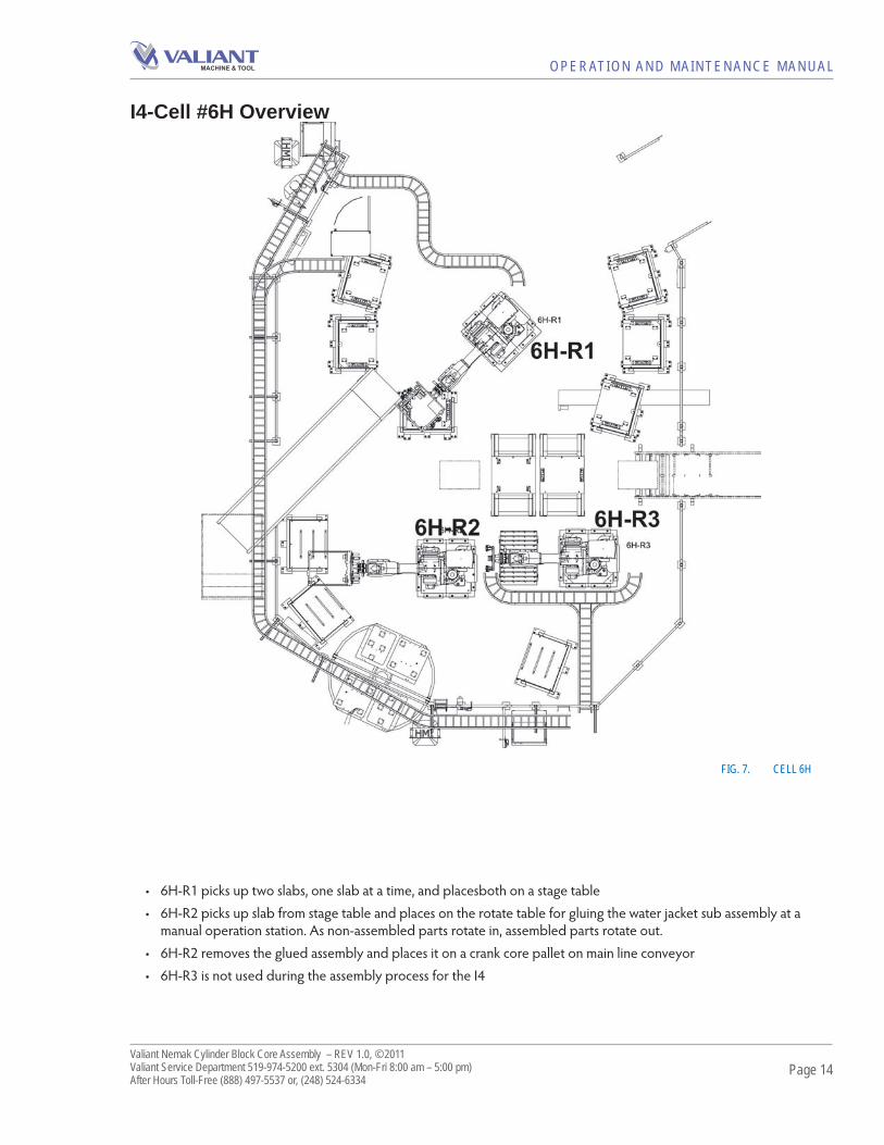
FIG. 7. CELL 6H
• 6H-R1 picks up two slabs, one slab at a time, and placesboth on a stage table• 6H-R2 picks up slab from stage table and places on the rotate table for gluing the water jacket sub assembly at a
manual operation station. As non-assembled parts rotate in, assembled parts rotate out.• 6H-R2 removes the glued assembly and places it on a crank core pallet on main line conveyor• 6H-R3 is not used during the assembly process for the I4

Page 15Valiant Nemak Cylinder Block Core Assembly – REV 1.0, © 2011Valiant Service Department 519-974-5200 ext. 5304 (Mon-Fri 8:00 am – 5:00 pm)After Hours Toll-Free (888) 497-5537 or, (248) 524-6334
OPERATION AND MAINTENANCE MANUAL
I4-Cell #8H Overview
FIG. 8. CELL 8
• 8H-R1 will pick up an now complete core package and place it in the buff er rack if the line is down. Completed core packages will otherwise be sent through the Cell for pouring.

Page 16Valiant Nemak Cylinder Block Core Assembly – REV 1.0, © 2011Valiant Service Department 519-974-5200 ext. 5304 (Mon-Fri 8:00 am – 5:00 pm)After Hours Toll-Free (888) 497-5537 or, (248) 524-6334
OPERATION AND MAINTENANCE MANUAL
V8-Cell #2H Overview
FIG. 9. CELL #2H
• 2H-R1 picks up two chills from the chill pallet• 2H-R1 moves to the core machine and inserts two empty chills into core box• 2H-R2 picks up two base cores and two slide cores from core box• 2H-R2 put 2 base cores on pallets and them drops in the slide cores. • 2H-R2 then removes assembled base core and places them on assembly pallet on the main conveyor• If there is no assembly pallet present, 2H-R2 will place base cores into buff er racks

Page 17Valiant Nemak Cylinder Block Core Assembly – REV 1.0, © 2011Valiant Service Department 519-974-5200 ext. 5304 (Mon-Fri 8:00 am – 5:00 pm)After Hours Toll-Free (888) 497-5537 or, (248) 524-6334
OPERATION AND MAINTENANCE MANUAL
V8-Cell #3H Overview
FIG. 10. CELL 3H• 3H-R1 is utilized for I4 process only• 3H-R2 picks up fi rst pair of side cores from core machine• 3H-R2 places side core on the stage table, if the stage table is full, 3H-R2 will set sides into buff er• 3H-R3 picks up sides from stage table and moves to rotate table for Operator gluing. • Rotate table cycles to Operator for gluing of the RH & LH oil drains on to their respective side cores• Aft er gluing is complete, operator cycles rotate table into cell and 3H-R3 picks up glued sides • 3H-R3 moves to assembly pallet on the main conveyor and assembles LH side to core package and then assembles
RH side• If there is no assembly pallet present, 3H-R3 will buff er glued cores in their designated buff ers• Cycle repeats for pick up of second set of sides

Page 18Valiant Nemak Cylinder Block Core Assembly – REV 1.0, © 2011Valiant Service Department 519-974-5200 ext. 5304 (Mon-Fri 8:00 am – 5:00 pm)After Hours Toll-Free (888) 497-5537 or, (248) 524-6334
OPERATION AND MAINTENANCE MANUAL
V8-Cell #4H Overview
FIG. 11. CELL 4• 4H-R2 picks fi rst crankcase and moves to defi ner fi xture• 4H-R2 rotates to stage table and sets crank down• 4H-R1 picks up fi rst pair of slabs from core machine and defi ns both slabs at the defi ner station• 4H-R1 then moves to stage table, sets down RH slab fi rst and moves to set LH slab• 4H-R4 picks up crank from stage table and sets core to rotate table (feet down)• Rotate table rotates 180 deg for Operator to sub-assemble breather onto crankcase• Operator cycles rotate table back into cell, where 4H-R4 will pick sub-assembled crank/breather and assemble crank-
case/breather and place onto the base core on the assembly pallet• 4H-R3 picks up RH slab from stage fi rst and moves to pick up LH slab.• 4H-R3 then moves to the rotate table and places the LH/RH slabs on the glue fi xture for gluing of water jackets• Rotate table cycles to Operator for gluing of the water jackets onto the slabs• 4H-R3 then picks up the glued slabs/jackets, moves to the assembly pallet and assembles the LH slab/jacket , articulates
and assembles the RH slab/jacket• Cycle repeats to pick up second crankcase and slabs from core machine and subassembly of breather to crank and
gluing of jackets to slabs

Page 19Valiant Nemak Cylinder Block Core Assembly – REV 1.0, © 2011Valiant Service Department 519-974-5200 ext. 5304 (Mon-Fri 8:00 am – 5:00 pm)After Hours Toll-Free (888) 497-5537 or, (248) 524-6334
OPERATION AND MAINTENANCE MANUAL
V8-Cell #5H Overview
FIG. 12. CELL 5• 5H-R2 and 5H-R4 are not used for V8 process• 5H-R1 picks up one set of end cores from core machine• 5H-R1 rotates to stage table and places the ends to stage table• 5H-R3 picks up ends from stage and sets them to rotate table• Rotate cycles to the Operator for gluing of the dirty oil drain to the front core• Aft er gluing, Operator releases rotate back into cell where 5H-R3 picks up end cores and goes to the assembly pallet
on the main line• 5H-R3 places front core onto base core. Th e EoAT pushes the front end core into the core package with (2) push
pads added to the tool.• 5H-R3 then moves to assemble the rear end core in a similar fashion as the front end.• Cycle repeats for the second set of end cores

Page 20Valiant Nemak Cylinder Block Core Assembly – REV 1.0, © 2011Valiant Service Department 519-974-5200 ext. 5304 (Mon-Fri 8:00 am – 5:00 pm)After Hours Toll-Free (888) 497-5537 or, (248) 524-6334
OPERATION AND MAINTENANCE MANUAL
V8-Cell #6H Overview
FIG. 13. CELL 6
• 6H-R1 picks up fi rst cope core and four wedges from cope pallet• 6H-R1 then moves to the stage table and sets cope and four wedges on the stage table fi xture• If there is no pallet assembly present, 6H-R1 will buff er the cope and wedges • 6H-R3 picks up (4) wedges from stage table and assembles them into core package• 6H-R2 picks up cope and wedges from stage table and sets cope onto rotate table for gluing operations• Aft er core is glued onto cope, 6H-R2 picks up cope and assembles in onto the core package
*R3 picks up cope and wedges and they are staged to a fl at top conveyor for manual wedge installation
Information below refl ects FULL AUTO operation. *Cell is in semi-auto operation at time of publication

Page 21Valiant Nemak Cylinder Block Core Assembly – REV 1.0, © 2011Valiant Service Department 519-974-5200 ext. 5304 (Mon-Fri 8:00 am – 5:00 pm)After Hours Toll-Free (888) 497-5537 or, (248) 524-6334
OPERATION AND MAINTENANCE MANUAL
V8-Cell #8H Overview
FIG. 14. CELL 8
• 8H-R1 picks up the complete core package from the assembly conveyor and buff ers in racks in cell 8H if the line is down beyond the cell. Total buff er capacity is 44 core packages.

Page 22Valiant Nemak Cylinder Block Core Assembly – REV 1.0, © 2011Valiant Service Department 519-974-5200 ext. 5304 (Mon-Fri 8:00 am – 5:00 pm)After Hours Toll-Free (888) 497-5537 or, (248) 524-6334
OPERATION AND MAINTENANCE MANUAL
HMI Controls
AlarmsBeginning with the ALARM SCREENS used to check line operation status typically at the beginning of each shift . Use
the following screens to determine the most frequent alarms and take action to investigate the cause of the alarm.
FIG. 15. ALARM SCREEN
By using the K-15 butt on an ALARM HISTORY screen can be viewed. Th is shows the history of faults during a shift .
FIG. 16. K-15

Page 23Valiant Nemak Cylinder Block Core Assembly – REV 1.0, © 2011Valiant Service Department 519-974-5200 ext. 5304 (Mon-Fri 8:00 am – 5:00 pm)After Hours Toll-Free (888) 497-5537 or, (248) 524-6334
OPERATION AND MAINTENANCE MANUAL
Alarm HistoryTh e ALARM HISTORY screen can be seen below. Th is is a detailed snap shot of what faults have been appearing in
each cell. Each cell has its own screen.
FIG. 17. ALARM HISTORY

Page 24Valiant Nemak Cylinder Block Core Assembly – REV 1.0, © 2011Valiant Service Department 519-974-5200 ext. 5304 (Mon-Fri 8:00 am – 5:00 pm)After Hours Toll-Free (888) 497-5537 or, (248) 524-6334
OPERATION AND MAINTENANCE MANUAL
Communication ScreensTh ese screens are used for diagnostics of communication with the PLC. By accessing this screen it is possible to quickly
check and see if a COMM ERROR is present and where to start looking for the problem. Use F-7 to access this screen. Th e red shaded dot highlights K-8. Th e conveyor communication is faulting out and as a result, a red frame is shown around the aff ected component.
FIG. 18. COMMUNICATION SCREENS
Further investigation into communications can be done by accessing REMOTE CABINET screens. Use butt on F14 to begin and continue to the next screen using F15
FIG. 19. REMOTE CABINET SCREEN

Page 25Valiant Nemak Cylinder Block Core Assembly – REV 1.0, © 2011Valiant Service Department 519-974-5200 ext. 5304 (Mon-Fri 8:00 am – 5:00 pm)After Hours Toll-Free (888) 497-5537 or, (248) 524-6334
OPERATION AND MAINTENANCE MANUAL
InterlocksTh is screen allows for monitoring external equipment such at the COPE MACHINE and the CONVEYOR.
FIG. 20. INTERLOCKS
Production InformationProduction Information shows current production levels as well as the production information for the entire day. AC-
TUAL shows current shift production and ANTERIOR shows production for the previous shift which can be broken down into FIRST, SECOND and THIRD shift .
FIG. 21. PRODUCTION INFORMATION

Page 26Valiant Nemak Cylinder Block Core Assembly – REV 1.0, © 2011Valiant Service Department 519-974-5200 ext. 5304 (Mon-Fri 8:00 am – 5:00 pm)After Hours Toll-Free (888) 497-5537 or, (248) 524-6334
OPERATION AND MAINTENANCE MANUAL
Production Information Con’tIt is possible to look further at production and see how long cycle times have been as well as fault times in minutes for
each shift . Each shift has a column that reports TIME IN AUTO, TIME IN MANUAL and TIME IN FAULT.
FIG. 22. MAINTENANCE SCREEN
HMI Robot ControlTh is screen gives a general overview of the robot status for a cell. Th is screen will not allow changes to what the robot
is currently doing but by navigating with butt ons K14 or K15 it is possible to gain control over some of the robot motions.
FIG. 23. ROBOT CONTROL

Page 27Valiant Nemak Cylinder Block Core Assembly – REV 1.0, © 2011Valiant Service Department 519-974-5200 ext. 5304 (Mon-Fri 8:00 am – 5:00 pm)After Hours Toll-Free (888) 497-5537 or, (248) 524-6334
OPERATION AND MAINTENANCE MANUAL
HMI Robot Control Con’tFrom this screen is it possible to turn the robot motors on and off , send the robot to home or service positions and
change the End of Arm Tooling.
FIG. 24. HMI ROBOT CONTROL
Other robot functions will be discussed in CELL OVERVIEW.
Cell OverviewTh is screen reports robot status (MANUAL/AUTO), buff er overview and safety interlocks. From here it is possible to
select a SAFETY INTERLOCK OVERVIEW as well as control the robot motions for buff ers and stage tables.
FIG. 25. CELL OVERVIEW

Page 28Valiant Nemak Cylinder Block Core Assembly – REV 1.0, © 2011Valiant Service Department 519-974-5200 ext. 5304 (Mon-Fri 8:00 am – 5:00 pm)After Hours Toll-Free (888) 497-5537 or, (248) 524-6334
OPERATION AND MAINTENANCE MANUAL
Cell Overview Con’tTh e SAFETIES SCREEN shows the safety interlocks that are active or that need att ention.
FIG. 26. SAFETIES SCREEN
A POP-UP screen for robot control will allow the operator to control how a part is handled by the robot simply by selecting the appropriate “K” butt on.
FIG. 27. ROBOT PART HANDLING

Page 29Valiant Nemak Cylinder Block Core Assembly – REV 1.0, © 2011Valiant Service Department 519-974-5200 ext. 5304 (Mon-Fri 8:00 am – 5:00 pm)After Hours Toll-Free (888) 497-5537 or, (248) 524-6334
OPERATION AND MAINTENANCE MANUAL
Overview BuffersTh is screen allows for the enable/disable of buff er stacks. Simply stated: You can tell the robot where or where not to
leave parts. Th e screen shows each level of the stacked buff er and which level is active. Th is screen is password protected.
FIG. 28. OVERVIEW BUFFERS
Overview PalletsPressing butt on F2 exits from the main HMI screen to the OVERVIEW PALLETS screen and the operation is password
protected. Th is screen allows operations to change the number of chills stored on each pallet. Th e robot will stack 2 chill per pallet starting at number 1 position and continues to number 36. If more or less chills are needed on each pallet touch #CHILLS and press ENTER, then press CALCULATOR. Th e PLC will then change how the pallets are loaded with chills.
FIG. 29. OVERVIEW PALLETS

Page 30Valiant Nemak Cylinder Block Core Assembly – REV 1.0, © 2011Valiant Service Department 519-974-5200 ext. 5304 (Mon-Fri 8:00 am – 5:00 pm)After Hours Toll-Free (888) 497-5537 or, (248) 524-6334
OPERATION AND MAINTENANCE MANUAL
Manual MotionsManual Motions control the conveyors. Th e example below shows the START/STOP butt ons as well as the AUTO
MODE butt on.
FIG. 30. MANUAL MOTIONS

Page 31Valiant Nemak Cylinder Block Core Assembly – REV 1.0, © 2011Valiant Service Department 519-974-5200 ext. 5304 (Mon-Fri 8:00 am – 5:00 pm)After Hours Toll-Free (888) 497-5537 or, (248) 524-6334
OPERATION AND MAINTENANCE MANUAL
ABB ROBOT FAULT RECOVERY
ABB Robot Teach Pendant
FIG. 31. ABB TEACH PENDANT
Using the Teach Pendant to ‘RECOVER THE ROBOT’DO NOT ATTEMPT TO USE THE TEACH PENDANT
TO MANIPULATE THE ROBOT UNLESS YOU ARE AN EXPERIENCED ROBOT TECHNICIAN.
Th is procedure will help you recover the robot in the event of a crash or system failure when the robot will not restart from the normal control panel commands. To use the Teach Pendant for the purpose of moving the robots, the robot controller must be in MANUAL MODE. Proceed as follows:
• Turn the robot controller key switch to MANUAL (the ‘HAND’ position).
• Press ‘MOVE PP TO MAIN’ on the teach pendant’s control panel. (Th is icon is displayed in the lower left corner of the teach pendant’s screen.)
• Pick up the teach pendant and squeeze the ‘live man’ switch to the midway position to enable the teach pendant.
• Use the ‘joystick’ to carefully maneuver the robot to a CLEAR position.
• Once in a ‘clear’ position, press the start butt on ( 4).• A new menu opens on the teach pendant panel
and you will be asked: “IS THE ROBOT CLEAR TO GO HOME?”.
THINK BEFORE YOU ANSWER. IS THEREANYTHING THAT WILL BE CRUSHED, REMOVEDOR DESTROYED WHEN THE ROBOT MOVES TOITS HOME POSITION?• If the path is clear, press CONTINUE. If thepath is not clear and it is not safe to send therobot HOME now, press END.• Press CONTINUE and the robot will moveimmediately to its HOME position.• When the robot is HOME and any problem iscleared, you can restart the system in AUTOMODE, AUTO CYCLE.• A pop-up screen will display WAITING FORAUTO: Acknowledge by pressing OK.• Turn the key switch back to AUTO andreplace the teach pendant.• Return to the HMI and restart the system from the
main control panel.

Page 32Valiant Nemak Cylinder Block Core Assembly – REV 1.0, © 2011Valiant Service Department 519-974-5200 ext. 5304 (Mon-Fri 8:00 am – 5:00 pm)After Hours Toll-Free (888) 497-5537 or, (248) 524-6334
OPERATION AND MAINTENANCE MANUAL
FIG. 32. MOVEMENT REFERNCE

Page 33Valiant Nemak Cylinder Block Core Assembly – REV 1.0, © 2011Valiant Service Department 519-974-5200 ext. 5304 (Mon-Fri 8:00 am – 5:00 pm)After Hours Toll-Free (888) 497-5537 or, (248) 524-6334
OPERATION AND MAINTENANCE MANUAL
Nest Block Inspection Checklist• Look for build-up of sand or resin. Th e two illustra-
tions below show acceptable (left ) and unacceptable (right) accumulations of sand/resin on a cross-section of a nest block. ‘Visual inspections’ will NOT produce a repeatable measurement, it can however, with ex-perience, provide suffi cient warning of a tool that is in need of thorough inspection or replacement.
FIG. 33. SAND ACCUMULATION ON NEST BLOCKS
• It is common and acceptable for loose sand to remain on the nest blocks aft er the part is released or re-moved from the tooling.
• It is NOT ACCEPTABLE to allow sand and/or resin to accumulate on the part-touching surfaces of a nest block.
• Clean the nest block of accumulated sand and/or resin.
• Look for excessive wear. Wear is deemed to be excessive if there is any irregularities on the machined surfaces (see photos following). Refer to the DETAIL DRAWINGS of the nest blocks to be sure what you believe to be an irregularity is not a purposely ma-chined surface.
• A WORN NEST BLOCK IS AN INDICATOR OF EOAT MISALIGNMENT OR PALLET / TABLE MIS-ALIGNMENT.
• If a nest block has wear-damage, remove the block and replace with a spare, or replace the end-of-arm-tooling with a spare and perform a thorough CMM inspection. (Contact Valiant Spare Parts Department to re-order immediately). Use the CMM Inspection Reports provided by Valiant and/or the certifi cation DETAIL DRAWINGS provided by Valiant for your verifi cation data.
NOTE: Robot programming Teach Points should not be changed to compensate for worn nest blocks!
EoAT MaintenanceTh e END OF ARM TOOL is built to drawing dimen-
sions based on the intended job. Th e arms of the tool and the ROBOT WRIST CONNECTION should never need service unless a severe impact has occurred. Th e Sand Core environment is harsh and will make it necessary to inspect and change NEST BLOCKS (see next section) and other components. If the robot is dropping parts or not pick-ing parts up properly then the cause must be determined starting with any part changes, pick/place point changes including part pallets and nest blocks on the End of Arm Tool. DO NOT RE-TEACH THE ROBOT! See “Mainte-nance of Coreline Components” for more information.
Nest Block MaintenanceNest blocks are precision-machined tools used to lo-
cate and hold sand cores, chills, and fi nished castings. Nest blocks are CNC machined to the locating surfaces of the part with a typical clearance of .15mm (or .006”).
Maintaining Nest Block Dimensions
Sand cores are extremely abrasive and the constant action of gripping and releasing parts will wear the contact surface of the nest block. Th is causes the interior dimen-sions of the nest block to expand resulting in a loose fi t to the locating surfaces. If the nest block is allowed to wear too much, the resulting movement of the sand core will cause mis-location of cores during robotic assembly result-ing in loss of quality of the fi nished casting.
Surface integrity of the nest block is critical. Conduct a visual inspection of the nest blocks every month. Load-bearing surfaces and all horizontal surfaces on the advance side nest blocks are primary indicators of excess wear.
Nest blocks can also accumulate excess sand and/or resin. A build-up of any contaminant on the part-touching surfaces of the nest block reduces the interior dimensions resulting in a fi t that is too tight. If the nest block is too tight it can crush the core resulting in abrasion which leads to a poor quality casting.

Page 34Valiant Nemak Cylinder Block Core Assembly – REV 1.0, © 2011Valiant Service Department 519-974-5200 ext. 5304 (Mon-Fri 8:00 am – 5:00 pm)After Hours Toll-Free (888) 497-5537 or, (248) 524-6334
OPERATION AND MAINTENANCE MANUAL
What to Look For Th e photographs below are examples of unacceptable
wear on part-touching surfaces of nest blocks.
FIG. 34. REPEATED CONTACT WITH THE PART HAS WORN A NOTICEABLE GROVE INTO THE SURFACE OF THE NEST BLOCK.
FIG. 35. CORNER SURFACE SHOWING SIGNS OF WEAR.
FIG. 36. ONE SECTION OF THIS NEST BLOCK’S PART-TOUCHING SURFACE IS SHOWING SIGNS OF WEAR.
FIG. 37. THIS ACETEL NEST BLOCK HAS BEEN RE-SHAPED BY CONTACT WITH THE PART. IT IS OVER-DUE FOR REPLACEMENT.

Page 35Valiant Nemak Cylinder Block Core Assembly – REV 1.0, © 2011Valiant Service Department 519-974-5200 ext. 5304 (Mon-Fri 8:00 am – 5:00 pm)After Hours Toll-Free (888) 497-5537 or, (248) 524-6334
OPERATION AND MAINTENANCE MANUAL
General HousekeepingWithout exception, Valiant supports our customer’s
ZERO TOLERANCE policy for dirt build-up and contami-nants on any part-touching or locating surfaces. Th is means that the plant’s maintenance team and operators must work together to establish the machine cleaning schedule and procedures that are best-suited to the environment. Th ese schedules must include the Nest Block Cleaning and Inspection procedures outlined herein.
BackgroundRobots are designed to be repeatable to a tolerance
of +/- 0.1 mm in a clean, sterile laboratory environment. Valiant designs nest blocks with specifi c clearances that comply with assembly requirements, fi t-and-function speci-fi cations, and dimensional process integrity. Th is means that the entire system must be maintained with a zero tolerance for any build-up of sand, dirt, aluminum, or miscellaneous debris.
Valiant robot installations are equipped with Colli-sion Detect / Load Identifi cation soft ware to protect the robot, the end-of-arm-tooling, product, and most impor-tantly, plant personnel. Th is soft ware works with the ex-tremely sensitive servo encoders responsible for accurate robot positioning. Th e robot, using the collision detection soft ware, will start to move to a coordinate position ac-curate to within 0.15 mm. If the robot, or the robot’s end of arm tool, is prevented it from maintaining it’s path or reach-ing its target coordinate, the robot will stop immediately.
While the Collision Detection soft ware is intended to save you thousands of dollars in repair and can potentially save someone’s life, it will also cause the robot to ‘fault-out’ and stop if the positioning system detects dirt build-up (even a small amount of sand) or aluminum spillage, or dimensional damage, or wear on the pallet or nest blocks. DO NOT DISABLE THIS FEATURE.
If the robot stops and reports a collision fault, inspect the cell from outside the guarding. If you see no sign of a collision, back the robot away from the last point at which it came into contact with the load. Shut down the entire cell in accordance with all plant safety requirements. Enter the cell and inspect the area for cleanliness. Even a small
amount of debris (sand, dirt, aluminium, glue, etc) will cause the robot to ‘collide’ unexpectedly. Th e two pho-tographs below, illustrate the conditions the robot was ‘taught’ to expect (left ), and the working conditions the robot will tolerate (right). Th ere is very litt le margin for error. How litt le? An accumulation of sand that can be lift ed and cleaned with a single sheet of paper or a razor knife will cause the system to fault.

Page 36Valiant Nemak Cylinder Block Core Assembly – REV 1.0, © 2011Valiant Service Department 519-974-5200 ext. 5304 (Mon-Fri 8:00 am – 5:00 pm)After Hours Toll-Free (888) 497-5537 or, (248) 524-6334
OPERATION AND MAINTENANCE MANUAL
End of Arm Tooling

Page 37Valiant Nemak Cylinder Block Core Assembly – REV 1.0, © 2011Valiant Service Department 519-974-5200 ext. 5304 (Mon-Fri 8:00 am – 5:00 pm)After Hours Toll-Free (888) 497-5537 or, (248) 524-6334
OPERATION AND MAINTENANCE MANUAL
End of Arm Tooling Con’t.
Page 38Valiant Nemak Cylinder Block Core Assembly – REV 1.0, © 2011Valiant Service Department 519-974-5200 ext. 5304 (Mon-Fri 8:00 am – 5:00 pm)After Hours Toll-Free (888) 497-5537 or, (248) 524-6334
OPERATION AND MAINTENANCE MANUAL
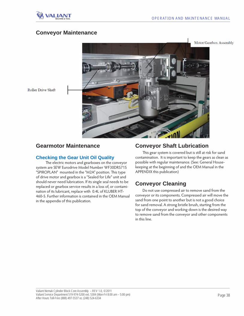
Conveyor Shaft LubricationTh is gear system is covered but is still at risk for sand
contamination. It is important to keep the gears as clean as possible with regular maintenance. (See: General House-keeping at the beginning of and the OEM Manual in the APPENDIX this publication)
Conveyor CleaningDo not use compressed air to remove sand from the
conveyor or its components. Compressed air will move the sand from one point to another but is not a good choice for sand removal. A strong bristle brush, starting from the top of the conveyor and working down is the desired way to remove sand from the conveyor and other components in this line.
Gearmotor Maintenance
Checking the Gear Unit Oil QualityTh e electric motors and gearboxes on the conveyor
system are SEW Eurodrive Model Number WF30DRS71S “SPIROPLAN” mounted in the “M2A” position. Th is type of drive motor and gearbox is a “Sealed for Life” unit and should never need lubrication. If its single seal needs to be replaced or gearbox service results in a loss of, or contami-nation of its lubricant, replace with 0.4L of KLUBER HT-460-5. Further information is contained in the OEM Manual in the appendix of this publication.
Conveyor Maintenance

Page 39Valiant Nemak Cylinder Block Core Assembly – REV 1.0, © 2011Valiant Service Department 519-974-5200 ext. 5304 (Mon-Fri 8:00 am – 5:00 pm)After Hours Toll-Free (888) 497-5537 or, (248) 524-6334
OPERATION AND MAINTENANCE MANUAL
Troubleshooting BearingsPROBLEM POSSIBLE CAUSE SUGGESTED CORRECTIVE ACTION
Excessive noise and vibration
Incorrect lubricant. Use recommended lubricant.Defective bearing. Replace bearings.Grit or other contamination. Clean bearing or replace seals and bearings if
damaged. Corrosion. Use lubricant that resists corrosion. Replace bearing.Improper load. Adjust load conditions or change bearing application. Misalignment. Verify alignment of all drive components – sheaves,
motors, couplings, mountings, etc.Bearings fi t too loose on shaft or in housing.
Skating can occur between inner race and shaft. Replace bearings and make sure shaft has a proper fi t to inner race.
Improper mounting. Skating can occur between outer race and housing and can allow bearing fl oat. Repair housing (machine) and reevaluate the bearing fi t. It may be necessary to provide a locking sealant between the outer housing and the bearing ( Locktite 271 Red). Note: Never apply Locktite sealant between the shaft and the inner race, as it may throw the alignment off and cause premature bearing failure.Verify if bearing is mounted crooked or is binding, causing excessive preload to the bearing.
Excessive heat Improper load. Change load conditions or bearing application must be adjusted. Please note that premature bearing failure can be caused from improper load conditions (angular, axial, and radial).
Misalignment. Determine what is misaligned – housing, shaft, or bores. Shaft may be bent or housing bores not aligned. Replace shaft or housing. Outside structures and components may cause similar effects on bearings. Do not eliminate these possible causes.
Excessive creep. Either inner or outer race may skate around its seated surface. Build up shaft or housing and machine them or replace bearing, whichever is applicable.
System effects. This condition is described as any affect that may be a condition of its environment, such as bearings located too close to a heat source. Remove this condition or consult with the OEM as to other solutions.
Bearing is binding Contaminated with dirt or grit. Clean or replace bearing.
Corrosion. Change to a lubricant that resists corrosion and replace bearing if necessary.
Improper load. Consult with bearing or component manufacturer for assistance, or consult with the OEM.
Seal too tight. If seal is replaceable disassemble bearing and use proper size and type of seal.
Bearing cocked. Remove bearing and clean all mating surfaces. Reinstall bearing if not damaged.

Page 40Valiant Nemak Cylinder Block Core Assembly – REV 1.0, © 2011Valiant Service Department 519-974-5200 ext. 5304 (Mon-Fri 8:00 am – 5:00 pm)After Hours Toll-Free (888) 497-5537 or, (248) 524-6334
OPERATION AND MAINTENANCE MANUAL
Troubleshooting AC MotorsPROBLEM POSSIBLE CAUSE SUGGESTED CORRECTIVE ACTION
Motor fails to start upon initial installation.
Motor is improperly wired. Verify motor is wired correctly. Motor damaged and rotor is striking stator.
Reassembly may fi x the problem, otherwise the motor should be replaced.
Fan guard bent and contacting fan.
Replace fan guard.
Motor has been running, then fails to start.
Fuse or circuit breaker tripped. Replace fuse or reset the breaker. Stator is shorted grounded. Motor will make a humming noise and the circuit breaker or fuse will trip.
Disassemble motor and inspect windings and internal connections. A blown stator will show a burn mark. The motor must be replaced or the stator rewound.
Motor overloaded or load jammed.
Inspect to see that the load is free. Verify amp draw of motor matches nameplate rating.
Capacitor (on single phase motor) may have failed.
First discharge capacitor. To check capacitor, set volt-ohm meter to Rx100 scale and touch its probes to capacitor terminals. If capacitor is OK, needle will jump to zero ohms and drift back to high. Steady zero ohm reading indicates a short circuit. Steady high ohm reading indicates an open circuit.
Starting switch has failed. Disassemble motor and inspect both the centrifugal and stationary switches. The weights of the centrifugal switch should move in and out freely. Make sure that the switch is not loose on the shaft. Inspect contacts and connections on the stationary switch. Replace switch if the contacts are burned or pitted.
Motor runs but dies down. Voltage drop. If voltage is less than 10% of the motor’s rating contact power company or check if some other equipment is taking power away from the motor.
Load increased. Verify the load has not changed. Verify equipment hasn’t got tighter. If fan application verify the air fl ow hasn’t changed.
Motor takes too long to accelerate.
Defective capacitor. Test capacitor per previous instructions. Faulty stationary switch. Inspect switch contacts and connections. Verify that
switch reeds have some spring in them. Bad bearings. Noisy or rough feeling bearings should be replaced.
Voltage too low. Make sure that the voltage is within 10% of the motor’s nameplate voltage rating. If not, contact power company or check if some other equipment is taking power away from the motor.
Motor runs in the wrong direction.
Incorrect wiring. Rewire the motor connections according to the wiring schematic provided.

Page 41Valiant Nemak Cylinder Block Core Assembly – REV 1.0, © 2011Valiant Service Department 519-974-5200 ext. 5304 (Mon-Fri 8:00 am – 5:00 pm)After Hours Toll-Free (888) 497-5537 or, (248) 524-6334
OPERATION AND MAINTENANCE MANUAL
Motor overload protector continually trips.
Load too high. Verify that the load is not jammed. If motor is a replacement, verify that the rating is the same as the old motor. If previous motor was a special design, a stock motor may not be able to duplicate the performance. Remove the load from the motor and inspect the amp draw of the motor. It should be less than the full load rating stamped on the nameplate.
Ambient temperature too high. Verify that the motor is getting enough air for proper cooling. Most motors are designed to run in an ambient temperature of less than 40°C. (Note: A properly operating motor may be hot to the touch.)
Load out of balance. (Direct drive application.)
Remove motor from load and inspect motor by itself. Verify that motor shaft is not bent. As a rule of thumb .001” runout is per allowable for every inch of shaft length.
Motor bearings defective. Test motor by itself. If bearings are bad, you will hear noise or feel roughness. Replace bearings. Add oil if a sleeve of bearing. Add grease if bearings have grease fi ttings.
Rotor out of balance. Inspect motor by itself with no load attached. If it feels rough and vibrates but the bearings are good, the rotor may have been improperly balanced at the factory. Rotor must be replaced or rebalanced.
Motor may have too much endplay.
With the motor disconnected from power, turn the motor shaft by hand. It should move but with some resistance. If the shaft moves in and out too freely, it may indicate a preload problem and the bearings may need additional shimming.
Winding may be defective. Test winding for shorted or open circuits and high amps reading. Replace motor or have stator rewound.
Bearings continuously fail. Load on motor may be excessive or unbalanced
Besides checking load, also inspect drive belt tension to ensure it’s not too tight may be too high. An unbalanced load will also cause the bearings to fail.
High ambient temperature. If the motor is used in an area with high ambient temperature, a different type of bearing grease may be required. You may need to consult with the factory of bearing distributor.
At start-up, the motor makes a loud rubbing or grinding noise.
Rotor may be striking stator. Ensure that motor was not damaged in shipment. Frame damage may not be repairable. If you cannot see physical damage, inspect the motor’s rotor and stator for strike marks. If signs of rubbing are apparent the motor should be replaced. Sometimes simply disassembling and reassembling motor eliminates rubbing. Endbells are also sometimes knocked out of alignment during transportation.

Page 42Valiant Nemak Cylinder Block Core Assembly – REV 1.0, © 2011Valiant Service Department 519-974-5200 ext. 5304 (Mon-Fri 8:00 am – 5:00 pm)After Hours Toll-Free (888) 497-5537 or, (248) 524-6334
OPERATION AND MAINTENANCE MANUAL
Start capacitors continuously fail.
The motor is not coming up to speed quickly enough.
The motor may not be sized properly. Verify how long the motor takes to come up to speed. Most single phase capacitor start motors should come up to speed within three seconds, otherwise the capacitors may fail.
The motor is being cycled too frequently.
Verify duty cycle. Capacitor manufacturers recommend no more than 20, three-second starts per hour. Install capacitor with higher voltage rating, or add bleed resistor to the capacitor.
Voltage to motor is too low. Verify that voltage to the motor is within 10% of the nameplate value. If the motor is rated 208-230V, the deviation must be calculated from 230V.
Starting switch may be defective, preventing the motor from coming out of start winding.
Replace switch.
Run capacitor fails. Ambient temperature too high. Verify that ambient temperature does not exceed motor’s nameplate value.
Possible power surge to motor, caused by lightning strike or other high transient voltage.
If a common problem, install surge protector.
Troubleshooting Conveyor DrivePROBLEM POSSIBLE CAUSE SUGGESTED CORRECTIVE ACTION
Excessive noise or vibration from motor or gear unit.
Loose mounting. Check gear unit mounting bolts for tightness. Tighten as required.
Oil leakage from gear unit. Loose drain plug. Tighten drain plug or replace plug if threads are damaged.
Damaged oil seal. Disassemble gear unit and replace oil seals. Cracked gear unit housing. Drain and remove gear unit and install
replacement.
ValiantCylinder Block Sand Cast Core Assembly System
Technical Service Manual © 20116555 Hawthorne Drive
Windsor, ON, N8T 3G6

Page 43Valiant Nemak Cylinder Block Core Assembly – REV 1.0, © 2011Valiant Service Department 519-974-5200 ext. 5304 (Mon-Fri 8:00 am – 5:00 pm)After Hours Toll-Free (888) 497-5537 or, (248) 524-6334
OPERATION AND MAINTENANCE MANUAL
Appendix
Bleichert ConveyorPHD GripperSEW Eurodrive Gear DriveSEW Eurodrive Motor
BLEICHERT, INC. 7447 19 Mile Road
Sterling Heights, MI 48314
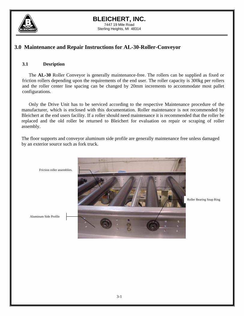
3.0 Maintenance and Repair Instructions for AL-30-Roller-Conveyor
3.1 Desription
The AL-30 Roller Conveyor is generally maintenance-free. The rollers can be supplied as fixed or friction rollers depending upon the requirements of the end user. The roller capacity is 300kg per rollers and the roller center line spacing can be changed by 20mm increments to accommodate most pallet configurations. Only the Drive Unit has to be serviced according to the respective Maintenance procedure of the manufacturer, which is enclosed with this documentation. Roller maintenance is not recommended by Bleichert at the end users facility. If a roller should need maintenance it is recommended that the roller be replaced and the old roller be returned to Bleichert for evaluation on repair or scraping of roller assembly.
The floor supports and conveyor aluminum side profile are generally maintenance free unless damaged by an exterior source such as fork truck.
3-1
Friction roller assemblies.
Aluminum Side Profile
Roller Bearing Snap Ring

BLEICHERT, INC. 7447 19 Mile Road
Sterling Heights, MI 48314
3.2 Replacement of AL-30 Rollers, timing Belts or Drive Motor
The procedure for this is as follows: 1. Remove the finger protection cover over the roller drive shafts on either side of the drive unit.
Also remove the plastic finger guard on the drive motor box.
2. Remove tension from the belt by loosening the motor mount bolts located on the inside of the drive motor box and loosening the motor drive belt adjuster bolt located on the outside edge of the drive motor box.
3-2
Motor/Gearbox Assembly
Roller Drive Shaft

BLEICHERT, INC. 7447 19 Mile Road
Sterling Heights, MI 48314
3. The drive shafts are assembled in one (1) meter lengths and attached to the conveyor aluminum
side profile with two mount blocks per shaft. Locate the drive shaft with the belt sprocket. Loosen and remove the Shoulder Bolts of the shaft mount blocks, located on the inside (roller side) of the aluminum profiles. This drive shaft section can now be removed along with the belt. Access to the roller axles is also available if a roller should need to be replaced.
3-3
Motor/Gearbox Mount Bolts
Motor Drive Belt Adjuster Bolt
Plastic Finger Guard Cover
Bevel Gear Assembly and roller drive shaft
Roller Drive Shaft and Bevel Gear Finger Guard

BLEICHERT, INC. 7447 19 Mile Road
Sterling Heights, MI 48314
Shaft Mount Block Mount Bolts on Inside of Side Profile Shaft Mounting Block
1. Roller Replacement
After procedures 1 thru 3 have been followed, with the exception that only the drive axle which is driving the roller to be replaced needs to be removed.
Loosen and remove the bolt attaching the bevel gear to the roller axle shaft, and remove the bevel gear.
Roller Drive Shaft Bevel Gear and Gear Mount Bolt.
3-4
BLEICHERT, INC. 7447 19 Mile Road
Sterling Heights, MI 48314
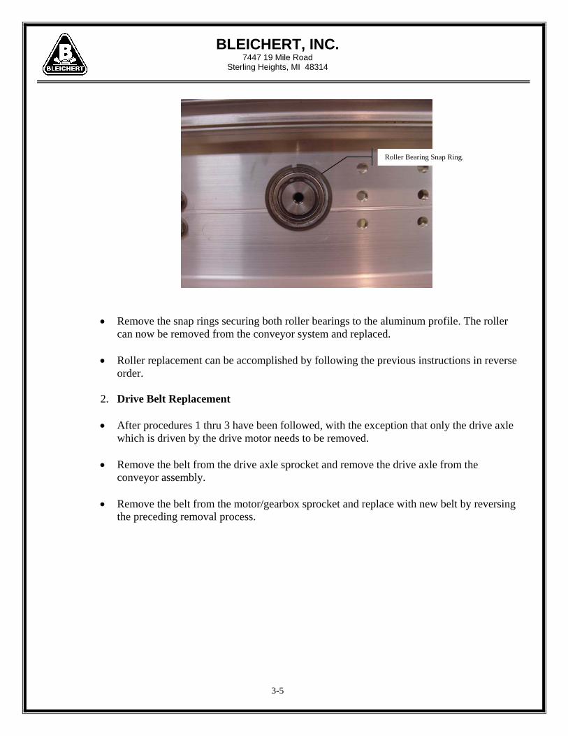
Roller Bearing Snap Ring.
Remove the snap rings securing both roller bearings to the aluminum profile. The roller can now be removed from the conveyor system and replaced.
Roller replacement can be accomplished by following the previous instructions in reverse order.
2. Drive Belt Replacement After procedures 1 thru 3 have been followed, with the exception that only the drive axle
which is driven by the drive motor needs to be removed.
Remove the belt from the drive axle sprocket and remove the drive axle from the conveyor assembly.
Remove the belt from the motor/gearbox sprocket and replace with new belt by reversing the preceding removal process.
3-5

BLEICHERT, INC. 7447 19 Mile Road
Sterling Heights, MI 48314
Roller Motor Drive Belt Drive Shaft Belt Sprocket
Motor/Gearbox Belt Sprocket
3. Drive Motor/Gearbox Replacement Turn off the motor safety disconnect box for the motor being worked on and remove the
electrical wiring from the Motor J-box.
After following the proceeding procedures 1 thru 2.
Remove the four bolts securing the Motor/gearbox mount plate to the motor drive box assembly and remove motor assembly to work table.
Remove the motor/gearbox mount plate from the motor assembly and install on replacement motor.
Re-install the new motor/gearbox by reversing the proceeding procedures.
3-6

3-7
BLEICHERT, INC. 7447 19 Mile Road
Sterling Heights, MI 48314
Motor Mount Plate
Motor/Gearbox Assembly
3.3 Tensioning of the drive timing Belt
The Drive Unit has to be installed by using the leveling screw with following conditions:
a) The Drive Unit has to be parallel to the AL-30 Roller
b) The Drive timing Belt should be tensioned so that a test load of 26 lbs in the center of the two timing pulleys will cause a deflection of max. 5.3mm
The procedure for this is as follows:
i. Lose the Drive Motor Tension Plate Bolts
ii. Level the Drive Unit with the Drive Belt Tension Bolt.
iii. Secure the Drive Motor Tension Plate Bolts and check the tension of
the timing belt.

Use this information sheet to assist with gripper installation and setup.File with maintenance or machine documentation.
IMPORTANT DOCUMENTATION
DO NOT DISCARD!
SERIES GRT 3 JAW PARALLEL GRIPPERS INFORMATION SHEET
Model Number Definition
CUSTOM PRODUCTSA model number “ML-xxxxx” indicates the unit is a custom
product. Contact your local distributor or PHD, Inc. for a completeproduct description.
For additional technical assistance, call:
P.O. Box 9070, Fort Wayne, IN 468991-800-624-8511
PART NO.: 6441-263C
INTERNAL PROXIMITY SWITCHESSWITCH DESCRIPTION
4 mm Round NPN (Sink)4 mm Round PNP (Source)8 mm Threaded NPN (Sink)8 mm Threaded PNP (Source)
PART NO.18430-001-0218430-002-0251422-005-0251422-006-02
GRIPPER SIZE
GRTx6, 7, & 8
GRTx1, 2, 3,4, & 5
EXTERNAL PROXIMITY SWITCHES
SWITCH DESCRIPTION8 mm Threaded NPN (Sink)8 mm Threaded PNP (Source)12 mm Threaded NPN (Sink)12 mm Threaded PNP (Source)12 mm Threaded AC 20-250 VAC
PART NO.51422-005-0251422-006-02
15561-00115561-00215561-003
GRIPPER SIZE
GRTx6, 7, & 8
GRTx1, 2, 3,4, & 5
TO ORDER, SPECIFY:Product Type, Series, Type, Style,Size, Jaw Style, Design No., Options,and Seals.
--G R T 1 4 2 1 0 0 0 1
BORE SIZE
DIRECTIONJAWS OPENINGJAWS CLOSING
GRTx2x62805-0162806-01
KIT NUMBERGRTx3x
62805-0262806-01
GRTx4x62805-0262806-02
GRTx5x62805-0262806-03
GRTx6x62805-0362806-04
GRTx7x62805-0462806-05
GRTx8x62805-0462806-05
Kit includes: 1 Proximity Target, 1 Proximity Adjustment Screw, 2 Target Adjustment Screws
GRTx1x62805-0562806-06
SPRING OPTIONS0 - None
HEAVY FORCE5 - Spring assist closed6 - Spring assist open
STYLE1 - Imperial5 - Metric
1 - 27 mm2 - 40 mm3 - 50 mm4 - 63 mm5 - 80 mm6 - 100 mm7 - 125 mm8 - 160 mm
JAW STYLE2 - Standard travel
SENSOR OPTIONS0 - None5 - Proximity switch ready
(For internal switches)
SEALS1 - Buna-N2 - Fluoro-Elastomer
OPTIONS0 - None1 - Part Ejector
DESIGN NO.TYPE
T - Three jaw
SERIES
PRODUCT TYPEG - Gripper
INTERNAL PROXIMITY SWITCH TARGET KITS
FINGER BLANKS
EXTERNAL PROXIMITY SWITCH MOUNTING BRACKETS
KIT NUMBERIMPERIAL METRIC
MODELNUMBERGRTx12GRTx22GRTx32GRTx42GRTx52GRTx62GRTx72GRTx82
62890-0162890-0262890-0362890-0462890-0562890-0662890-0762890-08
62890-1162890-1262890-1362890-1462890-1562890-1662890-1762890-18
GRTx2x61552-02
KIT NUMBERGRTx3x
61552-03GRTx4x
61552-04GRTx5x
61552-05GRTx6x
61552-06GRTx7x
61552-07GRTx8x
61552-08GRTx1x
61552-01
2
ENGINEERING DATA: SERIES GRT GRIPPERS
B
C
A
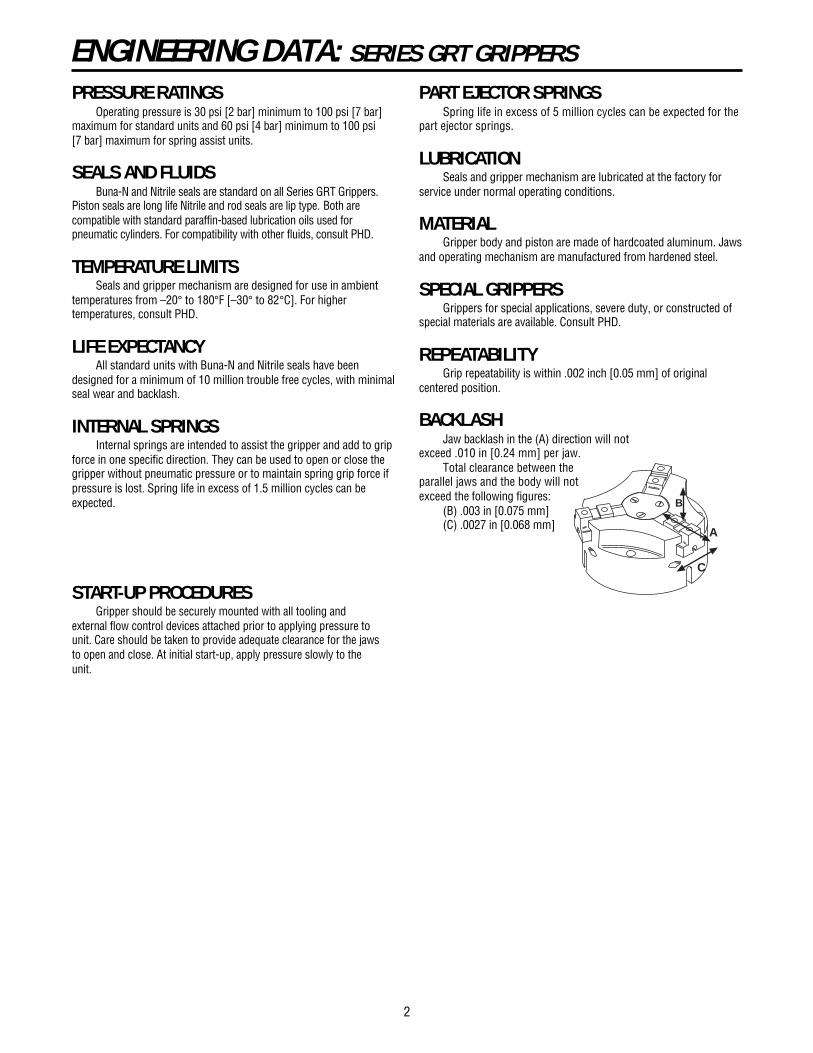
PRESSURE RATINGSOperating pressure is 30 psi [2 bar] minimum to 100 psi [7 bar]
maximum for standard units and 60 psi [4 bar] minimum to 100 psi[7 bar] maximum for spring assist units.
SEALS AND FLUIDSBuna-N and Nitrile seals are standard on all Series GRT Grippers.
Piston seals are long life Nitrile and rod seals are lip type. Both arecompatible with standard paraffin-based lubrication oils used forpneumatic cylinders. For compatibility with other fluids, consult PHD.
TEMPERATURE LIMITSSeals and gripper mechanism are designed for use in ambient
temperatures from –20° to 180°F [–30° to 82°C]. For highertemperatures, consult PHD.
LIFE EXPECTANCYAll standard units with Buna-N and Nitrile seals have been
designed for a minimum of 10 million trouble free cycles, with minimalseal wear and backlash.
INTERNAL SPRINGSInternal springs are intended to assist the gripper and add to grip
force in one specific direction. They can be used to open or close thegripper without pneumatic pressure or to maintain spring grip force ifpressure is lost. Spring life in excess of 1.5 million cycles can beexpected.
PART EJECTOR SPRINGSSpring life in excess of 5 million cycles can be expected for the
part ejector springs.
LUBRICATIONSeals and gripper mechanism are lubricated at the factory for
service under normal operating conditions.
MATERIALGripper body and piston are made of hardcoated aluminum. Jaws
and operating mechanism are manufactured from hardened steel.
SPECIAL GRIPPERSGrippers for special applications, severe duty, or constructed of
special materials are available. Consult PHD.
REPEATABILITYGrip repeatability is within .002 inch [0.05 mm] of original
centered position.
BACKLASHJaw backlash in the (A) direction will not
exceed .010 in [0.24 mm] per jaw.Total clearance between the
parallel jaws and the body will notexceed the following figures:
(B) .003 in [0.075 mm](C) .0027 in [0.068 mm]
START-UP PROCEDURESGripper should be securely mounted with all tooling and
external flow control devices attached prior to applying pressure tounit. Care should be taken to provide adequate clearance for the jawsto open and close. At initial start-up, apply pressure slowly to theunit.

OPTIONS/ACCESSORIES: SERIES GRT GRIPPERS
PROCEDURE FOR ADJUSTING PROX TARGET1) Loosen outer target set screw, by turning counter-clockwise,until seat is broken (set screw can turn freely).2) Continue to turn target set screw counter-clockwise untilwrench can slide through inner target set screw (1/6 turnor less).3) Adjust target in by turning inner and outer target set screwsclockwise or out by turning inner and outer target set screwscounter-clockwise.4) When target is in approximately the correct location, pull thewrench out of inner target set screw and turn outer target setscrew clockwise until firmly seated.
TARGET ORIENTATION FOR SENSING CLOSING
JAWINNER TARGET SET SCREW
JAW CLOSINGTARGET ORIENTATION FOR:ALL SIZES
OUTER TARGET SET SCREW
TARGET ORIENTATIONFOR SENSING OPENING
TARGET ORIENTATION FOR:GRTx6x, GRTx7x,AND GRTx8x
JAW OPENINGTARGET ORIENTATION FOR:
GRTx3x, GRTx4x,AND GRTx5x
JAW
INNER TARGETSET SCREW
OUTER TARGETSET SCREW
JAW OPENINGTARGET ORIENTATION FOR:GRTx1x AND GRTx2x
BODY
PROX ADJUSTING SET SCREW
OPENPORT CLOSE
PORT
PROXIMITY SWITCH READY-INTERNAL
This option equips the gripper with sleeves to provide for themounting of up to three round proximity switches. Target Kits and
5
PART NUMBER18430-001-0218430-002-02
DESCRIPTIONNPN (Sink) 10-30 VDC, 2 meter cablePNP (Source) 10-30 VDC, 2 meter cable
4 mm ROUND INDUCTIVE PROXIMITY SWITCHES
PART NUMBER51422-005-0251422-006-02
DESCRIPTIONNPN (Sink) 5-30 VDC, 2 meter cablePNP (Source) 5-30 VDC, 2 meter cable
8 mm THREADED INDUCTIVE PROXIMITY SWITCHES
1.18 [30mm]MIN BEND RADIUS
PS11 MAXTARGET WIDTH
Ø PS1(PROX SWITCH)
PS2 MAXSENSING DISTANCE
DETAIL A
TARGET KIT NUMBERSENSINGDIRECTION
JAWS OPENINGJAWS CLOSING
GRTx2x62805-0162806-01
GRTx3x62805-0262806-01
GRTx4x62805-0262806-02
GRTx5x62805-0262806-03
GRTx6x62805-0362806-04
GRTx7x62805-0462806-05
GRTx8x62805-0462806-05
EACH KIT WILL MOUNT ONE SWITCH.KIT INCLUDES: 1 PROXIMITY TARGET, 1 PROXIMITY ADJUSTMENT SCREW,
2 TARGET ADJUSTMENT SCREWS
MODEL NUMBERLETTER
DIMPS1PS2PS3PS4PS5PS6PS7PS9PS10PS11
GRTx2x GRTx3x GRTx4x GRTx5x GRTx6x GRTx7x GRTx8xin
.020
.5271.0531.8241.421.42.773.030.157
mm
.513.3726.7546.3336.036.019.6.754.0
in
.0301.1812.3624.0911.381.381.524.167.315
4mm ROUND 8mm THREADEDin
.020
.6201.2402.1481.221.22.971.030.157
4mm ROUNDmm
.515.7531.554.5531.031.024.7.754.0
in
.020
.7781.5552.6931.181.041.147.030.157
4mm ROUNDmm
.519.7539.568.4130.026.529.1.754.0
4mm ROUNDin
.020
.9451.8903.2731.18.83
1.364.060.157
mm
.524.048.083.1330.021.034.61.54.0
mm
.7630.060.0
103.9135.035.038.74.258.0
in
.0301.4472.8945.0121.141.141.760.276.315
8mm THREADEDmm
.7636.7573.5
127.3029.029.044.77.08.0
8mm THREADEDin
.0301.8213.6426.3071.18.81
2.095.404.315
mm
.7646.2592.5
160.2030.020.553.210.258.0
GRTx1xin
.020
.388
.7751.3421.211.21.555.030.157
mm
.59.8619.6934.0930.730.714.1.754.0
4mm ROUND
GRTx1x62805-0562806-06
NOTES: 1) (PS10) THE PROX TARGET MAY EXTEND OUT OF THE JAW WHEN THE JAWS CLOSE. TARGETIS ADJUSTED TO SENSE LESS THAN .039 [1mm] MOVEMENT FROM THE FULL CLOSED POSITION
2) JAWS SHOWN IN FULL OPEN POSITION
A
PS7
PS9
PS10 MAX
PS6APPROX LED LOCATION -
4mm PROX
APPROX LED LOCATION -8mm PROX
LOCATION OF PROXIMITYSWITCHES
PS4
PS3
PS5
5/64 [2mm]TARGET ADJUSTMENTHEX
Ø PS1(PROX SWITCH)
Proximity Switches are ordered separately. See Switches and Sensorssection in PHD’s main catalog for complete switch specifications.Adjustable positioning target assembly protected under U.S. PatentNo. 6019409
3All dimensions are reference only unless specifically toleranced.

All dimensions are reference only unless specifically toleranced.
MANIFOLD KIT INCLUDES2 PORT PLUGS2 MANIFOLD O-RING SEALS
MANIFOLD PORTS(SHIPPED PLUGGED
FROM FACTORY)
PORT(TO BE PLUGGED WHEN
USING MANIFOLD PORTS)CLOSED
OPEN
MANIFOLD O-RING
MODEL NUMBERGRT122
61553-01-1
61553-01-2.157 ID x .059 CS
GRT522
61553-05-1
61553-05-24.0 ID x 1.5 CS
GRT132
61553-01-1
61553-01-2.157 ID x .059 CS
GRT532
61553-05-1
61553-05-24.0 ID x 1.5 CS
GRT142
61553-02-1
61553-02-2.197 ID x .059 CS
GRT542
61553-06-1
61553-06-25.0 ID x 1.5 CS
GRT152
61553-03-1
61553-03-2.197 ID x .059 CS
GRT552
61553-07-1
61553-07-25.0 ID x 1.5 CS
GRT162
61553-04-1
61553-04-2.236 ID x .059 CS
GRT562
61553-08-1
61553-08-26.0 ID x 1.5 CS
GRT172
61553-04-1
61553-04-2.236 ID x .059 CS
GRT572
61553-08-1
61553-08-26.0 ID x 1.5 CS
GRT182
61553-04-1
61553-04-2.236 ID x .059 CS
GRT582
61553-08-1
61553-08-26.0 ID x 1.5 CS
KIT NUMBER: (STD SEALS) (FLUORO-ELAS- TOMER SEALS)O-RING SIZE
GRT512
61553-05-1
61553-05-24.0 ID x1.5 CS
GRT112
61553-01-1
61553-01-2.157 ID x .059 CS
ACCESSORIES: SERIES GRT GRIPPERS
MANIFOLD SEAL KITAll Series GRT grippers have manifold porting as standard.
Port plugs must first be removed when using this feature.
PROXIMITY SWITCHES - EXTERNALThis accessory provides for the external mounting of round
metal sensing proximity switches. Up to six switches may bemounted using multiple brackets. The user is required to design and
EP2
2X EP3EP9 EP5
EP1 PROXIMITYSWITCH (ORDEREDSEPARATELY)
EP6
EP7EP8
EP4 HEX
EP12
EP11
EP10JAWS CLOSED
MODEL NUMBERLETTER
DIMEP1EP2EP3EP4EP5EP6EP7EP8EP9EP10EP11EP12
GRTx2x GRTx3x GRTx4x GRTx5x GRTx6x GRTx7x GRTx8xin
1.772.157.512.9051.221.413.738.105.693.68925°
mm
45.04.013.023.031.010.518.752.717.617.525°
in
2.362.157.6691.7322.638.512.935.1051.4331.20722.5°
8mm THREADED 12mm THREADEDin
1.772.157.5121.1031.418.419.744.105.817.68822.0°
8mm THREADEDmm
45.04.013.028.036.010.618.92.720.817.522.0°
in
1.772.157.5121.2791.772.403.728.105.983.83622.5°
8mm THREADEDmm
45.04.013.032.545.010.2518.52.725.021.222.5°
8mm THREADEDin
1.772.157.5121.4962.087.443.768.1051.077.96822.5°
mm
45.04.013.038.053.011.2519.52.727.424.622.5°
mm
60.04.017.044.067.013.023.752.736.430.722.5°
in
2.362.157.6691.9683.170.492.915.1051.5221.40122.5°
12mm THREADEDmm
60.04.017.050.080.512.523.252.738.735.622.5
12mm THREADEDin
2.362.157.6692.3033.977.515.938.1051.9441.72322.5°
mm
60.04.017.058.5101.013.123.82.749.443.822.5°
GRTx1xin
1.772.157.512.748.925.377.702.060.483.64830°
mm
45.04.013.019.023.59.617.81.512.316.530°
8mm THREADED
PART NUMBERGRTx12GRTx22GRTx32GRTx42GRTx52GRTx62GRTx72GRTx82
BRACKET NUMBER61552-0161552-0261552-0361552-0461552-0561552-0661552-0761552-08
MOUNTING BRACKETS
PART NUMBER15561-00115561-00215561-003
DESCRIPTIONNPN (Sink) 24 VDC, 3 meter cablePNP (Source) 24 VDC, 3 meter cableAC 117 VAC, 3 meter cable
12 mm THREADED INDUCTIVE PROXIMITY SWITCHES
PART NUMBER51422-005-0251422-006-02
DESCRIPTIONNPN (Sink) 5-30 VDC, 2 meter cablePNP (Source) 5-30 VDC, 2 meter cable
8 mm THREADED INDUCTIVE PROXIMITY SWITCHES
mount targets for the switch to sense. Proximity Switches areordered separately. See Switches and Sensors section in PHD’smain catalog for complete switch specifications.
4

KIT NUMBERFASTENER
(SHCS)
MODEL NUMBERGRT12261620-02
8-32 x1-1/4
GRT52262813-02M4 x 0.7
x 30
GRT13261620-0310-24 x1-1/2
GRT53262813-03M5 x 0.8
x 40
GRT14261620-041/4-20 x
1-3/4
GRT54262813-04M6 x 1.0
x 45
GRT15261620-051/4-20 x
2
GRT55262813-05M6 x 1.0
x 50
GRT16261620-065/16-18 x 2-1/4
GRT56262813-06M8 x 1.25
x 50
GRT17261620-075/16-18 x
2-1/2
GRT57262813-07M8 x 1.25
x 65
GRT18261620-083/8-16 x
3
GRT58262813-08M10 x 1.5
x 80
STANDARDUNIT
KIT NUMBERFASTENER
(SHCS)
MODEL NUMBERGRT12264128-02
8-32 x1-1/2
GRT52264129-02M4 x 0.7
x 35
GRT13264128-0310-24 x1-3/4
GRT53264129-03M5 x 0.8
x 45
GRT14264128-04
1/4-20x 2
GRT54264129-04M6 x 1.0
x 50
GRT15264128-05
1/4-20x 2-1/2
GRT55264129-05M6 x 1.0
x 60
GRT16264128-065/16-18 x 2-3/4
GRT56264129-06M8 x 1.25
x 62
GRT17264128-075/16-18
x 3
GRT57264129-07M8 x 1.25
x 75
GRT18264128-08
3/8-16x 3-1/2
GRT58264129-08M10 x 1.5
x 90
SPRING ASSISTUNIT
GRT51262813-01M3 x 0.5
x 25
GRT11261620-01
5-40 x1-1/4
GRT11264128-01
6-32 x1-1/4
GRT51264129-01M3 x 0.5
x 30
5
DISASSEMBLY OF A STANDARD GRT GRIPPER1. Warning: All air pressure in the unit must be relieved prior to disassembly of gripper.2. On the bottom of the gripper, remove bore plug retaining ring (Figure 1).3. Remove bore plug (note orientation) and bore plug seal.4. Remove the piston fastener and piston from the unit.5. When removing the piston seal from the piston, be careful not to damage the sealing surfaces.6. From the top of the gripper remove the 3 cover fasteners and the cover (Figure 2).7. Slowly move the jaws in the open direction until the center cam can be lifted out of the body. Remove the cam. Be careful to prevent damage to the
edges of the cam and gripper jaws.8. Remove the jaws from the body.9. The rod seal is located in the center bore of the body and can be removed from the bottom of the gripper. Note orientation of the rod seal (Figure 1).10. Clean and inspect all components. Excessively damaged or worn components should be replaced.
DISASSEMBLY OF A SPRING CLOSED GRT GRIPPER1. Warning: All air pressure in the unit must be relieved prior to disassembly of gripper.2. Unscrew fasteners from the cap of the gripper and remove the cap. Also remove the bore plug seal from the groove in the body. Note the location of
the seal for re-installation.3. On Spring Closed Units PHD suggests using a clamping device to keep the piston compressed while removing the piston fastener. After the piston
fastener is removed, GRADUALLY release the compression of the piston. After the piston is removed, the spring(s) may be easily removed.4. Complete steps 5-10 of Standard GRT Gripper Disassembly.
DISASSEMBLY OF A SPRING OPEN GRT GRIPPER1. Warning: All air pressure in the unit must be relieved prior to disassembly of gripper.2. On Spring Open Units PHD suggests using a clamping device to keep the cap compressed while removing the fasteners. After fasteners are
removed, GRADUALLY release the compression of the cap. After the cap is removed, the spring(s) may be easily removed.3. Remove bore plug seal, noting location in the body.4. Complete steps 4-10 of Standard GRT Gripper Disassembly.
RE-ASSEMBLY OF A STANDARD GRT GRIPPER1. Be careful to prevent cutting or damaging seals during re-assembly.2. In general, use a petroleum-based lubricant/grease (compatible with pneumatic devices) to lubricate the internal parts of the GRT gripper. However,
for lubrication of the body jaw slots, jaws, and the cam, it is recommended that you use a heavier petroleum-based lubricant.3. Use removable thread locker on all fasteners.4. Pre-lubricate rod seal cavity and install the rod seal. Orientation of the rod seal is critical (Figure 1).5. Refer to Step 2 for description of lubricants. Lubricate each body jaw slot, jaw, and lobes on the cam with the heavier lubricant. Lubricate the round
shank of the cam with the lighter petroleum-based lubricant.6. After each part is lubricated, insert each jaw halfway into a slot. Next, insert the cam into the center of the body so that each cam lobe rests on the
top of a jaw. Slowly pull the jaws out so the cam lobes slip into the grooves in the jaws. Once the cam and the jaws are engaged, push the jaws to thefully closed position.
7. Position the cover in the spot face provided in the top of the body. Insert the fasteners into the cover. Torque cover fasteners finger tight.8. Lightly lubricate the piston seal and install it in the groove on the piston.9. Lubricate the gripper bore and insert the piston, noting proper orientation.10. Install the piston fastener through the piston and into the cam and torque per the table on page 6.11. Lubricate the bore plug seal groove and install the seal in the groove closest to the gripper bore (Figure 1).12. Press the bore plug into the body of the gripper and then install the bore plug retaining ring. Care should be taken to insure that the retaining ring is
properly seated in the groove in the body.13. See start-up procedures on page 2.
GRIPPER MOUNTING KITGripper mounting kits are available. The kit includes three
socket head cap screws.
ACCESSORIES & ASSEMBLY INSTRUCTIONS
PHD, Inc. makes no warranty as to the fitness of its products or as to the length of service life after being prepared or parts replaced by anyone other thanauthorized employees of PHD, Inc. In no event shall PHD, Inc. be liable for loss of profits, in direct, consequential, or incidental damages arising out of the use ofPHD® Products.

PHD,Inc. PHDLtd. PHDGmbH 9009 Clubridge Drive 7 Eden Way, Pages Industrial Park Arnold-Sommerfeld-Ring 2 P.O. Box 9070, Fort Wayne, Indiana 46899 U.S.A. Leighton Buzzard, Bedfordshire LU7 8TP U.K. D-52499 Baesweiler GERMANY Phone (219) 747-6151 • Fax (219) 747-6754 Phone 01525 853488 • Fax 01525 378210 Phone 02401-805 230 • Fax 02401-805 232
6
ASSEMBLY INSTRUCTIONS: SERIES GRT GRIPPERS
GRT GRIPPER ASSEMBLY TORQUESPART
DESCRIPTIONPISTON FASTENERCAP ASSEMBLY SCREWS
GRTx2xin-lb N-m
GRTx3xin-lb N-m
GRTx4xin-lb N-m
GRTx5xin-lb N-m
GRTx6xin-lb N-m
GRTx7xin-lb N-m
GRTx8xin-lb N-m
85 9.617 1.9
85 9.617 1.9
200 22.540 4.5
400 45.075 8.4
700 78.8125 14.1
700 78.8125 14.1
1000 112.6300 33.8
GRTx1xin-lb N-m25 2.817 1.9
RE-ASSEMBLY OF A SPRING CLOSED GRT GRIPPER1. Complete steps 1-9 of Standard GRT Gripper Re-assembly.2. Lightly lubricate spring cavity(ies) in the piston.3. Lubricate the gripper bore piston sealing surface and the area where the spring(s) contact the body. 4. Place piston with bottom down on a flat, clean surface. Place spring(s) into piston cavity(ies). Carefully set gripper on top of spring(s). It may be
necessary to compress the spring(s) in order to install the piston fastener (Figure 3). Torque piston fastener per the table below.5. Lubricate the bore plug seal groove and install the seal in the groove closest to the gripper bore (Figure 3).6. Lightly lubricate the outside rim (sealing surface) on the cap that is inserted into the body of the gripper. Lightly lubricate the manifold mount
o-rings and place them over the manifold holes. Press the cap into place on the bottom of the gripper, noting proper alignment of holes with the body. Install the cap assembly screws and torque per the table below.
7. See start-up procedures on page 2.
RE-ASSEMBLY OF A SPRING OPEN GRT GRIPPER1. Complete steps 1-9 of Standard GRT Gripper Re-assembly.2. Lubricate the gripper bore and insert the piston with the spring cavity(ies) facing the bottom of the gripper.3. Install the piston fastener through the piston and into the cam and torque per the table below.4. Lubricate the bore plug seal groove and install the seal in the groove closest to the gripper bore. (Figure 4)5. Lightly lubricate spring cavity(ies) in the piston and insert spring(s).6. Lightly lubricate the inside of the cap where the spring(s) contact and the outside rim (sealing surface) that is inserted into the body of the
gripper. Lightly lubricate the manifold mount o-rings and place them over the manifold holes. Place cap on bottom of gripper, noting proper alignment of holes with the body. Compress cap on the unit, install cap assembly screws and torque per the table below.
7. See start-up procedures on page 2.
Figure 1 Figure 2
Figure 3 Figure 4
COVER
MANIFOLDMOUNT
O-RINGS
Internet Web Site: http://www.phdinc.com • E-Mail: [email protected]

04/2000Gear UnitsR..7, F..7, K..7, S..7 Series, Spiroplan® W
Edition
05/2001
Operating Instructions10503013 / EN
dbrode
04/2000 Gear Units R..7, F..7, K..7, S..7 Series, Spiroplan® W Edition 05/2001

7
32
Inspection and Maintenance
7 Inspection and Maintenance
7.1 Inspection and maintenance periods
7.2 Lubricant replacement schedule
Change oil more often in special version and under more demanding/aggressiveambient conditions!
Time period What to do?
• every 3000 operating hours, at least every six months • Check oil
• depending on operating conditions (see following illustration), at least every three years
• Replace mineral oil
• Replace bearing grease
• depending on operating conditions (see following illustration), at least every five years
• Replace synthetic oil
• Replace bearing grease
• R17, R27, F27 and Spiroplan® gear units are lubricated for life and do not require maintenance
• different (depending on external influences) • Touch up or replace surface/corrosion protection coat
04640AXXFig. 12: Replacement schedule for standard gear units operating under normal ambient conditions.
(1) Operating hours(2) Oil bath steady-state temperature • Average value depending on oil type at 70° C
R..7, F..7, K..7, S..7, Spiroplan® W Gear Units – Operating Instructions
dbrode
• every 3000 operating hours, at least every six months • Check oil
dbrode
• depending on operating conditions (see following illustration), at least every three years • Replace mineral oil • Replace bearing grease • depending on operating conditions (see following illustration), at least every five years • Replace synthetic oil • Replace bearing grease
dbrode
• R17, R27, F27 and Spiroplan® gear units are lubricated for life and do not require maintenance
dbrode
Lubricant replacement schedule

7Inspection and Maintenance
7.3 Inspection/maintenance of gear units
Do not mix synthetic lubricants with each other nor with mineral lubricants! Mineral oil is the standard lubricant.The position of the oil level plug, oil drain plug and the breather valve isdependent on the mounting position.
Checking the oil level
1. De-energize the drive and secure against unintentional switch-on!
Wait until the gear unit has cooled down – Danger of burns !
2. See section "Setup of gear unit" for change in mounting position!
3. For gear units with oil level plug: remove oil level plug, check fill level and correct ifnecessary, install oil level plug
Check oil 1. De-energize the drive and secure against unintentional switch-on!
Wait until gear unit has cooled down - Danger of burns!
2. Remove some oil from the oil drain plug
3. Check oil consistency
– viscosity– if the oil is visibly contaminated, it is recommended to change it sooner than re-
commended by the maintenance intervals listed under the heading "Inspectionand maintenance periods" on page 32
4. For gear units with an oil level plug: remove oil level plug, check oil fill level andcorrect if necessary, install oil level plug
Changing the oil Only change the oil when the gear unit is at operating temperature.1. De-energize the drive and secure against unintentional switch-on!
Wait until the gear unit has cooled down – Danger of burns!Note : Gear unit must still be warm, otherwise the high viscosity of excessivelycold oil will make it harder to drain the oil correctly.
2. Place a container underneath the oil drain plug3. Remove oil level plug, breather plug/valve and oil drain plug4. Drain oil completely5. Install oil drain plug6. Fill new oil of the same type through the breather hole, otherwise consult our service
department– amount in accordance with the mounting position (see section "Lubricant fill levels")
on the nameplate– check at the oil level plug
7. Install oil level plug8. Install breather plug/valve
R..7, F..7, K..7, S..7, Spiroplan® W Gear Units – Operating Instructions 33
dbrode
Do not mix synthetic lubricants with each other nor with mineral lubricants! Mineral oil is the standard lubricant.
dbrode
The position of the oil level plug, oil drain plug and the breather valve is dependent on the mounting position.
dbrode
2. Remove some oil from the oil drain plug 3. Check oil consistency – viscosity – if the oil is visibly contaminated, it is recommended to change it sooner than recommended by the maintenance intervals listed under the heading "Inspection and maintenance periods" on page 32 4. For gear units with an oil level plug: remove oil level plug, check oil fill level and correct if necessary, install oil level plug
dbrode
R..7, F..7, K..7, S..7, Spiroplan® W Gear Units – Operating Instructions Only change the oil when the gear unit is at operating temperature. 1. De-energize the drive and secure against unintentional switch-on! Wait until the gear unit has cooled down – Danger of burns! Note: Gear unit must still be warm, otherwise the high viscosity of excessively cold oil will make it harder to drain the oil correctly. 2. Place a container underneath the oil drain plug 3. Remove oil level plug, breather plug/valve and oil drain plug 4. Drain oil completely 5. Install oil drain plug 6. Fill new oil of the same type through the breather hole, otherwise consult our service department – amount in accordance with the mounting position (see section "Lubricant fill levels") on the nameplate – check at the oil level plug 7. Install oil level plug 8. Install breather plug/valve
dbrode
Changing the oil Only change the oil when the gear unit is at operating temperature.
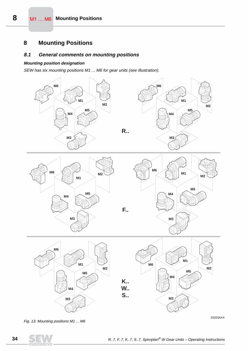
8
34
Mounting PositionsM1 … M6M1 … M6
8 Mounting Positions
8.1 General comments on mounting positions
Mounting position designation
SEW has six mounting positions M1 ... M6 for gear units (see illustration).
03203AXXFig. 13: Mounting positions M1 ... M6
M1
M1
M1
M1
M1
M1
M4
M4
M4
M4
M4
M4
M3
M3
M3
M3
M3
M3
M6
M6
M6
M6
M6
M6
M5
M5
M5
M5
M5
M5
M2
M2
M2
M2
M2
M2
R..
F..
K..W..S..
R..7, F..7, K..7, S..7, Spiroplan® W Gear Units – Operating Instructions

8Mounting Positions M1 … M6M1 … M6
Comparisonold/new
The following table indicates in which way the old SEW mounting position designationsare integrated into the new system:
Example A KA77B helical-bevel gear unit with the old mounting position B3I or B6II, is nowreferred to with mounting position designation M4.
04464AXX
R, RX
R..F
RF, RXF
M1 M2 M3 M4 M5 M6
F FA..BFH..BFV..B
FF
FA
FHFVFAF
FHFFVFFAZFHZFVZ
K KA..BKH..BKV..B
K/KH
166/167186/187
KF
KA
KHKVKAF
KHFKVFKAZKHZKVZ
S
SF
SA SHSAFSHFSAZSHZ
B3 V6 B8 V5 B6 B7
B35 V36 B85 V15 B65 B75
B5 V3 B5II V1 B5I B5III
B6 V6 B6II V5B3B8
B3IB8I
B5 V3 B5II V1 B5I B5III
H1 H6 H2 H5 H4 H3
B3B5/I
B3IB5/II
V1/ V1/I
B3B6I
B6B8I
B8B3IB6II
V5V5I
V6V6I
B5IB3/B5I
B5B65
B5IIIB8/B5III
B5IIB6/B5II
V1V15
V1IV6/V1I
H1 H4 H2 H3 H5 H6
B3B6I
B8II (S37)
B6B8I
B8B3II
B3IB6II
V5V5I
V6V6I
V5II (S37)
B5I B5 B5III B5II V1 V1I
H1 H4 H2 H3 H5 H6
R..7, F..7, K..7, S..7, Spiroplan® W Gear Units – Operating Instructions 35

8
36
Mounting PositionsM1 … M6M1 … M6
8.2 Legend for mounting position pages
Used symbols The following table contains all symbols used in the mounting position pages as well astheir meaning:
Churning losses There is a possibility of increased churning losses with some mounting positions. Pleasecontact SEW when dealing with the following combinations:
Symbol Meaning
Breather valve
Oil level check plug
Oil drain plug
Mounting position Gear unit type Gear unit sizeInput speed
[1/min]
M2, M4 R97 ... 107 > 2500
> 107 >1500
M2, M3, M4, M5, M6
F97 ... 107 > 2500
> 107 > 1500
K77 ... 107 > 2500
> 107 > 1500
S 77 ... 97 > 2500
R..7, F..7, K..7, S..7, Spiroplan® W Gear Units – Operating Instructions

8Mounting Positions M1 … M6M1 … M6
8.3 Mounting positions, helical gear units
R17-R167
04 040 100
* → page 36
270°
0°
90°
180° 1
2
3
*
R47-R57
R17, R27
R17, R27
R47, R57
M5
M4
M5
M1, M3 , M5 , M6
M1
M3
R17
M6
*M2
0°
270°90°
180°
0°180°
0°
90°270°
0°
0°
0°
x
xx x
x
x
x
x
x
x
xx
x
x
R..7, F..7, K..7, S..7, Spiroplan® W Gear Units – Operating Instructions 37

8
38
Mounting PositionsM1 … M6M1 … M6
RF17-RF167
04 041 100
* → page 36
M4
M1
M2
M3
M5 M6
* *
RF17
RF17, RF27
RF17, RF27
RF47, RF57
M1, M3 , M5 , M6
M5
1 3
2
270° 90°
0°
180°
90°
180°
270°
0°
90°
0°
270°
180°
0°
0°
0°
0°
x
xx
x
x
x
x
x
x
x
xx
x
x
R..7, F..7, K..7, S..7, Spiroplan® W Gear Units – Operating Instructions

8Mounting Positions M1 … M6M1 … M6
R17F-R87F
04 042 100
* → page 36
Caution: Note the notes in the "Geared Motors" catalog, section "Project Planning Gear Units/Overhung and axial loads."
M6M5
M4
M3
M2
M1
R47F-R57F
**
R17F, R27F
R17F, R27F
R47F, R57F
M1, M3 , M5 , M6
M5
R17F
1 3
2
270° 90°
0°
180°
270°90°
180°
0°
0°
0° 180°
90°
270°
0°
0°
0°
R..7, F..7, K..7, S..7, Spiroplan® W Gear Units – Operating Instructions 39

8
40
Mounting PositionsM1 … M6M1 … M6
RX57-RX107
04 043 100
* → page 36
M1
M2
M3
M4
M5 M6
31
2
0°
0°
90°
270°
180°
0°
0°
0°
0°
180°
90° 270°
0°
90°
180°
270°
xx
x
x
x x
x
x
x
x
xx x
R..7, F..7, K..7, S..7, Spiroplan® W Gear Units – Operating Instructions

8Mounting Positions M1 … M6M1 … M6
RXF57-RXF107
04 044 100
* → page 36
M3
M6M5
M4
M1
M2
1 3
2
0°
0°
0°
0°
270°
180°
0°
90°
0°
180°
270° 90°
0°
90°
270°
180°
x x
x
x
x
x x
x
x
x
x
xx x
R..7, F..7, K..7, S..7, Spiroplan® W Gear Units – Operating Instructions 41

8
42
Mounting PositionsM1 … M6M1 … M6
8.4 Mounting positions, parallel shaft helical gear units
F/FA..B/FH27B-157B, FV27B-107B
42 042 100
* → page 36
M2M4
M1
M3
M6M5
F47
* *
* *
*
180°0°
90°
1
270°
3
2
270°
0°
180°
90°
0°
0°
0°
0°
0°
180°
90° 270°
xx
x
x
x
x
x
x
xx
x x
x
x
M1, M3, M5, M6
M1 - M6
M1, M3, M5, M6
F..27
F..27
F..27
R..7, F..7, K..7, S..7, Spiroplan® W Gear Units – Operating Instructions

8Mounting Positions M1 … M6M1 … M6
FF/FAF/FHF/FAZ/FHZ27-157, FVF/FVZ27-107
42 043 100
* → page 36
M1
M6M5
M3
M4 M2**FF47
*
* *
2
90°
0° 180° 1 3
270°
90° 270°
180°
0°
0°
270° 90°
180°
0°
0°
0°
0°
x xx
x
x
x
x
x
x
x
xx
x x
M1, M3, M5, M6
M1 - M6
M1, M3, M5, M6
F..27
F..27
F..27
R..7, F..7, K..7, S..7, Spiroplan® W Gear Units – Operating Instructions 43

8
44
Mounting PositionsM1 … M6M1 … M6
FA/FH27-157, FV27-107
42 044 100
* → page 36
0°
0°
270° 90°
180°
M3
M5*
0° 180°
90°
*M4
270°
*M6*
FA47
M1
M2*
31
2
0°
270°
180°
90°
0°
0°
0°
x xx
x
x
x
x
x
x
xxx
x x
M1, M3, M5, M6
M1 - M6
M1, M3, M5, M6
F..27
F..27
F..27
R..7, F..7, K..7, S..7, Spiroplan® W Gear Units – Operating Instructions

8Mounting Positions M1 … M6M1 … M6
8.5 Mounting positions, helical-bevel gear units
K/KA..B/KH37B-157B, KV37B-107B
34 025 100
* → page 36
Caution: Note the notes in the "Geared Motors" catalog, section "Project Planning Gear Units/Overhung and axial loads."
K47
M1
M2M4
M3
M5 M6
K47
1 3
2
90° 270°
180°
0°
0°
270°
90°
A
0°
B
180°
0°
0°
0°
0°
180°
270° 90°
A
B A
B
x xx
x
x
x
x
x
x
x
xx
x x
R..7, F..7, K..7, S..7, Spiroplan® W Gear Units – Operating Instructions 45

8
46
Mounting PositionsM1 … M6M1 … M6
K167-187, KH167B-187B
34 026 100
* → page 36
Caution: Note the notes in the "Geared Motors" catalog, section "Project Planning Gear Units/Overhung and axial loads."
M1
M2
M6M5
M3
M4* *
*
**
1BA
0°
90°
180°
270°
3
2
270°
0°
180°
90°
0°
B
A B
A
x xx
x
x
0°
0°
0°
x
x
x
x
xx
270°
xx
180°x
90°
0°
R..7, F..7, K..7, S..7, Spiroplan® W Gear Units – Operating Instructions

8Mounting Positions M1 … M6M1 … M6
KF/KAF/KHF/KAZ/KHZ37-157, KVF/KVZ37-107
34 027 100
* → page 36
M5 M6
M4
M3
M2
M1
KF47
KF47
0°
90°
A
270°
180°
B 1
x
3
x
2
180°
x
0°x
270°
x
90°
A
BA
B
270°
0°x
x
180°
90°
x
x
x
0°
x
0°
0°
0°
x
x
x
x
R..7, F..7, K..7, S..7, Spiroplan® W Gear Units – Operating Instructions 47
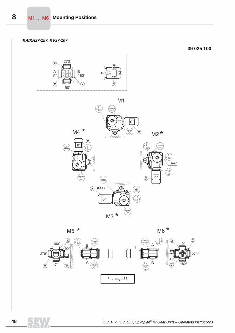
8
48
Mounting PositionsM1 … M6M1 … M6
KA/KH37-157, KV37-107
39 025 100
* → page 36
1
x x
x
3
x
2
90°
0°A
180°B
270°
M5
M3
M6
M2M4
M1
KA47
KA47
* *
*
* *
B
A
270°
0°
x
x
180°
90°
x
x
x
x
x
180°
x
270°
x0°
90°
x
B
A
0°
0°
0°
0°
R..7, F..7, K..7, S..7, Spiroplan® W Gear Units – Operating Instructions

8Mounting Positions M1 … M6M1 … M6
KH167-187
39 026 100
* → page 36
M1
M2
M6M5
M3
M4* *
***
B
90°x
0° 180°
x
270°x
A 31
x
2
90°
x
x 180°
0°
270°
x
x
270°
x0°
180°
90°
x
x
x
A
BA
B
x
x
0°
0°
0°
0°
R..7, F..7, K..7, S..7, Spiroplan® W Gear Units – Operating Instructions 49
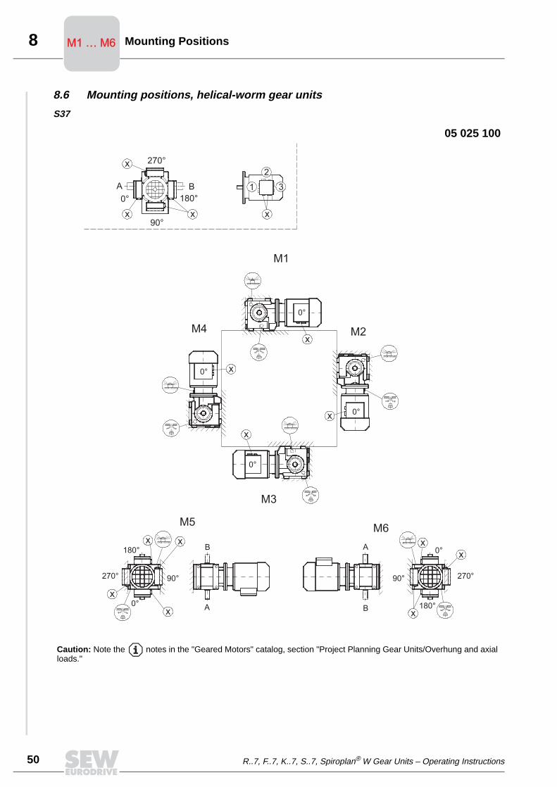
8
50
Mounting PositionsM1 … M6M1 … M6
8.6 Mounting positions, helical-worm gear units
S37
05 025 100
Caution: Note the notes in the "Geared Motors" catalog, section "Project Planning Gear Units/Overhung and axial loads."
M1
M2
M3
M4
M5M6
1BA
x
0°
90°x
180°
x 270°
3
x
2
270°
0°x
x
180°
90°
x
x
0°
0°
0°
0°
x
x
x
x
A
B
B
A
90° 270°
180°
0°x
x
x
R..7, F..7, K..7, S..7, Spiroplan® W Gear Units – Operating Instructions

8Mounting Positions M1 … M6M1 … M6
S47-S97
05 026 100
* → page 36
Caution: Note the notes in the "Geared Motors" catalog, section "Project Planning Gear Units/Overhung and axial loads."
M1
M2
M3
M5 M6
M4 **
*
* *
1BA
x
0°
90°x
180°
x 270°
3
x
2
180°x
0°x
270°
x
90°270°
0°x x
180°
90°
x
0°x
0°
0°
0°
x
x
x
B
A
A
B
R..7, F..7, K..7, S..7, Spiroplan® W Gear Units – Operating Instructions 51

8
52
Mounting PositionsM1 … M6M1 … M6
SF/SAF/SHF37
05 027 100
M1
M4
M3
M2
M6M5
A B 1
x
3
2
90°
x 180°
x
0° x
270°270°
x
x
x0°
180°
90°
x
B
A
A
B
0°
0°
0°
0° x
x
x
x
x
0°
x
180°
90°x x
270°
R..7, F..7, K..7, S..7, Spiroplan® W Gear Units – Operating Instructions

8Mounting Positions M1 … M6M1 … M6
SF/SAF/SHF/SAZ/SHZ47-97
05 028 100
* → page 36
M5
M2M4
M1
M3
M6
x90°
x
0°A
180°
270°x
B 1
x
3
2
x
0°
x
270°
x
A
x
90°
180°
B
*
**
*
0°
0°
x
x
0°
0°
x
x x0°
270°
180°
x
x x
90°
B
A
R..7, F..7, K..7, S..7, Spiroplan® W Gear Units – Operating Instructions 53

8
54
Mounting PositionsM1 … M6M1 … M6
SA/SH37
28 020 100
M1
M4 M2
M3
M6M5
1A
x
0°
90°x
180°
B
x 270°
3
x
2
x0°
x
x180°
90°270°
x 180°
x
90°
0°
270°
x
0°
0°
x 0°
0°
x
x
x
B
A
A
B
R..7, F..7, K..7, S..7, Spiroplan® W Gear Units – Operating Instructions

8Mounting Positions M1 … M6M1 … M6
SA/SH47-97
28 021 100
* → page 36
M4
M3
M5 M6
M2
M1
* *
* *
1
xx90°
A0°
x
B180°
270°
x
3
2
270°
90°
x 180°
x
0°x
x0°
x
270°
180°
90°
x
0°
0°
0°
0°
x
x
x
x
x
A
B
B
A
R..7, F..7, K..7, S..7, Spiroplan® W Gear Units – Operating Instructions 55

9
56
Lubricants
9 LubricantsGeneral SEW supplies the drives filled with a lubricant appropriate for the specific gear unit and
mounting position. The decisive factor is the indicated mounting position (M1...M6, →section "Mounting positions and important order information") when ordering the drive.The lubricant fill amounts for subsequent changes in the mounting position will have tobe adjusted for the specific mounting position (→ Lubricant fill quantities).
Lubricant table The lubricant table for SEW drives on the following page is a list of all approvedlubricants for SEW drives. Please note the following legend for the lubricant table.
Legend for lubricant table
Abbreviations, meaning of shading and notes:
Anti-friction bearing greases
The anti-friction bearings in SEW gear units and motors will be filled with the followinggreases at the factory. SEW recommends to change the grease when replacing the oilin anti-friction bearings with grease filling.
CLP = Mineral oil
CLP PG = Polyglykol (W gear unit, meeting USDA-H1standard)
CLP HC = Synthetic hydrocarbons
E = Diester oil (water pollution class WGK 1)
HCE = Synthetic hydrocarbons + diester oil (USDA - H1 approval)
HLP = Hydraulic oil
= Synthetic lubricant (= anti-friction bearing grease on synthetic base)
= Mineral lubricant (= anti-friction bearing grease on mineral base)
1) Helical-worm gear unit with PG oil: Please consult SEW
2) Special lubricant for Spiroplan® gear units only
3) Recommendation: Select SEW fB ≥ 1.2
4) Note critical starting performance at low temperatures!
5) Low-viscosity grease
6) Ambient temperature
Lubricant for the food industry
Biological oil (lubricant for agricultural, forestry and water industry)OilOil
Ambient temperature Manufacturer Type
Gear unit anti-friction bearing
-30°C ... +60°C Mobil Mobilux EP 2
-40°C ... +80°C Mobil Mobiltemp SHC 100
Motor anti-friction bearing
-25°C ... +80°C Esso Unirex N3
-25°C ... +60°C Shell Alvania R3
+80°C ... +100°C Klüber Barrierta L55/2
-45°C ... -25°C Shell Aero Shell Grease 16
Special greases for gear unit anti-friction bearings:
-30°C ... +40°C Aral Aral Eural Grease EP 2
-20°C ... +40°C AralKlüber
Aral Aralub BAB EP 2Klüberbio M32-82OilOil
You need the following grease amounts:
• For fast-running bearings (motor and gear unit input side): Fill one third of the hollowspaces between the actual roller bodies with grease.
• For slow-running bearings (in gear unit and gear unit output side): Fill two thirds ofthe spaces between the actual roller bodies with grease.
R..7, F..7, K..7, S..7, Spiroplan® W Gear Units – Operating Instructions
dbrode
Gear unit anti-friction bearing -30°C ... +60°C Mobil Mobilux EP 2
dbrode
Motor anti-friction bearing -25°C ... +60°C Shell Alvania R3
dbrode
-25°C ... +80°C Esso Unirex N3
dbrode
You need the following grease amounts: • For fast-running bearings (motor and gear unit input side): Fill one third of the hollow spaces between the actual roller bodies with grease. • For slow-running bearings (in gear unit and gear unit output side): Fill two thirds of the spaces between the actual roller bodies with grease.
dbrode
SEW recommends to change the grease when replacing the oil in anti-friction bearings with grease filling.

9Lubricants
Table of lubricants
50258AXX
Oil
Oil
VG
22
0BP
Energol
GR-XP
22
0
VG
22
0BP
Enersyn
SG-XP
22
0
VG
22
0
VG
15
0
VG
15
0
VG
10
0
VG
15
0
VG
10
0
SAE
75W9
0
(~V
G 1
00)
VG
22
VG
15
VG
68-46
VG
32
BP
Energol
GR-XP
10
0
VG
32
BP
Energol
HLP-HM
10
VG
68
0BP
Energol
GR-XP
68
0
VG
68
0BP
Enersyn
SG-XP
68
0
VG
46
0
VG
15
0
BP
Energol
GR-XP
10
0
BP
Energrease
LS-EP
00
VG
22
0
VG
32
VG
46
0
VG
46
0
VG
46
0
VG
46
0
00
00
0 -
0
0+100
+50 +40
+80
+80
+40
+40
+40
+40
+40
+40+60
+60
-20
-20
-20
+40
-15
-20
-30
4)
4)
6)
4)
4)
4)
4)
4)
3)
2)
1)
1)
4)
4)
5)
-30
-40
-40-20
-25
-40
+80
+10
+10
+10
+20
-25
0
-40
0
-40
+25
-25
-20
-30
-40
-40
+10
+10
-20
-10
-50
Standard
DIN
(ISO)
ISO,NL
GI
CLP(CC)
CLP
PG
CLP
(CC)
CLP
HC
HLP
(HM)
HLP
(HM)
CLP
(CC)
CLP
PG
01 805 692
CLP
HC
CLP
HC
CLP
(CC)
HLP
(HM)
CLP
PG
CLP
HC
SEW
PG
API GL5
CLP
PG
DIN
51
818
EHCE
R...
K...(HK...)
F...
S...(HS...)
R...,K...(HK...),
F...,S...(HS...)
R3
2
R3
02
W...(HW...)
Renolin
CLP
22
0
Optigear
BM
22
0Meropa
22
0Tribol
11
00/2
20
Optiflex
A
22
0
Synlube
CLP
22
0
Tribol
80
0/2
20
Renolin
Unisyn
CLP
22
0
Optigear Syn-
thetic
A 2
20
Pinnacle
EP
22
0
Pinnacle
EP
15
0
Pinnacle
EP
46
0
Pinnacle
EP
15
0
Rando
EP
Ashless
46
Cetus
PAO
46
Cetus
PAO
46
Tribol
151
0/2
20
Renolin
CLP
15
0
Optigear
BM
10
0Meropa
15
0Tribol
11
00/1
00
Renolin
B 46
HVI
Optigear
32
Tribol
11
00/68
Rando
HDZ
15
Renolin
CLP
68
0
Optigear
BM
68
0Meropa
68
0Tribol
11
00/68
0
Synlube
CLP
68
0
Synlube
CLP
22
0
Multifak
6833
EP
00
Multifak
EP
00
0
Tribol
80
0/68
0
Renolin
CLP
15
0
Renolin
SF
7 -
041
Optigear
BM
10
0Meropa
10
0Tribol
11
00/1
00
Optiflex
A
22
0
Tribol
80
0/2
20
Optileb
GT
46
0
Optisynt
BS
46
0
Longtime
PD
00
Shell Omala
22
0
Shell Tivela
WB
Shell Omala
22
0 HD
Shell Omala
10
0
Shell Tellus
T 3
2
Shell Tellus
T 15
Shell Omala
68
0
Shell Omala
46
0 HD
Shell Omala
10
0
Shell Cassida
Fluid
GL
46
0
Shell Tivela
Compound
A
Shell Alvania
GL
00
Aral Degol
BG
22
0
Aral Degol
GS
22
0
Aral Degol
PAS
22
0
Aral Degol
BG
10
0
Aral Degol
BG
46
Aral Degol
BG
68
0
Aral Degol
BG
10
0
Aral Degol
BAB
46
0
Aral Eural
Gear 46
0
Aralub
MFL
00
Klüberoil
GEM
1-2
20
Klübersynth
GH
6-2
20
Klübersynth
EG
4-2
20
Klübersynth
EG
4-15
0
Klüberoil
GEM
1-15
0
Klüberoil
GEM
1-68
Klüber-Summit
HySyn
FG-3
2
Klüber-Summit
HySyn
FG-3
2
Isoflex
MT
30
ROT
Klüberoil
GEM
1-68
0
Klübersynth
GH
6-68
0
Klübersynth
EG
4-46
0
Klübersynth
EG
4-15
0
Klüberoil
GEM
1-15
0
Klübersynth
GH
6-2
20
Klübersynth
GE
46-1
20
0
Klüber SEW
HT-46
0-5
Klübersynth
UH1
6-46
0
Klüberoil
4UH1-46
0
Klüberbio
CA
2-46
0
Mobilgear
63
0
Mobil
Glygolyle
30
Mobilgear
SHC
63
0
Mobil
SHC
629
Mobilgear
629
Mobil
D.T.E. 15M
Mobil
SHC
624
Mobil
D.T.E. 11M
Mobilgear
636
Mobil Glygoyle
HE
68
0
Mobil
SHC
634
Mobil
SHC
629
Mobil
D.T.E. 18M
Mobil
Glygoyle
30
Mobil
SHC
624
Glygoyle
Grease
00
Mobilux
EP
004
Mobilube
SHC
75
W9
0-LS
°C
Mobil
®
Oil
Oil
Standard
Standard
Standard
R..7, F..7, K..7, S..7, Spiroplan® W Gear Units – Operating Instructions 57
dbrode
R..7, F..7, K..7, Table of OilOil BP Energol 0 +100 +50 6) -10 -50 DIN (ISO) ISO,NLGI R... Renolin Optigear Tribol Shell Omala Aral Degol Klüberoil Mobilgear °C Mobil® Standard
dbrode
S...(
dbrode
W...(

9
58
Lubricants
Lubricant fill quantities
The indicated fill quantities are recommended values. The specific values varydepending on number of stages and ratio. Pay close attention to the oil level plug toserve as indicator for the correct amount of oil.
The following tables list the recommended values for the lubricant fill quantities inreference to mounting positions M1...M6.
Helical (R-) gear units
Gear unitsR.., R..F
Fill quantity in liters
M11) M21) M3 M4 M5 M6
R17/R17F 0.25 0.6 0.35 0.6 0.35 0.35
R27/R27F 0.25/0.4 0.7 0.4 0.7 0.4 0.4
R37/R37F 0.3/1 0.9 1 1.1 0.8 1
R47/R47F 0.7/1.5 1.6 1.5 1.7 1.5 1.5
R57/R57F 0.8/1.7 1.9 1.7 2.1 1.7 1.7
R67/R67F 1.1/2.3 2.6/3.5 2.8 3.2 1.8 2
R77/R77F 1.2 / 3 3.8 / 4.3 3.6 4.3 2.5 3.4
R87/R87F 2.3 / 6 6.7 / 8.4 7.2 7.7 6.3 6.5
R97 4.6/9.8 11.7/14 11.7 13.4 11.3 11.7
R107 6/13.7 16.3 16.9 19.2 13.2 15.9
R137 10/25 28 29.5 31.5 25 25
R147 15.4/40 46.5 48 52 39.5 41
R167 27/70 82 78 88 66 69
Gear unitsRF..
Fill quantity in liters
M11)
1) The larger gear unit in multi-stage gear units must be filled with the larger oil quantity.
M21) M3 M4 M5 M6
RF17 0.25 0.6 0.35 0.6 0.35 0.35
RF27 0.25/0.4 0.7 0.4 0.7 0.4 0.4
RF37 0.4/1 0.9 1 1.1 0.8 1
RF47 0.7/1.5 1.6 1.5 1.7 1.5 1.5
RF/RM57 0.8/1.7 1.8 1.7 2 1.7 1.7
RF/RM67 1.2/2.5 2.7/3.6 2.7 3.1 1.9 2.1
RF/RM77 1.2 / 2.6 3.8/4.1 3.3 4.1 2.4 3
RF/RM87 2.4 / 6 6.8/7.9 7.1 7.7 6.3 6.4
RF/RM97 5.1/10.2 11.9/14 11.2 14 11.2 11.8
RF/RM107 6.3/14.9 15.9 17 19.2 13.1 15.9
RF/RM137 9.5/25 27 29 32.5 25 25
RF/RM147 16.4/42 47 48 52 42 42
RF/RM167 26/70 82 78 88 65 71
Gear unitsRX..
Fill quantity in liters
M1 M2 M3 M4 M5 M6
RX57 0.6 0.8 1.3 1.3 0.9 0.9
RX67 0.8 0.8 1.7 1.9 1.1 1.1
RX77 1.1 1.5 2.6 2.7 1.6 1.6
RX87 1.7 2.5 4.8 4.8 2.9 2.9
RX97 2.1 3.4 7.4 7 4.8 4.8
RX107 3.9 5.6 11.6 11.9 7.7 7.7
Gear unitsRXF..
Fill quantity in liters
M1 M2 M3 M4 M5 M6
RXF57 0.5 0.8 1.1 1.1 0.7 0.7
RXF67 0.7 0.8 1.5 1.7 1 1
RXF77 0.9 1.5 2.4 2.5 1.6 1.6
RXF87 1.6 2.5 4.9 4.7 2.9 2.9
RXF97 2.1 3.6 7.1 7 4.8 4.8
RXF107 3.1 5.9 11.2 10.5 7.2 7.2
R..7, F..7, K..7, S..7, Spiroplan® W Gear Units – Operating Instructions
dbrode
Gear units R.., R..F Fill quantity in liters M11) M21) M3 M4 M5 M6
dbrode
Gear units RF.. Fill quantity in liters M11) M21) M3 M4 M5 M6
dbrode
Gear units RX.. Fill quantity in liters M1 M2 M3 M4 M5 M6
dbrode
Gear units RXF.. Fill quantity in liters M1 M2 M3 M4 M5 M6
dbrode
Helical (R-) gear units

9Lubricants
Parallel shaft heli-cal (F-) gear units
F.., FA..B, FH..B, FV..B:
FF..:
FA.., FH.., FV.., FAF.., FHF.., FVF.., FAZ.., FHZ.., FVZ..:
Gear unitsFill quantity in liters
M1 M2 M3 M4 M5 M6
F..27 0.6 0.8 0.7 0.7 0.6 0.6
F..37 1 1.2 0.7 1.2 1 1.1
F..47 1.5 1.8 1.1 1.9 1.5 1.7
F..57 2.6 3.7 2.1 3.5 2.8 2.9
F..67 2.7 3.8 1.9 3.8 2.9 3.2
F..77 5 7.3 4.3 8 6 6.3
F..87 10 13.0 7.7 13.8 10.8 11
F..97 18.5 22.5 12.6 25.2 18.5 20
F..107 24.5 32 19.5 37.5 27 27
F..127 40.5 55 34 61 46.5 47
F..157 69 104 63 105 86 78
Gear unitsFill quantity in liters
M1 M2 M3 M4 M5 M6
FF27 0.6 0.8 0.7 0.7 0.6 0.6
FF37 1 1.2 0.7 1.3 1 1.1
FF47 1.6 1.9 1.1 1.9 1.5 1.7
FF57 2.8 3.8 2.1 3.7 2.9 3
FF67 2.7 3.8 1.9 3.8 2.9 3.2
FF77 5.1 7.3 4.3 8.1 6 6.3
FF87 10.3 13.2 7.8 14.1 11 11.2
FF97 19 22.5 12.6 25.5 18.9 20.5
FF107 25.5 32 19.5 38.5 27.5 28
FF127 41.5 56 34 63 46.5 49
FF157 72 105 64 106 87 79
Gear unitsFill quantity in liters
M1 M2 M3 M4 M5 M6
F..27 0.6 0.8 0.7 0.7 0.6 0.6
F..37 1 1.2 0.7 1.2 1 1.1
F..47 1.5 1.8 1.1 1.9 1.5 1.7
F..57 2.7 3.8 2.1 3.6 2.9 3
F..67 2.7 3.8 1.9 3.8 2.9 3.2
F..77 5 7.3 4.3 8 6 6.3
F..87 10 13.0 7.7 13.8 10.8 11
F..97 18.5 22.5 12.6 25.0 18.5 20
F..107 24.5 32 19.5 37.5 27 27
F..127 39 55 34 61 45 46.5
F..157 68 103 62 104 85 77
R..7, F..7, K..7, S..7, Spiroplan® W Gear Units – Operating Instructions 59
dbrode
Parallel shaft helical (F-) gear units F.., FA..B, FH..B, FV..B:
dbrode
Gear units M1 M2 M3 M4 M5 M6
dbrode
M1 M2 M3 M4 M5 M6
dbrode
Fill quantity in liters
dbrode
Gear units
dbrode
Gear units
dbrode
Gear units Fill quantity in liters M1 M2 M3 M4 M5 M6

9
60
Lubricants
Helical-bevel (K-) gear units
K.., KA..B, KH..B, KV..B:
KF..:
KA.., KH.., KV.., KAF.., KHF.., KVF.., KAZ.., KHZ.., KVZ..:
Gear unitsFill quantity in liters
M1 M2 M3 M4 M5 M6
K..37 0.5 1 1 1.3 1 1
K..47 0.8 1.3 1.5 2 1.6 1.6
K..57 1.2 2.3 2.5 3 2.6 2.4
K..67 1.1 2.4 2.6 3.4 2.6 2.6
K..77 2.2 4.1 4.4 5.9 4.2 4.4
K..87 3.7 8 8.7 10.9 7.8 8
K..97 7 14 15.7 20 15.7 15.5
K..107 10 21 25.5 33.5 24 24
K..127 21 41.5 44 54 40 41
K..157 31 62 65 90 58 62
K..167 35 100 100 125 85 85
K..187 60 170 170 205 130 130
Gear unitsFill quantity in liters
M1 M2 M3 M4 M5 M6
KF37 0.5 1.1 1.1 1.5 1 1
KF47 0.8 1.3 1.7 2.2 1.6 1.6
KF57 1.3 2.3 2.7 3 2.9 2.7
KF67 1.1 2.4 2.8 3.6 2.7 2.7
KF77 2.1 4.1 4.4 6 4.5 4.5
KF87 3.7 8.2 9 11.9 8.4 8.4
KF97 7 14.7 17.3 21.5 15.7 16.5
KF107 10 22 26 35 25 25
KF127 21 41.5 46 55 41 41
KF157 31 66 69 92 62 62
Gear unitsFill quantity in liters
M1 M2 M3 M4 M5 M6
K..37 0.5 1 1 1.4 1 1
K..47 0.8 1.3 1.6 2.1 1.6 1.6
K..57 1.3 2.3 2.7 3 2.9 2.7
K..67 1.1 2.4 2.7 3.6 2.6 2.6
K..77 2.1 4.1 4.6 6 4.4 4.4
K..87 3.7 8.2 8.8 11.1 8 8
K..97 7 14.7 15.7 20 15.7 15.7
K..107 10 20.5 24 32 24 24
K..127 21 41.5 43 52 40 40
K..157 31 66 67 87 62 62
KH167 35 100 100 125 85 85
KH187 60 170 170 205 130 130
R..7, F..7, K..7, S..7, Spiroplan® W Gear Units – Operating Instructions
dbrode
Helical-bevel (K-) gear units K.., KA..B, KH..B, KV..B:
dbrode
Gear units M1 M2 M3 M4 M5 M6
dbrode
Fill quantity in liters
dbrode
Gear units M1 M2 M3 M4 M5 M6
dbrode
Fill quantity in liters
dbrode
Gear units M1 M2 M3 M4 M5 M6
dbrode
Fill quantity in liters

9Lubricants
Spiroplan® (W-) gear units
The Spiroplan® gear units always have the same fill quantity, independent of themounting position:
Helical-worm (S-) gear units
S..:
SF..:
SA.., SH.., SAF.., SHF.., SAZ.., SHZ..:
Gear units Mounting position independent fill quantity in liters
W..10 0.16
W..20 0.26
W..30 0.5
Gear unitsFill quantity in liters
M1 M2 M31)
1) The larger gear unit in multi-stage gear units must be filled with the larger oil quantity.
M4 M5 M6
S37 0.25 0.4 0.5 0.6 0.4 0.4
S47 0.35 0.8 0.7/0.9 1.1 0.8 0.8
S57 0.5 1.2 1/1.2 1.5 1.3 1.3
S67 1 2.0 2.2/3.1 3.2 2.6 2.6
S77 1.9 4.2 3.7/5.4 6 4.4 4.4
S87 3.3 8.1 6.9/10.4 12 8.4 8.4
S97 6.8 15 13.4/18 22.5 17 17
Gear unitsFill quantity in liters
M1 M2 M31)
1) The larger gear unit in multi-stage gear units must be filled with the larger oil quantity.
M4 M5 M6
SF37 0.25 0.4 0.5 0.6 0.4 0.4
SF47 0.4 0.9 0.9/1.1 1.2 1.0 1
SF57 0.5 1.2 1/1.5 1.6 1.4 1.4
SF67 1 2.2 2.3/3 3.2 2.7 2.7
SF77 1.9 4.1 3.9/5.8 6.5 4.9 4.9
SF87 3.8 8 7.1/10.1 12 9.1 9.1
SF97 7.4 15 13.8/18.8 23.6 18 18
Gear unitsFill quantity in liters
M1 M2 M31)
1) The larger gear unit in multi-stage gear units must be filled with the larger oil quantity.
M4 M5 M6
S..37 0.25 0.4 0.5 0.6 0.4 0.4
S..47 0.4 0.8 0.7/0.9 1.1 0.8 0.8
S..57 0.5 1.1 1/1.5 1.6 1.2 1.2
S..67 1 2 1.8/2.6 2.9 2.5 2.5
S..77 1.8 3.9 3.6/5 5.9 4.5 4.5
S..87 3.8 7.4 6/8.7 11.2 8 8
S..97 7 14 11.4/16 21 15.7 15.7
R..7, F..7, K..7, S..7, Spiroplan® W Gear Units – Operating Instructions 61
dbrode
Helical-worm (S-) gear units S..:
dbrode
Spiroplan® (W-) gear units The Spiroplan® gear units always have the same fill quantity, independent of the mounting position:
dbrode
Gear units Mounting position independent fill quantity in liters
dbrode
Gear units M1 M2 M31) M4 M5 M6
dbrode
Fill quantity in liters
dbrode
SA.., SH.., SAF.., SHF.., SAZ.., SHZ..:
dbrode
Gear units Fill quantity in liters M1 M2 M31) M4 M5 M6

Address list
AddressesGermany
HeadquartersProductionSalesService
Bruchsal SEW-EURODRIVE GmbH & CoErnst-Blickle-Straße 42 D-76646 BruchsalP.O. BoxPostfach 3023 · D-76642 Bruchsal
Tel. (0 72 51) 75-0Fax (0 72 51) 75-19 70http://[email protected]
Production Graben SEW-EURODRIVE GmbH & CoErnst-Blickle-Straße 1 D-76676 Graben-NeudorfP.O. BoxPostfach 1220 · D-76671 Graben-Neudorf
Tel. (0 72 51) 75-0Fax (0 72 51) 75-29 70Telex 7 822 276
AssemblyService
Garbsen (near Hannover)
SEW-EURODRIVE GmbH & CoAlte Ricklinger Straße 40-42 D-30823 GarbsenP.O. BoxPostfach 110453 · D-30804 Garbsen
Tel. (0 51 37) 87 98-30Fax (0 51 37) 87 98-55
Kirchheim (near München)
SEW-EURODRIVE GmbH & CoDomagkstraße 5D-85551 Kirchheim
Tel. (0 89) 90 95 52-10Fax (0 89) 90 95 52-50
Langenfeld (near Düsseldorf)
SEW-EURODRIVE GmbH & CoSiemensstraße 1D-40764 Langenfeld
Tel. (0 21 73) 85 07-30Fax (0 21 73) 85 07-55
Meerane(near Zwickau)
SEW-EURODRIVE GmbH & CoDänkritzer Weg 1D-08393 Meerane
Tel. (0 37 64) 76 06-0Fax (0 37 64) 76 06-30
Additional addresses for service in Germany provided on request!
France
ProductionSalesService
Haguenau SEW-USOCOME SAS48-54, route de Soufflenheim B. P. 185F-67506 Haguenau Cedex
Tel. 03 88 73 67 00 Fax 03 88 73 66 00http://[email protected]
AssemblySalesService
Bordeaux SEW-USOCOME SASParc d’activités de Magellan62, avenue de Magellan - B. P. 182F-33607 Pessac Cedex
Tel. 05 57 26 39 00Fax 05 57 26 39 09
Lyon SEW-USOCOME SASParc d’Affaires RooseveltRue Jacques TatiF-69120 Vaulx en Velin
Tel. 04 72 15 37 00Fax 04 72 15 37 15
Paris SEW-USOCOME SASZone industrielle 2, rue Denis Papin F-77390 Verneuil I’Etang
Tel. 01 64 42 40 80Fax 01 64 42 40 88
Additional addresses for service in France provided on request!
Argentina
AssemblySalesService
Buenos Aires SEW EURODRIVE ARGENTINA S.A.Centro Industrial Garin, Lote 35Ruta Panamericana Km 37,51619 Garin
Tel. (3327) 45 72 84Fax (3327) 45 72 [email protected]
Australia
AssemblySalesService
Melbourne SEW-EURODRIVE PTY. LTD.27 Beverage DriveTullamarine, Victoria 3043
Tel. (03) 99 33 10 00Fax (03) 99 33 10 03
Sydney SEW-EURODRIVE PTY. LTD.9, Sleigh Place, Wetherill Park New South Wales, 2164
Tel. (02) 97 25 99 00Fax (02) 97 25 99 05
Austria
AssemblySalesService
Wien SEW-EURODRIVE Ges.m.b.H. Richard-Strauss-Strasse 24A-1230 Wien
Tel. (01) 6 17 55 00-0Fax (01) 6 17 55 [email protected]
06/2001

Address list
Belgium
AssemblySalesService
Brüssel CARON-VECTOR S.A.Avenue Eiffel 5B-1300 Wavre
Tel. (010) 23 13 11Fax (010) 2313 36http://[email protected]
Brazil
ProductionSalesService
Sao Paulo SEW DO BRASILMotores-Redutores Ltda.Rodovia Presidente Dutra, km 208CEP 07210-000 - Guarulhos - SP
Tel. (011) 64 60-64 33Fax (011) 64 80 33 [email protected]
Additional addresses for service in Brazil provided on request!
Bulgaria
Sales Sofia BEVER-DRIVE GMBHBogdanovetz Str.1BG-1606 Sofia
Tel. (92) 9 53 25 65Fax (92) 9 54 93 [email protected]
Canada
AssemblySalesService
Toronto SEW-EURODRIVE CO. OF CANADA LTD. 210 Walker Drive Bramalea, Ontario L6T3W1
Tel. (905) 7 91-15 53Fax (905) 7 91-29 99
Vancouver SEW-EURODRIVE CO. OF CANADA LTD.7188 Honeyman Street Delta. B.C. V4G 1 E2
Tel. (604) 9 46-55 35Fax (604) 946-2513
Montreal SEW-EURODRIVE CO. OF CANADA LTD.2555 Rue Leger Street LaSalle, Quebec H8N 2V9
Tel. (514) 3 67-11 24Fax (514) 3 67-36 77
Additional addresses for service in Canada provided on request!
Chile
AssemblySalesService
Santiago de Chile
SEW-EURODRIVE CHILEMotores-Reductores LTDA.Panamericana Norte No 9261Casilla 23 - Correo QuilicuraRCH-Santiago de Chile
Tel. (02) 6 23 82 03+6 23 81 63Fax (02) 6 23 81 79
China
ProductionAssemblySalesService
Tianjin SEW-EURODRIVE (Tianjin) Co., Ltd.No. 46, 7th Avenue, TEDA Tianjin 300457
Tel. (022) 25 32 26 12Fax (022) 25 32 26 11
Colombia
AssemblySalesService
Bogotá SEW-EURODRIVE COLOMBIA LTDA. Calle 22 No. 132-60Bodega 6, Manzana BSantafé de Bogotá
Tel. (0571) 5 47 50 50Fax (0571) 5 47 50 [email protected]
Croatia
SalesService
Zagreb KOMPEKS d. o. o.PIT Erdödy 4 IIHR 10 000 Zagreb
Tel. +385 14 61 31 58Fax +385 14 61 31 58
Czech Republic
Sales Praha SEW-EURODRIVE S.R.O.Business Centrum Praha Luná 59116000 Praha 6
Tel. 02/20 12 12 34 + 20 12 12 36Fax 02/20 12 12 [email protected]
Denmark
AssemblySalesService
Kopenhagen SEW-EURODRIVEA/SGeminivej 28-30, P.O. Box 100DK-2670 Greve
Tel. 4395 8500Fax 4395 8509http://[email protected]
Estonia
Sales Tallin ALAS-KUUL ASPaldiski mnt.125EE 0006 Tallin
Tel. 6 59 32 30Fax 6 59 32 31
06/2001
dbrode
Canada
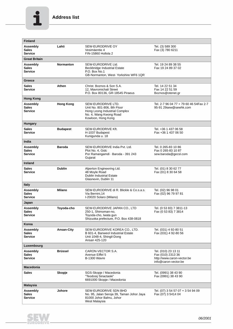
Address list
Finland
AssemblySalesService
Lahti SEW-EURODRIVE OYVesimäentie 4FIN-15860 Hollola 2
Tel. (3) 589 300Fax (3) 780 6211
Great Britain
AssemblySalesService
Normanton SEW-EURODRIVE Ltd.Beckbridge Industrial Estate P.O. Box No.1GB-Normanton, West- Yorkshire WF6 1QR
Tel. 19 24 89 38 55Fax 19 24 89 37 02
Greece
SalesService
Athen Christ. Boznos & Son S.A.12, Mavromichali StreetP.O. Box 80136, GR-18545 Piraeus
Tel. 14 22 51 34 Fax 14 22 51 [email protected]
Hong Kong
AssemblySalesService
Hong Kong SEW-EURODRIVE LTD.Unit No. 801-806, 8th FloorHong Leong Industrial ComplexNo. 4, Wang Kwong Road Kowloon, Hong Kong
Tel. 2-7 96 04 77 + 79 60 46 54Fax 2-7 95-91 [email protected]
Hungary
SalesService
Budapest SEW-EURODRIVE Kft.H-1037 BudapestKunigunda u. 18
Tel. +36 1 437 06 58Fax +36 1 437 06 50
India
AssemblySalesService
Baroda SEW-EURODRIVE India Pvt. Ltd.Plot No. 4, GidcPor Ramangamdi · Baroda - 391 243Gujarat
Tel. 0 265-83 10 86Fax 0 265-83 10 [email protected]
Ireland
SalesService
Dublin Alperton Engineering Ltd. 48 Moyle RoadDublin Industrial EstateGlasnevin, Dublin 11
Tel. (01) 8 30 62 77Fax (01) 8 30 64 58
Italy
AssemblySalesService
Milano SEW-EURODRIVE di R. Blickle & Co.s.a.s.Via Bernini,14 I-20020 Solaro (Milano)
Tel. (02) 96 98 01Fax (02) 96 79 97 81
Japan
AssemblySalesService
Toyoda-cho SEW-EURODRIVE JAPAN CO., LTD 250-1, Shimoman-no,Toyoda-cho, Iwata gunShizuoka prefecture, P.O. Box 438-0818
Tel. (0 53 83) 7 3811-13Fax (0 53 83) 7 3814
Korea
AssemblySalesService
Ansan-City SEW-EURODRIVE KOREA CO., LTD. B 601-4, Banweol Industrial Estate Unit 1048-4, Shingil-DongAnsan 425-120
Tel. (031) 4 92-80 51Fax (031) 4 92-80 56
Luxembourg
AssemblySalesService
Brüssel CARON-VECTOR S.A.Avenue Eiffel 5B-1300 Wavre
Tel. (010) 23 13 11Fax (010) 2313 36http://[email protected]
Macedonia
Sales Skopje SGS-Skopje / Macedonia"Teodosij Sinactaski” 6691000 Skopje / Macedonia
Tel. (0991) 38 43 90Fax (0991) 38 43 90
Malaysia
AssemblySalesService
Johore SEW-EURODRIVE SDN BHD No. 95, Jalan Seroja 39, Taman Johor Jaya81000 Johor Bahru, JohorWest Malaysia
Tel. (07) 3 54 57 07 + 3 54 94 09Fax (07) 3 5414 04
06/2001

Address list
Netherlands
AssemblySalesService
Rotterdam VECTOR Aandrijftechniek B.V. Industrieweg 175 NL-3044 AS RotterdamPostbus 10085NL-3004 AB Rotterdam
Tel. +31 10 44 63 700Fax +31 10 41 55 552http://[email protected]
New Zealand
AssemblySalesService
Auckland SEW-EURODRIVE NEW ZEALAND LTD. P.O. Box 58-428 82 Greenmount driveEast Tamaki Auckland
Tel. 0064-9-2 74 56 27Fax 0064-9-2 74 01 [email protected]
Christchurch SEW-EURODRIVE NEW ZEALAND LTD. 10 Settlers Crescent, FerrymeadChristchurch
Tel. (09) 3 84 62 51Fax (09) 3 84 64 [email protected]
Norway
AssemblySalesService
Moss SEW-EURODRIVE A/SSolgaard skog 71N-1599 Moss
Tel. (69) 2410 20Fax (69) 2410 [email protected]
Peru
AssemblySalesService
Lima SEW DEL PERU MOTORES REDUCTORES S.A.C.Los Calderos # 120-124Urbanizacion Industrial Vulcano, ATE, Lima
Tel. (511) 349-52 80Fax (511) 349-30 [email protected]
Poland
Sales Lodz SEW-EURODRIVE Polska Sp.z.o.o.ul. Pojezierska 63 91-338 Lodz
Tel. (042) 6 16 22 00Fax (042) 6 16 22 [email protected]
Portugal
AssemblySalesService
Coimbra SEW-EURODRIVE, LDA. Apartado 15 P-3050-901 Mealhada
Tel. (0231) 20 96 70Fax (0231) 20 36 [email protected]
Romania
SalesService
Bucuresti Sialco Trading SRL str. Madrid nr.4 71222 Bucuresti
Tel. (01) 2 30 13 28Fax (01) 2 30 71 70 [email protected]
Russia
Sales St. Petersburg ZAO SEW-EURODRIVE P.O. Box 193 193015 St. Petersburg
Tel. (812) 3 26 09 41 + 5 35 04 30Fax (812) 5 35 22 [email protected]
Singapore
AssemblySalesService
SEW-EURODRIVE PTE. LTD. No 9, Tuas Drive 2 Jurong Industrial Estate Singapore 638644
Tel. 8 62 17 01-705Fax 8 61 28 27Telex 38 659
Slovenia
SalesService
Celje Pakman - Pogonska Tehnika d.o.o.UI. XIV. divizije 14SLO – 3000 Celje
Tel. 00386 3 490 83 20Fax 00386 3 490 83 [email protected]
06/2001

ddress list
South Africa
AssemblySalesService
Johannesburg SEW-EURODRIVE (PROPRIETARY) LIMITEDEurodrive House Cnr. Adcock Ingram and Aerodrome RoadsAeroton Ext. 2Johannesburg 2013P.O.Box 90004Bertsham 2013
Tel. + 27 11 248 70 00Fax +27 11 494 23 11
Capetown SEW-EURODRIVE (PROPRIETARY) LIMITED Rainbow ParkCnr. Racecourse & Omuramba RoadMontague GardensCape TownP.O.Box 36556Chempet 7442 Cape Town
Tel. +27 21 552 98 20Fax +27 21 552 98 30Telex 576 062
Durban SEW-EURODRIVE (PROPRIETARY) LIMITED2 Monaceo PlacePinetownDurbanP.O. Box 10433, Ashwood 3605
Tel. +27 31 700 34 51Fax +27 31 700 38 47
Spain
AssemblySalesService
Bilbao SEW-EURODRIVE ESPAÑA, S.L. Parque Tecnológico, Edificio, 302E-48170 Zamudio (Vizcaya)
Tel. 9 44 31 84 70Fax 9 44 31 84 [email protected]
Sweden
AssemblySalesService
Jönköping SEW-EURODRIVE ABGnejsvägen 6-8S-55303 JönköpingBox 3100 S-55003 Jönköping
Tel. (036) 34 42 00Fax (036) 34 42 80www.sew-eurodrive.se
Switzerland
AssemblySalesService
Basel Alfred lmhof A.G.Jurastrasse 10 CH-4142 Münchenstein bei Basel
Tel. (061) 4 17 17 17Fax (061) 4 17 17 00http://[email protected]
Thailand
AssemblySalesService
Chon Buri SEW-EURODRIVE (Thailand) Ltd.Bangpakong Industrial Park 2700/456, Moo.7, Tambol DonhuarohMuang DistrictChon Buri 20000
Tel. 0066-38 21 40 22Fax 0066-38 21 45 31
Turkey
AssemblySalesService
Istanbul SEW-EURODRIVE Hareket Sistemleri San. ve Tic. Ltd. Sti Bagdat Cad. Koruma Cikmazi No. 3 TR-81540 Maltepe ISTANBUL
Tel. (0216) 4 41 91 63 + 4 41 91 64 + 3 83 80 14 + 3 83 80 15Fax (0216) 3 05 58 [email protected]
USA
ProductionAssemblySalesService
Greenville SEW-EURODRIVE INC. 1295 Old Spartanburg Highway P.O. Box 518Lyman, S.C. 29365
Tel. (864) 4 39 75 37Fax Sales (864) 439-78 30Fax Manuf. (864) 4 39-99 48Fax Ass. (864) 4 39-05 66Telex 805 550
AssemblySalesService
San Francisco SEW-EURODRIVE INC. 30599 San Antonio St.Hayward, California 94544-7101
Tel. (510) 4 87-35 60Fax (510) 4 87-63 81
Philadelphia/PA SEW-EURODRIVE INC. Pureland Ind. Complex 200 High Hill Road, P.O. Box 481Bridgeport, New Jersey 08014
Tel. (856) 4 67-22 77Fax (856) 8 45-31 79
Dayton SEW-EURODRIVE INC.2001 West Main Street Troy, Ohio 45373
Tel. (9 37) 3 35-00 36Fax (9 37) 4 40-37 99
Dallas SEW-EURODRIVE INC.3950 Platinum Way Dallas, Texas 75237
Tel. (214) 3 30-48 24Fax (214) 3 30-47 24
A
06/2001
dbrode
USA

Address list
Additional addresses for service in the USA provided on request!
Venezuela
AssemblySalesService
Valencia SEW-EURODRIVE Venezuela S.A.Av. Norte Sur No. 3, Galpon 84-319Zona Industrial Municipal NorteValencia
Tel. +58 (241) 8 32 98 04Fax +58 (241) 8 38 62 [email protected]@cantr.net
USA
06/2001

SEW-EURODRIVE GmbH & Co · P.O. Box 3023 · D-76642 Bruchsal/Germany · Phone +49-7251-75-0Fax +49-7251-75-1970 · http://www.sew-eurodrive.com · [email protected]

Gearmotors \ Industrial Gear Units \ Drive Electronics \ Drive Automation \ Services
AC Motors DR/DV/DT/DTE/DVE, Asynchronous Servo Motors CT/CV
Operating Instructions
A6.C01
Edition 08/200411291613 / EN

SEW-EURODRIVE – Driving the world

Operating Instructions – AC Motors DR / DV / DT / DTE / DVE / Asynchronous Servo Motors CT / CV 3
Contents
1 Important Notes................................................................................................. 4
2 Safety Notes ...................................................................................................... 5
3 Motor Design ..................................................................................................... 63.1 Basic structure of AC motors .................................................................... 63.2 Nameplate, unit designation ..................................................................... 7
4 Mechanical Installation..................................................................................... 94.1 Before you begin....................................................................................... 94.2 Preliminary work........................................................................................ 94.3 Installing the motor.................................................................................. 104.4 Installation tolerances ............................................................................. 11
5 Electrical Installation ...................................................................................... 125.1 Wiring notes ............................................................................................ 125.2 Special aspects for operation with a frequency inverter.......................... 125.3 Special aspects of single-phase motors.................................................. 125.4 Improving the grounding (EMC).............................................................. 135.5 Special aspects of torque motors and low-speed motors ....................... 135.6 Special aspects in switching operation ................................................... 145.7 Environmental conditions during operation............................................. 145.8 Connecting the motor.............................................................................. 155.9 Preparing motor sizes 56 and 63 – knockout.......................................... 165.10 Connecting DT56 motor...+/BMG............................................................ 165.11 Single-phase version ET56..................................................................... 175.12 Connecting the motor using the IS plug connector ................................. 175.13 Connect the motor using plug connectors AB.., AD.., AM.., AS.............. 215.14 Connecting the motor using ASK1 plug connector ................................. 215.15 Connecting the brake.............................................................................. 235.16 Accessory equipment.............................................................................. 24
6 Startup.............................................................................................................. 286.1 Prerequisites for startup.......................................................................... 286.2 Altering the blocking direction on motors with a backstop ...................... 29
7 Malfunctions .................................................................................................... 317.1 Motor Malfunctions.................................................................................. 317.2 Brake problems....................................................................................... 327.3 Malfunctions during operation with a frequency inverter......................... 32
8 Inspection / Maintenance................................................................................ 338.1 Inspection and maintenance intervals..................................................... 338.2 Preliminary work for motor and brake maintenance................................ 348.3 Inspection / maintenance on the motor .................................................. 378.4 Inspection / maintenance of the BMG02 brake....................................... 398.5 Inspection / maintenance of the brake BR03 .......................................... 408.6 Inspection / maintenance for BMG05-8, BM15-62 brakes ...................... 448.7 Inspection / maintenance of the BMG61/122 brake................................ 49
9 Technical Data................................................................................................. 529.1 Work done, braking torque BMG02......................................................... 529.2 Information for ordering a replacement BMG02...................................... 529.3 Work done, working air gap, braking torques of BMG05-8, BR03 .......... 539.4 Work done, working air gap, braking torques of BM15 - 62 .................... 549.5 Operating currents .................................................................................. 559.6 Permitted ball bearing types.................................................................... 599.7 Lubricant table for anti-friction bearings of SEW motors......................... 59
10 Appendix.......................................................................................................... 6010.1 Index of changes..................................................................................... 6010.2 Index ....................................................................................................... 61

4 Operating Instructions – AC Motors DR / DV / DT / DTE / DVE / Asynchrounos Servo Motors CT / CV
1 Important Notes
Betriebsanleitung1 Important NotesSafety and warning notes
Always follow the safety and warning instructions in these operating instructions!
You must adhere to the operating instructions to ensure:
• Trouble-free operation
• Fulfillment of any rights to claim under limited warranty
Consequently, read the operating instructions before you start operating the drive!
The operating instructions contain important information about servicing. Therefore,keep the operating instructions close to the drive.
Waste disposal Dispose of the following materials in accordance with the regulations in force:
• Iron
• Aluminum
• Copper
• Plastic
• Electronic components
Electrical hazardPossible consequences: Severe or fatal injuries.
Hazard Possible consequences: Severe or fatal injuries.
Hazardous situationPossible consequences: Slight or minor injuries.
Harmful situationPossible consequences: Damage to the drive and the environment.
Tips and useful information.

Operating Instructions – AC Motors DR / DV / DT / DTE / DVE / Asynchrounos Servo Motors CT / CV 5
2Safety Notes
2 Safety NotesPreface The following safety notes are concerned with the use of motors. If using gearmotors,
also refer to the safety notes for gear units in the corresponding operating instructions.
Please also consider the supplementary safety notes in the individual sections ofthese operating instructions.
General information
During and after operation, motors and gearmotors have live and moving parts and theirsurfaces may be hot.
All work related to transport, putting into storage, setting up/mounting,connection, startup, maintenance and repair may only be performed by trainedpersonnel observing
• The corresponding detailed operating instructions and wiring diagrams
• The warning and safety signs on the motor/gearmotor
• The specific regulations and requirements for the system
• The national / regional regulations governing safety and accident prevention
Severe injuries and damage to property may result from
• Improper use
• Incorrect installation or operation
• Unauthorized removal of necessary protection covers or the housing
Designated use These electric motors are intended for industrial systems. They fulfill the applicablestandards and regulations:
• Low voltage directive 73/23/EEC
Technical data and information about the permitted conditions can be found on thenameplate and in the documentation.
It is essential to observe all the specified information!
Transportation Inspect the shipment for damage as soon as you receive the delivery. Inform theshipping company immediately. It may be necessary to preclude startup.
Tighten installed eyebolts. They are only designed for the weight of themotor/gearmotor; do not attach any additional loads.
The installed lifting eyebolts comply with DIN 580. Observe the loads and regula-tions specified in this standard. If the gearmotor is equipped with two suspensioneye lugs or lifting eyebolts, then both of the suspension eye lugs should be usedfor transportation. In this case, the tension force vector of the slings must notexceed a 45° angle in accordance with DIN 580.
Use suitable, sufficiently rated handling equipment if necessary. Remove any transpor-tation fixtures prior to startup.
Installation / assembly
Follow the instructions in the section "Mechanical Installation"!
Inspection / maintenance
Follow the instructions in the section "Inspection and Maintenance"!

6 Operating Instructions – AC Motors DR / DV / DT / DTE / DVE / Asynchrounos Servo Motors CT / CV
3 Basic structure of AC motorsMotor Design
3 Motor Design
3.1 Basic structure of AC motors
The following illustration is intended to explain the general structure. Its only purpose isto facilitate the assignment of components to the spare parts lists. Discrepancies arepossible depending on the motor size and version!
02969AXX
10
7
1112
1
20 44 41
16
42
36
35
37
32
13
22
132131
112111
129
130 115113
119
123
116118
117
2107
106
9
100101
103
3
31
135
134
[1] Rotor, cpl. [31] Key [107] Oil-flinger ring [131] Sealing washer
[2] Circlip [32] Circlip [111] Gasket [132] Terminal box cover
[3] Key [35] Fan guard [112] Terminal box lower part [134] Screw plug
[7] Flanged end shield [36] Fan [113] Machine screw [135] Sealing washer
[9] Screw plug [37] V-ring [115] Terminal board
[10] Circlip [41] Equalizing ring [116] Terminal yoke
[11] Grooved ball bearing [42] Non drive-end bearing shield
[117] Hex head bolt
[12] Circlip [44] Grooved ball bearing [118] Lock washer
[13] Hex head screw (tie rod) [100] Hex nut [119] Machine screw
[16] Stator, cpl. [101] Lock washer [123] Hex head bolt
[20] Nilos ring [103] Stud [129] Screw plug
[22] Hex head bolt [106] Oil seal [130] Sealing washer

Operating Instructions – AC Motors DR / DV / DT / DTE / DVE / Asynchrounos Servo Motors CT / CV 7
3Nameplate, unit designationMotor Design
3.2 Nameplate, unit designation
Nameplate
Example: DFV 160 M4 /BM brake motor
Unit designation
Example: DR / DT / DV / DTE / DVE AC (brake) motors
Example: Serial number
03214BXX
DFV 132M2 / BM /TF / AMA1 / EV1T
Motor option: 5 V TTL incremental encoder
Motor option: AMB1 plug connector
Motor option: TF thermistor sensor
Motor option: Brake
Size 132M and 2-pole
Flange-mounted motor
01. 3009818304. 0002. 99
Year number end digits of the year of manufacture (2-digit)
Part number (4-digit)
Order number (10 digits)
Sales organization

8 Operating Instructions – AC Motors DR / DV / DT / DTE / DVE / Asynchrounos Servo Motors CT / CV
3 Nameplate, unit designationMotor Design
Nameplate
Example: CT90L4 / BMG / TF / ES1S servo brake motor
Unit designation
Examples: Servo (brake) motors CT / CV
Example: Serial number
51358BXX
CT90L4 BMG TF / ES1S
01.3410069302.0001.00
30.5
3000 10.5
103 345 7.9
B5 28 54 F
230~ 20 BGE 1.5
CFV 132M4 / BM / TF / EV1S
Motor option: Sine/cosine incremental encoder
Motor option: TF thermistor sensor
Motor option: Brake
Size 132M and 4-pole
Flange-mounted motor
01. 3009818304. 0002. 99
Year number end digits of the year of manufacture (2-digit)
Part number (4-digit)
Order number (10 digits)
Sales organization

Operating Instructions – AC Motors DR / DV / DT / DTE / DVE / Asynchrounos Servo Motors CT / CV 9
4Before you beginMechanical Installation
4 Mechanical Installation
4.1 Before you begin
The drive may only be installed if
• The entries on the nameplate of the drive and/or the output voltage of the frequencyinverter match the voltage supply system
• The drive is undamaged (no damage caused by transportation or storage)
• It is certain that the following requirements have been met:
– Ambient temperature between –20 °C and +40 °C1)
– No oil, acid, gas, vapors, radiation, etc.– Installation altitude max. 1000 m above sea level– Note the restrictions for encoders– Special versions: Drive configured in accordance with the ambient conditions
4.2 Preliminary work
Motor shaft ends must be thoroughly cleaned of anti-corrosion agents, contamination orsimilar (use a commercially available solvent). Do not allow the solvent to penetrate thebearings or shaft seals – this could cause material damage!
Extended storage of motors
• Please note the reduced grease utilization period of the ball bearings after storageperiods exceeding one year.
• Check whether the motor has absorbed moisture as a result of being stored for a longtime. Measure the insulation resistance to do this (measuring voltage 500 V).
The insulation resistance (→ following figure) varies greatly depending on thetemperature! The motor must be dried if the insulation resistance is not adequate.
It is essential to comply with the safety notes in Section 2 during installation!
1) Minimum temperature for motors with backstop: –15 °C. Note that the temperature range of the gear unitmay also be restricted (→ gear unit operating instructions)
01731AXX
100
10
1
0,10 20 40 60 80
[°C]
[M ]

10 Operating Instructions – AC Motors DR / DV / DT / DTE / DVE / Asynchrounos Servo Motors CT / CV
4 Installing the motorMechanical Installation
Drying the motor Heat up the motor
• with hot air or
• using an isolation transformer
– Connect the windings in series (→ following figure)– Auxiliary AC voltage supply max. 10 % of the rated voltage with max. 20 % of the
rated current
The drying process is finished when the minimum insulation resistance has beenattained.
Check the terminal box to see whether
• The inside is clean and dry
• The connections and fixing parts are free from corrosion
• The joint seals are OK
• The cable glands are sound, otherwise clean or replace them.
4.3 Installing the motor
The motor or gearmotor may only be mounted or installed in the specified mountingposition on a level and torsionally rigid support structure which is not subjected toshocks.
Carefully align the motor and the driven machine to avoid placing any unacceptablestrain on the output shafts (observe permissible overhung load and axial thrust data!).
Do not butt or hammer the shaft end.
Use an appropriate cover to protect motors in vertical mounting positions fromobjects or fluids entering (protection cowl C).
Ensure an unobstructed cooling air supply and that air heated by other apparatus cannotbe drawn in or reused.
Balance components for subsequent mounting on the shaft with a half key (motor shaftsare balanced with a half key).
Any condensation drain holes will be sealed by plastic plugs and should only beopened when necessary; open condensation drain holes are not permitted, asthis would invalidate higher classes of enclosure.
If using brake motors with manual brake release, screw in either the hand lever (withself-reengaging manual brake release) or the setscrew (with lockable manual brakerelease).
Note the following for encoder mounting:
Foot-mounted motors CT/DT71, CT/DT90, CV/DV132M, CV/DV160L must be mountedon supports because the radius of the cover is greater than the shaft height.
For foot-mounted (brake) motors sizes DTE90L and DVE132M, the shaft height corre-sponds to the IEC standard motor of the next higher power level (100 mm or 160 mm).The foot dimensions of DTE90, DVE180, and DVE225 motors differ from the IEC dimen-sions; see Sec. "Dimension Sheet Notes" in the Gearmotors catalog.
01730AEN
Transformer

Operating Instructions – AC Motors DR / DV / DT / DTE / DVE / Asynchrounos Servo Motors CT / CV 11
4Installation tolerancesMechanical Installation
Installation in damp locations or in the open
If possible, arrange the terminal box so the cable entries are pointing downwards.
Coat the threads of cable glands and pocket caps with sealant and tighten them well –then coat them again.
Seal the cable entry well.
Thoroughly clean the sealing surfaces of terminal boxes and terminal box covers priorto reassembly; gaskets must be glued in on one side. Install new gaskets to replaceembrittled ones!
Restore the anticorrosive coating if necessary.
Check the enclosure.
4.4 Installation tolerances
Shaft end Flanges
Diameter tolerance in accordance with DIN 748• ISO k6 at Ø ≤ 50 mm• ISO m6 at Ø > 50 mm• Center bore in accordance with DIN 332, shape
DR..
Centering shoulder tolerance in accordance with DIN 42948• ISO j6 at Ø ≤ 230 mm• ISO h6 at Ø > 230 mm

12 Operating Instructions – AC Motors DR / DV / DT / DTE / DVE / Asynchrounos Servo Motors CT / CV
5 Wiring notesElectrical Installation
5 Electrical InstallationIt is essential to comply with the safety notes in section 2 during installation!
Switch contacts in utilization category AC-3 to EN 60947-4-1 must be used forswitching the motor and the brake.
Using the wiring diagrams
The motor must only ever be connected as shown in the wiring diagram included withthe motor. Do not connect or start up the motor if this wiring diagram is missing.You can obtain the valid wiring diagram free of charge from SEW-EURODRIVE.
5.1 Wiring notes
Comply with the safety notes during installation.
Protecting brake control systems against interference
Do not route brake cables alongside switched-mode power cables, as otherwise thereis a risk of disrupting brake control systems.
Switched-mode power cables include in particular:
– Output cables from frequency and servo controllers, converters, soft start units andbrake units
– Feeder cables for brake resistors and similar options
Protecting motor protection devices against interference
To protect SEW motor protection devices (temperature sensors TF, winding thermostatsTH) against interference:
– Route separately shielded feeder cables together with switched-mode power lines inone cable
– Do not route unshielded feeder cables together with switched-mode power lines inone cable
5.2 Special aspects for operation with a frequency inverter
When motors are powered from inverters, you must adhere to the wiring instructionsissued by the inverter manufacturer. It is essential to observe the operating instructionsfor the frequency inverter.
5.3 Special aspects of single-phase motors
Bear in mind that SEW single-phase motors are supplied without accessory equipmentsuch as capacitors, starting relays or centrifugal switches (exception: ET56L4 → Sec."Single-phase version ET56"). Any parts you need must be obtained from your dealerand connected according to the corresponding instructions and wiring diagrams.

Operating Instructions – AC Motors DR / DV / DT / DTE / DVE / Asynchrounos Servo Motors CT / CV 13
5Improving the grounding (EMC)Electrical Installation
5.4 Improving the grounding (EMC)
For improved, low-impedance grounding at high frequencies, we recommend using thefollowing connections with the DR/DV/DT AC motors:
• Sizes DT71 ... DV 132S: [1] M5x10 thread rolling screw and 2 serrated lock washersto DIN 6798 in the stator housing.
• Sizes DV112M ... DV280: Screw and 2 serrated lock washers in the bore of the eyebolt.
Thread size of the eye bolt:
– DV112 / 132S: M8– DV132M ... 180L: M12– DV200 ... 280: M16
5.5 Special aspects of torque motors and low-speed motors
Due to the design of torque motors and low-speed motors, very high induction voltagesmay be generated when they are switched off. Consequently, SEW-EURODRIVErecommends using the varistor circuit shown below for protection. The size of the varis-tors depends, amongst other factors, on the starting frequency – note for project plan-ning!
[1]
01732CXX
U
U1
U U
V1 W1
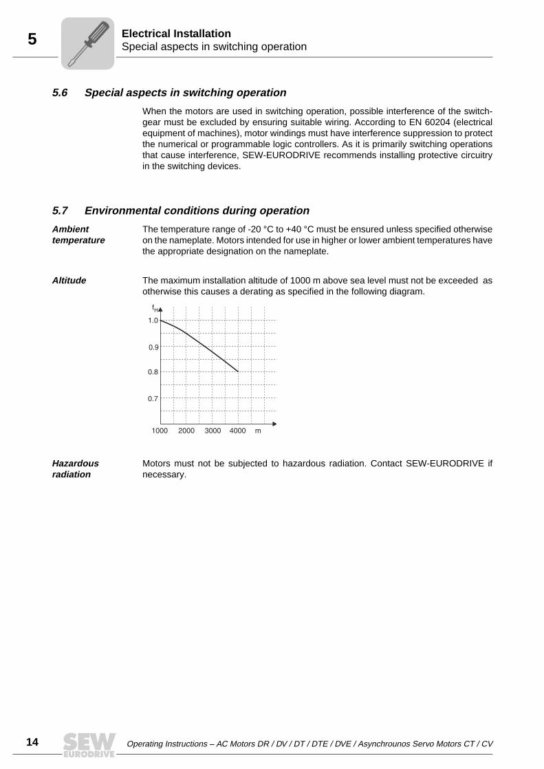
14 Operating Instructions – AC Motors DR / DV / DT / DTE / DVE / Asynchrounos Servo Motors CT / CV
5 Special aspects in switching operationElectrical Installation
5.6 Special aspects in switching operation
When the motors are used in switching operation, possible interference of the switch-gear must be excluded by ensuring suitable wiring. According to EN 60204 (electricalequipment of machines), motor windings must have interference suppression to protectthe numerical or programmable logic controllers. As it is primarily switching operationsthat cause interference, SEW-EURODRIVE recommends installing protective circuitryin the switching devices.
5.7 Environmental conditions during operation
Ambient temperature
The temperature range of -20 °C to +40 °C must be ensured unless specified otherwiseon the nameplate. Motors intended for use in higher or lower ambient temperatures havethe appropriate designation on the nameplate.
Altitude The maximum installation altitude of 1000 m above sea level must not be exceeded asotherwise this causes a derating as specified in the following diagram.
Hazardous radiation
Motors must not be subjected to hazardous radiation. Contact SEW-EURODRIVE ifnecessary.
1000 2000 3000 4000 m
0.7
0.8
0.9
1.0
fH

Operating Instructions – AC Motors DR / DV / DT / DTE / DVE / Asynchrounos Servo Motors CT / CV 15
5Connecting the motorElectrical Installation
5.8 Connecting the motor
Connecting the motor via terminal boxes
• According to the circuit diagram provided
• Check the line cross section
• Arrange terminal links correctly
• Screw connections and protective earth conductors on firmly
• In terminal boxes: Check winding connections and tighten them if necessary
Small connection accessories
Note: In the case of motor sizes DR63 - DV132S, the small connection accessories(connection nuts for feeder cables, terminal links, lock washer and washers) aresupplied in a bag. Depending on the type of terminal board, install the parts in accor-dance with the figure below. In the connection type shown on the right in the figurebelow, the second retaining nut, the lock washer and the washer are not used. Theexternal connection [6] can be installed directly or as a lug [4] below the connection disk[5]. The tightening torque of the hex net in the figure on the right is:
• 1.6 Nm ± 20 % for M4
• 2 Nm ± 20 % for M5
In case of operation with electronic control units, it is essential to adhere to thecorresponding operating instructions / wiring diagrams!
50926AXX
12345678
Terminal studLock washerConnection diskMotor terminal leadTop nutWasherExternal connectionBottom nut
123456
Terminal studHex nut with flangeTerminal linkMotor connection with Stocko connection terminalConnection diskExternal connection
1
1
2
3
4
5
6
2
3
4
5
6
7
8
The asynchronous servomotors of the CT/CV series are supplied with connectedterminal links according to the nameplate.

16 Operating Instructions – AC Motors DR / DV / DT / DTE / DVE / Asynchrounos Servo Motors CT / CV
5 Preparing motor sizes 56 and 63 – knockoutElectrical Installation
5.9 Preparing motor sizes 56 and 63 – knockout
Important: Wear safety glasses – danger of injury from fragments!
• Put on the terminal box cover and screw it into place
• Define which cable entries to open
• Open the cable entries
– with a chisel or similar (hold at an angle)– by a light tap with a hammer
Caution – Do not knock through into the inside of the terminal box!
• Open the terminal box, remove the knockout cover if it has broken off
• Secure the cable screw fittings with the supplied lock nuts
5.10 Connecting DT56 motor...+/BMG
The motor has a star point with three fixed connection points in the winding overhang.The supply system leads (L1, L2, L3) are connected to a spring cage terminal block [2]in the terminal box [1]. The BMG02 brake is controlled using the BG1.2 brake rectifier[3]. As an alternative, the brake can be controlled from the switch cabinet using BMseries rectifiers.
01733AXX
04861AXX
V WUTF TF
1
2
3

Operating Instructions – AC Motors DR / DV / DT / DTE / DVE / Asynchrounos Servo Motors CT / CV 17
5Single-phase version ET56Electrical Installation
5.11 Single-phase version ET56
The ET56 single-phase motor is supplied with a running capacitor that is mounted andconnected:
1~230 V, 50 Hz CB = 4 µF
1~230 V, 60 Hz CB = 4 µF
1~110 V, 60 Hz CB = 20 µF
5.12 Connecting the motor using the IS plug connector
The IS plug connector is supplied from the factory with its base fully wired-up, includingadditional features such as a brake rectifier. The upper section of the IS connector isincluded in the scope of delivery and must be connected as shown in the wiring diagram.
The IS plug connector has CSA approval up to 600 V. Note for application according toCSA regulations: Tighten the M3 terminal screws to a torque of 0.5 Nm! See thefollowing table for American Wire Gauge (AWG) line cross sections!
Line cross section
Make sure the type of line corresponds to the applicable regulations. The rated currentsare specified on the motor nameplate. The line cross sections that can be used are listedin the following table.
No full-load startup is possible with the running capacitor alone! The single-phase motor cannot be combined with a TF.
03075AXX
Without variable termi-nal link
With variable termi-nal link
Link cable Double assignment(Motor and brake/SR)
0.25 - 4.0 mm2 0.25 - 2.5 mm2 max. 1.5 mm2 max. 1 x 2.5 and 1 x 1.5 mm2
23 - 12 # AWG 23 - 14 # AWG max. 16 # AWG max. 1 x 14 # and 1 x 16 # AWG

18 Operating Instructions – AC Motors DR / DV / DT / DTE / DVE / Asynchrounos Servo Motors CT / CV
5 Connecting the motor using the IS plug connectorElectrical Installation
Wiring the upper section of the plug connection
• Loosen the housing cover screws
– Remove the housing cover
• Remove the screws from the upper section of the plug connector
– Remove the upper section of the plug connector from the cover
• Strip the insulation off the connection lead
– Strip about 9 mm insulation off the connecting leads
• Pass the cable through the cable gland
Wiring up as shown in circuit diagram DT82, DT83
• Connect the lines as shown in the circuit diagram
– Tighten the clamping screws carefully!
• Install the plug connector (→ Sec. "Installing the plug connector")
Wiring up as shown in wiring diagram DT81
For / startup:
• Connect with 6 lines
– Tighten the clamping screws carefully!– Motor contactors in the switch cabinet
• Install the plug connector (→ Sec. "Installing the plug connector")
For or operation:
• Connect as shown in the wiring diagram
• Install the variable terminal link as shown in the following figures according to therequired motor operation ( or )
• Install the plug connector (→ Sec. "Installing the plug connector")
01734AXX 01735AXX

Operating Instructions – AC Motors DR / DV / DT / DTE / DVE / Asynchrounos Servo Motors CT / CV 19
5Connecting the motor using the IS plug connectorElectrical Installation
Brake control system BSR – preparing the variable terminal link
For operation:
On the side of the variable terminal link as shown in the following figure: Remove onlythe bare metal pin of the marked prong horizontally – touch guard!
For operation:
On the side of the variable terminal link as shown in the following figure: Completelyremove two prongs horizontally.
Wiring according to the DT81 wiring diagram for or operation with double terminal assignment
• At terminal point for double assignment:
– Connect the link cable
• When operation is as required:
– Insert the link cable in the variable terminal link
• Install the variable terminal link
• At terminal point for double assignment:
– Connect the motor lead above the variable terminal link
• Connect the other lines as shown in the wiring diagram.
• Install the plug connector (→ Sec. "Installing the plug connector")
50429AXX
50430AXX
01738AXX
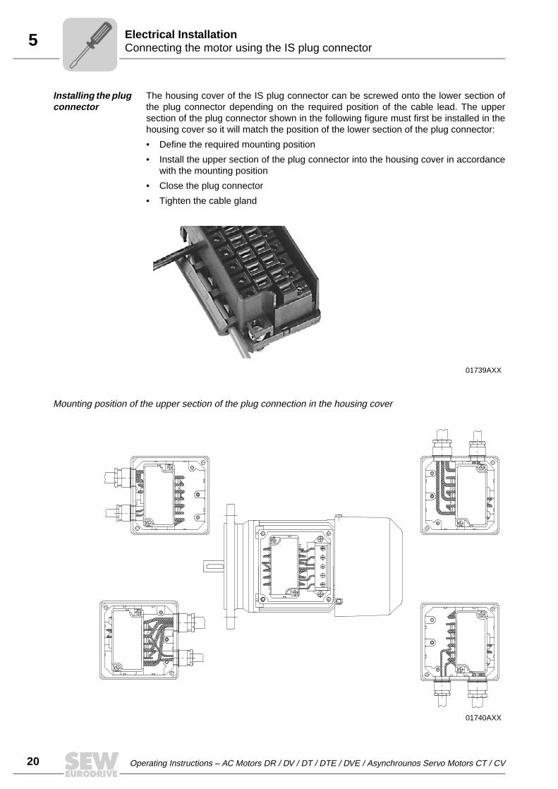
20 Operating Instructions – AC Motors DR / DV / DT / DTE / DVE / Asynchrounos Servo Motors CT / CV
5 Connecting the motor using the IS plug connectorElectrical Installation
Installing the plug connector
The housing cover of the IS plug connector can be screwed onto the lower section ofthe plug connector depending on the required position of the cable lead. The uppersection of the plug connector shown in the following figure must first be installed in thehousing cover so it will match the position of the lower section of the plug connector:
• Define the required mounting position
• Install the upper section of the plug connector into the housing cover in accordancewith the mounting position
• Close the plug connector
• Tighten the cable gland
Mounting position of the upper section of the plug connection in the housing cover
01739AXX
01740AXX

Operating Instructions – AC Motors DR / DV / DT / DTE / DVE / Asynchrounos Servo Motors CT / CV 21
5Connect the motor using plug connectors AB.., AD.., AM.., ASElectrical Installation
5.13 Connect the motor using plug connectors AB.., AD.., AM.., AS
The installed plug connector systems AB.., AD.., AM.., AC.. and AS.. are based on theplug connector systems made by Harting.
• AB.., AD.., AM.. → Han Modular®
• AC.., AS.. → Han 10E / 10ES
The plugs are mounted on the side of the terminal box. They are locked either using twoclamps or one clamp on the terminal box.
UL approval has been granted for the plug connectors.
The mating connectors (sleeve housing) with contact tubes are not included inthe scope of delivery.
The enclosure is only applied when the mating connector is mounted and locked.
5.14 Connecting the motor using ASK1 plug connector
Drives with ASK1 plug connectors are certified according to the ECOFAST specification(version 1.1). Switchgear or control units which also have to be certified can beconnected to SEW-EURODRIVE motors using a pre-fabricated system cable or a carri-er plate (installation integrated in the motor → Fig. B). The ASK1 plug connector withsingle-clip locking is mounted on the side of the terminal box and is supplied from the
50956AXX
AMA1 ASE1
51081AXX
ASK1
A B
ASK1
2
11
ECOcertifiedFAST

22 Operating Instructions – AC Motors DR / DV / DT / DTE / DVE / Asynchrounos Servo Motors CT / CV
5 Connecting the motor using ASK1 plug connectorElectrical Installation
factory fully wired up, including additional features such as a brake rectifier.
Position of the plug connector
Possible positions of the ASK1 plug connector are "X" (= normal position), "1", "2" or "3".Unless specified otherwise, the unit is supplied with the plug connector in position "3".For installation integrated in the motor (using the carrier plate), units are exclusivelysupplied with the plug connector in position "3".
Installing the carrier plate
• Unscrew and remove four retaining screws [1] below the terminal box (→ Fig. A)
• Place the carrier plate [2] against the holes for the retaining screws and install it byscrewing in the four retaining screws [1] (→ Fig. B).
• The customer must obtain the system cable pre-fabricated according to theECOFAST specification from a specialist retailer.
• For installation integrated in the motor according to the ECOFAST specifica-tion, the customer must obtain the carrier plate from SEW-EURODRIVE byquoting part number 0187 390 3. Carrier plates from other manufacturers donot fit on SEW-EURODRIVE motors.
51323AXX
1
X
3
2ASK1
Operating Instructions – AC Motors DR / DV / DT / DTE / DVE / Asynchrounos Servo Motors CT / CV 23
5Connecting the brakeElectrical Installation
5.15 Connecting the brake
The brake is released electrically. The brake is applied mechanically when the voltageis switched off.
• Connect the brake according to the wiring diagram supplied with the brake.
• Note:In view of the DC voltage to be switched and the high level of current load, it isessential to use either special brake contactors or AC contactors with contacts inutilization category AC-3 to EN 60947-4-1.
• Attach one of the following options for the version with manual brake release
– Hand lever (for self-reengaging manual brake release)– Setscrew (for locking manual brake release)
• After replacing the brake disc, the maximum braking torque is reached only after sev-eral cycles.
Connecting the brake control system
The DC disk brake is powered from a brake control system with a protection circuit. It islocated in the terminal box / IS lower part or must be installed in the switch cabinet (→Sec. "Wiring notes").
• Check the line cross sections - braking currents (→ Sec. "Technical Data")
• Connect the brake control system according to the wiring diagram supplied with thebrake
• For motors in thermal class H, install the brake rectifier in the switch cabinet!
Comply with the applicable regulations issued by the relevant employer's liabilityinsurance association regarding phase failure protection and the associatedcircuit/circuit modification!

24 Operating Instructions – AC Motors DR / DV / DT / DTE / DVE / Asynchrounos Servo Motors CT / CV
5 Accessory equipmentElectrical Installation
5.16 Accessory equipment
Connect supplied accessory equipment according to the wiring diagrams included.
TF temperature sensor
The positive temperature coefficient (PTC) thermistors comply with DIN 44082.
Resistance measurement (measuring instrument with V ≤ 2.5 V or I < 1 mA):
• Standard measured values: 20...500 Ω, thermal resistance > 4000 Ω• Measured values pole-changing with separate winding: 40...1000 Ω,
Thermal resistance > 4000 Ω
TH winding thermostatsThe thermostats are connected in series as standard and open when the permittedwinding temperature is exceeded. They can be connected in the drive monitoring loop.
Forced cooling fan
Motor sizes 71 - 132S
Do not apply voltage!
When using the temperature sensor for thermal monitoring, the evaluation function mustbe activated to maintain reliable isolation of the temperature sensor circuit. If thetemperature reaches an excessive level, the thermal protection function must beeffective immediately.
VAC VDC
Voltage U [V] 250 400 60 24
Current (cos ϕ = 1.0) [A]
2.5 0.75 1.0 1.6
Current (cos ϕ = 0.6) [A]
1.6 0.5
Contact resistance max. 1 ohm at 5 V = / 1 mA
VS system
• 1 x 230 VAC, 50 Hz
• Connection in separate terminal box
• Max. connection cross section 3 x 1.5 mm2
• Cable screw fitting M16x1.5
Refer to the VS wiring diagram for information about connecting the VS forced coolingfan (order number: 0975 8385).

Operating Instructions – AC Motors DR / DV / DT / DTE / DVE / Asynchrounos Servo Motors CT / CV 25
5Accessory equipmentElectrical Installation
The VR forced cooling fan is available for 24 V DC voltage and for 100 ... 240 V ACvoltage.
The AC voltage type includes a VR forced cooling fan and the UWU51A switch-modepower supply (→ following figure).
• Input: 90 ... 265 VAC – 6 % / + 10 %, 50/60 Hz
• Output: 24 VDC – 1 % / + 2 %, 1.3 A
• Connection: Terminal screws 0.2 ... 2.5 mm2, separable
• Enclosure: IP20; mounted on mounting rail EN 60715TH35 in the switch cabinet
VR system
• 24 VDC ± 20 %
• Plug connector
• Max. connection cross section 3x1 mm2
• Pg7 cable gland with 7 mm inside diamater
50990AXX
54411AXX
1
2-+
24V DC
77
3886.5
76
Refer to the VR wiring diagram for information about connecting the VR forced coolingfan (order number: 0880 3198)

26 Operating Instructions – AC Motors DR / DV / DT / DTE / DVE / Asynchrounos Servo Motors CT / CV
5 Accessory equipmentElectrical Installation
Motor size 132M - 280
A transformer may be present in the VS system to adapt to a voltage other than thestandard. The VS and V systems are also available for 60 Hz.
Overview of encoders
V system
• 3 x 400 VAC, 50 Hz
• Connection in separate terminal box
• Max. connection cross section 4 x 1.5 mm2
• Cable gland M16x1.5
Refer to the V wiring diagram for information about connecting the V system (ordernumber: 0975 8385).
Encoder
For SEW motor Encoder type ShaftSpecifica-
tionSupply Signal
EH1T1)
DR63... Encoder Hollow shaft -
5 VDC regulated 5 VDC TTL/RS-422
EH1S2)
24 VDC
1 Vss sin/cos
EH1R 5 VDC TTL/RS-422
EH1C 24 VDC HTL
ES1T1)
CT/DT/CV/DV71...100DTE/DVE90...100
Encoder
Spreadshaft
-
5 VDC regulated 5 VDC TTL/RS-422
ES1S2)
24 VDC
1 Vss sin/cos
ES1R 5 VDC TTL/RS-422
ES1C 24 VDC HTL
ES2T1)
CV/DV(E)112...132S
5 VDC regulated 5 VDC TTL/RS-422
ES2S2)
24 VDC
1 Vss sin/cos
ES2R 5 VDC TTL/RS-422
ES2C 24 VDC HTL
EV1T1)
CT/CV71...200DT/DV71...280
DTE/DVE90...225Solid shaft
5 VDC regulated 5 VDC TTL/RS-422
EV1S2)
24 VDC
1 Vss sin/cos
EV1R 5 VDC TTL/RS-422
EV1C 24 VDC HTL
NV11
DT/DV71...132DTE/DVE90...132S Proximity sensor Solid shaft
A track
24 VDC
1 pulse/revolution, nor-mally open contactNV21 A+B tracks
NV12 A track 2 pulses/revolution, normally open contactNV22 A+B tracks
NV16 A track 6 pulses/revolution, normally open contactNV26 A+B tracks
AV1Y CT/CV71...200DT/DV71...280
DTE/DVE90...225
absolute encoderSolid shaft -
15/24 VDCMSSI interface and 1
Vss sin/cos
AV1H3) HIPERFACE® encoder 12 VDC
RS485 interface and 1 Vss sin/cos
1) Recommended encoder for operation with MOVITRAC® 31C
2) Recommended encoder for operation with MOVIDRIVE®
3) recommended encoder for operation with MOVIDRIVE® compact

Operating Instructions – AC Motors DR / DV / DT / DTE / DVE / Asynchrounos Servo Motors CT / CV 27
5Accessory equipmentElectrical Installation
• Refer to the following wiring diagrams for information about connectingES1./ES2./EV1./EH1. encoders and AV1Y and AV1H absolute encoders:
• Wiring diagrams for ES1./ES2./EV1./EH1. encoders: Order number 0918 6832• Wiring diagram AV1Y absolute encoder: Order number 0918 6808• Wiring diagram AV1H absolute encoder: Order number 1052 9705
Encoder connection
When connecting the encoders to the inverters, always follow the operating instructionsfor the relevant inverter!
• Maximum line length (inverter - encoder):
– 100 m with a capacitance per unit length ≤ 120 nF/km
• Core cross section: 0,20 ... 0.5 mm2
• Use a shielded cable with twisted pairs of insulated conductors (exception: cable forHTL sensor) and connect the shield over a large surface area at both ends:
– to the encoder in the cable gland or in the encoder plug– to the inverter on the electronics shield clamp or to the housing of the sub D plug
• Install the encoder cables separately from the power cables, maintaining a distanceof at least 200 mm.
• Maximum oscillation load for encoder ≤ 10 g ≈ 100 m/s2 (10 Hz ... 2 kHz)
• Shock resistance ≤ 100 g ≈ 1000 m/s2
00
I

28 Operating Instructions – AC Motors DR / DV / DT / DTE / DVE / Asynchrounos Servo Motors CT / CV
6 Prerequisites for startupStartup
6 Startup6.1 Prerequisites for startup
Before startup, make sure that
• The drive is undamaged and not blocked
• The measures stipulated in the "Preliminary work" section are performed afterextended storage
• All connections have been made properly
• The direction of rotation of the motor/gearmotor is correct
– (motor rotating clockwise: U, V, W to L1, L2, L3)
• All protective covers have been fitted correctly
• All motor protection equipment is active and set for the rated motor current
• The self-reengaging manual brake release is used in case of hoist drives
• There are no other sources of danger present
During startup, make sure that
• The motor is running correctly (no overload, no speed fluctuation, no loud noises,etc.)
• The correct braking torque is set according to the specific application (→ Sec. "Tech-nical Data")
• In case of problems (→ Sec. "Malfunctions")
It is essential to comply with the safety notes in Sec. 2 during startup!
In brake motors with self-reengaging manual brake release, the manual brakerelease lever must be removed after startup. A bracket is provided for storing thelever on the outside of the motor.
00
I

Operating Instructions – AC Motors DR / DV / DT / DTE / DVE / Asynchrounos Servo Motors CT / CV 29
6Altering the blocking direction on motors with a backstopStartup
6.2 Altering the blocking direction on motors with a backstop
Dimension "x" after installation
50447AXX
[1] Fan guard[2] Fan[3] Hexagon socket head cap screw[4] V-ring
[5] Felt ring[6] Circlip[7] Threaded hole[8] Carrier
[9] Wedge element train[10] Equalizing ring
6107
1243589
X
Motor Dimension "x" after instal-lation
DT71/80 6.7 mm
DT90/DV100 9.0 mm
DV112/132S 9.0 mm
DV132M-160M 11.0 mm
DV160L - 225 11.0 mm
DV250-280 13.5 mm
00
I

30 Operating Instructions – AC Motors DR / DV / DT / DTE / DVE / Asynchrounos Servo Motors CT / CV
6 Altering the blocking direction on motors with a backstopStartup
Do not start up the motor in the blocking direction (note the phase angle whenconnecting). Note the direction of rotation of the output shaft and the number of stageswhen mounting the motor on a gear unit. The backstop can be operated once in theblocking direction at half the motor voltage for checking purposes.
1. Isolate the motor from the supply, safeguarding it against unintentional power-up.
2. Remove fan guard [1] and fan [2], unscrew hexagon socket head cap screws [3]
3. Remove the V-ring [4] and sealing flange with felt ring [5]. (Collect the grease forsubsequent use.)
4. Remove the circlip [6] (not for DT71/80); for DV132M-160M, also remove theequalizing rings [10].
5. Pull the carrier [8] and wedge element train [9] completely off the threaded holes [7],turn them by 180° and press them back on.
6. Refill the grease.
7. Important: Do not exert pressure on or hit the wedge element train – danger ofdamaging the material!
8. During the press-in operation – shortly before the wedge element penetrates thelocking collar – slowly turn the rotor shaft by hand in the direction of rotation. Thisallows the wedge element to slide into the locking collar more easily.
9. Install the remaining parts of the backstop by following steps 4. to 2. in reverse order.Note the installation dimension "x" for the V-ring [4].
00
I
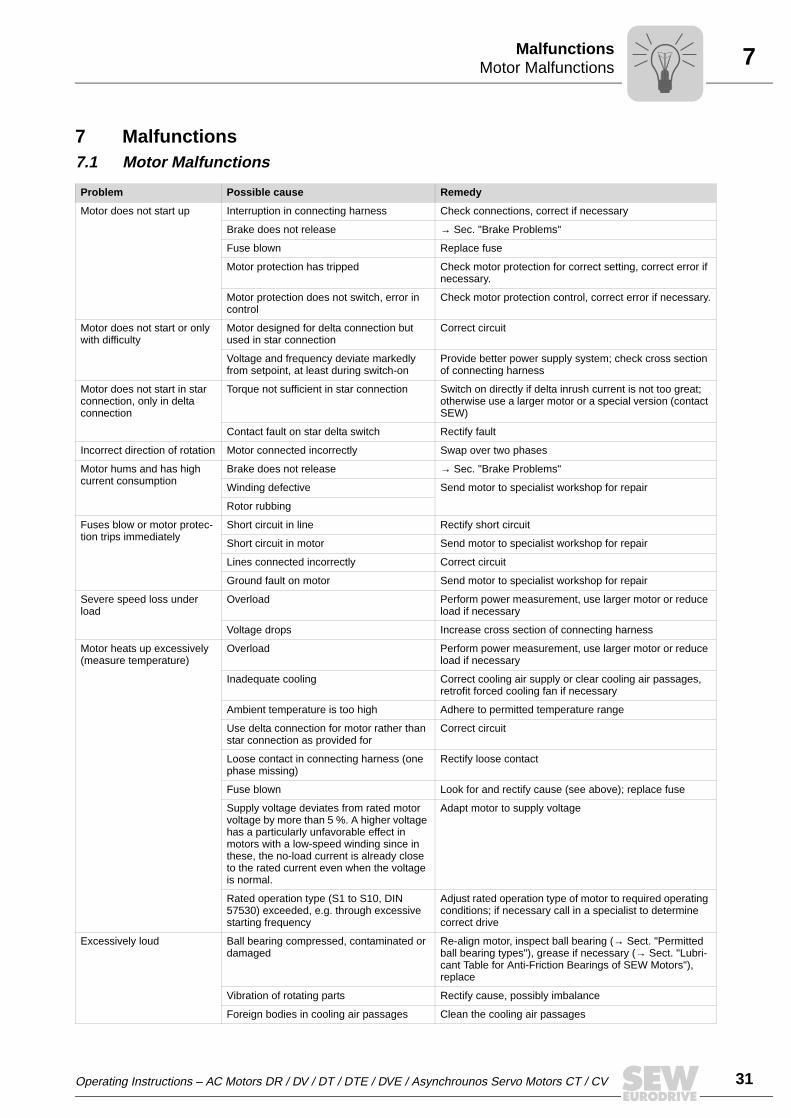
Operating Instructions – AC Motors DR / DV / DT / DTE / DVE / Asynchrounos Servo Motors CT / CV 31
7Motor MalfunctionsMalfunctions
7 Malfunctions7.1 Motor Malfunctions
Problem Possible cause Remedy
Motor does not start up Interruption in connecting harness Check connections, correct if necessary
Brake does not release → Sec. "Brake Problems"
Fuse blown Replace fuse
Motor protection has tripped Check motor protection for correct setting, correct error if necessary.
Motor protection does not switch, error in control
Check motor protection control, correct error if necessary.
Motor does not start or only with difficulty
Motor designed for delta connection but used in star connection
Correct circuit
Voltage and frequency deviate markedly from setpoint, at least during switch-on
Provide better power supply system; check cross section of connecting harness
Motor does not start in star connection, only in delta connection
Torque not sufficient in star connection Switch on directly if delta inrush current is not too great; otherwise use a larger motor or a special version (contact SEW)
Contact fault on star delta switch Rectify fault
Incorrect direction of rotation Motor connected incorrectly Swap over two phases
Motor hums and has high current consumption
Brake does not release → Sec. "Brake Problems"
Winding defective Send motor to specialist workshop for repair
Rotor rubbing
Fuses blow or motor protec-tion trips immediately
Short circuit in line Rectify short circuit
Short circuit in motor Send motor to specialist workshop for repair
Lines connected incorrectly Correct circuit
Ground fault on motor Send motor to specialist workshop for repair
Severe speed loss under load
Overload Perform power measurement, use larger motor or reduce load if necessary
Voltage drops Increase cross section of connecting harness
Motor heats up excessively (measure temperature)
Overload Perform power measurement, use larger motor or reduce load if necessary
Inadequate cooling Correct cooling air supply or clear cooling air passages, retrofit forced cooling fan if necessary
Ambient temperature is too high Adhere to permitted temperature range
Use delta connection for motor rather than star connection as provided for
Correct circuit
Loose contact in connecting harness (one phase missing)
Rectify loose contact
Fuse blown Look for and rectify cause (see above); replace fuse
Supply voltage deviates from rated motor voltage by more than 5 %. A higher voltage has a particularly unfavorable effect in motors with a low-speed winding since in these, the no-load current is already close to the rated current even when the voltage is normal.
Adapt motor to supply voltage
Rated operation type (S1 to S10, DIN 57530) exceeded, e.g. through excessive starting frequency
Adjust rated operation type of motor to required operating conditions; if necessary call in a specialist to determine correct drive
Excessively loud Ball bearing compressed, contaminated or damaged
Re-align motor, inspect ball bearing (→ Sect. "Permitted ball bearing types"), grease if necessary (→ Sect. "Lubri-cant Table for Anti-Friction Bearings of SEW Motors"), replace
Vibration of rotating parts Rectify cause, possibly imbalance
Foreign bodies in cooling air passages Clean the cooling air passages

32 Operating Instructions – AC Motors DR / DV / DT / DTE / DVE / Asynchrounos Servo Motors CT / CV
7 Brake problemsMalfunctions
7.2 Brake problems
7.3 Malfunctions during operation with a frequency inverter
The symptoms described in the "Motor Malfunctions" section may also occur when themotor is operated with a frequency inverter. Please refer to the frequency inverteroperating instructions for the significance of the problems which occur and to findinformation about rectifying the problems.
Customer service
Problem Possible cause Remedy
Brake does not release Incorrect voltage on brake control unit Apply correct voltage
Brake control unit failed Install a new brake control system, check internal resis-tance and insulation of brake coil, check switchgear
Max. permitted working air gap exceeded because brake lining worn down
Measure and set working air gap
Voltage drop along connecting harness > 10 %
Provide for correct connection voltage; check cable cross section
Inadequate cooling, brake overheats Replace type BG brake rectifier with type BGE
Brake coil has interturn fault or short circuit to exposed conductive part
Replace complete brake and brake control system (spe-cialist workshop), check switchgear
Rectifier defective Replace the rectifier and brake coil
Motor does not brake Working air gap not correct Measure and set working air gap
Brake lining worn down Replace entire brake disk
Incorrect braking torque Change the braking torque (→ Sect. "Technical Data")• By the type and number of brake springs• BrakeBMG 05: By installing the same brake coil body
design as in brakeBMG 1• BrakeBMG 2: By installing the same brake coil body
design as in brakeBMG 4
BM(G) only: Working air gap so large that set-ting nuts come into contact
Set the working air gap
Only BR03, BM(G): Manual brake release device not set correctly
Set the setting nuts correctly
Brake is applied with time lag
Brake is switched on AC voltage side Switch on DC and AC voltage sides (e.g. BSR); please refer to wiring diagram
Noise in the brake area Gearing wear caused by jolting startup Check project planning
Pulsating torques due to incorrectly set fre-quency inverter
Check/correct setting of frequency inverter according to operating instructions
Please have the following information to hand if you require the assistance of our customer service:• Data from the nameplate (complete)• Nature and extent of the fault• Time and peripheral circumstances of the fault• Presumed cause
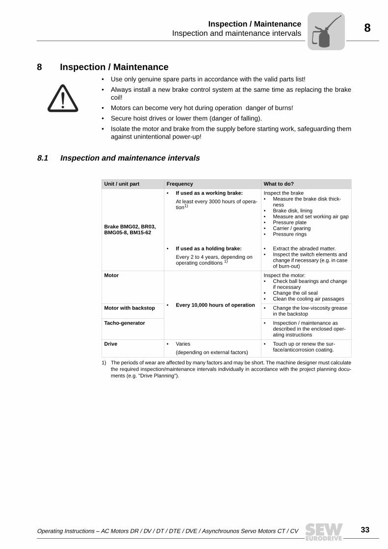
Operating Instructions – AC Motors DR / DV / DT / DTE / DVE / Asynchrounos Servo Motors CT / CV 33
8Inspection and maintenance intervalsInspection / Maintenance
8 Inspection / Maintenance• Use only genuine spare parts in accordance with the valid parts list!
• Always install a new brake control system at the same time as replacing the brakecoil!
• Motors can become very hot during operation danger of burns!
• Secure hoist drives or lower them (danger of falling).
• Isolate the motor and brake from the supply before starting work, safeguarding themagainst unintentional power-up!
8.1 Inspection and maintenance intervals
Unit / unit part Frequency What to do?
Brake BMG02, BR03, BMG05-8, BM15-62
• If used as a working brake:
At least every 3000 hours of opera-tion1)
• If used as a holding brake:
Every 2 to 4 years, depending on operating conditions 1)
1) The periods of wear are affected by many factors and may be short. The machine designer must calculatethe required inspection/maintenance intervals individually in accordance with the project planning docu-ments (e.g. "Drive Planning").
Inspect the brake• Measure the brake disk thick-
ness• Brake disk, lining• Measure and set working air gap• Pressure plate• Carrier / gearing• Pressure rings
• Extract the abraded matter.• Inspect the switch elements and
change if necessary (e.g. in case of burn-out)
Motor
• Every 10,000 hours of operation
Inspect the motor:• Check ball bearings and change
if necessary• Change the oil seal• Clean the cooling air passages
Motor with backstop • Change the low-viscosity grease in the backstop
Tacho-generator • Inspection / maintenance as described in the enclosed oper-ating instructions
Drive • Varies
(depending on external factors)
• Touch up or renew the sur-face/anticorrosion coating.

34 Operating Instructions – AC Motors DR / DV / DT / DTE / DVE / Asynchrounos Servo Motors CT / CV
8 Preliminary work for motor and brake maintenanceInspection / Maintenance
8.2 Preliminary work for motor and brake maintenance
Removing the EV1. incremental encoder / AV1H absolute encoder
• Remove the protective canopy [361]. If a forced cooling fan is fitted, remove it first.
• Unscrew the screw [366] from the adapter flange and remove the cover plate [369].
• Unscrew the clamping hub connection of the coupling.
• Loosen the retaining screws [232] and turn the conical spring washers [251]outwards.
• Remove the encoder [220] together with the coupling [233].
• Lever off the intermediate flange [236] after removing the screws [234].
Note:
During re-assembly, make sure the runout of the shaft end is ≤ 0.05 mm.
Brakes for the encoder mounting must be completely replaced.
Isolate the motor and brake from the power supply before starting work,safeguarding them against unintentional power-up!
51322AXX 51324AXX
Removing EV1. / AV1 encoders from motors up to size 225 Removing EV1. / AV1 encoders from motors from size 250 upwards
361
220
EV1.
AV1.
369
232251366233236
234 369 251 232 361234703
366236 233550
EV1.
AV1.
220
[220] Encoder[232] Hexagon socket head cap screw[233] Coupling[234] Hex head screw
[236] Adapter flange[251] Conical spring washer[361] Protective canopy / fan guard[366] Hexagon socket head cap screw
[369] Cover plate[550] Brake[703] Hex head screw

Operating Instructions – AC Motors DR / DV / DT / DTE / DVE / Asynchrounos Servo Motors CT / CV 35
8Preliminary work for motor and brake maintenanceInspection / Maintenance
Incremental encoder ES1. Removing / ES2. / EH1.
• Remove the protective canopy [361].
• Unscrew the retaining screws [733] for the torque arm.
• Open the screw cover at the rear of the encoder [220].
• Unscrew the central retaining screw [367] by about 2-3 turns and loosen the cone bytapping lightly on the head of the screw. Then unscrew the retaining screw and pulloff the encoder.
54196AXX
[220] Encoder[367] Retaining screw
[361] Protective canopy[733] Retaining screw for torque arm
367733 220 3611 220 367
During re-assembly:
– Apply Noco® fluid to the encoder spigot
– Tighten the central retaining screw [367] to 2.9 Nm.

36 Operating Instructions – AC Motors DR / DV / DT / DTE / DVE / Asynchrounos Servo Motors CT / CV
8 Preliminary work for motor and brake maintenanceInspection / Maintenance
Removing the proximity sensor NV1. / NV2.
• Disconnect plug
• Pull off the fan guard including NV1. / NV2. Do not tilt it, in order to avoid damagingthe proximity switch.
• If the mounting block has been removed from the fan guard or has come loose, it isessential to ensure the following during re-assembly:
The switching surface of the proximity switch must be calibrated to a distance of3.5 mm from the edge of the prismatic block (→ figure above).
01114CXX
Caution! It is essential for the fan wheel to be stationary!
3.5

Operating Instructions – AC Motors DR / DV / DT / DTE / DVE / Asynchrounos Servo Motors CT / CV 37
8Inspection / maintenance on the motorInspection / Maintenance
8.3 Inspection / maintenance on the motor
Example: Motor DFT90
Key
54008AXX
12
3
4 5
67
8
911 12
13
14
16
1718
1
20
9
15
1 Circlip 8 Circlip 16 V-ring
2 Oil-flinger ring 9 Rotor 17 Fan
3 Oil seal 11 Ball bearing 18 Circlip
4 Screw plug 12 Equalizing ring 19 Fan guard
5 Drive end bearing end shield 13 Stator 20 Housing screw
6 Circlip 14 Non drive-end bearing shield
7 Ball bearing 15 Hex head bolt

38 Operating Instructions – AC Motors DR / DV / DT / DTE / DVE / Asynchrounos Servo Motors CT / CV
8 Inspection / maintenance on the motorInspection / Maintenance
Sequence
1. Remove the forced cooling fan and encoder, if installed (→ Sec. "Preliminary workfor motor and brake maintenance")
2. Remove flange or fan guard [19], fan [17].
3. Remove the hex head bolt [15] from the drive end bearing end shield [5] and the non-drive end bearing end shield [14], release the stator [13] from the drive end bearingend shield.
4. Motors with BM/BMG brake:
– Open the terminal box cover, unfasten the brake cable from the rectifier– Push the non-drive end bearing end shield and the brake off the stator and
carefully lift them off (if necessary, run the brake cable along with trailing wire)– Pull the stator back by approx. 3 to 4 cm
5. Motors with BMG02, BR03 brake:
– Remove the complete brake with the releasing lever (on version with manualbrake release)
6. Visual inspection: Are there traces of gear oil or condensation inside the stator?
– If not, continue with 9– If there is condensation, continue with 7– If there is gear oil, have the motor repaired by a specialist workshop
7. If there is moisture inside the stator:
– With gearmotors: Remove the motor from the gear unit– With motors without a gear unit: Remove the drive end flange– Remove the rotor [9]
8. Clean the winding, dry it and check it electrically (→ Sec. "Preliminary work")
9. Replace the ball bearings [7], [11] (only use authorized ball bearings → Sec."Permitted ball bearing types")
10.Reseal the stator seat ("Hylomar L Spezial") and grease the V-ring or labyrinth seal(DR63)
11.Install the motor, brake and accessories
12.Check the gear unit (→ gear unit operating instructions)
Lubrication of the backstop
The backstop is supplied with Mobil LBZ low-viscosity grease as a lubricant andanticorrosion protection. If you want to use a different grease, make sure it complies withNLGI class 00/000, with a base oil viscosity of 42 mm2/s at 40 °C on a lithium saponifiedand mineral oil base. The temperature range extends from –50 °C to +90 °C. See thefollowing table for the amount of grease required.
Isolate the motor and brake from the supply, safeguarding them against uninten-tional power-up!
Motor type 71/80 90/100 112/132 132M/160M 160L/225 250/280
Grease [g] 9 15 15 20 45 80

Operating Instructions – AC Motors DR / DV / DT / DTE / DVE / Asynchrounos Servo Motors CT / CV 39
8Inspection / maintenance of the BMG02 brakeInspection / Maintenance
8.4 Inspection / maintenance of the BMG02 brake
Measure the brake disk thickness, install a new brake BMG02
The status of the brake disk is ascertained by measuring the brake disk thickness. Installa new BMG02 brake once the brake disk thickness reaches the minimum value (→ fig-ure below). It is not possible to adjust the working air gap.
1. Isolate the motor and brake from the supply, safeguarding them againstunintentional power-up.
2. Unscrew the hand lever [1] (on version with manual brake release), remove the fanguard and the fan.
3. Loosen the screws [2] and remove the complete brake with the releasing lever (onversion with manual brake release).
4. Measure the thickness "d" of the brake disk [3]:
5. Replace the complete brake if the brake disk thickness has reached theminimum value.
6. Install the complete brake in the motor:
– Make sure that the gearing of the brake disk [4] engages in the gearing of thecarrier [5]
– Route the electric connection leads through the non drive-end bearing shield andthe inside of the motor into the terminal box
7. Use screws [2] to install the brake back onto the non drive-end bearing shield
8. Refit the fan and fan guard, screw the hand lever [1] (on version with manual brakerelease)
50345AXX
Brake Thickness "d" of the brake disk [mm] Max. braking torque
Type Maximum Minimum [Nm]
BMG02 6 5.45.6
0.81.2
1
2
d
5 4 3

40 Operating Instructions – AC Motors DR / DV / DT / DTE / DVE / Asynchrounos Servo Motors CT / CV
8 Inspection / maintenance of the brake BR03Inspection / Maintenance
8.5 Inspection / maintenance of the brake BR03
Key
50067AXX
4
5
5
6
12
7
3
8
9
10
12 11
13
151617
18
12
14
1 Carrier 7 Brake disk 13 Hand lever
2 Clip 8 Pressure plate with stud 14 Releasing lever
3 Circlip 9 Damping plate 15 Sealing washer
4 Friction plate 10 Brake springs 16 Self locking counter nut
5 Screw 11 Brake coil body 17 Conical coil spring
6 Guide ring 12 Screw 18 Sealing element

Operating Instructions – AC Motors DR / DV / DT / DTE / DVE / Asynchrounos Servo Motors CT / CV 41
8Inspection / maintenance of the brake BR03Inspection / Maintenance
Inspect brake BR03, measure the working air gap
The working air gap cannot be adjusted and can only be measured by means of thestroke of the pressure plate when the brake is released.
1. Isolate the motor and brake from the supply, safeguarding them againstunintentional power-up.
2. Unscrew the hand lever [13] (on version with manual brake release), remove the fanguard and the fan.
3. Remove the self locking counter nuts [16] and, if manual brake release is fitted,remove the conical coil springs [17] and the releasing lever [14]
4. Measure clearance x (→ following figure) with the brake at rest:
– From the end of the stud on the pressure plate [8] to the brake coil body [11]
5. Release the brake electrically
6. Measure clearance x with the brake released:
– From the end of the stud on the pressure plate [8] to the brake coil body [11]
7. The differential corresponds to the working air gap, i.e. the stroke of the pressureplate [18]:
– If the working air gap ≤ 0.8 mm, reinstall the conical coil springs [17], releasinglever [14] and self locking counter nuts [16]
– If the working air gap ≥ 0.8 mm, install a complete new brake– Use setting nuts to set the floating clearance "s" between the conical coil springs
(pressed flat) and the setting nuts (→ following figure)
Important: The floating clearance "s" is necessary so that the pressure platecan move up as the brake lining wears. Otherwise, reliable braking is notguaranteed.
50066AXX
01111BXX
Brake Floating clearance s [mm]
BR03 2
X
s

42 Operating Instructions – AC Motors DR / DV / DT / DTE / DVE / Asynchrounos Servo Motors CT / CV
8 Inspection / maintenance of the brake BR03Inspection / Maintenance
8. Reassemble the removed parts. Connect the complete new brake (replaced if theworking air gap ≥ 0.8 mm) to the motor (→ following figure)
– Make sure the gearing of the brake disk engages in the gearing of the carrier andthat the plug on the motor end fits into the socket on the brake end.
Changing the BR03 braking torque
The braking torque can be changed in steps (→ Sec. "Work done, working air gap,braking torques of brake BR03, BMG05-8")
• by installing different brake springs
• by changing the number of brake springs
1. Isolate the motor and brake from the supply, safeguarding them againstunintentional power-up!
2. Unscrew the hand lever [13] (on version with manual brake release), remove the fanguard and the fan.
3. Loosen the screws [12] and remove the complete brake with the releasing lever (onversion with manual brake release).
4. Loosen the screws [5] and remove the guide ring [6] with friction plate [4], brake disc[7], pressure plate [8] and damping plate [9]
5. Remove the brake springs [10] from the brake coil body [11] and replace them withnew ones.
6. Position the new brake springs symmetrically
7. Slide the damping plate [9] over the two studs attached to the pressure plate [8] sothe embossing pattern is located with the projecting side facing the pressure plate.
8. Pressure plate [8]:
– Place on the brake springs [10] together with the damping plate [9]– Guide the studs attached to the pressure plate [8] through the holes in the brake
coil body [6] and make sure the pressure plate is in the correct position
9. Place the flat side of the brake disk [7] on the pressure plate [8].
Note: Do not bring the disk into contact with grease or oil!
10.Place the guide ring [6] and friction disk [4] onto the brake disk [7], press down andinstall the screws [5].
50175AXX

Operating Instructions – AC Motors DR / DV / DT / DTE / DVE / Asynchrounos Servo Motors CT / CV 43
8Inspection / maintenance of the brake BR03Inspection / Maintenance
11.Design with manual brake release:
– Put on the conical coil springs [17] and releasing lever [14], install the self lockingcounter nuts [16]
– With manual brake release: Use setting nuts to set the floating clearance "s"between the conical coil springs (pressed flat) and the setting nuts (→ followingfigure)
Important: The floating clearance "s" is necessary so that the pressure platecan move up as the brake lining wears. Otherwise, reliable braking is notguaranteed.
12.Connect the complete brake back onto the motor (→ following figure):
– Make sure the gearing of the brake disk engages in the gearing of the carrier andthat the plug on the motor end fits into the socket on the brake end
13.Refit the fan and fan guard, screw the hand lever [10] (on version with manual brakerelease)
01111BXX
Brake Floating clearance s [mm]
BR03 2
50175AXX
s

44 Operating Instructions – AC Motors DR / DV / DT / DTE / DVE / Asynchrounos Servo Motors CT / CV
8 Inspection / maintenance for BMG05-8, BM15-62 brakesInspection / Maintenance
8.6 Inspection / maintenance for BMG05-8, BM15-62 brakes
BM(G)05-08 brakes
Key
01955AXX
1
23
45
67
89
10
ab
c
11 12 1314
1516
1718
19
20
2122
e
1 Motor with brake bearing end shield 10a Stud (3 pcs.) 15 Release lever with hand lever2 Carrier 10b Counter spring 16 Stud (2 pcs.)3 Circlip 10c Pressure ring 17 Conical coil spring
4 Niro disk (BMG only) 10e Hex nut 18 Setting nut5 Rubber sealing collar 11 Brake spring 19 Fan
6 Annular spring 12 Brake coil body 20 Circlip7 Brake disk 13 In BMG: Gasket 21 Fan guard8 Pressure plate In BM: V-ring 22 Housing screw
9 Damping plate (BMG only) 14 Dowel pin

Operating Instructions – AC Motors DR / DV / DT / DTE / DVE / Asynchrounos Servo Motors CT / CV 45
8Inspection / maintenance for BMG05-8, BM15-62 brakesInspection / Maintenance
BM15-62 brake
Key
01956AXX
2 3 5
6
7
7b
18
112
1314
1516
1718
19
20
10
a
d
e
1 Motor with brake bearing end shield 8 Pressure plate 14 Dowel pin
2 Carrier 9 Damping plate (BMG only) 15 Release lever with hand lever3 Circlip 10a Stud (3 pcs.) 16 Stud (2 pcs.)4 Niro disk (BMG only) 10b Counter spring 17 Conical coil spring
5 Rubber sealing collar 10c Pressure ring 18 Setting nut6 Annular spring 10e Hex nut 19 Fan7 Brake disk 11 Brake spring 20 Circlip
7b Only BM 32, 62: 12 Brake coil body 21 Fan guardBrake stationary disk, annular spring, 13 In BMG: Gasket 22 Housing screw
Brake disk In BM: V-ring

46 Operating Instructions – AC Motors DR / DV / DT / DTE / DVE / Asynchrounos Servo Motors CT / CV
8 Inspection / maintenance for BMG05-8, BM15-62 brakesInspection / Maintenance
BMG05-8, BM15-62 brakes, set the working air gap
1. Isolate the motor and brake from the supply, safeguarding them againstunintentional power-up.
2. Remove the following:
– If installed, forced cooling fan, tacho/encoder (→ Sec. "Preliminary work for motorand brake maintenance")
– Flange cover or fan guard [21]
3. Push the rubber sealing collar aside [5]
– Release the clip to do this, if necessary– Extract the abraded matter.
4. Measure the brake disc [7], [7b]:
If the brake disk is
– ≤ 9 mm on brake motors up to size 100– ≤ 10 mm on brake motors up to size 112
Install a new brake disk (→ Sec. "Changing the brake disk BMG 05-8, BM 15-62"),otherwise
5. With BM30-62:
Loosen the setting sleeve [10d] by turning it towards the bearing end shield
6. Measure the working air gap A (→ following figure)
(use a feeler gauge and measure at three points offset by 120°)
– In BM, between the pressure plate [8] and the brake coil body [12]– In BMG, between the pressure plate [8] and the damping plate [9]
7. Tighten the hexagon nuts [10e]
– Until the working air gap is set correctly (→ Sec. "Technical Data")– In BM 30-62, until the working air gap is initially 0.25 mm
8. With BM30-62:
Tighten the setting sleeves
– Against the brake coil body– Until the working air gap is set correctly (→ Sec. "Technical Data")
9. Install the rubber sealing collar back in place and re-install the dismantled parts
01957AXX
A
.

Operating Instructions – AC Motors DR / DV / DT / DTE / DVE / Asynchrounos Servo Motors CT / CV 47
8Inspection / maintenance for BMG05-8, BM15-62 brakesInspection / Maintenance
Changing the BMG05-8, BM15-62 brake discsWhen fitting a new brake disk (in BMG05-4 ≤ 9 mm; in BMG62 ≤ 10 mm) inspect theother removed parts as well and install new ones if necessary.
1. Isolate the motor and brake from the supply, safeguarding them againstunintentional power-up!
2. Remove the following:
– If installed, forced cooling fan, tacho/encoder (→ Sec. "Preliminary work for motorand brake maintenance")
– Flange or fan guard [21], circlip [20] and fan [19].
3. Remove the rubber sealing collar [5] and the manual brake release:
– Setting nuts [18], conical coil springs [17], studs [16], release lever [15], dowel pin[14]
4. Unscrew hexagon nuts [10e], carefully pull off the coil body [12] (brake cable!) andtake out the brake springs [11].
5. Remove the damping cable [9], pressure plate [8] and brake disc [7], [7b], clean thebrake components
6. Install a new brake disk
7. Re-install the brake components
– Except for the rubber sealing collar, fan and fan guard, set the working air gap (→Sec. "Inspecting brake BMG 05-8, BM 30-62, setting the working air gap", points5 to 8)
8. With manual brake release: Use setting nuts to set the floating clearance "s" betweenthe conical coil springs (pressed flat) and the setting nuts (→ following figure)
Important: The floating clearance "s" is necessary so that the pressure platecan move up as the brake lining wears. Otherwise, reliable braking is notguaranteed.
9. Install the rubber sealing collar back in place and re-install the dismantled parts.
Notes • The lockable manual brake release (type HF) is already released if resistance isencountered when operating the grub screw.
• The self-reengaging manual brake release (type HR) can be operated with normalhand pressure.
Important: In brake motors with self-reengaging manual brake release, themanual brake release lever must be removed after startup/maintenance! Abracket is provided for storing the lever on the outside of the motor.
01111BXX
Brake Floating clearance s [mm]
BMG05-1 1.5
BMG2-8 2
BM15-62 2
s

48 Operating Instructions – AC Motors DR / DV / DT / DTE / DVE / Asynchrounos Servo Motors CT / CV
8 Inspection / maintenance for BMG05-8, BM15-62 brakesInspection / Maintenance
Change braking torque of BMG05-8, BM15-62
The braking torque can be changed in steps (→ Sec. "Technical Data")
• by installing different brake springs
• by changing the number of brake springs
• by changing the brake coil body:
– BMG05: if the maximum braking torque is not sufficient for the specificapplication, install the brake coil body [12] of brake BMG1 of the same design toensure safe braking
– BMG2: if the maximum braking torque is not sufficient for the specific application,install the brake coil body [12] of brake BMG4 of the same design to ensure safebraking
1. Isolate the motor and brake from the supply, safeguarding them against unin-tentional power-up
2. Remove the following:
– If installed, forced cooling fan, tacho/encoder (→ Sec. "Preliminary work for motorand brake maintenance")
– Flange or fan guard [21], circlip [20] and fan [19].
3. Remove the rubber sealing collar [5] and the manual brake release:
– Setting nuts [18], conical coil springs [17], studs [16], release lever [15], dowel pin[14]
4. Unscrew hex nuts [10e], pull off the coil body [12].
– by approx. 50 mm (watch the brake cable!)
5. Change or add brake springs [11]
– Position the brake springs symmetrically
6. Re-install the brake components
– Except for the rubber sealing collar, fan and fan guard, set the working air gap (→Sec. "Inspecting brake BMG 05-8, BM 15-62", points 5 to 8)
7. With manual brake release: Use setting nuts to set the floating clearance "s" betweenthe conical coil springs (pressed flat) and the setting nuts (→ following figure)
Important: The floating clearance "s" is necessary so that the pressure platecan move up as the brake lining wears. Otherwise, reliable braking is notguaranteed.
8. Install the rubber sealing collar back in place and re-install the dismantled parts.
Note Install new setting nuts [18] and hexagon nuts [10e] if the removal procedure is repeat-ed!
01111BXX
Brake Floating clearance s [mm]
BMG05-1 1.5
BMG2-8 2
BM15-62 2
s

Operating Instructions – AC Motors DR / DV / DT / DTE / DVE / Asynchrounos Servo Motors CT / CV 49
8Inspection / maintenance of the BMG61/122 brakeInspection / Maintenance
8.7 Inspection / maintenance of the BMG61/122 brake
BMG61/122 brakes
Key
BMG61/122 brakes with encoder mounting are only used as a holding brake.Maintenance work is only allowed to be performed by SEW-EURODRIVE.
54318AXX
1 2
9 11
64
8
753 10 12 13
16
14 18
19
17
22 26 27
21
24
2523
20
15
1 Brake end shield 10 Brake disc, complete 2 19 Release lever
2 Intermediate flange 11 Stud 20 Stud3 Hex head bolt 12 Annular spring 2 21 Conical coil spring4 Carrier 13 Brake stationary disc 22 Hex nut
5 Rubber sealing collar 14 Magnet, complete 23 Hand lever6 Brake disc, complete 1 15 Brake spring 24 Fan7 Annular spring 1 16 Hex head bolt 25 Circlip
8 Brake stationary disc 17 V-ring 26 Hex head bolt9 Setting sleeve 18 O-ring 27 Fan guard

50 Operating Instructions – AC Motors DR / DV / DT / DTE / DVE / Asynchrounos Servo Motors CT / CV
8 Inspection / maintenance of the BMG61/122 brakeInspection / Maintenance
BMG61/122 brake without encoder mounting, set the working air gap
1. Isolate the motor and brake from the supply, safeguarding them againstunintentional power-up.
2. Remove the following:
– Remove the forced cooling fan, if installed (→ Sec. "Preliminary work for motorand brake maintenance")
– Flange cover or fan guard [27]
3. Push the rubber sealing collar aside [5]
– Release the clamping strap to do this, if necessary– Extract the abraded matter.
4. Measure the brake discs [6], [10]:
If the brake disc ≤ 12 mm, change it (→ Sec. "Changing the BMG 61/122 brake disc),otherwise
5. Loosen the setting sleeve [9] by turning it towards the bearing end shield
6. Measure the working air gap A (→ following figure)
(use a feeler gauge and meausure at three points offset by 120° between thepressure plate [13] and the magnet [14])
–
7. Tighten the hexagon nuts [16]
– Until the working air gap is initially 0.25 mm
8. Tighten the setting sleeves [9]
– Against the magnet [14]– Until the working air gap is set correctly (→ Sec. "Technical Data")
9. Refit the rubber sealing collar [5] and re-install the dismantled parts
01957AXX
A
.

Operating Instructions – AC Motors DR / DV / DT / DTE / DVE / Asynchrounos Servo Motors CT / CV 51
8Inspection / maintenance of the BMG61/122 brakeInspection / Maintenance
BMG 61/122 brake without encoder mounting, change the brake discWhen fitting a new brake disk (≤ 12 mm), inspect the other removed parts as well andinstall new ones if necessary.
1. Isolate the motor and brake from the supply, safeguarding them againstunintentional power-up!
2. Remove the following:
– Forced cooling fan, if installed (→ Sec. "Preliminary work for motor and brakemaintenance")
– Flange or fan guard [27], circlip [25] and fan [24].
3. Remove the rubber sealing collar [5] and the manual brake release:
– Hex nuts [16], conical coil springs [21], studs [20], release level [17]
4. Loosen the hex nuts [16], remove the connection cable to the plug connector for themagnet [14], remove the magnet, and remove the brake springs [15].
5. Remove the complete pressure plate [8], the complete brake disc [10] as well as thebrake stationary disk and complete brake disc [6] for BMG122, clean the brakecomponents.
6. Install a new brake disk
7. Re-install the brake components
– Except for the rubber sealing collar, fan and fan guard, set the working air gap (→Sec. "Inspecting brake BMG 61/122, setting the working air gap", points 5 to 8)
8. With manual brake release: Use setting nuts [22] to set the floating clearance "s"between the conical coil springs [21] (pressed flat) and the setting nuts (→ followingfigure)
s = 2 mm
01111BXX
s

52 Operating Instructions – AC Motors DR / DV / DT / DTE / DVE / Asynchrounos Servo Motors CT / CV
9 Work done, braking torque BMG02Technical Data
9 Technical Data9.1 Work done, braking torque BMG02
9.2 Information for ordering a replacement BMG02
BrakeType
For motor size Work done until maintenance
Thickness of brake disk [mm]
Braking torque
[106 J] max. min [Nm]
BMG02 DT56ET56 30 6 5.6
5.41.20.8
BrakeType
Voltage Braking torque Brake part number
[VDC] [Nm]
BMG02 240.8 0574 319 2
1.2 0574 323 0
BMG02/HR 240.8 0574 327 3
1.2 0574 331 1
BrakeType
Voltage Braking torque Brake part number
[VAC] [Nm]
BMG02
2300.8 0574 320 6
1.2 0574 324 9
4000.8 0574 321 4
1.2 0574 325 7
460/5000.8 0574 322 2
1.2 0574 326 5
BMG02/HR
2300.8 0574 328 1
1.2 0574 332 X
4000.8 0574 329 X
1.2 0574 333 8
460/5000.8 0574 330 3
1.2 0574 334 6
Pi
fkVA
Hz
n

Operating Instructions – AC Motors DR / DV / DT / DTE / DVE / Asynchrounos Servo Motors CT / CV 53
9Work done, working air gap, braking torques of BMG05-8, BR03, BC, BdTechnical Data
9.3 Work done, working air gap, braking torques of BMG05-8, BR03, BC, Bd
Brake type
For Work done until
maintenance
Working air gap Braking torque settings
motor size
[mm] Braking torque
Type and no. of brake springs
Order number of brake springs
[106 J] min.1)
1) Please note when checking the working air gap: Parallelism tolerances on the brake disk may give rise to deviations of ± 0.1 mm aftera test run.
max. [Nm] standard red standard red
BR03 63 200 - 0.8
3.22.41.60.8
643-
-2-6
185 815 7 185 873 4
BMG052)
2) BMG05: If the maximum braking torque (5 Nm) is not sufficient, it is possible to install the brake coil body of the BMG1 brake.
7180 60 0.25 0.6
5.04.02.51.61.2
32---
-2643
135,017 X 135 018 8
BMG1 80 60 0.25 0.6107.56.0
643
-23
135,017 X 135 018 8
BMG23)
3) BMG2: If the maximum braking torque (20 Nm) is not sufficient, it is possible to install the brake coil body of the BMG4 brake.
90100 130 0.25 0.6
2016106.65.0
32---
-2643
135 150 8 135 151 6
BMG4 100 130 0.25 0.6103024
643
-23
135 150 8 135 151 6
BMG8 112M132S 300 0.3 0.9
755545373019
12.69.5
64332---
-23-2643
184 845 3 135 570 8
Pi
fkVA
Hz
n

54 Operating Instructions – AC Motors DR / DV / DT / DTE / DVE / Asynchrounos Servo Motors CT / CV
9 Work done, working air gap, braking torques of BM15 - 62Technical Data
9.4 Work done, working air gap, braking torques of BM15 - 62
Brake type
For Work done until
maintenance
Working air gap Braking torque settings
motor size
[mm] Braking torque
Type and no. of springs
Order number of springs
[106 J] min.1)
1) Please note when checking the working air gap: Parallelism tolerances on the brake disk may give rise to deviations of ± 0.15 mm aftera test run.
max. [Nm] standard red standard red
BM15 132M, ML160M 1000
0.3 1.2
15012510075503525
6433---
-23-643
184 486 5 184 487 3
BM30 160L180 1500 300
2502001501251007550
86442---
-24-4864
187 455 1 187 457 8BM31 200
225 1500
BM322)
2) Double disc brake
180 1500
0.4 1.2
300250200150100
42---
-4864
187 455 1 187 457 8
BM622) 200225 1500
600500400300250200150100
86442---
-24-4864
BMG61
250280 2500
0.3
1.2
600500400300200
8644-
-24-8
186 838 1 186,839 X
BMG1222) 0.4
12001000800600400
8644-
-24-8
Pi
fkVA
Hz
n

Operating Instructions – AC Motors DR / DV / DT / DTE / DVE / Asynchrounos Servo Motors CT / CV 55
9Operating currentsTechnical Data
9.5 Operating currents
The current values IH (holding current) specified in the tables are r.m.s. values. Use onlyunits to measure the r.m.s. values. The inrush current (acceleration current) IB only flowsfor a short time (max. 120 ms) when the brake is released or during voltage dips below70 % of rated voltage. There is no increased inrush current if the BG brake rectifier isused or if there is a direct DC voltage supply – both are only possible with brakes up tomotor size BMG4.
BMG02, BR03 brake
Key
BMG02 BR03
Motor size 56 63
Max. braking torque [Nm] 1.2 3.2
Braking power [W] 25 25
Inrush current ratio IB/IH - 4
Rated voltage VN BMG02 BR03
IH[AAC]
IG[ADC]
IH[AAC]
IG[ADC]VAC VDC
24 - 0.72 - 0.72
24 (23-26) 10 - - 1.5 1.80
42 (40-45) 18 - - 0.81 1.01
48 (46-50) 20 - - 0.72 0.90
53 (51-56) 22 - - 0.64 0.80
60 (57-63) 24 - - 0.57 0.72
67 (64-70) 27 - - 0.50 0.64
73 (71-78) 30 - - 0.45 0.57
85 (79-87) 36 - - 0.40 0.51
92 (88-98) 40 - - 0.35 0.45
110 (99-110) 44 - - 0.31 0.40
120 (111-123) 48 - - 0.28 0.36
133 (124-138) 54 - - 0.25 0.32
147 (139-154) 60 - - 0.22 0.29
160 (155-173) 68 - - 0.20 0.25
184 (174-193) 75 - - 0.17 0.23
208 (194-217) 85 - - 0.16 0.20
230 (218-243) 96 0.14 0.18 0.14 0.18
254 (244-273) 110 - - 0.12 0.16
290 (274-306) 125 - - 0.11 0.14
318 (307-343) 140 - - 0.10 0.13
360 (344-379) 150 - - 0.09 0.11
400 (380-431) 170 0.08 0.10 0.08 0.10
460 (432-500) 190 0.07 0.09 0.07 0.09
IB Accelerator current – brief inrush current
IH Holding current r.m.s. value in the connecting harness to the SEW brake rectifier
IG Direct current with direct DC voltage supply with rated voltage VN
VN Rated voltage (rated voltage range)
Pi
fkVA
Hz
n

56 Operating Instructions – AC Motors DR / DV / DT / DTE / DVE / Asynchrounos Servo Motors CT / CV
9 Operating currentsTechnical Data
BMG 05 - BMG 4 brake
Key
BMG05 BMG1 BMG2 BMG4
Motor size 71/80 80 90/100 100
Max. braking torque [Nm] 5 10 20 40
Braking power [W] 32 36 40 50
Inrush current ratio IB/IH 4 4 4 4
Rated voltage VN BMG05 BMG 1 BMG 2 BMG 4
IH[AAC]
IG[ADC]
IH[AAC]
IG[ADC]
IH[AAC]
IG[ADC]
IH[AAC]
IG[ADC]VAC VDC
24 1.38 1.54 1.77 2.20
24 (23-25) 10 2.0 3.3 2.4 3.7 - - - -
42 (40-46) 18 1.14 1.74 1.37 1.94 1.46 2.25 1.80 2.80
48 (47-52) 20 1.02 1.55 1.22 1.73 1.30 2.00 1.60 2.50
56 (53-58) 24 0.90 1.38 1.09 1.54 1.16 1.77 1.43 2.20
60 (59-66) 27 0.81 1.23 0.97 1.37 1.03 1.58 1.27 2.00
73 (67-73) 30 0.72 1.10 0.86 1.23 0.92 1.41 1.14 1.76
77 (74-82) 33 0.64 0.98 0.77 1.09 0.82 1.25 1.00 1.57
88 (83-92) 36 0.57 0.87 0.69 0.97 0.73 1.12 0.90 1.40
97 (93-104) 40 0.51 0.78 0.61 0.87 0.65 1.00 0.80 1.25
110 (105-116) 48 0.45 0.69 0.54 0.77 0.58 0.90 0.72 1.11
125 (117-131) 52 0.40 0.62 0.48 0.69 0.52 0.80 0.64 1.00
139 (132-147) 60 0.36 0.55 0.43 0.61 0.46 0.70 0.57 0.88
153 (148-164) 66 0.32 0.49 0.39 0.55 0.41 0.63 0.51 0.79
175 (165-185) 72 0.29 0.44 0.34 0.49 0.37 0.56 0.45 0.70
200 (186-207) 80 0.26 0.39 0.31 0.43 0.33 0.50 0.40 0.62
230 (208-233) 96 0.23 0.35 0.27 0.39 0.29 0.44 0.36 0.56
240 (234-261) 110 0.20 0.31 0.24 0.35 0.26 0.40 0.32 0.50
290 (262-293) 117 0.18 0.28 0.22 0.31 0.23 0.35 0.29 0.44
318 (294-329) 125 0.16 0.25 0.19 0.27 0.21 0.31 0.25 0.39
346 (330-369) 147 0.14 0.22 0.17 0.24 0.18 0.28 0.23 0.35
400 (370-414) 167 0.13 0.20 0.15 0.22 0.16 0.25 0.20 0.31
440 (415-464) 185 0.11 0.17 0.14 0.19 0.15 0.22 0.18 0.28
500 (465-522) 208 0.10 0.15 0.12 0.17 0.13 0.20 0.16 0.25
IB Accelerator current – brief inrush current
IH Holding current r.m.s. value in the connecting harness to the SEW brake rectifier
IG Direct current with direct DC voltage supply
VN Rated voltage (rated voltage range)
Pi
fkVA
Hz
n

Operating Instructions – AC Motors DR / DV / DT / DTE / DVE / Asynchrounos Servo Motors CT / CV 57
9Operating currentsTechnical Data
BMG 8 - BM 32/62 brake
Key
BMG8 BM 15 BM30/31; BM32/62
Motor size 112/ 132S 132M-160M 160L-225
Max. braking torque [Nm] 75 150 600
Braking power [W] 65 95 120
Inrush current ratio IB/IH 6.3 7.5 8.5
Rated voltage VN BMG8 BM 15 BM 30/31; BM 32/62
IH[AAC]
IH[AAC]
IH[AAC]VAC VDC
24 2.771)
1) Direct current in BSG operation
4.151) 4.001)
42 (40-46) - 2.31 3.35 -
48 (47-52) - 2.10 2.95 -
56 (53-58) - 1.84 2.65 -
60 (59-66) - 1.64 2.35 -
73 (67-73) - 1.46 2.10 -
77 (74-82) - 1.30 1.87 -
88 (83-92) - 1.16 1.67 -
97 (93-104) - 1.04 1.49 -
110 (105-116) - 0.93 1.32 1.78
125 (117-131) - 0.82 1.18 1.60
139 (132-147) - 0.73 1.05 1.43
153 (148-164) - 0.66 0.94 1.27
175 (165-185) - 0.59 0.84 1.13
200 (186-207) - 0.52 0.74 1.00
230 (208-233) - 0.46 0.66 0.90
240 (234-261) - 0.41 0.59 0.80
290 (262-293) - 0.36 0.53 0.71
318 (294-329) - 0.33 0.47 0.63
346 (330-369) - 0.29 0.42 0.57
400 (370-414) - 0.26 0.37 0.50
440 (415-464) - 0.24 0.33 0.44
500 (465-522) - 0.20 0.30 0.40
IH Holding current r.m.s. value in the connecting harness to the SEW brake rectifier
IB Accelerator current – brief inrush current
IG Direct current with direct DC voltage supply
VN Rated voltage (rated voltage range)
Pi
fkVA
Hz
n

58 Operating Instructions – AC Motors DR / DV / DT / DTE / DVE / Asynchrounos Servo Motors CT / CV
9 Operating currentsTechnical Data
BMG61, BMG122 brake
Key
BMG61 BMG122
Motor size 250M...280S
Max. braking torque [Nm] 600 1200
Braking power [W] 200
Inrush current ratio IB/IH 6
Rated voltage VN BMG61/122
IH[AAC]VAC
208 (194-217) 1.50
230 (218-243) 1.35
254 (244-273) 1.20
290 (274-306) 1.10
318 (307-343) 1.00
360 (344-379) 0.85
400 (380-431) 0.75
460 (432-484) 0.65
500 (485-500) 0.60
IB Accelerator current – brief inrush current
IH Holding current r.m.s. value in the connecting harness to the SEW brake rectifier
VN Rated voltage (rated voltage range)
Pi
fkVA
Hz
n

Operating Instructions – AC Motors DR / DV / DT / DTE / DVE / Asynchrounos Servo Motors CT / CV 59
9Permitted ball bearing typesTechnical Data
9.6 Permitted ball bearing types
9.7 Lubricant table for anti-friction bearings of SEW motors
The bearings are 2Z or 2RS closed bearings and cannot be regreased.
Motor type
Drive-end bearing(AC motor, brakemotor)
Non drive-end bearing(foot-mounted, flange-mounted,
gearmotors)Flange-
mounted motorGearmotor Foot-
mounted motor
AC motor Brake motor
DT56 - 6302-2Z-J - 6001-2RS-J 6001-2RS-JDFR63 6203-2Z-J 6303-2Z-J - 6202-2Z-J 6202-2RS-J-C3DT71 - DT80 6204-2Z-J 6303-2Z-J 6204-2Z-J 6203-2Z-J 6203-2RS-J-C3DT(E)90 - DV(E)100 6306-2Z-J 6205-2Z-J 6205-2RS-J-C3DV(E)112 - 132S 6208-2Z-J 6307-2Z-J 6208-2Z-J 6207-2Z-J 6207-2RS-J-C3DV(E)132M - 160M 6309-2Z-J-C3 6209-2Z-J-C3DV(E)160L - 180L 6312-2Z-J-C3 6213-2Z-J-C3DV(E)200 - 225 6314-2Z-J-C3 6314-2Z-J-C3DV250-280 6316-2Z-J-C3 6315-2Z-J-C3
Ambient temperature Manufacturer Type
Anti-friction bear-ing in motor
–20 °C ... +80 °C Esso Polyrex EM1)
1) Mineral lubricant (= mineral-based anti-friction bearing grease)
+20 °C ... +100 °C Klüber Barrierta L55/22)
2) Synthetic lubricant (= synthetic-based anti-friction bearing grease)
–40 °C ... +60 °C Klüber Asonic GHY722)

10
60 Operating Instructions – DR / DV / DT / DTE / DVE AC Motors / CT / CV Asynchronous Servomotors
Appendix
10 Appendix10.1 Index of changes
The following additions and changes have been made since the last edition of the "DR/DV/DT/DTE/DVE AC Motors, CT/CV Asynchronous Servomotors" operating instruc-tions (publication number: 10567917, Edition 02/2003):
General updates and revisions.
Motor design • Nameplate, unit designation: Example has been changed.
Mechanical installation
• Before you start: Ambient temperature.
Electrical installation
• Using wiring diagrams.• Improving the grounding (EMC).• Ambient conditions during operation.• Connecting the motor: Tightening torques.• Connecting the motor via the plug connectors AB.., AD.., AM.., AS.• Optional equipment: VR forced cooling fan.
Inspection / maintenance
• Inspection / maintenance of the BMG61/122 brake.

Operating Instructions – AC Motors DR / DV / DT / DTE / DVE / Asynchronous Servo Motors CT / CV 61
Index
10.2 Index
AAbsolute encoder, removal ..................................34Altering the blocking direction ..............................29AM........................................................................21Ambient temperature............................................14Anti-friction bearings for motors ...........................59AS ........................................................................21ASK1....................................................................21AV ........................................................................26AV1H removal ......................................................34
BBackstop ........................................................29, 38Ball bearing types.................................................59BM02 operating currents......................................55BM15-62, BMG61/122 .........................................54BMG02 spare parts ..............................................52BMG02 work done, braking torque ......................52BMG05 - BMG4 operating currents......................56BMG05-8, BC, Bd ................................................53BMG05-8, BM15-62 brake .............................44, 49BMG61, BMG122 operating currents...................58BMG8 - BMG32/62 operating currents.................57BR03 operating currents ......................................55Brake connection .................................................23Brake control system, interference.......................12Brake maintenance, preliminary work ..................34Braking torque
BM15-62, BMG61/122...................................54BMG02 ..........................................................52BMG05-8, BC, Bd..........................................53
Bremsenanschluss...............................................23
CConnecting accessory equipment ........................24Connecting the motor using the IS plug connector ..17Connection for encoder........................................27
DDesignated use ......................................................5DT56 motor connection........................................16Dust......................................................................14
EEH ........................................................................26Electrical installation.............................................12Encoder................................................................26Encoder connection .............................................27Encoder removal ..................................................34Environmental conditions.....................................14ES ........................................................................26ET56 motor connection........................................17ET56 single-phase motor .....................................17EV ........................................................................26EV1 removal.........................................................34
Extended storage of motors .................................. 9
FForced cooling fan............................................... 24
V ................................................................... 26VR................................................................. 25VS ................................................................. 24
Frequency inverter .............................................. 12
GGas...................................................................... 14
IIncremental encoder, removal............................. 34Inspection............................................................ 33
BMG02 brake................................................ 39BMG-05-8, BM15-62 brake..................... 44, 49BR03 brake................................................... 40Motor............................................................. 37
Inspection intervals ............................................. 33Installation altitude .............................................. 14Installation tolerances ......................................... 11Interference
Brake control system .................................... 12Motor protection equipment .......................... 12
IS......................................................................... 17IS Integrated plug connector ............................... 17
KKnockout ............................................................. 16
LLow-speed motors............................................... 13Lubricant table for anti-friction bearings .............. 59
MMaintenance............................................ 33, 44, 49
BMG02 brake................................................ 39BR03 brake................................................... 40Motor............................................................. 37
Maintenance intervals ......................................... 33Malfunctions ........................................................ 31
Brake ............................................................ 32Frequency inverter........................................ 32Motor............................................................. 31
Mechanical installation .......................................... 9Motor connection................................................. 15
DT56 ............................................................. 16ET56 ............................................................. 17
Motor maintenance, preliminary work ................. 34Motor protection equipment, interference ........... 12
NNameplate............................................................. 7NV ....................................................................... 26NV1 removal ....................................................... 36NV2 removal ....................................................... 36
62 Operating Instructions – AC Motors DR / DV / DT / DTE / DVE / Asynchronous Servo Motors CT / CV
Index
OOperating currents ...............................................55
BM02, BR03 ..................................................55BMG05 - BMG4 .............................................56BMG61, BMG122 ..........................................58BMG8 - BMG32/62 ........................................57
Operation with Frequency inverter .......................12Overivew of encoders ..........................................26
PPermitted ball bearing types.................................59Plug connector
AM .................................................................21AS..................................................................21ASK1 .............................................................21IS ...................................................................17
Proximity sensor, removal....................................36
RRadiation..............................................................14Removal
AV1H .............................................................34EV1................................................................34
SSafety and warning notes.......................................4Safety notes ...........................................................5Serial number.........................................................7Single-phase motors ............................................12Size 56 / 63, preparation for installation...............16Spare parts BMG02 .............................................52Startup .................................................................28Switching operation..............................................14
TTechnical data......................................................52Temperature sensor TF .......................................24TF.........................................................................24TH ........................................................................24Torque motors......................................................13Transportation........................................................5
UUnit designation .....................................................7
VV...........................................................................26Vapors..................................................................14VR ........................................................................25VS ........................................................................24
WWaste disposal.......................................................4Winding thermostat TH ........................................24Wiring diagrams ...................................................12Wiring notes .........................................................12Work done
BM15-62, BMG61/122...................................54BMG02 ..........................................................52BMG05-8, BC, Bd..........................................53
Working air gapBM15-62, BMG61/122 .................................. 54BMG05-8, BC, Bd ......................................... 53

Address List
10/2004 63
Address ListGermany
HeadquartersProductionSales
Bruchsal SEW-EURODRIVE GmbH & Co KGErnst-Blickle-Straße 42 D-76646 BruchsalP.O. BoxPostfach 3023 · D-76642 Bruchsal
Tel. +49 7251 75-0Fax +49 7251 75-1970http://[email protected]
Service Competence Center
Central Gear units / Motors
SEW-EURODRIVE GmbH & Co KGErnst-Blickle-Straße 1 D-76676 Graben-Neudorf
Tel. +49 7251 75-1710Fax +49 7251 [email protected]
Central Electronics
SEW-EURODRIVE GmbH & Co KGErnst-Blickle-Straße 42 D-76646 Bruchsal
Tel. +49 7251 75-1780Fax +49 7251 [email protected]
North SEW-EURODRIVE GmbH & Co KGAlte Ricklinger Straße 40-42 D-30823 Garbsen (near Hannover)
Tel. +49 5137 8798-30Fax +49 5137 [email protected]
East SEW-EURODRIVE GmbH & Co KGDänkritzer Weg 1D-08393 Meerane (near Zwickau)
Tel. +49 3764 7606-0Fax +49 3764 [email protected]
South SEW-EURODRIVE GmbH & Co KGDomagkstraße 5D-85551 Kirchheim (near München)
Tel. +49 89 909552-10Fax +49 89 [email protected]
West SEW-EURODRIVE GmbH & Co KGSiemensstraße 1D-40764 Langenfeld (near Düsseldorf)
Tel. +49 2173 8507-30Fax +49 2173 [email protected]
Drive Service Hotline / 24 Hour Service +49 180 5 SEWHELP+49 180 5 7394357
Additional addresses for service in Germany provided on request!
France
ProductionSalesService
Haguenau SEW-USOCOME 48-54, route de Soufflenheim B. P. 20185F-67506 Haguenau Cedex
Tel. +33 3 88 73 67 00 Fax +33 3 88 73 66 00http://[email protected]
AssemblySalesService
Bordeaux SEW-USOCOME Parc d’activités de Magellan62, avenue de Magellan - B. P. 182F-33607 Pessac Cedex
Tel. +33 5 57 26 39 00Fax +33 5 57 26 39 09
Lyon SEW-USOCOME Parc d’Affaires RooseveltRue Jacques TatiF-69120 Vaulx en Velin
Tel. +33 4 72 15 37 00Fax +33 4 72 15 37 15
Paris SEW-USOCOME Zone industrielle 2, rue Denis Papin F-77390 Verneuil I’Etang
Tel. +33 1 64 42 40 80Fax +33 1 64 42 40 88
Additional addresses for service in France provided on request!
Algeria
Sales Alger Réducom 16, rue des Frères ZaghnounBellevue El-Harrach16200 Alger
Tel. +213 21 8222-84Fax +213 21 8222-84
Argentina
AssemblySalesService
Buenos Aires SEW EURODRIVE ARGENTINA S.A.Centro Industrial Garin, Lote 35Ruta Panamericana Km 37,51619 Garin
Tel. +54 3327 4572-84Fax +54 3327 [email protected]
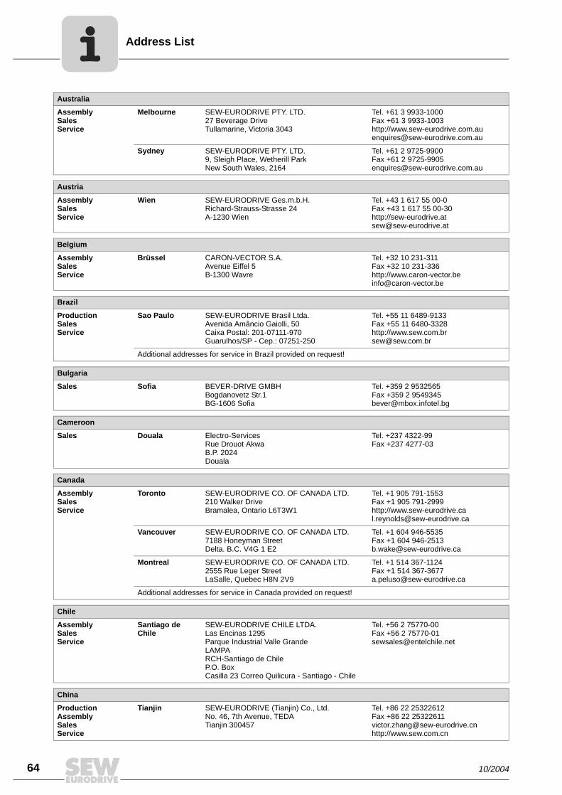
Address List
64 10/2004
Australia
AssemblySalesService
Melbourne SEW-EURODRIVE PTY. LTD.27 Beverage DriveTullamarine, Victoria 3043
Tel. +61 3 9933-1000Fax +61 3 9933-1003http://[email protected]
Sydney SEW-EURODRIVE PTY. LTD.9, Sleigh Place, Wetherill Park New South Wales, 2164
Tel. +61 2 9725-9900Fax +61 2 [email protected]
Austria
AssemblySalesService
Wien SEW-EURODRIVE Ges.m.b.H. Richard-Strauss-Strasse 24A-1230 Wien
Tel. +43 1 617 55 00-0Fax +43 1 617 55 00-30http://[email protected]
Belgium
AssemblySalesService
Brüssel CARON-VECTOR S.A.Avenue Eiffel 5B-1300 Wavre
Tel. +32 10 231-311Fax +32 10 231-336http://[email protected]
Brazil
ProductionSalesService
Sao Paulo SEW-EURODRIVE Brasil Ltda.Avenida Amâncio Gaiolli, 50Caixa Postal: 201-07111-970Guarulhos/SP - Cep.: 07251-250
Tel. +55 11 6489-9133Fax +55 11 6480-3328http://[email protected]
Additional addresses for service in Brazil provided on request!
Bulgaria
Sales Sofia BEVER-DRIVE GMBHBogdanovetz Str.1BG-1606 Sofia
Tel. +359 2 9532565Fax +359 2 [email protected]
Cameroon
Sales Douala Electro-ServicesRue Drouot AkwaB.P. 2024Douala
Tel. +237 4322-99Fax +237 4277-03
Canada
AssemblySalesService
Toronto SEW-EURODRIVE CO. OF CANADA LTD. 210 Walker Drive Bramalea, Ontario L6T3W1
Tel. +1 905 791-1553Fax +1 905 791-2999http://[email protected]
Vancouver SEW-EURODRIVE CO. OF CANADA LTD.7188 Honeyman Street Delta. B.C. V4G 1 E2
Tel. +1 604 946-5535Fax +1 604 [email protected]
Montreal SEW-EURODRIVE CO. OF CANADA LTD.2555 Rue Leger Street LaSalle, Quebec H8N 2V9
Tel. +1 514 367-1124Fax +1 514 [email protected]
Additional addresses for service in Canada provided on request!
Chile
AssemblySalesService
Santiago de Chile
SEW-EURODRIVE CHILE LTDA.Las Encinas 1295Parque Industrial Valle GrandeLAMPARCH-Santiago de ChileP.O. BoxCasilla 23 Correo Quilicura - Santiago - Chile
Tel. +56 2 75770-00Fax +56 2 [email protected]
China
ProductionAssemblySalesService
Tianjin SEW-EURODRIVE (Tianjin) Co., Ltd.No. 46, 7th Avenue, TEDA Tianjin 300457
Tel. +86 22 25322612Fax +86 22 [email protected]://www.sew.com.cn

Address List
10/2004 65
AssemblySalesService
Suzhou SEW-EURODRIVE (Suzhou) Co., Ltd.333, Suhong Middle RoadSuzhou Industrial ParkJiangsu Province, 215021P. R. China
Tel. +86 512 62581781Fax +86 512 [email protected]
Colombia
AssemblySalesService
Bogotá SEW-EURODRIVE COLOMBIA LTDA. Calle 22 No. 132-60Bodega 6, Manzana BSantafé de Bogotá
Tel. +57 1 54750-50Fax +57 1 [email protected]
Croatia
SalesService
Zagreb KOMPEKS d. o. o.PIT Erdödy 4 IIHR 10 000 Zagreb
Tel. +385 1 4613-158Fax +385 1 [email protected]
Czech Republic
Sales Praha SEW-EURODRIVE CZ S.R.O.Business Centrum Praha Luná 591CZ-16000 Praha 6 - Vokovice
Tel. +420 220121234 + 220121236Fax +420 220121237http://[email protected]
Denmark
AssemblySalesService
Kopenhagen SEW-EURODRIVEA/SGeminivej 28-30, P.O. Box 100DK-2670 Greve
Tel. +45 43 9585-00Fax +45 43 9585-09http://[email protected]
Estonia
Sales Tallin ALAS-KUUL ASPaldiski mnt.125EE 0006 Tallin
Tel. +372 6593230Fax +372 [email protected]
Finland
AssemblySalesService
Lahti SEW-EURODRIVE OYVesimäentie 4FIN-15860 Hollola 2
Tel. +358 3 589-300Fax +358 3 7806-211http://[email protected]
Gabon
Sales Libreville Electro-ServicesB.P. 1889Libreville
Tel. +241 7340-11Fax +241 7340-12
Great Britain
AssemblySalesService
Normanton SEW-EURODRIVE Ltd.Beckbridge Industrial Estate P.O. Box No.1GB-Normanton, West- Yorkshire WF6 1QR
Tel. +44 1924 893-855Fax +44 1924 893-702http://[email protected]
Greece
SalesService
Athen Christ. Boznos & Son S.A.12, Mavromichali StreetP.O. Box 80136, GR-18545 Piraeus
Tel. +30 2 1042 251-34 Fax +30 2 1042 251-59http://[email protected]
Hong Kong
AssemblySalesService
Hong Kong SEW-EURODRIVE LTD.Unit No. 801-806, 8th FloorHong Leong Industrial ComplexNo. 4, Wang Kwong Road Kowloon, Hong Kong
Tel. +852 2 7960477 + 79604654Fax +852 2 [email protected]
China

Address List
66 10/2004
Hungary
SalesService
Budapest SEW-EURODRIVE Kft.H-1037 BudapestKunigunda u. 18
Tel. +36 1 437 06-58Fax +36 1 437 [email protected]
India
AssemblySalesService
Baroda SEW-EURODRIVE India Pvt. Ltd.Plot No. 4, GidcPor Ramangamdi · Baroda - 391 243Gujarat
Tel. +91 265 2831021Fax +91 265 [email protected]
Technical Offices Bangalore SEW-EURODRIVE India Private Limited308, Prestige Centre Point7, Edward RoadBangalore
Tel. +91 80 22266565Fax +91 80 [email protected]
Mumbai SEW-EURODRIVE India Private Limited312 A, 3rd Floor, Acme PlazaAndheri Kurla Road, Andheri (E)Mumbai
Tel. +91 22 28348440Fax +91 22 [email protected]
Ireland
SalesService
Dublin Alperton Engineering Ltd. 48 Moyle RoadDublin Industrial EstateGlasnevin, Dublin 11
Tel. +353 1 830-6277Fax +353 1 830-6458
Israel
Sales Tel-Aviv Liraz Handasa Ltd. Ahofer Str 34B / 22858858 Holon
Tel. +972 3 5599511Fax +972 3 [email protected]
Italy
AssemblySalesService
Milano SEW-EURODRIVE di R. Blickle & Co.s.a.s.Via Bernini,14 I-20020 Solaro (Milano)
Tel. +39 2 96 9801Fax +39 2 96 [email protected]
Ivory Coast
Sales Abidjan SICASte industrielle et commerciale pour l’Afrique165, Bld de MarseilleB.P. 2323, Abidjan 08
Tel. +225 2579-44Fax +225 2584-36
Japan
AssemblySalesService
Toyoda-cho SEW-EURODRIVE JAPAN CO., LTD 250-1, Shimoman-no,Toyoda-cho, Iwata gunShizuoka prefecture, 438-0818
Tel. +81 538 373811Fax +81 538 [email protected]
Korea
AssemblySalesService
Ansan-City SEW-EURODRIVE KOREA CO., LTD. B 601-4, Banweol Industrial Estate Unit 1048-4, Shingil-DongAnsan 425-120
Tel. +82 31 492-8051Fax +82 31 [email protected]
Latvia
Sales Riga SIA Alas-KuulKatlakalna 11CLV-1073 Riga
Tel. +371 7139386Fax +371 [email protected]
Lebanon
Sales Beirut Gabriel Acar & Fils sarlB. P. 80484Bourj Hammoud, Beirut
Tel. +961 1 4947-86 +961 1 4982-72+961 3 2745-39Fax +961 1 4949-71 [email protected]

Address List
10/2004 67
Lithuania
Sales Alytus UAB IrsevaMerkines g. 2ALT-4580 Alytus
Tel. +370 315 79204Fax +370 315 [email protected]
Luxembourg
AssemblySalesService
Brüssel CARON-VECTOR S.A.Avenue Eiffel 5B-1300 Wavre
Tel. +32 10 231-311Fax +32 10 231-336http://[email protected]
Malaysia
AssemblySalesService
Johore SEW-EURODRIVE SDN BHD No. 95, Jalan Seroja 39, Taman Johor Jaya81000 Johor Bahru, JohorWest Malaysia
Tel. +60 7 3549409Fax +60 7 [email protected]
Morocco
Sales Casablanca S. R. M.Société de Réalisations Mécaniques 5, rue Emir Abdelkader05 Casablanca
Tel. +212 2 6186-69 + 6186-70 + 6186-71Fax +212 2 [email protected]
Netherlands
AssemblySalesService
Rotterdam VECTOR Aandrijftechniek B.V. Industrieweg 175 NL-3044 AS RotterdamPostbus 10085NL-3004 AB Rotterdam
Tel. +31 10 4463-700Fax +31 10 4155-552http://[email protected]
New Zealand
AssemblySalesService
Auckland SEW-EURODRIVE NEW ZEALAND LTD. P.O. Box 58-428 82 Greenmount driveEast Tamaki Auckland
Tel. +64 9 2745627Fax +64 9 [email protected]
Christchurch SEW-EURODRIVE NEW ZEALAND LTD. 10 Settlers Crescent, FerrymeadChristchurch
Tel. +64 3 384-6251Fax +64 3 [email protected]
Norway
AssemblySalesService
Moss SEW-EURODRIVE A/SSolgaard skog 71N-1599 Moss
Tel. +47 69 241-020Fax +47 69 [email protected]
Peru
AssemblySalesService
Lima SEW DEL PERU MOTORES REDUCTORES S.A.C.Los Calderos, 120-124Urbanizacion Industrial Vulcano, ATE, Lima
Tel. +51 1 3495280Fax +51 1 [email protected]
Poland
AssemblySalesService
Lodz SEW-EURODRIVE Polska Sp.z.o.o.ul. Techniczna 5 PL-92-518 Lodz
Tel. +48 42 67710-90Fax +48 42 67710-99http://[email protected]
Portugal
AssemblySalesService
Coimbra SEW-EURODRIVE, LDA. Apartado 15 P-3050-901 Mealhada
Tel. +351 231 20 9670Fax +351 231 20 3685http://[email protected]
Romania
SalesService
Bucuresti Sialco Trading SRL str. Madrid nr.4 011785 Bucuresti
Tel. +40 21 230-1328Fax +40 21 230-7170 [email protected]

Address List
68 10/2004
Russia
Sales St. Petersburg ZAO SEW-EURODRIVE P.O. Box 263 RUS-195220 St. Petersburg
Tel. +7 812 5357142 +812 5350430Fax +7 812 5352287http://[email protected]
Senegal
Sales Dakar SENEMECA Mécanique GénéraleKm 8, Route de Rufisque B.P. 3251, Dakar
Tel. +221 849 47-70Fax +221 849 [email protected]
Serbia and Montenegro
Sales Beograd DIPAR d.o.o.Kajmakcalanska 54SCG-11000 Beograd
Tel. +381 11 3046677Fax +381 11 [email protected]
Singapore
AssemblySalesService
Singapore SEW-EURODRIVE PTE. LTD. No 9, Tuas Drive 2 Jurong Industrial Estate Singapore 638644
Tel. +65 68621701 ... 1705Fax +65 [email protected]
Slovakia
Sales Sered SEW-Eurodrive SK s.r.o.Trnavska 920SK-926 01 Sered
Tel. +421 31 7891311Fax +421 31 [email protected]
Slovenia
SalesService
Celje Pakman - Pogonska Tehnika d.o.o.UI. XIV. divizije 14SLO – 3000 Celje
Tel. +386 3 490 83-20Fax +386 3 490 [email protected]
South Africa
AssemblySalesService
Johannesburg SEW-EURODRIVE (PROPRIETARY) LIMITEDEurodrive House Cnr. Adcock Ingram and Aerodrome RoadsAeroton Ext. 2Johannesburg 2013P.O.Box 90004Bertsham 2013
Tel. +27 11 248-7000Fax +27 11 [email protected]
Capetown SEW-EURODRIVE (PROPRIETARY) LIMITED Rainbow ParkCnr. Racecourse & Omuramba RoadMontague GardensCape TownP.O.Box 36556Chempet 7442 Cape Town
Tel. +27 21 552-9820Fax +27 21 552-9830Telex 576 [email protected]
Durban SEW-EURODRIVE (PROPRIETARY) LIMITED2 Monaceo PlacePinetownDurbanP.O. Box 10433, Ashwood 3605
Tel. +27 31 700-3451Fax +27 31 [email protected]
Spain
AssemblySalesService
Bilbao SEW-EURODRIVE ESPAÑA, S.L. Parque Tecnológico, Edificio, 302E-48170 Zamudio (Vizcaya)
Tel. +34 9 4431 84-70Fax +34 9 4431 [email protected]
Sweden
AssemblySalesService
Jönköping SEW-EURODRIVE ABGnejsvägen 6-8S-55303 JönköpingBox 3100 S-55003 Jönköping
Tel. +46 36 3442-00Fax +46 36 3442-80http://[email protected]

Address List
10/2004 69
Switzerland
AssemblySalesService
Basel Alfred lmhof A.G.Jurastrasse 10 CH-4142 Münchenstein bei Basel
Tel. +41 61 41717-17Fax +41 61 41717-00http://[email protected]
Thailand
AssemblySalesService
Chon Buri SEW-EURODRIVE (Thailand) Ltd.Bangpakong Industrial Park 2700/456, Moo.7, Tambol DonhuarohMuang DistrictChon Buri 20000
Tel. +66 38 454281Fax +66 38 [email protected]
Tunisia
Sales Tunis T. M.S. Technic Marketing Service7, rue Ibn EI Heithem Z.I. SMMT2014 Mégrine Erriadh
Tel. +216 1 4340-64 + 1 4320-29Fax +216 1 4329-76
Turkey
AssemblySalesService
Istanbul SEW-EURODRIVE Hareket Sistemleri Sirketi Bagdat Cad. Koruma Cikmazi No. 3 TR-34846 Maltepe ISTANBUL
Tel. +90 216 4419163 + 216 4419164 + 216 3838014Fax +90 216 [email protected]
USA
ProductionAssemblySalesService
Greenville SEW-EURODRIVE INC. 1295 Old Spartanburg Highway P.O. Box 518Lyman, S.C. 29365
Tel. +1 864 439-7537Fax Sales +1 864 439-7830Fax Manuf. +1 864 439-9948Fax Ass. +1 864 439-0566Telex 805 550 http://[email protected]
AssemblySalesService
San Francisco SEW-EURODRIVE INC. 30599 San Antonio St.Hayward, California 94544-7101
Tel. +1 510 487-3560Fax +1 510 [email protected]
Philadelphia/PA SEW-EURODRIVE INC. Pureland Ind. Complex 2107 High Hill Road, P.O. Box 481Bridgeport, New Jersey 08014
Tel. +1 856 467-2277Fax +1 856 [email protected]
Dayton SEW-EURODRIVE INC.2001 West Main Street Troy, Ohio 45373
Tel. +1 937 335-0036Fax +1 937 [email protected]
Dallas SEW-EURODRIVE INC.3950 Platinum Way Dallas, Texas 75237
Tel. +1 214 330-4824Fax +1 214 [email protected]
Additional addresses for service in the USA provided on request!
Venezuela
AssemblySalesService
Valencia SEW-EURODRIVE Venezuela S.A.Av. Norte Sur No. 3, Galpon 84-319Zona Industrial Municipal NorteValencia, Estado Carabobo
Tel. +58 241 832-9804Fax +58 241 [email protected]@cantv.net


How we’re driving the world
With people who
think fast and
develop the
future with you.
With a worldwide
service network that is
always close at hand.
With drives and controls
that automatically
improve your productivity.
With comprehensive
knowledge in virtually
every branch of
industry today.
With uncompromising
quality that reduces the
cost and complexity of
daily operations.
With a global presence
that offers responsive
and reliable solutions.
Anywhere.
With innovative
technology that solves
tomorrow’s problems
today.
With online information
and software updates, via
the Internet, available
around the clock.
Gearmotors \ Industrial Gear Units \ Drive Electronics \ Drive Automation \ Services
SEW-EURODRIVEDriving the world
SEW-EURODRIVE GmbH & Co KG
P.O. Box 3023 · D-76642 Bruchsal / Germany
Phone +49 7251 75-0 · Fax +49 7251 75-1970
→ www.sew-eurodrive.com