DISTRIBUTED BY: National Technical Infor'ation Service U. S. ...
161
I AD-A020 126 THE DELAMINATION THEORY OF WEAR-11 Nam P. Suh, et al Massachusetts Institute of Technology Prepared for: Office of Naval Research September 1975 DISTRIBUTED BY: National Technical Infor'ation Service U. S. DEPARTMENT OF COMMERCE
-
Upload
khangminh22 -
Category
Documents
-
view
0 -
download
0
Transcript of DISTRIBUTED BY: National Technical Infor'ation Service U. S. ...
IAD-A020 126
THE DELAMINATION THEORY OF WEAR-11
Nam P. Suh, et al
Massachusetts Institute of Technology
Prepared for:
Office of Naval Research
September 1975
DISTRIBUTED BY:
National Technical Infor'ation ServiceU. S. DEPARTMENT OF COMMERCE

ill 037132
Conrac No.~~ N001-004 03
NR 2 90 1 1* ' ~~
NANAS S
JpORGE@ P.TEXER
NATIONAL TECHNICALINFORMATION SERVICE
us Devarl! of con~,.rcqSpnnglheld, VA 22151
Septmber197S
TIM DELANIATION THEOY OF WEAR-Il
Second Progress Report
to
The Advanced Research Project Agency, DODContract No. YM0014-67-A-0204-0080
NR 229-011
Nam F. Suh
Said Jahanmir
Jonathan Fleming
Ernest P. Abrahamson, II
Nannaji Saka
Jorge P. Teixeira
Materials Processing LaboratoryDepartment of Mechanical EngineeringMassachusetts Institute of Teehnology
Cambridge, Massachusetts 02139
September 1975LI
Reproduction in whole or in part ispemitted for any purpose of the
United States Govirnment 7
Approved for public release; distribution unlimited.

4 UNCLASSIFIEDa
IEtuTY CLASSIFICATION OF THISl PAGE (ften bWm
RM I _ _ _ __PM uy CNPW G C
4. TTLE Md NWOO S.TYPE or MR a PI mOD COVERED
The DeaiainTheory of Wear-II Annual - May 1974-June 1975
7. AUHOR~) 6.CONTRACT ON OeaANT MUNERej
N=. P. SubSik hmr, Jonathan Fleming, N00014-67-A-0204-0080Ern~est P. Abrahamson, 11. Nannaji Saka, Jorge P. NR 229-011
t~ ~ ~ 9 PENVORMING ORGANIZATION NAME AND ADDRESS 10. PGAMEwNTPREC.ASI WORIC UNIMaterials Processing LaboratoryDepartment of Mechanical Engineerinsg0000D0
-Massachusetts Institute of Techrolce _____________
CONTROLLING OFFICE NAME AND ADORESS 12. REPORT OATS
Department of the Navy Sentember 197513. NUIMBER Of PAGESOffice of N3val Research
~~29917 Un____IN' AGENr ' J MAN&lAODRESIl I ffeengt bin Cmntrolling Offe) 15. SECURITY CLASS. (of lite repo")
Office of Naval ResearchMIT Resid. Repres. -Unclassified
77 Massachusetts Ave., Bldg. E19-62B Igo. SDC1 ASICATINIOOWNGROIDNOCambridge, Mass. 02139 (N66017) --- ____________
1S. DISTRIBUTION STATEMENT (ol ati Report)
The distribution of this document is unlimited.
x " BUT .IugON ST ATEMEN T (of the abstract mnteed In Nlock ".It ldilfemt koov Ret)
If. SUPPLEMENTARY NOTES
1S KEY WORDS (Cofirmet on rivers. side it n~eooewy OW fletfy by block timber)
delamination, sliding wear, subsurface deformation, void formation, crackpropagation, soft metallic coating, surface roughness, surface integrity,wear reduction, mechanics of delamination, steel, copper alloy, internallyoxidized copper alloy
20. ABSTRACT (Continue an reverse od If neceieeey mid Identili by block number)
This second progress report describes the work done by the MIT-WearResearch Group a,, fundamentals of wear by delamination. Such topics asthe mechanics of surface deformation, the relationship between frictionand wear, the effect of microstructure on wear, the effect of surfaceroughness and integrity on wear, wear resistant soft metallic coatingsand delamination in other types of wear are examined.
DL~~ ~~ EDITION Ol, I NOV 65 IS OBSOLETZ NLSSFES/N 0102-014-6601 ______________ ________
SECURITY CLASSIFICATION OF THIS5 PAGE (Ulueu Di Entered)

.LL.UIITY CLAWICATiON OF TIiS PA09fUbm boo Dam _ _
The mechanisms of surface and subeurface deformation are Investigatedusing a finite elment computer program. It is shown that In sliding In-teraction, the material below the surface experiences a tension-compressioncyclic state of loading. The compression region exists right under thecontact, while the tension region is located right behind the moving con-tact. If it is hypothesized that subsurface crack propagation occuree atthe position of maxima tensile stro.ss perpendicular to the surface, a cor-relation between observed and predicted crack depth as a function offriction coefficient can be found. Wear rate and friction coefficient arealso shown to be related by an, approximate energy analysis, yielding theo-retical predictions that are surprisingly close to the experimental results.
Studies carried out on acrostructural effects in sliding wear sub-stantlate the predictions of the delamination theory that the wear rate iscontrolled by both the hardness and the number of void nucleation and crackpropagation sites. The wear rate is decreased by increasing tl-- hardnessand decreasing the number of void nucleation and crack propagation sites.
Preliminary investigations in other modes of wear show that the dela-mination process may occur under any conditions where both normal and tan-gential forces exist at the contact. Evidence of sub-surface crack nucle-ation and propagation is found in fretting, abrasive and erosive wear. Itis proposed that the measures which can be taken to reduce sliding wearcan also be used to reduce fretting and catastrophic failure by frettingfatigue.
Studies on the effect of surface roughness on wear indicate that theoriginal surface roughness of machined parts con';rols the initial wear be-havior and not the steady state delamination wear rate. The influence ofsurface roughness on wear is shown to depend on the normal load. Under
low contact lopds, ro gh surfaces wear less than smoother ones, while at;higher contact lcads, the wear of rough surf-ces is larger than smootherones. The quality and the degree of subsurace damage generated duringsurface preparation has detrimental effects on the initial wear rate. Thispreliminary result indicates a strong need for quality control measures forsurfaces u chined for sliding applications.
The delawination theory of wear is used to develop wear-resistantmetallic s-irfaces by application of a thin soft metallic plate. The wearrate of the combination can be reduced by three orders of magnitude ifthe coating is softer than the substrate, has an optimum thickness( a 0.1 ijm), and is bonded bcrongly to the substrate. This phenomenon isdemonstrated experimentally for cadmium, silver, gold and nickel-platedsteel specimens.
U

-2-
Abstract
This second progress report describes the work done by the MIT-Wear
lesseurch Group on fundamentals of wear by delamination. Such topics as
the mechanics of surface deformation, the relationship between friction
and wear, the effect of uicrostructure on wear, the effect of surface
roughness and integrity on wear, wear resistant soft metallic coatings
and delamination in other types of v-Ar are examined.
The mechanisms of surface and subsurface deformation are investigated
usin, a finite element computer program.- It is shown that in sliding in-teraction, the material below the surface experiences a tension-compression
cyclic state of loading. The compression region exists right under the
contact, while the tension region is located right behind the moving con-
tacL. If it is hypothesized that subsurface crack propagation occures at
t!e position oi maximum tensile stress perpendicular to the surface, a cor-
relation between observed and predicted crack depth as a function of
friction coefficient cc. be found. Wear rate and friction coefficient are
also showr to be related by an approximate energy analysis, yielding theo-
retical predictions that are surprisingly close to the experimental results.
Studies carried out on microstructural effects in sliding wear sub-
stantiate the predictions of the delamination theory that the wear rate is
controlled by botn the hardness and thne number of void nucleation and crack
propagation sites. TIne wear rate is decreased by increasing the hardness
and decreasing the number of void nucleation and crack propagation sites.
Preliminary investigations in other modes of wear show that the dela-
mination process may occur under any conditions where both normal and tan-
gential forces exist at the contact. Evidence of sub-surface crack nucle-
ation and propagation is found in fretting, abrasive and erosive wear. It
is proposed that the measures which can be taken to reduce sliding wear
can also be used to reduce fretting and catastrophic failure by fretting
fatigue.
btudies on the effect of surface roughness on wear indicate that the
original surface roughness of machined pazts controls the initial wear be-
havior and not the steady state delaminatin wear rate. The influence of
surface roughness on wear is shown to depend on the normal load. Under
low contact loads, rough surfaces wear less than sn.)other ones, while at

-3-
higher contact leads, the wear of rough sjrfaces is larger than smoother
ones. The quality and the degree of subsurface damage generated during
surface preparation has detrimental effects on the initial wear rate. This
preliminary result indicates a strong need for quality control measures for
surfaces machined for sliding applications.
The delamination theory of wear is used to develop wear-resistant
metallic surfaces by application of a thin soft metallic plate. The wear
rate of the combination can be reduced by three orders of nagniLude If
the coating is softer than the substrate, has an optima thickness
( 0.1 Pm ), and is bonded strongly to the substrate. This phenomenon
is demonstrated experimentally for cadmium, silver, gold and nickel-plated
steel specimens.
The work reported in this report was sponsored by the DefenseAdvanced Research Projects Agency through the Office of Naval Research
under contract OOO14-67-A-0204-OO6O. We are grateful to Dr. Edward
van Routh and Lt. Richard S. Miller for their personal support and gui-
dance of our work.
rI!I171I1I
-5-
Table of Contents
Pa~g No.
Abstract 2
Acknowledgements 4
Table of Contents 5
List of Figures 7
List of Tables 12
Chapter I INTRODUCTION 13
Chapter II DESCRIPTICN OF THE DELAMINATION THEORYOF WEAR 15
1. Introduction 152. Adhesion Theories of Wear and Their
Shortcomings 153. The Wear Process According to the
Delamination Theory of Wear lt4. Flow Stress Gradient at the Surface 185. Surface Traction 20
6. Deformation of the Subsurface bySurface Traction 21
7. Wear Sheet Formation by Crack Nucleation
and Propagation 25
Chapter III MECHANICS OF DELAMINATION 36
1. Introduction 362. Investigation of Subsurface Stress and
Displacement 36
3. Discussion 37
4. Future Plans 44
Chapter IV ENERGY uONSIDERATIONS: THE RELATIONBETWEEN FRICTION COEFFICIENT AND WEARRATE 45
1. Introduction 452. Analysis of the Unlubricated Case 453. Analysis of the Lubricated Case 564. Limitations of the Analysis 57
5. Conclusions 57
Chapter V MICROSTRUCTURAL EFFECTS IN DELAMINATIONWEAP 58
1. Introduction 582. Experimental Procedure 593. Copper-Tin Solid Solutions 594. Internally Oxidized Copper Alloys 645. Iron Solid Solutions and Steels 69
6. Summary 74
-6-
Chapter VI DELAINATION IN OTHER WEAR PROCESSES 751. Introduction 752. Fretting Wear 753. A!rasive Wear 784. Erosive Wear 80
Chapter VII SURFACE ROUGHNESS AND INTEGRITYEFFECTS ON SLIDING WEAR 85
1. Introduction 85
2. Review of Previous Investigations 863. Experimental Procedure 894. Surface Roughness 92
5. The Effect f Surface and SuburfaceV*aage 96
6. Conclusions 105
Chapter VIII SLIDING WEAR RESISTANCE OF METALLICCOATED SURFACES 106
1. Introduction 106
2. Review of Earlier Work on Coated MetalSurfaces 106
3. Experimental Procedure 1084. The Effect of Plate Thickness 1085. The Effect of Surface Roughness and Bond
Strength 110
6. Discussion i14
7. Conclusions 114
Chapter IX SUMMARY AND CONCLUSIONS 118
References 121
Appendix A FINITE ELEMENT METHOD 127
Appendix B PREPARATION OF SOLID SOLUTIONS 140
Appendix C PREPARATION OF INTERNALLY OXIDIZED SPECIMENS 145
Appendix D WEAR TESTING EQUIPMENT AND PROCEDURZ 152
Appendix E PAPERS PUBLISHED AND PRESENTED ON THE
DELAMINATION THEORY OF WEAR 156
Distribution List 158
-7-
LIST OF FRUME
Flaures
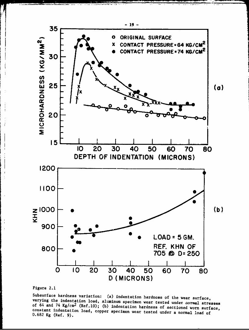
2.1 Subsurface hardness variation 19(a) indentation hardness of the wear surface,varying the indentatio, load, aluminum specimenwear tested under normal stresses of 64 and 74Kg/cm2 (Ref. 10).
(b) indentation hardness of sectioned wornsurface, constant indentation load, copperspecimen wear tested under a normal load of0.682 Kg (Ref. 9).
2.2 Evidence of plowing on the wear track of AISI 221020 steel tested under normal load of 2.25 Kgfor 10 minutes, lubricated.
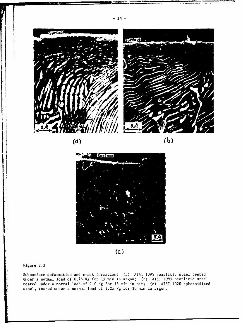
2.3 Subsurface deformation and crack formation 23(a) AISI 1095 pearlitic steel tested under anormal load of 0.45 Kg for 15 min in argon.(b) AISI 1095 pearlltic steel tested under anormal load of 2.0 Kg for 15 min in air.(c) AISI 1020 spheroidized steel, tested undera normal load of 2.25 Kg for 30 min in argon.
2.4 Subsurface strain variation obtained by grain 24shape measurements,(a) copper specimen tested under & normalload of 2.1 Kg and after a sliding distanceof 68 m In argon.(b)AIS" 1020 steel tested under a normalload of 2.4 Kg and a sliding distance of180 m in argon.
2.5 Subsurface void and crack formation in Fe-i.3% 26Mo specimen, tested under a normal load of2.5 Kg and a sliding distance of 21m in argon.
2.6 Subsurface crack formation in 27(a) OFUC copper, tested under a normal loadof 1.8 Kg and a sliding distance of 15 m.(b) AISI 1020 steel, tested under a normalload of 1.8 Kg and a sliding distance of 45 m.
2.7 Wear sheet or the wear track of Fe-Mo specimen, 28tested under a normal load of 2.25 Kg and asliding distance of 90 m.
2.8 Wear particles collected after tests in argon(a) AISI 1020 steel under a normal load of2.25 Kg 29(b) AISI 1020 steel under a normal load of0.40 Kg 30(c) AISI 4140 steel under a normal load of2.25 Kg 31
-8-
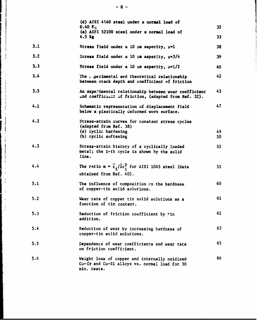
(d) AISI 4140 steel under a normal load of0.40 X, 32(e) AISI 52100 steel under a normal load of4.5 Kg 33
3.1 Stress field under a 10 am asperity, p-i 38
3.2 Stress field under a 10 um asperity, U-3/4 39
3.3 Stress field under a 10 um asperity, vi/2 40
3.4 The .pwrimental avd theoretical relationship 42between crack depth and coefficient of friction
3.5 An experimental relationship between wear coefficient 43.nd coefficie= of friction, (adapted from Ref. 32).
4.1 Schematic representation of displacement field 47below a plastically deformed worn surface.
4.2 Stress-strain curves for constant stress cycles(adapted frm Ref. 38)
(a) cyclic hardening 49(b) cyclic softening 50
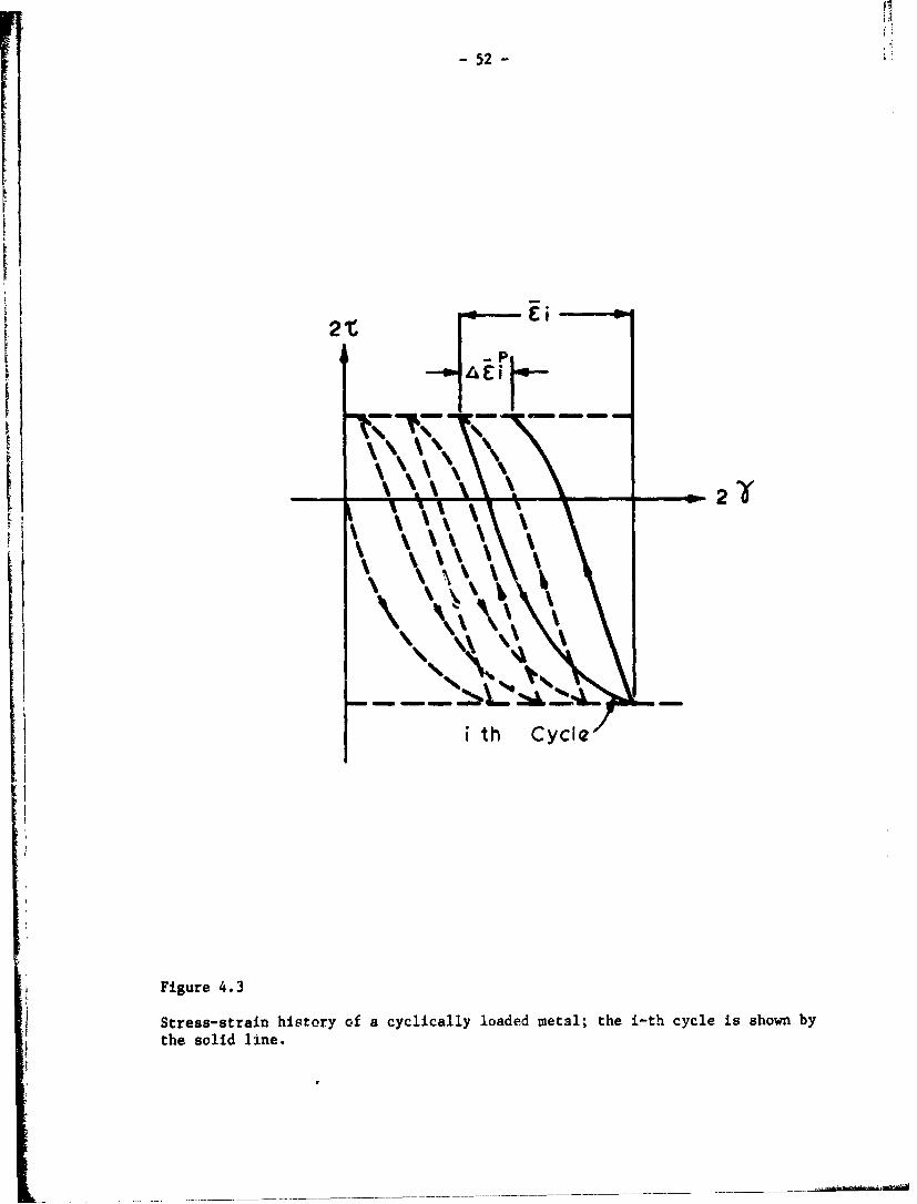
4.3 Stress-strain history of a cyclically loaded 52metal; the i-th cycle is shown by the solidline.
4.4 The ratio m =- / for AISI 1045 steel (data 55
obtained from Ref. 40).
5.1 The influence of composition cn the hardness 60of copper-tin solid solutions.
5.2 Wear rate of copper tin solid solutions as a 61function of tin content.
5.3 Reduction of friction coefficient by *in 62addition.
5.4 Reduction of wear by increasing hardness of 63copper-tin solid solutions.
5.5 Dependence of wear coefficients and wear rate 65on friction coefficient.
5.6 Weight loss of copper and internally oxidized 66Cu-Cr and Cu-Si alloys vs. normal load for 30min. tests.

-9-
5.7 Wer resistance and friction coefficients 67vs. the volume fraction of oxide particles.
5.8 Wear coefficient vs. friction coefficient 68for Internally oxidized copper alloys.
5.9 The effect of volume fraction and mean free 71path on the wear resistance (1/k-SL/3WH) ofiron and spheroidized steels.
6.1 Micrograph of a fretted Ti-6A1-4V surface 76(Ref. 50).
6.2 Fretting wear coefficient vs. the amplitude 77of oscillation (Ref. 52).
6.3 Subsurface deformation and void formation 79in abraded AISI 1020 steel.
6.4 Erosion surface of 202A-T4 aluminum Impacted 81at different speede b SiC particles at im-pingement angle of 45 (Ref. 57).(a) impact speed of 32 m/sec(b) impact speed of 156 m/sec(c) impact speed of 310 m/sec
6.5 Erosion surface of 2024 aluminum impacted at 82different temperatures §y SiC particles atimpingement angle of 900 (Ref. 57).(a) 171F, 280 m/sec(b) 2000F, 150m/sec
6.6 Subsurface damage in erosive wear 83(a) copper, 254 Pm SiC particles, impactedat 550, 105 m/sec(b) same as (a) except the impact angle is90.(c) AISI 1020 steel, same conditions as (b).
7.1 Weight loss as a function of sliding distancefor AISI 1020 steel, (pin on disk geometry).(a) under a normal load of 0.30 Kg 87(b) under a normal load of 0.075 Kg 88
7.2 Schematic representation of the delamination 90process during sliding wear; asperity defor-mation and fracture 1-5, subsurface cracknucleation, propagation, and wear sheet for-wation 5-6.
7.3 Wear track of 4.3 um (CLA) surface finish AISI 1020 91
steel specimen (pin on disk geometry), under a normalload of 0.30 Kg after 10 m sliding distance.(a) asperity deformation on the edge of the wear track,
and delamination at the center.(b) delamination at the center of the wear track.
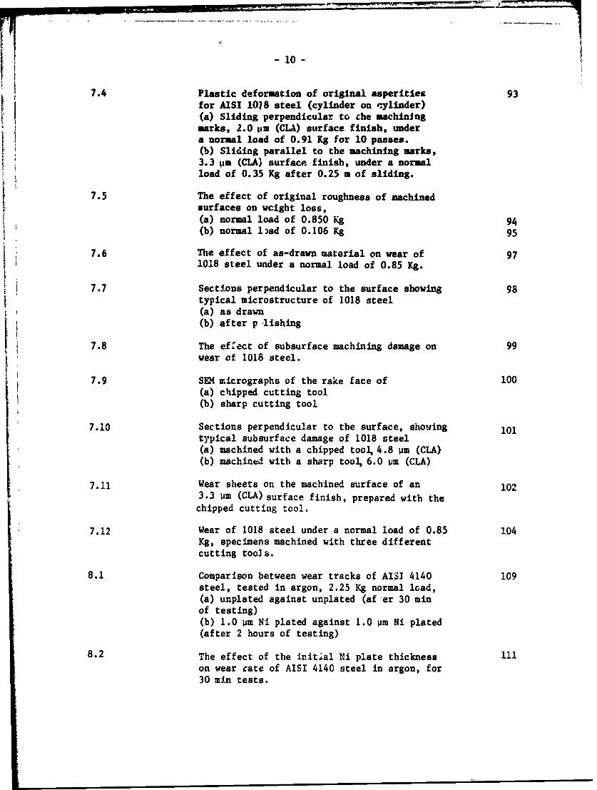
107.4 Plastic deformation of original asperities 93
for A1SI 1018 steel (cylinder on cylinder)(a) Sliding perpendicular to che machiningmarks, 2.0 vim (CLA) surface finish, undera normal load of 0.91 Kg for 10 passes.(b) Sliding parallel to the machining marks,3.3 Um (CIA) surface finish, under a normalload of 0.35 Kg after 0.25 . of sliding.
7.5 The effect of original roughness of machinedsurfaces on wcight loss,(a) normal load of 0.850 Kg 94(b) normal load of 0.106 Kg 95
7.6 The effect of as-drawn material on wear of 971018 steel under a normal load of 0.85 Kg.
7.7 Sections perpendicular to the surface showing 98typical microstructure of 1018 steel(a) as drawn(b) after p lishing
7.8 The effect of subsurface machining damage on 99wear of 1018 steel.
7.9 SEM micrographs of the rake face of 100
(a) chipped cutting tool(b) sharp cutting tool
7.10 Sections perpendicular to the surface, showing 101typical subsurface damage of 1018 steel(a) machined with a chipped tool, 4.8 pm (CLA)(b) machined with a sharp tool, 6.0 pm (CLA)
7.11 Wear sheets on the machined surface of an 1023.3 im (CLA) surface finish, prepared with the
chipped cutting tool.
7.12 Wear of 1018 steel under a normal load of 0.85 104Kg, specimens machined with three differentcutting tools.
8.1 Comparison between wear tracks of AISI 4140 109steel, tested in argon, 2.25 Kg normal load,(a) unplated against unplated (af er 30 minof testing)(b) 1.0 um Ni plated against 1.0 pm Ni plated(after 2 hours of testing)
8.2 The effect of the initial Ni plate thickness 111on wear rate of AISI 4140 steel in argon, for30 min tests.
- 11 -
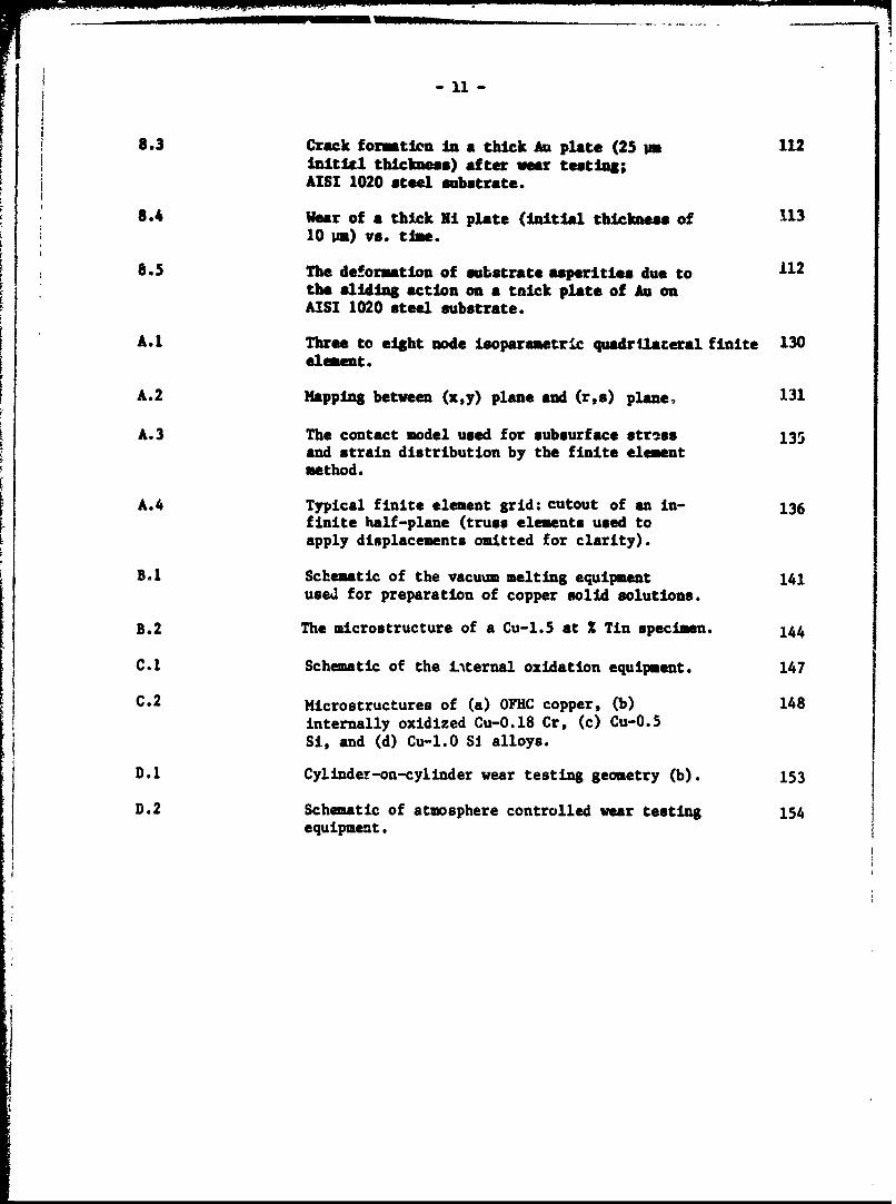
8.3 Crack formation in a thick Au plate (25 tm 112Initicl thickness) after ear testing;AISI 1020 steel substrate.
8.4 Wear of a thick Ni plate (initial thickness of 11310 I=) vs. time.
8.5 The deformation of substrate asperities due to 112the sliding action on a thick plate of Au onAISI 1020 steel substrate.
A.1 Three to eight node isoparametric quadrilateral finite 130element.
A.2 Mapping between (x,y) plane and (rs) plane, 131
A.3 The contact model used for subsurface str*ss 135and strain distribution by the finite elementmethod.
A.4 Typical finite element grid: cutout of an in- 136finite half-plane (truss elements used toapply displacements omitted for clarity).
B.1 Schematic of the vacuum melting equipment 141used for preparation of copper solid solutions.
B.2 The microstructure of a Cu-l.5 at Z Tin specimen. 144
C.1 Schematic of the L-%ternal oxidation equipment. 147
C.2 Microstructures of (a) OFHC copper, (b) 148internally oxidized Cu-O.18 Cr, (c) Cu-0.5Si, and (d) Cu-1.O SI alloys.
D.1 Cylinder-on-cylinder wear testing geometry (b). 153
D.2 Schematic of atmosphere controlled wear testing 154equipment.
12
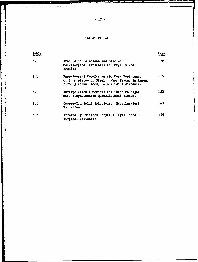
List of Tables
Table Page
5.1 Iron Solid Solutions and Steels: 72Metallurgical Variables and Experim .talResults
8.1 Experimental Results on the Wear Resistance 115of 1 um plates on Steel. Wear Tested in Argon,2.25 Kg normal load, 54 m sliding distance.
A.1 Interpolation Functions for Three to Eight 132Node Isopavametric Quadrilateral Element
B.1 Copper-Tin Solid Solutione: Metallurgical 143Variables
C. Internally Oxidized Copper Alloys: Metal- 149lurgical V7ariables

- 13 -
Chapter I
. .ucr
Until recently the wear of material. and other surface-related phenomena
have not received much attention from materials scientists and engineers, in
spite of the fact that the durability of machines and structures is often
controlled by surface-related phenomena such as wear and corrosion. The eco-
nomic impact of a basic understanding of wear phenomena cannot be overempha-
sized. According to Jost, the U.S. could save as such as 16 billion dollars
per annum by proper utilization of the existing knowledge in tribology alone
The purpose of the MIT wear research program is to control friction
and wear of materials through proper design of sliding surfaces. Innovative
and rational design of surfaces from both the metallurgical and the mechanistic
points of view can only be achieved if a basic theoretical description of the
wear phenomenon exists. Therefore, we have chosen first to analyze the friction
and wear behavior of materials in terms of both mechanical and microstructural
aspects, and secondly to apply this understanding to the design of sliding
surfaces. When theEp design criteria are established, the next task is to
insure that the surfaces can be prepared as designed. To achieve this we are
planning to develop quality control methods which can be used to check the
acceptance or rejection of surfaces manufactured for various sliding appli-
cations. For instance, premature failure of machines rcequently occurs owing tothe lack of sufficient specification and control of those variables which directly
affect surface behavior. On the other hand, manufacturing costs may sometimes
be higher than necessary mainly due tc the overspecification of surface finish
requirements.
During the first year of the program, the hypotheses of the de-. "ation
theory were examined aud proven experimentally (2 ). In the second year of our
effort advances have been made in understanding the mechanics of surface
deformation, and the possible influences on wear behavior of various mechanical
and microstructural properties of metals. Mechanistic effects in sliding wear
that have been studied include the mechanics of energy dissipation, the relation-
ship between wear and the coefficient of friction, and the effect of topography
on wear as a function of normal load. Studies have been carried out on micro-
structural effects in sliding wear, concentrating on methods of selective
hardening by dispersion, precipitation and solution hardening. Further work

-14 -
on coated metal surfaces has indicated that when used properly they indeedshow promise as A method for eliminating fretting wear, fretting fatigue,and slidin vear.
Scientific Inquiry often leads to new questions with exciting conse-quences. In this sense, the results of our effort have been very gratifying.We have discovered new possibilitis and Implications In the delaninstionth. ory, and we have formulated many questions which must be acawered beforethe delamination theory can be fully quantified. We hope to be able to answerall the questions we have raised, and to explore new possibilities in thereduction of wear and Lhe prevention of failure.

-15-
Chapter II
dESCc IOP OF THE DELAIINATION TORY OF WEAR
11 1) Introduction
The delamination thecry of wear was proposeu to provide basic under-
standing of sliding wear mechanisms so that sliding surfaces could be designed
rationally( 3 ) . This theory, unlike previous theories of wear, emphasizes
the controlling effect of the microstructure of metals on the mechanical
behavior of the surface and the subsurface.
Metals wear by different mechanisms depending on the environment and
the loading conditions. Wear can be caused by such mechanisms as diffusion,
abrasion, and cheuical reaction, a3 well as by the delamination mechanism.
In a given situation, more than one mechanism may be operating simultaneously,
but often the wear rate is controlled by a single dominant mechanism. In this
report only those wear processes which are controlled by the deformation of
the subsurface and crack nucleation and propagation are examined. The delam-
ination theory of wear is reviewed in this chapter. It will be shown in a
later chapter that a similar mechanism may be operative in such wear processes
as fretting, abrasive, and erosive wear.
lI 2) Adhesion Theories of Wear and Their Shortcomings
The important features of the delamination theory of wear can best be
understood by contrasting it with the adhesion theories of wear which have
dominated the thinking of tribologists.
Adhesion theories are based on the postulate that wear under sliding
conditions is a consequence of asperity-asperity interactions between two
opposing surfaces (4- . In particular, it is commonly assumed that the
asperity junctions adhere to each other and the weaker asperities are sub-
sequently sheared oft by the tangential force at the contact. Therefore,
much attention has been devoted in the past to the mechanism of adhesion
between different materials and to the determination of the actual area of con-
tact at the interface. The adhesion theories often cited are those of Archard(4)(5for wear and Green for friction (5 ). Existing experimental evidence is
sufficient to support the idea that the adhesion does indeed occur, thougb
perhaps not to the extent assumed by the proponents of the adhesion theories.

- 16 -
The disputable point Is the role of adhesion in sliding wear. The delamination
theory of wear has postulated that the primary role of adhesion is to increase
the surface traction which in turu causes greater deformation which leads to
increased crack nucleation and propagation rates in the subsurface. These pos-
tulates were later confirmed by experimental results. (2)
There are some gross friction and wear phenomena which have been knownto deviate from the postulates of the adhesion theories, e.g.,
a) The work required to create a given volume of wear particles 1 y
the adhesion mechanism, anJ given by the upper bound solutions
of plasticity, is much less than the external work done. The
difference is about two to three orders of magnitude.
b) The aspect ratio of wear particles is much larger than one,
although che adhesion models imply au, equiaxial wear particle.
c) Microstructural effects on wear cannot be accounted for by
the adhesion theories.
d) The coefficient of friction Lends to be much larger than that
predicted by the adhesion theories.
II 3) The Wear Process According to the Delamination Theory of Wear
The above known deviations of the experimental results from the pre-
dictions of the adhesion theorie3 motivated the examination of the basic
hypothesis of these theories. A3 a consequence, the delamination theory
of wear was conceived and formuJated. The delamination theory explained
previously unknown or misunders;ood phenomena such as the existence of
subsurface cracks, a "soft non-orkhardening" surface .ayer, the role of
hard particles, the primary role of hardness in wear cf metals, and the
shape of wear particles. Thr-se predictions have subsoquently been veri-
fied by experiments. (2)
The delamination theory of wear refers to the following particular
set of mechanisms which cause wear of metals under sliding conditions:
a) When two sliding surfaces come in contact, normal and tangential
loads are transmitted through the contact points. Asperities of
the softer surface ara easily deformed and fractured by the re-
peated loading action, forming small wear particles and eventually
creating a relatively smooth surface. At the same time the surface
layer is deformed by the surface traction.

S- 17-
b) The plastic deformation occurs by generation and movement of dis-
locations. However, the dislocations very near the surface are
subjected to a sufficient image force to be pulled out of the sur-
face as the coherent oxide layer which may be present on Lhe sur-
face is beoken by the moving asperities of the other sliding surface.
e dislocations below a critical depth, where the image force is
not strong enough, are stable and can accumulate and work-harden the
subsurface. C.nsequently, the deformed material exhibits a flow
stress gradient near the surface: as the distance from the surface
increases the hardness initially increases, reaches a maximum value,
and then decreases.
c) A consequence of the flow stress gradient is that the hard asper-
ities more easily "penetrate" the surface of the softer metal, dis-
placing and spreading the softer metal at the surface. Therefore,
the surface traction is caused by the plowing of the softer surface
by hard asperities as well as by the adhesive force. Furthermore,
once the major asperities are removed, the contact is not just as-
perity-to-asperity contact but rather the same loading history is
repeated all along the softer surface as the asperities of the
harder surface plow the softer surface.
d) As the subsurface deformation c-,ntinues, cracks are nucleated away
from the surface. Crack nucleation very neer the surface is not
favored for two reasons: a triaxial state of compressive stress
just below the contact points, and the "soft" metal layer near the
surface. In materials which contain hard particles (e.g. second
phase or inclusiors) crack nucleation is preferentially initiated
at the particle-matrix interface.
e) Upon further deformation, cracks extend and propagate, joining
the neighboring ones. The cracks tend to run parallel to the sur-
face since the loading condition io the same all along the surface.
The location of a long crack is likely to be controlled by the
tensilt state of loading existing below the surface in a region
behind each asperity.
f) When these cracks finally propagate to the surface, thin wear r"eets
delaminate. The thickness of the wear sheet is controlled by the
magnitude of the normal and the tangential loads at the surface,
the minimum possible sheet thickness being that of the "soft" layer.
*The existance of a flow stress gradient is as yet controversial.The flow stress gradient contributes to, but is not necessary for,the follow.ng mechanisms (except for miechanism c).

- 18 -
Il 4) Flow Stress ,radient at the Surface
Adhesion theorists had assumed that the flow stress at the very surface
is either the same as or larger than the bulk. The delamination theory postu-
lated that the very surface layer of metalb may be softer and non-vorkhardening
due tc the instability of dislocations very near the surface, and that there
is a flow stress gradient near the surface.
Two different kinds of erperiments have been done to verify these postu-
lates. Direct evidence for the flow stress gradient is obtained by micro-
hardness measurements of the surface. Less explicit evidence, which shows
that the very surface layer does not work-harden appreciably, is obtained
through the application of this idea to the minimization of the wear rate
of metals.
Direct microhardness tests have been made nn worn surfaces of metals by() ( 9)Robs/Cook and Kirk/Swanson to verify the delamination theory. Later it was
found that Savitskii(10) had published similar results earlier. Similar flow
stress gradient near the surface of copper single crystals which have undergoue
bulk deformation was reported by Fourie 1 . Figure 2.1 shows the results
obtained by Savitskii and Kirk. Savitskii obtained the hardness variation
in aluminum by varying the indentation load, while Kirk et al. obtained their
results by itdentt.g the subsurface below the wear track after sectioning a
copper specimen. The flow stress is indeed low at the very surface and in-
crrases to a maximum value before it decreases again. The experimental results
of Savitskii show that the peak hardness in aluminum occurs at about 10-15 um,
while Kirk et al. found the peak hardness in copper at about 80 pm. Similar
hardness variations In steel cannot be measured using this type of experimental
technique, probably because the flow stress varies over an extremely shallow
depth. The normal hardness variation in steel reported in the literature is
not due to the dislocation mechanism but rather to phase transformation asso-
ciated with thermal softening or quenching during the wear test. The hardness
variation of unworn well annealed metals is different. Whitehouse mea-
sured the hardness variation using a very fine indenter with a very light load
(&100 PN) on well annealed copper, which indicated that the hardness increases
continuously all the way to the surface.
According to dislocation theory, the image force on a dislocation varies
inversely as a function of depth from the surface. The depth at which the image
-19-35 -
0 ORIGINAL SURFACE* X CONTACT PRESSURE=64 KG/CM2
0 CONTACT PRESSURE 74 KG/CM2
30 p.
tu25 x x (a)Z x x
00
0 20-
15::0
H0 20 30 40 50 60 70 80DEPTH OF INDENTATION (MICRONS)
1200
1100-
z100 (b)900 •
LOAD :5 GM.80 REF. KHN OF800 - 705 1 D: 250
I I I I_ I0 10 20 30 40 50 60 70 80
D (MICRONS)Figure 2.1
Subsurface hardness variation: (a) indentation hardness of the wear surface,varying the indentation load, aluminum specimen wear tested under aormal stressesof 64 and 74 Kg/cm 2 (Ref.10); (b) indentation hardness of sectioned worn surface,constant indentation load, copper specimen wear tested under a normal load of0.682 Kg (Ref. 9).

-20-
stress is equal to the friction stress acting on dislocations is inversely
proportional to the dislocation friction stress. This depth is of the order
of 0.1 tim for sillcon-iron and 10 to 20 tim for well annealed copper( 3 )with a
dislocation density of only 50 cm- . This depth seems to be smaller thanthe depth at which the subsurface hardness rech"s a pek value. It is
difficult to draw any definitive conclusions on the thickness of the "soft"
layer, since the friction stress ating on dislocations da the dislocation
dynamics during wear tests are not known for these particular specimens.
It is reasonable to expect that other factors will also iniluence the flow
stress variation, such as the formation of microcracks in the highly deformed
surface layer.
Starting from the postulate that there is a "non-workhardenig soft layer"
near the surface due to the instability of dislocations, a method of mininizivg
sliding wear has been devised by plating a metal substrate with a very thin
layer of a softer metal ( . It was reasoned that when the thickness of the
plated layer is less than a critical value, the accumulation of dislocations
within the plated layer can be prevented and the resulting "soft" plated layer
will deform continuously without work-hardening. Thus this minimizes the
plastic deformation of the substrate and forestalls wear by delamination.
If the thickness of the plated l-yer is thicker than its critical value, the
delamination mechanism will function within the plated layer, generating wear
sheets of the plated metal, This reasoning was subsequently verified by
experiments
11 5) Surface Traction
The delamination theory and the adhesion theory differ as to the role
of surface traction. The adhesion model of Archard implies that wear is affected
by the magnitude of the normal load but not by the magnitude of the tangential
load. The delamination theory predicts that the magnitudes of both normal and
tangential loads affect the wear particle size and the wear rate. Experimental
evidence for the importance of both components of the load will be presented in a
later section. Here, the mechanisms by which a tangential load arises will be
discussed.
In the past, three mechanisms for the generation of frictional force
between two sliding surfaces have been considered: adhesion between asperities,

- 21 -
deformation of the softer asperities by harder asperities, and the plowing of
the softer surface by hard asperities. Much attention has been given to the
first two mechanisms in determining the tangential load using the adhesion(5,6,15-17)
theory ( . While it is generally accepted that adhesion plays an
important role in friction and wear, there is serious doubt that the contri-
bution of plowing to the frictional force, especially in the case of f.c.c.
metals, can be neglected.
Plowing is a possible mechanism since the flow stress gradient existing
near a worn surface favors the penetration of the softer surface by hard
asperities and spreading of the softer material at the surface. Experimental results
such as the topography of a worn surface shown in Fig. 2.2 support the existence
of this mechanism. In order to check this possibility theoretically, the dis-
placement field of an elasLo-plastic solid in plane strain under the action of
a much harder asperity is being investigated (18 ) by a finite element method(19)using the computer program ADINA developed by Bathe . The results show that
the hard asperities can penetrate into and spread the softer metal. Since the
asperities have a gradual slope of the order of 10- 3 , the area of contact should
increase as the asperities penetrate. When there is tangential motion of the
penetrated asperities, the softer metal must flow around the asperities. This
plowing action increases the frictional force over that due to adhesion alone.
II 6) Deformation of the Subsurface by Surface Traction
An important conseqience of the surface traction all along the surface is
uniform plastic deformation at each depth underneath the surface. This is shown to
be the case experimentally as seen in Fig.2.3. The micrographs show cross-sectional
views underneath the w(!ar tracks of an AISI 1020 specimen ar,0 an AISI 1095
specimen. It should be noted that even the carbides in the pearlite region
of the 1095 specimen deformed with the matrix. Figure 2.4 is a plot of the
equivalent strain as a function of the distance away from the surface (20)
It should be noted that the maximum equivalent strain shown in the figure is
several orders of magnitude greater than that observed in bulk fracture of
tensile specimens. Such a large strain is due to the combined effect of the
high compressive state of triaxial loading under asperities, the "sof;" nature
of the deformed metal surface, and the 3train accumulation due to Zyclic
softening of the metal under constant stress cyclic loading.

- 22 -
Figure 2.2
- Evidence of plowing on the wear track of AISI 1020 steel tested under a normal load
-: of 2.25 Kg for 10 minutes, lubricated.
- 23 -
Ur
(c)
Figure 2.3
Subsurface deformation and crack formation: (a) AISI 1095 pearlitic steel testedunder a normal load of 0.45 Kg for 15 min in argon; (b) AISI 1095 pearlitic steeltested under a normal load of 2.0 Kg for 15 min in air; (c) AISI 1020 spheroidizedsteel, tested under a normal load Lf 2.25 Kg for 30 min in argon.

II -24-
0 0
0@
0 .1
- C-
40 I
14 4
-W t
0.6
0)
000 00
0 00
/1 iiE 00
0 4
a 0
UIDJI A"" '
00

-25-
The large strain gradient below the surface of a worn metal (such as the
one shown !n Fig. 2.4) has been also determined theoretically by using the
finite element method. The analyse, however, is very approximate since the
material was assumed to be isotropic. In a real situation metals acquire
texture during the wear process( 2 1 -24 ) , tsaktvg the surface highly anisotropic
and affecting the adhesion and surface traction. In the case of f.c.c. metals
the plane of the surface after deforAation is determined to be a (111) plane,
whereas in b.c.c. metals it is a (01.1) plane. These are slip planes. In the
case of h.c.p. metals, some claim that the (0001) plane is the surface plane(23 di (re21).i h li ln o
after deformation 3), while others disagree This is the slip plane for
all h.c.p. metals, although other slip planes are activated in metals with a
c/a ratio larger than the ideal 1.63.
II 7) Wear Sheet Formation by Crack Nucleation and Propagation
a) General Observations
The large strain accumulated at the subsurface eventually causes void
nucleation below the surface as shown in Fig. 2.5(25). The micrograph is of
a metallographically polis, d and etched section through the wear track
(parallel to the sliding direction) and shows void nucleation and crack propa-
gation between two adjacent inclusions below the surface. These cracks eventually
propagate parallel to the surface, as shown in Fig. 2.6 for OFHC copper and
AISI 1020 steel (25) . When the subsurface cracks reach a critical length,
they become unstable and propagate to the surface to generate wear sheets on
the worn surface. Fig. 2.7 shows a wear sheet lifting off a worn surface (26).
Upon further passage of the slider these sheets separate from the surface and
generate loose wear particles. Some of these particles may fracture further
if they get entrapped between the sliding surfacec. Fig. 2.8 shows some typical
wear particles of different materials generated without lubricants under different
normal loads. It is noted that the size of the particles depends on the material
and the normal load. Most of the particles are in the form of sheets and some
have fractured into smaller pieces.
b) Crack Nucleation
:1 In bulk deformation of metals, crack nucleation is favored at the hard
inclusion-matrix interface.27'28 ) This is also true during delamination wear.

-26-
C4
4,1
0
4
0
0 1
>Cd
K 44
:j 0C4
4- V44
lo 44 )

-27-
00 n
0"440
0 .0
0 4
00
*14pa
44
040 rI
O14
0 09:
a)
0 M-ilr-4
00w
~4
41
(v0
$4
'.P4

-28-
i rIfF
Figure 2. 7
Wear sheet on the wear track of Fe-Mo specipien, tested undcr a normal load of2.5 Vg and a sliding distance of 90 m.

-29-
0
ii *14
0
'-I
*44
w .
C-40

1 -30-
L
I,
"4
N$
0
C
14C00
'-400aS
0C4C'"4
HU,H4I001..'U0
"4SaU0a140a
'4.40
*00aU'a
"4'-40U.
"40U4
~ "4.* aO
C'J 14044
0 0.0La0 I.I'TJcc two
"4 00SI4 ~3"4

-31-
4"
'II-4.
toI
4004J4a
4) 00-a.0
44
4

- 32 -
2ooI.
Figure 2.8d
Wear particles collected after tests in argon: AISI 4140 steel under a normal

-33-
C.4
00
0
"4
41
40
04
044U.0t-I
41 u
410
0 04
14
0Pk

34
however, the wear process is unique in that there are two opposing mechanisms
affecting crack nucleation: the high compressive state of triaxial loading
very near the asperity contact suppresses the crack nucleation process, while
the large plastic strain field promotes it. Since the hydrostatic pressure
decreases with distance from the surface, cracks will nucleate at a depth
below the surface where the condition for crack nucleation is satisfied.
The exact condition for subsurface crack nucleation during delamination
is not known. However, there is evidence that the crack nucleation process
does not differ, at least qualitatively, from those discussed for uniaxial
bulk deformation by Argon, et al. (28,29) even though the total strain and the
strain gradient are more severe in delamination wear than in bulk deformation.
Cracks are most readily nucleated between adjacent large particles and more
cracks are detected around large particles than around smaller ones. Crack
nucleation is usually by the decohesion of the matrix-particle interface rather
than by the fracture of particles in metals with equiaxial particles. In metals
with elongated particles of large aspect ratios the fracture of particles is
more prevalent. Crack nucleation is detected over the major portion of the
plastically deformed region, well below the depth at which crack propagation
occurs.
For crack nucleation around hard particles two conditions must be satis-
fied: the local stress must be equal to the strength of the particle-matrix
interface or the cohesive strength of the particle; and the elastic strain
energy released upon decohesion or fracture must be sufficient to supply the
surface energy of the crack or the void. According to Argon, et al. (28), the0
energy condition is always satisfied by particles larger than 100A in the case
of normal bulk deformation; or conversely, voids cannot form around particles0
smaller than 100A because the elastic energy released upon crack nucleation
is less than the surface energy requirement. The interface stress between
the particle and the matrix is developed due to the interfacial displacement
incompatibility upon plastic yielding of the matrix (30) . The interface stress
is greatly intensified when two inclusions are in such a close geometric
proximity that the strain field of the matrix material between the particles
is nearly homogeneous. In the case of delamination wear these interface tensile
stresses are counterbalanced by the triaxial state of compressive stress exist-
ing underneath the surface. Because of this high hydrostatic pressure which
retards void nucleation, large plastic deformation is required for crack
..... .. .. - .. .. ... . ... ..I .. ... .i • ' i ...iN

-35-
nucleation in delamination wear.
In zone refined-zone leveled iron with 500 ppm tungsten it was difficult
to identify the region of crack and/or void nucleation. However, a few large
cracks were detected very near the surface, indicating that cracks nucleated
and that a very large strain is necessary for crack nucleation and/or propa-g ton n etas ithnoincluin (26).ation in metals with no lusions The exact mechanism of crack nucle-
ation in clean single phase metals is not known at this time. However, several
plausible possibilities have been considered: vacancy formation during the
large plastic deformation and subsequent coalescence to form a void, crack
nucleation due to dislocation pile-ups at dislocation cells, and void formation
at triple points due to the large local stress developed during deformation and
texture development.
c) Crack Propagation
In general, crack nucleation does not guarantee crack propagation, since
crack propagation requires either a nelative hydrostatic pressure or presence
of shear stress parallel to the surface. It has been found t'tat a state of
negative hydrostatic pressure may be present below the surface in the region
behind a moving asperity ( 3 1 ) , which may cause crack propagation in that region.
The cracks may also propagate by the shear etress (tangential force) component
of the subsurface stress distribution. However, the presence of large hydro-
static pressure under the contact might retard the process of shear crack
propagation. In the next chapter the nature of subsurface crack propagation
will be analyzed by examining the state of stress below the sliding surfaces.

-36-
Chapter III
MECHANICS OF DEUMINA!IOI
III 1) Introduction
According to the delamination theory of wear, three processes must
take place for wear to occur: deformation, crack nucleation, and crack Ipropagation. Deformation and nucleation have been discussed in previous
sections. This section will deai with crack propagation (qmaltatvely,
since quantitative discussion is not yet possible).
The goal of this phase of the study of wear at M.I.T. is a criterionfor crack propagation based on loading and material properties. With such
a criterion, wear rates and part lives could be predicted. The formulation
and analysis of criteria for crack propagation is a part of the study of
fracture mechanics. Fracture mechanics deals with criteria for crack
propagation in terms of material properties and the type and mgnitude of
stress acting throughout the body.
Thus it is necessary to know the state of stress present below the
surface during sliding wear in order to apply existing fracture criteria
or to formulate a new criterion. At present, an exact solution for the state
of stress is not known; some approximate solutions are discussed below. Exact
analytic solutions seem impossible, but numerical solutions are possible
with minor extension of existing procedures. Numerical so..utions are cur-
rently being sought by the M.I.T. wear research group, using the finite
element method.
III 2) Investigation of Subsurface Stress and Displacement
The finite element method is discussed .In Appendix A. The material2being modelled is copper, with a yield point of 17 kg/rn , a Young's modulus
of 28000 kg/a 2 , and a Poissonts ratio of 0.333. The material is idealized
as an elastic-perfectly plastic body, and the von Mises yield criterion is
used. The loading condition is assumed to be plane strain, and the loai
is applied by a 10 pm long rigid ::perity. The body is assumed to be an
infinite half-plane.
Using this model, stresses, strains and displacements may be found
for loading and unloading by a stationary asperity in presence of both
thtt normal and tangential loads acting at the contact. At this time, the

- 37 -
results for unloading are not yet available. However, notwithstanding the
cyclic nature of the loading which occurs as asperities pas, over each point,
some qualitative conclusions may be drawn as to the possib.ities of crack
propagation.
Figures 3.1, 3.2, and 3.3 show, for three coefficients of friction j,
the state of stress underneath the asperity at nearly the maximum load the
elastic-plastic solid can support (approximately the point at wh:.. the
tangential applied stress is equal to the yield stress). Two double-headed
vectors intersect at each p.;int at which stress is evaluated. The vectors
are in the directions of the principal stress axes; their lengths are pro-
portional to the magnitudes of the principal stresses; and the arrowheads
point inward for negative (compressive) principal stress and outward for
positive (tensile) principal stress. A reference vector below the plot pro-
vides a scale for reading stress magnitudes. A capital P beside a point in-
dicates plastic deformation.
III 3) Discussion
Crack propagation in bulk occurs when a tensile stress is applied per-
pendicular to the plane of the crack (i.e. mode I) and also under the action
of shear stresses (i.e. modes II and III). Compressive loading perpendicular
to the crack plane influences the plastically deformed region around a crack
tip, but a hydrostatic compressive loading by itself cannot propagate the
crack. These statements have been used to formulate mathematical fracture
criteria, such as the critical stress intensity factor Kc and the J integral.
However, the formulations either assume small plastic deformation, a small
plastic zone, or no edge effects. None of these assumptions are justifiable
in a sliding wear situation.
The general statements about thn type of stress that can propagate a
crack do apply to sliding wear. The out-of-plane shear mode III cannot be
discussed herr, because the plane strain assumption forbids out-of-plane
sheai. Mode III is unlikely, since the plane strain assumption is a good one.
As to the possibility of in-plane shear (mode II), this mode seems unlikely.0
In Figs. 3.1, 3.2, and 3.3 the principal shear directions (45 from the prin-
cipal stress directions) are usually at - non-zero angle to the surface. Since
cracks propagate by mode II along the principal shear directions, and since

-38-
C-)
-Ja-
cr
0 o-
LUU
0
CL a
=) -z
%0 Cr)
\% z
% CCU
0 0
I- CI
La >LLJ
> (n(L) Z Lz L C
40, c LJ o~~IIX \\\ \N N 4
__ _ in z
002 YIW AT~ 08U~1 WOY.J JJBI

-39-
-CL
a:
LiCC
z zccCL
a_.. s
00
C H
a: a
0 CD
L) C)4 zN, C) C 1
0~
cnC1
0(SNOYJIWc cc~ to BlWY wNiI
ASI LI-

-40- -
I-
a:-JCL
U,tuJI-
C3
z z
LU 1
cc
CDa
S I
00 b
cr0.
CL Cj 0 0o
a:
VJQJ
+ 1-4
4-cr-L
__ % __ _ _ _ _ _ _ _ _ I i_____C
C3 N N00~ 61 01 OLZ
a:)a- c t
(SN0J1WJ00~ OU~ WDY J~N1SI

- 41 -
cracks have been observed only roughly parallel to the surfr-e, node 11 is
unlikely. Bowever, mode 11 Is still possible. This mode will not be dis-
cussed further here, since it has been investigated and understood less
than the more cmon tensile mode (node 1). Also, the discussion below
shows that mode I is the most likely mode.
There is some evidence that subsurface cracks may propagate by
a tmisile (model) process during sliding wear. Assuming for the moment that
a cr&ck may nucleate anywhere, and assuming that all nucleated cracks have the
same stress concentration factor and do not change the overall stress field
appreciably, the crack which lies at the point of maximum tensile stress ismost likely to propagate. For a given material, the position of the pointof maximu tensile stress is a function of the total applied load and the
coefficient of friction V. If the assumptions above are at all reasonable,
the depth of the maximum tensile stress should correlate well with the observed
crack depth.
Figure 3.4 is a plot of observed crack depth and the depth of the
maximum tensile stress perpendicular to the surface versus p. The tensile
stress depth was found by quadratic interpolation of the results shown in
Figs. 3.1 and 3.2. The tensile zone is too shallow in Fig. 3.3 for interpo-
lation. The stresses were evaluated at a load near to the maximum total load
that the elastic-plastic solid can support (approximately the yield stress to
half the yield stress as v increases from h to 1). The crack depths were mea-
sured from photographs of cross sections of various specimens.
By including work hardening or cyclic softening, the maximum load
the solid can support would be increased. This would increase the magnitude
and depth of the maximum tensile stress, and move the experimental points in
Fig. 3.4 vertically. However, the relative positfonsof the experimental
points (i.e. the slope of the line between them) is dictated by the mechanics
of loading rather than the magnitude of the load, and would not change. The
good correlation of slopes in Fig. 3.4 supports the hypothesis that cracks
propagate parallel to the surface by a mode I mechanism at the point of max-
imum tensile stress perpendicular to the surface. Furthermore, it should be
noted that the general trend is about the same as the experimentally deter-
mined wear coefficients vs. p relation found by Rabinowicz as shown in Fig. 3.5.(32)

- 42 -
I I I I I
10
0 0 x4--
_Eg
0. 0L 0
x
ot 4-
i _x TheoreticalI-- 0 Experimental
0.11
0.5 1.0
Coefficient of Friction
FToure 3.4
The exper0imental and theoretical relationship between crack depth and
cnefficient of friction.

-43-
F -
10 1
-3
0
65S 1 -0-
0 0.2 0.A 0.6 0.8 1.0
COEFFICIENT OF FRICTION
Figsure 3.5
An experimental relationship between wear coefficient and coefficient of
friction (adapted from Ref. 32).

- 44 -
The preceding discussion of tensile stress only considered the tensile
stress perpendicular to the surface. In view of the large tensile stresses
parallel to the surface in Figs. 3.1, 3.2, and 3.3, it seems surprising that
cracks generally do not propagate perpendicular to the surface. However,
the existence of the flow stress gradient would reduce the magnitude of
those stresses since the soft surface layer could not support such large
stresses Parallel to the surface. In addition, the textrre produced during
sliding wear may favor crack propagation parallel to the surface. Experi-
ments are now being carried out to investigate the possiLility of cracks
normal to the surface in brittle materials.
Further conclusions cannot be drawn until the cyclic loading condition
has been considered, the "coarseness" of the model (distance between points
at which stress is evaluated) has been decreased, and quantitative fracture
criteria have been devised. It is difficult to use established fracture
criteria, since all such criteria ignore edge and size effects which are
certainly important in wear since the cracks are so near the surface and
the plastic zone is so large.
III 4) Future Plans
Besides the aforementioned refinement of the grid and consideration of
unloading, the material model must be revised in order to account for cyclic
effects. Experimental work has been started which will lead to a constitu-
tive equation which will include both cyclic softening and hardenirg. This
equation will be used to define a yield criterion for finite element analyses
of repeated passes of moving asperities.
It is certain that inclusions, second phase particles, and cracks will
alter the stress field. Analyses are being performed which consider the
effect of a rigid inclusion. We hope to be able to analyze the effect of
cracks and inclusions in various positions in the body.
In summary, in order to fully understand wear, the mechanics of defor-
mation, crack nucleation, and crack propagation must be clarified. To
this end, the finite element method offers promise as a tool for finding
stresses and strains in sliding wear. These stresses and strains, once
found, can be used in fracture criteria to predict weqr rates and part lives.
- 45 -
Chapter IV
Itrv CONSIDEATIONS:
THE ilTION BETUEE FRICTION COEFFICINT AND WEAR R
IV 1) Introduction
An upper bound solution( 4 ) based on Archard's adhesion model of wear
predicts the external work done in sliding wear to be at least two to three
orders of magnitude mller than the wasured external work. This has been
explained by proponents of the adhesion theory by assuming that wear parti-
cles transfer from one surface to the other before coning loose. Although
transfer occurs for soue metals (e.g. gold and copper), it is very limited
in others (e.g. steel). There is no evidence that sufficient transfer occurs
to account for the external work in any case.
Any theory which describes a physical phenomenon must be consistent
with the laws of thermodynamics such as conservation of energy. An approx-
imate analysis presented in this chapter shows that the delamination theory
of wear does satisfy the energy conservation laws. It follows that friction
and wear are related, since the friction coefficient contributes to the
external work and wear is related to the internal plastic energy since it
is caused by subsurface deformation.
The energy conservation analysis is used to find an order of magnitude
approximation to the relationship between friction coefficient and wear
rate. The model is overly simplified, since sufficient information for
a detailed model is unavailable, yet it yields surprisingly good results.
The model shows that the coefficient of friction is related to the wear
factor by the constitutive relation for a cyclically loaded metal, the ex-
perimentally determined strain field near the wearing surface, and the
thickness of the delaminated sheet.
IV 2) Analysis of the Unlubricated Case
It is clear that the early stages of wear of a surface consist of the
plastic deformation of surface asperities and subsequent removal of these
deformed asperities by a fatigue process. However, the wear rate associated
with the removal of these asperities is low and the surface at this time
has a polished appearance and the surface is still usable.

-46-
A sliding surface becomes rough and unusable when wear o4curs by the de-
lamination process which is caused by sub-surface crack nucleation and
propagation following the deformation of the surface layer. (25,26,33-35)
When the wear process reaches a steady state condition, the depth of
the plastically deformed zone reaches a constant value for a given set ofsliding(35)
sliding conditions( . The equivalent plastic strain in the metal when
the steady state wear condition is reached differs from metal to metal.
The experimental measurements made by Agustsson (20 ) using the technique of
Dautzenberg and Zaat (36) show that the plastic strain gradient in steel
could be approximated by a combination of linear and exponential empirical
functions. The plastic strain in copper was so large that it could not be
measured quantitatively very near the suriace.
The equivalent plastic strain C in annealed AISI 1020 steel specimens,which have undergone a delamination wear process, was approximately determined
to be (20)
-P = co - ax = 16.5 - 2.2x for 0 x < x,
'" =e X- =44x-1 26 for x x,
where the x-axis is perpendicular to the surface as showr, in Fig. 4.1. The
unit of x is Pm. The depth at which both functions have the same value and
yield the same slope is given by
X.= ( "2_4 = 4.17 pm (2)
The plastic strain is accumulated in several cycles, each cycle corresponding
to the passage of one asperity. If Nf such cycles of loading are required
for delamination to occur, then the total equivalent plastic strain before
delamination is
N,
ye AC (3)
where A p is the net plastic strain generated during the ith cycle.
+ii

-47-
0I'.4
00
0 .
'4
1 .00
L *0
.0
41
00
00
C*1
I4.460
c00
0n

- 48 -
An energy argument will be used to relate the internal energy due to plas-
tic deformation to the external work done by the surface traction. In order
to be able to determine the plastic work done in generating a permanent
deformation JP, the work done per cycle may be summed over the entireloading history as
Nr
WP = bl V f f d(e,)dx (4)1=1 0 0
where b is the average width of the wear sheet, k is the average length of
the wear sheet, a is the equivalent stress, Ei is the total equivalent strain
the material undergoes and Nf is the total number of loading cycles that the
material has experienced at the time of delamination. Both a and c are functions
of the depth x. The total equivalent strain ci is not the same as the net
permanent strain Ac per cycle.
At this time there is no solution available for c and L. A similari
(371problem has been investigated by Merwin and Johnson for rolling zontact
problems by considering only the effect of normal stress. The problem we
are interested in solving differs from the Merwin-Johnson problem because of
the tangential load acting on he surface. The major conclusion of tle
Merwin-Johnson solution is th.t the subsurface material can deform plasti-
cally and the plastic strain can accumulate when the normal load exceeds a
critical value. It was shown that whenever the shear stress T exceeds thexy
shear flow stress of the metal the plastic strain accumulates, based on the
assumption that the material relaxes elastically until the residual stresses
satisfy the boundary condition. The possibility that the material may under-
go secondary plastic flow upon unloading was not considered by Merwin and
Johnson. We are in the process of aaalyzing the deformation of metals under
more realistic assumptions using a finite element method.
Another reason for the plastic strain accumulation may be the peculiar
behavior of metals under cyclic loading. When a metal is subjected to
cyclic loading, it either softens or hardens as shown in Fig. 4.2(38).
Cold worked metals usually undergo cyclic softening, while annealed metals
may first undergo cyclic hardening followed by cyclic softening. After each
cyclic loading there is a residual permanent strain AcJ, which is much smaller3.

- 49 -
Tensile StressLimit
Compressive StressLimit
Figure 4.2a
Stress-strain curves for constant stress cycles (adapted from Ref. 38):cyclic hardening.

_ _-_ o -
0
Tensile StressLimit
0
Compressive Stress
Limit
Figure 4.2b
Stress-strain curves for constant stress cycles (adapted from Ref. 38):cyclic softening.

- 51 -
than the maximum strain amplitude ci of that cycle, as illustrated in
Fig. 4.3. For cyclically softening materials Ae? increases with re~eatedi
loading, whereas it decreases with cycling for cyclically hardening
materials.The stress-strain history of the metal near the surface is different
depending on its distance from the surface. For the elastic semi-infinite(87)
solid loaded by a concentrated load the Boussinesq solution statzs
that the metal very near the surface experiences a reversed compression-
tension stress, while the material below it may only experience compressive
loading and unloadin There can also be secondary plastic flow upon un-(39)
loading due to the residual stress. A possible stress-strain history is
1±ven in Fig. 4.3 which is plotted in terms of the maximum resultant shear
stress T and the resultant shear strain y. It should be noted that a and
c always remain positive by definition and that the absolute value of T
is nearly equal to 3/2 and that of y is nearly equal to T/2.
As a first approximation to the problem one may assume that
a = o = constant (5)
Substituting eqn. (5) into eqn. (4), the latter may be written as
N, i
W P= (bl) Z f f od(e,) dx
1=1 0 0 (6)
Nf - -=(bl) ZJ f oe
i1 0
Let the ratio mi of the total equivalent strain Li to the net plastic strain
per cycle Ac be defined as
-(7)
and as a first approximation let mi=m, where m is a constant independent of x.
Substituting Eq. (7) into Eq. (6), -e obtain
N, -
WP m (b) f dx (8)i. 0
- 52 -
2t2
i th Cycle "
Figure 4.3
Stress-strain history of a cyclically loaded metal; the i-th cycle is shown bythe solid line.

4 - 53-
Using Eq. (3), Eq. (8) may be written as
W =o 0 (bl) f i Pd (9)
0
After a wear sheet of thickness 6 is delauinated, the additional work
necessary to delaminate the next layer AWp is given by
a W= m 0 (i) Px 0p j04
M o(bl) fP&(0(
If 6 < x , the first of Eqs. (1) may be substituted into Eq. (10) asC
oc62 1AW P =m 0 (bl ) f (eo-ax)dx=mo(bi) [eoC6- (11)
0
If 6 > x , Eqs. (1) may be substituted into Eq. (10) as
WP =m o (b l) (co -ax)dx+ e x- dxSxcJ
m oo (bl) x 2 ( X) (12)
The frictional work done by an external agent (i.e., slider) We in
removing the wear sheet of dimension (6bl) is
We=- F dS =/0Lo/ (13)
where S0 is the distance slid to generate n wear sheets, P is the coef-
ficLent of friction, and L is the normal load. Some of the work done is
used to generate a new surface for the newly delaminated sheet, but thf-s
avicface energy is expected to be one to two orders of magnitude smaller
than the work consumed during plastic deformation. Equating Eq. (13) to
Eq. (11) cr Eq. (12), we obtain
MLSo = nmoo (bl) 6 eo- - if6<Xc (14)- __2 + -el X1-- P)
pLSo = n m oo (bl ) eoYc 2 (--
if 6 > x, (15)

- 54 -
Eq. (14) and Eq. (15) may be re-written as
=MOO )o- if6<x, (16)
m 0 6 26 1- LSO
if6 > x, (17)
where (nbl6) -V is the volume of worn material. Using the definition of
the wear factor K, which is valid during the steady state wear process, i.e.,
V(18)LSo
Eq. (16) and Eq. (17) may be written as
-- =moo O-- if 6 < x, (19)
0noo .CO ) (20)6 2h 1 -
if 6 > x,
It should be noted that (./K) under dry sliding conditions is only a function
of material properties. However, Eq. (20) does not imply that there is in
general a linear relationship between v and K, because a constant, assumed
stress distribution was used in the calculation. Since the integral of
Eq. (12) goeb only from 0 to 6, the constant stress assumption is equivalent
to assuming an elastic-perfectly plastic material stress field.
A numerical example may be given using the cyclic softening data of(40)Morrow, et al 4 for AISI 1045 steel. As shown in Fig. 4.4, the ratio m
lies somewhere between 250 and 500. Assuming the following values for AISI
1045 steel
m = 375
oo = 175,000 p.sa.
if 6-2pm, the ratio (P/K) can be computed, using Eq. (19), to be 6.6x10 12
Kg/m2 . If 6&8um, the ratio (P/K) can be computed using Eq. (20) to be12 2
3.9x10 Kg/ . Typical friction and wear data for AISI 1045 steel yield

-55-
m
0 0
0.002-
0.001
100 200
NO. OF CYCLES
Figure 4.4
The ratio m c E for AISI 1045 steel (data obtained from Ref. 40).

-56--
-56-
the following values:
= 0.6
-13 2K = 1.31xl0 m /Kg
PI/K = 4.58xi012 Kg/m 2
The theoretical (P/K) ratio is surprisingly close to the experimentalvalue. Although the data were not obtained from the same specimens andtherefore the calculation is not reliable, it shows that it agrees withinan order of magnitude.
The foregoing analysis indicates that considering the approximatenature of material characterization, the agreement is quite reasonable.It should be pointed out that the value used for o0 may be too large fora cyclically softening metal near the surface. When the mechanics of thesurface deformation is properly taken into account, the agreement may bebetter.
The implications of the above crude analysis for the dry sliding caseare the following:
a) p and K are related to each other by material properties andare proportional to each other in a normal range of slidingconditions.
b) Once the deformation characteristics, the crack nucleationand propagation under the influence of surface traction,and the frictional coefficient of metals are known, thewear behavior may be predicted.
c) The basic hypothesis of the delamination theory, i.e., thewear caused by sub-surface deformation and crack nucleationand propagation, is reasonable, since it can account forthe energy dissipated.
d) At a given value of w, the metal with small a and largem, 0 1 C0 and c1 wears less.
IV 3) Analysis of the Lubricated CaseWhen there is a lubricant between the sliding surfaces, the interface
phenomenon is much more complicated and defies a simple analysis. Thedifficulty lies in taking into account the energy dissipated in deformingthe lubricant. The complicated nature of the problem is illustrated herethrough a simple analysis.
These values were obtained from a wear test on AISI 1045 steel with a BHN of370. The specimen was 0.6 cm diameter cylinder rotating in an argon gas at-mosphere, against a fixed specimen of the same material with its axis perpen-dicular to it. The normal load was 0.45 Kg.

-57-
Part of the external wrk done is used to deform the lubricant. UAa viscous fluid is used as a lubricant, the work done to deform the lubri-
cant Of is conw ted into thermal energy. The energy balance requires
that
Ar - AP + AV 21)
which may be ewritte and implifoi, for < x , m
io -e. - 2 - VS- (n)
where Vf is the volume of the fluid sheared by the sliding action of the
slider, pcp is the volumetric heat capacity of the fluid, and ATed is the
tesperature rise of the fluid under adiabatic conditions. The determination
of ATed is not straightforward, since heat transfer from the fluid to metals
and vice versa is difficult to isolate. If Tad can be determined, the
wear factor can again be determined once the coefficient of friction is
IV 4) Limitations of the Analysis
The foregoing analysis assumed that t.ae history of cyclic deformation
is analogous at all x except for the magnitude of the stress and strain.
The role of residual stress and strain was not properly taken into account.
It also did not consider the variation of material properties as a functionof depth. Many of these questions must be answered before the analysisgiven here can be established on a firm foundation.
IV 5) Conclusions
The work done by the surface traction can be accounted for based on
the delamination theory of wear. However, much work has to be done before
the wear rate and the coefficient of friction can be determined theoretically
based on the basic properties of materials.

-58-
Chapter V
MICROSTRUCTURAL EFFECTS IN DELAMINATION WEARV 1) Introduction
According to the delamination theory, sliding wear of metals is con-
trolled by the mechanical properties of the surface and the micro-tructLce
of the subsurface, since they control the processes of deformation, crack
nucleation and propagation. If the microstructure of a metal is modified in
a manner which increases the hardness (flow stress) alone without increasing
crack nucleation sites, the wear rate will decrease. This reduction in wearis expected because the subsurface deformation of the material with a higher
hardness is less, thus resulting in a lower rate of crack nucleation and pro-
pagation. On the other hand, if the modification of the microstructure in-
creases the number of void nucleation sites (second phase particles etc.)
without increasing the hardness, similar reasoning predicts that the wear
rate will increase. In most commercial metals, addition of second phase or
inclusions strengthens the material, i.e. microstructural changes affect
both the hardness and the number of crack nucleation sites.
For the present study three metal systems were chosen to explicitly
show the influence of microstructure on the sliding wear of metals. The
alloy systems were copper-tin solid solutions, internally oxidized copper-
chromium and copper-silicon solid solutions, and steels. The hardness of
the copper-tin solid solutions was increased by increasing the tin content
within the solubility range. Since this alloy was free of second phases or
inclusions, the effect of hardness on wear was isolated. In the internally
oxidized systems the hardness did not increase appreciably by increasing the
number of incoherent SiO 2 and Cr 203 particles, but the number of crack nu-
cleation sites was effectively increased. Therefore, the effect of second
phase particles was isolated with this system. The third alloy system, iron
solid solutions containing inclusions and low carbon steels, was chosen to
combine the effect of both the hardness and the number of second phase
particles, since by increasing the number of inclusions and cementite par-
ticle,3 the hardness was also increased. Additionally, steels with different
heat treatment conditions were used to show the effect of second phase par-
ticle morphology on the wear behavior.

- 59 -
V 2) Experimental Procedure
Cylinder-on-cylinder wear tests were conducted as described in Appendix
D. The btationary pins were made from AISI 52100 steel for all tests. The
specimens were rotated at a surface speed of 180 c/min. The Cu-Sn and
steel specimens were tested under normal loads of 1.81 Kg and 0.45 Xg, respec-
tively; whereas the internally oxidized samples were tested under normal loads
ranging from 0.22 to 2.25 Kg. All tests were run at room temperature in an
argon atmosphere without any lubricants.
V 3) Copper-Tin Solid Solutions
Solid solution specimens having four different tin concentrations (0,
1.5, 3.5 and 6 at 2) were prepared as described in Appendix B to be free of
any second phase or inclusion particles. By increasing the solute (tin)
concentration, the hardness of the material increased linearly, as shown in
Fig. 5.1. The strengthening by the addition of solute in this type of
material is caused by the substitutional mechanism. The linear relationship
between the hardness and the solute content (Fig. 5.1) has also been ob-
served by Fleisher.(41 ,42 )
The results of wear tests on the copper-tin solid solutions are presented
in Fig. 5.2. The figure shows that the steady state (delamination) wear
rate decreases with the addition of tin solute. This inverse dependence is
caused mostly by the increase in hardness (Fig. 5.1) and partly by the de-
crease in friction coefficient (Fig. 5.3) :as the tin concentration isincreased.
The steady state wear rate is plotted in Fig. 5.4 vs. the original hardness
of the worn material. It can be seen that the wear rate depends inverselyon the hardness. This dependence was expected because a material with ahigher hardness (flow stress) deforms less and is subjected to a lower rate
of crack nucleation and propagation. Even though these materials do not con-
tain any observable inclusions, subsurface cracks generate and lead to delamin- Iation. The exact mechanism of crack nucleation and propagation in clean
metals is not known yet; some possible mechanisms were suggested in Chapter II.
As was shown previously, the friction coefficient and the wear rate
are related because of the energy balance (Chapter IV) and the mechanics of
delamination (Chapter IIM).
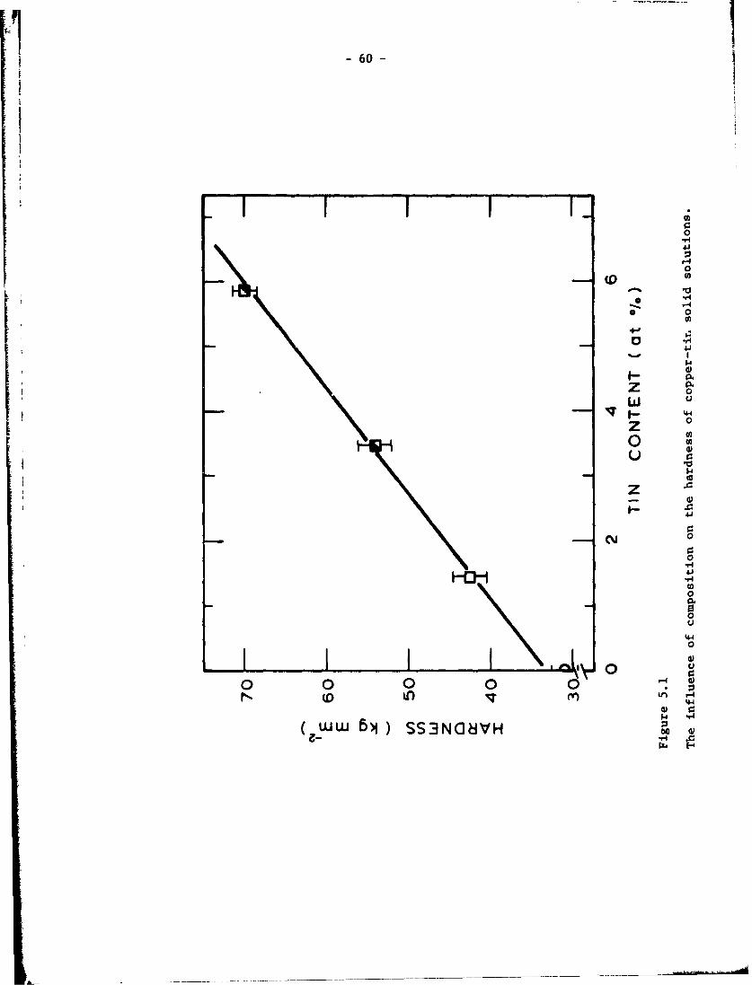
600
F- 44
z-0
-.4
*Y 0
4~9 0
(0
- 0
0
(00)0
0 0 0
144
'44
ww BN) SS3N(18VH z

-61-
Al
E 40 ,
E 30
0o 20
w
0.80.6 L
0 1.0 2.0 3.0 4.0 5.0 6.0 7.0
TIN CONTENT (at 1 )
Figure 5.2
Wear rate of copper-tin solid solutions as a function of tin content.

-62-
00
4
0 -W
0 .
4-44
CM 0
9- 00
U
06~'.4
0 0% cocc*64 60
IN31)lJ-3O:) NOII)18 4

-63-
0
40
ww
00
00
4.40
(/) 0ww40 0 . 0 O
Ivi 6H
(W:) W)) 318 dV0

- 64 -
Since the friction coefficients in the wea tests on copper-tin solid
solutions were not constant, the decrease of wear by addition of the tin
may be partially due to the decrease of friction coefficient. This de-
pendence is shown in Fig. 5.5, where wear rates and wear coefficients are
plotted vs. the friction coefficients. The wear coefficient is used pri-
marily because it is a dimensionless quantity representing the wear be-
havior.
V 4) Internally Oxidized Copper Alloys
In order to show the effect of inclusions on wear, intr.rnally ox'dized
copper-chromium and copper-silicon alloys were used. The copper-chromium
specimens contained 0.18% chromium, whereas thc copper silicon specimens
had 0.5 and 1.0% silicon. Details of alloy preparation are given in
Appendix C. The oxide content of these alloys, which ranged from 0.45%
to 7.30%, did not cause a large change in the hardness of the alloys as
indicated in Table C.l. Therefore, this class of alloys is suitable for
studying the effect of inclusions on wear.
The wear tests were run for 30 min. (54 m of sliding) under different
normal loads. Fig. 5.6, which is a plot of weight loss and the normal
load for the alloys tested, indicates that the wear rata increases with the
oxide content. This is more evident from Fig. 5 .7a which shows the inverse
of wear coefficients, an index of wear resistace, plotted rersus the volume
fraction of oxide particles. The relationship between the wear resistance
and volume fraction is very similar to the fracture strain vs. volume
fraction of particles for uniaxial fracture testing. (4 3 - 4 6 )
Fig. 5.8b which is a plot of friction coefficients vs. the volume
fraction of particles for the internally oxidized copper alloys, indicates
that friction decreases with the increase in the number of particles. The
wear coefficients and the friction coefficients are O1ntz in Fig. 5.8
for these samples. The figure shows that wear depends inversely on friction.
This relationship (which is the reverse of the expected dependence) indicates
the important Influence of inclusions on wear; I.e., reduction in friction
coefficients increases the wear rates because of larger number of crack pro-
pagation sites in the internally oxidized alloys.
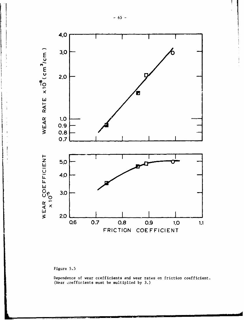
- 65 -
4.0 -I I
E 3.0vE
2.0'0
9-
Kr 1.0,,, 0.9 -V0.8-
0.7%I I
KzI- - 1I'
0 5.0-
3.0
crLi
: 0% U.0< X
2.0 I I I I0.6 0.7 0.8 0.9 1.0 1.1
FRICTION COEFFICIENT
Figure 5.5
Dependence of wear ccefficients and wear rates on friction coefficient.
(Wear coefficients must be multiplied by 3.)

-66 -
25.0 10OF HC COPPer
0 Cu 1.00 Si
LI)
0
NORMAL LOAD (Kg) 2.0
Figure 5.6Weight loss of copper and internally oxidized Cu-Cr and Cu-Si alloys vs.normal load for 30 min. tests.

-67 -
• , ,,i |i
w1.0KELa.LjLwU
0.50
U-
01
1. 5
O OFHC Copper0 Cu-0.18O/o Cr
0 A Cu- 0.50%. Si1.0 - 0 Cu- 1.0 0./o Si
wUz
w 0.5-
0 0.5 0.10
VOLUME FRACTION OF OXIDES
Figure 5.7
Wear resistance and friction coefficients vs. the volume fraction ofoxide particles.

-68-
24
200YO
'C
1-- 616zw
L.L 12
00 u:.8C
@OFHC Copper
w Cu =0.5 SiL0 CU 1.0 Si
H00 0.2 0.4 0.6 0.8 1.0 1.2
FRICTION COEFFICIENT
Figure 5.8
Wear coefficient vs. friction coefficient for internally oxidizedcapper alloys.
-69-
The similarity of Fig. 5.7a to uniaxial fracture strain vs. volume plots
indicates that a relationship between uniaxial tension ductility and wear re-
sistance exists. Therefore, it may be assumed that any metallurgical para-
meter which affects ductility will also have an influence on the wear resis-
tance. Particle size, spacing (and hence volume fraction) of particles,
and coherency of particles with the matrix are the most important metallur-
gical variables affecting ductility. The degree of coherency (i.e. the matrix/
particle bond strength) is an important variable in void nucleation. It has(81)been shown that by slight alloy addition the matrix/particle interface
can be strengthened and the ductility can be increased. Coherence of particles
with the matrix increases as the particle size is decreased. Therefore, void
nucleation and wear in metals containing secoaid phase particles can be de-
creased by either alloying to strengthen the bond or by decreasing the size
of the particles to increase coherency. Also, as discussed in Chapter II,
void nucleation may not be possible for very small particles (less than 100
due to the lack of sufficient elastic energy.
The next important parameter influencing ductility is the particle size.
Theoretical analyses by Gurland (8 and Ashby(82) indicate that ductility
increases as particle size is decreased. Experimental results obtained forinternally oxidized metals (8 4 ) support these theoretica'l analyses; whereas
the results obtained for spheroidized steels (8 5) are contrary to the theories.
This is perhaps due to the complete lack of coherency (presence of a bond
strength) in the internally oxidized metals as compared with some coherency
in steels.
The results presented here cunfirm the predictions of the delamination
theory. By increasing the number of inclusions the wear rate should increase,
provided that the hardness (flow stress) is not increased. Accordingly, when
only the hardness is increased, the wear rate decreases as was shown for
copper solid solutions. These two alloy systems are very specialized and
were selected to show the beparate effect of hardness and inclusion content
on sliding wear. In most commercial metals however, these two effects are
present simultaneously.
V 5) Iron Solid Solutions and Steels
In order to investigate the 'ombined effect of hardness and inclusions
on wear, pure iron, iron-ruthenium and iron-molybdenum solid solutioi.s and
- 70 -
AISI 1018, 1045 and 1095 steels were used. The pure iron was zone-refined
and practically contained no inclusions. The iron solid solutions had a
number of inclusions of 1-2.5tim (40-100tin) in diameter. The heat treat-
ment and the metallurgical variables of these metals are listed in Table 5.1
The volume fraction, f, and the particle size, d, of the inclusions in
iron solid solutions were determined by using approximately 2000 points of
intersection on 4 micrographs of each sample. The volume fraction of cemen-
tite in steels were determined from the stoichiometric relation. These were
then used to determine the mean free path, A, by the following relation:
2d-(1-f).
The steels were heat treated to have three types of carbide structure.
AISI 1018 steel was tested in the spheroidized and pearlitic conditions, AISI
1045 was tested after spheroidization and AISI 1095 was tested in the spher-
oidized, pearlitic, and bainitic conditions. The heat treatment was also
varied to obtain fine and coarse structures,
The wear tests were conducted for different sliding distances in orderto find the steady state wear coefficient for each material. Table 5.1 lists
the wear coefficients and the friction coefficients for the materials tested.
The table indicates that the wear coefficients for iran solid solutions in-
crease with increasing volume fraction of inclusions. This is more evident
from Fig.5.9a which plots the inverse of the wear coefficients, an index of
wear resistance, versus the volume fraction of inclusions and hard second
phsse particles for iron and sphexoidized steels. Wear resistance decreases
with increasing volume fraction of particles down to a minimum value of
wear resistance at 0.07 volume fraction. Beyond this value, wear resistance
increases with the volume fraction.
The relationship which exists between wear resistance and volume
fraction at low volume fractions is in fact similar to the fracture strain
Vs. volume fraction curves (43-46) obtained for fracture in uniaxial tension
or torsion testing. This similarity is not surprising because the mechanism
of void and crack formation in delamination and in tensile or torsional frac-
ture are similar even though the states of stress and strain are quite dif-

-71-
Ci
E
U) :;0= 4
00
IEc - 0 G
0 0
00
-0 C
0-0
-00
w0)
Hw LN .44
001 X 83UDISISOGj JDOM c
10 0
4-4
0
-4 440 0
c >~0 0 L4w
IL 0C2; 0'
04)- u
L0 44
OU)
[ -0001 X OOUD4SISS8 JOSM

-72-
04 N* %o 0-g- 00%0 in010oo 18 r coooor- o 00 0oo c 00000c c
iov-4 004- 0o Gc-.'40 O' C'JI N III-;
0 w go u I3 w o# 0a t DP %- 4
0 0
40
93 H 0 0 000000 0 0
1.4c 0 00 00 0, 4C4C4C
9-4 W 0 4 r- C 0N Ic'C -I I.0 0 " Ln ODf M r %000
'-4 VtV :: We
W 0
u- r0 u 4NrH 0 co
0H 41 H w01to in r .-40 n 0 .0 L .0 4p0
04 en M %TU 0P 0 Dt n
0- 1-4 0
0 H0
41.0 . 0 0 0
0 ~ Id-4 u w C
0140 0 ::::: ,
4.5 00 00 A0AA0 0O- CI 00 00 000 *4-
0 000 00 00 0 tI 0On 0% 04 1O'5Or
0N
0 0 uoH aHH 0
00 04 0 4 0 v-I
0. 0 ~0 0 4j. 4 C 41a. u cn 0. cn 0. f~~
11 1 1 0 V4 (n W
li0 00 0H 0 V4 r- - -4 H(n z~~14z N ~& 0 j0z N - 00 4 04z0
1.4 1.4 H, W CHC

i- 73 -
ferent. In both of these cases cracks are nucleated at the inclusions or
second ph. -! particles and lowering the volume fraction of particles in-
creases both the ductility and the wear resistance.
It is observed from Fig. 5.9a that at higher volume fractions, wear
resistance increases with increasing the volume fraction. This is possibledue to the increased flow stress of the material which allows less plastic
deformation and thus reduces the rate of void formation under the sliding
conditions similar to the case of copper tin solid solutions.
The wear resistance may also depend on the mean free path. (Fig. 5.9b)
A similar relationship has been reported for the fracture of steels in tor-(45)sion testing. However, it is difficult to separate the effect of the
mean free path from the volume fraction, since they are not independent when
the particle size is kept nearly constant. The wear behavior may depend on
both the volume fraction and the mean free path, if the volume fraction
controls the subsurface void and crack nucleation and if the mean free path
influences the rate of crack extension between the voids around the particles.
Theoretical analysis of McClintock (86 ) has shown that uniaxial fracture
strain depends on the logarithm of interparticle spacing, other variables
remaining constant.
The wear coefficients which are listed in Table 5% lfor steels, indicate
that the wear behavior depends on the morphology of the second phase parti-
cles. Among the various structures studied for AISI 1095 steel, coarse
pearlite and bainite had the lowest and the highest wear coefficients, re-
spectively. It was also found that the spheroidized steels had larger wear
coefficients than pearlitic steels.The particle morphology has been found to influence the fracture be-
havior under uniaxial and torsional loading conditions in contradiction tothe way it effects the wear behavior. Rosenfield et al. (46) and Lemnon
and Sherby (45) have reported a better ductility for spheroidized steels
than pearlitic steels, because the pearlite plates fracture preferentially
at lower strains than that required for crack formation in the spheroidized
steels. This may be reversed under sliding conditions because of the pre-
sence of the large hydrostatic compression very close to the surface. It
was observed (Fig. 2.3) that many of the pearlite plates behave plastically
under the large hydrostatic compression and deform rather than fracture.
Therefore, the subsurface crack formation by pearlite fracture may be retarded
under sliding conditions, resulting in a lower wear coefficient,

-74-
Despite these inherent similarities between fracture and delamination,
there are basic differences, primarily in the states of stress and strain.
In tensile or torsional fracture testing, the state of loading is uniaxial
tension or shear and the strains are uniformly distributed. Sliding con-
tacts, on the contrary, experience a unique loading condition which is a
combination of shear and hydrostatic compression. The deformation under
these conditions is not uniform with depth and is confined to a thin surface layer.
The large hydrostatic compression which exists near the surface could
greatly alter the ductility and fracture properties of the surface layer.
The effect of hydrostatic compression on ductility has been studied under(47) (48)
uniaxial tension and shear deformation These investigations
show that ductility increases in the presence of high hydrostatic compression.
The increase of ductility is shown to result from suppression(49)
of void nucleation at the particle/matrix interface . This retardation
of crack formation under high hydrostatic compression together with the soft-
ness of the surface (3 ) may explain the excessively large subsurface defor-
mation (2 0 ) which occurs before delamination.
V 6) Summary
The results of this chapter substantiate the predictions of the de-
lamination theory concerning the role of microstructure on sliding wear.
Therefore it may be concluded that wear of metals may be decreased by elim-
ination of void nucleation sites, by increasing the hardness of the material,
or by the combination of these two procedures.

- 75-
k Chapter VI
DEAMINhTION IN OTHER WEAR PROCESSES
VI 1) Introduction
The preceding chapters confirmed the delamination theory for the case
of sliding wear. Delamination occurs because of the presence of tractions
on the contacting surfaces. Therefore, delamination may be expected to be
present in other types of surface phenomena, if normal and tangential forces
are present at the surface. This chapter considers three types of wear in
which delamination may have an influential role.
VI 2) Fretting Wear
Fretting wear occurs between two tightly fitting surfaces when there
is a small amplitude oscillating slip between them. The early stage of
fretting wear(3,50,51) is caused by the wear mechanisms postulated by the
delamination theory of wear. Once the wear particles are generated, they
may oxidize and act as abrasive particles between the surfaces, accelerating
the wear process. However, the critical stage of fretting wear is the gen-
eration of wear particles by the delamination process. The micrograph in
Fig. 6.1, which was taken by Waterhousef50 ), shows the fretted surface of
Ti-7AI-4V alloy tested in air at 107 cycles per bacond under a mean stress2 2of 147 MN/m and alcernating stress of 83.5 MN/m . It can be seen that the
wear particles are in the form of thin sheets.
One of the unique and controversial phenomena observed in fretting
wear is the dependence of the wear rate on the amplitude of the oscillatory
motion, as shown in Fig. 6.2. (52) In terms of the delamination theory of
wear, the decrease in the wear rate at low amplitudes can be explained by
noting that cracks cannot link together between two inclusions (i.e. crack
nucleation site) when the plastic strain is small. Fretting wear rate
depends on the microstructure since the distance between crack nucleation
sites vis-a-vis the amplitude of oscillating slip is the rate determining
process. Once the amplitude of oscillating slip is sufficient to link the
cracks together, the early stage of fretting wear is not any different from
sliding wear.
One of the major problems associated with fretting wear is fretting
fatigue. Since fretting fatigue is initiated at cracks generated by fretting

-76-
Figure 6. 1
Micrograph of a fretted Ti-6A1-4V surface (Ref. 50).

-77-
j
00"30
00
K :1020-020 STEE
3 o Cu-IO0.O0
F
W
I00I00pC7 1i sem 1 a Atl I a III
110 100 1000
AMPLITUDE Am
Figure 6.2
FrettJ g wear coefficient vs. the amplitude of oscillation (Ref. 52).

- 78 -
wear, fretting fatigue can be prevented if fretting wear can be reduced.
Although lubrication of the interface is a possible solution, in some appli-
cations lubricants cannot be applied. Fretting fatigue may also be prevented
by plating a hard substrate with a thin layer of softer metal to minimize
the delamination wear as has been discussed earlier (1314)and in Chapter VIII.
Such experimental results for fretting fatigue were recently reported by
Ohmae, et al. (53), but the importance of the thickness of the plated layer
was not recognized by them.
The environmental effect on fretting was recently discussed by Van
Leeuwen in terms of the delamination theory of wear (54). He postulated
that since water may oxidize bare metal according to the following reactions
F2+Fe- Fe 2 + 2e
Fe2+ + 2 H20 ) Fe (011) + 21!+
2+ 2
the resulting hydro&en ions or protons could be transported by the dislo-
cations as Cottrell clouds, as they move from a region near the surface into
the subsurface region to pile up at hard particles. The di3locations would
then deposit the hydrogen at the interface between the matrix and the obsta-
cle and cause hydrogen embrittlement cracking at that location. This trans-
port of hydrogen by dislocation motion, rather than by thermaly activated
diffusion , would then explain the accelerated fretting-corrosion in a
water-containing enviro,.ment.
VI 3) Abrasive Wear
Abrasive wear can be caused either by hard abrasive particles entrapped
between two sliding surfaces or by the asperities of a hard surface sliding
on a soft surface. The abrasive wear volume is, to a first approximation,
proportional to the normal load and the distance slid, and inversely propor-
tional to the hardness. Many wear processes change into abrasive wear when
loose wear particles are generated.
The mechanism of abrasive wear consists of two modes of material re-
moval: cutting of the surfaces by hard loose particles or asperities on the
mating surface, and delamination by subsurface deformation. The surface
ttaction associated with the cutting action deforms the surface layer which
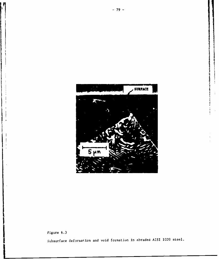
pini
I Figure 6.3
I Subsurface deformaion and void formation in abraded AISI 1020 steel.

- 80 -
causes subsurface crack nucleation and propagation as shown in Fig. 6.3.
The figure shows z micrograph of a section perpendicular to the abraded
surface of an annealed AISI 1018 steel pin (diameter 0.64cm) which was sub-
jected to abrasive action by abrading against 240 grit SiC abrasive paper at a
speed of 6.3 cu/sec and a normal lo3d of 0.4 kg. Depending on the sharp-
ness and hardness of the a- sive particles, either the delamination or the
cutting action may be the dominating mechanism. The harder the surface
the less will be the cutting action. When the delamination mechanism
dominates, the microstructural effects discussed for sliding wear should
be equally applicable.
VI 4) Erosive Wear
When a metal surface is gradually worn by the action of particles im-
pinging on the surface, it is called erosion by solid particle impingement.
This is a problem and arises in pipes which transport solid particle slurries,
gas turbines, and aircraft propellers. Finnie( 5 5 ) and Bitter(56) proposed
wear mechanisms for this type of wear caused by solid particle impingement.
Finnie's model assumes that each one of the solid particles acts as a cutting
tool when it strikes the surface, removing soma of the surface material.
Bitter (56) proposed that the normal velocity component of the impinging solidrarticle causes wear by a feti ue Oro's, while the tangential components
cause wear by deformation.
Fig. 6.4 shows micrographs o. re. surface of 2024-T4 aluminum impacted
at various speeds at an impingement angle of 450 . It should be noted that
the material is displaced a great deal but very little material has been
removed by actual cutting action. Fig. 6.5 shows aluminum specimens impacted
at 280 m/sec at room temperature 4nd at 150 m/sec at 2000F. The specimen
imp&."ted at the higher speed shows signs of melting (57), but the evidence
is not conclusive. The specimen impacted at 200OF shows "mud" cracks (Or-
lar to 1racks formed in drying mud), indicating that the surface has unaergone
oxidation at a high temperature or melted. Fig. 6.6 shows the cross sectional
view of the subsurface cracks in copper and steel. It should be noted that
the cracks tend to be perpendicular to the direction of impact and that
subsurface cracks exist at a finite distance away from the surface. The
subsurface cracks extend deeper in the specimen impacted perpendicular to
the surface. The mechanics of the surface deformation is such that we have
a maximum deformation at the surface. Since crack nucleation is not favored

1-81-
41
I-A-
41 0u3.
00
44 0
-w44 c 0.C
0 44 -%.-
U1 U0) u-
4) 0
0 --
w4r'

-82-
10
1.i
40
1.
to44
N 0.
0
44 4V)
w-40
IRN 0 (A
600
444
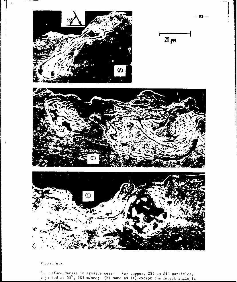
-83-
550i
If
2 6.i0 dvcl
5Ame as (. , . , V,.. .. -°-" ,' + ° I.
Tit
I i u r f i c d a a g i n e r o s i v w e a r ( a c o p e r 2 5 m a t i l s
t+'.,Ld i t 5.5 , 105 m/see; (b) ,same as (a) except the impact angle is

-84-
wherever there is a high hydrostatic pressure, cracks wil tend to nucleate
underneath the Impacted surface. Since crack propagation is similarlyaffected by the hydrostatic pressure, the depth of stable crack propagation
will vary depending on the position of the nsterial relative to the inter-
face between the particle and the surface and on the direction of particle
notion. It should be noted that tha mechania. of erosion by liquid particle
Impingement seems to be quite different from the case considered here.(58)

-85 -
Chapter VII
SURFACE ROUGHNESS AND INTEGRITY EFFECTS ON SLIDING WEAR
VII 1) Introduction
It has been recognized for some time that the surface roughness and
waviness affect the wear characteristics of unlubricated and boundary lubri-
cated surfaces. However, the exact nature of this effect has not been clari-
fied. In fact, it appears that in most instances the machining specifications
for sliding surfaces are left to empiricism. When the tolerance between the
sliding surfaces is large, one can normally avoid the problem by "running-
in" the surface, which is equivalent to letting the surface reach an equi-
librium steady state wear situation. For some critical applications where
the tolerance is extremely important (such as in bearings), this practice can-
not always be used.
The purpose of this chapter is to provide further insight into the
"run-in" process and to discuss the merits of having either rough or smooth
surface in sliding applications. The effect of surface roughness and surface
"quality" on sliding wear are examined, and it is shown th.t measurements of
the surface roughness alone is not sufficient to characterize the quality of
a sliding surface. According to the delamination theory of wear such factors
as microstructural damage are equally important.
The phenomenon of "run-in" which is generally observed in early stages
of sliding interactions, refers to the large wear rates observed on the
initiation of sliding. After this transient stage, the wear rate is reduced
a.(59,60)and becomes constant. Sasada et al. attribute this behavior to the
transfer of wear particles from one surface to the other, followed by oxi-
dation of both surfaces to reduce the wear rate. This explanation can only
be true in air and not under lubricated conditions or in ai inert atmosphere;
yet "run-in" is also observed under these conditions. Queener et al.( 6 1 )
correlated this behavior to the removal of the original surface asperities
and showed that under libricated conditions "run-in" wear depends on the
original surface roLghness.

-86
Although some (62) have tried to explain the steady state wear in terms
of interactions and fracture of asperities, there is convincing evidence(31 )
that the subsurface deformation, and crack nucleation and propagation processes are
the rate controlling mechanisms. The fact that there is always a steady
state deformation field in the subsurface corresponding to the steady state
wear, indicates that the steady state wear behavior can only be explained in
terms of the delamination theory of wear.
VII 2) Review of Previous Investigations
According to the delamination theory of wear, sliding wear of metals
at low speeds occurs by the following mechanisms:
1. Plastic deformation and fracture of the original asperities (i.e.,
originv! machining marks).
2. Plastic deformation of the subsurface by the traction existing at
the contact area.
3. Void and crack formation in the deformed subsurface.
4. Subsurface void growth and crack extension.
5. Generation of long subsurface cracks nearly parallel to the surface.
6. Crack extension to the surface to generate wear sheets.
According to this theory the roughness and integrity (i.e., subsurface
deformation and damage) of machined surfaces can affect only the initial wear
behavior but not the steady state delamination process. In a previous studV 63)
it was shown that the eftect of original surface roughness on wear was different
depending on the normal load (Fig. 7.1). Under large loads (0.3 kg), the
rougher surfaces resulted in a larger initial weight loss associated with the
volume of the initial surface asperities (Fig. 7.ia). However, once the original
machining marks were removed and steady state delamination was observed, the
wear rate of all surfaces were equal. hen the wear tests wer2 conducted
under lower normal loads (0.075 kg), it was found that the rough surfaces had
lower initial wear than smooth s Ataces (Fig. 7.1b). ihis was due to the fa:t
that dalamination of the smooth surfaces began on the initiation of sliding;
whereas delamination of the rough surfaces was delayed until the original
?in oy disk geometry, AISI 52100 steel pin, 4.7 m/min average sliding speed,argon gas environment.
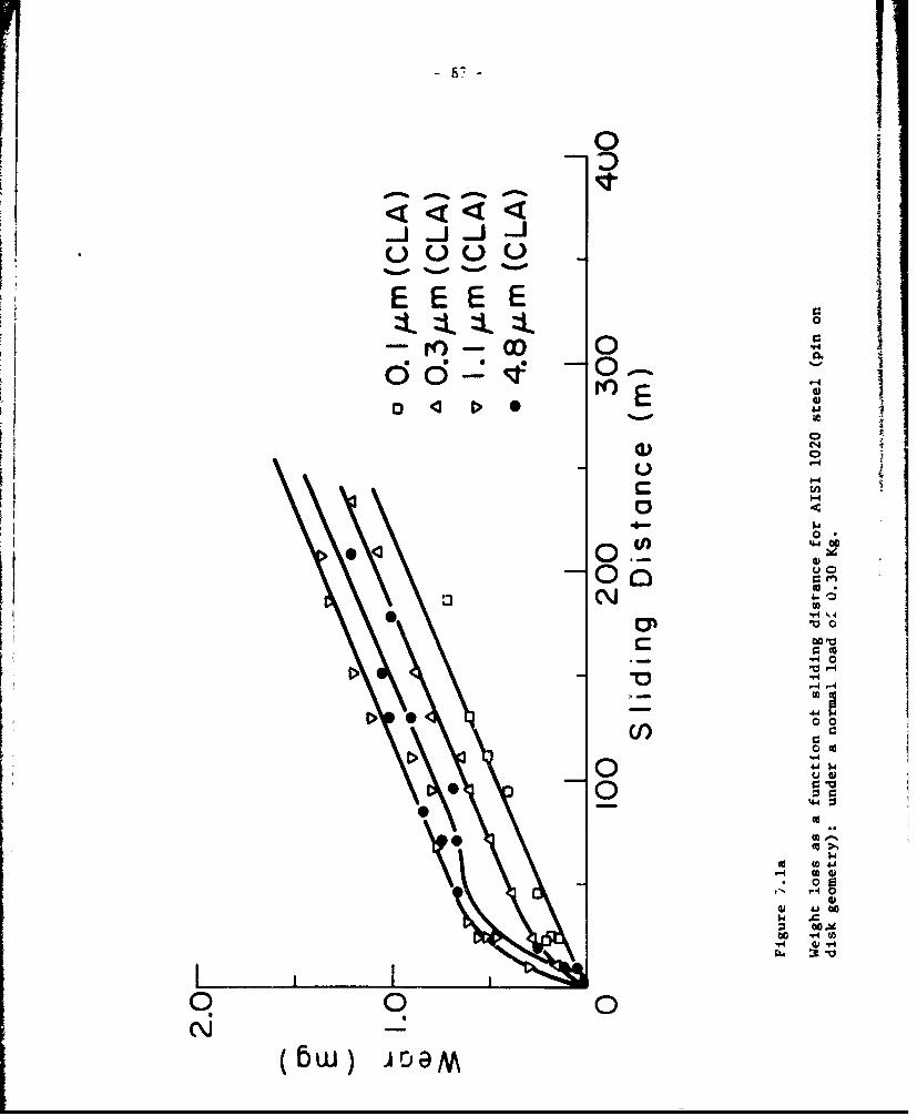
0
-0-
O .U) 44
Cdoz
CC
U40
00
4
0 u qW
Icd (a 40
90 0
(6W) oa~M

0-0
8
-0 0
rn-
-4
0'4
4-r
C0 0
coC
0 I-
c544 0
.- -40
44 0 0-
9 0M\ -J
( W JD4c 0 I
r-4( w) Dw

- 89 -
machining marks were removed. During steady state delamination the wear rate
of both surfaces were equal. Since the rate of the removal of asperities was
much lower than the delamination rate, the rough surfaces had smaller weight
losses than smooth surfaceo. This phenomenon was not observed under larger
loads because the contact stress was sufficient to remove the original as-
perities almost immediately and initiate delamination.
The transient wear process and delamination of a rough surface, is sche-
matically shown in Fig. 7.2. The initial weight loss is associated with
the deformation and removal by fracture of the tops of asperities (steps 1-5).
The amount removed depends on the strength of the material, the surtace
traction and the size of the asperities. However, when all of the original
asperities are removed, the rate of delamination (stcps 5-6) does not depend
on the surface finish as observed in Fig. 7.1.
The wear track of the coarsest surface finish specimen after a two minutes
test (lOm of sliding) is shown in Fig. 7.3. The deformation of the asperities
at the side of the track (Fig. 7.3a) and the occurance of delamination in the
center of the track (Fig. 7,3b is observed. Note that some machining marks
are still present across the track. Due to the large size of asperities in
this case, the whole track has not yet reached steady state delamination.
VII 3) Experimental Procedure
Wear tests were carried out on a lathe using a cylinder on cylinder
testing geometry. The specimens were rotated at a surface speed of 1.8 m/mmn
and the stationary AISI 52100 pins (0.6cm in diameter) were pushed against the
specimens by a normal load of 0.106 and 0.850 kg. A seiies of tests were
carried out with the slider moved mantally parallel to the axis of the
specimen. This was performed under a load of 0.907 kg for 10 passes. The
tests were run under argon flowing at a rate of 10 i/min into a chamber sur-
rounding the contacting surfaces. All tests were run dry and at room tem-
perature.
The material tested was commercial cold rolled AISI 1018 steel (hardness
84 kg/mm 2)and 70/30 brass thardnpqs 46 kg/mm 2),0.A cm in diameter. A variety
of surface finishes were generated by turning. The surface finishe. ranged
from 1.2 to 10.4 um (CLA). These specimen finishes were generated by turning
at 319 rpm with a 0.13 mn depth of cut at v-lous feed rates. Some specimens
were prepareu with cutting tools having a range of poitive and negative rake

40
0
0 LO
QO 1-
X0j
U Ij
0 r
'J 1. 4
Q) w CLo GZ L
L- ) C 0
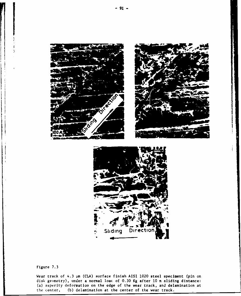
91 -
•, Shiding Direction L
rA
Figure 7.3
Wear track of 4.3 wm (CIA) surface finish AISI 1020 steel speciment (pin on
disk geometry), under a normal loac of 0.30 Kg after 10 m sliding distance:
(a) asperity deformation on the edge of the wear track, and delamination at
the center, (b) delamination at the center of the wear track.
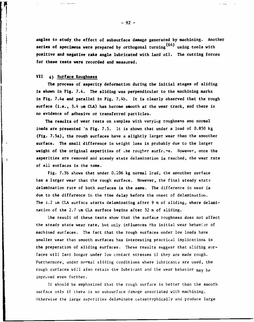
-92-
angles to study the effect of subsurface damage generated by machining. Another
(64)series of specimens were prepared by orthogonal turning using tools with
positive and negative rake angle lubricated with lard oil. The cutting forces
for these tests were recorded and measured.
VII 4) Surface Roughness
The process of asperity deformation during the initial stages of sliding
is shown in Fig. 7.4. The sliding was perpendicular to the machining marks
in Fig. 7.4a and parallel in Fig. 7.4b. It is clearly observed that the rough
surface (i.e., 3.4 um CLA) has become smooth at the wear track, and there is
no evidence of adhesive or transferred particles.
The results of wear tests on samples with varyiig roughness ana normal
loads are presented 'n Fig. 7.5. It is shown that under a load of 0.850 kg
(Fig. 7.5a), the rough surfaces have a slightly larger wear than the smoother
surface. The small difference in weight loss is probably due to the larger
weight of the original asperities of Lhe rougher surfEc:s. However, once the
asperities are removed and steady state delamination is reached, the wear rate
of all surfaces is the same.
Fig. 7.5b shows that under 0.106 kg normal load, the smoother surface
has a larger wear than the rough surface. However, the final steady state
delamination rate of both surfaces is the same. The difference in wear is
due to the difference in the time delay before the onset of delamination.
The 1.2 um CLA surface starts delaminating after 9 m of sliding, where delami-
nation of the 2.7 4m CLA surface begins after 32 m of sliding.
!he result of these tests show that the surface roughness does not affect
the steady state wear rate, but only influences th3 initial wear behavior of
machined surfaces. The fact that the rough surfaces under low loads have
smaller wear than smooth surfaces has interesting practical implications in
the preparation of sliding surfaces. These results suggest that sliding sur-
faces will last longer under low contact stresses if they are made rough.
Furthermore, under normal sliding conditions where lubricants are used, the
rough surfaces will also retain the lubricant and the wear behavior may be
impruved even further.
It should be emphasized that the rough surface is better than the smooth
surface only if there is no subsurface damage associated with machining.
Otherwise the large asperities delaminate catastrophically and produce large

-93-
(b)
7.4 Plastic deformation of original asperities for AISI 1018 steel(cylinder on cylinder). (a) Sliding perpendicular to the machiningmarks, 2.0 pm (CLA) surface finish, under a normal load of 0.91 Kgfor 10 passes. (b) Sliding parallel to the machining marks, 3.3 Pm(CLA) surface finish, under a normal load of 0.35 Kg after 0.25 mof sliding.

-94-
6.0
5.01 Normal Load: 0.850 Kg
4.0
E 3.0
2.0AISI 1018 Steel
0 2.1 pm (CLA)A 6.Opjm (CLA)
1.0 0 7.8 pm (CLA)
0 I I0 10 20 30
SLIDING DISTANCE (in)
Figure 7.5a,
The effect of original roughness of machined surf acee on weight loss: normalload of 0.850 Kg.

-95-
0IN
EU 0
EEE00
O L 0004 In
z UU)
'4.
1
z U
'.0
4)
0 000
11 0 r-4
II U U)
00
00w~ 440
0
0
z
L 00 0 0
(bw V3M
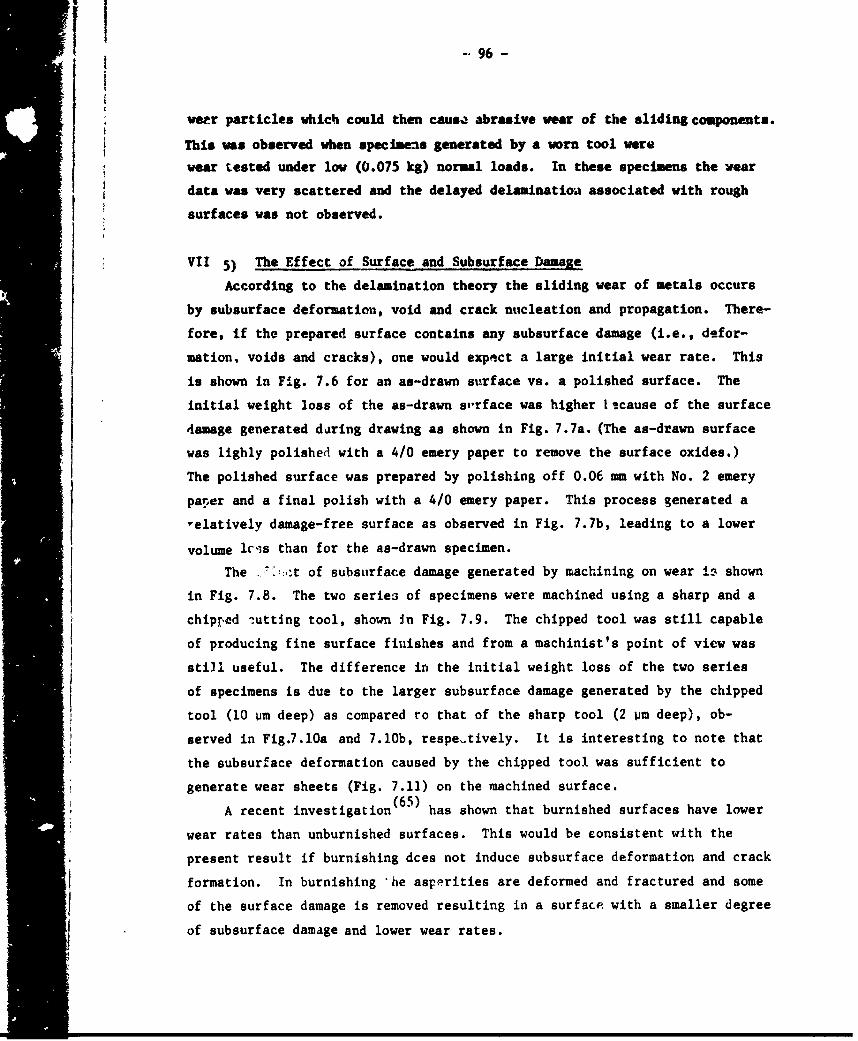
11 96 -
weer particles which could then causQ abrasive wear of the sliding components.
This was observed when specimens generated by a worn tool were
wear tested under low (0.075 kg) normal loads. In these specimens the wear
data was very scattered and the delayed delaminatioa associated with rough
surfaces was not observed.
VII 5) The Effect of Surface and Subsurface Damage
According to the delanination theory the sliding wear of metals occurs
by subsurface deformation, void and crack nucleation and propagation. There-
fore, if the prepared surface contains any subsurface damage (i.e., defor-
mation, voids and cracks), one would expect a large initial wear rate. This
is shown in Fig. 7.6 for an as-drawn surface vs. a polished surface. The
initial weight loss of the as-drawn s,,rface was higher 1 cause of the surface
damage generated during drawing as shown in Fig. 7.7a. (The as-drawn surface
was lighly polished with a 4/0 emery paper to remove the surface oxides.)
The polished surface was prepared by polishing off 0.06 mm with No. 2 emery
parer and a final polish with a 4/0 emery paper. This process generated a
-elatively damage-free surface as observed in Fig. 7.7b, leading to a lower
volume lcrs than for the as-drawn specimen.
The -::t of subsurface damage generated by machining on wear io shown
in Fig. 7.8. The two series of specimens were machined using a sharp and a
chipped iutting tool, shown In Fig. 7.9. The chipped tool was still capable
of producing fine surface finishes and from a machinist's point of view was
still useful. The difference in the initial weight loss of the two series
of specimens is due to the larger subsurface damage generated by the chipped
tool (10 um deep) as compared ro that of the sharp tool (2 Vm deep), ob-
served in Fig.7.10a and 7.lOb, respe-tively. It is interesting to note that
the subsurface deformation caused by the chipped tool was sufficient to
generate wear sheets (Fig. 7.11) on the machined surface.
A recent investigation (65) has shown that burnished surfaces have lower
wear rates than unburnished surfaces. This would be consistent with the
present result if burnishing dces not induce subsurface deformation and crack
formation. In burnishing 'he asperities are deformed and fractured and some
of the surface damage is removed resulting in a surface with a smaller degree
of subsurface damage and lower wear rates.

-97-
60
Normal Load 0.850 Kg
50
30- V -
40
30
Iir
20-
AISI 1018 Steel
V As DrownV Polished
0 10 20 30
SLIDING DISTANCE (i)
Figure 7.6
The effect of as-drawn materiald on wear of 1018 steel under a normal load
of 0.85 Kg.

F~r _____ 98-
Fiur 7.Secion p rpndculr ttesrfce_ howngtypca_ mirosruturo
101 steel:__(a)_asdrawn;_(b)_afterpolishing.

H -99-
II 6.0
Normal Load :0.850 Kg
5.0-
Chiped Cutting
4.0- ToolI
3.0-0
ii ~!4IiiSharp Cutting
2.0 ToolAISI 1018 Steel
0 1.'4 pm (C.LA)
A4.8pm (CLA)1.0 * 2.1 jum (CLA)-V A 6.0 p~m (CLA)4 110 47.8 pim (CLA)
0 0 20 30
SLIDING DISTANCE (i)
Figurr 7.8
The effect of subsurface machining damage on wear of 1018 steel.

- 100 -
(b)
Figure 7.9
SEM micrographs of the rake face of: (a) chipped cutting tool;(b) sharp cutting tool.
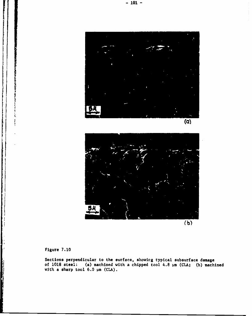
-101-
*1i
II
Figure 7.10Sections perpendicular to the surface, showirg typical subsurface damage
of 1018 steel: (a) machined with a chipped tool 4.8 um (CLA; (b) machinedwith a sharp tool 6.0 urm (CIA).

- 102 -
- -I
Figure 7.11
Wear sheets on the machined surface of an 3.3 um (CLA) surface finish, preparedwith chipped cutting tool.
-103-
The degree of subsurface damage associated with machining depends
n the cutting rake angle and the depth of cut. ( 66 , 6 7 ) Turley has shown
that the depth and the degree of deformation in 70/30 brass increases as the
rake angle becomes more positive or negative. At large negative rake angles
the tool does not cut any more and it slides over the surface causing plowing
and subsurface deformation. The depth of defozmation also increases withthe depth of cut and the cutting radius.
Fig. 7.12 showki the wear of steel specimens prepared with three dif-
ferent tools (40 rake, 80 rake and 1.3 mm honed radius, 400 rake). The
figure shows that all specimens have the same wear. This is posvible since
all the tools had positive rake angle and since steel is much harder than
brass and therefore the damage caused by machining with different cutting
t.,nls might have not been sufficient to affect the wear behavior.
Therefore, 70/30 brass specimens were prepared by orthogonal turning'
with +25', +50, and -1? rake angles. The results of the wear tests on the
brass indicated that there was not a large difference between the wear rates
of the samples cut with positive and negative tools. Subsurface observations
of the machined surfaces showed that the depth of deformation was 25 pm for
the +250 tool and 30 pm for the -15 tool. Since this difference was not
large it did not lead to a substantial difference in the wear rate of the
samples.
The depth of deformed lay.rs reported by Turley (66.67)ranged from
600 Pm for a +250 tool to 900 pm for a -150 tool. In the presence of such
a large difference in the deformed regions generated by the two tools, one
should expect to observe a large difference in the initial wear rate. However,
since the degree of machining damage in the brass samples of this work were
similar, no difference in the wear behavior was observed.
The deformation depth in brass observed by Turley was much more than
the deformation depth reported here, probably because of the difference in
the machining operation. Turley's specimens were prepared by planing; whereas
the specimen tested by us were prepared by turning. This indicates that the
choice of machining operation and perhaps machine tools is an imoortant factor
in preparation of surfaces for sliding applications, since each type of
machining generates a different type of damage in the finished product.

-104-
6.0
Normal Load 0.850 Kg
5.0-F
-~4.0
I'E3.0
Wo0
2.0
AISI 1018 Steel
S 40 Rake Angle, 1.3 ,um (CLA)
1.0- 0 8 Rake Angle,2.5pm(CLA)A 1.2mm Honed Radius,
400 Rake Angle, Z.0 pm (CLA)
0 1 10 10 20 30
SLIDING DISTANCE
Figure 7.12
Wear of 1018 steel under a normal load of 0.85 Kg, speciMents machined withthree different cutting tools.

- 105 -
VII 6) Conclusions
1) Surface roughness influences only the initial wear behavior and not
the steady state wear rate.
2) At low normal loads rough sliding surfaces have smaller wear than
smoother surfaces, provided that the surfaces are free from machining
damage.
3) Large subsurface damage associated vith machlxdng operations could
increase the initial delamination wear rate of the sliding surfaces.
4) The choice of machining operation and variables are important factors
in the preparation of surfaces for sliding applications.
-106-
Chapter VIII
SLIDING WEAR RESISTANCE OF METALLIC COATED SURFACES
1III 1) Introduction
Earlier work (2'13'3 4 ) has shown that the delamination theory of wear
may provide a Lheoretical . its for reducing wear through the application
of soft metallic coatings to metal surfaces. The hypothesis was that if
a thin layer of a softer metal is deposited on a harder substrate, heavy
plastic deformation and wear of the substrate by delaminaticn may be pre-
vented. The critical nature of the plate thickness was explained in terms
of dislocation instability very near the surface, although this has not*
been proved explicitly. Plating a metal substrate with a soft metal to
reduce friction and wear has been used quite extensively (68'79 ) , but the
exact nature and mechanism by which these coatings improve the tribological
behavior of surfaces has not been investigated completely. Previous attempts
have been made ( to determine the optimum thickness of these coatings,
but the results and the theoretical considerations were insufficient and
inadequate.
The purpose of this chapter is to show that large wear reduction is
possible by plating a soft metal on a hard surface if the deposited material
is not thicker than a critical thickness (much less than 1 pm). It is shown
that, as the plate thickness is increased, wear by delamination within the
plate occurs until the thickness is reduced to a stable value. Cadmium,
silver, gold and nickel coating have been used on steel and the influence of
substrate surface condition prior to plating has been investigated. The role
of the soft metallic coatings in wear reduction is discussed both in terms
of dislocation mechanics and the mechanics of delamination.
VIII 2) Review of Earlier Work on Coated Metal Surfaces
Elect :oplating with precious metals to increase the life of ball bear-
ings (7477)and gears (7778)operated in vacuum has been renorted in the
literature. However, the components still exhibited a high degree of wear.
The coatings were 30 to 75 pm thick, well above the probable optimum values,
which may explain the high wear rates.
Other investigators (6 9- 7 1 ) have noted the reduction in the sliding
The existence of the soft layer is and has been a controversial sub-ject. Definitive work has not been done to date.
Patent pending.
- 107 -
wear rate of steel when plated with soft materials such as lead, gold,
gold alloys, si 1.ver, copper and nickel. For the most part the wear was
reduced only by a factor of 2 to 3. These results were obtained in tests
which were run with an unplated slider rubbing against a plated specimen,
leading to the possibility of transfer of the soft plating material from
the specimen to the slider and also abrasive wear caused by loose wear
particles.
Kuczkowski and Buckley (72) coated nickel and AISI 440 C stainless
steel with 25 pm of various binary and ternary alloys if gallium and indium.
.A ternary alloy of gallium, indium and tin reduced the wear rate of the
sta.Tnless steel by four orders of magnitude when tested in a vacuum of
10-11 mmHg. Similar results were found for nickel with a coating of a
binary alloy of gallium and indium. No mention was made however of the
possible influence of plating thickness on the wear rate.
In previous papers by the authors (13'34) it was shown that a thin
coat ng of cadmium (0.1 um) on AISI 1020 steel can reduce the wear rate
of steel by a factor of 5000 under an inert atmosphere. The thickness of
the coating was found to be critical, since delamination within the cadmium
plate occurred for thicknesses greater than 0.1 urn. It was also shown that
the subsurface aeformation of the parent meal below the coated wear track
was much less than the corresponding deformation beneath an uncoated track.
The thin plated layer retarded substrate delamination because of the reduced
deformation due to the lower friction coefficient of the thin cadmium plated
steel. The critical thickness of the soft plating could be predicted by
utilizing the delamination theory of wear. This prediction was based on the
fact that dislocations near the surface are not stable and some of them
can be pulled out of the free surfa:.e by the action of the image forces
acting on these dislocations. Consequently, the thickness of the "low dis-
location density" J.yer is controlled by the magnitude of the image forces
which depend on such material properties as shear modulus and friction
stress. Therefore, if the plated layer is made thin enough such that most
of the dislocations can be eliminated, the plate deforms continuously with-
out appreciable strain-hardening and subsequent fracture. This thin plated
layer reduces the friction coefficient because of its non-strain-hardening

- 108
properties, thus resulting in less substrate deformation and wear. However,
if the plate is thicker than this critical thickness, dislocation accumu-
lation and strain hardening can take place in the plated layer, leading to
wear by delamination within the plating itself.
An alternate explanation may be provided :a terms of the stress dis-
tribution. It was shown in Chapter III that the .,ormal tensile stress coa-
ponent perpendicular to the surface over which an asperity has Just moved
becomes a maximum at a finite depth below the surface. Therefore, it can be
argued that delamination cannot occur in a critically thin plated layer,
since the magnitude of the tensile stress is very small in that layer.
VI:: 3) Experimental Procedure
Wear tests were carried out with a cylirder-on-cylinder geometry.
The specimens were 0.63 cm in diameter by 7.6 cm long with a 0.4 um (CLA)
ground finish prior to plating. In one case the surface was metallogra-
'.hically polished with a 0.25 um diamond paste. The specimens were rotated
at a surface speed of 1.8 m/mmn and the stationary pins were pushed against
the specimens by a normal load of 2.25 kg. All tests were carried out dry
in a chamber surrounding the mating surfaces under argon flowing at a rate
of 10 I/min.
The substrate materials used had a variety of hardnesses: AISI 1018
(84 kg/mm 2), AISI 1095 (170 kg/mm 2) and AISE 4140 (270,370,460 kg/mm 2 -
obtained by different heat treatments). In all cases the sliders were
made of the same material as the specimen, heat treated and plated in the
same fashion. The plating thickness varied from .05 to 10 pm. The platings
tested were gold, gold over a nickel flash, cadmium, nickel, and silver.
Some of the gold plated specimens were plated with a flash of gold first
and were then heated at 5000C for 2 hours in vacuum to obtain a diffused
bonding between the plate and the substrate. Then the required thickness
of gold was plated on the samples.
VIII 4) The Effect of Plate Thickness
The effectiveness of plating in wear reduction is dramatically shown
in Fig. 8.1 for 1 Pm nickel plated AISI 4140 steel. The large difference
in the size of the weai tracks between the unplated (Fig. 8.1a) and the
plated sample (Fig. 8.1b) should be noted. The unplated sample was tested
for 30 minutes, whereas the plated sample was tested for 2 hours. Since
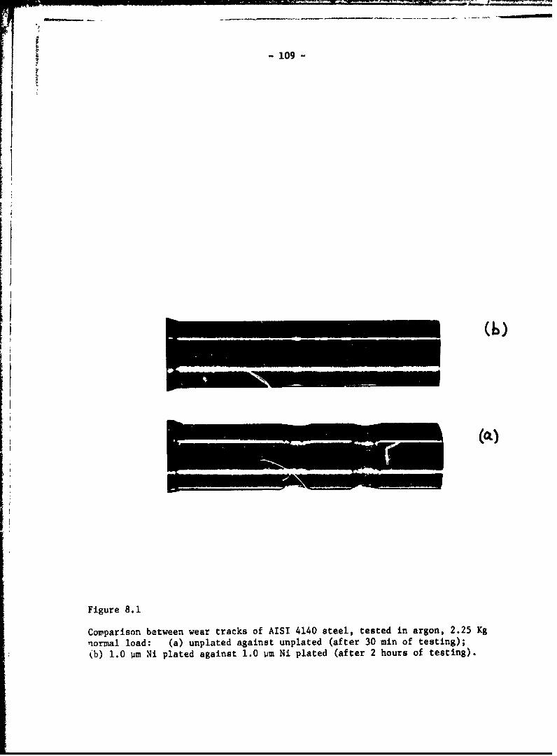
-109-
K((00
Figure 8.1
Comparison between wear tracks of AISI 4140 steel, tested in argon, 2.25 Kg
normal load: (a) unplated against unplated (after 30 min of testing);
(b) 1.0 pm Ni plated against 1.0 pm Ni plated (after 2 hours of testing).
- 110-
no further wear could be detected on the plated specimen after 2 hours
(216 a of sliding), the test was terminated.
The Important effect of the nickel plate thickness on the wear rate
of AISI 4140 steel is observed in Fig. 8.2. Wear reduction by three orders
of magnitude is observad for the initial nickel thickness of 1 lim. This
minmum thickness of the plate also decreased the coefficient of friction
from 0.63 to 0.45. Fig. 8.2 shows that the wear rate increases with the
nickel plate thickness. This increase in wear rate for thick plate, is
caused by dislocation accumulation leading to strain hardening and delam-
ination within the plate. The cracking and delamination within a thick
(25 pa) plate of gold on AISI 1018 steel is shown in Fig. 8.3. 1he
thick layers wear off by delamination until the thickness of the layer is
reduced to the optimum thickness in which the dislo,ations are presumably
not stable. Afterwards, the wear rate is very low, similar to the case of
thin platings. The transient behavior of thick coatings is shown in Fig.
8.4 for an initial 10 pm nickel plate on AISI 4140 steel. Under some sliding
situations where the wear particles cannot be removed from the contact, they
may act as abrasive particles and accelerate the wear process.
VIII 5) The Effect oi Surface Roughness and Bond Strength
The steel samples which were plated with a thin layer of gold without
any special treatments failed immediately at the beginning of sliding.
This failure was found to have been caused by the lack of adhesive bonding,
which was accentuated by the roughness of the substraze surface at the time
of plating. In these tests, since thit optimum plate thickness is very
small, the substrate surface roughness may play a major role ii, the life
of the coatings. The bond strength between electrodeposited go.1.d and steel
has been reported tc be very low and to become even weaker with increasing
substrate surface roughness. (80) Under sliding conditions, the roughness
could cause further deterioration of the bond strength by the deformation,
and final fracture (Fig. 5) of the original substrate esperities. There-
fore, the gold plated steel samples were specially treated to achieve a
good bond strength. By thermal diffusion of a very thin layer of gold or
by plating a flash of nickel over the substrate before gold plating, it
was possible to increase the life of the thin gold plates from immediate
failure to more than 108 m of sliding (60 min).

I
IM "11 - -
ODI0x 100-E
ECP -
0 10
I I , 11,111i I I ,1,11,11
0 1.0 iOInitial Ni plate thickness (/m)
Figure 8.2
The effect of the initial Ni plate thickness on wear rate of AISI 4140 steel
in argon, for 30 min tests.

-112-
k igure
Crack formation in a thick Au plate (25 um initial thickness) after weartesting; AISI 1020 ateel substrate.
Figure 8.5
The deformation of substrate asperities due to the sliding action on a
thick plate of Au on AISI 1020 steel substrate.

I- LU3
I: 1-2.0 o{B
0 IC20 30Time (min)
Figuce 8.4
Wear of a thick Ni plate (initial thickness of 10 urn) vs. time.

11 .......
The influence of the substrate surface finish on cadmium plated speci-
sens was checked with a 0.05 Pm cadmium coating on AISI 1018 steel with both
a fine ground finish and a metallographically polished finish. The surface
roughness had only a moderate effect on the life of the cadmium plates, and
polishing increased the life of the coatings only from 25 m to 31 m of sliding.
Since steel-cadmium adhesion strength is much greater than the adhesion of(80)
steel-gold, this result suggests that moderate changes of surface rough-
ness may influence only plating-substrate combinations which have low ad-
hesive strength.
VIII 6) Hardness Matching Between the Substrate and the Coating
The wear data for all coating materials and steel substrates with various
%ardnesses for the tests in argon is summarized in Table 8.1. The I pm plate
of gold (with special trertments) was also effective in air. (Nickel, silver
and cadmium were not, because they oAidized and were removed early in the
tests.) Wear tests were continued on the coatings which did not fail immed-
iately. After 60 min (108 m) those coatings had remained on the surface and
were still effective in reducing wear.
According to the delamination theory the plated material must be softer
than the substrate to minimize the wear rate. This is supported by the results
for nickel a.1d cadmium platings presented in Table 3.1. For the substrates
softer than 460 kg/mm2 failure of the nickel plate was immediately. However,2
for substrate hardness of 460 kg/nm 2 nickel plating had a very low wear rate.
Cadmium plate with a hardness of 30-50 Kg/mm2 (8 0 ), was successful on all substrates.
VIII 7) Discussion
The results presented in this chapter further substantiate the predictions
made by the delamination theory of wear on the wear resistance of soft metal
coatings. ror best wear resistance the plated material must be softer than
the substrate, thinner than a critical thickness, and bonded strongly to the
substrate. The condition of the surface of the substrate is an important
factor since it was shown that smoother plated surfaces last longer. It was
shown in Chapter VII that subsuriace damage caused by machining operation in-
fluences the initial wear behavior greatly. 'rherefore, these materials must
be prepared carefully so as to minimize the damage to the substrate during
machining. Otherwise, the damaged substrate may cause premature failure and
offset the beneficial effects of plating. If the delaminated particles are
not removed from the co ntact, they may oxidize and serve as abrasive particles,

-115-
0 0
HH4
0.0S
SI u
94.eNU
V o ~ ~ *4
u "4
0
= - 1- 0 0 0 -% 0 0 0 0
in 00
-4-
P- M~.4 -4 ,4 -4 --C v
41
ow
.0 _ ____ -- ____
'ccI0

-116-
thus degrading the coating and enhancing delamination.(69-79)Soft metals have been used for wear resistance previously by others
Some of these investigators assume that the soft metal layer melts during
sliding and acts as a lubricant. This explanation can only be correct when
the sliding speeds and the normal loads are high enough to cause a large
flash temperature at the contact. The present work has shown that even
nickel can be effective in wear reduction under low speed sliding wear and
that the thickness of the pl,.e has a pronounced influence. These findings
are contradictory to the previous assumptions on the mechanism of wear reduction
of soft metal layers. It was shown in this chapter that it is not the absolute
softness which is important; it is the relative hardness between the substrate
and the coating which is the determining factor.
The experimental results presented in this chapter are not direct and
explicit proof of the assumed dislocation instability caused by the image
force, but they are ir accordance with the original predictions made by the
delamination theory of wear. It appears however, that the original postulates
predicting the effects of thickness and hardness of the metallic coatings
are justified by th: 'ndirect evidence. However, other explanations may be
given for the lo,i wear rate observed with these coatings.
The central questions are why the thin layer zetards delamination and
why it Joes not delcminate itself while the thicker layer does. It wa3
shown in Chapter III that the normal tensile btress component perpendicular
to the surface over which an asperity has just passed is a maximum at a finite
depth below the surface. This depth of maximum tensile stress may be
responsible f.jr subsurface crack propagation and final delamination There-
fore, it can be argued that delamination cannot occvr within thin layers if
the layer's thickness is smaller than the depth of the maximum tensile stress.
When the thickness of the plate is increased and/or maximum tensile stress is
developed in the plate, the plate will delaniinate. Secondly, since the plated
layer reduces the frictional forLe, the substrate experiences a lower maximum
tensile stress and less plastic deformation. Consecuently, the substrate
delamination is retarded and large reductiox in 4ear is possible. The dif--
ficulty with the alternate explanation is that it cannot explain how a thin
surface coating undergoes 3uch a large plastic deformation without work

- 117 -
hardening, as evidenced by the low coefficient of friction which does not
change during testing. Sub-grain formation and annihilation of dislocations
are plausible explanations, but then the question is "why doesn't a similar
phenomenou occur at the sub-surface?" Therefore, we have to come back to
the postulatp that there is a unique phenomenon which occurs at the surface.
We think this may be associated with dislocation instability at the surface.
VIII 8) Conclusions
1. The delamination theory of wear provides the theoretical basis for
reducing wear through the development of a coated metal surface.
2. For major wear reduction che coating material must be softer than
the substrate material.
3. There exists an optimum thickness of soft coating for wear resis-
tance. This thickness is in general less than 1 urn for sLeel
plated with Cd, AS, Au, or Ni.
4. Cd, Ag and Ni plates are effective only in inert atmosphere, but
Au was effective in air or in inert atmosphere.
5. The surface roughness of the substrate and the coating/substrate
bond strength are two important factors for wear reductions by a
composite metal surface.

I-118-
Chapter IX
WbMMARY AND COICLUSIOA S
The purpose of the MIT Wear Research Program is to control friction
and wzar of materials through proper design of sliding Eurftces and proper
selection of materials. We are approaching this goal by first analysing
the friction and wear behavior of materials in terms of both mechanical and
microstructural aspects, and secondly by applying the understanding to the
design of sliding surfaces.
The hypotheses of the delaminatian theory have been examined and ex-
perimentally justified. Predictions based on these hypotheses have been
used to reduce wear by many orders of magnitude. Advances have been made
in understanding the mechanics of surface deformation and the effect of
microstructure on the wear behavior. It has been shown that the material
below the surface experiences a tension-compression cyclic state of loading,
and the magnitude and the position of the maximum tension perpendicular to
the surface is related to the friction coefficient and the normal load. It
was indicated that a relationship between fr.ctiorL coefficient and wear rate
could be formulated if subsurface crack propagation occurs at the position
of maximum tensile stress perpendicular to the surface. Wear and friction
coefficients were also shown to be related through consideration of energy
conservation. Even though this analysis is very approximate, the theoret-
ical predictions are surprisingly close tc the experimental resul, . These
types of energy and mechanics of delamination analyses will be refined
during the next phase of this project aince they are necessary for an under-
standing of wear behavior.
Studies have been carried out on microstructural effects in sliding
wear, concentrating on separating and understanding the effects of hardness
and hard-particle crack nucleation sites. The results substantiated the pre-
dictions of the delamination theory that the wear rate is controlled by
both the hardness and the number of void nucleation and crack propagation
sites. It was shown that the wear rate is decreated by increasing theIhardness and decreasing the number of void nucleation and crack propagation
sites.

- 119 -
Preliminary investigations in other modes of wear showed that the de-
lamination process may occur under any condition where both normal and
tangential forces exist at the contact. Evidence of delamination was
found in fretting, abrasive and erosive wear. Indications were that the
early stages of fretting wear are controlled by delamination. It was pro-
posed that the measures which can be taken to reduce sliding wear can also
be used to reduce fretting and catastrophic failure by fretting fatigue.
Studies on the effect of surface roughness on wear indicated that the
original surface roughness of machined parts controls the initial wear
behavior and not the steady state delamination wear rate. The influence
of surface roughness on wear was shown to depend on the normal load. Under
low contact loads, the delamination of rough surfaces was delayed, which
resulted in low wear of rough surfaces as compared to smoother ones. How-
ever, at higher contact loads, all surfaces delaminated at the beginning
of sliding and the wear of rough surfaces was larger than smooth ones
because of the larger volume of the original machining aspErities of
rough surfaces. It was shown that the quality and the degree of subsur-
face damage has detrimental effects on the initial wear rate. This pre-
liminary result indicates E st:ong need for quality control measures for
surfaces machined for sliding applications.
The delamination theory of wear was used to develop wear resistant
metallic surfaces by application of a thin soft metallic plate. The wear rate of
the combination can be reduced by three orders )f magnitude if the coating
is softer than the substrate, has an optimum thickness (0O.lum), and is
bonded strongly to the substrate. This phenomenon was demonstrated ex-
perimentally for cadmium, silver, gold and nickel plated steel specimens.
Based on the inveotigations reported here, the following conclusions
may be made in regard to wear reduction:
1) Wear rate can be decreased by increasing the hardness and de-
creasing the inclusion and second-phase particle density.
2) Wear of surfaces sliding under low contact loads can he decreased
by preparing rough surfaces which Jo not have any subsurface
damage.
3) The wear rate can be decreased by plating a softer metal on a
harder substrate.

-120 -
4) In order to insure that these procedures or other similar ones
are effictive in wear reduction, surface quality control methods
mst be deviued.
In regard to further investigation, the following courses of action
are recommended:
I) Further investigation of the mechanics of crack nucleation and
propagation in order to be able to predict and control these
proceuses.
2) Extension of the delamination theory to high speed sliding wear,
wear of lubricated surfaces, and other types of wear.
3) Application of the already developed wear reduction mezhods to
practical situations.
4) Development of manufacturing and quality control criteria for
the production of low-wear surfaces.
5) Investigation on the possible interaction between lubricants
and worn surfaces and the influence of this interaction on wear.

- 121 -
REFERENCES
1. H.P. Joqt, "Economic Impact of Tribology," Mechanical Engineering, 97(1975), 26-33.
2. N.P. Suh, S. Jahammir and E.P. Abrahamson, "The Delamination Theory ofWear," Progress Report to ARPA, Contract No. N00014-67-A-0204-0080,Sept. 1974.
3. N.P. Suh, "The Delamination Theory of Wear," Wear, 25 (1973), 111-124.
4. J.F. Archard, "Contact and Rubbing of Flat Surfaces," J. Appi. Phys.,24 (1953), 981-993.
5. A.P. Green, "Friction Between Unlubricated Metals: A TheoreticalAnalysis of the Junction Model," Proc. Roy. Soc. (London), A 228(1955), 191-204.
6. E. Rabinowicz, "Influence of Surface Energy on Friction and WearPhenomenon," J. Appl. Phys., 32 (1961), 1440-1444.
7. F.P. Bowden and D. Tabor, Friction and Lubrication of Solids, ClarendonPress, Oxford, 1954.
8. H. Koba and N.H. Cook, "Wear Particle Formation Mechanisms," ProgressReport to ONR, Contract No. N00014-67-A-0204-0054, May 1974.
9. J.A. Kirk and T.D. Swanson, "Subsurface Effects During Sliding Wear,"Wear, 35 (1975), 63-67.
10. K.B. Savitskii, cited in VI, Kragelskii, Friction and Wear, Butterworth,Washington, 1965.
11. J.T. Fourie, "Plastic Deformation of Thin Copper Single Crystals,"Canadian J. Phys., 45 (1967), 777-786.
12. D.J. Whitehouse, "Some Ultimate Limits on the Measurement of SurfaceUsing Stylus Techniqueb," Proc. Int. Corf. on Prod. Eng., Tokyo,Part II (1974), 39-44.
13. S. Jahanmir, N.P. Suh and E.P. Abrahamson, "The Delamination Theoryof Wear and Wear of a Composite Metal Surface," Wear, 32 (1975), 33-49.
14. S. Jahanmir, E.P. Abrahamson and N.P. Suh, "Wear Resistance of ThinMetallic Coatings," Wear, (1976), Submitted for publication.
15. D.H. Buckley, "Effect of Various Malerial Properties on the AdhesiveStage of Fretting," Proc 39th Meeting of the Structures and MaterialsPanel, NATO Report, AGARD-CP-161 (1974), 13.1-13.15.
16. '. Green, "The Plastic Yielding of Metal Junctions Due to CombinedSheat and Pressure," J. Mech. Phys. Solids, 2 (1954), 197-211.
17. P.K. Gupta and N.H. Cook, "Junction Deformation Model for Asperitiesin Sliding Interaction," Wear, 20 (1972), 73-87.
18 Fl n,- 122-
18. J. Fleming, "On the Mechanics of Delamination," S.M. Thesis, Depart-&.ant of Mechanical Engineering, MIT (In r.ogress), 1976.
19. K.J. Bathe, "ADINA-A Finite Element Program for Automatic DynamicIncremental Nonlinear Analysis," Report No. 82448-1, Acoustics andVibration Laboratory, Department of Mechanical Engineering, MIT, 1975.
20. G. Agustsson, "Strain Field Near the Surface Due to Surface Traction,"S.M. Thesis, Department of Mechanical Engineering, MIT, 1974.
2. D.R. Wheeler and D.H. Buckley, "Texturing in Metals as a Result ofSlidizg," Wear, 33 (1975), 65-74.
22. V.D. Scott and H. Wilman, "Surface Re-Orientation Caused on MetalsCaused by Abrasion - Its Nature, Origin and Relation to Friction andWear," Proc. Roy. Soc. London) A247 (1958), 353-368.
23. J. Goddard, H.J. Harker, and H. Wilman, "The Surface Re-OrientationCaused by Unidirectional Abrasion on FCC Metals," Proc*Phys. Soc.,80 (1962), 771-782.
24. W.J. Huppman and M.A. Clogg, "The Tribological Behavior of Polycrystal-line Cobalt and Rat.on to Crystallographic Texture and Structure,"Presented at ASLE-A .,, Int. Lub, Conf., New York, Oct. 1972.
25. N.P. Suh, S. Jahanmir, E.P. Abrahamson and A.P.L. Turner, "FurtherInvestigation on the Delamination Theory of Wear," J. Lub. Tcch.,Trans. ASME, 96 (1974), 631-637.
26. S. Jahanmir, N.P. Suh and E.P. Abrahamson, "Microscopic Observation ofthe Wear S., et Formation by Delamination," Wear, 28 (1974), 235-249.
27. A.R. Rosenfield, "Criteria for Ductile Fracture of Two Phase Alloys,"Met. Rev., 13 (1968), 29-42.
28 .-. Argon, J. Im and R. Safoglu, "Cavity Formation from Inclusionsin Ductile Fracture," Met. -rans. 6A(1975), 825-837.
29. A.S. Argon anu J. Im, "Separation of Second Phase Particles inSpheroidized 1045 steel, Cu-0.6 Pct. Cr Alloy, and MaraginL Steelin Plastic Straining," Met. Trans,, 6A (1975), 839-851.
30. M.F. Ashby, "Work Hardening of Dispersion-Hardened Crystals," Phil.Mag., 14 (1966), 1157-1178.
31. N.P. Suh, "Microstructural Efi-cts in Sliding Wear of Metals," Proc.Battelle Materials Science Colloquium, Fundament,-l Aspects of StructuralAlloy Design to be published, Plenum Press, 1976.
32. E. Rabinowicz, "F-,iction, Wear and Lubrication," Center for AdvancedEngineering Study, MIT, (1974).
33. N.P. Suh, S. Jahanmir, D.A. Colling and E.P. Abrahamson, "The Delami-nation Theory for Wear of Metals Sliding at Low Speeds," Proc. 2niNortii American Metal Working Research Cont., (1974), 117-127.

- 123 -
34. E.P. Abrahamson, S. Jahanmir, N.P. Suh and D.A. Colling, "Applicationof the Delamination Theory of Wear to a Composite Metal Surface," Proc.Int. Conf. on Production, Tokyo, Japan (1974), 408-413.
35. E.P. Abrahamson, S. Jahanmir, D.A. Colling and N.P. Suh, "Failure byDelamination During Wear," Proc. Scanning Electron Microscopy Conf.Part IV (1974), 889-894.
36. J.H. Dautzenberg and J.H. Zaat, "Quantitative Determination of Defor-mation by Sliding Wear," Wear, 23 (1973), 9-20.
37. J.E. Merwin and K.L. Johnson, "An Analysis of Plastic Deformation inRolling Contact," Proc. Instn. Mech. Engrs., 177 (1973), 676-690.
38. B.I. Sandor, Fundamentals of Cyclic Stress and Strain, The Universityof Wisconsin Press, (1972).
39. M.C. Shaw and G.J. DeSalvo, "A New Approach to Plasticity and itsApplication to Blunt Two Dimensional Indenters," J. Eng. Industry,Trans. ASME, 92 (1970), 469-495.
40. J. Morrow, "Low Cycle Fatigue Behavior of Quenched and Tempered SAE1045 Steel," Report No. 277, Department of Theoretical and AppliedMechanics, University of Illinois, Urbana, Ill., April (1965).
41. R. Fleisher, "Substitutional Solution Hardening," Acta Met., 11 (1963)203-209.
42. R. Fleisher, "Solution Hardening," Acta Met., 9 (1961), 996-1000.
43. B.I. Edelson and W.M. Baldwin, Jr., "The Effect of Second Phaseson the Mechanical Properties of Alloys," Trans. ASM, 55 (1962), 230-250.
44. C.T. Liu and J. Gurland, "The Fracture Behavior of Spheroidized CarbonSteels," Trans. ASK, 61 (1968)156-167.
45. D.C. Lemmon and O.D. Sherby, "Effect of Microstructure on the Ductilityof Steel in Torsion," J. Materials, 4 (1969) 444-456.
46. A.R. Rosenfield, G.T. Hahn and J.D. Embury, "Fracture of Steels Con-taining Pearlite," Met. Trans., 3 (1972) 2797-2804.
47. P.W. Bridgman, Studies in Large Plastic Flow and Fracture, HarvardPress, Cambridge, Mass., 1964.
48. T.J. Walker and M.C. Shaw, "On Deformation at Large Strains,"in Advances in Machine Tool Design and Research, (1969) 241-252.
49. A.R. Austen and B. Avitzur, "Influence of Hydrostatic Pressure onVoid Formation at Hard Particles," J. Eng. for Ind., Trans, ASME,96 (1974) 1192-1196.
50. R.B. Waterhouse and D.E. Taylor, "Fretting Debris and the DelaminationTheory of Wear ,' Wear, 29 (1974) 337-344.

-124-
51. R.B. Waterhouse, "Physics and Metallurgy of Fretting," Proc. 39thMeeting of the Structures and Materials Panel, NATO Report, AGARD-CP-161 (1974) 8.1-8.8.
52. I.F. Stowers, "The Mechanism of Fretting Wear," Ph.D. Thesis,
Department of Mechanical Engineering, MIT (1974).
53. N. Ohmae, T. Nakai and T. Tsukizoe, "Prevention of Fretting by IonPlated Film," Wear, 30 (1974) 299-309.
54. H.P. Van Loeuwen, "Discussion on Suh's Delamination Theory of FrettingWear and the Possible Role of Hydrogen," Proc 39th Meeting of the Struc-tures and Materials Panel, NATO Report, AGARD-CP-161 (1974) 13.19.
55. I. Finnie, "The Mechanism of Erosion of Ductile Materials," Prjc,3rd.U.S. Nat. Cong. Appl. Mech., (1958) 527--538.
56. J. G.A. Bitter, "A Study of Erosion Phenomena, Parts I and II," Wear,6 (1963) 5-21, 169-190.
57. C.J. Sherman, "Wear f Metallic Surfaces By Farticle impingement,"S.M. Thesis, Department of Mechanical Engineering, MIT (1971).
58. M.D. Speide*I and C. Keser," Resistance to Rain Erosion, Stress CorosionCracking, and Corosion Fatigue in a 127 Chromium Steel," Presented at4th International Conference on Rain Irosion and Associated Phenomena,Meersburg, Germany (1974).
59. T. Sasada, H. Ohmuta and S. Nororse, "The Wear and Mutual Transferin Cu/Fe Rubbing," Proc. 15th Japan Conp. on Mat. Research, (1972) 1-6.
60. T. Sasada, S. Nororse and K. Sugimoto, "The Mutual Metalic Transfer atFriction Surfaces in Lubricating Oil," Proc . i7th Janan Cong. on Mat.Research, (1974) 32-35.
61. C.A. Queener, T.C. Smith and W.L. Mitchel, "Transient Wear of MachineParts," Wear, 8 (1965) 391-400.
62. D. Landheer and J.H. Zaat, "The Mechanism of Metal Transfer in Sliding
Friction," Wear, 27 (1974) 129-145,
63. E.P. Abrahamson, S. Jahanmir and N.P. Suh, "The Effect of Surface
Finish on the Wear of Sliding Surfaces," CIRP Annals, 24 (1975) 513-514.
64. N.H. Cook, Manufacturing Analysis, Addison-Wesley, Readtng, Mass. (1Q66).
65. R. Rajasekariah and S. Vaidynathan, "Increasing the Wear Resistance ofSteel Components by Ball Burnishing," Wear, 34 (1975) 183-188.
66. D.M. Turley, "Deformed Layers Produced by Machining 70/30 Brass,"J. of the Inst. of Metals, 96 (1968) 82-86.
67. D.M. Turley, "Dislocation Substructures and Strain DistributionsBeneath Machined Surfaces of 70/30 Brass," J. of the Inst. of Metals,99 (1971) 271-276.

i
125
68. Y. Tsuya and R. Takagi, "Lubricating Properties of Lead Films onCopper," Wear, 7 (1964) 131-143.
69. R. Takagi and T. Liu, "The Lubrication of Steel by ElectroplatedGold," ASLE Trans., 10 (1967) 115-123.
70. R. Takagi and T. Liu, "Lubrication of Bearing Steels With ElectroplatedGold Under Heavy Loads," ASLE Tranb., It (1968) 64-71.
71. A.J. Solomon and M. Antler, "Wear Mechanisms of Gold Electr)deposits,"Plating, Aug (1970) 812-816.
72. T.J. Kuczkot ski and D.H. Buckley, "Friction and Wear of Low MeltIngBinary and Ternary Gallium Alloy Films in Argon and in Vacuum," NASATN D-2721 (1965).
73. H.E. Evans and T.W. Flatley, "Bearings for vacuum Operations, RetainerMaterial and Design," VASA TN D-1339 (1962).
74. H.E. Evans and T.W. Flatley, "High Speed Vacuum Performance of GoldPlated Miniature Ball Eearings with Various Retainer Materials and Con-figurations," NASA TN D-2101 (1963).
75. T.W. Flatley, "High Speed Vacuum Performance of Miniature Ball BearingsLubricated with Combination of Barium, Gold and Silver Films," NASA TND-2304 (1964).
76. P.E. Brown, "Bearing Retainer Material for Modern Jet Engines," ASLETrans., 13 (1970) 225-239.
77. T.L. Ridings, "Operetional Evaluation of Dry Thin Film LubricatedBearings and Gears for Use in Aerospace Environmental Chambers,"AEDC-TR-65-1 (1965).
78. R.D, Lee, Jr., "Lubrication of Heavily Loaded, Low Velocity Bearings,and Gears Operating in Aerospace Environmental Facilities," AEDC-TR-65-19 (1965).
79. E. Rabinowicz, "Variation of Friction and Wear of Solid Lubricant Filmswith the Film Thickness," ASLE Trans., 10 (1967) 1-9.
80. W.H. Safranck, The Properties cf E:ectrodeposited Metals and Alloys,Elsevier, New York (1974).
81. K.E. Easterling, H.F. Fishmeister and E. Navara,"The Particle to MatrixBond in Dispersion Hardened Austenitic and Ferritic Iron Alloys,"Powder Met., 16 (1973) 128-141.
82. M.F. Ashby, "Work Hardening of Dispersioi.-Hardened Crystals," Phil.Mag., 14 (1966) 1157-1178.
83. J. Gurland, "The Fracture Strength of Sintered Tungsten Carbide-CobaltAlloys in Relation to Composition and Particle Spacing," Trans. Met.Soc. AIME, 227 (1963) 1146-1150.

'T ! -, ,
-126-
84. B.A. Wilcox and A.B. Clsuer, "Creep of Thoriated Nickel Above and Below0.5 T.," Trans. Met. Soc. AI M, 236 (1966)570-580.
85. A.M. Turkalo and J.R. Low, Jr., "The Effect of Carbide Dispersion onthe Strength of Tempered Martensite," Trans.Met . Soc. ADIME, 212 (1958)750-758.
86. F.A. McClintock, "On the Mechanics of Fracture From Inclusions," inDuctility, American Society of Metals, (1968) 255-277.
87. S.P. Timshenko and J.N. Goddier, Theory of Elasticity, 3rd ed.,McGraw-Hill, 1970.

- 127 - -
Appendix A
THE FINITE ELEMENT METHOD
A 1) Introduction
The finite element method is a procedure for numerical solution of
partial differential equations, such as those that arise in continium mech-
anics. The basic formulation of the finite element method has been knovM
for over fifty years however, application of the method was not practical
for complex problems until the deveicr.uent of high-speed digital computers.
The advantages of finite element over finite difference methods (at least
for elliptic partial differential equation3) include the ease of handling
complicated boundary conditions and the relative ease of writing generalized
programs to solve any well-posed problem.
This appendix consists of three sections. First is a derivation of the
basic equations of the displacement based finite element method in elasticity.
Second is a discussion of how nonlinearities such as plasticity are included.
The final section discusses the particular program and models being used in
the ongoing analysis of the wear process.
A 2) Derivation of the Finite Element Method
The equations of the finite clement method may be derived in several
ways. The most elegant, phybically meaningful, and theoretically useful(2)
derivation is obtained by applying the principles of vdriational calculus
Since the variational calculus method is long and complicated, the following
derivation follows the simpler weighted residual method for a displacement
based two dimensiona) elastIL:itv problem to arrive at the same result.
Consider ai arbitrarily shaped two-dimensional elastic body. On some
region or regions of the boundary, Sf, the applied force F Ss proscribed.
On the remainder of the boundary, S , the displacement U is prescribed.
The equations of elasticity may be nondimensionalized into Poisson's equation
in the displacement j and the body force p:
2V = 0 =U on S
-F on S . (A.1)3n f
The numbers in parenthesis designate the references at the end of thisappendix.

- 128 -
Then let a be some approximate slution which satisfies the displacement
boundary condition *a = U on Su . In general, *a will not satisfy thedifferential equation or the f'orce boundary condition at all points. Let
the total error Et be defined as the sum of the Integrals of the error at
each point t.%4 es some arbitrary weighting function w:
Et B (V* pWdA +JSL dS (A.2)Et - a - P) w fA + f (- an
Note that there are many equally "good" ways to define Et; this particular
choice is taken to obtain the same final result as the variational formu-
lation.
To obtain a more convenient form, apply Gauss's theorem to the first
of the integrals in Eq. A.2 to yield:
A (2a- p) wD +S Dog d a ax + f aywdA
JSfS - ] C -x x+-- -Y 'A)
(A.3)
Since w is still arbitrary, and by definition *a satisfies the boundarycondition on S , let w - 0 on S . Substituting into Eq. A.2,
E -- a dA - pwdA-t AIj a ax a TY A J~f FwdS (A.4)
It would be extremely difficult to find a function 4a which reasonably
satisfies the differential equation and boundary conditions over the whole
body. However, we may reasonably try to approximate § in small areas first,
and then "paste together" the approximations to obtain a good overall
approximation.
Cousider the body broken up into small "finite" elements, generallyth
triangles and quadrilaterals. Then, within the - element, I is appr3ximated
by *an* Any portion of Sf that coincides with the boundary of the element
is denoted by Sn. Thenfn
N
Et En
~Now the approximating functions *a and the weighting functions w mustn

-129-
be defined. Consider the three to eight node isoparametric quadrilateral
element illustrated in Figure A.I. Assume that the value of *an at node i
is denoted by Vj. Then assume that an at any point in the element is given
by a linear combination of *i:
8Ian (x,y) = ii (A.6)
The functions h a:e called interpolation functions or shape functionssince their order and type determi - the way in which displacement may vary
within the element. For the element of Fig. A.1, the h are polynomials of
order one or two. This assumption, together with the fact that hi = 1
at node i and hi = 0 at all other nodes, determines the interpolation func-
tions completely. To actually evaluate the interpolation functions, the
element .s mapped onto the "natural" (r,s) plane as shown in Figure A.2.
This type of element is called isoparametric because the interpolation
functions and the mapping functions are of the same type and order; indeed,
the mapping functions are inverses of the interpolaticn functions, i.e.
8x = hi(r,s)xi
8y - h hi(r,s)y . (A.7)
i= 1
We have a form for 0an in Eq. A.6, but the weighting functions must
still be chosen. Since there are as many unknowns ( ) as there ace nodes,
we may choose as many weighting functions as there are nodes. From experience
and certain theoretical considerations, chouse wi = hi
Now if we define
K J a An a ?h dA (A.8)
then, using Eq. A.6
f 3 awa aw ' 8ia ?n n + an Wn I
f n + all 'wn] dA I K n (A.9)An , ax aj=xl iJ
where K ndepends only on the element geometry and material properties.
Physically, Kn is the force at node i per unit displacement at node J.
The eight by eight symmetric matrix [ K I n made up from K n is called the
element stiffness matrix.

F -130-
(2)
((8)
(3) (7) (4)
(1)LocaI Node Number(Adina Convention)
Figure A.l1
Three to eight node isoparametric quadrilateral finite element.

-131-
to U
OD,,
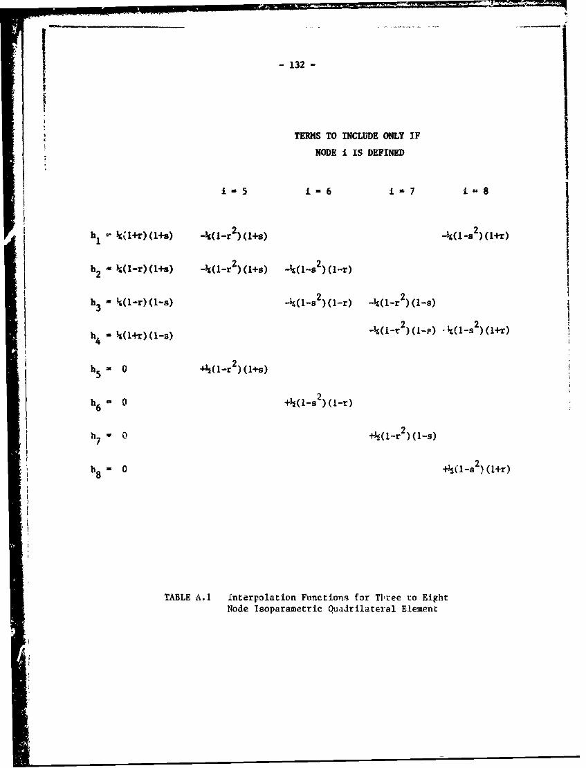
-132-
TERMS TO INCLUDE ONLY IF
NODE i IS DEFINED
i 5 1 -6 1 7 1 8
h2 kIr(s)2)(1+9) 2)(1-r)2
h W(-r)(1-s) - (-s 2)(1-r) -4(1-r 2(1-s)
2 2;4 (14T) (1-9) -(- )(1-?) 44(1-s )(1+r)
2h5 r 0 G Ir (4s)
h 0 2))1-r
7 2
h 0 -S(1 2 ),(1+r)8
TABLE A.1 Interpolation Fu.nctions for Tltree to EightNode Isoparametric Quaidrilateral Element

- 133 -
Defining
JAn phi dA n Fbi
- Jf Fhi ds F1si (A.1O)
the consistent element nodal force vector [Fb + F ]fn may be assembled.
Eqs. A.1O are merely a method for splitting up he forces into statically
equivalent point forces at the nodes.
If we number each node in the total assemblage of elements with a unique
global node number, and define the connectivity matrix [ C ] such that
C - the global node number of local node I of element i, the global stiff-
ness matrix [ K ] and the global displacement and force vectors [ 0 ] and[ Fb + F.] may be defined. Substituting into Eqs. A.5 results in a complete
set of linear equations for the nodal displacements:
[ K ] [ 0 ] = [ Fb + F ] • (A.11)
Here, Ki is the force at global node J per unit displacement at global node
1. [K is symmetric, positive definite, and banded (Ku f 0 unless nodes
i and J are in the same element). i is the displacement of global node i,
and Fbi + Fs1 is the applied force at global node i.
After solving the system of equations given alove, strains may be found
by differentiating Eqs. A.6, and stresses found by using Hooke's law or any
other %proprlate stress-strain relationshir.
A 3) Nonlinearities in the Finite Element Method
The preceding derivation covered a linear problem. Nonl~nearities that
may be introduced in static structural mechanics problems include plasticity
and creep (material nonlinearity) and finite strain (geometrical nonlinearity).
The methods of implementing these nonlinearities are many, and are too
complicated to discuss in detail here. However, it may be said that all
methods of handling nonlinearities reduce to linearizing the governing
equations 1 some manner and carrying out the analysis in small time or
load steps.

- 134 -
The process of linearization automatically introduces errors. Inplasticity, the error is a failure to satisfy equilibrium. For any nonlin-
earity, the solution procedure must be iterated without any increase in load
or time to reduce the error. The incremental nature of nonlinear analysis
and the necessity of iterating for equilibrium or its analogue are the major
factors in the expense of nonlinear inalysis.
A 4) The Finite Element Program and Models Used in Studying Wear
The program used in the analyses has been ADINA, developed by Bathe(3 ).
The program is designed to carry out static or dynamic, linear or nonlinear
(geometrically or materially) structural analyses. Thus far, only static
linear and static materially nonlinear (elestic - plastic) analyses have beenused in our study of wepr. Two programs have been developed at the Materials
Processing Laboratory: CNFCALC (Consistent Nodal Force CALCulator), which
numerically integratcs the second of Eqs. A.1O for any two-dimensional grid(4)under any loading ( , and CALPLOT (CALcomp PLOTter), which produces the stress
(5)and displacement field plots shown elsewhere in this report.
The models used here have been intended to investigate several processes
of delamination wear: strain accumulation, crack nucleation and crack propa-
gation. The crack nucleation studies have concentrated on calculating stress
fields around inclusions. Since the boundary conditions for the loading of
inclusions under asperities during plastic deformation are as yet unknown,
these studies have been essentially preliminary, designed to verify other's
results and to learn the use of the program,
The majority of the analyses have been intended to study possible mech-
anics of crack propagation, strain accumulation, and to calculate boundaly
conditions for use in studying crack nucleation. The problem considered
has been that of an infinite half-plane two dimensional solid in plane strain,
loaded by a stationary, rigid, straight sided asperity as shown in Figure A.3.
The asperity is straight sided to avoid the necessity of considering an increase
in the area of contact (geometric nonlinearity).
Since the finite element method deals only with finite bodies, the body
analysed must be a cutout of the infinite half-plane. The grid of Fig. A.4
represents a cutoit along the lines AB, BC, CD in Fig. A.3.

r - 135
46
LLALLJ
10
.0
04U1c 4K :~- =->---4 4 .H'4

-136-
cm E
In~ 00 Et Aal 0- - 3
C\l 0 0)C-v 10 zw
C, 04415 el C9O -, dl C'J I
N 0 E z
-% CL >%r10i rv0 0 W c
ID CD Cdr.1rhf9l;1 - 6 0D.
NN v4- -
4- .-
A0I--
-
o 10, "T r -q% -. P 000
-M CA *'0 l * 41 ' - L.... c0.... w 0) 0
cc -p- "--C4 0 P__ __
C * 04 6v.j t t C 0 0
NY N T-(V
~~.0 4a4.W~~~O (oNC NIi0
;D 0 a a _ _ _ _ _d
lin S OD 0 4JG
00 00 O-\ V- IL.) U
*r oo +.
AkI3S JrO 83N0V0-13NiI

- 137 -
Since the asperity is considered rigid, the loading on the top surface
consists of a step function of load from E to F in Fig. A.3. The loading
along Al, BC, and 5D in Fig. A.3 must be derived from an elastic stress
solutiou (valid as long as the boundaries remain elastic). With the notation
defined in Fig. A.3, the elastic solution ls given by Green and Zerna(6) as:
on + avy 2N 2T R2 ,-- () - 2) - 2 ln (A.12)
oy + i (T-M 21F1 2i- 2 ly + e T i(2 - TI)O
This solution was substituted into Eqs. A.1O, which were numerically integrated
by CNFCALC, to obtain the force boundary conditions along the cutout.
For a plane problem, at least three non-colinear displacements must be
specified in order to "pin down" rigid body translation and rotation. In
view of the difficulty of integrating the strains derived from Eqs. A.12,an approximation was introduced. If the distance from the asperity is large
enough that the asperity may be modeled by A line load (into the paper in
Fig.A.3 ), the stress solution is given by Timoshenko and Goodier(7) in
notat~.on defined in Fig. A.4 as
2FS 2cos (a + 0)rr ir
ae 0= O = 0. (A.13)
Finding strains subject to the plane strain condition, and integrating the
strain displacement equations subject to the boundary conditions u0 = 0 along
the line 8 - -a and ur=O at e- -a and r - d (d being arbitrary: d was chosen as
100 microns) yields equations for displacements in terms of Poisson's ratio
v and Young's modulus E:
u = -- 2F - 2) Cos (a + 6) In +-- (2u2 + u - 1) (a + 8) sin (a + 8)r E rr T
u - 2F (U + U2) sin (a + 0) +2 (I - u2) sin (a + 0) In (A.14)8 Enr Eir Nd
+ (2 2 + U 1) ( (a + 0) cos (a + e) - sin (a + )).
Eqs. A.14 were used to specify displacements at points A and C in Fig. A.3.
-138-
The analysis of asperity loading has been carried out for a stationary
asperity, taking the coefficient of friction u as 1/2, 3/4, and 1. E was
taken as 1195 xlO- Kgjm 2 , u was 1/3, and the linear hardening plastic modulus
(the slope of the plastic portion of the stress-strain curve) was 0.4.5 xO -5
Kg/pUm 2 . This material corresponds to an elastic-almost perfectly plastic ap-
proximation of copper.To date, the analysis has consisted of loading the model to investigate
the plastic stress field and calculate boundary conditions for loading on an
inclusion. The small tolerance (0.1%) used in iterating for equilibrium and
the good agreement of the elastic parts of the stress field with Eqs. A.13
indicate good accuracy in the results.
Plans for future analysis include a study of the effect of inclusions,
unloading of the model to study residual stress and strain distributions,
and experimental development of a constitutive equation for cyclic softening
in order to determine the effects of repeated asperity contact.
..__ _.
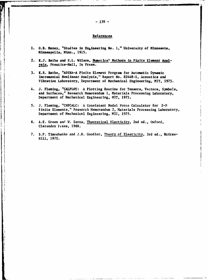
I-139-
References
1. G.B. Haney, "Studies in Engineering No. I," University of Minnesota,Minneapolis, Minn., 1915.
2. K.J. Bathe and E.L. Wilson, Numerical Methods in Finite Element Anal-ysis, Prentice-Hall, In Press.
3. K.S. Bathe, "ADINA-A Finite Element Program for Automatic DynamicIncremental Nonlinear Analysis," Report No. 82448-1, Acoustics andVibration Laboratory, Dep.qrtment of Mechanical Engineering, MIT, 1975.
4. J. Fleming, "CALPLOT: A Plotting Routine for Tensors, Vectors, Symbols,and Surfaces," Research Memorandum 1, Materials Processing Laboratory,Department of Mechanical Engineering, MIT, 1975.
5. 3. Fleming, "CNFCALC: A Consistent Nodal Force Calculator for 2-DFinite Elements," P.esearch Memorandum 2, Materials Processing Laboratory,Department of Mechanical Engineering, MIT, 1975.
6. A.E. Green an6 W. Zerna, Theoretical Elasticity, 2nd ed., Oxford,Clarendon kLess, 1968.
7. S.P. Timoshenko and J.N. Goodier, Theory of Elasticity, 3rd ed., McGraw-Hill, 1970.

-140-
Appendix B
IPEPOMATION OF COPPER-TIN SOLID SOLUTIONS
B 1) Introduction
Interest In the study of wear properties of FCC solid so-utions arosefrom the fact that alloyinb In the solid solution range without itroducing
second phase particles as crack nacleation sites could increase the wear
resistance of alloys. Clean solid solutions without inclusions "r unwantedimpurities were prepared by melting the alloys in dry and purified argon
gas. Details of the equipment, alloy product ion and specimen preparation
are described in this appendix.
B 2) Alloy Preparation
The induction unit which was used to melt the alloys hed an output of
7.5 KW at a frequency of 900 kHz. The water cooled induction coil, 67 mm
in diameter and 180 mm long, wab made with 6 mi O.D. copper tubing. The
main body of the furnace was a 64 m O.D. vycor tube held in vertical posi-
tion. Flanges at both ends of the tube provided a good seal and had the
necessary vacuum and gas fittings (see Fig. 6.1). Graphite was used boi.h
as susceptor and as mold.
Initially the systemt was evacuated by means of a mechanical pump with
a capacity of 425 L/min (free air displacement). The pressure in the
chamber was measured with a thermocouple vacuum gauge. In the vaccum
line there is a vaccum trap containing drierite (anhydrous calcium sulphate)
to dehumidify the gas. TIere is also a bubbler system to indicate ti'e gas
flow.
Different az.ountc of copper and tin were melted in the graphite mold.
The temperature in the mold was monitored hy means of an optical pyrometer
to an accuracy of + 50C. After reaching a temperature of 12000C , about
100 C higher than the melting point of copper (1083 C), the temperature was
maintained for an hour to allow good mixing of the two ,components of the
alloy. The cooling was very slow until the solv-us temperature was reached
and then it was increased to avoid any precipitatlen.
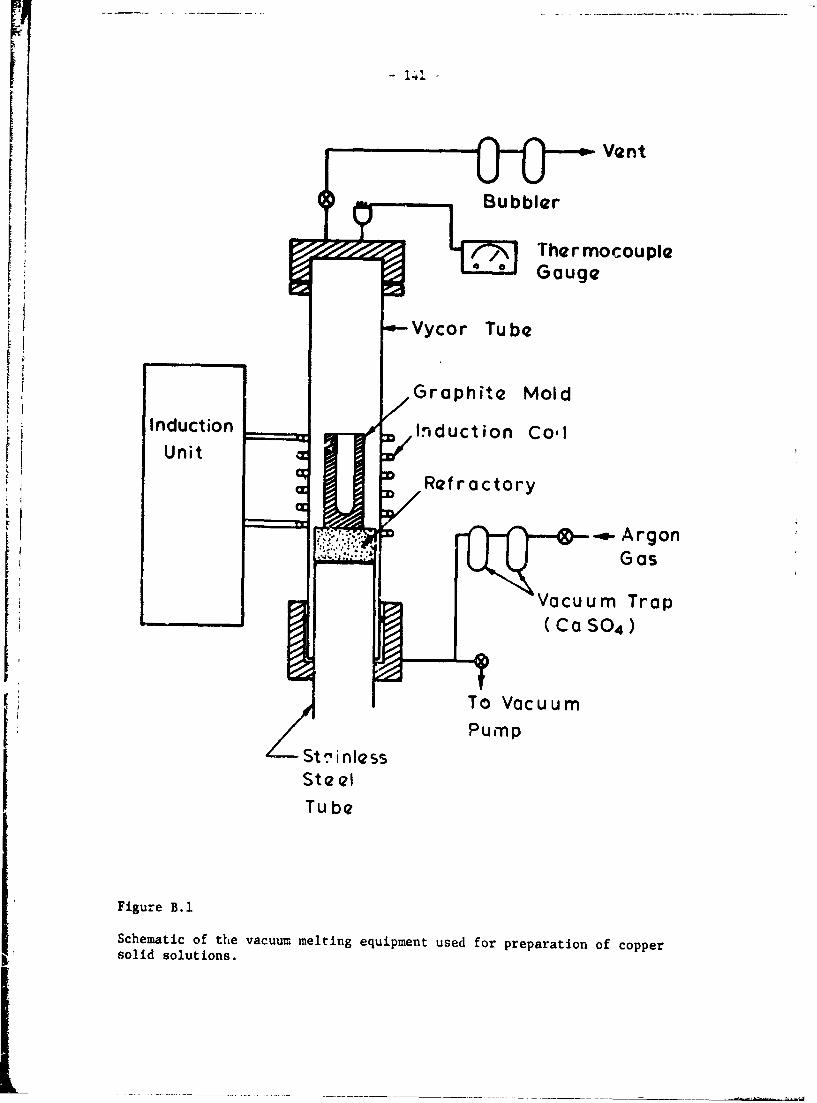
Vent
'~> ThermocoupleGog7~Vycor Tube
Graphite MoldInductionj In~duction Co-l
Unit
Reractor y
ArgonIi GasVacuum Trap(CO SO4 )
Zst ,nlessPump
SteelTube
Figure B. 1
Schematic of the vacuum melting equipment used for preparation of coppersolid solutions.
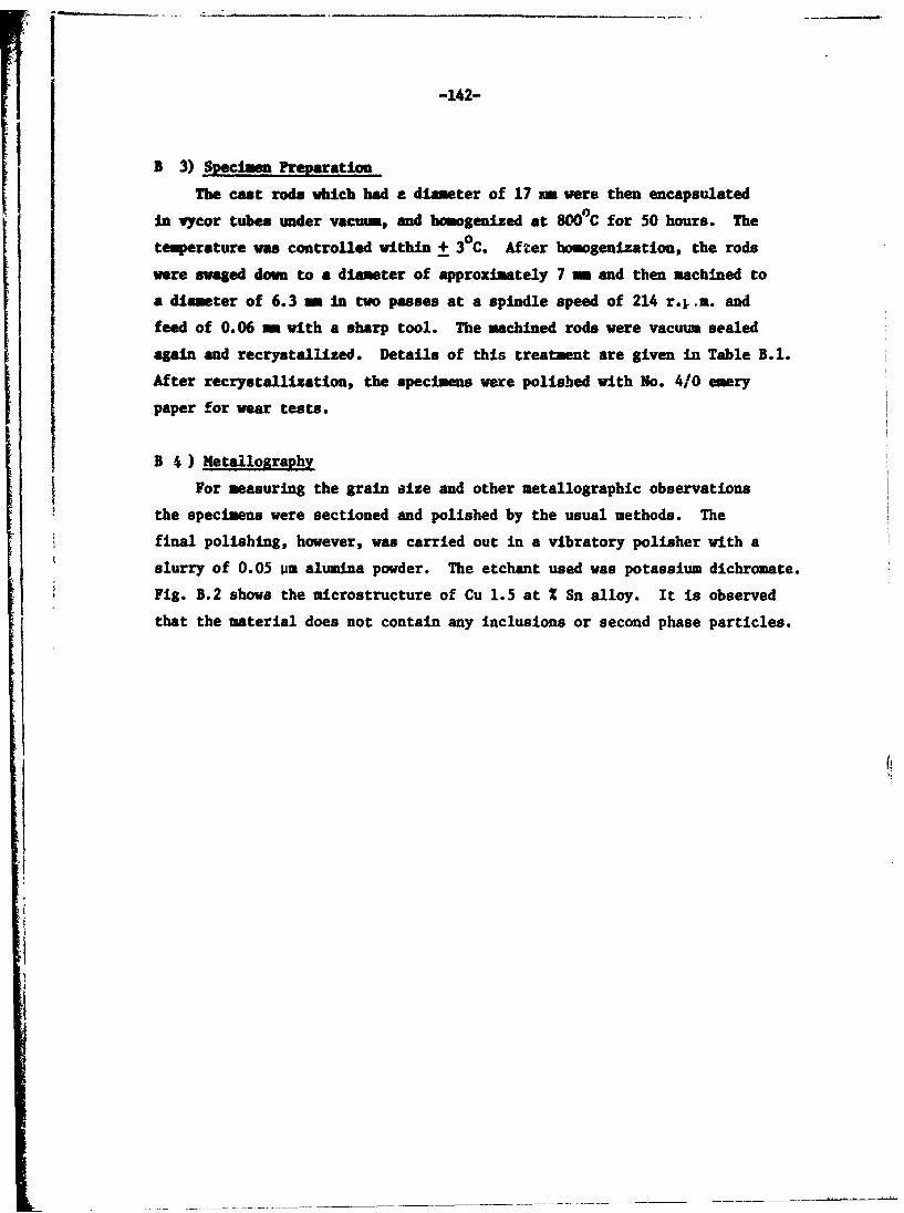
-142-
B 3) Specimen Preparation
The cast rods which had e diameter of 17 n were then encapsulated
In vycor tubes under vacuum, and homogenized at 800°C for 50 hours. The
temperature was controlled within + 30 C. After homogenization, the rods
were swaged down to a diameter of approximately 7 = and then machined to
a diameter of 6.3 mm in two passes at a spindle speed of 214 r.,.a. and
feed of 0.06 m- with a sharp tool. The machined rods were vacuum sealed
again and recrystallized. Details of this treatment are given in Table B.1.
After recrystallization, the specimens were polished with No. 4/0 emery
paper for wear tests.
B 4 ) Metallography
For measuring the grain size and other metallographic observations
the specimens were sectioned and polished by the usual methods. The
final polishing, however, was carried out in a vibratory polisher with a
slurry of 0.05 pm alumina powder. The etchant used was potassium dichromate.
Fig. B.2 shows the microstructure of Cu 1.5 at % Sn alloy. It is observed
that the material does not contain any inclusions or second phase particles.

-143-
q. N
k4 1 co tn 0 tnU on. n -4 N
60
-H
144
0 0
.4 440e w
goo 0
41.Hxg L
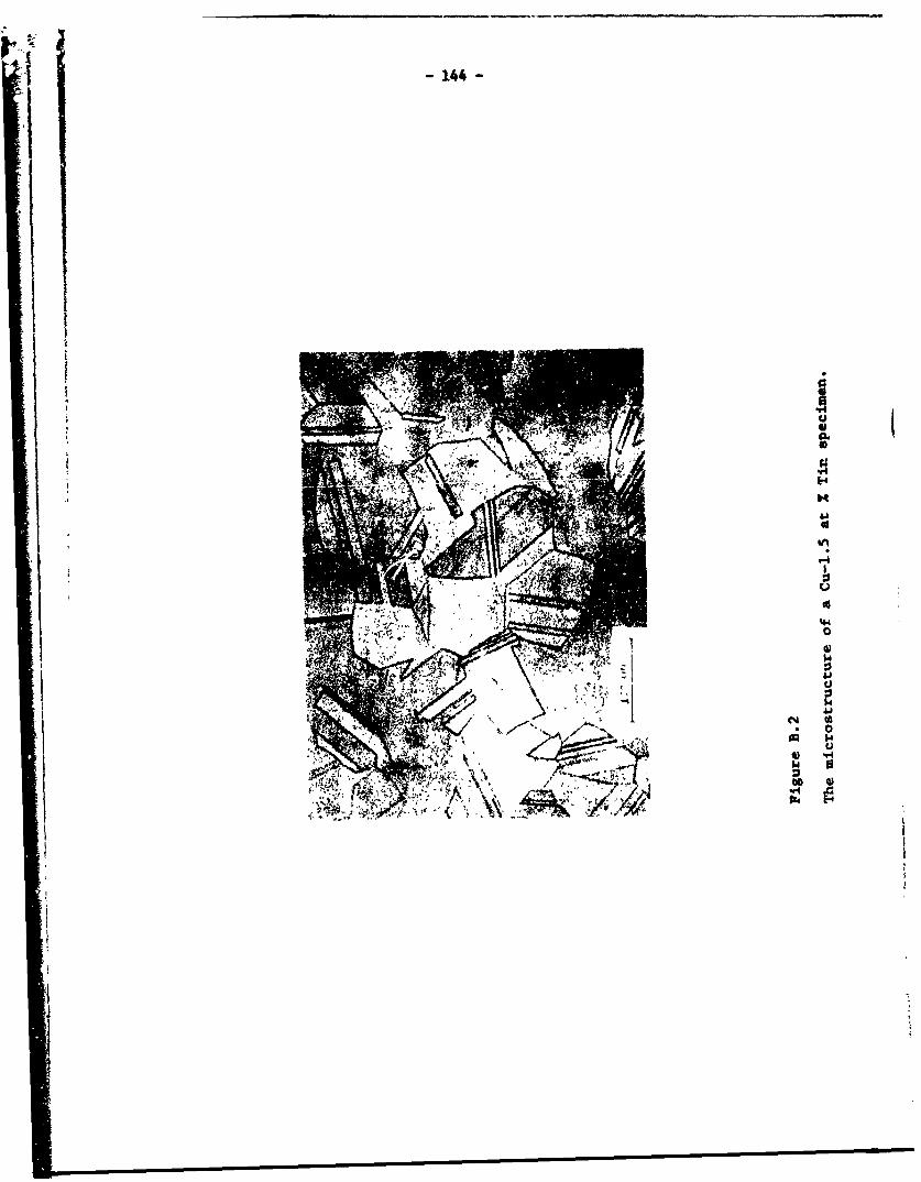
r -144-II
iUp.S
PA*145.4
N
S
U,
r4
U
S
'H0
0H
'aU
N S* 0
~ HU
* N4H U
.9 t~tt \\ 0
~ *1? ~' #"~' 6 \k
I

- 145 -
Appendix C
INTERNAL OXIDATION OF Cu-Si AND Cu-Cr ALLOYS
C 1) Introduction
Oxide dispersion strengthened alloys are gaining recognition as high
temperature creep resistant materials.(I)* Such unique properties of the
oride particles as insolubility, fineness, uniformity and stability to
coarsening make these alloys very strong compared to their solid solution
or precipitation hardened counterparts. High strength in these a1loyp is
further achieved by thermomechanical treatments. Some alloys, such as Cu-BeO,
are also used at room temperatures where both strength and electrical conduc-
tivity are important. The reasons for choosing these alloys for wear tests
were already given in the text. The chief reason being to investigate the
effect of the number of void nucleation sites on delamination wear.
A number of methods of producing oxide disparsoids in metallic matrices
are available. (2) They include: internal oxidation, thermal decompcsition,
mechanical blending, co-precipitation etc. Almost all commercial alloys
are produced chiefly by powdei metallurgy methods. In the laboratory, inter-
nal oxidation is the most convenient method of incorporating the oxide parti-
cles in the metal matrices. This appendix describes the procedure used to
prepare the specimens for wear tests.
All alloy systems are not susceptible to internal oxidation. Certain
thermodynamic and kinetic conditions are to be satisfied. Rhines (3) proposed
the following conditions as the necessary criteria for internal oxidation to
take place: (a) the alloy must have solubility for oxygen at the temperature
of oxidation, (b) oxygen should diffuse faster than the alloying element,
(c) the standare-free energy of formation of the solute metal oxide must be
more negative than the free energy of formation of the lowest oxide of the
base metal, and (a) the oxide should be insoluble in the metal. Rapp(4 )
added another condition to the above. He proposed that the solute content
of the bulk must always be lower than that required for the transition from
internal to external oxidation.
,The numbers in paranthesis designate the references at the end of thisappendix.

-146-
A variety of methods exist for controlling t4 right partial pressure
of oxygen for internal oxidation process to take place. By controlling
the flow rates of 12-H220 and CO-CO2 in gas flow systcas, right partialpressure of oxygen can be maintained. A second method ie to vaccum seal
the allo, to be oxidized with a mixture of powders of the solvent metal
and its oxide in a vycor tube %nd heat to the temperature required for dif-
fusion. For copper alloys the mixture, called Rhines Pack, consists of
equal parts by weight of Cu and Cu 20. Som times Al 203 is also mixed with
the Rbines Pack to avoid sintering of the powder to the specimen. (5)
In the presert work, a slight variation of that procedure is used.
Instead of using vacuua sealed capsules of the specimen and Rhines Pack,
the specimens were placed in the pack and purified argon was allowed to
pass over the pack while oxidizing. By this method large quantities of
glass in the form of capsules need not be used, Further, the danger of
capsule explosion during treatment can be avoided. Enough quantities of
Cu and Cu 20 were used so that the right partial pressure of oxygen was main-
tained even while the argon was flowing in small quantities.
C 2) Apparatus and Procedures
The copper silicon (Cu-0.5 Si, Cu-1.0 Si) and copper-chromium alloys
(Cu-0.18 Cr) used in this work were in the form of solid solutions before
internal oxidation. Copper-silicon alloys were melted in an induction
furnac n n dried argon atmosphere. Alloy preparation and solutionization
procedures for these alloys were given in Appendix B. CA--Cr alloy waa sup-
plied by American Metal Climax Company. This alloy in tbiv form of 1.3 cm
dia. 7.5 cm long specimens, was solutionized at 9000 C fvr 50 hours in
vacuum sealed vycor capsules, and water quenched after solution treatment.
The water quenched samples were then swaged to 0.6 cm diameter rods in
steps at room temperature without intermittent annealing. Specimens of
0.6 cm x 7.5 cm were cut from the swaged rods and were polished with No. 3/0
ei".rv, paper and cleaned with Irichloroethylene for internal oxidation.
Internal oxidation was carried out in the apparatus shown .4 Fig.C.1. The specimens were packed in Rhines Pack (equal parts of Cu, Cu 0 and
2Al0 in an alundum boat. The boats were kept in a vy~ur tube which has

0co co
0 0m-
CLC U
< LL LIx>0
0
44
0
CLC
H
ILC
0 0
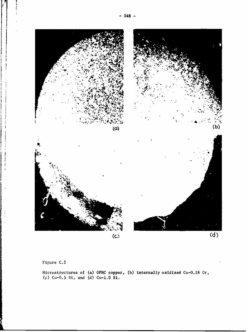
-148-
I0
V.~
10,W
Fiur C. 2 ~Micrstrcturs o (a)OFH coper,(b)intenaly oxdizd Cu0.1 Cr
C -0. Si an d u- i

-149
Table C.1 Inteznally Oxidized Copper Alloys: Metallurgical Variables
Material Hardness Volume Fraction ofKg/=a2 Oxide Particles
OFHC 31 0.00
Cu-O.18 Cr 36 0.004
Cu-O.5 Si 44 0.036
Cu-1.0 Si 34 0.073
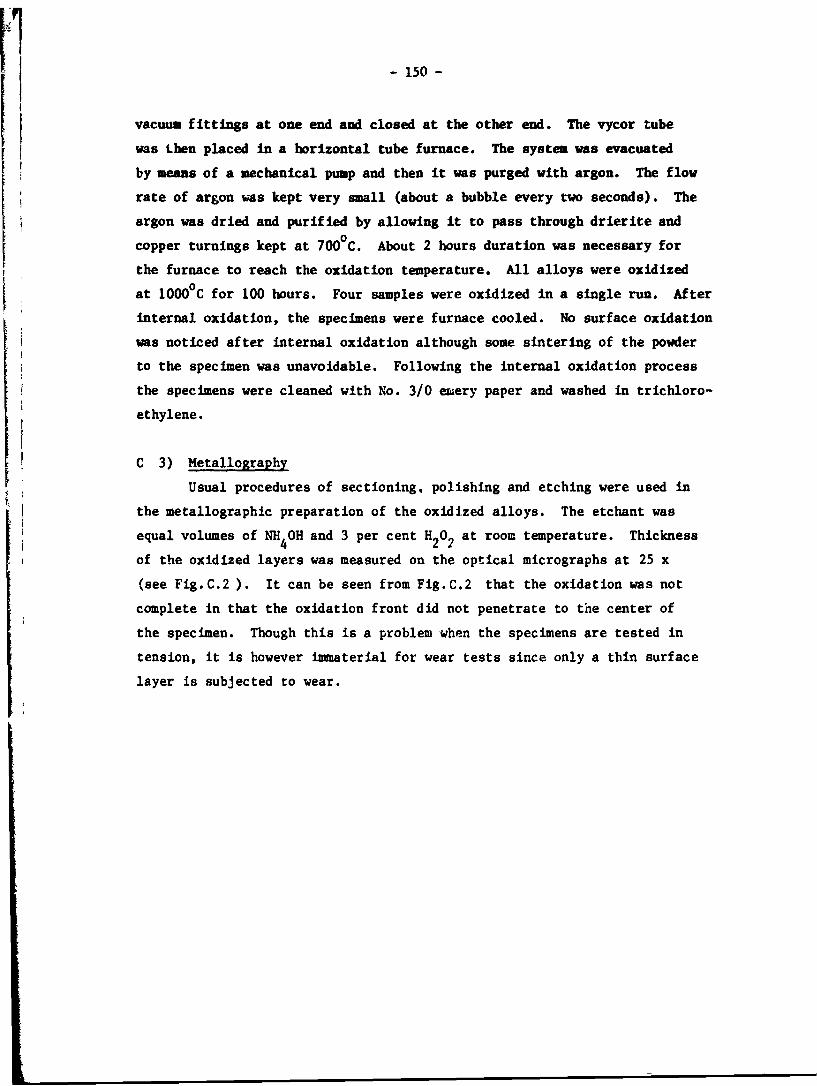
-150 -
vacuum fittings at one end and closed at the other end. The vycor tube
was Lhen placed in a horizontal tube furnace. The system was evacuated
by means of a mechanical pump and then it was purged with argon. The flow
rate of argon %as kept very small (about a bubble every two seconds). The
argon was dried and purified by allowing it to pass through drierite and
copper turnings kept at 7000 C. About 2 hours duration was necessary for
the furnace to reach the oxidation temperature. All alloys were oxidized
at 10000C for 100 hours. Four samples were oxidized in a single run. After
internal oxidation, the specimens were furnace cooled. No surface oxidation
was noticed after internal oxidation although some sintering of the powderto the specimen was unavoidable. Following the internal oxidation processthe specimens were cleaned with No. 3/0 emery paper and washed in trichloro-
ethylene.
1 C 3) Metallography
Usual procedures of sectioning, polishing and etching were used in
the metallographic preparation of the oxidized alloys. The etchant was
equal volumes of NH4OH and 3 per cent H202 at room temperature. Thickness
of the oxidized layers was measured on the optical micrographs at 25 x
(see Fig.C.2 ). It can be seen from Fig.C.2 that the oxidation was not
complete in that the oxidation front did not penetrate to the center of
the specimen. Though this is a problem when the specimens are tested in
tension, it is however immaterial for wear tests since only a thin surface
layer is subjected to wear.
- 151 -
References
(1) G.S. Ansell, "The Mechanism of Dispersion Strengthening - A Review,"Oxide Dispersion Strengthening, G.S. Ansell et al, ed., Gordon BreachScience Publishers (1968) 61-142.
(2) N.J. Grant, '")ispersed Phase Strengthenfrg," The Strengtheasng ofMetals, Reinhold Publishing Corporation (1064) 163-199.
(3) F.N. Rhines, "A Metallographic Study of Internal Oxidation in theAlpha Solid Solutions of Copper," Trans. Met. Soc. AIME 137 (1940)246-290.
(4) R.A. Rapp, "Kinetics, Microstructures and Mechanism of InternalOxidation - Its Effect and Prevention in High Temperature AlloyOxidation," Corrosion, 21 (1965) 382-401.
(5) M.F. Ashby and G.C. Smith, "Structures in Internally Oxidized CopperAlloys," J. Inst. Metals, 91 (1962-63) 182-187.
F
t0I

-152-
Appendix D
WEAR TESTING EQUIPMENTS AND PREPARATIONOF THE SPECIMENS FOR SEM OBSERVATION
D 1) Wear Testing Equients
A cylinder on cylinder sliding geometry, Fig. D.lb, was used in all
wear tests. The specimens were rotated by the spindle of a lathe. The
stationary slider pin was placed in a special holder and was connected
to a lathe tool dynamometer. The dynamometer was attached to the carri-
age of the lathe. The normal contacting force was applied by the trans-
verse motion of the carriage of the lathe. The friction force was mea-
sured by the bending streso in the pin-holder bar. The normal and fric-
tional forces were monitored through the dynamometer and recorded on a
Sanborn 321 Recorder.
The sliding surfaces wrre enclosed in a plexiglass chamber. Argongas entered the chamber at a flow rate of 10 L/min. For the tests on
copper solid solution specimens (Chapter V) the chamber was redesigned
such that it could be evacuated and purified argon could enter the cham-
ber, Fig. D.2. Purification procedure similar to the one already discussed
in Appendix B (Section B.2) was used.
D 2) Specimen Preparation After Wear Tests
After the wear tests, the specimens were gently brushed to remove the
loose wear debris. Then, they were degreased in trichloroethylene, dried
and weighed to an accuracy of 0.1 mg.
a) Wear Track Observations
The specimens were placed in a scanning electron microscope to ex-
amine the wear tracks. The cylindrical specimens were positioned so that
the cylindrical axis was parallel with the electron beam. Then by tilting
the specimen, the wear track on the cylindrical surface was observed.
Tilting was very important to discern the shape and dimension of the wear
sheets.
b) Sectioning and Observations
After observing the wear track,.the specimen was cut by a hack saw
approximately 1/8" away from the wear track, parallel to the sliding di-
rection and perpendicular to the worn surface. Then it was placed in a
special holder and abraded on grade 2 and 1 emery papers. The specimen

- 53
-~
1,
U
.0
'.4
S
0
S
0*14'IwS
'.4
S
'.4S
0HH
0 -. U
n H 0* I
~ 1.4
Ci1.4 0~ H00 HH ~r34 C..)

-154-
LL
300
u 00
OLL
00
0. 0
0. E 0,0 E
00 44
L 0 I0
u u
U~0 A0 0
> 0)
'A uV C 40
41 G
IA
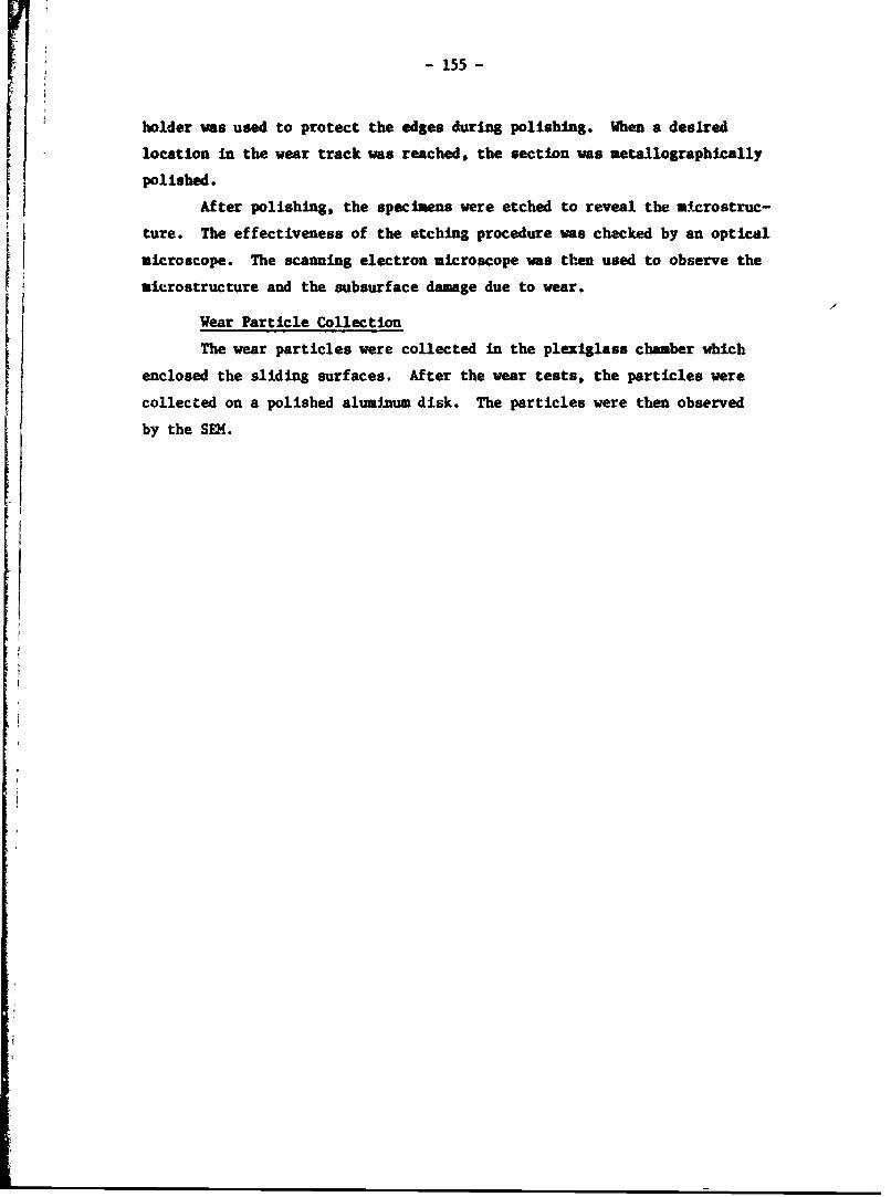
- 155 -
holder was used to protect the edges during polishing. When a desired
location in the wear track was reached, the section was metallographically
polished.
After polishing, the specimens were etched to reveal the a.crostruc-
ture. The effectiveness of the etching procedure was checked by an optical
microscope. The scanning electron microscope was then used to observe the
aicrostructure and the subsurface damage due to wear.
Wear Particle Collection
The wear particles were collected in the plexiglass chamber which
enclosed the sliding surfaces. After the wear tests, the particles were
collected on a polished aluminum disk. The particles were then observed
by the SEM.

- 156 -
Appendix I
PAPERS PUBLISHED AND PRESENTED ON THE DELANINATION THEORY OF WEAk
1. N.P. Suh, "The Delamination Theory of Wear", Wear, 25 (1973)111-124.
2. N.P. Sub, S. Jahanmir, E.P. Abrahamson, II and A.P.L. Turner, "FurtherInvestigation of the Delemination Theory of Wear", J.Lub. Tech., Trans.ASHE, 96 (1974) 631-637.
3. S. Jahanair, N.P. Suh and E.P. Abrahamson, II, "Microscopic Observationsof the Wear Saeet Formation by Delamination", Wear, 28 (1974) 235-249.
4. E.P. Abrahamson, I, S. Jaianmir, D.A. Coiling and N.P. Suh, "Failureby Delamination During, Wear", Proc. Scanning Electron Microscopy Conf.,(1974) part IV, 889-894.
5. N.P. Suh, S. Jahanmir, D.A. Colling and E.P. Abrahamson, II, "TheDelamination Theory for Wear of Metals Sliding at Low Speeds", Proc. 2ndNorth American Metalworking Research Conf., (1974) 117-127.
6. E.P. Abrahamson, II, S. Jahanmir, N.P. Suh and D.A. Coling," Applicationof the Delamination Theory of Wear to a Composite Metal Surface", Proc.~Int. Conf. in Production, Tokyo, Japan, (1974) 408-413.
7. S. Jahanmir, N.P. Sub and E.P. Abrahamson, II, "The Delamination Theoryof Wear and the Wear of a Composite Metal Surfice", Wear, 32 (1975) 33-49.
8. N.P. Sub, E.P. Abrahamson, II and S. Jahanmir, "Wear Resistance of Soft MetalCoatings", U.S. Patent application, filled October 1, 1974.
9. N.P. Suh, "Microstructural Effects in Metals", Proc. Battelle MaterialsScience Colloquium, on "Fundamental Aspects of Structural Alloy Design",To be published by Plenum Press, 1976.
10. N.P. Sub and P. Sridharan, "Relationship between the Coefficient of Frictionand the Wear Rate of Metals", Wear, 34 (1975) 291-299.
11. S. Jahanmir, E.P. Abrahamson, II and N.P. Sub, "The Effect of Seccnd PhaseParticles on Wear", Proceedings Third North American Metalworking ResearchConferelLce, Carnegie Press, (1975) 854-864.
12. S.P. Abrahamson, II, S. Jahanmir and N.P. Suh, "The Effect of Surface Finishon the Wear of Sliding Surfaces", '0IRP Annals, 24 (1975) 513-514.
13. N.P. Suh, "The Delamination Theory of Wear - Its Present Status and FutureProsnects", ONR Tribology Workshop, October 14, 1975.
14. S. Jahanmir, N.P. Suh and ".P. Abrahamson, ii, "The Effect of Surface Rouglneesand Integrity on Weat", Wear, submitted for publication.

- 17 -
15. S. Jahanmir, E. Abrahamsen, II and N.P. Suh, "Wear Resistance of Thin MetalCoatings", Wear, submitted for publication.
16. S. Jahanmir and N.P. Suh, "Metallic Coatings for the Reduction of Wear Utilizingthe Dalamination Theory", N.B.S. Conference on The Role of Coatings in theZrevention of Mechanical Failures, Gaithersburgb, Maryland, October 1975.
I