TECHNICAL DATA & SERVICE MANUAL - Ambience Air
230
TECHNICAL DATA & SERVICE MANUAL 8546484931000 REFERENCE NO. SM830210-00 ■ R410A Models Model No. Indoor Units Type Indoor Units Type 60 71 100 125 140 U1 4-Way Cassette S-60PU1R5 S-71PU1R5 S-100PU1R5 S-125PU1R5 S-140PU1R5 E1 Ducted S-60PE1R5 S-71PE1R5 S-100PE1R5 S-125PE1R5 S-140PE1R5 Outdoor Units Type Outdoor Units Type 60 71 100 125 140 PE1 Single Split (1-phase) U-60PE1R5 U-71PE1R5 U-100PE1R5 U-125PE1R5 U-140PE1R5 Single Split (3-phase) – – U-100PE1R8 U-125PE1R8 U-140PE1R8 Indoor Unit Outdoor Unit 4-Way Cassette Ducted
-
Upload
khangminh22 -
Category
Documents
-
view
1 -
download
0
Transcript of TECHNICAL DATA & SERVICE MANUAL - Ambience Air

TECHNICAL DATA&
SERVICE MANUAL
8546484931000 REFERENCE NO. SM830210-00
■ R410A ModelsModel No.
Indoor Units
Type Indoor Units Type 60 71 100 125 140
U1 4-Way Cassette S-60PU1R5 S-71PU1R5 S-100PU1R5 S-125PU1R5 S-140PU1R5
E1 Ducted S-60PE1R5 S-71PE1R5 S-100PE1R5 S-125PE1R5 S-140PE1R5
Outdoor Units
Type Outdoor Units Type 60 71 100 125 140
PE1
Single Split (1-phase)
U-60PE1R5 U-71PE1R5 U-100PE1R5 U-125PE1R5 U-140PE1R5
Single Split (3-phase)
– – U-100PE1R8 U-125PE1R8 U-140PE1R8
Indoor Unit Outdoor Unit
4-Way Cassette
Ducted
Cover.indd 1 2012/02/28 11:59:57
i
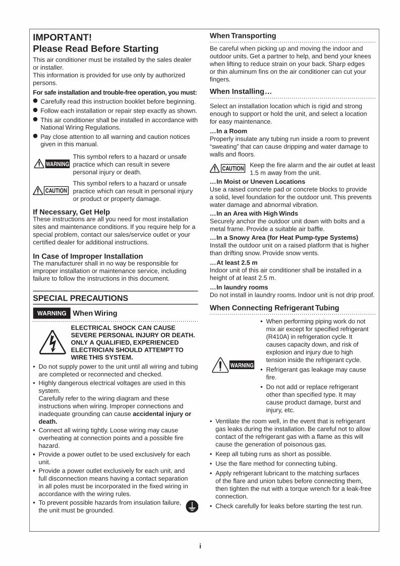
IMPORTANT! Please Read Before StartingThis air conditioner must be installed by the sales dealer or installer.This information is provided for use only by authorized persons.
For safe installation and trouble-free operation, you must:● Carefully read this instruction booklet before beginning.● Follow each installation or repair step exactly as shown.● This air conditioner shall be installed in accordance with
National Wiring Regulations.● Pay close attention to all warning and caution notices
given in this manual.
WARNINGThis symbol refers to a hazard or unsafe practice which can result in severe personal injury or death.
CAUTIONThis symbol refers to a hazard or unsafe practice which can result in personal injury or product or property damage.
If Necessary, Get HelpThese instructions are all you need for most installation sites and maintenance conditions. If you require help for a special problem, contact our sales/service outlet or your certified dealer for additional instructions.
In Case of Improper InstallationThe manufacturer shall in no way be responsible for improper installation or maintenance service, including failure to follow the instructions in this document.
SPECIAL PRECAUTIONS
WARNING When Wiring
ELECTRICAL SHOCK CAN CAUSE SEVERE PERSONAL INJURY OR DEATH. ONLY A QUALIFIED, EXPERIENCED ELECTRICIAN SHOULD ATTEMPT TO WIRE THIS SYSTEM.
• Do not supply power to the unit until all wiring and tubing are completed or reconnected and checked.
• Highly dangerous electrical voltages are used in this system. Carefully refer to the wiring diagram and these instructions when wiring. Improper connections and inadequate grounding can cause accidental injury or death.
• Connect all wiring tightly. Loose wiring may cause overheating at connection points and a possible fire hazard.
• Provide a power outlet to be used exclusively for each unit.
• Provide a power outlet exclusively for each unit, and full disconnection means having a contact separation in all poles must be incorporated in the fixed wiring in accordance with the wiring rules.
• To prevent possible hazards from insulation failure, the unit must be grounded.
When Transporting
Be careful when picking up and moving the indoor and outdoor units. Get a partner to help, and bend your knees when lifting to reduce strain on your back. Sharp edges or thin aluminum fins on the air conditioner can cut your fingers.
When Installing…
Select an installation location which is rigid and strong enough to support or hold the unit, and select a location for easy maintenance.
…In a RoomProperly insulate any tubing run inside a room to prevent “sweating” that can cause dripping and water damage to walls and floors.
CAUTION Keep the fire alarm and the air outlet at least 1.5 m away from the unit.
…In Moist or Uneven LocationsUse a raised concrete pad or concrete blocks to provide a solid, level foundation for the outdoor unit. This prevents water damage and abnormal vibration.…In an Area with High WindsSecurely anchor the outdoor unit down with bolts and a metal frame. Provide a suitable air baffle.…In a Snowy Area (for Heat Pump-type Systems)Install the outdoor unit on a raised platform that is higher than drifting snow. Provide snow vents.
…At least 2.5 mIndoor unit of this air conditioner shall be installed in a height of at least 2.5 m.
…In laundry roomsDo not install in laundry rooms. Indoor unit is not drip proof.
When Connecting Refrigerant Tubing
WARNING
• When performing piping work do not mix air except for specified refrigerant (R410A) in refrigeration cycle. It causes capacity down, and risk of explosion and injury due to high tension inside the refrigerant cycle.
• Refrigerant gas leakage may cause fire.
• Do not add or replace refrigerant other than specified type. It may cause product damage, burst and injury, etc.
• Ventilate the room well, in the event that is refrigerant gas leaks during the installation. Be careful not to allow contact of the refrigerant gas with a flame as this will cause the generation of poisonous gas.
• Keep all tubing runs as short as possible.
• Use the flare method for connecting tubing.
• Apply refrigerant lubricant to the matching surfaces of the flare and union tubes before connecting them, then tighten the nut with a torque wrench for a leak-free connection.
• Check carefully for leaks before starting the test run.
Cover.indd Sec1:i 2012/02/28 11:59:58

ii
• Do not leak refrigerant while piping work for an installation or re-installation, and while repairing refrigeration parts. Handle liquid refrigerant carefully as it may cause frostbite.
When Servicing
• Turn the power OFF at the main power box (mains) before opening the unit to check or repair electrical parts and wiring.
• Keep your fingers and clothing away from any moving parts.
• Clean up the site after you finish, remembering to check that no metal scraps or bits of wiring have been left inside the unit being serviced.
WARNING
• Do not clean inside the indoor and outdoor units by users. Engage authorized dealer or specialist for cleaning.
• In case of malfunction of this appliance, do not repair by yourself. Contact the sales dealer or service dealer for repair.
CAUTION
• Do not touch the air inlet or the sharp aluminum fins of the outdoor unit. You may get injured.
• Ventilate any enclosed areas when installing or testing the refrigeration system. Escaped refrigerant gas, on contact with fire or heat, can produce dangerously toxic gas.
• Confirm after installation that no refrigerant gas is leaking. If the gas comes in contact with a burning stove, gas water heater, electric room heater or other heat source, it can cause the generation of poisonous gas.
Others
CAUTION• Do not touch the air inlet or
the sharp aluminum fins of the outdoor unit. You may get injured.
• Do not sit or step on the unit, you may fall down accidentally.
• Do not stick any object into the FAN CASE. You may be injured and the unit may be damaged.
Cover.indd Sec1:ii 2012/02/28 11:59:59

iii
RoHS· This product does not contain any hazardous substances prohibited by the RoHS Directive.
WARNING· You are requested to use RoHS compliant for maintenance or repair.
2. The standards for minimum room volume are as follows.
(1) No partition (shaded portion)
(2) When there is an effective opening with the adjacent room for ventilation of leaking refrigerant gas (opening without a door, or an opening 0.15% or larger than the respective floor spaces at the top or bottom of the door).
(3) If an indoor unit is installed in each partitioned room and the refrigerant tubing is interconnected, the smallest room of course becomes the object. But when mechanical ventilation is installed interlocked with a gas leakage detector in the smallest room where the density limit is exceeded, the volume of the next smallest room becomes the object.
3. The minimum indoor floor space compared with the amount of refrigerant is roughly as follows (for room with 2.7 m high ceiling):
40
35
30
25
20
15
10
5
010 20 30
m2
Check of Density LimitThe room in which the air conditioner is to be installed requires a design that in the event of refrigerant gas leaking out, its density will not exceed a set limit.
The refrigerant (R410A), which is used in the air conditioner, is safe, without the toxicity or combustibility of ammonia, and is not restricted by laws imposed to protect the ozone layer. However, since it contains more than air, it poses the risk of suffocation if its density should rise excessively. Suffocation from leakage of refrigerant is almost non-existent. With the recent increase in the number of high density buildings, however, the installation of multi air conditioner systems is on the increase because of the need for effective use of floor space, individual control, and energy conservation by curtailing heat and carrying power, etc.Most importantly, the multi air conditioner system is able to replenish a large amount of refrigerant compared to conventional individual air conditioners. If a single unit of the multi air conditioner system is to be installed in a small room, select a suitable model and installation procedure so that if the refrigerant accidentally leaks out, its density does not reach the limit (and in the event of an emergency, measures can be made before injury can occur).In a room where the density may exceed the limit, create an opening with adjacent rooms, or install mechanical ventilation combined with a gas leak detection device. The density is as given below.
Total amount of refrigerant (kg)
Min. volume of the indoor unit installed room (m3)< Density limit (kg/m3)
The density limit of refrigerant which is used in multi air conditioners is 0.3 kg/m3 (ISO 5149).
NOTE1. If there are 2 or more refrigerating systems in a single
refrigerating device, the amount of refrigerant should be as charged in each independent device.
For the amount of charge in this example:
The possible amount of leaked refrigerant gas in rooms A, B and C is 10 kg.The possible amount of leaked refrigerant gas in rooms D, E and F is 15 kg.
e.g., charged amount (10 kg)
Indoor unit
Outdoor unit
e.g., charged amount (15 kg)
Room A Room B Room C Room D Room E Room F
Outdoor unit
Refrigerant tubing
Indoor unit
Mechanical ventilation device – Gas leak detector
Refrigerant tubing
Outdoor unit
Indoor unit
Verysmallroom
Smallroom
Mediumroom
Large room
Total amount of refrigerant
Min
. ind
oor
floor
spa
ce
Range above the density limit of 0.3 kg/m3
(countermeasures needed)
kg
Range below the density limit of 0.3 kg/m3
(countermeasures not needed)
Cover.indd Sec1:iii 2012/02/28 12:00:01

1-1
11. SPECIFICATIONS
1-1. Unit Specifications................................................................................................... 1-24-Way Cassette Type ............................................................................................................................ 1-2Ducted Type .......................................................................................................................................... 1-7
1-2. Dimensional Data ..................................................................................................... 1-15(A) Indoor Units ..................................................................................................................................... 1-15(B) Outdoor Units .................................................................................................................................. 1-18
1-3. Refrigerant Flow Diagram ....................................................................................... 1-20
1-4. Operating Range ...................................................................................................... 1-21
1-5. Capacity Correction Graph According to Temperature Condition ...................... 1-22
1-6. Noise Criterion Curves ............................................................................................ 1-27
1-7. Indoor Fan Performance .......................................................................................... 1-32
1-8. Airflow Distance Chart ............................................................................................ 1-33
1-9. Intaking Fresh Air of 4-Way Cassette Type ............................................................ 1-35
1-10. Electrical Wiring ....................................................................................................... 1-37
1-11. Installation instructions .......................................................................................... 1-40
Sec1.indb 1 2012/03/07 17:29:53

1-2
1 Single-Type
1-1. Unit Specifi cations
4-Way Cassette Type S-60PU1R5 / U-60PE1R5INDOOR MODEL S–60PU1R5PANEL MODEL CZ–KPU2
OUTDOOR MODEL U–60PE1R5Branch pipe MODEL –
PERFORMANCE TEST CONDITION ISO5151 / AS/NZS3823
POWER SUPPLYø, Hz 1ø 50 Hz 1ø 50 Hz
V 230 V 240 V 230 V 240 V Min Max
COOLING
CAPACITYkW 6.0 6.0 2.5 7.1
BTU/h 20500 20500 8500 24200CURRENT A 0.31 0.30 6.90 6.70 – –
INPUT POWERW 35 35 1.445 k 1.445 k – –
TOTAL W – 1.480 k 1.480 k 450 2.000 kANNUAL CONSUMPTION TOTAL W *4 – 740 – – –
EER/AEER /STR RAT TOTAL (W/W) – – – 4.05/3.94/3.0 4.05 5.56 3.55POWER FACTOR % – – 91 90 – –
NOISE INDOOR(H/M/L)
dB–A 36/31/28Power Level dB 53/48/45
NOISE OUTDOOR(H/L)
dB–A 48/–Power Level dB 65/–
HEATING
CAPACITYkW 7.0 7.0 2.0 8.0
BTU/h 23900 23900 6800 27300CURRENT A 0.30 0.29 8.20 7.95 – –
INPUT POWERW 35 35 1.775 k 1.775 k – –
TOTAL W – 1.810 k 1.810 k 400 2.480 kCOP/ACOP /STR RAT TOTAL (W/W) – – – 3.87/3.78/3.0 3.87 5.00 3.23
POWER FACTOR % – – 94 93 – –
NOISE INDOOR(H/M/L)
dB–A 36/31/28 – / /Power Level dB 53/48/45 –
NOISE OUTDOOR(H/L)
dB–A – 50/– / /Power Level dB – 67/–
EXTRA LOW TEMP TOTAL CAPACITY(kW)/INPUT POWER(W)/COP –MAX CURRENT(A)/MAX INPUT POWER(W) 0.31/35 0.30/35 18.0/3.930 k 18.0/4.060 k /
STARTING CURRENT(A)/COMP OUTPUT(W) – – 8.20/1.7 K 7.95/1.7 K /NETWORK IMPEDANCE(ΩMAX.) – –
FM OUTPUT (W) 60 90 /MOISTURE REMOVAL VOLUME L/h(Pt/h) 3.4 (7.1) –
Extarnal static pressure Pa (mmAq) –
I/D AIR FLOW
COOL m3/min (ft3/min) 21 (742)HEAT m3/min (ft3/min) 21 (742)
O/D AIR FLOW
COOL m3/min (ft3/min) 60 (2119)HEAT m3/min (ft3/min) 60 (2119)
REFRIGERANT TYPE, AMOUNT g(oz) R410A 2.00 k (70.5) /
PRO
DIM
HEIGHT: H mm (inch) 256 (10–3/32) 996 (39-7/32) /WIDTH: W mm (inch) 840 (33–3/32) 940 (37–1/32) /DEPTH: D mm (inch) 840 (33–3/32) 340 (13–13/32) /
PAC
DIM
HEIGHT: H mm 298 1136 /WIDTH: W mm 929 1055 /DEPTH: D mm 929 485 /
MASS(NET) kg(lb) 24(53) 68(150) /
(GROSS) kg(lb) 29(64) 76(168) /LAYERS LIMIT (actually) 11(12) 2(3)
OperationCondition
Cool (DBT) 18˚C – 32˚C -15˚C – 46˚CHeat (DBT) 16˚C – 30˚C -20˚C – 24˚C
PIPING
PIPE DIAMETER mm (inch) (Liquid)ø9.52(3/8) (Gas)ø15.88(5/8) (Liquid)ø9.52(3/8) (Gas)ø15.88(5/8)CONNECT METHOD, STD LENGTH m (ft) fl ared type, 5.0(16.4) fl ared type, 5.0(16.4)
PIPE LENGTH RANGE m (ft) 5 – 50 (16.4 – 164.0) – –I/D&O/D HEIGHT DIRRERENCE m (ft) 15 (OD located lower)/30 (OD located higher) (49.2/98.4)
ADD GAS AMOUNT g/m (oz/ft) 50 (537.6)PIPE LENGTH FOR ADDITIONAL GAS m (ft) 30 (98.4)
*1: In case it is necessary to indicate the air fl ow volume in (l/s), the value in (m3/min.) shall be multiplied by 16.7 and rounded down the decimal point.*2: If the EUROVENT Certifi ed models can be operated under the “extra-low” temperature condition, -7°C dry bulb and -8°C wet-bulb temperatures with rated voltage
230 V shall be used.*3: Network Impedance shall be applicable for EUROPE and CHINA models.*4: The annual consumption is calculated by multiplying the input power at 230 V (400 V) by an average of 500 hours per year in cooling mode.*5: EER and COP classification is at 230 V (400 V) only in accordance with EU directive 2002/31/EC.
Sec1.indb 2 2012/03/07 17:29:54
1-3
1Single-Type
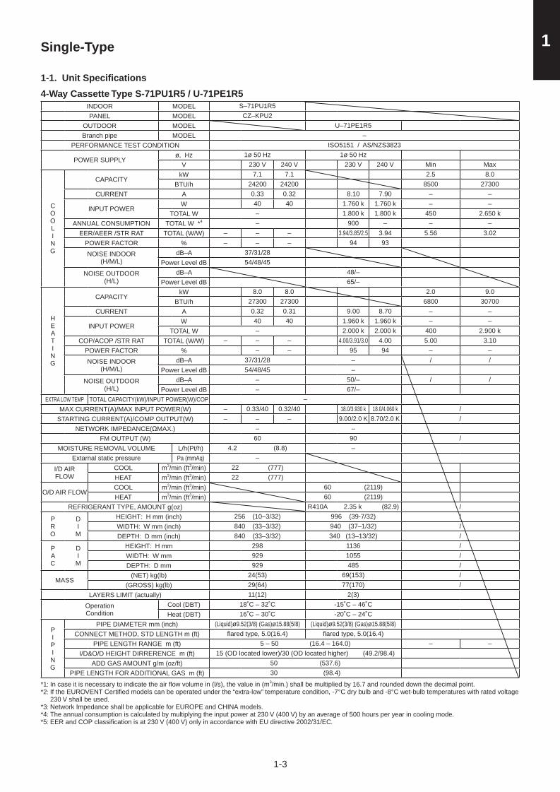
1-1. Unit Specifi cations
4-Way Cassette Type S-71PU1R5 / U-71PE1R5INDOOR MODEL S–71PU1R5PANEL MODEL CZ–KPU2
OUTDOOR MODEL U–71PE1R5Branch pipe MODEL –
PERFORMANCE TEST CONDITION ISO5151 / AS/NZS3823
POWER SUPPLYø, Hz 1ø 50 Hz 1ø 50 Hz
V 230 V 240 V 230 V 240 V Min Max
COOLING
CAPACITYkW 7.1 7.1 2.5 8.0
BTU/h 24200 24200 8500 27300 CURRENT A 0.33 0.32 8.10 7.90 – –
INPUT POWERW 40 40 1.760 k 1.760 k – –
TOTAL W – 1.800 k 1.800 k 450 2.650 kANNUAL CONSUMPTION TOTAL W *4 – 900 – – –
EER/AEER /STR RAT TOTAL (W/W) – – – 3.94/3.85/2.5 3.94 5.56 3.02POWER FACTOR % – – – 94 93
NOISE INDOOR(H/M/L)
dB–A 37/31/28Power Level dB 54/48/45
NOISE OUTDOOR(H/L)
dB–A 48/–Power Level dB 65/–
HEATING
CAPACITYkW 8.0 8.0 2.0 9.0
BTU/h 27300 27300 6800 30700 CURRENT A 0.32 0.31 9.00 8.70 – –
INPUT POWERW 40 40 1.960 k 1.960 k – –
TOTAL W – 2.000 k 2.000 k 400 2.900 kCOP/ACOP /STR RAT TOTAL (W/W) – – – 4.00/3.91/3.0 4.00 5.00 3.10
POWER FACTOR % – – 95 94 – –
NOISE INDOOR(H/M/L)
dB–A 37/31/28 – / /Power Level dB 54/48/45 –
NOISE OUTDOOR(H/L)
dB–A – 50/– / /Power Level dB – 67/–
EXTRA LOW TEMP TOTAL CAPACITY(kW)/INPUT POWER(W)/COP –MAX CURRENT(A)/MAX INPUT POWER(W) – 0.33/40 0.32/40 18.0/3.930 k 18.0/4.060 k /
STARTING CURRENT(A)/COMP OUTPUT(W) – – – 9.00/2.0 K 8.70/2.0 K /NETWORK IMPEDANCE(ΩMAX.) – –
FM OUTPUT (W) 60 90 /MOISTURE REMOVAL VOLUME L/h(Pt/h) 4.2 (8.8) –
Extarnal static pressure Pa (mmAq) –
I/D AIR FLOW
COOL m3/min (ft3/min) 22 (777)HEAT m3/min (ft3/min) 22 (777)
O/D AIR FLOWCOOL m3/min (ft3/min) 60 (2119)HEAT m3/min (ft3/min) 60 (2119)
REFRIGERANT TYPE, AMOUNT g(oz) R410A 2.35 k (82.9) /
PRO
D I M
HEIGHT: H mm (inch) 256 (10–3/32) 996 (39-7/32) /WIDTH: W mm (inch) 840 (33–3/32) 940 (37–1/32) /DEPTH: D mm (inch) 840 (33–3/32) 340 (13–13/32) /
PAC
D I M
HEIGHT: H mm 298 1136 /WIDTH: W mm 929 1055 /DEPTH: D mm 929 485 /
MASS(NET) kg(lb) 24(53) 69(153) /
(GROSS) kg(lb) 29(64) 77(170) /LAYERS LIMIT (actually) 11(12) 2(3)
OperationCondition
Cool (DBT) 18˚C – 32˚C -15˚C – 46˚C Heat (DBT) 16˚C – 30˚C -20˚C – 24˚C
PIPING
PIPE DIAMETER mm (inch) (Liquid)ø9.52(3/8) (Gas)ø15.88(5/8) (Liquid)ø9.52(3/8) (Gas)ø15.88(5/8)CONNECT METHOD, STD LENGTH m (ft) fl ared type, 5.0(16.4) fl ared type, 5.0(16.4)
PIPE LENGTH RANGE m (ft) 5 – 50 (16.4 – 164.0) – –I/D&O/D HEIGHT DIRRERENCE m (ft) 15 (OD located lower)/30 (OD located higher) (49.2/98.4)
ADD GAS AMOUNT g/m (oz/ft) 50 (537.6)PIPE LENGTH FOR ADDITIONAL GAS m (ft) 30 (98.4)
*1: In case it is necessary to indicate the air fl ow volume in (l/s), the value in (m3/min.) shall be multiplied by 16.7 and rounded down the decimal point.*2: If the EUROVENT Certifi ed models can be operated under the “extra-low” temperature condition, -7°C dry bulb and -8°C wet-bulb temperatures with rated voltage
230 V shall be used.*3: Network Impedance shall be applicable for EUROPE and CHINA models.*4: The annual consumption is calculated by multiplying the input power at 230 V (400 V) by an average of 500 hours per year in cooling mode.*5: EER and COP classification is at 230 V (400 V) only in accordance with EU directive 2002/31/EC.
Sec1.indb 3 2012/03/07 17:29:54

1-4
1 Single-Type
1-1. Unit Specifi cations
4-Way Cassette Type S-100PU1R5 / U-100PE1R5INDOOR MODEL S–100PU1R5PANEL MODEL CZ–KPU2
OUTDOOR MODEL U–100PE1R5Branch pipe MODEL –
PERFORMANCE TEST CONDITION ISO5151 / AS/NZS3823
POWER SUPPLYø, Hz 1ø 50 Hz 1ø 50 Hz
V 230 V 240 V 230 V 240 V Min Max
COOLING
CAPACITYkW 10.0 10.0 3.3 12.5
BTU/h 34100 34100 11300 42700 CURRENT A 0.71 0.71 10.3 9.90 – –
INPUT POWERW 95 95 2.285 k 2.285 k – –
TOTAL W – 2.380 k 2.380 k 840 3.700 kANNUAL CONSUMPTION TOTAL W *4 – 1190 – – –
EER/AEER /STR RAT TOTAL (W/W) – – 4.20/4.13/3.0 4.20 3.93 3.38POWER FACTOR % – – 96 96 – –NOISE INDOOR
(H/M/L)dB–A 44/38/32
Power Level dB 62/55/49NOISE OUTDOOR
(H/L)dB–A 52/–
Power Level dB 69/–
HEATING
CAPACITYkW 11.2 11.2 4.1 14.0
BTU/h 38200 38200 14000 47800 CURRENT A 0.65 0.64 11.4 11.0 – –
INPUT POWERW 85 85 2.515 k 2.515 k – –
TOTAL W – 2.600 k 2.600 k 900 4.400 kCOP/ACOP /STR RAT TOTAL (W/W) – – 4.31/4.24/4.0 4.31 4.56 3.18
POWER FACTOR % – – 96 95 – –NOISE INDOOR
(H/M/L)dB–A 44/38/32 – / /
Power Level dB 62/55/49 –NOISE OUTDOOR
(H/L)dB–A – 52/– / /
Power Level dB – 69/–EXTRA LOW TEMP TOTAL CAPACITY(kW)/INPUT POWER(W)/COP –
MAX CURRENT(A)/MAX INPUT POWER(W) 0.71/95 0.71/95 25.0/5.550 k 25.0/5.750 k /STARTING CURRENT(A)/COMP OUTPUT(W) – – 10.8/3.0 K 10.4/3.0 K /
NETWORK IMPEDANCE(ΩMAX.) – –FM OUTPUT (W) 90 90 × 2 /
MOISTURE REMOVAL VOLUME L/h(Pt/h) 6.0 (12.6) –Extarnal static pressure Pa (mmAq) –
I/D AIR FLOW
COOL m3/min (ft3/min) 33 (1165)HEAT m3/min (ft3/min) 33 (1165)
O/D AIR FLOW
COOL m3/min (ft3/min) 110 (3885)HEAT m3/min (ft3/min) 95 (3355)
REFRIGERANT TYPE, AMOUNT g(oz) R410A 3.40 k (119.9) /
PRO
D I M
HEIGHT: H mm (inch) 319 (12–9/16) 1416 (55–3/4) /WIDTH: W mm (inch) 840 (33–3/32) 940 (37–1/32) /DEPTH: D mm (inch) 840 (33–3/32) 340 (13–13/32) /
PAC
D I M
HEIGHT: H mm 361 1556 /WIDTH: W mm 929 1055 /DEPTH: D mm 929 485 /
MASS(NET) kg(lb) 27(60) 98(216) /
(GROSS) kg(lb) 33(73) 108(238) /LAYERS LIMIT (actually) 11(12) 1(2)
OperationCondition
Cool (DBT) 18˚C – 32˚C -15˚C – 46˚CHeat (DBT) 16˚C – 30˚C -20˚C – 24˚C
PIPING
PIPE DIAMETER mm (inch) (Liquid) ø9.52(3/8) (Gas) ø15.88(5/8) (Liquid) ø9.52(3/8) (Gas) ø15.88(5/8)CONNECT METHOD, STD LENGTH m (ft) fl ared type, 5.0(16.4) fl ared type, 5.0(16.4)
PIPE LENGTH RANGE m (ft) 5 – 75 (16.4 – 246.1) – –I/D&O/D HEIGHT DIRRERENCE m (ft) 15 (OD located lower)/30 (OD located higher) (49.2/98.4)
ADD GAS AMOUNT g/m (oz/ft) 50 (537.6)PIPE LENGTH FOR ADDITIONAL GAS m (ft) 30 (98.4)
*1: In case it is necessary to indicate the air fl ow volume in (l/s), the value in (m3/min.) shall be multiplied by 16.7 and rounded down the decimal point.*2: If the EUROVENT Certifi ed models can be operated under the “extra-low” temperature condition, -7°C dry bulb and -8°C wet-bulb temperatures with rated voltage
230 V shall be used.*3: Network Impedance shall be applicable for EUROPE and CHINA models.*4: The annual consumption is calculated by multiplying the input power at 230 V (400 V) by an average of 500 hours per year in cooling mode.*5: EER and COP classification is at 230 V (400 V) only in accordance with EU directive 2002/31/EC.
Sec1.indb 4 2012/03/07 17:29:54

1-5
1Single-Type
1-1. Unit Specifi cations
4-Way Cassette Type S-125PU1R5 / U-125PE1R5INDOOR MODEL S–125PU1R5PANEL MODEL CZ–KPU2
OUTDOOR MODEL U–125PE1R5Branch pipe MODEL –
PERFORMANCE TEST CONDITION ISO5151 / AS/NZS3823
POWER SUPPLYø, Hz 1ø 50 Hz 1ø 50 Hz
V 230 V 240 V 230 V 240 V Min Max
COOLING
CAPACITYkW 12.5 12.5 3.3 14.0
BTU/h 42700 42700 11300 47800 CURRENT A 0.76 0.73 15.3 14.8 – –
INPUT POWERW 100 100 3.370 k 3.370 k – –
TOTAL W – 3.470 k 3.470 k 840 4.600 kANNUAL CONSUMPTION TOTAL W *4 – 1735 – – –
EER/AEER /STR RAT TOTAL (W/W) – – 3.60/3.56/2.0 3.60 3.93 3.04POWER FACTOR % – – 96 95 – –
NOISE INDOOR(H/M/L)
dB–A 45/39/33Power Level dB 63/56/50
NOISE OUTDOOR(H/L)
dB–A 53/–Power Level dB 70/–
HEATING
CAPACITYkW 14.0 14.0 4.1 16.0
BTU/h 47800 47800 14000 54600 CURRENT A 0.73 0.73 15.4 14.9 – –
INPUT POWERW 100 100 3.400 k 3.400 k – –
TOTAL W – 3.500 k 3.500 k 900 5.200 kCOP/ACOP /STR RAT TOTAL (W/W) – – 4.00/3.95/3.0 4.00 4.56 3.08
POWER FACTOR % – – 96 95 – –
NOISE INDOOR(H/M/L)
dB–A 45/39/33 – / /Power Level dB 63/56/50 –
NOISE OUTDOOR(H/L)
dB–A – 53/– / /Power Level dB – 70/–
EXTRA LOW TEMP TOTAL CAPACITY(kW)/INPUT POWER(W)/COP –MAX CURRENT(A)/MAX INPUT POWER(W) – 0.76/100 0.73/100 – 28.0/6.200 k 28.0/6.400 k /
STARTING CURRENT(A)/COMP OUTPUT(W) – – – – 15.7/3.0 K 15.2/3.0 K /NETWORK IMPEDANCE(ΩMAX.) – –
FM OUTPUT (W) 90 90 × 2 /MOISTURE REMOVAL VOLUME L/h(Pt/h) 7.9 (16.6) –
Extarnal static pressure Pa (mmAq) –
I/D AIR FLOW
COOL m3/min (ft3/min) 35 (1236)HEAT m3/min (ft3/min) 35 (1236)
O/D AIR FLOW
COOL m3/min (ft3/min) 130 (4591)HEAT m3/min (ft3/min) 110 (3885)
REFRIGERANT TYPE, AMOUNT g(oz) R410A 3.40 k (119.9) /
PRO
D I M
HEIGHT: H mm (inch) 319 (12–9/16) 1416 (55–3/4) /WIDTH: W mm (inch) 840 (33–3/32) 940 (37–1/32) /DEPTH: D mm (inch) 840 (33–3/32) 340 (13–13/32) /
PAC
D I M
HEIGHT: H mm 361 1556 /WIDTH: W mm 929 1055 /DEPTH: D mm 929 485 /
MASS(NET) kg(lb) 27(60) 98(216) /
(GROSS) kg(lb) 33(73) 108(238) /LAYERS LIMIT (actually) 11(12) 1(2)
OperationCondition
Cool (DBT) 18˚C – 32˚C -15˚C – 46˚CHeat (DBT) 16˚C – 30˚C -20˚C – 24˚C
PIPING
PIPE DIAMETER mm (inch) (Liquid)ø9.52(3/8) (Gas)ø15.88(5/8) (Liquid)ø9.52(3/8) (Gas)ø15.88(5/8)CONNECT METHOD, STD LENGTH m (ft) fl ared type, 5.0(16.4) fl ared type, 5.0(16.4)
PIPE LENGTH RANGE m (ft) 5 – 75 (16.4 – 246.1) – –I/D&O/D HEIGHT DIRRERENCE m (ft) 15 (OD located lower)/30 (OD located higher) (49.2/98.4)
ADD GAS AMOUNT g/m (oz/ft) 50 (537.6)PIPE LENGTH FOR ADDITIONAL GAS m (ft) 30 (98.4)
*1: In case it is necessary to indicate the air fl ow volume in (l/s), the value in (m3/min.) shall be multiplied by 16.7 and rounded down the decimal point.*2: If the EUROVENT Certifi ed models can be operated under the “extra-low” temperature condition, -7°C dry bulb and -8°C wet-bulb temperatures with rated voltage
230 V shall be used.*3: Network Impedance shall be applicable for EUROPE and CHINA models.*4: The annual consumption is calculated by multiplying the input power at 230 V (400 V) by an average of 500 hours per year in cooling mode.*5: EER and COP classification is at 230 V (400 V) only in accordance with EU directive 2002/31/EC.
Sec1.indb 5 2012/03/07 17:29:55
1-6
1 Single-Type
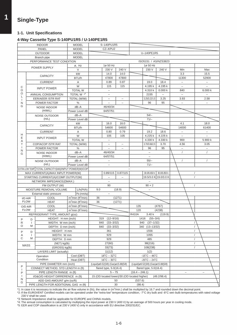
1-1. Unit Specifi cations
4-Way Cassette Type S-140PU1R5 / U-140PE1R5INDOOR MODEL S–140PU1R5PANEL MODEL CZ–KPU2
OUTDOOR MODEL U–140PE1R5Branch pipe MODEL –
PERFORMANCE TEST CONDITION ISO5151 / AS/NZS3823
POWER SUPPLYø, Hz 1ø 50 Hz 1ø 50 Hz
V 230 V 240 V 230 V 240 V Min Max
COOLING
CAPACITYkW 14.0 14.0 3.3 15.5
BTU/h 47800 47800 11300 52900 CURRENT A 0.89 0.87 19.0 18.4 – –
INPUT POWERW 115 115 4.195 k 4.195 k – –
TOTAL W – 4.310 k 0.000 k 840 6.000 kANNUAL CONSUMPTION TOTAL W *4 – 2155 – – –
EER/AEER /STR RAT TOTAL (W/W) – – 3.25/3.22/1.5 3.25 3.93 2.58POWER FACTOR % – – 96 95 – –
NOISE INDOOR(H/M/L)
dB–A 46/40/34Power Level dB 64/57/51
NOISE OUTDOOR(H/L)
dB–A 54/–Power Level dB 71/–
HEATING
CAPACITYkW 16.0 16.0 4.1 18.0
BTU/h 54600 54600 14000 61400 CURRENT A 0.80 0.79 19.2 18.6 – –
INPUT POWERW 105 105 4.225 k 4.225 k – –
TOTAL W – 4.330 k 4.330 k 900 5.900 kCOP/ACOP /STR RAT TOTAL (W/W) – – 3.70/3.66/2.5 3.70 4.56 3.05
POWER FACTOR % – – 96 95 – –
NOISE INDOOR(H/M/L)
dB–A 46/40/34 – / /Power Level dB 64/57/51 –
NOISE OUTDOOR(H/L)
dB–A – 55/– / /Power Level dB – 71/–
EXTRA LOW TEMP TOTAL CAPACITY(kW)/INPUT POWER(W)/COP –MAX CURRENT(A)/MAX INPUT POWER(W) 0.89/115 0.87/115 30.0/6.650 k 30.0/6.850 k /
STARTING CURRENT(A)/COMP OUTPUT(W) – – 19.5/3.0 K 19.0/3.0 K /NETWORK IMPEDANCE(ΩMAX.) – –
FM OUTPUT (W) 90 90 × 2 /MOISTURE REMOVAL VOLUME L/h(Pt/h) 9.0 (18.9) –
Extarnal static pressure Pa (mmAq) –
I/D AIR FLOW
COOL m3/min (ft3/min) 36 (1271)HEAT m3/min (ft3/min) 36 (1271)
O/D AIR FLOW
COOL m3/min (ft3/min) 135 (4767)HEAT m3/min (ft3/min) 120 (4238)
REFRIGERANT TYPE, AMOUNT g(oz) R410A 3.40 k (119.9) /
PRO
D I M
HEIGHT: H mm (inch) 319 (12–9/16) 1416 (55–3/4) /WIDTH: W mm (inch) 840 (33–3/32) 940 (37–1/32) /DEPTH: D mm (inch) 840 (33–3/32) 340 (13–13/32) /
PAC
D I M
HEIGHT: H mm 361 1556 /WIDTH: W mm 929 1055 /DEPTH: D mm 929 485 /
MASS(NET) kg(lb) 27(60) 98(216) /
(GROSS) kg(lb) 33(73) 108(238) /LAYERS LIMIT (actually) 11(12) 1(2)
OperationCondition
Cool (DBT) 18˚C – 32˚C -15˚C – 46˚CHeat (DBT) 16˚C – 30˚C -20˚C – 24˚C
PIPING
PIPE DIAMETER mm (inch) (Liquid)ø9.52(3/8) (Gas)ø15.88(5/8) (Liquid)ø9.52(3/8) (Gas)ø15.88(5/8)CONNECT METHOD, STD LENGTH m (ft) fl ared type, 5.0(16.4) fl ared type, 5.0(16.4)
PIPE LENGTH RANGE m (ft) 5 – 75 (16.4 – 246.1) – –I/D&O/D HEIGHT DIRRERENCE m (ft) 15 (OD located lower)/30 (OD located higher) (49.2/98.4)
ADD GAS AMOUNT g/m (oz/ft) 50 (537.6)PIPE LENGTH FOR ADDITIONAL GAS m (ft) 30 (98.4)
*1: In case it is necessary to indicate the air fl ow volume in (l/s), the value in (m3/min.) shall be multiplied by 16.7 and rounded down the decimal point.*2: If the EUROVENT Certifi ed models can be operated under the “extra-low” temperature condition, -7°C dry bulb and -8°C wet–bulb temperatures with rated voltage
230 V shall be used.*3: Network Impedance shall be applicable for EUROPE and CHINA models.*4: The annual consumption is calculated by multiplying the input power at 230 V (400 V) by an average of 500 hours per year in cooling mode.*5: EER and COP classification is at 230 V (400 V) only in accordance with EU directive 2002/31/EC.
Sec1.indb 6 2012/03/07 17:29:55

1-7
1Single-Type
1-1. Unit Specifi cations
Ducted Type S-60PE1R5 / U-60PE1R5INDOOR MODEL S–60PE1R5PANEL MODEL –
OUTDOOR MODEL U–60PE1R5Branch pipe MODEL –
PERFORMANCE TEST CONDITION ISO5151 / AS/NZS3823
POWER SUPPLY ø, Hz 1ø 50 Hz 1ø 50 HzV 230 V 240 V 230 V 240 V Min Max
COOLING
CAPACITY kW 6.0 6.0 2.5 7.1 BTU/h 20500 20500 8500 24200
CURRENT A 0.85 0.86 7.85 7.65 – –
INPUT POWER W 190 200 1.660 k 1.650 k – –TOTAL W – 1.850 k 1.850 k 605 2.155 k
ANNUAL CONSUMPTION TOTAL W *4 – 925 – – –EER/AEER /STR RAT TOTAL (W/W) – – 3.24/3.17/– 3.24 4.13 3.29
Erp *6Pdsign kW – – – – – –SEER (W/W) – – – – – –Class – – – – – –
POWER FACTOR % – – 92 90 – –NOISE INDOOR
(H/L)dB–A 43/40
Power Level dB 60/57NOISE OUTDOOR
(H/L)dB–A 48/–
Power Level dB 65/–
HEATING
CAPACITY kW 7.0 7.0 2.0 8.0BTU/h 23900 23900 6800 27300
CURRENT A 0.85 0.86 8.8 8.6 – –
INPUT POWER W 190 200 1.860 k 1.850 k – –TOTAL W – 2.050 k 2.050 k 555 2.635 k
COP/ACOP /STR RAT TOTAL (W/W) – – 3.41/3.34/– 3.41 3.60 3.04
Erp *6
Pdsign kW – – – – – –Tbivalen ˚C – – – – – –SCOP (W/W) – – – – – –
Annual consumption kWh – – – – – –Class – – – – – –
POWER FACTOR % – – 92 90 – –NOISE INDOOR
(H/L)dB–A 43/40 – / /
Power Level dB 60/57 –NOISE OUTDOOR
(H/L)dB–A – 50/– / /
Power Level dB – 67/–EXTRA LOW TEMP TOTAL CAPACITY(kW)/INPUT POWER(W)/COP –
MAX CURRENT(A)/MAX INPUT POWER(W) 0.89/0.200 k 0.90/0.210 k 18.0/3.93 k 18.0/4.060 k /STARTING CURRENT(A)/COMP OUTPUT(W) – – 8.8/1.7 K 8.6/1.7 K /
NETWORK IMPEDANCE(ΩMAX.) – –FM OUTPUT (W) 90 90 /
MOISTURE REMOVAL VOLUME L/h(Pt/h) 3.4 (7.1) –Extarnal static pressure Pa (mmAq) 70 (MIN10 – MAX100)
I/D AIR FLOW
COOL m3/min (ft3/min) 22 (777)HEAT m3/min (ft3/min) 22 (777)
O/D AIR FLOW
COOL m3/min (ft3/min) 60 (2119)HEAT m3/min (ft3/min) 60 (2119)
REFRIGERANT TYPE, AMOUNT g(oz) R410A 2.00 k (70.5) /PRO
D I M
HEIGHT: H mm (inch) 290 (11–13/32) 996 (39–7/32) /WIDTH: W mm (inch) 1100(+100) (43–5/16(+3–15/16)) 940 (37–1/32) /DEPTH: D mm (inch) 700 (27–9/16) 340 (13–13/32) /
PAC
D I M
HEIGHT: H mm 375 1136 /WIDTH: W mm 1315 1055 /DEPTH: D mm 812 485 /
MASS (NET) kg(lb) 35 68 /(GROSS) kg(lb) 42 76 /
LAYERS LIMIT (actually) 6(7) 2(3)OperationCondition
Cool (DBT) 18˚C – 32˚C -15˚C – 46˚CHeat (DBT) 16˚C – 30˚C -20˚C – 24˚C
PIPING
PIPE DIAMETER mm (inch) (Liquid)ø9.52(3/8) (Gas)ø15.88(5/8) (Liquid)ø9.52(3/8) (Gas)ø15.88(5/8)CONNECT METHOD, STD LENGTH m (ft) fl ared type, 5.0(16.4) fl ared type, 5.0(16.4)
PIPE LENGTH RANGE m (ft) 5 – 50 (16.4 – 164.0) – –I/D&O/D HEIGHT DIRRERENCE m (ft) 15 (OD located lower)/30 (OD located higher) (49.2/98.4)
ADD GAS AMOUNT g/m (oz/ft) 50 (537.6)PIPE LENGTH FOR ADDITIONAL GAS m (ft) 30 (98.4)
*1: In case it is necessary to indicate the air fl ow volume in (l/s), the value in (m3/min.) shall be multiplied by 16.7 and rounded down the decimal point.*2: If the EUROVENT Certifi ed models can be operated under the “extra-low” temperature condition, -7°C dry bulb and -8°C wet–bulb temperatures with rated voltage
230 V shall be used.*3: Network Impedance shall be applicable for EUROPE and CHINA models.*4: The annual consumption is calculated by multiplying the input power at 230 V (400 V) by an average of 500 hours per year in cooling mode.*5: EER and COP classification is at 230 V (400 V) only in accordance with EU directive 2002/31/EC.*6: SEER and SCOP classification is at 230V (400V) only in accordance with EN-14825. For heating, SCOP indicates the value of only Average heating season,
Other fiche data indicates in an attached sheet.
Sec1.indb 7 2012/03/07 17:29:55

1-8
1 Single-Type
1-1. Unit Specifi cations
Ducted Type S-71PE1R5 / U-71PE1R5INDOOR MODEL S–71PE1R5PANEL MODEL –
OUTDOOR MODEL U–71PE1R5Branch pipe MODEL –
PERFORMANCE TEST CONDITION ISO5151 / AS/NZS3823
POWER SUPPLY ø, Hz 1ø 50 Hz 1ø 50 HzV 230 V 240 V 230 V 240 V Min Max
COOLING
CAPACITY kW 7.1 7.1 2.5 8.0BTU/h 24200 24200 8500 27300
CURRENT A 1.24 1.25 9.1 8.80 – –
INPUT POWER W 275 290 1.925 k 1.910 k – –TOTAL W – 2.200 k 2.200 k 685 2.855 k
ANNUAL CONSUMPTION TOTAL W *4 – 1100 – – –EER/AEER /STR RAT TOTAL (W/W) – – 3.23/3.16/– 3.23 3.65 2.80
Erp *6Pdsign kW – – – – – –SEER (W/W) – – – – – –Class – – – – – –
POWER FACTOR % – – 92 90 – –NOISE INDOOR
(H/L)dB–A 45/43
Power Level dB 62/60NOISE OUTDOOR
(H/L)dB–A 48/–
Power Level dB 65/–
HEATING
CAPACITY kW 8.0 8.0 2.0 9.0BTU/h 27300 27300 6800 30700
CURRENT A 1.24 1.25 9.3 9.0 – –
INPUT POWER W 275 290 2.025 k 2.010 k – –TOTAL W – 2.300 k 2.300 k 635 3.135 k
COP/ACOP /STR RAT TOTAL (W/W) – – 3.48/3.41/– 3.48 3.15 2.87
Erp *6
Pdsign kW – – – – – –Tbivalen ˚C – – – – – –SCOP (W/W) – – – – – –
Annual consumption kWh – – – – – –Class – – – – – –
POWER FACTOR % – – 95 93 – –NOISE INDOOR
(H/L)dB–A 45/43 – / /
Power Level dB 62/60 –NOISE OUTDOOR
(H/L)dB–A – 50/– / /
Power Level dB – 67/–EXTRA LOW TEMP TOTAL CAPACITY(kW)/INPUT POWER(W)/COP –
MAX CURRENT(A)/MAX INPUT POWER(W) 1.30/0.290 k 1.31/0.305 k 18.0/3.93 k 18.0/4.060 k /STARTING CURRENT(A)/COMP OUTPUT(W) – – 9.3/2.0 K 9.0/2.0 K /
NETWORK IMPEDANCE(ΩMAX.) – –FM OUTPUT (W) 155 90 /
MOISTURE REMOVAL VOLUME L/h(Pt/h) 4.2 (8.8) –Extarnal static pressure Pa (mmAq) 100 (MIN10 – MAX150)
I/D AIR FLOW
COOL m3/min (ft3/min) 30 (1059)HEAT m3/min (ft3/min) 30 (1059)
O/D AIR FLOW
COOL m3/min (ft3/min) 60 (2119)HEAT m3/min (ft3/min) 60 (2119)
REFRIGERANT TYPE, AMOUNT g(oz) R410A 2.35 k (82.9) /PRO
D I M
HEIGHT: H mm (inch) 360 (14–5/32) 996 (39–7/32) /WIDTH: W mm (inch) 1100(+100) (43–5/16(+3–15/16)) 940 (37–1/32) /DEPTH: D mm (inch) 700 (27–9/16) 340 (13–13/32) /
PAC
D I M
HEIGHT: H mm 445 1136 /WIDTH: W mm 1315 1055 /DEPTH: D mm 812 485 /
MASS (NET) kg(lb) 42 69 /(GROSS) kg(lb) 50 77 /
LAYERS LIMIT (actually) 6(7) 2(3)OperationCondition
Cool (DBT) 18˚C – 32˚C -15˚C – 46˚CHeat (DBT) 16˚C – 30˚C -20˚C – 24˚C
PIPING
PIPE DIAMETER mm (inch) (Liquid)ø9.52(3/8) (Gas)ø15.88(5/8) (Liquid)ø9.52(3/8) (Gas)ø15.88(5/8)CONNECT METHOD, STD LENGTH m (ft) fl ared type, 5.0(16.4) fl ared type, 5.0(16.4)
PIPE LENGTH RANGE m (ft) 5 – 50 (16.4 – 164.0) – –I/D&O/D HEIGHT DIRRERENCE m (ft) 15 (OD located lower)/30 (OD located higher) (49.2/98.4)
ADD GAS AMOUNT g/m (oz/ft) 50 (537.6)PIPE LENGTH FOR ADDITIONAL GAS m (ft) 30 (98.4)
*1: In case it is necessary to indicate the air fl ow volume in (l/s), the value in (m3/min.) shall be multiplied by 16.7 and rounded down the decimal point.*2: If the EUROVENT Certifi ed models can be operated under the “extra-low” temperature condition, -7°C dry bulb and -8°C wet–bulb temperatures with rated voltage
230 V shall be used.*3: Network Impedance shall be applicable for EUROPE and CHINA models.*4: The annual consumption is calculated by multiplying the input power at 230 V (400 V) by an average of 500 hours per year in cooling mode.*5: EER and COP classification is at 230 V (400 V) only in accordance with EU directive 2002/31/EC.*6: SEER and SCOP classification is at 230V (400V) only in accordance with EN-14825. For heating, SCOP indicates the value of only Average heating season,
Other fiche data indicates in an attached sheet.
Sec1.indb 8 2012/03/07 17:29:55

1-9
1Single-Type
1-1. Unit Specifi cations
Ducted Type S-100PE1R5 / U-100PE1R5INDOOR MODEL S–100PE1R5PANEL MODEL –
OUTDOOR MODEL U–100PE1R5Branch pipe MODEL –
PERFORMANCE TEST CONDITION ISO5151 / AS/NZS3823
POWER SUPPLY ø, Hz 1ø 50 Hz 1ø 50 HzV 230 V 240 V 230 V 240 V Min Max
COOLING
CAPACITY kW 10.0 10.0 3.3 12.5BTU/h 34100 34100 11300 42700
CURRENT A 1.72 1.74 11.8 11.40 – –
INPUT POWER W 390 410 2.590 k 2.570 k – –TOTAL W – 2.980 k 2.980 k 980 3.900 k
ANNUAL CONSUMPTION TOTAL W *4 – 1490 – – –EER/AEER /STR RAT TOTAL (W/W) – – 3.36/3.31/– 3.36 3.37 3.21
Erp *6Pdsign kW – – – – – –SEER (W/W) – – – – – –Class – – – – – –
POWER FACTOR % – – 95 94 – –NOISE INDOOR
(H/L)dB–A 48/44
Power Level dB 70/66NOISE OUTDOOR
(H/L)dB–A 52/–
Power Level dB 69/–
HEATING
CAPACITY kW 11.2 11.2 4.1 14.0BTU/h 38200 38200 14000 47800
CURRENT A 1.72 1.74 12.7 12.3 – –
INPUT POWER W 390 410 2.790 k 2.770 k – –TOTAL W – 3.180 k 3.180 k 1050 4.600 k
COP/ACOP /STR RAT TOTAL (W/W) – – 3.52/3.47/– 3.52 3.90 3.04
Erp *6
Pdsign kW – – – – – –Tbivalen ˚C – – – – – –SCOP (W/W) – – – – – –
Annual consumption kWh – – – – – –Class – – – – – –
POWER FACTOR % – – 96 94 – –NOISE INDOOR
(H/L)dB–A 48/44 – / /
Power Level dB 70/66 –NOISE OUTDOOR
(H/L)dB–A – 52/– / /
Power Level dB – 69/–EXTRA LOW TEMP TOTAL CAPACITY(kW)/INPUT POWER(W)/COP –
MAX CURRENT(A)/MAX INPUT POWER(W) 2.0/0.44 k 2.1/0.47 k 25.0/5.550 k 25.0/5.750 k /STARTING CURRENT(A)/COMP OUTPUT(W) – – 10.8/3.0 K 10.4/3.0 K /
NETWORK IMPEDANCE(ΩMAX.) – –FM OUTPUT (W) 275 90 × 2 /
MOISTURE REMOVAL VOLUME L/h(Pt/h) 6.0 (12.6) –Extarnal static pressure Pa (mmAq) 100 (MIN10 – MAX150)
I/D AIR FLOW
COOL m3/min (ft3/min) 40 (1413)HEAT m3/min (ft3/min) 40 (1413)
O/D AIR FLOW
COOL m3/min (ft3/min) 110 (3885)HEAT m3/min (ft3/min) 95 (3355)
REFRIGERANT TYPE, AMOUNT g(oz) R410A 3.40 k (119.9) /PRO
D I M
HEIGHT: H mm (inch) 360 (14–5/32) 1416 (55–3/4) /WIDTH: W mm (inch) 1100(+100) (43–5/16(+3–15/16)) 940 (37–1/32) /DEPTH: D mm (inch) 700 (27–9/16) 340 (13–13/32) /
PAC
D I M
HEIGHT: H mm 445 1556 /WIDTH: W mm 1315 1055 /DEPTH: D mm 812 485 /
MASS (NET) kg(lb) 44 98 /(GROSS) kg(lb) 52 108 /
LAYERS LIMIT (actually) 6(7) 1(2)OperationCondition
Cool (DBT) 18˚C – 32˚C -15˚C – 46˚CHeat (DBT) 16˚C – 30˚C -20˚C – 24˚C
PIPING
PIPE DIAMETER mm (inch) (Liquid)ø9.52(3/8) (Gas)ø15.88(5/8) (Liquid)ø9.52(3/8) (Gas)ø15.88(5/8)CONNECT METHOD, STD LENGTH m (ft) fl ared type, 5.0(16.4) fl ared type, 5.0(16.4)
PIPE LENGTH RANGE m (ft) 5 – 75 (16.4 – 246.1) – –I/D&O/D HEIGHT DIRRERENCE m (ft) 15 (OD located lower)/30 (OD located higher) (49.2/98.4)
ADD GAS AMOUNT g/m (oz/ft) 50 (537.6)PIPE LENGTH FOR ADDITIONAL GAS m (ft) 30 (98.4)
*1: In case it is necessary to indicate the air fl ow volume in (l/s), the value in (m3/min.) shall be multiplied by 16.7 and rounded down the decimal point.*2: If the EUROVENT Certifi ed models can be operated under the “extra-low” temperature condition, -7°C dry bulb and -8°C wet–bulb temperatures with rated voltage
230 V shall be used.*3: Network Impedance shall be applicable for EUROPE and CHINA models.*4: The annual consumption is calculated by multiplying the input power at 230 V (400 V) by an average of 500 hours per year in cooling mode.*5: EER and COP classification is at 230 V (400 V) only in accordance with EU directive 2002/31/EC.*6: SEER and SCOP classification is at 230V (400V) only in accordance with EN-14825. For heating, SCOP indicates the value of only Average heating season,
Other fiche data indicates in an attached sheet.
Sec1.indb 9 2012/03/07 17:29:55
1-10
1 Single-Type
1-1. Unit Specifi cations
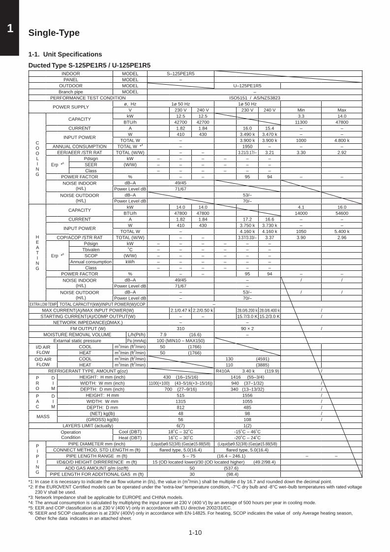
Ducted Type S-125PE1R5 / U-125PE1R5INDOOR MODEL S–125PE1R5PANEL MODEL –
OUTDOOR MODEL U–125PE1R5Branch pipe MODEL –
PERFORMANCE TEST CONDITION ISO5151 / AS/NZS3823
POWER SUPPLY ø, Hz 1ø 50 Hz 1ø 50 HzV 230 V 240 V 230 V 240 V Min Max
COOLING
CAPACITY kW 12.5 12.5 3.3 14.0BTU/h 42700 42700 11300 47800
CURRENT A 1.82 1.84 16.0 15.4 – –
INPUT POWER W 410 430 3.490 k 3.470 k – –TOTAL W – 3.900 k 3.900 k 1000 4.800 k
ANNUAL CONSUMPTION TOTAL W *4 – 1950 – – –EER/AEER /STR RAT TOTAL (W/W) – – 3.21/3.17/– 3.21 3.30 2.92
Erp *6Pdsign kW – – – – – –SEER (W/W) – – – – – –Class – – – – – –
POWER FACTOR % – – 95 94 – –NOISE INDOOR
(H/L)dB–A 49/45
Power Level dB 71/67NOISE OUTDOOR
(H/L)dB–A 53/–
Power Level dB 70/–
HEATING
CAPACITY kW 14.0 14.0 4.1 16.0BTU/h 47800 47800 14000 54600
CURRENT A 1.82 1.84 17.2 16.6 – –
INPUT POWER W 410 430 3.750 k 3.730 k – –TOTAL W – 4.160 k 4.160 k 1050 5.400 k
COP/ACOP /STR RAT TOTAL (W/W) – – 3.37/3.33/– 3.37 3.90 2.96
Erp *6
Pdsign kW – – – – – –Tbivalen ˚C – – – – – –SCOP (W/W) – – – – – –
Annual consumption kWh – – – – – –Class – – – – – –
POWER FACTOR % – – 95 94 – –NOISE INDOOR
(H/L)dB–A 49/45 – / /
Power Level dB 71/67 –NOISE OUTDOOR
(H/L)dB–A – 53/– / /
Power Level dB – 70/–EXTRA LOW TEMP TOTAL CAPACITY(kW)/INPUT POWER(W)/COP –
MAX CURRENT(A)/MAX INPUT POWER(W) 2.1/0.47 k 2.2/0.50 k 28.0/6.200 k 28.0/6.400 k /STARTING CURRENT(A)/COMP OUTPUT(W) – – 15.7/3.0 K 15.2/3.0 K /
NETWORK IMPEDANCE(ΩMAX.) – –FM OUTPUT (W) 310 90 × 2 /
MOISTURE REMOVAL VOLUME L/h(Pt/h) 7.9 (16.6) –Extarnal static pressure Pa (mmAq) 100 (MIN10 – MAX150)
I/D AIR FLOW
COOL m3/min (ft3/min) 50 (1766)HEAT m3/min (ft3/min) 50 (1766)
O/D AIR FLOW
COOL m3/min (ft3/min) 130 (4591)HEAT m3/min (ft3/min) 110 (3885)
REFRIGERANT TYPE, AMOUNT g(oz) R410A 3.40 k (119.9) /PRO
D I M
HEIGHT: H mm (inch) 430 (16–15/16) 1416 (55–3/4) /WIDTH: W mm (inch) 1100(+100) (43–5/16(+3–15/16)) 940 (37–1/32) /DEPTH: D mm (inch) 700 (27–9/16) 340 (13–13/32) /
PAC
D I M
HEIGHT: H mm 515 1556 /WIDTH: W mm 1315 1055 /DEPTH: D mm 812 485 /
MASS (NET) kg(lb) 48 98 /(GROSS) kg(lb) 56 108 /
LAYERS LIMIT (actually) 6(7) 1(2)OperationCondition
Cool (DBT) 18˚C – 32˚C -15˚C – 46˚CHeat (DBT) 16˚C – 30˚C -20˚C – 24˚C
PIPING
PIPE DIAMETER mm (inch) (Liquid)ø9.52(3/8) (Gas)ø15.88(5/8) (Liquid)ø9.52(3/8) (Gas)ø15.88(5/8)CONNECT METHOD, STD LENGTH m (ft) fl ared type, 5.0(16.4) fl ared type, 5.0(16.4)
PIPE LENGTH RANGE m (ft) 5 – 75 (16.4 – 246.1) – –I/D&O/D HEIGHT DIRRERENCE m (ft) 15 (OD located lower)/30 (OD located higher) (49.2/98.4)
ADD GAS AMOUNT g/m (oz/ft) 50 (537.6)PIPE LENGTH FOR ADDITIONAL GAS m (ft) 30 (98.4)
*1: In case it is necessary to indicate the air fl ow volume in (l/s), the value in (m3/min.) shall be multiplie d by 16.7 and rounded down the decimal point.*2: If the EUROVENT Certifi ed models can be operated under the “extra-low” temperature condition, -7°C dry bulb and -8°C wet–bulb temperatures with rated voltage
230 V shall be used.*3: Network Impedance shall be applicable for EUROPE and CHINA models.*4: The annual consumption is calculated by multiplying the input power at 230 V (400 V) by an average of 500 hours per year in cooling mode.*5: EER and COP classification is at 230 V (400 V) only in accordance with EU directive 2002/31/EC.*6: SEER and SCOP classification is at 230V (400V) only in accordance with EN-14825. For heating, SCOP indicates the value of only Average heating season,
Other fiche data indicates in an attached sheet.
Sec1.indb 10 2012/03/07 17:29:56

1-11
1Single-Type
1-1. Unit Specifi cations
Ducted Type S-140PE1R5 / U-140PE1R5INDOOR MODEL S–140PE1R5PANEL MODEL –
OUTDOOR MODEL U–140PE1R5Branch pipe MODEL –
PERFORMANCE TEST CONDITION ISO5151 / AS/NZS3823
POWER SUPPLY ø, Hz 1ø 50 Hz 1ø 50 HzV 230 V 240 V 230 V 240 V Min Max
COOLING
CAPACITY kW 14.0 14.0 3.3 15.5BTU/h 47800 47800 11300 52900
CURRENT A 2.62 2.70 17.8 17.2 – –
INPUT POWER W 590 640 3.860 k 3.810 k – –TOTAL W – 4.450 k 4.450 k 1000 6.200 k
ANNUAL CONSUMPTION TOTAL W *4 – 2225 – – –EER/AEER /STR RAT TOTAL (W/W) – – 3.15/3.12/– 3.15 3.30 2.50
Erp *6Pdsign kW – – – – – –SEER (W/W) – – – – – –Class – – – – – –
POWER FACTOR % – – 94 92 – –NOISE INDOOR
(H/L)dB–A 51/47
Power Level dB 73/69NOISE OUTDOOR
(H/L)dB–A 54/–
Power Level dB 71/–
HEATING
CAPACITY kW 16.0 16.0 4.1 18.0BTU/h 54600 54600 14000 61400
CURRENT A 2.62 2.70 18.1 17.5 – –
INPUT POWER W 590 640 3.960 k 3.910 k – –TOTAL W – 4.550 k 4.550 k 1050 6.100 k
COP/ACOP /STR RAT TOTAL (W/W) – – 3.52/3.48/– 3.52 3.90 2.95
Erp *6
Pdsign kW – – – – – –Tbivalen ˚C – – – – – –SCOP (W/W) – – – – – –
Annual consumption kWh – – – – – –Class – – – – – –
POWER FACTOR % – – 95 93 – –NOISE INDOOR
(H/L)dB–A 51/47 – / /
Power Level dB 73/69 –NOISE OUTDOOR
(H/L)dB–A – 55/– / /
Power Level dB – 71/–EXTRA LOW TEMP TOTAL CAPACITY(kW)/INPUT POWER(W)/COP –
MAX CURRENT(A)/MAX INPUT POWER(W) 2.9/0.66 k 3.0/0.71 k 30.0/6.650 k 30.0/6.850 k /STARTING CURRENT(A)/COMP OUTPUT(W) – – 19.5/3.0 K 19.0/3.0 K /
NETWORK IMPEDANCE(ΩMAX.) – –FM OUTPUT (W) 440 90 × 2 /
MOISTURE REMOVAL VOLUME L/h(Pt/h) 9.0 (18.9) –Extarnal static pressure Pa (mmAq) 100 (MIN10 – MAX150)
I/D AIR FLOW
COOL m3/min (ft3/min) 60 (2119)HEAT m3/min (ft3/min) 60 (2119)
O/D AIR FLOW
COOL m3/min (ft3/min) 135 (4767)HEAT m3/min (ft3/min) 120 (4238)
REFRIGERANT TYPE, AMOUNT g(oz) R410A 3.40 k (119.9) /PRO
D I M
HEIGHT: H mm (inch) 430 (16–15/16) 1416 (55–3/4) /WIDTH: W mm (inch) 1100(+100) (43–5/16(+3–15/16)) 940 (37–1/32) /DEPTH: D mm (inch) 700 (27–9/16) 340 (13–13/32) /
PAC
D I M
HEIGHT: H mm 515 1556 /WIDTH: W mm 1315 1055 /DEPTH: D mm 812 485 /
MASS (NET) kg(lb) 53 98 /(GROSS) kg(lb) 61 108 /
LAYERS LIMIT (actually) 6(7) 1(2)OperationCondition
Cool (DBT) 18˚C – 32˚C -15˚C – 46˚CHeat (DBT) 16˚C – 30˚C -20˚C – 24˚C
PIPING
PIPE DIAMETER mm (inch) (Liquid)ø9.52(3/8) (Gas)ø15.88(5/8) (Liquid)ø9.52(3/8) (Gas)ø15.88(5/8)CONNECT METHOD, STD LENGTH m (ft) fl ared type, 5.0(16.4) fl ared type, 5.0(16.4)
PIPE LENGTH RANGE m (ft) 5 – 75 (16.4 – 246.1) – –I/D&O/D HEIGHT DIRRERENCE m (ft) 15 (OD located lower)/30 (OD located higher) (49.2/98.4)
ADD GAS AMOUNT g/m (oz/ft) 50 (537.6)PIPE LENGTH FOR ADDITIONAL GAS m (ft) 30 (98.4)
*1: In case it is necessary to indicate the air fl ow volume in (l/s), the value in (m3/min.) shall be multiplied by 16.7 and rounded down the decimal point.*2: If the EUROVENT Certifi ed models can be operated under the “extra-low” temperature condition, -7°C dry bulb and -8°C wet–bulb temperatures with rated voltage
230 V shall be used.*3: Network Impedance shall be applicable for EUROPE and CHINA models.*4: The annual consumption is calculated by multiplying the input power at 230 V (400 V) by an average of 500 hours per year in cooling mode.*5: EER and COP classification is at 230 V (400 V) only in accordance with EU directive 2002/31/EC.*6: SEER and SCOP classification is at 230V (400V) only in accordance with EN-14825. For heating, SCOP indicates the value of only Average heating season,
Other fiche data indicates in an attached sheet.
Sec1.indb 11 2012/03/07 17:29:56

1-12
1 Single-Type
1-1. Unit Specifi cations
Single Split Type S-100PU1R5 / U-100PE1R8INDOOR MODEL S–100PU1R5PANEL MODEL CZ-KPU2
OUTDOOR MODEL U–100PE1R8Branch pipe MODEL –
PERFORMANCE TEST CONDITION AS/NZS3823.1
POWER SUPPLY ø, Hz 1ø 50 Hz 3ø 50 HzV 230 V 240 V 400 V 415 V Min Max
COOLING
CAPACITY kW 10.0 10.0 3.3 12.5BTU/h 34100 34100 11300 42700
CURRENT A 0.71 0.71 3.50 3.40 – –
INPUT POWER W 95 95 2.285 k 2.285 k – –TOTAL W – 2.380 k 2.380 k 840 3.700 k
ANNUAL CONSUMPTION TOTAL W *4 – 1190 – – –EER/AEER /STR RAT TOTAL (W/W) – – 4.20/4.13/– 4.20 3.93 3.38
Erp *6Pdsign kW – – – – – –SEER (W/W) – – – – – –Class – – – – – –
POWER FACTOR % – – 94 93 – –NOISE INDOOR
(H/L)dB–A 44/32
Power Level dB 62/49NOISE OUTDOOR
(H/L)dB–A 52/–
Power Level dB 69/–
HEATING
CAPACITY kW 11.2 11.2 4.1 14.0BTU/h 38200 38200 14000 47800
CURRENT A 0.65 0.64 3.85 3.75 – –
INPUT POWER W 85 85 2.515 k 2.515 k – –TOTAL W – 2.600 k 2.600 k 900 4.400 k
COP/ACOP /STR RAT TOTAL (W/W) – – 4.31/4.24/– 4.31 4.56 3.18
Erp *6
Pdsign kW – – – – – –Tbivalen ˚C – – – – – –SCOP (W/W) – – – – – –
Annual consumption kWh – – – – – –Class – – – – – –
POWER FACTOR % – – 94 93 – –NOISE INDOOR
(H/L)dB–A 44/32 – / /
Power Level dB 62/49 –NOISE OUTDOOR
(H/L)dB–A – 52/– / /
Power Level dB – 69/–EXTRA LOW TEMP TOTAL CAPACITY(kW)/INPUT POWER(W)/COP –
MAX CURRENT(A)/MAX INPUT POWER(W) 0.71/95 k 0.71/95 k 9.0/5.850 k 9.0/6.100 k /STARTING CURRENT(A)/COMP OUTPUT(W) – – 3.85/3.0 K 3.75/3.0 K /
NETWORK IMPEDANCE(ΩMAX.) – –FM OUTPUT (W) 90 90 × 2 /
MOISTURE REMOVAL VOLUME L/h(Pt/h) 6.0 (12.6) –Extarnal static pressure Pa (mmAq) –
I/D AIR FLOW
COOL m3/min (ft3/min) 33 (1165)HEAT m3/min (ft3/min) 33 (1165)
O/D AIR FLOW
COOL m3/min (ft3/min) 110 (3885)HEAT m3/min (ft3/min) 95 (3355)
REFRIGERANT TYPE, AMOUNT g(oz) R410A 3.40 k (119.9) /PRO
D I M
HEIGHT: H mm (inch) 319 (12–9/16) 1416 (55–3/4) /WIDTH: W mm (inch) 840 (33–3/32) 940 (37–1/32) /DEPTH: D mm (inch) 840 (33–3/32) 340 (13–13/32) /
PAC
D I M
HEIGHT: H mm 361 1556 /WIDTH: W mm 929 1055 /DEPTH: D mm 929 485 /
MASS (NET) kg(lb) 27 98 /(GROSS) kg(lb) 34 108 /
LAYERS LIMIT (actually) 11(12) 1(2)OperationCondition
Cool (DBT) 18˚C – 32˚C -15˚C – 46˚CHeat (DBT) 16˚C – 30˚C -20˚C – 24˚C
PIPING
PIPE DIAMETER mm (inch) (Liquid)ø9.52(3/8) (Gas)ø15.88(5/8) (Liquid)ø9.52(3/8) (Gas)ø15.88(5/8)CONNECT METHOD, STD LENGTH m (ft) fl ared type, 5.0(16.4) fl ared type, 5.0(16.4)
PIPE LENGTH RANGE m (ft) 5 – 75 (16.4 – 246.1) – –I/D&O/D HEIGHT DIRRERENCE m (ft) 15 (OD located lower)/30 (OD located higher) (49.2/98.4)
ADD GAS AMOUNT g/m (oz/ft) 50 (537.6)PIPE LENGTH FOR ADDITIONAL GAS m (ft) 30 (98.4)
*1: In case it is necessary to indicate the air fl ow volume in (l/s), the value in (m3/min.) shall be multiplied by 16.7 and rounded down the decimal point.*2: If the EUROVENT Certifi ed models can be operated under the “extra-low” temperature condition, -7°C dry bulb and -8°C wet–bulb temperatures with rated voltage
230 V shall be used.*3: Network Impedance shall be applicable for EUROPE and CHINA models.*4: The annual consumption is calculated by multiplying the input power at 230 V (400 V) by an average of 500 hours per year in cooling mode.*5: EER and COP classification is at 230 V (400 V) only in accordance with EU directive 2002/31/EC.*6: SEER and SCOP classification is at 230V (400V) only in accordance with EN-14825. For heating, SCOP indicates the value of only Average heating season,
Other fiche data indicates in an attached sheet.
Sec1.indb 12 2012/03/07 17:29:56

1-13
1Single-Type
1-1. Unit Specifi cations
Single Split Type S-125PU1R5 / U-125PE1R8INDOOR MODEL S–125PU1R5PANEL MODEL CZ-KPU2
OUTDOOR MODEL U–125PE1R8Branch pipe MODEL –
PERFORMANCE TEST CONDITION AS/NZS3823.1
POWER SUPPLY ø, Hz 1ø 50 Hz 3ø 50 HzV 230 V 240 V 400 V 415 V Min Max
COOLING
CAPACITY kW 12.5 12.5 3.3 14.0BTU/h 42700 42700 11300 47800
CURRENT A 0.76 0.73 5.15 5.00 – –
INPUT POWER W 100 100 3.370 k 3.370 k – –TOTAL W – 3.470 k 3.470 k 840 4.600 k
ANNUAL CONSUMPTION TOTAL W *4 – 1735 – – –EER/AEER /STR RAT TOTAL (W/W) – – 3.60/3.56/– 3.60 3.93 3.04
Erp *6Pdsign kW – – – – – –SEER (W/W) – – – – – –Class – – – – – –
POWER FACTOR % – – 94 94 – –NOISE INDOOR
(H/L)dB–A 45/33
Power Level dB 63/50NOISE OUTDOOR
(H/L)dB–A 53/–
Power Level dB 70/–
HEATING
CAPACITY kW 14.0 14.0 4.1 16.0BTU/h 47800 47800 14000 54600
CURRENT A 0.73 0.73 5.20 5.05 – –
INPUT POWER W 100 100 3.400 k 3.400 k – –TOTAL W – 3.500 k 3.500 k 900 5.200 k
COP/ACOP /STR RAT TOTAL (W/W) – – 4.00/3.95/– 4.00 4.56 3.08
Erp *6
Pdsign kW – – – – – –Tbivalen ˚C – – – – – –SCOP (W/W) – – – – – –
Annual consumption kWh – – – – – –Class – – – – – –
POWER FACTOR % – – 94 94 – –NOISE INDOOR
(H/L)dB–A 45/33 – / /
Power Level dB 63/50 –NOISE OUTDOOR
(H/L)dB–A – 53/– / /
Power Level dB – 70/–EXTRA LOW TEMP TOTAL CAPACITY(kW)/INPUT POWER(W)/COP –
MAX CURRENT(A)/MAX INPUT POWER(W) 0.76/100 k 0.73/100 k 10.0/6.500 k 10.0/6.750 k /STARTING CURRENT(A)/COMP OUTPUT(W) – – 5.20/3.0 K 5.05/3.0 K /
NETWORK IMPEDANCE(ΩMAX.) – –FM OUTPUT (W) 90 90 × 2 /
MOISTURE REMOVAL VOLUME L/h(Pt/h) 6.0 (12.6) –Extarnal static pressure Pa (mmAq) –
I/D AIR FLOW
COOL m3/min (ft3/min) 35 (1236)HEAT m3/min (ft3/min) 35 (1236)
O/D AIR FLOW
COOL m3/min (ft3/min) 130 (4591)HEAT m3/min (ft3/min) 110 (3885)
REFRIGERANT TYPE, AMOUNT g(oz) R410A 3.40 k (119.9) /PRO
D I M
HEIGHT: H mm (inch) 319 (12–9/16) 1416 (55–3/4) /WIDTH: W mm (inch) 840 (33–3/32) 940 (37–1/32) /DEPTH: D mm (inch) 840 (33–3/32) 340 (13–13/32) /
PAC
D I M
HEIGHT: H mm 361 1556 /WIDTH: W mm 929 1055 /DEPTH: D mm 929 485 /
MASS (NET) kg(lb) 27 98 /(GROSS) kg(lb) 34 108 /
LAYERS LIMIT (actually) 11(12) 1(2)OperationCondition
Cool (DBT) 18˚C – 32˚C -15˚C – 46˚CHeat (DBT) 16˚C – 30˚C -20˚C – 24˚C
PIPING
PIPE DIAMETER mm (inch) (Liquid)ø9.52(3/8) (Gas)ø15.88(5/8) (Liquid)ø9.52(3/8) (Gas)ø15.88(5/8)CONNECT METHOD, STD LENGTH m (ft) fl ared type, 5.0(16.4) fl ared type, 5.0(16.4)
PIPE LENGTH RANGE m (ft) 5 – 75 (16.4 – 246.1) – –I/D&O/D HEIGHT DIRRERENCE m (ft) 15 (OD located lower)/30 (OD located higher) (49.2/98.4)
ADD GAS AMOUNT g/m (oz/ft) 50 (537.6)PIPE LENGTH FOR ADDITIONAL GAS m (ft) 30 (98.4)
*1: In case it is necessary to indicate the air fl ow volume in (l/s), the value in (m3/min.) shall be multiplied by 16.7 and rounded down the decimal point.*2: If the EUROVENT Certifi ed models can be operated under the “extra-low” temperature condition, -7°C dry bulb and -8°C wet–bulb temperatures with rated voltage
230 V shall be used.*3: Network Impedance shall be applicable for EUROPE and CHINA models.*4: The annual consumption is calculated by multiplying the input power at 230 V (400 V) by an average of 500 hours per year in cooling mode.*5: EER and COP classification is at 230 V (400 V) only in accordance with EU directive 2002/31/EC.*6: SEER and SCOP classification is at 230V (400V) only in accordance with EN-14825. For heating, SCOP indicates the value of only Average heating season,
Other fiche data indicates in an attached sheet.
Sec1.indb 13 2012/03/07 17:29:56

1-14
1 Single-Type
1-1. Unit Specifi cations
Single Split Type S-140PU1R5 / U-140PE1R8INDOOR MODEL S–140PU1R5PANEL MODEL CZ-KPU2
OUTDOOR MODEL U–140PE1R8Branch pipe MODEL –
PERFORMANCE TEST CONDITION AS/NZS3823.1
POWER SUPPLY ø, Hz 1ø 50 Hz 3ø 50 HzV 230 V 240 V 400 V 415 V Min Max
COOLING
CAPACITY kW 14.0 14.0 3.3 15.5BTU/h 47800 47800 11300 52900
CURRENT A 0.89 0.87 6.45 6.20 – –
INPUT POWER W 115 115 4.195 k 4.195 k – –TOTAL W – 4.310 k 4.310 k 840 6.000 k
ANNUAL CONSUMPTION TOTAL W *4 – 2155 – – –EER/AEER /STR RAT TOTAL (W/W) – – 3.25/3.22/– 3.25 3.93 2.58
Erp *6Pdsign kW – – – – – –SEER (W/W) – – – – – –Class – – – – – –
POWER FACTOR % – – 94 94 – –NOISE INDOOR
(H/L)dB–A 46/34
Power Level dB 64/51NOISE OUTDOOR
(H/L)dB–A 54/–
Power Level dB 71/–
HEATING
CAPACITY kW 16.0 16.0 4.1 18.0BTU/h 54600 54600 14000 61400
CURRENT A 0.80 0.79 6.50 6.25 – –
INPUT POWER W 105 105 4.225 k 4.225 k – –TOTAL W – 4.330 k 4.330 k 900 5.900 k
COP/ACOP /STR RAT TOTAL (W/W) – – 3.70/3.66/– 3.70 4.56 3.05
Erp *6
Pdsign kW – – – – – –Tbivalen ˚C – – – – – –SCOP (W/W) – – – – – –
Annual consumption kWh – – – – – –Class – – – – – –
POWER FACTOR % – – 94 94 – –NOISE INDOOR
(H/L)dB–A 46/34 – / /
Power Level dB 64/51 –NOISE OUTDOOR
(H/L)dB–A – 55/– / /
Power Level dB – 71/–EXTRA LOW TEMP TOTAL CAPACITY(kW)/INPUT POWER(W)/COP –
MAX CURRENT(A)/MAX INPUT POWER(W) 0.89/115 k 0.87/115 k 11.0/7.150 k 11.0/7.450 k /STARTING CURRENT(A)/COMP OUTPUT(W) – – 6.50/3.0 K 6.25/3.0 K /
NETWORK IMPEDANCE(ΩMAX.) – –FM OUTPUT (W) 90 90 × 2 /
MOISTURE REMOVAL VOLUME L/h(Pt/h) 6.0 (12.6) –Extarnal static pressure Pa (mmAq) –
I/D AIR FLOW
COOL m3/min (ft3/min) 36 (1271)HEAT m3/min (ft3/min) 36 (1271)
O/D AIR FLOW
COOL m3/min (ft3/min) 135 (4767)HEAT m3/min (ft3/min) 120 (4238)
REFRIGERANT TYPE, AMOUNT g(oz) R410A 3.40 k (119.9) /PRO
D I M
HEIGHT: H mm (inch) 319 (12–9/16) 1416 (55–3/4) /WIDTH: W mm (inch) 840 (33–3/32) 940 (37–1/32) /DEPTH: D mm (inch) 840 (33–3/32) 340 (13–13/32) /
PAC
D I M
HEIGHT: H mm 361 1556 /WIDTH: W mm 929 1055 /DEPTH: D mm 929 485 /
MASS (NET) kg(lb) 27 98 /(GROSS) kg(lb) 34 108 /
LAYERS LIMIT (actually) 11(12) 1(2)OperationCondition
Cool (DBT) 18˚C – 32˚C -15˚C – 46˚CHeat (DBT) 16˚C – 30˚C -20˚C – 24˚C
PIPING
PIPE DIAMETER mm (inch) (Liquid)ø9.52(3/8) (Gas)ø15.88(5/8) (Liquid)ø9.52(3/8) (Gas)ø15.88(5/8)CONNECT METHOD, STD LENGTH m (ft) fl ared type, 5.0(16.4) fl ared type, 5.0(16.4)
PIPE LENGTH RANGE m (ft) 5 – 75 (16.4 – 246.1) – –I/D&O/D HEIGHT DIRRERENCE m (ft) 15 (OD located lower)/30 (OD located higher) (49.2/98.4)
ADD GAS AMOUNT g/m (oz/ft) 50 (537.6)PIPE LENGTH FOR ADDITIONAL GAS m (ft) 30 (98.4)
*1: In case it is necessary to indicate the air fl ow volume in (l/s), the value in (m3/min.) shall be multiplied by 16.7 and rounded down the decimal point.*2: If the EUROVENT Certifi ed models can be operated under the “extra-low” temperature condition, -7°C dry bulb and -8°C wet–bulb temperatures with rated voltage
230 V shall be used.*3: Network Impedance shall be applicable for EUROPE and CHINA models.*4: The annual consumption is calculated by multiplying the input power at 230 V (400 V) by an average of 500 hours per year in cooling mode.*5: EER and COP classification is at 230 V (400 V) only in accordance with EU directive 2002/31/EC.*6: SEER and SCOP classification is at 230V (400V) only in accordance with EN-14825. For heating, SCOP indicates the value of only Average heating season,
Other fiche data indicates in an attached sheet.
Sec1.indb 14 2012/03/07 17:29:57

1-15
11-2. Dimensional Data
(A) Indoor Units: S-60PU1R5 / 71PU1R5
123456789
10
Air intakeDischarge outletRefrigerant tubing (liquid tube) ø9.52 (flared)Refrigerant tubing (gas tube) ø15.88 (flared)Drain tube connection port VP25 (outer dia. ø32)Power supply portDischarge duct connection port (ø150)Vaporization-type humidifier (optional) installation areaSuspension bolt hole (4-12×30 elongated hole)Fresh air intake duct connection port (ø100) *
345
9
5 3 4
778
6
22
2
2
1
10 7
78
421
(411
)
745
(Sus
pens
ion
bolt
pitc
h)
860~
910
(Cei
ling
open
ing
dim
ensi
ons)
160
33.5
5012
142
84050271145
160
16082
unit: mm
130
480
130
167
4802
840
167
124
514950
515
950
9512
4
9518
0
30
18
118
256
115
115
80
80
* Necessary to provide optional air intake kit.
<Filter dimension>520 × 520 × 16
The length of the suspension boltsshould be selected so that there isa gap of 30 mm or more below thelower surface of the ceiling (18 mmor more below the lower surface ofthe main unit), as shown in thefigure at right. If the suspensionbolt is too long, it will contactthe ceiling panel and the unitcannot be installed.
Raise dimension of drain tube
Detailed view Z
Detailed view Y
View X
X
Z Y
860~910
786(Ceiling opening dimensions)
(Suspension bolt pitch)
Less than 35
Less than 300
Less
than
670
Less
than
850
Less than 35
4 - ø3 burring hole
4 - ø3 burring hole
ø162
ø113
Sec1.indb 15 2012/03/07 17:29:57

1-16
1(A) Indoor Units: S-100PU1R5 / 125PU1R5 / 140PU1R5
unit: mm
3018
118
187
2480840
167
187
180
319
95
80
80
123456789
10
Air intakeDischarge outletRefrigerant tubing (liquid tube) ø9.52 (flared)Refrigerant tubing (gas tube) ø15.88 (flared)Drain tube connection port VP25 (outer dia. ø32)Power supply portDischarge duct connection port (ø150)Vaporization-type humidifier (optional) installation areaSuspension bolt hole (4-12×30 elongated hole)Fresh air intake duct connection port (ø100) *
* Necessary to provide optional air intake kit.
<Filter dimension>520 × 520 × 16
115
115
Detailed view Z
Detailed view Y
4 - ø3 burring hole
4 - ø3 burring hole
ø162
ø113
The length of the suspension boltsshould be selected so that there isa gap of 30 mm or more below thelower surface of the ceiling (18 mmor more below the lower surface ofthe main unit), as shown in thefigure at right. If the suspensionbolt is too long, it will contactthe ceiling panel and the unitcannot be installed.
78
130
480
130
167
95
View X
Less than 300
Less
than
670
Less
than
850
22
2
1
514950
515
950
2
X
10 7
160
16082Z Y
7 6
160
33.5
5012
142
84050271145
7
8
Less than 35Less than 35
345
9
5 3 442
1
(411
)
745
(Sus
pens
ion
bolt
pitc
h)86
0~91
0(C
eilin
g op
enin
g di
men
sion
s)
860~910
786(Ceiling opening dimensions)
(Suspension bolt pitch)
1-2. Dimensional Data
Sec1.indb 16 2012/03/07 17:29:57

1-17
11-2. Dimensional Data
(A) Indoor Units: Ducted Type S-60PE1R5 / S-71PE1R5 / S-100PE1R5 / S-125PE1R5 / S-140PE1R5
POSITION OF SUSPENSION BOLT
S-60PE1R5 1060
1060
1100
1100
540
540
700
unit : mm
700
S-71PE1R5S-100PE1R5S-125PE1R5S-140PE1R5
S-60PE1R5TYPE
130
195
33.1
35.7
290
360
118A B C D
unit : mm
50
260 38.2 430 1215
S-71PE1R5S-100PE1R5S-125PE1R5S-140PE1R5
Sec1.indb 17 2012/03/07 17:29:57

1-18
1 1-2. Dimensional Data
(B) Outdoor Units: U-60PE1R5 / U-71PE1R5
1
2
3
4567
Mounting hole (4-R6.5), anchor bolt: M10Refrigerant piping (liquid pipe), flared connection (ø9.52)Refrigerant piping (gas pipe), flared connection (ø15.88)
Electrical wiring port (ø13)Electrical wiring port (ø22)Electrical wiring port (ø27)Electrical wiring port (ø35)
unit: mm
Sec1.indb 18 2012/03/07 17:29:57

1-19
11-2. Dimensional Data
(B) Outdoor Units: U-100PE1R5 / U-125PE1R5 / U-140PE1R5U-100PE1R8 / U-125PE1R8 / U-140PE1R8
1
2
3
4567
Mounting hole (4-R6.5), anchor bolt: M10Refrigerant piping (liquid pipe), flared connection (ø9.52)Refrigerant piping (gas pipe), flared connection (ø15.88)
Electrical wiring port (ø13)Electrical wiring port (ø22)Electrical wiring port (ø27)Electrical wiring port (ø35)
unit: mm
Sec1.indb 19 2012/03/07 17:29:57

1-20
1
M
P
EC
P
ø15.88
ø15.88
ø9.52
ø9.52
Compressor
Compressor
Heat exchanger
Heat EC
PDefrost Temp
Expantion valve
Cooling cycle
Heating cycle
exchanger
Heat exchangerTemp Thermistor
Temp ThermistorOutdoor-air
Discharge Temp Thermistor
Suction Temp Thermistor
4-way valve
High pressure switch
High pressure switch
Thermistor
Accumulator
Accumulator
Gas lineservice valve
Muffl er
Muffl er
4-way valve
Electronic ref. control valve
Liquid lineservice valve
Cooling cycleHeating cycle
Strainer
Strainer Strainer
Heat exchanger
Heat exchanger
Strainer
Distributor
Strainer
Distributor
Distributor
Distributor
Freeze-prevention coil(Attached to the heat exchanger)
1-3. Refrigerant Flow Diagram
Indoor Unit: Outdoor Units: U-60PE1R5 / U-71PE1R5
Indoor Unit: Outdoor Units: U-100PE1R5 / U-125PE1R5 / U-140PE1R5
U-100PE1R8 / U-125PE1R8 / U-140PE1R8
Sec1.indb 20 2012/03/07 17:29:57

1-21
11-4. Operating Range
Temperature Indoor air intake temp. Outdoor air intake temp.
CoolingMaximum 32°C DB / 25°C WB 46°C DB
Minimum 18°C DB / 14°C WB -15°C DB
HeatingMaximum 30°C DB / − WB 24°C DB/18°C WB
Minimum 16°C DB / − WB -20°C DB / -20°C WB
Sec1.indb 21 2012/03/07 17:29:57

1-22
1 1-5. Capacity Correction Graph According to Temperature Condition
U-60PE1R5 (For 50 Hz)
Cooling capacity ratio (maximum capacity) Heating capacity ratio (maximum capacity)
Inpu
t coe
ffici
ent (
%)
Cap
acity
coe
ffici
ent (
%)
Outdoor air intake temp ( °C DB)
20
40
60
80
100
120
140
20
40
60
80
100
120
140
-15 -5 5 15 25 35 45
Inpu
t coe
ffici
ent (
%)
40
60
80
100
120
Outdoor air intake temp ( °C WB) -20 -15 -10 -5 0 5 10 15
Cap
acity
coe
ffici
ent (
%)
20
40
60
80
100
120
140
Cooling
Capacity (kW)
Inpu
t coe
ffici
ent (
%)
0
20
40
60
80
100
120
140
160
180
Capacity (kW)
Heating
Inpu
t coe
ffici
ent (
%)
0
20
40
60
80
100
120
140
160
180
0 2 4 6 8 10
135%
100 2 4 6 8
137%
Indoor air intake temp ( °C DB)
Indoor air intake temp ( °C DB)
Indoor air intake temp ( °C WB)
Indoor air intake temp ( °C WB)
22°CWB19°CWB16°CWB
22°CWB19°CWB16°CWB
16 °CDB20 °CDB24 °CDB
16 °CDB20 °CDB24 °CDB
Outdoor unit heating capacity correction cofficient during of frosting/defrosting (RH approximately 85%)
Outdoor intake air temperature °C WB -20 -15 -10 -9 -8 -7 -6 -5 -4 -3 -2 -1 0 1 2 3 4 5 6
Correction coefficient 1.0 1.0 0.97 0.96 0.96 0.95 0.94 0.91 0.89 0.88 0.87 0.87 0.87 0.88 0.89 0.91 0.92 0.95 1.0
To calculate the heating capacity with consideration for frosting/defrosting operation, multiply the heating capacity found from the capacity graph by the correction coefficient from the table above.
Sec1.indb 22 2012/03/07 17:29:57

1-23
11-5. Capacity Correction Graph According to Temperature Condition
U-71PE1R5 (For 50 Hz)
Cooling capacity ratio (maximum capacity) Heating capacity ratio (maximum capacity)
Inpu
t coe
ffici
ent (
%)
Cap
acity
coe
ffici
ent (
%)
Outdoor air intake temp ( °C DB)
20
40
60
80
100
120
140
20
40
60
80
100
120
140
-15 -5 5 15 25 35 45
Inpu
t coe
ffici
ent (
%)
0 40
60
80
100
120
Outdoor air intake temp ( °C WB) -20 -15 -10 -5 0 5 10 15
Cap
acity
coe
ffici
ent (
%)
20
40
60
80
100
120
140
Cooling
Capacity (kW)
Inpu
t coe
ffici
ent (
%)
0
20
40
60
80
100
120
140
160
180
Capacity (kW)
Heating
Inpu
t coe
ffici
ent (
%)
0
20
40
60
80
100
120
140
160
180
0 2 4 6 8 10 100 2 4 6 8
147%
145%
22°CWB19°CWB16°CWB
22°CWB19°CWB16°CWB
Indoor air intake temp ( °C WB)
Indoor air intake temp ( °C WB)
16 °CDB20 °CDB24 °CDB
16 °CDB20 °CDB24 °CDB
Indoor air intake temp ( °C DB)
Indoor air intake temp ( °C DB)
Outdoor unit heating capacity correction cofficient during of frosting/defrosting (RH approximately 85%)
Outdoor intake air temperature °C WB -20 -15 -10 -9 -8 -7 -6 -5 -4 -3 -2 -1 0 1 2 3 4 5 6
Correction coefficient 1.0 1.0 0.97 0.96 0.96 0.95 0.94 0.91 0.89 0.88 0.87 0.87 0.87 0.88 0.89 0.91 0.92 0.95 1.0
To calculate the heating capacity with consideration for frosting/defrosting operation, multiply the heating capacity found from the capacity graph by the correction coefficient from the table above.
Sec1.indb 23 2012/03/07 17:29:58

1-24
1 1-5. Capacity Correction Graph According to Temperature Condition
U-100PE1R5 (For 50 Hz)
Cooling capacity ratio (maximum capacity) Heating capacity ratio (maximum capacity)
Cooling Heating
Inpu
t coe
ffici
ent (
%)
Cap
acity
coe
ffici
ent (
%)
Inpu
t coe
ffici
ent (
%)
Cap
acity
coe
ffici
ent (
%)
Outdoor air intake temp ( °C WB) Outdoor air intake temp ( °C DB)
Capacity (kW) Capacity (kW)
Inpu
t coe
ffici
ent (
%)
Inpu
t coe
ffici
ent (
%)
0
20
40
60
80
100
120
140
160
180
200
0
20
40
60
80
100
120
140
160
180
200
0 2 4 6 8 10 12 14 16 0 2 4 6 8 10 12 14 16 18
0
20
40
60
80
100
120
140
0
20
40
60
80
100
120
140
-15 -5 5 15 25 35 45
22°CWB19°CWB16°CWB
22°CWB19°CWB16°CWB
0
20
40
60
80
100
120
140
0
20
40
60
80
100
120
140
160
-20 -15 -10 -5 0 5 10 15
16 °CDB20 °CDB24 °CDB
16 °CDB20 °CDB24 °CDB
Indoor air intake temp ( °C WB)
Indoor air intake temp ( °C WB)
Indoor air intake temp ( °C DB)
Indoor air intake temp ( °C DB)
Outdoor unit heating capacity correction cofficient during of frosting/defrosting (RH approximately 85%)
Outdoor intake air temperature °C WB -20 -15 -10 -9 -8 -7 -6 -5 -4 -3 -2 -1 0 1 2 3 4 5 6
Correction coefficient 1.0 1.0 0.97 0.96 0.96 0.95 0.94 0.91 0.89 0.88 0.87 0.87 0.87 0.88 0.89 0.91 0.92 0.95 1.0
To calculate the heating capacity with consideration for frosting/defrosting operation, multiply the heating capacity found from the capacity graph by the correction coefficient from the table above.
Sec1.indb 24 2012/03/07 17:29:58

1-25
11-5. Capacity Correction Graph According to Temperature Condition
U-125PE1R5 (For 50 Hz)
Cooling capacity ratio (maximum capacity) Heating capacity ratio (maximum capacity)
Inpu
t coe
ffici
ent (
%)
Cap
acity
coe
ffici
ent (
%)
Inpu
t coe
ffici
ent (
%)
Cap
acity
coe
ffici
ent (
%)
Outdoor air intake temp ( °C DB)
0
20
40
60
80
100
120
140
0
20
40
60
80
100
120
140
-15 -5 5 15 25 35 45
22°CWB19°CWB16°CWB
22°CWB19°CWB16°CWB
Indoor air intake temp ( °C WB)
Indoor air intake temp ( °C WB)
0
20
40
60
80
100
120
140
0
20
40
60
80
100
120
140
Indoor air intake temp ( °C DB)
Indoor air intake temp ( °C DB)
Outdoor air intake temp ( °C WB) -20 -15 -10 -5 0 5 10 15
Cooling Heating
Capacity (kW)0 2 4 6 8 10 12 14 16
Inpu
t coe
ffici
ent (
%)
0
20
40
60
80
100
120
140
160
180
200
Inpu
t coe
ffici
ent (
%)
0
20
40
60
80
100
120
140
160
180
200
Capacity (kW)0 2 4 6 8 10 12 14 16 18
16 °CDB20 °CDB24 °CDB
16 °CDB20 °CDB24 °CDB
Outdoor unit heating capacity correction cofficient during of frosting/defrosting (RH approximately 85%)
Outdoor intake air temperature °C WB -20 -15 -10 -9 -8 -7 -6 -5 -4 -3 -2 -1 0 1 2 3 4 5 6
Correction coefficient 1.0 1.0 0.97 0.96 0.96 0.95 0.94 0.91 0.89 0.88 0.87 0.87 0.87 0.88 0.89 0.91 0.92 0.95 1.0
To calculate the heating capacity with consideration for frosting/defrosting operation, multiply the heating capacity found from the capacity graph by the correction coefficient from the table above.
Sec1.indb 25 2012/03/07 17:29:58
1-26
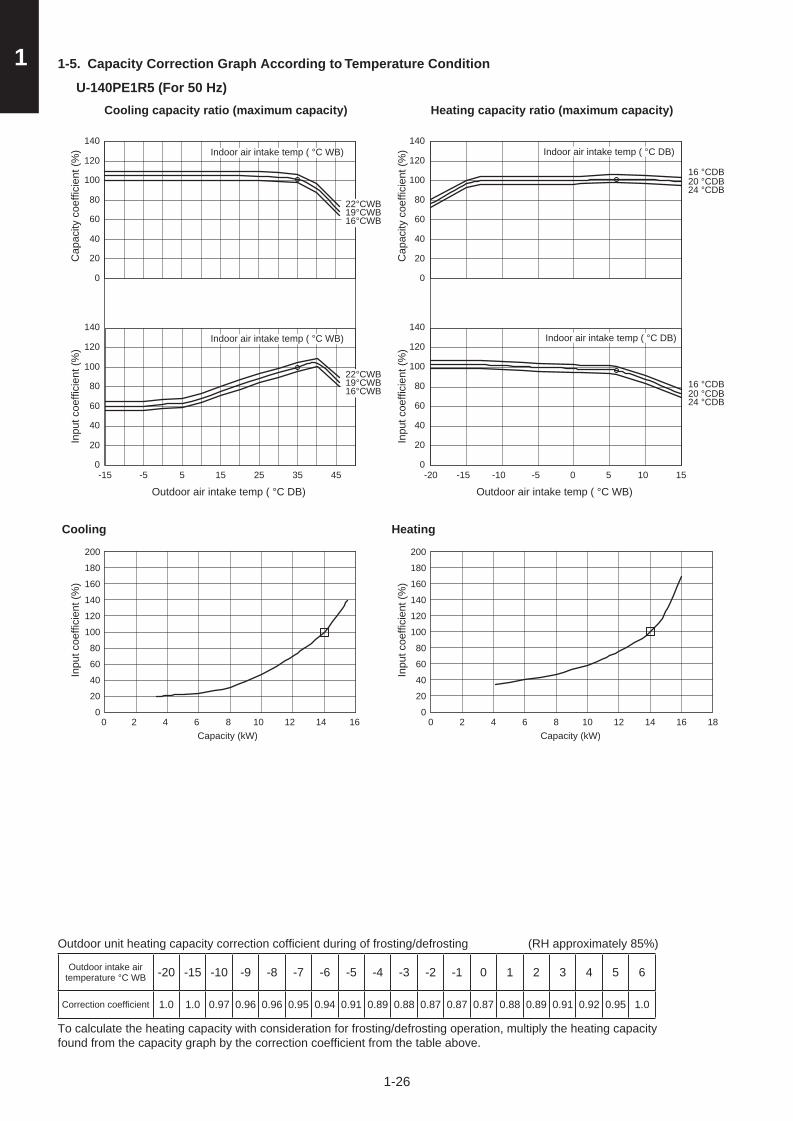
1 1-5. Capacity Correction Graph According to Temperature Condition
U-140PE1R5 (For 50 Hz)
Cooling capacity ratio (maximum capacity) Heating capacity ratio (maximum capacity)
Inpu
t coe
ffici
ent (
%)
Cap
acity
coe
ffici
ent (
%)
Outdoor air intake temp ( °C DB)
0
20
40
60
80
100
120
140
0
20
40
60
80
100
120
140
-15 -5 5 15 25 35 45
22°CWB19°CWB16°CWB
22°CWB19°CWB16°CWB
Indoor air intake temp ( °C WB)
Indoor air intake temp ( °C WB)
Inpu
t coe
ffici
ent (
%)
0
20
40
60
80
100
120
140
Outdoor air intake temp ( °C WB) -20 -15 -10 -5 0 5 10 15
Cap
acity
coe
ffici
ent (
%)
0
20
40
60
80
100
120
140
16 °CDB20 °CDB24 °CDB
16 °CDB20 °CDB24 °CDB
Indoor air intake temp ( °C DB)
Indoor air intake temp ( °C DB)
Cooling
Capacity (kW)0 2 4 6 8 10 12 14 16
Inpu
t coe
ffici
ent (
%)
0
20
40
60
80
100
120
140
160
180
200
Capacity (kW)0 2 4 6 8 10 12 14 16 18
Heating
Inpu
t coe
ffici
ent (
%)
0
20
40
60
80
100
120
140
160
180
200
Outdoor unit heating capacity correction cofficient during of frosting/defrosting (RH approximately 85%)
Outdoor intake air temperature °C WB -20 -15 -10 -9 -8 -7 -6 -5 -4 -3 -2 -1 0 1 2 3 4 5 6
Correction coefficient 1.0 1.0 0.97 0.96 0.96 0.95 0.94 0.91 0.89 0.88 0.87 0.87 0.87 0.88 0.89 0.91 0.92 0.95 1.0
To calculate the heating capacity with consideration for frosting/defrosting operation, multiply the heating capacity found from the capacity graph by the correction coefficient from the table above.
Sec1.indb 26 2012/03/07 17:29:58
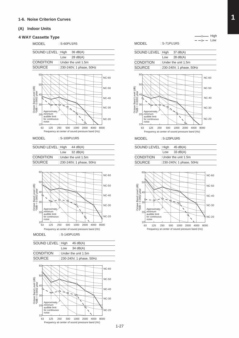
1-27
11-6. Noise Criterion Curves
(A) Indoor Units
LowHigh
Oct
ave
Ban
d Le
vel (
dB)
*0dB
= 0
.000
2 µb
ar
Frequency at center of sound pressure band (Hz)
10
20
30
40
50
60
63 125 250 500 1000 2000 4000 8000
NC-40
NC-60
NC-50
NC-30
NC-20
4 WAY Cassette Type
Approximate minimum audible limit for continuous noise
MODEL
SOUND LEVEL
CONDITIONSOURCE
: S-60PU1R5
: HighLow
36 dB(A)28 dB(A)
: Under the unit 1.5m: 230-240V, 1 phase, 50Hz
MODEL
SOUND LEVEL
CONDITIONSOURCE
: S-71PU1R5
: HighLow
37 dB(A)28 dB(A)
: Under the unit 1.5m
Oct
ave
Ban
d Le
vel (
dB)
*0dB
= 0
.000
2 µb
ar
Frequency at center of sound pressure band (Hz)
10
20
30
40
50
60
63 125 250 500 1000 2000 4000 8000
NC-60
NC-50
NC-40
NC-30
NC-20
Approximate minimum audible limit for continuous noise
: 230-240V, 1 phase, 50Hz
Oct
ave
Ban
d Le
vel (
dB)
*0dB
= 0
.000
2 µb
ar
Frequency at center of sound pressure band (Hz)
10
20
30
40
50
60
63 125 250 500 1000 2000 4000 8000
NC-40
NC-60
NC-50
NC-30
NC-20
Approximate minimum audible limit for continuous noise
MODEL
SOUND LEVEL
CONDITIONSOURCE
: S-100PU1R5
: HighLow
44 dB(A)32 dB(A)
: Under the unit 1.5m: 230-240V, 1 phase, 50Hz
Oct
ave
Ban
d Le
vel (
dB)
*0dB
= 0
.000
2 µb
ar
Frequency at center of sound pressure band (Hz)
10
20
30
40
50
60
63 125 250 500 1000 2000 4000 8000
NC-40
NC-50
NC-30
NC-20
NC-60
Approximate minimum audible limit for continuous noise
MODEL
SOUND LEVEL
CONDITIONSOURCE
: S-125PU1R5
: HighLow
45 dB(A)33 dB(A)
: Under the unit 1.5m: 230-240V, 1 phase, 50Hz
Oct
ave
Ban
d Le
vel (
dB)
*0dB
= 0
.000
2 µb
ar
Frequency at center of sound pressure band (Hz)
10
20
30
40
50
60
63 125 250 500 1000 2000 4000 8000
NC-40
NC-60
NC-50
NC-30
NC-20
Approximate minimum audible limit for continuous noise
MODEL
SOUND LEVEL
CONDITIONSOURCE
: S-140PU1R5
: HighLow
46 dB(A)34 dB(A)
: Under the unit 1.5m: 230-240V, 1 phase, 50Hz
Sec1.indb 27 2012/03/07 17:29:58

1-28
1 1-6. Noise Criterion Curves
(A) Indoor Units
Ducted TypeMODEL
SOUND LEVEL
SOURCE
: S-60PE1R5
: HIGH 43 dB(A) LOW 40 dB(A)
: 230-240V , Single Phase , 50Hz
CONDITION : Under the unit 1.5m
MODEL
SOUND LEVEL
SOURCE
: S-100PE1R5
: HIGH 48 dB(A) LOW 44 dB(A)
: 230-240V , Single Phase , 50Hz
CONDITION : Under the unit 1.5m
MODEL
SOUND LEVEL
SOURCE
: S-140PE1R5
: HIGH 51 dB(A) LOW 47 dB(A)
: 230-240V , Single Phase , 50Hz
CONDITION : Under the unit 1.5m
MODEL
SOUND LEVEL
SOURCE
: S-71PE1R5
: HIGH 45 dB(A) LOW 43 dB(A)
: 230-240V , Single Phase , 50Hz
CONDITION : Under the unit 1.5m
Sou
nd p
ress
ure
leve
l (dB
)(0
dB =
0.0
002
µbar
)
Frequency at center of sound pressure band (Hz)
HighLow
Frequency at center of sound pressure band (Hz)S
ound
pre
ssur
e le
vel (
dB)
(0dB
= 0
.000
2 µb
ar)
Sou
nd p
ress
ure
leve
l (dB
)(0
dB =
0.0
002
µbar
)
Frequency at center of sound pressure band (Hz)
Sou
nd p
ress
ure
leve
l (dB
)(0
dB =
0.0
002
µbar
)
Frequency at center of sound pressure band (Hz)
Sou
nd p
ress
ure
leve
l (dB
)(0
dB =
0.0
00 2
µbar
)
Frequency at center of sound pressure band (Hz)
10
20
30
40
50
60
10
20
30
40
50
60
10
20
30
40
50
60
10
20
30
40
50
60
10
20
30
40
50
60
63 125 250 500 1000 2000 4000 8000
63 125 250 500 1000 2000 4000 8000
63 125 250 500 1000 2000 4000 8000
63 125 250 500 1000 2000 4000 8000
63 125 250 500 1000 2000 4000 8000
NC-40
NC-50
NC-30
NC-20
NC-60
Approximate minimum audible limit for continuous noise
NC-40
NC-50
NC-30
NC-20
NC-60
MODEL
SOUND LEVEL
SOURCE
: S-125PE1R5
: HIGH 49 dB(A) LOW 45 dB(A)
: 230-240V , Single Phase , 50Hz
CONDITION : Under the unit 1.5m
Approximate minimum audible limit for continuous noise
NC-40
NC-50
NC-30
NC-20
NC-60
Approximate minimum audible limit for continuous noise
NC-40
NC-50
NC-30
NC-20
NC-60
NC-40
NC-50
NC-30
NC-20
NC-60
Approximate minimum audible limit for continuous noise
Approximate minimum audible limit for continuous noise
Sec1.indb 28 2012/03/07 17:29:58

1-29
11-6. Noise Criterion Curves
(B) Outdoor Units
MODEL
SOUND LEVEL
CONDITION
SOURCE
: U-60PE1R5
: Heating 50 dB(A)
: 1 m in front at height of 1.5 m
: 230-240V, 1 phase, 50Hz
Heating
MODEL
SOUND LEVEL
CONDITION
SOURCE
: U-60PE1R5
: Cooling 48 dB(A)
: 1 m in front at height of 1.5 m
: 230-240V, 1 phase, 50Hz
Cooling
Oct
ave
Ban
d Le
vel (
dB)
*0dB
= 0
.000
2 µb
ar
Oct
ave
Ban
d Le
vel (
dB)
*0dB
= 0
.000
2 µb
ar
Frequency at center of sound pressure band (Hz) Frequency at center of sound pressure band (Hz)
10
20
30
40
50
60
63 125 250 500 1000 2000 4000 8000
NC-60
NC-50
NC-40
NC-30
NC-20
10
20
30
40
50
60
63 125 250 500 1000 2000 4000 8000
NC-40
NC-60
NC-50
NC-30
NC-20
Approximate minimum audible limit for continuous noise
Approximate minimum audible limit for continuous noise
MODEL
SOUND LEVEL
CONDITION
SOURCE
: U-71PE1R5
: Heating 50 dB(A)
: 1 m in front at height of 1.5 m
: 230-240V, 1 phase, 50Hz
Heating
MODEL
SOUND LEVEL
CONDITION
SOURCE
: U-71PE1R5
: Cooling 48 dB(A)
: 1 m in front at height of 1.5 m
: 230-240V, 1 phase, 50Hz
Cooling
Oct
ave
Ban
d Le
vel (
dB)
*0dB
= 0
.000
2 µb
ar
Oct
ave
Ban
d Le
vel (
dB)
*0dB
= 0
.000
2 µb
ar
Frequency at center of sound pressure band (Hz) Frequency at center of sound pressure band (Hz)
10
20
30
40
50
60
63 125 250 500 1000 2000 4000 8000
NC-60
NC-50
NC-40
NC-30
NC-20
10
20
30
40
50
60
63 125 250 500 1000 2000 4000 8000
NC-40
NC-60
NC-50
NC-30
NC-20
Approximate minimum audible limit for continuous noise
Approximate minimum audible limit for continuous noise
Sec1.indb 29 2012/03/07 17:29:58

1-30
1 1-6. Noise Criterion Curves
(B) Outdoor Units
MODELSOUND LEVELCONDITIONSOURCE
: U-100PE1R5: Heating 52 dB(A): 1 m in front at height of 1.5 m: 230-240V, 1 phase, 50Hz
Heating
MODELSOUND LEVELCONDITIONSOURCE
: U-100PE1R5: Cooling 52 dB(A): 1 m in front at height of 1.5 m: 230-240V, 1 phase, 50Hz
Cooling
Oct
ave
Ban
d Le
vel (
dB)
*0dB
= 0
.000
2 µb
ar
Oct
ave
Ban
d Le
vel (
dB)
*0dB
= 0
.000
2 µb
ar
Oct
ave
Ban
d Le
vel (
dB)
*0dB
= 0
.000
2 µb
ar
Oct
ave
Ban
d Le
vel (
dB)
*0dB
= 0
.000
2 µb
ar
Frequency at center of sound pressure band (Hz)
Frequency at center of sound pressure band (Hz)
Frequency at center of sound pressure band (Hz)
Frequency at center of sound pressure band (Hz)
10
20
30
40
50
60
63 125 250 500 1000 2000 4000 8000
NC-60
NC-50
NC-40
NC-30
NC-20
10
20
30
40
50
60
63 125 250 500 1000 2000 4000 8000
NC-40
NC-60
NC-50
NC-30
NC-20
MODELSOUND LEVELCONDITIONSOURCE
: U-125PE1R5: Heating 53 dB(A): 1 m in front at height of 1.5 m: 230-240V, 1 phase, 50Hz
Heating
MODELSOUND LEVELCONDITIONSOURCE
: U-125PE1R5: Cooling 53 dB(A): 1 m in front at height of 1.5 m: 230-240V, 1 phase, 50Hz
Cooling
10
20
30
40
50
60
63 125 250 500 1000 2000 4000 8000
NC-40
NC-50
NC-30
NC-20
NC-60
10
20
30
40
50
60
63 125 250 500 1000 2000 4000 8000
NC-40
NC-60
NC-50
NC-30
NC-20
Approximate minimum audible limit for continuous noise
Approximate minimum audible limit for continuous noise
Approximate minimum audible limit for continuous noise
Approximate minimum audible limit for continuous noise
Sec1.indb 30 2012/03/07 17:29:58

1-31
11-6. Noise Criterion Curves
(B) Outdoor Units
MODELSOUND LEVELCONDITIONSOURCE
: U-140PE1R5: Heating 55 dB(A): 1 m in front at height of 1.5 m: 230-240V, 1 phase, 50Hz
Heating
MODELSOUND LEVELCONDITIONSOURCE
: U-140PE1R5: Cooling 54 dB(A): 1 m in front at height of 1.5 m: 230-240V, 1 phase, 50Hz
Cooling
Oct
ave
Ban
d Le
vel (
dB)
*0dB
= 0
.000
2 µb
ar
Oct
ave
Ban
d Le
vel (
dB)
*0dB
= 0
.000
2 µb
ar
Frequency at center of sound pressure band (Hz) Frequency at center of sound pressure band (Hz)
10
20
30
40
50
60
63 125 250 500 1000 2000 4000 8000
NC-60
NC-50
NC-40
NC-30
NC-20
10
20
30
40
50
60
63 125 250 500 1000 2000 4000 8000
NC-40
NC-60
NC-50
NC-30
NC-20
Approximate minimum audible limit for continuous noise
Approximate minimum audible limit for continuous noise
Sec1.indb 31 2012/03/07 17:29:58

1-32
1 1-7. Indoor Fan Performance
0
50
100
53525150
50
100
150
04030201
0
50
100
150
20.0 30.0 40.0 50.0 60.0 70.0
0
50
100
150
20.0 30.0 40.0 50.0 60.00
50
100
150
05040302
S-60PE1R5 P-Q curve
Ext
erna
l Sta
tic P
ress
ure
(Pa)
Air Volume (m3/min)
S-71PE1R5 P-Q curve
Ext
erna
l Sta
tic P
ress
ure
(Pa)
Air Volume (m3/min)
Limit line
Limit line
Limit line
Limit line
Limit line
Ext
erna
l Sta
tic P
ress
ure
(Pa)
Ext
erna
l Sta
tic P
ress
ure
(Pa)
Ext
erna
l Sta
tic P
ress
ure
(Pa)
S-100PE1R5 P-Q curve
Air Volume (m3/min)
S-125PE1R5 P-Q curve
Air Volume (m3/min)
S-140PE1R5 P-Q curve
Air Volume (m3/min)
Sec1.indb 32 2012/03/07 17:29:58

1-33
11-8. Airflow Distance Chart
4-Way Cassette Type
0
1
2
3
0
1
2
31.5m/s
1.0m/s
0.5m/s
0.3m/sVe
rtica
l air
flow
dis
tanc
e (m
)
Horizontal air flow distance (m)5 4 3 2 1 0 1 2 3 4 5
(Strong wind : Discharge angle approx.65°) (Room temperature approx.20°C)
0
1
2
3
0
1
2
31.5m/s
1.0m/s
0.5m/s
0.3m/s
Verti
cal a
ir flo
w d
ista
nce
(m)
Horizontal air flow distance (m)5 4 3 2 1 0 1 2 3 4 5
(Strong wind : Discharge angle approx.30°) (Room temperature approx.27°C)
0
1
2
3
0
1
2
320
2426
22
Verti
cal a
ir flo
w d
ista
nce
(m)
Horizontal air flow distance (m)5 4 3 2 1 0 1 2 3 4 5
(Strong wind : Discharge angle approx.30°) (Room temperature approx.27°C)
0
1
2
3
0
1
2
333
2724
30
Verti
cal a
ir flo
w d
ista
nce
(m)
Horizontal air flow distance (m)5 4 3 2 1 0 1 2 3 4 5
(Strong wind : Discharge angle approx.65°) (Room temperature approx.20°C)
S-60PU1R5 / 71PU1R5Heating : Distribution of wind velocity
Heating : Distribution of temperature
Cooling : Distribution of wind velocity
Cooling : Distribution of temperature
Sec1.indb 33 2012/03/07 17:29:58

1-34
1
S-100PU1R5 / 125PU1R5 / 140PU1R5Heating : Distribution of wind velocity
Heating : Distribution of temperature
Cooling : Distribution of wind velocity
Cooling : Distribution of temperature
0
1
2
3
0
1
2
320
2426
22
Verti
cal a
ir fl o
w d
ista
nce
(m)
Horizontal air flow distance (m)
(Strong wind : Discharge angle approx.30°) (Room temperature approx.27°C)
5 4 3 2 1 0 1 2 3 4 5
0
1
2
3
0
1
2
31.5m/s
1.0m/s
0.5m/s
0.3m/s
Verti
cal a
ir fl o
w d
ista
nce
(m)
Horizontal air flow distance (m)
(Strong wind : Discharge angle approx.65°) (Room temperature approx.20°C)
5 4 3 2 1 0 1 2 3 4 5
0
1
2
3
0
1
2
333
27
24
30
Verti
cal a
ir fl o
w d
ista
nce
(m)
Horizontal air flow distance (m)
(Strong wind : Discharge angle approx.65°) (Room temperature approx.20°C)
5 4 3 2 1 0 1 2 3 4 5
0
1
2
3
0
1
2
31.5m/s
1.0m/s
0.5m/s
0.3m/s
Verti
cal a
ir fl o
w d
ista
nce
(m)
Horizontal air flow distance (m)
(Strong wind : Discharge angle approx.30°) (Room temperature approx.27°C)
5 4 3 2 1 0 1 2 3 4 5
Sec1.indb 34 2012/03/07 17:29:58

1-35
11-9. Intaking Fresh Air of 4 Way cassette Type
Precautions Regarding External Air Intake (1) Ventilation Load Ensure that the design of the air-conditioner takes air-conditioning loads into consideration when external air
intake is involved.
(2) Restrictions on External Air Intake Ensure that the design conforms to the restrictions on air intake volume stipulated in accordance with the model
of the indoor unit and the intake method. Consideration must also be taken to mixed air content listed in (3) below without fail.
* If the air intake volume does not satisfy the required ventilation volume, air must be fed into the room separately with the use of a total heat exchanger or a fresh air processing air-conditioner, etc.
(3) Mixed Air The amount of external air intake must be set within the scope of the unit’s usage conditions when external air and
internal air is mixed together. This is especially important in the following cases, in which it is necessary to either feed external air into the room after it has been processed or reduce the amount of external air that is fed in.
1 When the external dew-point temperature is greater than the dry-bulb temperature of the air sucked into the unit.
Ensure that processing is performed so that the external dew-point temperature is lower than the temperature of the air sucked into the unit to prevent the risk of condensation building up.
2 In the case of low external temperatures. There are cases in which the temperature of mixed air is lower than the operating range of the unit if
excessive amounts of external air intake are used when the external temperature is low. This problem is to be solved by either feeding external air into the room after it has been processed or reducing the amount of external air that is fed in.
3 When used in combination with humidifiers External air must always be processed when the external air temperature reaches freezing point to prevent
the risk of the humidifier freezing.
(4) Arranging Ducts and Filters in the Field External air intake ducting must be arranged in the field. External
air filters must also be installed without fail in order to prevent the intake of dust and grit.
(5) Thermal Insulation for Ducts Ensure that all external air intake ducting is heat-insulated
without fail. Failure to observe this may result in the build-up of condensation.
(6) External Air Intake Coupling Ensure that the design for external air intake is coupled with the
fan blower operations of the indoor unit. There are cases in which the dust that accumulates in the filter is blown into the room if the external air is fed from the filter. There are also cases in which the noise of external air being fed into the room can be heard from the indoor unit if external air is forcibly fed when the booster fan or other components on the indoor unit are not operating.
(7) Booster Fan Selection Select the booster fan in accordance with the resistance of
the external air intake duct (diagram on the pressure loss characteristics of the air flow volume for flexible cylindrical ducts) and the resistance prevalent inside the unit (volume of external air fed and the resistance within the unit).
(8) Attaching the External Air Intake Flange
o100
o125
300.1
0.2
0.40.60.8
10
2030
1
2
46
50 100 200 300 500400
Flexible Cylindrical Duct
Pre
ssur
e Lo
ss (
Pa)
/Met
er
Airfl ow (m3/h)
Air Flow Volume for Flexible Cylindrical
Duct-Pressure Loss
Sec1.indb 35 2012/03/07 17:29:59

1-36
1• U1 Type
When an External Air Intake Flange (ø100) is in Use
External Air Intake Volume and Resistance and
Operation Noise Characteristics within the Unit
• Calculate the operation noise when external air is being fed by combining the noise when only external air is being fed as shown in the graph for operation noise characteristics and the operation noise of the unit as stipulated in the catalogue.
• The operation noise conforms to JIS standards and constitute measurements taken in an anechoic chamber 1.5 m directly beneath the indoor unit. Under normal circumstances, the values shown here are greater owing to the effects of surrounding noise and reverberation when the unit is actually installed.
With the External Air Intake Flange Attached
Res
ista
nce
with
in th
e U
nit (
Pa)
External Air Intake Volume (m3/h)
Noi
se w
ith o
nly
Ext
erna
l A
ir In
take
dB
(A)
Operation Noise (External Air Intake Only)
Duct (ø100) for Connecting the External Air Intake Flange
U1 Type
00
10
20
30
20
30
40
50
40
50
60
70
80
90
100
5 10 15 2018
Sec1.indb 36 2012/03/07 17:29:59

1-37
11-10. Electrical Wiring
■ General Precautions on Wiring (1) Before wiring, confirm the rated voltage of the unit as shown on its nameplate, then carry out the wiring closely following the wiring
diagram.
(2) Circuit breaker must be incorporated in the fixed wiring in accordance with the wiring regulations. The circuit breaker must be an approved 10-16 A, having a contact separation in all poles.
(3) To prevent possible hazards from insulation failure, the unit must be grounded.
(4) Each wiring connection must be done in accordance with the wiring system diagram. Wrong wiring may cause the unit to misoperate or become damaged.
(5) Do not allow wiring to touch the refrigerant tubing, compressor, or any moving parts of the fan.
(6) Unauthorized changes in the internal wiring can be very dangerous. The manufacturer will accept no responsibility for any damage or misoperation that occurs as a result of such unauthorized changes.
(7) Regulations on wire diameters differ from locality to locality. For field wiring rules, please refer to your LOCAL ELECTRICAL CODES before beginning.
You must ensure that installation complies with all relevant rules and regulations.
(8) To prevent malfunction of the air conditioner caused by electrical noise, care must be taken when wiring as follows:
● The remote control wiring and the inter-unit control wiring should be wired apart from the inter-unit power wiring.
● Use shielded wires for inter-unit control wiring between units and ground the shield on both sides.
(9) If the power supply cord of this appliance is damaged, it must be replaced by a repair shop designated by the manufacturer, because special-purpose tools are required.
■ Recommended Wire Length and Wire Diameter for Power Supply System
Indoor unit
Type(B) Power supply Time delay fuse or
circuit capacity2.5 mm2
U1, E1 Max. 130 m 10-16 A
Control wiring(C) Inter-unit
(between outdoor and indoor units)
control wiring
(D) Remote control wiring
(E) Control wiring for group control
0.75 mm2
(AWG #18)Use shielded wiring*
0.75 mm2
(AWG #18)0.75 mm2
(AWG #18)
Max. 1,000 m Max. 500 m Max. 200 m (Total)
NOTE* With ring-type wire terminal.
Sec1.indb 37 2012/03/07 17:29:59

1
1-38
■ Wiring System Diagrams
NOTE
(1) Refer to “Recommended Wire Length and Wire Diameter for Power Supply System” for the explanation of “A”, “B”, “C”, “D” and “E” in the above diagram.
(2) The basic connection diagram of the indoor unit shows the terminal boards, so the terminal boards in your equipment may differ from the diagram.
(3) Refrigerant Circuit (R.C.) address should be set before turning the power on.
(4) Regarding R.C. address setting, refer to the installation instructions supplied with the remote controller (optional). Auto address setting can be executed by remote controller automatically. Refer to the installation instructions supplied with the remote controller (optional).
L2
L1
U2
U1
L3
N
A L1L2L3N
U2
R2
U1
R1
R2
R1
L
N
U2
U1
2
1
D
C
B
LN
LN
2
1
B
E
C
L
N
A LN
2
1
N
L
Power supply230 – 240V ~50 Hz
Remote controllerWHT BLK
Power supply230 – 240V ~50 Hz
Power supply230 − 240 V ~50/60 Hz
Ground
Ground
Ground
Ground
* 3-phase model connections
* Single-phase model connectionsGround
Ground
Power supply400 − 415 V, 3 N~, 50 Hz
Outdoor unit (3-phase) INV unit
Outdoor unit (single-phase) INV unit
Ground
Indoor unit (No. 1)
Indoor unit (No. 2)
L N U1 U2 R1 R2
6P terminal board
Power supply
Unit control line
Remote control
line
U1 Type
R1 R2 U1 U2 N L
Remote controller line
Unit control wiring
Power supply
E1 Type
Sec1.indb 38 2012/03/07 17:30:00

1
1-39
Stranded wire
Ring pressure terminal Screw and
Special washer
Ring pressure terminal
Terminal plate
Ring pressure terminal
ScrewSpecial washer
Wire
Wire
Insulation tape
8 mm
Insulation tape
Shield mesh
Shield mesh
Str
ip 1
0 m
m
Fig. 1-1 Fig. 1-2
Fig. 1-3
Fig. 1-4
Fig. 1-5
Fig. 1-6
■ Wiring samples
U1 type
Use this screw when connecting the shield for the Inter-unit control wiring to ground.
Functional ground screw (External Electronic Expansion Valve Kit and Schedule Timer)
Protective ground screw (External Solenoid Valve Kit for 3WAY)
Power Supply
Clamping Clip
*1 Fasten tightly.
Inter-unit Control Wiring
Clamper*1
Remote Control Wiring
Clamper*1
Clamper*1
How to connect wiring to the terminal
■ For stranded wiring(1) Cut the wire end with cutting pliers,
then strip the insulation to expose the stranded wiring about 10 mm and tightly twist the wire ends. (Fig. 1-1)
(2) Using a Phillips head screwdriver, remove the terminal screw(s) on the terminal plate.
(3) Using a ring connector fastener or pliers, securely clamp each stripped wire end with a ring pressure terminal.
(4) Place the ring pressure terminal, and replace and tighten the removed terminal screw using a screwdriver. (Fig. 1-2)
■ Examples of shield wires(1) Remove cable coat not to scratch braided shield. (Fig. 1-3)
(2) Unbraid the braided shield carefully and twist the unbraided shield wires tightly together. Insulate the shield wires by covering them with an insulation tube or wrapping insulation tape around them. (Fig. 1-4)
(3) Remove coat of signal wire. (Fig. 1-5)
(4) Attach ring pressure terminals to the signal wires and the shield wires insulated in Step (2). (Fig. 1-6)
E1 type
R1 R2 U1 U2 N L
Power supply
Shielded wire ground
Unit control wiring
Remote controller line
Earth
Sec1.indb 39 2012/03/07 17:30:00

1
1-40
H1
1-11. Installation Instructions
Outdoor Unit
Tubing Length
(A) Single type
Keep refrigerant tubing between the indoor and outdoor units as short as possible.
The length of the refrigerant tubes between the indoor and outdoor units are limited by the elevation difference between the 2 units. During tubing work, try to make both the tubing length (L) and the difference in elevation (H1) as short as possible.
Single
Main tubing L
Sec1.indb 40 2012/03/07 17:30:01

1
1-41
Check of limit densityWhen installing an air conditioner in a room, it is necessary to ensure that even if the refrigerant gas accidentally escapes, its density does not exceed the limit level. If the density might exceed the limit level, it is necessary to set up an opening between it and the adjacent room, or to install mechanical ventilation which is interlocked with a leak detector.
(Total refrigerant charged amount: kg)(Min. indoor volume where the indoor unit is installed: m³) < Limit density 0.3 (kg/m3)
The limit density of refrigerant which is used in this unit is 0.3 kg/m3 (ISO 5149).
The shipped outdoor unit comes charged with the amount of refrigerant fi xed for each type, so add it to the amount that is charged at the fi eld. (For the refrigerant charge amount at shipment, refer to the unit’s nameplate.)
Minimum indoor volume & fl oor area relative to the amount of refrigerant are roughly as given in the following table.
CAUTIONPay special attention to any location, such as a basement or recessed area, etc. where leaked refrigerant can collect, since refrigerant gas is heavier than air.
1013.5
27.0
40.5
54.0
67.5
81.0
94.5
108
121.5
135
5
10
15
20
25
30
35
40
45
50m3m2
20 30 40 kg
Min
. ind
oor
fl oor
are
a(w
hen
the
ceili
ng is
2.7
m h
igh)
Total amount of refrigerant
Range below the density limit of 0.3 kg/m3 (Countermeasures not needed)
Range above the density limit of 0.3 kg/m3 (Countermeasures needed)
Min
. ind
oor
volu
me
CAUTION
Sec1.indb 41 2012/03/07 17:30:01

1
1-42
SELECTING THE INSTALLATION SITE
Outdoor Unit
ACCESSORIES SUPPLIED WITH OUTDOOR UNITThe following parts are supplied as accessories with each outdoor unit. Check that all accessory parts are present before installing the outdoor unit.
Part name Q’ty Figur Remarks Part name Q’ty Figur Remarks
Protective bushing 2 1For protecting electrical
wires
Banding strap 4 For tying electrical wires together
Installation Instruction
SELECT THE OUTDOOR UNIT INSTALLATION LOCATION
Warning
Be careful when picking up and moving the indoor and outdoor units. Get a partner to help, and bend your knees when lifting to reduce strain on your back. Sharp edges or thin aluminum fins on the air conditioner can cut your fingers.
1. Install the unit once you have checked that the installation location matches the following conditions. ● A location with sufficient ventilation. ● Possibly a location that is sheltered from rain or direct sunlight and is well-ventilated so that hot and cool air does not build up. ● A location where the area around the discharge is not exposed to animals or plants which could adversely affect the release of hot
or cool air from the unit. ● A location where the discharge and operation noise will not be a nuisance to the neighbours. ● A location that can support the product’s weight or vibrations and secured for horizontal installation wherever possible. ● A location that does not obstruct the air discharge or intake. ● A location where there is no danger of flammable or corrosive gas leaks. ● A location that provides space for installation and service. ● A location that allows the pipe and cable length fixture for internal and external connections.2. Refer to the diagram below for the installation location which is exposed to strong wind. ● If a strong wind of more than 5 m/sec blows to the area directly in front of the discharge, the outdoor unit’s air flow is reduced and
the outflow may re-enter (short circuit) causing the following outcome:“Reduced capacity”, “Increased frost formation during heating” or “Operation stopped due to increased pressure”. Should an exceptionally strong wind blow to the area directly in front of the discharge of the outdoor unit; there is the risk of damage due to the fan’s high-speed reverse rotation.
● If the direction of the prevailing wind is known when operating the unit, place the unit at an appropriate angle to the wind’s direction so that the discharge faces towards a building or a wall.
Air Intake
Strong wind
Intake side
Wall / Standing outer wall
Strong wind
Selecting the location for installation and service.
3. If installing at locations prone to snowfall, install the unit as high as possible with suitable roofing which shelters the unit from snow.4. Avoid installing the unit in locations where there are petroleum products (such as machine oil), saline content (such as coastal
areas), sulphurous gas and where high frequency noise is generated.5. Place the indoor and outdoor unit, power cords and indoor/outdoor unit connection cables at a minimum distance
of 1 meter or more away from televisions and radios. This is to avoid interference to picture and/or sound. (However, depending on the electromagnetic waves, noise interference may still occur even with the 1 meter separation.)
6. For restaurants and kitchens, avoid installing at locations which draws oil and steam.Plastic parts can deteriorate from droplets of oil and steam or it can cause falling parts or water leakage.
7. Avoid installing at the location where cutting oil mist or iron powder is present.8. If there is an immense voltage fluctuation due to the location’s problem, ensure to split the power supply.9. When installing the product in a place where it will be affected by typhoon or strong wind such as wind blowing between buildings, including
the rooftop of a building and a place where there is no building in surroundings, fix the product with an overturn prevention wire, etc.10. Ensure to assign several people or use a mechanical lift, etc. to transport the unit.
SELECTING THE LOCATION FOR INSTALLATION SERVICE
(A) If there are obstacles at the intake
• If the upper part is open ① For separate installation location
• Only if there are obstacles at the intake • If there are obstacles on both sides
More than 100
Mor
e th
an
100
Morethan 200
Morethan 500
Sec1.indb 42 2012/03/07 17:30:01

1
1-43
• If there are obstacles above the unit
① For separate installation location
• Only if there are obstacles at the intake • If there are obstacles on the intake and the other side
More than
100
Mor
e th
an 1
000
Less than 500
Less than 500
Mor
e th
an 1
000
Mor
e th
an
200
Morethan 500 More
than 200
(B) If there are obstacles at the discharge
• If the upper part is open ① For separate installation location
More than 300
• If there are obstacles above the unit ① For separate installation location
More t
han 3
00
Mor
e th
an 1
000
Less than 500
(C) If there are obstacles on both the intake and discharge
Pattern 1 If there is an obstacle that is higher than the unit on the intake side. (There is no limit to the height of the obstacle above the discharge.)
• If the upper part is open ① For separate installation location
More than
300
More than
100
p
• If there are obstacles above the unit① For separate installation location
• The dimensions for H, A and L are shown in the following table.
L A
L H0 < L 1/2 H 3001/2H < L H 500
H < L Install a pedestal or mount so that L H
• Cover the bottom part of the pedestal or mount so that air does not go through it.
Less than 500
Mor
e th
an
1000
More than
200
Sec1.indb 43 2012/03/07 17:30:01

1
1-44
Pattern 2 If there is an obstacle that is higher than the unit on the discharge side. (There is no limit to the height of the obstacle above the discharge.)
• If the upper part is open ① For separate installation location
More
than 100
More
than 300
• If there are obstacles above the unit① For separate installation location
• The dimensions for H, A and L are shown in the following table.
AL H 100H < L Install a pedestal or mount so that L H
• Cover the bottom part of the pedestal or mount so that air does not go through it.
Less than 500
Mor
e th
an
1000
More than
300 Less than 500
■ HOW TO INSTALL THE OUTDOOR UNIT
● Transporting 1. Transport the outdoor unit in its original packaging as close as possible to the installation location.
2. In the event that the unit needs to be lifted or suspended, use a rope or belt and use cloth or wood as padding to avoid damaging the unit.
3. Use the side handles to carry the unit and be careful not to touch the fan with your hand or any objects.
● Installation 1. Read the “SELECTING THE INSTALLATION SITE” thoroughly before installing the outdoor unit.
2. When installing to a concrete or solid surface, use M10 or a W 3/8 bolts and nuts to secure the unit. Ensure that it installed upright on a horizontal plane. (Use an anchor bolt for the installation as shown in the diagram below.)
3. Avoid installing on the slanted roof.
4. In the even where the roof is at risk of receiving oscillations or vibrations, secure the unit with a seismic isolating mount or vibration absorbing rubber.
5. The drain water will be discharged from the unit during heating or defrosting operation mode. Select an appropriate location with good drainage system. (In the winter, there is risk of slipping due to freezing, and depending on the installation set up there is risk of drain water running overhead.)
Please consult us if installing drain elbows. In cold regions (where the outdoor temperature can drop to below 0° for 2 to 3 consecutive days), the drain water may freeze and may prevent the fan from operating. For this case, do not use the drain elbow.
Less
than
25
Anchor bolt length
(Unit: mm)
Less
than
25
Anchor bolt length
(Unit: mm)
(Unit: mm)
(Anc
hor
pitc
h)
19.5
380.
5130
39
170
220 200 160 321
620 150
(Anchor pitch)
Anchor bolt position
(Unit: mm)
(Anc
hor
pitc
h)
19.5
380.
5130
39
170
220 200 160 321
620 150
(Anchor pitch)
Anchor bolt position
Sec1.indb 44 2012/03/07 17:30:02

1
1-45
REFRIGERANT INSTALLATION
For indoor unit refrigerant piping installation, refer to the Installation Instructions that comes with that indoor unit.
Do not reuse existing piping, install new piping.
1. Precautions during refrigerant installation.
● Use clean pipes with no dust inside.The pipe may corrode with the presence of fluorine dust which will adversely affect the refrigerant piping system due to deterioration of the refrigerant oil, etc.
● This unit is specifically for R410A. Ensure to adhere to the following items and install accordingly:• Use pipe cutters and flaring tools which are specially designed for use with R410A.
• When connecting with flaring tools, coat the flare section with ether-based oil.
• Ensure to use flare nuts supplied with the unit when connecting this unit.
• Only for storing or for open pipes.
• Set the lower limit of the allowable pipe length to 7.5 m. If the pipe is shorter than 7.5 m, the refrigerant may become overfilled and a problem such as abnormal high pressure could occur.
2. The local pipes can protrude from any four directions.
● Make holes in the pipe panel for the pipes to penetrate it and lay the pipes accordingly.
• It is recommended to apply additional substance to the cut area for anti-rust protection.
● Ensure to install pipe panels to prevent rain water from getting into the unit.
● Close the gap at the pipe connected area with putty or heat insulator (locally supplied).
• If an insect or small animal enters the outdoor unit, there is the risk of shorting in the product electronic casing.[Remove the front panel](1) Remove the 2 mounting screws.(2) Slide the front panel using your hands downwards to release the pawls.
Then remove by pulling the panel towards you.
Front panel
Mounting screws for the front panel
Reardirection
Sideways direction
Rear piping panel
Front piping panel
Downward direction
Front direction
Putty or heat insulator (locally
supplied)
Piping
Prevention measures to avoid small animals from entering
Front panel
Mounting screws for the front panel
Reardirection
Sideways direction
Rear piping panel
Front piping panel
Downward direction
Front direction
Putty or heat insulator (locally
supplied)
Piping
Prevention measures to avoid small animals from entering
Sec1.indb 45 2012/03/07 17:30:02

1
1-46
Precautions when operating the 3-way valve for piping installation
● Do not open the 3-way valve until the piping installation is completed.
• It is closed during shipment.
• During installation the side panel may warp if only the flare nut is loosened and tightened with a torque wrench. As a result, always be sure to secure to the hexagonal part of the 3-way valve with a spanner, or other tool.
● Refer to the following table for the tightening torque of the 3-way valve flare nuts.
• If the nuts are over tightened, they may cause the flares to break or leak.
● Do not add additional force to the valve’s cover.
• Using spanners on the cover or valve itself (other than the hexagonal parts) may cause gas leakage.Avoid using spanners on the cover or parts other than the hexagonal part of the valve.
Service port
Hexagonal part of the valve
Valve shaft
Valve cap
Flare nut
Spanner(Secure) Torque
wrench
● During the cooling mode operation under low ambient pressure, the low pressure side of the valve can be prone to freezing. Secure the flare nut (shared gas side / liquid side) section of the valve with a silicone sealing agent to prevent this from occurring.
Silicone sealing agent(Ensure not to leave any holes)
• Use an Allen wrench (Size 4 mm or 6 mm). Direction to open
[3-way valve operation method]
Opening : Open the cover and turn the Allen wrench counter-clockwise until it stops.
Closing : Open the cover and turn the Allen wrench clockwise until it stops.
Precautions for handling the valve cap
● Ensure not to scratch the inner surface of the valve or the end of the valve shaft.
• Once adjustments to the valve are completed, ensure to tighten the valve cap according to the prescribed torque.
Precautions for handling the service ports
● Use a push-rod with a charge hose.
• Once adjustments to the valve are completed, ensure to tighten the valve cap according to the prescribed torque.
Precautions for connecting the pipes
● Ensure that the pipes do not come into contact with the compressor’s bolts or exterior panel.
● There is a risk of condensation from the 3-way valve coming out between the insulation material and the indoor unit’s piping when you install the outdoor unit above then the indoor unit. Ensure to caulk the connection parts.
Precautions for insulation installation Maximum temperature limit of gas or liquid piping exceeds 120°C
● In high humidity environment, reinforce the insulation material for the refrigerant piping. Failure to do so may result in condensation on the surface of the insulation material.
● Use materials with good heat-resistant properties as the heat insulator for the pipes. Ensure to insulate both the gas side and liquid side pipes.If the pipes are not adequately insulated, condensation and water leakages may occur.
● Ensure that the current insulation covers the pipes up to the unit’s connecting part.If the piping is exposed, it may cause condensation or burn (when touch the pipe).
Valve size Tightening torque
ø9.5220.6N•m~28.4N•m
(2.1kgf•m~2.8kgf•m)
ø15.8848.0N•m~59.8N•m
(4.8kgf•m~6.0kgf•m)
Valve size Tightening torque
ø9.5220.6N•m~28.4N•m
(2.1kgf•m~2.8kgf•m)
ø15.8848.0N•m~59.8N•m
(4.8kgf•m~6.0kgf•m)
Tightening torque10.7N•m~14.7N•m
(1.1kgf•m~1.5kgf•m)
Tightening torque10.7N•m~14.7N•m
(1.1kgf•m~1.5kgf•m)
Caulking treatment, etc.
Insulationmaterial
Piping Caulking treatment, etc.
Insulationmaterial
Piping
Sec1.indb 46 2012/03/07 17:30:02

1
1-47
Precautions for flare nut installation
● Dimensions when adding flare nuts and the tightening torque
Piping size Tightening torque Flare section dimensions A Flare confi guration
ø6.3514.2N•m ~ 17.2N•m
(1.4kgf•m ~ 1.7kgf•m)8.7 ~ 9.1
90°
± 2
°45
° ±1
°
ø9.5232.7N•m ~ 39.9N•m
(3.3kgf•m ~ 4.0kgf•m)12.8 ~ 13.2
ø12.749.5N•m ~ 60.3N•m
(5.0kgf•m ~ 6.0kgf•m)16.2 ~ 16.6
ø15.8868.0N•m ~ 75.5N•m
(6.8kgf•m ~ 7.6kgf•m)19.3 ~ 19.7
After piping connection has completed, ensure there is no gas leakage.
● When tightening the flare nut, coat the flares (inner surface only) with refrigerant oil on the flares.Firstly, screw in 3-4 turns by hand.
Ensure not to get oil on the screw part.Refrigerant oil used is ether-based.
● Once the piping connections are completed, perform leakage inspection using nitrogen gas.
VACUUM PURGING
● Once the piping connections are completed, perform leakage inspection using nitrogen gas (leak tightness test) using the 3-way valve for the outdoor unit and then close it.(Test the pressure with 3.8 MPa)
● Ensure to use a vacuum pump (with a back-flow prevention device) for inside the refrigerant system.
● Vacuuming process will take place after the leak test.
REGARDING REFRIGERANT FILLINGPrecautions during refrigerant filling
● Ensure to fill only with liquid refrigerant when refilling. If gas refrigerant is filled, the refrigerant composition will not be balanced and will cause abnormal operation.
● If using cylinders as shown in the bottom left diagram; without a siphon tube inside, turn it upside down and use it. (It is recommended to use the manifold with the side glass.)
Cylinder with a siphon tube
Liquid refrigerant
Siphon tube
Cylinder Cylinder
Gas refrigerant
PossibleNot possible
Liquid refrigerant
● Use tools that are designed specifically for R410A, for pressure resistance and to prevent mixing impurities.
● Fill the refrigerant from the 3-way valve’s service port on the liquid-side.
For filling and replacing all refrigerant (For refilling due to a leak)
● For refilling refrigerant, first collect all residual refrigerant and after vacuum dehydration using the vacuum pump. Refill the refrigerant according to the prescribed amount stated on the placard affixed to this unit.
Precautions after the pipes’ connection have completed
● Ensure to open the 3-way valve after completing the piping installation, leak test and vacuuming. If it is closed during operation, it can lead to compressor failure.
Charging with refrigerant
● At the time of shipment from the factory, this unit is charged with enough refrigerant for an equivalent pipe length of 30 m. If the equivalent pipe length used will be 30 m or less, no additional charging will be necessary.
● If the equivalent pipe length will be between 30 and 50 m, charge with additional refrigerant according to the equivalent length given in the table below.
● For standard type
Additional charging amount Equivalent length Minimum lengthU-60/71P 50 g/m 50 m 5 mU-100/125/140P 50 g/m 75 m 5 m
Application for ether-based oilApplication for ether-based oil
Outdoor unit
3-way valve
Indoor unit
Use nitrogen gas for the leak tightness test.Using fl ammable gas can cause an explosion.
Pressuremeter
Nitrogen Refrigerant meter
Vacuum pump
Outdoor unit
3-way valve
Indoor unit
Use nitrogen gas for the leak tightness test.Using fl ammable gas can cause an explosion.
Pressuremeter
Nitrogen Refrigerant meter
Vacuum pump
Sec1.indb 47 2012/03/07 17:30:02

1
1-48
● Pump down operation
● Operate the pump down according to the following procedures.
Procedure Notes1. Confi rm the valve on the liquid side and the gas
side is surely open.2. Press the PUMP DOWN switch on outdoor
printed board for 1 second or more.Perform the cooling operation for fi ve minutes or more.
3. Shut the valve on the liquid side surely.When the valve is shut halfway, the compressor is occasionally damaged.
ELECTRICAL WIRING
Warning
The units must be connected to the supply cables for fi xed wiring by qualifi ed technician.Feed the power source to the unit via a distribution switch board designed for this purpose, the switch shoulddisconnected all poles with a contact separation of at least 3 mm.When the supply cable is damaged, it must be replaced by qualifi ed technician.Be sure to install a current leakage breaker, main switch and fuse to the main power supply, otherwise electricshocks may result.Be sure to connect the unit to secure earth connection.If the earthing work is not carried out properly, electric shocks may result.Wiring shall be connected securely by using specifi ed cables and fi x them securely so that external force ofthe cables may not transfer to the terminal connection section.Imperfect connection and fi xing leads to fi re, etc.
● Ensure to connect the electrical cable connections and clamp the wires securely to the terminal connections using cord clamps so that no undue force is placed on the wires (power source cable, indoor/outdoor connection cables, earth lead wire).
● Do not install a phase advance capacitor for power factor improvement. (It does not improve the power factor and will cause abnormal overheating.)
● Do not bind the excess cables together and place them inside this unit.● Protect the electrical cable with the protective bushing provided so that the cables do no get damaged on the knock hole or etched
portions. If there is space between the electrical cables and the protective bushing occurs, seal it accordingly.● Tie the cables with the provided binding strap so that they do not touch the compressor and the pipes.● When setting up the cables, inside of unit install properly so that the front panel will not lift up. Make sure that front panel mount
correctly.● Use a round type terminal with an insulation sleeve for connecting to the terminal block.● Use the appropriate screwdriver for tightening the terminal screws. Small sized
screwdriver damages the head of the screw and cannot tighten it properly. ● There is risk of damaging the screw if the terminal screw is over tightened.
Tighten with the appropriate torque.
Screw diameter name Tightening torque N•cm (kgf•cm)M4 157 ~ 196 (16 ~ 20)M5 196 ~ 245 (20 ~ 25)
● Direction to pull out wires
Back direction
Sideways directionFront direction
Seal wiring holes after wiring using included protection bush.(other holes are for connecting conduit pipe)
● Earth lead wire set up
The earth lead wire shall be longer than other lead wires as shown in the figure for electrical safety in case it slips out of the cord from the anchorage.
● Be sure to connect the wires correctly to terminal board with connecting the crimp type ring terminal to the wires.
● If connecting two separate wires to a single crimped terminal, place the two crimped terminal wires together as shown in Fig. A. (If the arrangement shown in Fig. B is used, poor contacts or contact damage may result.)
SG
Insulate the terminal section with insulation sleeves.
Cord clamp
Cord clamp
Controlterminal block Power supply
terminal block
Earth lead wire
Tying band(Standardaccessories)
Firmly secure the power supply cable, the internal/external connections and earth wire.
Tie the insulation pipes so that the power supply cable, control wires, and earth lead wire do not come into contact with the compressor and/or the exposed pipes.
Fig. A (OK) Fig. B (not OK)Fig. A (OK) Fig. B (not OK)
Sec1.indb 48 2012/03/07 17:30:02

1
1-49
LN
U1U2R1R2
L1L2L3N
U1U22
SG
1
SG
LN
U1U2R1R2
LN
U1U22
SG
1
SG
Outdoor unit Outdoor unit
Circuit breaker Circuit breaker Circuit breakerCircuit breaker
)~V042/032( ylppus rewoP)~V042/032( ylppus rewoP)~N3 V514/004( ylppus rewoP)~V042/032( ylppus rewoP
Earth Earth
Earth
Earth
Wired remote controller
Wired remote controller
Indoor unit Indoor unit
Control cable Control cable
Switch hctiwShctiwSSwitch
OUTDOOR UNIT/3-PHASE MODEL OUTDOOR UNIT/SINGLE-PHASE MODEL
This equipment complies with EN/IEC 31000-3-12 provided that the short-circuit power Ssc is greater than or equals to 2 kVA at the interface point between the user’s supply and the public system. It is the responsibility of the installer or user of the equipment to ensure; by consultation with the distribution network operator if necessary that the equipment is connected only to supply with a short-circuit power Ssc greater than or equals to 2 kVA.
Ssc : Short circuit powerSG : Shows the earth for the shielded cable.
Model name Power suppMaximum electric
current1
Control cable2
Ssc
U-60PE1R5 230/240V~ 18 A 0.75 mm² 4050 kVAU-71PE1R5 230/240V~ 18 A 0.75 mm² 4050 kVA
U-100PE1R5 230/240V~ 25 A 0.75 mm² 6000 kVAU-125PE1R5 230/240V~ 28 A 0.75 mm² 6000 kVAU-140PE1R5 230/240V~ 30 A 0.75 mm² 6000 kVA
● Electrical work should be handled by Certificated Electrical work personnel by following “Technical standard of electric installation” and “Regulated regulations of nation”.
● Adjust wire size, length, earth leakage breaker, and fuse capacity according to each country’s Wiring regulations.● If capacity of power supply circuit and enforcement are not enough, it can causes the electric shock and a fire.
NOTEUse the standard power supply cables for Europe (such as H05RN-F or H07RN-F which conforms to CENELEC (HAR) ratingspecifications) or use the cables based on IEC standard. (245 IEC57, 245 IEC66)
1 Use a shielded cable for the control cable. Overall extension less than 500 m
For the shield part of the shielded cable, twist the end out, crimp it with a round terminal, and connect it to the SG screw.After crimping it with a round terminal, wrap it with insulating tape so thereare no spaces and adjust it so the shield part does not touch any live parts.
CautionBe sure that the shield part of the shielded cable doesnot touch the terminal block or any live parts.Failure to do so may lead to electric shock or fire.
Crimp the round terminal
Wrap it well with insulating tape so there are no spaces.Shield part
Crimp the round terminal
Wrap it well with insulating tape so there are no spaces.Shield part
Sec1.indb 49 2012/03/07 17:30:03

1
1-50
PRECAUTIONS REGARDING TEST RUNCheck Before Test Run
Content check
Power supply cableIndoor/outdoor connection wireEarth wire
● Is the wire set up and connected as described in the instructions? Check for any phase sequence.
● Are the wire connection’s screws loose?● Is the open and close device / leakage breaker installed? ● Is the power supply cable’s thickness and length appropriately measured as described in
the instructions?● Is it earthed (grounded)?● Check that the insulation resistant value is more than 1 MΩ.
Use the 500 V mega-testers to measure the insulation. Do not use the mega-tester for any other circuit except for voltage of 220 V to 240 V.
● Are the wire connections for the indoor/outdoor units connected as described in the instructions? Are there any looped wires?
Refrigerant pipe ● Is the piping installed as described in the instructions?● Are the pipes sizes appropriate?● Does the pipe’s length adhere to the specifications?● Is the branch pipe slant being appropriately done as described in the instructions?● Was vacuum removal sufficiently carried out?● Was the leak tightness test carried out with nitrogen gas? Use the testing pressure of
3.8 MPa.● Is the piping insulation material appropriately installed? (Insulation material is necessary for
both gas and liquid piping.)● Is the 3-way valve for the liquid side and gas side open?
● Always be sure to use a properly insulated tool to operate the short-circuit pin on the circuit board. (Do not use your finger.)
● Never switch the power supply ON until the installation has completed.
● Supply electrical current through all indoor units and check the voltage.
● Supply electrical current through all the outdoor units and check each inter-phase voltage.
● Before the test run, ensure to check that the 3-way valve is open. Operating while the valve is closed causes the compressor to fail.
Test Run Procedure
● If there are duplicated system addresses, or if the settings for the Nos. of the indoor units are not consistent, an alarm will occur and the system will not start.
● Switch on both indoor and outdoor unit.
● Short-circuit CHK pin on the outdoor main PCB.Do not remove CHK pin until test run is completed.Removing CHK pin stops test run.
● Short-circuit RUN pin on the outdoor main PCB for one second or longer.Factory setting is cooling operation mode and cooling operation test run starts.If heating operation starts, short-circuit both right side and centre of the MODE pin (centre and COOL) for one second or longer.
● Ensure to conduct a test run. In addition, be sure to run the cooling operation test run for at least 20 minutes before starting the heating operation test run.
● To conduct heating operation test run, short-circuit left side and centre of the MODE pin (centre and HEAT) for one second or longer.
● Removing CHK pin’s short-circuit stops test run.
● For the test run using remote controller please see Installation Instructions included with the remote controller.
Sec1.indb 50 2012/03/07 17:30:03

1
1-51
RUN pin MODE pin
Outdoor main PCB
CHK pin
*MODE pin: factory setting is cooling operation mode.
CHECKS AFTER INSTALLATION HAVE COMPLETED
● Check the following items after completing installation. Is there a short circuit with the intake air flow? Is the insulation secure? (Refrigerant piping) Are there any errors with the wiring? Are the terminal screws loose? Tightening torque (Unit: N•cm {kgf•cm})M4… 157-196 {16-20}, M5... 196-245 {20-25}.
Is the drain water flowing smoothly? Is the insulation material properly installed? Is the earth wire securely connected? Is the front panel and the indoor unit air conditioner firmly fixed and was the installation completed without any leakage from the refrigerant?
Are the indoor and outdoor units secured firmly installed with bolts at secured locations?
REGARDING DELIVERY TO THE CUSTOMER
● Request the customer to review the instruction manual and explain the operating method for the product.● In addition, it is also recommended that regular inspection checks are agreed upon for maintenance.
User inspection places
Serviceman inspection places
• Filter and grill cleaning• Exterior cleaning• Check the operating status• Clean the drain pan or things related to the water discharge• Heat exchanger cleaning
Refer to the installation instruction manual provided with the indoor unit for the specifi cations on the indoor unit installation.
Sec1.indb 51 2012/03/07 17:30:03

1
1-52
■ HOW TO INSTALL THE INDOOR UNIT
■ 4-Way Cassette Type (U1 Type)
Preparation for SuspendingThis unit uses a drain pump. Use a carpenter’s level to check that the unit is level.
Suspending the Indoor Unit(1) Fix the suspension bolts securely in the ceiling using
the method shown in the diagrams, by attaching them to the ceiling support structure, or by any other method that ensures that the unit will be securely and safely suspended.
(2) Follow the diagram, Indoor Unit View from top and Table below to make the holes in the ceiling.
Table Unit: mmLength
Type A B C D
60, 71, 100, 125, 140
786 745 860 to 910 860 to 910
(3) Determine the pitch of the suspension bolts using the supplied full-scale installation diagram. The diagram and table below show the relationship between the positions of the suspension fitting, unit, and panel. Use the nut (field supply) and washer (supplied) for upper and lower position of the suspension lug.
Hole-in-anchorHole-in-plug Concrete Insert
Suspension bolt (M10 or 3/8")(field supply)
Note: For DC Fan Tap Change Procedure for 4-Way Cassette, see Others.
Indoor UnitView from top
B (
susp
ensi
on b
olt p
itch)
A (suspension bolt pitch)
C (ceiling opening dimension)
D (
ceili
ng o
peni
ng d
imen
sion
)
SELECTING THE INSTALLATION SITE (U1 Type)
Indoor Unit
AVOID:
● areas where leakage of flammable gas may be expected.
● places where large amounts of oil mist exist.
● direct sunlight.
● locations near heat sources which may affect the performance of the unit.
● locations where external air may enter the room directly. This may cause “condensation” on the air discharge ports, causing them to spray or drip water.
● locations where the remote controller will be splashed with water or affected by dampness or humidity.
● installing the remote controller behind curtains or furniture.
● locations where high-frequency emissions are generated.
DO:
● select an appropriate position from which every corner of the room can be uniformly cooled.
● select a location where the ceiling is strong enough to support the weight of the unit.
● select a location where tubing and drain pipe have the shortest run to the outdoor unit.
● allow room for operation and maintenance as well as unrestricted air flow around the unit.
● install the unit within the maximum elevation difference above or below the outdoor unit and within a total tubing length (L) from the outdoor unit as detailed in the installation manual packed with the outdoor unit.
● allow room for mounting the remote controller about 1 m off the floor, in an area that is not in direct sunlight or in the flow of cool air from the indoor unit.
1 m1 m
1 m 1 m
1 m
4-Way Cassette Type
Wal
l
indoor unit indoor unit
min. 1 m
min
. 1 m
min. 3 m
Obstacles
Ceiling
Sec1.indb 52 2012/03/07 17:30:03

1
1-53
Placing the Unit Inside the Ceiling
This unit is equipped with the drain pump. Check a tape measure or carpenter’s level.Before installing the ceiling panel, complete the work of drain pipe and refrigerant pipe installation.
(1) When placing the unit inside the ceiling, determine the pitch of the suspension bolts using the supplied full-scale installation diagram.
Tubing and wiring must be laid inside the ceiling when suspending the unit. If the ceiling is already constructed, lay the tubing and wiring into position for connection to the unit before placing the unit inside the ceiling.
(2) The length of suspension bolts must be appropriate for a distance between the bottom of the bolt and the bottom of the unit of more than 18 mm as shown in full-scale installation diagram.
(3) Thread the 3 hexagonal nuts and 2 washers (field supply) onto each of the 4 suspension bolts as shown in the figure below. Use 1 nut and 1 washer for the upper side, and 2 nuts and 1 washer for the lower side, so that the unit will not fall off the suspension lugs.
(4) Adjust so that the distance between the unit and the ceiling bottom is 12 to 17 mm. Tighten the nuts on the upper side and lower side of the suspension lug.
(5) Remove the protective polyethylene used to protect the fan parts during transport.
(6) Check with a tape measure or carpenter’s level.
Air conditioner
Air conditioner
Paper model for installation
Paper model for installation
Full-scale installation diagram (printed on top of container box)
Screw for attaching paper (4 points)
Open the ceiling as large as this paper outline
Ceiling
Ceiling
Over 18 mm
Ove
r 18
mm
12 –
17
mm
Nuts and washers (use for upper and lower)
Double nut
12 – 17 (mm)
Notch
Suspension lug
Suspension bolt
D
E A
B
C
33.5
Drain outlet (other side)(VP25)
Suspension lug
Refrigerant tubing joint (liquid side)
Refrigerant tubing joint (gas side)Unit: mm
Table Unit: mmLength
Type A B C D E
60, 71 121 171 256 180 130
100, 125, 140 121 171 319 180 130
Sec1.indb 53 2012/03/07 17:30:04
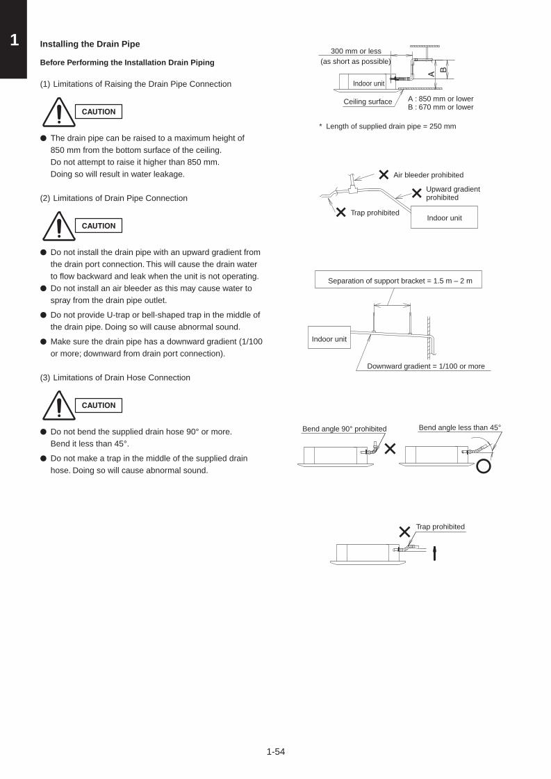
1
1-54
A B
300 mm or less
Indoor unit
Indoor unit
Bend angle 90° prohibited Bend angle less than 45°
Trap prohibited
Indoor unit
Ceiling surface
Air bleeder prohibited
Separation of support bracket = 1.5 m – 2 m
Trap prohibited
Upward gradient prohibited
* Length of supplied drain pipe = 250 mm
Downward gradient = 1/100 or more
A : 850 mm or lowerB : 670 mm or lower
(as short as possible)
Installing the Drain Pipe
Before Performing the Installation Drain Piping
(1) Limitations of Raising the Drain Pipe Connection
CAUTION
The drain pipe can be raised to a maximum height of 850 mm from the bottom surface of the ceiling.Do not attempt to raise it higher than 850 mm.Doing so will result in water leakage.
(2) Limitations of Drain Pipe Connection
CAUTION
Do not install the drain pipe with an upward gradient from the drain port connection. This will cause the drain water to flow backward and leak when the unit is not operating. Do not install an air bleeder as this may cause water to spray from the drain pipe outlet.
Do not provide U-trap or bell-shaped trap in the middle of the drain pipe. Doing so will cause abnormal sound.
Make sure the drain pipe has a downward gradient (1/100 or more; downward from drain port connection).
(3) Limitations of Drain Hose Connection
CAUTION
Do not bend the supplied drain hose 90° or more. Bend it less than 45°.
Do not make a trap in the middle of the supplied drain hose. Doing so will cause abnormal sound.
●
●
●
●
●
●
●
Sec1.indb 54 2012/03/07 17:30:04

1
1-55
Installing the Drain Pipe
CAUTION
Do not apply force to the drain port when connecting the drain pipe. Install and fix it near the indoor unit as close as possible.
Do not use adhesive when connecting the drain port pipe and the drain hose.
(1) How to Install the Drain Pipe
1) First insert the supplied hose band into the drain port pipe. Then make sure the head of the screw is facing toward a technical engineer when placing the screw of the hose band at an upward angle.
2) Insert the soft PVC socket of the supplied drain hose to the drain port pipe. Do not use adhesive when connecting the drain hose to the drain port pipe. Insert it until the tip of the drain hose contacts the circular projection rib of the drain port pipe.
●
●
3) Move the hose band so that the center position of the hose band can be placed approx. 30 mm away from the external plate of the indoor unit. (See the figure below.)
4) Screw the drain hose tightly facing the screw of the hose band upward. (Torque: 2.5 N·m - 3.4 N·m) (If the screw is tightened beneath the drain hose, the troubles will be generated.) Pay attention not to make hose band overlap the circular projection rib and the sealed circulation projection of the drain port pipe.
5) Apply approx. 2 g of adhesive on both sides of the drain hose without connection of the hard PVC socket and the hard PVC joint (VP25) in the local supply.
6) Connect the drain hose and the hard PVC joint so that the adhesive area of both sides can be overlapped. Wipe off the protrusion-adhesive with a soft cloth.
Drain port
Do not use adhesive here.
* Drain port may possibly be damaged if PVC adhesive is used.
* After checking the drainage, wrap the supplied packing and drain pipe insulator around the pipe.
Do not make hose band overlap the circular projection rib and the sealed circulation projection of the drain port pipe. (Torque: 2.5 N·m - 3.4 N·m)
Note:Be sure to tightly insert the hard PVC pipe joint (including elbow) minimum 20 mm or more.
57 mm
20 mm or more
Drain insulator (supplied)
* However, do not use the hard PVC pipe joint allowable more than 55 mm insertion.
Packing (supplied)
Approx. 5 mm
Approx. 30 mm
Adhere with PVC adhesive.
* Apply approx. 2 g of adhesive on both sides of the drain hose without connection of the hard PVC socket and the hard PVC joint (VP25) in the local supply. Wipe off the protrusion-adhesive with a soft cloth.
Hard PVC pipe
(VP25 field supplied)
Hard PVC socket Hose band (supplied)
Soft PVC socket
Drain hose(supplied)
Circular projection rib
Sealed circulation projection rib
Indoor unit
Indoor unit
Sealed circulation projection rib
Circular projection rib
(Drainage check section on drain port, transparent)
Sec1.indb 55 2012/03/07 17:30:06

1
1-56
Checking the Drainage
Be careful since the fan will start when you short the pin on the indoor control board.
After wiring and drain piping are completed, use the following procedure to check that the water will drain smoothly. For this, prepare a bucket and wiping cloth to catch and wipe up spilled water.(1) Connect power to the power terminal board (R, S
terminals) inside the electrical component box.(2) Slowly pour about 1,200 cc of water into the drain pan to
check drainage. (See the figure on the right.)(3) Short the check pin (CHK) on the indoor control board
and operate the drain pump. Check the water flow through the transparent drain pipe and see if there is any leakage.
(4) When the check of drainage is complete, open the check pin (CHK) and remount the tube cover.
(5) Checkpoint after installation
CAUTION
After installation of indoor and outdoor units, panels and electrical wiring, check the following items.
Checkpoint Symptom Check Remark
1Make sure whether indoor and outdoor units are correctly installed.
Fall, vibration, noise
2 Make sure whether gas leakage is tested. No cooling, no heating
3Make sure whether insulation is completed. (Refrigerant piping and drain piping)
Water leakage
4Make sure whether drain water is running smoothly.
Water leakage
5Make sure whether the power voltage matches the nameplate.
Inoperative, burnout
6Make sure whether there is miswiring or incorrect connection.
Inoperative, burnout
7Make sure whether the ground construction is completed.
Ground leakage
8Make sure whether the wire gauge is followed by the recommended specifications.
Inoperative, burnout
9Make sure whether the air intake and air outlet of the indoor and outdoor units are sealed by obstacles.
No cooling, no heating
Drainage check
Over 100 mm
Plastic container for water intake Water (Approx. 1,200 cc)
Drain pan outlet
Sec1.indb 56 2012/03/07 17:30:06

1
1-57
Main unit
Ceiling side
Ceiling opening dimension
A
A : Be sure to necessarily make a space within the range of 12 mm - 17 mm.
If not within this range, malfunction or other trouble may occur.
Flap
■ HOW TO INSTALL THE CEILING PANEL
■ 4-Way Cassette Type (U1 Type)
Accessories
Ceiling panel ×1 Washer head screws ×4
M5 × 40ø18
Installation notes ×1 Screws ×4
4 × 12
Preparation for Ceiling Panel Installation(1) Checking the unit position 1) Check that the ceiling hole is within this range:
860 mm × 860 mm to 910 mm × 910 mm 2) Confirm that the position of the indoor unit and the
ceiling as shown in the diagram. If the positions of the ceiling surface and unit do not match, air leakage, water leakage, flap operation failure, or other problems may occur.
CAUTION
Never place the panel face-down. Either hang it vertically or place it on top of a projecting object. Placing it face-down will damage the surface.Do not touch the flap or apply force to it. (This may cause flap malfunction.)
●
●
Sec1.indb 57 2012/03/07 17:30:07
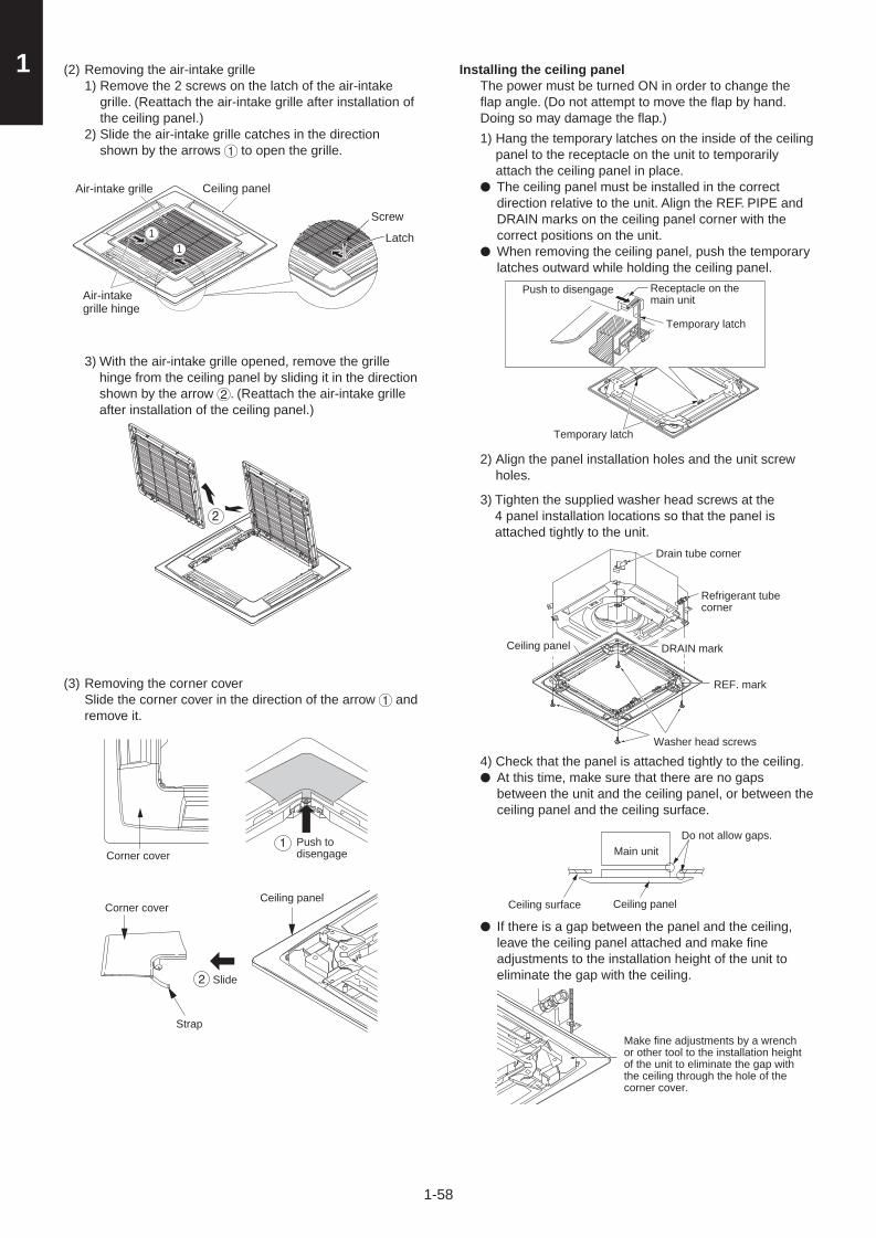
1
1-58
(2) Removing the air-intake grille 1) Remove the 2 screws on the latch of the air-intake
grille. (Reattach the air-intake grille after installation of the ceiling panel.)
2) Slide the air-intake grille catches in the direction shown by the arrows 1 to open the grille.
11
3) With the air-intake grille opened, remove the grille hinge from the ceiling panel by sliding it in the direction shown by the arrow 2. (Reattach the air-intake grille after installation of the ceiling panel.)
2
(3) Removing the corner cover Slide the corner cover in the direction of the arrow 1 and
remove it.
2
1Corner cover
Corner cover
Push to disengage
Ceiling panel
Slide
Strap
Installing the ceiling panel The power must be turned ON in order to change the
flap angle. (Do not attempt to move the flap by hand. Doing so may damage the flap.)
1) Hang the temporary latches on the inside of the ceiling panel to the receptacle on the unit to temporarily attach the ceiling panel in place. The ceiling panel must be installed in the correct direction relative to the unit. Align the REF. PIPE and DRAIN marks on the ceiling panel corner with the correct positions on the unit.When removing the ceiling panel, push the temporary latches outward while holding the ceiling panel.
2) Align the panel installation holes and the unit screw holes.
3) Tighten the supplied washer head screws at the 4 panel installation locations so that the panel is attached tightly to the unit.
4) Check that the panel is attached tightly to the ceiling. At this time, make sure that there are no gaps between the unit and the ceiling panel, or between the ceiling panel and the ceiling surface.
If there is a gap between the panel and the ceiling, leave the ceiling panel attached and make fine adjustments to the installation height of the unit to eliminate the gap with the ceiling.
●
●
●
●
Receptacle on the main unit
Push to disengage
Temporary latch
Temporary latch
Drain tube corner
Refrigerant tube corner
DRAIN mark
REF. mark
Washer head screws
Do not allow gaps.
Make fine adjustments by a wrench or other tool to the installation height of the unit to eliminate the gap with the ceiling through the hole of the corner cover.
Ceiling panel
Main unit
Ceiling surface
Ceiling panel
Air-intake grille
Air-intake grille hinge
Ceiling panel
Screw
Latch
Sec1.indb 58 2012/03/07 17:30:07

1
1-59
CAUTION
If the screws are not sufficiently tightened, trouble such as that shown in the figure below may occur. Be sure to tighten the screws securely.
If a gap remains between the ceiling surface and the ceiling panel even after the screws are tightened, adjust the height of the unit again.
(4) Wiring the Ceiling Panel 1) Open the cover of the electrical component box for
control PCB. 2) Connect the 22P connector (white) from the ceiling
panel to the connector on the control PCB in the unit electrical component box. In this case, expose the cutout section of the tube for the wiring protection to the outside from the electrical component box and fix it with the clamper attached to the electrical component box.
If the connectors are not connected, the Auto Flap will not operate. Be sure to connect them securely. (If not connected completely, “09” will be displayed on the remote controller.)
Check that the wiring connector is not caught between the electrical component box and the cover.
Check that the wiring connector is not caught between the unit and the ceiling panel.
●
●
●
●
●
(5) How to Attach the Corner & Air-Intake GrilleA. Attaching the corner cover1) Check that the safety cord from the corner cover is
fastened to the ceiling panel pin, as shown in the figure below.
2) Use the supplied screws to attach the corner cover to the ceiling panel.
B. Attaching the air-intake grilleTo install the air-intake grille, follow the steps for “Removing the grille” in the reverse order. By rotating the air-intake grille, it is possible to attach the grille onto the ceiling panel from any of 4 directions. Coordinate the directions of the air-intake grilles when installing multiple units, and change the directions according to customer’s requests.When attaching the air-intake grille, be careful that the flap lead wire does not become caught.Be sure to attach the safety cord that prevents the air-intake grille from dropping off to the ceiling panel unit as shown in the figure below.With this ceiling panel, the directions of the air-intake grille lattices when installing multiple units, and the position of the label showing the company name on the corner panel, can be changed according to customer’s requests, as shown in the figure below. However, the wireless signal receiver can only be installed at the refrigerant-tubing corner of the ceiling unit.
●
●
●
●
Air leakage
Staining
Pin
Hole for ceiling panel hook
Refrigerant tube side
Wireless signal receiver* Only this area
is possible for installation.
Electrical component box
Can be installed rotated 90°
Locations of air-intake grille hinges at the factory shipment* The grille can be
installed with these hinges facing in any of 4 directions.
Drain pipe side
Hook that prevents the grille from dropping
Place the corner cover so that the 3 tabs fit into the holes in the ceiling panel. Then fasten it in place with the supplied screws.
Air leakage from ceiling panel
Adjust so that there are no gaps.
Electrical component box cover
Screws (2 locations)
ClamperCeiling panel side
Main unit side
Cutout section of the tube for the wiring protection Ceiling panel
wiring connector
Wiring chart (Direction that the unit faces has been changed to facilitate explanation.)
If there is no affect to the horizontal of the unit and drain tube, adjustment to the installation height of the unit can be made through the hole of the ceiling panel corner.
Condensation, water leakage
Sec1.indb 59 2012/03/07 17:30:08

1
1-60
■ Others(1) Checking After Installation 1) Check that there are no gaps between the unit and
the ceiling panel, or between the ceiling panel and the ceiling surface.* Gaps may cause water leakage and condensation.
2) Check that the wiring is securely connected.* If it is not securely connected, the auto flap will not
operate. (“P09” is displayed on the remote controller.) In addition, the water leakage and condensation may occur.
(2) Operating the Wireless Remote ControllerFor details of installation, refer to the section “Wireless Signal Receiver” in the supplied installation instructions.
(3) Selecting DC Fan Motor Tap (4-Way cassette)Check the optional parts accordingly in the following table.
Table for DC Fan Motor Tap Setting
Setting No.Remote controller setting data Item code 5d
Contents & optional parts name
(3)
0003Air-blocking material(for 3-way air discharge)
0003Air-blocking material(when a discharge duct is connected)
(6) 0006Air-blocking material(for 2-way air discharge)
*1 When using optional parts in different setting No. in combination with multiple units, conform it to the larger setting No.
1) When setting from the P.C. Board <Procedure> Stop the system before performing these steps. 1 Open the electrical component box cover, then
check the indoor unit control PCB. 2 Connect the jumper connector (2P: yellow)
which was supplied with the accessory to the correct connector pin on the indoor unit control PCB according to the setting number which was confirmed in Table for DC Fan Motor Tap Settings.
Setting No. (3) : Then connect the jumper connector to the
connector pin TP3 (2P: yellow) on the indoor unit control PCB.
Setting No. (6) : Then connect the jumper connector to the
connector pin TP6 (2P: white) on the indoor unit control PCB.
2) When setting with the Wired Remote Controller <Procedure> Stop the system before performing these steps.
1 Press and hold the , and buttons simultaneously for 4 seconds or longer.
2 If group control is in effect, press the button and select the address (unit No.) of the indoor unit to set. At this time, the fan at the indoor unit begins operating.
3 Designate the item code by adjusting the
Temperature Setting / buttons. 4 Press the timer time / buttons to select the
desired setting data.* For item codes and setting data, refer to “Table for
DC Fan Motor Tap Setting”.
5 Press the button.(The display stops blinking and remains lit, and setting is completed.)
* If air-blocking material is used, use the same procedure as in steps 3 – 5 above and change the setting for item code “62” to “0000.”
If you wish to change the selected indoor unit, follow the step 2.
6 Press the button to return to normal remote controller display.
2
3
451
6
Sec1.indb 60 2012/03/07 17:30:09

1
1-61
■ SELECTING THE INSTALLATION SITE (E1 TYPE)
Indoor Unit
AVOID:
● areas where leakage of flammable gas may be expected.
● places where large amounts of oil mist exist.
● direct sunlight.
● locations near heat sources which may affect the performance of the unit.
● locations where external air may enter the room directly. This may cause “condensation” on the air discharge ports, causing them to spray or drip water.
● locations where the remote controller will be splashed with water or affected by dampness or humidity.
● installing the remote controller behind curtains or furniture.
● locations where high-frequency emissions are generated.
DO:
● select an appropriate position from which every corner of the room can be uniformly cooled.
● select a location where the ceiling is strong enough to support the weight of the unit.
● select a location where tubing and drain pipe have the shortest run to the outdoor unit.
● allow room for operation and maintenance as well as unrestricted air flow around the unit.
● install the unit within the maximum elevation difference above or below the outdoor unit and within a total tubing length (L) from the outdoor unit as detailed in the installation manual packed with the outdoor unit.
● allow room for mounting the remote controller about 1m off the floor, in an area that is not in direct sunlight or in the flow of cool air from the indoor unit.
25 cm
25 cm
25 cm
Sec1.indb 61 2012/03/07 17:30:10

1
1-62
SELECTING THE LOCATION FOR THE INDOOR UNIT Required Minimum Space for Installation and Service.
Provide a check port on the piping side ceiling for repair and maintenance.
● Install the indoor unit once the following conditions are satisfied and after receiving the customer approval.
1. The indoor unit must be within a maintenance space.
2. The indoor unit must be free from any obstacles in path of the air intet and outlet, and must allow spreading of air throughout the room.
* If the height from the floor to ceiling exceeds three meters, air flow distribution deteriorates and the effect is decreased.
INSTALLATION OF INDOOR UNIT
POSITION OF SUPENSION BOLT
(unit: mm)
A B C DS-60PE1RS 1060 1100 540 700S-71PE1R5
1060 1100 540 700S-100PE1R5S-125PE1R5S-140PE1R5
Uintmm Ha
S-60PE1R5 290
S-71PE1R5 360
S-100PE1R5 360
S-125PE1R5 430
S-140PE1R5 430
* The Ha is necessary for the access to the top of the unit for repair.
Uintmm Ha
S-60PE1R5 290
S-71PE1R5 360
S-100PE1R5 360
S-125PE1R5 430
S-140PE1R5 430
* The Ha is necessary for the access to the top of the unit for repair.
● Apply a joint-canvas between the unit and duct to absorb unnecessary vibration.
● Install the unit leaning to a drainage hole side as a figure for water drainage.
● Apply a joint-canvas between the unit and duct to absorb unnecessary vibration.
● Install the unit leaning to a drainage hole side as a figure for water drainage.
TYPE A B C DS-60PE1RS 130 33.1 290 118S-71PE1R5
S-100PE1R5195 35.7 360 50
S-125PE1R5S-140PE1R5
260 38.2 430 1215
TYPE A B C DS-60PE1RS 130 33.1 290 118S-71PE1R5
S-100PE1R5195 35.7 360 50
S-125PE1R5S-140PE1R5
260 38.2 430 1215
Sec1.indb 62 2012/03/07 17:30:10

1
1-63
Suspending the Indoor UnitDepending on the ceiling type:
• Insert suspension bolts or
• Use existing ceiling supports or construct a suitable support.
InsertHole-in-anchorHole-in-plug Concrete
Suspension bolt (M10 or 3/8")(field supply)
Ceiling support
Ceiling tiles
WARNINGIt is important that you use extreme care in supporting the indoor unit inside the ceiling. Ensure that the ceiling is strong enough to support the weight of the unit. Before hanging the unit, test the strength of each attached suspension bolt.
(1) When placing the unit inside the ceiling, determine the pitch of the suspension bolts referring to the dimensional data as shown in the figures on the previous page. Tubing must be laid and connected inside the ceiling when suspending the unit. If the ceiling is already constructed, lay the tubing into position for connection to the unit before placing the unit inside the ceiling.
(2) Screw in the suspension bolts allowing them to protrude from the ceiling. (Cut the ceiling material, if necessary.)
(3) Thread the 3 hexagonal nuts and 2 washers (field supply) onto each of the 4 suspension bolts. Use 1 nut and 1 washer for the upper part, and 2 nuts and 1 washer for the lower part, so that the unit will not fall off the suspension lugs.
Nuts and washers(use for upper and lower)
Suspension lug
Double nuts
Suspension bolt
Notch
Suspension bolt
Double nuts
Hexagonal nut
● This shows an example of installation.
Air outlet ductBolt anchorSuspension
bolt
Ceiling material
Air-outlet grilleIndoor unit
Sec1.indb 63 2012/03/07 17:30:10

1
1-64
Installing the Drain Pipe(1) Prepare standard hard PVC pipe (O.D. 32 mm) for the
drain and use the supplied hose band to prevent water leaks.The PVC pipe must be purchased separately.The transparent drain part on the unit allows you to check drainage. (Fig. 3-8)
CAUTION● Do not use adhesive tape at the drain connection port on
the indoor unit.● Insert the drain pipe until it contacts the socket, and then
secure it tightly with the hose band.● Do not use the supplied drain hose bent at a 90° angle.
(The maximum permissible bend is 45°.)● Tighten the hose clamps so their locking nuts face
upward.
Heat insulator (Local supply) (The thickness must be at least 8 mm)
Flexible hose with heat insulator (Accessory)
PVC pipe (O.D.ø32) (Local supply)
Hose clip (Accessory)
It may be required to take off this part for checking or servicing the drain up motor. Please do not glue.
To be glued
Make sure that there is not clearance here.
(2) After connecting the drain pipe securely, wrap the supplied packing and drain pipe insulator around the pipe, then secure it with the vinyl clamps.
Drain insulator (supplied)
Vinyl clamps(field supply)
NOTE
Make sure the drain pipe has a downward gradient (1/100 or more) and that there are no water traps.
CAUTION
● Do not install an air bleeder as this may cause water to spray from the drain pipe outlet.
Prohibited
Air bleeder
Drainage hole
Thermal insulator(Accessories) Hose clipr
(Accessories)
● Do not install the pipe with an upward gradient from the connection port. This will cause the drain water to flow backward and leak when the unit is not operating.
Upward gradient
Prohibited
● Do not apply force to the piping on the unit side when connecting the drain pipe. The pipe should not be allowed to hang unsupported from its connection to the unit. Fasten the pipe to a wall, frame, or other support as close to the unit as possible.
Support pieces
Connecting Duct to Indoor Unit(1) First pull out a filter in the direction of the electrical
equipment box in the unit. The pre-installed filter will not be used any more.
(2) Then remove the seal packing, bracket and filter attached to the side of the air intake port.
(3) Install the duct (local supply) for the Dimension of the installation hole.
Use M5 self-tapp Screws for installation. See the figure at the botton on page 1-58.
(4) The duct connection of the air outlet needs termal isulation.
Air outlet
Thermal insulator (Local arrangement)
NOTE
• Select an air-intake grille with a filter at a local shop.
• To get clean air and to extend the service life of the air conditioner, an air filter must be installed in the air intake. For installation and cleaning the air filter, consult your dealer or service center.
Sec1.indb 64 2012/03/07 17:30:11

1
1-65
Connection for demand and forced stop
■ Connection procedure
Be sure to always turn the power off first when setting up the wire and cable connections.Failure to do so may lead to electric shock or unit failure.
The demand terminal set up is shown in the following illustration.
SG (Shows the earth for the shielded cable)
Demand controller connection
Connection for next system outdoor unit (Forced Stop input connection)
Forced Stop inputSGSG
● Use a shielded cable for the cable connection.For the shield part of the shielded cable twist the end out, crimp it with a round terminal, and connect it to the SG screw.
After crimping it with a round terminal, wrap it with insulating tape so there are no spaces and adjust it so the shield part does not touch any live parts.
CAUTIONBe sure that the shield part of the shielded cable does not touch the terminal block or any live parts.
Failure to do so may lead to electric shock or fire.
Forced Stop connection for the next system
SG SG
Outdoor unit
Forced Stop input (Connect to fire alarm device, etc.)
Demand controller connection (field supply)
The next system outdoor unit
To the next system outdoor unit
Demand controller connection (field supply)
Crimp the round terminal
Shield part
Wrap it well with insulating tape so there are no spaces.
Sec1.indb 65 2012/03/07 17:30:11

1
1-66
Fire alarm device
Terminal block
Relay contact point: No voltage relay
Current input is DC 24 V 2 mAUse a very small electric current contact point for the relay.
When connection to the forced stop inputWith the Forced Stop input, it is possible to override the air conditioning operation to force a stop if a signal is received from a fire alarm device, etc.
Connect the wiring (2-wire) to points 1 and 2 on the left side of the terminal block.The shield part of the shielded cable is connected with SG under the terminal block.Secure the wiring with the cord clamp located on the lower part of the terminal block.
Terminal block
DRED (Demand controller)
Relay contact point: No voltage relay
Current input is DC 24 V 10 mA
When connecting the demand controller inputIt is possible to choose various demand levels.
Refer to the table shown on the right.
Termrial No. for demand section Description
DRM3 Approx. 75% of rated power inputDRM2 Approx. 50% of rated power inputDRM1 Compressor off
Connect the wiring (4-wire) to the Demand section (DRM1, DRM2, DRM3, C) on the terminal block.The shield part of the shielded cable is connected with SG under the terminal block.Secure the wiring with the cord clamp located on the lower part of the terminal block.
SG
SG
Sec1.indb 66 2012/03/07 17:30:12

1
1-67
When connecting to the next system unit● Forced Stop input can be transferred to the next system unit.● When using the Forced Stop input, connect the wiring to the terminal points 1 and 2 on the right side of the lower part of the terminal
block.● The maximum wire/cable length is 100 m.● The demand control cannot be transferred to the next system unit.● When transferring to the next system, the maximum number of connecting units is 30.1. Connecting the wining to the lower part of the terminal block.
When transferring the Forced Stop input to the next system connect the wiring (2-wire) to the terminal points 1 and 2 at the lower right side of the terminal block.The shield part of the shielded cable is connected with SG under the terminal block.Secure the wiring with the cord clamp located on the lower part of the terminal block.
2. Connecting the shielded cable to the terminal block for the next system.For the Forced Stop input, connect the wiring to the terminal points 1 and 2 at the lower right side of the terminal block.When connecting to the next system be sure to connect to the appropriate terminal point due to the polarity.
Continued on the back side
Connection terminal block fornext system outdoor unit
Cord clamp
Demand control cannot be transferredto the next system
Connecting line to the nextsystem outdoor unit
Be sure to connect to the appropriate terminalpoint due to the polarity.
Next systemoutdoor unit
To the next systemoutdoor unit
SG
Sec1.indb 67 2012/03/07 17:30:12

1
1-68
■ Wiring procedureFollow the wiring procedure below for terminal connection.
1 Set the wiring and cables for the power and signal lines to the outdoor unit together, and secure each wire and cable with the tie.
2 Secure and clamp the power and signal lines with the tie, set up close to the valve.
3 Set up the wiring and cable for the outdoor unit piping and secure with a tie.
Secure and clamp the wiring and cable with the tie (accessory) for the power and signal lines to the outdoor unit.
Secure and clamp the wiring and cable together with power and signal lines using the tie set up close to the valve.
Secure and clamp all wiring and cable together with the indoor/outdoor piping using the tie (accessory).
Sec1.indb 68 2012/03/07 17:30:12

1
1-69
■ Filter Chamber for Indoor Unit
■ Optional Parts
CZ-FDU2
Installation Instructions
Accessories
Installation
1. Be careful handling the unit when installing it inside the ceiling. Use particular care to avoid allowing
any impact to strike the side of the filter chamber, as this can result in damage.
2. Remove the cardboard inserted in the air outlet (4 locations)
before installation.
(1) Installing Filter Chamber
Align the black sealing material on the filter chamber with the indoor unit.
(The filter chamber must be installed in a specific direction, therefore align
the shape of the filter chamber with the shape of the indoor unit.)
Fasten with the supplied installation screws (x4).
(2) Installing Indoor Unit
Install the indoor unit (attached to the filter chamber) in the ceiling.
(Install the indoor unit according to instructions supplied with the indoor unit.)
(3) Installing Ceiling Panel
Install the ceiling panel to the chamber.
(Install the ceiling panel according to instructions supplied with the ceiling
panel.)
First cut off the bundled clamper and insert the ceiling panel 22P (white)
connector into the through-hole of the chamber.
Then connect it to the 22P connector in the electric component box.
Check that the following parts are in the box when unpacking.
Supplied parts Q'ty Remarks Supplied parts Q'ty Remarks
Instructions
Short-circuit
connector
4Washer
4Installation
screws (5x40)
Fixture for
filter chamber
Fixture for
filter chamber Each
1
Installation
Instructions, Fan tap
Through-hole of ceiling panel 22P (white) connector
Through-hole of ceiling panel 22P (white) connector
Indoor unit
Indoor unit
Ceiling panel
Filter chamber
Ceiling panel 22P (white) connector
Installation screw
Installation screw
Washer
Washer
Filter chamber
Clamper
Black sealing material
NOTE
Sec1.indb 69 2012/03/07 17:30:13

1
1-70
■ Air Intake Kit for Chamber
CZ-ATU2
Installation Instructions
Accessories
Installation
Install the duct connection box after installing
the indoor unit. Also, because the duct
connection box is attached to the aif-intake
plenum, use sufficient care when handling it.
Especially avoid any impacts on the side of
the air-intake plenum, as this can result in
damage.
(1) Remove the sealing plate from the air-intake
plenum.
(4) Apply the supplied thermal insulation A and B to
the installation screws.
(3) Fasten the duct connection box to the air-intake
plenum with the 6 installation screws.
(2) Fit the duct connection flange and installation
bracket into the duct connection box.
Fasten with the supplied 8 installation screws.
Follow the instructions in the air-intake plenum
installation instructions and install the air-intake
plenum on the indoor unit.
Check that the following parts are in the box when unpacking.
Duct connection box
Supplied parts Q'ty Remarks
Instruction screw
1
1
14
2
2
Duct connection box
installation bracket
Thermal insulation
for installation screws A
Thermal insulation
for installation screws B
Thermal insulation
for installation screws A
Thermal insulation
for installation screws B
1Duct connection box
Duct flange
Polyethylene foam T2
Polyethylene foam T5
Installation flange
( o100)
Indoor unit
Sealing plate
Air-intake plenum
NOTE
Sec1.indb 70 2012/03/07 17:30:13

1
1-71
■ Air Intake Kit for Unit
CZ-BCU2
Installation Instructions
Accessories
Installation
(2) Peel off the insulation of the shaded portion
and insert the connecting box for the main
unit from the air outlet of the main unit.
(3) If there is a space between the styrofoam and
the sheet-metal, this will result in condensation
forming.
First seal the supplied insulation "A" to meet the
hole of the screw and then seal that of "B".
(4) Fasten the flange to the indoor unit supplied
with the installation screws (x4).
Connecting box
for main unit
Duct connection flange
( 100, for fresh air intake)
Installation screw (4 x 10)1
Supplied parts Supplied parts Supplied partsQ'ty Q'ty Q'ty
Instructions
Sealing insulation "A" Sealing insulation "B"
1
122
4
(1) Cut and remove the sheet-metal together with an
insulation (styrofoam) with a nipper or a cutter
knife paying attention to the incision as a marker
on the indoor unit.
When cutting out the styrofoam, do not insert
the blade more than 30mm depth. (If the
inside of the drain pan is damaged, this will
result in water leakage.)
Also, be careful not to let the chips invade
the unit.
Cut out the sheet-metal with a nipper or the like (4 locations).
Indoor unit
Cut and remove all circumferences of the insulation (styrofoam) with a nipper or a cutter knife.
Indoor unit
Insulation Connecting box for main unit
Styrofoam
Sealing insulation "A"
Sheet-metalSeal tightly to prevent air leakage.
Sealing insulation "B"
Procedures for sealing insulation
Connecting box for main unit
Flange (fresh air intake)Indoor unit
NOTE
Sec1.indb 71 2012/03/07 17:30:13

1
1-72
■ Air Cut Insulation
CZ-CFU2
Installation Instructions
Applicable Model & Use
(1) Indoor Unit Installation
(2) Cut off the part to close air flow and the packing according to the
installation dimensions as shown in the right table.
Be careful as the dimensions are different due to the installation
location.
Be careful they should be no shorter than the installation
dimensions. The excessive cut may result in condensation forming.
(3) Part to close air flow Installation
Use this part to close air flow when setting 3-way or 2-way air discharge, or connecting the duct connection flange ( 150)
according to the situation of the unit installation.
When using the part to close air flow, follow the change procedures of DC Fan Tap and change the fan tap.
If not changed, air discharge temperature in the cooling mode drops due to the reduction in airflow.
This may result in condensation forming.
Install the indoor unit in the ceiling. (Install the indoor unit
according to instructions supplied with the indoor unit.)
Insert the part to close air flow into the air outlet (styrofoam) of
the indoor unit and apply the packing and close.
(See the figures on the next page.)
Paste the packing to cover the internal styrofoam in the unit
more than 15mm. (If not covered over 15mm, this may result in
condensation forming.)
List of Parts
Installation
When using an optional high-performance filter, a filter grille or a natural evaporation type humidifier, it is
impossible to shift the 3-way or 2-way air discharge or make a connection of duct connection flange ( 150).
Model
CZ-CFU2
Use
Close off in case of 3-Way or 2-Way Air DischargeClose off in case of connecting the duct connection flange ( 150)
Installation location
Installation dimension
Name
Part to close air flow
Packing
Packing
Packing
Packing
Part to close air flow
Part to close air flow
Part to close air flow
CZ-CFU2
2
2
2
1
Model
Part to close air flow
Packing
Short-circuit connector
Instructions
Supplied parts Dimensions Shape Q'ty
Instructions & Change Procedures of DC Fan Tap
490 70 T40
650 100 T2
450 70
490 100
400 70
620 100
490 70
650 100
490 70
610 100
NOTE
Sec1.indb 72 2012/03/07 17:30:13

1
1-73
(4) Block Pattern of Air Outlet (seen from the unit bottom)
In case of 3-way or 2-way air discharge and connecting the duct connection flange ( 150), block the air outlet
according to the block pattern of air outlet as shown on the next page. Also, select the appropriate piping position
referring to the following table. (See the figure below to correctly understand the illustration.)
Be careful not to cause condensation, cool wind leak and insulation shortage when installing the duct
connection flange ( 150).
Blocked area
Air discharge duct connection flange ( 150) Air outlet direction
Refrigerant piping Drain piping
Packing
Packing Packing
Packing
Drain pipe
Drain wiring
Main unit
Cut off the packing on a slant not to be subjected to the drain wiring.
The portion where the packing protrudes outward must be folded to the side of the lateral plate and paste it.
The packing should not be subjected to the corner metal.
Refrigerantpiping
Electriccomponentbox
Part to close air flow
Part to close air flow
Part to close air flow
Part to close air flow
Air outlet
Drain pan
Internal styrofoam
outer carton
PackingPart to close air flow
NOTE
Sec1.indb 73 2012/03/07 17:30:13

1
1-74
(5) Setting Changes of DC Fan Tap
Make settings of the wired remote control, timer remote control or indoor unit control P.C. board (using supplied short-circuit
connector) according to separate instructions.
Make settings of 3-way air discharge and 2-way air discharge according to separate instructions.
Do not apply any other block pattern of air outlet as listed below.
3-way air dischargeCapable of blocking 1 direction
( 150)connecting air outlet duct connection flange3-way air discharge + Block one of the air outlet and connect the duct connection flange. Then the air is discharged from the air discharge duct connection flange.
connecting air outlet duct connection flange ( 150)2-way air discharge + Block two (2) air outlet and connect either of the duct connection flanges. Then the air is discharged from the air discharge duct connection flange. There is, however, only capable of discharging the air from one set of air outlet duct connection flange.
2-way air dischargeCapable of blocking 2 directions
Sec1.indb 74 2012/03/07 17:30:13

2
2-1
■ PRECAUTIONS REGARDING TEST RUN ........................................................................ 2-2
■ CHECKS AFTER INSTALLATION HAVE COMPLETED ................................................... 2-3
■ REGARDING DELIVERY TO THE CUSTOMER ................................................................ 2-3
2. TEST RUN
Sec2.indd 1 2012/02/21 13:43:09
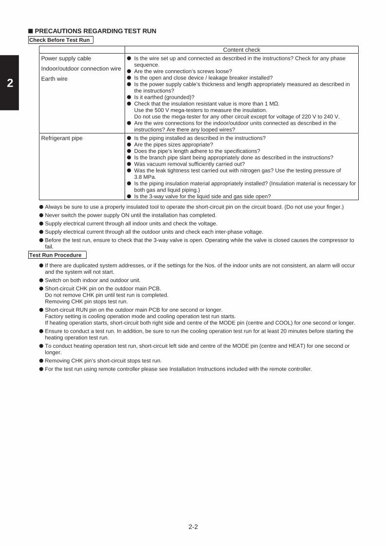
2
2-2
■ PRECAUTIONS REGARDING TEST RUNCheck Before Test Run
Content check
Power supply cable
Indoor/outdoor connection wire
Earth wire
● Is the wire set up and connected as described in the instructions? Check for any phase sequence.
● Are the wire connection’s screws loose?● Is the open and close device / leakage breaker installed? ● Is the power supply cable’s thickness and length appropriately measured as described in
the instructions?● Is it earthed (grounded)?● Check that the insulation resistant value is more than 1 MΩ.
Use the 500 V mega-testers to measure the insulation. Do not use the mega-tester for any other circuit except for voltage of 220 V to 240 V.
● Are the wire connections for the indoor/outdoor units connected as described in the instructions? Are there any looped wires?
Refrigerant pipe ● Is the piping installed as described in the instructions?● Are the pipes sizes appropriate?● Does the pipe’s length adhere to the specifications?● Is the branch pipe slant being appropriately done as described in the instructions?● Was vacuum removal sufficiently carried out?● Was the leak tightness test carried out with nitrogen gas? Use the testing pressure of
3.8 MPa.● Is the piping insulation material appropriately installed? (Insulation material is necessary for
both gas and liquid piping.)● Is the 3-way valve for the liquid side and gas side open?
● Always be sure to use a properly insulated tool to operate the short-circuit pin on the circuit board. (Do not use your finger.)
● Never switch the power supply ON until the installation has completed.
● Supply electrical current through all indoor units and check the voltage.
● Supply electrical current through all the outdoor units and check each inter-phase voltage.
● Before the test run, ensure to check that the 3-way valve is open. Operating while the valve is closed causes the compressor to fail.
Test Run Procedure
● If there are duplicated system addresses, or if the settings for the Nos. of the indoor units are not consistent, an alarm will occur and the system will not start.
● Switch on both indoor and outdoor unit.
● Short-circuit CHK pin on the outdoor main PCB.Do not remove CHK pin until test run is completed.Removing CHK pin stops test run.
● Short-circuit RUN pin on the outdoor main PCB for one second or longer.Factory setting is cooling operation mode and cooling operation test run starts.If heating operation starts, short-circuit both right side and centre of the MODE pin (centre and COOL) for one second or longer.
● Ensure to conduct a test run. In addition, be sure to run the cooling operation test run for at least 20 minutes before starting the heating operation test run.
● To conduct heating operation test run, short-circuit left side and centre of the MODE pin (centre and HEAT) for one second or longer.
● Removing CHK pin’s short-circuit stops test run.
● For the test run using remote controller please see Installation Instructions included with the remote controller.
Sec2.indd 2 2012/02/21 13:43:10

2
2-3
RUN pin MODE pin
Outdoor main PCB
CHK pin
*MODE pin: factory setting is cooling operation mode.
■ CHECKS AFTER INSTALLATION HAVE COMPLETED
● Check the following items after completing installation. Is there a short circuit with the intake air flow? Is the insulation secure? (Refrigerant piping) Are there any errors with the wiring? Are the terminal screws loose? Tightening torque (Unit: N• cm {kgf• cm})M4… 157-196 {16-20}, M5... 196-245 {20-25}.
Is the drain water flowing smoothly? Is the insulation material properly installed? Is the earth wire securely connected? Is the front panel and the indoor unit air conditioner firmly fixed and was the installation completed without any leakage from the refrigerant?
Are the indoor and outdoor units secured firmly installed with bolts at secured locations?
■ REGARDING DELIVERY TO THE CUSTOMER
● Request the customer to review the instruction manual and explain the operating method for the product.● In addition, it is also recommended that regular inspection checks are agreed upon for maintenance.
User inspection places
Serviceman inspection places
• Filter and grill cleaning• Exterior cleaning• Check the operating status• Clean the drain pan or things related to the water discharge• Heat exchanger cleaning
Refer to the installation instruction manual provided with the indoor unit for the specifications on the indoor unit installation.
Sec2.indd 3 2012/02/21 13:43:10

3-1
3
3. ELECTRICAL DATA
3-1. Indoor Units (Electric Wiring Diagram) .................................................................... 3-24-Way Cassette Type .............................................................................................................................. 3-2Ducted Type ............................................................................................................................................ 3-3
3-2. Outdoor Units (Electric Wiring Diagram) ................................................................. 3-5
Elite_PAC-i_Sec1-8.indb 1 2012/03/07 11:04:33

3-2
3
3-1. Indoor Units
4-Way Cassette Type S-60PU1R5 / S-71PU1R5 / S-100PU1R5 / S-125PU1R5 / S-140PU1R5Electric Wiring Diagram
�
Elite_PAC-i_Sec1-8.indb 2 2012/03/07 11:04:33

3-3
3
3-1. Indoor Units
Ducted Type S-60PE1R5 / S-71PE1R5 / S-100PE1R5 / S-125PE1R5Electric Wiring Diagram
�
Elite_PAC-i_Sec1-8.indb 3 2012/03/07 11:04:33

3-4
3
3-1. Indoor Units
Ducted Type S-140PE1R5Electric Wiring Diagram
�
Elite_PAC-i_Sec1-8.indb 4 2012/03/07 11:04:33

3-5
3
3-2. Outdoor Units
Electric Wiring Diagram U-60PE1R5 / U-71PE1R5
Elite_PAC-i_Sec1-8.indb 5 2012/03/07 11:04:33

3-6
3
3-2. Outdoor Units
Electric Wiring Diagram U-100PE1R5 / U-125PE1R5 / U-140PE1R5
ORA
NGE
O
PUYE
LLO
W/
GRE
EN
BL
BRP G
WIR
E C
OLO
R
BRO
WN
GRE
EN
YELL
OW
ELE
CTR
IC C
IRC
UIT
DIA
GR
AM
F223
346
PURP
LE
RED
WGR
WHI
TE
BLAC
KR Y
BLUE
GRA
Y
Y/G
PINK
B
21
21
11
3
ELE
CTR
O-M
AG
NE
TIC
CO
IL
FAN
MO
TOR
41
1
NLL-I
N
1 441 7 111 35
RY04
1 3311 3
OUTDOOR HEAT EXCHANGER TEMP.SENSOR(C2)
3CN
-TS (R)
CN-C
1(W
)2
1
OUTDOOR AIR TEMP.SENSOR(TO)
COMPRESSOR DISCHARGE TEMP.SENSOR(TD)
12
CN-C
2(W
)
CN-R
ELAY
(W)
3
2 31 1 31 1 5
COMPRESSOR SUCTION TEMP.SENSOR(TS)
OUTDOOR HEAT EXCHANGER TEMP.SENSOR(C1)
CN-H
IC2
(W)
CN-D
C_F
(W)
CN-H
IC3
(W)
CN-H
IC1
(W)
CN-H
IC2
(W)
CN-0
2(G
R)3
U V W
P N
FUSE
2
4
3~
POWE
R SU
PPLY
15 1
PFC
REAC
TOR
REAC
TOR
CIRC
UIT
FUSE
1
3
1 71
N-IN
3
220/2
30/24
0V~
50Hz
RE
CTI
FIC
ATIO
N
CIR
CU
IT
NO
ISE
FIL
TER
C
IRC
UIT
E2E1F9
00
PTC
CN-O
C(B
)
CN-E
MG(B
R)
CN-FM
B (Y
)
CN-M
OV1
(W)
CN-FM
A (Y
)
CN-
63PH
(R)
CN-TD
(BL)
TO TH
E IN
DOOR
UNI
TF5
01
AC
3
AC
1
AC
2
DC1(O
)
AC
3
AC
1
AC
2
COMP
RESS
OR15
A 250
V
(BL)(W
)
(GR
)
RY02
1
IC01
1
WVU
CN-20
S(B
)
ELECTRO-MAGNETIC COIL(4-WAY VALVE)
GBBR G
WWW WW WW
CN-H
IC1
(W)
WW WW
CN-H
IC3
(W)
WBLOBLWGR
CN-R
ELAY
(W)
CN-PA
M(W
)
RE1(R
)
U2U1P B
CN-
FM2
(R)
(W)
(GR
)
(BL) CN
-PAM
(BL)
RE2(R
)
R B Y
CN-TO
(BL)
BL BL
MS
RECT
IFIC
ATIO
N
CIRC
UIT
CN-
FM1
(R)
T3.1
5A L
250V
T3.1
5A L
250V
RY90
0
RY90
1
DC2(B
L)
TERM
INAL B
OARD
CONT
ROL B
OARD (HIC
)CO
NTRO
L BOA
RD (CR)
W WW W
(EX
PAN
D V
ALV
E)
WW W W W W
TERM
INAL B
OARD
FAN
MO
TOR
M M M
12
61
CN-O
PT2
(Y)
CN-O
PT1
(R)
BRR1 21 2DR
M3 CDRM1
DRM2
B BLP GR WPU
TO TH
E NEX
T SYS
TEM
FORC
ED ST
OP
DEMA
ND
TER
MIN
AL
BO
AR
D
TER
MIN
AL
BO
AR
D(FO
RCED
STOP
)
TOP
BO
TTO
M
t°
t°
t°
t°
t°
(U)
(V)YE
L
FOR W
IRE INS
ERT)
(W)
BLU
RED
(REFE
R TO T
ERMI
NAL C
OVER
COMP
RESS
OR TE
RMINA
L
DISCH
ARGE
PIPE
BOLT
RR
RE1(R
)RE
2(R)
RR
100P
TYPE
125・
140P
TYPE
100P
:30A A
C250
V12
5・14
0P:40
A AC2
50V
Elite_PAC-i_Sec1-8.indb 6 2012/03/07 11:04:33

3-7
3
3-2. Outdoor Units
Electric Wiring Diagram U-100PE1R8 / U-125PE1R8 / U-140PE1R8
Elite_PAC-i_Sec1-8.indb 7 2012/03/07 11:04:33

– MEMO –
3-8
Elite_PAC-i_Sec1-8.indb 8 2012/03/07 11:04:33

4-1
4
4-1. Room Temperature Control .......................................................................................... 4-2
4-2. Heating Standby ............................................................................................................ 4-4
4-3. Automatic Fan Speed Control ...................................................................................... 4-5
4-4. Drain Pump Control ....................................................................................................... 4-6
4-5. Automatic Heating/Cooling Control ............................................................................. 4-7
4-6. Automatic Flap Control ................................................................................................. 4-8
4-7. Filter Sign ....................................................................................................................... 4-8
4-8. Fan Control during Dry Mode ....................................................................................... 4-9
4-9. Ventilation Fan Output .................................................................................................. 4-9
4-10. T10 Terminal ................................................................................................................. 4-9
4-11. Parameter ..................................................................................................................... 4-10
4-12. Outdoor Units Control PCB (CR-PCB, HIC-PCB) ...................................................... 4-11
4-13. Functions of Outdoor Unit PCB ................................................................................. 4-19
4-14. Self-Diagnostics Function Table ................................................................................ 4-22
4. CONTROL FUNCTIONS
Sec4.indd 1 2012/03/07 17:35:19

4-2
4
4-1. Room Temperature Control
The body sensor or remote controller sensor detects temperature in the room. The detected temperature is called the room temperature. The body sensor is the one contained in the indoor unit.
Body sensor is enabled Remote controller sensor is enabled
Set temp. Set temp. in remote controller Set temp. in remote controller
Detected temp. by sensor
Detected temp. by body sensor Detected temp. by remote controller sensor
Room temp. Detected temp. by body sensor - *correction temp.
Detected temp. by remote controller sensor
The thermostat is turned ON or OFF according to the following T.
T (Cooling) T = room temp. – set temp. (set temp. in remote controller)
T (Heating) T = set temp. – room temp.
Correction temperature (only during heating)If the indoor unit is installed on the ceiling, temperature near the ceiling is higher than near the floor. When the body sensor is enabled, lower temperature near the floor must be considered. To correct this difference in temperature, the correction temperature is used.
The factory setting for the correction temperature is different depending on the model. Refer to “4-11. Parameter”.
Example: Cooling temperature correction4-Way Cassette (correction temperature: 0 degrees)Body sensor is enabled
Set temp. in remote controller
28℃ 28℃ 28℃
Detected temp. by sensor
30.0℃ 27.5℃ 27.0℃
Detected temp. by body sensor
30.0℃ 27.5℃ 27.0℃
Detected temp. by remote controller sensor
30.0℃ 27.5℃ 27.0℃
Room temp. = temp. detected by body sensor
30.0℃=30.0
27.5℃=27.5
27.0℃=27.0
T +2.0deg -0.5deg -1.0deg
ThermostatON
ThermostatON
ThermostatOFF
Example: Heating temperature correction4-Way Cassette (correction temperature: 4 degrees)Body sensor is enabled
Set temp. in remote controller
20℃ 20℃ 20℃
Detected temp. by sensor
17.0℃ 22.0℃ 25.0℃
Detected temp. by body sensor
17.0℃ 22.0℃ 25.0℃
Detected temp. by remote controller sensor
13.0℃ 18.0℃ 21.0℃
Room temp. = temp. detected by body sensor – 4 deg
13.0℃=17.0-4deg
18.0℃=22.0-4deg
21.0℃=25.0-4deg
T +7.0deg +2.0deg -1.0deg
ThermostatON
ThermostatON
ThermostatOFF
Sec4.indd 2 2012/03/07 17:35:19

4-3
4
Remote controller sensor is enabled
Set temp. in remote controller
28℃ 28℃ 28℃
Detected temp. by sensor
30.0℃ 27.5℃ 27.0℃
Detected temp. by body sensor
30.0℃ 27.5℃ 27.0℃
Detected temp. by remote controller sensor
30.0℃ 27.5℃ 27.0℃
Room temp. = temp. detected by remote controller sensor
30.0℃=30.0
27.5℃=27.5
27.0℃=27.0
T +2.0deg -0.5deg -1.0deg
ThermostatON
ThermostatOFF
ThermostatOFF
Remote controller sensor is enabled
Set temp. in remote controller
20℃ 20℃ 20℃
Detected temp. by sensor
17.0℃ 20.5℃ 21.0℃
Detected temp. by body sensor
21.0℃ 24.5℃ 25.0℃
Detected temp. by remote controller sensor
17.0℃ 20.5℃ 21.0℃
Room temp. = temp. detected by remote controller sensor
17.0℃=17.0
20.5℃=20.5
21.0℃=21.0
T +3.0deg -0.5deg -1.0deg
ThermostatON
ThermostatOFF
ThermostatOFF
① The thermostat does not turn OFF for 3 minutes after it turns ON.
② The thermostat does not turn ON 1 to 3 minutes after it turns OFF.
③ The thermostat does not turn OFF for 60 minutes during the test run mode. (Forced thermostat ON) *However, the thermostat turns OFF if an alarm occurs.
ON ONOFF
Set temp.
Set temp.
Set temp.
Set temp.
-1
+1
+2
(deg)
ON ONOFF
+1
+2
-1
(deg)
ON ONOFF
-1
+1
+2
(deg)
Heating
ON ONOFF
+1
+2
-1
(deg)
Body sensor is enabled Remote controller sensor is enabled
-0.5
-0.5
Roo
m te
mp.
Cooling
Roo
m te
mp.
Cooling
Heating
Roo
m
tem
p.
Roo
m
tem
p.
Thermostat Thermostat
ThermostatThermostat
Sec4.indd 3 2012/03/07 17:35:19

4-4
4
4-2. Heating Standby
In heating mode, the indoor fan speed decreases to prevent cold air discharge from the indoor unit. During this time, (heating standby) is displayed on the remote controller.
① This condition occurs in the following cases.
・ Thermostat OFF
・ Defrosting operation
・ Indoor heat exchanger liquid temperature (E1) < 28˚C and discharge air temperature < 25˚C just after heating operation startedThe fan speed may sometimes increase when this condition continues for 6 minutes.
② The fan mode increases when the heat exchanger liquid temperature (E1) or discharge air temperature increases.
The fan mode is selected based on the discharge air temperature and E1 temperature as shown in the below fi gure. If the E1 temperature and discharge air temperature are different, the higher temperature is used.
The function of “HH” is identical to the automatic fan speed mode.
Operation
Discharge airE132
Temprature ( )
30
28
26
20
16
29
27
25
23
17
13
*HHSTOP
L
STOP
STOP
LL
LL
STOP
STOP
LL
LL
L
L
L
L
HLL L H
L
H
L
HH
LH
Setfan STOPLLLHH
speed
Sec4.indd 4 2012/03/07 17:35:20

4-5
4
4-3. Automatic Fan Speed Control
① The indoor fan mode is controlled as shown below during the automatic fan mode.② The fan mode does not change for 3 minutes during cooling operation and 1 minute during heating
operation once it is changed.③ The values in the parenthesis are when the remote controller sensor is enabled.
+3+2+1
(deg)
Indoor fan mode HH H L HH
H
Cooling
Set temp.
Set temp.
(-1)-2
(-2)-4
(deg)
Indoor fan mode HH H L HHH
Heating
Sec4.indd 5 2012/03/07 17:35:20

4-6
4
4-4. Drain Pump Control
The drain pump operates in the following conditions.① Cooling thermostat ON② The fl oat switch worked.③ The drain pump may often operate for a while when the cooling thermostat turns OFF or the indoor
unit is stopped.④ The drain pump can be turned on when the cooling thermostat is OFF if the setting is made to prevent
water collected in the drain pan for a long time. For details, refer to “7-3. Detailed Settings Function.”⑤ The indoor unit heat exchanger liquid temperature (E1) is less than 0˚C when the cooling thermostat
is OFF or the indoor unit is stopped.
The drain pump operates for 20 minutes once it starts operating.
Sec4.indd 6 2012/03/07 17:35:20

4-7
4
4-5. Automatic Heating/Cooling Control① The operating mode is selected according to the set temperature and room temperature when the
operation is started.Room temperature > set temperature in remote controller – 1˚C → Cooling modeRoom temperature < set temperature in remote controller – 1˚C → Heating mode
② The set temperature is corrected according to the operating mode. The correction temperature is +2 degrees in cooling mode and -2 degrees in heating mode at the time of factory shipment.
The correction value is different depending on the model. Refer to “4-11. Parameter” for details.Corrected cooling temperature – control temperature for coolingCorrected heating temperature – control temperature for heating
When setting temperature in remote controller is 20˚C in the cooling mode (at shipment) :
Control temp. for cooling 22˚C
Set temp. in remote controller 20˚C
Control temp. for heating 18˚C
③ Condition for mode changeHeating → Cooling: Room temperature > Control temperature for cooling + 0.5 degreeCooling → Heating: Room temperature < Control temperature for heating -1.0 degree
When setting temperature in remote controller is 20˚C in the cooling mode :
Heating Heating thermostat OFF Cooling Cooling thermostat OFF Heating
continues for 10minutes regardlessof temp. condition.Then, the mode changes to cooling.
The heating thermostat OFF
continues for 10minutes regardlessof temp. condition.Then, the modechanges to heating.
The coolingthermostat OFF
Set temp. in remote controller
Control temp. for cooling +2deg
Control temp. for heating
+2.5degTemp. for switching to cooling
Temp. for switching to heating
-2deg
-3deg
Heating thermostat OFF temp. -1deg
Cooling thermostat OFF temp. +1deg
For settings at the time of factory shipment, refer to “4-11. Parameter”.
Sec4.indd 7 2012/03/07 17:35:20

4-8
4
4-6. Automatic Flap Control
The flap position can be selected from 5 positions.
Operating mode Flap position
Cooling/Dry F1・F2・F3
Fan F1・F2・F3・F4・F5
Heating F1・F2・F3・F4・F5
① The fl ap moves to the following position automatically when the indoor unit is stopped.F0 (close): Types K1, T1, U1, Y1F5: Models other than the above
② The fl ap closes once and moves to the set position when the operating mode is changed.
※ If the flap position cannot be adjusted because of a problem, only the swing operation can be used. Check the fl ap and fl ap motor.
※ The swing operation can be set for the fl ap.
4-7. Filter Sign① When accumulated operating time of the indoor unit reaches the set time, the fi lter sign appears on
the remote controller. Clean the fi lter.Refer to “7-3. Detailed Setting Function: Simple setting items and Filter sign ON times for each model”.
② After cleaning the fi lter, press the fi lter button on the remote controller once. The fi lter sign turns off.
F1
F2F3
F4F5
F0
Sec4.indd 8 2012/03/07 17:35:20

4-9
4
4-8. Fan Control during Dry Mode
The fan control during dry mode is as follows.
A ABFan mode
Set temp. in remote controller
+1
-1
T (deg)
A: Fan mode set in the remote controller
B: Fan mode is L during thermostat ON, LL during thermostat OFF
For details on T, refer to “4-1. Room Temperature Control”.
4-9. Ventilation Fan Output
The output of ventilation turns ON when the indoor unit turns ON. Also, when the indoor unit turns OFF,the output of the ventilation turns OFF.
The ventilation fan can also be turned ON and OFF using the ventilation button on the remote controller.
Refer to the operating instructions supplied with the remote controller.
To enable this function, set the indoor EEPROM DN31 to “0001” in advance.
4-10. T10 Terminal
Using the T10 terminal, each indoor unit can be operated or stopped separately. Also, operating condition can be checked.
Sec4.indd 9 2012/03/07 17:35:20

4-10
4
4-11. Parameter
Type Model
Correction temp. (heating)Heat/cool switching
correction temp.(automatic heat/cool)
Setting at time of factory shipment
Setting at time of factory shipment
U1 4-Way Cassette 4 deg 2 deg
E1 Ducted 4 deg 2 deg
Sec4.indd 10 2012/03/07 17:35:20

4-11
4
4-12. Outdoor Units Control PCB
4-12-1. Single-Phase Unit
CR-PCBA746894 (U-60PE1R5, U-71PE1R5)
A.ADD
MODE
D303(LED2)
D302(LED1)
S003
JP001
TERMINAL
S002
CN-OPT1
CN-OPT2
EMG plug (CN-EMG)
SILENT (CN-SILENT)
TEST
RUN
STOP
LED for EEPROM memory
IC(D330)
POWER LED(D514)
Outdoor air temp
(CN-TO)
Comp discharge
temp(CN-TD)
RC plug (CN-RC)
PUMPDOWN
Suction temp
(CN-TS)
High-pressureswitch plug(CN-63PH)
OC plug(CN-OC)
MOV plug(CN-MOV1)
EEPROM memory IC(IC18)
CHK
Intermediate temperature
sensor in heat exchanger
(CN-C2)
Inlet temperature
sensor in heat exchanger
(CN-C1)
�
Sec4.indd 11 2012/03/07 17:35:20

4-12
4
4-12-1. Single-Phase Unit (continued)
CR-PCBA746844 (U-100PE1R5)
A.ADD
MODE
D303(LED2)
D302(LED1)
S003
JP001
TERMINAL
S002
CN-OPT1
CN-OPT2
EMG plug (CN-EMG)
SILENT (CN-SILENT)
TEST
RUN
STOP
LED for EEPROM memory
IC(D330)
POWER LED(D514)
Outdoor air temp
(CN-TO)
Comp discharge
temp(CN-TD)
RC plug (CN-RC)
PUMPDOWN
Suction temp
(CN-TS)
High-pressureswitch plug(CN-63PH)
OC plug(CN-OC)
MOV plug(CN-MOV1)
EEPROM memory IC(IC18)
CHK
Intermediate temperature
sensor in heat exchanger
(CN-C2)
Inlet temperature
sensor in heat exchanger
(CN-C1)
�
Sec4.indd 12 2012/03/07 17:35:21

4-13
4
4-12-1. Single-Phase Unit (continued)
CR-PCBA746845 (U-125PE1R5, U-140PE1R5)
A.ADD
MODE
D303(LED2)
D302(LED1)
S003
JP001
TERMINAL
S002
CN-OPT1
CN-OPT2
EMG plug (CN-EMG)
SILENT (CN-SILENT)
TEST
RUN
STOP
LED for EEPROM memory
IC(D330)
POWER LED(D514)
Outdoor air temp
(CN-TO)
Comp discharge
temp(CN-TD)
RC plug (CN-RC)
PUMPDOWN
Suction temp
(CN-TS)
High-pressureswitch plug(CN-63PH)
OC plug(CN-OC)
MOV plug(CN-MOV1)
EEPROM memory IC(IC18)
CHK
Intermediate temperature
sensor in heat exchanger
(CN-C2)
Inlet temperature
sensor in heat exchanger
(CN-C1)
�
Sec4.indd 13 2012/03/07 17:35:21

4-14
4
HIC-PCB A746895 (U-60PE1R5, U-71PE1R5)
CN-VDC+
UP V W N
CN-VDC-
4WAY Valve(CN-20S)
�
Sec4.indd 14 2012/03/07 17:35:23

4-15
4
HIC-PCB (continued) A746846 (U-100PE1R5)
CN-VDC+
UVW
CN-VDC-
4WAY Valve(CN-20S)
PNU
�
Sec4.indd 15 2012/03/07 17:35:24

4-16
4
HIC-PCB (continued) A746847 (U-125PE1R5, U-140PE1R5)
CN-VDC+
UVW
CN-VDC-
4WAY Valve(CN-20S)
PNU
�
Sec4.indd 16 2012/03/07 17:35:25

4-17
4
4-12-2. 3-Phase Unit
CR-PCB A746967 (U-100PE1R8, U-125PE1R8, U-140PE1R8)
A.ADD
MODED303(LED2)
D302(LED1)
S003
JP001TEST
TERMINAL
CN-PRY2
CN-PRY1
S002
PUMPDOWN
RUN
STOP
CHK
CN-OPT1
CN-OPT2
EMG plug (CN-EMG)
SILENT (CN-SILENT)
LED for EEPROM memory IC(D330)
POWER LED(D514)
High-pressure sensor
(CN-HPS)
Outdoor air temp
(CN-TO)
Comp discharge
temp(CN-TD)
RC plug (CN-RC)
Intermediate temperature
sensor in heat exchanger
(CN-C2)
Suction temp
(CN-TS)
High-pressureswitch plug(CN-63PH)
OC plug(CN-OC)
MOV plug(CN-MOV1)
EEPROM memory IC(IC18)
Inlet temperature
sensor in heat exchanger
(CN-C1)
�
Sec4.indd 17 2012/03/07 17:35:26

4-18
4
HIC-PCBA746969 (U-100PE1R8, U-125PE1R8, U-140PE1R8)
U P CN-VDC+CN-VDC- VWNU
4WAY Valve(CN-20S)
�
Sec4.indd 18 2012/03/07 17:35:28

4-19
4
CN-A.ADD•
•
•
•setting if wiring is connected only to an outdoor unit and indoor units in a single system and the inter-unit control wiring does not cross multiple systems.
•
The setting is “1” at the time of shipment. It is not necessary to change the
If wiring links the inter-unit control wiring for multiple systems to the same communications lines, then a different address must be set for each refrigerant tubing system.
•
•
•In the case of link wiring which combines the inter-unit control wiring for multiple systems into a single communications circuit, leave the connecting socket in place at only one of the outdoor units, and move the socket from the “SHORT” side to the “OPEN” side at all other outdoor units. If multiple connecting sockets are left in place, communications trouble will occur.
Rotary switch (10 positions, yellow): Outdoor system address setting switch
•switch and S002.
••
If 10 systems or more are set, the setting is made by a combination of this DIP
If 10 – 19 systems are set, set switch 1 (10s digit) to ON.If 20 – 29 systems are set, set switch 2 (20s digit) to ON, and set switch 1 (10s digit) to OFF.
•
4-13. Functions of Outdoor Unit PCB
2P plug : Automatic address setting pinShort-circuit this pin for 1 second or longer to automatically set the addresses at the indoor units that are connected to that outdoor unit and are within the same system.The system address is “1” at the time of shipment. Automatic address setting is necessary even for communications lines in a single system where the inter-unit control wiring does not cross to any other systems.While automatic address setting is in progress, the 2 LEDs (LED1, 2: red) on the outdoor unit control PCB blink alternately. (Short-circuiting this pin while automatic address setting is in progress will stop the automatic address setting operation.)
If wiring links multiple systems, a maximum of 30 systems (up to 64 indoor units) can be connected. This setting can be set up to “39,” however control will be for 30 systems even if the setting is set to higher than 30. An alarm will be displayed if system addresses are duplicated. (For details, refer to Table 1.)
DIP switch (2P): Switches for setting system address 10s digit and 20s digit
If 30 systems are set, set both switch 1 (10s digit) and switch 2 (20s digit) to ON.(For details concerning S002 and S003, refer to Table 1.)
Jumper wire
3P plug : For communications circuit impedance matchingA connecting socket (3P, black) is attached to the terminal plug at the time of shipment from the factory.
TERMINAL
JP001
S003
S002
Sec4.indd 19 2012/03/07 17:35:30

4-20
4
••
•
•
•
••
PUMP DOWN
Stop
RUN
Power LED(D330)
(CN-RUN)
(CN-STOP)
(CN-PUMPDOWN)
(CN-MODE)
(CN-TEST)
(CN-CHK)
LED 1 (D302)LED 2 (D303)
Mode change
Test
CHK
LED (red × 2)LED 1 and 2 blink alternately while automatic address setting is in progress.Display the alarm contents for alarms that are detected by the outdoor unit.
LED (green): Power indicatorIndicates the DC 5V power on the outdoor unit control PCB.
2P plug (black) : Start pinShort-circuit this pin and apply a pulse signal to start all indoor units in that refrigerant system.
Short-circuit this pin and apply a pulse signal to stop all indoor units in that refrigerant system.
2P plug (black): Refrigerant recovery PinShort circuit this pin to perform refrigerant recovery control using cooling operation. The indoor unit fan will operate at HIGH and 55 Hz for a maximum of 10 minutes. When refrigerant recovery is completed, close the valves and open circuit this pin to stop the operation.
3P plug (black): Indoor unit Heating/Cooling mode change pinWhen operating the compressors to perform automatic address setting,operation in Heating mode can be normally used. However, short-circuiting thispin performs operation in Cooling mode. (Static signal)Short-circuiting this pin during ordinary operation changes the mode from Cooling to Heating (if the current mode is Cooling) or from Heating to Cooling(if the current mode is Heating).
2P plug (black)
2P plug (black)
This pin is used to test the PCB at the factory.
Short-circuit during the test run operation. Open the circuit after the test run.
When the power is turned ON after this pin has been short-circuited, all outputsignals will be output in sequence. (Sequential output does not occur if this pinis short-circuited when the power is already ON.) Releasing this pin returns the unit to normal control.
2P plug (black): Stop pin
Sec4.indd 20 2012/03/07 17:35:30

4-21
4
FFOFFO1
123456789
101112131415161718192021222324252627282930
123456789012345678901234567890
OFFOFFOFFOFFOFFOFFOFFOFFOFFONONONONONONONONONONOFFOFFOFFOFFOFFOFFOFFOFFOFFOFFON
OFFOFFOFFOFFOFFOFFOFFOFFOFFOFFOFFOFFOFFOFFOFFOFFOFFOFFOFFONONONONONONONONONONON
Table 1. Setting the System Address [S002: Rotary switch (yellow), S003: 2P DIP (black)]
Outdoor system address No.
1 refrigerantsystem only
Link wiring
2P (20s digit)1P (10s digit)S002 setting (systemaddress switch)
S003 setting
0
Sec4.indd 21 2012/03/07 17:35:30

4-22
4
• Causes and corrections in instances when automatic address setting cannot be started.
• Causes and corrections in instances when automatic address setting starts, but cannot be completed successfully.
• If alarm E15, E16, or E20 appears after automatic address setting is started, check the following items.
The power LED on the outdoor unit control PCB does not turn ON.
Trouble
Trouble
Cause and correction
Cause and correction
LED 1 and 2 on the outdoor unit control PCB do not turn OFF when the outdoor unit power is turned ON, and automatic address setting cannot be started.
Check for any errors in the power wiring to the outdoor unit, and check for a missing phase.
Check the "Alarm Displays" table and correct the problem.
Check that the remote controller wiring and the inter-unit control wiring are connected correctly.Check that the indoor unit power is ON.
An alarm appears on the remote controller sometime from several seconds to several minutes after automatic address setting is started.
LED 1 and 2 on the outdoor unit control PCB indicate that automatic address setting is in progress (the LEDs blink alternately) for several minutes after automatic address setting is started (the compressors may also start and stop several times), however LED 1 and 2 never indicate that automatic address setting is completed (turn OFF).
Check the "Alarm Displays" table and correct the problem.
Check the alarm details on the "Outdoor Unit Control PCB LED 1 and 2 Alarms" table, then check the "Alarm Displays" table and correct the problem.
E15
E16
E20
The total capacity of indoor units is too lower than that of outdoor unit.
The total capacity of indoor units is too higher than that of outdoor unit.
The outdoor unit received no serial signals from indoor units within 90 seconds after automatic address setting was started.
4-14. Self-Diagnostics Function Table
Alarm descriptionAlarm display
An alarm appears immediately when automatic address setting is started from the remote controller.
Nothing happens when the operator attempts to start automatic address setting from the remote controller.
Sec4.indd 22 2012/03/07 17:35:30

4-23
4
51E 61E 02ECheck itemsCheck that the indoor unit power is turned ON.
Check that the inter-unit control wiring is connected correctly. (Check that there are no open circuits, short circuits, terminal plugs, incorrect wiring to the remote controller terminals, or similar problems.)
Check that the remote controller wiring is connected correctly. (Check that there are no open circuits, short circuits, incorrect wiring to the inter-unit control wiring terminals, control wiring for group control, or similar problems.)
Check that the amount of additional refrigerant charge is correct (if automatic address setting is performed with the compressors ON).
Check that the refrigerant tubing connections are correct (if automatic address setting is performed with the compressors ON).
Check that there are no problems with indoor unit sensors E1 and E3 (if automatic address setting is performed with the compressors ON).
Check that there are no indoor units where the system address was already incorrectly set by manual or automatic address setting.
•
•
•
• If one of the below alarms appears when the remote controller is operated after automatic address setting was completed (LED 1 and 2 on the outdoor unit control PCB are turned OFF), follow the instructions in the table below and correct the problem location.
Cause
E01
E02
E09
Remote controllerdisplay
Nothing is displayed.
The remote controller is not connected correctly (remote controller receiving trouble).The remote controller of an indoor unit where the indoor unit address is not set is inadvertently operated. (Communications with the outdoor unit are not possible.)
The remote controller is not connected correctly (trouble with sending of the signal from the remote controller to the indoor unit).The indoor unit ceiling panel connector is not connected correctly.
Even if alarm E15 or E16 appears, addresses are set at those indoor units which could be verified. The setaddresses can be checked using the remote controller.
In the case of indoor unit group control, if there is a mistake in the remote controller inter-unit control wiring for group control, addresses may not be set even if (SETTING) appears.
When automatic address setting is started from the outdoor unit control PCB or from the remote controller, (SETTING) appears on the remote controller at units where the inter-unit control wiring and remote con-troller wiring are connected correctly. LED 1 and 2 on the outdoor unit control PCB blink alternately.
The remote controller is not connected correctly (power trouble).The indoor unit power was cut off after automatic address setting was completed.
Sec4.indd 23 2012/03/07 17:35:30

4-24
4
• The outdoor unit maintenance remote controller can be used to check the alarm display.The number of times that LED 1 and 2 blink on the outdoor unit control PCB can be used to check the alarm display.(Refer to "Checking the LED 1 and 2 Alarm Display on the Outdoor Unit Control PCB.")
Alarm Code Alarm Meaning
E01
E02
E03
E04
E05
E06 Outdoor Unit Failed to Receive Serial Communication Signals from Indoor Unit
Error in Indoor Unit Transmitting Signal to the Outdoor Unit
Error in Indoor Unit Receiving Signal from the Outdoor unit
Error in Indoor Unit Receiving Signal from Remote Controller (central)
Remote Controller Transmission Error
Remote Controller Reception Error
E07
E08
E09
E12
E13
E14
E15 Automatic Address Alarm (capacity too low)
Error in Indoor Unit Transmitting Signal to Remote Controller
Main Unit duplication in Simultaneous-operation Multi Control (detected outdoor unit)
Automatic Address Setting Start is Prohibited while Auto-address Setting in Progress.
More Than One Remote Controller Set to Main Error
E16
E18
E20 No Indoor Units Connected
Faulty Communication in Group Control Wiring
Automatic Address Alarm (capacity too high)
F04
F06
F07 Intermediate Temperature Sensor (C2) in Heat Exchanger Trouble
Inlet Temperature Sensor (C1) in Heat Exchanger Trouble
Compressor Discharge Temperature Sensor (TD) Trouble
F08
F12
F31 Outdoor Unit Nonvolatile Memory (EEPROM) Trouble
Compressor Inlet Suction Temperature Sensor (TS) Trouble
Outdoor Air Temperature Sensor (TO) Trouble
H01
H02
H03
H31 HIC Trouble
H05 Sensor Failure, Compressor Discharge Temperature Sensor (TD) Disconnected
Primary Current CT Sensor (current sensor) Failure
L04
L10
L18
Outdoor Unit Capacity not Set
4-way Valve Operation Failure
L13 Indoor Unit Type Setting Error
Outdoor Unit Address Duplication
PAM Trouble
Primary (input) Overcurrent Detected
Duplicate Indoor Unit Address Settings Error
Outdoor Unit Sending Failure to Indoor Unit
P03
P04
P05
P13
P14
P16 Compressor Overcurrent Trouble
P15 Insufficient Gas Level Detected
O2 Sensor Detect
Alarm Valve Open
AC Power Supply Trouble
High Pressure Trouble
Compressor Discharge Temperature Trouble
P22
P29 Lack of INV Compressor Wiring, INV Compressor Actuation Failure (including locked) due to DCCT Failure
Outdoor Unit Fan Motor Trouble
Sec4.indd 24 2012/03/07 17:35:30

5-1
5
5. TROUBLE DIAGNOSIS
5-1. Contents of Remote Controller Switch Alarm Display .......................................... 5-2
5-2. Outdoor Unit Control Panel LED Display ................................................................ 5-4
5-3. PAC-i System Alarm Codes ...................................................................................... 5-5
5-4. Inspection of Parts (Outdoor Unit) .......................................................................... 5-58
5-5. Symptom: Thermostat in OFF continues or cycles OFF & ON too frequently ..... 5-59
Sec5.indd 1 2012/03/09 20:42:50

5-2
5
5-1. Contents of Remote Controller Switch Alarm Display
Contents of Alarm Display on Remote Controller (only Outdoor Unit)
Wiredremotecontrollerdisplay
Wireless remote controller lamp display
Cause Correction
Outdoor unit failed to receive serial communication signals from indoor unit
Check inter-unit control wiring
Check outdoor HIC PCB
Faulty cooling of heat sink
Refrigerant cycle abnormal overload operation
Check discharge temperature sensor
Check inter-unit control wiringCheck indoor and outdoor unit control PCB
Check indoor unit combination
Check inter-unit control wiring
Check inter-unit control wiring
Check inter-unit control wiring
Check indoor and outdoor unit control PCB
Check inter-unit control wiringCheck indoor and outdoor unit control PCBCheck inter-unit control wiringCheck indoor and outdoor unit control PCBCheck inter-unit control wiringCheck indoor and outdoor unit control PCB
Check outdoor unit control PCB
Check outdoor unit control PCB
Check outdoor unit control PCB
Check outdoor unit control PCB
Check outdoor unit control PCB
Check outdoor unit control PCB
Check outdoor unit control PCB wiring
Check outdoor unit control PCB (HIC/CR)
Check outdoor unit system address
Check indoor and outdoor units PCBCheck AC power supply
Check AC power supply
Check outdoor unit control PCB
Check outdoor unit control PCBCheck outdoor unit EEPROM
Check outdoor unit EEPROM
Check indoor unit EEPROM
Check indoor and outdoor unit control PCBOutdoor unit sending failure to indoor unit
Automatic address alarm (capacity too low)Automatic address alarm (capacity too high)
No indoor units connected
Alternately
Alternately
Simultaneously
Simultaneously
Automatic address setting start is prohibited while auto-address setting in progress.Main unit duplication in simultaneous-operation multi control (detected outdoor unit)
Compressor discharge temperature sensor (TD) trouble
Sensor failure, Compressor discharge temperature sensor (TD) disconnected
Check compressor discharge temperature sensor (TD)
Compressor discharge temperature trouble
High pressure trouble
Compressor inlet suction temperature sensor (TS) trouble
Check compressor suction temperature sensor (TS)
Compressor lock
Check outdoor control PCBCheck compressor locked upValve blockage
Check 4-way valve wiringCheck outdoor unit control PCBCheck wiring between outdoor control PCB and outdoor HIC PCB (CN-RELAY)Check refrigerant cycle (gas leak)Trouble with electronic expansion valveCheck discharge temperature sensorCheck refrigerant cycleValve blockageHeat exchanger obstruction
Outdoor air temperature sensor (TO) trouble Check outdoor unit air temperature sensor (TO)
Inlet temperature sensor (C1) in heat exchanger trouble
Check outdoor unit heat exchanger temperature sensor (C1)
Screws connecting HIC circuit between heat sink are loose.
Check outdoor unit heat exchanger temperature sensor (C2)
Outdoor unit nonvolatile memory (EEPROM) trouble
Primary (input) overcurrent detected
PAM trouble
HIC trouble
Outdoor unit address duplication
Outdoor unit capacity not set
Indoor unit type setting error
4-way valve operation failure
Primary current CT sensor (current sensor) failure
Intermediate temperature (C2) in heat exchanger trouble
Opera
tion
Prep
aring
Tim
er
E06
E07
E12
E14
E15
E16
E20
F04
F06
F07
F08
F12
F31
H01
H02
H03
H05
H31
L04
L10
L13
L18
P03
P04
Check 4-way valve
Sec5.indd 2 2012/03/09 20:42:50

5-3
5
Wiredremotecontrollerdisplay Cause Correction
AC power supply trouble
Alarm valve open Valve blockage
Compressor overcurrent trouble
Outdoor unit fan motor trouble
Lack of INV compressor wiring, INV compressor actuation failure (including locked) due to DCCT failure
Insufficient gas level detected
O2 sensor detect Input from O2 sensor
Compressor & reactor wiring forgotten
Check R,S,T power supply & power pressure Check outdoor unit control PCB (HIC/CR)
Check outdoor unit control PCB (HIC/CR)
Check outdoor unit control PCB (HIC/CR)
Alternately
Alternately
Alternately
Check refrigerant cycle (gas leak)
Valve blockageLayer short on compressor
Layer short on compressor
Compressor locked up
Trouble with electronic expansion valve
Wireless remote controller lamp display
Opera
tion
Prep
aring
Tim
er
P05
P13
P14
P15
P16
P22
P29
: ON
: OFF: Blinking (0.5 second intervals)
Check outdoor unit control PCBCheck outdoor unit fan motor
Sec5.indd 3 2012/03/09 20:42:50

5-4
5
5-2. Outdoor Unit Control Panel LED Display
Contents of LED Display on Outdoor Unit Control PCB
Normal operationEEPROM error (F31)
Pre-trip (insufficient gas)Pre-trip (other)
Automatic address setting
Automatic address setting in progress
Automatic address setting alarm (E15)
Automatic address setting alarm (E20)
1. No communication from indoor units in system2. Communication received from 1 or more indoor units in
system3. Regular communication OK
(Capacity and unit quantity match)
Automatic address setting alarm (Other than E15 and E20)
Alarm
Power ON sequence (Initial mode/Reset mode)
Refrigerant recovery mode
: ONBlinking (0.25/0.75)
: OFF
Blinking alternately
Alternate blinking during alarmsLED 1 blinks M times and then LED 2 blinks N times.The cycle then repeats.
indicates that the lamp illuminates for 0.25 seconds, and then OFF for 0.75 seconds.Unless otherwise indicated, the blinking is 0.5/0.5.
M = 2: P alarm 3: H alarm 4: E alarm 5: F alarm 6: L alarmN = Alarm No.
If it is not possible to advance to 3,
At 3, changes to normal control.repeats 1 2.
* Example [H15]: LED 1 blinks 3 times and then LED 2 blinks 5 times. (The cycle then repeats.)
P03
(0.25/0.75)
(0.75/0.25)
(0.25/0.75)
(0.75/0.25)
(0.25/0.75)
(0.75/0.25)
Blinking simultaneously
Blinking simultaneously
Blinking simultaneously
Sec5.indd 4 2012/03/09 20:42:50

5-5
5
5-3. PAC-i System Alarm Codes
Alarm Code Alarm Meaning
E01
E02
E03
E04
E05
E06 Outdoor Unit Failed to Receive Serial Communication Signals from Indoor Unit
Error in Indoor Unit Transmitting Signal to the Outdoor Unit
Error in Indoor Unit Receiving Signal from the Outdoor Unit
Error in Indoor Unit Receiving Signal from Remote Controller (central)
Remote Controller Transmission Error
Remote Controller Reception Error
E07
E08
E09
E12
E13
E14
E15 Automatic Address Alarm (capacity too low)
Error in Indoor Unit Transmitting Signal to Remote Controller
Main Unit duplication in Simultaneous-operation Multi Control (detected outdoor unit)
Automatic Address Setting Start is Prohibited while Auto-address Setting in Progress.
More Than One Remote Controller Set to Main Error
E16
E18
E20 No Indoor Units Connected
Faulty Communication in Group Control Wiring
Automatic Address Alarm (capacity too high)
F04
F06
F07 Intermediate Temperature Sensor (C2) in Heat Exchanger Trouble
Inlet Temperature Sensor (C1) in Heat Exchanger Trouble
Compressor Discharge Temperature Sensor (TD) Trouble
F08
F12
F31 Outdoor Unit Nonvolatile Memory (EEPROM) Trouble
Compressor Inlet Suction Temperature Sensor (TS) Trouble
Outdoor Air Temperature Sensor (TO) Trouble
H01
H02
H03
H31 HIC Trouble
H05 Sensor Failure, Compressor Discharge Temperature Sensor (TD) Disconnected
Primary Current CT Sensor (current sensor) Failure
L04
L10
L18
Outdoor Unit Capacity not Set
4-way Valve Operation Failure
L13 Indoor Unit Type Setting Error
Outdoor Unit Address Duplication
PAM Trouble
Primary (input) Overcurrent Detected
Duplicate Indoor Unit Address Settings Error
Outdoor Unit Sending Failure to Indoor Unit
P03
P04
P05
P13
P14
P16 Compressor Overcurrent Trouble
P15 Insufficient Gas Level Detected
O2 Sensor Detect
Alarm Valve Open
AC Power Supply Trouble
High Pressure Trouble
Compressor Discharge Temperature Trouble
P22
P29 Lack of INV Compressor Wiring, INV Compressor Actuation Failure (including locked) due to DCCT Failure
Outdoor Unit Fan Motor Trouble
Alarms for outdoor units
Sec5.indd 5 2012/03/09 20:42:50

5-6
5
Symptoms and Parts to InspectRemote
controller alarm display
Alarm contents Judgement conditions Eliminating
condition of alarm Judgement and correction
P03 Abnormal discharge temperature error • Discharge temp.
detected at or above the specified value
Stops when temp. exceeds 106 .Alarm output on 5 pre-trips
1. Check refrigerant cycle (gas leak).
2.Trouble with electronic expansion valve
3.Check discharge temperature sensor (TD).
P05 CT disconnected or AC power supply error
The current value transmitted from the microcomputer on the outdoor unit control substrate is low.When no AC power input for more than 30 seconds to 5 minutes : Single alarm
Check outdoor unit control PCB.
1.
2. Lack of reactor wire
P15 Insufficient gas level detected.
• Discharge temperature is 95 or higher.
• Electronic expansion valve is at Step 480.
1.Check refrigerant cycle (gas leak).
2.Trouble with electronic expansion valve
3.Check outdoor unit valve opening.
L18 4-way valve locked trouble.• Judged after
operating for 5 minutes consecutively
The indoor unit heat exchanger temperature drops even though the compressor is switched on during the heating mode. The indoor unit heat exchanger temperature rises even though the compressor is switched on during cooling mode:To +20Pre-trip 1 time
1. Check 4-way valve.2. Check 4-way valve wiring.3. Check outdoor unit control
PCB.
P04
P22
P29
H31
High-pressure protection error
High pressure switched ON(Alarm is output when switch opened.)
OFF Recovery at restart
Recovery at restart
Recovery at restart
Recovery at restart
Recovery at restart
Recovery at restart
Overload operation of refrigerant cycle
Outdoor unit fan motor trouble• Inverter protection
circuit was activated, or lock was detected at outdoor unit fan motor.
Inverter stops after alarm is detected. Pre-trip 10 times
1.Position detection trouble.2.Outdoor unit fan motor over-
current Protection circuit is activated.• Check outdoor unit control
PCB.• Refer to outdoor unit fan
judgement methods.Inverter protector circuit was activated.G-Tr short-circuit within the HIC circuit. (Short time / 0.8 seconds or less)
HIC temperature protection
Inverter stops after alarm is detected. Alarm is output when inverter stops (pre-trip) consecutively 10 times.
Pre-trip consecutively 10 times
Recovery at restart
Temperature dropped
1.Stops immediately even when operations restarted.• Layer short on the
compressor2.Check HIC circuit.
• Wiring trouble
Heat sink and PCB (HIC)• Contact trouble
When the above has continued for 1 minute. Indoor air sucking due to body thermostat max (E1 or E2) - TA < 4
< E1
Sec5.indd 6 2012/03/09 20:42:50

5-7
5
Check Prior to Auto Address Setting
If an outdoor unit displays an alarm, conduct this process after diagnosing the problem.
2
3
2-2Connect the wiring
Has the wiring of the indoor/outdoor control line been completed?Is it all connected?
Is the power of the indoor unit(s) and outdoor unit(s) on?1-1
2-1
Run the auto address setting.3-6
When units are networked, first set the system address for each outdoor unit in the order 1-2-3 and then run auto address setting.3-5
Has high voltage (over AC200V) been applied to the control line circuit? Has the fuse on the control PC board blown?(Check each board of the indoor unit(s) and outdoor unit(s).)
2-2
Check the setting of the number of indoor units on the outdoor control PC board. Is the setting the same as the number of indoor units that are actually connected?
3-1
3-33-6
Is the indoor/outdoor control line connected to more than one outdoor unit? (Network wired?)
3-2
3-4
Correct the setting
Is the Terminal resistor select switch on the outdoor control PC board set to just one unit?3-3
3-5
2-1
Power on
2-3
3-1
3-2
Correct the setting
Yes
Yes
Yes
Yes
Yes
Yes
Yes
No
No
No
No
No
No
No 3-6Are other outdoor units using a duplicate setting?3-4
The power line and indoor/outdoor control line are miswired. Turn off the power, check & correct the miswiring and then make connections of the indoor/outdoor control lines to the emergency side of all the control PC boards and controllers.
2-3
Installationor settingrelated
Indoor/outdoorcontrol line
1 AutoAddress
Sec5.indd 7 2012/03/09 20:42:50

5-8
5
E01 Remote Controller Reception Error (When indoor unit(s) are connected)
Error Detection Method
Error Diagnosis
It is judged an error if no self-addressed communication is sent to the remote controller in a 3-minute period.When a remote controller is set to sub remote controller.When there are nine or more indoor units in a remote control group’s wiring.
The nonvolatile memory (EEPROM) is not installed or faulty when turning on the power.
Remote controller check modeMalfunctions of the remote controller itself (reception circuit error)
••
•
••
1.
2.
When the CHK (check pin) and/or TEST (test pin) on the indoor unit control PC board are short circuited.•
Indoor unit control PC board error•
2
3
2-23-1
Is that indoor unit under group control?
Is auto address setting complete?1-1
Is there an auto address setting error (Is the outdoor unit showing an alarm)?1-2
Conduct checks prior to auto address setting.1-3
2-1
The nonvolatile memory (EEPROM) on the indoor unit’s control PC board is either not installed, improperly installed or the nonvolatile memory is faulty. Correct this or after replacing the nonvolatile memory, write model data to it in the remote control detailed settings mode.
3-6
Is there a short, miswiring, disconnection, wrong contact or grounding in the remote control’s wiring? 3-7
Is the LED blinking on the indoor unit’s control PC board?3-5
Are there any indoor units with their power off in the remotecontrol group’s wiring?2-2
Are the CHK pin and TEST pin on the indoor unit control board short-circuited?3-1
3-33-5
Is the wireless remote controller connected to on the indoor unit’s control PC board?
3-2
3-4
3-5
Disconnect the connector mentioned above on the PC board of the indoor unit control PC board, and see whether the E01 goes off after several minutes. (When doing so, if two remote controllers are being used and the wireless remote controller is the main remote controller, set the other remote controller as the main.)
3-3
3-73-6
1-21-31-32-1
Power on2-3
Remove the short3-2
Yes
Yes
Yes
Yes
Yes
Yes
No
No
NoCorrect the wiring2-4
Are nine or more indoor units connected in one remote control group’s wiring?2-3
Was the remote control group’s wiring changed after auto address setting was complete? Alternatively, were group settings changed in the remote control detailed settings mode?
2-4
2-5
3-1
Yes
Yes
No
No
No
No
No
YesNo
Replace wireless remote control parts including wiring.3-4
No main unit in the remote control group’s wiring? Re-execute auto address setting.2-5
Installationor settingrelated
GroupControlWiring
1 AutoAddress
YesNo
Replace the indoor unit’s control board.
Correct the wiring Yes
No
Regarding the remote controller check, refer to the Reference Materials.•For information on the procedures for replacing the nonvolatile memory (EEPROM) of the indoor unit and/or replacing theindoor unit’s control board, refer to the manual that is packaged with the indoor unit service board.
•
Sec5.indd 8 2012/03/09 20:42:50

5-9
5
TEST PinOPTION CHK Pin RC
RC
EEPROM
EEPROM TEST PinOPTION CHK Pin
A746802
A746803
4-way Cassette Type Indoor Unit Control Board
Duct Type Indoor Unit Control Board
Sec5.indd 9 2012/03/09 20:42:55

5-10
5
E02 Remote Controller Transmission ErrorError Detection Method
Error Diagnosis
When the remote controller itself cannot transmit. Or when it cannot receive the signal it transmitted itself, or when they aredifferent and judged an error.
Malfunction of the remote controller itself (transmit circuit error)•
1.
2.
2 2-22-4
Is the wireless remote controller connected to on the indoor unit’s control PC board?
Is the indoor unit under group control?1-1
Are the wires 1 (white) & 2 (black) to the remote control group shorted or opened?1-2
2-1
Disconnect the connector mentioned above on the board of the indoor unit control PC board, and see whether the E02 goes off after several minutes. (When doing so, if two remote controllers are being used and the wireless remote controller is the main remote controller, set the other remote controller as the main.)
2-2
1-22-1Correct the wiring2-1
2-3
2-4
Yes
Yes
Yes
No
No
No
Replace wireless remote control parts including wiring.2-3
Is there a short, miswiring, open, wrong contact or grounding in the remote control’s wiring?2-4
Correct the wiring
Replace the indoor unit’s control PC board
Yes
No
GroupControlWiring
1 RemoteControlGroupWiring
YesNo
Regarding the remote controller check, refer to the Reference Materials.•For information on the procedures for replacing the nonvolatile memory (EEPROM) of the indoor unit and/or replacing theindoor unit’s control board, refer to the manual that is packaged with the indoor unit service board.
•
Sec5.indd 10 2012/03/09 20:43:01

5-11
5
2
Power on1-3
Is the central control unit’s powered off?
Is the central control unit connected?1-1
1-2
Replace wireless remote control parts including wiring.
Is there a short, miswiring, open, wrong contact or grounding in the remote control’s wiring?
3-3
3-4
Disconnect the connector mentioned above on the control PC board of the indoor unit control PC board, and see whether the E03 goes offafter several minutes. (When doing so, if two remote controllers are being used and the wireless remote controller is the main remote controller, set the other remote controller as the main.)
3-2
Are all the Main/Sub switches on the connected central control unit set to Sub?1-3
Is the indoor/outdoor operations line connected to the central control unit opened?1-5
2-23-1
Is the indoor unit under group control?2-1
Correct the setting3-1
Are the wires 1 (white) & 2 (black) to the remote control groupopened, have wrong contact or grounded?2-2
3-2
1-22-1
1-41-5
Correct the setting2-1
Yes
Yes
Yes
Yes
Yes
Yes
Yes
No
No
No
No
No
No
No 3-4
Correct the wiringYes
No Replace the indoorunit control board
3-3Yes
No 3-4
Is the wireless remote controller connected to on the indoor unit’s control PC board?3-1
Of the central control units that are connected, set only the uppermost central control unit toMain and the others to Sub. The order from top to bottom is communication adaptor
ON/OFF controller.1-4
Remotecontroller
3 Indoorunitcontrol PC board
1 Centralcontrol unit
E03 Error in Indoor Unit Receiving Signal from Remote Controller (central)
Error Detection Method(When indoor unit(s) are connected)
Error Diagnosis
It is judged an error when there is no communication from any remote controller (collectively) in a 3-minute period or if there is no communication from the central device in a 15-minute period.
When there was once communication, but during use the remote control wiring is opened or miswired.The line to the central control unit for indoor/outdoor operations is opened.
The power to the central control unit is not on and remote controllers are not being used (or the indoor/outdoor operations line to the central control unit is opened).When remote controller are not being used, only the sub remote controller is set up.
••
•
•
1.
2.
Settings are made only for sub remote controller.•
ON
1 2 3 4 5 6 77
8
ON
1 2 3 44
5 6 7 8
ON Side
OFF Side
ON Side
OFF Side
Main: OFF SideSub: ON Side
Central Control Main/Sub SwitchMain: OFF SideSub: ON Side
Central Control Main/Sub Switch
System Controller ON/OFF Controller
SW1
Regarding the remote controller check, refer to the Reference Materials.•For information on the procedures for replacing the nonvolatile memory (EEPROM) of the indoor unit and/or replacing theindoor unit’s control board, refer to the manual that is packaged with the indoor unit service board.
•
system controller
Sec5.indd 11 2012/03/09 20:43:01

5-12
5
TEST PinOPTION CHK Pin RC
RC
EEPROM
EEPROM TEST PinOPTION CHK Pin
A746802
A746803
4-way Cassette Type Indoor Unit Control Board
Duct Type Indoor Unit Control Board
Sec5.indd 12 2012/03/09 20:43:01

5-13
52
Power on2-1
Is the indoor unit powered off?
Is/was the power to the outdoor unit cut off?1-1
1-2
Disconnect the connector mentioned above on the control PC boardof the indoor unit control PC board, and see whether the E04 goes offafter several minutes. (When doing so, if two remote controllers are being used and the wireless remote controller is the main remote controller, set the other remote controller as the main.)Replace wireless remote control parts including wiring.
4-3
4-4
Is the LED on the indoor unit control PC board blinking?4-5
Are all the remote controllers of the other indoor units connected to that outdoor unit displaying E04?4-7
The nonvolatile memory (EEPROM) on the indoor unit’s control PC board is either not installed, improperly installed or the nonvolatile memory is faulty. Correct this or after replacing the nonvolatile memory, write model data to it in the remote control detailed settings mode.
4-6
Are the CHK pin and/or TEST pin on the indoor unit control PC board short-circuited?4-1
Is the wireless remote controller connected to on the indoor unit’s control PC board?4-2
Is the indoor/outdoor operation line shorted, opened, grounded or has a wrong contact? 2-1
Was a high voltage (over AC200V) applied in the indoor/outdoor operations line circuit?2-3
3-23-3
Was the number of indoor units increased or decreased afterauto address setting was complete?3-1
Conduct checks prior to auto address setting. 3-23-2
After turning the power on, wait three minutes1-2
Correct the wiring2-2
3-23-1
Yes
Yes
Yes
Yes
Yes
Yes
No
No
No Normally the (SHORT)
setting is just one unit.2-3
Yes
No
No
4-4
4-5
Yes
No
Remove the short4-2
YesNo
4-34-5
YesNo
No
No 4-1
Check the indoor unit addresses from the remote control’s detailed settings mode. Is it Not Set (99), or is the indoor unit’s address duplicated?
3-3
When the network of indoor/outdoor operation line was wired, was the (SHORT) setting of the terminal resistor switch on the outdoor control PC board set on multiple units (four or more)?
2-2
Indoor/outdoorcontrol line
4 IndoorunitcontrolPC board
3 No. ofIndoorUnits
1 PowerSource
E04 Error in Indoor Unit Receiving Signal from the Outdoor unitError Detection Method
Error Diagnosis
When there is no communication within a 3-minute period from the outdoor unit. Or, judged an error when no reply comes from the outdoor unit.
The outdoor unit is not turned on.When the network of indoor/outdoor operation line was wired, the (SHORT) setting of the terminal resistor switch on the outdoor control PC board was set on multiple units (four or more).When the power was turned on after auto address setting was completed, the number of indoor units had been changed.Forgot to turn on the indoor unit.The CHK pin and/or TEST pin on the indoor unit’s control PC board are shorted.Forgot to install the nonvolatile memory (EEPROM) when replacing the indoor unit control PC board.Mistakenly set the indoor unit address to Not Set in the remote control’s detailed setting mode.When indoor unit addresses are duplicated.
•
•••••
There is a short, open, wrong contact or grounding of the indoor/outdoor operation line.•There is an error in the receiving circuit on the signal output PC board (optional control PC board).•Malfunctions of the outdoor unit•High voltage was applied (over AC200V) in the indoor/outdoor operations line circuit.•The thermistor inside the indoor unit is grounded.•
•
•
1.
2.
4-64-7
YesNo
Replace the outdoor unit control boardReplace the indoor unit control board
YesNo
Sec5.indd 13 2012/03/09 20:43:10
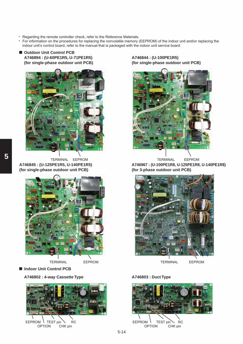
5-14
5
••
Regarding the remote controller check, refer to the Reference Materials.For information on the procedures for replacing the nonvolatile memory (EEPROM) of the indoor unit and/or replacing the indoor unit’s control board, refer to the manual that is packaged with the indoor unit service board.
TERMINAL EEPROM EEPROMTERMINAL
TERMINAL EEPROM TERMINAL EEPROM
EEPROM TEST pin RCOPTION CHK pin
TEST pin RCOPTION CHK pin
EEPROM
Outdoor Unit Control PCBA746894 : (U-60PE1R5, U-71PE1R5)(for single-phase outdoor unit PCB)
A746844 : (U-100PE1R5)(for single-phase outdoor unit PCB)
A746845 : (U-125PE1R5, U-140PE1R5)(for single-phase outdoor unit PCB)
A746967 : (U-100PE1R8, U-125PE1R8, U-140PE1R8)(for 3-phase outdoor unit PCB)
Indoor Unit Control PCB
A746802 : 4-way Cassette Type A746803 : Duct Type
Sec5.indd 14 2012/03/09 20:43:32

5-15
5
E05 Error in Indoor Unit Transmitting Signal to the Outdoor UnitError Detection Method
Error Diagnosis
It is judged an error when a unit itself cannot receive a signal that it has sent.Indoor unit control PC board errorThe setting of the terminal resistor select switch on the outdoor unit main PC board is set incorrectly.
••
For information on the procedures for replacing the indoor unit’s control PC board, refer to the manual that is packaged withthe indoor unit service board.
•
1.
2.
Is the terminal resistor select switch on the outdoor main PC board set to OPEN?
Is the indoor/outdoor operation line opened or shorted?
1-3
1-4
Replace the indoor unit control PC board.1-5
Is the indoor/outdoor operation line connected to more than one outdoor unit? (Network wired?)1-1
Is the SHORT on the terminal resistor select switch on the outdoor main PC board set to one unit, and the others are OPEN?1-2
Make the SHORTsetting1-4
Yes
No
1-21-3
YesNo
1-4Set the SHORT toone unit only
Yes
No
1 IndoorunitcontrolPC board
Correct the wiring1-5
YesNo
TERMINAL EEPROM EEPROMTERMINAL
TERMINAL EEPROM TERMINAL EEPROM
A746894 : (U-60PE1R5, U-71PE1R5)(for single-phase outdoor unit PCB)
A746844 : (U-100PE1R5)(for single-phase outdoor unit PCB)
A746845 : (U-125PE1R5, U-140PE1R5)(for single-phase outdoor unit PCB)
A746967 : (U-100PE1R8, U-125PE1R8, U-140PE1R8)(for 3-phase outdoor unit PCB)
Sec5.indd 15 2012/03/09 20:43:46

5-16
5
E06 Outdoor Unit Failed to Receive Serial Communication Signals from Indoor Unit
Error Detection Method(When indoor unit(s) are connected)
Error Diagnosis
It is judged an error when there is no transmission (reply) from the indoor unit to the outdoor unit for a period of three minutes.1.
2.
3 Remove the short3-2
Are the DISP pin and CHK pin on the indoor unit control PC board short-circuited?
Is the indoor unit powered off?1-1
Is the indoor/outdoor operation line shorted, opened, grounded or has a wrong contact? 2-1
3-1
Is the wireless remote controller connected to on the indoor unit’s control PC board?3-2
Power on2-1
Correct the wiring
3-1
3-33-5
Yes
Yes
Yes
No
No
No
Disconnect the connector mentioned above on the control PC boardof the indoor unit control PC board, and see whether the E06 goes offafter several minutes. (When doing so, if two remote controllers are being used and the wireless remote controller is the main remote controller, set the other remote controller as the main.)
3-3
Replace wireless remote control parts including wiring.3-43-5
3-4
3-5
Yes
No
Indoor unitscontrol PC board
1 Indoor unitpower
2 Indoor/outdoor operation line
Yes
No
The indoor unit is not turned on.The DISP pin of the indoor unit is shorted.
The signal output control PC board (optional control PC board) inside the indoor unit has failed.
••
•There is a short, open, wrong contact or grounding of the indoor/outdoor operation line.•
The thermistor inside the indoor unit is grounded.•
Indoor unit control PC board failure Replace board.
For information on the procedures for replacing the indoor unit’s control board, refer to the manual that is packaged withthe indoor unit control PCB.
•
EEPROM TEST pin RCOPTION CHK pin
TEST pin RCOPTION CHK pin
EEPROM
A746802 : 4-way Cassette Type A746803 : Duct Type
Sec5.indd 16 2012/03/09 20:43:57

5-17
5
E07 Outdoor unit sending failure to indoor unitError Detection Method
Error Diagnosis
It is judged an error when a unit itself cannot receive (discrepancy) a signal within a 3-minute period that it had sent.Outdoor main PC board errorThe setting of the terminal resistor select switch on the outdoor main PC board is set incorrectly.
••
For information on the procedures for replacing the outdoor main PC board, refer to the manual that is packaged with theservice board.
•
1.
2.
Is the terminal resistor select switch on the outdoor main PC board set to OPEN?
Is the indoor/outdoor operation line opened or shorted?
1-3
1-4
Replace the outdoor unit main PC board.1-5
Is the indoor/outdoor operation line connected to more than one outdoor unit? (Network wired?)1-1
Is the SHORT on the terminal resistor switch on the outdoor main PC board set to one unit, and the others are OPEN?1-2
Make the SHORTsetting1-4
Yes
No
1-21-3
YesNo
1-4Set the SHORT toone unit only
Yes
No
1 OutdoorunitcontrolPC board
Correct the wiring1-5
YesNo
TERMINAL EEPROM EEPROMTERMINAL
TERMINAL EEPROM TERMINAL EEPROM
A746894 : (U-60PE1R5, U-71PE1R5)(for single-phase outdoor unit PCB)
A746844 : (U-100PE1R5)(for single-phase outdoor unit PCB)
A746845 : (U-125PE1R5, U-140PE1R5)(for single-phase outdoor unit PCB)
A746967 : (U-100PE1R8, U-125PE1R8, U-140PE1R8)(for 3-phase outdoor unit PCB)
Sec5.indd 17 2012/03/09 20:43:59

5-18
5
E08 Duplicate Indoor Unit Address Settings Error
Error Detection Method
Error Diagnosis
It is judged an error if the addresses of indoor units are duplicated.
For information on the procedures for replacing the nonvolatile memory (EEPROM) of the indoor unit, refer to the manualthat is packaged with the indoor unit service board.
•
1.
2.
1
The indoor unit address settings are duplicated in the remote control detailed settings mode.The multiple unit DISP pin is shorted across the indoor unit whose address is Not Set.
••
Remove the short1-2
Is the DISP pin on the indoor unit control PC board shorted?1-1
Conduct checks prior to auto address setting.Does E08 fail to go off even after running auto address setting again?1-2
1-31-4
Yes
YesNo
No
1-3
Do not make changes to indoor unit addresses with the detailed settings of the remote controller.Make them in the remote control address change mode.
1-4
IndoorunitcontrolPC board
The nonvolatile memory (EEPROM) on the indoor unit board has failed.
Replace the EEPROM.
EEPROM DISP pin DISP pinEEPROM
A746802 : 4-way Cassette Type A746803 : Duct Type
Sec5.indd 18 2012/03/09 20:44:07

5-19
5
E09 More Than One Remote Controller Set to Main ErrorError Detection Method
Error Diagnosis
It is judged an error when more than one remote controller in a remote control group is set as the main remote controller.Forgot to set one remote controller to sub in a 2-remote control group.When using one wireless and one wired remote controller in a control group, forgot to set one of them to sub.
••
Method for setting a remote controller to sub (CZ-RTC2)•
1.
2.
Set one of the 2 remote controllers to sub.1-11 Remote
controller
Press and hold both + buttons for 4 seconds or longer.
Press button (Once the display changes from flashing to steady, the setting is complete).
Once you press button, the remote controller returns to its normal display.
This will display , the item “01” and the setting data “0001” or the like on the remote controller’s display.
Press Timer
1.
4.
5.
2.
3. / buttons to switch the setting data to “0000”. (0000:SUB 0001:Main)
Wireless remote controller
S003 (#3)Sub: I
Main: O
S003 (#3)Sub: ON
Main: OFF
S003 (#3)Sub: ON
Main: OFF
CZ-RWSL2
CZ-RWSU2
Cable clamp
PCB cover Adjustable Corner Cap
Receiver PCB
ON
1234
Screw
CZ-RWST2
S003
DIP Switch 3
CZ-RWSC2
Main/Sub Switch
Sec5.indd 19 2012/03/09 20:44:10

5-20
5
E12 Automatic address setting start is prohibited while auto-address setting in progress.
Error Detection Method
Error Diagnosis
It is judged an error if a command to start auto address setting comes from another controller during auto address setting.
For information on the procedures for replacing the Indoor unit control PC board, refer to the manual that is packaged with theindoor unit service board.
•
1.
2.
1
This occurs in a system that has more than one outdoor unit and operating lines among the indoor/outdoor units (networked wiring), when an instruction to start auto address setting is given from another controller during the auto address setting process.
•
When one controller in a networked system is running auto address setting, it is not possible to start auto address setting from another controller. Wait until the auto address setting in progress finishes.
1-1AutoAddress
E13 Error in Indoor Unit Transmitting Signal to Remote Controller
Error Detection Method
Error Diagnosis
It is judged an error when an indoor unit cannot itself receive a signal that it sent to its remote controller(s).1.
2.
1
Indoor unit control PC board faulty•The remote control’s wires 1(white) and 2(black) are shorted or opened.•
Are the remote control’s wires 1(white) and 2(black) are shorted oropened?Replace the indoor unit control PC board.1-2
1-1Indoor unitcontrolPCB
Correct the wiring1-2
YesNo
Sec5.indd 20 2012/03/09 20:44:11
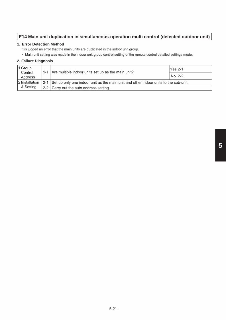
5-21
5
E14 Main unit duplication in simultaneous-operation multi control (detected outdoor unit)Error Detection Method
Failure Diagnosis
It is judged an error that the main units are duplicated in the indoor unit group.Main unit setting was made in the indoor unit group control setting of the remote control detailed settings mode.•
1.
2.
Carry out the auto address setting.2-2
Are multiple indoor units set up as the main unit?1-1
Set up only one indoor unit as the main unit and other indoor units to the sub-unit.2-1
2-1
2-2
Yes
No2 Installation
& Setting
1 Group Control Address
Sec5.indd 21 2012/03/09 20:44:12

5-22
5
E15 Automatic address alarm (capacity too low) Error Detection Method
It is judged an error the total capacity of indoor units replied by communication is fewer than that of outdoor units. (This is detected even when auto address setting is not used.)
Connecting indoor unit
The total capacity of indoor units is fewer than that of outdoor units.•Some indoor unit(s) are connected but power is not turned on.•The CHK pin (CN062/CN071) and/or TEST pin (CN064) of the indoor unit is shorted when its power is turned on.•High voltage was applied (over AC200V) in the indoor/outdoor operations line circuit.•
1.
Is the indoor unit powered off?1-1
Was the number of indoor units changed after auto address setting finished?3-1
Conduct checks prior to auto address setting. 3-2
3-23-1
YesNo
Power on2-1
YesNo
Was a high voltage (over AC200V) applied in the indoor/outdoor operations line circuit?2-2
2Is the indoor/outdoor control line opened or shorted?2-1
Correct the wiring2-2
YesNo
Indoor/outdoorcontrol line
3 No. ofIndoorUnits
1 PowerSource
Error Diagnosis2.
3-24-1
YesNo
Disconnect the connector mentioned above on the control PC boardof the indoor unit control PC board and see whether the E15 goes offafter several minutes. (When doing so, if two remote controllers are being used and the wireless remote controller is the main remote controller, set the other remote controller as the main.)Replace wireless remote control parts including wiring.
4-3
4-4
Is the LED blinking on the indoor unit’s control PC board?4-5
Set the number of the indoor unit setting at No.10 on the outdoor unit’s control PC board. And compare the status of the indoor unit’s connection setting at No.9 (indoor unit check). Then, make a detailed examination of any absent indoor units.
5-1
The nonvolatile memory (EEPROM) on the indoor unit’s control board is either not installed,improperly installed or the nonvolatile memory is faulty. Correct this or after replacing thenonvolatile memory, write model data to it in the remote control detailed settings mode.
4-6
Are the CHK pin and TEST pin on the indoor unit control board short-circuited?4-1
Is the wireless remote controller connected to on the indoor unit’s control PC board?4-2
4-4
4-5
Yes
No
Remove the short4-2
YesNo
4-34-5
YesNo
4 IndoorunitcontrolPC board
5 Outdoorunit controlPC board
4-65-1
YesNo
For information on the remote control’s detailed settings, refer to the Reference Materials.•
For information on the procedures for replacing the nonvolatile memory (EEPROM) of the indoor unit, refer to the manualthat is packaged with the indoor unit service board.
•
EEPROM TEST pin RCOPTION CHK pin
TEST pin RCOPTION CHK pin
EEPROM
A746802 : 4-way Cassette Type A746803 : Duct Type
Sec5.indd 22 2012/03/09 20:44:12

5-23
5
E16 Automatic address alarm (capacity too high)
Error Detection Method
Error Diagnosis
It is judged an error the total capacity of indoor units replied by communication is more than that of outdoor units. (This is detected even when auto address setting is not used.)
1.
2.
1
The total capacity of indoor units is more than that of outdoor units.•
Conduct checks prior to auto address setting. 1-1AutoAddress
Sec5.indd 23 2012/03/09 20:44:13

5-24
5
2
Remove the short2-1
Are the CHK pin, TEST pin and DISP pin on the indoor unit control PC board short-circuited?
Is the indoor unit powered off?1-1
1-2
3-4
Is the remote control group’s wiring opened?2-1
Is the wiring of the remote control group wired according to the wiring diagram?2-3
Run the auto address setting again.2-4Run the auto address setting again after correcting the wiring of the remote control group.2-5
Power on
1-2
Correct the wiring2-2
2-42-5
Yes
Yes
Yes
Yes
No
No
No 2-3
3-1
Yes
No
No
Check the group settings (Item Code 14) from the remote control’sdetailed settings mode. Is the main remote controller (1) set to more than one remote controller or to separate (0)?
2-2
SubstituteSubRemote Controller
3
1 Indoor Unit
E18 Faulty Communication in Group Control WiringError Detection Method
Error Diagnosis
When the main remote controller cannot communicate with a sub remote controller in the remote control group. It is judged an error if a sub remote controller in a remote control group fails to communicate with the main remote controller for a period of three minutes.
An indoor unit within the control group does not have its power on.The CHK pin and TEXT pin on the indoor unit in the control group are shorted.
Remote control group wiring is opened.More than one indoor unit in the control group is set to Main.An indoor unit in the control group is set to Separate.
•
••
•
•The DISP pin of an indoor unit sub remote controller in the control group is shorted.•
1.
2.
Replace wireless remote control parts including wiring.Replace the indoor unit control PC board.
3-3
Is the wireless remote controller connected to on the indoor unit’s control PC board?3-1
Disconnect the connector mentioned above on the control PC boardof the indoor unit control PC board, and see whether the E18 goes offafter several minutes. (When doing so, if two remote controllers are being used and the wireless remote controller is the main remote controller, set the other remote controller as the main.)
3-2
Yes
3-23-4No
3-3
3-4
Yes
No
IndoorunitcontrolPCB
For information on the remote control’s detailed settings, refer to the Reference Materials.•For information on the procedures for replacing the Indoor unit control PCB, refer to the manual that is packaged with theindoor unit service board.
•
EEPROM TEST pinRC
CHK pinOPTION DISP pin
TEST pinRCOPTION CHK pin
CHK pinEEPROM
A746802 : 4-way Cassette Type A746803 : Duct Type
Sec5.indd 24 2012/03/09 20:44:14

5-25
5
E20 No indoor units connected
Error Detection Method
Error Diagnosis
It is judged an error if an indoor unit cannot be recognized at the start of auto address setting or when the outdoor unit is turnedon.
1.
2.
The indoor unit is not turned on.•The address(es) of indoor unit(s) are not assigned correctly.•
The indoor/outdoor control line may be disconnected somewhere between the indoor unit(s) and the outdoor unit. Check and make sure the indoor/outdoor control line is connected.
Are the address(es) of indoor unit(s) assigned correctly?1-1
Are the indoor units turned on?1-2
1-3
1-2Set its address1-3Power on
YesNo
1 Indoor Unit
YesNo
Sec5.indd 25 2012/03/09 20:44:15

5-26
5
F04 Compressor discharge temperature sensor (TD) troubleError Detection Method
Error Diagnosis
It is judged an error based on the criteria listed below.Open circuit or Short circuitWhen compressor stopped temporally, even after 20 minutes passed, over 103°C of discharge temperature is detected.
••
1.
2.
Compressor stopped and remained over 60 minutes but over 93°C of discharge temperature is detected.•
Sensor connector is connected to PC board properly.1-1
Sensor is correctly installed at holder side.1-2
1-2Reconnect and checkReplace sensorCorrect and see what happens.1-3
YesNo
1 Sensor
2 PC board
3 Operating status
YesNo
Resistance between connector pins on PC board is less than 1 k ohm
2-1Replace PC board2-2
YesNo
Peripheral temperature of outdoor unit is over 46°C.3-1
Check noise.3-3
Correct 3-2
YesNo
Tends to have insufficient refrigerant charge in the system.3-2Adjust the amount of refrigerant3-3
Yes
No
Abnormal temperature exists even after replacing PC board.2-23-1See what happens.
YesNo
Abnormal temperature exists even after replacing sensor.1-32-1See what happens.
YesNo
Sec5.indd 26 2012/03/09 20:44:15

5-27
5
F06 Inlet temperature sensor (C1) in heat exchanger trouble
Error Detection Method
Error Diagnosis
1.
2.
In case of open or short•
Outdoor unit control PCB failureReplace PCB with a new one.
Is the connector properly connected to PCB?1-1
Is the resistor between the sockets infinity or 0Ω?1-2
2-1
1-2Reconnect & checkReplace sensor.2-1
YesNo
1 Sensor Trouble
2 Control PCB Failure
YesNo
Sec5.indd 27 2012/03/09 20:44:16

5-28
5
F07 Intermediate temperature (C2) in heat exchanger troubleError Detection Method
Error Diagnosis
It is judged an error when open circuit or short circuit.1.
2.
Sensor connector is connected to PC board properly.1-11-2Reconnect and check
YesNo
1 Sensor
2 PC boardReplace PC board because of outdoor control PC board failure.2-1
Resistance between sockets is infinity or 0 ohm.1-2Replace sensor2-1
YesNo
Sec5.indd 28 2012/03/09 20:44:16

5-29
5
F08 Outdoor air temperature sensor (TO) troubleError Detection Method1.It is judged an error when open circuit or short circuit.
Error Diagnosis2.
Sensor connector is connected to PC board properly.1-11-2Reconnect and check
YesNo
1 Sensor
2 PC boardReplace PC board because of outdoor control PC board failure.2-1
Resistance between sockets is infinity or 0 ohm.1-2Replace sensor2-1
YesNo
Sec5.indd 29 2012/03/09 20:44:16

5-30
5
F12 Compressor inlet suction temperature sensor (TS) troubleError Detection Method
Error Diagnosis
It is judged an error when open circuit or short circuit.1.
2.
Sensor connector is connected to PC board properly.1-11-2Reconnect and check
YesNo
1 Sensor
2 Outdoor control PC board
Replace PC board because of outdoor control PC board failure.2-1
Resistance between sockets is infinity or 0 ohm.1-2Replace sensor2-1
YesNo
Sec5.indd 30 2012/03/09 20:44:16

5-31
5
F31 Outdoor unit nonvolatile memory (EEPROM) troubleError Detection Method
Error Diagnosis
It is judged an error based on the criteria listed below.When power initially turned ON for the first time, nonvolatile memory (EEPROM) is not installed.Read values after writing onto nonvolatile memory (EEPROM) is inconsisntent.
••
1.
2.
Does EEPROM exist on the control PC board?1-11-2Install EEPROM
YesNo
1 PC board
Incorrect EEPROMReplace with correct EEPROM.1-3
Is EEPROM installed properly? (Check: Bent IC pin or incorrect installation, etc.)
1-21-3Correct
YesNo
Sec5.indd 31 2012/03/09 20:44:17

5-32
5
Check power supply1-3
Extreme voltage fluctuations
Not satisfied with +10% rated supply voltage1-1
1-2
Extreme distortion of voltage waveform1-3
Instantaneous blackout may sometimes occur.1-4
Check power supply1-2
Check power supply1-4Check power supply2-1
Yes
Yes
Yes
Yes
No
No
No
No
1 Power supply*
H01 Primary (input) overcurrent detected
Error Detection Method
Error Diagnosis
Primary current effective value detected overcurrent (trip current value).Trip current value
Single-phase model
hp = horse power•
1.
2.
2 2-32-2
Loose electrical wire connection
2-1
Correct wiring2-3
Has FUSE 1/FUSE 2 blown? Check the electrical conduction with tester.
2-2
Yes
YesNo
NoReplace CR board.2-3
PC board wiring
Check not only in the outdoor unit stop mode but in the drive mode.*
Heating
Cooling
2.5 hp
20.0A
18.5A
3 hp
20.0A
18.5A
4 hp
27.0A
27.0A
5 hp
29.0A
29.0A
6 hp
30.0A
30.0A
Trip current value
3-phase model
hp = horse power
Heating
Cooling
4 hp
12.5A
12.0A
5 hp
13.5A
12.6A
6 hp
14.5A
13.0A
FUSE1 FUSE1
FUSE1 FUSE1
A746894 : (U-60PE1R5, U-71PE1R5)(for single-phase outdoor unit PCB)
A746844 : (U-100PE1R5)(for single-phase outdoor unit PCB)
A746845 : (U-125PE1R5, U-140PE1R5)(for single-phase outdoor unit PCB)
A746967 : (U-100PE1R8, U-125PE1R8, U-140PE1R8)(for 3-phase outdoor unit PCB)
Sec5.indd 32 2012/03/09 20:44:17

5-33
5
H02 PAM trouble (Single-phase only)
Error Detection Method
Error Diagnosis
Error is detected by over-voltage and overcurrent of DC side.1.
2.
•
1-1
1-2
1-3
1-2Check power supply1-3
YesNo
1 Powersupply*
YesNo
2-1
2-2
2-3
Correct connection2-2Correct connection or wiring2-3
YesNo
2 PC board wiring
Yes
No
Extreme voltage fluctuations
Extreme distortion of voltage waveform
Check power supply
2-1YesNo
Check power supply
Loose electrical wire connection
Is HIC PC board connector (CN-PAM) poorly connected or opened with wire?
Replace HIC PC board.
Check not only in the outdoor unit stop mode but in the drive mode.*
Not satisfied with +10% rated supply voltage
Sec5.indd 33 2012/03/09 20:44:24

5-34
5
Turn the power on again and run the outdoor unit.Is alarm occurred after operation?1-1
Replace CR board.
See what happens.
Yes
No
1 Check the controlPC board
H03 Primary current CT sensor (current sensor) failure
Error Detection Method
Error Diagnosis
If 18A or greater is detected when the compressor is stopped (alarm triggered even if the connector is unplugged).•If no current is detected even though a compressor is running.•
1.
2.
It is judged an error based on the criteria listed below.
Sec5.indd 34 2012/03/09 20:44:24

5-35
5
H05 Sensor failure, Compressor discharge temperature sensor (TD) disconnected
Error Detection Method(In case of outdoor temperature over 5°C) For 10 minutes since started, variation of discharge temperature is always detected within 2°C comparing with the temperature just before starting.
1.•
(In case of outdoor temperature less than 5°C) For 30 minutes since started, variation of discharge temperature is always detected within 2°C comparing with the temperature just before starting.
•
1-1
1-2Reinstall correctly.
YesNo
1 Sensor Trouble
Replace the sensor with a new one.
1-2Is the sensor properly installed at the holder side?
Sec5.indd 35 2012/03/09 20:44:25

5-36
5
H31 HIC trouble
Error Detection Method
Error Diagnosis
HIC overcurrent due to HIC fault
1.
2.
•HIC abnormal heat caused by defective HIC or HIC radiation error•Signal line is not connected properly or opened between the HIC and the outdoor CR board.•
Measure with an analog tester. (Set to the k ohm range)•Measure the board by itself. (Remove wires connected from other parts.)•Measure using IPM terminals.
Conforming part resistance value (measure with an analog tester)•
Excepting the parts of “value is “0 = short-circuit”.
”, it is acceptable if a small resistance value appears as a reference value unless the •
HIC board IPM Pass/Fail Tests
It is judged an error if the computer detects an error signal from the HIC.An error signal is issued by the HIC if abnormal heat occurs inside the HIC or if there is an overcurrent.However, it is judged an error in the same way if the signal line from the HIC is not connected properly or opened.
1-1
1-2
2-1
3-1
Correct wiring (connector)
Correct wiring (connector)
3-1 : Single-phase model 2-1 : 3-phase model
3-1
Replace wiring
YesNo
1 Wiring between HIC &outdoor control PC board
Yes
Yes
No
No
3-2
4-1
4-2
4-1
Remove foreign matter
Replace the HIC PC board
4-2
Yes
No
3
2
HIC poorradiation
Yes
No
Everything is normal in the wiring (power cord & signal line) between the HIC and the outdoor CR board. Check the wiring one by one with a tester if there is opened and grounding.
The heat dissipating surface on the back of the HIC is in good contact with the heat sink (heat dissipating fins) of the electrical box. Check for looseness in the fastening screws and the condition of the heat-conducting putty.
1-2
Tighten screw(s),add putty
Yes
No
3-2
Refer to alarm code P16
Yes
No
Replace the HIC PC board
4 HIC overcurrent
A good flow of cooling air passes through the heat sink (heat dissipating fins) of the electrical box. Check for debris blocking the fins.
The results of the pass/fail tests for the following HIC board IPM show it to be outside the range of the resistance of a conforming part.
The inverter compressor was stopped/started more than 10 times and it triggered H31 at a high rate. If alarm code P16 occurs at times, refer to the alarm code P16.
The wiring (power cord and signal line) between the HIC and the outdoor CR board is connected properly.
The connector CN-PRY1 on the CR PC board is connected properly (locked). (3-phase only)
Tester terminals
-
Resistance value (ohm)
U
1 k to 5 k
V
1 k to 5 k
W
1 k to 5 k
U
1 k to 5 k
V
1 k to 5 k
W
1 k to 5 k
NU
5 k to 10 k
U
100 k to
V
100 k to
W
100 k to
P
100 k to
P NU+
Tester terminals
+
Resistance value (ohm)
P NU-
U
100 k to
100 k to
V
100 k to
W
100 k to
Check theoutdoorunit CRPC board
Sec5.indd 36 2012/03/09 20:44:25

5-37
5
Excepting the parts of “value is “0 = short-circuit”.
”, it is acceptable if a small resistance value appears as a reference value unless the •
Tester terminals
-
Resistance value (ohm)
U
1 k to 10 k
V
1 k to 10 k
W
1 k to 10 k
U
1 k to 10 k
V
1 k to 10 k
W
1 k to 10 k
HIC-
5 k to 20 k
U
20 k to
V
20 k to
W
20 k to
HIC+
20 k to
HIC+ HIC-+
Tester terminals
+
Resistance value (ohm)
HIC+ HIC--
U
20 k to
20 k to
V
20 k to
W
20 k to
Sec5.indd 37 2012/03/09 20:44:25

5-38
5
Outdoor Unit Control HIC PCB
Outdoor Unit Control PCB
A746895 : (U-60PE1R5, U-71PE1R5)(for single-phase outdoor unit HIC PCB) (for single-phase outdoor unit HIC PCB)
A746847 : (U-125PE1R5, U-140PE1R5)(for single-phase outdoor unit HIC PCB) (for 3-phase outdoor unit PCB)
A746846 : (U-100PE1R5)
A746967 : (U-100PE1R8, U-125PE1R8, U-140PE1R8)
NWVUP
PUVWNU
PUVWNU
PUVWNU
(for 3-phase outdoor unit PCB)A746967 : (U-100PE1R8, U-125PE1R8, U-140PE1R8)
CN-PRY1
Sec5.indd 38 2012/03/09 20:44:25

5-39
5
L04 Outdoor unit address duplication
Error Detection Method
Error Diagnosis
It is judged an error when the identical self-address communication on the indoor and outdoor wirings is received over 5 times within 3 minutes.
1.
2.
Are other outdoor units using a duplicate setting?1-12-1
2-2
Yes
No
2 When units are networked, first set the system address for each outdoor unit in the order 1-2-3 and then run auto address setting.2-1
Run the auto address setting.2-2
Installationor settingrelated
1 Systemaddress
Sec5.indd 39 2012/03/09 20:44:29

5-40
5
Was EEPROM replaced when PC board was replaced?1-12-1
Replace EEPROM
Yes
No
1 Check the control PC board
L10 Outdoor unit capacity not set
Error Detection Method
Error Diagnosis
1.
2.
Set an applicable capacity value on the item code 81 display of maintenance remote controller.2-1
2 Installationor settingrelated
It is judged an error when outdoor unit capacity not yet setup or systematically unauthorized setting.
Check : Connect the outdoor maintenance remote controller and check whether item code 81 outdoor capacity value shows “0” or unauthorized capacity is set on the detailed setting mode display of the outdoor EEPROM. If the capacity value of the item code 81 with the outdoor maintenance remote controller is incorrect, recorrect and set it again.
•
* After setting the capacity value, be sure to reset the power supply switches of both indoor and outdoor units.
Sec5.indd 40 2012/03/09 20:44:30

5-41
5
L13 Indoor unit type setting errorError Detection method1.
Are models for outdoor and indoor units matched respectively?(Ex: Are multiple indoor units connected to commercial outdoor units?)1-1
2-1Replace indoor units.
YesNo
3-1
Change installation.
Yes
No
2 Check the indoor unit’s motor valve with the remote control detailed settings mode (2C code) and commercial indoor unit is set to “2” and multiple indoor unit is “0”.
2-1
Check whether or not indoor and outdoor unit operating wires are short circuit, disconnection, loose connection or earth fault. 3-1
Installation Failure
3 Operating Wires for Indoor & Outdoor Units
1 Discordance Unit
Discordance model(s) between outdoor and indoor units are detected.•
Sec5.indd 41 2012/03/09 20:44:30

5-42
5
L18 4-way valve operation failureError Detection Method
Error Diagnosis
It is judged an error when during heating operation (Comp. ON), the highest detected temperature at an outdoor unitheat exchanger (C1) was 20°C or more above the outdoor air temperature (Air Temp.) continuously for 5 minutes or longer, or the detected suction temperature (SCT) was 20°C or more above the outdoor air temperature continuously for 5 minutes or longer.
1.
2.
Is the connector wired from the 4-WAY valve plugged in the CN-20S connector on the HIC PC board properly?1-1
1-2Correct connector
YesNo
2
Has the 4-way valve wiring become opened?1-2
Is the wire from the coil for controlling the 4-way valve firmly connected to the 4-way valve?1-3
4-way valve
1 PC board wiring
Correct wiring1-3
YesNo
2-1Correct connector
YesNo
During heating mode (Comp. ON), insert and remove the connector wired from the 4-WAY valve into or from CN-20S connector on the HIC PC board. At the same time, does the ON & OFF sounds occur from the 4-way valve?
2-12-2
Replace HIC PC board
Yes
No
During heating mode (Comp. ON), does the alarm code L18 reproduce for 5 minutes or longer after insertion and removal of CN-20S connector wired from the 4-way valve connector on the HIC PC board?
2-2
The parts inside the 4-way valve might have fixed at the cooling side.Replace the 4-way valve2-3
2-3
See what happens
Yes
No
Sec5.indd 42 2012/03/09 20:44:30

5-43
5
P03 Compressor discharge temperature trouble
Error Detection Method
Error Diagnosis
1.
2.
When the discharge temperature is over 106°C.•
1-1
1-2
2-1
2-2
Adjust the refrigerant amountReplace CR board
Yes
No
1 Adjustment to refrigerant charge
Yes
No
2-2
2-3
2-4
Avoid clogging2-32-4Replace the electronic control valve
YesNo
2 Blockage in refrigerant circuit
Yes
No
Tends to have insufficient refrigerant charge in the system.
Service valve inside the outdoor unit closed
Additional refrigerant charge
2-2YesNo
Open service valve
Replace CR boardYesNo
Replace the strainer
Are the tubes clogged?
Is the outdoor unit’s electronic control valve operating correctly? (Check for debris clogging the electronic control valve, a problem with the electronical coil and/or the control PC board.)
Is it observable difference in status of the dew or frost between the strainer’s primary and secondary sides?
Not additional refrigerant charged
Sec5.indd 43 2012/03/09 20:44:30
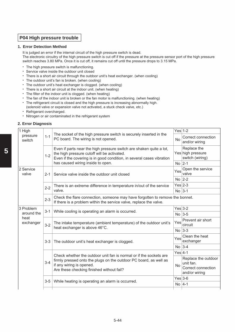
5-44
5
The socket of the high pressure switch is securely inserted in the PC board. The wiring is not opened.1-1
1-2Correct connection and/or wiring
Yes
No
Even if parts near the high pressure switch are shaken quite a lot, the high pressure cutoff will be activated. Even if the covering is in good condition, in several cases vibration has caused wiring inside to open.
1-2
Replace the high pressure switch (wiring)2-1
Yes
No
1 High pressureswitch
Service valve inside the outdoor unit closed2-1Open the service valve2-2
Yes
NoThere is an extreme difference in temperature in/out of the service valve.2-2
2-33-1
YesNo
Check the flare connection, someone may have forgotten to remove the bonnet.If there is a problem within the service valve, replace the valve.2-3
While cooling is operating an alarm is occurred.3-13-23-5
YesNo
The intake temperature (ambient temperature) of the outdoor unit’s heat exchanger is above 46°C.3-2
Prevent air short circuit3-3
Yes
No
The outdoor unit’s heat exchanger is clogged.3-3Clean the heat exchanger3-4
Yes
No
Check whether the outdoor unit fan is normal or if the sockets are firmly pressed onto the plugs on the outdoor PC board, as well as if any wiring is opened. Are these checking finished without fail?
3-4
4-1Replace the outdoorunit fan. Correct connection and/or wiring
Yes
No
While heating is operating an alarm is occurred.3-53-64-1
YesNo
2 Servicevalve
3 Problemaround theheatexchanger
P04 High pressure trouble
Error Detection Method
Error Diagnosis
It is judged an error if the internal circuit of the high pressure switch is dead.The electronic circuitry of the high pressure switch is cut off if the pressure at the pressure sensor port of the high pressureswitch reaches 3.80 MPa. Once it is cut off, it remains cut off until the pressure drops to 3.15 MPa.
The high pressure switch is malfunctioning.•Service valve inside the outdoor unit closed•There is a short air circuit through the outdoor unit’s heat exchanger. (when cooling)•The outdoor unit’s fan is broken. (when cooling)•The outdoor unit’s heat exchanger is clogged. (when cooling)•There is a short air circuit at the indoor unit. (when heating)•The filter of the indoor unit is clogged. (when heating)•The fan of the indoor unit is broken or the fan motor is malfunctioning. (when heating)•The refrigerant circuit is closed and the high pressure is increasing abnormally high. (solenoid valve or expansion valve not activated, a stuck check valve, etc.)
•
Refrigerant overcharged.•Nitrogen or air contaminated in the refrigerant system•
1.
2.
Sec5.indd 44 2012/03/09 20:44:30

5-45
5
The intake temperature (ambient temperature) of the indoor unit is above 36°C.3-6
Prevent air short circuit3-7
Yes
No
The filter of the indoor unit is clogged.3-7Clean the filter3-8
YesNo
The fan of the indoor unit is broken or the fan motor is faulty.3-8Replace the indoor fan (motor)4-1
Yes
No
Is the outdoor unit’s electronic control valve operating correctly? (Check for debris clogging the electronic control valve, a problem with the electronical coil and/or the control PC board.)
4-1
4-3Repair the electronic control valve of the outdoor unit
Yes
No
If an alarm is occurred with the high pressure below 3.80 MPa, with the pressure measured as displayed by the manifold gauge, check the check valve in the compressor discharge line. Are these checking finished without fail?
4-3
4-4Replace the checkvalve in thecompressordischarge line
Yes
No
The electronic control valve is faulty. In systems where the solenoid valve kits and the ice thermal storage tank are connected, check these solenoid valves.
4-4
Replace the electronic control valve and/or solenoid valve.5-1
Yes
No
The indoor unit’s expansion valve is operating correctly.(check for debris clogging the valve, a problem with the electronical coil and/or the control PC board)
4-2
4-3Repair the expansionvalve of the indoorunit
Yes
No
3 Problemaround theheatexchanger
4 Blockagein therefrigerantcircuit
Error occurs when the system is operating in cooling mode.5-15-35-2
YesNo
An alarm is occurred with the high pressure at 3.80 MPa, with the pressure measured either as displayed by the monitoring software or with a manifold gauge, at which time the temperature of liquid in the outdoor unit’s heat exchanger is detected to be at the temperature of the outside air.
5-35-5
Contact the servicerepresentative
Yes
No
An alarm is occurred with the high pressure at 3.80 MPa, with the pressure measured either as displayed by the monitoring software or with a manifold gauge, at which time the temperature of liquid in the indoor heat exchanger is detected to be at room temperature (intake temperature).
5-4
5-5
Contact the servicerepresentative
Yes
No
The system may be overcharged. Check how much refrigerant was added during installation.When a system is inspected for airtightness, it is seldom that enough nitrogen has been expelled, so some remains in the circuit. In this case, it is necessary to collect the refrigerant and then recharge the system.
5-5
Error occurs when the system is operating in heating mode.5-25-4
5-5
Yes
No
5Overcharging
Sec5.indd 45 2012/03/09 20:44:30

5-46
5
1-1
1-4 : Single-phase model 1-2 : 3-phase model
3-1 : Single-phase model 2-1 : 3-phase model
Check for open circuit and the voltage at the breaker. if a problem is found, fix it and check again.
Yes
No
Turn the power back on and check again. Is the alarm triggered again?1-4
2-1
Power wiring N-phase is connected.
Power wiring L2 and N are reverse connected. (3-phase only)
The connector CN-PRY2 on the outdoor CR PC board is connected properly (locked). (3-phase only)
1-2
1-3
4-1
Yes
No
Correct wiring1-3
YesNo
Correct wiring1-4
YesNo
1 Check the power supply &the wiring
Are the wires (RE1, RE2) from the reactor firmly installed?3-13-2Correct wiring
YesNo
Turn the power back on and check again. Is the alarm triggered again?3-2
Replace the outdoor unit HIC PC board. 4-1
Yes
No
3 Check theoutdoorunit HIC PC board
2 Check theoutdoorunit CRPC board
There may be a instantaneous blackout failure. If there is nothing abnormal, see what happens.4-14 Final check
P05 AC power supply trouble
Error Detection Method
Error Diagnosis
Instantaneous blackout•
Note : The work involved in diagnosing each of the items is extremely dangerous, so turn the power off at the breaker beforeperforming the tests.
Zero-cross (waveform input of power supply) error•DC voltage charge failure•
1.
2.
Is the voltage on each of the terminal boards within +10% of the rated voltage?
Correct wiring (connector)
3-1Yes
No
4hpCommon in RE1 and RE2
: Plug-in type5hp, 6hp : Fastening screw type
*
3-phase outdoor unit HIC PC board
(for 3-phase outdoor unit CR PC board)
Single-phase outdoor unit HIC PC boardRE1*
RE2*
RE1
RE2
CN-PRY2
Sec5.indd 46 2012/03/09 20:44:30

5-47
5
P13 Alarm valve open
Error Detection Method
Error Diagnosis
1.
2.
Detection is performed only in the test run. When once detected or the test run finished without any error, the second detection will not be done. In case of forgetting to open a valve, P04 (high-pressure switch operational alarm) is occasionally preceded due to the following conditions.
The status of small temperature change of the oprating indoor unit continues for 3 minutes even after 5-minute to 15-minute since the cooling test run has started.
•
The status of small temperature change of the oprating indoor unit continues for 3minutes even after 7-minute to 15-minute since the heating test run has started.
•
1-12-1
Yes
No
1 Service valve
Open the service valve
2-1
2 Adjustment to refrigerant change
3 Blockage in refrigerant circuit
3-1Avoid clogging3-2
YesNo
Are the tubes clogged?
Not additional refrigerant charged3-1
Yes
No
Additional refrigerant charge
3-2
3-3Replace the electronic control valve
Yes
No
Is the outdoor unit’s electronic control valve operating correctly? (Check for debris clogging the electronic control valve, a problem with the electronical coil and/or the control PC board.)
3-3 As the second detection is not done, restart and see what happens if there is no error.
Service valve inside the outdoor unit closed
Sec5.indd 47 2012/03/09 20:44:33

5-48
5
1-13-12-1
YesNo
1 System configuration
Is the indoor EEPROM setting, item code 0B, on the indoor unit’s control PC board set to 0001?2-1
After correcting thesetting, 3-14-1
Yes
No
2 Indoor unit’sEEPROMsetting
P14 O2 sensor detect
Error Detection Method
Error Diagnosis
It is judged an error whenever the outdoor unit receives the signal “O2 Alarm Occurred” from the indoor unit.•With the indoor unit’s EEPROM setting (item code 0B) set to 0001, the EXCT input was shorted.•
1.
2.
Is an O2 sensor being used?
Correct wiring4-1
YesNo
Is the indoor EXCT socket (wire) shorted?3-13
4
Indoor EXCTwiring
4-34-2
YesNo
Is the alarm triggered if the indoor EXCT socket (wire) is disconnected, and the power is reset?
Since there is no error, see what happens.
4-1
4-2
4-3 Indoor unit control PC board error replace PC board.
Indoor unit’scontrol PC board
Sec5.indd 48 2012/03/09 20:44:34

5-49
5
FFOFFO1
123456789
101112131415161718192021222324252627282930
123456789012345678901234567890
OFFOFFOFFOFFOFFOFFOFFOFFOFFONONONONONONONONONONOFFOFFOFFOFFOFFOFFOFFOFFOFFOFFON
OFFOFFOFFOFFOFFOFFOFFOFFOFFOFFOFFOFFOFFOFFOFFOFFOFFOFFOFFONONONONONONONONONONON
Table 1. Setting the System Address [S002: Rotary switch (yellow), S003: 2P DIP (black)]
Outdoor system address No.
1 refrigerantsystem only
Link wiring
2P (20s digit)1P (10s digit)S002 setting (systemaddress switch)
S003 setting
0
Sec5.indd 49 2012/03/09 20:44:34

5-50
5
P16 Compressor overcurrent trouble
Check of content2.
Meaning of Alarm1.
Single-phase model (2.5hp – 3hp) : Trip current = 23.0 ASingle-phase model (4hp – 6hp) : Trip current = 27.0 A
Single-phase model (4hp – 6hp) : Trip current = 45.0 Apeak
Single-phase model (2.5hp – 3hp) : Trip current = 28.0 Apeak
3-phase model (4hp – 6hp) : Trip current = 17.0 A
3-phase model (4hp – 6hp) : Trip current = 24.0 Apeak
Secondary current effective value detected the overcurrent (trip current value). •
Secondary current instantly detected overcurrent (trip current value). •
0-1-
YesNo
0 Multiplefactors
7-1
0-2
1 PowerSource
2 Boardwiring
3Compressorwiring
1-1Correct the wiring1-2
YesNo
Power cord connections are loose.
Replaced the board, but it occurred again immediately.
-
Yes
No
Replace compressor along with adding oil, then recheck from 1-1
1-2Test the power supply1-3
YesNo
Test the power supply1-4
YesNo
1-3 Extreme fluctuations in voltage.
Test the power supply2-1
YesNo
1-4 An open phase state is observed.
Replaced the compressor (added oil, if it was necessary) but it occurred again immediately.
Rated power voltage is not within ±10%.
2-1Correct
2-2
Yes
No
Disconnected parts, miswiring and/or poor connections (loose) are observed in the connections on the CR board and/or in the connections of components that are connected by wiring from the CR board.
2-2Correct
2-3
Yes
No
Correct
2-4
Yes
No2-3
Disconnected parts, miswiring and/or poor connections (loose) are observed in the connections of outdoor board(s) that are connected by wiring from the HIC board.
Correct
2-5
Yes
No2-4
Disconnected parts, miswiring and/or poor connections (loose) are observed in the connections of HIC boards connected by wiring from the CR board.
Correct
2-6
Yes
No2-5
Disconnected parts, miswiring and/or poor connections (loose) are observed in the connections of HIC board(s) that are connected by wiring from the outdoor board.
Correct
3-1
Yes
No2-6
Disconnected parts, miswiring and/or poor connections (loose) are observed in the connections of HIC board(s) that are connected by wiring to a compressor.
Disconnected parts, miswiring and/or poor connections (loose) are observed in the connections of outdoor board(s) that are connected by wiring from the CR board.
3-1Correct3-2
YesNo
Disconnections and/or miswiring are observed in the connecting location of the compressor terminals.
3-2
Eliminate looseness bychanging the terminals, or crimping the terminals again.4-1
Yes
No
Conditions such as burned terminal covers and/or discolored terminals are observed in the connecting location of the compressor terminals.
Sec5.indd 50 2012/03/09 20:44:34

5-51
5
Outdoor air intake temperature is high.4-1Take measures4-2
YesNo
May be caused by poor outdoor unit air flow (dirty or clogged heat exchanger, blocked discharge port, etc.)4-2
Correct4-3
YesNo
Air short circuit has occurred. This is a phenomenon when discharged air (exhaust heat) from the outdoor unit is drawn back into the suction vent.
4-3Prevent air short circuit4-4
Yes
No
Indoor air intake temperature is high.4-4Take measures4-5
YesNo
Air short circuit has occurred. This is a phenomenon when discharged air (exhaust heat) from the indoor unit is drawn back into the suction vent.
4-6Prevent air short circuit5-1
Yes
No
The filter of the indoor unit is clogged.4-5Clean the filter4-6
YesNo
Possible to operate.5-15-26-1
YesNo
Operating pressure is affected by pressure overload.5-25-35-4
YesNo
Tends to have an overcharge of refrigerant in the system.5-3Adjust the amount of refrigerant5-4
Yes
No
Tends to operate for a long time turning gas back into liquid.5-4Check the operation of functional parts5-5
Yes
No
Even though the high pressure saturation temperature is 43°C or less, the secondary current of the inverter is high. (The frequency (Hz) ends up dropping due to the current.)
5-6Replace the compressorSee what happens.
Yes
No
Tends to have insufficient refrigerant charge in the system.5-5Adjust the amount of refrigerant5-6
Yes
No
4 Check thesituation
5 Checkoperation
Dividing the outdoor EEPROM INV operation time by the number of times oil was supplied to the system yields 3 hours or less.6-1
6-26-2
YesNo
The results of HIC board IPM Pass/Fail Tests show the outside the range of the resistance of a conforming part listed in the next page.7-1
Replace HIC board8-1
YesNo
The compressor is causing a failure in the insulation.8-1Replace the compressor8-2
Yes
NoThe winding resistance of the compressor is abnormal.
Single-phase model(2.5hp – 3hp)
U-V :U-W :V-W :
0.720 ohm0.726 ohm0.708 ohm
8-2
Replace the compressor
9-1
Yes
No
There is a history of H31 in the pre-trip counter of the outdoorEEPROM alarm history.6-2
Replace the compressor and add oil. However if 6-1 was “no,” it is not necessary to add oil.7-1
Yes
No
6 Checkhistory
7 Check theHIC boards
8 Check thecompressor
Single-phase model(4hp – 6hp)
U-V :U-W :V-W :
0.490 ohm0.495 ohm0.483 ohm
3-phase modelhp: horse power
U-V :U-W :V-W :
1.061 ohm1.079 ohm1.050 ohm
Standard winding resistance
Sec5.indd 51 2012/03/09 20:44:34

5-52
5
Replace the HIC PC board and operate the unit. (Apply putty and screws must not be loose) Does it operate normally?9-1
See what happens.
10-1
Yes
No
Replace the control PC board and operate the unit.10-1 See what happens.
9 Check theHIC PC boards
10 Check theoutdoor unit main PC board
(Check content of 7) The test check of the HIC board is only a check on the output level, so the input stage may not be working.•With the filter board broken, alarm P16 may not be triggered.•
Measure with an analog tester. (Set to the k ohm range.)•Measure the board by itself. (Remove wires connected from other parts.)•Measure using IPM terminals.
Conforming part resistance value (measure with an analog tester)•
Excepting the parts of “value is “0 = short-circuit”.
”, it is acceptable if a small resistance value appears as a reference value unless the •
HIC board IPM Pass/Fail Tests
Tester terminals
-
Resistance value (ohm)
U
1 k to 5 k
V
1 k to 5 k
W
1 k to 5 k
U
1 k to 5 k
V
1 k to 5 k
W
1 k to 5 k
NU
5 k to 10 k
U
100 k to
V
100 k to
W
100 k to
P
100 k to
P NU+
Tester terminals
+
Resistance value (ohm)
P NU-
U
100 k to
100 k to
V
100 k to
W
100 k to
Excepting the parts of “value is “0 = short-circuit”.
”, it is acceptable if a small resistance value appears as a reference value unless the •
Tester terminals
-
Resistance value (ohm)
U
1 k to 10 k
V
1 k to 10 k
W
1 k to 10 k
U
1 k to 10 k
V
1 k to 10 k
W
1 k to 10 k
HIC-
5 k to 20 k
U
20 k to
V
20 k to
W
20 k to
HIC+
20 k to
HIC+ HIC-+
Tester terminals
+
Resistance value (ohm)
HIC+ HIC--
U
20 k to
20 k to
V
20 k to
W
20 k to
Sec5.indd 52 2012/03/09 20:44:34

5-53
5
Outdoor Unit Control HIC PCBA746895 : (U-60PE1R5, U-71PE1R5)(for single-phase outdoor unit HIC PCB) (for single-phase outdoor unit HIC PCB)
A746847 : (U-125PE1R5, U-140PE1R5)(for single-phase outdoor unit HIC PCB) (for 3-phase outdoor unit PCB)
A746846 : (U-100PE1R5)
A746967 : (U-100PE1R8, U-125PE1R8, U-140PE1R8)
NWVUP PUVWNU
PUVWNU PUVWNU
Sec5.indd 53 2012/03/09 20:44:35

5-54
5
1-12-1Correct the connector connections
Yes
No
3-1
Replace the outdoorfan motor
Yes
No
1 Wiring
2 Disconnect the connectors “CN-FMA”, “CN-FMB”, “CN-FM1”, and “CN-FM2” from the outdoor control PC board and rotate the outdoor fan by hand; does it rotate freely?(Check the outdoor fan motor lock)
2-1
Outdoorfan motor
P22 Outdoor unit fan motor trouble
Error Detection Method
Error Diagnosis
It is judged an error when the outdoor fan motor’s rotating signal cannot be detected normally.•
1.
2.
Are the connectors “CN-FMA”, “CN-FMB”, “CN-FM1”, and “CN-FM2” firmly connected to the outdoor control PC board (lock engaged)?
3 Turn the power on and run the unit again; is P22 triggered again? Or can you see or hear anything that is obviously wrong in its rotation?
Replace the outdoor control PC board. (If it fails to operate normally even after replacing the outdoor control PC board, replace the outdoor fan motor.)
3-1
3-2
3-3 If there is nothing particularly out of the ordinary, see what happens.
OutdoorcontrolPC board
3-2
3-3
Yes
No
Sec5.indd 54 2012/03/09 20:44:37

5-55
5
P29 Lack of INV compressor wiring, INV compressor actuation failure (including locked) due to DCCT failure
Error Diagnosis2.
Error Detection Method1.Abnormal current is detected at DCCT before start-up.
Open-wire of compressor and/or backspin detected.
•Start-up failed during overcurrent and/or step-out detected.•
•Secondary current is not detected during INV compressor is running.•
1-11-2
2-1
Yes
No
1 Wiring Correct wiring connections
1-2Disconnected parts, miswiring and/or poor connections (loose) are observed in the connections of outdoor board(s) that are connected by wiring from the HIC PC board. *1
Yes
No
Correct wiring connections
Disconnected parts, miswiring and/or poor connections (loose) are observed in the connections of HIC PC board(s) that are connected by wiring to a compressor. *1
2-1 2-2
3-1
YesNo
2Compressorwiring
Correct
2-2Conditions such as burned terminal covers and/or discolored terminals are observed at the connectors of the compressor terminals. *1
Yes
No
Eliminate loosenessby changing theterminals, or crimpingthe terminals again.
Disconnections and/or miswiring is observed in the connections of the compressor terminals. *1
44-1
Check theoutdoor control PC board
Replace the control PC board and operate the unit.
3-13-2
4-1
Yes
No
3 Check theHIC PCboards
Replace the HIC board
3-2 Replace the HIC PC board and operate the unit. (Apply putty and screws must not be loose) Does it operate normally?
YesNo
See what happens.
See what happens.
The results of the pass/fail tests for the following HIC PC board IPM show it to be outside the range of the resistance of a conforming part.
Checking for looseness of compressor terminals by wiggling them has the adverse effect of loosening them, so do not do it.Evaluate them by discoloration of wire insulation near the terminal.
*1
Measure with an analog tester. (Set to the k ohm range)•Measure the board by itself. (Remove wires connected from other parts.)•Measure using IPM terminals.Conforming part resistance value (measure with an analog tester)
•
Excepting the parts of “value is “0 = short-circuit”.
”, it is acceptable if a small resistance value appears as a reference value unless the •
HIC board IPM Pass/Fail Tests
Tester terminals
-Resistance value (ohm)
U V W
U1 k to 5 k
V1 k to 5 k
W1 k to 5 k
NU U V W PP NU+
Tester terminals
+Resistance value (ohm)
P NU-U
100 k to 100 k to
V100 k to
W100 k to
1 k to 5 k 1 k to 5 k 1 k to 5 k 5 k to 10 k 100 k to 100 k to 100 k to 100 k to
Excepting the parts of “value is “0 = short-circuit”.
”, it is acceptable if a small resistance value appears as a reference value unless the •
Tester terminals
-Resistance value (ohm)
U V W
U1 k to 10 k
V1 k to 10 k
W1 k to 10 k
HIC- U V W HIC+HIC+ HIC-+
Tester terminals
+Resistance value (ohm)
HIC+ HIC--U
20 k to 20 k to
V20 k to
W20 k to
1 k to 10 k 1 k to 10 k 1 k to 10 k 5 k to 20 k 20 k to 20 k to 20 k to 20 k to
Sec5.indd 55 2012/03/09 20:44:37

5-56
5
1-11 Other indoor unit
P31 Group control error
Error Detection MethodOther indoor unit alarms within the group.•
1.
Survey the indoor unit that alarms other than “P31” in the indoor unit group and specify the causes of failure.
Sec5.indd 56 2012/03/09 20:44:37

5-57
5
Outdoor Unit Control HIC PCBA746895 : (U-60PE1R5, U-71PE1R5)(for single-phase outdoor unit HIC PCB) (for single-phase outdoor unit HIC PCB)
A746847 : (U-125PE1R5, U-140PE1R5)(for single-phase outdoor unit HIC PCB) (for 3-phase outdoor unit PCB)
A746846 : (U-100PE1R5)
A746967 : (U-100PE1R8, U-125PE1R8, U-140PE1R8)
NWVUP
PUVWNU
PUVWNU
PUVWNU
Sec5.indd 57 2012/03/09 20:44:37

5-58
5
5-4. Inspection of Parts (Outdoor Unit)
(1) Electronic control valve (MOV1)
MOV1: Measure the voltage between plug pin 5 and pins 1 through 4 at the CN-MOV1 connector (5P, white) on the outdoor unit control PCB. (Because of the pulse output, a simplified measurement method is used. Set the tester to the 12 V range; if the value displayed is approximately 4 V, then the voltage is normal.)
If the voltage is normal, measure the resistance between connector pin 5 and pins 1 through 4.
Resistance between pin 5 and pins 1 through 4 should be approximately 46 for all. (If the result is 0or, then replace the coil.)
Sec5.indd 58 2012/03/09 20:44:39

5-59
5
5-5. Symptom: Thermostat in OFF continues or cycles OFF & ON too frequently
1-1Adjust setting temperature1-2
Yes
No
Connect correctly
1-3
Yes
No
1
Check if the sensors are connected correctly.Are all connection made properly? Room temp. (TA) in yellow, heat exchanger (E1) in red, heat exchanger (E2) in black, heat exchanger (E3) in brown, air outlet (BL) in green
1-2
Indoor control PC board
How to detect abnormality
Error Diagnosis
Abnormality does not occur. Protective function can be checked when the outdoor maintenance remote controller is connected.
•
1.
2.
Setting temperature reaches the level set ON thermostat. Setting temperature is too low in heating mode and too high in cooling and dry mode.
2
DISP (display mode) is applied.
With a thermostat OFF in heating mode, wind speed (item code 05) is out of range 0 - 6. (Use Simple Setting Function on standard timer remote controller.)
1-3
1-4
1-5 DEMAND is applied.
Outdoor control PC board
3 Control equipment
4 System
Turn OFF(OPEN)
1-4
Yes
No
Choose one of 0 to 6
1-5
Yes
No
Turn OFF(OPEN)
2-1
Yes
No
2-1
Outdoor unit and protective function of a system are operating.(Connect outdoor maintenance remote controller to RC socket on outdoor unit main control PC board and check alarm messages.)
See operational status
2-2
Yes
No
2-2
Discharge temperature is over 80°C in stop mode and does not decrease. (Connect outdoor maintenance remote controller to RC socket on outdoor unit main control PC board and check alarm messages.)
Replace discharge temperature sensor
2-3
Yes
No
2-3
Demand value always stays low. (The value is lower than 70. Excluding -1 (unlimited))(Connect outdoor maintenance remote controller to RC socket on outdoor unit main control PC board and check alarm messages.)
Increase values (over 70)
2-4
Yes
No
2-4 DEMAND is applied.Turn OFF(OPEN)3-1
YesNo
3-1 Demand setting is made by control units (P-AIMS, Seri-Para I/O unit for outdoor unit, Seri-Para I/O each indoor unit.)
Turn OFF4-1
YesNo
4-1When operating in cooling (including auto cooling & heating) and dry mode, lowest temp. of indoor E1, E2 and E3 sensor is less than 2°C (under anti-freeze control).
Wait until more than 2°C reaches4-2
Yes
No
4-2 During defrosting operationWait for a few minutes to 10 minutes or so4-3
Yes
No
4-3 Outdoor unit PC board failure → Replacement
According to a type of model, the indoor sensors will not be supplied in some cases.According to a type of model, the outdoor DEMAND will not be supplied in some cases.When LINE Checker is used, the temperature sensors can be observed (display, record) simultaneously.According to some areas, some of the models are unreleased.
Sec5.indd 59 2012/03/09 20:44:40

– MEMO –
5-60
Sec5.indd 60 2012/03/09 20:44:40

6-1
6
6. OUTDOOR UNIT MAINTENANCE REMOTE CONTROL
6-1. Overview .................................................................................................................. 6-2
6-2. Functions .................................................................................................................. 6-2
6-3. Normal Display Operations and Functions ............................................................ 6-3
6-4. Monitoring Operations: Display of Indoor Unit and Outdoor Unit Sensor
Temperatures ............................................................................................................ 6-6
6-5. Monitoring the Outdoor Unit Alarm History: Display of Outdoor Unit Alarm
History ....................................................................................................................... 6-7
6-6. Settings Modes: Setting the Outdoor Unit EEPROM ............................................. 6-7
Sec6.indd 1 2012/02/28 11:49:48

6-2
6
6-1. Overview
What is the outdoor unit maintenance remote controller?Beginning with the DC-INV series of outdoor units, nonvolatile memory (EEPROM) is used in the outdoor unit PCB. In this way, the setting switches that were located on earlier PCBs have been converted to EEPROM data. This remote controller is an out-door unit maintenance tool that is used to make and change the EEPROM settings.This remote controller can be used for checking the outdoor unit EEPROM settings and contents, and also can be used to monitor the outdoor unit alarm history and indoor/outdoor unit temperatures, and to check the status of the indoor unit connec-tions (No. of units, operating status, etc.).Note: It is used only during test runs and servicing because this tool does not func-
tion as a remote controller.
* The special service checker wiring is required in order to connect the outdoor unit maintenance remote controller to the outdoor unit PCB.
* Even when the outdoor unit maintenance remote controller is connected, a separate remote controller or other control device must be connected to the indoor unit.
6-2. Functions Normal display functions
(1) Functions: Button operations can be used to perform the following functions.• Start/stop of all indoor units• Switching between cooling and heating• Test run of all indoor units• High-speed operation of indoor units (Do not use with actual units. This may damage the devices.)
(2) Display: The following can be displayed.• Alarm details display• No. of indoor/outdoor units• Unit Nos. of connected indoor/outdoor units• Indoor/outdoor unit operating status (blinks when an alarm occurs)• Indoor unit thermostat ON• Individual display of outdoor unit alarms• Outdoor unit compressor total operating time• Outdoor unit oil sensor oil level• Outdoor unit total power ON time• Outdoor unit microcomputer version• Other
CZ-RTC2
ACC-CR-RCS
System diagramOutdoor unit maintenance
remote controller
Special service checker wiring (Optional, Servicing No:CV6231785082)
Remote controller
Manual supplied
Interface for outdoor unitmaintenance remote controller Outdoor unit
Inter-unit control wiring (main bus)
Outdoor unit control PCB
Indoorunit
Remote
controller
Indoorunit
Remote
controller
Outdoor unit maintenance remote controller
Special service checker wiring
Remote controller
Manual supplied
Outdoor unit
Outdoor unit control PCB
Inter-unit control wiring (main bus)
Indoorunit
Remote
controller
Indoorunit
Remote
controller
For 3-phase models
No. CV6233039848
Sec6.indd 2 2012/02/28 11:49:48

6-3
6
6-3. Normal Display Operations and Functions
Normal display functions• Connect the special service checker wiring to the outdoor unit PCB.
The connection is shown in the fi gure below.
Special service checker wiring
Relay connector (2P, white)
PCB connector (3P, blue)
Remote controller Assy
Interface for outdoor unit maintenance remote controller (No. CV6233039848)
Outdoor unit control PCB
RC (5P, red)
PCB connector (5P, red)
Fig. 6-1
Fig. 6-2
Temperature monitor• Displays the indoor/outdoor unit sensor temperatures.
Outdoor unit alarm history monitor• Displays the outdoor unit alarm history.
Setting modes• Setting mode 1 and setting mode 2 are used to make the outdoor EEPROM setting.
* It is not necessary to disconnect the communications line in the inter-unit control wiring if it has already been con-nected at this time.
* Setting modes 1 and 2 can be used even when the outdoor unit is independent (when 1 maintenance remote con-troller is connected to 1 outdoor unit and automatic address setting for the indoor units has not been completed).
* Displays the overall system status for that refrigerant system.
All units start/stop (Fig. 6-1)<Operation>The button can be used to start and stop all the indoor units.• The LED turns ON when 1 or more indoor units is operating.• The LED blinks when an alarm has occurred at 1 or more indoor units
during operation.
Switching between cooling/heating (Fig. 6-1)<Operation>The button switches between heating and cooling modes.• The specifi cations are equivalent to the heating/cooling input that was
present on earlier outdoor unit PCBs.• The display shows the operating mode of the indoor unit with the lowest
number.
All units test run (Fig. 6-2)<Operation>The button switches test run ON/OFF for all indoor units.• Press and hold for 4 seconds to turn ON.
“Test run” is displayed while the test run is in progress.• Conditions of test runs that are started from the unit remote controller are not displayed on the outdoor unit maintenance remote controller.
For 3-phase models
Special service checker wiring
RC (3P, blue) Outdoor unit PCB
PCB connector (3P, blue)
Relay connector (2P, white)
Remote controller Assy
Sec6.indd 3 2012/02/28 11:49:48

6-4
6
Display (functions)
• Use the temperature setting and buttons to change the item code.
Item code Display contents Remarks
00(1) Outdoor unit contents (code) : OFF when normal Blinking 8 - alarm code display at pre-trip,LED (2)
At initial status
01 No. of indoor units connected in that refrigerant system
02 Unit Nos. of connected indoor units in that refrigerant system *2
03 Operating status of indoor units in that refrigerant system (blinks when alarms occur)*2
04 Unit Nos. of indoor units in that refrigerant system where the thermostats are ON *2
05 No. of outdoor units connected in that refrigerant system No. of connected units :1
06 Unit Nos. of connected outdoor units in that refrigerant system *2
07 Operating status of outdoor units in that refrigerant system (blinks when alarms occur) *2
08
09
0A
0b
0C
0d
0E
0F
10 Total compressor operating time (in 1-hr. units)*3
11
12
13
14
15
16 Total power ON time of outdoor unit (in 1-hr. units)
17 Compressor start count
18
19
FE Outdoor unit microcomputer fi rmware version
FF Outdoor unit microcomputer software version
* See following page for *2 and *3.
• XX-YY R.C. Displays the outdoor unit address of the selected outdoor sub-bus. XX = Main bus line outdoor system address (1 – 30) YY = Outdoor unit address in outdoor sub-bus (1 – 8). This is “1”
when there is only 1 outdoor unit.
LED(3)
(1)(2)<Sample displays>
01: <No. of connected indoor units> 4 units connected
02: <Unit Nos. 1, 2, 3, and 4 are connected>
Locations where (1), (2), and (3) are displayed as shown below.
Sec6.indd 4 2012/02/28 11:49:49

6-5
6
*2: 7-segment, 4-digit display for remote controller timer display
The connected unit Nos. are displayed as shown below, using the 7-segment 4-digit ( ) display and the colon.
—
— — — —
— — —
1
2 7 12 17
3 13 1884 14 199
5 10 15 20
6 11 16
21
22 27 32 37
23 33 382824 34 3929
25 30 35 40
26 31 36
●
●
●
●
NOTE
The colon display (Unit Nos. 1 – 20, 21 – 40) changes automatically every 10 seconds.
(The display does not change if higher unit numbers do not exist.)Pressing the button switches the display immediately to the next higher level, even if 10 seconds have not passed.
BA*3: The total compressor operating time is displayed (in 1-hour units) using 8 digits.
When the fi rst 4 digits are displayed, the top point of the colon is lit.When the last 4 digits are displayed, the colon points are not lit.The display of the fi rst 4 and last 4 digits changes automatically every 10 seconds. It can also be changed by pressing the button.
•
•
•
NOTE
With the outdoor unit maintenance remote controller (when connected to the outdoor unit), the unit remote controller check functions will not operate.
Display for unit Nos. 1 – 20
Not lit
Lit
Not lit
Lit
Not lit
Lit
Not lit
Lit
Meaning of display colon
is not displayed.
Meaning of display colon
Display for unit Nos. 21 - 40
Not lit
Lit
Not lit
Lit
Not lit
Lit
Not lit
Lit
The meaning of the colon display changes in the same way, allowing unit Nos. up to 80 to be displayed.
Sample displays of the unit Nos. of connected indoor units
• Display of unit No. 1
• Display of unit Nos. 1 and 2
• Display of unit Nos. 1, 2, and 3
• Display of unit Nos. 1, 2, 3, and 4
10: <Total compressor operatin time> (A) and (B) are displayed alternately.
Sec6.indd 5 2012/02/28 11:49:49

6-6
6
6-4. Monitoring Operations: Display of Indoor Unit and Outdoor Unit Sensor Temperatures
<Operating procedure>
(1) Press and hold the button and button simultaneously for 4 seconds or longer to switch to temperature monitor mode.During temperature monitoring, “Service Monitor” is lit.(The display and operations are the same as when monitor mode is started from the unit remote controller.)
(2) Press the button and select the indoor unit to monitor.
(3) Use the temperature setting and buttons to select the item code of the temperature to monitor.The selected indoor unit No. and the temperature data are displayed.
(4) To end monitoring, press the button. The display returns to the normal display.
* The display does not blink.
Item code Meaning of Code
Indoor unit data 02 Indoor unit intake temp.
03 Indoor unit heat exchanger temp. (E1)
04 Indoor unit heat exchanger temp. (E2)
05 –
06 –
07 –
08 –
09
Outdoor unit data 0A Discharge temp. (TD)
0b –
0C Outdoor unit heat exchanger temp. (C2)
0d Intake temp. (TS)
0E Outdoor unit heat exchanger temp. (C1)
0F –
10 –
11 Outdoor air temp. (TO)
12 –
13 –
14 Current value
15 Outdoor MV value (1)
16 Outdoor MV value (2)
19 Frequency
* Depending on the model, some items may not be displayed.
(3)
(1)
(4)
(2)
Sec6.indd 6 2012/02/28 11:49:50

6-7
6
6-5. Monitoring the Outdoor Unit Alarm History: Display of Outdoor Unit Alarm HistoryDisplays outdoor unit alarms only. Does not display indoor unit alarms.Check the indoor unit alarm histories separately using the indoor unit remote controllers or other control device.
<Operating procedure>(1) Press and hold the button and button simultaneously for 4 seconds or
longer to change to outdoor unit alarm history mode. During the alarm history display, “Service Check” is lit. The display and operations are the same as the monitoring of the alarm device history that is performed using the unit remote controller. However, the outdoor unit address appears instead of the unit No.
↓(2) Press the button and select the outdoor unit for alarm history monitoring.
↓(3) Use the temperature setting and buttons to select the item code
for the alarm history. The display shows the address of the selected outdoor unit, the item code, and the alarm history (alarm data). The outdoor unit address is displayed as system XX-YY. System XX = Outdoor unit system address
↓ YY = Outdoor unit sub-bus address
The item code is displayed as 01 – 08. 01 indicates the most recent alarm.The alarm history is indicated by the alarm code. (If there have been no alarm codes, “ ” is displayed.)
(4) To clear the alarm history, press the button. (The outdoor unit alarm history will be cleared.)
↓(5) To end, press the button. The display returns to the normal remote controller display.
6-6. Settings Modes: Setting the Outdoor Unit EEPROMSetting mode 1
<Operating procedure>
(1) Press and hold the button and button simultaneously for 4 seconds or longer.
(2) Use the temperature setting and buttons to change the item code. The item codes and setting data are shown in the table of “List of Item Codes” on the next page.
(3) Use the timer time and buttons to change the setting data.To confi rm the changed setting data, press the button.(At this time, “Setting” stops blinking and remains lit.)
(4) During this mode, “Setting” is displayed, blinking. The outdoor unit address display section displays “ALL,” the item code and number (DN value in the table), and the setting data (6 digits). (The setting data is displayed in 6 digits. The display changes between the fi rst 3 digits (Fig.A ) and the last 3 digits (Fig. B ). When the fi rst 3 digits are displayed, the top point of the colon is lit.)
(5) To end the setting mode, press the button.
**
[
(5) (1) (4) (2)
(3)
A
B
(3)(1)
(2)
(5)
(3)(1)
(2)
(5)
Display of fi rst 3 digits
Display of last 3 digits
A and B are displayed alternately. (Example shows display of 000 001.)
Sec6.indd 7 2012/02/28 11:49:50

6-8
6
List of Item Codes (Some item codes cannot be set due to the type of models.)
Item code Parameter
01 Control system schedule Do not set
02 Control system schedule Do not set
03 Control system schedule Do not set
04 Snowfall sensor operation 0 = No sensor, control performed 1 = No sensor, control not performed2 = Sensor present, control performed3 = Sensor present, control not performed
05 Control system schedule Do not set
06 Control system schedule Do not set
07 Ignore capacity 0 = Disabled 1 = Ignores capacity ratio
08 Control system schedule Do not set
09 Control system schedule Do not set
0A Control system schedule Do not set
0b Control system schedule Do not set
0C Forced operation of indoor unit drain pump
0 = Disabled1 = During cooling only, 2 hours stopped + 20 minutes operating (regardless of whether the unit is running or stopped)2 = During cooling only, 4 hours stopped + 20 minutes operating (regardless of whether the unit is running or stopped)3 =At all times, 4 hours stopped + 20 minutes operating4 =At all times, 2 hours stopped + 20 minutes operating
0d Control system schedule Do not set
0E Cooling only 0 = Heat pump 1 = Cooling only
0F Control system schedule Do not set
10 Control system schedule Do not set
11 Multi-fl oor installation 0 = Non 1 = Available
12 Control system schedule Do not set
13 Control system schedule Do not set
20 Cool OL control Do not set
50 Demand 1 70% ~ 100% (40% ~ 160% setting capable)
51 Demand 2 70% ~ 100% (40% ~ 160% setting capable)
52 Current control level 70% ~ 100% , -1 (No control) (40% ~ 160% setting capable)
57 Silent mode 0 = Normal (at shipment) 1 = Auto silent 2 = Capacity priority
58 Silent mode starting time (hour) 22 = 22 o'clock (at shipment)
59 Silent mode starting time (minute) 00 = 00 minute (at shipment)
5A Silent mode fi nishing time (hour) 08 = 8 o'clock (at shipment)
5B Silent mode fi nishing time (minute) 00 = 00 minute (at shipment)
* Figures in parentheses indicate the data at the time of shipment from the factory.
Sec6.indd 8 2012/02/28 11:49:52

6-9
6
• Setting mode 2<Operating procedure>(1) Press and hold the button, button, and button simultaneously for
4 seconds or longer.(2) Use the temperature setting and buttons to change the item
code. The item codes and setting data are shown in the table below.(3) Use the timer time and buttons to change the setting data.
To confi rm the changed setting data, press the button.(At this time, “Setting” stops blinking and remains lit.)
(4) During this mode, “Setting” is displayed, blinking. The display shows the set outdoor unit address “System XX-YY” (System XX = System address, YY = Address at outdoor unit sub-bus), item code number (DN value in the table below), and the setting data (6 digits).(The setting data is displayed in 6 digits. The display changes between the fi rst 3 digits (Fig. A ) and the last 3 digits (Fig. B ). When the fi rst 3 digits are displayed, the top point of the colon is lit.)
(5) To end the setting mode, press the button. The display returns to the normal display mode.
List of Item Codes
Item code Parameter
80 Refi gerant typer 407 = R407C 22 = R22 410 = R410A
81 Outdoor unit capacity* 0 = Disabled 22 25 28 32 36 40 45 50 56 63 71 80 90 100 112 125 140 160 180 200 224 250 280 340 355 400 450 500 560 600 630 670 710 800 840
82 Control system schedule Do not set
83 Control system schedule Do not set
84 3-phase or single-phase 0 = 3-phase 1 = single-phase
85 Power frequency 0 = Disabled 1 = 50Hz
86 Control system schedule Do not set
87 Control system schedule Do not set
88 Control system schedule Do not set
89 Control system schedule Do not set
8A Control system schedule Do not set
8b Control system schedule Do not set
8EUpward fan model only available
Control temp. for outdoor fan's crack prevention
Setting temperature range : -125 ~ +125Crack prevention of outdoor fan actuates when the outdoor temp. reaches lower than the setting values.
(*) Figures represent the capacity data for each model.
(3)(1)
(2)
(5)
A B
(3)(1)
(2)
(5)
Display of fi rst 3 digits
80: <Refrigerant type> A and B are displayed alternately. (Example shows 000 410 (R410A).)
Display of last 3 digits
Sec6.indd 9 2012/02/28 11:49:52

– MEMO –
6-10
Sec6.indd 10 2012/02/28 11:49:53

7
7-1. Simple Settings Function ........................................................................................ 7-2
7-2. List of Simple Setting Items .................................................................................... 7-3
7-3. Detailed Settings Function ...................................................................................... 7-4
7-4. List of Detailed Setting Items .................................................................................. 7-5
7-5. Simple Setting Items ................................................................................................ 7-9
7-6. Detaild Setting Items ................................................................................................ 7-11
7-7. Remote Controller Servicing Functions ................................................................. 7-15
7-8. Test Run Function .................................................................................................... 7-15
7. REMOTE CONTROLLER FUNCTIONS SECTION
7-1
Elite_PAC-i_Sec1-8.indb 1 2012/03/06 10:58:53

7
7-1. Simple Settings FunctionThis allows the filter lifetime, operating mode priority change, central control address, and other settings to be made for an individual or group-control indoor unit to which the remote controller used for simple settings is connected.
When simple settings mode is engaged, operation stops at the individual or group-control indoor unit to which the remote controller for simple settings is connected.
<Procedure>
1 Press and hold the and buttons simultaneously for 4 seconds or longer.
2 “ ”, unit No. “ ” (or “ ” in the case of group control), item code “ ,” and settings data “ ” are displayed blinking on the remote controller LCD display (Fig. 7-1). At this time, the indoor unit fan (or all indoor unit fans in the case of group control) begins operating.
3 If group control is in effect, press the button and select the address (unit No.) of the indoor unit to set. At this time, the fan at the indoor unit begins operating.
If unit No. “ ” is displayed, the same setting will be made for all indoor units.
4 Press the temperature setting / buttons to select the item code to change.
5 Press the timer time / buttons to select the desired setting data.
For item codes and setting data, refer to the following page.
6 Press the button. (The display stops blinking and remains lit, and setting is completed.)
7 Press the button to return to normal remote controller display.
•
*
*
Fig. 7-1
CZ-RTC21
2
3
4
56
7
Fig. 7-1
7-2
Elite_PAC-i_Sec1-8.indb 2 2012/03/06 10:58:53

7
7-2. List of Simple Setting Items
Item code ItemSetting data
No. Description
Filter sign ON time (filter life time)
0000 Not displayed0001 150 hours0002 2,500 hours0003 5,000 hours0004 10,000 hours0005 Use the filter clogging sensor.
Degree of filter fouling0000 Standard (setting at time of shipping)
0001Highly fouled(Filter sign ON time is reduced to one-half the set time.)
Central control address
0001 Central control address 10002 Central control address 20003 Central control address 3
0064 Central control address 640099 No central control address set (setting at time of shipping)
Operating mode priority change
0000 Normal ( setting at time of shipping)0001 Priority
Fan speed when heating thermostat is
OFF
Compressor ON Compressor OFF0000 MED 1 min., LO 3 min. LO0001 MED LO0002 LO LO0004 MED 1 min., LO 3 min. MED0005 MED MED0006 LO MED
Heating intake temperature shift
0000 No shift0001 Shifts intake temperature 1 °C down.0002 Shifts intake temperature 2 °C down.0003 Shifts intake temperature 3 °C down.0004 Shifts intake temperature 4 °C down.0005 Shifts intake temperature 5 °C down.0006 Shifts intake temperature 6 °C down.
Electric heater installation
0000 No heater0001 Heater installed
Humidifying when heater thermostat is
OFF
0000 No (setting at time of shipping)
0001 Yes
Permit/prohibit automatic
heating/cooling
0000 Permit
0001 Prohibit
Cool-only0000 Normal0001 Cool only (Set “1” for item code OD.)
NOTE
In order to avoid water leakage and damage to the fan, do not set for humidifying when the thermostat is OFF unless a vaporizing humidifier is used.
Consider the device purpose and type when changing the settings. Incorrect settings may result in malfunction.
Do not change any setting data that does not appear in this list.
•
••
7-3
Elite_PAC-i_Sec1-8.indb 3 2012/03/06 10:58:55

7
This allows the system address, indoor unit address, and other settings to be made for the individual or group-control indoor unit to which the remote controller used for detailed settings is connected.
When detailed settings mode is engaged, operation stops at the individual or group-control indoor unit where the remote controller used for detailed settings is connected. Simple settings items can also be set at this time.
<Procedure>
1 Press and hold the , and buttons simultaneously for 4 seconds or longer.
2 “ ”, unit No. “ ” (or “ ” in the case of group control), item code “ ,” and settings data “ ” are displayed blinking on the remote controller LCD display (Fig. 7-2).
At this time, the indoor unit fan (or all indoor unit fans in the case of group control) begins operating.
3 If group control is in effect, press the button and select the address (unit No.) of the indoor unit to set. At this time, the fan at the indoor unit begins operating.
4 Press the temperature setting / buttons to select the item code to change.
5 Press the timer time / buttons to select the desired setting data.
For item codes and setting data, refer to the following page.
6 Press the button. (The display stops blinking and remains lit, and setting is completed.)
7 Press the button to return to normal remote controller display.
•
* CZ-RTC21
2
3
4
5
7
16
Fig. 7-2
7-3. Detailed Settings Function
7-4
Elite_PAC-i_Sec1-8.indb 4 2012/03/06 10:58:55

7
Item code
ItemSetting data
No. Description No. Description No. Description
Type
0000 1-Way Cassette (D1) 0001 4-Way Cassette (U1, Y1) 0002 2-Way Cassette (L1)
0003 1-Way Cassette (D1) 0005Low Silhouette Ducted/Slim Low Static Ducted
(F1, M1)0006 Ducted (E1)
0007 Ceiling (T1) 0008 Wall mounted (K1) 0010 Floor Standing (P1)
0011 Concealed Floor Standing (R1)
Indoor unit capacity
0001 22 (Type 7) 0003 28 (Type 9) 0005 36 (Type 12)
0007 45 (Type 16) 0009 56 (Type 18) 0011 71 (Type 25) For FR25 and FMR25
0012 80 (Type 25) (Except FR25, FMR25) 0015 112 (Type 36) 0017 140 (Type 48)
0018 160 (Type 60) 0021 224 (Type 70) 0023 280 (Type 96)
System address
0001 Unit No. 1
0002 Unit No. 2
0003 Unit No. 3
0030 Unit No. 30
0099 Not set
Indoor unit address
0001 Unit No. 1
0002 Unit No. 2
0003 Unit No. 3
0064 Unit No. 64
0099 Not set
Group control address
0000 Individual (1:1 = Indoor unit with no group wiring)
0001 Main unit (One of the group-control indoor units)
0002 Sub unit (All group-control indoor units except for main unit)
0099 Not set
Cooling intake temperature
shift
–010 Shifts intake temperature by –10°C.
–009 Shifts intake temperature by –9°C.
–001 Shifts intake temperature by –1°C.
0000 No intake temperature shift
0001 Shifts intake temperature by +1°C.
0009 Shifts intake temperature by +9°C.
0010 Shifts intake temperature by +10°C.
Automatic stop time after operation start
0000 Function disabled
0001 Stops automatically 5 minutes after operation starts.
0002 Stops automatically 10 minutes after operation starts.
Can be set in 5-minute units.
* 0123 Stops automatically 615 minutes after operation starts.
0124 Stops automatically 620 minutes after operation starts.
0125 Stops automatically 625 minutes after operation starts.
7-4. List of Detailed Setting Items
7-5
Elite_PAC-i_Sec1-8.indb 5 2012/03/06 10:58:56

7
Item code ItemSetting data
No. Description
(1B)Forced thermostat ON
time0000 5 minutes0001 4 minutes
Cooling discharge temperature shift
–010 –10°C
–009 –9°C
–008 –8°C
0010 10°C
Heating discharge temperature shift
–010 –10°C
–009 –9°C
–008 –8°C
0010 10°C
Temperature shift for cooling/heating change in auto heat/cool mode
0001 ± 1°C0002 ± 2°C0003 ± 3°C
0007 ± 7°C
(Upper limit)
(Lower limit)
Change to remote control temperature
setting range
Coo
ling
0018 18°C (Lower limit at shipment)0019 19°C
0029 29°C0030 30°C (Upper limit at shipment)
(Upper limit)
(Lower limit)
Hea
ting
0016 16°C (Lower limit at shipment)0017 17°C
0029 29°C0030 30°C (Upper limit at shipment)
(Upper limit)
(Lower limit)
Dry
ing
0018 18°C (Lower limit at shipment)0019 19°C
0029 29°C0030 30°C (Upper limit at shipment)
(Upper limit)
(Lower limit) Aut
o he
at/c
ool 0017 17°C (Lower limit at shipment)
0018 18°C
0026 26°C0027 27°C (Upper limit at shipment)
Humidifier operation0000 Normal0001 Ignore heat exchanger temperature conditions.
Filter (CN70) input switching
0000 Filter input (differential pressure switch input)0001 Alarm input (for trouble input about air cleaner or similar device)
0002Humidifier input (Operates linked with drain pump when humidifier is ON.)
Indoor unit electronic control valve
0000 Present (Setting at shipment)0002 None
T10 terminal switching0000
Normal (Used as optional relay PCB or JEMA standard HA terminal.)
0001 Used for OFF reminder0002 Fire prevention input
7-6
Elite_PAC-i_Sec1-8.indb 6 2012/03/06 10:58:56

7
Item code ItemSetting data
No. Description
Automatic drain pump operation
0000 No forced operation0001 Forced operation for 1 minute
0060 Continuous operation
Ventilation fan operation0000 None
0001 Ventilation fan operated by remote controller.
Wired remote controller sensor
0000 Not used. (Body sensor is used.)0001 Remote control sensor is used.
“Operation change control in progress” display
0000 Normal (displayed)
0001 Not displayed
OFF reminder function for when weekly timer is used
0000 None
0001 Only stop time setting is enabled.
Heat exchanger temperature for cold air discharge
(Heat exchanger control point for control to prevent
cold air)
0013 Control temperature 13°C0014 Control temperature 14°C
0025 Control temperature 25°C0026 Control temperature 26°C
Fan output switching0000 Output linked with fan. (ON when indoor unit fan is operating.)0001 Fan mode operation output
Drain pump delayed start time
0000 No delayed start0001 1 sec. delayed start
0002 2 sec. delayed start
0058 58 sec. delayed start0059 59 sec. delayed start0060 60 sec. delayed start
Humidifier setting
0000 Humidifier output OFF. Drain pump stopped.0001 Humidifier output ON. Drain pump operates.
0002Humidifier output ON. Drain pump operates for 1 minute when total humidifier operating time reaches 60 minutes.
0003 Humidifier output ON. Drain pump stopped.
Flap operation mode
0000 Standard setting
0001Draft reduction mode (Flap lower-limit position is shifted upwards.)
Flap swing mode
0000Smudging reduction mode (Flap swing upper-limit position is shifted downwards.)
0001 Normal mode
0002Draft reduction mode (Flap swing lower-limit position is shifted upwards.)
7-7
Elite_PAC-i_Sec1-8.indb 7 2012/03/06 10:58:59

7
Item code ItemSetting data
No. Description
Fan tap setting(Fan tap change in order
to prevent drop in air discharge caused by filter
installation)
DC fan tap operating mode
Purpose
0000 Standard Standard (setting at shipment)
0001
High ceiling use High ceiling setting 1 (with standard panel)
For low static-pressure filter
Ultra long-life filter, oil guard panel, ammonia deodorizing filter, optical regenerative deodorizing filter
0003
High ceiling use High ceiling setting 2 (with standard panel)
For low static-pressure filter
(Antibacterial) high-performance filter (90%) (Antibacterial) high-performance filter (65%) Air-cleaning unit, air-cleaning unit + optical regenerative deodorizing filter, deodorant (activated charcoal) filter
For air-blocking material
For 3-way discharge, when discharge duct is connected
0006For air-blocking material
For 2-way discharge
Humidifier ON time(ON time per 60 seconds)
0000 No humidifier output
0001 1 sec.
0002 2 sec.
0058 58 sec.
0059 59 sec.
0060 Continuously ON
Repeat timer switching0000 Function disabled
0001 Function enabled
Timer function change prohibit
0000 Function disabled
0001 Function enabled
Smudging control 0000 No smudging control
7-8
Elite_PAC-i_Sec1-8.indb 8 2012/03/06 10:58:59
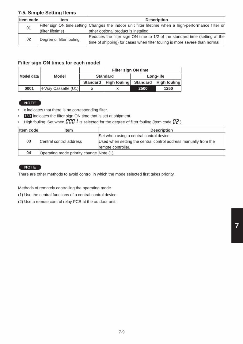
7
Item code Item Description
01Filter sign ON time setting (filter lifetime)
Changes the indoor unit filter lifetime when a high-performance filter or other optional product is installed.
02 Degree of filter foulingReduces the filter sign ON time to 1/2 of the standard time (setting at the time of shipping) for cases when filter fouling is more severe than normal.
Filter sign ON times for each model
Model data Model
Filter sign ON time
Standard Long-life
Standard High fouling Standard High fouling
0001 4-Way Cassette (U1) x x 2500 1250
NOTE
x indicates that there is no corresponding filter.
indicates the filter sign ON time that is set at shipment.
High fouling: Set when is selected for the degree of filter fouling (item code ).
Item code Item Description
03 Central control addressSet when using a central control device.Used when setting the central control address manually from the remote controller.
04 Operating mode priority change Note (1)
NOTE
There are other methods to avoid control in which the mode selected first takes priority.
Methods of remotely controlling the operating mode
(1) Use the central functions of a central control device.
(2) Use a remote control relay PCB at the outdoor unit.
•••
7-5. Simple Setting Items
7-9
Elite_PAC-i_Sec1-8.indb 9 2012/03/06 10:59:00

7
When the operating mode at the priority remote controller is changed, the operating modes of other remote controllers change as shown below.
Mode change at priority remote controller Operating modes at other remote controllers
Current mode New mode Current mode New mode
Cooling or dry HeatingCooling or dry Heating
Fan Fan (not changed)
Heating CoolingHeating Cooling
Fan Fan (not changed)
Cooling DryCooling Cooling (not changed)
Dry Dry (not changed)
Heating DryHeating Cooling
Fan Fan (not changed)
Cooling or dry Fan
Cooling Cooling (not changed)
Dry Dry (not changed)
Fan Fan (not changed)
Heating FanHeating Heating (not changed)
Fan Fan (not changed)
Item code Item Description
05Fan speed setting when heating thermostat is OFF
Changes the fan speed setting when the heating thermostat is OFF.
06Heating intake temperature shift
Shifts the intake temperature during heating.
Can be set when the body thermostat is used.
07 Electric heater installationSet when cost distribution is performed using an AMY central control system or similar system, and when an optional electric heater is installed. (This is unrelated to control of the electric heater.)
08Humidifying when heater thermostat is OFF
Normally humidifying does not occur when the thermostat is OFF during heating operation. However, this setting can be changed in order to increase the amount of humidifying.Caution: In order to avoid water leakage and damage to the fan, do not use this setting unless a vaporizing humidifier is used.
0DPermit/prohibit automatic heating/cooling
This setting can be used to prevent the automatic heating/cooling display on the remote control if the unit configuration permits automatic heating/cooling operation.
0F Cooling-onlyThis setting allows a heat pump indoor unit to be operated as a cooling-only unit.
7-10
Elite_PAC-i_Sec1-8.indb 10 2012/03/06 10:59:00

7
Item code Item Description10 Unit type
Set when the indoor unit EEPROM memory is replaced during servicing.11 Indoor unit capacity
12System (outdoor unit) address
These are not set at the time of shipping from the factory.
These must be set after installation if automatic address setting is not performed.
13 Indoor unit address14 Group address
17Cooling intake temperature shift
Shifts the intake temperature during cooling and dry operation.(Enabled only when the body thermostat is used.)Increase this value when it is difficult to turn the thermostat ON.
18Automatic stop time after operation start
The time at which an indoor unit is automatically stopped after operation starts can be set in increments of 5 minutes
1bForced thermostat ON time
Use this setting to change the time for forced operation at installation
or servicing from 5 minutes to 4 minutes.(Enabled only with PAC models.)
1ETemperature shift for cooling/heating change in “auto heat/cool” mode
“Auto heat/cool” selects the operating mode automatically based on the difference between the room temperature and the temperature set on the remote controller. This setting establishes a shift temperature for the heating/cooling temperature setting relative to the remote controller temperature setting.
Cooling temperature setting
Heating temperature setting
Remote controller temperature setting
Shift temperature
Shift temperature
7-6. Detaild Setting Items
Cooling temperature setting
Remote controller temperature setting
Heating temperature setting
Shift temperature
Shift temperature
7-11
Elite_PAC-i_Sec1-8.indb 11 2012/03/06 10:59:00

7
Item code Item Description1F (Upper limit)20 (Lower limit)
Change to the remote control temperature setting range
Cooling
This setting changes the temperature range (upper limit and lower limit) which is set from the remote controller or central control device. The set upper limit must be greater than or equal to the lower limit. If the temperature setting is to be a single point, set the upper limit and lower limit to the same temperature.
21 (Upper limit)22 (Lower limit)
Heating
23 (Upper limit)24 (Lower limit)
Drying
25 (Upper limit)26 (Lower limit)
Auto heat/cool
29Humidifier operation which ignores the heat exchanger temperature
During heating operation, the humidifier operates when the heat exchanger temperature is suitable for humidifying. This setting is used to ignore this condition for humidifier operation and operate the humidifier more.
2A Filter input switching This setting switches the filter input according to the purpose of use.
2CIndoor unit electronic control valve
This setting indicates whether or not an indoor unit electronic control valve is present. At the time of shipping, this setting is set according to the conditions of the indoor unit.
2E T10 terminal input switchingOrdinarily, the T10 terminal is used as the HA terminal at the time of shipping. However, this setting is used when the T10 terminal is used for OFF reminder or for fire prevention input.
31Ventilation fan operation from remote controller
It is possible to install a total heat exchanger and ventilation fan in the system, which can be started and stopped by the wired remote controller. The ventilation fan can operate linked with the start and stop of the indoor unit, or can be operated even when the indoor unit is stopped.Use a ventilation fan that can accept the no-voltage A contact as the external input signal.In the case of group control, the fans are operated together. They cannot be operated individually.
32Switching to remote controller sensor
This setting is used to switch from the body sensor to the remote controller sensor.Check that “remote controller sensor” is displayed.
Do not use this setting with models that do not include a remote controller sensor.Do not use this setting if both the body sensor and remote sensor are used.
34ON/OFF of “Operation change control in progress” display
In a MULTI system with multiple remote controllers, switching between heating and cooling is restricted, and “Operation change control in progress” is displayed.This setting is used to prevent this display from appearing.Refer to the item concerned with operating mode priorities.
35OFF reminder function for weekly timer
This setting switches the operation when the weekly timer is connected to the remote controller.This can be used to prevent cases in which the unit is accidentally left ON. There is no change when this setting is ON, however it is necessary to set the weekly timer ON time.
(Continued)
7-12
Elite_PAC-i_Sec1-8.indb 12 2012/03/06 10:59:00

7
(Continued from previous page)
Item code Item Description
3CHeat exchanger temperature for cold air discharge
The heat exchanger temperature control point for prevention of cold air discharge during heating operation can be changed.
3d Fan output switchingThe indoor unit PCB optional output for the fan can be switched according to the purpose of use.
3EDrain pump delayed start time
The drain pump starts after the set time delay after cooling operation stops.
40Humidifier drain pump setting
This specifies the humidifier and drain pump setting.
45 DC flap operation mode Changes flap operation to draft reduction mode.46 DC flap swing mode Selects the swing operation mode for the flap.
5d DC fan tap settingSets the DC fan tap according to the purpose of use.Change the settings data at the same time.
5E Humidifier ON time
Sets the humidifier output ON time for when the humidifier is operating.ON/OFF control is performed during humidifier operation.This setting therefore sets the ON time per 60-second interval.
5FStop at time set for OFF timer after operation starts
This setting enables a function that stops operation when the amount of time set for the OFF timer has passed after remote controller operation was started.
60Timer function change prohibit
This function prohibits changes from being made to the remote controller time setting.
62 Smudging control Smudging control is disabled when 0000 is set.
7-13
Elite_PAC-i_Sec1-8.indb 13 2012/03/06 10:59:00

7
<Procedure>
Be sure to turn the main power OFF before performing the steps below.
(1) Check the optional product that will be used from the table below.
Setting No. Optional part name Optional part No.
[3]Air-blocking material (for 3-direction discharge) CZ-CFU2
Air-blocking material (when a discharge duct is connected) CZ-CFU2
[6] Air-blocking material (for 2-direction discharge) CZ-CFU2
(2) Setting No. [3]
Open the cover of the electrical component box, and connect the supplied short-circuit connector (2P, yellow) to short-circuit pin TP3 (2P, yellow) on the indoor unit control PCB.
(3) Setting No. [6]
Open the cover of the electrical component box, and connect the supplied short-circuit connector (2P, yellow) to short-circuit pin TP6 (2P, white) on the indoor unit control PCB.
DC Fan Tap Change Procedure
7-14
Elite_PAC-i_Sec1-8.indb 14 2012/03/06 10:59:00

7
7-7. Remote Controller Servicing FunctionsThe remote controller includes a number of servicing functions. Use these as needed for test runs and inspections.
List of Servicing FunctionsFunctions Description Button operation Reset operation Unit status
Test runOperation with forced thermostat ON
Press and hold the button for 4 seconds or longer.
Press the button.
Current operation is maintained.
Sensor temperature display
Temperature display from each sensor
Press and hold the and buttons for 4 seconds or longer.
Servicing check display
Alarm history display Press and hold the and buttons for 4 seconds or longer.
Simple settings
Filter lifetime, operating mode priority, central control address, and other settings
Press and hold the and buttons for 4 seconds or longer.
When settings are made from a remote controller, the indoor unit where that remote controller is connected stops.
Detailed settings
System address, indoor unit address, central control address, and other settings
Press and hold the , and buttons for 4 seconds or longer.
Automatic address
Automatic address setting based on command from the wired remote controller
Press and hold the and the timer operation buttons for 4 seconds or longer.
Automatic reset
Entire system stops.
Address change
Change of indoor unit address
Press and hold the and the timer operation buttons for 4 seconds or longer.
Press the button.
•
7-8. Test Run FunctionOperates the unit with the thermostat forced ON.
<Procedure>
1 Press and hold the button for 4 seconds or longer.
2 “Test” appears on the remote controller LCD display (Fig. 7-3).
3 Start operation.
4 Press the button to return to normal remote controller display.
Fig. 7-3
CZ-RTC21
2
3
4
7-15
Elite_PAC-i_Sec1-8.indb 15 2012/03/06 10:59:00

7
The procedure below displays the sensor temperatures from the remote controller, indoor unit, and outdoor unit on the remote controller.
<Procedure>
1 Press and hold the and buttons simultaneously for 4 seconds or longer.
2 The unit No. “X-X” (main unit No.), item code “XX” (sensor address), and servicing monitor “ ” (sensor temperature) are displayed on the remote controller LCD display. (See Fig. 7-4 at right.)
3 Press the temperature setting / buttons and select the item code to the address of the sensor to monitor.(For the relationships between the sensor addresses and sensor types, refer to the table of temperature sensors and addresses at below.)
4 If group control is in effect, press the button to select the unit to monitor.Press the temperature setting buttons to select the item code to change.
5 Press the button to return to normal remote controller display.
Sensor Temperature Display Function(displayed regardless of whether unit is operating or stopped)
CZ-RTC21
2
3
45
Note:
The temperature display appears as “- - - -” for units that are not connected.
If monitor mode is engaged while normal operation is in progress, only the parts of the LCD display shown in the figure will change. Other parts continue to display the same information as during normal operation.
*
Fig. 7-4
Indoor unit sensors Outdoor unit sensors
02 Intake temp. Unit No.1 Unit No.2 Unit No.3 Unit No.4
03 E1 0A 2A 4A 6A Discharge temp. 1
04 E2 0B 2B 4B 6B Discharge temp. 2
05 E3 0C 2C 4C 6C High-pressure sensor temp.
06 Discharge temp. 0D 2D 4D 6D Heat exchanger gas 1
07 Discharge temp. setting 0E 2E 4E 6E Heat exchanger liquid 1
08Position of indoor unit electronic control valve
0F 2F 4F 6F Heat exchanger gas 2
10 30 50 70 Heat exchanger liquid 2
11 31 51 71 Outdoor air temp.
12 32 52 72 –
13 33 53 73 For inspection
14 34 54 74 CT2
15 35 55 75 For inspection
16 36 56 76 For inspection
17 37 57 77 Discharge temp. 3
18 38 58 78 CT3
19 39 59 79 For inspection
1A 3A 5A 7A For inspection
1B 3B 5B 7B Heat exchanger gas 3
1C 3C 5C 7C Heat exchanger liquid 3
1D 3D 5D 7D Low-pressure sensor temp.
1E 3E 5E 7E Receiver temp.
1F 3F 5F 7F Oil 1
20 40 60 80 Oil 2
21 41 61 81 Oil 3
22 42 62 82 For inspection
7-16
Elite_PAC-i_Sec1-8.indb 16 2012/03/06 10:59:01

8
■ Warning
8-1. Warning about Installation of Receivers ................................................................ 8-2
8-2. Warning about Installing Remote Controls ............................................................ 8-2
■ Optional Controller (Remote Controller) ........................................................................ 8-3
8-3. Names and Functions .............................................................................................. 8-3
8-4. Installing Batteries ................................................................................................... 8-5
8-5. Setting the Current Time ......................................................................................... 8-5
8-6. Operation .................................................................................................................. 8-6
8-7. Timer Oper ation ........................................................................................................ 8-7
8-8. Adjusting the Wind Direction .................................................................................. 8-8
8-9. Operating Multiple In/Outdoor Units Simultaneously (Group Control) ...............8-8
8-10. Using the Remote Control ....................................................................................... 8-9
8-11. For Best Results ...................................................................................................... 8-9
8-12. Addresses ................................................................................................................. 8-9
8-13. Emergency Operation .............................................................................................. 8-11
8-14. Miscellaneous S ettings ............................................................................................ 8-12
8-15. Before Requesting Service ...................................................................................... 8-13
■ How to Install the Wireless Remote Controller Receiver .............................................. 8-14
8-16. Common to All Models ............................................................................................. 8-14
8-17. CZ-RWSU2 ................................................................................................................. 8-16
8-18. CZ-RWST2 ................................................................................................................. 8-18
8-19. CZ-RWSL2 ................................................................................................................. 8-21
8-20. CZ-RWSC2 ................................................................................................................. 8-24
8-21. CZ-RWSY2 ................................................................................................................. 8-28
8-22. Common to All Models ............................................................................................. 8-30
8. HOW TO INSTALL THE WIRELESS REMOTE CONTROLLER RECEIVER
8-1
Sec8.indd 1 2012/02/28 16:13:59

8
■ Warning
8-1. Warning about Installation of ReceiversThe wireless remote uses a very weak infrared light for its signal, which can result in the signal not being received because of the following influences, so take care in where the unit is installed.
· Inverter or rapid-start type fluorescent lights (Models without glow lamps)
· Plasma display or LCD televisions
· Direct sunlight or other sources of bright light
8-2. Warning about Installing Remote Controls(1) If a remote control is to be operated from a remote control holder that is hung on a wall, turn on the lights
in the room as well as any electrical appliances and then check to make sure the air conditioner works with the remote control in the location where it will be installed. If it works, continue with installation.
(2) If the air conditioner is to be switched from the main sensor to a remote control sensor, pay attention to the following when installing.
· Locate where no warm or cold drafts will affect it
· Locate in a place free from direct sunlight
· Locate where it will not be affected by any other heat/cold source.
8-2
Sec8.indd 2 2012/02/28 16:14:00

8
■ Optional Controller (Remote Controller)Wireless Remote Controller CZ-RWSU2 / CZ-RWST2 / CZ-RWSL2
/ CZ-RWSC2 / CZ-RWSY2 / CZ-RWSK2
8-3. Names and Functions
1
234
5
6
7
8
9
10
1211
1314
1516
1. Operation Display Displays the operation status.
(The figure shows all the statuses.)
2. Start/Stop button
Pressing this button once starts and
pressing again stops the operation.
The auto-flap display may be different, depending on the installed unit.
3. Fan speed button
4. Swing/Wind Direction button
5. Timer setting button
Use for operating with a timer.
6. Reset button Use this button after changing the
batteries.
7. Cover Press at the top center and then
slide down.
8. Transmitter
12. Mode Select button
Press to switch the operation mode.
14. Address button
16. Clock button Use this when setting the clock.
13. Ventilation button
Use this when connected to an
aftermarket fan. Pressing this button
starts and stops the fan. When the
air conditioner is started or stopped,
the fan starts or stops at the same
time. ( appears on the display of
the remote control when the fan is
operating.)
15. Sensor button Use this when switching to detect
the temperature at the remote
control. At shipping the default
setting is set to detect the
temperature at the unit. At this time
is shown on the display.
9. Remote control sensor
Detects the temperature at the
remote controller when detection
has been switched to the remote
control by the sensor button.
11. Filter button CZ-RWSC2Press to turn off the filter lamp on
the receiver.
10. Temperature setting buttons
raises the temperature setting
1 at a time.lowers the temperature setting
1 at a time.
REMOTE CONTROLLER
From this page on the names of remote control buttons will be abbreviated as the illustration of the “button”. E.g.: Start/Stop button
One remote control can control a group of up to eight indoor units.
8-3
Sec8.indd 3 2012/02/28 16:14:00

8
1. Receiver Receives the signal sent from the
remote control.
This lamp is lit when the unit is
operating.
When an error occurs, one of the
lamps flashes. When a display
lamp is blinking, refer to " Before
Requesting Service ".
2. Emergency operation button
Display lamps
When the heater is working, the
lamp lights at the following times.
When the thermostat has operated
during defrosting at the time of the
startup.
The lamp flashes when an error
occurs.
5. Standby lamp
3. Operating lamp
This lamp is lit when the timer is set.4. Timer lamp
6. Filter lamp This lamp is for notifying you when
the filter needs to be cleaned.
Use in the Normal position. It does
not operate in the Stop All position.Remote control, main / remote
control, secondary, switch
In normal use this should be on
remote control, main. It is also
possible to use both in conjunction
with a wired remote control
(sold separately). (Consult with the
dealer where the product was
purchased about making the
settings.) Test/On switch This is used during service. It is not
for normal use.Test Run/On switchThis is used during service. It is not for normal use.
7. Swing button
8. Normal/Stop All switch
9. Address switch Differentiate between incoming and
outgoing signals.
If a heat pump model is being used, it will beep twice and the operating lamp will light up on the display; if the timer and standby
lamps blink alternately, a conflict between the heating and cooling exists, so the unit cannot operate in the desired mode.
(On models that do not have an Auto function, even if Auto is selected, it works in the same way.)
RECEIVER
CZ-RWSU2
12
3456
7
89
CZ-RWSC2
2 1
3 4 5
CZ-RWST2
When the local operation is disabled by such as the centralized control, and if the Start, Stop, Mode or Temperature setting
buttons are pressed, the unit will beep five times and the change will not be made.
Display
CZ-RWSL2
Indoor Unit (K type)
3 4 5
1
278 9
Operation Panel
345
2
NOTE
2345
1
CZ-RWSY2
2345
1
8-4
Sec8.indd 4 2012/02/28 16:14:00

8
Change the batteries when the display of the remote control gets weak or if it will
not work unless close to the receiver.
(Alkaline batteries generally last about one year.)
Reset hole
CoverWhen changing batteries, always use two fresh batteries of the same make.
If the remote control will not be used for a long period of time, remove the batteries.
Please dispose of batteries appropriately.
After changing the batteries, follow the procedures described below to reset the
current time.
2 1,43
1. Remove the cover.
2. Insert two AAA alkaline batteries.
Put the batteries in with the polarity [+/–] as shown in the figure.
3. Gently insert one end of an unfolded paper clip (or a similar object that can
fit) into the Reset hole and press the Reset button inside the hole and then
put the cover back on.
8-4. Installing Batteries
3. Remove the other battery in the same way.
1. Remove the cover.
2. Press the battery toward the negative end and lift it out by its positive end.
(As shown at right)
� How to remove batteries
NOTE
NOTE
8-5. Setting the Current Time
After changing the batteries and pressing reset, be sure to reset the current time.
(When reset is pressed, the current time reverts to [ ])
1. Press for two seconds or more.
2. Set the hour with / of the .
If you press and hold the button, the time changes quickly.
3. Set the minutes with / of the .
If you press and hold the button, the time changes quickly.
4. Pressing completes the time setting.
While you are setting the current time, the time display flashes but the colon does not.
If the buttons are not pressed for three minutes while setting the current time,
it is set to the displayed time.
When reset is pressed, the timer settings are deleted.
NOTE
Once the clock displays starts blinking, the clock can be set.
Dispose of the used batteries at the designated location in compliance with the
applicable local ordinances.
8-5
Sec8.indd 5 2012/02/28 16:14:00

8
1
4
2
3
8- 6. Operation
Auto , Heat , Dry , Cool , Fan
Models that only provide the cooling function cannot operate in the auto or heating modes.
Power: Turn on the power of the indoor unit at least 14 hours before operation.
1. Press .
2. Press and select from among Auto , Heat , Dry ,Cool and Fan .
3. Press and select the desired speed.
If set to Auto , the fan speed switches automatically.
(Auto does not work when in the Fan mode.)
4. Press one of the buttons and set the desired temperature.
Temperature settings cannot be made when in the Fan mode.
MAX MIN
Auto2717
3016
3018
Heat Dry / Cool
Stop: Press .
When the unit is stopped with the remote control, even though the compressor
of the outdoor unit stops, the fan on the outdoor unit may continue to run for a while.
If the unit is not heating very effectively with a Low fan speed , switch the fan speed to High or Medium.
Depending on the indoor unit being used, it may indicate a function that it does not have. (The fan speed is set.)
If you cannot turn the air conditioner off in the normal way.Disconnect the power to the indoor unit and contact the dealer where the product was purchased.
<Auto Operation>If all the indoor units are identical in a cooling system and are under control as one group, it heats or cools automatically
via the differences between the set temperature and the room temperature.
<Dry Operation>Depending on the indoor unit used, the remote control may have a [Dry] indicator on its display
even though the unit does not have the Dry function. (Same as cooler operation)
When the room temperature approaches the temperature setting, the unit continues to start up or stop automatically.
When the drying mode stops operating, the indoor unit’s fan blows a gentle breeze in order to keep the moisture from
returning to the room at a minimum.
Depending on the indoor unit used, and/or the temperature in the room, the fan speed may not be adjustable.
Depending on the unit used, when the outside air temperature is 15 °C or less, the dry function will not operate.
8-6
Sec8.indd 6 2012/02/28 16:14:00

8
8-7. Timer Operation
When setting the timer, make sure the current time on the remote control is accurate.
The timer’s clock can only be set when the display of the remote control is ON.
After setting the timer, put the remote control in a place where its signal will reach the
receiver of the indoor unit. (When the time set for the timer is reached, a signal is sent
from the remote control to Start/Stop the unit.)
3 1,2
Using the Timer
1. Press either / of the or , and while the time is being displayed,
if you press / again, a scheduled time can be set.
The time last set on the timer is displayed.
“--:--“ indicates time to change the batteries.
2. Press either / of the or and set the timer to the desired time.
Every time you press / , the time changes in 10 minute increments.
If you press and hold the button, the time changes quickly.
3. After setting the timer, if you press , the time you set changes to a steady display,
indicating settings are complete.
After the timer setting is displayed for three seconds, the display reverts to the current time.
Combining ON and OFF Timers
Setting the ON and OFF timers, respectively.
Checking the timer setting
If you press either / for the or the , the scheduled time is displayed for four seconds.
When no timer setting has been made, it displays --:--. (Initial Setting)
Changing a timer setting
Canceling a timer setting
If you press [CANCEL], the timer setting is canceled.
If you wish to cancel the setting for either the or the timer, press / or the desired timer and when the
scheduled time is displayed, press [CANCEL].
Using the same timer setting every day
If you press for 2 or more seconds, “ ” is displayed and the ON timer or the OFF timer will operate the unit
at the same time every day.
If you press again for two seconds or more, “ ” goes off and the timer operates just once.
Press / for the or the , and then when the timer setting is displayed, press / for the timer again.
8-7
Sec8.indd 7 2012/02/28 16:14:00

8
8-8. Adjusting the Wind Direction
8-9. Operating Multiple In/Outdoor Units Simultaneously (Group Control)
Please face the flap (up-down wind direction plate) downwards. If it faces upwards, the warm air will not reach the floor level.
In the Heat Mode
Please face the flap (up-down wind direction plate) upwards. If the plate faces downwards, condensation may form and drip from around the air outlet.
In the Cool and Dry Modes
In the Fan Mode In All Modes
Displays with Swing Stopped
Initial Setting
Initial Setting
Initial SettingMoves Constantly
Fan/Heat Modes Cool/Dry Modes
Never try to manually move the flap (up-down wind direction plate) that is operated by the remote control.
When the unit stops, the flap (up-down wind direction plate) automatically faces downwards.
When the unit is in heating standby, the flap (up-down wind direction plate) faces upward.
Also, bear in mind that the flap starts swinging after the heating standby mode is released, but the display on the remote
control indicates Auto Flap during standby heating as well.
One remote control can operate up to eight indoor units.
All the indoor units have identical settings.
Set temperature sensing to the indoor unit (Main Sensor).
CZ-RWSU2 / CZ-RWST2 /CZ-RWSL2 / CZ-RWSY2 / Indoor Unit (K1 type)
Setting the Wind Direction
While the unit is operating, every time you press , the direction the flap
faces changes.
Setting Flap to Swing
If you press to set the flap (up-down wind direction plate) in its most
downward facing position, and then press again, is displayed
and the flap swings automatically up and down.
Stopping Flap Swing
If you press again while the flap is swinging, you can stop the flap from
swinging and set it in place as desired. Thereafter, if you press , you can
set the wind direction starting from the most upward position.
When the unit is in the Cool or Dry modes, the flap cannot stop facing
downwards. If you try to stop the flap from swinging while it is facing
downwards, it will continue moving until it is in the third position from
the top.
CZ-RWSC2The available functions differ depending on the indoor unit being used.
The wind direction cannot be set via remote control for any models other than those noted below.
For more information, please refer to the users’ manual that came with your indoor unit.
Four-direction Ceiling Cassette Models, Bi-directional Ceiling Cassette Models,
Unidirectional Cassette Models for High Ceilings, Ceiling Suspended Models, Wall Models
Group control works well for providing air conditioning to one,
large room with more than one air conditioning units.
Please refer to Setting the Wind Direction and Stopping Flap Swing.
Indoor Unit
Indoor Unit
Signal Line
Receiver
Wireless Remote Control
8-8
Sec8.indd 8 2012/02/28 16:14:01

8
Point the transmitter of the remote control at the receiver. When the signal is received correctly it will beep once.
(It beeps twice only when the unit starts operating.)
The signal can be received at a distance of about 6 meters. This distance should be used only as a guide.
It depends on battery strength.
Make sure nothing is between the remote control and the receiver that could block the signal.
Do not leave the remote in direct sunlight, where the wind from the air conditioner can blow directly on it, or near any other
heat source.
Take care not to drop, throw or wash the remote control with water.
The signal from the remote control may not be received in rooms with rapid start fluorescent lighting, inverter lights, plasma
displays, LCD televisions (monitor), etc. For more information, please contact the dealer where the product was purchased.
1
2
Fasten the remote control
mount with screws.
Fitting the remote control in the mount.
Remote control mount
Press
Put in
Checking Addresses
When you press on the remote control, its current address is shown in the display. If this address corresponds to the
address of a receiver* 2, the buzzer sounds. (If it is on ALL, the buzzer will always sound.)
If it is on ALL, it can be operated regardless of receiver addresses. Point the remote control at the receiver you wish to operate
and transmit.*2 CZ-RWSL2 is a receiver. (Indoor unit)
8-10. Using the Remote Control
Wall Mount Use• Press from the location you wish to mount the remote
and make sure the signal is received correctly.
• Pull the remote control forward to remove it.
Don’t get the remote control too far away from the receiver.
This may cause a malfunction. Be sure to keep the remote control in the same room as the receiver.
remote control, addresses can be set up to avoid crosstalk. By setting the address switches on the receivers and matching
them with the number of addresses on the remote control, up to six indoor units can be controlled separately with the remote
control. (When using units in a flexible combination or operating multiple units simultaneously, as they are operated at the
same time, they cannot be controlled individually.) There are separate address settings, receiver addresses for the receivers*
and transmitter addresses for the remote control.
For more information, please contact the dealer where the product was purchased.
1
• The setting procedure is different for Indoor Unit (K1 type). (See Setting Addresses (K1 Type) in the next page.)
• These settings are saved in nonvolatile memory in the remote control, so even when its batteries are changed, the settings
do not have to be made again.
*1 CZ-RWST2 is of a receiver (Inside the indoor unit); CZ-RWSL2 is of an operation panel. (Inside the indoor unit)
8-11. For Best Results
Point the remote control at the receiver.
When the signal is received correctly it will beep one time.
Avoid locating the remote control where it is covered, such as behind a curtain.
Keep it out in the open.
In both multi and single unit installations, when more than one indoor unit is installed in the same room with a compatible
8-12. Addresses
8-9
Sec8.indd 9 2012/02/28 16:14:01

8
Matching up Addresses
Setting Remote Control Addresses
1. If you press and at the same time, “ ” will blink.
2. While holding down, every time you press , it cycles from ALL 1 2 3…
Set it to the receiver address switch of the indoor unit you wish to operate.
3. When you release , the address that was displayed is set.
When you do this, if it corresponds to the receiver’s address setting, the buzzer sounds.
6 ALL.
Address Display on the Remote Control
CZ-RWSU2
Position of receiver’s (inside indoor unit) address switch
The position of the receiver’s address switch does not matter.
For 1, 2 and 3, set the switch on the left and for 4, 5 and 6, to the right.
CZ-RWST2
Position of receiver’s (inside indoor unit) address switch
The position of the receiver’s address switch does not matter.
For 1, 2 and 3, set the switch on the left and for 4, 5 and 6, to the right.
CZ-RWSL2
Position of the operation panel’s (inside indoor unit) address switch
The position of the receiver’s address switch does not matter.
For 1, 2 and 3, set the switch on the left and for 4, 5 and 6, to the right.
CZ-RWSC2
Position of the Receiver’s Address Switch
The position of the receiver’s address switch does not matter.
For 1, 2 and 3, set the switch on the left and for 4, 5 and 6, to the right.
1 2 34 5 6
1 2 34 5 6
1 2 34 5 6
Setting Addresses (CZ-RWSY2 / K1 Type)
(Setting the address of the indoor unit)
1. First of all, set the address for the remote control with Setting Remote Control Address (See Page 3-12).
2. Press [Emergency Operation] of the indoor unit for four seconds or more.
When you do this, the lamps of the display will blink one after another.
3. Press on the remote control.
4. The buzzer will sound and the address of the indoor unit will change to the address displayed on the remote control.
5. If you press [Emergency Operation] of the indoor unit once, the lamps on the indoor unit’s display will turn off.
• Please do not hold the [Emergency Operation] button of the indoor unit down while the indoor unit’s display lamps are
blinking one after another.
• Make sure to operate while the indoor unit is stopped.
• The address of indoor unit is set to "ALL" at the time of the shipment.
NOTE
8-10
Sec8.indd 10 2012/02/28 16:14:01

8
Use [Emergency Operation] in the following situations when there is an urgent need.
When the remote control’s batteries have failed.
When the remote control is broken.
When the remote control is lost.*1 Figures: CZ-RWSU2, CZ-WRSY2 and CZ-RWST2 are of receivers (inside indoor unit),
CZ-RWSL2 is of the operation panel (inside indoor unit) and Indoor Unit (K1 type) is of its front panel.
CZ-RWSU2 / CZ-RWST2 / CZ-RWSY2 / Indoor Unit (K1 type)Start : press [Emergency Operation] of the receiver.
If the indoor temperature is 24 °C or greater when the unit starts running, it will act as a cooler.
If the indoor temperature is less than 24 °C when the unit starts running, it will act as a heater.
Stop : press [Emergency Operation] of the receiver again.
The Test Run/On and Test/On switches are for use when the unit is installed and test run. It is not for normal use.
If the [Normal/Stop ALL] switch is on Stop ALL, the unit cannot receive signals from the remote control.
CZ-RWSC2 / CZ-RWSL21. Press [Emergency Operation] of the receiver.
If the indoor temperature is 24 °C or greater when the unit starts running, it will act as a cooler.
If the indoor temperature is less than 24 °C when the unit starts running, it will act as a heater.
2. If you press , the wind direction automatically oscillates up and down.
Stop : press [Emergency Operation] of the receiver again.
2 1
CZ-RWSL2 CZ-RWSC2
The Test Run/On and Test/On switches are for use when the unit is installed and test run. It is not for normal use.
If the [Normal/Stop ALL] switch is on Stop ALL, the unit cannot receive signals from the remote control.
NOTE
NOTE
8-13. Emergency Operation
Start/Stop
Indoor Unit (K1 type)CZ-RWST2
Start/Stop
Start/Stop
CZ-RWSY2Start/Stop
CZ-RWSU2
21
8-11
Sec8.indd 11 2012/02/28 16:14:01

8
Wind Direction (flap) indicator, operation mode indicator, time display (24 hour, AM/PM), Heat Max Temp
For information about the flap function, refer to the users’ manual of the unit being used.
(These settings are saved in nonvolatile memory in the remote control, so even when its batteries are changed,
the settings do not have to be made again.)
First check the display of the remote control when the unit is stopped and then make any desired settings.
How to Operate• While holding down the buttons below, every time is pressed the remote control’s display changes.
• Whatever is being displayed when you release is set.
Setting Item Operation Button Setting Content Remote Control Display
Remote control flap
display setting for
when is pressed
Press
while pressing
Models with movable flaps
Swing only models
Models w/o lamps None
Remote control
operation mode
display setting when
is pressed
Press
while pressing
Heat Pump (with Auto)
Heat Pump (without Auto)
Dedicated air conditioner
Clock display settingPress
while pressing
24 Hour
AM/PM
Max possible temperature setting in the Heat mode
Press
while pressing
Maximum heating temperature range is 26 °C – 30 °C
A variety of changes can be made to settings, depending on the indoor unit being used.
8-14. Miscellaneous Settings
8-12
Sec8.indd 12 2012/02/28 16:14:01

8
Before requesting service, please check the followings.
Problem Cause Solution
The unit doesn’t work even when is pressed on the remote control.
The power to the indoor unit is not ON. Make sure the power to the indoor unit is ON.
Is the Normal/Stop All switch in the Stop All position? (See Page 3-7)
Switch it to the Normal position and cancel operation.
Are the remote control’s batteries dead? Change the batteries.
Is there a mismatch between the display lamp and cooling/heating or is it set to something other than Auto? (The operating lamp stays lit, while the timer lamp and the standby lamp blink alternately.)
Change the operating mode.
Do the addresses match one another? Check the addresses of the receiver*1 and the remote control. (See Page 3-12)
The air conditioner starts and stops on its own.
Has the timer been set to repeat? Check the timer settings.(See Page 3-10)
“ ” is displayed on the remote control when the unit is stopped.
An error has occurred in the non-volatile memory.
Please contact your sales outlet.
Although the unit is for air conditioning only, either Auto or Heat is indicated in the display.
Make settings to the remote control’s operation mode display. (See Page 3-15)
After putting the batteries in the remote control, even when it is operated, the display does not change.
Press the Reset button on the remote control.
(See Page 3-8)
The timer cannot be set. Make the settings when the remote control is in Operation Display. (See Page 3-9)
If the problem persists even after you check the foregoing items, stop the unit, disconnect the power to the indoor unit and
contact the dealer where the product was purchased with the model number and problem you are having.
As it is dangerous, under no circumstances should you undertake repairs yourself.
Further, when the receiver’s*2 lamps are blinking; please contact your retailer with that information.
* 1 CZ-RWSL2 is an operation panel
* 2 CZ-RWSL2 is a display
8-15. Before Requesting Service
Specifications
CZ-RWSU2 / CZ-RWST2 / CZ-RWSC2 /CZ-RWSY2 / CZ-RWSK2
CZ-RWSU2 / CZ-RWST2 /CZ-RWSC2 / CZ-RWSY2
Wireless Remote Control Receiver
Dimensions 182 mm (H) X 61 mm (W) X 18.5 mm (D)
Power source Two AAA alkaline batteries
Clock Accuracy ±30 seconds per month (at 25 °C)
CZ-RWSL2
Dimensions 37 mm (H) X 70 mm (W) X 22 mm (D)Display
Power source 5 V DC (supplied from the operation panel)
Dimensions 55 mm (H) X 120 mm (W) X 16 mm (D)
Power source
Operation
Panel 16 V DC (Supplied from the terminal strip of the indoor unit’s remote control)
Dimensions
Power source
200 mm (H) X 200 mm (W) X 25 mm (D)
65 mm (H) X 130 mm (W) X 22 mm (D)
120 mm (H) X 70 mm (W) X 13 mm (D)
108 mm (H) X 108 mm (W) X 20 mm (D)
16 V DC (Supplied from the terminal
strip of the indoor unit’s remote control)
CZ-RWSC2
CZ-RWSY2
CZ-RWSU2
CZ-RWST2
8-13
Sec8.indd 13 2012/02/28 16:14:01

8
8-16. Common to All Models� How to Install the Wireless Remote Controller Receiver
1. Warnings about Installation of ReceiversThe wireless remote uses a very weak infrared light for its signal, which can result in the signal not being received because of the
following influences, so take care in where the unit is installed.
• Inverter or rapid-start type fluorescent lights. (Models without glow lamps)
• Plasma display or LCD televisions.
• Direct sunlight or other sources of bright light.
2. Warnings about Installing Remote Controls
3. Things to remember when wired and wireless remotes are installed at the same time
If a remote control is to be operated from a remote control holder that is hung on a wall, turn on the lights in the room as well
as any electrical appliances and then check to make sure the air conditioner works with the remote control in the location
where it will be installed. If it works, continue with installation.
(1)
If the air conditioner is to be switched from the main sensor to a remote control sensor, pay attention to the following when
installing.
• Locate where no warm or cold drafts will affect it.
• Locate in a place free from direct sunlight.
• Locate where it will not be affected by any other heat/cold source.
(2)
Two remote controls can be used to control the unit if the wireless remote control kit is installed at the same time as the wired
remote control.
(Up to 2 remotes [a wireless remote kit and the wired remote control] can be installed.)
When using 2 remotes, one or more units can be operated by the remotes.
When wiring remote controls, be sure to double-check the terminal numbers of the indoor unit before connecting them so
there are no mistakes in the wiring. (Damage will occur if high voltage [e.g. supply voltage] is applied)
1.
It is not possible to use more than one wireless remote control kit with one indoor unit.
(A receiver located separately can be used at the same time)
2.
If both a wireless and a wired remote control are to be installed and used at the same time, one of them must be set up as
the sub remote control.
3.
If the wired remote control is to be the sub remote, change the wired remote control to the sub remote.
If the wireless remote control is to be the secondary, turn the #3 switch on the wireless receiver (operation panel)
from OFF to ON.
If a group of units are to be controlled by 2 remote controls;
Main/sub remote controls will work regardless of which indoor
unit they are installed to.
Wireless RemoteControl Kit
Wired RemoteControl
1st IndoorUnit
2nd IndoorUnit
3rd IndoorUnit
4th IndoorUnit
(Main) (Sub )
Groundingwire (Earth)
Cross-wiring Remotes for GroupControl (Field Supply)
Use wiring of 0.5 mm2 to 2 mm2 for field supply.Make the total wire length when cross-wiring a group no more than 200 m.
When 1 indoor unit is operated by 2 remote controls:
Either of the remotes can be set to main/sub.
Wireless Remote Control Kit Wired Remote Control
Receiver
(Sold Separately) (Sold Separately)
Remote Control Wiring
(Field Supply)
Indoor Unit
Groundingwire Earth
Use wiring of 0.5 mm2 to 2 mm2 for field supply.Use a total wire length of no more than 400 m.
(Main) (Sub)CN11 2 1 2
1 2 1 2CN1
NOTE
8-14
Sec8.indd 14 2012/02/28 16:14:01

8
CZ-RWSL2
CZ-RWSU2
Cable clamp
PCB cover Adjustable Corner Cap
Receiver PCB
ON
1234
Bit 1: OFF→ ONS003
Screw
CZ-RWST2
S003Bit 3: OFF→ON
DIP Switch 3
RCU: MAIN→ RCU: SUB
CZ-RWSC2
8-15
Sec8.indd 15 2012/02/28 16:14:01

8
8-17. CZ-RWSU2 1. Accessories
2. Installing the Receiver
Receiver
Remote Control
Remote Control Holder
The receiver can only be installed on the corner indicated in Fig. 8-1, so consider how the panel will face when it is installed
on the indoor unit.
(1) Remove the air inlet grill.
(2) Remove the screw holding the adjustable corner cap, slide the cap to the side and remove it. (Fig. 8-2)
(3) To pass the wire through the panel, bend back the clip on the hexagonal hole (diagonal line) and then pass wire protruding
from the wireless receiver through the grill. (Fig. 8-3) (4) After wiring according to the directions in Wiring the Receiver Unit below, leave enough wiring so the receiver’s adjustable
corner cap can be removed and fasten the cable clamp with its screw. (Fig. 8-3)
(5) Hang the string on the corner cover onto the pin on the ceiling panel as shown in the diagram. Then slide the corner
cover onto the ceiling panel until the three clips are correctly located, and then fix it in place with the screws. (Fig. 8-4)
(1) If the wiring for the receiver is bundled with other wires, such as the incoming line, it may cause a malfunction,
so avoid putting them together.
(2) If something causes the unit’s power source to make noise it will be necessary to resolve the problem, such as by
installing a noise filter.
For more information about wiring or test operation, refer to Wiring the Receiver and Test Run.
Refer to the installation instructions supplied with the panel.
NOTE
Fig. 8-1 Fig. 8-2
Fig. 8-3 Fig. 8-4
No. Accessories Quantity No. Accessories Quantity1 1
2 1
13
4 2Dry-cell Batteries
5 1Users Manual
6 Truss Self-Tapping Screws4 X 16
2
7 1Cable clamp
Make sure the wire is not caught.
Box with Indoor Unit’s Electrical Parts
Bend back the clip (diagonal line) with a screwdriver or similar implement to allow the wire to pass through.
Fix it in place with the cable clamp.
Pin
Screw fixed
Make sure the three clips on the corner cover are located over the holes on the ceiling panel, and then fix it in place with the screws supplied.
Receiver installation Location Adjustable Corner Cap Ceiling Panel
Adjustable Corner CapScrew
8-16
Sec8.indd 16 2012/02/28 16:14:01

8
3. Wiring the Receiver
Connect the wires from the receiver to the remote control terminal strip on the indoor unit. (Polarity does not matter)
Wiring Diagram
Connections
4. Test OperationImplementing a Test Run1. Turn the #1 DIP switch [S003] on the receiver’s PCB
from OFF to ON and operate the wireless remote
control with its Start/Stop button.
2. During a test run, all display lamps on the display will
light up.
3.
4. After completing a test run, be absolutely sure to turn
the #1 DIP switch from ON to OFF and make sure none
of the display lamps are blinking. Also, replace the PCB
cover back as it was and fasten it; while holding the
wiring with the cable clamp, tighten its screw.
(2)
(1) This is hard on the device, so only use this for the test
run.
After turning on the power, the unit will not receive any
commands from the remote control for about 1 minute.
This is not an error. (In fact it does receive signals, but
they are cancelled.)
5. Setting Address Switches
When more than one receiver and remote control are installed in the same room, setting up addresses allows them to avoid
interfering with each other.Refer to the Users Manual for information on how to change the addresses of the remote controls.
Changing the address of a receiver can be done after removing the screw to the receiver’s PCB cover. Once the change is
complete, put the cover back in place; while holding the wiring with the cable clamp, tighten its screw.
NOTE
Fig. 8-5
During a test run, it is not possible to adjust the
temperature.
Receiver PCBIndoor Unit
Terminal Strip for Wiring Remote Controls
WhiteBlack
CZ-RWSU2
Cable clamp
PCB cover Adjustable Corner Cap
Receiver PCB
Bit 1: OFF→ ONS003
ON
Screw
Address Display on the Remote ControlPosition of the Receiver’s Address Switch
It doesn’t matter where the receiver’s address switch is.
8-17
Sec8.indd 17 2012/02/28 16:14:02

8
8-18. CZ-RWST21. Accessories
2. Installing the Receiver
(1) Open the air inlet grill on the side panel, remove the 1 screw and then move it toward the front (direction of the arrow)
and remove it. (Fig. 8-6)
(2) Wrap the tip of a slotted screwdriver with plastic tape and then slip it in to the side of and under where O is printed on the
cover, wiggling the cover free. (Fig. 8-7) (Be careful not to scratch the panel.)
(3) After passing the lead wire through the panel, install the receiver in the hole in the panel.
(The projecting parts of the receiver is held in the hole in the panel)
(4) Fasten the receiver’s lead wire to the cable clip that is holding the wire from the louver motor. (Fig. 8-8)
(5) Attach the side panel.
(6) Put the receiver’s lead wire together with other wires, such as the louver motor wire and fasten them with the wire saddle.
(Fig. 8-9)
Use the hole in the upper part of the wiring box to lead it in.
Ceiling Suspended Model
Fig. 8-6 Fig. 8-7
Fig. 8-9Fig. 8-8
No. Accessories Quantity No. Accessories Quantity
1 1Receiver
2 1Remote Control
3 Remote Control Holder 1
2Dry-cell Batteries4
1Users Manual5
6 Truss Self-Tapping Screws4 X 16
2
7 Cable tie 1
Panel
Side Panel
Plastic Tape
Slotted Screwdriver (Wrapped with Plastic Tape)
CoverSlip in to the side and below the O mark
Cable clip
Receiver
Wire saddle
Panel
Air inlet grill
8-18
Sec8.indd 18 2012/02/28 16:14:02

8
Unidirectional cassette model for high ceilings/Unidirectional ceiling cassette model(1) While spreading the tabs of the cover, pull it out from the panel to the front. (Fig. 8-10)
(2) Pass the lead wire through the panel and install the receiver in the hole in the panel.
(The projecting parts of the receiver hold it in the hole in the panel)
(3) Press the lead wire from the receiver in along the rib on the back of the panel.
If installing to a unidirectional high ceiling cassette, pass it through the cutout. (Fig. 8-11)
(4) Install the panel on the indoor unit.
(5) Fasten the lead wire sticking out from the panel with the cable clips on the inside of the indoor unit. (Fig. 8-12)
(6) Draw the lead wire into the electrical box through the hole on the bottom and connect it to the remote control terminal strip.
If installing to a high ceiling unidirectional cassette, fasten the wire at the latch of the fan casing with the enclosed cable tie.
(Fig. 8-13)
Wiring Diagram
ConnectionsConnect the wires from the receiver to the remote control terminal strip on the indoor unit. (Polarity does not matter)
If the wiring for the receiver is bundled with other wires, such as the incoming line, it may cause a malfunction, so avoid
putting them together.
Fasten the lead wire securely so it does not get wrapped up in the fan.
If something causes the unit’s power source to make noise it will be necessary to resolve the problem,
such as by installing a noise filter.
For more information about wiring or test operation, refer to Wiring the Receiver and Test Run.
(1)
(2)
(3)
3. Wiring the Receiver
NOTE
Fig. 8-11
Fig. 8-13
Fig. 8-10
Fig. 8-12
Receiver PCBIndoor Unit
Terminal Strip for Wiring Remote Controls
2RWhite
Pull off to the front
Spread
Spread
Press the lead wire in
High ceiling unidirectional cassette
Unidirectional ceiling cassette
(Back of the panel)
Press the lead wire in
RibReceiver
High ceiling unidirectional cassette
Unidirectional ceiling cassette
Cutout
Fan Casing
Fasten at the latch of the fan casing with enclosed cable tie.
WhiteBlack
Cover
Cable clips
Rib
Receiver
8-19
Sec8.indd 19 2012/02/28 16:14:02

8
1. Turn the #1 DIP switch [S003] on the receiver’s PCB from OFF to ON and operate the wireless remote control with its
Start/Stop button.
2. During a test run, all display lamps on the display will light up.
3. During a test run, it is not possible to adjust the temperature.
4. After completing a test run, be absolutely sure to turn the #1 DIP switch from ON to OFF and make sure none of the display
lamps are blinking. Also, replace the PCB cover back as it was and fasten it; while holding the wiring with the cable clamp,
tighten its screw.
4. Test OperationImplementing a Test Run
When more than one receiver and remote control are installed in the same room, setting up addresses allows them to avoid
interfering with each other.
Refer to the Users Manual for information on how to change the addresses of the remote controls.
Changing the address of a receiver can be done after removing the screw to the receiver’s PCB cover.
Once the change is complete, put the cover back in place; while holding the wiring with the cable clamp, tighten its screw.
5. Setting Address Switches
This is hard on the device, so only use this for the test run.
After turning on the power, the unit will not receive any commands from the remote control for about 1 minute.
This is not an error. (In fact it does receive signals, but they are cancelled.)
(1)
(2)
NOTE
Fig. 8-14
S003Bit 1: OFF → ON
Address Display on the Remote ControlPosition of the Receiver’s Address Switch
It doesn’t matter where the receiver’s address switch is.
8-20
Sec8.indd 20 2012/02/28 16:14:02

8
8-19. CZ-RWSL21. Accessories
Installing the Display/Operation PanelResin Panel
Installing the Operation Panel(1)
(2)
(3)
Remove the 2 screws and remove cover A from the back of the panel. (Fig. 8-15)
Fasten the operation panel to the location in the diagram below with the 2 enclosed screws (4 X 10). (Fig. 8-16)
Pass the wiring for the display (W2, 6P white connector) through the back of the panel.
Installing the Display(1) 1 Cover B is fitted inside cover A, so remove the 1 screw and detach it by pressing on it from the front side of the panel.
(Fig. 8-17)
(2) Connect the wiring (W2) for the display that is sticking out from the operation panel and fit the display into the panel.
Make sure the 6P white connector is firmly connected all the way in.
(3) Bend the lead wire of the display into shape so it does not come in contact with the louver shaft. There is a groove in the
circled part in diagram 3 that is for passing wire through; press the lead wire into this groove so there is no slack in it.
(4) Attach cover A. When doing so, press it securely into the place indicated by the arrow in Fig 8-18.
(5) Shape the lead wire of the operation panel appropriately and fasten it with the enclosed plastic clamp.
(6) Install the ceiling panel.
Fig. 8-15 Fig. 8-16
Fig. 8-18Fig. 8-17
1 Operation Panel 1
2 Display 1
3 1Remote Control
4 Remote Control Holder 1
2Dry-cell Batteries4
1Users Manual5
6 Truss Self-Tapping Screws4 X 16
2
7 Pan Head Self-Tapping Screws 4 X 10
2
8 Plastic Clamp L150 4
Cover A
Enclosed screws (4 X 10)
Operation Panel
Display wiring (W2)
Cover B
Connect
Display
No. Accessories Quantity No. Accessories Quantity
8-21
Sec8.indd 21 2012/02/28 16:14:02

8
Metal Panel
Installing the Operation Panel(1)
(2)
(3)
Remove the 2 screws and remove cover A from the back of the panel. (Fig. 8-19)
Fasten the operation panel to the location in the diagram below with the 2 enclosed screws (4 X 10). (Fig. 8-20)
Pass the wiring for the display (W2, 6P white connector) through the back of the panel.
Installing the Display(1) Cover B is fit into Cover A, so spread the points as indicated in figure 8-21 and remove it.
The tape holding cover B is only to protect it during transport, so remove it and throw it away.
(2) Connect the wiring (W2) for the display that is sticking out from the operation panel and fit the display into the panel.
Make sure the 6P white connector is firmly connected all the way in.
(3) Pass the lead wire for the display through the cutout in the panel, and using the hole in the metal panel, fasten it with the
plastic clamp. (Fig. 8-22)
(4) Attach cover A.
(5)
(6)
Properly route the lead wire of the operation panel and fasten it with the twist lock. (Fig. 8-20)
Install the ceiling panel.
Wiring Diagram
Connections(1)
(2)
Connect W1 to the remote control terminal strip on the indoor unit. (Polarity does not matter)
Connect the display and the operation panel with W2.
If the wiring to the operation panel is bundled together with other wiring, such as the incoming line from the power source,
it can cause a malfunction, so avoid doing so.
(1)
If something causes the unit’s power source to make noise it will be necessary to resolve the problem, such as by
installing a noise filter.
(2)
For more information about wiring or test runs, refer to Wiring the Receiver and Test Run.
3. Wiring
NOTE
Fig. 8-19 Fig. 8-20
Fig. 8-21Fig. 8-22
WhiteBlack
BlueYellow
PinkRedGray
Cover ALoop extra wiring and fasten with a twist lock.
Operation Panel Enclosed screws (4 X 10)
Cover B
Connect
Spread
Display
Fasten to hole in metal panel
Pass through cutout
DisplayOperation PanelIndoor Unit
Terminal Strip for Wiring Remote Controls
8-22
Sec8.indd 22 2012/02/28 16:14:02

8
4. Test Operation
5. Setting Address Switches
This is hard on the device, so only use this for the test run.
After turning on the power, the unit will not receive any commands from the remote control for about 1 minute.
This is not an error. (In fact it does receive signals, but they are cancelled)
(1)
(2)
Implementing a Test Run
2. During a test run, all display lamps on the display will light up.
3. During a test run, it is not possible to adjust the temperature.
When more than one display/operation panel and remote control are installed in the same room, setting up addresses
allows them to avoid interfering with each other.
Refer to the Users Manual for information on how to change the addresses of the remote controls.
1. Turn the #1 DIP switch of the operation panel from OFF to ON (Down
4. After completing a test run, be absolutely sure to turn the #1 DIP switch from ON to OFF (Up
sure none of the display lamps are blinking. Also, replace the PCB cover back as it was and fasten it; while holding
the wiring in the cable clamp, tighten its screw.
NOTE
Fig. 8-23
Up) and operate the wireless remote
control with its Start/Stop button.
Down) and make
DIP Switch Bit 1
Address Display on the Remote ControlPosition of the Receiver’s Address Switch
It doesn’t matter where the receiver’s address switch is.
8-23
Sec8.indd 23 2012/02/28 16:14:02

8
8-20. CZ-RWSC21. Accessories
2. Installing the ReceiverWhen using a separately installed receiver as a built-in model, install it to the JIS switch box (field supply) shown
in the diagram on the right, which has been built into the wall on site in advance.(1) Remove the face plate of the receiver by slipping a slotted screwdriver or the like into the cutout on the bottom.
(2) Install the receiver with the 2 enclosed small M4 screws.
(3) Connect the receiver’s wiring (2 cores) with the wiring from the indoor unit. (Refer to the chapter on wiring the receiver)
When wiring receivers, be sure to double-check the terminal numbers of the indoor unit before connecting them so
there are no mistakes in the wiring. (Damage will occur if high voltage [e.g. supply voltage] is applied)
(4) Attach the face plate.
Fig. 8-24
1 Receiver(Enclosed 200 mm wiring)
1
2 Remote Control 1
3 Remote Control Holder 1
4 2Dry-cell Batteries
1Users Manual4
5 Truss Self-Tapping Screws4 X 16
2
6 Small screw 2
7 Wood screw 2
8 Cable tie 1
M4 X 25 Small screws (2)
Receiver Unit
Spacers
Single outlet switch box (no cover)
Face PlateCutout
No. Accessories Quantity No. Accessories Quantity
8-24
Sec8.indd 24 2012/02/28 16:14:02

8
When using a separately installed receiver as an exposed model, attach it to a wall where the receiver can be affixed.(1) Put a slotted screwdriver or the like into the groove on the bottom of the receiver unit and twist it to remove the
bottom of the case. (Fig. 8-25)
(2) To enable the receiver’s wiring to stick out from the upper part of the case (thin part at center-top), use side-cutters
or the like to cut a hole in the case big enough for the remote control cord (sold separately). (Fig. 8-26)
(3) Disconnect the wires that were connected at shipment from the connector.
(4) After installing the remote control cord (sold separately) at the position in Fig. 8-27 with the enclosed cable tie,
connect it to the connector on the receiver.
(5) Shape the remote control cord at the top of the PCB so it fits inside the receiver and after configuring the wiring
like it is in Fig. 8-28, attach the lower case. When doing this, arrange the head of the cable tie so it face sideways.
(6)
(7)
(8)
Remove the face plate and use the wood screws (2) to install the receiver unit.
Use the cord clip that comes enclosed with the remote control cord to fasten it to the wall.
Attach the face plate.
Fig. 8-26
Fig. 8-28Fig. 8-27
Fig. 8-25
Outlet in the upper part of the case for the remote control cord
Cable tie (Enclosed)
Connector Remote Control Cord (Sold Separately)
About 2 to 3 mm
Remote Control Cord (Sold Separately)Cable tie
(Enclosed)Wood screws (2)
Receiver Unit
8-25
Sec8.indd 25 2012/02/28 16:14:02

8
When using a receiver that has been installed separately into the ceiling, use the enclosed fittings for installing to a ceiling.
Fig. 8-29
Fig. 8-30
Fig. 8-31
Part A
Part B
(1) Remove the metal plate of the receiver by slipping a slotted screwdriver or the like into the cutout on the bottom.
(2) Cut out a hole in the ceiling to match the dimensions of the enclosed template. (95 X 51 mm)
(3) Pass the wiring through the enclosed installation metal fitting and put it into the hole. (Fig. 8-29)
(4) Bend parts A and B of the metal fitting so they hold onto the ceiling firmly. (Fig. 8-30)
(5) Connect the receiver’s wiring (2 cores) with the wiring from the indoor unit. (Refer to the chapter on wiring the receiver)
When wiring receivers, be sure to double-check the terminal numbers of the indoor unit before connecting them so
there are no mistakes in the wiring. (Damage will occur if high voltage [e.g. supply voltage] is applied)
(6) Adjust the enclosed spacers so they are several millimeters thicker than the ceiling material and hold the receiver in place
temporarily with the 2 enclosed small screws. (M4 X 40)
(7) Bend parts A and B back so they fit in the opening and are in the gap between the surface of the ceiling and the receiver;
then tighten the screws. Do not use too much force when tightening the screws. Doing so may warp or damage the case.
Move the receiver by hand and check that it can move just a little. (Fig. 8-31)
(8) Attach the face plate.
3. Wiring the Receiver
If to be used as an embedded model ;
Use wiring of 0.5 mm2 to 2 mm2 for field supply.Use a total wire length of no more than 400 m.
Polarity does not matter.
Wiring Diagram
Terminal strip for wiring the remote control of the indoor unit
Connections
Receiver wires (field supply)
Wires from the receiver unit
Receiver
Enclosed wire joints (2, white)
Receiver wires (field supply)
Wire joint CE-1 (Enclosed)
Receiver wires (field supply)
WhiteBlack
1.
2.
3.
Strip the wire to be connected of its sheathing for 14 mm.
Twist the two wires together and crimp the enclosed wire joint.
If a special crimping tool is not used, or if the connection is made
using solder, wrap the joint with insulating tape.
8-26
Sec8.indd 26 2012/02/28 16:14:02

8
If it is to be used as an exposed model:
(1) When wiring remote controls, be sure to double-check the terminal numbers of the indoor unit connecting them so there
are no mistakes in the wiring. (Damage will occur if high voltage [e.g. supply voltage] is applied.)
(2) If the wiring to the operation panel is bundled together with other wiring, such as the incoming line from the power source,
it can cause a malfunction, so avoid doing so.
(3) If something causes the unit’s power source to make noise it will be necessary to resolve the problem,
such as by installing a noise filter.
NOTE
Implementing a Test RunUp) and operate the
Down) and make sure
Address Display on the Remote ControlPosition of the Receiver’s Address Switch
It doesn’t matter where the receiver’s address switch is.
Use remote control cord (sold separately) for wiring a separately installed receiver.
When more than one receiver and remote control are installed in the same room, setting up addresses allows them to avoid
interfering with each other.
Refer to the Users Manual for information on how to change the addresses of the remote controls.
Changing the address of a receiver can be done after removing the screw to the receiver’s PCB cover.
Once the change is complete, put the cover back in place; while holding the wiring with the cable clamp, tighten its screw.
(1) For instructions on how to install a remote control cord (sold separately), refer to the chapter on Using as an Embedded
Model in Installing Separate Receivers.
(2) If a remote control cord (sold separately) is to be used, refer to the Mounting Instructions attached to the remote control
cord.
Receiver
Terminal strip for wiring the remote control of the indoor unit
Remote Control Cord (Sold Separately)
WhiteBlack
Wiring Diagram
4. Setting Address Switches
(1) Remove the face plate of the receiver’s PCB and turn the DIP switch to RUN/On (Down
wireless remote control with its Start/Stop button.
(2) During a test run, all display lamps on the display will light up.
(3) During a test run, it is not possible to adjust the temperature.
(4) After completing a test run, be absolutely sure to return the Test Run switch to OFF (Up
none of the display lamps are blinking. Also, put the face plate back in place.
5. Test Operation
(1) This is hard on the device, so only use this for the test run.
(2) After turning on the power, the unit will not receive any commands from the remote control for about 1 minute.
This is not an error. (In fact it does receive signals, but they are cancelled.)
(3) Make sure to operate while the indoor unit is stopped.
(4) The address of indoor unit is set to "ALL" at the time of the shipment.
NOTE
8-27
Sec8.indd 27 2012/02/28 16:14:02

8
8-21. CZ-RWSY2
1. Accessories
2. Installing the Receiver Unit
No. Accessories Quantity1 Receiver
2
1
No. Accessories Quantity3 Remote Control Holder 1
4 AAA alkaline batteries 2
5 Tapping screw 4x16 2
6 Clamper 11Remote Controller
As the receiver can only be installed in the corner where the panel wire comes out, as shown in Fig. 8-32,consideration should be given to orientation when fitting the panel to the indoor unit.1. Twist off the circled area shown in Fig. 8-32 with pliers or similar.2. Remove the suction grille and corner cover. (Fig. 8-33)
Break off
Panel wire
Corner cover
Panel wire
Fig. 8-32 Fig. 8-33
8-28
Sec8.indd 28 2012/02/28 16:14:03

8
3. Pass the wire from the wireless receiver through the grille. (Fig. 8-34)4. Fit the panel to the indoor unit and connect the wire from the receiver to the connector (CN130/WL/WHT/10P) on the indoor control board. (Fig. 8-35)5. After fixing the panel in place, fit the receiver to the panel taking care not to trap the wire from the receiver.6. Clamp the receiver wire and panel wire together with the supplied clamper. (Fig. 8-35)7. Insert the receiver wire and panel wire into the wire saddles. (Fig. 8-35) * Refer to the Users Manual supplied with the panel.
Receiver Panel wire
Pass wire through panel
Panel wire
Receiver wire
Clamper
CN130 [WL] (WHT 10P)
Wire saddle
1. Do not twist the receiver wire and the power lead-in wire together as this could lead to malfunction.2. If the unit power source is affected by noise, install a noise filter or take similar measures.
NOTE
Fig. 8-34
Fig. 8-35
8-29
Sec8.indd 29 2012/02/28 16:14:03

8
1. The Self-Diagnosis Function Display and What is Detected
8-22. Common to All Models
Alarm Display in the table below indicates the content of alarms that are displayed when a wired remote control isconnected. For information on how to deal with the alarms, refer to the Mounting Instructions for the indoor unit or toTest Run or servicing materials.
: Off / : On / : Blinking (0.5 sec. intervals)
Error Detected WL Remote Control LED Display
Alarm Display Run Timer Standby Blinking
Communication error in the remote control circuit
E01–E03, E08–E14, E17, E18
Communication error either in the in/outdoor operation line or the sub-bus of the outdoor unit
E04–E07, E15, E16, E19–E31
Operation of indoor protection device P01, P09–P14 Alternately
Operation of outdoor protection device P02–P08, P15–P31 Alternately
Error in the indoor thermistor F01–F03, F10–F11 Alternately
Error in the outdoor thermistor F04–F09, F12–F28 Alternately
Error in the indoor EEPROM F29 Simultaneously
Error in the outdoor EEPROM F30, F31 Simultaneously
Error related to the compressor H01–H31
Error in indoor settings L01–L03 L05–L09 Simultaneously
Error in outdoor settings L04, L10–L31 Simultaneously
Inconsistency in Air/Heat (Including an auto-temp setting for a model without auto-temp settings)
Alternately
Oil Alarm (Same as operation of outdoor protection device) Alternately
Test Run Simultaneously
When using CZ-RWSC2If you have either an outdoor maintenance remote control or a wired remote control and a service checker special wiring (623 178 5082: for service use) at hand, you can get more detailed information about an alarm by connecting one to the service connecter as in the diagram. For information such as how to connectto receivers, etc., refer to the Users Manual that came attached with the service checker special wiring.
ServiceConnector
Sensor Button
2. Room Temperature Sensor SettingsCommon to All Models
The indoor unit and the wireless remote control are equipped with indoor temperature sensors. The sensing of indoor temperature works via one of them.When the unit is shipped, it is set to the indoor unit, but to switch to the remote control, press the sensor button (diagram at right) inside the remote control’s cover and then check to make sure that Main Sensor on the LCD screen goes off.
Even when the Sensor switch has been set to the remote control, if the unit does not receive any room temperature data from the remote control for ten minutes, it automatically switches back to the indoor unit sensor, so be sure to install the remote control facing the receiver.
NOTE
Fig. 8-36
Fig. 8-37
8-30
Sec8.indd 30 2012/02/28 16:14:03

8
3. Setting Up Remote Control Functions
The operation of the air conditioner can be impacted, depending on the settings made, so only service personnelshould make the settings.Furthermore, making changes to these settings may cause actual operation to deviate from what is printed in the Users Manual, so be sure to explain this to the customer fully.
Making Settings (Do with unit stopped)
(1) Holding down the Swing/Wind Direction + OFF Timer + Mode Select buttons at the same time for 4 or more seconds makes the Display switch to the setting screen. (See diagram below.)
(2) Use the Temperature setting buttons, , to select the number of the item to be set.
(3) Use the ON Timer buttons, , to change settings.
(4) The settings are saved with the Once/Every Day button. When this is done, the settings display of the LCD changes from blinking to light.
(5) If other settings are to be changed as well, repeat steps 2 to 4.
(6) When all settings have been made, press the Start/Stop button.
Example: Operation mode setting screen
Item Number & Setting Item Setting Content Setting when Shipped
1 Operation Mode
2 Flap Display
3 Select Fan Speed
4 Display of Set Temperature
°C °F Setting Off (Note 2) °C
5 Time Display 24 Hour (No Display) AM/PM 24 Hour
6 Ventilation Fan ON/OFF Off (No Display) On OFF(Note 3)
7 Cool temp Max 18 – 30°C 30
8 Cool temp Min 18 – 30°C 18
9 Heat temp Max 16 – 30°C 30 (Note 4)
10 Heat temp Min 16 – 30°C 16
11 Dry temp Max 18 – 30°C 30
12 Dry temp Min 18 – 30°C 18
13 Auto temp Max 17 – 27°C 27
14 Auto temp Min 17 – 27°C 17
16 Address Setting Max Value
00 (ALL only) 01 – 31 06 (Note 5)
17 Heat temp Max ON/OFF JP (Heater Max Temp Change Off) EP (On)
JP
1
4
3
2
6
(Note 1) (No Display)
(No Display)
ItemNumber
/
/
(1) While the unit is in the swinging mode (Swing/Wind Direction), the flap cannot be stopped in a desired position.(2) When Setting OFF is selected, "°C" is displayed on the LCD screen.(3) You can toggle between ON and OFF by pressing Ventilation for 4 seconds or more.(4) If the Heater Max ON/OFF setting is not changed to EP (ON), the setting change will not be reflected.(5) This is the number of addresses that can be set in the address change mode. Do not set it to 07 or above.
The functions of the wireless remote can be set on site.(These settings are saved in nonvolatile memory in the remote control, so even when its batteries are changed, the settings do not revert to the defaults.)
NOTE
NOTE
8-31
Sec8.indd 31 2012/02/28 16:14:03