Water on the Sun: The Sun yields more secrets to spectroscopy
Upload
khangminh22Category
view
3download
0
Sun Microsystems, Inc.901 San Antonio RoadPalo Alto, CA 94303-4900 U.S.A.650-960-1300
Send comments about this document to: [email protected]
Sun™ Technical Compute FarmInstallation and Service Manual
Part No. 806-7328-10December 2000, Revision A

PleaseRecycle
Copyright 2000 Sun Microsystems, Inc., 901 San Antonio Road, Palo Alto, CA 94303-4900 U.S.A. All rights reserved.
This product or document is distributed under licenses restricting its use, copying, distribution, and decompilation. No part of this product or
document may be reproduced in any form by any means without prior written authorization of Sun and its licensors, if any. Third-party
software, including font technology, is copyrighted and licensed from Sun suppliers.
Parts of the product may be derived from Berkeley BSD systems, licensed from the University of California. UNIX is a registered trademark in
the U.S. and other countries, exclusively licensed through X/Open Company, Ltd.
Sun, Sun Microsystems, the Sun logo, AnswerBook2, docs.sun.com, Sun StorEdge, Sun Enterprise, Sun Management Center, Solaris Resource
Manager,Ultra, UltraSPARC, SunVTS, SPARC, and Solaris are trademarks, registered trademarks, or service marks of Sun Microsystems, Inc. in
the U.S. and other countries. All SPARC trademarks are used under license and are trademarks or registered trademarks of SPARC
International, Inc. in the U.S. and other countries. Products bearing SPARC trademarks are based upon an architecture developed by Sun
Microsystems, Inc.
The OPEN LOOK and Sun™ Graphical User Interface was developed by Sun Microsystems, Inc. for its users and licensees. Sun acknowledges
the pioneering efforts of Xerox in researching and developing the concept of visual or graphical user interfaces for the computer industry. Sun
holds a non-exclusive license from Xerox to the Xerox Graphical User Interface, which license also covers Sun’s licensees who implement OPEN
LOOK GUIs and otherwise comply with Sun’s written license agreements.
Federal Acquisitions: Commercial Software—Government Users Subject to Standard License Terms and Conditions.
DOCUMENTATION IS PROVIDED “AS IS” AND ALL EXPRESS OR IMPLIED CONDITIONS, REPRESENTATIONS AND WARRANTIES,
INCLUDING ANY IMPLIED WARRANTY OF MERCHANTABILITY, FITNESS FOR A PARTICULAR PURPOSE OR NON-INFRINGEMENT,
ARE DISCLAIMED, EXCEPT TO THE EXTENT THAT SUCH DISCLAIMERS ARE HELD TO BE LEGALLY INVALID.
Copyright 2000 Sun Microsystems, Inc., 901 San Antonio Road, Palo Alto, CA 94303-4900 Etats-Unis. Tous droits réservés.
Ce produit ou document est distribué avec des licences qui en restreignent l’utilisation, la copie, la distribution, et la décompilation. Aucune
partie de ce produit ou document ne peut être reproduite sous aucune forme, par quelque moyen que ce soit, sans l’autorisation préalable et
écrite de Sun et de ses bailleurs de licence, s’il y en a. Le logiciel détenu par des tiers, et qui comprend la technologie relative aux polices de
caractères, est protégé par un copyright et licencié par des fournisseurs de Sun.
Des parties de ce produit pourront être dérivées des systèmes Berkeley BSD licenciés par l’Université de Californie. UNIX est une marque
déposée aux Etats-Unis et dans d’autres pays et licenciée exclusivement par X/Open Company, Ltd.
Sun, Sun Microsystems, le logo Sun, AnswerBook2, docs.sun.com, Sun StorEdge, Sun Enterprise, Sun Management Center, Solaris Resource
Manager,Ultra, UltraSPARC, SunVTS, SPARC, et Solaris sont des marques de fabrique ou des marques déposées, ou marques de service, de Sun
Microsystems, Inc. aux Etats-Unis et dans d’autres pays. Toutes les marques SPARC sont utilisées sous licence et sont des marques de fabrique
ou des marques déposées de SPARC International, Inc. aux Etats-Unis et dans d’autres pays. Les produits portant les marques SPARC sont
basés sur une architecture développée par Sun Microsystems, Inc.
L’interface d’utilisation graphique OPEN LOOK et Sun™ a été développée par Sun Microsystems, Inc. pour ses utilisateurs et licenciés. Sun
reconnaît les efforts de pionniers de Xerox pour la recherche et le développement du concept des interfaces d’utilisation visuelle ou graphique
pour l’industrie de l’informatique. Sun détient une licence non exclusive de Xerox sur l’interface d’utilisation graphique Xerox, cette licence
couvrant également les licenciés de Sun qui mettent en place l’interface d’utilisation graphique OPEN LOOK et qui en outre se conforment aux
licences écrites de Sun.
LA DOCUMENTATION EST FOURNIE “EN L’ETAT” ET TOUTES AUTRES CONDITIONS, DECLARATIONS ET GARANTIES EXPRESSES
OU TACITES SONT FORMELLEMENT EXCLUES, DANS LA MESURE AUTORISEE PAR LA LOI APPLICABLE, Y COMPRIS NOTAMMENT
TOUTE GARANTIE IMPLICITE RELATIVE A LA QUALITE MARCHANDE, A L’APTITUDE A UNE UTILISATION PARTICULIERE OU A
L’ABSENCE DE CONTREFAÇON.
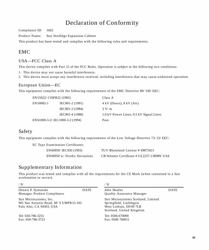
Declaration of ConformityCompliance ID: 1602
Product Name: Sun StorEdge Expansion Cabinet
This product has been tested and complies with the following rules and requirements.
EMC
USA—FCC Class A
This device complies with Part 15 of the FCC Rules. Operation is subject to the following two conditions:
1. This device may not cause harmful interference.
2. This device must accept any interference received, including interference that may cause undesired operation.
European Union—EC
This equipment complies with the following requirements of the EMC Directive 89/336/EEC:
Safety
This equipment complies with the following requirements of the Low Voltage Directive 73/23/EEC:
Supplementary Information
This product was tested and complies with all the requirements for the CE Mark (when connected to a Sunworkstation or server).
EN55022/CISPR22 (1985) Class A
EN50082-1 IEC801-2 (1991) 4 kV (Direct), 8 kV (Air)
IEC801-3 (1984) 3 V/m
IEC801-4 (1988) 1.0 kV Power Lines, 0.5 kV Signal Lines
EN61000-3-2/IEC1000-3-2 (1994) Pass
EC Type Examination Certificates:
EN60950/IEC950 (1993) TUV Rheinland License # S9872021
EN60950 w/Nordic Deviations CB Scheme Certificate # UL2257-138989/USA
/S/ /S/
Dennis P. Symanski DATEManager, Product Compliance
John Shades DATEQuality Assurance Manager
Sun Microsystems, Inc.901 San Antonio Road, M/S UMPK15-102Palo Alto, CA 94303, USA
Sun Microsystems Scotland, LimitedSpringfield, LinlithgowWest Lothian, EH49 7LRScotland, United Kingdom
Tel: 650-786-3255Fax: 650-786-3723
Tel: 0506-670000Fax: 0506 760011
iii

iv Sun Technical Compute Farm Installation and Service Manual • June 2000
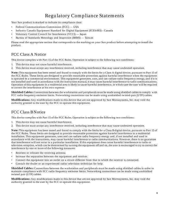
Regulatory Compliance Statements
Your Sun product is marked to indicate its compliance class:
• Federal Communications Commission (FCC) — USA
• Industry Canada Equipment Standard for Digital Equipment (ICES-003) - Canada
• Voluntary Control Council for Interference (VCCI) — Japan
• Bureau of Standards Metrology and Inspection (BSMI) — Taiwan
Please read the appropriate section that corresponds to the marking on your Sun product before attempting to install theproduct.
FCC Class A Notice
This device complies with Part 15 of the FCC Rules. Operation is subject to the following two conditions:
1. This device may not cause harmful interference.
2. This device must accept any interference received, including interference that may cause undesired operation.
Note: This equipment has been tested and found to comply with the limits for a Class A digital device, pursuant to Part 15 ofthe FCC Rules. These limits are designed to provide reasonable protection against harmful interference when the equipmentis operated in a commercial environment. This equipment generates, uses, and can radiate radio frequency energy, and if it isnot installed and used in accordance with the instruction manual, it may cause harmful interference to radio communications.Operation of this equipment in a residential area is likely to cause harmful interference, in which case the user will be requiredto correct the interference at his own expense.
Shielded Cables: Connections between the workstation and peripherals must be made using shielded cables to comply withFCC radio frequency emission limits. Networking connections can be made using unshielded twisted-pair (UTP) cables.
Modifications: Any modifications made to this device that are not approved by Sun Microsystems, Inc. may void theauthority granted to the user by the FCC to operate this equipment.
FCC Class B Notice
This device complies with Part 15 of the FCC Rules. Operation is subject to the following two conditions:
1. This device may not cause harmful interference.
2. This device must accept any interference received, including interference that may cause undesired operation.
Note: This equipment has been tested and found to comply with the limits for a Class B digital device, pursuant to Part 15 ofthe FCC Rules. These limits are designed to provide reasonable protection against harmful interference in a residentialinstallation. This equipment generates, uses and can radiate radio frequency energy and, if not installed and used inaccordance with the instructions, may cause harmful interference to radio communications. However, there is no guaranteethat interference will not occur in a particular installation. If this equipment does cause harmful interference to radio ortelevision reception, which can be determined by turning the equipment off and on, the user is encouraged to try to correct theinterference by one or more of the following measures:
• Reorient or relocate the receiving antenna.
• Increase the separation between the equipment and receiver.
• Connect the equipment into an outlet on a circuit different from that to which the receiver is connected.
• Consult the dealer or an experienced radio/television technician for help.
Shielded Cables: Connections between the workstation and peripherals must be made using shielded cables in order tomaintain compliance with FCC radio frequency emission limits. Networking connections can be made using unshieldedtwisted pair (UTP) cables.
Modifications: Any modifications made to this device that are not approved by Sun Microsystems, Inc. may void theauthority granted to the user by the FCC to operate this equipment.
v
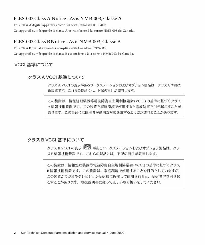
ICES-003 Class A Notice - Avis NMB-003, Classe A
This Class A digital apparatus complies with Canadian ICES-003.
Cet appareil numérique de la classe A est conforme à la norme NMB-003 du Canada.
ICES-003 Class B Notice - Avis NMB-003, Classe B
This Class B digital apparatus complies with Canadian ICES-003.
Cet appareil numérique de la classe B est conforme à la norme NMB-003 du Canada.
vi Sun Technical Compute Farm Installation and Service Manual • June 2000
BSMI Class A Notice
The following statement is applicable to products shipped to Taiwan and marked as Class A on the product compliancelabel.
Regulatory Compliance Statements vii

viii Sun Technical Compute Farm Installation and Service Manual • June 2000
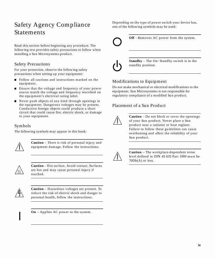
Safety Agency Compliance
Statements
Read this section before beginning any procedure. The
following text provides safety precautions to follow when
installing a Sun Microsystems product.
Safety Precautions
For your protection, observe the following safety
precautions when setting up your equipment:
■ Follow all cautions and instructions marked on theequipment.
■ Ensure that the voltage and frequency of your powersource match the voltage and frequency inscribed onthe equipment’s electrical rating label.
■ Never push objects of any kind through openings inthe equipment. Dangerous voltages may be present.Conductive foreign objects could produce a shortcircuit that could cause fire, electric shock, or damageto your equipment.
Symbols
The following symbols may appear in this book:
Depending on the type of power switch your device has,
one of the following symbols may be used:
Modifications to Equipment
Do not make mechanical or electrical modifications to the
equipment. Sun Microsystems is not responsible for
regulatory compliance of a modified Sun product.
Placement of a Sun Product
Caution – There is risk of personal injury and
equipment damage. Follow the instructions.
Caution – Hot surface. Avoid contact. Surfaces
are hot and may cause personal injury if
touched.
Caution – Hazardous voltages are present. To
reduce the risk of electric shock and danger to
personal health, follow the instructions.
On – Applies AC power to the system.
Off - Removes AC power from the system.
Standby – The On/Standby switch is in the
standby position.
Caution – Do not block or cover the openings
of your Sun product. Never place a Sun
product near a radiator or heat register.
Failure to follow these guidelines can cause
overheating and affect the reliability of your
Sun product.
Caution – The workplace-dependent noise
level defined in DIN 45 635 Part 1000 must be
70Db(A) or less.
ix
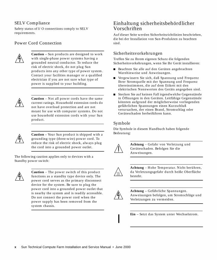
SELV Compliance
Safety status of I/O connections comply to SELV
requirements.
Power Cord Connection
The following caution applies only to devices with a
Standby power switch:
Einhaltung sicherheitsbehördlicherVorschriftenAuf dieser Seite werden Sicherheitsrichtlinien beschrieben,
die bei der Installation von Sun-Produkten zu beachten
sind.
Sicherheitsvorkehrungen
Treffen Sie zu Ihrem eigenen Schutz die folgenden
Sicherheitsvorkehrungen, wenn Sie Ihr Gerät installieren:
■ Beachten Sie alle auf den Geräten angebrachtenWarnhinweise und Anweisungen.
■ Vergewissern Sie sich, daß Spannung und FrequenzIhrer Stromquelle mit der Spannung und Frequenzübereinstimmen, die auf dem Etikett mit denelektrischen Nennwerten des Geräts angegeben sind.
■ Stecken Sie auf keinen Fall irgendwelche Gegenständein Öffnungen in den Geräten. Leitfähige Gegenständekönnten aufgrund der möglicherweise vorliegendengefährlichen Spannungen einen Kurzschlußverursachen, der einen Brand, Stromschlag oderGeräteschaden herbeiführen kann.
Symbole
Die Symbole in diesem Handbuch haben folgende
Bedeutung:
Caution – Sun products are designed to work
with single-phase power systems having a
grounded neutral conductor. To reduce the
risk of electric shock, do not plug Sun
products into any other type of power system.
Contact your facilities manager or a qualified
electrician if you are not sure what type of
power is supplied to your building.
Caution – Not all power cords have the same
current ratings. Household extension cords do
not have overload protection and are not
meant for use with computer systems. Do not
use household extension cords with your Sun
product.
Caution – Your Sun product is shipped with a
grounding type (three-wire) power cord. To
reduce the risk of electric shock, always plug
the cord into a grounded power outlet.
Caution – The power switch of this product
functions as a standby type device only. The
power cord serves as the primary disconnect
device for the system. Be sure to plug the
power cord into a grounded power outlet that
is nearby the system and is readily accessible.
Do not connect the power cord when the
power supply has been removed from the
system chassis.
Achtung – Gefahr von Verletzung und
Geräteschaden. Befolgen Sie die
Anweisungen.
Achtung – Hohe Temperatur. Nicht berühren,
da Verletzungsgefahr durch heiße Oberfläche
besteht.
Achtung – Gefährliche Spannungen.
Anweisungen befolgen, um Stromschläge und
Verletzungen zu vermeiden.
Ein – Setzt das System unter Wechselstrom.
x Sun Technical Compute Farm Installation and Service Manual • June 2000
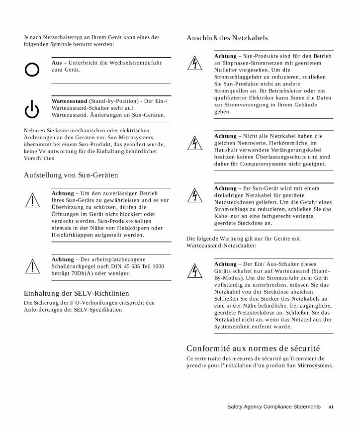
Je nach Netzschaltertyp an Ihrem Gerät kann eines der
folgenden Symbole benutzt werden:
Nehmen Sie keine mechanischen oder elektrischen
Änderungen an den Geräten vor. Sun Microsystems,
übernimmt bei einem Sun-Produkt, das geändert wurde,
keine Verantwortung für die Einhaltung behördlicher
Vorschriften
Aufstellung von Sun-Geräten
Einhaltung der SELV-Richtlinien
Die Sicherung der I/O-Verbindungen entspricht den
Anforderungen der SELV-Spezifikation.
Anschluß des Netzkabels
Die folgende Warnung gilt nur für Geräte mit
Wartezustand-Netzschalter:
Conformité aux normes de sécuritéCe texte traite des mesures de sécurité qu’il convient de
prendre pour l’installation d’un produit Sun Microsystems.
Aus – Unterbricht die Wechselstromzufuhr
zum Gerät.
Wartezustand (Stand-by-Position) - Der Ein-/
Wartezustand-Schalter steht auf
Wartezustand. Änderungen an Sun-Geräten.
Achtung – Um den zuverlässigen Betrieb
Ihres Sun-Geräts zu gewährleisten und es vor
Überhitzung zu schützen, dürfen die
Öffnungen im Gerät nicht blockiert oder
verdeckt werden. Sun-Produkte sollten
niemals in der Nähe von Heizkörpern oder
Heizluftklappen aufgestellt werden.
Achtung – Der arbeitsplatzbezogene
Schalldruckpegel nach DIN 45 635 Teil 1000
beträgt 70Db(A) oder weniger.
Achtung – Sun-Produkte sind für den Betrieb
an Einphasen-Stromnetzen mit geerdetem
Nulleiter vorgesehen. Um die
Stromschlaggefahr zu reduzieren, schließen
Sie Sun-Produkte nicht an andere
Stromquellen an. Ihr Betriebsleiter oder ein
qualifizierter Elektriker kann Ihnen die Daten
zur Stromversorgung in Ihrem Gebäude
geben.
Achtung – Nicht alle Netzkabel haben die
gleichen Nennwerte. Herkömmliche, im
Haushalt verwendete Verlängerungskabel
besitzen keinen Überlastungsschutz und sind
daher für Computersysteme nicht geeignet.
Achtung – Ihr Sun-Gerät wird mit einem
dreiadrigen Netzkabel für geerdete
Netzsteckdosen geliefert. Um die Gefahr eines
Stromschlags zu reduzieren, schließen Sie das
Kabel nur an eine fachgerecht verlegte,
geerdete Steckdose an.
Achtung – Der Ein/Aus-Schalter dieses
Geräts schaltet nur auf Wartezustand (Stand-
By-Modus). Um die Stromzufuhr zum Gerät
vollständig zu unterbrechen, müssen Sie das
Netzkabel von der Steckdose abziehen.
Schließen Sie den Stecker des Netzkabels an
eine in der Nähe befindliche, frei zugängliche,
geerdete Netzsteckdose an. Schließen Sie das
Netzkabel nicht an, wenn das Netzteil aus der
Systemeinheit entfernt wurde.
Safety Agency Compliance Statements xi
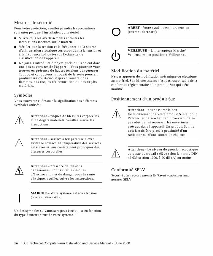
Mesures de sécurité
Pour votre protection, veuillez prendre les précautions
suivantes pendant l’installation du matériel :
■ Suivre tous les avertissements et toutes lesinstructions inscrites sur le matériel.
■ Vérifier que la tension et la fréquence de la sourced’alimentation électrique correspondent à la tension età la fréquence indiquées sur l’étiquette declassification de l’appareil.
■ Ne jamais introduire d’objets quels qu’ils soient dansune des ouvertures de l’appareil. Vous pourriez voustrouver en présence de hautes tensions dangereuses.Tout objet conducteur introduit de la sorte pourraitproduire un court-circuit qui entraînerait desflammes, des risques d’électrocution ou des dégâtsmatériels.
Symboles
Vous trouverez ci-dessous la signification des différents
symboles utilisés :
Un des symboles suivants sera peut-être utilisé en fonction
du type d'interrupteur de votre système:
Modification du matériel
Ne pas apporter de modification mécanique ou électrique
au matériel. Sun Microsystems n’est pas responsable de la
conformité réglementaire d’un produit Sun qui a été
modifié.
Positionnement d’un produit Sun
Conformité SELV
Sécurité : les raccordements E/S sont conformes aux
normes SELV.
Attention: – risques de blessures corporelles
et de dégâts matériels. Veuillez suivre les
instructions.
Attention: – surface à température élevée.
Evitez le contact. La température des surfaces
est élevée et leur contact peut provoquer des
blessures corporelles.
Attention: – présence de tensions
dangereuses. Pour éviter les risques
d’électrocution et de danger pour la santé
physique, veuillez suivre les instructions.
MARCHE – Votre système est sous tension
(courant alternatif).
ARRET - Votre système est hors tension
(courant alternatif).
VEILLEUSE – L'interrupteur Marche/
Veilleuse est en position « Veilleuse ».
Attention: – pour assurer le bon
fonctionnement de votre produit Sun et pour
l’empêcher de surchauffer, il convient de ne
pas obstruer ni recouvrir les ouvertures
prévues dans l’appareil. Un produit Sun ne
doit jamais être placé à proximité d’un
radiateur ou d’une source de chaleur.
Attention: – Le niveau de pression acoustique
au poste de travail s'élève selon la norme DIN
45 635 section 1000, à 70 dB (A) ou moins.
xii Sun Technical Compute Farm Installation and Service Manual • June 2000
Connexion du cordon d’alimentation.
L'avertissement suivant s'applique uniquement aux
systèmes équipés d'un interrupteur VEILLEUSE:
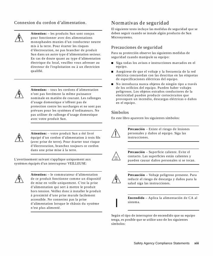
Normativas de seguridadEl siguiente texto incluye las medidas de seguridad que se
deben seguir cuando se instale algún producto de Sun
Microsystems.
Precauciones de seguridad
Para su protección observe las siguientes medidas de
seguridad cuando manipule su equipo:
■ Siga todas los avisos e instrucciones marcados en elequipo.
■ Asegúrese de que el voltaje y la frecuencia de la redeléctrica concuerdan con las descritas en las etiquetasde especificaciones eléctricas del equipo.
■ No introduzca nunca objetos de ningún tipo a travésde los orificios del equipo. Pueden haber voltajespeligrosos. Los objetos extraños conductores de laelectricidad pueden producir cortocircuitos queprovoquen un incendio, descargas eléctricas o dañosen el equipo.
Símbolos
En este libro aparecen los siguientes símbolos:
Según el tipo de interruptor de encendido que su equipo
tenga, es posible que se utilice uno de los siguientes
símbolos:
Attention: – les produits Sun sont conçus
pour fonctionner avec des alimentations
monophasées munies d’un conducteur neutre
mis à la terre. Pour écarter les risques
d’électrocution, ne pas brancher de produit
Sun dans un autre type d’alimentation secteur.
En cas de doute quant au type d’alimentation
électrique du local, veuillez vous adresser au
directeur de l’exploitation ou à un électricien
qualifié.
Attention: – tous les cordons d’alimentation
n’ont pas forcément la même puissance
nominale en matière de courant. Les rallonges
d’usage domestique n’offrent pas de
protection contre les surcharges et ne sont pas
prévues pour les systèmes d’ordinateurs. Ne
pas utiliser de rallonge d’usage domestique
avec votre produit Sun.
Attention: – votre produit Sun a été livré
équipé d’un cordon d’alimentation à trois fils
(avec prise de terre). Pour écarter tout risque
d’électrocution, branchez toujours ce cordon
dans une prise mise à la terre.
Attention: – le commutateur d’alimentation
de ce produit fonctionne comme un dispositif
de mise en veille uniquement. C’est la prise
d’alimentation qui sert à mettre le produit
hors tension. Veillez donc à installer le produit
à proximité d’une prise murale facilement
accessible. Ne connectez pas la prise
d’alimentation lorsque le châssis du système
n’est plus alimenté.
Precaución – Existe el riesgo de lesiones
personales y daños al equipo. Siga las
instrucciones.
Precaución – Superficie caliente. Evite el
contacto. Las superficies están calientes y
pueden causar daños personales si se tocan.
Precaución – Voltaje peligroso presente. Para
reducir el riesgo de descarga y daños para la
salud siga las instrucciones.
Encendido – Aplica la alimentación de CA al
sistema.
Safety Agency Compliance Statements xiii
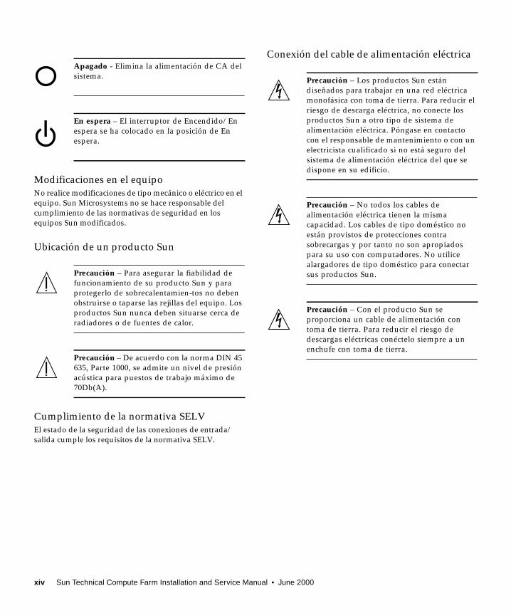
Modificaciones en el equipo
No realice modificaciones de tipo mecánico o eléctrico en el
equipo. Sun Microsystems no se hace responsable del
cumplimiento de las normativas de seguridad en los
equipos Sun modificados.
Ubicación de un producto Sun
Cumplimiento de la normativa SELV
El estado de la seguridad de las conexiones de entrada/
salida cumple los requisitos de la normativa SELV.
Conexión del cable de alimentación eléctricaApagado - Elimina la alimentación de CA del
sistema.
En espera – El interruptor de Encendido/En
espera se ha colocado en la posición de En
espera.
Precaución – Para asegurar la fiabilidad de
funcionamiento de su producto Sun y para
protegerlo de sobrecalentamien-tos no deben
obstruirse o taparse las rejillas del equipo. Los
productos Sun nunca deben situarse cerca de
radiadores o de fuentes de calor.
Precaución – De acuerdo con la norma DIN 45
635, Parte 1000, se admite un nivel de presión
acústica para puestos de trabajo máximo de
70Db(A).
Precaución – Los productos Sun están
diseñados para trabajar en una red eléctrica
monofásica con toma de tierra. Para reducir el
riesgo de descarga eléctrica, no conecte los
productos Sun a otro tipo de sistema de
alimentación eléctrica. Póngase en contacto
con el responsable de mantenimiento o con un
electricista cualificado si no está seguro del
sistema de alimentación eléctrica del que se
dispone en su edificio.
Precaución – No todos los cables de
alimentación eléctrica tienen la misma
capacidad. Los cables de tipo doméstico no
están provistos de protecciones contra
sobrecargas y por tanto no son apropiados
para su uso con computadores. No utilice
alargadores de tipo doméstico para conectar
sus productos Sun.
Precaución – Con el producto Sun se
proporciona un cable de alimentación con
toma de tierra. Para reducir el riesgo de
descargas eléctricas conéctelo siempre a un
enchufe con toma de tierra.
xiv Sun Technical Compute Farm Installation and Service Manual • June 2000

La siguiente advertencia se aplica solamente a equipos con
un interruptor de encendido que tenga una posición "En
espera":
GOST-R Certification Mark
Precaución – El interruptor de encendido de
este producto funciona exclusivamente como
un dispositivo de puesta en espera. El enchufe
de la fuente de alimentación está diseñado
para ser el elemento primario de desconexión
del equipo. El equipo debe instalarse cerca del
enchufe de forma que este último pueda ser
fácil y rápidamente accesible. No conecte el
cable de alimentación cuando se ha retirado la
fuente de alimentación del chasis del sistema.
Safety Agency Compliance Statements xv

xvi Sun Technical Compute Farm Installation and Service Manual • June 2000
Contents
Declaration of Conformity iii
Regulatory Compliance Statements v
Safety Agency Compliance Statements ix
Preface xxxiii
1. Sun Technical Compute Farm Overview 1-1
1.1 Typical Sun TCF System Applications 1-1
1.2 Hardware Description 1-2
1.2.1 Base Rack 1-3
1.2.2 Expansion Rack 1-6
1.2.3 Star Rack 1-9
1.3 System Devices 1-12
1.3.1 Rack 1-12
1.3.2 Disk Array 1-12
1.3.3 File Server and Compute Engine 1-13
1.3.4 Cisco C3524 and C3508 Ethernet Switches 1-17
1.3.4.1 C3524 Ethernet Switch 1-17
1.3.4.2 C3508 Ethernet Switch 1-18
1.3.5 Access Server 1-20
Contents xvii
1.4 I/O Devices 1-21
2. Preparing for Assembly and Installation 2-1
2.1 Site Planning 2-1
2.2 Space Planning 2-2
2.3 Rack Physical Characteristics 2-3
2.4 Environmental Requirements 2-3
2.5 Heating, Ventilation, and Air Conditioning 2-4
2.6 Clearance and Service Access 2-5
3. Unpacking and Installing the Rack 3-1
3.1 Unpacking the Rack 3-1
3.2 Moving and Placing the Rack 3-2
3.3 Adjusting the Leveling Pads 3-3
3.4 Installing the Stabilizer Legs 3-4
3.5 Installing the Floor Brackets 3-6
3.6 Cabling the Rack 3-8
3.6.1 Preparing the Rack 3-8
3.6.2 Connecting the Power Cord 3-11
3.6.3 Connecting the Ground Strap 3-14
3.6.4 Final Cabling Tasks 3-15
4. Installing a Second Disk Array 4-1
4.1 Installing the Rails 4-2
4.2 Installing the Chassis in the Rack 4-4
4.3 Connecting the Power Cable 4-6
4.4 Installing Additional Interface Boards and GBICs 4-8
4.5 Disk Array-to-File Server Cabling 4-9
4.6 Disk Array 1-to-Disk Array 2 Cabling 4-9
4.7 Repositioning the Airflow Baffle 4-9
4.7.1 Removing the Airflow Baffle 4-10
xviii Sun Technical Compute Farm Installation and Service Manual • June 2000
4.7.1.1 Removing the Filler Panel Assembly 4-10
4.7.1.2 Removing the Side Baffle 4-11
4.7.1.3 Removing the Main Baffle 4-11
4.7.2 Replacing the Airflow Baffle 4-12
4.7.2.1 Replacing the Main Baffle 4-12
4.7.2.2 Replacing the Side Baffle 4-13
4.7.2.3 Replacing the Filler Panel Assembly 4-14
4.8 Reassembling the Rack 4-16
5. Cabling the Sun TCF Devices 5-1
5.1 Small Farm Configuration Example 5-1
5.1.1 Cabling the Disk Array for the Small Farm Configuration 5-7
5.1.1.1 Disk Array 1-to-File Server Cabling 5-8
5.1.1.2 Point-to-Point Cabling With Second Disk Array
Installed 5-8
5.1.2 Cabling the File Server for the Small Farm Configuration 5-9
5.1.3 Cabling the Compute Engine for the Small Farm Configuration 5-
11
5.1.4 Cabling the C3524 Ethernet Switch for the
Small Farm Configuration 5-12
5.1.5 Cabling the Access Server for Small Farm Configuration 5-14
5.2 Medium Farm Configuration Example 1 5-15
5.2.1 Cabling the Disk Array for the Medium Farm Configuration
Example 1 5-21
5.2.2 Cabling the File Server for the Medium Farm Configuration
Example 1 5-21
5.2.3 Cabling the Compute Engines for the Medium Farm Configuration
Example 1 5-21
5.2.4 Cabling the C3524 Ethernet Switch for the Medium Farm
Configuration Example 1 5-23
5.2.5 Cabling the Access Server 2 for the Medium Farm Configuration
Example 1 5-25
5.3 Medium Farm Configuration Example 2 5-27
Contents xix

5.3.1 Cabling the Disk Array for the Medium Farm Configuration
Example 2 5-31
5.3.2 Cabling the File Server for the Medium Farm Configuration
Example 2 5-31
5.3.3 Cabling the Compute Engine for the Medium Farm Configuration
Example 2 5-31
5.3.4 Cabling the C3524 Ethernet Switches for the Medium Farm
Configuration Example 2 5-31
5.3.5 Cabling the Access Server for the Medium Farm Configuration
Example 2 5-34
5.4 Large Farm Configuration Example 5-34
5.4.1 Cabling the Disk Array for the Large Farm Configuration 5-39
5.4.1.1 Disk Array-to-File Server Cabling 5-40
5.4.1.2 Disk Array 1-to-Disk Array 2 Cabling 5-41
5.4.2 Cabling the File Server for the Large Farm Configuration 5-42
5.4.3 Cabling the Compute Engine for the Large Farm Configuration 5-
42
5.4.4 Cabling the C3524 Ethernet Switches for the
Large Farm Configuration 5-42
5.4.5 Cabling the Access Server for the Large Farm Configuration 5-44
5.4.6 Cabling the C3508 Ethernet Switch 5-45
6. Powering On and Off 6-1
6.1 Preparing to Power On 6-1
6.2 Power On and Off Sequence 6-2
6.2.1 Powering On the Rack 6-3
6.2.2 Powering Off the Rack 6-5
6.2.3 Powering On and Off the Access Server 6-6
6.2.4 Powering On and Off the C3524 and C3508 Ethernet Switches 6-6
6.2.5 Powering On the Disk Array 6-7
6.2.6 Powering Off the Disk Array 6-7
6.2.7 Powering On the File Server or Compute Engine 6-8
6.2.8 Powering Off the File Server or Compute Engine 6-10
xx Sun Technical Compute Farm Installation and Service Manual • June 2000
7. Connecting a System Console and Configuring the Access Server 7-1
7.1 Installing a System Console 7-1
7.2 Configuring the Access Server 7-3
7.3 Reverting To Factory Settings 7-10
7.4 Configuring the File Server and Compute Engines 7-10
8. Fault Isolation and Troubleshooting 8-1
8.1 Sun Management Center 2.1 Software 8-1
8.2 SunVTS Description 8-2
8.2.1 SunVTS Requirements 8-3
8.2.2 SunVTS References 8-3
8.3 Troubleshooting the Sun TCF System 8-4
8.3.1 Preparing to Service the Disk Array 8-4
8.3.2 Preparing to Service the File Server or Compute Engine 8-4
8.3.3 Preparing to Service the C3524 or C3508 Ethernet Switches 8-5
8.3.4 Preparing to Service the Access Server 8-5
9. Removing, Replacing, and Cabling Devices 9-1
9.1 Access Server 9-2
9.1.1 Removing the Access Server 9-2
9.1.2 Replacing the Access Server 9-4
9.1.3 Connecting the Access Server to the Network 9-6
9.1.4 Connecting the Access Server to a System Terminal 9-7
9.2 C3524 and C3508 Ethernet Switches 9-7
9.2.1 Removing the Ethernet Switches 9-8
9.2.2 Replacing the Ethernet Switches 9-10
9.2.3 Connecting the Ethernet Switches to the Network 9-12
9.2.4 Installing the Ethernet Switch 1000BASE-X GBIC Module 9-13
9.3 File Server or Compute Engine 9-14
9.3.1 Removing the File Server or Compute Engine 9-15
Contents xxi
9.3.2 Removing and Replacing the File Server or Compute Engine Main
Logic Board 9-18
9.3.3 Replacing the File Server or Compute Engine 9-18
9.3.4 Positioning the File Server or Compute Engine for Service 9-23
9.3.5 Removing and Replacing File Server or Compute Engine
Components 9-26
9.3.5.1 Removing and Replacing the File Server or Compute
Engine FRUs 9-27
9.3.5.2 Removing a File Server Host Adapter 9-27
9.3.5.3 Replacing a File Server Host Adapter 9-29
9.3.5.4 Removing the File Server GigabitEthernet Adapter 9-
30
9.3.5.5 Replacing the File Server GigabitEthernet Adapter 9-
32
9.3.6 Securing the File Server or Compute Engine After Service 9-33
9.3.7 Cabling the File Server or Compute Engine 9-35
9.4 Disk Array 9-35
9.4.1 Removing a Disk Array 9-36
9.4.2 Replacing a Disk Array 9-38
9.4.3 Cabling a Disk Array 9-39
9.4.4 Removing and Replacing the Disk Array FRUs 9-39
10. Removing and Replacing Rack FRUs 10-1
10.1 Tools Required 10-1
10.2 Key Switch 10-2
10.2.1 Removing the Key Switch 10-2
10.2.2 Replacing the Key Switch 10-3
10.3 AC Input Cable Assembly 10-4
10.3.1 Removing the AC Input Cable Assembly 10-4
10.3.2 Replacing the AC Input Cable Assembly 10-5
10.4 Power Sequencer 10-6
10.4.1 Removing the Power Sequencer 10-6
xxii Sun Technical Compute Farm Installation and Service Manual • June 2000
10.4.2 Replacing the Power Sequencer 10-7
10.5 Side Panel 10-7
10.5.1 Removing the Side Panel 10-7
10.5.2 Replacing the Side Panel 10-8
A. Product Specifications A-1
A.1 Physical Specifications A-1
A.2 Supporting Documentation A-3
A.3 Electrical Specifications A-4
A.4 Environmental Requirements A-5
A.5 Clearance and Service Access A-6
B. Parts Table B-1
Contents xxiii

xxiv Sun Technical Compute Farm Installation and Service Manual • June 2000
Figures
FIGURE 1-1 Sun TCF Base Rack Front View 1-4
FIGURE 1-2 Sun TCF Base Rack Back View 1-5
FIGURE 1-3 Sun TCF Expansion Rack Front View 1-7
FIGURE 1-4 Sun TCF Expansion Rack Back View 1-8
FIGURE 1-5 Sun TCF Star Rack Front View 1-10
FIGURE 1-6 Sun TCF Star Rack Back View 1-11
FIGURE 1-7 Disk Array Front View 1-13
FIGURE 1-8 Disk Array Back View 1-13
FIGURE 1-9 File Server/Compute Engine Front View 1-15
FIGURE 1-10 File Server/Compute Engine Front View With Front Doors Open 1-15
FIGURE 1-11 File Server Back View 1-16
FIGURE 1-12 Compute Engine Back View 1-16
FIGURE 1-13 C3524 Ethernet Switch Front Panel 1-17
FIGURE 1-14 C3524 Ethernet Switch Back Panel 1-18
FIGURE 1-15 C3508 Ethernet Switch Front Panel 1-19
FIGURE 1-16 C3508 Ethernet Switch Back Panel 1-19
FIGURE 1-17 Access Server Front Panel 1-20
FIGURE 1-18 Access Server Back Panel 1-20
FIGURE 3-1 Rack Leveling Pads 3-3
xxv
FIGURE 3-2 Stabilizer Legs 3-4
FIGURE 3-3 Installing the Right Stabilizer Leg 3-5
FIGURE 3-4 Adjusting the Leveling Pads on the Stabilizer Leg 3-6
FIGURE 3-5 Removing the Mounting Screws 3-7
FIGURE 3-6 Attaching the Floor Brackets 3-7
FIGURE 3-7 Location of Key Switch on Bottom Front Panel 3-9
FIGURE 3-8 Opening the Back Door of the Rack 3-10
FIGURE 3-9 Power Sequencer Control Panel 3-11
FIGURE 3-10 Connecting the Power Cord 3-12
FIGURE 3-11 NEMA L6-30P for 200-240V North American Operation 3-13
FIGURE 3-12 IEC 309 Connector for 200–240V International Operation 3-13
FIGURE 3-13 Connecting the Ground Strap to the Front Power Sequencer 3-15
FIGURE 4-1 Threading Screws Into the Rack 4-3
FIGURE 4-2 Aligning the Chassis and Baseplate With the Side Rails 4-5
FIGURE 4-3 Installing Screws to Secure the Baseplate to the Side Brackets 4-6
FIGURE 4-4 AC Power Connector 4-7
FIGURE 4-5 Power Cable Routing 4-8
FIGURE 4-6 Main and Side Baffles 4-10
FIGURE 4-7 Removing the Side Baffle 4-11
FIGURE 4-8 Main Baffle 4-12
FIGURE 4-9 Side Baffle 4-13
FIGURE 4-10 Installing the Side Baffle 4-15
FIGURE 5-1 Example of a Sun TCF Small Farm Configuration With One Base Rack 5-3
FIGURE 5-2 Small Farm Configuration Schematic Drawing 5-6
FIGURE 5-3 Disk Array Ports 5-7
FIGURE 5-4 Disk Array 1-to-File Server Cabling 5-8
FIGURE 5-5 Cabling the File Server for the Small Farm Configuration 5-10
FIGURE 5-6 Cabling the Base Rack Compute Engine for the Small Farm Configuration 5-11
xxvi Sun Technical Compute Farm Installation and Service Manual • June 2000
FIGURE 5-7 Cabling the Expansion Rack Compute Engine for the Small Farm Configuration 5-12
FIGURE 5-8 Cabling the C3524 Ethernet Switch for the Small Farm Configuration 5-13
FIGURE 5-9 Cabling Access Server 1 for the Small Farm Configuration 5-15
FIGURE 5-10 Example 1 of a Sun TCF Medium Farm Configuration With One Base Rack 5-17
FIGURE 5-11 Medium Farm Configuration Example 1 (Sheet 1 of 2) 5-19
FIGURE 5-12 Medium Farm Configuration Example 1 (Sheet 2 of 2) 5-20
FIGURE 5-13 Cabling the Expansion Rack 2 Compute Engine for the Medium Farm Configuration Example1 5-22
FIGURE 5-14 Cabling the C3524 Ethernet Switch for the Medium Farm Configuration Example 1 5-24
FIGURE 5-15 Cabling the Access Server 2 for the Medium Farm Configuration Example 1 5-26
FIGURE 5-16 Example 2 of a Sun TCF Medium Farm Configuration With Two Base Racks 5-28
FIGURE 5-17 Medium Farm Configuration Example 2 (Sheet 1 of 2) 5-29
FIGURE 5-18 Medium Farm Configuration Example 2 (Sheet 2 of 2) 5-30
FIGURE 5-19 Cabling the Base Rack 1 C3524 Ethernet Switch for the Medium Farm Configuration Example2 5-32
FIGURE 5-20 Cabling Base Rack 2 C3524 Ethernet Switch for the Medium Farm Configuration Example2 5-33
FIGURE 5-21 Example of a Sun TCF Large Farm Configuration With a Star Rack and Three BaseRacks 5-35
FIGURE 5-22 Large Farm Configuration 5-38
FIGURE 5-23 Disk Array Ports 5-39
FIGURE 5-24 Cabling Disk Arrays 1 and 2 to the File Server 5-40
FIGURE 5-25 Disk Array 1-to-Disk Array 2 Cabling 5-41
FIGURE 5-26 Cabling the Star Rack C3524 Ethernet Switch for the Large Farm Configuration 5-43
FIGURE 5-27 Cabling the C3508 Ethernet Switch 5-46
FIGURE 6-1 Location of Key Switch on Bottom Front Panel 6-3
FIGURE 6-2 AC Power Sequencer Control Panel 6-4
FIGURE 6-3 Front Sequencer Status Lights 6-4
FIGURE 6-4 Powering On the Disk Array 6-7
FIGURE 6-5 Powering On the File Server or Compute Engine 6-9
Figures xxvii
FIGURE 6-6 Setting the Locked Position 6-9
FIGURE 6-7 Setting the Standby Position 6-10
FIGURE 7-1 Installing a System Console 7-2
FIGURE 9-1 Removing and Replacing the Access Server 9-3
FIGURE 9-2 Removing and Replacing the Access Server Rear Bracket 9-4
FIGURE 9-3 Installing the Access Server Front Bracket 9-5
FIGURE 9-4 Mounting Location for the Access Servers 9-6
FIGURE 9-5 Removing and Replacing the C3524 Ethernet Switch 9-9
FIGURE 9-6 Removing and Replacing the C3524 Ethernet Rear Bracket 9-10
FIGURE 9-7 Installing the Ethernet Switch Front Bracket 9-11
FIGURE 9-8 Mounting Location for the Ethernet Switches 9-12
FIGURE 9-9 Installing the 1000BASE-X GBIC Module 9-13
FIGURE 9-10 Loosening the Captive Screws From the Left and Right Vertical Rails 9-16
FIGURE 9-11 Locating the Flat Spring Catches 9-17
FIGURE 9-12 Pushing in the Runner 9-19
FIGURE 9-13 Inserting the File Server or Compute Engine Glides Into the Inner Slides of the RackGlides 9-20
FIGURE 9-14 Pressing the Flat Spring Catches 9-21
FIGURE 9-15 Securing the File Server or Compute Engine to the Left and Right Vertical Rails 9-22
FIGURE 9-16 Loosening the Captive Screws Securing the File Server or Compute Engine to the Rails 9-24
FIGURE 9-17 Sliding the File Server or Compute Engine Chassis out of the Rack 9-25
FIGURE 9-18 Removing and Replacing the Host Adapter Fiber Optic Cable 9-28
FIGURE 9-19 Removing and Replacing the Host Adapter Dust Covers 9-28
FIGURE 9-20 Removing and Replacing the GigabitEthernet Adapter Fiber Optic Cable 9-31
FIGURE 9-21 Removing and Replacing the GigabitEthernet Adapter Dust Covers 9-31
FIGURE 9-22 Tightening the Captive Screws Securing the File Server or Compute Engine to the Rails 9-
34
FIGURE 9-23 Removing the Screws Securing the Baseplate to the Side Brackets 9-37
FIGURE 9-24 Removing the Chassis and Baseplate From the Rack 9-38
xxviii Sun Technical Compute Farm Installation and Service Manual • June 2000
FIGURE 10-1 Removing and Replacing the Key Switch 10-2
FIGURE 10-2 Removing and Replacing the Key Switch 10-3
FIGURE 10-3 Removing and Replacing the AC Input Cable 10-5
FIGURE 10-4 Removing and Replacing the Power Sequencer 10-6
FIGURE 10-5 Removing and Replacing the Side Panels 10-8
Figures xxix

xxx Sun Technical Compute Farm Installation and Service Manual • June 2000
Tables
TABLE 1-1 Base Rack Equipment 1-3
TABLE 1-2 Expansion Rack Equipment 1-6
TABLE 1-3 Star Rack Equipment 1-9
TABLE 1-4 Supported I/O Devices 1-21
TABLE 2-1 Operating Environment 2-3
TABLE 2-2 Sun TCF Rack Air Conditioning Tonnage 2-4
TABLE 2-3 Clearance and Service Access 2-5
TABLE 5-1 Point-to-Point Connections Within the Base Rack 5-3
TABLE 5-2 Point-to-Point Connections Between the Base Rack and the Expansion Rack 5-4
TABLE 5-3 Point-to-Point Connections Between the Base Rack and Expansion Rack 2 5-17
TABLE 5-4 Point-to-Point Connections Between the Base Racks 5-28
TABLE 5-5 Point-to-Point Connections Within the Star Rack 5-36
TABLE 5-6 Point-to-Point Connections Between the Star Rack and Three Small Farm Base Racks 5-37
TABLE 8-1 Sun Management Center 2.1 Software Features 8-2
TABLE A-1 Base Rack Physical Specifications A-1
TABLE A-2 Expansion Rack With 2-CPU Compute Engines Physical Specifications A-2
TABLE A-3 Expansion Rack With 4-CPU Compute Engines Physical Specifications A-2
TABLE A-4 Star Rack Physical Specifications A-2
TABLE A-5 Product Specifications A-3
TABLE A-6 Sun TCF Electrical Specifications A-4
xxxi
TABLE A-7 Sun TCF Environmental Requirements A-5
TABLE A-8 Sun TCF Rack Air Conditioning Tonnage A-5
TABLE A-9 Sun TCF Clearance and Service Access A-6
TABLE B-1 Sun TCF Replaceable Parts B-1
TABLE B-2 Sun TCF Devices With Replaceable Parts B-2
xxxii Sun Technical Compute Farm Installation and Service Manual • June 2000
Preface
The Sun Technical Compute Farm Installation and Service Manual provides procedures
for unpacking and installing the Sun™ Technical Compute Farm (Sun TCF) system.
It also includes procedures to install, remove, and replace the cabinet-mounted
devices and to remove and replace the expansion cabinet field replaceable units
(FRUs). Only a qualified service provider should perform the tasks in this manual.
This book is part of the Sun TCF software media kit shipped with the Sun TCF
product for final assembly and use.
In most cases, the Sun TCF hardware will be assembled and installed before
shipment to the customer site. At the customer site, Sun Enterprise Services may
unpack and install the complete Sun TCF for the customer. This document is
intended to support these activities.
How This Book Is Organized
Chapter 1 provides the product overview.
Chapter 2 describes site preparation.
Chapter 3 describes unpacking and installing the rack.
Chapter 4 provides procedures for installing a second disk array and repositioning
the airflow baffle.
Chapter 5 provides procedures for cabling the available Sun TCF configurations and
for cabling the Sun TCF devices.
Chapter 6 provides procedures to power on and power off the expansion cabinet,
and power on and power off the cabinet-mounted devices.
xxxiii
Chapter 7 provides procedures for adding a system console and initially configuring
the access server.
Chapter 8 provides fault isolation and troubleshooting.
Chapter 9 provides procedures to remove, replace, and cable a specific rack device.
Chapter 10 provides procedures to remove and replace Sun StorEdge™ expansion
cabinet (rack) subassemblies (FRUs).
Appendix A lists the various hardware devices, the supporting documents, and the
document part number for acquiring specifications for the particular device.
Appendix B provides a table that lists the replaceable components for the Sun TCF
by part number and a second table that lists the Sun TCF devices with replaceable
components. The listed documents associated with each device contain FRU part
numbers for the device.
Using UNIX Commands
This document may not contain information on basic UNIX® commands and
procedures such as shutting down the system, booting the system, and configuring
devices.
See one or more of the following for this information:
■ Solaris Handbook for Sun Peripherals (If you are incorporating Solaris softwarecommands in your document, delete this sentence.)
■ AnswerBook™ online documentation for the Solaris™ software environment
■ Other software documentation that you received with your system
xxxiv Sun Technical Compute Farm Installation and Service Manual • June 2000
Typographic Conventions
Shell Prompts
Typeface Meaning Examples
AaBbCc123 The names of commands, files,
and directories; on-screen
computer output
Edit your .login file.
Use ls -a to list all files.
% You have mail .
AaBbCc123 What you type, when
contrasted with on-screen
computer output
% suPassword:
AaBbCc123 Book titles, new words or
terms, words to be emphasized
Command-line variable;
replace with a real name or
value
Read Chapter 6 in the User’s Guide.
These are called class options.
You must be superuser to do this.
To delete a file, type rm filename.
Shell Prompt
C shell machine_name%
C shell superuser machine_name#
Bourne shell and Korn shell $
Bourne shell and Korn shell superuser #
Preface xxxv
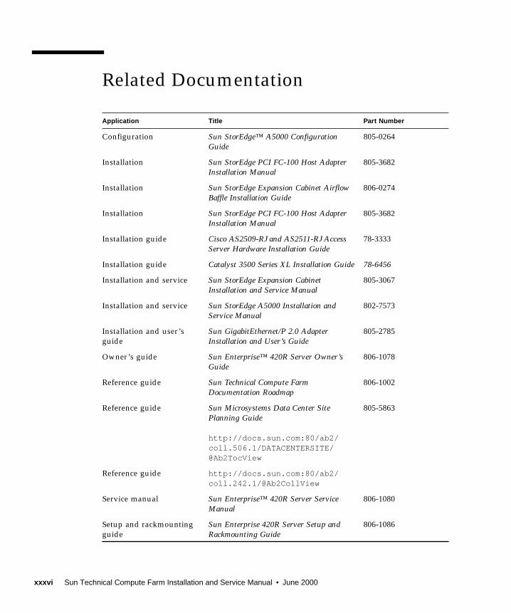
Related Documentation
Application Title Part Number
Configuration Sun StorEdge™ A5000 ConfigurationGuide
805-0264
Installation Sun StorEdge PCI FC-100 Host AdapterInstallation Manual
805-3682
Installation Sun StorEdge Expansion Cabinet AirflowBaffle Installation Guide
806-0274
Installation Sun StorEdge PCI FC-100 Host AdapterInstallation Manual
805-3682
Installation guide Cisco AS2509-RJ and AS2511-RJ AccessServer Hardware Installation Guide
78-3333
Installation guide Catalyst 3500 Series XL Installation Guide 78-6456
Installation and service Sun StorEdge Expansion CabinetInstallation and Service Manual
805-3067
Installation and service Sun StorEdge A5000 Installation andService Manual
802-7573
Installation and user’s
guide
Sun GigabitEthernet/P 2.0 AdapterInstallation and User’s Guide
805-2785
Owner’s guide Sun Enterprise™ 420R Server Owner’sGuide
806-1078
Reference guide Sun Technical Compute FarmDocumentation Roadmap
806-1002
Reference guide Sun Microsystems Data Center SitePlanning Guide
http://docs.sun.com:80/ab2/coll.506.1/DATACENTERSITE/@Ab2TocView
805-5863
Reference guide http://docs.sun.com:80/ab2/coll.242.1/@Ab2CollView
Service manual Sun Enterprise™ 420R Server ServiceManual
806-1080
Setup and rackmounting
guide
Sun Enterprise 420R Server Setup andRackmounting Guide
806-1086
xxxvi Sun Technical Compute Farm Installation and Service Manual • June 2000

Accessing Sun Documentation OnlineThe docs.sun.com sm web site enables you to access Sun technical documentation
on the Web. You can browse the docs.sun.com archive or search for a specific book
title or subject at:
http://docs.sun.com
Ordering Sun Documentation
Fatbrain.com, an Internet professional bookstore, stocks select product
documentation from Sun Microsystems, Inc.
For a list of documents and how to order them, visit the Sun Documentation Center
on Fatbrain.com at:
http://www1.fatbrain.com/documentation/sun
Software guide Sun Technical Compute Farm ProductOverview and Software Guide
806-1001
Software guide Solaris Naming Administration Guide 806-1391
User’s guide Sun Enterprise 6x00/5x00/4x00/3x00Systems Dynamic Reconfiguration User’sGuide
805-4455
User’s guide Sun Management Center™ 2.1 SoftwareUser’s Guide
806-3166
Application Title Part Number
Preface xxxvii

Sun Welcomes Your Comments
Sun is interested in improving its documentation and welcomes your comments and
suggestions. You can email your comments to Sun at:
Please include the part number of your document 806-0994 in the subject line of
your email.
xxxviii Sun Technical Compute Farm Installation and Service Manual • June 2000
CHAPTER 1
Sun Technical Compute FarmOverview
Sun™ Technical Compute Farm (Sun TCF) is a high performance clustering solution
that allows technical workgroups to more efficiently allocate and share computing
resources. The Sun TCF hardware is a collection of independent, rackmounted
technical compute engines that are connected to a file server. Both the compute
engines and the file server are Sun Enterprise™ 420Rs. The Sun TCF hardware also
includes a series of disk arrays, and various networking components. The Sun TCF
software makes the hardware appear to the end user and to applications as one
computational entity.
Sun Enterprise Services personnel install the Sun TCF hardware at the customer site.
The customer’s system administrator is then responsible for configuring the Solaris
operating system and other software components.
This chapter contains the following topics:
■ Section 1.1 “Typical Sun TCF System Applications” on page 1-1
■ Section 1.2 “Hardware Description” on page 1-2
■ Section 1.3 “System Devices” on page 1-12
■ Section 1.4 “I/O Devices” on page 1-21
1.1 Typical Sun TCF System ApplicationsThe following list describes some typical uses for a Sun TCF system:
■ Resource sharing for compute-intensive applications such as EDA (electronic
design automation), engineering simulations, software development, and
financial management
■ Cost-effectively deploying more compute resources to end users
■ Simultaneously executing many compute-intensive tasks
■ Minimizing effort and risk of expanding existing computing resources
1-1
■ Making development processes faster and more powerful by spawning multiple
jobs simultaneously
■ Maximizing CPU utilization
Through the use of workload management tools, the Sun TCF system allows for the
distribution of compute-intensive jobs from individual users to the compute engines
in the Sun TCF configuration, thus making more efficient use of local user machines
and relieving network traffic. Tools that support Sun TCF include Solaris™ Resource
Manager™, Platform Computing’s Load Sharing Facility (LSF), Gridware’s Codine,
or MRJ Software’s PBS.
Note – For best results, add a workload management tool to the Sun TCF
configuration. See the Sun Technical Compute Farm Product Overview and SoftwareGuide for specifics.
1.2 Hardware DescriptionThe Sun TCF integrates a group of hardware components into a single, powerful
computing entity. The Sun TCF software provides the ability to configure, monitor,
and analyze computing services such as load balancing the processor sharing so that
computing resources are maximized.
The Sun TCF uses Sun products and products from other hardware and software
providers to capitalize on high network bandwidth and efficient CPU utilization. All
of the hardware is rackmounted in 19-inch-wide Sun StorEdge™ expansion cabinets
(racks).
Note – The ratio of compute engines to file servers depends on the type of
applications and the system workload.
Sun TCF systems may use three different rack configurations:
■ Base rack
■ Expansion rack
■ Star rack
1-2 Sun Technical Compute Farm Installation and Service Manual • June 2000
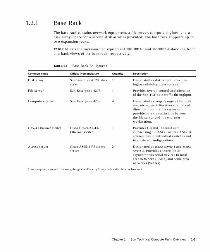
1.2.1 Base Rack
The base rack contains network equipment, a file server, compute engines, and a
disk array. Space for a second disk array is provided. The base rack supports up to
two expansion racks.
TABLE 1-1 lists the rackmounted equipment. FIGURE 1-1 and FIGURE 1-2 show the front
and back views of the base rack, respectively.
TABLE 1-1 Base Rack Equipment
Common name Official Nomenclature Quantity Description
Disk array Sun StorEdge A5200 disk
array
11
1. As an option, a second disk array, designated disk array 2, may be installed into the base rack.
Designated as disk array 1. Provides
high-availability mass storage.
File server Sun Enterprise 420R 1 Provides overall control and direction
of the Sun TCF data traffic throughput.
Compute engine Sun Enterprise 420R 4 Designated as compute engine 1 through
compute engine 4. Receives control and
direction from the file server to
provide data transmissions between
the file server and the end-user
workstation.
C3524 Ethernet switch Cisco C3524-XL-EN
Ethernet switch
1 Provides Gigabit Ethernet and
autosensing 10BASE-T or 100BASE-TX
connections in individual switches and
in clustered configurations.
Access server Cisco AS2511-RJ access
server
2 Designated as access server 1 and accessserver 2. Provides connection of
asynchronous serial devices to local
area networks (LANs) and wide area
networks (WANs).
Chapter 1 Sun Technical Compute Farm Overview 1-3

FIGURE 1-1 Sun TCF Base Rack Front View
Cisco 2600
Cisco 2600
Disk array 1Airflow baffle
Compute
File server
Access server 1
Rack
Access server 2
C3524 Ethernet switch
engine 1
Computeengine 2
Computeengine 3
Computeengine 4
Space forDisk array 2
1-4 Sun Technical Compute Farm Installation and Service Manual • June 2000

FIGURE 1-2 Sun TCF Base Rack Back View
Disk array 1Airflow baffle
Compute
File server
Access server 1
Rack
Access server 2
C3524 Ethernet switch
engine 1
Computeengine 2
Computeengine 3
Computeengine 4
Space forDisk array 2
Chapter 1 Sun Technical Compute Farm Overview 1-5

1.2.2 Expansion Rack
The expansion rack contains nine compute engines. The expansion rack is
configured for either 36 CPUs (4 CPUs per compute engine) or 18 CPUs (2 CPUs per
compute engine).
TABLE 1-2 lists the expansion rack equipment. FIGURE 1-3 and FIGURE 1-4 show the
front and back views of the expansion rack, respectively.
TABLE 1-2 Expansion Rack Equipment
Common name Official Nomenclature Quantity Description
Compute engine Sun Enterprise 420R 9 Designated as compute engine 1 through
compute engine 9. Receives control and
direction from the file server to
provide data transmissions between
the file server and the end-user
workstation.
1-6 Sun Technical Compute Farm Installation and Service Manual • June 2000

FIGURE 1-3 Sun TCF Expansion Rack Front View
Compute engine (1)
Compute engine (2)
Compute engine (3)
Compute engine (4)
Compute engine (5)
Compute engine (6)
Compute engine (7)
Compute engine (8)
Compute engine (9)
Chapter 1 Sun Technical Compute Farm Overview 1-7

FIGURE 1-4 Sun TCF Expansion Rack Back View
Compute engine (1)
Compute engine (2)
Compute engine (3)
Compute engine (4)
Compute engine (5)
Compute engine (6)
Compute engine (7)
Compute engine (8)
Compute engine (9)
1-8 Sun Technical Compute Farm Installation and Service Manual • June 2000
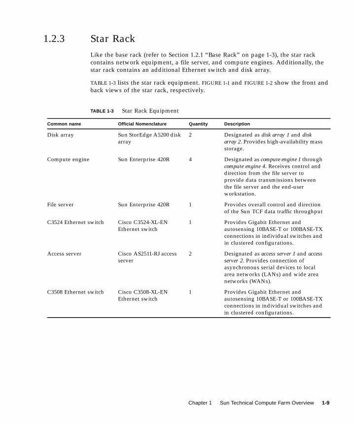
1.2.3 Star Rack
Like the base rack (refer to Section 1.2.1 “Base Rack” on page 1-3), the star rack
contains network equipment, a file server, and compute engines. Additionally, the
star rack contains an additional Ethernet switch and disk array.
TABLE 1-3 lists the star rack equipment. FIGURE 1-1 and FIGURE 1-2 show the front and
back views of the star rack, respectively.
TABLE 1-3 Star Rack Equipment
Common name Official Nomenclature Quantity Description
Disk array Sun StorEdge A5200 disk
array
2 Designated as disk array 1 and diskarray 2. Provides high-availability mass
storage.
Compute engine Sun Enterprise 420R 4 Designated as compute engine 1 through
compute engine 4. Receives control and
direction from the file server to
provide data transmissions between
the file server and the end-user
workstation.
File server Sun Enterprise 420R 1 Provides overall control and direction
of the Sun TCF data traffic throughput
C3524 Ethernet switch Cisco C3524-XL-EN
Ethernet switch
1 Provides Gigabit Ethernet and
autosensing 10BASE-T or 100BASE-TX
connections in individual switches and
in clustered configurations.
Access server Cisco AS2511-RJ access
server
2 Designated as access server 1 and accessserver 2. Provides connection of
asynchronous serial devices to local
area networks (LANs) and wide area
networks (WANs).
C3508 Ethernet switch Cisco C3508-XL-EN
Ethernet switch
1 Provides Gigabit Ethernet and
autosensing 10BASE-T or 100BASE-TX
connections in individual switches and
in clustered configurations.
Chapter 1 Sun Technical Compute Farm Overview 1-9

FIGURE 1-5 Sun TCF Star Rack Front View
Cisco 2600
Cisco 2600
Disk array 1
Airflow baffle
Compute
File server
Access server 1
Rack
Access server 2
C3524 Ethernet switch
engine 1
Computeengine 2
Computeengine 3
Computeengine 4
C3508 Ethernet switch
Disk array 2
1-10 Sun Technical Compute Farm Installation and Service Manual • June 2000
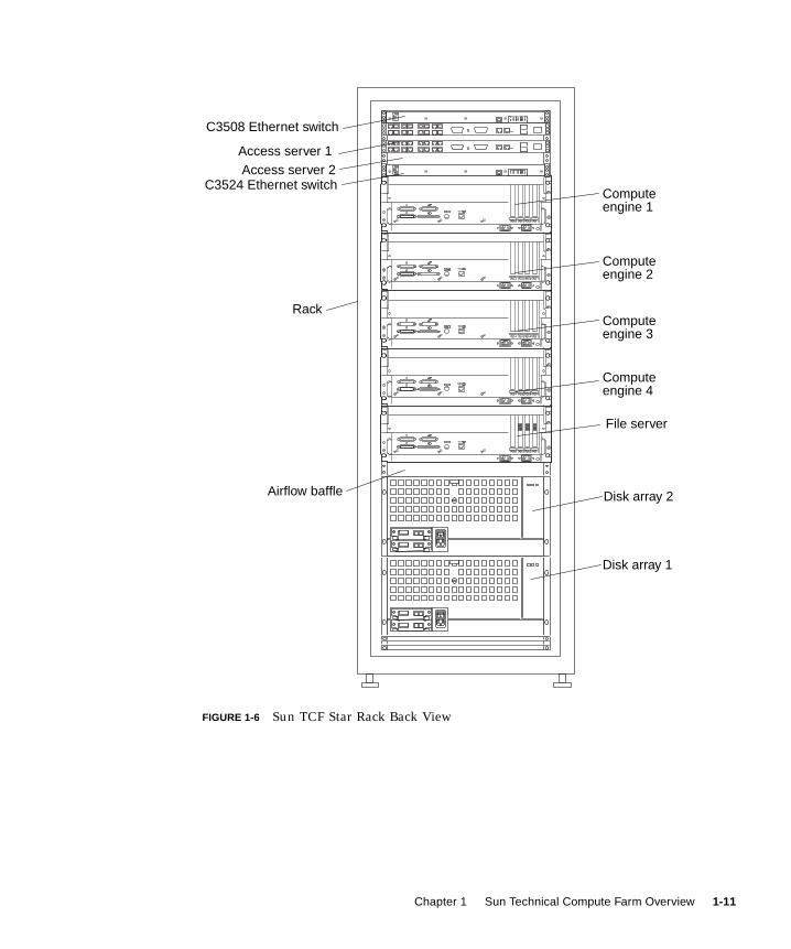
FIGURE 1-6 Sun TCF Star Rack Back View
Disk array 1
Airflow baffle
Compute
File server
Access server 1
Rack
Access server 2C3524 Ethernet switch
engine 1
Computeengine 2
Computeengine 3
Computeengine 4
C3508 Ethernet switch
Disk array 2
Chapter 1 Sun Technical Compute Farm Overview 1-11
1.3 System DevicesSystem devices include:
■ Section 1.3.1 “Rack” on page 1-12
■ Section 1.3.5 “Access Server” on page 1-20
■ Section 1.3.4 “Cisco C3524 and C3508 Ethernet Switches” on page 1-17
■ Section 1.3.3 “File Server and Compute Engine” on page 1-13
■ Section 1.3.2 “Disk Array” on page 1-12
1.3.1 Rack
The Sun StorEdge expansion cabinet (rack) includes:
■ Two power sequencer assemblies
■ Four floor mounting brackets
■ Two stabilizer legs
■ Associated mounting hardware
The floor mounting brackets enable the rack to be bolted to the floor. If the floor
mounting brackets are not to be installed, then the stabilizer legs must be installed.
The stabilizer legs are extended to prevent the rack from tipping over when devices
are installed, removed, or serviced.
For specific technical information about the rack, refer to the Sun StorEdge ExpansionCabinet Installation and Service Manual.
1.3.2 Disk Array
The Sun StorEdge A5200 disk array is a high-availability mass storage subsystem
capable of supporting twenty-two 1-inch disk drives (22-slot). Communication to
other devices is through one or two interface boards, each with up to two gigabit
interface converters (GBICs). A front panel module (FPM) enables the configuration
of the enclosure to be displayed and modified. Active components in the disk array
are redundant and can be replaced while the disk array is operating.
FIGURE 1-7 and FIGURE 1-8 show the front and back views of the disk array,
respectively. For specific technical information about the disk array, refer to the SunStorEdge A5000 Installation and Service Manual.
1-12 Sun Technical Compute Farm Installation and Service Manual • June 2000
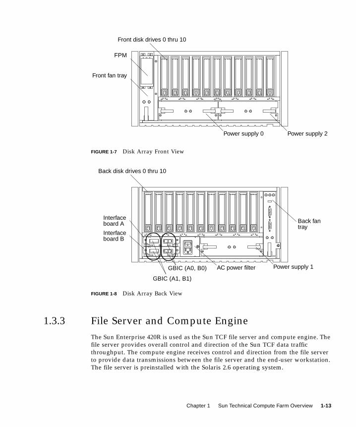
FIGURE 1-7 Disk Array Front View
FIGURE 1-8 Disk Array Back View
1.3.3 File Server and Compute Engine
The Sun Enterprise 420R is used as the Sun TCF file server and compute engine. The
file server provides overall control and direction of the Sun TCF data traffic
throughput. The compute engine receives control and direction from the file server
to provide data transmissions between the file server and the end-user workstation.
The file server is preinstalled with the Solaris 2.6 operating system.
FPM
Front fan tray
Power supply 2Power supply 0
Front disk drives 0 thru 10
Back fan
AC power filter
Interface
Back disk drives 0 thru 10
Power supply 1
Interface
GBIC (A0, B0)
GBIC (A1, B1)
board A
board B
tray
Chapter 1 Sun Technical Compute Farm Overview 1-13
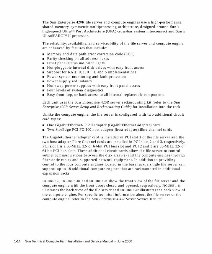
The Sun Enterprise 420R file server and compute engines use a high-performance,
shared memory, symmetric-multiprocessing architecture, designed around Sun’s
high-speed Ultra™ Port Architecture (UPA) cross-bar system interconnect and Sun’s
UltraSPARC™-II processor.
The reliability, availability, and serviceability of the file server and compute engine
are enhanced by features that include:
■ Memory and data path error correction code (ECC)
■ Parity checking on all address buses
■ Front panel status indicator lights
■ Hot-pluggable internal disk drives with easy front access
■ Support for RAID 0, 1, 0 + 1, and 5 implementations
■ Power system monitoring and fault protection
■ Power supply redundancy
■ Hot-swap power supplies with easy front panel access
■ Four levels of system diagnostics
■ Easy front, top, or back access to all internal replaceable components
Each unit uses the Sun Enterprise 420R server rackmounting kit (refer to the SunEnterprise 420R Server Setup and Rackmounting Guide) for installation into the rack.
Unlike the compute engine, the file server is configured with two additional circuit
card types:
■ One GigabitEthernet/P 2.0 adapter (GigabitEthernet adapter) card
■ Two StorEdge PCI FC-100 host adapter (host adapter) fibre channel cards
The GigabitEthernet adapter card is installed in PCI slot 1 of the file server and the
two host adapter Fibre Channel cards are installed in PCI slots 2 and 3, respectively.
PCI slot 1 is a 66-MHz, 32- or 64-bit PCI bus slot and PCI 2 and 3 are 33-MHz, 32- or
64-bit PCI bus slots. These additional circuit cards allow the file server to control
subnet communications between the disk array(s) and the compute engines through
fiber-optic cables and supported network equipment. In addition to providing
control to the four compute engines located in the base rack, a single file server can
support up to 18 additional compute engines that are rackmounted in additional
expansion racks.
FIGURE 1-9, FIGURE 1-10, and FIGURE 1-11 show the front view of the file server and the
compute engine with the front doors closed and opened, respectively. FIGURE 1-11
illustrates the back view of the file server and FIGURE 1-12 illustrates the back view of
the compute engine. For specific technical information about the file server or the
compute engine, refer to the Sun Enterprise 420R Server Service Manual.
1-14 Sun Technical Compute Farm Installation and Service Manual • June 2000
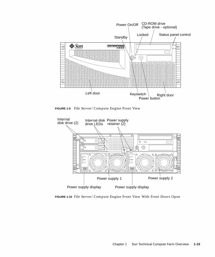
FIGURE 1-9 File Server/Compute Engine Front View
FIGURE 1-10 File Server/Compute Engine Front View With Front Doors Open
Right doorKeyswitchPower button
Power On/Off
Locked
CD-ROM drive(Tape drive - optional)
StandbyStatus panel control
Left door
Internaldisk drive (2)
Power supplyretainer (2)
Internal diskdrive LEDs
Power supply display
Power supply 2Power supply 1
Power supply display
Chapter 1 Sun Technical Compute Farm Overview 1-15
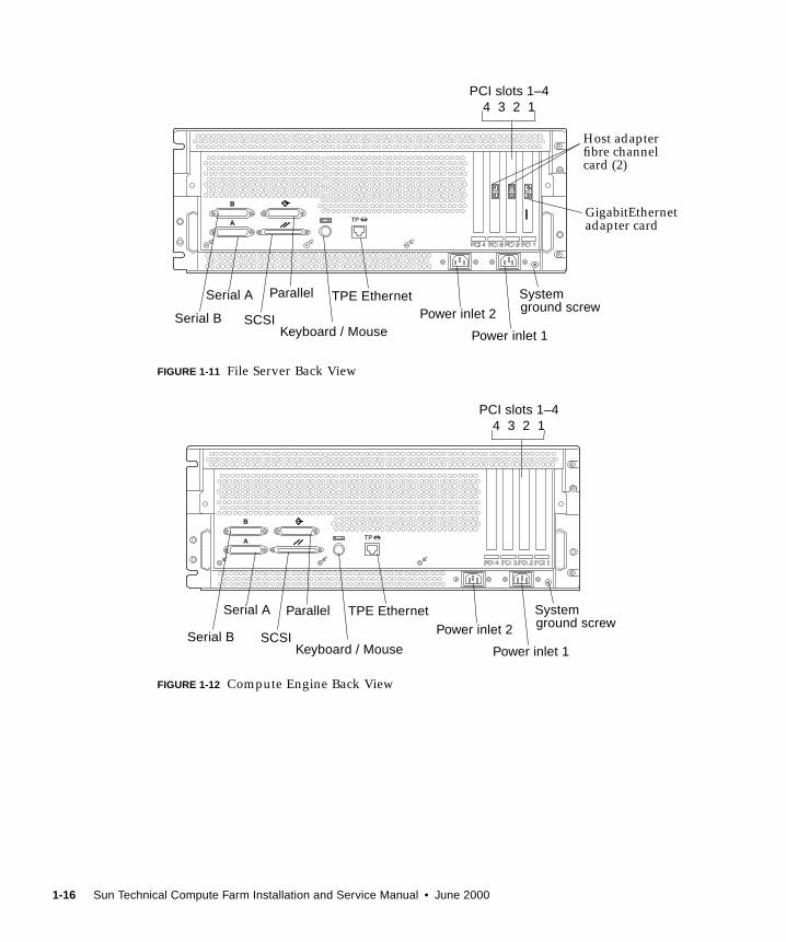
FIGURE 1-11 File Server Back View
FIGURE 1-12 Compute Engine Back View
SCSISerial B
Parallel
Keyboard / Mouse
TPE Ethernet
PCI slots 1–4
Serial A
Power inlet 1
4 3 2 1
Power inlet 2
Systemground screw
Host adapterfibre channelcard (2)
GigabitEthernetadapter card
SCSISerial B
Parallel
Keyboard / Mouse
TPE Ethernet
PCI slots 1–4
Serial A
Power inlet 1
4 3 2 1
Power inlet 2
Systemground screw
1-16 Sun Technical Compute Farm Installation and Service Manual • June 2000
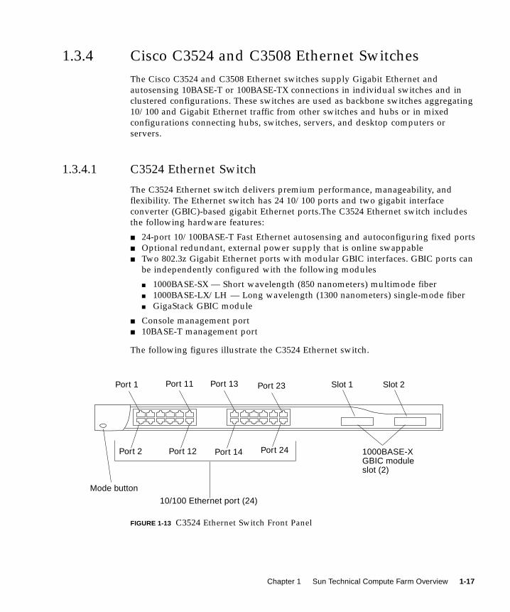
1.3.4 Cisco C3524 and C3508 Ethernet Switches
The Cisco C3524 and C3508 Ethernet switches supply Gigabit Ethernet and
autosensing 10BASE-T or 100BASE-TX connections in individual switches and in
clustered configurations. These switches are used as backbone switches aggregating
10/100 and Gigabit Ethernet traffic from other switches and hubs or in mixed
configurations connecting hubs, switches, servers, and desktop computers or
servers.
1.3.4.1 C3524 Ethernet Switch
The C3524 Ethernet switch delivers premium performance, manageability, and
flexibility. The Ethernet switch has 24 10/100 ports and two gigabit interface
converter (GBIC)-based gigabit Ethernet ports.The C3524 Ethernet switch includes
the following hardware features:
■ 24-port 10/100BASE-T Fast Ethernet autosensing and autoconfiguring fixed ports
■ Optional redundant, external power supply that is online swappable
■ Two 802.3z Gigabit Ethernet ports with modular GBIC interfaces. GBIC ports can
be independently configured with the following modules
■ 1000BASE-SX — Short wavelength (850 nanometers) multimode fiber
■ 1000BASE-LX/LH — Long wavelength (1300 nanometers) single-mode fiber
■ GigaStack GBIC module
■ Console management port
■ 10BASE-T management port
The following figures illustrate the C3524 Ethernet switch.
FIGURE 1-13 C3524 Ethernet Switch Front Panel
10/100 Ethernet port (24)
Mode button
1000BASE-XGBIC moduleslot (2)
Port 1 Port 23
Port 2 Port 24
Slot 1 Slot 2
Port 12 Port 14
Port 11 Port 13
Chapter 1 Sun Technical Compute Farm Overview 1-17
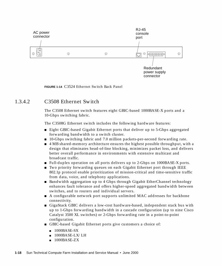
FIGURE 1-14 C3524 Ethernet Switch Back Panel
1.3.4.2 C3508 Ethernet Switch
The C3508 Ethernet switch features eight GBIC-based 1000BASE-X ports and a
10-Gbps switching fabric.
The C3508G Ethernet switch includes the following hardware features:
■ Eight GBIC-based Gigabit Ethernet ports that deliver up to 5-Gbps aggregated
forwarding bandwidth to a switch cluster.
■ 10-Gbps switching fabric and 7.0 million packets-per-second forwarding rate.
■ 4 MB shared-memory architecture ensures the highest possible throughput, with a
design that eliminates head-of-line blocking, minimizes packet loss, and delivers
better overall performance in environments with extensive multicast and
broadcast traffic.
■ Full-duplex operation on all ports delivers up to 2-Gbps on 1000BASE-X ports.
■ Two priority forwarding queues on each Gigabit Ethernet port through IEEE
802.1p protocol enable prioritization of mission-critical and time-sensitive traffic
from data, voice, and telephony applications.
■ Bandwidth aggregation up to 4 Gbps through Gigabit EtherChannel technology
enhances fault tolerance and offers higher-speed aggregated bandwidth between
switches, and to routers and individual servers.
■ A configurable network port supports unlimited MAC addresses for backbone
connectivity.
■ GigaStack GBIC delivers a low-cost hardware-based, independent stack bus with
up to 1-Gbps forwarding bandwidth in a cascade configuration (up to nine Cisco
Catalyst 3500 XL switches) or 2-Gbps forwarding rate in a point-to-point
configuration.
■ GBIC-based Gigabit Ethernet ports give customers a choice of:
■ 1000BASE-SX
■ 1000BASE-LX/LH
■ 1000BASE-ZX
AC powerconnector
Redundantpower supplyconnector
RJ-45consoleport
1-18 Sun Technical Compute Farm Installation and Service Manual • June 2000
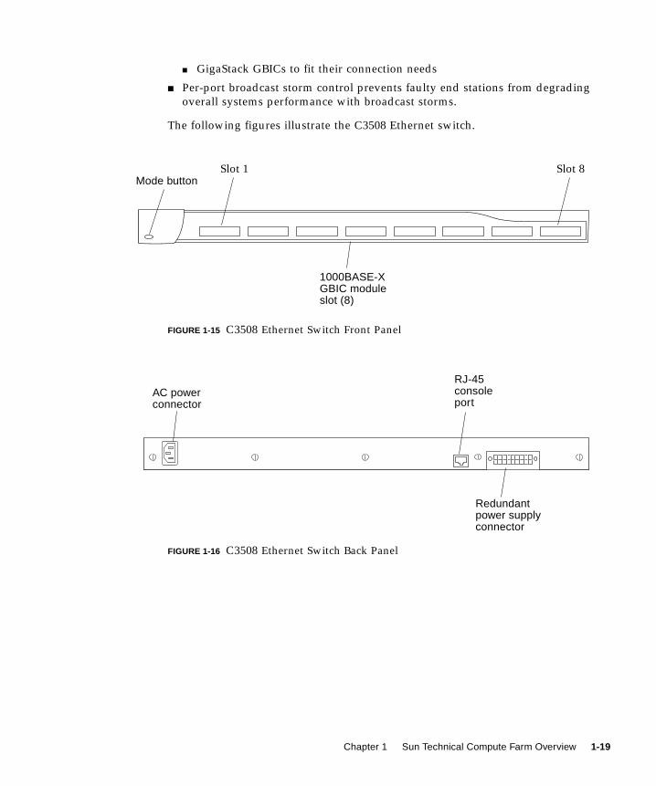
■ GigaStack GBICs to fit their connection needs
■ Per-port broadcast storm control prevents faulty end stations from degrading
overall systems performance with broadcast storms.
The following figures illustrate the C3508 Ethernet switch.
FIGURE 1-15 C3508 Ethernet Switch Front Panel
FIGURE 1-16 C3508 Ethernet Switch Back Panel
Mode button
1000BASE-XGBIC moduleslot (8)
Slot 1 Slot 8
AC powerconnector
RJ-45consoleport
Redundantpower supplyconnector
Chapter 1 Sun Technical Compute Farm Overview 1-19
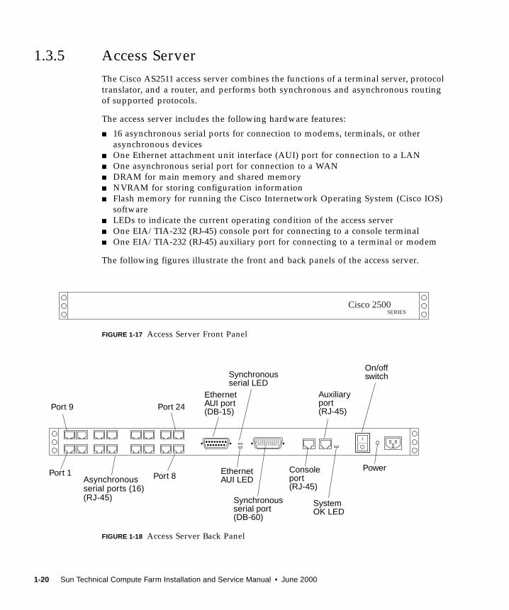
1.3.5 Access Server
The Cisco AS2511 access server combines the functions of a terminal server, protocol
translator, and a router, and performs both synchronous and asynchronous routing
of supported protocols.
The access server includes the following hardware features:
■ 16 asynchronous serial ports for connection to modems, terminals, or other
asynchronous devices
■ One Ethernet attachment unit interface (AUI) port for connection to a LAN
■ One asynchronous serial port for connection to a WAN
■ DRAM for main memory and shared memory
■ NVRAM for storing configuration information
■ Flash memory for running the Cisco Internetwork Operating System (Cisco IOS)
software
■ LEDs to indicate the current operating condition of the access server
■ One EIA/TIA-232 (RJ-45) console port for connecting to a console terminal
■ One EIA/TIA-232 (RJ-45) auxiliary port for connecting to a terminal or modem
The following figures illustrate the front and back panels of the access server.
FIGURE 1-17 Access Server Front Panel
FIGURE 1-18 Access Server Back Panel
Cisco 2500SERIES
Asynchronousserial ports (16)(RJ-45)
EthernetAUI port(DB-15)
Synchronousserial LED
EthernetAUI LED
Synchronousserial port(DB-60)
Consoleport(RJ-45)
Auxiliaryport(RJ-45)
SystemOK LED
On/offswitch
PowerPort 1 Port 8
Port 9 Port 24
1-20 Sun Technical Compute Farm Installation and Service Manual • June 2000
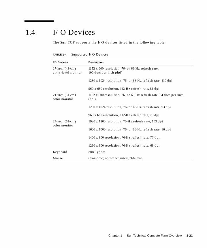
1.4 I/O DevicesThe Sun TCF supports the I/O devices listed in the following table:
TABLE 1-4 Supported I/O Devices
I/O Devices Description
17-inch (43-cm)
entry-level monitor
1152 x 900 resolution, 76- or 66-Hz refresh rate,
100 dots per inch (dpi)
1280 x 1024 resolution, 76- or 66-Hz refresh rate, 110 dpi
960 x 680 resolution, 112-Hz refresh rate, 81 dpi
21-inch (51-cm)
color monitor
1152 x 900 resolution, 76- or 66-Hz refresh rate, 84 dots per inch
(dpi)
1280 x 1024 resolution, 76- or 66-Hz refresh rate, 93 dpi
960 x 680 resolution, 112-Hz refresh rate, 70 dpi
24-inch (61-cm)
color monitor
1920 x 1200 resolution, 70-Hz refresh rate, 103 dpi
1600 x 1000 resolution, 76- or 66-Hz refresh rate, 86 dpi
1400 x 900 resolution, 76-Hz refresh rate, 77 dpi
1280 x 800 resolution, 76-Hz refresh rate, 69 dpi
Keyboard Sun Type-6
Mouse Crossbow; optomechanical, 3-button
Chapter 1 Sun Technical Compute Farm Overview 1-21

1-22 Sun Technical Compute Farm Installation and Service Manual • June 2000
CHAPTER 2
Preparing for Assembly andInstallation
This chapter contains the following topics:
■ Section 2.1 “Site Planning” on page 2-1
■ Section 2.2 “Space Planning” on page 2-2
■ Section 2.3 “Rack Physical Characteristics” on page 2-3
■ Section 2.4 “Environmental Requirements” on page 2-3
■ Section 2.5 “Heating, Ventilation, and Air Conditioning” on page 2-4
■ Section 2.6 “Clearance and Service Access” on page 2-5
2.1 Site PlanningIt is easier to address facility design issues in the planning stages than to correct
problems after the fact. Often, it is impossible to implement extensive actions in an
on-line computer room without impacting uptime. For this reason, it is extremely
important that adequate attention is paid to issues such as the physical location of
the building, the location of the data center relative to the other areas of the
building, and all aspects of the support infrastructure.
Facility design issues that should be addressed include:
■ General computer room criteria
■ Cleaning procedures and equipment
■ Facility power requirements
■ Grounding and bonding
■ Input Power Quality
■ Wiring and Cabling
■ Electromagnetic Compatibility
For further details regarding site planning, refer to the Sun Microsystems Data CenterSite Planning Guide.
2-1
2.2 Space Planning
Note – For further details regarding space planning, refer to the Sun MicrosystemsData Center Site Planning Guide.
The Sun TCF is built with sections of racks to maximize space and enable the
addition of more compute engines. Space planning is based upon the number of Sun
TCF racks that are required by a project. Rackmounted systems are used to minimize
floor space.
Each rack requires 23 inches by 30 inches (58.42 cm by 76.2 cm) of floor space. The
bottom panel on the exhaust side of the rack (the left side if you are facing the front
of the rack) is vented to allow airflow. Ensure that there is a clearance of at least 2
inches on this side of the rack to allow proper air circulation.
FIGURE 1-1 on page 1-4 and FIGURE 1-2 on page 1-5 shows the base rack. The base rack
accommodates a disk array (a second disk array may be added), one file server, four
compute engines, and networking equipment.
FIGURE 1-3 on page 1-7 and FIGURE 1-4 on page 1-8 illustrate an expansion rack. The
expansion rack consists of nine compute engines. The expansion rack is electrically
coupled to the base rack to provide either a 52-CPU small farm configuration, an 86-
CPU medium farm configuration, or an 88-CPU medium farm configuration.
FIGURE 1-5 on page 1-10 and FIGURE 1-6 on page 1-11 illustrate a star rack. The star
rack accommodates two disk arrays, one file server, four compute engines, and
networking equipment. Additionally, the star rack contains a Cisco C3508 Ethernet
switch that allows the Sun TCF large farm configuration.
2-2 Sun Technical Compute Farm Installation and Service Manual • June 2000

2.3 Rack Physical Characteristics
Caution – The rack structure and casters are designed to handle a 1300 pound (589
kg) static load. Make no mechanical or electrical modifications to this rack. Sun is
not responsible for the regulatory compliance if the rack is modified.
The physical characteristics of the rack include:
■ Internal dimensions conform to EIA RS-310C standard (RETMA) for 19-inch
(482 mm) racks. Universal mounting holes are used with 10-32UNF tapped holes
in all locations. The nominal rack opening is 17.875 inches (454 mm).
■ A vertical panel opening of 38 rack unit (RU) minimum is provided to
accommodate various rackmountable devices. One RU is equal to 1.75 inches
(44.45 mm).
■ Overall rack height with cosmetic panels is 73.5 inches (187 cm) maximum.
2.4 Environmental RequirementsAvoid temperature extremes and keep the work area clean. Maintain the
environmental requirements described in TABLE 2-1.
The rack should be in a computer room environment. Computer room installation
provides secure access to computers and stored information, and provides control
over environmental factors such as temperature, humidity, and airborne dust.
Computer room installation can also help protect equipment from fire, flood, or
other danger originating in the building.For further details regarding environmental
requirements, refer to the Sun Microsystems Data Center Site Planning Guide.
TABLE 2-1 Operating Environment
Parameter Value
Temperature
Operating 41°F to 104°F (5°C to 40°C)
Non-operating -4°F to 140°F (-20°C to 60°C)
Humidity
Operating 20% to 80% RH, noncondensing
80.6°F (27°C) maximum wet bulb
Chapter 2 Preparing for Assembly and Installation 2-3
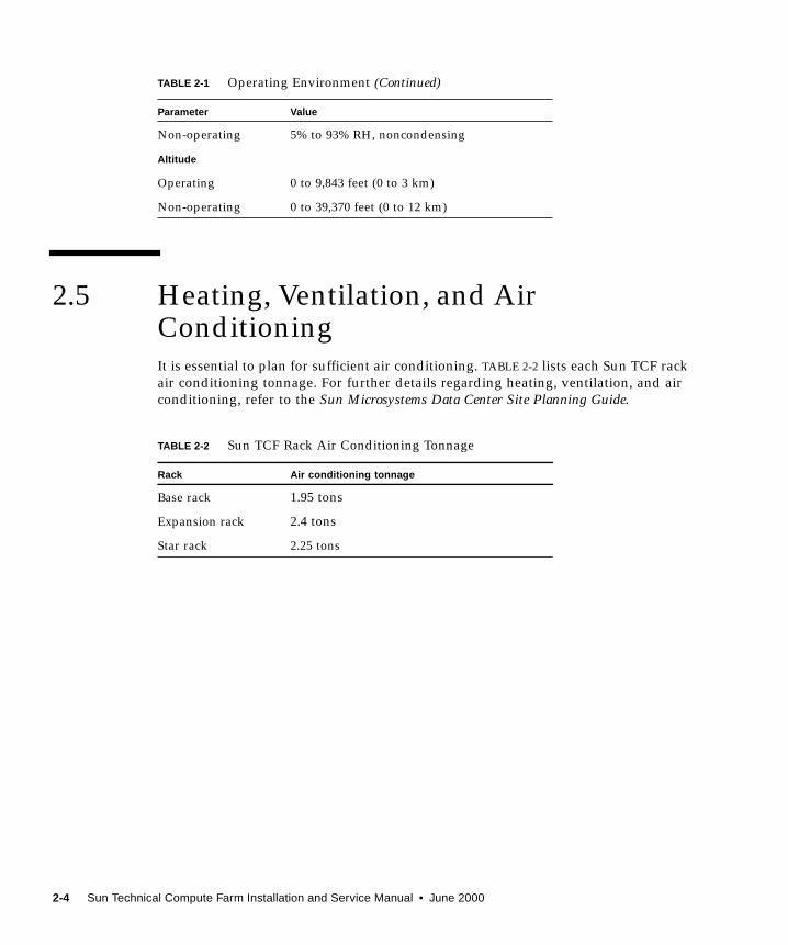
2.5 Heating, Ventilation, and AirConditioningIt is essential to plan for sufficient air conditioning. TABLE 2-2 lists each Sun TCF rack
air conditioning tonnage. For further details regarding heating, ventilation, and air
conditioning, refer to the Sun Microsystems Data Center Site Planning Guide.
Non-operating 5% to 93% RH, noncondensing
Altitude
Operating 0 to 9,843 feet (0 to 3 km)
Non-operating 0 to 39,370 feet (0 to 12 km)
TABLE 2-2 Sun TCF Rack Air Conditioning Tonnage
Rack Air conditioning tonnage
Base rack 1.95 tons
Expansion rack 2.4 tons
Star rack 2.25 tons
TABLE 2-1 Operating Environment (Continued)
Parameter Value
2-4 Sun Technical Compute Farm Installation and Service Manual • June 2000

2.6 Clearance and Service Access
TABLE 2-3 Clearance and Service Access
With Service Access Without Service Access
Front 48 inches
(122 cm)
24 inches
(61 cm)
Rear 36 inches
(92 cm)
24 inches
(61 cm)
Left 36 inches1
(92 cm)
1. Side access may be required for some service procedures. Refer to the documentation that came with the de-vices.
2 inches2
(51 cm)
2. The disk array requires a clearance of at least two inches for airflow. Unless otherwise stated in the documen-tation that shipped with your device, no clearance access is required.
Right 36 inches1
(92 cm)
0
Chapter 2 Preparing for Assembly and Installation 2-5

2-6 Sun Technical Compute Farm Installation and Service Manual • June 2000
CHAPTER 3
Unpacking and Installing the Rack
This chapter contains the following topics:
■ Section 3.1 “Unpacking the Rack” on page 3-1
■ Section 3.2 “Moving and Placing the Rack” on page 3-2
■ Section 3.3 “Adjusting the Leveling Pads” on page 3-3
■ Section 3.4 “Installing the Stabilizer Legs” on page 3-4
■ Section 3.5 “Installing the Floor Brackets” on page 3-6
■ Section 3.6 “Cabling the Rack” on page 3-8
3.1 Unpacking the RackIf the rack is already unpacked, proceed to the Section 3.2 “Moving and Placing the
Rack” on page 3-2.
1. Inspect all shipping containers for evidence of physical damage.
If a shipping carton is damaged, request that the carrier’s agent be present when the
carton is opened. Keep all of the contents and packing material for the agent’s
inspection.
Caution – Use three or more people to unpack and set up the rack. A typical rack
weighs approximately 990 pounds (449 kg).
2. Unpack the rack.
Refer to the unpacking instructions printed on the shipping carton.
Note – The stabilizer legs, floor mounting brackets, and associated hardware are
packed in the side saddles of the packing material that encase the rack.
3-1
3. Verify that the components you received match the shipping list.
4. Reassemble the packing materials and save them for future use. To prepare therack for shipment or storage, follow (in reverse order) the unpacking instructionsattached to or printed on the panels of each shipping container.
Note – If the shipping materials cannot be stored, recycle or dispose of the materials
properly. Your local recycling authority can supply specific information.
3.2 Moving and Placing the RackLeave enough space to situate the base rack near the expansion rack. The ground
strap between the base rack and the expansion rack is approximately 6.5 feet (2
meters) long. (The procedure for connecting the ground strap is covered in detail in
Section 3.6.3 “Connecting the Ground Strap” on page 3-14.)
Refer to the specifications in Appendix A when determining where to place the rack.
Caution – Never lift the rack by the cosmetic panel surfaces or pull the rack by the
back door. Use three or more people to move the rack safely. Two people must
restrain the front of the rack to control the movement. One person should be behind
the rack. To prevent the rack from tipping as it is moved, push or pull only on the
middle section of the rack.
For mobility, allow 3 inches (7.62 cm) clearance on both sides of the rack.
3-2 Sun Technical Compute Farm Installation and Service Manual • June 2000
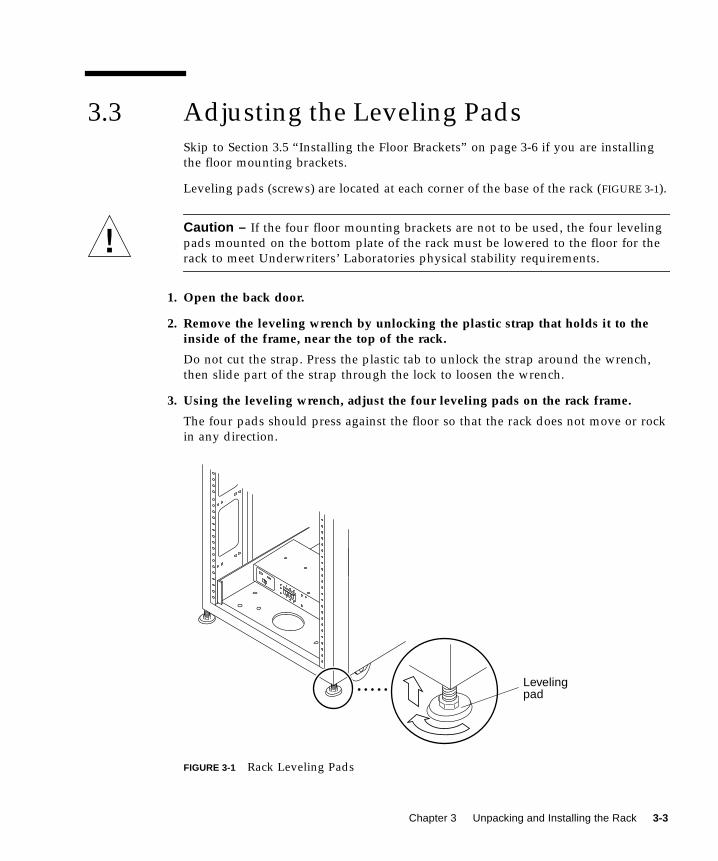
3.3 Adjusting the Leveling PadsSkip to Section 3.5 “Installing the Floor Brackets” on page 3-6 if you are installing
the floor mounting brackets.
Leveling pads (screws) are located at each corner of the base of the rack (FIGURE 3-1).
Caution – If the four floor mounting brackets are not to be used, the four leveling
pads mounted on the bottom plate of the rack must be lowered to the floor for the
rack to meet Underwriters’ Laboratories physical stability requirements.
1. Open the back door.
2. Remove the leveling wrench by unlocking the plastic strap that holds it to theinside of the frame, near the top of the rack.
Do not cut the strap. Press the plastic tab to unlock the strap around the wrench,
then slide part of the strap through the lock to loosen the wrench.
3. Using the leveling wrench, adjust the four leveling pads on the rack frame.
The four pads should press against the floor so that the rack does not move or rock
in any direction.
FIGURE 3-1 Rack Leveling Pads
Levelingpad
Chapter 3 Unpacking and Installing the Rack 3-3
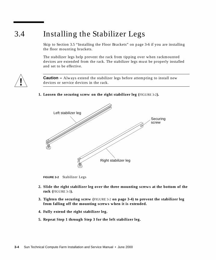
3.4 Installing the Stabilizer LegsSkip to Section 3.5 “Installing the Floor Brackets” on page 3-6 if you are installing
the floor mounting brackets.
The stabilizer legs help prevent the rack from tipping over when rackmounted
devices are extended from the rack. The stabilizer legs must be properly installed
and set to be effective.
Caution – Always extend the stabilizer legs before attempting to install new
devices or service devices in the rack.
1. Loosen the securing screw on the right stabilizer leg (FIGURE 3-2).
FIGURE 3-2 Stabilizer Legs
2. Slide the right stabilizer leg over the three mounting screws at the bottom of therack (FIGURE 3-3).
3. Tighten the securing screw (FIGURE 3-2 on page 3-4) to prevent the stabilizer legfrom falling off the mounting screws when it is extended.
4. Fully extend the right stabilizer leg.
5. Repeat Step 1 through Step 3 for the left stabilizer leg.
Right stabilizer leg
Left stabilizer leg
Securingscrew
3-4 Sun Technical Compute Farm Installation and Service Manual • June 2000
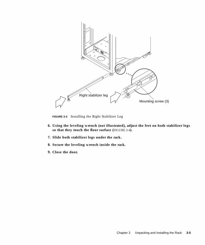
FIGURE 3-3 Installing the Right Stabilizer Leg
6. Using the leveling wrench (not illustrated), adjust the feet on both stabilizer legsso that they touch the floor surface (FIGURE 3-4).
7. Slide both stabilizer legs under the rack.
8. Secure the leveling wrench inside the rack.
9. Close the door.
Mounting screw (3)
Right stabilizer leg
Chapter 3 Unpacking and Installing the Rack 3-5
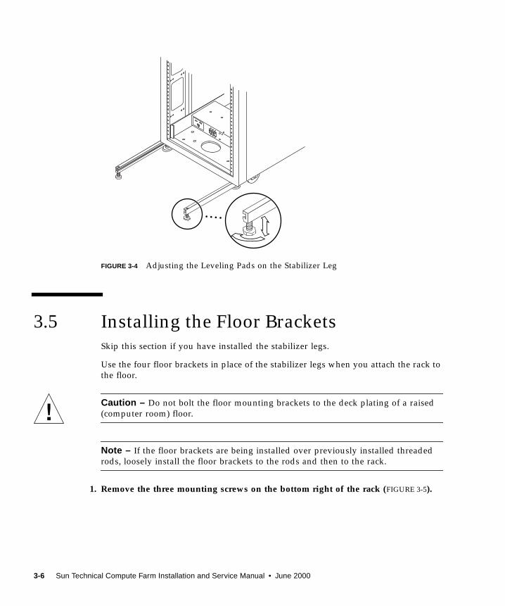
FIGURE 3-4 Adjusting the Leveling Pads on the Stabilizer Leg
3.5 Installing the Floor BracketsSkip this section if you have installed the stabilizer legs.
Use the four floor brackets in place of the stabilizer legs when you attach the rack to
the floor.
Caution – Do not bolt the floor mounting brackets to the deck plating of a raised
(computer room) floor.
Note – If the floor brackets are being installed over previously installed threaded
rods, loosely install the floor brackets to the rods and then to the rack.
1. Remove the three mounting screws on the bottom right of the rack (FIGURE 3-5).
3-6 Sun Technical Compute Farm Installation and Service Manual • June 2000

FIGURE 3-5 Removing the Mounting Screws
2. Using a 7/16-inch wrench, attach the right floor brackets to the front and back ofthe rack (FIGURE 3-6).
FIGURE 3-6 Attaching the Floor Brackets
Mounting screw (3)
Floor bracket
Chapter 3 Unpacking and Installing the Rack 3-7
3. Bolt the right floor brackets to the floor.
The bolts to secure the floor brackets to the floor are not included.
4. Repeat Step 1 through Step 3 for the left floor brackets.
3.6 Cabling the RackThis section describes how to connect the power cord to the rack power sequencer,
and how to connect the ground strap and fan-fail cable from the rack to the file
server and other racks.
Note – The keys for the Sun TCF system are found in the rack and in the Sun TCF
Accessory Kit, 565-1656.
■ Section 3.6.1 “Preparing the Rack” on page 3-8
■ Section 3.6.2 “Connecting the Power Cord” on page 3-11
■ Section 3.6.3 “Connecting the Ground Strap” on page 3-14
■ Section 3.6.4 “Final Cabling Tasks” on page 3-15
For instructions on how to cable storage device options in the cabinet, see the
documentation that is shipped with each device.
3.6.1 Preparing the Rack
1. Verify that the key switch located at the bottom front of the rack is in the Standbyposition (FIGURE 3-7).
2. Open the back door of the rack (FIGURE 3-8).
3. Loosen the screws on the front and back trim panels and remove the panels(FIGURE 3-7).
Set the panels aside.
3-8 Sun Technical Compute Farm Installation and Service Manual • June 2000

FIGURE 3-7 Location of Key Switch on Bottom Front Panel
Key switch
Front trim panelOn
Screw (2)
Standby
Chapter 3 Unpacking and Installing the Rack 3-9
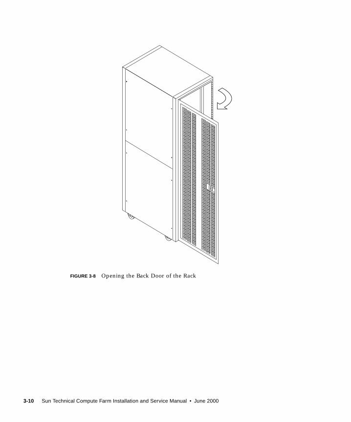
FIGURE 3-8 Opening the Back Door of the Rack
3-10 Sun Technical Compute Farm Installation and Service Manual • June 2000
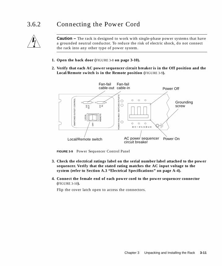
3.6.2 Connecting the Power Cord
Caution – The rack is designed to work with single-phase power systems that have
a grounded neutral conductor. To reduce the risk of electric shock, do not connect
the rack into any other type of power system.
1. Open the back door (FIGURE 3-8 on page 3-10).
2. Verify that each AC power sequencer circuit breaker is in the Off position and theLocal/Remote switch is in the Remote position (FIGURE 3-9).
FIGURE 3-9 Power Sequencer Control Panel
3. Check the electrical ratings label on the serial number label attached to the powersequencer. Verify that the stated rating matches the AC input voltage to thesystem (refer to Section A.3 “Electrical Specifications” on page A-4).
4. Connect the female end of each power cord to the power sequencer connector(FIGURE 3-10).
Flip the cover latch open to access the connectors.
SW
ITC
HE
D O
UT
LET
CO
NT
RO
L
M A I N P O W E R
PO
WE
R A
VA
ILA
BLE
SW
ITC
HE
D O
UT
LET
S
LOC
AL
RE
MO
TE
J15
OU
T
OF
F
J14 IN
AC power sequencercircuit breaker
Power Off
Power On
Fan-failcable-out
Fan-failcable-in
Local/Remote switch
Groundingscrew
Chapter 3 Unpacking and Installing the Rack 3-11

FIGURE 3-10 Connecting the Power Cord
5. Pull the latch cover over the power cord to secure it to the power socket.
Note – Route the power cord directly through the opening in the rack base.
6. Connect the other end of the power cord to a grounded outlet (FIGURE 3-11 andFIGURE 3-12).
The following connector types are provided on the power cord:
■ NEMA L6-30P for 200-240V North American operation
■ 32A, single-phase, IEC 309 connector for 200–240V international operation
7. Repeat this procedure for the other power sequencer.
Power cord
ConnectorLatch cover
Power cord securedto connector
3-12 Sun Technical Compute Farm Installation and Service Manual • June 2000
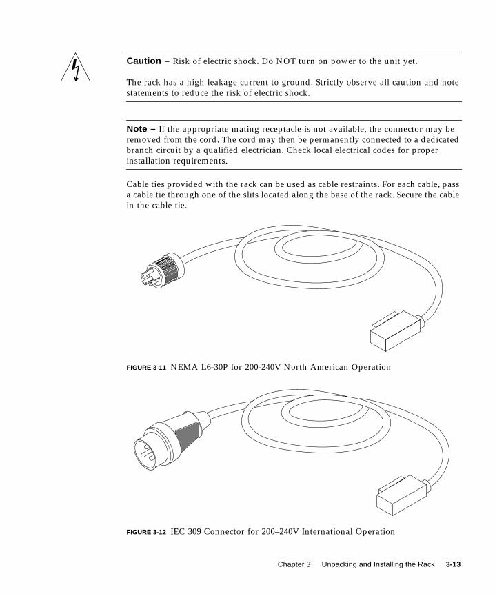
Caution – Risk of electric shock. Do NOT turn on power to the unit yet.
The rack has a high leakage current to ground. Strictly observe all caution and note
statements to reduce the risk of electric shock.
Note – If the appropriate mating receptacle is not available, the connector may be
removed from the cord. The cord may then be permanently connected to a dedicated
branch circuit by a qualified electrician. Check local electrical codes for proper
installation requirements.
Cable ties provided with the rack can be used as cable restraints. For each cable, pass
a cable tie through one of the slits located along the base of the rack. Secure the cable
in the cable tie.
FIGURE 3-11 NEMA L6-30P for 200-240V North American Operation
FIGURE 3-12 IEC 309 Connector for 200–240V International Operation
Chapter 3 Unpacking and Installing the Rack 3-13
3.6.3 Connecting the Ground Strap
Caution – An insulated grounding conductor must be installed as part of the circuit
supplying power to the rack. This conductor must be of identical size, insulation
material, and thickness to the neutral grounded and hot ungrounded branch-circuit
supply conductors, but green (with or without yellow stripe[s]). Ground wires can
(and should be) larger than circuit conductors.
The grounding conductor described in the above caution statement must be
grounded to either of the following:
■ Earth at service equipment
■ Supply transformer or motor-generator set (if supplied by a separately derived
system)
The outlets in the vicinity of the rack must be of the grounding type, and the
grounding conductors for these outlets must be connected to earth ground.
Connecting the ground strap between a rack and the next nearest rack prevents
ground loops between the two racks and keeps data errors from occurring.
1. Locate the 2-meter ground strap from the kit that was shipped with your rack.
2. Screw one end of the ground strap to the power sequencer on the second racknearest to the rack.
3. Screw the other end of the ground strap to the nearest power sequencer in therack (FIGURE 3-13).
3-14 Sun Technical Compute Farm Installation and Service Manual • June 2000
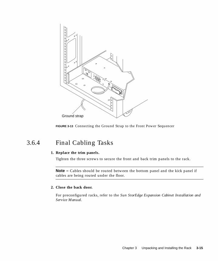
FIGURE 3-13 Connecting the Ground Strap to the Front Power Sequencer
3.6.4 Final Cabling Tasks
1. Replace the trim panels.
Tighten the three screws to secure the front and back trim panels to the rack.
Note – Cables should be routed between the bottom panel and the kick panel if
cables are being routed under the floor.
2. Close the back door.
For preconfigured racks, refer to the Sun StorEdge Expansion Cabinet Installation andService Manual.
Ground strap
Chapter 3 Unpacking and Installing the Rack 3-15

3-16 Sun Technical Compute Farm Installation and Service Manual • June 2000
CHAPTER 4
Installing a Second Disk Array
This chapter provides procedures for installing a second disk array into the base
rack.
■ Section 4.1 “Installing the Rails” on page 4-2
■ Section 4.2 “Installing the Chassis in the Rack” on page 4-4
■ Section 4.3 “Connecting the Power Cable” on page 4-6
■ Section 4.4 “Installing Additional Interface Boards and GBICs” on page 4-8
■ Section 4.5 “Disk Array-to-File Server Cabling” on page 4-9
■ Section 4.6 “Disk Array 1-to-Disk Array 2 Cabling” on page 4-9
■ Section 4.7 “Repositioning the Airflow Baffle” on page 4-9
■ Section 4.8 “Reassembling the Rack” on page 4-16
Note – Rackmount placement information for the disk array, as well as other
devices that can be mounted in the rack, is available on the Web at http://docs.sun.com:80/ab2/coll.242.1/@Ab2CollView . If you do not have access
to the Web, contact your service provider.
Note – When you install a second disk array in the base rack, you must remove and
reposition the airflow baffle above the second disk array (see Section 4.7
“Repositioning the Airflow Baffle” on page 4-9).
Note – The keys for the Sun TCF system are found in the rack and in the Sun TCF
Accessory Kit, 565-1656.
4-1
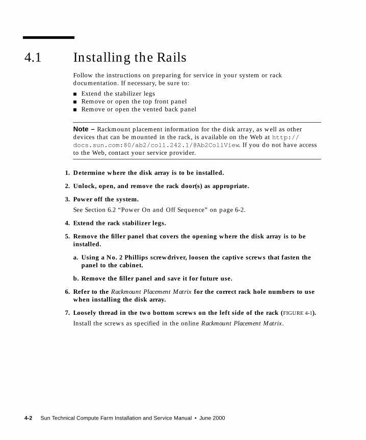
4.1 Installing the RailsFollow the instructions on preparing for service in your system or rack
documentation. If necessary, be sure to:
■ Extend the stabilizer legs
■ Remove or open the top front panel
■ Remove or open the vented back panel
Note – Rackmount placement information for the disk array, as well as other
devices that can be mounted in the rack, is available on the Web at http://docs.sun.com:80/ab2/coll.242.1/@Ab2CollView . If you do not have access
to the Web, contact your service provider.
1. Determine where the disk array is to be installed.
2. Unlock, open, and remove the rack door(s) as appropriate.
3. Power off the system.
See Section 6.2 “Power On and Off Sequence” on page 6-2.
4. Extend the rack stabilizer legs.
5. Remove the filler panel that covers the opening where the disk array is to beinstalled.
a. Using a No. 2 Phillips screwdriver, loosen the captive screws that fasten thepanel to the cabinet.
b. Remove the filler panel and save it for future use.
6. Refer to the Rackmount Placement Matrix for the correct rack hole numbers to usewhen installing the disk array.
7. Loosely thread in the two bottom screws on the left side of the rack (FIGURE 4-1).
Install the screws as specified in the online Rackmount Placement Matrix.
4-2 Sun Technical Compute Farm Installation and Service Manual • June 2000
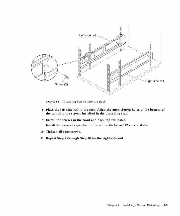
FIGURE 4-1 Threading Screws Into the Rack
8. Place the left side rail in the rack. Align the open-slotted holes at the bottom ofthe rail with the screws installed in the preceding step.
9. Install the screws in the front and back top rail holes.
Install the screws as specified in the online Rackmount Placement Matrix.
10. Tighten all four screws.
11. Repeat Step 7 through Step 10 for the right side rail.
Screw (2)
Left side rail
Right side rail
Chapter 4 Installing a Second Disk Array 4-3
4.2 Installing the Chassis in the Rack
Caution – To avoid damage to internal circuits, do not connect or disconnect any
cable while the system is powered on.
Caution – The rack can become front-heavy while the chassis is being installed.
Unless the rack is bolted to the floor, ensure that the stabilizer legs are extended
before proceeding. Failure to extend the legs can result in the rack tipping forward
and injuring personnel.
Caution – This installation requires two people to lift and move the disk array. Use
care to avoid injury. A disk array with a baseplate attached may weigh up to 130
pounds (59 kg).
When completing a two-person procedure, always communicate your intentions
clearly before, during, and after each step to minimize confusion.
Note – Rackmount placement information for the disk array, as well as other
devices that can be mounted in the rack, is available on the Web at http://docs.sun.com:80/ab2/coll.242.1/@Ab2CollView . If you do not have access
to the Web, contact your service provider.
Refer to the Rackmount Placement Matrix for the correct order for installing the
chassis.
1. With the aid of an assistant, lift the chassis (one person on each side) andapproach the rack with the chassis back facing the rack.
2. Align the chassis baseplate with the mating side rails in the rack (FIGURE 4-2).
4-4 Sun Technical Compute Farm Installation and Service Manual • June 2000
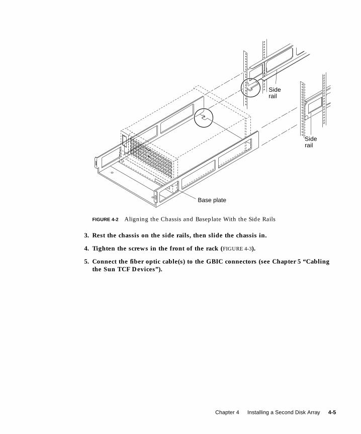
FIGURE 4-2 Aligning the Chassis and Baseplate With the Side Rails
3. Rest the chassis on the side rails, then slide the chassis in.
4. Tighten the screws in the front of the rack (FIGURE 4-3).
5. Connect the fiber optic cable(s) to the GBIC connectors (see Chapter 5 “Cablingthe Sun TCF Devices”).
Siderail
Base plate
Siderail
Chapter 4 Installing a Second Disk Array 4-5

FIGURE 4-3 Installing Screws to Secure the Baseplate to the Side Brackets
4.3 Connecting the Power Cable1. Connect the female end of the power cord to the power receptacle at the back of
the disk array (FIGURE 4-4).
Screw
Baseplate
Screw
4-6 Sun Technical Compute Farm Installation and Service Manual • June 2000
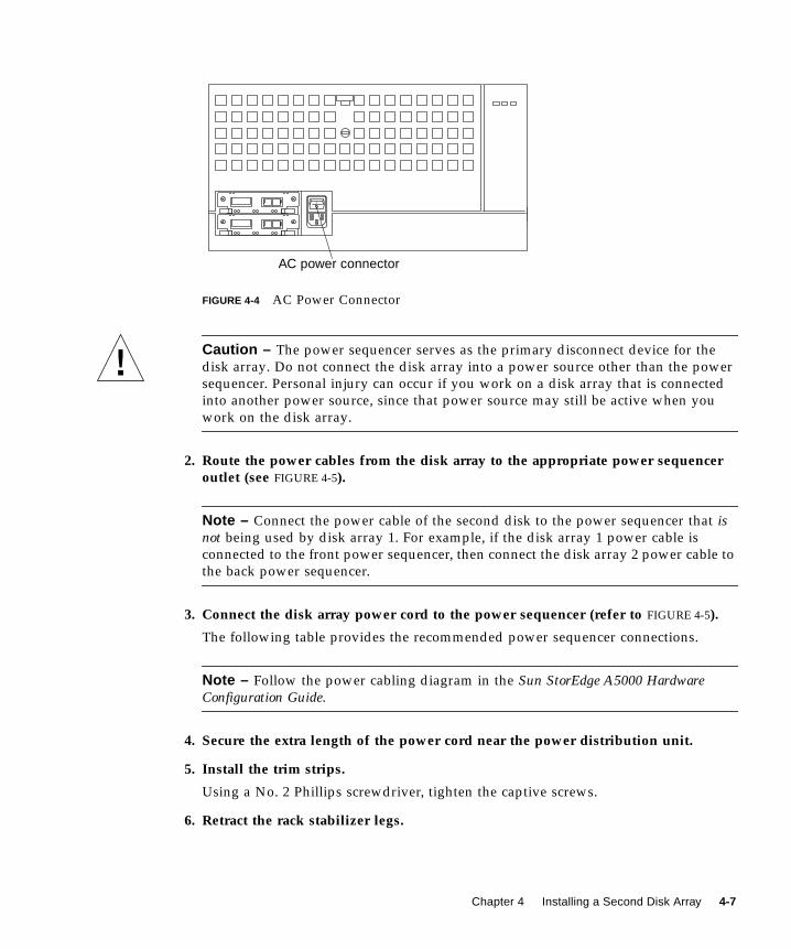
FIGURE 4-4 AC Power Connector
Caution – The power sequencer serves as the primary disconnect device for the
disk array. Do not connect the disk array into a power source other than the power
sequencer. Personal injury can occur if you work on a disk array that is connected
into another power source, since that power source may still be active when you
work on the disk array.
2. Route the power cables from the disk array to the appropriate power sequenceroutlet (see FIGURE 4-5).
Note – Connect the power cable of the second disk to the power sequencer that isnot being used by disk array 1. For example, if the disk array 1 power cable is
connected to the front power sequencer, then connect the disk array 2 power cable to
the back power sequencer.
3. Connect the disk array power cord to the power sequencer (refer to FIGURE 4-5).
The following table provides the recommended power sequencer connections.
Note – Follow the power cabling diagram in the Sun StorEdge A5000 HardwareConfiguration Guide.
4. Secure the extra length of the power cord near the power distribution unit.
5. Install the trim strips.
Using a No. 2 Phillips screwdriver, tighten the captive screws.
6. Retract the rack stabilizer legs.
AC power connector
Chapter 4 Installing a Second Disk Array 4-7
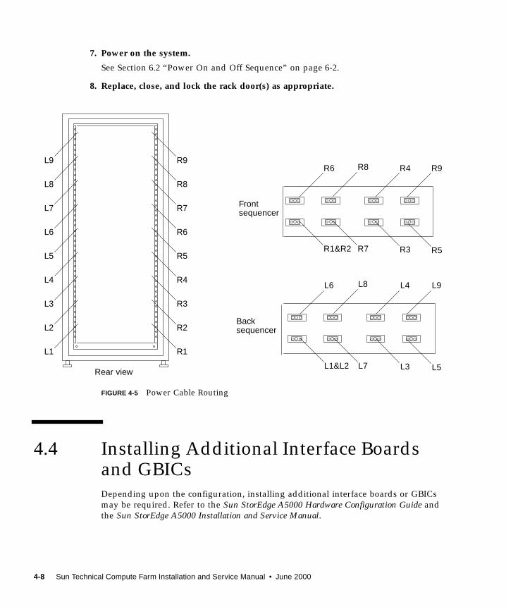
7. Power on the system.
See Section 6.2 “Power On and Off Sequence” on page 6-2.
8. Replace, close, and lock the rack door(s) as appropriate.
FIGURE 4-5 Power Cable Routing
4.4 Installing Additional Interface Boardsand GBICsDepending upon the configuration, installing additional interface boards or GBICs
may be required. Refer to the Sun StorEdge A5000 Hardware Configuration Guide and
the Sun StorEdge A5000 Installation and Service Manual.
R1&R2 R3
R6 R4 R9R8
R5R7
Frontsequencer
L1&L2 L3
L6 L4 L9L8
L5L7
Backsequencer
L8
L7
L4
L3
L2
L1
L6
L5
L9
R8
R7
R4
R3
R2
R1
R6
R5
R9
Rear view
4-8 Sun Technical Compute Farm Installation and Service Manual • June 2000
4.5 Disk Array-to-File Server CablingRefer to Section 5.1.1.1 “Disk Array 1-to-File Server Cabling” on page 5-8.
4.6 Disk Array 1-to-Disk Array 2 CablingRefer to Section 5.4.1.2 “Disk Array 1-to-Disk Array 2 Cabling” on page 5-41.
4.7 Repositioning the Airflow BaffleWhen installing a second disk array into the base rack, it is necessary to first remove
the airflow baffle. After the second disk array is installed, replace the airflow baffle
directly above the second disk array. FIGURE 4-6 shows the main and side baffles.
Chapter 4 Installing a Second Disk Array 4-9
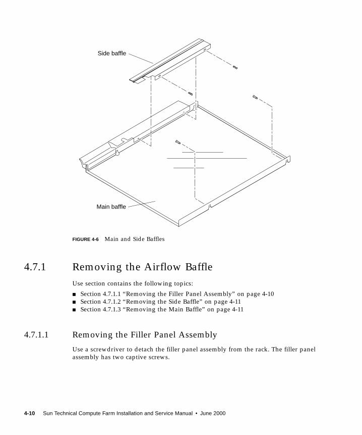
FIGURE 4-6 Main and Side Baffles
4.7.1 Removing the Airflow Baffle
Use section contains the following topics:
■ Section 4.7.1.1 “Removing the Filler Panel Assembly” on page 4-10
■ Section 4.7.1.2 “Removing the Side Baffle” on page 4-11
■ Section 4.7.1.3 “Removing the Main Baffle” on page 4-11
4.7.1.1 Removing the Filler Panel Assembly
Use a screwdriver to detach the filler panel assembly from the rack. The filler panel
assembly has two captive screws.
Side baffle
Main baffle
4-10 Sun Technical Compute Farm Installation and Service Manual • June 2000
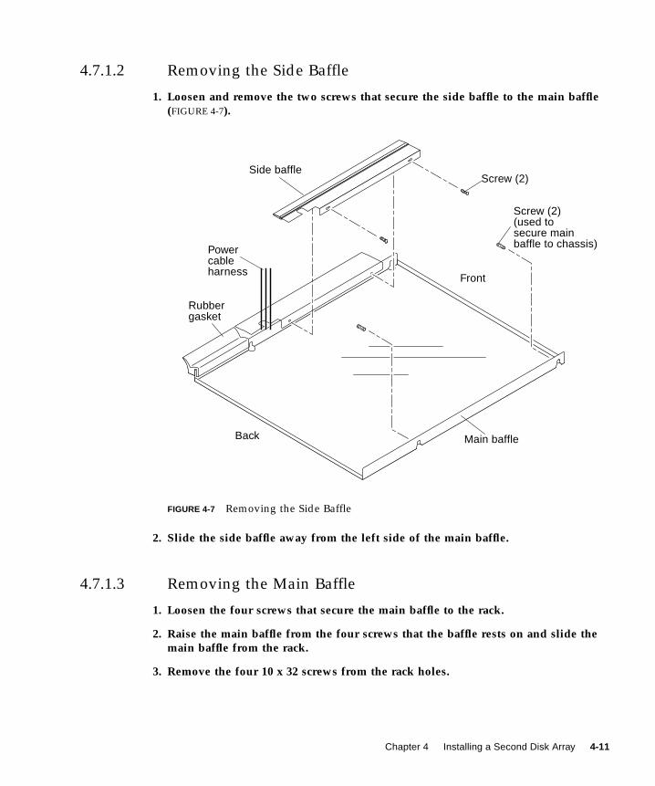
4.7.1.2 Removing the Side Baffle
1. Loosen and remove the two screws that secure the side baffle to the main baffle(FIGURE 4-7).
FIGURE 4-7 Removing the Side Baffle
2. Slide the side baffle away from the left side of the main baffle.
4.7.1.3 Removing the Main Baffle
1. Loosen the four screws that secure the main baffle to the rack.
2. Raise the main baffle from the four screws that the baffle rests on and slide themain baffle from the rack.
3. Remove the four 10 x 32 screws from the rack holes.
Rubbergasket
Powercableharness
Front
Back
Side baffle
Main baffle
Screw (2)
Screw (2)(used tosecure mainbaffle to chassis)
Chapter 4 Installing a Second Disk Array 4-11
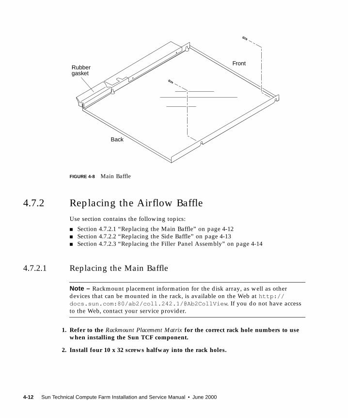
FIGURE 4-8 Main Baffle
4.7.2 Replacing the Airflow Baffle
Use section contains the following topics:
■ Section 4.7.2.1 “Replacing the Main Baffle” on page 4-12
■ Section 4.7.2.2 “Replacing the Side Baffle” on page 4-13
■ Section 4.7.2.3 “Replacing the Filler Panel Assembly” on page 4-14
4.7.2.1 Replacing the Main Baffle
Note – Rackmount placement information for the disk array, as well as other
devices that can be mounted in the rack, is available on the Web at http://docs.sun.com:80/ab2/coll.242.1/@Ab2CollView . If you do not have access
to the Web, contact your service provider.
1. Refer to the Rackmount Placement Matrix for the correct rack hole numbers to usewhen installing the Sun TCF component.
2. Install four 10 x 32 screws halfway into the rack holes.
Rubbergasket
Front
Back
4-12 Sun Technical Compute Farm Installation and Service Manual • June 2000
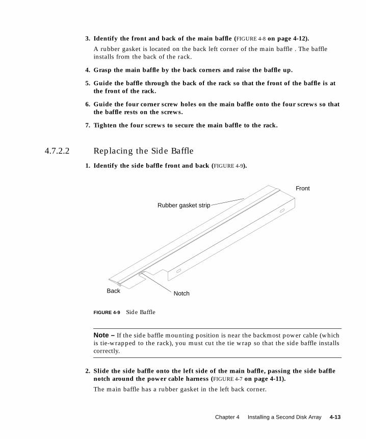
3. Identify the front and back of the main baffle (FIGURE 4-8 on page 4-12).
A rubber gasket is located on the back left corner of the main baffle . The baffle
installs from the back of the rack.
4. Grasp the main baffle by the back corners and raise the baffle up.
5. Guide the baffle through the back of the rack so that the front of the baffle is atthe front of the rack.
6. Guide the four corner screw holes on the main baffle onto the four screws so thatthe baffle rests on the screws.
7. Tighten the four screws to secure the main baffle to the rack.
4.7.2.2 Replacing the Side Baffle
1. Identify the side baffle front and back (FIGURE 4-9).
FIGURE 4-9 Side Baffle
Note – If the side baffle mounting position is near the backmost power cable (which
is tie-wrapped to the rack), you must cut the tie wrap so that the side baffle installs
correctly.
2. Slide the side baffle onto the left side of the main baffle, passing the side bafflenotch around the power cable harness (FIGURE 4-7 on page 4-11).
The main baffle has a rubber gasket in the left back corner.
Rubber gasket strip
Notch
Front
Back
Chapter 4 Installing a Second Disk Array 4-13
3. Align the side baffle holes with the two interior holes on the main baffle.
The side baffle gasket must contact and seal with the rack side panel.
4. Install and tighten the two screws to secure the side baffle to the main baffle.
4.7.2.3 Replacing the Filler Panel Assembly
● Use a screwdriver to attach the filler panel assembly to the rack.
The filler panel assembly has two captive screws. FIGURE 4-10 shows the repositioned
airflow baffle with the filler panel installed.
4-14 Sun Technical Compute Farm Installation and Service Manual • June 2000
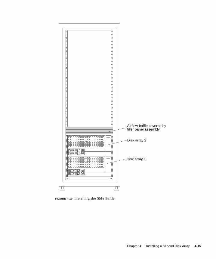
FIGURE 4-10 Installing the Side Baffle
Disk array 2
Disk array 1
Airflow baffle covered byfiller panel assembly
Chapter 4 Installing a Second Disk Array 4-15
4.8 Reassembling the RackFollow the instructions on preparing for service in the system or rack
documentation. If necessary, be sure to:
■ Replace or close the top front panel
■ Replace or close the vented back panel
■ Push the stabilizer legs back into the rack
4-16 Sun Technical Compute Farm Installation and Service Manual • June 2000
CHAPTER 5
Cabling the Sun TCF Devices
There are three basic Sun TCF configurations, based on the number of base racks in
the system:
■ One base rack with one or more expansion racks.
■ Two base racks with one or more expansion racks per base rack.
■ Three or more base racks with a star rack and one or two expansion racks per
base rack.
The following sections containing diagrams for example configurations:
■ Section 5.1 “Small Farm Configuration Example” on page 5-1
■ Section 5.2 “Medium Farm Configuration Example 1” on page 5-15
■ Section 5.3 “Medium Farm Configuration Example 2” on page 5-27
■ Section 5.4 “Large Farm Configuration Example” on page 5-34
5.1 Small Farm Configuration ExampleThis example of a Sun TCF small farm configuration provides 52 CPUs through
thirteen 4-way compute engines. Four of the thirteen compute engines are located in
the base rack and the remaining nine compute engines are mounted in the expansion
rack.
FIGURE 5-1 illustrates this small farm configuration. FIGURE 5-2 is a schematic showing
the cabling requirements for the small farm configuration. TABLE 5-1 lists the point-
to-point cabling scheme for connections within the base rack. TABLE 5-2 lists the
point-to-point cabling scheme for connections between the base rack and the
expansion rack.
5-1
The following sections describe cabling configurations for specific rackmounted
equipment within each rack.
■ Section 5.1.1 “Cabling the Disk Array for the Small Farm Configuration” on
page 5-7
■ Section 5.1.2 “Cabling the File Server for the Small Farm Configuration” on
page 5-9
■ Section 5.1.3 “Cabling the Compute Engine for the Small Farm Configuration” on
page 5-11
■ Section 5.1.4 “Cabling the C3524 Ethernet Switch for the Small Farm
Configuration” on page 5-12
■ Section 5.1.5 “Cabling the Access Server for Small Farm Configuration” on
page 5-14
5-2 Sun Technical Compute Farm Installation and Service Manual • June 2000

FIGURE 5-1 Example of a Sun TCF Small Farm Configuration With One Base Rack
TABLE 5-1 Point-to-Point Connections Within the Base Rack
Cable type Connection Point 1 Connection Point 2
Fibre Channel File server, GigabitEthernet card in the
66-MHz/64-bit PCI card slot 1
C3524 Ethernet switch, module in Gigabit
slot 1
Fibre Channel File server, host adapter card in the
33-MHz/64-bit PCI card slot 2
Disk array 1, interface board A in slot A0
Fibre Channel File server, host adapter card in the
33-MHz/64-bit PCI card slot 3
Disk array 1, interface board B in slot B0
Ethernet File server, serial port A Access server 1, async port 1
Ethernet Compute engine 1, serial port A Access server 1, async port 2
Ethernet Compute engine 2, serial port A Access server 1, async port 3
Base rackExpansion rack
Rack-to-rackinterconnection
Network
User group A
User group C
User group B
Chapter 5 Cabling the Sun TCF Devices 5-3
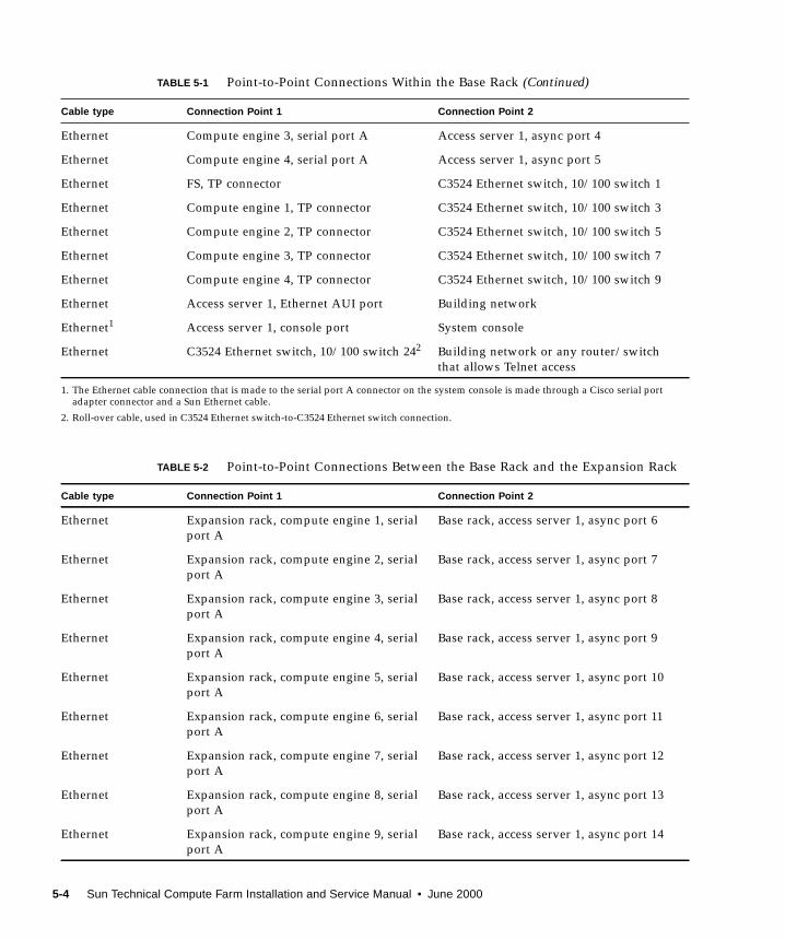
Ethernet Compute engine 3, serial port A Access server 1, async port 4
Ethernet Compute engine 4, serial port A Access server 1, async port 5
Ethernet FS, TP connector C3524 Ethernet switch, 10/100 switch 1
Ethernet Compute engine 1, TP connector C3524 Ethernet switch, 10/100 switch 3
Ethernet Compute engine 2, TP connector C3524 Ethernet switch, 10/100 switch 5
Ethernet Compute engine 3, TP connector C3524 Ethernet switch, 10/100 switch 7
Ethernet Compute engine 4, TP connector C3524 Ethernet switch, 10/100 switch 9
Ethernet Access server 1, Ethernet AUI port Building network
Ethernet1 Access server 1, console port System console
Ethernet C3524 Ethernet switch, 10/100 switch 242 Building network or any router/switch
that allows Telnet access
1. The Ethernet cable connection that is made to the serial port A connector on the system console is made through a Cisco serial portadapter connector and a Sun Ethernet cable.
2. Roll-over cable, used in C3524 Ethernet switch-to-C3524 Ethernet switch connection.
TABLE 5-2 Point-to-Point Connections Between the Base Rack and the Expansion Rack
Cable type Connection Point 1 Connection Point 2
Ethernet Expansion rack, compute engine 1, serial
port A
Base rack, access server 1, async port 6
Ethernet Expansion rack, compute engine 2, serial
port A
Base rack, access server 1, async port 7
Ethernet Expansion rack, compute engine 3, serial
port A
Base rack, access server 1, async port 8
Ethernet Expansion rack, compute engine 4, serial
port A
Base rack, access server 1, async port 9
Ethernet Expansion rack, compute engine 5, serial
port A
Base rack, access server 1, async port 10
Ethernet Expansion rack, compute engine 6, serial
port A
Base rack, access server 1, async port 11
Ethernet Expansion rack, compute engine 7, serial
port A
Base rack, access server 1, async port 12
Ethernet Expansion rack, compute engine 8, serial
port A
Base rack, access server 1, async port 13
Ethernet Expansion rack, compute engine 9, serial
port A
Base rack, access server 1, async port 14
TABLE 5-1 Point-to-Point Connections Within the Base Rack (Continued)
Cable type Connection Point 1 Connection Point 2
5-4 Sun Technical Compute Farm Installation and Service Manual • June 2000
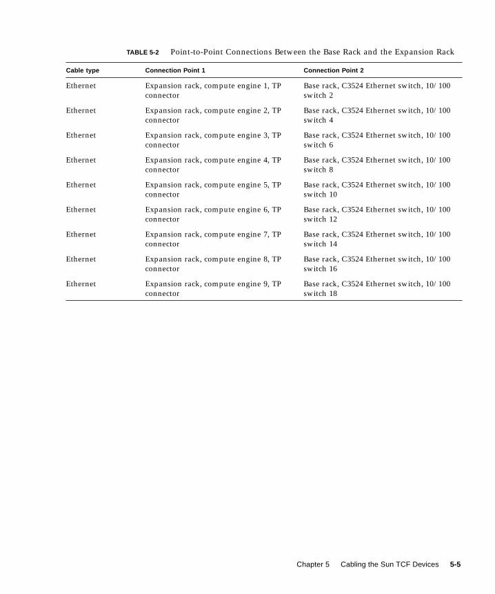
Ethernet Expansion rack, compute engine 1, TP
connector
Base rack, C3524 Ethernet switch, 10/100
switch 2
Ethernet Expansion rack, compute engine 2, TP
connector
Base rack, C3524 Ethernet switch, 10/100
switch 4
Ethernet Expansion rack, compute engine 3, TP
connector
Base rack, C3524 Ethernet switch, 10/100
switch 6
Ethernet Expansion rack, compute engine 4, TP
connector
Base rack, C3524 Ethernet switch, 10/100
switch 8
Ethernet Expansion rack, compute engine 5, TP
connector
Base rack, C3524 Ethernet switch, 10/100
switch 10
Ethernet Expansion rack, compute engine 6, TP
connector
Base rack, C3524 Ethernet switch, 10/100
switch 12
Ethernet Expansion rack, compute engine 7, TP
connector
Base rack, C3524 Ethernet switch, 10/100
switch 14
Ethernet Expansion rack, compute engine 8, TP
connector
Base rack, C3524 Ethernet switch, 10/100
switch 16
Ethernet Expansion rack, compute engine 9, TP
connector
Base rack, C3524 Ethernet switch, 10/100
switch 18
TABLE 5-2 Point-to-Point Connections Between the Base Rack and the Expansion Rack
Cable type Connection Point 1 Connection Point 2
Chapter 5 Cabling the Sun TCF Devices 5-5
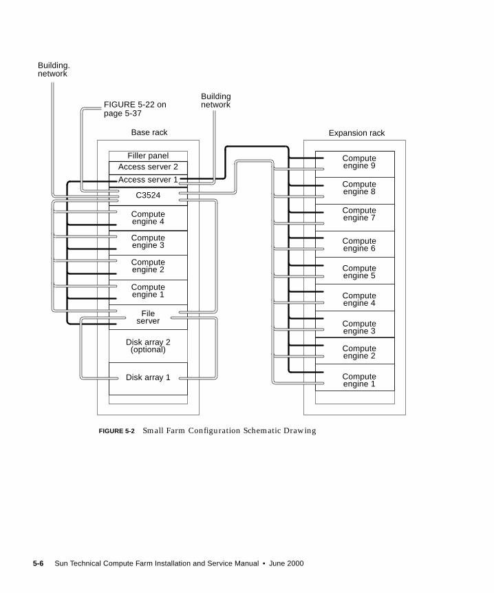
FIGURE 5-2 Small Farm Configuration Schematic Drawing
Access server 2
Disk array 1
Fileserver
Computeengine 1
Computeengine 4
Computeengine 3
Computeengine 2
Access server 1
C3524
Disk array 2(optional)
Computeengine 9
Computeengine 8
Computeengine 7
Computeengine 6
Computeengine 5
Computeengine 4
Computeengine 3
Computeengine 2
Computeengine 1
Filler panel
Buildingnetwork
Base rack Expansion rack
Building.network
FIGURE 5-22 onpage 5-37
5-6 Sun Technical Compute Farm Installation and Service Manual • June 2000
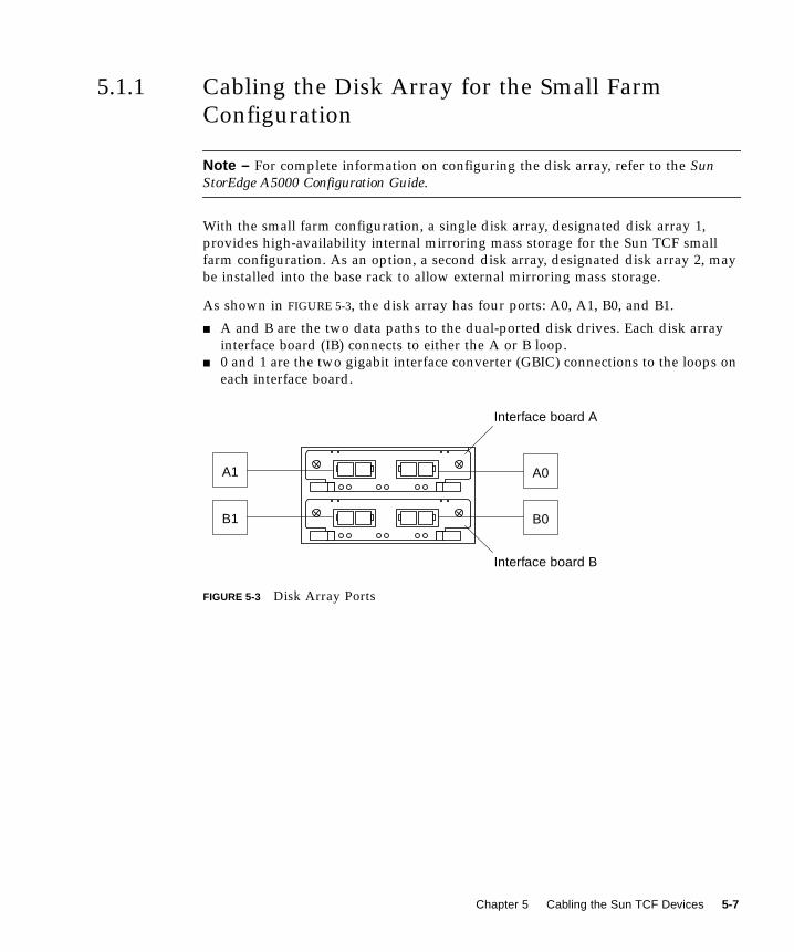
5.1.1 Cabling the Disk Array for the Small Farm
Configuration
Note – For complete information on configuring the disk array, refer to the SunStorEdge A5000 Configuration Guide.
With the small farm configuration, a single disk array, designated disk array 1,
provides high-availability internal mirroring mass storage for the Sun TCF small
farm configuration. As an option, a second disk array, designated disk array 2, may
be installed into the base rack to allow external mirroring mass storage.
As shown in FIGURE 5-3, the disk array has four ports: A0, A1, B0, and B1.
■ A and B are the two data paths to the dual-ported disk drives. Each disk array
interface board (IB) connects to either the A or B loop.
■ 0 and 1 are the two gigabit interface converter (GBIC) connections to the loops on
each interface board.
FIGURE 5-3 Disk Array Ports
B0
A0
Interface board A
B1
A1
Interface board B
Chapter 5 Cabling the Sun TCF Devices 5-7
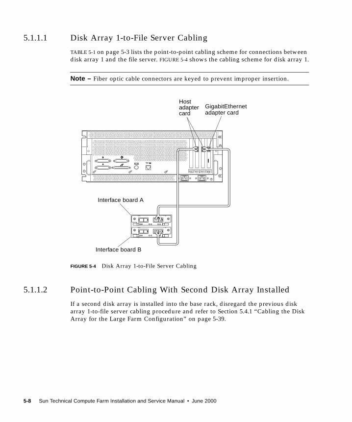
5.1.1.1 Disk Array 1-to-File Server Cabling
TABLE 5-1 on page 5-3 lists the point-to-point cabling scheme for connections between
disk array 1 and the file server. FIGURE 5-4 shows the cabling scheme for disk array 1.
Note – Fiber optic cable connectors are keyed to prevent improper insertion.
FIGURE 5-4 Disk Array 1-to-File Server Cabling
5.1.1.2 Point-to-Point Cabling With Second Disk Array Installed
If a second disk array is installed into the base rack, disregard the previous disk
array 1-to-file server cabling procedure and refer to Section 5.4.1 “Cabling the Disk
Array for the Large Farm Configuration” on page 5-39.
GigabitEthernetadapter card
Hostadaptercard
Interface board A
Interface board B
5-8 Sun Technical Compute Farm Installation and Service Manual • June 2000
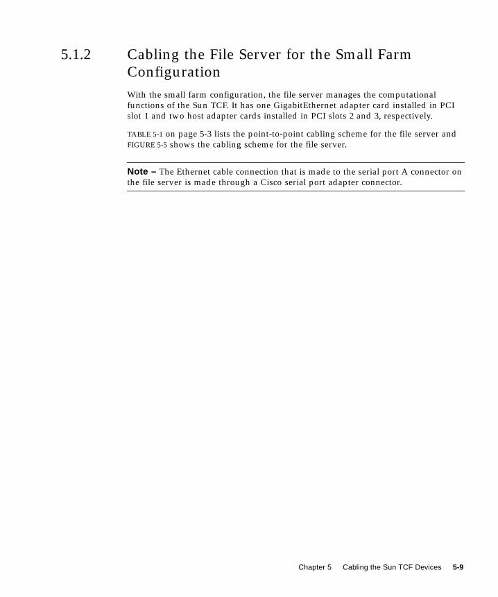
5.1.2 Cabling the File Server for the Small Farm
Configuration
With the small farm configuration, the file server manages the computational
functions of the Sun TCF. It has one GigabitEthernet adapter card installed in PCI
slot 1 and two host adapter cards installed in PCI slots 2 and 3, respectively.
TABLE 5-1 on page 5-3 lists the point-to-point cabling scheme for the file server and
FIGURE 5-5 shows the cabling scheme for the file server.
Note – The Ethernet cable connection that is made to the serial port A connector on
the file server is made through a Cisco serial port adapter connector.
Chapter 5 Cabling the Sun TCF Devices 5-9
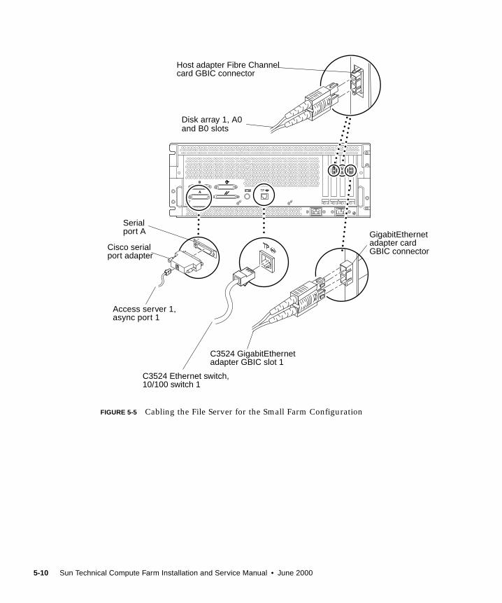
FIGURE 5-5 Cabling the File Server for the Small Farm Configuration
Serialport A
Access server 1,
Host adapter Fibre Channelcard GBIC connector
GigabitEthernetadapter cardGBIC connector
C3524 GigabitEthernetadapter GBIC slot 1
async port 1
C3524 Ethernet switch,10/100 switch 1
Disk array 1, A0and B0 slots
Cisco serialport adapter
5-10 Sun Technical Compute Farm Installation and Service Manual • June 2000
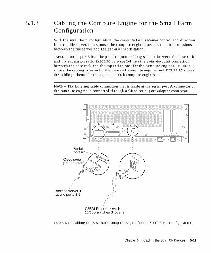
5.1.3 Cabling the Compute Engine for the Small Farm
Configuration
With the small farm configuration, the compute farm receives control and direction
from the file server. In response, the compute engine provides data transmissions
between the file server and the end-user workstation.
TABLE 5-1 on page 5-3 lists the point-to-point cabling scheme between the base rack
and the expansion rack. TABLE 5-2 on page 5-4 lists the point-to-point connection
between the base rack and the expansion rack for the compute engines. FIGURE 5-6
shows the cabling scheme for the base rack compute engines and FIGURE 5-7 shows
the cabling scheme for the expansion rack compute engines.
Note – The Ethernet cable connection that is made at the serial port A connector on
the compute engine is connected through a Cisco serial port adapter connector.
FIGURE 5-6 Cabling the Base Rack Compute Engine for the Small Farm Configuration
Serialport A
Access server 1,async ports 2-5
C3524 Ethernet switch,10/100 switches 3, 5, 7, 9
Cisco serialport adapter
Chapter 5 Cabling the Sun TCF Devices 5-11
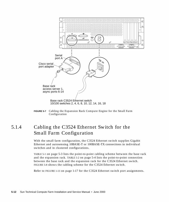
FIGURE 5-7 Cabling the Expansion Rack Compute Engine for the Small FarmConfiguration
5.1.4 Cabling the C3524 Ethernet Switch for the
Small Farm Configuration
With the small farm configuration, the C3524 Ethernet switch supplies Gigabit
Ethernet and autosensing 10BASE-T or 100BASE-TX connections in individual
switches and in clustered configurations.
TABLE 5-1 on page 5-3 lists the point-to-point cabling scheme between the base rack
and the expansion rack. TABLE 5-2 on page 5-4 lists the point-to-point connection
between the base rack and the expansion rack for the C3524 Ethernet switch.
FIGURE 5-8 shows the cabling scheme for the C3524 Ethernet switch.
Refer to FIGURE 1-13 on page 1-17 for the C3524 Ethernet switch port assignments.
Serialport A
Base rackaccess server 1,async ports 6-14
Base rack C3524 Ethernet switch10/100 switches 2, 4, 6, 8, 10, 12, 14, 16, 18
Cisco serialport adapter
5-12 Sun Technical Compute Farm Installation and Service Manual • June 2000
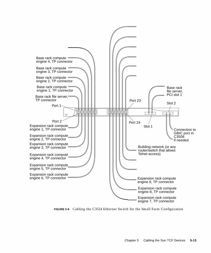
FIGURE 5-8 Cabling the C3524 Ethernet Switch for the Small Farm Configuration
Base rackfile server,PCI slot 1Base rack file server,
Base rack computeengine 1, TP connector
Base rack computeengine 2, TP connector
Base rack computeengine 3, TP connector
Base rack computeengine 4, TP connector
Building network (or anyrouter/switch that allowsTelnet access)
Expansion rack computeengine 1, TP connector
TP connector
Expansion rack computeengine 3, TP connector
Expansion rack computeengine 4, TP connector
Expansion rack computeengine 5, TP connector
Expansion rack computeengine 6, TP connector
Expansion rack computeengine 2, TP connector
Expansion rack computeengine 9, TP connector
Expansion rack computeengine 8, TP connector
Expansion rack computeengine 7, TP connector
Connection toGBIC port inC3508if needed
Port 1
Port 2
Port 23
Port 24Slot 1
Slot 2
Chapter 5 Cabling the Sun TCF Devices 5-13
5.1.5 Cabling the Access Server for Small Farm
Configuration
With the small farm configuration, access server 1 connects asynchronous serial
devices to local area networks (LANs) and wide area networks (WANs).
TABLE 5-1 on page 5-3 lists the point-to-point cabling scheme between the base rack
and the expansion rack. TABLE 5-2 on page 5-4 lists the point-to-point connection
between the base rack and the expansion rack for access server 1. FIGURE 5-9 shows
the cabling scheme for the base rack access server 1.
Refer to FIGURE 1-18 on page 1-20 for the access server port assignments.
5-14 Sun Technical Compute Farm Installation and Service Manual • June 2000
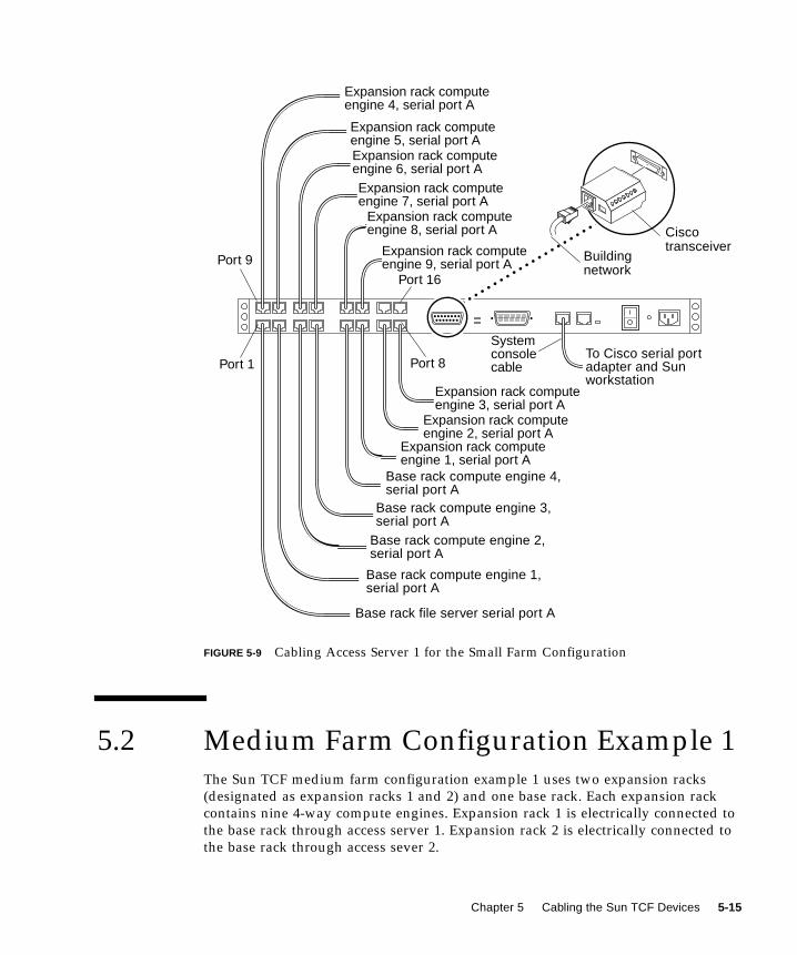
FIGURE 5-9 Cabling Access Server 1 for the Small Farm Configuration
5.2 Medium Farm Configuration Example 1The Sun TCF medium farm configuration example 1 uses two expansion racks
(designated as expansion racks 1 and 2) and one base rack. Each expansion rack
contains nine 4-way compute engines. Expansion rack 1 is electrically connected to
the base rack through access server 1. Expansion rack 2 is electrically connected to
the base rack through access sever 2.
Buildingnetwork
To Cisco serial port
Base rack compute engine 3,serial port A
Base rack compute engine 4,serial port A
Base rack compute engine 2,serial port A
Base rack compute engine 1,serial port A
Base rack file server serial port A
Expansion rack computeengine 2, serial port A
Expansion rack computeengine 1, serial port A
Expansion rack computeengine 6, serial port A
Expansion rack computeengine 5, serial port A
Expansion rack computeengine 4, serial port A
Expansion rack computeengine 3, serial port A
Expansion rack computeengine 7, serial port A
Expansion rack computeengine 8, serial port A
Expansion rack computeengine 9, serial port A
Ciscotransceiver
adapter and Sunworkstation
SystemconsolecablePort 1 Port 8
Port 9
Port 16
Chapter 5 Cabling the Sun TCF Devices 5-15
FIGURE 5-10 illustrates a medium farm configuration example 1. FIGURE 5-11 and
FIGURE 5-12 are schematics showing the cabling requirements for the medium farm
configuration example 1. With the exception of the point-to-point cabling differences
between the base rack and expansion rack 2, all other point-to-point cabling for this
medium farm configuration is identical to the small farm point-to-point cabling
scheme (refer to TABLE 5-2 on page 5-4). TABLE 5-3 lists the point-to-point cabling
scheme between the base rack and expansion rack 2.
The following sections describe cabling configurations for the individually
rackmounted equipment for the 88-CPU medium farm configuration.
■ Section 5.2.1 “Cabling the Disk Array for the Medium Farm Configuration
Example 1” on page 5-21
■ Section 5.2.2 “Cabling the File Server for the Medium Farm Configuration
Example 1” on page 5-21
■ Section 5.2.3 “Cabling the Compute Engines for the Medium Farm Configuration
Example 1” on page 5-21
■ Section 5.2.4 “Cabling the C3524 Ethernet Switch for the Medium Farm
Configuration Example 1” on page 5-23
■ Section 5.2.5 “Cabling the Access Server 2 for the Medium Farm Configuration
Example 1” on page 5-25
5-16 Sun Technical Compute Farm Installation and Service Manual • June 2000

FIGURE 5-10 Example 1 of a Sun TCF Medium Farm Configuration With One Base Rack
TABLE 5-3 Point-to-Point Connections Between the Base Rack and Expansion Rack 2
Cable type Connection Point 1 Connection Point 2
Ethernet Expansion rack 2, compute engine 1,
serial port A
Base rack, access server 2, async port 1
Ethernet Expansion rack 2, compute engine 2,
serial port A
Base rack, access server 2, async port 2
Ethernet Expansion rack 2, compute engine 3,
serial port A
Base rack, access server 2, async port 3
Ethernet Expansion rack 2, compute engine 4,
serial port A
Base rack, access server 2, async port 4
Ethernet Expansion rack 2, compute engine 5,
serial port A
Base rack, access server 2, async port 5
Base rackExpansion rack Expansion rack
Rack-to-rackinterconnection
Rack-to-rackinterconnection
Network
User group A User group B
User group C
Chapter 5 Cabling the Sun TCF Devices 5-17
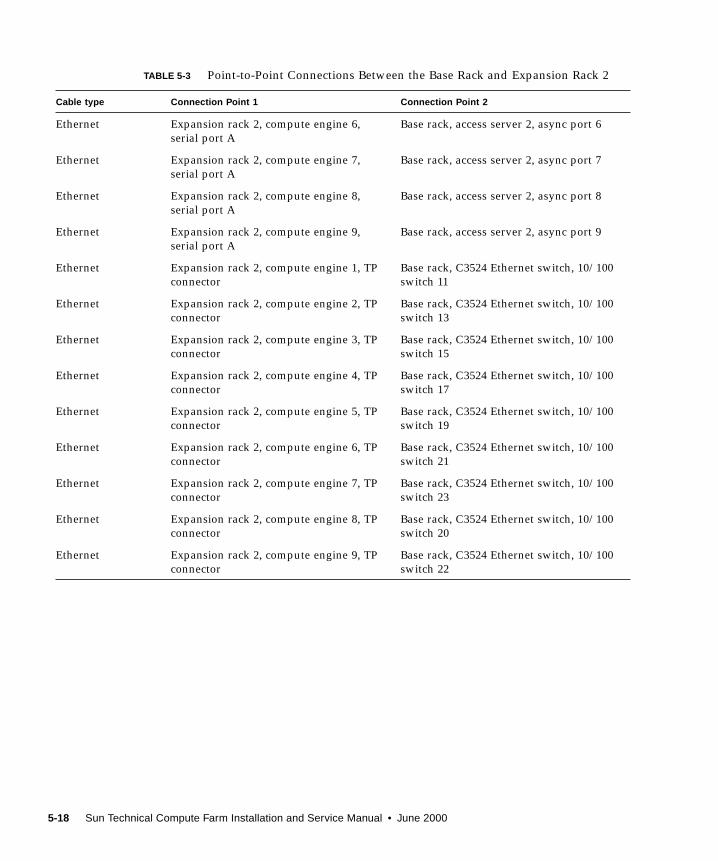
Ethernet Expansion rack 2, compute engine 6,
serial port A
Base rack, access server 2, async port 6
Ethernet Expansion rack 2, compute engine 7,
serial port A
Base rack, access server 2, async port 7
Ethernet Expansion rack 2, compute engine 8,
serial port A
Base rack, access server 2, async port 8
Ethernet Expansion rack 2, compute engine 9,
serial port A
Base rack, access server 2, async port 9
Ethernet Expansion rack 2, compute engine 1, TP
connector
Base rack, C3524 Ethernet switch, 10/100
switch 11
Ethernet Expansion rack 2, compute engine 2, TP
connector
Base rack, C3524 Ethernet switch, 10/100
switch 13
Ethernet Expansion rack 2, compute engine 3, TP
connector
Base rack, C3524 Ethernet switch, 10/100
switch 15
Ethernet Expansion rack 2, compute engine 4, TP
connector
Base rack, C3524 Ethernet switch, 10/100
switch 17
Ethernet Expansion rack 2, compute engine 5, TP
connector
Base rack, C3524 Ethernet switch, 10/100
switch 19
Ethernet Expansion rack 2, compute engine 6, TP
connector
Base rack, C3524 Ethernet switch, 10/100
switch 21
Ethernet Expansion rack 2, compute engine 7, TP
connector
Base rack, C3524 Ethernet switch, 10/100
switch 23
Ethernet Expansion rack 2, compute engine 8, TP
connector
Base rack, C3524 Ethernet switch, 10/100
switch 20
Ethernet Expansion rack 2, compute engine 9, TP
connector
Base rack, C3524 Ethernet switch, 10/100
switch 22
TABLE 5-3 Point-to-Point Connections Between the Base Rack and Expansion Rack 2
Cable type Connection Point 1 Connection Point 2
5-18 Sun Technical Compute Farm Installation and Service Manual • June 2000

FIGURE 5-11 Medium Farm Configuration Example 1 (Sheet 1 of 2)
Access server 2
Disk array 1
Fileserver
Computeengine 1
Computeengine 4
Computeengine 3
Computeengine 2
Access server 1
C3524
Disk array 2(optional)
Filler panel
A(Sheet 2)
B(Sheet 2)
Base rack
Buildingnetwork
C(Sheet 2)
Chapter 5 Cabling the Sun TCF Devices 5-19
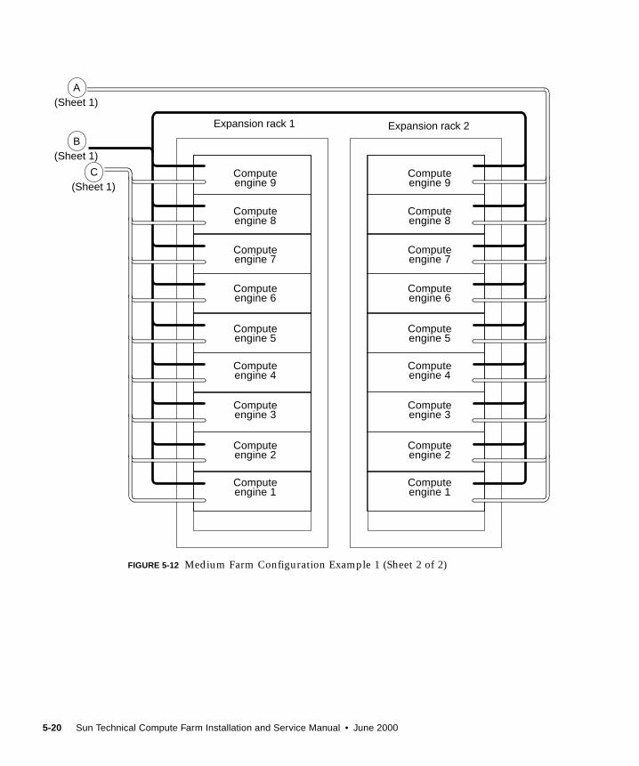
FIGURE 5-12 Medium Farm Configuration Example 1 (Sheet 2 of 2)
Computeengine 9
Computeengine 8
Computeengine 7
Computeengine 6
Computeengine 5
Computeengine 4
Computeengine 3
Computeengine 2
Computeengine 1
Computeengine 9
Computeengine 8
Computeengine 7
Computeengine 6
Computeengine 5
Computeengine 4
Computeengine 3
Computeengine 2
Computeengine 1
B(Sheet 1)
C(Sheet 1)
Expansion rack 1 Expansion rack 2
A(Sheet 1)
5-20 Sun Technical Compute Farm Installation and Service Manual • June 2000
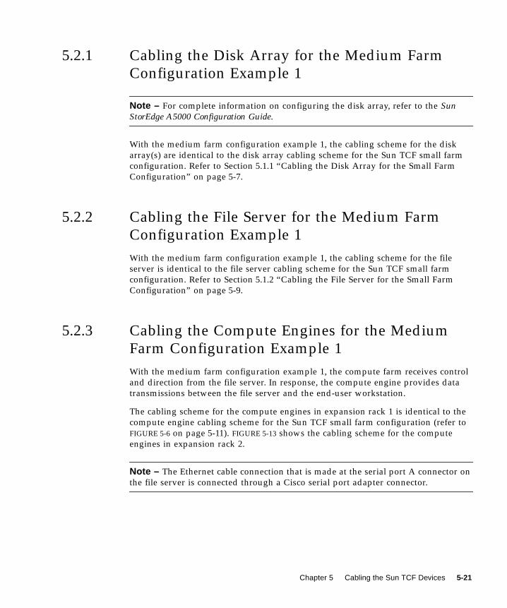
5.2.1 Cabling the Disk Array for the Medium Farm
Configuration Example 1
Note – For complete information on configuring the disk array, refer to the SunStorEdge A5000 Configuration Guide.
With the medium farm configuration example 1, the cabling scheme for the disk
array(s) are identical to the disk array cabling scheme for the Sun TCF small farm
configuration. Refer to Section 5.1.1 “Cabling the Disk Array for the Small Farm
Configuration” on page 5-7.
5.2.2 Cabling the File Server for the Medium Farm
Configuration Example 1
With the medium farm configuration example 1, the cabling scheme for the file
server is identical to the file server cabling scheme for the Sun TCF small farm
configuration. Refer to Section 5.1.2 “Cabling the File Server for the Small Farm
Configuration” on page 5-9.
5.2.3 Cabling the Compute Engines for the Medium
Farm Configuration Example 1
With the medium farm configuration example 1, the compute farm receives control
and direction from the file server. In response, the compute engine provides data
transmissions between the file server and the end-user workstation.
The cabling scheme for the compute engines in expansion rack 1 is identical to the
compute engine cabling scheme for the Sun TCF small farm configuration (refer to
FIGURE 5-6 on page 5-11). FIGURE 5-13 shows the cabling scheme for the compute
engines in expansion rack 2.
Note – The Ethernet cable connection that is made at the serial port A connector on
the file server is connected through a Cisco serial port adapter connector.
Chapter 5 Cabling the Sun TCF Devices 5-21
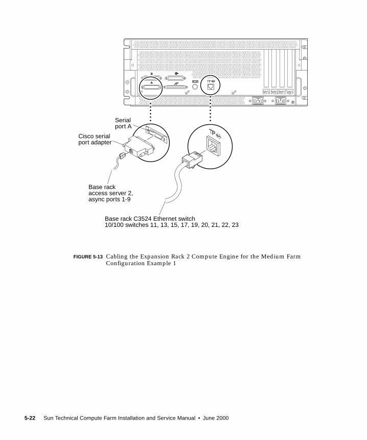
FIGURE 5-13 Cabling the Expansion Rack 2 Compute Engine for the Medium FarmConfiguration Example 1
Serialport A
Base rackaccess server 2,async ports 1-9
Base rack C3524 Ethernet switch10/100 switches 11, 13, 15, 17, 19, 20, 21, 22, 23
Cisco serialport adapter
5-22 Sun Technical Compute Farm Installation and Service Manual • June 2000

5.2.4 Cabling the C3524 Ethernet Switch for the
Medium Farm Configuration Example 1
With the medium farm configuration example 1, the cabling scheme for the C3524 is
identical to the C3524 cabling scheme for the small farm configuration (refer to
Section 5.1.4 “Cabling the C3524 Ethernet Switch for the Small Farm Configuration”
on page 5-12). In addition, the C3524 Ethernet switch also electrically connects the
expansion rack 2 compute engines to the base rack.
TABLE 5-3 on page 5-17 lists the point-to-point cabling scheme between the base
rack’s C3524 Ethernet switch and the compute engines in expansion rack 2.
FIGURE 5-14 shows the cabling scheme for the C3524 Ethernet switch-to-expansion
rack 2 compute engines.
Note – Refer to FIGURE 1-13 on page 1-17 for the C3524 Ethernet switch port
assignments.
Chapter 5 Cabling the Sun TCF Devices 5-23
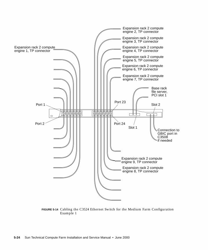
FIGURE 5-14 Cabling the C3524 Ethernet Switch for the Medium Farm ConfigurationExample 1
Expansion rack 2 computeengine 1, TP connector
Expansion rack 2 computeengine 2, TP connector
Expansion rack 2 computeengine 3, TP connector
Expansion rack 2 computeengine 8, TP connector
Expansion rack 2 computeengine 9, TP connector
Expansion rack 2 computeengine 4, TP connector
Expansion rack 2 computeengine 5, TP connector
Expansion rack 2 computeengine 6, TP connector
Expansion rack 2 computeengine 7, TP connector
Base rackfile server,PCI slot 1
Port 1
Port 2
Port 23
Port 24Slot 1
Slot 2
Connection toGBIC port inC3508if needed
5-24 Sun Technical Compute Farm Installation and Service Manual • June 2000
5.2.5 Cabling the Access Server 2 for the Medium Farm
Configuration Example 1
With the medium farm configuration example 1, access server 2 connects the base
rack to the expansion rack 2 compute engines.
TABLE 5-3 on page 5-17 lists the point-to-point connection between the base rack and
the expansion rack for access server 2. FIGURE 5-15 shows the cabling scheme for the
base rack access server 2.
Note – Refer to FIGURE 1-18 on page 1-20 for the C3524 Ethernet switch port
assignments.
Chapter 5 Cabling the Sun TCF Devices 5-25

FIGURE 5-15 Cabling the Access Server 2 for the Medium Farm Configuration Example 1
Buildingnetwork
Expansion rack 2 compute engine 3,serial port A
Expansion rack 2 compute engine 4,serial port A
Expansion rack 2 compute engine 2,serial port A
Expansion rack 2 compute engine 1,serial port A
Expansion rack 2 computeengine 6, serial port A
Expansion rack 2 computeengine 5, serial port A
Expansion rack 2 computeengine 9, serial port A
Expansion rack 2 computeengine 7, serial port A
Expansion rack 2 computeengine 8, serial port A
To Cisco serial portadapter and Sunworkstation
Systemconsolecable
Ciscotransceiver
Port 1 Port 8
Port 9Port 16
5-26 Sun Technical Compute Farm Installation and Service Manual • June 2000
5.3 Medium Farm Configuration Example 2The Sun TCF medium farm configuration example 2 uses two expansion racks
(designated as expansion racks 1 and 2) and two base racks (designated as base
racks 1 and 2). One of the expansion racks contains nine 4-way compute engines and
is electrically connected to base rack 1. The second expansion rack contains nine 2-
way compute engines and is electrically connected to base rack 2. Each base rack is
electrically connected to the other base rack in a cascading scheme through their
respective C3524 Ethernet switches.
FIGURE 5-16 illustrates a medium farm configuration example 2. FIGURE 5-17 and
FIGURE 5-18 are schematics showing the cabling requirements for the medium farm
configuration example 2. TABLE 5-4 lists the point-to-point cabling scheme for
connections between base rack 1 and base rack 2. With the exception of a point-to-
point cabling difference between the C3524 Ethernet switch in each base rack, all
other point-to-point cabling for this medium farm configuration is identical to the
point-to-point cabling in the small farm configuration.
The following sections describe cabling configurations for the individually
rackmounted equipment for the medium farm configuration example 2.
■ Section 5.3.1 “Cabling the Disk Array for the Medium Farm Configuration
Example 2” on page 5-31
■ Section 5.3.2 “Cabling the File Server for the Medium Farm Configuration
Example 2” on page 5-31
■ Section 5.3.3 “Cabling the Compute Engine for the Medium Farm Configuration
Example 2” on page 5-31
■ Section 5.3.4 “Cabling the C3524 Ethernet Switches for the Medium Farm
Configuration Example 2” on page 5-31
■ Section 5.3.5 “Cabling the Access Server for the Medium Farm Configuration
Example 2” on page 5-34
Chapter 5 Cabling the Sun TCF Devices 5-27
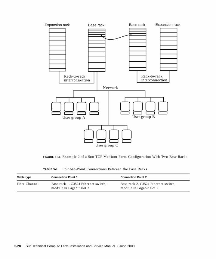
FIGURE 5-16 Example 2 of a Sun TCF Medium Farm Configuration With Two Base Racks
TABLE 5-4 Point-to-Point Connections Between the Base Racks
Cable type Connection Point 1 Connection Point 2
Fibre Channel Base rack 1, C3524 Ethernet switch,
module in Gigabit slot 2
Base rack 2, C3524 Ethernet switch,
module in Gigabit slot 2
Base rackExpansion rack Base rack Expansion rack
Rack-to-rackinterconnection
Rack-to-rackinterconnection
Network
User group BUser group A
User group C
5-28 Sun Technical Compute Farm Installation and Service Manual • June 2000

FIGURE 5-17 Medium Farm Configuration Example 2 (Sheet 1 of 2)
Access server 2
Disk array 1
Fileserver
Computeengine 1
Computeengine 4
Computeengine 3
Computeengine 2
Access server 1
C3524
Disk array 2(optional)
Computeengine 9
Computeengine 8
Computeengine 7
Computeengine 6
Computeengine 5
Computeengine 4
Computeengine 3
Computeengine 2
Computeengine 1
Filler panel
Base rack 1 Expansion rack 1A
(Sheet 2)
Buildingnetwork
Chapter 5 Cabling the Sun TCF Devices 5-29
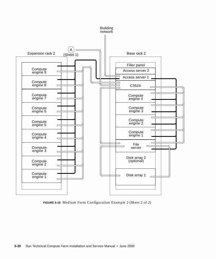
FIGURE 5-18 Medium Farm Configuration Example 2 (Sheet 2 of 2)
Computeengine 9
Computeengine 8
Computeengine 7
Computeengine 6
Computeengine 5
Computeengine 4
Computeengine 3
Computeengine 2
Computeengine 1
Access server 2
Disk array 1
Fileserver
Computeengine 1
Computeengine 4
Computeengine 3
Computeengine 2
Access server 1
C3524
Disk array 2(optional)
Filler panel
Buildingnetwork
Base rack 2Expansion rack 2A
(Sheet 1)
5-30 Sun Technical Compute Farm Installation and Service Manual • June 2000
5.3.1 Cabling the Disk Array for the Medium Farm
Configuration Example 2
Note – For complete information on configuring the disk array, refer to the SunStorEdge A5000 Configuration Guide.
With the medium farm configuration example 2, the cabling scheme for the disk
array(s) are identical to the disk array cabling scheme for the Sun TCF small farm
configuration. Refer to Section 5.1.1 “Cabling the Disk Array for the Small Farm
Configuration” on page 5-7.
5.3.2 Cabling the File Server for the Medium Farm
Configuration Example 2
With the medium farm configuration example 2, the cabling scheme for the file
server is identical to the file server cabling scheme for the Sun TCF small farm
configuration. Refer to Section 5.1.2 “Cabling the File Server for the Small Farm
Configuration” on page 5-9.
5.3.3 Cabling the Compute Engine for the Medium
Farm Configuration Example 2
With the medium farm configuration example 2, the cabling scheme for the compute
engine is identical to the compute engine cabling scheme for the Sun TCF small farm
configuration. Refer to Section 5.1.3 “Cabling the Compute Engine for the Small
Farm Configuration” on page 5-11.
5.3.4 Cabling the C3524 Ethernet Switches for the
Medium Farm Configuration Example 2
With the medium farm configuration example 2, the cabling scheme for the C3524 is
identical to the C3524 cabling scheme for the Sun TCF small farm configuration
(refer to Section 5.1.4 “Cabling the C3524 Ethernet Switch for the Small Farm
Configuration” on page 5-12) with one exception. The 86-CPU medium farm
configuration requires that the two base racks and their respective expansion racks
are electrically cascaded through each base rack’s C3524 Ethernet switch Gigabit
Ethernet port.
Chapter 5 Cabling the Sun TCF Devices 5-31
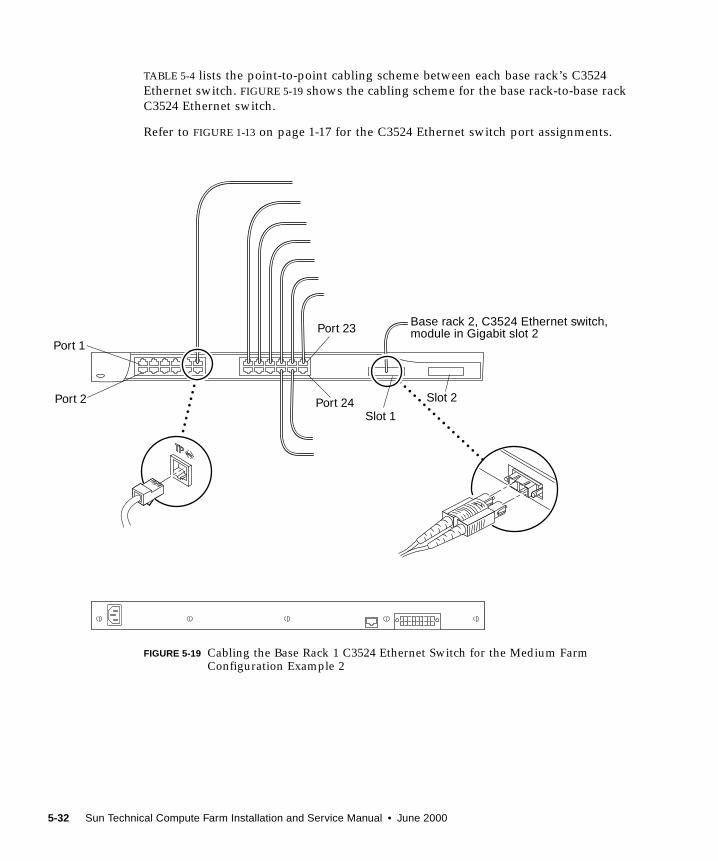
TABLE 5-4 lists the point-to-point cabling scheme between each base rack’s C3524
Ethernet switch. FIGURE 5-19 shows the cabling scheme for the base rack-to-base rack
C3524 Ethernet switch.
Refer to FIGURE 1-13 on page 1-17 for the C3524 Ethernet switch port assignments.
FIGURE 5-19 Cabling the Base Rack 1 C3524 Ethernet Switch for the Medium FarmConfiguration Example 2
Base rack 2, C3524 Ethernet switch,module in Gigabit slot 2
Port 1
Port 2
Port 23
Port 24Slot 1
Slot 2
5-32 Sun Technical Compute Farm Installation and Service Manual • June 2000
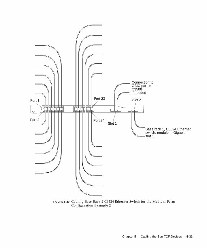
FIGURE 5-20 Cabling Base Rack 2 C3524 Ethernet Switch for the Medium FarmConfiguration Example 2
Base rack 1, C3524 Ethernetswitch, module in Gigabitslot 1
Port 1
Port 2
Port 23
Port 24Slot 1
Slot 2
Connection toGBIC port inC3508if needed
Chapter 5 Cabling the Sun TCF Devices 5-33
5.3.5 Cabling the Access Server for the Medium Farm
Configuration Example 2
With the medium farm configuration example 2, the cabling scheme for the access
server 1 is identical to the access server 1 cabling scheme for the Sun TCF small farm
configuration. Refer to Section 5.1.5 “Cabling the Access Server for Small Farm
Configuration” on page 5-14.
5.4 Large Farm Configuration ExampleThe Sun TCF large farm configuration connects either the small farm configuration
or the medium farm configuration example 1 to a star rack. Up to three small farm
configurations or medium farm configuration example 1 (or a combination thereof)
may be connected to the star rack to form a large farm configuration.
Note – When configured in the large farm configuration, each small farm base rack
or each medium farm base rack is designated as base rack 1, 2, or 3.
FIGURE 5-22 is a schematic showing the cabling requirements for the large farm
configuration. With the exception of the point-to-point cabling differences with the
star rack C3508 Ethernet switch and the two disk arrays, all other point-to-point
cabling for the large farm configuration is identical to the small farm point-to-point
cabling scheme (refer to TABLE 5-2 on page 5-4). TABLE 5-5 lists the point-to-point
cabling scheme within the star rack. TABLE 5-6 lists the point-to-point cabling scheme
between the star rack and three small farm base racks.
The following sections describe cabling configurations for the individually
rackmounted equipment for the large farm configuration.
■ Section 5.4.6 “Cabling the C3508 Ethernet Switch” on page 5-45
■ Section 5.4.1 “Cabling the Disk Array for the Large Farm Configuration” on
page 5-39
5-34 Sun Technical Compute Farm Installation and Service Manual • June 2000
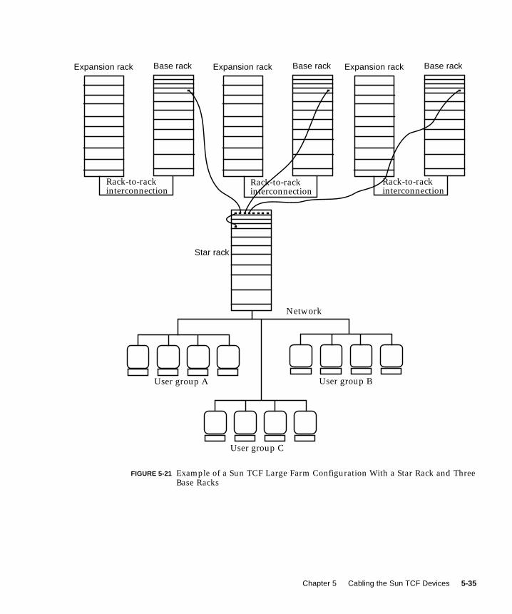
FIGURE 5-21 Example of a Sun TCF Large Farm Configuration With a Star Rack and ThreeBase Racks
Star rack
Base rackExpansion rack Base rackExpansion rack Base rackExpansion rack
Rack-to-rackinterconnection
Rack-to-rackinterconnection
Rack-to-rackinterconnection
Network
User group A User group B
User group C
Chapter 5 Cabling the Sun TCF Devices 5-35
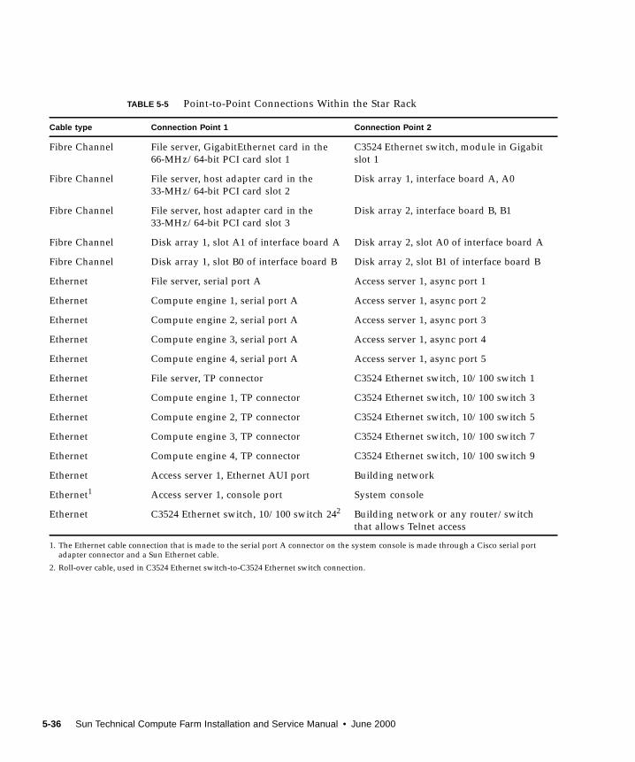
TABLE 5-5 Point-to-Point Connections Within the Star Rack
Cable type Connection Point 1 Connection Point 2
Fibre Channel File server, GigabitEthernet card in the
66-MHz/64-bit PCI card slot 1
C3524 Ethernet switch, module in Gigabit
slot 1
Fibre Channel File server, host adapter card in the
33-MHz/64-bit PCI card slot 2
Disk array 1, interface board A, A0
Fibre Channel File server, host adapter card in the
33-MHz/64-bit PCI card slot 3
Disk array 2, interface board B, B1
Fibre Channel Disk array 1, slot A1 of interface board A Disk array 2, slot A0 of interface board A
Fibre Channel Disk array 1, slot B0 of interface board B Disk array 2, slot B1 of interface board B
Ethernet File server, serial port A Access server 1, async port 1
Ethernet Compute engine 1, serial port A Access server 1, async port 2
Ethernet Compute engine 2, serial port A Access server 1, async port 3
Ethernet Compute engine 3, serial port A Access server 1, async port 4
Ethernet Compute engine 4, serial port A Access server 1, async port 5
Ethernet File server, TP connector C3524 Ethernet switch, 10/100 switch 1
Ethernet Compute engine 1, TP connector C3524 Ethernet switch, 10/100 switch 3
Ethernet Compute engine 2, TP connector C3524 Ethernet switch, 10/100 switch 5
Ethernet Compute engine 3, TP connector C3524 Ethernet switch, 10/100 switch 7
Ethernet Compute engine 4, TP connector C3524 Ethernet switch, 10/100 switch 9
Ethernet Access server 1, Ethernet AUI port Building network
Ethernet1
1. The Ethernet cable connection that is made to the serial port A connector on the system console is made through a Cisco serial portadapter connector and a Sun Ethernet cable.
Access server 1, console port System console
Ethernet C3524 Ethernet switch, 10/100 switch 242
2. Roll-over cable, used in C3524 Ethernet switch-to-C3524 Ethernet switch connection.
Building network or any router/switch
that allows Telnet access
5-36 Sun Technical Compute Farm Installation and Service Manual • June 2000
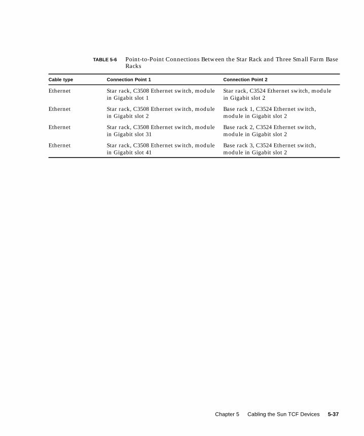
TABLE 5-6 Point-to-Point Connections Between the Star Rack and Three Small Farm BaseRacks
Cable type Connection Point 1 Connection Point 2
Ethernet Star rack, C3508 Ethernet switch, module
in Gigabit slot 1
Star rack, C3524 Ethernet switch, module
in Gigabit slot 2
Ethernet Star rack, C3508 Ethernet switch, module
in Gigabit slot 2
Base rack 1, C3524 Ethernet switch,
module in Gigabit slot 2
Ethernet Star rack, C3508 Ethernet switch, module
in Gigabit slot 31
Base rack 2, C3524 Ethernet switch,
module in Gigabit slot 2
Ethernet Star rack, C3508 Ethernet switch, module
in Gigabit slot 41
Base rack 3, C3524 Ethernet switch,
module in Gigabit slot 2
Chapter 5 Cabling the Sun TCF Devices 5-37
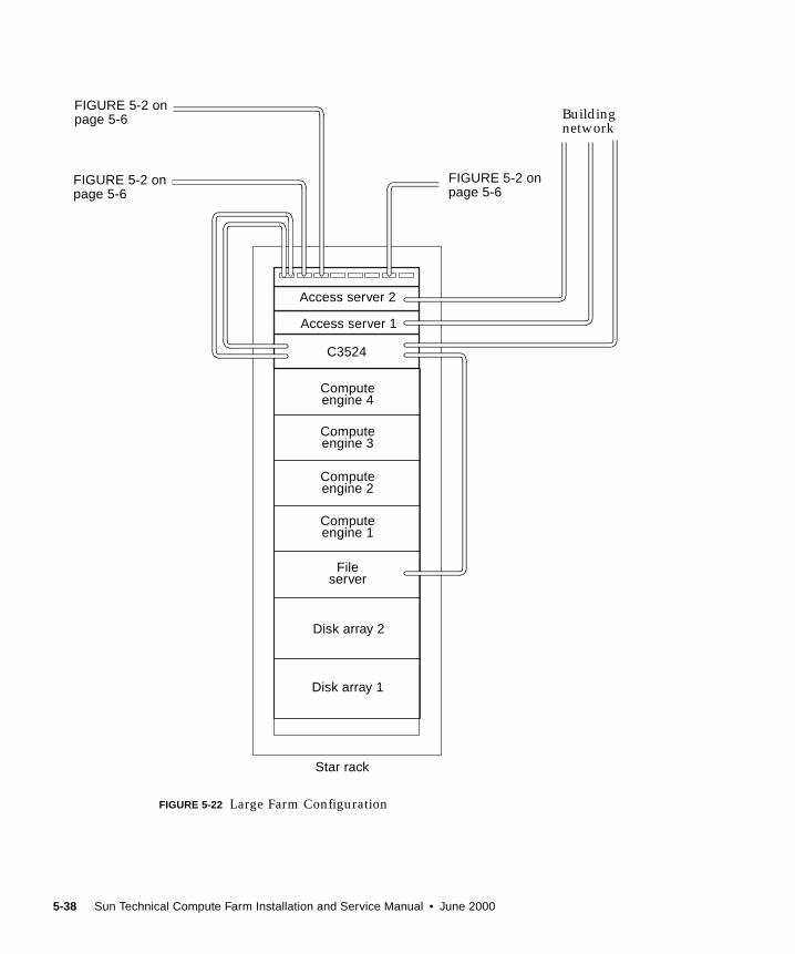
FIGURE 5-22 Large Farm Configuration
Star rack
Buildingnetwork
Access server 2
Disk array 1
Fileserver
Computeengine 1
Computeengine 4
Computeengine 3
Computeengine 2
Access server 1
C3524
Disk array 2
FIGURE 5-2 onpage 5-6
FIGURE 5-2 onpage 5-6
FIGURE 5-2 onpage 5-6
5-38 Sun Technical Compute Farm Installation and Service Manual • June 2000
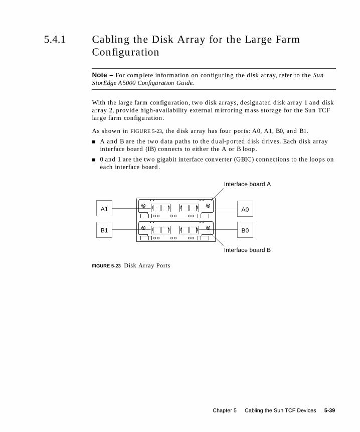
5.4.1 Cabling the Disk Array for the Large Farm
Configuration
Note – For complete information on configuring the disk array, refer to the SunStorEdge A5000 Configuration Guide.
With the large farm configuration, two disk arrays, designated disk array 1 and disk
array 2, provide high-availability external mirroring mass storage for the Sun TCF
large farm configuration.
As shown in FIGURE 5-23, the disk array has four ports: A0, A1, B0, and B1.
■ A and B are the two data paths to the dual-ported disk drives. Each disk array
interface board (IB) connects to either the A or B loop.
■ 0 and 1 are the two gigabit interface converter (GBIC) connections to the loops on
each interface board.
FIGURE 5-23 Disk Array Ports
B0
A0
Interface board A
B1
A1
Interface board B
Chapter 5 Cabling the Sun TCF Devices 5-39
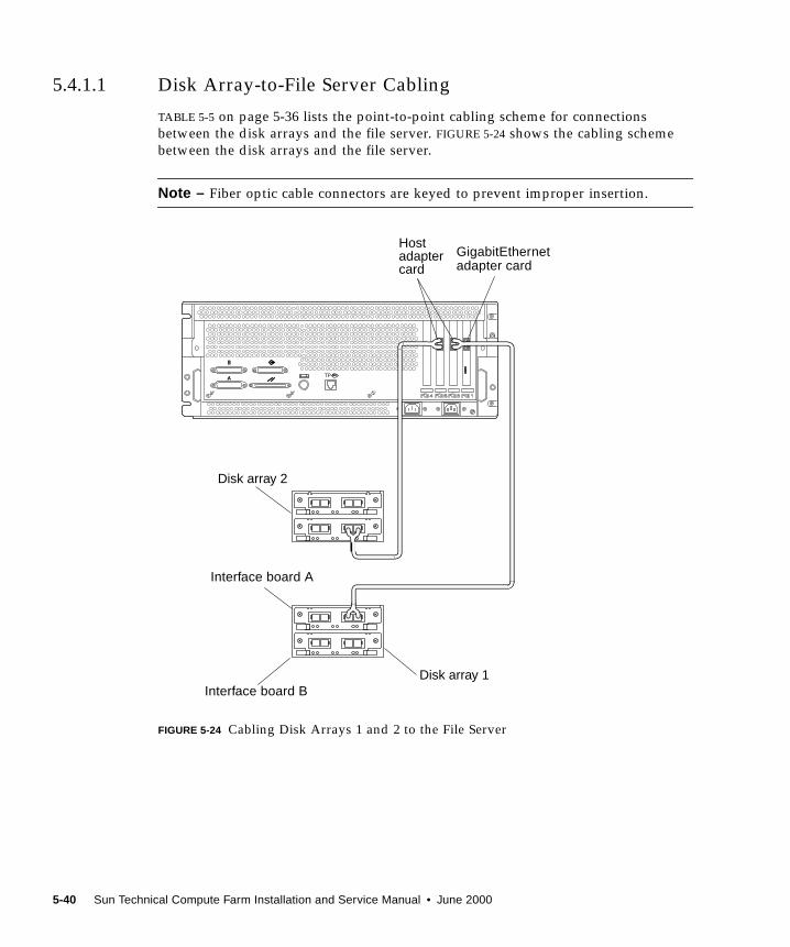
5.4.1.1 Disk Array-to-File Server Cabling
TABLE 5-5 on page 5-36 lists the point-to-point cabling scheme for connections
between the disk arrays and the file server. FIGURE 5-24 shows the cabling scheme
between the disk arrays and the file server.
Note – Fiber optic cable connectors are keyed to prevent improper insertion.
FIGURE 5-24 Cabling Disk Arrays 1 and 2 to the File Server
GigabitEthernetadapter card
Hostadaptercard
Interface board A
Interface board BDisk array 1
Disk array 2
5-40 Sun Technical Compute Farm Installation and Service Manual • June 2000
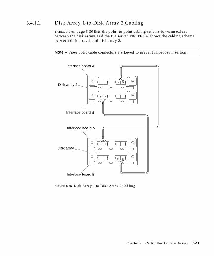
5.4.1.2 Disk Array 1-to-Disk Array 2 Cabling
TABLE 5-5 on page 5-36 lists the point-to-point cabling scheme for connections
between the disk arrays and the file server. FIGURE 5-24 shows the cabling scheme
between disk array 1 and disk array 2.
Note – Fiber optic cable connectors are keyed to prevent improper insertion.
FIGURE 5-25 Disk Array 1-to-Disk Array 2 Cabling
Disk array 1
Disk array 2
Interface board A
Interface board B
Interface board A
Interface board B
Chapter 5 Cabling the Sun TCF Devices 5-41
5.4.2 Cabling the File Server for the Large Farm
Configuration
With the large farm configuration, the cabling scheme for the file server is identical
to the file server cabling scheme for the Sun TCF small farm configuration. Refer to
Section 5.1.2 “Cabling the File Server for the Small Farm Configuration” on page 5-9.
Cabling the Compute Engine for the Large Farm Configuration
5.4.3 Cabling the Compute Engine for the Large Farm
Configuration
With the large farm configuration, the cabling scheme for the compute engine is
identical to the compute engine cabling scheme for the Sun TCF small farm
configuration. Refer to Section 5.1.3 “Cabling the Compute Engine for the Small
Farm Configuration” on page 5-11.
5.4.4 Cabling the C3524 Ethernet Switches for the
Large Farm Configuration
With the large farm configuration, the cabling scheme for the C3524 is identical to
the C3524 cabling scheme for the Sun TCF small farm configuration (refer to
Section 5.1.4 “Cabling the C3524 Ethernet Switch for the Small Farm Configuration”
on page 5-12) with one exception. With the large farm configuration, Gigabit slot 2 of
the C3524 Ethernet switch is electrically connected to Gigabit slot 1 of the C3508
Ethernet switch.
TABLE 5-5 lists the point-to-point cabling scheme for the star rack C3524 Ethernet
switch. FIGURE 5-26 shows the cabling scheme for the star rack C3524 Ethernet
switch.
Note – Refer to FIGURE 1-13 on page 1-17 for the C3524 Ethernet switch port
assignments.
5-42 Sun Technical Compute Farm Installation and Service Manual • June 2000
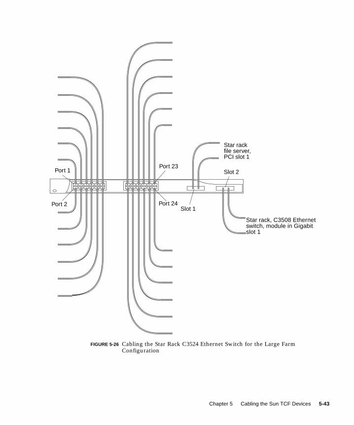
FIGURE 5-26 Cabling the Star Rack C3524 Ethernet Switch for the Large FarmConfiguration
Star rack, C3508 Ethernetswitch, module in Gigabitslot 1
Port 1
Port 2
Port 23
Port 24Slot 1
Slot 2
Star rackfile server,PCI slot 1
Chapter 5 Cabling the Sun TCF Devices 5-43
5.4.5 Cabling the Access Server for the Large Farm
Configuration
With the large farm configuration, the cabling scheme for the access server 1 is
identical to the access server 1 cabling scheme for the Sun TCF small farm
configuration. Refer to Section 5.1.5 “Cabling the Access Server for Small Farm
Configuration” on page 5-14.
Note – Refer to FIGURE 1-18 on page 1-20 for the access server port assignments.
5-44 Sun Technical Compute Farm Installation and Service Manual • June 2000

5.4.6 Cabling the C3508 Ethernet Switch
With the large farm configuration, the C3508 Ethernet switch interconnects other
base racks’ C3524 Ethernet switches to form a star network.
TABLE 5-6 on page 5-37 lists the point-to-point connection between the C3508
Ethernet switch and other base racks’ C3524 Ethernet switches. FIGURE 5-27 shows
the C3508 Ethernet switch port assignments.
Note – Refer to FIGURE 1-15 on page 1-19 for the C3508 Ethernet switch port
assignments.
Chapter 5 Cabling the Sun TCF Devices 5-45

FIGURE 5-27 Cabling the C3508 Ethernet Switch
1000BASE-XGBIC moduleconnector
Star rack, C3524Ethernet switch
Base rack 1, C3524Ethernet switch
Base rack 2, C3524Ethernet switch
Base rack 3, C3524Ethernet switch
Slot 1 Slot 8
5-46 Sun Technical Compute Farm Installation and Service Manual • June 2000

CHAPTER 6
Powering On and Off
This chapter provides procedures for powering on and powering off the rack and
rackmounted devices.
■ Section 6.1 “Preparing to Power On” on page 6-1
■ Section 6.2 “Power On and Off Sequence” on page 6-2
Note – The keys for the Sun TCF system are found in the rack and in the Sun TCF
Accessory Kit, 565-1656.
Caution – To avoid damage to internal circuits, do not connect or disconnect any
cables while the system is powered on.
6.1 Preparing to Power OnPrior to powering on the Sun TCF, verify the following:
■ All Ethernet transceivers and serial port adapters are properly installed.
■ All power, data, and fiber optic cables are properly installed.
See the appropriate service manual (refer to “Related Documentation” on
page xxxvi) for a particular device if specific troubleshooting is required.
6-1
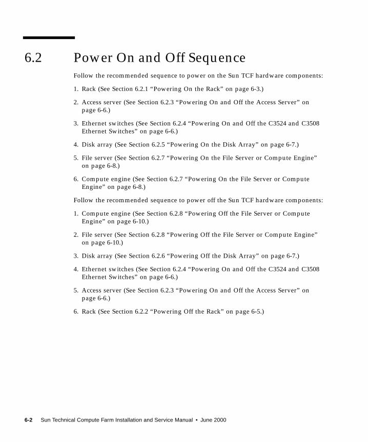
6.2 Power On and Off SequenceFollow the recommended sequence to power on the Sun TCF hardware components:
1. Rack (See Section 6.2.1 “Powering On the Rack” on page 6-3.)
2. Access server (See Section 6.2.3 “Powering On and Off the Access Server” on
page 6-6.)
3. Ethernet switches (See Section 6.2.4 “Powering On and Off the C3524 and C3508
Ethernet Switches” on page 6-6.)
4. Disk array (See Section 6.2.5 “Powering On the Disk Array” on page 6-7.)
5. File server (See Section 6.2.7 “Powering On the File Server or Compute Engine”
on page 6-8.)
6. Compute engine (See Section 6.2.7 “Powering On the File Server or Compute
Engine” on page 6-8.)
Follow the recommended sequence to power off the Sun TCF hardware components:
1. Compute engine (See Section 6.2.8 “Powering Off the File Server or Compute
Engine” on page 6-10.)
2. File server (See Section 6.2.8 “Powering Off the File Server or Compute Engine”
on page 6-10.)
3. Disk array (See Section 6.2.6 “Powering Off the Disk Array” on page 6-7.)
4. Ethernet switches (See Section 6.2.4 “Powering On and Off the C3524 and C3508
Ethernet Switches” on page 6-6.)
5. Access server (See Section 6.2.3 “Powering On and Off the Access Server” on
page 6-6.)
6. Rack (See Section 6.2.2 “Powering Off the Rack” on page 6-5.)
6-2 Sun Technical Compute Farm Installation and Service Manual • June 2000
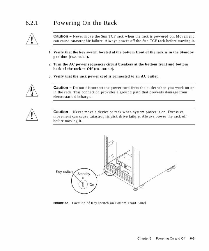
6.2.1 Powering On the Rack
Caution – Never move the Sun TCF rack when the rack is powered on. Movement
can cause catastrophic failure. Always power off the Sun TCF rack before moving it.
1. Verify that the key switch located at the bottom front of the rack is in the Standbyposition (FIGURE 6-1).
2. Turn the AC power sequencer circuit breakers at the bottom front and bottomback of the rack to Off (FIGURE 6-2).
3. Verify that the rack power cord is connected to an AC outlet.
Caution – Do not disconnect the power cord from the outlet when you work on or
in the rack. This connection provides a ground path that prevents damage from
electrostatic discharge.
Caution – Never move a device or rack when system power is on. Excessive
movement can cause catastrophic disk drive failure. Always power the rack off
before moving it.
FIGURE 6-1 Location of Key Switch on Bottom Front Panel
Key switch
On
Standby
Chapter 6 Powering On and Off 6-3
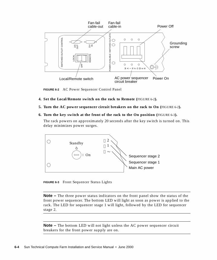
FIGURE 6-2 AC Power Sequencer Control Panel
4. Set the Local/Remote switch on the rack to Remote (FIGURE 6-2).
5. Turn the AC power sequencer circuit breakers on the rack to On (FIGURE 6-2).
6. Turn the key switch at the front of the rack to the On position (FIGURE 6-3).
The rack powers on approximately 20 seconds after the key switch is turned on. This
delay minimizes power surges.
FIGURE 6-3 Front Sequencer Status Lights
Note – The three power status indicators on the front panel show the status of the
front power sequencer. The bottom LED will light as soon as power is applied to the
rack. The LED for sequencer stage 1 will light, followed by the LED for sequencer
stage 2.
Note – The bottom LED will not light unless the AC power sequencer circuit
breakers for the front power supply are on.
SW
ITC
HE
D O
UT
LET
CO
NT
RO
L
M A I N P O W E R
PO
WE
R A
VA
ILA
BLE
SW
ITC
HE
D O
UT
LET
S
LOC
AL
RE
MO
TE
J15
OU
T
OF
F
J14 IN
AC power sequencercircuit breaker
Power Off
Power On
Fan-failcable-out
Fan-failcable-in
Local/Remote switch
Groundingscrew
Standby
On
1
2
Main AC power
Sequencer stage 1
Sequencer stage 2
6-4 Sun Technical Compute Farm Installation and Service Manual • June 2000
7. To check the status of the back power sequencer, open the back door of the rackand look at the three green LEDs on the back power sequencer.
8. Turn the power on to the rack.
After power is turned on, several events occur.
See the Sun StorEdge Expansion Cabinet Installation and Service Manual for instructions.
You might have to enter a specific software command when booting the system so
that the system will recognize the rack. See the Sun Technical Compute Farm ProductOverview and Software Guide for more information.
6.2.2 Powering Off the Rack
Caution – Never move a Sun TCF rack when the rack is powered on. Movement
can cause catastrophic failure. Always power off the rack before moving it.
Before turning off the power to the rack, halt any I/O between host system(s) and
devices in the rack.
Depending upon the type of devices in the rack, the type of host system(s), and the
software running on the host system(s), you might need to:
1. Stop software from accessing devices in the enclosure
2. Exit the Solaris operating environment
3. Turn off power to your host system(s)
Refer to the following for specific instructions:
■ Solaris Handbook for Sun Peripherals■ System administration guides that correspond to your operating system
■ Documentation that came with the devices
■ Documentation that came with your host system(s)
Caution – Failure to properly shut down the file server or compute engine may
result in the loss of data.
Caution – Failure to stop I/O between host system(s) and devices in the rack can
result in the loss of data.
1. Stop I/O to devices in the rack.
Chapter 6 Powering On and Off 6-5
2. Turn the key switch located at the front of the rack to the Standby position(FIGURE 6-1 on page 6-3).
3. At the bottom of the rack, remove the trim panels and turn the AC powersequencer circuit breakers to Off (FIGURE 6-2 on page 6-4).
4. If components other than disk or tape drives (such as the power sequencer) arebeing serviced, disconnect the rack power cords from the grounded outlets.
Caution – When disk drives are to be serviced, do not disconnect the power cords
from the rack power sequencer or the rack power cord from the outlet. These
connections provide the ground paths necessary to prevent any damage caused by
electrostatic discharge to the drives installed in the rack.
Caution – The power cables to each power sequencer must be disconnected from
the power source if you want to stop all AC power input to the rack.
6.2.3 Powering On and Off the Access Server
To power on and off the access server, press the on/off switch. Refer to the CiscoAS2509-RJ and AS2511-RJ Access Server Hardware Installation Guide.
6.2.4 Powering On and Off the C3524 and C3508
Ethernet Switches
To power on and off the C3524 and C3508 Ethernet switches, connect their power
cord to the power sequencer outlet. Refer to the Catalyst 3500 Series XL InstallationGuide.
6-6 Sun Technical Compute Farm Installation and Service Manual • June 2000
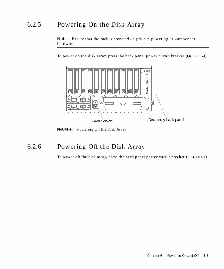
6.2.5 Powering On the Disk Array
Note – Ensure that the rack is powered on prior to powering on component
hardware.
To power on the disk array, press the back panel power circuit breaker (FIGURE 6-4).
FIGURE 6-4 Powering On the Disk Array
6.2.6 Powering Off the Disk Array
To power off the disk array, press the back panel power circuit breaker (FIGURE 6-4).
Power on/off Disk array back panel
Chapter 6 Powering On and Off 6-7
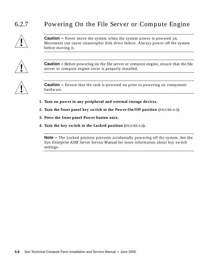
6.2.7 Powering On the File Server or Compute Engine
Caution – Never move the system when the system power is powered on.
Movement can cause catastrophic disk drive failure. Always power off the system
before moving it.
Caution – Before powering on the file server or compute engine, ensure that the file
server or compute engine cover is properly installed.
Caution – Ensure that the rack is powered on prior to powering on component
hardware.
1. Turn on power to any peripheral and external storage devices.
2. Turn the front panel key switch to the Power-On/Off position (FIGURE 6-5).
3. Press the front panel Power button once.
4. Turn the key switch to the Locked position (FIGURE 6-6).
Note – The Locked position prevents accidentally powering off the system. See the
Sun Enterprise 420R Server Service Manual for more information about key switch
settings.
6-8 Sun Technical Compute Farm Installation and Service Manual • June 2000
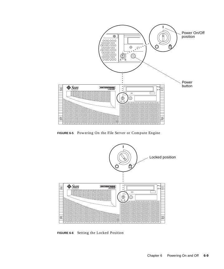
FIGURE 6-5 Powering On the File Server or Compute Engine
FIGURE 6-6 Setting the Locked Position
Power On/Off
Power
position
button
Locked position
Chapter 6 Powering On and Off 6-9

6.2.8 Powering Off the File Server or Compute Engine
Caution – Before turning off power to the file server or compute engine, halt the
operating system. Failure to halt the operating system properly can result in loss of
disk drive data.
1. Notify users that the Sun TCF will be powered down.
2. Back up the system files and data, if necessary.
3. Halt the operating system using the appropriate commands.
Refer to the Solaris Handbook for Sun Peripherals that corresponds to your operating
system.
4. Wait for the system halt messages and the ok prompt.
5. Turn the key switch on the front panel of the file server or the compute engine tothe Standby position (FIGURE 6-7).
FIGURE 6-7 Setting the Standby Position
Standby position
6-10 Sun Technical Compute Farm Installation and Service Manual • June 2000
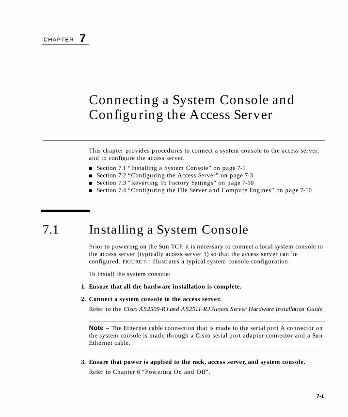
CHAPTER 7
Connecting a System Console andConfiguring the Access Server
This chapter provides procedures to connect a system console to the access server,
and to configure the access server.
■ Section 7.1 “Installing a System Console” on page 7-1
■ Section 7.2 “Configuring the Access Server” on page 7-3
■ Section 7.3 “Reverting To Factory Settings” on page 7-10
■ Section 7.4 “Configuring the File Server and Compute Engines” on page 7-10
7.1 Installing a System ConsolePrior to powering on the Sun TCF, it is necessary to connect a local system console to
the access server (typically access server 1) so that the access server can be
configured. FIGURE 7-1 illustrates a typical system console configuration.
To install the system console:
1. Ensure that all the hardware installation is complete.
2. Connect a system console to the access server.
Refer to the Cisco AS2509-RJ and AS2511-RJ Access Server Hardware Installation Guide.
Note – The Ethernet cable connection that is made to the serial port A connector on
the system console is made through a Cisco serial port adapter connector and a Sun
Ethernet cable.
3. Ensure that power is applied to the rack, access server, and system console.
Refer to Chapter 6 “Powering On and Off”.
7-1
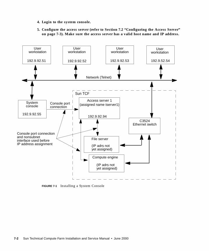
4. Login to the system console.
5. Configure the access server (refer to Section 7.2 “Configuring the Access Server”on page 7-3). Make sure the access server has a valid host name and IP address.
FIGURE 7-1 Installing a System Console
System
192.9.92.55
Sun TCF
File server
Compute engine
Network (Telnet)
C3524Ethernet switch
Console portconnection
Console port connectionand nonsubnetinterface used beforeIP address assignment
192.9.52.54
192.9.92.94
192.9.92.53192.9.92.52192.9.92.51
Userworkstation
Userworkstation
Userworkstation
console
Userworkstation
Access server 1(assigned name tserver1)
(IP adrs notyet assigned)
(IP adrs notyet assigned)
7-2 Sun Technical Compute Farm Installation and Service Manual • June 2000

7.2 Configuring the Access ServerYou must configure the access server prior to initial full power-on of the Sun TCF.
Typically, only one access server is required in the the Sun TCF and the
configuration process occurs only once.
If your Sun TCF configuration uses both access servers, such as in medium farm
configuration example 1, then you must configure each access server in turn through
a tip connection to the system console.
The following three code examples illustrate what is viewed at the system console
while configuring the access server. The three steps perform the following:
1. During the first step (CODE EXAMPLE 7-1), passwords are set and the access server
is named
2. During the second step (CODE EXAMPLE 7-2), the access server is configured.
3. The third step (refer to CODE EXAMPLE 7-3) is an optional step that shows a typical
display after the show run and show line commands are entered from the
system monitor (or user workstation through Telnet).
Note – The following examples provide the basic steps that are required to
configure the access server. For more detailed instructions and options about
configuring the access server, refer to the Cisco AS2509-RJ and AS2511-RJ AccessServer Hardware Installation Guide
Note – After the access server is configured, the system administrator can log in to
the access server through a remote system console on the same network as the NIS
server and use Telnet.
Prior to configuring the access server(s), you will need the following:
■ Host name for each access server to be actively configured
■ IP address for each access server to be actively configured
■ Password for enable secret
■ Password for Enable
Chapter 7 Connecting a System Console and Configuring the Access Server 7-3
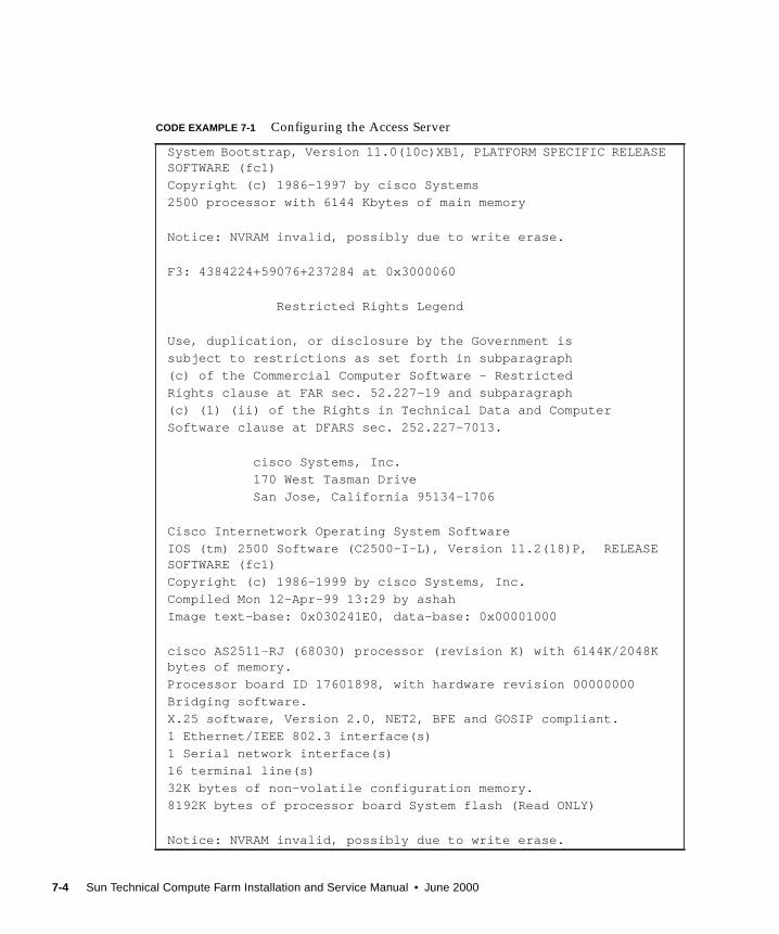
CODE EXAMPLE 7-1 Configuring the Access Server
System Bootstrap, Version 11.0(10c)XB1, PLATFORM SPECIFIC RELEASESOFTWARE (fc1)
Copyright (c) 1986-1997 by cisco Systems
2500 processor with 6144 Kbytes of main memory
Notice: NVRAM invalid, possibly due to write erase.
F3: 4384224+59076+237284 at 0x3000060
Restricted Rights Legend
Use, duplication, or disclosure by the Government is
subject to restrictions as set forth in subparagraph
(c) of the Commercial Computer Software - Restricted
Rights clause at FAR sec. 52.227-19 and subparagraph
(c) (1) (ii) of the Rights in Technical Data and Computer
Software clause at DFARS sec. 252.227-7013.
cisco Systems, Inc.
170 West Tasman Drive
San Jose, California 95134-1706
Cisco Internetwork Operating System Software
IOS (tm) 2500 Software (C2500-I-L), Version 11.2(18)P, RELEASESOFTWARE (fc1)
Copyright (c) 1986-1999 by cisco Systems, Inc.
Compiled Mon 12-Apr-99 13:29 by ashah
Image text-base: 0x030241E0, data-base: 0x00001000
cisco AS2511-RJ (68030) processor (revision K) with 6144K/2048Kbytes of memory.
Processor board ID 17601898, with hardware revision 00000000
Bridging software.
X.25 software, Version 2.0, NET2, BFE and GOSIP compliant.
1 Ethernet/IEEE 802.3 interface(s)
1 Serial network interface(s)
16 terminal line(s)
32K bytes of non-volatile configuration memory.
8192K bytes of processor board System flash (Read ONLY)
Notice: NVRAM invalid, possibly due to write erase.
7-4 Sun Technical Compute Farm Installation and Service Manual • June 2000
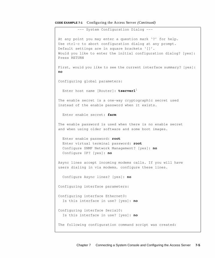
--- System Configuration Dialog ---
At any point you may enter a question mark ‘?’ for help.
Use ctrl-c to abort configuration dialog at any prompt.
Default settings are in square brackets ‘[]’.
Would you like to enter the initial configuration dialog? [yes]:Press RETURN
First, would you like to see the current interface summary? [yes]:no
Configuring global parameters:
Enter host name [Router]: tserver1 1
The enable secret is a one-way cryptographic secret used
instead of the enable password when it exists.
Enter enable secret: farm
The enable password is used when there is no enable secret
and when using older software and some boot images.
Enter enable password: root
Enter virtual terminal password: root
Configure SNMP Network Management? [yes]: no
Configure IP? [yes]: no
Async lines accept incoming modems calls. If you will have
users dialing in via modems, configure these lines.
Configure Async lines? [yes]: no
Configuring interface parameters:
Configuring interface Ethernet0:
Is this interface in use? [yes]: no
Configuring interface Serial0:
Is this interface in use? [yes]: no
The following configuration command script was created:
CODE EXAMPLE 7-1 Configuring the Access Server (Continued)
Chapter 7 Connecting a System Console and Configuring the Access Server 7-5
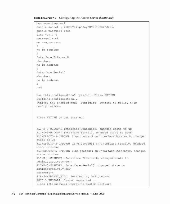
hostname tserver1
enable secret 5 $1$aMTe$5pEDayfUYX613YxzPJz/6/
enable password root
line vty 0 4
password root
no snmp-server
!
no ip routing
!
interface Ethernet0
shutdown
no ip address
!
interface Serial0
shutdown
no ip address
!
end
Use this configuration? [yes/no]: Press RETURN
Building configuration...
[OK]Use the enabled mode ‘configure’ command to modify thisconfiguration.
Press RETURN to get started!
%LINK-3-UPDOWN: Interface Ethernet0, changed state to up
%LINK-3-UPDOWN: Interface Serial0, changed state to down
%LINEPROTO-5-UPDOWN: Line protocol on Interface Ethernet0, changedstate to up
%LINEPROTO-5-UPDOWN: Line protocol on Interface Serial0, changedstate to down
%LINEPROTO-5-UPDOWN: Line protocol on Interface Ethernet0, changedstate to down
%LINK-5-CHANGED: Interface Ethernet0, changed state toadministratively down
%LINK-5-CHANGED: Interface Serial0, changed state toadministratively dow
tserver1>n
%IP-5-WEBINST_KILL: Terminating DNS process
%SYS-5-RESTART: System restarted --
Cisco Internetwork Operating System Software
CODE EXAMPLE 7-1 Configuring the Access Server (Continued)
7-6 Sun Technical Compute Farm Installation and Service Manual • June 2000

IOS (tm) 2500 Software (C2500-I-L), Version 11.2(18)P, RELEASESOFTWARE (fc1)
Copyright (c) 1986-1999 by cisco Systems, Inc.
Compiled Mon 12-Apr-99 13:29 by ashah
tserver1>
tserver1>
1. “tserver1” is an example. It is advisable that the NIS server name that corresponds to the IP address be used.
CODE EXAMPLE 7-2 Typical System Console Display After the Access Server isConfigured
tserver1>
tserver1> enable
Password: root
tserver2# configure
Configuring from terminal, memory, or network [terminal]? PressRETURN
Enter configuration commands, one per line. End with CNTL/Z.
tserver1(config)# interface Ethernet0
tserver1(config-if)# ip address 192.9.92.94 255.255.255.0
tserver1(config-if)# no shutdown
tserver1(config-if)# ip classless
tserver1(config)# ip routing 1
tserver1(config)# ip name-server 192.9.92.4
tserver1(config)# ip route 0.0.0.0 0.0.0.0 192.9.92.2
tserver1(config)# line 1 16
tserver1(config-line)# no exec
tserver1(config-line)# exec-timeout 0 0
tserver1(config-line)# no activation-character
tserver1(config-line)# transport input all
tserver1(config-line)# Escape None
tserver1(config-line)# flowcontrol hardware
tserver1(config-line)# no autobaud
tserver1(config-line)# speed 9600
tserver1(config-line)# exit
tserver1(config)#exit
tserver1#
CODE EXAMPLE 7-1 Configuring the Access Server (Continued)
Chapter 7 Connecting a System Console and Configuring the Access Server 7-7
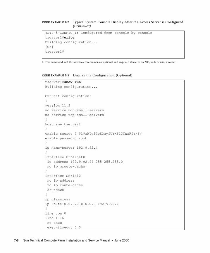
%SYS-5-CONFIG_I: Configured from console by console
tserver1# write
Building configuration...
[OK]
tserver1#
1. This command and the next two commands are optional and required if user is on NIS, and/or uses a router.
CODE EXAMPLE 7-3 Display the Configuration (Optional)
tserver1# show run
Building configuration...
Current configuration:
!
version 11.2
no service udp-small-servers
no service tcp-small-servers
!
hostname tserver1
!
enable secret 5 $1$aMTe$5pEDayfUYX613YxzPJz/6/
enable password root
!
ip name-server 192.9.92.4
!
interface Ethernet0
ip address 192.9.92.94 255.255.255.0
no ip mroute-cache
!
interface Serial0
no ip address
no ip route-cache
shutdown
!
ip classless
ip route 0.0.0.0 0.0.0.0 192.9.92.2
!
line con 0
line 1 16
no exec
exec-timeout 0 0
CODE EXAMPLE 7-2 Typical System Console Display After the Access Server is Configured(Continued)
7-8 Sun Technical Compute Farm Installation and Service Manual • June 2000
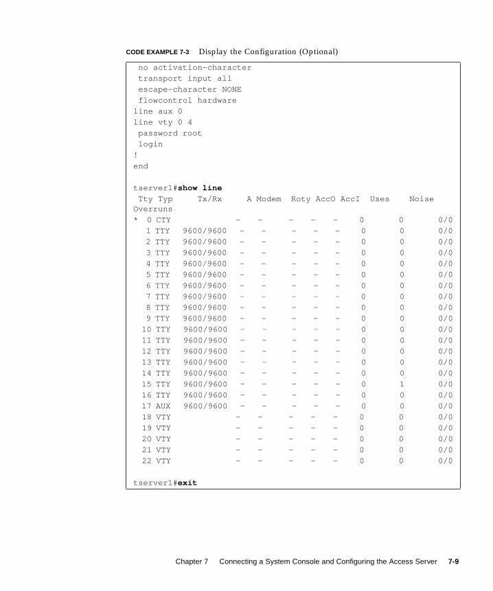
no activation-character
transport input all
escape-character NONE
flowcontrol hardware
line aux 0
line vty 0 4
password root
login
!
end
tserver1# show line
Tty Typ Tx/Rx A Modem Roty AccO AccI Uses NoiseOverruns
* 0 CTY - - - - - 0 0 0/0
1 TTY 9600/9600 - - - - - 0 0 0/0
2 TTY 9600/9600 - - - - - 0 0 0/0
3 TTY 9600/9600 - - - - - 0 0 0/0
4 TTY 9600/9600 - - - - - 0 0 0/0
5 TTY 9600/9600 - - - - - 0 0 0/0
6 TTY 9600/9600 - - - - - 0 0 0/0
7 TTY 9600/9600 - - - - - 0 0 0/0
8 TTY 9600/9600 - - - - - 0 0 0/0
9 TTY 9600/9600 - - - - - 0 0 0/0
10 TTY 9600/9600 - - - - - 0 0 0/0
11 TTY 9600/9600 - - - - - 0 0 0/0
12 TTY 9600/9600 - - - - - 0 0 0/0
13 TTY 9600/9600 - - - - - 0 0 0/0
14 TTY 9600/9600 - - - - - 0 0 0/0
15 TTY 9600/9600 - - - - - 0 1 0/0
16 TTY 9600/9600 - - - - - 0 0 0/0
17 AUX 9600/9600 - - - - - 0 0 0/0
18 VTY - - - - - 0 0 0/0
19 VTY - - - - - 0 0 0/0
20 VTY - - - - - 0 0 0/0
21 VTY - - - - - 0 0 0/0
22 VTY - - - - - 0 0 0/0
tserver1# exit
CODE EXAMPLE 7-3 Display the Configuration (Optional)
Chapter 7 Connecting a System Console and Configuring the Access Server 7-9
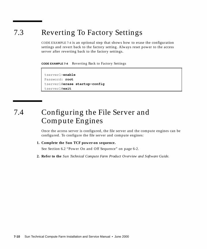
7.3 Reverting To Factory SettingsCODE EXAMPLE 7-4 is an optional step that shows how to erase the configuration
settings and revert back to the factory setting. Always reset power to the access
server after reverting back to the factory settings.
7.4 Configuring the File Server andCompute EnginesOnce the access server is configured, the file server and the compute engines can be
configured. To configure the file server and compute engines:
1. Complete the Sun TCF power-on sequence.
See Section 6.2 “Power On and Off Sequence” on page 6-2.
2. Refer to the Sun Technical Compute Farm Product Overview and Software Guide.
CODE EXAMPLE 7-4 Reverting Back to Factory Settings
tserver1> enable
Password: root
tserver1# erase startup-config
tserver1# exit
7-10 Sun Technical Compute Farm Installation and Service Manual • June 2000
CHAPTER 8
Fault Isolation and Troubleshooting
This chapter describes how to fault isolate and troubleshoot possible hardware
problems.
This chapter contains the following topics:
■ Section 8.1 “Sun Management Center 2.1 Software” on page 8-1
■ Section 8.2 “SunVTS Description” on page 8-2
■ Section 8.3 “Troubleshooting the Sun TCF System” on page 8-4
8.1 Sun Management Center 2.1 SoftwareThe Sun TCF is fault isolated through Sun Management Center 2.1 software. This
software identifies a range of hardware and system status states quickly. For
example, it can monitor a major condition such as a CPU failure or a minor
condition such as low swap space. You can also monitor hardware performance to
detect incipient hardware failures, such as soft read errors on a disk.
To give you this critical performance information, Sun Management Center 2.1
software analyzes system performance in real time; when performance problems
occur, the event system alerts you, if desired, to the status of most system
components.
To learn more about the Sun Management Center 2.1 software, refer to the SunManagement Center 2.1 Software User’s Guide and the Sun Technical Compute FarmProduct Overview and Software Guide.
8-1
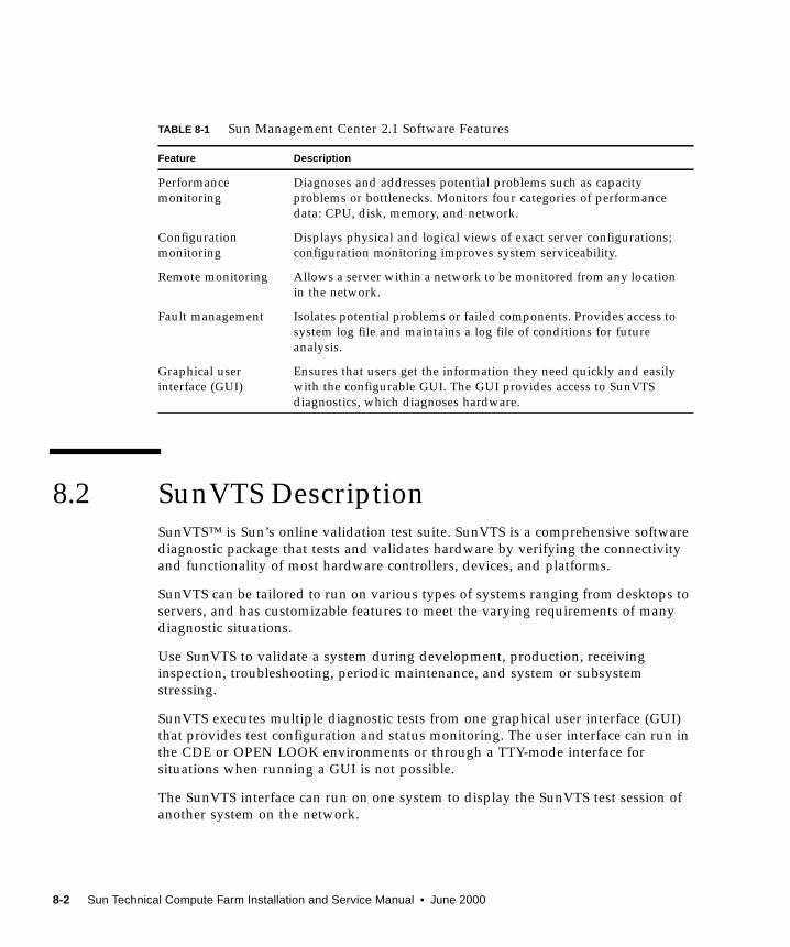
8.2 SunVTS DescriptionSunVTS™ is Sun’s online validation test suite. SunVTS is a comprehensive software
diagnostic package that tests and validates hardware by verifying the connectivity
and functionality of most hardware controllers, devices, and platforms.
SunVTS can be tailored to run on various types of systems ranging from desktops to
servers, and has customizable features to meet the varying requirements of many
diagnostic situations.
Use SunVTS to validate a system during development, production, receiving
inspection, troubleshooting, periodic maintenance, and system or subsystem
stressing.
SunVTS executes multiple diagnostic tests from one graphical user interface (GUI)
that provides test configuration and status monitoring. The user interface can run in
the CDE or OPEN LOOK environments or through a TTY-mode interface for
situations when running a GUI is not possible.
The SunVTS interface can run on one system to display the SunVTS test session of
another system on the network.
TABLE 8-1 Sun Management Center 2.1 Software Features
Feature Description
Performance
monitoring
Diagnoses and addresses potential problems such as capacity
problems or bottlenecks. Monitors four categories of performance
data: CPU, disk, memory, and network.
Configuration
monitoring
Displays physical and logical views of exact server configurations;
configuration monitoring improves system serviceability.
Remote monitoring Allows a server within a network to be monitored from any location
in the network.
Fault management Isolates potential problems or failed components. Provides access to
system log file and maintains a log file of conditions for future
analysis.
Graphical user
interface (GUI)
Ensures that users get the information they need quickly and easily
with the configurable GUI. The GUI provides access to SunVTS
diagnostics, which diagnoses hardware.
8-2 Sun Technical Compute Farm Installation and Service Manual • June 2000
SunVTS is distributed with each SPARC™ Solaris release. It is located on the Sun
Computer Systems Supplement CD.
8.2.1 SunVTS Requirements
Your system must meet the following requirements to run SunVTS:
■ The SunVTS packages must be installed. For specific details, refer to the
corresponding SunVTS documentation (described below).
■ The system must be booted to the multiuser level (level 3).
■ To run SunVTS with a GUI, that GUI must be installed. Otherwise, run SunVTS
with the TTY-mode interface.
8.2.2 SunVTS References
To find out more information about the use of SunVTS, refer to the SunVTS
documentation that corresponds to the Solaris release that you are running.
The following list describes the content of each SunVTS document:
■ SunVTS User’s Guide — describes how to install, configure, and run the SunVTS
diagnostic software.
■ SunVTS Quick Reference Card — provides an overview of how to use the SunVTS
CDE interface.
■ SunVTS Test Reference Manual — provides details about each individual SunVTS
test.
These documents are part of the Solaris on Sun Hardware Collection
AnswerBook2™ set. This collection is distributed on the Sun Computer Systems
Supplement CD with each SPARC Solaris release and also accessible at http://docs.sun.com .
Chapter 8 Fault Isolation and Troubleshooting 8-3
8.3 Troubleshooting the Sun TCF SystemUse this checklist as a guide to verify and isolate common installation problems.
■ All terminators are properly installed.
■ All power, data, and fiber optic cables are properly installed.
■ Ethernet switch ports operate properly.
■ All host names and IP addresses have been properly entered.
■ Two or more drives on the same SCSI bus do not use the same SCSI address.
■ The power is turned on to:
■ Rack(s)
■ Access server(s) and Ethernet switch(es)
■ Disk array(s)
■ File server
■ Compute engines
See the appropriate service manual (refer to Section “Related Documentation” on
page -xxxvi) for the device if specific troubleshooting is required.
8.3.1 Preparing to Service the Disk Array
Except for removing and replacing disk drives, the disk array should be serviced by
a qualified hardware service provider. To fault isolate and troubleshoot the disk
array, or the prepare the disk array for service, refer to Section 9.4 “Disk Array” on
page 9-35 and the Sun StorEdge A5000 Installation and Service Manual.
8.3.2 Preparing to Service the File Server or Compute
Engine
Except for removing and replacing disk drives, the file server and compute engine
should be serviced by a qualified hardware service provider. To fault isolate and
troubleshoot the file server and compute engine, or to prepare the file server and
compute engine for service, refer to Section 9.3 “File Server or Compute Engine” on
page 9-14 and the Sun Enterprise 420R Server Service Manual.
8-4 Sun Technical Compute Farm Installation and Service Manual • June 2000
8.3.3 Preparing to Service the C3524 or C3508 Ethernet
Switches
To fault isolate and troubleshoot the C3524 or C3508 Ethernet switches, refer to the
Cisco Catalyst 3500 Series XL Installation Guide.
8.3.4 Preparing to Service the Access Server
To fault isolate and troubleshoot the access server, refer to the Cisco AS2509-RJ andAS2511-RJ Access Server Hardware Installation Guide.
Chapter 8 Fault Isolation and Troubleshooting 8-5

8-6 Sun Technical Compute Farm Installation and Service Manual • June 2000
CHAPTER 9
Removing, Replacing, and CablingDevices
This chapter provides procedures to remove, replace, and cable specific rack devices.
This chapter contains the following topics:
■ Section 9.1 “Access Server” on page 9-2
■ Section 9.2 “C3524 and C3508 Ethernet Switches” on page 9-7
■ Section 9.3 “File Server or Compute Engine” on page 9-14
■ Section 9.4 “Disk Array” on page 9-35
Note – The keys for the Sun TCF system are found in the rack and in the Sun TCFAccessory Kit, 565-1656.
Caution – When servicing the rack, remove only one system device from the rack at
a time. If possible, remove system devices from the rack from the top to the bottom
to prevent raising the rack center of gravity. Use extra caution when moving the rack
onto ramps.
Caution – Never remove or replace a device when system power is on.
9-1
9.1 Access Server
Note – When removing and replacing the access server, a nonconducting step
ladder and a flashlight may be required.
Note – Refer to the Cisco AS2509-RJ and AS2511-RJ Access Server Hardware InstallationGuide for complete details.
Caution – Never remove or replace a device when system power is on.
Use the following procedures to remove, replace, and cable the access server.
■ Section 9.1.1 “Removing the Access Server” on page 9-2
■ Section 9.1.2 “Replacing the Access Server” on page 9-4
■ Section 9.1.3 “Connecting the Access Server to the Network” on page 9-6
■ Section 9.1.4 “Connecting the Access Server to a System Terminal” on page 9-7
9.1.1 Removing the Access Server
1. Unlock, open, and remove the rack door(s) as appropriate.
2. Power off the system.
See Section 6.2 “Power On and Off Sequence” on page 6-2.
Caution – Use proper ESD grounding techniques when handling components. Wear
an antistatic wrist strap and use an ESD-protected mat. Store ESD-sensitive
components in antistatic bags before placing them on any surface.
3. Disconnect the access server cabling.
Refer to Chapter 5 “Cabling the Sun TCF Devices”.
4. Disconnect the power cable from the back panel of the access server as describedin the Cisco AS2509-RJ and AS2511-RJ Access Server Hardware Installation Guide.
9-2 Sun Technical Compute Farm Installation and Service Manual • June 2000
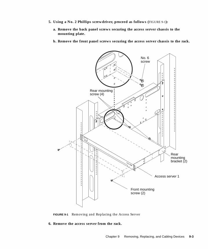
5. Using a No. 2 Phillips screwdriver, proceed as follows (FIGURE 9-1):
a. Remove the back panel screws securing the access server chassis to themounting plate.
b. Remove the front panel screws securing the access server chassis to the rack.
FIGURE 9-1 Removing and Replacing the Access Server
6. Remove the access server from the rack.
Cisco 2600
Front mountingscrew (2)
Access server 1
Rearmountingbracket (2)
Rear mountingscrew (4)
No. 6screw
Chapter 9 Removing, Replacing, and Cabling Devices 9-3
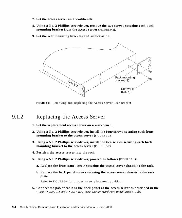
7. Set the access server on a workbench.
8. Using a No. 2 Phillips screwdriver, remove the two screws securing each backmounting bracket from the access server (FIGURE 9-2).
9. Set the rear mounting brackets and screws aside.
FIGURE 9-2 Removing and Replacing the Access Server Rear Bracket
9.1.2 Replacing the Access Server
1. Set the replacement access server on a workbench.
2. Using a No. 2 Phillips screwdriver, install the four screws securing each frontmounting bracket to the access server (FIGURE 9-3).
3. Using a No. 2 Phillips screwdriver, install the two screws securing each backmounting bracket to the access server (FIGURE 9-2).
4. Position the access server into the rack.
5. Using a No. 2 Phillips screwdriver, proceed as follows (FIGURE 9-1):
a. Replace the front panel screw securing the access server chassis to the rack.
b. Replace the back panel screws securing the access server chassis to the rackplate.
Refer to FIGURE 9-4 for proper screw placement position.
6. Connect the power cable to the back panel of the access server as described in theCisco AS2509-RJ and AS2511-RJ Access Server Hardware Installation Guide.
Cisco 2600 Screw (4)
Back mountingbracket (2)
(No. 6)
9-4 Sun Technical Compute Farm Installation and Service Manual • June 2000
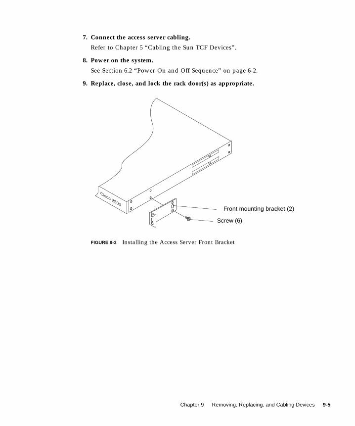
7. Connect the access server cabling.
Refer to Chapter 5 “Cabling the Sun TCF Devices”.
8. Power on the system.
See Section 6.2 “Power On and Off Sequence” on page 6-2.
9. Replace, close, and lock the rack door(s) as appropriate.
FIGURE 9-3 Installing the Access Server Front Bracket
Cisco 2500Front mounting bracket (2)
Screw (6)
Chapter 9 Removing, Replacing, and Cabling Devices 9-5
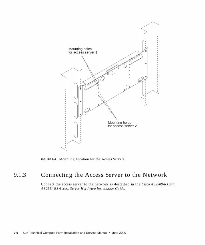
FIGURE 9-4 Mounting Location for the Access Servers
9.1.3 Connecting the Access Server to the Network
Connect the access server to the network as described in the Cisco AS2509-RJ andAS2511-RJ Access Server Hardware Installation Guide.
Mounting holesfor access server 1
Mounting holesfor access server 2
9-6 Sun Technical Compute Farm Installation and Service Manual • June 2000

9.1.4 Connecting the Access Server to a System
Terminal
The access server includes a console port. The console port provides local access to
the access server through a system terminal. Connect a system terminal to the access
server console port as described in Section 7.1 “Installing a System Console” on
page 7-1 and the Cisco AS2509-RJ and AS2511-RJ Access Server Hardware InstallationGuide.
9.2 C3524 and C3508 Ethernet Switches
Note – When removing and replacing the Ethernet switches, a nonconducting step
ladder and a flashlight may be required.
Caution – Never remove or replace a device when system power is on.
This section provides procedures to remove and replace the C3524 and C3508
Ethernet switches, and to connect the Ethernet switches to the network. This section
also includes information about installing the 1000BASE-X GBIC module into either
Ethernet switch. This chapter contains the following topics:
■ Section 9.2.1 “Removing the Ethernet Switches” on page 9-8
■ Section 9.2.2 “Replacing the Ethernet Switches” on page 9-10
■ Section 9.2.3 “Connecting the Ethernet Switches to the Network” on page 9-12
■ Section 9.2.4 “Installing the Ethernet Switch 1000BASE-X GBIC Module” on
page 9-13
Chapter 9 Removing, Replacing, and Cabling Devices 9-7
9.2.1 Removing the Ethernet Switches
Note – Refer to the Cisco Catalyst 3500 Series XL Installation Guide for complete
details.
Note – As an example, the removal and replacement procedure in this section is for
the C3524 Ethernet switch. The removal and replacement of the C3508 Ethernet
switch is identical to the removal and replacement of the C3524 Ethernet switch.
1. Unlock, open, and remove the rack door(s) as appropriate.
2. Power off the system.
See Section 6.2 “Power On and Off Sequence” on page 6-2.
Caution – Use proper ESD grounding techniques when handling components. Wear
an antistatic wrist strap and use an ESD-protected mat. Store ESD-sensitive
components in antistatic bags before placing them on any surface.
3. Disconnect the Ethernet switch cabling.
Refer to Chapter 5 “Cabling the Sun TCF Devices”.
4. Disconnect the power cable from the back panel of the Ethernet switch asdescribed in the Cisco Catalyst 3500 Series XL Installation Guide.
5. Using a No. 2 Phillips screwdriver, proceed as follows (FIGURE 9-5):
a. Remove the back panel screws securing the Ethernet switch chassis to themounting plate.
b. Remove the front panel screws securing the Ethernet switch chassis to the rack.
9-8 Sun Technical Compute Farm Installation and Service Manual • June 2000
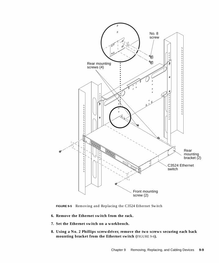
FIGURE 9-5 Removing and Replacing the C3524 Ethernet Switch
6. Remove the Ethernet switch from the rack.
7. Set the Ethernet switch on a workbench.
8. Using a No. 2 Phillips screwdriver, remove the two screws securing each backmounting bracket from the Ethernet switch (FIGURE 9-6).
Front mountingscrew (2)
Rearmountingbracket (2)
Rear mountingscrews (4)
C3524 Ethernetswitch
No. 8screw
Chapter 9 Removing, Replacing, and Cabling Devices 9-9
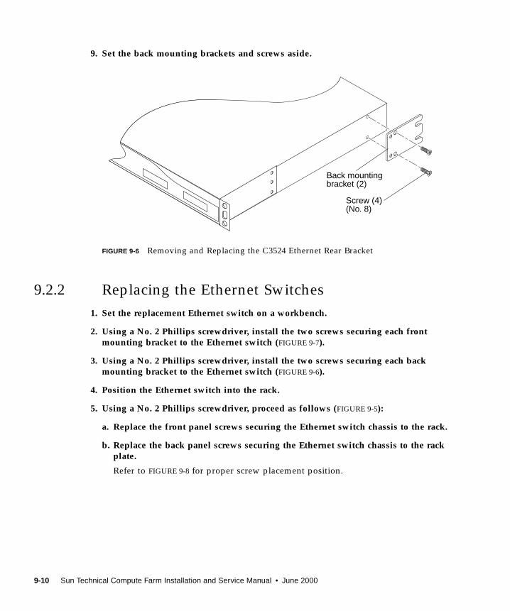
9. Set the back mounting brackets and screws aside.
FIGURE 9-6 Removing and Replacing the C3524 Ethernet Rear Bracket
9.2.2 Replacing the Ethernet Switches
1. Set the replacement Ethernet switch on a workbench.
2. Using a No. 2 Phillips screwdriver, install the two screws securing each frontmounting bracket to the Ethernet switch (FIGURE 9-7).
3. Using a No. 2 Phillips screwdriver, install the two screws securing each backmounting bracket to the Ethernet switch (FIGURE 9-6).
4. Position the Ethernet switch into the rack.
5. Using a No. 2 Phillips screwdriver, proceed as follows (FIGURE 9-5):
a. Replace the front panel screws securing the Ethernet switch chassis to the rack.
b. Replace the back panel screws securing the Ethernet switch chassis to the rackplate.
Refer to FIGURE 9-8 for proper screw placement position.
Cisco 2600 Screw (4)
Back mountingbracket (2)
(No. 8)
9-10 Sun Technical Compute Farm Installation and Service Manual • June 2000
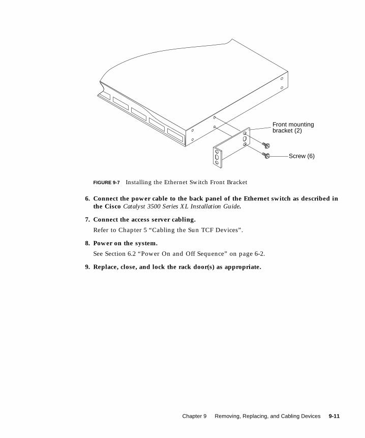
FIGURE 9-7 Installing the Ethernet Switch Front Bracket
6. Connect the power cable to the back panel of the Ethernet switch as described inthe Cisco Catalyst 3500 Series XL Installation Guide.
7. Connect the access server cabling.
Refer to Chapter 5 “Cabling the Sun TCF Devices”.
8. Power on the system.
See Section 6.2 “Power On and Off Sequence” on page 6-2.
9. Replace, close, and lock the rack door(s) as appropriate.
Front mounting
Screw (6)
bracket (2)
Chapter 9 Removing, Replacing, and Cabling Devices 9-11
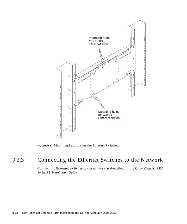
FIGURE 9-8 Mounting Location for the Ethernet Switches
9.2.3 Connecting the Ethernet Switches to the Network
Connect the Ethernet switches to the network as described in the Cisco Catalyst 3500Series XL Installation Guide.
Mounting holesfor C3508Ethernet switch
Mounting holesfor C3524Ethernet switch
9-12 Sun Technical Compute Farm Installation and Service Manual • June 2000
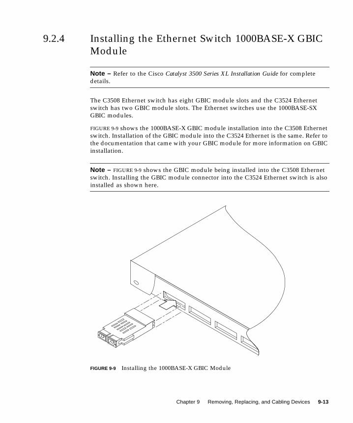
9.2.4 Installing the Ethernet Switch 1000BASE-X GBIC
Module
Note – Refer to the Cisco Catalyst 3500 Series XL Installation Guide for complete
details.
The C3508 Ethernet switch has eight GBIC module slots and the C3524 Ethernet
switch has two GBIC module slots. The Ethernet switches use the 1000BASE-SX
GBIC modules.
FIGURE 9-9 shows the 1000BASE-X GBIC module installation into the C3508 Ethernet
switch. Installation of the GBIC module into the C3524 Ethernet is the same. Refer to
the documentation that came with your GBIC module for more information on GBIC
installation.
Note – FIGURE 9-9 shows the GBIC module being installed into the C3508 Ethernet
switch. Installing the GBIC module connector into the C3524 Ethernet switch is also
installed as shown here.
FIGURE 9-9 Installing the 1000BASE-X GBIC Module
Chapter 9 Removing, Replacing, and Cabling Devices 9-13
9.3 File Server or Compute EngineThis section provides procedures to remove and replace the file server or the
compute engine. This section also includes procedures to position the file server or
the compute engine for service, and remove and replace FRU’s. This chapter
contains the following topics:
■ Section 9.3.1 “Removing the File Server or Compute Engine” on page 9-15
■ Section 9.3.2 “Removing and Replacing the File Server or Compute Engine Main
Logic Board” on page 9-18
■ Section 9.3.3 “Replacing the File Server or Compute Engine” on page 9-18
■ Section 9.3.4 “Positioning the File Server or Compute Engine for Service” on
page 9-23
■ Section 9.3.5 “Removing and Replacing File Server or Compute Engine
Components” on page 9-26
■ Section 9.3.6 “Securing the File Server or Compute Engine After Service” on
page 9-33
■ Section 9.3.7 “Cabling the File Server or Compute Engine” on page 9-35
Note – The file server or compute engine must be removed from the rack when
removing and replacing the main logic board. Perform all other file server or
compute engine procedures with the file server or compute engine in the service
position.
Note – When removing and replacing the file server or compute engine, a
nonconducting step ladder and a flashlight may be required.
Note – Refer to the Sun Enterprise 420R Server Setup and Rackmounting Guide and the
Sun Enterprise 420R Server Service Manual for complete details.
Caution – Never remove or replace a device when system power is on.
9-14 Sun Technical Compute Farm Installation and Service Manual • June 2000

9.3.1 Removing the File Server or Compute Engine
Caution – Unless the rack is bolted to the floor, the rack stabilizer legs must be
extend and the stabilizing feet must be adjusted to the floor. Level and secure the
rack to provide a safe working environment.
Caution – The file server or compute engine is heavy. Two people are required to
remove the file server or compute engine from the rack in the following procedure.
1. Unlock, open, and remove the rack door(s) as appropriate.
2. Power off the system.
See Section 6.2 “Power On and Off Sequence” on page 6-2.
3. Extend the rack stabilizer legs.
Caution – Do not disconnect the power cable(s) from the file server or compute
engine power inlet(s) unless you are removing or replacing the power distribution
board, main logic board, or a power supply. The power cord grounds the file server
or compute engine.
4. Disconnect the power cable(s) from the file server or compute engine powerinlet(s).
5. Position one person on each side of the file server or compute engine, facing thesystem glides.
When you are both in position, verify that your assistant understands what to do
with the file server or compute engine after it is removed. Also agree on a route to
follow, and visually inspect it for potential safety hazards (for example, cables on the
floor, other people working in the vicinity, and so on).
6. Using a No. 2 Phillips screwdriver, loosen the four captive screws securing the fileserver or compute engine to the left and right vertical rails at the front of the rack(FIGURE 9-10).
The captive screws are in recessed access holes in the filler panels affixed to the file
server or compute engine front panel.
Chapter 9 Removing, Replacing, and Cabling Devices 9-15
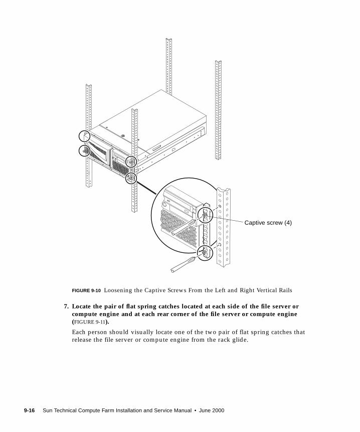
FIGURE 9-10 Loosening the Captive Screws From the Left and Right Vertical Rails
7. Locate the pair of flat spring catches located at each side of the file server orcompute engine and at each rear corner of the file server or compute engine(FIGURE 9-11).
Each person should visually locate one of the two pair of flat spring catches that
release the file server or compute engine from the rack glide.
Captive screw (4)
9-16 Sun Technical Compute Farm Installation and Service Manual • June 2000
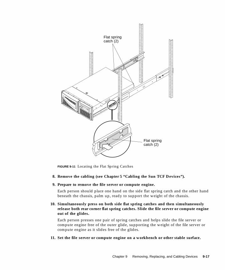
FIGURE 9-11 Locating the Flat Spring Catches
8. Remove the cabling (see Chapter 5 “Cabling the Sun TCF Devices”).
9. Prepare to remove the file server or compute engine.
Each person should place one hand on the side flat spring catch and the other hand
beneath the chassis, palm up, ready to support the weight of the chassis.
10. Simultaneously press on both side flat spring catches and then simultaneouslyrelease both rear corner flat spring catches. Slide the file server or compute engineout of the glides.
Each person presses one pair of spring catches and helps slide the file server or
compute engine free of the outer glide, supporting the weight of the file server or
compute engine as it slides free of the glides.
11. Set the file server or compute engine on a workbench or other stable surface.
Flat springcatch (2)
Flat springcatch (2)
Chapter 9 Removing, Replacing, and Cabling Devices 9-17
12. Slide the empty rack slides back into their protective outer glides.
9.3.2 Removing and Replacing the File Server or
Compute Engine Main Logic Board
To remove and replace the file server or compute engine main logic board, refer to
the Sun Enterprise 420R Server Service Manual.
9.3.3 Replacing the File Server or Compute Engine
Caution – The file server or compute engine is heavy, and two people are required
to place the file server or compute engine into the rack enclosure glides in the
following procedure.
When completing a two-person lift, always communicate your intentions clearly
before, during, and after each step to minimize confusion.
Caution – Unless the rack is bolted to the floor, you must extend the rack stabilizer
legs and adjust the stabilizing feet to the floor.
1. Push the runner on each slide assembly as far back as possible into the slideassembly (FIGURE 9-12).
a. Push in the inner rail on each slide assembly until it reaches the stops that arelocated farthest away from the front of the rack.
b. Push in the runner until it stops in the slide assembly.
2. Position one person on each side of the file server or compute engine, facing theinner glides on the file server or compute engine chassis.
When you are both in position, verify that your assistant understands what to do
with the file server or compute engine after it is lifted. Also agree on a route to
follow, and visually inspect it for potential safety hazards (for example, cables on the
floor, other people working in the vicinity, and so on).
9-18 Sun Technical Compute Farm Installation and Service Manual • June 2000

FIGURE 9-12 Pushing in the Runner
3. Lift the file server or compute engine.
Each person should place both hands beneath the chassis and support half the
weight of the file server or compute engine.
4. Carry the file server or compute engine from its location to the front of the rackenclosure.
Inner rail
Stops
Chapter 9 Removing, Replacing, and Cabling Devices 9-19

5. Insert the file server or compute engine glides into the inner slides of the rackglides (FIGURE 9-13).
Verify that the empty rack slides are completely inside their protective outer glides.
Slide the crimped end of each file server or compute engine glide into the
corresponding inner slide within the rack glide.
FIGURE 9-13 Inserting the File Server or Compute Engine Glides Into the Inner Slides ofthe Rack Glides
6. Slide the file server or compute engine smoothly into the rack until the rear cornerflat spring catches stop the file server or compute engine.
7. Simultaneously release both rear corner flat spring catches and thensimultaneously press on both side flat spring catches (FIGURE 9-14).
8. Finish sliding the file server or compute engine completely into the rack.
Glide
Innerslides
9-20 Sun Technical Compute Farm Installation and Service Manual • June 2000
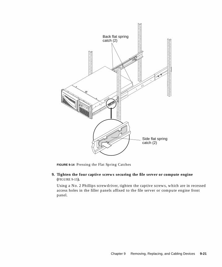
FIGURE 9-14 Pressing the Flat Spring Catches
9. Tighten the four captive screws securing the file server or compute engine(FIGURE 9-15).
Using a No. 2 Phillips screwdriver, tighten the captive screws, which are in recessed
access holes in the filler panels affixed to the file server or compute engine front
panel.
Side flat springcatch (2)
Back flat springcatch (2)
Chapter 9 Removing, Replacing, and Cabling Devices 9-21
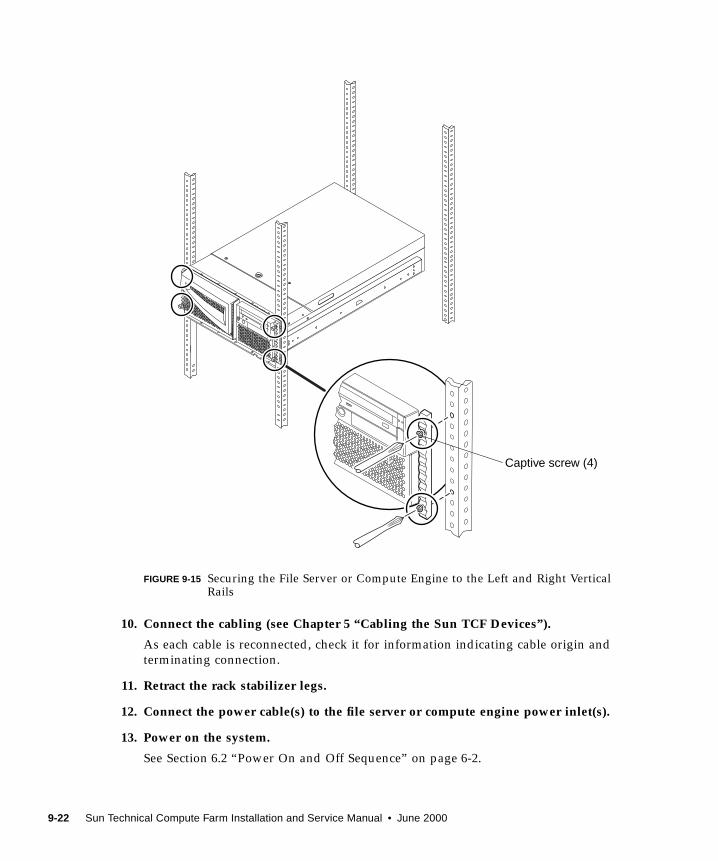
FIGURE 9-15 Securing the File Server or Compute Engine to the Left and Right VerticalRails
10. Connect the cabling (see Chapter 5 “Cabling the Sun TCF Devices”).
As each cable is reconnected, check it for information indicating cable origin and
terminating connection.
11. Retract the rack stabilizer legs.
12. Connect the power cable(s) to the file server or compute engine power inlet(s).
13. Power on the system.
See Section 6.2 “Power On and Off Sequence” on page 6-2.
Captive screw (4)
9-22 Sun Technical Compute Farm Installation and Service Manual • June 2000
14. Replace, close, and lock the rack door(s) as appropriate.
9.3.4 Positioning the File Server or Compute Engine for
Service
This section provides procedures to position the file server or compute engine in
preparation for servicing, and removing and replacing components. This section also
contains the following topics:
Note – When positioning the file server or compute engine for service, a
nonconducting step ladder and a flashlight may be required.
Note – For detailed instructions for positioning the file server or compute engine for
service, refer to the Sun Enterprise 420R Server Service Manual.
Note – Unless the rack is bolted to the floor, the rack stabilizer legs must be
extended and the stabilizing feet must be adjusted to the floor. The rack must be
level and secure to provide a safe working environment.
1. Unlock, open, and remove the rack door(s) as appropriate.
Caution – Do not disconnect the power cable(s) from the file server or compute
engine power inlet(s) unless you are removing or replacing the power distribution
board, main logic board, or a power supply. The power cord grounds the file server
or compute engine.
2. Power off the system.
See Section 6.2 “Power On and Off Sequence” on page 6-2.
3. Extend the rack stabilizer legs.
4. Disconnect cabling (see Chapter 5 “Cabling the Sun TCF Devices”).
5. Loosen the four captive screws securing the file server or compute engine to theleft and right vertical rails at the front of the rack (FIGURE 9-16).
Using a No. 2 Phillips screwdriver, loosen the captive screws, which are in recessed
access holes in the trim panels affixed to the file server or compute engine front
panel.
Chapter 9 Removing, Replacing, and Cabling Devices 9-23
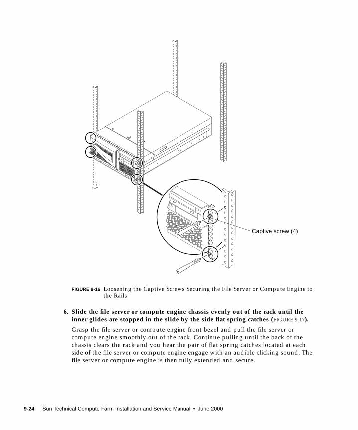
FIGURE 9-16 Loosening the Captive Screws Securing the File Server or Compute Engine tothe Rails
6. Slide the file server or compute engine chassis evenly out of the rack until theinner glides are stopped in the slide by the side flat spring catches (FIGURE 9-17).
Grasp the file server or compute engine front bezel and pull the file server or
compute engine smoothly out of the rack. Continue pulling until the back of the
chassis clears the rack and you hear the pair of flat spring catches located at each
side of the file server or compute engine engage with an audible clicking sound. The
file server or compute engine is then fully extended and secure.
Captive screw (4)
9-24 Sun Technical Compute Farm Installation and Service Manual • June 2000
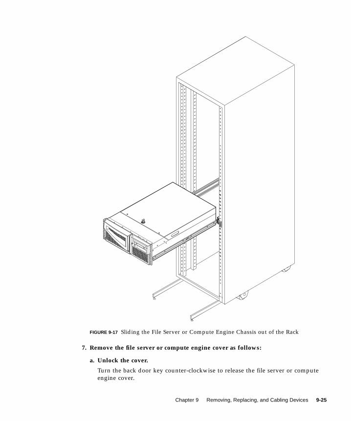
FIGURE 9-17 Sliding the File Server or Compute Engine Chassis out of the Rack
7. Remove the file server or compute engine cover as follows:
a. Unlock the cover.
Turn the back door key counter-clockwise to release the file server or compute
engine cover.
Chapter 9 Removing, Replacing, and Cabling Devices 9-25
b. Loosen the three captive screws securing the cover to the enclosure.
c. Grasp the file server or compute engine cover by the sides, and lift the coverupwards and away from the front of the enclosure.
d. Remove the cover and set it aside.
Note – The file server or compute engine cover hinges on two cutouts in the
enclosure back panel. Lift the file server or compute engine cover away from the
back of the enclosure.
9.3.5 Removing and Replacing File Server or Compute
Engine Components
Caution – Do not disconnect the power cable(s) from the file server or compute
engine power inlet(s) unless you are removing or replacing the power distribution
board, main logic board, or a power supply. The power cord grounds the file server
or compute engine.
Caution – Never remove or replace a device when system power is on.
This section provides procedures to remove and replace file server or compute
engine components. This section also includes procedures to remove and replace the
host adapter fibre channel card and the GigabitEthernet adapter card from the file
server.
This section contains the following topics:
■ Section 9.3.5.1 “Removing and Replacing the File Server or Compute Engine
FRUs” on page 9-27
■ Section 9.3.5.2 “Removing a File Server Host Adapter” on page 9-27
■ Section 9.3.5.3 “Replacing a File Server Host Adapter” on page 9-29
■ Section 9.3.5.4 “Removing the File Server GigabitEthernet Adapter” on page 9-30
■ Section 9.3.5.5 “Replacing the File Server GigabitEthernet Adapter” on page 9-32
9-26 Sun Technical Compute Farm Installation and Service Manual • June 2000
9.3.5.1 Removing and Replacing the File Server or Compute EngineFRUs
To remove and replace the file server or compute engine FRUs, refer to the SunEnterprise 420R Server Service Manual.
9.3.5.2 Removing a File Server Host Adapter
Note – Refer to the Sun StorEdge PCI FC-100 Host Adapter Installation Manual for
further information.
1. Position the file server for service.
See Section 9.3.4 “Positioning the File Server or Compute Engine for Service” on
page 9-23.
Caution – Use proper ESD grounding techniques when handling components. Wear
an antistatic wrist strap and use an ESD-protected mat. Store ESD-sensitive
components in antistatic bags before placing them on any surface.
2. Attach the adhesive copper strip of the wrist strap to the metal casing of the fileserver power supply. Wrap the other end twice around your wrist, with theadhesive side against your skin.
3. Disconnect the fiber optic cable from the host adapter card (FIGURE 9-18).
Note – The host adapter Fibre Channel cards are located in PCI slots 2 and 3.
4. Remove the screw securing the host adapter to the PCI slot. Retain the screw.
5. Applying even pressure at both corners of the host adapter, pull the host adapteruntil it unseats from the slot.
6. Remove the host adapter card from the PCI slot.
7. Push the two dust covers into the host adapter gigabit interface converter (GBIC)connectors (FIGURE 9-19).
Chapter 9 Removing, Replacing, and Cabling Devices 9-27
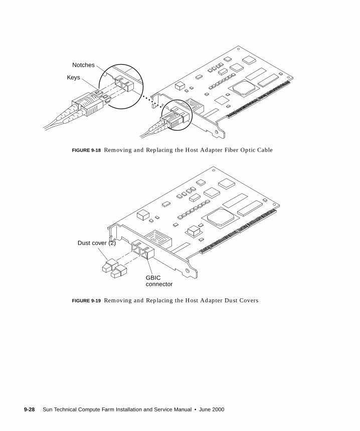
FIGURE 9-18 Removing and Replacing the Host Adapter Fiber Optic Cable
FIGURE 9-19 Removing and Replacing the Host Adapter Dust Covers
Keys
Notches
Dust cover (2)
GBICconnector
9-28 Sun Technical Compute Farm Installation and Service Manual • June 2000
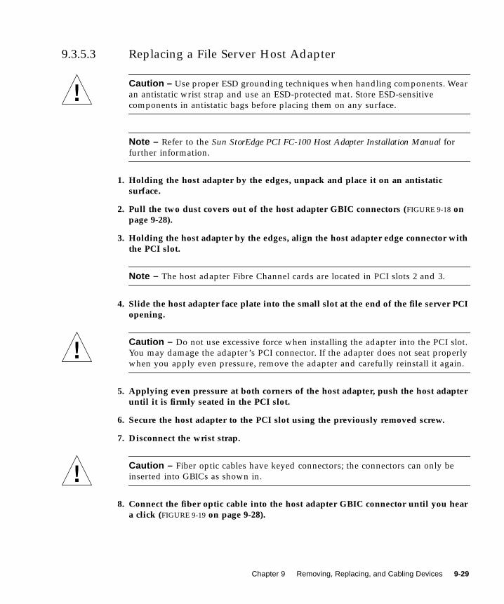
9.3.5.3 Replacing a File Server Host Adapter
Caution – Use proper ESD grounding techniques when handling components. Wear
an antistatic wrist strap and use an ESD-protected mat. Store ESD-sensitive
components in antistatic bags before placing them on any surface.
Note – Refer to the Sun StorEdge PCI FC-100 Host Adapter Installation Manual for
further information.
1. Holding the host adapter by the edges, unpack and place it on an antistaticsurface.
2. Pull the two dust covers out of the host adapter GBIC connectors (FIGURE 9-18 onpage 9-28).
3. Holding the host adapter by the edges, align the host adapter edge connector withthe PCI slot.
Note – The host adapter Fibre Channel cards are located in PCI slots 2 and 3.
4. Slide the host adapter face plate into the small slot at the end of the file server PCIopening.
Caution – Do not use excessive force when installing the adapter into the PCI slot.
You may damage the adapter’s PCI connector. If the adapter does not seat properly
when you apply even pressure, remove the adapter and carefully reinstall it again.
5. Applying even pressure at both corners of the host adapter, push the host adapteruntil it is firmly seated in the PCI slot.
6. Secure the host adapter to the PCI slot using the previously removed screw.
7. Disconnect the wrist strap.
Caution – Fiber optic cables have keyed connectors; the connectors can only be
inserted into GBICs as shown in.
8. Connect the fiber optic cable into the host adapter GBIC connector until you heara click (FIGURE 9-19 on page 9-28).
Chapter 9 Removing, Replacing, and Cabling Devices 9-29
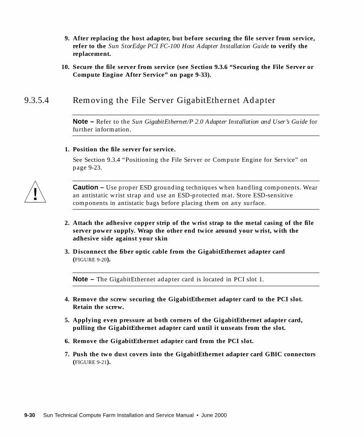
9. After replacing the host adapter, but before securing the file server from service,refer to the Sun StorEdge PCI FC-100 Host Adapter Installation Guide to verify thereplacement.
10. Secure the file server from service (see Section 9.3.6 “Securing the File Server orCompute Engine After Service” on page 9-33).
9.3.5.4 Removing the File Server GigabitEthernet Adapter
Note – Refer to the Sun GigabitEthernet/P 2.0 Adapter Installation and User’s Guide for
further information.
1. Position the file server for service.
See Section 9.3.4 “Positioning the File Server or Compute Engine for Service” on
page 9-23.
Caution – Use proper ESD grounding techniques when handling components. Wear
an antistatic wrist strap and use an ESD-protected mat. Store ESD-sensitive
components in antistatic bags before placing them on any surface.
2. Attach the adhesive copper strip of the wrist strap to the metal casing of the fileserver power supply. Wrap the other end twice around your wrist, with theadhesive side against your skin
3. Disconnect the fiber optic cable from the GigabitEthernet adapter card(FIGURE 9-20).
Note – The GigabitEthernet adapter card is located in PCI slot 1.
4. Remove the screw securing the GigabitEthernet adapter card to the PCI slot.Retain the screw.
5. Applying even pressure at both corners of the GigabitEthernet adapter card,pulling the GigabitEthernet adapter card until it unseats from the slot.
6. Remove the GigabitEthernet adapter card from the PCI slot.
7. Push the two dust covers into the GigabitEthernet adapter card GBIC connectors(FIGURE 9-21).
9-30 Sun Technical Compute Farm Installation and Service Manual • June 2000
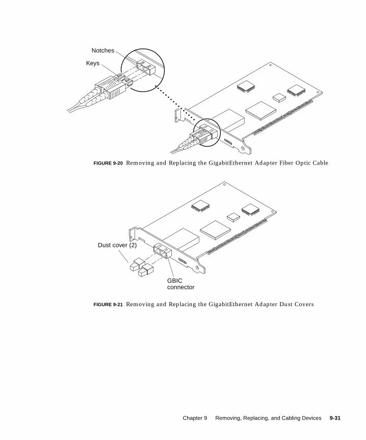
FIGURE 9-20 Removing and Replacing the GigabitEthernet Adapter Fiber Optic Cable
FIGURE 9-21 Removing and Replacing the GigabitEthernet Adapter Dust Covers
Keys
Notches
Dust cover (2)
GBICconnector
Chapter 9 Removing, Replacing, and Cabling Devices 9-31
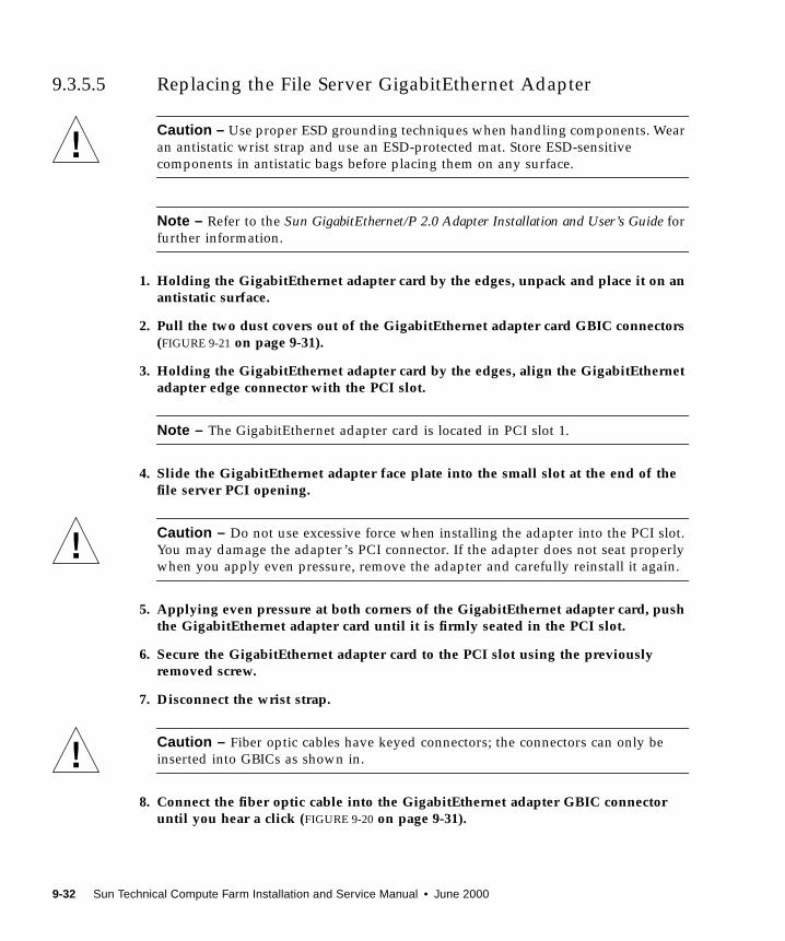
9.3.5.5 Replacing the File Server GigabitEthernet Adapter
Caution – Use proper ESD grounding techniques when handling components. Wear
an antistatic wrist strap and use an ESD-protected mat. Store ESD-sensitive
components in antistatic bags before placing them on any surface.
Note – Refer to the Sun GigabitEthernet/P 2.0 Adapter Installation and User’s Guide for
further information.
1. Holding the GigabitEthernet adapter card by the edges, unpack and place it on anantistatic surface.
2. Pull the two dust covers out of the GigabitEthernet adapter card GBIC connectors(FIGURE 9-21 on page 9-31).
3. Holding the GigabitEthernet adapter card by the edges, align the GigabitEthernetadapter edge connector with the PCI slot.
Note – The GigabitEthernet adapter card is located in PCI slot 1.
4. Slide the GigabitEthernet adapter face plate into the small slot at the end of thefile server PCI opening.
Caution – Do not use excessive force when installing the adapter into the PCI slot.
You may damage the adapter’s PCI connector. If the adapter does not seat properly
when you apply even pressure, remove the adapter and carefully reinstall it again.
5. Applying even pressure at both corners of the GigabitEthernet adapter card, pushthe GigabitEthernet adapter card until it is firmly seated in the PCI slot.
6. Secure the GigabitEthernet adapter card to the PCI slot using the previouslyremoved screw.
7. Disconnect the wrist strap.
Caution – Fiber optic cables have keyed connectors; the connectors can only be
inserted into GBICs as shown in.
8. Connect the fiber optic cable into the GigabitEthernet adapter GBIC connectoruntil you hear a click (FIGURE 9-20 on page 9-31).
9-32 Sun Technical Compute Farm Installation and Service Manual • June 2000
9. After replacing the GigabitEthernet adapter card, but before securing the fileserver from service, refer to the Sun GigabitEthernet/P 2.0 Adapter Installation andUser’s Guide to verify the replacement.
10. Secure the file server from service (see Section 9.3.6 “Securing the File Server orCompute Engine After Service” on page 9-33).
9.3.6 Securing the File Server or Compute Engine After
Service
1. Replace the file server or compute engine cover as follows:
a. Replace the cover by grasping the cover by the sides and lowering it towardsthe front of the enclosure.
b. Tighten the three captive screws securing the cover to the enclosure.
c. Lock the system cover.
Use the back door key to turn the key clockwise to lock the system cover.
2. Simultaneously press on the side flat spring catches and slide the file server orcompute engine into the rack.
Grasp the file server or compute engine front bezel and push the file server or
compute engine smoothly into the rack.
3. Tighten the four captive screws securing the file server or compute engine to theleft and right vertical rails at the front of the rack (FIGURE 9-22).
Using a No. 2 Phillips screwdriver, tighten the captive screws, which are in recessed
access holes in the trim panels affixed to the file server or compute engine front
panel.
Chapter 9 Removing, Replacing, and Cabling Devices 9-33
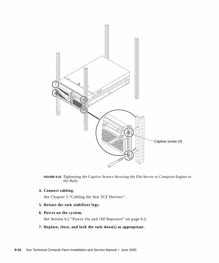
FIGURE 9-22 Tightening the Captive Screws Securing the File Server or Compute Engine tothe Rails
4. Connect cabling.
See Chapter 5 “Cabling the Sun TCF Devices”.
5. Retract the rack stabilizer legs.
6. Power on the system.
See Section 6.2 “Power On and Off Sequence” on page 6-2.
7. Replace, close, and lock the rack door(s) as appropriate.
Captive screw (4)
9-34 Sun Technical Compute Farm Installation and Service Manual • June 2000
9.3.7 Cabling the File Server or Compute Engine
To cable the file server or compute engine, refer to Chapter 5 “Cabling the Sun TCF
Devices”.
9.4 Disk Array
Caution – Never remove or replace a device when system power is on.
To remove and replace the disk array, proceed as follows.
■ Section 9.4.1 “Removing a Disk Array” on page 9-36
■ Section 9.4.2 “Replacing a Disk Array” on page 9-38
■ Section 9.4.3 “Cabling a Disk Array” on page 9-39
■ Section 9.4.4 “Removing and Replacing the Disk Array FRUs” on page 9-39
Note – Refer to the Sun StorEdge A5000 Installation and Service Manual for complete
details.
Chapter 9 Removing, Replacing, and Cabling Devices 9-35
9.4.1 Removing a Disk Array
Caution – The rack can become front-heavy while the disk array chassis is being
replaced. Unless the rack is bolted to the floor, ensure that the stabilizer legs are
extended before proceeding. Failure to extend the legs can result in the rack tipping
forward and injuring personnel.
Caution – This replacement requires two people to lift and move the disk array.
Use care to avoid injury. A disk array with a baseplate attached may weigh up to 130
pounds (59 kg).
When completing a two-person procedure, always communicate your intentions
clearly before, during, and after each step to minimize confusion.
Follow the instructions on preparing for service in this documentation. If necessary,
be sure to:
■ Extend the stabilizer bars
■ Remove or open the top front panel
1. Power off the system.
See Section 6.2 “Power On and Off Sequence” on page 6-2.
Caution – Use proper ESD grounding techniques when handling components. Wear
an antistatic wrist strap and use an ESD-protected mat. Store ESD-sensitive
components in antistatic bags before placing them on any surface.
2. Disconnect the power cable.
3. Disconnect the fiber optic cable(s) from the GBIC connectors.
Caution – Always extend a rack stabilizer legs before removing the locking screws
from the front of the disk array.
4. Remove the locking screws from the front of the disk array (FIGURE 9-23).
5. With the aid of an assistant, slide the disk array out of the rack until the chassisbaseplate is stopped by the tabs on the side rails in the rack (FIGURE 9-24).
6. With the aid of an assistant (one person on each side), tilt the front of the chassisdown and remove it from the rack.
7. Place the disk array on a surface capable of supporting 130 pounds (59 kg).
9-36 Sun Technical Compute Farm Installation and Service Manual • June 2000
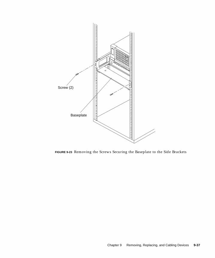
FIGURE 9-23 Removing the Screws Securing the Baseplate to the Side Brackets
Screw (2)
Baseplate
Chapter 9 Removing, Replacing, and Cabling Devices 9-37
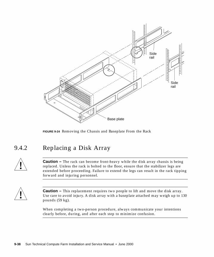
FIGURE 9-24 Removing the Chassis and Baseplate From the Rack
9.4.2 Replacing a Disk Array
Caution – The rack can become front-heavy while the disk array chassis is being
replaced. Unless the rack is bolted to the floor, ensure that the stabilizer legs are
extended before proceeding. Failure to extend the legs can result in the rack tipping
forward and injuring personnel.
Caution – This replacement requires two people to lift and move the disk array.
Use care to avoid injury. A disk array with a baseplate attached may weigh up to 130
pounds (59 kg).
When completing a two-person procedure, always communicate your intentions
clearly before, during, and after each step to minimize confusion.
Siderail
Base plate
Siderail
9-38 Sun Technical Compute Farm Installation and Service Manual • June 2000
Caution – Use proper ESD grounding techniques when handling components. Wear
an antistatic wrist strap and use an ESD-protected mat. Store ESD-sensitive
components in antistatic bags before placing them on any surface.
1. With the aid of an assistant (one person on each side), position the disk array intothe rack.
2. With the aid of an assistant, slide the disk array into the rack until the chassisbaseplate is stopped by the tabs on the side rails in the rack (FIGURE 9-24 onpage 9-38).
3. Replace the locking screws securing the front of the disk array (FIGURE 9-23 onpage 9-37).
4. Connect the fiber optic cable(s) to the GBIC connectors (see Chapter 5 “Cablingthe Sun TCF Devices”).
5. Connect the power cable.
6. Power on the system.
See Section 6.2 “Power On and Off Sequence” on page 6-2.
9.4.3 Cabling a Disk Array
To cable a disk array, refer to Chapter 5 “Cabling the Sun TCF Devices”.
9.4.4 Removing and Replacing the Disk Array FRUs
To remove and replace the disk array FRUs, refer to the Sun StorEdge A5000Installation and Service Manual.
Chapter 9 Removing, Replacing, and Cabling Devices 9-39

9-40 Sun Technical Compute Farm Installation and Service Manual • June 2000
CHAPTER 10
Removing and Replacing RackFRUs
This chapter describes how to remove and replace the following Sun StorEdge™
expansion cabinet (rack) subassemblies. This chapter covers the following topics:
■ Section 10.1 “Tools Required” on page 10-1
■ Section 10.2 “Key Switch” on page 10-2
■ Section 10.3 “AC Input Cable Assembly” on page 10-4
■ Section 10.4 “Power Sequencer” on page 10-6
■ Section 10.5 “Side Panel” on page 10-7
Note – The keys for the Sun TCF system are found in the rack and in the Sun TCFAccessory Kit, 565-1656.
10.1 Tools Required■ No. 2 Phillips screwdriver
■ 1/4-inch, slotted screwdriver
■ Needlenose pliers
■ Set of Allen wrenches
10-1
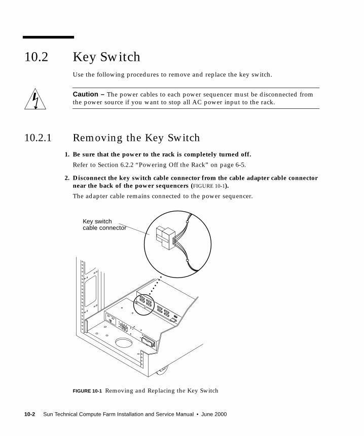
10.2 Key SwitchUse the following procedures to remove and replace the key switch.
Caution – The power cables to each power sequencer must be disconnected from
the power source if you want to stop all AC power input to the rack.
10.2.1 Removing the Key Switch
1. Be sure that the power to the rack is completely turned off.
Refer to Section 6.2.2 “Powering Off the Rack” on page 6-5.
2. Disconnect the key switch cable connector from the cable adapter cable connectornear the back of the power sequencers (FIGURE 10-1).
The adapter cable remains connected to the power sequencer.
FIGURE 10-1 Removing and Replacing the Key Switch
Key switchcable connector
10-2 Sun Technical Compute Farm Installation and Service Manual • June 2000

3. Remove the Phillips screws and cable ties that secure the key switch cable to thechassis frame.
Each screw secures a clamp on the frame that holds the cable in place.
4. Facing the back of the key switch on the inside of the rack, use a pair ofneedlenose pliers to slide out and remove the metal clip that secures the keyswitch to the rack (FIGURE 10-2).
FIGURE 10-2 Removing and Replacing the Key Switch
10.2.2 Replacing the Key Switch
1. Insert the key switch into the panel opening.
2. Facing the back of the key switch on the inside of the rack, slide the metal cliponto the notch of the key switch body to secure it in place (FIGURE 10-2)
3. Route the key switch cable to the power sequencer, securing it to the chassisframe with cable ties and Phillips screws.
Each screw secures a clamp on the frame that holds the cable in place.
4. Connect the key switch cable connector to the adapter-cable connector near theback of the power sequencer (FIGURE 10-1).
5. Power on the rack.
Refer to Section 6.2.1 “Powering On the Rack” on page 6-3.
Note – To maintain proper airflow, filler panels must be installed over locations that
do not have devices mounted.
Key switch
Metal clip
Chapter 10 Removing and Replacing Rack FRUs 10-3
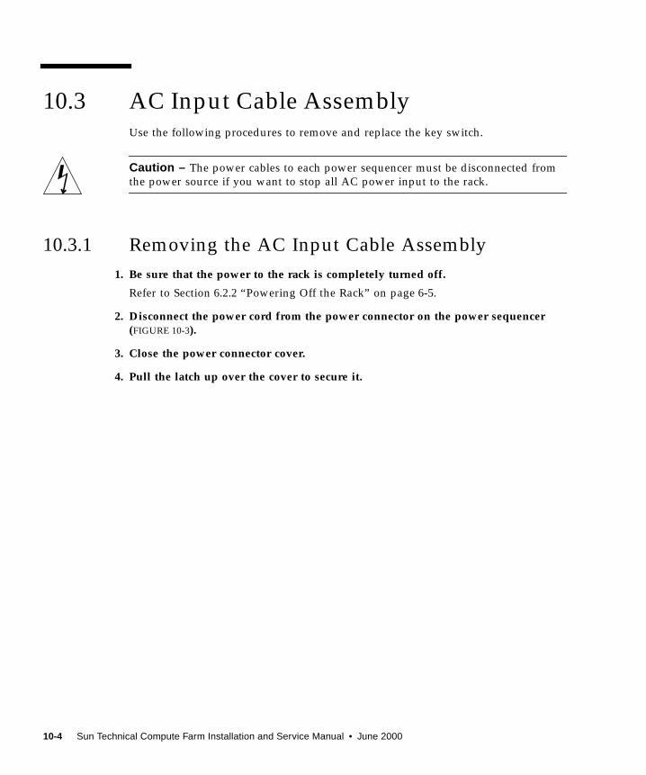
10.3 AC Input Cable AssemblyUse the following procedures to remove and replace the key switch.
Caution – The power cables to each power sequencer must be disconnected from
the power source if you want to stop all AC power input to the rack.
10.3.1 Removing the AC Input Cable Assembly
1. Be sure that the power to the rack is completely turned off.
Refer to Section 6.2.2 “Powering Off the Rack” on page 6-5.
2. Disconnect the power cord from the power connector on the power sequencer(FIGURE 10-3).
3. Close the power connector cover.
4. Pull the latch up over the cover to secure it.
10-4 Sun Technical Compute Farm Installation and Service Manual • June 2000
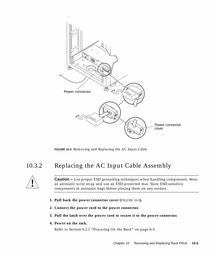
FIGURE 10-3 Removing and Replacing the AC Input Cable
10.3.2 Replacing the AC Input Cable Assembly
Caution – Use proper ESD grounding techniques when handling components. Wear
an antistatic wrist strap and use an ESD-protected mat. Store ESD-sensitive
components in antistatic bags before placing them on any surface.
1. Pull back the power connector cover (FIGURE 10-3).
2. Connect the power cord to the power connector.
3. Pull the latch over the power cord to secure it to the power connector.
4. Power on the rack.
Refer to Section 6.2.1 “Powering On the Rack” on page 6-3.
Power connector
Power connectorcover
Chapter 10 Removing and Replacing Rack FRUs 10-5
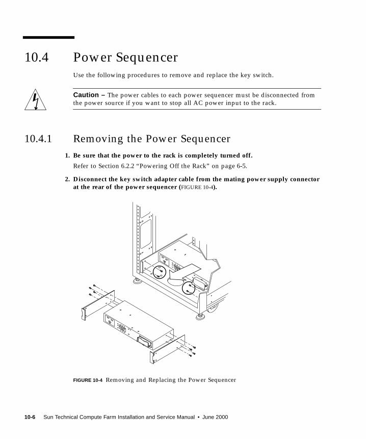
10.4 Power SequencerUse the following procedures to remove and replace the key switch.
Caution – The power cables to each power sequencer must be disconnected from
the power source if you want to stop all AC power input to the rack.
10.4.1 Removing the Power Sequencer
1. Be sure that the power to the rack is completely turned off.
Refer to Section 6.2.2 “Powering Off the Rack” on page 6-5.
2. Disconnect the key switch adapter cable from the mating power supply connectorat the rear of the power sequencer (FIGURE 10-4).
FIGURE 10-4 Removing and Replacing the Power Sequencer
10-6 Sun Technical Compute Farm Installation and Service Manual • June 2000

3. Remove the power cord from the power sequencer.
See Section 10.3 “AC Input Cable Assembly” on page 10-4.
4. Remove the screws that secure the sequencer to the chassis.
5. Slide out the power sequencer to access the power cables.
6. Disconnect all other power cables from the sequencer.
7. Remove the power sequencer.
10.4.2 Replacing the Power Sequencer
1. Place the power sequencer on the floor.
2. Connect all cables on the back of the power sequencer.
3. Slide the power sequencer into the rack (FIGURE 10-4).
4. Tighten the screws that secure the sequencer to the chassis.
5. Connect the power cord.
See Section 10.3 “AC Input Cable Assembly” on page 10-4.
6. Power on the rack.
Refer to Section 6.2.1 “Powering On the Rack” on page 6-3.
10.5 Side PanelUse the following procedures to remove and replace the side panel.
10.5.1 Removing the Side Panel
Use an Allen wrench to loosen the four .25-inch shoulder screws that fasten the
panel to the rack and remove the panel from the rack (FIGURE 10-5).
Chapter 10 Removing and Replacing Rack FRUs 10-7
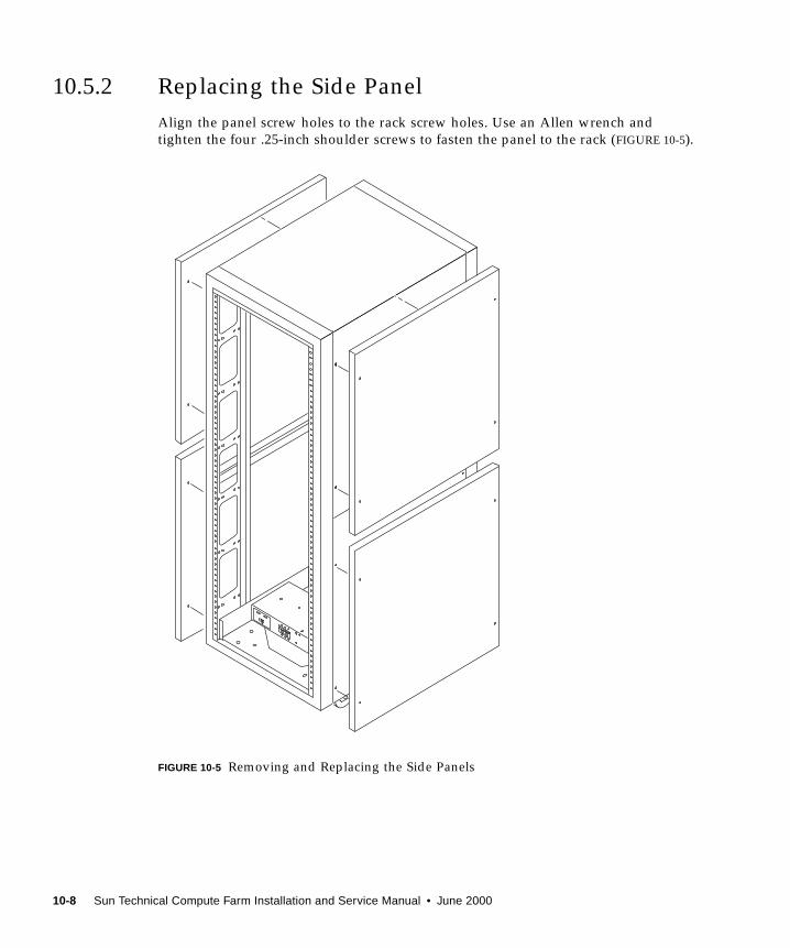
10.5.2 Replacing the Side Panel
Align the panel screw holes to the rack screw holes. Use an Allen wrench and
tighten the four .25-inch shoulder screws to fasten the panel to the rack (FIGURE 10-5).
FIGURE 10-5 Removing and Replacing the Side Panels
10-8 Sun Technical Compute Farm Installation and Service Manual • June 2000
APPENDIX A
Product Specifications
This appendix provides product specifications for the Sun TCF.
■ Section A.1 “Physical Specifications” on page A-1
■ Section A.2 “Supporting Documentation” on page A-3
■ Section A.3 “Electrical Specifications” on page A-4
■ Section A.4 “Environmental Requirements” on page A-5
■ Section A.5 “Clearance and Service Access” on page A-6
A.1 Physical SpecificationsTABLE A-1 through TABLE A-4 lists the physical specifications for the base rack, the
expansion rack with 2-CPU compute engines, the expansion rack with 4-CPU
compute engines, and the star rack.
TABLE A-1 Base Rack Physical Specifications
Specification U.S.A. Metric
Height 73.5 in 187 cm
Width 24.0 in 61 cm
Depth 36.5 in 93 cm
Weight (approximate) 890 lb 404.5 kg
A-1

TABLE A-2 Expansion Rack With 2-CPU Compute Engines Physical Specifications
Specification U.S.A. Metric
Height 73.5 in 187 cm
Width 24.0 in 61 cm
Depth 36.5 in 93 cm
Weight (approximate) 990 lb 454.3 kg
TABLE A-3 Expansion Rack With 4-CPU Compute Engines Physical Specifications
Specification U.S.A. Metric
Height 73.5 in 187 cm
Width 24.0 in 61 cm
Depth 36.5 in 93 cm
Weight (approximate) 1019 lb 470.3 kg
TABLE A-4 Star Rack Physical Specifications
Specification U.S.A. Metric
Height 73.5 in 187 cm
Width 24.0 in 61 cm
Depth 36.5 in 93 cm
Weight (approximate) 1055 lb 479.5 kg
A-2 Sun Techanical Compute Farm Installation and Service Manual • June 2000
A.2 Supporting DocumentationTABLE A-5 lists the supporting documentation where physical specifications for
specific Sun TCF devices are found.
TABLE A-5 Product Specifications
Harwdare Device Supporting Documentation Document Part Number
Rack Sun StorEdge Expansion CabinetInstallation and Service Manual
805-3067
Disk array Sun StorEdge A5000 Installation andService Manual
802-7573
File server Sun Enterprise 420R Server ServiceManual
806-1080
Compute engine Sun Enterprise 420R Server ServiceManual
806-1080
Airflow baffle Sun StorEdge Expansion CabinetAirflow Baffle Installation Guide
806-0274
StorEdge PCI FC-100
host adapter Fibre
Channel circuit card
Sun StorEdge PCI FC-100 HostAdapter Installation Manual
805-3682
GigabitEthernet/P 2.0
adapter circuit card
Sun GigabitEthernet/P 2.0 AdapterInstallation and User’s Guide
805-2785
Access server Cisco AS2509-RJ and AS2511-RJAccess Server Hardware InstallationGuide
http://www.cisco.com
78-3333
C3524 Ethernet switch Catalyst 3500 Series XL InstallationGuide
http://www.cisco.com
78-6456
C3508 Ethernet switch Catalyst 3500 Series XL InstallationGuide
http://www.cisco.com
78-6456
Appendix A Product Specifications A-3
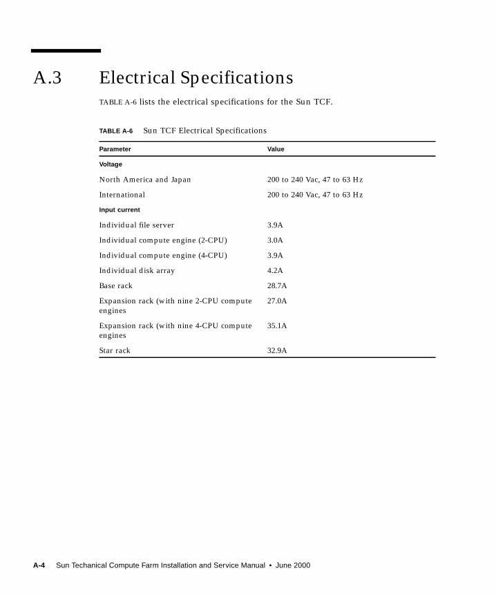
A.3 Electrical SpecificationsTABLE A-6 lists the electrical specifications for the Sun TCF.
TABLE A-6 Sun TCF Electrical Specifications
Parameter Value
Voltage
North America and Japan 200 to 240 Vac, 47 to 63 Hz
International 200 to 240 Vac, 47 to 63 Hz
Input current
Individual file server 3.9A
Individual compute engine (2-CPU) 3.0A
Individual compute engine (4-CPU) 3.9A
Individual disk array 4.2A
Base rack 28.7A
Expansion rack (with nine 2-CPU compute
engines
27.0A
Expansion rack (with nine 4-CPU compute
engines
35.1A
Star rack 32.9A
A-4 Sun Techanical Compute Farm Installation and Service Manual • June 2000

A.4 Environmental RequirementsTABLE A-7 lists the environmental specifications for the Sun TCF. TABLE A-8 lists the
air conditioning tonnage for each Sun TCF rack.
TABLE A-7 Sun TCF Environmental Requirements
Parameter Value
Temperature
Operating 41°F to 104°F (5°C to 40°C)
Non-operating -4°F to 140°F (-20°C to 60°C)
Humidity
Operating 20% to 80% RH, noncondensing
80.6°F (27°C) maximum wet bulb
Non-operating 5% to 93% RH, noncondensing
Altitude
Operating 0 to 9,843 feet (0 to 3 km)
Non-operating 0 to 39,370 feet (0 to 12 km)
TABLE A-8 Sun TCF Rack Air Conditioning Tonnage
Rack Air conditioning tonnage
Base rack 1.95 tons
Expansion rack 2.40 tons
Star rack 2.25 tons
Appendix A Product Specifications A-5
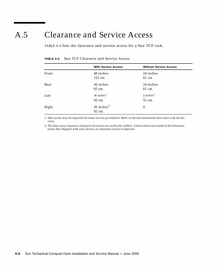
A.5 Clearance and Service AccessTABLE A-9 lists the clearance and service access for a Sun TCF rack.
TABLE A-9 Sun TCF Clearance and Service Access
With Service Access Without Service Access
Front 48 inches
122 cm
24 inches
61 cm
Rear 36 inches
92 cm
24 inches
61 cm
Left 36 inches1
92 cm
1. Side access may be required for some service procedures. Refer to the documentation that came with the de-vices.
2 inches2
51 cm
2. The disk array requires a clearance of at least two inches for airflow. Unless otherwise stated in the documen-tation that shipped with your device, no clearance access is required.
Right 36 inches1
92 cm.
0
A-6 Sun Techanical Compute Farm Installation and Service Manual • June 2000
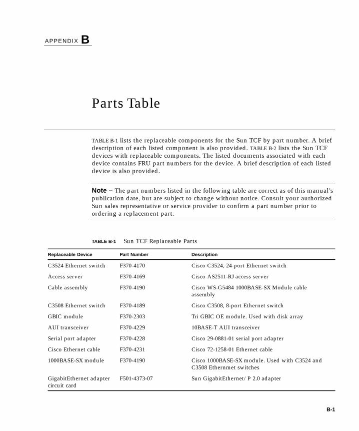
APPENDIX B
Parts Table
TABLE B-1 lists the replaceable components for the Sun TCF by part number. A brief
description of each listed component is also provided. TABLE B-2 lists the Sun TCF
devices with replaceable components. The listed documents associated with each
device contains FRU part numbers for the device. A brief description of each listed
device is also provided.
Note – The part numbers listed in the following table are correct as of this manual’s
publication date, but are subject to change without notice. Consult your authorized
Sun sales representative or service provider to confirm a part number prior to
ordering a replacement part.
TABLE B-1 Sun TCF Replaceable Parts
Replaceable Device Part Number Description
C3524 Ethernet switch F370-4170 Cisco C3524, 24-port Ethernet switch
Access server F370-4169 Cisco AS2511-RJ access server
Cable assembly F370-4190 Cisco WS-G5484 1000BASE-SX Module cable
assembly
C3508 Ethernet switch F370-4189 Cisco C3508, 8-port Ethernet switch
GBIC module F370-2303 Tri GBIC OE module. Used with disk array
AUI transceiver F370-4229 10BASE-T AUI transceiver
Serial port adapter F370-4228 Cisco 29-0881-01 serial port adapter
Cisco Ethernet cable F370-4231 Cisco 72-1258-01 Ethernet cable
1000BASE-SX module F370-4190 Cisco 1000BASE-SX module. Used with C3524 and
C3508 Ethernmet switches
GigabitEthernet adapter
circuit card
F501-4373-07 Sun GigabitEthernet/P 2.0 adapter
B-1
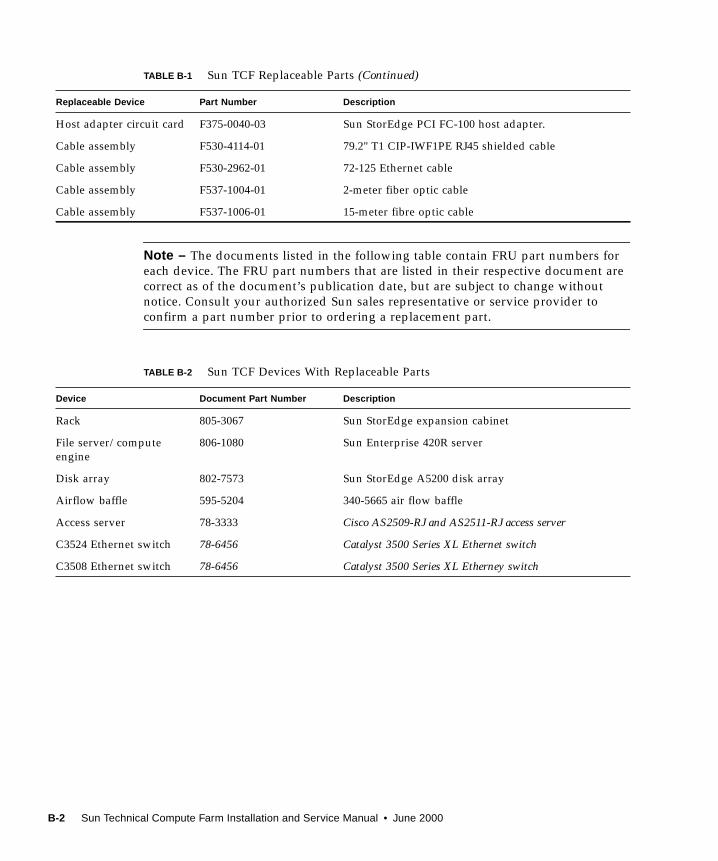
Note – The documents listed in the following table contain FRU part numbers for
each device. The FRU part numbers that are listed in their respective document are
correct as of the document’s publication date, but are subject to change without
notice. Consult your authorized Sun sales representative or service provider to
confirm a part number prior to ordering a replacement part.
Host adapter circuit card F375-0040-03 Sun StorEdge PCI FC-100 host adapter.
Cable assembly F530-4114-01 79.2" T1 CIP-IWF1PE RJ45 shielded cable
Cable assembly F530-2962-01 72-125 Ethernet cable
Cable assembly F537-1004-01 2-meter fiber optic cable
Cable assembly F537-1006-01 15-meter fibre optic cable
TABLE B-2 Sun TCF Devices With Replaceable Parts
Device Document Part Number Description
Rack 805-3067 Sun StorEdge expansion cabinet
File server/compute
engine
806-1080 Sun Enterprise 420R server
Disk array 802-7573 Sun StorEdge A5200 disk array
Airflow baffle 595-5204 340-5665 air flow baffle
Access server 78-3333 Cisco AS2509-RJ and AS2511-RJ access server
C3524 Ethernet switch 78-6456 Catalyst 3500 Series XL Ethernet switch
C3508 Ethernet switch 78-6456 Catalyst 3500 Series XL Etherney switch
TABLE B-1 Sun TCF Replaceable Parts (Continued)
Replaceable Device Part Number Description
B-2 Sun Technical Compute Farm Installation and Service Manual • June 2000
Index
AAC input cable assembly
removing, 10-4
replacing, 10-5
access server
cabling, 5-14, 5-34, 5-44
configuring, 7-3
connect
to network, 9-6
to system terminal, 9-7
power off, 6-6
power on, 6-6
prepare to service, 8-5
removing, 9-2
replacing, 9-4
access server 2, cabling, 5-25
adjusting rack leveling pads, 3-3
air conditioning, 2-4
airflow baffle
removing, 4-10
replacing, 4-12
repositioning, 4-9
Bbase rack configuration, 1-3, 2-2
CC3508 Ethernet switch, 1-17, 1-18
cabling, 5-45
connect to network, 9-12
installing 1000BASE-X GBIC module, 9-13
power off, 6-6
power on, 6-6
prepare to service, 8-5
replacing, 9-10
C3524 Ethernet switch, 1-17
cabling, 5-12, 5-23, 5-31, 5-42
connect to network, 9-12
installing 1000BASE-X GBIC module, 9-13
power off, 6-6
power on, 6-6
prepare to service, 8-5
replacing, 9-10
cabling
access server, 5-14, 5-34, 5-44
access server 2, 5-25
C3508 Ethernet switch, 5-45
C3524 Ethernet switch, 5-12, 5-23, 5-31, 5-42
compute engine, 5-11, 5-21, 5-31, 5-42, 9-35
disk array, 5-7, 5-21, 5-31, 9-39
disk array 1-to-disk array 2, 4-9, 5-41
disk array 1-to-file server, 4-9, 5-8
disk arrays, 5-39
disk arrays-to-file server, 5-40
file server, 5-9, 5-21, 5-31, 5-42, 9-35
rack, 3-8
Sun TCF system
large farm configuration, 5-34
medium farm configuration example 1, 5-15
Index-1
medium farm configuration example 2, 5-27
small farm configuration, 5-1
clearance, 2-5
clearance and service access, Sun TCF system, A-6
compute engine, 1-13
cabling, 5-11, 5-21, 5-31, 5-42, 9-35
positioning for service, 9-23
power off, 6-10
power on, 6-8
prepare to service, 8-4
ratio to file server, 1-2
removing, 9-15
components, 9-26
FRUs, 9-27
main logic board, 9-18
replacing, 9-18
components, 9-26
FRUs, 9-27
main logic board, 9-18
securing after service, 9-33
configuration
base rack, 1-3, 2-2
expansion rack, 1-6, 2-2
star rack, 1-9, 2-2
configuring
access server, 7-3
compute engine, 7-10
file server, 7-10
connect
rack power cord, 3-11
to network
access server, 9-6
C3508 Ethernet switch, 9-12
C3524 Ethernet switch, 9-12
to system terminal, access server, 9-7
Ddevices with replaceable components, B-1
disk array, 1-12
cabling, 5-7, 5-21, 5-31, 9-39
installing
additional GBICs, 4-8
additional interface boards, 4-8
power off, 6-7
power on, 6-7
prepare to service, 8-4
removing, 9-36
replacing, 9-39
disk array 1-to-disk array 2 cabling, 4-9, 5-41
disk array 1-to-file server cabling, 4-9, 5-8
disk array FRUs
removing, 9-39
replacing, 9-39
disk arrays cabling, 5-39
disk arrays-to-file server cabling, 5-40
Eelectrical specifications, Sun TCF system, A-4
environmental requirements, Sun TCF system, 2-3,
A-5
example 1 medium farm configuration, 5-15
example 2 medium farm configuration, 5-27
expansion rack configuration, 1-6, 2-2
Ffactory settings, reverting to, 7-10
file server, 1-13
cabling, 5-9, 5-21, 5-31, 5-42, 9-35
positioning for service, 9-23
power off, 6-10
power on, 6-8
prepare to service, 8-4
ratio to compute engine, 1-2
removing, 9-15
components, 9-26
FRUs, 9-27
Gigabit Ethernet adapter, 9-30
host adapter, 9-27
main logic board, 9-18
replacing, 9-18
components, 9-26
FRUs, 9-27
Gigabit Ethernet adapter, 9-32
host adapter, 9-29
main logic board, 9-18
securing after service, 9-33
final rack cabling tasks, 3-15
Hheating, 2-4
Index-2 Sun Technical Compute Farm Installation and Service Manual • June 2000
IIEC 309 single-phase, 32A connector for 200–240V
international operation, 3-12
install
1000BASE-X GBIC module
into C3508 Ethernet switch, 9-13
into C3524 Ethernet switch, 9-13
disk array
additional GBICs, 4-8
additional interface boards, 4-8
rack
floor brackets, 3-6
stabilizer legs, 3-4
second disk array, 4-1
chassis into rack, 4-4
connecting power cable, 4-6
rails, 4-2
system console, 7-1
Kkey switch
removing, 10-2
replacing, 10-3
standby mode, 6-10
Llarge farm configuration, 5-34
cabling access server, 5-44
cabling C3508 Ethernet switch, 5-45
cabling C3524 Ethernet switch, 5-42
cabling compute engine, 5-42
cabling disk array 1-to-disk array 2, 5-41
cabling disk arrays, 5-39
cabling disk arrays-to-file server, 5-40
cabling file server, 5-42
point-to-point connections
between star rack and three small farm base
rack, 5-37
within star rack, 5-36
Mmedium farm configuration
example 1, 5-15
cabling access server 2, 5-25
cabling C3524 Ethernet switch, 5-23
cabling compute engine, 5-21
cabling disk array, 5-21
cabling file server, 5-21
point-to-point connections between base rack
and expansion rack 2, 5-17
example 2, 5-27
cabling access server, 5-34
cabling C3524 Ethernet switch, 5-31
cabling compute engine, 5-31
cabling disk array, 5-31
cabling file server, 5-31
point-to-point connections between base
racks, 5-28
moving the rack, 3-2
NNEMA L6-30P for 200-240V North American
operation, 3-12
Pphysical specifications, Sun TCF system, A-1
placing the rack, 3-2
planning
site, 2-1
space, 2-2
point-to-point
cabling, second disk array, 5-8
connections
between base rack and expansion rack, 5-4
between base rack and expansion rack 2, 5-17
between base racks, 5-28
between star rack and three small farm base
racks, 5-37
within base rack, 5-3
within star rack, 5-36
positioning for service
compute engine, 9-23
file server, 9-23
power
off sequence, Sun TCF system, 6-2
on sequence, Sun TCF system, 6-2
power off
access server, 6-6
Index-3
C3508 Ethernet switch, 6-6
C3524 Ethernet switch, 6-6
compute engine, 6-10
disk array, 6-7
file server, 6-10
rack, 6-5
power on
access server, 6-6
C3508 Ethernet switch, 6-6
C3524 Ethernet switch, 6-6
compute engine, 6-8
disk array, 6-7
file server, 6-8
rack, 6-3
power sequencer
removing, 10-6
replacing, 10-7
prepare
for assembly and installation, 2-1
to power on, Sun TCF system, 6-1
to service
access server, 8-5
C3508 Ethernet switch, 8-5
C3524 Ethernet switch, 8-5
compute engine, 8-4
disk array, 8-4
file server, 8-4
product specifications, xxxiv
Rrack, 1-12
adjusting leveling pads, 3-3
cabling, 3-8
connect power cord, 3-11
final cabling tasks, 3-15
installing, 3-1
floor brackets, 3-6
stabilizer legs, 3-4
moving, 3-2
physical characteristics, 2-3
placing, 3-2
power off, 6-5
power on, 6-3
unpacking, 3-1
ratio, file server-to-compute engine, 1-2
removing
AC input cable assembly, 10-4
access server, 9-2
airflow baffle, 4-10
compute engine, 9-15
components, 9-26
FRUs, 9-27
main logic board, 9-18
disk array, 9-36
disk array FRUs, 9-39
file server, 9-15
components, 9-26
FRUs, 9-27
Gigabit Ethernet adapter, 9-30
host adapter, 9-27
main logic board, 9-18
key switch, 10-2
power sequencer, 10-6
side panel, 10-7
replaceable components, B-1
replacing
AC input cable assembly, 10-5
access server, 9-4
airflow baffle, 4-12
C3508 Ethernet switch, 9-10
C3524 Ethernet switch, 9-10
compute engine, 9-18
components, 9-26
FRUs, 9-27
main logic board, 9-18
disk array, 9-39
disk array FRUs, 9-39
file server, 9-18
components, 9-26
FRUs, 9-27
Gigabit Ethernet adapter, 9-32
host adapter, 9-29
main logic board, 9-18
key switch, 10-3
power sequencer, 10-7
side panel, 10-8
repositioning airflow baffle, 4-9
reverting to factory settings, 7-10
Ssecond disk array
installing, 4-1
chassis into rack, 4-4
connecting power cable, 4-6
Index-4 Sun Technical Compute Farm Installation and Service Manual • June 2000
rails, 4-2
point-to-point cabling, 5-8
securing after service
compute engine, 9-33
file server, 9-33
service access, 2-5
side panel
removing, 10-7
replacing, 10-8
site planning, 2-1
small farm configuration, 5-1
cabling access server, 5-14
cabling C3524 Ethernet switch, 5-12
cabling compute engine, 5-11
cabling disk array, 5-7
cabling disk array 1-to-file server, 5-8
cabling file server, 5-9
point-to-point cabling with second disk array, 5-
8
point-to-point connections
between base rack and expansion rack, 5-4
within base rack, 5-3
space planning, 2-2
specifications, product, xxxiv
star rack configuration, 1-9, 2-2
Sun Management Center, description, 8-1
Sun TCF system
air conditioning, 2-4
applications, 1-1
clearance and service access, A-6
configuration
base rack, 2-2
expansion rack, 2-2
star rack, 2-2
devices, 1-12
C3508 Ethernet switch, 1-18
C3524 Ethernet switch, 1-17
compute engine, 1-13
disk array, 1-12
file server, 1-13
I/O, supported, 1-21
rack, 1-12
electrical specifications, A-4
environmental requirements, 2-3, A-5
heating, 2-4
physical specifications, A-1
power off sequence, 6-2
power on sequence, 6-2
preparing to power on, 6-1
product overview, 1-1
rack physical characteristics, 2-3
troubleshooting, 8-4
ventilation, 2-4
SunVTS
description, 8-2
references, 8-3
requirements, 8-3
supported, I/O devices, 1-21
system
console, installing, 7-1
devices, Sun TCF, 1-12
Ttroubleshoot Sun TCF system, 8-4
Uunpacking and installing rack, 3-1
Vventilation, 2-4
Index-5

Index-6 Sun Technical Compute Farm Installation and Service Manual • June 2000
Copyright © 2022 FDOKUMEN