Konfort Series 700R Service Manual TEXA Technical Assistance
175
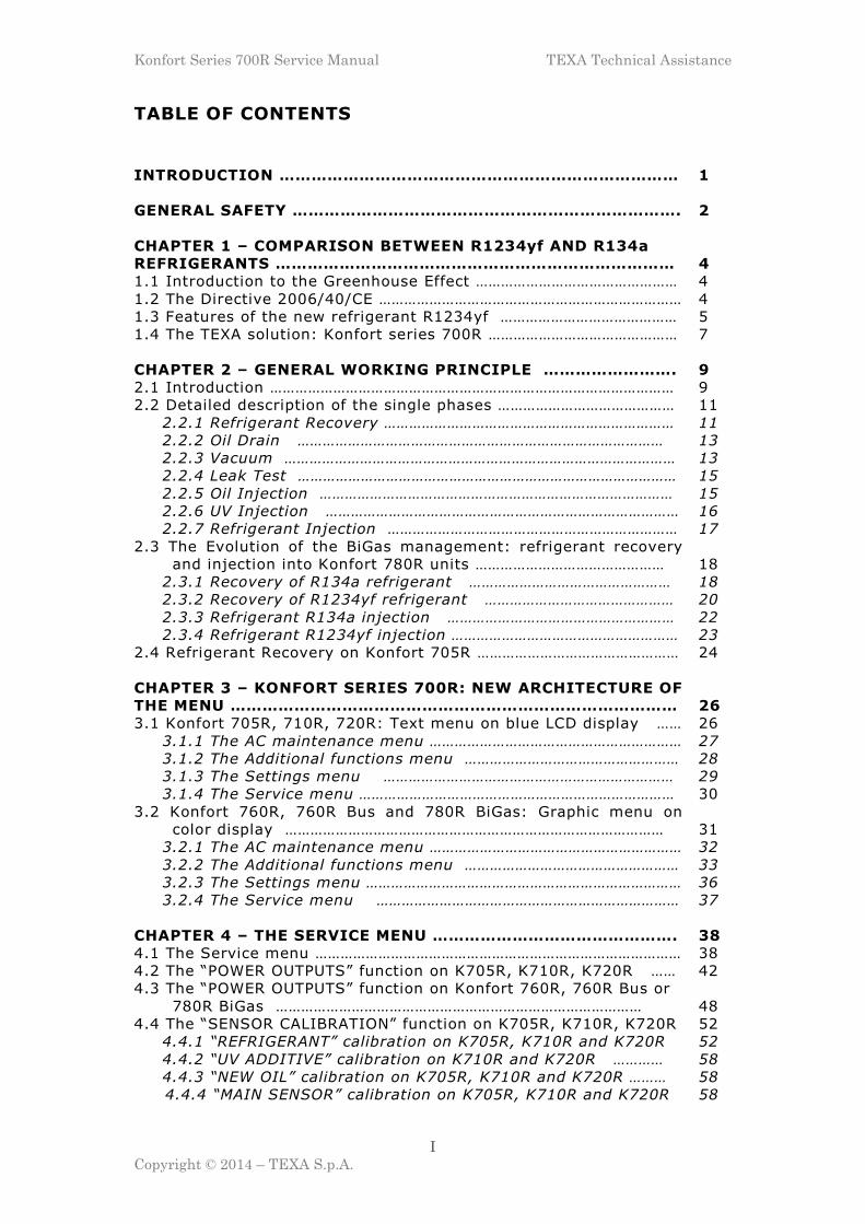
Konfort Series 700R Service Manual TEXA Technical Assistance I Copyright © 2014 – TEXA S.p.A. TABLE OF CONTENTS INTRODUCTION ………………………………………………………………… 1 GENERAL SAFETY ………………………………………………………………. 2 CHAPTER 1 – COMPARISON BETWEEN R1234yf AND R134a REFRIGERANTS ………………………………………………………………… 4 1.1 Introduction to the Greenhouse Effect ………………………………………… 4 1.2 The Directive 2006/40/CE ……………………………………………………………… 4 1.3 Features of the new refrigerant R1234yf …………………………………… 5 1.4 The TEXA solution: Konfort series 700R ……………………………………… 7 CHAPTER 2 – GENERAL WORKING PRINCIPLE ……………………. 9 2.1 Introduction …………………………………………………………………………………… 9 2.2 Detailed description of the single phases …………………………………… 11 2.2.1 Refrigerant Recovery …………………………………………………………… 11 2.2.2 Oil Drain …………………………………………………………………………… 13 2.2.3 Vacuum ………………………………………………………………………………… 13 2.2.4 Leak Test ……………………………………………………………………………… 15 2.2.5 Oil Injection ………………………………………………………………………… 15 2.2.6 UV Injection ………………………………………………………………………… 16 2.2.7 Refrigerant Injection …………………………………………………………… 17 2.3 The Evolution of the BiGas management: refrigerant recovery and injection into Konfort 780R units ……………………………………… 18 2.3.1 Recovery of R134a refrigerant ………………………………………… 18 2.3.2 Recovery of R1234yf refrigerant ……………………………………… 20 2.3.3 Refrigerant R134a injection ……………………………………………… 22 2.3.4 Refrigerant R1234yf injection ……………………………………………… 23 2.4 Refrigerant Recovery on Konfort 705R ………………………………………… 24 CHAPTER 3 – KONFORT SERIES 700R: NEW ARCHITECTURE OF THE MENU ………………………………………………………………………… 26 3.1 Konfort 705R, 710R, 720R: Text menu on blue LCD display …… 26 3.1.1 The AC maintenance menu …………………………………………………… 27 3.1.2 The Additional functions menu …………………………………………… 28 3.1.3 The Settings menu …………………………………………………………… 29 3.1.4 The Service menu ………………………………………………………………… 30 3.2 Konfort 760R, 760R Bus and 780R BiGas: Graphic menu on color display ……………………………………………………………………………… 31 3.2.1 The AC maintenance menu …………………………………………………… 32 3.2.2 The Additional functions menu …………………………………………… 33 3.2.3 The Settings menu ………………………………………………………………… 36 3.2.4 The Service menu ……………………………………………………………… 37 CHAPTER 4 – THE SERVICE MENU ………………………………………. 38 4.1 The Service menu …………………………………………………………………………… 38 4.2 The “POWER OUTPUTS” function on K705R, K710R, K720R …… 42 4.3 The “POWER OUTPUTS” function on Konfort 760R, 760R Bus or 780R BiGas …………………………………………………………………………… 48 4.4 The “SENSOR CALIBRATION” function on K705R, K710R, K720R 52 4.4.1 “REFRIGERANT” calibration on K705R, K710R and K720R 52 4.4.2 “UV ADDITIVE” calibration on K710R and K720R ………… 58 4.4.3 “NEW OIL” calibration on K705R, K710R and K720R ……… 58 4.4.4 “MAIN SENSOR” calibration on K705R, K710R and K720R 58
-
Upload
khangminh22 -
Category
Documents
-
view
0 -
download
0
Transcript of Konfort Series 700R Service Manual TEXA Technical Assistance
Konfort Series 700R Service Manual TEXA Technical Assistance
I
Copyright © 2014 – TEXA S.p.A.
TABLE OF CONTENTS
INTRODUCTION ………………………………………………………………… 1
GENERAL SAFETY ………………………………………………………………. 2
CHAPTER 1 – COMPARISON BETWEEN R1234yf AND R134a
REFRIGERANTS …………………………………………………………………
4
1.1 Introduction to the Greenhouse Effect ………………………………………… 4
1.2 The Directive 2006/40/CE ……………………………………………………………… 4
1.3 Features of the new refrigerant R1234yf …………………………………… 5
1.4 The TEXA solution: Konfort series 700R ……………………………………… 7
CHAPTER 2 – GENERAL WORKING PRINCIPLE ……………………. 9
2.1 Introduction …………………………………………………………………………………… 9
2.2 Detailed description of the single phases …………………………………… 11
2.2.1 Refrigerant Recovery …………………………………………………………… 11
2.2.2 Oil Drain …………………………………………………………………………… 13
2.2.3 Vacuum ………………………………………………………………………………… 13
2.2.4 Leak Test ……………………………………………………………………………… 15
2.2.5 Oil Injection ………………………………………………………………………… 15
2.2.6 UV Injection ………………………………………………………………………… 16
2.2.7 Refrigerant Injection …………………………………………………………… 17
2.3 The Evolution of the BiGas management: refrigerant recovery
and injection into Konfort 780R units ………………………………………
18
2.3.1 Recovery of R134a refrigerant ………………………………………… 18
2.3.2 Recovery of R1234yf refrigerant ……………………………………… 20
2.3.3 Refrigerant R134a injection ……………………………………………… 22
2.3.4 Refrigerant R1234yf injection ……………………………………………… 23
2.4 Refrigerant Recovery on Konfort 705R ………………………………………… 24
CHAPTER 3 – KONFORT SERIES 700R: NEW ARCHITECTURE OF
THE MENU …………………………………………………………………………
26
3.1 Konfort 705R, 710R, 720R: Text menu on blue LCD display …… 26
3.1.1 The AC maintenance menu …………………………………………………… 27
3.1.2 The Additional functions menu …………………………………………… 28
3.1.3 The Settings menu …………………………………………………………… 29
3.1.4 The Service menu ………………………………………………………………… 30
3.2 Konfort 760R, 760R Bus and 780R BiGas: Graphic menu on
color display ………………………………………………………………………………
31
3.2.1 The AC maintenance menu …………………………………………………… 32
3.2.2 The Additional functions menu …………………………………………… 33
3.2.3 The Settings menu ………………………………………………………………… 36
3.2.4 The Service menu ……………………………………………………………… 37
CHAPTER 4 – THE SERVICE MENU ………………………………………. 38
4.1 The Service menu …………………………………………………………………………… 38
4.2 The “POWER OUTPUTS” function on K705R, K710R, K720R …… 42
4.3 The “POWER OUTPUTS” function on Konfort 760R, 760R Bus or
780R BiGas ……………………………………………………………………………
48
4.4 The “SENSOR CALIBRATION” function on K705R, K710R, K720R 52
4.4.1 “REFRIGERANT” calibration on K705R, K710R and K720R 52
4.4.2 “UV ADDITIVE” calibration on K710R and K720R ………… 58
4.4.3 “NEW OIL” calibration on K705R, K710R and K720R ……… 58
4.4.4 “MAIN SENSOR” calibration on K705R, K710R and K720R 58

Konfort Series 700R Service Manual TEXA Technical Assistance
II
Copyright © 2014 – TEXA S.p.A.
4.4.5 “SECONDARY SENSORS” calibration on K705R, K710R,
K720R ………………………………………………………………………………………………
61
4.5 The “SENSOR CALIBRATION” function on Konfort 760R, 760R
Bus and 780R BiGas ……………………………………………………………………
62
4.5.1 “REFRIGERANT” calibration on Konfort 760R and 760R
Bus ……………………………………………………………………………………………………
62
4.5.2 “REFRIGERANT” calibration on Konfort 780R BiGas ………… 68
4.5.3 “RECOVERED OIL” calibration on Konfort 760R, 760R Bus
and 780R BiGas ……………………………………………………………………………
76
4.5.4 “UV ADDITIVE” calibration on Konfort 760R, 760R Bus
and 780R BiGas ……………………………………………………………………………
80
4.5.5 “NEW OIL” calibration on Konfort 760R, 760R Bus and
780R BiGas …………………………………………………………………………………
81
4.5.6 “MAIN SENSOR” calibration on Konfort 760R, 760R Bus
and 780R BiGas …………………………………………………………………………
81
4.5.7 “SECONDARY SENSORS” calibration on Konfort 760R,
760R Bus and 780R BiGas …………………………………………………………
85
4.6 “PRIVATE PARAMETERS” function on Konfort 700R units ………… 85
4.6.1 List of the private parameters for Konfort 705R …………… 85
4.6.2 List of the private parameters for Konfort 710R …………… 86
4.6.3 List of the private parameters for Konfort 720R …………… 87
4.6.4 List of the private parameters for Konfort 760R …………… 87
4.6.5 List of the private parameters for Konfort 760R Bus …… 88
4.6.6 List of the private parameters for Konfort 780R BiGas … 89
4.7 “PUBLIC PARAMETERS” function on Konfort 700R units ………… 89
4.7.1 List of the public parameters for Konfort 705R ……………… 90
4.7.2 List of the public parameters for Konfort 710R ……………… 91
4.7.3 List of the public parameters for Konfort 720R ……………… 92
4.7.4 List of the public parameters for Konfort 760R ……………… 93
4.7.5 List of the public parameters for Konfort 760R Bus ……… 94
4.7.6 List of the public parameters for Konfort 780R BiGas …… 95
4.8 “CALIBRATION STATUS” function on Konfort 700R units ……… 95
4.9 “SELECT REFRIGERANT” function on Konfort 700R units ……… 97
4.10 “STORED ERRORS” function on Konfort 700R units ……………… 97
4.11 “DEFAULT PARAMETERS” function on Konfort 700R units …… 99
4.12 “CUSTOMISED SERVICE” function on Konfort 700R units ……… 100
CHAPTER 5 – ORDINARY MAINTENANCE …………………………… 104
5.1 Main Filter Replacement ……………………………………………………………… 104
5.2 Vacuum Pump Oil Replacement …………………………………………………… 110
CHAPTER 6 – SOFTWARE UPDATE ……………………………………… 113
6.1 Manual update of the software packages in the SD card …………… 114
6.2 Automatic update by means of Konfort 700 Updater ………………… 116
CHAPTER 7 – TROUBLE SHOOTING ……………………………………. 122
7.1 Introduction …………………………………………………………………………………… 122
7.2 The equipment does not switch on ……………………………………………… 123
7.3 The display of the Konfort unit does not visualize correctly …… 126
7.4 The unit does not recover refrigerant …………………………………… 130
7.5 The unit does not perform the vacuum ……………………………………… 136
7.6 The unit does not inject oil ………………………………………………………… 140
7.7 The unit does not inject UV additive …………………………………………… 142
7.8 Too much oil and/or UV additive is injected ……………………………… 143
7.9 The equipment does not inject refrigerant ……………………………… 146
7.10 The unit injects a larger amount of refrigerant ……………………… 148

Konfort Series 700R Service Manual TEXA Technical Assistance
III
Copyright © 2014 – TEXA S.p.A.
7.11 The recovered oil is not discharged into the DRAIN bottle …… 150
7.12 The main load cell is not properly calibrated …………………………… 151
7.13 The auxiliary load cells are not properly calibrated ………………… 152
7.14 The main pressure sensor is not properly calibrated …………… 152
APPENDX 1 – SPARE PARTS PORTAL ………………………………… 154
APPENDX 2 – ELECTRICAL AND SIGNAL CONNECTIONS ……….. 155
APPENDIX 3 – FLOW DIAGRAMS ………………………………………… 165
APPENDIX 4 – SOLENOID VALVES LOCATION ……………………… 169

Konfort Series 700R Service Manual TEXA Technical Assistance
1
Copyright © 2014 – TEXA S.p.A.
INTRODUCTION
This manual is intended to simplify routine and extraordinary
maintenance on the new air-conditioning recharging units Konfort 700R
series.
The first chapter of this manual will aim to compare the features of the
two refrigerants R134a and R1234yf in relation to their use in air-
conditioning systems and, therefore, in the new Konfort 700R series
equipments.
Since any type of assistance operation is not possible without an
excellent knowledge of the equipment (in particular, of the components
involved during its operating cycle), in the next chapter plenty space will
be given to the description of each component involved in the cycle,
firstly starting with a description of the overall operation, then gradually
giving further details to the description.
In particular, the way in which Konfort 780R BiGas equipments are able
to do the switch between the two types of refrigerant will be analyzed.
The third chapter will describe the main functions of the menu of the
Konfort 700R series equipments.
In the fourth chapter, then, the features of the Service menu of the
equipments will be carefully described. Particular attention will be given
to the section which allows to check the functioning of the sensors and
actuators of the Konfort unit. Furthermore, a detailed description of the
new calibration procedures of the equipment’s sensors will be provided.
The fifth chapter will provide a brief description of the main ordinary
maintenance operations which will have to be periodically performed on
the equipment.
The sixth chapter explains the procedures that are necessary to follow to
perform the software updates required during the normal service and
assistance operations on the equipment.
Finally, the seventh chapter will review in detail the techniques of
diagnosis and resolution of problems you might encounter in the work of
maintaining of Konfort equipments, produced by TEXA S.p.A. The goal is
that of providing an easy-to-use trouble shooting, where each problem is
separately dealt, leading the reader to its correct solution.
Konfort Series 700R Service Manual TEXA Technical Assistance
2
Copyright © 2014 – TEXA S.p.A.
GENERAL SAFETY
� Konfort 700R series equipments are intended for qualified
personnel, who must demonstrate to have a basic knowledge of the
principles of refrigeration, of the operation of refrigeration systems,
of the physical properties of refrigerants and of the potential dangers
which equipments under high pressure could cause.
� Konfort 700R series units are equipped with the following safety
devices:
- Safety pressure switch: it stops the compressor when action
pressure (19 Bars) has been reached.
- Safety valve: it is fully open if the action value (20 Bars) is
reached.
- Power supply line fuses: they allow the interruption of the power
supply in case of overload by any device.
Any type of tampering of the above mentioned safety devices is
strictly forbidden. TEXA S.p.A. declines any liability for
damages to people or things produced by not approved
alterations, even partial, performed on the equipment.
� The Konfort 700R series equipments are designed and constructed
to treat exclusively with the refrigerant R134a or with refrigerant
R1234yf. Their use is not approved with any other kind of gas.
- The coolant fluid removed from an A/C system must be handled
with extreme caution, in order to avoid any possible refrigerant
output to the open air.
- The tanks used for storing refrigerants must be dedicated each to
a particular cooling fluid, in order to avoid any possible mixing
between R134a and R1234yf. For any further information about
the precautions to adopt, refer to the safety sheets released by
the refrigerant fluid manufacturers.
- The tanks must be clean and clearly marked, in order to identify
the type of refrigerant inside them.
- It is absolutely forbidden to use external tanks or other storage
containers without homologation and not equipped with safety
valves.
� It’s mandatory to guard the equipments during their operation.
� It’s mandatory to wear suitable protective clothes, like glasses and
gloves. The refrigerant liquids could cause physical injuries (i.e.
blindness). Due to their low boiling temperature (about -30 °C), the
contact with the skin may cause cold burns to the operator.
� Avoid the inhalation of refrigerants’ vapors.

Konfort Series 700R Service Manual TEXA Technical Assistance
3
Copyright © 2014 – TEXA S.p.A.
� Some air and R134a mixtures have been shown to be combustible at
high pressures. These mixtures are potentially dangerous and may
generate fire or explosion, thus causing personal injuries and
damage. In addition, the refrigerant R1234yf is classified as
flammable. For these reasons, it is absolutely forbidden to use the
equipment near open flames, hot surfaces or any other possible
source of ignition.
� Caution: Before performing any kind of reparation or component
replacement on the equipment, disconnect the it from the external
power supply.
� Caution: It is always recommended to depressurize the equipment
before making any maintenance or component replacement on it.
� Caution: Before disconnecting the equipment from the vehicle, make
sure that every step of the service has been completed and that all
valves are closed, in order to prevent any possible release of
refrigerant into the atmosphere.
� Caution: The hoses can contain refrigerant under pressure.
Disconnect the hoses with extreme care and, anyway, always after a
proper depressurization of the equipment.
� Caution: When the hoses are rolled onto their lateral support and the
rapid connectors are attached to their supports, be sure that the
connectors themselves will not be open.

Konfort Series 700R Service Manual TEXA Technical Assistance
4
Copyright © 2014 – TEXA S.p.A.
CHAPTER 1 – COMPARISON BETWEEN R1234yf AND
R134a REFRIGERANTS
1.1 Introduction to the Greenhouse Effect
The greenhouse effect is the natural principle that refers to the ability
of a planet's atmosphere to retain the heat from the Sun. Thanks to the
greenhouse effect, the development of life on Earth is possible, because
the typical temperature imbalances of the celestial bodies with no
atmosphere are avoided.
The atmospheric gases which are responsible for this natural phenomenon
are called greenhouse gases, and they have the property of being
transparent to incoming solar radiation on the Earth but they can hold,
in a consistent manner, the infrared radiation emitted by the Earth's
surface, by the atmosphere and by the clouds.
Water vapor (H2O), carbon dioxide (CO2), nitrous oxide (N2O) and
methane (CH4) are the main greenhouse gases in the Earth’s atmosphere.
Ozone (O3), which is often listed as a greenhouse gas, is not exactly one
of them: its action in the atmosphere, in fact, is mainly "cooling",
because it acts as a filter against the solar UV rays.
The air pollution, due to the continuous and increasing combustion of fossil
fuels, the emission of chlorofluorocarbons (CFCs) and hydrofluorocarbons
(HFCs) leads to an increase of the greenhouse gases in the atmosphere
(especially CO2, N2O and CH4) and, at the same time, a thinning of the
ozone layer. This leads to an abnormal increase in global temperature,
with consequences in the medium/long term which are still unpredictable
(extreme weather conditions, such as hurricanes, storms and floods).
The refrigerants used in cars’ air conditioning systems can also contribute
to this abnormal increase of the greenhouse effect. In order to quantify
the impact of each type of refrigerant on raising global temperatures, a
number of parameters are used, including the GWP (Global Warming
Potential). As benchmark for the calculation of this parameter, the CO2 is
taken into account (namely, the GWP value for each gas is defined with
reference to that of CO2).
1.2 The Directive 2006/40/CE
With the Directive 2006/40/EC the European Community requires that,
starting from January 1st , 2011, all the Member States will no longer
have the chance to grant EC type-approvals or national type-
approvals for vehicles which are equipped with air conditioning systems
designed to contain fluorinated greenhouse gases with a GWP> 150.

Konfort Series 700R Service Manual TEXA Technical Assistance
5
Copyright © 2014 – TEXA S.p.A.
The directive also requires that, starting from January 1st , 2017, all the
new registered cars will be prohibited to have air-conditioning systems
containing fluorinated gases with GWP> 150.
The refrigerant R134a, which is currently used in the A/C systems of
vehicles with a mass less than 3,5 tones, has a GWP factor = 1400: this
means that its global warming potential is 1400 times higher than the
one of carbon dioxide.
According to the new constraints imposed by the EU Directive, the new
refrigerant that has been established for the air conditioning systems of
new registration vehicles will be the R1234yf, because characterized by
a very low global warming potential (GWP = 4).
Refrigerant GWP
R134a 1400
R1234yf 4
CO2 1
Table 1.1 – GWP coefficients of the two refrigerants
compared to that of carbon dioxide
1.3 Features of the new refrigerant R1234yf
The decision to opt for the new refrigerant R1234yf is dictated by some of
its interesting features:
� excellent environmental properties in relation to the greenhouse
effect (GWP=4).
� reduced levels of acute and chronic toxicity, such as the ones of
R134a. The refrigerant R1234yf does not constitute any risk of
exposure due to chemical toxicity.
� very similar performances to the ones of R134a: R1234yf is
thermally stable and compatible with R134a system components. This
can lead to a potential direct replacement of the refrigerant in current
systems employing R134a (through appropriate conversion kits).
� slight flammability: R1234yf is classified as a slightly-flammable
liquid. However, even if ignited, this refrigerant would burn only
weakly, with very limited effects. That flammability would be,
therefore, absolutely manageable.

Konfort Series 700R Service Manual TEXA Technical Assistance
6
Copyright © 2014 – TEXA S.p.A.
Properties R1234yf R134a
Boiling point TB -29°C -26°C
Critical point TC 95°C 102°C
PVAP MPA (25°C) 0,677 0,665
PVAP MPA (80°C) 2,44 2,63
GWP (100 ITH) 4 1410
Toxicity Low Low
Flammability Slight None
Table 1.2 – Comparative table of the properties of the two refrigerants
Image 1.1 – Comparative graph of the pressure-temperature
characteristic of the two refrigerants
Image 1.2 – Diagram showing the combustion levels of the different types of refrigerant

Konfort Series 700R Service Manual TEXA Technical Assistance
7
Copyright © 2014 – TEXA S.p.A.
1.4 The TEXA solution: Konfort series 700R
In order to face up to the advent of the new refrigerant R1234yf, TEXA
has developed a new line of innovative air-conditioning recharging units:
Konfort series 700R.
All the Konfort series 700R units can be purchased right now for working
either with R134a gas or with the new R1234yf refrigerant (the only
exception is given by Konfort 780R BiGas, top of the line, which is able to
work simultaneously with both types of refrigerant). The unit must be
initialized to work with one of the two refrigerants by means of the Gas
Kit, which has to be ordered together with the equipment.
If a user wishes to opt initially for the R134a refrigerant, he can, in any
case, decide at any time to convert his Konfort unit to the use of the new
refrigerant R1234yf by purchasing the appropriate Retrofit Kit R134a -
R1234yf (available as optional).
The TEXA offer is now completed with two entry level models which are
dedicated exclusively to the R134a refrigerant, that is Konfort 705R and
Konfort 710R.
The following table summarizes the technical features of all the models
of the new Konfort 700R series:
Image 1.3 – The complete Konfort series 700R new line
Description
K705R K710R K720R K760R K760R Bus K780R
R134a Compatibility
• • • • • • R1234yf Compatibility
x x • • • • Double refrigerant management
x x x x x • Rotating upper head system (*)
x x • • • • Totally automatic recycling
x x x • • •
Table 1.3 – Technical features of the various models of Konfort series 700R units
((*) – Feature not available for the German market)

Konfort Series 700R Service Manual TEXA Technical Assistance
8
Copyright © 2014 – TEXA S.p.A.
Description
K705R K710R K720R K760R K760R Bus K780R
Automatic hold test approach
• • • • • • TL System (scale locking system) (**)
x x x • • • Internal cleaning system for the refrigerant change
x
x
x
x
x
• Advanced database • • • • • • Vacuum pump 100
lt./min 100
lt./min 100
lt./min 100
lt./min 146 lt./min 100 lt./min
Compressor Hermetic 12cc
Hermetic 12cc
Hermetic 12cc
Hermetic 12cc
Hermetic 21cc
Hermetic 12cc
Tank capability 10Kg 10Kg 12Kg 20Kg 30Kg 2 x 12Kg
Display LCD Blue 80 char.
LCD Blue 80 char.
LCD Blue 80 char.
TFT 320x240 65000
col.
TFT 320x240 65000 col.
TFT 320x240 65000 col.
Maximum working pressure
20bars 20bars 20bars 20bars 20bars 20bars
Olio and UV electronic scales resolution
-
-
-
1gr
1gr
1gr
Refrigerant electronic scale resolution
5gr
5gr
5gr
5gr
5gr
5gr
SD card size 2GB 2GB 2GB 2GB 2GB 2GB
Table 1.3 (Continue) – Technical features of the various models of Konfort series 700R
units ((**) – Device orderable as optional)

Konfort Series 700R Service Manual TEXA Technical Assistance
9
Copyright © 2014 – TEXA S.p.A.
CHAPTER 2 – GENERAL WORKING PRINCIPLE
2.1 Introduction
From a general point of view, the complete operating cycle of any Konfort
A/C recharging unit consists in five basic steps:
� Refrigerant recovery and used oil drain;
� Vacuum creation;
� Oil/UV injection;
� Refrigerant injection;
� Recovery of the residual refrigerant from the hydraulic circuit of the
equipment.
This operating cycle is schematized by the following flowchart:
Image 2.1 – Simplified block diagram of the complete operating cycle
of a Konfort equipment
Once the initial setup of the equipment will be completed, the compressor
starts to recovery the refrigerant from the system. When the pressure
measured by the main sensor decreases under a threshold of -150mBars
relative (850mBars absolute), the compressor stops and the equipment
performs a check of the reached pressure: if the pressure remains below
the threshold of 600mBars relative (1600mBars absolute), the unit
proceeds with the next step, otherwise it restarts the compressor for a
further recovery. This architecture allows the equipment to recover all

Konfort Series 700R Service Manual TEXA Technical Assistance
10
Copyright © 2014 – TEXA S.p.A.
the refrigerant into the system, including those refrigerant pockets that
might remain stored, for example, on points distant from the HP and LP
connectors.
Then, a oil drain phase is following, in which oil and impurities picked up
from the vehicle’s A/C system together with the refrigerant during the
recovery phase are discharged into the proper bottle.
At this point, the unit passes to the vacuum phase, during which it
activates the vacuum pump in order to create the vacuum necessary for
the success of the service. During this phase, the pressure measured by
the main sensor and shown on the display is an absolute pressure, which
decreases under the value of the room pressure, up to settling to the
value P=1 (thus indicating the achievement of the vacuum state).
Conversely, the pressure measured by gauges is always a relative
pressure, namely it is related to the room pressure, which means that the
value 0 of the gauges actually corresponds with the room pressure (≈
1000mBars), therefore under vacuum conditions gauges cannot drop
below zero (full scale).
After the evacuation of the system from the air and residual moisture,
the equipment performs a leak test to assess the quality of the reached
depression: if the reading of the pressure sensor is below the absolute
value 120mBars, the equipment passes to the next step. Otherwise, the
unit stops and advises the operator about the fault by means of a beep
and of a message on the display. It will be demanded to the operator's
discretion to choose whether to block the service or to switch to the next
step anyway.
The next step consists in the oil and UV injection. It occurs
automatically in any case: in case of Konfort 705R, 710R and 720R, the
opening of the corresponding electro-valves is automatically timed by the
equipment according to the amount of fluid set to be injected at the
beginning of the service; on the other hand, for Konfort 760R, 760R Bus
and 780R BiGas units, the opening of the electro-valves is controlled with
a high degree of accuracy depending on the weight decrease measure
coming from the electronic scales.
At the end of each injection, the Konfort unit performs some controls on
the depression state of the system: if the value is not sufficient to
complete the next phase, the cycle is blocked. On the other hand, if the
depression conditions are maintained, the equipment proceeds with the
next phase, that is the injection of the desired amount of refrigerant.
Before ending the cycle, the unit performs a final recovery with the HP
and LP fittings disconnected from the vehicle’s A/C system: this allows
the equipment to recover the residual refrigerant from the service pipes.

Konfort Series 700R Service Manual TEXA Technical Assistance
11
Copyright © 2014 – TEXA S.p.A.
2.2 Detailed description of the single phases
We would like now to provide a more detailed description of each
operating phase of the equipment. For each phase, the hydraulic
components that are activated and the part of the hydraulic circuit
involved will be shown. The flow diagram of a Konfort 760R will be taken
as reference. From this diagram, the main components of the equipment
(recovery group, compressor, vacuum pump, pressure sensor, electro-
valves, condenser, refrigerant bottle) can be easily identified.
2.2.1 Refrigerant Recovery
During this phase, the equipment activates the following electrical
components:
� Pressure sensor (1);
� LP electro-valves (only for 760R, 760R Bus and 780R BiGas);
� HP electro-valves (only for 760R, 760R Bus and 780R BiGas);
� EVREC electro-valve;
� Compressor CO;
� Condenser fan (2);
� Refrigerant load cell (3).
During this phase, the equipment carries out the refrigerant recovery
from the A/C system of the vehicle. The recovered refrigerant does not
end directly into the internal bottle, but it is firstly cleaned from any solid
impurities and moisture, by submitting it to an appropriate filtering.
More specifically, the refrigerant, thanks to the opening of the four HP
and LP electro-valves (only on Konfort 760R, 760R Bus and 780R BiGas
units, in the K705R, K710R and K720R the LP and HP branches have to be
manually opened by means of the HP and LP valves located on the side of
the unit) and of the EVREC electro-valves, is converged into the recovery
hydraulic circuit of the equipment. By entering in the filtering body, the
refrigerant firstly encounters a mechanic filter (4), which aims is that of
blocking any large solid impurity mixed with it.
Then, the fluid passes through an expansion valve (5), whose function
is that of raising the temperature to values close to 0°C. Under these
thermal conditions, the fluid enters the inner chamber of the following
separator filter (6): there the refrigerant (which, at this temperature, is
in the gas phase and is remaining suspended into the chamber) can be
separated from the oil which has been recovered from the A/C system
(which is in the liquid phase and, therefore, tends to settle in the bottom
of the separator filter).
The refrigerant, now completely in the gaseous phase, passes through a
dryer filter DF, where it is purified from any residual moisture.

Konfort Series 700R Service Manual TEXA Technical Assistance
12
Copyright © 2014 – TEXA S.p.A.
The refrigerant emerging from the dryer filter is then brought into the
compressor (CO), which compresses it thereby raising its pressure (and,
therefore, its temperature).
Once coming out from the compressor, the fluid passes through a second
separator filter (7), whose function is that of separating the
compressed refrigerant from the oil taken from the equipment’s
compressor (which is then poured into the compressor itself).
The refrigerant (at high temperature) is then injected into the external
chamber of the main separator filter where, thanks to the heat exchange
with the inner chamber (where T≈0°C), it begins to cool and to condense
into a liquid phase.
The cooling and condensation of the refrigerant are then completed in the
next condenser (2), which allows the transit of the refrigerant to the
liquid phase.
The fluid, now completely in the liquid state, is then pumped into the
bottle of the equipment.
Image 2.2 – Part of the hydraulic circuit involved into the refrigerant recovery phase
Konfort Series 700R Service Manual TEXA Technical Assistance
13
Copyright © 2014 – TEXA S.p.A.
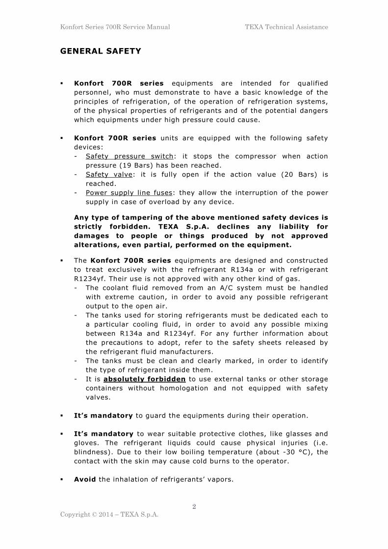
2.2.2 Oil Drain
During this phase, the equipment activates the following electrical
components:
� EVSO electro-valve;
� Load cell (8)1.
After the recovery phase, the equipment opens the exhaust oil EVSO
electro-valve for the time necessary to empty the bottom of the separator
filter from the oil and the impurities collected during the recovery phase
from the A/C system of the vehicle. The discharge is helped by the
residual pressure inside the equipment.
Image 2.3 – Part of the hydraulic circuit involved into the oil drain phase
2.2.3 Vacuum
During this phase, the equipment activates the following electrical
components:
� Pressure sensor (1);
� LP electro-valves (only for 760R, 760R Bus and 780R BiGas);
� HP electro-valves (only for 760R, 760R Bus and 780R BiGas);
� EVP01 and EVP02 electro-valves;
� Vacuum pump PO;
� Heating band.
1 Component available only on 760R, 760R Bus and 780R BiGas models

Konfort Series 700R Service Manual TEXA Technical Assistance
14
Copyright © 2014 – TEXA S.p.A.
Before the starting of the real vacuum phase, the pressure sensor checks
the residual pressure inside the system: if the pressure does not remain
below the relative value of 600mbar, a further recovery phase is started,
in order to remove any presence of residual refrigerant from the A/C
system.
If, on the other hand, the pressure is lower than the above mentioned
value, the two EVP01 and EVP02 electro-valves are opening and the
vacuum pump switches on. In this way, the equipment evacuates the
system from any residual air and moisture. The duration of the vacuum
phase is selected during the initial setting of the A/C service from the
menu of the equipment.
If, within 1/3 of the vacuum time initially set, the pressure does not
reach a value which is below the threshold of 120mBars absolute, the
equipment alerts the operator about the fault (by means of a beep and of
a warning message on the display), but the vacuum pump will continue to
operate. The user can decide whether to stop the cycle, by pressing the
STOP button (this anomaly, in fact, could be indicative of a possible leak
of the vehicle’s A/C system) or to continue the service.
Image 2.4 – Part of the hydraulic circuit involved into the vacuum phase

Konfort Series 700R Service Manual TEXA Technical Assistance
15
Copyright © 2014 – TEXA S.p.A.
2.2.4 Leak Test
During this phase, the equipment activates only the pressure sensor (1).
Spent the amount of time set for the vacuum phase, the vacuum pump
turns off and the two electro-valves EVP01 and EVP02 close. At this
point, the pressure sensor performs a further control of pressure inside
the A/C system (for an amount of time preventively selected from the
initial menu of the equipment).
If, within this laps of time, the pressure rises above the limit value of
120mBars absolute, the unit will automatically stop the cycle, by putting
itself into a stand-by state and by alerting the operator (by means of a
beep and of a special message on the display) about the anomaly
(indicative, in this case, of a possible leak on the A/C system of the
vehicle). If, on the other hand, the remaining pressure is below this
threshold, the operative cycle of the Konfort unit automatically switches
to the next step.
Image 2.5 – Part of the hydraulic circuit involved into the leak test
2.2.5 Oil Injection
During this phase, the equipment activates the following electrical
components:
� Pressure sensor (1);
� LP electro-valves (only for 760R, 760R Bus and 780R BiGas);
� HP electro-valves (only for 760R, 760R Bus and 780R BiGas);
� EVIO electro-valve;

Konfort Series 700R Service Manual TEXA Technical Assistance
16
Copyright © 2014 – TEXA S.p.A.
� Load cell (9)2.
The oil injection is mainly performed by opening the EVIO electro-valve
and by pouring, thanks to the pressure difference, the new oil (PAG or
POE) into the A/C system of the vehicle. The electro-valve opening is
temporized in Konfort 705R, 710R and 720R units, while in all the other
models is governed by the decrease of weight detected by the oil
injection load cell. At the end of injection, the equipment will check the
residual pressure into the system. This will ensure the possibility of
implementing the next phase.
Image 2.6 – Part of the hydraulic circuit involved into the oil injection
2.2.6 UV Injection
During this phase, the equipment activates the following electrical
components:
� Pressure sensor (1);
� LP electro-valves (only for 760R, 760R Bus and 780R BiGas);
� HP electro-valves (only for 760R, 760R Bus and 780R BiGas);
� EVUV electro-valve;
� Load cell (10)3.
The UV injection is similar to the oil one, thanks to the opening of the
EVUV electro-valve and of the pour, because of the pressure difference,
of the UV fluid into the A/C system of the vehicle. Once again, the
electro-valve opening is temporized in Konfort 710R and 720R units,
2 Component available only on 760R, 760R Bus and 780R BiGas models 3 Component available only on 760R, 760R Bus and 780R BiGas models

Konfort Series 700R Service Manual TEXA Technical Assistance
17
Copyright © 2014 – TEXA S.p.A.
while in all the other models is governed by the weight decrease
measured by the corresponding load cell. Even at the end of this phase,
the unit will check the residual pressure inside the system, in order to
determine if the conditions for the execution of the next step will exist.
Image 2.7 – Part of the hydraulic circuit involved into the UV injection
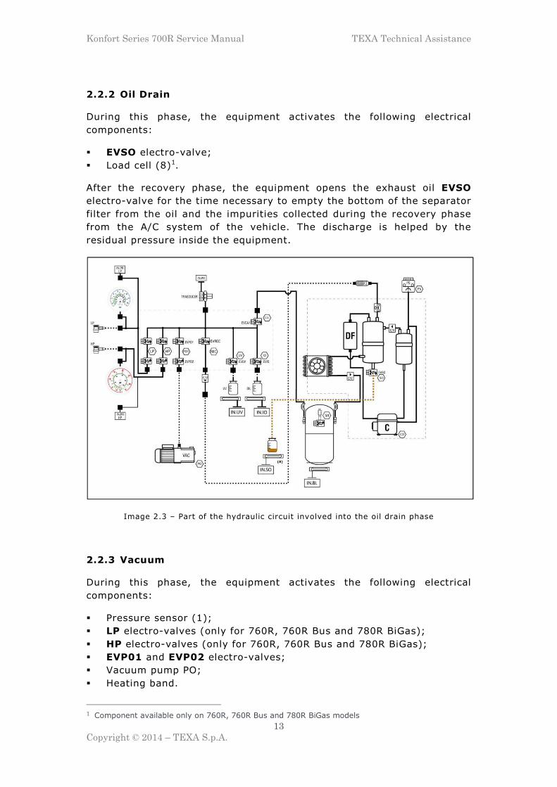
2.2.7 Refrigerant Injection
During this phase, the equipment activates the following electrical
components:
� Pressure sensor (1);
� LP electro-valves (only for 760R, 760R Bus and 780R BiGas);
� HP electro-valves (only for 760R, 760R Bus and 780R BiGas);
� EVCA1 electro-valve;
� Refrigerant load cell (3).
The refrigerant injection occurs by means of the transfer of the
refrigerant amount, which has been initially set from the menu of the
unit, from the inner vessel into the A/C system of the vehicle, thanks to
the pressure difference. This transfer is performed simply thanks to the
opening of the EVCA1 electro-valve. The closure of this electro-valve is
managed by the microcontroller board of the unit according to the weight
decrease measured by the load cell located under the equipment’s bottle.
Konfort Series 700R Service Manual TEXA Technical Assistance
18
Copyright © 2014 – TEXA S.p.A.
Image 2.8 – Part of the hydraulic circuit involved into the refrigerant injection
2.3 Evolution of the BiGas management: refrigerant recovery
and injection into Konfort 780R units
Unlike all the other models, Konfort 780R BiGas units provide the chance
to simultaneously manage both the services on the traditional A/C
systems working with R134a and the ones on the new generation
systems, based on the new refrigerant R1234yf.
This innovative architecture has led, inevitably, to a review of the
operating logic, in order to avoid any possible contamination between the
two different refrigerants within the equipment. More precisely, the
splitting of the recovery and injection hydraulic circuits has been
necessary, in order to keep the flows of R134a and R1234yf
distinguished.
Now, the way in which the equipment performs the hydraulic switching
that allows, depending on the type of A/C system, to deal either with
R134a or with R1234yf, will be detailed described, both for the recovery
phase and for the injection phase .
2.3.1 Recovery of R134a refrigerant
Before proceeding with the R134a refrigerant recovery from the vehicle’s
A/C system, the equipment performs a preliminary check of which
refrigerant has been involved in previous service: if the service has been
done on an A/C system operating with R1234yf, then Konfort starts an
automatic clean-up process of the hydraulic circuit, in order to avoid
Konfort Series 700R Service Manual TEXA Technical Assistance
19
Copyright © 2014 – TEXA S.p.A.
any possible contamination with the R134a, which will be employed in the
current service.
Once the clean-up will be completed, the equipment will start the
recovery phase, during which the following electrical components will be
activated:
� Pressure sensor (1);
� LP electro-valves;
� HP electro-valves;
� EVREC electro-valve;
� Compressor CO;
� Upper condenser fan (2);
� EVREF1 electro-valves;
� Refrigerant load cell (4).
The R134a refrigerant, thanks to the opening of the four HP and LP
electro-valves and of the EVREC electro-valve, is made to flow (thanks
to the compressor suction) inside the recovery hydraulic circuit of the
equipment.
It will flow, according with processes and status changes similar to those
described in paragraph 2.2.1, through the mechanic filter (5), the
expansion valve (6), the main separator filter (7) and the dryer
filter (DF).
At this point the R134a, which emerges from the dryer filter, is brought
into the compressor (CO), whose function is that of compressing the
refrigerant, thus raising its pressure (and therefore its temperature).
Once released from the compressor, the R134a refrigerant is passed
through an auxiliary separator filter (8), thanks to the simultaneous
opening of both the EVREF1 electro-valves by the firmware of the unit.
This auxiliary separator filter is exclusively dedicated to the separation
of R134a from the oil taken from the compressor (which is, then, poured
back to the compressor itself thanks to the opening of the EVREF1
electro-valve located on the output of the separator).
The refrigerant (now at high temperature) is then injected again into the
main separator filter where, according with processes and status changes
similar to those described in paragraph 2.2.1, the R134a begins to cool
and condense into a liquid phase.
The cooling and condensation of R134a are then completed into the
condenser (2), which allows the full refrigerant transition to the liquid
phase.
The refrigerant, now completely in the liquid state, is finally conveyed
into the upper tank, dedicated to the R134a.

Konfort Series 700R Service Manual TEXA Technical Assistance
20
Copyright © 2014 – TEXA S.p.A.
Image 2.9 – Part of the hydraulic circuit involved in the R134a recovery
phase on Konfort 780R BiGas units
2.3.2 Recovery of R1234yf refrigerant
Before proceeding with the R1234yf refrigerant recovery from the
vehicle’s A/C system, the equipment performs a preliminary check of
which refrigerant has been involved in previous service: if the service has
been done on an A/C system operating with R134a, then Konfort starts an
automatic clean-up process of the hydraulic circuit, in order to avoid
any possible contamination with the R1234yf, which will be employed in
the current service.
Once the clean-up will be completed, the equipment will start the
recovery phase, during which the following electrical components will be
activated:
� Pressure sensor (1);
� LP electro-valves;
� HP electro-valves;
� EVREC electro-valve;
� Compressor CO;
� Lower condenser fan (3);
� EVREF2 electro-valves;
� Refrigerant load cell (4).

Konfort Series 700R Service Manual TEXA Technical Assistance
21
Copyright © 2014 – TEXA S.p.A.
The R1234yf refrigerant, thanks to the opening of the four HP and LP
electro-valves and of the EVREC electro-valve, is made to flow (thanks
to the compressor suction) inside the recovery hydraulic circuit of the
equipment.
It will flow, according with processes and status changes similar to those
described in paragraph 2.2.1, through the mechanic filter (5), the
expansion valve (6), the main separator filter (7) and the dryer
filter (DF).
At this point the R1234yf, which emerges from the dryer filter, is brought
into the compressor (CO), whose function is that of compressing the
refrigerant, thus raising its pressure (and therefore its temperature).
Once released from the compressor, the R1234yf refrigerant is passed
through an auxiliary filter separator (9) (hydraulically connected in
parallel to the separator filter (8), dedicated to the R134a), thanks to the
simultaneous opening of both the EVREF2 electro-valves by the firmware
of the unit. This auxiliary separator filter is exclusively dedicated to the
separation of R1234yf from the oil taken from the compressor (which is,
then, poured back to the compressor itself thanks to the opening of the
EVREF2 electro-valve located at the output of the separator itself).
The R1234yf refrigerant (now at high temperature) is then injected again
into the main separator filter where, according with processes and status
changes similar to those described in paragraph 2.2.1, it begins to cool
and condense into a liquid phase.
The cooling and condensation of R1234yf are then completed into the
condenser (3), which allows the full refrigerant transition to the liquid
phase.
The refrigerant, now completely in the liquid state, is finally conveyed
into the lower tank, dedicated to the R1234yf.

Konfort Series 700R Service Manual TEXA Technical Assistance
22
Copyright © 2014 – TEXA S.p.A.
Image 2.10 – Part of the hydraulic circuit involved in the R1234yf recovery
phase on Konfort 780R BiGas units
2.3.3 Refrigerant R134a injection
During this phase, the equipment activates the following electrical
components:
� Pressure sensor (1);
� LP electro-valves;
� HP electro-valves;
� EVCA1 charge electro-valves;
� Refrigerant load cell (4).
The injection of the R134a refrigerant occurs because of the transfer of
the amount of refrigerant, initially set from the menu of the equipment,
from the upper bottle to the A/C system of the vehicle (thanks to the
pressure difference).
This transfer is simply performed thanks to the opening of the two
EVCA1 electro-valves in case of R134a.
The closure of these electro-valves is controlled by the firmware of the
management board of the equipment depending on the weight decrease
revealed by the load cell located under the two bottles of the unit.

Konfort Series 700R Service Manual TEXA Technical Assistance
23
Copyright © 2014 – TEXA S.p.A.
Image 2.11 – Part of the hydraulic circuit involved in the R134a injection
phase on Konfort 780R BiGas units
2.3.4 Refrigerant R1234yf injection
During this phase, the equipment activates the following electrical
components:
� Pressure sensor (1);
� LP electro-valves;
� HP electro-valves;
� EVCA2 electro-valves;
� Refrigerant load cell (4).
The injection of the R1234yf refrigerant occurs because of the transfer of
the amount of refrigerant, initially set from the menu of the equipment,
from the lower bottle to the A/C system of the vehicle (thanks to the
pressure difference).
This transfer is simply performed thanks to the opening of the two
EVCA2 electro-valves in case of R1234yf.
Also in this case, the closure of these electro-valves is controlled by the
firmware of the management board of the equipment depending on the
weight decrease revealed by the load cell located under the two bottles of
the unit.

Konfort Series 700R Service Manual TEXA Technical Assistance
24
Copyright © 2014 – TEXA S.p.A.
Image 2.12 – Part of the hydraulic circuit involved in the R1234yf injection
phase on Konfort 780R BiGas units
2.4 Refrigerant Recovery on Konfort 705R
The refrigerant recovery on the Konfort 705R units is very similar to the
one described in paragraph 2.2.1. The only difference, due to the need to
simplify the hydraulic circuit of this model of A/C station for reasons of
costs, consists in the fact that the separation of the oil, which is taken
from the compressor, is performed because of coalescence effect by
means of a capillary tube which is connected between the external
chamber of the main separator filter and the compressor. Therefore, in
this case, the unit is not using an auxiliary separator filter.

Konfort Series 700R Service Manual TEXA Technical Assistance
25
Copyright © 2014 – TEXA S.p.A.
Image 2.13 – Part of the hydraulic circuit involved in the refrigerant recovery
phase on Konfort 705R units

Konfort Series 700R Service Manual TEXA Technical Assistance
26
Copyright © 2014 – TEXA S.p.A.
CHAPTER 3 – KONFORT SERIES 700R: NEW
ARCHITECTURE OF THE MENU
3.1 Konfort 705R, 710R, 720R: Text menu on blue LCD display
The menu of Konfort 705R, 710R and 720R recharging units is shown on
a 80-digits blue display.
Once the unit is switched on, the following screenshot will be shown:
K O N F O R T 7 2 0 R e f r i g e r a n t g . X X X X h h : m m : s s d d / m m / y y y y
Image 3.1 – Main screen on the display of a Konfort 705R, 710R and 720R
By clicking on the DOWN button of the keyboard, the main page of the
menu of the equipment will be shown:
A C m a i n t e n a n c e A d d i t i o n a l f u n c t i o n s S e t t i n g s S e r v i c e
Image 3.2 – Main page of the menu of Konfort 705R, 710R and 720R
The desired option can be selected by pressing the UP and DOWN
buttons and by confirming the selection with the green ENTER button.

Konfort Series 700R Service Manual TEXA Technical Assistance
27
Copyright © 2014 – TEXA S.p.A.
3.1.1 The AC maintenance menu
The AC maintenance option, selectable from the main menu, allows to
choose how to operate with the equipment. Once this option will be
selected, the display will show the following screenshot:
V e h i c l e s e l e c t i o n C u s t o m i s e d s e r v i c e M y D a t a b a s e
Image 3.3 – The AC maintenance menu of Konfort 705R, 710R and 720R
The available choices are:
� Vehicle selection: It allows user to select a specific vehicle from the
database stored into the SD card of the equipment. The amount of
refrigerant to be charged will be automatically set for the selected
vehicle.
� Customised service: It allows user to customize which phase(s) of
the operative cycle (recovery, vacuum, leak test, oil/UV injection,
refrigerant injection) he would like to run on the equipment. This
option can be a very useful tool for verifying the proper function of
the unit.
� My Database: It allows user to store up to 128 new vehicles4 and
to specify, for each one of them, the quantity of refrigerant, the
duration of vacuum and leak phases and the quantities of oil and UV
to be injected. This option could be very useful, because it provides
the operator the chance to add new vehicles to his liking, if not
already included in the latest database release.
4 This quantity depends on the capacity of the internal flash memory of the unit.

Konfort Series 700R Service Manual TEXA Technical Assistance
28
Copyright © 2014 – TEXA S.p.A.
3.1.2 The Additional functions menu
The Additional functions option, selectable from the main menu, allows
to select some interesting service functions for the equipment. Once this
option will be selected, the display will show the following screenshot:
R 1 3 4 a v e s s e l f i l l . A / C s y s t e m f l u s h i n g V D C c o n t r o l S c a l e c h e c k
L a s t s e r v i c e d a t a C o u n t e r c h e c k R e s e t c o u n t e r s S y s t e m c h e c k
N o n - c o n d e n s a b l e g a s
Image 3.4 – The Additional function menu of the Konfort 705R, 710R and 720R.
It is possible to scroll the different pages/options of the menu by using
the UP and DOWN buttons on the keyboard
The functions available inside this menu are:
� Vessel fill.: It allows user to recharge the internal tank of the
equipment from an external bottle.
� A/C system flushing: It allows user to initiate the flushing
procedure through the use of TEXA Flushing Kit, affordable as an
accessory (only on Konfort 710R and 720R, refer to the corresponding
instruction manual for further details).
� VDC control: It allows to perform the control, from the Konfort
command panel, the variable displacement compressor of A/C
systems which are equipped with dedicated electronic control unit.
This control action can be done by using the TEXA VDC device,
available as an optional (only on Konfort 720R, refer to the
corresponding instruction manual for further details).
� Scale check: It allows to check the linearity of the refrigerant load
cell of the equipment.
Konfort Series 700R Service Manual TEXA Technical Assistance
29
Copyright © 2014 – TEXA S.p.A.
� Last service data: It allows to view the data of the last complete
A/C service performed by the equipment.
� Counter check: It allows to perform the view of the counters (total
and partial) of the equipment, both for the recovered refrigerant and
for the time of vacuum.
� Reset counters: It allows to perform the reset of the counters of the
recovered refrigerant and of the vacuum time of the unit. This action
has to be performed during the ordinary maintenance of the
equipment. Further details will be given on Chapter 5.
� System check: It allows to perform the check of the performances of
the A/C system of the vehicle based on the pressure readings from
the gauges or by means of the Climate Control Efficiency Kit,
available as an optional (only on Konfort 720R, refer to the
corresponding instruction manual for further details).
� Non-condensable gas: This function allows to force the automatic
check and/or discharge of the non-condensable gases from the inside
of the vessel of the unit5.
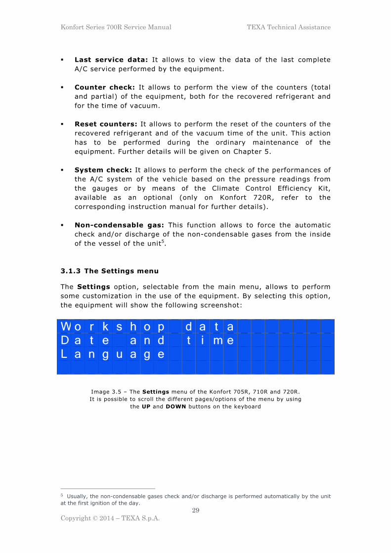
3.1.3 The Settings menu
The Settings option, selectable from the main menu, allows to perform
some customization in the use of the equipment. By selecting this option,
the equipment will show the following screenshot:
W o r k s h o p d a t a D a t e a n d t i m e L a n g u a g e
Image 3.5 – The Settings menu of the Konfort 705R, 710R and 720R.
It is possible to scroll the different pages/options of the menu by using
the UP and DOWN buttons on the keyboard
5 Usually, the non-condensable gases check and/or discharge is performed automatically by the unit
at the first ignition of the day.

Konfort Series 700R Service Manual TEXA Technical Assistance
30
Copyright © 2014 – TEXA S.p.A.
The functions available inside this menu are:
� Workshop data: It allows to specify the name and the details of the
own workshop.
� Date and time: It allows to change the date and time inside the
equipment.
� Language: It allows to change the display language for the menu
and for the various functions of the equipment.
3.1.4 The Service menu
The Service option, selectable from the main menu, allows to access to
the service and maintenance features of the Konfort unit. By selecting
this option, the display of the equipment will show the following
screenshot:
E n t e r p a s s w o r d _ y y y y
Image 3.6 – Request for password insertion from
the Service menu of Konfort 705R, 710R and 720R
Because of the importance of this menu, it will be detailed described into
Chapter 4.

Konfort Series 700R Service Manual TEXA Technical Assistance
31
Copyright © 2014 – TEXA S.p.A.
3.2 Konfort 760R, 760R Bus and 780R BiGas: Graphic menu on
color display
The menu of Konfort 760R, 760R Bus and 780R BiGas units is showed by
a graphic 65000-color display.
When the equipment is turned on, the following screenshot will be
displayed:
Image 3.7 – Initial screenshot of the display of Konfort 760R,
760R Bus and 780R BiGas
By clicking on the DOWN button of the keyboard, the main page of the
menu of the equipment will be shown:
Image 3.8 – Main page of the menu of Konfort 760R,
760R Bus and 780R BiGas
In the black top part of the screen the amount of the various fluids
(refrigerant(s), injection oil, UV tracer) is shown in grams. A colored icon
is reported next to each fluid. When this icon is red:
it means that the corresponding fluid is insufficient.

Konfort Series 700R Service Manual TEXA Technical Assistance
32
Copyright © 2014 – TEXA S.p.A.
When it is green:
it means that the fluid is sufficient to perform a service on the A/C system
of a vehicle.
3.2.1 The AC maintenance menu
The AC maintenance option, selectable from the main menu, allows to
choose how to operate with the equipment. Once this option will be
selected, the display will show the following screenshot:
Image 3.9 – Options available in the AC maintenance menu of
Konfort 760R, 760R Bus and 780R BiGas
The available choices are:
� Vehicle selection: It allows user to select a specific vehicle from the
database stored into the SD card of the equipment. The amount of
refrigerant to be charged will be automatically set for the selected
vehicle.
� Customised service: It allows user to customize which phase(s) of
the operative cycle (recovery, vacuum, leak test, oil/UV injection,
refrigerant injection) he would like to run on the equipment. This
option can be a very useful tool for verifying the proper function of
the unit.
� My Database: It allows user to store up to 128 new vehicles and
to specify, for each one of them, the quantity of refrigerant, the
duration of vacuum and leak phases and the quantities of oil and UV
to be injected. This option could be very useful, because it provides
the operator the chance to add new vehicles to his liking, if not
already included in the latest database release.

Konfort Series 700R Service Manual TEXA Technical Assistance
33
Copyright © 2014 – TEXA S.p.A.
3.2.2 The Additional functions menu
The Additional functions option, selectable from the main menu, allows
to select some interesting service functions for the equipment. Once this
option will be selected, the display will show the following screenshot:
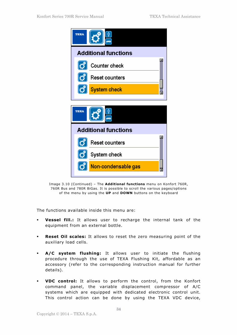
Image 3.10 – The Additional functions menu on Konfort 760R,
760R Bus and 780R BiGas. It is possible to scroll the various pages/options
of the menu by using the UP and DOWN buttons on the keyboard
Konfort Series 700R Service Manual TEXA Technical Assistance
34
Copyright © 2014 – TEXA S.p.A.
Image 3.10 (Continued) – The Additional functions menu on Konfort 760R,
760R Bus and 780R BiGas. It is possible to scroll the various pages/options
of the menu by using the UP and DOWN buttons on the keyboard
The functions available inside this menu are:
� Vessel fill.: It allows user to recharge the internal tank of the
equipment from an external bottle.
� Reset Oil scales: It allows to reset the zero measuring point of the
auxiliary load cells.
� A/C system flushing: It allows user to initiate the flushing
procedure through the use of TEXA Flushing Kit, affordable as an
accessory (refer to the corresponding instruction manual for further
details).
� VDC control: It allows to perform the control, from the Konfort
command panel, the variable displacement compressor of A/C
systems which are equipped with dedicated electronic control unit.
This control action can be done by using the TEXA VDC device,

Konfort Series 700R Service Manual TEXA Technical Assistance
35
Copyright © 2014 – TEXA S.p.A.
available as an optional (refer to the corresponding instruction
manual for further details).
� Scale check: It allows to check the linearity of the refrigerant load
cell of the equipment.
� Last service data: It allows to view the data of the last complete
A/C service performed by the equipment.
� Counter check: It allows to perform the view of the counters (total
and partial) of the equipment, both for the recovered refrigerant and
for the time of vacuum.
� Reset counters: It allows to perform the reset of the counters of the
recovered refrigerant and of the vacuum time of the unit. This action
has to be performed during the ordinary maintenance of the
equipment. Further details will be given on Chapter 5.
� System check: It allows to perform the check of the performances of
the A/C system of the vehicle based on the pressure readings from
the gauges or by means of the Climate Control Efficiency Kit,
available as an optional (refer to the corresponding instruction
manual for further details).
� Non-condensable gas: This function allows to force the automatic
check and/or discharge of the non-condensable gases from the inside
of the vessel of the unit.

Konfort Series 700R Service Manual TEXA Technical Assistance
36
Copyright © 2014 – TEXA S.p.A.
3.2.3 The Settings menu
The Settings option, selectable from the main menu, allows to perform
some customization in the use of the equipment. By selecting this option,
the equipment will show the following screenshot:
Image 3.11 – The Settings menu on Konfort 760R,
760R Bus and 780R BiGas. It is possible to scroll the various pages/options
of the menu by using the UP and DOWN buttons on the keyboard
The functions available inside this menu are:
� Workshop data: It allows to specify the name and the details of the
own workshop.
� Date and time: It allows to change the date and time inside the
equipment.
� Language: It allows to change the display language for the menu
and for the various functions of the equipment.

Konfort Series 700R Service Manual TEXA Technical Assistance
37
Copyright © 2014 – TEXA S.p.A.
� Bottle management: It allows to initialize the drained oil, injection
oil and injection UV bottles.
3.2.4 The Service menu
The Service option, selectable from the main menu, allows to access to
the service and maintenance features of the Konfort unit. By selecting
this option, the display of the equipment will show the following
screenshot:
Image 3.12 – Request for password insertion from
the Service menu of Konfort 760R, 760R Bus
and 780R BiGas
Because of the importance of this menu, it will be detailed described into
Chapter 4.
Konfort Series 700R Service Manual TEXA Technical Assistance
38
Copyright © 2014 – TEXA S.p.A.
CHAPTER 4 – THE SERVICE MENU
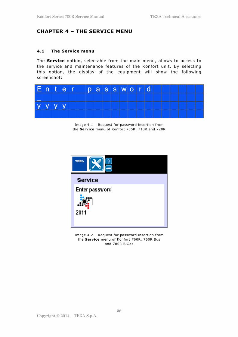
4.1 The Service menu
The Service option, selectable from the main menu, allows to access to
the service and maintenance features of the Konfort unit. By selecting
this option, the display of the equipment will show the following
screenshot:
E n t e r p a s s w o r d _ y y y y
Image 4.1 – Request for password insertion from
the Service menu of Konfort 705R, 710R and 720R
Image 4.2 – Request for password insertion from
the Service menu of Konfort 760R, 760R Bus
and 780R BiGas

Konfort Series 700R Service Manual TEXA Technical Assistance
39
Copyright © 2014 – TEXA S.p.A.
There are two different levels of access to the service menu:
� User Level: Any end user can access the Konfort Service menu
through the user password 1236. By accessing the menu in this way,
the equipment will display the following functions:
S e n s o r c a l i b r a t i o n . P u b l i c p a r a m e t e r s C a l i b r a t i o n s t a t u s S t o r e d e r r o r s
D e f a u l t p a r a m e t e r s
Image 4.3 – Access to the Service menu with user level on Konfort 705R,
710R and 720R by means of the password 1236
Image 4.4 – Access to the Service menu with user level on Konfort 760R,
760R Bus and 780R BiGas by means of the password 1236

Konfort Series 700R Service Manual TEXA Technical Assistance
40
Copyright © 2014 – TEXA S.p.A.
Image 4.4 (Continue) – Access to the Service menu with user level on Konfort 760R,
760R Bus and 780R BiGas by means of the password 1236
� Dealer level: This access mode to the Service menu allows only the
dealer to have the access to an extended variety of features of the
service menu. Such extended access can be performed by means of
the dealer password provided annually by TEXA S.p.A. and it allows
the display of the following functions:
P o w e r o u t p u t s S e n s o r c a l i b r a t i o n . P r i v a t e p a r a m e t e r s P u b l i c p a r a m e t e r s
C a l i b r a t i o n s t a t u s S e l e c t r e f r i g e r a n t S t o r e d e r r o r s D e f a u l t p a r a m e t e r s
C u s t o m i s e d s e r v i c e
Image 4.5 – Access to the Service menu with the dealer level on Konfort
705R, 710R and 720R unit by using the dealer password (annually renewed)

Konfort Series 700R Service Manual TEXA Technical Assistance
41
Copyright © 2014 – TEXA S.p.A.
Image 4.6 – Access to the Service menu with the dealer level on Konfort
760R, 760R Bus and 780R BiGas units by using the dealer password
(annually renewed)

Konfort Series 700R Service Manual TEXA Technical Assistance
42
Copyright © 2014 – TEXA S.p.A.
Image 4.6 (Continue) – Access to the Service menu with the dealer level on Konfort
760R, 760R Bus and 780R BiGas units by using the dealer password
(annually renewed)
The following paragraphs will describe in detail the various functions of
the Service menu.
4.2 The “POWER OUTPUTS” function on K705R, K710R, K720R
By selecting the feature called Power outputs in a Konfort 705R, 710R
or 720R, the following page of the Service menu will be displayed:
C O P O S O U V I O C 1 C 2 0 0 0 0 0 0 0 H P R E L P R 1 R 2 F 1 F 2 0 0 0 0 0 0 0
Image 4.7 – The first page of Power outputs function
in the Service menu of a Konfort 705R, 710R and 720R
This page offers to the dealer the chance to perform the manual
activation of each equipment’s actuator (compressor, vacuum pump,
electro-valves) and may reveal to be very useful in the identification of
possible anomalies in the behavior of the unit.
The marks reported on the first and on the third lines of this screenshot
indicate the different actuators of the equipment. More precisely:
� CO = Compressor;
� PO = Vacuum pump;
� SO = Oil discharge electro-valve;
� UV = UV injection electro-valve (not available on K705R);
� IO = Oil injection electro-valve;
� C1 = Refrigerant injection electro-valve;
� C2 = (not available)

Konfort Series 700R Service Manual TEXA Technical Assistance
43
Copyright © 2014 – TEXA S.p.A.
� HP = (not available)
� RE = Refrigerant recovery electro-valve;
� LP = (not available)
� R1 = (not available)
� R2 = (not available)
� F1 = Non-condensable gases automatic discharge electro-valve (not
available on K705R and K710R);
� F2 = (not available).
By using the UP and DOWN buttons on the keyboard of the equipment,
the user can select the second or the fourth line of the screen. Then, by
using the buttons from 1 to the 7, the status of each of the actuators
shown in the previous line can be changed. The possible states are:
� 0 = Actuator off;
� 1 = Actuator on.
For example, by placing the cursor on the second line, the 1 button
activates or deactivates the compressor (CO), the 2 key switches on or
off the vacuum pump (PO), and so on for all other actuators.
Similarly, by placing the cursor on the fourth line, the 2 button activates
or deactivates the recovery electro-valve (RE) and the 6 key activates or
deactivates the non-condensable gas automatic discharge electro-valve
(F1).
By further pressing the DOWN button from the previous page of Power
outputs menu, the following screenshots will be displayed:
S E N S O R S ( P O I N T S ) P R 4 1 7 8 B L 1 5 9 7 7 D O 0 I O 0 U V 0 H P 9 7
S E N S O R S ( P O I N T S ) L P 8 6 R F 3 0 7 1 8 T A 1 0 6 0 9 T V 1 6 3 7 2 T U 2 3 2 8 A L L H P 0
Image 4.8 – Punctual values obtained by means of the digital conversion of the analog
electrical signals incoming to the ACE Micro board from the sensors of the Konfort unit
The parameters displayed in these two screens provide a punctual
indication, that is instant per instant, of the measure of all the sensors
(load cells, pressure transducers, temperature sensors) which are
connected to the inputs of the ACE Micro board. These values give the
possibility to make an estimation of the dynamic operation of each
sensor.

Konfort Series 700R Service Manual TEXA Technical Assistance
44
Copyright © 2014 – TEXA S.p.A.
These punctual values, in fact, correspond to the digital conversion of the
analog electrical signal provided to the ACE Micro board from each
sensor. More precisely:
� PR indicates the value (in points) of the signal coming from the main
pressure sensor ;
� BL indicates the value (in points) of the signal coming from the main
load cell;
� DO, IO and UV are not used in Konfort 705R, 710R and 720R;
� HP indicates the value (in points) of the signal coming from the
auxiliary pressure sensor mounted on the HP branch (only in case
of installation of the VDC device);
� LP is not used in Konfort 705R, 710R and 720R6;
� TA indicates the value (in points) of the signal coming from the room
temperature sensor;
� TV is not used;
� TU indicates the value (in points) of the signal coming from the
microcontroller temperature sensor;
� ALLHP indicates a state of alarm in the case of excessive pressure
into the hydraulic circuit of the Konfort unit: when the safety
pressure switch is not operating (normal condition), the state of this
parameter is 0. In case the safety pressure switch would operate (by
interrupting, in case of too much high pressures, the power supply of
the compressor), the state of this parameter will get the value 1.
6 Although not related to any sensor, the punctual value of this input could be in any case different
from zero, as the ACE Micro board is characterized by floating inputs.

Konfort Series 700R Service Manual TEXA Technical Assistance
45
Copyright © 2014 – TEXA S.p.A.
By further pressing the DOWN button on the keyboard of the Konfort
unit, the following screens will be displayed:
S E N S O R S ( M E A S U R E ) P R 1 0 4 9 B L 1 0 7 3 2 D O 0 I O 0 U V 0 H P 9 9
S E N S O R S ( M E A S U R E ) L P 8 8 R F 2 2 9 6 T A 2 5 8 T V - 4 1 3 T U 2 7 4 A L L H P 0
Image 4.9 – Absolute values of the physical quantities measured by the different
sensors connected to the inputs of the ACE Micro board of the Konfort unit
The values displayed in these two screenshots show the conversion into
physical quantity of each punctual value of the same parameters
displayed by the screenshots shown in Image 4.8. Specifically:
� PR indicates the absolute pressure (in mBars) measured by the
main pressure sensor of the equipment;
� BL indicates the value of the absolute weight (in grams, sum of the
net refrigerant weight and of the tare weight of the bottle) currently
located on the main load cell;
� DO, UV and IO are not used in Konfort 705R, 710R and 720R;
� HP indicates the absolute pressure (in mBars) measured by the
auxiliary pressure sensor mounted on the HP branch (only in case
of installation of the VDC device);
� LP is not used in Konfort 705R, 710R and 720R;
� TA indicates the temperature (in Celsius degrees) measured by the
room temperature sensor of the Konfort unit. The last digit of the
parameter indicates the tenths of degree (hence, for example,
TA=258 indicates a temperature of 25,8°C);
� TV is not used;
� TU indicates the temperature (in Celsius degrees) measured by the
microcontroller temperature sensor of the Konfort unit. The last

Konfort Series 700R Service Manual TEXA Technical Assistance
46
Copyright © 2014 – TEXA S.p.A.
digit of the parameter indicates the tenths of degree (hence, for
example, TU=274 indicates a temperature of 27,4°C);
� ALLHP indicates, once again, a state of alarm in the case of
excessive pressure into the hydraulic circuit of the Konfort unit (as
also described on Image 4.8).
By pressing again the DOWN button on the key board of the Konfort unit,
the following screen will be displayed:
F A N S T A T U S F A N 1 1 F A N 2 1 F A N 3 1
Image 4.10 – Page for checking the status of the fans
in Konfort 705R, 710R and 720R
From this page, the user can check which is the status of the
functioning/malfunctioning of the fans of the unit. More precisely:
� FAN1 is the main fan of the unit, located on the back door of the
equipment (not available on Konfort 705R and 710R);
� FAN2 is the fan located on the condenser of the intake assembly of
the unit (not electronically controlled on Konfort 705R and 710R);
� FAN3 is not used on Konfort 705R, 710R and 720R.
The possible statuses of the fans are:
� status 1: the fan is working properly;
� status 0: the fan is in overload;
� status 3: the fan is in open circuit.

Konfort Series 700R Service Manual TEXA Technical Assistance
47
Copyright © 2014 – TEXA S.p.A.
By further pressing the DOWN button on the keyboard of the Konfort unit,
the following screen will be displayed:
T I M I N G S ( S E C ) < > m s .
Image 4.11 – Page for setting the timing for
the activation of the actuators in Konfort 705R, 710R and 720R
From this page, user can select the duration (in milliseconds) with which
he wants to operate the actuators by the manual activation page shown
in Image 4.7. For example, by setting a value of 1000 (1000msec = 1
sec), while each actuator is manually activated, when its status will be 1
(on), it will be activate and deactivate consecutively every second. This
function can be very useful to check the status of operation of the
electronic drivers (relays and triacs) of the ACE Power board which
control the various actuators of the unit.
Konfort Series 700R Service Manual TEXA Technical Assistance
48
Copyright © 2014 – TEXA S.p.A.
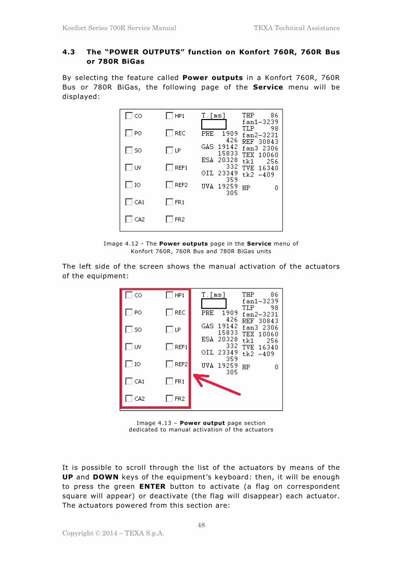
4.3 The “POWER OUTPUTS” function on Konfort 760R, 760R Bus
or 780R BiGas
By selecting the feature called Power outputs in a Konfort 760R, 760R
Bus or 780R BiGas, the following page of the Service menu will be
displayed:
Image 4.12 - The Power outputs page in the Service menu of
Konfort 760R, 760R Bus and 780R BiGas units
The left side of the screen shows the manual activation of the actuators
of the equipment:
Image 4.13 – Power output page section dedicated to manual activation of the actuators
It is possible to scroll through the list of the actuators by means of the
UP and DOWN keys of the equipment’s keyboard: then, it will be enough
to press the green ENTER button to activate (a flag on correspondent
square will appear) or deactivate (the flag will disappear) each actuator.
The actuators powered from this section are:

Konfort Series 700R Service Manual TEXA Technical Assistance
49
Copyright © 2014 – TEXA S.p.A.
� CO = Compressor;
� PO = Vacuum pump;
� SO = Oil discharge electro-valve;
� UV = UV injection electro-valve;
� IO = Oil injection electro-valve;
� CA1 = Refrigerant charge electro-valve;
� CA2 = R1234yf charge electro-valve (available only on K780R BiGas);
� HP1 = HP branch electro-valves;
� REC = Refrigerant recovery electro-valve;
� LP = LP branch electro-valves;
� REF1 = R134a separation electro-valves (only on K780R BiGas);
� REF2 = R1234yf separation electro-valves (only on K780 BiGas);
� FR1 = Automatic non-condensable gases discharge electro-valve;
� FR2 = Automatic non-condensable gases discharge electro-valve from
the R1234yf tank (only on K780R BiGas).
The central part of the screen shows, on the other hand, the values of the
quantities measured by sensors connected to the equipment’s ACE Micro
board:
Image 4.14 – Section of the Power output page dedicated
to the signals from the Konfort sensors
In particular, each parameter of this section is characterized by two
values:
� the first one is given by the points of the digital conversion of the
analog signal coming from the sensor in object;
� the second one is given by the absolute value of the physical
quantity measured by the sensor in object.
The parameters shown in this section of the Power outputs page are:
� PRE: punctual values and absolute pressure (in mBars) measured by
the main pressure sensor of the equipment;

Konfort Series 700R Service Manual TEXA Technical Assistance
50
Copyright © 2014 – TEXA S.p.A.
� GAS: punctual values and absolute weight (in grams, sum of the net
refrigerant weight and of the tare weight of the bottle(s)) measured
by the main load cell of the equipment;
� ESA: punctual values and absolute weight (in grams) measured by the
discharged oil load cell of the equipment;
� OIL: punctual values and absolute weight (in grams) measured by the
injected oil load cell of the equipment;
� UVA: punctual values and absolute weight (in grams) measured by the
UV load cell of the equipment.
In the middle of the screen of this section, finally, the timing option for
manually enabling/disabling the actuators from the Power outputs menu
is shown (similarly to what described for Konfort K720R):
Image 4.15 – Setup of the timing for the manual powering
of the actuators in Konfort 760R, 760R Bus and 780R BiGas

Konfort Series 700R Service Manual TEXA Technical Assistance
51
Copyright © 2014 – TEXA S.p.A.
By keeping the orange INFO button pressed for few seconds, the status
of the fans of the unit will be shown on the right side of the display:
Image 4.16 - Page for checking the status of the fans
in Konfort 760R, 760R Bus and 780R BiGas
From this section, the user can check which is the status of the
functioning/malfunctioning of the fans of the unit. More precisely:
� FAN1 is the main fan of the unit, located on the back door of the
equipment;
� FAN2 is the fan located on the condenser of the intake assembly of
the unit;
� FAN3 is the fan located on the lower condenser (R1234yf) of the
intake assembly of the K780R BiGas.
The possible statuses of the fans are:
� status 1: the fan is working properly;
� status 0: the fan is in overload;
� status 3: the fan is in open circuit.

Konfort Series 700R Service Manual TEXA Technical Assistance
52
Copyright © 2014 – TEXA S.p.A.
4.4 The “SENSOR CALIBRATION” function on K705R, K710R and
K720R
By selecting the feature called Sensor calibration in a Konfort 705R,
710R and 720R, the following page of the Service menu will be
displayed:
R e f r i g e r a n t U V A d d i t i v e N e w O i l M a i n S e n s o r
Image 4.17 – The first page of the Sensor Calibration function
of the Service menu in a Konfort 705R, 710R and 720R
S e c o n d a r y s e n s o r s
Image 4.18 – The second page of the Sensor Calibration function
of the Service menu in a Konfort 705R, 710R and 720R
Now the calibration procedures for each individual sensor of the Konfort
705R, 710R and 720R units will be passed in review.
4.4.1 “REFRIGERANT” calibration on K705R, K710R and K720R
The Refrigerant function, available in the Sensor Calibration menu,
allows to calibrate the refrigerant load cell of the equipment.
In order to proceed with the calibration, the user must first of all remove
the front panel of the Konfort unit and release the cylinder from the
scale, in order to easily make the steps required during the calibration
procedure.

Konfort Series 700R Service Manual TEXA Technical Assistance
53
Copyright © 2014 – TEXA S.p.A.
More specifically, the user has to:
� unscrew (by means of an 3-millimiters Allen key) the two screws on the
top panel of the equipment:
Image 4.19 – Screws removal from the top panel of the equipment
� unscrew (by means of an 3-millimiters Allen key, preferably with a
flexible handle) the four screws on the rear-side edges of the
equipment:
Image 4.20 – Removal of the four screws on the rear side
of the Konfort unit
� lift the top panel and remove the plastic front panel of the equipment,
in order to open it completely;

Konfort Series 700R Service Manual TEXA Technical Assistance
54
Copyright © 2014 – TEXA S.p.A.
� remove the heating band from the tank. Remove it and place it on the
one side, ensuring that it will not touch the scale (otherwise, it would
alter the calibration):
Image 4.21 – Heating band removal
from the refrigerant tank
� remove (with the help of a 8-millimiters hexagonal wrench) the screw
of the bracket which blocks the tank on the scale. Then remove the
bracket:
Image 4.22 – Removal of the bracket that blocks
the tank to the structure of the scale
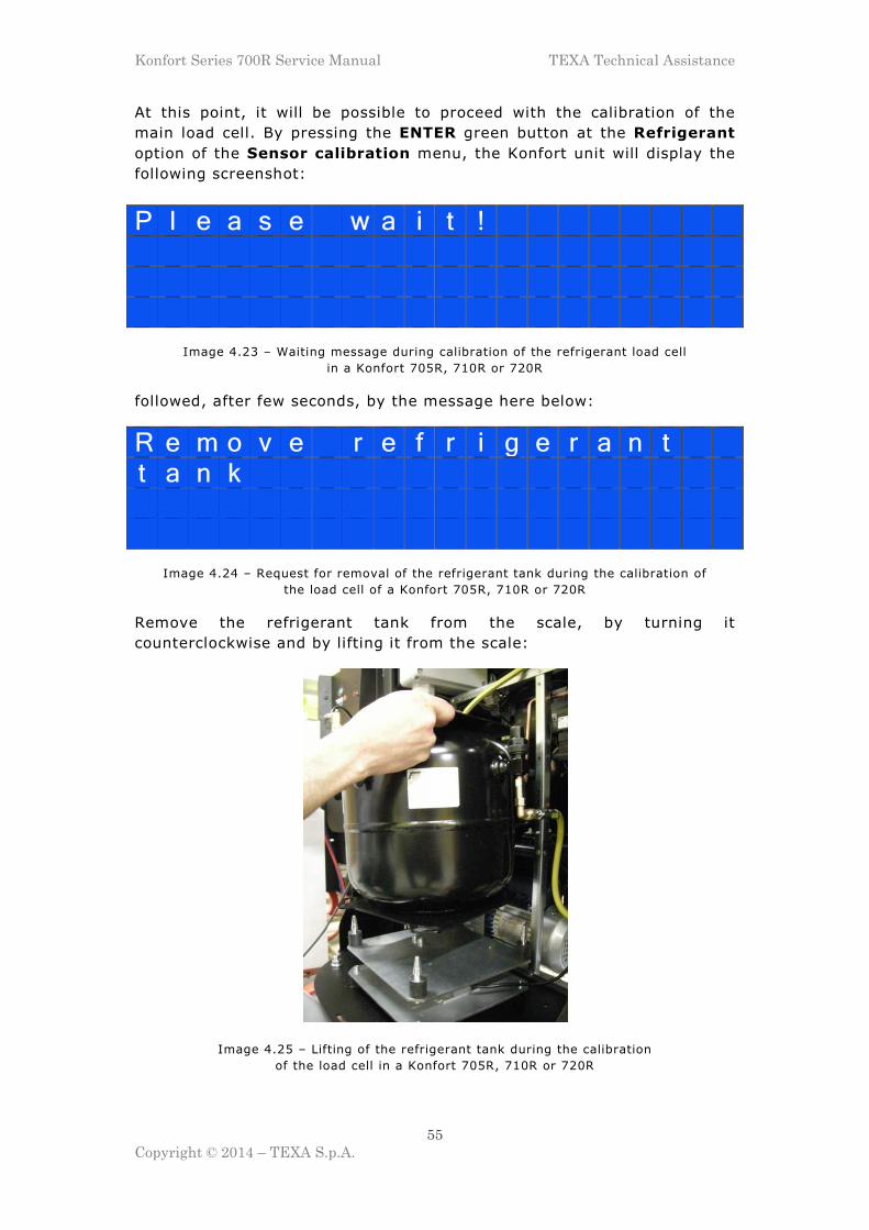
Konfort Series 700R Service Manual TEXA Technical Assistance
55
Copyright © 2014 – TEXA S.p.A.
At this point, it will be possible to proceed with the calibration of the
main load cell. By pressing the ENTER green button at the Refrigerant
option of the Sensor calibration menu, the Konfort unit will display the
following screenshot:
P l e a s e w a i t !
Image 4.23 – Waiting message during calibration of the refrigerant load cell
in a Konfort 705R, 710R or 720R
followed, after few seconds, by the message here below:
R e m o v e r e f r i g e r a n t t a n k
Image 4.24 – Request for removal of the refrigerant tank during the calibration of
the load cell of a Konfort 705R, 710R or 720R
Remove the refrigerant tank from the scale, by turning it
counterclockwise and by lifting it from the scale:
Image 4.25 – Lifting of the refrigerant tank during the calibration
of the load cell in a Konfort 705R, 710R or 720R

Konfort Series 700R Service Manual TEXA Technical Assistance
56
Copyright © 2014 – TEXA S.p.A.
Press, then, the green ENTER button on the keyboard, while keeping the
tank raised from the scale. The equipment will display the following
screenshot:
P l e a s e w a i t !
Image 4.26 – Waiting message during calibration of the refrigerant load cell
in a Konfort 705R, 710R or 720R
followed by the message here below:
R e p l a c e r e f r i g e r a n t t a n k
Image 4.27 – Request for replacement of the tank on the scale
Replace the tank on the scale, by putting its lower edges in the four
conical pins of the scale plate and by turning clockwise to lock it. Then
press ENTER to confirm.
The equipment, then, will show the following screenshot:
P l e a s e w a i t !
Image 4.28 – Waiting message during calibration of the refrigerant load cell
in a Konfort 705R, 710R or 720R
followed by the message here below:
I s t h e s a m p l e w e i g h t o n t h e s c a l e ?
Image 4.29 – Request for placement of the sample weight

Konfort Series 700R Service Manual TEXA Technical Assistance
57
Copyright © 2014 – TEXA S.p.A.
Place a sample weight of at least 1 kg7 over the refrigerant tank:
Image 4.30 – Placement of the sample weight on
refrigerant tank
then press ENTER to continue.
The display, then, will show the following message:
E n t e r s a m p l e w e i g h t v a l u e g .
Image 4.31 – Request for insertion of the value of the sample weight
Type the value in grams of sample weight (for example, in the case of a
sample weight of 1 Kg, type 1000), then press ENTER to confirm.
7 We recommend to perform the scale calibration by using the magnetic 1-kilogram sample weight
included into the new sample weight kit for Konfort 700R. The kit is available for purchase from the Electronic Spare Parts website (part no. 4800103).

Konfort Series 700R Service Manual TEXA Technical Assistance
58
Copyright © 2014 – TEXA S.p.A.
The unit will show the following screenshot:
P l e a s e w a i t !
Image 4.32 – Waiting message during calibration of the refrigerant load cell
in a Konfort 705R, 710R or 720R
followed by the message here below:
C a l i b r a t i o n O K !
Image 4.33 – Confirmation message of the correctness of the calibration
thus confirming the correctness of the procedure.
4.4.2 “UV ADDITIVE” calibration on K710R and K720R
Although not equipped with a scale for the management of the amount of
UV additive that is injected during a service on the A/C system of a
vehicle, Konfort 710R and 720R units allow in any case the calibration of
the time constant which controls the opening of the EVUV electro-valve.
4.4.3 “NEW OIL” calibration on K705R, K710R and K720R
Although not equipped with a scale for the management of the amount of
oil that is injected during a service on the A/C system of a vehicle,
Konfort 705R, 710R and 720R units allow in any case the calibration of
the time constant which controls the opening of the EVIO electro-valve.
4.4.4 “MAIN SENSOR” calibration on K705R, K710R and K720R
The Main Sensor function available in the Sensor calibration menu
allows user to calibrate the main pressure sensor of equipment.

Konfort Series 700R Service Manual TEXA Technical Assistance
59
Copyright © 2014 – TEXA S.p.A.
By pressing the ENTER button on this option, Konfort K720R displays the
following screenshot:
P l e a s e w a i t !
Image 4.34 – Waiting message during calibration of the main pressure sensor
in a Konfort 705R, 710R or 720R
After few seconds, the unit will show the following message:
O p e n L P / H P v a l v e s .
Image 4.35 – Request for opening of the LP and HP valves on the side of the unit
Open the two HP and LP valves positioned on the side of the equipment,
then press the ENTER button to confirm.
The unit will show the following screenshot:
P l e a s e w a i t !
Image 4.36 – Waiting message during calibration of the main pressure sensor
in a Konfort 705R, 710R or 720R
followed by the message here below :
A r e t h e L P / H P q u i c k c o u p l e r s r e m o v e d ?
Image 4.37 – Request for removal of the LP and HP fittings from service pipes

Konfort Series 700R Service Manual TEXA Technical Assistance
60
Copyright © 2014 – TEXA S.p.A.
Unscrew the fittings from the HP and LP service pipes:
Image 4.38 – Removal of both the HP and LP fittings
from the service pipes of the unit
then press ENTER to confirm.
The display will show the following screenshot:
P l e a s e w a i t !
Image 4.39 - Waiting message during calibration of the main pressure sensor
in a Konfort 705R, 710R or 720R
followed by the message here below:
R e - i n s t a l l L P / H P c o u p l e r s o n h o s e s
Image 4.40 – Request for reconnection of the HP and LP fittings to the service pipes
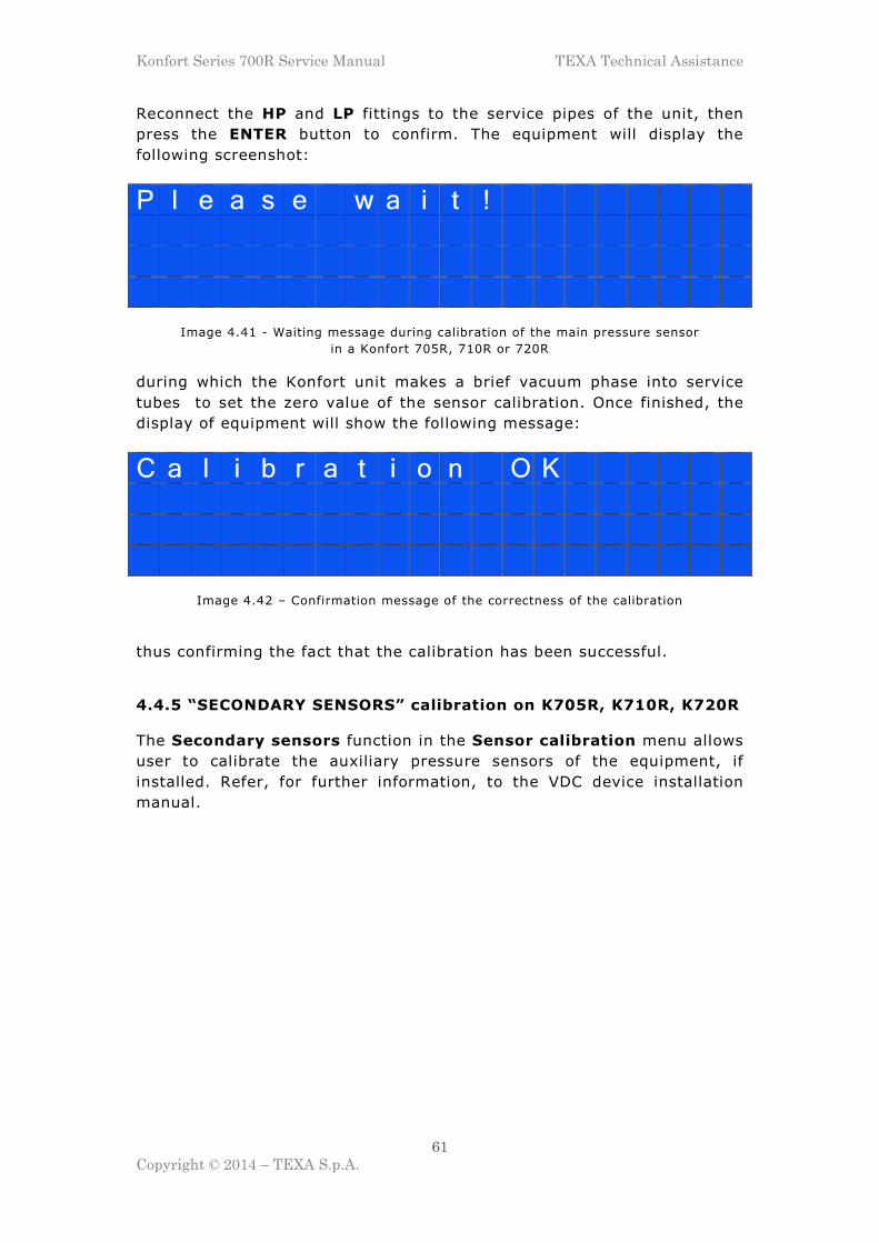
Konfort Series 700R Service Manual TEXA Technical Assistance
61
Copyright © 2014 – TEXA S.p.A.
Reconnect the HP and LP fittings to the service pipes of the unit, then
press the ENTER button to confirm. The equipment will display the
following screenshot:
P l e a s e w a i t !
Image 4.41 - Waiting message during calibration of the main pressure sensor
in a Konfort 705R, 710R or 720R
during which the Konfort unit makes a brief vacuum phase into service
tubes to set the zero value of the sensor calibration. Once finished, the
display of equipment will show the following message:
C a l i b r a t i o n O K
Image 4.42 – Confirmation message of the correctness of the calibration
thus confirming the fact that the calibration has been successful.
4.4.5 “SECONDARY SENSORS” calibration on K705R, K710R, K720R
The Secondary sensors function in the Sensor calibration menu allows
user to calibrate the auxiliary pressure sensors of the equipment, if
installed. Refer, for further information, to the VDC device installation
manual.

Konfort Series 700R Service Manual TEXA Technical Assistance
62
Copyright © 2014 – TEXA S.p.A.
4.5 The “SENSOR CALIBRATION” function on Konfort 760R, 760R
Bus and 780R BiGas
By selecting the feature called Sensor calibration in on Konfort 760R,
760R Bus and 780R BiGas, the following page of the Service menu will
be displayed:
Image 4.43 - The Sensors calibration function in the Service menu of Konfort 760R, 760R Bus and 780R BiGas units
Now the calibration procedures for each individual sensor of Konfort
760R, 760R Bus and 780R BiGas units will be passed in review.
4.5.1 “REFRIGERANT” calibration on Konfort 760R and 760R Bus
The Refrigerant function, available in the Sensor calibration menu,
allows user to calibrate the refrigerant load cell of the equipment.

Konfort Series 700R Service Manual TEXA Technical Assistance
63
Copyright © 2014 – TEXA S.p.A.
In order to proceed with the calibration, the front panel of the unit has to
be removed, according to the instruction already provided on Paragraph
4.4.1.
By pressing the ENTER button on the Refrigerant option, the Konfort
760R or 760R Bus unit will display the following screenshot:
Image 4.44 – Waiting message during calibration
of the main load cell
followed, after few seconds, by the following screenshot:
Image 4.45 – Request for locking of the refrigerant scale

Konfort Series 700R Service Manual TEXA Technical Assistance
64
Copyright © 2014 – TEXA S.p.A.
Proceed with the lock of the refrigerant scale, by pushing and rotating the
lock/unlock mechanism clockwise with a 8-millimiters hex wrench:
Image 4.46 – Refrigerant scale lock
then press the ENTER button to confirm. The unit will show the following
screenshot:
Image 4.47 – Waiting message during calibration
of the main load cell

Konfort Series 700R Service Manual TEXA Technical Assistance
65
Copyright © 2014 – TEXA S.p.A.
followed, after few seconds, by the following screenshot:
Image 4.48 - Request for unlocking of the refrigerant scale
Proceed with the unlock of the refrigerant scale, by pushing and rotating
the lock/unlock mechanism counterclockwise:
Image 4.49 - Refrigerant scale unlock
then press the ENTER button to confirm.

Konfort Series 700R Service Manual TEXA Technical Assistance
66
Copyright © 2014 – TEXA S.p.A.
The unit will show the following screenshot:
Image 4.50 – Request for placing a sample weight
above the refrigerant tank
Place a sample weight of at least 1 Kg8 over the refrigerant tank:
Image 4.51 – Positioning of a sample weight
over the tank
then press the ENTER button to confirm.
8 Also in this case, the 1-Kilogram magnetic sample weight included into the sample weight kit
(spare part no. 4800103) can be used

Konfort Series 700R Service Manual TEXA Technical Assistance
67
Copyright © 2014 – TEXA S.p.A.
The unit will show the following screenshot:
Image 4.52 – Request for entering the value in grams
of the sample weight
Type the value in grams of sample weight (for example, in case of a 1Kg
sample weight, type 1000), then press ENTER button to confirm.
The unit will show the following screenshot:
Image 4.53 – Confirmation message of the correctness of the calibration
thus certifying the correctness of the main load cell calibration.
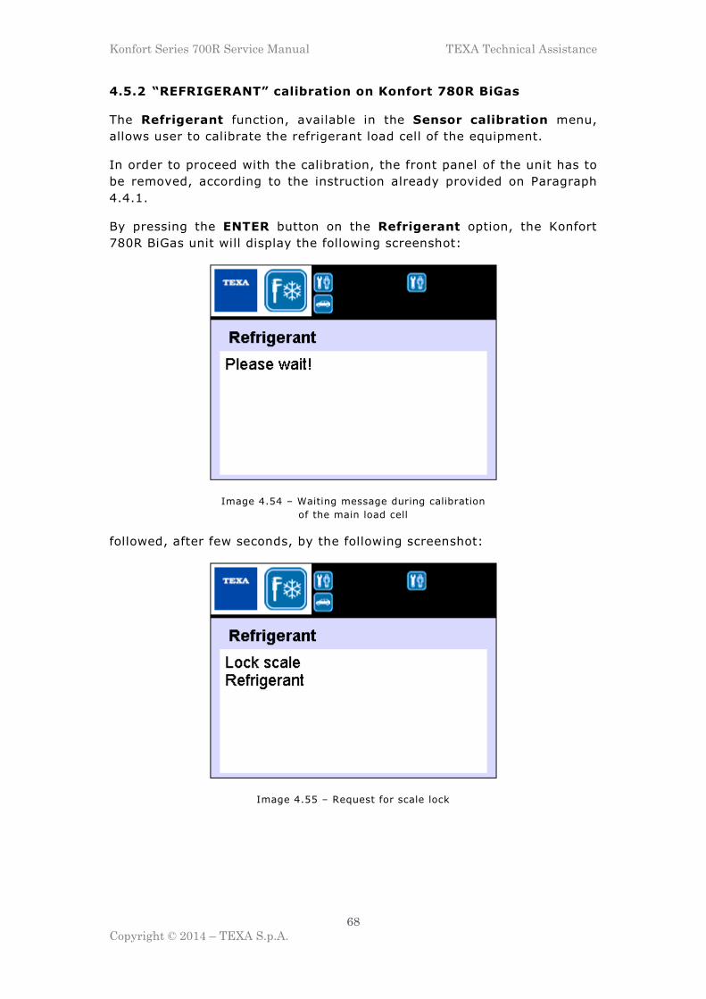
Konfort Series 700R Service Manual TEXA Technical Assistance
68
Copyright © 2014 – TEXA S.p.A.
4.5.2 “REFRIGERANT” calibration on Konfort 780R BiGas
The Refrigerant function, available in the Sensor calibration menu,
allows user to calibrate the refrigerant load cell of the equipment.
In order to proceed with the calibration, the front panel of the unit has to
be removed, according to the instruction already provided on Paragraph
4.4.1.
By pressing the ENTER button on the Refrigerant option, the Konfort
780R BiGas unit will display the following screenshot:
Image 4.54 – Waiting message during calibration
of the main load cell
followed, after few seconds, by the following screenshot:
Image 4.55 – Request for scale lock

Konfort Series 700R Service Manual TEXA Technical Assistance
69
Copyright © 2014 – TEXA S.p.A.
Proceed with the lock of the refrigerant scale, by pushing and rotating the
lock/unlock mechanism clockwise with a 8-millimiters hex wrench:
Image 4.56 – Scale lock on a Konfort 780R BiGas
then press the ENTER button to confirm. The unit will show the following
screenshot:
Image 4.57 – Waiting message during calibration
of the main load cell

Konfort Series 700R Service Manual TEXA Technical Assistance
70
Copyright © 2014 – TEXA S.p.A.
followed, after few seconds, by the following screenshot:
Image 4.58 – Request for scale unlock
Proceed with the unlock of the refrigerant scale, by pushing and rotating
the lock/unlock mechanism counterclockwise:
Image 4.59 – Scale unlock on a Konfort 780R BiGas
then press the ENTER button to confirm.

Konfort Series 700R Service Manual TEXA Technical Assistance
71
Copyright © 2014 – TEXA S.p.A.
The unit will show the following screenshot:
Image 4.60 – Request for placing a sample weight
above the refrigerant tank
Place a sample weight of at least 1 Kg9 over the upper refrigerant tank:
Image 4.61 – Positioning of a sample weight
over the upper tank of 780R BiGas
then press the ENTER button to confirm.
9 Also in this case, the 1-kilogram magnetic sample weight included into the sample weight kit
(spare part no. 4800103) can be used
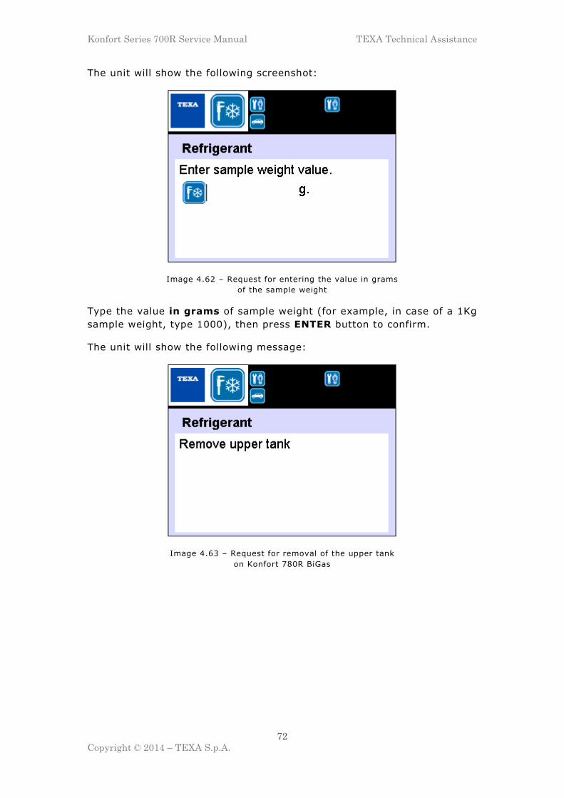
Konfort Series 700R Service Manual TEXA Technical Assistance
72
Copyright © 2014 – TEXA S.p.A.
The unit will show the following screenshot:
Image 4.62 – Request for entering the value in grams
of the sample weight
Type the value in grams of sample weight (for example, in case of a 1Kg
sample weight, type 1000), then press ENTER button to confirm.
The unit will show the following message:
Image 4.63 – Request for removal of the upper tank
on Konfort 780R BiGas

Konfort Series 700R Service Manual TEXA Technical Assistance
73
Copyright © 2014 – TEXA S.p.A.
Remove the heating band from the upper tank of the unit:
Image 4.64 – Removal of the heating band from the
upper tank of the Konfort 780R BiGas
as well as the the screw of the bracket which blocks the upper tank to the
lower one (with the help of a 8-millimiters hexagonal wrench). Then
remove the bracket:
Image 4.65 – Removal of the blocking bracket from the
upper tank of the Konfort 780R BiGas

Konfort Series 700R Service Manual TEXA Technical Assistance
74
Copyright © 2014 – TEXA S.p.A.
Now, rotate the upper refrigerant tank counterclockwise and raise it from
lower tank, by ensuring that it will not touch the four conical pins located
on the lower tank (see picture below, refer to the red circles):
Image 4.66 – Raising of the upper tank from the
lower one of the Konfort 780R BiGas
Then, press the ENTER button to proceed. The unit will show the
following message:
Image 4.67 – Waiting message during calibration
of the main load cell
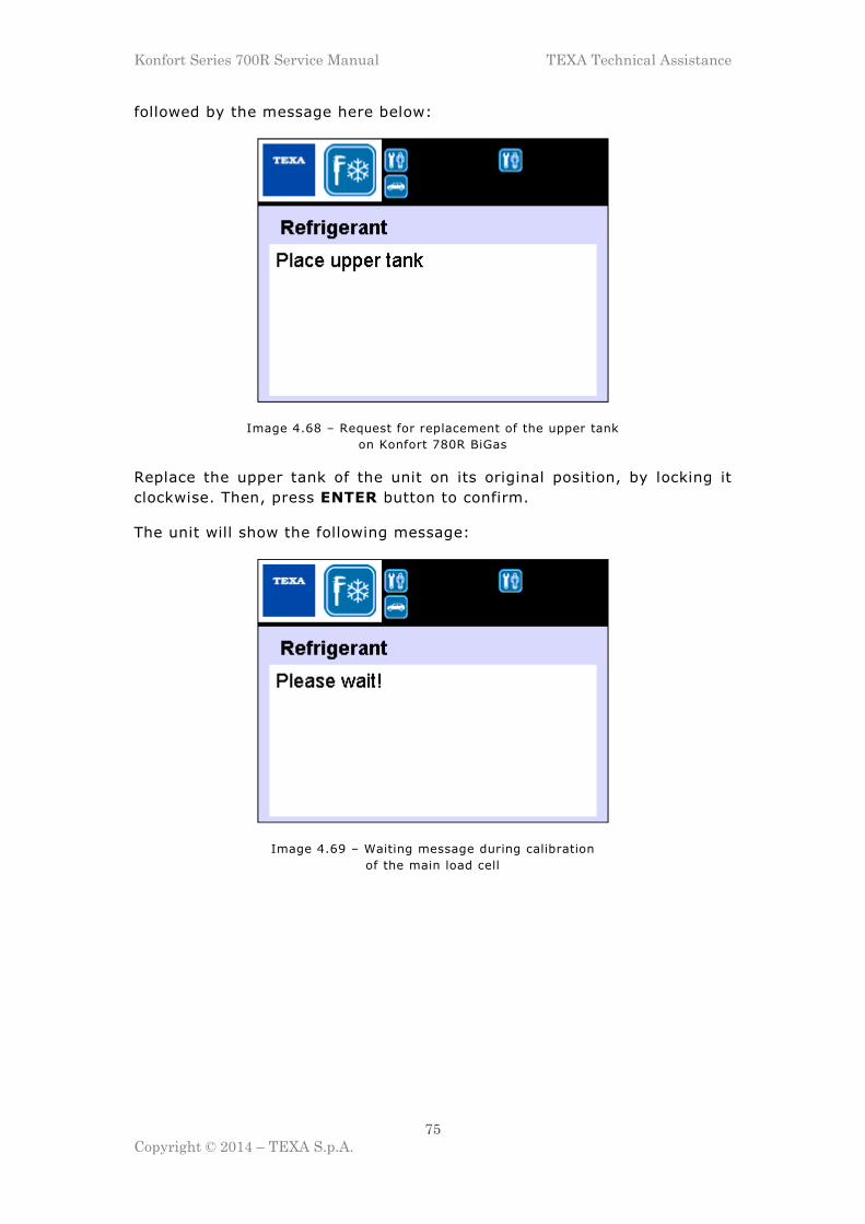
Konfort Series 700R Service Manual TEXA Technical Assistance
75
Copyright © 2014 – TEXA S.p.A.
followed by the message here below:
Image 4.68 – Request for replacement of the upper tank
on Konfort 780R BiGas
Replace the upper tank of the unit on its original position, by locking it
clockwise. Then, press ENTER button to confirm.
The unit will show the following message:
Image 4.69 – Waiting message during calibration
of the main load cell

Konfort Series 700R Service Manual TEXA Technical Assistance
76
Copyright © 2014 – TEXA S.p.A.
followed by the message here below:
Image 4.70 – Confirmation message of the correctness of the calibration
thus certifying the correctness of the main load cell calibration.
4.5.3 “RECOVERED OIL” calibration on Konfort 760R, 760R Bus
and 780R BiGas
The Recovered Oil function, available in the Sensor calibration menu,
allows user to calibrate the auxiliary load cell for the drained oil.
By pressing the ENTER button on this option, the following screenshot
will be shown:
Image 4.71 – Waiting message during calibration
of the drained oil load cell

Konfort Series 700R Service Manual TEXA Technical Assistance
77
Copyright © 2014 – TEXA S.p.A.
followed, after few seconds, by the following screenshot:
Image 4.72 - Request for removing of the drained oil bottle
Remove the bottle for the oil drain from the back of Konfort, then press
the ENTER button to confirm. The equipment will then display the
following screenshot:
Image 4.73 – Waiting message during calibration
of the drained oil load cell
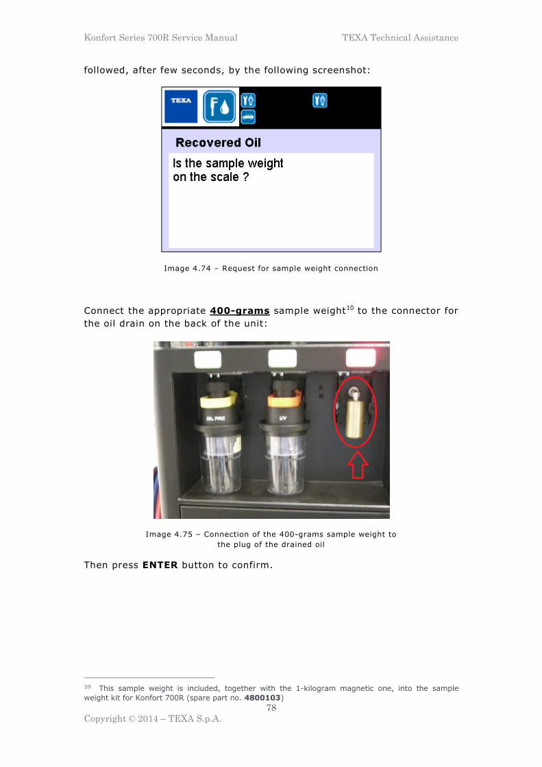
Konfort Series 700R Service Manual TEXA Technical Assistance
78
Copyright © 2014 – TEXA S.p.A.
followed, after few seconds, by the following screenshot:
Image 4.74 – Request for sample weight connection
Connect the appropriate 400-grams sample weight10 to the connector for
the oil drain on the back of the unit:
Image 4.75 – Connection of the 400-grams sample weight to
the plug of the drained oil
Then press ENTER button to confirm.
10 This sample weight is included, together with the 1-kilogram magnetic one, into the sample
weight kit for Konfort 700R (spare part no. 4800103)

Konfort Series 700R Service Manual TEXA Technical Assistance
79
Copyright © 2014 – TEXA S.p.A.
The equipment will display the following screenshot:
Image 4.76 – Request for insertion of the
sample weight value in grams
Type the value in grams of the sample weight (for example, in case of a
400-grams sample weight, type 400), then press ENTER to confirm.
The unit will show the following message:
Image 4.77 – Waiting message during calibration
of the drained oil load cell

Konfort Series 700R Service Manual TEXA Technical Assistance
80
Copyright © 2014 – TEXA S.p.A.
followed, after few seconds, by the message here below:
Image 4.78 – Confirmation message of the correctness of the calibration
thus certifying the correctness of calibration of the drained oil the load
cell.
4.5.4 “UV ADDITIVE” calibration on Konfort 760R, 760R Bus and
780R BiGas
The UV Additive function, available in the Sensor calibration menu,
allows user to calibrate the auxiliary load cell for the UV injection on the
equipment.
Refer to the procedure reported on Paragraph 4.5.3 for the calibration of
the auxiliary load cell for the drained oil. When requested, place the
appropriate sample weight to the UV injection plug on the back of the
unit:
Image 4.79 – Connection of the 400-grams sample
weight to the plug of the UV injection
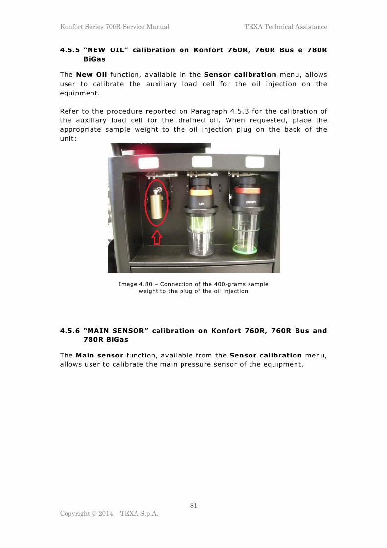
Konfort Series 700R Service Manual TEXA Technical Assistance
81
Copyright © 2014 – TEXA S.p.A.
4.5.5 “NEW OIL” calibration on Konfort 760R, 760R Bus e 780R
BiGas
The New Oil function, available in the Sensor calibration menu, allows
user to calibrate the auxiliary load cell for the oil injection on the
equipment.
Refer to the procedure reported on Paragraph 4.5.3 for the calibration of
the auxiliary load cell for the drained oil. When requested, place the
appropriate sample weight to the oil injection plug on the back of the
unit:
Image 4.80 – Connection of the 400-grams sample
weight to the plug of the oil injection
4.5.6 “MAIN SENSOR” calibration on Konfort 760R, 760R Bus and
780R BiGas
The Main sensor function, available from the Sensor calibration menu,
allows user to calibrate the main pressure sensor of the equipment.

Konfort Series 700R Service Manual TEXA Technical Assistance
82
Copyright © 2014 – TEXA S.p.A.
By pressing the ENTER button on this option, the display will show the
following screenshot:
Image 4.81 – Waiting message during calibration
of the main pressure sensor
followed, after few seconds, by the message here below:
Image 4.82 – Request for removal of the HP and LP
fittings from the service tubes
Unscrew the fittings from the HP and LP service pipes (see Image 4.38),
then press ENTER to confirm.

Konfort Series 700R Service Manual TEXA Technical Assistance
83
Copyright © 2014 – TEXA S.p.A.
The unit will show the following screenshot:
Image 4.83 – Waiting message during calibration
of the main pressure sensor
followed, after few seconds, by the message here below:
Image 4.84 – Request for reconnection of the HP and LP
fittings to the service tubes
Reconnect the fittings to the HP and LP service pipes, then press ENTER
to confirm.

Konfort Series 700R Service Manual TEXA Technical Assistance
84
Copyright © 2014 – TEXA S.p.A.
The unit will show the following screenshot:
Image 4.85 – Waiting message during calibration
of the main pressure sensor
during which the Konfort will perform a short vacuum phase into service
tubes, in order to set the zero value for the calibration of the sensor.
Finally, the display of the Konfort unit will show the following message:
Image 4.86 – Confirmation message of the correctness
of the calibration of the main pressure sensor
thus confirming the fact that the main sensor calibration has been
successful.

Konfort Series 700R Service Manual TEXA Technical Assistance
85
Copyright © 2014 – TEXA S.p.A.
4.5.7 “SECONDARY SENSORS” calibration on Konfort 760R, 760R
Bus and 780R BiGas
The Secondary sensors function in the Sensor calibration menu allows
user to calibrate the auxiliary pressure sensors of the equipment, if
installed. Refer, for further information, to the VDC device installation
manual.
4.6 “PRIVATE PARAMETERS” function on Konfort 700R units
The Private parameters function, available from the Service menu,
allows user to check the value of some reserved functional parameters of
the equipment.
The following subparagraphs will report the default values for the private
parameters of each model of Konfort 700R unit. The changing of each
parameter will be possible by simply editing the new value and by
confirming with the ENTER button.
WARNING! The private parameters change implies a modification
of the behavior of the unit. Please, contact TEXA Technical
Assistance for being instructed in any parameter change.
4.6.1 List of the private parameters for Konfort 705R
PARAMETER DEFAULT
VALUE
MAX ABSOLUTE WEIGHT MAIN TANK gr. 25000
MAX ABSOLUTE WEIGHT SECOND TANK gr. 0
OTHER OILS 3
CLEANING TIME sec. 10
FIRST RECOVERY TIME sec. 30
USED OIL PHASE sec. 40
RECOVERY CLEANING TIME sec. 90
HOSES CLEANING TIME sec. 75
VACUUM TIME FOR FLUXING min. 5
MINIMUM WEIGHT FOR FLUXING Kg. 5
AUTOCALIBRATION THRESHOLD (10 pt.) 15
ON TIME LP PRESSURE CHARGING PHASE (0.1 sec.) 5
RECOVERY PHASE WAITING TIME sec. 20
RECOVERY PHASE FINAL TIME sec. 20
CHECK WAITING TIME sec. 2
IO/UV DELAY TIME (0.01 sec.) 30
REFR. IDENTIFIER CALIBRATION THRESHOLD T(h) 0
MAX FAILED DRAIN RETRIES 4
Table 4.1 – List of the private parameters for Konfort 705R

Konfort Series 700R Service Manual TEXA Technical Assistance
86
Copyright © 2014 – TEXA S.p.A.
PARAMETER DEFAULT
VALUE
LEAK TIME FOR FLUXING min. 3
FORCE DISCHARGE BEFORE RECOVERY 0
ANALYZE GAS 1
PRE VACUUM TIME min. 15
Table 4.1 (Continue) – List of the private parameters for Konfort 705R
4.6.2 List of the private parameters for Konfort 710R
PARAMETER DEFAULT
VALUE
MAX ABSOLUTE WEIGHT MAIN TANK gr. 25000
MAX ABSOLUTE WEIGHT SECOND TANK gr. 0
OTHER OILS 3
CLEANING TIME sec. 10
FIRST RECOVERY TIME sec. 30
USED OIL PHASE sec. 40
RECOVERY CLEANING TIME sec. 90
HOSES CLEANING TIME sec. 75
VACUUM TIME FOR FLUXING min. 5
MINIMUM WEIGHT FOR FLUXING Kg. 5
AUTOCALIBRATION THRESHOLD (10 pt.) 15
ON TIME LP PRESSURE CHARGING PHASE (0.1 sec.) 5
RECOVERY PHASE WAITING TIME sec. 20
RECOVERY PHASE FINAL TIME sec. 20
CHECK WAITING TIME sec. 2
IO/UV DELAY TIME (0.01 sec.) 30
REFR. IDENTIFIER CALIBRATION THRESHOLD T(h) 0
MAX FAILED DRAIN RETRIES 4
LEAK TIME FOR FLUXING min. 3
FORCE DISCHARGE BEFORE RECOVERY 0
ANALYZE GAS 1
PRE VACUUM TIME min. 15
Table 4.2 – List of the private parameters for Konfort 710R

Konfort Series 700R Service Manual TEXA Technical Assistance
87
Copyright © 2014 – TEXA S.p.A.
4.6.3 List of the private parameters for Konfort 720R
PARAMETER DEFAULT
VALUE
MAX ABSOLUTE WEIGHT MAIN TANK gr. 25000
MAX ABSOLUTE WEIGHT SECOND TANK gr. 0
OTHER OILS 3
CLEANING TIME sec. 10
FIRST RECOVERY TIME sec. 30
USED OIL PHASE sec. 40
RECOVERY CLEANING TIME sec. 90
HOSES CLEANING TIME sec. 75
VACUUM TIME FOR FLUXING min. 5
MINIMUM WEIGHT FOR FLUXING Kg. 5
AUTOCALIBRATION THRESHOLD (10 pt.) 15
ON TIME LP PRESSURE CHARGING PHASE (0.1 sec.) 5
RECOVERY PHASE WAITING TIME sec. 20
RECOVERY PHASE FINAL TIME sec. 20
CHECK WAITING TIME sec. 2
IO/UV DELAY TIME (0.01 sec.) 30
REFR. IDENTIFIER CALIBRATION THRESHOLD T(h) 0
MAX FAILED DRAIN RETRIES 4
LEAK TIME FOR FLUXING min. 3
FORCE DISCHARGE BEFORE RECOVERY 0
ANALYZE GAS 1
PRE VACUUM TIME min. 15
Table 4.3 – List of the private parameters for Konfort 720R
4.6.4 List of the private parameters for Konfort 760R
PARAMETER DEFAULT
VALUE
MAX ABSOLUTE WEIGHT MAIN TANK gr. 37000
MAX ABSOLUTE WEIGHT SECOND TANK gr. 0
OTHER OILS 3
CLEANING TIME sec. 10
FIRST RECOVERY TIME sec. 30
USED OIL PHASE sec. 40
RECOVERY CLEANING TIME sec. 90
HOSES CLEANING TIME sec. 75
VACUUM TIME FOR FLUXING min. 5
MINIMUM WEIGHT FOR FLUXING Kg. 5
AUTOCALIBRATION THRESHOLD (10 pt.) 15
ON TIME LP PRESSURE CHARGING PHASE (0.1 sec.) 5
RECOVERY PHASE WAITING TIME sec. 20
RECOVERY PHASE FINAL TIME sec. 20
CHECK WAITING TIME sec. 2
IO/UV DELAY TIME (0.01 sec.) 30
REFR. IDENTIFIER CALIBRATION THRESHOLD T(h) 0
Table 4.4 – List of the private parameters for Konfort 760R

Konfort Series 700R Service Manual TEXA Technical Assistance
88
Copyright © 2014 – TEXA S.p.A.
PARAMETER DEFAULT
VALUE
MAX FAILED DRAIN RETRIES 4
LEAK TIME FOR FLUXING min. 3
FORCE DISCHARGE BEFORE RECOVERY 0
ANALYZE GAS 1
PRE VACUUM TIME min. 15
Table 4.4 (Continue) – List of the private parameters for Konfort 760R
4.6.5 List of the private parameters for Konfort 760R Bus
PARAMETER DEFAULT
VALUE
MAX ABSOLUTE WEIGHT MAIN TANK gr. 55000
MAX ABSOLUTE WEIGHT SECOND TANK gr. 0
OTHER OILS 3
CLEANING TIME sec. 10
FIRST RECOVERY TIME sec. 30
USED OIL PHASE sec. 40
RECOVERY CLEANING TIME sec. 90
HOSES CLEANING TIME sec. 75
VACUUM TIME FOR FLUXING min. 5
MINIMUM WEIGHT FOR FLUXING Kg. 5
AUTOCALIBRATION THRESHOLD (10 pt.) 15
ON TIME LP PRESSURE CHARGING PHASE (0.1 sec.) 5
RECOVERY PHASE WAITING TIME sec. 20
RECOVERY PHASE FINAL TIME sec. 20
CHECK WAITING TIME sec. 2
IO/UV DELAY TIME (0.01 sec.) 30
REFR. IDENTIFIER CALIBRATION THRESHOLD T(h) 0
MAX FAILED DRAIN RETRIES 4
LEAK TIME FOR FLUXING min. 3
FORCE DISCHARGE BEFORE RECOVERY 0
ANALYZE GAS 1
PRE VACUUM TIME min. 15
Table 4.5 – List of the private parameters for Konfort 760R Bus

Konfort Series 700R Service Manual TEXA Technical Assistance
89
Copyright © 2014 – TEXA S.p.A.
4.6.6 List of the private parameters for Konfort 780R BiGas
PARAMETER DEFAULT
VALUE
MAX ABSOLUTE WEIGHT MAIN TANK gr. 25000
MAX ABSOLUTE WEIGHT SECOND TANK gr. 25000
OTHER OILS 3
CLEANING TIME sec. 10
FIRST RECOVERY TIME sec. 30
USED OIL PHASE sec. 40
RECOVERY CLEANING TIME sec. 90
HOSES CLEANING TIME sec. 75
VACUUM TIME FOR FLUXING min. 5
MINIMUM WEIGHT FOR FLUXING Kg. 5
AUTOCALIBRATION THRESHOLD (10 pt.) 15
ON TIME LP PRESSURE CHARGING PHASE (0.1 sec.) 5
RECOVERY PHASE WAITING TIME sec. 20
RECOVERY PHASE FINAL TIME sec. 20
CHECK WAITING TIME sec. 2
IO/UV DELAY TIME (0.01 sec.) 30
REFR. IDENTIFIER CALIBRATION THRESHOLD T(h) 0
MAX FAILED DRAIN RETRIES 4
LEAK TIME FOR FLUXING min. 3
FORCE DISCHARGE BEFORE RECOVERY 0
ANALYZE GAS 1
PRE VACUUM TIME min. 15
Table 4.6 – List of the private parameters for Konfort 780R BiGas
4.7 “PUBLIC PARAMETERS” function on Konfort 700R units
The Public parameters function, available from the Service menu,
allows user to check the value of some standard functional parameters of
the equipment.
The following subparagraphs will report the default values for the public
parameters of each model of Konfort 700R units. The changing of each
parameter will be possible by simply editing the new value and by
confirming with the ENTER button.
WARNING! The public parameters change implies a modification of
the behavior of the unit. Please, contact TEXA Technical Assistance
for being instructed in any parameter change.
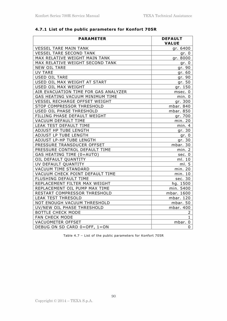
Konfort Series 700R Service Manual TEXA Technical Assistance
90
Copyright © 2014 – TEXA S.p.A.
4.7.1 List of the public parameters for Konfort 705R
PARAMETER DEFAULT
VALUE
VESSEL TARE MAIN TANK gr. 6400
VESSEL TARE SECOND TANK gr. 0
MAX RELATIVE WEIGHT MAIN TANK gr. 8000
MAX RELATIVE WEIGHT SECOND TANK gr. 0
NEW OIL TARE gr. 90
UV TARE gr. 60
USED OIL TARE gr. 90
USED OIL MAX WEIGHT AT START gr. 50
USED OIL MAX WEIGHT gr. 150
AIR EVACUATION TIME FOR GAS ANALYZER msec. 0
GAS HEATING VACUUM MINIMUM TIME min. 0
VESSEL RECHARGE OFFSET WEIGHT gr. 300
STOP COMPRESSOR THRESHOLD mbar. 840
USED OIL PHASE THRESHOLD mbar. 850
FILLING PHASE DEFAULT WEIGHT gr. 700
VACUUM DEFAULT TIME min. 20
LEAK TEST DEFAULT TIME min. 4
ADJUST HP TUBE LENGTH gr. 30
ADJUST LP TUBE LENGTH gr. 0
ADJUST LP-HP TUBE LENGTH gr. 30
PRESSURE TRANSDUCER OFFSET mbar. 30
PRESSURE CONTROL DEFAULT TIME min. 2
GAS HEATING TIME (0=AUTO) sec. 0
OIL DEFAULT QUANTITY ml. 10
UV DEFAULT QUANTITY ml. 5
VACUUM TIME STANDARD min. 20
VACUUM CHECK POINT DEFAULT TIME min. 10
FLUSHING DEFAULT TIME sec. 30
REPLACEMENT FILTER MAX WEIGHT hg. 1500
REPLACEMENT OIL PUMP MAX TIME min. 5400
RESTART COMPRESSOR THRESHOLD mbar. 1600
LEAK TEST THRESOLD mbar. 120
NOT ENOUGH VACUUM THRESHOLD mbar. 50
UV/NEW OIL PHASE THRESHOLD mbar. 400
BOTTLE CHECK MODE 2
FAN CHECK MODE 1
VACUOMETER OFFSET mbar. 0
DEBUG ON SD CARD 0=OFF, 1=ON 0
Table 4.7 – List of the public parameters for Konfort 705R

Konfort Series 700R Service Manual TEXA Technical Assistance
91
Copyright © 2014 – TEXA S.p.A.
4.7.2 List of the public parameters for Konfort 710R
PARAMETER DEFAULT
VALUE
VESSEL TARE MAIN TANK gr. 9300
VESSEL TARE SECOND TANK gr. 0
MAX RELATIVE WEIGHT MAIN TANK gr. 10000
MAX RELATIVE WEIGHT SECOND TANK gr. 0
NEW OIL TARE gr. 90
UV TARE gr. 60
USED OIL TARE gr. 90
USED OIL MAX WEIGHT AT START gr. 50
USED OIL MAX WEIGHT gr. 150
AIR EVACUATION TIME FOR GAS ANALYZER msec. 0
GAS HEATING VACUUM MINIMUM TIME min. 0
VESSEL RECHARGE OFFSET WEIGHT gr. 300
STOP COMPRESSOR THRESHOLD mbar. 840
USED OIL PHASE THRESHOLD mbar. 850
FILLING PHASE DEFAULT WEIGHT gr. 700
VACUUM DEFAULT TIME min. 20
LEAK TEST DEFAULT TIME min. 4
ADJUST HP TUBE LENGTH gr. 30
ADJUST LP TUBE LENGTH gr. 0
ADJUST LP-HP TUBE LENGTH gr. 30
PRESSURE TRANSDUCER OFFSET mbar. 30
PRESSURE CONTROL DEFAULT TIME min. 2
GAS HEATING TIME (0=AUTO) sec. 0
OIL DEFAULT QUANTITY ml. 10
UV DEFAULT QUANTITY ml. 5
VACUUM TIME STANDARD min. 20
VACUUM CHECK POINT DEFAULT TIME min. 10
FLUSHING DEFAULT TIME sec. 30
REPLACEMENT FILTER MAX WEIGHT hg. 1500
REPLACEMENT OIL PUMP MAX TIME min. 5400
RESTART COMPRESSOR THRESHOLD mbar. 1600
LEAK TEST THRESOLD mbar. 120
NOT ENOUGH VACUUM THRESHOLD mbar. 50
UV/NEW OIL PHASE THRESHOLD mbar. 400
BOTTLE CHECK MODE 2
FAN CHECK MODE 1
VACUOMETER OFFSET mbar. 0
DEBUG ON SD CARD 0=OFF, 1=ON 0
Table 4.8 – List of the public parameters for Konfort 710R

Konfort Series 700R Service Manual TEXA Technical Assistance
92
Copyright © 2014 – TEXA S.p.A.
4.7.3 List of the public parameters for Konfort 720R
PARAMETER DEFAULT
VALUE
VESSEL TARE MAIN TANK gr. 11300
VESSEL TARE SECOND TANK gr. 0
MAX RELATIVE WEIGHT MAIN TANK gr. 12000
MAX RELATIVE WEIGHT SECOND TANK gr. 0
NEW OIL TARE gr. 90
UV TARE gr. 60
USED OIL TARE gr. 90
USED OIL MAX WEIGHT AT START gr. 50
USED OIL MAX WEIGHT gr. 150
AIR EVACUATION TIME FOR GAS ANALYZER msec. 0
GAS HEATING VACUUM MINIMUM TIME min. 0
VESSEL RECHARGE OFFSET WEIGHT gr. 300
STOP COMPRESSOR THRESHOLD mbar. 840
USED OIL PHASE THRESHOLD mbar. 850
FILLING PHASE DEFAULT WEIGHT gr. 700
VACUUM DEFAULT TIME min. 20
LEAK TEST DEFAULT TIME min. 4
ADJUST HP TUBE LENGTH gr. 30
ADJUST LP TUBE LENGTH gr. 0
ADJUST LP-HP TUBE LENGTH gr. 30
PRESSURE TRANSDUCER OFFSET mbar. 30
PRESSURE CONTROL DEFAULT TIME min. 2
GAS HEATING TIME (0=AUTO) sec. 0
OIL DEFAULT QUANTITY ml. 10
UV DEFAULT QUANTITY ml. 5
VACUUM TIME STANDARD min. 20
VACUUM CHECK POINT DEFAULT TIME min. 10
FLUSHING DEFAULT TIME sec. 30
REPLACEMENT FILTER MAX WEIGHT hg. 1500
REPLACEMENT OIL PUMP MAX TIME min. 5400
RESTART COMPRESSOR THRESHOLD mbar. 1600
LEAK TEST THRESOLD mbar. 120
NOT ENOUGH VACUUM THRESHOLD mbar. 50
UV/NEW OIL PHASE THRESHOLD mbar. 400
BOTTLE CHECK MODE 2
FAN CHECK MODE 1
VACUOMETER OFFSET mbar. 0
DEBUG ON SD CARD 0=OFF, 1=ON 0
Table 4.9 – List of the public parameters for Konfort 720R

Konfort Series 700R Service Manual TEXA Technical Assistance
93
Copyright © 2014 – TEXA S.p.A.
4.7.4 List of the public parameters for Konfort 760R
PARAMETER DEFAULT
VALUE
VESSEL TARE MAIN TANK gr. 16000
VESSEL TARE SECOND TANK gr. 0
MAX RELATIVE WEIGHT MAIN TANK gr. 20000
MAX RELATIVE WEIGHT SECOND TANK gr. 0
NEW OIL TARE gr. 310
UV TARE gr. 310
USED OIL TARE gr. 270
USED OIL MAX WEIGHT AT START gr. 200
USED OIL MAX WEIGHT gr. 250
AIR EVACUATION TIME FOR GAS ANALYZER msec. 500
GAS HEATING VACUUM MINIMUM TIME min. 10
VESSEL RECHARGE OFFSET WEIGHT gr. 300
STOP COMPRESSOR THRESHOLD mbar. 840
USED OIL PHASE THRESHOLD mbar. 850
FILLING PHASE DEFAULT WEIGHT gr. 700
VACUUM DEFAULT TIME min. 20
LEAK TEST DEFAULT TIME min. 4
ADJUST HP TUBE LENGTH gr. 30
ADJUST LP TUBE LENGTH gr. 0
ADJUST LP-HP TUBE LENGTH gr. 30
PRESSURE TRANSDUCER OFFSET mbar. 30
PRESSURE CONTROL DEFAULT TIME min. 2
GAS HEATING TIME (0=AUTO) sec. 0
OIL DEFAULT QUANTITY ml. 10
UV DEFAULT QUANTITY ml. 5
VACUUM TIME STANDARD min. 20
VACUUM CHECK POINT DEFAULT TIME min. 10
FLUSHING DEFAULT TIME sec. 30
REPLACEMENT FILTER MAX WEIGHT hg. 1500
REPLACEMENT OIL PUMP MAX TIME min. 5400
RESTART COMPRESSOR THRESHOLD mbar. 1600
LEAK TEST THRESOLD mbar. 120
NOT ENOUGH VACUUM THRESHOLD mbar. 50
UV/NEW OIL PHASE THRESHOLD mbar. 400
BOTTLE CHECK MODE 2
FAN CHECK MODE 1
VACUOMETER OFFSET mbar. 0
DEBUG ON SD CARD 0=OFF, 1=ON 0
Table 4.10 – List of the public parameters for Konfort 760R

Konfort Series 700R Service Manual TEXA Technical Assistance
94
Copyright © 2014 – TEXA S.p.A.
4.7.5 List of the public parameters for Konfort 760R Bus
PARAMETER DEFAULT
VALUE
VESSEL TARE MAIN TANK gr. 24000
VESSEL TARE SECOND TANK gr. 0
MAX RELATIVE WEIGHT MAIN TANK gr. 30000
MAX RELATIVE WEIGHT SECOND TANK gr. 0
NEW OIL TARE gr. 310
UV TARE gr. 310
USED OIL TARE gr. 270
USED OIL MAX WEIGHT AT START gr. 200
USED OIL MAX WEIGHT gr. 250
AIR EVACUATION TIME FOR GAS ANALYZER msec. 500
GAS HEATING VACUUM MINIMUM TIME min. 10
VESSEL RECHARGE OFFSET WEIGHT gr. 600
STOP COMPRESSOR THRESHOLD mbar. 920
USED OIL PHASE THRESHOLD mbar. 920
FILLING PHASE DEFAULT WEIGHT gr. 800
VACUUM DEFAULT TIME min. 20
LEAK TEST DEFAULT TIME min. 4
ADJUST HP TUBE LENGTH gr. 30
ADJUST LP TUBE LENGTH gr. 0
ADJUST LP-HP TUBE LENGTH gr. 30
PRESSURE TRANSDUCER OFFSET mbar. 30
PRESSURE CONTROL DEFAULT TIME min. 2
GAS HEATING TIME (0=AUTO) sec. 0
OIL DEFAULT QUANTITY ml. 10
UV DEFAULT QUANTITY ml. 5
VACUUM TIME STANDARD min. 20
VACUUM CHECK POINT DEFAULT TIME min. 10
FLUSHING DEFAULT TIME sec. 30
REPLACEMENT FILTER MAX WEIGHT hg. 1500
REPLACEMENT OIL PUMP MAX TIME min. 5400
RESTART COMPRESSOR THRESHOLD mbar. 1600
LEAK TEST THRESOLD mbar. 120
NOT ENOUGH VACUUM THRESHOLD mbar. 50
UV/NEW OIL PHASE THRESHOLD mbar. 400
BOTTLE CHECK MODE 2
FAN CHECK MODE 1
VACUOMETER OFFSET mbar. 0
DEBUG ON SD CARD 0=OFF, 1=ON 0
Table 4.11 – List of the public parameters for Konfort 760R Bus

Konfort Series 700R Service Manual TEXA Technical Assistance
95
Copyright © 2014 – TEXA S.p.A.
4.7.6 List of the public parameters for Konfort 780R BiGas
PARAMETRO VALORE
PREDEFINITO
VESSEL TARE MAIN TANK gr. 11300
VESSEL TARE SECOND TANK gr. 13300
MAX RELATIVE WEIGHT MAIN TANK gr. 12000
MAX RELATIVE WEIGHT SECOND TANK gr. 12000
NEW OIL TARE gr. 310
UV TARE gr. 310
USED OIL TARE gr. 270
USED OIL MAX WEIGHT AT START gr. 200
USED OIL MAX WEIGHT gr. 250
AIR EVACUATION TIME FOR GAS ANALYZER msec. 500
GAS HEATING VACUUM MINIMUM TIME min. 10
VESSEL RECHARGE OFFSET WEIGHT gr. 300
STOP COMPRESSOR THRESHOLD mbar. 840
USED OIL PHASE THRESHOLD mbar. 850
FILLING PHASE DEFAULT WEIGHT gr. 700
VACUUM DEFAULT TIME min. 20
LEAK TEST DEFAULT TIME min. 4
ADJUST HP TUBE LENGTH gr. 30
ADJUST LP TUBE LENGTH gr. 0
ADJUST LP-HP TUBE LENGTH gr. 30
PRESSURE TRANSDUCER OFFSET mbar. 30
PRESSURE CONTROL DEFAULT TIME min. 2
GAS HEATING TIME (0=AUTO) sec. 0
OIL DEFAULT QUANTITY ml. 10
UV DEFAULT QUANTITY ml. 5
VACUUM TIME STANDARD min. 20
VACUUM CHECK POINT DEFAULT TIME min. 10
FLUSHING DEFAULT TIME sec. 30
REPLACEMENT FILTER MAX WEIGHT hg. 1500
REPLACEMENT OIL PUMP MAX TIME min. 5400
RESTART COMPRESSOR THRESHOLD mbar. 1600
LEAK TEST THRESOLD mbar. 120
NOT ENOUGH VACUUM THRESHOLD mbar. 50
UV/NEW OIL PHASE THRESHOLD mbar. 400
BOTTLE CHECK MODE 2
FAN CHECK MODE 1
VACUOMETER OFFSET mbar. 0
DEBUG ON SD CARD 0=OFF, 1=ON 0
Table 4.12 – List of the public parameters for Konfort 780R BiGas
4.8 “CALIBRATION STATUS” function on Konfort 700R units
The Calibration status function, available from the Service menu,
allows user to get a quick overview of the status of the calibration of
each sensor of the equipment.

Konfort Series 700R Service Manual TEXA Technical Assistance
96
Copyright © 2014 – TEXA S.p.A.
By accessing this function, the following screenshot will be displayed:
C a l i b r a t i o n s t a t u s P R D I U H L 1 1 1 1 1 1 1
Image 4.87 – The Calibration status function on Konfort 705R, 710R and 720R
Image 4.88 – The Calibration status function on
Konfort 760R, 760R Bus and 780R BiGas
In this page, the initial letter of each sensor of the Konfort unit will be
reported:
� P = Main pressure sensor;
� R = Refrigerant load cell;
� D = Load cell (not used on K705R, K710R and K720R) for the
discharged oil;
� I = Load cell (not used on K705R, K710R and K720R) for the oil
injection;
� U = Load cell (not used on K705R, K710R and K720R) for the UV
injection;
� H = Auxiliary HP pressure sensor11;
� L = Auxiliary LP pressure sensor12.
11 This sensor can be installed as an accessory on the equipment (for example, in case of use of the
VDC device) 12 This sensor can be installed as an accessory on the equipment

Konfort Series 700R Service Manual TEXA Technical Assistance
97
Copyright © 2014 – TEXA S.p.A.
For each sensor, on the line just below, the unit reports the status of the
corresponding calibration:
� 1 = the sensor is correctly calibrated;
� 0 = the sensor is not calibrated, it is necessary to check its proper
functioning.
4.9 “SELECT REFRIGERANT” function on Konfort 700R units
The Select Refrigerant function, available from the Service menu with
the dealer password, allows to select the type of refrigerant with which
the user would like to make the unit to operate. The options available
are:
� R134a : by choosing this option, the GAS light on the top panel of
the unit will be colored in ORANGE;
� R1234yf : by choosing this option, the GAS light on the top panel of
the unit will be colored in GREEN.
This function has to be used on Konfort 720R, 760R and 760R Bus units
for changing the type of refrigerant to be employed by the unit, for
example after the retrofit operation from R134a to R1234yf.
4.10 “STORED ERRORS” function on Konfort 700R units
The Stored errors function, available from the Service menu both with
the user password 1236 and with the dealer one (provided every year by
TEXA S.p.A), allows to display the history of the functioning faults of the
unit:
Image 4.89 – Example of the Stored errors function
on Konfort 700R units
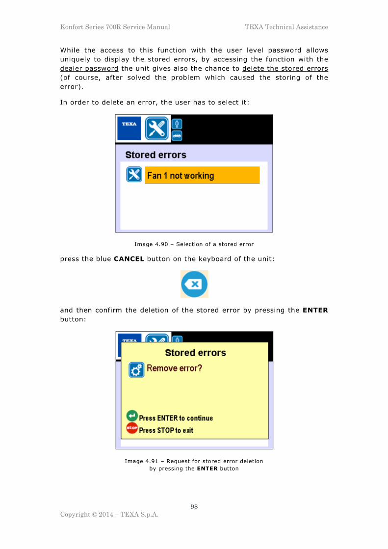
Konfort Series 700R Service Manual TEXA Technical Assistance
98
Copyright © 2014 – TEXA S.p.A.
While the access to this function with the user level password allows
uniquely to display the stored errors, by accessing the function with the
dealer password the unit gives also the chance to delete the stored errors
(of course, after solved the problem which caused the storing of the
error).
In order to delete an error, the user has to select it:
Image 4.90 – Selection of a stored error
press the blue CANCEL button on the keyboard of the unit:
and then confirm the deletion of the stored error by pressing the ENTER
button:
Image 4.91 – Request for stored error deletion
by pressing the ENTER button

Konfort Series 700R Service Manual TEXA Technical Assistance
99
Copyright © 2014 – TEXA S.p.A.
The unit will confirm the deletion of the stored error by displaying the
following screenshot:
Image 4.92 – Confirmation of the stored error deletion.
Press the ENTER button for quitting the page
4.11 “DEFAULT PARAMETERS” function on Konfort 700R units
The Default parameters function, available from the Service menu both
with the user password 1236 and with the dealer one, allows the user to
restore the default values to the working parameters of the unit.
By selecting this option, the unit will ask to confirm the restore of the
default values of the parameters, by showing the following screenshot:
Image 4.93 – Request for restoring the default values
of the working parameters of the unit

Konfort Series 700R Service Manual TEXA Technical Assistance
100
Copyright © 2014 – TEXA S.p.A.
By pressing the ENTER button, the restore operation will be completed:
Image 4.94 – Confirmation of the restore of the default values
of the parameters. Press the ENTER button for quitting the page
4.12 “CUSTOMISED SERVICE” function on Konfort 700R units
The Customised service function, available from the Service menu only
with the dealer password, will allow the technician to perform some
customized settings on the AC maintenance working mode of the Konfort
unit under specific request of the final user. By choosing this function,
the following options will be displayed:
Image 4.95 – Options available in the
Customised service function of the Konfort 700R units

Konfort Series 700R Service Manual TEXA Technical Assistance
101
Copyright © 2014 – TEXA S.p.A.
Image 4.95 (Continue) – Options available in the
Customised service function of the Konfort 700R units
Here below a detailed description of each function of this menu will be
reported:
� UV injection : This function will allow to enable/disable the UV
injection in the AC maintenance working modes of the unit. This
function is necessary in order to set up the functioning of the unit
according to the requirements of some car manufacturers:
Image 4.96 – Possibility to enable or disable
the UV injection in the Konfort 700R units
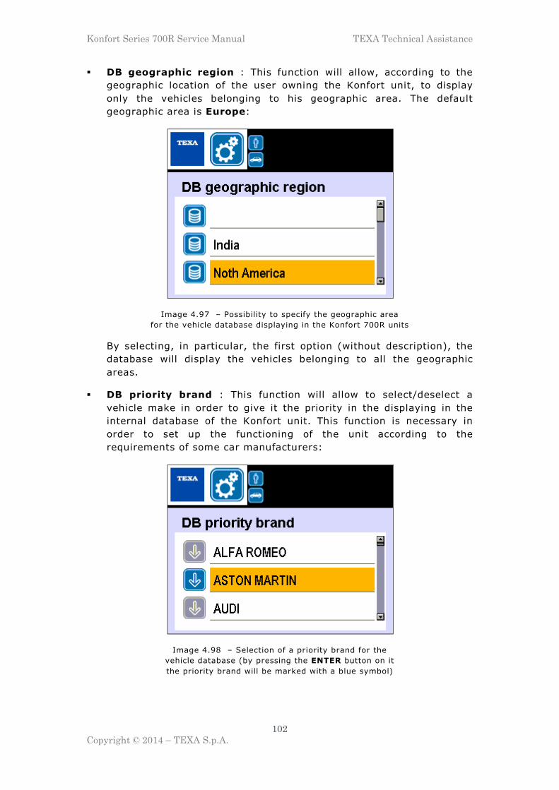
Konfort Series 700R Service Manual TEXA Technical Assistance
102
Copyright © 2014 – TEXA S.p.A.
� DB geographic region : This function will allow, according to the
geographic location of the user owning the Konfort unit, to display
only the vehicles belonging to his geographic area. The default
geographic area is Europe:
Image 4.97 – Possibility to specify the geographic area
for the vehicle database displaying in the Konfort 700R units
By selecting, in particular, the first option (without description), the
database will display the vehicles belonging to all the geographic
areas.
� DB priority brand : This function will allow to select/deselect a
vehicle make in order to give it the priority in the displaying in the
internal database of the Konfort unit. This function is necessary in
order to set up the functioning of the unit according to the
requirements of some car manufacturers:
Image 4.98 – Selection of a priority brand for the
vehicle database (by pressing the ENTER button on it
the priority brand will be marked with a blue symbol)

Konfort Series 700R Service Manual TEXA Technical Assistance
103
Copyright © 2014 – TEXA S.p.A.
Image 4.99 – The selected make will be displayed
as first in the vehicle database. It will be enough to
click on Others in order to display all the other vehicles
� Vacuum mode : This function, available only on Konfort 760R Bus
units, allows to select the execution mode for the vacuum phase, by
opting between two possible alternatives:
Image 4.100 – Available modes for the vacuum phase
execution on Konfort 760R Bus units
- DEFAULT : Default selection. The Konfort unit performs the
vacuum phase in the classic mode.
- HIGH VOLUME SYSTEMS : This mode is optimized for the high
volume A/C systems. The countdown of the vacuum time starts
only if the pressure will decrease under 50mBars absolute. In
case, once the countdown has started, the pressure would
increase over 50mBars, the countdown will be reset to the initial
time value and it will remain blocked until the pressure will come
again under the above mentioned threshold.

Konfort Series 700R Service Manual TEXA Technical Assistance
104
Copyright © 2014 – TEXA S.p.A.
CHAPTER 5 – ORDINARY MAINTENANCE
This chapter will describe the main operations needed for performing the
ordinary maintenance on a Konfort series 700R unit.
Basically, the ordinary maintenance consists in the periodical replacement
of the main filter and of the oil of the vacuum pump of the unit.
The unit will automatically inform the user about the need of these
maintenance operations, by means of proper messages which will be
shown on the display every time the usage limits set by the firmware of
the unit will be overcome.
5.1. Main Filter Replacement
The main filter replacement has to be performed when it will be
automatically requested by the unit. The Konfort unit will start to
advice about the imminent need to replace the main filter once the 80%
of its total consumption will be reached:
Image 5.1 – Warning message about the
imminent exhaustion of the main filter

Konfort Series 700R Service Manual TEXA Technical Assistance
105
Copyright © 2014 – TEXA S.p.A.
WARNING: Once the 100% of the consumption of the main filter
will be reached (i.e. 150Kg of recovered refrigerant), the unit will
block and will not allow anymore to perform any other AC
maintenance service.
Image 5.2 – The main filter is completely exhausted.
The unit cannot proceed with further recovery phases
In order to perform main filter replacement, it is needed to proceed as
follows:
� Select the option named Reset counters from the Additional
functions menu, then select the option named Replace filter.
� The unit will show the following message on the display:
Image 5.3 – Preliminary internal cleaning in order to
depressurize the internal hydraulic circuit before the filter removal
During this phase, the unit will perform an automatic depressurization
of its internal hydraulic circuit, in order to allow the removal of the
main filter in safety conditions.

Konfort Series 700R Service Manual TEXA Technical Assistance
106
Copyright © 2014 – TEXA S.p.A.
� Once this operation will be completed, the unit will show one of the
following messages:
O p e n t h e c a b i n e t a n d r e p l a c e f i l t e r d r i e r
Image 5.4 – Request to open the front panel on Konfort 705R
in order to replace the main filter
Image 5.5 – Request to open the back compartment
in order to replace the main filter
� In case of Konfort 705R, remove the red front panel of the unit in
order to be able to access the main filter location.
� In case of Konfort 710R, remove the protection cover for the main
filter from the back side of the unit. Use a 3mm Allen wrench in order
to remove the four screws:
Image 5.6 – Opening the back compartment on Konfort 710R

Konfort Series 700R Service Manual TEXA Technical Assistance
107
Copyright © 2014 – TEXA S.p.A.
� In case of all the other models of Konfort 700R, open the service
door located on the back of the unit, by rotating its handle clockwise:
Image 5.7 – Opening of the service door
located on the back of the Konfort unit
� In case of Konfort 705R, the main filter is located vertically inside
the unit (see Image 5.8, element c):
Image 5.8 – Location of the main filter on Konfort 705R
In all the other models of Konfort 700R, the main filter is located
horizontally on the upper part of the recovery group (see Image 5.9,
element c):
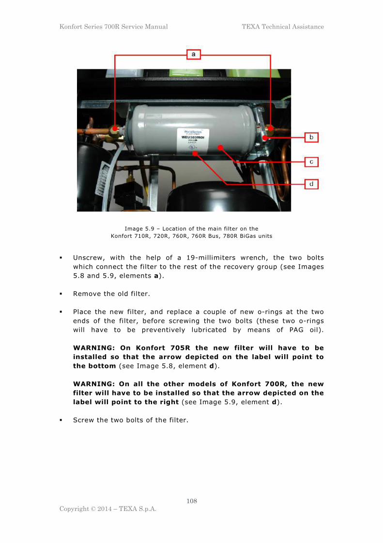
Konfort Series 700R Service Manual TEXA Technical Assistance
108
Copyright © 2014 – TEXA S.p.A.
Image 5.9 – Location of the main filter on the
Konfort 710R, 720R, 760R, 760R Bus, 780R BiGas units
� Unscrew, with the help of a 19-millimiters wrench, the two bolts
which connect the filter to the rest of the recovery group (see Images
5.8 and 5.9, elements a).
� Remove the old filter.
� Place the new filter, and replace a couple of new o-rings at the two
ends of the filter, before screwing the two bolts (these two o-rings
will have to be preventively lubricated by means of PAG oil).
WARNING: On Konfort 705R the new filter will have to be
installed so that the arrow depicted on the label will point to
the bottom (see Image 5.8, element d).
WARNING: On all the other models of Konfort 700R, the new
filter will have to be installed so that the arrow depicted on the
label will point to the right (see Image 5.9, element d).
� Screw the two bolts of the filter.
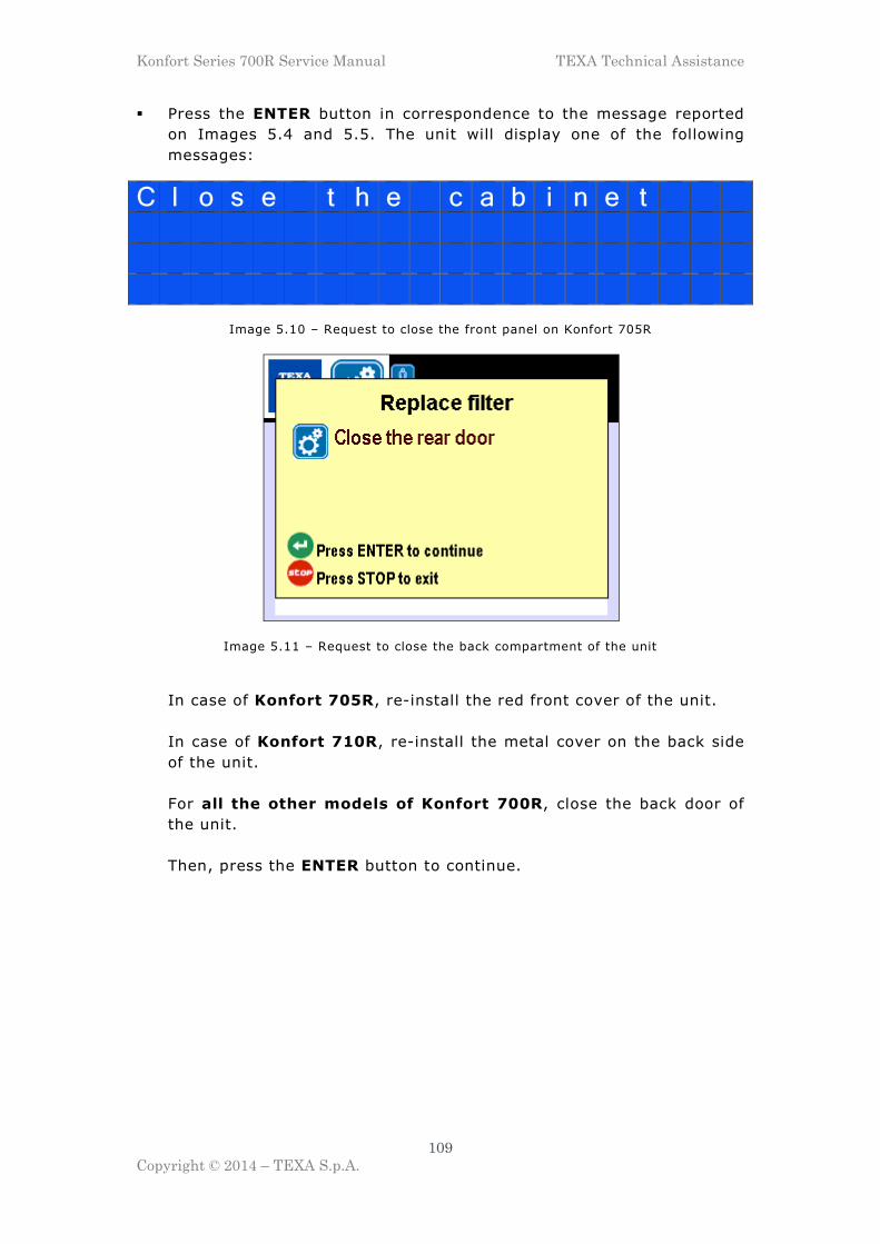
Konfort Series 700R Service Manual TEXA Technical Assistance
109
Copyright © 2014 – TEXA S.p.A.
� Press the ENTER button in correspondence to the message reported
on Images 5.4 and 5.5. The unit will display one of the following
messages:
C l o s e t h e c a b i n e t
Image 5.10 – Request to close the front panel on Konfort 705R
Image 5.11 – Request to close the back compartment of the unit
In case of Konfort 705R, re-install the red front cover of the unit.
In case of Konfort 710R, re-install the metal cover on the back side
of the unit.
For all the other models of Konfort 700R, close the back door of
the unit.
Then, press the ENTER button to continue.

Konfort Series 700R Service Manual TEXA Technical Assistance
110
Copyright © 2014 – TEXA S.p.A.
� The unit will perform a small refrigerant filling into its own internal
hydraulic circuit, in order to check the possible presence of leakages
related to the filter replacement. In this situation, the display of the
unit will show the following message:
Image 5.12 – Request to close the back compartment of the unit
At the end of this leak check, the counter related to the filter
replacement will be automatically reset and the maintenance will
be completed.
5.2. Vacuum Pump Oil Replacement
The vacuum pump oil replacement has to be performed when it will be
automatically requested by the unit (i.e., once the pump will reach 90
hours of functioning):
Image 5.13 – Request to replace the vacuum pump oil

Konfort Series 700R Service Manual TEXA Technical Assistance
111
Copyright © 2014 – TEXA S.p.A.
It is needed to proceed as follows:
� Switch the unit off and disconnect the power supply cable from the
plug of the power supply network.
� In case of Konfort 705R,
� Open the service door located on the back of the unit, by rotating its
handle clockwise (see Image 5.1).
� Identify the vacuum pump (see Image 5.3, element 1):
Image 5.3 – Location of the vacuum pump in the Konfort K700R units
� Place a lowered-edge container under the Konfort unit in order to
easily collect the oil which will come out from the pump.
� Open the cap of the pump for the oil discharge, which is located
under the unit (see Image 5.3, element 3). Wait until all the oil will
be come out from the pump.
� Once the oil will be completely come out, replace the o-ring on the
cap of the pump for the oil discharge; then, replace it by paying
attention not to screw it too tight, otherwise it could come out from
its location.

Konfort Series 700R Service Manual TEXA Technical Assistance
112
Copyright © 2014 – TEXA S.p.A.
� Unscrew the red cap for the oil charge located on the upper part of
the pump (see Image 5.3, element 2).
� Insert the new oil into the pump.
WARNING: The correct oil level inside the pump corresponds
approximately to the middle of the window for the oil level
check on the pump. The total oil capacity which has to be
inserted is approximately equal to 370ml.
� Screw again the red cap for the oil charge.
� Restart the Konfort unit.
� Access the Reset counters function from the Additional functions
menu of the unit, then proceed with the erase of the Pump Working
Time counter.

Konfort Series 700R Service Manual TEXA Technical Assistance
113
Copyright © 2014 – TEXA S.p.A.
CHAPTER 6 – SOFTWARE UPDATE
Unlike the TEXA old-generation air conditioning equipments, in the new
Konfort 700R units all the software updates (firmware, vehicles
database and language pack) will be performed uniquely by means of
the SD card.
This new approach will make the update process easier and more
immediate for the operator.
The latest version of the various software update packages for Konfort
700R units are available into the Service Code website under the section:
Download � Software Release � Air Conditioning � Konfort Series 700R
Image 6.1 – The Service Code section from which
the software resources for Konfort 700R units can be downloaded
Inside the section named KONFORT SERIES 700 three subsections are
available:
� Firmware: from this folder the zip archive containing the latest
firmware release for the Konfort 700R series units can be downloaded.
This archive will allow to carry out the manual update of the Konfort
units.
� Database: from this folder the zip archive containing the database
version for which the user owning a Konfort 700R series unit has right
for can be downloaded.
� Konfort 700 Updater: from this folder the PC setup package for the
Konfort 700 Updater program can be downloaded. The program allows
to automatically download from the Internet and install the software
packages for the Konfort 700R series units.

Konfort Series 700R Service Manual TEXA Technical Assistance
114
Copyright © 2014 – TEXA S.p.A.
6.1 Manual update of the software packages in the SD card
A first approach for the update consists in the manual extractions of the
packages which have been downloaded from the Firmware and
Database sections of the Service Code website directly to the SD card of
the Konfort unit.
Each desired software resource will be downloaded in the form of a zip
archive:
Image 6.2 – The downloaded zip archive containing the software update
In order to proceed with the update, the operator has first of all to switch
off the unit, to remove the SD card from the equipment’s reader:
Image 6.3 – SD card removal from the Konfort 700R

Konfort Series 700R Service Manual TEXA Technical Assistance
115
Copyright © 2014 – TEXA S.p.A.
insert it into the TEXA SD card reader (provided together with the Konfort
unit) and to connect the card reader to the PC:
Image 6.4 – SD card insertion into TEXA card reader and
connection of the reader to the PC
At this point, in order to start the upgrade it will be enough to:
� open the content of the SD card from the PC;
� open the zip archive and select all the files and folders inside it;
� copy the content of the zip file to the SD card, by overwriting the
existing files inside the SD card:
Image 6.5 – Starting the update process of the SD card

Konfort Series 700R Service Manual TEXA Technical Assistance
116
Copyright © 2014 – TEXA S.p.A.
Once the copy of the files will be completed, remove the SD card from
the PC and re-insert it into the card reader of the Konfort 700R unit.
Once the Konfort unit will be restarted, it automatically will start up the
software update process.
In case the firmware update would have been performed, the green REC
led located on the upper part of the Konfort unit will flash irregularly:
Image 6.6 – Flashing green REC led
during the firmware update of the unit
The update process will last few seconds; once finished, the unit will
normally start up, by showing the initial page of its menu.
6.2 Automatic update by means of Konfort 700 Updater
As an alternative to the manual procedure described in the previous
paragraph, the software of a Konfort 700R series unit can be updated by
using the Konfort 700 Updater program.
The installation package of this program can be downloaded from the
Konfort 700 Updater folder of the Service Code website (as previously
described).

Konfort Series 700R Service Manual TEXA Technical Assistance
117
Copyright © 2014 – TEXA S.p.A.
As an alternative, the program can also be installed from any end user:
actually, the same installation package is also available inside the CD
labelled “KONFORT SERIE 700R – MANUAL”, available inside the
package of the A/C machine:
Image 6.7 – Installation procedure of the Konfort 700 Updater program
from the CD “KONFORT SERIE 700R - MANUALS” of the Konfort package
Once the program will be installed, it will be enough to click on the
Konfort 700 Updater icon on the desktop of the PC to start it up:
Image 6.8 – Double click on the Konfort 700 Updater icon
located on the desktop in order to start the update program

Konfort Series 700R Service Manual TEXA Technical Assistance
118
Copyright © 2014 – TEXA S.p.A.
The following screenshot will be displayed:
Image 6.9 – Main screenshot of the Konfort 700 Updater program
In order to proceed with the update, the operator has first of all to switch
off the unit, to remove the SD card from the equipment’s reader:
Image 6.10 – SD card removal from the Konfort 700R

Konfort Series 700R Service Manual TEXA Technical Assistance
119
Copyright © 2014 – TEXA S.p.A.
insert it into the TEXA SD card reader (provided together with the Konfort
unit) and to connect the card reader to the PC:
Image 6.11 – SD card insertion into TEXA card reader and
connection of the reader to the PC
When the SD card will be detected, the program will automatically ask to
specify the serial number of the Konfort unit:
Image 6.12 – Request to enter the serial number of the Konfort unit
Edit the serial number of the Konfort unit on which the update is going to
be performed, then press the OK button to confirm.

Konfort Series 700R Service Manual TEXA Technical Assistance
120
Copyright © 2014 – TEXA S.p.A.
At this point, the program will search for the possible updates available
for the specific Konfort unit with the specified serial number. In case an
update would be available for the specified unit, the following screenshot
will be displayed:
Image 6.13 – Notification of the availability of new software updates
for the Konfort unit with the specified serial number
It will be enough to press the UPDATE button to start the update of the
SD card.
Once the update will be completed, the following confirmation message
will be displayed:
Image 6.14 – Confirmation of the completion of the update.
It is possible to remove the SD card from the PC

Konfort Series 700R Service Manual TEXA Technical Assistance
121
Copyright © 2014 – TEXA S.p.A.
At this point, it will be enough to close the program, remove the SD card
from the PC and re-insert it into the card reader of the Konfort 700R unit.
Once the Konfort unit will be restarted, it automatically will start up the
software update process.
In case the firmware update would have been performed, the green REC
led located on the upper part of the Konfort unit will flash irregularly:
Image 6.15 – Flashing green REC led
during the firmware update of the unit
The update process will last few seconds; once finished, the unit will
normally start up, by showing the initial page of its menu.

Konfort Series 700R Service Manual TEXA Technical Assistance
122
Copyright © 2014 – TEXA S.p.A.
CHAPTER 7 – TROUBLE SHOOTING
7.1 Introduction
The general working principle of any Konfort equipment is essentially
based on the information (physical quantities) which come from the
sensors, the load cells and the pressure transducers.
The most efficient method for diagnosing any potential failure of the
equipment is determined by a good knowledge of the tool and by a
careful analysis of the different phases of its operation: these two
prerequisites are fundamental in order to be able to isolate the possible
cause of the problem.
For example, if the equipment is showing a problem related to an
inaccurate measurement of the quantity of refrigerant during the charge
phase, the replacement of the pressure transducer is never
recommended; conversely, if the Konfort equipment never ends the
recovery phase, the carry out of a calibration of the main load cell is not
strictly necessary.
In order to determine whether, during a certain phase, the sensors
involved in it are faulty or inaccurate, the correctness of their measured
quantities should be checked, by comparing these quantities to
appropriate sample quantities, which must be known and which can be
taken as a reference.
In this regard, a useful aid is provided by the equipment’s Service menu,
in particular by the Power outputs function.
In the next paragraphs, some of the most common problems, which
might be encountered during the maintenance of Konfort 700R
equipments, will be listed. For each individual critical situation, all the
steps needed for the quick identification of the cause of the problem and
for its correct solution will be described.

Konfort Series 700R Service Manual TEXA Technical Assistance
123
Copyright © 2014 – TEXA S.p.A.
7.2 The equipment does not switch on
� If the equipment is connected to an extension cable, remove it.
� Check the voltage of the network power supply plug (~ 230V - 50Hz)
of the place where the equipment is operating.
� Open the cap of the network filter (use a 2-millimiters Allen wrench,
press the two plastic tongues above and below the cap and pull it
out) and, with the switch of the unit set in "ON" position, check the
voltage (~ 230V - 50Hz) by placing the probes of a multimeter on the
blue and brown wires:
Image 7.1 – Removal of the cap of the network filter on Konfort 720R, 760R,
760R Bus and 780R BiGas
Image 7.2 – Check the voltage (~ 230V - 50Hz)
between the blue and the brown wires

Konfort Series 700R Service Manual TEXA Technical Assistance
124
Copyright © 2014 – TEXA S.p.A.
� Ensure that the main fuses, located inside the cover above the power
supply switch, will not be interrupted (lever slightly with the help of a
screwdriver to remove the cover):
Image 7.3 – Removal of the cover containing the two
main fuses of Konfort 700R equipments
Image 7.4 – With the help of a multimeter in diode test mode,
check the continuity of each of the two fuses
In the case that one of the two fuses would be interrupted, replace it
with a new one with proper value (250V - T10A).

Konfort Series 700R Service Manual TEXA Technical Assistance
125
Copyright © 2014 – TEXA S.p.A.
� Disconnect the cable coming from the J2 connector of the ACE Micro
board:
Image 7.5 – Removal of the cable coming from the J2 connector
of the ACE Micro board of a Konfort 700R
and check the correctness of the AC voltage first between the two red
wires (about 14V AC) and then between the two blue wires (about
15,5 V AC) of the cable:
Image 7.6 – Between the two red wires of the cable
there must be an alternate voltage of about 14V

Konfort Series 700R Service Manual TEXA Technical Assistance
126
Copyright © 2014 – TEXA S.p.A.
Image 7.7 – Between the two blue wires of the cable
there must be an alternate voltage of about 15,5V
In case, try to check the continuity of the cable up to the
transformer. In absence of continuity, replace the entire cable.
Instead, if the cable would be provided with continuity, replace the
transformer of the Konfort unit.
7.3 The display of the Konfort unit does not visualize correctly
� If the equipment is connected to an extension cable, remove it.
� If, while powering the unit up, no “beeps” are emitted and the display
shows one of the following situations:
Image 7.8 – Request for SD insertion and no “beep” while starting up a Konfort 705R, 710R or 720R unit

Konfort Series 700R Service Manual TEXA Technical Assistance
127
Copyright © 2014 – TEXA S.p.A.
Image 7.9 – Request for SD insertion and no “beep” while starting up a Konfort 760R, 760R Bus or 780R BiGas unit
then it could be that the SD card would not be properly inserted into
the slot of the equipment. Try to turn the unit off, to connect the SD
card and to restart the equipment.
The same behavior could also be due to the lack of software inside
the SD card. In this case, try to reload the software by using the
procedure described in Chapter 6.
� If, while powering up a Konfort 720R unit, a “beeps” is emitted, but
the backlight of the display stays off:
Image 7.10 - Backlight off accompanied by
a “beep” while starting up a Konfort 720R

Konfort Series 700R Service Manual TEXA Technical Assistance
128
Copyright © 2014 – TEXA S.p.A.
it could be that the pin J1 on the ACE Micro board would be
mistakenly short-circuited by a jumper. In this case, remove the
jumper from the pin:
Image 7.11 – Removal of the jumper from the J1 pin
of the ACE Micro board on Konfort 720R (if present)
NOTE: In the Konfort 705R and Konfort 710R models, on which
the structure of the ACE Micro board has been simplified for price
reasons, the J1 pin is not available.
� If, while switching on a Konfort 760R, 760R Bus or 780R BiGas unit, a
“beep” is emitted, but the display remains black:
Image 7.12 – Black display accompanied by a “beep” while starting up
a Konfort 760R, 760R Bus or 780R BiGas

Konfort Series 700R Service Manual TEXA Technical Assistance
129
Copyright © 2014 – TEXA S.p.A.
it could be that the pin J1 on the ACE Micro board would not be
short-circuited by a jumper.
In this case, insert the jumper on pin J1:
Image 7.13 – Insertion of the jumper on pin J1 of the ACE Micro board of a
Konfort 760R, 760R Bus or 780R BiGas (if not present)
� In case, on a Konfort 705R, 710R or 720R, the display would be
completely white, just with the backlight switched on:
Image 7.14 – Display completely white
(only backlight) on Konfort 705R, 710R or 720R
try to adjust again the backlight of the display, by keeping the orange
INFO button pressed and by adjusting the brightness with the UP
and DOWN buttons.

Konfort Series 700R Service Manual TEXA Technical Assistance
130
Copyright © 2014 – TEXA S.p.A.
� In case, on a Konfort 760R, 760R Bus or 780R BiGas, the display
would result in to be not enough bright:
Image 7.15 – Display not enough bright (low backlight)
on Konfort 760R, 760R Bus or 780R BiGas
try to adjust again the backlight of the display, by keeping the orange
INFO button pressed and by adjusting the brightness with the UP
and DOWN buttons.
� If the display would show meaningless inscriptions or question marks,
update the software package on the SD card, as described in Chapter
6. In case, replace the SD card.
7.4 The unit does not recover refrigerant
A. The compressor starts
� Check that the service hoses will be properly connected to the A/C
system of the vehicle and that the two fittings will be open.
� Check that both the HP and LP valves, located on the upper or side
panel of the equipment, will be opened (only in Konfort 705R, 710R
and 720R).
� Ensure that there would be pressure inside the A/C system of the
vehicle (if not, there could not be any refrigerant to be recovered
from the system itself).
� Check that, during the recovery phase, there will be correspondence
between the value measured by the pressure sensor (pressure value
shown on the display) and the one reported by the gauges (especially
by the LP gauge, which can better make the user appreciate the low
values of relative pressure). If the difference of the two values would

Konfort Series 700R Service Manual TEXA Technical Assistance
131
Copyright © 2014 – TEXA S.p.A.
be large (≈ 500 mBars), proceed with the calibration of the main
pressure sensor, as described in paragraphs 4.4.4 and 4.5.6.
� Ensure that the dryer filter will not be obstructed. If necessary,
replace it.
� Ensure that the mechanic filter will not be obstructed. If necessary,
replace it.
� Ensure that the HP and LP solenoid valves (on 760R, 760R Bus and
780R BiGas), the EVREC solenoid valve (on all models) and the
EVREF1 or EVREF2 solenoid valves (only on 780R BiGas) will be
active during the recovery phase. If necessary, check the wiring of
each solenoid valve towards the ACE Power board.
� Ensure that no other valves than those mentioned on the previous
point, will be active.
� Check the suction capacity of the compressor: in order to do that,
remove the small transparent tube which connects the HP and LP
hoses to the mechanic filter:
Image 7.16 – Removal of the small tube that leads
the refrigerant from the HP/LP hoses to the mechanic filter

Konfort Series 700R Service Manual TEXA Technical Assistance
132
Copyright © 2014 – TEXA S.p.A.
Image 7.17 – Small silicone tube coming from the HP/LP
hoses disconnected from the mechanic filter
Connect that pipe to the inlet of a vacuum gauge:
Image 7.18 – Connection of the silicone tube coming from
the HP/LP hoses to the inlet of a vacuum gauge

Konfort Series 700R Service Manual TEXA Technical Assistance
133
Copyright © 2014 – TEXA S.p.A.
then, connect a new segment of silicone pipe between the inlet of the
mechanic filter and the outlet of the vacuum gauge:
Image 7.19 – Connection of a segment of silicone tube between
the inlet of the mechanic filter (left picture) and the outlet
of the vacuum gauge (right picture)
At this point, from the Customised service function of the
equipment, select a single recovery phase. Then check that the
depression measured by the pointer of the vacuum gauge will be
appropriate:
Image 7.20 – Depression level showing that
the suction capability is appropriate

Konfort Series 700R Service Manual TEXA Technical Assistance
134
Copyright © 2014 – TEXA S.p.A.
In case the suction power would not be enough:
Image 7.21 – Very low depression level showing
a possible suction problem
try first to replace the mechanic filter. If the insufficient suction
would persist, proceed with the replacement of the entire recovery
group of the unit (or the only compressor on Konfort 705R).
B. After few minutes, the message “INTERNAL TANK PRESSURE TOO
HIGH” appears
� Check that the FR1 solenoid valve (also the FR2 solenoid valve on
Konfort 780R BiGas), for the automatic discharge of non-condensable
gases from the tank, will work properly (this solenoid valve can be
manually activated from the Power outputs function. This control is
available on the Konfort 720R, 760R, 760R Bus and 780R BiGas
models).
� Pull the manual valve with the ring located on the refrigerant tank of
the unit for about 15-20 seconds in order to speed-up the non-
condensable gases discharge.

Konfort Series 700R Service Manual TEXA Technical Assistance
135
Copyright © 2014 – TEXA S.p.A.
� Check that the two inlet valves to the tank will be open (both the one
on the yellow hose coming from the condenser (1), and the one over
the tank (2), see Image 7.22; the latter can be opened with the help
of a 7-mm wrench):
Image 7.22 – Check of the opening of the inlet
valves to the tank
� Check, with the help of a multimeter, the continuity of pressure
switch connected to SP2 pins of the ACE Power board (see Appendix
2). In normal conditions, it should be closed. In case the pressure
switch would result in open, proceed with its replacement.
� Ensure that all conductors of the cable J1 of the ACE Power board
(see Appendix 2) will be fully inserted into the corresponding
connector. In case that the conductors insertion would be correct,
proceed with the replacement of the complete ACE Power board.

Konfort Series 700R Service Manual TEXA Technical Assistance
136
Copyright © 2014 – TEXA S.p.A.
C. The compressor does not start
� Replace the capacitor and the starter of the compressor (cod.
4800022 and cod. 4800026).
� Check, with the help of a multimeter, the continuity of thermal
protection (overload, cod. 4800027) inside the electrical connection
box of the compressor. If the problem would persist, replace the
complete recovery group (or the only compressor on Konfort 705R).
� Check the continuity of fuses F1 and F3 located on the ACE Power
board (see Appendix 2). If they would be interrupted, replace them
with two new ones with appropriate features (250V – T10A). If the
problem would persist, replace the complete ACE Power board.
� Check that the plug of the power supply network will provide a
correct voltage (~ 230V – 50Hz).
� Check that an alternate voltage of 230V will be present at input of the
compressor. Check this value between pin CO and its corresponding
neutral pin N on the ACE Power board (see Appendix 2).
7.5 The unit does not perform the vacuum
A. The vacuum pump does not start
� Try to manually start the vacuum pump from the Power outputs
function. If it would not start, check the presence of the power supply
network voltage (~ 230V – 50Hz) between the pin PO and the neutral
pin N of the ACE Power board (see Appendix 2). If the voltage would
not be correct, replace the ACE Power board.
� If the pump starts for about 3 minutes and then stops, check the
continuity of the thermal relay located into the box above the pump
(which contains the electrical part of the pump itself). If the problem
would persist, replace the thermal relay.
� Remove the power supply cable of the equipment from the power
supply network plug, remove the protective cover of the fan of the
vacuum pump and try to rotate the shaft with the hand, in order to
check that it will be able to rotate freely. In case it would be blocked,
proceed with the replacement of the vacuum pump.

Konfort Series 700R Service Manual TEXA Technical Assistance
137
Copyright © 2014 – TEXA S.p.A.
B. The vacuum pump starts
� In case of Konfort 705R, 710R or 720R units, ensure that the HP and
LP valves located on the side or on the top panel of the equipment
will be open.
� In the of Konfort 760R, 760R Bus and 780R BiGas units, try to
manually start the HP and LP solenoid valves from the Power
outputs menu, in order to ensure that they will be able to open/close
properly.
� Ensure that, during the vacuum phase, only the EVPO1 and EVPO2
solenoid valves will be open.
C. During the vacuum phase, the message “INSUFFICIENT VACUUM”
appears
WARNING: Before performing any operation, ensure that the pressure
value on the gauges of the unit will be zero.
� Check, from the Power outputs menu, the room pressure measure
(about 1000 mBars) of the main pressure sensor. In order to check
this, remove the rapid connectors from the HP and LP service hoses;
then, in case of Konfort 705R, 710R or 720R units, open the two HP
and LP valves on the side or upper panel of the unit:
S E N S O R S ( M E A S U R E ) P R 9 9 8 B L 1 0 7 3 2 D O 0 I O 0 U V 0 H P 9 9
Image 7.23 – Correct room pressure value (marked in red)
from the Power outputs menu of a Konfort 705R, 710R or 720R unit
On the other hand, in case of Konfort 760R, 760R Bus or 780R BiGas
units, activate the HP and LP solenoid valves from the Power
outputs menu, in order to open the two high and low pressure
branches to the air flow:

Konfort Series 700R Service Manual TEXA Technical Assistance
138
Copyright © 2014 – TEXA S.p.A.
Image 7.24 – Correct room pressure value (marked in red)
from the Power outputs menu of
Konfort 760R, 760R Bus and 780R BiGas units
In case the measured pressure value would be different from the one
of the room pressure, proceed with the calibration of the main
pressure sensor.
If, despite the above calibration, the room pressure value would be
incorrect and the punctual values (also available from the Power
outputs menu) would differ much from the range 4300 – 5000,
proceed with the replacement of the main pressure sensor.
� Plug the rapid fittings to the brass connectors located on the side of
the equipment, enter the AC maintenance menu, select the
Customised service option, then select a single vacuum phase of 5
minutes, followed by a leak test of 3 minutes. In case that this
vacuum phase would not detect any leak inside the equipment, check
the A/C system of the vehicle. Otherwise, check the airtight of the HP
and LP rapid fittings; if necessary, replace the o-rings inside the
fittings, by using the appropriate removal kit (cod. 1003030).
� In the case of Konfort 705R, 710R or 720R units, close the two HP
and LP valves of the equipment and perform a single vacuum phase,
as described at the previous point. If the message "INSUFFICIENT
VACUUM" would occur, replace the two HP and LP valves.
� Check that the rubbers of the actuators of EVPO1 and EVPO2
solenoid valves will not be deformed or deteriorated. In case, replace
the actuators of these electro-valves.

Konfort Series 700R Service Manual TEXA Technical Assistance
139
Copyright © 2014 – TEXA S.p.A.
� Close the outlet valve of the tank:
Image 7.25 – Closure of the outlet valve of the tank
connect the HP and LP fittings to the brass connectors located on the
side of the equipment, then start a single vacuum phase from the
Customised service menu. In case that the vacuum would not be
stable, replace the actuator of the EVCA charge solenoid valve.
� If the “INSUFFICIENT VACUUM” message appears during the oil
injection and/or during injection of the UV additive, check the silicone
tubes which connect the bottles group to the manifold:
Image 7.26 – Silicone tubes which connect the oil and UV
injection bottles to the manifold
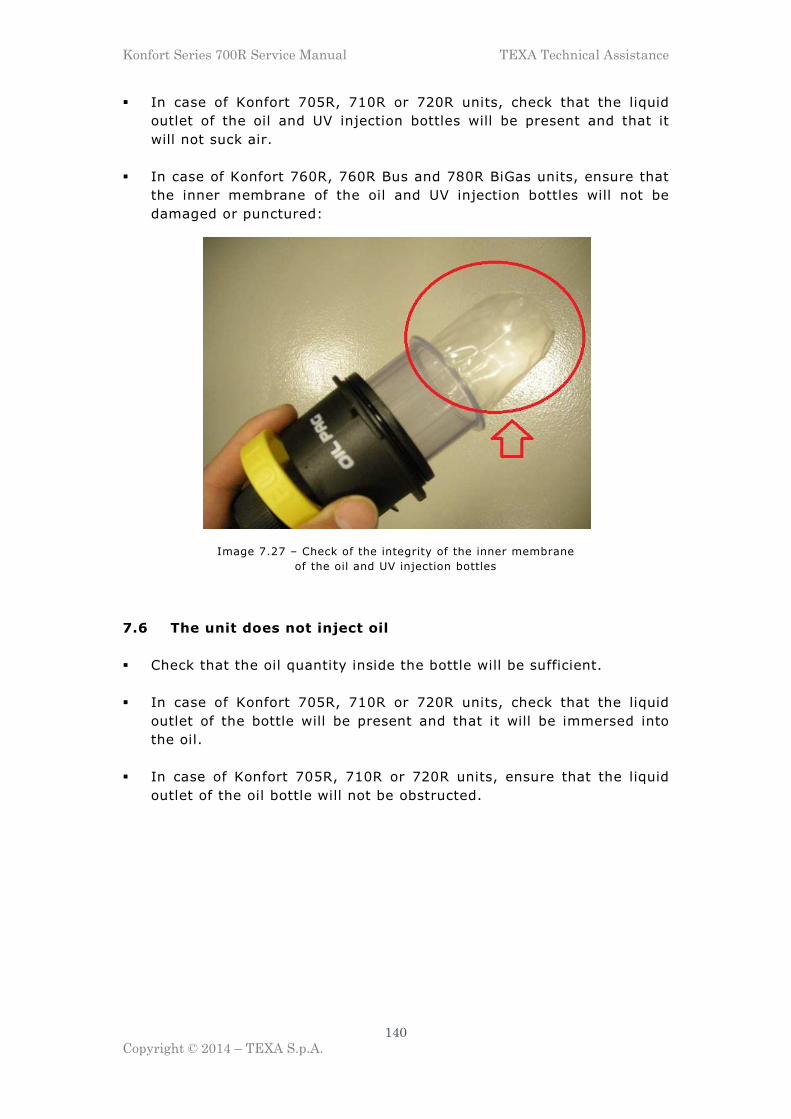
Konfort Series 700R Service Manual TEXA Technical Assistance
140
Copyright © 2014 – TEXA S.p.A.
� In case of Konfort 705R, 710R or 720R units, check that the liquid
outlet of the oil and UV injection bottles will be present and that it
will not suck air.
� In case of Konfort 760R, 760R Bus and 780R BiGas units, ensure that
the inner membrane of the oil and UV injection bottles will not be
damaged or punctured:
Image 7.27 – Check of the integrity of the inner membrane
of the oil and UV injection bottles
7.6 The unit does not inject oil
� Check that the oil quantity inside the bottle will be sufficient.
� In case of Konfort 705R, 710R or 720R units, check that the liquid
outlet of the bottle will be present and that it will be immersed into
the oil.
� In case of Konfort 705R, 710R or 720R units, ensure that the liquid
outlet of the oil bottle will not be obstructed.
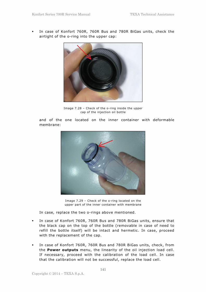
Konfort Series 700R Service Manual TEXA Technical Assistance
141
Copyright © 2014 – TEXA S.p.A.
� In case of Konfort 760R, 760R Bus and 780R BiGas units, check the
airtight of the o-ring into the upper cap:
Image 7.28 – Check of the o-ring inside the upper
cap of the injection oil bottle
and of the one located on the inner container with deformable
membrane:
Image 7.29 – Check of the o-ring located on the
upper part of the inner container with membrane
In case, replace the two o-rings above mentioned.
� In case of Konfort 760R, 760R Bus and 780R BiGas units, ensure that
the black cap on the top of the bottle (removable in case of need to
refill the bottle itself) will be intact and hermetic. In case, proceed
with the replacement of the cap.
� In case of Konfort 760R, 760R Bus and 780R BiGas units, check, from
the Power outputs menu, the linearity of the oil injection load cell.
If necessary, proceed with the calibration of the load cell. In case
that the calibration will not be successful, replace the load cell.
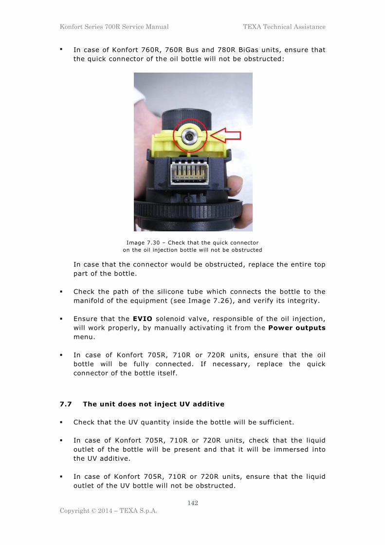
Konfort Series 700R Service Manual TEXA Technical Assistance
142
Copyright © 2014 – TEXA S.p.A.
� In case of Konfort 760R, 760R Bus and 780R BiGas units, ensure that
the quick connector of the oil bottle will not be obstructed:
Image 7.30 – Check that the quick connector
on the oil injection bottle will not be obstructed
In case that the connector would be obstructed, replace the entire top
part of the bottle.
� Check the path of the silicone tube which connects the bottle to the
manifold of the equipment (see Image 7.26), and verify its integrity.
� Ensure that the EVIO solenoid valve, responsible of the oil injection,
will work properly, by manually activating it from the Power outputs
menu.
� In case of Konfort 705R, 710R or 720R units, ensure that the oil
bottle will be fully connected. If necessary, replace the quick
connector of the bottle itself.
7.7 The unit does not inject UV additive
� Check that the UV quantity inside the bottle will be sufficient.
� In case of Konfort 705R, 710R or 720R units, check that the liquid
outlet of the bottle will be present and that it will be immersed into
the UV additive.
� In case of Konfort 705R, 710R or 720R units, ensure that the liquid
outlet of the UV bottle will not be obstructed.

Konfort Series 700R Service Manual TEXA Technical Assistance
143
Copyright © 2014 – TEXA S.p.A.
� In case of Konfort 760R, 760R Bus and 780R BiGas units, check the
airtight of the o-ring into the upper cap (see Image 7.28) and of the
one located on the inner container with deformable membrane (see
Image 7.29). In case, replace the two o-rings.
� In case of Konfort 760R, 760R Bus and 780R BiGas units, ensure that
the black cap on the top of the bottle (removable in case of need to
refill the bottle itself) will be intact and hermetic. In case, proceed
with the replacement of the cap.
� In case of Konfort 760R, 760R Bus and 780R BiGas units, check, from
the Power outputs menu, the linearity of the UV injection load cell.
If necessary, proceed with the calibration of the load cell. In case
that the calibration will not be successful, replace the load cell.
� In case of Konfort 760R, 760R Bus and 780R BiGas units, ensure that
the quick connector of the oil bottle will not be obstructed (refer to
Image 7.30). In case that the connector would be obstructed, replace
the entire top part of the bottle.
� Check the path of the silicone tube which connects the bottle to the
manifold of the equipment (see Image 7.26), and verify its integrity.
� Ensure that the EVUV solenoid valve, responsible of the UV injection,
will work properly, by manually activating it from the Power outputs
menu.
� In case of Konfort 710R or 720R units, ensure that the UV bottle will
be fully connected. If necessary, replace the quick connector of the
bottle itself.
7.8 Too much oil and/or UV additive is injected
� Check that the tube which connects the bottle to the manifold will
allow the free movement of the load cell (see Image 7.26). If
necessary, restore its correct position.

Konfort Series 700R Service Manual TEXA Technical Assistance
144
Copyright © 2014 – TEXA S.p.A.
� Check that the wirings coming from the rotating head of the
equipment will not press on the silicone tube which connects the
bottle to the manifold. If necessary, remove any possible abnormal
contact:
Image 7.31 – Possible contact between the cables coming from
the rotating head and the silicone tube which connects
the manifold to the bottle
� In case of Konfort 760R, 760R Bus and 780R BiGas units, ensure that
the cable which comes to the bottle recognition connector will not
affect the correct movement of the load cell:
Image 7.32 – The cable which comes to the oil-injection bottle
recognition connector (the same for the UV) could be too tight

Konfort Series 700R Service Manual TEXA Technical Assistance
145
Copyright © 2014 – TEXA S.p.A.
Image 7.33 – As a result of this excessive tightness,
even though the bottle is removed, the load cell for the oil injection
(the same for the UV) could provide a weight value that would wrongly
let to think about a loss of linearity of the load cell
In order to check that the oil or UV load cell will have a linear
behavior, connect a sample weight (for example, 400 grams) to it and
check that the corresponding value on the Power outputs menu will
vary from about 400 to about 0 by simply removing the sample
weight from the cell:
Image 7.34 (A) – See below

Konfort Series 700R Service Manual TEXA Technical Assistance
146
Copyright © 2014 – TEXA S.p.A.
Image 7.34 (B) – Weight value of the oil injection load cell
with the sample weight (first image) and without sample weight
(second image): the load cell has a linear behavior
If the auxiliary load cell would continue to show a non-linear
behavior, proceed with its calibration. If, despite this process, the
problem will persist, proceed with the replacement of the load cell.
7.9 The equipment does not inject refrigerant
� Ensure that the service pipes will be properly connected to the A/C
system of the vehicle and that the two quick fittings will be open.
� In case of Konfort 705R, 710R and 720R units, ensure that both the
HP and LP valves located on the side panel of the equipment will be
open.

Konfort Series 700R Service Manual TEXA Technical Assistance
147
Copyright © 2014 – TEXA S.p.A.
� Make sure that the valve on the tank and the one outgoing from the
tank will be open:
Image 7.35 – The valve on top of the tank (1) must be
open (in this case, it must come out of about 1,4cm), as well as the
outgoing valve (2)
� Check that inside the unit’s tank at least 3Kg of refrigerant will be
present in addition to the amount which has to be injected into the
A/C system.
� Perform a calibration of the refrigerant load cell of the equipment by
using a sample weight of at least 1Kg. In case that the calibration
would give negative results, proceed with the replacement of the
main load cell.
� Ensure that the refrigerant injection solenoid valve CA13 will be
activated. Otherwise, check the integrity of the corresponding wiring.
Try also to manually activate the electro-valve from the Power
outputs menu. In case of failure, replace the solenoid valve.
� Connect the HP service pipe to an external sampling cylinder (cod.
4800003) and, from the Customised service option, select a single
refrigerant injection phase.
13 In case of Konfort 780R BiGas units, this check will have to be performed on the CA1 solenoid
valves in case of R134a refrigerant injection, otherwise on the CA2 solenoid valves in case of R1234yf refrigerant injection

Konfort Series 700R Service Manual TEXA Technical Assistance
148
Copyright © 2014 – TEXA S.p.A.
7.10 The unit injects a larger amount of refrigerant
� Check the refrigerant quantity set during the initial configuration of
the A/C service on the unit’s menu.
� Connect the HP pipe to an external sampling cylinder with regular
volume (cod. 4800003) and, from the Customised service option,
select a single injection phase towards the cylinder. Once the
injection will be completed, check the accuracy of the charged
amount of refrigerant by using an external digital scale (cod.
4800004).
� Check the correctness of the compensation value of the tubes length
parameter (ADJUST TUBE LENGTH) from the Public parameters
list of the equipment: in case of absence of any extension on the
service pipes, the default value should be 30 grams.
� Check that the rubber cone located on the safety bar will not touch
against the tank:
Image 7.36 – Abnormal contact between the rubber
cone and the internal tank
In order to prevent this abnormal contact, loosen the two screws
which block the safety bar and lift the bar completely:
Image 7.37 – Lifting of the internal safety bar in order to
prevent any abnormal contact between the cone and the tank(s)

Konfort Series 700R Service Manual TEXA Technical Assistance
149
Copyright © 2014 – TEXA S.p.A.
� Lubricate the two cams located on the lock/unlock system of the unit
by using grease or spray lubricant:
Image 7.38 – Location of the two cams of the lock/unlock system
of the scale to be lubricated
� Check the alignment of the load cell compared to the mechanic
structure of the scale. If necessary, loosen the screws of the load cell
and proceed to its centering with the help of the holes positioned on
the top and on the bottom sides of the mechanic structure:
Image 7.39 – Use the holes on the top and on the bottom of the scale to center
the load cell into the mechanic structure of the scale
If necessary, replace the mechanic structure of the scale.
� In case, proceed with the replacement of the main load cell.

Konfort Series 700R Service Manual TEXA Technical Assistance
150
Copyright © 2014 – TEXA S.p.A.
7.11 The recovered oil is not discharged into the DRAIN bottle
� Ensure that the silicone tube that connects the EVSO electro-valve,
located on the output of the main separator filter, to the oil drain
connector will not be disconnected or obstructed:
Image 7.40 – Silicone tube for the oil drain properly connected to its junction
(See red circle)
� Check that the quick connectors of the oil drain bottle will not be
obstructed (in the case of Konfort 760R, 760R Bus and 780R BiGas
units refer again to Image 7.30 as example):
Image 7.41 – Checking of the quick connector on the oil drain
bottle of a Konfort 705R, 710R or 720R
� Try, from the Power outputs menu, to manually activate the EVSO
oil drain solenoid valve, in order to verify its functionality.

Konfort Series 700R Service Manual TEXA Technical Assistance
151
Copyright © 2014 – TEXA S.p.A.
7.12 The main load cell is not properly calibrated
� Ensure that all the steps of the refrigerant scale calibration have been
carefully followed (refer to the information reported in Chapter 4
regarding the calibration procedures for the different models of
Konfort 700R units).
� If, during the calibration of the main load cell, the unit shows the
following message:
C a l i b r a t i o n f a u l t .
Image 7.42 – Message of a calibration fault in Konfort 705R, 710R or 720R
Image 7.43 – Message of a calibration fault in Konfort
760R, 760R Bus and 780R BiGas
try again the calibration process, by ensuring that all the steps of the
procedure have been carefully followed (see Chapter 4). If the
problem would persist, replace the main load cell.
� Ensure that the cable which connects the load cell to the ACE Micro
board will not be damaged and that all its wires will be properly
inserted into the corresponding connector.
� Remove the tank(s) from the plate, lock the scale by rotating the
corresponding pin counterclockwise and, from the Power outputs
menu, check if the corresponding weight value (not the punctual one)
will be close to 0. Place a sample weight on the plate of the scale,
unlock it by turning the pin clockwise and check whether the weight
value on the Power outputs menu has increased. If, under these

Konfort Series 700R Service Manual TEXA Technical Assistance
152
Copyright © 2014 – TEXA S.p.A.
conditions, the weight value would not change, replace the mechanic
part of the scale.
7.13 The auxiliary load cells are not properly calibrated14
� Make sure that all the steps of the auxiliary load cells calibration have
been carefully followed (refer to the information reported on Chapter
4 regarding these calibration processes).
� Use always the 400-grams sample weight provided by TEXA S.p.A.
� Remove the bottle from the back of the equipment. Check from the
Power outputs menu that, when the sample weight is inserted, the
value of the corresponding load cell will be increased. If not, replace
the corresponding auxiliary load cell.
7.14 The main pressure sensor is not properly calibrated
� Ensure that all the steps of the main pressure sensor calibration have
been carefully followed (refer to the information reported in Chapter
4 for this calibration).
� Ensure that the cable which connects the pressure sensor to the ACE
Micro board will not be damaged and that all its wires will be
properly inserted into the corresponding connector.
� Remove the HP connector from the corresponding service pipe, open
the HP valve (in the case of Konfort 705R, 710R or 720R) or the HP
solenoid valves from the Power outputs menu (in case of Konfort
760R, 760R Bus and 780R BiGas unit). Blow, with compressed air,
into the HP tube and ensure, from the Power outputs menu, that
the pressure measured by the main sensor will increase. Otherwise,
proceed with the replacement of the sensor.
14 Only on Konfort 760R, 760R Bus and 780R BiGas units

Konfort Series 700R Service Manual TEXA Technical Assistance
153
Copyright © 2014 – TEXA S.p.A.
� If, during the calibration, the unit shows the following message:
C a l i b r a t i o n f a u l t .
Image 7.44 – Message of a calibration fault in Konfort 705R, 710R and 720R
Image 7.45 – Message of a calibration fault in Konfort
760R, 760R Bus and 780R BiGas
try again to perform the calibration, by meticulously following the
corresponding procedure. In case that the problem would persist,
proceed with the replacement of the pressure sensor.

Konfort Series 700R Service Manual TEXA Technical Assistance
154
Copyright © 2014 – TEXA S.p.A.
APPENDIX 1 – SPARE PARTS PORTAL
In order to purchase any Konfort spare part, use the Electronic Spare
Parts website:

Konfort Series 700R Service Manual TEXA Technical Assistance
155
Copyright © 2014 – TEXA S.p.A.
APPENDIX 2 – ELECTRICAL AND SIGNAL CONNECTIONS
KONFORT 705R
Image A2.1 – Actuators connection to the ACE Power board on Konfort 705R

Konfort Series 700R Service Manual TEXA Technical Assistance
156
Copyright © 2014 – TEXA S.p.A.
Image A2.2 – Sensors connection to the ACE Micro board on Konfort 705R

Konfort Series 700R Service Manual TEXA Technical Assistance
157
Copyright © 2014 – TEXA S.p.A.
KONFORT 710R
Image A2.3 – Actuators connection to the ACE Power board on Konfort 710R

Konfort Series 700R Service Manual TEXA Technical Assistance
158
Copyright © 2014 – TEXA S.p.A.
Image A2.4 – Sensors connection to the ACE Micro board on Konfort 710R

Konfort Series 700R Service Manual TEXA Technical Assistance
159
Copyright © 2014 – TEXA S.p.A.
KONFORT 720R
Image A2.5 – Actuators connection to the ACE Power board in Konfort 720R

Konfort Series 700R Service Manual TEXA Technical Assistance
160
Copyright © 2014 – TEXA S.p.A.
Image A2.6 – Sensors connection to the ACE Micro board in Konfort 720R

Konfort Series 700R Service Manual TEXA Technical Assistance
161
Copyright © 2014 – TEXA S.p.A.
KONFORT 760R AND 760R Bus
Image A2.7 – Actuators connection to the ACE Power board in Konfort
760R and 760R Bus

Konfort Series 700R Service Manual TEXA Technical Assistance
162
Copyright © 2014 – TEXA S.p.A.
Image A2.8 – Sensors connection to the ACE Micro board in Konfort
760R and 760R Bus

Konfort Series 700R Service Manual TEXA Technical Assistance
163
Copyright © 2014 – TEXA S.p.A.
KONFORT 780R BiGas
Image A2.9 – Actuators connection to the ACE Power board in Konfort 780R BiGas

Konfort Series 700R Service Manual TEXA Technical Assistance
164
Copyright © 2014 – TEXA S.p.A.
Image A2.10 – Sensors connection to the ACE Micro board in Konfort 780R BiGas

Konfort Series 700R Service Manual TEXA Technical Assistance
165
Copyright © 2014 – TEXA S.p.A.
APPENDIX 3 – FLOW DIAGRAMS
KONFORT 705R
Image A3.1 – Flow diagram for the Konfort 705R

Konfort Series 700R Service Manual TEXA Technical Assistance
166
Copyright © 2014 – TEXA S.p.A.
KONFORT 710R AND 720R
Image A3.2 – Flow diagram for the Konfort 710R and 720R
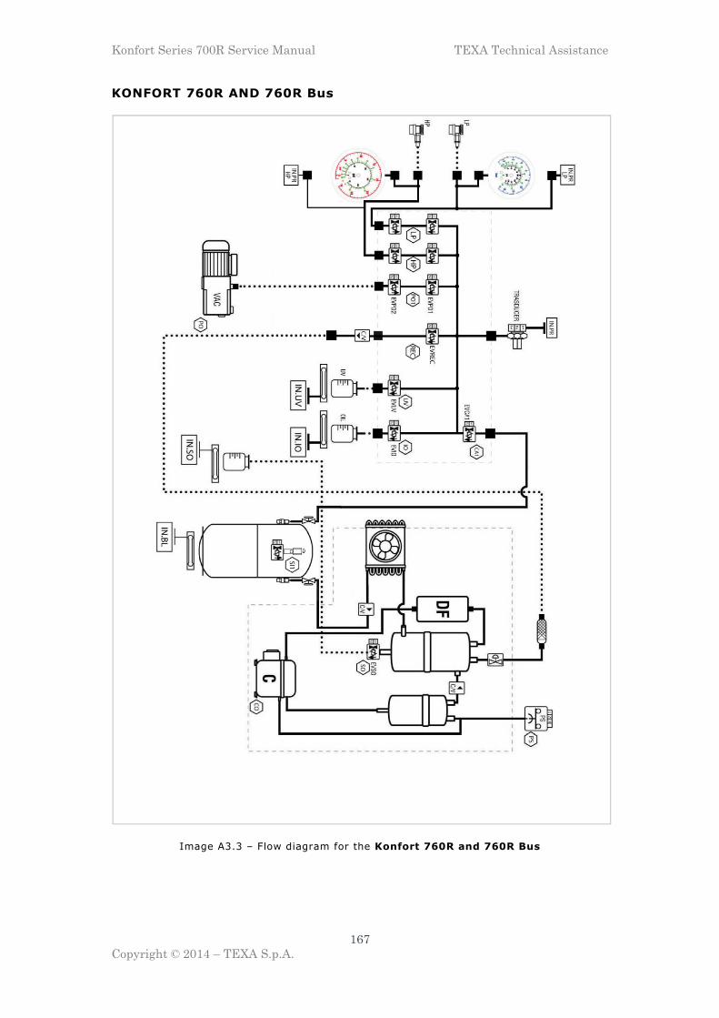
Konfort Series 700R Service Manual TEXA Technical Assistance
167
Copyright © 2014 – TEXA S.p.A.
KONFORT 760R AND 760R Bus
Image A3.3 – Flow diagram for the Konfort 760R and 760R Bus

Konfort Series 700R Service Manual TEXA Technical Assistance
168
Copyright © 2014 – TEXA S.p.A.
KONFORT 780R BiGas
Image A3.4 – Flow diagram for the Konfort 780R BiGas
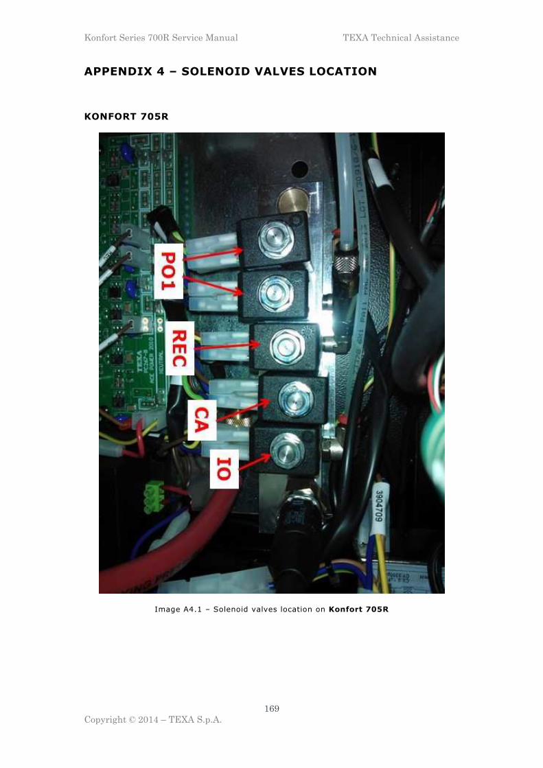
Konfort Series 700R Service Manual TEXA Technical Assistance
169
Copyright © 2014 – TEXA S.p.A.
APPENDIX 4 – SOLENOID VALVES LOCATION
KONFORT 705R
Image A4.1 – Solenoid valves location on Konfort 705R

Konfort Series 700R Service Manual TEXA Technical Assistance
170
Copyright © 2014 – TEXA S.p.A.
KONFORT 710R AND 720R
Image A4.2 – Solenoid valves location on Konfort 710R and 720R

Konfort Series 700R Service Manual TEXA Technical Assistance
171
Copyright © 2014 – TEXA S.p.A.
KONFORT 760R AND 760R Bus
Image A4.3 – Solenoid valves location on Konfort 760R and 760R Bus

Konfort Series 700R Service Manual TEXA Technical Assistance
172
Copyright © 2014 – TEXA S.p.A.
KONFORT 780R BiGas
Image A4.4 – Solenoid valves location on Konfort 780R BiGas