
BiPAP® Synchrony Service & Technical Information
155
B B iPAP® iPAP® Synchrony Synchrony Service Service & Technical & Technical Information Information
-
Upload
khangminh22 -
Category
Documents
-
view
9 -
download
0
Transcript of BiPAP® Synchrony Service & Technical Information

BBiPAP® iPAP® SynchronySynchrony
Service Service & Technical & Technical InformationInformation

BIPAP SYNCHRONY SERVICE & TECHNICAL INFORMATION
REVISION HISTORY
SECTION NAME (NO.) REV. # DATE DESCRIPTION
Copyright/Warranty (1032405) 00 Initial Revision
Revision History (1032450) 02 Initial Revision
Table of Contents (1032406) 01 Initial Revision
Introduction (1032407) 00 Initial Revision
Warnings & Cautions (1032408)
01 Initial Revision
Specifications & System Features (1032409)
00 Initial Revision
Theory of Operation (1032410)
00 Initial Revision
Setup (1032411) 00 Initial Revision
Maintenance (1032412) 00 Initial Revision
Troubleshooting & Diagnostics (1032443)
00 Initial Revision
Repair & Replacement (1032444)
00 Initial Revision
Repair Kits (1032445) 00 Initial Revision
Testing (1032447) 00 Initial Revision
Tools and Equipment (1032448)
00 Initial Revision
Schematics (1032449) 01 Initial Revision
REVISION HISTORY - PAGE 11032450, REV. 02

BIPAP SYNCHRONY SERVICE & TECHNICAL INFORMATION
This page intentionally blank.
1032450, REV. 02REVISION HISTORY - PAGE 2

BIPAP SYNCHRONY SERVICE & TECHNICAL INFORMATION
© 2006, Respironics, Inc. and affiliates. All rights reserved.
COPYRIGHT/WARRANTY - PAGE 11032405, REV. 00

BIPAP SYNCHRONY SERVICE & TECHNICAL INFORMATION
WARRANTYRespironics, Inc. warrants that the system shall be free from defects of workmanship and materialsand will perform in accordance with the product specifications for a period of two (2) years from thedate of sale by Respironics, Inc. to the dealer. Respironics warrants that the BiPAP Synchrony unitsserviced by Respironics will be free from defects in serviced materials for a period of one year and freefrom defects in workmanship for a period of 90 days from the time of service. Respironics accessoriesare warranted to be free of defects in materials and workmanship for a period of 90 days from the timeof purchase. If the product fails to perform in accordance with the product specifications, Respironics,Inc. will repair or replace – at its option – the defective material or part. Respironics, Inc. will paycustomary freight charges from Respironics, Inc. to the dealer location only. This warranty does notcover damage caused by accident, misuse, abuse, alteration, and other defects not related to materialor workmanship.
Respironics, Inc. disclaims all liability for economic loss, loss of profits, overhead, or consequentialdamages which may be claimed to arise from any sale or use of this product. Some states do not allowthe exclusion or limitation of incidental or consequential damages, so the above limitation or exclusionmay not apply to you.
This warranty is given in lieu of all other express warranties. In addition, any implied warranties –including any warranty of merchantability or fitness for the particular purpose – are limited to two years.Some states do not allow limitations on how long an implied warranty lasts, so the above limitation maynot apply to you. This warranty gives you specific legal rights, and you may also have other rightswhich vary from state to state.
To exercise your rights under this warranty, contact your local authorized Respironics, Inc. dealer orcontact Respironics, Inc. at:
Visit Respironics Home Page on the World Wide Web at:
www.respironics.com
1032405, REV. 00COPYRIGHT/WARRANTY - PAGE 2

BIPAP SYNCHRONY SERVICE & TECHNICAL INFORMATION
INTRODUCTIONBIPAP SYNCHRONY VENTILATORY SUPPORT SYSTEM OVERVIEW ................................. 1SERVICE NOTICE .......................................................................................................... 2TECHNICAL SUPPORT STATEMENT ................................................................................ 2TRAINING ..................................................................................................................... 3
WARNINGS, CAUTIONS, AND NOTESCHAPTER OVERVIEW .................................................................................................... 1WARNINGS................................................................................................................... 1CAUTIONS .................................................................................................................... 2NOTES ......................................................................................................................... 2
SPECIFICATIONS, & SYSTEM FEATURESOVERVIEW ................................................................................................................... 1SPECIFICATIONS........................................................................................................... 2SYSTEM FEATURES ...................................................................................................... 4LEAK TOLERANCE........................................................................................................ 5SENSITIVITY ................................................................................................................. 5SYMBOLS FOR DEVICE AND POWER SUPPLY................................................................. 6
THEORY OF OPERATIONOVERVIEW ................................................................................................................... 1MAIN PRINTED CIRCUIT ASSEMBLY (PCA).................................................................... 15 VOLT SWITCHING POWER SUPPLY ............................................................................. 1+12V REGULATOR ....................................................................................................... 1-15V SWITCHING CIRCUIT............................................................................................. 1+3.3V REGULATOR ...................................................................................................... 1MICROCONTROLLER U2................................................................................................ 1IR COMMUNICATION LINK FOR THE INTEGRATED HUMIDIFIER ......................................... 28KBIT EEPROM .......................................................................................................... 24MBITS OF PROGRAM FLASH MEMORY......................................................................... 2128 KBYTES OF ASYNCHRONOUS SRAM...................................................................... 2WATCHDOG SUPERVISOR ............................................................................................. 2PRESSURE SENSORS.................................................................................................... 3BAROMETRIC PRESSURE SENSOR................................................................................. 3BI-DIRECTIONAL MASS FLOW SENSOR ......................................................................... 3ELECTRO-MECHANICAL ................................................................................................ 3SENSORLESS MOTOR CONTROLLER............................................................................... 3MOTOR SPEED CONTROL ............................................................................................. 3BRAKING AND STARTING CIRCUITRY ............................................................................. 3
TABLE OF CONTENTS - PAGE 11032406, REV. 01

BIPAP SYNCHRONY SERVICE & TECHNICAL INFORMATION
SLEEVE VALVE ............................................................................................................. 4VALVE CONTROLLER .................................................................................................... 4SOFT KEY WITH PUSH BUTTONS ................................................................................... 4DISPLAY DRIVER AND LCD........................................................................................... 4POWER FAIL CIRCUITRY................................................................................................ 4
SYSTEM SETUP PROCEDURESOVERVIEW.................................................................................................................... 1SYSTEM SETUP............................................................................................................. 2SETTING UP THE BIPAP SYNCHRONY............................................................................ 3REQUIRED, ALTERNATE, AND OPTIONAL ACCESSORIES ............................................... 11CIRCUITS AND ACCESSORIES ...................................................................................... 12MASKS, EXHALATION PORTS, AND RELATED ACCESSORIES......................................... 12HUMIDIFIERS............................................................................................................... 12SOFTWARE ................................................................................................................. 13DC POWER ACCESSORIES.......................................................................................... 13ADDING A HUMIDIFIER................................................................................................. 13
ROUTINE MAINTENANCECHAPTER OVERVIEW .................................................................................................... 1CLEANING THE SYSTEM ................................................................................................ 1CLEANING/REPLACING THE INTAKE FILTER.................................................................... 1PREVENTIVE MAINTENANCE SCHEDULE ......................................................................... 2BIPAP SYNCHRONY SYSTEM PREVENTIVE MAINTENANCE SCHEDULE (FACTORY RECOMMENDED) ......................................................................................... 3
TROUBLESHOOTING AND DIAGNOSTICSCHAPTER OVERVIEW .................................................................................................... 1TROUBLESHOOTING FLOW CHART................................................................................. 2ALARM INTRODUCTION.................................................................................................. 3OVERVIEW OF ALARM BEHAVIOR .................................................................................. 4HIGH PRIORITY SOUNDS ............................................................................................... 4MEDIUM PRIORITY SOUND............................................................................................. 4LOW PRIORITY SOUND.................................................................................................. 4SILENCE PERIOD .......................................................................................................... 4ALARM LED BEHAVIOR ................................................................................................ 5RED ALARM LED ......................................................................................................... 5YELLOW ALARM LED ................................................................................................... 5DISPLAY BEHAVIOR ...................................................................................................... 5SYSTEM ALARMS.......................................................................................................... 5
1032406, REV. 01TABLE OF CONTENTS - PAGE 2

BIPAP SYNCHRONY SERVICE & TECHNICAL INFORMATION
PATIENT ALARMS......................................................................................................... 7POWER ALARMS .......................................................................................................... 8TROUBLESHOOTING TABLE......................................................................................... 10BIPAP SYNCHRONY SYSTEM ERROR CODE RETRIEVAL .............................................. 15SYSTEM ERROR CODES LIST (PATIENT ACTION) ......................................................... 16BIPAP SYNCHRONY SYSTEM ERROR CODES (CORRECTIVE ACTION)........................... 20BIPAP SYNCHRONY SMARTCARD ERROR CODES....................................................... 25
REPAIR AND REPLACEMENTCHAPTER OVERVIEW .................................................................................................... 1WARNINGS AND CAUTIONS ........................................................................................... 2REPLACEMENT INSTRUCTIONS ...................................................................................... 2PROCEDURE................................................................................................................. 5PROCEDURE................................................................................................................. 7
REPAIR KITSCHAPTER OVERVIEW .................................................................................................... 1REPAIR KIT REFERENCE TABLE.................................................................................... 2TOP ENCLOSURE REPAIR KIT ....................................................................................... 3MAIN PRINTED CIRCUIT ASSEMBLY (PCA) REPAIR KIT ................................................. 4KEYPAD REPAIR KIT .................................................................................................... 5OUTLET-FLOW-TUBING REPAIR KIT .............................................................................. 6DIFFUSER ASSEMBLY REPAIR KIT................................................................................. 7VALVE ASSEMBLY REPAIR KIT ..................................................................................... 8 BLOWER ASSEMBLY REPAIR KIT ................................................................................. 9MUFFLER REPAIR KIT................................................................................................. 10BUZZER ASSEMBLY REPAIR KIT ................................................................................. 11BOTTOM ENCLOSURE REPAIR KIT .............................................................................. 12WARNING LABEL REPAIR KIT ..................................................................................... 13ULTRA FINE FILTER REPAIR KIT ................................................................................. 14POLLEN FILTER REPAIR KIT ....................................................................................... 15FILTER CAP REPAIR KIT............................................................................................. 1660 WATT POWER SUPPLY REPAIR KIT........................................................................ 17ALARM LABEL REPAIR KIT ......................................................................................... 18SLEEPLINK COMMUNICATION CABLE REPAIR KIT........................................................ 19SMARTCARD SEAL REPAIR KIT .................................................................................. 20TUBING REPAIR KIT ................................................................................................... 21
TABLE OF CONTENTS - PAGE 31032406, REV. 01

BIPAP SYNCHRONY SERVICE & TECHNICAL INFORMATION
TESTINGTESTING PROCESS ....................................................................................................... 1BIPAP SYNCHRONY SYSTEM RUN-IN ............................................................................ 1PERFORMANCE VERIFICATION ....................................................................................... 1REAL-TIME CLOCK CALIBRATION .................................................................................. 2BIPAP SYNCHRONY CALIBRATION................................................................................ 7PRINTING OF THE FINAL TEST DATA SHEET................................................................. 19CURRENT DRAW TEST ................................................................................................ 20BIPAP SYNCHRONY CURRENT DRAW TEST DATA SHEET............................................ 21PERFORMANCE VERIFICATION DATA SHEET................................................................. 22
TOOLS AND EQUIPMENTSERVICE TOOLS AND SUPPLIES .................................................................................... 1ACCEPTABLE TEST EQUIPMENT .................................................................................... 2
SCHEMATICSSCHEMATICS STATEMENT ............................................................................................. 1
1032406, REV. 01TABLE OF CONTENTS - PAGE 4

BIPAP SYNCHRONY SERVICE & TECHNICAL INFORMATION
INTRODUCTION
BIPAP SYNCHRONY VENTILATORY SUPPORT SYSTEM OVERVIEWThe BiPAP Synchrony, shown in Figure A, is a low-pressure, electronically driven ventilator systemwith electronic pressure control. The device’s pressure controls are adjusted to deliver pressuresupport for patient ventilatory assistance.
FIGURE A: BIPAP SYNCHRONY DEVICE
The BiPAP Synchrony is intended to augment patient breathing by supplying pressurized air through apatient circuit. It senses the patient’s breathing effort by monitoring airflow in the patient circuit andadjusts its output to assist in inhalation and exhalation. This assistance is provided by theadministration of two levels of positive pressure. During exhalation, pressure is variably positive ornear ambient. During inspiration, pressure is variably positive and always equal to or higher than theexpiratory level.
The BiPAP Synchrony responds reliably to patient flow rates that indicate movement to inhalation orexhalation, even in the presence of most normal leaks in the patient circuit. Automatic adjustment ofthis trigger threshold in the presence of leaks makes the system ideal for mask-applied ventilationassistance. The patient-controllable Rise Time and Bi-Flex features may enhance patient-ventilatorsynchrony and patient comfort.
The BiPAP Synchrony operates in the following modes: Continuous Positive Airway Pressure (CPAP),Spontaneous (S), Spontaneous/Timed (S/T), Timed (T), and Pressure Control (PC).
In the Continuous Positive Airway Pressure (CPAP) mode, the BiPAP Synchrony delivers continuouspressure support ventilation at one pressure level.
In the Spontaneous (S) mode, the BiPAP Synchrony delivers bi-level pressure support. The devicetriggers to Inspiratory Positive Airway Pressure (IPAP) in response to spontaneous inspiratory effortand cycles to Expiratory Positive Airway Pressure (EPAP) during exhalation. The level of pressuresupport delivered is determined by the difference between the IPAP and EPAP settings. TheSpontaneous/Timed (S/T) mode of the BiPAP Synchrony is similar to the S mode, except that it alsocan deliver a machine-triggered breath if the patient does not spontaneously breathe within a set time.
INTRODUCTION - PAGE 11032407, REV. 00

BIPAP SYNCHRONY SERVICE & TECHNICAL INFORMATION
The S/T mode ensures that patients receive a minimum number of breaths per minute based on theRate setting. If the patient fails to initiate an inspiration within the interval determined by the Ratecontrol, the unit triggers a timed (or machine-triggered) breath resulting in a pressure-control(pressure-limited, time-cycled) breath at the set IPAP level. The rate of timed breaths is adjustable.The duration of each timed breath is controlled by an Inspiratory Time control.
The Timed mode provides mandatory pressure assist. All breaths are machine triggered and machinecycled. The patient breathing has no affect on this machine. The triggering is determined by theBreath Rate control. The cycle time is determined by the Inspiratory Control.
The PC mode is equivalent to the S/T mode except that all breaths are machine cycled and, therefore,have a fixed inspiratory time. This mode is a pressure limited, machine or patient triggered, timecycled mode. The patient may initiate a breath, but all breaths are pressure limited (IPAP) and time-cycled. The cycle time is determined by the Inspiratory Time control setting.
AVAPS is available in the S, S/T, Timed and PC modes. AVAPS provides dynamic IPAP control. TheIPAP pressure is dynamically controlled so that exhaled tidal volumes approach the Vte control value.AVAPS provides gradual pressure changes to compensate for the tidal volume error observed overseveral preceding breaths.
The BiPAP Synchrony provides the Bi-Flex feature in S mode. The Bi-Flex attribute adjusts therapy byinserting a small amount of pressure relief during the latter stages of inspiration and during activeexhalation (the beginning part of exhalation).
The device incorporates a user interface made up of a Ramp Button, Humidifier Button, Alarm ResetButton, Alarm Silence Button, Scroll Button, and Liquid Crystal Display (LCD). A pressure On/Offpush-button is located on the side of the unit.
SERVICE NOTICEThis service manual was prepared by Respironics primarily for use by technicians to service the BiPAPSynchrony Ventilatory Support System. The individuals using this manual to service the BiPAPSynchrony should have prior training or experience servicing ventilatory devices.
TECHNICAL SUPPORT STATEMENTRespironics is committed to customer satisfaction and may be contacted with any questions or forproduct support. For product assistance or replacement part ordering information, contact RespironicsCustomer Service.
US and Canada
Phone:1-800-345-6443
Fax:1-800-866-0245
Email: [email protected]
International
Phone:1-724-387-4000
Fax:1-724-387-5012
Email: [email protected]
1032407, REV. 00INTRODUCTION - PAGE 2

BIPAP SYNCHRONY SERVICE & TECHNICAL INFORMATION
TRAININGRespironics offers service training for BiPAP and CPAP systems. For more information, EmailRespironics at:
Visit Respironics Home Page on the World Wide Web at:
www.respironics.com
INTRODUCTION - PAGE 31032407, REV. 00

BIPAP SYNCHRONY SERVICE & TECHNICAL INFORMATION
This page intentionally left blank.
1032407, REV. 00INTRODUCTION - PAGE 4

BIPAP SYNCHRONY SERVICE & TECHNICAL INFORMATION
WARNINGS, CAUTIONS, AND NOTES
CHAPTER OVERVIEWWarnings, Cautions, and Notes are used throughout this manual to identify possible safety hazards,conditions that may result in equipment or property damage, and important information that must beconsidered when performing service and testing procedures on the BiPAP Synchrony.
Please read this section carefully before servicing the BiPAP Synchrony.
WARNINGS
WARNING
Warnings indicate the possibility of injury to the patient, operator, ortechnician.
CAUTION
Cautions indicate the possibility of damage to the device
NOTE
Notes are used to emphasize a characteristic or important consideration.
WARNINGS
• The service technician should read and understand this entire manual before servicing the BiPAP Synchrony. Ensure that all warnings, cau-tions, and notes cited in the BiPAP Synchrony Provider manual are read and understood prior to servicing this device.
• To assure the safety of the service technician and the specified per-formance of the device, Respironics recommends that only techni-cians having prior training or experience servicing ventilatory devices perform any repairs or adjustment to the BiPAP Synchrony.
• High voltages are present inside this device. To avoid electrical shock, disconnect the electrical supply before attempting any repairs on the device.
• DO NOT immerse this device into any fluids.
WARNINGS & CAUTIONS - PAGE 11032408, REV. 01

BIPAP SYNCHRONY SERVICE & TECHNICAL INFORMATION
CAUTIONS
NOTES
CAUTIONS
• Electronic components used in this device are subject to damage from static electricity. Repairs made to this device must be performed only in an anti-static, Electro-static Discharge (ESD)-protected environment.
• Care should be taken to avoid exposure of the BiPAP Synchrony to tempera-tures at or near the extremes of those specified in Chapter 3. If exposure to such temperatures has occurred, the device should be allowed to return to room temperature before being turned on.
• Never place liquids on or near the BiPAP Synchrony.
• The information in this manual is provided for service personnel reference.
NOTES
• Additional Warnings, Cautions, and Notes are located throughout this man-ual.
• Refer to the BiPAP Synchrony User and Provider Manual for product use, additional Warnings, Cautions and Notes.
1032408, REV. 01WARNINGS & CAUTIONS - PAGE 2

BIPAP SYNCHRONY SERVICE & TECHNICAL INFORMATION
SPECIFICATIONS, & SYSTEM FEATURES
OVERVIEWThis chapter describes the specifications and system features for the BiPAP Synchrony VentilatorySupport System.
SPECIFICATIONS & SYSTEM FEATURES - PAGE 11032409, REV. 00

BIPAP SYNCHRONY SERVICE & TECHNICAL INFORMATION
SPECIFICATIONS
ENVIRONMENTAL
Operating Temperature 5 °C to 35 °C
Storage Temperature -20 °C to 60 °C
Humidity 15 - 95% non-condensing
Atmospheric Pressure 83 - 102 kPascals(Storage: 50 - 102 kPascals)
Elevation 0 - 5,600 ft. with automatic altitude adjustment
Noise Level No specification is given because various test instruments, test procedures, and unit operating conditions produce varying results.
FUSES
Fuses There are no replaceable fuses in this device.
ELECTRICAL
AC Voltage Source 90 - 264 VAC; 47/70 Hz*
DC Input Voltage 9.8-17.0 VDC**
AC Current Consumption 1.25 A maximum
DC Current Consumption 3.0 A maximum
Protection Against Electric Shock
Class II
Degree of Protection Against Electric Shock
Type BF Applied Part
Degree of Protection Against Harmful Ingress of Water
Device:Ordinary Equipment, IPX0External AC and External DC Power Supply:Drip Proof, IPX1
* When used with an external AC/DC power converter.
**When used with an external DC boost converter and > 10.5 VDC to start.
MODE OF OPERATION
Continuous
1032409, REV. 00SPECIFICATIONS & SYSTEM FEATURES - PAGE 2

BIPAP SYNCHRONY SERVICE & TECHNICAL INFORMATION
FUNCTIONS
Modes Continuous Positive Airway Pressure (CPAP)Spontaneous (S)Timed (T)Spontaneous/Times (S/T)Pressure Control (PC)
PRESSURE
IPAP 4 to 30 cm H2O*
EPAP 4 to 25 cm H2O
CPAP 4 to 20 cm H2O
Vte Setpoint 200mL to 1500mL
Low MinVent Alarm 0.0 LPM to 99.0 LPM
Flex Setpoint 0 to 3
Breath Rate 0 to 30 BPM
Timed Inspiration 0.5 to 3.0 seconds
Ramp Duration 0 to 45 minutes
Rise Time** 1 to 6 (0.1 to 0.6 seconds)
* Limited to 25 cmH2O when using the Bi-Flex feature in S mode.
** The range of values correspond to tenths of seconds (e.g., a setting of 4 indicates a Rise Time of 0.4 seconds). When in BiFlex Mode, the unit shall always use a rise time of 3 regardless of this setpoint.
PHYSICAL
Dimensions 9.8”(L) x 6.6”(W) x 4.4”(H)
Weight Less than 7 lbs. without the humidifier
EMC NORMATIVE DOCUMENTS
This product is designed to conform to the following standards:
IEC 60601-1 Medical Electrical Equipment, Part 1 General Requirements for Safety and essential performance.
SPECIFICATIONS & SYSTEM FEATURES - PAGE 31032409, REV. 00

BIPAP SYNCHRONY SERVICE & TECHNICAL INFORMATION
SYSTEM FEATURES
SYSTEM FEATURES
AC Power Connector AC power supply connection.
Air Outlet Port Flexible tubing/patient circuit connection.
DC Power Connector Optional DC power connection.
AC Power Indicator LED Display for AC power.
DC Power Indicator LED Display for DC power.
High Priority Alarm Indicator LED Display for High Priority Alarms. (RED)
Low/Medium Priority Alarm Indicator LED Display for Low/Medium Priority Alarms. (YELLOW)
Display Screen Liquid Crystal Display where all device settings appear.
Pressure On/Off Starts or stops the devices airflow.
Bi-Flex Feature Available in S Mode.
AVAPS Feature Available in S, S/T, and PC and T Modes.
Heat Controls the optional Heated Humidifier.
Ramp Lowers the airflow pressure allowing the patient to fall asleep more easily.
User Buttons Navigate the display screen.
Alarm Silence Button Temporarily silences the audible portion of the alarm.
Reset Acknowledges an alarm and resets the device for alarm detection.
Scroll Button Allows for the user to scroll through monitoring parameters on the display.
Filter Cap and Filters The pollen filter screens out normal household dust and pollens. This must be in place at all times when the BiPAP Synchrony is operating. An optional, ultra-fine filter is also included for more complete filtration of very fine particles. The filter cap can be positioned to direct the air flow away from your device.
1032409, REV. 00SPECIFICATIONS & SYSTEM FEATURES - PAGE 4

BIPAP SYNCHRONY SERVICE & TECHNICAL INFORMATION
RAMP FEATURE
BiPAP Synchrony is equipped with a linear ramp function. The ramp feature will reduce the pressureand then gradually increase (ramp) the pressure to the prescription pressure setting so patients canfall asleep more comfortably.
DIGITAL AUTO-TRAK SENSITIVITY
An important characteristic of the BiPAP Synchrony is its ability to recognize and compensate forunintentional leaks in the system and to automatically adjust its trigger and cycle algorithms tomaintain optimum performance in the presence of leaks. This feature is known as Digital Auto-TrakSensitivity. The following sections examine this function in detail by describing the leak tolerancefunction and sensitivity.
LEAK TOLERANCE
A microprocessor monitors the total flow of the patient circuit and calculates patient flow values. TheBiPAP Synchrony uses two leak estimation algorithms. A conservation of mass algorithm is used tocompute the average leak for a given pressure support relationship. This average leak is a highestimate during EPAP pressure and a low estimate during IPAP pressure.
A better leak estimate, enabled by the digital system, is the parabolic leak algorithm. Parabolic leak isproportional to the square of the patient pressure; therefore, the leak estimate is correlated to thechanging patient pressure. Both algorithms include unintentional circuit leak and are averaged overseveral breaths.
The total circuit flow is comprised of the circuit leak and the patient flow. The calculated patient flow isthe circuit flow minus the circuit leak. Patient flow is a primary input into the triggering and cyclingmechanisms.
SENSITIVITY
An essential feature of the BiPAP Synchrony while operating in the S and S/T modes is its ability toeffectively sense spontaneous breathing efforts, which causes the unit to trigger IPAP and cycle toEPAP. Because no preset sensitivity threshold can assure patient and machine synchrony withchanging breathing efforts and circuit leaks, the BiPAP Synchrony continuously tracks patientbreathing patterns and automatically adjusts sensitivity thresholds to ensure optimum sensitivity asbreathing patterns change or as circuit leaks change. The algorithms used to ensure optimumsensitivity are the Volume Trigger/Cycle, Shape Trigger, Flow Reversal and Spontaneous ExpiratoryThreshold (SET).
The shape trigger/cycle is another method used to trigger IPAP and/or cycle from IPAP to EPAP duringspontaneous breathing in the S and S/T modes. This method continuously tracks patient inspiratoryand expiratory flow and adjusts the spontaneous trigger and cycle thresholds for optimum sensitivity.The Shape Signal appears as a shadow image of the patient’s actual flow. The shape signal functionsas a sensitivity threshold at either inspiration or expiration. When the patient’s flow rate crosses theshape signal, the unit changes pressure levels. The shape signal is created by offsetting the signalfrom the actual patient flow by 15 lpm and delaying it for a 300 ms period. This intentional delaycauses the shape signal to be slightly behind the patient’s flow rate. A sudden change in patient flowwill cross the shape signal, causing the pressure level to change.
A second method used to cycle off IPAP during spontaneous breathing in the S and S/T modes iscalled Spontaneous Expiratory Threshold (SET). The SET rises in proportion to the inspiratory flowrate on each breath. When the SET and actual patient flow value are equal, the unit cycles to EPAP.
SPECIFICATIONS & SYSTEM FEATURES - PAGE 51032409, REV. 00

BIPAP SYNCHRONY SERVICE & TECHNICAL INFORMATION
A maximum IPAP time of 3.0 seconds acts as a safety mechanism to limit the time spent at the IPAPlevel during spontaneous breathing in the S and S/T modes. Once the time limit is reached, the unitautomatically cycles off IPAP to the EPAP level.
As flow begins to decrease during IPAP, a flow reversal can occur due to a large leak around the maskor because the patient’s mouth is open. When the BiPAP Synchrony unit senses this flow reversal, theunit automatically cycles to the EPAP level.
SYMBOLS FOR DEVICE AND POWER SUPPLY
SYMBOLS AND MEANINGS
Attention, consult accompanying documents
DC Power
Pressure On/Off
Type BF Applied Part
Class II (Double Insulated)
European CE Declaration of Conformity
Canadian/US Certification
1032409, REV. 00SPECIFICATIONS & SYSTEM FEATURES - PAGE 6

BIPAP SYNCHRONY SERVICE & TECHNICAL INFORMATION
SYMBOLS AND MEANINGS CONT.
Electrostatic Discharge
Ordinary Equipment
UL Recognized for Canada and the United States
TUV Safety Standard Compliance
No User Serviceable Parts
WEEE/RoHS Symbol
SPECIFICATIONS & SYSTEM FEATURES - PAGE 71032409, REV. 00

BIPAP SYNCHRONY SERVICE & TECHNICAL INFORMATION
This page intentionally left blank.
1032409, REV. 00SPECIFICATIONS & SYSTEM FEATURES - PAGE 8

BIPAP SYNCHRONY SERVICE & TECHNICAL INFORMATION
THEORY OF OPERATION
OVERVIEWThis chapter describes the operation of the BiPAP Synchrony Printed Circuit Assembly (PCA).Operation of the various circuits on the board are explained.
MAIN PRINTED CIRCUIT ASSEMBLY (PCA)The Main PCA is the computer control center of the BiPAP Synchrony. A microcontroller reads andwrites to various I/O devices such as the control pad, LCD, memory chips, pressure and flow sensorsand motor control circuitry. The microcontroller will make appropriate adjustments to the valve andblower using this information to deliver the desired therapy to the patient.
POWER DISTRIBUTION
There are two 3 pin power din connectors on the back of the BiPAP Synchrony. They will accept thebulk voltage on pin 1 from either an external AC/DC 60W Respironics’ power supply or an external DC/DC Respironics’ power supply with the mating connector. Pin 2 is the return on both connectors. Pin3 is a multi-purpose pin. It is floating when the AC/DC converter is connected. It is connected to thebattery voltage to read on internal ADC channel 0. When the AC/DC converter is used, the bulkvoltage will range from 24 to 28 VDC (read on internal ADC channel 4). When the DC/DC converter isused, the voltage will be less than 23 VDC.
5 VOLT SWITCHING POWER SUPPLY
5 Volts is needed throughout the Main PCA for logic circuits. U16 is a simple switcher which producesa 5V output from the bulk voltage. The input cap, C45, is oversized and serves both as an input filterfor the bulk voltage at the input connector and the high frequency input cap for this switcher. Theoutput cap, C79, maintains the output ripple voltage below 50 mV. L2 allows 2A output currentscomfortably due to its size.
+12V REGULATOR
U18 produces the 12 Volts needed to bias the flow sensor and it is also used as the positive rail for theanalog circuitry and the operational amplifiers of the valve controller.
-15V SWITCHING CIRCUIT
A negative power supply is created by using an output from the microcontroller switching currentthrough resistor R186 and capacitor C80. This negative voltage is used as the negative rail for theanalog circuitry and valve controller operational amplifiers.
+3.3V REGULATOR
The core and I/O of the microcontroller are driven by 3.3 volts. Voltage regulator U12 creates thisvoltage from the 5V power supply.
DIGITAL CIRCUITRY
MICROCONTROLLER U2
The microcontroller, U2, has a high-performance 32 bit RISC architecture. The 176 pin devicecontains an external address and data bus interface, an eight level external interrupt controller, 58programmable I/O lines, six 16 bit timers, 3 UARTs, a 3 wire SPI interface, an eight channel 10 bitADC, a two channel 10 bit DAC, an on chip oscillator and PLL for multiplication, a real time clock, a
THEORY OF OPERATION - PAGE 11032410, REV. 00

BIPAP SYNCHRONY SERVICE & TECHNICAL INFORMATION
JTAG interface for boundry scans and a power management controller for sleep and wakeupoperations.
The core and I/O ports of the microcontroller use 3.3 V connected at several pins shown on theschematic.
There is an eight channel successive approximation Analog to Digital Converter (ADC) on thismicrocontroller. Channels AD0 through AD7 are all in use.
When power is initially supplied to the chip, the main oscillator is off until the PLL is enabled. Until thisis done, the chip is clocked off of the 32.768 kHz crystal, Y2. The main oscillator takes the output fromfundamental crystal, Y1 and is capable of multiplying this frequency up to 33 MHz.
The computer uses the watch crystal (Y2) and a lithium battery (B1) to maintain an internal clock thatconsumes very little power. The lithium coin cell battery (B1) provides a minimum of 17 years ofbattery life for the Main PCA.
The main board uses both channels of the two channel 10 bit DAC to control motor speed and set theoutput pressure controlled by the valve sleeve. The range of the output voltage is 0 to 3.3V. Themotor speed command is a calibrated non-linear relationship between RPM and DAC counts.
This device features a Serial Peripheral Interface (SPI) that communicates with external devices ineither master or slave mode. Two external devices on the board use this type of communication, theEEPROM (U1) and the ADC (U11). The microcontroller provides three universal sychronous/asynchronous receiver/transmitters. The zero transmitter, TXD0, is used for communication with thehumidifier. TXD1 and RXD1 are used for two way communications with a PC via the SleepLink card orto communicate with an external smart modem.
IR COMMUNICATION LINK FOR THE INTEGRATED HUMIDIFIER
The BiPAP Synchrony communicates serially via an infrared LED with the integrated humidifier thatcradles the enclosure. The LED (CR3) transmits 2 wire serial commands to an IR detector inside thehumidifier to turn on, turn off and adjust the water temperature in the humidifier.
8KBIT EEPROM
Eight thousand bits of memory are provided on this board for the storage of therapy parameters in U1.
4MBITS OF PROGRAM FLASH MEMORY
IC, U4 contains 512 kbytes of non-volatile Flash memory that is programmed and operated with 3.3V.This chip contains the application software.
128 KBYTES OF ASYNCHRONOUS SRAM
U5 has 128 kbytes of static ram which allows for the freedom and complexity of the application code.This chip is designed for 3V operation.
WATCHDOG SUPERVISOR
An external supervisory chip, U3, monitors the 3.3 Volts. When the voltage approaches 2.93 V thechip will protect the Flash Chip by resetting the processor before the voltage reaches a level too low forthe Flash and also shuts down the processor while the core voltage is dropping.
1032410, REV. 00THEORY OF OPERATION - PAGE 2

BIPAP SYNCHRONY SERVICE & TECHNICAL INFORMATION
ANALOG DEVICES
PRESSURE SENSORS
The main control board uses two sensors to monitor pressure amplitudes, MT4 or MT5 and MT3 orMT1. MT4 or MT5 is connected to the outlet pressure and MT3 or MT1 is connected at the blower.(Type of sensor used on the PCA will determine the MT locations used.)
BAROMETRIC PRESSURE SENSOR
The BiPAP Synchrony uses a 15psia pressure sensor. The sensor, MT6, is used to provide altitudecompensation for volumetric flow calculations. It is a 0 to 15 psia sensor with temperaturecompensation and calibrated zero and span.
BI-DIRECTIONAL MASS FLOW SENSOR
The main board uses mass flow sensor (MT2). The sensor uses the thermal properties of air to qualifythe mass of a gas passing through the element. The sensing elements are seated on a heaterelement and are normally at some temperature above the ambient. As flow passes over the firstelement, which can be called the upstream element, it cools this element and at the same time picksup heat. Between the two elements the gas picks up more heat as it traverses the heater and finallyadds its newly acquired heat to the downstream element. The two elements are thermistors that whenplaced in a Wheat-stone bridge configuration, produce an output voltage proportional to the mass ofthe airflow.
ELECTRO-MECHANICAL
A brushless DC motor is used in the BiPAP Synchrony to spin the impeller used to generate thepressure for therapy. The BiPAP Synchrony uses a valve to control the patient pressure but the blowerprovides a deadhead pressure above the maximum pressure setpoint.
SENSORLESS MOTOR CONTROLLER
The motor control chip (U9) runs off of the regulated +12 Volt power. When a motor speed commandvoltage is present and the BRAKE signal goes from high to low, the unit aligns the motor, ramps themotor in open loop control mode and then senses crossing from the phase windings to commutate themotor at the command speed.
MOTOR SPEED CONTROL
The DAC command from the microcontroller is a 0 to 3.3 volt signal and the signal is doubled by theOp-amp (U7). It is filtered by R85 and C39 to prevent noise on the signal. The speed command isvirtually linear up until the command voltage reaches 6 volts and then it begins to flatten (less speedfor changing voltage). The range of speed commands is from zero to the 6.9V reference voltage.
BRAKING AND STARTING CIRCUITRY
The BRAKE output from the microcontroller commands both the BRAKE and the reset (CRST) pins.When the brake is released, Q10 and Q11 are both switched off. When these two pins are left floating,the chip enters the reset state by turning on two of the high side drivers (Q8 and Q21) and one of thelow side drivers (Q9). This has the effect of aligning the motor 30 degrees before the first commutationstate. While this is happening, the unit is switching in and out of current limit and the capacitor C40 ischarging up by a small output current from the CRST pin and the additional current supplied by +12Volts through R89. When the voltage on C40 exceeds 1.5 Volts, the chip enters the ramp mode. Inramp mode, the chip begins the commutation sequence and increases the rate of the sequence whilecharging both the ramp capacitor, and the PLL filter components. When the ramp capacitor, C38reaches 1.5 Volts, the motor has enough speed for sensing and closed loop control.
THEORY OF OPERATION - PAGE 31032410, REV. 00

BIPAP SYNCHRONY SERVICE & TECHNICAL INFORMATION
SLEEVE VALVE
The sleeve valve of the BiPAP Synchrony controls with good response time and stability. The valve isa linear DC motor with a slitted sleeve sliding over ports in the stationary barrel. One of the ports ispneumatically connected to the blower pressure and the other is an exhaust outlet. There is always anominal flow through the annulas between the two concentric parts that provides additional stabilityand an air bearing. The sleeve is wound with copper wire and a magnet is attached to the innerdiameter of the barrel to provide a perpendicular bi-directional force.
VALVE CONTROLLER
The command is a voltage generated from the microcontroller DAC channel 1. When a pressure isrequested, the voltage generated from the DAC is multiplied by 1.499 by the amp, U23 with R146 andR147. MT4 or MT3 produces a pressure feedback signal through an amplifier U28. This signal issubtracted from the command pressure with U22A and the difference or error signal U22 pin 1 is theinput to the sleeve controller. The output of the controller network is delivered to the valve driver/amplifier U24. U24 takes a 5V analog input signal and drives a voltage out that can swing from -5V to5V across the valve coil. 2.5V corresponds to zero voltage and current.
USER INTERFACE
SOFT KEY WITH PUSH BUTTONS
The board has seven pills to detect keypresses. The pull-up resistors, R20, R22, R23, R24, R41,R129, and R130 are used for this circuit. The BiPAP Synchrony has a Scroll key that allows the userto scroll through different measured parameters. The pullup resistor for the Scroll key is R41. Fourwhite LED’s CR1, CR2, CR10, and CR11 are illuminated by switching Q1. All four are turned on andoff together.
DISPLAY DRIVER AND LCD
The backlighting for the display is switched on through Q27 and the current is set by R227. Alldisplays are driven by display drives U6 and U15. Both chips run off of 3.3 Volts. The clock output canbe found on pin 4.
POWER FAIL CIRCUITRY
When power is removed from the unit, but the on/off button remains in the on position, the unit willenter power fail mode. Voltage is held up by C57. This voltage is boosted and regulated by U15 toprovide a fixed loudness. As the capacitor drains, Q26 and Q25 with the surrounding circuitry providean astable vibrator to provide a 2 second on / 2 second off alarm. The red LED remains oncontinuously. Power fail on the board is detected by the existence or lack of +5 Volts.
1032410, REV. 00THEORY OF OPERATION - PAGE 4

BIPAP SYNCHRONY SERVICE & TECHNICAL INFORMATION
SYSTEM SETUP PROCEDURES
OVERVIEWThis section provides an overview of the system setup, including detailed instructions on how toaccess the Therapy settings.
FIGURE A: BIPAP SYNCHRONY DISPLAY
NOTE
This section provides directions for accessing the Therapy settings. To preventpatients from tampering with these settings, the directions to access the therapysettings should not be revealed to the patient.
CAUTION
If the BiPAP Synchrony has been exposed to either very hot or very coldtemperatures, allow it to adjust to room temperature (approximately two hours)before beginning startup.
SETUP - PAGE 11032411, REV. 00

BIPAP SYNCHRONY SERVICE & TECHNICAL INFORMATION
SYSTEM SETUPPlug the external power supply into the connector in the back of the BiPAP Synchrony. The BiPAPSynchrony will sound a confirmation alarm, and the control panel buttons light up. The first screen toappear is the Self Test screen
The next screen that will appear will display the software version of the device
The Blower Hours Screen will then appear, which displays the Blower Hours Time Meter:
The next screen that will appear will be the Standby Screen:
The Standby Screen appears when the BiPAP Synchrony is in the Standby state. Pressing thePressure On/Off button in puts the BiPAP Synchrony in the Operate state. The Monitoring Screen willthen appear:
Both the Monitoring and the Standby screens display the Patient, Apnea, and Light icons if thesefeatures are enabled. Likewise, the Card icon displays if a SmartCard is inserted, and the Setup icon
FLEX
A
TiBPMEPAP
LEAKMinVent
RRVTE
s mlcm
H2OPCPAPS/T AVAPS
IPAPIPAPVT
TiBPMEPAP
cmH2O
S/T
IPAP
1032411, REV. 00SETUP - PAGE 2

BIPAP SYNCHRONY SERVICE & TECHNICAL INFORMATION
displays if the access level is set to Provider mode. The monitoring screen also displays the actualmeasured pressure and the Flex icon if Flex is enabled.
When in the Standby or Monitoring screens, you can modify the humidifier setting by pressing andholding the Heat button until the following screen appears:
You can increase or decrease the humidifier setting from 1 to 5 in increments of 1. The settingchanges immediately as you adjust it.
PROVIDER MODE
There are two ways to access Provider mode:1. When the access level parameter is set to 1, the BiPAP Synchrony will be in Provider
mode when power is supplied to the unit. The only way to exit this mode is to change the access level parameter to 0.
2. Simultaneously hold down the right user button and the alarm silence button for approxi-mately 2 seconds while supplying power to the unit until the device beeps. Pressing the alarm silence button at any time will exit you from the Provider mode.
SETTING UP THE BIPAP SYNCHRONY1. Enter the Provider Mode. The first screen is the Mode setting screen. To change the
selection, press the Heat or Ramp button until the correct setting appears. Available modes are PC, CPAP, S, S/T, and T. Press the right user button once the desired setting is reached.
NOTE
In order to scroll through the different menus, you must use the left and right userbuttons along with the ramp and heat buttons.
S/T
PC
SETUP - PAGE 31032411, REV. 00

BIPAP SYNCHRONY SERVICE & TECHNICAL INFORMATION
2. If CPAP is chosen, the CPAP setting screen will appear next.
Increase or decrease the CPAP pressure by pressing the Heat and Ramp buttons until thedesired pressure appears. You can adjust the pressure from 4 to 20 cm H2O in 1 cm H2Oincrements. Press the right user button to move to the next screen. If CPAP is the chosenmode, proceed to Step 10 for next screen.
If PC, S, S/T, or T mode is chosen, the AVAPS screen will appear next.
Turn the AVAPS on or off by pressing the Heat or Ramp buttons until the correct numberappears. A One (1) on the display screen indicates that AVAPS is enabled and a Zero (0)indicates that the AVAPS feature is disabled. Press the right user button to move to thenext screen. If AVAPS is not chosen proceed to Step 6.
3. The Target Tidal Volume screen will appear next.
Increase or decrease the Target VT pressure by pressing the Heat or Ramp buttons untilthe correct pressure appears. You can adjust Target VT from 200 mL to 1500mL inincrements of 10mL. Press the right user button to move to the next screen.
EPAP
cmH2O
CPAP
PC AVAPS
ml
PC
VT
1032411, REV. 00SETUP - PAGE 4

BIPAP SYNCHRONY SERVICE & TECHNICAL INFORMATION
4. The IPAP max screen will appear next.
Increase or decrease the IPAP max pressure by pressing the Heat or Ramp buttons untilthe correct pressure appears. You can adjust the pressure from 4 to 30 cm H2O in 1 cmH2O increments. The IPAP max pressure setpoint cannot be set lower than the IPAP minpressure setting. Press the right user button to move to the next screen.
5. The IPAP min screen will appear next.
Increase or decrease the IPAP min pressure by pressing the Heat or Ramp buttons untilthe correct pressure appears. You can adjust the pressure from 4 to 30 cm H2O in 1 cmH2O increments. The IPAP min pressure setpoint cannot be set lower than the EPAPsetting. Press the right user button to move to the next screen.
6. If AVAPS is not enabled the IPAP screen will appear next.
Increase or decrease the IPAP pressure by pressing the Heat or Ramp buttons until thecorrect pressure appears. You can adjust the pressure from 4 to 30 cm H2O in 1 cm H2Oincrements. The IPAP pressure setpoint cannot be set lower than the EPAP setting.Press the right user button to move to the next screen.
cmH2O
PC
IPAP
cmH2O
PC
IPAP
cmH2O
PC
IPAP
SETUP - PAGE 51032411, REV. 00

BIPAP SYNCHRONY SERVICE & TECHNICAL INFORMATION
7. The EPAP screen will appear next.
Increase or decrease the EPAP pressure by pressing the Heat or Ramp buttons until thecorrect pressure appears. You can adjust the pressure from 4 to 25 cm H2O in 1 cm H2Oincrements. The EPAP pressure cannot be set higher than the IPAP setting. If the EPAPis set to less than the ramp start pressure, the ramp start pressure automatically sets tothe EPAP. Press the right user button to move to the next screen.
8. If the unit is set to PC, S/T, or T mode, the next screen will be the Breath Rate Mode. (For CPAP, proceed to step 11 and S mode, proceed to step 10.)
Increase or decrease the breath rate by pressing the Heat or Ramp buttons until thecorrect setting appears. You can adjust the breath rate from 0 to 30 in 1 BPM increments.Press the right user button to move to the next screen.
9. The next screen will be the Inspiratory Time Setting screen. (For CPAP, proceed to step 11 and S mode, proceed to step 10.)
Increase or decrease the inspiratory time by pressing the Heat and Ramp buttons until thecorrect setting is reached. You can adjust the inspiratory time from 0.5 to 3 seconds in 0.1second increments. Press the right user button to move to the next screen.
NOTE:
The inspiratory time and breath rate controls are linked so the inspiratory timenever exceeds the expiratory time. If the breath rate or inspiratory time are set tovalues that would cause the IE ratio to exceed 1:1, the inspiratory time isautomatically reduced to maintain a IE ratio of 1:1.
EPAP
cmH2O
PC
BPM
PC
Ti
s
PC
1032411, REV. 00SETUP - PAGE 6

BIPAP SYNCHRONY SERVICE & TECHNICAL INFORMATION
10. When in S mode the next screen will be the Flex Setting screen. (All other modes should proceed to Step 11.)
This screen allows you to adjust the level of air pressure relief that the patient feels whenhe or she exhales during therapy. To change the selection, press the Heat or Rampbuttons until the correct setting appears. The Flex set point is adjustable from 0-3 inincrements of 1. Press the right user button to move to the next screen.
11. The next screen is the Ramp Length Setting. This allows you to change the ramp time.
To change the ramp time, press the Heat and Ramp buttons until the correct time appears.The setting increases or decreases from 0 to 45 minutes in 5 minute increments. If you donot want to ramp, set the time to zero. Press the right user button to move to the nextscreen.
12. The next screen is the ramp setting pressure. This screen will only display if the ramp length setting is greater than zero.
To change the ramp setting pressure, press the Heat and Ramp buttons until the correctpressure appears. The setting increases or decreases in 1.0 cmH2O increments. Theuser can adjust the setting from 4 cmH2O to the EPAP/CPAP pressure setting. Press theright user button to move to the next screen.
NOTE
The Flex Setting is not available if the IPAP at 26 cm H2O or higher.
FLEX
S
PC
PC
cmH2O
SETUP - PAGE 71032411, REV. 00

BIPAP SYNCHRONY SERVICE & TECHNICAL INFORMATION
13. The Rise Time is the next screen that will appear. In S mode, this screen will only display if the Flex setting is equal to zero.
Rise Time is the time it takes for the BiPAP Synchrony to change from EPAP to IPAP.This screen allows you to adjust the rise time so you can find the most comfortablesetting for the patient. To change the rise time setting, press the Heat and Rampbuttons until you find the right setting. The rise time can be set from 1 to 6. The risetime of 1 to 6 corresponds to tenths of a second. When in Bi-Flex mode, the BiPAPSynchrony will use a rise time of 3 regardless of the setpoint. Press the right user buttonto move to the next screen.
14. The next screen is the Apnea Alarm Setting. This screen will allow you to enable or dis-able the audible alert (a beeping sound) when an apnea is detected.
Change the apnea setting by pressing the Heat and Ramp buttons until the desired settingis reached. You can increase the time from 0 to 30 seconds in 10 second increments.
• 0 will disable the apnea alarm.
• 10 means that the alarm sounds if the time between spontaneous breaths exceeds 10 seconds.
• 20 means that the alarm sounds if the time between spontaneous breaths exceeds 20 seconds.
• 30 means that the alarm sounds if the time between spontaneous breaths exceeds 30 seconds.
Press the right user button to move to the next screen.
PC
As
PC
1032411, REV. 00SETUP - PAGE 8

BIPAP SYNCHRONY SERVICE & TECHNICAL INFORMATION
15. The next screen is the Patient Disconnect Alarm Setting.
This setting enables or disables the audible alert (a beeping sound) when a large,continuous air leak (such as mask removal) has been detected in the circuit.
To change the patient disconnect alarm setting, press the Heat and Ramp buttons until thecorrect setting appears. You can increase or decrease the setting between 0, 15, and 60seconds.
• 0 disables the patient disconnect alarm.
• 15 means that the alarm sounds after the patient has been disconnected for 15 sec-onds.
• 60 means that the alarm sounds after the patient has been disconnected for one minute.
Press the right user button to move to the next screen.
16. The Next Screen is the Low Minute Ventilation Alarm Setpoint.
This setting enables or disables the audible alert (a beeping sound) when a low minuteventilation event is detected.
To change the low minute ventilation alarm setting, press the Heat and Ramp buttons untilthe correct setting appears. You can increase or decrease the setting from 0 to 99 LPM inincrements of 1 LPM.
Press the right user button to move to the next screen.
s
PC
MinVent
PC
SETUP - PAGE 91032411, REV. 00

BIPAP SYNCHRONY SERVICE & TECHNICAL INFORMATION
17. When in PC, S, S/T, and T mode and AVAPS is enabled, the next screen to appear is the Low Tidal Volume Alarm Setpoint. (For CPAP mode proceed to step 18.)
This screen turns on/off the Low Vte alarm. A 1 on the display window turns the alarm onand a zero indicates that the alarm is off. This alarm will sound when the measured tidalvolume is less than 90% of the target tidal volume setpoint.
18. The Reset Therapy Meter Setting screen is the next screen that will appear.
This screen displays the number of hours that the BiPAP Synchrony delivered therapy tothe patient. The decimal digit displays with a 0.1 hour resolution if the therapy time is lessthan 1000 hours. Otherwise, the decimal digit does not display so values between 1000and 19999 hours can display.
To erase the totals and go back to zero, press and hold the Ramp or Heat buttons. TheErase Hours icon displays on the screen. Hold the button down until the time changes tozero and the icon disappears. Press the right user button to move to the next screen.
19. The next screen is the LED Backlight Setting Screen.
The LED Backlight Setting screen allows you to have the control pad lights behind thebuttons on or off while the airflow is turned on and the unit is in the Operate state. Tochange the LED backlight setting, press the Heat and Ramp button until the correct settingappears. 1 means the light is on, while 0 means the light is off. Press the right user buttonto move to the next screen.
VTE
PC
PC
1032411, REV. 00SETUP - PAGE 10

BIPAP SYNCHRONY SERVICE & TECHNICAL INFORMATION
20. The next and final screen is the Access Level Setting screen.
This screen allows you to select Provider mode or User mode access. Press the Heat orRamp buttons to select the appropriate access level. 0 indicates that the BiPAPSynchrony is in User mode, and 1 indicates that the unit is in Provider mode.
The Provider mode settings are complete. Press the Alarm Silence button to exit thesettings menu or continue pressing the right and left user buttons to navigate the Providermode screens.
REQUIRED, ALTERNATE, AND OPTIONAL ACCESSORIESThis section addresses the required, alternate, and optional circuit accessories that can be used withthe BiPAP Synchrony. For additional information, refer to the literature supplied with the accessory
WARNING
The BiPAP Synchrony requires an intentional leak port, either built into the mask oron a separate exhalation device (e.g., Whisper Swivel II, Disposable ExhalationValve) to remove exhaled air from the circuit. Therefore, specific masks andcircuits using an intentional leak port are required for normal operation. Thepressurized air from the BiPAP Synchrony causes a continuous flow of air toexhaust from the leak port to flush the exhaled air from the circuit. The BiPAPSynchrony should be turned on and the intentional leak port should be checkedbefore using the device.
WARNING
At low CPAP and bi-level pressures, the air flow through the exhalation ports maynot be enough to clear all of the exhaled gas (CO2) from the mask. Patients maybreathe in some of the air that they exhaled. DO NOT block or try to seal theexhalation ports in the circuit.
PC
SETUP - PAGE 111032411, REV. 00

BIPAP SYNCHRONY SERVICE & TECHNICAL INFORMATION
CIRCUIT CONFIGURATIONS
The BiPAP Synchrony is intended for use with Respironics-approved patient circuits. Typicalcomponents are:
• Bacteria Filter (Optional)
• 22 mm reusable circuit tubing
• Exhalation Device
• Respironics Patient Interface (e.g., mask)
• Respironics Pressure Valve (RI p/n 302418, required), if using supplemental oxygen
• Humidifier (Optional)
Additional accessories may be added to the circuit to meet specific needs.
CIRCUITS AND ACCESSORIESReusable or Disposable Circuit
• Reusable smooth inner lumen circuit tubing and exhalation port
• Disposable smooth inner lumen circuit tubing and exhalation portCircuit Accessories
• 6” disposable circuit tubing
• 18” disposable circuit tubing
• 72” disposable circuit tubing
• O2 enrichment attachment
• Bacteria FilterBiPAP Synchrony Accessories
• DC/DC Power Adapter
• Respironics Communication Cable
• Remote Alarm
• Respironics Portable Battery Pack (RI p/n 1028869)
MASKS, EXHALATION PORTS, AND RELATED ACCESSORIESMasks
• Respironics mask with built-in exhalation port
• Respironics mask with separate exhalation deviceAccessories
• Disposable Headgear
• Reusable Headgear
• Chin Strap
HUMIDIFIERS
• Respironics REMstar Heated Humidifier
• Respironics Pass-over Humidifier
• Respironics H2 Heated Humidifier
1032411, REV. 00SETUP - PAGE 12

BIPAP SYNCHRONY SERVICE & TECHNICAL INFORMATION
SOFTWARE
• Respironics Encore Pro Data Management software for reading compliance data.
DC POWER ACCESSORIES
The BiPAP Synchrony can be used in a stationary recreational vehicle, boat, or motor home whenpowered by the DC/DC power adapter.
The Respironics DC/DC power adapter and cord enables the BiPAP Synchrony to be operated from a12 VDC free-standing battery, or a portable battery pack from Respironics (RI p/n 1028869).
ADDING A HUMIDIFIER
When using a humidifier, always disconnect the humidifier tubing from the BiPAP Synchrony systemwhen it is turned off. DO NOT use a room humidifier within 6 ft. of the BiPAP Synchrony. Moisture canbuild up in the system and cause damage. Follow the instructions included with the humidifier.
.
CAUTIONS
• Only use the Respironics DC Power Accessories. Use of any other system may cause damage to the BiPAP Synchrony.
• DC Power is not intended to be used as battery back-up. DO NOT connect the DC Power while the BiPAP Synchrony is operating on AC Power. System dam-age may occur.
SETUP - PAGE 131032411, REV. 00

BIPAP SYNCHRONY SERVICE & TECHNICAL INFORMATION
This page intentionally left blank.
1032411, REV. 00SETUP - PAGE 14

BIPAP SYNCHRONY SERVICE & TECHNICAL INFORMATION
ROUTINE MAINTENANCE
CHAPTER OVERVIEWThis chapter provides guidelines and illustrates the cleaning and maintenance procedures for theBiPAP Synchrony system.
CLEANING THE SYSTEM
Wipe the outside of the device with a cloth slightly dampened with water and a mild detergent. Let thedevice dry before reconnecting the electrical supply.
CLEANING/REPLACING THE INTAKE FILTERThe gray pollen filter is a reusable filter that screens out pollens and some household dust. This filtershould be cleaned at least once every two weeks under normal usage, or as required, and replacedwith a new one every six months. One additional pollen filter is included with the system. The pollenfilter must be in place at all times when the unit is operating.
REMOVING, CLEANING, AND REPLACING THE FILTER1. With the airflow turned off, disconnect the AC power cord from the back of the unit.2. Remove the filter cap by gently lifting up on the bottom of the filter cap, then pull it away
from the back of the device.
WARNING
To avoid electrical shock, disconnect the electrical supply before attempting toclean the BiPAP Synchrony. DO NOT immerse the device in water or allow anyliquid to enter the cabinet or the filter intake.
CAUTION
Failure to replace a dirty filter may cause the device to operate at higher thannormal temperatures and damage the device.
ROUTINE MAINTENANCE - PAGE 11032412, REV. 00

BIPAP SYNCHRONY SERVICE & TECHNICAL INFORMATION
FIGURE A BIPAP SYNCHRONY SYSTEM WITH FILTERS AND CAP
3. Remove the pollen filter by gently pulling the edges of the filter. Rinse the filter in a steady stream of running water. Squeeze out the water, and repeat. Allow the pollen filter to air dry for 8 to 12 hours, or in a clothes dryer on low heat for 15 to 20 minutes.
4. If using the optional ultra-fine filter, place it into the filter area in the back of the BiPAP Syn-chrony. Then place the pollen filter in line with the ultra-fine filter. Place the filter cap onto the back of the unit.
PREVENTIVE MAINTENANCE SCHEDULEThe following Preventive Maintenance Schedule lists the items that must be inspected or testedperiodically, or after service is performed. Use the Preventive Maintenance Schedule to record thedates on which the maintenance items are performed.
The Preventive Maintenance Schedule may be copied for each device serviced.
CAUTIONS
The pollen filter must be completely dry before use. Never place a wet filter into the device.Respironics recommends that you clean the filter in the morning and alternate using the twopollen filters provided with the system to ensure enough drying time for the cleaned filter.
DO NOT place both pollen filters into the device at the same time. One pollen filter and oneultra-fine filter or one pollen filter may be used.
1032412, REV. 00ROUTINE MAINTENANCE - PAGE 2

BIPAP SYNCHRONY SERVICE & TECHNICAL INFORMATION
BIPAP SYNCHRONY SYSTEM PREVENTIVE MAINTENANCE SCHEDULE (FACTORY RECOMMENDED)
Model Number:________________________________________
Serial Number:________________________________________
Date:_____/_____/_____
Technicians Name:____________________________________
Maintenance Item Verification Reference Service Invoice Date
Record Blower Hours
Displayed on LCD Screen As Desired
Clean/Replace Pollen Filters
Routine Maintenance Section Clean every two weeks, or as required; Change every six months
Perform Testing Process
Testing Section After service is performed
Cleaning Routine Maintenance Section As required
1032412, REV. 00ROUTINE MAINTENANCE - PAGE 3

BIPAP SYNCHRONY SERVICE & TECHNICAL INFORMATION
This page intentionally left blank.
1032412, REV. 00ROUTINE MAINTENANCE - PAGE 4

BIPAP SYNCHRONY SERVICE & TECHNICAL INFORMATION
TROUBLESHOOTING AND DIAGNOSTICS
CHAPTER OVERVIEW
This section contains information necessary to troubleshoot and diagnose problems with the BiPAPSynchrony. It provides a summary of common system problems as well as a flow chart and table tosimplify the troubleshooting process. The error code chart lists all error codes, the associatedproblem, and suggested corrective action to be taken.
WARNING
Disconnect the electrical supply before repairing the device.
CAUTION
Electrical components used in this device are subject to damage by staticelectricity. Use the proper static discharge equipment and grounding precautionswhen servicing the equipment. Service only in an ESD-protected environment.
TROUBLESHOOTING & DIAGNOSTICS - PAGE 11032443, REV. 00

BIPAP SYNCHRONY SERVICE & TECHNICAL INFORMATION
TROUBLESHOOTING FLOW CHART
Problem Reported
Attempt to Verify Problem by:• Visual Inspection
• Operate Unit & Observe Behavior
• Perform a specific test
• Use Manometer to Verify Pressure
Follow Troubleshooting Table
Substitute Known Good Parts (if available)
Perform System Final Test
Repair per Procedures in Repair &
Replacement Section
Run Unit for Minimum of one hour (two if the blower was replaced)
Perform System Final Test.
1032443, REV. 00TROUBLESHOOTING & DIAGNOSTICS - PAGE 2

BIPAP SYNCHRONY SERVICE & TECHNICAL INFORMATION
ALARM INTRODUCTIONThis section describes the BiPAP Synchrony alarms, how to set them, and what corrective actions totake for the alarm conditions.
The BiPAP Synchrony provides three alarm levels: high, medium, and low priority.
High Priority: These alarms require immediate operator response. The alarm signal consists of a red LED and a high priority sound. The display has the message ALARM at the top of the screen.
Medium Priority: These alarms require prompt operator response. The alarm signal consists of a yellow LED and a medium priority sound. The display has the message ALARM at the top of the screen.
Low Priority: These alarms require operator awareness. The alarm signal consists of a yellow LED and a low priority sound. The display has the message ALARM at the top of the screen.
FIGURE A: BIPAP SYNCHRONY ALARM LEDS AND BUTTONS
TROUBLESHOOTING & DIAGNOSTICS - PAGE 31032443, REV. 00

BIPAP SYNCHRONY SERVICE & TECHNICAL INFORMATION
OVERVIEW OF ALARM BEHAVIORAlarm conditions are signalled by the BiPAP Synchrony in three ways: sound, an LED, and a displaymessage. Each signal type behaves differently depending on the type of alarm.
ALARM SOUND BEHAVIOR
HIGH PRIORITY SOUNDS
The BiPAP Synchrony has two possible high priority sounds.• High Priority - The sound repeats a pattern of three beeps followed by a pause and then two
more beeps until the Silence or Reset button is pressed. The silence period is one minute. This pattern is indicated as ••• ••
• Loss of Power - The sound repeats a pattern of one beep followed by a two second pause periodically without user intervention. The Pressure On/Off button silences this alarm. The Silence and Reset buttons and the LED control panel backlight do not apply to this alarm. This pattern is indicated as:
MEDIUM PRIORITY SOUND
The medium priority sound repeats a pattern of three beeps every 20 seconds until the Silence orReset button is pressed. The silence period is one minute. This pattern is indicated as •••
LOW PRIORITY SOUND
The low priority sound repeats a pattern of two beeps every 30 seconds until the Silence or Resetbutton is pressed. The audible alarm will not reoccur. This pattern is indicated as ••
SILENCE PERIOD
The silence period for all applicable alarms is one minute. When the alarm sound is silenced, aflashing LED becomes continuous. If the alarm condition is not corrected by the end of the silenceperiod, the alarm sound is repeated; the LED will flash again. If a new high or medium priority alarmcondition occurs during this time, the appropriate LED flashes. New low priority alarms do not causethe LED to flash.
NOTE
Pressing the Silence button while the silence period is active does not restart the silenceperiod.
1032443, REV. 00TROUBLESHOOTING & DIAGNOSTICS - PAGE 4

BIPAP SYNCHRONY SERVICE & TECHNICAL INFORMATION
ALARM LED BEHAVIOR
RED ALARM LED
The red alarm LED indicates high priority system and patient alarms. The LED flashes when a newhigh priority alarm is detected. It changes from flashing to continuous when the alarm sound issilenced or the alarm condition is corrected. The LED resumes flashing when the silence periodexpires or if a new alarm occurs. The LED turns off when all high priority alarms with an automaticreset method end and there are no high priority alarms with a manual reset method are active.Additionally, the red LED turns off when you press the Reset button.
YELLOW ALARM LED
The yellow alarm LED indicates medium or low priority system and power alarms. The LED flasheswhen a new medium priority alarm is detected. It changes from flashing to continuous when the alarmsound is silenced or if the alarm condition is corrected. The LED resumes flashing when the silenceperiod expires or if a new alarm occurs. The LED turns off when all medium and low priority alarmswith an automatic reset method end and there are no medium or low priority alarms with a manualreset method active. Additionally, the yellow alarm LED turns off when you press the Reset Button.
DISPLAY BEHAVIOR
For high, medium, and low priority alarms the display shows ALARM and the name of the alarm.
SYSTEM ALARMSThe BiPAP Synchrony has several system alarms:
• System Error
• Card Error
• Pressure Regulation High
• Pressure Regulation Low
• Low Pressure Support
SYSTEM ERROR ALARM
The System Error Alarm is a high priority alarm. It indicates that there is a problem with the device.Unlike other high priority alarms, the red LED cannot be turned off because the alarm does not stopuntil the power shuts down and is then restored. A three digit error code displays on the screen,indicating the type of error (e.g., error code 57 displays as E57). When a system error occurs, theBiPAP Synchrony’s LCD backlight is turned on and the blower and humidifier are off. Pressing theReset button only shuts off the audible alarm.
TROUBLESHOOTING & DIAGNOSTICS - PAGE 51032443, REV. 00

BIPAP SYNCHRONY SERVICE & TECHNICAL INFORMATION
CARD ERROR ALARM
The Card Error alarm is a low priority alarm. It indicates that a problem exists with the SmartCardinserted in the device. Removing the SmartCard automatically resets this alarm. Additionally,pressing the Reset button stops the alarm until another valid SmartCard is inserted and detected.
A three digit error code displays on the screen, indicating the type of error (e.g., error code 57 displaysas C57). When a card error occurs, the BiPAP Synchrony’s LCD backlight is turned on. Pressingeither the Reset button or Silence button exits this screen and returns to the previous screen.
PRESSURE REGULATION HIGH ALARM The Pressure Regulation High alarm is a high priority alarm. It indicates that the outlet pressure isgreater than 5 cmH2O above the IPAP setpoint. This alarm does not reset automatically. Press theReset button to manually reset this alarm. The Pressure Regulation High, Pressure Regulation Low,and Low Pressure Support alarms both display the following screen.
When this screen displays a Pressure Regulation High alarm, the cm H2O and ALARM icons flashand the LCD backlight is turned on. Pressing either the Silence or Reset button exits this screen andreturns to the previous screen. If the condition occurs for 0.5 seconds, the device cycles to EPAP.After 3 seconds, if the condition continues, a high priority alarm is generated, but the device stilloperates. If the condition is still detected after 10 seconds, the device shuts down.
PRESSURE REGULATION LOW ALARM
The Pressure Regulation Low alarm is a high priority alarm that indicates when the patient is notreceiving adequate pressure therapy (the outlet pressure is 5 cm H2O below the IPAP set point). Thisalarm does not reset automatically. Press the Reset button to manually reset this alarm. When thePressure Regulation Low alarm screen appears, the cmH2O, and Alarm icons flash and the LCDbacklight is turned on. Pressing either the Silence or Reset button exits this screen and returns to theprevious screen.
LOW PRESSURE SUPPORT ALARM
The Low Pressure alarm is a high priority alarm that indicates that a low pressure support conditionhas been detected for 60 seconds. This alarm does not reset automatically. Press the reset button tomanually reset this alarm. Pressing either the Silence or Reset button exits this screen and returns tothe previous screen.
cmH2O
1032443, REV. 00TROUBLESHOOTING & DIAGNOSTICS - PAGE 6

BIPAP SYNCHRONY SERVICE & TECHNICAL INFORMATION
PATIENT ALARMSThe BiPAP Synchrony has the following patient alarms:
• Apnea
• Patient Disconnect
• Low Minute Ventilation
• Low Tidal Volume
APNEA ALARM
The Apnea Alarm is a high priority alarm that detects the sensation of spontaneous breathing. Itoccurs when the time between spontaneous breaths exceeds the Apnea alarm time setting (10, 20, or30 seconds). A setting of zero disables the Apnea Alarm. When an apnea alarm occurs, the APNEAand ALARM icons flash on display and the LCD backlight is turned on. This alarm does notautomatically reset. Press the Reset button to manually reset the alarm.
PATIENT DISCONNECT ALARM
The Patient Disconnect Alarm is a high priority alarm. It occurs when the patient is disconnected fromthe BiPAP Synchrony for the time specified in the Patient Disconnect alarm time setting (0, 15,or 60seconds). When a patient disconnect alarm occurs, the Patient and ALARM icons flash on the displayand the LCD backlight is turned on. A setting of zero disables the Patient Disconnect alarm. Thisalarm does not automatically reset. Press the Reset button to manually reset the alarm.
LOW MINUTE VENTILATION
The Low Minute Ventilation alarm is a high priority alarm. It occurs when the calculated minuteventilation is less than or equal to the alarm setting. When a Low Minute Ventilation alarm occurs, theAlarm and Min Vent icons flash on the display and the LCD backlight is turned on. This alarm doesnot automatically reset. Press the reset button to manually reset the alarm.
NOTE
A setting of zero disables the Low Minute Ventilation alarm.
A
A
TROUBLESHOOTING & DIAGNOSTICS - PAGE 71032443, REV. 00

BIPAP SYNCHRONY SERVICE & TECHNICAL INFORMATION
LOW TIDAL VOLUME ALARM
The Low Tidal Volume alarm is a high priority alarm. IT occurs when the calculated tidal volume is lessthan 90% of the target tidal volume setting. When a Low Tidal Alarm occurs, the Alarm and VTEsymbols flash on the display and the LCD backlight is turned on. This alarm does not automaticallyreset. Press the reset button to manually reset the alarm
POWER ALARMSThe BiPAP Synchrony power alarms are described below.
EXTERNAL BATTERY DISCHARGED
This alarm occurs when the external battery is below 9.8V. This alarm does not occur if AC power isavailable, but the Low External Battery alarm remains active. The red alarm LED flashes when thisalarm occurs and the power failure audible alarm beeps. The Silence and Reset buttons do not applyto this alarm.
NOTE
A setting of zero disables the Low Tidal Volume alarm.
1032443, REV. 00TROUBLESHOOTING & DIAGNOSTICS - PAGE 8
BIPAP SYNCHRONY SERVICE & TECHNICAL INFORMATION
LOSS OF INPUT POWER
This alarm occurs when AC and DC power is lost while the unit is in the Operate state, or AC and DCpower is not available when the Pressure On/Off button is pressed. The red alarm LED flashes whenthis alarm occurs and the power failure audible alarm beeps. The Silence and Reset buttons do notapply to this alarm.
LOW EXTERNAL BATTERY
This alarm occurs when the external battery is below 10.3V. It is a medium priority alarm. When thisalarm occurs, the yellow LED and the DC power LED flash upon detection. When the alarm is reset orthe battery is replaced, the yellow LED goes away and the DC power LED stops flashing (but remainson to indicate that DC power is being used). The medium priority audible alarm sounds. This alarmautomatically resets when the external battery is replaced. Additionally, you can press the Resetbutton to reset this alarm; however, the alarm will recur unless the external battery is replaced.
AC TO DC POWER SWITCHOVER
This alarm occurs when the BiPAP Synchrony switches from AC to DC power. It is a low priority alarm.When this alarm occurs, the yellow LED is on and the DC power LED flashes upon detection. Whenthe alarm is reset, the yellow LED goes away and the DC power LED stops flashing (but remains on toindicate that DC power is being used). The low priority audible alarm sounds. This alarmautomatically resets when AC power is restored. Additionally, you can use the Reset button tomanually reset this alarm.
BATTERY IN USE
This alarm occurs only upon startup, to notify the user that the battery power is being used. This is alow priority alarm.
When this alarm occurs, the yellow LED is on and the DC Power LED flashes. The low priority audiblealarm sounds. This alarm automatically resets when AC power is provided. Additionally, you can usethe Reset button to manually reset this alarm.
AC POWER SUPPLY ALARM
This alarm may indicate two issues, depending on which power supply is connected. If only the DCpower adapter is connected, the alarm indicates that the power supply has a defective battery senseline. If only the AC power supply is connected or if both the AC power supply and DC power adapterare connected, this alarm indicates that the AC power supply is out of specification (less than 22V).You can press the Reset button to reset the alarm. However, the AC power LED continues to flashafter a manual reset.
TROUBLESHOOTING & DIAGNOSTICS - PAGE 91032443, REV. 00

BIPAP SYNCHRONY SERVICE & TECHNICAL INFORMATION
TROUBLESHOOTING TABLE
Symptom Cause Verification Corrective ActionDisplay Indicator-LED or other indicator not working
Main printed circuit assembly (Main PCA).
Perform BiPAP Synchrony Performance Verification (8.5)
If device fails user interface checkout procedure, replace Main PCA
Display-Display is blank or contains erroneous information.
Display Assembly
Main PCA
Inspect solder joints between display and Main PCA.
Replace Main PCA.
Intermittent Power Supply Problem-An intermittent on/off condition exists, unit alarms randomly, or indicator lights blink sporadically.
Power cord, Power Supply, AC inlet, Main PCA, loose connections.
Inspect power cord and power supply for fraying at cable ends.
Inspect all connections on the Main PCA.
Replace Power Supply
Replace Main PCA.
Noise- Missing or damaged rubber feet on bottom of device, blower malfunctioning. Blower impeller imbalance.
Turn over and inspect the bottom for missing or damaged rubber feet. Place hand on device, if vibration is detected, then replace blower S/A.
If rubber feet are missing replace rubber feet. Tighten any loose screws.
Resolve any air leaks.
Replace Blower
1032443, REV. 00TROUBLESHOOTING & DIAGNOSTICS - PAGE 10

BIPAP SYNCHRONY SERVICE & TECHNICAL INFORMATION
Symptom Cause Verification Corrective Action
Humidifier will not turn on.
Humidifier not turned back on after BiPAP Synchrony was turned off
Faulty Power Cord
Broken or damaged Light Pipe
No infrared connection
Humidifier Main PCA
BiPAP Synchrony Main PCA
Humidifier Heater Plate
Inspect main power cord for fraying at cable ends.
Inspect power cord between BiPAP Synchrony and Humidifier base.
Inspect Light Pipe inside BiPAP Synchrony for misalignment.
Make sure receiver on Humidifier base is not damaged.
Make sure BiPAP Synchrony is seated properly on the humidifier base.
Inspect BiPAP Synchrony Main PCA for damage to the Humidifier On/Off button.
Inspect Heater Plate to see that it is connected to the humidifier Main PCA and that it is not damaged.
Replace Power Cord.
Replace Main PCA in humidifier base.
Realign or replace light pipe.
Replace Humidifier Main PCA.
Reset BiPAP Synchrony on humidifier base.
Replace BiPAPSynchrony Main PCA.
Replace Heater Plate in humidifier base.
Pressure Offset-Static pressure fluctuates from -2.0 cm to +2.0 cm H2O of set pressure
The delivered pressure is higher or lower than the set value by more than - 2.0 cm to +2.0 cm H2O.
Perform power up process. Check internal tubing for kinks.
Check Valve
Replace Main PCA.
TROUBLESHOOTING & DIAGNOSTICS - PAGE 111032443, REV. 00

BIPAP SYNCHRONY SERVICE & TECHNICAL INFORMATION
Symptom Cause Verification Corrective Action
No Stored Therapy Data
SmartCard not installed
Not a Respironics SmartCard (error code displayed)
SmartCard not formatted or faulty SmartCard (error code displayed)
No therapy data after usage
Depress the blower on/off button before disconnecting the Main PCA.
Replace SmartCard.
Format SmartCard.
Device LCD or Backlight Failure
Damage to LCD or backlight
Remove power from unit and retry.
Replace Main PCA.
Device On, displays pressure setpoint, No airflow
Loose Connection
Blower/motor failure
Main PCA failure
Check motor plug/PCA connections.
Troubleshoot by substitution with a known good Blower S/A.
Ensure connections are secure.
Replace the blower assembly.
Replace the Main PCA.
Pressure check out of range
Occluded or restricted pressure tube
Defective Valve
Defective pressure sensor
Blower speed regulation
Leaks in flow path
Check pressure with calibrated Manometer.
Replace pressure tubing.
Check/Replace valve
Calibrate Main PCA.
Replace Main PCA.
Check or replace flow element.
Odor- Tubing smells new, device new, airborne residue buildup.
Visually inspect patient tubing for contamination.
Run device in a clean environment for a few hours to eliminate new smell. Wash tubing with soap and water. To clear residue buildup, replace all subassemblies in the patient air stream (blower, filters, patient circuit).
1032443, REV. 00TROUBLESHOOTING & DIAGNOSTICS - PAGE 12

BIPAP SYNCHRONY SERVICE & TECHNICAL INFORMATION
Symptom Cause Verification Corrective Action
Outlet air temperature-The outlet air temperature is too warm.
Filters dirty, blower, Main PCA.
Ensure the filter is clean and not restricting airflow. Monitor the outlet temperature at the end of the six foot patient tubing. A rise in temperature can be expected (See Chapter 3 for Operating Temperature).
Replace in order until solved:
Filters
Blower
Main PCA
Pressure Related Problem-The outlet pressure does not change or properly adjust.
Pressure tubing has been blocked, disconnected, or kinked. Valve malfunctioning Main PCA or blower malfunction.
Inspect pressure tubing for secure connections and kinks.
Check blower for leaks.
Secure pressure tubing connections.
Check/Replace Valve
Replace blower, pressure tubing, or Main PCA.
Audible Alarm-During audible alarm condition, the alarm is not audible.
Audible Alarm cable not connected to Main PCA.
Buzzer Assembly.
Main PCA.
Perform power up sequence. Visually verify the LEDs and display illuminate. Re-establish original alert conditions. Listen for audible alarm.
Verify with known good buzzer.
Check that audible alarm cable is connected to Main PCA.
Replace Buzzer Assembly
If Audible alarm does not work, replace Main PCA.
If visual indicators are not present at power up, perform user checkout procedure.
If device fails user interface checkout procedure, replace Main PCA.
If alarm is audible during both tests, no corrective action is required.
TROUBLESHOOTING & DIAGNOSTICS - PAGE 131032443, REV. 00

BIPAP SYNCHRONY SERVICE & TECHNICAL INFORMATION
Symptom Cause Verification Corrective Action
Device does not operate from the 12 VDC power source-
Faulty DC plug, low DC voltage, fuse in DC cord is blown.
Main PCA.
Ensure DC voltage supply is a minimum of 11.5 VDC. Ensure the DC voltage is stable. Monitor the voltage at the back of the DC connector mounted on the Main PCA. If DC voltage is below 11.5 VDC, replace or recharge DC source. If there is no DC measured at the Main PCA, then check the DC adapter cord for continuity.
If DC source is not at 11.5 VDC or higher, replace or recharge power source as required.
If 12 VDC supply and DC cords are okay, replace Main PCA.
Ramp Pressure-The pressure does not ramp correctly.
No ramp time prescribed in the CPAP mode.
Ramp minimum pressure has to be lower than CPAP pressure.
Main PCA.
Ramp button not functioning.
Verify the patient’s prescription specified ramp. Make sure unit was set for ramp.
Perform the Performance Verification Testing Procedure (Section 8.5).
Set device for ramp.
Replace Main PCA.
If device fails the Performance Verification, replace KeyPad or Main PCA.
Pressure Variation-The pressure varies around the set value, pressure fluctuates greater than 2.0 cm H2O.
Internal Air Leak.
Filters Dirty.
Main PCA, blower, valve.
Air path blocked.
Replace Filter.
Perform Testing Process in Chapter 8.
Replace Blower.
If pressure still drifts, then replace Main PCA, valve.
Check internal tubing.
1032443, REV. 00TROUBLESHOOTING & DIAGNOSTICS - PAGE 14

BIPAP SYNCHRONY SERVICE & TECHNICAL INFORMATION
BIPAP SYNCHRONY SYSTEM ERROR CODE RETRIEVALThe BiPAP Synchrony Ventilatory Support System stores error codes that may aid the technician introubleshooting. The following instructions aid in the retrieval of those error codes. The BiPAPSynchrony can store up to 10 error codes at a time. Once this limit is reached, the error codes will beoverwritten, beginning with the first error code.
INSTALLING THE SOFTWARE1. Go to http://servicesoftware.respironics.com on the internet.2. Download the Utility Software to your computer.
CONNECTING THE BIPAP SYNCHRONY TO YOUR COMPUTER1. Connect the Sleep Link interface card and cable between the BiPAP Synchrony and the
computer serial port.2. Connect the BiPAP Synchrony to the proper power source.
RETRIEVING THE ERROR CODES1. With your mouse, click on the Start Button of your computer.2. Select:
• Programs
• Respironics
• Tools
• Read Error Logs3. The software will load automatically.4. With your mouse, click on the Run Arrow located in the upper left corner of the computer
screen.5. Choose System Error Log or Patient Alarm Log.6. The software will automatically read and display any error codes stored in the unit along
with the time the error occurred.7. To close the software select exit from the file menu.8. Disconnect the Power Cord and the Sleep Link communications cable from the BiPAP
Synchrony.
TROUBLESHOOTING & DIAGNOSTICS - PAGE 151032443, REV. 00

BIPAP SYNCHRONY SERVICE & TECHNICAL INFORMATION
SYSTEM ERROR CODES LIST (PATIENT ACTION)
Error Code Description of Error Device Action
E0 No Error Reserved
E1 Generic Software Error REBOOT
E2 Software Corrupt STOP
E3 External RAM Failure STOP
E4 FIQ Stack Overflow REBOOT
E5 FIQ Stack Underflow REBOOT
E6 Nested IRQ Stack Overflow REBOOT
E7 Nested IRQ Stack Underflow REBOOT
E8 IRQ Stack Overflow REBOOT
E9 IRQ Stack Underflow REBOOT
E10 Timer Stack Overflow REBOOT
E11 Timer Stack Underflow REBOOT
E12 Service Stack Overflow REBOOT
E13 Service Stack Underflow REBOOT
E14 Thread Stack Overflow REBOOT
E15 Undefined Instruction REBOOT
E16 Unexpected Software Interrupt REBOOT
E17 Microprocessor Prefetch Exception REBOOT
E18 Data Access Exception REBOOT
E19 Reserved Exception REBOOT
E20 Spurious Default Interrupt REBOOT
E21 Spurious Interrupt REBOOT
E22 Corrupt Calibration Table STOP
E23 Invalid Zero Flow Value in Calibration Table
Not Used
E24 Unrecognized Version of Calibration Table
STOP
1032443, REV. 00TROUBLESHOOTING & DIAGNOSTICS - PAGE 16

BIPAP SYNCHRONY SERVICE & TECHNICAL INFORMATION
Error Code Description of Error Device Action
E25 Excessive Drift on Flow Sensor STOP
E26 Communications Failure with LCD Driver Chip STOP
E27 Excessive Drift on Outlet Pressure Sensor STOP
E28 Empty Calibration Table Not Used
E29 Excessive Drift on Blower Pressure Sensor STOP
E30 Unrecognized Version of Parameter Storage STOP
E31 Un-repairable Parameter Storage STOP
E32 Corrupt Parameter Storage STOP
E33 Excessive Parameter Storage Size STOP
E34 Unable to Queue Data to Parameter Storage REBOOT
E35 Unable to write to parameter storage STOP
E36 Parameter Out of Range STOP
E37 Corrupt Real-Time Clock Value CONTINUE
E38 Real-Time Clock not Ticking CONTINUE
E39 Unable to Queue Data to User Interface REBOOT
E40 Invalid Built-in Self Test Call Not Used
E41 Over Pressure Condition STOP
E42 Operating System not Responding to Software REBOOT
E43 Insufficient Voltage for Audible Alarm STOP
E44 12V Reference Out of Range STOP
E45 5V Reference Out of Range STOP
E46 Bulk Voltage Out of Range STOP
E47 -15V Reference Out of Range STOP
E48 Railed Flow Sensor STOP
E49 Blower Pressure Sensor Failure STOP
E50 Flash Memory Failure Not Used
E51 Unrecognized Main PCA STOP
E52 Blower Failure STOP
E53 Blower Speed Out of Tolerance STOP
TROUBLESHOOTING & DIAGNOSTICS - PAGE 171032443, REV. 00

BIPAP SYNCHRONY SERVICE & TECHNICAL INFORMATION
Error Code Description of Error Device Action
E54 Motor Current High While Blower Off STOP
E55 Buffer Overflow REBOOT
E56 Motor Current High While Blower On STOP
E57 Unable to Queue Data to Provide Therapy REBOOT
E58 Stuck Key CONTINUE
E59 Outlet Pressure Sensor Railed STOP
E60 Blower Pressure Sensor Railed STOP
E61 Real-time Clock’s Battery Dead CONTINUE
E62 Blower Speed Exceeds Maximum Limit STOP
E63 Internal Watchdog Failure STOP
E64 External Watchdog failure STOP
E65 Unexpected Watchdog Reset REBOOT
E66 Reserved for Future Use REBOOT
E67 Operating System Failed Initialization REBOOT
E68 Unable to Queue Data for Communication REBOOT
E69 Sampling Thread Locked REBOOT
E70 Execution Thread Locked REBOOT
E71 Internal RAM Failure STOP
E72 Unable to Queue Data for logging REBOOT
E73 Reserved for Future Use REBOOT
E74 Reserved for Future Use REBOOT
E75 Incorrect Display Tape STOP
E76 Failure in Loss of Power Battery STOP
E77 High Pressure Condition LOGGED
E78 Low Pressure Condition LOGGED
E79 Unable to Maintain Pressure Support LOGGED
E80 Barometric Pressure Sensor Failure LOGGED
E81 Barometric Sensor Failure STOP
E82 Invalid Error Code RESERVED
1032443, REV. 00TROUBLESHOOTING & DIAGNOSTICS - PAGE 18

BIPAP SYNCHRONY SERVICE & TECHNICAL INFORMATION
NOTE
The error conditions are categorized into three groups:
CONTINUE/LOGGED: This group contains error conditions in which there isreasonable expectation that the device will operate within published specificationand not cause an unacceptable level of risk.
REBOOT: This group contains error conditions in which there is a reasonableexpectation that the error was a transient and the device will perform properly aftera system reboot.
STOP: This group contains error conditions in which there is a low confidence inthe ability of the device to operate within specification or may cause unacceptablelevel of risk. Additionally, any three (3) Reboot errors within a 24-hour period asreferenced from the last error shall constitute a Stop error.
User will only see STOP errors displayed.
TROUBLESHOOTING & DIAGNOSTICS - PAGE 191032443, REV. 00

BIPAP SYNCHRONY SERVICE & TECHNICAL INFORMATION
BIPAP SYNCHRONY SYSTEM ERROR CODES (CORRECTIVE ACTION)
Error Code
Description of Error Probable Cause Corrective Action
E0 No Error Reserved Replace Main PCA
E1 Generic Software Error Defective RAM chip Replace Main PCA
E2 Software Corrupt Defective FLASH chip Replace Main PCA
E3 External RAM Failure Defective RAM chip Replace Main PCA
E4 FIQ Stack Overflow Defective RAM chip Replace Main PCA
E5 FIQ Stack Underflow Defective RAM chip Replace Main PCA
E6 Nested IRQ Stack Overflow Defective RAM chip Replace Main PCA
E7 Nested IRQ Stack Underflow Defective RAM chip Replace Main PCA
E8 IRQ Stack Overflow Defective RAM chip Replace Main PCA
E9 IRQ Stack Underflow Defective RAM chip Replace Main PCA
E10 Timer Stack Overflow Defective RAM chip Replace Main PCA
E11 Timer Stack Underflow Defective RAM chip Replace Main PCA
E12 Service Stack Overflow Defective RAM chip Replace Main PCA
E13 Service Stack Underflow Defective RAM chip Replace Main PCA
E14 Thread Stack Overflow Defective RAM chip Replace Main PCA
E15 Undefined Instruction Defective FLASH chip Replace Main PCA
E16 Unexpected Software Interrupt
Defective FLASH or RAM chip
Replace Main PCA
E17 Microprocessor Prefetch Exception
Defective FLASH chip Replace Main PCA
E18 Data Access Exception Defective FLASH or RAM chip
Replace Main PCA
E19 Reserved Exception Defective FLASH chipDefective Microprocessor
Replace Main PCA
E20 Spurious Default Interrupt Defective FLASH chip Replace Main PCA
E21 Spurious Interrupt Defective FLASH or RAM chip
Replace Main PCA
E22 Corrupt Calibration Table Improper CalibrationDefective FLASH chip
RecalibrateReplace Main PCA
1032443, REV. 00TROUBLESHOOTING & DIAGNOSTICS - PAGE 20

BIPAP SYNCHRONY SERVICE & TECHNICAL INFORMATION
Error Code
Description of Error Probable Cause Corrective Action
E23 Invalid Zero Flow Value in Calibration Table
Improper CalibrationOccluded or Restricted Flow TubeDefective Flow Sensor
RecalibrateReplace Flow TubeReplace Main PCA
E24 Unrecognized Version of Calibration Table
Improper CalibrationDefective FLASH chip
RecalibrateReplace Main PCA
E25 Excessive Drift on Flow Sensor
Improper CalibrationOccluded or Restricted Flow TubeDefective Flow Sensor
RecalibrateReplace Flow TubeReplace Main PCA
E26 Communications Failure with LCD Driver Chip
Defective LCD Driver Chip Replace Main PCA
E27 Excessive Drift on Outlet Pressure Sensor
Occluded or Restricted Pressure TubeDefective Pressure Sensor
Replace Pressure TubingReplace Main PCA
E28 Empty Calibration Table Improper CalibrationDefective FLASH Chip
RecalibrateReplace Main PCA
E29 Excessive Drift on Blower Pressure Sensor
Occluded or Restricted Pressure TubeDefective Pressure Sensor
Replace Pressure TubingReplace Main PCA
E30 Unrecognized Version of Parameter Storage
Normal for First Time Power UpDefective EPROM
Remove and Restore PowerReplace Main PCA
E31 Un-repairable Parameter Storage
Defective EPROM Replace Main PCA
E32 Corrupt Parameter Storage Normal for First Time Power UpDefective EPROM
Remove and Restore PowerReplace Main PCA
E33 Excessive Parameter Storage Size
Defective FLASH or RAM chip
Replace Main PCA
E34 Unable to Queue Data to Parameter Storage
Defective EPROM, FLASH, or RAM chip
Replace Main PCA
E35 Unable to write to parameter storage
Defective EPROM Replace Main PCA
E36 Parameter Out of Range Defective EPROM Replace Main PCA
E37 Corrupt Real-Time Clock Value
Defective Microprocessor Replace Main PCA
TROUBLESHOOTING & DIAGNOSTICS - PAGE 211032443, REV. 00

BIPAP SYNCHRONY SERVICE & TECHNICAL INFORMATION
Error Code
Description of Error Probable Cause Corrective Action
E38 Real-Time Clock not Ticking Defective MicroprocessorDefective Crystal
Replace Main PCAReplace Main PCA
E39 Unable to Queue Data to User Interface
Defective FLASH or RAM chip
Replace Main PCA
E40 Invalid Built-in Self Test Call Invalid RASP command Reissue RASP Command
E41 Over Pressure Condition Occluded or Restricted Pressure TubeDefective Pressure SensorDefective Motor Drive chipDefective Valve
Replace Pressure TubingReplace Main PCAReplace Main PCAReplace Valve
E42 Operating System not Responding to Software
Defective FLASH or RAM chip
Replace Main PCA
E43 Insufficient Voltage for Audible Alarm
Defective PCA Replace Main PCA
E44 12V Reference Out of Range Defective Power Supply Replace Main PCA
E45 5V Reference Out of Range Defective Power Supply Replace Main PCA
E46 Bulk Voltage Out of Range Defective Power Supply Replace Main PCA
E47 -15V Reference Out of Range Defective Power Supply Replace Main PCA
E48 Railed Flow Sensor Occluded or Restricted Flow TubeDefective Flow Sensor
Replace Flow TubeReplace Main PCA
E49 Blower Pressure Sensor Failure Occluded or Restricted Pressure TubeDefective Blower Pressure Sensor
Replace Pressure TubingReplace Main PCA
E50 Flash Memory Failure Defective FLASH chip Replace Main PCA
E51 Unrecognized Main PCA Needs New SoftwareDefective PCA
Replace Main PCAReplace Main PCA
E52 Blower Failure Stalled or Locked BlowerDefective Motor Drive Chip
Replace BlowerReplace Main PCA
E53 Blower Speed Out of Tolerance Stalled or Locked BlowerDefective Motor Drive Chip
Replace BlowerReplace Main PCA
E54 Motor Current High While Blower Off
Stalled or Locked BlowerDefective Motor Drive Chip
Replace BlowerReplace Main PCA
1032443, REV. 00TROUBLESHOOTING & DIAGNOSTICS - PAGE 22

BIPAP SYNCHRONY SERVICE & TECHNICAL INFORMATION
Error Code
Description of Error Probable Cause Corrective Action
E55 Buffer Overflow Defective PCA Replace Main PCA
E56 Motor Current High While Blower On
Stalled or Locked BlowerDefective Motor Drive Chip
Replace BlowerReplace Main PCA
E57 Unable to Queue Data to Provide Therapy
Defective FLASH or RAM chip
Replace Main PCA
E58 Stuck Key Verify all keys protrude through topDefective KeypadDefective Pad on PCA
Replace Main PCAAlign keys with topReplace Keypad
E59 Outlet Pressure Sensor Railed Occluded or restricted pressure tubeDefective pressure sensor
Replace Main PCAReplace Pressure Tube
E60 Blower Pressure Sensor Railed Occluded or restricted pressure tubeDefective pressure sensor
Replace Main PCAReplace Pressure Tube
E61 Real-time Clock’s Battery Dead Dead Battery Replace Main PCA
E62 Blower Speed exceeds maximum limit
Defective Motor Drive chip Replace Main PCA
E63 Internal Watchdog Failure Defective RAM chip Replace Main PCA
E64 External Watchdog failure Defective Microprocessor Replace Main PCA
E65 Unexpected Watchdog Reset Defective FLASH or RAM chip
Replace Main PCA
E66 Reserved for Future Use Defective RAM chip Replace Main PCA
E67 Operating System Failed Initialization
Defective FLASH or RAM chip
Replace Main PCA
E68 Unable to Queue Data for Communication
Defective FLASH or RAM chip
Replace Main PCA
E69 Sampling Thread Locked Defective PCA Replace Main PCA
E70 Execution Thread Locked Defective PCA Replace Main PCA
E71 Internal RAM Failure Defective Microprocessor Replace Main PCA
E72 Unable to Queue Data for logging
Defective FLASH or RAM chip
Replace Main PCA
E73 Reserved for Future Use Defective RAM chip Replace Main PCA
TROUBLESHOOTING & DIAGNOSTICS - PAGE 231032443, REV. 00

BIPAP SYNCHRONY SERVICE & TECHNICAL INFORMATION
Error Code
Description of Error Probable Cause Corrective Action
E74 Reserved for Future Use Defective RAM chip Replace Main PCA
E75 Incorrect Display Tape Incorrect LCD setup on Main PCA Replace Main PCA
E76 Failure in Loss of Power Battery
Defective PCA Replace Main PCA
E77 Invalid Error Code Reserved Replace Main PCA
E78 Low Pressure Condition Defective Motor Drive ChipDefective ValveDefective PCAExcessive leak in patient circuit
Replace Main PCAReplace ValveReplace Main PCACorrect leak in patient circuit
E79 Unable to Maintain Pressure Support
Defective ValveDefective PCAExcessive leak in patient circuit
Replace ValveReplace Main PCACorrect leak in patient circuit
E80 Barometric Pressure Sensor Failure
The raw value from the barometric pressure sensor A/D converter is outside its valid range of values
Replace Main PCA
E81 BarometricSensor Failure The barometric pressure reading is outside its acceptable range.
Replace Main PCA
E82 Invalid Error Code Reserved Replace Main PCA
1032443, REV. 00TROUBLESHOOTING & DIAGNOSTICS - PAGE 24

BIPAP SYNCHRONY SERVICE & TECHNICAL INFORMATION
BIPAP SYNCHRONY SMARTCARD ERROR CODES
Error Code Description of Error User Action
C1 Unable to Write to SmartCard Card inserted Upside-down. Remove card and reinsert properly. Otherwise, card is damaged and should be replaced.
C2, C3 Card is Corrupt Erase or reprogram card.
C4 Card contains a prescription and was inserted while the unit was in a parameter screen.
Remove Card. Exit parameter screen. Then reinsert card.
C5 Card inserted while the unit was in calibration mode
Remove Card. Exit Calibration mode. Then reinsert card.
C6 Card is Corrupt Erase or reprogram card.
C7 Reserved N/A
C8 Unable to Read from SmartCard Card inserted Upside-down. Remove card and reinsert properly. Otherwise, card is damaged and should be replaced.
C9, C10C100, C101
Card is Corrupt Erase or reprogram card.
C103-C105 Card Contains an Unknown Prescription Card contains a prescription that is not supported by this unit. Perhaps card is intended for another unit.
C106-C109,C200
Card is corrupt Erase or reprogram card.
C201 Card Contains an Unknown Logging Format
Card contains a logging format that is not supported by this unit. Perhaps card is intended for another unit.
C202-C207,C300-C303,C400-C409,C500-C506
Card is Corrupt Erase or reprogram card.
TROUBLESHOOTING & DIAGNOSTICS - PAGE 251032443, REV. 00

BIPAP SYNCHRONY SERVICE & TECHNICAL INFORMATION
This page intentionally left blank.
1032443, REV. 00TROUBLESHOOTING & DIAGNOSTICS - PAGE 26

BIPAP SYNCHRONY SERVICE & TECHNICAL INFORMATION
REPAIR AND REPLACEMENT
CHAPTER OVERVIEWThis chapter illustrates the names and locations of the replaceable components in the BiPAPSynchrony system. This chapter provides a quick reference and overview of the unit. Within eachreplacement section, more detailed support information is provided to illustrate the exact componentlocation and replacement procedure(s).
For technical assistance or replacement part ordering information, contact Respironics ProductSupport.
USA and Canada
Phone: 1-800-345-6443Fax: 1-800-866-0245
Email: [email protected]
International
Phone: 1-724-387-4000Fax: 1-800-387-5012
Visit Respironics Home Page on the World Wide Web at:
www.respironics.com
NOTE
Refer to the Repair Kits Section for proper repair part identification.
REPAIR & REPLACEMENT - PAGE 11032444, REV. 00

BIPAP SYNCHRONY SERVICE & TECHNICAL INFORMATION
WARNINGS AND CAUTIONS
REPLACEMENT INSTRUCTIONSRefer to Figure A and Figure B before removing or installing any components. These figures will detailthe order in which each item must be removed or installed and should be used as a guideline for quickreference.
WARNING
To prevent electrical shock, disconnect the electrical supply beforeattempting to make any repairs to the BiPAP Synchrony VentilatorySupport System.
CAUTION
Electromagnetic components used in this unit are subject to damagefrom static electricity. Repairs made to this unit must be performed onlyin an antistatic, Electro-Static Discharge (ESD) protected environment.
1032444, REV. 00REPAIR & REPLACEMENT - PAGE 2

BIPAP SYNCHRONY SERVICE & TECHNICAL INFORMATION
FIGURE A: REMOVAL FLOW CHART
Alarm Label
Key Pad
Top Enclosure
Main PCA
Outlet Port/Flow Element
Diffuser/ Coupler
Valve Assembly
Blower Assembly
Muffler
Buzzer Assembly
Bottom Enclosure with foam
Filters
Filter Cover
REPAIR & REPLACEMENT - PAGE 31032444, REV. 00

BIPAP SYNCHRONY SERVICE & TECHNICAL INFORMATION
FIGURE B: INSTALLATION FLOW CHART
Bottom Enclosure with foam
Buzzer Assembly
Muffler
Blower Assembly
Valve Assembly
Diffuser/ Coupler
Outlet Port/Flow
Main PCA
Top Enclosure
Alarm Label
Key Pad
Filter Cover
Filters
1032444, REV. 00REPAIR & REPLACEMENT - PAGE 4

BIPAP SYNCHRONY SERVICE & TECHNICAL INFORMATION
TOP ENCLOSURE REPLACEMENT
PROCEDURE
Removed/Installed During Process:• Top Enclosure
FIGURE C: REMOVAL AND INSTALLATION OF THE TOP ENCLOSURE
To remove the Top Enclosure:1. Place the device on a protected work surface and carefully turn it over, exposing the bot-
tom enclosure. 2. Using a Phillips screwdriver, remove the three screws that secure the top enclosure to the
bottom enclosure.
REPAIR & REPLACEMENT - PAGE 51032444, REV. 00

BIPAP SYNCHRONY SERVICE & TECHNICAL INFORMATION
FIGURE D: SCREW LOCATIONS
3. While securely holding the top and bottom enclosure together, carefully return the device to its upright position.
4. Lift the top enclosure up and away from the bottom enclosure.
To Install the Top Enclosure1. Place the new top enclosure down over the key pad and Main PCA.2. While securely holding the top enclosure and bottom enclosure together, carefully turn the
device upside down.3. Insert and tighten the three Phillips screws to secure the top and bottom enclosure
together.
Screws
1032444, REV. 00REPAIR & REPLACEMENT - PAGE 6

BIPAP SYNCHRONY SERVICE & TECHNICAL INFORMATION
MAIN PRINTED CIRCUIT ASSEMBLY (PCA) REPLACEMENT
PROCEDURE
Removed/Installed During Process:• Top Enclosure (Refer to page 5 for detailed instructions.)
• Main PCA
FIGURE E: REMOVAL AND INSTALLATION OF THE MAIN PRINTED CIRCUIT ASSEMBLY
To remove the Main PCA:1. Remove the Top Enclosure (Refer to page 5 for more detailed instructions on removing
the Top Enclosure).2. Lift the Main PCA and hold it slightly above the Blower Assembly to provide access to the
blower cable connector and buzzer connector. 3. Disconnect the blower connector from the Main PCA.4. Disconnect the buzzer from the Main PCA.5. Disconnect the pressure tubing and flow sensor tubing from the Main PCA.6. Disconnect the Valve Assembly connector from the Main PCA.
REPAIR & REPLACEMENT - PAGE 71032444, REV. 00

BIPAP SYNCHRONY SERVICE & TECHNICAL INFORMATION
FIGURE F: LOCATION OF BLOWER CABLE CONNECTOR AND BUZZER CONNECTOR
FIGURE G: PRESSURE TUBING
FIGURE H: FLOW SENSOR TUBING AND VALVE ASSEMBLY
Blower Connector
Buzzer Connector
Pressure Tubing
Flow Sensor Tubing
Valve Assembly Connector
1032444, REV. 00REPAIR & REPLACEMENT - PAGE 8

BIPAP SYNCHRONY SERVICE & TECHNICAL INFORMATION
7. Remove the Key Pad (Refer to page 10 for more detailed instructions on removing the Key Pad).
To install the Main PCA:1. Install the Key Pad (Refer to page 10 for more detailed instructions on installing the Key
Pad). 2. While holding the Main PCA over the bottom enclosure assembly, attach the flow sensor
tubing closest to the outlet port to P1 on MT2. Attach the flow sensor tubing closest to the valve assembly to P2 on MT2.
3. Attach the valve assembly connector to J9 on the Main PCA. 4. Attach the pressure tubing from the outlet port to the flow sensor marked “Outlet” on the
Main PCA.5. Attach the pressure tubing from the blower to the sensor marked “Sensor” on the Main
PCA.6. Attach the blower connector to J5 on the Main PCA.7. Attach the buzzer connector to J6 on the Main PCA. Ensure that the wires are positioned
between the two ports on the Flow Element.8. Gently set the Main PCA down on the three stands that will hold the Main PCA in place. 9. Install the Top Enclosure (Refer to page 5 for more detailed instructions on installing the
Top Enclosure).
NOTE
The display assembly is soldered to the Main PCA.
REPAIR & REPLACEMENT - PAGE 91032444, REV. 00

BIPAP SYNCHRONY SERVICE & TECHNICAL INFORMATION
KEYPAD REPLACEMENT
Procedure
Removed/Installed During Process:• Top Enclosure (Refer to page 5 for more detailed instructions.)
• Main PCA (Refer to page 7 for more detailed instructions.)
• Key Pad
FIGURE I: KEY PAD
To remove the Key Pad:1. Remove the Top Enclosure (Refer to page 5 for more detailed instructions on removing
the Top Enclosure).2. Remove the Main PCA (Refer to page 7 for more detailed instructions on removing the
Main PCA).3. Carefully lift the Key Pad from the Main PCA. There are three locking pins that hold the
key pad to the Main PCA.
FIGURE J: KEY PAD
Locking Pins
1032444, REV. 00REPAIR & REPLACEMENT - PAGE 10

BIPAP SYNCHRONY SERVICE & TECHNICAL INFORMATION
To install the Key Pad:1. Place the key pad on the Main PCA. Align the locking pins with the three holes on the dis-
play assembly. Press down on the locking pins until they snap into place.
FIGURE K: PIN LOCATION
2. Install the Main PCA (Refer to page 7 for more detailed instructions on installing the Main PCA).
3. Install the Top Enclosure (Refer to page 5 for more detailed instructions on installing the top enclosure).
Align Locking
Pins Here
REPAIR & REPLACEMENT - PAGE 111032444, REV. 00

BIPAP SYNCHRONY SERVICE & TECHNICAL INFORMATION
OUTLET-FLOW-TUBING REPLACEMENT
Procedure
Removed/Installed During Process:• Top Enclosure (Refer to page 5 for more detailed instructions.)
• Main PCA (Refer to page 7 for more detailed instructions.)
• Outlet-Flow-Tubing Assembly
FIGURE L: REMOVAL AND INSTALLATION OF THE OUTLET-FLOW TUBING
To remove the Outlet-Flow-Tubing Kit:1. Remove the Top Enclosure (Refer to page 5 for more detailed instructions on removing
the top enclosure).2. Remove the Main PCA (Refer to page 7 for more detailed instructions on removing the
Main PCA).3. Disconnect the Flow Element from the Coupler and remove the Flow Element, Outlet Port,
and Tubing from the unit.
NOTE
This kit comes pre-assembled for easy installation in the device.
1032444, REV. 00REPAIR & REPLACEMENT - PAGE 12

BIPAP SYNCHRONY SERVICE & TECHNICAL INFORMATION
To install the Outlet-Flow-Tubing:
1. Position the Outlet Port in its mounting location in the Bottom Enclosure.2. Connect the Flow Element to the Coupler.3. Route the Flow Sensor Tubing underneath the Outlet Port and on the outside of the Cou-
pler as Shown in Figure L. 4. Connect all Tubing to the Main PCA. 5. Install the Main PCA (Refer to page 7 for more detailed instructions on installing the Main
PCA).6. Install the Top Enclosure (Refer to page 5 for more detailed instructions on installing the
top enclosure).
CAUTION
Twisting and/or turning the Flow Element or Outlet Port may cause improper alignment.
REPAIR & REPLACEMENT - PAGE 131032444, REV. 00

BIPAP SYNCHRONY SERVICE & TECHNICAL INFORMATION
DIFFUSER ASSEMBLY REPLACEMENT
Procedure
Removed/Installed During Process:• Top Enclosure (Refer to page 5 for more detailed instructions.)
• Main PCA (Refer to page 7 for more detailed instructions.)
• Outlet-Flow-Tubing (Refer to page 12 for more detailed instructions.)
• Diffuser Assembly
FIGURE M: DIFFUSER ASSEMBLY
To remove the Diffuser Assembly:1. Remove the Top Enclosure (Refer to page 5 for more detailed instructions on removing
the Top Enclosure).2. Remove the Main PCA (Refer to page 7 for more detailed instructions on removing the
Main PCA).3. Remove the Outlet-Flow Tubing (Refer to page 12 for more detailed instructions on
removing the Outlet-Flow-Tubing).4. Slide the Coupler off the Diffuser Assembly. 5. Slide the Diffuser out of the Valve Assembly.
To install the Diffuser Assembly:1. Slide the Diffuser into the Valve Assembly2. Slide the Coupler onto the other end of the Diffuser.3. Install the Outlet-Flow-Tubing (Refer to page 12 for more detailed instructions on installing
the Outlet-Flow-Tubing).4. Install the Main PCA (Refer to page 7 for more detailed instructions on installing the Main
PCA).5. Install the Top Enclosure (Refer to page 5 for more detailed instructions on installing the
Top Enclosure).
Diffuser
1032444, REV. 00REPAIR & REPLACEMENT - PAGE 14

BIPAP SYNCHRONY SERVICE & TECHNICAL INFORMATION
VALVE ASSEMBLY REPLACEMENT
Procedure
Removed/Installed During Process:• Top Enclosure (Refer to page 5 for more detailed instructions.)
• Main PCA (Refer to page 7 for more detailed instructions.)
• Outlet-Flow-Tubing (Refer to page 12 for more detailed instructions.)
• Diffuser Assembly (Refer to page 14 for more detailed instructions.)
• Valve Assembly
FIGURE N: REMOVAL AND INSTALLATION OF VALVE ASSEMBLY
To remove the Valve Assembly:1. Remove the Top Enclosure (Refer to page 5 for more detailed instructions on removing
the Top Enclosure).2. Remove the Main PCA (Refer to page 7 for more detailed instructions on removing the
Main PCA).3. Remove the Outlet-Flow Tubing (Refer to page 12 for more detailed instructions on
removing the Outlet-Flow-Tubing).4. Remove the Diffuser Assembly (Refer to page 14 for more detailed instructions on remov-
ing the Diffuser Assembly).5. Remove the three screws and washers that hold the Valve Assembly onto the bottom
enclosure stands.
REPAIR & REPLACEMENT - PAGE 151032444, REV. 00

BIPAP SYNCHRONY SERVICE & TECHNICAL INFORMATION
6. Slide the elbow off of the blower outlet.7. Lift the Valve Assembly up and away from the bottom enclosure.
To install the Valve Assembly:1. Place the Valve Assembly onto the Bottom Enclosure standoffs making sure the grommets
do not cover the holes and the foam gasket on the valve assembly exhaust outlet is prop-erly seated in the muffler exhaust port.
2. Route the valve wires towards the rear of the unit.3. Fasten the Valve Assembly to the Bottom Enclosure standoffs using the three screws and
washers. 4. Slide the elbow over the blower outlet.5. Install the Diffuser Assembly (Refer topage 14 for more detailed instructions on installing
the Diffuser Assembly).6. Install the Outlet-Flow-Tubing (Refer to page 12 for more detailed instructions on installing
the Outlet-Flow-Tubing).7. Install the Main PCA (Refer to page 7 for more detailed instructions on installing the Main
PCA).8. Install the Top Enclosure (Refer to page 5 for more detailed instructions on installing the
Top Enclosure).
NOTE
Do not remove tubing from the Valve Assembly.
1032444, REV. 00REPAIR & REPLACEMENT - PAGE 16

BIPAP SYNCHRONY SERVICE & TECHNICAL INFORMATION
BLOWER ASSEMBLY
Procedure
Removed/Installed During Process:• Top Enclosure (Refer to page 5 for more detailed instructions.)
• Main PCA (Refer to page 7 for more detailed instructions.)
• Blower Assembly
FIGURE O: BLOWER ASSEMBLY
To remove the Blower Assembly:1. Remove the Top Enclosure (Refer to page 5 for more detailed instructions).2. Remove the Main PCA (Refer to page 7 for more detailed instructions).3. Remove the two screws that hold the damper strap to the Bottom Enclosure. 4. Lift the damper strap up and away from the blower.5. Gently pull the pressure tubing from the blower outlet pickoff.6. Slide the Valve Assembly elbow off of the blower outlet.7. Lift the Blower Assembly up and away from the Bottom Enclosure. The blower doughnut
may not come out of the Bottom Enclosure with the blower. If this is the case, remove the doughnut.
Blower Assembly
REPAIR & REPLACEMENT - PAGE 171032444, REV. 00

BIPAP SYNCHRONY SERVICE & TECHNICAL INFORMATION
To install the Blower Assembly:1. Place the blower doughnut onto the bottom of the Blower Assembly. Ensure the keys on
the blower bottom are aligned with the slots in the doughnut.
FIGURE P: BLOWER DOUGHNUT
2. Align the Blower Assembly with the doughnut into the slot in the Bottom Enclosure.
FIGURE Q: BLOWER CAP
3. Place the blower cap on top of the Blower Assembly. Make sure the blower wires and connector are aligned with the cut-out in the blower top and the slot in the top of the Blower Assembly.
4. Place the damper strap onto the blower assembly. 5. Align the damper strap with blower assembly with the screw holes in the Bottom Enclo-
sure. 6. Fasten the damper strap down to the Bottom Enclosure with the two screws. 7. Slide the Valve Assembly elbow onto the blower outlet.8. Attach the pressure tubing to the blower outlet pickoff.9. Install the Main PCA (Refer to page 7 for more detailed instructions).10. Install the Top Enclosure (Refer to page 5 for more detailed instructions).
Doughnut
Cap
1032444, REV. 00REPAIR & REPLACEMENT - PAGE 18

BIPAP SYNCHRONY SERVICE & TECHNICAL INFORMATION
MUFFLER REPLACEMENT
Procedure
Removed/Installed During Process:• Top Enclosure (Refer to page 5 for more detailed instructions.)
• Main PCA (Refer to page 7 for more detailed instructions.)
• Outlet-Flow-Tubing (Refer to page 12 for more detailed instructions.)
• Diffuser Assembly (Refer to page 14 for more detailed instructions.)
• Valve Assembly (Refer to page 15 for more detailed instructions.)
• Blower Assembly (Refer to page 17 for more detailed instructions.)
• Muffler
FIGURE R: REMOVAL AND INSTALLATION OF THE MUFFLER
REPAIR & REPLACEMENT - PAGE 191032444, REV. 00

BIPAP SYNCHRONY SERVICE & TECHNICAL INFORMATION
To remove the Muffler:1. Remove the Top Enclosure (Refer to page 5 for more detailed instructions).2. Remove the Main PCA (Refer to page 7 for more detailed instructions).3. Remove the Outlet-Flow-Tubing Assembly (Refer to page 12 for more detailed instruc-
tions).4. Remove the Diffuser assembly (Refer to page 14 for more detailed instructions).5. Remove the Valve Assembly (Refer to page 15 for more detailed instructions).6. Remove the Blower Assembly (Refer to page 17 for more detailed instructions).7. Remove the four screws that fasten the Muffler to the Bottom Enclosure.8. Lift the Muffler up and away from the Bottom Enclosure.
To install the Muffler:1. Place the Muffler onto the Bottom Enclosure.2. Ensure the exhaust air path foam and the inlet air path foam are aligned properly. 3. Fasten the Muffler down to the bottom with four screws.4. Install the Blower Assembly (Refer to page 17 for more detailed instructions).5. Install the Valve Assembly (Refer to page 15 for more detailed instructions).6. Install the Diffuser Assembly (Refer to page 14 for more detailed instructions).7. Install the Outlet-Flow Tubing Assembly (Refer to page 12 for more detailed instructions).8. Install the Main PCA (Refer to page 7 for more detailed instructions).9. Install the Top Enclosure (Refer to page 5 for more detailed instructions).
1032444, REV. 00REPAIR & REPLACEMENT - PAGE 20

BIPAP SYNCHRONY SERVICE & TECHNICAL INFORMATION
BUZZER ASSEMBLY
Procedure
Removed/Installed During Process:• Top Enclosure (Refer to page 5 for more detailed instructions.)
• Main PCA (Refer to page 7 for more detailed instructions.)
• Outlet-Flow-Tubing (Refer to page 12 for more detailed instructions.)
• Buzzer Assembly
FIGURE S: REMOVAL AND INSTALLATION OF THE BUZZER ASSEMBLY
To remove the Buzzer Assembly:1. Remove the Top Enclosure (Refer to page 5 for more detailed instructions).2. Remove the Main PCA (Refer to page 7 for more detailed instructions).3. Remove the Outlet-Flow-Tubing Assembly (Refer to page 12 for more detailed instruc-
tions).4. Remove the two screws and washer that fasten the buzzer assembly to the Bottom Enclo-
sure and lift the buzzer up and away from the Bottom Enclosure.
To install the Buzzer Assembly:1. Place the buzzer in the Bottom Enclosure and fasten it down using two screws and wash-
ers. Ensure that the buzzer wire is positioned towards the rear of the unit.2. Install the Outlet-Flow Tubing Assembly (Refer to page 12 for more detailed instructions).3. Install the Main PCA (Refer to page 7 for more detailed instructions).4. Install the Top Enclosure (Refer to page 5 for more detailed instructions).
REPAIR & REPLACEMENT - PAGE 211032444, REV. 00

BIPAP SYNCHRONY SERVICE & TECHNICAL INFORMATION
BOTTOM ENCLOSURE
Procedure
Removed/Installed During Process:• Top Enclosure (Refer topage 5 for more detailed instructions.)
• Main PCA (Refer to page 7 for more detailed instructions.)
• Outlet-Flow-Tubing (Refer topage 12 for more detailed instructions.)
• Diffuser Assembly (Refer to page 14 for more detailed instructions.)
• Valve Assembly (Refer to page 15 for more detailed instructions.)
• Blower Assembly (Refer to page 17 for more detailed instructions.)
• Muffler (Refer to page 19 for more detailed instructions.)
• Buzzer (Refer to page 21 for more detailed instructions.)
• Bottom Enclosure
FIGURE T: BOTTOM ENCLOSURE
To remove the Bottom Enclosure:1. Remove the Top Enclosure (Refer to page 5 for more detailed instructions).2. Remove the Main PCA (Refer to page 7 for more detailed instructions).3. Remove the Outlet-Flow-Tubing Assembly (Refer to page 12 for more detailed instruc-
tions).4. Remove the Diffuser Assembly (Refer to page 14 for more detailed instructions).5. Remove the Valve Assembly (Refer to page 15 for more detailed instructions).6. Remove the Blower Assembly (Refer to page 17 for more detailed instructions).7. Remove the Muffler (Refer to page 19 for more detailed instructions).8. Remove the Buzzer (Refer to page 21 for more detailed instructions).9. Remove Light Pipe from Bottom Enclosure.
1032444, REV. 00REPAIR & REPLACEMENT - PAGE 22

BIPAP SYNCHRONY SERVICE & TECHNICAL INFORMATION
To install the Bottom Enclosure:1. Remove the backing from the AVAPS Label. Place the label on the front of the unit, in the
bottom right-hand corner. 2. Remove the backing from the Pressure On/Off Sticker. Center the sticker under the cut-
out for the On/Off button.
FIGURE U: PRESSURE ON/OFF STICKER PLACEMENT
3. Position the end of the light pipe with the notch in it towards the Bottom Enclosure.4. Insert the Light Pipe into the Bottom Enclosure until the Light Pipe snaps in the mating fea-
ture in the bottom.
FIGURE V: LIGHT PIPE PLACEMENT
5. Place the Exhaust Air Path Foam onto the Bottom Enclosure (Refer to Figure W).6. Place the Inlet Air Path Foam onto the Bottom Enclosure (Refer to Figure W).
Pressure On/Off Sticker
Light Pipe Placement
REPAIR & REPLACEMENT - PAGE 231032444, REV. 00

BIPAP SYNCHRONY SERVICE & TECHNICAL INFORMATION
FIGURE W: FOAM PLACEMENT
7. Install the Buzzer (Refer to page 21 for more detailed instructions).8. Install the Muffler (Refer topage 19 for more detailed instructions).9. Install the Blower Assembly (Refer to page 17 for more detailed instructions).10. Install the Valve Assembly (Refer to page 15 for more detailed instructions).11. Install the Diffuser Assembly (Refer to page 14 for more detailed instructions).12. Install the Outlet-Flow Tubing Assembly (Refer to page 12 for more detailed instructions).13. Install the Main PCA (Refer to page 7 for more detailed instructions).14. Install the Top Enclosure (Refer to page 5 for more detailed instructions).
Inlet Air Path Foam Placement
Exhaust Air Path Foam Placement
1032444, REV. 00REPAIR & REPLACEMENT - PAGE 24

BIPAP SYNCHRONY SERVICE & TECHNICAL INFORMATION
REPAIR KITS
CHAPTER OVERVIEWThis chapter illustrates the names and components for each of the repair kits for the BiPAP Synchronysystem.
For technical assistance or replacement part ordering information, contact Respironics ProductSupport.
USA and Canada
Phone: 1-800-345-6443Fax: 1-800-866-0245
Email: [email protected]
International
Phone: 1-724-387-4000Fax: 1-800-387-5012
Visit Respironics Home Page on the World Wide Web at:
www.respironics.com
REPAIR KITS - PAGE 11032445, REV. 00

BIPAP SYNCHRONY SERVICE & TECHNICAL INFORMATION
REPAIR KIT REFERENCE TABLE
PART NUMER REPAIR KIT NAME PAGE IDENTIFIER1031394 Top Enclosure Page 31031732 Main PCA Page 41031731 KeyPad Page 51025184 Outlet-Flow-Tubing Assembly Page 61018156 Diffuser Page 71017912 Valve Assembly Page 81023818 Blower Assembly Page 91017913 Muffler Page 101018163 Buzzer Assembly Page 111032132 Bottom Enclosure Page 121017937 Warning Label Page 131005945 Ultra Fine Filter Page 141005964 Pollen Filter Page 151019523 Filter Cap Page 161012832 60 Watt Power Supply Page 171018160 Alarm Label Page 181007492 SleepLink Communication Cable Page 191031099 SmartCard Seal Page 201032896 Tubing Kit Page 21
1032445, REV. 00REPAIR KITS - PAGE 2

BIPAP SYNCHRONY SERVICE & TECHNICAL INFORMATION
TOP ENCLOSURE REPAIR KIT
PART NUMBER: 1031394
Included in Kit Tools Required
Top Enclosure Phillips Screwdriver (No. 2 Medium)
REPAIR KITS - PAGE 31032445, REV. 00

BIPAP SYNCHRONY SERVICE & TECHNICAL INFORMATION
MAIN PRINTED CIRCUIT ASSEMBLY (PCA) REPAIR KIT
PART NUMBER:1031732
Included in Kit Tools Required
Main PCA Phillips Screwdriver (No. 2 Medium)
SmartCard Seal
Power Switch Seal
Connector Seal
1032445, REV. 00REPAIR KITS - PAGE 4

BIPAP SYNCHRONY SERVICE & TECHNICAL INFORMATION
KEYPAD REPAIR KIT
PART NUMBER: 1031731
Included in Kit Tools Required
KeyPad Phillips Screwdriver (No. 2 Medium)
REPAIR KITS - PAGE 51032445, REV. 00

BIPAP SYNCHRONY SERVICE & TECHNICAL INFORMATION
OUTLET-FLOW-TUBING REPAIR KIT
PART NUMBER: 1025184
Included in Kit Tools Required
Flow Element Phillips Screwdriver (No. 2 Medium)
Outlet Port
Flow Sensor Tubing (x2)
Pressure Tubing (x2)
Coupler
NOTE
This kit comes pre-assembled for easy installation in the device.
1032445, REV. 00REPAIR KITS - PAGE 6

BIPAP SYNCHRONY SERVICE & TECHNICAL INFORMATION
DIFFUSER ASSEMBLY REPAIR KIT
PART NUMBER: 1018156
Included in Kit Tools Required
Diffuser Phillips Screwdriver (No. 2 Medium)
REPAIR KITS - PAGE 71032445, REV. 00

BIPAP SYNCHRONY SERVICE & TECHNICAL INFORMATION
VALVE ASSEMBLY REPAIR KIT
PART NUMBER: 1017912
Included in Kit Tools Required
Valve Assembly Phillips Screwdriver (No. 2 Medium)
Grommets (x3)
Screws (x3)
Washers (x3)
1032445, REV. 00REPAIR KITS - PAGE 8

BIPAP SYNCHRONY SERVICE & TECHNICAL INFORMATION
BLOWER ASSEMBLY REPAIR KIT
PART NUMBER: 1023818
Included in Kit Tools Required
Blower Assembly Phillips Screwdriver (No. 2 Medium)
Blower Cap
Damper Strap
Doughnut
Screws (x2)
REPAIR KITS - PAGE 91032445, REV. 00

BIPAP SYNCHRONY SERVICE & TECHNICAL INFORMATION
MUFFLER REPAIR KIT
PART NUMBER: 1017913
Included in Kit Tools Required
Muffler Phillips Screwdriver (No. 2 Medium)
Screws (x4)
1032445, REV. 00REPAIR KITS - PAGE 10

BIPAP SYNCHRONY SERVICE & TECHNICAL INFORMATION
BUZZER ASSEMBLY REPAIR KIT
PART NUMBER: 1018163
Included in Kit Tools Required
Buzzer Assembly Phillips Screwdriver (No. 2 Medium)
Screws (x2)
Washers (x2)
REPAIR KITS - PAGE 111032445, REV. 00

BIPAP SYNCHRONY SERVICE & TECHNICAL INFORMATION
BOTTOM ENCLOSURE REPAIR KIT
PART NUMBER: 1032132
Included in Kit Tools Required
Bottom Enclosure Phillips Screwdriver (No. 2 Medium)
Light Pipe
AVAPS Label
Pressure On/Off Label
Exhaust Air Foam
Inlet Air Foam
Screws (x3)
NOTE
Contact Respironics Product Support for the proper labeling when replacing thebottom enclosure
1032445, REV. 00REPAIR KITS - PAGE 12

BIPAP SYNCHRONY SERVICE & TECHNICAL INFORMATION
WARNING LABEL REPAIR KIT
PART NUMBER: 1017937
Included in Kit Tools Required
Warning Label None
REPAIR KITS - PAGE 131032445, REV. 00

BIPAP SYNCHRONY SERVICE & TECHNICAL INFORMATION
ULTRA FINE FILTER REPAIR KIT
PART NUMBER: 1005945
Included in Kit Tools Required
Ultra Fine Filter None
1032445, REV. 00REPAIR KITS - PAGE 14

BIPAP SYNCHRONY SERVICE & TECHNICAL INFORMATION
POLLEN FILTER REPAIR KIT
PART NUMBER: 1005964
Included in Kit Tools Required
Pollen Filter None
REPAIR KITS - PAGE 151032445, REV. 00

BIPAP SYNCHRONY SERVICE & TECHNICAL INFORMATION
FILTER CAP REPAIR KIT
PART NUMBER: 1019523
Included in Kit Tools Required
Filter Cap None
1032445, REV. 00REPAIR KITS - PAGE 16

BIPAP SYNCHRONY SERVICE & TECHNICAL INFORMATION
60 WATT POWER SUPPLY REPAIR KIT
PART NUMBER: 1012832
Included in Kit Tools Required
Power Supply None
REPAIR KITS - PAGE 171032445, REV. 00

BIPAP SYNCHRONY SERVICE & TECHNICAL INFORMATION
ALARM LABEL REPAIR KIT
PART NUMBER: 1018160
Included in Kit Tools Required
Alarm Label None
1032445, REV. 00REPAIR KITS - PAGE 18

BIPAP SYNCHRONY SERVICE & TECHNICAL INFORMATION
SLEEPLINK COMMUNICATION CABLE REPAIR KIT
PART NUMBER: 1007492
Included in Kit Tools Required
SleepLink Communication Cable
None
REPAIR KITS - PAGE 191032445, REV. 00

BIPAP SYNCHRONY SERVICE & TECHNICAL INFORMATION
SMARTCARD SEAL REPAIR KIT
PART NUMBER: 1031099
Included in Kit Tools Required
SmartCard Seal None
1032445, REV. 00REPAIR KITS - PAGE 20

BIPAP SYNCHRONY SERVICE & TECHNICAL INFORMATION
TUBING REPAIR KIT
PART NUMBER: 1032896
Included in Kit Tools Required
Pressure Tubing (x2) None
Flow Tubing (x2)
Coupler
REPAIR KITS - PAGE 211032445, REV. 00

BIPAP SYNCHRONY SERVICE & TECHNICAL INFORMATION
This page intentionally left blank.
1032445, REV. 00REPAIR KITS - PAGE 22

BIPAP SYNCHRONY SERVICE & TECHNICAL INFORMATION
TESTING
TESTING PROCESSThis chapter provides run-in, calibration, AC current draw testing, and performance verificationprocedures for the BiPAP Synchrony. Calibration and AC current draw testing are necessary onlywhen a repair has been made to the BiPAP Synchrony. However, these procedures may be used inconjunction with the performance verification to determine that the BiPAP Synchrony is functioningproperly. Verification shall be performed at periodic intervals commensurate with hospital or homecare provider guidelines for preventive maintenance, between rentals or during normal patient usage.
Calibration and testing of the BiPAP Synchrony requires the use of Respironics Utility Software.Before proceeding, log on to http://servicesoftware.respironics.com and download the Utility Softwareonto your PC.
Calibration and testing can also be performed on the Multi-function Test Station at service locationsequipped with this device.
BIPAP SYNCHRONY SYSTEM RUN-INBefore the BiPAP Synchrony can be calibrated, the device must be run-in for at least 2 hours to avoidpossible calibration failures.
EQUIPMENT REQUIRED
• 0.25” Test Orifice (RI p/n 332353)
PROCEDURE1. Connect the test orifice to the outlet port of the unit. 2. Enter the therapy setup menu (refer to the System Setup Porcedures Section for detailed
instructions). Set the unit to CPAP mode and set the pressure to 20 cm H2O.
3. Run the unit for at least 2 hours before performing the calibration.
PERFORMANCE VERIFICATIONThis procedure provides guidelines to verify the performance of the BiPAP Synchrony.
PROCEDURE1. Record the Serial Number and Model Number of the unit located on the bottom enclosure
on the test data sheet (refer to page 22). 2. Plug the BiPAP Synchrony power source in and record the line voltage used for testing
and the blower hours on the test data sheet (refer to page 22). 3. Place the BiPAP test orifice (RI p/n 332353) on the outlet of the unit. Connect a Digital
Manometer to the test orifice. a. Enter the provider menu of the BiPAP Synchrony.b. Set the BiPAP Synchrony to the CPAP mode and the pressure to 4 cm H2O. Verify
the pressure reading and record it on the test data sheet. c. Set the BiPAP Synchrony to 20 cm H2O. Verify the pressure reading and record it on
the test data sheet.
TESTING & CALIBRATION - PAGE 11032447, REV. 00

BIPAP SYNCHRONY SERVICE & TECHNICAL INFORMATION
d. Set the BiPAP Synchrony to the S mode and set the IPAP pressure to 10 cm H2O and EPAP pressure to 5 cm H2O.
e. Using your finger, occlude and unocclude the outlet and verify that the BiPAP Syn-chrony is switching between IPAP and EPAP mode on the display screen. Record results on the test data sheet.
f. Set the BiPAP Synchrony to the S/T mode and set the IPAP pressure to 10 cm H2O, EPAP pressure to 5 cm H2O, BPM to 10 and the Ti time to 2.0.
g. Verify that the BiPAP Synchrony is switching between IPAP and EPAP mode on the display screen and record the results on the test data sheet.
h. While still in the provider menu, activate the ramp mode. i. Once the BiPAP Synchrony has achieved the set IPAP and EPAP pressure, press the
ramp button.j. Observe the display and the manometer reading until the pressure increases at least
1 cm H2O in approximately 1 minute. Record results on test data sheet.
REAL-TIME CLOCK CALIBRATIONThe BiPAP Synchrony will record and track several different parameters (e.g. patient pressures, apneaevents, when and how the device is used, error codes, etc.). To do this in a logical manner and for atechnician or therapist to know exactly when a certain event has occurred, the BiPAP Synchrony runsand records events in real-time. This time is checked and compared to your computers time whenrunning the calibration software. If the time does not match, the calibration will fail. Therefore, youmust perform the real-time clock calibration before you proceed with the BiPAP Synchrony calibration.
EQUIPMENT REQUIRED
• SleepLink Interface Card w/Cable (RI p/n 1007492)
• Utility Software
PROCEDURE1. Ensure AC power is connected to the BiPAP Synchrony2. Connect the SleepLink cable to communication port (1) of your computer. Connect the
other end of the cable to the SleepLink card.3. Log onto http://servicesoftware.respironics.com.4. Click on the Respironics Utility Tools Software link. Refer to Figure A.
1032447, REV. 00TESTING & CALIBRATION - PAGE 2

BIPAP SYNCHRONY SERVICE & TECHNICAL INFORMATION
:
FIGURE A: RESPIRONICS SERVICE SOFTWARE WEB PAGE
5. Click on the Download button adjacent to Service Center Tools Suite. Refer to Figure B.
:
FIGURE B: UTILITY TOOLS WEB PAGE
6. When you click on the Download button, the following window will appear:
Click Here
Click Here
TESTING & CALIBRATION - PAGE 31032447, REV. 00
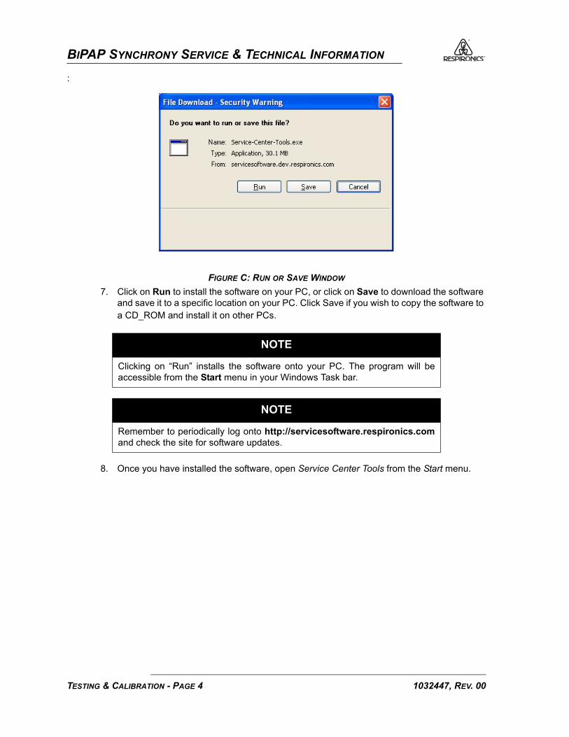
BIPAP SYNCHRONY SERVICE & TECHNICAL INFORMATION
:
FIGURE C: RUN OR SAVE WINDOW
7. Click on Run to install the software on your PC, or click on Save to download the software and save it to a specific location on your PC. Click Save if you wish to copy the software to a CD_ROM and install it on other PCs.
8. Once you have installed the software, open Service Center Tools from the Start menu.
NOTE
Clicking on “Run” installs the software onto your PC. The program will beaccessible from the Start menu in your Windows Task bar.
NOTE
Remember to periodically log onto http://servicesoftware.respironics.comand check the site for software updates.
1032447, REV. 00TESTING & CALIBRATION - PAGE 4

BIPAP SYNCHRONY SERVICE & TECHNICAL INFORMATION
:
FIGURE D: START MENU
9. Once you launch the software click on the Drop Down Menu and select “Real-Time Clock Calibration”. Refer to Figure E.
FIGURE E: DROP DOWN MENU
Click Here to Launch the Software
Drop-down Menu
TESTING & CALIBRATION - PAGE 51032447, REV. 00

BIPAP SYNCHRONY SERVICE & TECHNICAL INFORMATION
10. Click the “Execute Tool” button. Refer to Figure F.
FIGURE F: EXECUTE TOOL BUTTON
11. When the program has finished, a “Success” screen will appear. Click the “OK” button.
FIGURE G: REAL-TIME CLOCK CALIBRATION COMPLETE
Execute Tool Button
1032447, REV. 00TESTING & CALIBRATION - PAGE 6

BIPAP SYNCHRONY SERVICE & TECHNICAL INFORMATION
BIPAP SYNCHRONY CALIBRATIONThis procedure provides remote instructions for the calibration of the BiPAP Synchrony. The results ofthis calibration can be printed to a local printer and used as a final test data sheet that can be retainedas part of the device history record.
EQUIPMENT REQUIRED
• Utility Software (http://servicesoftware.respironics.com)
• Digital Manometer (Refer to Testing Section)
• Windows® - compatible personal computer running Windows 95 or higher version soft-ware.
• Printer
• SleepLink Card with cable (RI p/n 1007492)
• Flow Meter (Refer to Testing Section)
• Flow control valve (RI p/n 1006120)
• O2 Enrichment Adapter (RI p/n 312710)
• Barometer
• Pressure Tubing
• Negative Flow Source (CPAP capable of 60 lpm)
• Smooth Bore Patient Tubing for intradevice connection
• REMstar Heated Humidifier (optional)
PROCEDURE1. Connect the RS-232 connector of the SleepLink cable to the communication port (1) of
your computer. Connect the other end to the cable to the SleepLink card. Slide the card into the SmartCard slot on the BiPAP Synchrony (the card must be inserted with the words “SleepLink” facing upwards).
2. Connect the external power supply to the BiPAP Synchrony.3. Set the BiPAP Synchrony on the Remstar Heated Humidifier and connect the AC power
cord to the Humidifier.4. Connect the O2 adapter to the outlet of the BiPAP Synchrony and occlude the adapter.
5. Connect the pressure tubing from the O2 port of the O2 adapter to the digital manometer. Refer to Figure K for setup.
6. Log onto http://servicesoftware.respironics.com.
NOTE
Remove the humidifier’s water chamber if connected. All connections must bemade to the outlet port of the BiPAP Synchrony.
TESTING & CALIBRATION - PAGE 71032447, REV. 00

BIPAP SYNCHRONY SERVICE & TECHNICAL INFORMATION
7. Click on the Respironics Utility Tools Software Individual Updates link.
FIGURE H: RESPIRONICS SERVICE SOFTWARE PAGE
8. Click on the Download button adjacent to Service Center Calibration.
FIGURE I: UTILITY TOOLS SOFTWARE INDIVIDUAL PAGE
Click Here
Click Here
1032447, REV. 00TESTING & CALIBRATION - PAGE 8

BIPAP SYNCHRONY SERVICE & TECHNICAL INFORMATION
9. When you click on the Download button, the following window will appear:
FIGURE J: RUN OR SAVE WINDOW
10. Click on Run to install the software on your PC, or click on Save to download the software and save it to a specific location on your PC. Click Save if you wish to copy the software to a CD_ROM and install it on other PCs.
11. Once you have installed the software, open Service Center Calibration Software from the Start menu. Refer to Figure D.
12. Start the calibration by clicking on the white run time arrow in the upper left hand corner of the window.
NOTE
Clicking on “Run” installs the software onto your PC. The program will beaccessible from the Start menu in your Windows Task bar.
NOTE
Remember to periodically log onto http://servicesoftware.respironics.comand check the site for software updates.
TESTING & CALIBRATION - PAGE 91032447, REV. 00

BIPAP SYNCHRONY SERVICE & TECHNICAL INFORMATION
FIGURE K: PRESSURE SETUP
FIGURE L: SYSTEM SETUP
13. The program will then prompt the user to enter the serial number. After typing in the serial number, click “OK”. The program will ask you to enter the model number. Then, click “OK”. Enter the user name and hit “ENTER” on the keyboard.
NOTE
Click the appropriate button in Figure M. You may run the Calibration Software withor without a humidifier.
1032447, REV. 00TESTING & CALIBRATION - PAGE 10
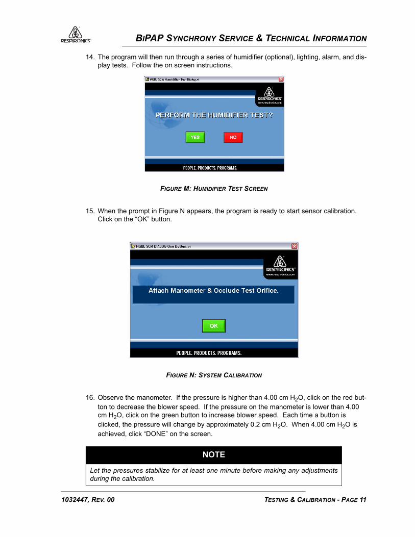
BIPAP SYNCHRONY SERVICE & TECHNICAL INFORMATION
14. The program will then run through a series of humidifier (optional), lighting, alarm, and dis-play tests. Follow the on screen instructions.
FIGURE M: HUMIDIFIER TEST SCREEN
15. When the prompt in Figure N appears, the program is ready to start sensor calibration. Click on the “OK” button.
FIGURE N: SYSTEM CALIBRATION
16. Observe the manometer. If the pressure is higher than 4.00 cm H2O, click on the red but-ton to decrease the blower speed. If the pressure on the manometer is lower than 4.00 cm H2O, click on the green button to increase blower speed. Each time a button is clicked, the pressure will change by approximately 0.2 cm H2O. When 4.00 cm H2O is achieved, click “DONE” on the screen.
NOTE
Let the pressures stabilize for at least one minute before making any adjustmentsduring the calibration.
TESTING & CALIBRATION - PAGE 111032447, REV. 00

BIPAP SYNCHRONY SERVICE & TECHNICAL INFORMATION
FIGURE O: INCREASE/DECREASE BLOWER SPEED
17. Type in the pressure reading from the manometer and press “ENTER” on the keyboard.
FIGURE P: ENTERING MANOMETER READING
18. The program will now request calibration at several higher pressures. Perform the same procedure for the remaining different settings.
19. After the last pressure calibration is performed, the following prompt will appear, indicating the program is about to start the flow element calibration. The program will first calibrate positive flow.
1032447, REV. 00TESTING & CALIBRATION - PAGE 12

BIPAP SYNCHRONY SERVICE & TECHNICAL INFORMATION
FIGURE Q: FLOW ELEMENT CALIBRATION
20. Unblock the end of the O2 adapter. Connect a section of patient tubing between the O2 adapter and the inlet of the flow meter. Connect another section of patient tubing from the outlet of the flow meter to the control valve (completely open the flow valve). Click on the green “OK” button on the program window.
FIGURE R: CALIBRATION CIRCUIT
TESTING & CALIBRATION - PAGE 131032447, REV. 00

BIPAP SYNCHRONY SERVICE & TECHNICAL INFORMATION
21. Observe the flow meter. If the flow is greater than 160 lpm, click on the red button to decrease the flow. If the flow is less than 150 lpm, click on the green button to increase the flow. When the BiPAP Synchrony is delivering between 150-160 lpm, click on the “DONE” button.
FIGURE S: INCREASE/DECREASE FLOW
22. Observe the flow meter and adjust the flow control valve until 146 lpm of flow is achieved. Click on the green ‘OK” button.
FIGURE T: FLOW ELEMENT CALIBRATION
1032447, REV. 00TESTING & CALIBRATION - PAGE 14

BIPAP SYNCHRONY SERVICE & TECHNICAL INFORMATION
23. Type in the flow reading from the flow meter and press “ENTER” on the keyboard.
FIGURE U: ENTERING THE FLOW METER READING
24. The program will now request several different flow settings decreasing in value down to and including zero flow. For each setting, raise the flow control valve to set the flow and then type in each value. After zero flow is confirmed, the following prompt will appear.
FIGURE V: ZERO FLOW CONFIRMATION
25. The program will now calibrate negative flow. Connect another section of patient tubing between the outlet of the flow control valve and the outlet of the negative flow source. Turn on the negative flow source and click on the green “OK” button.
NOTE
For the negative flow source, a REMstar device may be used with the pressure set at 20 cmH2O.
TESTING & CALIBRATION - PAGE 151032447, REV. 00
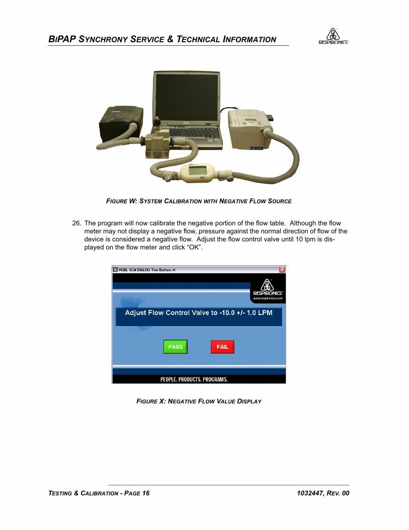
BIPAP SYNCHRONY SERVICE & TECHNICAL INFORMATION
FIGURE W: SYSTEM CALIBRATION WITH NEGATIVE FLOW SOURCE
26. The program will now calibrate the negative portion of the flow table. Although the flow meter may not display a negative flow, pressure against the normal direction of flow of the device is considered a negative flow. Adjust the flow control valve until 10 lpm is dis-played on the flow meter and click “OK”.
FIGURE X: NEGATIVE FLOW VALUE DISPLAY
1032447, REV. 00TESTING & CALIBRATION - PAGE 16

BIPAP SYNCHRONY SERVICE & TECHNICAL INFORMATION
27. Before entering the flow value, ensure that the negative or minus symbol is typed in first. The software will reject a positive value here.
FIGURE Y: ENTERING THE NEGATIVE FLOW VALUE
28. Once again, use the flow control valve to set the negative flows that the program requests and enter the values.
29. The program has now completed calibrating the flow and pressure sensor. 30. The program will now ask for the barometric pressure reading. Using your barometer
enter the value in iniches.
FIGURE Z: ENTERING THE BAROMETRIC PRESSURE
31. Pressure and flow accuracy of the device must now be verified. The program will now read the pressure and flow parameters from the device and compare these reading to the pressure and flow values that the user will enter.
32. The program will first verify positive flows. Turn off the negative flow source and discon-nect the patient tubing from between the negative flow source and the flow valve. Com-pletely open the flow valve. Follow the prompts on the screen for the flow settings.
TESTING & CALIBRATION - PAGE 171032447, REV. 00

BIPAP SYNCHRONY SERVICE & TECHNICAL INFORMATION
33. After zero flow is confirmed, the program will verify negative flow. Connect the patient tub-ing between the outlet of the flow valve and the negative flow source. Turn on the nega-tive flow source and follow the prompts.
34. After completion of the negative flow verification, pressure accuracy will be checked. Turn off the negative flow source. Disconnect the patient tubing and occlude the O2 port at the BiPAP Synchrony outlet port.
35. The program will now verify the barometirc pressure. Enter the value, in inches of mer-cury, displayed on the barometer.
36. When the pressure verification is complete, the program will request a button test for the BiPAP Synchrony. Press the buttons on the device in the order that they are numbered on the program screen.
FIGURE AA: BUTTON TEST
37. When the button test has been completed and the BiPAP Synchrony has successfully passed all tests, a green “PASS” prompt will appear on the computer screen. Click the “OK” button to view the test data sheet. Click “OK” on the print results button to print the test data sheet.
FIGURE AB: PASS SCREEN
1032447, REV. 00TESTING & CALIBRATION - PAGE 18

BIPAP SYNCHRONY SERVICE & TECHNICAL INFORMATION
PRINTING OF THE FINAL TEST DATA SHEET38. Sign the sheet and retain as part of a device history record. Refer toFigure AC. This com-
pletes the calibration procedure. The BiPAP Synchrony Current Draw Test must now be performed.
FIGURE AC: TEST DATA SHEET
TESTING & CALIBRATION - PAGE 191032447, REV. 00

BIPAP SYNCHRONY SERVICE & TECHNICAL INFORMATION
CURRENT DRAW TESTThis procedure provides instructions for testing the current draw on the BiPAP Synchrony System.
EQUIPMENT REQUIRED
• 0.25” Test Adapter (RI p/n 332353)
• Multimeter
• Test Leads
PROCEDURE 1. Connect the adapted, spare BiPAP Synchrony Power cord to the BiPAP Synchrony Unit
and the other end to an AC outlet. Attach the Amprobe to the hot side of the adapted, spare BiPAP Synchrony Power cord.
2. Place the test adapter on the outlet of the BiPAP Synchrony. Enter the Setup menu and set the IPAP pressure to 25 cm H2O and EPAP to 25 cm H2O.
3. Turn on the BiPAP Synchrony and allow the device to stabilize for at least one minute. 4. Record the current readings from the Amprobe in the space provided on the Test Data
Sheet. Sign and date the test data sheet and retain for a device history record. This con-cludes the BiPAP Synchrony Current Draw Test.
NOTE
It is recommended to use an adapted, spare BiPAP Synchrony Power cord, inconjunction with an Amprobe for measuring the current draw of the unit. The spareBiPAP Synchrony power cord can be adapted by separating the two insulated sidesof the power cord, taking extra care NOT to remove any insulation, thus exposingthe bare wires.
Alternatively, the technician may use whichever method they are comfortable withto complete the current draw test.
NOTE
Refer to the REMstar Heated Humidifier Service Manual (Reorder Number: 1015720)for steps to perform current draw test with a heated humidifier.
1032447, REV. 00TESTING & CALIBRATION - PAGE 20
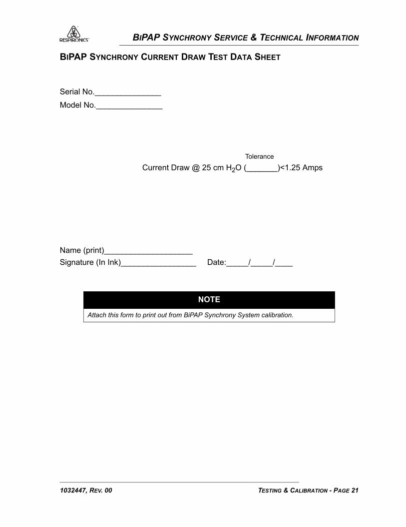
BIPAP SYNCHRONY SERVICE & TECHNICAL INFORMATION
BIPAP SYNCHRONY CURRENT DRAW TEST DATA SHEET
Serial No._______________
Model No._______________
Tolerance
Current Draw @ 25 cm H2O (_______)<1.25 Amps
Name (print)____________________Signature (In Ink)_________________ Date:_____/_____/____
NOTE
Attach this form to print out from BiPAP Synchrony System calibration.
TESTING & CALIBRATION - PAGE 211032447, REV. 00

BIPAP SYNCHRONY SERVICE & TECHNICAL INFORMATION
PERFORMANCE VERIFICATION DATA SHEET
Serial No: ____________________________
Model Number:________________________
Line Voltage: __________________________
Blower Hours:__________________________
CPAP Mode Pressure Settings:
3b) 4 cm H2O____________(3-5 cm H2O)
3c) 20 cm H2O___________(18-22 cm H2O)
3e) Synchrony Mode Trigger Performance: Pass/Fail___________
3j) Ramp Performance Bi-Level: Pass/Fail___________
3g) S Mode Trigger Performance: Pass/Fail___________
Humidifier Testing: Pass/Fail___________
Name (print)____________________
Signature (In Ink)_________________ Date:_____/_____/____
NOTE
You should record all information on this data sheet after each test has been completed.Data sheet must then be signed in ink and dated by the technician performing the test.
1032447, REV. 00TESTING & CALIBRATION - PAGE 22

BIPAP SYNCHRONY SERVICE & TECHNICAL INFORMATION
TOOLS AND EQUIPMENT
SERVICE TOOLS AND SUPPLIESYou should have the following hand tools and supplies available for troubleshooting, testing, andrepairing the BiPAP Synchrony Ventilatory Support System.
• Common Hand Tools
• Flat-Blade Screwdriver - small
• Phillips Screwdriver - medium
• Antistatic, Electro-Static Discharge (ESD)-protected work station - minimum requirement is a grounded mat and wrist strap
• Windows®-compatible personal computer running Windows 95, 98, 2000, NT with a CD-ROM drive and internet access
• SleepLink Cable (RI p/n 1007492)
• Cleaning Cloth
• Digital Manometer - Refer to page 2.
• Digital Multimeter - Refer to page 2.
• Flow Meter - Refer to page 2.
• Barometer - Refer to page 3.
• Test Leads
• Isopropyl Alcohol
• Mild Detergent
• Pressure Tubing
• Test Orifice (RI p/n 332353)
• Whisper Swivel II (RI p/n 332113)
• Flow Control Valve (RI p/n 1006120) or any commercially available flow control valve.
• CPAP (for negative flow)
• O2 Enrichment Port (RI p/n 312710)
TOOLS & EQUIPMENT - PAGE 11032448, REV. 01

BIPAP SYNCHRONY SERVICE & TECHNICAL INFORMATION
ACCEPTABLE TEST EQUIPMENT
DIGITAL MANOMETER
Specifications:• 0 - 45 cmH2O (or better)
• ± 0.3 cmH2O accuracy
• ± 0.1 cmH2O resolution
Acceptable Options:• Respironics Digital Manometer
• Merical DP2001
• Sensym PDM 200CD
• TSI Certifier (RI p/n 1012598)
• Any commercially available digital manometer that meets the above specifications.
• A water column manometer may also be used.
DIGITAL MULTIMETER
Specifications:• 2.5 digit readout minimum
• 0.0 - 20.0 VDC
• 0.0 - 25.0 VAC
Acceptable Options:• Fluke 83 or better model
• any commercially available multimeter that meets the above specifications.
FLOW METER
Specifications:• Range: +180 to -180 LPM
• ± 2% Accuracy
• ± 1 LPM Resolution
Acceptable Options:• Certifier (RI p/n 1012598)
• TSI 4000 Series Flow Meter
• Time Meter RT-200
• Any commercially available flowmeter that meets the above specifications.
1032448, REV. 01TOOLS & EQUIPMENT - PAGE 2

BIPAP SYNCHRONY SERVICE & TECHNICAL INFORMATION
BAROMETER
Specifications:• Range: 83-102 kPa
Acceptable Options:• Any commercially available barometer that meets the above specifications.
TOOLS & EQUIPMENT - PAGE 31032448, REV. 01

BIPAP SYNCHRONY SERVICE & TECHNICAL INFORMATION
This page intentionally left blank.
1032448, REV. 01TOOLS & EQUIPMENT - PAGE 4

BIPAP SYNCHRONY SERVICE & TECHNICAL INFORMATION
SCHEMATICS
SCHEMATICS STATEMENTSchematics are supplied with this manual in direct support of the sale and purchase of this product.
The schematics are proprietary and confidential. Do not copy the schematics or disclose themto third parties beyond the purpose for which they are intended. Patents are pending.
The schematics are intended to satisfy administrative requirements only. They are not intended to beused for component level testing and repair. Any changes of components could effect the reliability ofthe device, prohibit lot tracking of electronic components, and void warranties. Repairs and testing aresupported only at the complete board level.
The schematics are of the revision level in effect at the time this manual was last revised. Newrevisions may or may not be distributed in the future.
SCHEMATICS - PAGE 11032449, REV. 01

BIPAP SYNCHRONY SERVICE & TECHNICAL INFORMATION
AP
PR
BY:
DR
N B
Y:
CHK
BY:
PR
OD
UC
T L
INE
:
PR
OC
ES
S:
TIT
LE:
SIZ
E
SCA
LE
DR
AW
ING
NO
.
DP
AR
T N
O.
SH
EE
TO
FREV
.
AP
PR
BY:
DR
N B
Y:
CHK
BY:
PR
OD
UC
T L
INE
:
PR
OC
ES
S:
TIT
LE:
SIZ
E
SCA
LE
DR
AW
ING
NO
.
DP
AR
T N
O.
SH
EE
TO
FREV
.
*
*
NR
ST
P_A
TM
NP
CS0
SCK
RXD
2
TXD
2
RXD
1
TXD
1
CAN
CE
L
ON
/OF
F
TD
I
TD
O
NTR
ST
DIT
HE
R
TAC
H
SDA
GN
D
CAN
CE
L
CAN
CE
L
ALA
RM
2
CAN
CE
L
SIL
EN
CE
LE
FT
RIG
HT
GN
D
+5
V
R196
10.0K
R181
10.0K
GN
D-1
2V
+5
V+3
.3V
VBA
TT
BR
AK
E
MIS
O
MO
SI
BU
ZZ
ER
TC
K
TM
S
.1uF
C12*
GN
D
R12
10.0K
*
GN
D
.1uF
C124
GN
D
+3
.3V
R38
10.0K
+1
2VG
ND
GN
D
.1uF
C18
R30
10
0K
GN
D
R14
33
.2
GN
D
.1uF
C15
GN
D
+3
.3VR
15
33
.2
.1uF
C113
GN
D
+3
.3V
R42
ZERO
+3
.3V
TES
T_C
AP
SCL
GN
D
C7 2
2pF
+5
V
GN
D
3 1BAT54
CR5
*
**
R166
R158+5
V
GN
D
**
R16
+5
V
GN
D
+5
V
SIL
EN
CER22
10.0K
R20
10.0K
+3
.3V
R24
10.0K
GN
D
+5
V
GN
D
+6
V
RAM
P
HU
MIDG
ND
N/A
GN
D
+5
V
10
29
67
71
3 8
47.5
R11
R28
10
.0K
R195
40.2K
GN
DG
ND
+5
V
R178
10.0KR57
49.9K
GN
D
R129
10.0K
+3
.3V
R130
10.0K
R4
10.0K
R192 R194
10.0K
*
R36
39.2K
+3
.3VR9
10.0K
R179
10.0K
R6
10.0K
GN
DR13
33
.2 1000pF
C3
GN
D
.1uF
C21
R3
10.0K
GN
D
C13
*
GN
D
R31
24
9
C14
22
pF
C6
68
00
pF
C92.00K
R1
R35
2.00K
R159
10.0K
R167
10.0K
2.00K
R2
R26
10.0K
2.00K
R127
R173
1.00K
4.99K
R180
CR
20
GR
EE
N
3.09K
R18
4.99K
R19
CR
19
RED
R200
4.99K
4.99K
R177
CR
23
GR
EE
NIN
TER
NA
TIO
NA
L/D
OM
ES
TIC
REV
TYP
E_
BIT
2
REV
TYP
E_
BIT
0
CAP
_STA
TU
S
SLE
EP
TYP
E_
BIT
0
FLO
W_
OF
FSE
T
SCL_
DIS
PL
AY
SDA
_D
ISPL
AY
LC
D_
BA
CK
LIG
HT
REM
OT
E_
AL
AR
M
HU
MID
FAU
LT
DC
PO
WER
SIL
EN
CE
RAM
P
SCH
EM
AT
IC
ALA
RM
1
PF_
SIG
NA
L
.1uF
C123
IR LIN
K
Q3
MM
BT
39
04
LT1J
JP1+3
.3V
GN
D
.1uF
C17
R33
1.0
0K
R56
1.00K
R1
99
R2
03
10
.0K
+3
.3V
MIS
O
GN
DG
ND
10.0K
R39
VBU
LK
GN
D
SLE
EP/V
ENT
ILA
TO
R
GN
DC19
.1uF
GN
D+
3.3
V
R40
10.0KG
ND
R29
1.0
0K
68
0pF
C8
REV
TYP
E_
BIT
1
SLE
EP
TYP
E_
BIT
1
+3
.3V
R41
10
.0K
BU
ZZ
ER
_SLE
EP
GN
D
LE
D_O
N
BAT
TER
Y_B
U
R32
1.0
0M
CR4
*
R17
R10
+3
.3V
+5
V
EDM
S
EDM
SE
DM
S
EDM
S
10
-5-0
5C
.HA
LL
WIR
TH
SYN
CH
RO
NY
REP
LAC
EM
ENT
GN
D
12
SW
ITC
HC
ON
D R
UB
BER
3M
M S
PSTN
O
SW
14
12
SW
ITC
HC
ON
D R
UB
BER
3M
M S
PSTN
O
SW
12
12
SW
ITC
HC
ON
D R
UB
BER
3M
M S
PSTN
O
SW
10
12
SW
ITC
HC
ON
D R
UB
BER
3M
M S
PSTN
O
SW
8
12
SW
ITC
HC
ON
D R
UB
BER
3M
M S
PSTN
O
SW
6
12
SW
ITC
HC
ON
D R
UB
BER
3M
M S
PSTN
O
SW
4
12
SW
ITC
HC
ON
D R
UB
BER
3M
M S
PSTN
O
SW
2
R23
10.0K
GN
D
SCR
OL
L
S1
02
96
77
MIC
RO
& D
IGIT
AL
.1uF
C122
CR
3
ZTN
15
5W-0
3
GN
D
R8
10.0K
NO
TES
:
.1uF
C2
1C
S
2S
O
3W
P
4V
SS
5S
I
6S
CK
7H
OL
D
8V
CC
25
LC0
80
U1
R5
10.0K
.1uF
C1
R191
10.0K
R193*
100K
R37
.1uF
C4
4W
DI
1R
ES
ET5
VC
C
2G
ND
3M
R
U3
MA
X6
320
.1uF
C11
.1uF
C5
+3
.3V
32
41
Y2
32
.76
8 K
HZY
13
.68
64
MH
Z
R7
10
.0K
CR
1W
HIT
E
+
BR
20
32
-1H
E
B1
+
25
V1
0uF
C10
GN
D
+3
.3VR25
10.0K
R27
10.0K
CR
11
WH
ITE
CR
10
WH
ITE
CR
2W
HIT
E
2.00K
R128
12
SW
ITC
HC
ON
D R
UB
BER
3M
M S
PSTN
O
SW
15
12
SW
ITC
HC
ON
D R
UB
BER
3M
M S
PSTN
O
SW
13
12
SW
ITC
HC
ON
D R
UB
BER
3M
M S
PSTN
O
SW
5
12
SW
ITC
HC
ON
D R
UB
BER
3M
M S
PSTN
O
SW
7
12
SW
ITC
HC
ON
D R
UB
BER
3M
M S
PSTN
O
SW
9
12
SW
ITC
HC
ON
D R
UB
BER
3M
M S
PSTN
O
SW
3
12
SW
ITC
HC
ON
D R
UB
BER
3M
M S
PSTN
O
SW
1
1
23
BS
S1
23
LT1
Q22
1
23
BS
S1
23
LT1
Q15
1
23
BSS
12
3LT
1
Q16
CR
18
YEL
LO
W
3
1
2
Q2
BSS
84
LT1
PR
ES
S_B
LOW
ER
VAL
VE
_D
AC
VAL
VE
_IN
T
MO
TO
R_C
UR
REN
T
VAL
VE
_SHU
TD
OW
N
ALA
RM
_V
OL
TA
GE
SM
AR
T_
DET
EC
T
JTA
GS
EL
AC
PO
WER
2.
- IN
DIC
AT
ES
ITE
MS
NO
T IN
STA
LL
ED
.
1. R
EFER
TO
S
EP
AR
ATE
BIL
L O
FM
AT
ER
IALS
FO
R A
DD
ITIO
NA
LP
AR
TIN
FO
RM
ATIO
N.
MO
T_
DAC
REM
OT
E_
AL
AR
M_
2
SCK
MO
SI
NP
CS1
SIL
EN
CE
AN
ALO
G_
SW
ITC
HE
R
SYN
CH
RO
NY
REP
LAC
EM
ENT
INT
ER
NA
TIO
NA
L
12
SW
ITC
HC
ON
D R
UB
BE
R S
PSTN
O
SW
19
12
SW
17
1
23
BS
S1
23L
T1
Q1
12
SW
11 1
2
SW
18
1
23
BS
S1
23
LT1
Q17
1
23
BSS
123L
T1
Q19
76
PA8
/TIO
B5
75
PA7
/TIO
A5
71
PA5
/TIO
B4
70
PA4
/TIO
A4
14
0P
B1
13
9P
B0
15
8P
B1
7
15
7P
B1
6
15
6P
B1
5
15
5P
B1
4
15
4P
B1
3
15
3P
B1
2
15
2P
B1
1
15
1P
B1
0
15
0P
B9
14
9P
B8
15
9N
WD
OV
F
12
6A
DV
RE
F
11
7V
DD
A
12
7D
AV
RE
F
13
0G
ND
A
14
5P
B6
/AD
0TR
G1
46
PB7
/AD
1TR
G
12
1A
D3
12
0A
D2
11
9A
D1
11
8A
D0
92
PA2
0/S
CK
2
10
1P
A2
9/N
PC
S3
10
0P
A2
8/N
PC
S2
99
PA2
7/N
PC
S1
98
PA2
6/N
PC
S0
/NS
S
97
PA2
5/M
OS
I
96
PA2
4/M
ISO
95
PA2
3/S
PC
K
94
PA2
2/R
XD2
93
PA2
1/T
XD
2
10
8P
LL
RC
10
6X
OU
T
10
5X
IN
16
0M
CK
O
12
5A
D7
12
4A
D6
12
3A
D5
12
2A
D4
12
8D
A0
12
9D
A1
11
2N
RS
TBU
11
1X
OU
T3
2
11
0X
IN32
17
0N
RS
T
16
6T
DI
16
8T
CK
77
PA9
/IR
Q0
78
PA1
0/IR
Q1
79
PA1
1/IR
Q2
80
PA1
2/IR
Q3
14
2P
B3
/IR
Q4
14
3P
B4
/IR
Q5
14
4P
B5
/IR
Q6
81
PA1
3/F
1Q
82
PA1
4/S
CK
08
3P
A1
5/T
XD
08
4P
A1
6/R
XD0
85
PA1
7/S
CK
18
6P
A1
8/T
XD
1/N
TR
19
1P
A1
9/R
XD1
16
3P
B1
8/B
MS
55
PB1
9/T
CL
K0
58
PB2
2/T
CL
K1
63
PB2
5/T
CL
K2
56
PB2
0/T
IOA
05
7P
B2
1/T
IOB
0
61
PB2
3/T
IOA
16
2P
B2
4/T
IOB
1
64
PB2
6/T
IOA
26
5P
B2
7/T
IOB
2
66
PA0
/TC
LK
36
9P
A3
/TC
LK
47
2P
A6
/TC
LK
5
67
PA1
/TIO
A3
68
PA2
/TIO
B3
11
5S
HD
N
11
4W
AK
EU
P1
64
JTA
GS
EL
16
9N
TR
ST
16
5T
MS
16
7T
DO
14
1P
B2
AT9
1M
55
80
0-3
3A
I
U2:
B
TXD
0
1032449, REV. 01SCHEMATICS - PAGE 2
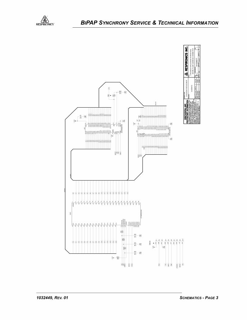
BIPAP SYNCHRONY SERVICE & TECHNICAL INFORMATION
AP
PR
BY:
DR
N B
Y:
CHK
BY:
PR
OD
UC
T L
INE
:
PR
OC
ES
S:
TIT
LE:
SIZ
E
SCA
LE
DR
AW
ING
NO
.
DP
AR
T N
O.
SH
EE
TO
FREV
.
AP
PR
BY:
DR
N B
Y:
CHK
BY:
PR
OD
UC
T L
INE
:
PR
OC
ES
S:
TIT
LE:
SIZ
E
SCA
LE
DR
AW
ING
NO
.
DP
AR
T N
O.
SH
EE
TO
FREV
.
D15
D13
D12
D10
D9
D7
D6
D4
D3
D1
D0
WE
NC
S2
A15
A14
A12
A11A9
A8
A6
A5
A3
A2
NW
R1
A0
A9
A7
A6
A4
A3
A1
D0
D4
D6
D10
D12
D1
D3
D7
D9
D13
D15
+3
.3V
GN
D
10
J2:
J
9J
2:I
7J
2:G
6J
2:F
3J
2:C
4J
2:D
* 1J
2:A
DE
BU
G
GN
D
D14
D11
D8
D5
D2
GN
D
R46
33
.2
OE
A13
A16A7
A10A4
A1
GN
D
+3
.3V
A8
A5
A2
GN
D
.1uF
C26
GN
D
+3
.3V
D2
D8
D14
D5
D11
*
R44
10
.0
A19
N/A
10
29
67
72
3 8
R45
10.0K
8J
2:H
5J
2:E
2J
2:B
+3
.3V
D0:D
15
R43
TD
I
JTA
GS
EL
NR
ST
TC
K
TD
O
NC
S2
NC
SO
NW
R1
WE
A19
A18
A16
A15
A13
A12
A10
A9
A7
A6
A4
A3
A1
A0
NR
ST
WE
OE
A18
A16
A15
A13
A12
A10
D15
D14
D12
D11
D9
D8
D6
D5
D3
D2
D0
A18
SCH
EM
AT
IC
NTR
ST
TM
S
GN
D
+3
.3V
OE
A17
A14
A11
A8
A5
A2
A17
NC
SO
A14
A11
D13
D7
D10
D1
D4
GN
DA
17
GN
D
EDM
S
EDM
S
EDM
S
EDM
S
10
-5-0
5C
.HA
LL
WIR
TH
SYN
CH
RO
NY
REP
LAC
EM
ENT
R47
100K
S1
02
96
77
15pF
C24
15pF
C85
R1
85
33
.2
15pF
C25
.1uF
C23
GN
D
19
A14
24
A11
27
A8
44
A5
3A
2
40
BH
E
17
!WE
38
I/O
16
35
I/O
13
30
I/O
10
15
I/O
7
10
I/O
4
7I/O
1
33
VC
C
18
A15
12
VSS
26
A9
25
A10
2A
31
A4
39
BLE
41
OE
28
NC
34
VSS
32
I/O
12
31
I/O
11
14
I/O
6
13
I/O
5
23
NC
22
NC
5A
04
A1
43
A6
42
A7
21
A12
20
A13
6C
E
9I/O
3
8I/O
2
37
I/O
15
36
I/O
14
29
I/O
9
16
I/O
8
11
VC
C
CY7
C1
02
1BV
33
-12
U5
25
A0
24
A1
23
A2
22
A3
21
A4
20
A5
19
A6
18
A7
8A
87
A9
6A
10
5A
11
4A
12
3A
13
2A
14
1A
15
48
A16
17
A17
12
RP
11
W
28
G
26
E
47
BYT
E
37
VC
C
46
VSS
27
VSS
29
DQ
03
1D
Q1
33
DQ
23
5D
Q3
38
DQ
44
0D
Q5
42
DQ
64
4D
Q7
30
DQ
83
2D
Q9
34
DQ
10
36
DQ
11
39
DQ
12
41
DQ
13
43
DQ
14
45
DQ
15
-A
13
NC
15
RB
U4
M2
9W
40
0BB
-70
N1
R48
33
.2
A1:A
19
MIC
RO
,FLA
SH
& D
EB
UG
CO
NN
EC
TOR
SYN
CH
RO
NY
REP
LAC
EM
ENT
INT
ER
NA
TIO
NA
L
12
A5
11
A4
10
A3
9A
2
7A
O/N
LB
39
D4
38
D3
37
D2
36
D1
35
D0
40
D5
8A
1
13
5N
CS
41
36
NC
S5
13
7N
CS
61
38
NC
S7
3N
CS
04
NC
S1
5N
CS
26
NC
S3
17
4N
WR
1/N
UB
17
1N
WA
IT
17
2N
RD
/NO
E1
73
NW
R0/
NW
E
17
A8
14
A7
13
A6
34
A23
33
A22
32
A21
31
A20
28
A19
27
A18
26
A17
25
A16
24
A15
23
A14
22
A13
21
A12
20
A11
19
A10
18
A9
47
D8
42
D7
41
D6
54
D15
53
D14
52
D13
51
D12
50
D11
49
D10
48
D9
U2:C
AT9
1M
55
80
0-3
3A
I
D0:D
15
SCHEMATICS - PAGE 31032449, REV. 01

BIPAP SYNCHRONY SERVICE & TECHNICAL INFORMATION
AP
PR
BY:
DR
N B
Y:
CHK
BY:
PR
OD
UC
T L
INE
:
PR
OC
ES
S:
TIT
LE:
SIZ
E
SCA
LE
DR
AW
ING
NO
.
DP
AR
T N
O.
SH
EE
TO
FREV
.
AP
PR
BY:
DR
N B
Y:
CHK
BY:
PR
OD
UC
T L
INE
:
PR
OC
ES
S:
TIT
LE:
SIZ
E
SCA
LE
DR
AW
ING
NO
.
DP
AR
T N
O.
SH
EE
TO
FREV
.
*
TXD
2
RXD
2
SCL
GN
D
+3
.3VGN
D
+3
.3VR49
10.0K
+3
.3V
GN
D
+3
.3V
.1uF
C56
+3
.3V
1/4
W
R2
27
30
.1
GN
DG
ND
.1uF
C88
U19
*
E21
GN
D
GN
D
.1uF
C30+5
V
12100pf
FL8
+5
V
GN
D
+5
V
GN
D
N/A
GN
D
R162
1.50K
10
29
67
7
+3
.3V
+3
.3V
3
TXD
1
SDA
RXD
1
3 8
R52 R54
**R118
*
R156
ZERO
GN
D
R157
10.0K
+3
.3V
+5
V
*
GN
D
R117
+5
V
GN
D
GN
D
550pF
FL4
GN
D
GN
D
R21
10.0K
12100pf
FL7
R116
*
GN
D+3
.3V
R163
10.0K
R161
10.0K
R51
10.0K 550pF
FL3
PP
4
PP
2
PP
1
SCL_
DIS
PL
AY
SDA
_D
ISPL
AY
PP
6
PP
5
NO
PIN
4 IN
CO
NN
EC
TOR
SCH
EM
AT
IC
+3
.3VP
P3
R50
10.0K
+3
.3V
+3
.3V
GN
D
.1uF
C28
GN
D
PP
7
.1uF
C53
U14
+5
V
8J
4:H
7J
4:G
6J
4:F
3J
4:C
5J
4:E
2J
4:B
4J
4:D
S2
J3:
J
S1
J3:
I
4J1
0:D
*
3J1
0:C
*2
J1
0:B
C6
J3:
F
1J1
0:A
*C
4J
3:D
C3
J3:
C
2J
1:B *
C2
J3:
B
1J
1:A
SM
AR
T C
AR
D
EDM
S
EDM
S
EDM
S
EDM
S
10
-5-0
5C
.HA
LL
WIR
TH
SYN
CH
RO
NY
REP
LAC
EM
ENT
GN
D
GN
D
550pF
FL1
SM
AR
T_
DET
EC
T
Q32
MM
BT
39
04
LT1
GN
D
R160
1.50K
.1uF
C27
+3
.3V
S1
02
96
77G
ND
4
12
MM
74
VH
C1
GT
32(3
=G
ND
,5=
+5
V)
U31
REM
OT
E_
AL
AR
M
REM
OT
E_
AL
AR
M_
2
C29
*
1
23
BS
S1
23
LT1
Q27
1J
4:A
MIN
IDIN
*
C8
J3:
H
C7
J3:
G
3J
1:C
4J
1:D**
C5
J3:
E
C1
J3:
A
550pF
FL6
GN
D
550pF
FL5
4
12
MM
74
VH
C1
GT
32(3
=G
ND
,5=
+5
V)
U19
Q31
MM
BT
39
04
LT1
4
12 MM
74
VH
C1
GT
32(3
=G
ND
,5=
+3
.3V
)
U32
LC
D_
BA
CK
LIG
HT
NO
TE:
NO
CO
PP
ERU
ND
ER
CO
NN
EC
TOR
DIG
ITAL
& S
MA
RT
CA
RD
CO
NN
EC
TOR
SYN
CH
RO
NY
REP
LAC
EM
ENT
INT
ER
NA
TIO
NA
L
27
00
OH
MS
@ 1
00
MH
Z
E5
27
00
OH
MS
@ 1
00
MH
Z
E4
27
00
OH
MS
@ 1
00
MH
Z
E2
27
00
OH
MS
@ 1
00
MH
Z
E12
27
00
OH
MS
@ 1
00
MH
Z
E9
27
00
OH
MS
@ 1
00
MH
Z
E3
1S
DA
2S
CL
3S
YN
C4
CLK
5V
DD
6O
SC
7A
08
A1
9A
21
0S
A01
1V
SS
12
VLC
D1
3B
P0
14
BP2
15
BP1
16
BP3
17
S0
18
S1
19
S2
20
S3
21
S4
22
S5
23
S6
24
S7
25
S8
26
S9
28
S11
27
S10
29
S12
30
S13
31
S14
32
S15
33
S16
34
S17
35
S18
36
S19
37
S20
38
S21
39
S22
40
S23
PC
F85
66
T
U6
27
00
OH
MS
@ 1
00
MH
Z
E16
27
00
OH
MS
@ 1
00
MH
Z
E15
27
00
OH
MS
@ 1
00
MH
Z
E11
27
00
OH
MS
@ 1
00
MH
Z
E10
60
OH
MS
@ 1
00
MH
Z
E18
60
OH
MS
@ 1
00
MH
Z
E17
4
12 MM
74
VH
C1
GT
32(3
=G
ND
,5=
+3
.3V
)
U14
Q30
MM
BT
39
04
LT1
1S
DA
2S
CL
3S
YN
C4
CLK
5V
DD
6O
SC
7A
08
A1
9A
21
0S
A01
1V
SS
12
VLC
D1
3B
P0
14
BP2
15
BP1
16
BP3
17
S0
18
S1
19
S2
20
S3
21
S4
22
S5
23
S6
24
S7
25
S8
26
S9
28
S11
27
S10
29
S12
30
S13
31
S14
32
S15
33
S16
34
S17
35
S18
36
S19
37
S20
38
S21
39
S22
40
S23
PC
F85
66
T
U15
24
S24
21
S21
18
S18
15
S15
12
S12
9S
9
6S
6
3S
3
30
S26
33
S29
36
S32
39
S35
42
S38
45
S41
48
S44
25
S25
19
S19
20
S20
13
S13
14
S14
7S
78
S8
1S
12
S2
31
S27
32
S28
37
S33
38
S34
43
S39
44
S40
49
S45
50
K
51
A
22
S22
23
S23
4S
45
S5
10
S10
11
S11
16
S16
17
S17
34
S30
35
S31
40
S36
41
S37
46
S42
47
S43
27
CO
M2
26
CO
M1
28
CO
M3
29
CO
M4
DLD
-05
00
7
DS
1
1032449, REV. 01SCHEMATICS - PAGE 4

BIPAP SYNCHRONY SERVICE & TECHNICAL INFORMATION
AP
PR
BY:
DR
N B
Y:
CHK
BY:
PR
OD
UC
T L
INE
:
PR
OC
ES
S:
TIT
LE:
SIZ
E
SCA
LE
DR
AW
ING
NO
.
DP
AR
T N
O.
SH
EE
TO
FREV
.
AP
PR
BY:
DR
N B
Y:
CHK
BY:
PR
OD
UC
T L
INE
:
PR
OC
ES
S:
TIT
LE:
SIZ
E
SCA
LE
DR
AW
ING
NO
.
DP
AR
T N
O.
SH
EE
TO
FREV
.
NR
ST
FAU
LTR
17
6
10
0K
GN
D
GN
D
GN
D
.01uF
C108
GN
D
.1uF
C135
R64
47
.5K
R61
1.00K
R65
47
.5K
R97
10.0K
GN
D
R95
10.0K
R62
1.00K
VBU
LK_M
OT
GN
D
R80
10.0K
R66
47
.5K
GN
D.0
1uF
C34
C43
10uF
25
V+1
2V
R81
34
KR63
1.00K
C44
.1uF
PP
14
R75
1.8
2K
PP
13
PP
12
GN
D
R72
1.7
4K
PH
3
GN
D
R89
10
M
GN
D
N/A
10
29
67
7
BR
AK
E
4
3 8
R214
499K1
3
2
Q38
IRF
R5
30
5R94
10.0K
GN
DG
ND
R88
10.0KGN
D
2700 OHMS@ 100 MHZ
E1
GN
D
2700 OHMS@ 100 MHZ
E6
+1
2V
GN
D
2700 OHMS@ 100 MHZ
E7
R74
1.00K
C32
.01
uF
C33
22
0pF.1uF
C31
GN
D
R84
12
.1K
.1uF
C38
GN
D
+1
2V
MO
T_
DAC
SCH
EM
AT
IC
***
MO
TO
R_C
UR
REN
T
TAC
H
+3
.3V
R85
1.0
0K
.1uF
C39
27
00
OH
MS
@ 1
00
MH
Z
E22
MM
BT
39
04
LT1
Q39
R174
1.00M
R175
10.0KV
BU
LK
.1uF
C41
5 6
7
(4=
GN
D,
8=+
12
V)
LM
35
8A
U7:
B
VBU
LK_M
OT
R1
02
1.0
0K
GN
D
GN
D
VBU
LK_M
OT
R1
04
1.0
0K
PP1
1
GN
D
GN
D
ISE
NS
E
27
00
OH
MS
@ 1
00
MH
Z
E14
VBU
LK_M
OT
R1
12
1.0
0K
VBU
LK_M
OT
R92
80
.6K
+
25
V2
.2uF
C40
C42
330
0pF
R86
4.7
5K
.1uF
C36
PH
2
R82
12
.1K
+1
2V
GN
D
R70
10
0K
EDM
S
EDM
S
EDM
S
EDM
S
10
-5-0
5C
.HA
LL
WIR
TH
SYN
CH
RO
NY
REP
LAC
EM
ENT
R93
10
.0K
+3
.3V
GN
D
GN
D
C109
S1
02
96
77
MO
TO
R C
ON
TR
OL
LER
1C
ON
N M
3 P
IN 1
00
J5:
A
2C
ON
N M
3 P
IN 1
00
J5:
B
3C
ON
N M
3 P
IN 1
00
J5:
CR98
10.0K
CR25
LLSD103
GN
D
R87
10
.0K
+1
2V
MM
BT
39
04
LT1
Q4
56
OH
MS
@ 1
00
MH
Z
E24
15
14
MC
14
05
0BD
(8=
GN
D,1
=+
12
V)
U8:
F
R91
10.0K
12
11
MC
14
05
0BD
(8=
GN
D,1
=+
12
V)
U8:
E
10
9
MC
14
05
0BD
(8=
GN
D,1
=+
12
V)
U8:D
67
MC
14
05
0BD
U8:C
(8=
GN
D,1
=+
12
V)
27
00
OH
MS
@ 1
00
MH
Z
E13
R71
0.222W
+1
2V
MM
BT
39
04
LT1
Q5
GN
D
C35
10
00
pF
R76
10.0K
1
32
IRF
R2
40
5Q
20
MM
BT
39
04
LT1
Q6
R78
14
0K
+
C37
2.2
uF
25
V
R83
12
.1K
GN
D
R73
1.00K
3 2
1
LM
35
8A
U7:
A
(4=
GN
D,
8=+
12
V)
GN
D
1
23
BSS
12
3LT
1
Q10
4.99K
R90
C111GN
D
C110
R77
10.0K
1
3 2
IRF
R9
02
4Q
21
R79
10M
23
MC
14
05
0BD
U8:
A
(8=
GN
D,1
=+
12
V)
27
00
OH
MS
@ 1
00
MH
Z
E8
+
50
V1
20
0uF
C20
VBU
LK_M
OT
VBU
LK_M
OT
SYN
CH
RO
NY
REP
LAC
EM
ENT
INT
ER
NA
TIO
NA
L
Q11
MM
BT
39
04
LT1
1
3 2
IRF
R9
02
4Q
8
1
3 2
IRF
R9
02
4Q
14
PH
1
45
U8:
BM
C1
40
50
BD
(8=
GN
D,1
=+
12
V)
1
32
IRF
R2
40
5Q
9
1
32
IRF
R2
40
5Q
7
11
N3
14
VC
C
13
VC
O
10
N2
9N
1
8V
SP
EE
D
7V
RE
F
6C
OS
C
5R
CP
WM
4P
3
3P
2
2P
1
1IS
ENS
E
12
ILIM
IT
15
CVC
O
16
RVC
O
17
CR
ST
26
CO
S
27
RR
EF
28
GN
D
21
CRA
MP
20
RCV
CO
19
CEN
22
PH
1
23
PH
2
24
PH
3
25
BR
AK
E
18
VFL
T
ML44
25
U9
PH
3
PH
2
PH
1
SCHEMATICS - PAGE 51032449, REV. 01

BIPAP SYNCHRONY SERVICE & TECHNICAL INFORMATION
AP
PR
BY:
DR
N B
Y:
CHK
BY:
PR
OD
UC
T L
INE
:
PR
OC
ES
S:
TIT
LE:
SIZ
E
SCA
LE
DR
AW
ING
NO
.
DP
AR
T N
O.
SH
EE
TO
FREV
.
AP
PR
BY:
DR
N B
Y:
CHK
BY:
PR
OD
UC
T L
INE
:
PR
OC
ES
S:
TIT
LE:
SIZ
E
SCA
LE
DR
AW
ING
NO
.
DP
AR
T N
O.
SH
EE
TO
FREV
.
*
GN
D
*
GN
D
GN
D
*
GN
D
+1
2V
GN
D
*
GN
D
+1
2V
GN
D
*
+3
.3VG
ND
C95
R222
*
GN
DG
ND
C1
34
.22
uF
C47
*
GN
D
GN
D
R2
17
93
1
GN
D
R219
+1
2V
-12
V
+1
2V
R103
24.9K
+1
2VG
ND
U21
+3
.3V
+5
V
.1uF
C91
U29
+5
V
-12
V
.1uF
C86
GN
D
R53
8.2
5K
+1
2V
+5
V
+1
2V
GN
D
R207
200K
R69
20
0K
R59
1.0
0K
R2
28
1.0
0K
N/A
P_A
TM
10
29
67
75
3 8
*
GN
D
GN
D
GN
D
GN
D
R201
1.00KC1
14
.1uF
GN
D
R221
+1
2V
.1uF
C128
*
**
R108
24.9K
.1uF
C127
GN
D
GN
D GN
D
GN
DG
ND
GN
D
GN
D
R1
10
10
.0K
GN
D
.01
uF
C46
SCH
EM
AT
IC
MO
SI
MIS
O
NP
CS0
MA
SS
FLO
W
C94
*
+5
V
PR
ES
SUR
EB
LOW
ER
R1
84
9.0
9K
.02
2uF
C1
30
R2
15
1.0
0K
.02
2uF
C1
32
C112+5
V
PR
ES
SUR
EO
UT
LET
.01
uF
C1
26
R99
1.0
0K
R1
06
1.8
2K
R55
1.0
0K
R1
07
4.2
2K
*
GN
D
R2
23
GN
DR2
16
48
7
*
.1uF
C90
.1uF
C89
U26
GN
D
+5
VR1
09
3.9
2K
.1uF
C51
.01
uF
C49
GN
D
R1
01
9.0
9K
.1uF
C87
R2
13
10
.0K
BAR
OM
ET
RIC
GN
D
.1uF
C54
+
16
V1
0uF
C1
16
GN
D
GN
D
+5
V
5 6
7U
25
:B
OP
A4
23
4
(4=
+1
2V
, 1
1=-1
2V
)
R67
10
.0K
EDM
S
EDM
S
EDM
S
EDM
S
10
-5-0
5C
.HA
LL
WIR
TH
SYN
CH
RO
NY
REP
LAC
EM
ENT
GN
D
GN
D
SCK
GN
D
GN
D
S1
02
96
77
GN
D
R2
24
R1
26
1.0
0K
.1uF
C1
33
1-S
O
2-V
3+S
O
4+V
MT
3
SM
56
52
R1
00
1.0
0K
GN
D
R2
18
2V
S
4V
OU
T
3G
ND
1N
C
MT
5
1-S
O
2-V
3+S
O
4+V
MT
4
SM
56
52
.1uF
C1
15
.01
uF
C1
25
5 6
7
(4=
GN
D,
8=+
5V
)
U1
0:B
.1uF
C131
.1uF
C129
1-I
NA
2+IN
A
3R
GA
4R
GA
5R
EFA
6V
OA
7S
EN
SE
A
8V
-9
V+
10
SEN
SE
B
11
VO
B
12
REF
B
13
RG
B
14
RG
B
15
+IN
B
16
-IN
B
U28
INA
21
26
UA
R2
20
3 2
1
(4=
GN
D,
8=+
5V
)
U1
0:A*
.01
uF
C52
GN
D
R1
05
3.9
2K
R212
1.00K
GN
D
5 6
7
(4=
GN
D,
8=+
12
V)
LM
35
8A
U1
3:B
3 2
1U
25
:A
OP
A4
23
4
(4=
+1
2V
, 1
1=-1
2V
)
+1
2V
.1uF
C48
5D
IN
8V
CC
7C
LK
4V
SS
3C
H1
6D
OU
T
1C
S/S
HD
N
2C
H0 MC
P3
20
2BI/S
N
U1110 9
8U
25
:C
(4=
+1
2V
, 1
1=-1
2V
)
OP
A4
23
4
R68
10
.0K
4
12 MM
74
VH
C1
GT
32(3
=G
ND
,5=
+3
.3V
)
U26
4
12
MM
74
VH
C1
GT
32(3
=G
ND
,5=
+5
V)
U29
4
12
MM
74
VH
C1
GT
32(3
=G
ND
,5=
+5
V)
U33
12
13
14
OP
A4
23
4
U2
5:D
(4=
+1
2V
, 1
1=-1
2V
)
.1uF
C139
741 5 6 82 3
AIR
FLO
W S
EN
SO
R
MT
2
2V
S
4V
OU
T
3G
ND
1N
C
MT
1
3 2
1U
13
:A
(4=
GN
D,
8=+
12
V)
1R
G
2V
IN-
3V
IN+
4V
-5
REF
6V
OU
T
7V
+
8R
G
INA
12
6U
U20
4
12
MM
74
VH
C1
GT
32(3
=G
ND
,5=
+5
V)
U21
FLO
W_
OF
FSE
T
PR
ES
S_B
LOW
ER
ME
AS
UR
ED
_PR
ES
S
1
2
3
BAT54S
CR12
PR
ES
SUR
E &
FLO
W S
EN
SO
RS
SYN
CH
RO
NY
REP
LAC
EM
ENT
INT
ER
NA
TIO
NA
L
FLO
W
3+V
1-V
2V
O+
4V
O-
MT
6
CP
C15
AH
1032449, REV. 01SCHEMATICS - PAGE 6

BIPAP SYNCHRONY SERVICE & TECHNICAL INFORMATION
AP
PR
BY:
DR
N B
Y:
CHK
BY:
PR
OD
UC
T L
INE
:
PR
OC
ES
S:
TIT
LE:
SIZ
E
SCA
LE
DR
AW
ING
NO
.
DP
AR
T N
O.
SH
EE
TO
FREV
.
AP
PR
BY:
DR
N B
Y:
CHK
BY:
PR
OD
UC
T L
INE
:
PR
OC
ES
S:
TIT
LE:
SIZ
E
SCA
LE
DR
AW
ING
NO
.
DP
AR
T N
O.
SH
EE
TO
FREV
.
*
+3
.3V
R115
100K
GN
D
+6
V
GN
D
GN
D
+3
.3V
R1
65
10
0K
GN
D
GN
D
+5
V
+3
.3V
*** *
10
uF
C55
R1
25
1.0
0M
+3
.3V
*TP9
*
GN
D
+6
V
GN
D
*
GN
D
R226
249K
R121
1.00M
GN
DGN
D
+6
V
+5
V
R164
100K
GN
D
BU
ZZ
ER
N/A
10
29
67
76
3 8
+5
V
R171
10.0K
R34
37.4K
R206
200K
R202
15.0K
R204
100K
CR
28
LL
SD
10
3
R169
10.0K
R170
10.0K
R205
10.0K*G
ND
GN
D
2.2
uF
C22R168
10.0K
*R123
200K
1 2
LS
1
GN
D
+3
.3V
+6
V
GN
D
*
R114
BU
ZZ
ER
ON
/OF
F
TES
T_C
AP
PF_
SIG
NA
L
SCH
EM
AT
IC
PF_
SIG
NA
L
CAP
_STA
TU
S
BU
ZZ
ER
_SLE
EP
GN
D
CR
26
LL
SD
10
3
6S
W1
6B
:F
4S
W1
6B
:D
5S
W1
6B
:E
GN
D
2S
W1
6B
:B
1S
W1
6B
:A
+C
57
1.5
F
R1
72
10
0K
GN
D
*
R2
10
+1
2V
GN
D
R1
22
1.0
0M
2.2
uF
C93
+6
V
22
uH
L1
+1
2V
5 6
7
(4=
GN
D,
8=+
3.3
V)
LM
29
03
U3
0:B
+5
V
R111
10.0K
+1
uF
50
V
C1
38
GN
D
1
23
BS
S1
23
LT1
Q24
+5
V
EDM
S
EDM
S
EDM
S
EDM
S
10
-5-0
5C
.HA
LL
WIR
TH
SYN
CH
RO
NY
REP
LAC
EM
ENT
ALA
RM
_V
OL
TA
GE
S1
02
96
77
BU
ZZ
ER
CIR
CU
ITR
Y
1
2
3
Q36
BS
S8
4LT
1
CR
16
LL
SD
10
3
3S
W1
6B
:C
R209
Q33
R124
200K
1
23
Q25
BS
S12
3L
T1
2
GN
D
5V
IN1
SW
4S
HD
N3
FB
LT1
61
5ES
5-1
U34
GN
D
1
23
BS
S1
23
LT1
Q28
+6
V
1
2 3
BS
S8
4LT
1Q
13
3 2
1
(4=
GN
D,
8=+
3.3
V)
LM
29
03
U3
0:A
1
23
Q23
BS
S1
23
LT1
1
23
Q34
BS
S12
3L
T1
1
23
BS
S12
3LT
1Q
37
SYN
CH
RO
NY
REP
LAC
EM
ENT
INT
ER
NA
TIO
NA
L
2C
ON
N M
2 P
IN M
ICRO
FIT
3.0
J6:
B
1
23
Q26
BS
S1
23
LT1
2 5
1 3 4 6
SW
16
SW
ITC
HP
US
HB
UT
TON
LAT
CH
ING
DP
DT
CR
30
LL
SD
10
3
8V
+
3-I
N
2+IN
4V
-5
BAL
6B
AL
/STB
1G
ND
7O
UT
LM
31
1M
U27
CR
29
B1
40
1C
ON
N M
2 P
IN M
ICRO
FIT
3.0
J6:
A
SCHEMATICS - PAGE 71032449, REV. 01

BIPAP SYNCHRONY SERVICE & TECHNICAL INFORMATION
AP
PR
BY:
DR
N B
Y:
CHK
BY:
PR
OD
UC
T L
INE
:
PR
OC
ES
S:
TIT
LE
:
SIZ
E
SCA
LE
DR
AW
ING
NO
.
DP
AR
T N
O.
SH
EE
TO
FREV
.
AP
PR
BY:
DR
N B
Y:
CHK
BY:
PR
OD
UC
T L
INE
:
PR
OC
ES
S:
TIT
LE
:
SIZ
E
SCA
LE
DR
AW
ING
NO
.
DP
AR
T N
O.
SH
EE
TO
FREV
.
* *
*
BAT
TER
Y_
BU
VBA
TT
GN
D
+
25
V1
0uF
C83
+5
VGN
D
VBU
LK
C120
GN
DGN
D
*R
18
9
GN
D
+
25
V1
0uF
C84
+3
.3V
*
GN
D
VBU
LK
GN
D
GN
D
GN
D
.1uF
C80
CR
6
B1
60
GN
D+
35
V3
30
uFC
79
+5
V
-12
V
GN
D
TP2
TP4
TP5
+5
VT
P6
+1
2V
TP7
VBU
LK
GN
D
GN
D
+3
.3V
GN
D
12
CR7
SMBJ36CA
VBU
LK
GN
D
GN
D
GN
D
GN
D
GN
D
GN
D
.1uF
C69
.1uF
C67
.1uF
C63
.1uF
C60
.1uF
C65
.1uF
C61
+3
.3V
PO
WE
R 1
N/A
10
29
67
77
3 8
+
50
V1
80
uFC
45
GN
DGN
D
1uF
C81
R1
90
1.5
4K**
.1uF
C76
GN
D.1uF
C77 R1
87
ZE
RO
GN
D
R188R208
CR9
MBRS340T3
.01
uF
C78
CR27
P6SMB6.8AT3
**
**
**
.1uF
C72
.1uF
C66
GN
D
PO
WE
R 2
1000pF
C75
*
SCH
EM
AT
IC
AN
ALO
G_
SW
ITC
HE
R
VBU
LK
GN
D
+1
2V
INO
UT
GN
D
LM
78
12
CT
U18
*
U17
(3=
GN
D,5
=+
5V
)
R1
86
24
02
W
TP1
TP3
GN
DG
ND
+3
.3V
TP8
+3
.3V
.1uF
C70
.1uF
C59
EDM
S
EDM
S
EDM
S
EDM
S
10
-5-0
5C
.HA
LL
WIR
TH
SYN
CH
RO
NY
REP
LAC
EM
ENT
+3
.3V
R1
20
10
0
R1
19
ZE
RO
GN
D
GN
D
GN
D
+3
.3V
S1
02
96
77
INO
UT
OU
TG
ND
TAB
LM
11
17
MP
X-3
.3U
12
.1uF
C82GN
D
2IN
PU
T
7O
N/O
FF
5N
C
8
GN
D
1S
W_
OU
TP
UT
3C
_BO
OST
6F
B
4GN
D
LM
26
76
S-5
.0U
16
GN
D*
+
25
V
C1
19
10
00
uFCR21
B160
*
.1uF
C68
.1uF
C73.1uF
C71
.1uF
C64
.1uF
C62
56
OH
MS
@ 1
00
MH
Z
E19
5
CG
6
CG
4C
G
2C
B
3P
SG
1B
E23
BN
X0
02
-01
GN
D
GN
D
27
00
OH
MS
@ 1
00
MH
Z
E20
11
5
6
22
33
4
J7
CO
NN
F 3
PIN
JAC
KS
HIE
LD
ED
BAR
REL
& H
OU
SIN
G R
A
11
5
6
22
33
4
J8
CO
NN
F 3
PIN
JAC
KS
HIE
LD
ED
BAR
REL
& H
OU
SIN
G R
A
3
12
CR
22
.1uF
C74
39
0 O
HM
S@
10
0 M
HZ
E25
DC
INP
UT
,REG
UL
AT
OR
S &
MIC
RO
DE
CO
UP
LIN
G
SYN
CH
RO
NY
REP
LAC
EM
ENT
IN
TER
NA
TIO
NA
L
R1
98
CR
14
MB
R7
60
R1
97
BSS
13
8LT
1
Q18
12
47
UH
L2
CR
13
MB
R7
60
89
GN
D9
0G
ND
10
2V
DD
IO
10
3G
ND
10
7G
ND
PL
L
10
4V
DD
PL
L
11
6G
ND
BU
11
3T
ES
T
88
VD
DIO
10
9V
DD
BU
87
VD
DC
OR
E
73
VD
DIO
74
GN
D
44
VD
DIO
45
GN
D4
6G
ND
59
VD
DIO
29
VD
DIO
30
GN
D
43
VD
DC
OR
E
60
GN
D
15
VD
DIO
16
GN
D
17
6V
DD
IO
2G
ND
17
5V
DD
CO
RE
1G
ND
13
4G
ND
13
3G
ND
13
2V
DD
IO
13
1V
DD
CO
RE
16
2G
ND
16
1V
DD
IO
14
8G
ND
14
7V
DD
IO
AT9
1M
55
80
0-3
3A
I
U2:A
1032449, REV. 01SCHEMATICS - PAGE 8
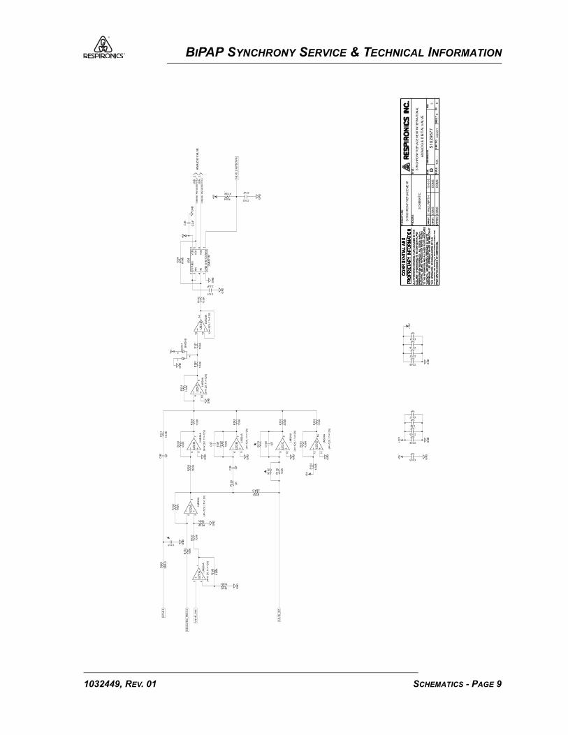
BIPAP SYNCHRONY SERVICE & TECHNICAL INFORMATION
AP
PR
BY:
DR
N B
Y:
CHK
BY:
PR
OD
UC
T L
INE
:
PR
OC
ES
S:
TIT
LE:
SIZ
E
SCA
LE
DR
AW
ING
NO
.
DP
AR
T N
O.
SH
EE
TO
FREV
.
AP
PR
BY:
DR
N B
Y:
CHK
BY:
PR
OD
UC
T L
INE
:
PR
OC
ES
S:
TIT
LE:
SIZ
E
SCA
LE
DR
AW
ING
NO
.
DP
AR
T N
O.
SH
EE
TO
FREV
.
GN
D
R2
25
ZE
RO
*
C137
GN
D
R1
32
10
0K
R1
44
2K
+5
V
GN
D
R1
52
10
.0K
GN
D
GN
D
GN
D
.1uF
C104+1
2V
.1uF
C1
00
C97
10
pF
1uF
C5010
.0K
R1
53
R1
38
10
.0K
GN
D
.1uF
C106
1uF
C118
1uF
C121
-12
V
GN
D
+5
V
GN
D
47.5K
R154+5
V
N/A
10
29
67
78
3 8
R147
10.0K
GN
D
R139
100K
GN
DG
ND
R1
51
4.9
9K*
R1
13
R1
43
10
0K
R1
33
10
.0K
R1
50
49
.9K
10
.0K
R1
45
GN
D
R1
40
10
.0K
GN
D
R1
42
10
.0K
R1
48
10
.0K
.01uF
C102
VAL
VE
_D
AC
DIT
HE
R
SCH
EM
AT
IC
VAL
VE
_IN
T
4.9
9K
R1
46
ME
AS
UR
ED
_PR
ES
SR
13
5
10
0K
10
0K
R1
37
.1uF
C105
.1uF
C103
1uF
C117
+5
V*R
18
2.1uF
C98
R1
36
15
.0K
R1
31
10
.0K
.1uF
C107
R1
34
10
.0K
+5
V
2.2uF
C101
EDM
S
EDM
S
EDM
S
EDM
S
10
-5-0
5C
.HA
LL
WIR
TH
SYN
CH
RO
NY
REP
LAC
EM
ENT
GN
D2
CO
NN
M2
PIN
MIC
RO
FIT
3.0
J9:
B2
.2uF
C99
S1
02
96
77
R183
ZERO
12
13
14
LM
32
4A
(4=
+1
2V
, 1
1=-1
2V
)
U2
3:D
109
8
(4=
+1
2V
, 1
1=-1
2V
)
LM
32
4A
U2
3:C
R1
49
10
0K
56
7U
23
:B LM
32
4A
(4=
+1
2V
, 1
1=-1
2V
)
.1uF
C96
R1
41
10
.0K
109
8U
22
:C LM
32
4A
(4=
+1
2V
, 1
1=-1
2V
)
GN
D
1J
9:A
CO
NN
M2
PIN
MIC
RO
FIT
3.0
32
1
LM
32
4A
U2
2:A
(4=
+1
2V
, 1
1=-1
2V
)
56
7
(4=
+1
2V
, 1
1=-1
2V
)
LM
32
4A
U2
2:B
1
2
3
CR
17
BAT
54
S
2B
YP
ASS
3+IN
4-I
N
6V
DD
5V
O1
8V
O2
7G
ND
1S
HU
TD
OW
N
U24
LM
48
71
M
VAL
VE
_SHU
TD
OW
N
AN
ALO
G &
DIG
ITAL
VAL
VE
SYN
CH
RO
NY
REP
LAC
EM
ENT
INT
ER
NA
TIO
NA
L
AN
ALO
GV
AL
VE
12
13
14
U2
2:D L
M3
24
A
(4=
+1
2V
, 1
1=-1
2V
)
3 2
1U
23
:A LM
32
4A
(4=
+1
2V
, 1
1=-1
2V
)
SCHEMATICS - PAGE 91032449, REV. 01

BIPAP SYNCHRONY SERVICE & TECHNICAL INFORMATION
This page intentionally left blank.
1032449, REV. 01SCHEMATICS - PAGE 10

1032446, rev 00BRM 01/15/2006
Reorder: 1031896

BiPAP® Synchrony
Service & Technical
Information