
Technical application guide OPTOTRONIC® constant-voltage ...
35
www.osram.com/optotronic Technical application guide OPTOTRONIC ® constant-voltage LED drivers and controls 12/2021 Light is OSRAM
-
Upload
khangminh22 -
Category
Documents
-
view
0 -
download
0
Transcript of Technical application guide OPTOTRONIC® constant-voltage ...
www.osram.com/optotronic
Technical application guideOPTOTRONIC® constant-voltage LED drivers and controls
12/2021
Light is OSRAM
OPTOTRONIC® LED drivers and controls | Contents
2
Contents
1 Introduction 03
1.1 Purpose and scope of this document 03
1.2 Driving LED 03
1.3 LED modules 04
2 OPTOTRONIC® – benefits and features 05
2.1 Overview 05
2.2 OPTOTRONIC® types 05
2.2.1 LED drivers 05
2.2.1.1 Constant-voltage LED drivers 05
2.2.2 Dimmable LED drivers and dimmers 06
2.2.2.1 Control inputs 06
2.3 Type designation 19
2.4 IP rating 19
2.5 Safety and performance 20
2.5.1 Safety 20
2.5.2 Performance 20
2.6 EMC compliance 20
2.6.1 Harmonic content of the mains current 21
2.6.2 Voltage fluctuations and flickers 21
2.6.3 Immunity 21
2.6.4 Emissions (EMI) 21
2.7 Audible noise 21
2.8 Temperature and lifetime 22
2.9 Protection against overload, short circuit, no load
and partial load and over-temperature operation 22
2.9.1 Overload 22
2.9.2 Short circuit 23
2.9.3 Over-temperature 23
2.10 Smart Power Supply feature 23
3 Planning, installation and operation 24
3.1 System planning 24
3.1.1 LED module selection 24
3.1.2 Level of control 24
3.1.3 Total wattage 24
3.1.4 Maximum cable lengths 25
3.1.4.1 Maximum output cable length 25
3.2 Installation 26
3.2.1 Mounting requirements 26
3.2.1.1 Independent mounting 26
3.2.1.2 Outdoor mounting 26
3.2.1.3 Mounting on wooden surfaces 26
3.2.2 Wiring 26
3.2.2.1 Recommended cables 26
3.2.2.2 Cable stripping 26
3.2.2.3 Wiring limitations 27
3.2.2.4 1…10 V max. control port 27
3.2.2.5 DALI wiring instructions 28
3.2.2.6 DMX wiring instructions 28
3.2.3 Avoiding noise 28
3.2.4 Start-up current, maximum number of devices
per circuit breaker 28
3.2.5 Supply requirements 28
3.2.5.1 DC operation 29
3.2.6 Installing control units 29
3.2.6.1 1…10 V 29
3.2.7 Thermal management 30
3.2.8 Output switching 30
4 OPTOTRONIC® portfolio 31
4.1 Outdoor 31
4.1.1 DALI 31
4.1.2 Outdoor, 24 V on/off 31
4.1.3 Outdoor, 12 V on/off 31
4.1.4 Outdoor, 24 V, dimmable with 1…10 V 31
4.2 Indoor 32
4.2.1 Indoor, 24 V, dimmable, BLE 32
4.2.2 Indoor, 24 V, dimmable, DALI 32
4.2.3 Indoor, 24 V, dimmable, phase cut 32
4.2.4 Indoor, 24 V, on/off 32
4.3 Dimmers 32
5 Appendix 33
5.1 Abbrevations 33
5.2 Device labels, symbols 33
Please note:All information in this guide has been prepared with great care. OSRAM, however, does not accept liability for pos-sible errors, changes and/or omissions. Please check www.osram.com or contact your sales partner for an up-dated copy of this guide. This technical application guide is for information purposes only and aims to support you in tackling the challenges and taking full advantage of all opportunities the technology has to offer. Please note that this guide is based on own measurements, tests, specific parameters and assumptions. Individual applications may not be covered and need different handling. Responsibility and testing obligations remain with the luminaire manu-facturer/OEM/application planner.
OPTOTRONIC® LED drivers and controls | Introduction
3
1 Introduction1.1 Purpose and scope of this documentThis document is a compact reference guide with techni-cal information on selecting, installing and using OSRAM’s OPTOTRONIC® LED drivers and controls. Always check the OPTOTRONIC® website at www.osram.com/optotronic for additional or updated information and pay special attention to supplementary instruction sheets delivered with our products. The technical information in this document is focused on OPTOTRONIC® LED drivers. For system design and configuration please also refer to the data sheets and application notes available at OSRAM’s LED Systems website at www.osram.com/flex.
1.2 Driving LED
DimmingDimming of an LED can be done by either reducing the current level through the diode (DC dimming, analogue dimming) or by applying PWM dimming (short for Pulse Width Modulation) to the LED.
DC dimmingDC dimming is a straightforward solution to reduce the thermal load (and brightness) of an LED. For example, reducing the LED’s current from 350 mA down to 250 mA will reduce the thermal load on the LED accordingly. Varying the current of LED may however have sideeffects on the light output of the LED. LED can have a noticeable dependency of the output color on the current that is applied; this is also referred to as a color-shift of the LED. For white LED reducing (or increasing) the LED current may lead to a change of the white-point. It is important to check whether any color-shift occurs with DC dimming and whether it is acceptable in your application. If the color-shift is too strong, consider using PWM dimming, which can help reduce this effect. In particular for RGB appli-cations it is advisable to use devices with PWM dimming.
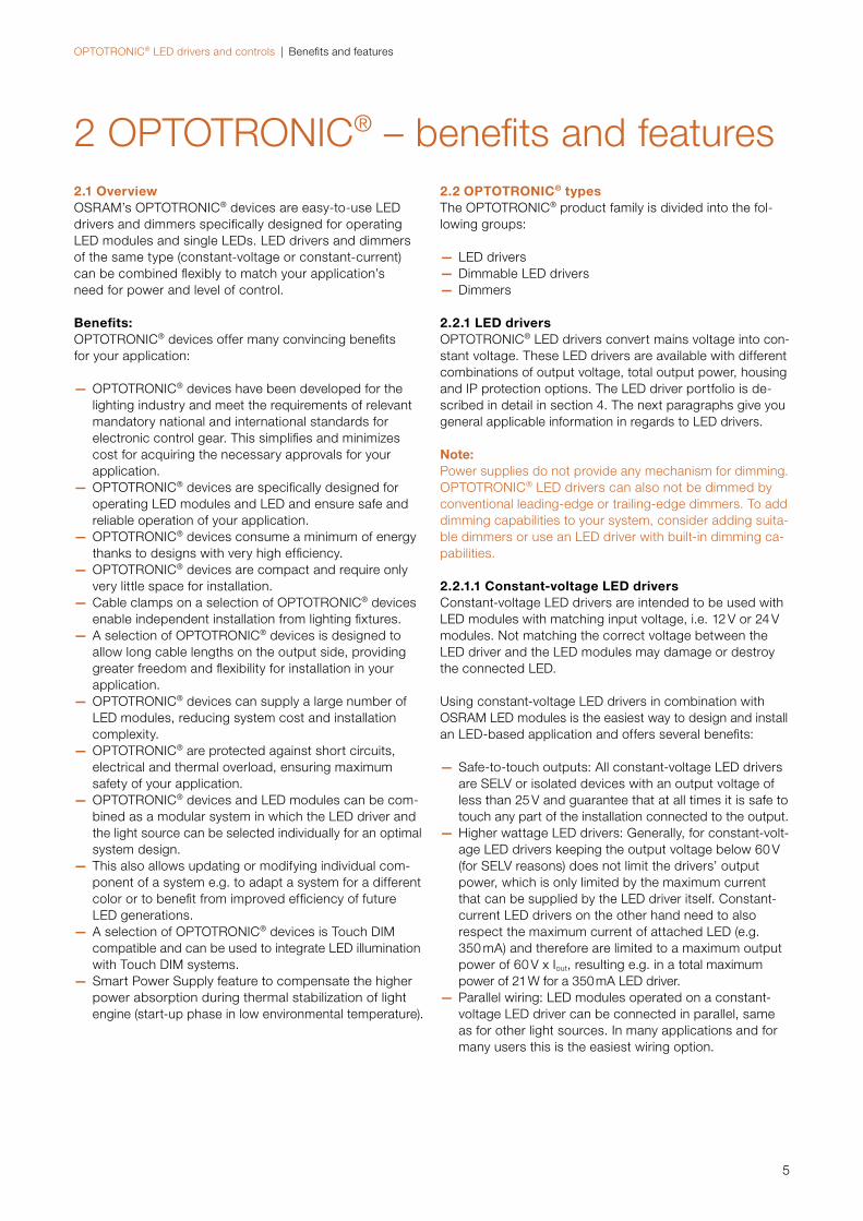
PWM dimmingPWM dimming utilizes a different method for reducing the average current through the LED: the current applied to the LED is turned on and off at a high frequency (i.e. 3 kHz) while keeping the current level fixed (e.g. at 350 mA). The average value of the current flowing through the LED is then determined by the length of the on-period as com-pared to the off-period (the duty-cycle).
Regardless of the control protocol used to dim the luminous flux, OSRAM constant-voltage LED drivers and dimmers exclusively use PWM as the output dimming method.
Figure 1: PWM dimming
0
50 %
Time
100 %
Time
100 % average
0
50 %
100 %
Time
50 % average
0
50 %
100 %
25 % average
Output
Output
Output

OPTOTRONIC® LED drivers and controls | Introduction
4
1.3 LED modulesFigure 1 shows dimming at 25 %, 50 % and 100 % and the resulting, average current flow through the diode. Since the current through the LED remains unchanged at different dimming levels, there is also no color-shift introduced due to a change in current. This ensures best performance of the LED in both RGB and white light applications.
OSRAM LED modules integrate single or multiple LED into one module with optional driving circuits (i.e. for limiting or controlling the current through the LED).
Some of the benefits of using LED modules are:
— Easy installation (through screw mounting or adhesive tape)
— Easy electrical connections (e.g. through plug-and-play connections)
— Simplified thermal management — Select modules are available with optional optics for ad-justing the radiation pattern to suit your application
OSRAM’s LED modules are designed and optimized for use with OPTOTRONIC® LED drivers with guaranteed performance and lifetime. When using OSRAM LED mod-ules in combination with OSRAM LED drivers, OSRAM guarantees up to 7 years of system lifetime (please refer to www.osram.com/cb/services/guarantees for updates).
OSRAM currently offers LED modules in the following color combinations:
— White (W-white, available with different color tempera-tures)
— RGBW (Red, Green, Blue, White) — RGB (Red, Green, Blue) — TW (Tunable White, changeable light temperature) — TWW (Tunable Warm White)
Constant-voltage LED modules from OSRAM are designed to be operated on a constant voltage of either 12 V or 24 V. For each LED module OSRAM offers a perfectly matching OPTOTRONIC® LED driver.
For further, detailed information on all available CV LED modules, please visit the LED Systems website at www.osram.com/flex
For monochrome versions of LINEARlight FLEX LED modules, please contact OSRAM DS Customer Care: [email protected]
OPTOTRONIC® LED drivers and controls | Benefits and features
5
2 OPTOTRONIC® – benefits and features2.1 OverviewOSRAM’s OPTOTRONIC® devices are easy-to-use LED drivers and dimmers specifically designed for operating LED modules and single LEDs. LED drivers and dimmers of the same type (constant-voltage or constant-current) can be combined flexibly to match your application’s need for power and level of control.
Benefits:OPTOTRONIC® devices offer many convincing benefits for your application:
— OPTOTRONIC® devices have been developed for the lighting industry and meet the requirements of relevant mandatory national and international standards for electronic control gear. This simplifies and minimizes cost for acquiring the necessary approvals for your application.
— OPTOTRONIC® devices are specifically designed for operating LED modules and LED and ensure safe and reliable operation of your application.
— OPTOTRONIC® devices consume a minimum of energy thanks to designs with very high efficiency.
— OPTOTRONIC® devices are compact and require only very little space for installation.
— Cable clamps on a selection of OPTOTRONIC® devices enable independent installation from lighting fixtures.
— A selection of OPTOTRONIC® devices is designed to allow long cable lengths on the output side, providing greater freedom and flexibility for installation in your application.
— OPTOTRONIC® devices can supply a large number of LED modules, reducing system cost and installation complexity.
— OPTOTRONIC® are protected against short circuits, electrical and thermal overload, ensuring maximum safety of your application.
— OPTOTRONIC® devices and LED modules can be com-bined as a modular system in which the LED driver and the light source can be selected individually for an optimal system design.
— This also allows updating or modifying individual com-ponent of a system e.g. to adapt a system for a different color or to benefit from improved efficiency of future LED generations.
— A selection of OPTOTRONIC® devices is Touch DIM compatible and can be used to integrate LED illumination with Touch DIM systems.
— Smart Power Supply feature to compensate the higher power absorption during thermal stabilization of light engine (start-up phase in low environmental temperature).
2.2 OPTOTRONIC® typesThe OPTOTRONIC® product family is divided into the fol-lowing groups:
— LED drivers — Dimmable LED drivers — Dimmers
2.2.1 LED driversOPTOTRONIC® LED drivers convert mains voltage into con-stant voltage. These LED drivers are available with different combinations of output voltage, total output power, housing and IP protection options. The LED driver portfolio is de-scribed in detail in section 4. The next paragraphs give you general applicable information in regards to LED drivers.
Note:Power supplies do not provide any mechanism for dimming. OPTOTRONIC® LED drivers can also not be dimmed by conventional leading-edge or trailing-edge dimmers. To add dimming capabilities to your system, consider adding suita-ble dimmers or use an LED driver with built-in dimming ca-pabilities.
2.2.1.1 Constant-voltage LED driversConstant-voltage LED drivers are intended to be used with LED modules with matching input voltage, i.e. 12 V or 24 V modules. Not matching the correct voltage between the LED driver and the LED modules may damage or destroy the connected LED.
Using constant-voltage LED drivers in combination with OSRAM LED modules is the easiest way to design and install an LED-based application and offers several benefits:
— Safe-to-touch outputs: All constant-voltage LED drivers are SELV or isolated devices with an output voltage of less than 25 V and guarantee that at all times it is safe to touch any part of the installation connected to the output.
— Higher wattage LED drivers: Generally, for constant-volt-age LED drivers keeping the output voltage below 60 V (for SELV reasons) does not limit the drivers’ output power, which is only limited by the maximum current that can be supplied by the LED driver itself. Constant- current LED drivers on the other hand need to also respect the maximum current of attached LED (e.g. 350 mA) and therefore are limited to a maximum output power of 60 V x Iout, resulting e.g. in a total maximum power of 21 W for a 350 mA LED driver.
— Parallel wiring: LED modules operated on a constant- voltage LED driver can be connected in parallel, same as for other light sources. In many applications and for many users this is the easiest wiring option.
OPTOTRONIC® LED drivers and controls | Benefits and features
6
2.2.2 Dimmable LED drivers and dimmers Dynamic lighting can simply provide dimming of the bright-ness of an application or can provide highly sophisticated control of color in RGB decorative applications. OSRAM offers suitable devices for both uses, either as dimmable LED drivers or as external dimmers.
Dimmable LED drivers combine an LED driver and a dim-mer in one device that offers space savings and simplifies installation.
External dimmers are linked in between the LED driver and the LED light sources (e.g. the LED modules). A solution based on an LED driver with an external dimmer, on the other hand, provides greater flexibility in choosing the amount of power supplied to your application.
Dimmable LED drivers and dimmers are available with the following different control inputs.
2.2.2.1 Control inputs
1…10 VThe 1…10 V control input is a well-established control method in the lighting industry and primarily used for easy brightness control in an application.
Features of the 1…10 V interface — It is insulated. — The output is controlled by a DC voltage signal from 10 V (maximum light output; control wires open) to <1 V (minimum light output; control wires short-circuited).
— With 1…10 V control input it’s possible to reach a dim-ming down to 1 %.
— The control voltage is supplied by each LED driver itself. Each LED driver can supply a maximum current of 0.1 mA.
— The voltage on the control wires is galvanic separated from the mains cables and it does comply with the SELV requirements.
— Units operated on different main phases can be dimmed by one controller.
The output power of the LED drivers can be adjusted by a 1…10 V interface and an external controller (Vin) or external resistor.
Table 1 supports you in finding the correct resistor for your desired dimming value. For dimming, you just have to connect the resistor to the dimming wires of the 1…10 V in-terface.
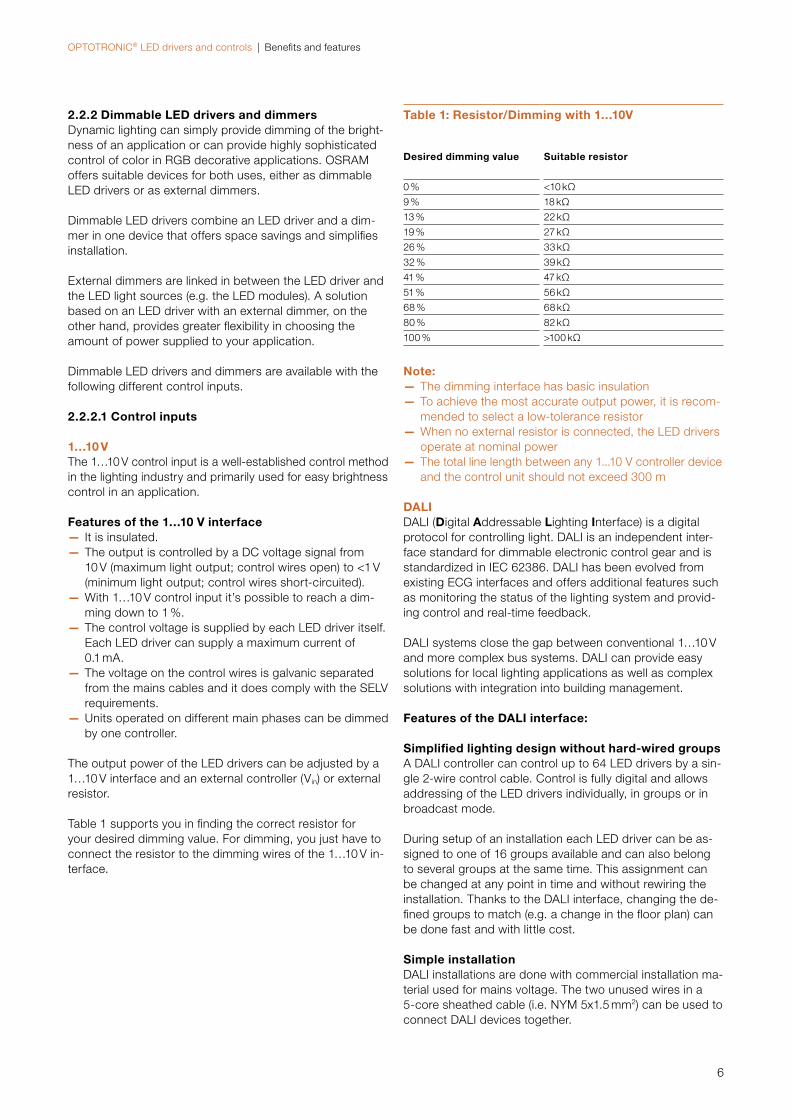
Table 1: Resistor/Dimming with 1…10V
Desired dimming value Suitable resistor
0 % <10 kΩ
9 % 18 kΩ
13 % 22 kΩ
19 % 27 kΩ
26 % 33 kΩ
32 % 39 kΩ
41 % 47 kΩ
51 % 56 kΩ
68 % 68 kΩ
80 % 82 kΩ
100 % >100 kΩ
Note: — The dimming interface has basic insulation — To achieve the most accurate output power, it is recom-mended to select a low-tolerance resistor
— When no external resistor is connected, the LED drivers operate at nominal power
— The total line length between any 1...10 V controller device and the control unit should not exceed 300 m
DALIDALI (Digital Addressable Lighting Interface) is a digital protocol for controlling light. DALI is an independent inter-face standard for dimmable electronic control gear and is standardized in IEC 62386. DALI has been evolved from existing ECG interfaces and offers additional features such as monitoring the status of the lighting system and provid-ing control and real-time feedback.
DALI systems close the gap between conventional 1…10 V and more complex bus systems. DALI can provide easy solutions for local lighting applications as well as complex solutions with integration into building management.
Features of the DALI interface:
Simplified lighting design without hard-wired groups A DALI controller can control up to 64 LED drivers by a sin-gle 2-wire control cable. Control is fully digital and allows addressing of the LED drivers individually, in groups or in broadcast mode.
During setup of an installation each LED driver can be as-signed to one of 16 groups available and can also belong to several groups at the same time. This assignment can be changed at any point in time and without rewiring the installation. Thanks to the DALI interface, changing the de-fined groups to match (e.g. a change in the floor plan) can be done fast and with little cost.
Simple installation DALI installations are done with commercial installation ma-terial used for mains voltage. The two unused wires in a 5-core sheathed cable (i.e. NYM 5x1.5 mm2) can be used to connect DALI devices together.
OPTOTRONIC® LED drivers and controls | Benefits and features
7
When connecting the control inputs of DALI LED drivers, it is not required to observe polarity for proper operation. This eliminates a potential source for errors and reduces instal-lation complexity. The control wires must be approved for mains voltage, no other special requirements apply.
Flexible powering Controller and ballasts can be connected arbitrarily to the available phases of the mains voltage in order to achieve a better load distribution. Independent of the powering phase all LED drivers can be controlled and switched off by a sin-gle controller. The factory-default of OSRAM’s DALI LED drivers is set to 100 % brightness upon initial power-up. This way even without programming by a controller an installation can be switched on and off by a circuit breaker and provides basic illumination during installation and a quick way to verify op-eration.
DALI controlled switching No relays are needed for switching DALI units on or off. Switching and dimming is carried out exclusively via the control wires.
Synchronized change of lighting scenes When DALI units with different start dimming levels are combined (e.g. when individual units are set to a new mas-ter value) the change to the master value will be synchro-nized by DALI so that all light sources reach the new final dimming level at the same time, resulting in a best perform-ing dimming solution.
Lamp status on demand DALI LED drivers can send a lamp status report to the con-troller on demand so that is possible to remotely detect and report lamp failures or display the current dimming level of each lamp.
Integrated scene storage The LED drivers store the light levels per lighting scene as-signed to a corresponding group. Independent of any defi-nition of groups the individual LED driver can store up to 16 different light levels. Transitions between scenes are syn-chronized so that all LED drivers start and finish the transi-tion at the same time by operating with different dimming speed.
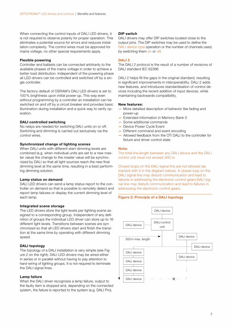
DALI topology The topology of a DALI installation is very simple (see Fig-ure 2 on the right). DALI LED drivers may be wired either in series or in parallel without having to pay attention to hard-wiring of lighting groups. It is not required to terminate the DALI signal lines.
Lamp failure When the DALI driver recognizes a lamp failure, output to the faulty item is stopped and, depending on the connected system, the failure is reported to the system (e.g. DALI Pro).
DIP switch DALI drivers may offer DIP switches located close to the output pins. The DIP switches may be used to define the DALI device type operation or the number of channels used, by switching them on or off.
DALI 2The DALI 2 protocol is the result of a number of revisions of DALI standard IEC 62386
DALI 2 helps fill the gaps in the original standard, resulting in significant improvements in interoperability. DALI 2 adds new features, and introduces standardisation of control de-vices including the recent addition of input devices, while maintaining backwards compatibility.
New features: — More detailed description of behavior like fading and power-up
— Extended information in Memory Bank 0 — Some additional commands — Device Power Cycle Event — Different command and event encoding — Allowed feedback from the OTi DALI to the controller for fixture and driver control state
Note:The total line length between any DALI device and the DALI control unit must not exceed 300 m.
Closed loops on the DALI signal line are not allowed (as marked with X in the diagram below). A closed loop on the DALI signal line may disturb communication and lead to failures in addressing the electronic control gears.DALI sig-nal line may disturb communication and lead to failures in addressing the electronic control gears.
300 m max. length
DALI device
DALI device
DALI device
DALI device
DALI device
DALI device
DALI device
DALI device
DALI control
unit
DALI device
Figure 2: Principle of a DALI topology
OPTOTRONIC® LED drivers and controls | Benefits and features
8
Distributed intelligence During the initialization process, DALI LED drivers store the following data:
— Unique, individual address for each LED driver (0–63) — Assignment to lighting groups (to a total of 16 groups, multiple assignments are possible)
— Optionally lighting levels for individual scenes (max. 16) plus special settings such as:
— Global dimming speed — Behavior of LED drivers when control signal inter-rupted (emergency lighting, system failure)
— Behavior of LED drivers after power failure
OSRAM offers controllers and accessory parts for design-ing a DALI-based system, either for fluorescent lamps, compact fluorescent lamps, halogen lamps or LED. OP TOTRONIC® devices are either available with a built-in DALI control port or can be controlled via a DALI gateway.
OSRAM’s DALI devices can also be controlled via Touch DIM. Touch DIM uses only a pushbutton connected to the DALI inputs and allows to control on/off, dimming level and the default dimming value of connected DALI LED drivers.
The dedicated Light Management section of the OSRAM DS website (https://www.osram.com/ds/light-manage-ment-systems/) provides detailed information about the available OSRAM components for light management sys-tems, including the most important features, functions andapplications as well as technical and ordering data.
AstroDIMThe AstroDIM feature allows an autonomous dimming with-out the need for an additional control line. The LED drivers OTi DALI XX/24 P supports up to five independent dimming levels and flexible settings of fade times between the indi-vidual dimming levels.
The output levels can be set to 0 % (OFF) or between 10 %and 100 %.
In addition, switch-on and switch-off fade times can be programmed at the beginning and the end of a switching cycle to allow for further energy savings during the twilight phase. This function is also helpful for installations with a pedestrian crossing where no specific infrastructure is available to switch the pedestrian crossing illumination inde-pendently of the rest of the street light illumination.
Two different modes for AstroDIM are supported:
Time-based: The dimming profile defined in the reference schedule is referenced to the switch-on time of the LED driver.
Astro-based: The dimming profile defined in the reference schedule is referenced to the annual average middle of the night, which is calculated based on the theoretical sunrise and sunset times.
The LED driver does not have a real-time clock. The inter-nal reference clock is derived from the mains frequency and the driver detects if it is connected to a 50 Hz or 60 Hz supply system, assuming a time base of 20 ms or 16.6 ms. This allows a synchronized switching of all units. The dim-ming mode works only when AC voltage is applied.
Warning: If the output level is set below the minimum physical dimming level of the LED driver (except OFF), the minimum dimming current is used. The software still displays the original value. If the output level falls below the minimum allowed dimming current, the value is visualized in red.
Wiring and feature activationThe AstroDIM mode can be activated by the Tuner4TRONIC® software. Selected dimming mode: “AstroDIM (DALI)”
Astro-based modeIn this mode, the LED driver performs a dimming profile based on the daily power-on and power-off times. The dim-ming schedule is adapted according to the length of the night.
The Tuner4TRONIC® software calculates the annual aver-age middle of the night based on the theoretical sunrise and sunset times, which are related to the location selected in the software. Based on this average middle of the night, five independent dimming periods can be defined in the reference schedule. The minimum length of one dimming period has to be longer than the AstroDIM fade time. Valid time values can be set between 12:00 pm and 11:59 am.If less than five output levels need to be performed, two sequenced levels have to be set to the same value. The defined dimming profile is already performed after the sec-ond power-off/on cycle after programming.
Fade timing: — AstroDIM fade time: Fade time between the different dimming levels. To achieve further energy savings in the twilight phase, the switch-on and switch-off fade time can be set to up to 60 minutes.
— Switch-on fade time: Fade time after the LED driver has been powered on. The output level at the end of this fade time is defined by the output level of the related dimming period (step x).
— Switch-off fade time: Fade time prior to the estimated power-off point. The switch-off fading is performed down to the minimum dimming current until the LED driver is switched off externally.
The “schedule by day” in the AstroDIM feature tab calcu-lates the estimated dimming behavior for a specific day based on the theoretical sunrise and sunset times. If day-light saving has to be considered, the corresponding check box needs to be ticked. The LED driver itself is not able to detect summer and winter time and does not have an inter-nal real-time clock.
OPTOTRONIC® LED drivers and controls | Benefi ts and features
9
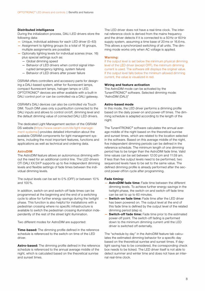
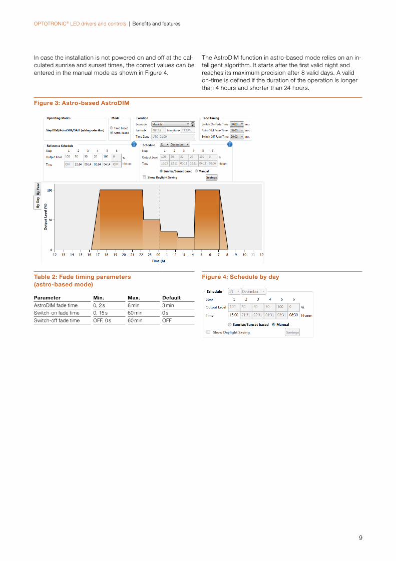
In case the installation is not powered on and off at the cal-culated sunrise and sunset times, the correct values can be entered in the manual mode as shown in Figure 4.
The AstroDIM function in astro-based mode relies on an in-telligent algorithm. It starts after the fi rst valid night and reaches its maximum precision after 8 valid days. A valid on-time is defi ned if the duration of the operation is longer than 4 hours and shorter than 24 hours.
Table 2: Fade timing parameters (astro-based mode)
Parameter Min. Max. Default
AstroDIM fade time 0, 2 s 8 min 3 min
Switch-on fade time 0, 15 s 60 min 0 s
Switch-off fade time OFF, 0 s 60 min OFF
Figure 3: Astro-based AstroDIM
Figure 4: Schedule by day
OPTOTRONIC® LED drivers and controls | Benefits and features
10
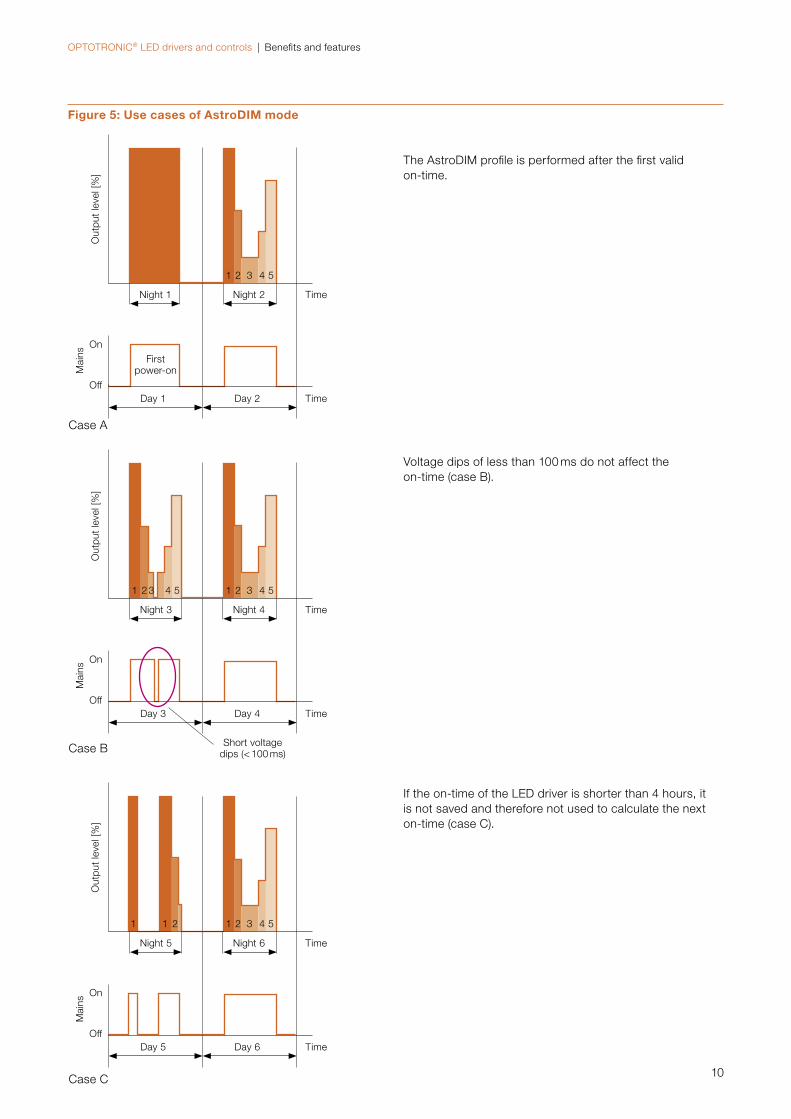
Voltage dips of less than 100 ms do not affect the on-time (case B).
If the on-time of the LED driver is shorter than 4 hours, it is not saved and therefore not used to calculate the next on-time (case C).
The AstroDIM profile is performed after the first valid on-time.
Figure 5: Use cases of AstroDIM mode
Case A
Case B
Case C
1
1
1
Night 1
Night 3
Night 5
Firstpower-on
Short voltage dips (< 100 ms)
Time
Time
Time
Time
Time
Time
Out
put
leve
l [%
]O
utpu
t le
vel [
%]
Out
put
leve
l [%
]
Mai
nsM
ains
Mai
ns
On
On
On
Off
Off
Off
Night 2
Night 4
Night 6
Day 2
Day 4
Day 6
Day 1
Day 3
Day 5
2
2
2
3
3
3
4
4
4
5
5
5
1 2 3 4
1
5
21
OPTOTRONIC® LED drivers and controls | Benefits and features
11
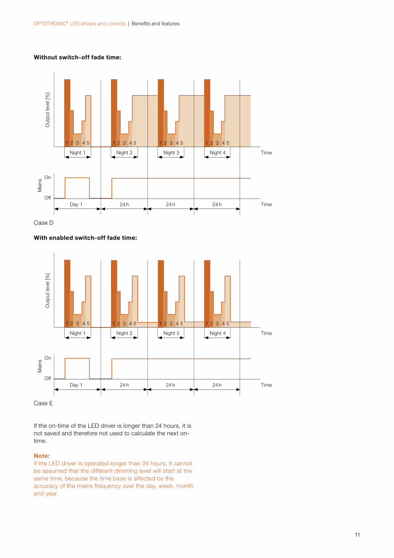
If the on-time of the LED driver is longer than 24 hours, it is not saved and therefore not used to calculate the next on-time.
Note:If the LED driver is operated longer than 24 hours, it cannot be assumed that the different dimming level will start at the same time, because the time base is affected by the accuracy of the mains frequency over the day, week, month and year.
Without switch-off fade time:
With enabled switch-off fade time:
Case D
Case E
1
1
1
1
1
1
Night 1
Night 1
Time
Time
Time
Time
Out
put
leve
l [%
]O
utpu
t le
vel [
%]
Mai
nsM
ains
On
On
Off
Off
Night 2
Night 2
Night 3
Night 3
Night 4
Night 4
24 h
24 h
24 h
24 h
24 h
24 h
Day 1
Day 1
2
2
2
2
2
2
3
3
3
3
3
3
4
4
4
4
4
4
5
5
5
5
5
5
1
1
2
2
3
3
4
4
5
5
OPTOTRONIC® LED drivers and controls | Benefits and features
12
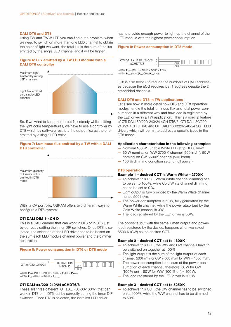
DALI DT6 and DT8Using TW and TWW LED you can find out a problem: when we need to switch on more than one LED channel to obtain the color of light we want, the total lux is the sum of the lux emitted by the single LED channel and it will be higher.
So, if we want to keep the output flux steady while shifting the light color temperatures, we have to use a controller by DT8 which by software restricts the output flux as the one emitted by a single LED color.
With its CV portfolio, OSRAM offers two different ways to configure a DT8 system:
OTi DALI DIM 1-4CH DThis is a DALI dimmer that can work in DT8 or in DT6 just by correctly setting the inner DIP switches. Once DT8 is se-lected, the selection of the LED driver has to be based on the sum each LED module channel power and the dimmer absorption.
Figure 8: Power consumption in DT6 or DT8 mode
OTi DALI xx/220-240/24 xCHDT6/8These are three different OT DALI (50-80-160 W) that can work in DT8 or in DT6 just by correctly setting the inner DIP switches. Once DT8 is selected, the installed LED driver
Figure 9: Power consumption in DT8 mode
DT8 is also helpful to reduce the numbers of DALI address-es because the ECG requires just 1 address despite the 2 embedded channels.
DALI DT6 and DT8 in TW applications Let’s see now in more detail how DT6 and DT8 operation modes handle the total luminous flux and total power con-sumption in a different way and how load is registered by the LED driver in a TW application. This is a special feature of OTi DALI 50/220-240/24 4CH DT6/8, OTi DALI 80/220-240/24 4CH DT6/8 and OTi DALI 160/220-240/24 2CH LED drivers which will permit to address a specific issue in the DT8 mode.
Application characteristics in the following examples: — Nominal 100 W Tunable White LED strip, 1000 lm/m — 50 W nominal on WW 2700 K channel (500 lm/m), 50 W nominal on CW 6500 K channel (500 lm/m)
— 100 % dimming condition setting (full power)
DT6 operationExample 1 – desired CCT is Warm White – 2700 K
— To achieve this CCT, Warm White channel dimming has to be set to 100 %, while Cold White channel dimming has to be set to 0 %.
— Light output is fully provided by the Warm White channel, hence 500 lm/m.
— The power consumption is 50 W, fully generated by the Warm White channel, while the power absorbed by the Cold White channel is 0 W.
— The load registered by the LED driver is 50 W.
The opposite, but with the same lumen output and power/load registered by the device, happens when we select 6500 K (CW) as the desired CCT.
Example 2 – desired CCT set to 4600 K — To achieve this CCT, the WW and CW channels have to be switched on together at 100 %.
— The light output is the sum of the light output of each channel: 500 lm/m for CW + 500 lm/m for WW = 1000 lm/m.
— The power consumption is the sum of the power con-sumption of each channel, therefore: 50 W for CW (100 % on) + 50 W for WW (100 % on) = 100 W.
— The load registered by the LED driver is 100 W.
Example 3 – desired CCT set to 5250 K — To achieve this CCT, the CW channel has to be switched on at 100 %, while the WW channel has to be dimmed to 50 %.
OTi DALI DIM 1-4CH DOT xx/220...240/24 -
+CH1CH2
has to provide enough power to light up the channel of the LED module with the highest power consumption.
In DT6: Ptot ≥ PCH1 + PCH2 + PCH3 + PCH4In DT8: Ptot ≥ MAX [PnomCH1; PnomCH2]
CH1CH2
OTi DALI xx/220...240/24 xCHDT6/8
-+
-
In DT6: Ptot ≥ PCH1 + PCH2 + PCH3 + PCH4 + Pdimmer
In DT8: Ptot ≥ PCH1 + PCH2 + Pdimmer
Figure 6: Lux emitted by a TW LED module with a DALI DT6 controller
Maximum light emitted by mixing LED channels
Light flux emitted by a single LED channel
Figure 7: Luminous flux emitted by a TW with a DALI DT8 controller
Maximum quantity of luminous flux emitted in DT8 mode
OPTOTRONIC® LED drivers and controls | Benefits and features
13
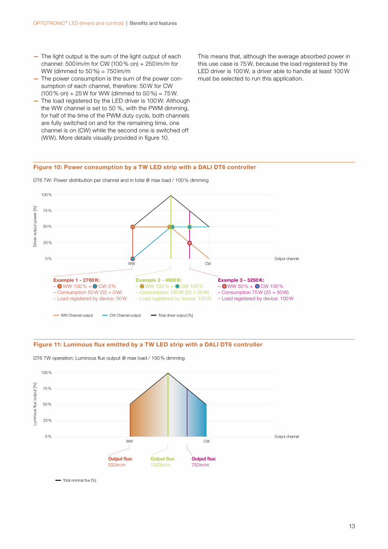
Figure 10: Power consumption by a TW LED strip with a DALI DT6 controller
— The light output is the sum of the light output of each channel: 500 lm/m for CW (100 % on) + 250 lm/m for WW (dimmed to 50 %) = 750 lm/m
— The power consumption is the sum of the power con-sumption of each channel, therefore: 50 W for CW (100 % on) + 25 W for WW (dimmed to 50 %) = 75 W.
— The load registered by the LED driver is 100 W: Although the WW channel is set to 50 %, with the PWM dimming, for half of the time of the PWM duty cycle, both channels are fully switched on and for the remaining time, one channel is on (CW) while the second one is switched off (WW). More details visually provided in figure 10.
DT6 TW: Power distribution per channel and in total @ max load / 100 % dimming
Example 1 - 2700 K:– WW 100 % + CW 0 %– Consumption 50 W (50 + 0 W)– Load registered by device: 50 W
Example 2 - 4600 K: – WW 100 % + CW 100 % – Consumption 100 W (50 + 50 W)– Load registered by device: 100 W
WW CW
CW Channel outputWW Channel output Total driver output [%]
Example 3 - 5250 K: – WW 50 % + CW 100 %– Consumption 75 W (25 + 50 W)– Load registered by device: 100 W
Figure 11: Luminous flux emitted by a TW LED strip with a DALI DT6 controller
DT6 TW operation: Luminous flux output @ max load / 100 % dimming
0 %
25 %
50 %
75 %
100 %
Lum
inou
s flu
x ou
tput
[%]
Output channel
Total nominal flux [%]
Output flux: 500 lm/m
Output flux: 1000 lm/m
Output flux: 750 lm/m
This means that, although the average absorbed power in this use case is 75 W, because the load registered by the LED driver is 100 W, a driver able to handle at least 100 W must be selected to run this application.
WW CW
Output channel0 %
25 %
50 %
75 %
100 %
Driv
er o
utpu
t po
wer
[%]
OPTOTRONIC® LED drivers and controls | Benefits and features
14
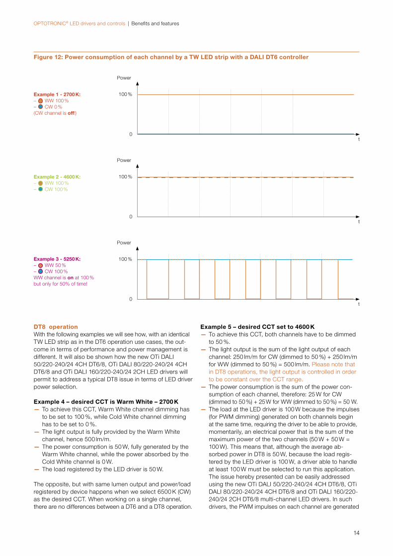
Figure 12: Power consumption of each channel by a TW LED strip with a DALI DT6 controller
Example 1 - 2700 K:– WW 100 % – CW 0 % (CW channel is off!)
t0
100 %
Power
t0
100 %
Power
t0
100 %
Power
DT8 operationWith the following examples we will see how, with an identical TW LED strip as in the DT6 operation use cases, the out-come in terms of performance and power management is different. It will also be shown how the new OTi DALI 50/220-240/24 4CH DT6/8, OTi DALI 80/220-240/24 4CH DT6/8 and OTi DALI 160/220-240/24 2CH LED drivers will permit to address a typical DT8 issue in terms of LED driver power selection.
Example 4 – desired CCT is Warm White – 2700 K — To achieve this CCT, Warm White channel dimming has to be set to 100 %, while Cold White channel dimming has to be set to 0 %.
— The light output is fully provided by the Warm White channel, hence 500 lm/m.
— The power consumption is 50 W, fully generated by the Warm White channel, while the power absorbed by the Cold White channel is 0 W.
— The load registered by the LED driver is 50 W.
The opposite, but with same lumen output and power/load registered by device happens when we select 6500 K (CW) as the desired CCT. When working on a single channel, there are no differences between a DT6 and a DT8 operation.
Example 5 – desired CCT set to 4600 K — To achieve this CCT, both channels have to be dimmed to 50 %.
— The light output is the sum of the light output of each channel: 250 lm/m for CW (dimmed to 50 %) + 250 lm/m for WW (dimmed to 50 %) = 500 lm/m. Please note that in DT8 operations, the light output is controlled in order to be constant over the CCT range.
— The power consumption is the sum of the power con-sumption of each channel, therefore: 25 W for CW (dimmed to 50 %) + 25 W for WW (dimmed to 50 %) = 50 W.
— The load at the LED driver is 100 W because the impulses (for PWM dimming) generated on both channels begin at the same time, requiring the driver to be able to provide, momentarily, an electrical power that is the sum of the maximum power of the two channels (50 W + 50 W = 100 W). This means that, although the average ab-sorbed power in DT8 is 50 W, because the load regis-tered by the LED driver is 100 W, a driver able to handle at least 100 W must be selected to run this application. The issue hereby presented can be easily addressed using the new OTi DALI 50/220-240/24 4CH DT6/8, OTi DALI 80/220-240/24 4CH DT6/8 and OTi DALI 160/220-240/24 2CH DT6/8 multi-channel LED drivers. In such drivers, the PWM impulses on each channel are generated
Example 2 - 4600 K:– WW 100 % – CW 100 %
Example 3 - 5250 K:– WW 50 % – CW 100 % WW channel is on at 100 %but only for 50% of time!
OPTOTRONIC® LED drivers and controls | Benefits and features
15
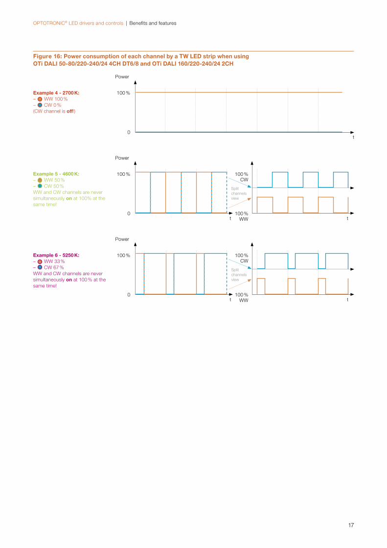
in order to not overlap each other during DT8 operation (see figure 6), enabling the LED driver to register only the maximum power at each channel and thus avoiding an over-designed LED driver selection.
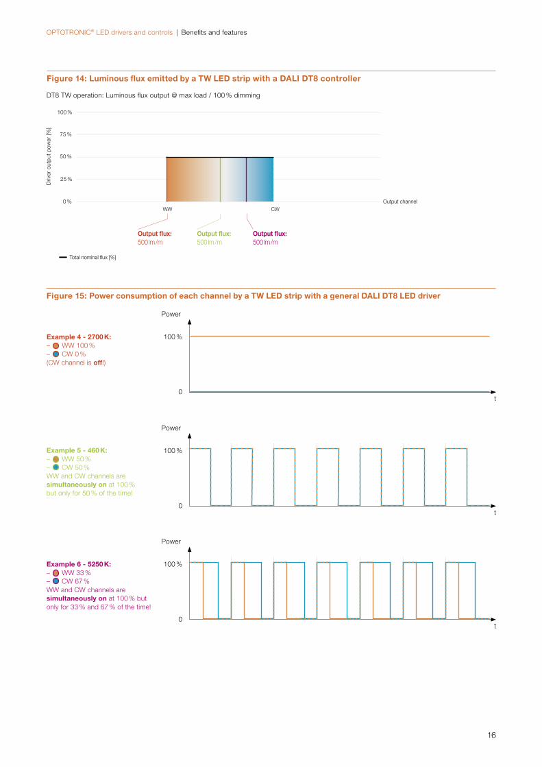
Example 6 – desired CCT set to 5250 K — To achieve this CCT, the WW channel has to be dimmed to 33 %, while the CW channel has to be dimmed to 67 %.
— The light output is the sum of the light output of each channel: 335 lm/m for CW (dimmed to 66 %) + 165 lm/m for WW (dimmed to 33 %) = 500 lm/m. Please note that in DT8 operations, the light output is controlled in order to be constant over the CCT range (indeed, this is the same output as in examples 4 and 5).
— The power consumption is the sum of the power con-sumption of each channel, therefore: 37.5 W for CW (dimmed to 67 %) + 12.5 W for WW (dimmed to 33 %) = 50 W.
— The load registered by the LED driver is 100 W instead, exactly as in example 5, because the PWM impulses generated on both channels begin at the same time, requir-ing the driver to be able to provide, momentarily, an electrical power that is the sum of the maximum power of the two channels (50 W + 50 W = 100 W). What has changed here is the number of impulses, in a given time, of the single channels: This number will be higher
for the CW in order to achieve the desired light output; and lower for the WW. This means that, although the average absorbed power in DT8 is 50 W, because the load registered by the LED driver is 100 W, a suitable 100 W driver must be selected to be able to run this application. The issue hereby presented can be easily addressed using the new OTi DALI 50/220-240/24 4CH DT6/8, OTi DALI 80/220-240/24 4CH DT6/8 and OTi DALI 160/220-240/24 2CH DT6/8 multi-channel LED drivers. Exactly as in example 5, the PWM impulses on each channel are generated in order to not overlap each other during DT8 operation (see figure 6), enabling the LED driver to register only the maximum power at each channel and thus avoiding an over-designed LED driver selection.
As a final note, OTi DALI DIM 1-4 CH D doesn’t have the same feature as OTi DALI 50/220-240/24 4CH DT6/8, OTi DALI 80/220-240/24 4CH DT6/8 and OTi DALI 160/220-240/24 2CH DT6/8. Therefore, the power evaluation in a DT8 operation must consider the nominal power of the LED module load at full power.
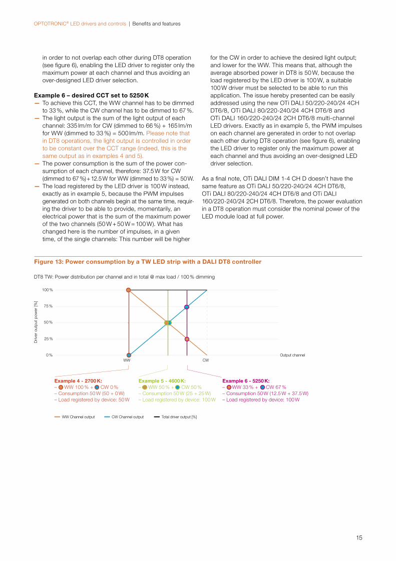
Figure 13: Power consumption by a TW LED strip with a DALI DT8 controller
DT8 TW: Power distribution per channel and in total @ max load / 100 % dimming
WW CW
Example 4 - 2700 K:– WW 100 % + CW 0 %– Consumption 50 W (50 + 0 W)– Load registered by device: 50 W
Example 5 - 4600 K: – WW 50 % + CW 50 % – Consumption 50 W (25 + 25 W)– Load registered by device: 100 W
CW Channel outputWW Channel output Total driver output [%]
Example 6 - 5250 K: – WW 33 % + CW 67 %– Consumption 50 W (12.5 W + 37.5 W)– Load registered by device: 100 W
Output channel0 %
25 %
50 %
75 %
100 %
Driv
er o
utpu
t po
wer
[%]
OPTOTRONIC® LED drivers and controls | Benefits and features
16
Figure 15: Power consumption of each channel by a TW LED strip with a general DALI DT8 LED driver
t0
100 %
Power
t0
100 %
Power
t0
100 %
Power
Output channel0 %
25 %
50 %
75 %
100 %
Driv
er o
utpu
t po
wer
[%]
Figure 14: Luminous flux emitted by a TW LED strip with a DALI DT8 controller
DT8 TW operation: Luminous flux output @ max load / 100 % dimming
Total nominal flux [%]
Output flux: 500 lm /m
Output flux: 500 lm /m
Output flux: 500 lm /m
WW CW
Example 4 - 2700 K:– WW 100 % – CW 0 % (CW channel is off!)
Example 5 - 460 K:– WW 50 % – CW 50 %WW and CW channels are simultaneously on at 100 % but only for 50 % of the time!
Example 6 - 5250 K:– WW 33 % – CW 67 % WW and CW channels are simultaneously on at 100 % but only for 33 % and 67 % of the time!
OPTOTRONIC® LED drivers and controls | Benefits and features
17
Figure 16: Power consumption of each channel by a TW LED strip when using OTi DALI 50-80/220-240/24 4CH DT6/8 and OTi DALI 160/220-240/24 2CH
t0
100 %
Power
t0
100 %
Power
100 % WW
100 % CW
t
t0
100 %
Power
100 % WW
100 % CW
t
Split channels view
Split channels view
Example 4 - 2700 K:– WW 100 % – CW 0 % (CW channel is off!)
Example 5 - 4600 K:– WW 50 % – CW 50 %WW and CW channels are never simultaneously on at 100% at the same time!
Example 6 - 5250 K:– WW 33 % – CW 67 % WW and CW channels are never simultaneously on at 100 % at the same time!
OPTOTRONIC® LED drivers and controls | Benefi ts and features
18
DMXDMX is another digital control protocol. Originally, it was developed for use in stage and effect lighting applications. DMX can be used for a large variety of devices to control options such as light levels, focus, light color or rotation of lights. Using DMX, even complex and demanding lighting systems can be designed.
In standard confi guration DMX controllers can provide up to 512 addresses and are suitable for complex lighting scene sequences and are programmable via software and/or mixing desks.
The DMX512 format is a distribution/control protocol based on the electrical standard RS-485. DMX512 devices can be daisy chained together (i.e. all devices are connected in se-ries, with the DMX signal passed from one device to the next) to form half-duplex DMX512 networks. On a DMX512 network, there is one data path that all devices must share (the DMX512 “bus”). In a typical network, a single device acts as the master device and controls all other slave de-vices. The DMX512 protocol is extremely fast (compared to serial RS-232 networks used for telecommunications) and can easily control the maximum number of devices at the fastest frame rate.
The DMX512 protocol uses packets to transfer information. Each packet contains a synchronization signal followed by device data. Typically, each packet contains suffi cient infor-mation to update the entire network. That is, the device da-ta payload section contains complete information on the state of every device.
After the synchronization signaling, the actual device data payload is transmitted. As many as 512 bytes may follow; in general each device on the DMX512 network uses a sin-gle byte of information to determine, for example, how much to dim a lighting fi xture. Most DMX512 devices have a pro-grammable “start address”. This start address determines which portion of the payload the unit will interpret. For ex-ample, for a device with four channels if the start address is set to seven, the device will read the seventh, eight, ninth, and tenth payload bytes and program the dimmer for each channel accordingly. All this data must go through a DMX booster or splitter at least every 32 devices because along the cable there is a power loss that could make diffi cult the reading of the signals.
While very powerful, DMX-based solutions however may also incur higher component costs and costs required for de-sign and installation. Furthermore, wiring of a DMX installa-tion requires use of special three-wire cable according to AES-EBU-standard, as compared to a standard NYM-cablewhich can be used for a DALI installation (more information in section 3.2.2.6).
OSRAM offers DMX-compatible OPTOTRONIC® devices that can be controlled by a suitable DMX controller. DMX controllers are available in the market from several suppliers.
Both 1…10 V as well as DALI units can also be integrated into DMX installations via suitable gateways (units which
“translate” the DMX protocol to another protocol). DMX gateways are available in the market from several suppliers.
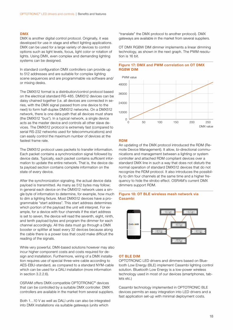
OT DMX RGBW DIM dimmer implements a linear dimming technology, as shown in the next graph. The PWM resolu-tion is 16 bit.
Figure 17: DMX and PWM correlation on OT DMX RGBW DIM
DMX value
PWM value
00
48000
36000
24000
12000
50 100 150 200 250
RDMAn updating of the DMX protocol introduced the RDM (Re-mote Device Management). It allow, bi-directional commu-nications and management between a lighting or system controller and attached RDM compliant devices over a standard DMX line in such a way that does not disturb the normal operation of standard DMX512 devices that do not recognize the RDM protocol. It also introduces the possibil-ity to dim four channels at the same time and a higher fre-quency to hide the strobo effect. OSRAM’s current DMX dimmers support RDM.
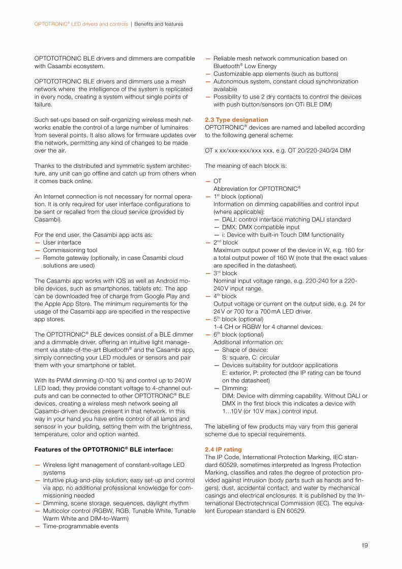
OT BLE DIMOPTOTRONIC LED drivers and dimmers based on Blue-tooth Low Energy (BLE) implement Casambi lighting control solution. Bluetooth Low Energy is a low-power wireless technology used in most of our devices (smartphones, tab-lets etc.)
Casambi technology implemented in OPTOTRONIC BLE devices permits an easy integration into LED drivers and a fast application set-up with minimal deployment costs.
Figure 18: OT BLE wireless mesh network via Casambi
OPTOTRONIC® LED drivers and controls | Benefits and features
19
OPTOTOTRONIC BLE drivers and dimmers are compatible with Casambi ecosystem.
OPTOTOTRONIC BLE drivers and dimmers use a mesh network where the intelligence of the system is replicated in every node, creating a system without single points of failure.
Such set-ups based on self-organizing wireless mesh net-works enable the control of a large number of luminaires from several points. It also allows for firmware updates over the network, permitting any kind of changes to be made over the air. Thanks to the distributed and symmetric system architec-ture, any unit can go offline and catch up from others when it comes back online.
An Internet connection is not necessary for normal opera-tion. It is only required for user interface configurations to be sent or recalled from the cloud service (provided by Casambi).
For the end user, the Casambi app acts as: — User interface — Commissioning tool — Remote gateway (optionally, in case Casambi cloud solutions are used)
The Casambi app works with iOS as well as Android mo-bile devices, such as smartphones, tablets etc. The app can be downloaded free of charge from Google Play and the Apple App Store. The minimum requirements for the usage of the Casambi app are specified in the respective app stores.
The OPTOTRONIC® BLE devices consist of a BLE dimmer and a dimmable driver, offering an intuitive light manage-ment via state-of-the-art Bluetooth® and the Casambi app, simply connecting your LED modules or sensors and pair them with your smartphone or tablet.
With its PWM dimming (0-100 %) and control up to 240 W LED load, they provide constant voltage to 4-channel out-puts and can be connected to other OPTOTRONIC® BLE devices, creating a wireless mesh network seeing all Casambi-driven devices present in that network. In this way in your hand you have entire control of all lamps and sensosr in your building, setting them with the brightness, temperature, color and option wanted.
Features of the OPTOTRONIC® BLE interface:
— Wireless light management of constant-voltage LED systems
— Intuitive plug-and-play solution; easy set-up and control via app, no additional professional knowledge for com-missioning needed
— Dimming, scene storage, sequences, daylight rhythm — Multicolor control (RGBW, RGB, Tunable White, Tunable Warm White and DIM-to-Warm)
— Time-programmable events
— Reliable mesh network communication based on Bluetooth® Low Energy
— Customizable app elements (such as buttons) — Autonomous system, constant cloud synchronization available
— Possibility to use 2 dry contacts to control the devices with push button/sensors (on OTi BLE DIM)
2.3 Type designationOPTOTRONIC® devices are named and labelled according to the following general scheme:
OT x xx/xxx-xxx/xxx xxx, e.g. OT 20/220-240/24 DIM
The meaning of each block is:
— OT Abbreviation for OPTOTRONIC®
— 1st block (optional) Information on dimming capabilities and control input (where applicable):
— DALI: control interface matching DALI standard — DMX: DMX compatible input — i: Device with built-in Touch DIM functionality
— 2nd block Maximum output power of the device in W, e.g. 160 for a total output power of 160 W (note that the exact values are specified in the datasheet).
— 3rd block Nominal input voltage range, e.g. 220-240 for a 220-240 V input range.
— 4th block Output voltage or current on the output side, e.g. 24 for 24 V or 700 for a 700 mA LED driver.
— 5th block (optional) 1-4 CH or RGBW for 4 channel devices.
— 6th block (optional) Additional information on:
— Shape of device: S: square, C: circular
— Devices suitability for outdoor applications E: exterior, P: protected (the IP rating can be found on the datasheet)
— Dimming: DIM: Device with dimming capability. Without DALI or DMX in the first block this indicates a device with 1…10 V (or 10 V max.) control input.
The labelling of few products may vary from this general scheme due to special requirements.
2.4 IP ratingThe IP Code, International Protection Marking, IEC stan-dard 60529, sometimes interpreted as Ingress Protection Marking, classifies and rates the degree of protection pro-vided against intrusion (body parts such as hands and fin-gers), dust, accidental contact, and water by mechanical casings and electrical enclosures. It is published by the In-ternational Electrotechnical Commission (IEC). The equiva-lent European standard is EN 60529.

OPTOTRONIC® LED drivers and controls | Benefits and features
20
The standard aims to provide users more detailed informa-tion than vague marketing terms such as waterproof. For example, an LED driver rated IP67 does not permit the in-gress of dust (6x) and is protected against the effects of temporary immersion in water under standardized condi-tions of pressure and time (x7). IP20 or IP2X are typical minimum requirements for the design of electrical accesso-ries for indoor use.
The digits indicate conformity with the conditions summa-rized in the following tables.
Table 3: First IP number
Level Effective against
X X means there is no data available
0 No protection against contact
1 >50 mm
2 >12.5 mm
3 >2.5 mm
4 >1 mm
5 Dust protected
6 Dust tight
Table 4: Second IP number
Level Effective against
0 Non-protected
1 Vertically falling water drops
2 Vertically falling water drops when enclosure tilted up to 15°
3 Spraying water
4 Splashing of water
5 Water jets
6 Powerful water jets
6K Powerful water jets with increased pressure
7 Temporary immersion in water, up to 1 m
8 Continuous immersion in water
9K Powerful high temperature water jets
For more details on IP rating, please refer to “Technical application guide – IP codes in accordance with IEC 60529 and external environment impacts” in the following OSRAM DS website section: https://www.osram.com/ds/app-guides/index.jsp
2.5 Safety and performanceAll OPTOTRONIC® devices are designed to meet or exceedapplicable standards for use in lighting applications. The next sections give an overview of safety and performance features built into OPTOTRONIC® devices. Furthermore all lighting applications have to comply with the luminaire standards IEC 60598.
2.5.1 SafetyThe luminaires standard IEC 60598 references the safety standard IEC 61347, for LED converters specifically to IEC 61347-2-13.
OPTOTRONIC® devices meet the requirements of the safe-ty standard IEC/EN 61347-2-13. Devices conforming to this standard are designed to ensure the safety of the user and implement measures to protect against electric shocks and thermal overload of the electronic control gear in case of malfunction.
All OPTOTRONIC® LED drivers for constant-voltage LED modules have a double/reinforced insulation between the primary and the secondary side, providing a SELV output with galvanic insulation and additional safety features that minimize the risk of electric shock to the user.
OSRAM is testing the galvanic insulation of 100 % of pro-duction at 3 kV according to the safety standard require-ments for SELV LED drivers.
The control port of dimmable LED drivers or dimmers is al-so insulated against the output, according to the safety standards with levels depending on the kind of control port.
To minimize the risk due to thermal overload of a device in case of malfunction, all OPTOTRONIC® devices are further-more equipped with an over-temperature shut-down fea-ture.
2.5.2 PerformanceThe performance standard IEC/EN 62384 defines the opti-mal operation of LED with electronic control gear, ensuring that LED are only operated within their specified operating parameters. This guarantees best performance and maxi-mum lifetime of suitable LED and LED modules.
All OPTOTRONIC® devices labelled with the ENEC mark are already approved according to IEC/EN 62384.
2.6 EMC complianceEMC (electromagnetic compatibility) is specified as a series of different test criteria. The most important in connection with electronic control gear are radio interference suppres-sion (noise), harmonic content (up to the 39th harmonic) and immunity to interference.
The CE symbol (see section 5.2) on OSRAM devices indi-cate compliance with immunity to interference, harmonic content and radio interference suppression requirements.

OPTOTRONIC® LED drivers and controls | Benefits and features
21
Devices for luminaire integration and stand-alone devices are equipped with a high-quality internal filter to ensure compliance with the radio interference values specified in EN 55015.
When installing OPTOTRONIC® in a luminaire of protection class II or plastic installation boxes, no additional measures against radio interference are required.
When installing OPTOTRONIC® units in metal-case luminaires of protection class I or in metal-case installation boxes, radio interference will increase due to higher earth capacities.
Installations which combine OPTOTRONIC® LED drivers and OPTOTRONIC® dimmers should also be measured to guarantee that radio interference of the system is not exceeded.
Therefore, it may be necessary to include an additional mains filter with earth connection.
Note:The luminaire manufacturer is responsible to measure and verify EMI compliance of the complete lighting fixture as the level of radio interference will vary depending on the instal-lation of the LED driver. Especially primary and secondary cable lengths and routing may have a significant effect on radio interference.
Maximum cable lengthsOPTOTRONIC® LED drivers are tested and verified to be EMI compliant with secondary cable lengths of up to 50 m (shorter cable lengths on some devices, please refer to product datasheet) in accordance with applicable stan dard testing. When cable length exceeds the maximum de-clared, EMI emissions have to be verified in the application. When EMI emission exceed the allowed levels it may be possible to reduce the EMI emissions by using EMI external filters, e.g. ferrite cores.
More information on maximum cable length can be found in section 3.1.4.
Also note that the maximum cable length possible may be reduced due to an excessive voltage drop caused by the resistance of the wire, this is also detailed in the section mentioned above.
2.7 Audible noiseThe frequency-dependent sound pressure level generated by an OPTOTRONIC® device approximates the audibility threshold, i.e. a person with normal hearing capability will virtually not be able to notice the noise generated by a unit in a room.
The overall sound pressure level is determined by the sound power level of the unit, the number of units in operation and the absorption properties of the room (characterized by its volume and reverberation time).
Note that for mains supplies with a high level of distortion where the mains voltage deviates significantly from a sine
Table 5: EMC compliance overview
IEC, international European standard
Radio interference suppression
CISPR 15 EN 55015
Harmonic content IEC 61000-3-2 EN 61000-3-2
Immunity to interference
IEC 61547 EN 61547
Voltage fluctuations and flickers
EC 61000-3-3 EN 61000-3-3
Immunity to interference and harmonic content is deter-mined solely by the LED driver, therefore it is not necessary to repeat any measurement related to these for luminaires equipped with OSRAM OPTOTRONIC® units. This results in a significant cost saving and reduces time required for ap-proval by the luminaire manufacturer. Radio suppression may need to be verified in each particular application.
2.6.1 Harmonic content of the mains currentLighting equipment is subject to restrictions on harmonics.
The maximum permissible threshold values are defined according to class C of the standard EN 61000-3-2 for the subclasses below 25 W and over 25 W. All OPTOTRONIC® LED drivers are designed and approved according to this standard.
Power factor correctionOPTOTRONIC® devices with an input power rated at 25 W or higher are equipped with a power factor correcting fea-ture in compliance with IEC/EN 61000-3-2. Electronic con-trol gear must not disturb the mains supply with an “irregu-lar current drain”, i.e. harmonics.
The power factor of each device is specified in the data sheets on our website: https://www.osram.com/optotronic
2.6.2. Voltage fluctuations and flickersOur OPTOTRONIC® devices comply with EN 61000-3-3 limits of voltage change fluctuations and flickers.
2.6.3 ImmunityAll OPTOTRONIC® devices comply with the immunity requirements described in EN 61547 (IEC 61547, VDE 0875 T15-2). This guarantees protection against interference from external high-frequency fields, discharge of static electricity and transient over voltages of the mains supply as defined in EN 61547.
2.6.4. Emissions (EMI) OPTOTRONIC® LED drivers and control units (independent, with built-in strain relief) comply with the limit values for ra-dio interference voltage in accordance with IEC/EN 55015. The length of low voltage cables must not exceed the val-ues given in the data sheets to comply with the require-ments of radio interference suppression.
OPTOTRONIC® LED drivers and controls | Benefits and features
22
2.9 Protection against overload, short circuit, no load and partial load and over-temperature operation
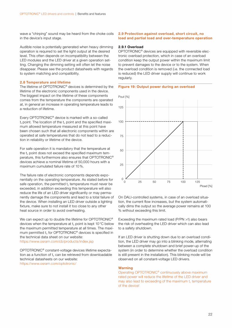
2.9.1 OverloadOPTOTRONIC® devices are equipped with reversible elec-tronic overload protection, which in case of an overload condition keep the output power within the maximum limit to prevent damages to the device or to the system. When the overload condition is removed (i.e. the connected load is reduced) the LED driver supply will continue to work regularly.
wave a “chirping” sound may be heard from the choke coils in the device’s input stage.
Audible noise is potentially generated when heavy dimming operation is required to set the light output at the desired level. This often depends on incompatibility between the LED modules and the LED driver at a given operation set-ting. Changing the dimming setting will often let the noise disappear. Please see the product datasheets with regards to system matching and compatibility.
2.8 Temperature and lifetimeThe lifetime of OPTOTRONIC® devices is determined by the lifetime of the electronic components used in the device. The biggest impact on the lifetime of these components comes from the temperature the components are operated at, in general an increase in operating temperature leads to a reduction of lifetime.
Every OPTOTRONIC® device is marked with a so-called tc point. The location of the tc point and the specified maxi-mum allowed temperature measured at this point have been chosen such that all electronic components within are operated at safe temperatures that do not lead to a reduc-tion in reliability or lifetime of the device.
For safe operation it is mandatory that the temperature at the tc point does not exceed the specified maximum tem-perature, this furthermore also ensures that OPTOTRONIC® devices achieve a nominal lifetime of 50,000 hours with a maximum cumulated failure rate of 10 %.
The failure rate of electronic components depends expo-nentially on the operating temperature. As stated before for safe operation, the permitted tc temperature must never be exceeded, in addition exceeding this temperature will also reduce the life of an LED driver significantly or may perma-nently damage the components and lead to a total failure of the device. When installing an LED driver outside a lighting fixture, make sure to not install it too close to any other heat source in order to avoid overheating.
We can expect up to double the lifetime for OPTOTRONIC® devices when the temperature at tc point is kept 10 °C below the maximum permitted temperature at all times. The maxi-mum permitted tc for OPTOTRONIC® devices is specified in the technical data sheet on our website: https://www.osram.com/cb/products/index.jsp
OPTOTRONIC® constant-voltage devices lifetime expecta-tion as a function of tc can be retrieved from downloadable technical datasheets on our website:https://www.osram.com/optotronic/
Figure 19: Output power during an overload
Pload [%]
Pout [%]
00 25 50 75 100 125
125
100
75
50
25
On DALI-controlled systems, in case of an overload situa-tion, the current flow increases, but the system automati-cally dims the output so the average power remains at 100 % without exceeding this limit.
Exceeding the maximum rated load (P/PN >1) also bears the risk of overheating the LED driver which can also lead to a safety shutdown.
If an LED driver is shutting down due to an overload condi-tion, the LED driver may go into a blinking mode, alternating between a complete shutdown and brief power-up of the system (in order to determine whether the overload condition is still present in the installation). This blinking mode will be observed on all constant-voltage LED drivers.
WarningOperating OPTOTRONIC® continuously above maximum rated power will reduce the lifetime of the LED driver and may also lead to exceeding of the maximum tc temperature of the device!
OPTOTRONIC® LED drivers and controls | Benefits and features
23
2.9.2 Short circuitOPTOTRONIC® devices have a reversible electronic protec-tion against damage caused by short circuit on the sec-ondary side. If a short circuit is detected on the output side, the LED driver will cut off the output power. The LED driver will be fully operational again once the cause of the short circuit has been removed.
2.9.3 Over-temperatureAn OPTOTRONIC® LED driver may become overheated due to high load operations, insufficient device cooling or because a close-by heat source is heating up the LED driver causing an excessive tc.
Regardless of the source of overheating, OPTOTRONIC® devices are protected against permanent damage from over-temperature. When an over-temperature condition occurs, the LED driver will reduce output power and even-tually shut down to avoid permanent damages.
When the LED driver has cooled down to safe levels, full output is restored automatically. Note that this may lead to a blinking mode or periodical shut-down of the LED driver once the previous operational conditions that have led to overheating are still present. Should this be the case, the root source of overheating must be found and removed.
OSRAM’s outdoor devices, according to ISO4892-2, are also protected against sun radiation (including issues caused by UV light).
Attention:For safe and reliable operation and to avoid a reduction in lifetime, it is mandatory to keep the value of tc below the specified maximum value at all times.
2.10 Smart Power Supply featureThe power consumption of LED modules is related to the ambient temperature. For example, at low temperatures (below 0 °C) the required power to operate LED modules may be significantly higher than under standard conditions. This can lead to problems when operating LED installations at these temperatures, such as a reduction of brightness or instable operation of modules due to an overload condition of the LED driver.
To address this issue, OSRAM has developed the “Smart Power Supply” (SPS) feature, which, within certain limits, can automatically compensate the temporary increase in power consumption. Thanks to this feature, over-power conditions are managed by the OPTOTRONIC® LED drivers in order to guarantee optimum system reliability and ther-mal management even at these low temperatures. The “Smart Power Supply” feature does not impact the lifetime of these OPTOTRONIC® LED drivers.
Note:Do not use the Smart Power Supply feature to intentionally overload an OPTOTRONIC® device, as this may reduce its lifetime or damage it. To avoid damages, please have a look at the user instructions and the online catalogue avail-able on www.osram.com/optotronic.

OPTOTRONIC® LED drivers and controls | Planning, installation and operation
24
3 Planning, installation and operation3.1 System planningSystem planning must take into consideration several important factors:
1. The selection of suitable LED modules.2. The required level of control in the application.3. The total wattage and number of LED modules to be in-
stalled and limitations due to maximum output voltage (for systems using constant-current modules).
4. Maximum allowed cable lengths.
All these important system planning factors are discussed in the next sections of this chapter.
3.1.1 LED module selectionThe very first step when planning an application is the se-lection of the right LED module(s).
For an overview of available CV LED modules for different applications, please refer to the “Flexible Light Systems” section of the OSRAM website: www.osram.com/flex.
3.1.2 Level of controlThe required level of control in your application determines whether the system will use any OT dimmers in addition to OPTOTRONIC® LED drivers.
The level of control in an application can range from no control (i.e. fixed output), simple control (i.e. brightness) or full multi-channel control (i.e. multiple independently con-trolled channels). Besides the level of control also the pre-ferred control protocol must be selected, such as 1…10 V, BLE, DALI 2 or DMX.
Both the LED modules’ characteristics and the desired level of control are used for the selection of OPTOTRONIC LED drivers and dimmers best matching the application. Dimmers have also to be considered in planning a system because:
— They draw additional power from the LED driver. Even though this amount in general is much smaller than the power drawn from the LED modules, it should be con-sidered in the calculation.
— Dimmers also introduce a small voltage drop along the cabling to the LED modules, which must also be taken into consideration when calculating maximum cable lengths.
— The cable length between the LED driver and the dimmer has to be considered as part of the maximum cable length to the LED load.
— The maximum current rating of a controller may further-more limit the number of modules that can be connected to a controller and to an LED driver.
3.1.3 Total wattageThe overall installed power must be higher than the power absorbed by the connected LED modules and controllers.
For normal operating temperatures, the maximum number of LED modules which can be operated on one OPTOTRONIC® can be easily obtained by calculating the ratio between nominal wattage of the LED driver and the total power consumption of the connected LED module:
— Nmax Maximum number of LED modules that can be operated on one LED driver, rounded down (i.e. 18.8 becomes 18)
— PN, OPTOTRONIC Nominal power of the OPTOTRONIC® LED driver. This value can be found in the technical product data sheet (see our website: https://www.osram.com/cb/products/index.jsp)
— PN, module Nominal power of the connected LED module. The module wattage is specified in the data sheets of the LED module.
In case a controller is connected to the OPTOTRONIC® LED driver, the available power to drive the LED modules is reduced by the power absorbed by the controller itself. The power absorbed by the controller is specified in the device’s data sheet (see: https://www.osram.com/cb/products/index.jsp). The formula to be used in case a controller is connected is the following one:
The above calculation is a best-case scenario in case all LED modules could be evenly connected (in terms of absorbed power) to the LED drivers.
In a real-word application, the distance between the LED driver and the LED module and the cross-section of the cables may have an impact on the system configuration and therefore the quantity of drivers needed.
N max =PN,OPTOTRONIC
PN,module
N max =PN,OPTOTRONIC - PLosses, dimmer
PN,module

OPTOTRONIC® LED drivers and controls | Planning, installation and operation
25
3.1.4 Maximum cable lengths
3.1.4.1 Maximum output cable lengthCable length on the secondary side is limited by EMI and the voltage drop that occurs along the cables.
EMI complianceAll OPTOTRONIC® products are tested and comply with the limit values for radio interference according to EN 55015. The maximum cable length to comply with IEC/EN 55015 is given in the technical product data sheet in our website: https://www.osram.com/cb/products/index.jspPlease note that this is the maximum cable length between the LED driver and the LED modules and that this includes any dimmers and controllers that may be installed in between LED driver and LED module.
In some applications, it may be required to extend the maxi-mum permitted cable length. In this case, special EMC fi lters can be applied on the secondary side (12 V and 24 V). A ferrite close to the output terminals can reduce the effect of radio interference signifi cantly. If OPTOTRONIC® dimmers are also installed, place the fi lters on output wires as close as possible to the dimmer device.
Simple and easy-to-use solutions are available in the market, see pictures below as a possible example.
In any case, the EMI compliance must be verifi ed and con-fi rmed by the luminaire manufacturer.
Voltage dropBesides the requirements for electromagnetic compliance, the planning of LED lighting installations must also consider the resistance of secondary cables, which leads to a voltage drop along the cable and a reduced supply voltage at the LED module. If the voltage at the LED modules drops below the minimum specifi ed value, the module may not operate properly.
Constant-voltage LED driversFor constant-voltage LED drivers the maximum cable length on the secondary side can be calculated using the following formula:
Table 7 below lists typical values for the resistance of copper cables with 1.5 mm² and 0.75 mm² diameter at a copper temperature of 20 °C. These values will also be used for the calculation examples below.
Example:OTi DALI 80/220…240/24 1…4 CH, LFD400T-830 G1 06, 0.75 mm² cable
ELEMENT 60/220…240/24 G2, OT DIM, LF500-G1-840-10 L2, 1.5 mm² cable
To guarantee a reliable and EMI compliant installation – es-pecially when using higher wattages – these factors must be taken into account carefully and may require adapting an installation to the specifi c EMI and voltage-drop require-ments.
The following table explains the parameters used to calculate the maximum permitted length of secondary cables:
Figure 20: Ferrite example
formula:
Table 6: Calculation parameters for length of secondary cables
Parameter Explanation
ρ Resistance of cable used on secondary side (in [Ω/m]). See table below for typical values of secondary cables.
VOT OPTOTRONIC® nominal output voltage as spec-fi ed in the datasheet (i.e.: for OT SLIM 100/220-240/24, VOT to be considered is 24.2 V)
VLED Minimum input voltage of LED modules (i.e. for LF1200-G3-865-09 L2, it is 23 V)
VDIM Voltage drop of OPTOTRONIC® dimmer (if used). A typical value is ~ 0.3 V. Further information about the voltage drop of dimmers is available in the product data sheets.
PLED Total maximum wattage of the connected LED modules
Table 7: Typical resistance of secondary cables
Cable 1.5 mm² Cable 0.75 mm²
Ω [Ω/km] 1/ρ [m/Ω] ρ [Ω/km] 1/ρ [m/Ω]
13.6 73.8 29.1 34.3
OPTOTRONIC® LED drivers and controls | Planning, installation and operation
26
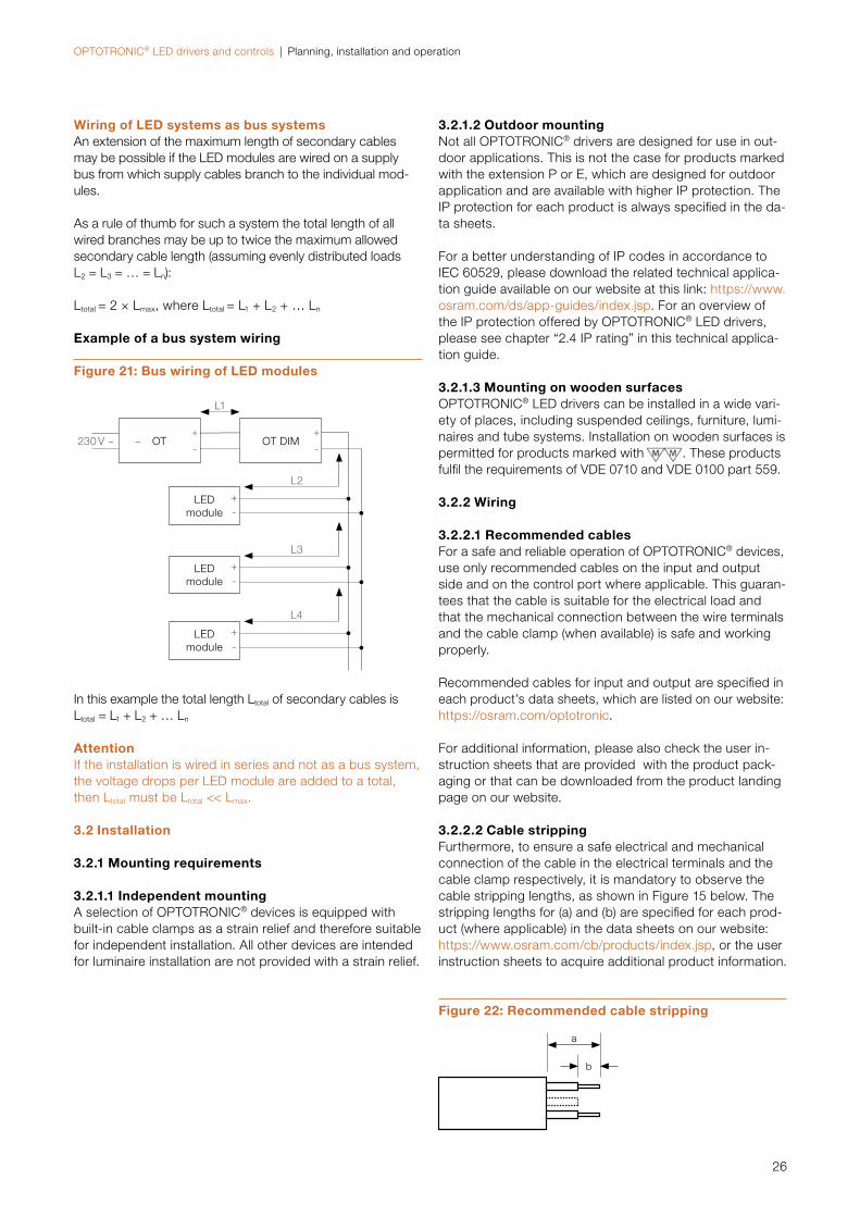
Wiring of LED systems as bus systemsAn extension of the maximum length of secondary cables may be possible if the LED modules are wired on a supply bus from which supply cables branch to the individual mod-ules.
As a rule of thumb for such a system the total length of all wired branches may be up to twice the maximum allowed secondary cable length (assuming evenly distributed loads L2 = L3 = … = Ln):
Ltotal = 2 × Lmax, where Ltotal = L1 + L2 + … Ln
Example of a bus system wiring
In this example the total length Ltotal of secondary cables isLtotal = L1 + L2 + … Ln
AttentionIf the installation is wired in series and not as a bus system, the voltage drops per LED module are added to a total, then Ltotal must be Ltotal << Lmax.
3.2 Installation
3.2.1 Mounting requirements
3.2.1.1 Independent mountingA selection of OPTOTRONIC® devices is equipped with built-in cable clamps as a strain relief and therefore suitable for independent installation. All other devices are intended for luminaire installation are not provided with a strain relief.
Figure 21: Bus wiring of LED modules
3.2.1.2 Outdoor mountingNot all OPTOTRONIC® drivers are designed for use in out-door applications. This is not the case for products marked with the extension P or E, which are designed for outdoor application and are available with higher IP protection. The IP protection for each product is always specifi ed in the da-ta sheets.
For a better understanding of IP codes in accordance to IEC 60529, please download the related technical applica-tion guide available on our website at this link: https://www.osram.com/ds/app-guides/index.jsp. For an overview of the IP protection offered by OPTOTRONIC® LED drivers, please see chapter “2.4 IP rating” in this technical applica-tion guide.
3.2.1.3 Mounting on wooden surfacesOPTOTRONIC® LED drivers can be installed in a wide vari-ety of places, including suspended ceilings, furniture, lumi-naires and tube systems. Installation on wooden surfaces is permitted for products marked with . These products fulfi l the requirements of VDE 0710 and VDE 0100 part 559.
3.2.2 Wiring
3.2.2.1 Recommended cablesFor a safe and reliable operation of OPTOTRONIC® devices, use only recommended cables on the input and output side and on the control port where applicable. This guaran-tees that the cable is suitable for the electrical load and that the mechanical connection between the wire terminals and the cable clamp (when available) is safe and working properly.
Recommended cables for input and output are specifi ed in each product’s data sheets, which are listed on our website:https://osram.com/optotronic.
For additional information, please also check the user in-struction sheets that are provided with the product pack-aging or that can be downloaded from the product landing page on our website.
3.2.2.2 Cable strippingFurthermore, to ensure a safe electrical and mechanical connection of the cable in the electrical terminals and the cable clamp respectively, it is mandatory to observe the cable stripping lengths, as shown in Figure 15 below. The stripping lengths for (a) and (b) are specifi ed for each prod-uct (where applicable) in the data sheets on our website: https://www.osram.com/cb/products/index.jsp, or the user instruction sheets to acquire additional product information.
OT OT DIM
LED module
+-
LED module
+-
LED module
+-
L2
L3
L4
L1
230 V ~ ~+ +
- -
Figure 22: Recommended cable stripping
a
b
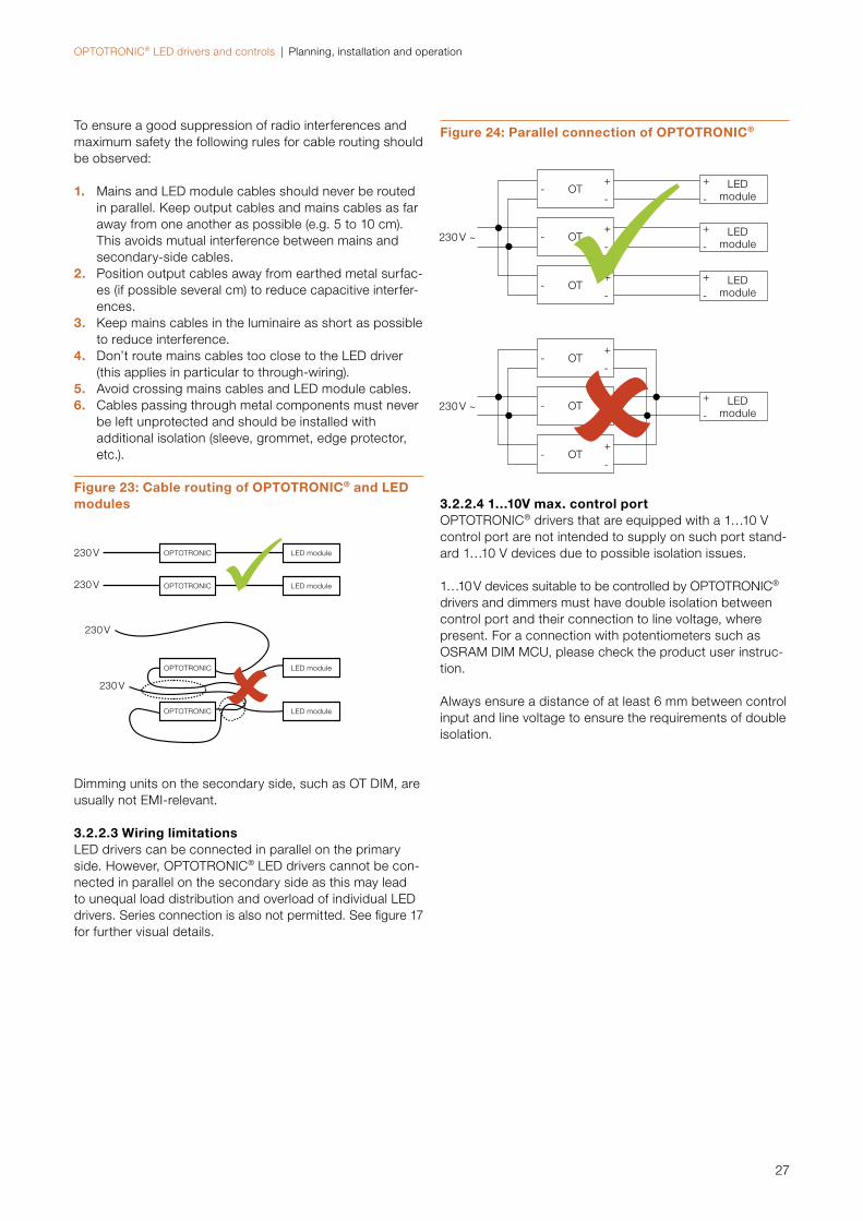
OPTOTRONIC® LED drivers and controls | Planning, installation and operation
27
To ensure a good suppression of radio interferences and maximum safety the following rules for cable routing should be observed:
1. Mains and LED module cables should never be routed in parallel. Keep output cables and mains cables as far away from one another as possible (e.g. 5 to 10 cm). This avoids mutual interference between mains and secondary-side cables.
2. Position output cables away from earthed metal surfac-es (if possible several cm) to reduce capacitive interfer-ences.
3. Keep mains cables in the luminaire as short as possible to reduce interference.
4. Don’t route mains cables too close to the LED driver (this applies in particular to through-wiring).
5. Avoid crossing mains cables and LED module cables.6. Cables passing through metal components must never
be left unprotected and should be installed with additional isolation (sleeve, grommet, edge protector, etc.).
Dimming units on the secondary side, such as OT DIM, are usually not EMI-relevant.
3.2.2.3 Wiring limitationsLED drivers can be connected in parallel on the primary side. However, OPTOTRONIC® LED drivers cannot be con-nected in parallel on the secondary side as this may lead to unequal load distribution and overload of individual LED drivers. Series connection is also not permitted. See figure 17 for further visual details.
3.2.2.4 1…10V max. control portOPTOTRONIC® drivers that are equipped with a 1…10 V control port are not intended to supply on such port stand-ard 1…10 V devices due to possible isolation issues.
1…10 V devices suitable to be controlled by OPTOTRONIC® drivers and dimmers must have double isolation between control port and their connection to line voltage, where present. For a connection with potentiometers such as OSRAM DIM MCU, please check the product user instruc-tion.
Always ensure a distance of at least 6 mm between control input and line voltage to ensure the requirements of double isolation.
Figure 23: Cable routing of OPTOTRONIC® and LED modules
OPTOTRONIC
OPTOTRONIC
LED module
LED module
230 V
230 V
230 V
230 V
OPTOTRONIC LED module
OPTOTRONIC LED module
Figure 24: Parallel connection of OPTOTRONIC®
230 V ~
OT--
+
OT--
+
OT--
+
LEDmodule-
+
230 V ~
OT--
+
OT--
+
OT--
+
LEDmodule-
+
LEDmodule-
+
LEDmodule-
+
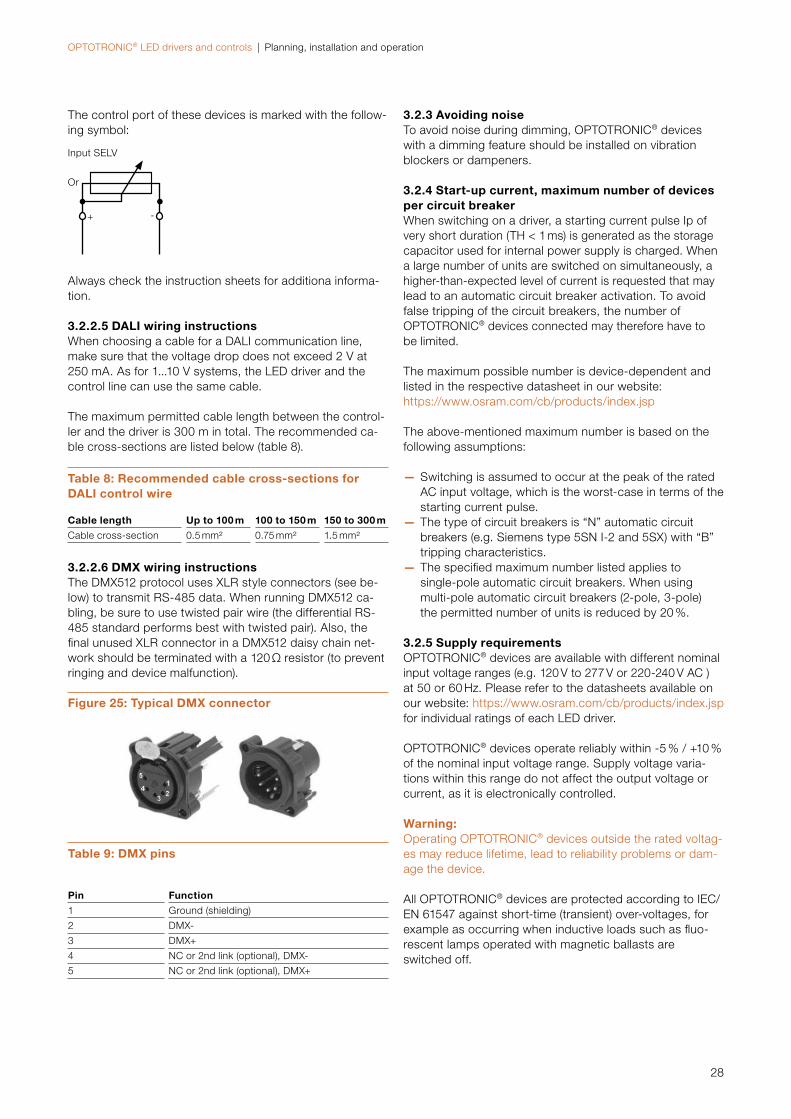
OPTOTRONIC® LED drivers and controls | Planning, installation and operation
28
Always check the instruction sheets for additiona informa-tion.
3.2.2.5 DALI wiring instructionsWhen choosing a cable for a DALI communication line, make sure that the voltage drop does not exceed 2 V at 250 mA. As for 1...10 V systems, the LED driver and the control line can use the same cable.
The maximum permitted cable length between the control-ler and the driver is 300 m in total. The recommended ca-ble cross-sections are listed below (table 8).
3.2.2.6 DMX wiring instructionsThe DMX512 protocol uses XLR style connectors (see be-low) to transmit RS-485 data. When running DMX512 ca-bling, be sure to use twisted pair wire (the differential RS-485 standard performs best with twisted pair). Also, the fi nal unused XLR connector in a DMX512 daisy chain net-work should be terminated with a 120 Ω resistor (to prevent ringing and device malfunction).
Table 8: Recommended cable cross-sections for DALI control wire
Cable length Up to 100 m 100 to 150 m 150 to 300 m
Cable cross-section 0.5 mm² 0.75 mm² 1.5 mm²
Figure 25: Typical DMX connector
Table 9: DMX pins
Pin Function
1 Ground (shielding)
2 DMX-
3 DMX+
4 NC or 2nd link (optional), DMX-
5 NC or 2nd link (optional), DMX+
3.2.3 Avoiding noiseTo avoid noise during dimming, OPTOTRONIC® devices with a dimming feature should be installed on vibration blockers or dampeners.
3.2.4 Start-up current, maximum number of devices per circuit breakerWhen switching on a driver, a starting current pulse Ip of very short duration (TH < 1 ms) is generated as the storage capacitor used for internal power supply is charged. When a large number of units are switched on simultaneously, a higher-than-expected level of current is requested that maylead to an automatic circuit breaker activation. To avoid false tripping of the circuit breakers, the number of OPTOTRONIC® devices connected may therefore have tobe limited.
The maximum possible number is device-dependent and listed in the respective datasheet in our website: https://www.osram.com/cb/products/index.jsp
The above-mentioned maximum number is based on the following assumptions:
— Switching is assumed to occur at the peak of the rated AC input voltage, which is the worst-case in terms of the starting current pulse.
— The type of circuit breakers is “N” automatic circuit breakers (e.g. Siemens type 5SN I-2 and 5SX) with “B” tripping characteristics.
— The specifi ed maximum number listed applies to single-pole automatic circuit breakers. When using multi-pole automatic circuit breakers (2-pole, 3-pole) the permitted number of units is reduced by 20 %.
3.2.5 Supply requirementsOPTOTRONIC® devices are available with different nominal input voltage ranges (e.g. 120 V to 277 V or 220-240 V AC )at 50 or 60 Hz. Please refer to the datasheets available on our website: https://www.osram.com/cb/products/index.jsp for individual ratings of each LED driver.
OPTOTRONIC® devices operate reliably within -5 % / +10 % of the nominal input voltage range. Supply voltage varia-tions within this range do not affect the output voltage or current, as it is electronically controlled.
Warning:Operating OPTOTRONIC® devices outside the rated voltag-es may reduce lifetime, lead to reliability problems or dam-age the device.
All OPTOTRONIC® devices are protected according to IEC/EN 61547 against short-time (transient) over-voltages, for example as occurring when inductive loads such as fl uo-rescent lamps operated with magnetic ballasts are switched off.
The control port of these devices is marked with the follow-ing symbol:
+ -
Or
Input SELV
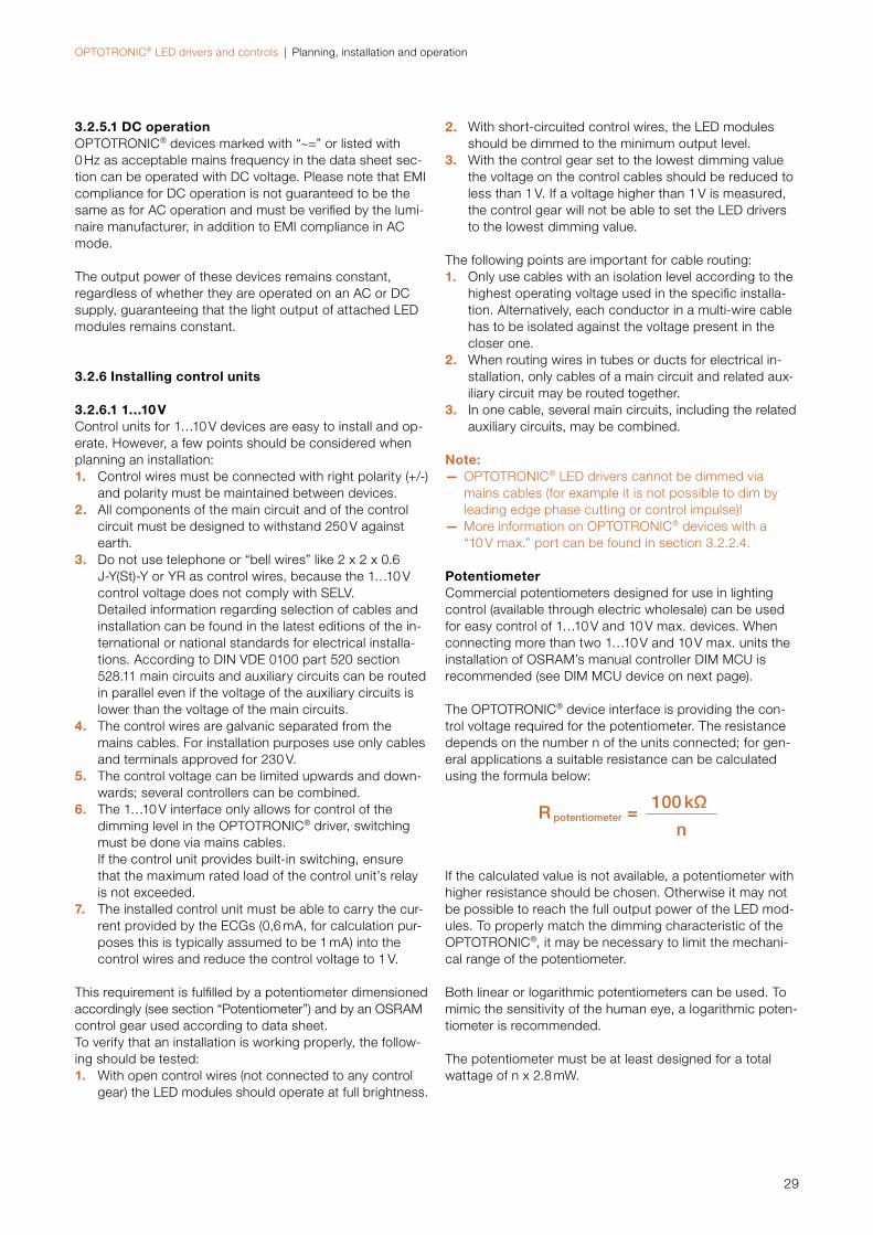
OPTOTRONIC® LED drivers and controls | Planning, installation and operation
29
3.2.5.1 DC operationOPTOTRONIC® devices marked with “~=” or listed with 0 Hz as acceptable mains frequency in the data sheet sec-tion can be operated with DC voltage. Please note that EMI compliance for DC operation is not guaranteed to be the same as for AC operation and must be verified by the lumi-naire manufacturer, in addition to EMI compliance in AC mode.
The output power of these devices remains constant, regardless of whether they are operated on an AC or DC supply, guaranteeing that the light output of attached LED modules remains constant.
3.2.6 Installing control units
3.2.6.1 1…10 VControl units for 1…10 V devices are easy to install and op-erate. However, a few points should be considered when planning an installation:1. Control wires must be connected with right polarity (+/-)
and polarity must be maintained between devices.2. All components of the main circuit and of the control
circuit must be designed to withstand 250 V against earth.
3. Do not use telephone or “bell wires” like 2 x 2 x 0.6 J-Y(St)-Y or YR as control wires, because the 1…10 V control voltage does not comply with SELV. Detailed information regarding selection of cables and installation can be found in the latest editions of the in-ternational or national standards for electrical installa-tions. According to DIN VDE 0100 part 520 section 528.11 main circuits and auxiliary circuits can be routed in parallel even if the voltage of the auxiliary circuits is lower than the voltage of the main circuits.
4. The control wires are galvanic separated from the mains cables. For installation purposes use only cables and terminals approved for 230 V.
5. The control voltage can be limited upwards and down-wards; several controllers can be combined.
6. The 1…10 V interface only allows for control of the dimming level in the OPTOTRONIC® driver, switching must be done via mains cables. If the control unit provides built-in switching, ensure that the maximum rated load of the control unit’s relay is not exceeded.
7. The installed control unit must be able to carry the cur-rent provided by the ECGs (0,6 mA, for calculation pur-poses this is typically assumed to be 1 mA) into the control wires and reduce the control voltage to 1 V.
This requirement is fulfilled by a potentiometer dimensionedaccordingly (see section “Potentiometer”) and by an OSRAM control gear used according to data sheet.To verify that an installation is working properly, the follow-ing should be tested:1. With open control wires (not connected to any control
gear) the LED modules should operate at full brightness.
2. With short-circuited control wires, the LED modules should be dimmed to the minimum output level.
3. With the control gear set to the lowest dimming value the voltage on the control cables should be reduced to less than 1 V. If a voltage higher than 1 V is measured, the control gear will not be able to set the LED drivers to the lowest dimming value.
The following points are important for cable routing:1. Only use cables with an isolation level according to the
highest operating voltage used in the specific installa-tion. Alternatively, each conductor in a multi-wire cable has to be isolated against the voltage present in the closer one.
2. When routing wires in tubes or ducts for electrical in-stallation, only cables of a main circuit and related aux-iliary circuit may be routed together.
3. In one cable, several main circuits, including the related auxiliary circuits, may be combined.
Note: — OPTOTRONIC® LED drivers cannot be dimmed via mains cables (for example it is not possible to dim by leading edge phase cutting or control impulse)!
— More information on OPTOTRONIC® devices with a “10 V max.” port can be found in section 3.2.2.4.
PotentiometerCommercial potentiometers designed for use in lighting control (available through electric wholesale) can be used for easy control of 1…10 V and 10 V max. devices. When connecting more than two 1…10 V and 10 V max. units the installation of OSRAM’s manual controller DIM MCU is recommended (see DIM MCU device on next page).
The OPTOTRONIC® device interface is providing the con-trol voltage required for the potentiometer. The resistance depends on the number n of the units connected; for gen-eral applications a suitable resistance can be calculated using the formula below:
R potentiometer =100 kΩ
n
If the calculated value is not available, a potentiometer with higher resistance should be chosen. Otherwise it may not be possible to reach the full output power of the LED mod-ules. To properly match the dimming characteristic of the OPTOTRONIC®, it may be necessary to limit the mechani-cal range of the potentiometer.
Both linear or logarithmic potentiometers can be used. To mimic the sensitivity of the human eye, a logarithmic poten-tiometer is recommended.
The potentiometer must be at least designed for a total wattage of n x 2.8 mW.
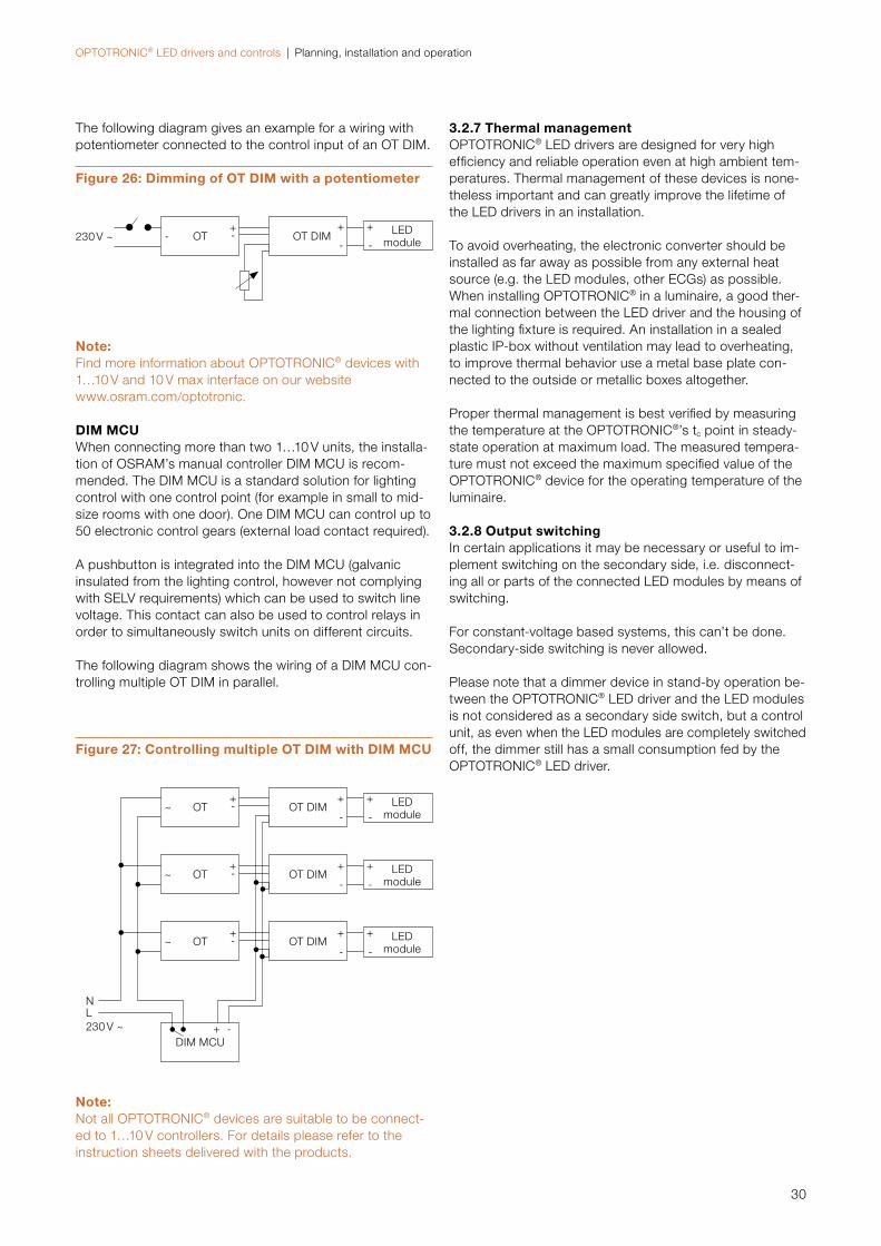
OPTOTRONIC® LED drivers and controls | Planning, installation and operation
30
Note:Find more information about OPTOTRONIC® devices with 1…10 V and 10 V max interface on our website www.osram.com/optotronic.
DIM MCUWhen connecting more than two 1…10 V units, the installa-tion of OSRAM’s manual controller DIM MCU is recom-mended. The DIM MCU is a standard solution for lighting control with one control point (for example in small to mid-size rooms with one door). One DIM MCU can control up to 50 electronic control gears (external load contact required).
A pushbutton is integrated into the DIM MCU (galvanicinsulated from the lighting control, however not complying with SELV requirements) which can be used to switch line voltage. This contact can also be used to control relays in order to simultaneously switch units on different circuits.
The following diagram shows the wiring of a DIM MCU con-trolling multiple OT DIM in parallel.
Note:Not all OPTOTRONIC® devices are suitable to be connect-ed to 1…10 V controllers. For details please refer to the instruction sheets delivered with the products.
3.2.7 Thermal managementOPTOTRONIC® LED drivers are designed for very highefficiency and reliable operation even at high ambient tem-peratures. Thermal management of these devices is none-theless important and can greatly improve the lifetime of the LED drivers in an installation.
To avoid overheating, the electronic converter should be installed as far away as possible from any external heat source (e.g. the LED modules, other ECGs) as possible. When installing OPTOTRONIC® in a luminaire, a good ther-mal connection between the LED driver and the housing of the lighting fixture is required. An installation in a sealed plastic IP-box without ventilation may lead to overheating, to improve thermal behavior use a metal base plate con-nected to the outside or metallic boxes altogether.
Proper thermal management is best verified by measuring the temperature at the OPTOTRONIC®’s tc point in steady-state operation at maximum load. The measured tempera-ture must not exceed the maximum specified value of the OPTOTRONIC® device for the operating temperature of the luminaire.
3.2.8 Output switchingIn certain applications it may be necessary or useful to im-plement switching on the secondary side, i.e. disconnect-ing all or parts of the connected LED modules by means of switching.
For constant-voltage based systems, this can’t be done. Secondary-side switching is never allowed.
Please note that a dimmer device in stand-by operation be-tween the OPTOTRONIC® LED driver and the LED modules is not considered as a secondary side switch, but a control unit, as even when the LED modules are completely switched off, the dimmer still has a small consumption fed by the OPTOTRONIC® LED driver.
Figure 27: Controlling multiple OT DIM with DIM MCU
OT DIM
OT DIM
OT DIM
-
-
-
+
+
+
OT
OT
OT
DIM MCU
~
~
~
-
-
-
-
+
+
+
+
LEDmodule
LEDmodule
LEDmodule
-
-
-
+
+
+
NL230 V ~
The following diagram gives an example for a wiring with potentiometer connected to the control input of an OT DIM.
Figure 26: Dimming of OT DIM with a potentiometer
230 V ~ OT- -+
OT DIM-
+ LEDmodule-
+
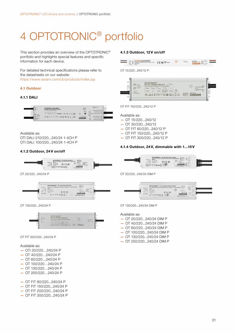
OPTOTRONIC® LED drivers and controls | OPTOTRONIC portfolio
31
4 OPTOTRONIC® portfolioThis section provides an overview of the OPTOTRONIC® portfolio and highlights special features and specific information for each device.
For detailed technical specifications please refer to the data sheets on our website: https://www.osram.com/cb/products/index.jsp
4.1 Outdoor
4.1.1 DALI
Available as:OTi DALI 210/220...240/24 1-4CH POTi DALI 100/220...240/24 1-4CH P
4.1.2 Outdoor, 24 V on/off
OT 20/220...240/24 P
OT 130/220...240/24 P
OT FIT 300/220...240/24 P
Available as: — OTi 20/220…240/24 P — OT 40/220…240/24 P — OT 60/220…240/24 P — OT 100/220…240/24 P — OT 130/220…240/24 P — OT 250/220…240/24 P
— OT FIT 80/220...240/24 P — OT FIT 150/220...240/24 P — OT FIT 200/220...240/24 P — OT FIT 300/220...240/24 P
4.1.3 Outdoor, 12 V on/off
OT 15/220...240/12 P
OT FIT 150/220...240/12 P
Available as: — OT 15/220...240/12 — OT 30/220...240/12 — OT FIT 60/220...240/12 P — OT FIT 150/220...240/12 P — OT FIT 300/220...240/12 P
4.1.4 Outdoor, 24 V, dimmable with 1…10 V
OT 20/220...240/24 DIM P
OT 130/220...240/24 DIM P
Available as: — OT 20/220...240/24 DIM P — OT 40/220...240/24 DIM P — OT 60/220...240/24 DIM P — OT 100/220...240/24 DIM P — OT 130/220...240/24 DIM P — OT 250/220...240/24 DIM P
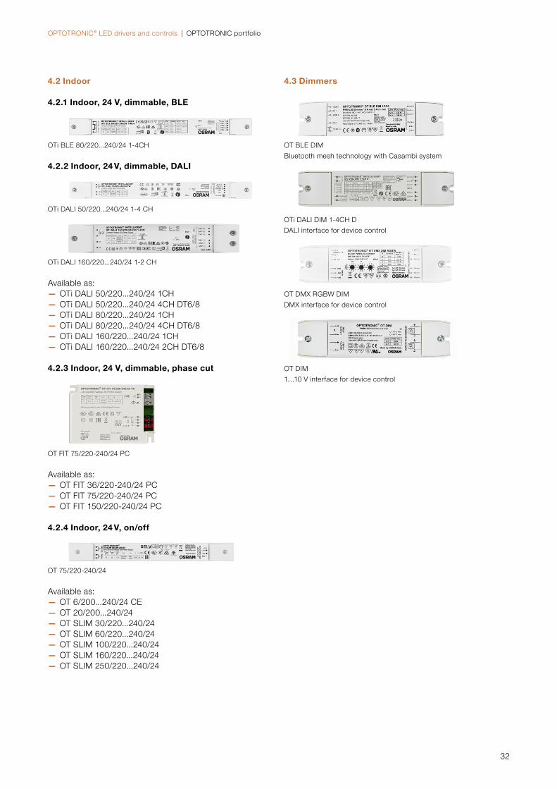
OPTOTRONIC® LED drivers and controls | OPTOTRONIC portfolio
32
4.3 Dimmers
OT BLE DIM
Bluetooth mesh technology with Casambi system
OTi DALI DIM 1-4CH D
DALI interface for device control
OT DMX RGBW DIM
DMX interface for device control
OT DIM
1…10 V interface for device control
4.2 Indoor
4.2.1 Indoor, 24 V, dimmable, BLE
OTi BLE 80/220...240/24 1-4CH
4.2.2 Indoor, 24 V, dimmable, DALI
OTi DALI 50/220...240/24 1-4 CH
OTi DALI 160/220...240/24 1-2 CH
Available as:— OTi DALI 50/220...240/24 1CH— OTi DALI 50/220...240/24 4CH DT6/8— OTi DALI 80/220...240/24 1CH— OTi DALI 80/220...240/24 4CH DT6/8— OTi DALI 160/220...240/24 1CH— OTi DALI 160/220...240/24 2CH DT6/8
4.2.3 Indoor, 24 V, dimmable, phase cut
OT FIT 75/220-240/24 PC
Available as:— OT FIT 36/220-240/24 PC— OT FIT 75/220-240/24 PC— OT FIT 150/220-240/24 PC
4.2.4 Indoor, 24 V, on/off
OT 75/220-240/24
Available as:— OT 6/200...240/24 CE— OT 20/200...240/24 — OT SLIM 30/220...240/24— OT SLIM 60/220...240/24— OT SLIM 100/220...240/24— OT SLIM 160/220...240/24— OT SLIM 250/220...240/24
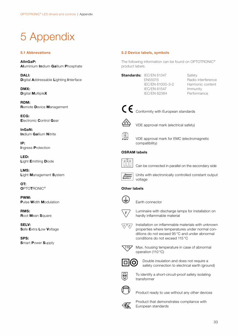
OPTOTRONIC® LED drivers and controls | Appendix
33
5 Appendix5.1 Abbrevations
AlInGaP:Aluminium Indium Gallium Phosphate
DALI:Digital Addressable Lighting Interface
DMX:Digital MultipleX
RDM:Remote Device Management
ECG:Electronic Control Gear
InGaN:Indium Gallium Nitrite
IP:Ingress Protection
LED:Light Emitting Diode
LMS:Light Management System
OT:OPTOTRONIC®
PWM:Pulse Width Modulation
RMS:Root Mean Square
SELV:Safe Extra Low Voltage
SPS:Smart Power Supply
5.2 Device labels, symbols
The following information can be found on OPTOTRONIC®
product labels.
Standards: IEC/EN 61347 SafetyEN55015 Radio interferenceIEC/EN 61000-3-2 Harmonic contentIEC/EN 61547 ImmunityIEC/EN 62384 Performance
E Conformity with European standards
M VDE approval mark (electrical safety)
N VDE approval mark for EMC (electromagnetic compatibility)
OSRAM labels
Can be connected in parallel on the secondary side
SUPPLY
SMART POWER Units with electronically controlled constant output
voltage
Other labels
q Earth connector
R Luminaire with discharge lamps for installation on
hardly infl ammable material
S Installation on infl ammable materials with unknown
properties where temperatures under normal con-ditions do not exceed 95 °C and under abnormal conditions do not exceed 115 °C
L Max. housing temperature in case of abnormal operation (110 °C)
Double insulation and does not require a safety connection to electrical earth (ground)
To identify a short-circuit-proof safety isolating transformer
Product ready to use without any other devices
Product that demonstrates compliance with European standards
OPTOTRONIC® LED drivers and controls | Appendix
34
Product that demonstrates compliance with United Kingdom standards
Products that conform to all technical regulations of the Eurasian Customs Union
Product that demonstrates compliance with Chinese standards
Product that demonstrates compliance with Indian standards
Product that demonstrates compliance with Australian standards
It works with DALI 2 system
Dimmable with just a button
Dimming and changing CCT on TW applications with two buttons
Dimmable from 0.1 % to 100 %
Suitable for applications on wooden surfaces
Lambda λ Power factor
ta Ambient temperature in °C
tc Case temperature in °C
Touch DIM
2 channels

OSRAM GmbH Headquarters GermanyPhone: +49 89 6213-0E-mail: [email protected]
OSRAM a.s Office AustriaPhone: +43 1 250 24 E-mail: [email protected]
OSRAM Benelux B.V.NetherlandsPhone: +31 (0) 88 750 8800E-mail: [email protected]: +32 (0) 2 588 49 51E-mail: [email protected]
OSRAM Sales EOOD Bulgaria Phone: +359 32 348 110E-mail: [email protected]
OSRAM d.o.o. CroatiaPhone: +385 1 3032-023E-mail: [email protected]
OSRAM Ceska republika s.r.o. Czech Republic Phone: +42 0 554 793 111E-mail: [email protected]
OSRAM A/S Denmark Phone: +45 43 30 20 40
OSRAM Oy Finland Phone: +358 9 8493 2200E-mail: [email protected]
Baltic DS/OSRAM Oy Finland:Estonia, Latvia and LithuaniaPhone: +358 9 8493 2200E-mail: [email protected]
OSRAM Lighting Middle East FZEDubai – United Arab EmiratesPhone: +971 4 523 1777E-mail: [email protected]
OSRAM Lighting SASU FrancePhone: +33 3 68 41 89 33E-mail: [email protected]
OSRAM Limited Great Britain Phone: +44 1925 273 360E-mail: [email protected]
OSRAM a.s. Magyarországi Fióktelepe HungaryPhone: +36 1 225 30 55 E-mail: [email protected]
OSRAM SpA Società Riunite OSRAM Edison Clerici Italy Phone: +39 02 424 91E-mail: [email protected]
OSRAM Lighting AS NorwayPhone: +47 40 00 40 14
OSRAM North Africa S.a.r.l.E-mail: [email protected]
OSRAM (Pty.) Ltd. South AfricaPhone: +27 10 221 40 00
OSRAM Sp. z.o.o. PolandPhone: +48 22 376 57 00E-mail: [email protected]
OSRAM LDAPortugal, Açores, Madeira Phone: +351 21 033 22 10E-mail: [email protected]
OSRAM OOO Russia DS Phone: +7 (499) 649-7070E-mail: [email protected]
OSRAM Romania S.R.L.Phone: +40 (21) 232 85 61 E-mail: [email protected]
OSRAM, a.s. Slovak RepublicPhone: +421 35 64 64 473 E-mail: [email protected]
OSRAM a.s. SloveniaPhone: +43 1 250 24 E-mail: [email protected]
OSRAM Lighting S.L. Spain Phone: +34 91 491 52 17 E-mail: [email protected]
OSRAM AB SwedenPhone: +46 128 70 400E-mail: [email protected]
OSRAM Lighting AG Switzerland Phone: +41 52 555 25 55E-mail: [email protected]
OSRAM Teknolojileri Ticaret A.S. Turkey Phone: +90 212 703 43 00 E-mail: [email protected]
OSRAM Sales Greece Phone: +30 21 309 940 36E-mail: [email protected]
OS
RA
M D
S S
MK
12/
21 S
ubje
ct t
o c
hang
e w
itho
ut n
otic
e. E
rro
rs a
nd o
mis
sio
ns e
xcep
ted
.
OSRAM GmbH
Headquarters Germany:
Marcel-Breuer-Strasse 6
80807 Munich, Germany
Phone +49 89 6213-0
Fax +49 89 6213-2020
www.osram.com
www.osram.com/ds