
Technical data sheet powerIO®-Box T1.B100
12
Technical data sheet powerIO ® -Box T1.B100 www.powerio.com powerIO-Box T1.B100• EN-1.3 • Subject to change without notice 1 Automation box for HVAC (heating/ventilation/air conditioning) and Single room control applications • Power and data over one cable, with 230V voltage outputs • Connection manufacturer-independent Sensors/Actors via RS485 (Modbus RTU) • Automatic or manual conversion to Modbus TCP signals, manufacturer-independent control selection (PLC/BMS) • M12 5-pin pluggable connections, with 24V power supply and bus • Slot for other bus protocols • Bluetooth connection for app configuration • Optional with CODESYS ® PLC control application Savings on cable pull up to 80% Power and communication in one cable Modular, flexible and fast in installation and communication Increase of the information content by up to 95% Technical data General data Name/Type powerIO ® -Box T1.B100 Item number 100101 Color Black Electrical data Nominal voltage AC 230V Nominal voltage frequency 50/60 Hz Power consumption during operation 20 W Power consumption sleep mode 10 W Power consumption dimensioning 50 VA Connection power supply / control powerIO®-Line cable Power 3 x 4.00 mm² Data 2 x (2 x 0.34 mm²) Output voltage, 24V power supply 24V DC, max. 1,9A Output voltage tolerance ± 2,5 % Short circuit behaviour Functional data Control communicative TCP Modbus TCP Control communicative Port 1 to 4 Modbus RTU CPU and memory Processor ARM Cortex A53 core, 1,2 GHz RAM memory 1 Gbyte Flash memory 4Gbyte eMMC UPS function buffer time for 5V power supply Up to 30s, safe shut down Components with UPS function CPU, Ethernetchip Security Protection class IEC/EN IP 64 EMC CE according to 2014/30/EU Ambient temperature -30...50°C Storage temperature -40...70°C Ambient Humidity Max. 95% r.h., non-condensing Maintenance Maintenance-free Dimensions 255 x 266 x 64 mm (W x H x D) Weight 1360 g
-
Upload
khangminh22 -
Category
Documents
-
view
0 -
download
0
Transcript of Technical data sheet powerIO®-Box T1.B100

Technical data sheet powerIO®-Box T1.B100
www.powerio.com powerIO-Box T1.B100• EN-1.3 •
Subject to change without notice 1
Automation box for
HVAC (heating/ventilation/air conditioning) and
Single room control applications
• Power and data over one cable,
with 230V voltage outputs
• Connection manufacturer-independent
Sensors/Actors via
RS485 (Modbus RTU)
• Automatic or manual
conversion to Modbus TCP signals,
manufacturer-independent control selection
(PLC/BMS)
• M12 5-pin pluggable connections,
with 24V power supply and bus
• Slot for other bus protocols
• Bluetooth connection for app configuration
• Optional with CODESYS® PLC control application
Savings on cable pull up to 80%
Power and communication
in one cable
Modular, flexible and fast in installation and communication
Increase of the information content
by up to 95%
Technical data
General data Name/Type powerIO®-Box T1.B100
Item number 100101
Color Black
Electrical data Nominal voltage AC 230V
Nominal voltage frequency 50/60 Hz
Power consumption during operation 20 W
Power consumption sleep mode 10 W
Power consumption dimensioning 50 VA
Connection power supply / control powerIO®-Line cable Power 3 x 4.00 mm² Data 2 x (2 x 0.34 mm²)
Output voltage, 24V power supply 24V DC, max. 1,9A
Output voltage tolerance ± 2,5 %
Short circuit behaviour
Functional data Control communicative TCP Modbus TCP
Control communicative Port 1 to 4 Modbus RTU
CPU and memory Processor ARM Cortex A53 core, 1,2 GHz
RAM memory 1 Gbyte
Flash memory 4Gbyte eMMC
UPS function buffer time for 5V power supply Up to 30s, safe shut down
Components with UPS function CPU, Ethernetchip
Security Protection class IEC/EN IP 64
EMC CE according to 2014/30/EU
Ambient temperature -30...50°C
Storage temperature -40...70°C
Ambient Humidity Max. 95% r.h., non-condensing
Maintenance Maintenance-free
Dimensions 255 x 266 x 64 mm (W x H x D)
Weight 1360 g
Technical data sheet powerIO®-Box T1.B100
www.powerio.com powerIO-Box T1.B100• EN-1.3 •
Subject to change without notice 2
Safety Instructions
• It is forbidden to install the powerIO® box in the immediate vicinity of fre-quency converters. Frequency converters must be wired with all protective measures to ensure that the required regulations and guidelines are obser-ved (e.g. line filters etc.).
• The supply voltage must correspond to the specifications in the documenta-tion
• The connection terminals inside the device may only be wired by authorized and instructed personnel.
• Do not carry out any wiring work under voltage. There is a risk of electric shock as some terminals may carry 230/400 V. The installation must be car-ried out by authorized personnel. The legal and official regulations must be observed.
• Avoid connecting and disconnecting plug connections (under voltage). This could destroy the devices!
• Make sure that no objects, e.g. screws, screen remnants, sleeves or other fastening material get into the device.
• This device is designed for use in stationary heating, ventilation and air con-ditioning systems. It is forbidden to use the device for applications outside the specified field of application, especially not in airplanes or any other me-ans of transportation in the air.
• Avoid installation in places with extreme and rapid temperature changes. Please note that an outdoor application is only possible if no water, snow, ice, sunlight or aggressive gases directly affect the box and if it is guaran-teed that the environmental conditions are always within the limits of the data sheet.
Product features
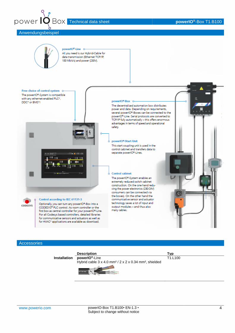
System description The powerIO® system combines power and data in only one cable and enables a
decentralized design! Reduction of the building automation costs and cable pulling costs, reduction of the fire load in the building, reduction of the construction time, fe-wer planning interfaces and many more possibilities with high-quality information of the individual devices are only a few advantages of the powerIO®-System.
Installation The powerIO®-Boxes are mounted decentrally in the immediate vicinity of the sensor
and actuators. For example in heating circuits, directly at the ventilation unit or in rooms for individual room control. The powerIO®-Line then connects the boxes with each other. Power and communication are transmitted via the powerIO®-Line.
Connections from inside (remove cover)
Power supply 230 V: 3 x 4.0 mm², incoming and outgoing. Ethernet: 2 x 2 x 0.34 mm², incoming and outgoing. 230V outlets: 2 x 230 V (3 x 1.5 mm²) fused with up to 6 A per outlet for external 230 V consumers.
Connections from outside Cable gland incoming and outgoing for powerIO®-Line: M25 2 x cable gland for 230V consumers: M20 Port 1-4: Up to 2 RS485 Modbus RTU devices per port can be connected via the 4 x M12 5-pin A-coded connectors. At the same time they are supplied with 24V DC vol-tage. Pin assignment can be seen under "Electrical Installation".
Technical data sheet powerIO®-Box T1.B100
www.powerio.com powerIO-Box T1.B100• EN-1.3 •
Subject to change without notice 3
Port 5: This can be extended via pluggable additional boards. Further protocols can be connected via this port and classic digital and analog inputs and outputs can be connected. Port 6: M12 4-pin A-coded. Here the powerIO®-Bluetooth Dongle can be connected to the powerIO®-Box for configuration. This enables the commissioning of sensors and actuators via the powerIO®-App.
Communication Each powerIO®-Box is assigned an individual IP address using the powerIO® App/Web interface or DIP switches. Each connected Modbus RTU sensor/actuator transmits its data and is converted by the powerIO®-Box to Modbus TCP protocol. This means that any PLC/DDC/GLT controller that has implemented the Modbus TCP protocol can be used to control the sensors and actuators. Additional Modbus registers of the powerIO® box (status, 24V current measurement ...) can be called up. These Modbus registers are documented in the additional docu-mentation. The serial slave address corresponds to the NodeID in the Modbus TCP query! Never assign the same slave address to each powerIO®-Box! Otherwise there will be conflicts in the TCP query. Furthermore the NodeID addresses 240 to 247 are reserved for the powerIO®-Box and are not allowed to be assigned serially.
Configuration With the help of the powerIO®-App and the powerIO®-Bluetooth Dongle the follo-wing settings can be made on the powerIO®-Box:
• IP settings, Box Name
• Baud rate, communication parameters per RS485 COM port
• Testing the Modbus devices of common manufacturers through many de-vice templates, which can also be created by yourself
In addition, the web interface of the powerIO®-Box can be called up via the IP address. The same settings as in the powerIO®-App are available via the web inter-face. Additionally firmware updates can be installed. The default IP address at delivery is: DHCP Call of the web interface: for example http://192.168.60.250/ Default logins for the web interface: User: powerio Password: powerioT1
Technical data sheet powerIO®-Box T1.B100
www.powerio.com powerIO-Box T1.B100• EN-1.3 •
Subject to change without notice 4
Anwendungsbeispiel
Accessories
Description Typ
Installation powerIO®-Line Hybrid cable 3 x 4.0 mm² / 2 x 2 x 0.34 mm², shielded
T1.L100
Technical data sheet powerIO®-Box T1.B100
www.powerio.com powerIO-Box T1.B100• EN-1.3 •
Subject to change without notice 5
powerIO® installation plate Aluminum Wall Mount
T1.Z119
M12 connection accessories
T1.ZXXX
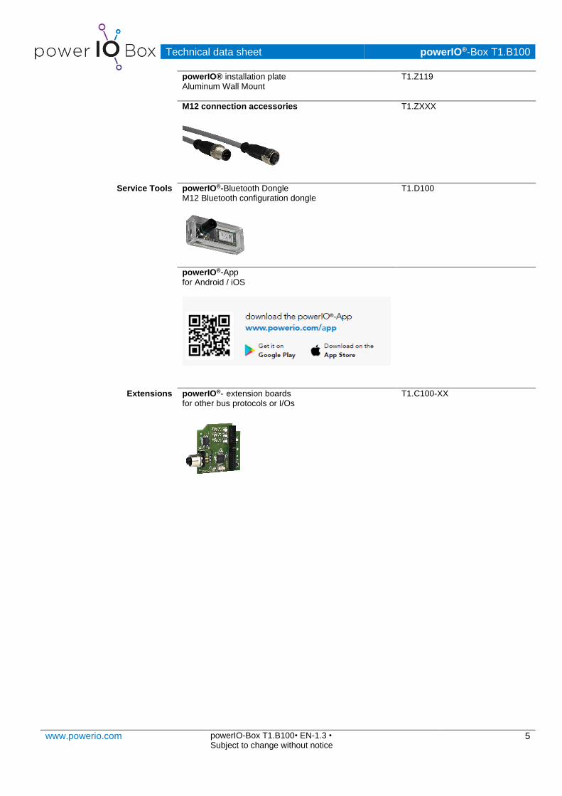
Service Tools powerIO®-Bluetooth Dongle M12 Bluetooth configuration dongle
T1.D100
powerIO®-App for Android / iOS
Extensions powerIO®- extension boards for other bus protocols or I/Os
T1.C100-XX

Technical data sheet powerIO®-Box T1.B100
www.powerio.com powerIO-Box T1.B100• EN-1.3 •
Subject to change without notice 6
Electrical Installation
Notes
• The relevant RS485 guidelines must be followed when wiring the lines for BACnet MS/TP / Modbus RTU.
• Power supply and communication of BACnet / Modbus are not galvanically isolated. Connect the ground signals of the devices with each other.
Connection diagram upper area - Inside: Performance and communication
Cable colors Ethernet: 1 = WH (white) 2 = YE (yellow) 3 = WH (white) 4 = GN (green)
Cable color performance: L = BR (brown) N = BL (blue) PE = GN/YE (green/yellow)
Technical data sheet powerIO®-Box T1.B100
www.powerio.com powerIO-Box T1.B100• EN-1.3 •
Subject to change without notice 7
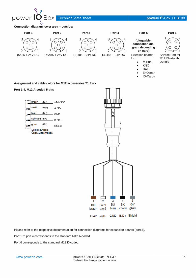
Connection diagram lower area – outside:
Port 1 Port 2 Port 3 Port 4 Port 5 Port 6
(pluggable,
connection dia-gram depending
on card) RS485 + 24V DC RS485 + 24V DC RS485 + 24V DC RS485 + 24V DC Extention boards
for:
• M-Bus
• KNX
• DALI
• EnOcean
• IO-Cards
Service Port for M12 Bluetooth Dongle
Assignment and cable colors for M12 accessories T1.Zxxx
Port 1-4, M12 A-coded 5-pin:
Please refer to the respective documentation for connection diagrams for expansion boards (port 5).
Port 1 to port 4 corresponds to the standard M12 A-coded.
Port 6 corresponds to the standard M12 D-coded.
+24V DC
A / D-
GND
B / D+
Shield
(BN)
(WH)
(BU)
(BK)
(GY)
Technical data sheet powerIO®-Box T1.B100
www.powerio.com powerIO-Box T1.B100• EN-1.3 •
Subject to change without notice 8
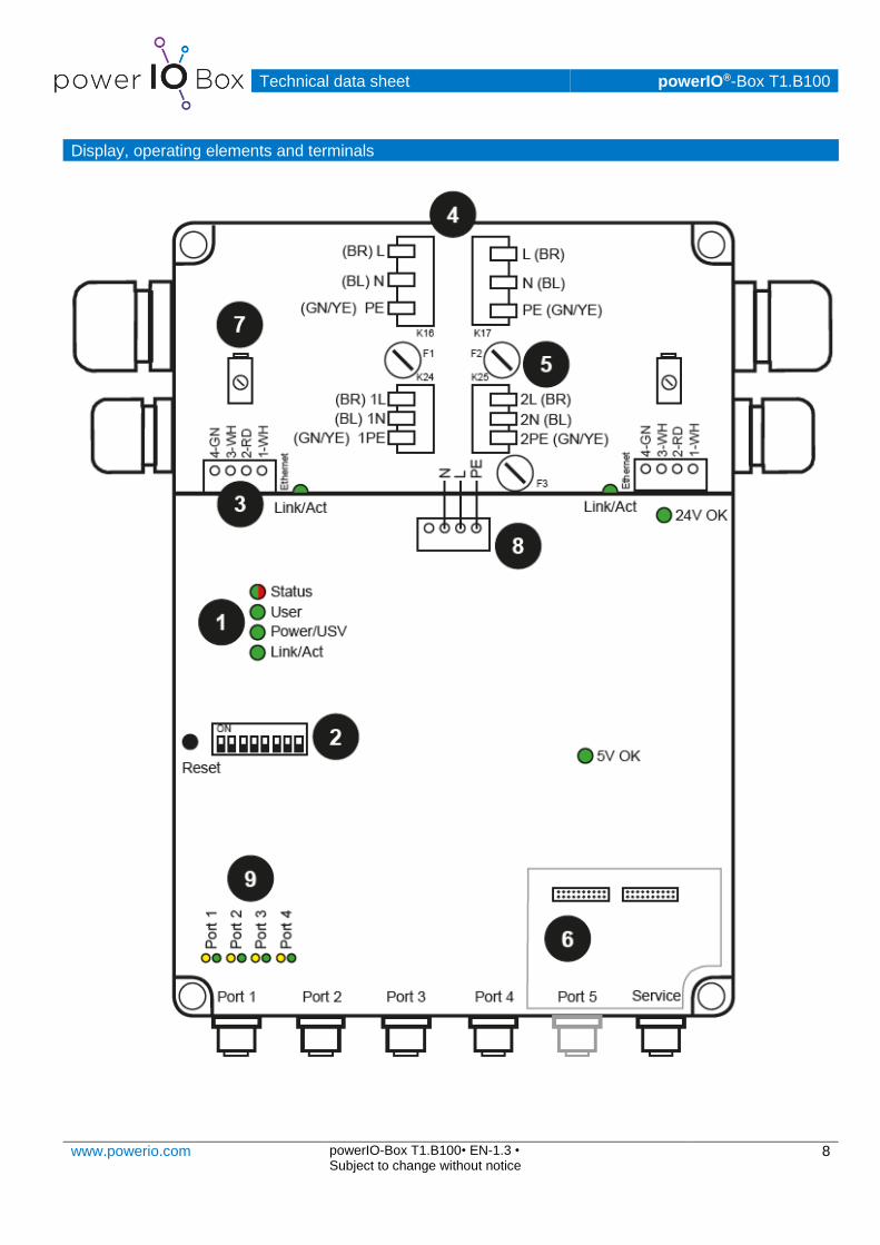
Display, operating elements and terminals

Technical data sheet powerIO®-Box T1.B100
www.powerio.com powerIO-Box T1.B100• EN-1.3 •
Subject to change without notice 9
Display, operating elements and terminals
Status LEDs
Status flashing green: everything ok permanent red: collective fault
User green: free use Power/USV permanent green: voltage ok
flashes green: UPS charging/discharging Ethernet permanent green: Link
flashes green: Communication (Act)
24V OK permanent green: 24V voltage ok off: no 24V voltage available
5V OK permanent green: 5V voltage OK off: no 5V voltage available
DIP IP addressing
All ON: IP address set to DHCP. (default)
All OFF: IP address set to configuration via App/Web
Manual IP address of the last IP location:192.168.60.1 (DIP1 ON) …
192.168.60.3 (DIP1 & 3 ON) …
192.168.60.254 (DIP2-8 ON) max address
Video: https://youtu.be/M9WfinYbEY8
Pluggable terminal block
Ethernet Connection of the 4 wires of the powerIO®-Line for Ethernet TCP/IP communication (2x, right/left, coming/going). Conductors do not have to be stripped, insulation displacement connector. The two connectors can also be plugged into each other, thus bridging a powerIO®-Box. Adapter necessary.
LED green = Link flashes green: Communication (act)
Fixed connection terminal K16/K17
Performance Connection of the 3 x 4.0 mm² power wires of the powerIO®-Line (2x, coming/going).
Outlet 230V AC consumer with fuse
Terminal K24/25
Connection of 230V consumers (2x, outlet left/right) maximum cross-section 2.5 mm²
Backup F1/2
2x 230V, up to 6A fuse for voltage outputs. Fuse left/right for outgoing left/right. Delivery with 2A fuse.
Optional extension
Slot Optional slot for powerIO®-Expansion boards. Touch protection and M12 provision must be broken out. Observe the documentation of the respective board!

Technical data sheet powerIO®-Box T1.B100
www.powerio.com powerIO-Box T1.B100• EN-1.3 •
Subject to change without notice 10
Shield clamp
left/right The two separately shielded wire pairs of the powerIO® line are placed underneath and slightly tightened. Enables fast and efficient shielding of the data line. Put the shield back on the coat and tighten it slightly with the shield clamp.
Pluggable terminal block
Communica-tion board
This terminal supplies the communication board as well as the 24V and 5V power supply unit with 230V. The communication board can be disconnected for VDE measurements..
Port 1 to 4 communication - 2 LEDs per separate COM port
LED orange flashes: TX - Data is sent serially on this port
LED green flashes: RX - Data is received serially on this port.

Technical data sheet powerIO®-Box T1.B100
www.powerio.com powerIO-Box T1.B100• EN-1.3 •
Subject to change without notice 11
Dimensions [mm]
View from above
View from the side
Technical data sheet powerIO®-Box T1.B100
www.powerio.com powerIO-Box T1.B100• EN-1.3 •
Subject to change without notice 12
Further documentation
download area Software updates, further documentation: https://www.powerio.com/de/produkte/t1.b100-powerio-box
Youtube Video Channel Videos on installation, commissioning: https://www.youtube.com/channel/UCe-ukckqz3BeRexIvQPK-qg
Further notes
The device contains electrical and electronic components and must not be disposed of as household waste. The local and
currently valid legislation must be observed.
Copyright
Copyright ® 2020 powerIO® GmbH. All rights reserved. No part of this manual may be reproduced, transmitted, transcribed, stored
in a retrieval system, or translated into any language or computer language without the express written permission of the author.
This applies to any form and any means, whether electronic, mechanical, magnetic, optical, manual or any other way.
Modbus is a registered trademark of Schneider Electric, licensed to the Modbus Organization
Raspberry Pi is a trademark of the Raspberry Pi Foundation
ARM is registered trademark and ARM Limited Linux is a registered trademark of Linus Torvalds
All other brand names or product names are the property of their respective holders
Support
powerIO GmbH
Building Automation
Eberhardstraße 65
70173 Stuttgart
Tel +49 (0)711 99887200
E-Mail: [email protected]
www.powerio.com