TECHNICAL MANUAL - Mowers at Jacks
50
TECHNICAL MANUAL MAN 4157301 Rev. A 10-2008 MODEL: 544873B MATAWAY OVERSEEDER
-
Upload
khangminh22 -
Category
Documents
-
view
3 -
download
0
Transcript of TECHNICAL MANUAL - Mowers at Jacks

TEC
HN
ICA
L M
AN
UA
L
MA
N 4
1573
01R
ev. A
10-
2008
MODEL:544873B
MATAWAY OVERSEEDER

CALIFORNIAProposition 65 Warning
Diesel engine exhaust and some of its constituents are known to the State of California to cause cancer, birth defects and other reproductive harm.
Californie Proposition 65 Avertissement
Les échappements des moteurs diesel et certains de leurs composés sont reconnus par l’Etat de Californie pour être cancérigènes, provoquer des défauts congénitaux et d’autres dangers en matière de reproduction.
AdvertenCiA
Avertissement
WARNINGThe engine exhaust from this product contains chemicals known to the State of California to cause cancer, birth defects or other reproductive harm.
California Advertencia
de la Proposicion 65
El estado de California hace saber que los gases de escape de los motores diesel y algunos de sus componentes producen cáncer, defectos de nacimiento y otros daños en el proceso de reproducción humana.
L’émission du moteur de ce matériel con-tient des produits chimiques que l’Etat de Californie considère être cancérigènes, provoquer des défauts congénitaux et d’autres dangers en matière de reproduc-tion.
El estado de California hace saber que los gases de escape de este producto contienen productos quÍmicos que producen cáncer, defectos de nacimiento y otros daños en el proceso de reproducción humana.
CALIFORNIAProposition 65 Warning
Battery posts, terminals, wiring insulation, and related accessories contain lead and lead compounds, chemicals known to the State of California to cause cancer and birth defects or other reproductive harm. WASH HANDS AFTER HANDLING.

1
MATAWAYOVERSEEDER
10-2008
IMPORTANT MESSAGEThank you for purchasing this Ryan product. You have purchased a world class product, one of the best de-signed and built anywhere.
This machine comes with a Technical Manual containing safety, operation, parts, maintenance and service information. The useful life and good service you receive from this machine depends to a large extent on how well you read and understand this manual. Treat your machine properly, lubricate and adjust it as instructed, and it will give you many years of reliable service.
Your safe use of this Ryan product is one of our prime design objectives. Many safety features are built in, but we also rely on your good sense and care to achieve accident-free operation. For best protection, study the manual thoroughly. Learn the proper operation of all controls. Observe all safety precautions. Follow all instruc-tions and warnings completely. Do not remove or defeat any safety features. Make sure those who operate this machine are as well informed and careful in its use as you are.
See a Ryan dealer for any service or parts needed. Ryan service ensures that you continue to receive the best results possible from Ryan’s products. You can trust Ryan replacement parts because they are manufactured with the same high precision and quality as the original parts.
Ryan designs and builds its equipment to serve many years in a safe and productive manner. For longest life, use this machine only as directed in the manual, keep it in good repair and follow safety warnings and instruc-tions. You'll always be glad you did.
Schiller Grounds Care, Inc.One Bob Cat Lane
Johnson Creek, WI 53038-0469
TABLE OF CONTENTS ..................................................................... FIGURES PAGE
SAFETY ............................................................................................................................................................2SAFETY AND OPERATION DECALS ..............................................................................................................3SET-UP .............................................................................................................................................................4CONTROLS ......................................................................................................................................................5OPERATION ..................................................................................................................................................6-9SERVICE ...................................................................................................................................................10-23STORAGE ......................................................................................................................................................24TRANSPORTING ...........................................................................................................................................25SPECIFICATIONS ..........................................................................................................................................26PARTS SECTION ...........................................................................................................................................27CHASSIS FIGURE 1 ................................................................................................................................. 28, 29HANDLE ASSEMBLY FIGURE 2 .............................................................................................................. 30, 31CLUTCH ASSEMBLY AND CONTROL FIGURE 3 ..................................................................................... 32, 33ENGINE AND DRIVE ASSEMBLY FIGURE 4 ............................................................................................ 34, 35TRANSMISSION FIGURE 5 ....................................................................................................................... 36, 37GUARDS FIGURE 6 ................................................................................................................................... 38, 39HOPPER DRIVE FIGURE 7 ....................................................................................................................... 40, 41HOPPER FRAME FIGURE 8 ..................................................................................................................... 42, 43HOPPER AND DISC ASSEMBLY FIGURE 9 ............................................................................................. 44, 45REEL FIGURE 10 ....................................................................................................................................... 46, 47

2
MATAWAYOVERSEEDER
MODEL NUMBER: This number appears on sales literature, technical manuals and price lists.
SERIAL NUMBER: This number appears only on your mower. It contains the model number followed consecutively by the serial number. Use this number when ordering parts or seeking warranty information.
SAFETY
NOTICE !!!Unauthorized modifications may present extreme safety hazards to operators and bystanders and could also result in product damage.
Schiller Grounds Care, Inc. strongly warns against, rejects and disclaims any modifications, add-on accessories or product alterations that are not designed, developed, tested and approved by Schiller Grounds Care, Inc. Engineering Department. Any Schiller Grounds Care, Inc. product that is altered, modified or changed in any manner not specifically authorized after original manufacture–including the addition of “after-market” accessories or component parts not specifically approved by Schiller Grounds Care, Inc.–will result in the Schiller Grounds Care, Inc. Warranty being voided.
Any and all liability for personal injury and/or property damage caused by any unauthorized modifications, add-on accessories or products not approved by Schiller Grounds Care, Inc. will be considered the responsibility of the individual(s) or company designing and/or making such changes. Schiller Grounds Care, Inc. will vigorously pursue full indemnification and costs from any party responsible for such unauthorized post-manufacture modifications and/or accessories should personal injury and/or property damage result.
This symbol means: ATTENTION! BECOME ALERT!
Your safety and the safety of others is involved.
Signal word definitions:The signal words below are used to identify levels of hazard seriousness. These words appear in this manual and on the safety labels attached to Schiller Grounds Care, Inc. machines. For your safety and the safety of others, read and follow the information given with these signal words and/or the symbol shown above.
DANGER indicates an imminently hazardous situation which, if not avoided, WILL result in death or serious injury.
WARNING indicates a potentially hazardous situation which, if not avoided, COULD result in death or serious injury.
CAUTION indicates a potentially hazardous situation which, if not avoided, MAY result in minor or moderate injury. It may also be used to alert against unsafe practices or property damage.
CAUTION used without the safety alert symbol indicates a potentially hazardous situation which, if not avoided, MAY result in property damage.

3
MATAWAYOVERSEEDER
SAFETY AND OPERATION DECALS
Throttle Control
Engine Stop
Throttle Fast
Slow
Sound LevelOperator should wear hearing protection if operating the machinery for extended periods of time (longer than 4 hours).
Sound Level
Operating InstructionsTo prevent injury, the operator must be familiar with the operation of this machinery and fully aware of safe operating procedures.
Read and understand the operator's manual
Lift Control
Push down on the handle to lower the reel
Pull the handle up to raise the reel
Clutch ControlBoth drive and reel clutches DISENGAGED (control is pulled back)
Drive clutch ONLY engaged(control is pushed forward)
Both drive and reel clutches engaged (lever is pulled back to knob, then control is pushed forward)
Turn the adjustment screw clockwise to raise the cutting height.
Turn the adjustment screw counterclockwise to lower the cutting height.
Cutting Height Adjustment
Safety Warnings
Hands or feet may be severely injured or severed if placed beneath the unit while running.
Bystanders should keep a safe distance from the machine while it is run-ning.
Safety shieds should remain in place while running the machine. Hands may become entangled in belts.
Disconnect the spark plug wire and read the manual before performing any service or maintenance on the unit.
Keep hands away from moving parts.

4
MATAWAYOVERSEEDER
SET-UP
Do not operate this equipment until you
have read the CONTROLS and OPERATION sections of this manual thoroughly.
To prevent injury, use an adequate lifting device (i.e., hoist, or fork lift) to remove unit from pallet.
1. Remove and discard banding attaching the Mataway Overseeder to the pallet, and remove unit from pallet.
Banding is under tension and may snap back when cut. Wear eye protection and stay clear when cutting the band.
2. Check the oil level in the transmission. Level should be up to the plug opening in the side of the case. Add EP 80-90 gear lube if required. Case capacity is 1/2 pint (.4L).
3. Check engine oil level. Refer to the engine manual for the appropriate amount and weight of oil.
4. Inspect the chassis for proper lubrication. When lubricating, be sure to wipe the lubrication fittings before and after lubrication.
5
MATAWAYOVERSEEDER
CONTROLS
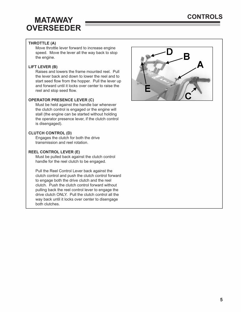
THROTTLE (A) Move throttle lever forward to increase engine
speed. Move the lever all the way back to stop the engine.
LIFT LEVER (B) Raises and lowers the frame mounted reel. Pull
the lever back and down to lower the reel and to start seed flow from the hopper. Pull the lever up and forward until it locks over center to raise the reel and stop seed flow.
OPERATOR PRESENCE LEVER (C) Must be held against the handle bar whenever
the clutch control is engaged or the engine will stall (the engine can be started without holding the operator presence lever, if the clutch control is disengaged).
CLUTCH CONTROL (D) Engages the clutch for both the drive
transmission and reel rotation.
REEL CONTROL LEVER (E) Must be pulled back against the clutch control
handle for the reel clutch to be engaged.
Pull the Reel Control Lever back against the clutch control and push the clutch control forward to engage both the drive clutch and the reel clutch. Push the clutch control forward without pulling back the reel control lever to engage the drive clutch ONLY. Pull the clutch control all the way back until it locks over center to disengage both clutches.

6
MATAWAYOVERSEEDER
OPERATION
Gasoline is extremely flammable and highly
explosive under certain conditions. Always stop the engine and do not smoke or allow open flames or sparks when refueling. BE SURE to install fuel cap after refueling.
Remove fuel cap slowly. Fuel tank may be under pressure and could cause personal injury from spraying.
NEVER start or run the engine inside where exhaust fumes can collect. Carbon monoxide present in the exhaust is an odorless and deadly gas.
DO NOT operate equipment without shields in place. DO NOT make adjustments or perform any maintenance while the engine is running.
Immediately replace any warning decal which becomes illegible.
STARTING THE ENGINE
Before starting engine, check engine oil level. Fill if necessary following the engine manufacturer's recommendation for the type and amount of oil required.
Fill fuel tank with appropriate fuel recommended by the engines manufacturer.
1. Make sure the lift lever is in the raised position.
2. Make sure the clutch control is disengaged (engine will not start if the clutch control is engaged).
3. Move the throttle lever midway between fast and slow.
4. Use the choke as required to start a cold engine. Choke control F is located on the front of the engine.
5. Stand at side of unit placing left foot on top of housing and slowly pull the recoil starter until just past compression. Return starter handle, pull firmly with a smooth, steady motion to start.

7
MATAWAYOVERSEEDER
OPERATION
DEPTH ADJUSTMENT
Loosen the locking nut. Turn the adjusting screw G clockwise (down) to raise reel from the turf, and turn the adjusting screw counterclockwise (up) to lower reel into the turf. Tighten locking nut H after each reel adjustment.
Low tire pressure may cause uneven reel penetration. Correct tire pressure should be maintained to eliminate this possibility (refer to the Tire Pressure section of this manual, for recommended tire pressure).
NOTE: The factory reel depth setting gives a maximum of 1/4" (6 mm) turf penetration on level terrain, and a reel to ground clearance of 1-1/2" (38 mm) when reel lift lever is in the transport (raised) position. Do not operate at turf depths exceeding 1/4" (6 mm).
Never cross hard surfaces or objects (sidewalks, driveways, stepping stones etc.) with reel blades down and/or engaged.
Increasing the depth of the reel blades will decrease ground clearance when the reel is in the raised position.
After adjusting to desired cutting depth, test run the unit to check for desired blade penetration.

8
MATAWAYOVERSEEDER
OPERATION
OVERSEEDER OPERATION
1. Adjust reel to desired cutting depth, not to exceed 1/4" (6mm) maximum.
NOTE: Cutting depth exceeding 1/4" (6 mm) may be too deep for most seed and may prevent germination.
2. Make a test run to check for desired blade penetration.
3. Set the feed control cam A on the hopper according to the "Seed Feed Chart" located inside the hopper cover. Fill the hopper with seed.
4. Start the engine. Compress and hold the operator presence lever.
5. Pull back on the reel control lever and push the clutch control forward to engage both the reel and drive clutches. Adjust the throttle to the operator's desired walking speed.
6. Lower the reel after the unit is in motion, the seed gate opens automatically as the reel is lowered.
NOTE: To prevent damage to the turf, the unit should be in motion and the clutch control engaged before lowering reel onto the turf.
Never cross hard surfaces or objects (sidewalks,
driveways, stepping stones, etc.) while the reel is down and/or engaged.
7. After each pass across the turf, raise the reel, disengage the clutch control and position the unit manually for the next pass (this will help prevent damage to the turf). Make all passes across the turf at uniform speed. Slightly overlap the area previously seeded to ensure complete coverage.
Before operating, check area to be worked and remove any object(s) which may present a safety hazard and/or damage the equipment.
To prevent injury due to rotating blades, never place hands or feet beneath the equipment at any time.
To prevent injury from thrown blades, never operate equipment with reel blades that are cracked, badly bent, missing, or in any abnormal condition.

9
MATAWAYOVERSEEDER
OPERATION
DETHATCHING
For the de-thatching operation, make sure there is no seed in the hopper, seed gate will still open during use.
Whenever possible, a few test runs should be made on turf similar to where the unit will be used. This will allow preliminary adjustments to be made before entering greens (etc.) and help eliminate the possibility of turf damage due to misadjustments. Low tire pressure may cause uneven reel penetration. Correct tire pressures should be maintained to eliminate this possibility (refer to the Tire Pressure section of this manual, for recommended tire pressure).
1. Start the engine. Compress and hold the operator presence lever.
2. Pull back on the reel control lever and push the clutch control forward to engage both the reel and drive clutches. Adjust the throttle to the operator's desired walking speed.
3. Lower the reel after the unit is in motion, the seed gate opens automatically as the reel is lowered.
NOTE: To prevent damage to the turf, the unit should be in motion and the clutch control engaged before lowering reel onto the turf. Never cross hard surfaces or objects (sidewalks, driveways, stepping stones, etc.) while the reel is down and/or engaged.
4. After each pass across the turf, raise the reel, disengage the clutch control and position the unit manually for the next pass (this will help prevent damage to the turf). Make all passes across the turf at uniform speed.
Before operating, check area to be worked and remove any object(s) which may present a safety hazard and/or damage the equipment.
To prevent injury due to rotating blades, never place hands or feet beneath the equipment at any time.
To prevent injury from thrown blades, never operate equipment with reel blades that are cracked, badly bent, missing, or in any abnormal condition.
CROSSHATCH OVERSEEDING
Making two passes over the same area with the feed cam set at half the desired seed flow rate will provide faster fill in.
Make the first set of passes (parallel to each other) over the area in the normal manner but at half the seed feed rate.
Cover the same area again, but make the second set of passes at a 45o angle across the first set of passes, again at half the seed rate.
This will lay down the seed in a diamond pattern, resulting in better distribution and faster cover after germination.

10
MATAWAYOVERSEEDER
SERVICE
To keep the Mataway Overseeder in good operating condition, proper maintenance and immediate repair of any damaged part is necessary. Perform the following services, and follow procedures for proper storage.
When replacement parts are required, use
genuine RYAN parts or parts with equivalent characteristics, including type, strength and material. Failure to do so may result in product malfunction and possible injury to the operator and/or bystanders.
Any warning decal that becomes illegible should be replaced immediately.
Wear protective eye equipment when using hammer, chisels, punches and drills.
Carbon monoxide present in the exhaust is an odorless and deadly gas. Provide enough ventilation. Never start or run the engine inside where exhaust fumes can collect.
Stop engine and let cool before servicing or making adjustments around the engine area.
Use adequate lifting device to raise unit. Use
appropriate jack stands to support unit.
PREVENTIVE MAINTENANCE
After each days use:
1. Wash unit with water after engine has cooled.
2. Check blades for damage (cracks, broken blades, etc.) replace if necessary. Make sure blades are free of debris and apply a light coat of oil to the blades to help prevent rust (any motor oil will work effectively).
3. Check engine oil level and air cleaner for dirt and/or obstructions. Service according to engine manual recommendations.
4. Check transmission case for proper oil level. The case holds 1/2 pint (.4L) when full. Use EP90w Oil.
5. Keep all belts free from dirt and oil.
LUBRICATION
The Mataway Overseeder has 7 lubrication fittings.
1. Wipe off each fitting before and after lubrication.
2. Use a good quality Lithium based lubricant.
3. Lubricate equipment after every 8 hours of use and before long storage periods.

11
MATAWAYOVERSEEDER
SERVICE
TIRE PRESSURE
Keep the tires to the recommended pressure. Improper inflation will shorten the life of the tires and cause unsatisfactory operation.
Tires......................................4.10 / 3.50 - 4, 2-ply Tire Pressure.........24 to 26 PSI (165 to 179 kPa)
Due to low air volume of tires, over-inflation can be reached in a matter of seconds. To prevent explosion, check air pressure with air gauge before filling the tire. Fill to recommended air pressure, and Do Not exceed the recommended pressure.
CHAIN REPLACEMENT
1. Remove the belt guards and the hopper drive belt.
2. Loosen the drive chain idler sprocket B.
3. Remove connecting link C and chain D.
4. Install new chain and connecting link.
5. Adjust the idler sprocket to allow approximately 1/8" (3 mm) to 1/4" (6 mm) of play in the chain (check for play on the straight section of chain opposite the sprocket). Tighten the idler sprocket hardware.
NOTE: Proper chain tension is essential. A tight chain will impose excessive bearing loads. A loose chain will cause noisy operation and chain pulsations, which may result in irregular sprocket speed and abnormal chain and sprocket wear.
6. Lubricate the fitting on the idler sprocket.
7. Reinstall the hopper drive belt and make sure all guards and covers are in place before using the unit.
12
MATAWAYOVERSEEDER
SERVICE
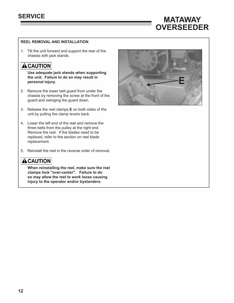
REEL REMOVAL AND INSTALLATION
1. Tilt the unit forward and support the rear of the chassis with jack stands.
Use adequate jack stands when supporting the unit. Failure to do so may result in personal injury.
2. Remove the lower belt guard from under the chassis by removing the screw at the front of the guard and swinging the guard down.
3. Release the reel clamps E on both sides of the unit by pulling the clamp levers back.
4. Lower the left end of the reel and remove the three belts from the pulley at the right end. Remove the reel. If the blades need to be replaced, refer to the section on reel blade replacement.
5. Reinstall the reel in the reverse order of removal.
When reinstalling the reel, make sure the reel clamps lock "over-center". Failure to do so may allow the reel to work loose causing injury to the operator and/or bystanders.

13
MATAWAYOVERSEEDER
SERVICE
REEL BLADE REPLACEMENT
NOTE: Note how the blades and spacers are arranged on the reel and the direction of the blades before disassembly so that it can be reassembled in the same manner.
1. On the end of the shaft opposite the pulley, loosen the set screw in the locking collar A on the reel shaft. Insert a punch in the small hole on the collar and use a hammer to tap the collar clockwise until it's loose (approx. 1/4 turn). Remove the collar and remove the pillow block and bearing B.
2. Loosen the socket head screw C in the reel nut D and remove the reel nut from the shaft.
3. Slide the blades and spacers off of the shaft.
4. Reassemble the reel with new blades.
NOTE: When reassembling the reel, it is important to start and end with a spacer. DO NOT assemble with a blade next to the shaft nut.
5. Make sure the socket head screw C in the reel nut D is just "snug" or about 1 to 2 ft.-lb.
(1.5 - 3 N·m). Screw the nut onto the reel shaft and torque to 80 + 10 ft.-lb. (108 + 13 N·m). Make sure enough spacers are used to prevent the reel nut from contacting the shoulder of the hexagonal section of the shaft. Tighten the socket head screw to 10 to 12 ft.-lb. (13-16 N·m).
6. Install the pillow block with bearing B on the shaft. Slide the pillow block on until the outside edge of the block is 5/8" (16mm) from the end of the shaft.
7. The pillow block B must also be perpendicular to the shaft. To check this, hold a ruler G against the first blade H and across the edge of the pillow block. Rotate the pillow block by hand. If the edge of the pillow block does not appear to wobble (move back and forth) the pillow block is perpendicular.
8. Install the locking collar against the bearing by tapping it counterclockwise approx. 1/4 turn and tightening the set screw.
9. After the reel has been reinstalled (refer to the section on Reel Removal And Installation) readjust the blade height.
10. With the unit on a level surface, lower the reel, loosen the locking nut and turn the depth adjusting screw until the blades just touch the ground.
11. Raise the reel and turn the adjustment screw counterclockwise 3-1/2 turns to achieve
1/4" (6 mm) blade penetration.
NOTE: This unit is designed for a maximum of 1/4" (6 mm) turf penetration. Some seeds will not germinate at depths exceeding 1/4", and turf penetration exceeding 1/4" will shorten belt life.
After 4 hours of use, check reel nut for proper torque. The torque value for the reel nut is 80 ft.-lbs. + 10 ft.-lbs. (108 + 13 N·m).

14
MATAWAYOVERSEEDER
SERVICE
REEL-BELT AND DRIVE-BELT REPLACEMENT
NOTE: Reel belts are serviced in matched sets of three belts. When replacement is required, always replace all three belts. It is a good idea to replace all belts (drive and reel) on the unit at the same time.
1. Remove the belt guards and the hopper drive belt.
2. Tilt the unit forward and support the rear of the chassis with jack stands.
Use adequate jack stands when supporting the unit. Failure to do so may result in personal injury.
3. Remove the lower belt guard from under the chassis and take out the reel. Remove the jack stands and lower the unit.
4. Loosen the set screw in the locking collar K on the drive shaft. Insert a punch in the small hole in the collar and use hammer to tap the collar clockwise (opposite direction of engine rotation) until it's loose (approx. 1/4 turn). Remove the collar.
5. Remove the bolts H securing the mounting plate L. Remove plate and the pillow block J (leave the pillow block attached to the mounting plate).
6. Remove all three reel belts.
NOTE: Inspect the drive belt to the transmission after the reel belts have been removed. Replacing the drive belt now will save work and down time at a later date.
7. Install new belts (matched set of three).
8. Before reinstalling the mounting plate L, loosen but do not remove the pillow block J.
9. Slide the pillow block bearing onto the shaft and loosely mount the plate to the chassis. Adjust the mounting plate L side-to-side so that there is no side load on the drive shaft. Tighten the mounting plate hardware H.

15
MATAWAYOVERSEEDER
SERVICE
10. Reinstall the locking collar against the bearing. Tighten locking collar by rotating counterclockwise on pillow block shoulder. Using punch and hammer, lock collar into position. Tighten set screw.
11 Adjust the pillow block up and down until it is centered on the shaft. Tighten the pillow block hardware.
12. Rotate the drive shaft by hand to make sure there is no side load.
NOTE: Excessive side load on the shaft may cause engine crankshaft failure.
13. Check the reel belt pulley alignment. The measurement A should be 5/8" (16mm). If adjustment is required, loosen the set screw in the pulley and move the pulley in or out on the shaft.
NOTE: The pulley is secured to the shaft by set screw and key. It may need to be tapped with a hammer for adjustment. Use a plastic, rubber, lead or leather head hammer to avoid damaging the pulley.
14. Support the unit on jack stands and reinstall the reel and belt guard beneath the chassis.
Use adequate jack stands when supporting the unit. Failure to do so may result in personal injury.
15. Install the hopper belt and belt guards before operating the unit.
NOTE: Belts should be tight when the reel and drive are engaged and loose enough to slip when they are disengaged.

16
MATAWAYOVERSEEDER
SERVICE
ADJUSTMENT FOR REEL AND DRIVE BELTS
Over time, the belts will naturally need adjusting due to the use of the equipment. Inspect belts daily to ensure proper operation of the unit.
Before adjusting belts, make sure to:
1. Loosen the transmission mounting plate A and chain idler sprocket hardware.
2. Clean the underside of chassis to allow movement of the engine and loosen the engine mounting hardware.
3. Loosen the hardware securing the mounting plate B (supporting the reel drive pulley) and the pillow block.
4. Loosen the set screw in the locking collar C on the drive shaft. Insert a punch in the small hole in the collar and use a hammer to tap the collar clockwise (opposite direction of engine rotation) until it's loose (approx. 1/4 turn).
5. Make sure the springs are in place on the drive belt idler arm and the reel belt idler arm.
6. Slide transmission and mounting plate toward the rear of unit as far as possible. Tighten transmission mounting hardware.
7. Position engine so it is square with the chassis and tighten either the two front or the two rear mounting screws.
8. Engage the reel drive clutch. Measure the distance between the reel drive belts and the forward edge of the idler assembly belt stop. Measurement D should be 3/4" (19 mm). If necessary, reposition engine to obtain proper dimension.
9. Engage the drive clutch. Measure the distance from the top edge of the idler pulley F, to the top edge of the drive belt G. The measurement E should be 1-3/4" to 2" (44 to 51 mm).
10. If measurement is less than 1-3/4" (44 mm) slide transmission forward until proper dimension is obtained.

17
MATAWAYOVERSEEDER
SERVICE
11. If the measurement is over 2" (51 mm) slide the engine forward to obtain correct measurement. If the engine has to be moved, check the reel belt measurement again for proper dimension.
NOTE: Reel and drive belt adjustments are guidelines only. The reel drive belts should engage without slipping and disengage completely. The drive belt should engage without slipping and disengage so that the unit will not creep.
12. Tighten engine and transmission mounting hardware securely. Slide chain idler sprocket against the drive chain until there is 1/8" to 1/4" (3 to 6 mm) play in the chain opposite the sprocket and secure hardware.
13. Using a straight edge, align the belt drive pulley on the transmission with the drive pulley on the engine. Loosen the set screw on the transmission pulley and slide it in or out to achieve proper alignment.
14. Align the mounting plate L so that it is perpendicular to the chassis and the pillow block bearing is centered on the coupler shaft. Tighten the two plate mounting screws H at the bottom of the plate.
15. Align the pillow block bearing with the coupler shaft so that there is no vertical or side load on the shaft and tighten the pillow block mounting hardware. Torque the pillow block screws to
25 ft.-lbs. (34 N·m).
16. Tighten locking collar K on engine coupler shaft. Rotate collar counterclockwise on pillow block shoulder. Using hammer and punch, lock collar into position. Tighten set screw in collar K.
17. Engage reel drive clutch. Check the clearance from the idler pulley M to the belt stop N bolted to the mounting plate, clearance should be a minimum of 1/16" (2 mm). If necessary, loosen the belt stop hardware O and reposition it. Tighten hardware.

18
MATAWAYOVERSEEDER
SERVICE
18. Check clutch control for positive over-center action in disengaged position. Adjust rod length if necessary.
19. To adjust rod length to achieve positive over-center locking, loosen the jam nut on top of the clevis at the bottom of the clutch lever.
20. Remove the cotter pin A and clevis pin B, and the two bushings C on the control handle. Turn the rod to shorten or lengthen the rod as required and reattach the rod to the handle with the clevis pin.
21. Double check to ensure over-center locking action. When proper locking action is obtained, completely assemble control handle and tighten jam nut.
22. Engage and disengage clutch control lever several times and check to see that belt stops work properly. The belts should be held firmly, but not pinched severely, with reel drive lever disengaged.
NOTE: Overtight belt stops will cause undo wear on reel drive belts.
23. Belt stop tension on the reel belts can be adjusted by loosening the screw D in the reel belt idler assembly and screwing it in or out to adjust the tension on the idler arm when it is in the disengaged position.
24. Disengage the clutch lever. Check the tips of the two belt stops E & F. The gap G should be a minimum of 1/32" (1 mm) between the tips of the stops. If necessary, loosen reel idler pivot plate and adjust accordingly.
25. The belt stops should be perpendicular to the reel belts and parallel to each other. Make sure reel drive idler pulley is centered and aligned over reel drive belts.

19
MATAWAYOVERSEEDER
SERVICE
HOOK AND CABLE ADJUSTMENT
1. Loosen the hardware securing the hook A. Slide the hook in the slot so that it captures the reel idler assembly when the clutch control is disengaged. When only the drive clutch is engaged, the hook should hold the reel idler assembly back far enough that the reel belts will not engage. Retighten the hook mounting hardware.
2. After the hook has been adjusted. Loosen the two jam nuts B at the top of the cable. Adjust the bottom nut to take up any slack in the cable. Be careful not to overtighten the cable or the hook may not hold the reel idler assembly. Use the top nut to lock the lower nut into place.

20
MATAWAYOVERSEEDER
SERVICE
HOPPER DRIVE PULLEY SPROCKET ADJUSTMENT
With the belt covers removed, raise and lower the reel using the Reel Lift Lever, and check to make sure the sprocket C on the inside of the hopper drive pulley properly engages the drive chain D from the transmission.
1. If the pulley sprocket C does not align with the chain D, the set screw in the drive sprocket E on the transmission can be loosened, and the sprocket moved in or out on its shaft to align the chain with the pulley sprocket.
2. If the pulley sprocket is aligned with the chain but does not engage the chain fully, raise the reel and check the chain tension for the proper 1/8" to 1/4" (3 to 6mm) play.
3. If the chain tension is correct, lower the reel and loosen the nut G on the hopper pulley adjustment rod H until the sprocket C fully engages the chain.
4. To make sure the pulley sprocket fully disengages the chain, raise the reel, and check for clearance F of approximately 1/8" (3 mm) between the sprocket and chain.

21
MATAWAYOVERSEEDER
SERVICE
DISC ALIGNMENT
1. Tip unit forward and place on jack stands. Check the disc/blade alignment by placing a straight edge C against the concave side of the either the fifth or sixth disc A and the corresponding blade B on the reel. The straight edge should lie flat against both disc and blade.
Use adequate jack stands when supporting the unit. Failure to do so may result in personal injury.
2. The discs can be aligned with the blades by loosening the two locking collars just inside the bearings at either end of the disc shaft. Loosen the set screws and tap the collar clockwise (with hammer and punch) to unlock, then move the entire shaft until the discs align with the blades. Lock the collars against the bearings and tighten the set screws.

22
MATAWAYOVERSEEDER
SERVICE
TRANSMISSION GEAR REPLACEMENT
1. Remove the transmission from the unit.
2. Remove the sprocket, pulley and keys.
3. Remove the plug and drain the oil from the gear case.
4. Remove the the remaining hardware. Take note of which side is the input side and which is the output side so that they can be reassembled correctly. Using a soft hammer, tap case on the tabs to break the seal, and pull halves E & F apart.
5. Remove the input shaft A, output shaft B and spacer C. Also remove the bearings D and grease seals.
6. Install new bearings into both case halves. DO NOT install new grease seals at this time.
INPUT SHAFT
7. Remove large double gear E, small gear F, key G, and spacer H from input shaft J.
8. Check the input shaft for wear and replace if necessary (if shaft needs to be replaced, install the existing snap ring K on new shaft). If the shaft is NOT replaced, remove any burrs from keyways and/or shaft ends if necessary.
9. Replace bushings in the large double gear E (or replace gear if necessary). When replacing bushings, make sure they are flush with the edge of the gear and that the oil holes on gear are aligned.
10. Install the spacer H onto shaft against the snap ring K. Install the large double gear E, with the small gear side against the spacer.
11. Install key G into keyway and slide the small gear F (flat side toward the larger gear) onto the shaft.

23
MATAWAYOVERSEEDER
SERVICE
OUTPUT SHAFT
12. Remove large gear L , large double gear M and key N from shaft P. Check the shaft for wear and replace if necessary (if shaft needs to be replaced, install the existing snap ring O on new shaft). If the shaft is NOT replaced, remove any burrs from keyways and/or shaft ends if necessary.
13. Replace bushings on large double gear M (or replace gear if necessary). When replacing bushings, keep the bushings flush with the edge of the gear. Be sure oil holes on gear are aligned.
14. Install key N and large single gear L onto shaft P (be sure the deep-step side of gear is toward snap ring O).
15. Slide the large double gear M onto shaft, with the small gear toward the large single gear.
16. Install spacer onto output shaft.
17. Clean the old gasket material from the case halves.
18. Install the input and output shafts into the gear case half, making sure the spacer on the output shaft remains in place.
19. With shafts in gear case half, turn either shaft to make sure gears are turning. This will ensure the keys are properly set.
20. Apply Loctite 515 sealant (or equivalent) to case halves. Make sure the spacer bushings are in the center top and bottom holes of the case half.
21. Position transmission onto the mounting bracket with the drain plug facing to the outside of unit. Reinstall the six screws removed during disassembly. Secure all six screws and torque to 16 + 2 ft.- lbs. (21.5 N·m).
22. Apply 30w oil onto the lips of the new grease seals. Install the seals, drive pulley, and sprocket.
23. With the gear case resting level on the mounting bracket, fill transmission with EP90w oil until the oil reaches the bottom of the threads in the plug hole. Install plug (use a teflon based thread sealer on the threads). The transmission will hold 1/2 pint (.4L) of oil.
24. Check the alignment of the belt pulley and chain sprocket. If necessary, loosen the set screws securing the pulley and sprocket to the shaft and position each until properly aligned. If alignment cannot be reached refer to the previous instructions for adjustment of belts and chain.

24
MATAWAYOVERSEEDER
STORAGE
STORAGE INSTRUCTIONS
To prevent possible explosion or ignition of
vaporized fuel, do not store equipment with fuel in tank or carburetor in enclosure with open flame (for example, a furnace or water heater pilot light).
Do not smoke, avoid sparks and open flames when draining or filling the fuel tank.
Before the equipment is put in to storage for any period exceeding 30 days, the following steps should be taken.
1. Drain all fuel from the fuel tank and fuel lines.
2. Start the engine and run until all the fuel is used from the carburetor float bowl.
3. While engine is warm, drain the crankcase oil and replace it with the proper weight oil corresponding to the season the unit will next be used. Refer to the engine manual for proper oil recommendations.
Do not attempt to service or make repairs near the engine area while the engine is still hot.
4. Remove the spark plug and squirt a small amount of clean motor oil into the cylinder. Turn the engine over a few times to distribute the oil and reinstall the sparkplug.
5. Lubricate all lubrication fittings.
6. Apply a light coat of oil to the blades and reel shaft to prevent rust.
7. Lubricate drive chain with Lubriplate #13563 or equivalent.
NOTE: Do not store unit with blades in the down position. Be sure all belts are free from tension (the clutch control lever in the disengaged position).
To put the equipment into service after an extended period of storage:
1. Move unit to a level, well ventilated area.
2. Check unit for loose hardware and broken parts. Tighten and replace as necessary.
3. Check for cracked or split fuel lines.
4. Make sure the air cleaner filter is clean.
5. Check that the air cleaner components and all shrouds and belt covers are in place.
6. Check spark plug and plug wire.
7. Note if any blades need replacing.
8. Determine if the transmission and engine oil need filling. Refill engine oil according to the manufacturers recommendations, and refer to the Preventive Maintenance section of this manual for correct oil weight and amount for the transmission.
9. Fill the tank with appropriate fuel as recommended by the engine manual.
Do not smoke, avoid sparks and open flames
when draining or filling the fuel tank.
10. Make sure controls are in the disengaged or neutral position.
11. Start engine and let run (at slow speed) until approximate operating temperature has been reached.
12. While engine is running (and has reached operating temperature) visually inspect fuel lines and carburetor for leaks. If a leak is found, make sure the engine has cooled sufficiently before attempting any repairs.
25
MATAWAYOVERSEEDER
TRANSPORTING
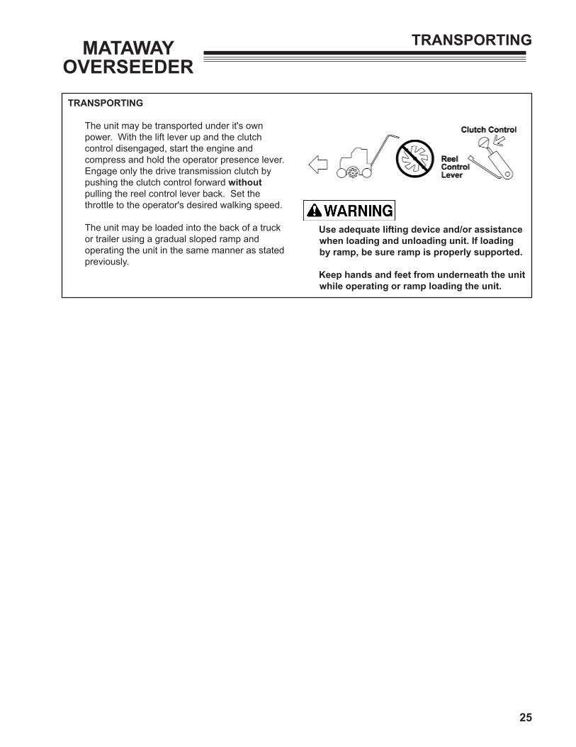
TRANSPORTING
The unit may be transported under it's own power. With the lift lever up and the clutch control disengaged, start the engine and compress and hold the operator presence lever. Engage only the drive transmission clutch by pushing the clutch control forward without pulling the reel control lever back. Set the throttle to the operator's desired walking speed.
The unit may be loaded into the back of a truck or trailer using a gradual sloped ramp and operating the unit in the same manner as stated previously.
Use adequate lifting device and/or assistance when loading and unloading unit. If loading by ramp, be sure ramp is properly supported.
Keep hands and feet from underneath the unit
while operating or ramp loading the unit.

26
MATAWAYOVERSEEDER
SPECIFICATIONS
SPECIFICATIONS
Front axle........................... ... 3/4" (19 mm) diameter mounted in self-aligning ball bearingsRear axle................................ 3/4" (19 mm) diameter welded to pivot arms
Blades..........................High carbon steel (hardened)
Chassis...............................3/16" (5 mm) formed and welded steel plate
Clutch................................Belt tightener type for reel and forward travel
Controls...............................Throttle control, lift lever combined drive and reel clutch lever
Depth Adjustment.........................Micrometer screw
Depth of Cut...................................Up to 1/4" (6 mm)
Dimensions:Width..........................................................36" (91cm)Height...........................44" (112cm) including handleLength..........................53" (135cm) including handleWheelbase...........................................16 1/2" (42cm)Width of cut..........................................19" (483 mm)
Net Weight.........425 lbs. (195 Kg) with 547553 Reel
Gear Case........................................22 to 1 reduction
Speed...246 ft./min.(74m/min.) at 3200 engine r.p.m.
Drive............"A" section belt from engine to gear box No. 40 sealed roller chain from gearbox to front axle Matched set of 3, V section belts from engine to reel
Engine.................Model No. CH11T, 11 H.P. Kohler Kohler specification number PS - 1630. Governor set at 3200 r.p.m. (no load). Engine displacement is 24.3 cu. in. (398 cc) and develops 20.2 ft.-lbs. (27.4 N·m) of torque at 2000 r.p.m.
Hopper Capacity...............0.83 cu. ft. (0.0235 cu. m)
Reduction.....................................Engine to reel - 1:1 Engine to wheels - 36:1
Reel.......................................Quick change mounting Rotation in opposite direction of forward motion
Seed Density.......................Adjustable for seed type
Seed Flow Control.....seed dispensed automatically when unit is lowered, stops when reel is raised.
Seed Spacing.................seed rows 2" (50mm) apart Reel Speed...............................................3200 r.p.m.
Wheels...............Front; 4.10/3.50 - 4, pneumatic tires chain driven Rear; 4.10/3.50 - 4 pneumatic tires free wheeling on self-aligning ball bearings.

27
MATAWAYOVERSEEDER
PARTS SECTION
PARTS SECTION

28
MATAWAYOVERSEEDERFIGURE 1
CHASSIS

29
ITEM PART NO. DESCRIPTION QTY ITEM PART NO. DESCRIPTION QTY
MATAWAYOVERSEEDER FIGURE 1
CHASSIS
1 64006-03 WASHER, 3/8 HELICAL LCK 32 64123-82 BOLT-HEX 3/8-16X2-1/2 13 64123-107 BLT-HEX 5/16-18X7/8 44 64151-15 5/16-18 HEX NUT CNTRLCK 25 64164-19 KEY WOODRUFF.19X.75 #9 36 64001-2 NUT-JAM 3/8-24 47 64123-50 BOLT-HEX 3/8-16X1 28 306555 SCREW, 5/6-18 X 5/8 119 64025-05 NUT-3/8-16 HEX 110 64123-104 BLT-HEX 5/16-18X2-3/4 211 64018-9 BLT-CRG 5/16-18X3/4 G5 412 64025-02 NUT-HEX 5/16-18 213 306956 COTTER PIN 614 841261 SPROCKET, 16T 1/2P BLK 115 516825 GUARD 116 516944 HUB 217 517226 BRG,SLV .33 .50 .20 IRON 218 517348 SPROCKET 119 517641 SCRW,SPCL.38-16 1.75 HX 120 518506 SPRING 221 519038 BUSHING 222 519039 LEVER 223 519040 HOOK, UPPER RIGHT 124 519041 HOOK, UPPER LEFT 125 519042 NUT 226 519043 CLAMP, ROD LOWER 227 519045 CLAMP, REEL 228 519057 PLATE 129 519059 SHAFT,FRONT 130 519874 RACE,INNER 131 522714 SCRAPER, WHEEL 232 524508 LINK, LIFT 433 547743 STOP, BELT 134 548962 HOUSING,BEARING 435 521856 BEARING,BALL 236 521857 COLLAR,BRG LOCKING 237 540195 FRAME 1 (INCLUDES ITEM 38)
38 548224 FITTING,GREASE 1/4 SPC 439 540236 ARM, LEFT 140 540237 ARM, RIGHT 141 4124194 WHEEL, 4.10/3.50-4 2PLY 2 INCLUDES ITEMS 42-47)
42 306320 NUT-5/16-24 443 64006-02 LOCKWSHR-HELICAL 5/16 444 306861 SCRW,.31-24.625 YS HX 445 548123 BEARING, WHEEL 246 548543 TIRE-4.10/3.50-4, 2 PLY 147 548546 TUBE 1
48 4124197 WHEEL ASSY 2 (INCLUDES ITEMS 42-44, 47, 49 & 50)
49 517332 RIM 150 523264 TIRE 151 64141-6 NUT, 5/16-18 452 64144-02 SNAP RING 3/4 253 807443 FTG, GREASE 45D.25-28 154 64151-18 NUT, HEX 255 547634 WEIGHT AY 156 523477 CHAIN,SEALED ROLLER 1 (INCLUDES 522122 LINK CONNECTOR)
57 521845 BEARING,NEEDLE 158 64163-55 WASHER .328X.75X14 GA 259 64163-61 WSHR .81X.406X16GA 1360 548201 SETSCREW, 5/16-18 X 5/16 661 64144-03 SNAP RING 7/8" 262 548456 PIN,CLEVIS.438 1.25 YS 463 548477 WASHER 464 64141-4 NUT-WLF 3/8-16 265 64123-87 BOLT-HEX 3/8-16X1-3/4 266 4161123 LABEL-FRYAN OVAL LARGE 167 524544 DECAL,REEL HEIGHT ADJ. 168 869081 DECAL,DANGER 1

30
MATAWAYOVERSEEDERFIGURE 2
HANDLE ASSEMBLY

31
ITEM PART NO. DESCRIPTION QTY ITEM PART NO. DESCRIPTION QTY
MATAWAYOVERSEEDER FIGURE 2
HANDLE ASSEMBLY
1 64163-55 WASHER .328X.75X14 GA 62 111898 CLAMP,CABLE 13 120052 LOCKWASHER 34 64006-05 LOCKWSHR-HELICAL 1/2 25 64001-10 NUT-HEX JAM 7/16-20 16 64123-89 BOLT-HEX 1/4-20X3/4 17 304636 COTTER PIN, 12 x 1.12 YS 18 64123-107 BLT-HEX 5/16-18X7/8 29 64006-02 LOCKWSHR-HELICAL 5/16 210 64164-19 KEY WOODRUFF.19X.75 #9 511 64025-01 NUT-1/4-20 HEX 612 306391 SCRW,#10-32.31 YS 213 64006-01 LOCKWSHR-1/4 HELICAL 614 306401 SCREW, MACHINE-RNDHD 115 64123-68 BOLT-HEX 5/16-18X1 216 306531 NUT, 10-24 YS HEX 217 64025-02 NUT-HEX 5/16-18 218 306956 COTTER PIN 119 64163-55 WASHER .328X.75X14 GA 120 64163-03 WSHR-.256X.62X18GA. 621 64123-73 BLT-HEX 1/2-13X1 222 65286-4A TIE,CABLE 11-5/8 BLACK 223 515838 ROD, CONTROL 124 516855 SHAFT 125 516859 LEVER, ADJUSTING 126 516972 BRACE 227 521679 BUSHING 228 548456 PIN,CLEVIS.438 1.25 YS 129 524490 MOUNT,SWITCH (PLATED) 130 524493 ARM,PIVOT 131 524513 ARM, LIFT 232 524526 BRACKET, LIFT HANDLE 133 524578 BUSHING, .328X.63X.6 234 540242 HANDLE AY 135 540243 CONTROL AY,THROTTLE 136 540245 CONTROL AY,KILL SWITCH 137 540265 WIRE AY, 7.5" 138 540266 WIRE AY, 75" 139 540272 COVER, CNTRL W/DECALS 140 2702291.2 HANDLE AY 141 2702111 HANDLE AY,LOCKING PLTD 142 2702295.2 ARM AY,FRAME LIFT 243 546321 SCREW AY, ADJUST PLTD 144 548201 SETSCREW, 5/16-18 X 5/16 345 548204 SSCRW,.38-16.38 BS NH 246 548507 CLEVIS 147 548518 HAND GRIP 248 64141-4 NUT-WLF 3/8-16 249 548905 SCREW, .38-16 1.00 YS 450 800024 SCRW,.25-20 1.50 YS 151 800026 SCREW, .25-20.75 YS 4
52 64151-17 LOCKNUT, HEX 153 64151-15 5/16-18 HEX NUT CNTRLCK 254 819195 TSCRW,#8-18.50 YS 255 800896 TSCRW,.190-24.75 YS 156 805421 SPRING,EXTENSION 157 806800 SWITCH,STOP LIGHT 158 813840 CLIP 159 814585 BUSHING 160 820529 SPACER (PLATING) 161 826190 TUBING, CONVOLUTED 50'A/R62 826633 PIN,CLEVIS.31 2.38 ZS 163 524496 DECAL,CONTROL DRIVE 164 524497 DECAL,CONTROL REEL 165 00903491 DECAL, OPERATING INSTR 166 524547 DECAL,WARN-HEARING 167 524564 DECAL,THROTTLE 168 64123-100 BOLT-3/8-16X2-1/4 HEX 269 522638 BUSHING, PIVOT 270 524517 PLATE, MOUNTING 2

32
MATAWAYOVERSEEDERFIGURE 3
CLUTCH ASSEMBLY AND CONTROL

33
ITEM PART NO. DESCRIPTION QTY ITEM PART NO. DESCRIPTION QTY
MATAWAYOVERSEEDER FIGURE 3
CLUTCH ASSEMBLY AND CONTROL
1 64006-03 WASHER, 3/8 HELICAL LCK 52 64163-55 WASHER .328X.75X14 GA 33 64001-10 NUT-HEX JAM 7/16-20 14 64123-89 BOLT-HEX 1/4-20X3/4 15 64123-82 BOLT-HEX 3/8-16X2-1/2 26 304363 PIN, COTTER 1/8X1-1/8 17 64025-04 NUT-3/8-24 HEX 18 64123-107 BLT-HEX 5/16-18X7/8 19 64025-01 NUT-1/4-20 HEX 310 64006-01 LCKWSHER-1/4 HELICAL 311 64123-50 BOLT-HEX 3/8-16X1 312 64123-69 BOLT-5/16-18X1-1/2 HEX 213 306531 NUT, 10-24 YS HEX 214 64025-05 NUT-3/8-16 HEX 415 64123-100 BOLT-3/8-16X2-1/4 HEX 116 64025-02 NUT-HEX 5/16-18 117 306956 COTTER PIN 218 64163-03 WSHR-.256X.62X18GA. 319 64163-67 WASHER-.516X1X12GA 120 516544 BUSHING (PLATING) 121 517226 BRG,SLV .33 .50 .20 IRON 122 2701258 SPRING, TSN 1.0X3.62X14 123 518487 SPRING 124 522882 PULLEY,IDLER 125 522604 BRACKET, HANDLE 126 523508 GUIDE, BELT 227 524507 NUT,SSPCL.312-18 Z HX 228 524509 LINK (PLATING) 129 524560 RETAINER,SPRING 130 524561 ROD, CONTROL 131 524565 CAM,CONTROL (PLATED) 132 524576 TRIGGER,LOCKING PLTD 133 524577 BUSHING,.328X.63X.41 234 524579 CABLE,CONTROL 135 524585 HANDLE, CONTROL 136 524591 COVER,VINYL 137 540241 ARM AY 138 540246 PIVOT 139 540247 IDLER ARM 140 540270 BRACKET 141 540271 LEVER AY,CONTROL PLTD 142 822474 SPACER 143 64163-61 WSHR .81X.406X16GA 544 548171 KNOB 145 548224 FITTING,GREASE 1/4 SPCL 246 548456 PIN,CLEVIS.438 1.25 YS 147 548507 CLEVIS 148 64141-6 NUT, 5/16-18 249 548942 PULLEY, PLAIN FLAT 3.25 150 800026 SCREW, .25-20.75 YS PR 2
51 64151-15 5/16-18 HEX NUT CNTRLCK 152 800177 SCRW,.31-18.75 YS PR 153 64151-18 NUT, HEX 154 800492 CAPSCREW,HEX 255 64268-02 NUT-FL NYLN LCK 5/16-18 256 64262-006 BLT-FLG HD 5/16-18 X 3/4 157 800883 SCRW,.38-24 2.25 YS HX 158 805421 SPRING,EXTENSION 159 830005 PIN,CLEVIS.308 1.69 PS 160 809183 WSHR,.25.75.10 YS FLAT 261 64163-34 WSHR.256/.267X1X11GA 1

34
MATAWAYOVERSEEDERFIGURE 4
ENGINE AND DRIVE ASSEMBLY

35
ITEM PART NO. DESCRIPTION QTY ITEM PART NO. DESCRIPTION QTY
MATAWAYOVERSEEDER FIGURE 4
ENGINE AND DRIVE ASSEMBLY
1 111898 CLAMP,CABLE 12 120052 LOCKWASHER 13 64006-03 WASHER, 3/8 HELICAL LCK 64 64123-50 BOLT-HEX 3/8-16X1 25 64152-06 10-24X1/2 MACH SCREW 16 306531 NUT, 10-24 YS HEX 17 64123-100 BOLT-3/8-16X2-1/4 HEX 48 64164-25 KEY-1/4X7/8 #807 29 515390 WASHR,.39 1.25.19 FLAT 410 515755 CLIP 111 516892 PULLEY, REEL BELT 112 517101 PULLEY,3 IN. DIA BLK 113 517123 SHAFT 114 520574 KEY,.25 X.25 X 2.50 PS 115 544068 PILLOW BLOCK COMPLETE 1 (INCLUDES ITEMS 16, 17, 18 & 30)
16 547835 PILLOW BLOCK AY 1 (INCLUDES ITEMS 17 & 30)
17 521856 BEARING,BALL 118 521857 COLLAR,BRG LOCKING 119 547755 COUPLING 1 (INCLUDES ITEMS 20 & 21)
20 330748 SCRW,.31-18 1.00 BS HS 221 548183 LWSHR,.31.09 HI-COLLAR 222 547759 BELT,DRIVE, SET OF 3 123 64163-61 WSHR .81X.406X16GA 224 548201 SETSCREW, 5/16-18 X 5/16 625 548204 SSCRW,.38-16.38 BS NH 226 548403 V-BELT 127 800400 NIPPLE,.38-18NPT 5.0 GS 128 800401 CAP,.38-18NPT GS PIPE 129 838790 SPACER, ENG MNT PLTD 430 519809 PILLOW BLOCK 1

36
MATAWAYOVERSEEDERFIGURE 5
TRANSMISSION

37
ITEM PART NO. DESCRIPTION QTY ITEM PART NO. DESCRIPTION QTY
MATAWAYOVERSEEDER FIGURE 5
TRANSMISSION
1 64006-03 WASHER, 3/8 HELICAL LCK 42 64123-50 BOLT-HEX 3/8-16X1 23 64025-05 NUT-3/8-16 HEX 24 524536 GUIDE,BELT (PLATING) 15 2702128.2 TRANSMISSION AY 1 (INCLUDES ITEMS 6-26)
6 516700 SPACER 27 516724 GEAR 18 517137 PULLEY,4" DIA "A" SIZE 19 517226 BRG,SLV .33 .50 .20 IRON 210 517342 SPROCKET 111 518820 SHAFT, OUTPUT 112 518826 SHAFT, INPUT 113 518827 GEAR 114 522638 CASE, GEAR 215 523515 BRACKET, MOUNTING 116 546708 GEAR AY,IDLER 56T/20T 2 (INCLUDES ITEM 17)
17 515511 BUSHING 218 548119 BRG,BALL.75 1.62.31 "OP" 419 548201 SETSCREW, 5/16-18 X 5/16 220 548204 SSCRW,.38-16.38 BS 121 548274 OIL SEAL 222 548324 RING,EXT RET.691ID.042T 223 548369 KEY, WOODRUFF.19 X.62 424 548911 NUT,.31-18 YS HSF 625 548958 SCREW, .31-18 3.50 YS HX 626 800120 PLUG,.38-18NPT PS SQ HD 227 64163-61 WSHR .81X.406X16GA 428 551094 SCREW, 3/8X1-3/4 229 316909 SCREW, 5/16-18X4-1/2 2 (ITEM 5 INCLUDES A QUANTITY OF (6) ITEM 25 (2) OF THESE SCREWS WILL BE REPLACED BY ITEM 29)

38
MATAWAYOVERSEEDERFIGURE 6
GUARDS

39
ITEM PART NO. DESCRIPTION QTY ITEM PART NO. DESCRIPTION QTY
MATAWAYOVERSEEDER FIGURE 6
GUARDS
1 112050 TSCRW,.25-20.62 YS HW 72 64006-06 LCKWSHER-HELICAL 7/16 23 64006-01 LCKWSHER-1/4 HELICAL 34 64163-55 WASHER .328X.75X14 GA 25 64163-03 WSHR-.256X.62X18GA. 36 64123-84 BLT-HEX 7/16-14X1-1/2 27 540279 GUARD, OVERSEEDER 18 522982 SPACER (PLATING) 19 540278 GUARD, W/DECALS 110 524568 DECAL,OP INST 111 840697 DECAL,WARNING HANDS 112 4161123 LABEL-RYAN OVAL LARGE 1

40
MATAWAYOVERSEEDERFIGURE 7
HOPPER DRIVE

41
ITEM PART NO. DESCRIPTION QTY ITEM PART NO. DESCRIPTION QTY
MATAWAYOVERSEEDER FIGURE 7
HOPPER DRIVE
1 64163-55 WASHER .328X.75X14 GA 32 64006-03 WASHER, 3/8 HELICAL LCK 13 64006-02 LCKWSHER-HELICAL 5/16 14 64140-3 COTTER PIN-3/32X3/4 15 64123-69 BOLT-5/16-18X1-1/2 HEX 16 64025-05 NUT-3/8-16 HEX 17 64025-02 NUT-HEX 5/16-18 18 64163-61 WSHR .81X.406X16GA 19 64123-88 BOLT, 3/8-16X2-3/4 HEX 110 64163-67 WASHER-.516X1X12GA 211 518487 SPRING 212 521031 BUSHING 113 521032 IDLER 114 522606 ROD - CONTROL (PLATING) 115 522613 ARM, IDLER 116 522614 PULLEY, SPROCKET 117 522653 BUSHING 118 522882 PULLEY,IDLER 119 547746 BRACKET, SPROCKET 120 547754 BRACKET, MOUNTING 1 (INCLUDES ITEMS 21-26)
21 64006-03 WASHER, 3/8 HELICAL LCK 122 64025-05 NUT-3/8-16 HEX 123 64123-100 BOLT-3/8-16X2-1/4 HEX 124 515390 WASHR,.39 1.25.19 YS FLAT 125 523516 NUT,SPECIAL 126 523517 BUSHING 127 548190 PIN,HAIR.69 1.88.09 YS 128 64151-15 5/16-18 HEX NUT CNTRLCK 129 822474 SPACER 230 522902 BRACKET 1

42
MATAWAYOVERSEEDERFIGURE 8
HOPPER FRAME

43
ITEM PART NO. DESCRIPTION QTY ITEM PART NO. DESCRIPTION QTY
MATAWAYOVERSEEDER FIGURE 8
HOPPER FRAME
1 64163-55 WASHER .328X.75X14 GA 12 822529 PIN,HAIR.44 2.00.13 YS 13 64006-02 LCKWSHER-HELICAL 5/16 54 64123-68 BOLT-HEX 5/16-18X1 45 64123-61 BLT-HEX 5/16-18X1-3/4 16 64025-02 NUT-HEX 5/16-18 97 516544 BUSHING (PLATING) 18 517226 BRG,SLV .33 .50 .20 IRON 19 522634 SPRING 110 522656 STUD (PLATED) 111 522657 BUSHING (PLATING) 112 522659 LEVER,CONTROL 113 524569 PIN (PLATED) 114 522691 SUPPORT,ARM PIVOT 115 524514 SPRING, EX 1.14X6.64x21 116 524571 SUPPORT, HOPPER LH 117 524572 SUPPORT, HOPPER RH 118 545958 YOKE AY, CONTROL 119 64163-61 WSHR .81X.406X16GA 220 548190 PIN,HAIR.69 1.88.09 YS 121 548902 SCRW,.31-18 1.00 YS HSF 422 64141-6 NUT, 5/16-18 423 64151-15 5/16-18 HEX NUT CNTRLCK 124 806725 PIN,ROD CONNECTING 125 64163-29 WASHER-21/64 X 1 X 11GA 1

44
MATAWAYOVERSEEDERFIGURE 9
HOPPER AND DISC ASSEMBLY

45
ITEM PART NO. DESCRIPTION QTY ITEM PART NO. DESCRIPTION QTY
MATAWAYOVERSEEDER FIGURE 9
HOPPER AND DISC ASSEMBLY
1 103960 WASHER, .75 1.50.13 FLAT 22 112050 TSCRW,.25-20.62 YS HW 43 64163-55 WASHER .328X.75X14 GA 24 64123-07 BOLT, 1/4-20X1-1/2 HEX 205 64006-02 LCKWSHER-HELICAL 5/16 46 64140-3 COTTER PIN-3/32X3/4 27 64123-68 BOLT-HEX 5/16-18X1 48 64163-61 WSHR .81X.406X16GA 29 307665 NUT,.75-16 YS HX JAM 210 65286-4A TIE,CABLE 11-5/8 BLACK 111 522607 COLLAR,LOCKING 212 522632 TUBE 1013 522633 V-BELT 114 522652 COLLAR (PLATING) 215 522662 PULLEY,6.50 DIA. 116 522678 SPACER,DISC END, LEFT 117 522679 SPACER,DISC END, RIGHT 118 522680 SHAFT,DISC 119 522682 SPACER,DISC 920 522684 DISC,BLADE 1021 522688 BLADE,SCRAPER PLATED 1022 522689 FLANGETTE,TWO BOLT 423 522690 BEARING 224 522700 PLATE,RETAINER PLATED 225 523493 CLIP,HOSE 1026 545938 SUPPORT AY 127 2702280.2 SUPPORT AY,END LH 128 545990 PANEL, TUBE HOLDER 129 547648 ROD AY,ADJUSTING 1 (INCLUDES ITEMS 30-33)
30 306405 WASHER, 3/8" 231 518510 SPRING 132 523342 CONNECTOR,ROD PLATED 133 64151-18 NUT, HEX 134 548190 PIN,HAIR.69 1.88.09 YS 435 64044-1 SCREW-SET 1/4-20X1/4 236 64139-08 BOLT-5/16-18X3/4 WLF 837 548848 SPRING,COMPRESSION 2038 64141-2 NUT-WLF 1/4-20 439 64141-6 NUT, 5/16-18 840 64151-17 LOCKNUT, HEX 2041 826633 PIN,CLEVIS.31 2.38 ZS 242 4161123 LABEL-RYAN OVAL LARGE 144 4124323 LABEL-FRONT, OVERSDR 145 522834 DECAL,OP INST OVERSDR 1
* FOR HOPPER PARTS OR DEALER INFORMATION CONTACT:GANDY CO.528 GANDRUD ROADOWATONA, MN USA 550060REFER TO THEIR MODEL NUMBER 09086877

46
MATAWAYOVERSEEDERFIGURE 10
REEL
47
ITEM PART NO. DESCRIPTION QTY ITEM PART NO. DESCRIPTION QTY
MATAWAYOVERSEEDER FIGURE 10
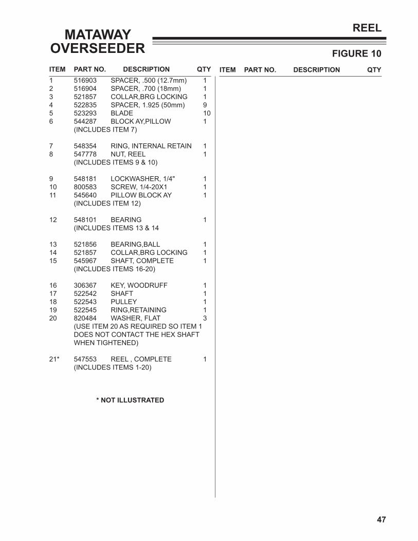
REEL
1 516903 SPACER, .500 (12.7mm) 12 516904 SPACER, .700 (18mm) 13 521857 COLLAR,BRG LOCKING 14 522835 SPACER, 1.925 (50mm) 95 523293 BLADE 106 544287 BLOCK AY,PILLOW 1 (INCLUDES ITEM 7)
7 548354 RING, INTERNAL RETAIN 18 547778 NUT, REEL 1 (INCLUDES ITEMS 9 & 10)
9 548181 LOCKWASHER, 1/4" 110 800583 SCREW, 1/4-20X1 111 545640 PILLOW BLOCK AY 1 (INCLUDES ITEM 12)
12 548101 BEARING 1 (INCLUDES ITEMS 13 & 14
13 521856 BEARING,BALL 114 521857 COLLAR,BRG LOCKING 115 545967 SHAFT, COMPLETE 1 (INCLUDES ITEMS 16-20)
16 306367 KEY, WOODRUFF 117 522542 SHAFT 118 522543 PULLEY 119 522545 RING,RETAINING 120 820484 WASHER, FLAT 3 (USE ITEM 20 AS REQUIRED SO ITEM 1 DOES NOT CONTACT THE HEX SHAFT WHEN TIGHTENED)
21* 547553 REEL , COMPLETE 1 (INCLUDES ITEMS 1-20)
* NOT ILLUSTRATED

BOB-CAT BUNTON RYAN STEINER
SCHILLER GROUNDS CARE, INC.ONE BOB-CAT LANEP.O. BOX 469JOHNSON CREEK, WI 53038920-699-2000www.schillergc.com