
Illustrated Parts Manual - Walker Mowers
36
Illustrated Parts Manual Beginning S/N: 128442 Effective Date: 05.05.14 P/N 5000-27
-
Upload
khangminh22 -
Category
Documents
-
view
0 -
download
0
Transcript of Illustrated Parts Manual - Walker Mowers

Illustrated Parts Manual
Beginning S/N: 128442 Effective Date: 05.05.14
P/N 5000-27

Beginning S/N 128442Effective Date 05-05-14
Use only genuine Walker® replacement parts.
KEY TO ABBREVIATIONS USED IN THIS MANUAL
º (Dimension) .....................................................................................................................................Degrees (Angle)" (Dimension) .....................................................................................................................................................inches(-) ....................................................................................................................................................Negative (Polarity)(+) .................................................................................................................................................... Positive (Polarity)AT ................................................................................................................................................................All-TerrainCCW ...............................................................................................................................................Counter-clockwiseConn. .......................................................................................................................................................... ConnectorCW ...............................................................................................................................................................ClockwiseD ................................................................................................................................................................... DiameterDC ..................................................................................................Deck, Collection (number refers to size in inches)DM ................................................................................................... Deck, Mulching (number refers to size in inches)DR .........................................................................................Deck, Rear Discharge (number refers to size in inches)DS...........................................................................................Deck, Side Discharge (number refers to size in inches)DU ...................................................................................................................................................Garlock (Bearing)ESNA (Fastener)..........................................................................................................................Nylon Insert LocknutFSC ........................................................................................................................................ Forward Speed ControlGA.....................................................................................................................................................................Gaugegal. ..................................................................................................................................................................... gallonGHS ........................................................................................................................................Grass Handling SystemGR (Fastener) ....................................................................................................................................................GradeHD .............................................................................................................................................................Heavy DutyHP ........................................................................................................................................................... Horse PowerID ............................................................................................................................... Identification or Inside DiameterL ........................................................................................................................................................................LengthLH ............................................................................................................Left Hand (orientated with operator on seat)LP .............................................................................................................................................................. Low Profilemm (Dimension) .........................................................................................................................................millimetersMS (Fastener) ......................................................................................................................................Machine ScrewNS (as part number)..................................................................................... Item is not sold by Walker ManufacturingOD ................................................................................................................................................... Outside Diameteroz. ...................................................................................................................................................................... ouncePFH (Fastener) ................................................................................................................................ Phillips Flat HeadP/N...........................................................................................................................................................Part NumberPPH (Fastener) ................................................................................................................................Phillips Pan HeadPTH (Fastener) ..............................................................................................................................Phillips Truss HeadPTO .................................................................................................................................................... Power Take-OffQKS ...........................................................................................................................................................Quick Slideqt..........................................................................................................................................................................quartRH ........................................................................................................ Right Hand (orientated with operator on seat)SAE (Fastener) .........................................................................................................Society of Automotive EngineersSBH (Fastener) ...................................................................................................................Socket Button Head (Bolt)SD........................................................................................................................................................Side DischargeSFH (Fastener) .................................................................................................................................Slotted Flat HeadSHC (Fastener)................................................................................................................................ Socket Head CapSHL (Fastener) .................................................................................................................................... Shoulder (Bolt)SM (Fastener) ..............................................................................................................................Sheet Metal (Screw)S/N........................................................................................................................................................ Serial NumberSpg. ...................................................................................................................................................................SpringSQH (Fastener) ......................................................................................................................................Square HeadSS (Fastener) ...................................................................................................................................... Stainless SteelST (Fastener) ..............................................................................................................................Self-Tapping (Screw)Term. .............................................................................................................................................................. TerminalV ..........................................................................................................................................................................VoltsNOTE: In some instances, combinations of abbreviations may be used (e.g. PPHMS - Phillips Pan Head Machine Screw).
Abbreviation What it Represents

1
Beginning S/N 128442Effective Date 05-05-14Use only genuine Walker® replacement parts.
ILLUSTRATED PARTS LIST
Section of Tractor Covered Page Section of Tractor Covered Page
Decals
Tractor Decals ..........................................................2
Body / Chassis Assemblies
Body / Chassis Assembly ..........................................4Rear Body Assembly.................................................6
Tractor Components
Main Component Power Transmission .....................8Engine Group .........................................................10Hydrostatic Ground Drive Assemblies.....................12Steering Control Assemblies ...................................14GHS Group .............................................................16GHS Powerfil® Assembly (7.0) ................................18GHS 7.0 Bushel Catcher Assembly.........................20
Electrical Components
Electrical Assembly ................................................22Electrical Assemblies(GHS 7.0 Bushel Components)...............................24Electrical Connectors ..............................................26
Maintenance
Lubrication Points ...................................................28Wiring Schematic ...................................................30
Operator’s Notes...................................................31
Warranty
Limited Warranty ....................................................33

ITEM PART DESCRIPTION LOCATION NO. NO. NO. REQ’D GHS
2
Beginning S/N 128442Effective Date 05-05-14
Use only genuine Walker® replacement parts.
TRACTOR DECALS
Walker Product Decals
1 5800-11 Walker (8" Round) 7.0 Bushel Catcher (one on each side) 22 9804-1 Axle Lockout Chassis 23 8600-27 LH Fender Body, LH near Seat 14 8821-7 Decal, S14 Body 15 5856-1 Made in USA Body 16 8600-26 RH Fender Body, RH near Seat 1
Danger Decals Warning Decals Caution Decals
7 8600-10 Danger, Pinch Point 7.0 Bushel Catcher Mounting Frame Assembly 2 (one on each side)
8 8600-12 Danger, Engine Exhaust Engine 19 8600-4 Danger, Rotating Blower Blades Body, Near Body Chute 1
Maintenance Decals
10 5869 Removable Screen 7.0 Bushel Catcher Removable Screen 111 5855 Important, Engine Cooling Engine 112 5082-5 Fuel Recommendations Engine 113 4024-2 Oil Reservoir Reservoir Cap (one on each) 214 6875 PTO Alignment Arrow Universal Joint Tube Assembly 1
NOTE: All parts requiring decals are shipped with decals applied.

3
Beginning S/N 128442Effective Date 05-05-14Use only genuine Walker® replacement parts.
Refer to DecksParts Manualfor Deck Decals
<15°
8600-4
9804-1
9804-1
8600-12
1.
2.
1
1
54
3
2
13
2
69
12
811
13
10
7
7
14
TRACTOR DECALS
.
.
.
.
.
.
.
.
.
.
.
.
.
.

ITEM PART DESCRIPTION NO. NO. NO. REQ’D
ITEM PART DESCRIPTION NO. NO. NO. REQ’D
4
Beginning S/N 128442Effective Date 05-05-14
Use only genuine Walker® replacement parts.
BODY / CHASSIS ASSEMBLY
Seat Assembly1 5103 Seat 12 7223-1 Compression Spring 23 5841-1 Retainer Washer 44 7434 Washer (3/8 x 1-1/4 x 1/4) 25 7845-1 Rubber Bumper (1.375 x .750) 26 7440-5 Shock Mount (1-1/4 x 3/4) 2
Rear Bumper Assembly7 7516-5 Catcher Pivot Bushing 28 5517-6 Rear Bumper 19 7517-2 Catcher Pivot Plate 2
10 5162 Roller Wheel (5" Rubber) 2Body Assembly11 2505 Leaf Spring 112 5100-10 Welded Body 113 4102-1 Body Guide, Upper 114 7844 Rubber Bumper (1.25 x .250) 215 NS Body ID Plate 116 5180 Edge Molding, Lever Opening 217 4504-3 Hinge (19") 1Tilt-Up Latch Assembly**18 5847 Plastic Tip 119 5744-20 Spring Arm, Tilt-Up Latch 120 5744-10 Spring Pivot Bushing 121 5744-15 Compression Spring (3/8 x 5/8) 122 5744-13 Mount Angle, LH 123 5744-12 Hook, Tilt-Up Latch 124 5744-14 Mount Angle, RH 1Chassis Assembly25 5300-2 Chassis Side Cover, RH 126 5300-10 Chassis Frame 127 5267-1 Retainer Collar (1") 1 (Includes Item # F413) 28 5270-1 Pivot Bearing 229 5420-2 Tail Wheel Fork 130 5037-1 Bearing, Tail Wheel 231 5035 Tail Wheel & Tire Assembly (13 x 6.50-6) 1 5035-1 Tail Wheel Tire (13 x 6.50-6) * 5036 Tail Wheel & Hub (6 x 4.5) *32 5038-1 Axle Spacer Tube (6-5/8) 133 5300-1 Chassis Side Cover, LH 134 5146 10mm Ball Stud 235 5145-4 Gas Spring Assembly 1 (Includes Item # 34) 36 7383-1 Body Latch Hook 137 7854 Plastic Tip, Red 138 7222 Extension Spring (1/4 x 3) 139 4102-2 Body Guide, Lower 1
Deck Support Arm & Hitch Assemblies40 5830 Grease Fitting 241 6840-1 Support Arm Bushing (2-1/16) 242 6431-5 Deck Arm Mount 243 6431-3 Deck Support Arm, LH (Includes Item # 40) 144 2775 Lynch Pin (5/16 x 1-1/4) 245 5303-5 Deck Arm Hydro Mount, LH 146 5303-6 Deck Arm Hydro Mount, RH 147 6431-4 Deck Support Arm, RH (Includes Item # 40) 1Fasteners F002 10-24 Keps Nut 12 F004 1/4-20 Keps Nut 6 F005 1/4-20 ESNA Nut 1 F009 5/16-18 Whiz Locknut 22 F012 3/8-16 Keps Nut 2 F013 3/8-16 Whiz Locknut 4 F014 3/8-16 ESNA Nut 2 F016 1/2-13 Self-Locking Nut 1 F020 5/16-18 ESNA Nut 1 F025 10-24 x 3/8 PPHMS 2 F028 10-24 x 3/4 PPHMS 1 F029 1/4-20 x 1/2 Hex Bolt 4 F031 1/4-20 x 5/8 Hex Bolt 8 F034 5/16-18 x 3/4 Hex Bolt 8 F042 3/8-16 x 2-1/4 Hex Bolt 2 F048 1/2 SAE Washer 2 F049 5/16 SAE Washer 8 F053 7/16 Int. Star Lock Washer 2 F059 3/8 Wave Spring Washer 2 F093 5/16-18 x 1 Hex Bolt 1 F116 1/4-20 x 1-1/4 Hex Bolt 1 F151 3/8-16 x 7/8 Hex Bolt 2 F183 .312 x .700 x .074 Washer 2 F200 7/16-20 x 3 Grade 8 Bolt 2 F206 #2 x 3/16 Drive Pin 2 F227 3/8 x 1-1/4 x 1/8 Washer 2 F241 .375 x .875 x .10 Washer 4 F246 1/4-20 x 1/2 PTHMS 8 F257 3/8 x 1-11/16 Shoulder Bolt 2 F292 1/2-13 x 8-1/2 Hex Bolt, GR 2 1 F341 Coil Roll Pin (7/64 x 9/16) 1 F342 5/16 Conical Washer 2 F413 5/16-24 x 5/16 Set Screw 2 F438 5/16-18 x 2-3/4 Hex Bolt 4 F477 1/4-20 x 5/8 Carriage Bolt 2* Service Part Only** Complete Tilt-Up Latch Assembly Kit available by ordering
kit # 5747.

5
Beginning S/N 128442Effective Date 05-05-14Use only genuine Walker® replacement parts.
<15°
8600-4
1.
2.
9804-1
9804-1
13
14
12
F004
39F477
F004
F002
F246
F002
F002
F028 F009
16
17
F009F034
F020
F004F004 F342
F342
F093
F034
F009
F009
F009
F009
F034
F034F034
F029
F029
F031
F031
F031
F34118
19
2021
22
2324
25
26
6
62
2
5
5
43
43 3
3
F009
F025F009
F009
F009
F009
10
10
F227
F183
F183
F227
8
99
7
7
F014
F241
F241F042
F013
F014
F012
F241F012
F151
F151
F048
3032
33
41
41 40
40
42
42
4344
44
45
4647
3031
F413 27
28
29
11
F413
F292
F048
F016
1
F257
F257
F206
15
F009
35
34
34
F002
F059
F059
F042
Refer to Hydrostatic GroundDrive Assemblies
F005
F116
3637
38
F034
F034F009
F009
F009
F049
F049
F049
F049
F200
F200
F053F438
F438
F009F151
F013F013
F151
F053
F029
BODY / CHASSIS ASSEMBLY.
.
.
.
.
.
.
.
.
.
.
.
.
.
.
.
.
.
.
..
.
.
.
.
.
.
.
.
.
..
.
.
.
.
.
.
.
.
.
.
.
.
.
.
.
.
.
.
.
.
.
.
.
.
.
.
.
.
.
.
.
.
.
.
.
.
.
.
.
.
.
.
.
.
.
.
.
.
.
.

6
Beginning S/N 128442Effective Date 05-05-14
Use only genuine Walker® replacement parts.
ITEM PART DESCRIPTION NO. NO. NO. REQ’D
ITEM PART DESCRIPTION NO. NO. NO. REQ’D
REAR BODY ASSEMBLY
Rear Body Assembly
1 6515 Catcher Support Frame 12 5977-6 Grommet (1 x 1-1/4) 23 5100-9 Rear Body Tie-In 14 5100-1 Rear Body Panel, LH 15 5100-26 Rear Body Panel, RH 16 8515-14 Catcher Handle Plate, RH 17 8515-13 Catcher Handle Plate, LH 18 7147 Spring Clip 29 7146 13mm Ball Stud 2
10 7145 Gas Spring Assembly 1 (Includes Items # 8 & 9)
Fasteners
F002 10-24 Keps Nut 4 F004 1/4-20 Keps Nut 5 F009 5/16-18 Whiz Locknut 10 F025 10-24 x 3/8 PPHMS 4 F031 1/4-20 x 5/8 Hex Bolt 3 F034 5/16-18 x 3/4 Hex Bolt 8 F390 1/4-20 x 7/8 Carriage Bolt 2
NOTE: Rear Bumper Assembly for GHS Models is not shown here. Refer to BODY / CHASSIS ASSEMBLY, Page 4.

7
Beginning S/N 128442Effective Date 05-05-14Use only genuine Walker® replacement parts.
9804-1
9804-1
8
10
9
1
2
3
4
5
2
Refer to GHS 7.0 BushelCatcher Assembly
Refer to GHS 7.0 BushelCatcher Assembly
Refer to GHS 7.0 BushelCatcher Assembly
Refer to Body / ChassisAssembly
Refer to Engine Group
F004
F009
F009
7
F390
F004
F004
F004
F031
F031
F031F009
F009
F025
F025
F002
F004
6
F390
F034
F091
REAR BODY ASSEMBLY
.
.
.
.
.
.
.
..
.
.
.
.
.
.
.
.
.

ITEM PART DESCRIPTION NO. NO. NO. REQ’D
ITEM PART DESCRIPTION NO. NO. NO. REQ’D
8
Beginning S/N 128442Effective Date 05-05-14
Use only genuine Walker® replacement parts.
MAIN COMPONENT POWER TRANSMISSION
PTO Drive Assembly
1 4850 Handle Grip, Black 12 6358-29 Clutch Lever 13 5830 Grease Fitting 24 4303-7 Clutch Actuator Bolt (5/16) 15 7380 Knuckle Joint 16 5830-4 Grease Fitting (90 Degree) 17 2358-6 5/16-18 x 1-3/4 Stud 28 5103-2 Pivot Bushing (5/16 ID) 29 6325-5 Clutch Arm 1
10 7377 Plastic Washer (1 x .438 x .025) 211 7378 Pivot Bearing (7/16 x 9/16) 112 5214-3 Ball Joint (5/16-24LH) (Nylon Lined) 113 6325-6 Clutch Arm Support Bracket 114 6410-3 Clutch Pull Rod 8-5/8 115 5214-2 Ball Joint (5/16-24) (Nylon Lined) 116 5221 Extension Spring (3/4 x 4) 117 5214-4 Ball Joint (5/16-24) W/O Stud 118 5226-1 Spring (3/4 x 2-1/2) 119 5247-2 V-Groove Idler (4") 220 5234-4 PTO Drive Belt 121 5238-4 PTO Drive Pulley (5/B) 1 (Includes Items # F067 & F171) 22 5830-3 Grease Fitting (45 Degree) 123 6358-4 PTO / Clutch / Brake Actuator 1 (Includes Items # 22 & 25) 24 6358-3 PTO / Clutch / Brake Support 125 7201-3 Fiberglide Bearing 226 7201-5 Inner Race (2-1/4) 127 5303-3 Belt Guide Mount 1
Engine Belt Tightener Assembly
28 5240-1 Compound Pulley, 4/B 1 (Includes Items # F135 & F171) 29 5234-3 Engine Drive Belt 130 5495-28 Engine Idler Arm 1 (Includes Item # 3) 31 5103-8 Bushing .500 x .3125 x 1.655-.660 132 5221-1 Extension Spring (3/4 x 5) 133 5237-2 Engine Pulley (4-1/4B) 1 (Includes Items # F066 & F171) 34 5268 Bearing W/Collar (3/4) 235 6394-1 Jackshaft Bearing Housing 136 6273-1 Jackshaft (3/4 x 11.750) 1
Blower Brake Assembly
37 7523-2 Clevis Pin W/Hole (1/4 x 5/8) 138 8304 Brake Band (14-1/2) 139 4359-1 Brake Band Link, Front 2
Fasteners
F004 1/4-20 Keps Nut 8 F005 1/4-20 ESNA Nut 1 F008 5/16-24 Keps Nut 2 F009 5/16-18 Whiz Locknut 10 F010 5/16-24 ESNA Nut 1 F012 3/8-16 Keps Nut 1 F024 5/16-24 Jam Nut 2 F029 1/4-20 x 1/2 Hex Bolt 1 F031 1/4-20 x 5/8 Hex Bolt 6 F034 5/16-18 x 3/4 Hex Bolt 5 F035 5/16-18 x 1-1/4 Hex Bolt 1 F040 3/8-16 x 1-1/2 Hex Bolt 2 F049 5/16 SAE Washer 1 F050 1/4 SAE Washer 3 F054 AN960616 Washer 2 F060 AN960516 Washer 2 F061 1/4 Star Lock Washer 1 F063 3/8 Int. Star Lock Washer 2 F067 3/16 x 3/16 x 1 Key 1 F069 3/32 x 1/2 Cotter Pin 1 F106 3/8-16 x 5/8 Hex Bolt 2 F116 1/4-20 x 1-1/4 Hex Bolt 1 F135 3/16 x 3/16 x 1-3/4 Key 1 F171 5/16-18 x 3/8 Set Screw 6 F178 1/4 x 1 Fender Washer 1 F179 1/4-20 x 1 Hex Bolt 1 F183 .312 x .700 x .074 Washer 1 F241 .375 x .875 x .10 Washer 1 F350 1/4-20 LP Nylock 1 F373 5/16-24 Hex Nut, LH 1 F393 3/8-16 x 3-1/4 Hex Bolt 1 F447 1/4 x 1/4 x 1 Key 1 F535 5/16-24 x 2-1/2 Hex Bolt 1

9
Beginning S/N 128442Effective Date 05-05-14Use only genuine Walker® replacement parts.
1
2
3
4
5
67
7
89
1213
14
15
16 19
28
29
F049
30
31
3219
33
20
21373839
39
25
2526
27
34
17
18
35
36
3423
22
3
1010 11
8
24
F183F035
F008F031
Refer to GHS Group
Refer to Hydrostatic Ground Drive Assemblies
Refer to Body / Chassis Assembly
Refer to Engine GroupF031
F009
F009
F178F004 F061
F024
F029
F009
F009
F004
F004F040F031
F069
F067
F034
F004
F009
F009
F050
F350
F009F040
F060
F060F010F024
F034
F034
F005
F171F171
F171F135
F171F171
F179
F116
F535
F106
F012F373
F008
F393
F447
F054
F063
F031
9804-1
9804-1
8600-12
F050F241
MAIN COMPONENT POWER TRANSMISSION
.
.
.
.
.
.
.
.
.
..
.
.
.
.
.
..
..
.
.
.
.
.
.
.
.
.
.
.
.
.
.
.
.
.
.
.
.
.
.
.
.
.
.
.
.
.
.
.
.
.
.
.
.
.
.
.
.
.
.
.
.
.
..
.
.
.
ITEM PART DESCRIPTION NO. NO. NO. REQ’D
ITEM PART DESCRIPTION NO. NO. NO. REQ’D
10
Beginning S/N 128442Effective Date 05-05-14
Use only genuine Walker® replacement parts.
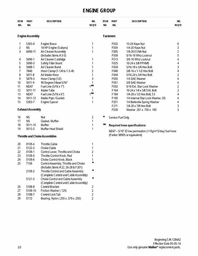
ENGINE GROUP
Engine Assembly
1 5303-4 Engine Brace 12 NS 14 HP Engine (Subaru) 13 6090-11 Air Cleaner Assembly 1
(Includes Items # 3-5) 4 5090-1 Air Cleaner Cartridge 15 5090-3 Safety Filter Insert 16 5088-1 Air Cleaner Band 17 7840 Hose Clamp (1-1/4 to 1-3-/4) 28 5011-8 Air Intake Hose 19 5879-3 Hose Clamp (1/2) 3
10 5011-9 90 Degree Elbow 5/16" 111 M247 Fuel Line (5/16 x 1") 1**12 5011-11 Intake Tube 113 M247 Fuel Line (5/16 x 6") 1**14 5011-12 Intake Pipe / Gasket 115 5303-7 Engine Spacer 1
Exhaust Assembly
16 NS Nut 217 NS Gasket,Muffler 118 5011-15 Muffler 119 5013-3 MufflerHeatShield 1
Throttle and Choke Assemblies
20 8108-4 ThrottleCable 121 5122-3 ChokeCable 122 5108-1 ControlLever,ThrottleandChoke 223 5108-5 ThrottleControlKnob,Red 124 5108-6 ChokeControlKnob,Black 125 7108 ControlAssembly,ThrottleandChoke * (Includes Items # 22, 26-28 & F201) 2108-2 ThrottleControlandCableAssembly * (Complete Control and Cable Assembly) 5121-3 ChokeControlandCableAssembly * (Complete Control and Cable Assembly) 26 5108-8 Control Bracket 227 5108-10 FrictionWasher(.125) 228 5108-7 Control Lock Tab 229 5172 Bearing,Nylon(.255x.379x.250) 2
Fasteners
F002 10-24KepsNut 6 F004 1/4-20KepsNut 3 F005 1/4-20 ESNA Nut 2 F009 5/16-18WhizLocknut 5 F013 3/8-16WhizLocknut 4 F025 10-24 x 3/8 PPHMS 4 F034 5/16-18 x 3/4 Hex Bolt 3 F040 3/8-16 x 1-1/2 Hex Bolt 4 F044 5/16-24 x 3/4 Hex Bolt 2 F050 1/4SAEWasher 4 F051 3/8SAEWasher 4 F052 5/16Ext.StarLockWasher 2 F164 10-24 x 1/4 x 3/8 SHL Bolt 2 F184 1/4-20 x 1/2 Hex Bolt, SS 4 F185 1/4InternalStarLockWasher,SS 4 F201 1/4BellevilleSpringWasher 4 F211 1/4-20 x 7/8 Hex Bolt 3 F539 Washer.281x.750x.185 3
* Service Part Only
** Required hose specifications: M247 – 5/16"IDlowpermeation(<15g/m^2/day)fuelhose(Parker 38905 or equivalent)

11
Beginning S/N 128442Effective Date 05-05-14Use only genuine Walker® replacement parts.
8600-12
9804-1
9804-1
F184
F004
F004 F539
F539
F185
F185
F185F184
F184F184
F185
16
17 18
19
F164
F050F201
F002
F002 F025
F005
F034F009
F009
F034
20
28 2729
2324
25
21
1
2 34
5
6
3
7
89 10
9
9
7121314
11
15
26
22
F050
Refer to Body / ChassisAssembly
F044
F044
F211
F211
F013F051
F040
F052
F052
F211
ENGINE GROUP
.
.
.
.
.
.
.
.
..
.
.
.
.
.
.
. .
.
.
.
.
.
.
.
.
.
.
.
.
.
.
.
.
.
.
.
.
.
.
.
.
.
.
.
.
.

ITEM PART DESCRIPTION NO. NO. NO. REQ’D
ITEM PART DESCRIPTION NO. NO. NO. REQ’D
12
Beginning S/N 128442Effective Date 05-05-14
Use only genuine Walker® replacement parts.
HYDROSTATIC GROUND DRIVE ASSEMBLIES
Ground Drive Assemblies
1 4024-5 Oil Expansion Reservoir 22 7840-4 Hose Clamp (3/4 to 1-1/2) 23 4024-7 O-Ring (15/16 x 1-1/8) 24 6024-1 Oil Reservoir Retainer 25 4024-15 O-Ring (3/8 x 1/2) 26 5026-14 Hydro-Gear ZT3100, RH 17 2028-6 Lockout Arm, RH 18 4407-4 Bow Tie Cotter Pin 39 7364-3 Idler Spring Bushing 1
10 7364-2 Torsion Spring 111 6345-4 Idler Arm 112 5025-18 Hydro Fan Washer 213 5025-17 Hydro Fan 214 7244-21 Hydro Pulley (4.075) Splined 215 5025-19 Hydro Fan Nut 216 7241-2 Transmission Drive Pulley (3-1/4MV) 1 (Includes Items # F067 & F171) 17 5232-1 Ground Drive Belt (Micro V) 118 5245-1 Idler Pulley 119 6325-2 Spacer Bushing (5/16) 120 2028-5 Lockout Arm, LH 121 5025-14 Hydro-Gear ZT3100, LH 122 9430-1 Spacer Tube 423 6215 Shock Mount / Body Lift Arm 1 (Includes Item # 24) 24 5830 Grease Fitting 2
Parking Brake Assembly
25 7406-1 Handle Grip, Red 126 6406-6 Parking Brake Lever 1 (Includes Item # 24) 27 6406-1 Brake Actuator Pull 128 2280 Clevis (3/8) 129 6406-2 Parking Brake Pull Rod 230 8655-4 Clevis Pin (5/16 x 3/4) 531 6406-4 Parking Brake Pull Mount, Inner 232 6406-5 Parking Brake Pull Mount, Outer 233 5665-1 Compression Spring (2-1/2) 234 5222 Extension Spring (1/2 x 3-1/4) 235 6406-3 Parking Brake Actuator 136 2406-4 Clevis Pin (5/16 x 1-1/8) 1
Wheel Assembly
37 5033-6 Wheel & Tire (18 x 7.00-8) 2 5030-6 Standard Tire (18 x 7.00-8) * 5031-2 Standard Wheel (8 x 5.00-5.00) * 5030-4 Tire Tube (18 x 8.50-8) *
Fasteners
F004 1/4-20 Keps Nut 3 F009 5/16-18 Whiz Locknut 9 F013 3/8-16 Whiz Locknut 4 F015 1/2-20 Wheel Lug Nut 8 F020 5/16-18 ESNA Nut 2 F029 1/4-20 x 1/2 Hex Bolt 1 F031 1/4-20 x 5/8 Hex Bolt 3 F034 5/16-18 x 3/4 Hex Bolt 2 F041 3/8-16 x 1-3/4 Hex Bolt 1 F042 3/8-16 x 2-1/4 Hex Bolt 2 F067 3/16 x 3/16 x 1 Key 1 F069 3/32 x 1/2 Cotter Pin 5 F129 10-24 x 1/2 PTHMS 2 F171 5/16-18 x 3/8 Set Screw 2 F182 1/4 x 5/8 x 1/8 Washer 2 F183 .312 x .700 x .074 Washer 3 F316 5/16-18 x 1-3/4 Hex Bolt 1 F336 3/8-16 Jam Nut 1 F388 3/8-16 x 2-1/2 Hex Bolt 2 F489 Washer 1/4 x 7/8 x .090 1 F529 Washer 1.0 OD x .515 ID x 1/8 2 F533 5/16-18 x 3-1/2 Socket Cap Bolt 4
* Service Part Only

13
Beginning S/N 128442Effective Date 05-05-14Use only genuine Walker® replacement parts.
9804-1
9804-1
1
2
23
34
4
8
8
910
11
14
1413
12
F529
F529
12
13 15
15
16
1718
19
20
21
22
25
26
28 27
24
F06936
30
30
29
29
3233
34
34
37
37
33
32
3131
35 30
8F069
F069 F069
F069
23 24
5
5
67
1
Refer to Main ComponentPower Transmission
Refer to Body / ChassisAssembly
Refer to Body / ChassisAssembly
Refer to Body / ChassisAssembly
F015
F067
F171 F171
F042
F388F489
F029
F388
F013
F013
F013
F013
F009
F009
F020
F020
F034
F009
F316
F031
F004
F183F336
F533
F009
F042
F041
F009
F182
F182
F129
F129
HYDROSTATIC GROUND DRIVE ASSEMBLIES
.
.
.
..
.
.
.
.
.
.
.
..
.
.
.
.
.
.
..
.
.
.
..
.
.
.
..
.
.
.
.
..
.
.
.
.
.
.
.
.
.
.
.
.
.
.
.
.
.
.
.
.
.

ITEM PART DESCRIPTION NO. NO. NO. REQ’D
ITEM PART DESCRIPTION NO. NO. NO. REQ’D
14
Beginning S/N 128442Effective Date 05-05-14
Use only genuine Walker® replacement parts.
STEERING CONTROL ASSEMBLIES
Steering Lever & FSC Assemblies
1 5862 FSC Knob 12 4170 FSC Lever Assembly (Includes Item # 4) *3 2170-1 Step Washer 14 5830 Grease Fitting 15 5214-5 Ball Joint (5/16-24/LH) W/O Stud 16 4173-1 Control Rod (4-15/16) 17 5214 Ball Joint (5/16-24) 18 4219 Extension Spring (3/4 x 6-1/2) 19 4451-9 FSC Friction Actuator 1
10 8201-3 Fiberglide Bearing 411 6451-2 Speed Control Actuator, RH 1 (Includes Items # 10 & 13) 12 4452-6 Steering Pivot (1/4-20 x 1-5/8) 213 5830-3 Grease Fitting (45 Degree) 214 5146 10mm Ball Stud 415 2215-7 Steering Lever Spring, Dampener 216 2463 Actuator Washer 217 7201-2 Fiberglide Bearing (1/2") 218 5463-2 Steering Lever Actuator 219 5665-1 Compression Spring (2-1/2) 220 4213-2 Control Rod (6-1/2) 221 5214-4 Ball Joint (5/16-24) W/O Stud 222 2212-3 Seal Retainer 223 2212 Transmission Control Arm Stop 224 6212-2 Transmission Control Arm, RH 125 6212-3 Transmission Control Arm, LH 126 6451-1 Speed Control Actuator, LH 1 (Includes Items # 10 & 13) 27 4451-1 Steering Pivot Shaft W/Stop 128 9704-3 Pivot Rod Bushing / Plastic 229 4142-2 FSC Friction Washer 1 (1-1/2 x 1-1/32 x 1/16) 30 5141 FSC Friction Washer (1-1/2 x 3/8 x 1/16) 131 4142-1 FSC Cam 132 5222 Extension Spring (1/2 x 3-1/4) 233 5450 D-Clip 234 6452-1 Steering Lever Tube W/Tab 235 5453-10 Steering Lever Handle / Adjustable 2 (Includes Items # 36 & F345) 36 5850-2 Handle Grip, Foam (5-1/2) 2
Fasteners
F004 1/4-20 Keps Nut 2 F005 1/4-20 ESNA Nut 2 F009 5/16-18 Whiz Locknut 6 F010 5/16-24 ESNA Nut 2 F024 5/16-24 Jam Nut 3 F035 5/16-18 x 1-1/4 Hex Bolt 1 F044 5/16-24 x 3/4 Hex Bolt 2 F059 3/8 Wave Spring Washer 1 F093 5/16-18 x 1 Hex Bolt 2 F146 1/4-20 Jam Nut 2 F167 5/16-18 Hex Nut 1 F183 .312 x .700 x .074 Washer 6 F188 1/4-20 Self-Locking Nut 4 F192 3/8-24 Self-Locking Nut 1 F198 .250 x .625 x .040 Washer, SS 2 F211 1/4-20 x 7/8 Hex Bolt 1 F312 3/8 x 3/8 Shoulder Bolt 1 F345 1/4-20 x .770 Knurled Bolt 4 F360 1/4-20 x 3/8 Hex Bolt 2 F373 5/16-24 Hex Nut, LH 1 F385 1/4 x 1-1/4 Roll Pin 1 F386 5/16-18 x 1-1/2 x 3/8 Shoulder Bolt 1 F391 1/4-20 x 1/2 Set Screw, SS 2 F407 Belleville Washer 3/8 x 1.187, SS 1 F427 5/16-18 Flange Nut 1
* Service Part Only

15
Beginning S/N 128442Effective Date 05-05-14Use only genuine Walker® replacement parts.
9804-1
9804-1
1016
17
18
17
12
12
10
10
10
2716
F005
F010
F360F360
F005
3332
3332
36
3635
34
34
35
F345F188
F198
F009
F009
F188
F345F198
F4273
4
7
6F386F059
F183
F024F093
1
2
5
13
14
14
14
1426
13
1519
19
20
20
22
22
2121
23
23
25
15
118
F385
9
F093F183
F167F035
F373
F009
F009
31 30
29 28
28
F312
F192
F407F004
F004F211
24
F044F024
F024
F183
F183
F009
F009
F009
F009
F044
F183
F391
F391
F146 F093
F183F183
F146
F183
Refer to Body / Chassis Assembly
Refer to Hydrostatic GroundDrive Assemblies
Refer to Hydrostatic GroundDrive Assemblies
Refer to Hydrostatic GroundDrive Assemblies
STEERING CONTROL ASSEMBLIES .
.
.
.
.
.
.
.
.
.
.
.
.
.
..
.
.
.
.
.
.
.
.
.
.
.
.
.
.
.
.
.
.
.
.
.
.
.
.
.
.
.
.
..
.
.
.
.
.
.
.
.
.
.
.
.
.
.
.
.

ITEM PART DESCRIPTION NO. NO. NO. REQ’D
ITEM PART DESCRIPTION NO. NO. NO. REQ’D
16
Beginning S/N 128442Effective Date 05-05-14
Use only genuine Walker® replacement parts.
GHS GROUP
Delivery Chute Assembly
1 5515-2 Elbow Delivery Spout 12 5592-13 Backing Plate, Grass-Pak® Switch 13 5578 Rear Clip, Chute Mount 14 5577 Side Clip, Chute Mount 25 6530-6 Body Chute 16 7511-5 Outside Chute Cover Lip 17 7511-4 Inside Chute Cover Lip 18 7511-2 7.0 Delivery Chute W/Clips 1
(Includes Items # 3, 4, F079 & F411)
Blower Assembly
9 6543-5 Blower Scroll 110 4349-10 Flanged Bearing (3/4") 211 6349-1 Sleeve .3150 x .375 x 3/8 212 5526-9 Receiver Cone 113 5275-15 U-Joint Tube/9.5" OAL Spline 1 (Includes Item # F076) 14 6545-1 Blower Wheel 115 6543-4 Blower Faceplate 116 6543-6 Blower Ring 117 5794-4 Fixed Chute 1 (Includes Items # 18, 19 & F079)18 5794-10 Rubber Flap 219 5794-9 Backing Plate 2
Fasteners
F002 10-24 Keps Nut 6 F004 1/4-20 Keps Nut 18 F009 5/16-18 Whiz Locknut 2 F013 3/8-16 Whiz Locknut 2 F025 10-24 x 3/8 PPHMS 4 F026 10-24 x 1/2 PPHMS 2 F031 1/4-20 x 5/8 Hex Bolt 2 F032 1/4-20 x 3/4 Hex Bolt 4 F038 3/8-16 x 1 Hex Bolt 2 F050 1/4 SAE Washer 2 F067 3/16 x 3/16 x 1 Key 1 F076 3/8-16 x 5/8 SQH Set Screw 1 F079 A/A66D Aluminum Pop Rivet 14 F169 5/16-18 x 1 Carriage Bolt 2 F411 3/16 Bulbex Rivet 6 F426 1/4-20 x 1/2 Carriage Bolt 4 F531 1/4-20 x 5 Hex Bolt 11 F532 1/4-20 x 5-1/2 Hex Bolt 1
NOTE: Refer to ELECTRICAL CONNECTORS, Page 26, for iden-tification of all Electrical Wiring Service Parts.

17
Beginning S/N 128442Effective Date 05-05-14Use only genuine Walker® replacement parts.
Refer to Main Component Power Transmission
Refer to Main Component Power Transmission
9804-1
9804-1
Refer to Body / ChassisAssembly
Refer to GHS PowerfilAssembly (7.0)
48
3
F411
F079
F025
F002
F004
F004
F532
F531
F004
F079F079
7
65
9
14
15
10
10
12
16
1819
1819
17
Refer to GHS 7.0 BushelCatcher Assembly
Refer to Electrical Assemblies(GHS 7.0 BushelComponents)
1
4
Refer to Electrical Connectors
2
F002
F026
F079F411
F411
F076
13
F426
F067
F038F013
F013
F169
F169
F009
F009
F004
11
11
F031
F050
F032
GHS GROUP
.
.
.
.
..
.
.
.
.
.
.
.
.
.
..
.
.
.
.
.
.
.
.
.
..
.
.
.
.
.
.
.
.
.

18
Beginning S/N 128442Effective Date 05-05-14
Use only genuine Walker® replacement parts.
ITEM PART DESCRIPTION NO. NO. NO. REQ’D
ITEM PART DESCRIPTION NO. NO. NO. REQ’D
GHS POWERFIL® ASSEMBLY (7.0)
7.0 GHS Powerfil® Assembly
1 5552 Ball Joint (1/4-28) 22 5553-3 Bushing,Powerfil® Actuator 43 5553-1 Compression Spring (1/2 x 2) 24 5558-2 Powerfil® Actuator Rod 1
5549 Actuator Rod Assembly * (Includes Items # 1-5 & F003)
5 5558-1 Powerfil® Push Rod 16 5551-3 BearingCap,Powerfil® 17 5551-1 Pivot Bearing (#S3PP) 28 5518-2 Pivot, Delivery Spout 19 5517-2 Pivot Mount 1
10 5519-5 Actuator Motor (12V) 1 (Includes Items # 11 & 12) 11 5519-2 Motor Mount Washer *12 5519-3 Motor Mount Nut (5/8-24) *13 5554 Actuator Arm 1
Fasteners
F002 10-24 Keps Nut 10 F003 1/4-28 Hex Nut 3 F026 10-24 x 1/2 PPHMS 1 F037 10-24 x 5/8 PTH Screw 2 F054 AN960616 Washer 1 F085 3/16 Rivet Backup Washer 1 F101 10-24 x 1-1/4 SHC Screw 1 F109 1/8 x 5/8 Roll Pin 1 F129 10-24 x 1/2 PTHMS 6 F261 AN960616L Washer 1 F287 1/4-28 Keps Nut 1
* Service Part Only

19
Beginning S/N 128442Effective Date 05-05-14Use only genuine Walker® replacement parts.
Refer to GHS Group
F037F129
F002
F129
F002
F002
F002 8
7
9
10
11 12 13
1
2
2
2
2
3
4
5
61
3Refer to Electrical Assemblies(GHS 7.0 Bushel Components)Refer to
Electrical Assemblies(GHS 7.0 Bushel Components)
Refer to GHS 7.0 Bushel Catcher Assembly
F129F037
F287
F002
F002F085
F026
F101F003
F003
F003 F109 F261
F054
GHS POWERFIL® ASSEMBLY (7.0).
.
.
.
.
.
.
.
..
.
.
.
.
.
.
.
.
.
.
.
.
.
.
.
20
Beginning S/N 128442Effective Date 05-05-14
Use only genuine Walker® replacement parts.
ITEM PART DESCRIPTION NO. NO. NO. REQ’D
ITEM PART DESCRIPTION NO. NO. NO. REQ’D
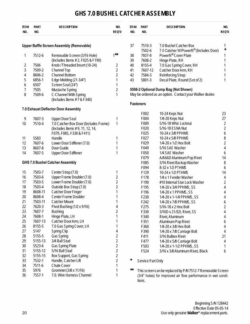
GHS 7.0 BUSHEL CATCHER ASSEMBLY
Upper Baffle Screen Assembly (Removable)
1 7512-6 Removable Screen (3/16 Hole) 1** (Includes Items # 2, F025 & F190)
2 7506 Knob / Threaded Insert (10-24) 23 7509-2 Channel Top 24 8606-2 Channel Bottom 25 6856-1 Edge Molding (21-3/4") 16 6507 Screen Seal (24") 17 7505 Mustache Spring 28 7509-6 C-Channel With Spring 1
(Includes Items # 7 & F340)
7.0 Exhaust Deflector Door Assembly
9 7607-3 Upper Door Seal 110 7510-4 7.0 Catcher Box Door (Includes Frame) 1 (Includes Items # 9, 11, 12, 14, F079, F085, F330 & F411)11 5583 Handle 112 7607-6 Lower Door Stiffener (7.0) 113 8607-8 Door Guide 114 7607-5 Upper Door Stiffener 1
GHS 7.0 Bushel Catcher Assembly
15 7503-7 Center Strap (7.0) 116 7503-6 Upper Frame Doubler (7.0) 217 7503-5 Lower Frame Doubler (7.0) 218 7503-4 Outside Box Strap (7.0) 219 8608-11 Catcher Door Finger 120 8608-4 Center Frame Doubler 121 7503-11 Catcher Mount 122 7620-3 Pivot Bushing (1/2 x 9/16) 423 7607-7 Bushing 224 7608-1 Hinge Plate, LH 125 7607-13 Catcher Door Arm, LH 126 8155-5 7.0 Gas Spring Cover, LH 127 5147 Spring Clip 428 5155-5 Gas Spring 229 5155-13 3/4 Ball Stud 230 5523-6 Gas Spring Plate 231 5155-12 5/16 Ball Stud 232 5155-15 Box Support, Gas Spring 233 7532-1 Handle, Catcher Lift 234 7511-6 Chute Cover 135 5976 Grommet (3/8 x 11/16) 136 7557-1 7.0. Wire Harness Channel 1
37 7510-3 7.0 Bushel Catcher Box 1 7502-6 7.0CatcherW/Powerfil® (Includes Door) *38 7607-8 Powerfil® Cover Plate 139 7608-2 Hinge Plate, RH 140 8155-4 7.0 Gas Spring Cover, RH 141 7607-12 Catcher Door Arm, RH 142 7584-3 Reinforcing Strap 143 5801-3 Decal Plate, Round (Set of 2) 1
5598-2 Optional Dump Bag (Not Shown)May be ordered as an option. Contact your Walker dealer.
Fasteners
F002 10-24 Keps Nut 23 F004 1/4-20 Keps Nut 27 F009 5/16-18 Whiz Locknut 2 F020 5/16-18 ESNA Nut 2 F025 10-24 x 3/8 PPHMS 6 F027 10-24 x 5/8 PPHMS 8 F029 1/4-20 x 1/2 Hex Bolt 2 F049 5/16 SAE Washer 4 F050 1/4 SAE Washer 6 F079 A/A66D Aluminum Pop Rivet 14 F085 3/16 Rivet Backup Washer 8 F094 8-32 x 1/2 PTHMS 6 F129 10-24 x 1/2 PTHMS 14 F178 1/4 x 1 Fender Washer 4 F190 #10 Internal Star Lock Washer 2 F195 1/4-20 x 3/4 PPHMS, SS 4 F196 1/4-20 x 1 PPHMS, SS 4 F230 1/4-20 x 1-1/4 PPHMS, SS 4 F242 1/4-20 x 7/8 PPHMS, SS 6 F275 5/16-18 x 2 Hex Bolt 2 F330 3/16D x 21/32L Rivet, SS 4 F340 Rivet, Aluminum 4 F351 Aluminum Pop Rivet 6 F360 1/4-20 x 3/8 Hex Bolt 4 F390 1/4-20 x 7/8 Carriage Bolt 4 F411 3/16 Bulbex Rivet 21 F477 1/4-20 x 5/8 Carriage Bolt 4 F503 1/4-20 x 1-1/2 PPHMS, SS 1 F524 3/16 x 3/8 Aluminum Rivet, Black 6
* Service Part Only
** This screen can be replaced by P/N 7512-7 Removable Screen (3/4"holes) for improvedairflowperformance inwetcondi-tions.

21
Beginning S/N 128442Effective Date 05-05-14Use only genuine Walker® replacement parts.
F477F178
F004
F025F025
F025
F002
F002
F002
F002
F002
F190
F340
F340
F340
F129
F330
F411
F079
F079
F360F360
F411
F050
F050
F050F029
F027F027
F129
F129
F027
F027
F351
F351
F275
F085
F085
F242F242
F004
F004
F503
F004
F004F004
F004
F004
F004
F004
F004
F004
F004
F094
F004F004
F002
F002
F002F524
F390
F390
F351
F027
F027 F027 F275
F351
F027
F129
F129F002
F002F002
F049
F049
F079
F242F242
F242
F020
F009
F029F050
F411F411
F411F411
F009
F020 F049
F049
F004 F196
F196
F242F195
F195
F195
F195
F050F360
F129
F129
F129
2 3
914
10
11
13
1216
17
25
22242322
21
2019
18
15
16
1718
43
42
37
26
28 27
29
31
30
3233
34
38
33
32
40 41
22
31
23 22
39
302827
29
4
78
7
1
43
F230
F230
Refer to Rear Body AssemblyRefer to
Rear Body Assembly
Refer to Electrical Assemblies(GHS 7.0 Bushel Components)
5
6
F129F129
F002
F002 35
36
F002
F002F129
GHS 7.0 BUSHEL CATCHER ASSEMBLY.
.
.
.
.
.
.
.
..
.
.
.
.
.
.
.
.
.
.
.
.
.
.
..
.
.
.
.
.
.
.
.
.
.
.
.
.
.
.
.
.
.
.
.
.
.
.
.
.
.
.
.
.
.
.
.
.
.
.
.
.
.
.
.
.
.
.
.
.
.
.

ITEM PART DESCRIPTION NO. NO. NO. REQ’D
ITEM PART DESCRIPTION NO. NO. NO. REQ’D
22
Beginning S/N 128442Effective Date 05-05-14
Use only genuine Walker® replacement parts.
ELECTRICAL ASSEMBLY
Electrical Assembly
1 5942-11 Delta Hex Nut 12 5942-9 Safety Switch (NO), Delta Threaded 13 7834-3 Wire Saddle (3 Wires) 34 5832 Cable Clamp (1/2) 15 5975-1 Cable Tie (18# x 3-3/4") 36 5943-5 Wire Harness Assembly 17 5942-10 Safety Switch (NC), Delta Side Mount 18 5942-8 Safety Switch (NO), Delta Side Mount 19 4024-13 Safety Switch Plate 1
10 6942 Relay Switch (30/40 Amp) NC 3 (Includes Items # 11 & 12) 11 6941-6 Relay Switch (30/40 Amp) *12 6941-7 Relay Mount *13 8990-1 Hourmeter (Global) 114 8960-15 Ignition Switch (with Keys) 1 (Includes Items # 15, 16 & F349) 15 7854 Plastic Tip / Red 116 8960-3 Key Set W/Umbrella 117 7941-3 Boot, Circuit Breaker 118 7941-6 Circuit Breaker (15 Amp) 1
Battery Assembly
19 6923 Battery Cable (-) 120 5932 Battery Terminal Insul., Black (-) 121 5933 Battery Terminal Insul., Red (+) 122 NS Battery (12V/300.CA/Wet) 123 5844-3 Battery Protector Plate 124 5839 Hook Bolt 225 4940-6 Battery Cable (33") 126 6832 Cable Clamp (9/16 x 1/4) 1
Fasteners
F002 10-24 Keps Nut 4 F004 1/4-20 Keps Nut 5 F019 1/4-20 ESNA Wing Nut 2 F025 10-24 x 3/8 PPHMS 1 F026 10-24 x 1/2 PPHMS 3 F029 1/4-20 x 1/2 Hex Bolt 3 F031 1/4-20 x 5/8 Hex Bolt 2 F050 1/4 SAE Washer 4 F112 5/8 x 1-1/4 x .03 Washer 3 F146 1/4-20 Jam Nut 1 F211 1/4-20 x 7/8 Hex Bolt 1 F349 Washer .835 ID 1.122 OD, SS 1 F505 6-32 x 7/8 Hex Trim MS, SS 4 F506 6-32 Nylock Nut 4
* Service Part Only
NOTE: Refer to ELECTRICAL CONNECTORS, Page 26, for iden-tificationofallElectricalWiringServiceParts.
NOTE: Decals for this assembly are not shown here. Refer to TRACTOR DECALS, Page 2, for Decal listing and place-ment information.

23
Beginning S/N 128442Effective Date 05-05-14Use only genuine Walker® replacement parts.
9804-1
9804-1
E
7
6
YEL
RED
WHT/BLK PUR/WHT
BLK
10
10
8
9
4
26 25
232422
5
19 5
5
20
21
10
<15°
8600-4
1.
2.
2
F112
F025
F002
F031
F031
F019F019F004
F004
F004
F029
F505
F505
F211F146
F004
F029
F506
F506
F026F002
F050F050F050
F050
1
J
A
D
B
13
1414
15
16
14
17 18F349
24
3
33
DETAIL E
DETAIL G
DETAIL FEND VIEWS ARE SHOWN FROM BACK OF PLUG
DETAIL A
WHT
BLK RED
BLURED/WHTYEL
PUR/WHTPUR
DETAIL C
PUR/WHT BRNBLU
DETAIL I
DETAIL B DETAIL D
DETAIL J
PUR PUR/RED
DETAIL H
RED/WHT
BLK
ORG/WHTBLK
BRN/WHT
ORG
PURPUR
BLKBLK
YEL
YEL
PUR
BLK
ORG
PUR/RED
BLKBLK
BLKBLK
WHTBLK/WHT
BRN
BRN/WHTORG/WHT
RED
RED
Refer to Body / ChassisAssembly
Refer to Body / ChassisAssembly
Refer to Body / ChassisAssembly
Refer to Steering ControlAssemblies
Refer to Main ComponentPower Transmission
C
FG
1211
H
I
ELECTRICAL ASSEMBLY
.
.
.
.
.
.
.
.
.
.
.
.
.
.
..
.
.
.
.
.
.
.
.
.
.
.
.
.
.
.
.
.
.
.
.
.
.
.
.

24
Beginning S/N 128442Effective Date 05-05-14
Use only genuine Walker® replacement parts.
ITEM PART DESCRIPTION NO. NO. NO. REQ’D
ITEM PART DESCRIPTION NO. NO. NO. REQ’D
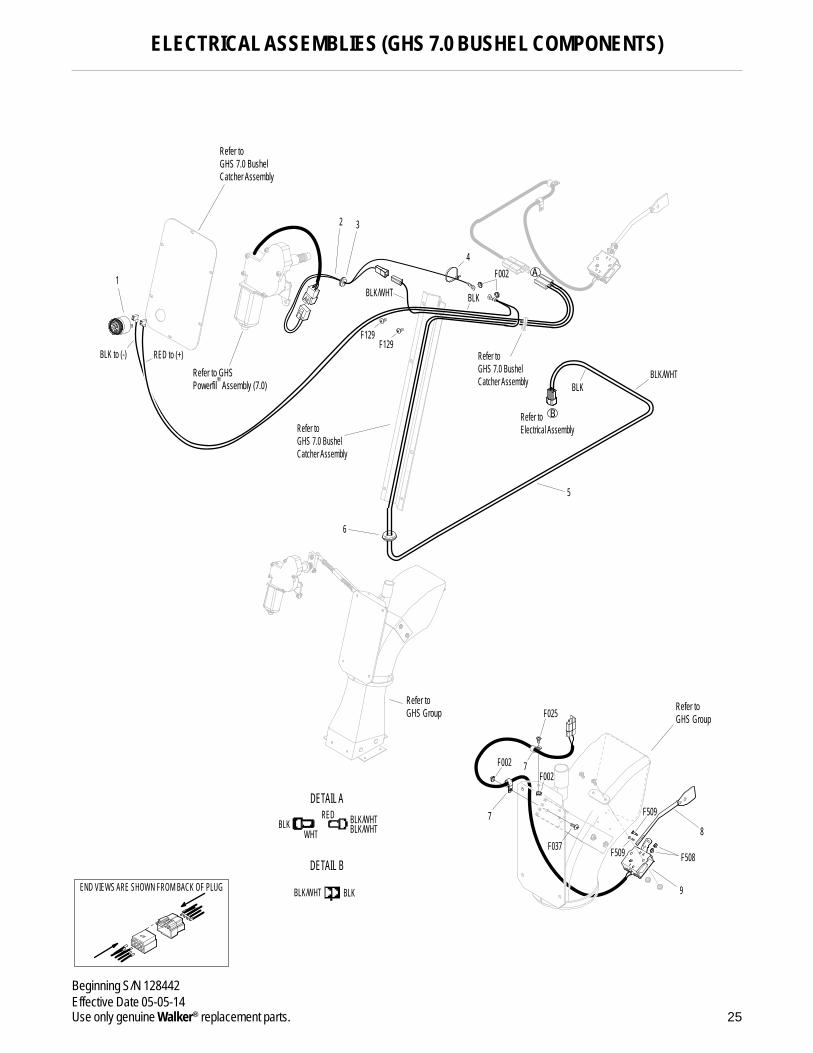
ELECTRICAL ASSEMBLIES (GHS 7.0 BUSHEL COMPONENTS)
Horn & Harness Channel Assemblies
1 5536-2 Horn, Full Signal *2 5519-4 Adapter Harness 13 5976-2 Grommet (3/16 x 3/4) 14 5975-1 Cable Tie (18# x 3-3/4") 1
Harness & Grass-Pak® Switch Assemblies
5 8950 9.5 / 10.0 Wire Harness 16 5976 Grommet (3/8 x 11/16) 17 5833 Cable Clamp (1/4) 28 5594-6 Aluminum Shaft & Vane Assembly 19 5592-14 Grass-Pak® Switch Assembly 1
Fasteners
F002 10-24 Keps Nut 4 F025 10-24 x 3/8 PPHMS 1 F037 10-24 x 5/8 PTH Screw 1 F129 10-24 x 1/2 PTHMS 2 F508 4-40 Keps Nut, SS 2 F509 4-40 x 1/2 Hex Head, SS 2
* Service Part Only
NOTE: Refer to ELECTRICAL CONNECTORS, Page 26 for identi-ficationofallElectricalWiringServiceParts.
25
Beginning S/N 128442Effective Date 05-05-14Use only genuine Walker® replacement parts.
9
8
F509
F509 F508
Refer to GHS 7.0 Bushel Catcher Assembly
RED to (+)BLK to (-)
BLKBLK/WHT
BLK/WHT
F129F129
F002
Refer toGHS Group
6
1
5
4
2 3
Refer toGHS 7.0 BushelCatcher Assembly
Refer toGHS 7.0 BushelCatcher Assembly
Refer toElectrical Assembly
BLK
REDBLK
BLK
WHTBLK/WHT
BLK/WHT
BLK/WHT
DETAIL A
DETAIL B
B
A
Refer to GHSPowerfil Assembly (7.0)
F002F002
7
7
F025
F037
Refer to GHS Group
ELECTRICAL ASSEMBLIES (GHS 7.0 BUSHEL COMPONENTS)
.
.
.
.
.
.
.
END VIEWS ARE SHOWN FROM BACK OF PLUG
.
.
.
.
.
.
.
.
.
.

ITEM PART DESCRIPTION NO. NO. NO. REQ’D
ITEM PART DESCRIPTION NO. NO. NO. REQ’D
26
Beginning S/N 128442Effective Date 05-05-14
Use only genuine Walker® replacement parts.
ELECTRICAL CONNECTORS
Electrical Wiring Service Parts
1 5996-1 16-14 GA Butt Connector *2 5996-11 12-10 GA Butt Connector *3 7942-14 16-14 GA Shrink Connector *4 7942-13 12-10 GA Shrink Connector *5 5995-1 Wire Terminal Adapter *6 5996-4 16-14 GA Bullet Conn., Male *7 5996-5 16-14 GA Bullet Conn., Female *8 5940-4 16-14 GA Spg. Loaded Term., Female *9 5940-7 Wire Clip, Female *
10 5996 1/4 x 16-14 GA QKS Term., Female *11 5996-2 3/16 x 22-18 GA QKS Term., Female *12 7996 16-14 GA QKS Term., Female *13 5940-5 16-14 GA Spg. Loaded Term., Male *14 5996-0 1/4 x 22-18 GA QKS Term., Male *15 5996-18 16-14 GA Ring Term. (#8) Nylon Insulated *16 7996-1 1/4 x 16-14 GA QKS Term., Male *17 5996-8 6 GA Ring Lug (5/16) *18 5996-9 22-18 GA Ring Term., #10 *19 5996-10 16-14 GA Ring Term. (5/16) *20 5996-12 12-10 GA Ring Term. (5/16) *21 5996-13 16-14 GA Ring Term., # 10 *22 5996-15 12-10 GA Ring Term. (1/2) *23 5996-16 6 GA Ring Terminal (1/4) *24 5996-17 16-14 GA Ring Term. (1/4) *25 5996-20 12-10 GA Ring Term. (1/4) *26 5996-21 12-10 GA Ring Term., #10 *27 7942-4 Single Connector, Male *28 8942 2-Way Connector, Male *
29 7942-1 2-Way Locking Connector, Female *30 7942-2 2-Way Connector, Male *31 7942-3 2-Way Connector, Female *32 7942-10 2-Way Locking Connector, Male *33 5940-8 3-Way Connector, Male *34 7942-9 3-Way Connector, Male *35 8944 3-Way Locking Connector, Male *36 8944-1 3-Way Locking Connector, Female *37 7942-11 4-Way Connector, Male *38 7942-12 4-Way Connector, Female *39 7942-5 5-Way Connector, Male *40 5940-2 5-Way Connector, Male *41 8942-1 5-Way Connector, Female *42 7942-6 6-Way Connector, Male *43 7942-7 6-Way Connector, Male *44 7942-8 8-Way Connector, Male *45 8942-2 8-Way Connector, Female *46 8942-3 5-Way Connector, Male *47 5940-9 3-Way Connector (M) *48 7942-15 6-Way Connector (Female) *49 7940-3 Packard Plug (Male) *50 7940-4 Packard Plug (Female) *
* Service Part Only
NOTE: Not all Electrical Connectors are used with all assemblies.
NOTE: Refer to ELECTRICAL ASSEMBLY, Page 22, for loca-tions of Wiring Harness, Electrical Components and of all Electrical Wiring Service Parts.

27
Beginning S/N 128442Effective Date 05-05-14Use only genuine Walker® replacement parts.
6
7
1
2
3
4
5
9
10
8
12
13
11
16
17
14
15
19
20
18
22
23
21
25
26
24
28
29
27
31
32
30
34
35
33
37
38
36
40
41
39
43
44
42
46
47
48
49
50
45
ELECTRICAL CONNECTORS
.
.
.
.
.
.
.
.
.
.
.
.
.
.
.
.
.
.
.
.
.
.
.
.
.
.
.
.
.
.
.
.
.
.
.
.
.
.
.
.
.
.
.
.
.
.
.
.
.
.

ITEM LOCATION LUBRICATION NO. NO. TYPE PLACES
ITEM LOCATION LUBRICATION NO. NO. TYPE PLACES
28
Beginning S/N 128442Effective Date 05-05-14
Use only genuine Walker® replacement parts.
LUBRICATION POINTS
Lubrication Points
1 Steering Lever Pivot Grease 22 FSC Lever Pivot Grease 13 Deck-to-PTO Coupling Grease 1 (Grease Spline Slide Area) 4 Transaxle Oil Reservoir Oil/20W-50 25 Universal Joint Tube Assembly Grease* 16 Deck Support Arm Pivot Grease 27 Hydro Idler Pivot Grease 18 PTO Clutch Lever Pivot Grease 19 Body Latch Pivot Oil 1
10 Clutch Actuator Push Rod Grease 1 (Grease Slide Area) 11 PTO Belt Tightener Pivot Grease 1
12 Engine Dipstick / Oil Filler Oil** 113 Catcher Hinge Point Oil 214 Choke Control Cable Ends Oil 215 Throttle Control Cable Ends Oil 216 Engine Idler Pivot Grease 117 Parking Brake Lever Grease 118 Choke Control Pivot Oil 119 Throttle Control Pivot Oil 1
* Grease every eight (8) hours.
** Refer to Engine Oil in Operator’s Manual.
NOTE: See Model S14 Operator’s Manual (P/N 5000-28) for proper lubrication intervals.

29
Beginning S/N 128442Effective Date 05-05-14Use only genuine Walker® replacement parts.
LUBRICATION POINTS
1
23
54
6
7
8
9
10
12
1313
14
15
17
14 & 1846
15 & 19
16
11

30
Beginning S/N 128442Effective Date 05-05-14
Use only genuine Walker® replacement parts.
WIRING SCHEMATIC
BLUBRN
PUR/WHT
RED/WHT
ORG
BRN/WHT BLK
RED
WHT
YEL
RED/WHT BLU
BLK
REDPUR
PUR/WHT
RED
HOURMETER
B
A
M
S1
S2
G
15 AMPCIRCUIT
BREAKER
BATTERY
S1 = START CIRCUITS2 = START/ACCESSORY CIRCUITM = MAGNETO GROUND CIRCUITB = BATTERY CIRCUITA = ACCESSORY CIRCUITG = GROUND CIRCUIT
IGNITION SWITCH CIRCUITSOFF
STARTRUN
G + MB + A / S1 + S2B + A
RUN
RELAY - ASTART RELAY
OFFSTART 30 + 87
30 + 87
30 + 87A
RUN
RELAY - BIGNITION RELAY
OFFSTART 30 + 87
30 + 87
30 + 87A
RUN
RELAY - CPTO INTERLOCK RELAYOFF
START
PTO ON
30 + 8730 + 87
30 + 87A
30 + 87
WALKER MODEL S14 Beginning S/N 2014-128442
STARTER
ALTERNATOR
MAGNETO
ENGINE GROUND
ENGINE
CASE GROUNDTO MOTOR MOUNT
POWERFILMOTOR
GRASS PAKSWITCH
R
R
HORN
STARTER SOLENOID
BLKBLK
SEATSWITCH
PTOSWITCH
FSCNEUTRAL
INTERLOCKSWITCH
RELAY - B
BRN/WHT
ORG/WHT
ORG/WHT
PUR/RED
WHT
PUR
BLK
BLK
YEL
YEL
BRN
ORG
BLK
BLK
BLK
BLK
BLK
PUR
PUR
PUR
RED
BLK
PUR/WHT
WHT/BLK
YEL
RELAY - C
PUR/RED
RELAY - A
BLK
ORG BLK
BLK
BLKWHT
RED
+
-
WHT/BLK
87A
30
85
87
87 87A
30
8685
30
8585
87
86
87A
86

31
Beginning S/N 128442Effective Date 05-05-14Use only genuine Walker® replacement parts.
OPERATOR’S NOTES

32
Beginning S/N 128442Effective Date 05-05-14
Use only genuine Walker® replacement parts.
OPERATOR’S NOTES

33
LIMITED WARRANTYFOR
WALKER MODEL S14RIDER MOWER
1. WHAT THIS WARRANTY COVERS, AND FOR HOW LONG:
Walker Manufacturing company will, at its option, repair or replace, without charge, any part covered by this warranty which is found to be defective in material and/or workmanship within one (1) year* after date of sale to the original retail purchaser unless the product is used for rental purposes, in which case this warranty is limited to ninety (90) days. At Walker’s request, customer will make the defective part available for inspection by Walker and/or return the defective part to Walker, transportation charges prepaid. All parts and compo-nents of the Walker Mower are covered by this warranty except the following components which are warranted separately by their re-spective manufacturers:
Subaru EngineHydro-Gear TransaxlesBatteryTires
The available warranties covering these items are furnished with each mower. Walker does not assume any warranty obli gation, liability or modification for these items, which are covered exclusively by the stated warranty of the respective man ufacturers noted above.
* A two (2) year or 2000 hour (whichever comes first) warranty is offered for Hydro-Gear ZT3100 hydrostatic transmissions; covers full cost of replacement up to 1000 hours of use, and after 1000 hours warranty coverage is prorated against 2000 hours.
2. WHAT THIS WARRANTY DOES NOT COVER:
A. This warranty does not cover defects caused by depreciation or damage caused by normal wear, accidents, improper maintenance, improper use or abuse of the product, alterations, or failure to follow the instructions contained in the Operator’s Manual for operation and maintenance.
B. The customer shall pay any charges for making service calls and/or for transporting the mower to and from the place where the inspection and/or warranty work is performed.
3. HOW TO OBTAIN SERVICE UNDER THIS WARRANTY:
Warranty service can be arranged by contacting the dealer where you purchased the mower or by contacting Walker Man ufacturing Company, 5925 East Harmony Road, Ft. Collins, CO 80528. Proof of the date of purchase may be required to verify warranty coverage.
4. WARRANTY LIMITATION:
A. THERE IS NO OTHER EXPRESS WARRANTY. ANY WARRANTY THAT MAY BE IMPLIED FROM THIS PURCHASE INCLUDING MERCHANTABILITY AND FITNESS FOR A PARTICULAR PURPOSE IS HEREBY LIMITED TO THE DURATION OF THIS WARRANTY AND TO THE EXTENT PERMITTED BY LAW ANY AND ALL IMPLIED WARRANTIES ARE EXCLUDED. Some states do not allow limitations on how long an implied warranty lasts, so the above limitations may not apply to you.
B. WALKER WILL NOT BE LIABLE FOR ANY INCIDENTAL, CONSEQUENTIAL, OR SPECIAL DAMAGES AND/OR EXPENSES IN CONNECTION WITH THE PURCHASE OR USE OF THE MOWER. Some states do not allow the exclusion or limitation of incidental or consequential damages, so the above limitation(s) or exclusion(s) may not apply to you.
C. Only the warranty expressed in this limited warranty shall apply and no dealer, distributor, or individual is authorized to amend, modify, or extend this warranty in any way. Accordingly, additional statements such as dealer advertising or presentations, whether oral or written, do not constitute warranties by Walker, and should not be relied upon.
D. This warranty gives you specific legal rights, and you may also have other rights which vary from state to state.

WALKER MFG. CO. • 5925 E. HARMONY ROAD, FORT COLLINS, CO 80528 • (970) 221-5614FORM NO. 050514 PRINTED IN USA www.walkermowers.com ©2014 WALKER MFG. CO