Biomechanical Configurations of Mandibular Transport Distraction Osteogenesis Devices
12
Biomechanical Configurations of Mandibular Transport Distraction Osteogenesis Devices Uriel Zapata, M.Sc., Ph.D., 1,2 Mohammed E. Elsalanty, M.D., Ph.D., 3 Paul C. Dechow, Ph.D., 2 and Lynne A. Opperman, Ph.D. 2 Mandibular bone transport (MBT) distraction osteogenesis devices are used for achieving reconstruction of mandibular defects in a predictable way, with few complications, less complexity than other alternative surgical procedures, and minimal tissue morbidity. However, selection of appropriate MBT device characteristics is critical for ensuring both their mechanical soundness and their optimal distraction function for each patient’s condition. This article assesses six characteristics of currently available MBT devices to characterize their design and function and to classify them in a way that assists the selection of the best device option for each clinical case. In addition, the present work provides a framework for both the biomechanical conception of new devices and the modification of existing ones. Introduction A myriad of mandibular bone transport (MBT) de- vices are being developed or are already being used for creating bone in the mandible (Table 1), making it difficult to choose the most appropriate device to use. The literature shows that there is a good understanding of how device position and vector of distraction affect the ability to conduct MBT effectively; however, there appears to be a dearth of understanding as to how the device mechanism of action, its method of anchorage, and its relation to the soft tissues in- fluence the eventual outcome. This review article informs the reader of the types of devices that are available and discusses the importance of understanding their biomechanical mech- anisms, both for improving device design and for choosing the most appropriate device for achieving successful MBT outcomes. Distraction osteogenesis is a surgical technique for the growth of new bone through the application of tensile stresses to a preexisting tissue laying between two bone ends. This technique of skeletal regeneration generally involves four stages 1,2 : (1) creation of a full osteotomy or a corti- cotomy, (2) latency period or callus formation between two bone ends, (3) distraction period or bone formation by callus stretching, and (4) consolidation or new bone tissue matu- ration. Although distraction osteogenesis was first popular- ized by Ilizarov in the mid-20th century to correct long bone defects, 3,4 its application was extended to the distraction of the membranous bones of the craniofacial skeleton by Snyder et al. in 1973. They removed 15 mm of bone in canine man- dibles, generating a severe crossbite that was then reopened with an external distraction device (Fig. 1). 5 The mandibular distraction procedure was further devel- oped by Michieli and Miotti. 6 They performed bilateral dis- traction in two dogs, using an external tooth-borne device to lengthen the mandible by 15 mm. Based on their histologic and microscopic results, they suggested the first mandibular distraction operative protocol in humans, involving a latency period of 1 week after osteotomy, an activation rate of 1 mm on alternate days, and a minimum consolidation period of 45 days for every 15 mm of distraction. 6 Since previous animal studies showed the high potential of mandibular distraction osteogenesis to correct deformities, the first clinical distrac- tion osteogenesis application in the human mandible was reported in 1992 by McCarthy et al., 7 using an extraoral distraction device. They applied monofocal distraction tech- niques to four children with mandibular hypoplasia by using either unilateral or bilateral treatment. Costantino et al. 8 first reported the clinical use of bifocal distraction of the mandible in one patient by using an external custom-made distraction device to correct a 40 mm defect. Procedures for distraction osteogenesis of the mandible can be classified into two main groups: monofocal distrac- tion osteogenesis and transport distraction osteogenesis. 9 Monofocal distraction involves the separation of two man- dibular bone segments at a single osteotomy site (Fig. 2A) 1 Mechanical Engineering Department, Eafit University, Medellı ´n, Colombia. 2 Texas A&M Health Science Center, Baylor College of Dentistry, Dallas, Texas. 3 Medical College of Georgia, Department of Oral Biology, Augusta, Georgia. TISSUE ENGINEERING: Part B Volume 16, Number 3, 2010 ª Mary Ann Liebert, Inc. DOI: 10.1089=ten.teb.2009.0502 273
Transcript of Biomechanical Configurations of Mandibular Transport Distraction Osteogenesis Devices

Biomechanical Configurations of Mandibular TransportDistraction Osteogenesis Devices
Uriel Zapata, M.Sc., Ph.D.,1,2 Mohammed E. Elsalanty, M.D., Ph.D.,3
Paul C. Dechow, Ph.D.,2 and Lynne A. Opperman, Ph.D.2
Mandibular bone transport (MBT) distraction osteogenesis devices are used for achieving reconstruction ofmandibular defects in a predictable way, with few complications, less complexity than other alternative surgicalprocedures, and minimal tissue morbidity. However, selection of appropriate MBT device characteristics iscritical for ensuring both their mechanical soundness and their optimal distraction function for each patient’scondition. This article assesses six characteristics of currently available MBT devices to characterize their designand function and to classify them in a way that assists the selection of the best device option for each clinicalcase. In addition, the present work provides a framework for both the biomechanical conception of new devicesand the modification of existing ones.
Introduction
Amyriad of mandibular bone transport (MBT) de-vices are being developed or are already being used for
creating bone in the mandible (Table 1), making it difficult tochoose the most appropriate device to use. The literatureshows that there is a good understanding of how deviceposition and vector of distraction affect the ability to conductMBT effectively; however, there appears to be a dearth ofunderstanding as to how the device mechanism of action, itsmethod of anchorage, and its relation to the soft tissues in-fluence the eventual outcome. This review article informs thereader of the types of devices that are available and discussesthe importance of understanding their biomechanical mech-anisms, both for improving device design and for choosingthe most appropriate device for achieving successful MBToutcomes.
Distraction osteogenesis is a surgical technique for thegrowth of new bone through the application of tensilestresses to a preexisting tissue laying between two bone ends.This technique of skeletal regeneration generally involvesfour stages1,2: (1) creation of a full osteotomy or a corti-cotomy, (2) latency period or callus formation between twobone ends, (3) distraction period or bone formation by callusstretching, and (4) consolidation or new bone tissue matu-ration. Although distraction osteogenesis was first popular-ized by Ilizarov in the mid-20th century to correct long bonedefects,3,4 its application was extended to the distraction of
the membranous bones of the craniofacial skeleton by Snyderet al. in 1973. They removed 15 mm of bone in canine man-dibles, generating a severe crossbite that was then reopenedwith an external distraction device (Fig. 1).5
The mandibular distraction procedure was further devel-oped by Michieli and Miotti.6 They performed bilateral dis-traction in two dogs, using an external tooth-borne device tolengthen the mandible by 15 mm. Based on their histologicand microscopic results, they suggested the first mandibulardistraction operative protocol in humans, involving a latencyperiod of 1 week after osteotomy, an activation rate of 1 mmon alternate days, and a minimum consolidation period of 45days for every 15 mm of distraction.6 Since previous animalstudies showed the high potential of mandibular distractionosteogenesis to correct deformities, the first clinical distrac-tion osteogenesis application in the human mandible wasreported in 1992 by McCarthy et al.,7 using an extraoraldistraction device. They applied monofocal distraction tech-niques to four children with mandibular hypoplasia by usingeither unilateral or bilateral treatment. Costantino et al.8 firstreported the clinical use of bifocal distraction of the mandiblein one patient by using an external custom-made distractiondevice to correct a 40 mm defect.
Procedures for distraction osteogenesis of the mandiblecan be classified into two main groups: monofocal distrac-tion osteogenesis and transport distraction osteogenesis.9
Monofocal distraction involves the separation of two man-dibular bone segments at a single osteotomy site (Fig. 2A)
1Mechanical Engineering Department, Eafit University, Medellın, Colombia.2Texas A&M Health Science Center, Baylor College of Dentistry, Dallas, Texas.3Medical College of Georgia, Department of Oral Biology, Augusta, Georgia.
TISSUE ENGINEERING: Part BVolume 16, Number 3, 2010ª Mary Ann Liebert, Inc.DOI: 10.1089=ten.teb.2009.0502
273
Ta
bl
e1.
Ma
nd
ib
ul
ar
Bo
ne
Tr
an
sp
or
tD
ev
ic
eC
la
ssifi
ca
tio
nIs
Ba
se
do
nt
he
Ac
tiv
at
io
nS
yst
em
,t
he
Re
la
tiv
eP
osit
io
no
ft
he
De
vic
e,
th
eA
na
to
mic
al
Po
sit
io
no
ft
he
De
fe
ct
,V
ec
to
rC
om
po
ne
nt
so
ft
he
Dist
ra
ct
io
n,
an
dt
he
Ac
tiv
at
io
nM
ec
ha
nism
Rel
ativ
ep
osit
ion
An
atom
ical
def
ect
pos
itio
nD
istr
acti
onv
ecto
rB
one
tran
spor
tA
ctiv
atio
nm
ech
anis
mO
bser
vat
ion
Act
ivat
ion
mec
han
ism
Ref
eren
ceE
xte
rnal
Inte
rnal
Con
dy
leR
amu
sB
ody
Sy
mp
hy
sis
Un
idir
ecti
onal
Bid
irec
tion
alM
ult
idir
ecti
onal
Bif
ocal
Tri
foca
lM
anu
alA
uto
mat
icA
nim
als
Hu
man
sG
apsi
ze(m
m)
Po
wer
scre
w23
XX
XX
XX
2530
XX
XX
XX
501
XX
XX
XX
208
XX
XX
X40
45X
XX
XX
X15
–35
29X
XX
XX
XX
6026
XX
XX
XX
5122
XX
XX
XX
X30
–80
54X
XX
XX
X35
–50
32X
XX
XX
XX
7928
XX
XX
XX
—a
18X
XX
XX
X20
9X
XX
XX
X43
17X
XX
XX
XX
40–7
015
XX
XX
XX
35–8
019
XX
XX
XX
4020
XX
XX
XX
4021
XX
XX
XX
25–6
031
XX
XX
XX
25–3
042
XX
XX
XX
30S
pri
ng
55X
XX
XX
X15
24X
XX
XX
X8
25X
XX
XX
X40
Tra
ctio
nw
ire
16X
XX
XX
XX
5014
XX
XX
XX
30H
yd
rau
lic
27X
XX
XX
X15
Rac
kan
dp
inio
n2
XX
XX
XX
X65
56X
XX
XX
XX
90
aD
efec
tle
ng
thw
asra
ng
edfr
om
can
ine
toca
nin
e;X
,in
dic
ates
dev
ice
cap
abil
itie
s.
274

and is widely used for bone lengthening to correct cranio-facial deformities,10 such as mandibular widening to correctdental crowding,11 sutural expansion at the maxilla andskull,12 mandibular or midface advancement,13 and treat-ment of unilateral craniofacial microsomia.7
Bone transport distraction osteogenesis is used for thereconstruction of segmental defects by means of the incre-mental movement of one (bifocal distraction) (Fig. 2B1),14–27
two (trifocal distraction) (Fig. 2B2),9,28–32 or three (quad-rifocal distraction) (Fig. 2B3)32 viable bone segments, called‘‘transport discs,’’ across a defect. Bone transport osteogen-esis is generally performed in the mandible. Such defects canresult from surgical removal of cancers, chronic bone infec-tions, blast injuries, and gunshot wounds.
Trifocal transport distraction requires half the time ofbifocal transport distraction for the same mandibular bonedefect. The transport disc, used in MBT, is cut from one ortwo ends of a mandibular segmental defect and is fixed tothe transport unit of the distraction device to be moved at thedesired rate until it reaches either the distal native side or itsopposing disc counterpart (docking site), where it bonds byosteogenesis.28 In general, MBT technique selection dependson the size of the defect.33
Although MBT has many advantages over conventionalbone grafting, it presents several difficulties in selection of a
FIG. 1. External mandibular distraction appliance first usedby Snyder et al. in a mandibular canine distraction procedurethrough a technique similar to monofocal distraction of thehuman mandible. Reproduced with permission from Snyderet al.5
FIG. 2. Two variations of mandibular distraction osteogenesis. (A) Monofocal distraction osteogenesis creates bone betweentwo corticotomy surfaces that are moved apart. Transport distraction osteogenesis generates new bone within a segmentaldefect by moving one transport disc or bifocal distraction osteogenesis (B1), two transport discs or trifocal distractionosteogenesis (B2), and three transport discs or quadrifocal distraction osteogenesis (B3). Color images available online atwww.liebertonline.com=ten.
MANDIBULAR TRANSPORT DISTRACTION OSTEOGENESIS DEVICES 275

suitable device with consideration of each defect, the acti-vation vector, the osteotomy site, and the appropriate patientcondition. Inspite of the proven success of the MBT tech-nique, problems still persist, such as soft tissue dehiscence,occurrence of occlusal disturbances, bone transport segmentlosing orientation, premature consolidation, regenerate de-ficiency, docking site nonunion, and failing devices.34 Al-though several mandibular distraction devices havefailed,13,32,35–37 paradoxically, no studies have examinedboth device design and biomechanical characteristics.
Biomechanical Classification of MBT Devices
MBT devices are conceptually designed in four parts(Fig. 3): the frame that provides mechanical stiffness,strength, and support to the other components, along withprotection to the new bone tissue and fixation ends; the bonetransport unit that provides support to the transport disc ofbone, allowing it to move between the two bone edges; thedistraction activating mechanism that transforms energy intomovement to displace the transport unit; and the activationarm that transfers the external energy to the distraction ac-tivating mechanism. Although MBT devices have a wide
variety of designs,38 they can be classified based on sixcriteria.
The anchoring tissue
The manner in which the ends of the MBT device are at-tached to the hard tissues defines the rigidity of fixation thatprovides mechanical stability to the device. Bone-borne an-chorage is achieved using cortical screws, mini-implants, orimplants that are fastened fully into the cortical bone toprovide the most stable anchorage condition.39 Tooth-borneanchorage is solely supported by the teeth and thereforeproduces dental tipping that could lower the MBT’s directeffect on the mandible.6,11,40,41 Finally, bone-tooth-borne(hybrid) anchorage simultaneously attaches to both the teethand the cortical bone.40 Tooth-borne and hybrid-borne MBTdevices can potentially damage the teeth and the gingiva.Bone-borne MBT distraction devices produce the greatestskeletal effect, because most of the distraction force is applieddirectly to the distraction segment.40 In general, most of theMBT devices use the bone-borne anchorage system to pro-vide both stability and stiffness.
The relationship with the cutaneous tissues
MBT devices can be internal,9,14–21,24,25,27,31,42 if the bulk ofthe device is buried beneath the cutaneous tissues, or exter-nal,1,8,22,23,26,28–30,32,43–45 if the device uses transcutaneouspins to attach to the bone (Fig. 4). Depending on the specificdevice design, internal MBT devices, sometimes called in-traoral devices, have excellent stability, favorable patientcompliance, low infection rates, leave no scars, and maycontribute to soft tissue expansion.13,46,47 Eating and main-taining oral hygiene can be problematic in patients usinginternal devices,46 and they need at least an additional minorsurgical procedure to remove the device.47 However, newresorbable materials are becoming available to build internaldevices.48
External MBT devices, sometimes called extraoral devices,are usually preferred when complicated three-dimensionalbone reconstruction is required.32,49 However, fixation pinssometimes lose their stability, because they are not able toovercome soft tissue resistance and regenerate bone oppo-sition during distraction.50 In addition, pin-tract infection iscommon51 and cutaneous scars result from the pin use.52
External devices can enable unidirectional, bidirectional, andmultidirectional distraction,53 whereas internal devices, in
FIG. 3. The basic bifocal BTO device configuration containsan activation distraction mechanism, the bone transport unit,the activation arm, and the frame, which is constructed oftwo longitudinal bars that provide both a guide and stabilityfor the bone transport unit and two support plates thatprovide the support for the active distraction system and thefixation ends. Color images available online at www.liebertonline.com=ten.
FIG. 4. Mandibular bonetransport (MBT) device posi-tion relative to the skin. (A)Internal MBT device. Re-produced with permissionfrom Wang et al.9 (B) ExternalMBT device. Reproducedwith permission from Sawakiet al.29 Color images availableonline at www.liebertonline.com=ten.
276 ZAPATA ET AL.
almost all the cases, can perform only unidirectional andbidirectional distraction (Table 1).47,49
The activating mechanism
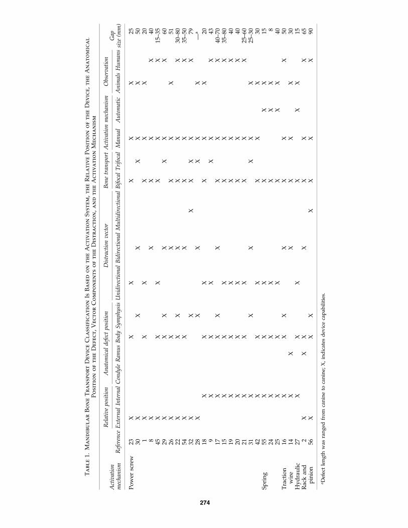
Active distraction mechanisms exist in a great variety ofdesigns, and most of them are based on five basic principles(Fig. 5): power screw,1,8,9,15,17–23,26,28–32,42,45,54 spring,24,25,55
traction wire,14,16 hydraulic,27 and rack and pinion.2,56
The power screw activation system, also called screw leadactivation system, translates torque into linear force to beused to distract the mandibular bone by matching an exter-nal helical threaded screw with either a negative or femalethreaded nut with the same thread form (Fig. 5A) or a bandwith the same pattern of holes (Fig. 5F). Several MBT devicesbased on power screw activation are unable to reproduce thecurvature of the mandible, because they produce unidirec-tional distraction by moving the transport unit parallel to thescrew (Table 1).1,9,15,18–21,23,42,45 It is possible to improve theirdesign to generate bidirectional MBT by adding comple-mentary moveable mechanisms31 performing complemen-tary steps that include the rotation of the distraction device57
or bending either the track8,30 or the screw.22,26
The power screw activation system needs one17,21,28,58–60
or two9,61 complementary guide bars to form a stableframe and ensure an efficient function. However, it isalso possible to achieve MBT without guide bars, by usingdevices complemented with a titanium reconstructionplate.1,15,18–20,22,26,29,42,45 Most of the power screw activa-tion systems without guide bars are built to accomplishmonofocal distraction on the mandible.13,62,63 Power screwactivation systems with one and two complementary
guides are mechanically more stable than power screwactivation systems without guides or supporting recon-struction plates. The average length that can be distractedby using internal MBT devices with power screw activationsystems is 40 mm,9,15,18–20,47 and 50 mm of distraction byusing external MBT devices.26,30,54
A novel MBT device, which combines the power screw ac-tivation mechanism with the stabilizing reconstruction plate toform a bone transport reconstruction plate unit, has recentlybeen developed.42 Combining the MBT and reconstructionplate reduces the size of the internal device and increases thestability of the transport unit. Curving the reconstruction=bonetransport plate will allow this device to conduct monofocalbone transport across the mandibular midline or bifocal bonetransport to meet at the midline (Fig. 5F).
The spring activation system is an elastic system thatproduces constant external loads by deforming itself. It isunique in that it does not have an activation arm, because theexternal energy is stored within a preformed superelasticshape memory alloy (SMA) that allows the system to delivera continuous force directly on the callus without externalactivation.24,25 However, the first activation of the spring,after the latency period, requires an operative process torelease the activation mechanism.64
Spring activation mechanisms can be either a uniformcoiled wire24,35,65 or a bent wire with different conforma-tions.25,55,66,67 Bent springs (Fig. 5B), sometimes called archsprings, are unable to follow a linear distraction vector, be-cause their asymmetric shape produces a caudal distractionforce component,64 whereas MBT devices based on coiledspring activation systems tend to produce unidirectionaldistraction.24,65 Coiled springs are only effective over short
FIG. 5. MBT active mechanism. (A) A power screw system with female nuts, based on a prototype by Zapata. (B) A springsystem, based on the design from Ref.24 (C) A wire system, based on the design from Zhou et al.14 (D) A hydraulic system,based on the design from Ayoub et al.27 (E) A rack and pinion system, based on the design from Kramer et al.75 (F) A powerscrew system with patterned band, based on a prototype by Elsalanty. Color images available online at www.liebertonline.com=ten.
MANDIBULAR TRANSPORT DISTRACTION OSTEOGENESIS DEVICES 277

distraction lengths, because the distraction load produced bythe alloy tends to be constant for a small range of springdeformation.68 Body temperature changes also can affect thedistraction force magnitude in SMA like Nitinol�.24,64 AnMBT length up to 40 mm was achieved in canine models byusing a bent spring.25
The traction wire activation system is based upon the basicmechanism for traction loads that are able to produce uni-directional, bidirectional, and multidirectional MBT (Fig.5C). However, for both bidirectional and multidirectionalMBT, the traction wire system needs either a guide or ahousing to provide a track for the wire. The guides or thehousing help solve some of the MBT limitations related tothe defect length, the external mandibular curvature, and theposition of the defect.16 Most of the time, a rail, which has thesame shape as the external contour of the mandible, is usedto slide the transport unit along and to guide the tractionwire.14 The activation of the traction mechanism can beperformed by either a conventional screw rod16 or a rodwithin a cylinder.14 MBT lengths up to 50 mm have beenachieved by using this activation system.16
The hydraulic activation system is composed of threesealed parts: the hydraulic activation mechanism, the remotecontrol, and the flexible noncompressible hydraulic tube thatconnects them.69 The hydraulic cylinder, the tube, and theremote control are filled with uncompressible fluid to powerthe movement of the piston.70,71 The hydraulic activationmechanism (Fig. 5D) is based on the principle of a hydraulicpump, which is composed of two parts, the hydraulic cyl-inder and the piston. The hydraulic system is activated by aninjector that works through a remote control device to applyeither continuous or incremental pressure on the piston andproduce similar distraction frequencies.69–71 However, thehydraulic pressure of the activation system is variable duringthe distraction period, for both continuous and especiallyincremental activation processes.70,72
In general, the hydraulic activation system does not have aconstant relationship between pressure applied at the remotecontrol and the amount of disc displacement, except if boththe hydraulic activation system and the remote control havethe same internal diameter.69,71,73 This activation system hasbeen mainly used for monofocal distraction by attaching thecylinder and the piston directly to the edges of the bone andtaking advantage of the relative displacement betweenthem.70–73 The device has also been used for MBT by using atitanium reconstruction plate to stabilize both mandibularsegments (Fig. 5D), fixing the cylinder to one side of the
defect and projecting the transport unit attached to the end ofthe piston.27 However, this telescopic process tends to beunstable with increasing defect length. The maximum MBTlength achieved by using this active mechanism was15 mm.27
The rack and pinion activation system is made up of acircular pinion that perpendicularly engages the cogs on agear bar to convert rotational movement into linear move-ment and produce displacement of the transport unit (Fig.5E). Few MBT devices have been reported to be using thisactive system,2,56 although another device was reported forcalvarial bifocal distraction, wherein a bone graft was usedas the transport disc.74,75 The maximum bifocal distractionlength reported was 90 mm.56
The distraction vector
The vector of distraction is related to the orientation of thenew bone produced by the MBT device (Fig. 6). Vectors canbe unidirectional1,9,15,17–21,23,24,27,42,45,76 if the MBT deviceprovides linear distraction in the same direction as the MBTdevice orientation. Alternately, the vector can be bidirec-tional2,8,14,16,17,26,28–31,77,78 if the MBT device provides twodistraction direction components. Most of these devices arecalled curved or curvilinear MBT devices. Finally, the vectorcan be multidirectional16,22,29,32,44,79,80 if the MBT deviceprovides up to three distraction direction components.Multidirectional MBT devices that are used to correct com-plex mandibular defects are external distraction devices(Table 1) that are mounted on a U-shape rod that not onlyprovides support but also allows bidirectional transport ofthe bone segments. The third distraction vector component isproduced by a vertical element of the device that permitsmandibular contour definition. The multidirectional MBTdevices are able to perform both bone transport over longerdistances and bone transport in the symphyseal region of themandible.32,56
Most internal MBT devices only provide unidirectionaldistraction in which the new bone generated does not followthe original curved shape of the mandible; however, severalinternal MBT devices have been designed to provide bidi-rectional distraction.14,16,17,31
Device position
The device position corresponds with the site of themandibular defect location according to Urken’s classifica-tion (Fig. 7).81 Defects can be located on the condyle,82,83
FIG. 6. Distraction vector activation in MBT devices. (A) Unidirectional (KLS Martin, Jacksonville, FL), reproduced withpermission from Sacco and Chepeha.76 (B) Bidirectional, reproduced with permission from Hibi and Ueda.16 (C) Multi-directional (www.globalmednet.com=do-cdrom=Clinical=Transp=Klein=kl001.htm). Color images available online at www.liebertonline.com=ten.
278 ZAPATA ET AL.

ramus,47,84 body,1,15,18,19,24,42,45 or symphysis.17,28,30–32,56,57,85
Although the condyle, ramus, and body anatomical positionsare able to receive either unilateral or bilateral MBT devices,most of the MBT devices are applied to only one side of themandible,14–17,25 and only one MBT device has been suc-cessfully used bilaterally.28,54 According to reports in theliterature, most of the MBT devices for use across the sym-physis are external (Table 1). Currently, few internal MBTdevices for the symphysis have been tested in animal31 andhuman16,17,57 subjects, because the reconstruction of thecurved mandibular symphysis is challenging. In addition,most of the monofocal internal distraction devices that havebeen applied at the human symphysis are used to obtainmandibular widening.85
Although restoration of the condyle-ramus complex re-quires bidirectional MBT devices to reconstruct its curvedanatomical shape,2,54 several monofocal distraction deviceshave been applied for the reconstruction of the condyle-ramus unit in a process that is used to unidirectionally pro-ject the posterior part of the condyle. This method is oftenincorrectly referred to as an MBT process.37,82,83,86 In con-trast, reconstruction of segmental bone defects of the man-dibular body has been mainly accomplished by usingunidirectional MBT devices,19,42 whereas few devices havebeen designed to reconstruct the slightly curved lateral as-pect of the mandibular body.1,16 Examination of the litera-ture reveals that no internal devices have been reported forthe reconstruction of the mandibular symphysis, althoughseveral external MBT devices provide either bidirectional26,31
or multidirectional reconstruction of this anatomical part.56
Activation mechanism
The activation mechanism is the means by which the MBTdevice receives external energy through the activation rod,which usually emerges from the mucosa (transmucosal), theskin (trascutaneous) in the internal devices,18,21 or directly atthe device in external systems.22,26 The activation mecha-nisms can be either manual1,2,8,9,14–21,23,28–32,42,45 or automatic(Fig. 8).87–91 Manual activation mechanisms are operated bydoctors or the patients using a tool similar to a screwdriveror a wrench that is inserted into the end of the activationarm. Manual activation involves two different and comple-mentary components: (1) the frequency or the number ofactivation steps a day and (2) the rate or the distractionlength that is achieved each day by the movement of theMBT system. Manual activation varies from one or two stepsfor rates between 1 and 2 mm=day92 to frequencies between4 and 5 steps for a rate of 1 mm=day.90
Automatic distraction activation can be provided by amotor-driven system that supplies an electromechanicalmicro-incremental frequency,91 by an electro-hydraulicpump that provides a continuous hydraulic pressure,27,69,71
or by an SMA spring that provides constant force to generateMBT disc displacement.24 In internal MBT devices, the acti-vation component tends to be distant from the surgical site. Ifactivation is via a flexible cable that connects the device andthe automatic control-power unit mechanically, the mecha-nism is vulnerable at the connections.91 It is also important toremember that the further the activating mechanism is fromthe transport mechanism, the lower is the translation of theactivation force into forward motion. This is especiallyproblematic in external devices, because the activatingmechanisms on external devices are only indirectly attachedto the bone.92
Discussion
Both monofocal distraction and bone transport distractiontechniques are used to create bone regenerate; however,there are distinct differences between these two methods.Monofocal distraction is generally used to correct skeletaldefects, whereas bone transport is used to correct skeletaldeformities. Monofocal distraction requires that the twostumps of bone begin, in direct contact with one another, togenerate new bone while separating the bone stumps. Incontrast, bone transport uses discs of bone cut from the endsof the segmental defect to be transported across the gap. The
FIG. 7. MBT device relative position with respect to themandibular bone defect. C, Condyle; R, Ramus; B, Body; S,Symphysis. Adapted from Urken et al.81
FIG. 8. MBT activationmechanism. (A) Manual acti-vation of the device, re-produced with permissionfrom Spagnoli.21 (B) Electro-mechanical activation systemwith expandable transportingrods (arrow), reproduced withpermission from Ploder et al.91
Color images available onlineat www.liebertonline.com=ten.
MANDIBULAR TRANSPORT DISTRACTION OSTEOGENESIS DEVICES 279

bone transport technique has a docking site or place wherethe transport disc meets its opposing counterpart at the endof the activation process.54 Monofocal distraction does nothave tissue discontinuities, whereas bone transport often hasconcomitant soft tissue losses. Bone transport has five stagesinstead of the four monofocal stages, adding a docking siteosteogenesis stage8,20,26,30 after the distraction period and inparallel with the consolidation period. These basic differ-ences support the necessity of independent and special de-vice designs for both monofocal distraction and bonetransport distraction.
The clinical patient’s defect characteristics must be thebasis for determining the selection of the optimal device toaccomplish most of the bone distraction requirements.21
Based on the biomechanical description and classification ofMBT devices presented here, an optimal device should havethe following characteristics. MBT devices should be internalto lessen scar formation and small to improve patient com-fort and reduce soft tissues stress. Further, the devices shouldbe stable, with the use of a strong frame and ends attacheddirectly to the bone to diminish shear stresses within the newbone. The devices should follow the initial vector plan, withan activation system that allows distraction without patientintervention and either bifocal or multifocal distractionabilities to restore the curvilinear continuity of the newlyformed bone when reconstructing the facial contour.
Based on the variety of device options described in thepresent classification system, new MBT device designs cancombine a multitude of options to produce devices optimizedfor specific defect characteristics. Future MBT device designsare likely to include new material options like composites andare likely to increase the number of devices using resorbablematerials. In addition, future MBT device designs can incor-porate biophysical and biochemical stimulation factors de-veloped to accelerate bone formation, abbreviate theconsolidation period, and reduce complication risks.93 Finally,it is likely that MBT device designers will consider includingdrug delivery options within the device’s conception.
Acknowledgments
This work was supported by NIH=NIDCR grants R43DE017259-05, R42 DE015437-03, and a fellowship fromDepartamento Administrativo de Ciencia, Tecnologıa eInnovacion COLCIENCIAS-Colombia.
Disclosure Statement
The bone transport reconstruction plate device described42
was invented by M.E.E., and the patent is assigned to acompany (Craniotech ACR Devices, LLC) owned by M.E.E.and L.A.O.
References
1. Gantous, A., Phillips, J.H., Catton, P., and Holmberg, D.Distraction osteogenesis in the irradiated canine mandible.Plast Reconstr Surg 93, 164, 1994.
2. Basa, S., Uner, E., Citir, M., and Aras, K. Reconstruction of alarge mandibular defect by distraction osteogenesis: a casereport. J Oral Maxillofac Surg 58, 1425, 2000.
3. Ilizarov, G.A. The tension-stress effect on the genesis andgrowth of tissues. Part I. The influence of stability of fixa-
tion and soft-tissue preservation. Clin Orthop Relat Res238, 249, 1989.
4. Ilizarov, G.A. The tension-stress effect on the genesis andgrowth of tissues: Part II. The influence of the rate and fre-quency of distraction. Clin Orthop Relat Res 239, 263, 1989.
5. Snyder, C.C., Levine, G.A., Swanson, H.M., and Browne,E.Z., Jr. Mandibular lengthening by gradual distraction:preliminary report. Plast Reconstr Surg 51, 506, 1973.
6. Michieli, S., and Miotti, B. Lengthening of mandibular bodyby gradual surgical orthodontic distraction. J Oral Surg 35,
187, 1977.7. McCarthy, J.G., Schreiber, J., Karp, N., Thorne, C.H., and
Grayson, B.H. Lengthening the human mandible by gradualdistraction. Plast Reconstr Surg 89, 1, 1992.
8. Costantino, P.D., Johnson, C.S., Friedman, C.D., and Sisson,G.A, Sr. Bone regeneration within a human segmentalmandible defect: a preliminary report. Am J OtolaryngolHead Neck Med Surg 16, 56, 1995.
9. Wang, X., Lin, Y., Yi, B., Liang, C., and Li, Z. Mandibularfunctional reconstruction using internal distraction osteo-genesis. Chin Med J 115, 1863, 2002.
10. Spagnoli, D.B., and Gollehon, S.G. Distraction osteogen-esis in reconstruction of the mandible and temporoman-dibular joint. Oral Maxillofac Surg Clin North Am 18, 383,2006.
11. Guerrero, C.A., Bell, W.H., Contasti, G.I., and Rodriguez,A.M. Mandibular widening by intraoral distraction osteo-genesis. Br J Oral Maxillofac Surg 35, 383, 1997.
12. Imola, M.J., and Tatum, S.A. Craniofacial distraction osteo-genesis. Facial Plast Surg Clin 10, 287, 2002.
13. Chin, M., and Toth, B.A. Distraction osteogenesis in maxil-lofacial surgery using internal devices: review of five cases.J Oral Maxillofac Surg 54, 45, 1996.
14. Zhou, L.B., Shang, H.T., Hu, M., Li, D.C., Sigare, S., Chen,B.L., Liu, Y.P., and Zhao, J.L. Reconstruction of curvedmandibular angle defects using a new internal transportdistraction device: an experiment in goats. Br J Oral Max-illofac Surg 2008.
15. Rubio-Bueno, P., Naval, L., Rodriguez-Campo, F., Gil-Diez,J.L., and Diaz-Gonzalez, F.J. Internal distraction osteogenesiswith a unidirectional device for reconstruction of mandib-ular segmental defects. J Oral Maxillofac Surg 63, 598, 2005.
16. Hibi, H., and Ueda, M. New internal transport distractiondevice for reconstructing segmental defects of the mandible.Br J Oral Maxillofac Surg 44, 382, 2006.
17. Herford, A.S. Use of a plate-guided distraction device fortransport distraction osteogenesis of the mandible. J OralMaxillofac Surg 62, 412, 2004.
18. Rubio-Bueno, P., Sanroman, F., Garcia, P., Sanchez, M.,Llorens, P., Nieto, S., Adrados, M., Sastre, J., de Artinano,F.O., Amde, S., Naval, L., and Diaz-Gonzalez, F.J. Experi-mental mandibular regeneration by distraction osteogenesiswith submerged devices: preliminary results of a caninemodel. J Craniofac Surg 13, 224, 2002.
19. Muraki, Y., Tominaga, K., Yoshioka, I., Fujita, M., Khanal,A., Matsushita, S., and Fukuda, J. Mandibular reconstructionwith bone transport in a patient with osteogenesis imper-fecta. Int J Oral Maxillofac Surg 37, 870, 2008.
20. Gonzalez-Garcia, R., Rubio-Bueno, P., Naval-Gias, L.,Rodriguez-Campo, F.J., Escorial-Hernandez, V., Martos,P.L., Munoz-Guerra, M.F., Sastre-Perez, J., Gil-Diez Usan-dizaga, J.L., and Diaz-Gonzalez, F.J. Internal distraction os-teogenesis in mandibular reconstruction: clinical experiencein 10 cases. Plast Reconstr Surg 121, 563, 2008.
280 ZAPATA ET AL.
21. Spagnoli, D. Mandible reconstruction with transport dis-traction osteogenesis. Atlas Oral Maxillofac Surg Clin NorthAm 16, 287, 2008.
22. Shvyrkov, M.B., Shamsudinov, A.H., Sumarokov, D.D., andShvyrkova, I.I. Non-free osteoplasty of the mandible inmaxillofacial gunshot wounds: mandibular reconstructionby compression-osteodistraction. Br J Oral Maxillofac Surg37, 261, 1999.
23. Costantino, P.D., Shybut, G., Friedman, C.D., Pelzer, H.J.,Masini, M., Shindo, M.L., and Sisson, G.A., Sr. Segmentalmandibular regeneration by distraction osteogenesis. An ex-perimental study. Arch Otolaryngol Head Neck Surg 116, 535,1990.
24. Idelsohn, S., Pena, J., Lacroix, D., Planell, J.A., Gil, F.J., andArcas, A. Continuous mandibular distraction osteogenesisusing superelastic shape memory alloy (SMA). J Mater SciMater Med 15, 541, 2004.
25. Zhou, H.Z., Hu, M., Hu, K.J., Yao, J., and Liu, Y.P. Transportdistraction osteogenesis using nitinol spring: an explorationin canine mandible. J Craniofac Surg 17, 943, 2006.
26. Jonsson, B., and Siemssen, S.J. Arced segmental mandibularregeneration by distraction osteogenesis. Plastic and Re-constructive Surgery. 101, 1925, 1998.
27. Ayoub, A.F., Richardson, W., Koppel, D., Thompson, H.,Lucas, M., Schwarz, T., Smith, L., and Boyd, J. Segmentalmandibular reconstruction by microincremental automaticdistraction osteogenesis: an animal study. Br J Oral Max-illofac Surg 39, 356, 2001.
28. Li, J., Ying, B., Hu, J., Zhu, S., and Braun, T.W. Re-construction of mandibular symphyseal defects by trifocaldistraction osteogenesis: an experimental study in Rhesus.Int J Oral Maxillofac Surg 35, 159, 2006.
29. Sawaki, Y., Hagino, H., Yamamoto, H., and Ueda, M. Tri-focal distraction osteogenesis for segmental mandibulardefect: a technical innovation. J Craniomaxillofac Surg 25,
310, 1997.30. Annino, D.J., Jr., Goguen, L.A., and Karmody, C.S. Distrac-
tion osteogenesis for reconstruction of mandibular sym-physeal defects. Arch Otolaryngol Head Neck Surg 120, 911,1994.
31. Zhang, R.Z., Zhang, L., Deng, Y., Zhang, Q.L., Zhen, E.M.,and Yu, B. Reconstruction of mandibular symphyseal de-fects by an internal trifocal distractor: an experiment in dogs.Br J Oral Maxillofac Surg 47, 205, 2009.
32. Labbe, D., Nicolas, J., Kaluzinski, E., Soubeyrand, E., Sabin,P., Compere, J.F., and Benateau, H. Gunshot wounds: re-construction of the lower face by osteogenic distraction.Plast Reconstr Surg 116, 1596, 2005.
33. Lo, J., and Cheung, L.K. Distraction osteogenesis for thecraniomaxillofacial region. Part 2: A compendium of devicesfor the mandible. Asian J Oral Maxillofac Surg 19, 6, 2007.
34. Suhr, M.A.A., and Kreusch, T. Technical considerations indistraction osteogenesis. Int J Oral Maxillofac Surg 33, 89,2004.
35. Uckan, S., Veziroglu, F., and Arman, A. Unexpected breakageof mandibular midline distraction device: case report. OralSurg Oral Med Oral Pathol Oral Radiol Endod 102, e21, 2006.
36. Alkan, A., Ozer, M., Bas, B., Bayram, M., Celebi, N., Inal, S.,and Ozden, B. Mandibular symphyseal distraction osteo-genesis: review of three techniques. Int J Oral MaxillofacSurg 36, 111, 2007.
37. Holmes, S.B., Lloyd, T., Coghlan, K.M., and Newman, L.Distraction osteogenesis of the mandible in the previouslyirradiated patient. J Oral Maxillofac Surg 60, 305, 2002.
38. Maull, D.J. Review of devices for distraction osteogenesis ofthe craniofacial complex. Semin Orthod 5, 64, 1999.
39. Mommaerts, M.Y. Horizontal anchorage in the ascendingramus—a technical note. Int J Adult Orthod OrthognathicSurg 13, 59, 1998.
40. Conley, R., and Legan, H. Mandibular symphyseal distrac-tion osteogenesis: diagnosis and treatment planning con-siderations. Angle Orthod 73, 3, 2003.
41. Dessner, S., Razdolsky, Y., El-Bialy, T., and Evans, C.A.Mandibular lengthening using preprogrammed intraoraltooth-borne distraction devices. J Oral Maxillofac Surg 57,
1318, 1999.42. Elsalanty, M.E., Zakhary, I., Akeel, S., Benson, B., Mulone,
T., Triplett, G.R., and Opperman, L.A. Reconstruction ofcanine mandibular bone defects using a bone transport re-construction plate. Ann Plast Surg 63, 441, 2009.
43. Hurmerinta, K., and Hukki, J. Vector control in lower jawdistraction osteogenesis using an extra-oral multidirectionaldevice. J Craniomaxillofac Surg 29, 263, 2001.
44. Klein, C. Multidimensional distraction osteogenesis forprofile correction in severe facial asymmetries. Mehrdi-mensionale Distraktionsosteogenese zur Profilkorrektur beischweren Gesichtsasymmetrien 1 Suppl 1, 598, 1997.
45. Block, M.S., Otten, J., McLaurin, D., and Zoldos, J. Bifocaldistraction osteogenesis for mandibular defect healing: casereports. J Oral Maxillofac Surg 54, 1365, 1996.
46. Primrose, A.C., Broadfoot, E., Diner, P.A., Molina, F., Moos,K.F., and Ayoub, A.F. Patients’ responses to distractionosteogenesis: a multi-centre study. Int J Oral Maxillofac Surg34, 238, 2005.
47. Rubio-Bueno, P., Padron, A., Villa, E., and Dıaz-Gonzalez,F.J. Distraction osteogenesis of the ascending ramusfor mandibular hypoplasia using extraoral or intraoraldevices: a report of 8 cases. J Oral Maxillofac Surg 58, 593,2000.
48. Burstein, F.D., and Williams, J.K. Resorbable bone distrac-tion: current status and future directions. Clin Plast Surg 31,
407, 2004.49. Ortakoglu, K., Karacay, S., Sencimen, M., Akin, E., Ozyigit,
A.H., and Bengi, O. Distraction osteogenesis in a severemandibular deficiency. Head Face Med 3, 7, 2007.
50. Gateno, J., Kim, K.W., Lalani, Z., Teichgraeber, J.F.,Liebschner, M.A.K., Lemoine, J.J., and Xia, J.J. Biomechanicalevaluation of the pins of a mandibular external distractor.J Oral Maxillofac Surg 62, 1259, 2004.
51. Kessler, P., Schultze-Mosgau, S., Neukam, F.W., and Wilt-fang, J. Lengthening of the reconstructed mandible usingextraoral distraction devices: report of five cases. Plast Re-constr Surg 111, 1400, 2003.
52. McCarthy, J.G., Katzen, J.T., Hopper, R., and Grayson, B.H.The first decade of mandibular distraction: lessons we havelearned. Plast Reconstr Surg 110, 1704, 2002.
53. Brown, N.L., House, K., Leach, A., Page, K., Irvine, G.H.,and Sandy, J.R. A paralleling device and ethylene vinyl ac-etate baffles for use with mandibular distraction osteogen-esis: technical note. J Orthod 31, 181, 2004.
54. Kuriakose, M.A., Shnayder, Y., and DeLacure, M.D. Re-construction of segmental mandibular defects by distractionosteogenesis for mandibular reconstruction. Head Neck 25,
816, 2003.55. Zeng, R.S., Zhang, P., and Wang, C. Osteotomy with
titanium-nickel shape memory alloy distracter for repairingmandibular defects in dogs. J Clin Rehabil Tissue Eng Res12, 217, 2008.
MANDIBULAR TRANSPORT DISTRACTION OSTEOGENESIS DEVICES 281

56. Klein, C. Bone transport for mandibular anterior defect re-construction: a case report. In: Samchukov, M.L., Cope, J.B.,Cherkashin, A.M., eds. Craniofacial Distraction Osteogen-esis. Mosby, St. Louis, MO, 2001, pp. 634.
57. Whitesides, L.M., Wunderle, R.C., and Guerrero, C. Mand-ible reconstruction using a 2-phase transport disc distractionosteogenesis: a case report. J Oral Maxillofac Surg 63, 261,2005.
58. Cheung, L.K., Zhang, Q., Zhang, Z.G., and Wong, M.C.M.Reconstruction of maxillectomy defect by transport distrac-tion osteogenesis. Int J Oral Maxillofac Surg 32, 515, 2003.
59. Fang, T.D., Nacamuli, R.P., Song, H.M., Fong, K.D., Warren,S.M., Salim, A., Carano, R.A., Filvaroff, E.H., and Longaker,M.T. Creation and characterization of a mouse model ofmandibular distraction osteogenesis. Bone 34, 1004, 2004.
60. Freitas, R.D.S., Alonso, N., Busato, L., D’Oro, U., and Ferreira,M.C. Mandible distraction using internal device: mathemat-ical analysis of the results. J Craniofac Surg 18, 29, 2007.
61. Miao, J., Li, C., Zhao, P., Chen, G., Teng, L., and Ling, Y. 2=3osteotomy for lengthening the mandible in dogs by gradualdistraction. J Craniomaxillofac Surg 25, 301, 1997.
62. Del Campo, A.F. A simplified bone distractor for inducedosteogenesis. Plast Reconstr Surg 110, 1485, 2002.
63. Kaban, L.B., Thurmuller, P., Troulis, M.J., Glowacki, J.,Wahl, D., Linke, B., Rahn, B., and Parrott, D.H. Correlationof biomechanical stiffness with plain radiographic and ul-trasound data in an experimental mandibular distractionwound. Int J Oral Maxillofac Surg 32, 296, 2003.
64. Mofid, M.M., Inoue, N., Tufaro, A.P., Vander Kolk, C.A.,and Manson, P.N. Spring-mediated mandibular distractionosteogenesis. J Craniofac Surg 14, 756, 2003.
65. Al-Sebaei, M.O., Gagari, E., and Papageorge, M. Mandibulardistraction osteogenesis: a rabbit model using a novel ex-perimental design. J Oral Maxillofac Surg 63, 664, 2005.
66. Lekston, Z., Drugacz, J., and Morawiec, H. Application ofsuperelastic NiTi wires for mandibular distraction. Mater SciEng A 378, 537, 2004.
67. Zhou, H.Z., Hu, M., Yao, J., and Ma, L. Rapid lengthening ofrabbit mandibular ramus by using nitinol spring: a prelim-inary study. J Craniofac Surg 15, 725, 2004.
68. von Fraunhofer, J.A., Bonds, P.W., and Johnson, B.E. Forcegeneration by orthodontic coil springs. Angle Orthod 63,
145, 1993.69. Ayoub, A.F., and Richardson, W. A new device for a
microincremental automatic distraction osteogenesis. BrJ Oral Maxillofac Surg 39, 353, 2001.
70. Wiltfang, J., Kessler, P., Merten, H.A., and Neukam, F.W.Continuous and intermittent bone distraction using amicrohydraulic cylinder: an experimental study in minipigs.Br J Oral Maxillofac Surg 39, 2, 2001.
71. Kessler, P., Wiltfang, J., and Wilhelm Neukam, F. A newdistraction device to compare continuous and discontinuousbone distraction in mini-pigs: a preliminary report. J Cranio-maxillofac Surg 28, 5, 2000.
72. Kessler, P.A., Merten, H.A., Neukam, F.W., and Wiltfang, J.The effects of magnitude and frequency of distraction forceson tissue regeneration in distraction osteogenesis of themandible. Plast Reconstr Surg 109, 171, 2002.
73. Kessler, P., Neukam, F.W., and Wiltfang, J. Effects of dis-traction forces and frequency of distraction on bony regen-eration. Br J Oral Maxillofac Surg 43, 392, 2005.
74. Muller, M.C., Kramer, F.J., Swennen, G.R.J., Rahmsdorf, M.,Haupt, C., van Griensven, M., Tschernig, T., Otto, K., andSchierle, H.F. A comparison of two types of free bone grafts
as transport discs in segmental distraction for reconstructionof calvarial bone defects: an experimental study. Arch Or-thop Trauma Surg 124, 665, 2004.
75. Kramer, F.J., Sinikovic, B., Mueller, M., Rahmstorf, M., andSchierle, H. Experimental application of a biomaterial inbifocal transport osteogenesis for craniofacial reconstruction.J Craniomaxillofac Surg 36, 218, 2008.
76. Sacco, A.G., and Chepeha, D.B. Current status of transport-disc-distraction osteogenesis for mandibular reconstruction.Lancet Oncol 8, 323, 2007.
77. Molina, F., Monasterio, F.O., and Levignac, J. Mandibularelongation and remodeling by distraction: a farewell tomajor osteotomies. Plast Reconstr Surg 96, 825, 1995.
78. Seldin, E.B., Troulis, M.J., and Kaban, L.B. Evaluation of asemiburied, fixed-trajectory, curvilinear, distraction device inan animal model. J Oral Maxillofac Surg 57, 1442; discussion7, 1999.
79. McCarthy, J.G., Williams, J.K., Grayson, B.H., and Crombie,J.S. Controlled multiplanar distraction of the mandible:device development and clinical application. J CraniofacSurg 9, 322, 1998.
80. Williams, J.K., Rowe, N.M., Mackool, R.J., Levine, J.P.,Hollier, L.H., Longaker, M.T., Cutting, C.B., Grayson, B.H.,and McCarthy, J.G. Controlled multiplanar distraction of themandible, part II: laboratory studies of sagittal (anteropos-terior) and vertical (superoinferior) movements. J CraniofacSurg 9, 504, 1998.
81. Urken, M.L., Weinberg, H., Vickery, C., Buchbinder, D., Law-son, W., and Biller, H.F. Oromandibular reconstruction usingmicrovascular composite free flaps: report of 71 cases and anew classification scheme for bony, soft-tissue, and neurologicdefects. Arch Otolaryngol Head Neck Surg 117, 733, 1991.
82. Stucki-McCormick, S.U., Fox, R.M., and Mizrahi, R.D. Re-construction of a neocondyle using transport distractionosteogenesis. Semin Orthod 5, 59, 1999.
83. Zhu, S.S., Hu, J., Ying, B.B., and Li, J.H. Growth of themandible after condylar reconstruction using transport dis-traction osteogenesis: an experimental investigation in goats.Plast Reconstr Surg 121, 1760, 2008.
84. Diner, P.A., Kollar, E.M., Martinez, H., and Vazquez, M.P.Intraoral distraction for mandibular lengthening: a technicalinnovation. J Craniomaxillofac Surg 24, 92, 1996.
85. Bell, W.H., Gonzalez, M., Samchukov, M.L., and Guerrero,C.A. Intraoral widening and lengthening of the mandible inbaboons by distraction osteogenesis. J Oral Maxillofac Surg57, 548, 1999.
86. Schwartz, H.C., and Relle, R.J. Distraction osteogenesis fortemporomandibular joint reconstruction. J Oral MaxillofacSurg 66, 718, 2008.
87. Schmelzeisen, R., Neumann, G., and Von Der Fecht,R. Distraction osteogenesis in the mandible with a motor-driven plate: a preliminary animal study. Br J Oral Max-illofac Surg 34, 375, 1996.
88. Ploder, O., Mayr, W., Schnetz, G., Unger, E., Plenk, H., Jr.,Losert, U., and Ewers, R. [Distraction osteogenesis with afully implantable system. Experimental study]. Mund KieferGesichtschir 3 Suppl 1, S140, 1999.
89. Ploder, O., Mayr, W., Schnetz, G., Unger, E., Ewers, R., andPlenk, H., Jr. Mandibular lengthening with an implantedmotor-driven device: preliminary study in sheep. Br J OralMaxillofac Surg 37, 273, 1999.
90. Ayoub, A.F., Richardson, W., and Barbenel, J.C. Mandibularelongation by automatic distraction osteogenesis: the firstapplication in humans. Br J Oral Maxillofac Surg 43, 324, 2005.
282 ZAPATA ET AL.

91. Ploder, O., Kanz, F., Randl, U., Mayr, W., Voracek, M., andPlenk, H., Jr. Three-dimensional histomorphometric analysisof distraction osteogenesis using an implanted device formandibular lengthening in sheep. Plast Reconstr Surg 110,
130, 2002.92. Hollier, L.H., Jr., Higuera, S., Stal, S., and Taylor, T.D. Dis-
traction rate and latency: factors in the outcome of pediatricmandibular distraction. Plast Reconstr Surg 117, 2333, 2006.
93. Pereira, M.A., Luiz de Freitas, P.H., da Rosa, T.F., andXavier, C.B. Understanding distraction osteogenesis on themaxillofacial complex: a literature review. J Oral MaxillofacSurg 65, 2518, 2007.
Address correspondence to:Lynne A. Opperman, Ph.D.
Texas A&M Health Science CenterBaylor College of Dentistry
3302 Gaston Ave.Dallas, TX 75246
E-mail: [email protected]
Received: July 21, 2009Accepted: December 3, 2009
Online Publication Date: January 21, 2010
MANDIBULAR TRANSPORT DISTRACTION OSTEOGENESIS DEVICES 283