Application of discrete layer peeling algorithm for design of selective photonic devices obeying the...
9
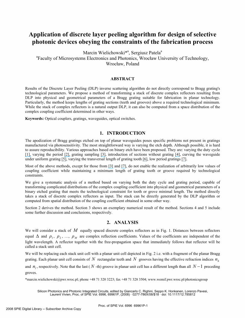
Application of discrete layer peeling algorithm for design of selective photonic devices obeying the constraints of the fabrication process Marcin Wielichowski* a , Sergiusz Patela a a Faculty of Microsystems Electronics and Photonics, Wrocław University of Technology, Wrocław, Poland ABSTRACT Results of the Discrete Layer Peeling (DLP) inverse scattering algorithm do not directly correspond to Bragg grating's technological parameters. We propose a method of transforming a stack of discrete complex reflectors resulting from DLP into physical and geometrical parameters of a Bragg grating suitable for fabrication in planar technology. Particularly, the method keeps lengths of grating sections (teeth and grooves) above a required technological minimum. While the stack of complex reflectors is a natural output DLP, it can also be computed from a space distribution of the complex coupling coefficient determined in other ways. Keywords: Optical couplers, gratings, waveguides, optical switches. 1. INTRODUCTION The apodization of Bragg gratings etched on top of planar waveguides poses specific problems not present in gratings manufactured via photosensitivity. The most straightforward way is varying the etch depth. Although possible, it is hard to assure reproducibility. Various approaches based on binary etch have been proposed. They are: varying the duty cycle [1], varying the period [2], grating sampling [3], introduction of sections without grating [4], curving the waveguide under uniform grating [5], varying the transversal length of grating tooth [6], low period gratings [7]. Most of the above methods, except for those from [3] and [7], do not enable the realization of arbitrarily low values of coupling coefficient while maintaining a minimum length of grating tooth or groove required by technological constraints. We give a systematic analysis of a method based on varying both the duty cycle and grating period, capable of transforming complicated distributions of the complex coupling coefficient into physical and geometrical parameters of a binary etched grating that meets the technological constraint for tooth or grove minimal length. The method directly takes a stack of discrete complex reflectors as input. The stack can be directly generated by the DLP algorithm or computed from spatial distribution of the coupling coefficient obtained in some other way. Section 2 derives the method. Section 3 shows an exemplary numerical result of the method. Sections 4 and 5 include some further discussion and conclusions, respectively. 2. ANALYSIS We will consider a stack of M equally spaced discrete complex reflectors as in Fig. 1. Distances between reflectors equal ∆ and 1 ρ , 2 ρ , …, M ρ are complex reflection coefficients. Values of the coefficients are independent of the light wavelength. A reflector together with the free-propagation space that immediately follows that reflector will be called a stack unit cell. We will be replacing each stack unit cell with a planar unit cell depicted in Fig. 2 i.e. with a fragment of the planar Bragg grating. Each planar unit cell consists of N rectangular teeth and N grooves having the effective refraction indices h n and l n , respectively. Note that the last ( N -th) groove in planar unit cell has a different length than all 1 − N preceding groves. *[email protected]; phone +48 71 320 3223; fax +48 71 328 3504; www.wemif.pwr.wroc.pl/photonicsgroup Silicon Photonics and Photonic Integrated Circuits, edited by Giancarlo C. Righini, Seppo K. Honkanen, Lorenzo Pavesi, Laurent Vivien, Proc. of SPIE Vol. 6996, 69961P, (2008) · 0277-786X/08/$18 · doi: 10.1117/12.785812 Proc. of SPIE Vol. 6996 69961P-1 2008 SPIE Digital Library -- Subscriber Archive Copy
Transcript of Application of discrete layer peeling algorithm for design of selective photonic devices obeying the...
Application of discrete layer peeling algorithm for design of selective photonic devices obeying the constraints of the fabrication process
Marcin Wielichowski*a, Sergiusz Patelaa
aFaculty of Microsystems Electronics and Photonics, Wrocław University of Technology, Wrocław, Poland
ABSTRACT
Results of the Discrete Layer Peeling (DLP) inverse scattering algorithm do not directly correspond to Bragg grating's technological parameters. We propose a method of transforming a stack of discrete complex reflectors resulting from DLP into physical and geometrical parameters of a Bragg grating suitable for fabrication in planar technology. Particularly, the method keeps lengths of grating sections (teeth and grooves) above a required technological minimum. While the stack of complex reflectors is a natural output DLP, it can also be computed from a space distribution of the complex coupling coefficient determined in other ways.
Keywords: Optical couplers, gratings, waveguides, optical switches.
1. INTRODUCTION The apodization of Bragg gratings etched on top of planar waveguides poses specific problems not present in gratings manufactured via photosensitivity. The most straightforward way is varying the etch depth. Although possible, it is hard to assure reproducibility. Various approaches based on binary etch have been proposed. They are: varying the duty cycle [1], varying the period [2], grating sampling [3], introduction of sections without grating [4], curving the waveguide under uniform grating [5], varying the transversal length of grating tooth [6], low period gratings [7].
Most of the above methods, except for those from [3] and [7], do not enable the realization of arbitrarily low values of coupling coefficient while maintaining a minimum length of grating tooth or groove required by technological constraints.
We give a systematic analysis of a method based on varying both the duty cycle and grating period, capable of transforming complicated distributions of the complex coupling coefficient into physical and geometrical parameters of a binary etched grating that meets the technological constraint for tooth or grove minimal length. The method directly takes a stack of discrete complex reflectors as input. The stack can be directly generated by the DLP algorithm or computed from spatial distribution of the coupling coefficient obtained in some other way.
Section 2 derives the method. Section 3 shows an exemplary numerical result of the method. Sections 4 and 5 include some further discussion and conclusions, respectively.
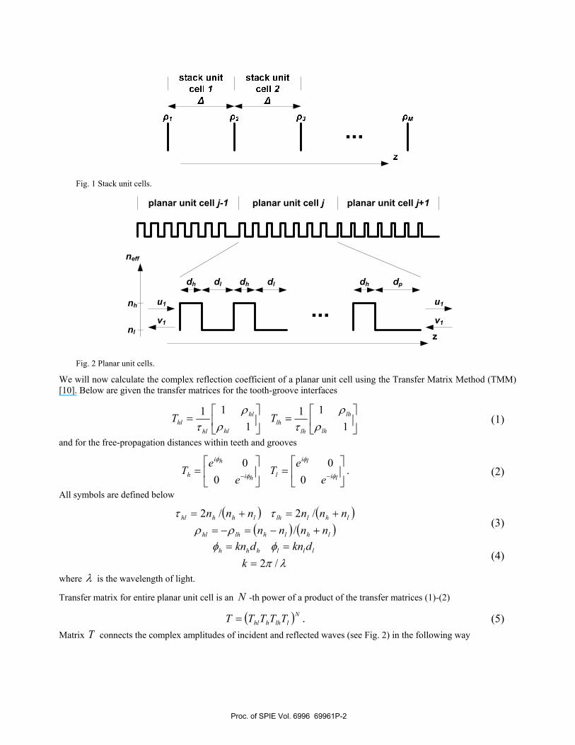
2. ANALYSIS We will consider a stack of M equally spaced discrete complex reflectors as in Fig. 1. Distances between reflectors equal ∆ and 1ρ , 2ρ , …, Mρ are complex reflection coefficients. Values of the coefficients are independent of the light wavelength. A reflector together with the free-propagation space that immediately follows that reflector will be called a stack unit cell.
We will be replacing each stack unit cell with a planar unit cell depicted in Fig. 2 i.e. with a fragment of the planar Bragg grating. Each planar unit cell consists of N rectangular teeth and N grooves having the effective refraction indices hn
and ln , respectively. Note that the last (N -th) groove in planar unit cell has a different length than all 1−N preceding groves.
*[email protected]; phone +48 71 320 3223; fax +48 71 328 3504; www.wemif.pwr.wroc.pl/photonicsgroup
Silicon Photonics and Photonic Integrated Circuits, edited by Giancarlo C. Righini, Seppo K. Honkanen, Lorenzo Pavesi,Laurent Vivien, Proc. of SPIE Vol. 6996, 69961P, (2008) · 0277-786X/08/$18 · doi: 10.1117/12.785812
Proc. of SPIE Vol. 6996 69961P-12008 SPIE Digital Library -- Subscriber Archive Copy
29CK I
3
IU!4
COII29CK I
II
Fig. 1 Stack unit cells.
v1
u1
z
planar unit cell j-1 planar unit cell j planar unit cell j+1
nh
nl
neff
dh dl dpdhdh dl
v1
u1
Fig. 2 Planar unit cells.
We will now calculate the complex reflection coefficient of a planar unit cell using the Transfer Matrix Method (TMM) [10]. Below are given the transfer matrices for the tooth-groove interfaces
⎥⎦
⎤⎢⎣
⎡=⎥
⎦
⎤⎢⎣
⎡=
111
111
lh
lh
lhlh
hl
hl
hlhl TT
ρρ
τρρ
τ (1)
and for the free-propagation distances within teeth and grooves
⎥⎦
⎤⎢⎣
⎡=⎥
⎦
⎤⎢⎣
⎡=
−− li
li
lhi
hi
h ee
Te
eT φ
φ
φ
φ
00
00
. (2)
All symbols are defined below
( ) ( )( ) ( )lhlhlhhl
lhllhlhhhl
nnnnnnnnnn
+−=−=+=+=
//2/2
ρρττ
(3)
λπφφ/2===
kdkndkn lllhhh (4)
where λ is the wavelength of light.
Transfer matrix for entire planar unit cell is an N -th power of a product of the transfer matrices (1)-(2)
( )Nllhhhl TTTTT = . (5)Matrix T connects the complex amplitudes of incident and reflected waves (see Fig. 2) in the following way
Proc. of SPIE Vol. 6996 69961P-2

⎥⎦
⎤⎢⎣
⎡=⎥
⎦
⎤⎢⎣
⎡
2
2
1
1
vu
Tvu
. (6)
Note that in (5) we have ignored for simplicity the length pd and just replaced it with ld . This can be done since pd does not affect neither amplitude nor phase of reflection.
The exponentiation in (5) will be performed using the Sylvester’s theorem [11]. For a unimodular matrix we have
( )( ) ( )( )
( )( )
( ) ( )( )⎥⎦⎤
⎢⎣
⎡Ω−−Ω
ΩΩ
Ω−−Ω×
Ω=⎥
⎦
⎤⎢⎣
⎡1sinsin
sinsin
1sinsinsin
1NND
NBNCNNA
DCBA N
(7)
where
( ) ( )DA +=Ω21cos . (8)
After performing the exponentiation in (5) and then calculating the complex reflection coefficient r of entire planar unit cell using the formula [9]
2221 /TTr = (9)where 21T and 22T are the submatrices of T , we arrive at a fairly complicated expression
( ) ( )( )( )( ) ( ) ( )( )pNpNq
pNqr 111
12
cos1sincossincossin
−−
−
−−=λ (10)
where
( ) ( ) ( ) ( )( )lh
lhlhlh nn
nnp2
sinsincoscos22 +
−=φφφφ (11)
( ) ( ) lihi
lh
lhlihi
lh
lh ennnn
ennnn
q φφφφ −−−
⎟⎟⎠
⎞⎜⎜⎝
⎛ +−+
+=
41
4
22
1 (12)
( )( )lihilihi
lh
lh eennnn
q φφφφ −−− −−
=4
22
2 . (13)
Let us now assume that hd and ld obey the following conditions
BragghlBraggll
BragghBragghh
dddddd
,,
,,
ηηη
+=−=
(14)
where 1,0∈η , lη will be calculated later and Bragghd , and Braggld , meet the Bragg condition
( ) ( )00
0,0,
/22/2/
λπππ
===
knkdnkd lBragglhBraggh (15)
where 0λ is the light wavelength of the centre of grating's reflection peak.
Figure Fig. 3 shows the modulus of r in function of η for several sample values of lη treated as parameter. For fixed
values of N , hn and ln , modulus of the maximum reflection coefficient maxr is independent of lη and it can be calculated as
Proc. of SPIE Vol. 6996 69961P-3

0max ==
ηrr . (16)
00.20.40.60.81
0
0.01
0.02
0.03
0.04
0.05
0.06
0.07
0.08
0.09
ηab
s(pl
anar
uni
t cel
l ref
lect
ion
coef
ficie
nt)
0 20 40 60 80 1000
0.01
0.02
0.03
0.04
0.05
0.06
0.07
0.08
0.09
dh [nm]
ηl=1
ηl=0.91211
ηl=0.86248
Fig. 3 Modulus of planar unit cell reflection coefficient r for several values of parameter ηl. The refrective indexes assumed
are nh=3.3087, nl=3.3023 and N=46.
Explicitly, maxr has the form
⎟⎟⎠
⎞⎜⎜⎝
⎛ += −
lh
lh
nnnn
Nr2
coshtanh22
1max (17)
what, for 1max <<r , can be approximated as
( )( )lh
lh
nnnn
Nr+−
≈ 2max . (18)
The formula above can be interpreted as Fresnel's reflection coefficient at tooth-groove boundary multiplied by N2 (i.e. N2 reflections). Results of (17) and (18) for exemplary values of hn an ln are shown in Fig. 4.
Zeros of ( )ηr we will find by analyzing the argument of the sin function in the numerator of (10). For lh nn ≈ , i.e.
under conditions of planar grating, ( ) ( ) 12/22 ≈+ lhlh nnnn so p from (11) takes the form
( )lhp φφ += cos . (19)We can then write
( ) πφφ nN lh =+ (20)where n is natural.
Proc. of SPIE Vol. 6996 69961P-4

50 100 150 200 250 3000
0.2
0.4
0.6
0.8
1
planar unit cell teeth count
plan
ar u
nit c
ell
refle
ctio
n co
effic
ient
Fig. 4 Planar unit cell reflection coefficient r in function of teeth count calculated using formula (17) (solid line) and (18)
(dashed line). The pairs of lines from botom to top are calculated for increasing difference between nh and nl. The values used are: nh=3.3087, nl=3.3023; nh=3.3187, nl=3.2923 and nh=3.3287, nl=3.2823.
After substituting (4) and (14) into (20), we find
( )( )llh
h
nnNnNn
ηη
−−
+=21 . (21)
Substituting n = 1−N in (21) and using (14) we find a length min,hd closest to Bragghd , , for which r is zero
( )⎟⎟⎠
⎞⎜⎜⎝
⎛−
−=llh
h
hh nnN
nnk
dη
π 212 0
min, (22)
As stated at the beginning of this section, stack unit sections are to be substituted with planar unit sections. We are now ready to give precise criteria of such a substitution. First, using (17) or (18) we find maxr such that
( ),...,,max 321max ρρρ≥r (23)and using (22) we find lη such that
min,min, technolh dd ≥ (24)where min,technold means a minimum technologically realizable length of hn section. Note that, according to (14), for
lη >0, all ln sections will have lengths higher than Bragghd , so we assume their technological realizability. Second, by
numerically solving (10) for η (having substituted (14) to (10)) we find M planar unit cells such that
MMrrr ρρρ === ...,,, 2211 . (25)Condition (25) defines the amplitude properties of planar unit sections. For defining the phase properties, we will use a general result from [8]
( )jhljjjjjp rrk ,11, 2221 φγρρφ −∠+∠−∆+∠−∠= ++ (26)
Proc. of SPIE Vol. 6996 69961P-5

where j means the unit cell number, hlφ is a phase shift induced by all sections preceding the pd section within the
given planar unit cell, and pφ is the phase shift induced by the pd section. Rewriting (26) for our problem, we have
( ) )( lhjjjjp NNkrr φφγρρφ 121
11 −+−∆+∠+∠−∠−∠= ++ . (27)
Having the value of pφ , pd is calculated as
( ) min,
min,
0
0
,,
/2/
technolp
technolp
hp
hpp dd
ddnk
nkd
<≥
⎩⎨⎧
+=
πφφ
. (28)
Finally, one more condition is needed to assure identical spectral widths of both reflection spectra, i.e. of the reflectors stack and the planar Bragg grating. We will calculate the maximum local coupling coefficients in the stack and in the planar grating. For the stack we have [8]
( )( ),...,,maxtanh1321
1max, ρρρκ −
∆=DLP (29)
and for the grating
( ) ( )max1
1,,,max tanh
11 r
ddNNd jpjljh
−
−+−+=κ . (30)
Neglecting the varying lengths of individual planar unit cells, we will iteratively look for values of hn , ln and N such that
maxmax, κκ ≈DLP . (31)
3. NUMERICAL EXAMPLE As an example result of the procedure described above we will show a transformation of a DLP-generated reflection coefficient from [12] to the parameters of a Bragg grating etched on top of a strip-loaded planar waveguide.
50 100 150 2000
0.02
0.04
0.06
0.08
0.1
complex reflector number
abs(
com
plex
refle
ctor
refle
ctio
n co
effic
ient
)
50 100 150 200-1
-0.5
0
0.5
1
complex reflector number
arg(
com
plex
refle
ctor
refle
ctio
n co
effic
ient
) / π
Fig. 5 Modulus (abs) and angle (arg) of complex reflection coefficients of consecutive complex reflectors ρ1,ρ2,...,ρM.
Proc. of SPIE Vol. 6996 69961P-6
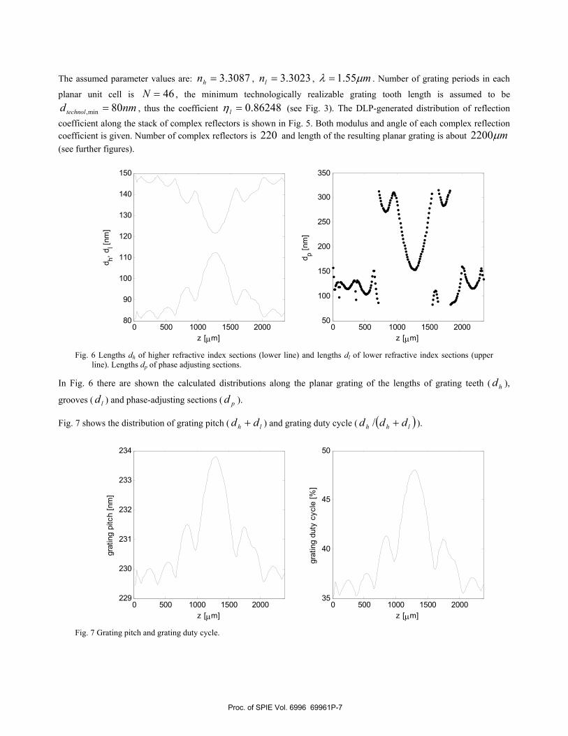
The assumed parameter values are: 3.3087=hn , 3.3023=ln , mµλ 55.1= . Number of grating periods in each
planar unit cell is 46=N , the minimum technologically realizable grating tooth length is assumed to be nmdtechnol 80min, = , thus the coefficient 86248.0=lη (see Fig. 3). The DLP-generated distribution of reflection
coefficient along the stack of complex reflectors is shown in Fig. 5. Both modulus and angle of each complex reflection coefficient is given. Number of complex reflectors is 220 and length of the resulting planar grating is about mµ2200 (see further figures).
0 500 1000 1500 200080
90
100
110
120
130
140
150
z [µm]
d h, dl [n
m]
0 500 1000 1500 200050
100
150
200
250
300
350
z [µm]
d p [nm
]
Fig. 6 Lengths dh of higher refractive index sections (lower line) and lengths dl of lower refractive index sections (upper
line). Lengths dp of phase adjusting sections.
In Fig. 6 there are shown the calculated distributions along the planar grating of the lengths of grating teeth ( hd ),
grooves ( ld ) and phase-adjusting sections ( pd ).
Fig. 7 shows the distribution of grating pitch ( lh dd + ) and grating duty cycle ( ( )lhh ddd +/ ).
0 500 1000 1500 2000229
230
231
232
233
234
z [µm]
grat
ing
pitc
h [n
m]
0 500 1000 1500 200035
40
45
50
z [µm]
grat
ing
duty
cyc
le [%
]
Fig. 7 Grating pitch and grating duty cycle.
Proc. of SPIE Vol. 6996 69961P-7

4. DISCUSSION
As can be seen in (14), the parameter lη determines how strong the modulation of grating period is. Particularly, for
lη =0 only modulation of duty cycle takes place.
The planar grating is from both sides surrounded with waveguide of the effective refractive index hn . Thus the planar
unit cell number 1 lacks the first groove-teeth interface, whereas cell number N has an additional teeth-grove interface. These facts have been neglected in derivations from section II but must be taken into consideration in the calculation of reflection spectra of the resulting frating.
No formula for etch depth has been given. This is because no specific type of planar waveguide has been assumed. For a given type of planar waveguide, the required etch depth and, in fact, all other parameters of the waveguide will be defined by the values of hn and ln .
It is possible to swap the roles of teeth and grooves in the method presented. This might be needed in case the minimum-length constraint is imposed on grating grooves, not teeth.
The calculation of the complex reflector stack from a given coupling coefficient distribution is described in [9].
5. CONCLUSIONS We have proposed a method allowing the transformation of a stack of complex reflectors or, equivalently, a distribution of complex coupling coefficient into physical and geometrical parameters, i.e. effective refractive indices and sections lengths, respectively, of a planar Bragg grating. Values of the resulting geometrical parameters meet the technological constraint.
6. ACKNOWLEDGMENT This work is supported by Polish State Committee for Scientific Research during 2006 – 2009 under Grant 350-730 W12
REFERENCES
[1] H. Sakata, Sidelobe suppression in grating-assisted wavelength-selective couplers, Opt. Lett., 17, pp. 463-465, 1992 [2] A. Lupu, A. Carenco, P. Win, H. Sik, P. Boulet, M. Carre, S. Slempkes, Spectral response apodization of Bragg-like
optical filters with a novel grating chirp design, Optical Fiber Communication Conference, 1999, and the International Conference on Integrated Optics and Optical Fiber Communication. OFC/IOOC '99. Technical Digest, vol. 2, 21-26 Feb., pp. 271-273, 1999
[3] V. Jayaraman, D.A. Cohen, L.A. Coldren, Demonstration of broadband tunability in a semiconductor laser using sampled gratings, Appl. Phys. Lett., vol. 60, pp. 2321-2323, 1992
[4] Y. Shibata, T. Tamamura, S. Oku, Y. Kondo, Coupling coefficient modulation of waveguide grating using sampled grating, IEEE Photon. Technol. Lett., vol. 6, no. 10, pp. 1222 – 1224, 1994
[5] C.J. Brooks, G.L. Vossler, K.A. Winick, Integrated-optic dispersion compensator that uses chirped gratings, Opt. Lett., vol. 20, no. 4, 368-370, 1995
[6] C. Greiner, T.W. Mossberg, D. Iazikov, Bandpass engineering of lithographically scribed channel-waveguide Bragg gratings, Opt. Lett., vol. 29, no. 8, 2004
[7] D. Levner, M.F. Fay, J.M. Xu, Programmable spectral design using a simple binary Bragg-diffractive structure, IEEE J. Quantum Electron., vol. 42, no. 4, pp. 410-417, 2006
[8] J. Skaar, L. Wang, T. Erdogan, Synthesis of Thick Optical Thin-Film Filters with a Layer-Peeling Inverse-Scattering Algorithm, Appl. Opt., vol. 40, no. 13, pp. 2183-2189, 2001
[9] J. Skaar, O.H. Waagaard, Design and characterization of finite-length fiber gratings, IEEE J. Quantum Electron., vol. 39, no. 10, pp. 1238-1245, 2003
Proc. of SPIE Vol. 6996 69961P-8
[10] J. Capmany, M.A. Muriel, S. Sales, J.J. Rubio, D. Pastor, Microwave V-I transmission matrix formalism for the analysis of photonic circuits: application to fiber Bragg gratings, J. Lightwave Technol., vol. 21, no. 12, pp. 3125-3134, 2003
[11] A.A. Tovar, L.W. Casperson, Generalized Sylvester theorems for periodic applications in matrix optics, J. Opt. Soc. Am. A, vol. 12, no. 3, pp. 578-590, 1995
[12] M. Wielichowski, S. Patela, Phase Shaping to Control the Performance of a Contra-Directional Grating-Assisted Coupler, IEEE Photon. Technol. Lett., vol. 19, no. 14, pp. 1102-1104, 2007
Proc. of SPIE Vol. 6996 69961P-9