Theoretical analysis of tuber movement during mechanical peeling of cassava
10
IOSR Journal of Mechanical and Civil Engineering (IOSR-JMCE) e-ISSN: 2278-1684,p-ISSN: 2320-334X, Volume 11, Issue 6 Ver. I (Nov- Dec. 2014), PP 27-36 www.iosrjournals.org www.iosrjournals.org 27 | Page Theoretical analysis of tuber movement during mechanical peeling of cassava M. O. Jimoh 1* , O. J. Olukunle 2 , S. I. Manuwa 2 , O. T. Amumeji 3 1 (Department of Food Science and Technology, Bells University of Technology, Ota, Nigeria) 2 (Department of Agricultural Engineering, Federal University of Technology, Akure, Nigeria) 3 (Department of Mathematics, Ondo State University of Science and Technology, Okitipupa, Nigeria) Abstract: Cassava Peeling has been identified as the only un-mechanized unit operation in cassava production which has constituted global challenge in twenty-first century despite an ever-increasing demand for the crop. As at today, cassava peeling is still largely carried out manually, it makes the process to be slow, labour intensive, arduous in nature, and low productivity. This research work aimed to analyse and model tuber movement during mechanical peeling. Preliminary experiment was carried out on newly harvested tubers graded into sizes and sliced at 50 to 100 mm using peeling machine developed earlier on the basis of this principle. The data collected were used to validate the model. Model developed adequately analyses the concept of tuber movement during peeling and also predicts peel shear stress, 6.142 N/mm 2 and effective peeling time, 9.5 – 12.0 s at velocity of conveyance, 1 – 5 m/s. This is therefore considered as reliable tool for further development and improvement of cassava peeling system. Keywords: cassava tuber, mechanical peeling, modeling, movement, I. Introduction Cassava (Manihot Esculenta, Crantz) is a crop with natural ability to grow under wide range of conditions [1]. Traditionally it is used mainly for food in sub Saharan Africa [2]. The tubers of cassava cannot be stored for too long. The root perish soon after harvest and mass processing of the tubers remains the best way to extend the shelf life in large quantities [3]. Cassava require more processing than any other tuber crops in Africa. Value addition to the harvested tubers could address unemployment and turn around the fortunes of farmers. However, processing communities are yet to harness maximum benefit from cassava because of inadequate processing facilities [4]. The unit operations in cassava processing include peeling, washing, grating, dewatering and frying. Cassava products are commercially important and these are classified into primary and secondary. The primary products are those obtainable from value addition centre and these include gari, lafun-flour, fufu, pellets and chips. The secondary products are made for industrial applications such as ethanol, glucose-syrup, bio-fuel, monosodium-glutamate, starches and noodles. The current cassava tuber production level has reached 49 million metric tons in Nigeria. Federal Government of Nigeria in 2011 released newly improved cassava varieties to strengthen the position as a world leading producer of cassava [5]. Cassava peeling remains the only operation that is still manually carried out. Several efforts have been made to develop suitable machines for peeling process and these include: Chemical peeling (using a hot solution of sodium hydroxide to loosen and soften the skin of roots), which is well developed for peeling sweet potatoes in processing industries, has been considered. A major reason why this method will not be suitable for cassava peeling is that a higher temperature and more root immersion time will be required for cassava roots because they have peel that are tougher than those of potatoes. This will result in the formation of an objectionable heat ring (dark colour) on the surface of the useful root flesh and the gelatinization of starch in the cassava root [6]. Such roots are obviously unsuitable for consumption and industrial starch production. For similar reasons, steam peeling is also ruled out for the peeling of cassava roots. Mechanical peeling such as abrasive and impact concept developed in Africa, China and Brazil as reported by [7] and [8] is either manually operated, low peel removal efficiency or high mechanical damage. This paper discuss theoretical analysis of tuber movement and mathematical modeling of cassava peeling concept during mechanical peeling process using machine newly developed by [9] This concept works by impact as the tubers spin and come in contact with cutting tool. II. Mechanics of Tuber Movement during Peeling Tuber size and shape are the major challenges facing cassava peeling mechanization. This is as a result of environmental factors from one farm location to another, such factors include; relative humidity, temperature, rainfall, soil type, soil moisture, soil acidity, soil fertility, and vegetation of the farm [10]. Variety of the crop * [email protected]
-
Upload
independent -
Category
Documents
-
view
3 -
download
0
Transcript of Theoretical analysis of tuber movement during mechanical peeling of cassava

IOSR Journal of Mechanical and Civil Engineering (IOSR-JMCE)
e-ISSN: 2278-1684,p-ISSN: 2320-334X, Volume 11, Issue 6 Ver. I (Nov- Dec. 2014), PP 27-36 www.iosrjournals.org
www.iosrjournals.org 27 | Page
Theoretical analysis of tuber movement during mechanical
peeling of cassava
M. O. Jimoh1*
, O. J. Olukunle2, S. I. Manuwa
2, O. T. Amumeji
3
1(Department of Food Science and Technology, Bells University of Technology, Ota, Nigeria) 2(Department of Agricultural Engineering, Federal University of Technology, Akure, Nigeria)
3(Department of Mathematics, Ondo State University of Science and Technology, Okitipupa, Nigeria)
Abstract: Cassava Peeling has been identified as the only un-mechanized unit operation in cassava production
which has constituted global challenge in twenty-first century despite an ever-increasing demand for the crop.
As at today, cassava peeling is still largely carried out manually, it makes the process to be slow, labour
intensive, arduous in nature, and low productivity. This research work aimed to analyse and model tuber
movement during mechanical peeling. Preliminary experiment was carried out on newly harvested tubers
graded into sizes and sliced at 50 to 100 mm using peeling machine developed earlier on the basis of this
principle. The data collected were used to validate the model. Model developed adequately analyses the concept
of tuber movement during peeling and also predicts peel shear stress, 6.142 N/mm2 and effective peeling time,
9.5 – 12.0 s at velocity of conveyance, 1 – 5 m/s. This is therefore considered as reliable tool for further
development and improvement of cassava peeling system. Keywords: cassava tuber, mechanical peeling, modeling, movement,
I. Introduction
Cassava (Manihot Esculenta, Crantz) is a crop with natural ability to grow under wide range of
conditions [1]. Traditionally it is used mainly for food in sub Saharan Africa [2]. The tubers of cassava cannot
be stored for too long. The root perish soon after harvest and mass processing of the tubers remains the best way
to extend the shelf life in large quantities [3]. Cassava require more processing than any other tuber crops in
Africa. Value addition to the harvested tubers could address unemployment and turn around the fortunes of
farmers. However, processing communities are yet to harness maximum benefit from cassava because of
inadequate processing facilities [4]. The unit operations in cassava processing include peeling, washing, grating, dewatering and frying.
Cassava products are commercially important and these are classified into primary and secondary. The
primary products are those obtainable from value addition centre and these include gari, lafun-flour, fufu, pellets
and chips. The secondary products are made for industrial applications such as ethanol, glucose-syrup, bio-fuel,
monosodium-glutamate, starches and noodles. The current cassava tuber production level has reached 49 million
metric tons in Nigeria. Federal Government of Nigeria in 2011 released newly improved cassava varieties to
strengthen the position as a world leading producer of cassava [5]. Cassava peeling remains the only operation
that is still manually carried out. Several efforts have been made to develop suitable machines for peeling
process and these include: Chemical peeling (using a hot solution of sodium hydroxide to loosen and soften the
skin of roots), which is well developed for peeling sweet potatoes in processing industries, has been considered.
A major reason why this method will not be suitable for cassava peeling is that a higher temperature and more root immersion time will be required for cassava roots because they have peel that are tougher than those of
potatoes. This will result in the formation of an objectionable heat ring (dark colour) on the surface of the useful
root flesh and the gelatinization of starch in the cassava root [6]. Such roots are obviously unsuitable for
consumption and industrial starch production. For similar reasons, steam peeling is also ruled out for the peeling
of cassava roots. Mechanical peeling such as abrasive and impact concept developed in Africa, China and Brazil
as reported by [7] and [8] is either manually operated, low peel removal efficiency or high mechanical damage.
This paper discuss theoretical analysis of tuber movement and mathematical modeling of cassava
peeling concept during mechanical peeling process using machine newly developed by [9] This concept works
by impact as the tubers spin and come in contact with cutting tool.
II. Mechanics of Tuber Movement during Peeling
Tuber size and shape are the major challenges facing cassava peeling mechanization. This is as a result
of environmental factors from one farm location to another, such factors include; relative humidity, temperature,
rainfall, soil type, soil moisture, soil acidity, soil fertility, and vegetation of the farm [10]. Variety of the crop
Theoretical analysis of tuber movement during mechanical peeling of cassava
www.iosrjournals.org 28 | Page
also contributes to the problem facing mechanical peeling of the tuber. Transverse cutting of cassava tuber in the
range of 50-100 mm long during peeling process eliminates pronounced bends posed by its irregular shape [11].
Analysis of tuber movement in a mechanical peeling system is idealized so as to form the basis for 100% peel removal as well as whole tuber flesh recovery. This is accomplished by: continuous impact between
tuber and cutting tool, linear movement of tubers in the direction of auger, displacement of tuber during kinetic
energy, circular motion of cylindrical barrel at which cutting blade tract tuber, material flow as a result of
continuous feeding in the hopper governed by the combine action of the auger, tuber monitor on each side and
driving force.
The design principle of the peeling machine is in such a way that, moving tubers TMS 30572 obtain
from IITA repositioned it selves in the chamber and in the process peeling is achieved in all orientation.
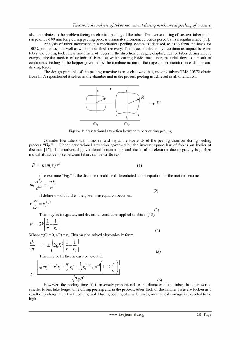
Figure 1: gravitational attraction between tubers during peeling
Consider two tubers with mass m1 and m2 at the two ends of the peeling chamber during peeling
process “Fig.” 1. Under gravitational attraction governed by the inverse square law of forces on bodies at
distance [12], if the universal gravitational constant is γ and the local acceleration due to gravity is g, then
mutual attractive force between tubers can be written as:
2
21
1 rmmF (1)
if re-examine “Fig.” 1, the distance r could be differentiated so the equation for the motion becomes:
2
1
2
2
1r
km
dt
rdm
(2)
If define v = dr /dt, then the governing equation becomes:
2rkdr
dvv
(3)
This may be integrated, and the initial conditions applied to obtain [13]:
0
2 112
rrkv
(4) Where v(0) = 0, r(0) = r0. This may be solved algebraically for r:
0
2 112
rrgRv
dt
dr
(5)
This may be further integrated to obtain:
2
0
12/3
0
2
00
22
0
2
21sin2
1
4
gR
r
rrrrrrr
t
(6)
However, the peeling time (t) is inversely proportional to the diameter of the tuber. In other words,
smaller tubers take longer time during peeling and in the process, tuber flesh of the smaller sizes are broken as a
result of prolong impact with cutting tool. During peeling of smaller sizes, mechanical damage is expected to be
high.

Theoretical analysis of tuber movement during mechanical peeling of cassava
www.iosrjournals.org 29 | Page
In the process of peeling during mass production, the movement of tubers from the inlet to outlet of the
peeling chamber generates displacement among themselves as a result of spinning of the tuber as it comes in
contact with cutting tool. Forces exerted by one on another could be treated as internal and external. Since peeling chamber is a closed system, tubers exert forces on each other [14]. Let F1
21 be the force
that tuber 2 exerts on tuber 1, there is also external force (gravitational) exerted on tuber 1, Fext1.
From Newton‟s second law, maFij
1, applied to each tuber gives
111311
211 amFFF ext
(7)
222321
121 amFFF ext
(8)
333231
131 amFFF ext
(9)
From Newton‟s third law of motion, during interaction of tubers, the force exerted by one tuber on the
other is equal in magnitude and opposite in direction to one another.
F121 = - F1
12, F131 = - F1
13, F132 = - F1
23
The sum of the three equations becomes:
332211321 amamamFFF extextext (10)
For n number of tubers,
nnextnextextext amamamamFFFF ............. 332211321 (11)
n
i
n
i
ext maF (12)
Where extF is the net external force exerted on the tubers
Consider circular motion of the auger, the tubers have net force exerted on it toward the center of the circle with
magnitude mv2/R where v is the velocity of conveyance.
R
mvF
21 //
(13)
This term indicates that the net force is directed toward the center of the circular motion. When the
external horizontal force is applied to tubers, as long as the tuber is moving,
sFF 1. The net force is
horizontal. The static frictional force Fs provides the centripetal force because the tubers do not slide on the
surface of the cutting tool [15].
maFs (14)
Frictional force, Fs is a function of velocity of conveyance. By combining “equation 13 and 14”, we have:
R
mvFs
2
(15)
Thus Fs is large when v is larger, but Fs cannot exceed Fs.max. The maximum velocity of conveyance for
optimum performance, vm corresponds to max.ss FF
mgFFR
mvsNss
m max.
2
(16)
Solving for vm
gRv sm (17)
Where μs is the coefficient of static friction between the cutting tool edge and tuber surfaces and FN is
the vertical force acting normally as displaced in “Fig.” 2. From practical experience during experimental
analysis, it was observed that μs = 0.614 for smooth-edge and 0.671 for serrated-edge cutting tool. vm is a
function of μs, it was reported by [11] that vm = 2.44 m/s for smooth-edge and 2.79 m/s for serrated edge tool. If this is exceeded during mechanical peeling, more damages are expected to be done to tuber flesh.

Theoretical analysis of tuber movement during mechanical peeling of cassava
www.iosrjournals.org 30 | Page
Figure 2: (a) sketch of the peeling system; (b) free body diagram of the tuber.
R
mvSinFN
2
(18)
Since there is no vertical acceleration, the vertical component of FN is equal to the tuber‟s weight
mgCosFN (19)
Where θ is the angle of inclination of the cutting blade. Taking the ratio of these equations:
mg
Rmv
CosF
SinF
N
N
2
(20)
Rg
v21tan
(21)
This is consistence with designer‟s expectation; θ was estimated at 45o in the design. This expression
predicts that θ could be smaller if length of chamber is shorter and it could be bigger for longer chamber. This is
necessary so as to prevent losses due to mechanical damage.
III. Modeling of Peeling Time as a Function of Velocity of Conveyance
The peeling process is analysed using Hertz theory. The root is pressurized by application of force FN. It experiences a radial deformation, δ as reported by [16] and is given as:
31
2
ad
Nc
t
Fk
(22)
Where: kc = constant and tad = average tuber diameter. For a unit length of root, the length c1, true length of peel
separated within contact area between tuber and cutting tool is given by
2
21
12
2
ad
ad
ttc (23)
Usually, δ would be very small compared to tad.
Consider the loading of tubers in the hopper; a b
Figure 3: (a) tuber loading point; (b) (x,y) distribution theory
Referring to point x in the hopper as shown in “Fig.” 3a. Distributed load FN(x) is applied to the surface as
tuber is discharged in the peeling chamber over a range of x. Consider (x,y) axes of the distribution in “Fig.” 3b,

Theoretical analysis of tuber movement during mechanical peeling of cassava
www.iosrjournals.org 31 | Page
222
22
yx
yxFNxx
(24)
222
22
yx
xyFNxx
(25)
222
32
yx
yFNxx
(26)
The principle of linear superposition can be applied to determine the resultant shear stress from integral
equations [10]:
b
a
Nxx
yxx
dxxxxFy2
221
12112
(27)
b
a
Nxx
yxx
dxxxxFy2
221
111122
(28)
b
a
Nxx
yxx
dxxFy2
221
1132
(29)
When the tubers are in motion relative to one another in the chamber, they interact by pressure or stress
at their interface [17]. Consider the point of contact s between tuber surface and cutting edge in the (x,y) axes
with z axis assumed to the surface. A normal pressure distribution between tubers p = p(x,y) = q(x,y); and surface traction distribution between cutting tool and tubers qx = q(x,y) and qy = q(x,y) over a cross-sectional
area A. Using Newtonian force balance:
s
dAyxPpx ,
(30)
s
dAyxqqx ,
(31)
At the point of contact, a force is generated to track down the tuber and compressed its peel irrespective
of the orientation at which it was discharged.
Using serrated cutting tool, two rough surfaces (tool surface and tuber surface) are involved. The true
contact Area A1 is much smaller than the apparent contact area A0 and the true contact area is related to the
force FN by:
NFEh
kA
11 (32)
Where h1 is the root mean square of the taper angle, E is the elasticity module and k is constant = 2 [18].
But FFFF sN 1
(33)
Where F is the force required to penetrate through peel thickness at the point of contact. From “equation 18”,
2
2
R
RvkmFN
(34)
Substitute “equation 34” into “equation 32”;
REh
k
v
Rmk
A1
2
2
1
1
(35)

Theoretical analysis of tuber movement during mechanical peeling of cassava
www.iosrjournals.org 32 | Page
Figure 4: tuber in contact with cutting tool during peeling process
Radius, R with peel thickness, tp creates a contact area of radius a on a cutting tool during peeling process as
shown in “Fig.” 4.
pRta (36)
The normal force is related to the tp by
23
21
3
4pN tERF
(37)
The distribution of normal traction in the contact area as a function of distance from the centre of the contact
circle is
2
1
2
2
0 1
a
tptp l
l
(38)
Where p0 is the maximum contact pressure given by:
31
2
2
20
61
2
3
R
FE
a
Fp
(39)
The general solution for the pressure distribution in the contact area is
2
1
2
2
01
2
1
2
2
0 11
a
tp
a
tptp ll
l
(40)
Note that in the original Hertz theory, the term containing p10 is negligible on the ground that tension could not
be sustained in the contact zone.
The critical contact area is given by
E
Rac
4
9 23
(41)
While critical peel penetration depth is
32
31
32
323
22
4
9
E
R
R
ad c
c
(42)
But 1221 (43)
Where γ1, γ2 are the adhesive forces of the two surfaces in contact and γ12 is an interaction term [19].
Consider the separation between peel and tuber flesh, the tuber flesh is surrounded by a thin cambium layer and
covering the layer is the tuber peel. The separation at the cambium layer is given by
22
1
22
1 11
sin21
ncn
ncR
ts
(44)

Theoretical analysis of tuber movement during mechanical peeling of cassava
www.iosrjournals.org 33 | Page
Where ts is the vertical displacement or shear stress at the cambium layer and c1 is the true length of
peel separated within contact area knowing fully well that c0 > c1 and n is the ratio between c1 and apparent
length, c0. From practical experience during experimentation, it was observed that average value of R = 30 mm, c1
= 25 mm and n = 0.5.
Putting these values into “equation 44”, so as to obtain:
ts = 6.142 N/mm2
Referring to “equation 6”, it was deduced that for a given mass of tuber, theoretical peeling time is
affected by tuber density. Thus, it may therefore write:
2
3/1
2
0
12/3
0
2
00
22
0
2
21sin2
1
4
v
tX
gR
r
trrrtrt
t w
lll
(45)
Where tw is weight of tuber.
IV. Effect of Peeling Time on Velocity of Conveyance
Tuber parameters such as tl and td are major criteria considered for cassava grading and they also play
important role in the velocity of conveyance during peeling process. These parameters influenced peeling time.
Theoretically, it is therefore established that machine capacity which is a function of tuber weight and the
peeling time varies with change in tl as well as td.
Figure 5: peeling time t (sec) against velocity of conveyance v (m/s) at various values of tl (m) with td= 0.019m,
r = 2.5m, g = 9.81m/s2
Figure 6: peeling time t (sec) against velocity of conveyance v (m/s) at various values of tl (m) with td =
0.140m, r = 2.5m, g = 9.81m/s2

Theoretical analysis of tuber movement during mechanical peeling of cassava
www.iosrjournals.org 34 | Page
Figure 7: peeling time t (sec) against velocity of conveyance v (m/s) at various values of td (m) with tl =
0.125m, r = 2.5m, g = 9.81m/s2
Figure 8: peeling time t (sec) against Velocity of conveyance v (m/s) at various values of td (m) with tl =
0.492m, r = 2.5m, g = 9.81m/s2
The length of peeling chamber r = 2.5 m, and from experimental data; tl varied from 0.125 to 0.492 m,
tuber diameter, td varied from 0.019 to 0.140 m and velocity of conveyance, v varied from 1 to 5 ms-1. At a given value of v, tl increased as t also increased. During peeling within the range of smaller tuber diameter (td), t
increased from 69 to 89 s as tl increased from 0.125 to 0.492 m as reflected in “Fig.” 5. When peeling within the
range of larger (td), t increased from 9.4 to 12.1 s as tl increased from 0.125 to 0492 m as reflected in “Fig.” 6.
Thus, smaller tubers stayed longer in the peeling chamber and this prolong interaction connotes higher
mechanical damage on the tubers. This justified theoretical expression in “equation 45”, that cassava peeling
time is inversely proportional to root square diameter.
Similarly, keeping tl constant, for smaller range of tl, t increased from 10 to 90 s as td decreased from
0.140 to 0.019 m for a given value of v during mechanical peeling “Fig.” 7. When peeling larger range of tl, t
also increased from 10 to 90 s as td decreased from 0.140 to 0.019 m for a given value of v “Fig.” 8. In other
word, there is no significant difference in the t with respect to v when peeling tubers of different tl. Thus, t is
significantly influenced by td. The outstanding merit of this concept is that effective peeling time with respect to velocity of conveyance of different sizes of cassava tuber is achieved.
V. Conclusions The following conclusions are drawn from the work:
1. During peeling of small sizes, mechanical damage is expected to be high. Thus, this concept is not
economically suitable for peeling tuber ≤ 19 mm diameter.

Theoretical analysis of tuber movement during mechanical peeling of cassava
www.iosrjournals.org 35 | Page
2. Length of tuber has no effect on peeling time. However, peeling time is significantly influenced by tuber
diameter.
3. The concept is an invaluable and reliable tool for developing mechanical peeling machine at high quality peeling efficiency.
References [1]. S.A. Odedina, J.N. Odedina, M.O. Ogunkoya, and S.O. Ojeniyi, Agronomic evaluation of new cassava variety introduced to
farmers in Nigeria. African crop science conference proceedings (9), 2009, 77-80
[2]. S.A. Odoemelam, Studies on residual hydrocyanic acid (HCN) in gari flour made from cassava. Pakistan Journal of Nutrition, 4(6),
2005, 376-378
[3]. O.P. Kolawole, L.A.S. Agbetoye, and A.S. Ogunlowo, Evaluation of cassava mash dewatering methods. Journal of Bioinformatics
and sequence analysis, 3(2), 2011, 23-30
[4]. P. Hartman, Value addition key to cassava revolution in Nigeria, Director General of IITA speech to stake holder‟s forum, CFC-
funded cassava value chain project in Nigeria implemented by IITA http://www.thisdaylive.com/articles/value-addition-key-to-
cassava-revolution-in-nigeria/9881, 2011
[5]. IITA, IITA bulletin, issue No. 2050, 2-7 January http://www.iita.org/Bulletin accessed, 2011
[6]. J.C. Igbeka, Mechanization of tuber (cassava) peeling. Paper presented at International Symposium on Mechanization of
Harvesting and Subsequent Processing of Agricultural Products in Tropical Africa and the Manufacturing of Relevant Agricultural
Implements, held in Yaounde, Cameroun, 11-15 February, 1985
[7]. D.A. Adetan, L.O. Adekoya, and O.B. Aluko, Characterisation of some properties of cassava root tubers, Journal of Food
Engineering, 59, 2003, 349-353
[8]. O.J. Olukunle, Development of a cassava peeling machine. Proceeding of the International Conference on Global Food and
Product Chain, Dynamics, Innovations, Conflicts and Strategies. „Tropentag 2005‟ University of Hohenheim Stuttgart, Germany.
http://www.tropentag.de/2005/abstracts/full/590.pdf
[9]. M.O. Jimoh, and O.J. Olukunle, An automated cassava peeling system for the enhancement of food security in Nigeria, Nigerian
Food Journal, 30(2), 2012, 73-79
[10]. O.J. Olukunle, and P.G. Oguntunde, Analysis of peeling pattern in an automated cassava peeling system, Nigerian Journal of
Technology and Development, 6(1) and (2), 2008, 41-52
[11]. O.C. Ademosun, M.O. Jimoh, and O.J. Olukunle, Effect of physical and mechanical properties of cassava tubers on the performance
of an automated peeling machine, International Journal of Development and Sustainability, 1(3), 2012, 2168-8662
[12]. D.E. Thompson, Design analysis; mathematical modeling of nonlinear system United Kingdom, Cambridge University Press, 1999
[13]. R.S. Khurmi, A Textbook of applied mechanics, Ram Nagar, New Delhi, S. Chand and company limited, 2009, 216-222
[14]. D.R. Heldman, and D.B. Lund, Handbook of food engineering, New York, Marcel Dekker, 1992
[15]. A.K. Srivastava, C.E. Goering, and R.P. Rohrback, Engineering principles of agricultural machines, ASAE Textbook, 1996
[16]. D.A. Adetan, L.O. Adekoya, and O.B. Aluko, Theory of a mechanical method of peeling cassava tubers with knives, Journal of
International Agrophysics, 20, 2006, 269-276
[17]. A.S. Foust, I.A. Wenzel, C.W. Clump, L. Maus, and L.B. Anderson, Principle of unit operations, New York, John Wiley & Sons,
1980
[18]. S. Hyun, and M.O. Robbins, Elastic contact between rough surfaces, effect of roughness at large and small wavelengths. Tribology
International, 40, 2007, 1413-1422
[19]. I. Albert, and V.B. Gustavo, Unit operation in food engineering, New York, CRC Press, 2003
Nomenclature
r = length of peeling chamber, m
tl = length of tuber, m
R = radius of tuber, m
γ = universal gravitational constant
g = a = local acceleration due to gravity, ms-2
F1 = force exerted by the tuber, N
v = velocity of conveyance, ms-1
ts = peel shear stress, Nmm-2
Fs = frictional force, N
θ = angle of inclination of the cutting blade, o t = peeling time, s
Fs = static frictional force, N
vm = maximum velocity of conveyance for optimum performance, ms-1
Fs.max = maximum static frictional force, N
μs = coefficient of static frictional force
FN = vertical force acting normally on tuber, N
kc = constant proportionality
δ = radial deformation, m
c = length of contact between tuber and cutting tool, m
x,y and z = axes
p = normal pressure distribution between tubers, Nm-2
A1 = true contact area, m2
A0 = apparent contact area, m2
Theoretical analysis of tuber movement during mechanical peeling of cassava
www.iosrjournals.org 36 | Page
h1 = root mean square of the taper angle, o
E = elasticity module
po = maximum contact pressure, Nm-2 a = radius of contact area on cutting tool, m
ac = critical contact area, m2
dc = critical peel penetration depth, m
γ1, γ2 = adhesive forces of the two surfaces in contact, N
γ12 = interaction term between adhesive forces
c1 = true length of peel separated within contact area, m
c0 = apparent length of peel separated within contact area, m
n = ratio between true and apparent length
td = tuber diameter, m
![Assessing Spiritual Crises: Peeling Off Another Layer of a Seemingly Endless Onion. (2014). [Bronn & McIlwain].](https://static.fdokumen.com/doc/165x107/63323539b6829c19b80bdc9e/assessing-spiritual-crises-peeling-off-another-layer-of-a-seemingly-endless-onion.jpg)