Application of digital techniques to a nuclear reactor safety ...
150
APPLICATION OF DIGITAL TECHNIQUES TO A NUCLEAR REACTOR SAFETY MONITOR FOR THE LIQUID METAL FAST BREEDER REACTOR Stephen Anthony El rod
-
Upload
khangminh22 -
Category
Documents
-
view
4 -
download
0
Transcript of Application of digital techniques to a nuclear reactor safety ...

APPLICATION OF DIGITAL TECHNIQUESTO A NUCLEAR REACTOR SAFETY MONITOR
FOR THE LIQUID METAL FASTBREEDER REACTOR
Stephen Anthony El rod

NAVAL POSTGRADUATE SCHOOL
Monterey, California
XH ESISAPPLICATION OF DIGITAL TECHNIQUES
TO A NUCLEAR REACTOR SAFETY MONITORFOR THE LIQUID METAL FAST
BREEDER REACTOR
by
Stephen Anthony Elrod
Thesis Advisor M. L. Cotton
Harch 1972
kpphjjvid ^oh. pubtlc xejtza&e.; dij>£/uhuuti.cyi antlmittd.

Application of Digital Techniques to a NuclearReactor Safety Monitor for the
Liquid Metal Fast Breeder Reactor
by
Stephen Anthony ElrodLieutenant Commander, United States Navy
B.E.E., Auburn University,, 1962
Submitted in partial fulfillment of the
requirements for the degree of
MASTER OF SCIENCE IN ELECTRICAL ENGINEERING
from the
NAVAL POSTGRADUATE SCHOOLMarch 1972


ABSTRACT
This paper demonstrates a nuclear reactor safety monitor incor-
porating hard-wired, redundant, digital program modules that control
independent, redundant, digital monitor modules. One monitor module
is used for each parameter significant to reactor safety. The charac-
teristics of a proposed LIQUID METAL FAST BREEDER REACTOR
are used as the reference performance criteria. The established cri-
terion that a single failure must not prevent reactor shut down is used
as the failure mode criterion. Within the program module, a pro-
grammable read-only memory (PROM) is used for sequence control of
another PROM containing variable length subroutines. The subroutine
PROM outputs are used as photo-isolated logic outputs for sequence
control of the various monitor modules. The program module action
is modelled on a digital computer. A four-input digital monitor module
is developed. This module provides a shut down signal if three of the
inputs exceed the parameter limit.

TABLE OF CONTENTS
I. INTRODUCTION 9
II. OBJECTIVES 16
A. OBJECTIVES OF THIS INVESTIGATION £T
B. ASSUMPTIONS OT7
C. CRITERIA FOR IDEAL PERFORMANCE IS
HI. COMPARISON OF SMALL SEQUENTIAL-STEP STORED
-
PROGRAM AND HARD-WIRED COMPUTERS 19
A. IMPORTANT CHARACTERISTICS OF SMALLSEQUENTIAL-STEP STORED-PROGRAM COMPUTERS 19
B. IMPORTANT CHARACTERISTICS OF SMALLSEQUENTIAL-STEP HARD-WIRED COMPUTERS 2d
C. COMPARISON AND CONCLUSION 21
IV. PROGRAM MODULE DESIGN 22
A. GENERAL CONSIDERATIONS 22
B. DESCRIPTION OF A PROGRAM MODULE [Fig. 4 1 24
C. FAULT TREE OF A PROGRAM MODULE 27
D. TEST REQUIREMENTS FOR THE PROGRAM MODULE 27
E. COMPUTER MODEL OF THE PROGRAM MODULE. 28
V. DIGITAL MONITOR MODULE DESIGN 33
A. GENERAL CONSIDERATIONS 33
B. SPECIFIC DESIGN CHARACTERISTICS EMPLOYED 34
C. DESIGN CHOICES 34
D. DESCRIPTION OF A COMPARATOR MODULE (COM) 35
3

E. PROGRAM INPUTS TO THE COMPARATOR MODULE 36
F. DESCRIPTION OF A SCRAM LOGIC MODULE (SLM) 37
G. FAULT TREE OF THE DIGITAL MONITOR MODULE 37
H. TEST REQUIREMENTS FOR THE MONITOR MODULE 39
VI. RELIABILITY CONSIDERATIONS 45
A. RELIABILITY CONSIDERATIONS IN A CONTROLSYSTEM 45
B. RELIABILITY CONSIDERATIONS IN A SAFETYCHANNEL 46
VII. CONCLUSIONS 50
APPENDIX A. INTRODUCTION TO THE LIQUID METAL FASTBREEDER REACTOR OVERALL PROGRAMPLAN [Ref. 1] 51
i
APPENDIX B. LMFBR PERFORMANCE REQUIREMENTS ANDDATA WORD LENGTHS 55
APPENDIX C. COMPUTER MODEL DEMONSTRATION OF THEDIGITAL PROGRAM MODULE 59
1. DEFINITION OF TERMS USED 59
2. FLOW DIAGRAM OF THE COMPUTER MODEL 60
3. CONTENTS OF PROGRAM PROM, ADDRESS I 61
4. CONTENTS OF SUBROUTINE PROM, ADDRESS I 62
5. RESULTANT ACTION OF PROGRAM MODULE 63
6. MAIN SIMULATION PROGRAM 64
7. BLOCK DATA INPUT 65
8. SUBROUTINE "READ" 66
BIBLIOGRAPHY 67
INITIAL DISTRIBUTION LIST 70
FORM DD 1473 71
4


LIST OF TABLES
I. TABLE OF SYMBOLS 7
II. FAILURE RATE DATA FOR RELIABILITY ESTIMATION --- 49

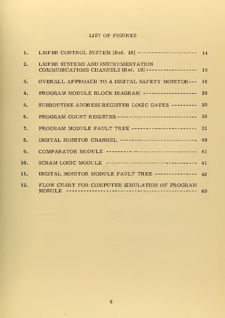
LIST OF FIGURES
1. LMFBR CONTROL SYSTEM [Ref. 10] 14
2. LMFBR SYSTEMS AND INSTRUMENTATIONCOMMUNICATIONS CHANNELS [Ref. 10] 15
3. OVERALL APPROACH TO A DIGITAL SAFETY MONITOR--- 16
4. PROGRAM MODULE BLOCK DIAGRAM 29
5. SUBROUTINE ADDRESS REGISTER LOGIC GATES 30
6. PROGRAM COUNT REGISTER 30
7. PROGRAM MODULE FAULT TREE 31
8. DIGITAL MONITOR CHANNEL 40
9. COMPARATOR MODULE 41
10. SCRAM LOGIC MODULE 41
11. DIGITAL MONITOR MODULE FAULT TREE 42
12. FLOW CHART FOR COMPUTER SIMULATION OF PROGRAMMODULE 60

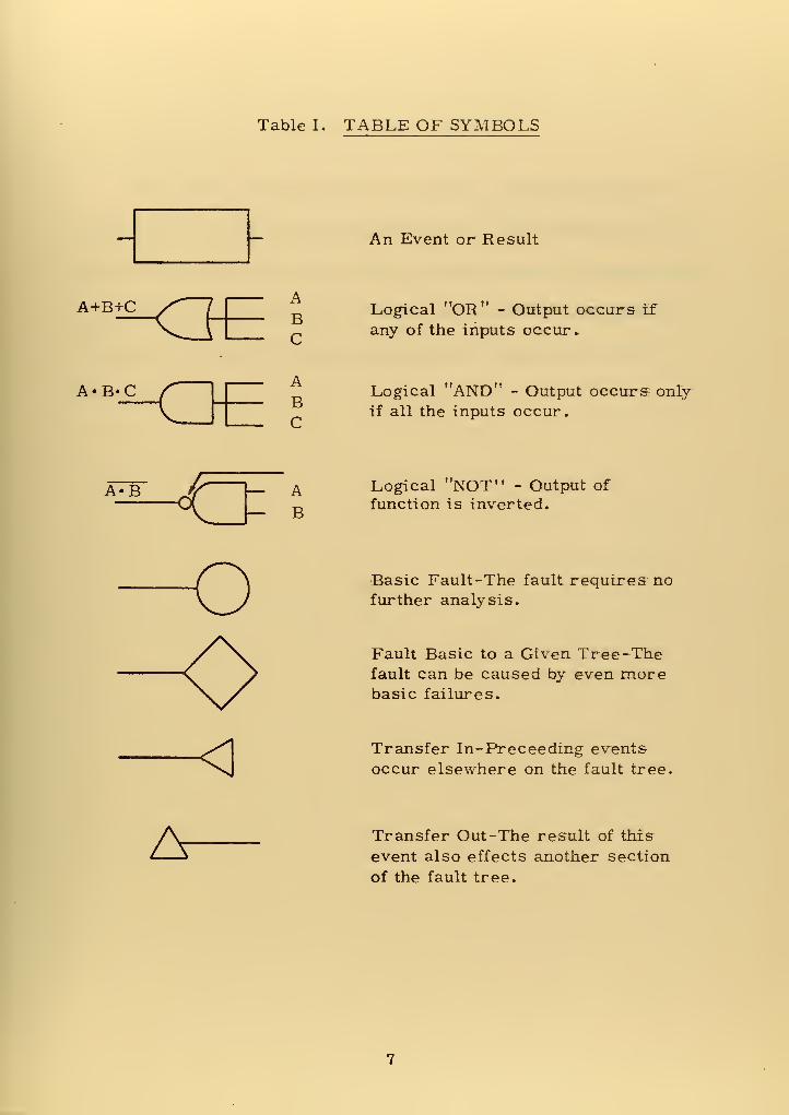
Table I. TABLE OF SYMBOLS
An Event or Result
A+B+C=KJABC
Logical "OR" - Output occurs if
any of the inputs occur.
A*B*C ABC
ti A TVTT-V "Logical AND - Output occurs only
if all the inputs occur.
t«~tA«B I— AB
Logical "NOT" - Output of
function is inverted.
Basic Fault-The fault requires nofurther analysis.
Fault Basic to a Given Tree -Thefault can be caused by even morebasic failures.
< Transfer In-Preceeding events
occur elsewhere on the fault tree.
A Transfer Out-The result of this
event also effects another section
of the fault tree.


ACKNOWLEDGMENTS
The author acknowledges his gratitude to his wife for the days
of typing and re-typing of drafts of this work. Her willingness to do
this during preparations for moving certainly deserves commendation*.
Also, to Professor M. L. Cotton of the Naval Postgraduate
School, who helped the author greatly with his suggestions and
encouragement.
8


I. INTRODUCTION
The rapidly increasing electrical power demands in the United
States and the resultant decreasing availability of natural fuels has
caused a great demand by utility companies for nuclear powered gen-
erating stations of any kind. This, in turn, has placed heavy demands
on the nation's ability to process from natural ores the amounts of
fissile (i.e., easily split by neutron interaction into by-products and
excess high-energy neutrons) uranium and plutonium required to fuel
the reactors. These are mostly light-water moderated, thermal
reactors which operate at moderate temperatures (500-700 F) and use
saturated steam to power the electric generators. Much larger but
presently little used supplies of uranium, thorium, and plutonium are
not easily fissionable in their natural state but do easily absorb neu-
trons and become fissile materials suitable for reactor fuels. These
materials are referred to as "fertile."
During the 1960's a development program was instituted by the
United States Atomic Energy Commission (AEC) to develop sodium
cooled fast breeder reactor plants intended to convert fertile fuel into
fissile fuel (breeding) in addition to supplying electricity. Since cool-
ant temperatures are higher in this process, more efficient conversion
of thermal energy into electrical energy is feasible also. The poten-
tial result is enhanced availability of nuclear fuel, both by breeding

and by increased plant efficiency. (See Appendix A, the introduction
to the LIQUID METAL FAST BREEDER REACTOR (LMFBR) DEVEL-
OPMENT PLAN, v. 1. [Ref. 1]).
The LMFBR Development Plan [Ref. 1] presents the state-of-
the-art advances required by the much harsher environment character-
ized by higher neutron and gamma fluxes, higher temperatures, and
liquid metal coolant. These documents indicate that current levels of
technology are unsatisfactory in almost all areas and that concurrent
research is being pursued. References 6-9 indicate some of this
research with respect to reactor instrumentation. Reference 6 dis-
cussus the test facilities required and efforts to upgrade test environ-
ments from 700 F to 1400 F, 109 nv thermal-neutron flux to 10
16nv
fast-neutron flux, and 104 R/h to 10 9 R/h gamma flux. Research
efforts in sensor development for temperature (thermocouples),
neutron flux, flow, pressure, level, and strain are also discussed.
Reference 7 discussus a possible microwave temperature sensor con-
figuration. Reference 8 reports work on in-core, self-powered, fast-
neutron flux monitors. Rpference 9 discussus the problems of radia-
tion induced noise on electrical signal cables. The varying approaches
taken by the researchers indicate that optimum instrumentation tech-
niques are yet to be proven.
The exact configuration of the reactors and controls, and the
methods of detecting, transmitting* and utilizing various parameters
are undetermined. This situation forces the use of assumptions of
10

most likely future conditions. Published feasibility studies have pro-
vided insight into probable reactor designs and those parameters
required to be measured and used for safety considerations. Refer-
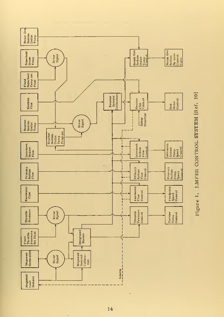
ence 10, a good example of such a study based on the estimated state
of the technology in 1980, proposes a 3-loop, double heat exchange,.
1150 F, 2415 Mwt, 43% efficient plant, with a fuel doubling time of
14.3 years, and a core lifetime of 605 full power days. Direct digital
control is proposed for many operations in the plant, including safety
system backup. Figure one illustrates the referenced concept of the
plant control system, primarily analog. The importance of the figure
to this work is its use as an illustration of typical relationships among
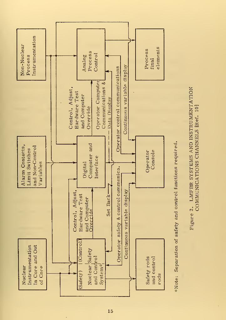
control parameters. Figure two shows the referenced plant's gross
relationship between the control systems of figure one and the digital
computer. The analog safety monitor system operates as part of thp
"Nuclear Safety and Control System" to provide safety actions if para-
meter limits are exceeded. An important point not clear in the figure
is the required independence of the nuclear safety and nuclear control
systems. Functions which initiate safety shutdown are:
1. high outlet temperature
2. high start up rate
3. high power level
4. low flow rate
5. low coolant level
6. high neutron flux /flow rate
7. turbine generator trip
11

8. loss of feedwater
9. loss of heat sink
10. loss of vital instrument power
11. manual trip
Reference 10 is not a final study and does not develop the hardware to
accomplish the objectives.
The safety criteria discussed in the various publications are all
based on the concept of preventing a power excursion or other event that
could damage the core and release activity to the coolant or atmosphere.
From this concept, several criteria pertinent to this investigation have
been developed:
1. The nuclear power plant protection system shall, with
precision and reliability, automatically initiate appropriateprotective action whenever a plant condition monitored by
the system reaches a pre-set level.
2. Components and modules shall be of a quality that is con-sistent with minimum maintenance requirements and lowfailure rates.
3. Channels that provide signals for the same plant protective
function shall be independent and physically separated.
4. Any single equipment failure within the protective systemshall not prevent proper protection system action whenrequired (single failure criterion).
These criteria have resulted in multiple safety channels, multiple
power supplies, and required periodic testing of safety channels.
References 11-15 discuss many of these concepts in detail. In any
case, each individual reactor installation must be reviewed and
approved by the AEC prior to operation.
12


Presently, analog safety systems provide the proper isolation
and redundancy for a safety system but suffer from additive errors
due to the series arrangement of components; widening the margin
between an allowed indicated condition and allowed actual condition.
Since multiple adjustments are provided in analog channels, they
must be regularly checked to ensure that they are still within allowed
tolerances. A digital form of data transmission appears to be capable
of providing channel separation, and yet can both reduce the number of
error introducing components in the safety circuit and be made largely
self-checking.
13

"S3 6
fc £
a „
§§«!§£ill £§mwO HO a> co e U >
4) ,S
SSfe
SIS c«j o 3 •K«iOf-
6 1
BS *
fc OT E
•b o
au L.
o to I
!h •£ bH CU
c
s a
HH
DQ
oKH
OU
CUD
14

^*
.
co J'
s- -H
uclea:
ss
menta CO ^Process
final
elements
tuo J,O ^ Sh
^
Non-NProce
Instru
Anal Proc ContCO
(3 1—
1
O a.CO
oJ -a>_,
1 1 0, ofi
n-t-»
3 ?, ^ Comput-ations
lay
3a1—
1
jQ03
•r-i
•
2Ot—
1
T3 Ch +S B 5h
03
> <oj a . ^ a Pi —
ntrol,rdwar
i
Com erride erator mmun
ta
Dis
r-i
CO
33.
tUMEN'
Ref.
10
O Oj £ > (X CO +->
U HI 03 O1
OSh
O
COO INSTF
els
[:
-4->
cd
daO
•
<L
U3a<
In
CO
CO
•i-t+->
C3
Alarm
Contacts,
Limit
Switches
and
Non-Control
CO
cu1—
1
X!cd
•i-i
u03
>
Digital
Computer
and
Interface
1
1
OperatorConsole MS
AND
3
CHANN
k ^) *
s
03
O"3
,I6
STE ION!
FBR
SY
UNICAT
—^>
1
-t->
i >>03
s 5 u03
PQ
1—
1
O
.
•1—3 VL fl;
Tl Ch -2<C 3
"o
-t->
CO
Oa„
> o- co
a
=2
a1—
1
03
OT3Coj
CM O
3C Sh -n °- s Ih
h> tuO
O 03 £ >U E c3C
+->
03
o3
>CO 03
•1-1
CO 3O
CO
^z.1—<
(h 3
r*
O+->
03
S-. •1-1-t->
>-'
^U 03 O
03 O g
« 3 "S £
(1) -t-J
fuclear
istruments
n
Core
and
UoU
U
afety
rods
nd
control
ods
o3
Jh
03
CD
CO
CD
J
> •-
S2 i—i i—
i
O 05 2 03 03 CO 03 Sh Oco £
15


II. OBJECTIVES
Consideration of current practice in reactor control design,
digital techniques, and safety criteria, coupled with anticipated
requirements [Refs. 1-5, 10, Appendix B], led to the conclusion that
some digital technique should provide a reliable and acceptable safety
monitoring system for the LMFBR. Figure 3 illustrates the overall
approach taken by this investigator in developing such a safety monitor
system. Two basic concepts were incorporated. One concept was to
have each safety parameter channel and its monitor module indepen-
dent of the others and to have each channel comply with the conditions
required in Sec. II B, ASSUMPTIONS, and Sec. II C, CRITERIA FOR
IDEAL PERFORMANCE, of this report. The other concept was to
provide a redundant and independent program module that would con-
trol the operation of the various monitor modules yet maintain their
individual independence.
Parameter 1
Signals
f y f |
N Digital Monitor Module[Fig. 8]
Safety
Action
Outputs
MonitorModuleControlInputs
ProgramModule(Redundant)[Fig. 4]
MonitorModuleControlInputs
Parameter NSignals
111
TSafety
ActionOutputs
Figure 3. OVERALL APPROACH TO A DIGITAL SAFETY MONITOR
16


A. OBJECTIVES OF THIS INVESTIGATION
The objective of this investigation was to provide the following
within the framework of LMFBR operation:
1. Compare the characteristics of sequential-step stored-
program design with sequential-step hard-wired design
of a monitor within the framework of speed, programhardness, and separability of channels.
2. Design a solid-state program module that would replacea stored program, maximize parallel-parameter opera-tion of the safety monitor, and provide for field programchanges.
3. Determine how closely this solid-state program modulesatisfied the ideal monitor criteria.
4. Demonstrate, by designing a digital monitor module, a
digital method of monitoring one safety parameter. Investi-
gate the extent to which safety channel separability, self
test, and abnormal operation determination could be main-tained in this one parameter channel.
B. ASSUMPTIONS
Since the LMFBR was undeveloped, assumptions were required
to provide a framework for investigation:
1. The LMFBR configuration of Ref. 10 was to be used.
Pertinent details of the configuration are listed in the
introduction.
2. On-line digital computer control would be used.
References 16-23 support this contention and discuss
sampled-data techniques, optimal control, and severalpresently-installed digital control systems.
3. The control computer, though separate from the safety
system, would have the safety limits programmed.
4. The environmental and performance requirements of
Appendix B must be met.
17

5. A separate monitor unit for safety parameters would be
used in addition to the on-line control computer to provide
two independent mechanisms for actuating the safety shut
down system.
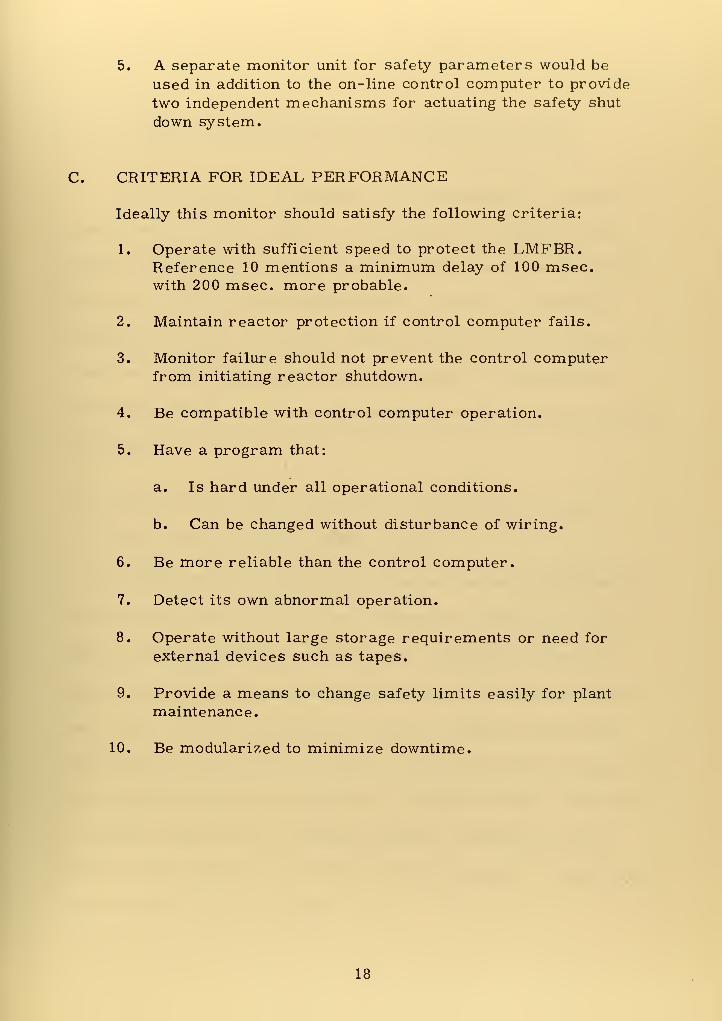
C. CRITERIA FOR IDEAL PERFORMANCE
Ideally this monitor should satisfy the following criteria:
1. Operate with sufficient speed to protect the LMFBR.Reference 10 mentions a minimum delay of 100 msec,with 200 msec, more probable.
2. Maintain reactor protection if control computer fails.
3. Monitor failure should not prevent the control computerfrom initiating reactor shutdown.
4. Be compatible with control computer operation.
5. Have a program that:
a. Is hard under all operational conditions.
b. Can be changed without disturbance of wiring.
6. Be more reliable than the control computer.
7. Detect its own abnormal operation.
8. Operate without large storage requirements or need for
external devices such as tapes.
9. Provide a means to change safety limits easily for plant
maintenance.
10. Be modularized to minimize downtime.
18


III. COMPARISON OF SMALL SEQUENTIAL-STEPSTORED-PROGRAM AND HARD-WIRED COMPUTERS
The general public acceptance of minicomputers for dedicated
control and monitoring applications prompted an investigation of the
utility of these machines with respect to LMFBR safety monitor imple-
mentation. The literature describing these machines emphasizes
reliability, low cost, expandable configuration, and custom-tailored
functions. All of these assets would be pertinent to LMFBR utiliza-
tion provided that speed, channel separation, and single failure criteria
were met.
A. IMPORTANT CHARACTERISTICS OF SMALL SEQUENTIAL
STEP STORED-PROGRAM COMPUTER
A small sequential-step stored-program computer (minicomputer)
stores its program and data in core memory and executes the program
step by step at the register transfer level. Though some may use a
read-only memory to control the arithmetic unit and registers, allow-
ing several arithmetic operations or register transfers (some simul-
taneously) per core memory cycle time, the program steps are executed
sequentially at the operation level; i.e., multiply, divide. The storing
of the basic operations in a read-only memory is sometimes called
"firm-wired. " Typical cycle time is 1-2 microseconds for each simple
operation (one read-write time).
19


The most important characteristic features that restrict the
utility of these machines for the nuclear monitoring application are:
1. Storage in the computer memory unit of both programsequence and data. Inherently, the program and the
data from the various safety channels in a reactor
safety monitor environment are brought together,
violating the philosophy of monitor channel separation.
2. Common busses for data transfer. Again, one failure
can effect both program and data if the bus is associated
with the memory unit. One failure can effect data fromall safety channels if the failure is associated with a data
bus.
3. Sequential data handling. In a small machine, no pro-
vision is made for parallel handling of data from morethan one source at a time.
4. Requirements for external equipment to input the programif it fails or if safety limits require changing.
5. Checkout programs cannot be independently run in parallel
with the main program.
B. IMPORTANT CHARACTERISTICS OF SMALL SEQUENTIAL-
STEP HARD-WIRED COMPUTERS
A small sequential-step hard-wired computer maintains its
main program in its wiring or read-only memory thus eliminating a
stored program.
Important characteristic features:
1. Can operate at faster speeds because a read-write cycle
into core memory is not required to access the program.
2. Retains sequential steps for the main program. .
3. Simple machines tend to retain common data busses anda single arithmetic unit.
20

4. Expansion to provide parallel data handling appears to be
easier to accomplish than with a primarily software machine.
5. The wiring or hard memory must be changed to change the
program sequence.
6. Application of the single failure criterion requires multiple
hardware.
7. Test programs either result in interbus connections,
destroying channel separation, or must be externally applied.
C. COMPARISON AND CONCLUSION
Comparison of the characteristics of stored-program design with
hard-wired design led to the conclusion that a small stored-program
device was unsatisfactory and to the search for a device that would
utilize the desirable features, such as higher speed and a hard program,
of a hard-wired computer, improve the ability to provide for simultane-
ous parallel operation of independent steps, incorporate self -test while
providing data channel isolation, and reduce the amount of hardware
needed to provide redundancy. The result was the Program Module
described in this paper.
21


IV. PROGRAM MODULE DESIGN
A. GENERAL CONSIDERATIONS
The first tasks encountered in the design of the program module
were the selection of suitable memory and micrologic systems. Par-
ticular emphasis was placed on availability and variety of packaged
functions, compatability between memory and micrologic, speed of
operation, temperature range allowed, and resistance to propagation
of failures. Afield-programmable, read-only memory (PROM) con-
cept was selected because it offered a hard, but easily changeable,
program in an integrated form. Transistor-transistor logic (TTL)
medium scale integration (MSI) logic gates and setable counters
(Registers) were selected because they appeared to provide a wider
range of packaged complex functions and higher speed than the metal-
oxide-semiconductor (MOS) type logic. Other attributes of TTL are:
a wide range of allowed operating temperature (-55C to +125C), input
diode clamping to reduce line-noise reflections, and a wide variety of
speed and power specifications.
The program module for the monitor [Fig. 4] was based on the
concept that some parameters must be monitored at shorter periods
than others, such that the longer monitor periods could be made some
multiple of the shortest one. This allowed a simple synchronization
scheme with longer -period events inserted at the appropriate time.
22

Appendix B supports this concept. It was possible then to make each
monitor event or test sequence a subroutine that could be called at the
proper time. Two clock frequences were required; one at the sub-
routine operating frequency and one to synchronize the shortest moni-
tor period. The output of the subroutine PROM consisted of dedicated
bits, confining the effect of a bit failure compared to the effect if
decoders were to be used in conjunction with the PROM output. The
dedicated bit concept allows the system designer a great deal of lati-
tude in the use of parallel and concurrent monitor events and in the
use of feedback within the control module to control subroutines of
varying lengths.
The problem of electrical and physical isolation was solved by
application of photo -isolators to the subroutine PROM outputs. A
photo-isolator is a packaged unit consisting of a light-emitting diode,
a photo-sensitive transistor or reverse-biased diode, and a clear
insulator between them. The only connection between the input and
output is light.
The output of the diode -transistor type photo -isolator is com-
patable with TTL inputs but the signal rise and fall times are much too
long (5-20 microseconds) to be useful in this application. The output of
the diode -diode type photo -isolator is not directly compatable with TTL
inputs. A MOS input-TTL output buffer has been developed that oper-
ates at TTL voltage and reduces propagation delay to the .05-. 1 micro-
second range. This device allows the use of the diode -diode photo-
isolator configuration.
23

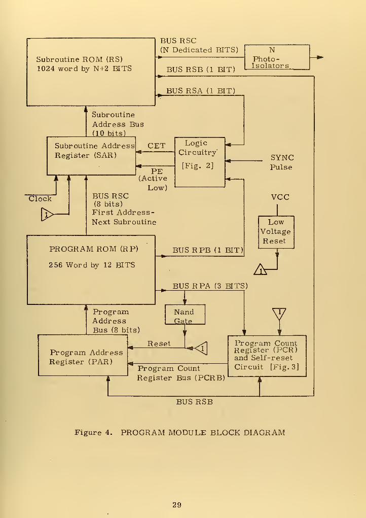
B. DESCRIPTION OF A PROGRAM MODULE [Fig. 4]
1. Subroutine PROM (RS)
The subroutine PROM (RS) is a 1024 word x (N+2) bit PROM
where N is based on overall monitor requirements. With the excep-
tion of the two feedback control bits, the output of RS is arbitrary and
each bit is dedicated to some function to be performed. Feedback bus
RSA holds a logical "1" only when that word is the last word of a sub-
routine, and feedback bus RSB holds a logical "1" only when that word
is the first word of a subroutine. A subroutine may be of arbitrary
length but must be at least two words long. Propagation times in the
feedback paths also require that, at the 10 MHZ clock frequency, each
subroutine be at least two words long. The longest propagation time
is in the PROM itself and is limiting; considering that faster counters
and logic gates exist.
2. Subroutine Address Register (SAR)
The subroutine address register is a ten bit binary counter.
During a subroutine the counter counts up one count each clock pulse;
incrementing the address of RS by one. At the end of a subroutine,
logic into the CET and PE (active low, parallel enable) inputs causes
incrementing to stop and, when conditions pre -determined by logic on
bus RPB are met, the first address in the next subroutine to be entered
by parallel input from the program PROM-RP. Since only eight parallel
input lines are available in the basic configuration, the number of pre-
set addresses is only one fourth of the total number of addresses in
24

SAR and RS. Two hundred fifty six separate subroutines sepm to be
adequate, considering that PROM dedicated bits may be used regard-
less of the subroutine involved, but, if more subroutines were
required, the PROMs and registers could be expanded.
3. Program PROM (RP)
The sequence of subroutines is stored in PROM-RP (2 56
words by 12 bits) and sequentially executed. An eight bit bus, RPC,
contains the start address of the next subroutine, a three bit bus,
RPA, contains the number of times the next subroutine is to be
repeated prior to going on, and a one bit bus, RPB, contains a logical
"0" if the start of the next subroutine must be synchronized with the
sync input. Since the main program and the subroutines are contained
in different PROMs, they can be changed independently.
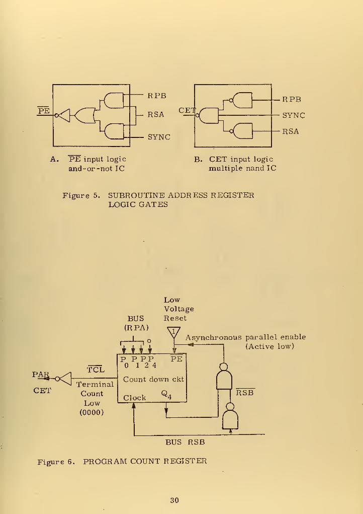
4. Program Count Register (PCR)
The program count register [Fig. 6] is a four bit binary up/
down counter that counts down, being clocked by bits on bus RSB;
therefore, one count occurs per subroutine. When 0000 is reached
the terminal-count-low or borrow gate enables the program address
register PAR. At the start of the next subroutine, PAR is incremen-
ted and PCR goes to 1111 (binary). After the first step of the sub-
routine, PCR receives parallel inputs for the number of repeats of
the next subroutine.
25

5. Program Address Register (PAR)
The program address register is an eight bit binary counter
similar to SAR. It is enabled by the PCR terminal-count-low gate and
uses the RSB output as a clock.
6. Enable Logic for the Subroutine Address Register (SAR)
(PE) = (RSA • (RPB + SYNC)) - i.e., parallel entry is
permitted only at the end of a subroutine and, if required by RPB = "0,
at a sync pulse.
(CET) = (SYNC + RPB + RSA) - i.e. , both counting up and
parallel entry are inhibited at the end of a subroutine unless conditions
for PE are met. These gates are constructed as shown in Fig. 5 and
consist of one standard MSI chip each.
7. Reset Circuitry
The reset circuitry consists of two elements. Upon initial
turn-on or recovery of voltage, one element (low-voltage reset) resets
the PAR, resets the SAR, and enables the parallel input into the PCR.
Upon encountering a 111 (binary) on bus RPA (end of programmed
portion of program PROM), the second element (end-of-program
reset) resets the PAR only. The low-voltage reset may consist of a
delay device to hold the resets and parallel enable low until after Vcc
has risen. The end-of-program reset consists of a simple three-input
NAND gate.
26

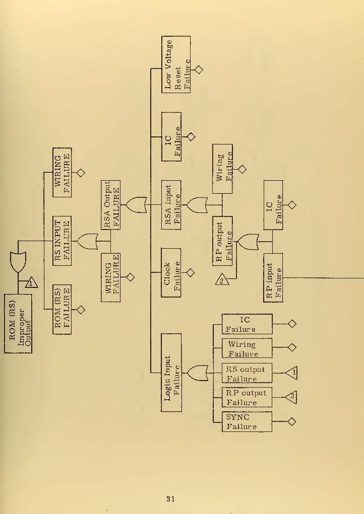
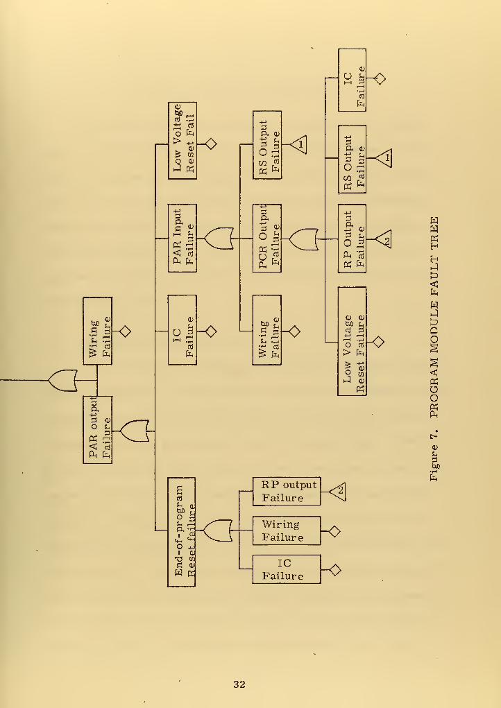
C. FAULT TREE OF A PROGRAM MODULE
Table I shows the symbols used in constructing all fault trees
in this paper. Figure 7 is the fault tree of the control module.
1. Power Supply Failures
Power supply failures were not included in the control
module fault tree because a loss of voltage would cause the control
module to reset and a catastrophically high voltage would cause burn-
out of the light -emitting diodes in the photo -isolators, having the
same effect as a reset. Provision is made in the digital monitor
module construction for voting inputs from three parallel program
modules; thus preventing a single failure of a program module from
inhibiting monitor operation.
2. Analysis with Respect to the Single Failure Criterion
Review of the fault tree of the program module revealed that,
while the module contains several feedback paths, the effect of any
fault is to prevent proper output; hence a serial fault tree and implied
serial consideration of reliability. The serial nature of faults dictates
redundant program modules to satisfy the single failure criterion
[Ref. 14] which states that no single failure may prevent reactor shut
down.
D. TEST REQUIREMENTS FOR THE PROGRAM MODULE
Self-test circuitry in the program module cannot test the connect-
ing wiring between the program module and monitor modules and per-
forms little function not tested elsewhere. It also tends to reduce both
27

the dedication of PROM-RS dedicated bits and the reliability, due to
increased complexity, of feedback paths. It was decided, based on
these deleterious conditions, coupled with the simple implementation
of redundant program modules, to provide for testing at the monitor
module level.
E. COMPUTER MODEL OF THE PROGRAM MODULE
Operation of the program module was tested using a digital
computer model [Appendix C]. The functional requirements for the
reset circuitry were developed using this model. The model verified
that the program module configuration of Fig. 4 operated in the
desired manner.
28

Subroutine ROM (RS)
1024 word by N+2 BITS
BUS RSC(N Dedicated BITS)
BUS RSB (1 BIT)
NPhoto
-
Isolators
BUS RSA (1 BIT)
Subroutine
Address Bus(10 bits)
Subroutine AddressRegister (SAR)
Clockr
\p-
CET
PE(Active
Low)
LogicCircuitry
[Fig. 2]
BUS RSC(8 bits)
First Address-Next Subroutine
PROGRAM ROM (RP)
2 56 Word by 12 BITS
BUS RPB (1 BIT)
BUS RPA (3 BITS)
ProgramAddressBus (8 bits)
INandGate
Program AddressRegister (PAR)
Reset <Program CountRegister Bus (PCRB)
SYNCPulse
VCC
LowVoltage
Reset
Program CountRegister (PCR)and Self-reset
Circuit [Fig. 3]
IBUS RSB
Figure 4. PROGRAM MODULE BLOCK DIAGRAM
29

PE input logic
and -or -not ICB. CET input logic
multiple nand IC
Figure 5. SUBROUTINE ADDRESS REGISTERLOGIC GATES
PA
CET
TCL
TerminalCountLow
(0000)
BUS(RPA)
I
—L_^o
LLti
LowVoltage
Reset
Asynchronous parallel enable
(Active low)
P P PP12 4
PE
Count down ckt
Clock~~*
I
BUS RSB
Figure 6. PROGRAM COUNT REGISTER
30

-&
go
OK
uCD
ft^
U Qcur
OHS D
fa
-o
D
K fa
co Wk KP
2<
K fa
^^-o
5 K
co <K fa
<3
fa
*3t-H _|
£fa
-o
CL
boCO-->1—
1
o>
oCO 3a> cd
tf fa
^C>
fa
^0>
+->
3ft a;
5< 1—
1
CO aP5 fa
U cd
fa
^o
3
o fa
tuOc
13r4 co
£ fa
-o
3ft CD
fa rt
K fa
ICFailure
WiringFailure
u|-0•—1
»—>
v
a c
5 3"*" 1—
<
a. '3
oo
RS output
Failure
RP output
Failure
SYNCFailure -o
31

o
±; rt
o fa
> .,,
. 0)
£ CO
o a;
J K
+->
aft „c ?i-i Kh
355< oJ
fa fa
(1)
U 3HH i,—
0)
fa
anj
Jh abo r
? sin r-o* -
1-
irt
«w «*-
O +ji aTS a:
C cu
W £
_X~~L
RP output
Failure
WiringFailurev_i
ICFailure
-o
-o
fa
fa
KHH
<fa
H
QO
«ao«fa
U
fcuo
•i-i
fa
32


V. DIGITAL MONITOR MODULE DESIGN
This section describes the design of a Digital Monitor Module
whose function is, under the control of the program module, to com-
pare four independent digital signals representing a safety parameter
with a digital representation of the parameter limit and provide two
independent shut down signals if three of the four incoming signals
exceed the parameter limit. The module test facilities provide for
functional test of the module and, coupled with other monitor modules,
the program modules.
A. GENERAL CONSIDERATIONS
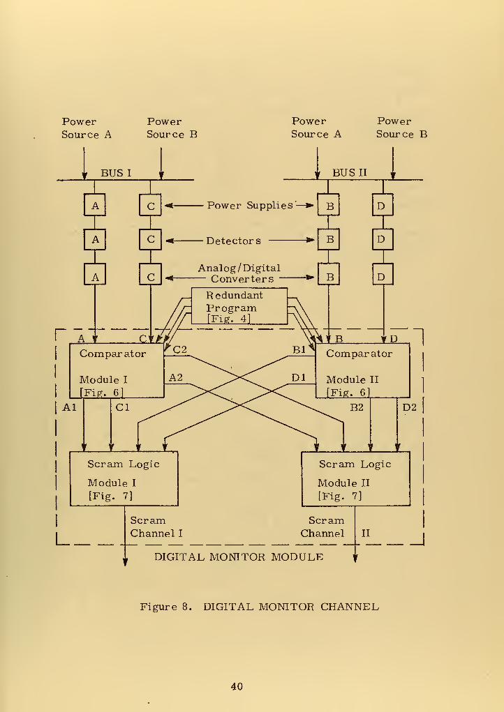
In a four -parameter channel, the detectors are usually grouped
into two sub-groups for power source and signal channel considerations
as shown in Figure 8. Each sub-group is powered from at least two
independent sources determined by the overall plant design. Detectors
A and C would be associated with power bus I and signal channel I,, and
detectors B and D would be associated with power bus II and a signal
channel II. Reference 14 requires that Channel I and associated cir-
cuitry must be physically and electrically isolated from channel EL and
its circuitry, yet at some point the signals must be combined to provide
two independent safety shut down (SCRAM) channels, each representing
a combination of data from all four sources. The inability to provide
electrical isolation using integrated circuits severely limits the use of
33


such circuits in the logic design of such a channel. The module design
effectively copes with that limitation.
The portion of interest of Figure 8 is inside the dotted lines r
and consists of the comparater modules and scram logic modules-
These modules, while independent, are controlled by redundant pro-
gram modules.
B. SPECIFIC DESIGN CHARACTERISTICS EMPLOYED
1. Comply with the philosophy of separation of scram channels..
2. Incorporate integrated circuits to the extent that the failure
of one IC does not interrupt both safety signals in a signal
channel.
3. Indicate an unsafe reactor condition upon loss of power to
the module or component that processes a signal.
4. Prevent the propagation of device failure throughout the
monitor.
5. Be amenable to some periodic test to detect a device
failure indicating a safe reactor condition.
6. Provide for adjustment of parameter limit setpoints.
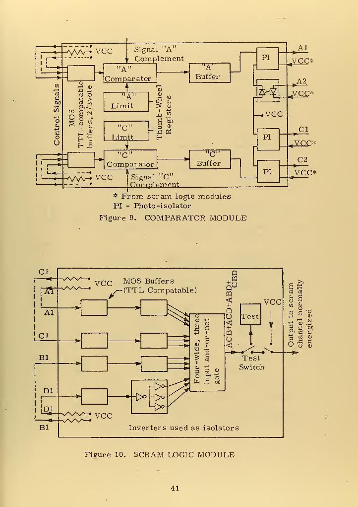
C. DESIGN CHOICES
The comparator module [Fig. 9] shows the result of several
comparisons of techniques. One comparison was among techniques
for presenting the parameter limit. Three techniques were considered.
The first technique was to enter the parameter into a ROM that had an
output of "0" or "l" depending on whether the parameter limit had
been exceeded. The second was to store the parameter limit in a core
memory and compare it with the parameter measured. The third was
• 34

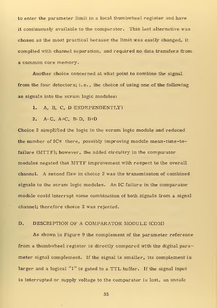
to enter the parameter limit in a local thumbwheel register and have
it continuously available to the comparator. This last alternative was
chosen as the most practical because the limit was easily changed,, it
complied with channel separation, and required no data transfers from
a common core memory.
Another choice concerned at what point to combine the signal
from the four detectors; i. e. , the choice of using one of the following,
as signals into the scram logic modules:
1. A, B, C, D (INDEPENDENTLY)
2. A-C, A+C, B-D, B+D
Choice 2 simplified the logic in the scram logic module and reduced
the number of ICs there, possibly improving module mean-time -to-
failure (MTTF); however, the added circuitry in the comparator
modules negated that MTTF improvement with respect to the overall
channel. A second flaw in choice 2 was the transmission of combined
signals to the scram logic modules. An IC failure in the comparator
module could interrupt some combination of both signals from a signal
channel; therefore choice 2 was rejected.
D. DESCRIPTION OF A COMPARATOR MODULE (COM)
As shown in Figure 9 the complement of the parameter reference
from a thumbwheel register is directly compared with the- digital para-
meter signal complement. If the signal is smaller, its complement is
larger and a logical "1" is gated to a TTL buffer. If the signal input
is interrupted or supply voltage to the comparator is lost, an unsafe
35

condition (logical "0") is gated. The buffer has the capability of sink-
ing larger light-emitting diode turn-on surge currents than standard
TTL devices can. This reduces light turn-on time and increases
response speed of the photo-isolator. Light turn-off time does not
appear to be a function of a surge current. The buffer output drives
two photo-isolators whose light-emitting diodes conduct when a safe
condition is indicated. The photo-isolators provide independent,
electrically isolated, single-parameter signals to each of the scram
logic modules. This is the feature that enables digital IC devices to
be used in a monitor module.
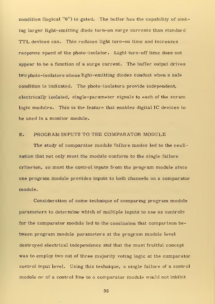
E. PROGRAM INPUTS TO THE COMPARATOR MODULE
The study of comparator module failure modes led to the reali-
zation that not only must the module conform to the single failure
criterion, so must the control inputs from the program module since
one program module provides inputs to both channels on a comparator
module.
Consideration of some technique of comparing program module
parameters to determine which of multiple inputs to use as controls
for the comparator module led to the conclusion that comparison be-
tween program module parameters at the program module level
destroyed electrical independence and that the most fruitful concept
was to employ two out of three majority voting logic at the comparator
control input level. Using this technique, a single failure of a control
module or of a control line to a comparator module would not inhibit
36

operation. The use of photo-isolated program module outputs to the
comparator module necessitates the use of a MOS-TTL buffer as the
voting circuit. Since a failure in the three control lines to one section
of a comparator module will not feed back to the program modules and
inhibit their operation, those lines can be considered to belong to that
comparator module section. A common mode failure of the control
lines can be considered to be the same as a failure of that section of
the comparator module.
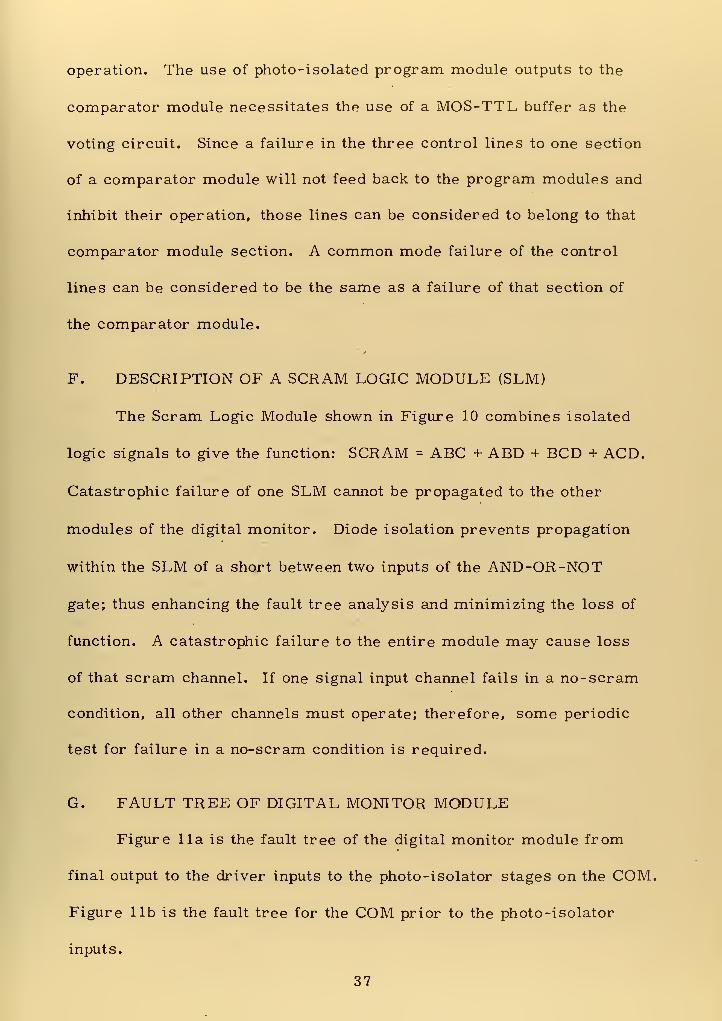
F. DESCRIPTION OF A SCRAM LOGIC MODULE (SLM)
The Scram Logic Module shown in Figure 10 combines isolated
logic signals to give the function: SCRAM = ABC + ABD + BCD + ACD.
Catastrophic failure of one SLM cannot be propagated to the other
modules of the digital monitor. Diode isolation prevents propagation
within the SLM of a short between two inputs of the AND-OR-NOT
gate; thus enhancing the fault tree analysis and minimizing the loss of
function. A catastrophic failure to the entire module may cause loss
of that scram channel. If one signal input channel fails in a no-scram
condition, all other channels must operate; therefore, some periodic
test for failure in a no-scram condition is required.
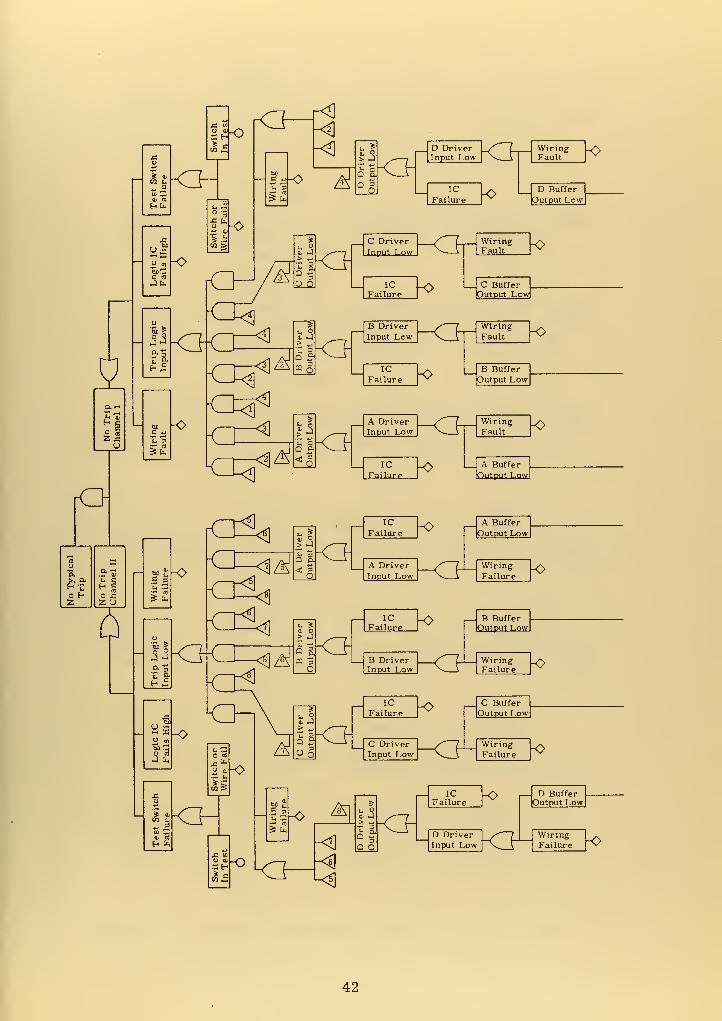
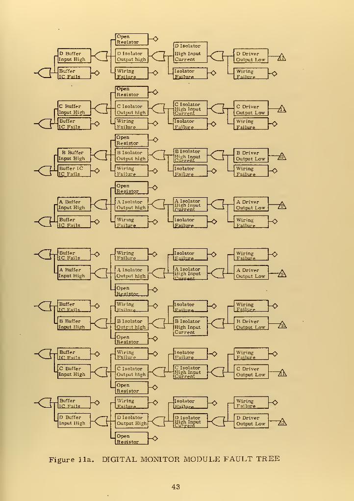
G. FAULT TREE OF DIGITAL MONITOR MODULE
Figure 11a is the fault tree of the digital monitor module from
final output to the driver inputs to the photo -isolator stages on the COM.
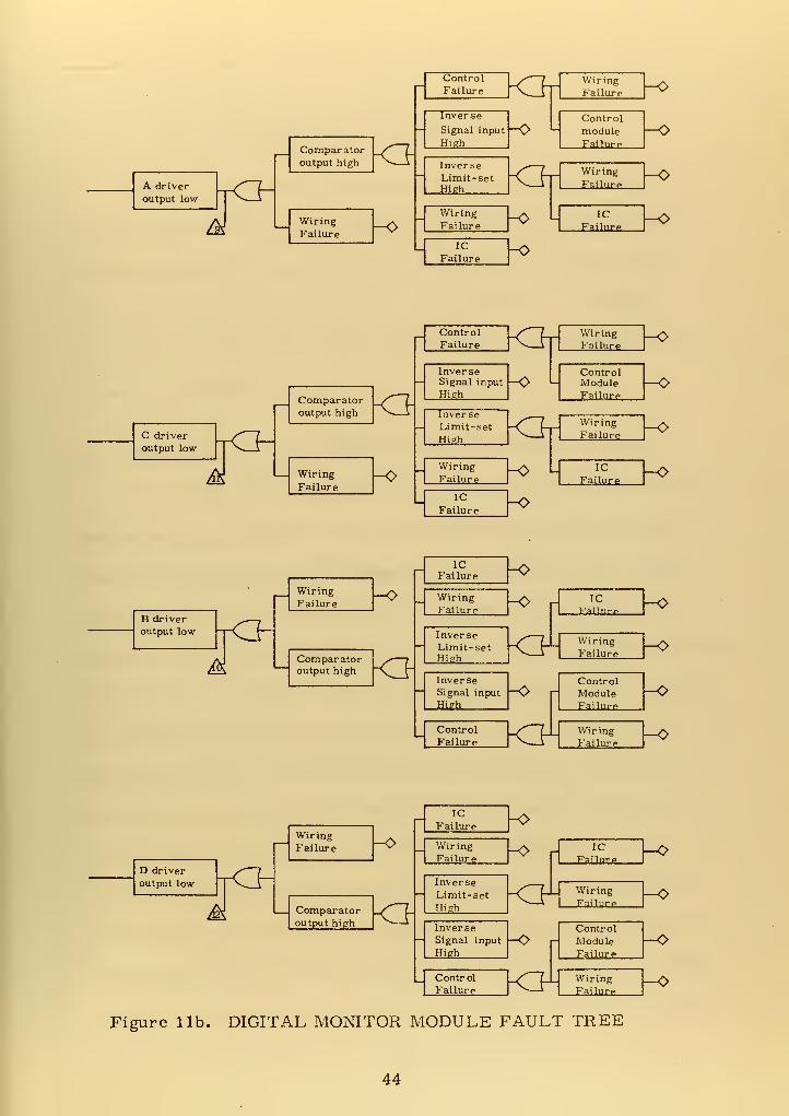
Figure lib is the fault tree for the COM prior to the photo-isolator
inputs.
37

1. Power Supply Failure
Power supply failures were not accounted for in this analysis
because a voltage loss to either the COM or SLM would insert a signal
tending to cause reactor shut down. The effects of a catastrophically
high voltage were uncertain; however, one event that would occur is
photo-isolator light -emitting diode burn-out. The cessation of emis-
sion would transmit a signal tending to cause reactor shut down also.
2. Wiring Faults
The term "wiring fault" as used in the diagram refers to
the worst-case scram-inhibiting casualty to the particular connecting
wires or printed circuit; i. e. , the only wiring fault applicable to the
output wiring of the SLM would be a short to Vcc. Opens, grounds,
or very high voltage would result in a shut down signal.
3. Compliance with the Single Failure Criterion
Review of the fault tree for the monitor module itself indicated
that no single failure within the module could prevent reactor shut down.
The minimum number of failures required was two independent ones,
one of the output portion of each scram logic module or of each of two
comparator circuits. The use of buffers and diode isolation has mini-
mized propagation of the effects of an IC failure. Reference 25, p. 4-7
states that the testing program for the Advanced Multi-Function Array
Radar (AMFAR) revealed that failure of TTL integrated circuits, such
as proposed here, do not seem to propagate. In that case, seven IC
chip failures not corrected by design occurred in 11.2 million operating
38


hours. No failures propagated to other circuits either on the same
chip or connected to the failed circuit.
H. TEST REQUIREMENTS FOR THE MONITOR MODULE
In-service test procedures must identify circuit failures and
localize their location at least to the module concerned. The follow-
ing procedures were adequate to locate defective modules:
1. Turning off the voltage to one program module and inserting
unsafe conditions into the comparators, one at a time, functionally
tests both remaining program modules, the comparator module, and
the interconnecting wiring to the scram logic module.
2. Inserting unsafe conditions into two comparators will
functionally test the scram logic modules.
While these tests may be automatic or manual, it is considered
that the inherent redundancy and high mean-time-to-failure preclude
the need for automatic testing.
39

PowerSource A
PowerSource B
\r BUS I
A
A
A
r A V
Comparator
Module I
[Fig. 6]
PowerSource A
W BUS
PowerSource B
Power Supplies
Detectors
Analog /Digital— Converters
RedundantProgram[Fig. 41
Al
JD
D
D
\[ B "D 1Comparator
Module II
[Fig. 61
B2
Scram Logic
Module I
[Fig. 7]
I
D2
Scram Logic
Module II
[Fig. 7]
ScramChannel I
ScramChannel
DIGITAL MONITOR MODULE
II
_l
Figure 8. DIGITAL MONITOR CHANNEL
40

i r1
1
1
1
i
-•
—
0)I—
I
acbJD
I—
•
o
coU
1
-vw- vcc
t/3
o
"33
JO £03 OS >
S NO *
' *•—
1
t4H
H .O
Signal "A"Complement
"A"Comparator
"A"Buffer
"A"Limit
"C"Limit
CD
0)
i
X!
a
H
CO
cd
CO• 1-1
b€CD
"C"Comparator
rTCTT~
Buffer
AAA/-* VCC Signal "C"Complement
PI
>£— VCC
PI
PI
* From scram logic modulesPI - Photo -isolator
Figure 9. COMPARATOR MODULE
Al
.VCC*
A2
JVCO
CI
X££>
C2
VCC*
vcc MOS Buffers
(TTL Compatable)fh*
VCC
cu
!-)
J3
cu
TS•i-i
I
oc
oI
T3
OJ3ofe £ So
Qpq
U
VCC
Test
T.V
TestSwitch
Inverters used as isolators
cct aJ
U C
CO uo
o C o+-> CD
i—
i
M+-•cu •r-i
fcuO
CD
O oCCD
»"
Figure 10. SCRAM LOGIC MODULE
41

2Zx
Hi
rO
o HZ
O X.Z O
"5
L M -O
?fe
5 fa
-o
Xu
k
ai rt
H In
tj^A ICFailure
<>B Buffer
Output Low
o-̂4]
^5 <}IC
Failure<> A Buffer
Output Low
<
<3^
> j
Q a< 3-a
ICFailure o r~
A DriverInput Low
A Buffer
Output Low
WiringFailure
42

<FD Buffer
Input High
Buffer
tfi Fails
<BC Buffer
Input High
Buffer
IC Fails
<FB Buffer
Input High
Buffer ICIC Fails
<FA Buffer
Input High
Buffer
IC Fails
KM^>
OpenResistor -o
D Isolator
Output high
Wiring
F^lwre
D Isolator
High Input
Current
Isolator
Failure
-o L
OpenResistor -o
C Isolator
Output high
WiringFailure
^>
C IsolatorHigh InputCurrent
Isolator
Failure
<3r-
-o
OpenResistor -o
B Isolator
Output high
WiringFailure
High Inpt„Currpnt
Isolator
Failure
\a-\
-o
OpenResistor -o
D DriverOutput Low "&
Wiring
Failure }+
o L
C Driver
Output Low
Wiring
Failure
-A
-o
B Isolator > 7
^0
B DriverOutput Low -AWiringFailure -o
A Isolator
Output high
_JWiringFailure
MO L
s 7 A Isolator /" 7"^ h— High Input -\^ {-[—rurrpn
Isolator
Failure-o L
A DriverOutput Low 7^
WiringFailurp
-o
<hlBufferC Fails
A Buffer
Input High
<MBufferC. Fails
B Buffer
Input
-o WiringI Failure h H
/ 7 I A Isolator I S—7 IA Isolator
IlsolatorFailure
_|Open
Resistor
-o WiringFailure
-o
-o
fer _/" 7__ B Isolator [/ 7 I Ib Isolator _•* 7 I [ BlHigh [
~N
—
rIOutput high P^y-A [High Input "^ 1 [ou
,(isolator
r.-nlnro—
, [WiringFailurp
-o
A DriverOutput Low -A
^>
—jOpenResistor
_/^~L_ Buffer _£>V \ lie: Fails I
C Buffer
Input High
WiringFailure
WiringFailure
-o
DriverJtput Low -A
,(IsolatorFailure
/• 7 JC Isolator _y* 7__
X^_T|j Output high [Vj
-O
C IsolatorHigh InputCurrent
WiringFailure
-o
C DriverOutput Low -A
_ OpenResistor
<M
Figure 11a. DIGITAL MONITOR MODULE FAULT TREE
43

A driver
output low
/M
Comparatoroutput high <J
WiringFailure -o
ControlFailure k3rlInverse
Signal input
High
InverseLimit-setHigh
WiringFailure
ICFailure
-o L
-o
-o
WiringFailure
Control
moduleFailure
_^~7_ Wiring
Failure
IC
Failurp
^>
-o
-o
-o
C driveroutput low
M
Comparatoroutput high
WiringFailure
<JInverse
— Signal input
High
-o
ControlFailure <h
InverseLimit-setHigh
WiringFailure
ICFailure
-O L.
<Jt
-o
WiringFailure
ControlModuleFailurp
WiringFailure
ICFailure
-o
-o
-o
-o
B driveroutput low
M
WiringFailure
^>
Comparator >*
—
joutput high **C r"
ICFailure
WiringFailure
Inverse-1 Limit-set
High
-o
-0
<FInverseSignal input — (~
High
ControlP'ailure <F
ICFailure
WiringFailure
ControlModuleFailure
WiringFailure
H>
-o
-o
-o
D driver
output low
WiringFailure -0
I
Comparator _/ Loutput high *
ICFailure
WiringFailure
Inverse
Limit-setHigh
-o
-o
<FInverse
— Signal input —O |~
High
ControlFailure
<¥-
ic
Failurp
WiringFailure
Control
ModuleFailure
WiringFailure
Figure lib. DIGITAL MONITOR MODULE FAULT TREE
—
-O
—
o
-o
44

VI. RELIABILITY CONSIDERATIONS
While a reactor safety channel may be considered a sub-set of
a general control system, the emphasis of performance and reliability
considerations in a reactor safety channel is differentiated from that
in a reactor control system because of the differences in method of
determination of parameter state and in the desired state after control
action is performed.
A. RELIABILITY CONSIDERATIONS IN A CONTROL SYSTEM
In a reactor control system, the desired new state and best resul-
tant action to get there are dependent upon the present reactor state and
input demands as well as determination of whether or not the reactor
state is safe. One example is the situation where a parameter is
sensed by four detectors and one has failed such that an unsafe condition
is indicated. The control system must reliably estimate actual reactor
state based on those four signals, along with many others, and may well
decide that the failed signal will be discarded for control purposes. If
the spread in values of the four signals is great enough, the control
system may not be able to decide which signals are correct and pro-
vision must be made for this possibility. Reference 24 presents the
same problem in an aircraft control system. In the aircraft though,
when system state is unclear, pilot override is provided and no action
or neutral control surface position seems to be considered safer than
45


some positive action because the operating conditions of the aircraft
are too varied to incorporate in the control model. Reliability con-
siderations in a control system are not considered in this paper.
B. RELIABILITY CONSIDERATIONS IN A SAFETY CHANNEL
The action of a nuclear safety channel is to place the reactor
in a previously determined safe state if a parameter exceeds a pre-
determined limit. The limit is calculated allowing for anticipated
channel errors.
Primary emphasis in the design of the safety channel is placed
on the concept that a single failure will not prevent placing the reactor
in a known safe state. The safe state, being pre-determined, usually
means shut down and will be so considered here. From a safety
standpoint, though perhaps inconvenient, it is acceptable for a single
signal or component failure to cause a shut down even though actual
reactor conditions are satisfactory. A safe condition in this context
is usually inconvenient to the operator. In order to provide assurance
that a single failure will not prevent shut down, multiple signal and
safety shutdown channels are used. In order to provide continuity of
operation, voting logic such as one out of two, two out of three or
four, or three out of four is used. Design effort is used to cause
most signal or device failures to be self-indicating. Periodic tests
are used to detect failures that are not self-indicating.
Because the safe reactor state is pre-determined and the safety
system is not tasked with the responsibility of determining the exact
46

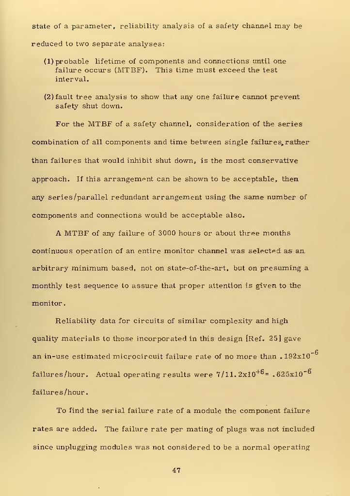
state of a parameter, reliability analysis of a safety channel may be
reduced to two separate analyses:
(1) probable lifetime of components and connections until one
failure occurs (MTBF). This time must exceed the test
interval.
(2) fault tree analysis to show that any one failure cannot preventsafety shut down.
For the MTBF of a safety channel, consideration of the series
combination of all components and time between single failures, rather
than failures that would inhibit shut down, is the most conservative
approach. If this arrangempnt can be shown to be acceptable, then
any series /parallel redundant arrangement using the same number of
components and connections would be acceptable also.
A MTBF of any failure of 3000 hours or about three months
continuous operation of an entire monitor channel was selected as an
arbitrary minimum based, not on state-of-the-art, but on presuming a
monthly test sequence to assure that proper attention is given to the
monitor.
Reliability data for circuits of similar complexity and high
quality materials to those incorporated in this design [Ref. 25] gave
an in-use estimated microcircuit failure rate of no more than .192x10
failures /hour. Actual operating results were 7/ll.2xl0+ - .625x10"°
failures /hour
.
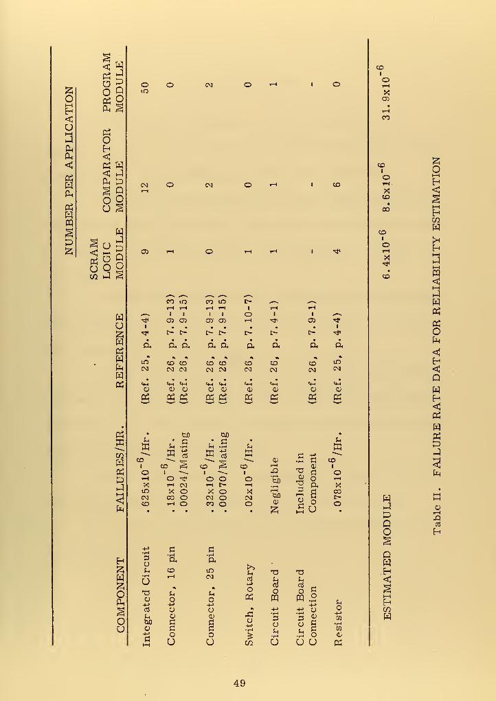
To find the serial failure rate of a module the component failure
rates are added. The failure rate per mating of plugs was not included
since unplugging modules was not considered to be a normal operating
47


procedure. The results of these calculations, as given in Table IL„
indicate that a 3000 hour test interval is reasonable and that, since
the program module has no redundant parts, yet has a much higher
failure rate than the monitor module, a redundant program module
should be provided for an operating installation.
48

o1—
I
H<U>—
i
PPh
<!
PSWPPwn
p
<poopp
p
pDo
po
P p< J
Ou
5 O Q
W i-4 S
poHPw
wp
PSpCOP
PP
P
H5P
O
oU
oLO
CM
CD
O-r-l
u
CU+>nJ
UbJO
CD
CO lO
CM O T-i
CM O *H
oo m
ft
CD
in
OH->
o0)
oU
•f-laLOCM
Sh
o-t->
oa)
oO
>>Jh
cti
h->
oP
o
CO
opq
3OSh•rH
u
T3&H.
cti
OPQ
2§.3 oU U
co
^
t0mm^
t—
1
1
T-H
1
i—i
i
H1
1
Ot-H
1
r-l
1 # ,
*# a> 03 o CD T~l "# cx> -*1 • • • • • • • i
* r- C- t> l> r- r> c- <tf
• • • • • • • • •
ft a ft ft a ft a, ft ft
• % •N m •» •» •i % ^LO CD CD CD CD CD CD CD toCM CM CM CM CM CM CM CM CM
• • , • • • . . •
«rH «4H <+H «m «+H <4-t «fH t-t =4-1
cu CD CU QJ CD 0) CD <L> CD
« P PCS P Ph Ph" p P PS
•CJO bfl
•
u • c • C • Mp u •r-l Sh •rH u Pp H->
cc! P H->
CtiP c H->
CD ~~~- *»
—
§—~~ CD •r-l a CD
1 CD £^j CD CD i—
i
0) 1
O 1"•»»
1X! -a c O
rH o •^ O o O •i—i
tUQa> o i—
i
X rH CM r-l t> T-H •rHT3 ft X
LO X O X o X 1—
1
CJO
3i—
i
oCr-l
a00
CM CO O CM o CM c-CD r-l O CO o O cu o o
• • • • • £ U •
oH->
W•r-l
CO
CD
P
COI
or-H
XCD
CO
CDI
orW
XCD
CO
CDI
Or-H
X
CD
ppppo
QP.H
i—
i
HCOP
Or-l
H<
S
awrtH
O
<UH<QWH<
WP^PP
p
cur-l
X!Cti
H
49


vn. CONCLUSIONS
As a result of this investigation, several conclusions were
reached. Some were basic to the initial goal and some became evident
as techniques for implementing the circuits were considered.
A. The design indicates that a ROM circuit using isolated out-
puts—such as the program module—can perform the program functions
of a hard-wired sequential controller with an apparent reduction in sizLe
and complexity.
B. The meeting of isolation requirements shows that the reactor
safety system single failure criterion can be met using TTL ICs and
photo -isolators in the safety circuit.
C. External performance monitors tend to reduce independence
of redundant circuits, such as the program module, and voting logic
downstream of the photo -isolators performs the same task while main-
taining redundant module independence.
D. Photo -isolation should be accomplished at signal branch
points and should form the upstream terminus of the branch path.
E. Automatic self-test is not always required if enough redun-
dancy is provided.
50

APPENDIX A
INTRODUCTION TO THE LIQUID METAL FASTBREEDER REACTOR OVERALL PROGRAM PLAN [Ref. 1]
The following remarks are quoted from Ref. 1.
'The Liquid Metal Fast Breeder Reactor (LMFBR) Program has
been assigned the highest priority in the Atomic Energy Commission's
(AEC) broader program for the development of civilian nuclear power.
The primary objective of the civilian power reactor development pro-
gram in the United States is widespread use of nuclear energy for the
production of heat and electricity with full exploitation of the energy
available in our resources of uranium and thorium. The AEC's objec-
tive also includes fostering the development of a self-sufficient and
competitive nuclear industry. The need for a power reactor that can
fully and economically exploit the energy reserves contained in uranium
and thorium was recognized in the 'Civilian Nuclear Power--A Report
to the President- -1962' which stated:
The overall objective of the Commission's nuclear powerprogram should be to foster and support the growing use of
nuclear energy, and importantly to guide the program in
such directions as to make possible the exploitation of the
vast energy resources latent in the fertile materials uranium-238 and thorium.
The breeder is needed because it serves the above objective by:
providing the most efficient means of exploiting the energy available
in uranium; minimizing the quantity of uranium consumed per unit of
51


electricity generated; providing potential for low fuel costs; extending
ore reserves manyfold by increasing the utilization of uranium
recovered from ore; and providing a more effective use for plutonium
produced in light-water reactor plants. The 1962 Report to the Presi-
dent includes a detailed discussion of the place to be occupied by the
breeder in the overall program.
The 1967 Supplement to the 1962 Report to the President estab-
lished the following specific objectives: (1) 'The development of
improved converter and later breeder reactors to convert the fertile
isotopes to fissionable ones, thus making available the full potential
of the nuclear fuels;' and (2) 'The early establishment of a self-
sufficient and growing nuclear power industry that will assume an
increasing share of the development costs. '
In the breeder-reactor concept, excess neutrons produced in the
process of generating nuclear power by fission are used to produce
more fissionable material than is consumed. The fissionable isotopes
U-233, U-235, Pu-239, and Pu-241 all produce more neutrons than
are needed to maintain a nuclear chain reaction in power reactors.
Reactor designs for large central -station power plants are arranged
so that these excess neutrons are absorbed either in U-238, leading
to the production of Pu-239, or in thorium, leading to the production
of U-233. Of the four .fissionable isotopes, only U-233, Pu-239, and
Pu-241 produce sufficient neutrons to allow the possibility, in practical
power reactors, of producing more fissionable material than is
consumed.
52

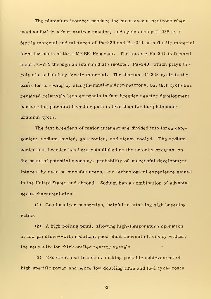
The plutonium isotopes produce the most excess neutrons when
used as fuel in a fast-neutron reactor, and cycles using U-238 as a
fertile material and mixtures of Pu-239 and Pu-241 as a fissile material
form the basis of the LMFBR Program. The isotope Pu-241 is formed
from Pu-239 through an intermediate isotope, Pu-240, which plays the
role of a subsidiary fertile material. The thorium-U-233 cycle is the
basis for breeding by usingthprmal-neutron reactors, but this cycle has
received relatively less emphasis in fast breeder reactor development
because the potential breeding gain is less than for the plutonium-
uranium cycle.
The fast breeders of major interest are divided into three cate-
gories: sodium-cooled, gas-cooled, and steam-cooled. The sodium
cooled fast breeder has been established as the priority program on
the basis of potential economy, probability of successful development
interest by reactor manufacturers, and technological experience gained
in the United States and abroad. Sodium has a combination of advanta-
geous characteristics:
(1) Good nuclear properties, helpful in attaining high breeding
ratios
(2) A high boiling point, allowing high-tempprature operation
at low pressure- -with resultant good plant thermal efficiency without
the necessity for thick-walled reactor vessels
(3) Excellent heat transfer, making possible achievement of
high specific power and hence low doubling time and fuel cycle costs
53


(4) A large heat capacity, allowing time for corrective action in
the event of a power transient or loss of coolant flow
(5) Low pumping power and relative lack of corrosion in the
absence of air and water.
The Program Plan has been developed to lay out the course of
action for achieving the objectives of the LMFBR Program. The Plan
consists of ten sections, each in a separate volume. Volume 1 pre-
sents the Overall Plan. Each of the other nine volumes treats a
specific area of the technology in depth by presenting: the objectives
to be attained, an evaluation of the state of the art, and the tasks to
be carried out to reach the objectives. This Overall Plan describes
the scope of each of the nine sections, referred to as Program elements,
and the relationships between them. "
54

APPENDIX B
LMFBR PERFORMANCE REQUIREMENTS ANDDATA WORD LENGTHS
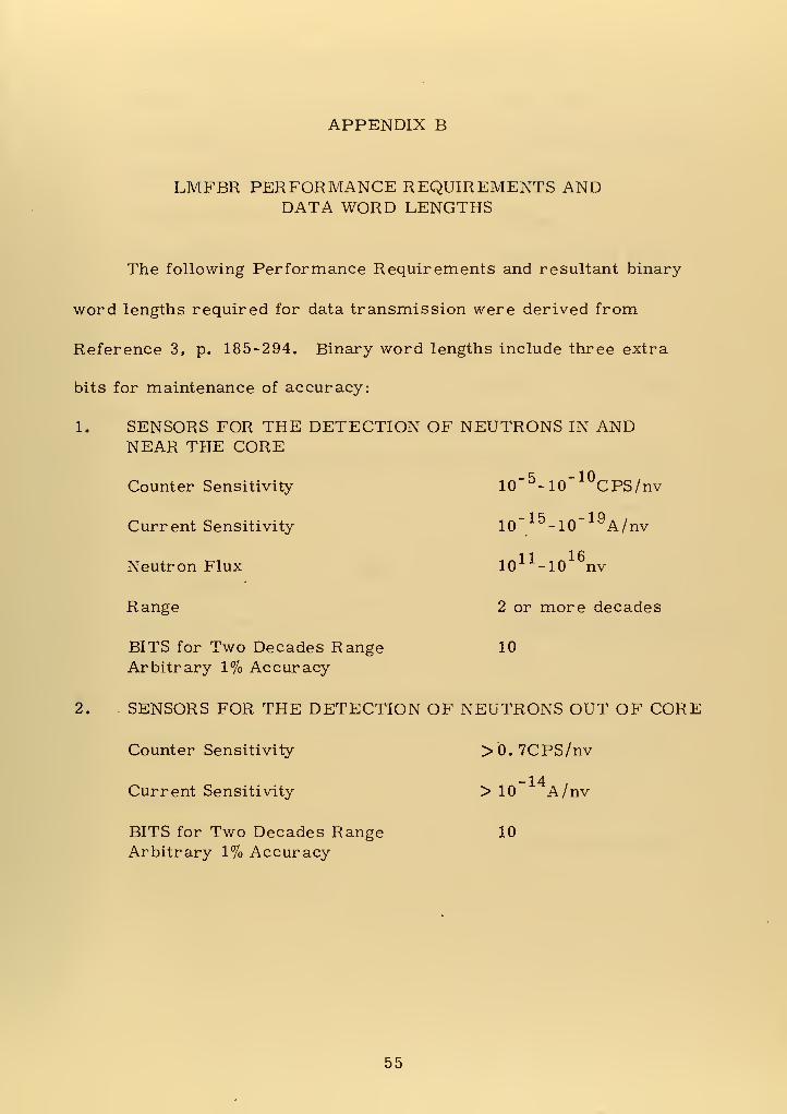
The following Performance Requirements and resultant binary
word lengths required for data transmission were derived from
Reference 3, p. 185-294. Binary word lengths include three extra
bits for maintenance of accuracy:
1. SENSORS FOR THE DETECTION OF NEUTRONS IN ANDNEAR THE CORE
Counter Sensitivity 10~ 5 -10" 10CPS/nv
Current Sensitivity 10" 15 -10~ 19A/nv
Neutron Flux 1011 -10
16nv
Range 2 or more decades
BITS for Two Decades Range 10
Arbitrary 1% Accuracy
2. SENSORS FOR THE DETECTION OF NEUTRONS OUT OF CORE
Counter Sensitivity >0.7CPS/nv
-14Current Sensitivity > 10 A/nv
BITS for Two Decades Range 10
Arbitrary 1% Accuracy
55


TEMPERATURE SENSORS FOR GENERAL USE
Range
Accuracy-
Transient Range
Response Time
Thermal Shock
BITS for 1 F in 2000 F
300-1400 F
+ 1% on line (+lFtest)
to 2000 F
unknown
max rate 100 F/sec
14
4. TEMPERATURE SENSORS FOR USE IN FUEL
Work is in progress to discover a device that will survive the
radiation environment. No specifications are set.
5. SODIUM-FLOW SENSORS FOR USE ON FUEL ASSEMBLIES
6.
Accuracy-
Sensitivity
Time Constant
Expected Flow Rates
BITS for 1% Sensitivity
+ 10% of full range
1% of full range
1/2 second or less
150 gal/min to 600 gal/min
10
SODIUM-FLOW SENSORS FOR USE IN PIPES
Accuracy
Dynamic Range
Flow Range
BITS for 5% Accuracy
+ 5% of actual flow
(above 10% flow)
10:1 to 100:1
to 120, 000 gal/min
8
56

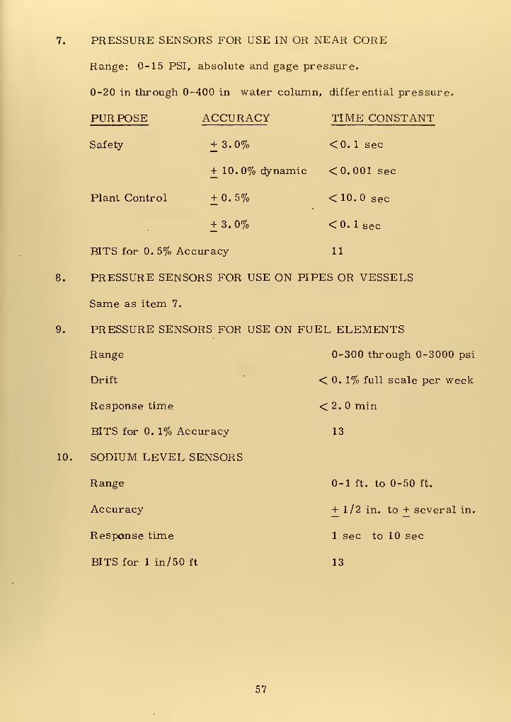
7. PRESSURE SENSORS FOR USE IN OR NEAR CORE
Range: 0-15 PSI, absolute and gage pressure.
0-20 in through 0-400 in water column, differential pressure.
PURPOSE ACCURACY TIME CONSTANT
9.
Safety
Plant Control
+ 3.0% <0. 1 sec
+ 10. 0% dynamic < 0.001 sec
+ 0.5% < 10.0 sec
+ 3.0% <0. 1 sec
BITS for 0. 5% Accuracy 11
8. PRESSURE SENSORS FOR USE ON PIPES OR VESSELS
Same as item 7.
PRESSURE SENSORS FOR USE ON FUEL ELEMENTS
Range
Drift
Response time
BITS for 0. 1% Accuracy
10. SODIUM LEVEL SENSORS
Range
Accuracy
Response time
BITS for 1 in/ 50 ft
0-300 through 0-3000 psi
< 0. 1% full scale per week
< 2. min
13
0-1 ft. to 0-50 ft.
+ 1/2 in. to + several in.
1 sec to 10 sec
13
57


11. STRAIN SENSORS FOR USE ON PLANT, CORE, AND FUELCOMPONENTS
Microstrain Range + 2000 Me
Drift <2.0^e/hr.
Gage Factor >1.5
Linearity unknown
BITS for 2000 Me 14
+ 1 AJ e Arbitrary
58

APPENDIX C
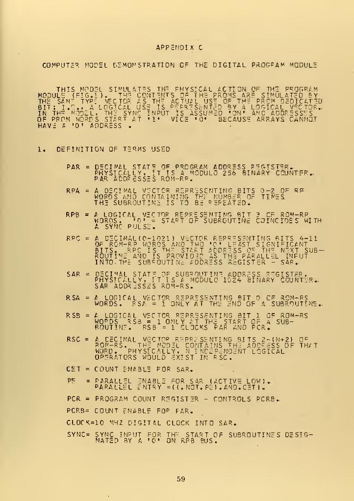
COMPUTED MODEL DEMONSTRATION OF THE DIGITAL PROGRAM MODULE
THIS MODEL SIMULAT-S TH- PHYSICAL ACTION OF THE PROGRAMMODULE (FIG. II. THE CONTENTS OF TH: PROMS ARE SIMULATED BYTHE SAM' TYPE VICTOR AS TH" ACTUAL US!! OF THE PRCM DEDICATEDBIT; I.E., A LOGICAL USE IS REPRESENTED BY A LOGICAL VECTOR.,IN TH^ MODEL, THE SYNC INPUT IS ASSUMED r ON» AND ADDRESSESOF PPPM WORDS START AT »1« VICE 0« BECAUSE ARRAYS CANNOTHAVE A '0' ADDRESS .
1. DEFINITION OF TERMS USED
PAR = DECIMAL STAT* OF PROGRAM ADDRESS REGISTER*PHYSICALLY, IT IS A MODULO 2 56 BINARY CCUNTFR..PAR ADDRESSES ROM-RP.
RPA = A DECIMAL VICTOR REPRESENTING BITS 0-2 OF RPWORDS AND CONTAINING THE NUMBER OF TIMESTHE SUBROUTINE IS TO BE REPEATED.
RPB = A LOGICAL VECTOR REPRESENTING BIT ? CF ROM-RPWORDS. Ti' = STA^T OF SUBROUTINE COINCIDES WITHA SYNC PULSE.
RPC = A DECIMAL (0-1021) VECTOR REPRESENTING BITS 4-11OF RCM-R? WORDS AND TWO "0 • LEAST SIGNIFICANTBITS. RPC IS th" START ADDRESS CF TH*5 NEXT SUB-ROUTINE AND IS PROVIDED AS THE PARALLEL INPUTINTO. THE SUBROUTINc ADDRESS REGISTER - SAP.,
SAR = DECIMAL STATE OF SUBROUTINE ADDRESS REGISTER'.PHYSICALLY, TT IS A MODULO 1024 BINARY COUNTER-SAP. ADDRESSES ROM-RS.
RSA = A LOGICAL VECTOR REPRESENTING BIT CF ROM-RSWORDS. PSA = 1 ONLY AT THE END OF A SUBROUTINE.-
RSB = A LOGICAL VECTOR REPRESENTING BIT 1 OF ROM-RSWO p DS 5.SB = 1 ONLY AT THE START CF A SUB-ROUTINE. RSB = 1 CLOCKS PAR AND PCR.
RSC = A CECIMAL VECTP& REPRESENTING BITS 2-CN+Z) O c
ROM-RS. THE MODEL CONTAINS THE ADDRESS OF TH/
T
WORD. PHYSICALLY, N INDEPENDENT LOGICALOPERATORS WOULD EXIST IN RSC.
CET = COUNT ENABLE FOR SAR.
P£ = PARALLEL ENABLE FOR SAR (ACTIVE LOW).PARALLEL ENTRY = ( ( . NOT. PE ) . AND. CET ) .
PCR = PROGRAM COUNT REGISTER - CONTROLS PCRB.
PCRB= COUNT ENABLE F0 P FAR.
CL0CK=10 MHZ DIGITAL CLOCK INTO SAR.
SYNC= SYNC INPUT FOR THE START OF SUBROUTINES DESIG-NATED BY A 'C" ON RPB BUS.
59

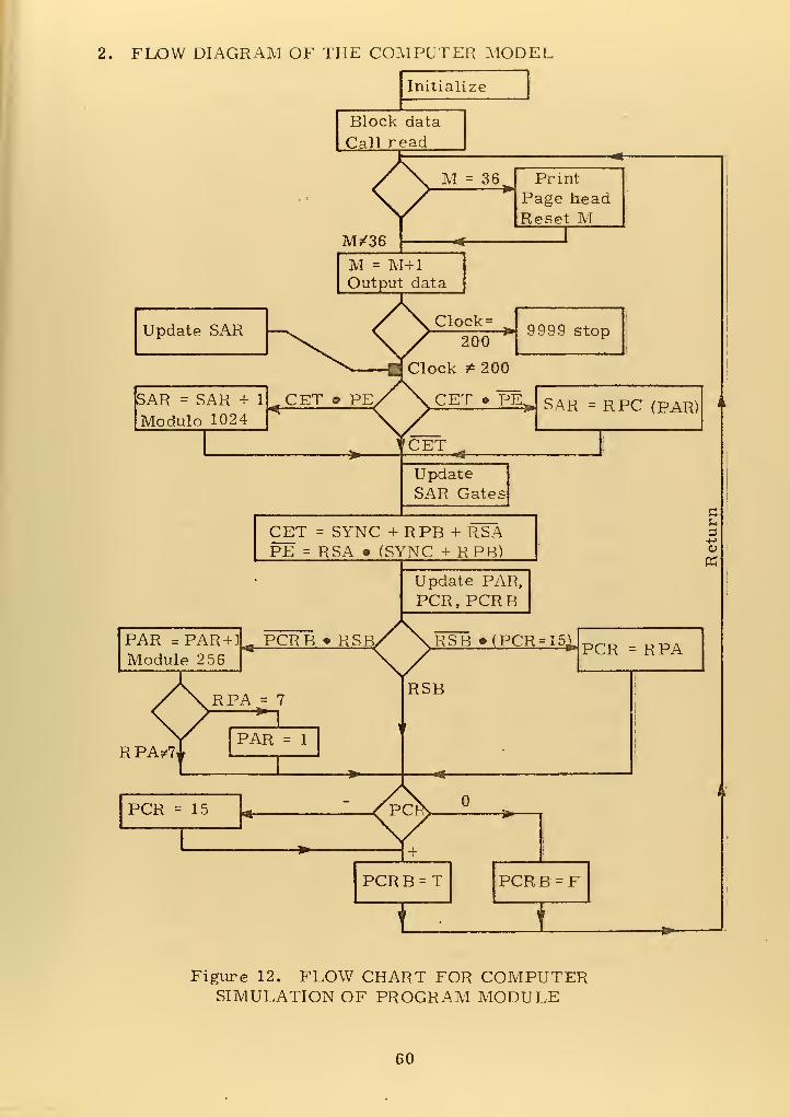
2. FLOW DIAGRAM OF THE COMPUTER MODEL
Initialize
Block data
Call read
M^36
M = 36 Print
Page headReset M
M = M+lOutput data
Update SAR Clock=
ISAR = SAR + 1
Modulo 1024
9999 stop
SAR =RPC (PAR)
UpdateSAR Gates
CET = SYNC +RPB+ RSAPE = RSA • (SYNC + RPB)
u
Update PAR,PCR, PCRB
PAR = PAR + 1
Module 2 56
RPA/7
PCRB » RSBX XRSB (PCR-I5jrrCK _ RrA
RPA = 7—
n
PAR = 1
PCR = 15 V
PCR B = T PCRB=F
Figure 12. FLOW CHART FOR COMPUTERSIMULATION OF PROGRAM MODULE
60

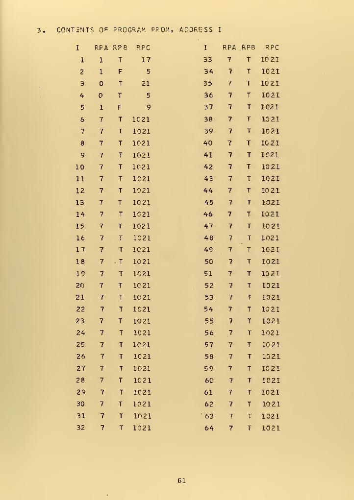
3. CONTENTS 0^ PROGRAM PPOM, ADDRESS I
I RPA RPB RPC I RPA RPB RPC
1 1 T 17 33 7 T 10 ZI
2 1 F 5 34 7 T 10ZI
3 T 21 35 7 T 1QZI
4 T 5 36 7 T 1021
5 1 F 9 37 7 T I0Z1
6 7 T 1C21 38 7 T 10 21
7 7 T 1021 39 7 T 1021
8 7 T 1021 40 7 T 1G2I
9 7 T 1021 41 7 T 10Z1
10 7 T 1021 42 7 T I0Z1
II 7 T 1021 43 7 T L0Z1
12 7 T 1021 44 7 T 10 21
13 7 T 1C21 45 7 T 1021
14 7 T 1021 46 7 T 1021
15 7 T 1021 47 7 T 1021
16 7 T 1021 48 7 T 1021
17 7 T 1C21 49 7 T 1021
18 7 • T 10 21 50 7 T 1021
19 7 T 1021 51 7 T 1021
20 7 T 1021 52 7 T 1021
21 7 T 1021 53 7 T 1021
22 7 T 1021 54 7 T 1021
23 7 T 10 21 55 7 T 1021
24 7 T 1021 56 7 T 1021
25 7 T 1021 57 7 T 1021
26 7 T 1C21 58 7 T 10Z1
27 7 T 1021 59 7 T 1021
28 7 T 1021 60 7 T 1021
29 7 T 1021 61 7 T 1021
30 7 T 1021 62 7 T 1021
31 7 T 1021 '63 7 T 1021
32 7 T 1021 64 7 T 1021
61


4. CONTENTS OF SUBRCUTI NE PROM, ADDRESS I
I RSA RS3 RSC I RSA R SB R SC
1 T F 1 33 T T 33
2 F F 2 34 T T 34
3 T F 3 35 T T 35
4 F F 4 36 T T 36
5 F T 5 37 T T 37
6 F F 6 38 T T 38
7 F F 7 39 T T 39
8 T F 8 40 T T 40
9 F T 9 41 T T 41
10 F F 10 42 T T 42
II T F 11 43 T T 43
12 F c 12 44 T T 44
13 F T 13 45 T T 45
14 F F 14 46 T T 46
15 F F 15 47 T T 47
16 T F 16 48 T T 48
17 F T 17 49 T T 49
18 F . F 18 50 T T 50
19 T F 19 51 T T 51
20 F F 20 52 T T 52
21 F T 21 53 T T 53
22 F F 22 54 T T 54
23 F F 23 55 T T 55
24 T F 24 56 T T 56
25 F T 25 57 T T 57
26 F F 26 58 T T 58
27 T F 27 59 T T 59
28 F F 28 60 T T 60
29 F T 29 61 7 T 61
30 F F 30 62 T T 62
31 F F 31 63 T T 63
32 T F 32 64 T T 64
62


5. RESULTAN7 ACTION OF PROGRAM MODULE
:lock SAR GET PS RSA RSB RSC PCR PCRB PAR *PA RPB RPC
1 T F T F 1 1 T 1 T 171 17 T T F T 17 F 1 T i 72 18 T 7 F F 18 F 1 T 173 19 T F T F 19 F 1 T
X *
174 17 T T F T 17 15 T 2 FX 1
55 18 T T F F 18 1 T 2 F 56 19 T F T F 19 1 T 2 F 5SYNC REQUIRED SYNC REQUIRED7 5 7 T F T 5 F 2 F 58 6 T T F F 6 F 2 F 59 7 T T F F 7 c 2 F 5
510 8 T F T F 8 F 2 FSYNC REQUIRED SYNC REQUIRED11 5 7 T F T 5 15 T 3 T 2112 6 T T F F 6 F 3 T 2113 7 T T F F 7 F 3 T 2114 8 T F T F 8 F 3 T 2115 21 T T F T 21 15 T 4 o T
£- J.
516 22 T T F F 22 F 4 T 517 23 T T F F 23 F 4 T 518 24 T F T F 24 F 4 o T 519 5 7 T F T 5 15 T 5 F q20 6 T T F F 6 i T 5 F 9Q21 7 T T F F 7 1 T 5 F
22 e T F T F 8 1 T 5 F7
9SYNC REQUIRED SYNC REOUIF/ED23 9 T T F T 9 F 5 F o24 10 T T F F 10 F 5 F g25 11 T F T F 11 F 5 F 9o f
SYNC REQUIRED SYNC REQUIRE26 9 T T F T 9 15 T T 1727 10 T T F F 10 1 T TX f
1 728 11 7 F T F 11 1 T TX 1
171 729 17 T T F T 17 F T30 18 T T F F 18 f\ F fX '
171731 19 T F T F 19 6 F T32 17 T T F T 17 15 T 2 FX '
555
5
33 18 T T F F 18 1 T 2 F34 19 T F 7 F 19 1 T 2 F
35 5SYNC
TREQUIREDT F T 5
SYNCF
REQUIR2
ED1 F
63

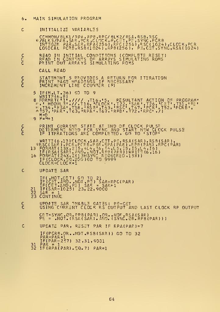
6. MAIN SIMULATION PROGRAM
C INITIALIZE VARIABLES
RSCCR P
024) , CLOCK. PCRSYNC,RSA( 1024)
ccc
READ IN INITIAL CONDITIONS (COMPLETE RESET)RFAD IN CONTENTS OF ARRAYS SIMULATING ROMSPRINT OUT ARRAYS SIMULATING ROMS
CALL READ
ccc
STATEMENT 5 PROVIDES A PFTURN FOR ITERATIONPRINT PAGE HEADINGS IF NECESSARYINCREMENT LINE COUN^cR ( v)
5 IF(M.LT.36) GO TO 9WRIT?<6,8)
8 FORMAT( •! ,//// ,T16,'5. RESULTANT ACTION OF PROGRAM**i • MODULE' .//.T16, 'CLOCK «,T 2 2, »SAR' , T26, •CET 1 ,T31 , ' P£* ,T34,'PSA' ,T38 , «RS8' ,T43,'RSC ,T47, «PCR',T52, 'PCRB',*T57, »PAR» f T63, »RPA , .T67. t RPB» •T72. , RPC t t/)
9 M = M+1
ccc
PRINT CURRENT STATE AT END OF CLOCK PULSEDETERMINE NEED FCR SYNC ANO START NEW CLOCK PULSEIF ITERATIONS ARE COMPLETED, GO TO 'STOP'
WRITE (6 ,13)CL0CK,SAR fCET,P£,RSA(SAR),RSB(SAR ),*RSC( SAP ) tPCR. PCRB. PAR ,RPA( PAR) .PPB(PAR) .RPC(PAR)
13 FORMAT (13X,2I5,4L4,!6,T4,L5,I5,I5,L4,I6)IF(RSA( SARKAND. .NOT.RPBt PAR) )WRIT e (6,16)
16 FORMAT (24Xt2(13HSYNC REQUIRED »
1
5X) )
IF(CLOCK.E0.2DO )G0 TO 9999CL0CK=CL0CK + 1
C UPDATE SAR
IF( .NOT.CET) GO TO 21IF (CET .AND. .NOT .PE ) SAR=RPC(PAR
)
IF(C<ET.AND.PE ) SAR = SAR+121 IF(SAR-1025) 23,22,900022 SAR = 1
23 CONTINUE
C UPDATE SAR ENABLE GATES: PE-C5TC USING CURRENT CLOCK RS OUTPUT AND LAST CLOCK RP OUTPUT
CET = SYNC.OR.PPB( PAR) .OR. .NOT .RS A (S AP )
PE = .NOT. (RSA( SAR). AND. (SYNC. OR. RPB(PAR) ) )
C UPDATE PAR, RESET PAR IF RPA(PAR)=7
IF(PCRB.OR..NOT.RSB(SAR) ) GO TO 32PA.R = PAR + 1
IF(PAR-257) 32,31,900131 PAR = 132 IF(RPA(PAR).IQ.7) PAR=1
64

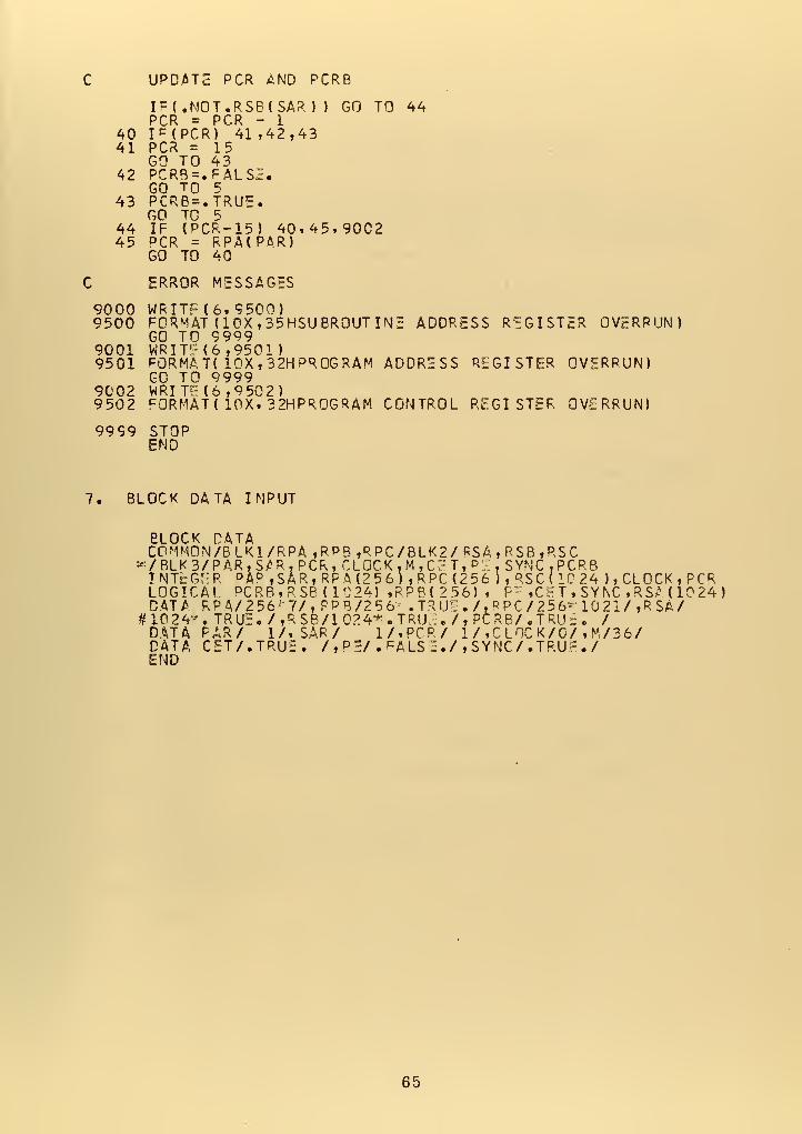
: UPDATE PCR AND PCRB
IF(.NOT.RSB(SAR J ) GO TO 44PCR = PCR - 1
40 IF(PCR) 41,42,4341 PCR = 15
GO TO 4342 PCR8=. FALSI;.
GO TO 543 PCRB=.TRUE.
GO TO 544 IF (PCR-15) 40,45,900245 PCR = RPA(PAR)
GO TO 40
) ERROR MESSAGES
9000 WRITF (6, 9500)9500 FORMAT (10X , 35HSU BROUT INS ADDRESS REGISTER OVERRUN)
GO TO 99999001 WRIT 1" (6,9501)9501 FORMAT( 10X , 32H PROGRAM ADDRESS REGISTER OVERRUN)
GO TO 99999002 WRITE (6, 9502 )
9502 cORMAT( 10X, 32HPROGRAM CONTROL REGISTER OVERRUN)
9999 STOPEND
7, BLOCK DATA INPUT
eLOCK DATAC0MM0N/BLK1/RPA ,RPB ,RPC/BLK2/ RSA,RSB ,RSC
»/ BLK 3/P AR, S*R . PCR t CLOCK tM,C7T, PI, SYNC.PCRB
INTEGER D A° ,SAR,RPA(2 56) ,RPC(2 56 ), RSC(1C24 ), CLOCK, PCRLOGICAL DCRB,RSB(1C24) ,RPB< 2 56) , P: ,C ^ T , SYNC , RSA ( 10 24
)
DATA RP4/256- 7/, PPB/256 . TRUE . /, PPC /256- 10 21/ ,R SA/#10 24*.TRUS./,RSB/1024+.TRU^./,PCRB/.TRU=. /DATA PAR/ 1/, SAR/ 1/,PCR/ 1 / ,C LOC K/0/ , M/36/DATAEND
CET/.TRU! /,P5/.FALSS./i SYNC/. TRUE./
65

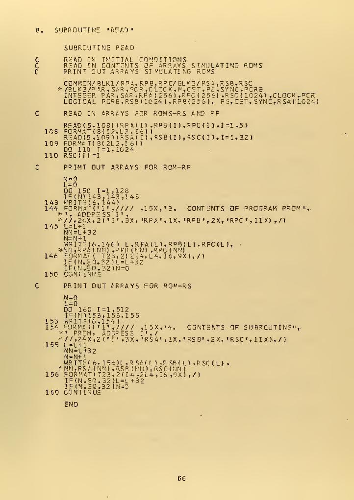
8. SUBROUTINE 'R^AD*
SUBROUTINE READ
C READ IN INITIAL CONDITIONSC READ IN CONT-NTS OF ARRAYS SIMULATING ROMSC PRINT OUT ARRAYS SIMULATING RGMS
COMMON/ BLK1/ R Pi, t RP8, RPC/ ELK2/RSA ,RS8,RSC* /BLK 3 /° * R , S AR , °C R ,C LOC K , M , C c T , Pc , SY NC , P C R BINTEGER PAP, SAP ,RPM 25 6
)
.RFC ( 2 56) ,RSC(1C24) , CLOCK ,.nrRLOGICAL PCRB,RS8(1024),RP8(256), Pir C=T, SYNC,R SA ( L024)
C READ IN ARRAYS FOR ROMS-RS AND PP
READ<5,108) (RPMI) ,RPB ( I
)
,RPC < I ) ,1 =1 ,5
)
108 FORMAT (8(
I
2.L2. 16) )
READ (5 ,1 09
)
(RSA( I) , RS B ( I ) , RS C < I ) , 1=1, 32
)
109 FORM* T( 8(2L2,I 6) )
DO 110 T =1,10 2
A
110 RSC(I) =1
C PRINT OUT ARRAYS FOR ROM-RP
N =L=0DO 150 1=1,128I p (N) 143,143,145
143 WRIT-. (6, 144)144 FORMATC 1' ,//// ,15X,«3. CONTENTS OF PROGRAM PROM'S-
*• , ADDRESS I '
,
* //.24X,2( ' If ,3X, 'RPA', IX, 'RPBN2X, »RPC r ,HX) ,/)
145 L=L+1NN=L+32N=M + 1WRIT"i(6,146) L ,RFA(L),RDB(L),RPC(L),
*NN,RPA( NM) ,PPB (NN) ,R?C ( NN)146 FORMAT ( T23,2( 214, L4, 16, 9X),/)
IF(N.£0.32 ).L=L+32IF(N.5O.32)N=0
150 CONTINUE
C PRINT OUT ARRAYS FOR RO^-RS
N=0L=0DO 160 1=1,512IF(N)153. 153,155
153 WPITE(6,154)154 H3RM£T( '
1' ,//// ,15X,«4. CONTENTS OF SUBRCUTINF'V* PROM, ADDRESS I',/*-//,24X,2('!«,3X, 'RSA' , IX , • RS B' ,2 X, «RSC» , II X ) , / )
155 L=L+1NN=L+32N = N+1WRITE (6, 156)L,RSAtL).R5B(L>.RSCm«
*NN,RSA(NN) ,RSB (MN),RSC(NM )
156 FORMATS T2 3,2 (14,2 L4, 16 ,9 X) ,/)IF(N.E0.32)L=L+32IF(N.E0.32 )N=D
160 CONTINUE
END
66

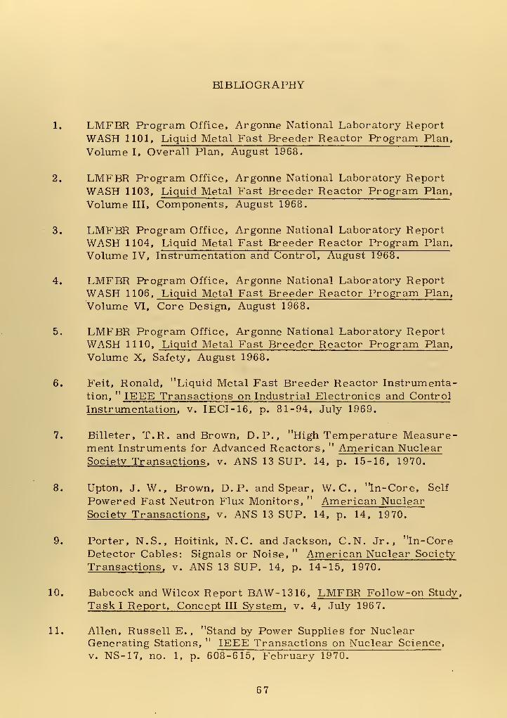
BIBLIOGRAPHY
1. LMFBR Program Office, Argonne National Laboratory ReportWASH 1101, Liquid Metal Fast Breeder Reactor Program Plan,
Volume I, Overall Plan, August 1968.
2. LMFBR Program Office, Argonne National Laboratory ReportWASH 1103, Liquid Metal Fast Breeder Reactor Program Plan,
Volume III, Components, August 1968.
3. LMFBR Program Office, Argonne National Laboratory ReportWASH 1104, Liquid Metal Fast Breeder Reactor Program Plan,
Volume IV, Instrumentation and Control, August 1968.
4. LMFBR Program Office, Argonne National Laboratory ReportWASH 1106, Liquid Metal Fast Breeder Reactor Program Plan,
Volume VI, Core Design, August 1968.
5. LMFBR Program Office, Argonne National Laboratory ReportWASH 1110, Liquid Metal Fast Breeder Reactor Program Plan ,
Volume X, Safety, August 1968.
6. Feit, Ronald, "Liquid Metal Fast Breeder Reactor Instrumenta-tion, " IEEE Transactions on Industrial Electronics and Control
Instrumentation , v. IECI-16, p. 81-94, July 1969.
7. Billeter, T.R. and Brown, D.P., "High Temperature Measure-ment Instruments for Advanced Reactors, " American NuclearSociety Transactions , v. ANS 13 SUP. 14, p. 15-16, 1970.
8. Upton, J. W., Brown, D. P. and Spear, W. C. , "in-Core, Self
Powered Fast Neutron Flux Monitors, " American NuclearSociety Transactions, v. ANS 13 SUP. 14, p. 14, 1970.
9. Porter, N.S., Hoitink, N.C. and Jackson, C.N. Jr., "In-CoreDetector Cables: Signals or Noise, " American Nuclear Society
Transactions, v. ANS 13 SUP. 14, p. 14-15, 1970.
10. Babcock and Wilcox Report BAW-1316, LMFBR Follow-on Study ,
Task I Report, Concept III System, v. 4, July 196 7.
11. Allen, Russell E. , "Stand by Power Supplies for NuclearGenerating Stations, " IEEE Transactions on Nuclear Science ,
v. NS-17, no. 1, p. 608-615, February 1970.
67

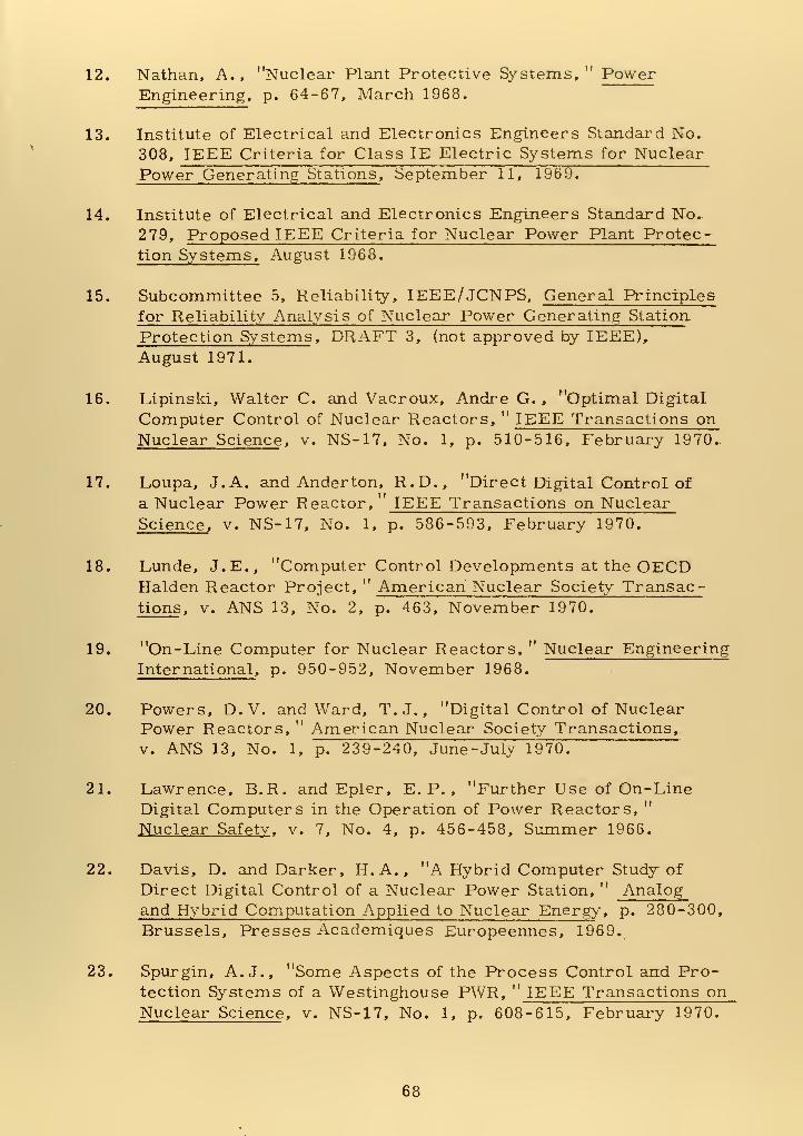
12. Nathan, A., "Nuclear Plant Protective Systems," PowerEngineering, p. 64-67, March 1968.
13. Institute of Electrical and Electronics Engineers Standard No.
308, IEEE Criteria for Class IE Electric Systems for NuclearPower Generating Stations, September 11, 1969.
14. Institute of Electrical and Electronics Engineers Standard No..
279, Proposed IEEE Criteria for Nuclear Power Plant Protec-tion Systems, August 1968.
15. Subcommittee 5, Reliability, IEEE/JCNPS, General Principles
for Reliability Analysis of Nuclear Power Generating Station
Protection Systems , DRAFT 3, (not approved by IEEE),August 1971.
16. Lipinski, Walter C. and Vacroux, Andre G. , "Optimal Digital
Computer Control of Nuclear Reactors, " IEEE Transactions onNuclear Science , v. NS-17, No. 1, p. 510-516, February 1970.
17. Loupa, J. A. and Anderton, R.D., "Direct Digital Control of
a Nuclear Power Reactor, IEEE Transactions on NuclearScience, v. NS-17, No. 1, p. 586-593, February 1970.
18. Lunde, J.E., "Computer Control Developments at the OECDHalden Reactor Project, " American Nuclear Society Transac-tions , v. ANS 13, No. 2, p. 463, November 1970.
19. "On-Line Computer for Nuclear Reactors, " Nuclear EngineeringInternational, p. 950-952, November 1968.
20. Powers, D. V. and Ward, T.J., "Digital Control of NuclearPower Reactors, " American Nuclear Society Transactions,v. ANS 13, No. 1, p. 239-240, June-July 1970.
21. Lawrence, B.R. and Epler, E. P. , "Further Use of On-LineDigital Computers in the Operation of Power Reactors,Nuclear Safety , v. 7, No. 4, p. 456-458, Summer 1966.
22. Davis, D. and Darker, H.A., "A Hybrid Computer Study of
Direct Digital Control of a Nuclear Power Station, " Analogand Hybrid Computation Applied to Nuclear Energy , p. 280-300,
Brussels, Presses Academiques Europeennes, 1969.
23. Spurgin, A. J., "Some Aspects of the Process Control and Pro-tection Systems of a Westinghouse PWR, " IEEE Transactions onNuclear Science , v. NS-17, No. 1, p. 608-615, February 1970.
68


24. Sutherland, J. P., "Fly-By-Wire Flight Control Systems, "
Advisory Group for Aerospace Research &. DevelopmentConference Proceedings, No. 58, January 1970.
25. Bird Engineering-Research Associates, Inc., Final Report,Advanced Multi-Function Array Radar (AMFAR), Reliability -
Maintainability Assessment, October 15, 1971.
26. Department of Defense MIL-HDBK-217A, Reliability Stress
and Failure Rate Data for Electronic Equipment, December 1,
1965.
69

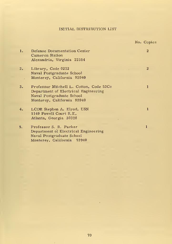
INITIAL DISTRIBUTION LIST
No. Copies
1. Defense Documentation Center 2
Cameron Station
Alexandria, Virginia 22314
2. Library, Code 0212 2
Naval Postgraduate School
Monterey, California 93940
3. Professor Mitchell L. Cotton, Code 52Cc 1
Department of Electrical Engineering
Naval Postgraduate School
Monterey, California 93940
4. LCDR Stephen A. Elrod, USN 1
1149 Powell Court S.E.Atlanta, Georgia 30316
5. Professor S. R. Parker 1
Department of Electrical Engineering
Naval Postgraduate School
Monterey, California 93940
70

UnciassiiiPdSecurity Classification
DOCUMENT CONTROL DATA -R&D(Security classification of title, body of abstract and indexing annotation must be entered when the overall report Is classified)
I originating ACTIVITY ( Corporate author)
Naval Postgraduate School
Monterey, California 93940
2*. REPOR T SECURI TY CLASSIFICATION
Unclassified
2b. GROUP
3 REPOR T TITLE
Application of Digital Techniques to a Nuclear Reactor Safety Monitor
for the Liquid Metal Fast Breeder Reactor
4. DESCRIPTIVE NOTES (Type of report and,inctus ive dates)
Master's Thesis; (March 1972)5. AU TMORIS) (First name, middle initial, last name)
Stephen Anthony Elrod
6- REPOR T O A TE
March 1972
la. TOTAL. NO. OF PAGES
72
7b. NO. OF REF5
268a. CONTRACT OR GRANT NO.
b. PROJEC T NO.
9a. ORIGINATOR'S REPORT NUMBERISI
96. OTHER REPORT NO(S) (Any other numbers that may be assignedthis report)
10. DISTRIBUTION STATEMENT
Approved for public release; distribution unlimited.
II. SUPPLEMENTARY NOTES 12. SPONSORING MILI TAR Y ACTIVITY
Naval Postgraduate School
Monterey, California 93940
13. ABSTRAC T
This paper demonstrates a nuclear reactor safety monitor incor-
porating hard-wired, redundant, digital program modules that control
independent, redundant, digital monitor modules. One monitor moduleis used for each parameter significant to reactor safety. The charac-teristics of a proposed LIQUID METAL FAST BREEDER REACTORare used as the reference performance criteria. The established cri-
terion that a single failure must not prevent reactor shut down is usedas the failure mode criterion. Within the program module, a pro-grammable read-only memory (PROM) is used for sequence control of
another PROM containing variable length subroutines. The subroutine
PROM outputs are used as photo-isolated logic outputs for sequencecontrol of the various monitor modules. The program module action
is modelled on a digital computer. A four -input digital monitor moduleis developed. This module provides a shut down signal if three of the
inputs exceed the parameter limit.
DD i nov es I ** / WS/N 01 01 -807-681 1
(PAGE 1)Unclassified
71 Security ClassificationA-3M08

UllCld.b^i l ieuSecurity Classification
KEY WORDS LINK C
Liquid Metal Cooled Reactor
Safety Devices
Nuclear Reactor Safety-
Digital Techniques
D ,^","..1473 WW0101 -«07-e»2j
_L
72Unclassifipd
Security Classification A- 31 409

13526'
°f dito
9/'-
^n/ torre;ctors;;^
acto rre-
tyfaSt ^ree
e
de>
Thesis 135265E427 El rod
c.l Application of digi-
tal techniques to a nu-
clear reactor safety
monitor for the liquid
metal fast breeder re-
actor.

!hesE427
AppJi
ilfflflW^L^^toan
° ^/d8 001 OlfiOQ r>