Control rod worth calculation for VVER-1000 nuclear reactor using WIMS and CITATION codes
8
Control rod worth calculation for VVER-1000 nuclear reactor using WIMS and CITATION codes Amir Hosein Fadaei * , Saeed Setayeshi Faculty of Nuclear Engineering and Physics, Amirkabir University of Technology (Tehran Polytechnic), Hafez Street, Tehran, Iran Keywords: Control rod worth PIJ þ PERSEUS DSN WIMS CITATION Reactor simulation abstract This paper summarizes efforts related to developing a technically justifiable approach for investigating the control rod worth of VVER-1000 reactor. For this assessment, computer simulation of nuclear reactor was needed. In this study nuclear reactor behavior was modeled by WIMS code, which solves transport equation for fuel assemblies’ modeling at first step, and CITATION code that solves diffusion equation for core modeling. From these two codes, neutronic calculation of reactor was performed and control rod worth was calculated. Results of this study are comparable with the plant’s FSAR. On comparing results of this study and reference some unacceptable errors were discerned. To find out the cause of these errors, some efforts had been performed and finally was discerned that the method of cell calculation, i.e., DSN method, was the important cause of errors. Therefore, some analysis had been performed by WIMS in PIJ þ PERSEUS method and was shown that the results were improved. Ó 2009 Elsevier Ltd. All rights reserved. 1. Introduction The basic purpose of the reactor control system is to provide a means for starting the reactor, i.e., bringing the power output up to the desired level, for maintaining it at that level, and for shutting it down in the course of routine operations. As an adjunct to the control system, a power reactor has a protection system designed to shut the reactor down automatically in the event that potentially unsafe conditions should arise. An important feature of a nuclear reactor that has bearing on the control system design is that, in most power reactors, the fuel supply cannot be continuously replaced as it is consumed. Con- sequently, at the beginning of each operational period, the re- actor core mostly contains all the fuel (fissile material) that will be required to produce a predetermined quantity of energy. Furthermore, additional fuel is necessary to allow for the de- crease in neutron multiplication arising from fission-product poisons and from the high operating temperature, i.e., the neg- ative temperature coefficient. Hence, when a thermal reactor core is assembled prior to commencing operation, it includes a con- siderable amount of excess fuel – some 25–30% in water- moderated reactors – more than required value for criticality in the initial cold condition. The additional fissile material in the core is said to represent built-in (or excess) reactivity. An essential requirement of the control system is that it must be capable of introducing enough negative reactivity to compensate for the built-in (positive) reactivity at initial startup of the reactor (Glasstone and Sesonke, 1967). The power level of the reactor depends on the macroscopic fission cross-section and the neutron flux. Over a short time in- terval, the cross-section remains essentially constant, although it may not have the same value at all locations in the core. Hence, the power level at any instant can be considered proportional to the neutron flux. Four general methods are possible for changing the neutron flux in a reactor: they involve temporary addition or removal of (1) fuel, (2) moderator, (3) reflector, or (4) a neutron absorber (poison). Each of these methods or a combination of them has been used (or proposed) for reactor control, but the procedure most commonly employed, especially in power reactors, is the insertion or with- drawal of a material, such as boron or cadmium, having a large cross-section for the absorption of neutrons. The absorber and the fissile material may be regarded as competitors for neutrons; the larger the proportion absorbed by the control material, the smaller the fraction available for fissions, and vice versa. The control ele- ments are generally referred to as control ‘rods’ because they were originally, and often still are, long cylindrical rods (or combination of such rods). In power reactors they are in the reactor core; however, in some experimental reactors, the control rods are lo- cated in the reflector close to the core where the thermal neutron flux tends to be high. The determination of the control reactivity requirements and the apportionment of control reactivity among various types of * Corresponding author. Tel.: þ98 21 88630644; fax: þ98 21 88417576. E-mail addresses: [email protected] (A.H. Fadaei), [email protected] (S. Setayeshi). Progress in Nuclear Energy 51 (2009) 184–191 Contents lists available at ScienceDirect Progress in Nuclear Energy journal homepage: www.elsevier.com/locate/pnucene 0149-1970/$ – see front matter Ó 2009 Elsevier Ltd. All rights reserved. doi:10.1016/j.pnucene.2008.03.003
-
Upload
independent -
Category
Documents
-
view
1 -
download
0
Transcript of Control rod worth calculation for VVER-1000 nuclear reactor using WIMS and CITATION codes

lable at ScienceDirect
Progress in Nuclear Energy 51 (2009) 184–191
lable at ScienceDirect
Contents lists avaiContents lists avaiProgress in Nuclear Energy
journal homepage: www.elsevier .com/locate/pnucene
Progress in Nuclear Energy
journal homepage: www.elsevier .com/locate/pnucene
Control rod worth calculation for VVER-1000 nuclear reactorusing WIMS and CITATION codes
Amir Hosein Fadaei*, Saeed SetayeshiFaculty of Nuclear Engineering and Physics, Amirkabir University of Technology (Tehran Polytechnic), Hafez Street, Tehran, Iran
Keywords:Control rod worthPIJþ PERSEUSDSNWIMSCITATIONReactor simulation
* Corresponding author. Tel.: þ98 21 88630644; faE-mail addresses: [email protected] (A.H.
(S. Setayeshi).
0149-1970/$ – see front matter � 2009 Elsevier Ltd.doi:10.1016/j.pnucene.2008.03.003
a b s t r a c t
This paper summarizes efforts related to developing a technically justifiable approach for investigatingthe control rod worth of VVER-1000 reactor. For this assessment, computer simulation of nuclear reactorwas needed. In this study nuclear reactor behavior was modeled by WIMS code, which solves transportequation for fuel assemblies’ modeling at first step, and CITATION code that solves diffusion equation forcore modeling. From these two codes, neutronic calculation of reactor was performed and control rodworth was calculated. Results of this study are comparable with the plant’s FSAR.On comparing results of this study and reference some unacceptable errors were discerned. To find outthe cause of these errors, some efforts had been performed and finally was discerned that the method ofcell calculation, i.e., DSN method, was the important cause of errors. Therefore, some analysis had beenperformed by WIMS in PIJþ PERSEUS method and was shown that the results were improved.
� 2009 Elsevier Ltd. All rights reserved.
1. Introduction
The basic purpose of the reactor control system is to providea means for starting the reactor, i.e., bringing the power output upto the desired level, for maintaining it at that level, and for shuttingit down in the course of routine operations. As an adjunct to thecontrol system, a power reactor has a protection system designed toshut the reactor down automatically in the event that potentiallyunsafe conditions should arise.
An important feature of a nuclear reactor that has bearing onthe control system design is that, in most power reactors, the fuelsupply cannot be continuously replaced as it is consumed. Con-sequently, at the beginning of each operational period, the re-actor core mostly contains all the fuel (fissile material) that willbe required to produce a predetermined quantity of energy.Furthermore, additional fuel is necessary to allow for the de-crease in neutron multiplication arising from fission-productpoisons and from the high operating temperature, i.e., the neg-ative temperature coefficient. Hence, when a thermal reactor coreis assembled prior to commencing operation, it includes a con-siderable amount of excess fuel – some 25–30% in water-moderated reactors – more than required value for criticality inthe initial cold condition. The additional fissile material in thecore is said to represent built-in (or excess) reactivity. An
x: þ98 21 88417576.Fadaei), [email protected]
All rights reserved.
essential requirement of the control system is that it must becapable of introducing enough negative reactivity to compensatefor the built-in (positive) reactivity at initial startup of the reactor(Glasstone and Sesonke, 1967).
The power level of the reactor depends on the macroscopicfission cross-section and the neutron flux. Over a short time in-terval, the cross-section remains essentially constant, although itmay not have the same value at all locations in the core. Hence, thepower level at any instant can be considered proportional to theneutron flux.
Four general methods are possible for changing the neutron fluxin a reactor: they involve temporary addition or removal of (1) fuel,(2) moderator, (3) reflector, or (4) a neutron absorber (poison). Eachof these methods or a combination of them has been used (orproposed) for reactor control, but the procedure most commonlyemployed, especially in power reactors, is the insertion or with-drawal of a material, such as boron or cadmium, having a largecross-section for the absorption of neutrons. The absorber and thefissile material may be regarded as competitors for neutrons; thelarger the proportion absorbed by the control material, the smallerthe fraction available for fissions, and vice versa. The control ele-ments are generally referred to as control ‘rods’ because they wereoriginally, and often still are, long cylindrical rods (or combinationof such rods). In power reactors they are in the reactor core;however, in some experimental reactors, the control rods are lo-cated in the reflector close to the core where the thermal neutronflux tends to be high.
The determination of the control reactivity requirements andthe apportionment of control reactivity among various types of

Fig. 1. Effect of central control rod on radial neutron flux distribution.
Table 1All cell types (fuel assemblies and reflectors) in VVER-1000 reactor core
No. Cell type Description
1 Fuel 16 Fuel assembly of rods with 1.6% enrichment2 Fuel 24 Fuel assembly of rods with 2.4% enrichment3 Fuel 36 Fuel assembly of rods with 3.3% and 3.7% enrichment4 Fuel 24B20 Fuel assembly of rods with 2.4% enrichment and
burnable absorber with 20 kg/m3 density5 Fuel 24b36 Fuel assembly of rods with 2.4% enrichment and
burnable absorber with 36 kg/m3 density6 Fuel 36B36 Fuel assembly of rods with 3.3% and 3.7% enrichment
and burnable absorber with 36 kg/m3 density7 Fuel 24B4C Fuel assembly of rods with 2.4% enrichment
and B4C part of CPS rod8 Fuel 24DyTi Fuel assembly of rods with 2.4% enrichment
and DyTi part of CPS rod9 Lateral reflector Model of lateral reflector10 Top and bottom
reflectorModel of top and bottom reflector
A.H. Fadaei, S. Setayeshi / Progress in Nuclear Energy 51 (2009) 184–191 185
control elements is a very important aspect of nuclear reactor coredesign (Duderstadt and Hamilton, 1975).
In this study, control rod worth of VVER-1000 reactor has beencalculated. In this paper, the applied methods for calculations areintroduced and their results are presented. In Section 2, concepts ofcontrol rod worth are discussed; in Section 3, simulation of VVER-1000 reactor core is considered; in Section 4, procedure of calcu-lation is discussed; in Section 5, results of this study are evaluatedand Section 6 deals with conclusion.
2. Control rod worth
The calculation of the reactivity worth of individual control el-ements and groups of such control elements and the effects of suchelements on the power distribution in the core of a nuclear reactorconstitute a very important facet of nuclear reactor design.
When a control rod is inserted in a reactor core, it absorbsneutrons in its vicinity and thereby produces a distortion of theneutron flux distribution. The effect of absorber rods can beexplained by considering a reactor in which the maximum neutronflux is maintained constant, with or without control rod insertion.Suppose a single absorber rod is inserted at the center of a uniformreactor core; the radial neutron flux distribution, under the con-ditions postulated, will then be as shown qualitatively in Fig. 1. Itis seen that the neutron flux is decreased close to the control rod,
Fig. 2. Control
but farther out nearer the core boundary, the flux is increased(Glasstone and Sesonke, 1967).
According to diffusion theory, the neutron leakage from the coreis determined by the gradient of the flux near the boundary. Thechange in the neutron flux distribution results in an increase in thegradient, so that neutron leakage is increased. Thus, an absorbercontrol rod can affect the average neutron flux (or power level)both by absorption and by leakage. The relative importance of thesetwo factors on the core reactivity is dependent on variouscircumstances.
Since a single control rod decreases the neutron flux in its vi-cinity but increases it at a greater radial distance, the effectivenessor reactivity ‘worth’ of a second rod, i.e., the change in reactivity itcan produce, will depend on its location. The worth of an absorberrod at a given location is roughly proportional to the square of theneutron flux at that location before rod insertion.
There are two ways for control rod worth definition; those areintegral rod worth and differential rod worth that are shown inFig. 2.
In integral rod worth, calculation is done based on reactivitychange due to the insertion of control rod from top to bottom ofthe core. The effect of inserting each part of control rod is calcu-lated by measuring the reactivity change between the rod with-drawal state and the state at which rod be inserted from top tothat part (shown in left side of Fig. 2). In other method, differentialrod worth, worth of each part of control rod is estimated based onreactivity change by inserting that part of control rod (shown inright side of Fig. 2).
rod worth.
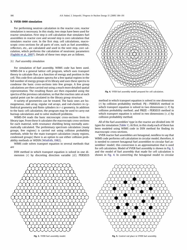
Fig. 4. VVER fuel assembly model prepared for cell calculation.
A.H. Fadaei, S. Setayeshi / Progress in Nuclear Energy 51 (2009) 184–191186
3. VVER-1000 simulation
For performing neutron calculation in the reactor core, reactorsimulation is necessary. In this study, two steps have been used forreactor simulation. First step is cell calculation that simulates fuelassemblies in reactor core and second step is core calculation thatsimulates reactor core. In the first step, cell calculations, macro-scopic cross-sections for all parts of core, such as fuel assemblies,reflectors, etc., are calculated and used in the next step, core cal-culation, which performs the calculation of neutronic parameters(Faghihi et al., 2007). Details of these two steps are as follows.
3.1. Fuel assembly simulation
For simulation of fuel assembly, WIMS code has been used.WIMS-D4 is a general lattice cell program, which uses transporttheory to calculate flux as a function of energy and position in thecell. This code first calculates spectra for a few spatial regions in thefull number of energy groups of its library and uses these spectra tocondense the basic cross-sections into few groups. A few groupcalculations are then carried out using a much more detailed spatialrepresentation. The resulting fluxes are then expanded using thespectra of the previous calculation, so that the reaction rates at eachspatial point can be calculated in the library group structure.
A variety of geometries can be treated. The basic ones are ho-mogeneous, slab array, regular rod arrays, and rod-clusters in cy-lindrical geometry and finite cylinders in r–z geometry. In additionto the basic cell calculation, the program may be used to carry outburnup calculations and to solve multicell problems.
WIMS-D4 reads the basic microscopic cross-sections from itslibrary tape. From these it calculates the macroscopic cross-sectionsfor each material, with resonance shielding being normally auto-matically calculated. The preliminary spectrum calculation (manygroups, few regions) is carried out using collision probabilitymethods, while for the main transport calculation (many regions,condensed groups) there is an option to use either collision prob-ability methods or WDSN (Winfrith, 1982).
WIMS code solves transport equation in several methods thatare
DSN method in which transport equation is solved in one di-mension (r) by discreting direction variable (U); PERSEUS
Fig. 3. VVER fuel assembly model.
method in which transport equation is solved in one dimension(r) by collision probability method; PIJþ PERSEUS method inwhich transport equation is solved in two dimensions (r, q) bycollision probability method; and PRIZEþ PERSEUS method inwhich transport equation is solved in two dimensions (r, z) bycollision probability method.
All of the fuel assemblies’ type in the reactor are divided into 10types for simulation (Table 1). At first, in this study each of them hasbeen modeled using WIMS code in DSN method for finding itsmacroscopic cross-sections.
VVER reactor fuel assemblies are hexagonal, needless to say thatWIMS code performs cell calculation in circular model, therefore, itis needed to convert hexagonal fuel assemblies to circular fuel as-semblies’ model; this conversion is an approximation that is usedfor cell calculation. Model of VVER fuel assembly is shown in Fig. 3,and the model of fuel assembly that made for cell calculation isshown in Fig. 4. In converting the hexagonal model to circular
Fig. 5. Control rod place in VVER fuel assembly.

Fig. 6. VVER-1000 core model.
A.H. Fadaei, S. Setayeshi / Progress in Nuclear Energy 51 (2009) 184–191 187
model, all the volumes remain constant, only the hexagonal shapesconvert to circular with the same volume. Location of control rodsin fuel assembly is shown in Fig. 5.
Control rods of VVER reactor core consist of two different partsin material. Ninety percent of control rod length in axial is
Fig. 7. VVER-1000 core model pr
composed of B4C that is upper part, other, i.e., 10% of control rodlength, is composed of DyTi that is bottom part. Therefore, twodifferent models are used for control rod simulation.
In WIMS code, some information is needed, some of whichcertain are listed below:
epared for core calculation.
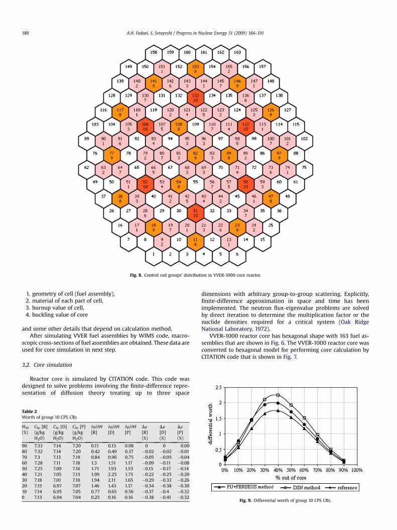
Fig. 8. Control rod groups’ distribution in VVER-1000 core reactor.
A.H. Fadaei, S. Setayeshi / Progress in Nuclear Energy 51 (2009) 184–191188
1. geometry of cell (fuel assembly),2. material of each part of cell,3. burnup value of cell,4. buckling value of core
and some other details that depend on calculation method.After simulating VVER fuel assemblies by WIMS code, macro-
scopic cross-sections of fuel assemblies are obtained. These data areused for core simulation in next step.
3.2. Core simulation
Reactor core is simulated by CITATION code. This code wasdesigned to solve problems involving the finite-difference repre-sentation of diffusion theory treating up to three space
Table 2Worth of group 10 CPS CRs
H10
(%)Cbc [R](g/kgH2O)
Cbc [D](g/kgH2O)
Cbc [P](g/kgH2O)
vr/vH[R]
vr/vH[D]
vr/vH[P]
Dr
[R](%)
Dr
[D](%)
Dr
[P](%)
90 7.33 7.14 7.20 0.11 0.13 0.08 0 0 0.0080 7.32 7.14 7.20 0.42 0.49 0.37 �0.02 �0.02 �0.0170 7.3 7.13 7.19 0.84 0.96 0.75 �0.05 �0.05 �0.0460 7.28 7.11 7.18 1.3 1.51 1.17 �0.09 �0.11 �0.0850 7.25 7.09 7.16 1.71 1.93 1.53 �0.15 �0.17 �0.1440 7.21 7.05 7.13 1.99 2.25 1.75 �0.22 �0.25 �0.2030 7.18 7.01 7.10 1.94 2.11 1.65 �0.29 �0.33 �0.2620 7.15 6.97 7.07 1.46 1.43 1.17 �0.34 �0.38 �0.3010 7.14 6.95 7.05 0.77 0.65 0.56 �0.37 �0.4 �0.320 7.13 6.94 7.04 0.25 0.16 0.16 �0.38 �0.41 �0.32
dimensions with arbitrary group-to-group scattering. Explicitly,finite-difference approximation in space and time has beenimplemented. The neutron flux-eigenvalue problems are solvedby direct iteration to determine the multiplication factor or thenuclide densities required for a critical system (Oak RidgeNational Laboratory, 1972).
VVER-1000 reactor core has hexagonal shape with 163 fuel as-semblies that are shown in Fig. 6. The VVER-1000 reactor core wasconverted to hexagonal model for performing core calculation byCITATION code that is shown in Fig. 7.
Fig. 9. Differential worth of group 10 CPS CRs.

Table 3Worth of group 9 CPS CRs
H9
(%)Cbc [R](g/kgH2O)
Cbc [D](g/kgH2O)
Cbc [P](g/kgH2O)
vr/vH[R]
vr/vH[D]
vr/vH[P]
Dr [R](%)
Dr [D](%)
Dr [P](%)
90 7.13 6.93 7.04 0.19 0.24 0.12 �0.01 �0.01 �0.0080 7.12 6.93 7.03 0.73 0.97 0.68 �0.03 �0.04 �0.0370 7.09 6.91 7.02 1.45 1.83 1.35 �0.08 �0.1 �0.0760 7.05 6.88 7.00 2.24 2.76 2.11 �0.16 �0.2 �0.1550 6.99 6.83 6.97 3.1 3.91 2.95 �0.27 �0.34 �0.2540 6.92 6.76 6.91 3.99 5.23 3.8 �0.41 �0.53 �0.3930 6.84 6.67 6.84 4.5 6.33 4.27 �0.57 �0.75 �0.5420 6.77 6.55 6.77 3.81 5.43 3.51 �0.7 �0.94 �0.6610 6.73 6.46 6.70 2.01 2.44 1.71 �0.77 �1.03 �0.720 6.72 6.41 6.67 0.6 0.5 0.42 �0.8 �1.04 �0.74
Table 4Worth of group 8 CPS CRs
H8
(%)Cbc [R](g/kgH2O)
Cbc [D](g/kgH2O)
Cbc [P](g/kgH2O)
vr/vH[R]
vr/vH[D]
vr/vH[P]
Dr [R](%)
Dr [D](%)
Dr [P](%)
90 6.71 6.8 6.67 0.33 0.45 0.29 �0.01 �0.01 �0.0180 6.69 6.79 6.66 1.15 1.50 1.21 �0.05 �0.07 �0.0570 6.65 6.77 6.64 2.11 2.65 2.21 �0.13 �0.16 �0.1360 6.59 6.72 6.60 3.17 3.69 3.3 �0.24 �0.29 �0.2550 6.51 6.64 6.54 4.51 5.63 4.78 �0.4 �0.49 �0.4140 6.39 6.54 6.46 6.32 8.01 6.92 �0.62 �0.77 �0.6630 6.24 6.39 6.34 8.35 12.80 9.83 �0.92 �1.22 �1.0020 6.08 6.14 6.16 8.69 16.10 11.5 �1.22 �1.79 �1.4110 5.99 5.84 5.96 4.85 10.10 6.19 �1.39 �2.15 �1.630 5.97 5.65 5.85 1.26 1.37 1.13 �1.43 �2.2 �1.67
A.H. Fadaei, S. Setayeshi / Progress in Nuclear Energy 51 (2009) 184–191 189
For simulating reactor core, cell models that had been preparedin the preceding step were used. CITATION code needs several dataas input, some of them are
1. description of the neutron flux problem,2. geometry of reactor core, and3. macroscopic cross-sections of any part of reactor core.
This information with some other details makes input code.Note that, CITATION code performs neutronic calculation in steadystate, therefore, dynamic analysis of reactor core needs to developa software. In this study, FORTRAN program was used for preparinga software to perform dynamic analysis by coupling cell and corecalculation.
There are 10 groups of control rods in VVER-1000 reactor core,which is shown in Fig. 8, and each of them has a different work incontrol reactor program.
4. Procedure
This paper summarizes efforts related to developing a techni-cally justifiable approach for investigating the control rod worth ofVVER-1000 reactor. For calculating control rod worth, simulation ofreactor is needed. Simulation of reactor core was performed bydeveloping a software in FORTRAN that models reactor core bycoupling WIMS and CITATION codes. Procedure of this software isas follows:
1. At beginning, as before mentioned, fuel assemblies are mod-eled by WIMS code in DSN method. WIMS code calculates
Fig. 10. Differential worth of group 9 CPS CRs.
macroscopic cross-sections of each fuel assembly at hot zeropower conditions and critical boric acid concentration.
2. At the second step, calculated macroscopic cross-sections inpreceding step were used for simulation of reactor core byCITATION code. In this step situation of control rods that areunder assessment is imposed in core model.
3. For accounting real conditions in evaluation, it is necessary tocalculate critical boric acid concentration before imposingcontrol rod movement at each state.
4. For calculating control rod worth, each part of control rod isinserted into core from top to bottom and then reactivitychange is investigated. Note that after inserting each part ofcontrol rod, critical boric acid concentration should be calcu-lated and used for next step.
5. Steps 1–4 for each control rod are performed by FORTRANsoftware. This software links WIMS and CITATION codes atdefinite conditions that are described in VVER-1000 reactorFSAR (final safety analysis report of Busher NPP, 1998) and thencalculates control rod worth by investigating the reactivitychange.
Note in this study, control rod worth calculation was performedat hot zero power conditions (i.e., Tcoolant¼ Tfuel¼ Tclad¼ 553.15 K).
Comparing the results between this study and reference dis-cerned that there were unacceptable errors at some state. There-fore, some efforts were performed for orienting errors. In theprocedure of error assessment, it was discerned that the modelingof fuel assemblies that contain control rods was the importantcause for the occurrence of unacceptable error.
With regard to anisotropic distribution of fuel assemblies thatcontain control rods (Fig. 5), DSN method is unreliable for cellcalculation, but PIJ method due to ability of solving transportequation in two dimensions (r, q) can apply for accounting the effect
Fig. 11. Differential worth of group 8 CPS CRs.
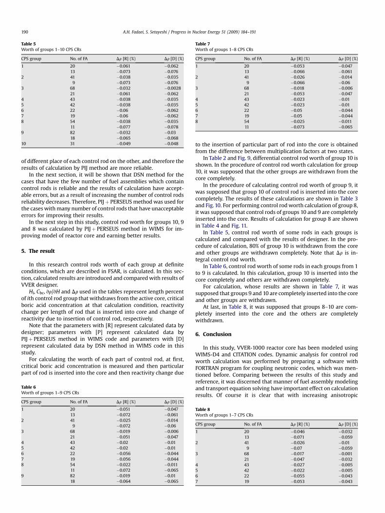
Table 5Worth of groups 1–10 CPS CRs
CPS group No. of FA Dr [R] (%) Dr [D] (%)
1 20 �0.061 �0.06213 �0.073 �0.076
2 41 �0.038 �0.0359 �0.073 �0.076
3 68 �0.032 �0.002821 �0.061 �0.062
4 43 �0.038 �0.0355 42 �0.038 �0.0356 22 �0.06 �0.0627 19 �0.06 �0.0628 54 �0.038 �0.035
11 �0.077 �0.0789 82 �0.032 �0.03
18 �0.065 �0.06810 31 �0.049 �0.048
Table 7Worth of groups 1–8 CPS CRs
CPS group No. of FA Dr [R] (%) Dr [D] (%)
1 20 �0.053 �0.04713 �0.066 �0.061
2 41 �0.026 �0.0149 �0.066 �0.06
3 68 �0.018 �0.00621 �0.053 �0.047
4 43 �0.023 �0.015 42 �0.023 �0.016 22 �0.05 �0.0447 19 �0.05 �0.0448 54 �0.025 �0.011
11 �0.073 �0.065
A.H. Fadaei, S. Setayeshi / Progress in Nuclear Energy 51 (2009) 184–191190
of different place of each control rod on the other, and therefore theresults of calculation by PIJ method are more reliable.
In the next section, it will be shown that DSN method for thecases that have the few number of fuel assemblies which containcontrol rods is reliable and the results of calculation have accept-able errors, but as a result of increasing the number of control rodsreliability decreases. Therefore, PIJþ PERSEUS method was used forthe cases with many number of control rods that have unacceptableerrors for improving their results.
In the next step in this study, control rod worth for groups 10, 9and 8 was calculated by PIJþ PERSEUS method in WIMS for im-proving model of reactor core and earning better results.
5. The result
In this research control rods worth of each group at definiteconditions, which are described in FSAR, is calculated. In this sec-tion, calculated results are introduced and compared with results ofVVER designer.
Hi, Cbc, vr/vH and Dr used in the tables represent length percentof ith control rod group that withdraws from the active core, criticalboric acid concentration at that calculation condition, reactivitychange per length of rod that is inserted into core and change ofreactivity due to insertion of control rod, respectively.
Note that the parameters with [R] represent calculated data bydesigner; parameters with [P] represent calculated data byPIJþ PERSEUS method in WIMS code and parameters with [D]represent calculated data by DSN method in WIMS code in thisstudy.
For calculating the worth of each part of control rod, at first,critical boric acid concentration is measured and then particularpart of rod is inserted into the core and then reactivity change due
Table 6Worth of groups 1–9 CPS CRs
CPS group No. of FA Dr [R] (%) Dr [D] (%)
1 20 �0.051 �0.04713 �0.072 �0.061
2 41 �0.025 �0.0149 �0.072 �0.06
3 68 �0.019 �0.00621 �0.051 �0.047
4 43 �0.02 �0.015 42 �0.02 �0.016 22 �0.056 �0.0447 19 �0.056 �0.0448 54 �0.022 �0.011
11 �0.072 �0.0659 82 �0.019 �0.01
18 �0.064 �0.065
to the insertion of particular part of rod into the core is obtainedfrom the difference between multiplication factors at two states.
In Table 2 and Fig. 9, differential control rod worth of group 10 isshown. In the procedure of control rod worth calculation for group10, it was supposed that the other groups are withdrawn from thecore completely.
In the procedure of calculating control rod worth of group 9, itwas supposed that group 10 of control rod is inserted into the corecompletely. The results of these calculations are shown in Table 3and Fig. 10. For performing control rod worth calculation of group 8,it was supposed that control rods of groups 10 and 9 are completelyinserted into the core. Results of calculation for group 8 are shownin Table 4 and Fig. 11.
In Table 5, control rod worth of some rods in each groups iscalculated and compared with the results of designer. In the pro-cedure of calculation, 80% of group 10 is withdrawn from the coreand other groups are withdrawn completely. Note that Dr is in-tegral control rod worth.
In Table 6, control rod worth of some rods in each groups from 1to 9 is calculated. In this calculation, group 10 is inserted into thecore completely and others are withdrawn completely.
For calculation, whose results are shown in Table 7, it wassupposed that groups 9 and 10 are completely inserted into the coreand other groups are withdrawn.
At last, in Table 8, it was supposed that groups 8–10 are com-pletely inserted into the core and the others are completelywithdrawn.
6. Conclusion
In this study, VVER-1000 reactor core has been modeled usingWIMS-D4 and CITATION codes. Dynamic analysis for control rodworth calculation was performed by preparing a software withFORTRAN program for coupling neutronic codes, which was men-tioned before. Comparing between the results of this study andreference, it was discerned that manner of fuel assembly modelingand transport equation solving have important effect on calculationresults. Of course it is clear that with increasing anisotropic
Table 8Worth of groups 1–7 CPS CRs
CPS group No. of FA Dr [R] (%) Dr [D] (%)
1 20 �0.046 �0.03213 �0.071 �0.059
2 41 �0.026 �0.019 �0.07 �0.059
3 68 �0.017 �0.00121 �0.047 �0.032
4 43 �0.027 �0.0055 42 �0.022 �0.0056 22 �0.055 �0.0437 19 �0.053 �0.043
A.H. Fadaei, S. Setayeshi / Progress in Nuclear Energy 51 (2009) 184–191 191
distribution of rods in fuel assembly, due to insertion of morecontrol rods into the core, this effect increased.
References
Busher NPP neutronic calculations of the core. Report RRC KI no. 32/1-38-498, 1998.Duderstadt, J.J., Hamilton, L.J., 1975. Nuclear Reactor Analysis. John Wiley & Sons,
Inc.
Faghihi, F., Fadaie, A.H., Sayareh, R., 2007. Reactivity coefficients simulation of theIranian VVER-1000 nuclear reactor using WIMS and CITATION codes. Progressin Nuclear Energy 49, 68–78.
Glasstone, S., Sesonke, A., 1967. Nuclear Reactor Engineering. Van NostrandReinhold Company Inc.
Oak Ridge National Laboratory, 1972. CITATION-LDI2 code.Winfrith, 1982. LWR-WIMS, a Computer Code for Light Water Reactor Calculations.
AEE, UK. AEEW-R 1498.