Anion-π and halide-halide nonbonding interactions in a new ionic liquid based on imidazolium cation...
13
Anion−π and Halide−Halide Nonbonding Interactions in a New Ionic Liquid Based on Imidazolium Cation with Three-Dimensional Magnetic Ordering in the Solid State Abel García-Saiz, † Imanol de Pedro,* ,† Pedro Migowski, ‡ Oriol Vallcorba, § Javier Junquera, † Jesú s Angel Blanco, ⊥ Oscar Fabelo, ∥ Denis Sheptyakov, ⊗ Joao Carlos Waerenborgh, ▽ María Teresa Ferna ́ ndez-Díaz, ∥ Jordi Rius, § Jairton Dupont, ‡ Jesú s Antonio Gonzalez, † and Jesú s Rodríguez Ferna ́ ndez † † CITIMAC, Facultad de Ciencias, Universidad de Cantabria, 39005 Santander, Spain ‡ Universidade Federal do Rio Grande do Sul, 90040-060 Porto Alegre, Brazil § Institut de Cie ̀ ncia de Materials de Barcelona (CSIC) Campus de la UAB, 08193 Bellaterra, Catalunya, Spain ⊥ Departamento de Física, Universidad de Oviedo, 33007 Oviedo, Spain ∥ Institut Laue-Langevin, BP 156X, F-38042 Grenoble Cedex, France ⊗ Laboratory for Neutron Scattering and Imaging, Paul Scherrer Institut, 5232 Villigen PSI, Villigen, Switzerland ▽ Centro de Ciê ncias e Tecnologias Nucleares, Instituto Superior Te ́ cnico, Universidade de Lisboa, CFMC-UL, 2695-066 Bobadela LRS, Portugal * S Supporting Information ABSTRACT: We present the first magnetic phase of an ionic liquid with anion−π interactions, which displays a three- dimensional (3D) magnetic ordering below the Né el temper- ature, T N = 7.7 K. In this material, called Dimim[FeBr 4 ], an exhaustive and systematic study involving structural and physical characterization (synchrotron X-ray, neutron powder diffraction, direct current and alternating current magnetic susceptibility, magnetization, heat capacity, Raman and Mö ssbauer measurements) as well as first-principles analysis (density functional theory (DFT) simulation) was performed. The crystal structure, solved by Patterson-function direct methods, reveals a monoclinic phase (P2 1 symmetry) at room temperature with a = 6.745(3) Å, b = 14.364(3) Å, c = 6.759(3) Å, and β = 90.80(2)°. Its framework, projected along the b direction, is characterized by layers of cations [Dimim] + and anions [FeBr 4 ] − that change the orientation from layer to layer, with Fe···Fe distances larger than 6.7 Å. Magnetization measurements show the presence of 3D antiferromagnetic ordering below T N with the existence of a noticeable magneto−crystalline anisotropy. From low-temperature neutron diffraction data, it can be observed that the existence of antiferromagnetic order is originated by the antiparallel ordering of ferromagnetic layers of [FeBr 4 ] − metal complex along the b direction. The magnetic unit cell is the same as the chemical one, and the magnetic moments are aligned along the c direction. The DFT calculations reflect the fact that the spin density of the iron ions spreads over the bromine atoms. In addition, the projected density of states (PDOS) of the imidazolium with the bromines of a [FeBr 4 ] − metal complex confirms the existence of the anion−π interaction. Magneto−structural correlations give no evidence for direct iron− iron interactions, corroborating that the 3D magnetic ordering takes place via superexchange coupling, the Fe−Br···Br−Fe interplane interaction being defined as the main exchange pathway. 1. INTRODUCTION Hybrid organic−inorganic materials now play the major role in the development of advanced functional materials. 1 Research in these materials is supported by the growing interest of chemists, physicists, biologists, and materials scientists due to the opportunity to combine useful properties of both components (organic and inorganic) and the possibility of tuning the physical properties thanks to small modifications at the interface. 2 A new class of these materials are the magnetic ionic liquids (MILs), where the organic and inorganic constituents are embedded, and only hydrogen, van der Waals (vdw), and/or ionic bonds provide cohesion between them. 3 These metal-containing ionic liquids combine the properties of ionic liquids, defined as salts with the melting point below 100 °C, 4 with additional intrinsic magnetic, 5 Received: April 16, 2014 Published: July 31, 2014 Article pubs.acs.org/IC © 2014 American Chemical Society 8384 dx.doi.org/10.1021/ic500882z | Inorg. Chem. 2014, 53, 8384−8396
-
Upload
independent -
Category
Documents
-
view
1 -
download
0
Transcript of Anion-π and halide-halide nonbonding interactions in a new ionic liquid based on imidazolium cation...

Anion−π and Halide−Halide Nonbonding Interactions in a New IonicLiquid Based on Imidazolium Cation with Three-DimensionalMagnetic Ordering in the Solid StateAbel García-Saiz,† Imanol de Pedro,*,† Pedro Migowski,‡ Oriol Vallcorba,§ Javier Junquera,†
Jesus Angel Blanco,⊥ Oscar Fabelo,∥ Denis Sheptyakov,⊗ Joao Carlos Waerenborgh,▽
María Teresa Fernandez-Díaz,∥ Jordi Rius,§ Jairton Dupont,‡ Jesus Antonio Gonzalez,†
and Jesus Rodríguez Fernandez†
†CITIMAC, Facultad de Ciencias, Universidad de Cantabria, 39005 Santander, Spain‡Universidade Federal do Rio Grande do Sul, 90040-060 Porto Alegre, Brazil§Institut de Ciencia de Materials de Barcelona (CSIC) Campus de la UAB, 08193 Bellaterra, Catalunya, Spain⊥Departamento de Física, Universidad de Oviedo, 33007 Oviedo, Spain∥Institut Laue-Langevin, BP 156X, F-38042 Grenoble Cedex, France⊗Laboratory for Neutron Scattering and Imaging, Paul Scherrer Institut, 5232 Villigen PSI, Villigen, Switzerland▽Centro de Ciencias e Tecnologias Nucleares, Instituto Superior Tecnico, Universidade de Lisboa, CFMC-UL, 2695-066 BobadelaLRS, Portugal
*S Supporting Information
ABSTRACT: We present the first magnetic phase of an ionicliquid with anion−π interactions, which displays a three-dimensional (3D) magnetic ordering below the Neel temper-ature, TN = 7.7 K. In this material, called Dimim[FeBr4], anexhaustive and systematic study involving structural andphysical characterization (synchrotron X-ray, neutron powderdiffraction, direct current and alternating current magneticsusceptibility, magnetization, heat capacity, Raman andMossbauer measurements) as well as first-principles analysis(density functional theory (DFT) simulation) was performed.The crystal structure, solved by Patterson-function direct methods, reveals a monoclinic phase (P21 symmetry) at roomtemperature with a = 6.745(3) Å, b = 14.364(3) Å, c = 6.759(3) Å, and β = 90.80(2)°. Its framework, projected along the bdirection, is characterized by layers of cations [Dimim]+ and anions [FeBr4]
− that change the orientation from layer to layer, withFe···Fe distances larger than 6.7 Å. Magnetization measurements show the presence of 3D antiferromagnetic ordering below TNwith the existence of a noticeable magneto−crystalline anisotropy. From low-temperature neutron diffraction data, it can beobserved that the existence of antiferromagnetic order is originated by the antiparallel ordering of ferromagnetic layers of[FeBr4]
− metal complex along the b direction. The magnetic unit cell is the same as the chemical one, and the magnetic momentsare aligned along the c direction. The DFT calculations reflect the fact that the spin density of the iron ions spreads over thebromine atoms. In addition, the projected density of states (PDOS) of the imidazolium with the bromines of a [FeBr4]
− metalcomplex confirms the existence of the anion−π interaction. Magneto−structural correlations give no evidence for direct iron−iron interactions, corroborating that the 3D magnetic ordering takes place via superexchange coupling, the Fe−Br···Br−Feinterplane interaction being defined as the main exchange pathway.
1. INTRODUCTION
Hybrid organic−inorganic materials now play the major role inthe development of advanced functional materials.1 Research inthese materials is supported by the growing interest of chemists,physicists, biologists, and materials scientists due to theopportunity to combine useful properties of both components(organic and inorganic) and the possibility of tuning thephysical properties thanks to small modifications at theinterface.2 A new class of these materials are the magnetic
ionic liquids (MILs), where the organic and inorganicconstituents are embedded, and only hydrogen, van derWaals (vdw), and/or ionic bonds provide cohesion betweenthem.3 These metal-containing ionic liquids combine theproperties of ionic liquids, defined as salts with the meltingpoint below 100 °C,4 with additional intrinsic magnetic,5
Received: April 16, 2014Published: July 31, 2014
Article
pubs.acs.org/IC
© 2014 American Chemical Society 8384 dx.doi.org/10.1021/ic500882z | Inorg. Chem. 2014, 53, 8384−8396

spectroscopic,6 or catalytic7 properties depending on theenclosed metal ion used. Thus, in the past few years, thesynthesis, study, and application of these smart materials haveincreased exponentially.8 First, MILs were composed of ametal-containing anion (such as iron, cobalt, manganese,copper) and an organic cation, generally imidazolium,pyrrolidinium, pyridinium,9 or tetraalkylphosphonium.10 Inmore recent years, the development of these materials hasmade possible the combination of different rare-earth ions(neodymium, gadolinium, dysprosium),11 chiral amionacids,12
bimagnetic ions,13 or heteroanions5 to increase or improve theirtechnological applications, such as the transport and separationof materials,14 separation of greenhouse gases (CO2) throughsupported MILs membranes,15 magnetic surfactants,5 ester-ification of acid oleic to biodiesel,16 etc.The noncovalent interactions play the most important role in
the organization of the structural units of MILs.17 A goodunderstanding of these interactions would give rise to theimprovement of their technological applications. Many researchgroups have focused upon understanding the Coulomb,dipole−dipole, and hydrogen bonds within the crystalstructures of these compounds.18 However, in MILs based onhalometallates19 MX4 (M = metal and X = halogen), such asthe compound studied in this work, namely, the 1,3-dimethylimidazolium tetrabromoferrate Dimim[FeBr4], it isnecessary to consider other nonbonding interactions, such ashalogen−halogen20 (between two bromine atoms of twoneighboring [FeBr4]
− tetrahedra) or anion−π21 (between[FeBr4]
− anion and imidazolium cation), because these alsocontribute to the molecular self-assembly of the anion speciesin the crystal framework.22 In addition, these noncovalentinteractions develop very interesting electrical and magneticphenomena; for instance, in hybrid organic−inorganic materialsbased on the halopyridinium metal complex (4-XpyH)2[CoX4](X = Cl or Br and pyH = 4-halopyridinium),23 in the magneticconducting molecular system of BEDT-TTF and BETS, basedon tetrahalometallate24 (DMET)2FeBr4, (EDTDM)2FeBr4 or(EDOTTFBr2)2FeX4 (X = Cl and Br),25 where the electrontransport and magnetism (antiferromagnetism with a weakferromagnetism) interplay, or in the family of MILs based onimidazolium and tetrachloroferrate ions,26 where the Fe−Cl···Cl−Fe noncovalent interactions are strong enough for theestablishment of a three-dimensional (3D) magnetic ordering.In previous works we have shown that (i) halogen−halogen
interactions may serve as a primary force that induces a 3Dmagnetic ordering in MILs based on imidazolium andtetrachloroferrate ions,27 (ii) the spin population in the metalcomplex anion and the distances and angles between thesuperexchange pathways of the type Fe−X···X−Fe (X = halide)play a decisive role in the formation and stability of these 3Dmagnetic orderings, and (iii) a smaller chain length of theorganic cation increases the efficiency in the transmission of themagnetic interactions, resulting in an increase in the orderingtemperatures [from [Bmim]+28 that shows no 3D magneticordering through [Emim]+ (TN = 4 K)26 to [Dimim]+ (TN =5.6 K)29] (Bmim = 1-butyl-3-methylimidazolium; Emim = 1-ethyl-3-methylimidazolium). In the present study we sub-stituted the chloride ion in the metal complex by a lesselectronegative halide ion, bromide, based on the principlesthat the magnetic interaction between the [FeX4]
− anionshould be stronger in the order X = I > Br > Cl > F. Thisreplacement would allow a larger delocalization of the chargedensity in the metal complex anion [FeBr4] than in the related
[FeCl4], which will favor both the formation of strongerhalogen−halogen interactions and the arrangement of anion−πinteractions with the imidazolium cation. In fact, it has beenfound that the replacement of Cl with Br in Emim[FeX4]
26b
leads to an increase in the Neel temperature. Herein we reportthe synthesis and physicochemical characterization of a newMIL, namely, Dimim[FeBr4]. The magneto−structural studyinvolving experimental results and density functional theory(DFT) calculations will be also presented.
2. EXPERIMENTAL SECTIONThe synthesis of Dimim[FeBr4] was realized following a methodpreviously used for Dimim[FeCl4].
29 For the chemical character-ization, elemental and thermal analyses were used. The crystal andmagnetic structures were obtained by synchrotron X-ray powderdiffraction and by high- and low-resolution neutron diffractionexperiments. The physical characterization was studied using directcurrent (DC) and alternating current (AC) magnetic susceptibility,magnetization, heat capacity, Raman, and Mossbauer measurements.Finally, density functional first-principles simulations based on anumerical atomic orbital method as implemented in the SIESTA30
code were carried out. All the calculations were performed within theefficient implementation31 of the vdw density functional of Dion etal.,32 recently tested on imidazolium-based ionic liquids.33 For a moredetailed description of the Experimental Section, see the SupportingInformation.
3. RESULTS AND DISCUSSION3.1. Description of the Crystal Structure. The crystal
structure of Dimim[FeBr4] at 280 and 300 K, listed in theSupporting Information and the corresponding CIF files, weresolved from synchrotron X-ray powder diffraction (SXPD) andhigh-resolution neutron diffraction data, respectively. Theindexing of the patterns showed similar unit cell parametersand the same space group (P21) as the reported structure forDimim[FeCl4]
29 at room temperature, which was used as thestarting model for the Rietveld refinements. Neutron data hadenough quality to locate the hydrogen atoms in the crystalstructure but not to refine the CH bond lengths. To improvethe refinement, the crystal structure was optimized by DFTcalculations, using the output of the initial neutron Rietveldrefinement as the initial position of the theoretical conjugategradient minimization. With the coordinates from the initialRietveld refinement and soft distance restraints obtained fromthe DFT model, a final crystal refinement of both sets of data ofDimim[FeBr4], at 280 and 300 K, was performed. Both crystalstructures obtained are practically equivalent, with only a slightvariation in the [Dimim]+ cation orientation. The experimental,calculated, and difference powder diffraction profiles are shownin Figure S.2 of Supporting Information. The final structuralparameters and figures of merit of the last refinements aresummarized in Table S.2 and the positional parameters aregiven in Table S.3 of the Supporting Information. For thestructural discussion, the crystal structure at 300 K (neutrondata) will be taken due to the better determination of Hpositions (with synchrotron data H atoms are constrained tothe respective C atoms). The most relevant interatomicdistances in Dimim[FeBr4] crystal structure at 300 K aredisplayed in Table 1.The crystal structure of Dimim[FeBr4] at 300 K can be
defined as layers of [Dimim]+ cations and [FeBr4]− anions
stacked along the b direction with Fe···Fe distances of 6.74(4)and 6.76(3) Å inside a layer (in the a and c directions) and8.57(1) Å between the layers (the b direction) (see Figure 1).
Inorganic Chemistry Article
dx.doi.org/10.1021/ic500882z | Inorg. Chem. 2014, 53, 8384−83968385

In the unit cell, there are three different Br···Br interactiondistances smaller than the sum of the vdw radii (<3.9 Å)between [FeBr4]
− tetrahedra, propagating them in a zigzagmanner along the b axis [3.69(7) Å] and as linear chains alongthe a and c directions [3.71(7) and 3.83(5) Å, respectively].The 21 screw axis changes the relative orientation of both themetal complex anions and the molecular cations from layer tolayer (see Figure 1), passing through the center of theimidazolium ring and causing the antiparallel stacking of the[Dimim]+ cation along the b direction. The [FeBr4]
− units havea slightly distorted tetrahedral geometry with a mean Br−Fe−Br bond angle of 107(6)° and a mean Fe−Br bond distance of2.43(4) Å. All the refined values for the C−C and C−N bondlengths lie in the expected range of other imidazoliumcompounds, as for example in Bmim2[XCl4] (X = Fe, Ni,and Co)34 and Emim[FeCl4].
27a Inside hybrid organic−inorganic materials, like the present compound, an anioncould interact with a cation π system through three differentmodes: (i) hydrogen bonding, (ii) strong noncovalent anion−πinteractions, where the anion will reside above the center of the
aromatic ring, (iii) weak noncovalent anion−π interactions,where the anion will be located outside the periphery of the πsystem.35 Taking the crystallographic data and comparing thesewith each specification rule of these interactions, Dimim[FeBr4]could form: hydrogen bonds and weak anion−π interactionsbetween [FeBr4]
− and [Dimim]+ (Figures 2 and 3). On one
hand, there are six hydrogen bonds according to the IUPACrule36 [Br···H interaction distances smaller than the sum of thevdw radii (<3.15 Å) and C−H···Br angle > 110°], the shortestone involving the H4 atom of the imidazolium ring37 (Figure 2and Table 1). Surprisingly, the most acidic hydrogen of the ring(H2) is at 3.20(5) Å to the closest Br atom, this distance beingtoo long to consider its participation in the hydrogen-bondnetwork as relevant. This issue differs from the data reportedfor the Emim2[MCl4] (M = Co, Ni, and Fe)34 and Dimim[Cl]ionic liquids,38 where the shortest hydrogen bond distance waslocated in this position. However, a similar behavior wasobserved in the Emim[BF4],
39 Emim[FeCl4],27a and Dimim-
[FeCl4]29 ionic liquids. On the other hand, for anion−π
interactions, the nearest imidazolium centroid···Br− distancesvary from 3.82(1) to 4.26(1) Å (Figure 3a and Table 1). The
Table 1. Most Relevant Interatomic Distances inDimim[FeBr4] Crystal Structure at 300 and 0 K Obtainedfrom HRPT and DFT, Respectively
HRPT, 300 K DFT, 0 K
length (Å) angle (deg) length (Å) angle (deg)
Br···BrBr1···Br3 3.69(7) 4.108Br3···Br4 3.71(7) 3.913Br2···Br3 3.83(5) 4.284H···Br (potential hydrogen bonds)C4−H4···Br1 2.67(5) 160(3) 3.011 173.4C5−H5···Br3 2.89(8) 119(5) 3.061 121.9C1′−H1B′···Br3 2.89(7) 133(5) 3.131 150.7C1′−H1B′···Br1 3.06(8) 119(2) 3.318 128(1)C1′−H1A′···Br4 3.10(4) 120(3) 3.477 101.9C1′−H1C′···Br2 3.00(10) 99(3)a 3.553 97.4C1″−H1B″···Br2 3.01(9) 154(4) 3.612 116.9C2−H2···Br1 3.20(5)b 167(4) 3.227 155.2[FeBr]−···[Dimim]+ (potential π−d interactions)Fe···Centroid 4.32(2) 87.6c 4.598 76.2Br2···C5 3.38(3) 3.878Br4···N1 3.69(5) 4.111Br4···[N1−C2]d 3.67(5) 4.056Br3···N3 3.93(5) 3.929Br1···Centroid 6.75(5) 85.3 7.010 78.8Br2···Centroid 3.82(7) 56.3 4.225 64.6Br3···Centroid 4.35(4) 61.2 4.355 60.0Br4···Centroid 4.15(5) 52.8 4.661 45.9[FeBr]−···[Dimim]+ (potential π−d interactions)Fe···Centroid 4.45(2) 84.3c 4.475 80.8Br2···C2 3.95(8) 3.815Br1···N1 3.88(5) 4.523Br4···C4 4.24(7) 3.815Br1···Centroid 4.26(5) 51.9 4.080 65.3Br2···Centroid 4.54(7) 50.2 4.225 56.1Br3···Centroid 4.59(5) 82.3 6.898 82.1Br4···Centroid 6.91(6) 60.0 4.581 50.8
aHydrogen bond not allowed according to IUPAC considerations(angle > 110°). bLong distance to be considered a relevant hydrogenbond. cAngle between Fe−Centroid vector and the imidazolium ringplane. dDistance from Br4 to the center of the N1−C2 bond.
Figure 1. Crystal packing in the ab plane of Dimim[FeBr4] crystalstructure at 300 K. Orange (iron), gold (bromine), gray (carbon), blue(nitrogen), and white (hydrogen). The blue and green dashed squaresrepresent the unit cell and the part of the crystal structure, which isplotted in Figure 3, respectively.
Figure 2. Hydrogen-bonding network in Dimim[FeBr4] (H−Brcontact up to 3.10 Å are marked with pink and white stripes).
Inorganic Chemistry Article
dx.doi.org/10.1021/ic500882z | Inorg. Chem. 2014, 53, 8384−83968386

angles of the Br···centroid axis to the plane of the imidazoliumrings range between 56(1) and 52(1)°. These distances andangles are in disagreement with the rule for strong Br−πinteractions, where the bonding contact should be shorter thanthe sum of the vdw (≤3.75 Å) and the bromine should belocated over the center of the π system (θ = 90 ± 10°).35 Itshould also be mentioned that in the case of other organic−inorganic systems with anion−π interactions involving the[MXn]
m− metal complex, instead of the anion−π interactionresiding above the ring centroid, it is usually located above thering periphery,40 this being characteristic of weak anion−πinteractions. Indeed, Dimim[FeBr4], which presents twocontacts smaller than the sum of the vdw radii of Br···C andBr···[C−N] (≤3.75 and 3.70 Å, respectively) [Br2···C5 andBr4···[N1−C2] distances of 3.38(5) and 3.67(5) Å, respec-tively], could present some electrostatic interactions betweenthe metal complex anions and the electron-deficient imidazo-lium rings. These experimental results, which will confirm thefavorable nature of weak anion−π interactions betweenimidazolium and tetrabromideferrate ions, will be furtheranalyzed below in the theoretical part.3.2. Physical Characterization. 3.2.1. Spectroscopy
Measurements. Together with the crystal structure, Mossba-uer, Raman, and far-IR spectroscopies offer the most rewardingmeans for studying the bonding and type of ionic liquid anionicspecies.41 In particular, Raman spectroscopy provides the mostuseful, versatile, and straightforward technique for the study ofmetal coordination environments of MILs. Moreover, theMossbauer effect allows a quantitative measurement of thecovalent degree of the chemical bonding. This informationderives from the Mossbauer isomer shift, which depends on thes-electron density at the Fe nucleus.Figure 4a shows the nonpolarized Raman spectrum of the
Dimim[FeBr4] sample between 50 and 400 cm−1 at 300 K with647 nm excitation. The [FeBr4]
− iron complex belongs to thesymmetry point group Td and has four Raman-active vibrationmodes; two of them are attributed to the bending modes [νs =70 and νas = 89 cm−1], while the others are related to thestretching modes [νs = 201 and νas = 222 cm−1] of the Fe−Brbond. Moreover, in the presented frequency region, two modes
at 288 and 302 cm−1 are also detected, which correspond to thebending vibrations of CH3−N and CH2−N bonds ofimidazolium cation, respectively.42
An estimation of the vibration bending and stretching modesof the [FeBr4]
− metal complex can be performed starting fromthe position of the [FeCl4]
− Raman bands, which has beenbroadly studied in the literature. In this case, the reportedspectrum has been compared with the Dimim[FeCl4] sample
29
(see Figure 4), taken under the same experimental conditions.The Raman frequency can be described approximately byformula 1
νπ
κμ
= 12 (1)
where κ and μ are the bond strength and the reduced mass,respectively. Considering the difference between the atomicweight of Cl and Br, the Raman frequencies of the [FeBr4]
−
metal complex can be scaled as νFeBr4 = νFeCl4/1.55,assuming constant bond strengths. Thus, the estimated valuesobtained are [νs = 73 and νas = 88 cm−1] and [νs = 215 and νas= 243 cm−1] for the bending and stretching modes,respectively, showing a good agreement with the experimentalones. Finally, we have also compared the Raman spectrum ofDimim[FeBr4] with another hybrid organic−inorganic materialbased on the [FeBr4]
− ion, namely, tetrabutylammoniumtetrabromoferrate, TBA[FeBr4] (see Figure S.3 of SupportingInformation). As can be seen, the frequencies of the iron
Figure 3. Potential π−d interactions between the metal complex and(a) imidazolium centroid and (b) imidazolium periphery (two views).Relevant distances and orientations are shown for the strongestinteractions.
Figure 4. (a) Raman spectra of Dimim[FeBr4] and Dimim[FeCl4]between 30 and 500 cm−1 at 300 K. (b) Raman spectra ofDimim[FeBr4] between 120 and 390 cm−1 at 300 K and from 4 to10 K. (inset) The temperature dependence of the intensity of themagnon scattering, marked with * symbol in the picture. The red lineis only a visual guide.
Inorganic Chemistry Article
dx.doi.org/10.1021/ic500882z | Inorg. Chem. 2014, 53, 8384−83968387
complex appear almost at the same position, confirming thatthe assigned bands are related with the dominant iron-containing species [FeBr4]
−.43,44
The Mossbauer spectra of Dimim[FeBr4] at 78 and 10 K(see Figure S.4 of Supporting Information) consist of aquadrupole doublet with a quadrupole splitting (QS) smallerthan the line widths. This result is in good agreement withRaman spectroscopy and the reported data of an analogoustetrahalometallate ionic liquid, choline[FeCl4],
45 indicating asmall electric field gradient at the iron nucleus. This smallelectric field gradient evidence a highly symmetric electriccharge distribution about the iron metal complex with the sp3
orbitals giving rise to an almost perfect tetrahedral environ-ment. The estimated isomer shift (IS) (relative to metallic Fe at295 K) of Dimim[FeBr4] in the paramagnetic state (10 K)displays a value of 0.37 mm/s, which is higher than thoseobserved for choline[FeCl4] (see Table S.4 of SupportingInformation). The increase in the positive isomer shift in thetetrahaloferrates as the number of bromides in the coordinationsphere increases indicates a decrease in the s-electron density atthe iron nucleus, which is just the opposite from what onewould predict based upon covalency considerations. The Fe−Br bond is more covalent than the Fe−C1 bond, and thus onewould expect the s-electron density at the Fe nuclei in [FeCl4]
−
to be lower than that for [FeBr4]−, causing a higher IS in
[FeCl4]−. The actual lower s-electron density at the iron
nucleus in [FeBr4]− as compared to [FeCl4]
− can be accountedfor if the nonbonding interactions in these complexes isconsidered in addition to the iron-halide σ bond formation.46
The ability to form π bonds between p electrons of the halideswith partially filled t2 orbitals of Fe3+ as well as halogen−halogen and anion−π interactions is stronger in the bromidethan it is in the chloride derivatives. This leads to a higher 3delectron density in [FeBr4]
−. The increased screening effect onthe 4s electrons accounts for the reduction in the s electrondensity at the iron nucleus in [FeBr4]
− relative to that of[FeCl4]
−, producing a higher IS. These results will beconfirmed below with the calculation of the spin densitydistribution in the metal complex anion by DFT studies.The low-temperature dependence (4−10 K) of the Raman
modes of Dimim[FeBr4] in the spectral region of 120−390cm−1 is shown in Figure 4b. First, no splitting of the stretchingmodes of the [FeBr4]
− metal complex appears when thetemperature decreases (see spectra of 300 and 4 K), which isassociated with no solid−solid phase transition,29 in goodagreement with crystallographic studies. Second, a shifting andnarrowing of Raman bands are observed, which is attributed totemperature effect. Third, when the sample was cooled belowTN (see spectra below of 8 K), the spectra display a new weakbroad Raman band, visible near 169 cm−1, which becomessharper as the temperature is further decreased. This newRaman band is mostly consistent with magnon scattering,whose integrated intensity in function of temperature ispresented in the inset of Figure 4b. On the basis of theirrelatively high frequency, it is unlikely that the magnetic-order-induced bands correspond to one-magnon excitations, that is,single spin-flip processes with wave vectors at the center of theBrillouin zone. In comparative terms, the magnon excitationfrequencies appear in rare-earth ortho-ferrites, such as RFeO3(R = Dy, Ho, Er, and Sm), below 25 cm−1.47 So, it would bemore realistic to analyze the magnetic excitations under theassumption that they involve two-magnon processes, such as inthe well-known cases of manganites48 or cuprates.49
To the best of our knowledge, there are no modelcalculations of Raman-active magnetic excitations in theantiferromagnetic structures of hybrid organic−inorganicmaterials that could resemble Dimim[FeBr4]. Therefore, atthis stage we can analyze only qualitatively the magneticexcitations in this material. Finally, when the temperaturedecreases below 10 K, another well-defined Raman mode isobserved at 180 cm−1, which was masked by the broadening ofthe symmetric stretching mode of νs = 201 cm−1 at roomtemperature. At this moment, we do not have an assignment ofthis new Raman band unless the small distortion of thetetrahedron [FeBr4]
−, due to temperature effect, could producea splitting of the symmetric stretching mode.
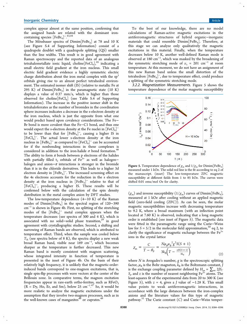
3.2.2. Magnetization Measurements. Figure 5 shows thetemperature dependence of the molar magnetic susceptibility
(χm) and inverse susceptibility (1/χm) curves of Dimim[FeBr4],measured at 1 kOe after cooling without an applied magneticfield (zero-field cooling (ZFC)). As can be seen, the molarmagnetic susceptibilities increase with decreasing temperatureto 9.2 K, where a broad maximum (with an inflection pointlocated at 7.60 K) is observed, indicating that a long magneticorder is established (see inset of Figure 5). The magnetic datawere fitted in the paramagnetic range using the Curie−Weisslaw for S = 5/2 in the molecular field approximation,50 eq 2, toclarify the significance of magnetic exchange between the Fe3+
ions in the crystal lattice
χθ
μ μ=
−=
+
− +( )C
T
N g S S
k T
( 1)
3 zJS Sk
mP
0 B2 2
B( 1)3 B (2)
where N is Avogadro’s number, g is the spectroscopic splittingfactor, μB is the Bohr magneton, kB is the Boltzmann constant, Jis the exchange coupling parameter defined by Hex = ∑nn 2JSi·Sj, and z is the number of nearest neighboring Fe3+ atoms. Theleast-squares fit of the experimental data from 20 to 300 K (seeFigure 5), with z = 4, gives a J value of −1.28 K. This smallvalue points to weak antiferromagnetic interactions, inaccordance with the large distances between the iron-complexanions and the literature values for this type of magneticpathway.51 The Curie constant (C) and Curie−Weiss temper-
Figure 5. Temperature dependence of χm and 1/χm for Dimim[FeBr4]measured under 1 kOe. The solid red line is the fit according to eq 2 ofthe manuscript. (inset) The low-temperature ZFC magneticsusceptibility at different fields from 1 to 85 kOe. The curves wereshifted 0.01 emu/mol Oe for clarity.
Inorganic Chemistry Article
dx.doi.org/10.1021/ic500882z | Inorg. Chem. 2014, 53, 8384−83968388

ature (θP), obtained by the fitting, have values of 4.25 emu K/mol Oe and −14.9 K, respectively. This Curie constantcorresponds to an effective paramagnetic moment μeff = 5.75μB/Fe ion, in good agreement with the expected value of 4.38emu K/mol Oe (5.92 μB) for Fe
3+ ion with a magnetic spin S =5/2.52 Moreover, to study the magnetic field dependence of the3D magnetic ordering with the applied magnetic field, anotherset of DC magnetic susceptibility measurements wereperformed from 1 to 85 kOe and between 2 and 25 K, aftercooling in absence of the applied field (see inset of Figure 5).Switching to higher fields, the inflection point of χm observed at7.60 K under 1 kOe field moves weakly to lower temperatures,being located at 6.80 and 6.60 K for an applied field of 25 and85 kOe, respectively.The field dependence of the magnetization at 15 K shows a
lineal behavior in the whole applied field range confirming theparamagnetic behavior at this temperature (see Figure 6). At 2
K, in the ordered state, the magnetization shows no hysteresis,thereby discarding the existence of any ferromagneticcomponent. Moreover, it continuously increases, withoutshowing any tendency to saturation, to 85 kOe. The valueobtained in this magnetic field (2.15 μB/Fe ion) is far from theexpected fully saturated value for a Fe3+ ion (5 μB/Fe ion),confirming the presence of a noticeable magnetocrystallineanisotropy within the material. This issue differs from the datareported in other MILs based on tetrachloroferrate exhibiting3D ordering, where the magnetization tends toward saturationfor magnetic fields larger than 60 kOe.27a,53,29 Finally themagnetization presents an inflection point near 35 kOe, whichmay suggest a metamagnetic behavior; therefore, this could bethe result of a canted magnetic structure that becomesprogressively collinear under the effect of the magnetic field(see below the description of the magnetic structure).To study a possible dynamical response due to magnetic
ordering, AC magnetic susceptibility measurements wereperformed with an alternate excitation field (Hac) of amplitude10 Oe and frequencies from 100 to 10 000 Hz (see SupportingInformation, Figure S.5). The curves display a broad peak inthe real component of the susceptibility χ′ near 9 K, confirmingthe existence of long-range order interactions. The weakabsorption in the imaginary component χ″ in this temperaturerange ratifies the presence of an antiferromagnetic order, ingood agreement with the results obtained above from the molar
magnetic susceptibility data; moreover, it excludes the existenceof a possible dynamical magnetic process at low temperatures.54
3.2.3. Heat Capacity Measurements. The temperaturedependence of the molar heat capacity (CP) for Dimim[FeBr4]is presented in Figure 7. Calorimetric measurements in the
absence of external magnetic field reveal a maximum (ΔCP =4.9 J/molK) centered at 7.3 K (see lower inset in Figure 7).This anomaly displays the typical λ shape appearance of asecond-order transition, which can be related to the establish-ment of a 3D antiferromagnetic order, in good agreement withthe magnetic susceptibility data. Above TN = 7.7 K, defined asthe inflection point of the maximum, CP increases continuouslyas a result of the phonon contribution and does not show anytendency to saturation even up to room temperature, where thevalue of CP is 290.3 J/mol K, still far from the expected value(525 J/mol K) according to the Dulong and Petit law.55 Thisbehavior is attributable to the presence of a high number ofhydrogen atoms within the imidazolium cation, which displayvery high excitation energies.56
To extract the magnetic contribution (Cmag), the phononcontribution (Cpho) should be determined. The exactcalculation of Cpho is difficult due to the absence of a suitablenonmagnetic isomorphous ionic liquid. Thus, an estimation ofCpho was obtained using the Debye model57 and consideringthe existence of three Debye temperatures, the smaller one (θ1)related to the heavy ions, such as Fe and Br (n1), (θ2) linked tothe C and N ions (n2), and the higher one (θ3) associated withthe H light ions. The best fit to the experimental data from 15to 300 K is obtained for θ1 = 86 K, θ2 = 293 K, θ3 = 1720 K, n1= 4.22, n2 = 4.00, and n3 = 12.78 ions. The temperaturedependence of the magnetic contribution (Cmag) is shown inthe lower inset of Figure 7. The jump of Cmag at TN, ΔCmag =14.7 J K−1 mol−1 is 25% smaller than the expected one for anantiferromagnetic structure with S = 5/2, ΔCmag = 19.6 J K−1
mol−1, within the molecular field approximation.58 This featurecould be attributed to the presence of spin fluctuations. Apart
Figure 6. Magnetization vs applied magnetic field at 2 and 15 K forDimim[FeBr4]. (inset) An enlargement of the low-field region.
Figure 7. Specific heat of Dimim[FeBr4] between 2 and 300 K.Experimental data (blue full dots), estimated phonon contribution(red line), and magnetic contribution (green dots). (lower inset) Themagnetic contribution at low temperatures. (upper-right inset) Themagnetic entropy variation as a function of temperature. (upper-leftinset) The magnetic specific heat as a function of temperature in thepresence of external magnetic fields (0 ≤ H ≤ 80 kOe).
Inorganic Chemistry Article
dx.doi.org/10.1021/ic500882z | Inorg. Chem. 2014, 53, 8384−83968389

from the maximum associated with the 3D magnetic orderaround 7.3 K, another anomaly like a shoulder from 8 to 15 K isobserved. One of the most plausible explanations for thismagnetic anomaly is the contribution to the magnetic heatcapacity of the Fe−Br···Br−Fe magnetic couplings in the formof two-dimensional (2D) ordering.59 This would be locatedinside the layers, as ferromagnetic coupling, as will be discussedlater from magnetic structure data. The magnetic entropyvariation calculated as ΔS = ∫ (Cm/T)dT is shown in the right-upper inset of Figure 7. As can be seen, it becomes graduallylarger with increasing temperature, reaching at about 20 K avalue very close to 1.79 R = 14.9 J mol−1 K−1, whichcorresponds to the full entropy coming from the magneticspecific heat based on the degenerate freedom of S = 5/2. Byapplying magnetic fields (see left-upper inset of Figure 7), theinflection point of the λ peak shifts to lower temperatures,displaying a TN = 7.60 and 6.90 K at 40 and 80 kOe,respectively, which almost correspond to those obtained fromthe magnetic susceptibility data. These results confirm that themagnetic order is antiferromagnetic and that the spin of thetrivalent iron ions (Fe3+) is a high-spin state (S = 5/2). Inaddition, the magnetic peak does not disappear for fields largerthan 80 kOe, corroborating the presence of the magneto-crystalline anisotropy detected in the magnetic susceptibilitydata.3.3. Description of the Magnetic Structure. The
temperature evolution of the D1B patterns between 2 and 10K (see Figure 8) shows the appearance of additional elastic
intensity at temperatures below around 8 K, confirming theonset of a magnetic ordering (TN = 7.6 K). A comparative viewof the nuclear pattern (10 K) as different from the magneticones (2 K) reveals the occurrence of a long-range magneticordering due to the presence of an extra magnetic signal insome structural reflections [see left inset of Figure 8],compatible with the magnetometry results. Moreover, a weak
diffuse scattering superposed to the 3D ordering is detectedbelow around 2θ = 15°, which increases in a monotonous waybelow TN (not shown), suggesting a complex magnetictransition.60 A structural phase transition was discarded as theorigin of this diffuse scattering. Rietveld refinements above themagnetic phase transition show that the P21 symmetry of thecrystal structure is maintained down to 2 K; only a slight shiftof the Bragg reflections associated with lattice contraction wasobserved. Therefore, further studies are required to understandthe origin of this diffuse scattering, which also was detected inDimim[FeCl4].
29
Focusing on the long-range magnetic ordering, below TN, theadditional elastic intensities can be indexed with thepropagation vector k = (0, 0, 0), indicating that the magneticand nuclear unit cells are the same.To determine the possible magnetic structures, the
irreducible representations (irreps) compatible with theindexed propagation vector [k = (0, 0, 0)] were investigatedusing Bertaut’s symmetry analysis method.61 This approachallows us to determine the symmetry constraints between thedifferent magnetic moments of the Fe3+ atom within themagnetic unit cell. The total magnetic representation of thepropagation vector group can be decomposed on twoirreducible representations, each one of three dimensionswith three basis vectors, and therefore the Gmag can berepresented as
= +G G G3( )mag 1 2
leading to two possible spin configurations:
= − = + = −G A S S F S S A S S: , ,Xx x
Yy y
Zz z
1 1 2 1 2 1 2
= + = − = +G F S S A S S F S S: , ,Xx x
Yy y
Zz z
2 1 2 1 2 1 2
where Six is the component along x of the magnetic moment of
atom (i). Note that there are two Fe3+ ions in the magnetic unitcell that are symmetry-related (Wyckoff position 2a). Themagnetic moments for Fe(2a) atoms on each sublattice areobtained from the basis vectors as m2a(1) = (u, v, w) andm2a(2) = (−u, v, −w) for irrep G1 and m2a(1) = (u, v, w) andm2a(2) = (u, −v, w) for irrep G2. In both cases there are threedegrees of freedom (u, v, w) for the magnetic structure.The magnetic model described by irrep G1 corresponds to
ferromagnetic layers, which are antiferromagnetically coupledalong the b axis with a canting that could produce a globalferromagnetic behavior, extended into the ac plane. Themagnetic structure described by irrep G2 can be seen asantiferromagnetic chains running along the b axis with a cantinginto the ac plane. Rietveld refinement of the 2 K pattern, wherethe atomic coordinates and isotropic temperature factors of thenuclear part were fixed to those obtained from the High-Resolution Powder Diffractometer for Thermal Neutrons(HRPT) and DFT calculations, respectively, shows that G1 isthe only irrep that provides a satisfactory agreement betweenthe calculated and the experimental diffraction patterns.Therefore, using G1 we are able to obtain the relativeorientation of the magnetic moments of the two symmetry-related magnetic sites present in this MIL. The Shubnikovgroup corresponding to G1 is P21, and therefore the spacegroup remains invariable after the magnetic phase transition.To avoid overparameterization and due to the negligible valueobtained in the first refinements for the magnetic momentcomponent along the b axis, it was fixed at zero, giving rise to acollinear antiferromagnetic behavior, with the magnetic mo-
Figure 8. Neutron thermodiffractogram collected at D1B diffrac-tometer between 2 and 10 K. (left inset) The neutron diffractionprofiles of Dimim[FeBr4] at 10 (blue) and 2 K (red) obtained in D1B.The (*) dots show the magnetic contributions. (right inset) Thetemperature dependence of the normalized Fe magnetic moment(calculated from μFe(T)/μFe, the μFe being the theoretical value ofca. 5 μB) obtained from the fit of the neutron diffraction pattern andthe expected theoretical dependence for the Brillouin function with S= 5/2 (red line).
Inorganic Chemistry Article
dx.doi.org/10.1021/ic500882z | Inorg. Chem. 2014, 53, 8384−83968390

ments parallel to the a axis (refinement of the c axis was also 0),which is in good agreement with the macroscopic magneticmeasurements. The final refinement is shown in Figure S.6 ofSupporting Information, and the corresponding magneticstructure is shown in Figure 9. The nuclear and magneticdiscrepancy factors are Rp = 22.0, Rwp = 14.4, RBragg = 8.37, andRmag = 5.24.
Out of all the possible orientations, the collinear solutionproposed by G1 gives the best agreement between observed andcalculated patterns. The magnetic moment obtained is the onerefined to 4.75(6) μB, slightly lower than the expected value of5 μB for Fe3+ in high-spin configuration, which could beattributed to the diffuse magnetic background observed belowTN. In addition, the possible metamagnetic transition observedat 35 kOe (see inset of Figure 6) could be interpreted based onthe hypothesis that the magnetic structure proposed would notbe “strictly” collinear, showing a small canting in the b axis,which has not been detected by neutron powder diffraction.Finally, sequential refinements against these data wereperformed using the FullProf suite61b to follow the evolutionof the magnitude of the magnetic moment with thetemperature. The temperature dependence of the modulus ofthe Fe magnetic moment, μFe, obtained from the refinementbetween 2 and 10 K is given in the right inset of Figure 8,compared with the theoretical dependence corresponding tothe Brillouin type S = 5/2.62
3.4. Density Functional Theory Calculations. A paralleltheoretical study for the crystal and magnetic structure ofDimim[FeBr4] was carried out by DFT calculations asimplemented within the SIESTA30 code. As already explainedin Section 3.1, we carried out a structural relaxation to refinethe atomic coordinates starting from an approximation of theexperimental coordinates after the first Rietveld analysis. Inaddition, we assumed the antiferromagnetic A phase (G1)obtained by neutron diffraction studies, as discussed in Section3.3. The intramolecular geometries (reduced coordinates) anddistances of the [Dimim]+ cation and [FeBr4]
− anion obtainedby DFT are not too far away from the starting point, with only
an overestimation of about 3% from the experimental data,within the standard deviations of the functional approach.32
Previous theoretical studies have shown that an electron-donor molecule (anion) can experience favorable bindinginteractions with the π cloud of an electron-deficient aromaticring, such as in pyridine63 or azines64 derivatives. However, theanion−π interactions with imidazolium π systems are extremelyrare and only recently studied in calix[n]imidazolium,65
hydrogen bonding being the predominant interaction motif.According to the structural studies, Dimim[FeBr4] exhibitsremarkable features that would support the existence ofattractive anion−π interactions66 between the tetrabromofer-rate anion and the dimethylimidazolium cation, this being, toour knowledge, the first evidence of an MIL.The binding energy between a metal complex and an
aromatic ring depends on the halide of the [MXn]m− anion, the
geometric features (lineal, trigonal planar, square planar,tetrahedral, or octahedral), and the different orientationsadopted by the metal complex.22 To confirm the existence ofthe anion−π interactions in Dimim[FeBr4] we have pursuedtwo different pathways. The first is to compute the “ionizationenergy” of the gas phase, defined following ref 32 as EI = Epair −(Ecat + Ean), where Ean and Ecat are the energies of the [FeBr4]
−
and the [Dimim]+ ions, respectively, and Epair is the ion-pairground state energy. All the calculations for the isolatedDimim[FeBr4] and the corresponding charged constituentswere performed in cubic supercells of 25 Å per side, with acompensating uniform background of the opposite charge toavoid the divergence of the electrostatic potential in chargedperiodic systems. The same correction energy for the isolatedions as in ref 32, proposed initially by Leslie and Gillan67 andalso for G. Makov and M. Payne,68 was used here. Theionization energy amounts to −3.17 eV/pair. Thus, thesesimulations show that the anion−π interactions are energeti-cally favorable at least in the gas phase.To further check their existence in the condensed phase, we
studied as a second step the projected density of states (PDOS)of the imidazolium with the bromines of the [FeBr4]
− metalcomplex, depicted in Figure 10a. We observed a wide range ofenergies between 1 and 3 eV below the Fermi energy, wherethe PDOS on the imidazolium and on the metal complexes takea nonzero value, proving the existence of a chemical bondingbetween them. To visualize the shape of one of these states thatcan be described by a linear combination of the atomic orbitalsof the [Dimim]+ and the [FeBr4]
− complex, we chose arepresentative state at the Γ point, with an energy of 1.65 eVbelow the Fermi energy, corresponding to the position wherethe PDOS show the peak marked in Figure 10a. The isosurfacefor a value of the wave function of 0.02 is shown in Figure 10band shows how the wave function can connect two [FeBr4]
−
anions from layer to layer across the π orbital of theimidazolium ring. Thus, an electronic transmitting mechanismcan be propagated via anion−π interactions. Interestingly, thewave function is located above the ring periphery, rather thanresiding above the ring centroid, which is characteristic of weakanion−π interactions; this is in good agreement withcrystallographic studies.For the study of the possible magnetic superexchange
pathways in MILs, it is important to know the spin densitydistribution in the metal complex anion. As happened withDimim[FeCl4],
29 in the present compound, there is a partialtransfer of charge from the iron atoms to the bromine atomsdue to the partial covalent bond. This issue strengthens the
Figure 9. Magnetic structure of Dimim[FeBr4]. The magneticmoments of Fe3+ are in the c direction. The dashed lines representthe unit cell.
Inorganic Chemistry Article
dx.doi.org/10.1021/ic500882z | Inorg. Chem. 2014, 53, 8384−83968391

interaction between two iron atoms through superexchangepathways, type Fe−Br···Br−Fe. To further check the stability ofthe antiferromagnetic A phase, with spin configuration type G1(see Section 3.3), we compared the difference in energy withrespect to the ferromagnetic one, type G2. The data displaylower energy [−5.38 (ev/cell)] for the G1, in good agreementwith the result obtained by the experimental data. Figure 11shows the spin delocalization for the most stable magneticstructure (type A), integrated in the plane containing two ironsand two bromines. The different sign in the spin density alongthe b direction is related to the antiferromagnetic interactionbetween planes. Table S.5 of the Supporting Information showsthe Mulliken charge obtained by DFT for the [FeBr4]
− anion.The sum of the Mulliken populations gives a value of 4.98 μB,which is expected for a Fe3+ with a high spin of S = 5/2. Thequantity of spin transferred to the bromines ranges from 0.27and 0.29 μB, the total transfer being 1.12 μB, which represents22.4% of the magnetic moment. These numbers are consistentwith a direct integration of the charge density over spheressurrounding atoms. Assuming nonoverlapping spheres aroundFe and Br of 2.00 and 2.6 Bohr, respectively (whose sum equalsthe mean Fe−Br distance in the tetrahedra), the spin chargeamounts to 3.6027 and 0.2262 μB. Finally, comparing thepresent result with those obtained for Dimim[FeCl4]
29 (totalspin density transfer from Fe to Cl = 1.05 μB, which symbolizes21.0%), we find that the delocalization is slightly higher. Thisresult is in good agreement with Mossbauer results and thereported data of other halometallate compounds with thesetypes of superexchange pathways.51b
3.5. Magneto−Structural Correlations. The magneto−structural correlations of mixed organic−inorganic materials are
attracting the interest of scientific community, with specialattention toward the anion−anion and anion−donor−anionmagnetic interactions.69 In the case of the present MIL, themagnetic structure consists of an arrangement of iron metalcomplex groups, stabilizing the overall antiferromagneticordering (see Figure 9). If we consider their structural features,we can deduce that direct Fe···Fe interactions are not present.The shorter Fe···Fe distances through the space range between6.74 and 8.57 Å (see Table 2), the superexchange interactionsbeing responsible for the 3D magnetic ordering.In the crystal structure of Dimim[FeBr4], all the [FeBr4]
−
metal complexes are stacked upon one another in a 3D mannerwith three types of nonbonding interactions (a) hydrogenbond, (b) anion−π, and (c) bromine−bromine. Two of themcan transmit magnetic couplings between an iron ion and itsfirst shell of neighboring iron ions:70 (i) direct superexchangeanion−anion interactions (Fe−Br···Br−Fe) and (ii) indirectsuperexchange anion−anion interactions (Fe−Br···Im···Br−Fe), where Im represents an imidazolium donor cation. Figure12 shows a scheme of the three possible magnetic interactionsprojected on the ac plane, according to the most appropriatemodel of the magnetic structure obtained from neutrondiffraction data. The J1 interaction, J⊥ or interplane coupling,gives rise to zigzag chains to form a ladder structure that runsparallel to the b direction. It is supposed to be the strongestcoupling, according to the predominant antiferromagneticbehavior of this material (see below the discussion of magneticfitting calculations and Figure S.7 of Supporting Information).Furthermore, there are two intraplane interactions, defined byJ2 or J∥, with similar (Fe−Br···Br−Fe) distances and angles,which connect the iron atoms in linear ferromagnetic chains inthe ac plane. In both magnetic interactions, J1 and J2, the fourligand atoms involved in the magnetic pathways are bromineswhich are connected through a single superexchange pathway(Fe−Br···Br−Fe). In addition to these two interactions, twoadjacent zigzag chains, coupled with Fe−Br···Br−Fe inter-actions in the b direction, can be connected via an imidazolium
Figure 10. (a) PDOS of bromines from a [FeBr4]− ion (black marks)
with the atoms in the imidazolium ring (color lines). Dashed lineshows the state with energy of −1.65 eV below the Fermi energy,where there is orbital overlapping. (b) Representation of the wavefunction for this state (red and blue colors represent the positive andnegative part, respectively).
Figure 11. Schematic view of the projection of the induced spindensity for the interplane exchange magnetic interaction, through Fe−Br−Br−Fe bridges, at 0 K. The levels are 0.05 e Å3 with steps of 0.005e Å3. Only the low-density levels are drawn. Blue and red colorsrepresent the opposite sign of the spin density.
Inorganic Chemistry Article
dx.doi.org/10.1021/ic500882z | Inorg. Chem. 2014, 53, 8384−83968392

cation (Fe−Br···Im···Br−Fe). According to the magneticstructure obtained, these types of interactions will beantiferromagnetic, presenting direct Fe···Fe and Br···Im···Brexperimental distances of 8.75 and 8.59 Å, respectively.First, the strength of the magnetic exchange halide−halide
nonbonding interactions between MX4 metal complex (M =metal and X = halide) can be estimated according to theseparameters: (i) X···X distance, (ii) M−X···X angles, and (iii)the M−X···X−M torsion angle (τ). In general, shorter X···Xdistances, larger M−X···X angles, and torsion angles near 0 and180° are correlated with stronger magnetic exchangeconstants.20 These parameters were estimated in the presentMIL from the crystal structure obtained from neutron powderdiffraction data [see Table 2 and the electronic SupportingInformation (.CIF file)]. In relation to the Br···Br distances, theinterplane (J1) and intraplane couplings (J2) range from 3.69to 3.83 Å, this being smaller than the sum of the vdw radii oftwo bromine atoms (3.90 Å), which displays remarkableagreement with other reported magnetic coupling distances inseveral metal−organic materials.71 For the second and thirdparameters, J1, which connects the tetrabromoferrate(III)anions in zigzag chains propagating along the b direction,presents a nearly lineal combination of Fe−Br···Br and Br···Br−Fe angles (167.9 and 171.1°) with τ = 16.2°. In the case of theintraplane interactions (J2), which give rise to linear chains inthe ac plane, the magnetic couplings show a mixture ofexchange angles: (i) Fe−Br···Br, which varies between 87.4 and89.6° and (ii) Br···Br−Fe, which ranges from 155.6 to 164.1°with τ from 18.0 to 38.9°. Therefore, according to theseconsiderations, the interplane magnetic interactions will bestronger than the intraplane ones due to their present shorterdistances, larger angles, and a smaller torsion angle.Second, the electrostatic effects and the deformation of
electric charge around the halogen atom, in tetrahaloferrate(III)complexes containing the heteroaromatic organic cation, alsoplay a crucial role in the force and type of nonbondingmagnetic interactions.72 These issues can be analyzed in thepresent MIL, with the results obtained from the DFTcalculations. On one hand, the spin density delocalized ontothe first four bromide neighborings is very uniform (rangingfrom 0.27 to 0.29). On the other hand, the electron density ofT
able
2.Selected
GeometricalParam
eters,Bon
dLengths(Å
)andAngles(deg)Obtainedfrom
High-ResolutionNeutron
Diffraction(Experim
entalat
10K)andDFT
(Calculated)
Related
tothePossibleMagneticExchangePathw
aysforDim
im[FeB
r 4]
magnetic
exchange
pathways
direct
distance
Fe−Fe,(Å)
length
ofexchange
pathway,(Å)
bond,(Å)Fe−Br
bond,(Å)Br−
Br
bond,(Å)Br−
Feangle,(deg)Fe−Br−
Br
angle,(deg)Br−
Br−
Fetorsionangle
τ,(deg)
direction
J1(exp.)
8.57(2)
8.60
2.46
3.69
2.45
167.9
171.1
16.2
bJ2
(exp.)
6.74(4)
8.57
2.46
3.71
2.40
89.6
164.1
38.9
aJ2
(exp.)
6.76(3)
8.68
2.46
3.83
2.39
87.4
155.6
18.0
cJ3
(exp.)
8.75(1)
13.51
2.40
8.59
2.45
73.9
76.7
bJ1
(calc.)
8.945
8.959
2.426
4.108
2.425
175.0
172.6
17.1
bJ2
(calc.)
6.846
8.769
2.426
3.913
2.430
87.4
154.9
39.3
aJ2
(calc.)
6.851
8.872
2.425
4.031
2.416
83.6
156.3
19.2
cJ3
(calc.)
8.747
13.246
2.425
8.395
2.426
81.2
81.4
b
Figure 12. Schematic view of the possible magnetic exchangepathways for Dimim[FeBr4] via Fe−Br···Br−Fe (J1 and J2) andFe−Br···Im···Br−Fe (J3) bridges.
Inorganic Chemistry Article
dx.doi.org/10.1021/ic500882z | Inorg. Chem. 2014, 53, 8384−83968393

magnetic exchange interactions show a linear coupling (near to180°) and out of-plane of angles for J⊥ (J1) and J∥ (J2),respectively. Therefore, the orbital overlap between the twononbonding bromide ions should be higher when the couplingis collinear. Thus, the interplane magnetic interactions shouldbe stronger than intraplane ones, in good agreement with theoverall antiferromagnetic behavior of this MIL.Third, the quantitative analysis of the exchange couplings
between the Fe3+ ions can be realized from the parametersexperimentally obtained from magnetic measurements. On thebasis of the previous estimations, we are able to consider thedirect Fe−Br···Br−Fe superexchange coupling along the b axis,J1, as the main exchange pathway. In addition, on the ac plane,the orthogonal conformation of the Br−Br−Fe interactionspromotes a weak orbital coupling, giving rise to a weakferromagnetic coupling between Fe3+ ions. Another indirectexchange coupling is present in this complex, J3 (Fe−Br···Im···Br−Fe), which should be weakest, due to the involvement of animidazolium ion (defined as S = 1/2)73 inside the exchangepathway. On the basis of these considerations, the mostappropriate model to treat the magnetic susceptibility data is acombination of a modified expression classical spin ladderlikechain (one-dimensional) together with a mean-field term totake into account the intraplane interactions (2D).74 Themodel described by Fisher75 [see eq 3] was carried out toextract the magnetic exchange couplings between the Fe3+ ions
χχ
χ=
−1obs1D
2D (3)
defined as
χμ
=+
· +−
Ng S S
k Tuu
( 1) 111D
2B
2
B
= − =+
u YY
YJS S
k Tcoth( )
1;
( 1)
B
χμ
χ= ·zj
Ng2
2D 2B
2 1D
where J and j are the J1 and J2 magnetic interaction parametersand z is the number of nearest neighboring magnetic species (z= 4). The least-squares best-fit of the experimental data, from 2to 300 K, gives the parameters J = −2.38(1) K, j = 0.017(1) K,and g = 1.97(1). The calculated curve obtained (solid line inFigure S.7 of Supporting Information) reproduces quite wellthe magnetic data in the whole temperature range investigated,and the fitting parameters are in agreement with the hypothesisthat the Fe−Br···Br−Fe interactions along the b axis are thestrongest. Even when the quantitative analysis of the exchangecouplings is not easy due to the occurrence of differentexchange coupling, the proposed approach can be valuable inthe absence of a more realistic model.The comparison of the magneto−structural correlations of
Dimim[FeBr4] with the MIL analogue Dimim[FeCl4]29 points
to the fact that the larger antiferromagnetic ordering observedin the bromide compound [from Cl that shows the 3Dmagnetic ordering at 5.6 K to Br at 7.7 K)] cannot be attributedto the geometrical factor of nonbonding interactions. On onehand, the bigger the halide size is, the larger the distancesbetween the iron−iron and superexchange magnetic pathwaysare. Therefore, a lower ordering temperature is expected inDimim[FeBr4]. On the other hand, both MILs display an
almost linear coupling and out-of-plane magnetic exchangeangles in J1 and J2, respectively. Thus, this enhancement of theantiferromagnetic interactions with the substitution of brominefor chlorine atoms can be attributed to the spin delocalizationof iron atoms in the metal complex, which favors the magneticcouplings. Moreover, these issues can explain why theinterplane magnetic coupling parameter J1, along the b axis,is higher in the case of the tetrabromide metal complex (J1 =−0.51129 and −2.38 K for Cl and Br, respectively). Finally, theexistence of weak ferromagnetic superexchange magneticinteraction in the ac plane (J2 = 0.017 K) is in contrast tothe chloride drivative (J2 = −0.359 K; weak antiferromagnetic),and the presence of a new electrostatic mechanism acrossnoncovalent interactions via an imidazolium cation (Fe−Br···Im···Br−Fe) opens up a new field of understanding andimproving of the magneto−structural correlations within MILs.
■ CONCLUSIONS
A new 3D magnetic correlated ionic liquid based onimidazolium cation and tetrabromoferrate ions, namely,Dimim[FeBr4], was synthesized and structurally characterized.This compound was obtained as a microcrystalline powder atroom temperature and exhibits high thermal stability. Thetopological framework of its condensed phase is characterizedby layers of cations [Dimim]+ and anions [FeBr4]
−, whichchange the orientation from layer to layer, stacked upon oneanother in a 3D manner with several nonbonding interactions:hydrogen bond, anion−π, and halide−halide. Magnetic studiesshow the existence of predominant antiferromagnetic inter-actions, exhibiting a 3D magnetic ordering below 8 K, togetherwith the presence of magnetocrystalline anisotropy. Thecollinear antiferromagnetic structure is formed by ferromag-netic layers extended into the ac plane, which areantiferromagnetically coupled along the b axis. A spindelocalization reflects the fact that the magnetic molecularorbitals are spread over the bromine atoms, thus enhancing themagnetic interactions through a superexchange magneticinteraction mechanism, (Fe−Br···Br−Fe). In addition, theexperimental and DFT calculations display that two [FeBr4]
−
anions can connect across the π orbital of an imidazolium ring.These magnetic phenomena are responsible for the 3Dordering observed in the family of MILs based on thetetrahaloferrate ion and imidazolium cation, displaying a higherordering temperature with a halide ion less electronegative inthe metal complex.
■ ASSOCIATED CONTENT
*S Supporting InformationThis contains a detailed Experimental Section, thermoanalyticalMossbauer and Raman data, AC magnetic measurements,magnetic fitting, and crystallographic information (CIF data).This material is available free of charge via the Internet athttp://pubs.acs.org.
■ AUTHOR INFORMATION
Corresponding Author*E-mail: [email protected].
NotesThe authors declare no competing financial interest.
Inorganic Chemistry Article
dx.doi.org/10.1021/ic500882z | Inorg. Chem. 2014, 53, 8384−83968394

■ ACKNOWLEDGMENTS
Financial support from the Spanish Ministerio de Ciencia eInnovacion (Projects MAT2011-27573-C04 and FIS2012-37549-C05-04) and Becas Iberoamericas Jovenes ProfesoresInvestigadores, 2011, Santander Universidades is acknowl-edged. The authors gratefully acknowledge the computerresources, technical expertise, and assistance provided by theRed Espanola de Supercomputacion and MALTA ConsoliderIngenio 2010 (Ref. CSD2007-00045). The paper is (partly)based on the results of experiments carried out at the SwissSpallation Neutron Source SINQ, Paul Scherrer Institut,Villigen, Switzerland and Institute Laue-Langevin (ILL) ofGrenoble.
■ REFERENCES(1) (a) Hagrman, P. J.; Hagrman, D.; Zubieta, J. Angew. Chem., Int.Ed. 1999, 38, 2638−2684. (b) Kickelbick, G. Hybrid Materials;Wiley.com: Hoboken, NJ, 2007.(2) (a) Gomez-Romero, P. Adv. Mater. 2001, 13, 5. (b) Kitagawa, S.;Kitaura, R.; Noro, S.-i. Angew. Chem., Int. Ed. 2004, 43, 2334−2375.(3) Giernoth, R. Angew. Chem., Int. Ed. 2010, 49, 2834−2839.(4) Welton, T. Chem. Rev. 1999, 99, 2071−2084.(5) Brown, P.; Butts, C. P.; Eastoe, J.; Padron Hernandez, E.;Machado, F. L. d. A.; de Oliveira, R. J. Chem. Commun. 2013, 49,2765−2767.(6) Mallick, B.; Balke, B.; Felser, C.; Mudring, A.-V. Angew. Chem.,Int. Ed. 2008, 47, 7635−7638.(7) Wang, H.; Yan, R.; Li, Z.; Zhang, X.; Zhang, S. Catal. Commun.2010, 11, 763−767.(8) (a) Brown, P.; Bushmelev, A.; Butts, C. P.; Cheng, J.; Eastoe, J.;Grillo, I.; Heenan, R. K.; Schmidt, A. M. Angew. Chem., Int. Ed. 2012,51, 2414−2416. (b) Okuhata, M.; Funasako, Y.; Takahashi, K.;Mochida, T. Chem. Commun. 2013, 49, 7662−7664. (c) Hu, X. L.;Qian, L. W.; Tang, Y. M.; Guan, P. Adv. Mater. Res. 2013, 702, 74−78.(9) Del Sesto, R. E.; McCleskey, T. M.; Burrell, A. K.; Baker, G. A.;Thompson, J. D.; Scott, B. L.; Wilkes, J. S.; Williams, P. Chem.Commun. 2008, 0, 447−449.(10) Peppel, T.; Kockerling, M.; Geppert-Rybczyn ska, M.; Ralys, R.V.; Lehmann, J. K.; Verevkin, S. P.; Heintz, A. Angew. Chem., Int. Ed.2010, 49, 7116−7119.(11) Bwambok, D. K.; Thuo, M. M.; Atkinson, M. B.; Mirica, K. A.;Shapiro, N. D.; Whitesides, G. M. Anal. Chem. 2013, 85, 8442−8447.(12) Tanaka, K.; Ishiguro, F.; Chujo, Y. J. Am. Chem. Soc. 2010, 132,17649−17651.(13) Miao, C.-X.; Wang, J.-Q.; Yu, B.; Cheng, W.-G.; Sun, J.;Chanfreau, S.; He, L.-N.; Zhang, S.-J. Chem. Commun. 2011, 47,2697−2699.(14) Okuno, M.; Hamaguchi, H.; Hayashi, S. Appl. Phys. Lett. 2006,89, 132506.(15) (a) Santos, E.; Albo, J.; Rosatella, A.; Afonso, C. A. M.; Irabien,A. J. Chem. Technol. Biotechnol. 2014, 89, 866−871. (b) Albo, J.;Santos, E.; Neves, L. A.; Simeonov, S. P.; Afonso, C. A. M.; Crespo, J.G.; Irabien, A. Sep. Purif. Technol. 2012, 97, 26−33.(16) Mohammad Fauzi, A. H.; Amin, N. A. S.; Mat, R. Appl. Energy2014, 114, 809−818.(17) Steed, J. W.; Atwood, J. L. Supramolecular Chemistry; John Wiley& Sons: Hoboken, NJ, 2009.(18) (a) Weingartner, H. Angew. Chem., Int. Ed. 2008, 47, 654−670.(b) Dupont, J. J. Braz. Chem. Soc. 2004, 15, 341−350.(19) Estager, J.; Holbrey, J.; Swadzba-Kwasny, M. Chem. Soc. Rev.2014, 43, 847−886.(20) Bertani, R.; Sgarbossa, P.; Venzo, A.; Lelj, F.; Amati, M.; Resnati,G.; Pilati, T.; Metrangolo, P.; Terraneo, G. Coord. Chem. Rev. 2010,254, 677−695.(21) Frontera, A.; Gamez, P.; Mascal, M.; Mooibroek, T. J.; Reedijk,J. Angew. Chem., Int. Ed. 2011, 50, 9564−9583.
(22) Estarellas, C.; Quinonero, D.; Deya, P. M.; Frontera, A.ChemPhysChem 2013, 14, 145−154.(23) (a) Metrangolo, P.; Neukirch, H.; Pilati, T.; Resnati, G. Acc.Chem. Res. 2005, 38, 386−395. (b) Lommerse, J. P.; Stone, A. J.;Taylor, R.; Allen, F. H. J. Am. Chem. Soc. 1996, 118, 3108−3116.(24) (a) Ouahab, L.; Enoki, T. Eur. J. Inorg. Chem. 2004, 2004, 933−941. (b) Coronado, E.; Day, P. Chem. Rev. 2004, 104, 5419−5448.(c) Kobayashi, H.; Cui, H.; Kobayashi, A. Chem. Rev. 2004, 104,5265−5288.(25) Enoki, T.; Miyazaki, A. Chem. Rev. 2004, 104, 5449−5478.(26) (a) Yoshida, Y.; Otsuka, A.; Saito, G.; Natsume, S.; Nishibori, E.;Takata, M.; Sakata, M.; Takahashi, M.; Yoko, T. Bull. Chem. Soc. Jpn.2005, 78, 1921−1928. (b) Yoshida, Y.; Saito, G. J. Mater. Chem. 2006,16, 1254−1262. (c) de Pedro, I.; Rojas, D. P.; Albo, J.; Luis, P.;Irabien, A.; Blanco, J. A.; Rodriguez Fernandez, J. J. Phys.: Condens.Matter 2010, 22, 296006. (d) de Pedro, I.; Rojas, D. P.; Blanco, J. A.;Rodriguez Fernandez, J. J. Magn. Magn. Mater. 2011, 323, 1254−1257.(27) (a) Backer, T.; Breunig, O.; Valldor, M.; Merz, K.; Vasylyeva, V.;Mudring, A.-V. Cryst. Growth Des. 2011, 11, 2564−2571. (b) Lin, I. J.;Vasam, C. S. J. Organomet. Chem. 2005, 690, 3498−3512.(28) Hayashi, S.; Hamaguchi, H.-O. Chem. Lett. 2004, 33, 1590−1591.(29) García-Saiz, A.; Migowski, P.; Vallcorba, O.; Junquera, J.;Blanco, J. A.; Gonzalez, J. A.; Fernandez-Díaz, M. T.; Rius, J.; Dupont,J.; Rodríguez Fernandez, J.; de Pedro, I. Chem.Eur. J. 2014, 20, 72−76.(30) Soler, J. M.; Artacho, E.; Gale, J. D.; García, A.; Junquera, J.;Ordejon, P.; Sanchez-Portal, D. J. Phys.: Condens. Matter 2002, 14,2745−2779.(31) Roman-Perez, G.; Soler, J. M. Phys. Rev. Lett. 2009, 103, 096102.(32) Dion, M.; Rydberg, H.; Schroder, E.; Langreth, D. C.;Lundqvist, B. I. Phys. Rev. Lett. 2004, 92, 246401.(33) Kohanoff, J.; Pinilla, C.; Youngs, T. G.; Artacho, E.; Soler, J. M.J. Chem. Phys. 2011, 135, 154505.(34) Zhong, C.; Sasaki, T.; Jimbo-Kobayashi, A.; Fujiwara, E.;Kobayashi, A.; Tada, M.; Iwasawa, Y. Bull. Chem. Soc. Jpn. 2007, 80,2365−2374.(35) Salonen, L. M.; Ellermann, M.; Diederich, F. Angew. Chem., Int.Ed. 2011, 50, 4808−4842.(36) Arunan, E.; Desiraju, G. R.; Klein, R. A.; Sadlej, J.; Scheiner, S.;Alkorta, I.; Clary, D. C.; Crabtree, R. H.; Dannenberg, J. J.; Hobza, P.;Kjaergaard, H. G.; Legon, A. C.; Mennucci, B.; Nesbitt, D. J. Pure Appl.Chem. 2011, 83, 1637−1641.(37) (a) Roth, C.; Peppel, T.; Fumino, K.; Kockerling, M.; Ludwig,R. Angew. Chem., Int. Ed. 2010, 49, 10221−10224. (b) Wulf, A.;Fumino, K.; Ludwig, R. Angew. Chem., Int. Ed. 2010, 49, 449−453.(38) Skarmoutsos, I.; Dellis, D.; Matthews, R. P.; Welton, T.; Hunt,P. A. J. Phys. Chem. B 2012, 116, 4921−4933.(39) Matsumoto, K.; Hagiwara, R.; Mazej, Z.; Benkic, P.; Zemva, B.Solid State Sci. 2006, 8, 1250−1257.(40) Hay, B. P.; Custelcean, R. Cryst. Growth Des. 2009, 9, 2539−2545.(41) Estager, J.; Holbrey, J.; Swadzba-Kwasny, M. Chem. Soc. Rev.2014, 43, 847−886.(42) Heimer, N. E.; Del Sesto, R. E.; Meng, Z.; Wilkes, J. S.; Carper,W. R. J. Mol. Liq. 2006, 124, 84−95.(43) (a) Krieger, B. M.; Lee, H. Y.; Emge, T. J.; Wishart, J. F.;Castner, E. W., Jr. Phys. Chem. Chem. Phys. 2010, 12, 8919−8925.(b) Larkin, P. Infrared and Raman Spectroscopy; Principles and SpectralInterpretation; Elsevier: Amsterdam, The Netherlands, 2011. (c) Ny-quist, R. A.; Kagel, R. O. Handbook of Infrared and Raman Spectra ofInorganic Compounds and Organic Salts: Infrared Spectra of InorganicCompounds; Academic Press: Waltham, MA, 1972; Vol. 4.(44) Nakamoto, K. Infrared and Raman Spectra of Inorganic andCoordination Compounds; Wiley Online Library: Hoboken, NJ, 1978.(45) de Pedro, I.; Garcia-Saiz, A.; Gonzalez, J. A.; Ruiz deLarramendi, I.; Rojo, T.; Afonso, C.; Simeonov, S.; Waerenborgh, J.C.; Blanco, J. A.; Rodriguez, J. Phys. Chem. Chem. Phys. 2013, 15,12724−12733.
Inorganic Chemistry Article
dx.doi.org/10.1021/ic500882z | Inorg. Chem. 2014, 53, 8384−83968395

(46) Clausen, C. A.; Good, M. L. Inorg. Chem. 1970, 9, 220−223.(47) White, R.; Nemanich, R.; Herring, C. Phys. Rev. B 1982, 25,1822.(48) Abrashev, M.; Backstrom, J.; Borjesson, L.; Popov, V.; Chakalov,R.; Kolev, N.; Meng, R.-L.; Iliev, M. Phys. Rev. B 2002, 65, 184301.(49) (a) Blumberg, G.; Abbamonte, P.; Klein, M.; Lee, W.; Ginsberg,D.; Miller, L.; Zibold, A. Phys. Rev. B 1996, 53, R11930. (b) Massey,M.; Baier, U.; Merlin, R.; Weber, W. Phys. Rev. B 1990, 41, 7822.(50) Boca, R. A Handbook of Magnetochemical Formulae; Elsevier:Amsterdam, The Netherlands, 2012; p 1010.(51) (a) Zora, J. A.; Seddon, K. R.; Hitchcock, P. B.; Lowe, C. B.;Shum, D. P.; Carlin, R. L. Inorg. Chem. 1990, 29, 3302−3308.(b) Campo, J.; Luzon, J.; Palacio, F.; McIntyre, G. J.; Millan, A.;Wildes, A. R. Phys. Rev. B 2008, 78, 054415.(52) Hagrman, P. J.; Hagrman, D.; Zubieta, J. Angew. Chem., Int. Ed.1999, 38, 2638−2684.(53) García-Saiz, A.; de Pedro, I.; Blanco, J. A.; Gonzalez, J.;Fernandez, J. R. J. Phys. Chem. B 2013, 117, 3198−3206.(54) (a) de Pedro, I.; Maria Rojo, J.; Luis Pizarro, J.; RodriguezFernandez, J.; Sanchez Marcos, J.; Teresa Fernandez-Diaz, M.;Arriortua, M.; Rojo, T. J. Mater. Chem. 2007, 17, 3915−3926.(b) de Pedro, I.; Rojo, J. M.; Jubera, V.; Fernandez, J. R.; Marcos, J. S.;Lezama, L.; Rojo, T. J. Mater. Chem. 2004, 14, 1157−1163.(55) Dulong, P. L.; Petit, A. T. Ann. Chim. Phys. 1819, 10.(56) (a) de Pedro, I.; Rojo, J. M.; Rodríguez Fernandez, J.;Fernandez-Díaz, M. T.; Rojo, T. Phys. Rev. B 2010, 81, 134431. (b) dePedro, I.; Rojo, J. M.; Rodriguez Fernandez, J.; Sanchez Marcos, J.;Fernandez-Diaz, M. T.; Rojo, T. J. Solid State Chem. 2012, 188, 1−10.(57) Debye, P. Ann. Phys. 1912, 344, 789−839.(58) Blanco, J.; Gignoux, D.; Morin, P.; Schmitt, D. J. Magn. Magn.Mater. 1990, 90, 166−168.(59) de Pedro, I.; Rojo, J. M.; Rius, J.; Vallcorba, O.; Ruiz deLarramendi, I.; Rodriguez Fernandez, J.; Lezama, L.; Rojo, T. Inorg.Chem. 2012, 51, 5246−5256.(60) (a) Lautenschlager, G.; Weitzel, H.; Vogt, T.; Hock, R.; Bohm,A.; Bonnet, M.; Fuess, H. Phys. Rev. B 1993, 48, 6087−6098.(b) Boehm, M.; Roessli, B.; Schefer, J.; Wills, A. S.; Ouladdiaf, B.;Lelievre-Berna, E.; Staub, U.; Petrakovskii, G. A. Phys. Rev. B 2003, 68,024405.(61) (a) Arques, P.-Y. J. Phys. (Paris) 1971, 32, 1−5. (b) Rodríguez-Carvajal, J. Phys. B 1993, 192, 55−69.(62) Blanco, J. A.; Espeso, J. I.; García Soldevilla, J.; Gomez Sal, J. C.;Ibarra, M. R.; Marquina, C.; Fischer, H. E. Phys. Rev. B 1999, 59, 512−518.(63) Rosokha, Y. S.; Lindeman, S. V.; Rosokha, S. V.; Kochi, J. K.Angew. Chem., Int. Ed. 2004, 43, 4650−4652.(64) Gamez, P.; Mooibroek, T. J.; Teat, S. J.; Reedijk, J. Acc. Chem.Res. 2007, 40, 435−444.(65) Chun, Y.; Jiten Singh, N.; Hwang, I.-C.; Woo Lee, J.; Yu, S. U.;Kim, K. S. Nat. Commun. 2013, 4, 1797.(66) Schottel, B. L.; Chifotides, H. T.; Dunbar, K. R. Chem. Soc. Rev.2008, 37, 68−83.(67) Leslie, M.; Gillan, N. J. Phys. C: Solid State Phys. 1985, 18, 973.(68) Makov, G.; Payne, M. Phys. Rev. B 1995, 51, 4014.(69) (a) Awwadi, F.; Haddad, S. F.; Willett, R. D.; Twamley, B. Cryst.Growth Des. 2009, 10, 158−164. (b) Jornet-Somoza, J.; Codina-Castillo, N.; Deumal, M.; Mota, F.; Novoa, J. J.; Butcher, R. T.;Turnbull, M. M.; Keith, B.; Landee, C. P.; Wikaira, J. L. Inorg. Chem.2012, 51, 6315−6325. (c) Awwadi, F.; Willett, R. D.; Twamley, B.;Schneider, R.; Landee, C. P. Inorg. Chem. 2008, 47, 9327−9332.(d) Borras-Almenar, J. J.; Coronado, E.; Muller, A.; Pope, M.Polyoxometalate Molecular Science; Springer: New York, 2003; Vol. 98.(70) (a) Kurmoo, M.; Day, P.; Guionneau, P.; Bravic, G.; Chasseau,D.; Ducasse, L.; Allan, M. L.; Marsden, I. D.; Friend, R. H. Inorg.Chem. 1996, 35, 4719−4726. (b) Zhang, B.; Wang, Z.; Fujiwara, H.;Kobayashi, H.; Kurmoo, M.; Inoue, K.; Mori, T.; Gao, S.; Zhang, Y.;Zhu, D. Adv. Mater. 2005, 17, 1988−1991.(71) Turnbull, M. M.; Landee, C. P.; Wells, B. M. Coord. Chem. Rev.2005, 249, 2567−2576.
(72) Awwadi, F. F.; Willett, R. D.; Peterson, K. A.; Twamley, B.Chem.Eur. J. 2006, 12, 8952−8960.(73) Glerup, J.; Goodson, P. A.; Hodgson, D. J.; Michelsen, K. Inorg.Chem. 1995, 34, 6255−6264.(74) McElearney, J.; Merchant, S.; Carlin, R. Inorg. Chem. 1973, 12,906−908.(75) (a) Bonner, J. C.; Fisher, M. E. Phys. Rev. 1964, 135, A640−A658. (b) Kahn, O. Molecular Magnetism; VCH: New York, 1993; Vol.60.
Inorganic Chemistry Article
dx.doi.org/10.1021/ic500882z | Inorg. Chem. 2014, 53, 8384−83968396