Acceleration fields induced by hypervelocity impacts on spacecraft structures
12
International Journal of Impact Engineering 33 (2006) 580–591 Acceleration fields induced by hypervelocity impacts on spacecraft structures D. Pavarin a, , A. Francesconi a , R. Destefanis b , M. Lambert c , A. Bettella a , S. Debei a , M.De Cecco a , M. Faraud b , C. Giacomuzzo a , P.C. Marucchi-Chierro b , G. Parzianello a , B. Saggin d , F. Angrilli a a CISAS University of Padua, Via Venezia 15, 35131 Padova, Italy b ESA ESTEC, Postbus 299, NL-2200AG Noordwijk, The Netherlands c ALENIA SPAZIO Torino Str., Antica di Collegno, 253 10146 Torino, Italy d Politecnico di Milano Polo di Lecco Via Marco D 0 Oggiono 18/A, 23900 Lecco, Italy Available online 13 November 2006 Abstract This paper presents an overview of the hypervelocity impact test campaign ongoing in the frame of the ESA contract ‘‘spacecraft disturbances from hypervelocity impact’’. The project aims at analyzing the propagation of shocks due to hypervelocity impacts from the external shell of a spacecraft to its internal components. The object of the study is the GOCE satellite, which has been recognized to be very sensitive to small disturbances because of its payload that has been designed to measure even very low acceleration levels. In the first step presented hereafter, the test campaign has been focused on the qualification of the background environment inside the impact chamber and on the determination of the vibration levels induced by perforating and non-perforating hypervelocity projectiles on simple aluminum plates. The results currently obtained and a preliminary data analysis will be presented in the following. r 2006 Elsevier Ltd. All rights reserved. Keywords: Shock; Hypervelocity impact; GOCE; Vibration 1. Introduction Space debris and meteoroids are a well-known source of possible damage for satellites. Nevertheless, among the potential effects induced by hypervelocity impacts on a spacecraft, mainly direct structural damage has been investigated so far. However, some experiments have recognized that the shock environment induced by hypervelocity impacts could be close to what is generated by explosive devices as Pyros [1,2], being therefore a real threat for equipment and instrumentation. The induced vibration environments have been studied by means of acoustic emission by Prosser et al. [3,4] but its full characterization, as suggested for example by NASA [5], has not been yet performed. ARTICLE IN PRESS www.elsevier.com/locate/ijimpeng 0734-743X/$ - see front matter r 2006 Elsevier Ltd. All rights reserved. doi:10.1016/j.ijimpeng.2006.09.060 Corresponding author. Tel.: +39 049 8276854; fax: +39 049 8276855. E-mail address: [email protected] (D. Pavarin).
Transcript of Acceleration fields induced by hypervelocity impacts on spacecraft structures

ARTICLE IN PRESS
0734-743X/$ - s
doi:10.1016/j.iji
�CorrespondE-mail addr
International Journal of Impact Engineering 33 (2006) 580–591
www.elsevier.com/locate/ijimpeng
Acceleration fields induced by hypervelocity impacts onspacecraft structures
D. Pavarina,�, A. Francesconia, R. Destefanisb, M. Lambertc, A. Bettellaa, S. Debeia,M.De Ceccoa, M. Faraudb, C. Giacomuzzoa, P.C. Marucchi-Chierrob,
G. Parzianelloa, B. Saggind, F. Angrillia
aCISAS University of Padua, Via Venezia 15, 35131 Padova, ItalybESA ESTEC, Postbus 299, NL-2200AG Noordwijk, The Netherlands
cALENIA SPAZIO Torino Str., Antica di Collegno, 253 10146 Torino, ItalydPolitecnico di Milano Polo di Lecco Via Marco D0Oggiono 18/A, 23900 Lecco, Italy
Available online 13 November 2006
Abstract
This paper presents an overview of the hypervelocity impact test campaign ongoing in the frame of the ESA contract
‘‘spacecraft disturbances from hypervelocity impact’’. The project aims at analyzing the propagation of shocks due to
hypervelocity impacts from the external shell of a spacecraft to its internal components. The object of the study is the
GOCE satellite, which has been recognized to be very sensitive to small disturbances because of its payload that has been
designed to measure even very low acceleration levels. In the first step presented hereafter, the test campaign has been
focused on the qualification of the background environment inside the impact chamber and on the determination of the
vibration levels induced by perforating and non-perforating hypervelocity projectiles on simple aluminum plates. The
results currently obtained and a preliminary data analysis will be presented in the following.
r 2006 Elsevier Ltd. All rights reserved.
Keywords: Shock; Hypervelocity impact; GOCE; Vibration
1. Introduction
Space debris and meteoroids are a well-known source of possible damage for satellites. Nevertheless, amongthe potential effects induced by hypervelocity impacts on a spacecraft, mainly direct structural damage hasbeen investigated so far. However, some experiments have recognized that the shock environment induced byhypervelocity impacts could be close to what is generated by explosive devices as Pyros [1,2], being therefore areal threat for equipment and instrumentation. The induced vibration environments have been studied bymeans of acoustic emission by Prosser et al. [3,4] but its full characterization, as suggested for example byNASA [5], has not been yet performed.
ee front matter r 2006 Elsevier Ltd. All rights reserved.
mpeng.2006.09.060
ing author. Tel.: +39 049 8276854; fax: +39 049 8276855.
ess: [email protected] (D. Pavarin).

ARTICLE IN PRESSD. Pavarin et al. / International Journal of Impact Engineering 33 (2006) 580–591 581
The characteristics of the vibration environment induced by a hypervelocity impact are under investigationin the frame of the ESA contract ‘‘spacecraft disturbances from hypervelocity impact’’ [6]. The object of thisstudy is the gravity field and steady-state ocean circulation explorer (GOCE) satellite, because of its veryaccurate gradiometer, that is very sensitive to even very small external disturbances [7,8].
The present study is focused on the analysis of the structural propagation of transient disturbances ontypical satellite jointed panels, particularly close to the GOCE ones. Beyond assessing the potential risk to theGOCE mission, the study aims also at the identification of a general numerical and experimental verificationcriterion allowing reliable prediction/characterization of the vibration environment induced by hypervelocityimpacts to generic spacecrafts. A general overview of the study is provided by Pavarin et al. [6].
The study is based on an extensive hypervelocity impact campaign aiming at providing data about thevibration field induced on structures representative of the real spacecraft configuration. The test matrix hasbeen divided into preparatory tests, tests on simplified targets and tests on complex targets. The main structureof the test matrix is presented in the following. In particular, preparatory tests are focused on the analysis andcontrol of the background environment and on the determination of the acceleration ranges on different partsof simple and complex targets to proceed with the instrumentation set-up.
The analysis of the background noise is a fundamental step since the test environment inside the vacuumchamber is not vibration-free. Many effects related to the gun shooting determine vibrations, which could bepropagated to the target providing a background noise, which is an interfering input for the measurements.Moreover, some noise sources can provide a signal so strong that could completely overlap the vibrationenvironment induced by the impacting projectile, especially far away from the impact site and after structuraljoints. Thus, background noise must be carefully analyzed and possibly reduced. Several tests have beenconducted to qualify each single source of the background perturbations. Details of these tests are provided inthe following. Determination of the expected vibration envelope for different targets configurations is also afundamental preliminary step to proceed with a careful instrumentation definition and set-up. Severalhypervelocity tests have then been conducted leading to a preliminary assessment of the expected vibrationenvelope on simple aluminum targets.
2. Experimental set-up
2.1. The light gas gun
The test campaign is conducted at CISAS hypervelocity Impact facility. The facility is based on a high-frequency two-stage light gas gun [9,10]. The main gun characteristics are reported in Table 1. Projectiles arecarried by sabots, which are aerodynamically separated inside the flight chamber. The normal operationpressure inside the flight chamber is between 4 and 7 kPa of inert gas. The speed of the projectile is measuredthrough the acquisition of three different signals during and at the end of its flight path. Two signals areacquired when the projectile, together with sabots, transits through two laser beams. The smallest projectiledetectable is a 0.6mm sphere flying at 5 km/s, a third signal, acquired by a photodetector looking at the target(light impact sensor), is generated by the light emitted during the impact of the projectile onto the target. Theuncertainty on velocity measurements is calculated according to ISO guidelines [11]. Depending if theprojectile is shaded or not by sabots fingers, the total uncertainty ranges from 0.5% to 2%.
Table 1
Main gun characteristics, the projectile mass does not include the sabot
First stage Second stage Barrel Projectile
Vol. (dm3) Gas Press. (Mpa) Diam. (mm) Length (m) Gas Press. (MPa) Diam. (mm) Length (m) Mass (mg) Vel. (km/s)
3 He 0.1–20 35 3 H2 0.1–0.5 4.76, 6 1.5–2.5 1–60 5.5
ARTICLE IN PRESSD. Pavarin et al. / International Journal of Impact Engineering 33 (2006) 580–591582
2.2. Impact chamber and target set-up
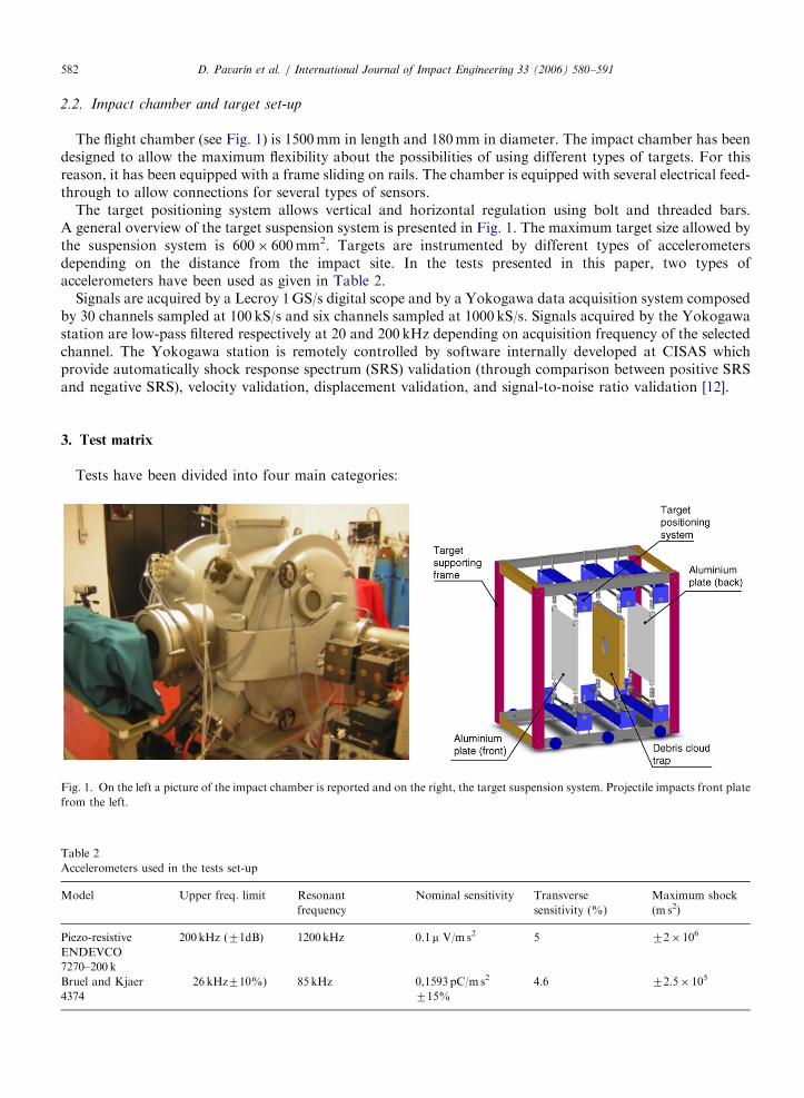
The flight chamber (see Fig. 1) is 1500mm in length and 180mm in diameter. The impact chamber has beendesigned to allow the maximum flexibility about the possibilities of using different types of targets. For thisreason, it has been equipped with a frame sliding on rails. The chamber is equipped with several electrical feed-through to allow connections for several types of sensors.
The target positioning system allows vertical and horizontal regulation using bolt and threaded bars.A general overview of the target suspension system is presented in Fig. 1. The maximum target size allowed bythe suspension system is 600� 600mm2. Targets are instrumented by different types of accelerometersdepending on the distance from the impact site. In the tests presented in this paper, two types ofaccelerometers have been used as given in Table 2.
Signals are acquired by a Lecroy 1GS/s digital scope and by a Yokogawa data acquisition system composedby 30 channels sampled at 100 kS/s and six channels sampled at 1000 kS/s. Signals acquired by the Yokogawastation are low-pass filtered respectively at 20 and 200 kHz depending on acquisition frequency of the selectedchannel. The Yokogawa station is remotely controlled by software internally developed at CISAS whichprovide automatically shock response spectrum (SRS) validation (through comparison between positive SRSand negative SRS), velocity validation, displacement validation, and signal-to-noise ratio validation [12].
3. Test matrix
Tests have been divided into four main categories:
Fig. 1. On the left a picture of the impact chamber is reported and on the right, the target suspension system. Projectile impacts front plate
from the left.
Table 2
Accelerometers used in the tests set-up
Model Upper freq. limit Resonant
frequency
Nominal sensitivity Transverse
sensitivity (%)
Maximum shock
(m s2)
Piezo-resistive
ENDEVCO
7270–200 k
200kHz (71dB) 1200kHz 0.1 m V/m s2 5 72� 106
Bruel and Kjaer
4374
26 kHz710%) 85 kHz 0,1593 pC/m s2
715%
4.6 72.5� 105

ARTICLE IN PRESSD. Pavarin et al. / International Journal of Impact Engineering 33 (2006) 580–591 583
1.
Preparatory tests: These are performed to tune the facility set-up, to identify the background noise and todefine the expected acceleration range on different zones of the target to eventually optimize the signal-to-noise ratio in the following tests campaigns. They are a total of 42 shots.2.
Tests on simplified targets: The aim of this group of tests is to acquire knowledge in shock propagation, toidentify the type of waves traveling on different zones of the target, to identify the relationship betweenvibration fields and impact conditions and to tune numerical models. The total number of tests in this frameis 56.3.
Tests on complex targets aiming to provide information on wave propagation through spacecraft (S/C)structural joints, to identify transfer functions of elementary structural components and to tune numericalmodels on complex assemblies. The total number of experiments on this group is 52 hypervelocity tests and24 hammer tests.4.
Momentum transfer, aiming at measuring on different panels the momentum transferred by HVI. The totalnumber of tests in this frame is 6.At the moment, preparatory tests have been partially completed and results will be presented and discussedin the following.
4. Preparatory tests
Preparatory tests are divided into two main groups. Both of them have been completed.
–
Identification of background noise: these experiments are intended to analyze each source of backgroundnoise inside the impact chamber and to qualify its effect on the determination of the vibration environmentinduced by hypervelocity impacts. This point is fundamental to evaluate the uncertainty on accelerationmeasurements.–
Preliminary assessment of the vibration environment induced by hypervelocity impacts on simplealuminum panels, honeycomb panels and complex targets, as a function of projectile velocity and mass toidentify the instrumentation requirements.4.1. Identification of the background noise
Since the execution of impact tests is always associated with significant undesired vibrations, the necessitywas recognized, as a fundamental step, to assess and possibly reduce the interfering inputs that build up thebackground noise environment of the impact facility. This is helpful to increase the signal-to-noise ratio, tosimplify the analysis of data and to identify the uncertainty in acceleration measurements. The backgroundnoise environment is particularly relevant for measurement taken far away form the impact site, where thevibration environment is attenuated by the distance and by joints.
The main sources of the background noise were theoretically identified and analyzed separately, throughdedicated experiments. The test set-up was the same used during real impact tests, but operation sequencesand conditions were changed in order to separate the different effects. Moreover, the gun was always operatedat working conditions normally used to accelerate a 2mm aluminum projectile at 5 km/s. The following issueshave been analyzed.
–
Shocks due to gun operations, generated during the gun shooting phase and propagating through thevacuum chamber structure. During the shooting phase, the structure undergoes strong impulsive loads,which have been measured to be in the order of millions of Newtons with a frequency content of a few kHz.This force impulse could propagate through the vacuum chamber walls and through the ground, finallydisturbing the target.–
Shocks generated by sabots impacting onto their sabot stopper: polycarbonate sabots fingers carry arelevant momentum since each of them weight the same as the largest aluminum sphere launched (2.3mmdiameter aluminum sphere) and almost two order of magnitude more than the smallest (0.6mm diameter
ARTICLE IN PRESSD. Pavarin et al. / International Journal of Impact Engineering 33 (2006) 580–591584
aluminum sphere) and flies almost at the same speed. Hence, the shock transmitted to the stopper plate bythe sabot can propagate through the structure to the target.
–
Electromagnetic signals due to gun operation, and hypervelocity phenomena. – Acoustic disturbances due to expansion of propellant inside the vacuum chamber: high-pressure, high-temperature hydrogen expanding from the launch tube outlet could produce shock waves generating anacoustic environment coupled with the target.–
Shocks due to impact of the debris cloud onto the target support structure. In case of complex targets, thedebris cloud generated from the perforation of the first bumper is arrested by, a debris trap to avoid impactagainst other parts of the target (see Fig. 1). However, the impacted plate and the protection plate cantransfer vibrations to the target, through its suspension arrangements. Moreover, the expansion of thedebris cloud itself and the vibration field induced onto the protection system can cause acousticdisturbances, which could perturb the target.4.2. Experimental analysis of the background environment
All the tests described below have been conducted using Bruel & Kjaer 4374 accelerometers. The amplifiersand the data acquisition system have been set-up to achieve a background noise of the measurement chainlower than 20m/s2. Acceleration data have been high-pass-filtered at 100Hz according to standard proceduresapplied on Pyro-shock testing [5]. The target is a 500� 500� 2mm3 aluminum 2024–81 plate. Sensors arelocated on the diagonal of the plate 300mm away from the center, which is also centered on the line of fire ofthe gun. Data have been acquired with a Lecroy 1GS/s scope running at 5MS/s.
4.2.1. Electromagnetic signals
Electromagnetic signals due to gun operations are below the background noise of the measurement chain.Electromagnetic interference due to the hypervelocity impact cannot be considered part of the backgroundenvironment since it is not repetitive and is very dependent on the test condition and on the set-up of themeasurement chain. Electromagnetic interferences due to the hypervelocity phenomena are analyzed for eachexperiment through free hanged accelerometers inside the impact chamber.
4.2.2. Shock due to gun operation
The gun was operated with the launch tube mechanically sealed in a way that disturbances were due only tomechanical vibrations propagating either through the ground or the vacuum chamber walls. Five experimentshave been conducted operating the gun at the same nominal performances correspondent to a 5 km/s shot. Nosignals have been detected higher than the background noise of the measurement chain.
4.2.3. Shock generated by sabots hitting the sabot stopper
Experiments have been conducted shooting sabots at 5 km/s with no projectile inside. Moreover, the flightchamber was mechanically sealed from the impact chamber thus avoiding any kind of acoustic transmissionthrough the atmosphere. The flight chamber was left at 0.1 kPa. In this way, the acceleration inputs were dueonly to the shock induced by sabots onto the stopper plate, propagating through the vacuum chamber walland the target support to the target itself. Five experiments have been performed. Experimental results arepresented in Fig. 2 for the average SRS and the standard deviation.
4.2.4. Acoustic disturbances due to expansion of propellant inside the vacuum chamber
Tests have been completed using nothing but gas at performances corresponding to a 5 km/s shot. The flightand vacuum chamber were connected as in normal gun operation. The pressures inside the flight and impactchamber were 7 kPa of inert gas. Five tests were performed using the gun at nominal conditions. Theacceleration inputs were due only to the impact of the hydrogen propellant onto the target and due to theacoustic environment induced by the hydrogen propellant expansion inside the vacuum chamber.Experimental results are presented in Fig. 3 for the average SRS and the standard deviation. Some

ARTICLE IN PRESS
Fig. 2. Shock response spectra calculated from acceleration measured on the target located inside the impact chamber due to impact of
sabot fingers onto the stopper plate located inside the flight chamber.
Fig. 3. Shock response spectra calculated from acceleration measured on the target located inside the impact chamber due the expansion
of the hydrogen propellant injected by the gun inside the flight chamber.
D. Pavarin et al. / International Journal of Impact Engineering 33 (2006) 580–591 585
modifications have been then implemented to reduce the acoustic noise. A substantial reduction of this hasbeen obtained especially below 1 kHz (see Fig. 4).
4.2.5. Noise due to debris clouds development
The experiment has been set-up as showed in Fig. 1 using two AL 2024–81 500� 500mm platesmechanically uncoupled and separated by the debris stopper device. Only the second, not impacted plate wasinstrumented. The acceleration measured was related to the background environment characterized on theprevious tests plus the vibrations transmitted through the target support system and the acoustic environmentgenerated inside the impact chamber by the debris cloud expansion.
Tests have been conducted operating the gun on the same nominal conditions needed to accelerate aprojectile for a 5 km/s shot. Two sets of tests have been performed:
(I)
With a pressure inside the impact chamber of 0.1 kPa shooting a 70mg plastic cylinder at 5 km/s. This testconfiguration minimized the acoustic environment inside the impact chamber due to the expansion of thedebris cloud. Three tests have been performed.
ARTICLE IN PRESS
Fig. 4. Shock response spectra calculated from acceleration measured on the target located inside the impact chamber due to the
expansion of the hydrogen propellant injected by the gun inside the improved flight chamber.
Fig. 5. Shock response spectra calculated from acceleration measured on the back target located inside the impact chamber showing the
vibration environment due to the impact of the debris cloud onto the debris stopper plate with no acoustic effect (vacuum chamber was
evacuated down to 0.1 kPa).
D. Pavarin et al. / International Journal of Impact Engineering 33 (2006) 580–591586
(II)
With a pressure inside the vacuum chamber of 7 kPa (nominal pressure), shooting a 70mg plasticprojectile at 5 km/s. This configuration is much closer to the real test configuration even if the debris cloudis in this case larger.Comparison between these two tests allowed for the identification of the vibration componentdue to propagation through the target support system and due to the debris cloud expansion.Plastic cylinders were used in these tests since the pressure of 0.1 kPa did not allow for sabotseparation. These tests overestimated the component of the background environment under investigation,since the debris cloud was generated by a cylinder 3 times heavier than the largest sphere launched.However, they provide an assessment of the maximum disturbance level. Results of group (1)are presented through the average SRS and the standard deviation in Fig. 5, results of group (2) arepresented in Fig. 6.
ARTICLE IN PRESS
Fig. 6. SRS calculated from acceleration measured on the back target located inside the impact chamber showing the vibration
environment due to the impact of the debris cloud onto the debris stopper plate, including effects of the acoustic disturbances due to the
debris cloud (vacuum chamber pressure was 7 kPa of inert gas).
Fig. 7. Average SRS and standard deviation of the global background noise for a simple target on the left: the in-plane component; on the
right: the out-of-plane component.
D. Pavarin et al. / International Journal of Impact Engineering 33 (2006) 580–591 587
4.2.6. Combined background noise
The global background environment can be calculated combining together all the sources analyzed below orperforming dedicated tests to assess it globally. The first procedure provides an insight on the backgroundenvironment; the second procedure is followed each time some modification is applied to the experimental set-up. In the following, the global background noise determined for simple targets and a complex target throughdedicated experiments is presented. In the case of simple targets, the experiment consists of shooting a sabotwith no projectile inside and measuring the vibration level on the target. In the case of complex targets, theexperiment is done shooting an aluminum sphere (the biggest for the type of experiment planned) on a faketarget and measuring the vibration levels on the real target which is behind the impacted target but protectedby the debris cloud device, as for example presented in Fig. 1. Results are presented in Figs. 7 and 8 for simpleplate configuration and complex target configuration.
ARTICLE IN PRESS
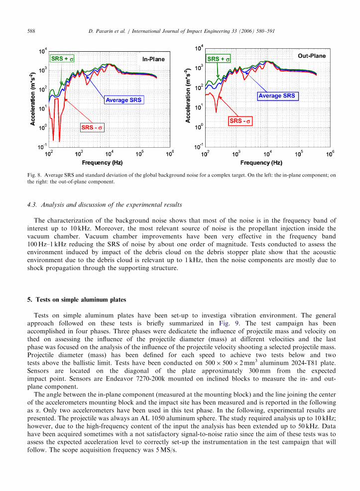
Fig. 8. Average SRS and standard deviation of the global background noise for a complex target. On the left: the in-plane component; on
the right: the out-of-plane component.
D. Pavarin et al. / International Journal of Impact Engineering 33 (2006) 580–591588
4.3. Analysis and discussion of the experimental results
The characterization of the background noise shows that most of the noise is in the frequency band ofinterest up to 10 kHz. Moreover, the most relevant source of noise is the propellant injection inside thevacuum chamber. Vacuum chamber improvements have been very effective in the frequency band100Hz–1 kHz reducing the SRS of noise by about one order of magnitude. Tests conducted to assess theenvironment induced by impact of the debris cloud on the debris stopper plate show that the acousticenvironment due to the debris cloud is relevant up to 1 kHz, then the noise components are mostly due toshock propagation through the supporting structure.
5. Tests on simple aluminum plates
Tests on simple aluminum plates have been set-up to investiga vibration environment. The generalapproach followed on these tests is briefly summarized in Fig. 9. The test campaign has beenaccomplished in four phases. Three phases were dedicatete the influence of projectile mass and velocity onthed on assessing the influence of the projectile diameter (mass) at different velocities and the lastphase was focused on the analysis of the influence of the projectile velocity shooting a selected projectile mass.Projectile diameter (mass) has been defined for each speed to achieve two tests below and twotests above the ballistic limit. Tests have been conducted on 500� 500� 2mm3 aluminum 2024-T81 plate.Sensors are located on the diagonal of the plate approximately 300mm from the expectedimpact point. Sensors are Endeavor 7270-200k mounted on inclined blocks to measure the in- and out-plane component.
The angle between the in-plane component (measured at the mounting block) and the line joining the centerof the accelerometers mounting block and the impact site has been measured and is reported in the followingas a. Only two accelerometers have been used in this test phase. In the following, experimental results arepresented. The projectile was always an AL 1050 aluminum sphere. The study required analysis up to 10 kHz;however, due to the high-frequency content of the input the analysis has been extended up to 50 kHz. Datahave been acquired sometimes with a not satisfactory signal-to-noise ratio since the aim of these tests was toassess the expected acceleration level to correctly set-up the instrumentation in the test campaign that willfollow. The scope acquisition frequency was 5MS/s.

ARTICLE IN PRESS
Fig. 10. In-plane and out-plane SRS measured on 500� 500� 2mm3 aluminum plate with a 1mm aluminum projectile at different
velocities in the frequency band 100Hz–50kHz/h is the distance between the impact site and the center of the accelerometers mounting
block, a is the angle between the in-plane component (measured at the mounting block) and the line joining the center of the
accelerometers mounting block and the impact site. P: perforation; NP: no perforation.
Fig. 9. General overview of tests conducted on simple aluminum plates. Dots represent tests, the number represents the tests identification
number F is the internal diameter of the hole in mm, v is the measured speed in km/s.
D. Pavarin et al. / International Journal of Impact Engineering 33 (2006) 580–591 589
5.1. Influence of impact velocity
The influence of the impact velocity has been investigated by shooting a 1mm aluminum projectile at 2.5,2.9, 4.2, 5.1 km/s. Comparisons between SRS are prevented in Fig. 10.
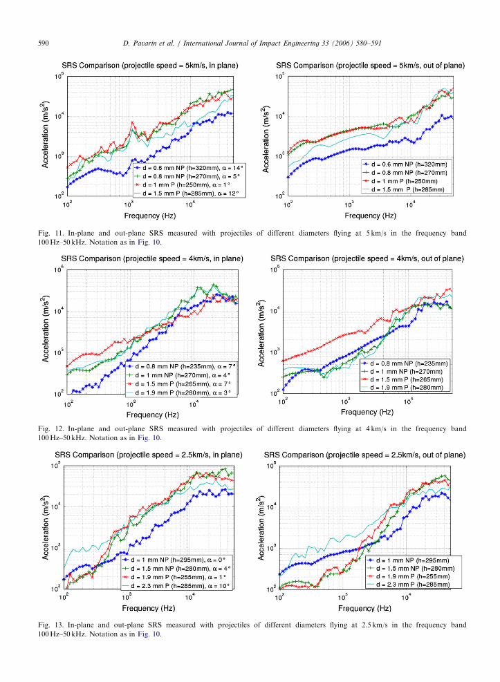
5.2. Influence of projectile mass
In the following, the measured SRS from tests conducted shooting two projectiles below the ballistic limitsand two projectiles over the ballistic limit, at velocities 2.5, 4, 5 km/s are reported in Figs. 11–13.
ARTICLE IN PRESS
Fig. 11. In-plane and out-plane SRS measured with projectiles of different diameters flying at 5 km/s in the frequency band
100Hz–50 kHz. Notation as in Fig. 10.
Fig. 12. In-plane and out-plane SRS measured with projectiles of different diameters flying at 4 km/s in the frequency band
100Hz–50 kHz. Notation as in Fig. 10.
Fig. 13. In-plane and out-plane SRS measured with projectiles of different diameters flying at 2.5 km/s in the frequency band
100Hz–50 kHz. Notation as in Fig. 10.
D. Pavarin et al. / International Journal of Impact Engineering 33 (2006) 580–591590
ARTICLE IN PRESSD. Pavarin et al. / International Journal of Impact Engineering 33 (2006) 580–591 591
6. Conclusions
The experimental analysis on the impact facility background environment has been conducted. Thecharacterization of the background noise shows that most of the noise is in the frequency band of interest upto 10 kHz. However, a comparison between SRS of background noise and SRS measured during hypervelocityimpact shows that signal and noise are of the same order of magnitude only around 100Hz, and then the SRSof noise is between 1 and 2 orders of magnitude less than the signal measured during the impact. Comparisonbetween background environment and the vibration environment induced by hypervelocity impact shows thatthe background noise could be relevant for accelerometers located far away from the impact site, where mostof the high-frequency components will be cut-off by joints. Finally, tests have been conducted to assess thedependency of shock conditions from the impact conditions aiming to tune the experimental set-up and tooptimize the signal-to-noise ratio. Trends generally indicate complex dependence from projectile velocity andmass due to the superposition of phenomena having different influence on the acceleration field. In fact, themomentum carried by the projectile changes linearly with projectile’s speed and mass but the momentumtransferred to the target has non-linear dependence from impact conditions. Finally, the acceleration field isaffected by wave reflections onto the target edges whose intensity depends on the momentum transferred tothe target and the damping factor of the material. The way these phenomena combine to determine theacceleration field will be subject of future investigation.
References
[1] CNES activity report at the 19th IADC meeting DLR March 22–23, 2001, Cologne-Porz, Germany.
[2] Pavarin D, Francesconi A, Debei S, Caporal G. Preliminary design of a test bed to evaluate the requirements of an accelerometric
instrumentation to study the effects of hypervelocity impacts on space shields. Proc. mechanical measurements conference, Abano
Terme, Italy, 2002, pp. 200–6, Universita degli Studi di Padova.
[3] Prosser WH, Gorman MR, Humes DH. Acoustic emission signal in thin plates produced by impact damage. J Acoust Emission
1999;17(1–2):29–36.
[4] Prosser WH. Application of advanced, waveform based AE techniques for testing composite material. SPIE conf. on nondestructive
evaluation technique for aging infrastructure and manufacturing: material and composites, Scottsdale, Arizona, 3 December 1996
published by SPIE on volume 2944 pp. 146–53.
[5] NASA technical standard pyroshock test criteria, NASA-STD-7003, 1999.
[6] Pavarin D, Lambert L, Francesconi A, Destefanis R, Bettella A, Debei S, De Cecco M, Faraud M, Giacomuzzo C, Marucchi-Chierro
PC, Parzianello G, Saggin B and Angrilli F. Analysis of GOCE’s disturbances induced by hypervelocity impact. 4th European
conference on space debris, Darmstadt, 18–20 April 2005. ESA SP-587 pp. 437–45, August 2005, Editor: D. Dansey ESA Publications
Division published and distributed by: ESA Publications Division
[7] Faraud M. Meteoroids and debris environment analysis for disturbance assessment on the gradiometer. Alenia internal report
GO-TN-AI-0092, Issue 01, 30 July 2002.
[8] Faraud M. Disturbances induced by MMOD impacts. Alenia internal report GO-TN-AI-0099, Issue 01, 20 May 2003.
[9] Angrilli F, Pavarin D, De Cecco M, Francesconi A. Impact facility based upon high frequency two stage light-gas gun. Acta Astron
2003;53:185–9.
[10] Pavarin D, Francesconi A. Improvement of the CISAS high-shot-frequency light-gas-gun. Int J Impact Eng 2003;29:549–62.
[11] ISO Guide to the expression of uncertainty in measurement (GUM), 1994.
[12] Piersol AG. Pyroshock recommendations in proposed MIL-HDBK on guidelines for dynamic data acquisition and analysis. J IES
1992;35(5):21–6.