3D visualization of spacecraft dynamics
17
3D visualization of spacecraft dynamics Introduction to MATLAB Simulink 3D animation toolbox
-
Upload
khangminh22 -
Category
Documents
-
view
0 -
download
0
Transcript of 3D visualization of spacecraft dynamics

3D visualization of spacecraft dynamics
Introduction to MATLAB Simulink 3D animation toolbox
Contents
• Why it is very useful?
• MATLAB Simulink and its 3D animation toolbox
• Basic knowledge to take into account
• Flowchart for the development of a virtual simulator
• Simulation of orbital dynamics
• Simulate of attitude dynamics

Why it is very useful?
3D visualization helps to improve the understanding of the spacecraft’s dynamics
Orbital elements
Two-line orbital elements:
• Right ascension of ascending
node (Ω)
• Inclination (i)
• Eccentricity (e)
• Argument of perigee ω)
• Mean anomaly (M)
• Mean motion (n)
Why it is very useful?
3D visualization helps to improve the understanding of the spacecraft’s dynamics
Attitude of a body expressed in Euler angles

Why it is very useful?
3D visualization helps to improve the understanding of the spacecraft’s dynamics
Attitude of a body expressed in Euler angles
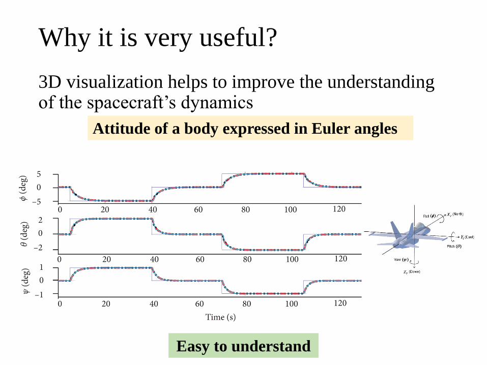
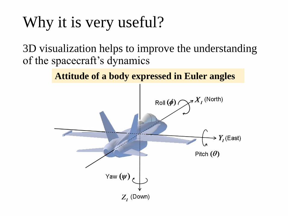
Why it is very useful?
3D visualization helps to improve the understanding of the spacecraft’s dynamics
Attitude of a body expressed in Euler angles
Easy to understand

Why it is very useful?
3D visualization helps to improve the understanding of the spacecraft’s dynamics
Attitude of a body expressed in quaternions

Why it is very useful?
3D visualization helps to improve the understanding of the spacecraft’s dynamics
Attitude of a body expressed in quaternions

Why it is very useful?
3D visualization helps to improve the understanding of the spacecraft’s dynamics
qs
qx
qy
qz
Attitude of a body expressed in quaternions

Why it is very useful?
3D visualization helps to improve the understanding of the spacecraft’s dynamics
Attitude of a body expressed in quaternions
qs
qx
qy
qz
Difficult to understand

MATLAB Simulink and its 3D animation toolbox
Simulink 3D animation toolbox allows the connection
between a physical model and a 3D virtual
environment

MATLAB Simulink and its 3D animation toolbox
Elements required: Connection between the model
and the virtual environmentSimulink model
Virtual
environment
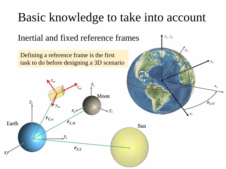
Basic knowledge to take into account
Inertial and fixed reference frames
Defining a reference frame is the first
task to do before designing a 3D scenario

Basic knowledge to take into account
Inertial and fixed reference frames
Objects placed in a tree
diagram
Preview of the virtual
scenario
Parameters or
comments from each
object
X axis
Y axis
Z axis

Flowchart for the development of a virtual simulator
Create your 3D objects and save them in .wrl
Import them into MATLAB 3D World Editor
Customize the properties of each 3D objects
Create a MATLAB Simulink file
Implement your physical models (orbit and/or
attitude dynamics
Create a link between the physical model and
the 3D scenario
Verify the behavior of your 3D model during the simulations
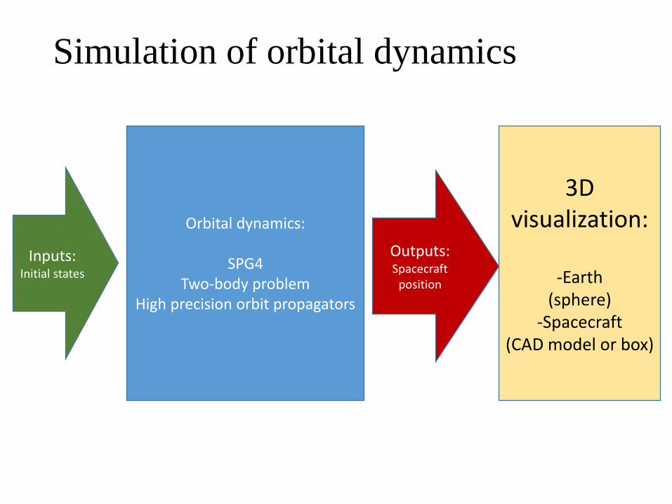
Simulation of orbital dynamics
Orbital dynamics:
SPG4Two-body problem
High precision orbit propagators
Inputs:Initial states
Outputs:Spacecraft
position
3D visualization:
-Earth(sphere)
-Spacecraft(CAD model or box)

Simulation of attitude dynamics
Attitude dynamics:
• Rigid body dynamics model• Attitude representation:
- Euler angles- Quaternions
Inputs:Initial statesMoment of
inertia
Outputs:Spacecraft
attitude
3D visualization
Spacecraft (CAD model or box)