A finite element solution procedure for porous medium with fluid flow and electromechanical coupling
12
COMMUNICATIONS IN NUMERICAL METHODS IN ENGINEERING Commun. Numer. Meth. Engng, 14, 381-392 (1998) A FINITE ELEMENT SOLUTION PROCEDURE FOR POROUS MEDIUM WITH FLUID FLOW AND ELECTROMECHANICAL COUPLING MILOS KOJIC,I* NENAD FILIPOVIC,1 SNEZANA VULOVICI AND SRBOLJUB MIJAILOVIC 2 IFaculty of Mechanical Engineering, University of Kragujevac, 34000 Kragujevac, Serbia, Yugoslavia 2Harvard School of Public Health, Cambridge, MA 02139, U.S.A. SUMMARY We consider a coupled problem of the deformation of a porous solid, flow of a compressible fluid and the electrical field in the mixture. The governing equations consist of balance of the linear momentum of solid and of fluid, continuity equations of the fluid and current density, and a generalized form of Darcy's law which includes electrokinetic coupling. The compressibility of the solid and the fluid are taken into account. We transform these equations to the corresponding finite element relations by employing the principle of virtual work and the Galerkin procedure. The nodal point variables in our general formulation are dis- placements of solid, fluid pore pressure, relative velocity of the fluid and electrical potential. Derivation of the FE equations is presented for small displacements and elastic solid, which can further be generalized to large displacements and inelastic behaviour of the solid skeleton. According to this formulation we can include general boundary conditions for the solid, relative velocity of the fluid, fluid pressure, current density and electrical potential. The dynamic-type non-symmetric system of equations is solved through the Newmark procedure, while in the case of neglect of inertial terms we use the Euler method. Numerical examples, solved by our general-purpose FE package PAK, are taken from biomechanics. The results are compared with those available in the literature, demonstrating the correctness and generality of the procedure presented. © 1998 John Wiley & Sons, Ltd. KEY WORDS porous medium; fluid flow; electromechanical coupling; FEM 1. INTRODUCTION Finite element solution procedures of coupled problems, which include deformation of solid and 5 fluid flow through a porous medium, have been the subject of investigation of many authors. 1 - Implementation of these methods has been directed to geomechanics and to biomechanics. Many important practical problems such as settlement of foundation under loading and with water flow through porous solid skeletons have been solved numerically, confirming the correctness of the theoretical basis and numerical (FE) procedures. Application of the FE analysis to these coupled problems in biomechanics is still in the development phase. Various approaches have been adopted, starting basically from the same fundamental equations, in formulation of the governing relations for flow through porous deformable media. * Correspondence to: Milos Kojic, Faculty of Mechanical Engineering, University of Kragujevac, 34000 Kragujevac, Serbia, Yugoslavia. CCC 1069-8299/98/040381-12$17·50 Received 17 January 1997 © 1998 John Wiley & Sons, Ltd. Accepted 10 November 1997
-
Upload
independent -
Category
Documents
-
view
3 -
download
0
Transcript of A finite element solution procedure for porous medium with fluid flow and electromechanical coupling

COMMUNICATIONS IN NUMERICAL METHODS IN ENGINEERING Commun Numer Meth Engng 14 381-392 (1998)
A FINITE ELEMENT SOLUTION PROCEDURE FOR POROUS MEDIUM WITH FLUID FLOW AND
ELECTROMECHANICAL COUPLING
MILOS KOJICI NENAD FILIPOVIC1 SNEZANA VULOVICI AND SRBOLJUB MIJAILOVIC2
IFaculty of Mechanical Engineering University of Kragujevac 34000 Kragujevac Serbia Yugoslavia 2Harvard School of Public Health Cambridge MA 02139 USA
SUMMARY
We consider a coupled problem of the deformation of a porous solid flow of a compressible fluid and the electrical field in the mixture The governing equations consist of balance of the linear momentum of solid and of fluid continuity equations of the fluid and current density and a generalized form of Darcys law which includes electrokinetic coupling The compressibility of the solid and the fluid are taken into account We transform these equations to the corresponding finite element relations by employing the principle of virtual work and the Galerkin procedure The nodal point variables in our general formulation are disshyplacements of solid fluid pore pressure relative velocity of the fluid and electrical potential Derivation of the FE equations is presented for small displacements and elastic solid which can further be generalized to large displacements and inelastic behaviour of the solid skeleton
According to this formulation we can include general boundary conditions for the solid relative velocity of the fluid fluid pressure current density and electrical potential The dynamic-type non-symmetric system of equations is solved through the Newmark procedure while in the case of neglect of inertial terms we use the Euler method
Numerical examples solved by our general-purpose FE package PAK are taken from biomechanics The results are compared with those available in the literature demonstrating the correctness and generality of the procedure presented copy 1998 John Wiley amp Sons Ltd
KEY WORDS porous medium fluid flow electromechanical coupling FEM
1 INTRODUCTION
Finite element solution procedures of coupled problems which include deformation of solid and 5fluid flow through a porous medium have been the subject of investigation of many authors 1shy
Implementation of these methods has been directed to geomechanics and to biomechanics Many important practical problems such as settlement of foundation under loading and with water flow through porous solid skeletons have been solved numerically confirming the correctness of the theoretical basis and numerical (FE) procedures Application of the FE analysis to these coupled problems in biomechanics is still in the development phase
Various approaches have been adopted starting basically from the same fundamental equations in formulation of the governing relations for flow through porous deformable media
Correspondence to Milos Kojic Faculty of Mechanical Engineering University of Kragujevac 34000 Kragujevac Serbia Yugoslavia
CCC 1069-829998040381-12$17middot50 Received 17 January 1997 copy 1998 John Wiley amp Sons Ltd Accepted 10 November 1997
382
I ~
M KOJIC ET AL
There are differences in some details related to compressibility of solid material In our formulashytion we follow approach of Lewis 1 In transformation of the basic relations to the FE formulashytion some authors use displacements of solid and fluid pressure as the nodal point variables (u-p formulation) like Lewis l and Siriwardane2 leading to a symmetrical system of equations Simon3 proposes two formulations (i) displacements of solid and relative displacements of fluid - with a symmetric system and (ii) u-p formulation - with a non-symmetric system Gaj0 4 uses displacements of solid and fluid and pressure with a symmetric system of equations Small displacements are considered in References 1-4 with material non-linearity of the solidI2 while in Reference 5 a large displacement formulation is given
In our presentation we give in some detail the derivation of dynamic FE equations for small displacements and linear material behaviour following Simon et al3 and Lewis et al for the fluid continuity equation This approach relies on the balance of the linear momentum of solid and fluid and the continuity of fluid which takes into account the compressibility of solid and of fluid The paper represents a generalization of the approach given in Kojic et al6 We include electrokinetic coupling by using linearized electrokinetics and a continuity equation for the current density according to References 7 and 8 From the electrokinetic coupling follows a correction of the equation of balance of linear momentum for fluid
The above formulation is suitable for general use since we can implement all boundary conditions appearing in the applications boundary conditions for solid relative fluid velocity given current density and electrical potential
In the next Section we summarize the fundamental equations of the coupled problem described above and then in Section 3 we derive the basic FE equations for linear dynamics In Section 4 some typical numerical examples from biomechanics are presented and finally we give some concluding remarks in Section 5
2 FUNDAMENTAL EQUATIONS
We present here the fundamental equations supposing first that displacements of the solid are small which represent the basis for the FE formulation in Section 3 The assumptions are that the solid is linear elastic with compressible material of the skeleton and that the fluid is comshypressible Also we consider the dynamic problem and take into account inertial forces of the solid and the fluid We first present all governing equations in the case when there is no electroshykinetic coupling and then give corrections due to this effect
The balance equation of the solid in the case of no electric coupling can be written in the form
(1 - n)LT (Js + (1 - n)psb + k-1nq - (1 - n)psii == 0 (1)
where (Js is stress in the solid phase n is porosity k is the permeability matrix Ps is the density of the solid b is the body force per unit mass q is the relative velocity of the fluid ii is the acceleration of the solid material and LT is the differential operator
The balance equation of the fluid phase (no electrokinetic coupling) is
-nVp + nprb - k-1nq - nprvr == 0 (2)
Commun Numer Meth Engng 14 381-392 (1998) copy 1998 John Wiley amp Sons Ltd
383 A FINITE ELEMENT SOLUTION PROCEDURE
where p is the pore fluid pressure Pr is the density of the fluid and vr is the acceleration of the fluid This equation is also known as the generalized Darcy law Both equilibrium equations are written per unit volume of the mixture Combining equations (1) and (2) we obtain
L T
(J + pb - pii - PrCt == 0 (3)
where (J is the total stress which can be expressed in terms of (Jsand p as
(J == (1 - n)(Js - nmp (4)
and p == (1 - n)ps + nPr is the density of mixture Here m is a constant vector defined as mT == Ill 0 0 O to indicate that the pressure contributes to normal stresses only Also we have taken into account that the pressure has a compressive character while tensional stresses and strains are considered positive In further analysis we use the effective stress (J defined as
(J == (J + mp (5)
which is relevant for the constitutive relations of the solid Using the definition of relative velocity q as the volume of fluid passing in unit time through unit area of the mixture (also called the Darcy velocity) ie
q == n(vr - 0) (6)
we transform (3) to a form
k-I 0 Prmiddot 0 - Vp + Prb - q - Pro - -q == (7) n
The next fundamental equation is the constitutive relation of the solid
E((J == C e - e ) (8)p
where CE is the elastic constitutive matrix of the solid skeleton e is total strainmiddot and e p is the deformation of the solid material due to pressure1
m (9)ep == - 3K P
s
Here Ks is the bulk modulus of the solid grains Now we write the continuity equation for the fluid which takes into account the compressshy
ibilities of the solid and fluid as well as the elastic constitutive law for the solid skeleton I
T (T mTCE) (1 - n n mTcEm) 0Vq+ m --_ e+ --+-- 2 p== (10)3Ks Ks Kr 9~
Now we c0nsider electrokinetic coupling The basic relations which encompasses both Ohms and Darcys laws as special cases are
~ == [ -kll k I2 ] Vp (11) J V4Jk21 -k22
copy 1998 John Wiley amp Sons Ltd Commun Numer Meth Engng 14 381-392 (1998)
384
iC
~
M KOJIC ET AL
where cent is the electrical potential k ll is the (short-circuit) Darcy hydraulic permeability k 22 is the electrical conductivity and k l2 and k21 are electrokinetic coupling coefficients that are equal by Onsager reciprocity according to References 7 and 8 Next we generalize the equation of balance of linear momentum for the fluid (7) to include electrokinetic coupling The resistance force Fw
for the fluid follows from the first equation of system (11)
Fw == -k~q +k~kI2Vcent (12)
and the equation of balance of linear momentum (8) now changes to
t7 b k- I k-Ik t7~ bullbull Prmiddot 0-vP+Pr - llq+ II 12 v lfJ-Pru --q== (13) n
Note that this equation corresponds to isotropic conditions of the solid skeleton and represents a form of the generalized Darcy law
Finally we can use the continuity equation for the current density in the form
VTj == 0 (14)
Substituting the current density j from the second equation of system (11) into (14) we obtain
T Tk21 V Vp - Vcent == 0 (15)k22V
3 DERIVATION OF FINITE ELEMENT EQUATIONS
In this Section we transform the fundalnental relations of Section 2 into the finite element equations We present derivations assuming small displacements of solid and elastic material These equations can be generalized to large displacements of the solid and inelastic deformation
12of the material by a standard procedure9shy
First by employing the principle of virtual work and supposing that the material is elastic from equation (4) we obtain the following equation
[beTCEe dV+ [beT(~~ - m)p dV + [bUTpii dV + [bUTPrq dV
= [bUTpb dV +i buTt dA (16)
Next in the case of electrokinetic coupling we multiply equation (13) by the interpolation matrix H~ for the relative velocity of fluid q and integrate over the finite element volume according to the Galerkin method The resulting equation is
T -I T T T- lv H qVp dV - k ll k 12 lv H qV4J dV + lv HqPrb dV - k ll lv Hqq dV
- rH T Prii dV - rH T Pr it dV = 0 (17)Jv q Jv q n
Commun Numer Meth Engng 14381-392 (1998) copy 1998 John Wiley amp Sons Ltd
385 A FINITE ELEMENT SOLUTION PROCEDURE
Further we multiply the continuity equation (10) by the interpolation matrix U~ for pressure (which is vector-column) and obtain
E
1UTVT dV 1HT ( T - mTC ) dV 1U T(1 - n - - mTcEm) dV == 0 (18) p q + p m 3K e + p K + K 9K2 P
V V s V s f s
Finally we multiply the continuity equation (10) by the interpolation matrix U~ for electrical potential and integrate over the volume V
T T T T k 21 Jv H V Vp dV - k 22 Jv H V V4J dV = 0 (19)
Note that (usually) in practical applications interpolation functions for displacements H u and for relative velocities H q are quadratic while Up for pressure and Hltfgt for electrical potential are linear
We employ the standard procedure of integration over the element volume in equations (16)shy(19) and use the Gauss theorem The resulting FE system of equations is
l muu 0 0 0ll I r 0 0 Cuq
0 0 0 o I I I I cpu Cpp 0 i
m 0 0 0 0 0 Cqqqu
0 0 00 0 0 0 J I~l +
fk k 0 0 uu up u
f0 0 k 0pq pI (20)-+1
f0 k kqp qq kqltfgt q~
0- 0 fltfgtk4gtp kltfgtltfgt ~
The matrices and vectors in this equation are
muu = [H~PHu dV mqu = [ H~PrHu dV
E T 1 T 1 T( T mTC )Cuq = mqu = v HuPrHq dV Cpu = - v Hp m - 3K B dV
s
( T(1 - n n mTcEm) C == HTPfU dVCpp = - Jv Hp ~ + K - 9K Hp dV qq lv q n qr
copy 1998 John Wiley amp Sons Ltd Commun Numer Meth Engng 14 381-392 (1998)
386
~~
M KOJIC ET AL
T E T T (CErn )kuu = Jv B C B dV kUp = Cpu = Jv B 3K - m Hp dV
s
kpq = [H~XHq dV kqp = [H~Hpx dV
kqq = [H~k-IHq dV kq = -kikl2 [ H~Hx dV
(21)
kq = k 21 [ H~xHqx d V k = -k22 [ H~xHx d V
( T Tfu = [H~Pb dV + i H~t dA fp = JA HpD q dA
f q = [H~Pfb dV f = i H~DTj dA
In these expressions n is the normal vector to the boundary and B is the strain-displacement transformation matrix
As we can see from (20) the nodal point variables are displacements of solid relative velocities q pressures p and electrical potential lJ Boundary conditions include general boundary conditions for the solid relative velocities SUrface pressures current densities and electric potential
The system of equations (20) is non-symmetrical in general In the case when inertial forces are neglected the system becomes symmetric A standard Newmark method can be employed for time integration of the system (20) as it is done in Reference 8 We note that in the case of no electrokinetic coupling we drop-out terms corresponding to the electric potential ~
4 NUMERICAL EXAMPLES
We give two typical examples from biomechanics and demonstrate that our results agree with those available in the cited references 13- IS
41 Example 1 One-dimensional electrokinetic transduction
We consider electrokinetic transduction in cartilage in one dimension Two transductions are analysed (i) mechanical-to-electrical and (ii) electrical-to-mechanical We impose on the top
1 displacement with amplitude Uo which elicits stress and electrokinetic response and 2 current density with amplitude Jowhich generates a mechanical response
Both the prescribed displacement and the current density have an oscillatory character as given in Figure l(a)
The cartilage is constrained at the bottom surface z == 0 by noflow no-displacement and impermeability with respect to currency also pressure p == 0 at z == h
CommunNumer Meth Engng 14381-392 (1998) copy 1998 John Wiley amp Sons Ltd
387 A FINITE ELEMENT SOLUTION PROCEDURE
Displacements and fluid velocities in the cartilage have an oscillatory character In Figures I(b) (c) and (d) we show distributions along the cartilage depth for various frequencies of excitation They are practically the same as those reported in Reference 15 obtained analytically and experimentally
42 Example 2 Cartilage subjected to current density
In this example we analyse the response of cartilage poroelastic material subjected to current density on the top surface according to the function8
Jy = Jo cos(2nxjA - rot)
E=ll MPa v=Ol k=3xI0middot 15 rn4Ns h=680 Jlrn 10= I Nm2
Uo=IO Jlm
1015 Ns 107 VS]b ll bl2 _ m4 m2
(b bJ -[ 10m107 lshyAm
Figure l(a) Caption on next page
---f=0001 bull f=001
h
u(t)=U ocos rot
10xlOmiddotS
f=01
80xlOmiddot ~
~ 6 u
i ~
60xIOmiddot
40xlOmiddot
A
i
ti
lOxIOmiddot
I 40xlOmiddot4
t 60xlOmiddot4
I 8 Oxl 04
Depth Figure 1(b) Caption on next page
copy 1998 John Wiley amp Sons Ltd Commun Numer Meth Engng 14 381-392 (1998)
bullbullbullbullbullbullbullbull bullbullbull bullbullbull bull bull bull bull bull bull bull bull bull bullbullbullbullbullbullbullbullbullbull bull
bull bull bull bull
bull bull bull bull
bullbull bullbull
388 M KOJIC ET AL
---f=O001 -middot-f=001 gtA f=O1
5xlOmiddot1
4xlOmiddot1
5 ~ shyI bull bull ~3xlOmiddot1sect Imiddot bull bull
t)
bullI bullbull bull bull bull~ 2xlOmiddot7 I bull bull
~ J bull bull bull r ~bullbull bullbull
lxlOmiddot1 4 middotpoundpound~~A~A~middot ~IIt AAipound4middot4AAc ApoundAAt~ampk~~ j bulla middot~middotk~ -I ~ ampi ~ ~A~ A44
o bull I I I ii
00 20xlOmiddot4 40xlOmiddot4 60xlOmiddot4 80xlOmiddot4
Depth Figure l(c)
---f=003 ---f=01 A f=O3
10xlOmiddotS middotmiddotXIIII UIxXXXmiddot -~--f=1 Y tt~ ~ y AA T A- bullbull
1 ~
~ ~ ~ bull bull ~ I80xlOmiddot9
Ji bull bull ~ A bull r bull bull bull ~t
I ~ bullbullbullbullbullbullbullbullbullbullbullbull - ~ ~ t) J r ~ bullbullbullbull bullbullbullbull ~ ~ ~60xlOmiddotg
0 J bull ~ A ~ bull bull ~ ~ gt I bull bull --
~ li =a 40xlOmiddotg
~ bull bull ~I ~ r bull bull bull ~
f l bull bull
j1 ~ ~~ ~~20xlOmiddot9
If I _ middotI~
~I ~
00 bull bull
00 20xlOmiddot4 4 Oxl 04 60xlOmiddot4 80xlOmiddot4
Depth
Figure led)
Figure l(a-d) One-dimensional electrokinetic transduction in cartilage (a) geometrical and material data (b) distribution of displacement amplitudes generated by displacement on top surface (c) distribution of displacement amplitudes generated by current density on top surface (d) distribution of fluid velocity amplitudes generated by current density
Commun Numer Meth Engng 14381-392 (1998) copy 1998 John Wiley amp Sons Ltd
389 A FINITE ELEMENT SOLUTION PROCEDURE
where Jo is the amplitude A is the wavelength and w is the angular frequency (m == 2nf f == frequency) The medium is infinite in the x-direction and is subjected to plane strain conditions in the z-direction We use the length 1==3 mm in the analysis which for given A== 2 mm provides repetition of the solution in the x-direction Boundary conditions are shown in Figure 2(a) top and bottom surfaces have zero displacements and no normal fluid flow current density flux is zero through the bottom surface
We have solved this example by using appropriate tilne steps depending on frequency I Solutions repeat after time period T == 11 Results are shown in Figures 2(b)-(e) They agree with those in Reference 8 obtained analytically and by experimental investigation
5 CONCLUSIONS
We have presented a general numerical procedure for FE analysis of coupled problems which include deformation of a porous medium with flow of compressible fluid and with electrokinetic coupling The generalized Darcy law is extended to include electrokinetic coupling The formulation also takes into account inertial forces of solid and fluid
v Jy= Jocos(21rxlA-rot)
~Om----------------- ~ E= 05xl06 Pa p=0306xI03 kgm3
v= 04 PFO2977x103 kgm3
1015 Ns 107 VS]m4 m2Y=-lllllllllllllllllllllll~~~~I11111111111111 ~ b ll b l2 _
)raquo) )) (bll bJ -[107 10m
Jo=IAlm2
1=3mm h= 1 mm
Figure 2(a) Caption on page 391
-Tl~ 1 -shy ~ ~ ~ ~
11I l - P
Figure 2(b) Caption on page 391
copy 1998 John Wiley amp Sons Ltd Commun Numer Meth Engng 14381-392 (1998)
390 M KOJIC ET AL
14x1O-7
12x10middot7
IOxIOmiddot7
~ 6 80xI0-S
i u 60xIOmiddota ~ c 00
0 40xl0middotS
lOxIO-S
00 i i
-10xI0middot3 -80xI0middotmiddot -60xIO-4 -40xIO-4 -20xIOmiddot4 00
IOxI0middot7
80xI0middotS
~ 60xIOmiddotamp
6 i u 40xIOmiddotampbull
~_ I ~
I I
Igt~-
Depth Figure 2(c) Caption opposite
---f=0001 ----f=001 f=01
----
~~-_ ------~ ~
~
~shy ~ bull bullbull J bull
k ~ ~~ V 2OxIOmiddotS ~00 ~__ __ ~
-1Oxlo-3 i-80xI0middotmiddot
---f=0001 ---f=001 middotmiddotmiddotmiddotmiddotmiddotmiddotmiddotmiddotmiddotmiddotmiddotmiddotmiddot--middotmiddot1=01
Imiddot I ~
I~ ~I bull
I
-~~_
JIo
JIo bullbullbull j lt1gt bullbullbullbull
~-- --
~ r_--~
I
-60xlo-4 -4 Oxl 0middotmiddot -lOxIOmiddot4
Depth Figure 2d) Caption opposite
Commun Numer Meth Engng 14381-392 (1998) copy 1998 John Wiley amp Sons Ltd
391 A FINITE ELEMENT SOLUTION PROCEDURE
-S8+888 -48+888 -31+_ -21+888
-J6+888 -6 -eeJ
4S-eeJ JS+888 2S+888 36
46
+_+_
SanSott CAD v28 St - kOIOPOnnta VV
Uie Plint
[9 Figure 2(e)
Figure 2(a-e) Cartilage subjected to current density (two-dimensional infinite medium) (a) geometrical and material data (b) relative velocity field f = 0middot001 A = 2 mm t = I s Maximum value is 9middot3 nm (c) magnitude of horizontal displacement I U I f = 0middot1 to f = 0middot001 x = 1middot75 mm A = 2 mm t = 1000 s (d) magnitude of vertical displacement I Uy lf= 0middot1 tof
y
= 0middot001 x= 1middot75 mm A = 2 mm t = 1000 s (e) normal stress (IT)y) fieldf=Omiddotool A = 2 mm t = I s
Generalized nodal point variables are displacements of solid fluid pressure relative fluid velocity and electric potential With these nodal point variables all boundary conditions appearing in practice can be employed including given current density
The linear formulation which has a general form can be extended to geometrically and materially non-linear problems Therefore we have presented a methodology applicable to general problems in geomechanics and biomechanics We have employed the implicit time integration with equilibrium iteration in time step and hence selection of time~step size is dictated by the excitation characteristics of the system Although we have a non-symmetric system of equations with more variables per node than in other formulations in the cited refershyences (for example the u-p formulation) the presented approach offers generality and suitability for applications
We have implemented the presented algorithm into our general-purpose FE package PAK as a special module PAK_pI6 so that 2D and 3D practical problems in geomechanics and bioshymechanics can be analysed Numerical examples show the accuracy of our solutions since the results agree very well with those obtained with other FE formulations and other methods
copy 1998 John Wiley amp Sons Ltd Commun Numer Meh Engng 14 381-392 (1998)
392 M KOJIC ET AL
REFERENCES
1 R W Lewis and B A Schrefler The Finite Element Method in the Deformation and Consolidation of Porous Media Wiley 1987
2 H J Siriwardane and C S Desai Two numerical schemes for nonlinear consolidation Int numer methods eng 17405-426 (1981)
3 B R Simon J S-S Su O C Zienkiewicz and D K Paul Evaluation ofu-w and u-p finite element methods for the dynalnic response of saturated porous media using one-dimensional models Int numer anal methods geomech 10 461-482 (1986)
4 A Gajo A Saetta and R Vitaliani Evaluation of three- and two-field finite element methods for dynamic response of saturated soil Int numer methods eng 37 1231-1247 (1994)
5 M E Levenston E H Frank and A J Grodzinsky Variationally derived 3-field finite element formulations for quasistatic poroelastic analysis of hydrated biological tissues private communication
6 M Kojic N Filipovic and S Mijailovic A general formulation for finite element analysis of flow through a porous deformable mediuln Theor Appl Mech (Yugoslavian) 23 67-82 (1997)
7 E H Frank and A J Grodzinsky Cartilage electromechanics - I Electrokinetic transduction and the effects of electrolyte pH and ionic strength J Biomech 20615-627 (1987)
8 J R Sachs and A J Grodzinsky An electromechanically coupled poroelastic medium driven by an applied electric current surface detection of bulk material properties PCH 11585-614 (1989)
9 M Kojic R Slavkovic M Zivkovic and N Grujovic PAK - Program Package for Linear and Nonlinear Structural Analysis Heat Conduction Mass and Heat Transfer (Fluid Mechanics) Laboratshyory for Engineering Software Faculty of Mechanical Engineering Kragujevac 1996
10 M Kojic and K J Bathe Inelastic Analysis of Solids and Structures Wiley in preparation 11 K J Bathe Finite Element Procedure in Engineering Analysis Prentice-Hall Englewood Cliffs NJ
1982 12 M Kojic R Slavkovic N Grujovic and M Vukicevic Implicit stress integration algorithm for the
modified Cam-Clay material Theor Appl Mech (Yugoslavian) 20 95-118 (1994) 13 B R Simon J S S Wu M W Cartlo)J H Evans and L E Kazarian Structural models for human
spinal motion segments based on a poro~lastic view of the intervertebral disk J Biomech Eng 107 327-335 (1985)
14 Y Kim L J Bonassar and A J Grodzinsky The role of cartilage streaming potential fluid flow and pressure in the stimulation of chondrocyte biosynthesis duritigdynamic compression J Biomech 28 1055-1066 (1995)
15 E H Frank and A J Grodzinsky Cartilage electromechanics - II A continuum model of cartilage electrokinetics and correlation with experiments J Biomech 20 629-639 (1987)
16 M Kojic R Slavkovic M Zivkovic N Grujovic NFilipovic and S Vulovic PAK-P Program Module for FE Analysis of Flow Through a Porous Deformable Medium Laboratory for Engineering Software Faculty of Mechanical Engineering Kragujevac 1996
Commun Numer Meth Engng 14 381-392 (1998) copy 1998 John Wiley amp Sons Ltd
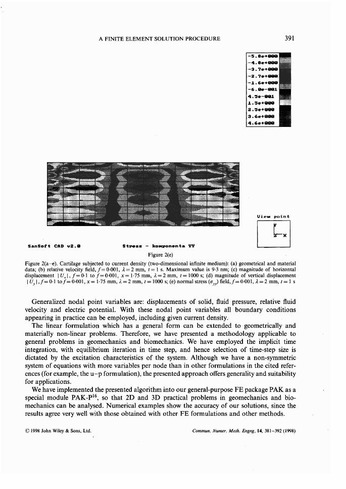