Electromechanical System Integration for a Powered Upper ...
Upload
independentCategory
view
0download
0
Proceedings of JRC2006Joint Rail Conference
April 4-6, 2006, Atlanta, GA, USA
JRC2006-94023
COUPLED ELECTROMECHANICAL COST OPTIMIZATION OF HIGH SPEEDRAILWAY OVERHEADS
J. R. [email protected]
E. Pilo, IEEE [email protected]
0. Lopez-Garcia A. [email protected] [email protected]
Universidad Pontificia Comillasc/ Alberto Aguilera, 23 28015 Madrid, Spain
Tel: (+34) 91 542 28 00
ABSTRACTThis paper presents a coupled electromechanical
optimization of the cost of high speed railway overheads. Theproposed electromechanical optimization solves the coupledmechanical and electrical problems by obtaining the railwayoverhead with minimum cost. A simple model cost of therailway overhead is proposed. This model cost defines theglobal cost per kilometer, which is mainly composed by thecosts of material used in the construction of the overheadsupports and the electric lines respectively. Using a standardgenetic algorithm the optimized railway overhead is obtained.
The parameters which describe the railway overheadare defined by: (i) sizing and (ii) configuration of the overheadsupports; (iii) geometric location and (iv) type of electricconductors. The constraints considered are: (i) maximumallowable stress, and (ii) structural static stability; (iii) structuregauge to limit the position of physical conductors, (iv)minimum distance between conductors or between conductorand earth and (v) maximum allowable current of eachconductor. In addition, the fitness function also considers theminimization of the equivalent electrical system impedance as asecondary optimization criterion. This optimization method hasbeen successfully applied to the design of the high speedrailway overhead C-350, used in the new line Madrid-Barcelona-French Border. The optimized railway overheadshows an overall improvement at two levels. Firstly theperformance is enhanced and secondly the global cost isreduced. The obtained results are compared with the non-optimized configuration in order to demonstrate the obtainedimprovements.
NOMENCLATURE
a: Main parameter of the penalty function.1: Population penalty parameter of the penalty function.y: Fitness factor for equivalent impedance.i,j: Members of an individual: beams, conductors, etc.i: Set of electrical members with equal voltage.n: Population.s: Individual of a population.DC-C: Minimum distance between conductors [m].dc-: Real distance between conductors [m].DCf: Minimum distance between each conductor and field.d4f: Real distance between each conductor and field.DC-S: Minimum distance between each conductor and
overhead supports.dCS: Real distance between each conductor and overhead
supports.E: Elastic modulus [N/m2].F: Maximum conductor deflection [m].F(i): Objective function.F'(i): Penalized objective function.I: Current flow through a conductor [A].Imax: Maximum current allowed through a conductor.Idem: Demanded current through equal voltage conductors.K: Coefficient that depends on conductors' wind
oscillations and electric line category.L: Hanging chain length [m].PXover: Crossover probability.Pmutation: Mutation probability.Mr: Penalty function.U: Voltage of a conductor [kV].We: Electrical global weight [kg].W,,: Mechanical global weight [kg].
Copyright C 2006 by ASME
231

Z:Zeq:v:
X:p:(yadm:(Ycr,adm:3:
Serial impedance matrix [Q/m].Equivalent impedance [fQm].Poisson coefficient.Slendemess ratio.Density [kg/m3].Allowable stress [N/M2].Critical allowable stress.Feasible region of the design space.
INTRODUCTIONA coupled electromechanical optimization of high
speed railway overheads needs an optimization algorithmrobust enough and flexible to admit several type of functionsand input data. Gradient-based mathematical programming mayconsume a large part of the total computational effort and couldinvolve major modifications with using non linear, discrete ormixed programming.
Fortunately, both evolutionary strategies and geneticalgorithms are based on probabilistic searching and do not needgradient information. These algorithms imitate biologicalevolution in nature and have three characteristics [1] that differfrom any others: (i) firstly, instead of deterministic operators,they use randomized operators like selection, crossover andmutation; (ii) to avoid bad convergence to non global minimumthese algorithms work simultaneously with the wholepopulation of design points in the space of design variables,and; (iii) finally, they easily work with non linear, discrete ormixed programming, so it is possible to evaluate and adjustdifferent variables without many problems.
These reasons together with the problems associatedto couple mechanical and electrical fields in a globaloptimization; and to use some standards for selecting structuralbeams or physical conductors, make genetic algorithms verysuitable for this electromechanical optimization.
Railway overheads design, composed by the overheadsupports and the electric lines, can be determined by differentcriteria like constructive, standard, safety or reliability.However, there is another criterion that insists on the efficientresources use, minimizing material weights and consequentlycosts without underestimating safety or quality of supply.
Thus, there are two parallel ways for globaloptimization: (a) to deal the electromechanical problem as a bi-stage weak coupling model, feeding the electrical model withthe solution of the mechanical model which is or vice versa; (b)to use a strongly coupled model able to jointly optimizeelectrical and mechanical variables with the same fitnessfunction. Thus, in this paper the second choice has beenselected because is able to unify under the same criteria andevaluation function the different field variables. This kind ofcoupling also allows to modify the importance of differentvariables which compose the fitness function with littlechanges.
This is important to remark that the strong couplingmodel uses only one chromosome for an electromechanicalindividual. Thus, their genes couples different variables of themechanical and the electrical problem. And evaluation functionis another big conceptual difference of this coupling model,because it allows to couple variables and optimizationobjectives as a multi-criteria analysis [2].
Figure 1 shows two key aspects of the proposedoptimization: on one hand relation between mechanical andelectrical problem; and in the other hand relation between bothproblems and genetic algorithm.
Figure 1: Optimization problem flowchart
In order to show the benefits of the proposed model,an application of this optimization is the design of the highspeed railway overhead C-350, used in the new line Madrid-Barcelona-French Border. The typical configuration of thecatenary ofAC railway line is shown in Figure 2, considering abitension or dual electrical system 2x25[kV], although theproposed optimization method is also reliable for monotensionsystems lx25[kV]. The catenary contains several physicalconductors that can be grouped into three groups: positive,negative and ground or neutral wires. In case of multiple tracks,other conductor arrangements are possible.
Copyright © 2006 by ASME
232

The positive wires are the positive phase feeder, thesustainer or messenger wire and the contact wire. There isusually only one negative wire called negative phase feeder.The neutral wires are the rails, the collector wire and the returnor guard wire. On the other hand it has been designed asimplified mechanical support for the two railways (Figure 4).
* Positive phase condixtors& Neffatve chase conductors
- - Positivea NetrA conductors pha
i fede,r
jj< 7 iMess5fZ erJwire
Logn inal section
contact wire
Rails
# Negatvephseeeder
Guard wire
Transvesal section
Figure 2: Typical railway overhead configuration
The purpose of this work is to obtain someconclusions about relations between mechanical and electricalfields and a coupled electromechanical optimization of the costof high speed railway overheads. So, the following lines areorganized into logical sections analyzing: firstly, the mostimportant parts of the genetic algorithm; the mechanical andthe electrical problem and their optimizations; and finally theelectromechanical optimization and the obtained conclusionsare explained.
GENETIC ALGORITHMOver the years, much work has been done in
engineering optimization, but instead of real-worldapplications, the trend has been to deal with ideal andunrealistic problems. Considering only single objectivefunctions is not a realistic assumption, thus, it seems suitableusing a meta-heuristic technique inspired by the mechanics ofnatural selection (see [3, 4]) to solve this multiobjectiveoptimization problem.
Therefore, a common genetic algorithm has been used,although some specific tools and functions for this particularproblem have been tailored too. For the whole optimization thesame global criteria are taken, and hereafter they are slightlydescribed:
represent all the possible solutions to the problem. Eachchromosome will be a data structure that holds a string of taskparameters, or genes. This string is stored as some consecutivebinary bit-strings that represent: (a) type of structural beams orelectrical conductors with the discrete position in a standardsystem specification; (b) mechanical beam's node or physicalconductor's location.
At the beginning of the codified string are the bits neededto the designation of each structural beam or physicalconductor, with the possibility to assign the same for a set ofmembers. And after them, bits needed to locate each node areincorporated. Configuration codification includes differenthorizontal and vertical movements for each node, and thepossibility to relate the movement of different nodes.
* Selection.Knowing each chromosome's fitness, the selection process
takes place to choose the individuals that will be the parents ofthe following generation. It has been used an own rankingselection scheme that could be named "pseudo-stochasticremainder selection" (PSMER). This is an original contributionof this work, obtaining a fast and robust convergence. In thisscheme the population is scaled and sorted from best to worst.Then each individual is copied as many times as it can,depending on its fitness scale and according to a non-increasingassignment function, and finally proportionate selection isperformed according to that assignment [5]. The aim of thismethod is to properly mix some selection concepts like scale,elitism and proportionate reproduction without increasingpopulation.
* Crossover.After being selected, crossover takes place. During this
stage, the genetic material of a pair of individuals is exchangedin order to create the population of the next generation. Asingle-point crossover scheme has been used. In this procedurea position of the chromosome is randomly selected as thecrossover point as indicated in Figure 3.
Cross point cros point
II lo 1 001 0I01° II 1 01 0 IIio 11 1 1
1 1 o1 o11 1 o1 0111 1o 1 1111 101°1101 1
Descendants
Figure 3: Single-point crossover.
* Codification.First, an initial population is randomly generated. The
individuals of this population will be a set of chromosomes that
Copyright c 2006 by ASME
233

* Mutation.Usually this is the last genetic operator that randomly
changes a gene of a chromosome. Using a binaryrepresentation, mutation changes a 0 to 1 and vice-versa. Thisoperator allows the introduction of new chromosomic materialto the population and, from the theoretical perspective, itassures that, given any population, the entire search space isconnected [6].
* Evaluation.Evaluation or fitness function is the most specific function
of each problem. Thus, it has to be able to satisfy designcriteria and all restrictions, both electrical and mechanical inthis problem.
In this optimization algorithm, as in many other fields ofoptimization, the constraint handling method is based on theconcept of exterior penalty functions 7t, which penalizeinfeasible solutions with the parameter a. Usually, the penaltyfunction is based on the distance of a solution from the feasibleregion and. In order to favor exploration of the space of designvariables in the first populations, penalty terms also increaseproportionally with generations and the parameter P (see Table1). Although boundary conditions are detailed in the followingsections, the approach depicted in equation (1) has been used.
MECHANICAL OPTIMIZATION
The optimization of overhead supports could beincluded into the optimal design of truss structures topic. Thisproblem has always been an active area of research in the fieldof search and optimization. Various techniques based onclassical optimization methods have been developed to findoptimal truss structures. However, most of these techniques canbe classified into three main categories: (i) Sizing, (ii)Configuration, and (iii) Topology optimization [8].Nevertheless, the scopes considered in this optimizationproblem are sizing and configuration.
In the sizing optimization, cross-sectional areas ofmembers are considered as design variables, restricting them totake only certain pre-specified discrete values from a IJPN]beams standard system specification. These are the first genes
built on the population's chromosomes string. Configurationoptimization considers nodal coordinates as design variablestoo.
In another aspect, Table 4 gathers the materialproperties of the overhead supports, specifically elasticmodulus, Poisson coefficient, allowable stress and density of a
usual kind of steel.
E [N/M2] u I a [gNhm1 p [kg/nI2.1.101 1 0.3 2.6 106 7800
Table 4: Material propertiesF -(S)= F(s), if sE3-F(s)+ r, otherwise
(1)
Parameters Valuesa l1o60 0.2
Table 1: Main and population parameters of the penalty function.
a Termination criteria.For discrete optimization some termination criteria are
suggested in [7]. In the present work the optimization processfinishes if the best value of the objective function in the last 50generations has not been improved.
The parameters related with the operators describedbefore are summarized in Table 2. Others that are also sharedby the tackled optimization problems are collected in Table 3.
I Code I Selection Crossover I MutationBinary PSMER Single-point Uniform ITable 2: Code and operator schemes of the GA
Max. Generations I Population I P.- I P..ti - ITermination200 1 800 0.5 1 0.03 1 50
Table 3: Numeric parameters of the GA
2
-5 -4 -3 -2 -1 0
Figure 4: Simplified mechanical model
' This algorithm also allows to use another kind ok beam profiles likeIPN, IPE, HE and L. All of them are standard structural shapes from theSpanish regulation NBE-EA-95. However could be also useful for I, S, etc.American structural shapes.
Copyright 2006 byASME
234
B 4 '1 5-
EN2B6
B1

The following variables have been taken into accountin the simplified mechanical model (Figure 4), that representsone of the two symmetric overhead railway supports. Thecross-sections of all the members (from Bl to B6) that build thetruss structure but one of them that is pre-defined as a steelwire. To reduce the number of variables it has been consideredcolumn composed of BI, B2 and B3 into the same profile set,subsequently they will have the same type of beam profile afteroptimization. This can directly improve computational costs.On the other hand, the change in nodal coordinates is possible:vertically at nodes NI, N2, N3 and N4; vertically andhorizontally at nodes N5 and N6; whereas nodes NI and N7 aremotionless. The first one for being fixed to earth, and thesecond one for the structure gauge limited by the height of thetrain.
The aim of this optimization is to minimize the weight ofthe truss structure, whose influence is obviously related withfinal building costs. For this reason the evaluation function inthis case only tries to minimize the global structure weight (2).
W (s), if SCE=
F(s) = W (s)+Yr, otherwise(2)
Thus, the fitness function is penalized adding a term (3)able to include the maximum allowable stress and structuralstatic stability or buckling conditions.
(3)(4)
7r(i) = aZ (I + ,B * (n-l)) * |S(i) ar,ad (i)|
a-,ad0 n= aa6m (A)
9
8
7
6
S
4
3
12
'
i
Hereafter, there are exposed some graphical results of themechanical optimization: Figure 5 shows the optimizedgeometry together with the initial geometry; and in Figure 6evolution and convergence of the global weight Wm alonggenerations is shown.
-----L-W-1 - - - INb1l G.otY3Opwi-d G..,.ty I -<
-4 -2 0 2 4 6 8
Figure 5: Initial and optimized mechanical configuration
Goneration
Figure 6: Global weight evolution
In the last graphic (Figure 6), optimal solution is markedwith a circle, although the algorithm continues until terminationcriterion was fulfilled.
In the following tables (Table 5 and Table 6) numericalresults are also presented. Considering that optimal weight isthe weight of the two parallel overhead supports at the sametime; and conversely, optimal types of beam profiles are relatedwith the simplified mechanical model of Figure 4, though aresymmetrical to the other truss structure.
I Optimal weight [kg] | 467.6 |ptimal population | 94 l
Table 5: Optimal weight and generation
Beam B I UPN 180Beam B2 UPN 180Beam B3 UPN 180Beam B4 UPN 80Beam B5 UPN 80Beam B6 UPN 80
Table 6: Optimal types ofbeam profiles
Copyright © 2006 by ASME
235

ELECTRICAL OPTIMIZATION
Electrical optimization also includes two maincategories: (i) type of electric conductors and (ii) theirgeometric location.
In the first one, physical conductors are considered asdesign variables, restricting them to take only certain pre-specified discrete values from a conductor's standard systemspecification collected in Table 7.
Standard Radius Internal resistance Intemal reactancename [ml lfYnil [f5m1 iLA-30 3.57.10-3 1.18.10-3 1.48.10-5LA-56 4.72. 1 - 6.74-104 1.48 10-5LA-78 5.67 10-3 4.68-104 1.48- 10-LA-l10 7.00.1O- 3.37 104 1.45*10-5LA-145 7.87 10-3 2.66.104 1.45 1i-5LA-180 8.75 10-3 2.16-104 1.45.10-5LA-280 1.09.10-2 1.31.101 1.47 10-5LA-380 1.27.10-2 9.42 10-5 1.48 10-5LA-455 1.39.10-2 7.89.10-5 1.48 10-5LA-545 1.52.10-2 6.55 10-5 1.48 10-5LA-635 1.64.10-2 5.61 10-5 1.48 10-5lOOCu 5.64.10-3 1.93.1014 .50.i0-5
I50Cu60% 6.91 10-3 2.15. 104 1.50 10-5225Cu 8.46-10-3 5.59.10-5 1.50.101-UIC-60 4.95.10-2 2.47 10-5 1.50.104
Table 7: Standard system specification of conductors
The type of conductor is related with the first genesbuilt on the population's chromosomes string. On the otherhand, in the geometric location or configuration optimization,the changes in nodal coordinates are also kept as designvariables.
Some important parameters related to electricproperties are shown in the following tables, specifically:conductor's voltage in Table 8; and frequency, electric demandand bay's length in the railways in Table 9.
Conductor VVoltage fkVIContact wire 25Messenger wire 25Positive feeder 25Negative feeder -25Guard wire 0ORails 0
Table 8: Conductor's voltage
Frequency [Hz] 1 50Electric demand [MVA] 20, each railwayBay [m} 60
Table 9: Frequency, electric demand and bay length
Thus, the variables taken into account in thisoptimization are: the type of electric conductor used for thepositive and negative phase feeders and the guard wire. Thetype of physical conductors used for all the others are initiallyfixed as is designed in Table 10; on the other hand, the changeof nodal coordinates is considered for the same first set ofconductors, assuming motionless the contact and messengerwires and obviously the rails. In this aspect it has beenrestricted guard wires displacement with less action space thanthe others.
Contact wire Messen er wire RailsLA-180 LA-180 UIC-60
Table 10: Fixed type of conductors
The aim of this optimization is to minimize the weightof the electrical conductors, whose influence is obviouslyrelated with final costs.
Furthermore, as a secondary criterion for optimizationis considered the equivalent impedance minimization. Thissecond criterion is related with the improvements in theefficiency of the electrical system. As sectors of catenary arequite short (typically no longer than 50 km), each one portioncan be represented by its concentrated parameter it-model [91that includes serial impedance and shunt admittance.
Serial impedance matrix represents the effect ofresistance, self-inductance and magnetic coupling betweenconductors. Shunt admittance matrix represents capacitancesand the leakage resistances between conductors (or betweenconductors and the earth). However, due to the reducedcatenary lengths, shunt effects can usually be neglected.
Physical conductors models represent separately eachconductor of the catenary (Figure 2). In such models, serialimpedance matrices can be calculated from Carson formulasthat take into account the effect of earth currents.
Grounded conductor voltages can be assumed to bezero, and the equivalent ground conductor can be eliminated.Consequently, dual system catenaries are usually modeled astwo mutually coupled conductors.
In the equivalent conductors model, voltage drops canbe expressed as:
(5)
where Z is the serial impedance matrix of the sectionof catenary, and their sub-indexes represents the positive andnegative conductors respectively, being impedance expressedper length unit.
Finally, the equivalent impedance used in thisoptimization can be written, with [10, 11], as follows:
Copyright © 2006 byASME
236
pp P.
I., z z I. V.Z_1i11=[__np Z_J[i11=1V11
dz *pz --Z *z=
pp ,t_n pe +ZP (6)
Thus, evaluation function (7) will add the twoobjectives and some penalty terms break down below too.
W (s)+ryZeq (s), ifse3
F W (s)+Y.Z (s)+;r, otherwisee eq(7)
Where the parameter y, whose value is in Table 11, isnecessary to adjust equivalent impedance to the same order ofmagnitude of the weight. This parameter is also adjustedconsidering equivalent impedance as a secondary optimizationcriterion.
Parameter Value
Table 11: Equivalent impedance fitness factor
There are two kinds of penalties:1) Current penalties:
* If there are over current on conductors.;r(i) = a- (1 +,/ (n-1)) I(')-',(i)I (8)
* If electric demand is dissatisfied.;r(i) = a* (I + /3 (n -1)) I(i )-Id,. (i)I (9)
2) Geometric penalties are referred to a Spanishregulation of high overhead conductors voltage [12]:
* Minimum distance between each conductor andfield [m].
UD i = max(6; 5.3 + -)
150(10)
where:U: Voltage between the conductor and the earth [kV].
Then, ifDC (i) > dc)(i):
;(i)=a (I+,- (n-I)) |Dcf(i)-dc-f(i)l* Minimum distance between conductors [m].
UL,= K.(F+L±-)150
(I 1)
where:K: Coefficient that depends on conductors' windoscillations and electric line category; K takes valuesfrom 0.55 to 0.7.F: Maximum conductor deflection [m]. The valueassumed is 0.8 m.L: Hanging chain length [m]2.U: Voltage between conductors [kV].
Then, ifD_ (i,j) > d__ (i, j):;r(i,j) = a .(I+6 (n - 1)). ID,_ (i,j)-d_ (ij])l (13)
* Minimum distance between each conductor andoverhead supports [m].
UD~__ = max(0.2; 0.1I +-)
150(14)
where:U: Voltage between the conductor and the mechanicalsupports [kV].
Then, ifD _,(i) > d _s(i):ir(i) =a (I+ /.(n-1)) |IDC-s(i)-d,-J(i)l (15)
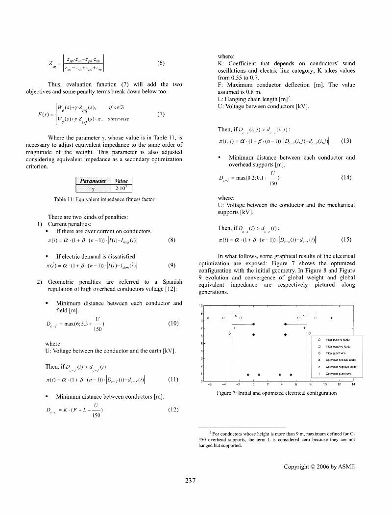
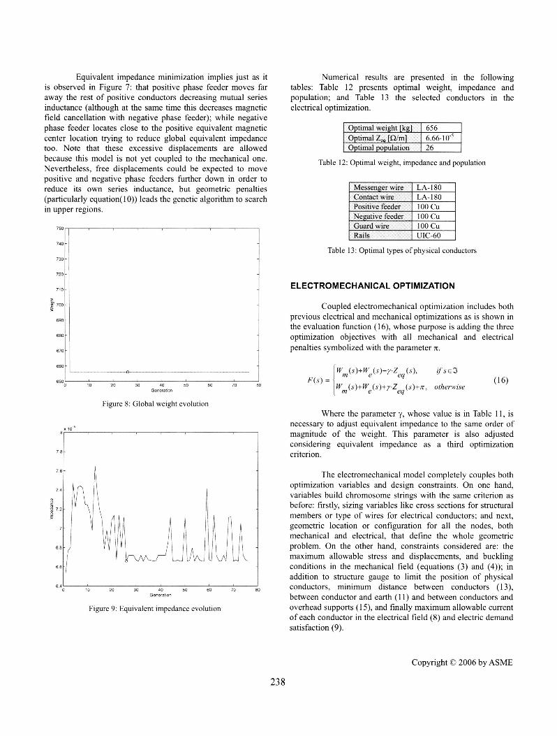
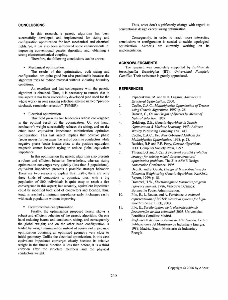
In what follows, some graphical results of the electricaloptimization are exposed: Figure 7 shows the optimizedconfiguration with the initial geometry. In Figure 8 and Figure9 evolution and convergence of global weight and globalequivalent impedance are respectively pictured alonggenerations.
109
8 *
7
6
5
4
3
2
1 -
-6
o3 0 0 0 *
0 0D INO. OgOe xdDr
* liedp*. feder
C Optind pnglivn der
* * * * + OpImMg-dgnerdle
-4 -2 0 2 4 6 8 10 12 14
Figure 7: Initial and optimized electrical configuration
(12)
2 For conductors whose height is more than 9 m, maximum defined for C-350 overhead supports, the term L is considered zero because they are nothanged but supported.
Copyright C) 2006 byASME
237
Equivalent impedance minimization implies just as itis observed in Figure 7: that positive phase feeder moves faraway the rest of positive conductors decreasing mutual seriesinductance (although at the same time this decreases magneticfield cancellation with negative phase feeder); while negativephase feeder locates close to the positive equivalent magneticcenter location trying to reduce global equivalent impedancetoo. Note that these excessive displacements are allowedbecause this model is not yet coupled to the mechanical one.Nevertheless, free displacements could be expected to movepositive and negative phase feeders further down in order toreduce its own series inductance, but geometric penalties(particularly equation(10)) leads the genetic algorithm to searchmn upper regions.
740
730
720
710-
690 _
670 _
660
E
01 10 20 30 40 50 6GeFG raiten
Figure 8: Global weight evolution
Figure 9: Equivalent impedance evolution
Numerical results are presented in the followingtables: Table 12 presents optimal weight, impedance andpopulation; and Table 13 the selected conductors in theelectrical optimization.
Optimal weight [kg] 656Optirpal Z4, L14 6.66-10-5Otimal population 26
Table 12: Optimal weight, impedance and population
Messenger wire LA-180C6ntct wire LA-180Positive feder 100 CuNegative feeder 100 CuGuad wire 100 CuRails UIC-60
Table 13: Optimal types of physical conductors
ELECTROMECHANICAL OPTIMIZATION
Coupled electromechanical optimization includes bothprevious electrical and mechanical optimizations as is shown inthe evaluation function (16), whose purpose is adding the threeoptimization objectives with all mechanical and electricalpenalties symbolized with the parameter zT.
[W(S)+W (S)+r.Z (s), if sCeF(s) = otherwise
W s+ s+. s+r tews(16)
Where the parameter y, whose value is in Table 11, isnecessary to adjust equivalent impedance to the same order ofmagnitude of the weight. This parameter is also adjustedconsidering equivalent impedance as a third optimizationcriterion.
The electromechanical model completely couples bothoptimization variables and design constraints. On one hand,variables build chromosome strings with the same criterion asbefore: firstly, sizing variables like cross sections for structuralmembers or type of wires for electrical conductors; and next,geometric location or configuration for all the nodes, bothmechanical and electrical, that define the whole geometricproblem. On the other hand, constraints considered are: themaximum allowable stress and displacements, and bucklingconditions in the mechanical field (equations (3) and (4)); inaddition to structure gauge to limit the position of physicalconductors, minimum distance between conductors (13),between conductor and earth (11) and between conductors andoverhead supports (15), and finally maximum allowable currentof each conductor in the electrical field (8) and electric demandsatisfaction (9).
Copyright ©D 2006 byASME
238
5S! 700

Some graphical results of the electromechanicaloptimization appear below: Figure 10 shows the optimizedconfiguration with the initial geometry; and in Figure 11 andFigure 12 evolution and convergence of electrical andmechanical weights and equivalent impedance are respectivelyshown along generations.
9
8
7
6
5
4
3
2
'O- 0
0
-s
'
0
. 0 0
0
E
10
I
15
Figure 10: Initial and optimized electromechanical configuration
As previously observed, Figure 10 shows thatconfiguration is leaded by weight minimization instead ofequivalent impedance optimization. Note that it had beendefined in equation (16) as the optimization objective function.For this reason natural tendencies of electrical optimizationwithout mechanical coupling can't be freely executed,obtaining an optimized geometry very close to initial geometry,although objective variables are optimized fulfilling all theconstraints.
71
6.5
6
5.50 20 40 60 80 100
Generation
Figure 12: Equivalent impedance evolution
There are also detailed numerical results in thefollowing tables: Table 14 shows optimal weights, impedanceand population; Table 15 presents the optimal structuremembers obtained; and finally, Table 16 the optimal physicalconductors. Considering that optimal weights are the weightsof the two parallel railways at the same time.
timal mechanical weight [kg] 482Optimal electrical weight [kg]i 656Otimal Z. fI/m 7.110-5Optimal population 38
Table 14: Optimal weights, equivalent impedance and population
3500
10DOo
0 5 10 15 20G-ti-bon
25 30 35 40
BeamBII UPN 180Beam B2 UPN 180Beam B3 UPN 180Bearn B4 UPN 80Beam B5 UPN 80Beam B6 UPN 80
Table 15: Optimal types ofbeam profiles
Messenger wire LA- 180Contact wire LA- 180Positive feeder 100 CuNegative feeder 100 CuGuard wire 1100 CuRails UIC-60
Table 16: Optimal types of electrical conductors
Figure 11: Electrical and mechanical weights evolution
Copyright 2006 by ASME
239
- ---ri eieodhl
__O,d _ n.0 I1. po.M. Wd
o hz " -gb. %eW,
0 1ilM al9d e
* Opted pe ted,
X OPWed nen bede
+ Opfi-edgood woe
Mavnical W igt
_, ~~~~~~~~-- - E cricel WeighlE!ecldrndrni&lWMight
III
25002
I9
v
5
30D00
2000
CONCLUSIONS
In this research, a genetic algorithm has beensuccessfully developed and implemented for sizing andconfiguration optimization for both mechanical and electricalfields. So, it has also been introduced some enhancements in:improving conventional genetic algorithm, and; obtaining astrong electromechanical coupling.
Therefore, the following conclusions can be drawn:
Mechanical optimization.The results of this optimization, both sizing and
configuration, are quite good but also predictable because thealgorithm tries to reduce material without violating boundaryconditions.
An excellent and fast convergence with the geneticalgorithm is obtained. Thus, it is necessary to remark that inthis aspect it has been successfully developed (and used for thewhole work) an own ranking selection scheme named "pseudo-stochastic remainder selection" (PSMER).
* Electrical optimization.This field presents two tendencies whose convergence
is the optimal result of the optimization. On one hand,conductor's weight successfully reduces the sizing, and on theother hand equivalent impedance minimization optimizesconfiguration. This last aspect implies that positive phasefeeder moves further away the rest of positive conductors whilenegative phase feeder locates close to the positive equivalentmagnetic center location trying to reduce global equivalentimpedance.
In this optimization the genetic algorithm also presentsa robust and efficient behavior. Nevertheless, whereas sizingoptimization converges very quickly (less than 5 populations),equivalent impedance presents a possible stranger behavior.There are two reasons to explain this: firstly, there are onlythree kinds of conductors to optimize, thus, with a bigpopulation of 800 individuals is quite easy to reach a fastconvergence in this aspect; but secondly, equivalent impedancecould be modified both kind of conductors and location, thus,tough is reached a minimum impedance early, it changes easilywith each population without improving.
* Electromechanical optimization.Finally, the optimization proposed herein shows a
robust and efficient behavior of the genetic algorithm. On onehand reducing beams and conductors sizing, and consequentlythe global weight; and on the other hand configuration isleaded by weight minimization instead of equivalent impedanceoptimization obtaining an optimized geometry very close toinitial geometry. Unlike the electrical optimization, in this caseequivalent impedance converges clearly because its relativeweight in the fitness function is less than before, it is a thirdcriterion after the structure members and the physicalconductors weight.
Thus, costs don't significantly change with regard toconventional design except sizing optimization.
Consequently, in order to reach more interestingconclusions in configuration is needed to tackle topologicaloptimization. Author's are currently working on itsimplementation.
ACKNOWLEDGMENTSThe research was completely supported by Instituto de
Investigacion Tecnol6gica (IIT), Universidad PontificiaComillas. Their assistance is greatly appreciated.
REFERENCES
1. Papadrakakis, M. and N.D. Lagaros, Advances inStructural Optimization. 2000.
2. Coello, C.A.C., Multiobjective Optimization ofTrussesusing Genetic Algorithms. 1997: p. 26.
3. Darwin, C., On the Origin ofSpecies by Means ofNatural Selection. 1959.
4. Goldberg, D.E., Genetic Algorithms in Search,Optimization & Machine Learning. 1953: Addison-Wesley Publishing Company, INC. 412.
5. Coello, C.A.C., Two New GA-based MethodsforMultiobjective Optimization. 1998: p. 28.
6. Buckles, B.P. and F.E. Petry, Genetic Algorithms.IEEE Computer Society Press, 1992.
7. Thierauf, G. and J. Cai, A two levelparallel evolutionstrategyfor solving mixed-discrete structuraloptimization problems. The 21 st ASME DesignAutomation Conference, 1995.
8. Deb, K. and S. Gulati, Design ofTruss-StructuresforMinimum Weight using Genetic Algorithms. KanGALReport, 1999: p. 18.
9. Dommel, H.W., Electromagnetic transients programreference manual. 1986, Vancouver, Canada:Bonneville Power Administration.
10. Pilo, E., L. Rouco, and A. Femrndez, A reducedrepresentation of2x25kV electrical systemsfor high-speed railways. IEEE, 2003.
11. Pilo, E., Diseno optimo de la electrificaci6n deferrocarriles de alta velocidad. 2003, UniversidadPontificia Comillas: Madrid.
12. Reglamento de Lineas Aereas de Alta Tensi6n. CentroPublicaciones del Ministerio de Industria y Energia.1989, Madrid, Spain: Ministerio de Industria yEnergia.
Copyright © 2006 by ASME
240
Copyright © 2022 FDOKUMEN