Electromechanical Contactors Series LA
103
Page 273 w Terminal Screws Technical Specification - Electromechanical Contactors Series LA w Technical Information Devices Kind of connection Type Screw with Screw with Screw Screw driver Tightening torque washer clamp box w.nut Nm Ib. inch Micro Contactors, all conductors K0-.. M2,5 - - - Pz1 0.6-0.8 5-7 Mini Contactors, all conductors K1-.. M3,5 - - - Pz2 0.8-1.4 7-12 Auxiliary Contactors, all conductors K(G)3-07.. M3,5 - - - Pz2 0.8-1.4 7-12 Contactors Main conductor K(G)3-10.. to K3-22.. M3,5 - - - Pz2 0.8-1.4 7-12 K(G)3-24.. to K3-40.. - M5 - - Pz2 2.5-3 22-26 K3-50.. to K3-74.. - M6 - - Pz3 3.5-4.5 31-40 K2-23, -30, -37A00-40 M4 - - - Pz2 1.2-1.8 11-16 K2-45, -60A00-40 - M6 - - Pz3 3.5-4.5 31-40 K3-90, K3-115 - - M8 - 4mm hex socket 4-6.5 35-57 K3-116.. to K3-176.. - - - M8 17 150 K3-210.. to K3-316 - - - M10 35 315 K3-450.. and K3-550.. - - - M12 60 540 Auxiliary conductor K(G)3-10 to K3-22 M3,5 - - - Pz2 0.8-1.4 7-12 Coil conductor K(G)3-10 to K3-550 M3,5 - - - Pz2 0.8-1.4 7-12 Accessories HK, HKM M3,5 - - - Pz2 0.8-1.4 7-12 HA, HN, K2-.., HB.. M3,5 - - - Pz2 0.8-1.4 7-12
-
Upload
khangminh22 -
Category
Documents
-
view
0 -
download
0
Transcript of Electromechanical Contactors Series LA

Page
273
w Terminal Screws
Technical Specification - Electromechanical Contactors Series LA
w Technical Information
Devices Kind of connection
Type
Screw with Screw with Screw Screw driver Tightening torque
washer clamp box w.nut Nm Ib. inch
Micro Contactors, all conductors
K0-.. M2,5 - - - Pz1 0.6-0.8 5-7
Mini Contactors, all conductors
K1-.. M3,5 - - - Pz2 0.8-1.4 7-12
Auxiliary Contactors, all conductors
K(G)3-07.. M3,5 - - - Pz2 0.8-1.4 7-12
Contactors
Main conductor
K(G)3-10.. to K3-22.. M3,5 - - - Pz2 0.8-1.4 7-12
K(G)3-24.. to K3-40.. - M5 - - Pz2 2.5-3 22-26
K3-50.. to K3-74.. - M6 - - Pz3 3.5-4.5 31-40
K2-23, -30, -37A00-40 M4 - - -
Pz2 1.2-1.8 11-16
K2-45, -60A00-40 - M6 - - Pz3 3.5-4.5 31-40
K3-90, K3-115 - - M8 -
4mm hex socket 4-6.5 35-57
K3-116.. to K3-176.. - - - M8
17 150
K3-210.. to K3-316 - - - M10 35 315
K3-450.. and K3-550.. - - - M12 60 540
Auxiliary conductor
K(G)3-10 to K3-22 M3,5 - - - Pz2 0.8-1.4 7-12
Coil conductor
K(G)3-10 to K3-550 M3,5 - - - Pz2 0.8-1.4 7-12
Accessories
HK, HKM M3,5 - - - Pz2 0.8-1.4 7-12
HA, HN, K2-.., HB.. M3,5 - - - Pz2 0.8-1.4 7-12

Page
274
w Technical Specifications according to IEC 60947-4-1, VDE 0660, EN 60947-4-1
Main contacts Type K0-05D
Rated insulation voltage Ui VAC 440 1)
Making capacity Ieff at Ue = 440VAC A 65
Breaking capacity Ieff 400VAC A 50
cos = 0,65
Utilization category AC1
Switching of resistive load
Rated operational current Ie (=Ith) at 40°C, open A 12
Rated operational power of three-phase resistive loads 230V kW 4.7
50-60 Hz, cos = 1 240V kW 4.8
400V kW 8.3
415V kW 8.6
440V kW 9.0
Rated operational current Ie (=Ith) at 60°C, open A 8
Rated operational power of three-phase resistive loads 230V kW 3.1
50-60 Hz, cos = 1 240V kW 3.3
400V kW 5.5
415V kW 5.7
440V kW 6.0
Minimum cross-section of conductor at load with Ie (=Ith) mm2 1.5
Utilization category AC2 and AC3
Switching of three-phase motors
Rated operational current Ie 220V A 6.2
open and enclosed 230V A 6.2
240V A 5.6
380-400V A 5
415-440V A 5
Rated operational power of three-phase motors 220-240V kW 1.5
50-60 Hz 380-440V kW 2.2
Utilization category AC4 Switching of squirrel cage motors, inching Rated operational current Ie 220V A 4.9
open and enclosed 230V A 4.9
240V A 4.1
380-400V A 3.5
415-440V A 3.5
Rated operational power of three-phase motors 220-240V kW 1.1
50-60 Hz 380-440V kW 1.5
Utilization category AC5a
Switching of gas discharge lamps
Rated operational current Ie per pole at 220/230V
Fluorescent lamps,
uncompensated and serial compensated A 6
parallel compensated A 0.5
dual-connection A 9
Metal halide lamps 2),
uncompensated A 6
parallel compensated A 0.5
Mercury-vapour lamps 3),
uncompensated A 9
parallel compensated A 0.5
Mixed light lamps 4) A 9
LED-Lamps
consider the inrush current of the lamp ballast max.lamps per pole (InLED ≤ Ith)=
inrush current of contactor
and cos of the lamp inrush current of lamp/EVG
max inrush current of contactor A 91
Utilization category AC5b
Switching of incandescent lamps 5)
per pole at 220/230V A 3 1) Suitable for: earthed-neutral systems, overvoltage category I to III, pollution degree 3 (standard-industry): Uimp = 4 kV. Data for other conditions on request. 2) Metal halide lamps on sodium-vapour lamps (high- and low-pressure lamps). 3) High-pressure lamps. 4) Blended lamps, containing a mercury high-pressure unit and a tungsten helix in a fluorescent glass bulb (daylight lamps). 5) Current inrush approx. 16 x Ie
Technical Specification - Electromechanical Contactors Series LA
w Micro Contactors LA, Size M

Page
275
w Technical Specifications according to IEC 60947-4-1, VDE 0660, EN 60947-4-1
Main contacts Type K0-05D
Utilization category DC1
Switching of resistive load 1 pole 24V A 12
Time constant L/R ≤1ms 60V A 12
Rated operational current Ie 110V A -
220V A -
3 poles in series 24V A 12
60V A 12
110V A 12
220V A -
Utilization category DC3 and DC5
Switching of shunt motors 1 pole 24V A 12
and series motors 60V A -
Time constant L/R ≤15ms 110V A -
Rated operational current Ie 220V A -
3 poles in series 24V A 12
60V A 12
110V A 12
220V A -
Maximum ambient temperature
Operation open °C -40 to +60 (+90) 1)
enclosed °C -40 to +40
Storage °C -50 to +90
Short circuit protection
for contactors without thermal overload relay
Coordination-type "1" according to IEC 947-4-1
Contact welding without hazard of persons
max. fuse size gL (gG) A 32
Coordination-type "2" according to IEC 947-4-1
Light contact welding accepted
max. fuse size gL (gG) A -
Contact welding not accepted
max. fuse size gL (gG) A -
For contactors with thermal overload relay the
device with the smaller admissible backup ruse
(contactor of thermal overload relay) determines the fuse size
Cable cross-sections
for contactors
main connector solid of stranded mm2 0.5-1.5
flexible mm2 0.5-1.5
flexible with multicore cable end mm2 0.5-1.5
Cables per clamp 2
solid of stranded AWG 20-14
Frequency of operation z without load 1/h 10000
contactors without thermal overload relay AC3, Ie 1/h 600
AC4, Ie 1/h 120
DC3, Ie 1/h 600
Mechanical life AC operated S x 106 3
DC operated S x 106 4
Short time current 10s-current A 50
Power loss per pole at Ie/AC3 400V W 0.2
Resistance to shock according to IEC 68-2-27
Shock time 20 ms sine-wave
AC operated NO g 2.5
NC g 2.5
1) 90°C: reduces the control voltage range to 0.9 up to 1.0xUs and reduces the rated current Ie/AC1 to the value of Ie/AC3
Technical Specification - Electromechanical Contactors Series LA
w Micro Contactors LA, Size M

Page
276
w Technical Specifications according to IEC 60947-5-1, VDE 0660, EN 60947-5-1
Auxiliary contacts Type K0-04D
K0-05D
Rated insulation voltage Ui VAC 440 1)
Thermal rated current Ith to 440 V
Ambient temperature 40°C A 5
60°C A 3
Power loss per pole at Ith W 0.25
Utilization category AC15
Rated operational current Ie 220-240V A 3
380-415V A 1.5
440V A 1
Utilization category DC13
Rated operational current Ie 24-60V A 0.5
Maximum ambient temperature
Operation open °C -40 to +60 (+90) 2)
enclosed °C -40 to +40
Storage °C -40 to +90
Short circuit protection
short circuit current 1kA,
contact welding not accepted
max. fuse size gL (gG) A 10
For contactors with thermal overload relay the device with the smaller admissible control fuse (contactor of thermal overload relay) determines the fuse size.
Power consumption of coils
AC operated inrush VA 9
sealed VA 4
W 1.8
DC operated inrush W 2.5
sealed W 2.5
Operation rage of coils
in multiples of control voltage Us 0.85-1.1
Switching time at control voltage Us ± 10% 3)
AC operated make time ms 13-18
release time ms 5-10
arc duration ms 10-15
DC operated make time ms 10-20
release time ms 2-10
arc duration ms 10-15
Cable cross-section
all connectors solid mm2 0.5-1.5
flexible mm2 0.5-1.5
flexible with multicore
cable end mm2 0.5-1.5
Clamps per pole 2
solid or stranded AWG 20-14
1) Suitable at 690 V for: earthed-neutral systems, overvoltage category I to III, pollution degree 3 (standard industry): Uimp = 4kV. Data for other conditions on request.
2) 90°C: reduces the control voltage range to 0.9 up to 1.0xUs and reduces the thermal rated current Ith to Ie/AC15.
3) Summary switching time = release time + arc duration.
Technical Specification - Electromechanical Contactors Series LA
w Micro Contactors LA, Size M

Page
277
w Motor Rating and Breaking Current (K0-05D)
1) Millions of Operations
a) Motor Rating
b) Breaking Current
Technical Specification - Electromechanical Contactors Series LA
w Micro Contactors LA, Size M

Page
278
w Technical Specifications according to IEC 947-4-1, VDE 0660, EN 60947-4-1
Main contacts Type K1-09D
Rated insulation voltage Ui V AC 690 1)
Making capacity Ieff at Ue = 690V AC A 165
Breaking capacity Ieff 400V AC A 100
cos = 0.65 500V AC A 90
690V AC A 80
Utilization category AC1 - Switching of resistive load
Rated operational current Ie (=Ith) at 40°C, open A 20
Rated operational power of three-phase resistive loads 230V kW 7.9
50-60 Hz, cos = 1 240V kW 8.3
400V kW 13.8
415V kW 14.3
Rated operational current Ie (=Ith) at 60°C, enclosed A 16
Rated operational power of three-phase resistive loads 230V kW 6.3
50-60 Hz, cos = 1 240V kW 6.7
400V kW 11
415V kW 11.5
Minimum cross-section of conductor at load with Ie (=Ith) mm2 2.5
Utilization category AC2 and AC3 - Switching of three-phase motors
Rated operational current Ie 220V A 12
open and enclosed 230V A 11.5
240V A 11
380-400V A 9
415-440V A 8
500V A 7
660-690V A 5
Rated operational power of three-phase motors 220-240V kW 3
50-60Hz 380-440V kW 4
500-690V kW 4
Utilization category AC4 - Switching of squirrel cage motors, inching
Rated operational current Ie 220V A 12
open and enclosed 230V A 11.5
240V A 11
380-400V A 9
415-440V A 8
500V A 7
660-690V A 5
Rated operational power of three-phase motors 220-240V kW 3
50-60Hz 380-440V kW 4
500-690V kW 4
Utilization category AC5a - Switching of gas discharge lamps
Rated operational current Ie per pole at 220/230V
Fluorescent lamps,
uncompensated and serial compensated A 10
parallel compensated A 2
dual-connection A 16
Metal halide lamps 3),
uncompensated A 10
parallel compensated A 2
Mercury-vapour lamps 4)
uncompensated A 16
parallel compensated A 2
Mixed light lamps 5) A 16
LED-Lamps
consider the inrush current of the lamp ballast max. lamps per pole (InLED ≤ Ith) =
inrush current of contactor
and cos of the lamp inrush current of lamp/EVG
max. inrush current of contactor A 233
Utilization category AC5b Switching of incandescent lamps 6)
Rated operational current Ie per pole at 220/230 V A 8
1) Suitable at 690V for: earthed-neutral systems, overvoltage category I to IV, pollution degree 3 (standard-industry): Uimp = 8kV. Data for other conditions on request.
3) Metal halide lamps and sodium-vapour lamps (high- and low-pressure lamps).
4) High-pressure lamps.
5) Blended lamps, containing a mercury high-pressure unit and a tungsten helix in a fluorescent glass bulb (daylight lamps).
6) Current inrush approx. 16 x Ie.
Technical Specification - Electromechanical Contactors Series LA
w Mini Contactors LA, Size 1
Page
279
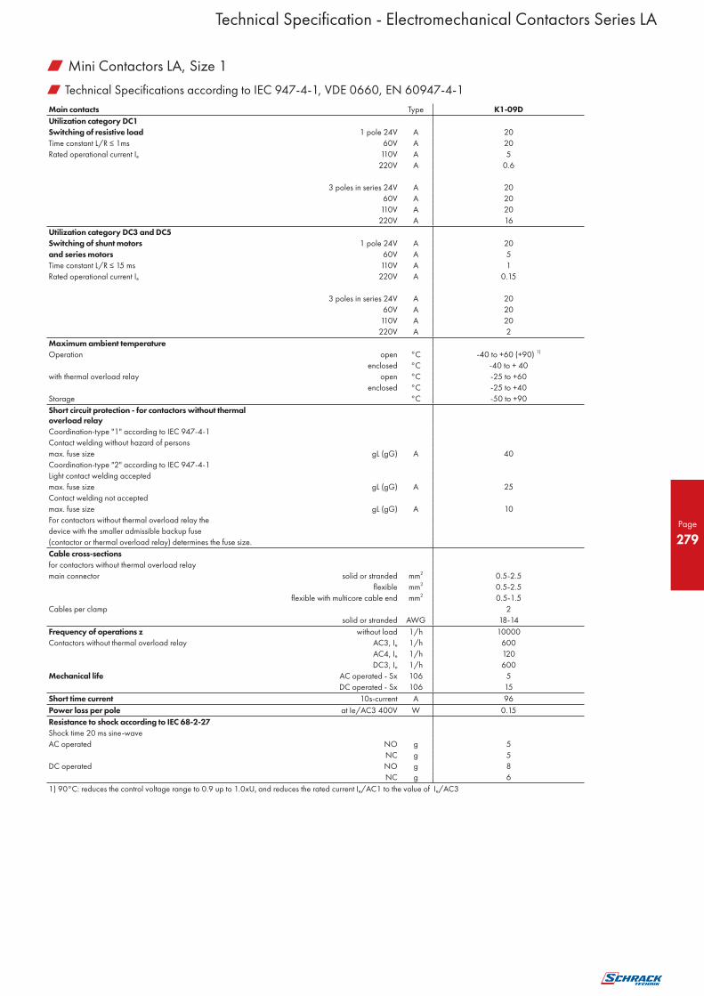
w Technical Specifications according to IEC 947-4-1, VDE 0660, EN 60947-4-1
Main contacts Type K1-09D
Utilization category DC1
Switching of resistive load 1 pole 24V A 20
Time constant L/R ≤ 1ms 60V A 20
Rated operational current Ie 110V A 5
220V A 0.6
3 poles in series 24V A 20
60V A 20
110V A 20
220V A 16
Utilization category DC3 and DC5
Switching of shunt motors 1 pole 24V A 20
and series motors 60V A 5
Time constant L/R ≤ 15 ms 110V A 1
Rated operational current Ie 220V A 0.15
3 poles in series 24V A 20
60V A 20
110V A 20
220V A 2
Maximum ambient temperature
Operation open °C -40 to +60 (+90) 1)
enclosed °C -40 to + 40
with thermal overload relay open °C -25 to +60
enclosed °C -25 to +40
Storage °C -50 to +90
Short circuit protection - for contactors without thermal overload relay
Coordination-type "1" according to IEC 947-4-1
Contact welding without hazard of persons
max. fuse size gL (gG) A 40
Coordination-type "2" according to IEC 947-4-1
Light contact welding accepted
max. fuse size gL (gG) A 25
Contact welding not accepted
max. fuse size gL (gG) A 10
For contactors without thermal overload relay the
device with the smaller admissible backup fuse
(contactor or thermal overload relay) determines the fuse size.
Cable cross-sections
for contactors without thermal overload relay
main connector solid or stranded mm2 0.5-2.5
flexible mm2 0.5-2.5
flexible with multicore cable end mm2 0.5-1.5
Cables per clamp 2
solid or stranded AWG 18-14
Frequency of operations z without load 1/h 10000
Contactors without thermal overload relay AC3, Ie 1/h 600
AC4, Ie 1/h 120
DC3, Ie 1/h 600
Mechanical life AC operated - Sx 106 5
DC operated - Sx 106 15
Short time current 10s-current A 96
Power loss per pole at Ie/AC3 400V W 0.15
Resistance to shock according to IEC 68-2-27
Shock time 20 ms sine-wave
AC operated NO g 5
NC g 5
DC operated NO g 8
NC g 6
1) 90°C: reduces the control voltage range to 0.9 up to 1.0xUs and reduces the rated current Ie/AC1 to the value of Ie/AC3
Technical Specification - Electromechanical Contactors Series LA
w Mini Contactors LA, Size 1

Page
280
w Technical Specifications according to IEC 947-5-1, VDE 0660, EN 60947-5-1
Auxiliary contacts Type K1-09D K1-09D = HK
Rated insulation voltage Ui VAC 6901) 6901) 6901)
Thermal rated current Ith to 690V
Ambient temperature 40°C A 10 10 10
60°C A 6 6 6
Power loss per pole at Ith W 0.5 0.5 0.5
Utilization category AC15
Rated operational current Ie 220-240V A 3 3 3
380-415V A 2 2 2
440V A 1.6 1.6 1.6
500V A 1.2 1.2 1.2
660-690V A 0.6 0.6 0.6
Utilization category DC13
Rated operational current Ie 60V A 2 2 2
110V A 0.4 0.4 0.4
220V A 0.1 0.1 0.1
Maximum ambient temperature
Operation open °C -40 to +60 (+90)3)
°C -40 to +40
Storage °C -40 to +90
Short circuit protection
short-circuit current 1kA
contact welding not accepted
max. fuse size gL (gG) A 20 20 20
For contactors with thermal overload relay the
device with the smaller admissible control fuse
(contactor or thermal overload relay)
determines the fuse size.
Power consumption of coils
AC operated inrush VA 25 - -
sealed VA 4-5 - -
W 1.2 - -
DC operated inrush W - 2.5 -
sealed W - 2.5 -
Operation range of coils 19-30 V DC
in multiples of control voltage Us 0.85-1.1 0.8-1.1 -
Switching time at control voltage Us ±10 % 4) 5)
AC operated make time ms 15-19 - -
release time ms 8-25 - -
arc duration ms 10-15 - -
DC operated make time ms - 15-25 -
release time ms - 8-25 -
arc duration ms - 10-15 -
Cable cross-section
all connectors solid mm2 0.5-2.5 0.5-2.5 0.5-2.5
flexible mm2 0.5-2.5 0.5-2.5 0.5-2.5
flexible with multicore cable end
mm2 0.5-1.5 0.5-1.5 0.5-1.5
Clamps per pole 2 2 2
1) Suitable at 690V for: earthed-neutral systems, overvoltage category I to IV, pollution degree 3 (standard-industry): Uimp = 8kV. Data for other conditions on request.
3) 90°C: reduces the control voltage range to 0.9 up to 1.0xUs and reduces the thermal rated current Ith to the value of Ie/AC15.
4) Summary switching time = release time + arc duration.
5) Release time of NC make time of NO increase when suppressor units for voltage peak protection are use (Varistor, RC-units, Diode units).
Technical Specification - Electromechanical Contactors Series LA
w Mini Contactors LA, Size 1

Page
281
w Motor Rating and Breaking Current (K1-09D)
1) Millions of Operations
a) Motor Rating
b) Breaking Current
Technical Specification - Electromechanical Contactors Series LA
w Mini Contactors LA, Size 1

Page
282
w Technical Specifications according to IEC 947-5-1, VDE 0660, EN 60947-5-1
Type K3-07ND K3-07ND= KG3-07A KG3-07D
Rated insulation voltage Ui 1) VAC1) 690 690 690 690
Thermal rated current Ith to 690V
Ambient temperature 40°C A 10 10 20 10
60°C A 6 6 16 6
Frequency of operations z 1/h 10000 10000 10000 10000
Mechanical life S x 106 10 10 10 50
Utilization category AC15
Rated operational 220-240V A 4 4 12 4
current Ie 380-415V A 2 2 4 2
440V A 1.6 1.6 4 1.6
500V A 1.2 1.2 3 1.2
660-690V A 0.6 0.6 1 0.6
Utilization category DC13
Rated operational 24-60V A 3.5 3.5 8 3.5
current Ie 110V A 0.5 0.5 1 0.5
per pole 220V A 0.1 0.1 0.1 0.1
Power consumption of coils
AC operated inrush VA 30-45 - - -
sealed VA 7-10 - - -
W 2.6-3 - - -
DC operated inrush W - 75 3 3
sealed W - 2 3 3
Operation range of coils
in multiples of control voltage Us 0.85-1.1 0.8-1.1 0.8-1.1 0.8-1.1
Switching time at control voltage Us ± 10%
make time ms 8-16 8-16 65-85 65-85
release time ms 5-13 5-13 20-30 3) 20-30 3)
Maximum ambient temperature
Operation open °C -40 to +60 (+90) 2)
enclosed °C -40 to +40
Storage °C -40 to +90
Short circuit protection
short-circuit current 1 kA, contact welding not accepted
max. fuse size gL (gG) A 20 20 25 20
Cable cross-section
Connector solid mm2 0.75-6
flexible mm2 1-4
flexible with multicore cable end
mm2 0.75-4
Magnet coil solid mm2 0.75-2.5
flexible mm2 0.75-2.5
flexible with multicore cable end
mm2 0.5-1.5
Clamps per pole 2
Connector solid AWG 18-10
flexible AWG 18-10
Clamps per pole 2
Magnet coil solid AWG 14-12
flexible AWG 18-12
Clamps per pole 2
1) Suitable at 690 V for: earthed-neutral systems, overvoltage category I to IV, pollution degree 3 (standard-industry): Uimp = 8kV. Data for other conditions on request.
2) 90° reduces the control voltage range to 0.9 up to 1.0xUs and reduces the thermal rated current Ith/AC1 to the value of Ie/AC15
3) With built-in coil suppressor.
Technical Specification - Electromechanical Contactors Series LA
w Auxiliary Contactors LA

Page
283
w Rated Operational Power at 50/60Hz
Ambient Temperature Auxiliary Contacts Type
50°C 60°C Built-in Add. Coil voltage 1)
380V 415 V 660 V 380 V 415 V 660 V
400V 440 V 690 V 400 V 440 V 690 V
Pack Weight
kVAr kVAr kVAr kVAr kVAr kVAr NO NC pcs. pcs. kg/pc.
0-12.5 0-13 0-20 0-12.5 0-13 0-20 1 - 1 2) K3-18NK10 230 1 0.34
0-12.5 0-13 0-20 0-12.5 0-13 0-20 - 1 1 2) K3-18NK01 230 1 0.34
10-20 10.5-22 17-33 10-20 10.5-22 17-33 - - 3 3) K3-24K00 230 1 0.62
10-25 10.5-27 17-41 10-25 10.5-27 17-41 - - 3 3) K3-32K00 230 1 0.62
20-33.3 23-36 36-55 20-33.3 23-36 36-55 - - 3 3) K3-50K00 230 1 1.0
20-50 23-53 36-82 20-50 23-53 36-82 - - 3 3) K3-62K00 230 1 1.0
20-75 4) 23-75 4) 36-120 4) 20-60 23-64 36-100 - - 3 3) K3-74K00 230 1 1.0
33-80 36-82 57-120 33-75 36-77 57-120 - - 6 5) K3-90K00 230 1 2.3
33-100 6) 36-103 6) 57-148 6) 33-90 6) 36-93 6) 57-148 6) - - 6 5) K3-115K00 230 1 2.3
Specification: Contactors K3-..K are suitable for switching low-inductive and low loss capacitors in capacitor banks
(IEC70 and 831, VDE 0560) without and with reactors.
Capacitor switching contactors are fitted with early make contacts and damping resistors, to reduce the value of make current < 70 x Ie.
Operating Conditions: Capacitor switching contactors are protected against contact welding for a prospective making current of 200 x Ie.
1) See coil voltage range and non-standard coil voltages
2) 1 HN.. Or HA.. snap-on.
3) 2HB.. for side mounting and 1 HN.. or HA.. snap-on.
4) Consider the max. thermal current of the contactor K3-74A: Ith 130A.
5) 2 HB.. on the left or right side and 4 HN.. or HA.. snap-on.
6) Consider the min. cross-section of conductor at max. load.
w Technical Specifications according to IEC 947-4-1, IEC 947-5-1, EN 60947-4-1, EN 60947-5-1, VDE 0660
Type K3-18NK K3-24K K3-32K K3-50K K3-62K K3-74K K3-90K K3-115K
Max. frequency of operations z 1/h 120 120 120 120 120 80 80 80
Contact life non reactive capacitor banks S x 103 250 150 150 150 150 120 120 120
reactive capacitor banks S x 103 400 300 300 300 300 200 200 200
Rated operational current Ie at 50°C A 0-18 14-28 14-36 30-48 30-72 30-108 50-115 50-144
AC6b at 60°C A 0-18 14-28 14-36 30-48 30-72 30-87 50-108 50-130
Rated operational current Ith at 50°C A 32 45 60 100 110 120 155 190
AC1 at 60°C A 32 40 55 90 100 110 145 170
Overload factor at 50°C % 78 60 67 108 53 11 35 32
acc. To EN 61921: 30 % min. at 60°C % 78 43 53 88 39 26 34 31
Fuses gL (gG) from/to A 35/63 50/80 63/100 80/160 125/160 160/200 160/200 160/250
Technical Specification - Electromechanical Contactors Series LA
w Capacitor Switching Contactors LA, Size 3

Page
284
Contactor Type K3-18NK10 K3-18NK01 K3-24K K3-32K
Capacitor rating at 230V, 50/60Hz kVAr 0 – 7 0 – 7 5 – 11 5 – 14
rated power 400V, 50/60Hz kVAr 0 – 12,5 0 – 12,5 10 – 20 10 – 25
(Utilization category AC-6b) 525V, 50/60Hz kVAr 0 – 15 0 – 15 12 – 25 12 – 32
690V, 50/60Hz kVAr 0 – 20 0 – 20 17 – 33 17 – 41
Auxiliary contact mounted 1NO 1NC -- --
Auxiliary contacts mountable snap on front 1NC/6A 1NC/6A -- --
HA01 HA01
1NO/3A 1NO/3A 1NO/3A 1NO/3A
HN10 HN10 HN10 HN10
1NC/3A 1NC/3A 1NC/3A 1NC/3A
HN01 HN01 HN01 HN01
side mounted -- -- 1NO+1NC/3A 1NO+1NC/3A
HB11 HB11
Magnetic coil operating range -- -- -- --
Max. switching frequency h-1 120 120 120 120
Electrical endurance operating cycles 250000 250000 150000 150000
Rated operational current Ie at 50°C A 0 – 18 0 – 18 14 – 28 14 – 36
at 60°C A 0 – 18 0 – 18 14 – 28 14 – 36
Ambient temperature °C ≤ 60 (90) 1) ≤ 60 (90)1) ≤ 60 (90) 1) ≤ 60 (90) 1)
Standards IEC 947-4-1 / EN 60947-4-1 / VDE 0660
Short-circuit protection fuse gL/gG A 35 – 63 35 – 63 50 – 80 63 – 100
Conductor cross-sections
For contactors without thermal overload relay
• 1 cable per clamp solid or stranded mm2 0.75 – 6 1.5 – 25
flexible mm2 1 – 4 2.5 – 16
flexible with multicore cable end mm2 0.75 – 4 1.5 – 16
• 2 cable per clamp solid or stranded mm2 6 + (1 – 6) / 4 + (0.75 – 4) 16 + (2.5 – 6) / 10 + (4 – 10)
2.5 + (0.75 – 2.5) / 1.5 + (0.75 – 1.5) 6 + (4 – 6) / 4 + (2.5 – 4)
flexible mm2 6 + (1.5 – 6) / 4 + (1 – 4) 16 + (2.5 – 6) / 10 + (4 – 10)
2.5 + (0.75 – 2.5) / 1.5 + (0.75 – 1.5) 6 + (4 – 6) / 4 + (2.5 – 4)
• Cables per clamp 2 2
For main connector
• 1 cable per clamp solid AWG 18 – 10 16 – 10
flexible AWG 18 – 10 14 – 4
• 2 cable per clamp solid AWG 10 + (16 – 10) / 12 + (18 – 12) 10 + (16 – 10) / 12 + (18 – 12)
14 + (18 – 16) / 16 + (18 – 16) 14 + (18 – 16) / 16 + (18 – 16)
flexible AWG 10 + (14 – 10) / 12 + (18 – 12) 4 + (18 – 12) / 6 + (18 – 8)
14 + (18 – 14) / 16 + (18 – 16) 8 + (18 – 8) / 10 + (18 – 12)
• Cables per clamp 2 2
Coil voltage
0,85 – 1,1 x UN 230VAC; 50Hz
Mechanical life AC operated S x 106 10 10
DC operated S x 106 10 10
Short time current 10 S current A 144 240
Power loss per pole at Ie / AC3 400V W 0.5 1.3
1) With reduced control voltage range 0.9 up to 1.0 x Us and with reduced rated current Ie/AC1 according to Ie/AC3
Technical Specification - Electromechanical Contactors Series LA
w Capacitor Switching Contactors LA, Size 3
Page
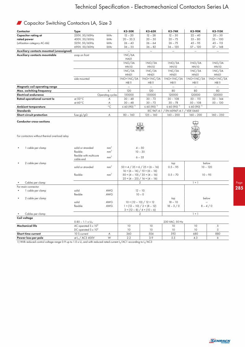
285
Contactor Type K3-50K K3-62K K3-74K K3-90K K3-115K
Capacitor rating at 230V, 50/60Hz kVAr 12 – 20 12 – 28 12 – 30 22 – 40 20 – 50
rated power 400V, 50/60Hz kVAr 20 – 33.3 20 – 50 20 – 75 33 – 80 33 – 100
(utilization category AC-6b) 525V, 50/60Hz kVAr 26 – 43 26 – 64 26 – 75 45 – 95 45 – 115
690V, 50/60Hz kVAr 36 – 55 36 – 82 36 – 120 57 – 120 57 – 148
Auxiliary contacts mounted (unassigned) -- -- -- -- --
Auxiliary contacts mountable snap on front 1NC/6A
HA01
1NO/3A 1NO/3A 1NO/3A 1NO/3A 1NO/3A
HN10 HN10 HN10 HN10 HN10
1NC/3A 1NC/3A 1NC/3A 1NC/3A 1NC/3A
HN01 HN01 HN01 HN01 HN01
side mounted 1NO+1NC/3A 1NO+1NC/3A 1NO+1NC/3A 1NO+1NC/3A 1NO+1NC/3A
HB11 HB11 HB11 HB11 HB11
Magnetic coil operating range -- -- -- -- --
Max. switching frequency h-1 120 120 80 80 80
Electrical endurance Operating cycles 150000 150000 120000 120000 120000
Rated operational current Ie at 50°C A 30 – 48 30 – 72 30 – 108 50 – 115 50 – 144
at 60°C A 30 – 48 30 – 72 30 – 78 50 – 108 50 – 130
Ambient temperature °C ≤ 60 (90) 1) ≤ 60 (90) 1) ≤ 60 (90) 1) ≤ 60 (90) 1)
Standards IEC 947-4-1 / EN 60947-4-1 / VDE 0660
Short-circuit protection fuse gL/gG A 80 – 160 125 – 160 160 – 200 160 – 200 160 – 250
Conductor cross-sections
For contactors without thermal overload relay
• 1 cable per clamp solid or stranded mm2 4 – 50
flexible mm2 10 – 35
flexible with multicore cable end
mm2 6 – 35
• 2 cable per clamp top below
solid or stranded mm2 50 + 4 / 35 + 6 / 25 + (6 – 16) 0.5 – 95 10 – 120
16 + (6 – 16) / 10 + (6 – 16)
flexible mm2 50 + (4 – 10) / 35 + (4 – 16) 0.5 – 70 10 – 95
25 + (4 – 25) / 16 + (4 – 16)
• Cables per clamp 2 1 + 1
For main connector
• 1 cable per clamp solid AWG 12 – 10
flexible AWG 10 – 0
• 2 cable per clamp top below
solid AWG 10 + (12 – 10) / 12 + 12 18 – 10 --
flexible AWG 1 + (12 – 10) / 2 + (8 – 12) 18 – 3 / 0 8 – 4 / 0
3 + (12 – 8) / 4 + (10 – 6)
• Cables per clamp 2 1 + 1
Coil voltage
0.85 – 1.1 x UN 230 VAC; 50 Hz
Mechanical life AC operated S x 106 10 10 10 10 5
DC operated S x 106 10 10 10 10 5
Short time current 10 S current A 360 504 592 680 880
Power loss per pole at Ie / AC3 400V W 2.2 3.9 5.5 4.3 6
1) With reduced control voltage range 0.9 up to 1.0 x Ue and with reduced rated current Ie/AC1 according to Ie/AC3
Technical Specification - Electromechanical Contactors Series LA
w Capacitor Switching Contactors LA, Size 3

Page
286
Mounted auxiliary contacts Type
K3-18NK K3-24K, K3-32K K3-50K, K3-62K
K3-74K K3-90K, K3-115K
Control circuit
Power consumption of coils
AC operated inrush VA 33-45 90-115 140-165 190-280
sealed VA 7-10 9-13 13-18 2.5-5
W 2.6-3 2.7-4 5.4-7 2.5-5
DC operated inrush W 75 140 200 190-280
sealed W 2 2 6 2.5-5
Operation range of coils
in multiples of control voltage Us AC operated 0.85-1.1 0.85-1.1 0.85-1.1 0.85-1.1
DC operated 0.8-1.1 0.8-1.1 0.8-1.1 0.8-1.1
Switching time
At control voltage Us ±10% 2) 3)
AC operated make time ms 8-16 10-25 12-28 20-35
release time ms 5-13 8-15 8-15 35-50
arc duration ms 10-15 10-15 10-15 10-15
DC operated make time ms 8-12 10-20 12-23 20-35
release time ms 8-13 10-15 10-18 35-50
arc duration ms 10-15 10-15 10-15 10-15
Cable cross-section
Auxiliary connector solid mm2 0.75-6 -- -- --
flexible mm2 1-4 -- -- --
flexible with multicore cable end
mm2 0.75-4 -- -- --
Magnet coil solid mm2 0.75-2.5 0.75-2.5 0.75-2.5 0.75-2.5
flexible mm2 0.5-2.5 0.5-2.5 0.5-2.5 0.5-2.5
flexible with multicore cable end
mm2 0.5-1.5 0.5-1.5 0.5-1.5 0.5-1.5
Clamps per pole 2 2 2 2
Auxiliary connector solid AWG 18-10 -- -- --
flexible AWG 18-10 -- -- --
Magnet coil solid AWG 14-12 14-12 14-12 14-12
flexible AWG 18-12 18-12 18-12 18-12
Clamps per pole 2 2 2 2
Rated insulation voltage Ui 1) V~ 690 -- -- --
Thermal rated current Ith to 690V
Ambient temperature 40°C A 16 -- -- --
60°C A 12 -- -- --
Utilization category AC15
Rated operational current Ie 220-240V A 12 -- -- --
380-415V A 4 -- -- --
440V A 4 -- -- --
500V A 3 -- -- --
660-690V A 1 -- -- --
Utilization category DC13
Rated operational current Ie 60V A 8 -- -- --
110V A 1 -- -- --
220V A 0.1 -- -- --
Short circuit protection
short-circuit current 1kA, contact welding not accepted
max. fuse size gL (gG) A 25 -- -- --
Auxiliary contacts snap on or side mounted
Type HA01 HB11 HN10 HN01
1 NC 1 NO+1 NC 1 NO 1 NC
AC15 230V A 6 3 3 3
AC15 400V A 3 2 2 2
AC1 690V A 25 10 10 10
1) Suitable for: earthed-neutral systems, overvoltage category I to IV, pollution degree 3 (standard-industry): Uimp = 8kV. Data for other conditions on request
2) Total breaking time = release time + arc duration
3) Values for delay of the release time of the make contact and the make time of the break contact will be increased, if magnet coils are protected against voltage peaks (varistor, RC-unit, diode-unit)
Technical Specification - Electromechanical Contactors Series LA
w Capacitor Switching Contactors LA, Size 3

Page
287
w Technical Specifications according to IEC 947-4-1, EN 60947-4-1, VDE 0660
Main contacts Type K(G)3-10 K(G)3-14 K(G)3-18 K(G)3-22 K(G)3-24 K(G)3-32 K(G)3-40 K3-50 K3-62 K3-74
Rated insulation voltage Ui 1) V AC 690 690 690 690 690 690 690 830 830 830
Making capacity Ieff
at Ue = 690VAC
A 200 200 200 200 400 500 500 700 900 900
1000VAC A - - - - - - - - - -
Breaking capacity Ieff 400VAC A 180 180 200 200 380 400 400 600 800 800
K3-10 to K3-22 cos = 0.65 500VAC A 150 150 180 180 300 370 370 500 700 700
K3-24 to K3-1200 cos = 0.35 690VAC A 100 100 150 150 260 340 340 400 500 500
1000VAC A - - - - - - - - - -
Utilization category AC1
Switching of resistive load
Rated operational current Ie (=Ith) 690V A 25 25 32 32 50 65 80 110 120 130
at 40 °C, open
Rated operational power 220V kW 9.5 9.5 12.2 12.2 19.0 24.7 30.4 41.9 45.7 49.5
of three-phase resistive loads 230V kW 9.9 9.9 12.7 12.7 19.9 25.9 31.8 43.8 47.7 51.7
50-60 Hz, cos = 1 240V kW 10.4 10.4 13.3 13.3 20.8 27.0 33.2 45.7 49.8 54.0
380V kW 16.4 16.4 21.0 21.0 32.9 42.7 52.6 72.3 78.9 85.5
400V kW 17.3 17.3 22.1 22.1 34.6 45.0 55.4 76.1 83.0 90.0
415V kW 17.9 17.9 23.0 23.0 35.9 46.7 57.4 79.0 86.2 93.3
440V kW 19.9 19.0 24.4 24.4 38.1 49.5 60.9 83.7 91.3 99.0
500V kW 21.6 21.6 27.7 27.7 43.3 56.2 69.2 95.2 103.8 112.5
660V kW 28.5 28.5 36.5 36.5 57.1 74.2 91.3 125.6 137.0 148.4
690V kW 29.8 29.8 38.2 38.2 59.7 77.6 95.5 131.3 143.2 155.2
1000V kW - - - - - - - - - -
Rated operational current Ie (=Ithe) 690V A 25 25 32 32 40 55 65 90 100 110
at 60 °C, enclosed
Rated operational power 220V kW 9.5 9.5 12.2 12.2 15.2 20.9 24.7 34.3 38.1 41.9
of three-phase resistive loads 230V kW 9.9 9.9 12.7 12.7 15.9 21.9 25.9 35.8 39.8 43.8
50-60 Hz, cos = 1 240V kW 10.4 10.4 13.3 13.3 16.6 22.8 27.0 37.4 41.5 45.7
380V kW 16.4 16.4 21.0 21.0 26.3 36.2 42.7 59.2 65.7 72.3
400V kW 17.3 17.3 22.1 22.1 27.7 38.1 45.0 62.3 69.2 76.1
415V kW 17.9 17.9 23.0 23.0 28.7 39.5 46.7 64.6 71.8 79.0
440V kW 19.0 19.0 24.4 24.4 30.4 41.9 49.5 68.5 76.1 83.7
500V kW 21.6 21.6 27.7 27.7 34.6 47.6 56.2 77.9 86.5 95.2
660V kW 28.5 28.5 36.5 36.5 45.7 62.8 74.2 102.8 114.2 125.6
690V kW 29.8 29.8 38.2 38.2 47.7 65.7 77.6 107.4 119.4 131.3
1000V kW - - - - - - - - - -
Minimum cross-section of conductor at load with Ie (=Ith)
mm2 4 4 6 6 10 16 25 35 50 50
Utilization category AC2 and AC3
Switching of three-phase motors
Rated operational current Ie 220V A 12 15 18 22 24 30 40 50 63 74
open and enclosed 230V A 11.5 14.5 18 22 24 30 40 50 63 74
240V A 11 15 18 22 24 30 40 50 63 74
380-400V A 10 14 18 22 24 30 40 50 63 74
415V A 9 14 18 22 24 30 40 50 63 74
440V A 9 14 18 22 24 30 40 50 63 74
500V A 8.9 11.9 15 15 22.5 28.5 28.5 44 54 64.5
660-690V A 6.7 9 12 12 17.5 21 21 33 42 49
1000V A - - - - - - - - - -
Rated operational power 220-230V kW 3 4 5 6 6 8.5 11 12.5 18.5 22
of three-phase motors 240V kW 3 4 5 7 7 9 11.5 13.5 19 23
50-60 Hz 380-400V kW 4 5.5 7.5 11 11 15 18.5 22 30 37
415V kW 4.5 6 8.5 12 12 16 20 24 33 40
440V kW 4.5 6 8.5 12 12 16 20 24 33 40
500V kW 5.5 7.5 10 10 15 18.5 18.5 30 37 45
660-690V kW 5.5 7.5 10 10 15 18.5 18.5 30 37 45
1000V kW - - - - - - - - - -
1) Suitable at 690V for: earthed-neutral systems, overvoltage category I to IV. pollution degree 3 (standard-industry): Uimp = 8 kV. Data for other conditions on request.
Technical Specification - Electromechanical Contactors Series LA
w Power Contactors

Page
288
w Technical Specifications according to IEC 947-4-1, EN 60947-4-1, VDE 0660
Main Contacts Type K3-90 K3-115 K3-116 K3-151 K3-176 K3-210 K3-260 K3-316 K3-450 K3-550
Rated insulation voltage Ui1) VAC 1000 1000 1000 1000 1000 1000 1000 1000 1000 1000
Making capacity Ieff
at Ue = 690VAC
A 1100 1200 1200 1500 2000 2100 2600 3200 4500 5500
1000VAC A 540 600 600 720 840 1020 1200 1500 2400 3000
Breaking capacity Ieff 400VAC A 950 1100 1000 1200 1500 1600 2100 2600 4500 5500
K3-10 up to K3-22 cos = 0.65 500VAC A 850 1000 1000 1200 1500 1600 2100 2600 4500 5500
K3-24 up to K3-1200 cos = 0.35 690VAC A 600 600 800 1000 800 1200 1900 2300 3200 4400
1000VAC A 450 450 400 500 600 700 850 1000 - -
Utilization category AC1 Switching of resistive load Rated operational current Ie (=Ith) 690V A 160 200 200 230 250 350 450 500 700 760
at 40°C, open Rated operational power 220V kW 60 76 76 87 95 133 171 190 266 289
of three-phase resistive loads 230V kW 63 79 79 91 99 139 179 199 279 302
50-60Hz, cos = 1 240V kW 66 83 83 95 103 145 187 207 291 315
380V kW 105 131 131 151 164 230 296 329 460 500
400V kW 110 138 138 159 173 242 311 346 485 526
415V kW 115 143 143 165 179 251 323 359 503 546
440V kW 121 152 152 175 190 266 342 381 533 579
500V kW 138 173 173 199 216 303 389 453 606 658
660V kW 182 228 228 262 285 400 514 571 800 868
690V kW 191 239 239 274 298 418 537 597 836 908
1000V kW 221 277 216 318 346 433 546 606 692 866
Rated operational current Ie (=Ith) at 60°C, enclosed 690V A 145 170 170 180 200 280 360 400 550 600
Rated operational power 220V kW 55 64 64 68 76 106 137 152 209 228
of three-phase resistive loads 230V kW 57 67 67 71 79 111 143 159 219 239
50-60Hz, cos = 1 240V kW 59 70 70 74 83 116 150 166 228 249
380V kW 95 111 111 118 131 184 237 263 362 395
400V kW 100 117 117 124 138 193 249 277 381 415
415V kW 104 122 122 129 143 201 259 287 395 431
440V kW 110 129 129 137 152 213 274 304 419 457
500V kW 125 147 147 155 173 242 312 346 476 519
660V kW 165 194 194 205 228 320 412 457 628 685
690V kW 173 202 202 215 239 334 430 478 657 717
1000V kW 166 187 216 277 346 388 499 554 692 866
Minimum cross-section of conductor at load with Ie(=Ith) mm² 95 120 95 95 120 240 2x150 2x(30x6) 2x(40x5) 2x(50x5)
Utilization category AC2 and AC3 Switching of three-phase motors Rated operational current Ie 220V A 90 115 115 150 175 210 260 315 450 550
open and enclosed 230V A 90 115 115 150 175 210 260 315 450 550
240V A 90 115 115 150 175 210 260 315 450 550
380-400V A 90 115 115 150 175 210 260 315 450 550
415V A 90 115 115 150 175 210 260 315 450 550
440V A 90 115 115 150 175 210 260 315 450 550
500V A 79 79 115 150 175 210 260 315 450 550
660-690V A 60 60 100 120 140 150 180 240 400 500
1000V A 45 45 45 60 70 85 100 125 200 250
Rated operational power 220-230V kW 25 33 30 40 50 60 75 90 132 175
of three-phase motors 240V kW 27 35 35 45 55 65 80 100 140 185
50-60Hz 380-400V kW 45 55 55 75 90 110 132 160 250 300
415V kW 49 63 59 80 95 115 140 180 257 315
440V kW 49 63 63 85 100 125 150 190 270 335
500V kW 55 55 75 90 100 132 160 210 300 375
660-690V kW 55 55 90 110 132 132 160 210 375 500
1000V kW 55 55 55 75 90 110 132 160 280 355
1) Suitable at 690V for: earthed-neutral systems, overvoltage category I to IV, pollution degree 3 (standard-industry): Uimp = 8kV.
Data for other conditions on request.
Technical Specification - Electromechanical Contactors Series LA
w Power Contactors

Page
289
w Technical Specifications according to IEC 947-4-1, EN 60947-4-1, VDE 0660
Main contacts Type K(G)3-10 K(G)3-14 K(G)3-18 K(G)3-22 K(G)3-24 K(G)3-32 K(G)3-40 K3-50 K3-62 K3-74
Utilization category AC4
Switching of squirrel cage motors, inching
Rated operational current Ie 220V A 12 15 18 18 24 30 40 50 63 63
open and enclosed 230V A 11.5 14,5 18 18 24 30 40 50 62 62
240V A 11 14 18 18 24 32 40 50 62 62
380-400V A 10 14 18 18 24 32 40 50 62 62
415V A 9 14 18 18 23 30 37 45 60 60
440V A 9 14 18 18 23 30 37 45 55 55
500V A 9 12 16 16 17,5 21 21 33 42 42
660V A 7 9 9 9 17 20 20 31 40 40
690V A 6,5 8,5 8,5 8,5 17 20 20 31 40 40
1000V A - - - 5 - - - - - -
Rated operational power 220-230V kW 3 4 5 5 6 8,5 11 12,5 18,5 18,5
of three-phase motors 240V kW 3 4 5 7,5 7 9 11,5 13,5 19 19
50-60Hz 380-400V kW 4 5,5 7,5 8,5 11 15 18,5 22 30 30
415V kW 4,5 6 8,5 8,5 12 16 20 24 33 33
440V kW 4,5 6 8,5 10 12 16 20 24 33 33
500V kW 5,5 7,5 10 10 15 18,5 18,5 30 37 37
660-690V kW 5,5 7,5 10 - 15 18,5 18,5 30 37 37
1000V kW - - - - - - - - -
Utilization category AC5a
Switching of gas discharge lamps
Rated operational current Ie
per pole at 220/230V
Fluorescent lamps,
uncompensated and serial compensated A 20 20 25 25 40 52 64 88 96 104
parallel compensated A 7 9 9 9 18 22 22 30 40 45
dual-connection A 22,5 22,5 28 28 45 58 72 98 108 117
Metal halide lamps1),
uncompensated A 12 15 19 19 30 39 48 66 72 78
parallel compensated A 7 9 9 9 18 22 22 30 40 45
Mercury-vapour lamps2),
uncompensated A 22,5 25 28 28 45 58 72 99 108 117
parallel compensated A 7 9 9 9 18 22 22 30 40 45
Mixed light lamps3) A 20 20 25 25 40 52 64 88 96 104
LED-Lamps
consider the inrush current of the lamp ballast
max. lamps per pole (InLED ≤ Ith) =
inrush current of contactor
and cos of the lamp inrush current of lamp/EVG
max inrush current of contactor A 282 282 282 282 564 705 705 987 1269 1268
Utilization category AC5b
Switching of incandescent lamps4)
Rated operational current Ie
per pole at 220/230V A 12.5 12.5 12.5 12.5 25 31 31 43 56 56
1) Metal halide lamps and sodium-vapour lamps (high- and low-pressure lamps)
2) High-pressure lamps
3) Blended lamps, containing a mercury high-pressure unit and a tungsten helix in a fluorescent glass bulb (daylight lamps)
4) Current inrush approx. 16 x Ie
Technical Specification - Electromechanical Contactors Series LA
w Power Contactors

Page
290
w Technical Specifications according to IEC 947-4-1, EN 60947-4-1, VDE 0660
Main Contacts Type K3-90 K3-115 K3-151 K3-176 K3-210 K3-260 K3-316 K3-450 K3-550
Utilization category AC4
Switching of squirrel cage motors, inching
Rated operational current Ie 220V A 85 98 55 63 85 100 120 150 180
open and enclosed 230V A 85 98 55 63 85 100 120 150 180
240V A 85 98 55 63 85 100 120 150 180
380-400V A 85 85 55 63 85 100 120 150 180
415V A 85 85 55 63 85 100 120 150 180
440V A 85 85 55 63 85 100 120 150 180
500V A 85 85 - - - - - - -
660V A 60 60 - - - - - - -
690V A 57.5 57.5 - - - - - - -
1000V A - - - - - - - - -
Rated operational power 220-230V kW 25 30 15 18,5 25 30 37 45 51
of three-phase motors 240V kW 27 32 15,5 19 26 31 38 47 53
50-60Hz 380-400V kW 45 45 25 30 45 55 63 75 90
415V kW 49 49 25 33 45 55 65 80 100
440V kW 49 49 30 34 48 55 67 85 100
500V kW 55 55 25 30 55 65 75 100 110
660-690V kW 55 55 25 30 55 65 75 100 110
1000V kW - - - - - - - - -
Utilization category AC5a
Switching of gas discharge lamps
Rated operational current Ie
per pole at 220/230V
Fluorescent lamps,
uncompensated and serial compensate A 100 120 120 140 180 220 280 360 450
parallel compensated A 55 70 85 100 130 160 200 300 360
dual-connection A 112 144 120 140 180 220 280 360 450
Metal halide lamps1)
uncompensated A 85 90 95 110 140 180 230 300 380
parallel compensated A 55 70 75 85 110 140 170 260 300
Mercury-vapour lamps2)
uncompensated A 112 144 120 140 180 220 280 360 450
parallel compensated A 55 70 75 85 110 140 170 260 300
Mixed light lamps3) A 100 120 100 120 160 200 250 320 400
LED-Lamps max. lamps per pole (InLED ≤ Ith) =
inrush current of contactor
consider the inrush current of the lamp ballast inrush current of lamp/EVG
and cos of the lamp
max inrush current of contactor A 1551 1692 2115 2820 2961 3666 4512 6345 7755
Utilization category AC5b
Switching of incandescent lamps4)
Rated operational current Ie
per pole at 220/230V A 69 75 100 120 160 190 220 260 315
1) Metal halide lamps and sodium-vapour lamps (high- and low-pressure lamps)
2) High-pressure lamps
3) Blended lamps, containing a mercury high-pressure unit and a tungsten helix in a flourescent glass bulb (daylight lamps)
4) Current inrush approx. 16 x Ie
Technical Specification - Electromechanical Contactors Series LA
w Power Contactors

Page
291
w Technical Specifications according to IEC 947-4-1, EN 60947-4-1, VDE 0660
Main Contacts Type K(G)3-10 K(G)3-14 K(G)3-18 K(G)3-22 K(G)3-24 K(G)3-32 K(G)3-40 K3-50 K3-62 K3-74
Utilization category AC6A
Transformer primary switching
at inrush n 30 30 30 30 30 30 30 30 30 30
Rated operational current Ie 400V A 4,5 5,5 7,5 7,5 10,5 13,5 13,5 20 27 33
Rated operational power 220-230V kVA 1,8 2,2 3 3 4,2 5,4 5,4 8 10,7 13
dependent on inrush n 240V kVA 1,9 2,3 3,1 3,1 4,3 5,6 5,6 8,3 11,2 13,5
380-400V kVA 3,1 3,8 5,2 5,2 7,3 9,3 9,3 13,5 18,5 22,5
For different inrush-factors x 415-440V kVA 3,4 4,2 5,7 5,7 8 10,2 10,2 15 20,5 25
use the following formula: 500V kVA 3,9 4,8 6,5 6,5 9 11,5 11,5 17 23 28
Px=Pn*(n/x) 660-690V kVA 5,4 6,5 9 9 12,5 16 16 24 32 39
Utilization category AC6b
Switching of three-phase capacitors
Maximum inrush current (peak value)
as multiple k of the
capacitor rated current k 35 25 20 20 25 25 25 25 25 20
Rated operational current Ie 500V A 8 12 15,5 15,5 23 32 32 45 60 70
Rated operational power 220-230V kVAr 3 4,5 6 6 8,5 12 12 17 24 28
(sin 1) 240V kVAr 3,5 5 6,5 6,5 9,5 13 13 18,5 25 29
380-400V kVAr 5 7,5 10 10 15 20 20 29 39 46
For different multiples x 415-440V kVAr 5,5 8 11 11 16 22 22 32 43 50
use the following formula: 500V kVAr 7 10 13 13 20 26 26 39 50 58
Px=Pk*(k/x) 660-690V kVAr 7 10 13 13 20 26 26 40 50 58
Switching of
reactive capacitor banks
Rated operational current Ie 690V A 8 13 18 20 28 36 42 48 72 108 1)
Rated operational power 220-230V kVAr 2,9 5 7 7,5 11 14 16 20 28 33
240V kVAr 3,1 5,4 7 8 11 14 17 20 28 36
380-400V kVAr 5 9 12,5 13 20 25 27,5 33,3 50 75 1)
415-440V kVAr 5,5 9,5 13 14 22 27 30 36 53 75 1)
500V kVAr 6 11 15 17 25 30 36 40 60 75
660-690V kVAr 8 15 20 22 33 41 48 55 82 100
1000V kVAr - - - - - - - - - -
Utilization category DC1
Switching of resistive load
Time constant L/R ≤1ms
Rated operational current Ie 1 pole 24V A 20 25 32 32 50 65 80 110 120 130
60V A 20 25 32 32 50 65 80 110 120 130
110V A 6 6 6 6 10 10 10 12 12 12
220V A 0,8 0,8 0,8 0,8 1,4 1,4 1,4 1,4 1,4 1,4
3 poles in series 24V A 20 25 32 32 50 65 80 110 120 130
60V A 20 25 32 32 50 65 80 110 120 130
110V A 20 25 32 32 50 65 80 110 120 130
220V A 16 20 20 20 30 35 35 63 80 80
Utilization category DC3 and DC5
Switching of shunt motors
and series motors
Time constant L/R ≤15ms
Rated operational current Ie 1 pole 24V A 20 25 32 32 50 65 80 110 120 130
60V A 6 6 6 6 30 30 30 60 60 60
110V A 1,2 1,2 1,2 1,2 1,8 1,8 1,8 1,8 1,8 1,8
220V A 0,2 0,2 0,2 0,2 0,2 0,2 0,2 0,25 0,25 0,25
3 poles in series 24V A 20 25 32 32 50 65 80 110 120 130
60V A 20 25 32 32 40 40 40 80 80 80
110V A 20 20 20 20 40 40 40 80 80 80
220V A 2,5 2,5 2,5 2,5 4 4 4 5 5 5
1) Consider resistive load (Ith)
Technical Specification - Electromechanical Contactors Series LA
w Power Contactors

Page
292
w Technical Specifications according to IEC 947-4-1, EN 60947-4-1, VDE 0660
Main Contacts Type K3-90 K3-115 K3-151 K3-176 K3-210 K3-260 K3-316 K3-450 K3-550
Utilization category AC6A Transformer primary switching at inrush n 30 30 30 30 30 30 30 30 30
Rated operational current Ie 400V A 38 50 65 80 90 120 142 203 248
Rated operational power 220-230V kVA 15 20 25 30 34 45 54 77 95
dependent on inrush n 240V kVA 15,5 20,5 27 33 37 50 59 80 100
380-400V kVA 26 34 45 55 60 80 95 140 170
For different inrush-factors x 415-440V kVA 29 38 46 57 63 85 100 145 175
use the following formula: 500V kVA 33 43 55 69 75 100 120 170 210
Px=Pn*(n/x) 660-690V kVA 45 60 56 69 100 135 160 200 250
Utilization category AC6b Switching of three-phase capacitors Maximum inrush current (peak value) as multiple k of the capacitor rated current k 20 20 20 20 25 20 20 20 20
Rated operational current Ie 500V A 87 100 120 155 195 225 255 300 370
Rated operational power 220-230V kVAr 33 38 45 60 75 90 100 115 145
(sin 1) 240V kVAr 36 42 52 62 78 94 104 120 150
380-400V kVAr 57 65 80 100 130 155 170 200 250
For different multiples x 415-440V kVAr 60 70 95 110 135 165 175 210 260
use the following formula: 500V kVAr 70 80 100 130 170 194 220 260 320
Px=Pk*(k/x) 660-690V kVAr 70 80 100 130 170 194 220 260 320
Switching of reactive capacitor banks Rated operational current Ie 690V A 115 144 115 140 200 225 250 330 420
Rated operational power 220-230V kVAr 45 55 43 53 76 85 95 125 160
240V kVAr 45 55 45 55 80 90 100 130 170
380-400V kVAr 80 100 75 90 130 145 160 210 270
415-440V kVAr 100 120 80 100 140 160 170 230 290
500V kVAr 105 125 95 120 170 190 210 280 350
660-690V kVAr 120 148 125 150 200 230 260 350 450
1000V kVAr 160 200 155 200 300 340 400 500 650
Utilization category DC1 Switching of resistive load Time constant L/R ≤1ms Rated operational current Ie 1 pole 24V A 160 200 - - - - - - -
60V A 160 200 - - - - - - -
110V A 20 25 - - - - - - -
220V A 2 2,5 - - - - - - -
3 poles in series 24V
A 160 200 200 250 350 400 450 600 760
60V A 160 200 200 250 350 400 450 600 760
110V A 160 200 150 170 250 280 315 400 480
220V A 100 160 80 100 150 180 200 250 315
Utilization category DC3 and DC5 Switching of shunt motors and series motors Time constant L/R ≤15ms Rated operational current Ie 1 pole 24V A 160 200 - - - - - - -
60V A 85 110 - - - - - - -
110V A 2 2,5 - - - - - - -
220V A 0,5 0,5 - - - - - - -
3 poles in series 24V
A 160 200 - - - - - - -
60V A 100 110 - - - - - - -
110V A 100 110 - - - - - - -
220V A 7 8 - - - - - - -
Technical Specification - Electromechanical Contactors Series LA
w Power Contactors

Page
293
w Technical Specifications according to IEC 947-4-1, EN 60947-4-1, VDE 0660
Main contacts Type K(G)3-10 K(G)3-14 K(G)3-18 K(G)3-22 K(G)3-24 K(G)3-32 K(G)3-40 K3-50 K3-62 K3-74
Maximum ambient temperature
Operation open °C -40 to +60 (+90) 1)
enclosed °C -40 to +40
with thermal overload relay open °C -25 to +60
enclosed °C -25 to +40
Storage °C -50 to +90
Short circuit protection
for contactors without thermal overload relay
Coordination-type "1" according to IEC 947-4-1
Contact welding without hazard of persons
max. fuse size gL (gG) A 63 63 63 63 100 100 100 160 160 160
Coordination-type “2” according to IEC 947-4-1
Light contact welding accepted
max. fuse size gL (gG) A 25 35 35 35 50 50 50 100 125 125
Contact welding not accepted
max. fuse size gL (gG) A 16 16 16 16 25 35 35 50 63 63
For contactors with thermal overload relay the device with the smaller admissible backup fuse (contactor or thermal overload relay) determines the fuse size.
Cable cross-sections
for contactors without thermal overload relay
1 cable per clamp
main connector
solid or stranded mm² 0.75 - 6 1.5 - 25 4 - 50
flexible mm² 1 - 4 2.5 - 16 10 - 35
flexible with multicore cable end mm² 0,75 - 4 1.5 - 16 6 - 35
2 cables per clamp
solid or stranded mm² 6+(1-6) / 4+(0,75-4) 16+(2,5-16) / 10+(4-16) 50+4 / 35+6 / 25+(6-16)
2.5+(0.75-2.5) / 1.5+(0.75-1.5) 6+(4-16) / 4+(2.5-16) 16+(6-16) / 10+(6-16)
flexible mm² 6+(1.5-4) / 4+(1-4) 16+(2.5-6) / 10+(4-10) 50+(4-10) / 35+(4-16)
2.5+(0.75-2.5) / 1.5+(0.75-1.5) 6+(4-16) / 4+(2.5-16) 25+(4-25) / 16+(4-16)
1 cable per clamp
main connector
solid AWG 18 - 10 16 - 10 12 - 10
flexible AWG 18 - 10 14 - 4 10 - 0
2 cables per clamp
solid AWG 10+(16-10) / 12+(18-12) 10+(16-10) / 12+(18-12) 10+(12-10) / 12+12
14+(18-14) / 16+(18-16) 14+(18-14) / 16+(18-16)
flexible AWG 10+(14-10) / 12+(18-12) 4+(18-12) / 6+(18-8) 1+(12-10) / 2+(8-12)
14+(18-14) / 16+(18-16) 8+(18-8) / 10+(18-12) 3+(12-8) / 4+(10-6)
Frequency of operations z
Contactors without thermal overload relay
without load 1/h 10000 7000 7000
AC3, Ie 1/h 600 600 400
AC4, Ie 1/h 120 120 120
DC3, Ie 1/h 600 600 400
Mechanical life
AC operated S x 106 10 10 10
DC operated S x 106 10 10 10
DC-solenoid operated (KG3) S x 106 50 50 -
Short time current 10s-current A 96 120 144 176 184 240 296 450 504 592
120s-current A 42 52 58 66 80 97 110 195 203 222
Power loss per pole at Ie/AC3
400V W 0,21 0,35 0,5 0,75 0,7 1,3 2 2,2 3,9 5,5
contact resistance mOhm 2,1 1,8 1,5 1,5 1,2 1,2 1,2 1 1 1
Resistance to shock acc. to IEC 68-2-27
Shock time 20ms sine-wave NO g 10 10 10 10 8 8 8 8 8 8
NC g 6 6 6 6 - - - - - -
1) 90° reduces the control voltage range to 0.9 up to 1.0xUs and reduces the rated current Ie/AC1 to the value of Ie/AC3
Technical Specification - Electromechanical Contactors Series LA
w Power Contactors

Page
294
w Technical Specifications according to IEC 947-4-1, EN 60947-4-1, VDE 0660
Main contacts Type K3-90 K3-115 K3-116 K3-151 K3-176 K3-210 K3-260 K3-316 K3-450 K3-550
Maximum ambient temperature Operation open °C -40 to +60 (+90)2) -25 to +55 (+70)2)
enclosed °C -40 to +40 -25 to +40
with thermal overload relay open °C -25 to +60 -25 to +55
enclosed °C -25 to +40 -25 to +40
Storage °C -50 to +90 -55 to +80
Short circuit protection for contactors without thermal overload relay
Coordination-type "1" according to IEC 947-4-1
Contact welding without hazard of persons
max. fuse size gL (gG) A 250 250 200 250 315 400 450 500 630 630
Coordination-type “2” according to IEC 947-4-1
Light contact welding accepted max. fuse size gL (gG) A 160 200 160 200 250 315 400 400 500 560
Contact welding not accepted max. fuse size gL (gG) A 100 125 125 160 200 250 315 - - -
For contactors with thermal overload relay the device with the smaller admissible backup fuse (contactor or thermal overload relay) determines the fuse size.
Cable cross-sections
for contactors without thermal overload relay
1 cable per clamp
main connector solid or
stranded mm² 0.5 - 95 10 - 120
flexible mm² 0.5 - 70 25 - 95 busbar busbar busbar busbar
flexible with
multicore cable end
mm² 0.5 - 70 10 - 95 18 x 4 25 x 6 30 x 5 40 x 6
2 cables per clamp screw screw screw screw
solid or
stranded mm² 0.5 - 95 + 10 - 120 M8 M10 M12 M12
flexible mm² 0.5 - 70 + 25 - 95
1 cable per clamp main connector solid AWG 18 - 10 -
flexible AWG 18 - 3/0 8 - 4/0
2 cables per clamp solid AWG -
flexible AWG 18 - 3/0 + 8 - 4/0
Frequency of operations z Contactors without thermal overload relay
without load 1/h 3000 1200
AC3, Ie 1/h 300 50
AC4, Ie 1/h 120 -
DC3, Ie 1/h 300 -
Mechanical life AC operated S x 106 S x 106 5 10 5 5
DC operated S x 106 S x 106 5 10 5 5
DC-solenoid operated (KG3) S x 106 S x 106 - - - -
Short time current 10s-current A 680 880 920 1200 1400 1800 2200 2600 3600 4400
120s-current A 275 330 410 500 575 800 900 1000 1400 1750
Power loss per pole at Ie/AC3
400V W 4,8 7,9 7,9 9 11 8 11 14,9 26,3 33,3
contact resistance mOhm 0,6 0,5 0,5 0,4 0,35 0,18 0,16 0,15
Resistance to shock acc. to IEC 68-2-27
Shock time 20ms sine-wave NO g 7 7 - - - - - - - -
NO g 5 5 - - - - - - - -
1) 90° reduces the control voltage range to 0.9 up to 1.0xUs and reduces the rated current Ie/AC1 to the value of Ie/AC3
2) 70° reduces the control voltage range to 1.0xUs and reduces the rated current Ie/AC1 to the value of Ie/AC3
3) After each 1x10⁶ operations magnetic core and built-in auxiliary contact block must be changed
Technical Specification - Electromechanical Contactors Series LA
w Power Contactors

Page
295
w Technical Specifications according to IEC 947-4-1, EN 60947-4-1, VDE 0660
Auxiliary Contacts Type K(G)3-10 K(G)3-14 K(G)3-18 K(G)3-22 K(G)3-24 K(G)3-32 K(G)3-40 K3-50 K3-62 K3-74
Rated insulation voltage Ui 1) V~ 690 - -
Thermal rated current Ith to 690V
Ambient temperature 40°C A 10 (16)5) - -
60°C A 6 (12)5) - -
Utilization category AC15
Rated operational current Ie 220-240V A 3 (12)5) - -
380-415V A 2 (4)5) - -
440V A 1,6 (4)5) - -
500V A 1,2 (3)5) - -
660-690V A 0,6 (1)5) - -
Utilization category DC13
Rated operational current Ie 60V A 3,5 (8)5) - -
110V A 0,5 (1)5) - -
220V A 0,1 - -
Short circuit protection For contactors with thermal overload relay the device with the smaller admissible control
short-circuit current 1kA, fuse (contactor or thermal overload relay) determines the fuse.
contact welding not accepted
max. fuse size gL (gG) A 20 (25)5) - -
Control Circuit
Power consumption of coils
AC operated inrush VA 33-45 90-115 140-165
sealed VA 7-10 9-13 13-18
W 2.6-3 2.7-4 5.4-7
DC operated inrush W 75 140 200
double winding coil sealed W 2 2 6
DC solenoid operated inrush W 3 4 -
(KG3) sealed W 3 4 -
Operation range of coils
in multiples of control voltage Us
AC operated 0.85-1.1 0.85-1.1 0.85-1.1
DC operated 0.8-1.1 0.8-1.1 0.8-1.1
Switching time at control voltage Us ±10% 2) 3)
AC operated make time ms 8-16 10-25 12-28
release time ms 5-13 8-15 8-15
arc duration ms 10-15 10-15 10-15
DC operated make time ms 8-12 10-20 12-23
double winding coil release time ms 8-13 10-15 10-18
arc duration ms 10-15 10-15 10-15
DC solenoid operated make time ms 65 - 85 65 - 85 -
(KG3) release time ms 20 - 30 4) 20 - 30 4) -
arc duration ms 10-15 10-15 -
Cable cross-section
Auxiliary connector solid mm² 0.75-6 - -
flexible mm² 1-4 - -
flexible with multicore cable end
mm² 0.75-4 - -
Magnet coil solid mm² 0.75-2.5 0.75-2.5 0.75-2.5
flexible mm² 0.5-2.5 0.5-2.5 0.5-2.5
flexible with multicore cable end
mm² 0.5-1.5 0.5-1.5 0.5-1.5
Clamps per pole 2 2 2
Auxiliary connector solid AWG 18 - 10 - -
flexible AWG 18 - 10 - -
Magnet coil solid AWG 14 - 12 14 - 12 14 - 12
flexible AWG 18 - 12 18 - 12 18 - 12
Clamps per pole 2 2 2
1) Suitable for: earthed-neutral systems, overvoltage category I to IV, pollution degree 3 (standard-industry): Uimp = 8kV. Data for other conditions on request
2) Total breaking time = release time + arc duration
3) Values for delay of the release time of the make contact and the make time of the break contact will be increased, if magnet coils are protected against voltage peaks (varistor, RC-unit, diode-unit)
4) with built-in coil suppressor
5) for contactors KG3-A.. only.
Technical Specification - Electromechanical Contactors Series LA
w Power Contactors

Page
296
w Technical Specifications according to IEC 947-4-1, EN 60947-4-1, VDE 0660
Auxiliary Contacts Type K3-90 K3-115 K3-116 K3-151 K3-176 K3-210 K3-260 K3-316 K3-450 K3-550
Rated insulation voltage Ui1) Thermal rated current Ith up to 690V V~ - - - 690
Ambient temperature 40°C A - - - 10
60°C A - - - -
Utilization category AC15 - - - - -
Rated operational current Ie 220-240V A - - - 3
380-415V A - - - 2
440V A - - - 1.5
500V A - - - 1.5
660-690V A - - - 1
Utilization category DC13 Rated operational current Ie 60V A - - - -
110V A - - - 1
220V A - - - 0.5
Short-circuit protection short-circuit current 1kA contact welding not accepted max. fuse size gL (gG) A - - - 10
Control circuit Power consumption of coils AC operated inrush VA 165-220 350 360 800-950
sealed VA 2.5-5 5 5 9-11
W 2.5-5 5 5 9-11
DC operated inrush W 250 350 360 700-850
sealed W 5 5 5 8-10
DC solenoid operated (KG3) inrush W - - - -
sealed W - - - -
Operation range of coils in multiples of control voltage Us AC operated 0.85-1.1 0.85-1.1 0.85-1.1 0.85-1.1
DC operated 0.8-1.1 0.85-1.1 0.85-1.1 0.85-1.1
Switching time at control voltage Us ±10%2)3) AC operated make time ms 20-35 30-60 40-60 50-100
release time ms 35-50 30-80 15-45 150-200 / 500-10001)
arc duration ms 10-15 - -
DC operated make time ms 20-35 30-60 40-60 -
double winding coil release time ms 35-50 30-80 15-45 -
arc duration ms 10-15 - - -
DC solenoid operated make time ms - - - -
(KG3) release time ms - - - -
arc duration ms - - - -
Cable cross-sections Auxiliary connector solid mm² - - - 0.75-2,5
flexible mm² - - - 0.75-2,5
flexible with multicore cable end
mm² - - - -
Magnet coil solid mm² 0.75-2.5 1-2.5 1-2.5 1-2.5
flexible mm² 0.5-2.5 1-2.5 1-2.5 1-2.5
flexible with multicore cable end
mm² 0.5-1.5 - - -
Clamps per pole 2 2 2 2
Auxiliary connector solid AWG - - - 16 - 12
solid AWG - - - 16 - 12
Magnet coil solid AWG 14 - 12 16 - 12 16 - 12 16 - 12
solid AWG 18 - 12 16 - 12 16 - 12 16 - 12
Clamps per pole 2 2 2 2
1) Suitable for: earthed-neutral systems, overvoltage category I to IV, pollution degree 3 (standard-industry): Uimp = 8kV. Data for other conditions on request
2) Total breaking time = release time + arc duration
3) Values for delay of the release time of the make contact and the make time of the break contact will be increased, if magnet coils are protected against voltage peaks (varistor, RC-unit, diode-unit)
Technical Specification - Electromechanical Contactors Series LA
w Power Contactors

Page
297
w Technical Specifications according to IEC 947-4-1, EN 60947-4-1, VDE 0660
Main contacts Type K2-23 K2-30 K2-37 K2-45 K2-60
Rated insulation voltage Ui 1) V~ 690 690 690 690 690
Making capacity Ieff at Ue = 690V AC A 400 500 500 700 900
Breaking capacity Ieff 400V~ A 380 400 400 600 800
K2-09 to K2-16 cos = 0,65 500V AC
A 300 370 370 500 700
K2-23 to K3-1200 cos = 0,35 690V AC
A 260 340 340 400 500
1000V~ A - - - - -
Utilization category AC1
Switching of resistive load
Rated operational current Ie (=Ith)
at 40°C, open A 45 50 50 80 100
Rated operational power 220V kW 17 19 19 30 38
of three-phase resistive loads 230V kW 18 20 20 31,5 40
50-60Hz, cos = 1 240V kW 18,5 20,5 20,5 33 41
380V kW 29,5 33 33 52 65
400V kW 31 34,5 34,5 55 69
415V kW 32 36 36 57 71
440V kW 34 38 38 61 76
500V kW 39 43 43 69 86
660V kW 51 57 57 91 114
690V kW 53,5 60 60 95 119
Rated operational current Ie (=Ithe) A 35 40 40 63 80
at 60°C, enclosed 220V kW 13 15 15 24 30
Rated operational power 230V kW 13,5 16 16 25 31,5
of three-phase resistive loads 240V kW 14,5 16,5 16,5 26 33
50-60Hz, cos = 1 380V kW 23 26 26 41 52
400V kW 24 27,5 27,5 43 55
415V kW 25 28,5 28,5 45 57
440V kW 26,5 30 30 48 61
500V kW 30 34 34 54 69
660V kW 40 45 45 72 91
690V kW 42 48 48 75 95
Minimum cross-section of conductor
at load with Ie (=Ith ) mm2 10 10 10 25 35
Utilization category AC2 and AC3
Switching of three-phase motors
Rated operational current Ie 220V A 23 30 37 45 63
open and enclosed 230V A 23 30 37 45 61
240V A 23 30 37 45 60
380-400V A 23 30 37 45 60
415-440V A 23 30 37 45 60
500V A 23 30 30 45 55
660V A 17,5 21 21 33 42
690V A 17 20 20 31 40
Rated operational power 220-230V kW 6 8,5 11 12,5 18,5
of three-phase motors 240V kW 7 9 11,5 13,5 19
50-60Hz 380-400V kW 11 15 18,5 22 30
415V kW 12 16 20 24 33
440V kW 12 16 20 24 33
500V kW 15 18,5 18,5 30 37
660-690V kW 15 18,5 18,5 30 37
1) Suitable at 690V for: earthed-neutral systems, overvoltage category I to IV, pollution degree 3 (standard-industry): Uimp = 8kV.
Data for other conditions on request.
Technical Specification - Electromechanical Contactors Series LA
w Power Contactors

Page
298
w Technical Specifications according to IEC 947-4-1, EN 60947-4-1, VDE 0660
Main contacts Type K2-23 K2-30 K2-37 K2-45 K2-60
Utilization category AC4
Switching of squirrel cage motors, inching
Rated operational current Ie 220V A 23 30 37 45 63
open and enclosed 230V A 23 30 37 45 61
240V A 23 30 37 45 60
380-400V A 23 30 37 45 60
415V A 21 28 37 45 60
440V A 21 28 37 45 60
500V A 17 23 23 45 55
660V A 13 17 17 33 42
690V A 12,5 16,5 16,5 31 40
Rated operational power 220-230V kW 6 8,5 11 12,5 18,5
of three-phase motors 240V kW 7 9 11,5 13,5 19
50-60Hz 380-400V kW 11 15 18,5 22 30
415-440V kW 11 15 20 24 33
500V kW 11 15 15 30 37
660-690V kW 11 15 15 30 37
Utilization category AC5a
Switching of gas discharge lamps
Rated operational current Ie
per pole at 220/230V
Fluorescent lamps, uncompensated A 35 40 40 65 85
Fluorescent lamps, compensated A 18 22 22 30 40
Fluorescent lamps, dual-connection A 41 45 45 72 90
Metal-halide lamps1), uncompensated A 28 30 30 50 62
Metal-halide lamps1), compensated A 18 22 22 30 40
Mercury-vapour lamps2), uncompensated A 41 45 45 72 90
Mercury-vapour lamps2), compensated A 18 22 22 30 40
Mixed light lamps3) A 35 40 40 65 85
Utilization category AC5b
Switching of incandescent lamps4)
Rated operational current Ie
per pole at 220/230V A 25 31 31 43 56
Utilization category AC6A
Transformer primary switching
at inrush n 30 30 30 30 30
Rated operational current Ie 400V A 10,5 13,5 13,5 20 27
Rated operational power 220-230V kVA 4,2 5,4 5,4 8 10,7
240V kVA 4,3 5,6 5,6 8,3 11,2
dependent on inrush n 380-400V kVA 7,3 9,3 9,3 13,5 18,5
For different inrush-factors x 415-440V kVA 8 10,2 10,2 15 20,5
use the following formula: 500V kVA 9 11,5 11,5 17 23
Px=Pn*(n/x) 660-690V kVA 12,5 16 16 24 32
Utilization category DC1
Switching of resistive load
Time constant L/R ≤1ms 1 pole 24V A 45 50 50 80 100
Rated operational current Ie 60V A 45 50 50 80 100
110V A 10 10 10 12 12
220V A 1,4 1,4 1,4 1,4 1,4
2 poles in series 24V A 45 50 50
60V A 45 50 50
110V A 45 50 50
220V A 10 10 10
3 poles in series 24V A 45 50 50 80 100
60V A 45 50 50 80 100
110V A 45 50 50 80 100
220V A 30 35 35 63 80
1) Metal halide lamps and sodium-vapour lamps (high- and low-pressure lamps)
2) High-pressure lamps
3) Blended lamps, containing a mercury high-pressure unit and a tungsten helix in a fluorescent glass bulb (daylight lamps)
4) Current inrush approx. 16 x Ie
5) With central compensation pay attention to the current inrush (capacitor switching contactors)
Technical Specification - Electromechanical Contactors Series LA
w Power Contactors

Page
299
w Technical Specifications according to IEC 947-4-1, EN 60947-4-1, VDE 0660
Main contacts Type K2-23 K2-30 K2-37 K2-45 K2-60
Utilization category DC3 and DC5
Switching of shunt motors
and series motors
Time constant L/R ≤15ms 1 pole 24V A 45 50 50 80 100
Rated operational current Ie 60V A 30 30 30 60 60
110V A 1,8 1,8 1,8 1,8 1,8
220V A 0,2 0,2 0,2 0,25 0,25
2 poles in series 24V A 45 50 50
60V A 45 50 50
110V A 30 30 30
220V A 1,8 1,8 1,8
3 poles in series 24V A 45 50 50 80 100
60V A 40 40 40 80 80
110V A 40 40 40 80 80
220V A 4 4 4 5 5
Maximum ambient temperature
Operation open °C -40 to +60 (+90) 1)
enclosed °C -40 to +40
with thermal overload relay open °C -25 to +60
enclosed °C -25 to +40
Storage °C -50 to +90
Short circuit protection
for contactors without thermal overload relay, Coordination-type "1" according to IEC 947-4-1, Contact welding without hazard of persons
max. fuse size gL (gG) A 80 80 80 160 160
Coordination-type “2” according to IEC 947-4-1, Light contact welding accepted
max. fuse size gL (gG) A 50 50 50 100 125
Contact welding not accepted
max. fuse size gL (gG) A 25 35 35 50 63
For contactors with thermal overload relay the device with the smaller admissible backup fuse (contactor or thermal overload relay) determines the fuse size.
Cable cross-sections
for contactors without thermal overload relay
main connector solid or stranded mm² 1,5-10 + 1,5-6 4 - 35 2)
flexible mm² 1,5-6 + 1,5-4 6 - 25 2)
flexible with multicore cable end
mm² 1,5-6 + 1,5-4 4 - 25
Cables per clamp 1+1 1
main connector solid AWG 14 - 10 + 14 - 10 10
flexible AWG 14 - 8 + 14 - 10 10 - 2
Cables per clamp 1+1 1
Frequency of operations z
Contactors without thermal overload relay
without load 1/h 7000 7000
AC3, Ie 1/h 600 400
AC4, Ie 1/h 120 120
DC3, Ie 1/h 600 400
Mechanical life
AC operated S x 106 10 10
DC operated with economy resistor S x 106 10 10
Short time current 10s-current A 184 240 296 360 504
Power loss per pole at Ie /AC3 400V W 0.63 1.1 1.7 1.8 3.6
Resistance to shock acc. to IEC 68-2-27
Shock time 20ms sine-wave NO g 8 8 8 8 8
NO g 5 5 5 - -
1) 90° reduces the control voltage range to 0.9 up to 1.0xUs and reduces the rated current Ie/AC1 to the value of Ie/AC3
2) Maximum cable cross-section with prepared conductor
Technical Specification - Electromechanical Contactors Series LA
w Power Contactors

Page
300
w Technical Specifications according to IEC 947-4-1, EN 60947-4-1, VDE 0660
Auxiliary contacts Type K2-23 K2-30 K2-37 K2-45 K2-60
Rated insulation voltage Ui 1) V AC 690 -
Thermal rated current Ith to 690V
Ambient temperature 40 °C A 16 -
60 °C A 12 -
Utilization category AC15
Rated operational current Ie 220-240V A 12 -
380-415V A 4 -
440V A 4 -
500V A 3 -
660-690V A 1 -
Utilization category DC13
Rated operational current Ie 60V A 8 -
110V A 1 -
220V A 0,1 -
Short circuit protection
short-circuit current 1kA,
contact welding not accepted
max. fuse size gL (gG) A - -
For contactors with thermal overload relay the device with the smaller admissible control fuse (contactor or thermal overload relay) determines the fuse.
Control Circuit
Power consumption of coils
AC operated inrush VA 90-115 140-165
sealed VA 9 - 13 13-18
W 2.7-4 5.4-7
DC operated inrush W 140 200
with economic circuit sealed W 2 6
Operation range of coils
in multiples of control voltage Us AC operated 0.85-1.1 0.85-1.1
DC operated 0.8-1.1 0.8-1.1
Switching time at control voltage Us ±10% 2) 3)
AC operated make time ms 10-25 12-28
release time ms 8-15 8-15
arc duration ms 10-15 10-15
DC operated make time ms 10-20 12-23
with AC magnet system release time ms 10-15 10-18
arc duration ms 10-15 10-15
Cable cross-section
Auxiliary connector solid mm² - -
flexible mm² - -
flexible with multicore cable end
mm² - -
Magnet coil solid mm² 0.75-2.5 0.75-2.5
flexible mm² 0.5-2.5 0.5-2.5
flexible with multicore cable end
mm² 0.5-1.5 0.5-1.5
Clamps per pole 2 2
1) Suitable for: earthed-neutral systems, overvoltage category I to IV, pollution degree 3 (standard-industry): Uimp = 8kV. Data for other conditions on request
2) Total breaking time = release time + arc duration
3) Values for delay of the release time of the make contact and the make time of the break contact will be increased, if magnet coils are protected against voltage
peaks (varistor, RC-unit, diode-unit)
Technical Specification - Electromechanical Contactors Series LA
w Power Contactors

Page
301
w Contact Life
For selection of the suitable contactor-type according to supply voltage, For contactors frequently used under AC3/AC4-mixed service conditions
power rating and application (utilization category AC1, AC3 or AC4) use calculate contact life with the formula:
contact life characteristic diagram.
M =
For the most common supply voltages four scales of power ratings Pn are AC3
provided for each utilization category. 1 +
%AC4 X (
AC3 -1)
Select contactor-type according to utilization category AC3 (breaking 100 AC4
current Ia = Ie) using the motor rating scales to the right, according to M = Contact life (switching cycles) for AC3/AC4-mixed operations
utilization category AC4 (breaking current Ia = 6 x Ie) using the motor rating AC3 = Contact life (switching cycles) for AC3 operations (normal switching conditions).
scales to the left. 1) Breaking current Ia = rated motor current In.
Select contactor-type according to utilization category AC1 (breaking AC4 = Contact life (switching cycles) for AC4 operations (inching).
current Ia = Ie/AC1) using the breaking current scale. 1) Breaking current Ia= multiples of rated motor current In.
%AC4 = Percents of AC4-operations related to the total cycles.
1) Pay attention to the approved rated values of the selected contactor according to the national approvals
w Power Contactors - Contact life
w Motor Rating (K1-09 up to K3-74)
Technical Specification - Electromechanical Contactors Series LA
w Power Contactors

Page
302
w Breaking Current (K1-09 up to K3-74)
1) Millions of Operations
w Motor Rating (K3-90 up to K3-550)
Technical Specification - Electromechanical Contactors Series LA
w Power Contactors - Contact life

Page
303
w Breaking Current (K3-90 up to K3-550)
1) Millions of Operations
Technical Specification - Electromechanical Contactors Series LA
w Power Contactors - Contact life

Page
304
w Technical Specifications according to IEC 947-5-1, EN 60947-5-1, VDE 0660
Type HN HTN HA HB HKT/HKA HKF K2-L 2)
Rated insulation voltage Ui 1) V AC 690 690 690 690 690 690 690
Thermal rated current Ith to 690V
Ambient temperature max. 40°C A 10 10 25 10 10 16 10
max. 60°C A 6 6 20 6 - - 6
Frequency of operations z 1/h 3000 - 3000 3000 - - 3000
Mechanical life S x 106 10 10 10 10 - - 10
Power loss per pole at Ie/AC1 W 0.5 0.5 1.5 0.4 - - -
Utilization category AC15
Rated operational 220-240V A 3 3 6 3 3 3 3
current Ie 380-400V A 2 2 3 2 2 2 2
440V A 1,6 1,6 2 1,6 1,5 1,5 1,6
500V A 1,2 1,2 2 1,2 1,5 1,5 1
660-690V A 0,6 0,6 1 0,6 1 1 0,5
Utilization category DC13
Rated operational 60V A 2 2 8 2 - - 2
current Ie 110V A 0.4 0.4 1 0.4 0.5 0.5 0.4
220V A 0.1 0.1 0.1 0.1 0.5 0.2 0.1
Short circuit protection
short-circuit current 1kA,
contact welding not accepted
max. fuse size gL (gG) A 20 20 25 20 10 10 10
For contactors with thermal overload relay or auxiliary contacts the device with the smaller admissible control fuse (contactor or thermal overload relay) determines the fuse size.
Cable cross-sections
solid or stranded mm² 0.75-2.5
flexible mm² 0.75-2.5
flexible with multicore cable end mm² 0.5-1.5
solid AWG 14 - 12
flexible AWG 18 - 12
Cables per clamp 2
1) Suitable for: earthed-neutral systems, overvoltage category I to IV, pollution degree 3 (standard-industry): Uimp = 8kV. Data for other conditions on request.
2) Command duration min. 30ms, 10% duty cycle, max. 30 eec.
w Direct on Line Starters D.O.L. with Selector Switch D.O.L. Starters with Selector Switch
4 K3-10ND10 2 U12/16 K3 IP65 Ø 20.5mm P1W10 . . . 1 0,6
7.5 K3-18ND10 2 U12/16 K3 IP65 Ø 20.5mm P1W18 . . . 1 0,6
11 K3-22ND10 2 U12/16 K3 IP65 Ø 20.5mm P1W22 . . . 1 0,6 Enclosures for Contactors
Suitable for Protection Conduit Entries Type Pack Weight
contactor Degree Top Bottom pcs. kg/pc.
K3-07.. to K3-22.. IP65 2 x Ø 20.5mm 2 x Ø 20.5mm P1 1 0,35
K3-24.. 1) to K3-40.. 1)
Enclosures for D.O.L. Starters with reset button
Suitable for Protection Conduit Entries Type Pack Weight
contactor Degree Top Bottom pcs. kg/pc.
K3-10.. to K3-22.. IP65 2 x Ø 20.5mm 2 x Ø 20.5mm P1R 1 0,35
+U12/16.. K3
Technical Specification - Electromechanical Contactors Series LA
w Accessories - Auxiliary Contacts and Latch

Page
305
Rated Operational Current DC1 Additional Pack Weight 600V 1000V 1200V Aux. Contacts Type Coil voltage 1) pcs. kg/pc
30A 30A - 2 HKA11 K3PV-30 230 220-230V 50Hz,
240V 60Hz 1 0.9
Contactors for DC-Switching for PV-installations, as remote controlled fire protection defeat device In most Photovoltaic-installations, the switch disconnectors according to IEC 60364-7-712 are integrated in the DC/AC-inverter. So the wires between solar-panels and inverter are continuously under voltage.
According to ÖVE-R11-1: 2013, Photovoltaic installations must have a fire protection defeat device. For this purpose, contactors for DC switching, used as a fire protection defeat device, can switch off the Photovoltaic-installation with a remote controlled fire brigade Emergency-Stop button. 1) Other coil voltages from 24 to 600VAC, on request
w Technical Specifications
Type K3PV-30
Rated insulation voltage VDC 1000 Uimp kV 8
Pole in series 6
DC1 600VDC Ie A 30 DC1 1000VDC Ie A 30 DC1 1200VDC Ie A - DC3/5 310VDC Ie A 15 DC3/5 460VDC Ie A 15 DC3/5 600VDC Ie A -
Main pole resistance mOhm 1.8 Poles in series resistance mOhm 10.8
Mechanical life 106 10 Protection degree IP20
Main poles
Cable cross sections mm2 2 x 1.5 - 10
Tightening torque Nm 2.3 - 2.7
Mounting DIN-rail or screws
Operating range of coils Uc 0.85 - 1.1
Power consumption of coils AC inrush VA 180 sealed VA/W 18 / 6 DC inrush W 230 sealed W 5 Suppressor Unit Coil AC - x ... integrated DC -
Switching time AC make time ms 10 - 25 release time ms 6 - 18 DC make time ms 15 - 25 release time ms 40 - 70
Maximum ambient temperature Operation °C -40 to +40 (+70) 2)
Storage °C -40 to +70
Short circuit protection for contactors Coordination-type „1“ max. fuse size gPV 600 VDC A - 1000 VDC A 63 Coordination-type „2“ max. fuse size gPV 600 VDC A - 1000 VDC A 50 Short-circuit current kA 3
2) > 40° ... 1% / C° de-rating (e.g.. at 60°C 20% de-rating)
Technical Specification - Electromechanical Contactors Series LA
w Contactors for Photovoltaic Plants, 1000V DC

Page
306
w Endurance of the Main Contacts
The characteristic curves show the contact endurance of the contactors when switching resistive and inductive AC loads (AC-1/AC-3) depending on the breaking current and
rated operational voltage. It is assumed that the operating mechanisms are switched randomly, i.e. not synchronized with the phase angle of the supply system.
The rated operational current Ie complies with utilization category AC-4 (breaking six times the rated operational current) and is intended for a contact endurance
of at least 200 000 operating cycles.
If a shorter endurance is sufficient, the rated operational current I e /AC-4 can be increased. If the contacts are used for mixed operation, i.e. normal switching (breaking the
rated operational current according to utilization category AC-3) in combination with intermittent inching (breaking several times the rated operational current according
to utilization category AC-4), the contact endurance can be calculated approximately from the following equation:
X =
A
1 + C
( A
- 1 )
100 B Characters in the equation:
X Contact endurance for mixed operation in operating cycles
A Contact endurance for normal operation ( Ia = Ie) in operating cycles
B Contact endurance for inching ( Ia = multiple of Ie ) in operating cycles
C Inching operations as a percentage of total switching operations
w Diagram: Endurance of the Main Contacts - Size 00/0
A) Size 00 PN = Rated power for squirrel-cage motors at 400V
B) Size 0 Ia = Breaking current
1) Operating cycles Ie = Rated operational current
Technical Specification - Electromechanical Contactors Series ALEA LS
w General Information - Main Contacts for Contactors LSD, LSR, LSS and LSU

Page
307
w Diagram: Endurance of the Main Contacts - Size 2/3/6-12
A) Size 2 1) Operating cycles
B) Size 3 PN = Rated power for squirrel-cage motors at 400V
C) Size 6 (LSD6) Ia = Breaking current
Size 10 (LSDE) Ie = Rated operational current
Size 12 (LSDG) Electromagnetic compatibility (EMC)
The contactors with solid-state operating mechanism comply with the requirements for operation in industrial installations.
• Interference immunity Burst IEC 61000-4-4 4kW
Surge IEC 61000-4-5 4kW
Electrostatic discharge IEC 61000-4-2 8/15kW
Electromagnetic field IEC 61000-4-3 10V/m
• Emitted interference
Limited value class EN 55011 A
Technical Specification - Electromechanical Contactors Series ALEA LS
w General Information - Main Contacts for Contactors LSD, LSR, LSS and LSU
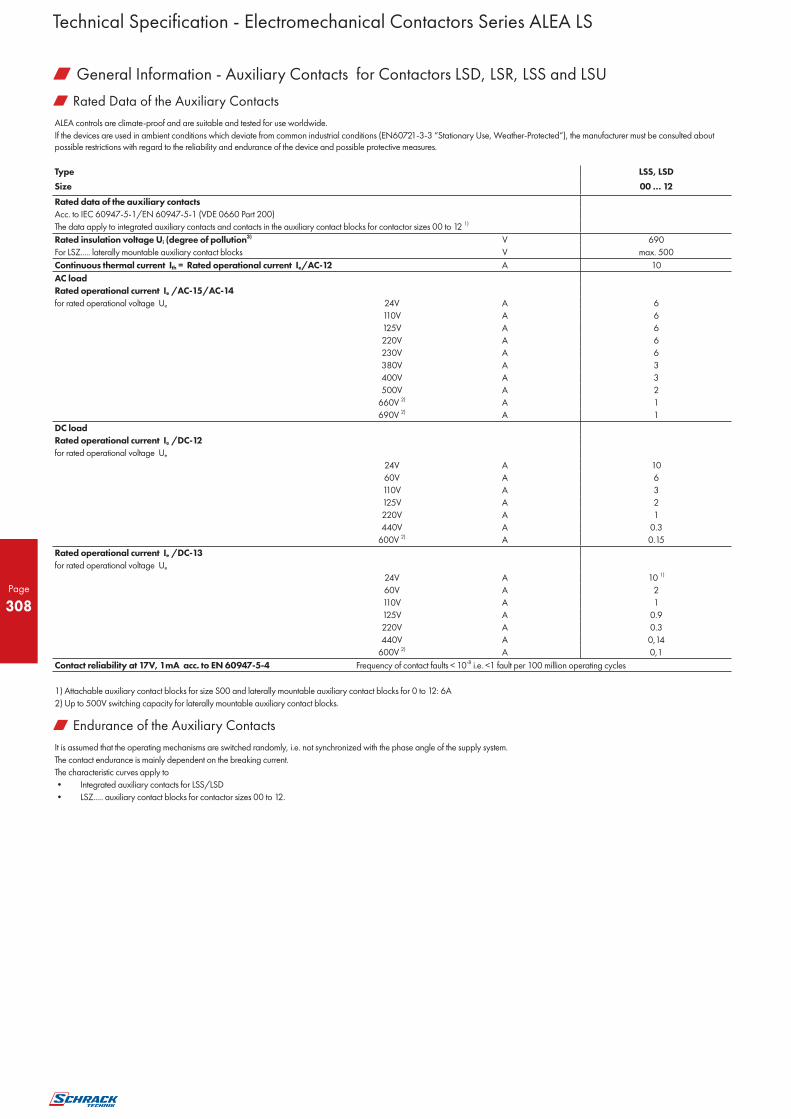
Page
308
w Rated Data of the Auxiliary Contacts
ALEA controls are climate-proof and are suitable and tested for use worldwide.
If the devices are used in ambient conditions which deviate from common industrial conditions (EN60721-3-3 “Stationary Use, Weather-Protected“), the manufacturer must be consulted about possible restrictions with regard to the reliability and endurance of the device and possible protective measures.
Type LSS, LSD
Size 00 … 12
Rated data of the auxiliary contacts
Acc. to IEC 60947-5-1/EN 60947-5-1 (VDE 0660 Part 200)
The data apply to integrated auxiliary contacts and contacts in the auxiliary contact blocks for contactor sizes 00 to 12 1)
Rated insulation voltage Ui (degree of pollution3) V 690
For LSZ..... laterally mountable auxiliary contact blocks V max. 500
Continuous thermal current Ith = Rated operational current Ie/AC-12 A 10
AC load
Rated operational current Ie /AC-15/AC-14
for rated operational voltage Ue 24V A 6
110V A 6
125V A 6
220V A 6
230V A 6
380V A 3
400V A 3
500V A 2
660V 2) A 1
690V 2) A 1
DC load
Rated operational current Ie /DC-12
for rated operational voltage Ue
24V A 10
60V A 6
110V A 3
125V A 2
220V A 1
440V A 0.3
600V 2) A 0.15
Rated operational current Ie /DC-13
for rated operational voltage Ue
24V A 10 1)
60V A 2
110V A 1
125V A 0.9
220V A 0.3
440V A 0,14
600V 2) A 0,1
Contact reliability at 17V, 1mA acc. to EN 60947-5-4 Frequency of contact faults < 10-8 i.e. <1 fault per 100 million operating cycles
1) Attachable auxiliary contact blocks for size S00 and laterally mountable auxiliary contact blocks for 0 to 12: 6A
2) Up to 500V switching capacity for laterally mountable auxiliary contact blocks.
w Endurance of the Auxiliary Contacts
It is assumed that the operating mechanisms are switched randomly, i.e. not synchronized with the phase angle of the supply system.
The contact endurance is mainly dependent on the breaking current.
The characteristic curves apply to
• Integrated auxiliary contacts for LSS/LSD
• LSZ..... auxiliary contact blocks for contactor sizes 00 to 12.
Technical Specification - Electromechanical Contactors Series ALEA LS
w General Information - Auxiliary Contacts for Contactors LSD, LSR, LSS and LSU

Page
309
w Diagram: Endurance of the Auxiliary Contacts
Legend:
Ia = Breaking current
Ie = Rated operational current
1) Million operating cycles
2) Basic unit
3) Basic unit with auxiliary block snapped on
Technical Specification - Electromechanical Contactors Series ALEA LS
w General Information - Auxiliary Contacts for Contactors LSD, LSR, LSS and LSU

Page
310
w General Data - Contactors LSDD, LSSD
Type LSDD, LSSD
Size 00
Allgemeine Daten
Permissible mounting position AC and DC operation
The contactors are designed for With DC operation and slope to the front until 22,5°
operation on a vertical mounting surface. Operating range 0.85 ... 1.1 x Us
Upright mounting position: AC operation
Special version required.
DC operation Standard version
Mechanical endurance Basic unit Operating 30 million
Basic unit with snap-on auxiliary contact block
cycles 10 million
Solid-state compatible auxiliary contact block
5 million
Electrical endurance 1)
Rated insulation voltage Ui (degree of pollution 3, overvoltage category III) V 690
Rated impulse withstand voltage Uimp kV 6
Safe isolation between the coil and the main contacts acc. to EN 60947-1, Appendix N V 400
Ambient temperature During operation °C -25 ... +60
During storage °C -55 ... +80
Degree of protection acc. to EN 60947-1, Appendix C IP20, coil assembly IP40
Touch protection acc. to EN 50274 Finger-safe
Shock resistance rectangular pulse AC operation g/ms 7/5 and 4,2/10
DC operation g/ms 7/5 and 4,2/10
Shock resistance sine pulse AC operation g/ms 9,8/5 and 5,9/10
DC operation g/ms 9,8/5 and 5,9/10
Conductor cross-sections 2)
Short-circuit protection for contactors without overload relays
For short-circuit protection for contactors with overload relays see Overload Relays
Main circuit Fuse links gL/gG LV HRC, DIAZED, NEOZED Type of coordination "1" A 35
Acc. to IEC 60947-4-1/ D49EN 60947-4-1 Type of coordination "2" A 20
Weld-free 3) A 10
Miniature circuit breakers (up to 230 V) with C characteristic A 10
Short-circuit current 1 kA, type of coordination "1"
Auxiliary circuit
Fuse links gL/gG DIAZED , NEOZED (weld-free protection Ik ≥ 1kA) A 10
Miniature circuit breakers up to 230 V with C characteristic Short-circuit current Ik <400A A 6
1) See “Endurance of the main contacts”
2) See “Conductor cross-sections”
3) Test conditions according to IEC 60947-4-1
Technical Specification - Electromechanical Contactors Series ALEA LS
w Contactors LSDD, LSSD and LSUD

Page
311
w Control-Contactors LSDD, LSSD, LSUD
Type LSDD, LSUD LSSD
Size 00 00
Magnetic coil operating range
• AC operation 50Hz 0.8 ... 1.1 x Us
60Hz 0.85 ... 1.1 x Us
• DC operation up to 50Hz 0.8 ... 1.1 x Us 0.7 ... 1.25 x Us(Us=17-13VDC)
up to 60Hz 0.85 ... 1.1 x Us
Power consumption of the magnetic coils (when coil is cold and 1.0 x Us )
• AC operation, 50/60 Hz
Standard version • Closing VA 27/24.3
• P.f. 0.8/0.75
• Closed VA 4.4/3.4
• P.f. 0.27/0.27
• AC operation, 50 Hz, USA/Canada • Closing VA 26.4
• P.f. for closing 0.81
• Closed VA 4.7
• P.f. for closed 0.26
• AC operation, 60 Hz, USA/Canada • Closing VA 31.7
• P.f. for closing 0.77
• Closed VA 5.1
• P.f. for closed 0.27
• DC operation Closing = Closed W 3.3 2,3
Permissible residual current of the electronics (with 0 signal)
• AC operation < 3mA x (230V/Us)
• DC operation < 10mA x (24V/Us)
Operating times1)
Total break time = Opening delay + Arcing time
• AC operation at 0.8 ... 1.1 x Us Closing delay ms 8 ... 35
Opening delay ms 4 ... 30
• DC operation at 0.85 ... 1.1 x Us Closing delay ms 25 ... 100
Opening delay ms 7 ... 10
• Arcing time ms 10 ... 15
Operating times for 1.0 x Us 1)
• AC operation Closing delay ms 10 ... 25
Opening delay ms 5 ... 30
• DC operation Closing delay ms 30 ... 50
Opening delay ms 7 ... 9
1) The OFF-delay of the NO contact and the ON-delay of the NC contact are increased if the contactor
coils are attenuated against voltage peaks (noise suppression diode 6 to 10 times; diode assemblies 2 to 6 times, varistor +2 to 5ms).
w Main Circuit-Contactors LSDD, LSSD, LSUD
Type LSDD07, LSSD07 LSDD09, LSSD09 LSDD12, LSSD12, LSUD12
Size 00 00 00
AC capacity Utilization category AC-1
Switching resistive loads
Rated operational current Ie at 40°C up to 690V A 18 22 22
at 60°C up to 690V A 16 20 20
Rated power for AC loads1) 230V kW 6.3 7.5 7.5
P.f.= 0.95 (at 60 °C) 400V kW 11 13 13
500V kW 13.8 17 17
690V kW 19 22 22
Minimum conductor cross-section at 40°C mm2 2.5 2.5 2.5
for loads with Ie at 60°C mm2 2.5 2.5 2.5
Utilization categories AC-2 and AC-3 Rated operational currents Ie up to 400V A 7 9 12
440V A 7 9 11
500V A 5 6.5 9
690V A 4 5.2 6.3
Rated power for slipring or squirrel cage at 230V kW 2.2 3 3
motors at 50 and 60 Hz 400V kW 3 4 5.5
500V kW 3.5 4.5 5.5
690V kW 4 5.5 5.5
Thermal load capacity 10 s current2) A 56 72 96
1) Industrial furnaces and electric heaters with resistance heating, etc. (increased power consumption on heating up has been taken into account).
Technical Specification - Electromechanical Contactors Series ALEA LS
w Contactors LSDD, LSSD and LSUD

Page
312
w Main Circuit-Contactors LSDD, LSSD, LSUD
Type LSDD07, LSSD07 LSDD09, LSSD09 LSDD12, LSSD12
Size 00 00 00
AC capacity Power loss per conducting path at Ie/AC-3 W 0,42 0,7 1,24
Utilization category AC-4 (at Ia = 6 x Ie) 1)
• Rated operational current Ie up to 400V A 6,5 8,5 8,5
• Rated power for squirrel-cage motors with 50 and 60Hz
up to 400V kW 3 4 4
• The following applies to a contact endurance of about 200000 operating cycles:
- Rated operational currents Ie up to 400V A 2,6 4,1 4,1
690V A 1,8 3,3 3,3
- Rated power for squirrel-cage motors with 50 and 60Hz
at 230V kW 0,67 1,1 1,1
400V kW 1,15 2 2
500V kW 1,45 2 2
690V kW 1,15 2,5 2,5
Utilization category AC-5a
Switching gas discharge lamps, inductive ballast per main current path at 230V
• Uncorrected, rated power per lamp/rated operational current per lamp
L 18W/0.37A Units 54 59 59
L 36W/0.43A Units 46 51 51
L 58W/0.67A Units 29 32 32
L 80W/0.79A Units 25 27 27
• DUO switching (two-lamp)
L 18W/0.22A Units 90 ( 2 x 90 lamps) 100 (�/ 2 x 100 lamps) 100 (�/ 2 x 100 lamps)
L 36W/0.42A Units 47 (�/ 2 x 47 lamps) 52 (�/ 2 x 52 lamps) 52 (�/ 2 x 52 lamps)
L 58W/0.63A Units 31 (�/ 2 x 31 lamps) 34 (�/ 2 x 34 lamps) 34 (�/ 2 x 34 lamps)
L 80W/0.87A Units 22 (�/ 2 x 22 lamps) 25 (�/ 2 x 25 lamps) 25 (�/ 2 x 25 lamps)
Switching gas discharge lamps with correction per main current path at 230V
• Shunt compensation with inductive ballast, rated power per lamp/capacitance/rated operational current per lamp
L 18W/4.5 F/0.11A Units 17 22 22
L 36W/4.5 F/0.21A Units 16 22 22
L 58W/7.0 F/0.32A Units 10 14 14
L 80W/7.0 F/0.49A Units 6 9 9
• With solid-state ballast 1) single lamp
L 18W/6.8 F/0.10A Units 49 63 63
L 36W/6.8 F/0.18A Units 27 35 35
L 58W/10 F/0.29A Units 16 23 23
L 80W/10 F/0.43A Units 11 14 14
• With solid-state ballast 1) two lamp
L 18W/10 F/0.18A Units 27 (�/ 2 x 27 lamps) 35 (�/ 2 x 35 lamps) 35 (�/ 2 x 35 lamps)
L 36W/10 F/0.35A Units 14 (�/ 2 x 14 lamps) 18 (�/ 2 x 18 lamps) 18 (�/ 2 x 18 lamps)
L 58W/22 F/0.52A Units 9 (�/ 2 x 9 lamps) 12 (�/ 2 x 12 lamps) 12 (�/ 2 x 12 lamps)
L 80W/22 F/0.86A Units 5 (�/ 2 x 5 lamps) 7 (�/ 2 x 7 lamps) 7 (�/ 2 x 7 lamps)
Utilization category AC-5b, switching incandescent lamps kW 1,3 1,7 1,7
Per main current path at 230/220V
Utilization category AC-6a
switching AC transformers
• Rated operational current Ie
For inrush current n = 20 up to 400V A 3,6 5,1 7,2
For inrush current n = 30 up to 400V A 2,4 3,3 5,1
• Rated power P
For inrush current n = 20 at 230V kVA 1,4 2 2,9
400V kVA 2,5 3,5 5
500V kVA 3,3 4,6 6,2
690V kVA 4,3 6 8,6
For inrush current n = 30 at 230V kVA 1 1,3 2
400V kVA 1,6 2,3 3,5
500V kVA 2,2 3,1 4,6
690V kVA 2,9 4 6
1) Depending on the electronic ballast used, higher lamp numbers are also possible
Technical Specification - Electromechanical Contactors Series ALEA LS
w Contactors LSDD, LSSD and LSUD

Page
313
w Main Circuit-Contactors LSDD, LSSD, LSUD
Type LSDD07, LSSD07 LSDD09, LSSD09 LSDD12, LSSD12
Size 00 00 00
DC capacity Utilization category DC-1 Switching resistive loads (L/R ≤ 1ms)
• Rated operational current Ie (at 60°C)
- 1 conducting path up to 24V A 15 20
60V A 15 20
110V A 1.5 2.1
220V A 0.6 0.8
440V A 0.42 0.6
600V A 0.42 0.6
- 2 conducting paths in series up to 24V A 15 20
60V A 15 20
110V A 8.4 12
220V A 1.2 1.6
440V A 1.6 0.8
600V A 0.5 0.7
- 3 conducting paths in series up to 24V A 15 20
60V A 15 20
110V A 15 20
220V A 15 20
440V A 0.9 1.3
600V A 0.7 1
Utilization category DC-3 und DC-5, Shunt-wound and series-wound motors (L/R ≤ 15ms)
• Rated operational current Ie(at 60 °C)
- 1 conducting path up to 24V A 15 20
60V A 0.35 0.5
110V A 0.1 0.15
220V A -- --
440V A -- --
600V A -- --
- 2 conducting paths in series up to 24V A 15 20
60V A 3.5 5
110V A 0.25 0.35
220V A -- --
440V A -- --
600V A -- --
- 3 conducting paths in series up to 24V A 15 20
60V A 15 20
110V A 15 20
220V A 1.2 1.5
440V A 0.14 0.2
600V A 0.14 0.2
Switching frequency z in operating cycles/hour
• Contactors without overload relay No-load switching frequency AC
h-1 1000
No-load switching frequency DC
h-1 1000
Dependence of the switching Rated operation
frequency z ’ on the operational current AC-1 (AC/DC) h-1 1000
I ’ and operational voltage U ’: AC-2 (AC/DC) h-1 750
z' = z ⋅(Ie/I') ⋅(400 V/U')1,5 ⋅1/h AC-3 (AC/DC) h-1 750
AC-4 (AC/DC) h-1 250
• Contactors with overload relays (mean value) h-1 15
w Conductor Cross-Sections-Contactors LSDD, LSSD, LSUD
(1 or 2 conductors can be connected) Main and auxiliary conductors; coil connections:
Screw terminals
For standard screwdriver size 2 and • Solid mm2 2 x (0.5 ... 1.5)1) ; 2 x (0.75 ... 2.5)1) acc. to IEC 60947;
Pozidriv 2 max. 2 x (1 ... 4)
• Finely stranded with end sleeve mm2 2 x (0.5 ... 1.5)1); 2 x (0.75 ... 2.5)1)
• Solid or stranded, AWG cables AWG 2 x (20 ... 16)1) ; 2 x (18 ... 14)1); 1 x 12
• Terminal screw M3
- tightening torque Nm 0.8 ... 1.2 (7 ... 10.3 lb.in)
(1 or 2 conductors can be connected) Main and auxiliary conductors; coil connections:
Cage Clamp terminals (on request)
• Solid mm2 2 x (0.25 ... 2.5)
• Finely stranded with end sleeve mm2 2 x (0.25 ... 1.5)
• Finely stranded without end sleeve mm2 2 x (0.25 ... 2.5)
• AWG cables, solid or stranded AWG 2 x (24 ... 14)
1) If two different conductor cross-sections are connected to one clamping point, both cross-sections must lie in the range specified. If identical cross-sections are used, this restriction does not apply.
Technical Specification - Electromechanical Contactors Series ALEA LS
w Contactors LSDD, LSSD and LSUD

Page
314
w General Data - Contactors LSD0, LSSD, LSUD
Type
LSD009 LSD012 LSD017 LSD025
LSS012 LSS017 LSS025
Size 0 0 0 0
Permissible mounting position • AC and DC operation
The contactors are designed for operation on a vertical mounting surface.
Upright mounting position: • AC operation
Standard version
• DC operation Special version required.
Mechanical endurance • Basic unit Operating 10 million
• Basic unit with snap-on auxiliary contact block
cycles 10 million
• Solid-state compatible auxiliary contact block
5 million
Electrical endurance 1)
Rated insulation voltage U i (degree of pollution 3, overvoltage category III) V 690
Rated impulse withstand voltage Uimp kV 6
Safe isolation between the coil and the main contacts acc. to EN 60947-1, Appendix N V 400
Mirror contacts
• A mirror contact is an auxiliary NC contact that cannot LSD0…., LSS0….(removable auxiliary contact block) Yes, acc. to EN 60947-4-1, Appendix F
be closed simultaneously with a NO main contact. LSD0…., LSS0….(permanent auxiliary contact block) Acc. to SUVA requirements on request
Ambient temperature During operation °C -25 ... +60
During storage °C -55 ... +80
Degree of protection acc. to EN 60947-1, Appendix C IP20, coil assembly IP20
Touch protection acc. to EN 50274 finger safe
Shock resistance rectangular pulse AC operation g/ms 8.2/5 and 4.9/10
DC operation g/ms 10/5 and 7.5/10
Shock resistance sine pulse AC operation g/ms 12.5/5 and 7.8/10
DC operation g/ms 15/5 and 10/10
Conductor cross-sections 2)
Short-circuit protection for contactors without overload relays For short-circuit protection for contactors with overload relays see Overload Relays
Main circuit
• Fuse links gL/gG LV HRC, DIAZED, NEOZED Type of coordination "1"
- Acc. to IEC 60947-4-1/ D49EN 60947-4-1 Type of coordination "2" A 63 100
Weld-free 3) A 25 35
• Miniature circuit breakers (up to 230 V) with C characteristic A 10 16
Short-circuit current 1 kA, type of coordination "1" A 25 32
Auxiliary circuit
• Fuse links gL/gG DIAZED , NEOZED (weld-free protection Ik ≥ 1kA) A 10
• Miniature circuit breakers up to 230 V with C characteristic Short-circuit current Ik <400A A 10
1) See “Endurance of the main contacts”
2) See “Conductor cross-sections”
3) Test conditions according to IEC 60947-4-1
Technical Specification - Electromechanical Contactors Series ALEA LS
w Contactors LSD0, LSS0 and LSU0

Page
315
w Control-Contactors LSD0, LSS0, LSU0
Type LSD0, LSU0 LSS0
Size 0 0
Magnetic coil operating range AC/DC 0.8 ... 1.1 x Us 0.7 ... 1.25 x Us/Us=17-30VDC
Power consumption of the magnetic coils (when coil is cold and 1.0 x Us ) • AC operation, 50/60 Hz • Closing VA 61
Standard version • P.f. 0.82
• Closed VA 7,8
• P.f. 0.24
• AC operation, 50/60 Hz • Closing VA 64/63
Standard version • P.f. for closing 0.72/0.74
• Closed VA 8.4/6.8
• P.f. for closed 0.24/0.28
• AC operation, 50 Hz, USA/Canada • Closing VA 61
• P.f. for closing 0,82
• Closed VA 7,8
• P.f. for closed 0,24
• AC operation, 60 Hz, USA/Canada • Closing VA 69
• P.f. for closing 0,76
• Closed VA 7,5
• P.f. for closed 0,28
• DC operation Closing = Closed W 5,4 4,2
Permissible residual current of the electronics (with 0 signal)
• AC operation mA <6 mA x (230 V/Us)
• DC operation mA <16 mA x (24 V/Us)
Operating times1) Total break time = Opening delay + Arcing time • AC operation at 0.8 ... 1.1 x Us Closing delay ms 8 ... 44
Opening delay ms 4 ... 20
• DC operation at 0.85 ... 1.1 x Us Closing delay ms 50 ... 170
Opening delay ms 13.5 ... 15.5
• Arcing time ms 10
Operating times for 1.0 x Us 1)
• AC operation Closing delay ms 10 ... 17
Opening delay ms 4 ... 20
• DC operation Closing delay ms 55 ... 85
Opening delay ms 14 ... 15.5
1) The OFF-delay of the NO contact and the ON-delay of the NC contact are increased if the contactor coils are attenuated against voltage peaks (varistor +2ms to 5ms, diode assembly: 2 to 6 times).
w Main Circuit Contactors LSD0, LSS0, LSU0
Type
LSD009 LSD012, LSS012 LSD017, LSS017 LSD025, LSS025
LSU025
Size 0 0 0 0
AC capacity Utilization category AC-1
Switching resistive loads
Rated operational current Ie at 40°C up to 690V A 40
at 60°C up to 690V A 35
Rated power for AC loads1) 230V kW 13,3
P.f.= 0.95 (at 60 °C) 400V kW 23
500V kW 29
690V kW 40
Minimum conductor cross-section at 40°C mm2 10
for loads with Ie at 60°C mm2 10
Utilization categories AC-2 and AC-3
Rated operational currents Ie up to 400V A 9 12 17 25
440V A 9 12 17 22
500V A 6,5 12 17 18
690V A 5,2 9 13 13
Rated power for slipring or squirrel cage at 110V kW 1,1 1,5 2,2 3
motors at 50 and 60 Hz 230V kW 3 3 4 5,5
400V kW 4 5,5 7,5 11
500V kW 4,5 7,5 10 11
660V/690V kW 5,5 7,5 11 11
Thermal load capacity 10 s current2) A 80 110 150 200
Power loss per conducting path at Ie/AC-3 W 0,4 0,5 0,9 1,6
1) Industrial furnaces and electric heaters with resistance heating, etc. (increased power consumption on heating up has been taken into account).
2) According to IEC 60947-4-1. For rated values for various start-up conditions see Protection Equipment: Thermal Overload Relays.
Technical Specification - Electromechanical Contactors Series ALEA LS
w Contactors LSD0, LSS0 and LSU0

Page
316
w Main Circuit Contactors LSD0, LSS0, LSU0
Type
LSD009 LSD012, LSS012 LSD017, LSS017 LSD025, LSS025
LSU025
Size 0 0 0 0
AC capacity
Power loss per conducting path at Ie/AC-3
Utilization category AC-4 (at Ia = 6 x Ie) 1)
• Rated operational current Ie up to 400V A 8,5 12,5 15,5 15,5
• Rated power for squirrel-cage motors with 50 and 60Hz
up to 400V kW 4 5,5 7,5 7,5
• The following applies to a contact endurance of about 200000 operating cycles:
- Rated operational currents Ie up to 400V A 4,1 5,5 7,7 9
690V A 3,3 5,5 7,7 9
- Rated power for squirrel-cage motors with 50 and 60Hz
at 110V kW 0,5 0,73 1 1,2
230 kW 1,1 1,5 2 2,5
400V kW 2 2,6 3,5 4,4
500V kW 2 3,3 4,6 5,6
690V kW 2,5 4,6 6 7,7
Utilization category AC-5a
Switching gas discharge lamps, inductive ballast per main current path at 230V
• Uncorrected, rated power per lamp/rated operational current per lamp
• Uncorrected L 18W/0.37A Units 108
L 36W/0.43A Units 93
L 58W/0.67A Units 59
L 80W/0.79A Units 50
• DUO switching (two-lamp)
L 18W/0.22A Units 181 ( 2 x 181 lamps)
L 36W/0.42A Units 95 ( 2 x 95 lamps)
L 58W/0.63A Units 63 ( 2 x 63 lamps)
L 80W/0.87A Units 45 ( 2 x 45 lamps)
Switching gas discharge lamps with correction per main current path at 230V
Shunt compensation with inductive ballast, rated power per lamp/capacitance/rated operational current per lamp
• Shunt compensation with inductive ballast L 18W/4.5 F/0.11A Units 37 41 61
L 36W/4.5 F/0.21A Units 30 30 51
L 58W/7.0 F/0.32A Units 20 20 33
L 80W/7.0 F/0.49A Units 13 13 22
• With solid-state ballast 1) single lamp
L 18W/6.8 F/0.10A Units 105 119 175
L 36W/6.8 F/0.18A Units 58 66 97
L 58W/10 F/0.29A Units 36 41 60
L 80W/10 F/0.43A Units 24 27 40
• With solid-state ballast 1) two lamp
L 18W/10 F/0.18A Units 58 (�/ 2 x 58 lamps) 66 (�/ 2 x 66 lamps) 97 (�/ 2 x 97 lamps)
L 36W/10 F/0.35A Units 30 (�/ 2 x 30 lamps) 34 (�/ 2 x 34 lamps) 50 (�/ 2 x 50 lamps)
L 58W/22 F/0.52A Units 20 (�/ 2 x 20 lamps) 22 (�/ 2 x 22 lamps) 33 (�/ 2 x 33 lamps)
L 80W/22 F/0.86A Units 12 (�/ 2 x 12 lamps) 13 (�/ 2 x 13 lamps) 20 (�/ 2 x 20 lamps)
Utilization category AC-5b, switching incandescent lamps kW 2,8 3,2 4,7
Per main current path at 230/220V
Utilization category AC-6a, switching AC transformers
• Rated operational current Ie
For inrush current n = 20 up to 400V A 11,4 20,2
For inrush current n = 30 up to 400V A 7,6 13,5
• Rated power P
For inrush current n = 20 at 230V kVA 4,5 8
400V kVA 7,9 13,9
500V kVA 9,9 15,5
690V kVA 13,6 15,5
For inrush current n = 30 at 230V kVA 3 5,4
400V kVA 5,2 9,3
500V kVA 6,6 11,7
690V kVA 9,1 15,5
For deviating inrush current factors x, the power must be recalculated as follows: Px = Pn30 · 30/x
Utilization category AC-6b, switching low-inductance (low-loss, metallized dielectric) AC capacitors
Rated operational currents I e up to 400V A 5,8 10,8
Rated power for single capacitors or at 230V kVAr 2,5 4
banks of capacitors (minimum inductance 400V kVAr 4 7,5
of 6 µH between capacitors connected in 500V kVAr 4 7,5
parallel) at 50 Hz, 60 Hz 690V kVAr 4 7,5
1) For Ie /AC-1 = 35A (60°C) and the corresponding minimum conductor cross-section10mm2.
2) Depending on the electronic ballast used, higher lamp numbers are also possible.
Technical Specification - Electromechanical Contactors Series ALEA LS
w Contactors LSD0, LSS0 and LSU0

Page
317
w Main Circuit Contactors LSD0, LSS0, LSU0
Type
LSD009 LSD012, LSS012 LSD017, LSS017 LSD025, LSS025
LSU025
Size 0 0 0 0
DC capacity
Utilization category DC-1 Switching resistive loads (L/R ≤ 1ms)
• Rated operational current Ie (at 60°C)
- 1 conducting path up to 24V A 35
60V A 20
110V A 4,5
220V A 1
440V A 0,4
600V A 0,25
- 2 conducting paths in series up to 24V A 35
60V A 35
110V A 35
220V A 5
440V A 1
600V A 0,8
- 3 conducting paths in series up to 24V A 35
60V A 35
110V A 35
220V A 35
440V A 2,9
600V A 1,4
Utilization category DC-3 und DC-5, Shunt-wound and series-wound motors (L/R ≤ 15ms)
• Rated operational current Ie (at 60°C)
- 1 conducting path up to 24V A 20
60V A 5
110V A 2,5
220V A 1
440V A 0,09
600V A 0,06
- 2 conducting paths in series up to 24V A 35
60V A 35
110V A 15
220V A 3
440V A 0,27
600V A 0,16
- 3 conducting paths in series up to 24V A 35
60V A 35
110V A 35
220V A 10
440V A 0,6
600V A 0,6
Switching frequency z in operating cycles/hour
• Contactors without overload relay No-load switching frequency AC
h-1 5000
No-load switching frequency DC
h-1 1500
Dependence of the switching Rated operation
frequency z ’ on the operational current AC-1 (AC/DC) h-1 1000
I ’ and operational voltage U ’: AC-2 (AC/DC) h-1 1000 750
z' = z ⋅(Ie/I') ⋅(400 V/U')1,5 ⋅1/h AC-3 (AC/DC) h-1 1000 750
AC-4 (AC/DC) h-1 300 250
• Contactors with overload relays (mean value) h-1 15
Technical Specification - Electromechanical Contactors Series ALEA LS
w Contactors LSD0, LSS0 and LSU0

Page
318
w Conductor Cross-Section-Contactors LSD0, LSS0, LSU0
Type LSD009, LSS012, LSD012, LSS017, LSD017, LSS025, LSD025, LSU025
Size 0
Conductor cross-sections (1 or 2 conductors can be connected) Main conductors: Screw terminals
• Solid mm2 2 x (1 ... 2.5)1) ; 2 x (2.5 ... 6)1) acc. to IEC 60947; max. 1 x 10
• Finely stranded with end sleeve mm2 2 x (1 ... 2.5)1) ; 2 x (2.5 ... 6)1)
• AWG cables, solid AWG 2 x (16 ... 12)
• AWG cables, solid or stranded AWG 2 x (14 ... 10)
• AWG cables, stranded AWG 1 x 8
• Terminal screws M4 (Pozidriv size 2)
- tightening torque Nm 2 ... 2.5 (18 ... 22 lb.in)
Auxiliary conductors
• Solid mm2 2 x (0.5 ... 1.5)1) ; 2 x (0.75 ... 2.5)1) acc. to IEC 60947; max. 2 x (0.75 ... 4)
• Finely stranded with end sleeve mm2 2 x (0.5 ... 1.5)1) ; 2 x (0.75 ... 2.5)1)
• Solid or stranded AWG (2 x) AWG 2 x (20 ... 16)1) ; 2 x (18 ... 14)1) ; 1 x 12
• Terminal screws M3
tightening torque Nm 0.8 ... 1.2 (7 ... 10.3 lb.in)
Auxiliary conductors Cage Clamp terminals (on request)
• Solid mm2 2 x (0.25 ... 2.5)
• Finely stranded with end sleeve mm2 2 x (0.25 ... 1.5)
• Finely stranded without end sleeve mm2 2 x (0.25 ... 2.5)
• AWG cables, solid or stranded AWG 2 x (24 ... 14)
1) If two different conductor cross-sections are connected to one clamping point, both cross-sections must lie in the range specified. If identical cross-sections are used, this restriction does not apply.
Technical Specification - Electromechanical Contactors Series ALEA LS
w Contactors LSD0, LSS0 and LSU0

Page
319
w General Data - Contactors LSD2, LSU2
Type LSD232 LSD240, LSU240 LSD250
Size 2 2 2
Permissible mounting position • AC and DC operation
The contactors are designed for For DC operation and 22.5 ° inclination towards the front,
operation on a vertical mounting surface. operating range 0,85 ... 1,1 x Us
Upright mounting position: • AC operation
• DC operation Special version required.
Mechanical endurance • Basic unit Operating 10 million
• Basic unit with snap-on auxiliary contact block cycles 10 million
• Auxiliary contact block capable for electronic circuits 5 million
Electrical endurance 1)
Rated insulation voltage Ui (degree of pollution 3, overvoltage category III) V 690
Rated impulse withstand voltage Uimp kV 6
Safe isolation between the coil and the main contacts acc. to EN 60947-1, Appendix N V 400
Mirror contacts
A mirror contact is an auxiliary NC LSD, LSR Yes, acc. to EN 60947-4-1, Appendix F
contact that cannot be closed (removable auxiliary contact block)
simultaneously with a NO main contact. LSD, LSR Acc. to SUVA requirements on request
(permanent auxiliary contact block)
Ambient temperature During operation °C -25 ... +60
During storage °C -55 ... +80
Degree of protection acc. to EN 60947-1, Appendix C
IP20 (terminal compartment IP00),
AC-coil assembly IP40,
DC-coil assembly IP30
Touch protection acc. to EN 50274 finger-safe
Shock resistance - rectangular pulse AC and DC operation g/ms 10/5 and 5/10
Shock resistance -sine pulse AC and DC operation g/ms 15/5 and 8/10
Conductor cross-sections 2)
Short-circuit protection for contactors without overload relays For short-circuit protection for contactors with thermal overload relays
see protection equipment: Thermal overload relays
Main circuit
• Fuse links gL/gG NH, DIAZED, NEOZED
acc. to IEC 60 947-4-1/DIN EN 60 947-4-1 Type of coordination "1" A 125 125 160
Type of coordination "2" A 63 63 80
Weld-free1) A 16 16 50
Auxiliary circuit
• Fuse links gL/gG
DIAZED, NEOZED (weld-free protection at Ik ≥ 1kA) A 10
• Miniature circuit breakers with C characteristic
short-circuit current Ik < 400A A 10
1) See “Endurance of the main contacts”
2) See “Conductor cross-sections” pages onward
3) According to IEC 60 947-4-1.
Technical Specification - Electromechanical Contactors Series ALEA LS
w Contactors LSD2 and LSU2

Page
320
w Control-Contactors LSD2, LSU2
Type LSD232 LSD240, LSU240 LSD250
Size 2 2 2
Magnetic coil operating range AC/DC 0.8 ... 1.1 x Us
Power consumption of the magnetic coils (when coil is cold and 1.0 x Us ) • AC operation, 50/60 Hz • Closing VA 104 145
Standard version • P.f. 0,78 0,79
• Closed VA 9,7 12,5
• P.f. 0,42 0,36
• AC operation, 50/60 Hz • Closing VA 127/113 170/155
Standard version • P.f. for closing 0.73/0.69 0.76/0.72
• Closed VA 11.3/9.5 15/11.8
• P.f. for closed 0.41/0.42 0.35/0.38
• AC operation, 50 Hz, USA/Canada • Closing VA 108 150
• P.f. for closing 0,76 0,77
• Closed VA 9,6 12,5
• P.f. for closed 0,42 0,35
• AC operation, 60 Hz, USA/Canada • Closing VA 120 166
• P.f. for closing 0,7 0,71
• Closed VA 10,1 12,6
• P.f. for closed 0,42 0,37
• DC operation Closing = Closed W 13,3 13,3
Permissible residual current of the electronics (with 0 signal)
• AC operation mA < 12mA x (230V/Us) < 18mA x (230V/Us)
• DC operation mA < 38mA x (24V/Us) < 38mA x (24V/Us)
Operating times for 1) Total break time = Opening delay + Arcing time • AC operation at 0.8 ... 1.1 x Us Closing delay ms 11 ... 30 10 ... 24
Opening delay ms 7 ... 10 7 ... 10
• DC operation at 0.85 ... 1.1 x Us Closing delay ms 50 ... 95 60 ... 100
Opening delay ms 20 ... 30 20 ... 25
• Arcing time ms 10 10
Operating times for 1.0 x Us 1)
• AC operation Closing delay ms 13 ... 22 12 ... 20
Opening delay ms 7 ... 10 7 ... 10
• DC operation Closing delay ms 60 ... 75 70 ... 85
Opening delay ms 20 ... 30 20 ... 25
1) The OFF-delay of the NO contact and the ON-delay of the NC contact are increased if the contactor coils are attenuated against voltage peaks (varistor +2ms to 5ms, diode assembly: 2 to 6 times).
Technical Specification - Electromechanical Contactors Series ALEA LS
w Contactors LSD2 and LSU2

Page
321
w Main Circuit-Contactors LSD2, LSU2
Type LSD232 LSD240, LSU240 LSD250
Size 2 2 2
AC capacity Utilization category AC-1, Switching resistive loads
Rated operational current Ie at 40°C up to 690V A 50 60 60
at 60°C up to 690V A 45 55 55
Rated power for AC loads1) 230V kW 18 22 22
P.f.= 0.95 (at 60 °C) 400V kW 31 38 38
500V kW 39 46 46
690V kW 54 66 66
Minimum conductor cross-section at 40°C mm2 16 16 16
for loads with Ie at 60°C mm2 10 16 16
Utilization categories AC-2 and AC-3
Rated operational currents Ie up to 500V A 32 40 50
690V A 20 24 24
Rated power for slipping or squirrel cage 230V kW 7,5 11 15
motors at 50 and 60 Hz 400V kW 15 18,5 22
500V kW 18,5 22 30
690V kW 18,5 22 22
Thermal load capacity 10 s current2) A 320 400 400
Power loss per conducting path at Ie/AC-3 W 1,8 2,6 5
Utilization category AC-4 (at Ia = 6 x Ie)
• Rated operational current Ie up to 400V A 29 35 41
• Rated power for squirrel-cage motors with 50 and 60Hz up to 400V kW 15 18,5 22
• The following applies to a contact endurance of about 200000 operating cycles:
- Rated operational currents Ie up to 400V A 15,6 18,5 24
690V A 15,6 18,5 24
- Rated power for squirrel-cage motors with 50 and 60Hz 230 kW 4,7 5,4 7,3
400V kW 8,2 9,5 12,6
500V kW 9,8 11,8 15,8
690V kW 13 15,5 21,8
Utilization category AC-5a, Switching gas discharge lamps, inductive ballast per main current path at 230V
• Uncorrected, rated power per lamp/rated operational current per lamp
• Uncorrected L 18W/0,37A Units 135 162 162
L 36W/0,43A Units 116 139 139
L 58W/0,67A Units 74 89 89
L 80W/0,79A Units 63 75 75
• DUO switching (two-lamp)
L 18W/0,22A Units 227 ( 2x227 lamps) 272 ( 2x272 lamps) 272 ( 2x272 lamps)
L 36W/0,42A Units 119 ( 2x119 lamps) 142 ( 2x142 lamps) 142 ( 2x142 lamps)
L 58W/0,63A Units 79 ( 2x79 lamps) 95 ( 2x95 lamps) 95 ( 2x95 lamps)
L 80W/0,87A Units 57 ( 2x57 lamps) 68 ( 2x68 lamps) 68 ( 2x68 lamps)
Switching gas discharge lamps with correction per main current path at 230V
Shunt compensation with inductive ballast, rated power per lamp/capacitance/rated operational current per lamp
• Shunt compensation with inductive ballast L 18W/4,5 F/0,11A Units 78 98 123
L 36W/4,5 F/0,21A Units 78 98 123
L 58W/7,0 F/0,32A Units 50 63 79
L 80W/7,0 F/0,49A Units 50 63 73
• With solid-state ballast 3) single lamp
L 18W/6,8 F/0,10A Units 224 280 350
L 36W/6,8 F/0,18A Units 124 155 194
L 58W/10 F/0,29A Units 77 96 120
L 80W/10 F/0,43A Units 52 65 81
• With solid-state ballast 3) two lamp
L 18W/10 F/0,18A Units 124 (�/ 2 x 124 lamps) 155 (�/ 2 x 155 lamps 194 (�/ 2 x 194 lamps)
L 36W/10 F/0,35A Units 64 (�/ 2 x 64 lamps) 80 (�/ 2 x 80 lamps) 100 (�/ 2 x 100 lamps)
L 58W/22 F/0,52A Units 43 (�/ 2 x 43 lamps) 54 (�/ 2 x 54 lamps) 67 (�/ 2 x 67 lamps)
L 80W/22 F/0,86A Units 26 (�/ 2 x 26 lamps) 32 (�/ 2 x 32 lamps) 40 (�/ 2 x 40 lamps)
1) Industrial furnaces and electric heaters with resistance heating, etc. (increased power consumption on heating up has been taken into account).
2) According to IEC 60947-4-1. For rated values for various start-up conditions see: Thermal Overload Relays.
3) Depending on the electronic ballast used, higher lamp numbers are also possible.
Technical Specification - Electromechanical Contactors Series ALEA LS
w Contactors LSD2 and LSU2

Page
322
w Main Circuit-Contactors LSD2, LSU2
Type LSD232 LSD240, LSU240 LSD250
Size 2 2 2
AC capacity
Utilization category AC-5b, switching incandescent lamps per main current path at 230/220V
kW 6 7,6 9,5
Utilization category AC-6a, switching AC transformers
• Rated operational current Ie
For inrush current n = 20 up to 400V A 31 36,5 43,2
For inrush current n = 30 up to 400V A 20,7 24,3 28,8
• Rated power P
For inrush current n = 20 at 230V kVA 12,3 14,5 17,2
400V kVA 21,5 25,3 29,9
500V kVA 26,8 31,6 37,4
690V kVA 23,9 28,7 28,7
For inrush current n = 30 at 230V kVA 8,2 9,7 11,5
400V kVA 14,3 16,8 20
500V kVA 17,9 21 24,9
690V kVA 23,9 28,7 28,7
For deviating inrush current factors x, the power must be recalculated as follows: Px = Pn30 · 30/x
Utilization category AC-6b, switching low-inductance (low-loss, metallized dielectric) AC capacitors
Rated operational currents I e up to 400V A 29 36 36
Rated power for single capacitors or at 230V kVAr 12 15 15
banks of capacitors (minimum inductance 400V kVAr 20 25 25
of 6 µH between capacitors connected in 525V kVAr 25 33 33
parallel) at 50 Hz, 60 Hz 690V kVAr 20 25 25
1) For Ie /AC-1 = 35A (60°C) and the corresponding minimum conductor cross-section10mm2.
2) Depending on the electronic ballast used, higher lamp numbers are also possible.
Technical Specification - Electromechanical Contactors Series ALEA LS
w Contactors LSD2 and LSU2

Page
323
w Main Circuit-Contactors LSD2, LSU2
Type LSD232 LSD240, LSU240 LSD250
Size 2 2 2
DC capacity Utilization category DC-1 Switching resistive loads (L/R ≤ 1ms)
• Rated operational current Ie (at 60°C)
- 1 conducting path up to 24V A 45 55 55
60V A 20 23 23
110V A 4.5 4.5 4,5
220V A 2 2 2
440V A 0.4 0.4 0.4
600V A 0.25 0.25 0.25
- 2 conducting paths in series up to 24V A 45 55 55
60V A 45 45 45
110V A 45 45 45
220V A 5 5 5
440V A 1 1 1
600V A 0.8 0.8 0.8
- 3 conducting paths in series up to 24V A 45 55 55
60V A 45 55 55
110V A 45 55 55
220V A 45 45 45
440V A 2.9 2.9 2.9
600V A 1.4 1.4 1.4
Utilization category DC-3 und DC-5, Shunt-wound and series-wound motors (L/R ≤ 15ms)
• Rated operational current Ie (at 60°C)
- 1 conducting path up to 24V A 35 35 35
60V A 6 6 6
110V A 2.5
220V A 2 2 2
440V A 0.1 0.1 0.1
600V A 0.06 0.06 0.06
- 2 conducting paths in series up to 24V A 45 55 55
60V A 45 45 45
110V A 25 25 25
220V A 5 5 5
440V A 0.27 0.27 0.27
600V A 0.16 0.16 0.16
- 3 conducting paths in series up to 24V A 45 55 55
60V A 45 55 55
110V A 45 55 55
220V A 25 25 25
440V A 0.6 0.6 0.6
600V A 0.35 0.35 0.35
Switching frequency z in operating cycles/hour
• Contactors without overload relay No-load switching frequency AC
h-1 5000 5000 5000
No-load switching frequency DC
h-1 1500 1500 1500
Dependence of the switching Rated operation
frequency z ’ on the operational current AC-1 (AC/DC) h-1 1200 1200 1000
I ’ and operational voltage U ’: AC-2 (AC/DC) h-1 750 600 400
z' = z ⋅(Ie/I') ⋅(400 V/U')1,5 ⋅1/h AC-3 (AC/DC) h-1 1000 1000 800
AC-4 (AC/DC) h-1 250 300 300
• Contactors with overload relays (mean value) h-1 15 15 15
Technical Specification - Electromechanical Contactors Series ALEA LS
w Contactors LSD2 and LSU2

Page
324
w Conductor Cross-Sections-Contactors LSD2, LSU2
Type LSD2... LSU2..
Size 2
Conductor cross-sections (1 or 2 conductors can be connected)
Main conductors: Screw terminals
Front clamping point • Finely stranded with end sleeve mm2 0.75 ... 25
connected • Finely stranded without end sleeve mm2 0.75 ... 25
• Stranded mm2 0.75 ... 35
• Solid mm2 0.75 ... 16
• Ribbon cable conductors (number x width x thickness) mm2 6 x 9 x 0.8
• AWG cables, solid or stranded AWG 18 ... 2
Rear clamping point • Finely stranded with end sleeve mm2 0.75 ... 25
connected • Finely stranded without end sleeve mm2 0.75 ... 25
• Stranded mm2 0.75 ... 35
• Solid mm2 0.75 ... 16
• Ribbon cable conductors (number x width x thickness) mm2 6 x 9 x 0.8
• AWG cables, solid or stranded AWG 18 ... 2
Both clamping points • Finely stranded with end sleeve mm2 2 x (0.75 ... 16)
connected • Finely stranded without end sleeve mm2 2 x (0.75 ... 16)
• Stranded mm2 2 x (0.75 ... 25)
• Solid mm2 2 x (0.75 ... 16)
• Ribbon cable conductors (number x width x thickness) mm2 2 x (6 x 9 x 0.8)
• AWG cables, solid or stranded AWG 2 x (18 ... 2)
• Terminal screw M6 (Pozidriv Gr. 2)
- tightening torque Nm 3 ... 4.5 (27 ... 40 lb.in)
Auxiliary conductors:
• Solid mm2 2 x (0.5 ... 1.5)1) ; 2 x (0.75 ... 2.5)1)
acc. to IEC 60947; max. 2 x (0.75 ... 4)
• Finely stranded with end sleeve mm2 2 x (0.5 ... 1.5)1) ; 2 x (0.75 ... 2.5)1)
• AWG cables, solid or stranded AWG 2 x (20 ... 16)1) ; 2 x (18 ... 14)1) ; 1 x 12
• Terminal screw M3
- tightening torque Nm 0.8 ... 1.2 (7 ... 10.3 lb.in)
Auxiliary conductors: Cage Clamp terminals (on request)
• Solid mm2 2 x (0.25 ... 2.5)
• Finely stranded with end sleeve mm2 2 x (0.25 ... 1.5)
• Finely stranded without end sleeve mm2 2 x (0.25 ... 2.5)
• AWG cables, solid or stranded mm2 2 x (24 ... 14)
1) If two different conductor cross-sections are connected to one clamping point, both cross-sections must lie in the range specified. If identical cross-sections are used, this restriction does not apply.
Technical Specification - Electromechanical Contactors Series ALEA LS
w Contactors LSD2 and LSU2

Page
325
w General Data - Contactors LSD3
Type LSD365 LSD380 LSD395
Size 3 3 3
Permissible mounting position • AC and DC operation
The contactors are designed for operation on a vertical mounting surface. For DC operation and 22.5 ° inclination towards the front
Operating range 0.85 ... 1.1 x Us
Upright mounting position: • AC operation
Special version required.
• DC operation _
Mechanical endurance • Basic unit Operating 10 million
• Basic unit with snap-on auxiliary contact block cycles 10 million
• Auxiliary contact block capable for electronic circuits 5 million
Electrical endurance 1)
Rated insulation voltage Ui (degree of pollution 3, overvoltage category III) V 1000
Rated impulse withstand voltage Uimp kV 6
Safe isolation between the coil and the main contacts acc. to EN 60947-1, Appendix N V 690
Ambient temperature During operation °C -25 ... +60
During storage °C -55 ... +80
Degree of protection acc. to EN 60947-1, Appendix C
IP20 (terminal compartment IP00),
AC-coil assembly IP40,
DC-coil assembly IP30
Touch protection acc. to EN 50274 finger-safe
Shock resistance - rectangular pulse AC and DC operation g/ms 6.8/5 and 4/10
Shock resistance -sine pulse AC and DC operation g/ms 10.6/5 and 6.2/10
Conductor cross-sections 2)
Short-circuit protection for contactors without overload relays For short-circuit protection for contactors with thermal overload relays see Thermal
overload relays
Main circuit • Fuse links gL/gG NH, DIAZED, NEOZED acc. to IEC 60 947-4-1/DIN EN 60 947-4-1 Type of coordination "1" A 250 250
Type of coordination "2" A 125 160
Weld-free1) A 63 100
Auxiliary circuit • Fuse links gL/gG DIAZED, NEOZED (weld-free protection at Ik ≥ 1kA) A 10
• Miniature circuit breakers with C characteristic short-circuit current Ik < 400A A 10
1) See “Endurance of the main contacts” 2) See “Conductor cross-sections” 3) According to IEC 60 947-4-1
Technical Specification - Electromechanical Contactors Series ALEA LS
w Contactors LSD3 and LSU3

Page
326
w Control-Contactors LSD3
Type LSD365 LSD380 LSD395
Size 3 3 3
Magnetic coil operating range AC/DC 0,. ... 1.1 x Us
Power consumption of the magnetic coils (when coil is cold and 1.0 x Us ) • AC operation, 50/60 Hz • Closing VA 218 270
Standard version • P.f. 0,61 0,68
• Closed VA 21 22
• P.f. 0,26 0,27
• AC operation, 50/60 Hz • Closing VA 247/211 298/274
Standard version • P.f. for closing 0.62/0.57 0.7/0.62
• Closed VA 25/18 27/20
• P.f. for closed 0.27/0.3 0.29/0.31
• AC operation, 50 Hz, USA/Canada • Closing VA 218 270
• P.f. for closing 0,61 0,68
• Closed VA 21 22
• P.f. for closed 0,26 0,27
• AC operation, 60 Hz, USA/Canada • Closing VA 232 300
• P.f. for closing 0,55 0,52
• Closed VA 20 21
• P.f. for closed 0,28 0,29
• DC operation Closing = Closed W 15 15
Permissible residual current of the electronics (with 0 signal) • AC operation mA <25mA x (230 V/Us)
• DC operation mA <43mA x (24 V/Us)
Operating times Total break time = Opening delay + Arcing time • AC operation at 0.8 ... 1.1 x Us Closing delay ms 16 ... 57 17 ... 90
Opening delay ms 10 ... 19 10 ... 25
• DC operation at 0.85 ... 1.1 x Us Closing delay ms 90 ... 230 90 ... 230
Opening delay ms 14 ... 20 14 ... 20
• Arcing time ms 10 ... 15 10 ... 15
Operating times for 1.0 x Us 1)
• AC operation Closing delay ms 18 ... 34 18 ... 30
Opening delay ms 11 ... 18 11 ... 23
• DC operation Closing delay ms 100 ... 120 100 ... 120
Opening delay ms 16 ... 20 16 ... 20
1) The OFF-delay of the NO contact and the ON-delay of the NC contact are increased if the contactor coils are attenuated against voltage peaks (varistor +2ms to 5ms, diode assembly: 2 to 6 times)
Technical Specification - Electromechanical Contactors Series ALEA LS
w Contactors LSD3 and LSU3

Page
327
w Main Circuit-Contactors LSD3
Type LSD365 LSD380 LSD395
Size 3 3 3
AC capacity Utilization category AC-1, Switching resistive loads
Rated operational current Ie at 40°C up to 690V A 100 120 120
1000V A 50 60 70
at 60°C up to 690V A 90 100 100
1000V A 40 50 60
Rated power for AC loads1) 230V kW 34 38 38
P.f.= 0.95 (at 60 °C) 400V kW 59 66 66
500V kW 74 82 82
690V kW 102 114 114
1000V kW 66 82 98
Minimum conductor cross-section at 40°C mm2 35 50 50
for loads with Ie at 60°C mm2 35 35 35
Utilization categories AC-2 and AC-3
Rated operational currents Ie up to 500V A 65 80 95
690V A 47 58 58
1000V A 25 30 30
Rated power for slipping or squirrel cage 230V kW 18,5 22 22
motors at 50 and 60 Hz 400V kW 30 37 45
500V kW 37 45 55
690V kW 45 55 55
1000V kW 30 37 37
Thermal load capacity 10 s current2) A 600 760 760
Power loss per conducting path at Ie/AC-3 W 4,6 7,7 10,8
Utilization category AC-4 (at Ia = 6 x Ie) 1)
• Rated operational current Ie up to 400V A 55 66 80
• Rated power for squirrel-cage motors with 50 and 60Hz up to 400V kW 30 37 45
• The following applies to a contact endurance of about 200000 operating cycles: - Rated operational currents Ie up to 400V A 28 34 42
690V A 28 34 42
1000V A 20 23 23
- Rated power for squirrel-cage motors with 50 and 60Hz 230 kW 8,7 10,4 12
400V kW 15,1 17,9 22
500V kW 18,4 22,4 27
690V kW 25,4 30,9 38
1000V kW 22 30 30
1) Industrial furnaces and electric heaters with resistance heating, etc. (increased power consumption on heating up has been taken into account).
2) According to IEC 60947-4-1. For rated values for various start-up conditions see: Thermal Overload Relays.
3) Depending on the electronic ballast used, higher lamp numbers are also possible.
Technical Specification - Electromechanical Contactors Series ALEA LS
w Contactors LSD3 and LSU3
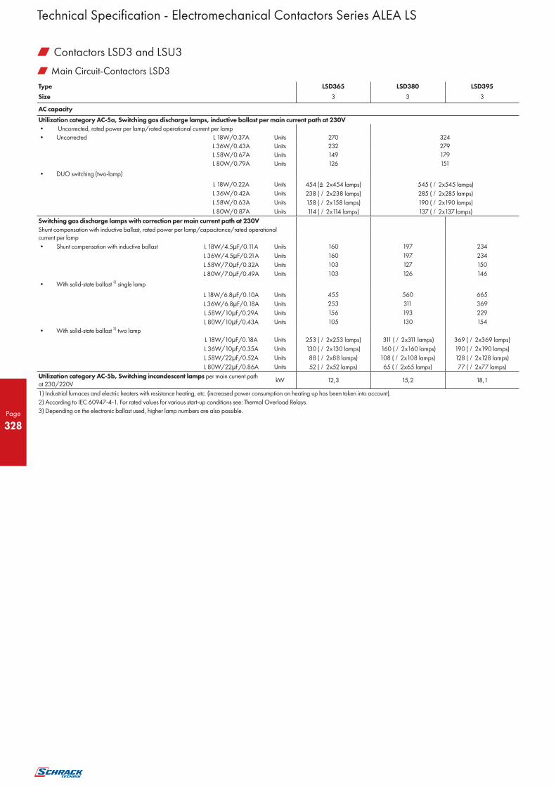
Page
328
w Main Circuit-Contactors LSD3
Type LSD365 LSD380 LSD395
Size 3 3 3
AC capacity Utilization category AC-5a, Switching gas discharge lamps, inductive ballast per main current path at 230V
• Uncorrected, rated power per lamp/rated operational current per lamp
• Uncorrected L 18W/0.37A Units 270 324
L 36W/0.43A Units 232 279
L 58W/0.67A Units 149 179
L 80W/0.79A Units 126 151
• DUO switching (two-lamp)
L 18W/0.22A Units 454 ( 2x454 lamps) 545 (�/ 2x545 lamps)
L 36W/0.42A Units 238 (�/ 2x238 lamps) 285 (�/ 2x285 lamps)
L 58W/0.63A Units 158 (�/ 2x158 lamps) 190 (�/ 2x190 lamps)
L 80W/0.87A Units 114 (�/ 2x114 lamps) 137 (�/ 2x137 lamps)
Switching gas discharge lamps with correction per main current path at 230V
Shunt compensation with inductive ballast, rated power per lamp/capacitance/rated operational current per lamp
• Shunt compensation with inductive ballast L 18W/4.5 F/0.11A Units 160 197 234
L 36W/4.5 F/0.21A Units 160 197 234
L 58W/7.0 F/0.32A Units 103 127 150
L 80W/7.0 F/0.49A Units 103 126 146
• With solid-state ballast 3) single lamp L 18W/6.8 F/0.10A Units 455 560 665
L 36W/6.8 F/0.18A Units 253 311 369
L 58W/10 F/0.29A Units 156 193 229
L 80W/10 F/0.43A Units 105 130 154
• With solid-state ballast 3) two lamp
L 18W/10 F/0.18A Units 253 (�/ 2x253 lamps) 311 (�/ 2x311 lamps) 369 (�/ 2x369 lamps)
L 36W/10 F/0.35A Units 130 (�/ 2x130 lamps) 160 (�/ 2x160 lamps) 190 (�/ 2x190 lamps)
L 58W/22 F/0.52A Units 88 (�/ 2x88 lamps) 108 (�/ 2x10⁸ lamps) 128 (�/ 2x128 lamps)
L 80W/22 F/0.86A Units 52 (�/ 2x52 lamps) 65 (�/ 2x65 lamps) 77 (�/ 2x77 lamps)
Utilization category AC-5b, Switching incandescent lamps per main current path at 230/220V
kW 12,3 15,2 18,1
1) Industrial furnaces and electric heaters with resistance heating, etc. (increased power consumption on heating up has been taken into account).
2) According to IEC 60947-4-1. For rated values for various start-up conditions see: Thermal Overload Relays.
3) Depending on the electronic ballast used, higher lamp numbers are also possible.
Technical Specification - Electromechanical Contactors Series ALEA LS
w Contactors LSD3 and LSU3

Page
329
w Main Circuit-Contactors LSD3
Type LSD365 LSD380 LSD395
Size 3 3 3
AC capacity Utilization category AC-6a, switching AC transformers
• Rated operational current Ie
For inrush current n = 20 up to 400V A 63,5 80 84,4
up to 690V A 47 58 58
For inrush current n = 30 up to 400V A 42,3 56,3 56,3
up to 690V A 42,3 56,3 56,3
• Rated power P
For inrush current n = 20 230V kVA 25,3 31,9 33,6
400V kVA 43,9 55,4 58
500V kVA 54,9 69,3 73,1
690V kVA 56,2 69,3 69,3
For inrush current n = 30 230V kVA 16,8 22,4 22,4
400V kVA 29,3 39 39
500V kVA 36,6 48,7 48,7
690V kVA 50,3 67,3 67,3
For deviating inrush current factors x, the power must be recalculated as follows: Px = Pn30 · 30/x
Utilization category AC-6b, switching low-inductance (low-loss, metallized dielectric) AC capacitors
Rated operational currents I e up to 400V A 57 72
Rated power for single capacitors or at 230V kvar 24 29
banks of capacitors (minimum inductance 400V kvar 40 50
of 6 µH between capacitors connected in 525V kvar 50 65
parallel) at 50 Hz, 60 Hz 690V kvar 40 50
DC capacity
Utilization category DC-1 Switching resistive loads (L/R ≤ 1ms)
• Rated operational current Ie (at 60°C)
- 1 conducting path up to 24V A 90 100 100
60V A 23 60 60
110V A 4,5 9 9
220V A 1 2 2
440V A 0,4 0,6 0,6
600V A 0,26 0,4 0,4
- 2 conducting paths in series up to 24V A 90 100 100
60V A 90 100 100
110V A 90 100 100
220V A 5 10 10
440V A 1 1,8 1,8
600V A 0,8 1 1
- 3 conducting paths in series up to 24V A 90 100 100
60V A 90 100 100
110V A 90 100 100
220V A 70 80 80
440V A 2,9 1,8 4,5
600V A 1,4 1 2,6
Technical Specification - Electromechanical Contactors Series ALEA LS
w Contactors LSD3 and LSU3

Page
330
w Main Circuit-Contactors LSD3
Type LSD365 LSD380 LSD395
Size 3 3 3
AC capacity Utilization category DC-3 und DC-5, Shunt-wound and series-wound motors (L/R ≤ 15ms)
• Rated operational current Ie (at 60°C)
- 1 conducting path up to 24V A 40 40 40
60V A 6 6,5 6,5
110V A 2,5 2,5 2,5
220V A 1 1 1
440V A 0,15 0,15 0,15
600V A 0,06 0,06 0,06
- 2 conducting paths in series up to 24V A 90 100 100
60V A 90 100 100
110V A 90 100 100
220V A 7 7 7
440V A 0,42 0,42 0,42
600V A 0,16 0,16 0,16
- 3 conducting paths in series up to 24V A 90 100 100
60V A 90 100 100
110V A 90 100 100
220V A 35 35 35
440V A 0,8 0,8 0,8
600V A 0,35 0,35 0,35
Switching frequency z in operating cycles/hour
• Contactors without overload relay No-load switching frequency AC
h-1 5000 5000 5000
No-load switching frequency DC
h-1 1000 1000 1000
Dependence of the switching AC-1 (AC/DC) h-1 1000 900 900
frequency z ’ on the operational current AC-2 (AC/DC) h-1 400 400 350
I ’ and operational voltage U ’: AC-3 (AC/DC) h-1 1000 1000 850
z' = z ⋅(Ie/I') ⋅(400 V/U')1,5 ⋅1/h AC-4 (AC/DC) h-1 300 300 250
• Contactors with overload relays (mean value) h-1 15 15 15
Technical Specification - Electromechanical Contactors Series ALEA LS
w Contactors LSD3 and LSU3

Page
331
w Conductor Cross-Sections-Contactors LSD3
Type LSD3
Size 3
1 or 2 conductors can be connected Main conductors: Screw terminals
Front clamping point • Finely stranded with end sleeve mm2 2.5 ... 35
connected • Finely stranded without end sleeve mm2 4 ... 50
• Stranded mm2 2.5 ... 16
• Solid mm2 4 ... 70
• Ribbon cable conductors (number x width x thickness) mm2 6 x 9 x 0.8
• AWG cables, solid or stranded AWG 10 ... 2/0
Rear clamping point • Finely stranded with end sleeve mm2 2.5 ... 50
connected • Finely stranded without end sleeve mm2 10 ... 50
• Stranded mm2 2.5 ... 16
• Solid mm2 10 ... 70
• Ribbon cable conductors (number x width x thickness) mm2 6 x 9 x 0.8
• AWG cables, solid or stranded AWG 10 ... 2/0
Both clamping points • Finely stranded with end sleeve mm2 2 x (2.5 ... 35)
connected • Finely stranded without end sleeve mm2 2 x (4 ... 35)
• Stranded mm2 2 x (2.5 ... 16)
• Solid mm2 2 x (4 ... 50)
• Ribbon cable conductors (number x width x thickness) mm2 2 x (6 x 9 x 0.8)
• AWG cables, solid or stranded AWG 2 x (10 ... 1/0)
• Terminal screw M6 (Inbus. SW 4)
- tightening torque Nm 4 ... 6 (36 ... 53 lb.in)
Connection for drilled copper bars 1) Max. width mm 10
Without box terminal with • Finely stranded with cable lug 10 ... 503)
cable lugs2) • Stranded with cable lug 10 ... 703)
(1 or 2 conductors can be connected) • AWG cables, solid or stranded 7 ... 1/0
Auxiliary conductors:
• Solid mm2 2 x (0.5 ... 1.5)4) ; 2 x (0.75 ... 2.5)4) acc. to IEC 60947;
max. 2 x (0.75 ... 4)
• Finely stranded with end sleeve mm2 2 x (0.5 ... 1.5) 4) ; 2 x (0.75 ... 2.5) 4)
• AWG cables, solid or stranded AWG 2 x (20 ... 16)4) ; 2 x (18 ... 14)4) ; 1 x 12
• Terminal screw M3
- tightening torque Nm 0.8 ... 1.2 (7 ... 10.3 lb.in)
Auxiliary conductors: Cage Clamp terminals (on request)
• Solid mm2 2 x (0.25 ... 2.5)
• Finely stranded with end sleeve mm2 2 x (0.25 ... 1.5)
• Finely stranded without end sleeve mm2 2 x (0.25 ... 2.5)
• AWG cables, solid or stranded AWG 2 x (24 ... 14)
1 ) If bars larger than 12 x 10mm are connected, a terminal cover is needed to comply with the phase clearance (on request).
2 ) If conductors larger than 25mm2 are connected, a terminal cover is needed to comply with the phase clearance (on request).
3 ) Only with crimped cable lugs according to DIN 46234. Cable lug max. 20mm wide.
4 ) If two different conductor cross-sections are connected to one clamping point, both cross-sections must lie in the range specified. If identical cross-sections are used, this restriction
does not apply.
Technical Specification - Electromechanical Contactors Series ALEA LS
w Contactors LSD3 and LSU3

Page
332
w General Data - Contactors LSD6
Type LSD611 LSD615 LSD619
Size 6 6 6
Permissible mounting position AC and DC operation
The contactors are designed for operation on a vertical mounting surface.
Mechanical endurance Operating 10 million
Electrical endurance cycles 1)
Rated insulation voltage Ui (degree of pollution 3, overvoltage category III) V 1000
Rated impulse withstand voltage Uimp kV 8
Safe isolation between the coil and the main contacts acc. to EN 60947-1, Appendix N V 690
Mirror contacts A mirror contact is an auxiliary NC contact that cannot be closed Yes, acc. to EN 60947-4-1, Appendix F
simultaneously with a NO main contact.
Ambient temperature During operation °C -25 ... +60/+55 with AS-Interface
During storage °C -55 ... +80
Degree of protection acc. to EN 60947-1, Appendix C IP00/open, coil assembly IP20
Touch protection acc. to EN 50274 finger-safe
Shock resistance - rectangular pulse AC and DC operation g/ms 8.5/5 und 4.2/10
Shock resistance -sine pulse AC and DC operation g/ms 13.4/5 und 6.5/10
Conductor cross-sections 2)
Electromagnetic compatibility (EMC) 3)
Short-circuit protection without overload relays For short-circuit protection for contactors with overload relays see: Overload Relays
Main circuit Fuse links gL/gG NH, DIAZED, NEOZED acc. to IEC 60 947-4-1/DIN EN 60 947-4-1 Type of coordination "1" A 355 355
Type of coordination "2" A 315 315
Weld-free1) A 80 160
Auxiliary circuit Fuse links gL/gG DIAZED, NEOZED (weld-free protection at Ik ≥ 1kA) A 10
Miniature circuit breakers with C characteristic short-circuit current Ik < 400A A 10
1) See “Endurance of the main contacts” 2) See “Conductor cross-sections” 3) See “Electromagnetic compatibility (EMC)“ 4) According to IEC 60 947-4-1
w Control - Contactors LSD6
Type LSD6
Size 6
Operating range of the solenoid AC/DC (UC) AC/DC 0.8 ... 1.1 x Us
Power consumption of the solenoid
• Conventional operating mechanism
- AC operation Closing at Us min VA/p.f. 250/0.9
Closing at Us max VA/p.f. 300/0.9
Closed at Us min VA/p.f. 4.8/0.8
Closed at Us max VA/p.f. 5.8/0.8
- DC operation Closing at Us min W 300
Closing at Us max W 360
Closed at Us min W 4,3
Closed at Us max W 5,2
PLC control input (EN 61131-2/type 2) 24VDC/≤ 30mA power consumption (operating range 17 ... 30VDC)
Operating times (Total break time = Opening delay + Arcing time)
• Conventional operating mechanism
- at 0,8 x Us min ... 1,1 x Us max Closing delay ms 20 ... 95
Opening delay ms 40 ... 60
- at Us min ... Us max Closing delay ms 25 ... 50
Opening delay ms 40 ... 60
• Arcing time ms 10 ... 15
Technical Specification - Electromechanical Contactors Series ALEA LS
w Contactors LSD6

Page
333
w Main Circuit-Contactors LSD6
Type LSD611 LSD615 LSD619
Size 6 6 6
AC capacity Utilization category AC-1, Switching resistive loads
Rated operational current Ie at 40°C up to 690V A 160 185 215
at 60°C up to 690V A 140 160 185
at 60°C up to 1000V A 80 90 100
Rated power for AC loads1) 230V kW 53 60 70
P.f.= 0.95 (at 60 °C) 400V kW 92 105 121
500V kW 115 131 152
690V kW 159 181 210
1000V 131 148 165
Minimum conductor cross-section at 40°C mm2 70 95 95
for loads with Ie at 60°C mm2 50 70 95
Utilization categories AC-2 and AC-3
Rated operational currents Ie up to 500V A 115 150 185
690V A 115 150 170
1000V A 53 65 65
Rated power for slipping or squirrel cage 230V kW 37 50 61
motors at 50 and 60 Hz 400V kW 64 84 104
500V kW 81 105 132
690V kW 113 146 167
1000V kW 75 90 90
Thermal load capacity 10 s current2) A 1100 1300 1480
Power loss per conducting path at Ie/AC-3 W 7 9 13
Utilization category AC-4 (at Ia = 6 x Ie) 1)
• Rated operational current Ie up to 400V A 97 132 160
• Rated power for squirrel-cage motors with 50 and 60Hz up to 400V kW 55 75 90
• The following applies to a contact endurance of about 200000 operating cycles: - Rated operational currents Ie up to 400V A 54 68 81
690V A 48 57 65
1000V A 34 38 42
- Rated power for squirrel-cage motors with 50 and 60Hz 230 kW 16 20 25
400V kW 29 38 45
500V kW 37 47 57
690V kW 48 55 65
1000V kW 49 55 60
Utilization category AC-6a, switching AC transformers
• Rated operational current Ie
For inrush current n = 20 up to 690V A 115 148 148
For inrush current n = 30 up to 690V A 90 99 99
• Rated power P at 230V KVA 45 58 58
For inrush current n = 20 400V KVA 79 102 102
500V KVA 99 128 128
690V KVA 137 176 176
1000V KVA 80 98 117
For inrush current n = 30 at 230V KVA 35 39 39
400V KVA 62 68 68
500V KVA 77 85 85
690V KVA 107 118 118
1000V KVA 80 98 117
For deviating inrush current factors x, the power must be recalculated as follows: Px = Pn30 · 30/x
Utilization category AC-6b, switching low-inductance (low-loss, metallized dielectric) AC capacitors
Ambient temperature 40 °C
Rated operational currents Ie up to 500V A 105 125 145
Rated power for single capacitors or at 230V kvar 42 50 58
banks of capacitors (minimum 400V kvar 72 86 100
inductance of 6 H between capacitors 500V kvar 90 108 125
connected in parallel) at 50Hz, 60Hz 690V kvar 72 86 100
1) Industrial furnaces and electric heaters with resistance heating, etc. (increased power consumption on heating up has been taken into account)
2) According to IEC 60947-4-1
Technical Specification - Electromechanical Contactors Series ALEA LS
w Contactors LSD6

Page
334
w Main Circuit-Contactors LSD6
Type LSD611 LSD615 LSD619
Size 6 6 6
DC capacity Utilization category DC-1 Switching resistive loads (L/R ≤ 1ms)
• Rated operational current Ie (at 60°C)
- 1 conducting path up to 24V A 160
60V A 160
110V A 18
220V A 3,4
440V A 0,8
600V A 0,5
- 2 conducting paths in series up to 24V A 160
60V A 160
110V A 160
220V A 20
440V A 3,2
600V A 1,6
- 3 conducting paths in series up to 24V A 160
60V A 160
110V A 160
220V A 160
440V A 11,5
600V A 4
Utilization category DC-3 und DC-5, Shunt-wound and series-wound motors (L/R ≤ 15ms)
• Rated operational current Ie (at 60°C)
- 1 conducting path up to 24V A 160
60V A 7,5
110V A 2,5
220V A 0,6
440V A 0,17
600V A 0,12
- 2 conducting paths in series up to 24V A 160
60V A 160
110V A 160
220V A 2,5
440V A 0,65
600V A 0,37
- 3 conducting paths in series up to 24V A 160
60V A 160
110V A 160
220V A 160
440V A 1,4
600V A 0,75
Switching frequency z in operating cycles/hour
• Contactors without overload relay No-load switching
frequency AC h-1 2000 2000
Dependence of the switching AC-1 h-1 800 800
frequency z ’ on the operational current AC-2 h-1 400 300
I ’ and operational voltage U ’: AC-3 h-1 1000 750
z' = z ⋅(Ie/I') ⋅(400 V/U')1,5 ⋅1/h AC-4 h-1 130 130
Technical Specification - Electromechanical Contactors Series ALEA LS
w Contactors LSD6

Page
335
w Conductor Cross-Sections-Contactors LSD6
Type LSD6
Size 6
Screw terminals Main conductors: without box terminal/busbar connection
• Finely stranded with cable lug1) mm2 16 ... 95
• Stranded with cable lug1) mm2 25 ... 120
• AWG cables, solid or stranded AWG 4 ... 250 kcmil
• Connecting bar (max. width) mm 17
• Terminal screw M8 x 25 (SW 13)
Tightening torque Nm 10 ... 14 (89 ... 124 lb.in)
Auxiliary conductors:
• Solid mm2 2 x (0.5 ... 1.5)2) ; 2 x (0.75 ... 2.5)2) acc. to IEC 60947; max. 2 x (0.75 ... 4)
• Finely stranded with end sleeve mm2 2 x (0.5 ... 1.5)2) ; 2 x (0.75 ... 2.5)2)
• AWG cables, solid or stranded AWG 2 x (18 ... 14)
• Terminal screw M3 (PZ 2)
Tightening torque Nm 0.8 ... 1.2 (7 ... 10.3 lb.in)
Cage Clamp terminals (on request)
Auxiliary conductors:
• Solid mm2 2 x (0.25 ... 2.5)
• Finely stranded with end sleeve mm2 2 x (0.25 ... 1.5)
• Finely stranded without end sleeve mm2 2 x (0.25 ... 2.5)
• AWG cables, solid or stranded AWG 2 x (24 ... 14)
1) When connecting cable lugs according to DIN 46235, use LSZ6D001 terminal cover for conductor cross-sections from 95mm² to ensure phase spacing.
2) If two different conductor cross-sections are connected to one clamping point, both cross-sections must lie in the range specified. If identical cross-sections are used, this restriction does not apply.
Technical Specification - Electromechanical Contactors Series ALEA LS
w Contactors LSD6

Page
336
w General data - Contactors LSDE
Type LSDE22 LSDE26 LSDE30
Size 10 10 10
Permissible mounting position AC and DC operation
The contactors are designed for operation on a vertical mounting surface.
Mechanical endurance Operating 10 million
Electrical endurance cycles 1)
Rated insulation voltage Ui (degree of pollution 3, overvoltage category III) V 1000
Rated impulse withstand voltage Uimp kV 8
Safe isolation between the coil and the main contacts acc. to EN 60947-1, Appendix N V 690
Mirror contacts
A mirror contact is an auxiliary NC contact that cannot be closed simultaneously with a NO main contact. Yes, acc. to EN 60947-4-1, Appendix F
Ambient temperature During operation °C -25 ... +60/+55 with AS-Interface
During storage °C -55 ... +80
Degree of protection acc. to EN 60947-1, Appendix C IP00/open, coil assembly IP20
Touch protection acc. to EN 50274 Finger-safe with cover
Shock resistance Rectangular pulse g/ms 8.5/5 and 4.2/10
Sine pulse g/ms 13.4/5 and 6.5/10
Conductor cross-sections 2)
Electromagnetic compatibility (EMC) 3)
Short-circuit protection
Main circuit
Fuse links gL/gG NH, DIAZED, NEOZED
acc. to IEC 60 947-4-1/DIN EN 60 947-4-1 Type of coordination "1" A 500
Type of coordination "2" A 400
Weld-free4) A 250
Auxiliary circuit
Fuse links gL/gG DIAZED, NEOZED (weld-free protection at Ik ≥ 1kA) A 10
Miniature circuit breakers with C characteristic short-circuit current Ik < 400A A 10
1) See “Endurance of the main contacts”
2) See “Conductor cross-sections”
3) See “Electromagnetic compatibility (EMC)“
4) According to IEC 60 947-4-1
w Control-Contactors LSDE
Type LSDE22 LSDE26 LSDE30
Size 10 10 10
Operating range of the solenoid AC/DC (UC) AC/DC 0.8 ... 1.1 x Us
Power consumption of the solenoid • Conventional operating mechanism - AC operation Closing at Us min VA/p.f. 490/0.9
Closing at Us max VA/p.f. 590/0.9
Closed at Us min VA/p.f. 5.6/0.9
Closed at Us max VA/p.f. 6.7/0.9
- DC operation Closing at Us min W 540
Closing at Us max W 650
Closed at Us min W 6,1
Closed at Us max W 7,4
PLC control input (EN 61131-2/type 2) 24VDC/≤ 30mA power consumption, (operating range 17 ... 30VDC)
Operating times (Total break time = Opening delay + Arcing time) • Conventional operating mechanism - at 0.8 x Us min ... 1.1 x Us max Closing delay ms 30 ... 95
Opening delay ms 40 ... 80
- at Us min ... Us max Closing delay ms 35 ... 50
Opening delay ms 50 ... 80
• Arcing time ms 10 ... 15
Technical Specification - Electromechanical Contactors Series ALEA LS
w Contactors LSDE

Page
337
w Main Circuit-Contactors LSDE
Type LSDE22 LSDE26 LSDE30
Size 10 10 10
AC capacity
Utilization category AC-1, Switching resistive loads
Rated operational current Ie at 40°C up to 690V A 275 330
at 60°C up to 690V A 250 300
at 60°C up to 1000V A 100 150
Rated power for AC loads1) 230V kW 94 113
P.f.= 0.95 (at 60 °C) 400V kW 164 197
500V kW 205 246
690V kW 283 340
1000V kW 164 246
Minimum conductor cross-section at 40°C mm2 150 185
for loads with Ie at 60°C mm2 120 185
Utilization categories AC-2 and AC-3
Rated operational currents Ie up to 500V A 225 265 300
690V A 225 265 280
1000V A 68 95 95
Rated power for slipping or squirrel cage 230V kW 73 85 97
motors at 50 and 60 Hz 400V kW 128 151 171
500V kW 160 189 215
690V kW 223 265 280
1000V kW 90 132 132
Thermal load capacity 10 s current2) A 1800 2400 2400
Power loss per conducting path at Ie/AC-3/500V W 17 18 22
Utilization category AC-4 (at Ia = 6 x Ie) 1)
• Rated operational current Ie up to 400V A 195 230 280
• Rated power for squirrel-cage motors with 50 and 60Hz up to 400V kW 110 132 160
• The following applies to a contact endurance of about 200000 operating cycles:
- Rated operational currents Ie up to 400V A 96 117 125
690V A 85 105 115
1000V A 42 57 57
- Rated power for squirrel-cage motors with 50 and 60Hz 230 kW 30 37 40
400V kW 54 66 71
500V kW 67 82 87
690V kW 82 102 112
1000V kW 59 80 80
Utilization category AC-6a, switching AC transformers
• Rated operational current Ie
For inrush current n = 20 up to 690V A 227 265 273
For inrush current n = 30 up to 690V A 151 182 182
• Rated power P at 230V KVA 90 105 109
For inrush current n = 20 400V KVA 157 183 189
500V KVA 196 229 236
690V KVA 271 317 326
1000V KVA 117 164 164
For inrush current n = 30 at 230V KVA 60 72 72
400V KVA 105 126 126
500V KVA 130 158 158
690V KVA 180 217 217
1000V KVA 117 164 164
For deviating inrush current factors x, the power must be recalculated as follows: Px = Pn30 · 30/x
Utilization category AC-6b, switching low-inductance (low-loss, metallized dielectric) AC capacitors
Ambient temperature 40 °C
Rated operational currents Ie up to 500V A 183 220
Rated power for single capacitors or at 230V kvar 73 88
banks of capacitors (minimum 400V kvar 127 152
inductance of 6 H between capacitors 500V kvar 159 191
connected in parallel) at 50Hz, 60Hz 690V kvar 127 152
1) Industrial furnaces and electric heaters with resistance heating, etc. (increased power consumption on heating up has been taken into account).
2) According to IEC 60947-4-1.
Technical Specification - Electromechanical Contactors Series ALEA LS
w Contactors LSDE

Page
338
w Main Circuit-Contactors LSDE
Type LSDE22 LSDE26 LSDE30
Size 10 10 10
DC capacity
Utilization category DC-1 Switching resistive loads (L/R ≤ 1ms)
• Rated operational current Ie (at 60°C)
- 1 conducting path up to 24V A 200 300
60V A 200 300
110V A 18 33
220V A 3,4 3,8
440V A 0,8 0,9
600V A 0,5 0,6
- 2 conducting paths in series up to 24V A 200 300
60V A 200 300
110V A 200 300
220V A 20 300
440V A 3,2 4
600V A 1,6 2
- 3 conducting paths in series up to 24V A 200 300
60V A 200 300
110V A 200 300
220V A 200 300
440V A 11,5 11
600V A 4 5,2
Utilization category DC-3 und DC-5, Shunt-wound and series-wound motors (L/R ≤ 15ms)
• Rated operational current Ie (at 60°C)
- 1 conducting path up to 24V A 200 300
60V A 7,5 11
110V A 2,5 3
220V A 0,6 0,6
440V A 0,17 0,18
600V A 0,12 0,125
- 2 conducting paths in series up to 24V A 200 300
60V A 200 300
110V A 200 300
220V A 2,5 2,5
440V A 0,65 0,65
600V A 0,37 0,37
- 3 conducting paths in series up to 24V A 200 300
60V A 200 300
110V A 200 300
220V A 200 300
440V A 1,4 1,4
600V A 0,75 0,75
Switching frequency z in operating cycles/hour
• Contactors without overload relay No-load switching
frequency AC h-1 2000 2000 2000
Dependence of the switching AC-1 h-1 750 800 750
frequency z ’ on the operational current AC-2 h-1 250 300 250
I ’ and operational voltage U ’: AC-3 h-1 500 700 500
z' = z ⋅(Ie/I') ⋅(400 V/U')1,5 ⋅1/h AC-4 h-1 130 130 130
Technical Specification - Electromechanical Contactors Series ALEA LS
w Contactors LSDE

Page
339
w Conductor Cross-Sections-Contactors LSDE
Type LSDE
Size 10
Conductor cross-sections of main conductors Screw terminals Main conductors:
• Finely stranded with cable lug1) mm2 50 ... 240
• Stranded with cable lug1) mm2 70 ... 240
• AWG cables, solid or stranded AWG 2/0 ... 500 kcmil
• Connecting bar (max. width) mm 25
• Terminal screw M10 x 30 (SW 17)
- Tightening torque Nm 14 ... 24 (124 ... 210 lb.in)
Auxiliary conductors:
• Solid mm2 2 x (0.5 ... 1.5)2) ; 2 x (0.75 ... 2.5)2)
acc. to IEC 60947; max. 2 x (0.75 ... 4)
• Finely stranded with end sleeve mm2 2 x (0.5 ... 1.5)2) ; 2 x (0.75 ... 2.5)2)
• AWG cables, solid or stranded AWG 2 x (18 ... 14)
• Terminal screw M3 (PZ 2)
- Tightening torque Nm 0.8 ... 1.2 (7 ... 10.3 lb.in)
Cage Clamp terminals (on request)
Auxiliary conductors:
• Solid mm2 2 x (0.25 ... 2.5)
• Finely stranded with end sleeve mm2 2 x (0.25 ... 1.5)
• Finely stranded without end sleeve mm2 2 x (0.25 … 2.5)
• AWG cables, solid or stranded AWG 2 x (24 ... 14)
1) When connecting cable lugs according to DIN 46235, use LSZ6 D001 terminal cover for conductor cross-sections from 95mm² to ensure phase spacing.
2) If two different conductor cross-sections are connected to one clamping point, both cross-sections must lie in the range specified. If identical cross-sections are used, this restriction does not apply.
Technical Specification - Electromechanical Contactors Series ALEA LS
w Contactors LSDE

Page
340
w General Data - Contactors LSDG
Type LSDG41 LSDG51
Size 12 12
Permissible mounting position
The contactors are designed for operation on a vertical mounting surface.
Mechanical endurance Operating 10 million
Electrical endurance cycles 1)
Rated insulation voltage Ui (degree of pollution 3, overvoltage category III) V 1000
Rated impulse withstand voltage Uimp kV 8
Safe isolation between the coil and the main contacts acc. to EN 60947-1, Appendix N V 690
Mirror contacts A mirror contact is an auxiliary NC contact that cannot be closed simultaneously with a NO main contact. Yes, acc. to EN 60947-4-1, Appendix F
Ambient temperature During operation °C -25 ... +60/+55 with AS-Interface
During storage °C -55 ... +80
Degree of protection acc. to EN 60947-1, Appendix C IP00/open, coil assembly IP20
Touch protection acc. to EN 50274 Finger-safe with cover
Shock resistance Rectangular pulse g/ms 8.5/5 and 4.2/10
Sine pulse g/ms 13.4/5 and 6.5/10
Conductor cross-sections 2)
Electromagnetic compatibility (EMC) 3)
Short-circuit protection Main circuit • Fuse links gL/gG NH, DIAZED, NEOZED acc. to IEC 60 947-4-1/DIN EN 60 947-4-1 • Type of coordination "1" A 630 630
• Type of coordination "2" A 500 500
• Weld-free4) A 250 315
Auxiliary circuit • Fuse links gL/gG DIAZED, NEOZED (weld-free protection at Ik ≥ 1kA) A 10
• Miniature circuit breakers with C characteristic short-circuit current Ik < 400A A 10
1) See “Endurance of the main contacts” 2) See “Conductor cross-sections” 3) See “Electromagnetic compatibility (EMC)“ 4) According to IEC 60 947-4-1
w Control - Contactors LSDG
Type LSDG41 LSDG51
Size 12 12
Operating range of the solenoid AC/DC (UC) AC/DC 0.8 ... 1.1 x Us
Power consumption of the solenoid • Conventional operating mechanism - AC operation Closing at Us min VA/p.f. 700/0.9
Closing at Us max VA/p.f. 830/0.9
Closed at Us min VA/p.f. 7.6/0.9
Closed at Us max VA/p.f. 9.2/0.9
- DC operation Closing at Us min W 770
Closing at Us max W 920
Closed at Us min W 8,5
Closed at Us max W 10
PLC control input (EN 61131-2/type 2) 24VDC/≤ 30mA power consumption, (operating range 17 ... 30VDC)
Operating times (Total break time = Opening delay + Arcing time) • Conventional operating mechanism - at 0.8 x Us min ... 1.1 x Us max Closing delay ms 45 ... 100
Opening delay ms 60 ... 100
- at Us min ... Us max Closing delay ms 50 ... 70
Opening delay ms 70 ... 100
• Arcing time ms 10 ... 15
Technical Specification - Electromechanical Contactors Series ALEA LS
w Contactors LSDG

Page
341
w Main Circuit-Contactors LSDG
Type LSDG41 LSDG51
Size 12 12
AC capacity
Utilization category AC-1, Switching resistive loads
Rated operational current Ie at 40°C up to 690V A 430 610
at 60°C up to 690V A 400 550
at 60°C up to 1000V A 200 200
Rated power for AC loads1) 230V kW 151 208
P.f.= 0.95 (at 60 °C) 400V kW 263 362
500V kW 329 452
690V kW 454 624
1000V kW 329 329
Minimum conductor cross-section at 40°C mm2 2 x 150 2 x 185
for loads with Ie at 60°C mm2 240 2 x 185
Utilization categories AC-2 and AC-3
Rated operational currents Ie up to 500V A 400 500
690V A 400 450
1000V A 180 180
Rated power for slipping or squirrel-cage 230V kW 132 164
motors at 50 and 60 Hz 400V kW 231 291
500V kW 291 363
690V kW 400 453
1000V kW 250 250
Thermal load capacity 10 s current2) A 3200 4000
Power loss per conducting path at Ie/AC-3/500V W 35 55
Utilization category AC-4 (at Ia = 6 x Ie) 1)
• Rated operational current Ie up to 400V A 350 430
• Rated power for squirrel-cage motors with 50 and 60Hz up to 400V kW 200 250
• The following applies to a contact endurance of about 200000 operating cycles:
- Rated operational currents Ie up to 400V A 150 175
690V A 135 150
1000V A 80 80
- Rated power for squirrel-cage motors with 50 and 60Hz 230V kW 48 56
400V kW 85 98
500V kW 105 123
690V kW 133 148
1000V kW 113 113
Utilization category AC-6a, switching AC transformers
• Rated operational current Ie
For inrush current n = 20 up to 690V A 377 404
For inrush current n = 30 up to 690V A 251 270
• Rated power P
For inrush current n = 20 at 230V kVA 150 161
400V kVA 261 280
500V kVA 326 350
690V kVA 450 483
1000V kVA 311 311
For inrush current n = 30 at 230V kVA 100 107
400V kVA 173 187
500V kVA 217 234
690V kVA 300 323
1000V kVA 311 311
For deviating inrush current factors x, the power must be recalculated as follows: Px = Pn30 · 30/x
Utilization category AC-6b, switching low-inductance (low-loss, metallized dielectric) AC capacitors
Ambient temperature 40 °C
Rated operational currents Ie up to 500V A 287 407
Rated power for single capacitors or at 230V kVAr 114 162
banks of capacitors (minimum 400V kVAr 199 282
inductance of 6 H between capacitors 500V kVAr 248 352
connected in parallel) at 50Hz, 60Hz 690V kVAr 199 282
1) Industrial furnaces and electric heaters with resistance heating, etc. (increased power consumption on heating up has been taken into account)
2) According to IEC 60947-4-1
Technical Specification - Electromechanical Contactors Series ALEA LS
w Contactors LSDG

Page
342
w Main Circuit-Contactors LSDG
Type LSDG41 LSDG51
Size 12 12
DC capacity
Utilization category DC-1 Switching resistive loads (L/R ≤ 1ms)
• Rated operational current Ie (at 60°C)
- 1 conducting path up to 24V A 400
60V A 330
110V A 33
220V A 3,8
440V A 0,9
600V A 0,6
- 2 conducting paths in series up to 24V A 400
60V A 400
110V A 400
220V A 400
440V A 4
600V A 2
- 3 conducting paths in series up to 24V A 400
60V A 400
110V A 400
220V A 400
440V A 11
600V A 5,2
Utilization category DC-3 und DC-5, Shunt-wound and series-wound motors (L/R ≤ 15ms)
• Rated operational current Ie (at 60°C)
- 1 conducting path up to 24V A 400
60V A 11
110V A 3
220V A 0,6
440V A 0,18
600V A 0,125
- 2 conducting paths in series up to 24V A 400
60V A 400
110V A 400
220V A 2,5
440V A 0,65
600V A 0,37
- 3 conducting paths in series up to 24V A 400
60V A 400
110V A 400
220V A 400
440V A 1,4
600V A 0,75
Switching frequency z in operating cycles/hour
• Contactors without overload relay No-load switching frequency AC
h-1 2000 2000
Dependence of the switching AC-1 h-1 700 500
frequency z ’ on the operational current AC-2 h-1 200 170
I ’ and operational voltage U ’: AC-3 h-1 500 420
z' = z ⋅(Ie/I') ⋅(400 V/U')1,5 ⋅1/h AC-4 h-1 130 130
Technical Specification - Electromechanical Contactors Series ALEA LS
w Contactors LSDG

Page
343
w Conductor Cross-Sections-Contactors LSDG
Type LSDG
Size 12
Screw terminals Main conductors: without box terminal/busbar connection (box terminals on request)
• Finely stranded with cable lug1) mm2 50 ... 240
• Stranded with cable lug1) mm2 70 ... 240
• AWG cables, solid or stranded AWG 2/0 ... 500 kcmil
• Connecting bar (max. width) mm 25
• Terminal screw M10 x 30 (SW 17)
- Tightening torque Nm 14 ... 24 (124 ... 210 lb.in)
Auxiliary conductors:
• Solid mm2 2 x (0.5 ... 1.5)2) ; 2 x (0.75 ... 2.5)2) acc. to IEC 60947; max. 2 x (0.75 ... 4)
• Finely stranded with end sleeve mm2 2 x (0.5 ... 1.5)2) ; 2 x (0.75 ... 2.5)2)
• AWG cables, solid or stranded AWG 2 x (18 ... 14)
• Terminal screw M3 (PZ 2)
- Tightening torque Nm 0.8 ... 1.2 (7 ... 10.3 lb.in)
Cage Clamp terminals (on request) Auxiliary conductors: • Solid mm2 2 x (0.25 ... 2.5)
• Finely stranded with end sleeve mm2 2 x (0.25 ... 1.5)
• Finely stranded without end sleeve mm2 2 x (0.25 ...2.5)
• AWG cables, solid or stranded AWG 2 x (24 ... 14)
1) When connecting cable lugs according to DIN46234 for conductor cross-sections of 185mm²2 and more and according to DIN46235 for conductor cross-sections of 240mm2 and more, the LSZED001 terminal cover must be used to keep the phase clearance.
2) If two different conductor cross-sections are connected to one clamping point, both cross-sections must lie in the range specified. If identical cross-sections are used, this restriction does not apply.
Technical Specification - Electromechanical Contactors Series ALEA LS
w Contactors LSDG

Page
344
w CSA and UL Rated Data for Contactors LSDD/0, LSSD/0 and LSUD/0
Type
LSUD12 LSU025
LSSD07 LSSD09 LSSD12 LSS012 LSS017 LSS025
LSDD07 LSDD09 LSDD12 LSD009 LSD012 LSD017 LSD025
Size 00 00 00 0 0 0 0
Rated insulation voltage VAC 600
Uninterrupted current, at 40 °C • Open and enclosed A 20
Maximum horsepower ratings (CSA and UL approved values)
• Rated power for induction motor at 60Hz at 200V hp 1,5 2 3 2 3 5 7,5
230V hp 2 3 3 3 3 5 7,5
460V hp 3 5 7,5 5 7,5 10 15
575V hp 5 7,5 10 7,5 10 15 20
Short-circuit protection1) (contactor or overload relay) at 600V kA 5 5 5 5 5 5 5
• CLASS RK5 fuse A 60 60 60 70 70 70 100
• Circuit breakers with overload A 50 50 50 70 70 70 100
protection acc. to UL 489
• Combination motor controllers, type E acc. to UL 508
at 480V Type -- -- -- BES0
A -- -- -- 8 10 16 22
kA -- -- -- 65 65 65 65
at 600V Type -- -- -- BES0
A -- -- -- 8 10 12,5 12,5
kA -- -- -- 25 25 25 25
NEMA/EEMAC ratings
NEMA/EEMAC-Size hp -- -- 0 -- -- -- 1
• Uninterrupted current Open A -- -- 18 -- -- -- 27
Enclosed A -- -- 18 -- -- -- 27
• Rated power for induction motor at 60Hz at 200V hp -- -- 3 -- -- -- 7,5
230V hp -- -- 3 -- -- -- 7,5
460V hp -- -- 5 -- -- -- 10
575V hp -- -- 5 -- -- -- 10
Thermal Overload relays Type LSTD LST0
Setting range A 0.11 ... 12 1.8 ... 25
w CSA and UL Rated Data for Contactors LSD2, LSU2, LSD3
Type LSU240
LSD232 LSD240 LSD250 LSD365 LSD380 LSD395
Size 2 2 2 3 3 3
Rated insulation voltage VAC 600
Uninterrupted current, at 40 °C • Open and enclosed A 45 55 50 90 105 105
Maximum horsepower ratings (CSA and UL approved values)
• Rated power for induction at 200V hp 10 10 15 20 25 30
motors at 60Hz 230V hp 10 15 15 25 30 30
460V hp 25 30 40 50 60 75
575V hp 30 40 50 60 75 100
Short-circuit protection1) (contactor or overload relay) at 600V kA 5 5 5 10 10 10
• CLASS RK5 fuse A 125 150 200 250 300 350
• Circuit breakers with overload A 125 150 200 250 300 400
protection acc. to UL 489
• Combination motor controllers, type E acc. to UL 508
at 480 V Type BES2 BES3
A 32 40 50 63 75 100
kA 65 65 65 65 65 65
at 600 V Type BES3 BES3
A 32 40 50 63 75 75
kA 25 25 25 30 30 30
NEMA/EEMAC ratings
NEMA/EEMAC-Size hp -- -- 2 -- -- 3
• Uninterrupted current Open A -- -- 45 -- -- 90
Enclosed A -- -- 45 -- -- 90
• Rated power for induction motor at 60Hz at 200V hp -- -- 10 -- -- 25
230V hp -- -- 15 -- -- 30
460V hp -- -- 25 -- -- 50
575V hp -- -- 25 -- -- 50
Thermal Overload relays Type LST2 LST3
Setting range A 5.5 ... 50 18 ... 100
Technical Specification - Electromechanical Contactors Series ALEA LS
w CSA and UL Rated Data for Contactors LSD, LSS and LSU

Page
345
w CSA and UL Rated Data for Auxiliary Contacts
Size 00 00 - 12
Screw terminals and Screw terminals and Screw terminals and
Cage Clamp terminals Cage Clamp terminals Cage Clamp terminals
Integrated or snap-on 1- and 4-pole snap-on Laterally mountable
auxiliary contact block auxiliary contact block auxiliary contact block
Rated voltage VAC 600 600 600
Switching capacity A 600, Q 600 A 600, Q 600 A 300, Q 300
• Uninterrupted current at 240VAC
A 10 10 10
w CSA and UL Rated Data for Contactors LSD6, LSDE
Type LSD611 LSD615 LSD619 LSDE22 LSDE26 LSDE30
Size 6 6 6 10 10 10
Rated insulation voltage VAC 600
Uninterrupted current, at 40°C • Open and enclosed A 140 195 195 250 330 330
Maximum horsepower ratings (CSA and UL approved values)
• Rated power for at 200V hp 40 50 60 60 75 100
induction motor at 60Hz 230V hp 50 60 75 75 100 125
460V hp 100 125 150 150 200 250
575V hp 125 150 200 200 250 300
Short-circuit protection1) (contactor or overload relay) at 600V kA 10 10 10 10 18 18
• CLASS RK5 fuse A 450 500 500 700 800 800
• Circuit breakers with overload A 350 450 500 500 700 800
protection acc. to UL 489
NEMA/EEMAC ratings
NEMA/EEMAC-Size hp -- 4 -- -- -- 5
• Uninterrupted current Open A -- 150 -- -- -- 300
Enclosed A -- 135 -- -- -- 270
• Rated power for at 200V hp -- 40 -- -- -- 75
induction motor at 60Hz 230V hp -- 50 -- -- -- 100
460V hp -- 100 -- -- -- 200
575V hp -- 100 -- -- -- 200
w CSA and UL Rated Data for Contactors LSDG
Typ LSDG41 LSDG51
Size 12 12
Rated insulation voltage VAC 600
Uninterrupted current, at 40 °C • Open and enclosed A 400 540
Maximum horsepower ratings (CSA and UL approved values)
• Rated power for induction motor at 60Hz at 200V hp 125 150
230V hp 150 200
460V hp 300 400
575V hp 400 500
Short-circuit protection (contactor or overload relay) at 600V kA 18 30
• CLASS RK5 fuse A 1000 1200
• Circuit breakers with overload A 900 900
protection acc. to UL 489
NEMA/EEMAC ratings
NEMA/EEMAC-Size hp -- 6
• Uninterrupted current Open A -- 600
Enclosed A -- 540
• Rated power for induction motor at 60Hz at 200V hp -- 150
230V hp -- 200
460V hp -- 400
575V hp -- 400
Technical Specification - Electromechanical Contactors Series ALEA LS
w CSA and UL Rated Data for Contactors LSD, LSS and LSU

Page
346
w Vakuum Contactors LSDH - Overview
IEC 60947-4-1, EN 60947-4-1 (VDE 0660 Part 102)The LSDH contactors are climate-proof. They are finger-safe according to EN 50274. Terminal covers may have to be fitted onto the connecting bars, depending on the configuration with other devices (see chapter “Accessories” – terminal covers).
FUNCTION
MAIN CONTACTS
Contact erosion indication with LSDH 6/8 vacuum contactors
The contact erosion of the vacuum interrupters can be checked during operation with the help of 3 white double slides on the contactor base. If the distance indicated by one of the double slides is < 0.5 mm while the contactor is in the closed position, the vacuum interrupter must be replaced. To ensure maximum reliability, it is recommended to replace all 3 vacuum interrupters.
AUXILIARY CONTACTS
Contact reliability
The auxiliary contacts are suitable for solid-state circuits
• with currents ≥ 1mA
• and voltages from 17V
SURGE SUPPRESSION
Control circuit
Protection of coils against overvoltage:
AC operation
• Fitted with varistors as standard
DC operation
Retrofitting options:
• With varistors
If LSDH 6/8 is to be used for DC operation, an additional reversing contactor is required; this is included in the scope of supply in the same packaging as the vacuum contactor.
w Electromagnetic Compatibility
LSDH 6/8 contactors for AC operation are fitted with an electronically controlled solenoid operating mechanism with a high interference immunity.
Contactor Rated control Overvoltage type Degree of severity Overvoltage
type supply voltage Us (IEC 60801) (IEC 60801) strength
LSDH6 110V ... 132V Burst 3 2kV
LSDH8 Surge 4 6kV
200V ... 277V Burst 4 4kV
Surge 4 5kV
380V ... 600V Burst 4 4kV
Surge 4 6kV
Note:
During operation in installations in which the emitted interference limits cannot be observed, e.g. when used for output contactors in converters,
LSDH6/8 contactors without a main conductor path circuit are recommended (see description next page). APPLICATION
The standard LSDH6. and LSDHB. contactors with electronically controlled contactor mechanism, have high resistance to electromagnetic interference.
Causes for such interference can be, for example:
• Frequency converters which are operated nearby can cause periodic overvoltages at the control level of the contactors.
• High-energy pulses cause by switching operations and atmospheric discharges can cause interference on the control cables.
To reduce interference voltages caused by frequency converters, the manufacturer recommends the use of e.g. input filters, output filters, grounding or shielding in the installation.
Further measures that should be applied for overvoltage damping:
• Feeding the contactors using control transformer according to EN 60204 - rather than directly from the network
• Use of surge arresters, if required
Control circuit
The rectifier bridge is connected to varistors for protection against overvoltages. The built-in rectifier bridge affords sufficient protection for the coils.
Main circuit
As standard LSDH. contactors with integrated RC varistors.
Protection of the main current paths
An integrated RC varistor connection for the main current paths of the contactors dampens the switching overvoltage rises to safe values. This prevents multiple restriking. The operator of an installation can therefore rest assured that the motor winding cannot be damaged by switching overvoltages with steep voltage rises.
Important note:
The overvoltage damping circuit is not required if LSDH 6/8 contactors are used in circuits with DC choppers, frequency converters or speed-variable operating mechanisms, for example. It could be damaged by the voltage peaks and harmonics which are generated. This may cause phase-to-phase short-circuits in the contactors.
Order special contactor version without overvoltage damping (on request).
Technical Specification - Electromechanical Contactors Series ALEA LS
w General Information - Vacuum Contactors LSDH

Page
347
w Endurance of the auxiliary contacts
The contact endurance for utilization category AC-12 or AC-15/AC-14 depends
mainly on the breaking current. It is assumed that the operating
mechanisms are switched randomly, i.e. not synchronized with
the phase angle of the supply system.
Diagram:
1) Operating cycles
w Contactors LSDH6 and LSDH8 at 230VAC
w Contact Erosion Indication with LSDH6 and LSDH8 Vacuum Contactors
The contact erosion of the vacuum interrupters can be checked during operation with the help of 3 white double slides on the contactor base.
If the distance indicated by one of the double slides is < 0.5mm while the contactor is in the closed position, the vacuum interrupter must be replaced. To ensure maximum reliability,
it is recommended to replace all 3 vacuum interrupters.
w Endurance of the Main Contacts
1) Operating cycles at …
PN = Rated power for squirrel-cage motors at 400V
Ia = Breaking current
Ie = Rated operational current
Technical Specification - Electromechanical Contactors Series ALEA LS
w General Information - Vacuum Contactors LSDH

Page
348
w Rated Data of the Auxiliary Contacts
Type LSDH6 and LSDH8
acc. to IEC 60947-5-1 (VDE 0660 Part 200)
Rated insulation voltage Ui (degree of pollution 3, overvoltage category III) V 690
Continuous thermal current Ith = Rated operational current Ie /AC-12 A 10
AC load, Rated operational current Ie/AC-15/AC-14
• for rated operational voltage Ue 24V A 10
110V A 10
125V A 10
220V A 6
230V A 5,6
380V A 4
400V A 3,6
500V A 2,5
660V A 2,5
690V A 2,3
DC load, Rated operational current Ie/DC-12
• for rated operational voltage Ue 24V A 10
60V A 10
110V A 3,2
125V A 2,5
220V A 0,9
440V A 0,33
600V A 0,22
DC load, Rated operational current Ie/DC-13
• for rated operational voltage Ue 24V A 10
60V A 5
110V A 1,14
125V A 0,98
220V A 0,48
440V A 0,13
600V A 0,07
CSA and UL rated data for the auxiliary contacts
Rated voltage VAC max.
600
Switching capacity A 600, P 600
Technical Specification - Electromechanical Contactors Series ALEA LS
w General Information - Vacuum Contactors LSDH

Page
349
w General Data - Vacuum Contactors LSDH6, LSDH8
Type LSDH6 LSDH8
Size 14 14
Permissible mounting position, installation instructions1) 2) AC and DC operation
The contactors are designed for operation on a vertical mounting surface.
Mechanical endurance Operating 5 Mio.
Electrical endurance cycles 3)
Rated insulation voltage Ui (degree of pollution 3, overvoltage category III) kV 1
Rated impulse withstand voltage Uimp kV 8
Safe isolation between the coil and the main contacts acc. to EN 60947-1, Appendix N kV 1
Permissible ambient temperature During operation °C -25 ... +55
During storage °C -55 ... +80
Degree of protection acc. to EN 60947-1, Appendix C IP00/open, coil assembly IP40
Touch protection acc. to EN 50274 Finger-safe with cover
Shock resistance • Rectangular pulse AC operation g/ms 8.1/5 and 4.7/10 9.5/5 and 5.7/10
DC operation g/ms 9/5 and 5.7/10 8.6/5 and 5.1/10
• Sine pulse AC operation g/ms 12.8/5 and 7.4/10 13.5/5 and 7.8/10
DC operation g/ms 14.4/5 and 9.1/10 13.5/5 and 7.8/10
Conductor cross-sections See "Conductor Cross-Sections"
Electromagnetic compatibility (EMC) See "Electromagnetic compatibility (EMC)"
Short-circuit protection • Fuse link gL/gG NH, DIAZED, NEOZED acc. to IEC 60 947-4-1/DIN EN 60 947-4-1 Type of coordination "1" A 1000 1250
Type of coordination "2" A 500 630
Weld-free4) A 400 500
Auxiliary circuit • Fuse links gL/gG DIAZED, NEOZED (weld-free protection at Ik ≥ 1kA) A 10
• Or miniature circuit breakers with C characteristic Ik < 400A A 10
1) To easily replace the laterally mounted auxiliary switches it is recommended to maintain a minimum distance of 30mm between the contactors.
2) If mounted at a 90° angle (conducting paths are horizontally above each other), the switching frequency is reduced by 80% compared with the normal values.
3) See page before “Endurance of the auxiliary contacts”.
4) Test conditions according to IEC 60947-4-1.
Technical Specification - Electromechanical Contactors Series ALEA LS
w General Information - Vacuum Contactors LSDH
w Control - Vacuum Contactors LSDH6, LSDH8
Type LSDH6 LSDH8
Size 14 14
Magnetic coil operating range 0.8 ... 1.1 x Us
Power consumption of the magnetic coils (when coil is cold and 1.0 x Us) • AC operation, Us max Closing VA/p.f. 1850/1 950/0.98
Closed VA/p.f. 49/0.15 30.6/0.31
• AC operation, Us min Closing VA/p.f. 1200/1 600/0.98
Closed VA/p.f. 13.5/0.47 12.9/0.43
• DC economy circuit1) Closing at 24V W 1010 960
Closed W 28 20,6
Operating times at 0.8 ... 1.1 x Us (Total break time = Opening delay + Arcing time) (Values apply to cold and warm coil)
• AC operation Closing delay ms 70 ... 120 80 ... 120
Opening delay ms 70 ... 100 70 ... 80
• DC operation Closing delay ms 76 ... 110 86 ... 280
Opening delay ms 50 19 ... 25
• Arcing time ms 10 ... 15 10
Operating times at 1.0 x Us (Total break time = Opening delay + Arcing time) • AC operation Closing delay ms 80 ... 100 85 ... 100
Opening delay ms 70 ... 100 70
• DC operation Closing delay ms 80 ... 90 90 ... 125
Opening delay ms 50 19 ... 25
Minimum command duration Standard ms 120 120
for closing Reduced make-time ms 90 --
Minimum interval time between two ON commands ms 100 300
1) At 24VDC; for further voltages, deviations of up to ±10 % are possible.
w Vacuum Contactors LSDH

Page
350
w Main Circuit - Vacuum Contactors LSDH6, LSDH8
Type LSDH6 LSDH8
Size 14 14
AC capacity
Utilization category AC-1, Switching resistive loads
• Rated operational current Ie at 40°C up to 690V A 700 910
at 60°C up to 690V A 630 850
at 60°C up to 1000V A 450 800
• Rated power for AC loads1) 230V kW 240 323
P.f.= 0.95 (at 60 °C) 400V kW 415 558
500V kW 545 735
690V kW 720 970
1000V kW 780 1385
• Minimum conductor cross-section at 40°C mm2 2 x 24 Ie≥ 800A: 2 x 60 x 5 (Cu busbars)
for loads with Ie at 55°C mm2 2 x 18 Ie < 800A: 2 x 240
Utilization categories AC-2 and AC-3
• Rated operational currents Ie up to 690V A 630 820
1000V A 435 580
• Rated power for slipping or squirrel-cage at 230V kW 200 260
motors at 50 and 60 Hz 400V kW 347 450
500V kW 434 600
690V kW 600 800
1000V kW 600 800
Utilization category AC-4 (at Ia = 6 x Ie) 1)
• Rated operational current Ie up to 690V A 610 690
• Rated power for squirrel-cage motors with 50 and 60Hz up to 400V kW 355 400
• The following applies to a contact endurance of about 200000 operating cycles:
- Rated operational currents Ie up to 690V A 300 360
1000V A 210 250
- Rated power for squirrel-cage motors with 50 and 60Hz 230V kW 97 110
400V kW 168 191
500V1) kW 210 250
690V1) kW 278 335
1000V1) A 290 350
Utilization category AC-6a, switching AC transformers
• Rated operational current Ie
- For inrush current n = 20 up to 400V A 513 675
- For inrush current n = 30 up to 400V A 342 450
• Rated power P at 230V kVA 195 256
- For inrush current n = 20 400V kVA 338 445
500V kVA 444 584
690V kVA 586 771
1000V kVA 752 1003
- For inrush current n = 30 at 230V kVA 130 171
400V kVA 226 297
500V kVA 296 389
690V kVA 390 514
1000V kVA 592 778
Utilization category AC-6b, switching low-inductance (low-loss, metallized dielectric) AC capacitors
• Rated operational currents Ie up to 400V A 433
• Rated power for single capacitors at 50Hz and 60Hz at 230V kVAr 175
400V kVAr 300
500V kVAr 400
690V kVAr 300
• Rated power for single capacitors or banks of capacitors at 230V kVAr 145
(minimum inductance of 6 H between capacitors 400V kVAr 250
connected in parallel) at 50Hz, 60Hz 500V kVAr 333
690V kVAr 250
1) Max. permissible rated operational current Ie /AC-4 = Ie /AC-3 up to 500V, for reduced contact endurance and reduced switching frequency
2) For deviating inrush current factors x, the power must be recalculated as follows: Px = Pn30 ⋅ 30/x
Technical Specification - Electromechanical Contactors Series ALEA LS
w Vacuum Contactors LSDH

Page
351
w Main Circuit - Vacuum Contactors LSDH6, LSDH8
Type LSDH6 LSDH8
Size 14 14
AC capacity
Short-time current carrying capacity (5 ... 30s)
• CLASS 5 and 10 A 630 820
• CLASS 15 A 630 662
• CLASS 20 A 536 572
• CLASS 25 A 479 531
• CLASS 30 A 441 500
Thermal current-carrying capacity 10-s-current1) A 5040 7000
Power loss per conducting path at Ie/AC-3/690V W 45 70
Switching frequency
Switching frequency z in operating cycles/hour
• Contactors without overload relays No-load switching frequency AC
1/h 2000 1000
No-load switching frequency DC
1/h 1000 1000
AC-1 1/h 700 700
AC-2 1/h 200 200
AC-3 1/h 500 500
AC-4 1/h 150 150
• Contactors with overload relays (mean value) 1/h 15 15
1) Acc. to IEC 60947-4-1
w Conductor Cross Sections - Vacuum Contactors LSDH6, LSDH8
Type LSDH6 LSDH8
Size 14 14
Main conductors: Screw terminals
Busbar connections
- finely stranded with cable lug mm2 50 ... 240 50 ... 240
- stranded with cable lug mm2 70 ... 240 50 ... 240
- solid or stranded AWG 2/0 ... 500 MCM 2/0 ... 500 MCM
- connecting bar (max. width) mm 50 60 (Ue ≤ 690 V)
50 (Ue > 690 V)
Terminal screw M10 x 30 M12 x 40
- tightening torque Nm 14 ... 24 (124 ... 210 lb.in) 20 ... 35 (177 ... 310 lb.in)
With box terminal (on request)
- connectable copper bars
- width mm 15 ... 25 15 ... 38
- max. thickness mm 1 x 26 or 2 x 11 1 x 46 or 2 x 18
- terminal screw A/F 6 (hexagon socket) A/F 8 (hexagon socket)
- tightening torque Nm 25 ... 40 (221 ... 354 lb.in) 35 ... 50 (266 ... 443 lb.in)
Auxiliary conductors: Screw terminals
• Solid mm2 2 x (0.5 ... 1)3) /2 x (1 ... 2.5)3)
• Finely stranded with end sleeve mm2 2 x (0.5 ... 1)3) /2 x (0.75 ... 2.5)3)
• Pin-end connector to DIN 46231 mm2 2 x (1 ... 1.5)
• Solid or stranded AWG 2 x (18 ... 12)
• Tightening torque Nm 0.8 ... 1.4 (7 ... 12 lb.in)
3) If two different conductor cross-sections are connected to one clamping point, both cross-sections must lie in the range specified. If identical cross-sections are used, this restriction does not apply.
w CSA and UL Rated Data for Vacuum Contactors LSDH6, LSDH8
Type LSDH6 LSDH8
Size 14 14
Rated insulation voltage VAC 600 600
Uninterrupted current • Open and enclosed A 630 820
Maximum horsepower ratings (CSA and UL approved values)
• Rated power for induction motors at 60Hz at 200V hp 231 290
230V hp 266 350
460V hp 530 700
575V hp 664 860
NEMA/EEMAC ratings
NEMA/EEMAC size hp 6 7
Uninterrupted current Open A 600 820
Enclosed A 540 810
Rated power for induction motors at 60Hz at 200V hp 150 --
230V hp 200 300
460V hp 400 600
575V hp 400 600
Technical Specification - Electromechanical Contactors Series ALEA LS
w Vacuum Contactors LSDH

Page
352
AC und DC OPERATION
According to EN60947-4-1 (VDE0660 Part102).The contactors are suitable for use in any climate. They are finger-safe according to EN50274.
The accessories for the 3-pole ALEA contactors can also be used for the 4-pole versions.
FUNCTION
• Switching resistive loads
• Isolating systems with ungrounded or poorly grounded neutral conductors
• System transfers when alternative AC power supplies are used
• As contactors, e.g. for variable-speed operating mechanisms which only have to carry current and not switch
• These contactors are also suitable for switching of combined loads at distribution plants (e.g.: supply of heatings, lamps, motors or PC´s)
with an cos > 0,8 according IEC 60947-4-1 for AC-1.
INTEGRATION
MOUNTABLE AUXILIARY CONTACTS
Size 00
Maximum 4 auxiliary contacts.
Size 0
Maximum 2 auxiliary contacts (either laterally mounted or snapped onto the top).
Size 2–3
Maximum 4 auxiliary contacts (either laterally mounted or snapped onto the top).
CONTACTOR ASSEMBLY WITH MECHANICAL INTERLOCK
The 4-pole LSR contactors with 4NO contacts as the main contacts are suitable for making contactor assemblies with a mechanical interlock, e.g. for system transfers.
Size 00
Contactor assemblies can be constructed from two LSRD contactors in conjunction with mechanical interlocks and two connecting clips (Order No.: LSZDW002).
Size 0
When constructing 4-pole contactor assemblies from two LSR0 contactors, the fourth pole of the left contactor must always be moved to the left side.
If the laterally mountable LSZ0W002 mechanical interlock is used, the contactor assembly is connected with LSZ0W004 (2 pcs.).
Sizes 2 and 3
Contactor assemblies can be constructed from two LSR2 or two LSR3 contactors in conjunction with the laterally mountable LSZ0W002 mechanical interlock and the LSZ2W002 for size 2 or LSZ3W002 for size 3.
w General Data - Contactors LSR
Type LSRD18 LSRD22 LSR035 LSR040 LSR260 LSR311 LSR314
Size 00 00 0 0 2 3 3
Permissible mounting position 1)
Mechanical endurance Operating cycles 30 million 10 million
Electrical endurance at Ie/AC-1 Operating cycles approx. 0.5 million
Rated insulation voltage Ui (degree of pollution 3, overvoltage category III)
V 690
Permissible ambient temperature During operation °C -25 ... +60
During storage °C -55 ... +80
Degree of protection acc. to DIN EN 60947-1, Appendix C
Device IP20 IP20
Connection range IP00
Touch protection acc. to EN 50274 finger-safe
Short-circuit protection of contactors without thermal overload relays
Main circuit
• Fuse links gL/gG NH, DIAZED, NEOZED acc. to IEC 60947-4-1/DIN EN 60947-4-1
- Type of coordination "1"1) A 35 63 160 250 250
- Type of coordination "2"1) A 20 25/35 63 125 160
- Weld-free A 10 16 50 63 100
1) In accordance with the corresponding 3-pole LSD contactors
Technical Specification - Electromechanical Contactors Series ALEA LS
w Contactors LSR (4-pole) for Switching Resistive Loads

Page
353
w Control - Contactors LSR
Type LSRD18 LSRD22 LSR035 LSR040 LSR260 LSR311 LSR314
Size 00 00 0 0 2 3 3
Magnetic coil operating range
AC at 50Hz 0.8 ... 1.1 x Us -- -- -- -- --
AC at 60Hz 0.85 ...1.1 x Us -- -- -- -- --
DC at 50°C 0.8 ... 1.1 x Us -- -- -- -- --
DC at 60°C 0.85 ... 1.1 x Us -- -- -- -- --
AC/DC -- 0.8 ... 1.1 x Us
Power consumption of the magnetic coils
(when coil is cold and 1.0 x Us )
• AC operation, 50 Hz • Closing VA -- 61 145 270
• P.f. VA -- 0,82 0,79 0,68
• Closed VA -- 7,8 12,5 22
• P.f. VA -- 0,24 0,36 0,27
• AC operation, 50/60 Hz • Closing VA 26.5/24.3 64/63 170/155 298/274
• P.f. VA 0.79/0.75 0.82/0.74 0.76/0.72 0.72/0.62
• Closed VA 4.4/3.4 8.4/6.8 15.11.2008 27/20
• P.f. VA 0.27/0.27 0.24/0.28 0.35/0.38 0.29/0.31
• DC operation • Closing W 3,3 5,6 13,3 15
= Closed
Operating times for 0.8 ... 1.1 x Us1)
Total break time = Opening delay + Arcing time
• DC operation Closing delay ms 25 ... 100 30 ... 90 50 ... 110 110 ... 200
Opening delay ms 7 ... 10 13 ... 40 15 ... 30 14 ... 20
• AC operation Closing delay ms 8 ... 35 6 ... 30 4 ... 35 20 ... 50
Opening delay ms 4 ... 30 13 ... 25 10 ... 30 10 ... 25
• Arcing time ms 10 ... 15 10 ... 15 10 ... 15 10 ... 15
1) With size 00, DC operation: Operating times at 0.85 ... 1.1 x Us
Technical Specification - Electromechanical Contactors Series ALEA LS
w Contactors LSR (4-pole) for Switching Resistive Loads

Page
354
w Main Circuit - Contactors LSR
Type LSRD18 LSRD22 LSR035 LSR040 LSR260 LSR311 LSR314
Size 00 00 0 0 2 3 3
AC capacity
Utilization category AC-1, switching resistive loads
• Rated operational currents Ie at 40°C up to 690V A 18 22 35 40 60 110 140
at 60°C up to 690V A 16 20 30 35 55 100 120
• Rated power for AC loads 230V kW 7 8,5 12,5 15 23 42 53
P.f. = 0.95 (at 40 °C) 400V kW 12 14,5 22 26 39 72 92
• Minimum conductor cross-section for loads with Ie
at 40°C mm2 3 2,5 10 10 16 50 50
at 55°C mm2 3 2,5 10 10 16 50 50
Utilization category AC-2 and AC-3
• Rated operational currents Ie at 60°C, at 400V A 9 12 17 25 26 -- --
• Rated power of slipring at 230V kW 3 3 4 5,5 5,5 -- --
or squirrel-cage motors at 50 and 60Hz 400V kW 4 5,5 7,5 11 11 -- --
DC capacity
Utilization category DC-1, switching resistive loads ( L/R ≤ 1ms)
• Rated operational currents Ie (at 40°C)
- 1 conducting path up to 24V A 18 22 35 50 70 80
60V A 18 22 20 23 23 60
110V A 2,1 2,1 4,5 4,5 4,5 9
220V A 0,8 0,8 1 1 1 2
440V A 0,6 0,6 0,4 0,4 0,4 0,6
- 2 conducting paths in series up to 24V A 18 22 35 50 70 80
60V A 18 22 35 45 70 80
110V A 12 12 35 45 70 80
220V A 1,6 1,6 5 5 5 10
440V A 0,8 0,8 1 1 1 1,8
- 3 conducting paths in series up to 24V A 18 22 35 50 70 80
60V A 18 22 35 45 70 80
110V A 18 22 35 45 70 80
220V A 18 22 35 45 70 80
440V A 1,3 1,3 2,9 2,9 2,9 4,5
- 4 conducting paths in series up to 24V A 18 22 35 50 70 80
60V A 18 22 35 45 70 80
110V A 18 22 35 45 70 80
220V A 18 22 35 45 70 80
440V A 1,3 1,3 2,9 2,9 2,9 4,5
Utilization category DC-3/DC-5, Shunt-wound and series-wound motors (L/R ≤ 15ms)
• Rated operational currents Ie (at 40°C)
- 1 conducting path up to 24V A 18 20 20 20 20 20
60V A 0,5 0,5 5 6 6 6,5
110V A 0,15 0,15 2,5 2,5 2,5 2,5
220V A -- -- 1 1 1 1
440V A -- -- 0,09 0,1 0,15 0,15
- 2 conducting paths in series up to 24V A 18 20 35 45 70 80
60V A 5 5 35 45 70 80
110V A 0,35 0,35 15 25 70 80
220V A -- -- 3 5 7 7
440V A -- -- 0,27 0,27 0,42 0,42
- 3 conducting paths in series up to 24V A 18 20 35 45 70 80
60V A 18 20 35 45 70 80
110V A 18 20 35 45 70 80
220V A 1,5 1,5 10 25 35 35
440V A 0,2 0,2 0,6 0,6 0,8 0,8
- 4 conducting paths in series up to 24V A 18 20 35 45 70 80
60V A 18 20 35 45 70 80
110V A 18 20 35 45 70 80
220V A 1,5 1,5 35 45 70 80
440V A 0,2 0,2 0,6 0,6 0,8 0,8
Maximum breaking current AC
e.g. for isolation of load distributions
• 50/60Hz 400V A 72 96 200 400 520 760
Technical Specification - Electromechanical Contactors Series ALEA LS
w Contactors LSR (4-pole) for Switching Resistive Loads

Page
355
w General Data - Auxiliary Contactors LSH
Type LSH
Size 00
Permissible mounting position AC and DC operation
The contactors are designed for operation on a vertical mounting surface.
Upright mounting position • AC operation
Special version required
• DC operation Standard version
Positively-driven operation of contacts in contactor relays Explanations:
LSH: There is positively-driven operation if it is ensured that the NC and NO
Yes, in the basic unit and the auxiliary contact block as well as between the contacts cannot be closed at the same time.
basic unit and the snap-on auxiliary contact block (removable) acc. to: ZH1/457
• ZH 1/457 Safety rules for control units on power-operated presses in the metalworking industry.
• EN 60947-5-1, Appendix L EN 60947-5-1, Appendix L
Low-voltage control gear, control equipment, and switching elements.
Special requirements for positively-driven contacts
SUVA
Accident prevention regulations of the „Schweizer Unfallverhütungsanstalt“
(Swiss Institute for Accident Insurance)
Contact reliability Frequency of contact faults <10-8, d. h. <1
Contact reliability at 17 V, 1 mA acc. to EN 60947-5-4 fault per 100 million operating cycles
w Contact Endurance for AC-15/AC-14 and DC-13 Utilization Categories
The contact endurance is mainly dependent on the breaking current. It is assumed that the operating mechanisms are switched randomly,
i.e. not synchronized with the phase angle of the supply system.
If magnetic circuits other than the contactor coil systems or solenoid valves are present, e.g. magnetic brakes, protective
measures for the load circuits are necessary. RC elements and freewheel diodes would be suitable as protective measures.
The characteristic curves apply to:
• LSH auxiliary contactors
• LSZDH5 and LSZD05 auxiliary contact blocks
Technical Specification - Electromechanical Contactors Series ALEA LS
w General Information - Auxiliary Contactors LSH

Page
356
Ia = Breaking current
Ie = Rated operational current
1) Basic unit
2) Basic unit with aux. Block snapped on
3) Million operating cycles
4) Snap-on auxiliary contact blocks: Ie/DC-13 max. 6A
w Diagram: Contact Endurance
w CSA and UL Rated Data for Auxiliary Contactors LSHD
Type LSHD
Size 00
Basic units and auxiliary contact blocks
• Rated control supply voltage VAC max. 600
• Rated voltage VAC 600
• Switching capacity A A 600, Q 60
• Uninterrupted current at 240VAC 10
General data
Mechanical endurance
• Basic units Operating cycles 30 million
• Basic unit with snap-on auxiliary contact block Operating cycles 10 million
• Solid-state compatible auxiliary contact block Operating cycles 5 million
Rated insulation voltage Ui (Rated insulation voltage 3, overload category III) V 690
Rated impulse withstand voltage Uimp kV 6
Safe isolation between the coil and the contacts in the basic unit acc. to EN 60947-1, Appendix N
V 400
Permissible ambient temperature During operation °C -25 ... +60
During storage °C -55 ... +80
Degree of protection acc. to EN 60947-1, Appendix C IP20, coil assembly IP40
Touch protection acc. to EN 50274 finger-safe
Shock resistance AC/DC operation
Rectangular pulse g/ms 10/5 and 5/10
Sine pulse g/ms 15/5 and 8/10
Conductor cross-sections (1 or 2 conductors can be connected)
Auxiliary conductor and coil terminals Screw terminals
• Solid mm2 2 x (0,5 ... 1,5); 2 x (0,75 ... 2,5) acc. to IEC 60947;
max. 2 x (1 ... 4)
• Finely stranded with end sleeve mm2 2 x (0,5 ... 1,5); 2 x (0,75 ... 2,5)
• AWG cables, solid or stranded AWG 2 x (20 ... 16); 2 x (18 ... 14); 1 x 12
• Terminal screws M3
- tightening torque Nm 0,8 ... 1,2 (7 ... 10,3 lb.in)
Auxiliary conductor and coil terminals Cage Clamp terminals (on request)
• Solid mm2 2 x (0,25 ... 2,5)
• Finely stranded with end sleeve mm2 2 x (0,25 ... 1,5)
• Finely stranded without end sleeve mm2 2 x (0,25 ... 2,5)
• AWG cables, solid or stranded AWG 2 x (24 ... 14)
Short-circuit protection
(weld-free protection at Ik ≥ 1kA)
• Fuse links, gL/gG operational class
- DIAZED A 10
- NEOZED A 10
• Or miniature circuit breakers with C characteristic (short-circuit current Ik< 400A) A 6
Technical Specification - Electromechanical Contactors Series ALEA LS
w General Information - Auxiliary Contactors LSH

Page
357
w Control - Auxiliary Contactors LSHD
Type LSHD
Size 00
Magnetic coil operating range
AC at 50Hz 0.8 ... 1.1 x Us
AC at 60Hz 0.85 ...1.1 x Us
DC at +50°C 0.8 ... 1.1 x Us
DC at +60°C 0.85 ... 1.1 x Us
Power consumption of the magnetic coils (when coil is cold and 1.0 x Us )
• AC operation, 50 Hz Closing VA/p.f. 27/0.8
Closed VA/p.f. 4.6/0.27
• AC operation, 50/60 Hz Closing VA/p.f. 24/0.75
Closed VA/p.f. 3.5/0.27
• DC operation Closing = Closed W 3,2
Permissible residual current of the electronics (with 0 signal)
• for AC operation < 3mA x (230V/Us)
• for DC operation < 10mA x (24V/Us)
Operating times1
(Total break time = OFF-delay + Arcing time)
• AC operation Values apply with coil in cold state and at operating temperature for operating range
Closing
ON-delay of NO contact 0.8 ... 1.1 x Us ms 8 ... 35
1.0 x Us ms 10 ... 25
OFF-delay of NC contact 0.8 ... 1.1 x Us ms 6 ... 20
1.0 x Us ms 7 ... 20
Opening
OFF-delay of NO contact 0.8 ... 1.1 x Us ms 4 ... 30
1.0 x Us ms 5 ... 30
ON-delay of NC contact 0.8 ... 1.1 x Us ms 5 ... 30
1.0 x Us ms 7 ... 20
• DC operation
Closing
ON-delay of NO contact 0.8 ... 1.1 x Us ms 25 ... 100
1.0 x Us ms 30 ... 50
FF-delay of NC contact 0.8 ... 1.1 x Us ms 20 ... 90
1.0 x Us ms 25 ... 45
Opening
OFF-delay of NO contact 0.8 ... 1.1 x Us ms 7 ... 10
1.0 x Us ms 7 ... 9
ON-delay of NC contact 0.8 ... 1.1 x Us ms 13 ... 16
1.0 x Us ms 13 ... 15
Arcing time ms 10 ... 15
Dependence of the switching frequency z' v on the operational current I' and operational voltage U'
z' = z ⋅ I e /I' ⋅ (U e /U')1,5 ⋅ 1/h
1) The OFF-delay of the NO contact and the ON-delay of the NC contact are increased if the contactor coils are attenuated against voltage peaks (noise suppression diode 6 to 10 times; diode assemblies 2 to 6 times, varistor +2 to 5ms).
Technical Specification - Electromechanical Contactors Series ALEA LS
w General Information - Auxiliary Contactors LSH

Page
358
w Contact Capacity - Auxiliary Contactors LSHD
Type LSHD
Size 00
Rated operational currents Ie
AC-12 A 10
AC-15/AC-14 up to 230V A 6
for rated operational voltage Us 400V A 3
500V A 2
690V A 1
DC-12 for rated operational voltage Us
• 1 conducting path 24V A 10
60V A 6
110V A 3
220V A 1
440V A 0,3
600V A 0,15
• 2 conducting paths in series 24V A 10
60V A 10
110V A 4
220V A 2
440V A 1,3
600V A 0,65
• 3 conducting paths in series 24V A 10
60V A 10
110V A 10
220V A 3,6
440V A 2,5
600V A 1,8
DC-13 for rated operational voltage Us
• 1 conducting path 24V A 101)
60V A 2
110V A 1
220V A 0,3
440V A 0,14
600V A 0,1
• 2 conducting paths in series 24V A 10
60V A 3,5
110V A 1,3
220V A 0,9
440V A 0,2
600V A 0,1
• 3 conducting paths in series 24V A 10
60V A 4,7
110V A 3
220V A 1,2
440V A 0,5
600V A 0,26
Switching frequency z
• In operating cycles/h AC-12/DC-12 h-1 1000
during normal duty AC-15/AC-14 h-1 1000
for utilization category DC-13 h-1 1000
• No-load switching frequency h-1 10000
Dependence of the switching frequency z' on the operational current I' and operational voltage U'
z' = z ⋅ I e /I' ⋅ (U e /U')1,5 ⋅ 1/h
1) Snap-on auxiliary contact blocks: 6A
Technical Specification - Electromechanical Contactors Series ALEA LS
w General Information - Auxiliary Contactors LSH

Page
359
DC OPERATION
IEC 60947 and EN 60947 (VDE 0660).
The LSH auxiliary contactors for switching auxiliary circuits are tailored to the special requirements of working with electronic controls.
The LSHD ... G/N auxiliary contactors cannot be extended with auxiliary contact blocks.
FUNCTION
No auxiliary contact blocks can be snapped onto these auxiliary contactors. They have a low power consumption, an extended magnetic coil operating range and an integrated surge suppressor for damping opening surges (exception: LSHD ... N).
TECHNICAL SPECIFICATIONS
All technical specifications not mentioned in the table below are identical to those of the LSHD06.0., LSHD06.5., LSHD06.3 auxiliary contactors.
w General Data - Auxiliary Contactors LSH
Type LSHD…N LSH…G
Size 00 00
Magnetic coil operating range 0.7 ... 1.25 x Us
Power consumption of the magnetic coil (for cold coil)
Closing = closed
at Us = 17V W 1,2
at Us = 24V W 2,3
at Us = 30V W 3,6
Permissible residual current of the electronics for 0 signal <10mA x (24V/Us)
Overvoltage configuration of the magnetic coil No overvoltage damping With diode integrated
Operating times
• Closing at 17 V
- ON-delay NO ms 40 ... 120
- OFF-delay NC ms 30 ... 70
• At 24 V
- ON-delay NO ms 30 ... 60
- OFF-delay NC ms 20 ... 40
• At 30 V
- ON-delay NO ms 20 ... 50
- OFF-delay NC ms 15 ... 30
• Closing at 17 ... 30 V
- OFF-delay NO ms 7 ... 17 40 ... 60
- ON-delay NC ms 22 ... 30 60 ... 70
Upright mounting position please ask
Technical Specification - Electromechanical Contactors Series ALEA LS
w General Information - Auxiliary Contactors LSH

Page
360
DC OPERATION
IEC 60947, EN 60947 (VDE 0660).
The LSS contactors for switching motors are tailored to the special requirements of working with electronic controls. The LSSD contactors cannot be extended with auxiliary contacts or contact blocks. Two single-pole auxiliary contacts can be fitted to the LSS0 contactors.
FUNCTION
LSS contactors have a low power consumption, an extended operating range of the magnetic coil and an integrated surge suppressor for damping opening surges.
TECHNICAL SPECIFICATIONS
All technical specifications not mentioned in the table below are identical to those of the LSDD and LSD0 contactors for switching motors. The LSSD contactors cannot be extended with auxiliary contacts or contact blocks. Two single-pole auxiliary contacts LSZ0D010/D001 can be fitted to the LSS0 contactor (see Accessories).
w General data - Auxiliary Contactors LSSD, LSS0
Type LSSD…G LSS0…H
Size 00 0
General data
Mechanical endurance Operating
cycles 30 million 10 million
Safe isolation between the coil and the main contacts V 400
acc. to EN 60947-1, Appendix N
Control
Magnetic coil operating range 0.7 ... 1.25 x Us
Power consumption of the magnetic coil (for cold coil)
Closing = closed
at Us = 17V W 1,2 2,1
at Us = 24V W 2,3 4,2
at Us = 30V W 3,6 6,6
Permissible residual current of the electronics (for 0 signal) < 10mA x ( 24V/Us ) < 6mA x ( 24V/Us )
Overvoltage configuration of the magnetic coil With diode With varistor
Operating times of the contactors for PLC-use
• Closing
• at 17V
- ON-delay NO ms 40 ... 120 93 ... 270
- OFF-delay NC ms 30 ... 70 83 ... 250
• at 24V
- ON-delay NO ms 30 ... 60 64 ... 87
- OFF-delay NC ms 20 ... 40 55 ... 78
• at 30V
- ON-delay NO ms 20 ... 50 53 ... 64
- OFF-delay NC ms 15 ... 30 45 ... 56
• Opening at 17 ... 30V
- ON-delay NO ms 7 ... 17 18 ... 19
- OFF-delay NC ms 22 ... 30 24 ... 25
Technical Specification - Electromechanical Contactors Series ALEA LS
w General Information - Contactors LSS

Page
361
Operation
In the case of the versions for rated control supply voltages of 110 V and 230 V, either AC voltage or DC voltage can be applied on the line side, whereas the variant for 24 V is designed for DC operation only. A DC-operated contactor is connected to the output in accordance with the input voltage that is applied. The mean value of the OFF-delay is approximately 1.5 times the specified minimum time.
Surge Suppression
All LSD contactors and LSH auxiliary contactors can be retrofitted with RC elements or varistors for damping opening surges in the coil. Diodes or diode assemblies can be used. The surge suppressors are plugged onto the front of size 00 contactors. Space is provided for them next to a snap-on auxiliary contact block. With all size 0 to 3 contactors, varistors, RC elements and diode assemblies can be plugged on directly at the coil terminals, either on the top or underneath. With all size 0 to 3 contactors, varistors, RC elements and diode assemblies can be plugged on directly at the coil terminals, either on the top or underneath. The plug-in direction of the diodes and diode assemblies is determined by a coding device. Auxiliary contactors are supplied either without overvoltage damping or already fitted with a diode-assembly. According to the version. Note: The OFF-delay times of the NO contacts and the ON-delay times of the NC contacts increase if the contactor coils are damped against voltage peaks
Note: The OFF-delay times of the NO contacts and the ON-delay times of the NC contacts increase if the contactor coils are damped against voltage peaks (noise suppression diode 6 to 10 times; diode assemblies 2 to 6 times, varistor +2 to 5 ms).
Soldier Pin Adapter
The solder pin adapters can be used for all contactors of size 00.
w Technical Data
LSZ00113
Mechanical latching block for the LSD0, LSU0, LSD2, LSU2
Rated insulation voltage Ue
(degree of pollution 3) V 690
Mechanical endurance • with LSD0 3 million
(operating cycles) • with LSD2 50000
Permissible ambient temperature
• During operation °C -25 ... +60
• During storage °C -50 ... +80
Degree of protection acc. to EN 60947-1, Appendix C IP20
Operating range of the magnetic coil 0.85 ... 1.1 x Us
at AC 50/60 Hz and DC
Power consumption of the magnetic coils of the unlocking magnet W ca. 4
(for cold coil and 1.0 x Us ) AC and DC operation
Command duration for de-energizing
• AC operation ms 18 ... 31
• DC operation ms 18 ... 26
Conductor cross-sections
• Solid mm2 2 x (0.5 ... 2.5); 1 x 4
AWG 2 x 14; 1 x 12
• Finely stranded with end sleeve mm2 2 x (0.5 ... 2.5); 1 x 2.5
AWG 2 x 14; 1 x 12
Tightening torque of the terminal screws Nm 0.8 ... 1.1
lb.in 7 ... 9.5
w Capacitor Switching Contactors LSK
w Capacitor Contactors LSK
AC OPERATION
IEC 60947, EN 60947 (VDE 0660)
The contactors are suitable for use in any climate. They are finger-safe according to EN 50274. The LSK capacitor contactors are special version of the size 00 to 3 ALEA contactors. The capacitors are precharged by means of the mounted leading NO contacts and resistors; only then do the main contacts close.
This prevents disturbances in the network and welding of the contactors. Only discharged capacitors are permitted to be switched on with capacitor contactors.
The auxiliary contact block which is snapped onto the capacitor contactor contains the three leading NO contacts and in the case of 00 one standard NC contact and in the case of 0 and 3 one standard NO contact, which is unassigned. Size 00 also contains another unassigned NO contact in the basic unit.
In addition, a 2-pole auxiliary contact block can be mounted laterally on the LSK3 capacitor contactors (1 NO + 1 NC versions); type LSZ0D711. The fitting of auxiliary switches for LSKD and LSK0 is not expandable. For the capacitor switching capacity of the basic LSD contactor version, see Technical specifications.
MOUNTING INSTRUCTIONS
In the area of capacitor switching contactors, difficulty inflammable and self-extinguishing materials may be used only, because abnormal temperatures within the area of the resistance spirals cannot be excluded.
TECHNICAL SPECIFICATIONS
All technical specifications not mentioned in the table below are identical to those of the LSDD contactors for size 00, to those of the LSD0 contactors for size 0 and to those of the LSD3 contactors for size 3.
Technical Specification - Electromechanical Contactors Series ALEA LS
w Accessories for LSD and LSH Contactors and Auxiliary Contactors

Page
362
w Technical Data - Capacitor Contactors LSK
Type LSKD17B3 LSK03213 LSK36213
Size 00 0 3
Capacitor rating at 230V, 50/60Hz kvar 3 … 7.5 3.5 … 15 3.5 … 30
rated power 400V, 50/60Hz kvar 5 … 12.5 6 … 25 5 … 50
(utilization category AC-6b) 525V, 50/60Hz kvar 7.5 … 15 7.8 … 30 7.5 … 60
690V, 50/60Hz kvar 10 … 21 10 … 42 10 … 84
Auxiliary contacts mounted (unassigned) 1NO+1NC 1NO
Auxiliary contacts mountable (lateral), not for sizes 00 and 0 - 2NC+2NO or 1NO+1NC
Magnetic coil operating range 0.8 … 1.1 x Us
Max. switching frequency 180 100
Electrical endurance Operating cycles > 250000 > 150000 > 100000
Ambient temperature °C 60
Standards IEC 60947/DIN EN 60947 (VDE 0660)
Short-circuit protection 1.6 ... 2.2 x Ie
Conductor cross-sections (1 or 2 conductors can be connected)
Main conductors Screw terminals
• Solid mm2 2 x (0.5 ... 1.5); 2 x (0.75 ... 2.5) 2 x (1 ... 2.5); 2 x (2.5 ... 6) -
acc. to IEC 60947; max. 2 x (1 ... 4) acc. to IEC 60947; max. 1 x 101) -
• Finely stranded with end sleeve 2 x (0.5 ... 1.5); 2 x (0.75 ... 2.5) 2 x (1 ... 2.5); 2 x (2.5 ... 6)1) -
• AWG cables -
- solid AWG 2 x (20 ... 16) 2 x (16 ... 12) -
- solid or stranded AWG 2 x (18 ... 14) 2 x (14 ... 10) -
- stranded AWG 1 x 12 1 x 8 -
• Terminal screws M3 M4 (Pozidriv Gr. 2) -
- tightening torque Nm 0.8 ... 1.2 2 ... 2.5 -
lb.in 7 ... 10.3 18 ... 22 -
Coil voltage 0.85 – 1.1 x UN 230VAC; 50/60Hz 230VAC; 50/60Hz 230VAC; 50/60Hz
1) BEZ00116 feeder terminal for 25mm2
Technical Specification - Electromechanical Contactors Series ALEA LS
w Capacitor Switching Contactors LSK

Page
363
w Conductor Cross Sections - Capacitor Contactors LSK
Type LSKD17B3 LSK03213 LSK36213
Size 00 0 3
(1 or 2 conductors can be connected) Main conductors: Screw terminals
with box terminal Front clamping point • Finely stranded with end sleeve mm2 - - 2.5 ... 35
connected • Finely stranded without end sleeve mm2 - - 4 ... 50
• Solid mm2 - - 2.5 ... 16
• Stranded mm2 - - 4 ... 70
• Ribbon cable conductors (number x width x thickness)
mm2 - - 6 x 9 x 0.8
• AWG cables, solid or stranded AWG - - 10 ... 2/0
Rear clamping point • Finely stranded with end sleeve mm2 - - 2.5 ... 50
connected • Finely stranded without end sleeve mm2 - - 10 ... 50
• Solid mm2 - - 2.5 ... 16
• Stranded mm2 - - 10 ... 70
• Ribbon cable conductors (number x width x thickness)
mm2 - - 6 x 9 x 0.8
• AWG cables, solid or stranded AWG - - 10 ... 2/0
Both clamping points • Finely stranded with end sleeve mm2 - - max. 2 x 35
connected • Finely stranded without end sleeve mm2 - - max. 2 x 35
• Solid mm2 - - max. 2 x 16
• Stranded mm2 - - max. 2 x 50
• Ribbon cable conductors (number x width x thickness)
mm2 - - 2 x (6 x 9 x 0.8)
• AWG cables, solid or stranded AWG - - 2 x (10 ... 1/0)
• Terminal screw - - M6 (Inbus, SW 4)
- tightening torque Nm - - 4 ... 6
lb.in 36 ... 53
Connection for drilled copper bars1) Max. width mm - - 10
Without box terminal with cable lugs2) • Finely stranded with cable lug mm2 - - 10 ... 503)
• Stranded with cable lug mm2 - - 10 ... 703)
(1 or 2 conductors can be connected) • AWG cables, solid or stranded AWG - - 7 ... 1/0
Auxiliary conductors: • Solid mm2 2 x (0.5 ... 1.5)4) ; 2 x (0.5 ... 1.5)4);
2 x (0.75 ... 2.5)4) 2 x (0.75 ... 2.5)4) acc. to IEC 60947;
acc. to IEC 60947; max. 2 x (0.75 ... 4)
max. 2 x (1 ... 4) • Finely stranded with end sleeve mm2 2 x (0.5 ... 1.5)4) ;
2 x (0.75 ... 2.5)4)
• AWG cables, AWG 2 x (20 ... 16)4);
solid or stranded 2 x (18 ... 14)4); 1 x 12
• Terminal screw M3
- tightening torque Nm 0.8 ... 1.2
lb.in 7 ... 10.3
Cage Clamp terminals (on request) Auxiliary conductors: • Solid mm2 2 x (0.25 ... 2.5)
• Finely stranded with end sleeve mm2 2 x (0.25 ... 1.5)
• Finely stranded without end sleeve mm2 2 x (0.25 ...2.5)
• AWG cables, solid or stranded AWG 2 x (24 ... 14)
1) If bars larger than 12 x 10mm are connected, a terminal cover is needed to comply with the phase clearance. (on request)
2) When connecting conductors which are larger than 25mm2, the terminal cover must be used to keep the phase clearance. (on request)
3) Only with crimped cable lugs according to DIN 46234. Cable lug max. 20mm wide.
4) If two different conductor cross-sections are connected to one clamping point, both cross-sections must lie in the range specified. If identical cross-sections are used, this restriction does not apply.
Technical Specification - Electromechanical Contactors Series ALEA LS
w Capacitor Switching Contactors LSK

Page
364
The LSW reversing contactor assemblies can be ordered as follows:
Sizes 00 to 3
Fully wired and tested, with mechanical and electrical interlock. For assemblies with AC operation and 50/60Hz, a dead interval of 50ms must be provided when used with voltages ≥ 500V; a dead interval of 30ms is recommend for use with voltages ≥ 400V. These dead times do not apply to assemblies with DC operation.
Sizes 00 to 12
As components for self-assembly.
In addition, there are accessories (auxiliary switch blocks, surge suppressors, etc.), which have to be ordered separately.
For overload relays for motor protection, see “Thermal overload relays”. The LSW contactor assemblies have screw terminals and are suitable for screwing or snapping onto 35mm standard mounting rails.
Complete units up to size 3
The fully wired reversing contactor assemblies are suitable for use in any climate. They are finger-safe according to EN 50274. The contactor assemblies consist of 2 contactors with the same power, with one NC contact in the basic unit. The contactors are mechanically and electrically interlocked (NC contact interlock).
For motor protection, LST thermal overload relays for direct mounting or stand-alone installation must be ordered separately.
w Rated Data AC-2 and AC-3 at AC 50Hz 400V
Rating Operational current Ie Size
Order No. Mechanical Wiring set
Fully wired and tested
kW A Contactor interlock2) contactor assemblies
3 7 00 LSDD07 - LSZDW0015) LSWD0733
4 9 LSDD09 LSWD0933
5,5 12 LSDD12 LSWD1233
5,5 12 0 LSD012 LSZ0W002 LSZ0W0016) LSW01233
7,5 17 LSD017 LSW01733
11 25 LSD025 LSW02533
15 32 2 LSD232 LSZ0W002 LSZ2W0017) LSW23233
18,5 40 LSD240 LSW24033
22 50 LSD250 LSW25033
30 65 3 LSD365 LSZ0W002 LSZ3W0017) LSW36533
37 80 LSD380 LSW38033
45 95 LSD395 LSW39533
2) Laterally mountable with two auxiliary contacts, one for each contactor.
5) Wiring set contains: mechanical interlock; connecting clips for 2 contactors; wiring modules on the top and bottom.
6) Wiring set contains: wiring modules on the top and bottom.
7) Wiring set contains: 2 connecting clips for contactors; wiring modules on the top and bottom.
COMPONENTS FOR CUSTOMER ASSEMBLY For customer assembly of reversing contactor assemblies size 6, 10 and 12, following components are available.
Contactors, thermal overload relays, the mechanical interlock (as of size 0) and – for momentary-contact operation –
auxiliary contact blocks for latching must be ordered separately.
DESCRIPTION Order No.
Wiring set for size 6 LSZ6W002
Wiring set for size 10 LSZEW001
Wiring set for size 12 LSZGW001
Mechanical interlock for size 6, 10, 12 LSZ6W001 The operating times of the individual LSD contactors are rated in such a way that no overlapping of the contact making and the arcing time between two contactors
can occur on reversing, providing they are interlocked by way of their auxiliary switches (NC contact interlock) and the mechanical interlock. For assemblies with
AC operation and 50/60Hz, a dead interval of 50 ms must be provided when used with voltages ≥ 500V. This dead times does not apply to assemblies
with DC operation. The operating times of the individual contactors are not affected by the mechanical interlock. The following points should be noted:
Size 00
• For maintained-contact operation:
Use contactors with an NC contact in the basic unit for the electrical interlock.
• For momentary-contact operation:
Use contactors with an NC contact in the basic unit for the electrical interlock; in addition, an auxiliary contact block with at least one NO contact for
latching is required per contactor.
Sizes 0 to 3
• For maintained-contact operation:
The contactors have no auxiliary contact in the basic unit; NC contacts for the electrical interlock are therefore integrated in the mechanical interlock that can
be mounted on the side of contactor (one contact each for the left and right-hand contactors).
• For momentary-contact operation:
Electrical interlock as for maintained-contact operation; for the purpose of latching an auxiliary contact with an NO contact is additionally required for each
contactor. This contact can be snapped onto the top of the contactors. Alternatively, auxiliary contact blocks mounted on the side can be used; they must be
fitted onto the outside of each contactor.
SURGE SUPPRESSION
Sizes 00 to 3
All contactor assemblies can be fitted with RC elements or varistors for damping opening surges in the coil.
As with the individual contactors, the surge suppressors can either be plugged onto the top of the contactors (size 00) or fitted onto the coil terminals on the
top or bottom (size 0 to 3).
TECHNICAL SPECIFICATIONS
The technical specifications are identical to those of the LSD .. contactors.
The CSA and UL approvals only apply to the complete contactor assemblies and not to the individual parts for customer assembly.
Technical Specifications - Reversing Contactor Combinations Series LSW
w Reversing Contactor Combinations

Page
365
These LSY contactor assemblies for wye-delta starting are designed for standard applications.
Note:
Contactor assemblies for wye-delta starting in special applications such as very heavy starting or wye-delta starting of special motors must be customized.
Help with designing such special applications is available.
Complete units up to size 2
The LSY contactor assemblies for wye-delta starting can be ordered as follows:
Sizes 00 to 2
Fully wired and tested, with electrical interlock, dead interval of up to 10 s on reversing (size 00 with electrical and mechanical interlocks)
A dead interval of 50ms on reversing is already integrated in the time relay function. There is also a range of accessories (auxiliary contact blocks, surge suppressors, etc.) that must be ordered separately.
For overload relays for motor protection, see "Thermal Overload Relays”
The LSY contactor assemblies have screw terminals and are suitable for screwing or snapping onto 35 mm standard mounting rails. Fully wired and tested LSY contactor assemblies have one unassigned NO contact which is mounted onto the front of the K3 delta contactor. A timing relay is mounted onto the right side of the assemblies.
w Rated Data at AC 50Hz 400V
Rating Operational
current Ie
Motor current Size
Line/delta Star contactor WYE-Delta timer Order No.
kW A A contactor
up to 7.5 17 17 00-00-00 LSDD1213 LSDD0713 LSZD0101 LSYD1733
up to 15 32 34 0-0-0 LSD02533 LSD01213 LSZD0101 LSY03233
up to 22 50 43 2-2-0 LSD23233 LSD02533 LSZD0101 LSY25033 COMPONENTS FOR CUSTOMER ASSEMBLY
Installation kits with wiring modules and, if necessary, mechanical connectors are available for contactor assemblies for wyedelta starting. Contactors, overload relays, wye-delta timers, auxiliary contacts for electrical interlock – if required also feeder terminals, mechanical interlocks (exception: In the case of the wiring set for size 00 contactor assemblies the mechanical interlock between the delta contactor and the star contactor is included in the kit) and base plates – must be ordered separately.
The wiring sets for sizes 00 and 0 contain the top and bottom main conducting path connections between the line and delta contactors (top) and between the delta and star contactors (bottom). In the case of sizes 2 to 12 only the bottom main conducting path connection between the delta and star contactors is included in the wiring module, owing to the larger conductor cross-section at the infeed.
DESCRIPTION Order No.
Wiring set for Y-D assemblies size 0-0-0, including wiring, connection clips and star jumper1) LSZ0Y001
Parallel connector, star jumper 3-pole for contactors size 02) LSZ0Y002
Base-plate for YD-assemblies, size 2-2-0, for side arranged YD relay3) LSZ2Y001
Wiring set for Y-D assemblies size 2-2-0, including wiring bottom and star jumper LSZ2Y004
Parallel connector, star jumper 3-pole for contactors size 2 LSZ2Y005
Star-Delta timer 20s LSZD0101
Star-Delta timer 60s LSZD0102
Wiring Set for YD-Assemblies size 00, including mechanical Interlock LSZDY001
Star jumper 3-pole for LSDD size 00 LSZDY002
1) Wiring set contains: mechanical interlock, 3 connecting clips; wiring modules on the top (connection between line and delta contactor) and on the bottom (connection between delta and wye-contactor); star jumper.
2) Wiring set contains: 5 connecting clips; wiring modules on the top (connection between line and delta contactor) and on the bottom (connection between delta and wye-contactor); star jumper.
3) Wiring set includes the wiring at bottom between star and delta contactor and the star jumper. MOTOR PROTECTION
Thermal overload relays can be used for overload protection. The overload relay can be either mounted onto the line contactor or separately fitted.
It must be set to 0.58 times the rated motor current.
FUNCTION
Wye-delta starting can only be used either if the motor normally operates in a Δ connection or starts softly or if the load torque during Y starting is low and does not increase sharply. On the Y step the motors can carry approximately 50 % (class KL 16) or 30 % (class KL 10) of their rated torque; The tightening torque is approximately 1/3 of that during direct on-line starting. The starting current is approximately 2 to 2.7 times the rated motor current.
The changeover from Y to Δ must not be effected until the motor has run up to rated speed. Operating mechanisms which require this changeover to be performed earlier are unsuitable for wyedelta starting.
The ratings given in the table are only applicable to motors with a starting current ratio IA ≤ 8.4 x IN and using wye-delta timing relayLSZD0101/LSZD0101 with a dead interval of approximately 50ms.
SURGE SUPPRESSION
Sizes 00 to 3:
All contactor assemblies can be fitted with RC elements, varistors or diode assemblies for damping opening surges in the coil. As with the individual contactors, the surge suppressors can either be plugged onto the top of the contactors (size 00) or fitted onto the coil terminals on the top or bottom (size 0 to 3).
Sizes 6 to 12:
The contactors are fitted with varistors as standard.
Technical Specifications - Star-delta Contactor Combinations Series LSY
w Star-Delta Contactor Combinations

Page
366
w Technical Specifications
Short-circuit protection with fuses for motor feeders with short-circuit currents up to 50kA and 690V. For Thermal overload relays see: Thermal Overload Relays.
Setting range Permissible back-up fuses for starters,
comprising contactor assemblies and overload relays
Single or double infeed1) LV HRC British
Rating Sizes Rated motor Thermal Fuse links Operational class
listed Standard
of contactors current overload relay (the thermal overload LV HRC, DIAZED, NEOZED aM fuses Fuses
K1-K3-K2 relays must be set to gL/gG operational class Type of CLASS BS88
0.58 times the rated Type of coordination coordination RK5/L Type of coordination
motor current) „1“ „2“ „2“ „1“ „2“
kW A Type A A A A A A A
5,5 00-00-00 12 LSTD0800 5.5 ... 8 35 20 10 30 35 20
7,5 00-00-00 16 LSTD1000 7 ... 10 35 20 16 40 35 20
11 0-0-0 22 LST01600 11 ... 16 63 25 20 60 63 25
15 0-0-0 29 LST02000 14 ... 20 100 35 20 80 100 35
18,5 0-0-0 35 LST02500 20 ... 25 100 35 20 100 100 35
22 2-2-0 41 LST23200 22 ... 32 125 63 35 125 125 63
1) The maximum rated motor current must not be exceeded.
Technical Specifications - Star-delta Contactor Combinations Series LSY
w Star-Delta Contactor Combinations

Page
367
w Technical Specifications
Size LSYD LSY0 LSY2
Type 00-00-00 0-0-0 2-2-0
All technical specifications not mentioned in the table below are identical to those of the individual LSD contactors and LST thermal overload relays.
Utilization category DC-1 Operating
cycles 3 million
Short-circuit protection without overload relay 1)
Maximum rated current of the fuse
Main circuit
Fuse links, gL/gG, NH, DIAZED, NEOZED
Single or double infeed Type of coordination „1“ A 35 100 125
acc. to IEC 60947-4-1/DIN EN 60947-4-1 Type of coordination „2“ A 20 35 63
Control circuit
Fuse links, gL/gG DIAZED, NEOZED A 10
(short-circuit current Ik ≤ 1kA) A 62), if the auxiliary contact of the Thermal overload relay is connected in the contactor
coil circuit
Miniature circuit breaker with C characteristic A 10
A 62), if the auxiliary contact of the Thermal overload relay is connected in the contactor
coil circuit
Size of individual contactors K1 line contactor Type LSD ...D12 ...025 ...232
K3 delta contactor Type LSD ...D12 ...025 ...232
K2 star contactor Type LSD ...D07 ...012 ...025
Unassigned auxiliary contacts of the individual contactors 3)
Current-carrying capacity with reversing time up to 10s Rated operational current Ie at 400V A 17 40 65
500V A 11.3 31.2 55.4
690V A 9 22.5 53.7
Rated power for induction motors at at 230V kW 4.7 12 20.4
50Hz and 60Hz and 400V kW 8.2 21 35
500V kW 6.9 20.5 38
690V kW 7.5 20.4 51
1000V kW -- -- --
Switching frequency with overload relay h-1 15 15 15
Current-carrying capacity with reversing time up to 15s Rated operational current Ie at 400V A 17 31 44
500V A 11.3 31 44
690V A 9 22.5 44
Rated power for induction motors at at 230V kW 4.7 9.4 13.8
50Hz and 60Hz and 400V kW 8.2 16.3 24
500V kW 6.9 20.4 30
690V kW 7.5 20.4 42
1000V kW -- -- --
Switching frequency with overload relay h-1 15 15 15
Current-carrying capacity with reversing time up to 20s Rated operational current Ie at 400V A 17 28 39
500V A 11.3 28 39
690V A 9 22.5 39
Rated power for induction motors at at 230V kW 4.7 8.5 12.2
50Hz and 60Hz and 400V kW 8.2 14.7 21.3
500V kW 6.9 18.4 26.7
690V kW 7.5 20.4 37
1000V kW -- -- --
• Switching frequency with Thermal overload relay h-1 15 15 15
1) Short-circuit protection with overload relays, see Thermal Overload Relays.
2) Up to Ik < 0.5kA; ≤ 260V
3) For Circuit diagram see chapter "Star-Delta Contactor combinations"
Technical Specifications - Star-delta Contactor Combinations Series LSY
w Star-Delta Contactor Combinations

Page
368
w Electric Life Curve AC3
1) Electric life curve
2) Rated current (A)
3) Rated outputs of three-phase motors AC-3 (50Hz)
w Electric Life Curve AC4
1) Electric life curve
2) Rated current (A)
Technical Specification - Electromechanical Contactors Series CUBICO
w Electromechanical Contactors Series CUBICO Mini, 3-pole

Page
369
w Technical Specifications
LZDM06 LZDM09 LZDM12
Standard IEC/EN 60947-4-1
Rated insulation voltage 690VAC
Rated frequency 50/60Hz
Rated impulse withstand voltage 6kV
Overvoltage category III
Rated current AC1 20A 20A 20A
Rated current AC3 230V 6A 9A 12A
400V 6A 9A 12A
415V 6A 9A 12A
690V 3.8A 4.9A 4.9A
Rated current AC4 230V 6A 9A 12A
400V 6A 9A 9A
415V 6A 9A 9A
690V 3.8A 4.9A 4.9A
Rated making capacity 10 x Ie (AC3) / 12 x Ie (AC4)
Rated breaking capacity 8 x Ie (AC3) / 10 x Ie (AC4)
Short-time withstand current 10s 48A 72A 96A
Rated power AC3 230V 1.5kW 2.2kW 3kW
400V 2.2kW 4kW 5.5kW
415V 2.2kW 4kW 5.5kW
690V 3kW 4kW 4kW
Operating frequency AC3 1.200 operations/h
AC4 300 operations/h
Electrical lifetime AC3 1.200.000 operations
Mechanical lifetime 10.000.000 operations
Configuration of main contacts 3-pole 3 NO 3 NO 3 NO
Protection degree IP20 IP20 IP20
Ambient air temperature - 5 up to + 40°C - 5 up to + 40°C - 5 up to + 40°C
Storage temperature - 25 up to + 55°C - 25 up to + 55°C - 25 up to + 55°C
Correction coefficient 40°C 1 1 1
50°C 0,875 0,875 0,875
60°C 0,75 0,75 0,75
70°C 0,625 0,625 0,625
Altitude 2000m 2000m 2000m
Atmosphere conditions 50% humidity at +40°C
Installation position horizontal and vertical +/- 22,5°
Coil voltage Us 24VAC, 230VAC or 24VDC
Coil acting range attraction 85% - 110% Us 85% - 110% Us 85% - 110% Us
release AC: 20%-70% Us AC: 20%-70% Us AC: 20%-70% Us
DC: 10%-60% Us DC: 10%-60% Us DC: 10%-60% Us
Coil average power start 40VA 40VA 40VA
holding 7VA 7VA 7VA
Heat wastage 4W 4W 4W
Main contact action time close 10 - 18ms 10 - 18 ms 10 - 18ms
disconnection 4 - 16ms 4 - 16 ms 4 - 16ms
Terminal capacity of main circuit
flexible with end sleeve 1 x 1 - 2.5mm² 1 - 2.5mm² 1 - 2.5mm²
2 x 1 - 2.5mm² 1 - 2.5mm² 1 - 2.5mm²
rigid cable 1 x 1 - 2.5mm² 1 - 2.5mm² 1 - 2.5mm²
2 x 1 - 2.5mm² 1 - 2.5mm² 1 - 2.5mm²
screw size M3 M3 M3
torque 0.8Nm 0.8Nm 0.8Nm
Terminal capacity of control circuit
flexible with end sleeve 1 x 1 - 2.5mm² 1 - 2.5mm² 1 - 2.5mm²
2 x 1 - 2.5mm² 1 - 2.5mm² 1 - 2.5mm²
rigid cable 1 x 1 - 2.5mm² 1 - 2.5mm² 1 - 2.5mm²
2 x 1 - 2.5mm² 1 - 2.5mm² 1 - 2.5mm²
screw size M3 M3 M3
torque 0.8Nm 0.8Nm 0.8Nm
Terminal capacity of auxiliary contacts
flexible with end sleeve 1 x 1 - 2.5mm² 1 - 2.5mm² 1 - 2.5mm²
2 x 1 - 2.5mm² 1 - 2.5mm² 1 - 2.5mm²
rigid cable 1 x 1 - 2.5mm² 1 - 2.5mm² 1 - 2.5mm²
2 x 1 - 2.5mm² 1 - 2.5mm² 1 - 2.5mm²
screw size M3 M3 M3
torque 0.8Nm 0.8Nm 0.8Nm
Technical Specification - Electromechanical Contactors Series CUBICO
w Electromechanical Contactors Series CUBICO Mini, 3-pole

Page
370
w Application in Illumination Circuit
W A F LZDM06 LZDM09 LZDM12
max. number of lamps per phase
Incandescent lamp
60 0,27 - 35 35 35
75 0,34 - 28 28 28
100 0,45 - 21 21 21
150 0,68 - 14 14 14
200 0,71 - 10 10 10
300 1,4 - 6 6 6
500 2,3 - 4 4 4
750 3,4 - 2 2 2
1000 4,6 - 2 2 2
Single fluorescent lamp with starter, without compensation
20 0,39 - 24 24 24
40 0,45 - 21 21 21
64 0,7 - 12 12 12
80 0,8 - 12 12 12
110 1,15 - 8 8 8
Single fluorescent lamp with starter, parallel compensation
20 0,18 5 83 83 83
40 0,26 5 58 58 58
65 0,42 7 35 35 35
80 0,52 7 28 28 28
100 0,6 16 23 23 23
110 0,7 18 21 21 21
Fluorescent lamps in dual mounting with starter, without compensation
2 x 20 2 x 0,22 - 21 21 21
2 x 40 2 x 0,41 - 11 11 11
2 x 65 2 x 0,67 - 7 7 7
2 x 80 2 x 0,82 - 5 5 5
2 x 110 2 x 1,10 - 4 4 4
Fluorescent lamps in dual mounting with starter, with compensation in series
2 x 20 2 x 0,13 - 36 36 36
2 x 40 2 x 0,24 - 20 20 20
2 x 65 2 x 0,39 - 12 12 12
2 x 80 2 x 0,48 - 10 10 10
2 x 110 2 x 0,65 - 7 7 7
Single fluorescent lamp without starter, without compensation
20 0,43 - 22 22 22
40 0,55 - 17 17 17
65 0,8 - 12 12 12
80 0,95 - 10 10 10
110 0,4 - 6 6 6
Single fluorescent lamp with starter, with parallel compensation
20 0,19 5 50 50 50
40 0,29 5 33 33 33
65 0,46 7 20 20 20
80 0,57 7 16 16 16
110 0,79 16 - - -
Fluorescent lamp without starter, without compensation
2 x 20 2 x 0,25 - 19 19 19
2 x 40 2 x 0,47 - 10 10 10
2 x 65 2 x 0,76 - 6 6 6
2 x 80 2 x 0,93 - 5 5 5
2 x 110 2 x 1,3 - 3 3 3
Technical Specification - Electromechanical Contactors Series CUBICO
w Electromechanical Contactors Series CUBICO Mini, 3-pole

Page
371
w Application in Illumination Circuit
W A F LZDM06 LZDM09 LZDM12
max. number of lamps per phase
Fluorescent lamp in dual mounting without starter, with compensation in series
2 x 20 2 x 0,15 - 34 34 34
2 x 40 2 x 0,26 - 18 18 18
2 x 65 2 x 0,43 - 11 11 11
2 x 80 2 x 0,53 - 9 9 9
2 x 110 2 x 0,72 - 6 6 6
Low press sodium vapor lamps with parallel compensation
35 0,3 17 - - -
55 0,4 17 - - -
90 0,6 25 - - -
135 0,9 36 - - -
150 1 36 - - -
180 1,2 36 - - -
200 1,3 36 - - -
Low press sodium vapor lamps without compensation
150 1,9 - 4 4 4
250 3,2 - 2 2 2
400 5 - 1 1 1
700 8,8 - - - -
1000 12,4 - - - -
Low press sodium vapor lamps with parallel compensation
150 0,84 20 - - -
250 1,4 32 - - -
400 2,2 48 - - -
700 3,6 96 - - -
1000 5,5 120 - - -
High press hydrargyrum lamps without compensation
50 0,54 - 14 14 14
80 0,81 - 9 9 9
125 1,2 - 6 6 6
250 2,3 - 3 3 3
400 4,1 - 1 1 1
700 6,8 - - - -
1000 9,9 - - - -
High press hydrargyrum lamps with parallel compensation
50 0,3 10 - - -
80 0,45 10 - - -
125 0,67 10 - - -
250 1,3 18 - - -
400 2,3 25 - - -
700 3,8 40 - - -
1000 5,5 60 - - -
Technical Specification - Electromechanical Contactors Series CUBICO
w Electromechanical Contactors Series CUBICO Mini, 3-pole

Page
372
w Electric Life Curve AC3
1) Electric life curve
2) Rated current (A)
3) Rated outputs of three-phase motors AC-3 (50Hz)
w Electric Life Curve AC4
1) Electric life curve
2) Rated current (A)
Technical Specification - Electromechanical Contactors Series CUBICO
w Electromechanical Contactors Series CUBICO Classic, 3-pole

Page
373
w Technical Specifications
LZDC09 LZDC12 LZDC18 LZDC25 LZDC32 LZDC38
Standard IEC/EN 60947-4-1
Rated insulation voltage 690VAC
Rated frequency 50/60Hz
Rated impulse withstand voltage 6kV
Overvoltage category III
Rated current AC1 25A 25A 32A 40A 50A 50A
Rated current AC3 230V 9A 12A 18A 25A 32A 38A
400V 9A 12A 18A 25A 32A 38A
415V 9A 12A 18A 25A 32A 38A
690V 6.7A 9A 10.6A 17.3A 21.9A 21.9A
Rated current AC4 230V 9A 12A 18A 25A 32A 38A
400V 9A 12A 18A 25A 32A 32A
415V 9A 12A 18A 25A 32A 32A
690V 6.7A 9A 9A 17.3A 21.9A 21.9A
Rated making capacity 10 x Ie (AC3) / 12 x Ie (AC4)
Rated breaking capacity 8 x Ie (AC3) / 10 x Ie (AC4)
Short-time withstand current 10s 72A 96A 144A 200A 256A 304A
Rated power AC3 230V 2.2kW 4kW 4kW 5.5kW 7.5kW 9kW
400V 4kW 5.5kW 7.5kW 11kW 15kW 18.5kW
415V 4kW 5.5kW 9kW 11kW 15kW 18.5kW
690V 5.5kW 7.5kW 9kW 15kW 18.5kW 18.5kW
Operating frequency AC3 1.200 operations/h
AC4 300 operations/h
Electrical lifetime AC3 1.200.000 operations
Mechanical lifetime 10.000.000 operations
Configuration of main contacts 3-pole 3 NO
Configuration of auxiliary contacts 1 NO and 1 NC
Protection degree IP20
Ambient air temperature - 5 up to + 40°C
Storage temperature - 25 up to + 55°C
Correction coefficient 40°C 1 1 1 1 1 1
50°C 0,875 0,875 0,875 0,875 0,875 0,875
60°C 0,75 0,75 0,75 0,75 0,75 0,75
70°C 0,625 0,625 0,625 0,625 0,625 0,625
Altitude 2000m 2000m 2000m 2000m 2000m 2000m
Atmosphere conditions 50% humidity at +40°C
Installation position horizontal and vertical +/- 22,5°
Coil voltage Us 230VAC or 24VAC
Coil acting range attraction 85% - 110% Us
release AC: 20%-70% Us
Coil average power start 70VA 70VA 70VA 70VA 70VA 70VA
holding 10VA 10VA 10VA 10VA 10VA 10VA
Heat wastage 4W 4W 4W 4W 4W 4W
Main contact action time close 12 - 25ms 12 - 25ms 12 - 25ms 12 - 25ms 12 - 25ms 12 - 25ms
disconnection 5 - 20ms 5 - 20ms 5 - 20ms 5 - 20ms 5 - 20ms 5 - 20ms
Terminal capacity of main circuit
flexible with 1 x 1 - 4mm² 1 - 4mm² 1.5 - 6mm² 2.5 - 10mm² 2.5 - 10mm² 2.5 - 10mm²
end sleeve 2 x 1 - 2.5mm² 1 - 2.5mm² 1 - 4mm² 2.5 - 6mm² 2.5 - 6mm² 2.5 - 6mm²
rigid cable 1 x 1 - 4mm² 1 - 4mm² 1.5 - 6mm² 2.5 - 10mm² 2.5 - 10mm² 2.5 - 10mm²
2 x 1 - 4mm² 1 - 4mm² 1.5 - 6mm² 2.5 - 10mm² 2.5 - 10mm² 2.5 - 10mm²
screw size M3.5 M3.5 M3.5 M4 M4 M4
torque 1.2Nm 1.2Nm 1.2Nm 2Nm 2Nm 2Nm
Terminal capacity of control circuit
flexible with 1 x 1 - 4mm² 1 - 4mm² 1 - 4mm² 1 - 4mm² 1 - 4mm² 1 - 4mm²
end sleeve 2 x 1 - 2.5mm² 1 - 2.5mm² 1 - 2.5mm² 1 - 2.5mm² 1 - 2.5mm² 1 - 2.5mm²
rigid cable 1 x 1 - 4mm² 1 - 4mm² 1 - 4mm² 1 - 4mm² 1 - 4mm² 1 - 4mm²
2 x 1 - 4mm² 1 - 4mm² 1 - 4mm² 1 - 4mm² 1 - 4mm² 1 - 4mm²
screw size M3.5 M3.5 M3.5 M3.5 M3.5 M3.5
torque 1.2Nm 1.2Nm 1.2Nm 1.2Nm 1.2Nm 1.2Nm
Terminal capacity of auxiliary contacts
flexible with 1 x 1 - 4mm² 1 - 4mm² 1 - 4mm² 1 - 4mm² 1 - 4mm² 1 - 4mm²
end sleeve 2 x 1 - 2.5mm² 1 - 2.5mm² 1 - 2.5mm² 1 - 2.5mm² 1 - 2.5mm² 1 - 2.5mm²
rigid cable 1 x 1 - 4mm² 1 - 4mm² 1 - 4mm² 1 - 4mm² 1 - 4mm² 1 - 4mm²
2 x 1 - 4mm² 1 - 4mm² 1 - 4mm² 1 - 4mm² 1 - 4mm² 1 - 4mm²
screw size M3.5 M3.5 M3.5 M3.5 M3.5 M3.5
torque 1.2Nm 1.2Nm 1.2Nm 1.2Nm 1.2Nm 1.2Nm
Technical Specification - Electromechanical Contactors Series CUBICO
w Electromechanical Contactors Series CUBICO Classic, 3-pole

Page
374
w Application in Illumination Circuit
W A F LZDC09 LZDC12 LZDC18 LZDC25 LZDC32 LZDC38
max. number of lamps per phase
Incandescent lamp
60 0,27 - 59 59 77 92 129 129
75 0,34 - 47 47 61 73 103 103
100 0,45 - 35 35 46 55 77 77
150 0,68 - 23 23 30 36 51 51
200 0,71 - 17 17 23 27 38 38
300 1,4 - 11 11 15 18 25 25
500 2,3 - 7 7 8 11 15 15
750 3,4 - 4 4 6 7 10 10
1000 4,6 - 3 3 4 5 7 7
Single fluorescent lamp with starter, without compensation
20 0,39 - 41 41 53 66 89 89
40 0,45 - 35 35 46 57 77 77
64 0,7 - 22 22 30 37 50 50
80 0,8 - 20 20 26 32 43 43
110 1,15 - 12 12 15 20 26 26
Single fluorescent lamp with starter, parallel compensation
20 0,18 5 94 94 105 155 215 215
40 0,26 5 65 65 75 107 150 150
65 0,42 7 40 40 45 66 92 92
80 0,52 7 32 32 36 53 74 74
100 0,6 16 26 26 29 43 59 59
110 0,7 18 24 24 27 40 55 55
Fluorescent lamps in dual mounting with starter, without compensation
2 x 20 2 x 0,22 - 36 36 46 58 78 78
2 x 40 2 x 0,41 - 18 18 24 30 42 42
2 x 65 2 x 0,67 - 10 10 14 18 26 26
2 x 80 2 x 0,82 - 8 8 12 14 20 20
2 x 110 2 x 1,10 - 6 6 8 10 14 14
Fluorescent lamps in dual mounting with starter, with compensation in series
2 x 20 2 x 0,13 - 60 60 80 100 134 134
2 x 40 2 x 0,24 - 32 32 42 54 72 72
2 x 65 2 x 0,39 - 20 20 26 32 44 44
2 x 80 2 x 0,48 - 16 16 20 26 36 36
2 x 110 2 x 0,65 - 12 12 16 20 26 26
Single fluorescent lamp without starter, without compensation
20 0,43 - 37 37 48 60 97 97
40 0,55 - 29 29 38 47 63 63
65 0,8 - 20 20 26 32 43 43
80 0,95 - 16 16 22 27 36 36
110 0,4 - 11 11 15 18 25 25
Single fluorescent lamp with starter, with parallel compensation
20 0,19 5 84 84 110 136 184 184
40 0,29 5 55 55 72 89 101 101
65 0,46 7 34 34 45 56 76 76
80 0,57 7 28 28 36 45 61 61
110 0,79 16 20 20 26 32 44 44
Fluorescent lamp without starter, without compensation
2 x 20 2 x 0,25 - 32 32 42 52 70 70
2 x 40 2 x 0,47 - 16 16 22 26 36 36
2 x 65 2 x 0,76 - 10 10 12 16 22 22
2 x 80 2 x 0,93 - 8 8 10 12 18 18
2 x 110 2 x 1,3 - 6 6 8 10 12 12
Technical Specification - Electromechanical Contactors Series CUBICO
w Electromechanical Contactors Series CUBICO Classic, 3-pole

Page
375
w Application in Illumination Circuit
W A F LZDC09 LZDC12 LZDC18 LZDC25 LZDC32 LZDC38
max. number of lamps per phase
Fluorescent lamp in dual mounting without starter, with compensation in series
2 x 20 2 x 0,15 - 56 56 74 92 124 124
2 x 40 2 x 0,26 - 30 30 40 50 66 66
2 x 65 2 x 0,43 - 18 18 24 30 40 40
2 x 80 2 x 0,53 - 14 14 18 24 32 32
2 x 110 2 x 0,72 - 10 10 14 18 24 24
Low press sodium vapor lamps with parallel compensation
35 0,3 17 40 40 50 63 86 86
55 0,4 17 30 30 37 47 65 65
90 0,6 25 - - 25 31 43 43
135 0,9 36 - - - 21 28 28
150 1 36 - - - 19 26 26
180 1,2 36 - - - 15 21 21
200 1,3 36 - - - 14 20 20
Low press sodium vapor lamps without compensation
150 1,9 - 6 6 7 10 13 13
250 3,2 - 3 3 4 5 8 8
400 5 - 2 2 3 3 5 5
700 8,8 - - - 2 2 2 2
1000 12,4 - - - 1 1 2 2
Low press sodium vapor lamps with parallel compensation
150 0,84 20 - - 17 22 30 30
250 1,4 32 - - - 13 18 18
400 2,2 48 - - - 8 11 11
700 3,6 96 - - - - 6 6
1000 5,5 120 - - - - - -
High press hydrargyrum lamps without compensation
50 0,54 - 22 22 27 35 48 48
80 0,81 - 14 14 18 23 32 32
125 1,2 - 9 9 12 15 21 21
250 2,3 - 5 5 6 8 11 11
400 4,1 - 2 2 3 4 6 6
700 6,8 - 1 1 2 2 3 3
1000 9,9 - 1 1 1 1 2 2
High press hydrargyrum lamps with parallel compensation
50 0,3 10 40 40 50 63 86 86
80 0,45 10 26 26 33 42 57 57
125 0,67 10 17 17 22 28 38 38
250 1,3 18 9 9 11 14 20 20
400 2,3 25 - - 6 8 11 11
700 3,8 40 - - - 5 6 6
1000 5,5 60 - - - 3 4 4
Technical Specification - Electromechanical Contactors Series CUBICO
w Electromechanical Contactors Series CUBICO Classic, 3-pole