
Railway technical handbook
220
Railway technical handbook Volume 1 Axleboxes, wheelset bearings, sensors, condition monitoring, subsystems and services Overview g Contents g Back g Next g
-
Upload
khangminh22 -
Category
Documents
-
view
1 -
download
0
Transcript of Railway technical handbook

Railway technical handbookVolume 1
Axleboxes, wheelset bearings, sensors, condition monitoring, subsystems and services
Overview g Contents gBack g
Next g

Market value of the book 40 EUR
® SKF, AMPEP, @PTITUDE, AXLETRONIC, EASYRAIL, INSOCOAT, MRC, MULTILOG are registered trademarks of the SKF Group.
All other trademarks are the property of their respective owner.
© SKF Group 2011The contents of this publication are the copyright of the publisher and may not be reproduced (even extracts) unless prior written permission is granted. Every care has been taken to ensure the accuracy of the information contained in this publication but no liability can be accepted for any loss or damage whether direct, indirect or consequential arising out of the use of the information contained herein.
PUB 42/P7 10987/2 EN · July 2011
ISBN 978-91-978966-3-4
This publication supersedes publication 3561 E.
Printed in Sweden on environmentally friendly paper.
Certain image(s) used under license from Shutterstock.com
f Previous Next g
f Overview f Contentsf Back
2

Past and presen1 t
Bogie design2 s
Axlebox design3 s
Bearing design4 s
Bearing calculatio5 n
Bearing investigatio6 n
AXLETRONIC sensor7 s
Bogie condition monitorin8 g
Bogie subsystem9 s
Service10 s
Application11 s
Index
References
f Previous Next g
f Overview f Contentsf Back
3
1
2
3
4
8
7
6
5
9
10
11

f Previous Next g
f Overview f Contentsf Back
4
Railway technical handbookVolume 1
Axleboxes, wheelset bearings, sensors, condition monitoring, subsystems and services
A handbook for the industrial designer and operator
f Previous Next g
f Overview f Contentsf Back
1

f Previous Next g
f Overview f Contentsf Back
2

Foreword
This railway technical handbook covers axleboxes, wheelset bearings, sensors, condition monitoring, subsystems and services. The handbook has been developed with various industry specialists in mind.
For designers, this handbook provides the information needed to optimize a variety of features.
For specialists of the railway operators, there are recommendations on how to maximize service life through appropriate mounting, maintenance and condition monitoring.
The recommendations are based on experience gained by SKF during decades of close cooperation with the railway industry all over the world. This experience, along with customer input, strongly influences product development within SKF, leading to the introduction of new products and variants.
General information about the selection and calculation of ball and roller bearings is provided in the SKF General Catalogue. This publication deals with questions arising from the use of special solutions for railway bogies. Data from the SKF General Catalogue is only repeated here when it has been thought necessary for the sake of clarity.
Further information can be found at www.railways.skf.com
Gottfried Kuře and team
f Previous Next g
f Overview f Contentsf Back
3

The SKF brand now stands for more than ever before, and means more to you as a valued customer.
While SKF maintains its leadership as a high-quality bearing manufacturer throughout the world, new dimensions in technical advances, product support and services have evol ved SKF into a truly solutions-oriented supplier, creating greater value for customers.
These solutions enable customers to improve productivity, not only with breakthrough application-specific prod-ucts, but also through leading-edge design simulation tools and consultancy services, plant asset efficiency mainte-nance program mes, and the industry’s most advanced supply management techniques.
The SKF brand still stands for the very best in rolling bearings, but it now stands for much more.
SKF – the knowledge engineering company
Contents
Past and presen1 tEnergy saving . . . . . . . . . . . . . . . . . . . . . . . . . . . . . . . . . 9
Historical railway applications . . . . . . . . . . . . . . . . . . . . . 12
Past and present bearing designs . . . . . . . . . . . . . . . . . . . 14
Lubricant saving . . . . . . . . . . . . . . . . . . . . . . . . . . . . . . . 16
Present rail focus . . . . . . . . . . . . . . . . . . . . . . . . . . . . . . . 16
Global presence . . . . . . . . . . . . . . . . . . . . . . . . . . . . . . . . 20
Quality . . . . . . . . . . . . . . . . . . . . . . . . . . . . . . . . . . . . . . 22
Bogie design2 sDesign principles . . . . . . . . . . . . . . . . . . . . . . . . . . . . . . . 25
Wheelset designs . . . . . . . . . . . . . . . . . . . . . . . . . . . . . . . 29
Springs . . . . . . . . . . . . . . . . . . . . . . . . . . . . . . . . . . . . . . 32
Dampers . . . . . . . . . . . . . . . . . . . . . . . . . . . . . . . . . . . . . 35
Bogie design examples . . . . . . . . . . . . . . . . . . . . . . . . . . . 36
Earth return . . . . . . . . . . . . . . . . . . . . . . . . . . . . . . . . . . 40
Axlebox design3 sCapabilities . . . . . . . . . . . . . . . . . . . . . . . . . . . . . . . . . . . 43
Specifications . . . . . . . . . . . . . . . . . . . . . . . . . . . . . . . . . 45
Validation . . . . . . . . . . . . . . . . . . . . . . . . . . . . . . . . . . . . 49
Designs . . . . . . . . . . . . . . . . . . . . . . . . . . . . . . . . . . . . . 54
Calculation . . . . . . . . . . . . . . . . . . . . . . . . . . . . . . . . . . . 62
Industrialization . . . . . . . . . . . . . . . . . . . . . . . . . . . . . . . 69
Testing . . . . . . . . . . . . . . . . . . . . . . . . . . . . . . . . . . . . . . 70
f Previous Next g
f Overviewf Back f Overview
4
Bearing design4 sBearing capabilities . . . . . . . . . . . . . . . . . . . . . . . . . . . . . 73
Journal design . . . . . . . . . . . . . . . . . . . . . . . . . . . . . . . . . 75
Tapered roller bearing units . . . . . . . . . . . . . . . . . . . . . . . 77
Cylindrical roller bearings and units . . . . . . . . . . . . . . . . . 89
Spherical roller bearings . . . . . . . . . . . . . . . . . . . . . . . . . 97
Bearing testing . . . . . . . . . . . . . . . . . . . . . . . . . . . . . . . . 99
Bearing calculatio5 nCalculation principles . . . . . . . . . . . . . . . . . . . . . . . . . . . . 107
Basic rating life . . . . . . . . . . . . . . . . . . . . . . . . . . . . . . . . 108
SKF rating life . . . . . . . . . . . . . . . . . . . . . . . . . . . . . . . . . 112
Advanced calculations . . . . . . . . . . . . . . . . . . . . . . . . . . . 116
Bearing investigatio6 nConsiderations . . . . . . . . . . . . . . . . . . . . . . . . . . . . . . . . 123
Trouble in operation . . . . . . . . . . . . . . . . . . . . . . . . . . . . . 125
Bearing damage . . . . . . . . . . . . . . . . . . . . . . . . . . . . . . . 126
Damage and failure matrix . . . . . . . . . . . . . . . . . . . . . . . . 135
AXLETRONIC sensor7 sRailway sensors . . . . . . . . . . . . . . . . . . . . . . . . . . . . . . . . 137
Sensor capabilities . . . . . . . . . . . . . . . . . . . . . . . . . . . . . 139
Applications . . . . . . . . . . . . . . . . . . . . . . . . . . . . . . . . . . 151
Bogie condition monitorin8 gLCC reduction . . . . . . . . . . . . . . . . . . . . . . . . . . . . . . . . . 153
Bogie monitoring . . . . . . . . . . . . . . . . . . . . . . . . . . . . . . . 155
SKF Multilog online system IMx-R . . . . . . . . . . . . . . . . . . . 160
Applications . . . . . . . . . . . . . . . . . . . . . . . . . . . . . . . . . . 163
Bogie subsystem9 sAMPEP . . . . . . . . . . . . . . . . . . . . . . . . . . . . . . . . . . . . . . 165
Articulation joints . . . . . . . . . . . . . . . . . . . . . . . . . . . . . . 172
Wheel flange lubrication . . . . . . . . . . . . . . . . . . . . . . . . . 176
Service10 sService capabilities . . . . . . . . . . . . . . . . . . . . . . . . . . . . . 183
Mounting . . . . . . . . . . . . . . . . . . . . . . . . . . . . . . . . . . . . 184
Dismounting . . . . . . . . . . . . . . . . . . . . . . . . . . . . . . . . . . 190
Remanufacturing . . . . . . . . . . . . . . . . . . . . . . . . . . . . . . . 192
Training . . . . . . . . . . . . . . . . . . . . . . . . . . . . . . . . . . . . . 195
Application11 sHigh-speed vehicles . . . . . . . . . . . . . . . . . . . . . . . . . . . . . 198
Diesel and electric locomotives . . . . . . . . . . . . . . . . . . . . . 202
Diesel and electrical units, passenger coaches . . . . . . . . . . 204
Metro cars, light rail vehicles and tramways . . . . . . . . . . . 206
Freight cars . . . . . . . . . . . . . . . . . . . . . . . . . . . . . . . . . . . 208
Index
References
f Previous Next g
f Overviewf Back
5

SKF – the knowledge engineering company
From the company that invented the self-align ing ball bearing more than 100 years ago, SKF has evol ved into a knowledge engin eering company that is able to draw on five technology platforms to create unique solutions for its custom ers. These platforms include bearings, bearing units and seals, of course, but extend to other areas including: lubricants and lubrication sys tems, critical for long bearing life in many appli cations; mecha tronics that combine mech anical and electron ics knowledge into systems for more effective linear motion and sensorized solu-tions; and a full range of ser vices, from de-sign and logistics support to con dition moni-toring and reliability systems.
Though the scope has broadened, SKF continues to maintain the world’s leadership in the design, manufacture and marketing of rolling bearings, as well as complementary products such as radial seals. SKF also holds an increasingly important position in the market for linear motion products, high-precision aerospace bearings, machine tool spindles and plant maintenance services.
The SKF Group is globally certified to ISO 14001, the international standard for envi r-o n mental management, as well as OHSAS 18001, the health and safety manage ment standard. Individual divisions have been ap proved for quality certification in ac cord-ance with ISO 9001 and other customer specific requirements.
With over 120 manufacturing sites world-wide and sales companies in 70 countries, SKF is a truly international corporation. In addition, our distributors and dealers in some 15 000 locations around the world, an e-business marketplace and a global distri bution system put SKF close to cus-tomers for the supply of both products and services. In essence, SKF solutions are avail-able wherever and whenever customers need them. Over all, the SKF brand and the corporation are stronger than ever. As the knowledge engin eering company, we stand ready to serve you with world-class product competencies, intellectual resources, and the vision to help you succeed.
Seals Bearings and units
Lubrication systems
Mechatronics Services
Evolving by-wire technology SKF has a unique expertise in the fast-growing by-wire technology, from fly-by-wire, to drive-by-wire, to work-by-wire. SKF pioneered practical fly-by-wire technology and is a close working partner with all aerospace industry leaders. As an example, virtually all aircraft of the Airbus design use SKF by-wire systems for cockpit flight control.
SKF is also a leader in automotive by-wire tech-nology, and has partnered with automotive engin-eers to develop two concept cars, which employ SKF mecha tronics for steering and braking. Fur-ther by-wire develop ment has led SKF to produce an all-electric forklift truck, which uses mecha-tronics rather than hydraulics for all controls.
© Airbus – photo: exm company, H. Goussé
f Previous Next g
f Overview f Contentsf Back
6

Harnessing wind powerThe growing industry of wind-generated electric power provides a source of clean, green electricity. SKF is working closely with global industry leaders to develop efficient and trouble-free turbines, providing a wide range of large, highly specialized bearings and condition monitoring systems to extend equip-ment life of wind farms located in even the most remote and inhospitable environments.
Working in extreme environmentsIn frigid winters, especially in northern countries, extreme sub-zero tempera-tures can cause bearings in railway axleboxes to seize due to lubrication star-vation. SKF created a new family of synthetic lubricants formulated to retain their lubrication viscosity even at these extreme temperatures. SKF knowledge enables manufacturers and end user customers to overcome the performance issues resulting from extreme temperatures, whether hot or cold. For example, SKF products are at work in diverse environments such as baking ovens and instant freezing in food processing plants.
Developing a cleaner cleanerThe electric motor and its bearings are the heart of many household appli-ances. SKF works closely with appliance manufacturers to improve their prod-ucts’ performance, cut costs, reduce weight, and reduce energy consumption. A recent example of this cooperation is a new generation of vacuum cleaners with substantially more suction. SKF knowledge in the area of small bearing technology is also applied to manufacturers of power tools and office equipment.
Maintaining a 350 km/h R&D labIn addition to SKF’s renowned research and development facilities in Europe and the United States, Formula One car racing provides a unique environment for SKF to push the limits of bearing technology. For over 60 years, SKF prod-ucts, engineering and knowledge have helped make Scuderia Ferrari a formid-able force in F1 racing. (The average racing Ferrari utilizes around 150 SKF components.) Lessons learned here are applied to the products we provide to automakers and the aftermarket worldwide.
Delivering Asset Efficiency Optimization Through SKF Reliability Systems, SKF provides a comprehensive range of asset efficiency products and services, from condition monitoring hardware and software to maintenance strategies, engineering assistance and machine reliability programmes. To optimize efficiency and boost productivity, some industrial facil ities opt for an Integrated Maintenance Solution, in which SKF delivers all ser vices under one fixed-fee, performance-based contract.
Planning for sustainable growth By their very nature, bearings make a positive contribution to the natural environment, enabling machinery to operate more efficiently, consume less power, and require less lubrication. By raising the performance bar for our own products, SKF is enabling a new generation of high-efficiency products and equipment. With an eye to the future and the world we will leave to our children, the SKF Group policy on environment, health and safety, as well as the manufacturing techniques, are planned and implemented to help protect and preserve the earth’s limited natural resources. We remain committed to sustainable, environmentally responsible growth.
f Previous Next g
f Overview f Contentsf Back
7

Past and presen1 t
Energy saving . . . . . . . . . . . . . . . 9
Historical railway applications . . 12
Past and present bearing designs . . . . . . . . . . . . . 14
Lubricant saving . . . . . . . . . . . . . 16
Present rail focus . . . . . . . . . . . . 16
Global presence . . . . . . . . . . . . . 20
Quality . . . . . . . . . . . . . . . . . . . . . 22
f Previous Next g
f Overview f Contentsf Back
888

Past and present
The assembly of two railway wheels and an axle is commonly known as a wheelset, which is rotating and supported by bearings that are called axlebox, journal or wheelset bearings. These bearings are housed in axleboxes or supported by special adapters that are connected to the running gear directly or via springs and in most cases designed as a bogie. Axleboxes are one of the most safety-critical sub-systems in railway vehicles.
Energy savingThe continuous development of axleboxes and bearings is part of an overall effort to reduce friction and wear as well as to save energy. Interacting surfaces in relative motion are studied through tribology science and technology, which includes the study and application of the principles of friction, lubrication and wear. The word “tribology” is derived from the Greek “tribo” meaning root, and “logos” meaning principle or logic. Excellent examples of applied tribology can be found in the transportation sector. This goes back as far as the invention of the wheel. For railways, it started with the introduction of the first railways, and later the antifriction axlebox bearings. Today, highly sophisticated axlebox bearing units and complex solution packages covering bearings, seals, lubrication, mechatronics (e.g. sensors to detect operational parameters) and a comprehensive range of services are available from SKF.
Transportation is needed every day around the globe to move people and goods. Economic and environmentally friendly passenger and freight transportation are two of today’s most challenging issues. There are different modes of transportation by water, air and land, each having specific characteristics. Most of them are part of a complex logistic system including infrastructure, vehicles and operation. Even developments in the past were very much focused on cost-effectiveness that included high energy saving goals. Human and animal power, coal for steam engines and fuel for combustion engines, as well as electricity, often had limited availability. Today, energy saving is a very important topic. This has caused people to continuously strive to develop new solutions that are energy-efficient.
Left side above: Fifty years after it was withdrawn from service in Sunderland, tram 16 was launched in 2003 into service at Beamish Museum, UK. The tramcar is equipped with SKF axleboxes.
Left side below: Siemens S70 light rail vehicle operated by Houston TX MetroRail, photo: Siemens. This light rail train, with a maximum speed of 105 km/h, is equipped with SKF axlebridges, which are delivered as a ready-to-mount sub-system, containing the bearings units, wheels, brakes, couplings and earth return equipment.
f Previous Next g
f Overview f Contentsf Back f Past and present
1
99
1
9
1

Historical energy saving examples
The following pages include a selection of very early examples, showing fundamental inventions such as the wheel, railway, ball and roller bearings. These examples include their energy saving capabilities.
The wheel principleLand transport is very much connected with the development of the wheel, which can be seen as one of the oldest and most important inventions. The first wheels were originally used in Mesopotamia (an area between the Tigris and Euphrates rivers, in Iraq, as well as some parts of Syria, Turkey and Iran) around 5000 BC as potter’s wheels. The earliest display of wheel usage was newly-discovered in 1976 in the Kraków region in Poland. The Bronocice ceramic pot was named after the village where it was found and has been dated by the radiocarbon method to 3500–3350 BC. The pot can be attributed to the funnel beaker culture.
Some later applications of the early used wheel principle can be found in Europe and Western Asia and later also in China. The main advantage of the wheel is that it saves energy.
First railwaysA further development was the improvement of the wheel/road interface by using harder and geometrically optimized surfaces.
Description of the Sumerian “battle standard of Ur” (circa 2500 BC)
Comparison of payload transported on road with two horses and on rail with one horse
The “Bronocice pot” 3500–3350 BC is so far seen as the earliest display of wheel usage for a vehicle application and is stored in the Archaeological Museum in Kraków, Poland
A very descriptive energy saving example is given in an illustration of the Linz / Austria – Budweis1) / Czech Republic horse railway, mainly built for the transportation of, what was then, very expensive salt. The 130 km long line was opened in 1832 and was by far the world’s longest railway connection. The illustration shows that a rail system could carry 8 to 10 times the load of a road transport [1].
1) Ceské Budejovice in Czech language
Wheel energy saving calculation exampleDrag an object with a mass of 100 kg along a surface, assuming a medium friction coefficient of µ = 0,5.
The load = mass × g = 100 × 9,81 N = 981 NThe force required = mass × friction = 100 × 9,81 N × 0,5 = 490,5 NThe energy spend = force × sliding distance = 490,5 N × 10 m = 4 905 Nm = 4 905 J
Carry the same object by a 2-axle carriage on 4 wheels, assuming a friction coefficient µ = 0,1; the wheel diameter = 1 000 mm and the axle diameter = 50 mm.
The load remains the same: 981 NThe force required = mass × friction = 100 × 9,81 N × 0,1 = 98,1 N,To displace the object over 10 m, the surfaces shaft/wheel slide 10 m × 0,05 m / 1 m = 0,5 mThe energy spend = force × sliding distance = 98,1 N × 0,5 m = 49,05 Nm = 49,05 J
The energy saving is 99%.However, some energy is lost at the wheel to road interface. This rolling resistance is predominantly an energy loss because of deformation.
f Previous Next g
f Overview f Contentsf Back f Past and present
10

Axlebox bearingsThere are some early patents, but there is no evidence that they were really all used. One of the first well-documented antifriction axlebox bearing applications from 1903 are 3-axle passenger cars equipped with axleboxes, each incorporating two deep groove ball bearings [2]. The tractive effort for a 2-car set with a total weight of 33,15 tonnes was 4 400 N with plain bearings and 620 N with ball bearings, which is a reduction of 86%. The bearings and axleboxes were manufactured by Deutsche Waffen- und Munitionsfabriken A.G. (DWF) in Berlin, Germany. This company later became part of the Vereinigte Kugellagerfabriken (VKF), which in turn was acquired by SKF [3, 4].
1903 DWF field tests, axleboxes incorporating two deep groove ball bearingsExtract from May 1909 catalogue
1903 DWF axlebox arrangement, incorporating two deep groove ball bearings
Test results from Prof. Graham of Syracuse University, New York, United States in 1905SRB catalogue 1908
SRB tramway axlebox bearing used for the energy saving testing in 1905SRB catalogue 1908
A further test was conducted by Prof. Graham of Syracuse University, New York, United States in 1905. He researched energy consumption in the form of a comparison field test between two trams, the first equipped with sliding bearings and the second with roller bearings. Energy consumption of the tram using sliding bearings was 6,45 kWh; compared to 3,10 kWh of the tram with roller bearings, over the same distance – an energy saving of 52%. In 1907, the Syracuse Rapid Transit Co operator told the Standard Roller Bearing Co in Philadelphia that after four and a half years of operation and some 400 000 kilometres (250 000 miles), the roller bearings showed no wear. The annual saving in coal to generate the electrical power needed was 260 US dollars per year per vehicle, equal to 390 g gold. The Standard Roller Bearing Co later became part of the Marlin Rockwell Corporation (MRC). SKF acquired MRC in 1986 [5].
f Previous Next g
f Overview f Contentsf Back f Past and present
1
11

Historical railway applicationsSpeed has been the essence of railways since the first steam locomotive made its appearance in 18041). SKF remains at the forefront of high-speed train application design, providing some of the most safety-critical components for railway vehicles – the wheelset axlebox assemblies, comprising the wheelset bearings or units, the axlebox housing and integrated sensors. SKF has always been active in developing, designing and testing wheelset bearings to meet the challenging requirements of high-speed train manufacturers and operators. By the 1930s, trains in Europe and North America had already reached travelling speeds of 130 km/h, with top speeds of 160 km/h. Today, high-speed rail transport is defined in some European standards as vehicles with a maximum speed of more than 200 km/h [6].
In 1911, for the first time, Swedish long distance passenger coaches had axleboxes incorporating two SKF double row self-aligning ball bearings
Brazil iron ore freight carIron ore freight cars manufactured in the 1930s by Société Anonyme des Ateliers de Construction de et à Familleureux, Belgium, were used by Central do Brazil for transporting ore from the mines to Rio de Janeiro. Axleboxes incorporating a single spherical roller bearing mounted on a withdrawal sleeve, SKF Ball Bearing Journal 3/1938
Polish steam locomotivemanufactured in the 1930s by Pierwsza Fabryka Lokomotyw w Polsce, Chrzanow, Poland, max. speed 140 km/h, power 1 100 kW
Axlebox for front bogie, incorporating two spherical roller bearings mounted on a withdrawal sleeve
Axlebox for rear axle, incorporating a single spherical roller bearing mounted on a withdrawal sleeve, SKF Ball Bearing Journal 1/1938
600
500
400
300
100
200
01800 1850 1900 1950 2000
200 years of railway speed records with conventional wheel/rail systems
1) The first full scale working railway steam locomotive was built in 1804 by Richard Trevithick (1771 – 1833) in the United Kingdom.
year
Speed[km/h]
f Previous Next g
f Overview f Contentsf Back f Past and present
12

Rubber-tyred wheel equipped with two tapered roller bearings, SKF Ball Bearing Journal 1/1939
French rubber-tyred Michelin vehicleIn the 1930s, Michelin developed the rubber-tyred Michelin 23 vehicle to launch their pneumatic tyres. The specific vehicle mass per passenger could be reduced from around 950 kg for a typical bogie car to 170 kg for the Michelin 23 vehicle, by using new mass-saving technologies from car and aircraft design. The vehicle was 30,36 m long, max. speed 150 km/h
Front bogie axlebox incorporating two spherical roller bearings mounted on a withdrawal sleeve, SKF Ball Bearing Journal 4/1941
Swedish electric locomotiveThe Swedish railways used the class F electric locomotives for their Stockholm – Malmö and Stockholm – Göteborg lines, power rating 2 600 kW, max speed 135 km/h
Axlebox for non-powered front and rear wheelsets incorporating two spherical roller bearings mounted on a withdrawal sleeve, SKF Ball Bearing Journal 2/1944
Chilean diesel electric multiple unit In 1938, the Chilean railways ordered diesel electric multiple units from MAN in Nürnberg, Germany, to serve on the long distance 1 676 mm broad gauge lines to Santiago with an operating speed of max. 130 km/h, SKF Ball Bearing Journal 4/1941
Axlebox for powered wheelsets incorporating two spherical roller bearings mounted on a withdrawal sleeve
f Previous Next g
f Overview f Contentsf Back f Past and present
1
13

Axlebox bearingsBall bearings Roller bearings
Roller bearing units
Roller bearing units with integrated sealing system
Deep groove ball bearings
Self-aligning ball bearings
Needle or long roller bearings
Cylindrical roller bearings
Spherical roller bearings
Tapered roller bearings
Tapered roller bearing units
Cylindrical roller bearing units
Compact tapered roller bearing units
Introduction 1903: One of the first axlebox applications by DWF, Germany (later acquired by SKF)
1907: Invented by Sven Wingquist, Sweden (later SKF), 1911 first SKF axlebox application
1905: One of the first axlebox applications by SRB, USA, (later acquired by MRC, which was taken over by SKF)
Around 1920: Launched by SKF – Norma (Germany), FAG and some other companies
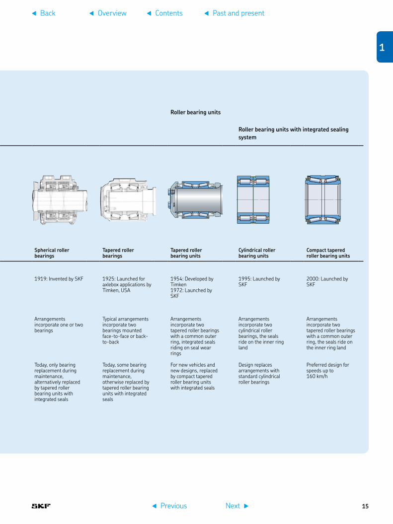
1919: Invented by SKF 1925: Launched for axlebox applications by Timken, USA
1954: Developed by Timken1972: Launched by SKF
1995: Launched by SKF
2000: Launched by SKF
Design Arrangements incorporate one or two bearings
Typical arrangements incorporate two bearings
Typical arrangements incorporate one bearing, full complement bearing design (without a cage)
Typical arrangements incorporate two bearings
Arrangements incorporate one or two bearings
Typical arrangements incorporate two bearings mounted face-to-face or back-to-back
Arrangements incorporate two tapered roller bearings with a common outer ring, integrated seals riding on seal wear rings
Arrangements incorporate two cylindrical roller bearings, the seals ride on the inner ring land
Arrangements incorporate two tapered roller bearings with a common outer ring, the seals ride on the inner ring land
Present status Historical relevance only, replaced by roller bearings because of higher load carrying capacity
Historical relevance only, replaced by spherical roller bearings because of higher load carrying capacity
Historical relevance only, replaced by other roller bearings with cages
Used for new vehicles based on existing designs, trend is to replace it with cylindrical roller bearing units with integrated seals
Today, only bearing replacement during maintenance, alternatively replaced by tapered roller bearing units with integrated seals
Today, some bearing replacement during maintenance, otherwise replaced by tapered roller bearing units with integrated seals
For new vehicles and new designs, replaced by compact tapered roller bearing units with integrated seals
Design replaces arrangements with standard cylindrical roller bearings
Preferred design for speeds up to 160 km/h
Past and present bearing designs
f Previous Next g
f Overview f Contentsf Back f Past and present
14
Axlebox bearingsBall bearings Roller bearings
Roller bearing units
Roller bearing units with integrated sealing system
Deep groove ball bearings
Self-aligning ball bearings
Needle or long roller bearings
Cylindrical roller bearings
Spherical roller bearings
Tapered roller bearings
Tapered roller bearing units
Cylindrical roller bearing units
Compact tapered roller bearing units
Introduction 1903: One of the first axlebox applications by DWF, Germany (later acquired by SKF)
1907: Invented by Sven Wingquist, Sweden (later SKF), 1911 first SKF axlebox application
1905: One of the first axlebox applications by SRB, USA, (later acquired by MRC, which was taken over by SKF)
Around 1920: Launched by SKF – Norma (Germany), FAG and some other companies
1919: Invented by SKF 1925: Launched for axlebox applications by Timken, USA
1954: Developed by Timken1972: Launched by SKF
1995: Launched by SKF
2000: Launched by SKF
Design Arrangements incorporate one or two bearings
Typical arrangements incorporate two bearings
Typical arrangements incorporate one bearing, full complement bearing design (without a cage)
Typical arrangements incorporate two bearings
Arrangements incorporate one or two bearings
Typical arrangements incorporate two bearings mounted face-to-face or back-to-back
Arrangements incorporate two tapered roller bearings with a common outer ring, integrated seals riding on seal wear rings
Arrangements incorporate two cylindrical roller bearings, the seals ride on the inner ring land
Arrangements incorporate two tapered roller bearings with a common outer ring, the seals ride on the inner ring land
Present status Historical relevance only, replaced by roller bearings because of higher load carrying capacity
Historical relevance only, replaced by spherical roller bearings because of higher load carrying capacity
Historical relevance only, replaced by other roller bearings with cages
Used for new vehicles based on existing designs, trend is to replace it with cylindrical roller bearing units with integrated seals
Today, only bearing replacement during maintenance, alternatively replaced by tapered roller bearing units with integrated seals
Today, some bearing replacement during maintenance, otherwise replaced by tapered roller bearing units with integrated seals
For new vehicles and new designs, replaced by compact tapered roller bearing units with integrated seals
Design replaces arrangements with standard cylindrical roller bearings
Preferred design for speeds up to 160 km/h
f Previous Next g
f Overview f Contentsf Back f Past and present
1
15

Lubricant savingIn addition to saving energy, reducing lubricant consumption can contribute to reducing environmental impact. Bearing lubricants such as oil and grease have to be refined from mineral oil. During maintenance, after many years of service, the used lubricant has to be collected during axlebox dismounting and disposed of as chemical waste, just like other used mineral oil-containing products. It is obvious that minimizing the quantities of lubricant used provides a positive contribution to the environment.
Oil lubricationOil-lubricated plain bearings were used in the early years of rail transportation. The initial oil fill of a typical German freight car in the axlebox was 1 300 g, of which 500 g were used for the oil pad lubrication and 800 g for the oil reservoir. The oil level had to be checked very frequently, as the continuous oil loss during operation heavily contaminated the railway tracks and the environment. The oil consumption was around 200 g / 1 000 km.
Grease lubricationA major step forward was the introduction of grease-lubricated roller bearings. The grease fill is applied during the mounting procedure. For most applications, no further relubrication is needed.
In the 1930s, the grease quantity of a typical German freight car axlebox fitted with cylindrical roller bearings was around 1,7 kg. Research over the years has confirmed that the lubricant quantity could be dramatically reduced without risking lubricant starvation. Around 1950, the grease quantity was reduced to 1,2 kg, later to 1 kg, and today to 0,7 kg for lubrication of open cylindrical roller bearings. A further major step in reducing grease consumption was the introduction of a sealed and pre-lubricated cylindrical roller bearing unit (CRU) where only 0,2 to 0,3 kg grease is needed. The reduced grease quantity results in a lower operating temperature. This leads to a longer grease and service life.
Present rail focus
High-speed developmentToday, high-speed trains, cruising at 300 km/h, have changed Europe’s geography, and distances between large cities are no longer counted in kilometres but rather in TGV, ICE, Eurostar or other train hours. The dark clouds of global warming threatening our planet are seen as rays of sunshine to this most sustainable transport medium, with other continents and countries following the growth path initiated by Europe and Japan. High-speed rail represents one solution to sustainable mobility needs and symbolizes the future of passenger travel.
2,0
1,0
1,0
0,5
0 1930 1950 1970 1990 2010
1,7
1,2
0,7
0,2–0,3
Grease quantity of a typical German freight car axlebox
[kg]
year
35 000
30 000
25 000
20 000
15 000
5 000
10 000
40 000
01970 1980 1990 2000 2010 2020
Evolution of the world high-speed network, source UIC
[km]
year
f Previous Next g
f Overview f Contentsf Back f Past and present
16

Present bearing designsThere is an ongoing worldwide trend to use more and more ready-to-mount factory pre-lubricated bearing units with an integrated sealing system on both sides. These units simplify the mounting process dramatically and contribute to higher reliability and safety. This is because maintenance of these units is moved to re-manufacturing divisions of bearing suppliers or other independent specialized facilities.
These axlebox bearing units can be based on tapered or cylindrical roller bearing units. Both systems have unique advantages and are successfully used in all kinds of railway vehicle applications († chapter 4). Many railway operators and manufacturers have strong preferences for the design to be used and trust to their well-established operational and maintenance knowledge and experience.
Early tapered roller bearing units had a garter sealing system riding on special seal wear rings that required an additional length of the axle journal. The next development step, already introduced, was to integrate the sealing system into the bearing and to mount seals that ride directly on the inner rings. These compact designs have a much narrower width and a shorter axle journal can be used. This contributes to reduced bending under axleload and offers a lot of advantages as described in chapter 4.
Using polymer bearing cages, instead of steel or brass ones, can significantly contribute to higher reliability and safety. This introduction process, supported by extensive laboratory and field testing, is becoming to be nearly complete, and except for some unique cases, the polymer cage is the standard design.
The sealing system is constantly under development. Newer designs are being implemented to reduce friction and operating temperatures, resulting in longer grease life and maintenance intervals.
Bearing unitsAxlebox bearing units are factory pre-lubricated and fitted with either contacting or non-contacting high performance seals. This design provides, in many cases, a much longer SKF rating life. This calculation is based on the load conditions, the reliability and the SKF life modification factor that takes the lubrication condition and level of contamination during operation into account († chapter 5).
Because of the grease performance, limitation of field service life has to be considered.
Example of axlebox bearing and axlebox bearing unit based on SKF rating life
Axlebox bearing units
Open axleboxbearings
SKF rating life
f Previous Next g
f Overview f Contentsf Back f Past and present
1
17

SKF solution packagesFor over 100 years, SKF has become synonymous with advanced bearing technology and is the world’s leading supplier to the railway industry. Adding to this solid knowledge base, SKF is also a leading supplier of products and solutions within mechatronics, lubrication systems, seals and services for various applications.
The present and future delivery scope comprises the axlebox bearing unit including sealing systems and the tailor-made axlebox, as well as mechatronic system solutions to measure operational parameters and to monitor the bogie condition. Lubrication systems include wheel flange lubrication solutions to reduce friction and wear between wheel and rail. Service packages are tailored to the manufacturers’ and operators’ needs, including testing, mounting, global after-market sales and service, remanufacturing and logistic services. SKF offers a unique worldwide network of sales, application and service engineers to work closely with manufacturers and operators on international projects († page 20).
Axleboxes († chapter 3)
Bearings:tapered roller bearing units –(† page 77)cylindrical roller bearings and units –(† page 89)spherical roller bearings ( – † page 97)
SKF Axletronic sensors († chapter 7)
Sensor capabilities:rotational speed ( – † page 140)direction of rotation ( – † page 142)distance measurement “odometer” –(† page 144)bearing operating temperature –(† page 148)vertical/lateral vibration ( – † page 149)
Slewing bearing
f Previous Next g
f Overview f Contentsf Back f Past and present
18

AMPEP high performance plain bearings(† page 165)
Bogie condition monitoring († chapter 8) Wheel flange lubrication († page 176)
Bogie condition data transmission, monitoring and management († page 154)(† page 160)
Gearbox and traction motor bearings
f Previous Next g
f Overview f Contentsf Back f Past and present
1
19

Global presenceSKF has established a global network to be close to the customers († page 6).
This unique global railway network comprises sales, service and application engineers to work closely with manufacturers and operators on domestic and international projects.
f Previous Next g
f Overview f Contentsf Back f Past and present
20

SKF global presenceCountries in blue colour with SKF railway sales and application engineers
In most of the countries in grey colour, SKF is represented through authorized distributors/dealers.
Railway manufacturing units
Railway remanufacturing units
f Previous Next g
f Overview f Contentsf Back f Past and present
1
21

QualitySKF pursues a systematic and disciplined approach to achieve radical improvements in all business processes, with improved customer satisfaction as a primary goal. Continuous improvement is achieved by using Six Sigma methods and toolboxes as well as the Manufacturing Excellence programme.
Six SigmaSKF Six Sigma is a continuous improvement programme within SKF that targets waste and defects in all business processes. SKF Six Sigma projects are run by extensively trained Black Belts and Green Belts. There are a number of tools and methodologies within the SKF Six Sigma programme, ranging from traditional DMAIC and Design for Six Sigma to Lean and other waste reducing methodologies.
The foundations for SKF Six Sigma improvements are fact-based and sustainable and contribute to the business objectives.
Design for Six Sigma (DfSS)A methodology that focuses on developing new products and services to the market with optimal performance levels.
Lean Six SigmaA methodology that combines tools from both Lean and Six Sigma. Lean focuses on increasing speed and reducing waste. Six Sigma concentrates on variation and quality – the result is faster with better quality.
Six Sigma for GrowthA customer focused approach that targets improvements in growth areas such as marketing, sales and distribution.
Transactional Six SigmaFocuses on people processes such as service, sales and human resources.
Manufacturing excellenceSKF Bridge of Manufacturing Excellence focuses on reducing waste and eliminating non-value adding activities. SKF bases this bridge on the following five principles:
Standardized way of working•Right from me•We care•Demand driven flow•Continuous improvement•
The heart of the system is the people in the production process, who use these principles everyday to continuously improve their work.
CertificatesSKF quality is documented by relevant quality certificates, based on international standards and customer approvals. The following page contains a selection of relevant certificates of the SKF Group and the SKF Railway Business Unit. Additional certificates pertaining to SKF railway sales and manufacturing units can be submitted to our customers on request.
CUSTOMERSUPPLIER
RIGH
T FR
OM
ME
WE
CARE
CON
TIN
UO
US
IMPR
OVE
MEN
T
STAN
DAR
DIZ
ED W
ORK
DEM
AND
DRI
VEN
FLO
W
WE
CHANNEL
EMPOWERMENT HIGH ETHICS OPENNESS TEAMWORK
PROF
ITABILI
TY QUALITY INNOVATION SPEED SUSTAINABILITY
f Previous Next g
f Overview f Contentsf Back f Past and present
22

ISO 14001, OHSAS 18001 management system standards certificate for the SKF Group
ISO 9001 quality management system certificate for the SKF Railway Business Unit
ISO/IEC 17025 certificate for the SKF Engineering & Research Centre, Nieuwegein, The Netherlands, about the capability to generate technical valid results
IRIS International Railway Industry Standard certificate for the SKF Railway Business Unit, which has become one of the first companies to gain the IRIS certification
EN 15085-2 welding quality organization certificate for SKF France, product division axleboxes
AAR certificate about the conformity of the SKF quality assurance programme
German DB Outstanding Q1 certificate for quality capability
French SNCF AQF2 unconditional quality certificate
Russian unconditional approval for CTBU 130 × 250 × 160
f Previous Next g
f Overview f Contentsf Back f Past and present
1
23

Bogie design2 sDesign principles . . . . . . . . . . . . 25
Wheelset designs . . . . . . . . . . . . 29
Springs . . . . . . . . . . . . . . . . . . . . 32
Dampers . . . . . . . . . . . . . . . . . . . 35
Bogie design examples . . . . . . . . 36
Earth return . . . . . . . . . . . . . . . . 40
f Previous Next g
f Overview f Contentsf Back
24

Bogie designs
Today, very different bogie design principles are applied. The main focus of this chapter are the bogie features that are directly or indirectly related to the axlebox application. The main ones are bogie design principle parameters, guiding / suspension, primary spring and damping principles that are interacting with the design of axleboxes and bearings.
Design principlesA bogie is a structure underneath a railway vehicle body to which axles and wheels are attached through bearings. The term “bogie” is used in British English, while a “wheel truck”, or simply “truck” is used in American English. The overall term is “running gear”, which covers bogies as well as vehicles with two, or more axles without any bogies. In this case, these axles are directly fitted to the vehicle body via guiding devices and springs, and for very low speeds even without springs.
Running gears serve a number of purposes:
support of the rail vehicle body•stability on both straight and curved •tracksproviding ride comfort by absorbing •vibration, and minimizing centrifugal forces when the train runs on curves at high-speed minimizing generation of track •irregularities and rail abrasion
f Previous Next g
f Overview f Contentsf Back f Bogie designs
25
2

Design principle elementsRailway bogies are complex subsystems in railway vehicles and contain brake systems, drive systems including gearbox coupling and traction motors for powered wheelsets, bogie frames with secondary spring systems and the wheelset subsystems, which are basically the assembly of two wheels and an axle. In this chapter, the focus is on some general bogie design principles and especially design features that interact with the axlebox bearing system. Directly connected to the wheelset and the bogie frame is the axlebox († chapter 3) containing the axlebox bearing system († chapter 4 and chapter 5). The axlebox is very much linked to further subsystems and components like primary spring systems, axlebox guidance, dampers, steering mechanisms of wheelsets, earth return devices as well as sensors to detect operational parameters († chapter 7) and bogie monitoring systems († chapter 8).
Further bogie-connected subsystems are wheel flange lubrication systems, articulation joints, slewing bearings and special plain bearings for damper supports († chapter 9).
Running gears and bogiesAll kinds of railway vehicles are equipped with running gears, which can be designed as 2- or 3-axle cars or as bogie vehicles. 2-axle car design principles are used mainly for European freight cars, shunting locomotives and for sections of articulated cars such as low-floor light rail vehicles or tramways.
Bogie designsToday, the majority of railway vehicles are equipped with bogies that contain mostly two axles, but in some cases, such as heavier and powerful locomotives, 3-axle designs are used. Because of the shorter axle distance of bogie designs, longer vehicles/vehicle sections can be used. On the other hand, the riding comfort of bogie vehicles is much better than vehicles equipped with axles that are supported directly by the vehicle body.
Design principles of running gears and bogiesOn top: 2-axle vehicleMiddle and bottom: articulated vehicles based on 2-axle running gear designs applied for light rail vehicles
Design principle of a bogie vehicle
Jacobs bogie design principle
Jacobs bogie designsA common bogie design principle, used especially for connected vehicle bodies for multiple units, special freight cars and mass transit vehicles, are Jacobs bogies1). These bogies support two body ends via one bogie. This design contributes to mass saving and running stabilization, resulting in a better riding performance for some applications.
Example of a typical low-floor multi- section tramway design
1) Jacobs bogies named after Wilhelm Jakobs (1858–1942)
Rail
PivotAxles
Bogies
f Previous Next g
f Overview f Contentsf Back f Bogie designs
26

Powered bogie designsLocomotives, multiple units such as high-speed trains as well as mass transit vehicles, are equipped with powered bogies. Typical propulsion systems contain a wheelset, a gearbox and a traction motor. More sophisticated designs are equipped with hollow shafts and couplings to reduce un-sprung mass.
Longitudinal propulsion (drive) systems contain a helical gearbox and cardan shafts. Hydraulic diesel propulsion systems contain mostly gearboxes and cardan shafts, connecting two bogie drives to one main gearbox and the hydraulic gearbox system connected to the diesel motor.
Powered bogie, transverse drive
Powered bogie, longitudinal drive
Radial steering principles To reduce the forces between rails and wheels, several radial steering design principles for wheelsets are applied. The aim of these designs is to reduce wear and noise caused by low steering forces. Designs with connected wheelsets and wheelsets connected to the vehicle body are based on lever systems that act on the wheelsets via the axleboxes.
Radial steering principles for wheelsets
Self steering
Connected wheelsets
Wheelsets steered by the vehicle’s body
f Previous Next g
f Overview f Contentsf Back f Bogie designs
27
2

Wheelset arrangement classification
The wheelset arrangement classification is a systematic tool to sort railway vehicles by position of the wheelsets (axles), bogies and connections of vehicle bodies. There are several notations used to describe wheelset and wheel arrangements, which vary by country. Within a given country, different notations may be employed for different kinds of locomotives, such as electric and diesel.
The UIC classification scheme is widely used. It is provided by the International Union of Railways and laid down in the UIC’s “Leaflet 650 – Standard designation of axle arrangement on locomotives and multiple-unit sets”.
Upper-case letters designate a number of •consecutive driving axles, starting at “A” for a single axle. “C” thus indicates three consecutive pairs of driving wheels. Numbers designate consecutive non-•driving axles, starting with “1” for a single axle.Lower-case “o” designates axles, which •are individually driven by electric traction motors in locomotives and multiple units. Prime sign “´” indicates that the axles are •mounted on a bogie.
Selection of practical examples:B´B´• two bogies or wheel assemblies under the unit. Each bogie has two powered axles, connected by driving rods or gears. Bo´Bo´• each bogie has two individually-driven powered axles (i.e. via traction motors). 75% of all modern locomotives (as well as the power cars of self-propelled trains) are configured as Bo´Bo´.Co´Co´• two bogies or wheel assemblies under the unit. Each bogie has three individually-driven, powered axles (i.e., via traction motors).Bo´Bo´ + 2´2´ + 2´2´• multiple unit, first unit: two bogies, each bogie has two individually-driven powered axles; second and third unit: two bogies, each bogie with two non-powered axles.Bo´ 2´ Bo´• articulated vehicle: first and last bogie have two individually-driven powered axles / middle bogie (Jacobs design) with two non-powered axles.
Wheelset arrangement examples
B´B´
Bo´Bo´
Co´Co´
Bo´Bo´ + 2´2´ + 2´2´
Bo´ 2´ Bo´
Un-powered wheelset
Powered wheelset
Motor
f Previous Next g
f Overview f Contentsf Back f Bogie designs
28

Wheelset designs
Railway gaugeThe gauge is the distance between the two wheel flanges, corresponding to the distance between the inner sides of the rails.
Examples of widely used railway gauges:
standard gauge • 1 435 mm (4 ft. 8 1/2 in.), comprises around 60% of total world track length
broad gauges, which are larger than •standard gauge e.g. Russian broad gauge 1 520 mm (17%), Indian broad gauge 1 665 mm (5 ft. 6 in.) and Iberian broad gauge 1 668 mm (5 ft. 5 2⁄3 in.), together comprise 9% of total world track length
narrow gauges, which are smaller than •standard gauge e.g. Meter gauge 1 000 mm (7%) and 1 067 mm (3 ft. 6 in.) Cape gauge, comprise 9% of total world track length
Bogie designs for the standard gauge are in some cases adapted for broad gauge vehicles and vice versa. Standard gauge bogie designs can be used in some cases as a basis for redesigning it for narrow gauge vehicles, which then have to be mostly equipped with other bearing designs.
Gauge
Railway gauge measurement principle
AxleloadThe permissible axleload is determined by bridges, roadbed and track design, such as load carrying capacity / weight of the rails, size and frequency of the sleepers, quantity and type of ballast, and depth of formation. On sharp curves, the frequency of sleepers often needs to be increased.
Common axleloads are:
light metros : • 14 thigh-speed vehicles: • 17 t (for new generations)heavy metros and multiple units : • 18 tlocomotives and freight cars: up to • 25 theavy haul freight cars: • 32 t up to 40 t
The axleload is calculated by:
Vehicle weight + cargo or passenger load
Axleload = —————————————————
Number of axles
The vehicle net weight includes the operating supplies like sand and for diesel powered vehicles a fully fuelled tank. The cargo refers to the payload of goods. The passenger load can be calculated by counting the number of seats plus, especially for mass transit vehicles, the number of standing persons. There are very different calculations applied, from 4 to 10 persons per m² and 70 or 80 kg average weight per person (with/without luggage) see prEN 15663:2007 Railway applications – Vehicle Mass definition. Further calculation methods are mentioned in specific standards and in customer specifications as well.
Multiple units and articulated vehicles are designed mostly by applying powered and non-powered bogies. Different axleloads have to be considered.
f Previous Next g
f Overview f Contentsf Back f Bogie designs
29
2

Wheel diameterDifferent wheel diameters are considered such as for new wheels, worn wheels or a medium dimension for half-worn wheels. This wheel diameter is mostly used for calculating the bearing rating life, which is a linear function of the wheel diameter. However, the wheel diameter influences the impact of dynamic forces acting on the axlebox bearings, especially by applying smaller wheels.
Some examples of current wheel diameters:
high-speed vehicles, multiple units and •passenger coaches: 750 to 950 mmlocomotives: • 1 000 to 1 300 mmfreight cars: • 900 to 1 000 mmpiggyback wagons: • 350 to 450 mm (carrying trailers, semi-trailers or containers – intermodal freight transport)
Wheelset arrangementsIn most cases, axlebox housings are situated on the axle ends. Some vehicles, such as light rail vehicles, have inboard axleboxes that are situated between the wheels because of space limitations. Inboard bearing bogie designs have a potential for mass saving opportunities.
However, there are a few applications where special axlebox bearing designs are needed. The dynamic forces acting on an inboard axlebox bearing can be heavier compared to outboard applications. The smaller support base of inboard bogie frames could cause more rolling of the vehicle body.
Independent wheelsLow-floor mass transit vehicles like tramways are equipped with special wheel arrangements to cope with limited available space. One design principle is the axlebridge design, which consists of a highly sophisticated cranked bridge covering the traditional axle function and two independent wheels fitted with the axlebox bearing units († page 58).
The hub traction motor concept is based on a direct drive system with an integrated wheel function. Today, very different design principles are applied. One of these is a traction motor design that directly powers the wheel and acts as wheel support and guidance without any gearbox or coupling components. The outside rotor directly powers the rubber spring-suspended wheel tyre. This space saving arrangement is especially suitable for 100% low-floor tramways, which have a plain floor without any steps or ramps.
Top: independent wheel arrangement with bearings on both sides
Bottom: Axlebridge design principle
Wheelset design principlesTop: outboard bearing arrangementBottom: inboard bearing arrangement
f Previous Next g
f Overview f Contentsf Back f Bogie designs
30

Axlebridge wheel arrangement,tapered roller bearing unit, outer ring rotation
Hub motor drive system, supporting cylindrical roller bearings, outer ring rotation
Single wheel arrangement, set of tapered roller bearings, inner ring rotation
f Previous Next g
f Overview f Contentsf Back f Bogie designs
31
2

Springs
Primary springsThe primary springs connect the axlebox to the bogie frame. For higher speeds, a secondary spring system connects the bogie frame to the vehicle body. The springs can be designed as steel leaf or coil springs, as rubber springs or as air springs.
The aim of bogie springs is to reduce the forces and vibrations, to avoid derailment and to uncouple vibration and noise between the wheelsets and the vehicle body. The primary spring acts between the wheelset via the axlebox bearing and the bogie frame. The secondary spring is situated between the bogie frame and the vehicle body.
Primary springs acting on the axlebox react to vertical jounce and loads that arise longitudinally and laterally from the influence of the rail track on the vehicle body. In addition, springs decouple structure-borne noise. Enhanced bogie designs are based on different spring systems acting in several directions and using materials such as steel and rubber.
Secondary springsSecondary spring systems of enhanced bogie designs are a combination of air spring bellows and the rubber-metal bearer spring, which supports the system, especially when there is torsional strain and large horizontal excursions. The system also absorbs a portion of the vertical deflection and acts as an emergency spring. An additional feature of air springs is the constant levelling function that maintains the vehicle body at a consistent height, regardless of whether it is full of passengers or empty.
Spring principles:Top: mainly used for freight cars
Middle: mainly used for freight cars and powered vehicles
Bottom: mainly used for passenger coaches, multiple units and locomotives
Primary spring system based on steel and rubber springs acting in different directionsIllustration: ContiTech
Secondary spring system based on an air spring system combined with rubber springsIllustration: ContiTech
f Previous Next g
f Overview f Contentsf Back f Bogie designs
32

Steel spring design principlesSteel springs are used for the majority of all railway vehicle types. There are several designs applied, such as:
Leaf type springs have a linear •characteristic and a mechanical damping effect between the leafs. Most of the leaf type springs are acting on top of the axlebox.The parabolic leaf type spring has a •multistep characteristic as well as a mechanical damping effect between the leafs. These springs act mainly on top of the axlebox.Cylindrical helical springs are made from •round coils. They are also used as a spring interlaced set with progressive characteristics, which is achievable by using different spring heights and leads. These springs can act either on top of the axlebox or on both sides.Another design modification is the flexi-•coil cylindrical helical spring arrangement. The flexi-coil effect is used to combine the spring function and the guidance of the bogie frame. The vehicle body is able to move laterally relative to the bogie against the restoring force of the springs. This spring design is widely used for locomotives.
Cylindrical helical spring
Flexi-coil spring arrangement
Leaf type spring
Parabolic leaf type spring
f Previous Next g
f Overview f Contentsf Back f Bogie designs
33
2

Rubber spring design principles
An alternative to steel springs are rubber springs, which offer a larger design flexibility in regard to geometrical shape and material selection. Some of the main rubber spring designs are:
Chevron springs are made from rubber •metal compounds and have a progressive characteristic as well as a damping effect. They are typically acting on both angled supports of the axlebox.Clouth springs are based on a rubber ring •rolling on a cone that can have a tailored profile to achieve a specific characteristic. Clouth springs also have a damping effect. These springs typically act on both sides of the axlebox and, in addition, fulfil the guiding function of the wheelset [7].Other rubber spring design principles are •hollow block springs, hollow block layer springs and conic rubber springs.
Chevron spring
Clouth spring
Other rubber spring designs:Left: Hollow block springMiddle: Hollow block layer springRight: Conic rubber springIllustration: ContiTech
f Previous Next g
f Overview f Contentsf Back f Bogie designs
34

DampersIn addition to the self-damping effect of some of the spring designs, additional dampers are used. These dampers are mainly designed as hydraulic dampers acting on the axlebox in different directions.
One damper design example is the twin-tube hydraulic damper. This device holds the wheelset on the bogie and the bogie on the rail. On both ends, either rubber elements or plain bearings are fitted. One end is typically connected with the axlebox.
In addition to hydraulic dampers, mechanical damper designs are applied. For Y25 freight cars that are mainly used in Europe, mechanical Lenoir friction dampers are used. The guiding surface of the damper acts on the guiding surface of the axlebox housing.
Active dampingThe active damping system controls resistance against motion of the vehicle body. This system helps to provide a more convenient and comfortable ride on trains.
Twin-tube hydraulic damperPhoto: ZF Sachs AG
Lenoir friction damper
Lenoirlink
Axlebox
SupportPistonBogie frame
f Previous Next g
f Overview f Contentsf Back f Bogie designs
35
2

Bogie design examplesThere have been many different bogie design principles applied throughout railway history. Even today, for the latest state of the art rolling stock, different design principles are still in use. In this chapter, some current bogie design principles are mentioned to give an overview of bogie design technology and their interaction with the axlebox design [8, 9, 10]. The aim of this chapter is to focus on guiding/suspension and primary spring and damping design that influence the design of axleboxes and bearings. The axlebox design features are mentioned in chapter 3.
Link arm suspension with one primary helical spring on top of the axlebox assembly, which is designed as a yoke, enabling vertical dismounting of the wheelset assembled with the axlebox for easier maintenance. This design was applied for the French bogie type Y32 for Corail coaches and is similar to Italian bogie Fiat Y0270S and Spanish bogie CAF-GC. 1 and is widely used in Europe, for instance in the Alstom TVG bogies.
Suspension by two steel leaf springs acting on both sides of the axlebox housing, which is equipped with two helical springs. This design is known as Minden-Deutz bogie MD 36.
Suspension by two parallel steel leaf springs acting on one side of the axlebox housing, which is equipped with helical springs. Axlebox assembly designed as a yoke, enabling vertical dismounting of the wheelset assembled with the axlebox for easier maintenance. Originally known as Minden-Deutz MD 52 bogie, it was later used for the MD 522 design, which used in the German ICE trailer bogies.
High-speed, passenger coach and multiple unit bogies
f Previous Next g
f Overview f Contentsf Back f Bogie designs
36

Locomotive bogies
The cylindrical guidance system is acting on both sides of the axlebox and has an integrated damping function. In addition, helical steel springs are applied. This design is used for passenger coach bogies like SGP 300 and Siemens SF 300.
Flexicoil suspension springs are acting on both sides of the axlebox. Additional horizontal guidance via link arms connecting the axlebox with the bogie frame is applied to transmit the longitudinal tractive and brake forces. This locomotive bogie design principle is used by ADtranz today Bombardier for different bogies based on 2- and 3-axle designs.
Suspension by two diagonal link arms supported by the axlebox. Two helical steel springs on both sides. This bogie design is used by different suppliers like Alstom.
Suspension with inclined side supports for Chevron rubber springs, acting as suspension and guidance, adaptable to different spring characteristics. This bogie design is used for various locomotives, multiple units and mass transit vehicles as well as for Swedish X2000 high-speed tilting trains.
Suspension by a moving motion link as an integral part of the axlebox. The primary helical steel spring acts on top of the axlebox. This design is used, e.g. in the German ICE 3 bogies and build as SGP 500 or Siemens SF 500.
Suspension by a steel leaf spring acting on one side of the axlebox housing, which is equipped with two helical springs. This design principle is used by several bogie manufacturers like MAN, ADtranz, Rotem etc.
f Previous Next g
f Overview f Contentsf Back f Bogie designs
37
2

3-axle locomotive bogie designs
Early middle axle wheelset designs were based on wheels with smaller or even no flanges e.g. for shunting locomotives or steam locomotives with more axles. Today, there are two principal solutions to manage the axial displacement of the wheelset of the middle axle:
axleboxes of the middle axle axially •floating in the bogie frame, e.g. axial elastic supportaxleboxes of the middle axle equipped •with a special bearing system with axial floating capability
Special cylindrical roller bearing units for axial displacement are mention on page 95.
Freight car bogie designs
European freight carsEuropean freight car designs are based on bogie designs as well as 2-axle running gears. These designs are also used in other parts of the world like in Asia.
Steel leaf spring suspension typically used for 2-axle freight wagons. The spring acts on top of the axlebox and guides the wheelset. The large longitudinal gap between horn guides enables a radial self-steering effect.
Parabolic steel leaf spring suspension typically used for freight bogies. The spring acts on top of the axlebox and guides the wheelset. The large gap between horn guides enables a radial self-steering effect. This design is used e.g. for the German 665 bogies.
Suspension by horn liner guides. Two helical steel springs acting on both sides of the axlebox. Damping by a Lenoir friction damper († page 35). This design is known as UIC bogie type Y25, which can be manufactured as cast or fabricated side frames.
Bearing unit design principle for middle axle applications of the 3-axle bogies
The 3-axle bogie design requires a special lateral movement of the middle axle by running curved tracks.
Axial displacement of the middle axle
Middle axle axially floating Bogie frame
f Previous Next g
f Overview f Contentsf Back f Bogie designs
38

3-piece bogie designsThe 3-piece bogie design was originally developed in the USA and is used worldwide. It consists of two longitudinal beams and a connecting beam. The bearing system is directly fixed with the longitudinal beam without a primary spring. The secondary spring is integrated into the transversal beam design. This design principle is also used widely in China and Russia.
Mass transit bogiesMass transit vehicles, such as suburban trains, metro cars, light rail vehicles and tramways, can be principally divided into standard height floor cars and low-floor cars. The set-up heavily influences the design of the bogie.
Sealed and greased axlebox bearing unit, directly fitted via an adapter with the transversal bogie beam without any primary suspension. This freight car bogie design is standardized, the AAR using narrow and wide adapters and different bearing sizes.
Sealed and greased axlebox bearing unit, directly fitted via an adapter with the transversal bogie beam. A rubber blanket is used as primary suspension between the adapter and the suspension. This freight car bogie design is used by Chinese railways.
Axlebox directly fitted via an adapter with the transversal bogie beam. The adapter is equipped with a front cover to protect the bearing system. This freight car bogie design is used by Russian railways.
Rubber guidance and spring load by applying different types of rubber springs acting on both sides of the axlebox. This design is applied by several bogie manufacturers, e.g. for Siemens SF 1000 bogies for light metros with an axleload of 14 t and SF 3000 bogies for heavy metros for up to 17 t axleload.
The moving motion link supports the drive system unit consisting of a planetary gearbox and a traction motor. The motion link is spring loaded via a longitudinal primary rubber spring. This design is used for Bombardier Cityrunner low-floor tramways.
Low-floor bogie with axleboxes integrated into a link arm bogie design element. This design, using an independent wheel design, is used for light rail vehicles and tramcars and was originally developed by MAN and is now finally used by Bombardier after several acquisitions. The powered wheel pair (left side) is loaded 2/3 and the non-powered around 1/3 of the total bogie load.
f Previous Next g
f Overview f Contentsf Back f Bogie designs
39
2

Axial tolerancesTo make sure that the axlebox bearing is not distorted axially by improper fastening, several tolerances have to be considered by the bogie manufacturer:
axial tolerance of the guidance’s acting on •the axleboxaxial tolerance of the axial bearing surface •of the wheelsetaxial tolerance of the bearing inner/outer •ring assembly width and the attachment parts, such as backing ring or labyrinth ring
Earth returnThe problem of electric current passing through rolling bearings like axlebox bearings and causing damage in the contact area of rollers and inner/outer ring raceways is well-known. In addition to the damage to bearing elements, it was also assumed that the structure of the lubricant itself might change under the influence of a passing current. All axlebox bearings potentially suffer from this phenomenon. Craters are formed and are known as electric pitting. In a more progressed stage, fluting or washboard pattern of multiple grey lines across the raceways can be detected († page 131).
Earth return devices transmit electrical current from the stationary part to the rotating axle of the wheelset. These devices avoid dangerous voltages between the vehicle and the ground as well as avoid damage to axlebox bearings by passing electric current through raceways of bearing rings and rollers. The earth return acts as a low ohmic bridge that transmits the current with coal brushes to a rotating part. The maximum current is in the range of 1 000 A, depending on the earth return design. In the German standard, DIN VDE 0123, electrical current flows in railway vehicles are explained in detail and suggestions to avoid current passing through axlebox bearings are proposed.
A sufficient earth return design is a pre-requisite to reach the requested reliability and safety requirements on axlebox bearings. However, the correct selection of the coal composite material and the minimization of the responding coal wear is very fundamental. The earth brush design has to avoid wear particles entering the bearing system and affecting the lubrication and contacting surfaces between rolling elements and inner/outer rings.
Axial tolerance principle
Distance between left andright axlebox bearing assembly
Distance betweenleft and right axlebox
f Previous Next g
f Overview f Contentsf Back f Bogie designs
40

M
1)
1) 1)1)
1)1)
1) 1) 1) 1)
Electric current flow in railway vehicles: combination of insulation, earth return devices and protective resistors (example)Source: DIN VDE 0123
Earth return device in combination with insulation of the axlebox
Electric insulated INSOCOAT bearing arrangement for low-floor light rail vehicles
One option to insulating axlebox bearing arrangements is to use the electrical insulated SKF INSOCOAT bearings [11, 12]. The insulating coating on the outer ring of the INSOCOAT bearing is made from aluminium oxide and applied using plasma spraying technology. This execution is widely used for electric traction motors and there are also some applications, e.g. for low-floor tram cars, that are equipped with INSOCOAT as well. The bearings are interchangeable with non-insulated bearing types because of ISO standardized boundary dimensions and tolerances. This INSOCOAT design prevents passage of damaging electric current through the bearings.
1) Connections in accordance with DIN VDE 0115 Part 2
CarriageElectric traction vehicleElectric traction vehicle
Protectiveresistor
Bogiechassis
Insulation
Wheelsetcontact
Vehicle bodyCoupling and buffer
Return busbar
Consumer
Train busbar Train busbar
OtherconsumersOther
consumers
D.C. voltageContact line
A.C. voltage
f Previous Next g
f Overview f Contentsf Back f Bogie designs
41
2

Axlebox design3 sCapabilities . . . . . . . . . . . . . . . . . 43
Specifications . . . . . . . . . . . . . . . 45
Validation . . . . . . . . . . . . . . . . . . 49
Designs . . . . . . . . . . . . . . . . . . . . 54
Calculation . . . . . . . . . . . . . . . . . 62
Industrialization . . . . . . . . . . . . . 69
Testing . . . . . . . . . . . . . . . . . . . . . 70
f Previous Next g
f Overview f Contentsf Back
42

Axlebox designs
Axleboxes are the linking design element between the rotating wheelset and the quasi-static frame of the bogie or running gear of a railway vehicle. All forces acting between these components are transmitted via springs, dampers and guiding elements. Axleboxes and axlebox bearings/units have always been a vital component in the reliability of railway rolling stock and they have a considerable influence on the operating safety, reliability and economics of railways.
CapabilitiesSKF has a unique experience in developing, designing, calculating and performing validation testing on axleboxes for all kinds of railway vehicles such as high-speed vehicles, locomotives, multiple units, coaches, mass transit vehicles and freight cars. Most high-speed trains are equipped with SKF solutions.
Millions of SKF axleboxes are in service throughout the world in every climate, from moderate Mediterranean to tropical desert to sub-zero wilderness.
Customized solution packages for railway vehicle manufacturers and operators are based on individual specifications.
These packages are typically composed of axleboxes, factory lubricated and sealed, ready-to-mount axlebox bearing units, sensors and monitoring systems as well as subsystems like high performance AMPEP self-lubricating spherical plain bearings, articulation joints, wheel flange lubrication
systems etc. († chapter 9). SKF offers a unique experience in handling these projects including engineering, logistics and after-sales service options.
Axlebox designs contain axlebox bearing units and AXLETRONIC sensors († chapter 7) and have to be linked with the wheelset journal geometry as well as further bogie design subsystems like guiding elements, springs, dampers, earth return devices, etc.
f Previous Next g
f Overview f Contentsf Back f Axlebox designs
43
3

Subsystems and components interacting with the axlebox design
Bogie Wheelset Axlebox assembly Axlebox Bearing AXLETRONIC sensor
Guiding elements
Dampers
Primary springs
Silent blocks
Rods
Earth returns
Life guards
Lifting devices
Stoppers
Slippers
Rail brakes
3rd rail current collector attachments
Axle journals
End caps
Backing rings
Labyrinth rings
Inspection capability like ultrasonic non-destructive crack detection
Axlebox housing assembly
Mounting and dismounting capabilities
Tapered and cylindrical roller bearing units
Open bearing sets like cylindrical and spherical roller bearings
AMPEP plain bearings
Detection:Rotation•Direction of rotation•Speed•Vibration•Operating •temperature
Main competence requirements for axlebox design
AssemblyMounting
PaintingProtection
MachiningManufacturing
FoundryMaterial
DesignFEM
PackagingDelivery
LubricationSealing
SKF axlebox benefits
comprehensive system solution supply integrated into the •train bogie subsystemone-stop shopping•competent handling of the interface between bearing and •housingcustomized engineering and logistic solutions•ready-to-mount packages•high engineering competencies•global customer support and project handling•after-sales service options•
f Previous Next g
f Overview f Contentsf Back f Axlebox designs
44

SpecificationsHigh quality specifications are a key factor in providing a functional design that can achieve high reliability and safety as well as low life cycle cost. In most business cases, the bogie manufacturer submits specifications for the axlebox engineering and logistics. However, these specifications could refer to additional specifications to be considered that are based on operators, wheelset suppliers, standardization bodies, consultants requirements and domestic/international standards. The main objective is to gather and summarize all individual standards, requirements and expectations.
Specifications have to consider the interaction of several bogie subsystems with the axlebox system in the context of a specific vehicle application. Therefore, the overall axlebox performance can relate only to the complete vehicle and not to the individual elements of bogies or running gear.
There are several European standards, either published or available as drafts, which are very helpful in communicating with operators as well as vehicle, bogie and bogie subsystems and component suppliers with SKF as the axlebox supplier.
Terms and definitions
Bogie frame:• load-bearing structure generally located between the primary and secondary suspensionBolster:• transverse load-bearing structure generally located between vehicle body and bogie frameSideframe:• longitudinal structural member of the bogie frameHeadstock:• transverse member joining the longitudinal extremities of the bogie sideframesTransom:• central transverse structural member(s) of the bogie frameAxlebox: • assembly comprising the axlebox housing, rolling bearings, sealing solution and greaseBox housing:• load-bearing structure housing the bearings, grease, sealing and accessoriesPrimary suspension:• suspension system consisting of the resilient elements, generally located between the axlebox and bogie frameSecondary suspension:• suspension system consisting of the resilient elements, generally located between the bogie frame and vehicle body or bolsterStatic force:• force that is constant with timeQuasi-static force:• force that changes with time at a rate that does not cause dynamic excitationDynamic force:• transient, impulsive or continuous force, uniform or random, that changes with time at a rate that causes dynamic excitationLoad case: • a set of loads or combination of loads that represents a loading condition that acts on the structure or componentExceptional load case:• load case used for assessment against static material propertiesFatigue load case:• repetitive load case used for assessment against durabilitySafety factor:• a factor applied during the strength assessment, which makes an allowance for a combination of uncertainties and safety criticalityValidation:• the process of demonstrating by analysis and/or tests that the system under consideration meets in all respects the specification, including requirements due to regulations, for that systemVerification:• the process of demonstrating by comparison or testing that an analytical result or estimated value is of an acceptable level of accuracy
Source: prEN 13749:2008, Railway applications – Wheelset and bogies – Method of specifying the structural requirements of bogie frames
General bogie and axlebox requirementsThe supply of bogies/running gear as well as of axleboxes shall be based on a comprehensive specification that is agreeable to both the customer and the supplier. The specification shall include information defining the intended operating conditions of the bogie or running gear:
vehicle space envelope•physical connections•payload and load inputs•traction system and performance•brake system and performance•hot axlebox detection (HABD)•other auxiliary systems (e.g. track/train communications)•vehicle gauge•track characteristics•operating environment•duty cycles•noise and vibration regulations•
Source: prEN 15827-1:2008 Bogies and running gear
f Previous Next g
f Overview f Contentsf Back f Axlebox designs
3
45

Structural integrityFor some components, such as a bogie frame or axlebox, transferring loads from one point to another is their primary function. But springs, dampers, etc. are also inherent load carrying parts. It follows that all parts shall be designed with a level of structural integrity compatible with the loads they carry.
Standard and regulationsAcceptance criteria shall comply with requirements of the normative references and current appropriate European standards. If these do not exist, acceptance shall be based on applicable national or international standards or alternative sources of equivalent standing. Where no appropriate data is available from standards, other data can be used, provided it is verified and supported by a documented quality control process.
New bogies and running gears are subject to existing and emerging legislation and regulations in the following areas:
physical agents (vibration) directive•EC noise directive•toxic materials usage – RoHS (Restriction •of Hazardous Substances Directive)pressure vessels•waste disposal•product disposal at life expiry•
Vehicle conditions and interfacesSpecifications should include, but not be limited to, the following information:
vehicle masses•vehicle geometry (e.g. available space, position of the centre •of gravity)body–bogie connections (e.g. mechanical, pneumatic, electric)•braking equipment•motors and transmission•active suspension systems (including tilt where applicable)•loading conditions (e.g. changes in payload and frequency, •dynamic load spectra)method of loading (e.g. progressive or sudden)•maintenance loading due to lifting, jacking, etc.•maximum axleloads•maximum operating speed•speeds on curves and cant deficiency•starts and stops (i.e. number and frequency, acceleration •rates, deceleration rates, including non-scheduled stops) wheel slip/slide control system characteristics•exceptional conditions (e.g. derailments, lifting, recovery, •allowable instability)layout of the tracks, including service depot tracks, (e.g. •minimum radius of curves, number and radius of curves)indication of distance covered on straight lines and on curves, •maximum and normal levels of twist, percentage of use on service depot tracks, number of junctions, canttypes of track (e.g. classification of quality including •construction, roughness and discrete irregularities)loading gauge and method of conformance demonstration•climatic conditions (e.g. temperature, humidity, rain, snow, •floods, wind)aggressive agents (e.g. corrosion, erosion, dirt)•description of maintenance operations, including their •frequencythe use of machines for washing (cleaning agents)•handling requirements (e.g. lifting, towing, recovery)•depot facilities•
The customer should indicate in the technical specification any particular requirements that are not covered by the above descriptions, for example, materials, components, types of construction and methods of assembly, operating and maintenance staff skills.
Source: prEN 15827-1:2008, Bogies and running gear
f Previous Next g
f Overview f Contentsf Back f Axlebox designs
46

Bogie classificationFor reference purposes, it is convenient to assign bogies to different categories. Although identified generally in terms of vehicle types, the selection of the category for a bogie should also take into account the structural requirements of the bogie frame. The structural requirements for bogies in a particular category are not unique and shall always be defined according to the operating requirements. Some bogies may not fit into any of the defined categories as mentioned in prEN 15827-1:2008:
category B-I bogies: for main line and •inter-city passenger carrying rolling stock, including high-speed and very high-speed vehicles, powered and non-poweredcategory B-II bogies: for inner and outer •suburban passenger carrying vehicles, powered and non-poweredcategory B-III bogies: for metro and rapid •transit rolling stock, powered and non-poweredcategory B-IV bogies: for light rail vehicles •and tramscategory B-V bogies: for freight rolling •stock with single-stage suspensionscategory B-VI bogies: for freight rolling •stock with two-stage suspensionscategory B-VII bogies: for locomotives•
Structural requirements of bogie frames
This method enables a satisfactory design of bogie frames and includes design procedures, assessment methods, verification and manufacturing quality requirements. It is limited to the structural requirements of bogie frames, including bolsters and axlebox housings. For the purpose of this document, these terms are taken to include all functional attachments, e.g. damper brackets.
130
130 10080 73 60
30
155,5
200
(l/2)
9351 175
1 250
Example of European vehicle loading gauge
1 3601 6501 7882 0162 700
1 000
200100
75
135
Example of British vehicle loading gauge
Vehicle gaugeThe loading gauge and the proposed body cross section dimensions shall be specified in a form consistent with the analysis methodology that enables acceptance in accordance with EN 15273-2 or an equivalent standard specified by the infrastructure controller.
Encroachment into this area only permitted for items with nil curve throw, e.g. wheels
Rail gauge
f Previous Next g
f Overview f Contentsf Back f Axlebox designs
3
47

Hotbox detection design requirements
In addition to the SKF Multilog IMx-R bogie condition monitoring systems († chapter 8), hot axlebox detection (HABD) devices are used. This equipment is mounted stationary on the track and detects the axlebox temperature via infrared measurement. To enable a safe detection, the axlebox design has to consider certain transverse and longitudinal dimensions of the target area.
Hotbox detection devices installed on the railway trackphoto: SCIIL AG
LE [mm]
Lmin [mm]
1
2
3
=
= =
=
Longitudinal dimension on the underside of the axlebox area which has to remain unobstructed to enable observation by a trackside HABD
WTMZYTMZ1
HTMZ
YTMZ2
ZTMZ2
ZTMZ1
1
2
Dimensions and position for the temperature measuring zone (example)Minimum area on an axlebox that shall remain unobstructed to permit observation by a trackside HABD, is a minimum unbroken length of 50 mm. The 50 mm shall be positioned within the transverse dimensions 1 050 mm and 1 120 mm from the axle centre.A common zone is from 1 070 mm to 1 100 mm.Source: EN 15437-1
Centre line of track1 Top of rail2
Zone in which no heat source (unless shielded) that has a 1 temperature greater than that of the bearing or that can influence the temperature of the bearing can be locatedTarget area2 Example: 3 LE = 500 mm (minimum length without any influencing heat source), Lmin = 100 mm
f Previous Next g
f Overview f Contentsf Back f Axlebox designs
48

ValidationA validation plan covering all intended validation activities and the strategy for demonstrating compliance has to be prepared and must consider the following elements:
analysis•laboratory tests•field tests•
The initial validation shows that a design has met all the requirements that have been provided by the associated design documentation and analysis (drawings, calculations, component specifications, tests, etc.).
All software used for theoretical analysis, simulation or the analysis of test data that is submitted as part of the validation process shall have an established pedigree in its field of application or be supported by specific corroboration of its suitability and accuracy.
In the case of an order for a small number of bogies/vehicles, it may not be convenient to justify performing a normal laboratory test programme and/or field testing. However, if these steps are not used as part of the validation, other measures shall be taken to compensate for the lack of testing. This can be done, for example, by using simulation in conjunction with higher safety margins in the design process or by applying more or tighter controls during the maintenance process.
In practice, a design is often a development based on a previously proven design. Where validation evidence from an earlier product is still applicable, it may be used to support the new product or application. The validation plan shall demonstrate how and why the earlier evidence is still applicable and then focus on the validation of the changes. In this context, evidence can be in the form of previous analysis or test results or it can be in the form of accumulated satisfactory service experience.
For small changes, it is not necessary to carry out any further testing, especially if the original analysis and test results agree and give high confidence in the predicted effect of the change, or there is a large reserve of safety, or the detail was not originally considered of sufficient importance to require validation by test.
Proven operating envelopeThe proven operating envelope refers to the performance defined by all parameters with maximum and minimum values that are relevant to safety and functionality. The bogie characteristics should include:
bogie categories•wheel base•track gauge•pivot/axleload•bogie inertia (z axis)•wheel diameter•braking forces•traction forces•primary suspension stiffness•secondary suspension stiffness•primary vertical damping•secondary vertical damping•lateral damping•anti-yaw damping or rotational torque•primary clearance•secondary clearance•body wheel base/pivot distance•body mass•body torsional stiffness•height of centre of gravity•body inertia (z axis)•speed•cant excess/cant deficiency•wheel load•track quality•a bogie configuration•one body configuration•one set of operating conditions•
Source: prEN 15827-1:2008, Bogies and running gear
f Previous Next g
f Overview f Contentsf Back f Axlebox designs
3
49

Source: prEN 15827-1:2008, Bogies and running gear
Acceptance process flow diagram (informative)
Homologation bynotified body
Customer acceptanceOK
OK
Not OK
Not OK
Yes
Yes
No
No
Validation againstregulations
Validation plan
Create/adopt validation records
Create/adopt design
Activity within the scope of the bogie supplier
Release for operation
Further action is the responsibility of customer/vehicle supplier
(e.g. concerning vehicle approval)
Validation againstcontract specification
Demonstrate applicabilityof existing validation records
Existingapplication
Existingdesign?
List of requirements
Applicableregulations
Customerspecification
f Previous Next g
f Overview f Contentsf Back f Axlebox designs
50

Structural requirementsThe structural design of the bogie and running gear shall be based on a complete definition of the loads to be carried. These shall be interpreted to form a set of design load cases. These load cases then define the loading for each structural component.
Vehicle parameters:vehicle mass, inertias and centre of gravity, including tolerances•vehicle configuration/layout•vehicle body stiffness (especially torsional)•payload conditions•wind loads (effective area and centre of pressure)•
Bogie/running gear parameters:internal system loads (driveline, brake, inertia forces, etc.)•attachment points•component masses•component performance (spring stiffness, damper rates, etc. and tolerances)•internal loads resulting from assembly/manufacturing•
Application and operating envelope:track quality•line characteristics (including depot track): type of track, radii of curves, number of •curves, track twist, cant, percentage of distance covered on straight lines and on curvesoperational characteristics: loading cycles, traction cycles, braking cycles, brake control •characteristics, wheel slip/slide control, velocity profile, service life/distance run
For design purposes, it is necessary to consider the load cases in two groups, namely:
the exceptional loads, which are the maximum loads under which the bogie is to •remain fully serviceable (and that are used for static strength assessment)the fatigue loads that quantify the normal repetitive service loading conditions (and •that are used for durability assessment)
Source: prEN 15827-2:2008, Bogies and running gear
f Previous Next g
f Overview f Contentsf Back f Axlebox designs
3
51

Acceptance criteriaThis information is based on EN 15827 and prEN 13479:2008. The safety factor incorporated into the design and validation process covers uncertainties in design, manufacturing and validation process, including:
dimensional tolerances (normally •calculations are based on the nominal component dimensions)manufacturing process•analytical accuracy•
Safety factorTo determine the appropriate safety factor, the following should be considered:
consequences of failure•redundancy•accessibility for inspection•level/frequency of quality control•component failure detection possibility•maintenance interval•
The safety factor, designated S (≥ 1,0), is applied when determining utilization. It shall be consistent with the assessment method being used.
When using established methods of analysis that have produced safe designs in the past, the safety factor can be based on this experience. If the methods are conservative in their approach, then the safety factor may be an inherent part of the method and S can be taken as 1,0.
Static strengthCalculation and/or testing is used to make sure that no permanent deformation, instability or fracture of the structure as a whole, or of any individual element, will occur under an exceptional design load. An appropriate failure criterion is chosen for the determination of the stress depending on the type of material. For example, for ductile material, it is common to use the von Mises stress criteria († page 64).
Exceptional loadsExamples of exceptional operating scenarios:
maximum (exceptional) payload•payload application rate (freight wagons)•exceptional vertical acceleration•exceptional bogie/vehicle twist•emergency braking or other exceptional braking conditions•exceptional component situations (motor short circuit, •maximum starting torque, etc., including dynamic effects)extreme environmental conditions (extreme temperature •changes, wind, etc.)heavy shunts•lateral/roll limit at overturning or at track movement •(Prud’homme limit), whichever is the most severe (i.e. gives the worst case of transverse and roll forces acting on the bogie structure)exceptional yawing (bogie rotation into stops)•exceptional steering/lozenging forces due to high wheel •adhesionexceptional acceleration loading from bogie mounted •equipmentlifting and jacking – in workshop and in service, with or •without the bogies attached to the vehicle bodytransportation of bogies•low speed derailment•vehicle recovery (re-railing, lifting of a rolled over vehicle, etc.)•vehicle body mass (dynamic movement)•load/unload cycles (payload)•wheel/rail interaction (lozenging, track twist)•enforced translations and rotations (e.g. shear stiffness of •secondary springs when yawing)normal acceleration inertia loading acting on mounted •equipment and bogies/running gear masses - including consideration of potential resonance problemstraction•braking•damper forces•
The way in which the loading is quantified and applied has to correspond with the way in which the permissible stresses are defined. This is particularly important in fatigue analysis; with the endurance limit approach, the stress due to the worst load combinations should be considered, whereas for a cumulative damage approach, the effective stress spectrum due to the combined effect of the load scenarios is required.
Where strength assessments are undertaken using fatigue loads derived from simulations or tests, an appropriate factor shall be included in the analysis to reflect the uncertainty in the design load.
Source: prEN 15827-2:2008, Bogies and running gear
f Previous Next g
f Overview f Contentsf Back f Axlebox designs
52

The required fatigue strength is demonstrated provided the stress, calculated from all appropriate combinations of the fatigue load cases or measurement results, remains below the endurance limit. It is permissible for stress cycles, due to exceptional loads, to exceed the endurance limit since, by definition, they do not occur frequently enough to significantly affect durability.
Stiffness criteriaStiffness requirements arise basically in two main areas:
Deflections under load have to be •confined to levels that will not impair functionality.Make sure that the stiffness of the bogie •structural components and equipment attachments are such that no unacceptable structural resonances occur.
In cases where local plasticity occurs, it shall be demonstrated that the functionality and durability of the structure is not impaired under exceptional loads. If the analysis incorporates local stress concentrations, then it is permissible for the theoretical stress to exceed the yield strength or 0,2% proof strength of the material.
The areas of local plastic deformation associated with stress concentrations shall be sufficiently small so as not to cause any significant permanent deformation when the load is removed. The avoidance of significant permanent deformation can be demonstrated by the following approaches, according to this standard.
Fatigue strengthThe fatigue strength can be demonstrated by methods like endurance limit approach, cumulative damage approach or other established methods. Fatigue strength can be evaluated using S-N curves, also known as Wöhler curves. These are derived assuming a survival probability of at least 95%.
Endurance limit approachThis approach can be used for areas where all dynamic stress cycles remain below the material endurance limit. Where a material has no defined endurance limit or some repetitive stress cycles exceed the limit, the cumulative damage approach shall be followed. Common standards used for material endurance limit stresses are:
prEN 1993-1-9:2004• , Eurocode 3: Design of steel structures, Part 1.9: FatigueEN 1999-1-2• , Eurocode 9: Design of aluminium structures. Structural fire design
f Previous Next g
f Overview f Contentsf Back f Axlebox designs
3
53

Freight car axleboxesMain bogie design principles for freight cars are already mentioned see page 38 and page 39. In addition to the 3-piece bogie designs where several designs of adapters are applied, freight car axleboxes are used for European designs. These designs are used by several bogie manufacturers and operators outside Europe as well [13].
L1
Da
H2H
H1
LJ J
Axlebox for Y25 bogies for 4-axle freight cars
L
H
H1
Da
UIC axlebox for 2- and 4-axle freight cars
Design principles of freight car axleboxes
Designs
PrinciplesIn this overview, some current axlebox designs and the wheelset interface are briefly described. This should help in communication, especially in cases where no detailed bogie design is fixed yet. However, axleboxes are customized and a huge number of other designs were applied in the past for different bogie configurations. New bogie design principles will require further design variations or complete new axlebox solutions.
Un-sprung axleboxes
Plummer block housingsFor vehicles that operate with very low speeds like in industrial areas such as metal and mining companies, different plummer block housings are used. These housings are attached directly to the frame or to the bogie.
Large SNL plummer block housingincorporating a spherical roller bearing mounted on an adapter sleeve
f Previous Next g
f Overview f Contentsf Back f Axlebox designs
54

Axleboxes for locomotive and passenger vehiclesThere are basically three axlebox design principles applied to different spring and guidance systems:
One-piece housings that have to be •mounted axially onto the wheelset with the mounted bearing unit.Two-piece housings that are split designs. •This enables a radial mounting of the axlebox. The main advantage is the ease of dismounting the complete wheelset by unscrewing and removing the upper part of the axlebox. Exchange of wheelsets in workshops is much easier.Three-piece housings are split designs as •well, but have an additional sleeve to protect the bearing arrangement or unit.
In addition, axlebox designs for rubber spring applications are used. These designs are widely known as Chevron or MEGI designs. The spring supports can be angled either inwards or outwards in accordance with the bogie design. Today, one-piece designs are used. Some older designs, especially for inboard bearing applications, were based on a two-piece design.
Typical one-piece link arm axlebox design
Axlebox assembly including subsystems like axle journal, rubber springs and AXLETRONIC sensor
Typical two-piece link arm design
Typical three-piece link arm design
f Previous Next g
f Overview f Contentsf Back f Axlebox designs
3
55

One-piece designs
Two off-set helical springs
Lemniscate lever guidance Link arm one-piece design
Two-piece designs
Three-piece designs
Chevron or MEGI
Rubber spring designs
Chevron or MEGISpring supports angled outwards
Chevron or MEGISpring supports angled inwards
Design principles of locomotive and passenger vehicle axleboxes
H2
H
H1
LL1 L1
DaDa
H
H2H1
LJ J
H2HH1
LJ J
Da
H2H
H1
LJ J
Da
H
H1
LJ J1
Da
H
H1
H2
J1
LJ
Da
L2
H1
HH2H3
LJ J
Da
H
H2 H1
LJ
L1
J
Da
H2
H
H1
LJ J1
Da
H
L
Da
Link arm two-piece design
f Previous Next g
f Overview f Contentsf Back f Axlebox designs
56

Wheelset geometryIn a case a detailed wheelset drawing is not available at the beginning of a project, the two principle drawings can be used for initial communication between the wheelset supplier and the axlebox designer.
Principles of axial wheelset/axlebox distances
Principal dimensions of an axle journal
Y SW
d1d
l
r
f Previous Next g
f Overview f Contentsf Back f Axlebox designs
3
57

Axlebridge designsAxlebridge designs are applied for low-floor vehicles in mass transit operation. There is a very limited space to accommodate propulsion and running gear/bogie components. The axlebridge design connects the two independent wheels and their bearings via a bridge design, which can be seen as a further development of an axlebox housing. This design principle can be applied to motorized and trailer bogies.
The powered running gear is equipped with a hollow shaft, which is connected to the wheel with an elastic spider coupling. The traction torque is transmitted to the wheels from a longitudinal traction motor and a gear drive on both ends.
At the non-powered axle, a flange brake disc is mounted to the wheel with two guiding rods mounted to support the axle during braking. In addition, on the stub axle of both executions (powered and non-powered), a magnetic track brake for emergency braking is mounted.
Assembled axlebridges for low-floor vehicles are delivered to the bogie manufacturer as ready-to-mount systems
SKF axlebridge assembly line where components such as wheels, couplings, earth return and brake systems are mounted
SKF delivers a ready-to-mount subassembly, including the axlebridge with the integrated bearing system and mounted components such as wheels, couplings, earth return and brake system. This integrated solution provides logistic cost reductions due to fewer components.
f Previous Next g
f Overview f Contentsf Back f Axlebox designs
58

Axlebox accessoriesAs mentioned on page 44, the axlebox can also serve as a carrier for various accessories or auxiliary equipment. In such cases, the standard front cover is replaced by a special cover.
Axleboxes with earth brushesIn electrically powered vehicles or those where electric power is consumed, e.g. by air conditioners or kitchen equipment of restaurant cars, the current has to be conducted back through the rails and must, therefore, flow from the vehicle body into the wheelset. In order to prevent damaging currents from passing through the rolling bearings, appropriate measures must be taken, such as:
complete insulation of the bearings, for •example, from the axlebox itself by rubber suspension, or by using electrically insulated INSOCOAT bearings (suffix VL0241, except for cylindrical roller axlebox bearings where the suffix VA359 replaces VA350) provision of an earthing contact, shunt-•connected to the bearings, which makes sure that the current density cannot exceed the critical value († page 40)
In all cases, a contact system is necessary and is generally incorporated in a locking plate at the end of the journal. It must be well-sealed against the bearing grease. The design of the special cover must be adapted to the various types of contact systems.
Axleboxes with wheel slide protection devicesIn order to provide short braking distances and to avoid the occurrence of flats, it is essential to prevent the wheels from locking. Wheelsets for passenger coaches, in particular those for higher speeds, are therefore equipped with an anti-skid device and AXLETRONIC sensors on one of the two axleboxes. The special cover is provided with the appropriate support surfaces and holes for the sensors. The devices may be mechanical or electronic.
Axleboxes with speedometers or AXLETRONIC sensorsThe speedometer drive is centred on the front cover and connected to the axle via the locking plate at the end of the journal by means of a driving tongue or crankpin.
Axleboxes with a mounting surface for magnetic rail brakesRailway vehicles used for high-speed operation or in road traffic (tramways) must, for safety reasons, have higher braking retardation than that attainable from the wheel/rail contact alone. Electromagnetic rail brakes, the carrier frames of which must be supported on an unsprung part of the bogie, are mounted between the axles. The axlebox housings are designed with a cast extension to carry the end of the carrier frame. Spacers of tough plastic minimize noise and wear.
Axleboxes with a mounting surface for electric power contactBecause of the shape of the tunnels of underground railways, electric power take-off is generally from a third “live” rail by a sliding contact arm. This arm must also be mounted on an unsprung part of the bogie and the front cover is then designed with a flange to carry the arm. A screw adjustment enables the height of the arm to be set according to the tyre wear.
Axleboxes for generator drive gears Passenger coaches are often provided with a generator to charge the coach batteries. The bevel gear that provides the drive is given the same attachment flange as the front cover, which it replaces. The locking plate at the end of the journal is combined with a coupling to the gear. In some cases, there is a considerable overhung mass which must be taken into account when designing the housing guides.
f Previous Next g
f Overview f Contentsf Back f Axlebox designs
3
59

Axlebox materialsAxlebox housings and covers are generally manufactured as castings. Depending on application and customer specifications, various materials can be used. For housings, mainly spheroidal cast iron GJS is used. This very ductile iron is also known as nodular cast iron, spheroidal graphite iron, spherulitic graphite cast iron and SG iron. The main advantage is much more flexibility and elasticity due to its nodular graphite inclusions.
In addition to spheroidal cast iron, light alloy is used in specific cases at the customer’s request to achieve a lighter design. However, this material is much more expensive. Older designs were based on cast steel material, which is much more difficult to cast and machine than spheroidal graphite iron [14].
PaintingThe painting specification contains requirements like colour (RAL), thickness, anti-corrosion, primer/top coat or single coat as well as cosmetic characteristics. Further topics are neutral salt spray, gloss level to enable precise hot box detection. Last, but not least, the painting has to be in accordance with environmental rules.
PackagingProper packaging is a further design feature to achieve high quality delivery of axleboxes to the customer. This is a prerequisite to protect the painting during transport and to secure proper assembly. The delivery has to be based on an optimized quantity per delivery batch. For long distance delivery, the packaging includes further requirements like Vapour Corrosion Inhibitor (VCI) protection.
Axlebox material examples
Housing Components such as end caps EN-GJS-
400-15 EN-GJS-
400-18 LT AlSi7Mg0.6 S235JR S355JO
Standard EN 1563 EN 1563 EN 1706 EN 10025 EN 10025Type SG iron SG iron Light alloy Steel SteelDensity (kg/m3) 7 100 7 100 2 700 7 800 7 800Yield limit (MPa) 250 240 210 235 355Ultimate strength (MPa)
400 400 250 340-510 450-680
Young modulus (MPa) 169 000 169 000 71 000 206 000 206 000Poisson ratio 0,275 0,275 0,33 0,3 0,3Elongation (%)1) 15 18 1 17-21 14-18
Packaging examples
1) measuring the percentage of change in length before fracture
f Previous Next g
f Overview f Contentsf Back f Axlebox designs
60

Conceptual processThe conception process is embedded in a complete project management. Based on the customer’s specification, a proposal drawing is developed and an offer is prepared. After receiving the customer order, the project phase starts.
Project management example
Proposal phase Project phase
Pre-design Detailed studies:Pre FEM calculation Designs –Sub-supplier investigation Calculation –Proposal drawing Validation –Offering Production –
Testing –Delivery –
Customer specification input
3-D modelling
FEM calculation
Drawing development
Instruction and report publishing
Conception process principleCustomer specification
Exceptional load example
Definition of cases Fzb [N] Fyb [N] Fxb [N]
1 Vertical load -106 3702 Transverse load -106 370 -33 2863 Simulation of track twist -106 370 -33 2864 Longitudinal lozenging -106 370 -46 0995 Verticale shocks -106 370 -44 3906 Simulation of derailment -151 9577 Starting or stopping torque -106 370 -33 9438 Simulation of braking -106 370 -20 9259 Inertia forces -106 370 0 0
Normal service load example
Definition of cases Fzb [N] Fyb [N] Fxt [N]
1 Vertical load -75 9782 roll + bouncing (maxi) -98 7723 roll + bouncing + transverse
load (maxi)-98 772 -21 214
4 roll + bouncing + transverse load + track twist (maxi)
-98 772 -21 214
5 roll + bouncing (mini) -53 1856 roll + bouncing + transverse
load (mini)-53 185 -21 214
7 roll + bouncing + transverse load + track twist (mini)
-53 185 -21 214
8 Longitudinal lozenging -75 978 -16 9719 Simulation of braking -75 978,45 010 Inertia forces -75 978,45 0 0
x
Fzb
Fxb
zy
Fyb
f Previous Next g
f Overview f Contentsf Back f Axlebox designs
3
61

CalculationAxlebox calculations are made to check mechanical resistance, deformation and displacement to detect critical areas to be reinforced. Hot box detection availability can be verified with calculations. Another advantage of detailed calculations, is investigating where material can be removed to save weight. Calculation is an important step to validate the design. The results are shared with customers and sub-suppliers for further optimization.
FEM calculationFinite element method (FEM) calculation is a tool for modal analysis in structural mechanics to determine natural mode shapes. These calculations are done to find approximate solutions of partial differential equations as well as of integral equations. The solution approach is based either on eliminating the differential equation completely (steady state problems), or rendering into an approximating system of ordinary differential equations, which are then numerically integrated using standard techniques such as Euler’s method, Runge-Kutta method, etc.1).
FEM modellingBased on the customer specification and current standards, like UIC rules and European standards, a loading definition is worked out to cover service requirement and requirements for exceptional cases. The process is mainly based on geometrical data obtained from 3D files or 2D drawings and customer specifications.
After the 3D modelling, first static calculations based on exceptional loads are done. The next step is the fatigue calculation based on service loads, which finishes with the fatigue results and their validation. The main advantage is that this validation step can be done without performing a physical test.
FEM calculation benefits
validation of a design and the calculated life•avoiding testing in many cases, depending on pending •customer approvaloptimization tool to achieve the best and most competitive •design
Software usage for calculations
3-D modelling Static calculation of exceptional loads
Fatigue calculation of service loads
PRO-ENGINEER ANSYS: non-linear contact and geometrics, steady state thermal studies, transient thermal studies etc.
FE-FATIGUE and FEMFAT: using directly ANSYS results, multi-axial stress theory according to Dang Van method
PRO-MECHANICA: linear calculations, steady state thermal studies
MFC: using directly Pro-M results, multi-axial stress theory according to FKM-guideline
Based on UIC or EN bogie standards, formulas and methodology to define loads and to simulate exceptional and service loading cases are extracted. Prerequisites are detailed data about axleload or mass of vehicles, bogies and unsprung mass suspension stiffness, application parameters, dynamic factors, acceleration of linked components etc.
Extract of rules and minimum results are required, such as safety factors, material yield limit, and number of cycles in fatigue application where 10 million cycles are more or equal to 30 years of operation.
In cooperation with the customer, service load cases are added to the FEM calculation and acting forces are distributed according to the axlebox design. The customer agrees with the final proposition of assumptions before running the calculation.
1) named after Leonhard Euler (1707 – 1783), Carl David Tolmé Runge (1856 – 1927), Martin Wilhelm Kutta (1867 – 1944)
f Previous Next g
f Overview f Contentsf Back f Axlebox designs
62

Loading specification provided by the customer:
Implementation of the customer specification and/or SKF specification assumptions into the FEM calculation process
Is the customer
specification enough to start?
Specification data prerequisites for FEM calculations and potential result portfolio
axleload•acceleration•suspension •stiffnessdimensions•payload•
calculation procedure•minimum safety factor•load cases definition•network factor •
von Mises•displacements•safety factor •in static and fatigue conditionfringes•etc.•
material data•surface roughness•interface & limit conditions•etc.•
Technical discussions
Customer acknowledgement of the SKF proposal
SKF proposes a loading specification
no
yes
loads for exceptional and fatigue •cases are definedservice cases like lifting or re-•profiling are definedforce is distributed to the axleboxes•
FEM model
Perform FEM calculation
Axlebox model
FEM resultsInput data
EN or UIC standards
f Previous Next g
f Overview f Contentsf Back f Axlebox designs
3
63

FEM calculation resultsThe FEM results can be provided as max. values based on von Mises1) or principal stresses.
1) named after Richard Edler von Mises (1883 – 1953)
Exceptional load example [N]
Definition of cases Fzb Fyb Fxb
1 Vertical load –106 3702 Transverse load –106 370 –33 2863 Simulation of track twist –106 370 –33 2864 Longitudinal lozenging –106 370 –46 0995 Verticale shocks –106 370 –44 3906 Simulation of derailment –151 9577 Starting or stopping torque –106 370 –33 9438 Simulation of braking –106 370 –20 9259 Inertia forces –106 370 0 0
Main forces acting on an axlebox
Normal service load example [N]
Definition of cases Fzb Fyb Fxt
1 Vertical load –75 9782 roll + bouncing (maxi) –98 7723 roll + bouncing + transverse
load (maxi)–98 772 –21 214
4 roll + bouncing + transverse load + track twist (maxi)
–98 772 –21 214
5 roll + bouncing (mini) –53 1856 roll + bouncing + transverse
load (mini)–53 185 –21 214
7 roll + bouncing + transverse load + track twist (mini)
–53 185 –21 214
8 Longitudinal lozenging –75 978 –16 9719 Simulation of braking –75 978 010 Inertia forces –75 978 0 0
Static exceptional load case example [N]
Case Fzp plate Fz suspension Fz bushing Fy bushing Fx bushing Fz reprofiling Fz wheelset Fzd Fyd Fxd
LCE1-1 47 000 41 602 36 033 –44 141 –15 017 0 0 5 000 –2 000 –1 000LCE1-2 47 000 70 310 36 033 –44 141 15 017 0 0 5 000 –2 000 1 000LCE2-1 47 000 61 548 36 033 28 804 24 350 0 0 0 0 0LCE2-2 47 000 61 548 36 033 –28 804 –24 350 0 0 0 0 0LCE3 47 000 30 544 36 033 0 –75 414 0 0 0 0 0LCE4 46 769 0 35 856 0 0 0 0 0 0 0LCE5 47 000 86 421 36 033 0 6 767 0 0 0 0 0LCE6 47 000 57 604 36 033 0 –21 932 0 0 0 0 0LCE7 47 000 97 072 36 033 0 0 0 0 0 0 0LCE8 28 700 –24 307 –13 393 0 0 0 0 0 0 0LCE9 28 732 0 49 061 0 0 50 000 0 0 0 0LCE10 28 732 0 0 0 0 0 –19 953 0 0 0
Fatigue load cases [N]
Case Fzp plate Fz suspension Fz bushing Fy bushing Fx bushing Fz reprofiling Fz wheelset Fzd Fyd Fxd
LCS Max1 8 980 0 6 885 –26 628 –18 558 0 0 2 500 –1 000 –500LCS Max2 8 980 0 6 885 26 628 18 558 0 0 2 500 1 000 500LCS Min1 47 000 33 537 36 033 26 628 18 558 0 0 2 500 1 000 500LCS Min2 47 000 33 537 36 033 –26 628 –18 558 0 0 2 500 –1 000 –500
x
Fzb
Fxb
zy
Fyb
f Previous Next g
f Overview f Contentsf Back f Axlebox designs
64

FEM calculation results for a passenger vehicle axlebox
Display of FEM calculation results for a link arm axlebox housing
Display of FEM calculation results for an integrated housing arm
f Previous Next g
f Overview f Contentsf Back f Axlebox designs
3
65

Fatigue post processing Based on proven standards and practical experience, like data from the FKM (Forschungskuratorium Maschinenbau) testing institute, statistical post-processing is done. The software uses the fatigue output files (e.g. stress results) to calculate a safety factor. The two load cases that give maximum stress amplitude are further calculated. Several influencing factors, like mean stress, surface condition, and local stress gradient have to be considered. This enables the detection of critical areas that cannot be observed only by FEM calculations.
Fatigue post processing input data and menu selection
Display of results of the equivalent stress historyDisplay of results of calculated combinations of mean and alternating stresses by a Haigh diagram
Visualization of the fatigue post processing results
f Previous Next g
f Overview f Contentsf Back f Axlebox designs
66

Results of a thermal analysis for a Y25 freight car axlebox
Results of a deformation analysis for a Y25 freight car axlebox
Further FEM capabilitiesIn addition to load and safety factor calculations, further detailed investigations can be done to validate the performance of the axlebox design. These analyses include thermal, displacement, contact and vibration investigations.
A further application of FEM results is the bolt calculation method based on the VDI 2230 method. This covers a complete procedure investigate into a threaded element subjected to strong loads. The load cases are extracted from application load case specifications.
Main calculation steps are definition of bolt component in regard to dimension and material, axial and radial load input. The force introduction parameter and pre-stress force lost as well as the friction input at the head, thread and interfaces have to be selected. The tightening method, either hydraulic tightening or torque wrench, has to be indicated. The calculation is according the tightening prescription from either yield limit, max. tightening torque or max. assembly pre-stress forces. After computing, the result are displayed with safety factors.
Results of a T-bar vibration analysis for a Y25 freight car axlebox Results of a contact analysis for a Y25 freight car axlebox
f Previous Next g
f Overview f Contentsf Back f Axlebox designs
3
67

Bolt calculation by FEM simulation is performed to verify the mechanical behaviour of the assembly.
static linear analysis to verify housing •arms acceptable stiffness and behaviourstatic linear analysis also gives input data •for bearing calculationcontact analysis considering bolts joints, •impact on covers and contact surface
Assumptions and inputs are made by calculating data according to application static loads as well as stiffness of the simplified bearing correlated with real part measurements.
The output shows the results as stresses, displacement and contact force.
In case of a gap between screwed parts and a certain bending of the components, a detailed FEM calculation has to be done (see illustration below). The VDI 2230 method is only applicable if there is no gap between components.
Bolts applied in an axlebox housing
Example of a bolt calculation report
Example of a bolt calculation model set up
Bolts applied in an axlebox housing, example for calculation
Safety factor protects against :Loosening•Yield limit•Contact pressure•Slipping•Fatigue•
Friction factors
Torque input and tightening factors
Component material
Application loads and intermediate results
Bolt component details and sketch
Gapbetweenparts
f Previous Next g
f Overview f Contentsf Back f Axlebox designs
68

IndustrializationAfter the design validation and the customer’s approval of the results, the industrialization process starts. This process includes manufacturing of patterns, moulding, machining, sometimes welding operations such as to connect guiding plates, painting, assembly, packaging. Delivery is in accordance with the logistical requirements and usually shipped to the customer or the wheelset supplier as a complete package containing the axlebox and bearing units as well as sensor arrangements and other components.
For mounting, SKF offers further services such as mounting by qualified engineers. Alternatively, SKF can either supervise the mounting process by the wheelset supplier or train the local mounting staff of wheelset suppliers († page 195).
Patterns
Machined housing
Machining
Assembly
Packaging
Main axlebox industrialization phases
f Previous Next g
f Overview f Contentsf Back f Axlebox designs
3
69

TestingIn general, SKF axlebox testing is in accordance with UIC 615-4. In addition, specific tests can be done at the customer’s request for certain applications.
Static testingMain features include:
magnitudes and positions of forces to be •appliedcombinations of forces to be applied•positions and types of measurements to •be made (e.g. displacements, strains, types of transducer)methods of evaluation and interpretation •of measured stresseslimiting stresses•any other acceptance criteria•
Dynamic testingMain features include:
forces to be applied (i.e., static •components, quasi-static components, dynamic components) and positionscombinations of different forces, taking •into account the phase relationship of different cyclic forces and their relative frequencynumber of cycles•positions and types of measurements to •be made (e.g. displacements, strains, types of transducer)methods of evaluation•acceptance criteria•
This test is based on UIC 615-4 requirements. The load distribution profile calculated according to UIC fatigue load cases. In general, dynamic testing is done with 10 million load cycles and three principal load cases:
up to 6 million cycles with 100% load •profile6 to 8 million cycles with 120% load •profile8 to 10 million cycles with 140% load •profile
Crack checking is done after each million load cycles. The test is approved if no parts are detected with any cracks.
Application of strain gauges for stress level recording
Axlebox equipped with load gauges for validation testing
Quasi-static load cycles, normally reversed every 10 to 20 dynamic cycles1 Force magnitude2 First load sequence3 Second load sequence4 Third load sequence5 CyclesSource: prEN 13749:2008
5
1
2n1 = 6 ¥ 106 n2 = 2 ¥ 106 n2 = 2 ¥ 106
3 4
F s +
Fsq
+F d
F s +
1,2
(Fsq
+F d
)
F s +
1,4
(Fsq
+F d
)
Variation of vertical and transverse forces with respect to time1 Transverse force Fy2 TimeSource: prEN 13749:2008
2
1
Fz1
Fz1d
Fz1qs
f Previous Next g
f Overview f Contentsf Back f Axlebox designs
70

Fatigue testing bench Fatigue testing of a high-speed axlebox housing
Example of the correlation of calculated loads based on an axlebox FEM model and measured loads during the laboratory test with a physical axlebox
200
180
160
140
120
100
80
60
40
200
180
160
140
120
100
80
60
40
200
180
160
140
120
100
80
60
40 1 2 3 4 5 6 1 2 3 4 5 6 1 2 3 4 5 6
MeasuredCalculated (mean)
Dynamic load caseDyn Dyn Dyn
Dynamic load case Dynamic load case
Strain gauge 3von Mises stresses [MPa]
Strain gauge 5von Mises stresses [MPa]
Strain gauge 6von Mises stresses [MPa]
f Previous Next g
f Overview f Contentsf Back f Axlebox designs
3
71

Bearing design4 sBearing capabilities . . . . . . . . . . 73
Journal design . . . . . . . . . . . . . . 75
Tapered roller bearing units . . . . 77
Cylindrical roller bearings and units . . . . . . . . . . . 89
Spherical roller bearings . . . . . . 97
Bearing testing . . . . . . . . . . . . . . 99
f Previous Next g
f Overview f Contentsf Back
72

Bearing designs
SKF offers a wide choice of axlebox bearing designs for all kinds of railway rolling stock, from high-speed trains to diesel and electric locomotives, diesel and electrical multiple units, passenger coaches, freight cars and mass transit vehicles like metro cars and tram cars.
Bearing capabilitiesThe reason for the choice of a specific bearing design can be quite different and depends on various criteria:
specific area/country/railway operator’s •standards that have to be consideredfield experience•established maintenance routines in the •maintenance workshopsnew vehicles equipped with existing bogie •and bearing designs
Some railway standards require extensive laboratory and field testing programmes for implementing new axlebox bearing designs and also for design or customer specification changes of existing bearings. These requirements have to be fulfilled before reaching a conditional, and later on, an unconditional approval for using a specific bearing design/size for a specific vehicle application.
f Previous Next g
f Overview f Contentsf Back f Bearing designs
73
4

Different bearing designs are used, such as:
tapered roller bearing units •cylindrical roller bearings and cylindrical •roller bearing unitsspherical roller bearings•
For some decades, these three designs were used in many vehicle types and applications in parallel, following individual customer preferences, requirements, specifications and standards. There is now an established worldwide trend to use factory pre-lubricated and sealed bearing units for new axlebox and bogie designs. These units can be in principle based on both tapered and cylindrical roller designs. SKF has played a leading role in introducing these unit designs to the worldwide railway industry.
Axlebox bearing unit design benefits
ready-to-mount unit•easy handling and installation•factory greased and sealed solution•higher reliability and safety•
Unit design principleThe main benefit of the pre-lubricated and sealed bearing unit's design is that it is much easier to handle and install. These units are already pre-lubricated in a very clean environment and fitted with highly specialized seals. Today, maintenance is performed more often by specialized bearing workshops than it was in the past. Another benefit is the clear system responsibility of the bearing supplier to take care of not only the bearing design but also sealing and lubrication. In many applications, prolonged service life can be achieved due to extended maintenance intervals that can result in reduced life cycle costs († page 17).
SKF offers a global network of highly specialized railway bearing remanufacturing workshops where bearing maintenance is performed in different grades following specific customer requirements († page 192). Tapered and cylindrical roller bearing units can be used for all kinds of rolling stock and preferences are sometimes connected with preferences of manufacturers and operators, which correlate with different regions and countries where specific requirements are applied.
On the other hand, so-called “open bearings”, which have to be greased and mounted separately by highly trained fitters working in a very clean workshop environment, are used for some established axlebox and bogie designs or for after-market requirements.
f Previous Next g
f Overview f Contentsf Back f Bearing designs
74

Bearing capabilities
Very high-speed trains
High-speed trains and locomotives
Diesel and electrical locomotives
Multiple units (EMU1) and DMU2)), passenger coaches
Metro cars, light rail and tramways
Freight cars with closed axlebox
Freight cars with adapter design
Max. speed km/h 301 to 400 201 to 300 121 to 200 up to 120 161 to 200 up to 160 up to 120 up to 120 up to 120
TBUTapered roller bearing units
CRUCylindrical roller bearing units
Cylindrical rollerbearings
Spherical roller bearings
1) Electrical multiple unit2) Diesel multiple unit
Journal designBearing / journal fitsMost axlebox applications have rotating shafts. To prevent creep (wander), the inner rings of axlebox bearings need to be fitted with an interference fit, in many cases for massive journals a p6 fit is applied. In absence of an appropriate interference fit, the inner ring could creep on its journal seat, leading to lamination and wear of the journal. A worn seat could finally lead to fracture of the axle.
Some selection criteria for journal interference fit selection are:
massive journal or hollow journal shaft•bearing clearance after mounting•operating temperature•inner ring hoop stress and contact •pressure in the inner ring bore/journal contact surface
Inner ring/journal interference fit (left) and without (right)
Gap due to the radial loadShaftInner ring
Load on the bearing
f Previous Next g
f Overview f Contentsf Back f Bearing designs
4
75

f Previous Next g
f Overview f Contentsf Back f Bearing designs
76

Tapered roller bearing unitsTapered roller bearing units (TBUs) consist of two inner rings, one common outer ring, two tapered roller and polymer cage assemblies, a central spacer, grease fill and two sealing systems. In addition, further components like lateral spacers, backing rings and end caps with their locking device can be added to the assembly, based on a customer's request.
TBUs are ready-to-mount units with a pre-defined axial clearance. The unit design offers bogie and vehicle suppliers and railway operators the advantage of a sealed and pre-lubricated unit that is easy to mount. The critical greasing procedure is moved from the wheelset workshop environment to the bearing production where greasing can be done in a very clean environment, using the right grease, grease quantity and distribution inside the bearing.
The TBU design offers many options in regard to specific sizes and technical features like grease fill, sealing systems, etc. SKF offers a wide variety of TBU designs that are tailored for specific vehicle types [15, 16, 17].
Design features
Bearing steelTapered roller bearing units were originally developed in the 1950s for American freight cars to substitute plain bearings. The Association of American Railroads (AAR) has standardized these bearings for adapter applications and requires case carburized steel for inner and outer rings as well as rollers. SKF offers a special assortment of inch size TBUs which comply exactly with the AAR specifications.
For high-speed and very high-speed applications, both case carburized and through hardened steel is used, depending on the application requirements.
Tapered roller bearing units (TBUs) consist of two inner rings, one common outer ring, two tapered roller and polymer cage assemblies, a central spacer, grease fill and two sealing systems. Further components like lateral spacers, backing rings and end caps with their locking device can be added to the assembly as well as components based on specific customer requests.
Through hardened steel is usually much cleaner and has less inclusions than case carburized steel. Through hardened steel offers, in many applications, a better performance. For applications like locomotives, multiple units, passenger coaches, mass transit vehicles as well as freight cars with closed axlebox designs, through hardened steel is widely used.
As an alternative, for freight cars with adapter applications, SKF offers special versions based on the advantages of multiple material combinations. The very exposed outer rings are case carburized. The inner rings are either through hardened or case carburized, depending on the specific customer request. The rollers are through hardened. With these material selection options, a higher reliability can be achieved.
f Previous Next g
f Overview f Contentsf Back f Bearing designs
4
77
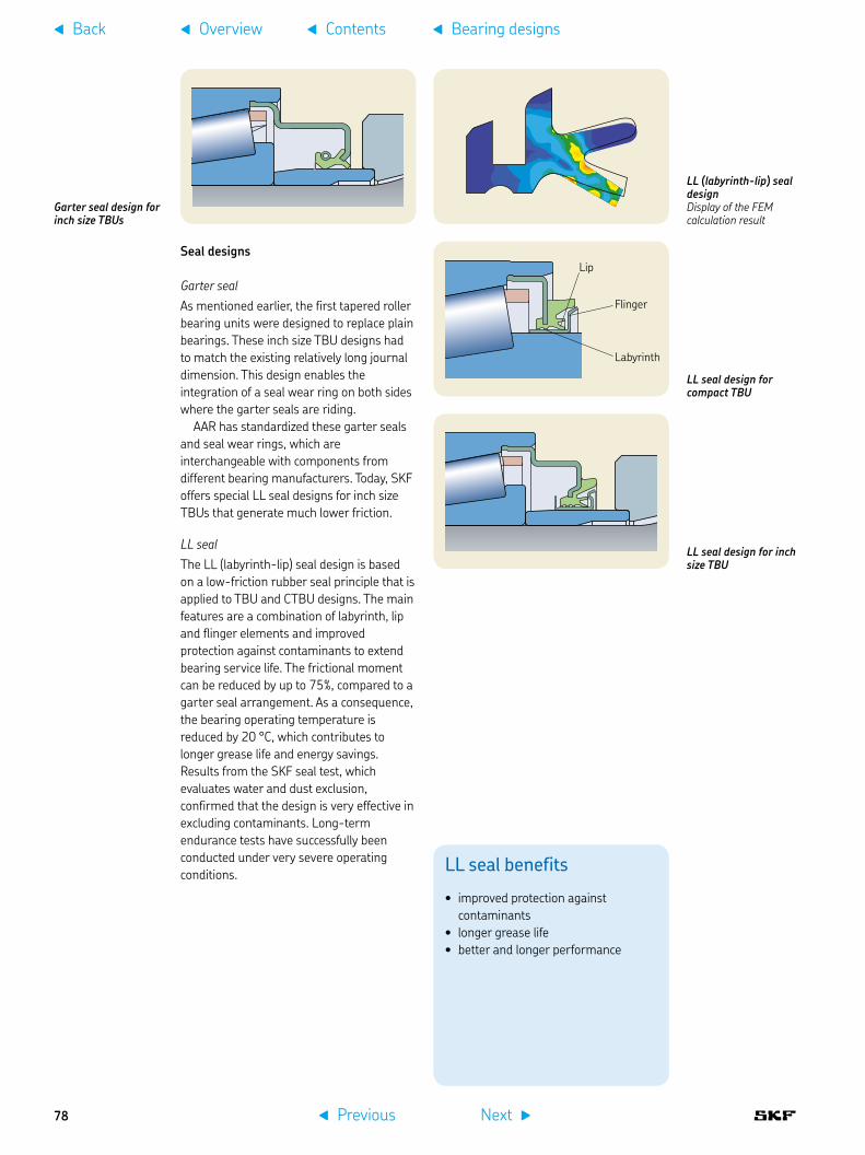
Garter seal design for inch size TBUs
LL seal benefits
improved protection against •contaminantslonger grease life•better and longer performance•
Seal designs
Garter sealAs mentioned earlier, the first tapered roller bearing units were designed to replace plain bearings. These inch size TBU designs had to match the existing relatively long journal dimension. This design enables the integration of a seal wear ring on both sides where the garter seals are riding.
AAR has standardized these garter seals and seal wear rings, which are interchangeable with components from different bearing manufacturers. Today, SKF offers special LL seal designs for inch size TBUs that generate much lower friction.
LL sealThe LL (labyrinth-lip) seal design is based on a low-friction rubber seal principle that is applied to TBU and CTBU designs. The main features are a combination of labyrinth, lip and flinger elements and improved protection against contaminants to extend bearing service life. The frictional moment can be reduced by up to 75%, compared to a garter seal arrangement. As a consequence, the bearing operating temperature is reduced by 20 °C, which contributes to longer grease life and energy savings. Results from the SKF seal test, which evaluates water and dust exclusion, confirmed that the design is very effective in excluding contaminants. Long-term endurance tests have successfully been conducted under very severe operating conditions.
LL (labyrinth-lip) seal designDisplay of the FEM calculation result
LL seal design for inch size TBU
LL seal design for compact TBU
Lip
Flinger
Labyrinth
f Previous Next g
f Overview f Contentsf Back f Bearing designs
78

Labyrinth sealsNon-contacting labyrinth seals have no friction in the sealing system and are used for full bore axleboxes protected with a front cover. This design is mainly used for metric size TBUs.
For some application requirements, improved protection against water ingress is requested. In this case, a combination of a labyrinth seal and an LL seal on the wheel side, where the backing or labyrinth ring is located, can combine both features and provide relative low friction and better protection.
Labyrinth seals are preferably used for high and very high-speed applications.
LL E2 seal benefits
lower energy consumption of hauled •rail vehicles because of a lower frictional moment compared to an LL sealreduced seal wear rate, better •performance and longer maintenance intervals achievablebetter thermal conductivity, lower •bearing operating temperature and longer grease life, longer maintenance intervals
LL E2 (Energy Efficient) sealThe LL E2 seal design is based on extensive research to further reduce the frictional moment and wear (abrasion resistance) and to achieve optimized thermal conductivity. This design contributes further to a lower energy consumption by hauling railway vehicles. Because of the lower temperature in the contact zone, this seal can be used for higher speeds. Another advantage of the lower temperature is the increased grease life which enables extended maintenance intervals.
Main features of this seal are an enhanced geometric design, optimized choice of the seal material and surface roughness of the contacting areas.
This seal design fulfils the requirements of UIC 515-1 in regard to the restricted contaminant ingress, especially water.
Labyrinth seal design
f Previous Next g
f Overview f Contentsf Back f Bearing designs
4
79

Polymer spacerFretting corrosion between the backing ring and the inner ring side face is caused by journal bending during operation. This corrosion not only causes foreign particles to enter the bearing, but also increases axial bearing clearance, resulting in reduced performance and reliability.
The development target was to avoid fretting corrosion by changing the steel-to-steel contact between the backing ring and the inner ring side face to steel-to-polymer contact. The polymer spacer of reinforced polymer material is clamped onto the bearing components. Extensive field experience confirmed the expectations. As a result, longer maintenance intervals can be scheduled. This design was first introduced for compact TBU designs. Today, the polymer spacer can be offered for nearly all TBU designs and sizes.
Without polymer spacer: strong fretting corrosion after 800 000 km
Polymer spacer benefits
fretting corrosion avoided•lower wear rate of the inner ring side •face/backing ring contact zonelonger performance and longer •maintenance intervals achievable because of longer grease life
With a polymer spacer: no fretting corrosion after 800 000 km
Polymer spacer design principle
Backing ring
Inner ring
Polymer spacer
f Previous Next g
f Overview f Contentsf Back f Bearing designs
80
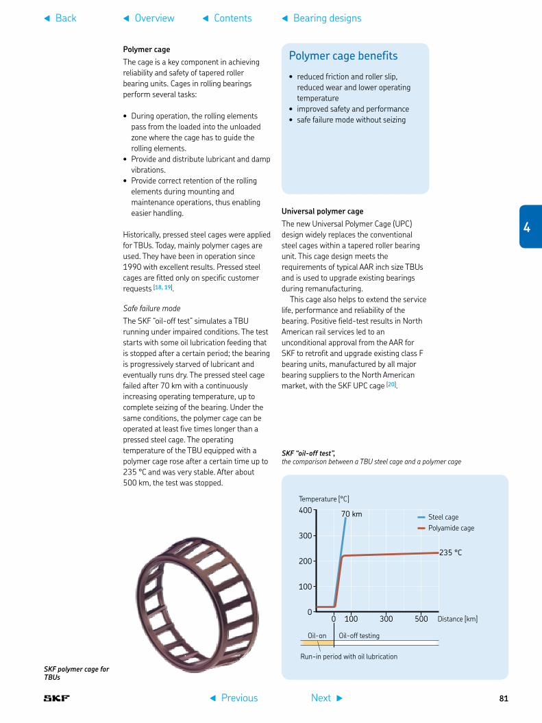
Polymer cageThe cage is a key component in achieving reliability and safety of tapered roller bearing units. Cages in rolling bearings perform several tasks:
During operation, the rolling elements •pass from the loaded into the unloaded zone where the cage has to guide the rolling elements. Provide and distribute lubricant and damp •vibrations. Provide correct retention of the rolling •elements during mounting and maintenance operations, thus enabling easier handling.
Historically, pressed steel cages were applied for TBUs. Today, mainly polymer cages are used. They have been in operation since 1990 with excellent results. Pressed steel cages are fitted only on specific customer requests [18, 19].
Safe failure modeThe SKF “oil-off test” simulates a TBU running under impaired conditions. The test starts with some oil lubrication feeding that is stopped after a certain period; the bearing is progressively starved of lubricant and eventually runs dry. The pressed steel cage failed after 70 km with a continuously increasing operating temperature, up to complete seizing of the bearing. Under the same conditions, the polymer cage can be operated at least five times longer than a pressed steel cage. The operating temperature of the TBU equipped with a polymer cage rose after a certain time up to 235 °C and was very stable. After about 500 km, the test was stopped.
SKF polymer cage for TBUs
Polymer cage benefits
reduced friction and roller slip, •reduced wear and lower operating temperatureimproved safety and performance•safe failure mode without seizing•
Universal polymer cageThe new Universal Polymer Cage (UPC) design widely replaces the conventional steel cages within a tapered roller bearing unit. This cage design meets the requirements of typical AAR inch size TBUs and is used to upgrade existing bearings during remanufacturing.
This cage also helps to extend the service life, performance and reliability of the bearing. Positive field-test results in North American rail services led to an unconditional approval from the AAR for SKF to retrofit and upgrade existing class F bearing units, manufactured by all major bearing suppliers to the North American market, with the SKF UPC cage [20].
SKF “oil-off test”, the comparison between a TBU steel cage and a polymer cage
400
300
200
100
0 0 100 300 500
235 °C
70 km
Temperature [°C]
Run-in period with oil lubrication
Oil-off testingOil-on
Distance [km]
Polyamide cageSteel cage
f Previous Next g
f Overview f Contentsf Back f Bearing designs
4
81

Application-specific designs
High-speed trainsFor high-speed and very high-speed trains, SKF offers a TBU design equipped with a labyrinth seal on both sides. For some selected applications, a special contacting seal like the LL E2 seal is used.
The TBU designs can be equipped with impulse wheels and sensors to detect operating parameters († chapter 7 and chapter 8).
Locomotives and multiple unitsFor locomotives with speeds up to 120 km/h, compact TBUs with an LL seal on both sides are used. This design requires less space in axial direction compared with a standard TBU design. In the case of
Metric size TBU with a labyrinth seal on both sides as used for high-speed applicationsOn the right side, a polymer spacer is applied which is part of the sealing system design. On the left side, an impulse wheel is flanged for the sensor application.
Metric size TBU with a labyrinth seal on the end cover side and an LL seal on the wheel side as used with multiple unit applicationsOn the right side a polymer spacer is applied which is part of the sealing system design.
GreaseWhen selecting the correct axlebox bearing execution, one of the main tasks is the choice of the right grease and quantity of grease. There are quite different application parameters to be considered, such as the engineering requirements for high-speed operation as well as heavy loads, different climatic and track conditions etc. In addition, standards and grease requirements like European EN and American AAR standards have to be fulfilled. Also, there are national requirements, such as in many European countries, in China and Russia, as well as individual customer specifications.
The grease has to pass all chemical, mechanical and tribology testing procedures in accordance with the European Standard EN 12081. In addition, endurance testing of the TBU has to fulfil the requirements of EN 12082. Extended endurance and dynamic simulation tests are being carried out on SKF railway test rigs, to confirm the expected high mechanical and thermal stability as well as resistance to corrosion. More information is provided in the testing section of this chapter († page 99).
The global trend is to achieve a no field lubrication (NFL) maintenance regime and to combine grease renewal with complete TBU remanufacturing, which is in most cases embedded into the complete wheelset overhaul cycle. For some specific applications like high-speed trains with very high mileage, field relubrication is performed to extend main overhaul intervals.
f Previous Next g
f Overview f Contentsf Back f Bearing designs
82

compact TBUs, shorter axle journals can be applied, which results in reduced axle bending and less wear in the journal/bearing contact area. For applications in very cold environments, special seal material is necessary.
For electrical and diesel multiple units with speeds up to 160 km/h, compact TBUs with an LL seal on both sides are used, as for locomotives, but smaller sizes are applicable because of lower axleload.
For higher speeds, full bore axleboxes with a front cover are used. For these applications, TBUs with labyrinth seals are used as shown in the previous application.
For some application requirements, improved protection against water ingress is requested. In this case, a combination of a labyrinth seal and an LL seal on the wheel side, where the backing or labyrinth ring is located, can combine both features with relative low friction and improved protection.
The TBU and compact TBU designs can be equipped with impulse wheels and sensors to detect operating parameters († chapter 7 and chapter 8).
AAR freight carsThe classic TBU design for American freight cars is following the enveloped size of American Association of Railroads (AAR) where initially the tapered roller bearings replaced plain bearings. This is the reason for a relatively long axle journal. SKF offers the inch size TBU design in two versions:
traditional inch size TBU design following •the AAR specificationenhanced inch size TBU design with LL •seals and special material selection for customers where AAR requirements are not compulsory
For new freight cars with increased cargo, the inch size compact TBU class K is used. This SKF design is fitted with LL seals, and a polymer clip ring and is approved by AAR.
Inch size compact TBU class K for freight cars
Traditional inch size TBU design following the AAR specification fitted with a garter seal on both sides
Enhanced inch size TBU design with LL seals and special material selectionfor customers where AAR requirements are not compulsory
f Previous Next g
f Overview f Contentsf Back f Bearing designs
4
83

Chinese freight carsSKF has developed special TBU designs for the Chinese freight car bogie designs to meet the Chinese Railways' standards. This special design is based on a TBU fitted with an LL seal on both sides, a polymer spacer and polymer cages.
These TBU 130 x 230 x 150 are interchangeable with other TBUs in China.
New generations of Chinese freight cars are designed for 80 t cargo and 120 km/h, compared to the previous generation of cars that were designed for 60 t cargo and 80 km/h. To meet these targets and to further improve operating safety, the Chinese Ministry of Railways has selected SKF as a technology partner.
The new bogies for freight cars are equipped with a special execution of CTBU 150 x 250 x 160 size [21].
Russian freight carsSKF has developed special compact TBU designs for Russian freight car bogie designs. This special design is based on an LL-seal on both sides, a polymer spacer and polymer cages. Several technical features were redesigned to meet Russian operating requirements such as poor track conditions, a maximum speed of 120 km/h and extreme climate conditions, e.g. winter temperatures down to –60 °C.
The Russian freight cars 12-132-03 with axleload 23,5 t are equipped with CTBU 130 x 250 x 160 in special execution. These compact TBUs are used for full bore axlebox designs.
The new generation of Russian freight cars is designed for 25 t axleload. SKF developed a special bearing solution for adapter applications.
This CTBU 150 x 250 x 160 provides lower life cycle cost and easier maintenance.
Mass transit vehiclesFor mass transit vehicles, like metro cars, light rail vehicles and tram cars with speeds up to 120 km/h, compact TBUs and TBUs with an LL seal on both sides are used. This design requires less space in axial direction. In case of compact TBUs, shorter axle journals can be applied, which results in reduced axle bending and less wear in the axle/bearing contact area. For applications in very cold environments, special seal material is necessary.
Compact TBU for Russian freight cars
Metric size compact TBU for Chinese freight cars
f Previous Next g
f Overview f Contentsf Back f Bearing designs
84

CTBU compact tapered roller bearing units
Size Principal dimensions
d D B C
Metric sizes mm
CTBU 100 x 175 100 175 130 120
CTBU 110 x 180 110 180 142 142
CTBU 130 x 210 130 210 148 132CTBU 130 x 220 130 220 145 135CTBU 130 x 230 130 230 166 150
130 230 176 160CTBU 130 x 240 130 240 172 160CTBU 130 x 250 130 250 172 160
CTBU 140 x 220 140 220 150 140
CTBU 150 x 250 150 250 180 160
CTBU 160 x 280 160 280 195 180
Inch sizes mm (in) – – –
CTBU Class K 6 1/2” x 9”
157(6.1880)
250(9.8420)
181(7.1102)
160(6.2992)
CTBU Class G7” x 9” and 7” x 12”
178(7.0005)
276(10.8750)
200(7.8740)
186(7.3120)
These figures are for information only. Contact SKF for detailed product specifications.
C
d D
B
f Previous Next g
f Overview f Contentsf Back f Bearing designs
4
85

TBU tapered roller bearing units, metric sizes
Size Principal dimensions
d D B C
– mm
TBU 90 90 154 106 115
TBU 100 100 175 113,5 120
TBU 120 120 195 126 131
TBU 130 x 210 130 210 126 132 TBU 130 x 220 130 220 145 150 TBU 130 x 230 130 230 150 160
TBU 140 140 220 133 140
TBU 150 150 250 154,5 160
TBU 160 x 270 160 270 160 150TBU 160 x 280 160 280 180 180
TBU 178 x 265 178,62 265,137 134 139
These figures are for information only. Contact SKF for detailed product specifications.
CB
d D
f Previous Next g
f Overview f Contentsf Back f Bearing designs
86

TBU tapered roller bearing units, inch sizes
Size Principal dimensions
d D B C
– mm (in)
Class B 4 1/4” x 8” 101,600 165,100 106,35 114,30(4.0000) (6.5000) (4.1870) (4.5000)
Class C 5” x 9” 119,088 195,263 136,525 142,875(4.6885) (7.6875) (5.3750) (5.6250)
Class D 5 1/2” x 10” 131,775 207,963 146,75 152,40(5.1880) (8.1875) (5.7780) (6.0000)
Class E 6” x 11” 144,475 220,663 155,575 163,51(5.6870) (8.6875) (6.1250) (6.4370)
Class F 6 1/2” x 12” 157,175 252,413 177,80 184,15(6.1879) (9.9375) (7.0000) (7.2500)
These figures are for information only. Contact SKF for detailed product specifications.
CB
d D
f Previous Next g
f Overview f Contentsf Back f Bearing designs
4
87

f Previous Next g
f Overview f Contentsf Back f Bearing designs
88

Cylindrical roller bearings and unitsCylindrical roller bearings and units are used for all kinds of railway rolling stock. These bearings are typically applied as sets of two single row bearings. The rollers in a single row cylindrical roller bearing are guided between the integral “open” flanges of the outer rings. These “open” flanges, combined with the specially designed and surface treated roller ends, provide improved lubrication, reduced friction and consequently lower operating temperatures. The outer ring with the integral flanges, together with the cylindrical roller and cage assembly, can be separated from the inner ring. This enables easy mounting and dismounting († page 184).
The main cylindrical roller bearing designs and sizes are described here in detail. For further application requirements, special bearing designs and sizes can be supplied on request. SKF has already introduced to the railway industry the next generation of cylindrical roller bearings, which is a sealed and ready-to-mount cylindrical roller bearing unit – called CRU. This design offers further benefits to railway customers († page 92).
Cylindrical roller bearingsSKF cylindrical roller axlebox bearings are manufactured in several designs, the main difference being in the configuration of the flanges.
NJ / NJP design also called WJ / WJPA typical axlebox assembly is equipped with a set of NJ / NJP (WJ / WJP) cylindrical roller bearings.
This design is offered for full bore axleboxes with a closed front cover. The
most popular are the NJ and NJP designs, which comply with DIN 5412-11. In this German standard, the bearings are called WJ referring to the NJ design and WJP referring to the NJP design, to be able to differentiate the specific axlebox bearing design from standard bearings. The reason for this specific designation is that some boundary dimensions of these bearing designs deviate from standard catalogue bearings.
The main benefit is a rather small bearing width providing a shorter axle journal, which results in reduced axle bending. This reduces micro-movement of inner rings on the journal and lowers the risk of fretting corrosion. The NJ / NJP (WJ / WJP) cylindrical roller bearing design is very common in some European countries and with customers outside Europe who prefer these bearing and axlebox designs.
NJ (WJ) designThe outer ring has two integral flanges and the inner ring one integral flange. The bearing is therefore suitable for the axial location of a shaft in one direction. This bearing design is widely used for the wheel side position of the axlebox bearing set.
NJP (WJP) designThe outer ring has two integral flanges and the inner ring one non-integral flange in the form of a loose flange ring. This bearing design is widely used for the outer side position of the axlebox bearing set.
German standardIn DIN 5412-11, not only boundary dimensions are standardized, but also the internal design, including radial and axial clearance. For example, for the bearing size WJ / WJP 130 x 240 P, clearances are:
Radial clearance: 0,130 to • 0,180 mmAxial clearance: 0,400 to • 0,900 mm for a bearing set
Typical axlebox assembly equipped with a set of NJ / NJP cylindrical roller bearings also called WJ / WJP cylindrical roller bearings
NJ (WJ) design
NJP (WJP) design
f Previous Next g
f Overview f Contentsf Back f Bearing designs
4
89

NJ / NU design with an HJ angle ringThis design is based on an NJ design bearing located at the wheel side position and previously described. On the opposite side, an NU design bearing is applied in combination with an HJ angle ring. This bearing arrangement requires a slightly longer axle because of the width of the additional angle ring. This design is an alternative to the previous one, but offers easier mounting because of the lead-in function (tapered transition between inner ring raceway and inner ring side faces).
NU design + HJ angle ringThe outer ring of NU design bearings has two integral flanges and the inner ring is without flanges. The NU design bearing, combined with an HJ angle ring, is used for the outer side position of the bearing set. The HJ angle ring for axlebox applications is usually specially designed to meet the requirements for axial clearance.
Typical application of an axlebox assembly fitted with a combination of a set of NJ / NU cylindrical roller bearings and an HJ angle ring
NU design + HJ angle ring
Polymer cageA key component in achieving reliability and safety of cylindrical roller bearing units is the cage. Cages in rolling bearings perform many functions:
During operation, the rolling elements •pass from the loaded into the unloaded zone where the cage has to guide the rolling elements.Provide and distribute lubricant and •dampen vibrations.Provide correct retention of the rolling •elements during mounting and maintenance operations, thus enabling easier handling.
Historically, machined brass cages were used for cylindrical roller bearings. Today, mainly polymer cages are used. Pressed steel cages are only applied upon a customer’s request. Polymer cages have been in service since 1990 with excellent results († page 81).
SKF polymer cage for cylindrical roller bearings
Roller slip of a cylindrical roller bearing equipped with a brass cage or a polymer cage
50 100 150 200
20
40
60
Speed [km/h]
Polymer cage
Brass cage
Roller slip [%]
f Previous Next g
f Overview f Contentsf Back f Bearing designs
90

CRB cylindrical roller bearings
Size Principal dimensions Basic designation
d D 2B B1
– mm –
CRB 90 x 160 90 160 104,8 – WJ / WJP 90 x 160P1)
CRB 100 x 180 100 180 120,6 – WJ / WJP 100 x 180P1)
CRB 120 x 215 120 215 146 – WJ / WJP 120 x 215P1)
CRB 120 x 240 120 240 160 – WJ / WJP 120 x 240P1)
CRB 130 x 220 130 220 122 – WJ / WJP 130 x 220P1)
CRB 130 x 240 130 240 160 – WJ / WJP 130 x 240P1)
CRB 130 x 250 130 250 160 – WJ / WJP 130 x 250P
CRB 150 x 270 150 270 146 12 NJ 2230 EC / NU 2230 EC / HJ 2230 EC
CRB 180 x 320 180 320 172 – NJ 2236 EC / NJP 2236 EC
2B
dD
12
1) In accordance with the German standard DIN 5412-11
WJ and NJ designWJP and NJP designNU designHJ angle ring
2BB1
dD
134
12
43
These figures are for information only. Contact SKF for detailed product specifications.
Type WJ + WJP or NJ + NJP Type NJ + NU + HJ angle ring
f Previous Next g
f Overview f Contentsf Back f Bearing designs
4
91

Cylindrical roller bearing unitsSKF has introduced to the railway market the CRU – a cylindrical roller bearing unit. This design is based on the long term experience of cylindrical roller bearings. The unit's design offers bogie and vehicle suppliers and railway operators the advantage of a sealed and factory pre-lubricated unit that is easy to mount. The critical greasing procedure is moved from the wheelset workshop environment to the location for bearing production where greasing can be done in a very clean environment using the right grease, grease quantity and distribution inside the bearing († page 17). The sealing is designed as a labyrinth seal which has no friction and wear during operation. This design is offered for full bore axleboxes with a closed front cover.
Short CRU designThe short CRU version has a rather small width like the NJ / NJP (WJ / WJP) design, which contributes to a more compact axlebox design and a shorter axle journal. This results in reduced axle bending and movement between the journal seat and bearing, which in turn results in less wear.
A mounting sleeve is inserted inside the bore of the inner rings to facilitate mounting. The sleeve is automatically removed by pressing the inner rings onto the journal of the wheelset. In addition, a sleeve on the outer ring enables easier pushing the unit into the axlebox bore.
Short CRU design with a mounting sleeve on the inner rings and outer rings to facilitate mounting
Long CRU design with a mounting sleeve on the inner rings
Long CRU designThe long CRU version is used for specific applications, especially larger sizes where a larger grease quantity has to be applied to reach the required performance and to meet longer service interval requirements. A mounting sleeve is inserted inside the bore of the inner rings for easy mounting. The one-piece outer ring has two raceways for the roller sets.
f Previous Next g
f Overview f Contentsf Back f Bearing designs
92

CRU cylindrical roller bearing units
Size Principal dimensions Type
d D C 2B
– mm –
CRU 100 x 180 100 180 – 120,6 1
CRU 120 x 200 120 200 – 112 1CRU 120 x 215 120 215 – 146 1
CRU 130 x 220 130 220 – 160 1CRU 130 x 240 130 240 – 160 1CRU 130 x 240 130 240 164 160 2
CRU 150 x 250 150 250 160 180 2
CRU 160 x 270 160 270 150 170 2
Mounting sleeves1
Type 1 Type 2
These figures are for information only. Contact SKF for detailed product specifications.
C
2B
dD
1
2B
dD1
1
f Previous Next g
f Overview f Contentsf Back f Bearing designs
4
93

CRU plus designThis advanced design offers some additional features to increase performance level by applying a more robust design with anti-fretting features for easier mounting and dismounting. These features include:
coated bore and outside diameter for •improved resistance against fretting corrosion and reduced mounting forces when pressing the bearing unit onto the axle journalpolymer spacer at the backing ring for •avoiding fretting corrosion between the contact areas of the backing ring and inner ring side faceinterface ring for retaining the outer rings •as a set and locating them in the correct load zone positionphosphated backing ring for improved •resistance against resulting damage from micro movements
Cylindrical roller bearing unit CRU plus design
CRU plus design benefits
improved resistance against fretting •corrosioneasier mounting and dismounting•less force required when pressing the •unit onto the axle journal
CRU plus design equipped with a polymer spacer and a phosphated backing ring
Interface ring
Phosphated backing ring
Polymer spacer
Coated bore
Coated outside diameter
f Previous Next g
f Overview f Contentsf Back f Bearing designs
94

Cylindrical roller bearing units for axial displacement
Size Principal dimensions Axial displacement Type
d D C B
– mm –
CRU 150 x 270 150,022 270 174 215 +/-10,0 1
CRU 160 x 270 160 270 150 176 +/-15,0 2CRU 160 x 280 160 280 159 180 +/-10,0 3
CRB 180 x 320 180 320 172 192 +/-10,0 4
C
BdD
1 1 1 Type 1 Type 2 Type 3 Type 4
Cylindrical roller bearings and units for middle axle applications
The 3-axle bogie design could require an extended bearing axial displacement to enable the middle axle to move when running in curves († page 38). In principle, this requirement could be necessary for all vehicles without bogies that have more than two axles, like 3-axle shunting locomotives.
These bearings are designed according to customer specifications. In the table above, most current bearing sizes and designs are listed. For new designs, type 3 is preferable.
Mounting sleeves1
These figures are for information only. Contact SKF for detailed product specifications.
f Previous Next g
f Overview f Contentsf Back f Bearing designs
4
95

f Previous Next g
f Overview f Contentsf Back f Bearing designs
96

Typical application of an axlebox assembly fitted with a set of two spherical roller bearings 229 750 separated by an inner ring spacer
Spherical roller bearing design
Spherical roller bearingsToday, spherical roller bearings are mainly used for freight cars. The bearings in this application are typically applied as sets of two double row bearings. Spherical roller bearings have two rows of rollers with a common sphered raceway in the outer ring and two inner ring raceways inclined at an angle to the bearing axis.
The commonly used bearing is the specific size SRB 130 x 220, basic SKF designation 229 750, which is produced in some variants according to specific customer’s requirements. The boundary dimensions 130 x 220 x 73 of this bearing deviate from standard catalogue bearings.
In addition, a full assortment of different sizes of spherical roller bearings can be used for further applications, see the SKF General Catalogue. These standard bearings are offered for full bore axleboxes with a closed front cover.
Design featuresThe bearing consists of an inner and outer ring, rollers, cages and guide ring. The bearing can accommodate misalignment due to the sphered raceways and rollers. The bearing is not separable. Axlebox bearing applications with spherical roller bearings are based on very long field experience.
One advantage of spherical roller bearings for freight car applications is the smaller outside diameter of 220 mm in comparison to 240 mm for cylindrical roller bearings and units designed for 130 mm shaft diameter and 25 t axleload. This advantage stimulates axlebox engineering, which can be designed smaller and lighter compared with other designs.
Single bearing arrangementSingle spherical roller bearings in axleboxes are used to gain more flexibility in the axlebox design. This design accommodates misalignment and shaft deflection.
This bearing can accommodate shaft-to-housing misalignment because its outer ring has a sphered raceway which is shared by the two rows of rollers.
Product rangeThe dimensions of standard spherical roller bearings can be obtained from the SKF General Catalogue. In addition to the standard bearing execution, specific customized features can be offered to the railway industry. These bearings have the suffix VA355 and R505. The special design of the 229 750 spherical roller bearing is listed in the table on the next page.
Axlebox fitted with a single spherical roller bearing
f Previous Next g
f Overview f Contentsf Back f Bearing designs
4
97

SRB spherical roller bearing
Size Principal dimensions Basic designation
d D B
– mm –
SRB 130 x 220 130 220 73 229750
These figures are for information only. Contact SKF for detailed product specifications.
Dimensions of standard spherical roller bearings can be found in the SKF General Catalogue.
B
dD
f Previous Next g
f Overview f Contentsf Back f Bearing designs
98

Bearing testingThe key for long-term reliability and performance of railway rolling stock is rigorous testing. SKF axlebox bearings and units are tested in the Railway Test Centre at the SKF Business and Technology Park in Nieuwegein, the Netherlands. In this centre, complete axleboxes with surrounding parts such as bogie frame interfaces are tested as well as bearing units and components such as seals and cages. This facility complies with the accreditation criteria for test laboratories according to ISO/IEC 17025 († page 23). Further test rigs are located at the development centres and production units [22, 23].
There are different testing standards and requirements such as European EN and American AAR, to be fulfilled as well as national requirements in many European countries, China and Russia and requirements by individual customers.
For safety and long-term reliability, rigorous testing procedures are applied before introducing new axlebox bearing designs for different speeds and axleloads.
The EN 12082 standard is an important tool for manufacturers of bearings, bogies and rolling stock as well as railway operators. It provides details on principles, methods and equipment to test assembled axleboxes in test rigs along with criteria for acceptance. This standard describes two main types of testing, rig performance and field testing.
R3 endurance test rigs for quasi-static performance testing
f Previous Next g
f Overview f Contentsf Back f Bearing designs
4
99

Seal testing
Water spray testThe water spray test is mentioned in the European Standard EN 12082 as a watertightness test, and in UIC 515-5 as well as other specifications. The test principle consists of water that is sprayed with a sprinkler device between the back of the sealed unit mounted on a dummy shaft and a simulated wheel. These tests are conducted under different operating conditions such as bearing speeds, angle of water spray flow, etc.
Water spray test principle
European Standard EN 12082 watertightness test
Watertightness test in operation
Seal friction, wear and torque test rig battery
SKF environmental seal test rig for simulating contaminated conditions such as dust and water
120°
30°
Arizona dust testThe test rig is based on a simulation of dust entry into the axlebox bearing under operating condition. The Arizona dust is a standard test medium for this application.
Seal friction testThe SKF seal friction test is a tool to evaluate wear, friction torque and sealing capability under severe operating conditions. The test rig consists of four different test machines.
f Previous Next g
f Overview f Contentsf Back f Bearing designs
100
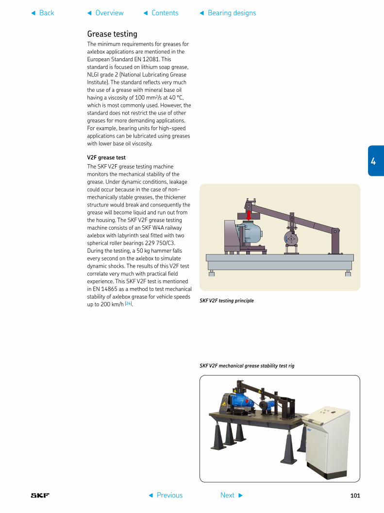
Grease testingThe minimum requirements for greases for axlebox applications are mentioned in the European Standard EN 12081. This standard is focused on lithium soap grease, NLGI grade 2 (National Lubricating Grease Institute). The standard reflects very much the use of a grease with mineral base oil having a viscosity of 100 mm2/s at 40 °C, which is most commonly used. However, the standard does not restrict the use of other greases for more demanding applications. For example, bearing units for high-speed applications can be lubricated using greases with lower base oil viscosity.
V2F grease testThe SKF V2F grease testing machine monitors the mechanical stability of the grease. Under dynamic conditions, leakage could occur because in the case of non-mechanically stable greases, the thickener structure would break and consequently the grease will become liquid and run out from the housing. The SKF V2F grease testing machine consists of an SKF W4A railway axlebox with labyrinth seal fitted with two spherical roller bearings 229 750/C3. During the testing, a 50 kg hammer falls every second on the axlebox to simulate dynamic shocks. The results of this V2F test correlate very much with practical field experience. This SKF V2F test is mentioned in EN 14865 as a method to test mechanical stability of axlebox grease for vehicle speeds up to 200 km/h [24].
SKF V2F testing principle
SKF V2F mechanical grease stability test rig
f Previous Next g
f Overview f Contentsf Back f Bearing designs
4
101
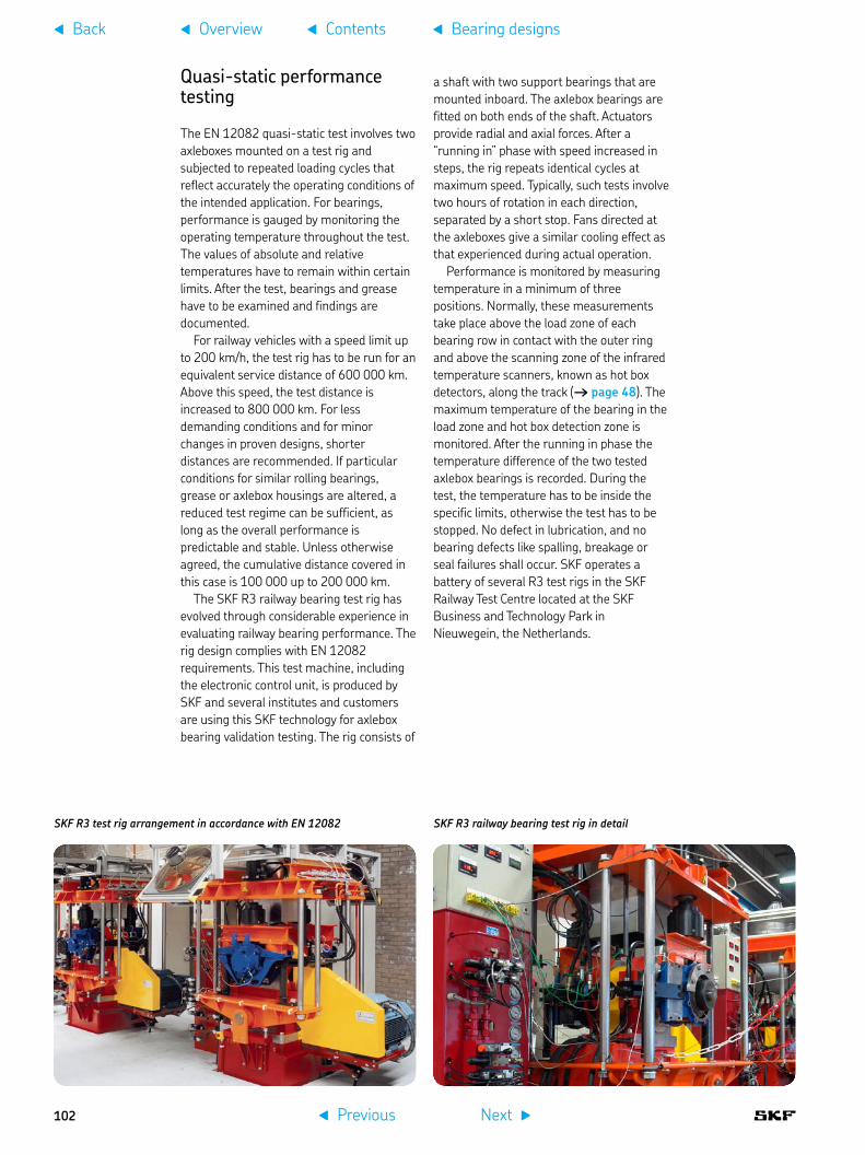
Quasi-static performance testing
The EN 12082 quasi-static test involves two axleboxes mounted on a test rig and subjected to repeated loading cycles that reflect accurately the operating conditions of the intended application. For bearings, performance is gauged by monitoring the operating temperature throughout the test. The values of absolute and relative temperatures have to remain within certain limits. After the test, bearings and grease have to be examined and findings are documented.
For railway vehicles with a speed limit up to 200 km/h, the test rig has to be run for an equivalent service distance of 600 000 km. Above this speed, the test distance is increased to 800 000 km. For less demanding conditions and for minor changes in proven designs, shorter distances are recommended. If particular conditions for similar rolling bearings, grease or axlebox housings are altered, a reduced test regime can be sufficient, as long as the overall performance is predictable and stable. Unless otherwise agreed, the cumulative distance covered in this case is 100 000 up to 200 000 km.
The SKF R3 railway bearing test rig has evolved through considerable experience in evaluating railway bearing performance. The rig design complies with EN 12082 requirements. This test machine, including the electronic control unit, is produced by SKF and several institutes and customers are using this SKF technology for axlebox bearing validation testing. The rig consists of
a shaft with two support bearings that are mounted inboard. The axlebox bearings are fitted on both ends of the shaft. Actuators provide radial and axial forces. After a “running in” phase with speed increased in steps, the rig repeats identical cycles at maximum speed. Typically, such tests involve two hours of rotation in each direction, separated by a short stop. Fans directed at the axleboxes give a similar cooling effect as that experienced during actual operation.
Performance is monitored by measuring temperature in a minimum of three positions. Normally, these measurements take place above the load zone of each bearing row in contact with the outer ring and above the scanning zone of the infrared temperature scanners, known as hot box detectors, along the track († page 48). The maximum temperature of the bearing in the load zone and hot box detection zone is monitored. After the running in phase the temperature difference of the two tested axlebox bearings is recorded. During the test, the temperature has to be inside the specific limits, otherwise the test has to be stopped. No defect in lubrication, and no bearing defects like spalling, breakage or seal failures shall occur. SKF operates a battery of several R3 test rigs in the SKF Railway Test Centre located at the SKF Business and Technology Park in Nieuwegein, the Netherlands.
SKF R3 railway bearing test rig in detailSKF R3 test rig arrangement in accordance with EN 12082
f Previous Next g
f Overview f Contentsf Back f Bearing designs
102

Test rig principle of the EN 12082 The axlebox bearings are mounted on both ends of the shaft. Actuators provide radial and axial forces. Fans on both sides simulate the wind cooling while travelling.
Graphical presentation of test cycles that are described in detail in EN 12082 1,00
0,750,500,25
0–0,25–0,50–0,75–1,00
1,000,750,500,25
0–0,25–0,50–0,75–1,00
nnn
Fr
t3 t3
t5
t
t
tFaFan
t4
2 3
t2
t1
1
4
5
6
7
t7
t8
t8
t9
t6
2 × t6
Keyspeed variation1 pre-test2 performance test3 detail of one test cycle4 radial force5 axial force variation (force 6 at pre-test as agreed ...detail of time history of 7 axial force (enlarged time scale)
Temperature sensors
Cooling air
Temperature sensor
Test axlebox
Vertical forceactuator and sensor
Motor Support bearing
Axial forceactuator and sensor
f Previous Next g
f Overview f Contentsf Back f Bearing designs
4
103

Dynamic testingBeyond the quasi-static performance testing, the behaviour of new bearing and axlebox designs is evaluated under more realistic operating conditions. SKF has developed a sophisticated test rig called THISBE (test rig for high-speed bearings) which can simulate dynamic load conditions († chapter 3). Here, the bearing and axlebox are fitted in a part of an actual bogie frame, including the suspension system with springs and dampers. The load and speed spectra can be taken directly from field recordings or from specifications from customers or institutes.
Left and right: THISBE test rig for high-speed bearings which can simulate dynamic load conditions equipped with an original bogie frame
Design principle of the THISBE test rig for high-speed bearings
Axial load Fa
Wagon load Fw
Support bearings
Test bearing
Vertical loadFv = Fw + Fdynamic
Hydraulic torque motor
f Previous Next g
f Overview f Contentsf Back f Bearing designs
104

Field test with SKF axlebox bearing unitsRussian Vorkuta – Cherepovets coal railway line, 1 900 km long, max. speed 91 km/h, lowest temperature during the test –37 °C
Field testingThis second step of the EN 12082 performance testing is usually done after the rig testing. For main line vehicles with a speed limit up to 200 km/h, the rig and field tests should last the equivalent of two years, or 600 000 km. Above this speed, the distance is increased to 1 million km. The number of axleboxes tested must be agreed between customer and supplier. During the test period and the inspection afterwards, no defect in lubrication, or bearing defects like spalling, breakage or seal failures shall occur.
Sensor application for field testing
Field testing equipment design
Field testing software installation
f Previous Next g
f Overview f Contentsf Back f Bearing designs
4
105

Bearing 5 calculation
Calculation principles . . . . . . . . . 107
Basic rating life . . . . . . . . . . . . . . 108
SKF rating life . . . . . . . . . . . . . . . 112
Advanced calculations . . . . . . . . 116
f Previous Next g
f Overview f Contentsf Back
106

Bearing calculation
When selecting an axlebox bearing or unit, SKF should be contacted for assistance with necessary calculations. SKF can provide a portfolio of different calculation methods to optimize bearing selection for any kind of application. Basic calculation principles are mentioned in this chapter, to give an overview of state of the art methods that can be used for axlebox bearing calculation and more advanced investigations. Depending on the individual specification requirements and experience, the most suitable package of calculations has to be selected to provide a design that is both reliable and safe.
Calculation principlesWhen selecting axlebox bearings, in addition to the bearing rating life calculation, other design elements should be considered as well. These include components associated with the bearing/unit and the axlebox such as axle journal, axlebox housing and the interaction of guidance principle, springs and dampers of the bogie design. The lubricant is also a very important component of the bearing arrangement, because it has to prevent wear and protect against corrosion, so that the bearing can reach its full performance potential. The seal performance is of vital importance to the cleanliness of the lubricant. Cleanliness has a profound effect on bearing service life, which is why tapered and cylindrical roller bearing units are mainly used, because they are factory lubricated and have integrated sealing systems († page 17).
How much calculation needs to be done depends on whether there is experience
data already available with a similar axlebox bearing/unit arrangement. When specific experience is lacking and extraordinary demands in the specification are made, then much more work is needed including, for example, more accurate calculations and/or testing.
In the following sections, basic calculation information is presented in the order it is generally required. More generic information can be found in the SKF Interactive Engineering Catalogue, available online at www.skf.com or in the printed version of the SKF General Catalogue. Obviously, it is impossible to include here all of the information needed to cover every conceivable axlebox bearing/unit application.
f Previous Next g
f Overview f Contentsf Back f Bearing calculation
107
5

Customers are mainly demanding calculation of the bearing's basic rating life according to ISO 281. This standard covers the calculation of the dynamic basic load rating and basic rating life. The calculation model for the bearing load conditions is not covered in this standard.
SpecificationsFor basic calculations, main input data and other information, like description of the operational parameters and drawings, are needed. Based on this information, it has to be decided if, in addition to the basic rating life calculation, further and more advanced calculations are needed.
Basic rating lifeFor simplified calculations and to obtain an approximate value of the bearing life, the so-called “handbook method” is used to calculate the basic rating life. The basic rating life of a bearing according to ISO 281 is
where L10 = basic rating life (at 90% reliability), millions of revolutionsC = basic dynamic load rating, kNP = equivalent dynamic bearing load, kNp = exponent for the life equation = 3 for ball bearings = 10/3 for roller bearings, as used typically in axlebox applications
The basic rating life for a specific bearing is based on the basic dynamic load rating according to ISO 281. The equivalent bearing load has to be calculated based on the bearing loads acting on the bearing via the wheelset journal and the axlebox housing.
For railway applications, it is preferable to calculate the life expressed in operating mileage, in million km
whereL10s = basic rating life (at 90% reliability), million kmDw = mean wheel diameter, m
When determining bearing size and life, it is suitable to verify and compare the C/P value and basic rating life with those of existing similar applications where a long-term field experience is already available.
Specification example
bogie manufacturer•operator name and country•vehicle type•project name•static axleload G• 00 in tons and expressed as a force in kNweight of the wheelset in tonnes and expressed as a force in •kN payload in tonnes and expressed as a force in kN•maximum speed•wheel diameters: new/mean/worn•axle journal diameter and length•preferred bearing/unit design and size•expected mileage per year•required maintenance regime in mileage in time, km and •yearsclimatic condition, min/max temperature and humidity•track condition•bogie design, in/outboard bearing application, axlebox design, •axlebox guidance principle, springs and dampersprincipal bogie design and axle journal drawing•axlebox design drawing if already existing•available field experience with similar applications•
For additional specification requirements † chapter 3.
f Previous Next g
f Overview f Contentsf Back f Bearing calculation
108

Typical basic life and C/P values and mean wheel diameters
Basic rating life, C/P Mean wheelVehicle type million km value diameter DW [m]
Freight cars1) 0,8 6,84) 0,9Mass transit vehicles like suburban trains, underground and metro vehicles, light rail and tramway vehicles
1,5 7,1÷7,7 0,7
Passenger coaches2) 33) 7,2÷8,8 0,9
Multiple units 3÷4 7,8÷9,1 1,0Locomotives 3÷5 6,6÷8,6 1,2
1) According to UIC International Union of Railways / Union Internationale des Chemins de fer codex, under continuously acting maximum axleload
2) According to UIC codex3) Some operators require up to 5 million km4) Tapered roller bearing units for AAR Association of American Railroads
applications can have, in some specific cases, a lower C/P value down to 5
Dynamic bearing loadsThe loads acting on a bearing can be calculated according to the laws of mechanics if the external forces, e.g. axleload, weight of the wheelset and payload are known or can be calculated. When calculating the load components for a single bearing, the axle journal is considered as a beam resting on rigid, moment–free bearing supports. Elastic deformation in the bearing, axlebox housing or bogie frame components are not considered in the basic rating life calculation. As well, resulting moments on the bearing due to elastic deflection of shaft, axlebox or suspension are not taken into account. The reason is that it is not only the shaft that creates moments.
These simplifications help to calculate the basic rating life, using readily available means such as a pocket calculator. The standardized methods for calculating basic load ratings and equivalent bearing loads are based on similar assumptions.
G = G00 – Gr
2
Acting bearing loads principles
Ka = axial load
G00 = static axleload
Gr = wheelset mass
Static bearing load
f Previous Next g
f Overview f Contentsf Back f Bearing calculation
5
109

Radial bearing loadThe maximum static axlebox load per bearing arrangement/unit is obtained from:
whereG = maximum static axlebox load [kN]G00 = maximum static axleload [kN]Gr = weight of the wheelset [kN]
Based on the static axlebox load, the mean radial load is calculated by considering any variations in the payload as well as any additional dynamic radial forces
Kr = f0 frd ftr G
whereKr = mean radial load [kN]f0 = payload factorfrd = dynamic radial factorftr = dynamic traction factor
For standard applications, usually the mean values are used, e.g. frd = 1,2 for passenger coaches in standard applications.
For specific applications like high-speed and very high-speed applications or specific dynamic effects like irregularities of the rails, hunting of bogies etc., the dynamic load factor frd has to be agreed by the customer. These additional dynamic loads are in many cases the result of field test recordings and statistical analysis. In principle, the dispersion of the dynamic load increases with the speed.
Payload factor f0 Vehicle type
0,8 to 0,9 Freight cars0,9 to 1 Multiple units, passenger coaches and
mass transit vehicles1 Locomotives and other vehicles having a
constant payload
The pay load factor f0 is used for variation in the static loading of the vehicle, e.g. goods for freight and passengers incl. baggage for coaches.
A locomotive has no significant variation in the static load; that’s why a full static axlebox load needs to be applied.
Dynamic radial factor frd Vehicle type
1,2 Freight cars, adapter application1,1 to 1,3 Multiple units, passenger coaches and
mass transit vehicles1,2 to 1,4 Locomotives and other vehicles having a
constant payload
The dynamic radial factor frd is used to take into account quasi-static effects like rolling and pitch as well as dynamic effects from the wheel rail contact.
Dynamic traction factor ftr Vehicle type
1,05 Powered vehicles with an elastic drive system, e.g. hollow shaft drive with elastic coupling
1,1 Powered vehicles with a non-elastic drive system, e.g. axle hung traction motors
1 Non-powered vehicles
The dynamic traction factor is used to take into account additional radial loads caused by the drive system.
Dynamic axial factor fad Vehicle type
0,1 Freight cars0,08 Multiple units, passenger coaches and
mass transit vehicles, max speed 160 km/h
0,1 Multiple units, passenger coaches and mass transit vehicles > 160 km/h
0,12 Locomotives, tilting trains or other concepts leading to higher lateral acceleration
f Previous Next g
f Overview f Contentsf Back f Bearing calculation
110
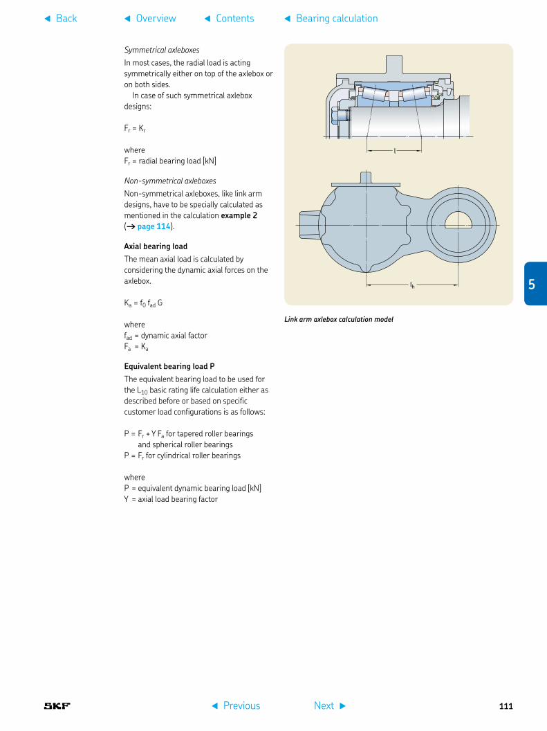
Symmetrical axleboxesIn most cases, the radial load is acting symmetrically either on top of the axlebox or on both sides.
In case of such symmetrical axlebox designs:
Fr = Kr
whereFr = radial bearing load [kN]
Non-symmetrical axleboxesNon-symmetrical axleboxes, like link arm designs, have to be specially calculated as mentioned in the calculation example 2 († page 114).
Axial bearing loadThe mean axial load is calculated by considering the dynamic axial forces on the axlebox.
Ka = f0 fad G
wherefad = dynamic axial factorFa = Ka
Equivalent bearing load PThe equivalent bearing load to be used for the L10 basic rating life calculation either as described before or based on specific customer load configurations is as follows:
P = Fr + Y Fa for tapered roller bearings and spherical roller bearingsP = Fr for cylindrical roller bearings
whereP = equivalent dynamic bearing load [kN]Y = axial load bearing factor
l
Link arm axlebox calculation model
lh
f Previous Next g
f Overview f Contentsf Back f Bearing calculation
5
111

Design examples of axleboxes where the radial load is acting symmetrically either on top of the axlebox or on both sides
SKF rating lifeFor more sophisticated bearing calculations, the basic rating calculation method can be further improved. The reason is that the service life of the bearing can deviate significantly from the calculated basic rating life. There is a variety of influencing factors like lubrication, degree of contamination, misalignment, proper installation and environmental conditions.
Therefore, ISO 281 contains a modified life equation to supplement the basic rating life. This life calculation makes use of a modification factor to account for the lubrication and contamination condition of the bearing and the fatigue load limit of the material.
This standard allows bearing manufacturers to recommend a suitable method for calculating the life modification factor to be applied to the bearing based on operating conditions. The SKF life modification factor aSKF applies the concept of a fatigue load limit Pu analogous to that used when calculating other machine components.
The SKF life modification factor aSKF makes use of the lubrication conditions (viscosity ratio k) and a factor hc for the contamination level, to reflect the real application operating conditions.
The equation for the SKF rating life is in accordance with ISO 281
Lnm = a1 aSKF L10 = a1 aSKF
whereLnm = SKF rating life (at 100 – n1)% reliability), millions of revolutionsa1 = life adjustment factor for reliabilityaSKF = SKF life modification factor
Calculations described here can be easily performed online using the SKF Interactive Engineering Catalogue, available online at www.skf.com as well as in the SKF General Catalogue.
Design examples of link arm axleboxes where the radial load is acting non-symmetrically
1) The factor n represents the failure probability, i.e. the difference between the requisite reliability and 100%
f Previous Next g
f Overview f Contentsf Back f Bearing calculation
112

Calculation example 1, symmetrical axlebox without link arm, tapered roller bearing unit
Project data
Customer Calculation example 1Application Electrical multiple unit / symmetrical axlebox / TBU
Application data
Static axleload G00 16,5 tonnes (161,87 kN)Wheelset weight Gr 1,5 tonnes (14,72 kN)Wheel diameter Dw 0,88 mMaximum speed 120 km/hAxlebox type Symmetrical axlebox (without link arm)
Bearing data
Bearing type TBU 130 x 230Basic dynamic load rating C 913 kNOuter ring raceway angle 10 degrees
Bearing boundary dimensions:Bore diameter 130 mmOutside diameter 230 mmWidth 160 mm
Axlebox load calculation
Axlebox load G = (G00 - Gr) / 2 = 73,58 kNEquivalent radial axlebox load Kr = f0 frd ftr G = 88,07 kNEquivalent axial axlebox load Ka = f0 fad G = 6,99 kN
where:f0 = payload factor: 0,95frd = dynamic radial factor: 1,20fad = dynamic axial factor: 0,10ftr = dynamic traction factor: 1,05
Bearing load calculation
Bearing load Fr = Kr + 2 fc Ka = 92,10 kN
where: fc = h Da / l = 0,29Da = shaft diameter 130,00 mml = distance between the 2 load centres = 112,60 mmh = 0,25with:h = 0,25 if the load acts at the top or at the bottom of the housingh = 0,10 if the load acts near to the central plane of the bearing
Fa = Ka = 6,99 kN
where:Fa = mean bearing axial load
Equivalent dynamic bearing load P = Fr + Y Fa = 109,94 kN
Basic rating life calculation
Basic rating life L10 = (C / P)10/3 (for roller bearings) = 1 160 million revolutionsL10s = π × L10 × Dw / 1 000 = 3,2 million km
where:C = basic dynamic load rating = 913,00 kNP = equivalent dynamic bearing load = 109,94 kNDw = Wheel diameter = 0,88 mC/P = 8,3
f Previous Next g
f Overview f Contentsf Back f Bearing calculation
5
113

Calculation example 2, link arm axlebox, tapered roller bearing unit
Project data
Customer Calculation example 2Application Locomotive / link arm axlebox / TBU
Application data
Static axleload G00 22,5 tonnes (220,73 kN)Wheelset weight Gr 2,88 tonnes (28,25 kN)Wheel diameter Dw 1,06 mMaximum speed 120 km/hAxlebox type Link arm axlebox
Bearing data
Bearing type TBU 160 x 280Basic dynamic load rating C 1 320 kNOuter ring raceway angle 10 degrees
Bearing boundary dimensions:Bore diameter 160 mmOutside diameter 280 mmWidth 180 mm
Axlebox load calculation
Axlebox load G = (G00 - Gr) / 2 = 96,24 kNEquivalent radial axlebox load Kr = f0 frd ftr G = 131,36 kNEquivalent axial axlebox load Ka = f0 fad G = 11,55 kN
where:f0 = payload factor: 1,00frd = dynamic radial factor: 1,30fad = dynamic axial factor: 0,12ftr = dynamic traction factor: 1,05
Bearing load calculation
Bearing load Fr = (Kr2 + Q2)0,5 = 137,08 kN
where: Q = Ka lh / l = additional load due to axlebox arm 39,19 kNl = distance between the 2 load centres = 132,60 mmlh = distance between journal axle and silentblock 450,00 mm
Fa = Ka = 11,55 kN
where:Fa = mean bearing axial load
Equivalent dynamic bearing load P = Fr + Y Fa = 166,56 kN
Basic rating life calculation
Basic rating life L10 = (C / P)10/3 (for roller bearings) = 992 million revolutionsL10s = π × L10 × Dw / 1 000 = 3,3 million km
where:C = basic dynamic load rating = 1 320,00 kNP = equivalent dynamic bearing load = 166,56 kNDw = Wheel diameter = 1,06 mC/P = 7,9
f Previous Next g
f Overview f Contentsf Back f Bearing calculation
114

Calculation example 3, symmetrical axlebox, cylindrical roller bearing unit
Project data
Customer Calculation example 3Application Freight car / symmetrical axlebox / CRU
Application data
Static axleload G00 25 tonnes (245,25 kN)Wheelset weight Gr 1,25 tonnes (12,26 kN)Wheel diameter Dw 0,88 mMaximum speed 100 km/hAxlebox type Symmetrical axlebox (without link arm)
Bearing data
Bearing type CRU 130 x 240Basic dynamic load rating C 1 010 kNOuter ring raceway angle 0 degrees
Bearing boundary dimensions:Bore diameter 130 mmOutside diameter 240 mmWidth 160 mm
Axlebox load calculation
Axlebox load G = (G00 - Gr) / 2 = 116,49 kNEquivalent radial axlebox load Kr = f0 frd ftr G = 118,82 kNEquivalent axial axlebox load Ka = f0 fad G = 9,90 kN
where:f0 = payload factor: 0,85frd = dynamic radial factor: 1,20fad = dynamic axial factor: 0,10ftr = dynamic traction factor: 1,00
Bearing load calculation
Bearing load Fr = Kr + 2 fc Ka = 122,04 kN
where: Fr = mean bearing radial load 122,04fc = h Da / l = 0,16Da = shaft diameter 130l = distance between the 2 load centres = 80with:h = 0,25 if the load acts at the top or at the bottom of the housingh = 0,10 if the load acts near to the central plane of the bearingFa = Ka = 9,90 kN
where:Fa = mean bearing axial load
Equivalent dynamic bearing load P = Fr 122,04 kN
Basic rating life calculation
Basic rating life L10 = (C / P)10/3 (for roller bearings) = 1 146 million revolutionsL10s = π × L10 × Dw / 1 000 = 3,2 million km
where:C = basic dynamic load rating = 1 010,00 kNP = equivalent dynamic bearing load = 122,04 kNDw =Wheel diameter = 0,88 mC/P = 8,28
f Previous Next g
f Overview f Contentsf Back f Bearing calculation
5
115

Advanced calculationsSKF has one of the most comprehensive and powerful sets of modelling and simulation packages in the bearing industry. They range from easy-to-use tools, based on SKF General Catalogue formulae, to the most sophisticated calculation and simulation systems running on parallel computers. One of the most used tools in SKF for advanced life calculations is the SKF bearing beacon.
SKF bearing beaconThe SKF bearing beacon is the mainstream bearing application programme used by SKF engineers to optimize the design of customers' bearing arrangements. Its technology enables modelling in a 3D graphic environment of flexible systems incorporating customer components. SKF bearing beacon combines the ability to model generic mechanical systems (using also shafts, gears, housings etc.) with a precise bearing model for an in-depth analysis of the system behaviour in a virtual environment. It also performs rolling bearing raceway fatigue life evaluations using the SKF rating life in particular. SKF bearing beacon is the result of several years of specific research and development within SKF.
For SKF axlebox bearing/unit calculations, the SKF bearing beacon is mainly used for investigating the load distribution on rollers and inner/outer ring raceways for specific applications with load offset, axle journal bending, extreme temperature conditions etc.
Comparison of input data requirements for a handbook calculation with those for the SKF bearing beacon calculation
Input“SKF bearing beacon”
Input “handbook method”
Otherinputs
Microgeometry
Contamination
Bearing clearance
Axleload
Axleboxdesign
Bearingdimensions
f Previous Next g
f Overview f Contentsf Back f Bearing calculation
116

20 000 [N]15 00010 0005 0000
90°
270° [deg]
180° 0°
90°
270°
180° 0°
14 00010 000
6 0002 000
0
Input data example, geometry of outer ring, roller, flange and raceway
SKF bearing beacon calculated roller contact loads The red and blue colours relate to the two different roller bearing sets. The calculation is typically done for various load conditions. As an example, two of them feature here
XB
A
r2 r4
b
h3ehe
DikDmin
MwPw
R
A
0
f Previous Next g
f Overview f Contentsf Back f Bearing calculation
5
117

ediyi
Fr
edi yi
Frdi
Influence of the bearing clearance on the load distribution of the roller set
Optimization capabilitiesIn addition to the above-mentioned programmes, SKF has developed dedicated computer programmes that enable SKF engineers to provide customers with bearings that have an optimized surface finish to extend bearing life under severe operating conditions. These programmes can calculate the lubricant film thickness in elasto-hydrodynamically lubricated contacts. In addition, the local film thickness resulting from the deformation of the three dimensional surface topography inside such contacts is calculated in detail.
In order to complete the necessary capabilities needed for their tasks, SKF engineers use commercial packages to perform (e.g. finite element or generic system) dynamic analyses. These tools are integrated into the SKF proprietary systems enabling a faster and more robust connection with customer data and models. Some examples of advanced calculations follow.
Bearing clearanceBearing internal clearance is defined as the total distance through which one bearing ring can be moved relative to the other in the radial direction (radial internal clearance) or in the axial direction (axial internal clearance).
It is necessary to distinguish between the internal clearance of a bearing before mounting and the internal clearance in a mounted bearing which has reached its operating temperature (operational clearance). The initial internal clearance (before mounting) is greater than the operational clearance because different degrees of interference in the fits and differences in thermal expansion of the bearing rings and the associated components cause the rings to expand or compress.
Load distribution on the roller set / outer ring raceway
Clearance > 0Clearance = 0
Load distribution
f Previous Next g
f Overview f Contentsf Back f Bearing calculation
118

Local stress calculationSome applications need to operate outside normal conditions. In these cases, SKF can offer advanced analysis using commercial FEM packages and, more importantly, proprietary software tools developed in-house. This, in combination with more than 100 years of experience, can provide valuable knowledge about the expected performance of an application. One example is an application of an advanced engineering calculation to investigate the local stresses in an inner ring to evaluate the risk of fatigue.
FEM model of an inner ring of a tapered roller bearing unit fitted on an axle journal
Calculation results of the inner ring stresses in an application with an axle journal with a large recess
Influence of the adapter geometryAdapter designs used for tapered roller bearing units in freight or metro applications influence the contact pressure on the roller set, which has a direct impact on bearing performance. The shape and flexibility of the adapter can deform the bearing outer ring. This affects the bearing operating conditions. SKF has developed methods and software tools to analyse such problems and can offer customers in-depth analysis and advice in these situations.
Model of a tapered roller bearing application with a saddle adapter
Contact pressure on the outer ring raceway for an adapter application
Contact pressure
Raceway coordinate
Outer ring raceway pressure
f Previous Next g
f Overview f Contentsf Back f Bearing calculation
5
119

Cage modelling and calculationIn operation, the rolling elements pass from the loaded into the unloaded zone where the cage has to guide them. SKF developed this simulation method for bearings in railway applications to analyse the elastic behaviour of the cage under all types of vibrations and shocks, such as the influence of wheel flats and rail joints. The cage is modelled as an elastic structure where the cage mass is uniformly distributed over each mass centre of the cage bars (prongs) that are connected by springs with radial, tangential and bending stiffness. The motion of each mass of rolling elements is described by a group of differential equations that are numerically solved in the simulation programme. The results of these equations have been verified experimentally, based on operating conditions covering most practical situations.
The inertia and support forces acting on the cage produce internal stresses. In the model of a cage cross section, the internal forces, F, and the moments, M, acting on the cross sections of the bars, s, and the lateral ring, r, are displayed. The nominal value of the normal stress is calculated as a function of the longitudinal forces and bending moments, while the nominal value of shear stress is derived from the transverse forces and the torsional moments. The stress components can be combined into an equivalent stress according to the form change energy hypothesis [25].
0
a
s
as
a
belbeA
bekbk
CrCt
Cd
bA
b1 b
e10L
Sk
FLA
SwW
k
l
eA
ek rk
r
Dynamic model for simulation of the cage forces
Calculation results of a FEM design optimization of a cage lateral ring and bar of a tapered roller bearing unit polymer cage
f Previous Next g
f Overview f Contentsf Back f Bearing calculation
120

Mrzz
z
y
yx
x
Msz
Msx
Fsz
Fsx
Fsy
Mry
Mrx
Msy
Frz
Frx
Fry
sbxy
sbzx
tFyz sy sbzy tMyx;tMyz
tMxy;tMxz
tFxy;tFxz
tFyx
sbyx
sx
Forces, moments and resultant stresses in sections of a cage lateral ring and bar
f Previous Next g
f Overview f Contentsf Back f Bearing calculation
5
121

Bearing 6 investigation
Considerations . . . . . . . . . . . . . . 123
Trouble in operation . . . . . . . . . . 125
Bearing damage . . . . . . . . . . . . . 126
Damage and failure matrix . . . . . 135
f Previous Next g
f Overview f Contentsf Back
122

Bearing investigation
Roller bearings are extremely vital components in any railway application. A large number of factors need to be considered to select the appropriate bearing for an application. But, complete information is not always available. Real operating conditions might differ from the specifications. Wear and tear might change the operating conditions. Also, use of the vehicle might change over time. All of these can influence rolling bearing service life. Damage to bearings might occur earlier than foreseen. It is therefore important that timely inspections are made to determine the root cause of the problem and that actions are taken necessary to avoid recurrence of the problem.
ConsiderationsCalculated bearing life is dealt with in the different chapters. However, to select the bearing final variant, a large number of factors need to be considered. The following main factors influence this selection:
type•dimensions•precision•fits•clearance•cage•heat treatment•lubrication•sealing•mounting/dismounting•
Selecting the appropriate bearing for the application († chapter 4 and chapter 5) is only the first step in achieving reliable equipment performance.
f Previous Next g
f Overview f Contentsf Back f Bearing investigation
123
6

A large number of operating conditions influence the bearing specification
Type
Operatingconditions
– mounting/dismounting procedure
MountingLubricationCageFitsDimensions
– tooling– accessibility
– operating temperature– speed– shocks– vibrations– environment– seal type– relubrication interval
– operating temperature– speed– noise– vibrations– lubricant
– loads– load direction– shaft/housing material– running precision– temperature– speed– ease of mounting
– required life– loads– static load– allowed axial load– minimum loads– temperature– viscosity– cleanliness– housing deformation
Bearingspecification
– environment– necessity of relubrication– frictional moment– temperature– speed
– lubricant– environment– operating temperature
– dimensional stability– preload– speed– component temperatures– fits
– friction variation– speed– required precision
– cost– friction– availability– easy mounting– rigidity– noise– misalignment– vibrations– shocks– speed– loads– space
SealingHeat treatmentClearancePrecision
f Previous Next g
f Overview f Contentsf Back f Bearing investigation
124

Trouble in operationIf all the assumptions in the table are met, a bearing would reach its calculated life.
Unfortunately, this is quite hypothetical. There is often something that occurs that prevents “ideal” operating conditions. Bearings might get damaged and their life impaired.
Even the smallest event can have severe consequences – an example:
A Y25 axlebox can be fitted with two spherical roller bearings. There are two versions, a long axle for 20 tonnes axleload and a shorter axle for 22,5 tonnes axleload. The main difference is the width of the spacer between the bearings. During an overhaul of an axlebox for a 20 tonnes axleload, the wrong distance ring (for 22,5 tonnes axleload) was fitted. The width difference of 21 mm caused the bearings to shift on the journal and, as a result, heat was generated. Shaft fatigue occurred and finally the axle collapsed, leading to a derailment with substantial material damage. A very costly affair indeed compared to the cost of a small spacer.
It is clear that identifying the root cause of bearing damage is the next step in achieving reliable equipment performance. One of the most difficult tasks is identifying the root cause and filtering out any secondary effects that resulted from the root cause of failure.
A new bearing looks beautiful. Its components have been made to exact dimensions, often to fractions of microns. The dimensions have been checked many times during the manufacturing process. The areas that have been ground, such as the surfaces of inner and outer rings and rolling elements, look very shiny.
When examining a bearing that has run for some time, a number of changes can be observed, such as:
dull areas on raceways and rolling •elements, sometimes even very shinyinner ring and outer ring seats are •discolouredcage wear•fretting corrosion on the inner ring bore •or outer ring outside diameter
Whether a bearing shows minor wear or damage, or has failed completely, a thorough inspection can provide information about what happened to the bearing during operation. During the inspection, the key is to look for “patterns”. A pattern can be
Y25 axlebox
Axlebox after derailment (cut through)
Bearing arrangement
“normal” or it can indicate a problem. The pattern found quite frequently identify the root cause of a problem.
Calculated life expectancy of any bearing is based on eight assumptions:
The bearing is the appropriate one for the application.1 The bearing is of high quality and has no inherent defects.2 Dimensions of parts related to the bearing, such as shaft and 3 housing seats, are appropriate.The bearing is mounted correctly.4 The appropriate lubricant in the required quantity is always 5 available to the bearing.The bearing arrangement is properly protected (sealed).6 The operating conditions are matched to the bearing 7 arrangement.Recommended maintenance is performed.8
f Previous Next g
f Overview f Contentsf Back f Bearing investigation
6
125

Bearing damageBecause of the increasing attention given to preventing bearing damage and failures from recurring, the International Organization for Standardization (ISO) has developed a methodology for classifying bearing damage and failures (ISO 15243).
This standard recognizes six primary damage/failure modes and their sub-modes related to post-manufacturing sustained damage. These are based primarily upon the features visible on rolling element contact surfaces and other functional surfaces and which identify the mechanisms involved in each type of damage/failure.
Most bearing damage can be linked back to the six main modes as well as their various sub-modes.
In the following pages, damage to wheelset bearings are presented. These are the most common damage modes [26]. For additional information, refer to the SKF Maintenance handbook.
ISO 15243: Bearing damage classification – showing 6 primary failure modes and their sub-modes.
Damage and limits of acceptability
Damage is explained and limits of acceptability are discussed below. Wheelset bearings are very critical components. If any doubt arises on acceptability, the bearing should be scrapped.
However, the limits for acceptability of bearings used in freight wagons are less stringent compared with other applications.
For additional information, refer to the chapter Services, section Remanufacturing († page 192).
Fracture and cracking
False brinelling
Fretting corrosion
Thermal cracking
Fatigue fracture
Forced fracture
Indentation from handling
Indentation from debris
Overload
Current leakage
Excessive voltage
Frictional corrosion
Moisture corrosion
Adhesive wear
Abrasive wear
Surface initiated fatigue
Sub-surface initiated fatigue
Plastic deformation
Electrical erosion
Corrosion
Wear
Fatigue
f Previous Next g
f Overview f Contentsf Back f Bearing investigation
126

FatigueFatigue is a change in the material structure that is caused by the repeated stresses developed in the contacts between the rolling elements and the raceways. Fatigue is mostly manifested visibly as spalling/flaking, i.e. breaking out of material.
Sub-surface initiated fatigueDue to repeated stresses, material fatigue results. Structural changes occur underneath the raceway surface and micro cracks develop. When these cracks reach the surface, material breaks loose and spalls occur.
Pure sub-surface fatigue under normal operating conditions does not occur frequently, only after very long running time.
However, if operating conditions become abnormal, certain areas of the bearing might become too heavily loaded, leading to early fatigue. One common example is shaft and housing seats that are deformed, i.e. tapered, out-of-round, out-of-square, or thermally distorted. Another possibility is steel that is not clean. Impurities such as oxides weaken the material structure, leading to earlier material fatigue.
Limits of acceptability1)
Bearings with sub-surface initiated fatigue should always be scrapped.
Possible actionCheck bearings seats for conformity.
Check loading conditions.
Sub-surface initiated fatigue in the outer ring load zone
Surface initiated fatigue in the outer ring of a spherical roller bearing.There is surface distress on part of the outer ring raceway. In one place spalling has already started.
Surface initiated fatigueSurface initiated fatigue in general is caused by inadequate lubrication. If the lubricant supply or lubricant selection is wrong, or if the lubricant is contaminated, the contact surfaces will no longer be separated by an appropriate lubricant film. Asperities shear over each other and break off. The surface becomes plastically deformed and sometimes smoothened. Micro-spalls occur and in turn grow to larger spalls. Finally, a combination of total spalling/wear might occur around the load zone and on the rotating inner ring. Sometimes wear, corrosion, electrical erosion and plastic deformation also damage the raceway surfaces. These are dealt with separately.
Limits of acceptability1)
Bearings with surface initiated fatigue spalls should always be scrapped.
Possible actionCheck lubrication conditions:
appropriate grease•sufficient grease•replenishment/overhaul intervals•adequate sealing•
1) See Damage and limits of acceptability on page 126. For additional information, refer to the chapter Services, section Remanufacturing († page 192) where different standards are described.
f Previous Next g
f Overview f Contentsf Back f Bearing investigation
6
127

WearWear is the progressive removal of material resulting from the interaction of the asperities of two sliding or rolling/sliding contacting surfaces during service.
Abrasive wearAbrasive wear is the progressive removal of material.
This type of wear occurs most of the time due to inadequate lubrication resulting mostly from the ingress of abrasive contaminant particles. Raceway material, but also rolling elements and cage material, is removed by abrasion. Most of the time, dull surfaces appear. However, some abrasive particles might act as polishing material and surfaces might become extremely shiny, all depending on the size, their hardness and in what stage.
This is an accelerating process because wear particles will further reduce the lubrication ability of the lubricant and this destroys the micro geometry of the bearings.
The cage is usually a critical part of the bearing. Rings and rolling elements are hardened to around 60 Rockwell. A sheet metal cage is usually made from unhardened soft steel. If lubrication fails, the cage might be the first component to collapse.
Limits of acceptability1)
Wear that results in a mirror finish on the bearing components might be acceptable. However, further clean conditions are needed. When wear causes ridges that can be felt with a fingernail or other blunt probes in the running surfaces of the bearing, the bearing should be scrapped.
Possible actionImplement bearings/units with polymer cages in case not already used before.
Check seals for effectiveness in stopping possible ingress of particles. Check the grease type. Analyze grease for foreign particles and their possible origin.
Pocket wear in a steel cage
Adhesive wear (smearing)Adhesive wear, just like most other lubrication-related damage, occurs between two mating surfaces. It is often a material transfer from one surface to another with friction heat, sometimes with a tempering or rehardening effect on the surface. This produces localized stress concentrations with potential spalling of the contact areas.
In railway axle bearings, this is quite rare and usually due to poor lubrication. The roller thrust face (large end) in tapered roller bearings and the corresponding thrust face on the inner ring become smeared with a characteristic torn finish as shown above.
Limits of acceptability1)
Any bearing with smearing detectable by drawing a fingernail across the damage should be scrapped.
Possible actionCheck lubrication conditions:
appropriate grease•sufficient grease•replenishment/overhaul intervals•adequate sealing•
Smearing on the large diameter thrust face of a tapered roller
1) See Damage and limits of acceptability on page 126. For additional information, refer to the chapter Services, section Remanufacturing († page 192) where different standards are described.
f Previous Next g
f Overview f Contentsf Back f Bearing investigation
128

Corrosion
Moisture corrosionRust will form if water or corrosive agents reach the inside of the bearing in such quantities that the lubricant cannot provide adequate protection for the steel surfaces. This process will soon lead to deep-seated rust. This produces greyish black streaks across the raceways, mostly corresponding to the rolling element distance.
The risk of corrosion is highest in non-rotating bearings, such as during standstill.
Concentration of the water will be highest just aside the rolling contact. The reason is that the free water in the oil, which is heavier than the oil, will sink until it comes to a suitable gap between the roller and the raceway (capillarity).
Limits of acceptability1)
Bearing components with corrosion damage that can be felt with a finger nail should be scrapped. A stain on the surface of the bearing components might be acceptable if it can be removed by polishing with fine abrasive paper.
Possible actionCheck the seal conditions and make sure to use appropriate grease.
Frictional corrosion Frictional corrosion is a chemical reaction activated by relative micro movements between contacting surfaces under certain conditions inside a bearing. Railway axle bearings usually suffer from either fretting corrosion or wear caused by vibration which is also known as false brinelling.
Fretting corrosionFretting corrosion occurs when there is a relative movement between a bearing ring and shaft or housing, because the fit is too loose, or inaccuracies are formed. The relative movement may cause small particles of material to become detached from the surface. These particles oxidize quickly when exposed to the oxygen in the atmosphere (or air trapped between the surfaces).
Rust marks on rolling element distanceseveral sets due to stop and go
As a result of the fretting corrosion, the bearing rings may not be evenly supported and this has a detrimental effect on the load distribution in the bearings. Corroded areas also act as fracture notches.
Appearance: Areas of rust on the outside surface of the outer ring or in the bore of the inner ring. The raceway path pattern could be heavily marked at corresponding positions.
This condition normally occurs on the external surfaces of the bearing outer ring with a clearance fit in its housing. It can also occur on the side faces of the inner rings where axle bending causes the parts to move microscopically in contact with each other.
Limits of acceptability1)
Fretting corrosion might be acceptable on the outside diameter of the outer ring if the bearing steel has not been worn away to a depth of more than 0,100 mm. Bearing inner rings might be reused if the fretting marks on the locating side faces are not deeper than 0,100 mm. Deep fretting marks may need to be removed by grinding if they are deeper than 0,100 mm, depending on the application.
Fretting corrosion on a rear seal and rear inner ring. The grease is discoloured brown due to the fretting debris.The SKF polymer washer eliminates this problem and extends the service life of the grease and therefore the bearing.
Fretting corrosion marks on the outer ring. The outer ring has a clearance fit in the housing.Note that the contact marks are not even or in line, suggesting an uneven load acting on the axlebox housing.
1) See Damage and limits of acceptability on page 126. For additional information, refer to the chapter Services, section Remanufacturing († page 192) where different standards are described.
f Previous Next g
f Overview f Contentsf Back f Bearing investigation
6
129

Possible actionUse special anti-fretting paste on the surfaces.
Implement bearing units with a polyamide spacer between the backing ring and the inner ring side face in case not already used before († page 80).
Vibration corrosion - false brinellingFalse brinelling occurs in rolling element-raceway contact areas due to micro-movements and/or resilience of the elastic contact under cyclic vibrations.
Depending on the intensity of the vibrations, the lubrication condition and load, a combination of corrosion and wear occurs, forming shallow depressions in the raceway.
In the case of a stationary bearing, the depressions appear at rolling element pitch and can often be discoloured (reddish) or shiny (lines for roller bearings).
Limits of acceptability1)
If the damage to the surfaces can be felt with a fingernail, then the bearing should be scrapped. Light vibration markings on the bearing surface might be acceptable if they can be polished away with abrasive paper and/or cannot be felt by a fingernail.
Possible actionAvoid using vibratory equipment close to rolling stock at standstill.
False brinelling damage in a TBU outer ringDamage occurs at roller spacing and can be felt with a fingernail.
1) See Damage and limits of acceptability on page 126. For additional information, refer to the chapter Services, section Remanufacturing († page 192) where different standards are described.
f Previous Next g
f Overview f Contentsf Back f Bearing investigation
130

Heavy cratering on a spherical roller due to excessive voltage
Electrical erosion
Excessive voltageWhen an electric current passes through a bearing, i.e. proceeds from one ring to the other via the rolling elements, damage will occur. At the contact surfaces, the process is similar to electric arc welding (high current density over a small contact surface).
The material is heated to temperatures ranging from tempering to melting levels. This leads to the appearance of discoloured areas, varying in size, where the material has been tempered, re-hardened or melted. Craters are formed where the material has been melted.
Appearance: Craters in raceways and rollers. Sometimes zigzag burns in ball bearing raceways. Localized burns in raceways and on rolling elements.
Limits of acceptability1)
Any bearing with craters should be scrapped.
Possible actionMake sure earth return devices (brushes) work properly († page 40).
When welding, make sure the earth connection is properly done.
Current leakageWhere current flows continually through the bearing in service, even at low intensity, the raceway surfaces become heat effected and eroded as many thousands of mini-craters are formed, mostly on the surface. They are closely positioned to one another and small in diameter compared to the damage from excessive voltage. Flutes (washboarding) will develop from craters over time, where they are found on the raceways of rings and rollers.
The extent of damage depends on a number of factors: current intensity, duration, bearing load, speed and lubricant.
Also, check the grease. In addition to bearing damage, the grease close to the damage will be carbonized, eventually
TBU outer ring with a large area full of cratersThe bearing should be scrapped.
Washboarding in a TBU outer ringThe bearing should be scrapped.
leading to poor lubrication conditions and consequently to surface distress and spalling.
Limits of acceptability1)
Any bearing with electrical erosion (craters or washboarding) should be scrapped.
Possible actionMake sure earthing devices (brushes) work properly († page 40).
1) See Damage and limits of acceptability on page 126. For additional information, refer to the chapter Services, section Remanufacturing († page 192) where different standards are described.
f Previous Next g
f Overview f Contentsf Back f Bearing investigation
6
131

Plastic deformation
OverloadOverload is caused by static or shock loads, leading to plastic deformation.
Typical root causes are incorrect mounting (force applied through the rolling elements), or blows to the cage, rings, rolling elements or seals.
Limits of acceptability1)
Any bearing with noticeable plastic deformation should be scrapped.
Possible actionUse the right tools when mounting bearings.
Indentation from debrisForeign particles (contaminants) that have gained entry into the bearing cavity cause indentations when rolled into the raceways by the rolling elements. This is also the case when a lubricant contains contaminant particles. The particles producing the indentations do not need to be hard. However, harder particles are more harmful.
Raised material, due to plastic deformation by heavy indentations, cause fatigue. This is caused by the load concentration on the raised rim around the indentation. When the fatigue reaches a certain level, it leads to premature spalling.
Limits of acceptability1)
Over rolled indentation damage is not acceptable if widespread throughout the bearing as shown in the photo. It might be acceptable if only slightly damaged and not present across the entire raceway.
Possible actionCheck seal conditions and make sure to use appropriate and clean grease during overhaul.
Impact during mounting or standstillPlastic deformation at roller distance. Spalling is starting.
TBU outer ring with heavy indentation damageSpalling has started on one side of the raceway (top).
Indentation by handlingHandling is sometimes critical, be it during transport, stocking, mounting or overhaul.
Inappropriate handling is characterized by localized overloading, which creates ‘nicks’.
Limits of acceptability1)
Bearings with indentations from handling might be acceptable if the damage only occurs in isolated areas and not deeper than 0,05 mm into the surface of any component.
Possible actionAlways treat bearings with care. Bearings can endure heavy loads, but are very sensitive to shock loads from handling.
1) See Damage and limits of acceptability on page 126. For additional information, refer to the chapter Services, section Remanufacturing († page 192) where different standards are described.
f Previous Next g
f Overview f Contentsf Back f Bearing investigation
132

Cracked inner ringThe bearing was fitted on an oversized journal.
Fractures and cracking
Forced fractureForced fracture is caused by stress concentration in excess of the material tensile strength by local overloading or by over-stressing.
The most common cause is rough treatment (impact) when the bearings are being mounted or dismounted.
Use of incorrect tooling or assembling onto axle journals that have a poor shape and incorrect size can cause ring fracture.
Limits of acceptability1)
Any bearing that exhibits a fracture should be scrapped.
Possible actionPrior to mounting, make sure the journals are the correct size.
Use the correct tools. Never use a hammer on any component.
Fatigue fractureFatigue fracture occurs when the fatigue strength is exceeded due to applied stress cycles. A crack is initiated, which will then propagate. Finally, the whole ring or cage cracks.
Limits of acceptability1)
Any bearing with fractures should be scrapped.
Possible actionMake sure the bearing seats are correct.
Due to heavy spalls and continuous loading, the material became fatigued and fractured all the way through.
Thermal crackingThermal cracking can occur in a bearing inner or outer ring where sliding causes high frictional heating. Cracks usually occur perpendicular to the direction of movement of the contacting surfaces. It can happen when a bearing is not correctly seated and the adjacent components, such as backing rings and end caps, are free to turn because they are not locked in position.
Limits of acceptability1)
Any bearing with a thermal crack should be scrapped.
Possible actionWhen mounting a TBU, make sure all components are locked correctly.
1) See Damage and limits of acceptability on page 126. For additional information, refer to the chapter Services, section Remanufacturing († page 192) where different standards are described.
f Previous Next g
f Overview f Contentsf Back f Bearing investigation
6
133

Other damage
DiscolourationThe components within a bearing or bearing unit can become discoloured. This is a sign of heat.
Be careful when analyzing the colour. Colour, to some extent, is temperature dependent, but also depends on the operating conditions (presence of air).
Generally, discolouration can caused by residue from the lubricant, the additives or thickener. It could be, however, also caused by the passage of current.
Consequently, inspection by high magnification might be necessary to determine the cause of the discolouration.
Limits of acceptability1)
Lubrication stains might be acceptable if no other damage is present.
Blue discolouration caused by heat is not acceptable on any bearing component.
DiscolourationThe tapered roller (left) had lubricant contamination.
The spherical roller (right) had passage from electric current (craters in the surface).
1) See Damage and limits of acceptability on page 126. For additional information, refer to the chapter Services, section Remanufacturing († page 192) where different standards are described.
f Previous Next g
f Overview f Contentsf Back f Bearing investigation
134

Damage and failure matrixWhen looking at a damaged bearing, often the damage can be classified in one of the ISO damage modes.
The difficulty might be to trace back this damage to its root cause.
Operating Environ-mental factor
Lubriction Mounting Other
Over
load
Over
spee
dEx
cess
ive
freq
. of l
oad/
spee
d ch
ange
sVi
brat
ions
Shaf
t/ho
usin
g de
flect
ion
Tem
pera
ture
too
high
/low
Dus
t and
dirt
ingr
ess
Wat
er in
gres
sEl
ectr
ical
leak
age
Wro
ng v
isco
sity
(Con
sist
ency
) add
itive
s se
lect
ion
Lack
of l
ubric
ant
Exce
ss o
f lub
rican
tIm
purit
ies
Inco
rrec
t han
dlin
g (s
hock
load
s)M
ount
ing
proc
edur
esFi
t too
tigh
tFi
t too
loos
eTi
lting
/mis
alig
nmen
tIn
corr
ect s
ettin
gIn
corr
ect l
ocat
ing
(cla
mpi
ng)
Stor
age
Tran
spor
tatio
n (v
ibra
tion/
shoc
k)Be
arin
g se
lect
ion
Equi
pmen
t des
ign
Man
ufac
turin
g co
ncer
nsM
ater
ial c
once
rns
Fatigue Flaking, spalling, peeling • • • • • • • • • • • • • • • •
Burnishing, microcracks • • • • • • • • • • • • • • • • • •
Wear Abrasive Excessive wear • • • • • • • • • • • • • • • • • • •
Scratches, scores • • • • • • • •
Adhesive Seizing marks, smearing • • • • • • • • • • • • • • • •
Hot runners • • • • • • • • • • • • • • • • • •
Corrosion Moisture corrosion • • • • • • •
Fretting corrosion • • • • • • • • • • •
False brinelling • • • • • • •
Electrical Craters, fluting • •
Plastic deformation Depressions • • • • • • • • • • • • • • •
Debris indentation • • • • • •
Nicks, gouges • • •
Fracture & cracking Forced fracture • • • • • • • • • • • • •
Fatigue fracture • • • • • • • • • • • • •
Thermal cracking • • • • • • • • • • • •
Possible causes
Failure modes with characteristics
The damage and failure matrix shown below can help.
It shows the links between the damage (sub)modes and operating conditions and whether or not one of the operating conditions might be a root cause.
Failure matrix
f Previous Next g
f Overview f Contentsf Back f Bearing investigation
6
135

AXLETRONIC 7 sensors
Railway sensors . . . . . . . . . . . . . 137
Sensor capabilities . . . . . . . . . . . 139
Applications . . . . . . . . . . . . . . . . 151
f Previous Next g
f Overview f Contentsf Back
136

AXLETRONIC sensors
Railway vehicles are equipped with several sensors installed in axleboxes to detect and monitor operational parameters such as speed, temperature, and vibration that provide input for several control systems, including brake and condition monitoring systems.
Railway sensorsThe SKF Axletronic railway sensor solution is a flexible platform for railway vehicles that can be installed in axlebox bearing units or front covers. These axlebox bearing units, or axlebox front covers, provide several options to detect speed and operational parameters for automatic train protection (ATP), automatic train control (ATC), juridical recording units (JRU) – commonly called “black box” – brake control and condition monitoring systems.
One of the first applications was monitoring the speed for wheel slide protection (WSP) in order to avoid skidding and locking during braking. Previous designs were based mainly on inductive and optical speed sensors mounted onto the axlebox cover. This arrangement requires more space and should be considered when the railway gauge/profile cannot accommodate additional space. For this design, a toothed wheel is usually located at the end of the axle and has to be mounted separately. During installation, the air gap between the toothed wheel and the measuring equipment mounted on the housing has to be adjusted with great precision. Usually,
such solutions tend to have a rather large number of components. In railway applications, as in many other fields, the trends are to reduce both the number of components and suppliers as well as the space occupied and un-sprung mass. Considering that un-sprung mass influences the dynamic load between wheel and rail as well as the wear of both, which in turn affects passenger comfort during travelling, vehicle manufacturers and railway operators are increasingly interested in compact solutions [27, 28, 29].
An SKF Axletronic sensor solution can be easily installed in both new and existing vehicles. There are two SKF Axletronic configurations available to the railway industry, depending on where the sensor should be located:
sensor systems installed onto the bearing •seal as an integral part of the axlebox bearing unitsensor systems installed within the •axlebox front cover that do not interfere with the bearing unit
f Previous Next g
f Overview f Contentsf Back f AXLETRONIC sensors
137
7

Bearing unit sensorsThe pre-lubricated and sealed bearing units can be based on either tapered or cylindrical roller bearing unit designs, with integrated sensors. The design of the bearing unit’s seals accommodates the sensors. If these sensors are for measuring speed, the encoder or impulse wheel also forms a part of the sealing system. The system is mechanically fitted on the journal after the bearing unit has been mounted.
For compact tapered roller bearing units, the metal ring of the bearing seal is used as an impulse wheel. The special shape is produced by laser cutting.
For cylindrical and tapered roller bearing units, the impulse wheel is produced by vulcanizing a metal ring with rubber coating containing magnetic particles. The metal ring is part of the sealing system. This special design is compatible with oils and greases and can withstand extreme temperatures. Its compact design requires less space in the axlebox than conventional designs and has fewer components.
There are retrofit kits available for easy upgrades of bearing units during maintenance. These kits comprise:
a new outer seal•a magnetic impulse wheel•an intermediate front cover•an external cable•a sensor•
Example of a conventional sensor mounted onto the axlebox and a toothed wheel located at the end of the axle
Example of an SKF Axletronic sensor integrated in an axlebox bearing unit
Front cover sensorsSKF Axletronic sensors are also designed for integration within the axlebox front cover. This solution is especially valuable for upgrading existing rolling stock as well as encouraging original equipment manufacturers to add the wheel speed function without implementing major design changes. The sensor is placed within the axlebox front cover and can be used with any type axlebox bearing.
This solution is supplied as a kit, with no need to fit the sensor onto the front cover. It can be used for new and existing trains. Main components are:
a toothed end-cap•an intermediate front cover•an external cable•a sensor•
The package comprises the SKF Axletronic sensor and its external cable with customized connectors that are mounted on the vehicle’s body. This package is a ready-to-mount sensor solution that can be used for ATP, ATC, WSP, temperature or condition monitoring systems.
Fewer partsLower un-sprung massSpace saving
No need for air gap adjustmentand regulation of the sensor
Large axial space is required
The air gapbetween thesensor andthe thoothed wheel has to beadjusted withgreat precisionduring mounting
Sensor Sensor
f Previous Next g
f Overview f Contentsf Back f AXLETRONIC sensors
138

Sensor capabilitiesThe SKF Axletronic sensor is a very versatile sub-system for railway application that supplies a greater range of signals than conventional axlebox sensor solutions. In most applications, measuring of the rotational speed is needed, either to be used as stand alone signal for several applications, or to manage data evaluation in combination with direction of movement for odometry systems (distance measurement). The SKF Axletronic sensors detect vertical and/or lateral acceleration signals, which are used for bogie condition monitoring systems. There are applications where only bearing temperatures are detected. However, these data can be used in combination with other parameters, such as bogie condition monitoring.
To manage the parameter requirements, there are several SKF Axletronic sensor configurations available with one or more channels, distributed on the circumference of the bearing unit seal or within the axlebox intermediate front cover.
SKF Axletronic benefits
compact design with fewer •components, which saves space and massenables the combination of sensors •with mounted earth brush on one axleboxpossible to integrate several speed •sensors using the same impulse ringtailor-made sensor configuration •based on individual customer specificationseasy mounting and signal checking•no adjustment of air gap and •alignmentbetter and longer performance•no maintenance needed•lower life cycle cost•
The first field tests of SKF Axletronic sensors were conducted in 1990. Soon after that, this design principle became the standard for main manufacturers of high-speed trains, locomotives, multiple units and mass transit vehicles.
SKF Axletronic sensor integrated into the axlebox front coverSKF Axletronic sensor integrated into the axlebox front cover with earth return
f Previous Next g
f Overview f Contentsf Back f AXLETRONIC sensors
7
139

Rotational speed detectionThe first SKF Axletronic sensors were designed for rotational speed detection, including movement detection. This signal is used for wheel slide protection (WSP) to avoid skidding and locking during braking, especially for high-speed operation of railway vehicles. Another typical application are tachograph systems. These safety-critical systems use the SKF Axletronic sensor for speed signal input, which is used in electronic railway units.
The SKF Axletronic speed sensor is based on a non-contact measurement of the magnetic flux and number of pulses per revolution. The number of pulses per revolution, together with the wheel diameter, establishes the resolution arc. This is the angular section of the magnetic impulse ring covered by each pulse. The distance covered by the wheel is a function of two subsequent pulses. There are two different configurations:
active full bridge transducer based on •current transition with a square digital transition waveformactive full bridge transducer based on •voltage transition with a square digital transition waveform
Today, rotational speed is requested as additional data for processing several other applications, such as Drive Information System (DIS), Juridical Recording Unit (JRU), motion detection, Passenger Information System (PIS) and Watt-hour meter.
The output signal of the SKF Axletronic transducer has a sine wave form with
Magnetic flux variation principle – metallic impulse ring
Sensor capabilities
Parameter Applications
Rotational speed Wheel Slide Protection (WSP)TachographJuridical Recording Unit (JRU)Drive Information System (DIS)Traction controlMotion detectionBogie condition monitoringPassenger Information System (PIS)Watt-hour meter
Direction of rotation Legacy Automatic Train Protection (ATP) Automatic Train Operation (ATO)
Odometric Automatic Train Control (ATC) European Train Control System (ETCS)Communication Based Train Control (CBTC)
Odometer (distance measurement) European Train Control System (ETCS)Bearing temperature Bearing damage detectionVertical vibration Bearing damage detection
Bogie condition monitoring – wheel conditionLateral vibration Bogie condition monitoring – bogie stability
constant amplitude and a frequency proportional to the rotational axle speed. This basic signal can be treated to obtain the square wave form required by the electronic system.
Depending on the customer’s electronic unit specification, the following configurations can be supplied:
Voltage PNP •Voltage NPN•Voltage Push-Pull•Current•
Magnetic flux variation principle – magnetic impulse ring
NS S
SN N
Magneticimpulse ring
Metallic impulse ring
Magnetic field
Magnetic field
Sensor
Sensor
f Previous Next g
f Overview f Contentsf Back f AXLETRONIC sensors
140

Voltage PNP configuration
Voltage NPN configuration
Voltage Push-Pull configuration
Current configuration
V+
Out
V–
V+
R
Resistive load
V+
Out
V–
V+
R
Resistive load
Sensor
Sensor
V+
Out
V–
V+
V–
R
R
Sensor Resistive load, connected to V+ or V-Voltage, depending on the customer electronic unit specification
V+
Out
V+
R
Sensor
Resistive load
Voltage NPNNPN is the most common bipolar transistor and consists of a layer of P-doped semiconductor between two layers of N-doped material.
The NPN output is also an open collector transistor. The resistive load is connected between positive voltage V+ and output. The voltage NPN configuration is also known as current sinking.
Voltage Push-PullThis output is implemented with a pair of transistors: one in sink mode and the other in source mode. The signal is taken from the midpoint between two transistors, which function as one NPN and one PNP. The resistive voltage could be referred to both positive voltage V+ or negative voltage V-, depending on the electronic unit specification.
CurrentThis is an electronic circuit in which the output switches between two current values. When a resistive load is connected to the output, the two levels can be read as voltage variation across the resistor. This signal is normally sent to an optocoupler in order to realize the interface with the electronic unit power supply.
Voltage PNP This bipolar transistor consists of a layer of N-doped semiconductor between two layers of P-doped material. The PNP output is an open collector transistor. The resistive load is connected between output and common. The voltage PNP configuration is also known as current sourcing.
(Common)
(Common)
f Previous Next g
f Overview f Contentsf Back f AXLETRONIC sensors
7
141

A BA
35,3 mm
900 mm
Impulse wheel designsThere are three different impulse wheel designs used for different applications:
impulse wheel with vulcanized rubber •containing ferromagnetic metal particles; integrated into the bearing unit seal design; used for axlebox bearing unitsmetallic impulse wheel with slots: •integrated into the bearing unit seal design; used for compact axlebox bearing unitsmetallic impulse wheel with slots; •mounted onto the wheelset axle end; used for retrofitting existing axleboxes with SKF Axletronic systems
Rotational speed “Single head” SKF Axletronic sensor with one channel Rotational speed “Single head” SKF Axletronic sensor with two channels
Typical sensor resolution example with 80 pulse impulse wheel
Direction of movementSome systems require information about the direction of rotation. In this case, double speed signals, shifted 90°, are needed. The detection of the direction of movement is required to determine the train’s positioning for train control and management systems. Typical applications are Communication Based Train Control (CBTC), Automatic Train Protection (ATP) and the European Train Control System (ETCS). Double speed signals are mainly required for the odometry of all traffic management systems to observe the appropriate speeds and avoid collisions with other trains.
Impulse ring Impulse ring
Magnets MagnetsSignal SignalsTransducer Transducer
f Previous Next g
f Overview f Contentsf Back f AXLETRONIC sensors
142

“Single head” SKF Axletronic speed sensor for wheel slide protection (WSP), tachograph and movement control
“Double head” SKF Axletronic speed sensors with a two-channel design and a one-channel design
Sensors for automatic train control systems
For automatic train control systems (ATC), a package of data is needed and multiple independent parameter measurements are required to achieve redundancy for security reasons. One of the SKF Axletronic sensor design advantages is the ability to apply more sensors, distributed on the circumference of the bearing unit seal or on the intermediate front cover of the axlebox, to measure several parameters.
A
A BDirection of rotation•Local automatic train protection •(ATP)Automatic train control (ATC)•
Wheel slide protection (WSP)•Tachograph•Movement detection•
“Double head” SKF Axletronic speed sensor for automatic train control (ATC) and ETCS applications
Two channels
One channel
f Previous Next g
f Overview f Contentsf Back f AXLETRONIC sensors
7
143

Odometer sensors for ETCSThere are some 20 different signalling and speed control systems installed throughout Europe. These systems have been historically developed on a national basis, without considering common international technical and operational standards. This results in very high costs for equipment investment and maintenance, as well as an increased risk of breakdown and the increased challenges of complex operation, including driver training and workload. Having several different systems on board and the need for tailor-made designs for each specific route increase the cost. The driver’s cab has to be equipped with different signalling systems plus a dedicated screen for operation on specific lines. These technical barriers have been a bottleneck for international rail interoperability.
Further train control systems are used in China, where the Chinese train control system is based on the latest European technology and adapted for the requirements of Chinese railways.
The European Rail Traffic Management SystemTraffic management systems make sure that trains operate safely and efficiently on the correct tracks, observe the speed limits and avoid collisions with other trains.
The European Rail Traffic Management System (ERTMS) features two basic functions: communication and control.
The communications function, GSM-R, is based on the GSM standard but uses different frequencies and offers certain advanced functions. It is a radio system used to exchange voice and data information between trackside and on-board.
The European Train Control System (ETCS) is basically a train-based computer, the Eurocab, which compares the speed of the train as transmitted from the track to the maximum permitted speed and slows the train down automatically if the speed is exceeded. With ETCS, a track-mounted device called Eurobalise sends information to the train, enabling it to continuously calculate its maximum permitted speed. On lines where there is trackside signalling (lights and traffic signs enabling the driver to know the permitted speed), this information can be forwarded by standard beacons (light signals) located along the track and connected to the Eurobalises. This is ETCS level 1.
For ETCS level 2, information can also be forwarded by radio (GSM-R), and trackside signals are no longer required. This enables substantial savings in investment and in maintenance. The position of trains is still detected by trackside systems.
For ETCS level 3, the train itself sends its rear-end location, making it possible to
ETCS level 2 design principle
End oftrackcircuit
Driver-machineinterface
Radio block centreInterlockingCanal GSM-R
Light signal
End oftrackcircuit
ETCS level 1 design principle
Eurobalise Eurobalise
Antenna Antenna
Eurocab Eurocab
Linesideelectronicunit
InterlockingDriver-machineinterface
f Previous Next g
f Overview f Contentsf Back f AXLETRONIC sensors
144

optimize line capacity and further reduce the trackside equipment. For all levels of ETCS, the train-based Eurocab computer compares the train’s speed to the maximum permitted speed and automatically slows the train down when required.
ETCS will be compulsory in Europe for any new installation or renewal of signalling for a number of rail corridors. In addition to ETCS requirements, the SKF Axletronic sensors also meet the requirements of other national automatic train protection systems such as:
German LZB (Linienzugbeeinflussung)•Italian SCMT (Sistema controllo •movimentazione treno)Spanish ASFAD (Aviso de Señales y •Frenado Automatico Digital)
Global applicationsBecause of the SKF Axletronic sensor design principle, it is possible to apply several sensors for different electronic systems distributed on the circumference of the bearing unit seal or axlebox front cover. The international rail transport industry is implementing a new common system. Similar efforts have already started in other countries outside Europe, including China, India, Japan, Korea and Russia.
SKF Axletronic odometersAn increasing number of new railway vehicles use odometers, which indicate the distance travelled like a mileage counter. These are also used for train positioning as well as to monitor mileage. Odometers are also used for ETCS systems to identify the vehicle position on the track. New and existing vehicles could be easily upgraded with SKF Axletronic odometers.
Technical featuresThe SKF solution can provide an independent redundancy system that meets the safety requirements of several specifications through a number of independent odometer sensor configurations. Another benefit of the use of this integrated odometer is that the original axle can be used without any design changes.
The SKF Axletronic odometer is a flexible, •modular solution that can be tailored to individual customer’s requirements. The installation is a plug-and-play solution, requiring no adjustment or calibration.The non-contact design of the SKF •Axletronic odometer means that its components are not subject to wear caused by contact. A functional signal inspection can be performed without moving the train or the wheelset. No further maintenance is needed.
3D model of an axlebox equipped with an AXLETRONIC odometer unit
f Previous Next g
f Overview f Contentsf Back f AXLETRONIC sensors
7
145

The main advantage of the SKF Axletronic •design is the “free axle end.” This is in contrast to conventional odometers that are designed to be installed at the end of the front cover with mechanical connection to the rotating wheelset, through an additional small shaft that must be supported by bearing and sealing components. These designs need more space and block the interface for earth return devices, which are compulsory for most rolling stock axleboxes to avoid current flow through the bearing.
SKF Axletronic odometer configurationsTwo SKF Axletronic odometer configurations are available for railway applications, depending on where the sensor is located:
sensors are installed onto the bearing •seal as an integral part of the axlebox bearing unitsensors are installed onto the axlebox •front cover that do not interfere with the axlebox bearing unit
Bearing unit installationIn this case, the pre-lubricated and sealed bearing units can be based on either tapered or cylindrical roller bearing unit designs with integrated sensors. The bearing units’ seals accommodate the odometer sensors. This is a smart and easy solution that saves space and components.
SKF Axletronic sensor applied in an axlebox front cover in combination with an earth return devicePhoto: Siemens
Two independent SKF Axletronic odometer sensors in an axlebox front cover, inside view
Axlebox bearing unit with SKF Axletronic “Quadruple head” sensor systemsinstalled onto the bearing seal as an integral part of the bearing unit
SKF Axletronic odometer benefits
modular solution with plug-and-play installation•independent and redundant speed signals•adjustment or calibration not required•compact design•maintenance-free•earth brush can be installed together with the SKF Axletronic •sensorfree axle end for ultrasonic inspection•retrofit solution for upgrading existing rolling stock•can be used for any bearing type and manufacturer•
There are two different retrofit kits offered for upgrading SKF bearing units:
for upgrading already sensorized SKF •bearing units:
speed sensors –an external cable –an adapter for the front cover –
for upgrading non-sensorized SKF •bearing units:
speed sensors –a new outer seal –a magnetic impulse wheel –an intermediate front cover –an external cable –an adapter for the front cover –
f Previous Next g
f Overview f Contentsf Back f AXLETRONIC sensors
146

“Triple head” SKF Axletronic sensor system with three independent two-channel sensors for ETCS
“Quadruple head” SKF Axletronic sensor system with three independent two-channel sensors for ETCS and one one-channel sensor for other applications such as wheel slide protection (WSP), tachograph and movement
A B
A B
A B
A B
A B
A B
A
Axlebox front cover installationIn some cases, customers require unmodified bearing units. SKF Axletronic odometers are designed for integration with the axlebox front cover. This solution is especially valuable for upgrading existing rolling stock as well as supporting original equipment manufacturers to add the odometer function without implementing major design changes. The odometer sensor is placed on the axlebox front cover and can be used with any type of axlebox bearing with a sensor mounting plate and a toothed end cap.
A typical retrofit kit for upgrading axleboxes contains:
sensors•a toothed end cap•an intermediate front cover•an external cable•an adapter for the front cover•
Two channels
Two channels
One channel
f Previous Next g
f Overview f Contentsf Back f AXLETRONIC sensors
7
147

Condition monitoring sensors
Temperature detectionAxlebox temperature monitoring started decades ago in the railway industry by means of stationary trackside-mounted temperature detection systems. This stationary equipment, also called hot box detectors, is typically installed at certain intervals along the track or at strategic locations, such as ramps in the case of alpine railway lines. The measurement frequency depends on the distance between stationary installations and can take too long to detect all occurring hot running bearing cases. A further disadvantage of track side hot box detection is the indirect measurement of the bearing temperature.
For the first applications of sensorized bearing units, bearing temperature sensors were installed as well as rotational speed sensors for the wheel slip protection system. The main advantage of this installation was the continuous temperature monitoring that can be performed either by on-board monitoring with signals sent to the driver’s cab, or by embedding the data into a condition monitoring system. More details on the system’s requirements for condition monitoring are mentioned in prEN 15437-2:2010 († chapter 8).
Continuous temperature detection system
“Single head” SKF Axletronic sensor systemfor detecting the rotational speed and temperature applied for tapered roller bearing units (TBU)
Temperaturesensor
Speed sensor
Temperaturesensor
f Previous Next g
f Overview f Contentsf Back f AXLETRONIC sensors
148

Axlebox compact tapered roller bearing unit (CTBU)equipped with a multi-functional SKF Axletronic sensor system
The on-board integrated bearing temperature monitoring solution is located entirely on the train. Main features:
continuous monitoring of bearing •temperature related eventstemperature measurement is performed •very close to the load zone of the bearing’s outer ring racewaythe system transmits warning and alarm •messages directly to the train driverthe temperature sensors are fully •integrated into the axlebox bearing unitthe signals are converted in function •boxes (one per bogie) to a digital format and transmitted via dedicated bus to the central temperature monitoring unit
Vibration detectionThe vibration sensors detect acceleration. Vibration signals measuring in vertical direction are used for bearing damage detection, and wheel/bogie condition monitoring systems. Vibration signals measured in lateral direction refer to the bogie condition monitoring and stability († chapter 8).
Multi-functional sensorTypically, several parameters are detected in combination with vibration detection, such as rotational speed, bearing temperature, etc. The sensors are all integrated into the sensor housing.
SKF Axletronic sensor system detection capabilitiesThis sensor design is used for compact tapered roller bearing units (CTBU)
Temperature Speed
Vertical vibration
Lateral vibration
f Previous Next g
f Overview f Contentsf Back f AXLETRONIC sensors
7
149

Performance verificationThe sensor and cable performance verification equipment enables the inspection of all connections to make sure they are working properly. This method enables validating the performance without moving the wheelset. SKF offers customized electrical and manual performance verification equipment.
SKF Axletronic demo unit
Manual SKF Axletronic sensor tester
SKF Axletronic sensor general specification
Detection parameter Sensor configuration Power supply Operating temperature
Speedanddirection
Voltage PNP 10 to 30 V DC –40 to +110 °CVoltage NPNVoltage Push-PullCurrent
Temperature Negative temperature coefficient (NTC) N. A.Platinum temperature resistor (PT)
Thermal diode 12 to 24 V DC
Vibration Piezoelectric effect 18 to 28 V DC 2 to 20 mA
f Previous Next g
f Overview f Contentsf Back f AXLETRONIC sensors
150

ApplicationsThe first SKF sensorized axlebox bearings were installed in 1990 for field testing and were followed by serial installations in Italy in 1991. Since then, all Italian high-speed trains have been equipped with SKF Axletronic solutions. The Italian Pendolino tilting trains, which are also used by many other European railway operators, are also completely equipped with SKF Axletronic solutions like most of the other Italian locomotives and multiple units.
Other European railway vehicles, such as high-speed trains, locomotives, multiple units and mass transit cars, especially in Austria, Czech Republic, France, Italy, Poland, Portugal, Slovenia, Spain, Switzerland and UK, are equipped with SKF Axletronic solutions.
Additionally, these SKF axlebox sensor solutions are also used outside Europe, in countries such as China, Morocco, Russia, South Africa, Turkey and Venezuela.
Meanwhile, a very large number of applications are equipped with SKF Axletronic sensors and are in service all over the world.
f Previous Next g
f Overview f Contentsf Back f AXLETRONIC sensors
7
151

Bogie condition 8 monitoring
LCC reduction . . . . . . . . . . . . . . . 153
Bogie monitoring . . . . . . . . . . . . 155
SKF Multilog online system IMx-R . . . . . . . . . . . . . . . 160
Applications . . . . . . . . . . . . . . . . 163
f Previous Next g
f Overview f Contentsf Back
152
Bogie condition monitoring
Bogie condition monitoring offers new opportunities to increase reliability and safety, and to achieve lower maintenance costs. Using condition detection systems and applying sophisticated algorithms for data processing can detect incipient damage and allow sufficient time for repairs before significant mechanical failures occur.
LCC reductionThe railway industry is constantly looking for methods and technologies to significantly reduce life cycle cost (LCC) and total cost of ownership (TCO). For more than 150 years, even before the economic terms LCC and TCO were invented, fragmented reporting systems were used for railway vehicle’s cost tracking. Purchasing cost, coal consumption for steam locomotives, workshop man-hours per operating mileage, and spare part costs were some of the main indicators for efficient railway operation, although reporting was rarely consolidated.
From the early beginnings of railway technology, there was always a strong focus on reliability and safety, and traditional on-the-spot repair was quickly replaced by maintenance schedules based on mileage and/or time. This resulted sometimes in maintenance intervals being too short, with the consequence of lost revenue opportunity from unused remaining operational time
including still available mileage on rolling stock.
In other cases, reduced maintenance intervals were required, typically for railway vehicles operated on specific challenging lines, like in the alpine regions, or on very poorly maintained tracks, under extreme weather conditions, or when derailments went unreported during shunting operations.
f Previous Next g
f Overview f Contentsf Back f Bogie condition monitoring
153
8

Lessons from wind energyToday, there is a continuously increasing demand for reliability and safety as well as for reduction in maintenance costs. Condition monitoring is a mature technology and the railway industry has benefited from such advances. In other industries, like wind energy for example, maintenance schedules have been based for years on condition monitoring results. Wind farm operators take a proactive approach to maintenance, thereby reducing operating costs.
The SKF WindCon online condition monitoring system collects and analyses a wide range of data, compiles them, and provides a reliable performance overview. This helps to identify incipient damage and predict failures before they occur, to plan maintenance activities more effectively and to extend the time between costly tower climbs.
SKF WindCon data transmission, monitoring and management
x
Data is presented using an Internet browser and the information is up-to-the-minute. The web-based version takes advantage of WebCon – SKF’s data warehousing and web hosting services. This tool helps to shorten lead-time from alarm to solution, since authorized personnel can undertake monitoring from any location with a computer or hand-held device with Internet access. The simplified maintenance and increased reliability that SKF WindCon provides can be enhanced with a SKF Windlub centralized automatic lubrication system for wind turbines.
A team of SKF engineers is dedicated exclusively to wind turbine condition monitoring issues and the management of installed systems. SKF WindCon is approved by Allianz and certified by Germanischer Lloyd. The main drivers for implementing condition monitoring into the wind power industry are the requirements of leading insurance companies.
Failure protection via trend observation
Pre-warning
time
Calculatedtrend
Normal level
Maintenance level
High-risk level
Time
BreakdownLevel
f Previous Next g
f Overview f Contentsf Back f Bogie condition monitoring
154

Bogie monitoringWhile there are similarities between the basic reliability and maintenance requirements of wind turbines and railway vehicles, there are also some significant differences. Wind turbines are stationary while railway vehicles are mobile, operating over vast areas and sometimes covering several countries.
This means not only different geographical locations but also different technical requirements. Even the very basic technical regulatory standards can be very
Principal capabilities in railway bogie condition monitoring
different. The average life expectancy time of railway rolling stock can be much longer than a wind turbine, which makes the threshold for entry of new technology into the railway industry higher and more difficult, and takes a longer time, particularly if one wants significant benefits in reliability and safety, and reduction in cost of operation.
The design, construction or assembly, maintenance and monitoring of safety-critical components, and more particularly of the components involved in train movements must be such as to provide safety at a level corresponding to the aims of the network, including those for specific degraded situations. The parameters involved in the wheel/rail contact must meet the stability requirements needed to provide safe movement at the maximum authorized speed.
The monitoring and maintenance of fixed or movable components that are involved in train movements must be organized, carried out and quantified in such a manner as to maintain their operation under the intended conditions [30, 31, 32].
Condition monitoring benefits
reduced maintenance cost for the operator:•operational cost reduction because of damage detection in –a very early stage which enables an optimized schedule of maintenancereduction of vehicle standstills –reduced need for maintenance –reduction of maintenance overtime work –
increased vehicle reliability•optimization of spare part logistics•
Derailment detection
Traction motor condition
Axlebox bearing condition
TSI hotbox axlebox detection
Wheel condition
Gearbox conditionGearbox oil leveland oil condition
Cardan shaft condition
TSI bogie hunting detection
f Previous Next g
f Overview f Contentsf Back f Bogie condition monitoring
8
155

CapabilitiesSKF Multilog on-board axlebox condition monitoring system IMx-R may be part of the train’s bogie condition monitoring system or may work as a stand-alone system. This system also fulfils the requirements of the European Technical Specification for Interoperability (TSI) Directive 96/48 EC. This standard stipulates that the equipment shall be able to detect a deterioration of the condition of an axlebox bearing, either by monitoring the temperature, and/or its dynamic frequencies. The maintenance requirement shall be generated by the system and the system shall indicate the need for operational restrictions when necessary, depending on the extent of the bearing damage. The detection system operates fully independently on-board the train and the diagnosis messages are communicated to the driver. This system complies with EN 15437-2.
TSI requirementsBogie condition monitoring includes sensors for the detection of running instability according to the requirements of the European Technical Specification for Interoperability (TSI) Directive 96/48 EC. The ERA Technical Specifications for Interoperability (TSI) are specifications created by the European Railway Agency to ensure the interoperability of the trans-European rail system. The interoperability issues apply to the lines within the Trans-European Rail network. This TSI stipulates that the monitoring of the running stability shall be continuous, or at a frequency to provide reliable and early detection of damage for high-speed rail applications. This TSI also defines different classes of rolling stock:
Class 1: Rolling stock having a maximum •speed equal to or greater than 250 km/h.
Class 2: Rolling stock having a maximum •speed of at least 190 km/h, but less than 250 km/h.
Rolling stock having a maximum speed •higher than 351 km/h. This TSI applies, but additional specifications are necessary, which have not been developed so far. These additional specifications are considered by TSI as open and therefore covered by national rules.
Bogie condition monitoring capabilities
Subsystem Detection parameters
Wheel Out-of-roundnessAxlebox bearing Temperature
Relative temperature in comparison with other axlebox bearings Vibration levels
Gearbox Bearing temperature, bearing vibration levels, unbalance, alignment, shaft bending, loose part, bearing damage, damaged gear wheel and resonances
Gearbox oil Oil temperature, oil level, oil conditionTraction motor Bearing temperature, bearing vibration levels
f Previous Next g
f Overview f Contentsf Back f Bogie condition monitoring
156

Wheel roundness
Wheel roundness spectrum
The assessed rolling stock is a group of vehicles that are indivisible in service or single vehicles that are within defined formations of powered and non-powered vehicles. It includes both passenger and/or non-passenger carrying vehicles. For Class 1 trains, the system shall also be linked to the on-board diagnosis data recorder to enable traceability.
Access to lines is not solely dependent on fulfilment of the technical requirements of this TSI. Other requirements in Directive 2004/49 and Directive 2001/14 shall also be taken into account in permitting a railway to operate this rolling stock on a specific line [33].
TSI requirements
Monitoring Detection parameters
Hotbox detection Axlebox temperature measurement on each axlebox
Bogie hunting detection Acceleration measurement in accordance with UIC 515-1
TSI function enhancement
Monitoring Detection parameters
Derailment detection Acceleration measurement on each axleboxAlgorithm to be defined
Wheelset monitoringWheelset condition monitoring is implemented by a vibration sensor mounted on the axlebox housing or integrated into the axlebox bearing. This provides information that can be used to determine the condition of the wheelset such as wheel flats and wheel shape. The real time calculation is also utilizing information about the shaft speed. Wheel maintenance is very costly and time consuming. With bogie condition based maintenance, the timing of these operations can be scheduled by optimizing the operating mileage of wheelsets without any compromise to reliability and safety.
f Previous Next g
f Overview f Contentsf Back f Bogie condition monitoring
8
157

Axlebox bearing vibration measurement – finding bearing damageInsert: outer ring with heavy spalls
Axlebox bearing vibration measurement – detection of bearing damageInsert: bearing outer ring with spalling
Axlebox bearing monitoringAxlebox bearings have been monitored for decades in the railway industry, by means of stationary trackside mounted temperature and noise detection systems. This equipment is typically installed at certain intervals along the track or at strategic locations, such as ramps in the case of alpine railway lines. Such a system typically provides an indication of heavily worn or damaged components, requiring the train to stop and the faulty wagon replaced and sent to the next suitable workshop. This causes a lot of operational delays and costs. For example, axlebox bearing elements like rollers and inner ring raceways, as well as toothed wheels, all generate specific dynamic frequencies which can be detected and analysed with additional knowledge of certain geometry data and shaft speed. Minor geometry bearing differences, such as spalling, can also be identified very early through the analysis of the generated frequency spectra.
Axlebox bearing vibration measurement – bearing in good condition
The two screen shots below were made during validation testing of the bogie condition monitoring system. By using bearings with spalling in different stages. In reality, bearing spalling would be detected in a much earlier stage.
f Previous Next g
f Overview f Contentsf Back f Bogie condition monitoring
158

Traction motor and gearbox monitoring capabilities
unbalance detection•misalignment detection•shaft bending detection•loose part detection•bearing damage detection•damaged gear wheel detection •resonance detection•
Traction motor and gearbox monitoring
Traction motors and gearbox components like bearings and toothed wheels may also be monitored, as well as shafts and couplings, using vibration sensors as part of the bogie condition monitoring system. Gearbox oil temperature and level, and more recently, oil condition, can be included in the bogie condition monitoring system, or work as a stand-alone. Vibration signatures from propulsion components vary, depending on the actual traction effort applied.
Information about the train speed and load, therefore, has to be considered in the data processing, together with certain geometric parameters and gearbox ratio.
Schematic illustration of gearbox vibration measurement points.All rotating components of a bogie produce a typical vibration spectra. This makes it possible to identify each component via the frequency
Accelerometer
Spectra[mm/s]
Frequency
Gearbox Traction motor
Shaft unbalance Gear wheel Gearbox bearing
Bearing
Axlebox bearing
f Previous Next g
f Overview f Contentsf Back f Bogie condition monitoring
8
159

point. Warning and alarm levels may be controlled by machine speed or load.
The IMx-R works as a mechanical condition monitoring and protection system with several other units in a network with the SKF @ptitude Observer monitor. The system can even run in an existing LAN, together with other computers, printers, servers, etc. or over the Internet.
The unit’s unique built-in hardware auto diagnosis system continuously checks all sensors, cabling and electronics for any faults, signal interruption, shortcuts or power failure. Any malfunction triggers an alarm. In the case of system power failure, the system will automatically restart when the power returns.
GPS track profilingInformation from axlebox vibration through the bogie condition monitoring system, linked with a global positioning system (GPS), facilitates sufficiently accurate
SKF Multilog online system IMx-R installation
IMx-RCommunication interface (GSM, etc.)24–120 V DC
Non-driven wheelsetDriven wheelset
LoadSpeed
Warning, alarm, system failure
GSM (GSM-R, global system for mobile communications – railway)
SKF Multilog online system IMx-RThe SKF Multilog online system IMx-R is the latest generation of powerful, cost-effective solutions for railway vehicles. Together with SKF @ptitude Observer software, IMx-R provides a complete system to improve machine reliability, availability and performance. This is done by providing early fault detection and automatic advice for correcting existing or impending conditions and advanced condition-based maintenance.
In addition to the analogue channels, four digital channels are used for measuring speed, trigger or digital status, such as indicating when a measurement can take place. Several measurement points may be attached to one channel and both AC and DC measurements can be measured on the same channel. Individual conditions for warning and alarm may be set for each
f Previous Next g
f Overview f Contentsf Back f Bogie condition monitoring
160

profiling of the track to determine track deterioration as seen by the wheelsets over time. The system accommodates any type of sensor, but principally vibration sensors are used. To increase accuracy, an AXLETRONIC odometer sensor can be applied on one axlebox to determine deterioration of the track.
IMx-R technical descriptionThe IMx-R is designed to operate worldwide in typical railway environments, as defined in customer specifications, railway operator standards and international standards. The IMx-R complies with EN 50155 regarding electromagnetic compatibility (EMC), shock and vibration levels as well as ambient temperatures.
Parameter Condition
Ambient temperature EN 50155, class TXHumidity Max 95% condensedEMC In accordance with EN 50121-3-2.
Maximum noise level during test: Bogie hunting detection (BHD) 0,08 g, sensor sensitivity 100 mV/g and hot axlebox bearing detection HABD = 2 °C
Altitude In accordance with EN 50155, usage up to 1 200 m
Vibration and shock In accordance with EN 61373, category 1BEncapsulation IP20 (EN 60529)Power supply Power supply interruptions in accordance with
EN 50155, chapter 3.1.1.2, class S2
IMx-R reference standards
Document number Document title
TSI HS RS Directive 96/48/EC, Version EN03, 23.06.2006
TSI, high-speed trains – working document on decision
EN 50155 Railway applications; electronic equipment used on rolling stock
EN 50126 Railway applications – specification and demonstration of reliability, availability, maintainability and safety (RAMS)
EN 50128 Communication, signalling and processing system – software for railway control and protection systems
EN 50129 Railway applications – safety related electronic systems for signalling
EN 61373 Railway applications – rolling stock equipment – shock and vibration tests
IMx-R design details
in accordance with TSI regulations UIC •515-1SIL Safety Integrity Level 2 capability •(measurement of performance required for a safety instrumented function) mounted in a 19” rack•true simultaneous measurement of all •channelsmulti-parameter gating•digital peak enveloping (DPE)•adaptive alarm levels•data buffering in non-volatile memory •when communication is downoutput relay drivers•fully supported by SKF @ptitude Observer•
IMx-R monitoring system and its boundaries
IMx-R system design of vibration monitoring and diagnostic of bogie hunting and axleboxes plus axlebox hotbox detection
SpeedPowerEthernetMVB
VibrationTemperatureIMx-R IMx-R
Sensor
IMx-R system
IMx-Rpower supplyTSI and
I/O boardCMcard
MVBinterface board
TCP/IP
MMITrain control system
Wirelesscommunication
AntennaInternetSKF @ptitude Observer
f Previous Next g
f Overview f Contentsf Back f Bogie condition monitoring
8
161

AXLETRONIC sensorsIn addition to the SKF Multilog IMx-R condition monitoring system and the SKF @ptitude Observer software, SKF offers a complete package including sensorized bearing units which are equipped with AXLETRONIC sensors. The sensors detect operational parameters for these condition monitoring systems like speed, sense of rotation, positioning, bearing temperature and vibration. For more information, refer to chapter 7.
SKF Axletronic sensorized axlebox bearing unit
SKF @ptitude Observer analyse tool
The main task for the IMx-R is to monitor and timely report axlebox bearing temperature detection and bogie hunting detection when observed in accordance with TSI. In addition, IMx-R is able to monitor the condition of wheelsets, axleboxes, traction motors, gearboxes and cardan shafts.
The hot box axlebox detection and bogie hunting detection and condition monitoring results are stored in the SKF @ptitude Observer database. Results from the IMx-R units are further processed by the SKF @ptitude Observer machine diagnostics into machine condition results such as trends and clear text messages showing detected machine faults. These results can be easily accessed using the SKF @ptitude Observer software.
SKF Multilog online system IMx-R
3D model of an axlebox equipped with an AXLETRONIC odometer unit
f Previous Next g
f Overview f Contentsf Back f Bogie condition monitoring
162

ApplicationsThe first bogie online condition monitoring application was introduced in 2001 with the installation of the earlier SKF MasCon16R system. SKF signed a long term contract to increase the reliability of 14 triple locomotives Dm3 type with the Swedish MTAB iron ore railway operator which serves the Swedish – Norwegian line Kiruna – Narvik. The aim was to increase reliability and to avoid unplanned stops caused by problems with equipment like axleboxes, traction motors and gearboxes. Before that, many mechanical breakdowns caused lost time and cost to haul the trains with the defect locomotive on the single track line. During the SKF monitoring and scheduled maintenance, not one unplanned stop was registered. The locomotives were taken out of service in 2005 when a new locomotive generation started operation († page 203). With the SKF contract, MTAB dramatically saved costs and increased reliability.
Global referencesIn the following years, several diesel and electrical locomotives, multiple units and high-speed trains were equipped with MasCon16R in Germany, Japan, Switzerland, Sweden and UK. The results confirmed the expectations of operators and manufacturers and enlarged the experience with the SKF bogie monitoring system.
In 2008, the first application of the new IMx-R generation was installed in one of the latest European high-speed trains. The experience confirmed expectations and soon the first serial order followed. From 2010 on, a larger number of European high-speed trains will be fully equipped with IMx-R.
Vibration sensor arrangement in a Swedish MTAB Dm3 locomotive axlebox
Vibration sensor installation in a Swedish MTAB Dm3 locomotive traction motor/gearbox
f Previous Next g
f Overview f Contentsf Back f Bogie condition monitoring
8
163

Bogie 9 subsystems
AMPEP. . . . . . . . . . . . . . . . . . . . . 165
Articulation joints . . . . . . . . . . . . 172
Wheel flange lubrication . . . . . . 176
f Previous Next g
f Overview f Contentsf Back
164

Bogie subsystems
In addition to the comprehensive range of axlebox solution packages, SKF offers a complementary portfolio of additional subsystems for bogie applications. As with axlebox solutions, these subsystems contribute to increasing service life by reducing wear and maintenance requirements of railway bogies. Thus achieving a lower life cycle cost and increasing reliability.
AMPEPThe particular dynamic stresses in railway bogies demand special solutions such as high performance self-lubricating plain bearings.
These bearings are excellent solutions for applications where bearing pressures are high, movement slow and maintenance is difficult or even impossible. In rail bogies, self-lubricating plain bearings are used for torsion bars, damper attachment points, swing links, brake mechanisms, steering linkages, valve linkages, and automatic couplers as well as for tilt mechanisms of high-speed tilting trains.
AMPEP self-lubricating spherical plain bearings are high quality products that provide a low coefficient of friction combined with low wear rates. This is achieved by using woven polytetrafluoroethylene (PTFE) and glass fibres. Typically used in high-speed trains, AMPEP bearings are also used in locomotives, and passenger and mass transit vehicles like low-floor tramways [34].
f Previous Next g
f Overview f Contentsf Back f Bogie subsystems
165
9

AMPEP bearing benefits
low friction and wear, minimal stick •sliplow life cycle cost•excellent for oscillatory applications•virtually maintenance-free, self-•lubricatingwide operating temperature range, •from –50 up to +200 °C
Bearing capabilitiesTo meet the stringent requirements previously defined, the AMPEP solution is based on a low friction coefficient combined with sliding materials with low wear rates. The one-piece outer ring is formed around the spherical shape of the inner ring during the manufacturing process and contains no splits or loader slots. This provides excellent conformity of the mating surfaces.
AMPEP bearings are used for railway bogies as well as for aerospace applications where these bearings are approved by the Joint Aviation Authorities (JAA) and are designed in accordance with ISO 9002 and Aerospace Sector Certification Scheme TS 157.
Intercoach dampers
Automatic coupling support
Torsion bar
f Previous Next g
f Overview f Contentsf Back f Bogie subsystems
166

Technical featuresMain components of an AMPEP spherical plain bearing are:
a one-piece outer ring•a PTFE/glass fibre liner•a ball or spherical inner ring•
The surfaces are continuously lubricated by a film of PTFE during the entire life of the bearing.
Liner systems
AMPEP X1The bearing liner AMPEP X1 is based on a woven polytetrafluoroethylene (PTFE) / glass fabric, laminated under heat and pressure with a phenolic resin-impregnated glass cloth. The oscillating movement of the bearing causes the spherical surface to be continuously lubricated with a film of PTFE during the life of the bearing, which provides a low coefficient of friction combined with low wear rates.
Various liner counterface combinations have different performance levels and can satisfy very stringent application criteria.
The AMPEP X1 liner system is qualified to American Aerospace Standard SAE AS81820 and is extensively used in aerospace and industrial applications.
AMPEP spherical plain bearing, design principal features
PTFElubricating film
Self-lubricated liner
Outer ring
Spherical inner ring
AMPEP XLHP and XLThe AMPEP XL and latest generation XLHP bearings are the result of an extensive development programme to produce acceptable lifespan in arduous aerospace applications. They exceed international standards by a considerable margin, thus providing long life and reliability. The AMPEP XLHP and XL liner system employs super finished hard coatings on the counterface. Counterface variants include super finished through hardened steel, hard chrome and other coatings appropriate to the application and performance required. The bearings are manufactured from high-quality carbon or corrosion-resistant steel to meet the demand for high reliability and low life cycle cost.
AMPEP XLNTTo further extend the life of AMPEP bearings, the AMPEP XLNT ceramic system has been introduced, which provides a significant increase in the wear resistance of many bearing applications, further improving service life and reliability.
f Previous Next g
f Overview f Contentsf Back f Bogie subsystems
9
167

Wear characteristicsLiner wear is primarily a function of bearing pressure, surface velocity and sliding distance at a given temperature. Other determining life factors are:
Surface finish of liner counterface• , life increases with improved surface finish.Hardness of the liner counterface• , generally, the harder the surface the longer the life of the bearing. The surface should be hardened and corrosion resistant.Good conformity• of the contact area between the liner and counterface is essential to maximize bearing life.Absence of contaminants,• which otherwise increases wear. If water contamination is likely, the bearing should be sealed.
0,4
0,3
0,2
0,1
0
0,20
0,15
0,10
0,05
00 20 40 60 80 100 120 140 160
AMPEP X1 AMPEP XL
AMPEP XLNT
Liner wear comparison
Frequency 6 HzRadial load ± 240 daN sinusoidalSliding velocity 0,046 m/secRadial projected stress 14,8 MpaMotion ± 11° oscillation ± 5° misalignment
Cycles × 106
Loaded radial backlash change [mm]
In a typical reversing load application, most rail applications require a wear limit of 0,125 mm per liner surface (0,25 mm of backlash). If the application is loaded primarily in one direction, the amount of acceptable backlash is restricted to the wear of one liner surface (0,125 mm). However, it is essential that an accurate analysis of the duty cycle of any particular application is performed if a service life is to be realistically predicted and obtained.
General operating guidancedynamic load• refers to steady loads with movement at the bearing surface
mean dynamic pressure from 3,5 up to –35 MPamaximum dynamic operating pressure –of 70 MPa
static load• implies a steady applied force with no movement of the sliding surfaces with respect to each other:
maximum static operating pressure of –140 MPamaximum static bearing pressure of –280 MPa
surface velocity• up to 0,1 m/soperating temperature• range from –50 up to +200 °C
Radial liner wear/loaded surface [mm]
f Previous Next g
f Overview f Contentsf Back f Bogie subsystems
168

Rod end spherical plain bearing assembly used for double end links
Spherical plain bearing assembly used for automatic couplers, steering pivot links and tail pin anchors
Sealed spherical plain bearing assembly used for torsion bars and brake mechanisms
Sealed tapered spherical plain bearing assembly used for torsion bars on high-speed trains
Sealed ball pin spherical plain bearing assembly used for intercoach dampers and torsion bars on high-speed trains
Bearing designs
f Previous Next g
f Overview f Contentsf Back f Bogie subsystems
9
169

Sealed ball pin spherical plain bearing assembly
Note: Materials:Bearing must be clamped or bonded in position
Outer ring and ball pin: medium carbon steelSeal: rubber
Boundary dimensions Maximum Radial static Mass Liner Designation3)
torque “X”1) limit load2) system
D C H J L N d a
mm degrees Nm kN kg – –
62 25 16 88 115 13 53 23 50 64 1,0 XL AMPEP 21-7075P21 16 88 118 17,5 53 15 22,6 81 1,0 X1 AMPEP 21-10031P25 16 88 115 13 53 23 50 64 1,0 X1 AMPEP 21-7955P
75 28 16 94 128 17,5 62 18 50 79 1,6 XL AMPEP 21-7113P29 19 127 171 17 62 18 7 100 2 XLHP AMPEP 21-12222P28 16 98 128 17,5 62 18 50 71 1,6 X1 AMPEP 21-7933P28 26 130 174 19 62 18 50 149 2,2 X1 AMPEP 21-8032P
90 50 27 135 175 17 80 15 30 157 3,5 XLHP AMPEP 21-13080P
105 40 30 125 171 25 92 12 50 316 4,5 XLHP AMPEP 21-12224P
J ±0,2
C ±0,1
H ±0,2 D 0–0,03
L
N
a
d“X”
1) Misaligning torque measured in plane “X”2) Radial static limit loads are based on bending failure of suitably clamped bearing assemblies using 2/3 ball pin yield stress (433 MPa)3) Other bearing configuration may be supplied on request
f Previous Next g
f Overview f Contentsf Back f Bogie subsystems
170

Application featuresWear in the bearing occurs as a result of movement between the mating surfaces under pressure. An accurate analysis of the duty cycle in any particular application is essential if an operating life is to be realistically predicted and obtained. In a typical rail bogie suspension system where extended lives are required, bearing pressures of 3,5 to 20 MPa are encountered, together with angles of oscillation of ± 1° at 30 Hz to ± 5° at 0,1 Hz. Under these demanding conditions, operating lives in excess of 2,2 million kilometres of travel are obtained.
For continuous running, it is recommended that surface velocities should not exceed 0,1 m/s. In applications where operation is intermittent, higher velocities may be tolerated. Temperature limits range from –50 up to 200 °C. However, wear rates are increased at the higher and lower temperatures.
AMPEP bearings are manufactured with a preload and closely controlled conformity between the mating surfaces of the inner ring and outer ring. When fitting a spherical plain bearing in its housing, the bearing should be pressed onto its seating using a special tool.
To assist with correct alignment, a 1 × 15° leading chamfer should be machined at the edge of the housing bore and at the end of the shaft. Load must never be applied to the ball face as this can have an adverse affect on the bearing conformity.
The coefficient of friction for AMPEP bearings is approximately 0,05 – 0,1 at the bearing pressures encountered in rail applications. Thus, it is necessary to use an adhesive or to clamp the bearing to prevent the bearings from rotating in the housing or on the pin. When using an adhesive, it is important to seek guidance from the adhesive manufacturer, because cleanliness of mating surfaces is essential.
Typical installation of a spherical plain bearing assembly
Bearing tolerances and recommended tolerances for shaft and housing seatsBearing outside diameter h7Housing inside diameter J7Shaft outside diameter h7Bearing inside diameter K7
Cylindricity should be checked so it is within the bore tolerance. The resultant fits are transition fits and known to operate satisfactorily.
Bearing mounting procedure by using a mounting tool
Ball face
Mounting tool
Never apply force to the ball face
f Previous Next g
f Overview f Contentsf Back f Bogie subsystems
9
171

Articulation jointsToday, there is an increased public and political awareness of the need for collective mobility, especially in crowded urban and suburban areas. This opens new opportunities for further development of mass transit systems and, as a consequence, encourages the rolling stock industry to pursue novel solutions. Innovative vehicle generations provide superior quality, comfort and safety in transport.
Articulated vehiclesModern articulated vehicle designs containing several body sections enable easy access inside the vehicle and contribute to passenger safety. The body sections are connected with articulation joints.
Modern mass transit vehicles such as multiple units, suburban trains, metro cars, light rail vehicles and trams are based on articulated body designs. There are different configurations on the market with 2 to 7 connected vehicle body sections. Previously, several independent vehicles such as powered cars and trailers were coupled to a train. The disadvantage of this is lower passenger capacity, no access inside the train and a diminished feeling of safety for the passengers.
Today, articulated mass transit vehicles offer new advantages that increase efficiency and provide higher passenger safety. Low-floor mass transit vehicles offer easy entry for passengers. The articulation joints of these sections contain special
Modern articulated vehicle designs containing several body sections enable easy access inside the vehicle and contribute to passenger safety. The body sections are connected with articulation joints.
spherical plain bearing solutions developed by SKF.
Articulated vehicle bodies can be joined by using bogies underneath, known as Jacobs bogies († page 26). In this case, a larger number of bogies have to be applied, which increases weight and cost. Another design principle, which is used more and more, is to connect vehicle bodies directly with articulated joints and reduce the number of bogies. Articulated joints have to enable 3-dimensional movement of the two connected vehicle bodies.
The sliding angles and velocity are very low and depend on the track design such as curve radii in horizontal and vertical directions and the speed. In addition, important emergency buffer strokes in horizontal direction need to be considered. In most applications, the articulation joint is well protected and outside the body design. Maintenance is not easy and customers demand to avoid it wherever possible.
f Previous Next g
f Overview f Contentsf Back f Bogie subsystems
172

Articulation joint capabilitiesBasic technical requirements like accommodation of various loads and motion cycles are designed according to:
VDV 152, structural requirements for rail •vehicles for the public mass transit in accordance with the German BOStrab light rail vehicle and tramway standard.EN 12663, structural requirements of •railway vehicle bodies.In addition to these standards, the specific •design of articulation joints is based on individual customer specifications.
When developing these special spherical plain bearing units, SKF has worked closely with leading vehicle manufacturers.
As the railway industry is one of the most sensitive concerning safety and LCC, it is crucial to provide reliable value-added integrated solutions at acceptable cost levels [35].
1 4 7 6
5 3 2
Articulation joint, design principle features: Case-hardened shaft washer with a hard-chromium plating on the ball-shaped raceway with precise 1 interface diameter and threaded holes for connectionHousing washer 2 The housing washer inserts of high-performing PTFE-composite polymer shells3 Central bolt acting as an anti-lifting device, with a ball-shaped head and is adjusted with clearance 4 relative to the shaft washerLock nut (if the central bolt is not directly connected to the housing washer)5 Flexible two-lip seal connected to the housing washer6 Polymer cover sealing the top of the bearing7
Articulation joint benefits
reliable operation•low life cycle costs (LCC)•ready to built-in solution customized •to the envelope space
Horizontal force – buffer stroke – EN 12663
Vehicle category Buffer stroke in kN
P-II Multiple units 1 500P-III Metro and suburban trains 800P-IV Light rail vehicles 400P-V Tramcars 200
f Previous Next g
f Overview f Contentsf Back f Bogie subsystems
9
173

Design featuresModern computer simulations are used when designing railway articulation joints. This enables a calculation of the reaction forces, in particular for the worst case, which is the maximal emergency horizontal force combined with a minimum vertical load. The vertical reaction force has to be carried by the anti-lifting device and all bearing parts, and determines the necessary bearing size. In addition, the design of the adjacent parts or special mounting needs has to be taken into consideration. Although the bearing is customized and adapted to the operating conditions, it follows the basic design, which contributes to keeping the costs low.
The sliding material combination is the core of this particular bearing design.
It provides smooth, reliable operation for a long service life, even under dry or boundary lubrication conditions. The polymer material that is thoroughly anchored to its substrate is supplied with an effective wear thickness of approximately 2 mm.
The sliding material friction values are excellent, exhibiting low noise levels and no negative stick slip. The tribological behaviour of the articulation joint can be further improved when appropriate lubrication is applied. Even though the sliding material combination might also be operated completely dry, SKF supplies the bearing
3
2
1
2 mm
Enlarged detail of the sliding area: Shaft washer1 Housing washer2 Polymer sliding material3
1
2
1
Articulation joint inside view, enhanced service life can be achieved by relubricationLubrication holes1 Lubrication grooves2
Articulation joint application benefits
reduced risk of disconnected joint in an emergency•3-dimensional functionality for cornering, rolling and pitching •(tilting) from operation and distortion of the vehicles bodiescompact and space-saving design•easy integration of the articulation joint into existing supports •with light alloy or cast ironoperation without noise and stick-slip free •insensitivity to cleaning media, salt-spray, corrosion attacks •and contaminantslow life cycle costs•
f Previous Next g
f Overview f Contentsf Back f Bogie subsystems
174

with an initial grease fill and provides a possibility for re-lubrication.
Compared to other, thinner dry-sliding materials, the articulation joint is less sensitive to the entrance of abrasive particles and thus a better choice, especially when considering the requested reliability. The sliding material also exhibits quite good damping properties, which is beneficial for railway applications. And, the material has very good wear-resistant properties, with an almost linear wear rate, which facilitates service life prediction. Re-lubrication not only enhances the tribological mechanism but also gets contaminants out of the bearing and improves the protection against corrosion.
SKF has gathered very positive field experience with the sliding material combination steel/PTFE fibre-reinforced polymers in railway and mass transit vehicles. This experience is reinforced in applications with comparable dynamic operation, such as thrust spherical plain bearings in ladle turrets in steel mills, bascule bridges, cranes and ship loaders.
Wear measurements of inspected tram bearings after eight years of service and mileage of about 500 000 km showed an amazingly low amount of wear. The bearings were found to be in excellent condition and could continue to be used for some time. With its specific design, SKF has set an industrial standard for articulation joints.
ApplicationsMeanwhile, various articulation joint designs for 400 kN and 800 kN buffer strokes and for different vehicle configurations have been developed and manufactured. These designs are based on the same design principles, with the well-proven sliding material combination in its centre and the anti-lifting device as a ready-to-mount “black box”.
From the first use of standard thrust spherical plain bearings, the articulation has evolved into a value-added unit fulfilling the ever-increasing requirements of the railway industry. The spherical plain bearing articulation joints supplied by SKF are contributing to the safe transport of passengers in cities all over the world.
Wear lubricatedFriction lubricated
Friction dry-running Wear dry-running
Sliding distance
Wear, friction
Qualitative wear and friction behaviour of the sliding material combination:
dry-sliding •conditionslubricated conditions•
The diagram shows characteristic linear wear curves and stable friction curves after the running-in phase
f Previous Next g
f Overview f Contentsf Back f Bogie subsystems
9
175

Wheel flange lubricationWheel flange and top-of-rail lubrication have become an important and two-fold strategy for operators and rail vehicle maintenance. These systems substantially contribute to reducing wear, friction and noise. Intelligent lubrication systems can support the operators in achieving higher profitability through less wear and, as a consequence, reduced maintenance costs and higher fleet availability. Active noise emission reduction through additional application of customized lubrication solutions results in increased environmental awareness by passengers and residents alike. Accurate application of biodegradable lubricants and intelligent control of the lubricant application process are reducing environmental pollution to a minimum and providing highly improved lubrication practices compared to those of two decades ago.
50.10 - Photo caption - heading
f Previous Next g
f Overview f Contentsf Back f Bogie subsystems
176

Wheel flange capabilitiesThe American Association of Railroads (AAR) estimated that the wear and friction occurring in the wheel/rail interface of trains due to ineffective lubrication costs US Railways in excess of 2 billion USD each year. Continuous monitoring of rolling stock equipment and analysis of wear data will be keys for decision-making to reduce maintenance costs and achieve operational excellence.
Wheel flange lubrication contributes not only to the friction properties of directly lubricated wheels, but also to following un-lubricated wheelsets of passenger coaches or freight cars. Moreover, rail vehicles left completely un-lubricated bear a risk of derailment. The interaction of a rail vehicle with its infrastructure is a key fundamental aspect of a railway system.
The highly stressed wheel/rail interface is a key cost driver for rail operators: on one hand, there is the wheelset performance and maintenance costs, and, on the other hand, upon track deterioration, maintenance and renewal. Friction occurs on all wheel flange contacts of a train and has impact on every journey, every day. Vehicle and track maintenance intervals are strongly determined by this wear process and highly influence the life-cycle cost of the vehicle and the rail infrastructure. Considerable energy and material cost savings can be achieved by reducing the friction to a necessary minimum [36, 37].
SKF EasyRail single line solution principle
SKF EasyRail system solutions
The SKF EasyRail on-board wheel flange lubrication system helps to reduce friction and wheel wear significantly and contribute to lower operating cost. Vehicle operators can reduce energy and material consumption and take advantage of improved vehicle life cycle cost by operating environmentally sustainable lubrication equipment. On-board systems have proven to be the most flexible and effective applications for railway operators due to their variable setting options.
The lubricant, sprayed on the wheel flanges of the first or second axle in the direction of travel, is transferred to the rail face, thus lubricating the following wheel flanges. On average, spraying volume is only 0,03 to 0,05 cm³ per 250 m. Optimally configured wheel flange lubrication systems could supply lubricant to as many as 250 wheelsets.
SKF wheel flange lubrication systems, available under the brand SKF EasyRail, cover the complete range of on-board flange lubrication technology and can be configured for single and dual-line applications.
SKF EasyRail Compact system for tram applications
f Previous Next g
f Overview f Contentsf Back f Bogie subsystems
9
177

SKF EasyRail CompactSKF EasyRail Compact single-line systems operate through homogenous lubricant metering. The dosage is already defined at the pump unit and compressed air is used as transport medium to move the lubricant via a flow divider towards the spraying nozzles from where the lubricant is evenly distributed on the wheel flange. Thus, only one line, carrying both the lubricant and compressed air at the same time, is installed. The air/lubricant mixture in the flow divider is split up into equal parts when the flow conditions prevailing in the outlet branches are similar. The steady supply of compressed air needs to be ensured. This is a simple configuration that means less installation time and expense. In many cases, it is possible to install the wheel flange lubrication system on low-floor vehicles without having to dismantle the panelling.
The SKF EasyRail Compact system consists of a piston pump with a lubrication reservoir, a flow divider and the respective spray nozzles. All moving parts are included in the lubrication module consisting of a piston pump with reservoir. This means the components are highly accessible and easy to service or replace.
Moreover, neither the flow divider nor the spray nozzles have any moving parts, which considerably reduces maintenance time and expense.
SKF EasyRail High PressureSKF EasyRail High Pressure is a dual-line lubrication system that is mainly used on large locomotives and high-speed trains. It is used as well for other applications that require a lubricant reservoir larger than 7 litres for maintenance reasons. The maximum distance between the pump unit and spray nozzle is 10 m. The pump feeds the lubricant via the grease control valve. From the grease control valve, the lubricant is directed to the spray nozzles for lubricant application in the appropriate direction of travel. The spray nozzles supply lubricant to the wheel flanges on the leading axle.
The lubricant is metered with a system pressure of up to 100 bars inside the spray nozzles in volumes of typically 0,03 or 0,05 cm³/spray and sprayed onto the wheel flanges. The high system pressure enables operations even under extreme operating climate conditions, like low temperatures (down to -40 °C) using appropriate lubricants. The system can be customized for bi-directional operations.
SKF EasyRail Compact single line lubrication system mainly used on commuter and intercity trains
Flow divider
Pump with reservoir Air
Valve
Curve sensor
Spray nozzle
Spray nozzle
SKF EasyRail High Pressure dual-line lubrication system mainly used on locomotives and high-speed trains
Grease control valve
Spray nozzle
Spray nozzle
Pump with reservoir Air
Curve sensor
Spray nozzle
Spray nozzle
Valve block
f Previous Next g
f Overview f Contentsf Back f Bogie subsystems
178

SKF EasyRail Low Pressure dual-line lubrication systemmainly used for a distance between the lubricant reservoir and the spray nozzles up to 5 m
Spray nozzle
Spray nozzle
Pressurized reservoir
Curve sensor
Valve block
Air
SKF EasyRail Track lubrication system
Grease control valve
Pump with reservoir
Curve sensor
Spray nozzle
Valve block
Air
SKF EasyRail Low PressureSKF EasyRail Low Pressure is a dual-line lubrication system that is mainly used for application on multiple units and smaller locomotives with a maximum distance of up to 5 m between the lubricant reservoir and the spray nozzles. The pressurized reservoir has been customized to capacities of 4,5 and 6 litres.
The continuous compressed air supply for the pressure reservoir is enabled when the rail vehicle is in motion. The lubricant is fed to the spray nozzles and is constantly available in the form of a column. The metering of the lubricant takes place in the spray nozzles. The spray nozzles are actuated by compressed air, and the compressed air is controlled by a valve block. The grease reservoir is depressurized when the rail vehicle is shut down. The system can be customized for bi-directional operations.
SKF EasyRail Track installation for a light rail vehicle
SKF EasyRail TrackSKF EasyRail Track is a dual-line lubrication system to be installed as an on-board unit on vehicles in revenue service to minimize squealing noises on inner-city lines or residential areas. This top-of-rail lubrication system applies a specially configured lubricant on top of the rail and significantly decreases the noise level to below the maximum noise level allowed by regulations. This solution can replace fixed lubrication installations or special purpose vehicles to lubricate the network. The lubrication module consisting of a piston pump with reservoir, plus the peripheral components for the compressed air supply can be installed as one unit in a cabinet or as separate subunits to enable customized fittings on the vehicle. This means the key components can be kept highly accessible and easy to service or replace.
f Previous Next g
f Overview f Contentsf Back f Bogie subsystems
9
179

SKF EasyRail benefits
noticeable reduction of downtime and •increased operational reliability and availabilitymaintenance optimized system •configuration, therefore improved LCC valuesreduction of impact on the •environment through use of rapidly biodegradable greasesreduced noise levels, therefore •increased public acceptanceincreased safety through reduced risk •of derailment by so-called wheel “climbing”
SKF EasyRail AirlessThe SKF EasyRail Airless is a single-line lubrication system mainly used for mass transit vehicles without its own compressed air supply on-board. Light rail vehicles and tramcars are typically “all electric cars” that are not equipped with an air brake system, because braking is done by electric motors, electric brake solenoids (operating magnets) and electric rail brakes.
This very compact system is easy to install on newly built rolling stock as well as for retrofit programmes. The electromagnetic powered pump unit is fed with lubricant from a tailor-made reservoir and supplies the lubricant to a heated integrated metering chamber from where the lubricant is pressed to the attached spray nozzles. The system actuates after an electromagnetic impulse. The two nozzles lubricate the outer and inner wheel flange. The reservoir for the lubricant can be mounted either onto the bogie or the vehicle body.
The SKF EasyRail Airless unit can be controlled by the SKF EasyRail controller LCG2, which helps to minimize the lubricant consumption. It activates the lubrication system when the vehicle is running through curves. In addition, distance- or time-dependent lubrication modes can be combined with the curve-dependent one.
The main advantage of the SKF EasyRail Airless lubrication system is the application of a very compact wheel flange lubrication system without the necessity to mount air compressors and reservoirs. It reduces the air consumption to zero and reduces the lubrication unit weight by more than 90%. The integrated heating system enables the operation of the lubrication unit even under challenging climate conditions.
SKF EasyRail Airless single-line lubrication systemmainly used for mass transit vehicles without its own compressed air supply on-board
Pump unit
Curve sensor
Reservoir
Electro magnetic SKF EasyRail Airless pump with nozzles
f Previous Next g
f Overview f Contentsf Back f Bogie subsystems
180

Intelligent lubrication control by EasyRail LCG2
The SKF EasyRail LCG2 lubrication control system detects rail curves and initiates lubrication. This sensor can be applied to all wheel flange lubrication systems. It offers a comprehensive range of functions and benefits. It is used to control wheel flange lubrication systems for optimizing the sprayed lubricant quantity. Two spray nozzles are actuated, the lubrication taking place in curve-, time- or distance-dependent mode. Lubrication is triggered after a certain number of previously specified pulses are received.
A combination of two operating modes can be programmed. The parameters for the different operating modes are currently set at an 8-position dual in-line package (DIP) switch. Future developments aim to change parameters only via an interface on a regular computer to enhance customer value and operator convenience.
In the case of curve-dependent lubrication, it is possible to specify whether lubrication is to take place on both sides or only on the respective outside curve, depending on the direction of travel.
Curves are detected via an integrated gyroscopic sensor with adjustable sensitivity, which starts lubrication while a train enters a curve.
Maintenance and operational impacts
The service life of wheelsets and tracks can be considerably extended, provided they are lubricated properly. Intervals of up to 300 000 km before wheelset re-profiling or 1 500 000 km before wheelset replacement, are no longer a distant target for railway operators. The cost saving potential for this major maintenance cost block and the return on investment in a wheel flange lubrication system can be achieved within a short time. Additionally, the savings resulting from longer rail track life, especially in curves, have to be considered, thanks to the systems’ high reliability, combined with significant technical developments in control and monitoring techniques.
LubricantsThe lubricant quality has a decisive impact on the effectiveness of the lubrication applied to the wheel-rail interface. Ultimately, it determines the friction, wear and noise level. In the past few years, attempts have been made to achieve optimal surface smoothness and minimal wear with the help of increasingly higher percentages of solid additives.
SKF lubrication products for wheel flange lubrication:
EasyRail Oil •EasyRail Grease •
These lubrication products enhance the performance of the lubrication units and achieve optimal results under various operating conditions.
ApplicationsSKF EasyRail wheel flange lubrication systems have a long record of excellent performance and reliability. Leading railway rolling stock suppliers like Alstom, AnsaldoBreda, Bombardier, Siemens and Stadler equip vehicles for major train operators with EasyRail systems. These systems are used by Deutsche Bahn, Trenitalia, Danish State Railway DSB, Norwegian State Railway NSB, Berliner Verkehrsbetriebe BVG, Hamburger Hochbahn AG, Erfurter Verkehrsbetriebe AG, Metro Hong Kong, Japan Railways Cargo, etc.
f Previous Next g
f Overview f Contentsf Back f Bogie subsystems
9
181

Service10 sService capabilities . . . . . . . . . . . 183
Mounting . . . . . . . . . . . . . . . . . . . 184
Dismounting . . . . . . . . . . . . . . . . 190
Remanufacturing . . . . . . . . . . . . 192
Training . . . . . . . . . . . . . . . . . . . . 195
f Previous Next g
f Overview f Contentsf Back
182

Services
SKF offers a first class range of services to the railway industry to meet customer’s specific requirements. Most services are modular, and can be acquired to address a specific design or maintenance need. The SKF railway services comprise a worldwide network of production and service units as well as highly trained sales, application and service engineers. In addition, SKF has a global network of remanufacturing units for railway customers who benefit from solutions that are cost-effective and reduce environmental impact.
Service capabilitiesSKF services help manufacturers and operators to achieve safety, excellent performance and life cycle cost expectations.
Some selected service capabilities are:
unique testing resources to validate •reliability and safety requirements († chapter 3 and chapter 4)application engineering focused on •specific customer specifications to achieve optimized solutions providing maximum customer valueon-site service engineering, which •includes mounting and a bearing or bearing unit replacement service. This service can significantly save on the cost of replacing wheelsets and helps to reduce downtime of vehiclesremanufacturing options•
special training courses for customer’s •senior technical or project management staff as well as for shop floor staff to gain a deeper understanding about railway solutions which can help realize greater service life and utilization of bearings
f Previous Next g
f Overview f Contentsf Back f Services
183
10

MountingTo achieve proper bearing performance and prevent premature failure, skill and cleanliness are necessary when storing and mounting bearings and bearing units. As precision components, rolling bearings should be handled carefully during mounting. It is also important to choose the appropriate method of mounting and to use the correct tools for the job.
SKF provides detailed mounting instructions for specific applications. These instructions are part of a comprehensive service package offered to the railway industry. Be sure to read the detailed mounting instructions in their entirety before mounting SKF bearings.
In this sub-chapter, only very generic advice is given. For further information, contact the nearest SKF office for on-site support from SKF service engineering or to obtain more detailed mounting instructions for specific applications.
PreparationProper care begins in storage. Store all bearings in their original unopened packages, in a dry place. The relative humidity should not exceed 60% and fluctuations in temperature should be avoided. The storage area should be clean and free of vibration.
The complete bearing designation is shown on the box or wrapping. Before packaging, the manufacturer protected the bearing with a rust preventive slush compound. An unopened package means continued protection. The bearings must be left in their original packages until immediately before mounting so that they will not be exposed to any contaminants, especially dirt. After removing the bearing from the original package, handle it with clean, dry hands and with clean rags. Put the bearing on clean paper and keep it covered.
Never place the bearing on a dirty bench or floor. Do not wash a new bearing – it is already clean. Normally, the preservative on new bearings does not need to be removed; it is only necessary to wipe off the outside cylindrical surface and bore.
Mounting locationBearings should be mounted in a dry, dust-free room away from metalworking or other machines producing swarf and dust. When bearings have to be mounted in an unprotected area, steps need to be taken to protect the bearing and mounting position from contamination by dust, dirt and moisture until installation has been completed. This can be done by covering or wrapping the bearings, components etc. with waxed paper or foil.
Material neededBefore mounting, all the necessary parts, tools, equipment and data need to be at hand. It is also recommended that drawings and instructions are studied to determine the correct order in which to assemble the various components. Axlebox housings, shafts, seals and other components of the bearing arrangement need to be checked to make sure that they are clean, particularly any threaded holes, leads or grooves where remnants of previous machining operations might have collected. In some cases, the un-machined surfaces of cast housings need to be free of core sand and any burrs need to be removed. The dimensional and form accuracy of all components of the bearing arrangement need to be checked. The bearings will only perform satisfactorily if the associated components have the requisite accuracy and if the prescribed tolerances are adhered to.
Fitting practice The inner ring bore and the outer ring outside diameter are manufactured within close limits to fit their respective supporting members – the journal and housing.
!Safety advice!Local safety and health rules
apply when handling heavy bearings, axleboxes and components. Always wear protective gear such as safety shoes, gloves, helmet and goggles.
f Previous Next g
f Overview f Contentsf Back f Services
184

Correct and incorrect cold mounting methods
Mounting procedureBefore mounting the bearing, journals should be inspected in accordance with the instructions provided by the wheelset or bogie supplier.
When mounting the inner ring of a bearing directly on the journal, the press fit on the journal will expand the inner ring. After mounting, the internal clearance in the bearing is reduced. However, bearings are designed in such a way that if the recommended shaft fits are used and operating temperatures have been taken into account, the internal clearance remaining after mounting the bearing will be sufficient for proper operation.
Depending on the bearing application, cold or hot mounting methods are used. In all cases, it is important that the bearing rings, cages and rolling elements or seals do not receive direct blows, and that the mounting force must never be directed through the rolling elements.
For proper bearing function, it is important that the correct mounting method and appropriate tools are used. Faulty mounting could easily destroy sensitive parts of the bearing such as raceways, rolling elements, cages, seals, impulse rings etc.
SKF axlebox bearings or units mounted onto the wheelsets, without the axlebox fitted, must be protected from the external environment and from shock loads. This is mostly done with a cylindrical protection sleeve made from a durable material such as plastic, covering the full length of the bearing from wheel to journal end. The protection must enable air circulation to avoid condensation.
Complete wheelsets must be protected from bad weather conditions and damaging agents. Bearings with contacting seals should preferably be stored in covered areas. Bearings with labyrinth seals should be stored in covered areas and, in all cases, with the final arrangement of the axlebox or with provisional protection supplied by SKF. Sealed plastic bags around the bearings or units should not be used as they promote condensation.
SKF bearings mounted on wheelsets with their axlebox fitted, must be stored in covered areas (possibly closed) and protected from bad weather conditions. To avoid possible standstill corrosion, wheelsets and bogies should be placed into service as soon as possible after mounting.
Cold mountingThe sealed and greased tapered and cylindrical roller bearing units must be cold mounted, i.e. pressed onto the journal without being heated. This can be done by using an SKF hydraulic press. Hydraulic equipment should be provided with a relief valve so that the specified pressure can be maintained for a short interval. To facilitate the correct mounting procedure, additional tooling, like pilot sleeve’s, adapters etc., should be used.
Correct
Incorrect
IncorrectMounting without outer ring rotation. In this case, the left inner ring has no axial contact and the axial load is transmitted via the roller set († page 189, photo 22)
f Previous Next g
f Overview f Contentsf Back f Services
10
185

Hot mountingHot mounting is only used for open bearings like cylindrical and spherical roller bearings and not for sealed and greased bearing units.
As the bearing cools, it contracts and tightly grips the shaft. It is important to heat the bearing uniformly and to regulate heat accurately.
Bearings should not be overheated, as excess heat can destroy a bearing’s metallurgical properties, softening the steel and potentially changing its dimensions permanently. Detailed advice about the maximum heating temperature can be obtained from the SKF application engineering service.
Never heat a bearing using an open flame such as a blowtorch. Localized overheating must be avoided.
SKF induction heaterTo heat bearings evenly, SKF induction heaters are recommended. The heating cycle can be controlled by checking the display of time or temperature. When the temperature of the bearing inner ring is measured, it is possible to set the heating temperature automatically. At the end of the heating cycle, the ring is automatically demagnetized.
Other heating methodsHot oil baths have traditionally been used to heat bearings, but are not recommended because of health and safety considerations and environmental issues about oil handling and disposal. The risk of contamination of the bearing is also much higher.
Mounting axleboxesThe mounting of the axlebox has to be done in accordance with specific instructions from bogie manufacturers and/or SKF.
SKF induction heater TIH 100m
Hot mounting of bearing inner rings
SKF induction heater TIH 100mheating a bearing
f Previous Next g
f Overview f Contentsf Back f Services
186

5 Checking journal straightness with a ruler
6 Checking the journal temperature
7 Checking the bearing seat diameter, journal end, vertical position
8 Checking the bearing seat diameter, journal end, horizontal position
9 Checking the bearing seat diameter, journal middle, vertical position
Mounting exampleTo give a brief overview, this example illustrates the main procedures (always read complete instructions before mounting). This series of photos is based on mounting a tapered roller bearing unit. SKF provides several on-site service engineering options, training courses for shop floor staff and detailed mounting instructions for specific applications.
3 Calibrating the measuring device, using a master
2 Exposed bearings
1 Protected bearings inside the pallet box
4 Cleaning the journal
f Previous Next g
f Overview f Contentsf Back f Services
10
187

17 Coating the journal with a thin layer of light oil prior to mounting
18 Preparing to install the tapered roller bearing unit including the backing ring
19 Installing the tapered roller bearing unit on the pilot sleeve
11 Checking the bearing seat diameter, journal inside, vertical position
12 Checking the bearing seat diameter, journal inside, horizontal position
13 Checking the backing ring seat diameter, vertical position
14 Checking the backing ring seat diameter, horizontal position
15 Attaching the pilot sleeve
16 Checking the alignment of the mounted pilot sleeve in three positions: 0°, 120° and 270°
10 Checking the bearing seat diameter, journal middle, horizontal position
f Previous Next g
f Overview f Contentsf Back f Services
188

20 Sliding the tapered roller bearing unit to the end position on the pilot sleeve
21 Preparing the TBU press
22 Pressing the TBU on its journal seat while rotating the outer ring by hand († page 185)
26 Bending the tabs of the locking plate
27 Installing the equipment to measure axial clearance in the tapered roller bearing unit
28 Measuring the axial clearance in the tapered roller bearing unit
23 Removing the pilot sleeve
24 Installing the end cap
25 Tightening the end cap bolts
f Previous Next g
f Overview f Contentsf Back f Services
10
189
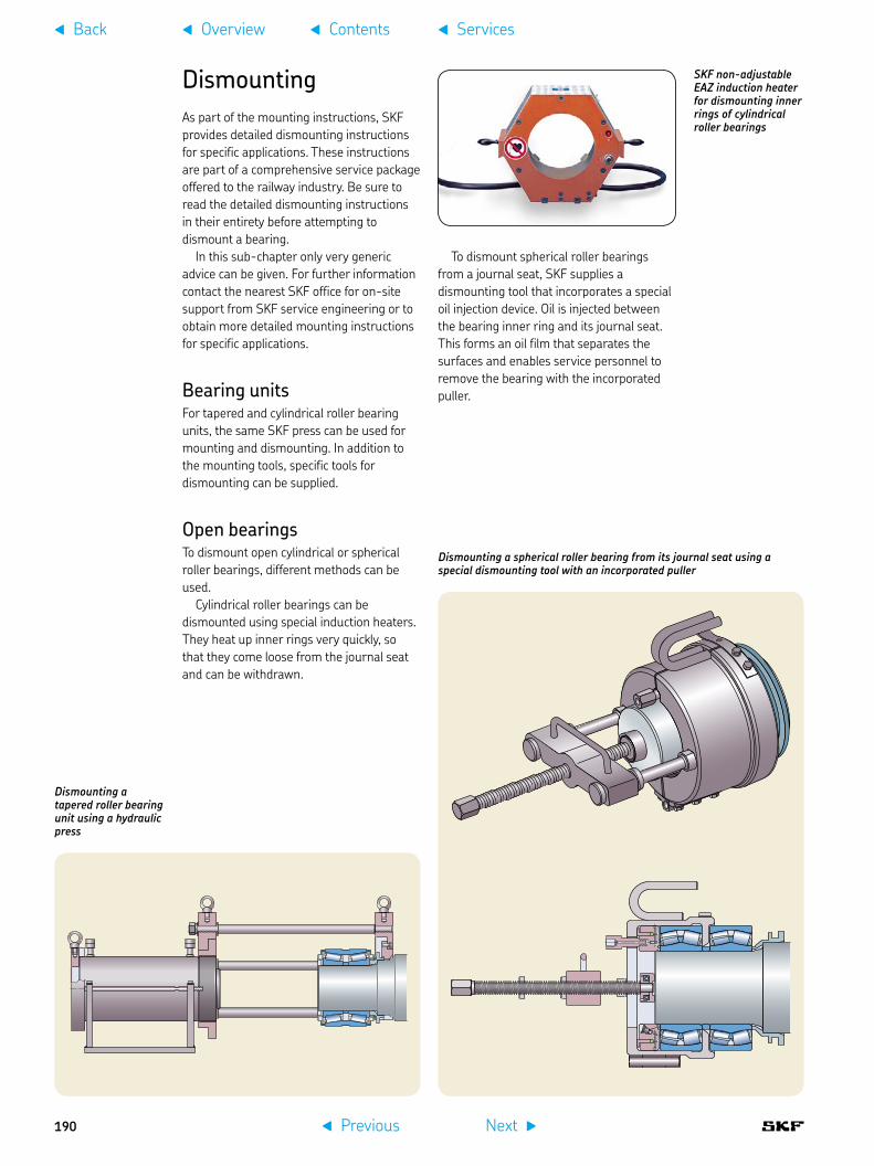
DismountingAs part of the mounting instructions, SKF provides detailed dismounting instructions for specific applications. These instructions are part of a comprehensive service package offered to the railway industry. Be sure to read the detailed dismounting instructions in their entirety before attempting to dismount a bearing.
In this sub-chapter only very generic advice can be given. For further information contact the nearest SKF office for on-site support from SKF service engineering or to obtain more detailed mounting instructions for specific applications.
Bearing unitsFor tapered and cylindrical roller bearing units, the same SKF press can be used for mounting and dismounting. In addition to the mounting tools, specific tools for dismounting can be supplied.
Open bearingsTo dismount open cylindrical or spherical roller bearings, different methods can be used.
Cylindrical roller bearings can be dismounted using special induction heaters. They heat up inner rings very quickly, so that they come loose from the journal seat and can be withdrawn.
Dismounting a tapered roller bearing unit using a hydraulic press
Dismounting a spherical roller bearing from its journal seat using a special dismounting tool with an incorporated puller
SKF non-adjustable EAZ induction heater for dismounting inner rings of cylindrical roller bearings
To dismount spherical roller bearings from a journal seat, SKF supplies a dismounting tool that incorporates a special oil injection device. Oil is injected between the bearing inner ring and its journal seat. This forms an oil film that separates the surfaces and enables service personnel to remove the bearing with the incorporated puller.
f Previous Next g
f Overview f Contentsf Back f Services
190

Preparing for dismounting in the workshop
Adjusting the dismounting tool
Dismounting the tapered roller bearing unit with the TBU press
SKF service engineering offers special solutions such as bearing unit exchange without the need to dismount the bogie or wheelset
Service engineeringSKF provides on-site service engineering, which includes a TBU exchange service. This can frequently save the cost of exchanging wheelsets.
f Previous Next g
f Overview f Contentsf Back f Services
10
191

Remanufacturing
CapabilitiesBearing remanufacturing can result in a significant reduction in CO2 emissions. Compared to the production of a new bearing, remanufacturing requires up to 90% less energy. By extending the service life of bearings, the process avoids the scrapping of many components and the unnecessary use of natural resources. In fact, remanufacturing a bearing that has a high percentage of service life left can provide substantial cost savings.
Remanufacturing is in many cases a teamwork between suppliers and customers. SKF can contribute greatly, thanks to its knowledge and experience in related matters such as diagnosis, lubrication, sealing, assembly, condition monitoring, bearing damage analysis and application engineering [38, 39, 40].
Principal optionsIn principle, remanufacturing is the process of disassembly and recovery at the component level. It can require the repair or replacement of worn out components. Parts subject to degradation which affect the performance or the expected life of the whole bearing system are replaced, like grease filling and contacting sealing systems. A remanufactured bearing or unit has to match the same customer expectations as a new one. There are quite different remanufacturing processes applied, depending on customer specification and location. For tapered roller bearing units:
dismantling, cleaning, inspection, •adjustment of the axial clearance by inserting a new defined inner ring spacer, greasing, mounting, documentation, logistic service, this process is used in Europebased on the process flow before and •after inspection, polishing or minor partial regrinding of raceways can be applied if necessary, this process is used in North Americaa complete remachining of inner and •outer ring raceways as well as new rollers, this process is used in China
In addition to the overall term “remanufacturing” and “remachining”, which includes polishing and grinding operations, some railway operators and manufacturers are using the terms “reconditioning” and “refurbishment” as well to differentiate specific requests. However, it seems that there is no global definition for these terms and they overlap and can be contradictory. When ordering services, be careful you understand what will be provided, no matter what name is associated with it.
SpecificationsThe exact specifications to be used for remanufacturing have to be agreed upon with the customer. This can be based on:
Association of American Railroads (AAR), •Manual of Standards and Recommended Practices, Section H-Part II specification of the Ministry of Railways of •the People’s Republic of China original equipment manufacturers’ (OEM) •specifications SKF specifications for axlebox bearing or •bearing unit remanufacturingindividual specifications of railway •operators and vehicle owners which are in the most cases based on one of the specifications mentioned above, plus additional requests with regard to specific operating conditions
Remanufacturing benefits
Bearing remanufacturing is a major contributing element to life cycle cost optimization.
significant cost reduction compared to new axlebox bearings•extended service life •better availability, leading to stock reduction•damage analysis and investigation of corrective actions•increased performance capability by upgrading•application feedback for improved operational and •maintenance customer technologyreduced environmental impact due to reduced waste, use of •raw material and energy consumption
f Previous Next g
f Overview f Contentsf Back f Services
192

Service centresSKF has many decades of experience in railway bearing remanufacturing. SKF offers to the railway industry a global network of specialized railway remanufacturing workshops. All work is performed at dedicated SKF remanufacturing service centres by specialists in accordance with rigorous SKF specifications and customer requirements. The remanufacturing service centres are located worldwide and cover most of the industrialized countries.
Process principleBearings that are not damaged beyond repair can be restored using appropriate procedures that can include polishing, grinding and component replacement. The applied remanufacturing process always has to meet individual customer’s specification requirements.
ExampleThe process described below illustrates the remanufacturing principle and can deviate based on customer requirements. The remanufacturing process usually begins with the transportation of railway bearings/units from the wheelset workshops to the SKF remanufacturing service centres. For example, the tapered roller bearing unit consists of two inner ring assemblies (cone assemblies), the outer ring (cup), a spacer, backing ring and seal wear rings, excluding the end cap assembly and cap bolts. The unit is dismantled, the seals are discarded and the components are placed in an agitating wash system in which the lubricant is removed from the internal rolling components by a cleaning detergent. The components are coated with a rust preventive agent and are moved to holding locations.
As soon as ambient temperature is reached after washing, external surfaces of components, such as the outer ring, seal wear rings and backing rings, are buffed and polished to remove accumulated rust and other external material build-up. This process supports the inspection process. The components are inspected for visual and dimensional requirements. Components are scrapped when they do not meet specifications, or if it is not possible to rework to meet the individual customer’s specifications.
Each bearing component is thoroughly inspected and measured for compliance to agreed specifications. These can be based on SKF or manufacturers specifications, or AAR Standards or even tighter customer specifications. Within the reconditioning process, it is imperative that each component is inspected in detail. Failure to uncover one abnormality could result in bearing failure while in service.
Inner ring assemblies and outer rings are visually inspected for wear and damage. This includes, for example, water or acidity damage (etching), or stain discolouration caused by acidity in the lubricant. Additionally, corrosion, pitting, rust, brinell
SKF remanufacturing capabilities
Asia:Nankou (Beijing), China•
Australia:Melbourne, Victoria•Perth, Western Australia•
Europe: Göteborg, Sweden•Luton, UK•Steyr, Austria•Tver, Russia •Pinerolo (Turin), Italy•
Latin America:Bogota, Colombia•
North America:Hanover, PA, USA•
f Previous Next g
f Overview f Contentsf Back f Services
10
193
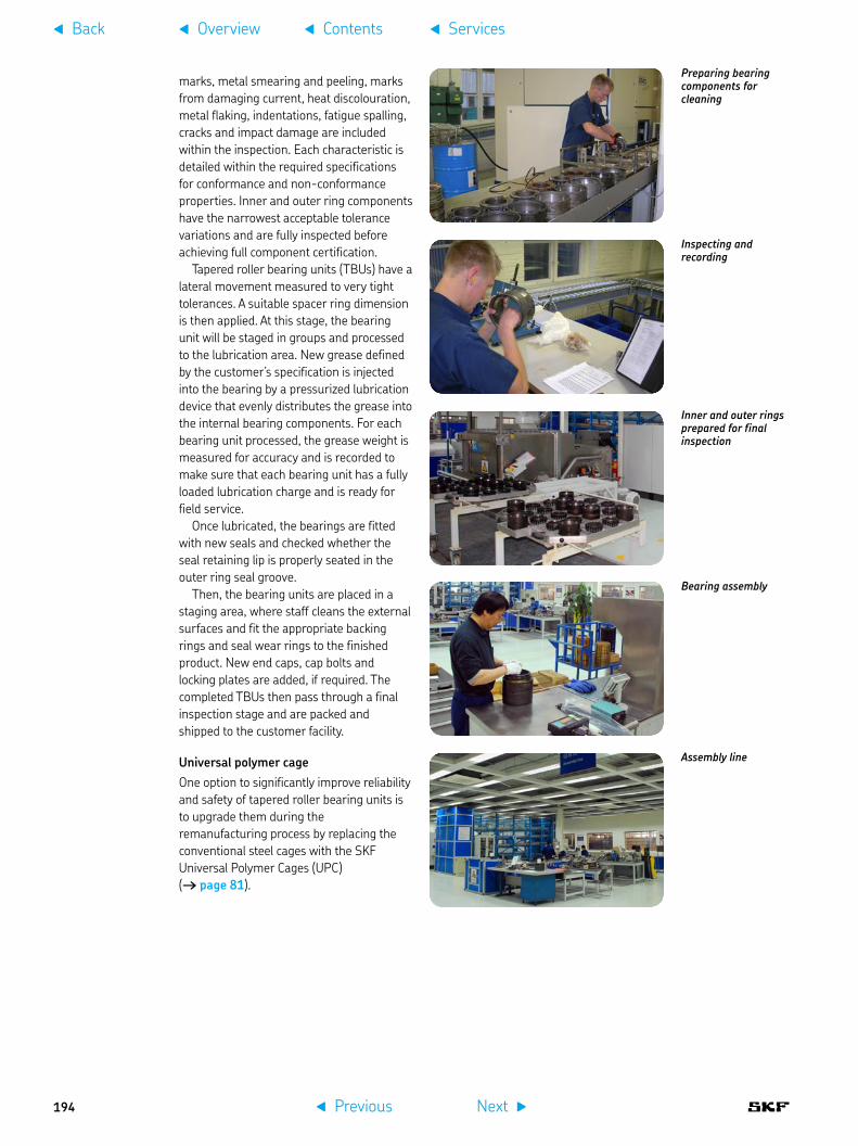
marks, metal smearing and peeling, marks from damaging current, heat discolouration, metal flaking, indentations, fatigue spalling, cracks and impact damage are included within the inspection. Each characteristic is detailed within the required specifications for conformance and non-conformance properties. Inner and outer ring components have the narrowest acceptable tolerance variations and are fully inspected before achieving full component certification.
Tapered roller bearing units (TBUs) have a lateral movement measured to very tight tolerances. A suitable spacer ring dimension is then applied. At this stage, the bearing unit will be staged in groups and processed to the lubrication area. New grease defined by the customer’s specification is injected into the bearing by a pressurized lubrication device that evenly distributes the grease into the internal bearing components. For each bearing unit processed, the grease weight is measured for accuracy and is recorded to make sure that each bearing unit has a fully loaded lubrication charge and is ready for field service.
Once lubricated, the bearings are fitted with new seals and checked whether the seal retaining lip is properly seated in the outer ring seal groove.
Then, the bearing units are placed in a staging area, where staff cleans the external surfaces and fit the appropriate backing rings and seal wear rings to the finished product. New end caps, cap bolts and locking plates are added, if required. The completed TBUs then pass through a final inspection stage and are packed and shipped to the customer facility.
Universal polymer cageOne option to significantly improve reliability and safety of tapered roller bearing units is to upgrade them during the remanufacturing process by replacing the conventional steel cages with the SKF Universal Polymer Cages (UPC) († page 81).
Preparing bearing components for cleaning
Inner and outer rings prepared for final inspection
Assembly line
Bearing assembly
Inspecting and recording
f Previous Next g
f Overview f Contentsf Back f Services
194

TrainingFrom bearing damage to asset management training, SKF provides a wide variety of training modules. SKF also offers training modules dedicated to the railway industry, either at the customer’s facility or at SKF’s facilities. The SKF training modules range from theoretical class room modules to hands-on workshops.
An example of a typical SKF training module for the railway industry is “Bearing damage”. This is an example of a training programme that SKF provides to its British railway customers. A main topic of these courses is to train them on how to examine rolling bearings for damage, and how to understand the limits of acceptability of bearings in service and possible actions to avoid bearing damage:
One-day practical course• complies with British railway standard TF/TT0025. Bearing theory •A module that provides participants with mandatory knowledge in accordance with British industry standard GM/RT2030. This modules exists in 2 versions. One provides an appreciation of how participants’ work can influence bearing operation on railway vehicles . The other one, more advanced, provides deeper knowledge in understanding the importance of lubrication, clearance and final checks when setting up a wheelset bearing assembly for railway service.
Training and assessment services
competence assessments in bearing-•related activities in accordance with industry standardspractical and theoretical training in •bearing subjects in accordance with industry standardstailor-made training in bearing-related •matterstraining in bearing damage and •examination techniquesquality audits of industry bearing facilities, •products and services, accredited to ISO 9001, ISO 14001, OHSAS 18001 and IRIS. Audited by major UK rail companies.
f Previous Next g
f Overview f Contentsf Back f Services
10
195

Application11 sHigh-speed vehicles . . . . . . . . . . 198
Diesel and electric locomotives . 202
Diesel and electrical units, passenger coaches . . . . . . . . . . . 204
Metro cars, light rail vehicles and tramways . . . . . . . . 206
Freight cars . . . . . . . . . . . . . . . . . 208
f Previous Next g
f Overview f Contentsf Back
196
Applications
Axleboxes are one of the safety-critical subsystems in railway vehicles. SKF has a unique experience in developing, designing, application engineering and manufacturing of axleboxes, bearings, bearing units as well as mechatronics, seals and lubrication systems. The following pages include an overview of designs currently in use and some of the major applications where SKF’s large range of solutions are incorporated.
In most cases, axleboxes are tailored to the specifications of the manufacturers and the requirements of the railway operators. Some axleboxes are used for the same or similar applications of bogie supplier platforms, which are deployed for different vehicles and operators.
In case of freight cars, more bogie standardization is applied and the same or very similar axleboxes are fitted for different freight car types and operators in several countries.
Some brief comments regarding the applications listed on the following pages:
SKF axleboxes and bearings are used •worldwide in all types of railway rolling stock. There is an ongoing global trend to use ready-to-mount bearing units that are lubricated in the factory and have an integrated sealing system on both sides.
More and more axleboxes are equipped •with mechatronic systems to measure operational parameters and monitor bogie condition.Some vehicles are equipped with •lubrication systems like wheel flange lubrication solutions to reduce friction and wear between wheel and rail. Service packages are tailored to the •manufacturer’s and operator’s needs including testing, mounting, global after-market service, remanufacturing and logistic services.SKF offers a unique global network of •sales, application and service engineers who work on domestic and international projects and are in close contact with manufacturers and operators.SKF offers tailor-made axlebox solution •packages that are based on individual customer’s requirements.
f Previous Next g
f Overview f Contentsf Back f Applications
197
11

High-speed vehiclesFor medium distances of several hundred kilometres or even more, high-speed railways offer an attractive, environmentally friendly alternative to aircraft and cars. In most cases, trains directly serve city centres without time consuming shuttle transfers or driving on crowded motorways and encountering any parking problems.
There are various definitions of high-speed trains. Usually these trains have a maximum speed of more than 200 km/h, but there are other categories that define
f Previous Next g
f Overview f Contentsf Back f Applications
198

contributes to less dynamic forces on the vehicles, bogies and tracks.
In most cases, either tapered or cylindrical roller bearing units are used. Because of the high-speed, labyrinth seals are applied. In addition, SKF offers a unique package comprising axleboxes, AXLETRONIC sensors, bogie condition monitoring systems and wheel flange lubrication systems plus service engineering support including remanufacturing options [41].
travel at more than 250 km/h. Achieving very high-speeds and long-distance maintenance intervals are typical requirements for high-speed trains.
Today, 2-axle powered and non-powered bogie designs are used. In some cases, power units, like special locomotives, are located at one or both ends and haul the train. In more and more applications, a high-speed train is composed of several coaches with only a certain number or all of the bogies powered. This configuration helps to achieve a lower axleload, which
f Previous Next g
f Overview f Contentsf Back f Applications
11
199

Chinese railway high-speed CRH5Operated by China Railways, manufactured by Alstom Changchun Railway Vehicles Co., Ltd., power rating 5 500 kW, max. speed 250 km/h
SKF axleboxes equipped with tapered roller bearing units (TBUs) and AXLETRONIC sensors
Photo: Poeloq
German Deutsche Bahn ICE T tilting trainOperated by Deutsche Bahn DB and Austrian railways ÖBB, vehicle types German ICE T class 411 and 415 and Austrian 4011 trains like German class 411, bogie manufacturer is Alstom, power rating 411 trains 4 000 kW and 415 trains 3 000 kW, max. speed 230 km/h
SKF axleboxes equipped with tapered roller bearing units (TBUs)
Photo: DB AG/Christian Bedeschinski
Italian ETR 500 FrecciarossaOperated by Trenitalia, before Ferrovie dello Stato (FS), vehicle type ETR 500 and ETR 500 P, manufactured by Trevi (a consortium of Alstom, Bombardier, AnsaldoBreda and Firema), power rating 8 800 kW in total, max. speed 300 km/h
SKF axleboxes equipped with tapered roller bearing units (TBUs) and AXLETRONIC sensors
Photo: StuporesMundi
Austrian ÖBB railjet passenger coachesOperated by Austrian Federal Railways (ÖBB), manufactured by Siemens, max. speed 230 km/h
SKF axleboxes equipped with tapered roller bearing units (TBUs)
Photo: ÖBB
Chinese railway high-speed CRH1A and CRH1BOperated by China Railways, China railway high-speed CRH, manufactured by Bombardier Sifang (Qingdao) Transportation Ltd, power rating CRH1A 5 300 kW and CRH1B 11 000 kW, max. speed CRH1A 200 km/h and CRH1B 250 km/h
SKF axleboxes equipped with tapered roller bearing units (TBUs)
Photo: Bvehk
Czech Pendolino tilting trainOperated by České Dráhy (ČD), manufactured by Alstom, power rating 3 920 kW, max. speed 230 km/h
SKF axleboxes equipped with tapered roller bearing units (TBUs) and AXLETRONIC sensors
Photo: Ceské Dráhy
f Previous Next g
f Overview f Contentsf Back f Applications
200

Spanish AVE S-103 / Siemens Velaro EOperated by Red Nacional de los Ferrocarriles Españoles (RENFE), manufactured by Siemens, power rating 8 800 kW, max. speed 350 km/h
SKF axleboxes equipped with cylindrical roller bearing units (CRUs)
Photo: Bonaventura Leris
Taiwanese Shinkansen 700 T trainsOperated by Taiwan Shinkansen Company (TSC) and manufactured by Kawasaki Heavy Industries (KHI), Nippon Sharyo and Hitachi as a Japanese consortium, power rating 10 260 kW in total, max. speed 300 km/h
SKF tapered roller bearing units (TBUs)
Photo: THSRC
Italian Pendolino tilting trainsOperated by Trenitalia, manufactured by Alstom, power rating 5 500 kW in total, max. speed 250 km/h, in addition similar trains are operating in several countries and owned by different operators
SKF axleboxes equipped with compact tapered roller bearing units (CTBUs) and AXLETRONIC sensors
Photo: Chriusha
Norwegian Flytoget airport trainsOperated by Flytoget AS before NSB Gardermobanen AS, manufactured by Adtranz today Bombardier, power rating 2 645 kW, max. speed 210 km/h
SKF axleboxes equipped with tapered roller bearing units (TBUs)
Photo: Bombardier
Turkish class HT65000 trainsOperated by Turkish State Railways (TCDD), manufactured by CAF, power rating 4 800 kW, max. speed 250 km/h
SKF axleboxes equipped with tapered roller bearing units (TBUs) and AXLETRONIC sensors
Photo: CAF
Spanish Talgo 350 trainsOperated by Renfe, manufactured by Talgo and Bombardier, power rating 4 000 kW, max. speed 330 km/h
SKF tapered roller bearing units (TBUs)
Photo: Talgo
f Previous Next g
f Overview f Contentsf Back f Applications
11
201
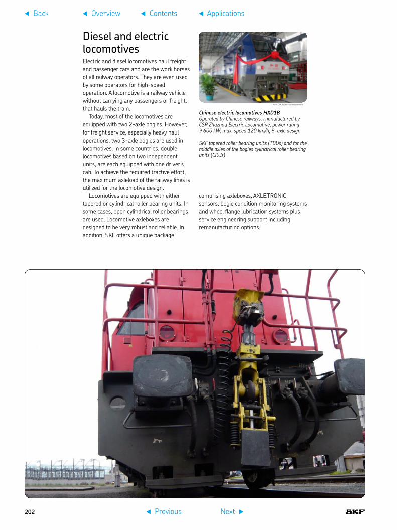
Diesel and electric locomotivesElectric and diesel locomotives haul freight and passenger cars and are the work horses of all railway operators. They are even used by some operators for high-speed operation. A locomotive is a railway vehicle without carrying any passengers or freight, that hauls the train.
Today, most of the locomotives are equipped with two 2-axle bogies. However, for freight service, especially heavy haul operations, two 3-axle bogies are used in locomotives. In some countries, double locomotives based on two independent units, are each equipped with one driver’s cab. To achieve the required tractive effort, the maximum axleload of the railway lines is utilized for the locomotive design.
Locomotives are equipped with either tapered or cylindrical roller bearing units. In some cases, open cylindrical roller bearings are used. Locomotive axleboxes are designed to be very robust and reliable. In addition, SKF offers a unique package
comprising axleboxes, AXLETRONIC sensors, bogie condition monitoring systems and wheel flange lubrication systems plus service engineering support including remanufacturing options.
Photo: CSR Zhuzhou Electric Locomotive
Chinese electric locomotives HXD1BOperated by Chinese railways, manufactured by CSR Zhuzhou Electric Locomotive, power rating 9 600 kW, max. speed 120 km/h, 6-axle design
SKF tapered roller bearing units (TBUs) and for the middle axles of the bogies cylindrical roller bearing units (CRUs)
f Previous Next g
f Overview f Contentsf Back f Applications
202

Photo: Passiondutrain
Photo: Thomas Wolf
Photo: Orlovic
Photo: Subway06
Photo: Kabelleger
Italian E464 electric locomotivesOperated by Trenitalia, manufactured by Bombardier, power rating 3 000 kW, max. speed 160 km/h
SKF axleboxes equipped with tapered roller bearing units (TBUs) and AXLETRONIC sensors
Korean class 8200 electric locomotivesOperated by Korail, manufactured by Rotem based on Siemens design, power rating 5 200 kW, max. speed 150 km/h
SKF axleboxes equipped with cylindrical roller bearing units (CRUs)
French class BB 475000 diesel locomotivesOperated by Fret SNCF, manufactured by Alstom, power rating on rail 1 600 kW, max. speed 120 km/h
SKF axleboxes equipped with tapered roller bearing units (TBUs)
Swedish electric iron ore locomotivesOperated by Luossavaara-Kiirunavaara Aktiebolag (LKAB), manufactured by Bombardier, before ADtranz, one locomotive consists of two units each with six axles, power rating 2 x 5 400 kW, max. speed 80 km/h
SKF axleboxes equipped with cylindrical roller bearing units (CRUs)
German electric locomotives 101, 145 and 152The locos 101 are operated by DBAG, manufactured by ADtranz, today Bombardier, power rating 6 400 kW, max. speed 220 km/h. The locos 145 and 152 are used by DB Schenker, and have different technical data but a very similar axlebox design. The locos 152 were manufactured by Krauss Maffei, today Siemens.
SKF axleboxes equipped with cylindrical roller bearing units (CRUs)
UK class 67 diesel locomotivesOperated by DB Schenker Rail (UK) before EWS, manufactured by Alstom based on a GM licence, power rating 1 850 kW, max. speed 200 km/h
SKF axleboxes equipped with tapered roller bearing units (TBUs) and AXLETRONIC sensors
Photo: Phil Sangwell
f Previous Next g
f Overview f Contentsf Back f Applications
11
203

Diesel and electrical units, passenger coachesIn passenger transportation, more and more electric and diesel multiple units are used for long and short distance service, especially where shorter trains operating with shorter intervals are needed. In addition, there are trains composed of one or two locomotives and passenger coaches. These coaches can be designed as sleeping or restaurant cars. Because of the special equipment, restaurant cars have a higher mass and axleload than similar standard passenger coaches.
These vehicles are mainly equipped with two 2-axle bogies. Some trains are composed of articulated vehicle bodies by using Jacobs bogie designs. This design connects the bodies by a common bogie. There is a very large variety of bogie designs
used in different applications tailored for specific operator’s and supplier’s request.
The vehicles are equipped with either tapered or cylindrical roller bearing units. To achieve a lower mass and reduce energy consumption, light designs are preferred. This also influences the design of axleboxes. Because of the different bogie designs, various axlebox designs are needed to fulfil a typical customer’s specifications. SKF offers a unique package comprising axleboxes, AXLETRONIC sensors, bogie condition monitoring systems and wheel flange lubrication systems plus service engineering support including remanufacturing options.
f Previous Next g
f Overview f Contentsf Back f Applications
204

Photo: Bombardier
Photo: Siemens
UK Electrostar electric multiple unitsOperated by several British railway companies, manufactured by ADtranz today Bombardier, power rating from 746 to 1 680 kW, max. speed 160 km/h
SKF axleboxes equipped with tapered roller bearing units (TBUs) and AXLETRONIC sensors
Swedish Regina electric trainsOperated by several Swedish operators, manufactured by Bombardier, power rating 1 590 kW up to 2 120 kW, max. speed 180 up to 200 km/h
SKF axleboxes equipped with tapered roller bearing units (TBUs)
Spanish 599 tilting diesel trainsOperated by RENFE Operadora, manufactured by CAF, power rating 1 528 kW, max. speed 160 km/h, gauge 1 668 mm
SKF axleboxes equipped with compact tapered roller bearing units (CTBUs) and AXLETRONIC sensors
Belgium Desiro ML electric trains for RER BrusselsOperated by SNCB, manufactured by Siemens, power rating 2 000 kW, max. speed 160 km/h
SKF axleboxes equipped with tapered roller bearing units (TBUs) and AXLETRONIC sensors
Austrian Talent electric trainsOperated by ÖBB, manufactured by Bombardier, power rating from 1 440 to 1 520 kW, max. speed 140 km/h
SKF axleboxes equipped with cylindrical roller bearing units (CRUs)
Photo: Yrithinnd
Photo: Janderk1968
Photo: Veolia transports
Hungarian Flirt electric trainsOperated by MÁV, manufactured by Stadler Rail, similar trains are used by operators in several European countries, power rating 2 000 kW, max. speed 160 km/h
SKF tapered roller bearing units (TBUs)
Photo: uzo19
f Previous Next g
f Overview f Contentsf Back f Applications
11
205

Metro cars, light rail vehicles and tramwaysMass transit railways are becoming an important alternative to cars in the crowded streets of cities and suburban areas. Vehicles like suburban trains, metros or underground and tramways operate world-wide. Sometimes, there are very similar vehicle designs used which can be applied for suburban, metro, light rail vehicles and tramway operations. The accurate definition is, in most cases, dependent on the legal definition that can be based on railway or tramway standards.
In comparison to other application fields, these vehicles can be designed based on very different technical concepts like low-floor, medium high floor and standard floor designs. Some vehicles are articulated by composing very different body section lengths. As a consequence, different bogie designs or single wheel arrangements are used.
These vehicles are equipped with either tapered or cylindrical roller bearing units. In some cases, open cylindrical roller bearings are used. To achieve a lower mass and reduce energy consumption, light designs are preferred. This challenge is also applicable to the design of axleboxes or axlebridges. These designs are tailored to the different customers’ requests. In addition, SKF offers a unique package comprising axleboxes, AXLETRONIC sensors, bogie condition monitoring systems and wheel flange lubrication systems plus service engineering support including remanufacturing options.
f Previous Next g
f Overview f Contentsf Back f Applications
206

Austrian Linz CityrunnerOperated by Linz Linien, manufactured by Bombardier, total power rating 600 kW, max. speed 70 km/h, gauge 900 mm
SKF axleboxes equipped with tapered roller bearing units (TBUs) and AXLETRONIC sensors
Photo: Dralon
French Paris metro MF 2000Operated by RATP, manufactured by Bombardier and Alstom, power rating 1 800 kW, max. speed 70 km/h
SKF axleboxes equipped with tapered roller bearing units (TBUs) and AXLETRONIC sensors
Photo: Pline
Chinese Shanghai metro line 7 and 9Operated by Shanghai Shentong Metro Group, manufactured by Changchun Bombardier Railway Vehicles, max speed 80 km/h
SKF axleboxes equipped with tapered roller bearing units (TBUs) and AXLETRONIC sensors
Photo: Bombardier
Spanish Barcelona metro series 5000Operated by Metro Barcelona (TMB), manufactured by CAF, total power rating 2 000 kW, max. speed 80 km/h
SKF compact tapered roller bearing units (CTBUs)
Photo: Carlos L´H
Swedish Stockholm metro C20Operated by MTR Stockholm, manufactured by Bombardier, total power rating 1 000 kW, max. speed 90 km/h
SKF axleboxes equipped with compact tapered roller bearing units (CTBUs)
Photo: Bombardier
USA S70 light rail vehiclesOperated by Houston, San Diego, Charlotte, Portland and Norfolk, manufactured by Siemens, total power rating 520 to 700 kW, max. speed 120 km/h, max. operational speed 88,5 km/h (55 mph) up to 106 km/h (66 mph)
SKF axlebridges equipped with tapered roller bearings
Photo: Siemens
f Previous Next g
f Overview f Contentsf Back f Applications
11
207

Freight carsRailway freight operation requires technical and economical solutions with low life cycle cost. Consequently, axlebox bearings requiring minimal maintenance are needed. Axlebox bearings must be able to operate under fully loaded cars and under extreme climate conditions.
Today, most freight cars are equipped with two 2-axle bogies. For heavy haul operations, two 3-axle bogies are used. On the other hand, 2-axle freight cars are operating as a cost-effective alternative, especially for lower cargo weight. There are axlebox designs used as well as adapter style applications († page 39). Achieving very long operational time and maintenance intervals are typical requirements for freight cars.
For bogies like Y25, full bore axleboxes and cylindrical roller bearings or spherical roller bearings are used. Freight cars with three-piece bogie designs, typically tapered
roller bearing units (TBUs) and adapters, are used. The TBUs incorporate a contacting seal to avoid contamination. To achieve low life cycle cost, minimal maintenance and cost-effective bearing and axlebox designs are required. SKF offers a unique package comprising axleboxes and bearing units plus service engineering support including remanufacturing options.
f Previous Next g
f Overview f Contentsf Back f Applications
208

Australian iron ore freight carsOperated by Pilbara Rail, manufactured by Bradken, axleload 35 tonnes, max. speed 80 km/h
Equipped with SKF compact tapered roller bearing units (CTBUs)
Chinese freight carsOperated by Chinese railways, axleload 21 tonnes, upgraded design axleload 25 tonnes, max. speed 120 km/h
Equipped with SKF compact tapered roller bearing units (CTBUs)
European freight cars equipped with Y25 bogiesThis standard design is widely used in Europe by the main freight operators, axleload 22,5 up to 25 tonnes, max. speed up to 120 km/h
SKF axleboxes equipped with cylindrical roller bearings
Swedish Malmbanan iron ore freight cars, trains 1-8Operated by Luossavaara-Kiirunavaara Aktiebolag (LKAB), manufactured by Kockums Industrier, bogie type: AMSTED Motion Control, axleload 31 tonnes, max. speed 60 km/h loaded and 70 km/h unloaded
Equipped with SKF tapered roller bearing units (TBUs)
Photo: Kockums Industrier
Russian freight carsOperated by Russian Railways RZD, manufactured by UralVagonZavod (UVZ), vehicle type 12-132-03 Gondola freight cars, bogie type 18-578, axleload 23,5 tonnes, max. speed 120 km/h, gauge 1 520 mm
Equipped with SKF compact tapered roller bearing units (CTBUs)
European freight cars equipped with UIC axleboxesThis standard design is used in 2-axle freight cars in Europe. Also 3- and 4-axle freight cars are equipped with similar axleboxes, axleload 22,5 up to 25 tonnes, max. speed up to 120 km/h
SKF axleboxes equipped with cylindrical roller bearings
f Previous Next g
f Overview f Contentsf Back f Applications
11
209

Keywords3-axle locomotive bogie designs. . . . . . 383-piece bogie designs. . . . . . . . . . . . . . 39
Aabrasive wear . . . . . . . . . . . . . . . . . . . . 128adhesive wear . . . . . . . . . . . . . . . . . . . 128Arizona dust test . . . . . . . . . . . . . . . . . 100automatic train control systems . . . . . . 143axial bearing load . . . . . . . . . . . . . . . . . 111axlebox bearing monitoring . . . . . . . . . 158axlebox materials . . . . . . . . . . . . . . . . . 60axleload . . . . . . . . . . . . . . . . . . . . . . . . 29AXLETRONIC odometers . . . . . . . . . . . 145
Bbearing clearance . . . . . . . . . . . . . . . . . 118bearing steel . . . . . . . . . . . . . . . . . . . . 77
Ccage modelling and calculation . . . . . . . 120certificates . . . . . . . . . . . . . . . . . . . . . . 22cold mounting . . . . . . . . . . . . . . . . . . . 185condition monitoring sensors . . . . . . . . 148corrosion . . . . . . . . . . . . . . . . . . . . . . . 129cracking . . . . . . . . . . . . . . . . . . . . . . . . 133CRU plus design . . . . . . . . . . . . . . . . . . 94current leakage . . . . . . . . . . . . . . . . . . 131current transition . . . . . . . . . . . . . . . . . 140
Ddampers . . . . . . . . . . . . . . . . . . . . . . . . 35direction of movement . . . . . . . . . . . . . 142discolouration . . . . . . . . . . . . . . . . . . . . 134dynamic testing . . . . . . . . . . . . . . . . . . 70
Eelectrical erosion . . . . . . . . . . . . . . . . . 131equivalent bearing load . . . . . . . . . . . . 111
Ffalse brinelling . . . . . . . . . . . . . . . . . . . 130fatigue . . . . . . . . . . . . . . . . . . . . . . . . . 127FEM modelling . . . . . . . . . . . . . . . . . . . 62fractures . . . . . . . . . . . . . . . . . . . . . . . . 133fretting corrosion . . . . . . . . . . . . . . . . . 129frictional corrosion . . . . . . . . . . . . . . . . 129
Ggearbox monitoring . . . . . . . . . . . . . . . 159GPS track profiling . . . . . . . . . . . . . . . . 161grease . . . . . . . . . . . . . . . . . . . . . . . . . 82
Hhotbox detection . . . . . . . . . . . . . . . . . . 48hot mounting . . . . . . . . . . . . . . . . . . . . 186
Iimpulse wheel designs . . . . . . . . . . . . . 142indentation . . . . . . . . . . . . . . . . . . . . . . 132independent wheels . . . . . . . . . . . . . . . 30induction heater . . . . . . . . . . . . . . . . . . 186
JJacobs bogie . . . . . . . . . . . . . . . . . . . . . 26
Mmanufacturing excellence . . . . . . . . . . . 22multi-functional sensor . . . . . . . . . . . . 149
Ooverload . . . . . . . . . . . . . . . . . . . . . . . . 132
Pplastic deformation . . . . . . . . . . . . . . . . 132polymer cage . . . . . . . . . . . . . . . . . . . . 81polymer spacer . . . . . . . . . . . . . . . . . . . 80primary springs . . . . . . . . . . . . . . . . . . 32
RR3 test rig . . . . . . . . . . . . . . . . . . . . . . 102radial bearing load . . . . . . . . . . . . . . . . 110radial steering principles. . . . . . . . . . . . 27railway gauge . . . . . . . . . . . . . . . . . . . . 29rotational speed detection . . . . . . . . . . 140rubber spring . . . . . . . . . . . . . . . . . . . . 34
Sseal designs . . . . . . . . . . . . . . . . . . . . . 78seal friction test . . . . . . . . . . . . . . . . . . 100secondary springs . . . . . . . . . . . . . . . . 32Six Sigma . . . . . . . . . . . . . . . . . . . . . . . 22SKF @ptitude Observer . . . . . . . . . . . . 162smearing . . . . . . . . . . . . . . . . . . . . . . . 128static testing . . . . . . . . . . . . . . . . . . . . . 70steel spring . . . . . . . . . . . . . . . . . . . . . . 33
Ttemperature detection . . . . . . . . . . . . . 148THISBE test rig. . . . . . . . . . . . . . . . . . . 104traction motor monitoring . . . . . . . . . . 159
VV2F grease test . . . . . . . . . . . . . . . . . . 101vehicle gauge . . . . . . . . . . . . . . . . . . . . 47vibration corrosion . . . . . . . . . . . . . . . . 130vibration detection . . . . . . . . . . . . . . . . 149voltage NPN . . . . . . . . . . . . . . . . . . . . . 141voltage PNP . . . . . . . . . . . . . . . . . . . . . 141voltage Push-Pull . . . . . . . . . . . . . . . . . 141voltage transition . . . . . . . . . . . . . . . . . 140
Wwater spray test . . . . . . . . . . . . . . . . . . 100wear . . . . . . . . . . . . . . . . . . . . . . . . . . . 128wheel diameter . . . . . . . . . . . . . . . . . . 30wheelset arrangement classification . . . 28wheelset monitoring . . . . . . . . . . . . . . . 157
Further keywords are mentioned as chapters and subchapters in the contents († page 4 and page 5).
Index
f Previous Next g
f Overview f Contentsf Back
210

Albert, M., Kuře, G.: [1] Wälzlager in Schienenfahrzeugen. ZEV-Glasers Annalen 107 (1983) 8/9, pp. 326–336.Illmann, A., Obst, H. K.: [2] Wälzlager in Eisenbahnwagen und Dampflokomotiven. Berlin: Verlag von Wilhelm Ernst und Sohn 1957.Jürgensmeyer, W.: [3] Die Wälzlager. Berlin: Verlag von Julius Springer 1937.Laubenheimer, G.: [4] Kugel- und Rollenlager für Eisenbahnfahrzeuge unter Berücksichtigung der Wälzlagerversuchsbauarten der Deutschen Reichsbahn. Sonderausgabe des Vereines Deutscher Ingenieure. Berlin: VDI-Verlag 1925.Kuře, G.: [5] More than 100 years of energy saving solutions. SKF Evolution magazine (2008) 1, p. 40.Kuře, G., Defossez, M.: [6] High-speed in railways. SKF Evolution magazine (2008) 3, pp. 21–26.Gedenk, V.: [7] Hydrosprings for application in railway vehicles as primary suspension. 16th International conference PRORAIL 2003.Baur, K. G.: [8] Drehgestelle – Bogies. Freiburg: EK-Verlag (2009) ISBN 978-3-88255-147-1.Haigermoser, A.: [9] Schienenfahrzeuge. Vorlesungsskriptum (2002) Technical University Graz.Iwnicki, S.: [10] Handbook of Railway Vehicle Dynamics. Boca Raton: Taylor & Francis 2006.Kuře, G.: [11] Electrically insulated rolling bearings in railway vehicles. English reprint. Neue Bahn (1989) 4, pp. 26–34.Kuře, G., Palmetshofer, W.: [12] Electrically insulated bearings. SKF Evolution magazine (1996) 3, pp. 22–24.Kuře, G., Charrier, F., Gouel, X.: [13] New axlebox concept for heavy loads. SKF Evolution magazine (2005) 4, pp. 24–27.Kuře, G.: [14] Compact and light axlebox solutions. 2nd International conference on railway bogies. Budapest 1992.Bertorelli, D.: [15] Application of SKF “Tapered bearing units” TBU from the high-speed to suburban trains axle-boxes. 2nd International conference on railway bogies. Budapest 1992.
Defossez, M., Kuře, G., Martinetti, M.: [16] The Compact TBU, a new concept in axlebox bearing units. SKF Evolution magazine (2002) 1, pp. 26–30.Kuře, G., Martinetti, M.: [17] Compact taper roller bearing lives up to his name. SKF Evolution magazine (2004) 3, pp. 26–30.Kuře, G., Liang, B., Martinetti, M., [18] Skiller, J.: Polymers enhance railway axlebox bearings. SKF Evolution magazine (1998) 4, pp. 27–31.Kuře, G., Schmiechen, R., Rode, W.: [19] Increased safety and reliability with axlebox bearings equipped with polymer cages. ZEV rail Glasers Annalen 126 (2002) 8, pp. 324–330.Kuře, G., Loose, M.: [20] The universal polymer cage. SKF Evolution magazine (2006) 2, pp. 25–26.Kuře, G., Gao, G.: [21] SKF sets new standards in China. SKF Evolution magazine (2007) 1, pp. 28–30.Kuře, G., Skiller, J.: [22] Testing standards set for railway bearings. SKF Evolution magazine (1997) 3, pp. 24–27.Kuře, G.: [23] Tests, test runs and applications of rolling bearings in railway vehicles. ZEV Glasers Annalen 113 (1989) 6–7, pp. 313–322.Hutchings, T.: [24] Testing times for greases. SKF Evolution magazine (1996) 4, pp. 22-24.Liang, B.: [25] Berechnungsgleichungen für Reibmomente in Planetenwälzlagern. Ruhr-Universität Bochum. Fakultät für Maschinenbau, Institut für Konstruktionstechnik. Schriftenreihe Heft 92.3.Kerry, M., Peterson, L., Cagnasso, R.: [26] An Atlas of railway axle bearing defects including guidelines on how to examine bearings and overhaul practice. SKF (2008).Kuře, G., Martinez, V.: [27] Covering the distance with SKF Axletronic odometers. SKF Evolution magazine (2009) 4, pp. 21–24.Kuře, G., Martinetti, M.: [28] New sensor solutions for railways. SKF Evolution magazine (2005) 3, pp. 25–27.
Kuře, G., Martinetti, M., Moretti, R.: [29] Sensors for railway bearing units. SKF Evolution magazine (2002) 3, pp. 24–26.Kuře, G., Schmiechen, R.: [30] Solutions for railway bogie condition monitoring. SKF Evolution magazine (2010) 1, pp. 25–27.Kuře, G.: [31] Condition monitoring: the apotheosis of maintenance. International Railway Journal 49 (2009) 5, pp. 42–43.Kuře, G., Skiller, J.: [32] Added safety for today’s railway industry. SKF Evolution magazine (2001) 1, pp. 21–24.Friesen, U., Wach, J-J., Schuhmacher, J., [33] Schmiechen, R.: Laufwerksüberwachung als integraler Bestandteil eines Bremssteuer- und Gleitschutzsystems zur Erfüllung der Anforderungen sowohl der TSI High Speed als auch der präventiven Erkennung von Schäden und Verschleiß. ZEVrail 135 (2011) 1/2, pp. 36–45.Kuře, G., Vicarage, A.: [34] High pressure and slow movement ideal for plain bearings. SKF Evolution magazine (2001) 4, pp. 21–24.Kuře, G., Herz, R.: [35] SKF solution for railway articulation joints. SKF Evolution magazine (2008) 1, pp. 21–24.Kuře, G., Schnappenberger, K.: [36] Wheel flange lubrication for railways. SKF Evolution magazine (2008) 4, pp. 28–31.Tietz, A., Schnappenberger, K.: [37] SKF intelligent wheel flange lubrication for railway systems. 8th International conference on contact mechanics and wear of rail/wheel systems. Firenze 2009.Kerry, M.: [38] Wheelset maintenance… on a roll. International Railway Journal 50 (2010) 5, pp. 35–38.Kuře, G., Rowcliffe, M.: [39] Service engineering for Australian railways. SKF Evolution magazine (2004) 4, pp. 28–31.Kuře, G., Price, P.: [40] High quality railway bearing service at RBI. SKF Evolution magazine (2002) 2, pp. 24–27.Kuře, G.: [41] High-speed operation. SKF Evolution magazine (1995) 4, pp. 24–27.
References
f Previous Next g
f Overview f Contentsf Back
211

f Previous Next g
f Overview f Contentsf Back
212

f Previous Next g

f Previous Next g

f Previous Next g

www .skf .com