Railway Technology Review - Eurailpress
36
September 2018 ISSN 0013-2845 ▸ High-speed systems ▸ Hybrid drives ▸ Predictive maintenance ▸ Ground penetrating radar Railway Technology Review ETR INTERNATIONAL EDITION
-
Upload
khangminh22 -
Category
Documents
-
view
0 -
download
0
Transcript of Railway Technology Review - Eurailpress
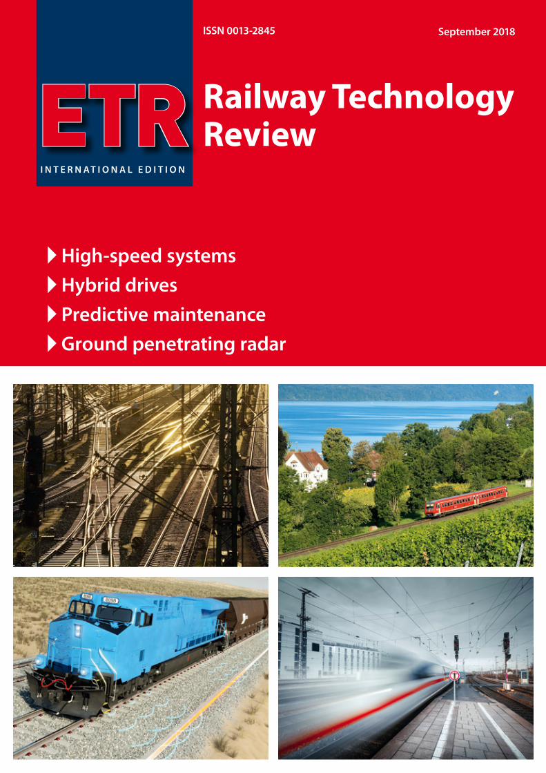
September 2018ISSN 0013-2845
High-speed systems Hybrid drives Predictive maintenance Ground penetrating radar
Railway Technology ReviewETR
I N T E R N A T I O N A L E D I T I O N
September 18 ndash 21 2018Hall 21 middot Booth 404Mobility for Tomorrow
Industry 40 is also revolutionizing railway technology Schaeffler is a strong development partner at your side who is intentionally following this track Our comprehensive understanding of systems means we can offer the ideal solution for any challenge in the railway sector From conventional bearings and complete drive systems through to condition-based monitoring with intelligent software and cloud connection You can find out more at InnoTrans Till then wwwschaefflerdeRailway
921019_Bahn_Image_A4_Messe_EN_NEUindd 1 07082018 114119
Contents
3ETR | INTERNATIONAL EDITION | 22018wwweurailpressdeetr
16
Advertiserrsquos IndexBerlin Partner fuumlr Wirtschaft und Technologie GmbH Berlin 17
DVV Media Group GmbH Hamburg 22
Frauscher Sensortechnik GmbH St Marienkirchen15
ground control GmbH Muumlnchen 19
MTU Friedrichshafen GmbH Friedrichshafen IBC
Rex Industrie-Produkte Vellberg 27
Schaeer Technologies GmbH amp Co KG Schweinfurt IFC
Vossloh AG Werdohl OBC
Wirthwein AG Creglingen11
Railway Technology Review
September 2018
A publication of
INTERNATIONAL EDITION
ETR
DVV Media GroupDeutscher Verkehrs-Verlag
Publishing house
DVV Media Group | EurailpressPostbox 10 16 09 D-20010 HamburgHeidenkampsweg 73-79 D-20097 Hamburgwwweurailpressdeetr
Managing DirectorCEOMartin Weber
Publishing DirectorManuel Bosch+49 40 237 14-155 | manuelboschdvvmediacom
Managing EditorUrsula Hahn+49 6203 661 9620 | ursulahahndvvmediacom
Advertising Director EurailpressSilke Haumlrtel+49 40 23714-227 | silkehaerteldvvmediacom
Marketing DirectorMarkus Kukuk+49 40 23714-291 | markuskukukdvvmediacom
GracLayout TZ-Verlag amp Print GmbH Roszligdorf
TO THE COVER
Picture creditsAbove left Deutsche Bahn AG Volker Emersleben
16 The treasure of the Data Lake ndash Predictive maintenance for vehicle eetsMathias Haimerl
20 Digital twin serving rail infrastructurePayam Amini
23 Ground Penetrating Radar ndash Basis for eective Track MaintenanceGiuseppe Staccone Ullrich Martin Sebastian Rapp David Camacho Moritz Schebuch
28 How Distributed Acoustic Sensing supports condition based maintenance strategiesMartin Rosenberger
32 Smart Tamping ndash Fields of Application of the Turnout Tamping Assistance SystemFlorian Auer David Buchbauer Martin Buumlrger Georg Jodlbauer Andreas Theiszlig Gerald Zauner
4 An eventful autumn for the railway industryAngela Berger
5 The next mobility revolutionBen Moumlbius
6 High-speed systems Four railways in EuropeEberhard Jaumlnsch
12 Quiet clean fast use of MTU hybrid drives on the Lake Constance belt railwayIngo Lehmann Dragan Nedic Benjamin Oszfolk
Angela Berger
4 ETR | INTERNATIONAL EDITION | 22018 wwweurailpressdeetr
An Austrian perspective with a focus on the fourth railway package the current EU Council presidency and Horizon Europe
Following a climatically hot summer the Austrian railway industry is facing a politically eventful autumn The current EU Council presidency gives Austria the opportunity to set priorities in the important issues of the EU budget negotia-tions the design of the ninth research programme Horizon Europe and the fourth railway package
The mobility of the future fac-es great challenges and in view of growing infrastructures this means a comprehensive digitalisation process For the rail-way industry digitalisation stands for the development of new applications greater power improved capacities the renewal of infrastructures ndash and the hope for a faster intro-duction of new systems
As innovative as our industry itself is experience shows how sluggish Europe-wide approval processes for new sys-tems can be With respect to the changes we are facing we place great hopes in the imple-mentation of the fourth railway package which is to come into force by June 2019
The Austrian EU Council pres-idency plays a key role in joining with the European Union Agency for Railways to push forward rapid implementation of the packagersquos technical pillars The techni-cal pillars of the fourth railway package are to create savings in time and expense during approval processes including certification of technical and safety standards for operators and manufacturers of railway vehicles For the railway indus-try there is now finally to be an approval for all of Europe The content of the technical pillars is currently being prepared in cooperation with the European Commission the ERA the national safety authorities and other interest groups in the train industry We expect to receive more information about progress in the implementation of the technical pillars from the EU Transport Council in Graz at the end of October 2018
Austrian EU Council presiden-cy promoting sustainable fair competitive safe trans-port systemsIn the area of transport the Austrian Council presiden-cyrsquos programme focuses on promoting sustainable fair competitive safe transport
systems From the perspec-tive of the Austrian rail-way industry
priority should be given to expanding the railways and especially to establishing a sucient budget for Europe-an transport projects securing the Connecting Europe Facility (CEF) 20 and more ecient planning phases
Special focus is also on the design of the ninth research pro-gramme Horizon Europe much of which will fall within the Austrian EU Council presidency From 2021 to 2027 around 100 billion euros are to be invested in research and development From industryrsquos point of view Horizon Europe needs a substantial budget increase and a strong focus on key technologies to set a clear course The rail-
way industry also wants a focus on railway networks as part of the solution to societal problems and expanded options for financing projects via public-private partnerships (PPP) to be at the top of the agenda
We are looking forward to this eventful autumn
For the railway industry there is now to be an approval for all of Europe
The EU Council presidency holds many opportunities for the railway industry ndash from target research funding to implementation of the fourth railway package
Dipl-Ing Dr Angela BergerManaging Director Austrian Association of the Railway Industry
An eventful autumn for the railway industry
photo Christian Husar
Ben Moumlbius
5ETR | INTERNATIONAL EDITION | 22018wwweurailpressdeetr
Every day the German railway industry produces a little bit of a better future Rail 40 ndash the digital mobility revolution ndash is shifting the limits of what is technically doable Innovations from the railway industryrsquos creative workshops are creating better climate protection and customer quality all over the world Our mission to join with partners around the globe to implement the best mobility there has ever been The showcase for sustainable mobility will be in Berlin in the next few days InnoTrans 2018 That is where the fascinating new inventions for railway trac will be tangible In the halls the out-door areas and the conferences InnoTrans is both a forum for and driver of digital rail
What if mobility were no longer a part of the climate prob-lem due to high greenhouse gas emissions but part of the solution The Paris climate goals must be binding and dig-ital rail puts the vision of zero emissions within reach For instance state-of-the-art autonomous driving provides up to 30 greater energy efficiency And emission-free electro-mobility will be available in future even without an overhead line ndash with innovative battery-driven hydrogen and hybrid solutions made in Germany Electrification and ever-greater efficiency is also advancing
And what if mobility in growing metropolises were no longer a load test with health-threatening emissions but available around the world emissions-free for local inhabit-ants safe and always available ndash Digital networking opti-mises urban traffic and automated subways mean that even at rush hour there are no waits and no overflowing metros This means better quality of life Incidentally a trendy virtu-ally developed design can contribute Taking the train makes sense ndash and is fun
What if high-speed cross-border connections that are al-ways on time and reliable replace international flights ndash ETCS the digital control system creates a more flexible precise system That is the condition sine qua non for digital rail Between Berlin and Munich Barcelona and Madrid the
train is becoming the vehicle of choice for more and more cus-tomers Intermodally linked da-ta-based railway logistics ndash with load monitoring precise geo-location and innovative noise protection ndash can also win them over Predictive maintenance is the hidden champion in digi-
tal rail since it corrects faults before they even occur
The mobility of the future has begun Sus-tainable emission-free eco-nomical extremely safe and quiet Of course the foundation must be in order ndash cybersecu-rity And the framework too ndash free trade open markets But when the two mesh the next mobility revolution can pro-ceed Our goal ndash Progress For people
Our mission To join with partners around the globe to implement the best mobility there has ever been
Dr Ben MoumlbiusManaging DirectorGerman Railway Industry Association (VDB)
The next mobility revolution
High-speed systems
6 ETR | INTERNATIONAL EDITION | 22018 wwweurailpressdeetr
The expansion of high-speed train sys-tems is something that takes several dec-ades in fragmented Europe ndash quite unlike de-velopments in China Framework conditions are dierent for each European country and solutions are customised as well In the wake of the EU Directive on the Interoperability of the Railway System in the Community struc-tural subsystems of the railway system in Eu-rope are subject to common regulations that are anchored in the ldquoTechnical Specications for Interoperabilityrdquo (TSI) This process is also taking decades Below is an overview of the current performance gures followed by a
High-speed systems Four railways in EuropeHigh-speed railway systems are growing by leaps and bounds in Europe as is the travel demand for these trains In this article we will focus primarily on four European countries whose railways operate high-speed rail
closer look at elements of Europersquos four larg-est high-speed systems
1 AN EUROPEAN OVERVIEW
Since the very beginning the International Union of Railways (UIC) has followed the traces of high-speed lines in Europe (Fig 1) The UICrsquos trac statistics show the passen-ger kilometres (Pkm) travelled per year in high-speed trains (Fig 2) France leads the way with its long lines and many high-speed trains The way these statistics are dened
means that they do not include Pkm data from conventional long-distance trains such as IC and EC trains even if such trains travel partially along high-speed lines
A cumulative representation of the growth of high-speed rail lines in Europe is shown in Fig 3 Spain has overtaken France
2 FRANCE
High-speed rail in Europe began with the commissioning of the rst section of the new Paris ndash Lyon line in September 1981 Since then the network has been continu-ously expanded with nearly all new lines originating in Paris (the exceptions being the easternsouthern Paris bypass route and the Rhine-Rhone line) There are 12 million people living in Paris and its greater area the Ile-de-France (1000 inhabitantskmsup2) 18 of the French population The rest of the country is sparsely populated (103 inhab-itantskmsup2) and the nearest metropolises are far from the capital (Tours Le Mans and Lille about 200 km distant Lyon and Stras-bourg more than 400 km) Short non-stop travel times are therefore the right answer by the French state railway SCNF to trans-port needs The average inhabitant of France travels 860 Pkmyear in high-speed trains (statistics from 2016) That is three times the mean common average for Germany Spain and Italy
After the complete commissioning of the 472-km Paris ndash Strasbourg eastern line in July 2016 which the fastest train at 320 kmh can travel in 1 hour 46 minutes (mean trav-el speed 267 kmh) the two new lines to FIG 1 High-speed lines in Europe (Source UIC updated)
Prof Dr-Ing Eberhard Jaumlnschformer head of the High-Speed Rail and Integration Management Organisational Unit DB AGebhsr-jaenschde
High-speed systems
7ETR | INTERNATIONAL EDITION | 22018wwweurailpressdeetr
raquo
Rennes and Bordeaux were opened in July 2017 The new lines bypass the cities of Le Mans and Tours although branches con-nect them to the existing main train stations there (Fig 4)
This network scheme has been the basis of new French lines from the very beginning What is new is the Tours-Bordeaux nanc-ing via a private-public partnership (PPP model) The building consortia nanced line construction and maintenance they receive leasing fees during a 50-year contract period from the SNCF The building programme for further TGV lines was deferred temporarily in the spring of 2018 for nancial reasons The French railway network is electried with 25 kV50 Hz to the north and east of Paris but with 1500 V direct current to the south The TGV high-speed trains were there-fore designed from the very beginning as two-system trains with a few three-system trains The new lines to the southeast and southwest are thus isolated in their 1500 V surroundings Mixed operations with con-ventional trains common on new and up-graded German lines were never intended in France The rst TGVs (Trains aacute Grande Vitesse) were the TGV-PSE (Paris Southeast) trains They were powered by direct-current (DC) engines and their successors were giv-en three-phase AC motors Their appearance has changed several times
In 2013 the new brand ldquoOuiGordquo appeared on the scene double-decker TGVs painted in blue with a greater number of seats provid-ing an economical alternative and marketed especially to a younger clientegravele Since July 2017 newly-built TGV trains are labelled as ldquoInOuirdquo trains ndash French for advanced learners (Fig 5)
TGV trac sees twice as many Pkmyear as Germanyrsquos ICE system
FIG 2 High-speed rail transport performance Europe 2016
FIG 5 Surely a TGV but not an ldquoOuiGordquo This is an ldquoInOuirdquo
FIG 3 Development of high-speed railway lines (V gt 200 kmh) in Europe
3 SPAIN
As in France Spainrsquos high-speed network is fundamentally focused on the capital Rela-tive to its land area Spain has very few peo-ple Twenty years ago Spain had 37 million inhabit-
ants current gures show 47 million or 92 inhabitantskmsup2 Major cities like Barcelona Valencia and Maacutelaga are far away on the coast and the area in between is almost empty (about 30 inhabitantskmsup2) The rail-
waysrsquo high-speed oerings are still focused on reduc-
FIG 4 TGV lines to Rennes and Bordeaux
High-speed systems
8 ETR | INTERNATIONAL EDITION | 22018 wwweurailpressdeetr
ing domestic air trac As expected the dual modal split has changed in favour of the ldquoAlta Velocidad Espantildeolardquo (AVE) system with each new high-speed line (Fig 6)
The rst line (Madrid-Seville) started high-speed train services in Spain in April 1992 A lot of German technology was used along the 471 km line including DBrsquos cab signal-ling with continuous automatic train control (called LZB) and high-speed switches from
BWGGermany DE-Consult (now DB Engi-neering amp Consulting) provided advice dur-ing line design and supervised line con-struction The line construction pro-gramme progressed continuously Today Spainrsquos high-speed rail network is the long-est of all railways in Europe and by 2022 it
is expected to grow to 3842 km A relatively new member of the European Union (EU) in the border state area Spain benets particu-larly greatly from the various EC nancing instruments
Its settlement structure makes construc-tion planning outside of cities very smooth The geology (soft rock mostly light lime-bound conglomerates) allows quick un-complicated construction of cuttings embankments and tunnels For historical reasons the railway network in Spain uses two track gauges Iberian gauge (1668 mm) and metre gauge (1000 mm primarily in the Basque region where Euskotren uses it) The Directive on the Interoperability of the Railway System in the Community brought the normal gauge system with its third track gauge of 1435 mm to the Iberian Peninsula The EU initially saw this as a con-dition for interoperability without which nancial subsidies from common EU funds for high-speed rail could not be expected Spain quickly backed o from its original intention of converting the gauge of its en-tire network Today normal gauge is gener-ally used on high-speed lines and in some peripheral areas of the network there are three-rail tracks (Fig 7)
Since December 2013 the high-speed network in Spain has been connected to the French network via the Barcelo-na ndash Figueres ndash Perpignan line The param-eters of a large part of the high-speed rail lines make them suitable for freight trac as well The rst AVE trains were TGV trains from Alstom that were used on the new Ma-
drid ndash Seville line The state railway company Renfe ordered ICE 3 derivates (Velaro E) from Siemens
for Madrid ndash Barcelona Collaboration with Bombardier gave rise to Talgo trains in Spain The fastest version is approved for 350 kmh (Fig 8)
Trains of the Talgo 250 model with track gauge-changing ability and multiple-unit trains from AlstomCAF were used After un-dergoing a gauge-changing procedure from normal gauge these trains operate on the broad-gauge network This procedure is on its third generation and gauge changes cur-rently take no more than ve minutes They must also change from alternating current of 25 kV50 Hz in the normal gauge system to direct current of 3000 V in the broad-gauge network A large part of the old network has no overhead line The hybrid Talgo 250H which carries two additional generator cars allows AVE operation all along the lines as e g to Santiago de Compostela
FIG 6 Modal split in Spain Bottom railways (AVE) top air trac Source Molina UIC HS symposium Tokyo 2015
European champion in high-speed rail network expansion ndash Brussels helps with the nancing
FIG 8 Talgo 350
FIG 7 Elastic support for a three-rail track (Source Vossloh)
High-speed systems
9ETR | INTERNATIONAL EDITION | 22018wwweurailpressdeetr
raquo
4 ITALY
In Italy high-speed rail began with incre-mental commissioning of the so-called Di-rettissima (Florence ndash Rome) Construction began in 1970 and was completed in 1992 At 248 km it is considerably shorter than the old line (314 km) which had arisen between 1866 and 1874 from a combination of local railway lines and in no way met the stand-ards of modern passenger and freight trac The Direttissima was therefore constructed and operated as a mixed-trac-operations line allowing 250 kmh and using the nor-mal Italian electric system of 3000 V direct current Because of the dense high-speed trac that has come to use the lines freight trains can use the Direttissima only at night
All cities between the end stations are by-passed although transition points to the old lines ensure that they continue to operate
This principle was followed for all subse-quent high-speed lines On the newly built connecting tracks the routing speed from the branch systems (220 kmh) to the old lines is reduced incrementally which re-quires a great deal of length (Fig 9)
In addition to the Italian high-speed rail network (currently 981 km) there are a total of 77 km of connecting lines (Interconnessio-ni) that are not included in the UIC statistics We will focus on the tunnels using the exam-ple of the 300 kmh Bologna-Florence line of which 73 km is in tunnels The newly con-structed section begins 5 km beyond the Bo-logna main station which has been replaced by a new underground station and ends after 77 km in Sesto Fiorentino 6 km from Firenze
Santa Maria Novela The tunnels have a free cross section of 82 msup2 and are equipped with niches as are all Italian tunnels of new con-struction (Fig 10)
An in-house risk assessment was performed to en-sure tunnel safety The concept is based on special safety areas that are arranged at inter-vals of about 4 km The intermediate access points created during tunnel construction are used as emergency exits (Fig 11) The opera-tions control system (ETCS Level 2) together with the train control system is to ensure that if there is an incident trains stop only in the ldquosafe areasrdquo The new line is electried with 2 x 25 kV50 Hz The system change is made near Florence at Sesto Fiorino the beginning of
the newly constructed section The approach to the Florence SMN terminus station is made with a 3000 V overhead line A new under-
ground through station in Florence is still in the plan-ning stages
5 GERMANY
51 TRAFFIC AND NETWORK DEVELOPMENT
High-speed rail trac in Germany is grow-ing slowly but generally steadily (Fig 12) DB AG statistics show the registered Pkms in ICE trains They agree with the UIC statistics
FIG10 Cross section of the new line tunnels (Bologna-Florence among others) (Graphic Italferr Sistaf)
FIG 9 Speed for the transi-tion between a high-speed railway line (left hand) and a conventional line (right hand)(Graphic Italferr-Sistaf)
New line linked closely to the conventional network
FIG 11 Safety areas in the Bologna ndash Florence tunnel (detail) Graphic Senesi UIC Highspeed symposium Tokyo 1015
High-speed systems
10 ETR | INTERNATIONAL EDITION | 22018 wwweurailpressdeetr
FIG 13 Standard cross section of the two-track tunnel for the new DB lines 92 msup2 300 kmh
FIG 12 Transport performance in DB long-distance passenger services
FIG 14 Standard cross section of the twin-tube tunnel for the new DB lines 2 x 60 msup2 300 kmh
which list all Pkms in high-speed trains no matter where these trains travel In Germa-ny the ICE network consists of a mix of new lines (up to 300 kmh) upgraded lines (up to 230 kmh) and old lines (up to 160 kmh) The length of the lines and line sections with V gt 200 kmh is currently 1538 km a further 977 km on the upgraded lines allow speeds of 200 kmh Given the size of the population living there new high-speed rail in Germany is quite modest There are just 19 km of new high-speed rail line per million inhabitants In comparison there are twice as many new high-speed rail kilometres per inhabitants in France and three and a half times as many
in Spain This also helps to explain why the French and Spanish are so proud of their high-speed railway networks ndash new lines and high-speed trains are a sign of national achievement that is visible to everyone
52 CHANGING TECHNICAL SPECIFICATIONS
The recently commissioned second section of the new line (Nuremberg ndash Ebensfeld ndash Er-furt ndash HalleLeipzig) is an example of how technical requirements can change even during the planning and construction peri-ods Pre-planning began shortly after Ger-man reunication and is based on DBrsquos July
1991 version of the ldquoNew linerdquo DS 80002 guidelines which now takes V = 300 kmh into account For trac reasons the line is intended for mixed-trac operations with passenger and freight trains In the Bavarian section of the line a track spacing of 470 m was used (based on the ldquoexpanded standard clearance gaugerdquo ndash (Erweiterter Lichtraum or ERL) DB abandoned this clearance gauge one year after commissioning the new Han-nover ndash Wuumlrzburg line (1991) because no-one used it In the sections of the new line that are further north the track spacing was reduced to 450 in line with the subsequent-ly updated guidelines and TSI Infrastructure
Two-track tunnels ndash recognised as state-of-the art at the time ndash were used (Fig 13) in the Ebensfeld ndash Erfurt section like the new Ingolstadt ndash Munich section
On 1 July 1997 the German Federal Rail-way Authority (Eisenbahn-Bundesamt or EBA) issued guidelines entitled ldquoFire and dis-aster protection requirements for the con-struction and operation of railway tunnelsrdquo These guidelines stipulated construction of two single-track tunnels with cross passages for mixed operations with passenger and freight trains in long tunnels The two-track tunnels in the Ebensfeld ndash Erfurt section were grandfathered but the EBA required a safe operational solution that would rule out simultaneous use of the tunnel by freight and passenger trains That is why only twin-tube tunnels were built in the Erfurt ndash HalleLeipzig section (Fig 14) They are signicant-ly more expensive than two-track tunnels Tunnel equipment including emergency lighting escape routes etc is detailed in the TSI entitled ldquoSafety in train tunnelsrdquo which came into force on 112015
53 PROTRACTED LARGE PROJECTS
In Germany the time between prelimi-nary evaluation and commissioning in a large railway project is very long The over-all Nuremberg ndash Leipzig line was commis-sioned in December 2017 27 years after its preliminary evaluation In comparison the new Cologne ndash RhineMain line was concep-tually designed in the 1970 DB expansion programme as a new Cologne ndash Groszlig-Gerau line but the large-scale alignment variant (via Koblenz or another station) and the technology remained under discussion for a long time In 1989 the German federal gov-ernment decided on the alignment variant 31 years passed between its initial concep-tual design in 1971 and its commissioning in 2002 The Hannover ndash Wuumlrzburg line was part of the 1970 expansion programme as a new Hannover ndash Gemuumlnden line The pre-liminary evaluation began in 1971 The de-
High-speed systems
11ETR | INTERNATIONAL EDITION | 22018wwweurailpressdeetr
FIG 15 DB AGrsquos ICE 4 on a new line
cision for the Hannover ndash Goumlttingen ndash Kassel alignment variant (put forward by the feder-al state of Lower Saxony) did not come until 1976 20 years passed between the prelimi-nary evaluation and the completion of its entire length in 1991 The Hannover ndash Berlin high-speed railway line moved quickly DBDR exploration in 1988 ministry agreements between the Federal Republic of Germany and the German Democratic Republic in June 1990 commissioning in 1998 ndash just ten years after the preliminary evaluation began
At present DB constructs the Stuttgart to Ulm dedicated passenger line and new tracks in the Rhine corridor between Karlsruhe and Basel where some newly-built sections are still put into operation Some more projects in Germany are in the pipeline as a link from Frankfurt to the HS linersquos section Wuumlrzburg-Fulda for creating more capacity and short-ening journey time between Frankfurt and Berlin In 2017 DB Netz AG presented its ldquoNetwork concep-tion 2030rdquo Besides providing more freight trac capacity along two north-south axes (the Rhine Corridor and the East Corridor via Halle) several improvements for passenger
trac are provided for Among them are the modication of several major nodes in
which passenger and freight trac must share tracks The long planning and
constructions times are to be shortened to about 15 years by means of citizen participa-tion building information modelling (BIM) and simplication of plan approval proce-dures
54 NEW TRAINS
Older models of high-speed trains especially the ICE 1 are now being gradually replaced by ICE 4 (Fig 15) They are multiple-unit trains for 250 kmh with distributed drives The ICE 4 cars are longer and narrower than the previous ones however DB AG promises more comfort in the trains and advanced in-terior ttings are to contribute
Expanding the high-speed rail network ndash a matter of decades
State-of-the-art rail plastic components
To date Wirthwein has supplied products for more than 30000 km railway lines worldwide We supply the rail superstructure with hundreds of millions of our products every year such as dowels intermediate plates or angle guide plates for rail fastening systems and cable ducts
As a specialist for plastics technology we have been caring for the perfect mold since 1968 Being based at twenty-two locations in Europe Asia and the USA we are always close to our customers
HIGH PERFORMANCEFOR THE RAILWAY
Forming Innovation
Wirthwein AG Walter-Wirthwein-Str 2-10 97993 Creglingen Germany +49 7933 702-0 bahnwirthweinde wwwwirthweinde
Visit us at InnoTrans Hall 26 Stand 231
MTU hybrid drives
12 ETR | INTERNATIONAL EDITION | 22018 wwweurailpressdeetr
PREFACE
The Lake Constance belt railway (in German Bodenseeguumlrtelbahn) is the only rail link be-tween the east and west of the lake The line is used not only for regional services but also for the international Ulm ndash Basel connection and in Friedrichshafen it links with the Wuumlrt-temberg Southern Railway (Suumldbahn) to-wards Ulm Electrication of the Suumldbahn is already in progress and scheduled for com-pletion by 2023
Electrication of the Lake Constance belt railway however has been a subject of con-stant debate for some years now Since elec-trication has not been taken into account in the Federal Transport Infrastructure Plan for the period up to 2030 nancing and realiza-
Quiet clean fast use of MTU hybrid drives on the Lake Constance belt railwayMTU Hybrid PowerPacks combine the advantages of diesel and battery-powered rail traction They can be installed in new or existing rolling stock without the need for additional changes to operations infrastructures or time schedules Even on non-electried routes they allow quieter cleaner faster and more cost-ecient rail travel The use of hybrid drives on the Lake Constance belt railway could signify a breakthrough for this innovative technology
tion are still open to question The under-taking would also bring certain challenges in the light of for example two low tunnels in the town of Uumlberlingen The nancial ex-penditure necessary to deal with them has not yet been calculated Furthermore the erection of overhead lines in such close prox-imity to the shore of Lake Constance would drastically alter the rural landscape and the touristic character of the location The pro-ject is therefore meeting with resistance from some local residents and communities
As an interim solution for improving service on the belt railway MTU Frie-drichshafen in discussion with the Lake Constance Railway interest group has pro-posed the tting of hybrid drives to the existing eet in regional and long-distance
service Diesel-based hybrids such as the MTU Hybrid Power Pack oer the advantages of both diesel and battery-driven rail travel and are quieter cleaner faster and more cost-ecient than the straightforward diesel drives currently in use An electric drive for example enables very low-noise emissions-free operation in urban areas and around stations Nitrogen oxide (NOx) and particu-late emissions fall impressively by compari-son with conventional eet and improved acceleration capabilities allow the planning of more stops and render the service less prone to delays Fuel consumption and in turn carbon emissions likewise fall by up to 25 All these benets are available without the need to change existing infrastructures
MTUrsquos Hybrid PowerPack is evolved from its conventional rail PowerPack PowerPacks
Dipl Ing Ingo LehmannProject and Safety Manager for Rail Mining Oil amp Gas Engineering MTU Friedrichshafen ingolehmannmtu-onlinecom
B Sc Dragan NedicKey Account Manager Rail Sales MTU Friedrichshafendragannedicrrpowersystemscom
Dipl Ing (BA) Benjamin OszfolkResearch and Technology Devel-opment MTU Friedrichshafenbenjaminoszfolkmtu-onlinecom
FIGURE 1 An IRE train with tilting technology on the Lake Constance belt railway
MTU hybrid drives
13ETR | INTERNATIONAL EDITION | 22018wwweurailpressdeetr
raquo
are compact drive systems with diesel en-gine transmission cooling system and au-tomation unit integrated on one base frame In the hybrid version of the PowerPack the drive is enhanced by an electric motor frequency convertor intermediate circuit on-board convertor and battery for storing energy harnessed during wear-free electro-dynamic braking This technology was al-ready presented by MTU in a previous article published in this journal [1]
Specic application of this concept on the Lake Constance belt railway has been exam-ined in simulations and verications carried out by MTU on its own systems test stand The subject of the study was the IRE service between Friedrichshafen and Singen
TEST STAND SIMULATION AND VERIFICATION
MTU Friedrichshafen is unique in its ability to simulate a complete vehicle drive such as the Hybrid PowerPack on a selected route and make reliable predictions on operation and fuel consumption Furthermore the company has a state-of-the-art Hardware-in-the-Loop (HiL) test stand that enables travel of the rail vehicle over the route to be simulated according to a given time sched-ule In this set-up the real drive is incorpo-rated into a virtual rail vehicle and subject to real conditions and loads Parameters such as fuel consumption drive dynamics and battery loads can be measured in the HiL set-up and compared with the previous computer-generated simulation results In this way MTU is able to verify its fuel-saving predictions and continually optimize its simulation tools
SIMULATION IRE FRIEDRICHS-HAFEN ndash SINGEN
Simulation of conditions on the Interregio service was carried out using the technical data from an existing Bombardier VT 612 DMU that is used on the Lake Constance belt railway The special feature of this train is its
tilting capability which allows it to negotiate curving track at speed Two vehicle congu-rations were simulated an existing VT 612 and a virtual VT 612 repowered with an MTU Hybrid PowerPack
Two scenarios were considered in the test In the rst the VT 612 Hybrid rail vehi-cle and the existing rail vehicle were run as per the current timetable (status 26012018) and compared in order to draw conclusions about time schedule feasibility and fuel consumption The second scenario looked at the feasibility of introducing a new time schedule with additional stops The new time schedule was taken from a study car-ried out by SMA amp Partner AG [2] whom the Lake Constance Railway interest group had engaged in 2013 to examine dierent timetable concepts also taking into account possible electrication of the line The study showed that operation of an hourly IRE ser-vice on the Lake Constance belt railway with additional stops in Markdorf and Salem could be recommended
In both scenarios electric-only mode for low-noise emissions-free rail travel was taken into account around planned stops
Route sections travelled in electric-only mode are shown in Figure 2
To determine fuel consumption the State of Charge (SOC) of the battery was taken into account in the energy balance SOC at the end of the journey must correspond to SOC at the beginning If despite smart en-ergy management and re-charging where appropriate en route the end SOC was not absolutely equal to the initial SOC the bat-tery was re-charged up to the required level using the diesel engine The fuel required to do so was also taken into account in overall fuel consumption
The aim of the simulation was to directly compare the VT 612 with the VT 612 Hybrid on the Friedrichshafen ndash Singen service of the Lake Constance belt railway based on the current time schedule (Scenario 1) and to determine the feasibility of the new time-table with additional stops in Markdorf and Salem as per the study made by SMA amp Part-ner AG (Scenario 2) A statement on fuel con-sumption was also to be made It is empha-sized again that the hybrid train switched to electric-only mode around stations and in urban areas as shown in Figure 2 Phases of
FIGURE 2 Deployment of a VT 612 Hybrid on the Lake Constance belt railway with electric-only phases
FIGURE 3 Simulation of IRE service on the Lake Constance belt railway
MTU hybrid drives
14 ETR | INTERNATIONAL EDITION | 22018 wwweurailpressdeetr
travel in electric-only mode caused a slight reduction in the fuel saving possible in rela-tion to the existing rail vehicle However this is seen as a justied compromise in view of the benets of phases of emissions-free qui-eter travel
The results for both scenarios are shown in Figure 3
The simulation results for Scenario 1 show that with a hybrid rail vehicle a fuel saving of 157 in relation to the existing VT 612 vehicle can be achieved including phases in electric-only mode The travel time in this case is 4600 min The fuel saving can be principally attributed to re-generative braking The energy thereby harnessed is used entirely for travel in elec-tric-only mode The results for Scenario 2 show a fuel saving of 206 in relation to the existing rail vehicle from Scenario 1 The time scheduled for Scenario 2 is 5600 min So with the hybrid rail vehicle the new Sce-nario 2 time schedule with additional stops in Salem and Markdorf can be realized with lower fuel consumption than for Scenario 1
and including electric-only mode around each stop
Evaluation of the simulation results even shows that potential still exists for a further reduction in the travel time (Fig 4) The blue line shows the vehicle speeds required for keeping to the time schedule The red line shows the speed limit for taking curving track at speed The route sections passed in electric-only mode are highlighted in green The speeds necessary along the route for keeping to the timetable remain for the most part well below the maximum speed limits This means that a reduction of the travel time is perfectly feasible still leaving sucient operational reserve
The simulation results shown were veri-ed on the Hardware-in-the-Loop (HiL) test stand and could be conrmed Besides time-keeping the most tangible improvements outside the vehicle are emissions-free travel and quieter operation around stations and in urban areas Measurements at the test stand and on a demonstrator showed that vehicle noise in the vicinity of stations can
be reduced by around 75 (20 dB(A)) This improvement might even be perceived by passengers inside the vehicle
Based on the simulation results it is pos-sible to calculate the annual savings in CO2 (132 tonnes) and NOx (105 tonnes) per ve-hicle based on 2500 hours runtime per year Extending this to the entire VT 612 eet in service in Baden-Wuumlrttemberg which amounts to 41 vehicles a total of 5412 tonnes of CO2 and 43 tonnes of NOx could be saved per year Rebuilding the rail vehicles with MTU Hybrid PowerPacks could there-fore make a very signicant contribution to air pollution control on Baden-Wuumlrttem-bergrsquos railways
REBUILDING THE VT 612 WITH A HYBRID DRIVE
The VT 612 is an ideal candidate for conver-sion to a hybrid drive As a high-oor vehicle it has more than enough space underoor for housing all Hybrid PowerPack compo-nents Since the Hybrid PowerPackrsquos compo-nents are not heavier than the current drive system it can be installed without any shift in the centre of gravity The feasibility of the rebuild was also conrmed by DB System-technik the Deutsche Bahn subsidiary Re-building tilting VT 612 railcars with hybrid drives would give them a new lease of life as fast eco-friendly trains and their tilting sys-tems ndash to which they owe their faster travel times ndash would remain available in the future
The rebuild concept proposed by MTU provides for installation of a Hybrid Power-Pack in each car The installation scope would comprise the following components
rarr Hybrid PowerPack (comprising diesel engine electric motor transmission cooling system)
rarr Batteries (3 MTU EnergyPacks with ca 90 kWh capacity overall)
rarr Water-based battery cooling
FIGURE 5 Rebuild concept for VT 612 Hybrid
FIGURE 4 Simulation results for IRE service using VT 612 Hybrid Scenario 2
15ETR | INTERNATIONAL EDITION | 22018wwweurailpressdeetr
rarr Intermediate DC circuit rarr Power electronics and lters for on-board power supply
The Hybrid PowerPack comprises an MTU 6H 1800 R85L diesel en-gine an electric motor and a ZF EcoWorld power-shift transmis-sion with integrated reversing function The diesel engine delivers 390 kW and the electric motor delivers 300 kW continuous power
The Hybrid PowerPack is arranged as a parallel hybrid with the electric motor sitting on the input side of the transmission up-stream of the diesel engine As a preference the electric motors are congured for electro-dynamic braking in order to harness surplus energy for battery storage or on-board power
SUMMARY
The simulations show that an MTU hybrid drive will have no dif-culties meeting either the current time schedule in place on the Lake Constance belt railway service or that planned for the future Rebuilding the rail vehicles with Hybrid PowerPacks would achieve signicantly cleaner quieter and more economical rail travel even without overhead electrication and with no compro-mises with respect to travel times The installation alone of state-of-the-art EU Stage V-compliant diesel engines in the VT 612 rail-cars could reduce particulate and NOx emissions by around 90 The further benets oered by a hybrid drive would prot the en-vironment passengers and operators alike Electric-only mode in urban areas and around stations lowers the noise level by as much as 75 Regenerative braking considerably enhances the ecologi-cal soundness of operations while improving their cost-eciency In this way up to 20 fuel savings can be made
All in all deployment of Hybrid PowerPacks on the Lake Con-stance belt railway could herald a breakthrough for this innova-tive technology in Germany
Literature[1] Oszfolk Benjamin et al Hybridantrieb stellt Marktreife unter Beweis ETR ndash Eisen-
bahntechnische Rundschau 92015 [2] SMA und Partner AG Optimierung Angebotskonzeption Bodenseeguumlrtelbahn
Zuumlrich SMA und Partner AG 2013
FIGURE 6 MTU Hybrid PowerPack
Discover intelligent sensors
INNOVATIONS TO SIMPLIFY RAILWAY OPERATIONS
EXPPERIEENCE THHE FUUTURE OF TTRAIN TRRACKINGG
InnoTranss in Berrlin18 ndashndash 21 Septembeer 220188Halll 255 | SStannd 2232
Digitalisation opens up new possibilities in generating a wide range of highly valuable information
wwwwfrauschherccominnootranns
Predictive Maintenance
16 ETR | INTERNATIONAL EDITION | 22018 wwweurailpressdeetr
BASIC PRINCIPLES OF DATA LAKES
Data Lakes dier fundamentally from clas-sic concepts of Business Intelligence such as Data Warehouses primarily by the type of data retained In data warehouses mainly transactional data is stored whose structure is dened upfront and which has already undergone pre-ltering before persistence In a data lake however all data is persisted regardless of its structure or relevance for known use cases Data Lakes have the fol-lowing basic properties [2]
rarr Data Lakes collect and store data regard-less of type format or data volume while they are to be stored in a structured manner in classic data warehouses
rarr Data Lakes provide large amounts of data Therefore it is important to keep costs low while maintaining a high ac-
The treasure of the Data Lake ndash Predictive maintenance for vehicle eetsEective asset management of vehicle eets in rail requires an ecient and comprehensive IT landscape as a basis The core of an associated architectural concept is a data lake that collects and provides real-time diagnostic data gathered on the vehicles It is the technical basis for the application of algorithms for condition-based maintenance of rail vehicle eets
cess rate Since data stored in structured form in data warehouses must be im-mediately accessible at all times to en-able fast access high persistence costs are generated Data Lakes on the other hand store raw data which depending on the frequency of accesses can also be stored with reduced access speed
rarr At Data Lakes all data is stored centrally and heterogeneously at the same time This means that data which is very dif-ferent from the format can be linked together in analyses without having to request potentially dierent systems beforehand Existing Application Pro-gramming Interfaces (APIs) provide a wide range of usable use cases It is easy to add dierent tools to the data stream as services for example or to store inter-mediate results in the Data Lake for fur-ther use by other tools
rarr Data Lakes keep all relevant data central and unstructured regardless of format-ting The analysis tools are always con-ceptually independent of the format and structure of the data This allows new analyses or new data sets to be integrat-ed easily and quickly
rarr In modern implementations of data lakes and the service landscapes required for this the concept provides for the rapid interchangeability of tools and micros-ervices The user can test generally avail-able tools with practically no initial eort and if required can transfer those to productive use in just a few steps
SERVICE-ORIENTED AND CLOUD-BASED ARCHITECTURE FOR DATA LAKES
Instead of using solutions based on indi-vidual or a few applications with a dened range of functions Data Lakes reliy on so-lutions consisting of a exible combination of dierent micro services around a central data store The software architecture must be detached from classical patterns such as a layered hierarchy and the development must lead to a data- or data-ow-centered architecture This makes it easy to add or re-place services at any point and keeps the ar-chitecture exible for future developments
When using data lakes primarily event-driven architectures are common By con-
Mathias Haimerl Senior Data Analyst ESE Engineering und Software-Entwicklung GmbHmathiashaimerlesede
FIGURE 1 Vehicle eets in rail transport as an object of asset management
Predictive Maintenance
raquo
trolling the events based on the underly-ing data streams this architecture can be called Data-Driven Architecture (cf[5]) The software therefore builds itself around the data stream as shown in Fig 1 The data stream therefore represents the basis for the achievement of objectives whereby each individual problem can be regarded as an in-dependent architecture The desired objec-tive is broken down top-down into required services and newly formed into a specic so-lution Right from the start not only services for data manipulation are considered but also accompanying services for areas such as logging and security
The implementation of data lakes on company-owned hardware does no longer make sense for most projects from a nan-cial point of view and therefore only makes sense for particularly critical applications (eg banks medicine military) if commercial cloud solutions with appropriate security options cannot be found or are not applica-ble for compliance reasons
CHALLENGES AND SOLUTIONS OF CLOUD-BASED ARCHITECTURES
The use of services in a cloud creates new
challenges that need to be addressed in ad-vance
Information security of the customer data available in the cloud is in most cases much higher in the Amazon Web Service (AWS) Cloud than on self-operated servers The large number of system administrators de-ployed worldwide for the AWS Cloud some of whom specialize in information security provides signicantly better information se-curity than would be the case with conven-tional IT infrastructures operated by compa-nies themselves
Handling security vulnerabilities Due to the high number of users in the global internet of things (IoT) security gaps that allow access to external data quickly become nancially and legally problematic The Linux base and the simple reporting of security problems allow newly discovered vulnerabilities to be resolved quickly and globally The globally uniform system and the uniform administra-tion of software components close security gaps within a few hours
Protection against unauthorized access by third parties Authentication measures serve to protect sensitive data against unauthor-ized read access (data theft) on the one hand
and to protect data against unauthorized manipulation (data modication computer sabotage) on the other Authorization meas-ures are aimed at ensuring that analysts and solution architects only have access to the data relevant to their projects This is supported by the targeted allocation of authorisations to the respective architects In addition organization-related boundary conditions are contractually secured One example of this are compliance guidelines such as certication of cloud providers ac-cording to standards like DIN EN ISOIEC 27001
Software maintainability The AWS ba-sic system is stable against updates and changes without interfering with customer projects Customer projects run in self-con-tained environments (sandbox) The pro-vider of the cloud system has the freedom to use exchange and extend any hardware components without expensive downtimes or waiting times for the user Software up-dates and time-consuming hardware up-grades are obsolete for the user
Legal framework Sending data across na-tional borders is often a legal hurdle that prohibits the use of cloud services To coun-teract this cloud providers have provided
FIGURE 2 Overall concept of the data-driven architec-ture The microservices are structured around the data stream
wwwmobility-bbcom
Berlin-Brandenburg
Moving mobility
to the next level
Meet us at InnoTrans
City Cube Hall B
210x99_VML_InnoTrans_eng_ETRindd 1 19072018 081118
Predictive Maintenance
18 ETR | INTERNATIONAL EDITION | 22018 wwweurailpressdeetr
for the possibility of binding to regions that ensure that data does not leave certain pre-dened regions
Calculability of costs An AWS solution is about 90 cheaper than the operation of ldquoclassicrdquo infrastructures This value is also evi-dent in one of our customer projects where about 98 of the costs were saved on the development system and the eective sav-ings for the live system were interpolated to be at about 91 AWS provides a billing calculator that provides an estimate based on past months and previous monthly costs
SAMPLE IMPLEMENTATION STEPS FOR AMAZON WEB SERVICES
As an example implementation of a data lake the cloud environment AWS was used as described below During implementation four functionalities were clearly separated which are described in more detail below
rarr Data acquisition including pre-process-ing (ingestion)
rarr central data storage rarr Cataloging of data rarr Preparation of concrete analyses
DATA ACQUISITION (DATA INPUT) FOR DISTRIBUTED DATA SOURCES
In order to be able to ingest sensor data from vehicle eets the receiving system must be able to accept and store a large number of distinct data from many sensors On the senderrsquos side however data must be collected buered and regularly transmit-ted to the Data Lake To do this a periodic Internet connection must be ensured For
the frequency of data transfer an individual taring between the local data collection and the frequency of synchronization to the cloud must also be found Data transfers at low bandwidth should preferably rely on the collection of several data sets and trans-fer with a stable connection However this requires more memory in the local device With higher bandwidth and stable connec-tions the data can also be transferred more frequently This on the other hand leads to an increased load on the receiver A project-specic optimum must be found here
Finally it should be taken into account that the order of data sets should already be de-ned during ingestion even if the structure does not have to be xed from the outset To simplify later evaluations considerably data of the same type for which the uniformity is to be foreseen should be grouped logically This unies the data accesses of the evaluat-ing processes and thus minimizes the eort
From a specic project of a customer we know that the current data load of 6754 MBh will increase tenfold by 2020 due to an increase in the number of equipped vehicles and a simultaneous tripling of the number of sensors to approx 2GBh The distribution of the eets is Europe-wide with the focus on Central Europe
CENTRAL DATA STORAGE
In order to eciently persist the collected sensor data of vehicle eets the receiving system stores the data in a central location In AWS data is stored centrally in any size and in an automatically growing storage unit a so-called bucket The data is stored in ob-jects a logical data unit comparable to les in a classic le system To make searching
through data easier the objects are indexed based on their specic prexes and opti-mized for fast access Since the implementa-tion is based on RESTful and therefore each data record transmitted by sensors sends a PUT request a new object is created for each data record This creates an immense num-ber of objects in the long term This is irrele-vant in terms of costs and storage space For an analysis based on large amounts of data with low reaction times however a catalog-ing of the data is still necessary
CATALOGUING FOR VARIOUS APPLICATIONS
The exible NoSQL database DynamoDB oers an optimal possibility to catalog data without having dened a schema and still get extremely fast access speeds A Dy-namoDB table has a primary key which con-sists of a partitioning key and an optional sort key The partitioning key determines the automatic partitioning of the table and should therefore be very well selected (see [9]) An entry also supports update com-mands DynamoDB oers a very exible memory which can be written and read in dierent ways
New data arriving in Simple Storage Ser-vice (S3) can be automatically analyzed as a trigger for cataloging and added to cor-responding catalogs Since the analyses are usually very individual a pipeline must be created so that the new data arriving in S3 can be processed This can be achieved with minimal eort using the Microservice Lamb-da which makes it possible to execute small programs in the AWS landscape without any further integration eort Optional lters can be set for the triggers so that dierent pre-xes start dierent lambda functions
rarr Read The respective lambda function receives the bucket and the object name of the newly arrived object and can ex-amine this import and the content ac-cording to previously dened criteria and extract the corresponding values
rarr Write This data can then be written to a DynamoDB table regardless of whether the data record already exists ie wheth-er it has to be updated or whether it is a new data record
This type of cataloging is the comparatively most complex but at the same time the ex-ibility exceeds that of other technologies by far The cost factor is also considerably lower here The costs for DynamoDB tables are cal-culated according to provisioned capacities for read and write accesses This is under-
FIGURE 3 Using cloud solutions brings new challenges
Predictive Maintenance
19ETR | INTERNATIONAL EDITION | 22018wwweurailpressdeetr
standable as an increase in capacity in the background is a real hardware replication This allows tables with costs of less than one euro per month for the minimum congura-tion and a separate table can be provided for each application case The requests for large amounts of data via the primary key or only a part of it can be retrieved extremely quickly whereby retrieval times in the low two-digit millisecond range are not uncommon
PREPARATION OF CONCRETE ANALYSES
The creation of analyses on the catalogued data is possible without great eort with the basis shown This is done in several consecu-tive steps
rarr Top-down analysis of the problem to be solved as there are various microservic-es for a wide variety of applications As a result individual use cases can be as-signed to the use cases
rarr Selection of suitable microservices De-pending on the target platform the ap-propriate microservices can be selected There are specic services that enable the further use of existing programs that work on relational databases for example Other microservices support machine learning or the visualization of complex interrelationships in informa-tive dashboards
rarr Bottom-up aggregation of specically congured microservices For this pur-pose services already congured for similar analyses can be reused or addi-tional instances with slightly modied conguration can be created
SUMMARY amp OUTLOOK
All in all Data Lakes oer an optimal solution from the initial setup of a collection of raw data from various sources without large upfront ef-fort or high costs to the data storage of many eets of dierent vehicles worldwide and the provision of data catalogs for various analyses of various kinds The collection of measure-ment data in persistent online data stores such as AWS buckets can be implemented within minutes and is operational from this point in time so that data can be collected and archived Even if no specic use cases are known at the time of implementation it is recommended to persist all data on low-cost cloud storage so that it is already available for possible evalua-tions at later points in time Since there is often no reason to process data without use cases favorable options for persistence of the data can be used To avoid vendor lock-in consider designing Data Lake to be adaptable to alter-native platforms Alternative options for data storage include the storage services of Google Cloud Services or Microsoft Azure Of course the use of a second service also doubles the total costs
References[1] Canalys (2017) Cloud service providersrsquo battle drives
the worldwide cloud infrastructure market up 42 in Q1 2017 httpswwwcanalyscomstaticpress_re-lease2017press-release-150517-cloud-service-providersE28099-battle-drives-worldwide-cloud-infrastructure-market-42_1pdf Palo Alto Shanghai Singapore and Reading (UK) Pressemit-teilung 15052017
[2] Amazon Web Services (2017) Building a Data Lake on AWS httpspagesawscloudcomrs112-TZM-766im-agesAWS_Data-Lake_eBookpdf 01112017
[3] Bundesministerium des Inneren (BMI) (2017) Polizeili-che Kriminalstatistik 2016 httpswwwbmibunddeSharedDocsdownloadsDEpublikationen2017pks-2016pdf Pressemitteilung 24042017
[4] Buschmann Frank and Christiane Loumlckenho eds (2000) Pattern-orientierte Softwarearchitektur ein Pat-tern-System 1 korr Nachdr Muumlnchen Addison-Wesley 2000
[5] Mahjourian Reza (2009) An Architectural Style for Data-Driven Systems Paper Gainesville FL 32611 USA httpswwwcsutexasedu~rezalesxpage-icsrpdf 22032009
[6] Tilkov Stefan (2009) REST und HTTP Einsatz der Ar-chitektur des Web fuumlr Integrationsszenarien 1 Au Hei-delberg dpunkt 2009 ISBN 9783898645836
[7] Hunkeler U H L Truong and A Stanford-Clark (2008) MQTT-S mdash A Publishsubscribe Protocol for Wireless Sensor Networks In Communication Systems Software and Middleware and Workshops 2008 COMSWARE 2008 3rd International Conference on 791ndash98 2008 httpsdoiorg101109COMSWA20084554519
[8] Manseld-Devine Steve (2016) DDoS Goes Main-stream How Headline-Grabbing Attacks Could Make This Threat an Organisationrsquos Biggest Nightmare Net-work Security 2016 no 11 (November 2016) 7ndash13 httpsdoiorg101016S1353-4858(16)30104-0
[9] Vyas Uchit (2014) DynamoDB Applied Design Patterns Birmingham United Kingdom Packt Publishing 2014
SAFERAILSYSTEMCOM
Guessing or GPR
bull GPR measurements and analysisbull Condition-based maintenance planningbull More than 25 years of working experience - worldwide
BIM
20 ETR | INTERNATIONAL EDITION | 22018 wwweurailpressdeetr
ABOUT SIEMENS MOBILITYrsquoS TURNKEY RAIL SOLUTIONS BUSINESS
Siemens AG is a global technology power-house that has stood for engineering ex-cellence innovation quality reliability and internationality for more than 170 years The company is a pioneer in supplying in-frastructure solutions Siemens Mobility is an experienced provider of complete turn-key solutions for rail systems having already carried out more than 50 various and major rail projects worldwide The organization is home to experts in project management and system integration as well as key prod-ucts of rail infrastructure These specialists develop and implement projects for all types of rail vehicle systems from metros trams and light rail vehicles and automated peo-ple-movers to Intercity and high-speed train units ndash all designed for maximum reliability availability and eciency
THE CHALLENGES OF RAIL INFRASTRUCTURE PROJECTS
Projects to install new rail infrastructure and expand existing systems are growing steadily more complex The rising number of project participants and stakeholders presenting a broad range of specic require-ments planning teams in dierent locations and time zones having to coordinate and
Digital twin serving rail infrastructure How turnkey rail infrastructure projects are beneting from applying Building Information Modeling (BIM) how Siemens Mobility is pursuing virtual planning of projects with project partners and custom-ers such as in the Riyadh Metro Project and what added value this methodology is creating
integrate their civil and rail engineering and planning and the ever increasing time and cost pressures exemplify this problematic complexity
There are an enormous number of inter-faces and requirements involved especially in large rail infrastructure projects and or-ganizing them demands extensive resources and absolute precision
AT THE VANGUARD OF DIGITAL PLANNING
Just as countless other sectors of the con-struction industry have already experienced digitalization is driving a para-digm shift in rail infrastructure away from analog meth-ods and embrac-ing digital and in-tegrated planning encompassing eve-rything from erec-tion planning installation and support for training to preparation and performance of repairs and maintenance all based on digital processes and data models
More than four years ago Siemens Mo-bility began applying building information modeling (BIM) techniques as well to project planning and execution of complete turnkey
solutions for rail systems As one of the trail-blazers of digitalization Siemens Mobility uses BIM to create a digital twin ndash a virtual model of major rail projects planned for im-plementation
This methodology focuses on achieving cost and time eciency while also ensuring the highest quality standards
Siemens Mobilityrsquos Turnkey Rail Solutions is using BIM in col-laboration with construction part-ners to optimize project planning and execution This involves the use of computer-generated 3D modeling and the
information integrated into or linked with the models
REFERENCE PROJECT RIYADH METRO
The Arriyadh Development Authority (ADA) ndash the executive arm of The High Commission
Both the implementing company and customer benet from the reduced risk of delays in planning as well as the prevention of defec-tive planning and resultant need to revise planning during ongoing installation
Dr Payam AminiHead of Digital Transformation Turnkey Projects amp Electrication Siemens Mobility Munich payamaminisiemenscom
A simulated view of the outside of the depot for which the path of sunlight can be simulated over time
raquo
BIM
21ETR | INTERNATIONAL EDITION | 22018wwweurailpressdeetr
for the Development of Arriyadh in Saudi Arabia ndash is currently building one of the larg-est metro projects in the world with six rail lines totaling 176 kilometers in length The system will be the backbone of the public rapid transit network serving Saudi Arabiarsquos capital city The order placed with Siemens Mobility covers supply of 67 Riyadh Metro model rail vehicles based on the Inspiro Plat-form series line electrication the signaling and communication systems for driverless service on Lines 1 and 2 as well as system integration and project management Sie-mens Mobility is part of the BACS consor-tium led by US company Bechtel along with Almabani General Contractors and Consoli-dated Contractors Company
The Riyadh Metro Project (RMP) kicked o by dening the information requirements and project-specic BIM objectives of the customer The BIM management team of Siemens Mobilityrsquos construction partner Be-chtel then used this information as the basis for elaborating in detail the BIM process for all project participants
The BIM execution plan that denes the BIM process for a specic project basi-cally provides the answers to the agreed require-ments In this key central document Turnkey Rail Solu-tions dened for all project participants in-volved in the infrastructure design the roles and scopes of responsibility the programs and le formats to be used what applica-tions are to be integrated into the BIM pro-cess the data-exchange process along the chain of project phases the quality review inspection and testing criteria procedures for coordination and collaboration and much more This was necessary in order to ensure smooth BIM implementation over the entire project cycle
Siemens Mobilityrsquos construction partner also generated the model element plan which denes in an overview who is to gen-erate what model content for the project by when and to what level of development (ie geometry information and coordination) In this project BIM standard the construc-tion partner also dened the details for modeling agreements and documentation standards
Model-based planning is one of the pro-jectrsquos centerpieces enabling comprehensive integration of all rail infrastructure systems such as rail electrication the depot and workshop equipment line signaling and communication technology and platform screen doors
CLARITY DRIVES THE EFFICIENCY OF WORKFLOWS
Siemens Mobilityrsquos infrastructure planning engineers used project-specic BIM software to share their model-based information with Siemens Mobilityrsquos suppliers and the con-
struction partner The program Pro-jectWise is used in combination with Aconex served and continues to
serve as a shared data platform accessible project-wide ensuring that each piece of information is retained only once and in its most recently valid version In this ldquosingle source of truthrdquo data are referenced rather than duplicated signicantly improving in-formation management increasing the reli-ability of data and eliminating any use of superseded obsolete data This provides full trans-parency for all pro-ject participants Photo-realistic displays and animated videos of the planning progress generated on the basis of the 3D planning information ensure transparency enhance understanding and support the iterative process
The permanent availability of data accel-erates collaboration across national borders and company boundaries These aspects are particularly benecial in the RMP Just Sie-mens Mobilityrsquos unit alone had colleagues based in 13 dierent cities working to de-sign the rail infrastructure coordinating and agreeing across national boundaries and dierent languages time zones and work capacities
In addition to the geometrical properties
of system components for example of fre-quency converters the participating plan-ning engineers also integrated non-geomet-rical information and requirements of their systems such as zones and clearance spaces that are essential for installation and mainte-nance Once work on a subarea of a model (work in progress) was approved for release this information was then available to all partners within the project (shared areas) In turn these partners reviewed the completed work for impacts on their own work scopes
In interdisciplinary collision reviews the design coordinators conducted collision tests with all other draft components Such reviews examined for example the civil struc-tures technical building equipment systems and Siemens Mobilityrsquos systems such as the signaling equipment and traction power supply grid to identify any conicts between
the systems them-selves or with the civil structures
In this way structural imple-mentation of the overall project as
well as individual subareas can be digitally tested at any time
As a provider of turnkey infrastructure solutions Siemens Mobilityrsquos unit was in-volved early in the RMP through BIM help-ing to prevent planning errors and leading to quicker validation of draft planning such as for spatial requirements of infrastructure equipment free clearance proles and pre-venting collisions
The RMP oers a basis for further infra-structure projects using BIM methodology The stock of digital objects available in the component library continues to grow Exist-ing digitally modeled components can be directly used for the next digital twin This
BIM creates full transparency for everyone participating in the plan-ning of infrastructure projects
The Control Center of the Riyadh Metro Project for Line 1 was fully planned digitally Once that design process was completed actual construction started
BIM enables earlier design valida-tion of rail infrastructure technol-ogy and engineering as well as civil construction
BIM
22 ETR | INTERNATIONAL EDITION | 22018 wwweurailpressdeetr
accelerates digital planning from one pro-ject to the next
Siemens Mobility Turnkey Rail Solutions sees particular potential for BIM in integrating the necessary man-agement process-es BIM supports the management of interfaces requirements congurations and project documentation This improved management leads to accelerated project execution And although project execution in Riyadh is still underway the added value created by the BIM method is already clearly evident today ndash for both Siemens Mobility and the customer
DIGITAL SCAN OF THE INFRASTRUCTURE CREATED
Siemens Mobility Turnkey Rail Solutions is utilizing other digital solutions as well for the Riyadh Metro Project that further optimize pro-ject execution Siemens Mobility-owned track measuring vehicles and 3D laser scanners are deployed to eciently compare the progress
of as-built construction and installation against the design target data These units travel along the existing sections scanning and thereby
digitalizing the as-built environment The object-specic information collect-ed by this measur-ing system whether on track position-
ing platform edges or technical spaces is com-pared with the digital design thereby directly revealing any deviations from planning
This produces a 100 -accurate database of the existing as-built status Particularly when projects aim to expand exist-ing infrastructure such transparency prevents costly conicts when equipping existing civil structures with new infrastructure equip-ment Besides the hardware procurement Siemens Mobility is banking in this context on developing the expertise of its own per-sonnel to cover planning of measuring cam-paigns kinematic and static imaging and evaluations such as review for collisions
PROMISING OUTLOOK
Siemens Mobilityrsquos Turnkey Rail Solutions has ceaselessly invested in implementing and further developing digital methods to keep pace with steadily growing deadline and cost pressures and the increasingly stringent demands of complex rail infra-structure projects These efforts are now empowering Siemens Mobility to better assess the sometimes extremely demand-ing detailed requirements early already in the project bidding phase and estimate costs more reliably thereby minimizing risks
In previous projects utilizing BIM meth-odology Siemens Mobilityrsquo experts identi-ed a shifting of eort into the early project phases
Siemens Mobilityrsquo experts see opportuni-ties in doing so particularly in the assess-ment of design modications in terms of im-pacts on costs and in early application when the leverage for such optimization can still prove very eective
Yet BIM doesnrsquot end when construction work on an infra-structure project has been complet-ed By developing a digital twin of the as-built infrastruc-ture and applying
that model over its entire lifecycle these sets of digital data can be used to optimize asset management
The BIM method harbors major potential for signicantly shaping the rail infrastruc-ture sector in the coming years
A view of the digital model of the King Abdullah Financial District Station on Line 1 which can be viewed in the computer pro-gram from all sides
Photo-realistic displays and animat-ed videos of the planning progress ensure transparency and enhance understanding
BIM provides the basis for simpler and ecient interface management and contributes signicantly to accelerating project execution
5 | 2017 Mai wwweurailpressdesd
109 Jahrgang
SIGNALLING amp DATACOMMUNICATION
Oumlsterreich Gut gesichertAustria Well-protected
13 Kostenguumlnstige Sicherung von Eisenbahnkreuzungen Cost-effective protection of level crossings
36 Finnland Gegen den Instandhaltungsruumlckstand Finland Reducing maintenance backlog
21 Schweiz Weltpremiere auf der Toumlsstalstrecke Switzerland A world premiere on the Toumlsstal line
Your contact person Silvia Sander +4940237 14-171 silviasanderdvvmediacom wwweurailpressde
Leader in Signalling and Datacommunication
No 1ad medium
SIGNALLING AND
DATACOMMUNICATION
AUTONOMOUS DRIVING
CYBE
R SE
CURI
TY
LEVEL CROSSING TECHNOLOGY
OPERATIONS MANAGEMENT SYSTEMS
MOBILE COMMUNICATIONETCS
REPUTABLE
UN
IQU
E
ESTABLISHEDTELECOMMUNICATION
OPERATIONS CONTROL TECHNOLOGY
INFORMATION TECHNOLOGYBILINGUAL
Book your advert right now
raquo
Ground Penetrating Radar
23ETR | INTERNATIONAL EDITION | 22018wwweurailpressdeetr
1 INTRODUCTION
Many countries allocate large amounts for the modernization and upgrading of their railway networks in order to meet the de-mands of increasingly dense rail trac with higher axle loads at ever higher speeds However this can only be achieved if all rel-evant key gures and geotechnical condi-
Ground Penetrating Radar ndash Basis for eective Track MaintenanceThis article describes the capabilities and functionality of Ground Penetrating Radar (GPR) for higher speeds GPR is a train-borne technology for a continuous inspection of the geotechnical conditions of railway tracks The basic principles of the GPR technology are explained with particular reference to all relevant railway specic tasks namely the identication qualication and quantication of ballast fouling by using a fouling index the determination of the quality of track drainage and its quantication through a drainage index and the calculation of the track modulus (TM) Special emphasis in the context of GPR investigations is placed on the mapping of sections with clay foulingmud spots inside the ballast bed or at its base and respectively inside intermediate layer formation or subsoil In the past such weak-spots have caused derailment they could represent a risk for rail-trac [11 13 14 15 16] Besides their late detection implies exceedingly high maintenance costs
tions of the respective tracks can be reliably evaluated On this basis only the necessary investments in track maintenance moderni-zation and support can be dened in the ap-propriate size and can be placed correctly This is particularly true when budgets are tight
The demands exerted on the track in terms of safety grow with increasing speed
FIGURE 1a) Trajectories of radar waves which are reected at the layer boundary between two media
with dierent dielectric constant (laquo)b) Due to the dierent travel time of the reections the layer boundary is reproduced in the
radargram (reference Ground Control and IEV)
Dipl-Geophys Giuseppe StacconeDirector of Ground Control GmbH MunichGermanystacconesaferailsystemcom
David Camacho MScDoktorand am Institut fuumlr Eisen-bahn- und Verkehrswesen der Universitaumlt Stuttgart (IEV)davidcamacho ievvwiuni-stuttgartde
Moritz SchebuchMitarbeiter am Institut fuumlr Eisen-bahn- und Verkehrswesen der Universitaumlt Stuttgart (IEV)moritzschebuch ievvwiuni-stuttgartde
Prof Dr-Ing Ullrich MartinDirektor des Instituts fuumlr Eisenbahn- und Verkehrswesen der Universitaumlt Stuttgart (IEV) und des Verkehrswis-senschaftlichen Instituts an der Universitaumlt Stuttgart eV (VWI eV)ullrichmartin ievvwiuni-stuttgartde
Dipl-Ing Sebastian RappAkademischer Mitarbeiter am Institut fuumlr Eisenbahn- und Verkehrswesen der Universitaumlt Stuttgart (IEV)sebastianrapp ievvwiuni-stuttgartde
Ground Penetrating Radar
24 ETR | INTERNATIONAL EDITION | 22018 wwweurailpressdeetr
Therefore failing to detect track damages or obtaining inadequate information on track damages represents a hazard for every kind of railway trac For this reason a decision guidance that facilitates a systematic and ecient renewal of the tracks is important The more intensive the rail trac and the higher the trac speed the bigger the re-quirements in terms of an ecient and reli-able track inspection
The mapping of clay fouling or mud sec-tions is of special importance Fine-grained soil material such as silt or clay wells up from the formation and reaches the ballast base or even penetrates the ballast layer itself As a consequence track drainage and track stability (ie bearing capacity) are strongly reduced This results in lasting deformations that require complex maintenance work and high costs If weak-spots are not identied or not detected in time clay fouling can in the worst case scenario lead to derailment [10 13 14 15 16]
During the past 25 years Ground Control GmbH which is placed in Munich Germany has surveyed more than 100000 km of rail-way tracks in many countries in Europe and all over the world Recently with information obtained from GPR results and other data (ie track geometry and track dynamics) a continuous and complete assessment of the trackrsquos structural condition is possible
2 MEASURING PROCESS
The GPR method is an electromagnetic re-ection method Radar pulses are transmit-ted into the subsoil by a transmitter antenna The energy of the electromagnetic waves is partly reected at interfaces between layers with dierent dielectric properties and re-transmitted to the receiver antenna Based on the measured travel time of the signals and knowing the propagation speed of the waves in the medium depth and surface of the layer can be computed
In order to dene the depth of the re-ector from the surveyed travel time the propagation speed of the radar waves in the subsoil has to be determined The speed of electromagnetic waves in the subsoil is re-lated to the water content of the individual material Therefore it is generally not pos-sible to refer to reference values for certain rock or soil types Thus the radar wave speed has to be calibrated for each project area
The penetration of electromagnetic waves mainly depends on the electric conductivity of the soil and the applied antenna frequen-cy By using low frequency antennae on low conductive subsoil the largest investigation depth can be achieved
PERFORMING SURVEYS WITH MODERN HIGH-SPEED-GPR
Todayrsquos GPR surveys are carried out with train mounted systems at speeds up to 160 kmh As a general rule the antennae system is fastened at the carrier vehiclersquos buers A precise positioning is achieved by an inte-grated Dierential Global Positioning Sys-tem (DGPS) and Doppler radar
The characteristics of modern GPR sys-tems are
rarr The equipment can be installed and run on a wide range of track-bound vehicles (including regular trains or vehicles on Hy-Rail)
rarr They are fast enough to be integrated into the regular trac schedule Hence expensive track closure is no longer nec-essary
rarr DGPS and Doppler radar are used for an accurate (ie precision within a meter) positioning of the antenna independ-ent of the speed and length of the track surveyed
rarr Measurement data resolution and data quality are equally high no matter what length and what speed
rarr All GPR components are eectively
shielded against interferences from sig-nalling and communication systems
3 GPR TASKS
In contrast with punctual boreholes and trenches modern GPR systems provide con-tinuous information about the geotechnical condition of the track performing the fol-lowing tasks
rarr Continuous mapping of track-bed-thick-ness and layers below (ie intermediate layer protective layers)
rarr Distinction between clean and fouled ballast and calculation of Fouling Index
rarr Mapping of mud spots or clay fouling sections inside ballast bed at its base or inside substructure layers respectively
rarr Detection of sections with drainage problems and calculation of ldquoWet Bed Indexrdquo
rarr Mapping of areas with insucient bearing capacity (eg settlements) and evaluation of the dynamics of track set-tlement
rarr Control and evaluation of the quality of maintenancerenewalconstruction work (quality of cleaned or exchanged ballast thickness of a new ballast bed quality and thickness of soil layers)
rarr Estimation of track condition based on track modulus (TM) calculation
Additionally GPR data allow for the deni-tion of a sustainable cause-based and there-fore eective track renewal recommenda-tions and programs Optionally GPR oers the possibility to accurately map cables pipes and other objects in the track sub-structure creating the possibility to provide a complete picture of the entire system
31 CLAY FOULING ndash STRONG EFFECT ON TRACK STABILITY
Clay Fouling is one of the main reasons for the reduction of the load bearing capacity of the track in a relatively short period of time Several derailments in the past were caused by mud spots [10 13 14 15 16] even when the limit values for track geometry failures according to [2] have not been exceeded [13 14] It is therefore and because of safety reasons of particular importance to detect clay fouling areas reliably in their precise dimension and as early as possible The rec-ognition of the problem should be irrespec-tive of whether the clay fouling exists in the substructure at the base of the ballast bed or in the ballast bed itself Clay fouling can
FIGURE 2 Figure 2 Antenna mounted on the train buers of a mainte-nance vehicle(reference Ground Control)
Ground Penetrating Radar
25ETR | INTERNATIONAL EDITION | 22018wwweurailpressdeetr
raquo
rapidly deteriorate the stiness of the track and its quality The trackrsquos lateral stability is massively reduced longitudinal errors along the rails arise
Clay fouling is also a serious decit from an economic point of view Its timely iden-tication allows for avoiding slow speed sections thus sparing time and money for maintenance procedures Detecting clay fouling before it reaches the ballast bed ena-bles cost eective renewal Otherwise it will be very expensive There is no option for bal-last cleaning a suciently compacted pro-tection layer built of the appropriate materi-al is essential the installation of composites does not prevent clay fouling from entering the ballast bed (see Fig 3)
Save few exceptions clay fouling spots are not visible at the track surface and since drill-ings and trenches do only provide punctual results reliable information is only achievable through GPR measurements (see Fig 4)
A frequency analysis of the measured data results in a typical change of the signal spectrum in the area of clay fouling Based on the GPR results borehole program can be implemented which can be used for further analysis GPR surveys to detect ballast foul-ing have been carried out for years in Swit-zerland Austria the Netherlands and France among others
32 TRACK MODULUS (TM)
Examining the geotechnical conditions of railway tracks requires an index which in-forms about state and quality of the tracks in a quantitative manner The challenge has
been to dene the track condition continu-ously This has been achieved by combin-ing TM with the results of continuous GPR-measurements
It is possible based on [3 4 5 6 7] to es-timate quality and bearing capacity of the railway track Therefore the TM describes the relation between vertical load and elas-tic deection of the sleeper-bearings
On the one hand the TM can be calculated based on the measured deection under load [18 20] on the other hand according to the soil properties [8 9 11] The measuring principle for determining the load deec-tion is described in detail in [12] and [17] The properties of the system components such as the area of inuence of the sleepers under load can greatly aect the TM Hence around turnouts the area of inuence of sleepers deviates from the standard track This is because an increased area of inu-ence causes an increase in the distribution of the load reducing the deection of the
rail Notwithstanding to simplify the calcula-tion of the TM the inuence area of sleepers around turnouts are assumed to be constant assuming the values of the standard track Depending on the type of sleepers installed the value of the TM can increase sharply around turnouts (Fig 5) In addition cavities under the sleepers increase the deection of the track under load which in turn inu-ences the calculation of the TM decreasing its value
An additional and new approach for calcu-lating the TM is based upon the soil proper-ties which can be described by the Poissonrsquos Ratio or the material density of the soil The soil properties derive from the GPR data This methodrsquos advantage is to be completely in-dependent from superstructure conditions The individual layers are assigned soil values according to condition and bulk density Averaged soil properties are calculated ac-cording to [1 19] The TM can be estimated according to [9] and [11] Previous studies
FIGURE 4 Visual analysis of GPR data depicting clay fouling along a track (reference Ground Control and IEV)
FIGURE 3 Geotextile or composite does not stop ne particle migration to the surface (reference Ground Control)
Ground Penetrating Radar
26 ETR | INTERNATIONAL EDITION | 22018 wwweurailpressdeetr
indicate that this method has signicantly lower value variations along the track axis compared to the approach based on the use of track displacement data (Figure 5)
The example in Fig 5 shows two track moduli based on the measured displacement under load (red line) and the soil properties (blue line) Around the turnouts a signicant increase of the TM is visible if the calculation is based on the measured deection By divid-ing the TM into quality classes according to [3 4 5 6 7] the condition of the track can be sat-isfactorily estimated (Fig 6)
33 TRACK ANALYZER ndash CONTINUOUS PRESENTATION OF ALL MEASUREMENT AND TEST RESULTS
Results from GPR surveys along with all identied soil parameters and indices cal-
culated can be displayed in comprehensive track analysis software called ldquoTrack Analyz-errdquo In order to provide all information for in-frastructure managers track geometry and track dynamics data are also integrated and displayed in the software (see Fig 7) which also oers the exibility to incorporate other tasks and aspects as required by the user
The Track Analyzer provides infrastructure managers continuous information about the geotechnical conditions of the track with regard to all relevant issues Moreover it provides a better understanding of the sub-structuresubgrade conditions and their in-uence on the superstructure This allows for a signicantly increased track quality pro-viding higher route availability and safety
A big advantage of the GPR method is the minimization of the need for intensive direct outcropping (probing drilling scooping)
to characterize the underlying geotechni-cal characteristics of the track substructuresubgrade which results in signicant cost reductions
4 SUMMARY
This paper describes a modern train-borne technology for the inspection of the geo-technical conditions of railway tracks It is based on High Speed GPR and on classical procedures for providing continuous infor-mation about geotechnical parameters and indices A new quality of GPR measurements is to provide quantitative indices in addition to qualitative results to full the require-ments of the railway engineers in the best possible way
Special attention is paid to the detection of mud spots and clay fouling sections as a risk for derailment [10 13 14 15 16] To date track inspection with GPR is more appropri-ate than any other inspection method to de-tect map and qualify areas with geotechni-cal problems
The Track Analyzer software combines GPR results with track geometry and track dynamics data This allows for cause-based track renewal and targeted investment and provides signicantly more reliable results than conventional methods This approach is especially relevant for limited budgets
Literature [1] Adam D Kopf F Dynamische Eekte durch bewegte
Lasten auf Fahrwegen In Bauingenieur Ausgabe 01-2003 2003
FIGURE 5 TM calculated from measured displacement under load (red graph) and soil proper-ties (blue graph) (reference IEV)
FIGURE 6 TM divided in dierent quality classes (reference IEV)
Ground Penetrating Radar
27ETR | INTERNATIONAL EDITION | 22018wwweurailpressdeetr
FIGURE 7 Track Analyzer(reference Ground Control)
[2] DB Netz AG Ril 821 Oberbau inspizieren Deutsche Bahn AG guumlltig ab 01052004
[3] Eisenmann J Stuumltzpunktelastizitaumlt bei einer Festen Fahrbahn In ZEV + DET Glasers Analen 111999
[4] Fendrich L (Hrsg) Handbuch Eisenbahninfrastruktur Springer-Verlag Berlin Heidelberg 2007
[5] Goumlbel C Lieberenz K (Hrsg) Handbuch Erdbau-werke der Bahnen DVV Media Group GmbH 2013
[6] Leykauf G Lothar M Elastisches Verformungsver-halten des Eisenbahnoberbaus ndash Eigenschaften und Anforderungen In EI ndash Eisenbahningenieur 031990
[7] Lichtberger B Handbuch Gleis DVV Media Group GmbH 2010
[8] Martin U Rapp S Ansatz zur Erfassung der Bodenei-genschaften am Bahnkoumlrper in Schotterbauweise In ETR ndash Eisenbahntechnische Rundschau 042017
[9] Martin U Rapp S Camacho D Moormann C Lehn J Prakaso P Abschaumltzung der Untergrundverhaumllt-nisse am Bahnkoumlrper anhand des Bettungsmoduls In ETR - Eisenbahntechnische Rundschau 052016
[10] Rail Accident Investigation Branch Freight train de-railment near Gloucester 15 October 2013 Rail Acci-dent Report102014
[11] Rapp S Modell zur Identizierung von punktuel-len Instabilitaumlten am Bahnkoumlrper in konventioneller Schotterbauweise Dissertation ndash Institut fuumlr Eisen-bahn- und Verkehrswesen der Universitaumlt Stuttgart 072017
[12] Soldati G Meier M Zurkirchen M Kontinuierliche Messung der Gleiseinsenkung mit 20 t Achslast In EI ndash Eisenbahningenieur 022016
[13] Untersuchungszentrale der Eisenbahn-Unfalluntersu-chungsstelle des Bundes Untersuchungsbericht Ak-tenzeichen 60 ndash 60uu2011-0200041 Zugentgleisung Groumlbers ndash Groszligkugel 062013
[14] Untersuchungszentrale der Eisenbahn-Unfalluntersu-chungsstelle des Bundes Untersuchungsbericht Ak-tenzeichen 60uu2013-06047-3323 Zugentgleisung Kaub ndash Lorch (Rhein) 062013
[15] Untersuchungszentrale der Eisenbahn-Unfalluntersu-chungsstelle des Bundes Untersuchungsbericht Ak-tenzeichen 60 ndash 60uu2011-0400043 Zugentgleisung Bf Hannover ndash Linden 092013
[16] Versa Verkehrssicherheitsarbeit fuumlr Oumlsterreich Unter-suchungsbericht Sicherheitsuntersuchungsstelle des Bundes BMVIT-795336-IVBAVUUBSCH2013 Ent-gleisung eines Guumlterzugs am 14 Februar 2013 2013
[17] Wang P Wang L Chen R Xu J Overview and out-look on railway track stiness measurement Jour-nal of Modern Transportation Volume 24 Issue 2 062016
[18] Winkler E Die Lehre von der Elastizitaumlt und Festigkeit Verlag von H Dominicus 1967
[19] Wolf J P Foundation Vibration Analysis using Simple Physical Models Swiss Federal Institute of Technology 1994
[20] Zimmermann H Die Berechnung des Eisenbahn-oberbaus 1888
wwwrex-industrie-produktede
INSULATING JACKETS FORHIGH TEMPERATURE INSULATION
high temperature resistant up to 1000degC
incombustible
high insulation performance
tailor made according to your wishes
New test reports for fire protection according to EN 45545-2 available R1R7R17 with Hazard Level HL 3
Distributed Acoustic Sensing
28 ETR | INTERNATIONAL EDITION | 22018 wwweurailpressdeetr
Dip-Ing FH MScMartin RosenbergerCTO Frauscher Sensor Technology martinrosenberger frauschercom
This involves planning and controlling maintenance measures based on the actual condition of the equipment systems and components (assets) Unexpected events due to faulty components and unnecessary work on fully intact elements can thus be reduced This is possible thanks to the ever increasing amount of reliable data about the condition of the asset that is available in real time
Continuous acoustic condition monitor-ing of the infrastructure based on Distribut-ed Acoustic Sensing (DAS) is a key building block of future solutions This technology can considerably increase the availability of rail networks since it continuously delivers very precise information about the condi-tion of the infrastructure and any changes thereby fullling a key prerequisite for the use of CBM solutions
The sensor technology and inspections form and remain the basis for condition-based maintenance of the track These in-clude track recording vehicles xed meas-urement points sensor technology on
How Distributed Acoustic Sensing supports condition based maintenance strategiesCurrent technological developments are opening up new opportunities for the railway industry in a whole range of application areas Most notably these include networking digitalization and the Inter-net of Things (IoT) This trend is also having a growing impact on processes and strategies for maintain-ing rolling stock and infrastructure Traditional maintenance philosophies which are based on xed intervals or in the case of vehicles on mileage are increasingly being replaced by predictive condition based maintenance (CBM)
standard trains track-side sensor technol-ogy selectively deployed manual measur-ing instruments and self-monitoring infra-structure systems Data from these sources must be consolidated and if applicable combined with information about rolling stock and system-side infrastructure data such as a system directory or inputs from other sensors
DAS enables a sensor solution to be cre-ated which fulls several of the specied re-quirements this technology allows railway networks to be monitored continuously in real time and with respect to a huge num-ber of dierent events Frauscher has devel-oped its own DAS solution for the railway sector Frauscher Tracking Solutions FTS The manufacturerrsquos team tested the tech-nology and through intensive develop-ment eliminated constraints with respect to use for rail trac To create this in-depth knowledge of DAS as well as requirements and standards in the railway industry was required
1 DAS FUNCTIONAL PRINCIPLE
DAS-based systems use laser pulses sent in a glass bre to detect events on or in the vicinity of the track part of the laser pulse is reected back out of the bre to the transmitting unit The sound and vibration waves impacting on the cable result in signicant shifts in the reection (Fig 1) The maximum frequency range of the vibrations detected in this man-ner is 125 kHz Using specically developed algorithms the acquired data can be used to calculate specic signatures in real time These describe highly precise locations and types of processes in the vicinity of the track
One of the advantages of installing a DAS system is that the bre optic cables it requires are often already laid next to the tracks These are normally used for commu-nication purposes As the optical bres used require practically no maintenance the sys-tem can be rolled out to large sections of the route extremely economically and ecient-ly In practice a single DAS unit can eective-ly cover up to 40 kilometres of glass bre in each direction so 80 kilometres in total [1]
2 CONTINUOUS MONITORING OF WHEEL-RAIL INTERACTION
The ongoing analysis of infrastructure us-ing FTS is based on continuous monitoring
FIG 1 Distributed Acoustic Sensing (DAS) allows for the detection of vibrations and sound waves caused by trains component defects people or other sources
raquo
Distributed Acoustic Sensing
29ETR | INTERNATIONAL EDITION | 22018wwweurailpressdeetr
of wheel-rail interaction (Fig 2) On the one hand this enables the detection of changes that arise slowly over the course of time To do so the system compares the relevant signatures that are captured each time a railway vehicle passes a spot On the other hand events that occur suddenly can also be reliably detected
21 TREND ANALYSIS FOR LOCALISATION OF CONDITION CHANGES
The wheel-rail interactions quality is the most important factor when it comes to the service life of both system components and the rolling stock This quality is derived from various parameters such as the roundness of the wheel the surface of the rail and the track design Even slight deviations from the ideal parameters result in increased signs of wear and tear over a certain amount of time Ultimately these can also lead to critical op-erating conditions Which is why continu-ous detection and thus early recognition of changes in condition along the entire route is extremely useful
This is where the FTS come into play by evaluating the signatures in the laser signal feedback it is possible to determine wheth-er a sp ecic anomaly in wheel-rail interac-tion comes from the train or from the infra-structure This is possible because the FTS system uses a glass bre as a permanent sen-sor along the track thus allowing the wheel-rail interaction for each individual axle on all train journeys to be permanently monitored along the entire route Changes are detected in real time and the method does not de-pend on a xed measurement point
If a notication is triggered by an out-of-round wheel for instance then this pattern will be part of the train signature and be de-tected in association with the moving train This allows the event to be clearly attributed to vehicle damage
By contrast if there is a change to the in-frastructure several axles will have a notice-able signature in one specic position The system uses this to determine an indicator Based on this trend analyses are formed for individual ten-metre long infrastruc-ture segments Warning or alarm notica-tions can now be created and transmitted through dened user-congured threshold values These indicate the type of change as well as the location With good georefer-encing for the bre optic cable the position identied via FTS can be localised to an accu-racy of up to ve metres and made available via machine-readable interfaces
Frauscher oers powerful interfaces for employees in railway infrastructure compa-
nies In particular these include a graphical user interface with map view and heat maps and depiction of the infrastructure condition in denable categories The zoom function can be used to display the entire route or a position with relevant localisation in route kilometres or GPS data the actual condition and the change in condition over a specic period Filters can be set for even more de-tailed analyses and evaluation
22 EVALUATION OF CHANGES IN CONDITION AS A PROCESS
To determine the relevance for a specic rail-way operation simply identifying a change in condition is not enough The trend analy-sis must also be correlated with the trains and their speeds After all identical techni-cal non-conformities will result in indicators with completely dierent frequencies and intensities when a heavy long freight train and when a lighter short passenger train travels over a position with a fault
Therefore a basic condition must rst be dened for the infrastructure and stored in the FTS The trend analyses can then be ap-plied to this To do so the system structure (primarily bridges tunnels or points) must be logged in the system and the sensor must be calibrated accordingly Data that needs to be entered includes rail joints or transitions from a point for example They create similar patterns to those of a rail defect but must be evaluated and examined dierently
It may also be necessary to lter out am-bient noise from stationary systems such as pumps and generators so that this does not have a negative eect on the detailed analy-sis of the wheel-rail interaction signature
These adjustments are currently carried out manually during the installation and com-missioning process However Frauscher is developing tools to automate these process-es These steps form part of the technologyrsquos path towards serial production
Once the basic condition has been dened then depending on the model the operator will receive regular reports or warning and alarm notications via dened interfaces The DAS systems that are currently available are not yet able to classify and quantify the changes detected with sucient accuracy Maintenance personal therefore take on the task of evaluating suspect positions through inspection actions during the development and installation phase A visual inspection is often enough to identify the cause of the warning classify the change and take the necessary action within a dened period
Based on experience with several installa-tions and Frauscherrsquos collaboration with op-erators there are essentially three relevant classications
rarr No detectable or only minimal damage rarr Non-critical damage rarr Critical damage
What is important is that this evaluation and classication is understood and followed as part and parcel of the maintenance process Dening the threshold values and deter-mining the sensitivity of the system is a key step in this regard Experienced specialist sta who evaluate and process the notica-tions can shape the system to suit their own needs This allows CBM concepts to be ap-plied even more eciently for practical sup-port and to build expertise (Fig 3)
The high sensitivity level of the system
FIG 2 By continuously monitoring the acoustic signature of the wheel-rail contact the FTS support condition based maintenance strategies
Distributed Acoustic Sensing
30 ETR | INTERNATIONAL EDITION | 22018 wwweurailpressdeetr
means that a range of errors can be detected at a very early stage However this also in-creases the risk that positions that are not relevant for maintenance will be displayed This is where empirical values are really needed so that the optimum setting can be tuned for the operator It is crucial to involve the maintenance personnel in this whether through the operator or the service contrac-tor After all only experts on the ground can evaluate the condition of the infrastructure and determine the necessary measures Maintenance employee experience thus re-mains essential for training the algorithms and evaluating the results the maintenance personnel must use their knowledge of routes and systems to determine whether a notication is in fact relevant or not
Not detectable or only minimal damageIn this case no maintenance measures are needed There are three main reasons why the system has indicated a potential fault in this case First there may be a structural fac-tor in the infrastructure or a factor in the en-vironment of the trigger In this case the in-uencing factor can be ltered out in future Secondly it could be that a visual inspection reveals no detectable fault but there are already signs of wear In this case the user
would add information to the system stating that this section is to be kept under observa-tion or specically monitored over a certain period of time ndash for example by adjusting the threshold value If the system contin-ues to exhibit a fault it is advisable to apply analysis methods that go beyond a visual inspection of this point or use other meas-urement data as a comparison Thirdly this could be due to a minor surface fault on the rail for example which does not require any action since scheduled surface processing measures are due to be carried out (Fig 4) In this case the fault message can be acknowl-edged
Non-critical damageIn this case the system has identied a rel-evant fault but it does not need to be cor-rected right away (Fig 5) The main advan-tage of this is that early detection allows the necessary measures to be planned in good time so these can be put into eect during quiet periods or eciently combined with other measures thus reducing the number of expensive individual activities
Critical damageIf such changes are detected then measures must be initiated immediately in order to re-
solve the safety-critical operating condition and minimise any expensive subsequent damage Experience shows that such critical conditions can develop over just a few days or can even be triggered by acute short-term factors Examples include ballast voids due to washout rail head cracks and broken rails
Critical conditions can arise during the analysis cycles even if the rail network is monitored regularly with track recording ve-hicles for example Continuous monitoring of the wheel-rail interaction enables quicker intervention and minimises personal injury and damage to property
23 EMPIRICAL RESULTS
In addition to various applications which can be used in real time on the basis of train lo-calisation over the last two years Frauscher has been taking a closer look at infrastruc-ture maintenance In particular at the po-tential that continuous monitoring of the wheel-rail interaction has to oer in the fol-lowing scenarios
rarr Rail monitoring rarr Rail fastening and sleeper monitoring rarr Track substructure and superstructure
monitoring
Practical application has shown that the data that can be provided via the FTS system al-ready oers a range of interesting options it helps users to plan and control maintenance measures in good time To do so Frauscher implements technology such as machine learning pattern recognition and articial
FIG 3 When developing advanced main-tenance solutions various levels within a railway network have to work together closely
FIG 4 Changes in the trackrsquos surface can be detected evaluated and considered when planning maintenance works
FIG 5 Detecting small defects allows for a targeted monitoring in order to generate alarms when their condition deteriorates
Distributed Acoustic Sensing
31ETR | INTERNATIONAL EDITION | 22018wwweurailpressdeetr
intelligence However in order to move to the next level a solid base of empirical val-ues and a library of signatures from a variety of sources of damage are needed
The company is working very closely with the operators of several installations select-ed from approximately 30 projects that are currently ongoing worldwide They are joint-ly considering the evaluation interpretation and derivation of measures Specic issues and ideas for further development of the evaluation software and logic are directly incorporated into Frauscherrsquos development processes using agile methods
Rail monitoringAll types of rail damage that cause vibrations or a noise spectrum that deviates from the norm are detected This ranges from surface damage such as rail corrugation squats rail head cracks wheel burns or corrosion and dents to cracking and ssuring or even bro-ken rails
Unsurprisingly the algorithm for detect-ing rail damage also detects rail joints After all the signature of a gap as in an isolation joint could be exactly the same as that for a break in part of the rail In this case depend-ing on requirements these rail joints can be suppressed or specically monitored with their own threshold values (Fig 6 7) The sensitive sensor system can detect broken rails as a train passes over them with high probability However due to the many dif-ferent forms and physical basic conditions a warning system with a 100 percent de-tection rate and zero error rate cannot be achieved
In addition there are still no empirical val-ues for broken rails which can be traced back to warping and thermal eects without the eect of the train Noises that arise due to warping (thermal popping) were detected during tests designed to identify and local-ise landslides and rock fall These are hard to classify or uniquely identify using the cur-rently available hardware and software It is to be assumed that a rail that breaks for thermal reasons generates a similar if more intensive signature and it is not possible to clearly distinguish this from the ldquothermal poprdquo
Therefore it is important to consider whether continuous monitoring of the tracks with appropriate trend analyses does not provide more information about the safety of the route than a warning system for broken rails Last but not least broken rails should generally be reduced by as-required maintenance measures
Rail fastening and sleeper monitoringIn several installations positions were de-
tected that exhibited increased vibration due to damaged or missing rail connections or broken sleepers These are typically faults that do not necessarily require action to be taken right away Instead they are classied in such a way that these tasks will be car-ried out during upcoming scheduled on-site maintenance
Track substructure and superstructure monitoringThe FTS system is able to localise weakness-es in the substructure and track superstruc-ture such as ballast voids under sleepers cavities or compacted areas The condition of the track bed may under certain circum-stances also lead to a critical situation in a relatively short period of time particularly in mountainous regions where heavy rain or mudslides can also make the track position unstable Practical examples also exist for these scenarios where FTS localised critical positions where ballast voids under sleepers were later identied
3 SUMMARY
Continuous monitoring of wheel-rail interac-tion based on FTS opens up numerous pos-sibilities for the user in terms of timely detec-tion of weaknesses and changes in condition on the route Thus targeted and as-required maintenance measures can be dened planned and eciently controlled This is a paradigm shift in terms of maintenance strategy similar to that which is emerging for vehicles Before xed periods based on theoretically calculated average loads were
key to the strategy Now the actual wear and condition of the specic component (rail surface fastening sleeper substructure or track superstructure) are the trigger for maintenance repair or servicing work
These new options for monitoring infra-structure will not replace existing measure-ment systems instead they will enhance them They will change the maintenance processes mainly through the high-pre-cision and early detection of continuous changes By determining individual thresh-old values necessary work can be planned and carried out preventively before critical damage arises
In addition to such continuous changes the FTS is also able to detect vehicle faults and short-term sporadic inuences on trackside infrastructure This includes natu-ral hazard management such as falling rocks and trees catenary ashover or protecting infrastructure from vandalism cable theft or unauthorised access to track systems
Even in times of advancing digitalisation employee experience forms an indispensa-ble basis for railway operations Manufac-turers and operators must work together to develop systems for CBM concepts and individually calibrate them so they become helpful tools which raise eciency while re-ducing ongoing costs
Literature[1] Rosenberger Martin Lancaster Gavin Real-time track
monitoring for sustainable maintenance strategies ETR International 12017 P 20-23
FIG 6 Rail joints are specic points which can be monitored via FTS by storing their base signature in a rst place
FIG 7 If the condition of the rail joint chang-es its acoustic signature will do the same
Smart Tamping
32 ETR | INTERNATIONAL EDITION | 22018 wwweurailpressdeetr
Plasser amp Theurerrsquos development of the turnout tamping assistance system ldquoPlasserSmartTamping ndash The Assistantrdquo has been an important step towards the further automation of tamping machines The assis-tance system provides automated support for tamping works in turnouts and crossings It recommends specic actions which must be conrmed by the operator before they are carried out As a result operators increasingly monitor processes intervening manually only in exceptional cases A new recording module allows for a completely new form of tamping documentation It increases transparency working quality and process reliability For the rst time the turnout tamping simulator ndash not a tamping machine ndash was used to develop all of the software modules of the turnout tamping assistance system In an extended hardware-in-the-loop application the turnout tamping assistance system was developed and tested using the simulator
David BuchbauerProject Manager for tamping and measuring technologydavidbuchbauer plassertheurercom
Dipl-Ing Martin BuumlrgerHead of Digital Track Systemsmartinbuerger plassertheurercom
Andreas Theiszlig MScProduct Owner Smart Tamping minus The Assistantandreastheissplassertheurercom
Dipl-Ing Georg JodlbauerHead of Research and Testinggeorgjodlbauer plassertheurercom
Dr techn Gerald ZaunerDigital Track Systemsgeraldzaunerplassertheurercom
Dipl-Ing Dr techn Florian AuerDirector of Technology and Innovationorianauerplassertheurercom
1 THE DEVELOPMENT
In modern track maintenance the conven-tional distinction between track inspection vehicles and track construction and main-tenance machines has increasingly been blurred To optimise processes track con-struction and maintenance machines are t-ted with the latest sensor technology turn-ing them into ldquosmart machinesrdquo Inertial track measuring systems used up to now only on track inspection vehicles have increasingly been installed on tamping machines This makes it possible to use tamping machines for separate track measuring runs to calcu-late the required track geometry correction values
The use of inertial track measuring sys-tems optimises the track geometry quality In addition laser scanners and light section sensors make it possible to create a ldquodigital track twinrdquo which provides the data base of the turnout tamping assistance system
2 THE OBJECTIVE OF THE TURNOUT TAMPING ASSISTANCE SYSTEM
Turnout tamping (Figure 1) requires consid-erable knowledge of several areas of exper-tise (track surveying machine technology track technology regulations) The most im-portant tasks include
Smart Tamping ndash Fields of Application of the Turnout Tamping Assistance System
rarr In the main tamping cabin Controlling the tamping unit including the turnta-ble opening width and tilting motion of the tines
rarr In the co-tamping cabin Controlling the lifting and lining unit the parts of the tamping units in the diverging track and the additional lifting unit
The turnout tamping assistance system com-plies with level 3 of the standard SAE J3016 The standard denes terms related to on-
road motor vehicle automated driving sys-tems and has been applied correspondingly On the automation level 3 the system rec-ommends specic actions which must be conrmed by the operator before they are carried out with the operator as fallback The design of the turnout tamping assis-tance system also allows for higher levels of automation However for reasons of liability automation options such as remote control or robot operation are not oered
The turnout tamping assistance system
Smart Tamping
33ETR | INTERNATIONAL EDITION | 22018wwweurailpressdeetr
raquo
oered to machine operators and infrastruc-ture managers consists of four product parts in modular design
rarr recording module for recommendations and operations
rarr operation assistant for the lifting and lin-ing unit
rarr operation assistant for the additional lift-ing unit
rarr operation assistant for the tamping unit
The modular design makes it easier to put the turnout tamping assistance system into operation for the rst time In a testing phase recording modes can be used to verify the accuracy of the recommended measures (comparison of the actual taming operations and the actions recommended by the assis-tance system) Upgrading to a higher level is possible if it has been taken into account in the design of the machine The modules are activated step by step to allow sta to famil-iarize themselves with the assistance system and to coordinate the work processes
3 THE RECORDING MODULE ldquo DIGITAL TRACK TWINrdquo
The rst step is to develop the digital track twin When selecting the hardware compo-nents of the turnout tamping assistance sys-tem (one rotation laser four light section sen-sors and one colour camera) it was ensured that the hardware can be exchanged and that the software can be adapted modularly
When designing the hardware components a particular focus was placed on meeting the accuracy requirements In addition it was ensured that the system is highly robust and easy to maintain
The recording module of the turnout tamping assistance system connects the digital twin of the track with the working parameters of the machine As a result the quality control of tamping works reaches a new transparency level Infrastructure op-erators can easily access all parameters rel-
FIG 1 Operators of turnout tamping machines must meet high requirements
FIG 2 Tamping docu-mentation using multi-layer technol-ogy (schematic representation)
evant to quality and work (such as the tine position tamping depth or squeeze time) digitally and immediately when connected to the Internet
In the future the recording document will also include the rolling marks of the rails and the position of the aluminothermic welds As the software is developed in-house we can meet our customersrsquo requirements exibly (Fig 2) For instance it will be possible to ex-port the ldquodigital twinrdquo for use on the tamping simulators
Smart Tamping
34 ETR | INTERNATIONAL EDITION | 22018 wwweurailpressdeetr
4 OPERATION ASSISTANCE
Based on their position at the time of record-ing the individual scans and recordings are merged to form a 3D image of the reality showing the exact position At the same time the position of the machine and every indi-vidual work unit is continually updated As a result a 3D image of the relevant machine parts is imported into the overall model pro-viding the basis for every decision of the as-
Federal Railways (OumlBB) and experience from practical operation A specic adaptation to the infrastructure managerrsquos requirements is possible
Figure 4 shows a list of position sensors angle sensors and actuators operated by the assistance system The values of the lin-ing adjustment the lifting operation and the tamping parameters (multiple tamping tamping vibration frequency squeeze force tamping depth) are not controlled by the as-sistance system
The turnout tamping assistance system has been designed for two applications In the rst design version (the separate view) separate measures are recommended to the operators in the main tamping cabin and the co-tamping cabin The second design version (the combined view) is the current develop-ment focus Both assistance modules are merged into a combined view in the main tamping cabin enabling the operator in the main tamping cabin to control the entire turn-out tamping process by himself (Figure 5)
The application focus of the rst genera-tion of the turnout tamping assistance sys-tem is on turnouts that have not yet been fully ballasted As a result the surface of the sleepers is visible Specic recommenda-tions require a good view onto most of the turnout area the sleepers and obstacles (such as switching contacts turnout operat-ing units)
In a next stage we plan to t the turnout tamping assistance system with sensors (eddy current sensors) for the detection of sleepers in ballasted areas (newly laid track)
Completed tamping works in turnouts can be duplicated using the machine control module turnout programming automation In a combined application of the turnout tamping assistance system and the turnout programming automation it is in principle possible to scan turnouts in advance while they have not yet been fully covered with ballast and to provide the turnout program-ming automation module with the recom-mendations to allow for their duplication Turnout tamping machines with the inte-grated supply of new ballast generally allow for the use of the turnout tamping assis-tance system as the turnout is not ballasted at the scan position at the front end of the machine
The prototype of the turnout tamping as-sistance system was introduced to the ex-pert audience at the trade show iaf 2017 in Muumlnster The positive feedback proves the great potential of the technology In practi-cal operation the turnout tamping assis-tance system is currently prepared for series production for the work unit types ldquo275rdquo ldquo475rdquo and ldquo4x4rdquo
FIG 3 Overview of the control recommen-dations
FIG 4 Position sensors angle sensors and actuators operated by the assistance system
FIG 5 Tamping cabin with the assistance system ldquoPlasserS-martTamping ndash The Assistantrdquo
sistant The data is processed with the lowest possible latency and highly parallel data pro-cessing to ensure fast operation The system recommends the respective actions several metres ahead of the tamping unit (Fig 3) to provide the operators with sucient time to analyse and modify the recommendation if necessary The recommendation of the as-sistance system is checked directly at the tamping position before the tamping unit is lowered At the same time the congura-tion of the lifting and lining unit (hock and tongue position) for the transfer to and the lifting operation at the next tamping posi-tion is checked prior to transfer travelling At this point the operator can take action at any time and further adjust the settings The operation of the additional lifting unit is checked in a similar way
To allow for tamping recommendations the track sections requiring actions must be located in an automated process To ensure this dierent image processing systems are combined with articial intelligence and connected systemically
The basic tamping scheme was developed on the basis of regulations and specications of German Federal Railway (DB) Austrian
Digital technologies are key to maximising track availability and planning forward-looking maintenance The ability to check the line at any time thanks to networked data capture in real time with innovative products reliable materials and optimised maintenance concepts for every aspect of rail infrastructure Thatrsquos what we mean by ldquoThe Smart Rail Track by Vosslohrdquo
Next stop Berlin InnoTrans 2018 Hall 26
wwwvossloh-innotranscom
The Smart Rail Track by Vossloh
DIN A4_Stadtmotiv_US_InnoTrans_Internet neuindd 1 12072018 131049
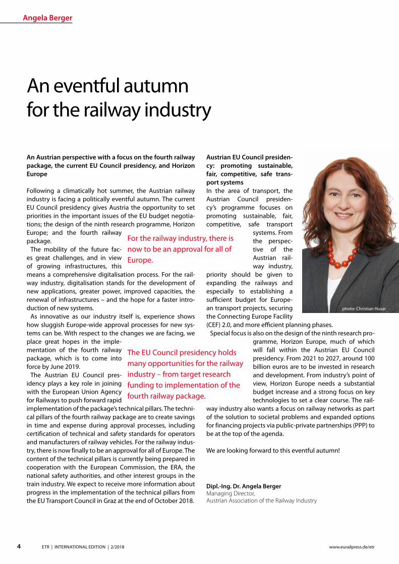
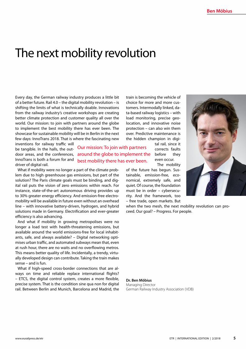
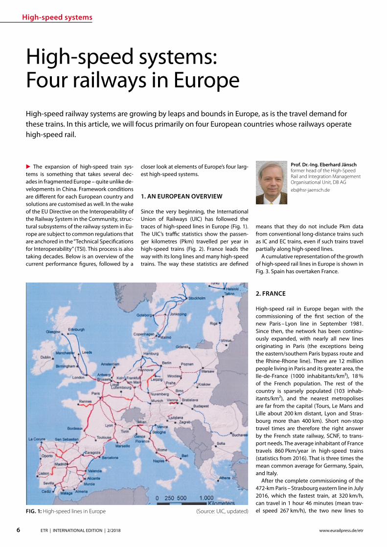
High-speed systems
7ETR | INTERNATIONAL EDITION | 22018wwweurailpressdeetr
raquo
Rennes and Bordeaux were opened in July 2017 The new lines bypass the cities of Le Mans and Tours although branches con-nect them to the existing main train stations there (Fig 4)
This network scheme has been the basis of new French lines from the very beginning What is new is the Tours-Bordeaux nanc-ing via a private-public partnership (PPP model) The building consortia nanced line construction and maintenance they receive leasing fees during a 50-year contract period from the SNCF The building programme for further TGV lines was deferred temporarily in the spring of 2018 for nancial reasons The French railway network is electried with 25 kV50 Hz to the north and east of Paris but with 1500 V direct current to the south The TGV high-speed trains were there-fore designed from the very beginning as two-system trains with a few three-system trains The new lines to the southeast and southwest are thus isolated in their 1500 V surroundings Mixed operations with con-ventional trains common on new and up-graded German lines were never intended in France The rst TGVs (Trains aacute Grande Vitesse) were the TGV-PSE (Paris Southeast) trains They were powered by direct-current (DC) engines and their successors were giv-en three-phase AC motors Their appearance has changed several times
In 2013 the new brand ldquoOuiGordquo appeared on the scene double-decker TGVs painted in blue with a greater number of seats provid-ing an economical alternative and marketed especially to a younger clientegravele Since July 2017 newly-built TGV trains are labelled as ldquoInOuirdquo trains ndash French for advanced learners (Fig 5)
TGV trac sees twice as many Pkmyear as Germanyrsquos ICE system
FIG 2 High-speed rail transport performance Europe 2016
FIG 5 Surely a TGV but not an ldquoOuiGordquo This is an ldquoInOuirdquo
FIG 3 Development of high-speed railway lines (V gt 200 kmh) in Europe
3 SPAIN
As in France Spainrsquos high-speed network is fundamentally focused on the capital Rela-tive to its land area Spain has very few peo-ple Twenty years ago Spain had 37 million inhabit-
ants current gures show 47 million or 92 inhabitantskmsup2 Major cities like Barcelona Valencia and Maacutelaga are far away on the coast and the area in between is almost empty (about 30 inhabitantskmsup2) The rail-
waysrsquo high-speed oerings are still focused on reduc-
FIG 4 TGV lines to Rennes and Bordeaux
High-speed systems
8 ETR | INTERNATIONAL EDITION | 22018 wwweurailpressdeetr
ing domestic air trac As expected the dual modal split has changed in favour of the ldquoAlta Velocidad Espantildeolardquo (AVE) system with each new high-speed line (Fig 6)
The rst line (Madrid-Seville) started high-speed train services in Spain in April 1992 A lot of German technology was used along the 471 km line including DBrsquos cab signal-ling with continuous automatic train control (called LZB) and high-speed switches from
BWGGermany DE-Consult (now DB Engi-neering amp Consulting) provided advice dur-ing line design and supervised line con-struction The line construction pro-gramme progressed continuously Today Spainrsquos high-speed rail network is the long-est of all railways in Europe and by 2022 it
is expected to grow to 3842 km A relatively new member of the European Union (EU) in the border state area Spain benets particu-larly greatly from the various EC nancing instruments
Its settlement structure makes construc-tion planning outside of cities very smooth The geology (soft rock mostly light lime-bound conglomerates) allows quick un-complicated construction of cuttings embankments and tunnels For historical reasons the railway network in Spain uses two track gauges Iberian gauge (1668 mm) and metre gauge (1000 mm primarily in the Basque region where Euskotren uses it) The Directive on the Interoperability of the Railway System in the Community brought the normal gauge system with its third track gauge of 1435 mm to the Iberian Peninsula The EU initially saw this as a con-dition for interoperability without which nancial subsidies from common EU funds for high-speed rail could not be expected Spain quickly backed o from its original intention of converting the gauge of its en-tire network Today normal gauge is gener-ally used on high-speed lines and in some peripheral areas of the network there are three-rail tracks (Fig 7)
Since December 2013 the high-speed network in Spain has been connected to the French network via the Barcelo-na ndash Figueres ndash Perpignan line The param-eters of a large part of the high-speed rail lines make them suitable for freight trac as well The rst AVE trains were TGV trains from Alstom that were used on the new Ma-
drid ndash Seville line The state railway company Renfe ordered ICE 3 derivates (Velaro E) from Siemens
for Madrid ndash Barcelona Collaboration with Bombardier gave rise to Talgo trains in Spain The fastest version is approved for 350 kmh (Fig 8)
Trains of the Talgo 250 model with track gauge-changing ability and multiple-unit trains from AlstomCAF were used After un-dergoing a gauge-changing procedure from normal gauge these trains operate on the broad-gauge network This procedure is on its third generation and gauge changes cur-rently take no more than ve minutes They must also change from alternating current of 25 kV50 Hz in the normal gauge system to direct current of 3000 V in the broad-gauge network A large part of the old network has no overhead line The hybrid Talgo 250H which carries two additional generator cars allows AVE operation all along the lines as e g to Santiago de Compostela
FIG 6 Modal split in Spain Bottom railways (AVE) top air trac Source Molina UIC HS symposium Tokyo 2015
European champion in high-speed rail network expansion ndash Brussels helps with the nancing
FIG 8 Talgo 350
FIG 7 Elastic support for a three-rail track (Source Vossloh)
High-speed systems
9ETR | INTERNATIONAL EDITION | 22018wwweurailpressdeetr
raquo
4 ITALY
In Italy high-speed rail began with incre-mental commissioning of the so-called Di-rettissima (Florence ndash Rome) Construction began in 1970 and was completed in 1992 At 248 km it is considerably shorter than the old line (314 km) which had arisen between 1866 and 1874 from a combination of local railway lines and in no way met the stand-ards of modern passenger and freight trac The Direttissima was therefore constructed and operated as a mixed-trac-operations line allowing 250 kmh and using the nor-mal Italian electric system of 3000 V direct current Because of the dense high-speed trac that has come to use the lines freight trains can use the Direttissima only at night
All cities between the end stations are by-passed although transition points to the old lines ensure that they continue to operate
This principle was followed for all subse-quent high-speed lines On the newly built connecting tracks the routing speed from the branch systems (220 kmh) to the old lines is reduced incrementally which re-quires a great deal of length (Fig 9)
In addition to the Italian high-speed rail network (currently 981 km) there are a total of 77 km of connecting lines (Interconnessio-ni) that are not included in the UIC statistics We will focus on the tunnels using the exam-ple of the 300 kmh Bologna-Florence line of which 73 km is in tunnels The newly con-structed section begins 5 km beyond the Bo-logna main station which has been replaced by a new underground station and ends after 77 km in Sesto Fiorentino 6 km from Firenze
Santa Maria Novela The tunnels have a free cross section of 82 msup2 and are equipped with niches as are all Italian tunnels of new con-struction (Fig 10)
An in-house risk assessment was performed to en-sure tunnel safety The concept is based on special safety areas that are arranged at inter-vals of about 4 km The intermediate access points created during tunnel construction are used as emergency exits (Fig 11) The opera-tions control system (ETCS Level 2) together with the train control system is to ensure that if there is an incident trains stop only in the ldquosafe areasrdquo The new line is electried with 2 x 25 kV50 Hz The system change is made near Florence at Sesto Fiorino the beginning of
the newly constructed section The approach to the Florence SMN terminus station is made with a 3000 V overhead line A new under-
ground through station in Florence is still in the plan-ning stages
5 GERMANY
51 TRAFFIC AND NETWORK DEVELOPMENT
High-speed rail trac in Germany is grow-ing slowly but generally steadily (Fig 12) DB AG statistics show the registered Pkms in ICE trains They agree with the UIC statistics
FIG10 Cross section of the new line tunnels (Bologna-Florence among others) (Graphic Italferr Sistaf)
FIG 9 Speed for the transi-tion between a high-speed railway line (left hand) and a conventional line (right hand)(Graphic Italferr-Sistaf)
New line linked closely to the conventional network
FIG 11 Safety areas in the Bologna ndash Florence tunnel (detail) Graphic Senesi UIC Highspeed symposium Tokyo 1015
High-speed systems
10 ETR | INTERNATIONAL EDITION | 22018 wwweurailpressdeetr
FIG 13 Standard cross section of the two-track tunnel for the new DB lines 92 msup2 300 kmh
FIG 12 Transport performance in DB long-distance passenger services
FIG 14 Standard cross section of the twin-tube tunnel for the new DB lines 2 x 60 msup2 300 kmh
which list all Pkms in high-speed trains no matter where these trains travel In Germa-ny the ICE network consists of a mix of new lines (up to 300 kmh) upgraded lines (up to 230 kmh) and old lines (up to 160 kmh) The length of the lines and line sections with V gt 200 kmh is currently 1538 km a further 977 km on the upgraded lines allow speeds of 200 kmh Given the size of the population living there new high-speed rail in Germany is quite modest There are just 19 km of new high-speed rail line per million inhabitants In comparison there are twice as many new high-speed rail kilometres per inhabitants in France and three and a half times as many
in Spain This also helps to explain why the French and Spanish are so proud of their high-speed railway networks ndash new lines and high-speed trains are a sign of national achievement that is visible to everyone
52 CHANGING TECHNICAL SPECIFICATIONS
The recently commissioned second section of the new line (Nuremberg ndash Ebensfeld ndash Er-furt ndash HalleLeipzig) is an example of how technical requirements can change even during the planning and construction peri-ods Pre-planning began shortly after Ger-man reunication and is based on DBrsquos July
1991 version of the ldquoNew linerdquo DS 80002 guidelines which now takes V = 300 kmh into account For trac reasons the line is intended for mixed-trac operations with passenger and freight trains In the Bavarian section of the line a track spacing of 470 m was used (based on the ldquoexpanded standard clearance gaugerdquo ndash (Erweiterter Lichtraum or ERL) DB abandoned this clearance gauge one year after commissioning the new Han-nover ndash Wuumlrzburg line (1991) because no-one used it In the sections of the new line that are further north the track spacing was reduced to 450 in line with the subsequent-ly updated guidelines and TSI Infrastructure
Two-track tunnels ndash recognised as state-of-the art at the time ndash were used (Fig 13) in the Ebensfeld ndash Erfurt section like the new Ingolstadt ndash Munich section
On 1 July 1997 the German Federal Rail-way Authority (Eisenbahn-Bundesamt or EBA) issued guidelines entitled ldquoFire and dis-aster protection requirements for the con-struction and operation of railway tunnelsrdquo These guidelines stipulated construction of two single-track tunnels with cross passages for mixed operations with passenger and freight trains in long tunnels The two-track tunnels in the Ebensfeld ndash Erfurt section were grandfathered but the EBA required a safe operational solution that would rule out simultaneous use of the tunnel by freight and passenger trains That is why only twin-tube tunnels were built in the Erfurt ndash HalleLeipzig section (Fig 14) They are signicant-ly more expensive than two-track tunnels Tunnel equipment including emergency lighting escape routes etc is detailed in the TSI entitled ldquoSafety in train tunnelsrdquo which came into force on 112015
53 PROTRACTED LARGE PROJECTS
In Germany the time between prelimi-nary evaluation and commissioning in a large railway project is very long The over-all Nuremberg ndash Leipzig line was commis-sioned in December 2017 27 years after its preliminary evaluation In comparison the new Cologne ndash RhineMain line was concep-tually designed in the 1970 DB expansion programme as a new Cologne ndash Groszlig-Gerau line but the large-scale alignment variant (via Koblenz or another station) and the technology remained under discussion for a long time In 1989 the German federal gov-ernment decided on the alignment variant 31 years passed between its initial concep-tual design in 1971 and its commissioning in 2002 The Hannover ndash Wuumlrzburg line was part of the 1970 expansion programme as a new Hannover ndash Gemuumlnden line The pre-liminary evaluation began in 1971 The de-
High-speed systems
11ETR | INTERNATIONAL EDITION | 22018wwweurailpressdeetr
FIG 15 DB AGrsquos ICE 4 on a new line
cision for the Hannover ndash Goumlttingen ndash Kassel alignment variant (put forward by the feder-al state of Lower Saxony) did not come until 1976 20 years passed between the prelimi-nary evaluation and the completion of its entire length in 1991 The Hannover ndash Berlin high-speed railway line moved quickly DBDR exploration in 1988 ministry agreements between the Federal Republic of Germany and the German Democratic Republic in June 1990 commissioning in 1998 ndash just ten years after the preliminary evaluation began
At present DB constructs the Stuttgart to Ulm dedicated passenger line and new tracks in the Rhine corridor between Karlsruhe and Basel where some newly-built sections are still put into operation Some more projects in Germany are in the pipeline as a link from Frankfurt to the HS linersquos section Wuumlrzburg-Fulda for creating more capacity and short-ening journey time between Frankfurt and Berlin In 2017 DB Netz AG presented its ldquoNetwork concep-tion 2030rdquo Besides providing more freight trac capacity along two north-south axes (the Rhine Corridor and the East Corridor via Halle) several improvements for passenger
trac are provided for Among them are the modication of several major nodes in
which passenger and freight trac must share tracks The long planning and
constructions times are to be shortened to about 15 years by means of citizen participa-tion building information modelling (BIM) and simplication of plan approval proce-dures
54 NEW TRAINS
Older models of high-speed trains especially the ICE 1 are now being gradually replaced by ICE 4 (Fig 15) They are multiple-unit trains for 250 kmh with distributed drives The ICE 4 cars are longer and narrower than the previous ones however DB AG promises more comfort in the trains and advanced in-terior ttings are to contribute
Expanding the high-speed rail network ndash a matter of decades
State-of-the-art rail plastic components
To date Wirthwein has supplied products for more than 30000 km railway lines worldwide We supply the rail superstructure with hundreds of millions of our products every year such as dowels intermediate plates or angle guide plates for rail fastening systems and cable ducts
As a specialist for plastics technology we have been caring for the perfect mold since 1968 Being based at twenty-two locations in Europe Asia and the USA we are always close to our customers
HIGH PERFORMANCEFOR THE RAILWAY
Forming Innovation
Wirthwein AG Walter-Wirthwein-Str 2-10 97993 Creglingen Germany +49 7933 702-0 bahnwirthweinde wwwwirthweinde
Visit us at InnoTrans Hall 26 Stand 231
MTU hybrid drives
12 ETR | INTERNATIONAL EDITION | 22018 wwweurailpressdeetr
PREFACE
The Lake Constance belt railway (in German Bodenseeguumlrtelbahn) is the only rail link be-tween the east and west of the lake The line is used not only for regional services but also for the international Ulm ndash Basel connection and in Friedrichshafen it links with the Wuumlrt-temberg Southern Railway (Suumldbahn) to-wards Ulm Electrication of the Suumldbahn is already in progress and scheduled for com-pletion by 2023
Electrication of the Lake Constance belt railway however has been a subject of con-stant debate for some years now Since elec-trication has not been taken into account in the Federal Transport Infrastructure Plan for the period up to 2030 nancing and realiza-
Quiet clean fast use of MTU hybrid drives on the Lake Constance belt railwayMTU Hybrid PowerPacks combine the advantages of diesel and battery-powered rail traction They can be installed in new or existing rolling stock without the need for additional changes to operations infrastructures or time schedules Even on non-electried routes they allow quieter cleaner faster and more cost-ecient rail travel The use of hybrid drives on the Lake Constance belt railway could signify a breakthrough for this innovative technology
tion are still open to question The under-taking would also bring certain challenges in the light of for example two low tunnels in the town of Uumlberlingen The nancial ex-penditure necessary to deal with them has not yet been calculated Furthermore the erection of overhead lines in such close prox-imity to the shore of Lake Constance would drastically alter the rural landscape and the touristic character of the location The pro-ject is therefore meeting with resistance from some local residents and communities
As an interim solution for improving service on the belt railway MTU Frie-drichshafen in discussion with the Lake Constance Railway interest group has pro-posed the tting of hybrid drives to the existing eet in regional and long-distance
service Diesel-based hybrids such as the MTU Hybrid Power Pack oer the advantages of both diesel and battery-driven rail travel and are quieter cleaner faster and more cost-ecient than the straightforward diesel drives currently in use An electric drive for example enables very low-noise emissions-free operation in urban areas and around stations Nitrogen oxide (NOx) and particu-late emissions fall impressively by compari-son with conventional eet and improved acceleration capabilities allow the planning of more stops and render the service less prone to delays Fuel consumption and in turn carbon emissions likewise fall by up to 25 All these benets are available without the need to change existing infrastructures
MTUrsquos Hybrid PowerPack is evolved from its conventional rail PowerPack PowerPacks
Dipl Ing Ingo LehmannProject and Safety Manager for Rail Mining Oil amp Gas Engineering MTU Friedrichshafen ingolehmannmtu-onlinecom
B Sc Dragan NedicKey Account Manager Rail Sales MTU Friedrichshafendragannedicrrpowersystemscom
Dipl Ing (BA) Benjamin OszfolkResearch and Technology Devel-opment MTU Friedrichshafenbenjaminoszfolkmtu-onlinecom
FIGURE 1 An IRE train with tilting technology on the Lake Constance belt railway
MTU hybrid drives
13ETR | INTERNATIONAL EDITION | 22018wwweurailpressdeetr
raquo
are compact drive systems with diesel en-gine transmission cooling system and au-tomation unit integrated on one base frame In the hybrid version of the PowerPack the drive is enhanced by an electric motor frequency convertor intermediate circuit on-board convertor and battery for storing energy harnessed during wear-free electro-dynamic braking This technology was al-ready presented by MTU in a previous article published in this journal [1]
Specic application of this concept on the Lake Constance belt railway has been exam-ined in simulations and verications carried out by MTU on its own systems test stand The subject of the study was the IRE service between Friedrichshafen and Singen
TEST STAND SIMULATION AND VERIFICATION
MTU Friedrichshafen is unique in its ability to simulate a complete vehicle drive such as the Hybrid PowerPack on a selected route and make reliable predictions on operation and fuel consumption Furthermore the company has a state-of-the-art Hardware-in-the-Loop (HiL) test stand that enables travel of the rail vehicle over the route to be simulated according to a given time sched-ule In this set-up the real drive is incorpo-rated into a virtual rail vehicle and subject to real conditions and loads Parameters such as fuel consumption drive dynamics and battery loads can be measured in the HiL set-up and compared with the previous computer-generated simulation results In this way MTU is able to verify its fuel-saving predictions and continually optimize its simulation tools
SIMULATION IRE FRIEDRICHS-HAFEN ndash SINGEN
Simulation of conditions on the Interregio service was carried out using the technical data from an existing Bombardier VT 612 DMU that is used on the Lake Constance belt railway The special feature of this train is its
tilting capability which allows it to negotiate curving track at speed Two vehicle congu-rations were simulated an existing VT 612 and a virtual VT 612 repowered with an MTU Hybrid PowerPack
Two scenarios were considered in the test In the rst the VT 612 Hybrid rail vehi-cle and the existing rail vehicle were run as per the current timetable (status 26012018) and compared in order to draw conclusions about time schedule feasibility and fuel consumption The second scenario looked at the feasibility of introducing a new time schedule with additional stops The new time schedule was taken from a study car-ried out by SMA amp Partner AG [2] whom the Lake Constance Railway interest group had engaged in 2013 to examine dierent timetable concepts also taking into account possible electrication of the line The study showed that operation of an hourly IRE ser-vice on the Lake Constance belt railway with additional stops in Markdorf and Salem could be recommended
In both scenarios electric-only mode for low-noise emissions-free rail travel was taken into account around planned stops
Route sections travelled in electric-only mode are shown in Figure 2
To determine fuel consumption the State of Charge (SOC) of the battery was taken into account in the energy balance SOC at the end of the journey must correspond to SOC at the beginning If despite smart en-ergy management and re-charging where appropriate en route the end SOC was not absolutely equal to the initial SOC the bat-tery was re-charged up to the required level using the diesel engine The fuel required to do so was also taken into account in overall fuel consumption
The aim of the simulation was to directly compare the VT 612 with the VT 612 Hybrid on the Friedrichshafen ndash Singen service of the Lake Constance belt railway based on the current time schedule (Scenario 1) and to determine the feasibility of the new time-table with additional stops in Markdorf and Salem as per the study made by SMA amp Part-ner AG (Scenario 2) A statement on fuel con-sumption was also to be made It is empha-sized again that the hybrid train switched to electric-only mode around stations and in urban areas as shown in Figure 2 Phases of
FIGURE 2 Deployment of a VT 612 Hybrid on the Lake Constance belt railway with electric-only phases
FIGURE 3 Simulation of IRE service on the Lake Constance belt railway
MTU hybrid drives
14 ETR | INTERNATIONAL EDITION | 22018 wwweurailpressdeetr
travel in electric-only mode caused a slight reduction in the fuel saving possible in rela-tion to the existing rail vehicle However this is seen as a justied compromise in view of the benets of phases of emissions-free qui-eter travel
The results for both scenarios are shown in Figure 3
The simulation results for Scenario 1 show that with a hybrid rail vehicle a fuel saving of 157 in relation to the existing VT 612 vehicle can be achieved including phases in electric-only mode The travel time in this case is 4600 min The fuel saving can be principally attributed to re-generative braking The energy thereby harnessed is used entirely for travel in elec-tric-only mode The results for Scenario 2 show a fuel saving of 206 in relation to the existing rail vehicle from Scenario 1 The time scheduled for Scenario 2 is 5600 min So with the hybrid rail vehicle the new Sce-nario 2 time schedule with additional stops in Salem and Markdorf can be realized with lower fuel consumption than for Scenario 1
and including electric-only mode around each stop
Evaluation of the simulation results even shows that potential still exists for a further reduction in the travel time (Fig 4) The blue line shows the vehicle speeds required for keeping to the time schedule The red line shows the speed limit for taking curving track at speed The route sections passed in electric-only mode are highlighted in green The speeds necessary along the route for keeping to the timetable remain for the most part well below the maximum speed limits This means that a reduction of the travel time is perfectly feasible still leaving sucient operational reserve
The simulation results shown were veri-ed on the Hardware-in-the-Loop (HiL) test stand and could be conrmed Besides time-keeping the most tangible improvements outside the vehicle are emissions-free travel and quieter operation around stations and in urban areas Measurements at the test stand and on a demonstrator showed that vehicle noise in the vicinity of stations can
be reduced by around 75 (20 dB(A)) This improvement might even be perceived by passengers inside the vehicle
Based on the simulation results it is pos-sible to calculate the annual savings in CO2 (132 tonnes) and NOx (105 tonnes) per ve-hicle based on 2500 hours runtime per year Extending this to the entire VT 612 eet in service in Baden-Wuumlrttemberg which amounts to 41 vehicles a total of 5412 tonnes of CO2 and 43 tonnes of NOx could be saved per year Rebuilding the rail vehicles with MTU Hybrid PowerPacks could there-fore make a very signicant contribution to air pollution control on Baden-Wuumlrttem-bergrsquos railways
REBUILDING THE VT 612 WITH A HYBRID DRIVE
The VT 612 is an ideal candidate for conver-sion to a hybrid drive As a high-oor vehicle it has more than enough space underoor for housing all Hybrid PowerPack compo-nents Since the Hybrid PowerPackrsquos compo-nents are not heavier than the current drive system it can be installed without any shift in the centre of gravity The feasibility of the rebuild was also conrmed by DB System-technik the Deutsche Bahn subsidiary Re-building tilting VT 612 railcars with hybrid drives would give them a new lease of life as fast eco-friendly trains and their tilting sys-tems ndash to which they owe their faster travel times ndash would remain available in the future
The rebuild concept proposed by MTU provides for installation of a Hybrid Power-Pack in each car The installation scope would comprise the following components
rarr Hybrid PowerPack (comprising diesel engine electric motor transmission cooling system)
rarr Batteries (3 MTU EnergyPacks with ca 90 kWh capacity overall)
rarr Water-based battery cooling
FIGURE 5 Rebuild concept for VT 612 Hybrid
FIGURE 4 Simulation results for IRE service using VT 612 Hybrid Scenario 2
15ETR | INTERNATIONAL EDITION | 22018wwweurailpressdeetr
rarr Intermediate DC circuit rarr Power electronics and lters for on-board power supply
The Hybrid PowerPack comprises an MTU 6H 1800 R85L diesel en-gine an electric motor and a ZF EcoWorld power-shift transmis-sion with integrated reversing function The diesel engine delivers 390 kW and the electric motor delivers 300 kW continuous power
The Hybrid PowerPack is arranged as a parallel hybrid with the electric motor sitting on the input side of the transmission up-stream of the diesel engine As a preference the electric motors are congured for electro-dynamic braking in order to harness surplus energy for battery storage or on-board power
SUMMARY
The simulations show that an MTU hybrid drive will have no dif-culties meeting either the current time schedule in place on the Lake Constance belt railway service or that planned for the future Rebuilding the rail vehicles with Hybrid PowerPacks would achieve signicantly cleaner quieter and more economical rail travel even without overhead electrication and with no compro-mises with respect to travel times The installation alone of state-of-the-art EU Stage V-compliant diesel engines in the VT 612 rail-cars could reduce particulate and NOx emissions by around 90 The further benets oered by a hybrid drive would prot the en-vironment passengers and operators alike Electric-only mode in urban areas and around stations lowers the noise level by as much as 75 Regenerative braking considerably enhances the ecologi-cal soundness of operations while improving their cost-eciency In this way up to 20 fuel savings can be made
All in all deployment of Hybrid PowerPacks on the Lake Con-stance belt railway could herald a breakthrough for this innova-tive technology in Germany
Literature[1] Oszfolk Benjamin et al Hybridantrieb stellt Marktreife unter Beweis ETR ndash Eisen-
bahntechnische Rundschau 92015 [2] SMA und Partner AG Optimierung Angebotskonzeption Bodenseeguumlrtelbahn
Zuumlrich SMA und Partner AG 2013
FIGURE 6 MTU Hybrid PowerPack
Discover intelligent sensors
INNOVATIONS TO SIMPLIFY RAILWAY OPERATIONS
EXPPERIEENCE THHE FUUTURE OF TTRAIN TRRACKINGG
InnoTranss in Berrlin18 ndashndash 21 Septembeer 220188Halll 255 | SStannd 2232
Digitalisation opens up new possibilities in generating a wide range of highly valuable information
wwwwfrauschherccominnootranns
Predictive Maintenance
16 ETR | INTERNATIONAL EDITION | 22018 wwweurailpressdeetr
BASIC PRINCIPLES OF DATA LAKES
Data Lakes dier fundamentally from clas-sic concepts of Business Intelligence such as Data Warehouses primarily by the type of data retained In data warehouses mainly transactional data is stored whose structure is dened upfront and which has already undergone pre-ltering before persistence In a data lake however all data is persisted regardless of its structure or relevance for known use cases Data Lakes have the fol-lowing basic properties [2]
rarr Data Lakes collect and store data regard-less of type format or data volume while they are to be stored in a structured manner in classic data warehouses
rarr Data Lakes provide large amounts of data Therefore it is important to keep costs low while maintaining a high ac-
The treasure of the Data Lake ndash Predictive maintenance for vehicle eetsEective asset management of vehicle eets in rail requires an ecient and comprehensive IT landscape as a basis The core of an associated architectural concept is a data lake that collects and provides real-time diagnostic data gathered on the vehicles It is the technical basis for the application of algorithms for condition-based maintenance of rail vehicle eets
cess rate Since data stored in structured form in data warehouses must be im-mediately accessible at all times to en-able fast access high persistence costs are generated Data Lakes on the other hand store raw data which depending on the frequency of accesses can also be stored with reduced access speed
rarr At Data Lakes all data is stored centrally and heterogeneously at the same time This means that data which is very dif-ferent from the format can be linked together in analyses without having to request potentially dierent systems beforehand Existing Application Pro-gramming Interfaces (APIs) provide a wide range of usable use cases It is easy to add dierent tools to the data stream as services for example or to store inter-mediate results in the Data Lake for fur-ther use by other tools
rarr Data Lakes keep all relevant data central and unstructured regardless of format-ting The analysis tools are always con-ceptually independent of the format and structure of the data This allows new analyses or new data sets to be integrat-ed easily and quickly
rarr In modern implementations of data lakes and the service landscapes required for this the concept provides for the rapid interchangeability of tools and micros-ervices The user can test generally avail-able tools with practically no initial eort and if required can transfer those to productive use in just a few steps
SERVICE-ORIENTED AND CLOUD-BASED ARCHITECTURE FOR DATA LAKES
Instead of using solutions based on indi-vidual or a few applications with a dened range of functions Data Lakes reliy on so-lutions consisting of a exible combination of dierent micro services around a central data store The software architecture must be detached from classical patterns such as a layered hierarchy and the development must lead to a data- or data-ow-centered architecture This makes it easy to add or re-place services at any point and keeps the ar-chitecture exible for future developments
When using data lakes primarily event-driven architectures are common By con-
Mathias Haimerl Senior Data Analyst ESE Engineering und Software-Entwicklung GmbHmathiashaimerlesede
FIGURE 1 Vehicle eets in rail transport as an object of asset management
Predictive Maintenance
raquo
trolling the events based on the underly-ing data streams this architecture can be called Data-Driven Architecture (cf[5]) The software therefore builds itself around the data stream as shown in Fig 1 The data stream therefore represents the basis for the achievement of objectives whereby each individual problem can be regarded as an in-dependent architecture The desired objec-tive is broken down top-down into required services and newly formed into a specic so-lution Right from the start not only services for data manipulation are considered but also accompanying services for areas such as logging and security
The implementation of data lakes on company-owned hardware does no longer make sense for most projects from a nan-cial point of view and therefore only makes sense for particularly critical applications (eg banks medicine military) if commercial cloud solutions with appropriate security options cannot be found or are not applica-ble for compliance reasons
CHALLENGES AND SOLUTIONS OF CLOUD-BASED ARCHITECTURES
The use of services in a cloud creates new
challenges that need to be addressed in ad-vance
Information security of the customer data available in the cloud is in most cases much higher in the Amazon Web Service (AWS) Cloud than on self-operated servers The large number of system administrators de-ployed worldwide for the AWS Cloud some of whom specialize in information security provides signicantly better information se-curity than would be the case with conven-tional IT infrastructures operated by compa-nies themselves
Handling security vulnerabilities Due to the high number of users in the global internet of things (IoT) security gaps that allow access to external data quickly become nancially and legally problematic The Linux base and the simple reporting of security problems allow newly discovered vulnerabilities to be resolved quickly and globally The globally uniform system and the uniform administra-tion of software components close security gaps within a few hours
Protection against unauthorized access by third parties Authentication measures serve to protect sensitive data against unauthor-ized read access (data theft) on the one hand
and to protect data against unauthorized manipulation (data modication computer sabotage) on the other Authorization meas-ures are aimed at ensuring that analysts and solution architects only have access to the data relevant to their projects This is supported by the targeted allocation of authorisations to the respective architects In addition organization-related boundary conditions are contractually secured One example of this are compliance guidelines such as certication of cloud providers ac-cording to standards like DIN EN ISOIEC 27001
Software maintainability The AWS ba-sic system is stable against updates and changes without interfering with customer projects Customer projects run in self-con-tained environments (sandbox) The pro-vider of the cloud system has the freedom to use exchange and extend any hardware components without expensive downtimes or waiting times for the user Software up-dates and time-consuming hardware up-grades are obsolete for the user
Legal framework Sending data across na-tional borders is often a legal hurdle that prohibits the use of cloud services To coun-teract this cloud providers have provided
FIGURE 2 Overall concept of the data-driven architec-ture The microservices are structured around the data stream
wwwmobility-bbcom
Berlin-Brandenburg
Moving mobility
to the next level
Meet us at InnoTrans
City Cube Hall B
210x99_VML_InnoTrans_eng_ETRindd 1 19072018 081118
Predictive Maintenance
18 ETR | INTERNATIONAL EDITION | 22018 wwweurailpressdeetr
for the possibility of binding to regions that ensure that data does not leave certain pre-dened regions
Calculability of costs An AWS solution is about 90 cheaper than the operation of ldquoclassicrdquo infrastructures This value is also evi-dent in one of our customer projects where about 98 of the costs were saved on the development system and the eective sav-ings for the live system were interpolated to be at about 91 AWS provides a billing calculator that provides an estimate based on past months and previous monthly costs
SAMPLE IMPLEMENTATION STEPS FOR AMAZON WEB SERVICES
As an example implementation of a data lake the cloud environment AWS was used as described below During implementation four functionalities were clearly separated which are described in more detail below
rarr Data acquisition including pre-process-ing (ingestion)
rarr central data storage rarr Cataloging of data rarr Preparation of concrete analyses
DATA ACQUISITION (DATA INPUT) FOR DISTRIBUTED DATA SOURCES
In order to be able to ingest sensor data from vehicle eets the receiving system must be able to accept and store a large number of distinct data from many sensors On the senderrsquos side however data must be collected buered and regularly transmit-ted to the Data Lake To do this a periodic Internet connection must be ensured For
the frequency of data transfer an individual taring between the local data collection and the frequency of synchronization to the cloud must also be found Data transfers at low bandwidth should preferably rely on the collection of several data sets and trans-fer with a stable connection However this requires more memory in the local device With higher bandwidth and stable connec-tions the data can also be transferred more frequently This on the other hand leads to an increased load on the receiver A project-specic optimum must be found here
Finally it should be taken into account that the order of data sets should already be de-ned during ingestion even if the structure does not have to be xed from the outset To simplify later evaluations considerably data of the same type for which the uniformity is to be foreseen should be grouped logically This unies the data accesses of the evaluat-ing processes and thus minimizes the eort
From a specic project of a customer we know that the current data load of 6754 MBh will increase tenfold by 2020 due to an increase in the number of equipped vehicles and a simultaneous tripling of the number of sensors to approx 2GBh The distribution of the eets is Europe-wide with the focus on Central Europe
CENTRAL DATA STORAGE
In order to eciently persist the collected sensor data of vehicle eets the receiving system stores the data in a central location In AWS data is stored centrally in any size and in an automatically growing storage unit a so-called bucket The data is stored in ob-jects a logical data unit comparable to les in a classic le system To make searching
through data easier the objects are indexed based on their specic prexes and opti-mized for fast access Since the implementa-tion is based on RESTful and therefore each data record transmitted by sensors sends a PUT request a new object is created for each data record This creates an immense num-ber of objects in the long term This is irrele-vant in terms of costs and storage space For an analysis based on large amounts of data with low reaction times however a catalog-ing of the data is still necessary
CATALOGUING FOR VARIOUS APPLICATIONS
The exible NoSQL database DynamoDB oers an optimal possibility to catalog data without having dened a schema and still get extremely fast access speeds A Dy-namoDB table has a primary key which con-sists of a partitioning key and an optional sort key The partitioning key determines the automatic partitioning of the table and should therefore be very well selected (see [9]) An entry also supports update com-mands DynamoDB oers a very exible memory which can be written and read in dierent ways
New data arriving in Simple Storage Ser-vice (S3) can be automatically analyzed as a trigger for cataloging and added to cor-responding catalogs Since the analyses are usually very individual a pipeline must be created so that the new data arriving in S3 can be processed This can be achieved with minimal eort using the Microservice Lamb-da which makes it possible to execute small programs in the AWS landscape without any further integration eort Optional lters can be set for the triggers so that dierent pre-xes start dierent lambda functions
rarr Read The respective lambda function receives the bucket and the object name of the newly arrived object and can ex-amine this import and the content ac-cording to previously dened criteria and extract the corresponding values
rarr Write This data can then be written to a DynamoDB table regardless of whether the data record already exists ie wheth-er it has to be updated or whether it is a new data record
This type of cataloging is the comparatively most complex but at the same time the ex-ibility exceeds that of other technologies by far The cost factor is also considerably lower here The costs for DynamoDB tables are cal-culated according to provisioned capacities for read and write accesses This is under-
FIGURE 3 Using cloud solutions brings new challenges
Predictive Maintenance
19ETR | INTERNATIONAL EDITION | 22018wwweurailpressdeetr
standable as an increase in capacity in the background is a real hardware replication This allows tables with costs of less than one euro per month for the minimum congura-tion and a separate table can be provided for each application case The requests for large amounts of data via the primary key or only a part of it can be retrieved extremely quickly whereby retrieval times in the low two-digit millisecond range are not uncommon
PREPARATION OF CONCRETE ANALYSES
The creation of analyses on the catalogued data is possible without great eort with the basis shown This is done in several consecu-tive steps
rarr Top-down analysis of the problem to be solved as there are various microservic-es for a wide variety of applications As a result individual use cases can be as-signed to the use cases
rarr Selection of suitable microservices De-pending on the target platform the ap-propriate microservices can be selected There are specic services that enable the further use of existing programs that work on relational databases for example Other microservices support machine learning or the visualization of complex interrelationships in informa-tive dashboards
rarr Bottom-up aggregation of specically congured microservices For this pur-pose services already congured for similar analyses can be reused or addi-tional instances with slightly modied conguration can be created
SUMMARY amp OUTLOOK
All in all Data Lakes oer an optimal solution from the initial setup of a collection of raw data from various sources without large upfront ef-fort or high costs to the data storage of many eets of dierent vehicles worldwide and the provision of data catalogs for various analyses of various kinds The collection of measure-ment data in persistent online data stores such as AWS buckets can be implemented within minutes and is operational from this point in time so that data can be collected and archived Even if no specic use cases are known at the time of implementation it is recommended to persist all data on low-cost cloud storage so that it is already available for possible evalua-tions at later points in time Since there is often no reason to process data without use cases favorable options for persistence of the data can be used To avoid vendor lock-in consider designing Data Lake to be adaptable to alter-native platforms Alternative options for data storage include the storage services of Google Cloud Services or Microsoft Azure Of course the use of a second service also doubles the total costs
References[1] Canalys (2017) Cloud service providersrsquo battle drives
the worldwide cloud infrastructure market up 42 in Q1 2017 httpswwwcanalyscomstaticpress_re-lease2017press-release-150517-cloud-service-providersE28099-battle-drives-worldwide-cloud-infrastructure-market-42_1pdf Palo Alto Shanghai Singapore and Reading (UK) Pressemit-teilung 15052017
[2] Amazon Web Services (2017) Building a Data Lake on AWS httpspagesawscloudcomrs112-TZM-766im-agesAWS_Data-Lake_eBookpdf 01112017
[3] Bundesministerium des Inneren (BMI) (2017) Polizeili-che Kriminalstatistik 2016 httpswwwbmibunddeSharedDocsdownloadsDEpublikationen2017pks-2016pdf Pressemitteilung 24042017
[4] Buschmann Frank and Christiane Loumlckenho eds (2000) Pattern-orientierte Softwarearchitektur ein Pat-tern-System 1 korr Nachdr Muumlnchen Addison-Wesley 2000
[5] Mahjourian Reza (2009) An Architectural Style for Data-Driven Systems Paper Gainesville FL 32611 USA httpswwwcsutexasedu~rezalesxpage-icsrpdf 22032009
[6] Tilkov Stefan (2009) REST und HTTP Einsatz der Ar-chitektur des Web fuumlr Integrationsszenarien 1 Au Hei-delberg dpunkt 2009 ISBN 9783898645836
[7] Hunkeler U H L Truong and A Stanford-Clark (2008) MQTT-S mdash A Publishsubscribe Protocol for Wireless Sensor Networks In Communication Systems Software and Middleware and Workshops 2008 COMSWARE 2008 3rd International Conference on 791ndash98 2008 httpsdoiorg101109COMSWA20084554519
[8] Manseld-Devine Steve (2016) DDoS Goes Main-stream How Headline-Grabbing Attacks Could Make This Threat an Organisationrsquos Biggest Nightmare Net-work Security 2016 no 11 (November 2016) 7ndash13 httpsdoiorg101016S1353-4858(16)30104-0
[9] Vyas Uchit (2014) DynamoDB Applied Design Patterns Birmingham United Kingdom Packt Publishing 2014
SAFERAILSYSTEMCOM
Guessing or GPR
bull GPR measurements and analysisbull Condition-based maintenance planningbull More than 25 years of working experience - worldwide
BIM
20 ETR | INTERNATIONAL EDITION | 22018 wwweurailpressdeetr
ABOUT SIEMENS MOBILITYrsquoS TURNKEY RAIL SOLUTIONS BUSINESS
Siemens AG is a global technology power-house that has stood for engineering ex-cellence innovation quality reliability and internationality for more than 170 years The company is a pioneer in supplying in-frastructure solutions Siemens Mobility is an experienced provider of complete turn-key solutions for rail systems having already carried out more than 50 various and major rail projects worldwide The organization is home to experts in project management and system integration as well as key prod-ucts of rail infrastructure These specialists develop and implement projects for all types of rail vehicle systems from metros trams and light rail vehicles and automated peo-ple-movers to Intercity and high-speed train units ndash all designed for maximum reliability availability and eciency
THE CHALLENGES OF RAIL INFRASTRUCTURE PROJECTS
Projects to install new rail infrastructure and expand existing systems are growing steadily more complex The rising number of project participants and stakeholders presenting a broad range of specic require-ments planning teams in dierent locations and time zones having to coordinate and
Digital twin serving rail infrastructure How turnkey rail infrastructure projects are beneting from applying Building Information Modeling (BIM) how Siemens Mobility is pursuing virtual planning of projects with project partners and custom-ers such as in the Riyadh Metro Project and what added value this methodology is creating
integrate their civil and rail engineering and planning and the ever increasing time and cost pressures exemplify this problematic complexity
There are an enormous number of inter-faces and requirements involved especially in large rail infrastructure projects and or-ganizing them demands extensive resources and absolute precision
AT THE VANGUARD OF DIGITAL PLANNING
Just as countless other sectors of the con-struction industry have already experienced digitalization is driving a para-digm shift in rail infrastructure away from analog meth-ods and embrac-ing digital and in-tegrated planning encompassing eve-rything from erec-tion planning installation and support for training to preparation and performance of repairs and maintenance all based on digital processes and data models
More than four years ago Siemens Mo-bility began applying building information modeling (BIM) techniques as well to project planning and execution of complete turnkey
solutions for rail systems As one of the trail-blazers of digitalization Siemens Mobility uses BIM to create a digital twin ndash a virtual model of major rail projects planned for im-plementation
This methodology focuses on achieving cost and time eciency while also ensuring the highest quality standards
Siemens Mobilityrsquos Turnkey Rail Solutions is using BIM in col-laboration with construction part-ners to optimize project planning and execution This involves the use of computer-generated 3D modeling and the
information integrated into or linked with the models
REFERENCE PROJECT RIYADH METRO
The Arriyadh Development Authority (ADA) ndash the executive arm of The High Commission
Both the implementing company and customer benet from the reduced risk of delays in planning as well as the prevention of defec-tive planning and resultant need to revise planning during ongoing installation
Dr Payam AminiHead of Digital Transformation Turnkey Projects amp Electrication Siemens Mobility Munich payamaminisiemenscom
A simulated view of the outside of the depot for which the path of sunlight can be simulated over time
raquo
BIM
21ETR | INTERNATIONAL EDITION | 22018wwweurailpressdeetr
for the Development of Arriyadh in Saudi Arabia ndash is currently building one of the larg-est metro projects in the world with six rail lines totaling 176 kilometers in length The system will be the backbone of the public rapid transit network serving Saudi Arabiarsquos capital city The order placed with Siemens Mobility covers supply of 67 Riyadh Metro model rail vehicles based on the Inspiro Plat-form series line electrication the signaling and communication systems for driverless service on Lines 1 and 2 as well as system integration and project management Sie-mens Mobility is part of the BACS consor-tium led by US company Bechtel along with Almabani General Contractors and Consoli-dated Contractors Company
The Riyadh Metro Project (RMP) kicked o by dening the information requirements and project-specic BIM objectives of the customer The BIM management team of Siemens Mobilityrsquos construction partner Be-chtel then used this information as the basis for elaborating in detail the BIM process for all project participants
The BIM execution plan that denes the BIM process for a specic project basi-cally provides the answers to the agreed require-ments In this key central document Turnkey Rail Solu-tions dened for all project participants in-volved in the infrastructure design the roles and scopes of responsibility the programs and le formats to be used what applica-tions are to be integrated into the BIM pro-cess the data-exchange process along the chain of project phases the quality review inspection and testing criteria procedures for coordination and collaboration and much more This was necessary in order to ensure smooth BIM implementation over the entire project cycle
Siemens Mobilityrsquos construction partner also generated the model element plan which denes in an overview who is to gen-erate what model content for the project by when and to what level of development (ie geometry information and coordination) In this project BIM standard the construc-tion partner also dened the details for modeling agreements and documentation standards
Model-based planning is one of the pro-jectrsquos centerpieces enabling comprehensive integration of all rail infrastructure systems such as rail electrication the depot and workshop equipment line signaling and communication technology and platform screen doors
CLARITY DRIVES THE EFFICIENCY OF WORKFLOWS
Siemens Mobilityrsquos infrastructure planning engineers used project-specic BIM software to share their model-based information with Siemens Mobilityrsquos suppliers and the con-
struction partner The program Pro-jectWise is used in combination with Aconex served and continues to
serve as a shared data platform accessible project-wide ensuring that each piece of information is retained only once and in its most recently valid version In this ldquosingle source of truthrdquo data are referenced rather than duplicated signicantly improving in-formation management increasing the reli-ability of data and eliminating any use of superseded obsolete data This provides full trans-parency for all pro-ject participants Photo-realistic displays and animated videos of the planning progress generated on the basis of the 3D planning information ensure transparency enhance understanding and support the iterative process
The permanent availability of data accel-erates collaboration across national borders and company boundaries These aspects are particularly benecial in the RMP Just Sie-mens Mobilityrsquos unit alone had colleagues based in 13 dierent cities working to de-sign the rail infrastructure coordinating and agreeing across national boundaries and dierent languages time zones and work capacities
In addition to the geometrical properties
of system components for example of fre-quency converters the participating plan-ning engineers also integrated non-geomet-rical information and requirements of their systems such as zones and clearance spaces that are essential for installation and mainte-nance Once work on a subarea of a model (work in progress) was approved for release this information was then available to all partners within the project (shared areas) In turn these partners reviewed the completed work for impacts on their own work scopes
In interdisciplinary collision reviews the design coordinators conducted collision tests with all other draft components Such reviews examined for example the civil struc-tures technical building equipment systems and Siemens Mobilityrsquos systems such as the signaling equipment and traction power supply grid to identify any conicts between
the systems them-selves or with the civil structures
In this way structural imple-mentation of the overall project as
well as individual subareas can be digitally tested at any time
As a provider of turnkey infrastructure solutions Siemens Mobilityrsquos unit was in-volved early in the RMP through BIM help-ing to prevent planning errors and leading to quicker validation of draft planning such as for spatial requirements of infrastructure equipment free clearance proles and pre-venting collisions
The RMP oers a basis for further infra-structure projects using BIM methodology The stock of digital objects available in the component library continues to grow Exist-ing digitally modeled components can be directly used for the next digital twin This
BIM creates full transparency for everyone participating in the plan-ning of infrastructure projects
The Control Center of the Riyadh Metro Project for Line 1 was fully planned digitally Once that design process was completed actual construction started
BIM enables earlier design valida-tion of rail infrastructure technol-ogy and engineering as well as civil construction
BIM
22 ETR | INTERNATIONAL EDITION | 22018 wwweurailpressdeetr
accelerates digital planning from one pro-ject to the next
Siemens Mobility Turnkey Rail Solutions sees particular potential for BIM in integrating the necessary man-agement process-es BIM supports the management of interfaces requirements congurations and project documentation This improved management leads to accelerated project execution And although project execution in Riyadh is still underway the added value created by the BIM method is already clearly evident today ndash for both Siemens Mobility and the customer
DIGITAL SCAN OF THE INFRASTRUCTURE CREATED
Siemens Mobility Turnkey Rail Solutions is utilizing other digital solutions as well for the Riyadh Metro Project that further optimize pro-ject execution Siemens Mobility-owned track measuring vehicles and 3D laser scanners are deployed to eciently compare the progress
of as-built construction and installation against the design target data These units travel along the existing sections scanning and thereby
digitalizing the as-built environment The object-specic information collect-ed by this measur-ing system whether on track position-
ing platform edges or technical spaces is com-pared with the digital design thereby directly revealing any deviations from planning
This produces a 100 -accurate database of the existing as-built status Particularly when projects aim to expand exist-ing infrastructure such transparency prevents costly conicts when equipping existing civil structures with new infrastructure equip-ment Besides the hardware procurement Siemens Mobility is banking in this context on developing the expertise of its own per-sonnel to cover planning of measuring cam-paigns kinematic and static imaging and evaluations such as review for collisions
PROMISING OUTLOOK
Siemens Mobilityrsquos Turnkey Rail Solutions has ceaselessly invested in implementing and further developing digital methods to keep pace with steadily growing deadline and cost pressures and the increasingly stringent demands of complex rail infra-structure projects These efforts are now empowering Siemens Mobility to better assess the sometimes extremely demand-ing detailed requirements early already in the project bidding phase and estimate costs more reliably thereby minimizing risks
In previous projects utilizing BIM meth-odology Siemens Mobilityrsquo experts identi-ed a shifting of eort into the early project phases
Siemens Mobilityrsquo experts see opportuni-ties in doing so particularly in the assess-ment of design modications in terms of im-pacts on costs and in early application when the leverage for such optimization can still prove very eective
Yet BIM doesnrsquot end when construction work on an infra-structure project has been complet-ed By developing a digital twin of the as-built infrastruc-ture and applying
that model over its entire lifecycle these sets of digital data can be used to optimize asset management
The BIM method harbors major potential for signicantly shaping the rail infrastruc-ture sector in the coming years
A view of the digital model of the King Abdullah Financial District Station on Line 1 which can be viewed in the computer pro-gram from all sides
Photo-realistic displays and animat-ed videos of the planning progress ensure transparency and enhance understanding
BIM provides the basis for simpler and ecient interface management and contributes signicantly to accelerating project execution
5 | 2017 Mai wwweurailpressdesd
109 Jahrgang
SIGNALLING amp DATACOMMUNICATION
Oumlsterreich Gut gesichertAustria Well-protected
13 Kostenguumlnstige Sicherung von Eisenbahnkreuzungen Cost-effective protection of level crossings
36 Finnland Gegen den Instandhaltungsruumlckstand Finland Reducing maintenance backlog
21 Schweiz Weltpremiere auf der Toumlsstalstrecke Switzerland A world premiere on the Toumlsstal line
Your contact person Silvia Sander +4940237 14-171 silviasanderdvvmediacom wwweurailpressde
Leader in Signalling and Datacommunication
No 1ad medium
SIGNALLING AND
DATACOMMUNICATION
AUTONOMOUS DRIVING
CYBE
R SE
CURI
TY
LEVEL CROSSING TECHNOLOGY
OPERATIONS MANAGEMENT SYSTEMS
MOBILE COMMUNICATIONETCS
REPUTABLE
UN
IQU
E
ESTABLISHEDTELECOMMUNICATION
OPERATIONS CONTROL TECHNOLOGY
INFORMATION TECHNOLOGYBILINGUAL
Book your advert right now
raquo
Ground Penetrating Radar
23ETR | INTERNATIONAL EDITION | 22018wwweurailpressdeetr
1 INTRODUCTION
Many countries allocate large amounts for the modernization and upgrading of their railway networks in order to meet the de-mands of increasingly dense rail trac with higher axle loads at ever higher speeds However this can only be achieved if all rel-evant key gures and geotechnical condi-
Ground Penetrating Radar ndash Basis for eective Track MaintenanceThis article describes the capabilities and functionality of Ground Penetrating Radar (GPR) for higher speeds GPR is a train-borne technology for a continuous inspection of the geotechnical conditions of railway tracks The basic principles of the GPR technology are explained with particular reference to all relevant railway specic tasks namely the identication qualication and quantication of ballast fouling by using a fouling index the determination of the quality of track drainage and its quantication through a drainage index and the calculation of the track modulus (TM) Special emphasis in the context of GPR investigations is placed on the mapping of sections with clay foulingmud spots inside the ballast bed or at its base and respectively inside intermediate layer formation or subsoil In the past such weak-spots have caused derailment they could represent a risk for rail-trac [11 13 14 15 16] Besides their late detection implies exceedingly high maintenance costs
tions of the respective tracks can be reliably evaluated On this basis only the necessary investments in track maintenance moderni-zation and support can be dened in the ap-propriate size and can be placed correctly This is particularly true when budgets are tight
The demands exerted on the track in terms of safety grow with increasing speed
FIGURE 1a) Trajectories of radar waves which are reected at the layer boundary between two media
with dierent dielectric constant (laquo)b) Due to the dierent travel time of the reections the layer boundary is reproduced in the
radargram (reference Ground Control and IEV)
Dipl-Geophys Giuseppe StacconeDirector of Ground Control GmbH MunichGermanystacconesaferailsystemcom
David Camacho MScDoktorand am Institut fuumlr Eisen-bahn- und Verkehrswesen der Universitaumlt Stuttgart (IEV)davidcamacho ievvwiuni-stuttgartde
Moritz SchebuchMitarbeiter am Institut fuumlr Eisen-bahn- und Verkehrswesen der Universitaumlt Stuttgart (IEV)moritzschebuch ievvwiuni-stuttgartde
Prof Dr-Ing Ullrich MartinDirektor des Instituts fuumlr Eisenbahn- und Verkehrswesen der Universitaumlt Stuttgart (IEV) und des Verkehrswis-senschaftlichen Instituts an der Universitaumlt Stuttgart eV (VWI eV)ullrichmartin ievvwiuni-stuttgartde
Dipl-Ing Sebastian RappAkademischer Mitarbeiter am Institut fuumlr Eisenbahn- und Verkehrswesen der Universitaumlt Stuttgart (IEV)sebastianrapp ievvwiuni-stuttgartde
Ground Penetrating Radar
24 ETR | INTERNATIONAL EDITION | 22018 wwweurailpressdeetr
Therefore failing to detect track damages or obtaining inadequate information on track damages represents a hazard for every kind of railway trac For this reason a decision guidance that facilitates a systematic and ecient renewal of the tracks is important The more intensive the rail trac and the higher the trac speed the bigger the re-quirements in terms of an ecient and reli-able track inspection
The mapping of clay fouling or mud sec-tions is of special importance Fine-grained soil material such as silt or clay wells up from the formation and reaches the ballast base or even penetrates the ballast layer itself As a consequence track drainage and track stability (ie bearing capacity) are strongly reduced This results in lasting deformations that require complex maintenance work and high costs If weak-spots are not identied or not detected in time clay fouling can in the worst case scenario lead to derailment [10 13 14 15 16]
During the past 25 years Ground Control GmbH which is placed in Munich Germany has surveyed more than 100000 km of rail-way tracks in many countries in Europe and all over the world Recently with information obtained from GPR results and other data (ie track geometry and track dynamics) a continuous and complete assessment of the trackrsquos structural condition is possible
2 MEASURING PROCESS
The GPR method is an electromagnetic re-ection method Radar pulses are transmit-ted into the subsoil by a transmitter antenna The energy of the electromagnetic waves is partly reected at interfaces between layers with dierent dielectric properties and re-transmitted to the receiver antenna Based on the measured travel time of the signals and knowing the propagation speed of the waves in the medium depth and surface of the layer can be computed
In order to dene the depth of the re-ector from the surveyed travel time the propagation speed of the radar waves in the subsoil has to be determined The speed of electromagnetic waves in the subsoil is re-lated to the water content of the individual material Therefore it is generally not pos-sible to refer to reference values for certain rock or soil types Thus the radar wave speed has to be calibrated for each project area
The penetration of electromagnetic waves mainly depends on the electric conductivity of the soil and the applied antenna frequen-cy By using low frequency antennae on low conductive subsoil the largest investigation depth can be achieved
PERFORMING SURVEYS WITH MODERN HIGH-SPEED-GPR
Todayrsquos GPR surveys are carried out with train mounted systems at speeds up to 160 kmh As a general rule the antennae system is fastened at the carrier vehiclersquos buers A precise positioning is achieved by an inte-grated Dierential Global Positioning Sys-tem (DGPS) and Doppler radar
The characteristics of modern GPR sys-tems are
rarr The equipment can be installed and run on a wide range of track-bound vehicles (including regular trains or vehicles on Hy-Rail)
rarr They are fast enough to be integrated into the regular trac schedule Hence expensive track closure is no longer nec-essary
rarr DGPS and Doppler radar are used for an accurate (ie precision within a meter) positioning of the antenna independ-ent of the speed and length of the track surveyed
rarr Measurement data resolution and data quality are equally high no matter what length and what speed
rarr All GPR components are eectively
shielded against interferences from sig-nalling and communication systems
3 GPR TASKS
In contrast with punctual boreholes and trenches modern GPR systems provide con-tinuous information about the geotechnical condition of the track performing the fol-lowing tasks
rarr Continuous mapping of track-bed-thick-ness and layers below (ie intermediate layer protective layers)
rarr Distinction between clean and fouled ballast and calculation of Fouling Index
rarr Mapping of mud spots or clay fouling sections inside ballast bed at its base or inside substructure layers respectively
rarr Detection of sections with drainage problems and calculation of ldquoWet Bed Indexrdquo
rarr Mapping of areas with insucient bearing capacity (eg settlements) and evaluation of the dynamics of track set-tlement
rarr Control and evaluation of the quality of maintenancerenewalconstruction work (quality of cleaned or exchanged ballast thickness of a new ballast bed quality and thickness of soil layers)
rarr Estimation of track condition based on track modulus (TM) calculation
Additionally GPR data allow for the deni-tion of a sustainable cause-based and there-fore eective track renewal recommenda-tions and programs Optionally GPR oers the possibility to accurately map cables pipes and other objects in the track sub-structure creating the possibility to provide a complete picture of the entire system
31 CLAY FOULING ndash STRONG EFFECT ON TRACK STABILITY
Clay Fouling is one of the main reasons for the reduction of the load bearing capacity of the track in a relatively short period of time Several derailments in the past were caused by mud spots [10 13 14 15 16] even when the limit values for track geometry failures according to [2] have not been exceeded [13 14] It is therefore and because of safety reasons of particular importance to detect clay fouling areas reliably in their precise dimension and as early as possible The rec-ognition of the problem should be irrespec-tive of whether the clay fouling exists in the substructure at the base of the ballast bed or in the ballast bed itself Clay fouling can
FIGURE 2 Figure 2 Antenna mounted on the train buers of a mainte-nance vehicle(reference Ground Control)
Ground Penetrating Radar
25ETR | INTERNATIONAL EDITION | 22018wwweurailpressdeetr
raquo
rapidly deteriorate the stiness of the track and its quality The trackrsquos lateral stability is massively reduced longitudinal errors along the rails arise
Clay fouling is also a serious decit from an economic point of view Its timely iden-tication allows for avoiding slow speed sections thus sparing time and money for maintenance procedures Detecting clay fouling before it reaches the ballast bed ena-bles cost eective renewal Otherwise it will be very expensive There is no option for bal-last cleaning a suciently compacted pro-tection layer built of the appropriate materi-al is essential the installation of composites does not prevent clay fouling from entering the ballast bed (see Fig 3)
Save few exceptions clay fouling spots are not visible at the track surface and since drill-ings and trenches do only provide punctual results reliable information is only achievable through GPR measurements (see Fig 4)
A frequency analysis of the measured data results in a typical change of the signal spectrum in the area of clay fouling Based on the GPR results borehole program can be implemented which can be used for further analysis GPR surveys to detect ballast foul-ing have been carried out for years in Swit-zerland Austria the Netherlands and France among others
32 TRACK MODULUS (TM)
Examining the geotechnical conditions of railway tracks requires an index which in-forms about state and quality of the tracks in a quantitative manner The challenge has
been to dene the track condition continu-ously This has been achieved by combin-ing TM with the results of continuous GPR-measurements
It is possible based on [3 4 5 6 7] to es-timate quality and bearing capacity of the railway track Therefore the TM describes the relation between vertical load and elas-tic deection of the sleeper-bearings
On the one hand the TM can be calculated based on the measured deection under load [18 20] on the other hand according to the soil properties [8 9 11] The measuring principle for determining the load deec-tion is described in detail in [12] and [17] The properties of the system components such as the area of inuence of the sleepers under load can greatly aect the TM Hence around turnouts the area of inuence of sleepers deviates from the standard track This is because an increased area of inu-ence causes an increase in the distribution of the load reducing the deection of the
rail Notwithstanding to simplify the calcula-tion of the TM the inuence area of sleepers around turnouts are assumed to be constant assuming the values of the standard track Depending on the type of sleepers installed the value of the TM can increase sharply around turnouts (Fig 5) In addition cavities under the sleepers increase the deection of the track under load which in turn inu-ences the calculation of the TM decreasing its value
An additional and new approach for calcu-lating the TM is based upon the soil proper-ties which can be described by the Poissonrsquos Ratio or the material density of the soil The soil properties derive from the GPR data This methodrsquos advantage is to be completely in-dependent from superstructure conditions The individual layers are assigned soil values according to condition and bulk density Averaged soil properties are calculated ac-cording to [1 19] The TM can be estimated according to [9] and [11] Previous studies
FIGURE 4 Visual analysis of GPR data depicting clay fouling along a track (reference Ground Control and IEV)
FIGURE 3 Geotextile or composite does not stop ne particle migration to the surface (reference Ground Control)
Ground Penetrating Radar
26 ETR | INTERNATIONAL EDITION | 22018 wwweurailpressdeetr
indicate that this method has signicantly lower value variations along the track axis compared to the approach based on the use of track displacement data (Figure 5)
The example in Fig 5 shows two track moduli based on the measured displacement under load (red line) and the soil properties (blue line) Around the turnouts a signicant increase of the TM is visible if the calculation is based on the measured deection By divid-ing the TM into quality classes according to [3 4 5 6 7] the condition of the track can be sat-isfactorily estimated (Fig 6)
33 TRACK ANALYZER ndash CONTINUOUS PRESENTATION OF ALL MEASUREMENT AND TEST RESULTS
Results from GPR surveys along with all identied soil parameters and indices cal-
culated can be displayed in comprehensive track analysis software called ldquoTrack Analyz-errdquo In order to provide all information for in-frastructure managers track geometry and track dynamics data are also integrated and displayed in the software (see Fig 7) which also oers the exibility to incorporate other tasks and aspects as required by the user
The Track Analyzer provides infrastructure managers continuous information about the geotechnical conditions of the track with regard to all relevant issues Moreover it provides a better understanding of the sub-structuresubgrade conditions and their in-uence on the superstructure This allows for a signicantly increased track quality pro-viding higher route availability and safety
A big advantage of the GPR method is the minimization of the need for intensive direct outcropping (probing drilling scooping)
to characterize the underlying geotechni-cal characteristics of the track substructuresubgrade which results in signicant cost reductions
4 SUMMARY
This paper describes a modern train-borne technology for the inspection of the geo-technical conditions of railway tracks It is based on High Speed GPR and on classical procedures for providing continuous infor-mation about geotechnical parameters and indices A new quality of GPR measurements is to provide quantitative indices in addition to qualitative results to full the require-ments of the railway engineers in the best possible way
Special attention is paid to the detection of mud spots and clay fouling sections as a risk for derailment [10 13 14 15 16] To date track inspection with GPR is more appropri-ate than any other inspection method to de-tect map and qualify areas with geotechni-cal problems
The Track Analyzer software combines GPR results with track geometry and track dynamics data This allows for cause-based track renewal and targeted investment and provides signicantly more reliable results than conventional methods This approach is especially relevant for limited budgets
Literature [1] Adam D Kopf F Dynamische Eekte durch bewegte
Lasten auf Fahrwegen In Bauingenieur Ausgabe 01-2003 2003
FIGURE 5 TM calculated from measured displacement under load (red graph) and soil proper-ties (blue graph) (reference IEV)
FIGURE 6 TM divided in dierent quality classes (reference IEV)
Ground Penetrating Radar
27ETR | INTERNATIONAL EDITION | 22018wwweurailpressdeetr
FIGURE 7 Track Analyzer(reference Ground Control)
[2] DB Netz AG Ril 821 Oberbau inspizieren Deutsche Bahn AG guumlltig ab 01052004
[3] Eisenmann J Stuumltzpunktelastizitaumlt bei einer Festen Fahrbahn In ZEV + DET Glasers Analen 111999
[4] Fendrich L (Hrsg) Handbuch Eisenbahninfrastruktur Springer-Verlag Berlin Heidelberg 2007
[5] Goumlbel C Lieberenz K (Hrsg) Handbuch Erdbau-werke der Bahnen DVV Media Group GmbH 2013
[6] Leykauf G Lothar M Elastisches Verformungsver-halten des Eisenbahnoberbaus ndash Eigenschaften und Anforderungen In EI ndash Eisenbahningenieur 031990
[7] Lichtberger B Handbuch Gleis DVV Media Group GmbH 2010
[8] Martin U Rapp S Ansatz zur Erfassung der Bodenei-genschaften am Bahnkoumlrper in Schotterbauweise In ETR ndash Eisenbahntechnische Rundschau 042017
[9] Martin U Rapp S Camacho D Moormann C Lehn J Prakaso P Abschaumltzung der Untergrundverhaumllt-nisse am Bahnkoumlrper anhand des Bettungsmoduls In ETR - Eisenbahntechnische Rundschau 052016
[10] Rail Accident Investigation Branch Freight train de-railment near Gloucester 15 October 2013 Rail Acci-dent Report102014
[11] Rapp S Modell zur Identizierung von punktuel-len Instabilitaumlten am Bahnkoumlrper in konventioneller Schotterbauweise Dissertation ndash Institut fuumlr Eisen-bahn- und Verkehrswesen der Universitaumlt Stuttgart 072017
[12] Soldati G Meier M Zurkirchen M Kontinuierliche Messung der Gleiseinsenkung mit 20 t Achslast In EI ndash Eisenbahningenieur 022016
[13] Untersuchungszentrale der Eisenbahn-Unfalluntersu-chungsstelle des Bundes Untersuchungsbericht Ak-tenzeichen 60 ndash 60uu2011-0200041 Zugentgleisung Groumlbers ndash Groszligkugel 062013
[14] Untersuchungszentrale der Eisenbahn-Unfalluntersu-chungsstelle des Bundes Untersuchungsbericht Ak-tenzeichen 60uu2013-06047-3323 Zugentgleisung Kaub ndash Lorch (Rhein) 062013
[15] Untersuchungszentrale der Eisenbahn-Unfalluntersu-chungsstelle des Bundes Untersuchungsbericht Ak-tenzeichen 60 ndash 60uu2011-0400043 Zugentgleisung Bf Hannover ndash Linden 092013
[16] Versa Verkehrssicherheitsarbeit fuumlr Oumlsterreich Unter-suchungsbericht Sicherheitsuntersuchungsstelle des Bundes BMVIT-795336-IVBAVUUBSCH2013 Ent-gleisung eines Guumlterzugs am 14 Februar 2013 2013
[17] Wang P Wang L Chen R Xu J Overview and out-look on railway track stiness measurement Jour-nal of Modern Transportation Volume 24 Issue 2 062016
[18] Winkler E Die Lehre von der Elastizitaumlt und Festigkeit Verlag von H Dominicus 1967
[19] Wolf J P Foundation Vibration Analysis using Simple Physical Models Swiss Federal Institute of Technology 1994
[20] Zimmermann H Die Berechnung des Eisenbahn-oberbaus 1888
wwwrex-industrie-produktede
INSULATING JACKETS FORHIGH TEMPERATURE INSULATION
high temperature resistant up to 1000degC
incombustible
high insulation performance
tailor made according to your wishes
New test reports for fire protection according to EN 45545-2 available R1R7R17 with Hazard Level HL 3
Distributed Acoustic Sensing
28 ETR | INTERNATIONAL EDITION | 22018 wwweurailpressdeetr
Dip-Ing FH MScMartin RosenbergerCTO Frauscher Sensor Technology martinrosenberger frauschercom
This involves planning and controlling maintenance measures based on the actual condition of the equipment systems and components (assets) Unexpected events due to faulty components and unnecessary work on fully intact elements can thus be reduced This is possible thanks to the ever increasing amount of reliable data about the condition of the asset that is available in real time
Continuous acoustic condition monitor-ing of the infrastructure based on Distribut-ed Acoustic Sensing (DAS) is a key building block of future solutions This technology can considerably increase the availability of rail networks since it continuously delivers very precise information about the condi-tion of the infrastructure and any changes thereby fullling a key prerequisite for the use of CBM solutions
The sensor technology and inspections form and remain the basis for condition-based maintenance of the track These in-clude track recording vehicles xed meas-urement points sensor technology on
How Distributed Acoustic Sensing supports condition based maintenance strategiesCurrent technological developments are opening up new opportunities for the railway industry in a whole range of application areas Most notably these include networking digitalization and the Inter-net of Things (IoT) This trend is also having a growing impact on processes and strategies for maintain-ing rolling stock and infrastructure Traditional maintenance philosophies which are based on xed intervals or in the case of vehicles on mileage are increasingly being replaced by predictive condition based maintenance (CBM)
standard trains track-side sensor technol-ogy selectively deployed manual measur-ing instruments and self-monitoring infra-structure systems Data from these sources must be consolidated and if applicable combined with information about rolling stock and system-side infrastructure data such as a system directory or inputs from other sensors
DAS enables a sensor solution to be cre-ated which fulls several of the specied re-quirements this technology allows railway networks to be monitored continuously in real time and with respect to a huge num-ber of dierent events Frauscher has devel-oped its own DAS solution for the railway sector Frauscher Tracking Solutions FTS The manufacturerrsquos team tested the tech-nology and through intensive develop-ment eliminated constraints with respect to use for rail trac To create this in-depth knowledge of DAS as well as requirements and standards in the railway industry was required
1 DAS FUNCTIONAL PRINCIPLE
DAS-based systems use laser pulses sent in a glass bre to detect events on or in the vicinity of the track part of the laser pulse is reected back out of the bre to the transmitting unit The sound and vibration waves impacting on the cable result in signicant shifts in the reection (Fig 1) The maximum frequency range of the vibrations detected in this man-ner is 125 kHz Using specically developed algorithms the acquired data can be used to calculate specic signatures in real time These describe highly precise locations and types of processes in the vicinity of the track
One of the advantages of installing a DAS system is that the bre optic cables it requires are often already laid next to the tracks These are normally used for commu-nication purposes As the optical bres used require practically no maintenance the sys-tem can be rolled out to large sections of the route extremely economically and ecient-ly In practice a single DAS unit can eective-ly cover up to 40 kilometres of glass bre in each direction so 80 kilometres in total [1]
2 CONTINUOUS MONITORING OF WHEEL-RAIL INTERACTION
The ongoing analysis of infrastructure us-ing FTS is based on continuous monitoring
FIG 1 Distributed Acoustic Sensing (DAS) allows for the detection of vibrations and sound waves caused by trains component defects people or other sources
raquo
Distributed Acoustic Sensing
29ETR | INTERNATIONAL EDITION | 22018wwweurailpressdeetr
of wheel-rail interaction (Fig 2) On the one hand this enables the detection of changes that arise slowly over the course of time To do so the system compares the relevant signatures that are captured each time a railway vehicle passes a spot On the other hand events that occur suddenly can also be reliably detected
21 TREND ANALYSIS FOR LOCALISATION OF CONDITION CHANGES
The wheel-rail interactions quality is the most important factor when it comes to the service life of both system components and the rolling stock This quality is derived from various parameters such as the roundness of the wheel the surface of the rail and the track design Even slight deviations from the ideal parameters result in increased signs of wear and tear over a certain amount of time Ultimately these can also lead to critical op-erating conditions Which is why continu-ous detection and thus early recognition of changes in condition along the entire route is extremely useful
This is where the FTS come into play by evaluating the signatures in the laser signal feedback it is possible to determine wheth-er a sp ecic anomaly in wheel-rail interac-tion comes from the train or from the infra-structure This is possible because the FTS system uses a glass bre as a permanent sen-sor along the track thus allowing the wheel-rail interaction for each individual axle on all train journeys to be permanently monitored along the entire route Changes are detected in real time and the method does not de-pend on a xed measurement point
If a notication is triggered by an out-of-round wheel for instance then this pattern will be part of the train signature and be de-tected in association with the moving train This allows the event to be clearly attributed to vehicle damage
By contrast if there is a change to the in-frastructure several axles will have a notice-able signature in one specic position The system uses this to determine an indicator Based on this trend analyses are formed for individual ten-metre long infrastruc-ture segments Warning or alarm notica-tions can now be created and transmitted through dened user-congured threshold values These indicate the type of change as well as the location With good georefer-encing for the bre optic cable the position identied via FTS can be localised to an accu-racy of up to ve metres and made available via machine-readable interfaces
Frauscher oers powerful interfaces for employees in railway infrastructure compa-
nies In particular these include a graphical user interface with map view and heat maps and depiction of the infrastructure condition in denable categories The zoom function can be used to display the entire route or a position with relevant localisation in route kilometres or GPS data the actual condition and the change in condition over a specic period Filters can be set for even more de-tailed analyses and evaluation
22 EVALUATION OF CHANGES IN CONDITION AS A PROCESS
To determine the relevance for a specic rail-way operation simply identifying a change in condition is not enough The trend analy-sis must also be correlated with the trains and their speeds After all identical techni-cal non-conformities will result in indicators with completely dierent frequencies and intensities when a heavy long freight train and when a lighter short passenger train travels over a position with a fault
Therefore a basic condition must rst be dened for the infrastructure and stored in the FTS The trend analyses can then be ap-plied to this To do so the system structure (primarily bridges tunnels or points) must be logged in the system and the sensor must be calibrated accordingly Data that needs to be entered includes rail joints or transitions from a point for example They create similar patterns to those of a rail defect but must be evaluated and examined dierently
It may also be necessary to lter out am-bient noise from stationary systems such as pumps and generators so that this does not have a negative eect on the detailed analy-sis of the wheel-rail interaction signature
These adjustments are currently carried out manually during the installation and com-missioning process However Frauscher is developing tools to automate these process-es These steps form part of the technologyrsquos path towards serial production
Once the basic condition has been dened then depending on the model the operator will receive regular reports or warning and alarm notications via dened interfaces The DAS systems that are currently available are not yet able to classify and quantify the changes detected with sucient accuracy Maintenance personal therefore take on the task of evaluating suspect positions through inspection actions during the development and installation phase A visual inspection is often enough to identify the cause of the warning classify the change and take the necessary action within a dened period
Based on experience with several installa-tions and Frauscherrsquos collaboration with op-erators there are essentially three relevant classications
rarr No detectable or only minimal damage rarr Non-critical damage rarr Critical damage
What is important is that this evaluation and classication is understood and followed as part and parcel of the maintenance process Dening the threshold values and deter-mining the sensitivity of the system is a key step in this regard Experienced specialist sta who evaluate and process the notica-tions can shape the system to suit their own needs This allows CBM concepts to be ap-plied even more eciently for practical sup-port and to build expertise (Fig 3)
The high sensitivity level of the system
FIG 2 By continuously monitoring the acoustic signature of the wheel-rail contact the FTS support condition based maintenance strategies
Distributed Acoustic Sensing
30 ETR | INTERNATIONAL EDITION | 22018 wwweurailpressdeetr
means that a range of errors can be detected at a very early stage However this also in-creases the risk that positions that are not relevant for maintenance will be displayed This is where empirical values are really needed so that the optimum setting can be tuned for the operator It is crucial to involve the maintenance personnel in this whether through the operator or the service contrac-tor After all only experts on the ground can evaluate the condition of the infrastructure and determine the necessary measures Maintenance employee experience thus re-mains essential for training the algorithms and evaluating the results the maintenance personnel must use their knowledge of routes and systems to determine whether a notication is in fact relevant or not
Not detectable or only minimal damageIn this case no maintenance measures are needed There are three main reasons why the system has indicated a potential fault in this case First there may be a structural fac-tor in the infrastructure or a factor in the en-vironment of the trigger In this case the in-uencing factor can be ltered out in future Secondly it could be that a visual inspection reveals no detectable fault but there are already signs of wear In this case the user
would add information to the system stating that this section is to be kept under observa-tion or specically monitored over a certain period of time ndash for example by adjusting the threshold value If the system contin-ues to exhibit a fault it is advisable to apply analysis methods that go beyond a visual inspection of this point or use other meas-urement data as a comparison Thirdly this could be due to a minor surface fault on the rail for example which does not require any action since scheduled surface processing measures are due to be carried out (Fig 4) In this case the fault message can be acknowl-edged
Non-critical damageIn this case the system has identied a rel-evant fault but it does not need to be cor-rected right away (Fig 5) The main advan-tage of this is that early detection allows the necessary measures to be planned in good time so these can be put into eect during quiet periods or eciently combined with other measures thus reducing the number of expensive individual activities
Critical damageIf such changes are detected then measures must be initiated immediately in order to re-
solve the safety-critical operating condition and minimise any expensive subsequent damage Experience shows that such critical conditions can develop over just a few days or can even be triggered by acute short-term factors Examples include ballast voids due to washout rail head cracks and broken rails
Critical conditions can arise during the analysis cycles even if the rail network is monitored regularly with track recording ve-hicles for example Continuous monitoring of the wheel-rail interaction enables quicker intervention and minimises personal injury and damage to property
23 EMPIRICAL RESULTS
In addition to various applications which can be used in real time on the basis of train lo-calisation over the last two years Frauscher has been taking a closer look at infrastruc-ture maintenance In particular at the po-tential that continuous monitoring of the wheel-rail interaction has to oer in the fol-lowing scenarios
rarr Rail monitoring rarr Rail fastening and sleeper monitoring rarr Track substructure and superstructure
monitoring
Practical application has shown that the data that can be provided via the FTS system al-ready oers a range of interesting options it helps users to plan and control maintenance measures in good time To do so Frauscher implements technology such as machine learning pattern recognition and articial
FIG 3 When developing advanced main-tenance solutions various levels within a railway network have to work together closely
FIG 4 Changes in the trackrsquos surface can be detected evaluated and considered when planning maintenance works
FIG 5 Detecting small defects allows for a targeted monitoring in order to generate alarms when their condition deteriorates
Distributed Acoustic Sensing
31ETR | INTERNATIONAL EDITION | 22018wwweurailpressdeetr
intelligence However in order to move to the next level a solid base of empirical val-ues and a library of signatures from a variety of sources of damage are needed
The company is working very closely with the operators of several installations select-ed from approximately 30 projects that are currently ongoing worldwide They are joint-ly considering the evaluation interpretation and derivation of measures Specic issues and ideas for further development of the evaluation software and logic are directly incorporated into Frauscherrsquos development processes using agile methods
Rail monitoringAll types of rail damage that cause vibrations or a noise spectrum that deviates from the norm are detected This ranges from surface damage such as rail corrugation squats rail head cracks wheel burns or corrosion and dents to cracking and ssuring or even bro-ken rails
Unsurprisingly the algorithm for detect-ing rail damage also detects rail joints After all the signature of a gap as in an isolation joint could be exactly the same as that for a break in part of the rail In this case depend-ing on requirements these rail joints can be suppressed or specically monitored with their own threshold values (Fig 6 7) The sensitive sensor system can detect broken rails as a train passes over them with high probability However due to the many dif-ferent forms and physical basic conditions a warning system with a 100 percent de-tection rate and zero error rate cannot be achieved
In addition there are still no empirical val-ues for broken rails which can be traced back to warping and thermal eects without the eect of the train Noises that arise due to warping (thermal popping) were detected during tests designed to identify and local-ise landslides and rock fall These are hard to classify or uniquely identify using the cur-rently available hardware and software It is to be assumed that a rail that breaks for thermal reasons generates a similar if more intensive signature and it is not possible to clearly distinguish this from the ldquothermal poprdquo
Therefore it is important to consider whether continuous monitoring of the tracks with appropriate trend analyses does not provide more information about the safety of the route than a warning system for broken rails Last but not least broken rails should generally be reduced by as-required maintenance measures
Rail fastening and sleeper monitoringIn several installations positions were de-
tected that exhibited increased vibration due to damaged or missing rail connections or broken sleepers These are typically faults that do not necessarily require action to be taken right away Instead they are classied in such a way that these tasks will be car-ried out during upcoming scheduled on-site maintenance
Track substructure and superstructure monitoringThe FTS system is able to localise weakness-es in the substructure and track superstruc-ture such as ballast voids under sleepers cavities or compacted areas The condition of the track bed may under certain circum-stances also lead to a critical situation in a relatively short period of time particularly in mountainous regions where heavy rain or mudslides can also make the track position unstable Practical examples also exist for these scenarios where FTS localised critical positions where ballast voids under sleepers were later identied
3 SUMMARY
Continuous monitoring of wheel-rail interac-tion based on FTS opens up numerous pos-sibilities for the user in terms of timely detec-tion of weaknesses and changes in condition on the route Thus targeted and as-required maintenance measures can be dened planned and eciently controlled This is a paradigm shift in terms of maintenance strategy similar to that which is emerging for vehicles Before xed periods based on theoretically calculated average loads were
key to the strategy Now the actual wear and condition of the specic component (rail surface fastening sleeper substructure or track superstructure) are the trigger for maintenance repair or servicing work
These new options for monitoring infra-structure will not replace existing measure-ment systems instead they will enhance them They will change the maintenance processes mainly through the high-pre-cision and early detection of continuous changes By determining individual thresh-old values necessary work can be planned and carried out preventively before critical damage arises
In addition to such continuous changes the FTS is also able to detect vehicle faults and short-term sporadic inuences on trackside infrastructure This includes natu-ral hazard management such as falling rocks and trees catenary ashover or protecting infrastructure from vandalism cable theft or unauthorised access to track systems
Even in times of advancing digitalisation employee experience forms an indispensa-ble basis for railway operations Manufac-turers and operators must work together to develop systems for CBM concepts and individually calibrate them so they become helpful tools which raise eciency while re-ducing ongoing costs
Literature[1] Rosenberger Martin Lancaster Gavin Real-time track
monitoring for sustainable maintenance strategies ETR International 12017 P 20-23
FIG 6 Rail joints are specic points which can be monitored via FTS by storing their base signature in a rst place
FIG 7 If the condition of the rail joint chang-es its acoustic signature will do the same
Smart Tamping
32 ETR | INTERNATIONAL EDITION | 22018 wwweurailpressdeetr
Plasser amp Theurerrsquos development of the turnout tamping assistance system ldquoPlasserSmartTamping ndash The Assistantrdquo has been an important step towards the further automation of tamping machines The assis-tance system provides automated support for tamping works in turnouts and crossings It recommends specic actions which must be conrmed by the operator before they are carried out As a result operators increasingly monitor processes intervening manually only in exceptional cases A new recording module allows for a completely new form of tamping documentation It increases transparency working quality and process reliability For the rst time the turnout tamping simulator ndash not a tamping machine ndash was used to develop all of the software modules of the turnout tamping assistance system In an extended hardware-in-the-loop application the turnout tamping assistance system was developed and tested using the simulator
David BuchbauerProject Manager for tamping and measuring technologydavidbuchbauer plassertheurercom
Dipl-Ing Martin BuumlrgerHead of Digital Track Systemsmartinbuerger plassertheurercom
Andreas Theiszlig MScProduct Owner Smart Tamping minus The Assistantandreastheissplassertheurercom
Dipl-Ing Georg JodlbauerHead of Research and Testinggeorgjodlbauer plassertheurercom
Dr techn Gerald ZaunerDigital Track Systemsgeraldzaunerplassertheurercom
Dipl-Ing Dr techn Florian AuerDirector of Technology and Innovationorianauerplassertheurercom
1 THE DEVELOPMENT
In modern track maintenance the conven-tional distinction between track inspection vehicles and track construction and main-tenance machines has increasingly been blurred To optimise processes track con-struction and maintenance machines are t-ted with the latest sensor technology turn-ing them into ldquosmart machinesrdquo Inertial track measuring systems used up to now only on track inspection vehicles have increasingly been installed on tamping machines This makes it possible to use tamping machines for separate track measuring runs to calcu-late the required track geometry correction values
The use of inertial track measuring sys-tems optimises the track geometry quality In addition laser scanners and light section sensors make it possible to create a ldquodigital track twinrdquo which provides the data base of the turnout tamping assistance system
2 THE OBJECTIVE OF THE TURNOUT TAMPING ASSISTANCE SYSTEM
Turnout tamping (Figure 1) requires consid-erable knowledge of several areas of exper-tise (track surveying machine technology track technology regulations) The most im-portant tasks include
Smart Tamping ndash Fields of Application of the Turnout Tamping Assistance System
rarr In the main tamping cabin Controlling the tamping unit including the turnta-ble opening width and tilting motion of the tines
rarr In the co-tamping cabin Controlling the lifting and lining unit the parts of the tamping units in the diverging track and the additional lifting unit
The turnout tamping assistance system com-plies with level 3 of the standard SAE J3016 The standard denes terms related to on-
road motor vehicle automated driving sys-tems and has been applied correspondingly On the automation level 3 the system rec-ommends specic actions which must be conrmed by the operator before they are carried out with the operator as fallback The design of the turnout tamping assis-tance system also allows for higher levels of automation However for reasons of liability automation options such as remote control or robot operation are not oered
The turnout tamping assistance system
Smart Tamping
33ETR | INTERNATIONAL EDITION | 22018wwweurailpressdeetr
raquo
oered to machine operators and infrastruc-ture managers consists of four product parts in modular design
rarr recording module for recommendations and operations
rarr operation assistant for the lifting and lin-ing unit
rarr operation assistant for the additional lift-ing unit
rarr operation assistant for the tamping unit
The modular design makes it easier to put the turnout tamping assistance system into operation for the rst time In a testing phase recording modes can be used to verify the accuracy of the recommended measures (comparison of the actual taming operations and the actions recommended by the assis-tance system) Upgrading to a higher level is possible if it has been taken into account in the design of the machine The modules are activated step by step to allow sta to famil-iarize themselves with the assistance system and to coordinate the work processes
3 THE RECORDING MODULE ldquo DIGITAL TRACK TWINrdquo
The rst step is to develop the digital track twin When selecting the hardware compo-nents of the turnout tamping assistance sys-tem (one rotation laser four light section sen-sors and one colour camera) it was ensured that the hardware can be exchanged and that the software can be adapted modularly
When designing the hardware components a particular focus was placed on meeting the accuracy requirements In addition it was ensured that the system is highly robust and easy to maintain
The recording module of the turnout tamping assistance system connects the digital twin of the track with the working parameters of the machine As a result the quality control of tamping works reaches a new transparency level Infrastructure op-erators can easily access all parameters rel-
FIG 1 Operators of turnout tamping machines must meet high requirements
FIG 2 Tamping docu-mentation using multi-layer technol-ogy (schematic representation)
evant to quality and work (such as the tine position tamping depth or squeeze time) digitally and immediately when connected to the Internet
In the future the recording document will also include the rolling marks of the rails and the position of the aluminothermic welds As the software is developed in-house we can meet our customersrsquo requirements exibly (Fig 2) For instance it will be possible to ex-port the ldquodigital twinrdquo for use on the tamping simulators
Smart Tamping
34 ETR | INTERNATIONAL EDITION | 22018 wwweurailpressdeetr
4 OPERATION ASSISTANCE
Based on their position at the time of record-ing the individual scans and recordings are merged to form a 3D image of the reality showing the exact position At the same time the position of the machine and every indi-vidual work unit is continually updated As a result a 3D image of the relevant machine parts is imported into the overall model pro-viding the basis for every decision of the as-
Federal Railways (OumlBB) and experience from practical operation A specic adaptation to the infrastructure managerrsquos requirements is possible
Figure 4 shows a list of position sensors angle sensors and actuators operated by the assistance system The values of the lin-ing adjustment the lifting operation and the tamping parameters (multiple tamping tamping vibration frequency squeeze force tamping depth) are not controlled by the as-sistance system
The turnout tamping assistance system has been designed for two applications In the rst design version (the separate view) separate measures are recommended to the operators in the main tamping cabin and the co-tamping cabin The second design version (the combined view) is the current develop-ment focus Both assistance modules are merged into a combined view in the main tamping cabin enabling the operator in the main tamping cabin to control the entire turn-out tamping process by himself (Figure 5)
The application focus of the rst genera-tion of the turnout tamping assistance sys-tem is on turnouts that have not yet been fully ballasted As a result the surface of the sleepers is visible Specic recommenda-tions require a good view onto most of the turnout area the sleepers and obstacles (such as switching contacts turnout operat-ing units)
In a next stage we plan to t the turnout tamping assistance system with sensors (eddy current sensors) for the detection of sleepers in ballasted areas (newly laid track)
Completed tamping works in turnouts can be duplicated using the machine control module turnout programming automation In a combined application of the turnout tamping assistance system and the turnout programming automation it is in principle possible to scan turnouts in advance while they have not yet been fully covered with ballast and to provide the turnout program-ming automation module with the recom-mendations to allow for their duplication Turnout tamping machines with the inte-grated supply of new ballast generally allow for the use of the turnout tamping assis-tance system as the turnout is not ballasted at the scan position at the front end of the machine
The prototype of the turnout tamping as-sistance system was introduced to the ex-pert audience at the trade show iaf 2017 in Muumlnster The positive feedback proves the great potential of the technology In practi-cal operation the turnout tamping assis-tance system is currently prepared for series production for the work unit types ldquo275rdquo ldquo475rdquo and ldquo4x4rdquo
FIG 3 Overview of the control recommen-dations
FIG 4 Position sensors angle sensors and actuators operated by the assistance system
FIG 5 Tamping cabin with the assistance system ldquoPlasserS-martTamping ndash The Assistantrdquo
sistant The data is processed with the lowest possible latency and highly parallel data pro-cessing to ensure fast operation The system recommends the respective actions several metres ahead of the tamping unit (Fig 3) to provide the operators with sucient time to analyse and modify the recommendation if necessary The recommendation of the as-sistance system is checked directly at the tamping position before the tamping unit is lowered At the same time the congura-tion of the lifting and lining unit (hock and tongue position) for the transfer to and the lifting operation at the next tamping posi-tion is checked prior to transfer travelling At this point the operator can take action at any time and further adjust the settings The operation of the additional lifting unit is checked in a similar way
To allow for tamping recommendations the track sections requiring actions must be located in an automated process To ensure this dierent image processing systems are combined with articial intelligence and connected systemically
The basic tamping scheme was developed on the basis of regulations and specications of German Federal Railway (DB) Austrian
Digital technologies are key to maximising track availability and planning forward-looking maintenance The ability to check the line at any time thanks to networked data capture in real time with innovative products reliable materials and optimised maintenance concepts for every aspect of rail infrastructure Thatrsquos what we mean by ldquoThe Smart Rail Track by Vosslohrdquo
Next stop Berlin InnoTrans 2018 Hall 26
wwwvossloh-innotranscom
The Smart Rail Track by Vossloh
DIN A4_Stadtmotiv_US_InnoTrans_Internet neuindd 1 12072018 131049
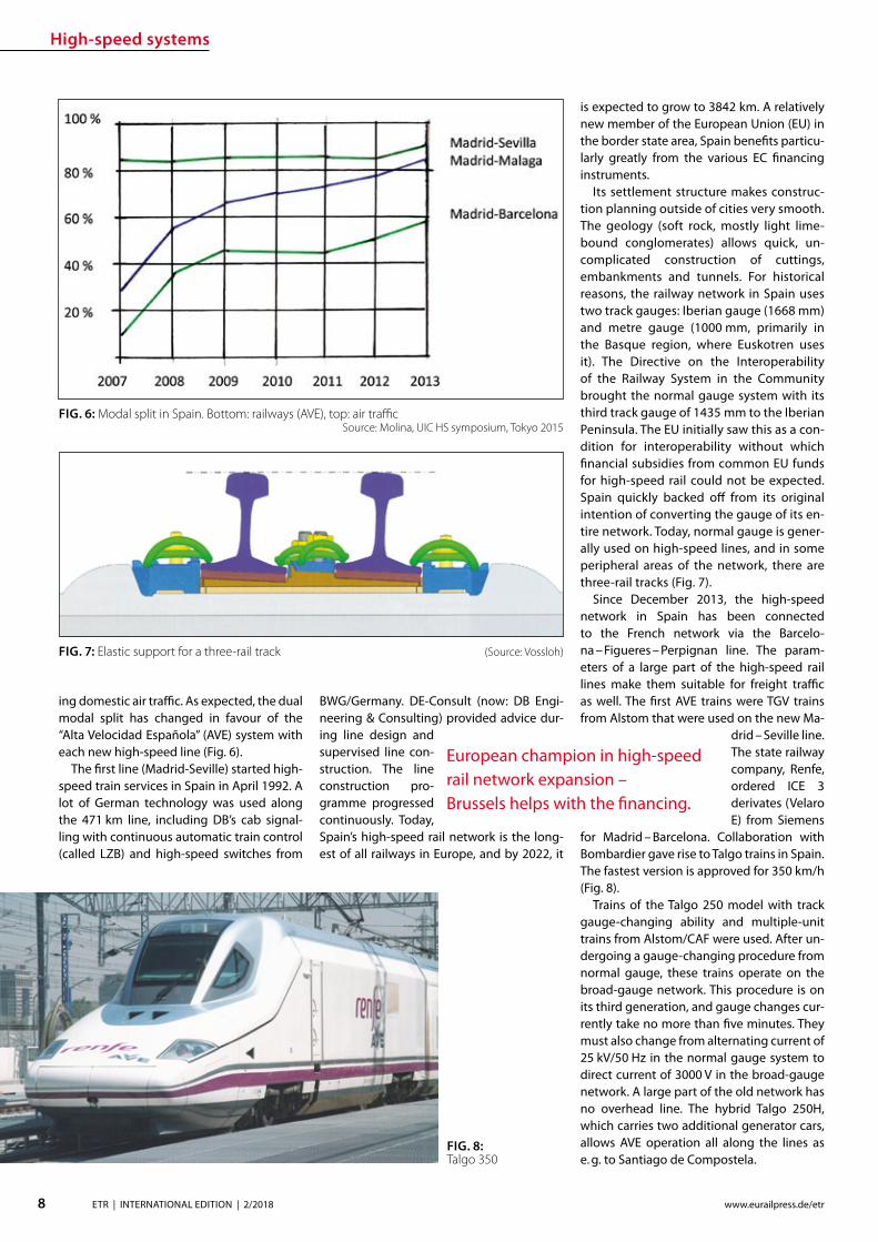
High-speed systems
8 ETR | INTERNATIONAL EDITION | 22018 wwweurailpressdeetr
ing domestic air trac As expected the dual modal split has changed in favour of the ldquoAlta Velocidad Espantildeolardquo (AVE) system with each new high-speed line (Fig 6)
The rst line (Madrid-Seville) started high-speed train services in Spain in April 1992 A lot of German technology was used along the 471 km line including DBrsquos cab signal-ling with continuous automatic train control (called LZB) and high-speed switches from
BWGGermany DE-Consult (now DB Engi-neering amp Consulting) provided advice dur-ing line design and supervised line con-struction The line construction pro-gramme progressed continuously Today Spainrsquos high-speed rail network is the long-est of all railways in Europe and by 2022 it
is expected to grow to 3842 km A relatively new member of the European Union (EU) in the border state area Spain benets particu-larly greatly from the various EC nancing instruments
Its settlement structure makes construc-tion planning outside of cities very smooth The geology (soft rock mostly light lime-bound conglomerates) allows quick un-complicated construction of cuttings embankments and tunnels For historical reasons the railway network in Spain uses two track gauges Iberian gauge (1668 mm) and metre gauge (1000 mm primarily in the Basque region where Euskotren uses it) The Directive on the Interoperability of the Railway System in the Community brought the normal gauge system with its third track gauge of 1435 mm to the Iberian Peninsula The EU initially saw this as a con-dition for interoperability without which nancial subsidies from common EU funds for high-speed rail could not be expected Spain quickly backed o from its original intention of converting the gauge of its en-tire network Today normal gauge is gener-ally used on high-speed lines and in some peripheral areas of the network there are three-rail tracks (Fig 7)
Since December 2013 the high-speed network in Spain has been connected to the French network via the Barcelo-na ndash Figueres ndash Perpignan line The param-eters of a large part of the high-speed rail lines make them suitable for freight trac as well The rst AVE trains were TGV trains from Alstom that were used on the new Ma-
drid ndash Seville line The state railway company Renfe ordered ICE 3 derivates (Velaro E) from Siemens
for Madrid ndash Barcelona Collaboration with Bombardier gave rise to Talgo trains in Spain The fastest version is approved for 350 kmh (Fig 8)
Trains of the Talgo 250 model with track gauge-changing ability and multiple-unit trains from AlstomCAF were used After un-dergoing a gauge-changing procedure from normal gauge these trains operate on the broad-gauge network This procedure is on its third generation and gauge changes cur-rently take no more than ve minutes They must also change from alternating current of 25 kV50 Hz in the normal gauge system to direct current of 3000 V in the broad-gauge network A large part of the old network has no overhead line The hybrid Talgo 250H which carries two additional generator cars allows AVE operation all along the lines as e g to Santiago de Compostela
FIG 6 Modal split in Spain Bottom railways (AVE) top air trac Source Molina UIC HS symposium Tokyo 2015
European champion in high-speed rail network expansion ndash Brussels helps with the nancing
FIG 8 Talgo 350
FIG 7 Elastic support for a three-rail track (Source Vossloh)
High-speed systems
9ETR | INTERNATIONAL EDITION | 22018wwweurailpressdeetr
raquo
4 ITALY
In Italy high-speed rail began with incre-mental commissioning of the so-called Di-rettissima (Florence ndash Rome) Construction began in 1970 and was completed in 1992 At 248 km it is considerably shorter than the old line (314 km) which had arisen between 1866 and 1874 from a combination of local railway lines and in no way met the stand-ards of modern passenger and freight trac The Direttissima was therefore constructed and operated as a mixed-trac-operations line allowing 250 kmh and using the nor-mal Italian electric system of 3000 V direct current Because of the dense high-speed trac that has come to use the lines freight trains can use the Direttissima only at night
All cities between the end stations are by-passed although transition points to the old lines ensure that they continue to operate
This principle was followed for all subse-quent high-speed lines On the newly built connecting tracks the routing speed from the branch systems (220 kmh) to the old lines is reduced incrementally which re-quires a great deal of length (Fig 9)
In addition to the Italian high-speed rail network (currently 981 km) there are a total of 77 km of connecting lines (Interconnessio-ni) that are not included in the UIC statistics We will focus on the tunnels using the exam-ple of the 300 kmh Bologna-Florence line of which 73 km is in tunnels The newly con-structed section begins 5 km beyond the Bo-logna main station which has been replaced by a new underground station and ends after 77 km in Sesto Fiorentino 6 km from Firenze
Santa Maria Novela The tunnels have a free cross section of 82 msup2 and are equipped with niches as are all Italian tunnels of new con-struction (Fig 10)
An in-house risk assessment was performed to en-sure tunnel safety The concept is based on special safety areas that are arranged at inter-vals of about 4 km The intermediate access points created during tunnel construction are used as emergency exits (Fig 11) The opera-tions control system (ETCS Level 2) together with the train control system is to ensure that if there is an incident trains stop only in the ldquosafe areasrdquo The new line is electried with 2 x 25 kV50 Hz The system change is made near Florence at Sesto Fiorino the beginning of
the newly constructed section The approach to the Florence SMN terminus station is made with a 3000 V overhead line A new under-
ground through station in Florence is still in the plan-ning stages
5 GERMANY
51 TRAFFIC AND NETWORK DEVELOPMENT
High-speed rail trac in Germany is grow-ing slowly but generally steadily (Fig 12) DB AG statistics show the registered Pkms in ICE trains They agree with the UIC statistics
FIG10 Cross section of the new line tunnels (Bologna-Florence among others) (Graphic Italferr Sistaf)
FIG 9 Speed for the transi-tion between a high-speed railway line (left hand) and a conventional line (right hand)(Graphic Italferr-Sistaf)
New line linked closely to the conventional network
FIG 11 Safety areas in the Bologna ndash Florence tunnel (detail) Graphic Senesi UIC Highspeed symposium Tokyo 1015
High-speed systems
10 ETR | INTERNATIONAL EDITION | 22018 wwweurailpressdeetr
FIG 13 Standard cross section of the two-track tunnel for the new DB lines 92 msup2 300 kmh
FIG 12 Transport performance in DB long-distance passenger services
FIG 14 Standard cross section of the twin-tube tunnel for the new DB lines 2 x 60 msup2 300 kmh
which list all Pkms in high-speed trains no matter where these trains travel In Germa-ny the ICE network consists of a mix of new lines (up to 300 kmh) upgraded lines (up to 230 kmh) and old lines (up to 160 kmh) The length of the lines and line sections with V gt 200 kmh is currently 1538 km a further 977 km on the upgraded lines allow speeds of 200 kmh Given the size of the population living there new high-speed rail in Germany is quite modest There are just 19 km of new high-speed rail line per million inhabitants In comparison there are twice as many new high-speed rail kilometres per inhabitants in France and three and a half times as many
in Spain This also helps to explain why the French and Spanish are so proud of their high-speed railway networks ndash new lines and high-speed trains are a sign of national achievement that is visible to everyone
52 CHANGING TECHNICAL SPECIFICATIONS
The recently commissioned second section of the new line (Nuremberg ndash Ebensfeld ndash Er-furt ndash HalleLeipzig) is an example of how technical requirements can change even during the planning and construction peri-ods Pre-planning began shortly after Ger-man reunication and is based on DBrsquos July
1991 version of the ldquoNew linerdquo DS 80002 guidelines which now takes V = 300 kmh into account For trac reasons the line is intended for mixed-trac operations with passenger and freight trains In the Bavarian section of the line a track spacing of 470 m was used (based on the ldquoexpanded standard clearance gaugerdquo ndash (Erweiterter Lichtraum or ERL) DB abandoned this clearance gauge one year after commissioning the new Han-nover ndash Wuumlrzburg line (1991) because no-one used it In the sections of the new line that are further north the track spacing was reduced to 450 in line with the subsequent-ly updated guidelines and TSI Infrastructure
Two-track tunnels ndash recognised as state-of-the art at the time ndash were used (Fig 13) in the Ebensfeld ndash Erfurt section like the new Ingolstadt ndash Munich section
On 1 July 1997 the German Federal Rail-way Authority (Eisenbahn-Bundesamt or EBA) issued guidelines entitled ldquoFire and dis-aster protection requirements for the con-struction and operation of railway tunnelsrdquo These guidelines stipulated construction of two single-track tunnels with cross passages for mixed operations with passenger and freight trains in long tunnels The two-track tunnels in the Ebensfeld ndash Erfurt section were grandfathered but the EBA required a safe operational solution that would rule out simultaneous use of the tunnel by freight and passenger trains That is why only twin-tube tunnels were built in the Erfurt ndash HalleLeipzig section (Fig 14) They are signicant-ly more expensive than two-track tunnels Tunnel equipment including emergency lighting escape routes etc is detailed in the TSI entitled ldquoSafety in train tunnelsrdquo which came into force on 112015
53 PROTRACTED LARGE PROJECTS
In Germany the time between prelimi-nary evaluation and commissioning in a large railway project is very long The over-all Nuremberg ndash Leipzig line was commis-sioned in December 2017 27 years after its preliminary evaluation In comparison the new Cologne ndash RhineMain line was concep-tually designed in the 1970 DB expansion programme as a new Cologne ndash Groszlig-Gerau line but the large-scale alignment variant (via Koblenz or another station) and the technology remained under discussion for a long time In 1989 the German federal gov-ernment decided on the alignment variant 31 years passed between its initial concep-tual design in 1971 and its commissioning in 2002 The Hannover ndash Wuumlrzburg line was part of the 1970 expansion programme as a new Hannover ndash Gemuumlnden line The pre-liminary evaluation began in 1971 The de-
High-speed systems
11ETR | INTERNATIONAL EDITION | 22018wwweurailpressdeetr
FIG 15 DB AGrsquos ICE 4 on a new line
cision for the Hannover ndash Goumlttingen ndash Kassel alignment variant (put forward by the feder-al state of Lower Saxony) did not come until 1976 20 years passed between the prelimi-nary evaluation and the completion of its entire length in 1991 The Hannover ndash Berlin high-speed railway line moved quickly DBDR exploration in 1988 ministry agreements between the Federal Republic of Germany and the German Democratic Republic in June 1990 commissioning in 1998 ndash just ten years after the preliminary evaluation began
At present DB constructs the Stuttgart to Ulm dedicated passenger line and new tracks in the Rhine corridor between Karlsruhe and Basel where some newly-built sections are still put into operation Some more projects in Germany are in the pipeline as a link from Frankfurt to the HS linersquos section Wuumlrzburg-Fulda for creating more capacity and short-ening journey time between Frankfurt and Berlin In 2017 DB Netz AG presented its ldquoNetwork concep-tion 2030rdquo Besides providing more freight trac capacity along two north-south axes (the Rhine Corridor and the East Corridor via Halle) several improvements for passenger
trac are provided for Among them are the modication of several major nodes in
which passenger and freight trac must share tracks The long planning and
constructions times are to be shortened to about 15 years by means of citizen participa-tion building information modelling (BIM) and simplication of plan approval proce-dures
54 NEW TRAINS
Older models of high-speed trains especially the ICE 1 are now being gradually replaced by ICE 4 (Fig 15) They are multiple-unit trains for 250 kmh with distributed drives The ICE 4 cars are longer and narrower than the previous ones however DB AG promises more comfort in the trains and advanced in-terior ttings are to contribute
Expanding the high-speed rail network ndash a matter of decades
State-of-the-art rail plastic components
To date Wirthwein has supplied products for more than 30000 km railway lines worldwide We supply the rail superstructure with hundreds of millions of our products every year such as dowels intermediate plates or angle guide plates for rail fastening systems and cable ducts
As a specialist for plastics technology we have been caring for the perfect mold since 1968 Being based at twenty-two locations in Europe Asia and the USA we are always close to our customers
HIGH PERFORMANCEFOR THE RAILWAY
Forming Innovation
Wirthwein AG Walter-Wirthwein-Str 2-10 97993 Creglingen Germany +49 7933 702-0 bahnwirthweinde wwwwirthweinde
Visit us at InnoTrans Hall 26 Stand 231
MTU hybrid drives
12 ETR | INTERNATIONAL EDITION | 22018 wwweurailpressdeetr
PREFACE
The Lake Constance belt railway (in German Bodenseeguumlrtelbahn) is the only rail link be-tween the east and west of the lake The line is used not only for regional services but also for the international Ulm ndash Basel connection and in Friedrichshafen it links with the Wuumlrt-temberg Southern Railway (Suumldbahn) to-wards Ulm Electrication of the Suumldbahn is already in progress and scheduled for com-pletion by 2023
Electrication of the Lake Constance belt railway however has been a subject of con-stant debate for some years now Since elec-trication has not been taken into account in the Federal Transport Infrastructure Plan for the period up to 2030 nancing and realiza-
Quiet clean fast use of MTU hybrid drives on the Lake Constance belt railwayMTU Hybrid PowerPacks combine the advantages of diesel and battery-powered rail traction They can be installed in new or existing rolling stock without the need for additional changes to operations infrastructures or time schedules Even on non-electried routes they allow quieter cleaner faster and more cost-ecient rail travel The use of hybrid drives on the Lake Constance belt railway could signify a breakthrough for this innovative technology
tion are still open to question The under-taking would also bring certain challenges in the light of for example two low tunnels in the town of Uumlberlingen The nancial ex-penditure necessary to deal with them has not yet been calculated Furthermore the erection of overhead lines in such close prox-imity to the shore of Lake Constance would drastically alter the rural landscape and the touristic character of the location The pro-ject is therefore meeting with resistance from some local residents and communities
As an interim solution for improving service on the belt railway MTU Frie-drichshafen in discussion with the Lake Constance Railway interest group has pro-posed the tting of hybrid drives to the existing eet in regional and long-distance
service Diesel-based hybrids such as the MTU Hybrid Power Pack oer the advantages of both diesel and battery-driven rail travel and are quieter cleaner faster and more cost-ecient than the straightforward diesel drives currently in use An electric drive for example enables very low-noise emissions-free operation in urban areas and around stations Nitrogen oxide (NOx) and particu-late emissions fall impressively by compari-son with conventional eet and improved acceleration capabilities allow the planning of more stops and render the service less prone to delays Fuel consumption and in turn carbon emissions likewise fall by up to 25 All these benets are available without the need to change existing infrastructures
MTUrsquos Hybrid PowerPack is evolved from its conventional rail PowerPack PowerPacks
Dipl Ing Ingo LehmannProject and Safety Manager for Rail Mining Oil amp Gas Engineering MTU Friedrichshafen ingolehmannmtu-onlinecom
B Sc Dragan NedicKey Account Manager Rail Sales MTU Friedrichshafendragannedicrrpowersystemscom
Dipl Ing (BA) Benjamin OszfolkResearch and Technology Devel-opment MTU Friedrichshafenbenjaminoszfolkmtu-onlinecom
FIGURE 1 An IRE train with tilting technology on the Lake Constance belt railway
MTU hybrid drives
13ETR | INTERNATIONAL EDITION | 22018wwweurailpressdeetr
raquo
are compact drive systems with diesel en-gine transmission cooling system and au-tomation unit integrated on one base frame In the hybrid version of the PowerPack the drive is enhanced by an electric motor frequency convertor intermediate circuit on-board convertor and battery for storing energy harnessed during wear-free electro-dynamic braking This technology was al-ready presented by MTU in a previous article published in this journal [1]
Specic application of this concept on the Lake Constance belt railway has been exam-ined in simulations and verications carried out by MTU on its own systems test stand The subject of the study was the IRE service between Friedrichshafen and Singen
TEST STAND SIMULATION AND VERIFICATION
MTU Friedrichshafen is unique in its ability to simulate a complete vehicle drive such as the Hybrid PowerPack on a selected route and make reliable predictions on operation and fuel consumption Furthermore the company has a state-of-the-art Hardware-in-the-Loop (HiL) test stand that enables travel of the rail vehicle over the route to be simulated according to a given time sched-ule In this set-up the real drive is incorpo-rated into a virtual rail vehicle and subject to real conditions and loads Parameters such as fuel consumption drive dynamics and battery loads can be measured in the HiL set-up and compared with the previous computer-generated simulation results In this way MTU is able to verify its fuel-saving predictions and continually optimize its simulation tools
SIMULATION IRE FRIEDRICHS-HAFEN ndash SINGEN
Simulation of conditions on the Interregio service was carried out using the technical data from an existing Bombardier VT 612 DMU that is used on the Lake Constance belt railway The special feature of this train is its
tilting capability which allows it to negotiate curving track at speed Two vehicle congu-rations were simulated an existing VT 612 and a virtual VT 612 repowered with an MTU Hybrid PowerPack
Two scenarios were considered in the test In the rst the VT 612 Hybrid rail vehi-cle and the existing rail vehicle were run as per the current timetable (status 26012018) and compared in order to draw conclusions about time schedule feasibility and fuel consumption The second scenario looked at the feasibility of introducing a new time schedule with additional stops The new time schedule was taken from a study car-ried out by SMA amp Partner AG [2] whom the Lake Constance Railway interest group had engaged in 2013 to examine dierent timetable concepts also taking into account possible electrication of the line The study showed that operation of an hourly IRE ser-vice on the Lake Constance belt railway with additional stops in Markdorf and Salem could be recommended
In both scenarios electric-only mode for low-noise emissions-free rail travel was taken into account around planned stops
Route sections travelled in electric-only mode are shown in Figure 2
To determine fuel consumption the State of Charge (SOC) of the battery was taken into account in the energy balance SOC at the end of the journey must correspond to SOC at the beginning If despite smart en-ergy management and re-charging where appropriate en route the end SOC was not absolutely equal to the initial SOC the bat-tery was re-charged up to the required level using the diesel engine The fuel required to do so was also taken into account in overall fuel consumption
The aim of the simulation was to directly compare the VT 612 with the VT 612 Hybrid on the Friedrichshafen ndash Singen service of the Lake Constance belt railway based on the current time schedule (Scenario 1) and to determine the feasibility of the new time-table with additional stops in Markdorf and Salem as per the study made by SMA amp Part-ner AG (Scenario 2) A statement on fuel con-sumption was also to be made It is empha-sized again that the hybrid train switched to electric-only mode around stations and in urban areas as shown in Figure 2 Phases of
FIGURE 2 Deployment of a VT 612 Hybrid on the Lake Constance belt railway with electric-only phases
FIGURE 3 Simulation of IRE service on the Lake Constance belt railway
MTU hybrid drives
14 ETR | INTERNATIONAL EDITION | 22018 wwweurailpressdeetr
travel in electric-only mode caused a slight reduction in the fuel saving possible in rela-tion to the existing rail vehicle However this is seen as a justied compromise in view of the benets of phases of emissions-free qui-eter travel
The results for both scenarios are shown in Figure 3
The simulation results for Scenario 1 show that with a hybrid rail vehicle a fuel saving of 157 in relation to the existing VT 612 vehicle can be achieved including phases in electric-only mode The travel time in this case is 4600 min The fuel saving can be principally attributed to re-generative braking The energy thereby harnessed is used entirely for travel in elec-tric-only mode The results for Scenario 2 show a fuel saving of 206 in relation to the existing rail vehicle from Scenario 1 The time scheduled for Scenario 2 is 5600 min So with the hybrid rail vehicle the new Sce-nario 2 time schedule with additional stops in Salem and Markdorf can be realized with lower fuel consumption than for Scenario 1
and including electric-only mode around each stop
Evaluation of the simulation results even shows that potential still exists for a further reduction in the travel time (Fig 4) The blue line shows the vehicle speeds required for keeping to the time schedule The red line shows the speed limit for taking curving track at speed The route sections passed in electric-only mode are highlighted in green The speeds necessary along the route for keeping to the timetable remain for the most part well below the maximum speed limits This means that a reduction of the travel time is perfectly feasible still leaving sucient operational reserve
The simulation results shown were veri-ed on the Hardware-in-the-Loop (HiL) test stand and could be conrmed Besides time-keeping the most tangible improvements outside the vehicle are emissions-free travel and quieter operation around stations and in urban areas Measurements at the test stand and on a demonstrator showed that vehicle noise in the vicinity of stations can
be reduced by around 75 (20 dB(A)) This improvement might even be perceived by passengers inside the vehicle
Based on the simulation results it is pos-sible to calculate the annual savings in CO2 (132 tonnes) and NOx (105 tonnes) per ve-hicle based on 2500 hours runtime per year Extending this to the entire VT 612 eet in service in Baden-Wuumlrttemberg which amounts to 41 vehicles a total of 5412 tonnes of CO2 and 43 tonnes of NOx could be saved per year Rebuilding the rail vehicles with MTU Hybrid PowerPacks could there-fore make a very signicant contribution to air pollution control on Baden-Wuumlrttem-bergrsquos railways
REBUILDING THE VT 612 WITH A HYBRID DRIVE
The VT 612 is an ideal candidate for conver-sion to a hybrid drive As a high-oor vehicle it has more than enough space underoor for housing all Hybrid PowerPack compo-nents Since the Hybrid PowerPackrsquos compo-nents are not heavier than the current drive system it can be installed without any shift in the centre of gravity The feasibility of the rebuild was also conrmed by DB System-technik the Deutsche Bahn subsidiary Re-building tilting VT 612 railcars with hybrid drives would give them a new lease of life as fast eco-friendly trains and their tilting sys-tems ndash to which they owe their faster travel times ndash would remain available in the future
The rebuild concept proposed by MTU provides for installation of a Hybrid Power-Pack in each car The installation scope would comprise the following components
rarr Hybrid PowerPack (comprising diesel engine electric motor transmission cooling system)
rarr Batteries (3 MTU EnergyPacks with ca 90 kWh capacity overall)
rarr Water-based battery cooling
FIGURE 5 Rebuild concept for VT 612 Hybrid
FIGURE 4 Simulation results for IRE service using VT 612 Hybrid Scenario 2
15ETR | INTERNATIONAL EDITION | 22018wwweurailpressdeetr
rarr Intermediate DC circuit rarr Power electronics and lters for on-board power supply
The Hybrid PowerPack comprises an MTU 6H 1800 R85L diesel en-gine an electric motor and a ZF EcoWorld power-shift transmis-sion with integrated reversing function The diesel engine delivers 390 kW and the electric motor delivers 300 kW continuous power
The Hybrid PowerPack is arranged as a parallel hybrid with the electric motor sitting on the input side of the transmission up-stream of the diesel engine As a preference the electric motors are congured for electro-dynamic braking in order to harness surplus energy for battery storage or on-board power
SUMMARY
The simulations show that an MTU hybrid drive will have no dif-culties meeting either the current time schedule in place on the Lake Constance belt railway service or that planned for the future Rebuilding the rail vehicles with Hybrid PowerPacks would achieve signicantly cleaner quieter and more economical rail travel even without overhead electrication and with no compro-mises with respect to travel times The installation alone of state-of-the-art EU Stage V-compliant diesel engines in the VT 612 rail-cars could reduce particulate and NOx emissions by around 90 The further benets oered by a hybrid drive would prot the en-vironment passengers and operators alike Electric-only mode in urban areas and around stations lowers the noise level by as much as 75 Regenerative braking considerably enhances the ecologi-cal soundness of operations while improving their cost-eciency In this way up to 20 fuel savings can be made
All in all deployment of Hybrid PowerPacks on the Lake Con-stance belt railway could herald a breakthrough for this innova-tive technology in Germany
Literature[1] Oszfolk Benjamin et al Hybridantrieb stellt Marktreife unter Beweis ETR ndash Eisen-
bahntechnische Rundschau 92015 [2] SMA und Partner AG Optimierung Angebotskonzeption Bodenseeguumlrtelbahn
Zuumlrich SMA und Partner AG 2013
FIGURE 6 MTU Hybrid PowerPack
Discover intelligent sensors
INNOVATIONS TO SIMPLIFY RAILWAY OPERATIONS
EXPPERIEENCE THHE FUUTURE OF TTRAIN TRRACKINGG
InnoTranss in Berrlin18 ndashndash 21 Septembeer 220188Halll 255 | SStannd 2232
Digitalisation opens up new possibilities in generating a wide range of highly valuable information
wwwwfrauschherccominnootranns
Predictive Maintenance
16 ETR | INTERNATIONAL EDITION | 22018 wwweurailpressdeetr
BASIC PRINCIPLES OF DATA LAKES
Data Lakes dier fundamentally from clas-sic concepts of Business Intelligence such as Data Warehouses primarily by the type of data retained In data warehouses mainly transactional data is stored whose structure is dened upfront and which has already undergone pre-ltering before persistence In a data lake however all data is persisted regardless of its structure or relevance for known use cases Data Lakes have the fol-lowing basic properties [2]
rarr Data Lakes collect and store data regard-less of type format or data volume while they are to be stored in a structured manner in classic data warehouses
rarr Data Lakes provide large amounts of data Therefore it is important to keep costs low while maintaining a high ac-
The treasure of the Data Lake ndash Predictive maintenance for vehicle eetsEective asset management of vehicle eets in rail requires an ecient and comprehensive IT landscape as a basis The core of an associated architectural concept is a data lake that collects and provides real-time diagnostic data gathered on the vehicles It is the technical basis for the application of algorithms for condition-based maintenance of rail vehicle eets
cess rate Since data stored in structured form in data warehouses must be im-mediately accessible at all times to en-able fast access high persistence costs are generated Data Lakes on the other hand store raw data which depending on the frequency of accesses can also be stored with reduced access speed
rarr At Data Lakes all data is stored centrally and heterogeneously at the same time This means that data which is very dif-ferent from the format can be linked together in analyses without having to request potentially dierent systems beforehand Existing Application Pro-gramming Interfaces (APIs) provide a wide range of usable use cases It is easy to add dierent tools to the data stream as services for example or to store inter-mediate results in the Data Lake for fur-ther use by other tools
rarr Data Lakes keep all relevant data central and unstructured regardless of format-ting The analysis tools are always con-ceptually independent of the format and structure of the data This allows new analyses or new data sets to be integrat-ed easily and quickly
rarr In modern implementations of data lakes and the service landscapes required for this the concept provides for the rapid interchangeability of tools and micros-ervices The user can test generally avail-able tools with practically no initial eort and if required can transfer those to productive use in just a few steps
SERVICE-ORIENTED AND CLOUD-BASED ARCHITECTURE FOR DATA LAKES
Instead of using solutions based on indi-vidual or a few applications with a dened range of functions Data Lakes reliy on so-lutions consisting of a exible combination of dierent micro services around a central data store The software architecture must be detached from classical patterns such as a layered hierarchy and the development must lead to a data- or data-ow-centered architecture This makes it easy to add or re-place services at any point and keeps the ar-chitecture exible for future developments
When using data lakes primarily event-driven architectures are common By con-
Mathias Haimerl Senior Data Analyst ESE Engineering und Software-Entwicklung GmbHmathiashaimerlesede
FIGURE 1 Vehicle eets in rail transport as an object of asset management
Predictive Maintenance
raquo
trolling the events based on the underly-ing data streams this architecture can be called Data-Driven Architecture (cf[5]) The software therefore builds itself around the data stream as shown in Fig 1 The data stream therefore represents the basis for the achievement of objectives whereby each individual problem can be regarded as an in-dependent architecture The desired objec-tive is broken down top-down into required services and newly formed into a specic so-lution Right from the start not only services for data manipulation are considered but also accompanying services for areas such as logging and security
The implementation of data lakes on company-owned hardware does no longer make sense for most projects from a nan-cial point of view and therefore only makes sense for particularly critical applications (eg banks medicine military) if commercial cloud solutions with appropriate security options cannot be found or are not applica-ble for compliance reasons
CHALLENGES AND SOLUTIONS OF CLOUD-BASED ARCHITECTURES
The use of services in a cloud creates new
challenges that need to be addressed in ad-vance
Information security of the customer data available in the cloud is in most cases much higher in the Amazon Web Service (AWS) Cloud than on self-operated servers The large number of system administrators de-ployed worldwide for the AWS Cloud some of whom specialize in information security provides signicantly better information se-curity than would be the case with conven-tional IT infrastructures operated by compa-nies themselves
Handling security vulnerabilities Due to the high number of users in the global internet of things (IoT) security gaps that allow access to external data quickly become nancially and legally problematic The Linux base and the simple reporting of security problems allow newly discovered vulnerabilities to be resolved quickly and globally The globally uniform system and the uniform administra-tion of software components close security gaps within a few hours
Protection against unauthorized access by third parties Authentication measures serve to protect sensitive data against unauthor-ized read access (data theft) on the one hand
and to protect data against unauthorized manipulation (data modication computer sabotage) on the other Authorization meas-ures are aimed at ensuring that analysts and solution architects only have access to the data relevant to their projects This is supported by the targeted allocation of authorisations to the respective architects In addition organization-related boundary conditions are contractually secured One example of this are compliance guidelines such as certication of cloud providers ac-cording to standards like DIN EN ISOIEC 27001
Software maintainability The AWS ba-sic system is stable against updates and changes without interfering with customer projects Customer projects run in self-con-tained environments (sandbox) The pro-vider of the cloud system has the freedom to use exchange and extend any hardware components without expensive downtimes or waiting times for the user Software up-dates and time-consuming hardware up-grades are obsolete for the user
Legal framework Sending data across na-tional borders is often a legal hurdle that prohibits the use of cloud services To coun-teract this cloud providers have provided
FIGURE 2 Overall concept of the data-driven architec-ture The microservices are structured around the data stream
wwwmobility-bbcom
Berlin-Brandenburg
Moving mobility
to the next level
Meet us at InnoTrans
City Cube Hall B
210x99_VML_InnoTrans_eng_ETRindd 1 19072018 081118
Predictive Maintenance
18 ETR | INTERNATIONAL EDITION | 22018 wwweurailpressdeetr
for the possibility of binding to regions that ensure that data does not leave certain pre-dened regions
Calculability of costs An AWS solution is about 90 cheaper than the operation of ldquoclassicrdquo infrastructures This value is also evi-dent in one of our customer projects where about 98 of the costs were saved on the development system and the eective sav-ings for the live system were interpolated to be at about 91 AWS provides a billing calculator that provides an estimate based on past months and previous monthly costs
SAMPLE IMPLEMENTATION STEPS FOR AMAZON WEB SERVICES
As an example implementation of a data lake the cloud environment AWS was used as described below During implementation four functionalities were clearly separated which are described in more detail below
rarr Data acquisition including pre-process-ing (ingestion)
rarr central data storage rarr Cataloging of data rarr Preparation of concrete analyses
DATA ACQUISITION (DATA INPUT) FOR DISTRIBUTED DATA SOURCES
In order to be able to ingest sensor data from vehicle eets the receiving system must be able to accept and store a large number of distinct data from many sensors On the senderrsquos side however data must be collected buered and regularly transmit-ted to the Data Lake To do this a periodic Internet connection must be ensured For
the frequency of data transfer an individual taring between the local data collection and the frequency of synchronization to the cloud must also be found Data transfers at low bandwidth should preferably rely on the collection of several data sets and trans-fer with a stable connection However this requires more memory in the local device With higher bandwidth and stable connec-tions the data can also be transferred more frequently This on the other hand leads to an increased load on the receiver A project-specic optimum must be found here
Finally it should be taken into account that the order of data sets should already be de-ned during ingestion even if the structure does not have to be xed from the outset To simplify later evaluations considerably data of the same type for which the uniformity is to be foreseen should be grouped logically This unies the data accesses of the evaluat-ing processes and thus minimizes the eort
From a specic project of a customer we know that the current data load of 6754 MBh will increase tenfold by 2020 due to an increase in the number of equipped vehicles and a simultaneous tripling of the number of sensors to approx 2GBh The distribution of the eets is Europe-wide with the focus on Central Europe
CENTRAL DATA STORAGE
In order to eciently persist the collected sensor data of vehicle eets the receiving system stores the data in a central location In AWS data is stored centrally in any size and in an automatically growing storage unit a so-called bucket The data is stored in ob-jects a logical data unit comparable to les in a classic le system To make searching
through data easier the objects are indexed based on their specic prexes and opti-mized for fast access Since the implementa-tion is based on RESTful and therefore each data record transmitted by sensors sends a PUT request a new object is created for each data record This creates an immense num-ber of objects in the long term This is irrele-vant in terms of costs and storage space For an analysis based on large amounts of data with low reaction times however a catalog-ing of the data is still necessary
CATALOGUING FOR VARIOUS APPLICATIONS
The exible NoSQL database DynamoDB oers an optimal possibility to catalog data without having dened a schema and still get extremely fast access speeds A Dy-namoDB table has a primary key which con-sists of a partitioning key and an optional sort key The partitioning key determines the automatic partitioning of the table and should therefore be very well selected (see [9]) An entry also supports update com-mands DynamoDB oers a very exible memory which can be written and read in dierent ways
New data arriving in Simple Storage Ser-vice (S3) can be automatically analyzed as a trigger for cataloging and added to cor-responding catalogs Since the analyses are usually very individual a pipeline must be created so that the new data arriving in S3 can be processed This can be achieved with minimal eort using the Microservice Lamb-da which makes it possible to execute small programs in the AWS landscape without any further integration eort Optional lters can be set for the triggers so that dierent pre-xes start dierent lambda functions
rarr Read The respective lambda function receives the bucket and the object name of the newly arrived object and can ex-amine this import and the content ac-cording to previously dened criteria and extract the corresponding values
rarr Write This data can then be written to a DynamoDB table regardless of whether the data record already exists ie wheth-er it has to be updated or whether it is a new data record
This type of cataloging is the comparatively most complex but at the same time the ex-ibility exceeds that of other technologies by far The cost factor is also considerably lower here The costs for DynamoDB tables are cal-culated according to provisioned capacities for read and write accesses This is under-
FIGURE 3 Using cloud solutions brings new challenges
Predictive Maintenance
19ETR | INTERNATIONAL EDITION | 22018wwweurailpressdeetr
standable as an increase in capacity in the background is a real hardware replication This allows tables with costs of less than one euro per month for the minimum congura-tion and a separate table can be provided for each application case The requests for large amounts of data via the primary key or only a part of it can be retrieved extremely quickly whereby retrieval times in the low two-digit millisecond range are not uncommon
PREPARATION OF CONCRETE ANALYSES
The creation of analyses on the catalogued data is possible without great eort with the basis shown This is done in several consecu-tive steps
rarr Top-down analysis of the problem to be solved as there are various microservic-es for a wide variety of applications As a result individual use cases can be as-signed to the use cases
rarr Selection of suitable microservices De-pending on the target platform the ap-propriate microservices can be selected There are specic services that enable the further use of existing programs that work on relational databases for example Other microservices support machine learning or the visualization of complex interrelationships in informa-tive dashboards
rarr Bottom-up aggregation of specically congured microservices For this pur-pose services already congured for similar analyses can be reused or addi-tional instances with slightly modied conguration can be created
SUMMARY amp OUTLOOK
All in all Data Lakes oer an optimal solution from the initial setup of a collection of raw data from various sources without large upfront ef-fort or high costs to the data storage of many eets of dierent vehicles worldwide and the provision of data catalogs for various analyses of various kinds The collection of measure-ment data in persistent online data stores such as AWS buckets can be implemented within minutes and is operational from this point in time so that data can be collected and archived Even if no specic use cases are known at the time of implementation it is recommended to persist all data on low-cost cloud storage so that it is already available for possible evalua-tions at later points in time Since there is often no reason to process data without use cases favorable options for persistence of the data can be used To avoid vendor lock-in consider designing Data Lake to be adaptable to alter-native platforms Alternative options for data storage include the storage services of Google Cloud Services or Microsoft Azure Of course the use of a second service also doubles the total costs
References[1] Canalys (2017) Cloud service providersrsquo battle drives
the worldwide cloud infrastructure market up 42 in Q1 2017 httpswwwcanalyscomstaticpress_re-lease2017press-release-150517-cloud-service-providersE28099-battle-drives-worldwide-cloud-infrastructure-market-42_1pdf Palo Alto Shanghai Singapore and Reading (UK) Pressemit-teilung 15052017
[2] Amazon Web Services (2017) Building a Data Lake on AWS httpspagesawscloudcomrs112-TZM-766im-agesAWS_Data-Lake_eBookpdf 01112017
[3] Bundesministerium des Inneren (BMI) (2017) Polizeili-che Kriminalstatistik 2016 httpswwwbmibunddeSharedDocsdownloadsDEpublikationen2017pks-2016pdf Pressemitteilung 24042017
[4] Buschmann Frank and Christiane Loumlckenho eds (2000) Pattern-orientierte Softwarearchitektur ein Pat-tern-System 1 korr Nachdr Muumlnchen Addison-Wesley 2000
[5] Mahjourian Reza (2009) An Architectural Style for Data-Driven Systems Paper Gainesville FL 32611 USA httpswwwcsutexasedu~rezalesxpage-icsrpdf 22032009
[6] Tilkov Stefan (2009) REST und HTTP Einsatz der Ar-chitektur des Web fuumlr Integrationsszenarien 1 Au Hei-delberg dpunkt 2009 ISBN 9783898645836
[7] Hunkeler U H L Truong and A Stanford-Clark (2008) MQTT-S mdash A Publishsubscribe Protocol for Wireless Sensor Networks In Communication Systems Software and Middleware and Workshops 2008 COMSWARE 2008 3rd International Conference on 791ndash98 2008 httpsdoiorg101109COMSWA20084554519
[8] Manseld-Devine Steve (2016) DDoS Goes Main-stream How Headline-Grabbing Attacks Could Make This Threat an Organisationrsquos Biggest Nightmare Net-work Security 2016 no 11 (November 2016) 7ndash13 httpsdoiorg101016S1353-4858(16)30104-0
[9] Vyas Uchit (2014) DynamoDB Applied Design Patterns Birmingham United Kingdom Packt Publishing 2014
SAFERAILSYSTEMCOM
Guessing or GPR
bull GPR measurements and analysisbull Condition-based maintenance planningbull More than 25 years of working experience - worldwide
BIM
20 ETR | INTERNATIONAL EDITION | 22018 wwweurailpressdeetr
ABOUT SIEMENS MOBILITYrsquoS TURNKEY RAIL SOLUTIONS BUSINESS
Siemens AG is a global technology power-house that has stood for engineering ex-cellence innovation quality reliability and internationality for more than 170 years The company is a pioneer in supplying in-frastructure solutions Siemens Mobility is an experienced provider of complete turn-key solutions for rail systems having already carried out more than 50 various and major rail projects worldwide The organization is home to experts in project management and system integration as well as key prod-ucts of rail infrastructure These specialists develop and implement projects for all types of rail vehicle systems from metros trams and light rail vehicles and automated peo-ple-movers to Intercity and high-speed train units ndash all designed for maximum reliability availability and eciency
THE CHALLENGES OF RAIL INFRASTRUCTURE PROJECTS
Projects to install new rail infrastructure and expand existing systems are growing steadily more complex The rising number of project participants and stakeholders presenting a broad range of specic require-ments planning teams in dierent locations and time zones having to coordinate and
Digital twin serving rail infrastructure How turnkey rail infrastructure projects are beneting from applying Building Information Modeling (BIM) how Siemens Mobility is pursuing virtual planning of projects with project partners and custom-ers such as in the Riyadh Metro Project and what added value this methodology is creating
integrate their civil and rail engineering and planning and the ever increasing time and cost pressures exemplify this problematic complexity
There are an enormous number of inter-faces and requirements involved especially in large rail infrastructure projects and or-ganizing them demands extensive resources and absolute precision
AT THE VANGUARD OF DIGITAL PLANNING
Just as countless other sectors of the con-struction industry have already experienced digitalization is driving a para-digm shift in rail infrastructure away from analog meth-ods and embrac-ing digital and in-tegrated planning encompassing eve-rything from erec-tion planning installation and support for training to preparation and performance of repairs and maintenance all based on digital processes and data models
More than four years ago Siemens Mo-bility began applying building information modeling (BIM) techniques as well to project planning and execution of complete turnkey
solutions for rail systems As one of the trail-blazers of digitalization Siemens Mobility uses BIM to create a digital twin ndash a virtual model of major rail projects planned for im-plementation
This methodology focuses on achieving cost and time eciency while also ensuring the highest quality standards
Siemens Mobilityrsquos Turnkey Rail Solutions is using BIM in col-laboration with construction part-ners to optimize project planning and execution This involves the use of computer-generated 3D modeling and the
information integrated into or linked with the models
REFERENCE PROJECT RIYADH METRO
The Arriyadh Development Authority (ADA) ndash the executive arm of The High Commission
Both the implementing company and customer benet from the reduced risk of delays in planning as well as the prevention of defec-tive planning and resultant need to revise planning during ongoing installation
Dr Payam AminiHead of Digital Transformation Turnkey Projects amp Electrication Siemens Mobility Munich payamaminisiemenscom
A simulated view of the outside of the depot for which the path of sunlight can be simulated over time
raquo
BIM
21ETR | INTERNATIONAL EDITION | 22018wwweurailpressdeetr
for the Development of Arriyadh in Saudi Arabia ndash is currently building one of the larg-est metro projects in the world with six rail lines totaling 176 kilometers in length The system will be the backbone of the public rapid transit network serving Saudi Arabiarsquos capital city The order placed with Siemens Mobility covers supply of 67 Riyadh Metro model rail vehicles based on the Inspiro Plat-form series line electrication the signaling and communication systems for driverless service on Lines 1 and 2 as well as system integration and project management Sie-mens Mobility is part of the BACS consor-tium led by US company Bechtel along with Almabani General Contractors and Consoli-dated Contractors Company
The Riyadh Metro Project (RMP) kicked o by dening the information requirements and project-specic BIM objectives of the customer The BIM management team of Siemens Mobilityrsquos construction partner Be-chtel then used this information as the basis for elaborating in detail the BIM process for all project participants
The BIM execution plan that denes the BIM process for a specic project basi-cally provides the answers to the agreed require-ments In this key central document Turnkey Rail Solu-tions dened for all project participants in-volved in the infrastructure design the roles and scopes of responsibility the programs and le formats to be used what applica-tions are to be integrated into the BIM pro-cess the data-exchange process along the chain of project phases the quality review inspection and testing criteria procedures for coordination and collaboration and much more This was necessary in order to ensure smooth BIM implementation over the entire project cycle
Siemens Mobilityrsquos construction partner also generated the model element plan which denes in an overview who is to gen-erate what model content for the project by when and to what level of development (ie geometry information and coordination) In this project BIM standard the construc-tion partner also dened the details for modeling agreements and documentation standards
Model-based planning is one of the pro-jectrsquos centerpieces enabling comprehensive integration of all rail infrastructure systems such as rail electrication the depot and workshop equipment line signaling and communication technology and platform screen doors
CLARITY DRIVES THE EFFICIENCY OF WORKFLOWS
Siemens Mobilityrsquos infrastructure planning engineers used project-specic BIM software to share their model-based information with Siemens Mobilityrsquos suppliers and the con-
struction partner The program Pro-jectWise is used in combination with Aconex served and continues to
serve as a shared data platform accessible project-wide ensuring that each piece of information is retained only once and in its most recently valid version In this ldquosingle source of truthrdquo data are referenced rather than duplicated signicantly improving in-formation management increasing the reli-ability of data and eliminating any use of superseded obsolete data This provides full trans-parency for all pro-ject participants Photo-realistic displays and animated videos of the planning progress generated on the basis of the 3D planning information ensure transparency enhance understanding and support the iterative process
The permanent availability of data accel-erates collaboration across national borders and company boundaries These aspects are particularly benecial in the RMP Just Sie-mens Mobilityrsquos unit alone had colleagues based in 13 dierent cities working to de-sign the rail infrastructure coordinating and agreeing across national boundaries and dierent languages time zones and work capacities
In addition to the geometrical properties
of system components for example of fre-quency converters the participating plan-ning engineers also integrated non-geomet-rical information and requirements of their systems such as zones and clearance spaces that are essential for installation and mainte-nance Once work on a subarea of a model (work in progress) was approved for release this information was then available to all partners within the project (shared areas) In turn these partners reviewed the completed work for impacts on their own work scopes
In interdisciplinary collision reviews the design coordinators conducted collision tests with all other draft components Such reviews examined for example the civil struc-tures technical building equipment systems and Siemens Mobilityrsquos systems such as the signaling equipment and traction power supply grid to identify any conicts between
the systems them-selves or with the civil structures
In this way structural imple-mentation of the overall project as
well as individual subareas can be digitally tested at any time
As a provider of turnkey infrastructure solutions Siemens Mobilityrsquos unit was in-volved early in the RMP through BIM help-ing to prevent planning errors and leading to quicker validation of draft planning such as for spatial requirements of infrastructure equipment free clearance proles and pre-venting collisions
The RMP oers a basis for further infra-structure projects using BIM methodology The stock of digital objects available in the component library continues to grow Exist-ing digitally modeled components can be directly used for the next digital twin This
BIM creates full transparency for everyone participating in the plan-ning of infrastructure projects
The Control Center of the Riyadh Metro Project for Line 1 was fully planned digitally Once that design process was completed actual construction started
BIM enables earlier design valida-tion of rail infrastructure technol-ogy and engineering as well as civil construction
BIM
22 ETR | INTERNATIONAL EDITION | 22018 wwweurailpressdeetr
accelerates digital planning from one pro-ject to the next
Siemens Mobility Turnkey Rail Solutions sees particular potential for BIM in integrating the necessary man-agement process-es BIM supports the management of interfaces requirements congurations and project documentation This improved management leads to accelerated project execution And although project execution in Riyadh is still underway the added value created by the BIM method is already clearly evident today ndash for both Siemens Mobility and the customer
DIGITAL SCAN OF THE INFRASTRUCTURE CREATED
Siemens Mobility Turnkey Rail Solutions is utilizing other digital solutions as well for the Riyadh Metro Project that further optimize pro-ject execution Siemens Mobility-owned track measuring vehicles and 3D laser scanners are deployed to eciently compare the progress
of as-built construction and installation against the design target data These units travel along the existing sections scanning and thereby
digitalizing the as-built environment The object-specic information collect-ed by this measur-ing system whether on track position-
ing platform edges or technical spaces is com-pared with the digital design thereby directly revealing any deviations from planning
This produces a 100 -accurate database of the existing as-built status Particularly when projects aim to expand exist-ing infrastructure such transparency prevents costly conicts when equipping existing civil structures with new infrastructure equip-ment Besides the hardware procurement Siemens Mobility is banking in this context on developing the expertise of its own per-sonnel to cover planning of measuring cam-paigns kinematic and static imaging and evaluations such as review for collisions
PROMISING OUTLOOK
Siemens Mobilityrsquos Turnkey Rail Solutions has ceaselessly invested in implementing and further developing digital methods to keep pace with steadily growing deadline and cost pressures and the increasingly stringent demands of complex rail infra-structure projects These efforts are now empowering Siemens Mobility to better assess the sometimes extremely demand-ing detailed requirements early already in the project bidding phase and estimate costs more reliably thereby minimizing risks
In previous projects utilizing BIM meth-odology Siemens Mobilityrsquo experts identi-ed a shifting of eort into the early project phases
Siemens Mobilityrsquo experts see opportuni-ties in doing so particularly in the assess-ment of design modications in terms of im-pacts on costs and in early application when the leverage for such optimization can still prove very eective
Yet BIM doesnrsquot end when construction work on an infra-structure project has been complet-ed By developing a digital twin of the as-built infrastruc-ture and applying
that model over its entire lifecycle these sets of digital data can be used to optimize asset management
The BIM method harbors major potential for signicantly shaping the rail infrastruc-ture sector in the coming years
A view of the digital model of the King Abdullah Financial District Station on Line 1 which can be viewed in the computer pro-gram from all sides
Photo-realistic displays and animat-ed videos of the planning progress ensure transparency and enhance understanding
BIM provides the basis for simpler and ecient interface management and contributes signicantly to accelerating project execution
5 | 2017 Mai wwweurailpressdesd
109 Jahrgang
SIGNALLING amp DATACOMMUNICATION
Oumlsterreich Gut gesichertAustria Well-protected
13 Kostenguumlnstige Sicherung von Eisenbahnkreuzungen Cost-effective protection of level crossings
36 Finnland Gegen den Instandhaltungsruumlckstand Finland Reducing maintenance backlog
21 Schweiz Weltpremiere auf der Toumlsstalstrecke Switzerland A world premiere on the Toumlsstal line
Your contact person Silvia Sander +4940237 14-171 silviasanderdvvmediacom wwweurailpressde
Leader in Signalling and Datacommunication
No 1ad medium
SIGNALLING AND
DATACOMMUNICATION
AUTONOMOUS DRIVING
CYBE
R SE
CURI
TY
LEVEL CROSSING TECHNOLOGY
OPERATIONS MANAGEMENT SYSTEMS
MOBILE COMMUNICATIONETCS
REPUTABLE
UN
IQU
E
ESTABLISHEDTELECOMMUNICATION
OPERATIONS CONTROL TECHNOLOGY
INFORMATION TECHNOLOGYBILINGUAL
Book your advert right now
raquo
Ground Penetrating Radar
23ETR | INTERNATIONAL EDITION | 22018wwweurailpressdeetr
1 INTRODUCTION
Many countries allocate large amounts for the modernization and upgrading of their railway networks in order to meet the de-mands of increasingly dense rail trac with higher axle loads at ever higher speeds However this can only be achieved if all rel-evant key gures and geotechnical condi-
Ground Penetrating Radar ndash Basis for eective Track MaintenanceThis article describes the capabilities and functionality of Ground Penetrating Radar (GPR) for higher speeds GPR is a train-borne technology for a continuous inspection of the geotechnical conditions of railway tracks The basic principles of the GPR technology are explained with particular reference to all relevant railway specic tasks namely the identication qualication and quantication of ballast fouling by using a fouling index the determination of the quality of track drainage and its quantication through a drainage index and the calculation of the track modulus (TM) Special emphasis in the context of GPR investigations is placed on the mapping of sections with clay foulingmud spots inside the ballast bed or at its base and respectively inside intermediate layer formation or subsoil In the past such weak-spots have caused derailment they could represent a risk for rail-trac [11 13 14 15 16] Besides their late detection implies exceedingly high maintenance costs
tions of the respective tracks can be reliably evaluated On this basis only the necessary investments in track maintenance moderni-zation and support can be dened in the ap-propriate size and can be placed correctly This is particularly true when budgets are tight
The demands exerted on the track in terms of safety grow with increasing speed
FIGURE 1a) Trajectories of radar waves which are reected at the layer boundary between two media
with dierent dielectric constant (laquo)b) Due to the dierent travel time of the reections the layer boundary is reproduced in the
radargram (reference Ground Control and IEV)
Dipl-Geophys Giuseppe StacconeDirector of Ground Control GmbH MunichGermanystacconesaferailsystemcom
David Camacho MScDoktorand am Institut fuumlr Eisen-bahn- und Verkehrswesen der Universitaumlt Stuttgart (IEV)davidcamacho ievvwiuni-stuttgartde
Moritz SchebuchMitarbeiter am Institut fuumlr Eisen-bahn- und Verkehrswesen der Universitaumlt Stuttgart (IEV)moritzschebuch ievvwiuni-stuttgartde
Prof Dr-Ing Ullrich MartinDirektor des Instituts fuumlr Eisenbahn- und Verkehrswesen der Universitaumlt Stuttgart (IEV) und des Verkehrswis-senschaftlichen Instituts an der Universitaumlt Stuttgart eV (VWI eV)ullrichmartin ievvwiuni-stuttgartde
Dipl-Ing Sebastian RappAkademischer Mitarbeiter am Institut fuumlr Eisenbahn- und Verkehrswesen der Universitaumlt Stuttgart (IEV)sebastianrapp ievvwiuni-stuttgartde
Ground Penetrating Radar
24 ETR | INTERNATIONAL EDITION | 22018 wwweurailpressdeetr
Therefore failing to detect track damages or obtaining inadequate information on track damages represents a hazard for every kind of railway trac For this reason a decision guidance that facilitates a systematic and ecient renewal of the tracks is important The more intensive the rail trac and the higher the trac speed the bigger the re-quirements in terms of an ecient and reli-able track inspection
The mapping of clay fouling or mud sec-tions is of special importance Fine-grained soil material such as silt or clay wells up from the formation and reaches the ballast base or even penetrates the ballast layer itself As a consequence track drainage and track stability (ie bearing capacity) are strongly reduced This results in lasting deformations that require complex maintenance work and high costs If weak-spots are not identied or not detected in time clay fouling can in the worst case scenario lead to derailment [10 13 14 15 16]
During the past 25 years Ground Control GmbH which is placed in Munich Germany has surveyed more than 100000 km of rail-way tracks in many countries in Europe and all over the world Recently with information obtained from GPR results and other data (ie track geometry and track dynamics) a continuous and complete assessment of the trackrsquos structural condition is possible
2 MEASURING PROCESS
The GPR method is an electromagnetic re-ection method Radar pulses are transmit-ted into the subsoil by a transmitter antenna The energy of the electromagnetic waves is partly reected at interfaces between layers with dierent dielectric properties and re-transmitted to the receiver antenna Based on the measured travel time of the signals and knowing the propagation speed of the waves in the medium depth and surface of the layer can be computed
In order to dene the depth of the re-ector from the surveyed travel time the propagation speed of the radar waves in the subsoil has to be determined The speed of electromagnetic waves in the subsoil is re-lated to the water content of the individual material Therefore it is generally not pos-sible to refer to reference values for certain rock or soil types Thus the radar wave speed has to be calibrated for each project area
The penetration of electromagnetic waves mainly depends on the electric conductivity of the soil and the applied antenna frequen-cy By using low frequency antennae on low conductive subsoil the largest investigation depth can be achieved
PERFORMING SURVEYS WITH MODERN HIGH-SPEED-GPR
Todayrsquos GPR surveys are carried out with train mounted systems at speeds up to 160 kmh As a general rule the antennae system is fastened at the carrier vehiclersquos buers A precise positioning is achieved by an inte-grated Dierential Global Positioning Sys-tem (DGPS) and Doppler radar
The characteristics of modern GPR sys-tems are
rarr The equipment can be installed and run on a wide range of track-bound vehicles (including regular trains or vehicles on Hy-Rail)
rarr They are fast enough to be integrated into the regular trac schedule Hence expensive track closure is no longer nec-essary
rarr DGPS and Doppler radar are used for an accurate (ie precision within a meter) positioning of the antenna independ-ent of the speed and length of the track surveyed
rarr Measurement data resolution and data quality are equally high no matter what length and what speed
rarr All GPR components are eectively
shielded against interferences from sig-nalling and communication systems
3 GPR TASKS
In contrast with punctual boreholes and trenches modern GPR systems provide con-tinuous information about the geotechnical condition of the track performing the fol-lowing tasks
rarr Continuous mapping of track-bed-thick-ness and layers below (ie intermediate layer protective layers)
rarr Distinction between clean and fouled ballast and calculation of Fouling Index
rarr Mapping of mud spots or clay fouling sections inside ballast bed at its base or inside substructure layers respectively
rarr Detection of sections with drainage problems and calculation of ldquoWet Bed Indexrdquo
rarr Mapping of areas with insucient bearing capacity (eg settlements) and evaluation of the dynamics of track set-tlement
rarr Control and evaluation of the quality of maintenancerenewalconstruction work (quality of cleaned or exchanged ballast thickness of a new ballast bed quality and thickness of soil layers)
rarr Estimation of track condition based on track modulus (TM) calculation
Additionally GPR data allow for the deni-tion of a sustainable cause-based and there-fore eective track renewal recommenda-tions and programs Optionally GPR oers the possibility to accurately map cables pipes and other objects in the track sub-structure creating the possibility to provide a complete picture of the entire system
31 CLAY FOULING ndash STRONG EFFECT ON TRACK STABILITY
Clay Fouling is one of the main reasons for the reduction of the load bearing capacity of the track in a relatively short period of time Several derailments in the past were caused by mud spots [10 13 14 15 16] even when the limit values for track geometry failures according to [2] have not been exceeded [13 14] It is therefore and because of safety reasons of particular importance to detect clay fouling areas reliably in their precise dimension and as early as possible The rec-ognition of the problem should be irrespec-tive of whether the clay fouling exists in the substructure at the base of the ballast bed or in the ballast bed itself Clay fouling can
FIGURE 2 Figure 2 Antenna mounted on the train buers of a mainte-nance vehicle(reference Ground Control)
Ground Penetrating Radar
25ETR | INTERNATIONAL EDITION | 22018wwweurailpressdeetr
raquo
rapidly deteriorate the stiness of the track and its quality The trackrsquos lateral stability is massively reduced longitudinal errors along the rails arise
Clay fouling is also a serious decit from an economic point of view Its timely iden-tication allows for avoiding slow speed sections thus sparing time and money for maintenance procedures Detecting clay fouling before it reaches the ballast bed ena-bles cost eective renewal Otherwise it will be very expensive There is no option for bal-last cleaning a suciently compacted pro-tection layer built of the appropriate materi-al is essential the installation of composites does not prevent clay fouling from entering the ballast bed (see Fig 3)
Save few exceptions clay fouling spots are not visible at the track surface and since drill-ings and trenches do only provide punctual results reliable information is only achievable through GPR measurements (see Fig 4)
A frequency analysis of the measured data results in a typical change of the signal spectrum in the area of clay fouling Based on the GPR results borehole program can be implemented which can be used for further analysis GPR surveys to detect ballast foul-ing have been carried out for years in Swit-zerland Austria the Netherlands and France among others
32 TRACK MODULUS (TM)
Examining the geotechnical conditions of railway tracks requires an index which in-forms about state and quality of the tracks in a quantitative manner The challenge has
been to dene the track condition continu-ously This has been achieved by combin-ing TM with the results of continuous GPR-measurements
It is possible based on [3 4 5 6 7] to es-timate quality and bearing capacity of the railway track Therefore the TM describes the relation between vertical load and elas-tic deection of the sleeper-bearings
On the one hand the TM can be calculated based on the measured deection under load [18 20] on the other hand according to the soil properties [8 9 11] The measuring principle for determining the load deec-tion is described in detail in [12] and [17] The properties of the system components such as the area of inuence of the sleepers under load can greatly aect the TM Hence around turnouts the area of inuence of sleepers deviates from the standard track This is because an increased area of inu-ence causes an increase in the distribution of the load reducing the deection of the
rail Notwithstanding to simplify the calcula-tion of the TM the inuence area of sleepers around turnouts are assumed to be constant assuming the values of the standard track Depending on the type of sleepers installed the value of the TM can increase sharply around turnouts (Fig 5) In addition cavities under the sleepers increase the deection of the track under load which in turn inu-ences the calculation of the TM decreasing its value
An additional and new approach for calcu-lating the TM is based upon the soil proper-ties which can be described by the Poissonrsquos Ratio or the material density of the soil The soil properties derive from the GPR data This methodrsquos advantage is to be completely in-dependent from superstructure conditions The individual layers are assigned soil values according to condition and bulk density Averaged soil properties are calculated ac-cording to [1 19] The TM can be estimated according to [9] and [11] Previous studies
FIGURE 4 Visual analysis of GPR data depicting clay fouling along a track (reference Ground Control and IEV)
FIGURE 3 Geotextile or composite does not stop ne particle migration to the surface (reference Ground Control)
Ground Penetrating Radar
26 ETR | INTERNATIONAL EDITION | 22018 wwweurailpressdeetr
indicate that this method has signicantly lower value variations along the track axis compared to the approach based on the use of track displacement data (Figure 5)
The example in Fig 5 shows two track moduli based on the measured displacement under load (red line) and the soil properties (blue line) Around the turnouts a signicant increase of the TM is visible if the calculation is based on the measured deection By divid-ing the TM into quality classes according to [3 4 5 6 7] the condition of the track can be sat-isfactorily estimated (Fig 6)
33 TRACK ANALYZER ndash CONTINUOUS PRESENTATION OF ALL MEASUREMENT AND TEST RESULTS
Results from GPR surveys along with all identied soil parameters and indices cal-
culated can be displayed in comprehensive track analysis software called ldquoTrack Analyz-errdquo In order to provide all information for in-frastructure managers track geometry and track dynamics data are also integrated and displayed in the software (see Fig 7) which also oers the exibility to incorporate other tasks and aspects as required by the user
The Track Analyzer provides infrastructure managers continuous information about the geotechnical conditions of the track with regard to all relevant issues Moreover it provides a better understanding of the sub-structuresubgrade conditions and their in-uence on the superstructure This allows for a signicantly increased track quality pro-viding higher route availability and safety
A big advantage of the GPR method is the minimization of the need for intensive direct outcropping (probing drilling scooping)
to characterize the underlying geotechni-cal characteristics of the track substructuresubgrade which results in signicant cost reductions
4 SUMMARY
This paper describes a modern train-borne technology for the inspection of the geo-technical conditions of railway tracks It is based on High Speed GPR and on classical procedures for providing continuous infor-mation about geotechnical parameters and indices A new quality of GPR measurements is to provide quantitative indices in addition to qualitative results to full the require-ments of the railway engineers in the best possible way
Special attention is paid to the detection of mud spots and clay fouling sections as a risk for derailment [10 13 14 15 16] To date track inspection with GPR is more appropri-ate than any other inspection method to de-tect map and qualify areas with geotechni-cal problems
The Track Analyzer software combines GPR results with track geometry and track dynamics data This allows for cause-based track renewal and targeted investment and provides signicantly more reliable results than conventional methods This approach is especially relevant for limited budgets
Literature [1] Adam D Kopf F Dynamische Eekte durch bewegte
Lasten auf Fahrwegen In Bauingenieur Ausgabe 01-2003 2003
FIGURE 5 TM calculated from measured displacement under load (red graph) and soil proper-ties (blue graph) (reference IEV)
FIGURE 6 TM divided in dierent quality classes (reference IEV)
Ground Penetrating Radar
27ETR | INTERNATIONAL EDITION | 22018wwweurailpressdeetr
FIGURE 7 Track Analyzer(reference Ground Control)
[2] DB Netz AG Ril 821 Oberbau inspizieren Deutsche Bahn AG guumlltig ab 01052004
[3] Eisenmann J Stuumltzpunktelastizitaumlt bei einer Festen Fahrbahn In ZEV + DET Glasers Analen 111999
[4] Fendrich L (Hrsg) Handbuch Eisenbahninfrastruktur Springer-Verlag Berlin Heidelberg 2007
[5] Goumlbel C Lieberenz K (Hrsg) Handbuch Erdbau-werke der Bahnen DVV Media Group GmbH 2013
[6] Leykauf G Lothar M Elastisches Verformungsver-halten des Eisenbahnoberbaus ndash Eigenschaften und Anforderungen In EI ndash Eisenbahningenieur 031990
[7] Lichtberger B Handbuch Gleis DVV Media Group GmbH 2010
[8] Martin U Rapp S Ansatz zur Erfassung der Bodenei-genschaften am Bahnkoumlrper in Schotterbauweise In ETR ndash Eisenbahntechnische Rundschau 042017
[9] Martin U Rapp S Camacho D Moormann C Lehn J Prakaso P Abschaumltzung der Untergrundverhaumllt-nisse am Bahnkoumlrper anhand des Bettungsmoduls In ETR - Eisenbahntechnische Rundschau 052016
[10] Rail Accident Investigation Branch Freight train de-railment near Gloucester 15 October 2013 Rail Acci-dent Report102014
[11] Rapp S Modell zur Identizierung von punktuel-len Instabilitaumlten am Bahnkoumlrper in konventioneller Schotterbauweise Dissertation ndash Institut fuumlr Eisen-bahn- und Verkehrswesen der Universitaumlt Stuttgart 072017
[12] Soldati G Meier M Zurkirchen M Kontinuierliche Messung der Gleiseinsenkung mit 20 t Achslast In EI ndash Eisenbahningenieur 022016
[13] Untersuchungszentrale der Eisenbahn-Unfalluntersu-chungsstelle des Bundes Untersuchungsbericht Ak-tenzeichen 60 ndash 60uu2011-0200041 Zugentgleisung Groumlbers ndash Groszligkugel 062013
[14] Untersuchungszentrale der Eisenbahn-Unfalluntersu-chungsstelle des Bundes Untersuchungsbericht Ak-tenzeichen 60uu2013-06047-3323 Zugentgleisung Kaub ndash Lorch (Rhein) 062013
[15] Untersuchungszentrale der Eisenbahn-Unfalluntersu-chungsstelle des Bundes Untersuchungsbericht Ak-tenzeichen 60 ndash 60uu2011-0400043 Zugentgleisung Bf Hannover ndash Linden 092013
[16] Versa Verkehrssicherheitsarbeit fuumlr Oumlsterreich Unter-suchungsbericht Sicherheitsuntersuchungsstelle des Bundes BMVIT-795336-IVBAVUUBSCH2013 Ent-gleisung eines Guumlterzugs am 14 Februar 2013 2013
[17] Wang P Wang L Chen R Xu J Overview and out-look on railway track stiness measurement Jour-nal of Modern Transportation Volume 24 Issue 2 062016
[18] Winkler E Die Lehre von der Elastizitaumlt und Festigkeit Verlag von H Dominicus 1967
[19] Wolf J P Foundation Vibration Analysis using Simple Physical Models Swiss Federal Institute of Technology 1994
[20] Zimmermann H Die Berechnung des Eisenbahn-oberbaus 1888
wwwrex-industrie-produktede
INSULATING JACKETS FORHIGH TEMPERATURE INSULATION
high temperature resistant up to 1000degC
incombustible
high insulation performance
tailor made according to your wishes
New test reports for fire protection according to EN 45545-2 available R1R7R17 with Hazard Level HL 3
Distributed Acoustic Sensing
28 ETR | INTERNATIONAL EDITION | 22018 wwweurailpressdeetr
Dip-Ing FH MScMartin RosenbergerCTO Frauscher Sensor Technology martinrosenberger frauschercom
This involves planning and controlling maintenance measures based on the actual condition of the equipment systems and components (assets) Unexpected events due to faulty components and unnecessary work on fully intact elements can thus be reduced This is possible thanks to the ever increasing amount of reliable data about the condition of the asset that is available in real time
Continuous acoustic condition monitor-ing of the infrastructure based on Distribut-ed Acoustic Sensing (DAS) is a key building block of future solutions This technology can considerably increase the availability of rail networks since it continuously delivers very precise information about the condi-tion of the infrastructure and any changes thereby fullling a key prerequisite for the use of CBM solutions
The sensor technology and inspections form and remain the basis for condition-based maintenance of the track These in-clude track recording vehicles xed meas-urement points sensor technology on
How Distributed Acoustic Sensing supports condition based maintenance strategiesCurrent technological developments are opening up new opportunities for the railway industry in a whole range of application areas Most notably these include networking digitalization and the Inter-net of Things (IoT) This trend is also having a growing impact on processes and strategies for maintain-ing rolling stock and infrastructure Traditional maintenance philosophies which are based on xed intervals or in the case of vehicles on mileage are increasingly being replaced by predictive condition based maintenance (CBM)
standard trains track-side sensor technol-ogy selectively deployed manual measur-ing instruments and self-monitoring infra-structure systems Data from these sources must be consolidated and if applicable combined with information about rolling stock and system-side infrastructure data such as a system directory or inputs from other sensors
DAS enables a sensor solution to be cre-ated which fulls several of the specied re-quirements this technology allows railway networks to be monitored continuously in real time and with respect to a huge num-ber of dierent events Frauscher has devel-oped its own DAS solution for the railway sector Frauscher Tracking Solutions FTS The manufacturerrsquos team tested the tech-nology and through intensive develop-ment eliminated constraints with respect to use for rail trac To create this in-depth knowledge of DAS as well as requirements and standards in the railway industry was required
1 DAS FUNCTIONAL PRINCIPLE
DAS-based systems use laser pulses sent in a glass bre to detect events on or in the vicinity of the track part of the laser pulse is reected back out of the bre to the transmitting unit The sound and vibration waves impacting on the cable result in signicant shifts in the reection (Fig 1) The maximum frequency range of the vibrations detected in this man-ner is 125 kHz Using specically developed algorithms the acquired data can be used to calculate specic signatures in real time These describe highly precise locations and types of processes in the vicinity of the track
One of the advantages of installing a DAS system is that the bre optic cables it requires are often already laid next to the tracks These are normally used for commu-nication purposes As the optical bres used require practically no maintenance the sys-tem can be rolled out to large sections of the route extremely economically and ecient-ly In practice a single DAS unit can eective-ly cover up to 40 kilometres of glass bre in each direction so 80 kilometres in total [1]
2 CONTINUOUS MONITORING OF WHEEL-RAIL INTERACTION
The ongoing analysis of infrastructure us-ing FTS is based on continuous monitoring
FIG 1 Distributed Acoustic Sensing (DAS) allows for the detection of vibrations and sound waves caused by trains component defects people or other sources
raquo
Distributed Acoustic Sensing
29ETR | INTERNATIONAL EDITION | 22018wwweurailpressdeetr
of wheel-rail interaction (Fig 2) On the one hand this enables the detection of changes that arise slowly over the course of time To do so the system compares the relevant signatures that are captured each time a railway vehicle passes a spot On the other hand events that occur suddenly can also be reliably detected
21 TREND ANALYSIS FOR LOCALISATION OF CONDITION CHANGES
The wheel-rail interactions quality is the most important factor when it comes to the service life of both system components and the rolling stock This quality is derived from various parameters such as the roundness of the wheel the surface of the rail and the track design Even slight deviations from the ideal parameters result in increased signs of wear and tear over a certain amount of time Ultimately these can also lead to critical op-erating conditions Which is why continu-ous detection and thus early recognition of changes in condition along the entire route is extremely useful
This is where the FTS come into play by evaluating the signatures in the laser signal feedback it is possible to determine wheth-er a sp ecic anomaly in wheel-rail interac-tion comes from the train or from the infra-structure This is possible because the FTS system uses a glass bre as a permanent sen-sor along the track thus allowing the wheel-rail interaction for each individual axle on all train journeys to be permanently monitored along the entire route Changes are detected in real time and the method does not de-pend on a xed measurement point
If a notication is triggered by an out-of-round wheel for instance then this pattern will be part of the train signature and be de-tected in association with the moving train This allows the event to be clearly attributed to vehicle damage
By contrast if there is a change to the in-frastructure several axles will have a notice-able signature in one specic position The system uses this to determine an indicator Based on this trend analyses are formed for individual ten-metre long infrastruc-ture segments Warning or alarm notica-tions can now be created and transmitted through dened user-congured threshold values These indicate the type of change as well as the location With good georefer-encing for the bre optic cable the position identied via FTS can be localised to an accu-racy of up to ve metres and made available via machine-readable interfaces
Frauscher oers powerful interfaces for employees in railway infrastructure compa-
nies In particular these include a graphical user interface with map view and heat maps and depiction of the infrastructure condition in denable categories The zoom function can be used to display the entire route or a position with relevant localisation in route kilometres or GPS data the actual condition and the change in condition over a specic period Filters can be set for even more de-tailed analyses and evaluation
22 EVALUATION OF CHANGES IN CONDITION AS A PROCESS
To determine the relevance for a specic rail-way operation simply identifying a change in condition is not enough The trend analy-sis must also be correlated with the trains and their speeds After all identical techni-cal non-conformities will result in indicators with completely dierent frequencies and intensities when a heavy long freight train and when a lighter short passenger train travels over a position with a fault
Therefore a basic condition must rst be dened for the infrastructure and stored in the FTS The trend analyses can then be ap-plied to this To do so the system structure (primarily bridges tunnels or points) must be logged in the system and the sensor must be calibrated accordingly Data that needs to be entered includes rail joints or transitions from a point for example They create similar patterns to those of a rail defect but must be evaluated and examined dierently
It may also be necessary to lter out am-bient noise from stationary systems such as pumps and generators so that this does not have a negative eect on the detailed analy-sis of the wheel-rail interaction signature
These adjustments are currently carried out manually during the installation and com-missioning process However Frauscher is developing tools to automate these process-es These steps form part of the technologyrsquos path towards serial production
Once the basic condition has been dened then depending on the model the operator will receive regular reports or warning and alarm notications via dened interfaces The DAS systems that are currently available are not yet able to classify and quantify the changes detected with sucient accuracy Maintenance personal therefore take on the task of evaluating suspect positions through inspection actions during the development and installation phase A visual inspection is often enough to identify the cause of the warning classify the change and take the necessary action within a dened period
Based on experience with several installa-tions and Frauscherrsquos collaboration with op-erators there are essentially three relevant classications
rarr No detectable or only minimal damage rarr Non-critical damage rarr Critical damage
What is important is that this evaluation and classication is understood and followed as part and parcel of the maintenance process Dening the threshold values and deter-mining the sensitivity of the system is a key step in this regard Experienced specialist sta who evaluate and process the notica-tions can shape the system to suit their own needs This allows CBM concepts to be ap-plied even more eciently for practical sup-port and to build expertise (Fig 3)
The high sensitivity level of the system
FIG 2 By continuously monitoring the acoustic signature of the wheel-rail contact the FTS support condition based maintenance strategies
Distributed Acoustic Sensing
30 ETR | INTERNATIONAL EDITION | 22018 wwweurailpressdeetr
means that a range of errors can be detected at a very early stage However this also in-creases the risk that positions that are not relevant for maintenance will be displayed This is where empirical values are really needed so that the optimum setting can be tuned for the operator It is crucial to involve the maintenance personnel in this whether through the operator or the service contrac-tor After all only experts on the ground can evaluate the condition of the infrastructure and determine the necessary measures Maintenance employee experience thus re-mains essential for training the algorithms and evaluating the results the maintenance personnel must use their knowledge of routes and systems to determine whether a notication is in fact relevant or not
Not detectable or only minimal damageIn this case no maintenance measures are needed There are three main reasons why the system has indicated a potential fault in this case First there may be a structural fac-tor in the infrastructure or a factor in the en-vironment of the trigger In this case the in-uencing factor can be ltered out in future Secondly it could be that a visual inspection reveals no detectable fault but there are already signs of wear In this case the user
would add information to the system stating that this section is to be kept under observa-tion or specically monitored over a certain period of time ndash for example by adjusting the threshold value If the system contin-ues to exhibit a fault it is advisable to apply analysis methods that go beyond a visual inspection of this point or use other meas-urement data as a comparison Thirdly this could be due to a minor surface fault on the rail for example which does not require any action since scheduled surface processing measures are due to be carried out (Fig 4) In this case the fault message can be acknowl-edged
Non-critical damageIn this case the system has identied a rel-evant fault but it does not need to be cor-rected right away (Fig 5) The main advan-tage of this is that early detection allows the necessary measures to be planned in good time so these can be put into eect during quiet periods or eciently combined with other measures thus reducing the number of expensive individual activities
Critical damageIf such changes are detected then measures must be initiated immediately in order to re-
solve the safety-critical operating condition and minimise any expensive subsequent damage Experience shows that such critical conditions can develop over just a few days or can even be triggered by acute short-term factors Examples include ballast voids due to washout rail head cracks and broken rails
Critical conditions can arise during the analysis cycles even if the rail network is monitored regularly with track recording ve-hicles for example Continuous monitoring of the wheel-rail interaction enables quicker intervention and minimises personal injury and damage to property
23 EMPIRICAL RESULTS
In addition to various applications which can be used in real time on the basis of train lo-calisation over the last two years Frauscher has been taking a closer look at infrastruc-ture maintenance In particular at the po-tential that continuous monitoring of the wheel-rail interaction has to oer in the fol-lowing scenarios
rarr Rail monitoring rarr Rail fastening and sleeper monitoring rarr Track substructure and superstructure
monitoring
Practical application has shown that the data that can be provided via the FTS system al-ready oers a range of interesting options it helps users to plan and control maintenance measures in good time To do so Frauscher implements technology such as machine learning pattern recognition and articial
FIG 3 When developing advanced main-tenance solutions various levels within a railway network have to work together closely
FIG 4 Changes in the trackrsquos surface can be detected evaluated and considered when planning maintenance works
FIG 5 Detecting small defects allows for a targeted monitoring in order to generate alarms when their condition deteriorates
Distributed Acoustic Sensing
31ETR | INTERNATIONAL EDITION | 22018wwweurailpressdeetr
intelligence However in order to move to the next level a solid base of empirical val-ues and a library of signatures from a variety of sources of damage are needed
The company is working very closely with the operators of several installations select-ed from approximately 30 projects that are currently ongoing worldwide They are joint-ly considering the evaluation interpretation and derivation of measures Specic issues and ideas for further development of the evaluation software and logic are directly incorporated into Frauscherrsquos development processes using agile methods
Rail monitoringAll types of rail damage that cause vibrations or a noise spectrum that deviates from the norm are detected This ranges from surface damage such as rail corrugation squats rail head cracks wheel burns or corrosion and dents to cracking and ssuring or even bro-ken rails
Unsurprisingly the algorithm for detect-ing rail damage also detects rail joints After all the signature of a gap as in an isolation joint could be exactly the same as that for a break in part of the rail In this case depend-ing on requirements these rail joints can be suppressed or specically monitored with their own threshold values (Fig 6 7) The sensitive sensor system can detect broken rails as a train passes over them with high probability However due to the many dif-ferent forms and physical basic conditions a warning system with a 100 percent de-tection rate and zero error rate cannot be achieved
In addition there are still no empirical val-ues for broken rails which can be traced back to warping and thermal eects without the eect of the train Noises that arise due to warping (thermal popping) were detected during tests designed to identify and local-ise landslides and rock fall These are hard to classify or uniquely identify using the cur-rently available hardware and software It is to be assumed that a rail that breaks for thermal reasons generates a similar if more intensive signature and it is not possible to clearly distinguish this from the ldquothermal poprdquo
Therefore it is important to consider whether continuous monitoring of the tracks with appropriate trend analyses does not provide more information about the safety of the route than a warning system for broken rails Last but not least broken rails should generally be reduced by as-required maintenance measures
Rail fastening and sleeper monitoringIn several installations positions were de-
tected that exhibited increased vibration due to damaged or missing rail connections or broken sleepers These are typically faults that do not necessarily require action to be taken right away Instead they are classied in such a way that these tasks will be car-ried out during upcoming scheduled on-site maintenance
Track substructure and superstructure monitoringThe FTS system is able to localise weakness-es in the substructure and track superstruc-ture such as ballast voids under sleepers cavities or compacted areas The condition of the track bed may under certain circum-stances also lead to a critical situation in a relatively short period of time particularly in mountainous regions where heavy rain or mudslides can also make the track position unstable Practical examples also exist for these scenarios where FTS localised critical positions where ballast voids under sleepers were later identied
3 SUMMARY
Continuous monitoring of wheel-rail interac-tion based on FTS opens up numerous pos-sibilities for the user in terms of timely detec-tion of weaknesses and changes in condition on the route Thus targeted and as-required maintenance measures can be dened planned and eciently controlled This is a paradigm shift in terms of maintenance strategy similar to that which is emerging for vehicles Before xed periods based on theoretically calculated average loads were
key to the strategy Now the actual wear and condition of the specic component (rail surface fastening sleeper substructure or track superstructure) are the trigger for maintenance repair or servicing work
These new options for monitoring infra-structure will not replace existing measure-ment systems instead they will enhance them They will change the maintenance processes mainly through the high-pre-cision and early detection of continuous changes By determining individual thresh-old values necessary work can be planned and carried out preventively before critical damage arises
In addition to such continuous changes the FTS is also able to detect vehicle faults and short-term sporadic inuences on trackside infrastructure This includes natu-ral hazard management such as falling rocks and trees catenary ashover or protecting infrastructure from vandalism cable theft or unauthorised access to track systems
Even in times of advancing digitalisation employee experience forms an indispensa-ble basis for railway operations Manufac-turers and operators must work together to develop systems for CBM concepts and individually calibrate them so they become helpful tools which raise eciency while re-ducing ongoing costs
Literature[1] Rosenberger Martin Lancaster Gavin Real-time track
monitoring for sustainable maintenance strategies ETR International 12017 P 20-23
FIG 6 Rail joints are specic points which can be monitored via FTS by storing their base signature in a rst place
FIG 7 If the condition of the rail joint chang-es its acoustic signature will do the same
Smart Tamping
32 ETR | INTERNATIONAL EDITION | 22018 wwweurailpressdeetr
Plasser amp Theurerrsquos development of the turnout tamping assistance system ldquoPlasserSmartTamping ndash The Assistantrdquo has been an important step towards the further automation of tamping machines The assis-tance system provides automated support for tamping works in turnouts and crossings It recommends specic actions which must be conrmed by the operator before they are carried out As a result operators increasingly monitor processes intervening manually only in exceptional cases A new recording module allows for a completely new form of tamping documentation It increases transparency working quality and process reliability For the rst time the turnout tamping simulator ndash not a tamping machine ndash was used to develop all of the software modules of the turnout tamping assistance system In an extended hardware-in-the-loop application the turnout tamping assistance system was developed and tested using the simulator
David BuchbauerProject Manager for tamping and measuring technologydavidbuchbauer plassertheurercom
Dipl-Ing Martin BuumlrgerHead of Digital Track Systemsmartinbuerger plassertheurercom
Andreas Theiszlig MScProduct Owner Smart Tamping minus The Assistantandreastheissplassertheurercom
Dipl-Ing Georg JodlbauerHead of Research and Testinggeorgjodlbauer plassertheurercom
Dr techn Gerald ZaunerDigital Track Systemsgeraldzaunerplassertheurercom
Dipl-Ing Dr techn Florian AuerDirector of Technology and Innovationorianauerplassertheurercom
1 THE DEVELOPMENT
In modern track maintenance the conven-tional distinction between track inspection vehicles and track construction and main-tenance machines has increasingly been blurred To optimise processes track con-struction and maintenance machines are t-ted with the latest sensor technology turn-ing them into ldquosmart machinesrdquo Inertial track measuring systems used up to now only on track inspection vehicles have increasingly been installed on tamping machines This makes it possible to use tamping machines for separate track measuring runs to calcu-late the required track geometry correction values
The use of inertial track measuring sys-tems optimises the track geometry quality In addition laser scanners and light section sensors make it possible to create a ldquodigital track twinrdquo which provides the data base of the turnout tamping assistance system
2 THE OBJECTIVE OF THE TURNOUT TAMPING ASSISTANCE SYSTEM
Turnout tamping (Figure 1) requires consid-erable knowledge of several areas of exper-tise (track surveying machine technology track technology regulations) The most im-portant tasks include
Smart Tamping ndash Fields of Application of the Turnout Tamping Assistance System
rarr In the main tamping cabin Controlling the tamping unit including the turnta-ble opening width and tilting motion of the tines
rarr In the co-tamping cabin Controlling the lifting and lining unit the parts of the tamping units in the diverging track and the additional lifting unit
The turnout tamping assistance system com-plies with level 3 of the standard SAE J3016 The standard denes terms related to on-
road motor vehicle automated driving sys-tems and has been applied correspondingly On the automation level 3 the system rec-ommends specic actions which must be conrmed by the operator before they are carried out with the operator as fallback The design of the turnout tamping assis-tance system also allows for higher levels of automation However for reasons of liability automation options such as remote control or robot operation are not oered
The turnout tamping assistance system
Smart Tamping
33ETR | INTERNATIONAL EDITION | 22018wwweurailpressdeetr
raquo
oered to machine operators and infrastruc-ture managers consists of four product parts in modular design
rarr recording module for recommendations and operations
rarr operation assistant for the lifting and lin-ing unit
rarr operation assistant for the additional lift-ing unit
rarr operation assistant for the tamping unit
The modular design makes it easier to put the turnout tamping assistance system into operation for the rst time In a testing phase recording modes can be used to verify the accuracy of the recommended measures (comparison of the actual taming operations and the actions recommended by the assis-tance system) Upgrading to a higher level is possible if it has been taken into account in the design of the machine The modules are activated step by step to allow sta to famil-iarize themselves with the assistance system and to coordinate the work processes
3 THE RECORDING MODULE ldquo DIGITAL TRACK TWINrdquo
The rst step is to develop the digital track twin When selecting the hardware compo-nents of the turnout tamping assistance sys-tem (one rotation laser four light section sen-sors and one colour camera) it was ensured that the hardware can be exchanged and that the software can be adapted modularly
When designing the hardware components a particular focus was placed on meeting the accuracy requirements In addition it was ensured that the system is highly robust and easy to maintain
The recording module of the turnout tamping assistance system connects the digital twin of the track with the working parameters of the machine As a result the quality control of tamping works reaches a new transparency level Infrastructure op-erators can easily access all parameters rel-
FIG 1 Operators of turnout tamping machines must meet high requirements
FIG 2 Tamping docu-mentation using multi-layer technol-ogy (schematic representation)
evant to quality and work (such as the tine position tamping depth or squeeze time) digitally and immediately when connected to the Internet
In the future the recording document will also include the rolling marks of the rails and the position of the aluminothermic welds As the software is developed in-house we can meet our customersrsquo requirements exibly (Fig 2) For instance it will be possible to ex-port the ldquodigital twinrdquo for use on the tamping simulators
Smart Tamping
34 ETR | INTERNATIONAL EDITION | 22018 wwweurailpressdeetr
4 OPERATION ASSISTANCE
Based on their position at the time of record-ing the individual scans and recordings are merged to form a 3D image of the reality showing the exact position At the same time the position of the machine and every indi-vidual work unit is continually updated As a result a 3D image of the relevant machine parts is imported into the overall model pro-viding the basis for every decision of the as-
Federal Railways (OumlBB) and experience from practical operation A specic adaptation to the infrastructure managerrsquos requirements is possible
Figure 4 shows a list of position sensors angle sensors and actuators operated by the assistance system The values of the lin-ing adjustment the lifting operation and the tamping parameters (multiple tamping tamping vibration frequency squeeze force tamping depth) are not controlled by the as-sistance system
The turnout tamping assistance system has been designed for two applications In the rst design version (the separate view) separate measures are recommended to the operators in the main tamping cabin and the co-tamping cabin The second design version (the combined view) is the current develop-ment focus Both assistance modules are merged into a combined view in the main tamping cabin enabling the operator in the main tamping cabin to control the entire turn-out tamping process by himself (Figure 5)
The application focus of the rst genera-tion of the turnout tamping assistance sys-tem is on turnouts that have not yet been fully ballasted As a result the surface of the sleepers is visible Specic recommenda-tions require a good view onto most of the turnout area the sleepers and obstacles (such as switching contacts turnout operat-ing units)
In a next stage we plan to t the turnout tamping assistance system with sensors (eddy current sensors) for the detection of sleepers in ballasted areas (newly laid track)
Completed tamping works in turnouts can be duplicated using the machine control module turnout programming automation In a combined application of the turnout tamping assistance system and the turnout programming automation it is in principle possible to scan turnouts in advance while they have not yet been fully covered with ballast and to provide the turnout program-ming automation module with the recom-mendations to allow for their duplication Turnout tamping machines with the inte-grated supply of new ballast generally allow for the use of the turnout tamping assis-tance system as the turnout is not ballasted at the scan position at the front end of the machine
The prototype of the turnout tamping as-sistance system was introduced to the ex-pert audience at the trade show iaf 2017 in Muumlnster The positive feedback proves the great potential of the technology In practi-cal operation the turnout tamping assis-tance system is currently prepared for series production for the work unit types ldquo275rdquo ldquo475rdquo and ldquo4x4rdquo
FIG 3 Overview of the control recommen-dations
FIG 4 Position sensors angle sensors and actuators operated by the assistance system
FIG 5 Tamping cabin with the assistance system ldquoPlasserS-martTamping ndash The Assistantrdquo
sistant The data is processed with the lowest possible latency and highly parallel data pro-cessing to ensure fast operation The system recommends the respective actions several metres ahead of the tamping unit (Fig 3) to provide the operators with sucient time to analyse and modify the recommendation if necessary The recommendation of the as-sistance system is checked directly at the tamping position before the tamping unit is lowered At the same time the congura-tion of the lifting and lining unit (hock and tongue position) for the transfer to and the lifting operation at the next tamping posi-tion is checked prior to transfer travelling At this point the operator can take action at any time and further adjust the settings The operation of the additional lifting unit is checked in a similar way
To allow for tamping recommendations the track sections requiring actions must be located in an automated process To ensure this dierent image processing systems are combined with articial intelligence and connected systemically
The basic tamping scheme was developed on the basis of regulations and specications of German Federal Railway (DB) Austrian
Digital technologies are key to maximising track availability and planning forward-looking maintenance The ability to check the line at any time thanks to networked data capture in real time with innovative products reliable materials and optimised maintenance concepts for every aspect of rail infrastructure Thatrsquos what we mean by ldquoThe Smart Rail Track by Vosslohrdquo
Next stop Berlin InnoTrans 2018 Hall 26
wwwvossloh-innotranscom
The Smart Rail Track by Vossloh
DIN A4_Stadtmotiv_US_InnoTrans_Internet neuindd 1 12072018 131049
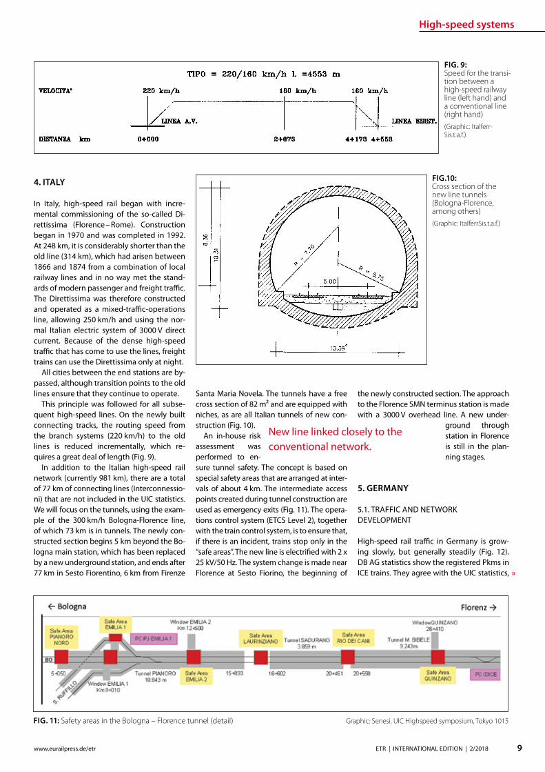
High-speed systems
10 ETR | INTERNATIONAL EDITION | 22018 wwweurailpressdeetr
FIG 13 Standard cross section of the two-track tunnel for the new DB lines 92 msup2 300 kmh
FIG 12 Transport performance in DB long-distance passenger services
FIG 14 Standard cross section of the twin-tube tunnel for the new DB lines 2 x 60 msup2 300 kmh
which list all Pkms in high-speed trains no matter where these trains travel In Germa-ny the ICE network consists of a mix of new lines (up to 300 kmh) upgraded lines (up to 230 kmh) and old lines (up to 160 kmh) The length of the lines and line sections with V gt 200 kmh is currently 1538 km a further 977 km on the upgraded lines allow speeds of 200 kmh Given the size of the population living there new high-speed rail in Germany is quite modest There are just 19 km of new high-speed rail line per million inhabitants In comparison there are twice as many new high-speed rail kilometres per inhabitants in France and three and a half times as many
in Spain This also helps to explain why the French and Spanish are so proud of their high-speed railway networks ndash new lines and high-speed trains are a sign of national achievement that is visible to everyone
52 CHANGING TECHNICAL SPECIFICATIONS
The recently commissioned second section of the new line (Nuremberg ndash Ebensfeld ndash Er-furt ndash HalleLeipzig) is an example of how technical requirements can change even during the planning and construction peri-ods Pre-planning began shortly after Ger-man reunication and is based on DBrsquos July
1991 version of the ldquoNew linerdquo DS 80002 guidelines which now takes V = 300 kmh into account For trac reasons the line is intended for mixed-trac operations with passenger and freight trains In the Bavarian section of the line a track spacing of 470 m was used (based on the ldquoexpanded standard clearance gaugerdquo ndash (Erweiterter Lichtraum or ERL) DB abandoned this clearance gauge one year after commissioning the new Han-nover ndash Wuumlrzburg line (1991) because no-one used it In the sections of the new line that are further north the track spacing was reduced to 450 in line with the subsequent-ly updated guidelines and TSI Infrastructure
Two-track tunnels ndash recognised as state-of-the art at the time ndash were used (Fig 13) in the Ebensfeld ndash Erfurt section like the new Ingolstadt ndash Munich section
On 1 July 1997 the German Federal Rail-way Authority (Eisenbahn-Bundesamt or EBA) issued guidelines entitled ldquoFire and dis-aster protection requirements for the con-struction and operation of railway tunnelsrdquo These guidelines stipulated construction of two single-track tunnels with cross passages for mixed operations with passenger and freight trains in long tunnels The two-track tunnels in the Ebensfeld ndash Erfurt section were grandfathered but the EBA required a safe operational solution that would rule out simultaneous use of the tunnel by freight and passenger trains That is why only twin-tube tunnels were built in the Erfurt ndash HalleLeipzig section (Fig 14) They are signicant-ly more expensive than two-track tunnels Tunnel equipment including emergency lighting escape routes etc is detailed in the TSI entitled ldquoSafety in train tunnelsrdquo which came into force on 112015
53 PROTRACTED LARGE PROJECTS
In Germany the time between prelimi-nary evaluation and commissioning in a large railway project is very long The over-all Nuremberg ndash Leipzig line was commis-sioned in December 2017 27 years after its preliminary evaluation In comparison the new Cologne ndash RhineMain line was concep-tually designed in the 1970 DB expansion programme as a new Cologne ndash Groszlig-Gerau line but the large-scale alignment variant (via Koblenz or another station) and the technology remained under discussion for a long time In 1989 the German federal gov-ernment decided on the alignment variant 31 years passed between its initial concep-tual design in 1971 and its commissioning in 2002 The Hannover ndash Wuumlrzburg line was part of the 1970 expansion programme as a new Hannover ndash Gemuumlnden line The pre-liminary evaluation began in 1971 The de-
High-speed systems
11ETR | INTERNATIONAL EDITION | 22018wwweurailpressdeetr
FIG 15 DB AGrsquos ICE 4 on a new line
cision for the Hannover ndash Goumlttingen ndash Kassel alignment variant (put forward by the feder-al state of Lower Saxony) did not come until 1976 20 years passed between the prelimi-nary evaluation and the completion of its entire length in 1991 The Hannover ndash Berlin high-speed railway line moved quickly DBDR exploration in 1988 ministry agreements between the Federal Republic of Germany and the German Democratic Republic in June 1990 commissioning in 1998 ndash just ten years after the preliminary evaluation began
At present DB constructs the Stuttgart to Ulm dedicated passenger line and new tracks in the Rhine corridor between Karlsruhe and Basel where some newly-built sections are still put into operation Some more projects in Germany are in the pipeline as a link from Frankfurt to the HS linersquos section Wuumlrzburg-Fulda for creating more capacity and short-ening journey time between Frankfurt and Berlin In 2017 DB Netz AG presented its ldquoNetwork concep-tion 2030rdquo Besides providing more freight trac capacity along two north-south axes (the Rhine Corridor and the East Corridor via Halle) several improvements for passenger
trac are provided for Among them are the modication of several major nodes in
which passenger and freight trac must share tracks The long planning and
constructions times are to be shortened to about 15 years by means of citizen participa-tion building information modelling (BIM) and simplication of plan approval proce-dures
54 NEW TRAINS
Older models of high-speed trains especially the ICE 1 are now being gradually replaced by ICE 4 (Fig 15) They are multiple-unit trains for 250 kmh with distributed drives The ICE 4 cars are longer and narrower than the previous ones however DB AG promises more comfort in the trains and advanced in-terior ttings are to contribute
Expanding the high-speed rail network ndash a matter of decades
State-of-the-art rail plastic components
To date Wirthwein has supplied products for more than 30000 km railway lines worldwide We supply the rail superstructure with hundreds of millions of our products every year such as dowels intermediate plates or angle guide plates for rail fastening systems and cable ducts
As a specialist for plastics technology we have been caring for the perfect mold since 1968 Being based at twenty-two locations in Europe Asia and the USA we are always close to our customers
HIGH PERFORMANCEFOR THE RAILWAY
Forming Innovation
Wirthwein AG Walter-Wirthwein-Str 2-10 97993 Creglingen Germany +49 7933 702-0 bahnwirthweinde wwwwirthweinde
Visit us at InnoTrans Hall 26 Stand 231
MTU hybrid drives
12 ETR | INTERNATIONAL EDITION | 22018 wwweurailpressdeetr
PREFACE
The Lake Constance belt railway (in German Bodenseeguumlrtelbahn) is the only rail link be-tween the east and west of the lake The line is used not only for regional services but also for the international Ulm ndash Basel connection and in Friedrichshafen it links with the Wuumlrt-temberg Southern Railway (Suumldbahn) to-wards Ulm Electrication of the Suumldbahn is already in progress and scheduled for com-pletion by 2023
Electrication of the Lake Constance belt railway however has been a subject of con-stant debate for some years now Since elec-trication has not been taken into account in the Federal Transport Infrastructure Plan for the period up to 2030 nancing and realiza-
Quiet clean fast use of MTU hybrid drives on the Lake Constance belt railwayMTU Hybrid PowerPacks combine the advantages of diesel and battery-powered rail traction They can be installed in new or existing rolling stock without the need for additional changes to operations infrastructures or time schedules Even on non-electried routes they allow quieter cleaner faster and more cost-ecient rail travel The use of hybrid drives on the Lake Constance belt railway could signify a breakthrough for this innovative technology
tion are still open to question The under-taking would also bring certain challenges in the light of for example two low tunnels in the town of Uumlberlingen The nancial ex-penditure necessary to deal with them has not yet been calculated Furthermore the erection of overhead lines in such close prox-imity to the shore of Lake Constance would drastically alter the rural landscape and the touristic character of the location The pro-ject is therefore meeting with resistance from some local residents and communities
As an interim solution for improving service on the belt railway MTU Frie-drichshafen in discussion with the Lake Constance Railway interest group has pro-posed the tting of hybrid drives to the existing eet in regional and long-distance
service Diesel-based hybrids such as the MTU Hybrid Power Pack oer the advantages of both diesel and battery-driven rail travel and are quieter cleaner faster and more cost-ecient than the straightforward diesel drives currently in use An electric drive for example enables very low-noise emissions-free operation in urban areas and around stations Nitrogen oxide (NOx) and particu-late emissions fall impressively by compari-son with conventional eet and improved acceleration capabilities allow the planning of more stops and render the service less prone to delays Fuel consumption and in turn carbon emissions likewise fall by up to 25 All these benets are available without the need to change existing infrastructures
MTUrsquos Hybrid PowerPack is evolved from its conventional rail PowerPack PowerPacks
Dipl Ing Ingo LehmannProject and Safety Manager for Rail Mining Oil amp Gas Engineering MTU Friedrichshafen ingolehmannmtu-onlinecom
B Sc Dragan NedicKey Account Manager Rail Sales MTU Friedrichshafendragannedicrrpowersystemscom
Dipl Ing (BA) Benjamin OszfolkResearch and Technology Devel-opment MTU Friedrichshafenbenjaminoszfolkmtu-onlinecom
FIGURE 1 An IRE train with tilting technology on the Lake Constance belt railway
MTU hybrid drives
13ETR | INTERNATIONAL EDITION | 22018wwweurailpressdeetr
raquo
are compact drive systems with diesel en-gine transmission cooling system and au-tomation unit integrated on one base frame In the hybrid version of the PowerPack the drive is enhanced by an electric motor frequency convertor intermediate circuit on-board convertor and battery for storing energy harnessed during wear-free electro-dynamic braking This technology was al-ready presented by MTU in a previous article published in this journal [1]
Specic application of this concept on the Lake Constance belt railway has been exam-ined in simulations and verications carried out by MTU on its own systems test stand The subject of the study was the IRE service between Friedrichshafen and Singen
TEST STAND SIMULATION AND VERIFICATION
MTU Friedrichshafen is unique in its ability to simulate a complete vehicle drive such as the Hybrid PowerPack on a selected route and make reliable predictions on operation and fuel consumption Furthermore the company has a state-of-the-art Hardware-in-the-Loop (HiL) test stand that enables travel of the rail vehicle over the route to be simulated according to a given time sched-ule In this set-up the real drive is incorpo-rated into a virtual rail vehicle and subject to real conditions and loads Parameters such as fuel consumption drive dynamics and battery loads can be measured in the HiL set-up and compared with the previous computer-generated simulation results In this way MTU is able to verify its fuel-saving predictions and continually optimize its simulation tools
SIMULATION IRE FRIEDRICHS-HAFEN ndash SINGEN
Simulation of conditions on the Interregio service was carried out using the technical data from an existing Bombardier VT 612 DMU that is used on the Lake Constance belt railway The special feature of this train is its
tilting capability which allows it to negotiate curving track at speed Two vehicle congu-rations were simulated an existing VT 612 and a virtual VT 612 repowered with an MTU Hybrid PowerPack
Two scenarios were considered in the test In the rst the VT 612 Hybrid rail vehi-cle and the existing rail vehicle were run as per the current timetable (status 26012018) and compared in order to draw conclusions about time schedule feasibility and fuel consumption The second scenario looked at the feasibility of introducing a new time schedule with additional stops The new time schedule was taken from a study car-ried out by SMA amp Partner AG [2] whom the Lake Constance Railway interest group had engaged in 2013 to examine dierent timetable concepts also taking into account possible electrication of the line The study showed that operation of an hourly IRE ser-vice on the Lake Constance belt railway with additional stops in Markdorf and Salem could be recommended
In both scenarios electric-only mode for low-noise emissions-free rail travel was taken into account around planned stops
Route sections travelled in electric-only mode are shown in Figure 2
To determine fuel consumption the State of Charge (SOC) of the battery was taken into account in the energy balance SOC at the end of the journey must correspond to SOC at the beginning If despite smart en-ergy management and re-charging where appropriate en route the end SOC was not absolutely equal to the initial SOC the bat-tery was re-charged up to the required level using the diesel engine The fuel required to do so was also taken into account in overall fuel consumption
The aim of the simulation was to directly compare the VT 612 with the VT 612 Hybrid on the Friedrichshafen ndash Singen service of the Lake Constance belt railway based on the current time schedule (Scenario 1) and to determine the feasibility of the new time-table with additional stops in Markdorf and Salem as per the study made by SMA amp Part-ner AG (Scenario 2) A statement on fuel con-sumption was also to be made It is empha-sized again that the hybrid train switched to electric-only mode around stations and in urban areas as shown in Figure 2 Phases of
FIGURE 2 Deployment of a VT 612 Hybrid on the Lake Constance belt railway with electric-only phases
FIGURE 3 Simulation of IRE service on the Lake Constance belt railway
MTU hybrid drives
14 ETR | INTERNATIONAL EDITION | 22018 wwweurailpressdeetr
travel in electric-only mode caused a slight reduction in the fuel saving possible in rela-tion to the existing rail vehicle However this is seen as a justied compromise in view of the benets of phases of emissions-free qui-eter travel
The results for both scenarios are shown in Figure 3
The simulation results for Scenario 1 show that with a hybrid rail vehicle a fuel saving of 157 in relation to the existing VT 612 vehicle can be achieved including phases in electric-only mode The travel time in this case is 4600 min The fuel saving can be principally attributed to re-generative braking The energy thereby harnessed is used entirely for travel in elec-tric-only mode The results for Scenario 2 show a fuel saving of 206 in relation to the existing rail vehicle from Scenario 1 The time scheduled for Scenario 2 is 5600 min So with the hybrid rail vehicle the new Sce-nario 2 time schedule with additional stops in Salem and Markdorf can be realized with lower fuel consumption than for Scenario 1
and including electric-only mode around each stop
Evaluation of the simulation results even shows that potential still exists for a further reduction in the travel time (Fig 4) The blue line shows the vehicle speeds required for keeping to the time schedule The red line shows the speed limit for taking curving track at speed The route sections passed in electric-only mode are highlighted in green The speeds necessary along the route for keeping to the timetable remain for the most part well below the maximum speed limits This means that a reduction of the travel time is perfectly feasible still leaving sucient operational reserve
The simulation results shown were veri-ed on the Hardware-in-the-Loop (HiL) test stand and could be conrmed Besides time-keeping the most tangible improvements outside the vehicle are emissions-free travel and quieter operation around stations and in urban areas Measurements at the test stand and on a demonstrator showed that vehicle noise in the vicinity of stations can
be reduced by around 75 (20 dB(A)) This improvement might even be perceived by passengers inside the vehicle
Based on the simulation results it is pos-sible to calculate the annual savings in CO2 (132 tonnes) and NOx (105 tonnes) per ve-hicle based on 2500 hours runtime per year Extending this to the entire VT 612 eet in service in Baden-Wuumlrttemberg which amounts to 41 vehicles a total of 5412 tonnes of CO2 and 43 tonnes of NOx could be saved per year Rebuilding the rail vehicles with MTU Hybrid PowerPacks could there-fore make a very signicant contribution to air pollution control on Baden-Wuumlrttem-bergrsquos railways
REBUILDING THE VT 612 WITH A HYBRID DRIVE
The VT 612 is an ideal candidate for conver-sion to a hybrid drive As a high-oor vehicle it has more than enough space underoor for housing all Hybrid PowerPack compo-nents Since the Hybrid PowerPackrsquos compo-nents are not heavier than the current drive system it can be installed without any shift in the centre of gravity The feasibility of the rebuild was also conrmed by DB System-technik the Deutsche Bahn subsidiary Re-building tilting VT 612 railcars with hybrid drives would give them a new lease of life as fast eco-friendly trains and their tilting sys-tems ndash to which they owe their faster travel times ndash would remain available in the future
The rebuild concept proposed by MTU provides for installation of a Hybrid Power-Pack in each car The installation scope would comprise the following components
rarr Hybrid PowerPack (comprising diesel engine electric motor transmission cooling system)
rarr Batteries (3 MTU EnergyPacks with ca 90 kWh capacity overall)
rarr Water-based battery cooling
FIGURE 5 Rebuild concept for VT 612 Hybrid
FIGURE 4 Simulation results for IRE service using VT 612 Hybrid Scenario 2
15ETR | INTERNATIONAL EDITION | 22018wwweurailpressdeetr
rarr Intermediate DC circuit rarr Power electronics and lters for on-board power supply
The Hybrid PowerPack comprises an MTU 6H 1800 R85L diesel en-gine an electric motor and a ZF EcoWorld power-shift transmis-sion with integrated reversing function The diesel engine delivers 390 kW and the electric motor delivers 300 kW continuous power
The Hybrid PowerPack is arranged as a parallel hybrid with the electric motor sitting on the input side of the transmission up-stream of the diesel engine As a preference the electric motors are congured for electro-dynamic braking in order to harness surplus energy for battery storage or on-board power
SUMMARY
The simulations show that an MTU hybrid drive will have no dif-culties meeting either the current time schedule in place on the Lake Constance belt railway service or that planned for the future Rebuilding the rail vehicles with Hybrid PowerPacks would achieve signicantly cleaner quieter and more economical rail travel even without overhead electrication and with no compro-mises with respect to travel times The installation alone of state-of-the-art EU Stage V-compliant diesel engines in the VT 612 rail-cars could reduce particulate and NOx emissions by around 90 The further benets oered by a hybrid drive would prot the en-vironment passengers and operators alike Electric-only mode in urban areas and around stations lowers the noise level by as much as 75 Regenerative braking considerably enhances the ecologi-cal soundness of operations while improving their cost-eciency In this way up to 20 fuel savings can be made
All in all deployment of Hybrid PowerPacks on the Lake Con-stance belt railway could herald a breakthrough for this innova-tive technology in Germany
Literature[1] Oszfolk Benjamin et al Hybridantrieb stellt Marktreife unter Beweis ETR ndash Eisen-
bahntechnische Rundschau 92015 [2] SMA und Partner AG Optimierung Angebotskonzeption Bodenseeguumlrtelbahn
Zuumlrich SMA und Partner AG 2013
FIGURE 6 MTU Hybrid PowerPack
Discover intelligent sensors
INNOVATIONS TO SIMPLIFY RAILWAY OPERATIONS
EXPPERIEENCE THHE FUUTURE OF TTRAIN TRRACKINGG
InnoTranss in Berrlin18 ndashndash 21 Septembeer 220188Halll 255 | SStannd 2232
Digitalisation opens up new possibilities in generating a wide range of highly valuable information
wwwwfrauschherccominnootranns
Predictive Maintenance
16 ETR | INTERNATIONAL EDITION | 22018 wwweurailpressdeetr
BASIC PRINCIPLES OF DATA LAKES
Data Lakes dier fundamentally from clas-sic concepts of Business Intelligence such as Data Warehouses primarily by the type of data retained In data warehouses mainly transactional data is stored whose structure is dened upfront and which has already undergone pre-ltering before persistence In a data lake however all data is persisted regardless of its structure or relevance for known use cases Data Lakes have the fol-lowing basic properties [2]
rarr Data Lakes collect and store data regard-less of type format or data volume while they are to be stored in a structured manner in classic data warehouses
rarr Data Lakes provide large amounts of data Therefore it is important to keep costs low while maintaining a high ac-
The treasure of the Data Lake ndash Predictive maintenance for vehicle eetsEective asset management of vehicle eets in rail requires an ecient and comprehensive IT landscape as a basis The core of an associated architectural concept is a data lake that collects and provides real-time diagnostic data gathered on the vehicles It is the technical basis for the application of algorithms for condition-based maintenance of rail vehicle eets
cess rate Since data stored in structured form in data warehouses must be im-mediately accessible at all times to en-able fast access high persistence costs are generated Data Lakes on the other hand store raw data which depending on the frequency of accesses can also be stored with reduced access speed
rarr At Data Lakes all data is stored centrally and heterogeneously at the same time This means that data which is very dif-ferent from the format can be linked together in analyses without having to request potentially dierent systems beforehand Existing Application Pro-gramming Interfaces (APIs) provide a wide range of usable use cases It is easy to add dierent tools to the data stream as services for example or to store inter-mediate results in the Data Lake for fur-ther use by other tools
rarr Data Lakes keep all relevant data central and unstructured regardless of format-ting The analysis tools are always con-ceptually independent of the format and structure of the data This allows new analyses or new data sets to be integrat-ed easily and quickly
rarr In modern implementations of data lakes and the service landscapes required for this the concept provides for the rapid interchangeability of tools and micros-ervices The user can test generally avail-able tools with practically no initial eort and if required can transfer those to productive use in just a few steps
SERVICE-ORIENTED AND CLOUD-BASED ARCHITECTURE FOR DATA LAKES
Instead of using solutions based on indi-vidual or a few applications with a dened range of functions Data Lakes reliy on so-lutions consisting of a exible combination of dierent micro services around a central data store The software architecture must be detached from classical patterns such as a layered hierarchy and the development must lead to a data- or data-ow-centered architecture This makes it easy to add or re-place services at any point and keeps the ar-chitecture exible for future developments
When using data lakes primarily event-driven architectures are common By con-
Mathias Haimerl Senior Data Analyst ESE Engineering und Software-Entwicklung GmbHmathiashaimerlesede
FIGURE 1 Vehicle eets in rail transport as an object of asset management
Predictive Maintenance
raquo
trolling the events based on the underly-ing data streams this architecture can be called Data-Driven Architecture (cf[5]) The software therefore builds itself around the data stream as shown in Fig 1 The data stream therefore represents the basis for the achievement of objectives whereby each individual problem can be regarded as an in-dependent architecture The desired objec-tive is broken down top-down into required services and newly formed into a specic so-lution Right from the start not only services for data manipulation are considered but also accompanying services for areas such as logging and security
The implementation of data lakes on company-owned hardware does no longer make sense for most projects from a nan-cial point of view and therefore only makes sense for particularly critical applications (eg banks medicine military) if commercial cloud solutions with appropriate security options cannot be found or are not applica-ble for compliance reasons
CHALLENGES AND SOLUTIONS OF CLOUD-BASED ARCHITECTURES
The use of services in a cloud creates new
challenges that need to be addressed in ad-vance
Information security of the customer data available in the cloud is in most cases much higher in the Amazon Web Service (AWS) Cloud than on self-operated servers The large number of system administrators de-ployed worldwide for the AWS Cloud some of whom specialize in information security provides signicantly better information se-curity than would be the case with conven-tional IT infrastructures operated by compa-nies themselves
Handling security vulnerabilities Due to the high number of users in the global internet of things (IoT) security gaps that allow access to external data quickly become nancially and legally problematic The Linux base and the simple reporting of security problems allow newly discovered vulnerabilities to be resolved quickly and globally The globally uniform system and the uniform administra-tion of software components close security gaps within a few hours
Protection against unauthorized access by third parties Authentication measures serve to protect sensitive data against unauthor-ized read access (data theft) on the one hand
and to protect data against unauthorized manipulation (data modication computer sabotage) on the other Authorization meas-ures are aimed at ensuring that analysts and solution architects only have access to the data relevant to their projects This is supported by the targeted allocation of authorisations to the respective architects In addition organization-related boundary conditions are contractually secured One example of this are compliance guidelines such as certication of cloud providers ac-cording to standards like DIN EN ISOIEC 27001
Software maintainability The AWS ba-sic system is stable against updates and changes without interfering with customer projects Customer projects run in self-con-tained environments (sandbox) The pro-vider of the cloud system has the freedom to use exchange and extend any hardware components without expensive downtimes or waiting times for the user Software up-dates and time-consuming hardware up-grades are obsolete for the user
Legal framework Sending data across na-tional borders is often a legal hurdle that prohibits the use of cloud services To coun-teract this cloud providers have provided
FIGURE 2 Overall concept of the data-driven architec-ture The microservices are structured around the data stream
wwwmobility-bbcom
Berlin-Brandenburg
Moving mobility
to the next level
Meet us at InnoTrans
City Cube Hall B
210x99_VML_InnoTrans_eng_ETRindd 1 19072018 081118
Predictive Maintenance
18 ETR | INTERNATIONAL EDITION | 22018 wwweurailpressdeetr
for the possibility of binding to regions that ensure that data does not leave certain pre-dened regions
Calculability of costs An AWS solution is about 90 cheaper than the operation of ldquoclassicrdquo infrastructures This value is also evi-dent in one of our customer projects where about 98 of the costs were saved on the development system and the eective sav-ings for the live system were interpolated to be at about 91 AWS provides a billing calculator that provides an estimate based on past months and previous monthly costs
SAMPLE IMPLEMENTATION STEPS FOR AMAZON WEB SERVICES
As an example implementation of a data lake the cloud environment AWS was used as described below During implementation four functionalities were clearly separated which are described in more detail below
rarr Data acquisition including pre-process-ing (ingestion)
rarr central data storage rarr Cataloging of data rarr Preparation of concrete analyses
DATA ACQUISITION (DATA INPUT) FOR DISTRIBUTED DATA SOURCES
In order to be able to ingest sensor data from vehicle eets the receiving system must be able to accept and store a large number of distinct data from many sensors On the senderrsquos side however data must be collected buered and regularly transmit-ted to the Data Lake To do this a periodic Internet connection must be ensured For
the frequency of data transfer an individual taring between the local data collection and the frequency of synchronization to the cloud must also be found Data transfers at low bandwidth should preferably rely on the collection of several data sets and trans-fer with a stable connection However this requires more memory in the local device With higher bandwidth and stable connec-tions the data can also be transferred more frequently This on the other hand leads to an increased load on the receiver A project-specic optimum must be found here
Finally it should be taken into account that the order of data sets should already be de-ned during ingestion even if the structure does not have to be xed from the outset To simplify later evaluations considerably data of the same type for which the uniformity is to be foreseen should be grouped logically This unies the data accesses of the evaluat-ing processes and thus minimizes the eort
From a specic project of a customer we know that the current data load of 6754 MBh will increase tenfold by 2020 due to an increase in the number of equipped vehicles and a simultaneous tripling of the number of sensors to approx 2GBh The distribution of the eets is Europe-wide with the focus on Central Europe
CENTRAL DATA STORAGE
In order to eciently persist the collected sensor data of vehicle eets the receiving system stores the data in a central location In AWS data is stored centrally in any size and in an automatically growing storage unit a so-called bucket The data is stored in ob-jects a logical data unit comparable to les in a classic le system To make searching
through data easier the objects are indexed based on their specic prexes and opti-mized for fast access Since the implementa-tion is based on RESTful and therefore each data record transmitted by sensors sends a PUT request a new object is created for each data record This creates an immense num-ber of objects in the long term This is irrele-vant in terms of costs and storage space For an analysis based on large amounts of data with low reaction times however a catalog-ing of the data is still necessary
CATALOGUING FOR VARIOUS APPLICATIONS
The exible NoSQL database DynamoDB oers an optimal possibility to catalog data without having dened a schema and still get extremely fast access speeds A Dy-namoDB table has a primary key which con-sists of a partitioning key and an optional sort key The partitioning key determines the automatic partitioning of the table and should therefore be very well selected (see [9]) An entry also supports update com-mands DynamoDB oers a very exible memory which can be written and read in dierent ways
New data arriving in Simple Storage Ser-vice (S3) can be automatically analyzed as a trigger for cataloging and added to cor-responding catalogs Since the analyses are usually very individual a pipeline must be created so that the new data arriving in S3 can be processed This can be achieved with minimal eort using the Microservice Lamb-da which makes it possible to execute small programs in the AWS landscape without any further integration eort Optional lters can be set for the triggers so that dierent pre-xes start dierent lambda functions
rarr Read The respective lambda function receives the bucket and the object name of the newly arrived object and can ex-amine this import and the content ac-cording to previously dened criteria and extract the corresponding values
rarr Write This data can then be written to a DynamoDB table regardless of whether the data record already exists ie wheth-er it has to be updated or whether it is a new data record
This type of cataloging is the comparatively most complex but at the same time the ex-ibility exceeds that of other technologies by far The cost factor is also considerably lower here The costs for DynamoDB tables are cal-culated according to provisioned capacities for read and write accesses This is under-
FIGURE 3 Using cloud solutions brings new challenges
Predictive Maintenance
19ETR | INTERNATIONAL EDITION | 22018wwweurailpressdeetr
standable as an increase in capacity in the background is a real hardware replication This allows tables with costs of less than one euro per month for the minimum congura-tion and a separate table can be provided for each application case The requests for large amounts of data via the primary key or only a part of it can be retrieved extremely quickly whereby retrieval times in the low two-digit millisecond range are not uncommon
PREPARATION OF CONCRETE ANALYSES
The creation of analyses on the catalogued data is possible without great eort with the basis shown This is done in several consecu-tive steps
rarr Top-down analysis of the problem to be solved as there are various microservic-es for a wide variety of applications As a result individual use cases can be as-signed to the use cases
rarr Selection of suitable microservices De-pending on the target platform the ap-propriate microservices can be selected There are specic services that enable the further use of existing programs that work on relational databases for example Other microservices support machine learning or the visualization of complex interrelationships in informa-tive dashboards
rarr Bottom-up aggregation of specically congured microservices For this pur-pose services already congured for similar analyses can be reused or addi-tional instances with slightly modied conguration can be created
SUMMARY amp OUTLOOK
All in all Data Lakes oer an optimal solution from the initial setup of a collection of raw data from various sources without large upfront ef-fort or high costs to the data storage of many eets of dierent vehicles worldwide and the provision of data catalogs for various analyses of various kinds The collection of measure-ment data in persistent online data stores such as AWS buckets can be implemented within minutes and is operational from this point in time so that data can be collected and archived Even if no specic use cases are known at the time of implementation it is recommended to persist all data on low-cost cloud storage so that it is already available for possible evalua-tions at later points in time Since there is often no reason to process data without use cases favorable options for persistence of the data can be used To avoid vendor lock-in consider designing Data Lake to be adaptable to alter-native platforms Alternative options for data storage include the storage services of Google Cloud Services or Microsoft Azure Of course the use of a second service also doubles the total costs
References[1] Canalys (2017) Cloud service providersrsquo battle drives
the worldwide cloud infrastructure market up 42 in Q1 2017 httpswwwcanalyscomstaticpress_re-lease2017press-release-150517-cloud-service-providersE28099-battle-drives-worldwide-cloud-infrastructure-market-42_1pdf Palo Alto Shanghai Singapore and Reading (UK) Pressemit-teilung 15052017
[2] Amazon Web Services (2017) Building a Data Lake on AWS httpspagesawscloudcomrs112-TZM-766im-agesAWS_Data-Lake_eBookpdf 01112017
[3] Bundesministerium des Inneren (BMI) (2017) Polizeili-che Kriminalstatistik 2016 httpswwwbmibunddeSharedDocsdownloadsDEpublikationen2017pks-2016pdf Pressemitteilung 24042017
[4] Buschmann Frank and Christiane Loumlckenho eds (2000) Pattern-orientierte Softwarearchitektur ein Pat-tern-System 1 korr Nachdr Muumlnchen Addison-Wesley 2000
[5] Mahjourian Reza (2009) An Architectural Style for Data-Driven Systems Paper Gainesville FL 32611 USA httpswwwcsutexasedu~rezalesxpage-icsrpdf 22032009
[6] Tilkov Stefan (2009) REST und HTTP Einsatz der Ar-chitektur des Web fuumlr Integrationsszenarien 1 Au Hei-delberg dpunkt 2009 ISBN 9783898645836
[7] Hunkeler U H L Truong and A Stanford-Clark (2008) MQTT-S mdash A Publishsubscribe Protocol for Wireless Sensor Networks In Communication Systems Software and Middleware and Workshops 2008 COMSWARE 2008 3rd International Conference on 791ndash98 2008 httpsdoiorg101109COMSWA20084554519
[8] Manseld-Devine Steve (2016) DDoS Goes Main-stream How Headline-Grabbing Attacks Could Make This Threat an Organisationrsquos Biggest Nightmare Net-work Security 2016 no 11 (November 2016) 7ndash13 httpsdoiorg101016S1353-4858(16)30104-0
[9] Vyas Uchit (2014) DynamoDB Applied Design Patterns Birmingham United Kingdom Packt Publishing 2014
SAFERAILSYSTEMCOM
Guessing or GPR
bull GPR measurements and analysisbull Condition-based maintenance planningbull More than 25 years of working experience - worldwide
BIM
20 ETR | INTERNATIONAL EDITION | 22018 wwweurailpressdeetr
ABOUT SIEMENS MOBILITYrsquoS TURNKEY RAIL SOLUTIONS BUSINESS
Siemens AG is a global technology power-house that has stood for engineering ex-cellence innovation quality reliability and internationality for more than 170 years The company is a pioneer in supplying in-frastructure solutions Siemens Mobility is an experienced provider of complete turn-key solutions for rail systems having already carried out more than 50 various and major rail projects worldwide The organization is home to experts in project management and system integration as well as key prod-ucts of rail infrastructure These specialists develop and implement projects for all types of rail vehicle systems from metros trams and light rail vehicles and automated peo-ple-movers to Intercity and high-speed train units ndash all designed for maximum reliability availability and eciency
THE CHALLENGES OF RAIL INFRASTRUCTURE PROJECTS
Projects to install new rail infrastructure and expand existing systems are growing steadily more complex The rising number of project participants and stakeholders presenting a broad range of specic require-ments planning teams in dierent locations and time zones having to coordinate and
Digital twin serving rail infrastructure How turnkey rail infrastructure projects are beneting from applying Building Information Modeling (BIM) how Siemens Mobility is pursuing virtual planning of projects with project partners and custom-ers such as in the Riyadh Metro Project and what added value this methodology is creating
integrate their civil and rail engineering and planning and the ever increasing time and cost pressures exemplify this problematic complexity
There are an enormous number of inter-faces and requirements involved especially in large rail infrastructure projects and or-ganizing them demands extensive resources and absolute precision
AT THE VANGUARD OF DIGITAL PLANNING
Just as countless other sectors of the con-struction industry have already experienced digitalization is driving a para-digm shift in rail infrastructure away from analog meth-ods and embrac-ing digital and in-tegrated planning encompassing eve-rything from erec-tion planning installation and support for training to preparation and performance of repairs and maintenance all based on digital processes and data models
More than four years ago Siemens Mo-bility began applying building information modeling (BIM) techniques as well to project planning and execution of complete turnkey
solutions for rail systems As one of the trail-blazers of digitalization Siemens Mobility uses BIM to create a digital twin ndash a virtual model of major rail projects planned for im-plementation
This methodology focuses on achieving cost and time eciency while also ensuring the highest quality standards
Siemens Mobilityrsquos Turnkey Rail Solutions is using BIM in col-laboration with construction part-ners to optimize project planning and execution This involves the use of computer-generated 3D modeling and the
information integrated into or linked with the models
REFERENCE PROJECT RIYADH METRO
The Arriyadh Development Authority (ADA) ndash the executive arm of The High Commission
Both the implementing company and customer benet from the reduced risk of delays in planning as well as the prevention of defec-tive planning and resultant need to revise planning during ongoing installation
Dr Payam AminiHead of Digital Transformation Turnkey Projects amp Electrication Siemens Mobility Munich payamaminisiemenscom
A simulated view of the outside of the depot for which the path of sunlight can be simulated over time
raquo
BIM
21ETR | INTERNATIONAL EDITION | 22018wwweurailpressdeetr
for the Development of Arriyadh in Saudi Arabia ndash is currently building one of the larg-est metro projects in the world with six rail lines totaling 176 kilometers in length The system will be the backbone of the public rapid transit network serving Saudi Arabiarsquos capital city The order placed with Siemens Mobility covers supply of 67 Riyadh Metro model rail vehicles based on the Inspiro Plat-form series line electrication the signaling and communication systems for driverless service on Lines 1 and 2 as well as system integration and project management Sie-mens Mobility is part of the BACS consor-tium led by US company Bechtel along with Almabani General Contractors and Consoli-dated Contractors Company
The Riyadh Metro Project (RMP) kicked o by dening the information requirements and project-specic BIM objectives of the customer The BIM management team of Siemens Mobilityrsquos construction partner Be-chtel then used this information as the basis for elaborating in detail the BIM process for all project participants
The BIM execution plan that denes the BIM process for a specic project basi-cally provides the answers to the agreed require-ments In this key central document Turnkey Rail Solu-tions dened for all project participants in-volved in the infrastructure design the roles and scopes of responsibility the programs and le formats to be used what applica-tions are to be integrated into the BIM pro-cess the data-exchange process along the chain of project phases the quality review inspection and testing criteria procedures for coordination and collaboration and much more This was necessary in order to ensure smooth BIM implementation over the entire project cycle
Siemens Mobilityrsquos construction partner also generated the model element plan which denes in an overview who is to gen-erate what model content for the project by when and to what level of development (ie geometry information and coordination) In this project BIM standard the construc-tion partner also dened the details for modeling agreements and documentation standards
Model-based planning is one of the pro-jectrsquos centerpieces enabling comprehensive integration of all rail infrastructure systems such as rail electrication the depot and workshop equipment line signaling and communication technology and platform screen doors
CLARITY DRIVES THE EFFICIENCY OF WORKFLOWS
Siemens Mobilityrsquos infrastructure planning engineers used project-specic BIM software to share their model-based information with Siemens Mobilityrsquos suppliers and the con-
struction partner The program Pro-jectWise is used in combination with Aconex served and continues to
serve as a shared data platform accessible project-wide ensuring that each piece of information is retained only once and in its most recently valid version In this ldquosingle source of truthrdquo data are referenced rather than duplicated signicantly improving in-formation management increasing the reli-ability of data and eliminating any use of superseded obsolete data This provides full trans-parency for all pro-ject participants Photo-realistic displays and animated videos of the planning progress generated on the basis of the 3D planning information ensure transparency enhance understanding and support the iterative process
The permanent availability of data accel-erates collaboration across national borders and company boundaries These aspects are particularly benecial in the RMP Just Sie-mens Mobilityrsquos unit alone had colleagues based in 13 dierent cities working to de-sign the rail infrastructure coordinating and agreeing across national boundaries and dierent languages time zones and work capacities
In addition to the geometrical properties
of system components for example of fre-quency converters the participating plan-ning engineers also integrated non-geomet-rical information and requirements of their systems such as zones and clearance spaces that are essential for installation and mainte-nance Once work on a subarea of a model (work in progress) was approved for release this information was then available to all partners within the project (shared areas) In turn these partners reviewed the completed work for impacts on their own work scopes
In interdisciplinary collision reviews the design coordinators conducted collision tests with all other draft components Such reviews examined for example the civil struc-tures technical building equipment systems and Siemens Mobilityrsquos systems such as the signaling equipment and traction power supply grid to identify any conicts between
the systems them-selves or with the civil structures
In this way structural imple-mentation of the overall project as
well as individual subareas can be digitally tested at any time
As a provider of turnkey infrastructure solutions Siemens Mobilityrsquos unit was in-volved early in the RMP through BIM help-ing to prevent planning errors and leading to quicker validation of draft planning such as for spatial requirements of infrastructure equipment free clearance proles and pre-venting collisions
The RMP oers a basis for further infra-structure projects using BIM methodology The stock of digital objects available in the component library continues to grow Exist-ing digitally modeled components can be directly used for the next digital twin This
BIM creates full transparency for everyone participating in the plan-ning of infrastructure projects
The Control Center of the Riyadh Metro Project for Line 1 was fully planned digitally Once that design process was completed actual construction started
BIM enables earlier design valida-tion of rail infrastructure technol-ogy and engineering as well as civil construction
BIM
22 ETR | INTERNATIONAL EDITION | 22018 wwweurailpressdeetr
accelerates digital planning from one pro-ject to the next
Siemens Mobility Turnkey Rail Solutions sees particular potential for BIM in integrating the necessary man-agement process-es BIM supports the management of interfaces requirements congurations and project documentation This improved management leads to accelerated project execution And although project execution in Riyadh is still underway the added value created by the BIM method is already clearly evident today ndash for both Siemens Mobility and the customer
DIGITAL SCAN OF THE INFRASTRUCTURE CREATED
Siemens Mobility Turnkey Rail Solutions is utilizing other digital solutions as well for the Riyadh Metro Project that further optimize pro-ject execution Siemens Mobility-owned track measuring vehicles and 3D laser scanners are deployed to eciently compare the progress
of as-built construction and installation against the design target data These units travel along the existing sections scanning and thereby
digitalizing the as-built environment The object-specic information collect-ed by this measur-ing system whether on track position-
ing platform edges or technical spaces is com-pared with the digital design thereby directly revealing any deviations from planning
This produces a 100 -accurate database of the existing as-built status Particularly when projects aim to expand exist-ing infrastructure such transparency prevents costly conicts when equipping existing civil structures with new infrastructure equip-ment Besides the hardware procurement Siemens Mobility is banking in this context on developing the expertise of its own per-sonnel to cover planning of measuring cam-paigns kinematic and static imaging and evaluations such as review for collisions
PROMISING OUTLOOK
Siemens Mobilityrsquos Turnkey Rail Solutions has ceaselessly invested in implementing and further developing digital methods to keep pace with steadily growing deadline and cost pressures and the increasingly stringent demands of complex rail infra-structure projects These efforts are now empowering Siemens Mobility to better assess the sometimes extremely demand-ing detailed requirements early already in the project bidding phase and estimate costs more reliably thereby minimizing risks
In previous projects utilizing BIM meth-odology Siemens Mobilityrsquo experts identi-ed a shifting of eort into the early project phases
Siemens Mobilityrsquo experts see opportuni-ties in doing so particularly in the assess-ment of design modications in terms of im-pacts on costs and in early application when the leverage for such optimization can still prove very eective
Yet BIM doesnrsquot end when construction work on an infra-structure project has been complet-ed By developing a digital twin of the as-built infrastruc-ture and applying
that model over its entire lifecycle these sets of digital data can be used to optimize asset management
The BIM method harbors major potential for signicantly shaping the rail infrastruc-ture sector in the coming years
A view of the digital model of the King Abdullah Financial District Station on Line 1 which can be viewed in the computer pro-gram from all sides
Photo-realistic displays and animat-ed videos of the planning progress ensure transparency and enhance understanding
BIM provides the basis for simpler and ecient interface management and contributes signicantly to accelerating project execution
5 | 2017 Mai wwweurailpressdesd
109 Jahrgang
SIGNALLING amp DATACOMMUNICATION
Oumlsterreich Gut gesichertAustria Well-protected
13 Kostenguumlnstige Sicherung von Eisenbahnkreuzungen Cost-effective protection of level crossings
36 Finnland Gegen den Instandhaltungsruumlckstand Finland Reducing maintenance backlog
21 Schweiz Weltpremiere auf der Toumlsstalstrecke Switzerland A world premiere on the Toumlsstal line
Your contact person Silvia Sander +4940237 14-171 silviasanderdvvmediacom wwweurailpressde
Leader in Signalling and Datacommunication
No 1ad medium
SIGNALLING AND
DATACOMMUNICATION
AUTONOMOUS DRIVING
CYBE
R SE
CURI
TY
LEVEL CROSSING TECHNOLOGY
OPERATIONS MANAGEMENT SYSTEMS
MOBILE COMMUNICATIONETCS
REPUTABLE
UN
IQU
E
ESTABLISHEDTELECOMMUNICATION
OPERATIONS CONTROL TECHNOLOGY
INFORMATION TECHNOLOGYBILINGUAL
Book your advert right now
raquo
Ground Penetrating Radar
23ETR | INTERNATIONAL EDITION | 22018wwweurailpressdeetr
1 INTRODUCTION
Many countries allocate large amounts for the modernization and upgrading of their railway networks in order to meet the de-mands of increasingly dense rail trac with higher axle loads at ever higher speeds However this can only be achieved if all rel-evant key gures and geotechnical condi-
Ground Penetrating Radar ndash Basis for eective Track MaintenanceThis article describes the capabilities and functionality of Ground Penetrating Radar (GPR) for higher speeds GPR is a train-borne technology for a continuous inspection of the geotechnical conditions of railway tracks The basic principles of the GPR technology are explained with particular reference to all relevant railway specic tasks namely the identication qualication and quantication of ballast fouling by using a fouling index the determination of the quality of track drainage and its quantication through a drainage index and the calculation of the track modulus (TM) Special emphasis in the context of GPR investigations is placed on the mapping of sections with clay foulingmud spots inside the ballast bed or at its base and respectively inside intermediate layer formation or subsoil In the past such weak-spots have caused derailment they could represent a risk for rail-trac [11 13 14 15 16] Besides their late detection implies exceedingly high maintenance costs
tions of the respective tracks can be reliably evaluated On this basis only the necessary investments in track maintenance moderni-zation and support can be dened in the ap-propriate size and can be placed correctly This is particularly true when budgets are tight
The demands exerted on the track in terms of safety grow with increasing speed
FIGURE 1a) Trajectories of radar waves which are reected at the layer boundary between two media
with dierent dielectric constant (laquo)b) Due to the dierent travel time of the reections the layer boundary is reproduced in the
radargram (reference Ground Control and IEV)
Dipl-Geophys Giuseppe StacconeDirector of Ground Control GmbH MunichGermanystacconesaferailsystemcom
David Camacho MScDoktorand am Institut fuumlr Eisen-bahn- und Verkehrswesen der Universitaumlt Stuttgart (IEV)davidcamacho ievvwiuni-stuttgartde
Moritz SchebuchMitarbeiter am Institut fuumlr Eisen-bahn- und Verkehrswesen der Universitaumlt Stuttgart (IEV)moritzschebuch ievvwiuni-stuttgartde
Prof Dr-Ing Ullrich MartinDirektor des Instituts fuumlr Eisenbahn- und Verkehrswesen der Universitaumlt Stuttgart (IEV) und des Verkehrswis-senschaftlichen Instituts an der Universitaumlt Stuttgart eV (VWI eV)ullrichmartin ievvwiuni-stuttgartde
Dipl-Ing Sebastian RappAkademischer Mitarbeiter am Institut fuumlr Eisenbahn- und Verkehrswesen der Universitaumlt Stuttgart (IEV)sebastianrapp ievvwiuni-stuttgartde
Ground Penetrating Radar
24 ETR | INTERNATIONAL EDITION | 22018 wwweurailpressdeetr
Therefore failing to detect track damages or obtaining inadequate information on track damages represents a hazard for every kind of railway trac For this reason a decision guidance that facilitates a systematic and ecient renewal of the tracks is important The more intensive the rail trac and the higher the trac speed the bigger the re-quirements in terms of an ecient and reli-able track inspection
The mapping of clay fouling or mud sec-tions is of special importance Fine-grained soil material such as silt or clay wells up from the formation and reaches the ballast base or even penetrates the ballast layer itself As a consequence track drainage and track stability (ie bearing capacity) are strongly reduced This results in lasting deformations that require complex maintenance work and high costs If weak-spots are not identied or not detected in time clay fouling can in the worst case scenario lead to derailment [10 13 14 15 16]
During the past 25 years Ground Control GmbH which is placed in Munich Germany has surveyed more than 100000 km of rail-way tracks in many countries in Europe and all over the world Recently with information obtained from GPR results and other data (ie track geometry and track dynamics) a continuous and complete assessment of the trackrsquos structural condition is possible
2 MEASURING PROCESS
The GPR method is an electromagnetic re-ection method Radar pulses are transmit-ted into the subsoil by a transmitter antenna The energy of the electromagnetic waves is partly reected at interfaces between layers with dierent dielectric properties and re-transmitted to the receiver antenna Based on the measured travel time of the signals and knowing the propagation speed of the waves in the medium depth and surface of the layer can be computed
In order to dene the depth of the re-ector from the surveyed travel time the propagation speed of the radar waves in the subsoil has to be determined The speed of electromagnetic waves in the subsoil is re-lated to the water content of the individual material Therefore it is generally not pos-sible to refer to reference values for certain rock or soil types Thus the radar wave speed has to be calibrated for each project area
The penetration of electromagnetic waves mainly depends on the electric conductivity of the soil and the applied antenna frequen-cy By using low frequency antennae on low conductive subsoil the largest investigation depth can be achieved
PERFORMING SURVEYS WITH MODERN HIGH-SPEED-GPR
Todayrsquos GPR surveys are carried out with train mounted systems at speeds up to 160 kmh As a general rule the antennae system is fastened at the carrier vehiclersquos buers A precise positioning is achieved by an inte-grated Dierential Global Positioning Sys-tem (DGPS) and Doppler radar
The characteristics of modern GPR sys-tems are
rarr The equipment can be installed and run on a wide range of track-bound vehicles (including regular trains or vehicles on Hy-Rail)
rarr They are fast enough to be integrated into the regular trac schedule Hence expensive track closure is no longer nec-essary
rarr DGPS and Doppler radar are used for an accurate (ie precision within a meter) positioning of the antenna independ-ent of the speed and length of the track surveyed
rarr Measurement data resolution and data quality are equally high no matter what length and what speed
rarr All GPR components are eectively
shielded against interferences from sig-nalling and communication systems
3 GPR TASKS
In contrast with punctual boreholes and trenches modern GPR systems provide con-tinuous information about the geotechnical condition of the track performing the fol-lowing tasks
rarr Continuous mapping of track-bed-thick-ness and layers below (ie intermediate layer protective layers)
rarr Distinction between clean and fouled ballast and calculation of Fouling Index
rarr Mapping of mud spots or clay fouling sections inside ballast bed at its base or inside substructure layers respectively
rarr Detection of sections with drainage problems and calculation of ldquoWet Bed Indexrdquo
rarr Mapping of areas with insucient bearing capacity (eg settlements) and evaluation of the dynamics of track set-tlement
rarr Control and evaluation of the quality of maintenancerenewalconstruction work (quality of cleaned or exchanged ballast thickness of a new ballast bed quality and thickness of soil layers)
rarr Estimation of track condition based on track modulus (TM) calculation
Additionally GPR data allow for the deni-tion of a sustainable cause-based and there-fore eective track renewal recommenda-tions and programs Optionally GPR oers the possibility to accurately map cables pipes and other objects in the track sub-structure creating the possibility to provide a complete picture of the entire system
31 CLAY FOULING ndash STRONG EFFECT ON TRACK STABILITY
Clay Fouling is one of the main reasons for the reduction of the load bearing capacity of the track in a relatively short period of time Several derailments in the past were caused by mud spots [10 13 14 15 16] even when the limit values for track geometry failures according to [2] have not been exceeded [13 14] It is therefore and because of safety reasons of particular importance to detect clay fouling areas reliably in their precise dimension and as early as possible The rec-ognition of the problem should be irrespec-tive of whether the clay fouling exists in the substructure at the base of the ballast bed or in the ballast bed itself Clay fouling can
FIGURE 2 Figure 2 Antenna mounted on the train buers of a mainte-nance vehicle(reference Ground Control)
Ground Penetrating Radar
25ETR | INTERNATIONAL EDITION | 22018wwweurailpressdeetr
raquo
rapidly deteriorate the stiness of the track and its quality The trackrsquos lateral stability is massively reduced longitudinal errors along the rails arise
Clay fouling is also a serious decit from an economic point of view Its timely iden-tication allows for avoiding slow speed sections thus sparing time and money for maintenance procedures Detecting clay fouling before it reaches the ballast bed ena-bles cost eective renewal Otherwise it will be very expensive There is no option for bal-last cleaning a suciently compacted pro-tection layer built of the appropriate materi-al is essential the installation of composites does not prevent clay fouling from entering the ballast bed (see Fig 3)
Save few exceptions clay fouling spots are not visible at the track surface and since drill-ings and trenches do only provide punctual results reliable information is only achievable through GPR measurements (see Fig 4)
A frequency analysis of the measured data results in a typical change of the signal spectrum in the area of clay fouling Based on the GPR results borehole program can be implemented which can be used for further analysis GPR surveys to detect ballast foul-ing have been carried out for years in Swit-zerland Austria the Netherlands and France among others
32 TRACK MODULUS (TM)
Examining the geotechnical conditions of railway tracks requires an index which in-forms about state and quality of the tracks in a quantitative manner The challenge has
been to dene the track condition continu-ously This has been achieved by combin-ing TM with the results of continuous GPR-measurements
It is possible based on [3 4 5 6 7] to es-timate quality and bearing capacity of the railway track Therefore the TM describes the relation between vertical load and elas-tic deection of the sleeper-bearings
On the one hand the TM can be calculated based on the measured deection under load [18 20] on the other hand according to the soil properties [8 9 11] The measuring principle for determining the load deec-tion is described in detail in [12] and [17] The properties of the system components such as the area of inuence of the sleepers under load can greatly aect the TM Hence around turnouts the area of inuence of sleepers deviates from the standard track This is because an increased area of inu-ence causes an increase in the distribution of the load reducing the deection of the
rail Notwithstanding to simplify the calcula-tion of the TM the inuence area of sleepers around turnouts are assumed to be constant assuming the values of the standard track Depending on the type of sleepers installed the value of the TM can increase sharply around turnouts (Fig 5) In addition cavities under the sleepers increase the deection of the track under load which in turn inu-ences the calculation of the TM decreasing its value
An additional and new approach for calcu-lating the TM is based upon the soil proper-ties which can be described by the Poissonrsquos Ratio or the material density of the soil The soil properties derive from the GPR data This methodrsquos advantage is to be completely in-dependent from superstructure conditions The individual layers are assigned soil values according to condition and bulk density Averaged soil properties are calculated ac-cording to [1 19] The TM can be estimated according to [9] and [11] Previous studies
FIGURE 4 Visual analysis of GPR data depicting clay fouling along a track (reference Ground Control and IEV)
FIGURE 3 Geotextile or composite does not stop ne particle migration to the surface (reference Ground Control)
Ground Penetrating Radar
26 ETR | INTERNATIONAL EDITION | 22018 wwweurailpressdeetr
indicate that this method has signicantly lower value variations along the track axis compared to the approach based on the use of track displacement data (Figure 5)
The example in Fig 5 shows two track moduli based on the measured displacement under load (red line) and the soil properties (blue line) Around the turnouts a signicant increase of the TM is visible if the calculation is based on the measured deection By divid-ing the TM into quality classes according to [3 4 5 6 7] the condition of the track can be sat-isfactorily estimated (Fig 6)
33 TRACK ANALYZER ndash CONTINUOUS PRESENTATION OF ALL MEASUREMENT AND TEST RESULTS
Results from GPR surveys along with all identied soil parameters and indices cal-
culated can be displayed in comprehensive track analysis software called ldquoTrack Analyz-errdquo In order to provide all information for in-frastructure managers track geometry and track dynamics data are also integrated and displayed in the software (see Fig 7) which also oers the exibility to incorporate other tasks and aspects as required by the user
The Track Analyzer provides infrastructure managers continuous information about the geotechnical conditions of the track with regard to all relevant issues Moreover it provides a better understanding of the sub-structuresubgrade conditions and their in-uence on the superstructure This allows for a signicantly increased track quality pro-viding higher route availability and safety
A big advantage of the GPR method is the minimization of the need for intensive direct outcropping (probing drilling scooping)
to characterize the underlying geotechni-cal characteristics of the track substructuresubgrade which results in signicant cost reductions
4 SUMMARY
This paper describes a modern train-borne technology for the inspection of the geo-technical conditions of railway tracks It is based on High Speed GPR and on classical procedures for providing continuous infor-mation about geotechnical parameters and indices A new quality of GPR measurements is to provide quantitative indices in addition to qualitative results to full the require-ments of the railway engineers in the best possible way
Special attention is paid to the detection of mud spots and clay fouling sections as a risk for derailment [10 13 14 15 16] To date track inspection with GPR is more appropri-ate than any other inspection method to de-tect map and qualify areas with geotechni-cal problems
The Track Analyzer software combines GPR results with track geometry and track dynamics data This allows for cause-based track renewal and targeted investment and provides signicantly more reliable results than conventional methods This approach is especially relevant for limited budgets
Literature [1] Adam D Kopf F Dynamische Eekte durch bewegte
Lasten auf Fahrwegen In Bauingenieur Ausgabe 01-2003 2003
FIGURE 5 TM calculated from measured displacement under load (red graph) and soil proper-ties (blue graph) (reference IEV)
FIGURE 6 TM divided in dierent quality classes (reference IEV)
Ground Penetrating Radar
27ETR | INTERNATIONAL EDITION | 22018wwweurailpressdeetr
FIGURE 7 Track Analyzer(reference Ground Control)
[2] DB Netz AG Ril 821 Oberbau inspizieren Deutsche Bahn AG guumlltig ab 01052004
[3] Eisenmann J Stuumltzpunktelastizitaumlt bei einer Festen Fahrbahn In ZEV + DET Glasers Analen 111999
[4] Fendrich L (Hrsg) Handbuch Eisenbahninfrastruktur Springer-Verlag Berlin Heidelberg 2007
[5] Goumlbel C Lieberenz K (Hrsg) Handbuch Erdbau-werke der Bahnen DVV Media Group GmbH 2013
[6] Leykauf G Lothar M Elastisches Verformungsver-halten des Eisenbahnoberbaus ndash Eigenschaften und Anforderungen In EI ndash Eisenbahningenieur 031990
[7] Lichtberger B Handbuch Gleis DVV Media Group GmbH 2010
[8] Martin U Rapp S Ansatz zur Erfassung der Bodenei-genschaften am Bahnkoumlrper in Schotterbauweise In ETR ndash Eisenbahntechnische Rundschau 042017
[9] Martin U Rapp S Camacho D Moormann C Lehn J Prakaso P Abschaumltzung der Untergrundverhaumllt-nisse am Bahnkoumlrper anhand des Bettungsmoduls In ETR - Eisenbahntechnische Rundschau 052016
[10] Rail Accident Investigation Branch Freight train de-railment near Gloucester 15 October 2013 Rail Acci-dent Report102014
[11] Rapp S Modell zur Identizierung von punktuel-len Instabilitaumlten am Bahnkoumlrper in konventioneller Schotterbauweise Dissertation ndash Institut fuumlr Eisen-bahn- und Verkehrswesen der Universitaumlt Stuttgart 072017
[12] Soldati G Meier M Zurkirchen M Kontinuierliche Messung der Gleiseinsenkung mit 20 t Achslast In EI ndash Eisenbahningenieur 022016
[13] Untersuchungszentrale der Eisenbahn-Unfalluntersu-chungsstelle des Bundes Untersuchungsbericht Ak-tenzeichen 60 ndash 60uu2011-0200041 Zugentgleisung Groumlbers ndash Groszligkugel 062013
[14] Untersuchungszentrale der Eisenbahn-Unfalluntersu-chungsstelle des Bundes Untersuchungsbericht Ak-tenzeichen 60uu2013-06047-3323 Zugentgleisung Kaub ndash Lorch (Rhein) 062013
[15] Untersuchungszentrale der Eisenbahn-Unfalluntersu-chungsstelle des Bundes Untersuchungsbericht Ak-tenzeichen 60 ndash 60uu2011-0400043 Zugentgleisung Bf Hannover ndash Linden 092013
[16] Versa Verkehrssicherheitsarbeit fuumlr Oumlsterreich Unter-suchungsbericht Sicherheitsuntersuchungsstelle des Bundes BMVIT-795336-IVBAVUUBSCH2013 Ent-gleisung eines Guumlterzugs am 14 Februar 2013 2013
[17] Wang P Wang L Chen R Xu J Overview and out-look on railway track stiness measurement Jour-nal of Modern Transportation Volume 24 Issue 2 062016
[18] Winkler E Die Lehre von der Elastizitaumlt und Festigkeit Verlag von H Dominicus 1967
[19] Wolf J P Foundation Vibration Analysis using Simple Physical Models Swiss Federal Institute of Technology 1994
[20] Zimmermann H Die Berechnung des Eisenbahn-oberbaus 1888
wwwrex-industrie-produktede
INSULATING JACKETS FORHIGH TEMPERATURE INSULATION
high temperature resistant up to 1000degC
incombustible
high insulation performance
tailor made according to your wishes
New test reports for fire protection according to EN 45545-2 available R1R7R17 with Hazard Level HL 3
Distributed Acoustic Sensing
28 ETR | INTERNATIONAL EDITION | 22018 wwweurailpressdeetr
Dip-Ing FH MScMartin RosenbergerCTO Frauscher Sensor Technology martinrosenberger frauschercom
This involves planning and controlling maintenance measures based on the actual condition of the equipment systems and components (assets) Unexpected events due to faulty components and unnecessary work on fully intact elements can thus be reduced This is possible thanks to the ever increasing amount of reliable data about the condition of the asset that is available in real time
Continuous acoustic condition monitor-ing of the infrastructure based on Distribut-ed Acoustic Sensing (DAS) is a key building block of future solutions This technology can considerably increase the availability of rail networks since it continuously delivers very precise information about the condi-tion of the infrastructure and any changes thereby fullling a key prerequisite for the use of CBM solutions
The sensor technology and inspections form and remain the basis for condition-based maintenance of the track These in-clude track recording vehicles xed meas-urement points sensor technology on
How Distributed Acoustic Sensing supports condition based maintenance strategiesCurrent technological developments are opening up new opportunities for the railway industry in a whole range of application areas Most notably these include networking digitalization and the Inter-net of Things (IoT) This trend is also having a growing impact on processes and strategies for maintain-ing rolling stock and infrastructure Traditional maintenance philosophies which are based on xed intervals or in the case of vehicles on mileage are increasingly being replaced by predictive condition based maintenance (CBM)
standard trains track-side sensor technol-ogy selectively deployed manual measur-ing instruments and self-monitoring infra-structure systems Data from these sources must be consolidated and if applicable combined with information about rolling stock and system-side infrastructure data such as a system directory or inputs from other sensors
DAS enables a sensor solution to be cre-ated which fulls several of the specied re-quirements this technology allows railway networks to be monitored continuously in real time and with respect to a huge num-ber of dierent events Frauscher has devel-oped its own DAS solution for the railway sector Frauscher Tracking Solutions FTS The manufacturerrsquos team tested the tech-nology and through intensive develop-ment eliminated constraints with respect to use for rail trac To create this in-depth knowledge of DAS as well as requirements and standards in the railway industry was required
1 DAS FUNCTIONAL PRINCIPLE
DAS-based systems use laser pulses sent in a glass bre to detect events on or in the vicinity of the track part of the laser pulse is reected back out of the bre to the transmitting unit The sound and vibration waves impacting on the cable result in signicant shifts in the reection (Fig 1) The maximum frequency range of the vibrations detected in this man-ner is 125 kHz Using specically developed algorithms the acquired data can be used to calculate specic signatures in real time These describe highly precise locations and types of processes in the vicinity of the track
One of the advantages of installing a DAS system is that the bre optic cables it requires are often already laid next to the tracks These are normally used for commu-nication purposes As the optical bres used require practically no maintenance the sys-tem can be rolled out to large sections of the route extremely economically and ecient-ly In practice a single DAS unit can eective-ly cover up to 40 kilometres of glass bre in each direction so 80 kilometres in total [1]
2 CONTINUOUS MONITORING OF WHEEL-RAIL INTERACTION
The ongoing analysis of infrastructure us-ing FTS is based on continuous monitoring
FIG 1 Distributed Acoustic Sensing (DAS) allows for the detection of vibrations and sound waves caused by trains component defects people or other sources
raquo
Distributed Acoustic Sensing
29ETR | INTERNATIONAL EDITION | 22018wwweurailpressdeetr
of wheel-rail interaction (Fig 2) On the one hand this enables the detection of changes that arise slowly over the course of time To do so the system compares the relevant signatures that are captured each time a railway vehicle passes a spot On the other hand events that occur suddenly can also be reliably detected
21 TREND ANALYSIS FOR LOCALISATION OF CONDITION CHANGES
The wheel-rail interactions quality is the most important factor when it comes to the service life of both system components and the rolling stock This quality is derived from various parameters such as the roundness of the wheel the surface of the rail and the track design Even slight deviations from the ideal parameters result in increased signs of wear and tear over a certain amount of time Ultimately these can also lead to critical op-erating conditions Which is why continu-ous detection and thus early recognition of changes in condition along the entire route is extremely useful
This is where the FTS come into play by evaluating the signatures in the laser signal feedback it is possible to determine wheth-er a sp ecic anomaly in wheel-rail interac-tion comes from the train or from the infra-structure This is possible because the FTS system uses a glass bre as a permanent sen-sor along the track thus allowing the wheel-rail interaction for each individual axle on all train journeys to be permanently monitored along the entire route Changes are detected in real time and the method does not de-pend on a xed measurement point
If a notication is triggered by an out-of-round wheel for instance then this pattern will be part of the train signature and be de-tected in association with the moving train This allows the event to be clearly attributed to vehicle damage
By contrast if there is a change to the in-frastructure several axles will have a notice-able signature in one specic position The system uses this to determine an indicator Based on this trend analyses are formed for individual ten-metre long infrastruc-ture segments Warning or alarm notica-tions can now be created and transmitted through dened user-congured threshold values These indicate the type of change as well as the location With good georefer-encing for the bre optic cable the position identied via FTS can be localised to an accu-racy of up to ve metres and made available via machine-readable interfaces
Frauscher oers powerful interfaces for employees in railway infrastructure compa-
nies In particular these include a graphical user interface with map view and heat maps and depiction of the infrastructure condition in denable categories The zoom function can be used to display the entire route or a position with relevant localisation in route kilometres or GPS data the actual condition and the change in condition over a specic period Filters can be set for even more de-tailed analyses and evaluation
22 EVALUATION OF CHANGES IN CONDITION AS A PROCESS
To determine the relevance for a specic rail-way operation simply identifying a change in condition is not enough The trend analy-sis must also be correlated with the trains and their speeds After all identical techni-cal non-conformities will result in indicators with completely dierent frequencies and intensities when a heavy long freight train and when a lighter short passenger train travels over a position with a fault
Therefore a basic condition must rst be dened for the infrastructure and stored in the FTS The trend analyses can then be ap-plied to this To do so the system structure (primarily bridges tunnels or points) must be logged in the system and the sensor must be calibrated accordingly Data that needs to be entered includes rail joints or transitions from a point for example They create similar patterns to those of a rail defect but must be evaluated and examined dierently
It may also be necessary to lter out am-bient noise from stationary systems such as pumps and generators so that this does not have a negative eect on the detailed analy-sis of the wheel-rail interaction signature
These adjustments are currently carried out manually during the installation and com-missioning process However Frauscher is developing tools to automate these process-es These steps form part of the technologyrsquos path towards serial production
Once the basic condition has been dened then depending on the model the operator will receive regular reports or warning and alarm notications via dened interfaces The DAS systems that are currently available are not yet able to classify and quantify the changes detected with sucient accuracy Maintenance personal therefore take on the task of evaluating suspect positions through inspection actions during the development and installation phase A visual inspection is often enough to identify the cause of the warning classify the change and take the necessary action within a dened period
Based on experience with several installa-tions and Frauscherrsquos collaboration with op-erators there are essentially three relevant classications
rarr No detectable or only minimal damage rarr Non-critical damage rarr Critical damage
What is important is that this evaluation and classication is understood and followed as part and parcel of the maintenance process Dening the threshold values and deter-mining the sensitivity of the system is a key step in this regard Experienced specialist sta who evaluate and process the notica-tions can shape the system to suit their own needs This allows CBM concepts to be ap-plied even more eciently for practical sup-port and to build expertise (Fig 3)
The high sensitivity level of the system
FIG 2 By continuously monitoring the acoustic signature of the wheel-rail contact the FTS support condition based maintenance strategies
Distributed Acoustic Sensing
30 ETR | INTERNATIONAL EDITION | 22018 wwweurailpressdeetr
means that a range of errors can be detected at a very early stage However this also in-creases the risk that positions that are not relevant for maintenance will be displayed This is where empirical values are really needed so that the optimum setting can be tuned for the operator It is crucial to involve the maintenance personnel in this whether through the operator or the service contrac-tor After all only experts on the ground can evaluate the condition of the infrastructure and determine the necessary measures Maintenance employee experience thus re-mains essential for training the algorithms and evaluating the results the maintenance personnel must use their knowledge of routes and systems to determine whether a notication is in fact relevant or not
Not detectable or only minimal damageIn this case no maintenance measures are needed There are three main reasons why the system has indicated a potential fault in this case First there may be a structural fac-tor in the infrastructure or a factor in the en-vironment of the trigger In this case the in-uencing factor can be ltered out in future Secondly it could be that a visual inspection reveals no detectable fault but there are already signs of wear In this case the user
would add information to the system stating that this section is to be kept under observa-tion or specically monitored over a certain period of time ndash for example by adjusting the threshold value If the system contin-ues to exhibit a fault it is advisable to apply analysis methods that go beyond a visual inspection of this point or use other meas-urement data as a comparison Thirdly this could be due to a minor surface fault on the rail for example which does not require any action since scheduled surface processing measures are due to be carried out (Fig 4) In this case the fault message can be acknowl-edged
Non-critical damageIn this case the system has identied a rel-evant fault but it does not need to be cor-rected right away (Fig 5) The main advan-tage of this is that early detection allows the necessary measures to be planned in good time so these can be put into eect during quiet periods or eciently combined with other measures thus reducing the number of expensive individual activities
Critical damageIf such changes are detected then measures must be initiated immediately in order to re-
solve the safety-critical operating condition and minimise any expensive subsequent damage Experience shows that such critical conditions can develop over just a few days or can even be triggered by acute short-term factors Examples include ballast voids due to washout rail head cracks and broken rails
Critical conditions can arise during the analysis cycles even if the rail network is monitored regularly with track recording ve-hicles for example Continuous monitoring of the wheel-rail interaction enables quicker intervention and minimises personal injury and damage to property
23 EMPIRICAL RESULTS
In addition to various applications which can be used in real time on the basis of train lo-calisation over the last two years Frauscher has been taking a closer look at infrastruc-ture maintenance In particular at the po-tential that continuous monitoring of the wheel-rail interaction has to oer in the fol-lowing scenarios
rarr Rail monitoring rarr Rail fastening and sleeper monitoring rarr Track substructure and superstructure
monitoring
Practical application has shown that the data that can be provided via the FTS system al-ready oers a range of interesting options it helps users to plan and control maintenance measures in good time To do so Frauscher implements technology such as machine learning pattern recognition and articial
FIG 3 When developing advanced main-tenance solutions various levels within a railway network have to work together closely
FIG 4 Changes in the trackrsquos surface can be detected evaluated and considered when planning maintenance works
FIG 5 Detecting small defects allows for a targeted monitoring in order to generate alarms when their condition deteriorates
Distributed Acoustic Sensing
31ETR | INTERNATIONAL EDITION | 22018wwweurailpressdeetr
intelligence However in order to move to the next level a solid base of empirical val-ues and a library of signatures from a variety of sources of damage are needed
The company is working very closely with the operators of several installations select-ed from approximately 30 projects that are currently ongoing worldwide They are joint-ly considering the evaluation interpretation and derivation of measures Specic issues and ideas for further development of the evaluation software and logic are directly incorporated into Frauscherrsquos development processes using agile methods
Rail monitoringAll types of rail damage that cause vibrations or a noise spectrum that deviates from the norm are detected This ranges from surface damage such as rail corrugation squats rail head cracks wheel burns or corrosion and dents to cracking and ssuring or even bro-ken rails
Unsurprisingly the algorithm for detect-ing rail damage also detects rail joints After all the signature of a gap as in an isolation joint could be exactly the same as that for a break in part of the rail In this case depend-ing on requirements these rail joints can be suppressed or specically monitored with their own threshold values (Fig 6 7) The sensitive sensor system can detect broken rails as a train passes over them with high probability However due to the many dif-ferent forms and physical basic conditions a warning system with a 100 percent de-tection rate and zero error rate cannot be achieved
In addition there are still no empirical val-ues for broken rails which can be traced back to warping and thermal eects without the eect of the train Noises that arise due to warping (thermal popping) were detected during tests designed to identify and local-ise landslides and rock fall These are hard to classify or uniquely identify using the cur-rently available hardware and software It is to be assumed that a rail that breaks for thermal reasons generates a similar if more intensive signature and it is not possible to clearly distinguish this from the ldquothermal poprdquo
Therefore it is important to consider whether continuous monitoring of the tracks with appropriate trend analyses does not provide more information about the safety of the route than a warning system for broken rails Last but not least broken rails should generally be reduced by as-required maintenance measures
Rail fastening and sleeper monitoringIn several installations positions were de-
tected that exhibited increased vibration due to damaged or missing rail connections or broken sleepers These are typically faults that do not necessarily require action to be taken right away Instead they are classied in such a way that these tasks will be car-ried out during upcoming scheduled on-site maintenance
Track substructure and superstructure monitoringThe FTS system is able to localise weakness-es in the substructure and track superstruc-ture such as ballast voids under sleepers cavities or compacted areas The condition of the track bed may under certain circum-stances also lead to a critical situation in a relatively short period of time particularly in mountainous regions where heavy rain or mudslides can also make the track position unstable Practical examples also exist for these scenarios where FTS localised critical positions where ballast voids under sleepers were later identied
3 SUMMARY
Continuous monitoring of wheel-rail interac-tion based on FTS opens up numerous pos-sibilities for the user in terms of timely detec-tion of weaknesses and changes in condition on the route Thus targeted and as-required maintenance measures can be dened planned and eciently controlled This is a paradigm shift in terms of maintenance strategy similar to that which is emerging for vehicles Before xed periods based on theoretically calculated average loads were
key to the strategy Now the actual wear and condition of the specic component (rail surface fastening sleeper substructure or track superstructure) are the trigger for maintenance repair or servicing work
These new options for monitoring infra-structure will not replace existing measure-ment systems instead they will enhance them They will change the maintenance processes mainly through the high-pre-cision and early detection of continuous changes By determining individual thresh-old values necessary work can be planned and carried out preventively before critical damage arises
In addition to such continuous changes the FTS is also able to detect vehicle faults and short-term sporadic inuences on trackside infrastructure This includes natu-ral hazard management such as falling rocks and trees catenary ashover or protecting infrastructure from vandalism cable theft or unauthorised access to track systems
Even in times of advancing digitalisation employee experience forms an indispensa-ble basis for railway operations Manufac-turers and operators must work together to develop systems for CBM concepts and individually calibrate them so they become helpful tools which raise eciency while re-ducing ongoing costs
Literature[1] Rosenberger Martin Lancaster Gavin Real-time track
monitoring for sustainable maintenance strategies ETR International 12017 P 20-23
FIG 6 Rail joints are specic points which can be monitored via FTS by storing their base signature in a rst place
FIG 7 If the condition of the rail joint chang-es its acoustic signature will do the same
Smart Tamping
32 ETR | INTERNATIONAL EDITION | 22018 wwweurailpressdeetr
Plasser amp Theurerrsquos development of the turnout tamping assistance system ldquoPlasserSmartTamping ndash The Assistantrdquo has been an important step towards the further automation of tamping machines The assis-tance system provides automated support for tamping works in turnouts and crossings It recommends specic actions which must be conrmed by the operator before they are carried out As a result operators increasingly monitor processes intervening manually only in exceptional cases A new recording module allows for a completely new form of tamping documentation It increases transparency working quality and process reliability For the rst time the turnout tamping simulator ndash not a tamping machine ndash was used to develop all of the software modules of the turnout tamping assistance system In an extended hardware-in-the-loop application the turnout tamping assistance system was developed and tested using the simulator
David BuchbauerProject Manager for tamping and measuring technologydavidbuchbauer plassertheurercom
Dipl-Ing Martin BuumlrgerHead of Digital Track Systemsmartinbuerger plassertheurercom
Andreas Theiszlig MScProduct Owner Smart Tamping minus The Assistantandreastheissplassertheurercom
Dipl-Ing Georg JodlbauerHead of Research and Testinggeorgjodlbauer plassertheurercom
Dr techn Gerald ZaunerDigital Track Systemsgeraldzaunerplassertheurercom
Dipl-Ing Dr techn Florian AuerDirector of Technology and Innovationorianauerplassertheurercom
1 THE DEVELOPMENT
In modern track maintenance the conven-tional distinction between track inspection vehicles and track construction and main-tenance machines has increasingly been blurred To optimise processes track con-struction and maintenance machines are t-ted with the latest sensor technology turn-ing them into ldquosmart machinesrdquo Inertial track measuring systems used up to now only on track inspection vehicles have increasingly been installed on tamping machines This makes it possible to use tamping machines for separate track measuring runs to calcu-late the required track geometry correction values
The use of inertial track measuring sys-tems optimises the track geometry quality In addition laser scanners and light section sensors make it possible to create a ldquodigital track twinrdquo which provides the data base of the turnout tamping assistance system
2 THE OBJECTIVE OF THE TURNOUT TAMPING ASSISTANCE SYSTEM
Turnout tamping (Figure 1) requires consid-erable knowledge of several areas of exper-tise (track surveying machine technology track technology regulations) The most im-portant tasks include
Smart Tamping ndash Fields of Application of the Turnout Tamping Assistance System
rarr In the main tamping cabin Controlling the tamping unit including the turnta-ble opening width and tilting motion of the tines
rarr In the co-tamping cabin Controlling the lifting and lining unit the parts of the tamping units in the diverging track and the additional lifting unit
The turnout tamping assistance system com-plies with level 3 of the standard SAE J3016 The standard denes terms related to on-
road motor vehicle automated driving sys-tems and has been applied correspondingly On the automation level 3 the system rec-ommends specic actions which must be conrmed by the operator before they are carried out with the operator as fallback The design of the turnout tamping assis-tance system also allows for higher levels of automation However for reasons of liability automation options such as remote control or robot operation are not oered
The turnout tamping assistance system
Smart Tamping
33ETR | INTERNATIONAL EDITION | 22018wwweurailpressdeetr
raquo
oered to machine operators and infrastruc-ture managers consists of four product parts in modular design
rarr recording module for recommendations and operations
rarr operation assistant for the lifting and lin-ing unit
rarr operation assistant for the additional lift-ing unit
rarr operation assistant for the tamping unit
The modular design makes it easier to put the turnout tamping assistance system into operation for the rst time In a testing phase recording modes can be used to verify the accuracy of the recommended measures (comparison of the actual taming operations and the actions recommended by the assis-tance system) Upgrading to a higher level is possible if it has been taken into account in the design of the machine The modules are activated step by step to allow sta to famil-iarize themselves with the assistance system and to coordinate the work processes
3 THE RECORDING MODULE ldquo DIGITAL TRACK TWINrdquo
The rst step is to develop the digital track twin When selecting the hardware compo-nents of the turnout tamping assistance sys-tem (one rotation laser four light section sen-sors and one colour camera) it was ensured that the hardware can be exchanged and that the software can be adapted modularly
When designing the hardware components a particular focus was placed on meeting the accuracy requirements In addition it was ensured that the system is highly robust and easy to maintain
The recording module of the turnout tamping assistance system connects the digital twin of the track with the working parameters of the machine As a result the quality control of tamping works reaches a new transparency level Infrastructure op-erators can easily access all parameters rel-
FIG 1 Operators of turnout tamping machines must meet high requirements
FIG 2 Tamping docu-mentation using multi-layer technol-ogy (schematic representation)
evant to quality and work (such as the tine position tamping depth or squeeze time) digitally and immediately when connected to the Internet
In the future the recording document will also include the rolling marks of the rails and the position of the aluminothermic welds As the software is developed in-house we can meet our customersrsquo requirements exibly (Fig 2) For instance it will be possible to ex-port the ldquodigital twinrdquo for use on the tamping simulators
Smart Tamping
34 ETR | INTERNATIONAL EDITION | 22018 wwweurailpressdeetr
4 OPERATION ASSISTANCE
Based on their position at the time of record-ing the individual scans and recordings are merged to form a 3D image of the reality showing the exact position At the same time the position of the machine and every indi-vidual work unit is continually updated As a result a 3D image of the relevant machine parts is imported into the overall model pro-viding the basis for every decision of the as-
Federal Railways (OumlBB) and experience from practical operation A specic adaptation to the infrastructure managerrsquos requirements is possible
Figure 4 shows a list of position sensors angle sensors and actuators operated by the assistance system The values of the lin-ing adjustment the lifting operation and the tamping parameters (multiple tamping tamping vibration frequency squeeze force tamping depth) are not controlled by the as-sistance system
The turnout tamping assistance system has been designed for two applications In the rst design version (the separate view) separate measures are recommended to the operators in the main tamping cabin and the co-tamping cabin The second design version (the combined view) is the current develop-ment focus Both assistance modules are merged into a combined view in the main tamping cabin enabling the operator in the main tamping cabin to control the entire turn-out tamping process by himself (Figure 5)
The application focus of the rst genera-tion of the turnout tamping assistance sys-tem is on turnouts that have not yet been fully ballasted As a result the surface of the sleepers is visible Specic recommenda-tions require a good view onto most of the turnout area the sleepers and obstacles (such as switching contacts turnout operat-ing units)
In a next stage we plan to t the turnout tamping assistance system with sensors (eddy current sensors) for the detection of sleepers in ballasted areas (newly laid track)
Completed tamping works in turnouts can be duplicated using the machine control module turnout programming automation In a combined application of the turnout tamping assistance system and the turnout programming automation it is in principle possible to scan turnouts in advance while they have not yet been fully covered with ballast and to provide the turnout program-ming automation module with the recom-mendations to allow for their duplication Turnout tamping machines with the inte-grated supply of new ballast generally allow for the use of the turnout tamping assis-tance system as the turnout is not ballasted at the scan position at the front end of the machine
The prototype of the turnout tamping as-sistance system was introduced to the ex-pert audience at the trade show iaf 2017 in Muumlnster The positive feedback proves the great potential of the technology In practi-cal operation the turnout tamping assis-tance system is currently prepared for series production for the work unit types ldquo275rdquo ldquo475rdquo and ldquo4x4rdquo
FIG 3 Overview of the control recommen-dations
FIG 4 Position sensors angle sensors and actuators operated by the assistance system
FIG 5 Tamping cabin with the assistance system ldquoPlasserS-martTamping ndash The Assistantrdquo
sistant The data is processed with the lowest possible latency and highly parallel data pro-cessing to ensure fast operation The system recommends the respective actions several metres ahead of the tamping unit (Fig 3) to provide the operators with sucient time to analyse and modify the recommendation if necessary The recommendation of the as-sistance system is checked directly at the tamping position before the tamping unit is lowered At the same time the congura-tion of the lifting and lining unit (hock and tongue position) for the transfer to and the lifting operation at the next tamping posi-tion is checked prior to transfer travelling At this point the operator can take action at any time and further adjust the settings The operation of the additional lifting unit is checked in a similar way
To allow for tamping recommendations the track sections requiring actions must be located in an automated process To ensure this dierent image processing systems are combined with articial intelligence and connected systemically
The basic tamping scheme was developed on the basis of regulations and specications of German Federal Railway (DB) Austrian
Digital technologies are key to maximising track availability and planning forward-looking maintenance The ability to check the line at any time thanks to networked data capture in real time with innovative products reliable materials and optimised maintenance concepts for every aspect of rail infrastructure Thatrsquos what we mean by ldquoThe Smart Rail Track by Vosslohrdquo
Next stop Berlin InnoTrans 2018 Hall 26
wwwvossloh-innotranscom
The Smart Rail Track by Vossloh
DIN A4_Stadtmotiv_US_InnoTrans_Internet neuindd 1 12072018 131049
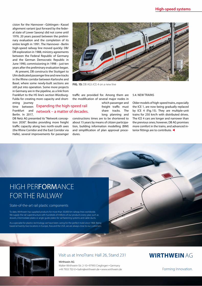
High-speed systems
11ETR | INTERNATIONAL EDITION | 22018wwweurailpressdeetr
FIG 15 DB AGrsquos ICE 4 on a new line
cision for the Hannover ndash Goumlttingen ndash Kassel alignment variant (put forward by the feder-al state of Lower Saxony) did not come until 1976 20 years passed between the prelimi-nary evaluation and the completion of its entire length in 1991 The Hannover ndash Berlin high-speed railway line moved quickly DBDR exploration in 1988 ministry agreements between the Federal Republic of Germany and the German Democratic Republic in June 1990 commissioning in 1998 ndash just ten years after the preliminary evaluation began
At present DB constructs the Stuttgart to Ulm dedicated passenger line and new tracks in the Rhine corridor between Karlsruhe and Basel where some newly-built sections are still put into operation Some more projects in Germany are in the pipeline as a link from Frankfurt to the HS linersquos section Wuumlrzburg-Fulda for creating more capacity and short-ening journey time between Frankfurt and Berlin In 2017 DB Netz AG presented its ldquoNetwork concep-tion 2030rdquo Besides providing more freight trac capacity along two north-south axes (the Rhine Corridor and the East Corridor via Halle) several improvements for passenger
trac are provided for Among them are the modication of several major nodes in
which passenger and freight trac must share tracks The long planning and
constructions times are to be shortened to about 15 years by means of citizen participa-tion building information modelling (BIM) and simplication of plan approval proce-dures
54 NEW TRAINS
Older models of high-speed trains especially the ICE 1 are now being gradually replaced by ICE 4 (Fig 15) They are multiple-unit trains for 250 kmh with distributed drives The ICE 4 cars are longer and narrower than the previous ones however DB AG promises more comfort in the trains and advanced in-terior ttings are to contribute
Expanding the high-speed rail network ndash a matter of decades
State-of-the-art rail plastic components
To date Wirthwein has supplied products for more than 30000 km railway lines worldwide We supply the rail superstructure with hundreds of millions of our products every year such as dowels intermediate plates or angle guide plates for rail fastening systems and cable ducts
As a specialist for plastics technology we have been caring for the perfect mold since 1968 Being based at twenty-two locations in Europe Asia and the USA we are always close to our customers
HIGH PERFORMANCEFOR THE RAILWAY
Forming Innovation
Wirthwein AG Walter-Wirthwein-Str 2-10 97993 Creglingen Germany +49 7933 702-0 bahnwirthweinde wwwwirthweinde
Visit us at InnoTrans Hall 26 Stand 231
MTU hybrid drives
12 ETR | INTERNATIONAL EDITION | 22018 wwweurailpressdeetr
PREFACE
The Lake Constance belt railway (in German Bodenseeguumlrtelbahn) is the only rail link be-tween the east and west of the lake The line is used not only for regional services but also for the international Ulm ndash Basel connection and in Friedrichshafen it links with the Wuumlrt-temberg Southern Railway (Suumldbahn) to-wards Ulm Electrication of the Suumldbahn is already in progress and scheduled for com-pletion by 2023
Electrication of the Lake Constance belt railway however has been a subject of con-stant debate for some years now Since elec-trication has not been taken into account in the Federal Transport Infrastructure Plan for the period up to 2030 nancing and realiza-
Quiet clean fast use of MTU hybrid drives on the Lake Constance belt railwayMTU Hybrid PowerPacks combine the advantages of diesel and battery-powered rail traction They can be installed in new or existing rolling stock without the need for additional changes to operations infrastructures or time schedules Even on non-electried routes they allow quieter cleaner faster and more cost-ecient rail travel The use of hybrid drives on the Lake Constance belt railway could signify a breakthrough for this innovative technology
tion are still open to question The under-taking would also bring certain challenges in the light of for example two low tunnels in the town of Uumlberlingen The nancial ex-penditure necessary to deal with them has not yet been calculated Furthermore the erection of overhead lines in such close prox-imity to the shore of Lake Constance would drastically alter the rural landscape and the touristic character of the location The pro-ject is therefore meeting with resistance from some local residents and communities
As an interim solution for improving service on the belt railway MTU Frie-drichshafen in discussion with the Lake Constance Railway interest group has pro-posed the tting of hybrid drives to the existing eet in regional and long-distance
service Diesel-based hybrids such as the MTU Hybrid Power Pack oer the advantages of both diesel and battery-driven rail travel and are quieter cleaner faster and more cost-ecient than the straightforward diesel drives currently in use An electric drive for example enables very low-noise emissions-free operation in urban areas and around stations Nitrogen oxide (NOx) and particu-late emissions fall impressively by compari-son with conventional eet and improved acceleration capabilities allow the planning of more stops and render the service less prone to delays Fuel consumption and in turn carbon emissions likewise fall by up to 25 All these benets are available without the need to change existing infrastructures
MTUrsquos Hybrid PowerPack is evolved from its conventional rail PowerPack PowerPacks
Dipl Ing Ingo LehmannProject and Safety Manager for Rail Mining Oil amp Gas Engineering MTU Friedrichshafen ingolehmannmtu-onlinecom
B Sc Dragan NedicKey Account Manager Rail Sales MTU Friedrichshafendragannedicrrpowersystemscom
Dipl Ing (BA) Benjamin OszfolkResearch and Technology Devel-opment MTU Friedrichshafenbenjaminoszfolkmtu-onlinecom
FIGURE 1 An IRE train with tilting technology on the Lake Constance belt railway
MTU hybrid drives
13ETR | INTERNATIONAL EDITION | 22018wwweurailpressdeetr
raquo
are compact drive systems with diesel en-gine transmission cooling system and au-tomation unit integrated on one base frame In the hybrid version of the PowerPack the drive is enhanced by an electric motor frequency convertor intermediate circuit on-board convertor and battery for storing energy harnessed during wear-free electro-dynamic braking This technology was al-ready presented by MTU in a previous article published in this journal [1]
Specic application of this concept on the Lake Constance belt railway has been exam-ined in simulations and verications carried out by MTU on its own systems test stand The subject of the study was the IRE service between Friedrichshafen and Singen
TEST STAND SIMULATION AND VERIFICATION
MTU Friedrichshafen is unique in its ability to simulate a complete vehicle drive such as the Hybrid PowerPack on a selected route and make reliable predictions on operation and fuel consumption Furthermore the company has a state-of-the-art Hardware-in-the-Loop (HiL) test stand that enables travel of the rail vehicle over the route to be simulated according to a given time sched-ule In this set-up the real drive is incorpo-rated into a virtual rail vehicle and subject to real conditions and loads Parameters such as fuel consumption drive dynamics and battery loads can be measured in the HiL set-up and compared with the previous computer-generated simulation results In this way MTU is able to verify its fuel-saving predictions and continually optimize its simulation tools
SIMULATION IRE FRIEDRICHS-HAFEN ndash SINGEN
Simulation of conditions on the Interregio service was carried out using the technical data from an existing Bombardier VT 612 DMU that is used on the Lake Constance belt railway The special feature of this train is its
tilting capability which allows it to negotiate curving track at speed Two vehicle congu-rations were simulated an existing VT 612 and a virtual VT 612 repowered with an MTU Hybrid PowerPack
Two scenarios were considered in the test In the rst the VT 612 Hybrid rail vehi-cle and the existing rail vehicle were run as per the current timetable (status 26012018) and compared in order to draw conclusions about time schedule feasibility and fuel consumption The second scenario looked at the feasibility of introducing a new time schedule with additional stops The new time schedule was taken from a study car-ried out by SMA amp Partner AG [2] whom the Lake Constance Railway interest group had engaged in 2013 to examine dierent timetable concepts also taking into account possible electrication of the line The study showed that operation of an hourly IRE ser-vice on the Lake Constance belt railway with additional stops in Markdorf and Salem could be recommended
In both scenarios electric-only mode for low-noise emissions-free rail travel was taken into account around planned stops
Route sections travelled in electric-only mode are shown in Figure 2
To determine fuel consumption the State of Charge (SOC) of the battery was taken into account in the energy balance SOC at the end of the journey must correspond to SOC at the beginning If despite smart en-ergy management and re-charging where appropriate en route the end SOC was not absolutely equal to the initial SOC the bat-tery was re-charged up to the required level using the diesel engine The fuel required to do so was also taken into account in overall fuel consumption
The aim of the simulation was to directly compare the VT 612 with the VT 612 Hybrid on the Friedrichshafen ndash Singen service of the Lake Constance belt railway based on the current time schedule (Scenario 1) and to determine the feasibility of the new time-table with additional stops in Markdorf and Salem as per the study made by SMA amp Part-ner AG (Scenario 2) A statement on fuel con-sumption was also to be made It is empha-sized again that the hybrid train switched to electric-only mode around stations and in urban areas as shown in Figure 2 Phases of
FIGURE 2 Deployment of a VT 612 Hybrid on the Lake Constance belt railway with electric-only phases
FIGURE 3 Simulation of IRE service on the Lake Constance belt railway
MTU hybrid drives
14 ETR | INTERNATIONAL EDITION | 22018 wwweurailpressdeetr
travel in electric-only mode caused a slight reduction in the fuel saving possible in rela-tion to the existing rail vehicle However this is seen as a justied compromise in view of the benets of phases of emissions-free qui-eter travel
The results for both scenarios are shown in Figure 3
The simulation results for Scenario 1 show that with a hybrid rail vehicle a fuel saving of 157 in relation to the existing VT 612 vehicle can be achieved including phases in electric-only mode The travel time in this case is 4600 min The fuel saving can be principally attributed to re-generative braking The energy thereby harnessed is used entirely for travel in elec-tric-only mode The results for Scenario 2 show a fuel saving of 206 in relation to the existing rail vehicle from Scenario 1 The time scheduled for Scenario 2 is 5600 min So with the hybrid rail vehicle the new Sce-nario 2 time schedule with additional stops in Salem and Markdorf can be realized with lower fuel consumption than for Scenario 1
and including electric-only mode around each stop
Evaluation of the simulation results even shows that potential still exists for a further reduction in the travel time (Fig 4) The blue line shows the vehicle speeds required for keeping to the time schedule The red line shows the speed limit for taking curving track at speed The route sections passed in electric-only mode are highlighted in green The speeds necessary along the route for keeping to the timetable remain for the most part well below the maximum speed limits This means that a reduction of the travel time is perfectly feasible still leaving sucient operational reserve
The simulation results shown were veri-ed on the Hardware-in-the-Loop (HiL) test stand and could be conrmed Besides time-keeping the most tangible improvements outside the vehicle are emissions-free travel and quieter operation around stations and in urban areas Measurements at the test stand and on a demonstrator showed that vehicle noise in the vicinity of stations can
be reduced by around 75 (20 dB(A)) This improvement might even be perceived by passengers inside the vehicle
Based on the simulation results it is pos-sible to calculate the annual savings in CO2 (132 tonnes) and NOx (105 tonnes) per ve-hicle based on 2500 hours runtime per year Extending this to the entire VT 612 eet in service in Baden-Wuumlrttemberg which amounts to 41 vehicles a total of 5412 tonnes of CO2 and 43 tonnes of NOx could be saved per year Rebuilding the rail vehicles with MTU Hybrid PowerPacks could there-fore make a very signicant contribution to air pollution control on Baden-Wuumlrttem-bergrsquos railways
REBUILDING THE VT 612 WITH A HYBRID DRIVE
The VT 612 is an ideal candidate for conver-sion to a hybrid drive As a high-oor vehicle it has more than enough space underoor for housing all Hybrid PowerPack compo-nents Since the Hybrid PowerPackrsquos compo-nents are not heavier than the current drive system it can be installed without any shift in the centre of gravity The feasibility of the rebuild was also conrmed by DB System-technik the Deutsche Bahn subsidiary Re-building tilting VT 612 railcars with hybrid drives would give them a new lease of life as fast eco-friendly trains and their tilting sys-tems ndash to which they owe their faster travel times ndash would remain available in the future
The rebuild concept proposed by MTU provides for installation of a Hybrid Power-Pack in each car The installation scope would comprise the following components
rarr Hybrid PowerPack (comprising diesel engine electric motor transmission cooling system)
rarr Batteries (3 MTU EnergyPacks with ca 90 kWh capacity overall)
rarr Water-based battery cooling
FIGURE 5 Rebuild concept for VT 612 Hybrid
FIGURE 4 Simulation results for IRE service using VT 612 Hybrid Scenario 2
15ETR | INTERNATIONAL EDITION | 22018wwweurailpressdeetr
rarr Intermediate DC circuit rarr Power electronics and lters for on-board power supply
The Hybrid PowerPack comprises an MTU 6H 1800 R85L diesel en-gine an electric motor and a ZF EcoWorld power-shift transmis-sion with integrated reversing function The diesel engine delivers 390 kW and the electric motor delivers 300 kW continuous power
The Hybrid PowerPack is arranged as a parallel hybrid with the electric motor sitting on the input side of the transmission up-stream of the diesel engine As a preference the electric motors are congured for electro-dynamic braking in order to harness surplus energy for battery storage or on-board power
SUMMARY
The simulations show that an MTU hybrid drive will have no dif-culties meeting either the current time schedule in place on the Lake Constance belt railway service or that planned for the future Rebuilding the rail vehicles with Hybrid PowerPacks would achieve signicantly cleaner quieter and more economical rail travel even without overhead electrication and with no compro-mises with respect to travel times The installation alone of state-of-the-art EU Stage V-compliant diesel engines in the VT 612 rail-cars could reduce particulate and NOx emissions by around 90 The further benets oered by a hybrid drive would prot the en-vironment passengers and operators alike Electric-only mode in urban areas and around stations lowers the noise level by as much as 75 Regenerative braking considerably enhances the ecologi-cal soundness of operations while improving their cost-eciency In this way up to 20 fuel savings can be made
All in all deployment of Hybrid PowerPacks on the Lake Con-stance belt railway could herald a breakthrough for this innova-tive technology in Germany
Literature[1] Oszfolk Benjamin et al Hybridantrieb stellt Marktreife unter Beweis ETR ndash Eisen-
bahntechnische Rundschau 92015 [2] SMA und Partner AG Optimierung Angebotskonzeption Bodenseeguumlrtelbahn
Zuumlrich SMA und Partner AG 2013
FIGURE 6 MTU Hybrid PowerPack
Discover intelligent sensors
INNOVATIONS TO SIMPLIFY RAILWAY OPERATIONS
EXPPERIEENCE THHE FUUTURE OF TTRAIN TRRACKINGG
InnoTranss in Berrlin18 ndashndash 21 Septembeer 220188Halll 255 | SStannd 2232
Digitalisation opens up new possibilities in generating a wide range of highly valuable information
wwwwfrauschherccominnootranns
Predictive Maintenance
16 ETR | INTERNATIONAL EDITION | 22018 wwweurailpressdeetr
BASIC PRINCIPLES OF DATA LAKES
Data Lakes dier fundamentally from clas-sic concepts of Business Intelligence such as Data Warehouses primarily by the type of data retained In data warehouses mainly transactional data is stored whose structure is dened upfront and which has already undergone pre-ltering before persistence In a data lake however all data is persisted regardless of its structure or relevance for known use cases Data Lakes have the fol-lowing basic properties [2]
rarr Data Lakes collect and store data regard-less of type format or data volume while they are to be stored in a structured manner in classic data warehouses
rarr Data Lakes provide large amounts of data Therefore it is important to keep costs low while maintaining a high ac-
The treasure of the Data Lake ndash Predictive maintenance for vehicle eetsEective asset management of vehicle eets in rail requires an ecient and comprehensive IT landscape as a basis The core of an associated architectural concept is a data lake that collects and provides real-time diagnostic data gathered on the vehicles It is the technical basis for the application of algorithms for condition-based maintenance of rail vehicle eets
cess rate Since data stored in structured form in data warehouses must be im-mediately accessible at all times to en-able fast access high persistence costs are generated Data Lakes on the other hand store raw data which depending on the frequency of accesses can also be stored with reduced access speed
rarr At Data Lakes all data is stored centrally and heterogeneously at the same time This means that data which is very dif-ferent from the format can be linked together in analyses without having to request potentially dierent systems beforehand Existing Application Pro-gramming Interfaces (APIs) provide a wide range of usable use cases It is easy to add dierent tools to the data stream as services for example or to store inter-mediate results in the Data Lake for fur-ther use by other tools
rarr Data Lakes keep all relevant data central and unstructured regardless of format-ting The analysis tools are always con-ceptually independent of the format and structure of the data This allows new analyses or new data sets to be integrat-ed easily and quickly
rarr In modern implementations of data lakes and the service landscapes required for this the concept provides for the rapid interchangeability of tools and micros-ervices The user can test generally avail-able tools with practically no initial eort and if required can transfer those to productive use in just a few steps
SERVICE-ORIENTED AND CLOUD-BASED ARCHITECTURE FOR DATA LAKES
Instead of using solutions based on indi-vidual or a few applications with a dened range of functions Data Lakes reliy on so-lutions consisting of a exible combination of dierent micro services around a central data store The software architecture must be detached from classical patterns such as a layered hierarchy and the development must lead to a data- or data-ow-centered architecture This makes it easy to add or re-place services at any point and keeps the ar-chitecture exible for future developments
When using data lakes primarily event-driven architectures are common By con-
Mathias Haimerl Senior Data Analyst ESE Engineering und Software-Entwicklung GmbHmathiashaimerlesede
FIGURE 1 Vehicle eets in rail transport as an object of asset management
Predictive Maintenance
raquo
trolling the events based on the underly-ing data streams this architecture can be called Data-Driven Architecture (cf[5]) The software therefore builds itself around the data stream as shown in Fig 1 The data stream therefore represents the basis for the achievement of objectives whereby each individual problem can be regarded as an in-dependent architecture The desired objec-tive is broken down top-down into required services and newly formed into a specic so-lution Right from the start not only services for data manipulation are considered but also accompanying services for areas such as logging and security
The implementation of data lakes on company-owned hardware does no longer make sense for most projects from a nan-cial point of view and therefore only makes sense for particularly critical applications (eg banks medicine military) if commercial cloud solutions with appropriate security options cannot be found or are not applica-ble for compliance reasons
CHALLENGES AND SOLUTIONS OF CLOUD-BASED ARCHITECTURES
The use of services in a cloud creates new
challenges that need to be addressed in ad-vance
Information security of the customer data available in the cloud is in most cases much higher in the Amazon Web Service (AWS) Cloud than on self-operated servers The large number of system administrators de-ployed worldwide for the AWS Cloud some of whom specialize in information security provides signicantly better information se-curity than would be the case with conven-tional IT infrastructures operated by compa-nies themselves
Handling security vulnerabilities Due to the high number of users in the global internet of things (IoT) security gaps that allow access to external data quickly become nancially and legally problematic The Linux base and the simple reporting of security problems allow newly discovered vulnerabilities to be resolved quickly and globally The globally uniform system and the uniform administra-tion of software components close security gaps within a few hours
Protection against unauthorized access by third parties Authentication measures serve to protect sensitive data against unauthor-ized read access (data theft) on the one hand
and to protect data against unauthorized manipulation (data modication computer sabotage) on the other Authorization meas-ures are aimed at ensuring that analysts and solution architects only have access to the data relevant to their projects This is supported by the targeted allocation of authorisations to the respective architects In addition organization-related boundary conditions are contractually secured One example of this are compliance guidelines such as certication of cloud providers ac-cording to standards like DIN EN ISOIEC 27001
Software maintainability The AWS ba-sic system is stable against updates and changes without interfering with customer projects Customer projects run in self-con-tained environments (sandbox) The pro-vider of the cloud system has the freedom to use exchange and extend any hardware components without expensive downtimes or waiting times for the user Software up-dates and time-consuming hardware up-grades are obsolete for the user
Legal framework Sending data across na-tional borders is often a legal hurdle that prohibits the use of cloud services To coun-teract this cloud providers have provided
FIGURE 2 Overall concept of the data-driven architec-ture The microservices are structured around the data stream
wwwmobility-bbcom
Berlin-Brandenburg
Moving mobility
to the next level
Meet us at InnoTrans
City Cube Hall B
210x99_VML_InnoTrans_eng_ETRindd 1 19072018 081118
Predictive Maintenance
18 ETR | INTERNATIONAL EDITION | 22018 wwweurailpressdeetr
for the possibility of binding to regions that ensure that data does not leave certain pre-dened regions
Calculability of costs An AWS solution is about 90 cheaper than the operation of ldquoclassicrdquo infrastructures This value is also evi-dent in one of our customer projects where about 98 of the costs were saved on the development system and the eective sav-ings for the live system were interpolated to be at about 91 AWS provides a billing calculator that provides an estimate based on past months and previous monthly costs
SAMPLE IMPLEMENTATION STEPS FOR AMAZON WEB SERVICES
As an example implementation of a data lake the cloud environment AWS was used as described below During implementation four functionalities were clearly separated which are described in more detail below
rarr Data acquisition including pre-process-ing (ingestion)
rarr central data storage rarr Cataloging of data rarr Preparation of concrete analyses
DATA ACQUISITION (DATA INPUT) FOR DISTRIBUTED DATA SOURCES
In order to be able to ingest sensor data from vehicle eets the receiving system must be able to accept and store a large number of distinct data from many sensors On the senderrsquos side however data must be collected buered and regularly transmit-ted to the Data Lake To do this a periodic Internet connection must be ensured For
the frequency of data transfer an individual taring between the local data collection and the frequency of synchronization to the cloud must also be found Data transfers at low bandwidth should preferably rely on the collection of several data sets and trans-fer with a stable connection However this requires more memory in the local device With higher bandwidth and stable connec-tions the data can also be transferred more frequently This on the other hand leads to an increased load on the receiver A project-specic optimum must be found here
Finally it should be taken into account that the order of data sets should already be de-ned during ingestion even if the structure does not have to be xed from the outset To simplify later evaluations considerably data of the same type for which the uniformity is to be foreseen should be grouped logically This unies the data accesses of the evaluat-ing processes and thus minimizes the eort
From a specic project of a customer we know that the current data load of 6754 MBh will increase tenfold by 2020 due to an increase in the number of equipped vehicles and a simultaneous tripling of the number of sensors to approx 2GBh The distribution of the eets is Europe-wide with the focus on Central Europe
CENTRAL DATA STORAGE
In order to eciently persist the collected sensor data of vehicle eets the receiving system stores the data in a central location In AWS data is stored centrally in any size and in an automatically growing storage unit a so-called bucket The data is stored in ob-jects a logical data unit comparable to les in a classic le system To make searching
through data easier the objects are indexed based on their specic prexes and opti-mized for fast access Since the implementa-tion is based on RESTful and therefore each data record transmitted by sensors sends a PUT request a new object is created for each data record This creates an immense num-ber of objects in the long term This is irrele-vant in terms of costs and storage space For an analysis based on large amounts of data with low reaction times however a catalog-ing of the data is still necessary
CATALOGUING FOR VARIOUS APPLICATIONS
The exible NoSQL database DynamoDB oers an optimal possibility to catalog data without having dened a schema and still get extremely fast access speeds A Dy-namoDB table has a primary key which con-sists of a partitioning key and an optional sort key The partitioning key determines the automatic partitioning of the table and should therefore be very well selected (see [9]) An entry also supports update com-mands DynamoDB oers a very exible memory which can be written and read in dierent ways
New data arriving in Simple Storage Ser-vice (S3) can be automatically analyzed as a trigger for cataloging and added to cor-responding catalogs Since the analyses are usually very individual a pipeline must be created so that the new data arriving in S3 can be processed This can be achieved with minimal eort using the Microservice Lamb-da which makes it possible to execute small programs in the AWS landscape without any further integration eort Optional lters can be set for the triggers so that dierent pre-xes start dierent lambda functions
rarr Read The respective lambda function receives the bucket and the object name of the newly arrived object and can ex-amine this import and the content ac-cording to previously dened criteria and extract the corresponding values
rarr Write This data can then be written to a DynamoDB table regardless of whether the data record already exists ie wheth-er it has to be updated or whether it is a new data record
This type of cataloging is the comparatively most complex but at the same time the ex-ibility exceeds that of other technologies by far The cost factor is also considerably lower here The costs for DynamoDB tables are cal-culated according to provisioned capacities for read and write accesses This is under-
FIGURE 3 Using cloud solutions brings new challenges
Predictive Maintenance
19ETR | INTERNATIONAL EDITION | 22018wwweurailpressdeetr
standable as an increase in capacity in the background is a real hardware replication This allows tables with costs of less than one euro per month for the minimum congura-tion and a separate table can be provided for each application case The requests for large amounts of data via the primary key or only a part of it can be retrieved extremely quickly whereby retrieval times in the low two-digit millisecond range are not uncommon
PREPARATION OF CONCRETE ANALYSES
The creation of analyses on the catalogued data is possible without great eort with the basis shown This is done in several consecu-tive steps
rarr Top-down analysis of the problem to be solved as there are various microservic-es for a wide variety of applications As a result individual use cases can be as-signed to the use cases
rarr Selection of suitable microservices De-pending on the target platform the ap-propriate microservices can be selected There are specic services that enable the further use of existing programs that work on relational databases for example Other microservices support machine learning or the visualization of complex interrelationships in informa-tive dashboards
rarr Bottom-up aggregation of specically congured microservices For this pur-pose services already congured for similar analyses can be reused or addi-tional instances with slightly modied conguration can be created
SUMMARY amp OUTLOOK
All in all Data Lakes oer an optimal solution from the initial setup of a collection of raw data from various sources without large upfront ef-fort or high costs to the data storage of many eets of dierent vehicles worldwide and the provision of data catalogs for various analyses of various kinds The collection of measure-ment data in persistent online data stores such as AWS buckets can be implemented within minutes and is operational from this point in time so that data can be collected and archived Even if no specic use cases are known at the time of implementation it is recommended to persist all data on low-cost cloud storage so that it is already available for possible evalua-tions at later points in time Since there is often no reason to process data without use cases favorable options for persistence of the data can be used To avoid vendor lock-in consider designing Data Lake to be adaptable to alter-native platforms Alternative options for data storage include the storage services of Google Cloud Services or Microsoft Azure Of course the use of a second service also doubles the total costs
References[1] Canalys (2017) Cloud service providersrsquo battle drives
the worldwide cloud infrastructure market up 42 in Q1 2017 httpswwwcanalyscomstaticpress_re-lease2017press-release-150517-cloud-service-providersE28099-battle-drives-worldwide-cloud-infrastructure-market-42_1pdf Palo Alto Shanghai Singapore and Reading (UK) Pressemit-teilung 15052017
[2] Amazon Web Services (2017) Building a Data Lake on AWS httpspagesawscloudcomrs112-TZM-766im-agesAWS_Data-Lake_eBookpdf 01112017
[3] Bundesministerium des Inneren (BMI) (2017) Polizeili-che Kriminalstatistik 2016 httpswwwbmibunddeSharedDocsdownloadsDEpublikationen2017pks-2016pdf Pressemitteilung 24042017
[4] Buschmann Frank and Christiane Loumlckenho eds (2000) Pattern-orientierte Softwarearchitektur ein Pat-tern-System 1 korr Nachdr Muumlnchen Addison-Wesley 2000
[5] Mahjourian Reza (2009) An Architectural Style for Data-Driven Systems Paper Gainesville FL 32611 USA httpswwwcsutexasedu~rezalesxpage-icsrpdf 22032009
[6] Tilkov Stefan (2009) REST und HTTP Einsatz der Ar-chitektur des Web fuumlr Integrationsszenarien 1 Au Hei-delberg dpunkt 2009 ISBN 9783898645836
[7] Hunkeler U H L Truong and A Stanford-Clark (2008) MQTT-S mdash A Publishsubscribe Protocol for Wireless Sensor Networks In Communication Systems Software and Middleware and Workshops 2008 COMSWARE 2008 3rd International Conference on 791ndash98 2008 httpsdoiorg101109COMSWA20084554519
[8] Manseld-Devine Steve (2016) DDoS Goes Main-stream How Headline-Grabbing Attacks Could Make This Threat an Organisationrsquos Biggest Nightmare Net-work Security 2016 no 11 (November 2016) 7ndash13 httpsdoiorg101016S1353-4858(16)30104-0
[9] Vyas Uchit (2014) DynamoDB Applied Design Patterns Birmingham United Kingdom Packt Publishing 2014
SAFERAILSYSTEMCOM
Guessing or GPR
bull GPR measurements and analysisbull Condition-based maintenance planningbull More than 25 years of working experience - worldwide
BIM
20 ETR | INTERNATIONAL EDITION | 22018 wwweurailpressdeetr
ABOUT SIEMENS MOBILITYrsquoS TURNKEY RAIL SOLUTIONS BUSINESS
Siemens AG is a global technology power-house that has stood for engineering ex-cellence innovation quality reliability and internationality for more than 170 years The company is a pioneer in supplying in-frastructure solutions Siemens Mobility is an experienced provider of complete turn-key solutions for rail systems having already carried out more than 50 various and major rail projects worldwide The organization is home to experts in project management and system integration as well as key prod-ucts of rail infrastructure These specialists develop and implement projects for all types of rail vehicle systems from metros trams and light rail vehicles and automated peo-ple-movers to Intercity and high-speed train units ndash all designed for maximum reliability availability and eciency
THE CHALLENGES OF RAIL INFRASTRUCTURE PROJECTS
Projects to install new rail infrastructure and expand existing systems are growing steadily more complex The rising number of project participants and stakeholders presenting a broad range of specic require-ments planning teams in dierent locations and time zones having to coordinate and
Digital twin serving rail infrastructure How turnkey rail infrastructure projects are beneting from applying Building Information Modeling (BIM) how Siemens Mobility is pursuing virtual planning of projects with project partners and custom-ers such as in the Riyadh Metro Project and what added value this methodology is creating
integrate their civil and rail engineering and planning and the ever increasing time and cost pressures exemplify this problematic complexity
There are an enormous number of inter-faces and requirements involved especially in large rail infrastructure projects and or-ganizing them demands extensive resources and absolute precision
AT THE VANGUARD OF DIGITAL PLANNING
Just as countless other sectors of the con-struction industry have already experienced digitalization is driving a para-digm shift in rail infrastructure away from analog meth-ods and embrac-ing digital and in-tegrated planning encompassing eve-rything from erec-tion planning installation and support for training to preparation and performance of repairs and maintenance all based on digital processes and data models
More than four years ago Siemens Mo-bility began applying building information modeling (BIM) techniques as well to project planning and execution of complete turnkey
solutions for rail systems As one of the trail-blazers of digitalization Siemens Mobility uses BIM to create a digital twin ndash a virtual model of major rail projects planned for im-plementation
This methodology focuses on achieving cost and time eciency while also ensuring the highest quality standards
Siemens Mobilityrsquos Turnkey Rail Solutions is using BIM in col-laboration with construction part-ners to optimize project planning and execution This involves the use of computer-generated 3D modeling and the
information integrated into or linked with the models
REFERENCE PROJECT RIYADH METRO
The Arriyadh Development Authority (ADA) ndash the executive arm of The High Commission
Both the implementing company and customer benet from the reduced risk of delays in planning as well as the prevention of defec-tive planning and resultant need to revise planning during ongoing installation
Dr Payam AminiHead of Digital Transformation Turnkey Projects amp Electrication Siemens Mobility Munich payamaminisiemenscom
A simulated view of the outside of the depot for which the path of sunlight can be simulated over time
raquo
BIM
21ETR | INTERNATIONAL EDITION | 22018wwweurailpressdeetr
for the Development of Arriyadh in Saudi Arabia ndash is currently building one of the larg-est metro projects in the world with six rail lines totaling 176 kilometers in length The system will be the backbone of the public rapid transit network serving Saudi Arabiarsquos capital city The order placed with Siemens Mobility covers supply of 67 Riyadh Metro model rail vehicles based on the Inspiro Plat-form series line electrication the signaling and communication systems for driverless service on Lines 1 and 2 as well as system integration and project management Sie-mens Mobility is part of the BACS consor-tium led by US company Bechtel along with Almabani General Contractors and Consoli-dated Contractors Company
The Riyadh Metro Project (RMP) kicked o by dening the information requirements and project-specic BIM objectives of the customer The BIM management team of Siemens Mobilityrsquos construction partner Be-chtel then used this information as the basis for elaborating in detail the BIM process for all project participants
The BIM execution plan that denes the BIM process for a specic project basi-cally provides the answers to the agreed require-ments In this key central document Turnkey Rail Solu-tions dened for all project participants in-volved in the infrastructure design the roles and scopes of responsibility the programs and le formats to be used what applica-tions are to be integrated into the BIM pro-cess the data-exchange process along the chain of project phases the quality review inspection and testing criteria procedures for coordination and collaboration and much more This was necessary in order to ensure smooth BIM implementation over the entire project cycle
Siemens Mobilityrsquos construction partner also generated the model element plan which denes in an overview who is to gen-erate what model content for the project by when and to what level of development (ie geometry information and coordination) In this project BIM standard the construc-tion partner also dened the details for modeling agreements and documentation standards
Model-based planning is one of the pro-jectrsquos centerpieces enabling comprehensive integration of all rail infrastructure systems such as rail electrication the depot and workshop equipment line signaling and communication technology and platform screen doors
CLARITY DRIVES THE EFFICIENCY OF WORKFLOWS
Siemens Mobilityrsquos infrastructure planning engineers used project-specic BIM software to share their model-based information with Siemens Mobilityrsquos suppliers and the con-
struction partner The program Pro-jectWise is used in combination with Aconex served and continues to
serve as a shared data platform accessible project-wide ensuring that each piece of information is retained only once and in its most recently valid version In this ldquosingle source of truthrdquo data are referenced rather than duplicated signicantly improving in-formation management increasing the reli-ability of data and eliminating any use of superseded obsolete data This provides full trans-parency for all pro-ject participants Photo-realistic displays and animated videos of the planning progress generated on the basis of the 3D planning information ensure transparency enhance understanding and support the iterative process
The permanent availability of data accel-erates collaboration across national borders and company boundaries These aspects are particularly benecial in the RMP Just Sie-mens Mobilityrsquos unit alone had colleagues based in 13 dierent cities working to de-sign the rail infrastructure coordinating and agreeing across national boundaries and dierent languages time zones and work capacities
In addition to the geometrical properties
of system components for example of fre-quency converters the participating plan-ning engineers also integrated non-geomet-rical information and requirements of their systems such as zones and clearance spaces that are essential for installation and mainte-nance Once work on a subarea of a model (work in progress) was approved for release this information was then available to all partners within the project (shared areas) In turn these partners reviewed the completed work for impacts on their own work scopes
In interdisciplinary collision reviews the design coordinators conducted collision tests with all other draft components Such reviews examined for example the civil struc-tures technical building equipment systems and Siemens Mobilityrsquos systems such as the signaling equipment and traction power supply grid to identify any conicts between
the systems them-selves or with the civil structures
In this way structural imple-mentation of the overall project as
well as individual subareas can be digitally tested at any time
As a provider of turnkey infrastructure solutions Siemens Mobilityrsquos unit was in-volved early in the RMP through BIM help-ing to prevent planning errors and leading to quicker validation of draft planning such as for spatial requirements of infrastructure equipment free clearance proles and pre-venting collisions
The RMP oers a basis for further infra-structure projects using BIM methodology The stock of digital objects available in the component library continues to grow Exist-ing digitally modeled components can be directly used for the next digital twin This
BIM creates full transparency for everyone participating in the plan-ning of infrastructure projects
The Control Center of the Riyadh Metro Project for Line 1 was fully planned digitally Once that design process was completed actual construction started
BIM enables earlier design valida-tion of rail infrastructure technol-ogy and engineering as well as civil construction
BIM
22 ETR | INTERNATIONAL EDITION | 22018 wwweurailpressdeetr
accelerates digital planning from one pro-ject to the next
Siemens Mobility Turnkey Rail Solutions sees particular potential for BIM in integrating the necessary man-agement process-es BIM supports the management of interfaces requirements congurations and project documentation This improved management leads to accelerated project execution And although project execution in Riyadh is still underway the added value created by the BIM method is already clearly evident today ndash for both Siemens Mobility and the customer
DIGITAL SCAN OF THE INFRASTRUCTURE CREATED
Siemens Mobility Turnkey Rail Solutions is utilizing other digital solutions as well for the Riyadh Metro Project that further optimize pro-ject execution Siemens Mobility-owned track measuring vehicles and 3D laser scanners are deployed to eciently compare the progress
of as-built construction and installation against the design target data These units travel along the existing sections scanning and thereby
digitalizing the as-built environment The object-specic information collect-ed by this measur-ing system whether on track position-
ing platform edges or technical spaces is com-pared with the digital design thereby directly revealing any deviations from planning
This produces a 100 -accurate database of the existing as-built status Particularly when projects aim to expand exist-ing infrastructure such transparency prevents costly conicts when equipping existing civil structures with new infrastructure equip-ment Besides the hardware procurement Siemens Mobility is banking in this context on developing the expertise of its own per-sonnel to cover planning of measuring cam-paigns kinematic and static imaging and evaluations such as review for collisions
PROMISING OUTLOOK
Siemens Mobilityrsquos Turnkey Rail Solutions has ceaselessly invested in implementing and further developing digital methods to keep pace with steadily growing deadline and cost pressures and the increasingly stringent demands of complex rail infra-structure projects These efforts are now empowering Siemens Mobility to better assess the sometimes extremely demand-ing detailed requirements early already in the project bidding phase and estimate costs more reliably thereby minimizing risks
In previous projects utilizing BIM meth-odology Siemens Mobilityrsquo experts identi-ed a shifting of eort into the early project phases
Siemens Mobilityrsquo experts see opportuni-ties in doing so particularly in the assess-ment of design modications in terms of im-pacts on costs and in early application when the leverage for such optimization can still prove very eective
Yet BIM doesnrsquot end when construction work on an infra-structure project has been complet-ed By developing a digital twin of the as-built infrastruc-ture and applying
that model over its entire lifecycle these sets of digital data can be used to optimize asset management
The BIM method harbors major potential for signicantly shaping the rail infrastruc-ture sector in the coming years
A view of the digital model of the King Abdullah Financial District Station on Line 1 which can be viewed in the computer pro-gram from all sides
Photo-realistic displays and animat-ed videos of the planning progress ensure transparency and enhance understanding
BIM provides the basis for simpler and ecient interface management and contributes signicantly to accelerating project execution
5 | 2017 Mai wwweurailpressdesd
109 Jahrgang
SIGNALLING amp DATACOMMUNICATION
Oumlsterreich Gut gesichertAustria Well-protected
13 Kostenguumlnstige Sicherung von Eisenbahnkreuzungen Cost-effective protection of level crossings
36 Finnland Gegen den Instandhaltungsruumlckstand Finland Reducing maintenance backlog
21 Schweiz Weltpremiere auf der Toumlsstalstrecke Switzerland A world premiere on the Toumlsstal line
Your contact person Silvia Sander +4940237 14-171 silviasanderdvvmediacom wwweurailpressde
Leader in Signalling and Datacommunication
No 1ad medium
SIGNALLING AND
DATACOMMUNICATION
AUTONOMOUS DRIVING
CYBE
R SE
CURI
TY
LEVEL CROSSING TECHNOLOGY
OPERATIONS MANAGEMENT SYSTEMS
MOBILE COMMUNICATIONETCS
REPUTABLE
UN
IQU
E
ESTABLISHEDTELECOMMUNICATION
OPERATIONS CONTROL TECHNOLOGY
INFORMATION TECHNOLOGYBILINGUAL
Book your advert right now
raquo
Ground Penetrating Radar
23ETR | INTERNATIONAL EDITION | 22018wwweurailpressdeetr
1 INTRODUCTION
Many countries allocate large amounts for the modernization and upgrading of their railway networks in order to meet the de-mands of increasingly dense rail trac with higher axle loads at ever higher speeds However this can only be achieved if all rel-evant key gures and geotechnical condi-
Ground Penetrating Radar ndash Basis for eective Track MaintenanceThis article describes the capabilities and functionality of Ground Penetrating Radar (GPR) for higher speeds GPR is a train-borne technology for a continuous inspection of the geotechnical conditions of railway tracks The basic principles of the GPR technology are explained with particular reference to all relevant railway specic tasks namely the identication qualication and quantication of ballast fouling by using a fouling index the determination of the quality of track drainage and its quantication through a drainage index and the calculation of the track modulus (TM) Special emphasis in the context of GPR investigations is placed on the mapping of sections with clay foulingmud spots inside the ballast bed or at its base and respectively inside intermediate layer formation or subsoil In the past such weak-spots have caused derailment they could represent a risk for rail-trac [11 13 14 15 16] Besides their late detection implies exceedingly high maintenance costs
tions of the respective tracks can be reliably evaluated On this basis only the necessary investments in track maintenance moderni-zation and support can be dened in the ap-propriate size and can be placed correctly This is particularly true when budgets are tight
The demands exerted on the track in terms of safety grow with increasing speed
FIGURE 1a) Trajectories of radar waves which are reected at the layer boundary between two media
with dierent dielectric constant (laquo)b) Due to the dierent travel time of the reections the layer boundary is reproduced in the
radargram (reference Ground Control and IEV)
Dipl-Geophys Giuseppe StacconeDirector of Ground Control GmbH MunichGermanystacconesaferailsystemcom
David Camacho MScDoktorand am Institut fuumlr Eisen-bahn- und Verkehrswesen der Universitaumlt Stuttgart (IEV)davidcamacho ievvwiuni-stuttgartde
Moritz SchebuchMitarbeiter am Institut fuumlr Eisen-bahn- und Verkehrswesen der Universitaumlt Stuttgart (IEV)moritzschebuch ievvwiuni-stuttgartde
Prof Dr-Ing Ullrich MartinDirektor des Instituts fuumlr Eisenbahn- und Verkehrswesen der Universitaumlt Stuttgart (IEV) und des Verkehrswis-senschaftlichen Instituts an der Universitaumlt Stuttgart eV (VWI eV)ullrichmartin ievvwiuni-stuttgartde
Dipl-Ing Sebastian RappAkademischer Mitarbeiter am Institut fuumlr Eisenbahn- und Verkehrswesen der Universitaumlt Stuttgart (IEV)sebastianrapp ievvwiuni-stuttgartde
Ground Penetrating Radar
24 ETR | INTERNATIONAL EDITION | 22018 wwweurailpressdeetr
Therefore failing to detect track damages or obtaining inadequate information on track damages represents a hazard for every kind of railway trac For this reason a decision guidance that facilitates a systematic and ecient renewal of the tracks is important The more intensive the rail trac and the higher the trac speed the bigger the re-quirements in terms of an ecient and reli-able track inspection
The mapping of clay fouling or mud sec-tions is of special importance Fine-grained soil material such as silt or clay wells up from the formation and reaches the ballast base or even penetrates the ballast layer itself As a consequence track drainage and track stability (ie bearing capacity) are strongly reduced This results in lasting deformations that require complex maintenance work and high costs If weak-spots are not identied or not detected in time clay fouling can in the worst case scenario lead to derailment [10 13 14 15 16]
During the past 25 years Ground Control GmbH which is placed in Munich Germany has surveyed more than 100000 km of rail-way tracks in many countries in Europe and all over the world Recently with information obtained from GPR results and other data (ie track geometry and track dynamics) a continuous and complete assessment of the trackrsquos structural condition is possible
2 MEASURING PROCESS
The GPR method is an electromagnetic re-ection method Radar pulses are transmit-ted into the subsoil by a transmitter antenna The energy of the electromagnetic waves is partly reected at interfaces between layers with dierent dielectric properties and re-transmitted to the receiver antenna Based on the measured travel time of the signals and knowing the propagation speed of the waves in the medium depth and surface of the layer can be computed
In order to dene the depth of the re-ector from the surveyed travel time the propagation speed of the radar waves in the subsoil has to be determined The speed of electromagnetic waves in the subsoil is re-lated to the water content of the individual material Therefore it is generally not pos-sible to refer to reference values for certain rock or soil types Thus the radar wave speed has to be calibrated for each project area
The penetration of electromagnetic waves mainly depends on the electric conductivity of the soil and the applied antenna frequen-cy By using low frequency antennae on low conductive subsoil the largest investigation depth can be achieved
PERFORMING SURVEYS WITH MODERN HIGH-SPEED-GPR
Todayrsquos GPR surveys are carried out with train mounted systems at speeds up to 160 kmh As a general rule the antennae system is fastened at the carrier vehiclersquos buers A precise positioning is achieved by an inte-grated Dierential Global Positioning Sys-tem (DGPS) and Doppler radar
The characteristics of modern GPR sys-tems are
rarr The equipment can be installed and run on a wide range of track-bound vehicles (including regular trains or vehicles on Hy-Rail)
rarr They are fast enough to be integrated into the regular trac schedule Hence expensive track closure is no longer nec-essary
rarr DGPS and Doppler radar are used for an accurate (ie precision within a meter) positioning of the antenna independ-ent of the speed and length of the track surveyed
rarr Measurement data resolution and data quality are equally high no matter what length and what speed
rarr All GPR components are eectively
shielded against interferences from sig-nalling and communication systems
3 GPR TASKS
In contrast with punctual boreholes and trenches modern GPR systems provide con-tinuous information about the geotechnical condition of the track performing the fol-lowing tasks
rarr Continuous mapping of track-bed-thick-ness and layers below (ie intermediate layer protective layers)
rarr Distinction between clean and fouled ballast and calculation of Fouling Index
rarr Mapping of mud spots or clay fouling sections inside ballast bed at its base or inside substructure layers respectively
rarr Detection of sections with drainage problems and calculation of ldquoWet Bed Indexrdquo
rarr Mapping of areas with insucient bearing capacity (eg settlements) and evaluation of the dynamics of track set-tlement
rarr Control and evaluation of the quality of maintenancerenewalconstruction work (quality of cleaned or exchanged ballast thickness of a new ballast bed quality and thickness of soil layers)
rarr Estimation of track condition based on track modulus (TM) calculation
Additionally GPR data allow for the deni-tion of a sustainable cause-based and there-fore eective track renewal recommenda-tions and programs Optionally GPR oers the possibility to accurately map cables pipes and other objects in the track sub-structure creating the possibility to provide a complete picture of the entire system
31 CLAY FOULING ndash STRONG EFFECT ON TRACK STABILITY
Clay Fouling is one of the main reasons for the reduction of the load bearing capacity of the track in a relatively short period of time Several derailments in the past were caused by mud spots [10 13 14 15 16] even when the limit values for track geometry failures according to [2] have not been exceeded [13 14] It is therefore and because of safety reasons of particular importance to detect clay fouling areas reliably in their precise dimension and as early as possible The rec-ognition of the problem should be irrespec-tive of whether the clay fouling exists in the substructure at the base of the ballast bed or in the ballast bed itself Clay fouling can
FIGURE 2 Figure 2 Antenna mounted on the train buers of a mainte-nance vehicle(reference Ground Control)
Ground Penetrating Radar
25ETR | INTERNATIONAL EDITION | 22018wwweurailpressdeetr
raquo
rapidly deteriorate the stiness of the track and its quality The trackrsquos lateral stability is massively reduced longitudinal errors along the rails arise
Clay fouling is also a serious decit from an economic point of view Its timely iden-tication allows for avoiding slow speed sections thus sparing time and money for maintenance procedures Detecting clay fouling before it reaches the ballast bed ena-bles cost eective renewal Otherwise it will be very expensive There is no option for bal-last cleaning a suciently compacted pro-tection layer built of the appropriate materi-al is essential the installation of composites does not prevent clay fouling from entering the ballast bed (see Fig 3)
Save few exceptions clay fouling spots are not visible at the track surface and since drill-ings and trenches do only provide punctual results reliable information is only achievable through GPR measurements (see Fig 4)
A frequency analysis of the measured data results in a typical change of the signal spectrum in the area of clay fouling Based on the GPR results borehole program can be implemented which can be used for further analysis GPR surveys to detect ballast foul-ing have been carried out for years in Swit-zerland Austria the Netherlands and France among others
32 TRACK MODULUS (TM)
Examining the geotechnical conditions of railway tracks requires an index which in-forms about state and quality of the tracks in a quantitative manner The challenge has
been to dene the track condition continu-ously This has been achieved by combin-ing TM with the results of continuous GPR-measurements
It is possible based on [3 4 5 6 7] to es-timate quality and bearing capacity of the railway track Therefore the TM describes the relation between vertical load and elas-tic deection of the sleeper-bearings
On the one hand the TM can be calculated based on the measured deection under load [18 20] on the other hand according to the soil properties [8 9 11] The measuring principle for determining the load deec-tion is described in detail in [12] and [17] The properties of the system components such as the area of inuence of the sleepers under load can greatly aect the TM Hence around turnouts the area of inuence of sleepers deviates from the standard track This is because an increased area of inu-ence causes an increase in the distribution of the load reducing the deection of the
rail Notwithstanding to simplify the calcula-tion of the TM the inuence area of sleepers around turnouts are assumed to be constant assuming the values of the standard track Depending on the type of sleepers installed the value of the TM can increase sharply around turnouts (Fig 5) In addition cavities under the sleepers increase the deection of the track under load which in turn inu-ences the calculation of the TM decreasing its value
An additional and new approach for calcu-lating the TM is based upon the soil proper-ties which can be described by the Poissonrsquos Ratio or the material density of the soil The soil properties derive from the GPR data This methodrsquos advantage is to be completely in-dependent from superstructure conditions The individual layers are assigned soil values according to condition and bulk density Averaged soil properties are calculated ac-cording to [1 19] The TM can be estimated according to [9] and [11] Previous studies
FIGURE 4 Visual analysis of GPR data depicting clay fouling along a track (reference Ground Control and IEV)
FIGURE 3 Geotextile or composite does not stop ne particle migration to the surface (reference Ground Control)
Ground Penetrating Radar
26 ETR | INTERNATIONAL EDITION | 22018 wwweurailpressdeetr
indicate that this method has signicantly lower value variations along the track axis compared to the approach based on the use of track displacement data (Figure 5)
The example in Fig 5 shows two track moduli based on the measured displacement under load (red line) and the soil properties (blue line) Around the turnouts a signicant increase of the TM is visible if the calculation is based on the measured deection By divid-ing the TM into quality classes according to [3 4 5 6 7] the condition of the track can be sat-isfactorily estimated (Fig 6)
33 TRACK ANALYZER ndash CONTINUOUS PRESENTATION OF ALL MEASUREMENT AND TEST RESULTS
Results from GPR surveys along with all identied soil parameters and indices cal-
culated can be displayed in comprehensive track analysis software called ldquoTrack Analyz-errdquo In order to provide all information for in-frastructure managers track geometry and track dynamics data are also integrated and displayed in the software (see Fig 7) which also oers the exibility to incorporate other tasks and aspects as required by the user
The Track Analyzer provides infrastructure managers continuous information about the geotechnical conditions of the track with regard to all relevant issues Moreover it provides a better understanding of the sub-structuresubgrade conditions and their in-uence on the superstructure This allows for a signicantly increased track quality pro-viding higher route availability and safety
A big advantage of the GPR method is the minimization of the need for intensive direct outcropping (probing drilling scooping)
to characterize the underlying geotechni-cal characteristics of the track substructuresubgrade which results in signicant cost reductions
4 SUMMARY
This paper describes a modern train-borne technology for the inspection of the geo-technical conditions of railway tracks It is based on High Speed GPR and on classical procedures for providing continuous infor-mation about geotechnical parameters and indices A new quality of GPR measurements is to provide quantitative indices in addition to qualitative results to full the require-ments of the railway engineers in the best possible way
Special attention is paid to the detection of mud spots and clay fouling sections as a risk for derailment [10 13 14 15 16] To date track inspection with GPR is more appropri-ate than any other inspection method to de-tect map and qualify areas with geotechni-cal problems
The Track Analyzer software combines GPR results with track geometry and track dynamics data This allows for cause-based track renewal and targeted investment and provides signicantly more reliable results than conventional methods This approach is especially relevant for limited budgets
Literature [1] Adam D Kopf F Dynamische Eekte durch bewegte
Lasten auf Fahrwegen In Bauingenieur Ausgabe 01-2003 2003
FIGURE 5 TM calculated from measured displacement under load (red graph) and soil proper-ties (blue graph) (reference IEV)
FIGURE 6 TM divided in dierent quality classes (reference IEV)
Ground Penetrating Radar
27ETR | INTERNATIONAL EDITION | 22018wwweurailpressdeetr
FIGURE 7 Track Analyzer(reference Ground Control)
[2] DB Netz AG Ril 821 Oberbau inspizieren Deutsche Bahn AG guumlltig ab 01052004
[3] Eisenmann J Stuumltzpunktelastizitaumlt bei einer Festen Fahrbahn In ZEV + DET Glasers Analen 111999
[4] Fendrich L (Hrsg) Handbuch Eisenbahninfrastruktur Springer-Verlag Berlin Heidelberg 2007
[5] Goumlbel C Lieberenz K (Hrsg) Handbuch Erdbau-werke der Bahnen DVV Media Group GmbH 2013
[6] Leykauf G Lothar M Elastisches Verformungsver-halten des Eisenbahnoberbaus ndash Eigenschaften und Anforderungen In EI ndash Eisenbahningenieur 031990
[7] Lichtberger B Handbuch Gleis DVV Media Group GmbH 2010
[8] Martin U Rapp S Ansatz zur Erfassung der Bodenei-genschaften am Bahnkoumlrper in Schotterbauweise In ETR ndash Eisenbahntechnische Rundschau 042017
[9] Martin U Rapp S Camacho D Moormann C Lehn J Prakaso P Abschaumltzung der Untergrundverhaumllt-nisse am Bahnkoumlrper anhand des Bettungsmoduls In ETR - Eisenbahntechnische Rundschau 052016
[10] Rail Accident Investigation Branch Freight train de-railment near Gloucester 15 October 2013 Rail Acci-dent Report102014
[11] Rapp S Modell zur Identizierung von punktuel-len Instabilitaumlten am Bahnkoumlrper in konventioneller Schotterbauweise Dissertation ndash Institut fuumlr Eisen-bahn- und Verkehrswesen der Universitaumlt Stuttgart 072017
[12] Soldati G Meier M Zurkirchen M Kontinuierliche Messung der Gleiseinsenkung mit 20 t Achslast In EI ndash Eisenbahningenieur 022016
[13] Untersuchungszentrale der Eisenbahn-Unfalluntersu-chungsstelle des Bundes Untersuchungsbericht Ak-tenzeichen 60 ndash 60uu2011-0200041 Zugentgleisung Groumlbers ndash Groszligkugel 062013
[14] Untersuchungszentrale der Eisenbahn-Unfalluntersu-chungsstelle des Bundes Untersuchungsbericht Ak-tenzeichen 60uu2013-06047-3323 Zugentgleisung Kaub ndash Lorch (Rhein) 062013
[15] Untersuchungszentrale der Eisenbahn-Unfalluntersu-chungsstelle des Bundes Untersuchungsbericht Ak-tenzeichen 60 ndash 60uu2011-0400043 Zugentgleisung Bf Hannover ndash Linden 092013
[16] Versa Verkehrssicherheitsarbeit fuumlr Oumlsterreich Unter-suchungsbericht Sicherheitsuntersuchungsstelle des Bundes BMVIT-795336-IVBAVUUBSCH2013 Ent-gleisung eines Guumlterzugs am 14 Februar 2013 2013
[17] Wang P Wang L Chen R Xu J Overview and out-look on railway track stiness measurement Jour-nal of Modern Transportation Volume 24 Issue 2 062016
[18] Winkler E Die Lehre von der Elastizitaumlt und Festigkeit Verlag von H Dominicus 1967
[19] Wolf J P Foundation Vibration Analysis using Simple Physical Models Swiss Federal Institute of Technology 1994
[20] Zimmermann H Die Berechnung des Eisenbahn-oberbaus 1888
wwwrex-industrie-produktede
INSULATING JACKETS FORHIGH TEMPERATURE INSULATION
high temperature resistant up to 1000degC
incombustible
high insulation performance
tailor made according to your wishes
New test reports for fire protection according to EN 45545-2 available R1R7R17 with Hazard Level HL 3
Distributed Acoustic Sensing
28 ETR | INTERNATIONAL EDITION | 22018 wwweurailpressdeetr
Dip-Ing FH MScMartin RosenbergerCTO Frauscher Sensor Technology martinrosenberger frauschercom
This involves planning and controlling maintenance measures based on the actual condition of the equipment systems and components (assets) Unexpected events due to faulty components and unnecessary work on fully intact elements can thus be reduced This is possible thanks to the ever increasing amount of reliable data about the condition of the asset that is available in real time
Continuous acoustic condition monitor-ing of the infrastructure based on Distribut-ed Acoustic Sensing (DAS) is a key building block of future solutions This technology can considerably increase the availability of rail networks since it continuously delivers very precise information about the condi-tion of the infrastructure and any changes thereby fullling a key prerequisite for the use of CBM solutions
The sensor technology and inspections form and remain the basis for condition-based maintenance of the track These in-clude track recording vehicles xed meas-urement points sensor technology on
How Distributed Acoustic Sensing supports condition based maintenance strategiesCurrent technological developments are opening up new opportunities for the railway industry in a whole range of application areas Most notably these include networking digitalization and the Inter-net of Things (IoT) This trend is also having a growing impact on processes and strategies for maintain-ing rolling stock and infrastructure Traditional maintenance philosophies which are based on xed intervals or in the case of vehicles on mileage are increasingly being replaced by predictive condition based maintenance (CBM)
standard trains track-side sensor technol-ogy selectively deployed manual measur-ing instruments and self-monitoring infra-structure systems Data from these sources must be consolidated and if applicable combined with information about rolling stock and system-side infrastructure data such as a system directory or inputs from other sensors
DAS enables a sensor solution to be cre-ated which fulls several of the specied re-quirements this technology allows railway networks to be monitored continuously in real time and with respect to a huge num-ber of dierent events Frauscher has devel-oped its own DAS solution for the railway sector Frauscher Tracking Solutions FTS The manufacturerrsquos team tested the tech-nology and through intensive develop-ment eliminated constraints with respect to use for rail trac To create this in-depth knowledge of DAS as well as requirements and standards in the railway industry was required
1 DAS FUNCTIONAL PRINCIPLE
DAS-based systems use laser pulses sent in a glass bre to detect events on or in the vicinity of the track part of the laser pulse is reected back out of the bre to the transmitting unit The sound and vibration waves impacting on the cable result in signicant shifts in the reection (Fig 1) The maximum frequency range of the vibrations detected in this man-ner is 125 kHz Using specically developed algorithms the acquired data can be used to calculate specic signatures in real time These describe highly precise locations and types of processes in the vicinity of the track
One of the advantages of installing a DAS system is that the bre optic cables it requires are often already laid next to the tracks These are normally used for commu-nication purposes As the optical bres used require practically no maintenance the sys-tem can be rolled out to large sections of the route extremely economically and ecient-ly In practice a single DAS unit can eective-ly cover up to 40 kilometres of glass bre in each direction so 80 kilometres in total [1]
2 CONTINUOUS MONITORING OF WHEEL-RAIL INTERACTION
The ongoing analysis of infrastructure us-ing FTS is based on continuous monitoring
FIG 1 Distributed Acoustic Sensing (DAS) allows for the detection of vibrations and sound waves caused by trains component defects people or other sources
raquo
Distributed Acoustic Sensing
29ETR | INTERNATIONAL EDITION | 22018wwweurailpressdeetr
of wheel-rail interaction (Fig 2) On the one hand this enables the detection of changes that arise slowly over the course of time To do so the system compares the relevant signatures that are captured each time a railway vehicle passes a spot On the other hand events that occur suddenly can also be reliably detected
21 TREND ANALYSIS FOR LOCALISATION OF CONDITION CHANGES
The wheel-rail interactions quality is the most important factor when it comes to the service life of both system components and the rolling stock This quality is derived from various parameters such as the roundness of the wheel the surface of the rail and the track design Even slight deviations from the ideal parameters result in increased signs of wear and tear over a certain amount of time Ultimately these can also lead to critical op-erating conditions Which is why continu-ous detection and thus early recognition of changes in condition along the entire route is extremely useful
This is where the FTS come into play by evaluating the signatures in the laser signal feedback it is possible to determine wheth-er a sp ecic anomaly in wheel-rail interac-tion comes from the train or from the infra-structure This is possible because the FTS system uses a glass bre as a permanent sen-sor along the track thus allowing the wheel-rail interaction for each individual axle on all train journeys to be permanently monitored along the entire route Changes are detected in real time and the method does not de-pend on a xed measurement point
If a notication is triggered by an out-of-round wheel for instance then this pattern will be part of the train signature and be de-tected in association with the moving train This allows the event to be clearly attributed to vehicle damage
By contrast if there is a change to the in-frastructure several axles will have a notice-able signature in one specic position The system uses this to determine an indicator Based on this trend analyses are formed for individual ten-metre long infrastruc-ture segments Warning or alarm notica-tions can now be created and transmitted through dened user-congured threshold values These indicate the type of change as well as the location With good georefer-encing for the bre optic cable the position identied via FTS can be localised to an accu-racy of up to ve metres and made available via machine-readable interfaces
Frauscher oers powerful interfaces for employees in railway infrastructure compa-
nies In particular these include a graphical user interface with map view and heat maps and depiction of the infrastructure condition in denable categories The zoom function can be used to display the entire route or a position with relevant localisation in route kilometres or GPS data the actual condition and the change in condition over a specic period Filters can be set for even more de-tailed analyses and evaluation
22 EVALUATION OF CHANGES IN CONDITION AS A PROCESS
To determine the relevance for a specic rail-way operation simply identifying a change in condition is not enough The trend analy-sis must also be correlated with the trains and their speeds After all identical techni-cal non-conformities will result in indicators with completely dierent frequencies and intensities when a heavy long freight train and when a lighter short passenger train travels over a position with a fault
Therefore a basic condition must rst be dened for the infrastructure and stored in the FTS The trend analyses can then be ap-plied to this To do so the system structure (primarily bridges tunnels or points) must be logged in the system and the sensor must be calibrated accordingly Data that needs to be entered includes rail joints or transitions from a point for example They create similar patterns to those of a rail defect but must be evaluated and examined dierently
It may also be necessary to lter out am-bient noise from stationary systems such as pumps and generators so that this does not have a negative eect on the detailed analy-sis of the wheel-rail interaction signature
These adjustments are currently carried out manually during the installation and com-missioning process However Frauscher is developing tools to automate these process-es These steps form part of the technologyrsquos path towards serial production
Once the basic condition has been dened then depending on the model the operator will receive regular reports or warning and alarm notications via dened interfaces The DAS systems that are currently available are not yet able to classify and quantify the changes detected with sucient accuracy Maintenance personal therefore take on the task of evaluating suspect positions through inspection actions during the development and installation phase A visual inspection is often enough to identify the cause of the warning classify the change and take the necessary action within a dened period
Based on experience with several installa-tions and Frauscherrsquos collaboration with op-erators there are essentially three relevant classications
rarr No detectable or only minimal damage rarr Non-critical damage rarr Critical damage
What is important is that this evaluation and classication is understood and followed as part and parcel of the maintenance process Dening the threshold values and deter-mining the sensitivity of the system is a key step in this regard Experienced specialist sta who evaluate and process the notica-tions can shape the system to suit their own needs This allows CBM concepts to be ap-plied even more eciently for practical sup-port and to build expertise (Fig 3)
The high sensitivity level of the system
FIG 2 By continuously monitoring the acoustic signature of the wheel-rail contact the FTS support condition based maintenance strategies
Distributed Acoustic Sensing
30 ETR | INTERNATIONAL EDITION | 22018 wwweurailpressdeetr
means that a range of errors can be detected at a very early stage However this also in-creases the risk that positions that are not relevant for maintenance will be displayed This is where empirical values are really needed so that the optimum setting can be tuned for the operator It is crucial to involve the maintenance personnel in this whether through the operator or the service contrac-tor After all only experts on the ground can evaluate the condition of the infrastructure and determine the necessary measures Maintenance employee experience thus re-mains essential for training the algorithms and evaluating the results the maintenance personnel must use their knowledge of routes and systems to determine whether a notication is in fact relevant or not
Not detectable or only minimal damageIn this case no maintenance measures are needed There are three main reasons why the system has indicated a potential fault in this case First there may be a structural fac-tor in the infrastructure or a factor in the en-vironment of the trigger In this case the in-uencing factor can be ltered out in future Secondly it could be that a visual inspection reveals no detectable fault but there are already signs of wear In this case the user
would add information to the system stating that this section is to be kept under observa-tion or specically monitored over a certain period of time ndash for example by adjusting the threshold value If the system contin-ues to exhibit a fault it is advisable to apply analysis methods that go beyond a visual inspection of this point or use other meas-urement data as a comparison Thirdly this could be due to a minor surface fault on the rail for example which does not require any action since scheduled surface processing measures are due to be carried out (Fig 4) In this case the fault message can be acknowl-edged
Non-critical damageIn this case the system has identied a rel-evant fault but it does not need to be cor-rected right away (Fig 5) The main advan-tage of this is that early detection allows the necessary measures to be planned in good time so these can be put into eect during quiet periods or eciently combined with other measures thus reducing the number of expensive individual activities
Critical damageIf such changes are detected then measures must be initiated immediately in order to re-
solve the safety-critical operating condition and minimise any expensive subsequent damage Experience shows that such critical conditions can develop over just a few days or can even be triggered by acute short-term factors Examples include ballast voids due to washout rail head cracks and broken rails
Critical conditions can arise during the analysis cycles even if the rail network is monitored regularly with track recording ve-hicles for example Continuous monitoring of the wheel-rail interaction enables quicker intervention and minimises personal injury and damage to property
23 EMPIRICAL RESULTS
In addition to various applications which can be used in real time on the basis of train lo-calisation over the last two years Frauscher has been taking a closer look at infrastruc-ture maintenance In particular at the po-tential that continuous monitoring of the wheel-rail interaction has to oer in the fol-lowing scenarios
rarr Rail monitoring rarr Rail fastening and sleeper monitoring rarr Track substructure and superstructure
monitoring
Practical application has shown that the data that can be provided via the FTS system al-ready oers a range of interesting options it helps users to plan and control maintenance measures in good time To do so Frauscher implements technology such as machine learning pattern recognition and articial
FIG 3 When developing advanced main-tenance solutions various levels within a railway network have to work together closely
FIG 4 Changes in the trackrsquos surface can be detected evaluated and considered when planning maintenance works
FIG 5 Detecting small defects allows for a targeted monitoring in order to generate alarms when their condition deteriorates
Distributed Acoustic Sensing
31ETR | INTERNATIONAL EDITION | 22018wwweurailpressdeetr
intelligence However in order to move to the next level a solid base of empirical val-ues and a library of signatures from a variety of sources of damage are needed
The company is working very closely with the operators of several installations select-ed from approximately 30 projects that are currently ongoing worldwide They are joint-ly considering the evaluation interpretation and derivation of measures Specic issues and ideas for further development of the evaluation software and logic are directly incorporated into Frauscherrsquos development processes using agile methods
Rail monitoringAll types of rail damage that cause vibrations or a noise spectrum that deviates from the norm are detected This ranges from surface damage such as rail corrugation squats rail head cracks wheel burns or corrosion and dents to cracking and ssuring or even bro-ken rails
Unsurprisingly the algorithm for detect-ing rail damage also detects rail joints After all the signature of a gap as in an isolation joint could be exactly the same as that for a break in part of the rail In this case depend-ing on requirements these rail joints can be suppressed or specically monitored with their own threshold values (Fig 6 7) The sensitive sensor system can detect broken rails as a train passes over them with high probability However due to the many dif-ferent forms and physical basic conditions a warning system with a 100 percent de-tection rate and zero error rate cannot be achieved
In addition there are still no empirical val-ues for broken rails which can be traced back to warping and thermal eects without the eect of the train Noises that arise due to warping (thermal popping) were detected during tests designed to identify and local-ise landslides and rock fall These are hard to classify or uniquely identify using the cur-rently available hardware and software It is to be assumed that a rail that breaks for thermal reasons generates a similar if more intensive signature and it is not possible to clearly distinguish this from the ldquothermal poprdquo
Therefore it is important to consider whether continuous monitoring of the tracks with appropriate trend analyses does not provide more information about the safety of the route than a warning system for broken rails Last but not least broken rails should generally be reduced by as-required maintenance measures
Rail fastening and sleeper monitoringIn several installations positions were de-
tected that exhibited increased vibration due to damaged or missing rail connections or broken sleepers These are typically faults that do not necessarily require action to be taken right away Instead they are classied in such a way that these tasks will be car-ried out during upcoming scheduled on-site maintenance
Track substructure and superstructure monitoringThe FTS system is able to localise weakness-es in the substructure and track superstruc-ture such as ballast voids under sleepers cavities or compacted areas The condition of the track bed may under certain circum-stances also lead to a critical situation in a relatively short period of time particularly in mountainous regions where heavy rain or mudslides can also make the track position unstable Practical examples also exist for these scenarios where FTS localised critical positions where ballast voids under sleepers were later identied
3 SUMMARY
Continuous monitoring of wheel-rail interac-tion based on FTS opens up numerous pos-sibilities for the user in terms of timely detec-tion of weaknesses and changes in condition on the route Thus targeted and as-required maintenance measures can be dened planned and eciently controlled This is a paradigm shift in terms of maintenance strategy similar to that which is emerging for vehicles Before xed periods based on theoretically calculated average loads were
key to the strategy Now the actual wear and condition of the specic component (rail surface fastening sleeper substructure or track superstructure) are the trigger for maintenance repair or servicing work
These new options for monitoring infra-structure will not replace existing measure-ment systems instead they will enhance them They will change the maintenance processes mainly through the high-pre-cision and early detection of continuous changes By determining individual thresh-old values necessary work can be planned and carried out preventively before critical damage arises
In addition to such continuous changes the FTS is also able to detect vehicle faults and short-term sporadic inuences on trackside infrastructure This includes natu-ral hazard management such as falling rocks and trees catenary ashover or protecting infrastructure from vandalism cable theft or unauthorised access to track systems
Even in times of advancing digitalisation employee experience forms an indispensa-ble basis for railway operations Manufac-turers and operators must work together to develop systems for CBM concepts and individually calibrate them so they become helpful tools which raise eciency while re-ducing ongoing costs
Literature[1] Rosenberger Martin Lancaster Gavin Real-time track
monitoring for sustainable maintenance strategies ETR International 12017 P 20-23
FIG 6 Rail joints are specic points which can be monitored via FTS by storing their base signature in a rst place
FIG 7 If the condition of the rail joint chang-es its acoustic signature will do the same
Smart Tamping
32 ETR | INTERNATIONAL EDITION | 22018 wwweurailpressdeetr
Plasser amp Theurerrsquos development of the turnout tamping assistance system ldquoPlasserSmartTamping ndash The Assistantrdquo has been an important step towards the further automation of tamping machines The assis-tance system provides automated support for tamping works in turnouts and crossings It recommends specic actions which must be conrmed by the operator before they are carried out As a result operators increasingly monitor processes intervening manually only in exceptional cases A new recording module allows for a completely new form of tamping documentation It increases transparency working quality and process reliability For the rst time the turnout tamping simulator ndash not a tamping machine ndash was used to develop all of the software modules of the turnout tamping assistance system In an extended hardware-in-the-loop application the turnout tamping assistance system was developed and tested using the simulator
David BuchbauerProject Manager for tamping and measuring technologydavidbuchbauer plassertheurercom
Dipl-Ing Martin BuumlrgerHead of Digital Track Systemsmartinbuerger plassertheurercom
Andreas Theiszlig MScProduct Owner Smart Tamping minus The Assistantandreastheissplassertheurercom
Dipl-Ing Georg JodlbauerHead of Research and Testinggeorgjodlbauer plassertheurercom
Dr techn Gerald ZaunerDigital Track Systemsgeraldzaunerplassertheurercom
Dipl-Ing Dr techn Florian AuerDirector of Technology and Innovationorianauerplassertheurercom
1 THE DEVELOPMENT
In modern track maintenance the conven-tional distinction between track inspection vehicles and track construction and main-tenance machines has increasingly been blurred To optimise processes track con-struction and maintenance machines are t-ted with the latest sensor technology turn-ing them into ldquosmart machinesrdquo Inertial track measuring systems used up to now only on track inspection vehicles have increasingly been installed on tamping machines This makes it possible to use tamping machines for separate track measuring runs to calcu-late the required track geometry correction values
The use of inertial track measuring sys-tems optimises the track geometry quality In addition laser scanners and light section sensors make it possible to create a ldquodigital track twinrdquo which provides the data base of the turnout tamping assistance system
2 THE OBJECTIVE OF THE TURNOUT TAMPING ASSISTANCE SYSTEM
Turnout tamping (Figure 1) requires consid-erable knowledge of several areas of exper-tise (track surveying machine technology track technology regulations) The most im-portant tasks include
Smart Tamping ndash Fields of Application of the Turnout Tamping Assistance System
rarr In the main tamping cabin Controlling the tamping unit including the turnta-ble opening width and tilting motion of the tines
rarr In the co-tamping cabin Controlling the lifting and lining unit the parts of the tamping units in the diverging track and the additional lifting unit
The turnout tamping assistance system com-plies with level 3 of the standard SAE J3016 The standard denes terms related to on-
road motor vehicle automated driving sys-tems and has been applied correspondingly On the automation level 3 the system rec-ommends specic actions which must be conrmed by the operator before they are carried out with the operator as fallback The design of the turnout tamping assis-tance system also allows for higher levels of automation However for reasons of liability automation options such as remote control or robot operation are not oered
The turnout tamping assistance system
Smart Tamping
33ETR | INTERNATIONAL EDITION | 22018wwweurailpressdeetr
raquo
oered to machine operators and infrastruc-ture managers consists of four product parts in modular design
rarr recording module for recommendations and operations
rarr operation assistant for the lifting and lin-ing unit
rarr operation assistant for the additional lift-ing unit
rarr operation assistant for the tamping unit
The modular design makes it easier to put the turnout tamping assistance system into operation for the rst time In a testing phase recording modes can be used to verify the accuracy of the recommended measures (comparison of the actual taming operations and the actions recommended by the assis-tance system) Upgrading to a higher level is possible if it has been taken into account in the design of the machine The modules are activated step by step to allow sta to famil-iarize themselves with the assistance system and to coordinate the work processes
3 THE RECORDING MODULE ldquo DIGITAL TRACK TWINrdquo
The rst step is to develop the digital track twin When selecting the hardware compo-nents of the turnout tamping assistance sys-tem (one rotation laser four light section sen-sors and one colour camera) it was ensured that the hardware can be exchanged and that the software can be adapted modularly
When designing the hardware components a particular focus was placed on meeting the accuracy requirements In addition it was ensured that the system is highly robust and easy to maintain
The recording module of the turnout tamping assistance system connects the digital twin of the track with the working parameters of the machine As a result the quality control of tamping works reaches a new transparency level Infrastructure op-erators can easily access all parameters rel-
FIG 1 Operators of turnout tamping machines must meet high requirements
FIG 2 Tamping docu-mentation using multi-layer technol-ogy (schematic representation)
evant to quality and work (such as the tine position tamping depth or squeeze time) digitally and immediately when connected to the Internet
In the future the recording document will also include the rolling marks of the rails and the position of the aluminothermic welds As the software is developed in-house we can meet our customersrsquo requirements exibly (Fig 2) For instance it will be possible to ex-port the ldquodigital twinrdquo for use on the tamping simulators
Smart Tamping
34 ETR | INTERNATIONAL EDITION | 22018 wwweurailpressdeetr
4 OPERATION ASSISTANCE
Based on their position at the time of record-ing the individual scans and recordings are merged to form a 3D image of the reality showing the exact position At the same time the position of the machine and every indi-vidual work unit is continually updated As a result a 3D image of the relevant machine parts is imported into the overall model pro-viding the basis for every decision of the as-
Federal Railways (OumlBB) and experience from practical operation A specic adaptation to the infrastructure managerrsquos requirements is possible
Figure 4 shows a list of position sensors angle sensors and actuators operated by the assistance system The values of the lin-ing adjustment the lifting operation and the tamping parameters (multiple tamping tamping vibration frequency squeeze force tamping depth) are not controlled by the as-sistance system
The turnout tamping assistance system has been designed for two applications In the rst design version (the separate view) separate measures are recommended to the operators in the main tamping cabin and the co-tamping cabin The second design version (the combined view) is the current develop-ment focus Both assistance modules are merged into a combined view in the main tamping cabin enabling the operator in the main tamping cabin to control the entire turn-out tamping process by himself (Figure 5)
The application focus of the rst genera-tion of the turnout tamping assistance sys-tem is on turnouts that have not yet been fully ballasted As a result the surface of the sleepers is visible Specic recommenda-tions require a good view onto most of the turnout area the sleepers and obstacles (such as switching contacts turnout operat-ing units)
In a next stage we plan to t the turnout tamping assistance system with sensors (eddy current sensors) for the detection of sleepers in ballasted areas (newly laid track)
Completed tamping works in turnouts can be duplicated using the machine control module turnout programming automation In a combined application of the turnout tamping assistance system and the turnout programming automation it is in principle possible to scan turnouts in advance while they have not yet been fully covered with ballast and to provide the turnout program-ming automation module with the recom-mendations to allow for their duplication Turnout tamping machines with the inte-grated supply of new ballast generally allow for the use of the turnout tamping assis-tance system as the turnout is not ballasted at the scan position at the front end of the machine
The prototype of the turnout tamping as-sistance system was introduced to the ex-pert audience at the trade show iaf 2017 in Muumlnster The positive feedback proves the great potential of the technology In practi-cal operation the turnout tamping assis-tance system is currently prepared for series production for the work unit types ldquo275rdquo ldquo475rdquo and ldquo4x4rdquo
FIG 3 Overview of the control recommen-dations
FIG 4 Position sensors angle sensors and actuators operated by the assistance system
FIG 5 Tamping cabin with the assistance system ldquoPlasserS-martTamping ndash The Assistantrdquo
sistant The data is processed with the lowest possible latency and highly parallel data pro-cessing to ensure fast operation The system recommends the respective actions several metres ahead of the tamping unit (Fig 3) to provide the operators with sucient time to analyse and modify the recommendation if necessary The recommendation of the as-sistance system is checked directly at the tamping position before the tamping unit is lowered At the same time the congura-tion of the lifting and lining unit (hock and tongue position) for the transfer to and the lifting operation at the next tamping posi-tion is checked prior to transfer travelling At this point the operator can take action at any time and further adjust the settings The operation of the additional lifting unit is checked in a similar way
To allow for tamping recommendations the track sections requiring actions must be located in an automated process To ensure this dierent image processing systems are combined with articial intelligence and connected systemically
The basic tamping scheme was developed on the basis of regulations and specications of German Federal Railway (DB) Austrian
Digital technologies are key to maximising track availability and planning forward-looking maintenance The ability to check the line at any time thanks to networked data capture in real time with innovative products reliable materials and optimised maintenance concepts for every aspect of rail infrastructure Thatrsquos what we mean by ldquoThe Smart Rail Track by Vosslohrdquo
Next stop Berlin InnoTrans 2018 Hall 26
wwwvossloh-innotranscom
The Smart Rail Track by Vossloh
DIN A4_Stadtmotiv_US_InnoTrans_Internet neuindd 1 12072018 131049
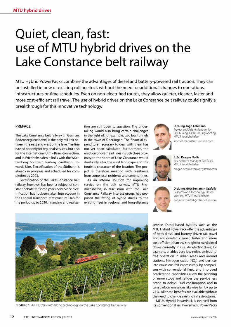
MTU hybrid drives
12 ETR | INTERNATIONAL EDITION | 22018 wwweurailpressdeetr
PREFACE
The Lake Constance belt railway (in German Bodenseeguumlrtelbahn) is the only rail link be-tween the east and west of the lake The line is used not only for regional services but also for the international Ulm ndash Basel connection and in Friedrichshafen it links with the Wuumlrt-temberg Southern Railway (Suumldbahn) to-wards Ulm Electrication of the Suumldbahn is already in progress and scheduled for com-pletion by 2023
Electrication of the Lake Constance belt railway however has been a subject of con-stant debate for some years now Since elec-trication has not been taken into account in the Federal Transport Infrastructure Plan for the period up to 2030 nancing and realiza-
Quiet clean fast use of MTU hybrid drives on the Lake Constance belt railwayMTU Hybrid PowerPacks combine the advantages of diesel and battery-powered rail traction They can be installed in new or existing rolling stock without the need for additional changes to operations infrastructures or time schedules Even on non-electried routes they allow quieter cleaner faster and more cost-ecient rail travel The use of hybrid drives on the Lake Constance belt railway could signify a breakthrough for this innovative technology
tion are still open to question The under-taking would also bring certain challenges in the light of for example two low tunnels in the town of Uumlberlingen The nancial ex-penditure necessary to deal with them has not yet been calculated Furthermore the erection of overhead lines in such close prox-imity to the shore of Lake Constance would drastically alter the rural landscape and the touristic character of the location The pro-ject is therefore meeting with resistance from some local residents and communities
As an interim solution for improving service on the belt railway MTU Frie-drichshafen in discussion with the Lake Constance Railway interest group has pro-posed the tting of hybrid drives to the existing eet in regional and long-distance
service Diesel-based hybrids such as the MTU Hybrid Power Pack oer the advantages of both diesel and battery-driven rail travel and are quieter cleaner faster and more cost-ecient than the straightforward diesel drives currently in use An electric drive for example enables very low-noise emissions-free operation in urban areas and around stations Nitrogen oxide (NOx) and particu-late emissions fall impressively by compari-son with conventional eet and improved acceleration capabilities allow the planning of more stops and render the service less prone to delays Fuel consumption and in turn carbon emissions likewise fall by up to 25 All these benets are available without the need to change existing infrastructures
MTUrsquos Hybrid PowerPack is evolved from its conventional rail PowerPack PowerPacks
Dipl Ing Ingo LehmannProject and Safety Manager for Rail Mining Oil amp Gas Engineering MTU Friedrichshafen ingolehmannmtu-onlinecom
B Sc Dragan NedicKey Account Manager Rail Sales MTU Friedrichshafendragannedicrrpowersystemscom
Dipl Ing (BA) Benjamin OszfolkResearch and Technology Devel-opment MTU Friedrichshafenbenjaminoszfolkmtu-onlinecom
FIGURE 1 An IRE train with tilting technology on the Lake Constance belt railway
MTU hybrid drives
13ETR | INTERNATIONAL EDITION | 22018wwweurailpressdeetr
raquo
are compact drive systems with diesel en-gine transmission cooling system and au-tomation unit integrated on one base frame In the hybrid version of the PowerPack the drive is enhanced by an electric motor frequency convertor intermediate circuit on-board convertor and battery for storing energy harnessed during wear-free electro-dynamic braking This technology was al-ready presented by MTU in a previous article published in this journal [1]
Specic application of this concept on the Lake Constance belt railway has been exam-ined in simulations and verications carried out by MTU on its own systems test stand The subject of the study was the IRE service between Friedrichshafen and Singen
TEST STAND SIMULATION AND VERIFICATION
MTU Friedrichshafen is unique in its ability to simulate a complete vehicle drive such as the Hybrid PowerPack on a selected route and make reliable predictions on operation and fuel consumption Furthermore the company has a state-of-the-art Hardware-in-the-Loop (HiL) test stand that enables travel of the rail vehicle over the route to be simulated according to a given time sched-ule In this set-up the real drive is incorpo-rated into a virtual rail vehicle and subject to real conditions and loads Parameters such as fuel consumption drive dynamics and battery loads can be measured in the HiL set-up and compared with the previous computer-generated simulation results In this way MTU is able to verify its fuel-saving predictions and continually optimize its simulation tools
SIMULATION IRE FRIEDRICHS-HAFEN ndash SINGEN
Simulation of conditions on the Interregio service was carried out using the technical data from an existing Bombardier VT 612 DMU that is used on the Lake Constance belt railway The special feature of this train is its
tilting capability which allows it to negotiate curving track at speed Two vehicle congu-rations were simulated an existing VT 612 and a virtual VT 612 repowered with an MTU Hybrid PowerPack
Two scenarios were considered in the test In the rst the VT 612 Hybrid rail vehi-cle and the existing rail vehicle were run as per the current timetable (status 26012018) and compared in order to draw conclusions about time schedule feasibility and fuel consumption The second scenario looked at the feasibility of introducing a new time schedule with additional stops The new time schedule was taken from a study car-ried out by SMA amp Partner AG [2] whom the Lake Constance Railway interest group had engaged in 2013 to examine dierent timetable concepts also taking into account possible electrication of the line The study showed that operation of an hourly IRE ser-vice on the Lake Constance belt railway with additional stops in Markdorf and Salem could be recommended
In both scenarios electric-only mode for low-noise emissions-free rail travel was taken into account around planned stops
Route sections travelled in electric-only mode are shown in Figure 2
To determine fuel consumption the State of Charge (SOC) of the battery was taken into account in the energy balance SOC at the end of the journey must correspond to SOC at the beginning If despite smart en-ergy management and re-charging where appropriate en route the end SOC was not absolutely equal to the initial SOC the bat-tery was re-charged up to the required level using the diesel engine The fuel required to do so was also taken into account in overall fuel consumption
The aim of the simulation was to directly compare the VT 612 with the VT 612 Hybrid on the Friedrichshafen ndash Singen service of the Lake Constance belt railway based on the current time schedule (Scenario 1) and to determine the feasibility of the new time-table with additional stops in Markdorf and Salem as per the study made by SMA amp Part-ner AG (Scenario 2) A statement on fuel con-sumption was also to be made It is empha-sized again that the hybrid train switched to electric-only mode around stations and in urban areas as shown in Figure 2 Phases of
FIGURE 2 Deployment of a VT 612 Hybrid on the Lake Constance belt railway with electric-only phases
FIGURE 3 Simulation of IRE service on the Lake Constance belt railway
MTU hybrid drives
14 ETR | INTERNATIONAL EDITION | 22018 wwweurailpressdeetr
travel in electric-only mode caused a slight reduction in the fuel saving possible in rela-tion to the existing rail vehicle However this is seen as a justied compromise in view of the benets of phases of emissions-free qui-eter travel
The results for both scenarios are shown in Figure 3
The simulation results for Scenario 1 show that with a hybrid rail vehicle a fuel saving of 157 in relation to the existing VT 612 vehicle can be achieved including phases in electric-only mode The travel time in this case is 4600 min The fuel saving can be principally attributed to re-generative braking The energy thereby harnessed is used entirely for travel in elec-tric-only mode The results for Scenario 2 show a fuel saving of 206 in relation to the existing rail vehicle from Scenario 1 The time scheduled for Scenario 2 is 5600 min So with the hybrid rail vehicle the new Sce-nario 2 time schedule with additional stops in Salem and Markdorf can be realized with lower fuel consumption than for Scenario 1
and including electric-only mode around each stop
Evaluation of the simulation results even shows that potential still exists for a further reduction in the travel time (Fig 4) The blue line shows the vehicle speeds required for keeping to the time schedule The red line shows the speed limit for taking curving track at speed The route sections passed in electric-only mode are highlighted in green The speeds necessary along the route for keeping to the timetable remain for the most part well below the maximum speed limits This means that a reduction of the travel time is perfectly feasible still leaving sucient operational reserve
The simulation results shown were veri-ed on the Hardware-in-the-Loop (HiL) test stand and could be conrmed Besides time-keeping the most tangible improvements outside the vehicle are emissions-free travel and quieter operation around stations and in urban areas Measurements at the test stand and on a demonstrator showed that vehicle noise in the vicinity of stations can
be reduced by around 75 (20 dB(A)) This improvement might even be perceived by passengers inside the vehicle
Based on the simulation results it is pos-sible to calculate the annual savings in CO2 (132 tonnes) and NOx (105 tonnes) per ve-hicle based on 2500 hours runtime per year Extending this to the entire VT 612 eet in service in Baden-Wuumlrttemberg which amounts to 41 vehicles a total of 5412 tonnes of CO2 and 43 tonnes of NOx could be saved per year Rebuilding the rail vehicles with MTU Hybrid PowerPacks could there-fore make a very signicant contribution to air pollution control on Baden-Wuumlrttem-bergrsquos railways
REBUILDING THE VT 612 WITH A HYBRID DRIVE
The VT 612 is an ideal candidate for conver-sion to a hybrid drive As a high-oor vehicle it has more than enough space underoor for housing all Hybrid PowerPack compo-nents Since the Hybrid PowerPackrsquos compo-nents are not heavier than the current drive system it can be installed without any shift in the centre of gravity The feasibility of the rebuild was also conrmed by DB System-technik the Deutsche Bahn subsidiary Re-building tilting VT 612 railcars with hybrid drives would give them a new lease of life as fast eco-friendly trains and their tilting sys-tems ndash to which they owe their faster travel times ndash would remain available in the future
The rebuild concept proposed by MTU provides for installation of a Hybrid Power-Pack in each car The installation scope would comprise the following components
rarr Hybrid PowerPack (comprising diesel engine electric motor transmission cooling system)
rarr Batteries (3 MTU EnergyPacks with ca 90 kWh capacity overall)
rarr Water-based battery cooling
FIGURE 5 Rebuild concept for VT 612 Hybrid
FIGURE 4 Simulation results for IRE service using VT 612 Hybrid Scenario 2
15ETR | INTERNATIONAL EDITION | 22018wwweurailpressdeetr
rarr Intermediate DC circuit rarr Power electronics and lters for on-board power supply
The Hybrid PowerPack comprises an MTU 6H 1800 R85L diesel en-gine an electric motor and a ZF EcoWorld power-shift transmis-sion with integrated reversing function The diesel engine delivers 390 kW and the electric motor delivers 300 kW continuous power
The Hybrid PowerPack is arranged as a parallel hybrid with the electric motor sitting on the input side of the transmission up-stream of the diesel engine As a preference the electric motors are congured for electro-dynamic braking in order to harness surplus energy for battery storage or on-board power
SUMMARY
The simulations show that an MTU hybrid drive will have no dif-culties meeting either the current time schedule in place on the Lake Constance belt railway service or that planned for the future Rebuilding the rail vehicles with Hybrid PowerPacks would achieve signicantly cleaner quieter and more economical rail travel even without overhead electrication and with no compro-mises with respect to travel times The installation alone of state-of-the-art EU Stage V-compliant diesel engines in the VT 612 rail-cars could reduce particulate and NOx emissions by around 90 The further benets oered by a hybrid drive would prot the en-vironment passengers and operators alike Electric-only mode in urban areas and around stations lowers the noise level by as much as 75 Regenerative braking considerably enhances the ecologi-cal soundness of operations while improving their cost-eciency In this way up to 20 fuel savings can be made
All in all deployment of Hybrid PowerPacks on the Lake Con-stance belt railway could herald a breakthrough for this innova-tive technology in Germany
Literature[1] Oszfolk Benjamin et al Hybridantrieb stellt Marktreife unter Beweis ETR ndash Eisen-
bahntechnische Rundschau 92015 [2] SMA und Partner AG Optimierung Angebotskonzeption Bodenseeguumlrtelbahn
Zuumlrich SMA und Partner AG 2013
FIGURE 6 MTU Hybrid PowerPack
Discover intelligent sensors
INNOVATIONS TO SIMPLIFY RAILWAY OPERATIONS
EXPPERIEENCE THHE FUUTURE OF TTRAIN TRRACKINGG
InnoTranss in Berrlin18 ndashndash 21 Septembeer 220188Halll 255 | SStannd 2232
Digitalisation opens up new possibilities in generating a wide range of highly valuable information
wwwwfrauschherccominnootranns
Predictive Maintenance
16 ETR | INTERNATIONAL EDITION | 22018 wwweurailpressdeetr
BASIC PRINCIPLES OF DATA LAKES
Data Lakes dier fundamentally from clas-sic concepts of Business Intelligence such as Data Warehouses primarily by the type of data retained In data warehouses mainly transactional data is stored whose structure is dened upfront and which has already undergone pre-ltering before persistence In a data lake however all data is persisted regardless of its structure or relevance for known use cases Data Lakes have the fol-lowing basic properties [2]
rarr Data Lakes collect and store data regard-less of type format or data volume while they are to be stored in a structured manner in classic data warehouses
rarr Data Lakes provide large amounts of data Therefore it is important to keep costs low while maintaining a high ac-
The treasure of the Data Lake ndash Predictive maintenance for vehicle eetsEective asset management of vehicle eets in rail requires an ecient and comprehensive IT landscape as a basis The core of an associated architectural concept is a data lake that collects and provides real-time diagnostic data gathered on the vehicles It is the technical basis for the application of algorithms for condition-based maintenance of rail vehicle eets
cess rate Since data stored in structured form in data warehouses must be im-mediately accessible at all times to en-able fast access high persistence costs are generated Data Lakes on the other hand store raw data which depending on the frequency of accesses can also be stored with reduced access speed
rarr At Data Lakes all data is stored centrally and heterogeneously at the same time This means that data which is very dif-ferent from the format can be linked together in analyses without having to request potentially dierent systems beforehand Existing Application Pro-gramming Interfaces (APIs) provide a wide range of usable use cases It is easy to add dierent tools to the data stream as services for example or to store inter-mediate results in the Data Lake for fur-ther use by other tools
rarr Data Lakes keep all relevant data central and unstructured regardless of format-ting The analysis tools are always con-ceptually independent of the format and structure of the data This allows new analyses or new data sets to be integrat-ed easily and quickly
rarr In modern implementations of data lakes and the service landscapes required for this the concept provides for the rapid interchangeability of tools and micros-ervices The user can test generally avail-able tools with practically no initial eort and if required can transfer those to productive use in just a few steps
SERVICE-ORIENTED AND CLOUD-BASED ARCHITECTURE FOR DATA LAKES
Instead of using solutions based on indi-vidual or a few applications with a dened range of functions Data Lakes reliy on so-lutions consisting of a exible combination of dierent micro services around a central data store The software architecture must be detached from classical patterns such as a layered hierarchy and the development must lead to a data- or data-ow-centered architecture This makes it easy to add or re-place services at any point and keeps the ar-chitecture exible for future developments
When using data lakes primarily event-driven architectures are common By con-
Mathias Haimerl Senior Data Analyst ESE Engineering und Software-Entwicklung GmbHmathiashaimerlesede
FIGURE 1 Vehicle eets in rail transport as an object of asset management
Predictive Maintenance
raquo
trolling the events based on the underly-ing data streams this architecture can be called Data-Driven Architecture (cf[5]) The software therefore builds itself around the data stream as shown in Fig 1 The data stream therefore represents the basis for the achievement of objectives whereby each individual problem can be regarded as an in-dependent architecture The desired objec-tive is broken down top-down into required services and newly formed into a specic so-lution Right from the start not only services for data manipulation are considered but also accompanying services for areas such as logging and security
The implementation of data lakes on company-owned hardware does no longer make sense for most projects from a nan-cial point of view and therefore only makes sense for particularly critical applications (eg banks medicine military) if commercial cloud solutions with appropriate security options cannot be found or are not applica-ble for compliance reasons
CHALLENGES AND SOLUTIONS OF CLOUD-BASED ARCHITECTURES
The use of services in a cloud creates new
challenges that need to be addressed in ad-vance
Information security of the customer data available in the cloud is in most cases much higher in the Amazon Web Service (AWS) Cloud than on self-operated servers The large number of system administrators de-ployed worldwide for the AWS Cloud some of whom specialize in information security provides signicantly better information se-curity than would be the case with conven-tional IT infrastructures operated by compa-nies themselves
Handling security vulnerabilities Due to the high number of users in the global internet of things (IoT) security gaps that allow access to external data quickly become nancially and legally problematic The Linux base and the simple reporting of security problems allow newly discovered vulnerabilities to be resolved quickly and globally The globally uniform system and the uniform administra-tion of software components close security gaps within a few hours
Protection against unauthorized access by third parties Authentication measures serve to protect sensitive data against unauthor-ized read access (data theft) on the one hand
and to protect data against unauthorized manipulation (data modication computer sabotage) on the other Authorization meas-ures are aimed at ensuring that analysts and solution architects only have access to the data relevant to their projects This is supported by the targeted allocation of authorisations to the respective architects In addition organization-related boundary conditions are contractually secured One example of this are compliance guidelines such as certication of cloud providers ac-cording to standards like DIN EN ISOIEC 27001
Software maintainability The AWS ba-sic system is stable against updates and changes without interfering with customer projects Customer projects run in self-con-tained environments (sandbox) The pro-vider of the cloud system has the freedom to use exchange and extend any hardware components without expensive downtimes or waiting times for the user Software up-dates and time-consuming hardware up-grades are obsolete for the user
Legal framework Sending data across na-tional borders is often a legal hurdle that prohibits the use of cloud services To coun-teract this cloud providers have provided
FIGURE 2 Overall concept of the data-driven architec-ture The microservices are structured around the data stream
wwwmobility-bbcom
Berlin-Brandenburg
Moving mobility
to the next level
Meet us at InnoTrans
City Cube Hall B
210x99_VML_InnoTrans_eng_ETRindd 1 19072018 081118
Predictive Maintenance
18 ETR | INTERNATIONAL EDITION | 22018 wwweurailpressdeetr
for the possibility of binding to regions that ensure that data does not leave certain pre-dened regions
Calculability of costs An AWS solution is about 90 cheaper than the operation of ldquoclassicrdquo infrastructures This value is also evi-dent in one of our customer projects where about 98 of the costs were saved on the development system and the eective sav-ings for the live system were interpolated to be at about 91 AWS provides a billing calculator that provides an estimate based on past months and previous monthly costs
SAMPLE IMPLEMENTATION STEPS FOR AMAZON WEB SERVICES
As an example implementation of a data lake the cloud environment AWS was used as described below During implementation four functionalities were clearly separated which are described in more detail below
rarr Data acquisition including pre-process-ing (ingestion)
rarr central data storage rarr Cataloging of data rarr Preparation of concrete analyses
DATA ACQUISITION (DATA INPUT) FOR DISTRIBUTED DATA SOURCES
In order to be able to ingest sensor data from vehicle eets the receiving system must be able to accept and store a large number of distinct data from many sensors On the senderrsquos side however data must be collected buered and regularly transmit-ted to the Data Lake To do this a periodic Internet connection must be ensured For
the frequency of data transfer an individual taring between the local data collection and the frequency of synchronization to the cloud must also be found Data transfers at low bandwidth should preferably rely on the collection of several data sets and trans-fer with a stable connection However this requires more memory in the local device With higher bandwidth and stable connec-tions the data can also be transferred more frequently This on the other hand leads to an increased load on the receiver A project-specic optimum must be found here
Finally it should be taken into account that the order of data sets should already be de-ned during ingestion even if the structure does not have to be xed from the outset To simplify later evaluations considerably data of the same type for which the uniformity is to be foreseen should be grouped logically This unies the data accesses of the evaluat-ing processes and thus minimizes the eort
From a specic project of a customer we know that the current data load of 6754 MBh will increase tenfold by 2020 due to an increase in the number of equipped vehicles and a simultaneous tripling of the number of sensors to approx 2GBh The distribution of the eets is Europe-wide with the focus on Central Europe
CENTRAL DATA STORAGE
In order to eciently persist the collected sensor data of vehicle eets the receiving system stores the data in a central location In AWS data is stored centrally in any size and in an automatically growing storage unit a so-called bucket The data is stored in ob-jects a logical data unit comparable to les in a classic le system To make searching
through data easier the objects are indexed based on their specic prexes and opti-mized for fast access Since the implementa-tion is based on RESTful and therefore each data record transmitted by sensors sends a PUT request a new object is created for each data record This creates an immense num-ber of objects in the long term This is irrele-vant in terms of costs and storage space For an analysis based on large amounts of data with low reaction times however a catalog-ing of the data is still necessary
CATALOGUING FOR VARIOUS APPLICATIONS
The exible NoSQL database DynamoDB oers an optimal possibility to catalog data without having dened a schema and still get extremely fast access speeds A Dy-namoDB table has a primary key which con-sists of a partitioning key and an optional sort key The partitioning key determines the automatic partitioning of the table and should therefore be very well selected (see [9]) An entry also supports update com-mands DynamoDB oers a very exible memory which can be written and read in dierent ways
New data arriving in Simple Storage Ser-vice (S3) can be automatically analyzed as a trigger for cataloging and added to cor-responding catalogs Since the analyses are usually very individual a pipeline must be created so that the new data arriving in S3 can be processed This can be achieved with minimal eort using the Microservice Lamb-da which makes it possible to execute small programs in the AWS landscape without any further integration eort Optional lters can be set for the triggers so that dierent pre-xes start dierent lambda functions
rarr Read The respective lambda function receives the bucket and the object name of the newly arrived object and can ex-amine this import and the content ac-cording to previously dened criteria and extract the corresponding values
rarr Write This data can then be written to a DynamoDB table regardless of whether the data record already exists ie wheth-er it has to be updated or whether it is a new data record
This type of cataloging is the comparatively most complex but at the same time the ex-ibility exceeds that of other technologies by far The cost factor is also considerably lower here The costs for DynamoDB tables are cal-culated according to provisioned capacities for read and write accesses This is under-
FIGURE 3 Using cloud solutions brings new challenges
Predictive Maintenance
19ETR | INTERNATIONAL EDITION | 22018wwweurailpressdeetr
standable as an increase in capacity in the background is a real hardware replication This allows tables with costs of less than one euro per month for the minimum congura-tion and a separate table can be provided for each application case The requests for large amounts of data via the primary key or only a part of it can be retrieved extremely quickly whereby retrieval times in the low two-digit millisecond range are not uncommon
PREPARATION OF CONCRETE ANALYSES
The creation of analyses on the catalogued data is possible without great eort with the basis shown This is done in several consecu-tive steps
rarr Top-down analysis of the problem to be solved as there are various microservic-es for a wide variety of applications As a result individual use cases can be as-signed to the use cases
rarr Selection of suitable microservices De-pending on the target platform the ap-propriate microservices can be selected There are specic services that enable the further use of existing programs that work on relational databases for example Other microservices support machine learning or the visualization of complex interrelationships in informa-tive dashboards
rarr Bottom-up aggregation of specically congured microservices For this pur-pose services already congured for similar analyses can be reused or addi-tional instances with slightly modied conguration can be created
SUMMARY amp OUTLOOK
All in all Data Lakes oer an optimal solution from the initial setup of a collection of raw data from various sources without large upfront ef-fort or high costs to the data storage of many eets of dierent vehicles worldwide and the provision of data catalogs for various analyses of various kinds The collection of measure-ment data in persistent online data stores such as AWS buckets can be implemented within minutes and is operational from this point in time so that data can be collected and archived Even if no specic use cases are known at the time of implementation it is recommended to persist all data on low-cost cloud storage so that it is already available for possible evalua-tions at later points in time Since there is often no reason to process data without use cases favorable options for persistence of the data can be used To avoid vendor lock-in consider designing Data Lake to be adaptable to alter-native platforms Alternative options for data storage include the storage services of Google Cloud Services or Microsoft Azure Of course the use of a second service also doubles the total costs
References[1] Canalys (2017) Cloud service providersrsquo battle drives
the worldwide cloud infrastructure market up 42 in Q1 2017 httpswwwcanalyscomstaticpress_re-lease2017press-release-150517-cloud-service-providersE28099-battle-drives-worldwide-cloud-infrastructure-market-42_1pdf Palo Alto Shanghai Singapore and Reading (UK) Pressemit-teilung 15052017
[2] Amazon Web Services (2017) Building a Data Lake on AWS httpspagesawscloudcomrs112-TZM-766im-agesAWS_Data-Lake_eBookpdf 01112017
[3] Bundesministerium des Inneren (BMI) (2017) Polizeili-che Kriminalstatistik 2016 httpswwwbmibunddeSharedDocsdownloadsDEpublikationen2017pks-2016pdf Pressemitteilung 24042017
[4] Buschmann Frank and Christiane Loumlckenho eds (2000) Pattern-orientierte Softwarearchitektur ein Pat-tern-System 1 korr Nachdr Muumlnchen Addison-Wesley 2000
[5] Mahjourian Reza (2009) An Architectural Style for Data-Driven Systems Paper Gainesville FL 32611 USA httpswwwcsutexasedu~rezalesxpage-icsrpdf 22032009
[6] Tilkov Stefan (2009) REST und HTTP Einsatz der Ar-chitektur des Web fuumlr Integrationsszenarien 1 Au Hei-delberg dpunkt 2009 ISBN 9783898645836
[7] Hunkeler U H L Truong and A Stanford-Clark (2008) MQTT-S mdash A Publishsubscribe Protocol for Wireless Sensor Networks In Communication Systems Software and Middleware and Workshops 2008 COMSWARE 2008 3rd International Conference on 791ndash98 2008 httpsdoiorg101109COMSWA20084554519
[8] Manseld-Devine Steve (2016) DDoS Goes Main-stream How Headline-Grabbing Attacks Could Make This Threat an Organisationrsquos Biggest Nightmare Net-work Security 2016 no 11 (November 2016) 7ndash13 httpsdoiorg101016S1353-4858(16)30104-0
[9] Vyas Uchit (2014) DynamoDB Applied Design Patterns Birmingham United Kingdom Packt Publishing 2014
SAFERAILSYSTEMCOM
Guessing or GPR
bull GPR measurements and analysisbull Condition-based maintenance planningbull More than 25 years of working experience - worldwide
BIM
20 ETR | INTERNATIONAL EDITION | 22018 wwweurailpressdeetr
ABOUT SIEMENS MOBILITYrsquoS TURNKEY RAIL SOLUTIONS BUSINESS
Siemens AG is a global technology power-house that has stood for engineering ex-cellence innovation quality reliability and internationality for more than 170 years The company is a pioneer in supplying in-frastructure solutions Siemens Mobility is an experienced provider of complete turn-key solutions for rail systems having already carried out more than 50 various and major rail projects worldwide The organization is home to experts in project management and system integration as well as key prod-ucts of rail infrastructure These specialists develop and implement projects for all types of rail vehicle systems from metros trams and light rail vehicles and automated peo-ple-movers to Intercity and high-speed train units ndash all designed for maximum reliability availability and eciency
THE CHALLENGES OF RAIL INFRASTRUCTURE PROJECTS
Projects to install new rail infrastructure and expand existing systems are growing steadily more complex The rising number of project participants and stakeholders presenting a broad range of specic require-ments planning teams in dierent locations and time zones having to coordinate and
Digital twin serving rail infrastructure How turnkey rail infrastructure projects are beneting from applying Building Information Modeling (BIM) how Siemens Mobility is pursuing virtual planning of projects with project partners and custom-ers such as in the Riyadh Metro Project and what added value this methodology is creating
integrate their civil and rail engineering and planning and the ever increasing time and cost pressures exemplify this problematic complexity
There are an enormous number of inter-faces and requirements involved especially in large rail infrastructure projects and or-ganizing them demands extensive resources and absolute precision
AT THE VANGUARD OF DIGITAL PLANNING
Just as countless other sectors of the con-struction industry have already experienced digitalization is driving a para-digm shift in rail infrastructure away from analog meth-ods and embrac-ing digital and in-tegrated planning encompassing eve-rything from erec-tion planning installation and support for training to preparation and performance of repairs and maintenance all based on digital processes and data models
More than four years ago Siemens Mo-bility began applying building information modeling (BIM) techniques as well to project planning and execution of complete turnkey
solutions for rail systems As one of the trail-blazers of digitalization Siemens Mobility uses BIM to create a digital twin ndash a virtual model of major rail projects planned for im-plementation
This methodology focuses on achieving cost and time eciency while also ensuring the highest quality standards
Siemens Mobilityrsquos Turnkey Rail Solutions is using BIM in col-laboration with construction part-ners to optimize project planning and execution This involves the use of computer-generated 3D modeling and the
information integrated into or linked with the models
REFERENCE PROJECT RIYADH METRO
The Arriyadh Development Authority (ADA) ndash the executive arm of The High Commission
Both the implementing company and customer benet from the reduced risk of delays in planning as well as the prevention of defec-tive planning and resultant need to revise planning during ongoing installation
Dr Payam AminiHead of Digital Transformation Turnkey Projects amp Electrication Siemens Mobility Munich payamaminisiemenscom
A simulated view of the outside of the depot for which the path of sunlight can be simulated over time
raquo
BIM
21ETR | INTERNATIONAL EDITION | 22018wwweurailpressdeetr
for the Development of Arriyadh in Saudi Arabia ndash is currently building one of the larg-est metro projects in the world with six rail lines totaling 176 kilometers in length The system will be the backbone of the public rapid transit network serving Saudi Arabiarsquos capital city The order placed with Siemens Mobility covers supply of 67 Riyadh Metro model rail vehicles based on the Inspiro Plat-form series line electrication the signaling and communication systems for driverless service on Lines 1 and 2 as well as system integration and project management Sie-mens Mobility is part of the BACS consor-tium led by US company Bechtel along with Almabani General Contractors and Consoli-dated Contractors Company
The Riyadh Metro Project (RMP) kicked o by dening the information requirements and project-specic BIM objectives of the customer The BIM management team of Siemens Mobilityrsquos construction partner Be-chtel then used this information as the basis for elaborating in detail the BIM process for all project participants
The BIM execution plan that denes the BIM process for a specic project basi-cally provides the answers to the agreed require-ments In this key central document Turnkey Rail Solu-tions dened for all project participants in-volved in the infrastructure design the roles and scopes of responsibility the programs and le formats to be used what applica-tions are to be integrated into the BIM pro-cess the data-exchange process along the chain of project phases the quality review inspection and testing criteria procedures for coordination and collaboration and much more This was necessary in order to ensure smooth BIM implementation over the entire project cycle
Siemens Mobilityrsquos construction partner also generated the model element plan which denes in an overview who is to gen-erate what model content for the project by when and to what level of development (ie geometry information and coordination) In this project BIM standard the construc-tion partner also dened the details for modeling agreements and documentation standards
Model-based planning is one of the pro-jectrsquos centerpieces enabling comprehensive integration of all rail infrastructure systems such as rail electrication the depot and workshop equipment line signaling and communication technology and platform screen doors
CLARITY DRIVES THE EFFICIENCY OF WORKFLOWS
Siemens Mobilityrsquos infrastructure planning engineers used project-specic BIM software to share their model-based information with Siemens Mobilityrsquos suppliers and the con-
struction partner The program Pro-jectWise is used in combination with Aconex served and continues to
serve as a shared data platform accessible project-wide ensuring that each piece of information is retained only once and in its most recently valid version In this ldquosingle source of truthrdquo data are referenced rather than duplicated signicantly improving in-formation management increasing the reli-ability of data and eliminating any use of superseded obsolete data This provides full trans-parency for all pro-ject participants Photo-realistic displays and animated videos of the planning progress generated on the basis of the 3D planning information ensure transparency enhance understanding and support the iterative process
The permanent availability of data accel-erates collaboration across national borders and company boundaries These aspects are particularly benecial in the RMP Just Sie-mens Mobilityrsquos unit alone had colleagues based in 13 dierent cities working to de-sign the rail infrastructure coordinating and agreeing across national boundaries and dierent languages time zones and work capacities
In addition to the geometrical properties
of system components for example of fre-quency converters the participating plan-ning engineers also integrated non-geomet-rical information and requirements of their systems such as zones and clearance spaces that are essential for installation and mainte-nance Once work on a subarea of a model (work in progress) was approved for release this information was then available to all partners within the project (shared areas) In turn these partners reviewed the completed work for impacts on their own work scopes
In interdisciplinary collision reviews the design coordinators conducted collision tests with all other draft components Such reviews examined for example the civil struc-tures technical building equipment systems and Siemens Mobilityrsquos systems such as the signaling equipment and traction power supply grid to identify any conicts between
the systems them-selves or with the civil structures
In this way structural imple-mentation of the overall project as
well as individual subareas can be digitally tested at any time
As a provider of turnkey infrastructure solutions Siemens Mobilityrsquos unit was in-volved early in the RMP through BIM help-ing to prevent planning errors and leading to quicker validation of draft planning such as for spatial requirements of infrastructure equipment free clearance proles and pre-venting collisions
The RMP oers a basis for further infra-structure projects using BIM methodology The stock of digital objects available in the component library continues to grow Exist-ing digitally modeled components can be directly used for the next digital twin This
BIM creates full transparency for everyone participating in the plan-ning of infrastructure projects
The Control Center of the Riyadh Metro Project for Line 1 was fully planned digitally Once that design process was completed actual construction started
BIM enables earlier design valida-tion of rail infrastructure technol-ogy and engineering as well as civil construction
BIM
22 ETR | INTERNATIONAL EDITION | 22018 wwweurailpressdeetr
accelerates digital planning from one pro-ject to the next
Siemens Mobility Turnkey Rail Solutions sees particular potential for BIM in integrating the necessary man-agement process-es BIM supports the management of interfaces requirements congurations and project documentation This improved management leads to accelerated project execution And although project execution in Riyadh is still underway the added value created by the BIM method is already clearly evident today ndash for both Siemens Mobility and the customer
DIGITAL SCAN OF THE INFRASTRUCTURE CREATED
Siemens Mobility Turnkey Rail Solutions is utilizing other digital solutions as well for the Riyadh Metro Project that further optimize pro-ject execution Siemens Mobility-owned track measuring vehicles and 3D laser scanners are deployed to eciently compare the progress
of as-built construction and installation against the design target data These units travel along the existing sections scanning and thereby
digitalizing the as-built environment The object-specic information collect-ed by this measur-ing system whether on track position-
ing platform edges or technical spaces is com-pared with the digital design thereby directly revealing any deviations from planning
This produces a 100 -accurate database of the existing as-built status Particularly when projects aim to expand exist-ing infrastructure such transparency prevents costly conicts when equipping existing civil structures with new infrastructure equip-ment Besides the hardware procurement Siemens Mobility is banking in this context on developing the expertise of its own per-sonnel to cover planning of measuring cam-paigns kinematic and static imaging and evaluations such as review for collisions
PROMISING OUTLOOK
Siemens Mobilityrsquos Turnkey Rail Solutions has ceaselessly invested in implementing and further developing digital methods to keep pace with steadily growing deadline and cost pressures and the increasingly stringent demands of complex rail infra-structure projects These efforts are now empowering Siemens Mobility to better assess the sometimes extremely demand-ing detailed requirements early already in the project bidding phase and estimate costs more reliably thereby minimizing risks
In previous projects utilizing BIM meth-odology Siemens Mobilityrsquo experts identi-ed a shifting of eort into the early project phases
Siemens Mobilityrsquo experts see opportuni-ties in doing so particularly in the assess-ment of design modications in terms of im-pacts on costs and in early application when the leverage for such optimization can still prove very eective
Yet BIM doesnrsquot end when construction work on an infra-structure project has been complet-ed By developing a digital twin of the as-built infrastruc-ture and applying
that model over its entire lifecycle these sets of digital data can be used to optimize asset management
The BIM method harbors major potential for signicantly shaping the rail infrastruc-ture sector in the coming years
A view of the digital model of the King Abdullah Financial District Station on Line 1 which can be viewed in the computer pro-gram from all sides
Photo-realistic displays and animat-ed videos of the planning progress ensure transparency and enhance understanding
BIM provides the basis for simpler and ecient interface management and contributes signicantly to accelerating project execution
5 | 2017 Mai wwweurailpressdesd
109 Jahrgang
SIGNALLING amp DATACOMMUNICATION
Oumlsterreich Gut gesichertAustria Well-protected
13 Kostenguumlnstige Sicherung von Eisenbahnkreuzungen Cost-effective protection of level crossings
36 Finnland Gegen den Instandhaltungsruumlckstand Finland Reducing maintenance backlog
21 Schweiz Weltpremiere auf der Toumlsstalstrecke Switzerland A world premiere on the Toumlsstal line
Your contact person Silvia Sander +4940237 14-171 silviasanderdvvmediacom wwweurailpressde
Leader in Signalling and Datacommunication
No 1ad medium
SIGNALLING AND
DATACOMMUNICATION
AUTONOMOUS DRIVING
CYBE
R SE
CURI
TY
LEVEL CROSSING TECHNOLOGY
OPERATIONS MANAGEMENT SYSTEMS
MOBILE COMMUNICATIONETCS
REPUTABLE
UN
IQU
E
ESTABLISHEDTELECOMMUNICATION
OPERATIONS CONTROL TECHNOLOGY
INFORMATION TECHNOLOGYBILINGUAL
Book your advert right now
raquo
Ground Penetrating Radar
23ETR | INTERNATIONAL EDITION | 22018wwweurailpressdeetr
1 INTRODUCTION
Many countries allocate large amounts for the modernization and upgrading of their railway networks in order to meet the de-mands of increasingly dense rail trac with higher axle loads at ever higher speeds However this can only be achieved if all rel-evant key gures and geotechnical condi-
Ground Penetrating Radar ndash Basis for eective Track MaintenanceThis article describes the capabilities and functionality of Ground Penetrating Radar (GPR) for higher speeds GPR is a train-borne technology for a continuous inspection of the geotechnical conditions of railway tracks The basic principles of the GPR technology are explained with particular reference to all relevant railway specic tasks namely the identication qualication and quantication of ballast fouling by using a fouling index the determination of the quality of track drainage and its quantication through a drainage index and the calculation of the track modulus (TM) Special emphasis in the context of GPR investigations is placed on the mapping of sections with clay foulingmud spots inside the ballast bed or at its base and respectively inside intermediate layer formation or subsoil In the past such weak-spots have caused derailment they could represent a risk for rail-trac [11 13 14 15 16] Besides their late detection implies exceedingly high maintenance costs
tions of the respective tracks can be reliably evaluated On this basis only the necessary investments in track maintenance moderni-zation and support can be dened in the ap-propriate size and can be placed correctly This is particularly true when budgets are tight
The demands exerted on the track in terms of safety grow with increasing speed
FIGURE 1a) Trajectories of radar waves which are reected at the layer boundary between two media
with dierent dielectric constant (laquo)b) Due to the dierent travel time of the reections the layer boundary is reproduced in the
radargram (reference Ground Control and IEV)
Dipl-Geophys Giuseppe StacconeDirector of Ground Control GmbH MunichGermanystacconesaferailsystemcom
David Camacho MScDoktorand am Institut fuumlr Eisen-bahn- und Verkehrswesen der Universitaumlt Stuttgart (IEV)davidcamacho ievvwiuni-stuttgartde
Moritz SchebuchMitarbeiter am Institut fuumlr Eisen-bahn- und Verkehrswesen der Universitaumlt Stuttgart (IEV)moritzschebuch ievvwiuni-stuttgartde
Prof Dr-Ing Ullrich MartinDirektor des Instituts fuumlr Eisenbahn- und Verkehrswesen der Universitaumlt Stuttgart (IEV) und des Verkehrswis-senschaftlichen Instituts an der Universitaumlt Stuttgart eV (VWI eV)ullrichmartin ievvwiuni-stuttgartde
Dipl-Ing Sebastian RappAkademischer Mitarbeiter am Institut fuumlr Eisenbahn- und Verkehrswesen der Universitaumlt Stuttgart (IEV)sebastianrapp ievvwiuni-stuttgartde
Ground Penetrating Radar
24 ETR | INTERNATIONAL EDITION | 22018 wwweurailpressdeetr
Therefore failing to detect track damages or obtaining inadequate information on track damages represents a hazard for every kind of railway trac For this reason a decision guidance that facilitates a systematic and ecient renewal of the tracks is important The more intensive the rail trac and the higher the trac speed the bigger the re-quirements in terms of an ecient and reli-able track inspection
The mapping of clay fouling or mud sec-tions is of special importance Fine-grained soil material such as silt or clay wells up from the formation and reaches the ballast base or even penetrates the ballast layer itself As a consequence track drainage and track stability (ie bearing capacity) are strongly reduced This results in lasting deformations that require complex maintenance work and high costs If weak-spots are not identied or not detected in time clay fouling can in the worst case scenario lead to derailment [10 13 14 15 16]
During the past 25 years Ground Control GmbH which is placed in Munich Germany has surveyed more than 100000 km of rail-way tracks in many countries in Europe and all over the world Recently with information obtained from GPR results and other data (ie track geometry and track dynamics) a continuous and complete assessment of the trackrsquos structural condition is possible
2 MEASURING PROCESS
The GPR method is an electromagnetic re-ection method Radar pulses are transmit-ted into the subsoil by a transmitter antenna The energy of the electromagnetic waves is partly reected at interfaces between layers with dierent dielectric properties and re-transmitted to the receiver antenna Based on the measured travel time of the signals and knowing the propagation speed of the waves in the medium depth and surface of the layer can be computed
In order to dene the depth of the re-ector from the surveyed travel time the propagation speed of the radar waves in the subsoil has to be determined The speed of electromagnetic waves in the subsoil is re-lated to the water content of the individual material Therefore it is generally not pos-sible to refer to reference values for certain rock or soil types Thus the radar wave speed has to be calibrated for each project area
The penetration of electromagnetic waves mainly depends on the electric conductivity of the soil and the applied antenna frequen-cy By using low frequency antennae on low conductive subsoil the largest investigation depth can be achieved
PERFORMING SURVEYS WITH MODERN HIGH-SPEED-GPR
Todayrsquos GPR surveys are carried out with train mounted systems at speeds up to 160 kmh As a general rule the antennae system is fastened at the carrier vehiclersquos buers A precise positioning is achieved by an inte-grated Dierential Global Positioning Sys-tem (DGPS) and Doppler radar
The characteristics of modern GPR sys-tems are
rarr The equipment can be installed and run on a wide range of track-bound vehicles (including regular trains or vehicles on Hy-Rail)
rarr They are fast enough to be integrated into the regular trac schedule Hence expensive track closure is no longer nec-essary
rarr DGPS and Doppler radar are used for an accurate (ie precision within a meter) positioning of the antenna independ-ent of the speed and length of the track surveyed
rarr Measurement data resolution and data quality are equally high no matter what length and what speed
rarr All GPR components are eectively
shielded against interferences from sig-nalling and communication systems
3 GPR TASKS
In contrast with punctual boreholes and trenches modern GPR systems provide con-tinuous information about the geotechnical condition of the track performing the fol-lowing tasks
rarr Continuous mapping of track-bed-thick-ness and layers below (ie intermediate layer protective layers)
rarr Distinction between clean and fouled ballast and calculation of Fouling Index
rarr Mapping of mud spots or clay fouling sections inside ballast bed at its base or inside substructure layers respectively
rarr Detection of sections with drainage problems and calculation of ldquoWet Bed Indexrdquo
rarr Mapping of areas with insucient bearing capacity (eg settlements) and evaluation of the dynamics of track set-tlement
rarr Control and evaluation of the quality of maintenancerenewalconstruction work (quality of cleaned or exchanged ballast thickness of a new ballast bed quality and thickness of soil layers)
rarr Estimation of track condition based on track modulus (TM) calculation
Additionally GPR data allow for the deni-tion of a sustainable cause-based and there-fore eective track renewal recommenda-tions and programs Optionally GPR oers the possibility to accurately map cables pipes and other objects in the track sub-structure creating the possibility to provide a complete picture of the entire system
31 CLAY FOULING ndash STRONG EFFECT ON TRACK STABILITY
Clay Fouling is one of the main reasons for the reduction of the load bearing capacity of the track in a relatively short period of time Several derailments in the past were caused by mud spots [10 13 14 15 16] even when the limit values for track geometry failures according to [2] have not been exceeded [13 14] It is therefore and because of safety reasons of particular importance to detect clay fouling areas reliably in their precise dimension and as early as possible The rec-ognition of the problem should be irrespec-tive of whether the clay fouling exists in the substructure at the base of the ballast bed or in the ballast bed itself Clay fouling can
FIGURE 2 Figure 2 Antenna mounted on the train buers of a mainte-nance vehicle(reference Ground Control)
Ground Penetrating Radar
25ETR | INTERNATIONAL EDITION | 22018wwweurailpressdeetr
raquo
rapidly deteriorate the stiness of the track and its quality The trackrsquos lateral stability is massively reduced longitudinal errors along the rails arise
Clay fouling is also a serious decit from an economic point of view Its timely iden-tication allows for avoiding slow speed sections thus sparing time and money for maintenance procedures Detecting clay fouling before it reaches the ballast bed ena-bles cost eective renewal Otherwise it will be very expensive There is no option for bal-last cleaning a suciently compacted pro-tection layer built of the appropriate materi-al is essential the installation of composites does not prevent clay fouling from entering the ballast bed (see Fig 3)
Save few exceptions clay fouling spots are not visible at the track surface and since drill-ings and trenches do only provide punctual results reliable information is only achievable through GPR measurements (see Fig 4)
A frequency analysis of the measured data results in a typical change of the signal spectrum in the area of clay fouling Based on the GPR results borehole program can be implemented which can be used for further analysis GPR surveys to detect ballast foul-ing have been carried out for years in Swit-zerland Austria the Netherlands and France among others
32 TRACK MODULUS (TM)
Examining the geotechnical conditions of railway tracks requires an index which in-forms about state and quality of the tracks in a quantitative manner The challenge has
been to dene the track condition continu-ously This has been achieved by combin-ing TM with the results of continuous GPR-measurements
It is possible based on [3 4 5 6 7] to es-timate quality and bearing capacity of the railway track Therefore the TM describes the relation between vertical load and elas-tic deection of the sleeper-bearings
On the one hand the TM can be calculated based on the measured deection under load [18 20] on the other hand according to the soil properties [8 9 11] The measuring principle for determining the load deec-tion is described in detail in [12] and [17] The properties of the system components such as the area of inuence of the sleepers under load can greatly aect the TM Hence around turnouts the area of inuence of sleepers deviates from the standard track This is because an increased area of inu-ence causes an increase in the distribution of the load reducing the deection of the
rail Notwithstanding to simplify the calcula-tion of the TM the inuence area of sleepers around turnouts are assumed to be constant assuming the values of the standard track Depending on the type of sleepers installed the value of the TM can increase sharply around turnouts (Fig 5) In addition cavities under the sleepers increase the deection of the track under load which in turn inu-ences the calculation of the TM decreasing its value
An additional and new approach for calcu-lating the TM is based upon the soil proper-ties which can be described by the Poissonrsquos Ratio or the material density of the soil The soil properties derive from the GPR data This methodrsquos advantage is to be completely in-dependent from superstructure conditions The individual layers are assigned soil values according to condition and bulk density Averaged soil properties are calculated ac-cording to [1 19] The TM can be estimated according to [9] and [11] Previous studies
FIGURE 4 Visual analysis of GPR data depicting clay fouling along a track (reference Ground Control and IEV)
FIGURE 3 Geotextile or composite does not stop ne particle migration to the surface (reference Ground Control)
Ground Penetrating Radar
26 ETR | INTERNATIONAL EDITION | 22018 wwweurailpressdeetr
indicate that this method has signicantly lower value variations along the track axis compared to the approach based on the use of track displacement data (Figure 5)
The example in Fig 5 shows two track moduli based on the measured displacement under load (red line) and the soil properties (blue line) Around the turnouts a signicant increase of the TM is visible if the calculation is based on the measured deection By divid-ing the TM into quality classes according to [3 4 5 6 7] the condition of the track can be sat-isfactorily estimated (Fig 6)
33 TRACK ANALYZER ndash CONTINUOUS PRESENTATION OF ALL MEASUREMENT AND TEST RESULTS
Results from GPR surveys along with all identied soil parameters and indices cal-
culated can be displayed in comprehensive track analysis software called ldquoTrack Analyz-errdquo In order to provide all information for in-frastructure managers track geometry and track dynamics data are also integrated and displayed in the software (see Fig 7) which also oers the exibility to incorporate other tasks and aspects as required by the user
The Track Analyzer provides infrastructure managers continuous information about the geotechnical conditions of the track with regard to all relevant issues Moreover it provides a better understanding of the sub-structuresubgrade conditions and their in-uence on the superstructure This allows for a signicantly increased track quality pro-viding higher route availability and safety
A big advantage of the GPR method is the minimization of the need for intensive direct outcropping (probing drilling scooping)
to characterize the underlying geotechni-cal characteristics of the track substructuresubgrade which results in signicant cost reductions
4 SUMMARY
This paper describes a modern train-borne technology for the inspection of the geo-technical conditions of railway tracks It is based on High Speed GPR and on classical procedures for providing continuous infor-mation about geotechnical parameters and indices A new quality of GPR measurements is to provide quantitative indices in addition to qualitative results to full the require-ments of the railway engineers in the best possible way
Special attention is paid to the detection of mud spots and clay fouling sections as a risk for derailment [10 13 14 15 16] To date track inspection with GPR is more appropri-ate than any other inspection method to de-tect map and qualify areas with geotechni-cal problems
The Track Analyzer software combines GPR results with track geometry and track dynamics data This allows for cause-based track renewal and targeted investment and provides signicantly more reliable results than conventional methods This approach is especially relevant for limited budgets
Literature [1] Adam D Kopf F Dynamische Eekte durch bewegte
Lasten auf Fahrwegen In Bauingenieur Ausgabe 01-2003 2003
FIGURE 5 TM calculated from measured displacement under load (red graph) and soil proper-ties (blue graph) (reference IEV)
FIGURE 6 TM divided in dierent quality classes (reference IEV)
Ground Penetrating Radar
27ETR | INTERNATIONAL EDITION | 22018wwweurailpressdeetr
FIGURE 7 Track Analyzer(reference Ground Control)
[2] DB Netz AG Ril 821 Oberbau inspizieren Deutsche Bahn AG guumlltig ab 01052004
[3] Eisenmann J Stuumltzpunktelastizitaumlt bei einer Festen Fahrbahn In ZEV + DET Glasers Analen 111999
[4] Fendrich L (Hrsg) Handbuch Eisenbahninfrastruktur Springer-Verlag Berlin Heidelberg 2007
[5] Goumlbel C Lieberenz K (Hrsg) Handbuch Erdbau-werke der Bahnen DVV Media Group GmbH 2013
[6] Leykauf G Lothar M Elastisches Verformungsver-halten des Eisenbahnoberbaus ndash Eigenschaften und Anforderungen In EI ndash Eisenbahningenieur 031990
[7] Lichtberger B Handbuch Gleis DVV Media Group GmbH 2010
[8] Martin U Rapp S Ansatz zur Erfassung der Bodenei-genschaften am Bahnkoumlrper in Schotterbauweise In ETR ndash Eisenbahntechnische Rundschau 042017
[9] Martin U Rapp S Camacho D Moormann C Lehn J Prakaso P Abschaumltzung der Untergrundverhaumllt-nisse am Bahnkoumlrper anhand des Bettungsmoduls In ETR - Eisenbahntechnische Rundschau 052016
[10] Rail Accident Investigation Branch Freight train de-railment near Gloucester 15 October 2013 Rail Acci-dent Report102014
[11] Rapp S Modell zur Identizierung von punktuel-len Instabilitaumlten am Bahnkoumlrper in konventioneller Schotterbauweise Dissertation ndash Institut fuumlr Eisen-bahn- und Verkehrswesen der Universitaumlt Stuttgart 072017
[12] Soldati G Meier M Zurkirchen M Kontinuierliche Messung der Gleiseinsenkung mit 20 t Achslast In EI ndash Eisenbahningenieur 022016
[13] Untersuchungszentrale der Eisenbahn-Unfalluntersu-chungsstelle des Bundes Untersuchungsbericht Ak-tenzeichen 60 ndash 60uu2011-0200041 Zugentgleisung Groumlbers ndash Groszligkugel 062013
[14] Untersuchungszentrale der Eisenbahn-Unfalluntersu-chungsstelle des Bundes Untersuchungsbericht Ak-tenzeichen 60uu2013-06047-3323 Zugentgleisung Kaub ndash Lorch (Rhein) 062013
[15] Untersuchungszentrale der Eisenbahn-Unfalluntersu-chungsstelle des Bundes Untersuchungsbericht Ak-tenzeichen 60 ndash 60uu2011-0400043 Zugentgleisung Bf Hannover ndash Linden 092013
[16] Versa Verkehrssicherheitsarbeit fuumlr Oumlsterreich Unter-suchungsbericht Sicherheitsuntersuchungsstelle des Bundes BMVIT-795336-IVBAVUUBSCH2013 Ent-gleisung eines Guumlterzugs am 14 Februar 2013 2013
[17] Wang P Wang L Chen R Xu J Overview and out-look on railway track stiness measurement Jour-nal of Modern Transportation Volume 24 Issue 2 062016
[18] Winkler E Die Lehre von der Elastizitaumlt und Festigkeit Verlag von H Dominicus 1967
[19] Wolf J P Foundation Vibration Analysis using Simple Physical Models Swiss Federal Institute of Technology 1994
[20] Zimmermann H Die Berechnung des Eisenbahn-oberbaus 1888
wwwrex-industrie-produktede
INSULATING JACKETS FORHIGH TEMPERATURE INSULATION
high temperature resistant up to 1000degC
incombustible
high insulation performance
tailor made according to your wishes
New test reports for fire protection according to EN 45545-2 available R1R7R17 with Hazard Level HL 3
Distributed Acoustic Sensing
28 ETR | INTERNATIONAL EDITION | 22018 wwweurailpressdeetr
Dip-Ing FH MScMartin RosenbergerCTO Frauscher Sensor Technology martinrosenberger frauschercom
This involves planning and controlling maintenance measures based on the actual condition of the equipment systems and components (assets) Unexpected events due to faulty components and unnecessary work on fully intact elements can thus be reduced This is possible thanks to the ever increasing amount of reliable data about the condition of the asset that is available in real time
Continuous acoustic condition monitor-ing of the infrastructure based on Distribut-ed Acoustic Sensing (DAS) is a key building block of future solutions This technology can considerably increase the availability of rail networks since it continuously delivers very precise information about the condi-tion of the infrastructure and any changes thereby fullling a key prerequisite for the use of CBM solutions
The sensor technology and inspections form and remain the basis for condition-based maintenance of the track These in-clude track recording vehicles xed meas-urement points sensor technology on
How Distributed Acoustic Sensing supports condition based maintenance strategiesCurrent technological developments are opening up new opportunities for the railway industry in a whole range of application areas Most notably these include networking digitalization and the Inter-net of Things (IoT) This trend is also having a growing impact on processes and strategies for maintain-ing rolling stock and infrastructure Traditional maintenance philosophies which are based on xed intervals or in the case of vehicles on mileage are increasingly being replaced by predictive condition based maintenance (CBM)
standard trains track-side sensor technol-ogy selectively deployed manual measur-ing instruments and self-monitoring infra-structure systems Data from these sources must be consolidated and if applicable combined with information about rolling stock and system-side infrastructure data such as a system directory or inputs from other sensors
DAS enables a sensor solution to be cre-ated which fulls several of the specied re-quirements this technology allows railway networks to be monitored continuously in real time and with respect to a huge num-ber of dierent events Frauscher has devel-oped its own DAS solution for the railway sector Frauscher Tracking Solutions FTS The manufacturerrsquos team tested the tech-nology and through intensive develop-ment eliminated constraints with respect to use for rail trac To create this in-depth knowledge of DAS as well as requirements and standards in the railway industry was required
1 DAS FUNCTIONAL PRINCIPLE
DAS-based systems use laser pulses sent in a glass bre to detect events on or in the vicinity of the track part of the laser pulse is reected back out of the bre to the transmitting unit The sound and vibration waves impacting on the cable result in signicant shifts in the reection (Fig 1) The maximum frequency range of the vibrations detected in this man-ner is 125 kHz Using specically developed algorithms the acquired data can be used to calculate specic signatures in real time These describe highly precise locations and types of processes in the vicinity of the track
One of the advantages of installing a DAS system is that the bre optic cables it requires are often already laid next to the tracks These are normally used for commu-nication purposes As the optical bres used require practically no maintenance the sys-tem can be rolled out to large sections of the route extremely economically and ecient-ly In practice a single DAS unit can eective-ly cover up to 40 kilometres of glass bre in each direction so 80 kilometres in total [1]
2 CONTINUOUS MONITORING OF WHEEL-RAIL INTERACTION
The ongoing analysis of infrastructure us-ing FTS is based on continuous monitoring
FIG 1 Distributed Acoustic Sensing (DAS) allows for the detection of vibrations and sound waves caused by trains component defects people or other sources
raquo
Distributed Acoustic Sensing
29ETR | INTERNATIONAL EDITION | 22018wwweurailpressdeetr
of wheel-rail interaction (Fig 2) On the one hand this enables the detection of changes that arise slowly over the course of time To do so the system compares the relevant signatures that are captured each time a railway vehicle passes a spot On the other hand events that occur suddenly can also be reliably detected
21 TREND ANALYSIS FOR LOCALISATION OF CONDITION CHANGES
The wheel-rail interactions quality is the most important factor when it comes to the service life of both system components and the rolling stock This quality is derived from various parameters such as the roundness of the wheel the surface of the rail and the track design Even slight deviations from the ideal parameters result in increased signs of wear and tear over a certain amount of time Ultimately these can also lead to critical op-erating conditions Which is why continu-ous detection and thus early recognition of changes in condition along the entire route is extremely useful
This is where the FTS come into play by evaluating the signatures in the laser signal feedback it is possible to determine wheth-er a sp ecic anomaly in wheel-rail interac-tion comes from the train or from the infra-structure This is possible because the FTS system uses a glass bre as a permanent sen-sor along the track thus allowing the wheel-rail interaction for each individual axle on all train journeys to be permanently monitored along the entire route Changes are detected in real time and the method does not de-pend on a xed measurement point
If a notication is triggered by an out-of-round wheel for instance then this pattern will be part of the train signature and be de-tected in association with the moving train This allows the event to be clearly attributed to vehicle damage
By contrast if there is a change to the in-frastructure several axles will have a notice-able signature in one specic position The system uses this to determine an indicator Based on this trend analyses are formed for individual ten-metre long infrastruc-ture segments Warning or alarm notica-tions can now be created and transmitted through dened user-congured threshold values These indicate the type of change as well as the location With good georefer-encing for the bre optic cable the position identied via FTS can be localised to an accu-racy of up to ve metres and made available via machine-readable interfaces
Frauscher oers powerful interfaces for employees in railway infrastructure compa-
nies In particular these include a graphical user interface with map view and heat maps and depiction of the infrastructure condition in denable categories The zoom function can be used to display the entire route or a position with relevant localisation in route kilometres or GPS data the actual condition and the change in condition over a specic period Filters can be set for even more de-tailed analyses and evaluation
22 EVALUATION OF CHANGES IN CONDITION AS A PROCESS
To determine the relevance for a specic rail-way operation simply identifying a change in condition is not enough The trend analy-sis must also be correlated with the trains and their speeds After all identical techni-cal non-conformities will result in indicators with completely dierent frequencies and intensities when a heavy long freight train and when a lighter short passenger train travels over a position with a fault
Therefore a basic condition must rst be dened for the infrastructure and stored in the FTS The trend analyses can then be ap-plied to this To do so the system structure (primarily bridges tunnels or points) must be logged in the system and the sensor must be calibrated accordingly Data that needs to be entered includes rail joints or transitions from a point for example They create similar patterns to those of a rail defect but must be evaluated and examined dierently
It may also be necessary to lter out am-bient noise from stationary systems such as pumps and generators so that this does not have a negative eect on the detailed analy-sis of the wheel-rail interaction signature
These adjustments are currently carried out manually during the installation and com-missioning process However Frauscher is developing tools to automate these process-es These steps form part of the technologyrsquos path towards serial production
Once the basic condition has been dened then depending on the model the operator will receive regular reports or warning and alarm notications via dened interfaces The DAS systems that are currently available are not yet able to classify and quantify the changes detected with sucient accuracy Maintenance personal therefore take on the task of evaluating suspect positions through inspection actions during the development and installation phase A visual inspection is often enough to identify the cause of the warning classify the change and take the necessary action within a dened period
Based on experience with several installa-tions and Frauscherrsquos collaboration with op-erators there are essentially three relevant classications
rarr No detectable or only minimal damage rarr Non-critical damage rarr Critical damage
What is important is that this evaluation and classication is understood and followed as part and parcel of the maintenance process Dening the threshold values and deter-mining the sensitivity of the system is a key step in this regard Experienced specialist sta who evaluate and process the notica-tions can shape the system to suit their own needs This allows CBM concepts to be ap-plied even more eciently for practical sup-port and to build expertise (Fig 3)
The high sensitivity level of the system
FIG 2 By continuously monitoring the acoustic signature of the wheel-rail contact the FTS support condition based maintenance strategies
Distributed Acoustic Sensing
30 ETR | INTERNATIONAL EDITION | 22018 wwweurailpressdeetr
means that a range of errors can be detected at a very early stage However this also in-creases the risk that positions that are not relevant for maintenance will be displayed This is where empirical values are really needed so that the optimum setting can be tuned for the operator It is crucial to involve the maintenance personnel in this whether through the operator or the service contrac-tor After all only experts on the ground can evaluate the condition of the infrastructure and determine the necessary measures Maintenance employee experience thus re-mains essential for training the algorithms and evaluating the results the maintenance personnel must use their knowledge of routes and systems to determine whether a notication is in fact relevant or not
Not detectable or only minimal damageIn this case no maintenance measures are needed There are three main reasons why the system has indicated a potential fault in this case First there may be a structural fac-tor in the infrastructure or a factor in the en-vironment of the trigger In this case the in-uencing factor can be ltered out in future Secondly it could be that a visual inspection reveals no detectable fault but there are already signs of wear In this case the user
would add information to the system stating that this section is to be kept under observa-tion or specically monitored over a certain period of time ndash for example by adjusting the threshold value If the system contin-ues to exhibit a fault it is advisable to apply analysis methods that go beyond a visual inspection of this point or use other meas-urement data as a comparison Thirdly this could be due to a minor surface fault on the rail for example which does not require any action since scheduled surface processing measures are due to be carried out (Fig 4) In this case the fault message can be acknowl-edged
Non-critical damageIn this case the system has identied a rel-evant fault but it does not need to be cor-rected right away (Fig 5) The main advan-tage of this is that early detection allows the necessary measures to be planned in good time so these can be put into eect during quiet periods or eciently combined with other measures thus reducing the number of expensive individual activities
Critical damageIf such changes are detected then measures must be initiated immediately in order to re-
solve the safety-critical operating condition and minimise any expensive subsequent damage Experience shows that such critical conditions can develop over just a few days or can even be triggered by acute short-term factors Examples include ballast voids due to washout rail head cracks and broken rails
Critical conditions can arise during the analysis cycles even if the rail network is monitored regularly with track recording ve-hicles for example Continuous monitoring of the wheel-rail interaction enables quicker intervention and minimises personal injury and damage to property
23 EMPIRICAL RESULTS
In addition to various applications which can be used in real time on the basis of train lo-calisation over the last two years Frauscher has been taking a closer look at infrastruc-ture maintenance In particular at the po-tential that continuous monitoring of the wheel-rail interaction has to oer in the fol-lowing scenarios
rarr Rail monitoring rarr Rail fastening and sleeper monitoring rarr Track substructure and superstructure
monitoring
Practical application has shown that the data that can be provided via the FTS system al-ready oers a range of interesting options it helps users to plan and control maintenance measures in good time To do so Frauscher implements technology such as machine learning pattern recognition and articial
FIG 3 When developing advanced main-tenance solutions various levels within a railway network have to work together closely
FIG 4 Changes in the trackrsquos surface can be detected evaluated and considered when planning maintenance works
FIG 5 Detecting small defects allows for a targeted monitoring in order to generate alarms when their condition deteriorates
Distributed Acoustic Sensing
31ETR | INTERNATIONAL EDITION | 22018wwweurailpressdeetr
intelligence However in order to move to the next level a solid base of empirical val-ues and a library of signatures from a variety of sources of damage are needed
The company is working very closely with the operators of several installations select-ed from approximately 30 projects that are currently ongoing worldwide They are joint-ly considering the evaluation interpretation and derivation of measures Specic issues and ideas for further development of the evaluation software and logic are directly incorporated into Frauscherrsquos development processes using agile methods
Rail monitoringAll types of rail damage that cause vibrations or a noise spectrum that deviates from the norm are detected This ranges from surface damage such as rail corrugation squats rail head cracks wheel burns or corrosion and dents to cracking and ssuring or even bro-ken rails
Unsurprisingly the algorithm for detect-ing rail damage also detects rail joints After all the signature of a gap as in an isolation joint could be exactly the same as that for a break in part of the rail In this case depend-ing on requirements these rail joints can be suppressed or specically monitored with their own threshold values (Fig 6 7) The sensitive sensor system can detect broken rails as a train passes over them with high probability However due to the many dif-ferent forms and physical basic conditions a warning system with a 100 percent de-tection rate and zero error rate cannot be achieved
In addition there are still no empirical val-ues for broken rails which can be traced back to warping and thermal eects without the eect of the train Noises that arise due to warping (thermal popping) were detected during tests designed to identify and local-ise landslides and rock fall These are hard to classify or uniquely identify using the cur-rently available hardware and software It is to be assumed that a rail that breaks for thermal reasons generates a similar if more intensive signature and it is not possible to clearly distinguish this from the ldquothermal poprdquo
Therefore it is important to consider whether continuous monitoring of the tracks with appropriate trend analyses does not provide more information about the safety of the route than a warning system for broken rails Last but not least broken rails should generally be reduced by as-required maintenance measures
Rail fastening and sleeper monitoringIn several installations positions were de-
tected that exhibited increased vibration due to damaged or missing rail connections or broken sleepers These are typically faults that do not necessarily require action to be taken right away Instead they are classied in such a way that these tasks will be car-ried out during upcoming scheduled on-site maintenance
Track substructure and superstructure monitoringThe FTS system is able to localise weakness-es in the substructure and track superstruc-ture such as ballast voids under sleepers cavities or compacted areas The condition of the track bed may under certain circum-stances also lead to a critical situation in a relatively short period of time particularly in mountainous regions where heavy rain or mudslides can also make the track position unstable Practical examples also exist for these scenarios where FTS localised critical positions where ballast voids under sleepers were later identied
3 SUMMARY
Continuous monitoring of wheel-rail interac-tion based on FTS opens up numerous pos-sibilities for the user in terms of timely detec-tion of weaknesses and changes in condition on the route Thus targeted and as-required maintenance measures can be dened planned and eciently controlled This is a paradigm shift in terms of maintenance strategy similar to that which is emerging for vehicles Before xed periods based on theoretically calculated average loads were
key to the strategy Now the actual wear and condition of the specic component (rail surface fastening sleeper substructure or track superstructure) are the trigger for maintenance repair or servicing work
These new options for monitoring infra-structure will not replace existing measure-ment systems instead they will enhance them They will change the maintenance processes mainly through the high-pre-cision and early detection of continuous changes By determining individual thresh-old values necessary work can be planned and carried out preventively before critical damage arises
In addition to such continuous changes the FTS is also able to detect vehicle faults and short-term sporadic inuences on trackside infrastructure This includes natu-ral hazard management such as falling rocks and trees catenary ashover or protecting infrastructure from vandalism cable theft or unauthorised access to track systems
Even in times of advancing digitalisation employee experience forms an indispensa-ble basis for railway operations Manufac-turers and operators must work together to develop systems for CBM concepts and individually calibrate them so they become helpful tools which raise eciency while re-ducing ongoing costs
Literature[1] Rosenberger Martin Lancaster Gavin Real-time track
monitoring for sustainable maintenance strategies ETR International 12017 P 20-23
FIG 6 Rail joints are specic points which can be monitored via FTS by storing their base signature in a rst place
FIG 7 If the condition of the rail joint chang-es its acoustic signature will do the same
Smart Tamping
32 ETR | INTERNATIONAL EDITION | 22018 wwweurailpressdeetr
Plasser amp Theurerrsquos development of the turnout tamping assistance system ldquoPlasserSmartTamping ndash The Assistantrdquo has been an important step towards the further automation of tamping machines The assis-tance system provides automated support for tamping works in turnouts and crossings It recommends specic actions which must be conrmed by the operator before they are carried out As a result operators increasingly monitor processes intervening manually only in exceptional cases A new recording module allows for a completely new form of tamping documentation It increases transparency working quality and process reliability For the rst time the turnout tamping simulator ndash not a tamping machine ndash was used to develop all of the software modules of the turnout tamping assistance system In an extended hardware-in-the-loop application the turnout tamping assistance system was developed and tested using the simulator
David BuchbauerProject Manager for tamping and measuring technologydavidbuchbauer plassertheurercom
Dipl-Ing Martin BuumlrgerHead of Digital Track Systemsmartinbuerger plassertheurercom
Andreas Theiszlig MScProduct Owner Smart Tamping minus The Assistantandreastheissplassertheurercom
Dipl-Ing Georg JodlbauerHead of Research and Testinggeorgjodlbauer plassertheurercom
Dr techn Gerald ZaunerDigital Track Systemsgeraldzaunerplassertheurercom
Dipl-Ing Dr techn Florian AuerDirector of Technology and Innovationorianauerplassertheurercom
1 THE DEVELOPMENT
In modern track maintenance the conven-tional distinction between track inspection vehicles and track construction and main-tenance machines has increasingly been blurred To optimise processes track con-struction and maintenance machines are t-ted with the latest sensor technology turn-ing them into ldquosmart machinesrdquo Inertial track measuring systems used up to now only on track inspection vehicles have increasingly been installed on tamping machines This makes it possible to use tamping machines for separate track measuring runs to calcu-late the required track geometry correction values
The use of inertial track measuring sys-tems optimises the track geometry quality In addition laser scanners and light section sensors make it possible to create a ldquodigital track twinrdquo which provides the data base of the turnout tamping assistance system
2 THE OBJECTIVE OF THE TURNOUT TAMPING ASSISTANCE SYSTEM
Turnout tamping (Figure 1) requires consid-erable knowledge of several areas of exper-tise (track surveying machine technology track technology regulations) The most im-portant tasks include
Smart Tamping ndash Fields of Application of the Turnout Tamping Assistance System
rarr In the main tamping cabin Controlling the tamping unit including the turnta-ble opening width and tilting motion of the tines
rarr In the co-tamping cabin Controlling the lifting and lining unit the parts of the tamping units in the diverging track and the additional lifting unit
The turnout tamping assistance system com-plies with level 3 of the standard SAE J3016 The standard denes terms related to on-
road motor vehicle automated driving sys-tems and has been applied correspondingly On the automation level 3 the system rec-ommends specic actions which must be conrmed by the operator before they are carried out with the operator as fallback The design of the turnout tamping assis-tance system also allows for higher levels of automation However for reasons of liability automation options such as remote control or robot operation are not oered
The turnout tamping assistance system
Smart Tamping
33ETR | INTERNATIONAL EDITION | 22018wwweurailpressdeetr
raquo
oered to machine operators and infrastruc-ture managers consists of four product parts in modular design
rarr recording module for recommendations and operations
rarr operation assistant for the lifting and lin-ing unit
rarr operation assistant for the additional lift-ing unit
rarr operation assistant for the tamping unit
The modular design makes it easier to put the turnout tamping assistance system into operation for the rst time In a testing phase recording modes can be used to verify the accuracy of the recommended measures (comparison of the actual taming operations and the actions recommended by the assis-tance system) Upgrading to a higher level is possible if it has been taken into account in the design of the machine The modules are activated step by step to allow sta to famil-iarize themselves with the assistance system and to coordinate the work processes
3 THE RECORDING MODULE ldquo DIGITAL TRACK TWINrdquo
The rst step is to develop the digital track twin When selecting the hardware compo-nents of the turnout tamping assistance sys-tem (one rotation laser four light section sen-sors and one colour camera) it was ensured that the hardware can be exchanged and that the software can be adapted modularly
When designing the hardware components a particular focus was placed on meeting the accuracy requirements In addition it was ensured that the system is highly robust and easy to maintain
The recording module of the turnout tamping assistance system connects the digital twin of the track with the working parameters of the machine As a result the quality control of tamping works reaches a new transparency level Infrastructure op-erators can easily access all parameters rel-
FIG 1 Operators of turnout tamping machines must meet high requirements
FIG 2 Tamping docu-mentation using multi-layer technol-ogy (schematic representation)
evant to quality and work (such as the tine position tamping depth or squeeze time) digitally and immediately when connected to the Internet
In the future the recording document will also include the rolling marks of the rails and the position of the aluminothermic welds As the software is developed in-house we can meet our customersrsquo requirements exibly (Fig 2) For instance it will be possible to ex-port the ldquodigital twinrdquo for use on the tamping simulators
Smart Tamping
34 ETR | INTERNATIONAL EDITION | 22018 wwweurailpressdeetr
4 OPERATION ASSISTANCE
Based on their position at the time of record-ing the individual scans and recordings are merged to form a 3D image of the reality showing the exact position At the same time the position of the machine and every indi-vidual work unit is continually updated As a result a 3D image of the relevant machine parts is imported into the overall model pro-viding the basis for every decision of the as-
Federal Railways (OumlBB) and experience from practical operation A specic adaptation to the infrastructure managerrsquos requirements is possible
Figure 4 shows a list of position sensors angle sensors and actuators operated by the assistance system The values of the lin-ing adjustment the lifting operation and the tamping parameters (multiple tamping tamping vibration frequency squeeze force tamping depth) are not controlled by the as-sistance system
The turnout tamping assistance system has been designed for two applications In the rst design version (the separate view) separate measures are recommended to the operators in the main tamping cabin and the co-tamping cabin The second design version (the combined view) is the current develop-ment focus Both assistance modules are merged into a combined view in the main tamping cabin enabling the operator in the main tamping cabin to control the entire turn-out tamping process by himself (Figure 5)
The application focus of the rst genera-tion of the turnout tamping assistance sys-tem is on turnouts that have not yet been fully ballasted As a result the surface of the sleepers is visible Specic recommenda-tions require a good view onto most of the turnout area the sleepers and obstacles (such as switching contacts turnout operat-ing units)
In a next stage we plan to t the turnout tamping assistance system with sensors (eddy current sensors) for the detection of sleepers in ballasted areas (newly laid track)
Completed tamping works in turnouts can be duplicated using the machine control module turnout programming automation In a combined application of the turnout tamping assistance system and the turnout programming automation it is in principle possible to scan turnouts in advance while they have not yet been fully covered with ballast and to provide the turnout program-ming automation module with the recom-mendations to allow for their duplication Turnout tamping machines with the inte-grated supply of new ballast generally allow for the use of the turnout tamping assis-tance system as the turnout is not ballasted at the scan position at the front end of the machine
The prototype of the turnout tamping as-sistance system was introduced to the ex-pert audience at the trade show iaf 2017 in Muumlnster The positive feedback proves the great potential of the technology In practi-cal operation the turnout tamping assis-tance system is currently prepared for series production for the work unit types ldquo275rdquo ldquo475rdquo and ldquo4x4rdquo
FIG 3 Overview of the control recommen-dations
FIG 4 Position sensors angle sensors and actuators operated by the assistance system
FIG 5 Tamping cabin with the assistance system ldquoPlasserS-martTamping ndash The Assistantrdquo
sistant The data is processed with the lowest possible latency and highly parallel data pro-cessing to ensure fast operation The system recommends the respective actions several metres ahead of the tamping unit (Fig 3) to provide the operators with sucient time to analyse and modify the recommendation if necessary The recommendation of the as-sistance system is checked directly at the tamping position before the tamping unit is lowered At the same time the congura-tion of the lifting and lining unit (hock and tongue position) for the transfer to and the lifting operation at the next tamping posi-tion is checked prior to transfer travelling At this point the operator can take action at any time and further adjust the settings The operation of the additional lifting unit is checked in a similar way
To allow for tamping recommendations the track sections requiring actions must be located in an automated process To ensure this dierent image processing systems are combined with articial intelligence and connected systemically
The basic tamping scheme was developed on the basis of regulations and specications of German Federal Railway (DB) Austrian
Digital technologies are key to maximising track availability and planning forward-looking maintenance The ability to check the line at any time thanks to networked data capture in real time with innovative products reliable materials and optimised maintenance concepts for every aspect of rail infrastructure Thatrsquos what we mean by ldquoThe Smart Rail Track by Vosslohrdquo
Next stop Berlin InnoTrans 2018 Hall 26
wwwvossloh-innotranscom
The Smart Rail Track by Vossloh
DIN A4_Stadtmotiv_US_InnoTrans_Internet neuindd 1 12072018 131049
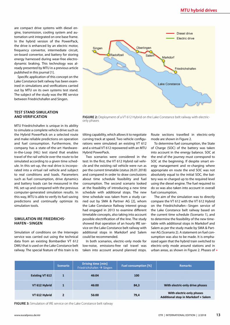
MTU hybrid drives
13ETR | INTERNATIONAL EDITION | 22018wwweurailpressdeetr
raquo
are compact drive systems with diesel en-gine transmission cooling system and au-tomation unit integrated on one base frame In the hybrid version of the PowerPack the drive is enhanced by an electric motor frequency convertor intermediate circuit on-board convertor and battery for storing energy harnessed during wear-free electro-dynamic braking This technology was al-ready presented by MTU in a previous article published in this journal [1]
Specic application of this concept on the Lake Constance belt railway has been exam-ined in simulations and verications carried out by MTU on its own systems test stand The subject of the study was the IRE service between Friedrichshafen and Singen
TEST STAND SIMULATION AND VERIFICATION
MTU Friedrichshafen is unique in its ability to simulate a complete vehicle drive such as the Hybrid PowerPack on a selected route and make reliable predictions on operation and fuel consumption Furthermore the company has a state-of-the-art Hardware-in-the-Loop (HiL) test stand that enables travel of the rail vehicle over the route to be simulated according to a given time sched-ule In this set-up the real drive is incorpo-rated into a virtual rail vehicle and subject to real conditions and loads Parameters such as fuel consumption drive dynamics and battery loads can be measured in the HiL set-up and compared with the previous computer-generated simulation results In this way MTU is able to verify its fuel-saving predictions and continually optimize its simulation tools
SIMULATION IRE FRIEDRICHS-HAFEN ndash SINGEN
Simulation of conditions on the Interregio service was carried out using the technical data from an existing Bombardier VT 612 DMU that is used on the Lake Constance belt railway The special feature of this train is its
tilting capability which allows it to negotiate curving track at speed Two vehicle congu-rations were simulated an existing VT 612 and a virtual VT 612 repowered with an MTU Hybrid PowerPack
Two scenarios were considered in the test In the rst the VT 612 Hybrid rail vehi-cle and the existing rail vehicle were run as per the current timetable (status 26012018) and compared in order to draw conclusions about time schedule feasibility and fuel consumption The second scenario looked at the feasibility of introducing a new time schedule with additional stops The new time schedule was taken from a study car-ried out by SMA amp Partner AG [2] whom the Lake Constance Railway interest group had engaged in 2013 to examine dierent timetable concepts also taking into account possible electrication of the line The study showed that operation of an hourly IRE ser-vice on the Lake Constance belt railway with additional stops in Markdorf and Salem could be recommended
In both scenarios electric-only mode for low-noise emissions-free rail travel was taken into account around planned stops
Route sections travelled in electric-only mode are shown in Figure 2
To determine fuel consumption the State of Charge (SOC) of the battery was taken into account in the energy balance SOC at the end of the journey must correspond to SOC at the beginning If despite smart en-ergy management and re-charging where appropriate en route the end SOC was not absolutely equal to the initial SOC the bat-tery was re-charged up to the required level using the diesel engine The fuel required to do so was also taken into account in overall fuel consumption
The aim of the simulation was to directly compare the VT 612 with the VT 612 Hybrid on the Friedrichshafen ndash Singen service of the Lake Constance belt railway based on the current time schedule (Scenario 1) and to determine the feasibility of the new time-table with additional stops in Markdorf and Salem as per the study made by SMA amp Part-ner AG (Scenario 2) A statement on fuel con-sumption was also to be made It is empha-sized again that the hybrid train switched to electric-only mode around stations and in urban areas as shown in Figure 2 Phases of
FIGURE 2 Deployment of a VT 612 Hybrid on the Lake Constance belt railway with electric-only phases
FIGURE 3 Simulation of IRE service on the Lake Constance belt railway
MTU hybrid drives
14 ETR | INTERNATIONAL EDITION | 22018 wwweurailpressdeetr
travel in electric-only mode caused a slight reduction in the fuel saving possible in rela-tion to the existing rail vehicle However this is seen as a justied compromise in view of the benets of phases of emissions-free qui-eter travel
The results for both scenarios are shown in Figure 3
The simulation results for Scenario 1 show that with a hybrid rail vehicle a fuel saving of 157 in relation to the existing VT 612 vehicle can be achieved including phases in electric-only mode The travel time in this case is 4600 min The fuel saving can be principally attributed to re-generative braking The energy thereby harnessed is used entirely for travel in elec-tric-only mode The results for Scenario 2 show a fuel saving of 206 in relation to the existing rail vehicle from Scenario 1 The time scheduled for Scenario 2 is 5600 min So with the hybrid rail vehicle the new Sce-nario 2 time schedule with additional stops in Salem and Markdorf can be realized with lower fuel consumption than for Scenario 1
and including electric-only mode around each stop
Evaluation of the simulation results even shows that potential still exists for a further reduction in the travel time (Fig 4) The blue line shows the vehicle speeds required for keeping to the time schedule The red line shows the speed limit for taking curving track at speed The route sections passed in electric-only mode are highlighted in green The speeds necessary along the route for keeping to the timetable remain for the most part well below the maximum speed limits This means that a reduction of the travel time is perfectly feasible still leaving sucient operational reserve
The simulation results shown were veri-ed on the Hardware-in-the-Loop (HiL) test stand and could be conrmed Besides time-keeping the most tangible improvements outside the vehicle are emissions-free travel and quieter operation around stations and in urban areas Measurements at the test stand and on a demonstrator showed that vehicle noise in the vicinity of stations can
be reduced by around 75 (20 dB(A)) This improvement might even be perceived by passengers inside the vehicle
Based on the simulation results it is pos-sible to calculate the annual savings in CO2 (132 tonnes) and NOx (105 tonnes) per ve-hicle based on 2500 hours runtime per year Extending this to the entire VT 612 eet in service in Baden-Wuumlrttemberg which amounts to 41 vehicles a total of 5412 tonnes of CO2 and 43 tonnes of NOx could be saved per year Rebuilding the rail vehicles with MTU Hybrid PowerPacks could there-fore make a very signicant contribution to air pollution control on Baden-Wuumlrttem-bergrsquos railways
REBUILDING THE VT 612 WITH A HYBRID DRIVE
The VT 612 is an ideal candidate for conver-sion to a hybrid drive As a high-oor vehicle it has more than enough space underoor for housing all Hybrid PowerPack compo-nents Since the Hybrid PowerPackrsquos compo-nents are not heavier than the current drive system it can be installed without any shift in the centre of gravity The feasibility of the rebuild was also conrmed by DB System-technik the Deutsche Bahn subsidiary Re-building tilting VT 612 railcars with hybrid drives would give them a new lease of life as fast eco-friendly trains and their tilting sys-tems ndash to which they owe their faster travel times ndash would remain available in the future
The rebuild concept proposed by MTU provides for installation of a Hybrid Power-Pack in each car The installation scope would comprise the following components
rarr Hybrid PowerPack (comprising diesel engine electric motor transmission cooling system)
rarr Batteries (3 MTU EnergyPacks with ca 90 kWh capacity overall)
rarr Water-based battery cooling
FIGURE 5 Rebuild concept for VT 612 Hybrid
FIGURE 4 Simulation results for IRE service using VT 612 Hybrid Scenario 2
15ETR | INTERNATIONAL EDITION | 22018wwweurailpressdeetr
rarr Intermediate DC circuit rarr Power electronics and lters for on-board power supply
The Hybrid PowerPack comprises an MTU 6H 1800 R85L diesel en-gine an electric motor and a ZF EcoWorld power-shift transmis-sion with integrated reversing function The diesel engine delivers 390 kW and the electric motor delivers 300 kW continuous power
The Hybrid PowerPack is arranged as a parallel hybrid with the electric motor sitting on the input side of the transmission up-stream of the diesel engine As a preference the electric motors are congured for electro-dynamic braking in order to harness surplus energy for battery storage or on-board power
SUMMARY
The simulations show that an MTU hybrid drive will have no dif-culties meeting either the current time schedule in place on the Lake Constance belt railway service or that planned for the future Rebuilding the rail vehicles with Hybrid PowerPacks would achieve signicantly cleaner quieter and more economical rail travel even without overhead electrication and with no compro-mises with respect to travel times The installation alone of state-of-the-art EU Stage V-compliant diesel engines in the VT 612 rail-cars could reduce particulate and NOx emissions by around 90 The further benets oered by a hybrid drive would prot the en-vironment passengers and operators alike Electric-only mode in urban areas and around stations lowers the noise level by as much as 75 Regenerative braking considerably enhances the ecologi-cal soundness of operations while improving their cost-eciency In this way up to 20 fuel savings can be made
All in all deployment of Hybrid PowerPacks on the Lake Con-stance belt railway could herald a breakthrough for this innova-tive technology in Germany
Literature[1] Oszfolk Benjamin et al Hybridantrieb stellt Marktreife unter Beweis ETR ndash Eisen-
bahntechnische Rundschau 92015 [2] SMA und Partner AG Optimierung Angebotskonzeption Bodenseeguumlrtelbahn
Zuumlrich SMA und Partner AG 2013
FIGURE 6 MTU Hybrid PowerPack
Discover intelligent sensors
INNOVATIONS TO SIMPLIFY RAILWAY OPERATIONS
EXPPERIEENCE THHE FUUTURE OF TTRAIN TRRACKINGG
InnoTranss in Berrlin18 ndashndash 21 Septembeer 220188Halll 255 | SStannd 2232
Digitalisation opens up new possibilities in generating a wide range of highly valuable information
wwwwfrauschherccominnootranns
Predictive Maintenance
16 ETR | INTERNATIONAL EDITION | 22018 wwweurailpressdeetr
BASIC PRINCIPLES OF DATA LAKES
Data Lakes dier fundamentally from clas-sic concepts of Business Intelligence such as Data Warehouses primarily by the type of data retained In data warehouses mainly transactional data is stored whose structure is dened upfront and which has already undergone pre-ltering before persistence In a data lake however all data is persisted regardless of its structure or relevance for known use cases Data Lakes have the fol-lowing basic properties [2]
rarr Data Lakes collect and store data regard-less of type format or data volume while they are to be stored in a structured manner in classic data warehouses
rarr Data Lakes provide large amounts of data Therefore it is important to keep costs low while maintaining a high ac-
The treasure of the Data Lake ndash Predictive maintenance for vehicle eetsEective asset management of vehicle eets in rail requires an ecient and comprehensive IT landscape as a basis The core of an associated architectural concept is a data lake that collects and provides real-time diagnostic data gathered on the vehicles It is the technical basis for the application of algorithms for condition-based maintenance of rail vehicle eets
cess rate Since data stored in structured form in data warehouses must be im-mediately accessible at all times to en-able fast access high persistence costs are generated Data Lakes on the other hand store raw data which depending on the frequency of accesses can also be stored with reduced access speed
rarr At Data Lakes all data is stored centrally and heterogeneously at the same time This means that data which is very dif-ferent from the format can be linked together in analyses without having to request potentially dierent systems beforehand Existing Application Pro-gramming Interfaces (APIs) provide a wide range of usable use cases It is easy to add dierent tools to the data stream as services for example or to store inter-mediate results in the Data Lake for fur-ther use by other tools
rarr Data Lakes keep all relevant data central and unstructured regardless of format-ting The analysis tools are always con-ceptually independent of the format and structure of the data This allows new analyses or new data sets to be integrat-ed easily and quickly
rarr In modern implementations of data lakes and the service landscapes required for this the concept provides for the rapid interchangeability of tools and micros-ervices The user can test generally avail-able tools with practically no initial eort and if required can transfer those to productive use in just a few steps
SERVICE-ORIENTED AND CLOUD-BASED ARCHITECTURE FOR DATA LAKES
Instead of using solutions based on indi-vidual or a few applications with a dened range of functions Data Lakes reliy on so-lutions consisting of a exible combination of dierent micro services around a central data store The software architecture must be detached from classical patterns such as a layered hierarchy and the development must lead to a data- or data-ow-centered architecture This makes it easy to add or re-place services at any point and keeps the ar-chitecture exible for future developments
When using data lakes primarily event-driven architectures are common By con-
Mathias Haimerl Senior Data Analyst ESE Engineering und Software-Entwicklung GmbHmathiashaimerlesede
FIGURE 1 Vehicle eets in rail transport as an object of asset management
Predictive Maintenance
raquo
trolling the events based on the underly-ing data streams this architecture can be called Data-Driven Architecture (cf[5]) The software therefore builds itself around the data stream as shown in Fig 1 The data stream therefore represents the basis for the achievement of objectives whereby each individual problem can be regarded as an in-dependent architecture The desired objec-tive is broken down top-down into required services and newly formed into a specic so-lution Right from the start not only services for data manipulation are considered but also accompanying services for areas such as logging and security
The implementation of data lakes on company-owned hardware does no longer make sense for most projects from a nan-cial point of view and therefore only makes sense for particularly critical applications (eg banks medicine military) if commercial cloud solutions with appropriate security options cannot be found or are not applica-ble for compliance reasons
CHALLENGES AND SOLUTIONS OF CLOUD-BASED ARCHITECTURES
The use of services in a cloud creates new
challenges that need to be addressed in ad-vance
Information security of the customer data available in the cloud is in most cases much higher in the Amazon Web Service (AWS) Cloud than on self-operated servers The large number of system administrators de-ployed worldwide for the AWS Cloud some of whom specialize in information security provides signicantly better information se-curity than would be the case with conven-tional IT infrastructures operated by compa-nies themselves
Handling security vulnerabilities Due to the high number of users in the global internet of things (IoT) security gaps that allow access to external data quickly become nancially and legally problematic The Linux base and the simple reporting of security problems allow newly discovered vulnerabilities to be resolved quickly and globally The globally uniform system and the uniform administra-tion of software components close security gaps within a few hours
Protection against unauthorized access by third parties Authentication measures serve to protect sensitive data against unauthor-ized read access (data theft) on the one hand
and to protect data against unauthorized manipulation (data modication computer sabotage) on the other Authorization meas-ures are aimed at ensuring that analysts and solution architects only have access to the data relevant to their projects This is supported by the targeted allocation of authorisations to the respective architects In addition organization-related boundary conditions are contractually secured One example of this are compliance guidelines such as certication of cloud providers ac-cording to standards like DIN EN ISOIEC 27001
Software maintainability The AWS ba-sic system is stable against updates and changes without interfering with customer projects Customer projects run in self-con-tained environments (sandbox) The pro-vider of the cloud system has the freedom to use exchange and extend any hardware components without expensive downtimes or waiting times for the user Software up-dates and time-consuming hardware up-grades are obsolete for the user
Legal framework Sending data across na-tional borders is often a legal hurdle that prohibits the use of cloud services To coun-teract this cloud providers have provided
FIGURE 2 Overall concept of the data-driven architec-ture The microservices are structured around the data stream
wwwmobility-bbcom
Berlin-Brandenburg
Moving mobility
to the next level
Meet us at InnoTrans
City Cube Hall B
210x99_VML_InnoTrans_eng_ETRindd 1 19072018 081118
Predictive Maintenance
18 ETR | INTERNATIONAL EDITION | 22018 wwweurailpressdeetr
for the possibility of binding to regions that ensure that data does not leave certain pre-dened regions
Calculability of costs An AWS solution is about 90 cheaper than the operation of ldquoclassicrdquo infrastructures This value is also evi-dent in one of our customer projects where about 98 of the costs were saved on the development system and the eective sav-ings for the live system were interpolated to be at about 91 AWS provides a billing calculator that provides an estimate based on past months and previous monthly costs
SAMPLE IMPLEMENTATION STEPS FOR AMAZON WEB SERVICES
As an example implementation of a data lake the cloud environment AWS was used as described below During implementation four functionalities were clearly separated which are described in more detail below
rarr Data acquisition including pre-process-ing (ingestion)
rarr central data storage rarr Cataloging of data rarr Preparation of concrete analyses
DATA ACQUISITION (DATA INPUT) FOR DISTRIBUTED DATA SOURCES
In order to be able to ingest sensor data from vehicle eets the receiving system must be able to accept and store a large number of distinct data from many sensors On the senderrsquos side however data must be collected buered and regularly transmit-ted to the Data Lake To do this a periodic Internet connection must be ensured For
the frequency of data transfer an individual taring between the local data collection and the frequency of synchronization to the cloud must also be found Data transfers at low bandwidth should preferably rely on the collection of several data sets and trans-fer with a stable connection However this requires more memory in the local device With higher bandwidth and stable connec-tions the data can also be transferred more frequently This on the other hand leads to an increased load on the receiver A project-specic optimum must be found here
Finally it should be taken into account that the order of data sets should already be de-ned during ingestion even if the structure does not have to be xed from the outset To simplify later evaluations considerably data of the same type for which the uniformity is to be foreseen should be grouped logically This unies the data accesses of the evaluat-ing processes and thus minimizes the eort
From a specic project of a customer we know that the current data load of 6754 MBh will increase tenfold by 2020 due to an increase in the number of equipped vehicles and a simultaneous tripling of the number of sensors to approx 2GBh The distribution of the eets is Europe-wide with the focus on Central Europe
CENTRAL DATA STORAGE
In order to eciently persist the collected sensor data of vehicle eets the receiving system stores the data in a central location In AWS data is stored centrally in any size and in an automatically growing storage unit a so-called bucket The data is stored in ob-jects a logical data unit comparable to les in a classic le system To make searching
through data easier the objects are indexed based on their specic prexes and opti-mized for fast access Since the implementa-tion is based on RESTful and therefore each data record transmitted by sensors sends a PUT request a new object is created for each data record This creates an immense num-ber of objects in the long term This is irrele-vant in terms of costs and storage space For an analysis based on large amounts of data with low reaction times however a catalog-ing of the data is still necessary
CATALOGUING FOR VARIOUS APPLICATIONS
The exible NoSQL database DynamoDB oers an optimal possibility to catalog data without having dened a schema and still get extremely fast access speeds A Dy-namoDB table has a primary key which con-sists of a partitioning key and an optional sort key The partitioning key determines the automatic partitioning of the table and should therefore be very well selected (see [9]) An entry also supports update com-mands DynamoDB oers a very exible memory which can be written and read in dierent ways
New data arriving in Simple Storage Ser-vice (S3) can be automatically analyzed as a trigger for cataloging and added to cor-responding catalogs Since the analyses are usually very individual a pipeline must be created so that the new data arriving in S3 can be processed This can be achieved with minimal eort using the Microservice Lamb-da which makes it possible to execute small programs in the AWS landscape without any further integration eort Optional lters can be set for the triggers so that dierent pre-xes start dierent lambda functions
rarr Read The respective lambda function receives the bucket and the object name of the newly arrived object and can ex-amine this import and the content ac-cording to previously dened criteria and extract the corresponding values
rarr Write This data can then be written to a DynamoDB table regardless of whether the data record already exists ie wheth-er it has to be updated or whether it is a new data record
This type of cataloging is the comparatively most complex but at the same time the ex-ibility exceeds that of other technologies by far The cost factor is also considerably lower here The costs for DynamoDB tables are cal-culated according to provisioned capacities for read and write accesses This is under-
FIGURE 3 Using cloud solutions brings new challenges
Predictive Maintenance
19ETR | INTERNATIONAL EDITION | 22018wwweurailpressdeetr
standable as an increase in capacity in the background is a real hardware replication This allows tables with costs of less than one euro per month for the minimum congura-tion and a separate table can be provided for each application case The requests for large amounts of data via the primary key or only a part of it can be retrieved extremely quickly whereby retrieval times in the low two-digit millisecond range are not uncommon
PREPARATION OF CONCRETE ANALYSES
The creation of analyses on the catalogued data is possible without great eort with the basis shown This is done in several consecu-tive steps
rarr Top-down analysis of the problem to be solved as there are various microservic-es for a wide variety of applications As a result individual use cases can be as-signed to the use cases
rarr Selection of suitable microservices De-pending on the target platform the ap-propriate microservices can be selected There are specic services that enable the further use of existing programs that work on relational databases for example Other microservices support machine learning or the visualization of complex interrelationships in informa-tive dashboards
rarr Bottom-up aggregation of specically congured microservices For this pur-pose services already congured for similar analyses can be reused or addi-tional instances with slightly modied conguration can be created
SUMMARY amp OUTLOOK
All in all Data Lakes oer an optimal solution from the initial setup of a collection of raw data from various sources without large upfront ef-fort or high costs to the data storage of many eets of dierent vehicles worldwide and the provision of data catalogs for various analyses of various kinds The collection of measure-ment data in persistent online data stores such as AWS buckets can be implemented within minutes and is operational from this point in time so that data can be collected and archived Even if no specic use cases are known at the time of implementation it is recommended to persist all data on low-cost cloud storage so that it is already available for possible evalua-tions at later points in time Since there is often no reason to process data without use cases favorable options for persistence of the data can be used To avoid vendor lock-in consider designing Data Lake to be adaptable to alter-native platforms Alternative options for data storage include the storage services of Google Cloud Services or Microsoft Azure Of course the use of a second service also doubles the total costs
References[1] Canalys (2017) Cloud service providersrsquo battle drives
the worldwide cloud infrastructure market up 42 in Q1 2017 httpswwwcanalyscomstaticpress_re-lease2017press-release-150517-cloud-service-providersE28099-battle-drives-worldwide-cloud-infrastructure-market-42_1pdf Palo Alto Shanghai Singapore and Reading (UK) Pressemit-teilung 15052017
[2] Amazon Web Services (2017) Building a Data Lake on AWS httpspagesawscloudcomrs112-TZM-766im-agesAWS_Data-Lake_eBookpdf 01112017
[3] Bundesministerium des Inneren (BMI) (2017) Polizeili-che Kriminalstatistik 2016 httpswwwbmibunddeSharedDocsdownloadsDEpublikationen2017pks-2016pdf Pressemitteilung 24042017
[4] Buschmann Frank and Christiane Loumlckenho eds (2000) Pattern-orientierte Softwarearchitektur ein Pat-tern-System 1 korr Nachdr Muumlnchen Addison-Wesley 2000
[5] Mahjourian Reza (2009) An Architectural Style for Data-Driven Systems Paper Gainesville FL 32611 USA httpswwwcsutexasedu~rezalesxpage-icsrpdf 22032009
[6] Tilkov Stefan (2009) REST und HTTP Einsatz der Ar-chitektur des Web fuumlr Integrationsszenarien 1 Au Hei-delberg dpunkt 2009 ISBN 9783898645836
[7] Hunkeler U H L Truong and A Stanford-Clark (2008) MQTT-S mdash A Publishsubscribe Protocol for Wireless Sensor Networks In Communication Systems Software and Middleware and Workshops 2008 COMSWARE 2008 3rd International Conference on 791ndash98 2008 httpsdoiorg101109COMSWA20084554519
[8] Manseld-Devine Steve (2016) DDoS Goes Main-stream How Headline-Grabbing Attacks Could Make This Threat an Organisationrsquos Biggest Nightmare Net-work Security 2016 no 11 (November 2016) 7ndash13 httpsdoiorg101016S1353-4858(16)30104-0
[9] Vyas Uchit (2014) DynamoDB Applied Design Patterns Birmingham United Kingdom Packt Publishing 2014
SAFERAILSYSTEMCOM
Guessing or GPR
bull GPR measurements and analysisbull Condition-based maintenance planningbull More than 25 years of working experience - worldwide
BIM
20 ETR | INTERNATIONAL EDITION | 22018 wwweurailpressdeetr
ABOUT SIEMENS MOBILITYrsquoS TURNKEY RAIL SOLUTIONS BUSINESS
Siemens AG is a global technology power-house that has stood for engineering ex-cellence innovation quality reliability and internationality for more than 170 years The company is a pioneer in supplying in-frastructure solutions Siemens Mobility is an experienced provider of complete turn-key solutions for rail systems having already carried out more than 50 various and major rail projects worldwide The organization is home to experts in project management and system integration as well as key prod-ucts of rail infrastructure These specialists develop and implement projects for all types of rail vehicle systems from metros trams and light rail vehicles and automated peo-ple-movers to Intercity and high-speed train units ndash all designed for maximum reliability availability and eciency
THE CHALLENGES OF RAIL INFRASTRUCTURE PROJECTS
Projects to install new rail infrastructure and expand existing systems are growing steadily more complex The rising number of project participants and stakeholders presenting a broad range of specic require-ments planning teams in dierent locations and time zones having to coordinate and
Digital twin serving rail infrastructure How turnkey rail infrastructure projects are beneting from applying Building Information Modeling (BIM) how Siemens Mobility is pursuing virtual planning of projects with project partners and custom-ers such as in the Riyadh Metro Project and what added value this methodology is creating
integrate their civil and rail engineering and planning and the ever increasing time and cost pressures exemplify this problematic complexity
There are an enormous number of inter-faces and requirements involved especially in large rail infrastructure projects and or-ganizing them demands extensive resources and absolute precision
AT THE VANGUARD OF DIGITAL PLANNING
Just as countless other sectors of the con-struction industry have already experienced digitalization is driving a para-digm shift in rail infrastructure away from analog meth-ods and embrac-ing digital and in-tegrated planning encompassing eve-rything from erec-tion planning installation and support for training to preparation and performance of repairs and maintenance all based on digital processes and data models
More than four years ago Siemens Mo-bility began applying building information modeling (BIM) techniques as well to project planning and execution of complete turnkey
solutions for rail systems As one of the trail-blazers of digitalization Siemens Mobility uses BIM to create a digital twin ndash a virtual model of major rail projects planned for im-plementation
This methodology focuses on achieving cost and time eciency while also ensuring the highest quality standards
Siemens Mobilityrsquos Turnkey Rail Solutions is using BIM in col-laboration with construction part-ners to optimize project planning and execution This involves the use of computer-generated 3D modeling and the
information integrated into or linked with the models
REFERENCE PROJECT RIYADH METRO
The Arriyadh Development Authority (ADA) ndash the executive arm of The High Commission
Both the implementing company and customer benet from the reduced risk of delays in planning as well as the prevention of defec-tive planning and resultant need to revise planning during ongoing installation
Dr Payam AminiHead of Digital Transformation Turnkey Projects amp Electrication Siemens Mobility Munich payamaminisiemenscom
A simulated view of the outside of the depot for which the path of sunlight can be simulated over time
raquo
BIM
21ETR | INTERNATIONAL EDITION | 22018wwweurailpressdeetr
for the Development of Arriyadh in Saudi Arabia ndash is currently building one of the larg-est metro projects in the world with six rail lines totaling 176 kilometers in length The system will be the backbone of the public rapid transit network serving Saudi Arabiarsquos capital city The order placed with Siemens Mobility covers supply of 67 Riyadh Metro model rail vehicles based on the Inspiro Plat-form series line electrication the signaling and communication systems for driverless service on Lines 1 and 2 as well as system integration and project management Sie-mens Mobility is part of the BACS consor-tium led by US company Bechtel along with Almabani General Contractors and Consoli-dated Contractors Company
The Riyadh Metro Project (RMP) kicked o by dening the information requirements and project-specic BIM objectives of the customer The BIM management team of Siemens Mobilityrsquos construction partner Be-chtel then used this information as the basis for elaborating in detail the BIM process for all project participants
The BIM execution plan that denes the BIM process for a specic project basi-cally provides the answers to the agreed require-ments In this key central document Turnkey Rail Solu-tions dened for all project participants in-volved in the infrastructure design the roles and scopes of responsibility the programs and le formats to be used what applica-tions are to be integrated into the BIM pro-cess the data-exchange process along the chain of project phases the quality review inspection and testing criteria procedures for coordination and collaboration and much more This was necessary in order to ensure smooth BIM implementation over the entire project cycle
Siemens Mobilityrsquos construction partner also generated the model element plan which denes in an overview who is to gen-erate what model content for the project by when and to what level of development (ie geometry information and coordination) In this project BIM standard the construc-tion partner also dened the details for modeling agreements and documentation standards
Model-based planning is one of the pro-jectrsquos centerpieces enabling comprehensive integration of all rail infrastructure systems such as rail electrication the depot and workshop equipment line signaling and communication technology and platform screen doors
CLARITY DRIVES THE EFFICIENCY OF WORKFLOWS
Siemens Mobilityrsquos infrastructure planning engineers used project-specic BIM software to share their model-based information with Siemens Mobilityrsquos suppliers and the con-
struction partner The program Pro-jectWise is used in combination with Aconex served and continues to
serve as a shared data platform accessible project-wide ensuring that each piece of information is retained only once and in its most recently valid version In this ldquosingle source of truthrdquo data are referenced rather than duplicated signicantly improving in-formation management increasing the reli-ability of data and eliminating any use of superseded obsolete data This provides full trans-parency for all pro-ject participants Photo-realistic displays and animated videos of the planning progress generated on the basis of the 3D planning information ensure transparency enhance understanding and support the iterative process
The permanent availability of data accel-erates collaboration across national borders and company boundaries These aspects are particularly benecial in the RMP Just Sie-mens Mobilityrsquos unit alone had colleagues based in 13 dierent cities working to de-sign the rail infrastructure coordinating and agreeing across national boundaries and dierent languages time zones and work capacities
In addition to the geometrical properties
of system components for example of fre-quency converters the participating plan-ning engineers also integrated non-geomet-rical information and requirements of their systems such as zones and clearance spaces that are essential for installation and mainte-nance Once work on a subarea of a model (work in progress) was approved for release this information was then available to all partners within the project (shared areas) In turn these partners reviewed the completed work for impacts on their own work scopes
In interdisciplinary collision reviews the design coordinators conducted collision tests with all other draft components Such reviews examined for example the civil struc-tures technical building equipment systems and Siemens Mobilityrsquos systems such as the signaling equipment and traction power supply grid to identify any conicts between
the systems them-selves or with the civil structures
In this way structural imple-mentation of the overall project as
well as individual subareas can be digitally tested at any time
As a provider of turnkey infrastructure solutions Siemens Mobilityrsquos unit was in-volved early in the RMP through BIM help-ing to prevent planning errors and leading to quicker validation of draft planning such as for spatial requirements of infrastructure equipment free clearance proles and pre-venting collisions
The RMP oers a basis for further infra-structure projects using BIM methodology The stock of digital objects available in the component library continues to grow Exist-ing digitally modeled components can be directly used for the next digital twin This
BIM creates full transparency for everyone participating in the plan-ning of infrastructure projects
The Control Center of the Riyadh Metro Project for Line 1 was fully planned digitally Once that design process was completed actual construction started
BIM enables earlier design valida-tion of rail infrastructure technol-ogy and engineering as well as civil construction
BIM
22 ETR | INTERNATIONAL EDITION | 22018 wwweurailpressdeetr
accelerates digital planning from one pro-ject to the next
Siemens Mobility Turnkey Rail Solutions sees particular potential for BIM in integrating the necessary man-agement process-es BIM supports the management of interfaces requirements congurations and project documentation This improved management leads to accelerated project execution And although project execution in Riyadh is still underway the added value created by the BIM method is already clearly evident today ndash for both Siemens Mobility and the customer
DIGITAL SCAN OF THE INFRASTRUCTURE CREATED
Siemens Mobility Turnkey Rail Solutions is utilizing other digital solutions as well for the Riyadh Metro Project that further optimize pro-ject execution Siemens Mobility-owned track measuring vehicles and 3D laser scanners are deployed to eciently compare the progress
of as-built construction and installation against the design target data These units travel along the existing sections scanning and thereby
digitalizing the as-built environment The object-specic information collect-ed by this measur-ing system whether on track position-
ing platform edges or technical spaces is com-pared with the digital design thereby directly revealing any deviations from planning
This produces a 100 -accurate database of the existing as-built status Particularly when projects aim to expand exist-ing infrastructure such transparency prevents costly conicts when equipping existing civil structures with new infrastructure equip-ment Besides the hardware procurement Siemens Mobility is banking in this context on developing the expertise of its own per-sonnel to cover planning of measuring cam-paigns kinematic and static imaging and evaluations such as review for collisions
PROMISING OUTLOOK
Siemens Mobilityrsquos Turnkey Rail Solutions has ceaselessly invested in implementing and further developing digital methods to keep pace with steadily growing deadline and cost pressures and the increasingly stringent demands of complex rail infra-structure projects These efforts are now empowering Siemens Mobility to better assess the sometimes extremely demand-ing detailed requirements early already in the project bidding phase and estimate costs more reliably thereby minimizing risks
In previous projects utilizing BIM meth-odology Siemens Mobilityrsquo experts identi-ed a shifting of eort into the early project phases
Siemens Mobilityrsquo experts see opportuni-ties in doing so particularly in the assess-ment of design modications in terms of im-pacts on costs and in early application when the leverage for such optimization can still prove very eective
Yet BIM doesnrsquot end when construction work on an infra-structure project has been complet-ed By developing a digital twin of the as-built infrastruc-ture and applying
that model over its entire lifecycle these sets of digital data can be used to optimize asset management
The BIM method harbors major potential for signicantly shaping the rail infrastruc-ture sector in the coming years
A view of the digital model of the King Abdullah Financial District Station on Line 1 which can be viewed in the computer pro-gram from all sides
Photo-realistic displays and animat-ed videos of the planning progress ensure transparency and enhance understanding
BIM provides the basis for simpler and ecient interface management and contributes signicantly to accelerating project execution
5 | 2017 Mai wwweurailpressdesd
109 Jahrgang
SIGNALLING amp DATACOMMUNICATION
Oumlsterreich Gut gesichertAustria Well-protected
13 Kostenguumlnstige Sicherung von Eisenbahnkreuzungen Cost-effective protection of level crossings
36 Finnland Gegen den Instandhaltungsruumlckstand Finland Reducing maintenance backlog
21 Schweiz Weltpremiere auf der Toumlsstalstrecke Switzerland A world premiere on the Toumlsstal line
Your contact person Silvia Sander +4940237 14-171 silviasanderdvvmediacom wwweurailpressde
Leader in Signalling and Datacommunication
No 1ad medium
SIGNALLING AND
DATACOMMUNICATION
AUTONOMOUS DRIVING
CYBE
R SE
CURI
TY
LEVEL CROSSING TECHNOLOGY
OPERATIONS MANAGEMENT SYSTEMS
MOBILE COMMUNICATIONETCS
REPUTABLE
UN
IQU
E
ESTABLISHEDTELECOMMUNICATION
OPERATIONS CONTROL TECHNOLOGY
INFORMATION TECHNOLOGYBILINGUAL
Book your advert right now
raquo
Ground Penetrating Radar
23ETR | INTERNATIONAL EDITION | 22018wwweurailpressdeetr
1 INTRODUCTION
Many countries allocate large amounts for the modernization and upgrading of their railway networks in order to meet the de-mands of increasingly dense rail trac with higher axle loads at ever higher speeds However this can only be achieved if all rel-evant key gures and geotechnical condi-
Ground Penetrating Radar ndash Basis for eective Track MaintenanceThis article describes the capabilities and functionality of Ground Penetrating Radar (GPR) for higher speeds GPR is a train-borne technology for a continuous inspection of the geotechnical conditions of railway tracks The basic principles of the GPR technology are explained with particular reference to all relevant railway specic tasks namely the identication qualication and quantication of ballast fouling by using a fouling index the determination of the quality of track drainage and its quantication through a drainage index and the calculation of the track modulus (TM) Special emphasis in the context of GPR investigations is placed on the mapping of sections with clay foulingmud spots inside the ballast bed or at its base and respectively inside intermediate layer formation or subsoil In the past such weak-spots have caused derailment they could represent a risk for rail-trac [11 13 14 15 16] Besides their late detection implies exceedingly high maintenance costs
tions of the respective tracks can be reliably evaluated On this basis only the necessary investments in track maintenance moderni-zation and support can be dened in the ap-propriate size and can be placed correctly This is particularly true when budgets are tight
The demands exerted on the track in terms of safety grow with increasing speed
FIGURE 1a) Trajectories of radar waves which are reected at the layer boundary between two media
with dierent dielectric constant (laquo)b) Due to the dierent travel time of the reections the layer boundary is reproduced in the
radargram (reference Ground Control and IEV)
Dipl-Geophys Giuseppe StacconeDirector of Ground Control GmbH MunichGermanystacconesaferailsystemcom
David Camacho MScDoktorand am Institut fuumlr Eisen-bahn- und Verkehrswesen der Universitaumlt Stuttgart (IEV)davidcamacho ievvwiuni-stuttgartde
Moritz SchebuchMitarbeiter am Institut fuumlr Eisen-bahn- und Verkehrswesen der Universitaumlt Stuttgart (IEV)moritzschebuch ievvwiuni-stuttgartde
Prof Dr-Ing Ullrich MartinDirektor des Instituts fuumlr Eisenbahn- und Verkehrswesen der Universitaumlt Stuttgart (IEV) und des Verkehrswis-senschaftlichen Instituts an der Universitaumlt Stuttgart eV (VWI eV)ullrichmartin ievvwiuni-stuttgartde
Dipl-Ing Sebastian RappAkademischer Mitarbeiter am Institut fuumlr Eisenbahn- und Verkehrswesen der Universitaumlt Stuttgart (IEV)sebastianrapp ievvwiuni-stuttgartde
Ground Penetrating Radar
24 ETR | INTERNATIONAL EDITION | 22018 wwweurailpressdeetr
Therefore failing to detect track damages or obtaining inadequate information on track damages represents a hazard for every kind of railway trac For this reason a decision guidance that facilitates a systematic and ecient renewal of the tracks is important The more intensive the rail trac and the higher the trac speed the bigger the re-quirements in terms of an ecient and reli-able track inspection
The mapping of clay fouling or mud sec-tions is of special importance Fine-grained soil material such as silt or clay wells up from the formation and reaches the ballast base or even penetrates the ballast layer itself As a consequence track drainage and track stability (ie bearing capacity) are strongly reduced This results in lasting deformations that require complex maintenance work and high costs If weak-spots are not identied or not detected in time clay fouling can in the worst case scenario lead to derailment [10 13 14 15 16]
During the past 25 years Ground Control GmbH which is placed in Munich Germany has surveyed more than 100000 km of rail-way tracks in many countries in Europe and all over the world Recently with information obtained from GPR results and other data (ie track geometry and track dynamics) a continuous and complete assessment of the trackrsquos structural condition is possible
2 MEASURING PROCESS
The GPR method is an electromagnetic re-ection method Radar pulses are transmit-ted into the subsoil by a transmitter antenna The energy of the electromagnetic waves is partly reected at interfaces between layers with dierent dielectric properties and re-transmitted to the receiver antenna Based on the measured travel time of the signals and knowing the propagation speed of the waves in the medium depth and surface of the layer can be computed
In order to dene the depth of the re-ector from the surveyed travel time the propagation speed of the radar waves in the subsoil has to be determined The speed of electromagnetic waves in the subsoil is re-lated to the water content of the individual material Therefore it is generally not pos-sible to refer to reference values for certain rock or soil types Thus the radar wave speed has to be calibrated for each project area
The penetration of electromagnetic waves mainly depends on the electric conductivity of the soil and the applied antenna frequen-cy By using low frequency antennae on low conductive subsoil the largest investigation depth can be achieved
PERFORMING SURVEYS WITH MODERN HIGH-SPEED-GPR
Todayrsquos GPR surveys are carried out with train mounted systems at speeds up to 160 kmh As a general rule the antennae system is fastened at the carrier vehiclersquos buers A precise positioning is achieved by an inte-grated Dierential Global Positioning Sys-tem (DGPS) and Doppler radar
The characteristics of modern GPR sys-tems are
rarr The equipment can be installed and run on a wide range of track-bound vehicles (including regular trains or vehicles on Hy-Rail)
rarr They are fast enough to be integrated into the regular trac schedule Hence expensive track closure is no longer nec-essary
rarr DGPS and Doppler radar are used for an accurate (ie precision within a meter) positioning of the antenna independ-ent of the speed and length of the track surveyed
rarr Measurement data resolution and data quality are equally high no matter what length and what speed
rarr All GPR components are eectively
shielded against interferences from sig-nalling and communication systems
3 GPR TASKS
In contrast with punctual boreholes and trenches modern GPR systems provide con-tinuous information about the geotechnical condition of the track performing the fol-lowing tasks
rarr Continuous mapping of track-bed-thick-ness and layers below (ie intermediate layer protective layers)
rarr Distinction between clean and fouled ballast and calculation of Fouling Index
rarr Mapping of mud spots or clay fouling sections inside ballast bed at its base or inside substructure layers respectively
rarr Detection of sections with drainage problems and calculation of ldquoWet Bed Indexrdquo
rarr Mapping of areas with insucient bearing capacity (eg settlements) and evaluation of the dynamics of track set-tlement
rarr Control and evaluation of the quality of maintenancerenewalconstruction work (quality of cleaned or exchanged ballast thickness of a new ballast bed quality and thickness of soil layers)
rarr Estimation of track condition based on track modulus (TM) calculation
Additionally GPR data allow for the deni-tion of a sustainable cause-based and there-fore eective track renewal recommenda-tions and programs Optionally GPR oers the possibility to accurately map cables pipes and other objects in the track sub-structure creating the possibility to provide a complete picture of the entire system
31 CLAY FOULING ndash STRONG EFFECT ON TRACK STABILITY
Clay Fouling is one of the main reasons for the reduction of the load bearing capacity of the track in a relatively short period of time Several derailments in the past were caused by mud spots [10 13 14 15 16] even when the limit values for track geometry failures according to [2] have not been exceeded [13 14] It is therefore and because of safety reasons of particular importance to detect clay fouling areas reliably in their precise dimension and as early as possible The rec-ognition of the problem should be irrespec-tive of whether the clay fouling exists in the substructure at the base of the ballast bed or in the ballast bed itself Clay fouling can
FIGURE 2 Figure 2 Antenna mounted on the train buers of a mainte-nance vehicle(reference Ground Control)
Ground Penetrating Radar
25ETR | INTERNATIONAL EDITION | 22018wwweurailpressdeetr
raquo
rapidly deteriorate the stiness of the track and its quality The trackrsquos lateral stability is massively reduced longitudinal errors along the rails arise
Clay fouling is also a serious decit from an economic point of view Its timely iden-tication allows for avoiding slow speed sections thus sparing time and money for maintenance procedures Detecting clay fouling before it reaches the ballast bed ena-bles cost eective renewal Otherwise it will be very expensive There is no option for bal-last cleaning a suciently compacted pro-tection layer built of the appropriate materi-al is essential the installation of composites does not prevent clay fouling from entering the ballast bed (see Fig 3)
Save few exceptions clay fouling spots are not visible at the track surface and since drill-ings and trenches do only provide punctual results reliable information is only achievable through GPR measurements (see Fig 4)
A frequency analysis of the measured data results in a typical change of the signal spectrum in the area of clay fouling Based on the GPR results borehole program can be implemented which can be used for further analysis GPR surveys to detect ballast foul-ing have been carried out for years in Swit-zerland Austria the Netherlands and France among others
32 TRACK MODULUS (TM)
Examining the geotechnical conditions of railway tracks requires an index which in-forms about state and quality of the tracks in a quantitative manner The challenge has
been to dene the track condition continu-ously This has been achieved by combin-ing TM with the results of continuous GPR-measurements
It is possible based on [3 4 5 6 7] to es-timate quality and bearing capacity of the railway track Therefore the TM describes the relation between vertical load and elas-tic deection of the sleeper-bearings
On the one hand the TM can be calculated based on the measured deection under load [18 20] on the other hand according to the soil properties [8 9 11] The measuring principle for determining the load deec-tion is described in detail in [12] and [17] The properties of the system components such as the area of inuence of the sleepers under load can greatly aect the TM Hence around turnouts the area of inuence of sleepers deviates from the standard track This is because an increased area of inu-ence causes an increase in the distribution of the load reducing the deection of the
rail Notwithstanding to simplify the calcula-tion of the TM the inuence area of sleepers around turnouts are assumed to be constant assuming the values of the standard track Depending on the type of sleepers installed the value of the TM can increase sharply around turnouts (Fig 5) In addition cavities under the sleepers increase the deection of the track under load which in turn inu-ences the calculation of the TM decreasing its value
An additional and new approach for calcu-lating the TM is based upon the soil proper-ties which can be described by the Poissonrsquos Ratio or the material density of the soil The soil properties derive from the GPR data This methodrsquos advantage is to be completely in-dependent from superstructure conditions The individual layers are assigned soil values according to condition and bulk density Averaged soil properties are calculated ac-cording to [1 19] The TM can be estimated according to [9] and [11] Previous studies
FIGURE 4 Visual analysis of GPR data depicting clay fouling along a track (reference Ground Control and IEV)
FIGURE 3 Geotextile or composite does not stop ne particle migration to the surface (reference Ground Control)
Ground Penetrating Radar
26 ETR | INTERNATIONAL EDITION | 22018 wwweurailpressdeetr
indicate that this method has signicantly lower value variations along the track axis compared to the approach based on the use of track displacement data (Figure 5)
The example in Fig 5 shows two track moduli based on the measured displacement under load (red line) and the soil properties (blue line) Around the turnouts a signicant increase of the TM is visible if the calculation is based on the measured deection By divid-ing the TM into quality classes according to [3 4 5 6 7] the condition of the track can be sat-isfactorily estimated (Fig 6)
33 TRACK ANALYZER ndash CONTINUOUS PRESENTATION OF ALL MEASUREMENT AND TEST RESULTS
Results from GPR surveys along with all identied soil parameters and indices cal-
culated can be displayed in comprehensive track analysis software called ldquoTrack Analyz-errdquo In order to provide all information for in-frastructure managers track geometry and track dynamics data are also integrated and displayed in the software (see Fig 7) which also oers the exibility to incorporate other tasks and aspects as required by the user
The Track Analyzer provides infrastructure managers continuous information about the geotechnical conditions of the track with regard to all relevant issues Moreover it provides a better understanding of the sub-structuresubgrade conditions and their in-uence on the superstructure This allows for a signicantly increased track quality pro-viding higher route availability and safety
A big advantage of the GPR method is the minimization of the need for intensive direct outcropping (probing drilling scooping)
to characterize the underlying geotechni-cal characteristics of the track substructuresubgrade which results in signicant cost reductions
4 SUMMARY
This paper describes a modern train-borne technology for the inspection of the geo-technical conditions of railway tracks It is based on High Speed GPR and on classical procedures for providing continuous infor-mation about geotechnical parameters and indices A new quality of GPR measurements is to provide quantitative indices in addition to qualitative results to full the require-ments of the railway engineers in the best possible way
Special attention is paid to the detection of mud spots and clay fouling sections as a risk for derailment [10 13 14 15 16] To date track inspection with GPR is more appropri-ate than any other inspection method to de-tect map and qualify areas with geotechni-cal problems
The Track Analyzer software combines GPR results with track geometry and track dynamics data This allows for cause-based track renewal and targeted investment and provides signicantly more reliable results than conventional methods This approach is especially relevant for limited budgets
Literature [1] Adam D Kopf F Dynamische Eekte durch bewegte
Lasten auf Fahrwegen In Bauingenieur Ausgabe 01-2003 2003
FIGURE 5 TM calculated from measured displacement under load (red graph) and soil proper-ties (blue graph) (reference IEV)
FIGURE 6 TM divided in dierent quality classes (reference IEV)
Ground Penetrating Radar
27ETR | INTERNATIONAL EDITION | 22018wwweurailpressdeetr
FIGURE 7 Track Analyzer(reference Ground Control)
[2] DB Netz AG Ril 821 Oberbau inspizieren Deutsche Bahn AG guumlltig ab 01052004
[3] Eisenmann J Stuumltzpunktelastizitaumlt bei einer Festen Fahrbahn In ZEV + DET Glasers Analen 111999
[4] Fendrich L (Hrsg) Handbuch Eisenbahninfrastruktur Springer-Verlag Berlin Heidelberg 2007
[5] Goumlbel C Lieberenz K (Hrsg) Handbuch Erdbau-werke der Bahnen DVV Media Group GmbH 2013
[6] Leykauf G Lothar M Elastisches Verformungsver-halten des Eisenbahnoberbaus ndash Eigenschaften und Anforderungen In EI ndash Eisenbahningenieur 031990
[7] Lichtberger B Handbuch Gleis DVV Media Group GmbH 2010
[8] Martin U Rapp S Ansatz zur Erfassung der Bodenei-genschaften am Bahnkoumlrper in Schotterbauweise In ETR ndash Eisenbahntechnische Rundschau 042017
[9] Martin U Rapp S Camacho D Moormann C Lehn J Prakaso P Abschaumltzung der Untergrundverhaumllt-nisse am Bahnkoumlrper anhand des Bettungsmoduls In ETR - Eisenbahntechnische Rundschau 052016
[10] Rail Accident Investigation Branch Freight train de-railment near Gloucester 15 October 2013 Rail Acci-dent Report102014
[11] Rapp S Modell zur Identizierung von punktuel-len Instabilitaumlten am Bahnkoumlrper in konventioneller Schotterbauweise Dissertation ndash Institut fuumlr Eisen-bahn- und Verkehrswesen der Universitaumlt Stuttgart 072017
[12] Soldati G Meier M Zurkirchen M Kontinuierliche Messung der Gleiseinsenkung mit 20 t Achslast In EI ndash Eisenbahningenieur 022016
[13] Untersuchungszentrale der Eisenbahn-Unfalluntersu-chungsstelle des Bundes Untersuchungsbericht Ak-tenzeichen 60 ndash 60uu2011-0200041 Zugentgleisung Groumlbers ndash Groszligkugel 062013
[14] Untersuchungszentrale der Eisenbahn-Unfalluntersu-chungsstelle des Bundes Untersuchungsbericht Ak-tenzeichen 60uu2013-06047-3323 Zugentgleisung Kaub ndash Lorch (Rhein) 062013
[15] Untersuchungszentrale der Eisenbahn-Unfalluntersu-chungsstelle des Bundes Untersuchungsbericht Ak-tenzeichen 60 ndash 60uu2011-0400043 Zugentgleisung Bf Hannover ndash Linden 092013
[16] Versa Verkehrssicherheitsarbeit fuumlr Oumlsterreich Unter-suchungsbericht Sicherheitsuntersuchungsstelle des Bundes BMVIT-795336-IVBAVUUBSCH2013 Ent-gleisung eines Guumlterzugs am 14 Februar 2013 2013
[17] Wang P Wang L Chen R Xu J Overview and out-look on railway track stiness measurement Jour-nal of Modern Transportation Volume 24 Issue 2 062016
[18] Winkler E Die Lehre von der Elastizitaumlt und Festigkeit Verlag von H Dominicus 1967
[19] Wolf J P Foundation Vibration Analysis using Simple Physical Models Swiss Federal Institute of Technology 1994
[20] Zimmermann H Die Berechnung des Eisenbahn-oberbaus 1888
wwwrex-industrie-produktede
INSULATING JACKETS FORHIGH TEMPERATURE INSULATION
high temperature resistant up to 1000degC
incombustible
high insulation performance
tailor made according to your wishes
New test reports for fire protection according to EN 45545-2 available R1R7R17 with Hazard Level HL 3
Distributed Acoustic Sensing
28 ETR | INTERNATIONAL EDITION | 22018 wwweurailpressdeetr
Dip-Ing FH MScMartin RosenbergerCTO Frauscher Sensor Technology martinrosenberger frauschercom
This involves planning and controlling maintenance measures based on the actual condition of the equipment systems and components (assets) Unexpected events due to faulty components and unnecessary work on fully intact elements can thus be reduced This is possible thanks to the ever increasing amount of reliable data about the condition of the asset that is available in real time
Continuous acoustic condition monitor-ing of the infrastructure based on Distribut-ed Acoustic Sensing (DAS) is a key building block of future solutions This technology can considerably increase the availability of rail networks since it continuously delivers very precise information about the condi-tion of the infrastructure and any changes thereby fullling a key prerequisite for the use of CBM solutions
The sensor technology and inspections form and remain the basis for condition-based maintenance of the track These in-clude track recording vehicles xed meas-urement points sensor technology on
How Distributed Acoustic Sensing supports condition based maintenance strategiesCurrent technological developments are opening up new opportunities for the railway industry in a whole range of application areas Most notably these include networking digitalization and the Inter-net of Things (IoT) This trend is also having a growing impact on processes and strategies for maintain-ing rolling stock and infrastructure Traditional maintenance philosophies which are based on xed intervals or in the case of vehicles on mileage are increasingly being replaced by predictive condition based maintenance (CBM)
standard trains track-side sensor technol-ogy selectively deployed manual measur-ing instruments and self-monitoring infra-structure systems Data from these sources must be consolidated and if applicable combined with information about rolling stock and system-side infrastructure data such as a system directory or inputs from other sensors
DAS enables a sensor solution to be cre-ated which fulls several of the specied re-quirements this technology allows railway networks to be monitored continuously in real time and with respect to a huge num-ber of dierent events Frauscher has devel-oped its own DAS solution for the railway sector Frauscher Tracking Solutions FTS The manufacturerrsquos team tested the tech-nology and through intensive develop-ment eliminated constraints with respect to use for rail trac To create this in-depth knowledge of DAS as well as requirements and standards in the railway industry was required
1 DAS FUNCTIONAL PRINCIPLE
DAS-based systems use laser pulses sent in a glass bre to detect events on or in the vicinity of the track part of the laser pulse is reected back out of the bre to the transmitting unit The sound and vibration waves impacting on the cable result in signicant shifts in the reection (Fig 1) The maximum frequency range of the vibrations detected in this man-ner is 125 kHz Using specically developed algorithms the acquired data can be used to calculate specic signatures in real time These describe highly precise locations and types of processes in the vicinity of the track
One of the advantages of installing a DAS system is that the bre optic cables it requires are often already laid next to the tracks These are normally used for commu-nication purposes As the optical bres used require practically no maintenance the sys-tem can be rolled out to large sections of the route extremely economically and ecient-ly In practice a single DAS unit can eective-ly cover up to 40 kilometres of glass bre in each direction so 80 kilometres in total [1]
2 CONTINUOUS MONITORING OF WHEEL-RAIL INTERACTION
The ongoing analysis of infrastructure us-ing FTS is based on continuous monitoring
FIG 1 Distributed Acoustic Sensing (DAS) allows for the detection of vibrations and sound waves caused by trains component defects people or other sources
raquo
Distributed Acoustic Sensing
29ETR | INTERNATIONAL EDITION | 22018wwweurailpressdeetr
of wheel-rail interaction (Fig 2) On the one hand this enables the detection of changes that arise slowly over the course of time To do so the system compares the relevant signatures that are captured each time a railway vehicle passes a spot On the other hand events that occur suddenly can also be reliably detected
21 TREND ANALYSIS FOR LOCALISATION OF CONDITION CHANGES
The wheel-rail interactions quality is the most important factor when it comes to the service life of both system components and the rolling stock This quality is derived from various parameters such as the roundness of the wheel the surface of the rail and the track design Even slight deviations from the ideal parameters result in increased signs of wear and tear over a certain amount of time Ultimately these can also lead to critical op-erating conditions Which is why continu-ous detection and thus early recognition of changes in condition along the entire route is extremely useful
This is where the FTS come into play by evaluating the signatures in the laser signal feedback it is possible to determine wheth-er a sp ecic anomaly in wheel-rail interac-tion comes from the train or from the infra-structure This is possible because the FTS system uses a glass bre as a permanent sen-sor along the track thus allowing the wheel-rail interaction for each individual axle on all train journeys to be permanently monitored along the entire route Changes are detected in real time and the method does not de-pend on a xed measurement point
If a notication is triggered by an out-of-round wheel for instance then this pattern will be part of the train signature and be de-tected in association with the moving train This allows the event to be clearly attributed to vehicle damage
By contrast if there is a change to the in-frastructure several axles will have a notice-able signature in one specic position The system uses this to determine an indicator Based on this trend analyses are formed for individual ten-metre long infrastruc-ture segments Warning or alarm notica-tions can now be created and transmitted through dened user-congured threshold values These indicate the type of change as well as the location With good georefer-encing for the bre optic cable the position identied via FTS can be localised to an accu-racy of up to ve metres and made available via machine-readable interfaces
Frauscher oers powerful interfaces for employees in railway infrastructure compa-
nies In particular these include a graphical user interface with map view and heat maps and depiction of the infrastructure condition in denable categories The zoom function can be used to display the entire route or a position with relevant localisation in route kilometres or GPS data the actual condition and the change in condition over a specic period Filters can be set for even more de-tailed analyses and evaluation
22 EVALUATION OF CHANGES IN CONDITION AS A PROCESS
To determine the relevance for a specic rail-way operation simply identifying a change in condition is not enough The trend analy-sis must also be correlated with the trains and their speeds After all identical techni-cal non-conformities will result in indicators with completely dierent frequencies and intensities when a heavy long freight train and when a lighter short passenger train travels over a position with a fault
Therefore a basic condition must rst be dened for the infrastructure and stored in the FTS The trend analyses can then be ap-plied to this To do so the system structure (primarily bridges tunnels or points) must be logged in the system and the sensor must be calibrated accordingly Data that needs to be entered includes rail joints or transitions from a point for example They create similar patterns to those of a rail defect but must be evaluated and examined dierently
It may also be necessary to lter out am-bient noise from stationary systems such as pumps and generators so that this does not have a negative eect on the detailed analy-sis of the wheel-rail interaction signature
These adjustments are currently carried out manually during the installation and com-missioning process However Frauscher is developing tools to automate these process-es These steps form part of the technologyrsquos path towards serial production
Once the basic condition has been dened then depending on the model the operator will receive regular reports or warning and alarm notications via dened interfaces The DAS systems that are currently available are not yet able to classify and quantify the changes detected with sucient accuracy Maintenance personal therefore take on the task of evaluating suspect positions through inspection actions during the development and installation phase A visual inspection is often enough to identify the cause of the warning classify the change and take the necessary action within a dened period
Based on experience with several installa-tions and Frauscherrsquos collaboration with op-erators there are essentially three relevant classications
rarr No detectable or only minimal damage rarr Non-critical damage rarr Critical damage
What is important is that this evaluation and classication is understood and followed as part and parcel of the maintenance process Dening the threshold values and deter-mining the sensitivity of the system is a key step in this regard Experienced specialist sta who evaluate and process the notica-tions can shape the system to suit their own needs This allows CBM concepts to be ap-plied even more eciently for practical sup-port and to build expertise (Fig 3)
The high sensitivity level of the system
FIG 2 By continuously monitoring the acoustic signature of the wheel-rail contact the FTS support condition based maintenance strategies
Distributed Acoustic Sensing
30 ETR | INTERNATIONAL EDITION | 22018 wwweurailpressdeetr
means that a range of errors can be detected at a very early stage However this also in-creases the risk that positions that are not relevant for maintenance will be displayed This is where empirical values are really needed so that the optimum setting can be tuned for the operator It is crucial to involve the maintenance personnel in this whether through the operator or the service contrac-tor After all only experts on the ground can evaluate the condition of the infrastructure and determine the necessary measures Maintenance employee experience thus re-mains essential for training the algorithms and evaluating the results the maintenance personnel must use their knowledge of routes and systems to determine whether a notication is in fact relevant or not
Not detectable or only minimal damageIn this case no maintenance measures are needed There are three main reasons why the system has indicated a potential fault in this case First there may be a structural fac-tor in the infrastructure or a factor in the en-vironment of the trigger In this case the in-uencing factor can be ltered out in future Secondly it could be that a visual inspection reveals no detectable fault but there are already signs of wear In this case the user
would add information to the system stating that this section is to be kept under observa-tion or specically monitored over a certain period of time ndash for example by adjusting the threshold value If the system contin-ues to exhibit a fault it is advisable to apply analysis methods that go beyond a visual inspection of this point or use other meas-urement data as a comparison Thirdly this could be due to a minor surface fault on the rail for example which does not require any action since scheduled surface processing measures are due to be carried out (Fig 4) In this case the fault message can be acknowl-edged
Non-critical damageIn this case the system has identied a rel-evant fault but it does not need to be cor-rected right away (Fig 5) The main advan-tage of this is that early detection allows the necessary measures to be planned in good time so these can be put into eect during quiet periods or eciently combined with other measures thus reducing the number of expensive individual activities
Critical damageIf such changes are detected then measures must be initiated immediately in order to re-
solve the safety-critical operating condition and minimise any expensive subsequent damage Experience shows that such critical conditions can develop over just a few days or can even be triggered by acute short-term factors Examples include ballast voids due to washout rail head cracks and broken rails
Critical conditions can arise during the analysis cycles even if the rail network is monitored regularly with track recording ve-hicles for example Continuous monitoring of the wheel-rail interaction enables quicker intervention and minimises personal injury and damage to property
23 EMPIRICAL RESULTS
In addition to various applications which can be used in real time on the basis of train lo-calisation over the last two years Frauscher has been taking a closer look at infrastruc-ture maintenance In particular at the po-tential that continuous monitoring of the wheel-rail interaction has to oer in the fol-lowing scenarios
rarr Rail monitoring rarr Rail fastening and sleeper monitoring rarr Track substructure and superstructure
monitoring
Practical application has shown that the data that can be provided via the FTS system al-ready oers a range of interesting options it helps users to plan and control maintenance measures in good time To do so Frauscher implements technology such as machine learning pattern recognition and articial
FIG 3 When developing advanced main-tenance solutions various levels within a railway network have to work together closely
FIG 4 Changes in the trackrsquos surface can be detected evaluated and considered when planning maintenance works
FIG 5 Detecting small defects allows for a targeted monitoring in order to generate alarms when their condition deteriorates
Distributed Acoustic Sensing
31ETR | INTERNATIONAL EDITION | 22018wwweurailpressdeetr
intelligence However in order to move to the next level a solid base of empirical val-ues and a library of signatures from a variety of sources of damage are needed
The company is working very closely with the operators of several installations select-ed from approximately 30 projects that are currently ongoing worldwide They are joint-ly considering the evaluation interpretation and derivation of measures Specic issues and ideas for further development of the evaluation software and logic are directly incorporated into Frauscherrsquos development processes using agile methods
Rail monitoringAll types of rail damage that cause vibrations or a noise spectrum that deviates from the norm are detected This ranges from surface damage such as rail corrugation squats rail head cracks wheel burns or corrosion and dents to cracking and ssuring or even bro-ken rails
Unsurprisingly the algorithm for detect-ing rail damage also detects rail joints After all the signature of a gap as in an isolation joint could be exactly the same as that for a break in part of the rail In this case depend-ing on requirements these rail joints can be suppressed or specically monitored with their own threshold values (Fig 6 7) The sensitive sensor system can detect broken rails as a train passes over them with high probability However due to the many dif-ferent forms and physical basic conditions a warning system with a 100 percent de-tection rate and zero error rate cannot be achieved
In addition there are still no empirical val-ues for broken rails which can be traced back to warping and thermal eects without the eect of the train Noises that arise due to warping (thermal popping) were detected during tests designed to identify and local-ise landslides and rock fall These are hard to classify or uniquely identify using the cur-rently available hardware and software It is to be assumed that a rail that breaks for thermal reasons generates a similar if more intensive signature and it is not possible to clearly distinguish this from the ldquothermal poprdquo
Therefore it is important to consider whether continuous monitoring of the tracks with appropriate trend analyses does not provide more information about the safety of the route than a warning system for broken rails Last but not least broken rails should generally be reduced by as-required maintenance measures
Rail fastening and sleeper monitoringIn several installations positions were de-
tected that exhibited increased vibration due to damaged or missing rail connections or broken sleepers These are typically faults that do not necessarily require action to be taken right away Instead they are classied in such a way that these tasks will be car-ried out during upcoming scheduled on-site maintenance
Track substructure and superstructure monitoringThe FTS system is able to localise weakness-es in the substructure and track superstruc-ture such as ballast voids under sleepers cavities or compacted areas The condition of the track bed may under certain circum-stances also lead to a critical situation in a relatively short period of time particularly in mountainous regions where heavy rain or mudslides can also make the track position unstable Practical examples also exist for these scenarios where FTS localised critical positions where ballast voids under sleepers were later identied
3 SUMMARY
Continuous monitoring of wheel-rail interac-tion based on FTS opens up numerous pos-sibilities for the user in terms of timely detec-tion of weaknesses and changes in condition on the route Thus targeted and as-required maintenance measures can be dened planned and eciently controlled This is a paradigm shift in terms of maintenance strategy similar to that which is emerging for vehicles Before xed periods based on theoretically calculated average loads were
key to the strategy Now the actual wear and condition of the specic component (rail surface fastening sleeper substructure or track superstructure) are the trigger for maintenance repair or servicing work
These new options for monitoring infra-structure will not replace existing measure-ment systems instead they will enhance them They will change the maintenance processes mainly through the high-pre-cision and early detection of continuous changes By determining individual thresh-old values necessary work can be planned and carried out preventively before critical damage arises
In addition to such continuous changes the FTS is also able to detect vehicle faults and short-term sporadic inuences on trackside infrastructure This includes natu-ral hazard management such as falling rocks and trees catenary ashover or protecting infrastructure from vandalism cable theft or unauthorised access to track systems
Even in times of advancing digitalisation employee experience forms an indispensa-ble basis for railway operations Manufac-turers and operators must work together to develop systems for CBM concepts and individually calibrate them so they become helpful tools which raise eciency while re-ducing ongoing costs
Literature[1] Rosenberger Martin Lancaster Gavin Real-time track
monitoring for sustainable maintenance strategies ETR International 12017 P 20-23
FIG 6 Rail joints are specic points which can be monitored via FTS by storing their base signature in a rst place
FIG 7 If the condition of the rail joint chang-es its acoustic signature will do the same
Smart Tamping
32 ETR | INTERNATIONAL EDITION | 22018 wwweurailpressdeetr
Plasser amp Theurerrsquos development of the turnout tamping assistance system ldquoPlasserSmartTamping ndash The Assistantrdquo has been an important step towards the further automation of tamping machines The assis-tance system provides automated support for tamping works in turnouts and crossings It recommends specic actions which must be conrmed by the operator before they are carried out As a result operators increasingly monitor processes intervening manually only in exceptional cases A new recording module allows for a completely new form of tamping documentation It increases transparency working quality and process reliability For the rst time the turnout tamping simulator ndash not a tamping machine ndash was used to develop all of the software modules of the turnout tamping assistance system In an extended hardware-in-the-loop application the turnout tamping assistance system was developed and tested using the simulator
David BuchbauerProject Manager for tamping and measuring technologydavidbuchbauer plassertheurercom
Dipl-Ing Martin BuumlrgerHead of Digital Track Systemsmartinbuerger plassertheurercom
Andreas Theiszlig MScProduct Owner Smart Tamping minus The Assistantandreastheissplassertheurercom
Dipl-Ing Georg JodlbauerHead of Research and Testinggeorgjodlbauer plassertheurercom
Dr techn Gerald ZaunerDigital Track Systemsgeraldzaunerplassertheurercom
Dipl-Ing Dr techn Florian AuerDirector of Technology and Innovationorianauerplassertheurercom
1 THE DEVELOPMENT
In modern track maintenance the conven-tional distinction between track inspection vehicles and track construction and main-tenance machines has increasingly been blurred To optimise processes track con-struction and maintenance machines are t-ted with the latest sensor technology turn-ing them into ldquosmart machinesrdquo Inertial track measuring systems used up to now only on track inspection vehicles have increasingly been installed on tamping machines This makes it possible to use tamping machines for separate track measuring runs to calcu-late the required track geometry correction values
The use of inertial track measuring sys-tems optimises the track geometry quality In addition laser scanners and light section sensors make it possible to create a ldquodigital track twinrdquo which provides the data base of the turnout tamping assistance system
2 THE OBJECTIVE OF THE TURNOUT TAMPING ASSISTANCE SYSTEM
Turnout tamping (Figure 1) requires consid-erable knowledge of several areas of exper-tise (track surveying machine technology track technology regulations) The most im-portant tasks include
Smart Tamping ndash Fields of Application of the Turnout Tamping Assistance System
rarr In the main tamping cabin Controlling the tamping unit including the turnta-ble opening width and tilting motion of the tines
rarr In the co-tamping cabin Controlling the lifting and lining unit the parts of the tamping units in the diverging track and the additional lifting unit
The turnout tamping assistance system com-plies with level 3 of the standard SAE J3016 The standard denes terms related to on-
road motor vehicle automated driving sys-tems and has been applied correspondingly On the automation level 3 the system rec-ommends specic actions which must be conrmed by the operator before they are carried out with the operator as fallback The design of the turnout tamping assis-tance system also allows for higher levels of automation However for reasons of liability automation options such as remote control or robot operation are not oered
The turnout tamping assistance system
Smart Tamping
33ETR | INTERNATIONAL EDITION | 22018wwweurailpressdeetr
raquo
oered to machine operators and infrastruc-ture managers consists of four product parts in modular design
rarr recording module for recommendations and operations
rarr operation assistant for the lifting and lin-ing unit
rarr operation assistant for the additional lift-ing unit
rarr operation assistant for the tamping unit
The modular design makes it easier to put the turnout tamping assistance system into operation for the rst time In a testing phase recording modes can be used to verify the accuracy of the recommended measures (comparison of the actual taming operations and the actions recommended by the assis-tance system) Upgrading to a higher level is possible if it has been taken into account in the design of the machine The modules are activated step by step to allow sta to famil-iarize themselves with the assistance system and to coordinate the work processes
3 THE RECORDING MODULE ldquo DIGITAL TRACK TWINrdquo
The rst step is to develop the digital track twin When selecting the hardware compo-nents of the turnout tamping assistance sys-tem (one rotation laser four light section sen-sors and one colour camera) it was ensured that the hardware can be exchanged and that the software can be adapted modularly
When designing the hardware components a particular focus was placed on meeting the accuracy requirements In addition it was ensured that the system is highly robust and easy to maintain
The recording module of the turnout tamping assistance system connects the digital twin of the track with the working parameters of the machine As a result the quality control of tamping works reaches a new transparency level Infrastructure op-erators can easily access all parameters rel-
FIG 1 Operators of turnout tamping machines must meet high requirements
FIG 2 Tamping docu-mentation using multi-layer technol-ogy (schematic representation)
evant to quality and work (such as the tine position tamping depth or squeeze time) digitally and immediately when connected to the Internet
In the future the recording document will also include the rolling marks of the rails and the position of the aluminothermic welds As the software is developed in-house we can meet our customersrsquo requirements exibly (Fig 2) For instance it will be possible to ex-port the ldquodigital twinrdquo for use on the tamping simulators
Smart Tamping
34 ETR | INTERNATIONAL EDITION | 22018 wwweurailpressdeetr
4 OPERATION ASSISTANCE
Based on their position at the time of record-ing the individual scans and recordings are merged to form a 3D image of the reality showing the exact position At the same time the position of the machine and every indi-vidual work unit is continually updated As a result a 3D image of the relevant machine parts is imported into the overall model pro-viding the basis for every decision of the as-
Federal Railways (OumlBB) and experience from practical operation A specic adaptation to the infrastructure managerrsquos requirements is possible
Figure 4 shows a list of position sensors angle sensors and actuators operated by the assistance system The values of the lin-ing adjustment the lifting operation and the tamping parameters (multiple tamping tamping vibration frequency squeeze force tamping depth) are not controlled by the as-sistance system
The turnout tamping assistance system has been designed for two applications In the rst design version (the separate view) separate measures are recommended to the operators in the main tamping cabin and the co-tamping cabin The second design version (the combined view) is the current develop-ment focus Both assistance modules are merged into a combined view in the main tamping cabin enabling the operator in the main tamping cabin to control the entire turn-out tamping process by himself (Figure 5)
The application focus of the rst genera-tion of the turnout tamping assistance sys-tem is on turnouts that have not yet been fully ballasted As a result the surface of the sleepers is visible Specic recommenda-tions require a good view onto most of the turnout area the sleepers and obstacles (such as switching contacts turnout operat-ing units)
In a next stage we plan to t the turnout tamping assistance system with sensors (eddy current sensors) for the detection of sleepers in ballasted areas (newly laid track)
Completed tamping works in turnouts can be duplicated using the machine control module turnout programming automation In a combined application of the turnout tamping assistance system and the turnout programming automation it is in principle possible to scan turnouts in advance while they have not yet been fully covered with ballast and to provide the turnout program-ming automation module with the recom-mendations to allow for their duplication Turnout tamping machines with the inte-grated supply of new ballast generally allow for the use of the turnout tamping assis-tance system as the turnout is not ballasted at the scan position at the front end of the machine
The prototype of the turnout tamping as-sistance system was introduced to the ex-pert audience at the trade show iaf 2017 in Muumlnster The positive feedback proves the great potential of the technology In practi-cal operation the turnout tamping assis-tance system is currently prepared for series production for the work unit types ldquo275rdquo ldquo475rdquo and ldquo4x4rdquo
FIG 3 Overview of the control recommen-dations
FIG 4 Position sensors angle sensors and actuators operated by the assistance system
FIG 5 Tamping cabin with the assistance system ldquoPlasserS-martTamping ndash The Assistantrdquo
sistant The data is processed with the lowest possible latency and highly parallel data pro-cessing to ensure fast operation The system recommends the respective actions several metres ahead of the tamping unit (Fig 3) to provide the operators with sucient time to analyse and modify the recommendation if necessary The recommendation of the as-sistance system is checked directly at the tamping position before the tamping unit is lowered At the same time the congura-tion of the lifting and lining unit (hock and tongue position) for the transfer to and the lifting operation at the next tamping posi-tion is checked prior to transfer travelling At this point the operator can take action at any time and further adjust the settings The operation of the additional lifting unit is checked in a similar way
To allow for tamping recommendations the track sections requiring actions must be located in an automated process To ensure this dierent image processing systems are combined with articial intelligence and connected systemically
The basic tamping scheme was developed on the basis of regulations and specications of German Federal Railway (DB) Austrian
Digital technologies are key to maximising track availability and planning forward-looking maintenance The ability to check the line at any time thanks to networked data capture in real time with innovative products reliable materials and optimised maintenance concepts for every aspect of rail infrastructure Thatrsquos what we mean by ldquoThe Smart Rail Track by Vosslohrdquo
Next stop Berlin InnoTrans 2018 Hall 26
wwwvossloh-innotranscom
The Smart Rail Track by Vossloh
DIN A4_Stadtmotiv_US_InnoTrans_Internet neuindd 1 12072018 131049
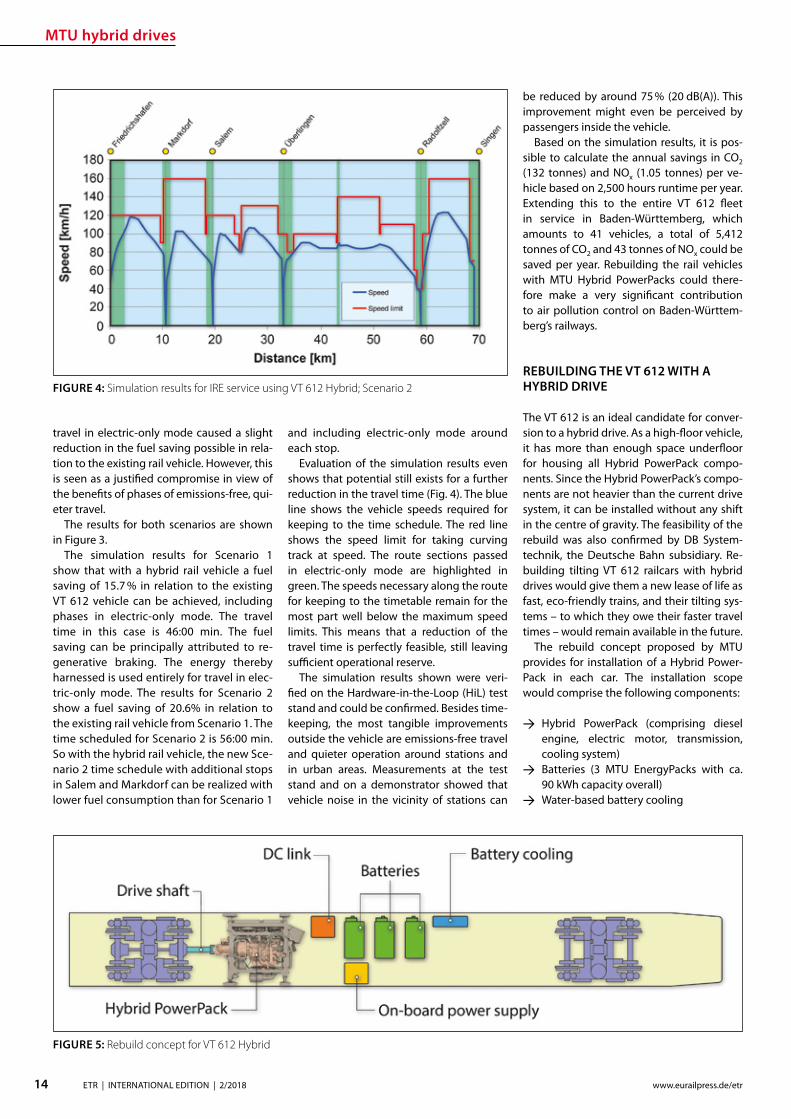
MTU hybrid drives
14 ETR | INTERNATIONAL EDITION | 22018 wwweurailpressdeetr
travel in electric-only mode caused a slight reduction in the fuel saving possible in rela-tion to the existing rail vehicle However this is seen as a justied compromise in view of the benets of phases of emissions-free qui-eter travel
The results for both scenarios are shown in Figure 3
The simulation results for Scenario 1 show that with a hybrid rail vehicle a fuel saving of 157 in relation to the existing VT 612 vehicle can be achieved including phases in electric-only mode The travel time in this case is 4600 min The fuel saving can be principally attributed to re-generative braking The energy thereby harnessed is used entirely for travel in elec-tric-only mode The results for Scenario 2 show a fuel saving of 206 in relation to the existing rail vehicle from Scenario 1 The time scheduled for Scenario 2 is 5600 min So with the hybrid rail vehicle the new Sce-nario 2 time schedule with additional stops in Salem and Markdorf can be realized with lower fuel consumption than for Scenario 1
and including electric-only mode around each stop
Evaluation of the simulation results even shows that potential still exists for a further reduction in the travel time (Fig 4) The blue line shows the vehicle speeds required for keeping to the time schedule The red line shows the speed limit for taking curving track at speed The route sections passed in electric-only mode are highlighted in green The speeds necessary along the route for keeping to the timetable remain for the most part well below the maximum speed limits This means that a reduction of the travel time is perfectly feasible still leaving sucient operational reserve
The simulation results shown were veri-ed on the Hardware-in-the-Loop (HiL) test stand and could be conrmed Besides time-keeping the most tangible improvements outside the vehicle are emissions-free travel and quieter operation around stations and in urban areas Measurements at the test stand and on a demonstrator showed that vehicle noise in the vicinity of stations can
be reduced by around 75 (20 dB(A)) This improvement might even be perceived by passengers inside the vehicle
Based on the simulation results it is pos-sible to calculate the annual savings in CO2 (132 tonnes) and NOx (105 tonnes) per ve-hicle based on 2500 hours runtime per year Extending this to the entire VT 612 eet in service in Baden-Wuumlrttemberg which amounts to 41 vehicles a total of 5412 tonnes of CO2 and 43 tonnes of NOx could be saved per year Rebuilding the rail vehicles with MTU Hybrid PowerPacks could there-fore make a very signicant contribution to air pollution control on Baden-Wuumlrttem-bergrsquos railways
REBUILDING THE VT 612 WITH A HYBRID DRIVE
The VT 612 is an ideal candidate for conver-sion to a hybrid drive As a high-oor vehicle it has more than enough space underoor for housing all Hybrid PowerPack compo-nents Since the Hybrid PowerPackrsquos compo-nents are not heavier than the current drive system it can be installed without any shift in the centre of gravity The feasibility of the rebuild was also conrmed by DB System-technik the Deutsche Bahn subsidiary Re-building tilting VT 612 railcars with hybrid drives would give them a new lease of life as fast eco-friendly trains and their tilting sys-tems ndash to which they owe their faster travel times ndash would remain available in the future
The rebuild concept proposed by MTU provides for installation of a Hybrid Power-Pack in each car The installation scope would comprise the following components
rarr Hybrid PowerPack (comprising diesel engine electric motor transmission cooling system)
rarr Batteries (3 MTU EnergyPacks with ca 90 kWh capacity overall)
rarr Water-based battery cooling
FIGURE 5 Rebuild concept for VT 612 Hybrid
FIGURE 4 Simulation results for IRE service using VT 612 Hybrid Scenario 2
15ETR | INTERNATIONAL EDITION | 22018wwweurailpressdeetr
rarr Intermediate DC circuit rarr Power electronics and lters for on-board power supply
The Hybrid PowerPack comprises an MTU 6H 1800 R85L diesel en-gine an electric motor and a ZF EcoWorld power-shift transmis-sion with integrated reversing function The diesel engine delivers 390 kW and the electric motor delivers 300 kW continuous power
The Hybrid PowerPack is arranged as a parallel hybrid with the electric motor sitting on the input side of the transmission up-stream of the diesel engine As a preference the electric motors are congured for electro-dynamic braking in order to harness surplus energy for battery storage or on-board power
SUMMARY
The simulations show that an MTU hybrid drive will have no dif-culties meeting either the current time schedule in place on the Lake Constance belt railway service or that planned for the future Rebuilding the rail vehicles with Hybrid PowerPacks would achieve signicantly cleaner quieter and more economical rail travel even without overhead electrication and with no compro-mises with respect to travel times The installation alone of state-of-the-art EU Stage V-compliant diesel engines in the VT 612 rail-cars could reduce particulate and NOx emissions by around 90 The further benets oered by a hybrid drive would prot the en-vironment passengers and operators alike Electric-only mode in urban areas and around stations lowers the noise level by as much as 75 Regenerative braking considerably enhances the ecologi-cal soundness of operations while improving their cost-eciency In this way up to 20 fuel savings can be made
All in all deployment of Hybrid PowerPacks on the Lake Con-stance belt railway could herald a breakthrough for this innova-tive technology in Germany
Literature[1] Oszfolk Benjamin et al Hybridantrieb stellt Marktreife unter Beweis ETR ndash Eisen-
bahntechnische Rundschau 92015 [2] SMA und Partner AG Optimierung Angebotskonzeption Bodenseeguumlrtelbahn
Zuumlrich SMA und Partner AG 2013
FIGURE 6 MTU Hybrid PowerPack
Discover intelligent sensors
INNOVATIONS TO SIMPLIFY RAILWAY OPERATIONS
EXPPERIEENCE THHE FUUTURE OF TTRAIN TRRACKINGG
InnoTranss in Berrlin18 ndashndash 21 Septembeer 220188Halll 255 | SStannd 2232
Digitalisation opens up new possibilities in generating a wide range of highly valuable information
wwwwfrauschherccominnootranns
Predictive Maintenance
16 ETR | INTERNATIONAL EDITION | 22018 wwweurailpressdeetr
BASIC PRINCIPLES OF DATA LAKES
Data Lakes dier fundamentally from clas-sic concepts of Business Intelligence such as Data Warehouses primarily by the type of data retained In data warehouses mainly transactional data is stored whose structure is dened upfront and which has already undergone pre-ltering before persistence In a data lake however all data is persisted regardless of its structure or relevance for known use cases Data Lakes have the fol-lowing basic properties [2]
rarr Data Lakes collect and store data regard-less of type format or data volume while they are to be stored in a structured manner in classic data warehouses
rarr Data Lakes provide large amounts of data Therefore it is important to keep costs low while maintaining a high ac-
The treasure of the Data Lake ndash Predictive maintenance for vehicle eetsEective asset management of vehicle eets in rail requires an ecient and comprehensive IT landscape as a basis The core of an associated architectural concept is a data lake that collects and provides real-time diagnostic data gathered on the vehicles It is the technical basis for the application of algorithms for condition-based maintenance of rail vehicle eets
cess rate Since data stored in structured form in data warehouses must be im-mediately accessible at all times to en-able fast access high persistence costs are generated Data Lakes on the other hand store raw data which depending on the frequency of accesses can also be stored with reduced access speed
rarr At Data Lakes all data is stored centrally and heterogeneously at the same time This means that data which is very dif-ferent from the format can be linked together in analyses without having to request potentially dierent systems beforehand Existing Application Pro-gramming Interfaces (APIs) provide a wide range of usable use cases It is easy to add dierent tools to the data stream as services for example or to store inter-mediate results in the Data Lake for fur-ther use by other tools
rarr Data Lakes keep all relevant data central and unstructured regardless of format-ting The analysis tools are always con-ceptually independent of the format and structure of the data This allows new analyses or new data sets to be integrat-ed easily and quickly
rarr In modern implementations of data lakes and the service landscapes required for this the concept provides for the rapid interchangeability of tools and micros-ervices The user can test generally avail-able tools with practically no initial eort and if required can transfer those to productive use in just a few steps
SERVICE-ORIENTED AND CLOUD-BASED ARCHITECTURE FOR DATA LAKES
Instead of using solutions based on indi-vidual or a few applications with a dened range of functions Data Lakes reliy on so-lutions consisting of a exible combination of dierent micro services around a central data store The software architecture must be detached from classical patterns such as a layered hierarchy and the development must lead to a data- or data-ow-centered architecture This makes it easy to add or re-place services at any point and keeps the ar-chitecture exible for future developments
When using data lakes primarily event-driven architectures are common By con-
Mathias Haimerl Senior Data Analyst ESE Engineering und Software-Entwicklung GmbHmathiashaimerlesede
FIGURE 1 Vehicle eets in rail transport as an object of asset management
Predictive Maintenance
raquo
trolling the events based on the underly-ing data streams this architecture can be called Data-Driven Architecture (cf[5]) The software therefore builds itself around the data stream as shown in Fig 1 The data stream therefore represents the basis for the achievement of objectives whereby each individual problem can be regarded as an in-dependent architecture The desired objec-tive is broken down top-down into required services and newly formed into a specic so-lution Right from the start not only services for data manipulation are considered but also accompanying services for areas such as logging and security
The implementation of data lakes on company-owned hardware does no longer make sense for most projects from a nan-cial point of view and therefore only makes sense for particularly critical applications (eg banks medicine military) if commercial cloud solutions with appropriate security options cannot be found or are not applica-ble for compliance reasons
CHALLENGES AND SOLUTIONS OF CLOUD-BASED ARCHITECTURES
The use of services in a cloud creates new
challenges that need to be addressed in ad-vance
Information security of the customer data available in the cloud is in most cases much higher in the Amazon Web Service (AWS) Cloud than on self-operated servers The large number of system administrators de-ployed worldwide for the AWS Cloud some of whom specialize in information security provides signicantly better information se-curity than would be the case with conven-tional IT infrastructures operated by compa-nies themselves
Handling security vulnerabilities Due to the high number of users in the global internet of things (IoT) security gaps that allow access to external data quickly become nancially and legally problematic The Linux base and the simple reporting of security problems allow newly discovered vulnerabilities to be resolved quickly and globally The globally uniform system and the uniform administra-tion of software components close security gaps within a few hours
Protection against unauthorized access by third parties Authentication measures serve to protect sensitive data against unauthor-ized read access (data theft) on the one hand
and to protect data against unauthorized manipulation (data modication computer sabotage) on the other Authorization meas-ures are aimed at ensuring that analysts and solution architects only have access to the data relevant to their projects This is supported by the targeted allocation of authorisations to the respective architects In addition organization-related boundary conditions are contractually secured One example of this are compliance guidelines such as certication of cloud providers ac-cording to standards like DIN EN ISOIEC 27001
Software maintainability The AWS ba-sic system is stable against updates and changes without interfering with customer projects Customer projects run in self-con-tained environments (sandbox) The pro-vider of the cloud system has the freedom to use exchange and extend any hardware components without expensive downtimes or waiting times for the user Software up-dates and time-consuming hardware up-grades are obsolete for the user
Legal framework Sending data across na-tional borders is often a legal hurdle that prohibits the use of cloud services To coun-teract this cloud providers have provided
FIGURE 2 Overall concept of the data-driven architec-ture The microservices are structured around the data stream
wwwmobility-bbcom
Berlin-Brandenburg
Moving mobility
to the next level
Meet us at InnoTrans
City Cube Hall B
210x99_VML_InnoTrans_eng_ETRindd 1 19072018 081118
Predictive Maintenance
18 ETR | INTERNATIONAL EDITION | 22018 wwweurailpressdeetr
for the possibility of binding to regions that ensure that data does not leave certain pre-dened regions
Calculability of costs An AWS solution is about 90 cheaper than the operation of ldquoclassicrdquo infrastructures This value is also evi-dent in one of our customer projects where about 98 of the costs were saved on the development system and the eective sav-ings for the live system were interpolated to be at about 91 AWS provides a billing calculator that provides an estimate based on past months and previous monthly costs
SAMPLE IMPLEMENTATION STEPS FOR AMAZON WEB SERVICES
As an example implementation of a data lake the cloud environment AWS was used as described below During implementation four functionalities were clearly separated which are described in more detail below
rarr Data acquisition including pre-process-ing (ingestion)
rarr central data storage rarr Cataloging of data rarr Preparation of concrete analyses
DATA ACQUISITION (DATA INPUT) FOR DISTRIBUTED DATA SOURCES
In order to be able to ingest sensor data from vehicle eets the receiving system must be able to accept and store a large number of distinct data from many sensors On the senderrsquos side however data must be collected buered and regularly transmit-ted to the Data Lake To do this a periodic Internet connection must be ensured For
the frequency of data transfer an individual taring between the local data collection and the frequency of synchronization to the cloud must also be found Data transfers at low bandwidth should preferably rely on the collection of several data sets and trans-fer with a stable connection However this requires more memory in the local device With higher bandwidth and stable connec-tions the data can also be transferred more frequently This on the other hand leads to an increased load on the receiver A project-specic optimum must be found here
Finally it should be taken into account that the order of data sets should already be de-ned during ingestion even if the structure does not have to be xed from the outset To simplify later evaluations considerably data of the same type for which the uniformity is to be foreseen should be grouped logically This unies the data accesses of the evaluat-ing processes and thus minimizes the eort
From a specic project of a customer we know that the current data load of 6754 MBh will increase tenfold by 2020 due to an increase in the number of equipped vehicles and a simultaneous tripling of the number of sensors to approx 2GBh The distribution of the eets is Europe-wide with the focus on Central Europe
CENTRAL DATA STORAGE
In order to eciently persist the collected sensor data of vehicle eets the receiving system stores the data in a central location In AWS data is stored centrally in any size and in an automatically growing storage unit a so-called bucket The data is stored in ob-jects a logical data unit comparable to les in a classic le system To make searching
through data easier the objects are indexed based on their specic prexes and opti-mized for fast access Since the implementa-tion is based on RESTful and therefore each data record transmitted by sensors sends a PUT request a new object is created for each data record This creates an immense num-ber of objects in the long term This is irrele-vant in terms of costs and storage space For an analysis based on large amounts of data with low reaction times however a catalog-ing of the data is still necessary
CATALOGUING FOR VARIOUS APPLICATIONS
The exible NoSQL database DynamoDB oers an optimal possibility to catalog data without having dened a schema and still get extremely fast access speeds A Dy-namoDB table has a primary key which con-sists of a partitioning key and an optional sort key The partitioning key determines the automatic partitioning of the table and should therefore be very well selected (see [9]) An entry also supports update com-mands DynamoDB oers a very exible memory which can be written and read in dierent ways
New data arriving in Simple Storage Ser-vice (S3) can be automatically analyzed as a trigger for cataloging and added to cor-responding catalogs Since the analyses are usually very individual a pipeline must be created so that the new data arriving in S3 can be processed This can be achieved with minimal eort using the Microservice Lamb-da which makes it possible to execute small programs in the AWS landscape without any further integration eort Optional lters can be set for the triggers so that dierent pre-xes start dierent lambda functions
rarr Read The respective lambda function receives the bucket and the object name of the newly arrived object and can ex-amine this import and the content ac-cording to previously dened criteria and extract the corresponding values
rarr Write This data can then be written to a DynamoDB table regardless of whether the data record already exists ie wheth-er it has to be updated or whether it is a new data record
This type of cataloging is the comparatively most complex but at the same time the ex-ibility exceeds that of other technologies by far The cost factor is also considerably lower here The costs for DynamoDB tables are cal-culated according to provisioned capacities for read and write accesses This is under-
FIGURE 3 Using cloud solutions brings new challenges
Predictive Maintenance
19ETR | INTERNATIONAL EDITION | 22018wwweurailpressdeetr
standable as an increase in capacity in the background is a real hardware replication This allows tables with costs of less than one euro per month for the minimum congura-tion and a separate table can be provided for each application case The requests for large amounts of data via the primary key or only a part of it can be retrieved extremely quickly whereby retrieval times in the low two-digit millisecond range are not uncommon
PREPARATION OF CONCRETE ANALYSES
The creation of analyses on the catalogued data is possible without great eort with the basis shown This is done in several consecu-tive steps
rarr Top-down analysis of the problem to be solved as there are various microservic-es for a wide variety of applications As a result individual use cases can be as-signed to the use cases
rarr Selection of suitable microservices De-pending on the target platform the ap-propriate microservices can be selected There are specic services that enable the further use of existing programs that work on relational databases for example Other microservices support machine learning or the visualization of complex interrelationships in informa-tive dashboards
rarr Bottom-up aggregation of specically congured microservices For this pur-pose services already congured for similar analyses can be reused or addi-tional instances with slightly modied conguration can be created
SUMMARY amp OUTLOOK
All in all Data Lakes oer an optimal solution from the initial setup of a collection of raw data from various sources without large upfront ef-fort or high costs to the data storage of many eets of dierent vehicles worldwide and the provision of data catalogs for various analyses of various kinds The collection of measure-ment data in persistent online data stores such as AWS buckets can be implemented within minutes and is operational from this point in time so that data can be collected and archived Even if no specic use cases are known at the time of implementation it is recommended to persist all data on low-cost cloud storage so that it is already available for possible evalua-tions at later points in time Since there is often no reason to process data without use cases favorable options for persistence of the data can be used To avoid vendor lock-in consider designing Data Lake to be adaptable to alter-native platforms Alternative options for data storage include the storage services of Google Cloud Services or Microsoft Azure Of course the use of a second service also doubles the total costs
References[1] Canalys (2017) Cloud service providersrsquo battle drives
the worldwide cloud infrastructure market up 42 in Q1 2017 httpswwwcanalyscomstaticpress_re-lease2017press-release-150517-cloud-service-providersE28099-battle-drives-worldwide-cloud-infrastructure-market-42_1pdf Palo Alto Shanghai Singapore and Reading (UK) Pressemit-teilung 15052017
[2] Amazon Web Services (2017) Building a Data Lake on AWS httpspagesawscloudcomrs112-TZM-766im-agesAWS_Data-Lake_eBookpdf 01112017
[3] Bundesministerium des Inneren (BMI) (2017) Polizeili-che Kriminalstatistik 2016 httpswwwbmibunddeSharedDocsdownloadsDEpublikationen2017pks-2016pdf Pressemitteilung 24042017
[4] Buschmann Frank and Christiane Loumlckenho eds (2000) Pattern-orientierte Softwarearchitektur ein Pat-tern-System 1 korr Nachdr Muumlnchen Addison-Wesley 2000
[5] Mahjourian Reza (2009) An Architectural Style for Data-Driven Systems Paper Gainesville FL 32611 USA httpswwwcsutexasedu~rezalesxpage-icsrpdf 22032009
[6] Tilkov Stefan (2009) REST und HTTP Einsatz der Ar-chitektur des Web fuumlr Integrationsszenarien 1 Au Hei-delberg dpunkt 2009 ISBN 9783898645836
[7] Hunkeler U H L Truong and A Stanford-Clark (2008) MQTT-S mdash A Publishsubscribe Protocol for Wireless Sensor Networks In Communication Systems Software and Middleware and Workshops 2008 COMSWARE 2008 3rd International Conference on 791ndash98 2008 httpsdoiorg101109COMSWA20084554519
[8] Manseld-Devine Steve (2016) DDoS Goes Main-stream How Headline-Grabbing Attacks Could Make This Threat an Organisationrsquos Biggest Nightmare Net-work Security 2016 no 11 (November 2016) 7ndash13 httpsdoiorg101016S1353-4858(16)30104-0
[9] Vyas Uchit (2014) DynamoDB Applied Design Patterns Birmingham United Kingdom Packt Publishing 2014
SAFERAILSYSTEMCOM
Guessing or GPR
bull GPR measurements and analysisbull Condition-based maintenance planningbull More than 25 years of working experience - worldwide
BIM
20 ETR | INTERNATIONAL EDITION | 22018 wwweurailpressdeetr
ABOUT SIEMENS MOBILITYrsquoS TURNKEY RAIL SOLUTIONS BUSINESS
Siemens AG is a global technology power-house that has stood for engineering ex-cellence innovation quality reliability and internationality for more than 170 years The company is a pioneer in supplying in-frastructure solutions Siemens Mobility is an experienced provider of complete turn-key solutions for rail systems having already carried out more than 50 various and major rail projects worldwide The organization is home to experts in project management and system integration as well as key prod-ucts of rail infrastructure These specialists develop and implement projects for all types of rail vehicle systems from metros trams and light rail vehicles and automated peo-ple-movers to Intercity and high-speed train units ndash all designed for maximum reliability availability and eciency
THE CHALLENGES OF RAIL INFRASTRUCTURE PROJECTS
Projects to install new rail infrastructure and expand existing systems are growing steadily more complex The rising number of project participants and stakeholders presenting a broad range of specic require-ments planning teams in dierent locations and time zones having to coordinate and
Digital twin serving rail infrastructure How turnkey rail infrastructure projects are beneting from applying Building Information Modeling (BIM) how Siemens Mobility is pursuing virtual planning of projects with project partners and custom-ers such as in the Riyadh Metro Project and what added value this methodology is creating
integrate their civil and rail engineering and planning and the ever increasing time and cost pressures exemplify this problematic complexity
There are an enormous number of inter-faces and requirements involved especially in large rail infrastructure projects and or-ganizing them demands extensive resources and absolute precision
AT THE VANGUARD OF DIGITAL PLANNING
Just as countless other sectors of the con-struction industry have already experienced digitalization is driving a para-digm shift in rail infrastructure away from analog meth-ods and embrac-ing digital and in-tegrated planning encompassing eve-rything from erec-tion planning installation and support for training to preparation and performance of repairs and maintenance all based on digital processes and data models
More than four years ago Siemens Mo-bility began applying building information modeling (BIM) techniques as well to project planning and execution of complete turnkey
solutions for rail systems As one of the trail-blazers of digitalization Siemens Mobility uses BIM to create a digital twin ndash a virtual model of major rail projects planned for im-plementation
This methodology focuses on achieving cost and time eciency while also ensuring the highest quality standards
Siemens Mobilityrsquos Turnkey Rail Solutions is using BIM in col-laboration with construction part-ners to optimize project planning and execution This involves the use of computer-generated 3D modeling and the
information integrated into or linked with the models
REFERENCE PROJECT RIYADH METRO
The Arriyadh Development Authority (ADA) ndash the executive arm of The High Commission
Both the implementing company and customer benet from the reduced risk of delays in planning as well as the prevention of defec-tive planning and resultant need to revise planning during ongoing installation
Dr Payam AminiHead of Digital Transformation Turnkey Projects amp Electrication Siemens Mobility Munich payamaminisiemenscom
A simulated view of the outside of the depot for which the path of sunlight can be simulated over time
raquo
BIM
21ETR | INTERNATIONAL EDITION | 22018wwweurailpressdeetr
for the Development of Arriyadh in Saudi Arabia ndash is currently building one of the larg-est metro projects in the world with six rail lines totaling 176 kilometers in length The system will be the backbone of the public rapid transit network serving Saudi Arabiarsquos capital city The order placed with Siemens Mobility covers supply of 67 Riyadh Metro model rail vehicles based on the Inspiro Plat-form series line electrication the signaling and communication systems for driverless service on Lines 1 and 2 as well as system integration and project management Sie-mens Mobility is part of the BACS consor-tium led by US company Bechtel along with Almabani General Contractors and Consoli-dated Contractors Company
The Riyadh Metro Project (RMP) kicked o by dening the information requirements and project-specic BIM objectives of the customer The BIM management team of Siemens Mobilityrsquos construction partner Be-chtel then used this information as the basis for elaborating in detail the BIM process for all project participants
The BIM execution plan that denes the BIM process for a specic project basi-cally provides the answers to the agreed require-ments In this key central document Turnkey Rail Solu-tions dened for all project participants in-volved in the infrastructure design the roles and scopes of responsibility the programs and le formats to be used what applica-tions are to be integrated into the BIM pro-cess the data-exchange process along the chain of project phases the quality review inspection and testing criteria procedures for coordination and collaboration and much more This was necessary in order to ensure smooth BIM implementation over the entire project cycle
Siemens Mobilityrsquos construction partner also generated the model element plan which denes in an overview who is to gen-erate what model content for the project by when and to what level of development (ie geometry information and coordination) In this project BIM standard the construc-tion partner also dened the details for modeling agreements and documentation standards
Model-based planning is one of the pro-jectrsquos centerpieces enabling comprehensive integration of all rail infrastructure systems such as rail electrication the depot and workshop equipment line signaling and communication technology and platform screen doors
CLARITY DRIVES THE EFFICIENCY OF WORKFLOWS
Siemens Mobilityrsquos infrastructure planning engineers used project-specic BIM software to share their model-based information with Siemens Mobilityrsquos suppliers and the con-
struction partner The program Pro-jectWise is used in combination with Aconex served and continues to
serve as a shared data platform accessible project-wide ensuring that each piece of information is retained only once and in its most recently valid version In this ldquosingle source of truthrdquo data are referenced rather than duplicated signicantly improving in-formation management increasing the reli-ability of data and eliminating any use of superseded obsolete data This provides full trans-parency for all pro-ject participants Photo-realistic displays and animated videos of the planning progress generated on the basis of the 3D planning information ensure transparency enhance understanding and support the iterative process
The permanent availability of data accel-erates collaboration across national borders and company boundaries These aspects are particularly benecial in the RMP Just Sie-mens Mobilityrsquos unit alone had colleagues based in 13 dierent cities working to de-sign the rail infrastructure coordinating and agreeing across national boundaries and dierent languages time zones and work capacities
In addition to the geometrical properties
of system components for example of fre-quency converters the participating plan-ning engineers also integrated non-geomet-rical information and requirements of their systems such as zones and clearance spaces that are essential for installation and mainte-nance Once work on a subarea of a model (work in progress) was approved for release this information was then available to all partners within the project (shared areas) In turn these partners reviewed the completed work for impacts on their own work scopes
In interdisciplinary collision reviews the design coordinators conducted collision tests with all other draft components Such reviews examined for example the civil struc-tures technical building equipment systems and Siemens Mobilityrsquos systems such as the signaling equipment and traction power supply grid to identify any conicts between
the systems them-selves or with the civil structures
In this way structural imple-mentation of the overall project as
well as individual subareas can be digitally tested at any time
As a provider of turnkey infrastructure solutions Siemens Mobilityrsquos unit was in-volved early in the RMP through BIM help-ing to prevent planning errors and leading to quicker validation of draft planning such as for spatial requirements of infrastructure equipment free clearance proles and pre-venting collisions
The RMP oers a basis for further infra-structure projects using BIM methodology The stock of digital objects available in the component library continues to grow Exist-ing digitally modeled components can be directly used for the next digital twin This
BIM creates full transparency for everyone participating in the plan-ning of infrastructure projects
The Control Center of the Riyadh Metro Project for Line 1 was fully planned digitally Once that design process was completed actual construction started
BIM enables earlier design valida-tion of rail infrastructure technol-ogy and engineering as well as civil construction
BIM
22 ETR | INTERNATIONAL EDITION | 22018 wwweurailpressdeetr
accelerates digital planning from one pro-ject to the next
Siemens Mobility Turnkey Rail Solutions sees particular potential for BIM in integrating the necessary man-agement process-es BIM supports the management of interfaces requirements congurations and project documentation This improved management leads to accelerated project execution And although project execution in Riyadh is still underway the added value created by the BIM method is already clearly evident today ndash for both Siemens Mobility and the customer
DIGITAL SCAN OF THE INFRASTRUCTURE CREATED
Siemens Mobility Turnkey Rail Solutions is utilizing other digital solutions as well for the Riyadh Metro Project that further optimize pro-ject execution Siemens Mobility-owned track measuring vehicles and 3D laser scanners are deployed to eciently compare the progress
of as-built construction and installation against the design target data These units travel along the existing sections scanning and thereby
digitalizing the as-built environment The object-specic information collect-ed by this measur-ing system whether on track position-
ing platform edges or technical spaces is com-pared with the digital design thereby directly revealing any deviations from planning
This produces a 100 -accurate database of the existing as-built status Particularly when projects aim to expand exist-ing infrastructure such transparency prevents costly conicts when equipping existing civil structures with new infrastructure equip-ment Besides the hardware procurement Siemens Mobility is banking in this context on developing the expertise of its own per-sonnel to cover planning of measuring cam-paigns kinematic and static imaging and evaluations such as review for collisions
PROMISING OUTLOOK
Siemens Mobilityrsquos Turnkey Rail Solutions has ceaselessly invested in implementing and further developing digital methods to keep pace with steadily growing deadline and cost pressures and the increasingly stringent demands of complex rail infra-structure projects These efforts are now empowering Siemens Mobility to better assess the sometimes extremely demand-ing detailed requirements early already in the project bidding phase and estimate costs more reliably thereby minimizing risks
In previous projects utilizing BIM meth-odology Siemens Mobilityrsquo experts identi-ed a shifting of eort into the early project phases
Siemens Mobilityrsquo experts see opportuni-ties in doing so particularly in the assess-ment of design modications in terms of im-pacts on costs and in early application when the leverage for such optimization can still prove very eective
Yet BIM doesnrsquot end when construction work on an infra-structure project has been complet-ed By developing a digital twin of the as-built infrastruc-ture and applying
that model over its entire lifecycle these sets of digital data can be used to optimize asset management
The BIM method harbors major potential for signicantly shaping the rail infrastruc-ture sector in the coming years
A view of the digital model of the King Abdullah Financial District Station on Line 1 which can be viewed in the computer pro-gram from all sides
Photo-realistic displays and animat-ed videos of the planning progress ensure transparency and enhance understanding
BIM provides the basis for simpler and ecient interface management and contributes signicantly to accelerating project execution
5 | 2017 Mai wwweurailpressdesd
109 Jahrgang
SIGNALLING amp DATACOMMUNICATION
Oumlsterreich Gut gesichertAustria Well-protected
13 Kostenguumlnstige Sicherung von Eisenbahnkreuzungen Cost-effective protection of level crossings
36 Finnland Gegen den Instandhaltungsruumlckstand Finland Reducing maintenance backlog
21 Schweiz Weltpremiere auf der Toumlsstalstrecke Switzerland A world premiere on the Toumlsstal line
Your contact person Silvia Sander +4940237 14-171 silviasanderdvvmediacom wwweurailpressde
Leader in Signalling and Datacommunication
No 1ad medium
SIGNALLING AND
DATACOMMUNICATION
AUTONOMOUS DRIVING
CYBE
R SE
CURI
TY
LEVEL CROSSING TECHNOLOGY
OPERATIONS MANAGEMENT SYSTEMS
MOBILE COMMUNICATIONETCS
REPUTABLE
UN
IQU
E
ESTABLISHEDTELECOMMUNICATION
OPERATIONS CONTROL TECHNOLOGY
INFORMATION TECHNOLOGYBILINGUAL
Book your advert right now
raquo
Ground Penetrating Radar
23ETR | INTERNATIONAL EDITION | 22018wwweurailpressdeetr
1 INTRODUCTION
Many countries allocate large amounts for the modernization and upgrading of their railway networks in order to meet the de-mands of increasingly dense rail trac with higher axle loads at ever higher speeds However this can only be achieved if all rel-evant key gures and geotechnical condi-
Ground Penetrating Radar ndash Basis for eective Track MaintenanceThis article describes the capabilities and functionality of Ground Penetrating Radar (GPR) for higher speeds GPR is a train-borne technology for a continuous inspection of the geotechnical conditions of railway tracks The basic principles of the GPR technology are explained with particular reference to all relevant railway specic tasks namely the identication qualication and quantication of ballast fouling by using a fouling index the determination of the quality of track drainage and its quantication through a drainage index and the calculation of the track modulus (TM) Special emphasis in the context of GPR investigations is placed on the mapping of sections with clay foulingmud spots inside the ballast bed or at its base and respectively inside intermediate layer formation or subsoil In the past such weak-spots have caused derailment they could represent a risk for rail-trac [11 13 14 15 16] Besides their late detection implies exceedingly high maintenance costs
tions of the respective tracks can be reliably evaluated On this basis only the necessary investments in track maintenance moderni-zation and support can be dened in the ap-propriate size and can be placed correctly This is particularly true when budgets are tight
The demands exerted on the track in terms of safety grow with increasing speed
FIGURE 1a) Trajectories of radar waves which are reected at the layer boundary between two media
with dierent dielectric constant (laquo)b) Due to the dierent travel time of the reections the layer boundary is reproduced in the
radargram (reference Ground Control and IEV)
Dipl-Geophys Giuseppe StacconeDirector of Ground Control GmbH MunichGermanystacconesaferailsystemcom
David Camacho MScDoktorand am Institut fuumlr Eisen-bahn- und Verkehrswesen der Universitaumlt Stuttgart (IEV)davidcamacho ievvwiuni-stuttgartde
Moritz SchebuchMitarbeiter am Institut fuumlr Eisen-bahn- und Verkehrswesen der Universitaumlt Stuttgart (IEV)moritzschebuch ievvwiuni-stuttgartde
Prof Dr-Ing Ullrich MartinDirektor des Instituts fuumlr Eisenbahn- und Verkehrswesen der Universitaumlt Stuttgart (IEV) und des Verkehrswis-senschaftlichen Instituts an der Universitaumlt Stuttgart eV (VWI eV)ullrichmartin ievvwiuni-stuttgartde
Dipl-Ing Sebastian RappAkademischer Mitarbeiter am Institut fuumlr Eisenbahn- und Verkehrswesen der Universitaumlt Stuttgart (IEV)sebastianrapp ievvwiuni-stuttgartde
Ground Penetrating Radar
24 ETR | INTERNATIONAL EDITION | 22018 wwweurailpressdeetr
Therefore failing to detect track damages or obtaining inadequate information on track damages represents a hazard for every kind of railway trac For this reason a decision guidance that facilitates a systematic and ecient renewal of the tracks is important The more intensive the rail trac and the higher the trac speed the bigger the re-quirements in terms of an ecient and reli-able track inspection
The mapping of clay fouling or mud sec-tions is of special importance Fine-grained soil material such as silt or clay wells up from the formation and reaches the ballast base or even penetrates the ballast layer itself As a consequence track drainage and track stability (ie bearing capacity) are strongly reduced This results in lasting deformations that require complex maintenance work and high costs If weak-spots are not identied or not detected in time clay fouling can in the worst case scenario lead to derailment [10 13 14 15 16]
During the past 25 years Ground Control GmbH which is placed in Munich Germany has surveyed more than 100000 km of rail-way tracks in many countries in Europe and all over the world Recently with information obtained from GPR results and other data (ie track geometry and track dynamics) a continuous and complete assessment of the trackrsquos structural condition is possible
2 MEASURING PROCESS
The GPR method is an electromagnetic re-ection method Radar pulses are transmit-ted into the subsoil by a transmitter antenna The energy of the electromagnetic waves is partly reected at interfaces between layers with dierent dielectric properties and re-transmitted to the receiver antenna Based on the measured travel time of the signals and knowing the propagation speed of the waves in the medium depth and surface of the layer can be computed
In order to dene the depth of the re-ector from the surveyed travel time the propagation speed of the radar waves in the subsoil has to be determined The speed of electromagnetic waves in the subsoil is re-lated to the water content of the individual material Therefore it is generally not pos-sible to refer to reference values for certain rock or soil types Thus the radar wave speed has to be calibrated for each project area
The penetration of electromagnetic waves mainly depends on the electric conductivity of the soil and the applied antenna frequen-cy By using low frequency antennae on low conductive subsoil the largest investigation depth can be achieved
PERFORMING SURVEYS WITH MODERN HIGH-SPEED-GPR
Todayrsquos GPR surveys are carried out with train mounted systems at speeds up to 160 kmh As a general rule the antennae system is fastened at the carrier vehiclersquos buers A precise positioning is achieved by an inte-grated Dierential Global Positioning Sys-tem (DGPS) and Doppler radar
The characteristics of modern GPR sys-tems are
rarr The equipment can be installed and run on a wide range of track-bound vehicles (including regular trains or vehicles on Hy-Rail)
rarr They are fast enough to be integrated into the regular trac schedule Hence expensive track closure is no longer nec-essary
rarr DGPS and Doppler radar are used for an accurate (ie precision within a meter) positioning of the antenna independ-ent of the speed and length of the track surveyed
rarr Measurement data resolution and data quality are equally high no matter what length and what speed
rarr All GPR components are eectively
shielded against interferences from sig-nalling and communication systems
3 GPR TASKS
In contrast with punctual boreholes and trenches modern GPR systems provide con-tinuous information about the geotechnical condition of the track performing the fol-lowing tasks
rarr Continuous mapping of track-bed-thick-ness and layers below (ie intermediate layer protective layers)
rarr Distinction between clean and fouled ballast and calculation of Fouling Index
rarr Mapping of mud spots or clay fouling sections inside ballast bed at its base or inside substructure layers respectively
rarr Detection of sections with drainage problems and calculation of ldquoWet Bed Indexrdquo
rarr Mapping of areas with insucient bearing capacity (eg settlements) and evaluation of the dynamics of track set-tlement
rarr Control and evaluation of the quality of maintenancerenewalconstruction work (quality of cleaned or exchanged ballast thickness of a new ballast bed quality and thickness of soil layers)
rarr Estimation of track condition based on track modulus (TM) calculation
Additionally GPR data allow for the deni-tion of a sustainable cause-based and there-fore eective track renewal recommenda-tions and programs Optionally GPR oers the possibility to accurately map cables pipes and other objects in the track sub-structure creating the possibility to provide a complete picture of the entire system
31 CLAY FOULING ndash STRONG EFFECT ON TRACK STABILITY
Clay Fouling is one of the main reasons for the reduction of the load bearing capacity of the track in a relatively short period of time Several derailments in the past were caused by mud spots [10 13 14 15 16] even when the limit values for track geometry failures according to [2] have not been exceeded [13 14] It is therefore and because of safety reasons of particular importance to detect clay fouling areas reliably in their precise dimension and as early as possible The rec-ognition of the problem should be irrespec-tive of whether the clay fouling exists in the substructure at the base of the ballast bed or in the ballast bed itself Clay fouling can
FIGURE 2 Figure 2 Antenna mounted on the train buers of a mainte-nance vehicle(reference Ground Control)
Ground Penetrating Radar
25ETR | INTERNATIONAL EDITION | 22018wwweurailpressdeetr
raquo
rapidly deteriorate the stiness of the track and its quality The trackrsquos lateral stability is massively reduced longitudinal errors along the rails arise
Clay fouling is also a serious decit from an economic point of view Its timely iden-tication allows for avoiding slow speed sections thus sparing time and money for maintenance procedures Detecting clay fouling before it reaches the ballast bed ena-bles cost eective renewal Otherwise it will be very expensive There is no option for bal-last cleaning a suciently compacted pro-tection layer built of the appropriate materi-al is essential the installation of composites does not prevent clay fouling from entering the ballast bed (see Fig 3)
Save few exceptions clay fouling spots are not visible at the track surface and since drill-ings and trenches do only provide punctual results reliable information is only achievable through GPR measurements (see Fig 4)
A frequency analysis of the measured data results in a typical change of the signal spectrum in the area of clay fouling Based on the GPR results borehole program can be implemented which can be used for further analysis GPR surveys to detect ballast foul-ing have been carried out for years in Swit-zerland Austria the Netherlands and France among others
32 TRACK MODULUS (TM)
Examining the geotechnical conditions of railway tracks requires an index which in-forms about state and quality of the tracks in a quantitative manner The challenge has
been to dene the track condition continu-ously This has been achieved by combin-ing TM with the results of continuous GPR-measurements
It is possible based on [3 4 5 6 7] to es-timate quality and bearing capacity of the railway track Therefore the TM describes the relation between vertical load and elas-tic deection of the sleeper-bearings
On the one hand the TM can be calculated based on the measured deection under load [18 20] on the other hand according to the soil properties [8 9 11] The measuring principle for determining the load deec-tion is described in detail in [12] and [17] The properties of the system components such as the area of inuence of the sleepers under load can greatly aect the TM Hence around turnouts the area of inuence of sleepers deviates from the standard track This is because an increased area of inu-ence causes an increase in the distribution of the load reducing the deection of the
rail Notwithstanding to simplify the calcula-tion of the TM the inuence area of sleepers around turnouts are assumed to be constant assuming the values of the standard track Depending on the type of sleepers installed the value of the TM can increase sharply around turnouts (Fig 5) In addition cavities under the sleepers increase the deection of the track under load which in turn inu-ences the calculation of the TM decreasing its value
An additional and new approach for calcu-lating the TM is based upon the soil proper-ties which can be described by the Poissonrsquos Ratio or the material density of the soil The soil properties derive from the GPR data This methodrsquos advantage is to be completely in-dependent from superstructure conditions The individual layers are assigned soil values according to condition and bulk density Averaged soil properties are calculated ac-cording to [1 19] The TM can be estimated according to [9] and [11] Previous studies
FIGURE 4 Visual analysis of GPR data depicting clay fouling along a track (reference Ground Control and IEV)
FIGURE 3 Geotextile or composite does not stop ne particle migration to the surface (reference Ground Control)
Ground Penetrating Radar
26 ETR | INTERNATIONAL EDITION | 22018 wwweurailpressdeetr
indicate that this method has signicantly lower value variations along the track axis compared to the approach based on the use of track displacement data (Figure 5)
The example in Fig 5 shows two track moduli based on the measured displacement under load (red line) and the soil properties (blue line) Around the turnouts a signicant increase of the TM is visible if the calculation is based on the measured deection By divid-ing the TM into quality classes according to [3 4 5 6 7] the condition of the track can be sat-isfactorily estimated (Fig 6)
33 TRACK ANALYZER ndash CONTINUOUS PRESENTATION OF ALL MEASUREMENT AND TEST RESULTS
Results from GPR surveys along with all identied soil parameters and indices cal-
culated can be displayed in comprehensive track analysis software called ldquoTrack Analyz-errdquo In order to provide all information for in-frastructure managers track geometry and track dynamics data are also integrated and displayed in the software (see Fig 7) which also oers the exibility to incorporate other tasks and aspects as required by the user
The Track Analyzer provides infrastructure managers continuous information about the geotechnical conditions of the track with regard to all relevant issues Moreover it provides a better understanding of the sub-structuresubgrade conditions and their in-uence on the superstructure This allows for a signicantly increased track quality pro-viding higher route availability and safety
A big advantage of the GPR method is the minimization of the need for intensive direct outcropping (probing drilling scooping)
to characterize the underlying geotechni-cal characteristics of the track substructuresubgrade which results in signicant cost reductions
4 SUMMARY
This paper describes a modern train-borne technology for the inspection of the geo-technical conditions of railway tracks It is based on High Speed GPR and on classical procedures for providing continuous infor-mation about geotechnical parameters and indices A new quality of GPR measurements is to provide quantitative indices in addition to qualitative results to full the require-ments of the railway engineers in the best possible way
Special attention is paid to the detection of mud spots and clay fouling sections as a risk for derailment [10 13 14 15 16] To date track inspection with GPR is more appropri-ate than any other inspection method to de-tect map and qualify areas with geotechni-cal problems
The Track Analyzer software combines GPR results with track geometry and track dynamics data This allows for cause-based track renewal and targeted investment and provides signicantly more reliable results than conventional methods This approach is especially relevant for limited budgets
Literature [1] Adam D Kopf F Dynamische Eekte durch bewegte
Lasten auf Fahrwegen In Bauingenieur Ausgabe 01-2003 2003
FIGURE 5 TM calculated from measured displacement under load (red graph) and soil proper-ties (blue graph) (reference IEV)
FIGURE 6 TM divided in dierent quality classes (reference IEV)
Ground Penetrating Radar
27ETR | INTERNATIONAL EDITION | 22018wwweurailpressdeetr
FIGURE 7 Track Analyzer(reference Ground Control)
[2] DB Netz AG Ril 821 Oberbau inspizieren Deutsche Bahn AG guumlltig ab 01052004
[3] Eisenmann J Stuumltzpunktelastizitaumlt bei einer Festen Fahrbahn In ZEV + DET Glasers Analen 111999
[4] Fendrich L (Hrsg) Handbuch Eisenbahninfrastruktur Springer-Verlag Berlin Heidelberg 2007
[5] Goumlbel C Lieberenz K (Hrsg) Handbuch Erdbau-werke der Bahnen DVV Media Group GmbH 2013
[6] Leykauf G Lothar M Elastisches Verformungsver-halten des Eisenbahnoberbaus ndash Eigenschaften und Anforderungen In EI ndash Eisenbahningenieur 031990
[7] Lichtberger B Handbuch Gleis DVV Media Group GmbH 2010
[8] Martin U Rapp S Ansatz zur Erfassung der Bodenei-genschaften am Bahnkoumlrper in Schotterbauweise In ETR ndash Eisenbahntechnische Rundschau 042017
[9] Martin U Rapp S Camacho D Moormann C Lehn J Prakaso P Abschaumltzung der Untergrundverhaumllt-nisse am Bahnkoumlrper anhand des Bettungsmoduls In ETR - Eisenbahntechnische Rundschau 052016
[10] Rail Accident Investigation Branch Freight train de-railment near Gloucester 15 October 2013 Rail Acci-dent Report102014
[11] Rapp S Modell zur Identizierung von punktuel-len Instabilitaumlten am Bahnkoumlrper in konventioneller Schotterbauweise Dissertation ndash Institut fuumlr Eisen-bahn- und Verkehrswesen der Universitaumlt Stuttgart 072017
[12] Soldati G Meier M Zurkirchen M Kontinuierliche Messung der Gleiseinsenkung mit 20 t Achslast In EI ndash Eisenbahningenieur 022016
[13] Untersuchungszentrale der Eisenbahn-Unfalluntersu-chungsstelle des Bundes Untersuchungsbericht Ak-tenzeichen 60 ndash 60uu2011-0200041 Zugentgleisung Groumlbers ndash Groszligkugel 062013
[14] Untersuchungszentrale der Eisenbahn-Unfalluntersu-chungsstelle des Bundes Untersuchungsbericht Ak-tenzeichen 60uu2013-06047-3323 Zugentgleisung Kaub ndash Lorch (Rhein) 062013
[15] Untersuchungszentrale der Eisenbahn-Unfalluntersu-chungsstelle des Bundes Untersuchungsbericht Ak-tenzeichen 60 ndash 60uu2011-0400043 Zugentgleisung Bf Hannover ndash Linden 092013
[16] Versa Verkehrssicherheitsarbeit fuumlr Oumlsterreich Unter-suchungsbericht Sicherheitsuntersuchungsstelle des Bundes BMVIT-795336-IVBAVUUBSCH2013 Ent-gleisung eines Guumlterzugs am 14 Februar 2013 2013
[17] Wang P Wang L Chen R Xu J Overview and out-look on railway track stiness measurement Jour-nal of Modern Transportation Volume 24 Issue 2 062016
[18] Winkler E Die Lehre von der Elastizitaumlt und Festigkeit Verlag von H Dominicus 1967
[19] Wolf J P Foundation Vibration Analysis using Simple Physical Models Swiss Federal Institute of Technology 1994
[20] Zimmermann H Die Berechnung des Eisenbahn-oberbaus 1888
wwwrex-industrie-produktede
INSULATING JACKETS FORHIGH TEMPERATURE INSULATION
high temperature resistant up to 1000degC
incombustible
high insulation performance
tailor made according to your wishes
New test reports for fire protection according to EN 45545-2 available R1R7R17 with Hazard Level HL 3
Distributed Acoustic Sensing
28 ETR | INTERNATIONAL EDITION | 22018 wwweurailpressdeetr
Dip-Ing FH MScMartin RosenbergerCTO Frauscher Sensor Technology martinrosenberger frauschercom
This involves planning and controlling maintenance measures based on the actual condition of the equipment systems and components (assets) Unexpected events due to faulty components and unnecessary work on fully intact elements can thus be reduced This is possible thanks to the ever increasing amount of reliable data about the condition of the asset that is available in real time
Continuous acoustic condition monitor-ing of the infrastructure based on Distribut-ed Acoustic Sensing (DAS) is a key building block of future solutions This technology can considerably increase the availability of rail networks since it continuously delivers very precise information about the condi-tion of the infrastructure and any changes thereby fullling a key prerequisite for the use of CBM solutions
The sensor technology and inspections form and remain the basis for condition-based maintenance of the track These in-clude track recording vehicles xed meas-urement points sensor technology on
How Distributed Acoustic Sensing supports condition based maintenance strategiesCurrent technological developments are opening up new opportunities for the railway industry in a whole range of application areas Most notably these include networking digitalization and the Inter-net of Things (IoT) This trend is also having a growing impact on processes and strategies for maintain-ing rolling stock and infrastructure Traditional maintenance philosophies which are based on xed intervals or in the case of vehicles on mileage are increasingly being replaced by predictive condition based maintenance (CBM)
standard trains track-side sensor technol-ogy selectively deployed manual measur-ing instruments and self-monitoring infra-structure systems Data from these sources must be consolidated and if applicable combined with information about rolling stock and system-side infrastructure data such as a system directory or inputs from other sensors
DAS enables a sensor solution to be cre-ated which fulls several of the specied re-quirements this technology allows railway networks to be monitored continuously in real time and with respect to a huge num-ber of dierent events Frauscher has devel-oped its own DAS solution for the railway sector Frauscher Tracking Solutions FTS The manufacturerrsquos team tested the tech-nology and through intensive develop-ment eliminated constraints with respect to use for rail trac To create this in-depth knowledge of DAS as well as requirements and standards in the railway industry was required
1 DAS FUNCTIONAL PRINCIPLE
DAS-based systems use laser pulses sent in a glass bre to detect events on or in the vicinity of the track part of the laser pulse is reected back out of the bre to the transmitting unit The sound and vibration waves impacting on the cable result in signicant shifts in the reection (Fig 1) The maximum frequency range of the vibrations detected in this man-ner is 125 kHz Using specically developed algorithms the acquired data can be used to calculate specic signatures in real time These describe highly precise locations and types of processes in the vicinity of the track
One of the advantages of installing a DAS system is that the bre optic cables it requires are often already laid next to the tracks These are normally used for commu-nication purposes As the optical bres used require practically no maintenance the sys-tem can be rolled out to large sections of the route extremely economically and ecient-ly In practice a single DAS unit can eective-ly cover up to 40 kilometres of glass bre in each direction so 80 kilometres in total [1]
2 CONTINUOUS MONITORING OF WHEEL-RAIL INTERACTION
The ongoing analysis of infrastructure us-ing FTS is based on continuous monitoring
FIG 1 Distributed Acoustic Sensing (DAS) allows for the detection of vibrations and sound waves caused by trains component defects people or other sources
raquo
Distributed Acoustic Sensing
29ETR | INTERNATIONAL EDITION | 22018wwweurailpressdeetr
of wheel-rail interaction (Fig 2) On the one hand this enables the detection of changes that arise slowly over the course of time To do so the system compares the relevant signatures that are captured each time a railway vehicle passes a spot On the other hand events that occur suddenly can also be reliably detected
21 TREND ANALYSIS FOR LOCALISATION OF CONDITION CHANGES
The wheel-rail interactions quality is the most important factor when it comes to the service life of both system components and the rolling stock This quality is derived from various parameters such as the roundness of the wheel the surface of the rail and the track design Even slight deviations from the ideal parameters result in increased signs of wear and tear over a certain amount of time Ultimately these can also lead to critical op-erating conditions Which is why continu-ous detection and thus early recognition of changes in condition along the entire route is extremely useful
This is where the FTS come into play by evaluating the signatures in the laser signal feedback it is possible to determine wheth-er a sp ecic anomaly in wheel-rail interac-tion comes from the train or from the infra-structure This is possible because the FTS system uses a glass bre as a permanent sen-sor along the track thus allowing the wheel-rail interaction for each individual axle on all train journeys to be permanently monitored along the entire route Changes are detected in real time and the method does not de-pend on a xed measurement point
If a notication is triggered by an out-of-round wheel for instance then this pattern will be part of the train signature and be de-tected in association with the moving train This allows the event to be clearly attributed to vehicle damage
By contrast if there is a change to the in-frastructure several axles will have a notice-able signature in one specic position The system uses this to determine an indicator Based on this trend analyses are formed for individual ten-metre long infrastruc-ture segments Warning or alarm notica-tions can now be created and transmitted through dened user-congured threshold values These indicate the type of change as well as the location With good georefer-encing for the bre optic cable the position identied via FTS can be localised to an accu-racy of up to ve metres and made available via machine-readable interfaces
Frauscher oers powerful interfaces for employees in railway infrastructure compa-
nies In particular these include a graphical user interface with map view and heat maps and depiction of the infrastructure condition in denable categories The zoom function can be used to display the entire route or a position with relevant localisation in route kilometres or GPS data the actual condition and the change in condition over a specic period Filters can be set for even more de-tailed analyses and evaluation
22 EVALUATION OF CHANGES IN CONDITION AS A PROCESS
To determine the relevance for a specic rail-way operation simply identifying a change in condition is not enough The trend analy-sis must also be correlated with the trains and their speeds After all identical techni-cal non-conformities will result in indicators with completely dierent frequencies and intensities when a heavy long freight train and when a lighter short passenger train travels over a position with a fault
Therefore a basic condition must rst be dened for the infrastructure and stored in the FTS The trend analyses can then be ap-plied to this To do so the system structure (primarily bridges tunnels or points) must be logged in the system and the sensor must be calibrated accordingly Data that needs to be entered includes rail joints or transitions from a point for example They create similar patterns to those of a rail defect but must be evaluated and examined dierently
It may also be necessary to lter out am-bient noise from stationary systems such as pumps and generators so that this does not have a negative eect on the detailed analy-sis of the wheel-rail interaction signature
These adjustments are currently carried out manually during the installation and com-missioning process However Frauscher is developing tools to automate these process-es These steps form part of the technologyrsquos path towards serial production
Once the basic condition has been dened then depending on the model the operator will receive regular reports or warning and alarm notications via dened interfaces The DAS systems that are currently available are not yet able to classify and quantify the changes detected with sucient accuracy Maintenance personal therefore take on the task of evaluating suspect positions through inspection actions during the development and installation phase A visual inspection is often enough to identify the cause of the warning classify the change and take the necessary action within a dened period
Based on experience with several installa-tions and Frauscherrsquos collaboration with op-erators there are essentially three relevant classications
rarr No detectable or only minimal damage rarr Non-critical damage rarr Critical damage
What is important is that this evaluation and classication is understood and followed as part and parcel of the maintenance process Dening the threshold values and deter-mining the sensitivity of the system is a key step in this regard Experienced specialist sta who evaluate and process the notica-tions can shape the system to suit their own needs This allows CBM concepts to be ap-plied even more eciently for practical sup-port and to build expertise (Fig 3)
The high sensitivity level of the system
FIG 2 By continuously monitoring the acoustic signature of the wheel-rail contact the FTS support condition based maintenance strategies
Distributed Acoustic Sensing
30 ETR | INTERNATIONAL EDITION | 22018 wwweurailpressdeetr
means that a range of errors can be detected at a very early stage However this also in-creases the risk that positions that are not relevant for maintenance will be displayed This is where empirical values are really needed so that the optimum setting can be tuned for the operator It is crucial to involve the maintenance personnel in this whether through the operator or the service contrac-tor After all only experts on the ground can evaluate the condition of the infrastructure and determine the necessary measures Maintenance employee experience thus re-mains essential for training the algorithms and evaluating the results the maintenance personnel must use their knowledge of routes and systems to determine whether a notication is in fact relevant or not
Not detectable or only minimal damageIn this case no maintenance measures are needed There are three main reasons why the system has indicated a potential fault in this case First there may be a structural fac-tor in the infrastructure or a factor in the en-vironment of the trigger In this case the in-uencing factor can be ltered out in future Secondly it could be that a visual inspection reveals no detectable fault but there are already signs of wear In this case the user
would add information to the system stating that this section is to be kept under observa-tion or specically monitored over a certain period of time ndash for example by adjusting the threshold value If the system contin-ues to exhibit a fault it is advisable to apply analysis methods that go beyond a visual inspection of this point or use other meas-urement data as a comparison Thirdly this could be due to a minor surface fault on the rail for example which does not require any action since scheduled surface processing measures are due to be carried out (Fig 4) In this case the fault message can be acknowl-edged
Non-critical damageIn this case the system has identied a rel-evant fault but it does not need to be cor-rected right away (Fig 5) The main advan-tage of this is that early detection allows the necessary measures to be planned in good time so these can be put into eect during quiet periods or eciently combined with other measures thus reducing the number of expensive individual activities
Critical damageIf such changes are detected then measures must be initiated immediately in order to re-
solve the safety-critical operating condition and minimise any expensive subsequent damage Experience shows that such critical conditions can develop over just a few days or can even be triggered by acute short-term factors Examples include ballast voids due to washout rail head cracks and broken rails
Critical conditions can arise during the analysis cycles even if the rail network is monitored regularly with track recording ve-hicles for example Continuous monitoring of the wheel-rail interaction enables quicker intervention and minimises personal injury and damage to property
23 EMPIRICAL RESULTS
In addition to various applications which can be used in real time on the basis of train lo-calisation over the last two years Frauscher has been taking a closer look at infrastruc-ture maintenance In particular at the po-tential that continuous monitoring of the wheel-rail interaction has to oer in the fol-lowing scenarios
rarr Rail monitoring rarr Rail fastening and sleeper monitoring rarr Track substructure and superstructure
monitoring
Practical application has shown that the data that can be provided via the FTS system al-ready oers a range of interesting options it helps users to plan and control maintenance measures in good time To do so Frauscher implements technology such as machine learning pattern recognition and articial
FIG 3 When developing advanced main-tenance solutions various levels within a railway network have to work together closely
FIG 4 Changes in the trackrsquos surface can be detected evaluated and considered when planning maintenance works
FIG 5 Detecting small defects allows for a targeted monitoring in order to generate alarms when their condition deteriorates
Distributed Acoustic Sensing
31ETR | INTERNATIONAL EDITION | 22018wwweurailpressdeetr
intelligence However in order to move to the next level a solid base of empirical val-ues and a library of signatures from a variety of sources of damage are needed
The company is working very closely with the operators of several installations select-ed from approximately 30 projects that are currently ongoing worldwide They are joint-ly considering the evaluation interpretation and derivation of measures Specic issues and ideas for further development of the evaluation software and logic are directly incorporated into Frauscherrsquos development processes using agile methods
Rail monitoringAll types of rail damage that cause vibrations or a noise spectrum that deviates from the norm are detected This ranges from surface damage such as rail corrugation squats rail head cracks wheel burns or corrosion and dents to cracking and ssuring or even bro-ken rails
Unsurprisingly the algorithm for detect-ing rail damage also detects rail joints After all the signature of a gap as in an isolation joint could be exactly the same as that for a break in part of the rail In this case depend-ing on requirements these rail joints can be suppressed or specically monitored with their own threshold values (Fig 6 7) The sensitive sensor system can detect broken rails as a train passes over them with high probability However due to the many dif-ferent forms and physical basic conditions a warning system with a 100 percent de-tection rate and zero error rate cannot be achieved
In addition there are still no empirical val-ues for broken rails which can be traced back to warping and thermal eects without the eect of the train Noises that arise due to warping (thermal popping) were detected during tests designed to identify and local-ise landslides and rock fall These are hard to classify or uniquely identify using the cur-rently available hardware and software It is to be assumed that a rail that breaks for thermal reasons generates a similar if more intensive signature and it is not possible to clearly distinguish this from the ldquothermal poprdquo
Therefore it is important to consider whether continuous monitoring of the tracks with appropriate trend analyses does not provide more information about the safety of the route than a warning system for broken rails Last but not least broken rails should generally be reduced by as-required maintenance measures
Rail fastening and sleeper monitoringIn several installations positions were de-
tected that exhibited increased vibration due to damaged or missing rail connections or broken sleepers These are typically faults that do not necessarily require action to be taken right away Instead they are classied in such a way that these tasks will be car-ried out during upcoming scheduled on-site maintenance
Track substructure and superstructure monitoringThe FTS system is able to localise weakness-es in the substructure and track superstruc-ture such as ballast voids under sleepers cavities or compacted areas The condition of the track bed may under certain circum-stances also lead to a critical situation in a relatively short period of time particularly in mountainous regions where heavy rain or mudslides can also make the track position unstable Practical examples also exist for these scenarios where FTS localised critical positions where ballast voids under sleepers were later identied
3 SUMMARY
Continuous monitoring of wheel-rail interac-tion based on FTS opens up numerous pos-sibilities for the user in terms of timely detec-tion of weaknesses and changes in condition on the route Thus targeted and as-required maintenance measures can be dened planned and eciently controlled This is a paradigm shift in terms of maintenance strategy similar to that which is emerging for vehicles Before xed periods based on theoretically calculated average loads were
key to the strategy Now the actual wear and condition of the specic component (rail surface fastening sleeper substructure or track superstructure) are the trigger for maintenance repair or servicing work
These new options for monitoring infra-structure will not replace existing measure-ment systems instead they will enhance them They will change the maintenance processes mainly through the high-pre-cision and early detection of continuous changes By determining individual thresh-old values necessary work can be planned and carried out preventively before critical damage arises
In addition to such continuous changes the FTS is also able to detect vehicle faults and short-term sporadic inuences on trackside infrastructure This includes natu-ral hazard management such as falling rocks and trees catenary ashover or protecting infrastructure from vandalism cable theft or unauthorised access to track systems
Even in times of advancing digitalisation employee experience forms an indispensa-ble basis for railway operations Manufac-turers and operators must work together to develop systems for CBM concepts and individually calibrate them so they become helpful tools which raise eciency while re-ducing ongoing costs
Literature[1] Rosenberger Martin Lancaster Gavin Real-time track
monitoring for sustainable maintenance strategies ETR International 12017 P 20-23
FIG 6 Rail joints are specic points which can be monitored via FTS by storing their base signature in a rst place
FIG 7 If the condition of the rail joint chang-es its acoustic signature will do the same
Smart Tamping
32 ETR | INTERNATIONAL EDITION | 22018 wwweurailpressdeetr
Plasser amp Theurerrsquos development of the turnout tamping assistance system ldquoPlasserSmartTamping ndash The Assistantrdquo has been an important step towards the further automation of tamping machines The assis-tance system provides automated support for tamping works in turnouts and crossings It recommends specic actions which must be conrmed by the operator before they are carried out As a result operators increasingly monitor processes intervening manually only in exceptional cases A new recording module allows for a completely new form of tamping documentation It increases transparency working quality and process reliability For the rst time the turnout tamping simulator ndash not a tamping machine ndash was used to develop all of the software modules of the turnout tamping assistance system In an extended hardware-in-the-loop application the turnout tamping assistance system was developed and tested using the simulator
David BuchbauerProject Manager for tamping and measuring technologydavidbuchbauer plassertheurercom
Dipl-Ing Martin BuumlrgerHead of Digital Track Systemsmartinbuerger plassertheurercom
Andreas Theiszlig MScProduct Owner Smart Tamping minus The Assistantandreastheissplassertheurercom
Dipl-Ing Georg JodlbauerHead of Research and Testinggeorgjodlbauer plassertheurercom
Dr techn Gerald ZaunerDigital Track Systemsgeraldzaunerplassertheurercom
Dipl-Ing Dr techn Florian AuerDirector of Technology and Innovationorianauerplassertheurercom
1 THE DEVELOPMENT
In modern track maintenance the conven-tional distinction between track inspection vehicles and track construction and main-tenance machines has increasingly been blurred To optimise processes track con-struction and maintenance machines are t-ted with the latest sensor technology turn-ing them into ldquosmart machinesrdquo Inertial track measuring systems used up to now only on track inspection vehicles have increasingly been installed on tamping machines This makes it possible to use tamping machines for separate track measuring runs to calcu-late the required track geometry correction values
The use of inertial track measuring sys-tems optimises the track geometry quality In addition laser scanners and light section sensors make it possible to create a ldquodigital track twinrdquo which provides the data base of the turnout tamping assistance system
2 THE OBJECTIVE OF THE TURNOUT TAMPING ASSISTANCE SYSTEM
Turnout tamping (Figure 1) requires consid-erable knowledge of several areas of exper-tise (track surveying machine technology track technology regulations) The most im-portant tasks include
Smart Tamping ndash Fields of Application of the Turnout Tamping Assistance System
rarr In the main tamping cabin Controlling the tamping unit including the turnta-ble opening width and tilting motion of the tines
rarr In the co-tamping cabin Controlling the lifting and lining unit the parts of the tamping units in the diverging track and the additional lifting unit
The turnout tamping assistance system com-plies with level 3 of the standard SAE J3016 The standard denes terms related to on-
road motor vehicle automated driving sys-tems and has been applied correspondingly On the automation level 3 the system rec-ommends specic actions which must be conrmed by the operator before they are carried out with the operator as fallback The design of the turnout tamping assis-tance system also allows for higher levels of automation However for reasons of liability automation options such as remote control or robot operation are not oered
The turnout tamping assistance system
Smart Tamping
33ETR | INTERNATIONAL EDITION | 22018wwweurailpressdeetr
raquo
oered to machine operators and infrastruc-ture managers consists of four product parts in modular design
rarr recording module for recommendations and operations
rarr operation assistant for the lifting and lin-ing unit
rarr operation assistant for the additional lift-ing unit
rarr operation assistant for the tamping unit
The modular design makes it easier to put the turnout tamping assistance system into operation for the rst time In a testing phase recording modes can be used to verify the accuracy of the recommended measures (comparison of the actual taming operations and the actions recommended by the assis-tance system) Upgrading to a higher level is possible if it has been taken into account in the design of the machine The modules are activated step by step to allow sta to famil-iarize themselves with the assistance system and to coordinate the work processes
3 THE RECORDING MODULE ldquo DIGITAL TRACK TWINrdquo
The rst step is to develop the digital track twin When selecting the hardware compo-nents of the turnout tamping assistance sys-tem (one rotation laser four light section sen-sors and one colour camera) it was ensured that the hardware can be exchanged and that the software can be adapted modularly
When designing the hardware components a particular focus was placed on meeting the accuracy requirements In addition it was ensured that the system is highly robust and easy to maintain
The recording module of the turnout tamping assistance system connects the digital twin of the track with the working parameters of the machine As a result the quality control of tamping works reaches a new transparency level Infrastructure op-erators can easily access all parameters rel-
FIG 1 Operators of turnout tamping machines must meet high requirements
FIG 2 Tamping docu-mentation using multi-layer technol-ogy (schematic representation)
evant to quality and work (such as the tine position tamping depth or squeeze time) digitally and immediately when connected to the Internet
In the future the recording document will also include the rolling marks of the rails and the position of the aluminothermic welds As the software is developed in-house we can meet our customersrsquo requirements exibly (Fig 2) For instance it will be possible to ex-port the ldquodigital twinrdquo for use on the tamping simulators
Smart Tamping
34 ETR | INTERNATIONAL EDITION | 22018 wwweurailpressdeetr
4 OPERATION ASSISTANCE
Based on their position at the time of record-ing the individual scans and recordings are merged to form a 3D image of the reality showing the exact position At the same time the position of the machine and every indi-vidual work unit is continually updated As a result a 3D image of the relevant machine parts is imported into the overall model pro-viding the basis for every decision of the as-
Federal Railways (OumlBB) and experience from practical operation A specic adaptation to the infrastructure managerrsquos requirements is possible
Figure 4 shows a list of position sensors angle sensors and actuators operated by the assistance system The values of the lin-ing adjustment the lifting operation and the tamping parameters (multiple tamping tamping vibration frequency squeeze force tamping depth) are not controlled by the as-sistance system
The turnout tamping assistance system has been designed for two applications In the rst design version (the separate view) separate measures are recommended to the operators in the main tamping cabin and the co-tamping cabin The second design version (the combined view) is the current develop-ment focus Both assistance modules are merged into a combined view in the main tamping cabin enabling the operator in the main tamping cabin to control the entire turn-out tamping process by himself (Figure 5)
The application focus of the rst genera-tion of the turnout tamping assistance sys-tem is on turnouts that have not yet been fully ballasted As a result the surface of the sleepers is visible Specic recommenda-tions require a good view onto most of the turnout area the sleepers and obstacles (such as switching contacts turnout operat-ing units)
In a next stage we plan to t the turnout tamping assistance system with sensors (eddy current sensors) for the detection of sleepers in ballasted areas (newly laid track)
Completed tamping works in turnouts can be duplicated using the machine control module turnout programming automation In a combined application of the turnout tamping assistance system and the turnout programming automation it is in principle possible to scan turnouts in advance while they have not yet been fully covered with ballast and to provide the turnout program-ming automation module with the recom-mendations to allow for their duplication Turnout tamping machines with the inte-grated supply of new ballast generally allow for the use of the turnout tamping assis-tance system as the turnout is not ballasted at the scan position at the front end of the machine
The prototype of the turnout tamping as-sistance system was introduced to the ex-pert audience at the trade show iaf 2017 in Muumlnster The positive feedback proves the great potential of the technology In practi-cal operation the turnout tamping assis-tance system is currently prepared for series production for the work unit types ldquo275rdquo ldquo475rdquo and ldquo4x4rdquo
FIG 3 Overview of the control recommen-dations
FIG 4 Position sensors angle sensors and actuators operated by the assistance system
FIG 5 Tamping cabin with the assistance system ldquoPlasserS-martTamping ndash The Assistantrdquo
sistant The data is processed with the lowest possible latency and highly parallel data pro-cessing to ensure fast operation The system recommends the respective actions several metres ahead of the tamping unit (Fig 3) to provide the operators with sucient time to analyse and modify the recommendation if necessary The recommendation of the as-sistance system is checked directly at the tamping position before the tamping unit is lowered At the same time the congura-tion of the lifting and lining unit (hock and tongue position) for the transfer to and the lifting operation at the next tamping posi-tion is checked prior to transfer travelling At this point the operator can take action at any time and further adjust the settings The operation of the additional lifting unit is checked in a similar way
To allow for tamping recommendations the track sections requiring actions must be located in an automated process To ensure this dierent image processing systems are combined with articial intelligence and connected systemically
The basic tamping scheme was developed on the basis of regulations and specications of German Federal Railway (DB) Austrian
Digital technologies are key to maximising track availability and planning forward-looking maintenance The ability to check the line at any time thanks to networked data capture in real time with innovative products reliable materials and optimised maintenance concepts for every aspect of rail infrastructure Thatrsquos what we mean by ldquoThe Smart Rail Track by Vosslohrdquo
Next stop Berlin InnoTrans 2018 Hall 26
wwwvossloh-innotranscom
The Smart Rail Track by Vossloh
DIN A4_Stadtmotiv_US_InnoTrans_Internet neuindd 1 12072018 131049

Predictive Maintenance
16 ETR | INTERNATIONAL EDITION | 22018 wwweurailpressdeetr
BASIC PRINCIPLES OF DATA LAKES
Data Lakes dier fundamentally from clas-sic concepts of Business Intelligence such as Data Warehouses primarily by the type of data retained In data warehouses mainly transactional data is stored whose structure is dened upfront and which has already undergone pre-ltering before persistence In a data lake however all data is persisted regardless of its structure or relevance for known use cases Data Lakes have the fol-lowing basic properties [2]
rarr Data Lakes collect and store data regard-less of type format or data volume while they are to be stored in a structured manner in classic data warehouses
rarr Data Lakes provide large amounts of data Therefore it is important to keep costs low while maintaining a high ac-
The treasure of the Data Lake ndash Predictive maintenance for vehicle eetsEective asset management of vehicle eets in rail requires an ecient and comprehensive IT landscape as a basis The core of an associated architectural concept is a data lake that collects and provides real-time diagnostic data gathered on the vehicles It is the technical basis for the application of algorithms for condition-based maintenance of rail vehicle eets
cess rate Since data stored in structured form in data warehouses must be im-mediately accessible at all times to en-able fast access high persistence costs are generated Data Lakes on the other hand store raw data which depending on the frequency of accesses can also be stored with reduced access speed
rarr At Data Lakes all data is stored centrally and heterogeneously at the same time This means that data which is very dif-ferent from the format can be linked together in analyses without having to request potentially dierent systems beforehand Existing Application Pro-gramming Interfaces (APIs) provide a wide range of usable use cases It is easy to add dierent tools to the data stream as services for example or to store inter-mediate results in the Data Lake for fur-ther use by other tools
rarr Data Lakes keep all relevant data central and unstructured regardless of format-ting The analysis tools are always con-ceptually independent of the format and structure of the data This allows new analyses or new data sets to be integrat-ed easily and quickly
rarr In modern implementations of data lakes and the service landscapes required for this the concept provides for the rapid interchangeability of tools and micros-ervices The user can test generally avail-able tools with practically no initial eort and if required can transfer those to productive use in just a few steps
SERVICE-ORIENTED AND CLOUD-BASED ARCHITECTURE FOR DATA LAKES
Instead of using solutions based on indi-vidual or a few applications with a dened range of functions Data Lakes reliy on so-lutions consisting of a exible combination of dierent micro services around a central data store The software architecture must be detached from classical patterns such as a layered hierarchy and the development must lead to a data- or data-ow-centered architecture This makes it easy to add or re-place services at any point and keeps the ar-chitecture exible for future developments
When using data lakes primarily event-driven architectures are common By con-
Mathias Haimerl Senior Data Analyst ESE Engineering und Software-Entwicklung GmbHmathiashaimerlesede
FIGURE 1 Vehicle eets in rail transport as an object of asset management
Predictive Maintenance
raquo
trolling the events based on the underly-ing data streams this architecture can be called Data-Driven Architecture (cf[5]) The software therefore builds itself around the data stream as shown in Fig 1 The data stream therefore represents the basis for the achievement of objectives whereby each individual problem can be regarded as an in-dependent architecture The desired objec-tive is broken down top-down into required services and newly formed into a specic so-lution Right from the start not only services for data manipulation are considered but also accompanying services for areas such as logging and security
The implementation of data lakes on company-owned hardware does no longer make sense for most projects from a nan-cial point of view and therefore only makes sense for particularly critical applications (eg banks medicine military) if commercial cloud solutions with appropriate security options cannot be found or are not applica-ble for compliance reasons
CHALLENGES AND SOLUTIONS OF CLOUD-BASED ARCHITECTURES
The use of services in a cloud creates new
challenges that need to be addressed in ad-vance
Information security of the customer data available in the cloud is in most cases much higher in the Amazon Web Service (AWS) Cloud than on self-operated servers The large number of system administrators de-ployed worldwide for the AWS Cloud some of whom specialize in information security provides signicantly better information se-curity than would be the case with conven-tional IT infrastructures operated by compa-nies themselves
Handling security vulnerabilities Due to the high number of users in the global internet of things (IoT) security gaps that allow access to external data quickly become nancially and legally problematic The Linux base and the simple reporting of security problems allow newly discovered vulnerabilities to be resolved quickly and globally The globally uniform system and the uniform administra-tion of software components close security gaps within a few hours
Protection against unauthorized access by third parties Authentication measures serve to protect sensitive data against unauthor-ized read access (data theft) on the one hand
and to protect data against unauthorized manipulation (data modication computer sabotage) on the other Authorization meas-ures are aimed at ensuring that analysts and solution architects only have access to the data relevant to their projects This is supported by the targeted allocation of authorisations to the respective architects In addition organization-related boundary conditions are contractually secured One example of this are compliance guidelines such as certication of cloud providers ac-cording to standards like DIN EN ISOIEC 27001
Software maintainability The AWS ba-sic system is stable against updates and changes without interfering with customer projects Customer projects run in self-con-tained environments (sandbox) The pro-vider of the cloud system has the freedom to use exchange and extend any hardware components without expensive downtimes or waiting times for the user Software up-dates and time-consuming hardware up-grades are obsolete for the user
Legal framework Sending data across na-tional borders is often a legal hurdle that prohibits the use of cloud services To coun-teract this cloud providers have provided
FIGURE 2 Overall concept of the data-driven architec-ture The microservices are structured around the data stream
wwwmobility-bbcom
Berlin-Brandenburg
Moving mobility
to the next level
Meet us at InnoTrans
City Cube Hall B
210x99_VML_InnoTrans_eng_ETRindd 1 19072018 081118
Predictive Maintenance
18 ETR | INTERNATIONAL EDITION | 22018 wwweurailpressdeetr
for the possibility of binding to regions that ensure that data does not leave certain pre-dened regions
Calculability of costs An AWS solution is about 90 cheaper than the operation of ldquoclassicrdquo infrastructures This value is also evi-dent in one of our customer projects where about 98 of the costs were saved on the development system and the eective sav-ings for the live system were interpolated to be at about 91 AWS provides a billing calculator that provides an estimate based on past months and previous monthly costs
SAMPLE IMPLEMENTATION STEPS FOR AMAZON WEB SERVICES
As an example implementation of a data lake the cloud environment AWS was used as described below During implementation four functionalities were clearly separated which are described in more detail below
rarr Data acquisition including pre-process-ing (ingestion)
rarr central data storage rarr Cataloging of data rarr Preparation of concrete analyses
DATA ACQUISITION (DATA INPUT) FOR DISTRIBUTED DATA SOURCES
In order to be able to ingest sensor data from vehicle eets the receiving system must be able to accept and store a large number of distinct data from many sensors On the senderrsquos side however data must be collected buered and regularly transmit-ted to the Data Lake To do this a periodic Internet connection must be ensured For
the frequency of data transfer an individual taring between the local data collection and the frequency of synchronization to the cloud must also be found Data transfers at low bandwidth should preferably rely on the collection of several data sets and trans-fer with a stable connection However this requires more memory in the local device With higher bandwidth and stable connec-tions the data can also be transferred more frequently This on the other hand leads to an increased load on the receiver A project-specic optimum must be found here
Finally it should be taken into account that the order of data sets should already be de-ned during ingestion even if the structure does not have to be xed from the outset To simplify later evaluations considerably data of the same type for which the uniformity is to be foreseen should be grouped logically This unies the data accesses of the evaluat-ing processes and thus minimizes the eort
From a specic project of a customer we know that the current data load of 6754 MBh will increase tenfold by 2020 due to an increase in the number of equipped vehicles and a simultaneous tripling of the number of sensors to approx 2GBh The distribution of the eets is Europe-wide with the focus on Central Europe
CENTRAL DATA STORAGE
In order to eciently persist the collected sensor data of vehicle eets the receiving system stores the data in a central location In AWS data is stored centrally in any size and in an automatically growing storage unit a so-called bucket The data is stored in ob-jects a logical data unit comparable to les in a classic le system To make searching
through data easier the objects are indexed based on their specic prexes and opti-mized for fast access Since the implementa-tion is based on RESTful and therefore each data record transmitted by sensors sends a PUT request a new object is created for each data record This creates an immense num-ber of objects in the long term This is irrele-vant in terms of costs and storage space For an analysis based on large amounts of data with low reaction times however a catalog-ing of the data is still necessary
CATALOGUING FOR VARIOUS APPLICATIONS
The exible NoSQL database DynamoDB oers an optimal possibility to catalog data without having dened a schema and still get extremely fast access speeds A Dy-namoDB table has a primary key which con-sists of a partitioning key and an optional sort key The partitioning key determines the automatic partitioning of the table and should therefore be very well selected (see [9]) An entry also supports update com-mands DynamoDB oers a very exible memory which can be written and read in dierent ways
New data arriving in Simple Storage Ser-vice (S3) can be automatically analyzed as a trigger for cataloging and added to cor-responding catalogs Since the analyses are usually very individual a pipeline must be created so that the new data arriving in S3 can be processed This can be achieved with minimal eort using the Microservice Lamb-da which makes it possible to execute small programs in the AWS landscape without any further integration eort Optional lters can be set for the triggers so that dierent pre-xes start dierent lambda functions
rarr Read The respective lambda function receives the bucket and the object name of the newly arrived object and can ex-amine this import and the content ac-cording to previously dened criteria and extract the corresponding values
rarr Write This data can then be written to a DynamoDB table regardless of whether the data record already exists ie wheth-er it has to be updated or whether it is a new data record
This type of cataloging is the comparatively most complex but at the same time the ex-ibility exceeds that of other technologies by far The cost factor is also considerably lower here The costs for DynamoDB tables are cal-culated according to provisioned capacities for read and write accesses This is under-
FIGURE 3 Using cloud solutions brings new challenges
Predictive Maintenance
19ETR | INTERNATIONAL EDITION | 22018wwweurailpressdeetr
standable as an increase in capacity in the background is a real hardware replication This allows tables with costs of less than one euro per month for the minimum congura-tion and a separate table can be provided for each application case The requests for large amounts of data via the primary key or only a part of it can be retrieved extremely quickly whereby retrieval times in the low two-digit millisecond range are not uncommon
PREPARATION OF CONCRETE ANALYSES
The creation of analyses on the catalogued data is possible without great eort with the basis shown This is done in several consecu-tive steps
rarr Top-down analysis of the problem to be solved as there are various microservic-es for a wide variety of applications As a result individual use cases can be as-signed to the use cases
rarr Selection of suitable microservices De-pending on the target platform the ap-propriate microservices can be selected There are specic services that enable the further use of existing programs that work on relational databases for example Other microservices support machine learning or the visualization of complex interrelationships in informa-tive dashboards
rarr Bottom-up aggregation of specically congured microservices For this pur-pose services already congured for similar analyses can be reused or addi-tional instances with slightly modied conguration can be created
SUMMARY amp OUTLOOK
All in all Data Lakes oer an optimal solution from the initial setup of a collection of raw data from various sources without large upfront ef-fort or high costs to the data storage of many eets of dierent vehicles worldwide and the provision of data catalogs for various analyses of various kinds The collection of measure-ment data in persistent online data stores such as AWS buckets can be implemented within minutes and is operational from this point in time so that data can be collected and archived Even if no specic use cases are known at the time of implementation it is recommended to persist all data on low-cost cloud storage so that it is already available for possible evalua-tions at later points in time Since there is often no reason to process data without use cases favorable options for persistence of the data can be used To avoid vendor lock-in consider designing Data Lake to be adaptable to alter-native platforms Alternative options for data storage include the storage services of Google Cloud Services or Microsoft Azure Of course the use of a second service also doubles the total costs
References[1] Canalys (2017) Cloud service providersrsquo battle drives
the worldwide cloud infrastructure market up 42 in Q1 2017 httpswwwcanalyscomstaticpress_re-lease2017press-release-150517-cloud-service-providersE28099-battle-drives-worldwide-cloud-infrastructure-market-42_1pdf Palo Alto Shanghai Singapore and Reading (UK) Pressemit-teilung 15052017
[2] Amazon Web Services (2017) Building a Data Lake on AWS httpspagesawscloudcomrs112-TZM-766im-agesAWS_Data-Lake_eBookpdf 01112017
[3] Bundesministerium des Inneren (BMI) (2017) Polizeili-che Kriminalstatistik 2016 httpswwwbmibunddeSharedDocsdownloadsDEpublikationen2017pks-2016pdf Pressemitteilung 24042017
[4] Buschmann Frank and Christiane Loumlckenho eds (2000) Pattern-orientierte Softwarearchitektur ein Pat-tern-System 1 korr Nachdr Muumlnchen Addison-Wesley 2000
[5] Mahjourian Reza (2009) An Architectural Style for Data-Driven Systems Paper Gainesville FL 32611 USA httpswwwcsutexasedu~rezalesxpage-icsrpdf 22032009
[6] Tilkov Stefan (2009) REST und HTTP Einsatz der Ar-chitektur des Web fuumlr Integrationsszenarien 1 Au Hei-delberg dpunkt 2009 ISBN 9783898645836
[7] Hunkeler U H L Truong and A Stanford-Clark (2008) MQTT-S mdash A Publishsubscribe Protocol for Wireless Sensor Networks In Communication Systems Software and Middleware and Workshops 2008 COMSWARE 2008 3rd International Conference on 791ndash98 2008 httpsdoiorg101109COMSWA20084554519
[8] Manseld-Devine Steve (2016) DDoS Goes Main-stream How Headline-Grabbing Attacks Could Make This Threat an Organisationrsquos Biggest Nightmare Net-work Security 2016 no 11 (November 2016) 7ndash13 httpsdoiorg101016S1353-4858(16)30104-0
[9] Vyas Uchit (2014) DynamoDB Applied Design Patterns Birmingham United Kingdom Packt Publishing 2014
SAFERAILSYSTEMCOM
Guessing or GPR
bull GPR measurements and analysisbull Condition-based maintenance planningbull More than 25 years of working experience - worldwide
BIM
20 ETR | INTERNATIONAL EDITION | 22018 wwweurailpressdeetr
ABOUT SIEMENS MOBILITYrsquoS TURNKEY RAIL SOLUTIONS BUSINESS
Siemens AG is a global technology power-house that has stood for engineering ex-cellence innovation quality reliability and internationality for more than 170 years The company is a pioneer in supplying in-frastructure solutions Siemens Mobility is an experienced provider of complete turn-key solutions for rail systems having already carried out more than 50 various and major rail projects worldwide The organization is home to experts in project management and system integration as well as key prod-ucts of rail infrastructure These specialists develop and implement projects for all types of rail vehicle systems from metros trams and light rail vehicles and automated peo-ple-movers to Intercity and high-speed train units ndash all designed for maximum reliability availability and eciency
THE CHALLENGES OF RAIL INFRASTRUCTURE PROJECTS
Projects to install new rail infrastructure and expand existing systems are growing steadily more complex The rising number of project participants and stakeholders presenting a broad range of specic require-ments planning teams in dierent locations and time zones having to coordinate and
Digital twin serving rail infrastructure How turnkey rail infrastructure projects are beneting from applying Building Information Modeling (BIM) how Siemens Mobility is pursuing virtual planning of projects with project partners and custom-ers such as in the Riyadh Metro Project and what added value this methodology is creating
integrate their civil and rail engineering and planning and the ever increasing time and cost pressures exemplify this problematic complexity
There are an enormous number of inter-faces and requirements involved especially in large rail infrastructure projects and or-ganizing them demands extensive resources and absolute precision
AT THE VANGUARD OF DIGITAL PLANNING
Just as countless other sectors of the con-struction industry have already experienced digitalization is driving a para-digm shift in rail infrastructure away from analog meth-ods and embrac-ing digital and in-tegrated planning encompassing eve-rything from erec-tion planning installation and support for training to preparation and performance of repairs and maintenance all based on digital processes and data models
More than four years ago Siemens Mo-bility began applying building information modeling (BIM) techniques as well to project planning and execution of complete turnkey
solutions for rail systems As one of the trail-blazers of digitalization Siemens Mobility uses BIM to create a digital twin ndash a virtual model of major rail projects planned for im-plementation
This methodology focuses on achieving cost and time eciency while also ensuring the highest quality standards
Siemens Mobilityrsquos Turnkey Rail Solutions is using BIM in col-laboration with construction part-ners to optimize project planning and execution This involves the use of computer-generated 3D modeling and the
information integrated into or linked with the models
REFERENCE PROJECT RIYADH METRO
The Arriyadh Development Authority (ADA) ndash the executive arm of The High Commission
Both the implementing company and customer benet from the reduced risk of delays in planning as well as the prevention of defec-tive planning and resultant need to revise planning during ongoing installation
Dr Payam AminiHead of Digital Transformation Turnkey Projects amp Electrication Siemens Mobility Munich payamaminisiemenscom
A simulated view of the outside of the depot for which the path of sunlight can be simulated over time
raquo
BIM
21ETR | INTERNATIONAL EDITION | 22018wwweurailpressdeetr
for the Development of Arriyadh in Saudi Arabia ndash is currently building one of the larg-est metro projects in the world with six rail lines totaling 176 kilometers in length The system will be the backbone of the public rapid transit network serving Saudi Arabiarsquos capital city The order placed with Siemens Mobility covers supply of 67 Riyadh Metro model rail vehicles based on the Inspiro Plat-form series line electrication the signaling and communication systems for driverless service on Lines 1 and 2 as well as system integration and project management Sie-mens Mobility is part of the BACS consor-tium led by US company Bechtel along with Almabani General Contractors and Consoli-dated Contractors Company
The Riyadh Metro Project (RMP) kicked o by dening the information requirements and project-specic BIM objectives of the customer The BIM management team of Siemens Mobilityrsquos construction partner Be-chtel then used this information as the basis for elaborating in detail the BIM process for all project participants
The BIM execution plan that denes the BIM process for a specic project basi-cally provides the answers to the agreed require-ments In this key central document Turnkey Rail Solu-tions dened for all project participants in-volved in the infrastructure design the roles and scopes of responsibility the programs and le formats to be used what applica-tions are to be integrated into the BIM pro-cess the data-exchange process along the chain of project phases the quality review inspection and testing criteria procedures for coordination and collaboration and much more This was necessary in order to ensure smooth BIM implementation over the entire project cycle
Siemens Mobilityrsquos construction partner also generated the model element plan which denes in an overview who is to gen-erate what model content for the project by when and to what level of development (ie geometry information and coordination) In this project BIM standard the construc-tion partner also dened the details for modeling agreements and documentation standards
Model-based planning is one of the pro-jectrsquos centerpieces enabling comprehensive integration of all rail infrastructure systems such as rail electrication the depot and workshop equipment line signaling and communication technology and platform screen doors
CLARITY DRIVES THE EFFICIENCY OF WORKFLOWS
Siemens Mobilityrsquos infrastructure planning engineers used project-specic BIM software to share their model-based information with Siemens Mobilityrsquos suppliers and the con-
struction partner The program Pro-jectWise is used in combination with Aconex served and continues to
serve as a shared data platform accessible project-wide ensuring that each piece of information is retained only once and in its most recently valid version In this ldquosingle source of truthrdquo data are referenced rather than duplicated signicantly improving in-formation management increasing the reli-ability of data and eliminating any use of superseded obsolete data This provides full trans-parency for all pro-ject participants Photo-realistic displays and animated videos of the planning progress generated on the basis of the 3D planning information ensure transparency enhance understanding and support the iterative process
The permanent availability of data accel-erates collaboration across national borders and company boundaries These aspects are particularly benecial in the RMP Just Sie-mens Mobilityrsquos unit alone had colleagues based in 13 dierent cities working to de-sign the rail infrastructure coordinating and agreeing across national boundaries and dierent languages time zones and work capacities
In addition to the geometrical properties
of system components for example of fre-quency converters the participating plan-ning engineers also integrated non-geomet-rical information and requirements of their systems such as zones and clearance spaces that are essential for installation and mainte-nance Once work on a subarea of a model (work in progress) was approved for release this information was then available to all partners within the project (shared areas) In turn these partners reviewed the completed work for impacts on their own work scopes
In interdisciplinary collision reviews the design coordinators conducted collision tests with all other draft components Such reviews examined for example the civil struc-tures technical building equipment systems and Siemens Mobilityrsquos systems such as the signaling equipment and traction power supply grid to identify any conicts between
the systems them-selves or with the civil structures
In this way structural imple-mentation of the overall project as
well as individual subareas can be digitally tested at any time
As a provider of turnkey infrastructure solutions Siemens Mobilityrsquos unit was in-volved early in the RMP through BIM help-ing to prevent planning errors and leading to quicker validation of draft planning such as for spatial requirements of infrastructure equipment free clearance proles and pre-venting collisions
The RMP oers a basis for further infra-structure projects using BIM methodology The stock of digital objects available in the component library continues to grow Exist-ing digitally modeled components can be directly used for the next digital twin This
BIM creates full transparency for everyone participating in the plan-ning of infrastructure projects
The Control Center of the Riyadh Metro Project for Line 1 was fully planned digitally Once that design process was completed actual construction started
BIM enables earlier design valida-tion of rail infrastructure technol-ogy and engineering as well as civil construction
BIM
22 ETR | INTERNATIONAL EDITION | 22018 wwweurailpressdeetr
accelerates digital planning from one pro-ject to the next
Siemens Mobility Turnkey Rail Solutions sees particular potential for BIM in integrating the necessary man-agement process-es BIM supports the management of interfaces requirements congurations and project documentation This improved management leads to accelerated project execution And although project execution in Riyadh is still underway the added value created by the BIM method is already clearly evident today ndash for both Siemens Mobility and the customer
DIGITAL SCAN OF THE INFRASTRUCTURE CREATED
Siemens Mobility Turnkey Rail Solutions is utilizing other digital solutions as well for the Riyadh Metro Project that further optimize pro-ject execution Siemens Mobility-owned track measuring vehicles and 3D laser scanners are deployed to eciently compare the progress
of as-built construction and installation against the design target data These units travel along the existing sections scanning and thereby
digitalizing the as-built environment The object-specic information collect-ed by this measur-ing system whether on track position-
ing platform edges or technical spaces is com-pared with the digital design thereby directly revealing any deviations from planning
This produces a 100 -accurate database of the existing as-built status Particularly when projects aim to expand exist-ing infrastructure such transparency prevents costly conicts when equipping existing civil structures with new infrastructure equip-ment Besides the hardware procurement Siemens Mobility is banking in this context on developing the expertise of its own per-sonnel to cover planning of measuring cam-paigns kinematic and static imaging and evaluations such as review for collisions
PROMISING OUTLOOK
Siemens Mobilityrsquos Turnkey Rail Solutions has ceaselessly invested in implementing and further developing digital methods to keep pace with steadily growing deadline and cost pressures and the increasingly stringent demands of complex rail infra-structure projects These efforts are now empowering Siemens Mobility to better assess the sometimes extremely demand-ing detailed requirements early already in the project bidding phase and estimate costs more reliably thereby minimizing risks
In previous projects utilizing BIM meth-odology Siemens Mobilityrsquo experts identi-ed a shifting of eort into the early project phases
Siemens Mobilityrsquo experts see opportuni-ties in doing so particularly in the assess-ment of design modications in terms of im-pacts on costs and in early application when the leverage for such optimization can still prove very eective
Yet BIM doesnrsquot end when construction work on an infra-structure project has been complet-ed By developing a digital twin of the as-built infrastruc-ture and applying
that model over its entire lifecycle these sets of digital data can be used to optimize asset management
The BIM method harbors major potential for signicantly shaping the rail infrastruc-ture sector in the coming years
A view of the digital model of the King Abdullah Financial District Station on Line 1 which can be viewed in the computer pro-gram from all sides
Photo-realistic displays and animat-ed videos of the planning progress ensure transparency and enhance understanding
BIM provides the basis for simpler and ecient interface management and contributes signicantly to accelerating project execution
5 | 2017 Mai wwweurailpressdesd
109 Jahrgang
SIGNALLING amp DATACOMMUNICATION
Oumlsterreich Gut gesichertAustria Well-protected
13 Kostenguumlnstige Sicherung von Eisenbahnkreuzungen Cost-effective protection of level crossings
36 Finnland Gegen den Instandhaltungsruumlckstand Finland Reducing maintenance backlog
21 Schweiz Weltpremiere auf der Toumlsstalstrecke Switzerland A world premiere on the Toumlsstal line
Your contact person Silvia Sander +4940237 14-171 silviasanderdvvmediacom wwweurailpressde
Leader in Signalling and Datacommunication
No 1ad medium
SIGNALLING AND
DATACOMMUNICATION
AUTONOMOUS DRIVING
CYBE
R SE
CURI
TY
LEVEL CROSSING TECHNOLOGY
OPERATIONS MANAGEMENT SYSTEMS
MOBILE COMMUNICATIONETCS
REPUTABLE
UN
IQU
E
ESTABLISHEDTELECOMMUNICATION
OPERATIONS CONTROL TECHNOLOGY
INFORMATION TECHNOLOGYBILINGUAL
Book your advert right now
raquo
Ground Penetrating Radar
23ETR | INTERNATIONAL EDITION | 22018wwweurailpressdeetr
1 INTRODUCTION
Many countries allocate large amounts for the modernization and upgrading of their railway networks in order to meet the de-mands of increasingly dense rail trac with higher axle loads at ever higher speeds However this can only be achieved if all rel-evant key gures and geotechnical condi-
Ground Penetrating Radar ndash Basis for eective Track MaintenanceThis article describes the capabilities and functionality of Ground Penetrating Radar (GPR) for higher speeds GPR is a train-borne technology for a continuous inspection of the geotechnical conditions of railway tracks The basic principles of the GPR technology are explained with particular reference to all relevant railway specic tasks namely the identication qualication and quantication of ballast fouling by using a fouling index the determination of the quality of track drainage and its quantication through a drainage index and the calculation of the track modulus (TM) Special emphasis in the context of GPR investigations is placed on the mapping of sections with clay foulingmud spots inside the ballast bed or at its base and respectively inside intermediate layer formation or subsoil In the past such weak-spots have caused derailment they could represent a risk for rail-trac [11 13 14 15 16] Besides their late detection implies exceedingly high maintenance costs
tions of the respective tracks can be reliably evaluated On this basis only the necessary investments in track maintenance moderni-zation and support can be dened in the ap-propriate size and can be placed correctly This is particularly true when budgets are tight
The demands exerted on the track in terms of safety grow with increasing speed
FIGURE 1a) Trajectories of radar waves which are reected at the layer boundary between two media
with dierent dielectric constant (laquo)b) Due to the dierent travel time of the reections the layer boundary is reproduced in the
radargram (reference Ground Control and IEV)
Dipl-Geophys Giuseppe StacconeDirector of Ground Control GmbH MunichGermanystacconesaferailsystemcom
David Camacho MScDoktorand am Institut fuumlr Eisen-bahn- und Verkehrswesen der Universitaumlt Stuttgart (IEV)davidcamacho ievvwiuni-stuttgartde
Moritz SchebuchMitarbeiter am Institut fuumlr Eisen-bahn- und Verkehrswesen der Universitaumlt Stuttgart (IEV)moritzschebuch ievvwiuni-stuttgartde
Prof Dr-Ing Ullrich MartinDirektor des Instituts fuumlr Eisenbahn- und Verkehrswesen der Universitaumlt Stuttgart (IEV) und des Verkehrswis-senschaftlichen Instituts an der Universitaumlt Stuttgart eV (VWI eV)ullrichmartin ievvwiuni-stuttgartde
Dipl-Ing Sebastian RappAkademischer Mitarbeiter am Institut fuumlr Eisenbahn- und Verkehrswesen der Universitaumlt Stuttgart (IEV)sebastianrapp ievvwiuni-stuttgartde
Ground Penetrating Radar
24 ETR | INTERNATIONAL EDITION | 22018 wwweurailpressdeetr
Therefore failing to detect track damages or obtaining inadequate information on track damages represents a hazard for every kind of railway trac For this reason a decision guidance that facilitates a systematic and ecient renewal of the tracks is important The more intensive the rail trac and the higher the trac speed the bigger the re-quirements in terms of an ecient and reli-able track inspection
The mapping of clay fouling or mud sec-tions is of special importance Fine-grained soil material such as silt or clay wells up from the formation and reaches the ballast base or even penetrates the ballast layer itself As a consequence track drainage and track stability (ie bearing capacity) are strongly reduced This results in lasting deformations that require complex maintenance work and high costs If weak-spots are not identied or not detected in time clay fouling can in the worst case scenario lead to derailment [10 13 14 15 16]
During the past 25 years Ground Control GmbH which is placed in Munich Germany has surveyed more than 100000 km of rail-way tracks in many countries in Europe and all over the world Recently with information obtained from GPR results and other data (ie track geometry and track dynamics) a continuous and complete assessment of the trackrsquos structural condition is possible
2 MEASURING PROCESS
The GPR method is an electromagnetic re-ection method Radar pulses are transmit-ted into the subsoil by a transmitter antenna The energy of the electromagnetic waves is partly reected at interfaces between layers with dierent dielectric properties and re-transmitted to the receiver antenna Based on the measured travel time of the signals and knowing the propagation speed of the waves in the medium depth and surface of the layer can be computed
In order to dene the depth of the re-ector from the surveyed travel time the propagation speed of the radar waves in the subsoil has to be determined The speed of electromagnetic waves in the subsoil is re-lated to the water content of the individual material Therefore it is generally not pos-sible to refer to reference values for certain rock or soil types Thus the radar wave speed has to be calibrated for each project area
The penetration of electromagnetic waves mainly depends on the electric conductivity of the soil and the applied antenna frequen-cy By using low frequency antennae on low conductive subsoil the largest investigation depth can be achieved
PERFORMING SURVEYS WITH MODERN HIGH-SPEED-GPR
Todayrsquos GPR surveys are carried out with train mounted systems at speeds up to 160 kmh As a general rule the antennae system is fastened at the carrier vehiclersquos buers A precise positioning is achieved by an inte-grated Dierential Global Positioning Sys-tem (DGPS) and Doppler radar
The characteristics of modern GPR sys-tems are
rarr The equipment can be installed and run on a wide range of track-bound vehicles (including regular trains or vehicles on Hy-Rail)
rarr They are fast enough to be integrated into the regular trac schedule Hence expensive track closure is no longer nec-essary
rarr DGPS and Doppler radar are used for an accurate (ie precision within a meter) positioning of the antenna independ-ent of the speed and length of the track surveyed
rarr Measurement data resolution and data quality are equally high no matter what length and what speed
rarr All GPR components are eectively
shielded against interferences from sig-nalling and communication systems
3 GPR TASKS
In contrast with punctual boreholes and trenches modern GPR systems provide con-tinuous information about the geotechnical condition of the track performing the fol-lowing tasks
rarr Continuous mapping of track-bed-thick-ness and layers below (ie intermediate layer protective layers)
rarr Distinction between clean and fouled ballast and calculation of Fouling Index
rarr Mapping of mud spots or clay fouling sections inside ballast bed at its base or inside substructure layers respectively
rarr Detection of sections with drainage problems and calculation of ldquoWet Bed Indexrdquo
rarr Mapping of areas with insucient bearing capacity (eg settlements) and evaluation of the dynamics of track set-tlement
rarr Control and evaluation of the quality of maintenancerenewalconstruction work (quality of cleaned or exchanged ballast thickness of a new ballast bed quality and thickness of soil layers)
rarr Estimation of track condition based on track modulus (TM) calculation
Additionally GPR data allow for the deni-tion of a sustainable cause-based and there-fore eective track renewal recommenda-tions and programs Optionally GPR oers the possibility to accurately map cables pipes and other objects in the track sub-structure creating the possibility to provide a complete picture of the entire system
31 CLAY FOULING ndash STRONG EFFECT ON TRACK STABILITY
Clay Fouling is one of the main reasons for the reduction of the load bearing capacity of the track in a relatively short period of time Several derailments in the past were caused by mud spots [10 13 14 15 16] even when the limit values for track geometry failures according to [2] have not been exceeded [13 14] It is therefore and because of safety reasons of particular importance to detect clay fouling areas reliably in their precise dimension and as early as possible The rec-ognition of the problem should be irrespec-tive of whether the clay fouling exists in the substructure at the base of the ballast bed or in the ballast bed itself Clay fouling can
FIGURE 2 Figure 2 Antenna mounted on the train buers of a mainte-nance vehicle(reference Ground Control)
Ground Penetrating Radar
25ETR | INTERNATIONAL EDITION | 22018wwweurailpressdeetr
raquo
rapidly deteriorate the stiness of the track and its quality The trackrsquos lateral stability is massively reduced longitudinal errors along the rails arise
Clay fouling is also a serious decit from an economic point of view Its timely iden-tication allows for avoiding slow speed sections thus sparing time and money for maintenance procedures Detecting clay fouling before it reaches the ballast bed ena-bles cost eective renewal Otherwise it will be very expensive There is no option for bal-last cleaning a suciently compacted pro-tection layer built of the appropriate materi-al is essential the installation of composites does not prevent clay fouling from entering the ballast bed (see Fig 3)
Save few exceptions clay fouling spots are not visible at the track surface and since drill-ings and trenches do only provide punctual results reliable information is only achievable through GPR measurements (see Fig 4)
A frequency analysis of the measured data results in a typical change of the signal spectrum in the area of clay fouling Based on the GPR results borehole program can be implemented which can be used for further analysis GPR surveys to detect ballast foul-ing have been carried out for years in Swit-zerland Austria the Netherlands and France among others
32 TRACK MODULUS (TM)
Examining the geotechnical conditions of railway tracks requires an index which in-forms about state and quality of the tracks in a quantitative manner The challenge has
been to dene the track condition continu-ously This has been achieved by combin-ing TM with the results of continuous GPR-measurements
It is possible based on [3 4 5 6 7] to es-timate quality and bearing capacity of the railway track Therefore the TM describes the relation between vertical load and elas-tic deection of the sleeper-bearings
On the one hand the TM can be calculated based on the measured deection under load [18 20] on the other hand according to the soil properties [8 9 11] The measuring principle for determining the load deec-tion is described in detail in [12] and [17] The properties of the system components such as the area of inuence of the sleepers under load can greatly aect the TM Hence around turnouts the area of inuence of sleepers deviates from the standard track This is because an increased area of inu-ence causes an increase in the distribution of the load reducing the deection of the
rail Notwithstanding to simplify the calcula-tion of the TM the inuence area of sleepers around turnouts are assumed to be constant assuming the values of the standard track Depending on the type of sleepers installed the value of the TM can increase sharply around turnouts (Fig 5) In addition cavities under the sleepers increase the deection of the track under load which in turn inu-ences the calculation of the TM decreasing its value
An additional and new approach for calcu-lating the TM is based upon the soil proper-ties which can be described by the Poissonrsquos Ratio or the material density of the soil The soil properties derive from the GPR data This methodrsquos advantage is to be completely in-dependent from superstructure conditions The individual layers are assigned soil values according to condition and bulk density Averaged soil properties are calculated ac-cording to [1 19] The TM can be estimated according to [9] and [11] Previous studies
FIGURE 4 Visual analysis of GPR data depicting clay fouling along a track (reference Ground Control and IEV)
FIGURE 3 Geotextile or composite does not stop ne particle migration to the surface (reference Ground Control)
Ground Penetrating Radar
26 ETR | INTERNATIONAL EDITION | 22018 wwweurailpressdeetr
indicate that this method has signicantly lower value variations along the track axis compared to the approach based on the use of track displacement data (Figure 5)
The example in Fig 5 shows two track moduli based on the measured displacement under load (red line) and the soil properties (blue line) Around the turnouts a signicant increase of the TM is visible if the calculation is based on the measured deection By divid-ing the TM into quality classes according to [3 4 5 6 7] the condition of the track can be sat-isfactorily estimated (Fig 6)
33 TRACK ANALYZER ndash CONTINUOUS PRESENTATION OF ALL MEASUREMENT AND TEST RESULTS
Results from GPR surveys along with all identied soil parameters and indices cal-
culated can be displayed in comprehensive track analysis software called ldquoTrack Analyz-errdquo In order to provide all information for in-frastructure managers track geometry and track dynamics data are also integrated and displayed in the software (see Fig 7) which also oers the exibility to incorporate other tasks and aspects as required by the user
The Track Analyzer provides infrastructure managers continuous information about the geotechnical conditions of the track with regard to all relevant issues Moreover it provides a better understanding of the sub-structuresubgrade conditions and their in-uence on the superstructure This allows for a signicantly increased track quality pro-viding higher route availability and safety
A big advantage of the GPR method is the minimization of the need for intensive direct outcropping (probing drilling scooping)
to characterize the underlying geotechni-cal characteristics of the track substructuresubgrade which results in signicant cost reductions
4 SUMMARY
This paper describes a modern train-borne technology for the inspection of the geo-technical conditions of railway tracks It is based on High Speed GPR and on classical procedures for providing continuous infor-mation about geotechnical parameters and indices A new quality of GPR measurements is to provide quantitative indices in addition to qualitative results to full the require-ments of the railway engineers in the best possible way
Special attention is paid to the detection of mud spots and clay fouling sections as a risk for derailment [10 13 14 15 16] To date track inspection with GPR is more appropri-ate than any other inspection method to de-tect map and qualify areas with geotechni-cal problems
The Track Analyzer software combines GPR results with track geometry and track dynamics data This allows for cause-based track renewal and targeted investment and provides signicantly more reliable results than conventional methods This approach is especially relevant for limited budgets
Literature [1] Adam D Kopf F Dynamische Eekte durch bewegte
Lasten auf Fahrwegen In Bauingenieur Ausgabe 01-2003 2003
FIGURE 5 TM calculated from measured displacement under load (red graph) and soil proper-ties (blue graph) (reference IEV)
FIGURE 6 TM divided in dierent quality classes (reference IEV)
Ground Penetrating Radar
27ETR | INTERNATIONAL EDITION | 22018wwweurailpressdeetr
FIGURE 7 Track Analyzer(reference Ground Control)
[2] DB Netz AG Ril 821 Oberbau inspizieren Deutsche Bahn AG guumlltig ab 01052004
[3] Eisenmann J Stuumltzpunktelastizitaumlt bei einer Festen Fahrbahn In ZEV + DET Glasers Analen 111999
[4] Fendrich L (Hrsg) Handbuch Eisenbahninfrastruktur Springer-Verlag Berlin Heidelberg 2007
[5] Goumlbel C Lieberenz K (Hrsg) Handbuch Erdbau-werke der Bahnen DVV Media Group GmbH 2013
[6] Leykauf G Lothar M Elastisches Verformungsver-halten des Eisenbahnoberbaus ndash Eigenschaften und Anforderungen In EI ndash Eisenbahningenieur 031990
[7] Lichtberger B Handbuch Gleis DVV Media Group GmbH 2010
[8] Martin U Rapp S Ansatz zur Erfassung der Bodenei-genschaften am Bahnkoumlrper in Schotterbauweise In ETR ndash Eisenbahntechnische Rundschau 042017
[9] Martin U Rapp S Camacho D Moormann C Lehn J Prakaso P Abschaumltzung der Untergrundverhaumllt-nisse am Bahnkoumlrper anhand des Bettungsmoduls In ETR - Eisenbahntechnische Rundschau 052016
[10] Rail Accident Investigation Branch Freight train de-railment near Gloucester 15 October 2013 Rail Acci-dent Report102014
[11] Rapp S Modell zur Identizierung von punktuel-len Instabilitaumlten am Bahnkoumlrper in konventioneller Schotterbauweise Dissertation ndash Institut fuumlr Eisen-bahn- und Verkehrswesen der Universitaumlt Stuttgart 072017
[12] Soldati G Meier M Zurkirchen M Kontinuierliche Messung der Gleiseinsenkung mit 20 t Achslast In EI ndash Eisenbahningenieur 022016
[13] Untersuchungszentrale der Eisenbahn-Unfalluntersu-chungsstelle des Bundes Untersuchungsbericht Ak-tenzeichen 60 ndash 60uu2011-0200041 Zugentgleisung Groumlbers ndash Groszligkugel 062013
[14] Untersuchungszentrale der Eisenbahn-Unfalluntersu-chungsstelle des Bundes Untersuchungsbericht Ak-tenzeichen 60uu2013-06047-3323 Zugentgleisung Kaub ndash Lorch (Rhein) 062013
[15] Untersuchungszentrale der Eisenbahn-Unfalluntersu-chungsstelle des Bundes Untersuchungsbericht Ak-tenzeichen 60 ndash 60uu2011-0400043 Zugentgleisung Bf Hannover ndash Linden 092013
[16] Versa Verkehrssicherheitsarbeit fuumlr Oumlsterreich Unter-suchungsbericht Sicherheitsuntersuchungsstelle des Bundes BMVIT-795336-IVBAVUUBSCH2013 Ent-gleisung eines Guumlterzugs am 14 Februar 2013 2013
[17] Wang P Wang L Chen R Xu J Overview and out-look on railway track stiness measurement Jour-nal of Modern Transportation Volume 24 Issue 2 062016
[18] Winkler E Die Lehre von der Elastizitaumlt und Festigkeit Verlag von H Dominicus 1967
[19] Wolf J P Foundation Vibration Analysis using Simple Physical Models Swiss Federal Institute of Technology 1994
[20] Zimmermann H Die Berechnung des Eisenbahn-oberbaus 1888
wwwrex-industrie-produktede
INSULATING JACKETS FORHIGH TEMPERATURE INSULATION
high temperature resistant up to 1000degC
incombustible
high insulation performance
tailor made according to your wishes
New test reports for fire protection according to EN 45545-2 available R1R7R17 with Hazard Level HL 3
Distributed Acoustic Sensing
28 ETR | INTERNATIONAL EDITION | 22018 wwweurailpressdeetr
Dip-Ing FH MScMartin RosenbergerCTO Frauscher Sensor Technology martinrosenberger frauschercom
This involves planning and controlling maintenance measures based on the actual condition of the equipment systems and components (assets) Unexpected events due to faulty components and unnecessary work on fully intact elements can thus be reduced This is possible thanks to the ever increasing amount of reliable data about the condition of the asset that is available in real time
Continuous acoustic condition monitor-ing of the infrastructure based on Distribut-ed Acoustic Sensing (DAS) is a key building block of future solutions This technology can considerably increase the availability of rail networks since it continuously delivers very precise information about the condi-tion of the infrastructure and any changes thereby fullling a key prerequisite for the use of CBM solutions
The sensor technology and inspections form and remain the basis for condition-based maintenance of the track These in-clude track recording vehicles xed meas-urement points sensor technology on
How Distributed Acoustic Sensing supports condition based maintenance strategiesCurrent technological developments are opening up new opportunities for the railway industry in a whole range of application areas Most notably these include networking digitalization and the Inter-net of Things (IoT) This trend is also having a growing impact on processes and strategies for maintain-ing rolling stock and infrastructure Traditional maintenance philosophies which are based on xed intervals or in the case of vehicles on mileage are increasingly being replaced by predictive condition based maintenance (CBM)
standard trains track-side sensor technol-ogy selectively deployed manual measur-ing instruments and self-monitoring infra-structure systems Data from these sources must be consolidated and if applicable combined with information about rolling stock and system-side infrastructure data such as a system directory or inputs from other sensors
DAS enables a sensor solution to be cre-ated which fulls several of the specied re-quirements this technology allows railway networks to be monitored continuously in real time and with respect to a huge num-ber of dierent events Frauscher has devel-oped its own DAS solution for the railway sector Frauscher Tracking Solutions FTS The manufacturerrsquos team tested the tech-nology and through intensive develop-ment eliminated constraints with respect to use for rail trac To create this in-depth knowledge of DAS as well as requirements and standards in the railway industry was required
1 DAS FUNCTIONAL PRINCIPLE
DAS-based systems use laser pulses sent in a glass bre to detect events on or in the vicinity of the track part of the laser pulse is reected back out of the bre to the transmitting unit The sound and vibration waves impacting on the cable result in signicant shifts in the reection (Fig 1) The maximum frequency range of the vibrations detected in this man-ner is 125 kHz Using specically developed algorithms the acquired data can be used to calculate specic signatures in real time These describe highly precise locations and types of processes in the vicinity of the track
One of the advantages of installing a DAS system is that the bre optic cables it requires are often already laid next to the tracks These are normally used for commu-nication purposes As the optical bres used require practically no maintenance the sys-tem can be rolled out to large sections of the route extremely economically and ecient-ly In practice a single DAS unit can eective-ly cover up to 40 kilometres of glass bre in each direction so 80 kilometres in total [1]
2 CONTINUOUS MONITORING OF WHEEL-RAIL INTERACTION
The ongoing analysis of infrastructure us-ing FTS is based on continuous monitoring
FIG 1 Distributed Acoustic Sensing (DAS) allows for the detection of vibrations and sound waves caused by trains component defects people or other sources
raquo
Distributed Acoustic Sensing
29ETR | INTERNATIONAL EDITION | 22018wwweurailpressdeetr
of wheel-rail interaction (Fig 2) On the one hand this enables the detection of changes that arise slowly over the course of time To do so the system compares the relevant signatures that are captured each time a railway vehicle passes a spot On the other hand events that occur suddenly can also be reliably detected
21 TREND ANALYSIS FOR LOCALISATION OF CONDITION CHANGES
The wheel-rail interactions quality is the most important factor when it comes to the service life of both system components and the rolling stock This quality is derived from various parameters such as the roundness of the wheel the surface of the rail and the track design Even slight deviations from the ideal parameters result in increased signs of wear and tear over a certain amount of time Ultimately these can also lead to critical op-erating conditions Which is why continu-ous detection and thus early recognition of changes in condition along the entire route is extremely useful
This is where the FTS come into play by evaluating the signatures in the laser signal feedback it is possible to determine wheth-er a sp ecic anomaly in wheel-rail interac-tion comes from the train or from the infra-structure This is possible because the FTS system uses a glass bre as a permanent sen-sor along the track thus allowing the wheel-rail interaction for each individual axle on all train journeys to be permanently monitored along the entire route Changes are detected in real time and the method does not de-pend on a xed measurement point
If a notication is triggered by an out-of-round wheel for instance then this pattern will be part of the train signature and be de-tected in association with the moving train This allows the event to be clearly attributed to vehicle damage
By contrast if there is a change to the in-frastructure several axles will have a notice-able signature in one specic position The system uses this to determine an indicator Based on this trend analyses are formed for individual ten-metre long infrastruc-ture segments Warning or alarm notica-tions can now be created and transmitted through dened user-congured threshold values These indicate the type of change as well as the location With good georefer-encing for the bre optic cable the position identied via FTS can be localised to an accu-racy of up to ve metres and made available via machine-readable interfaces
Frauscher oers powerful interfaces for employees in railway infrastructure compa-
nies In particular these include a graphical user interface with map view and heat maps and depiction of the infrastructure condition in denable categories The zoom function can be used to display the entire route or a position with relevant localisation in route kilometres or GPS data the actual condition and the change in condition over a specic period Filters can be set for even more de-tailed analyses and evaluation
22 EVALUATION OF CHANGES IN CONDITION AS A PROCESS
To determine the relevance for a specic rail-way operation simply identifying a change in condition is not enough The trend analy-sis must also be correlated with the trains and their speeds After all identical techni-cal non-conformities will result in indicators with completely dierent frequencies and intensities when a heavy long freight train and when a lighter short passenger train travels over a position with a fault
Therefore a basic condition must rst be dened for the infrastructure and stored in the FTS The trend analyses can then be ap-plied to this To do so the system structure (primarily bridges tunnels or points) must be logged in the system and the sensor must be calibrated accordingly Data that needs to be entered includes rail joints or transitions from a point for example They create similar patterns to those of a rail defect but must be evaluated and examined dierently
It may also be necessary to lter out am-bient noise from stationary systems such as pumps and generators so that this does not have a negative eect on the detailed analy-sis of the wheel-rail interaction signature
These adjustments are currently carried out manually during the installation and com-missioning process However Frauscher is developing tools to automate these process-es These steps form part of the technologyrsquos path towards serial production
Once the basic condition has been dened then depending on the model the operator will receive regular reports or warning and alarm notications via dened interfaces The DAS systems that are currently available are not yet able to classify and quantify the changes detected with sucient accuracy Maintenance personal therefore take on the task of evaluating suspect positions through inspection actions during the development and installation phase A visual inspection is often enough to identify the cause of the warning classify the change and take the necessary action within a dened period
Based on experience with several installa-tions and Frauscherrsquos collaboration with op-erators there are essentially three relevant classications
rarr No detectable or only minimal damage rarr Non-critical damage rarr Critical damage
What is important is that this evaluation and classication is understood and followed as part and parcel of the maintenance process Dening the threshold values and deter-mining the sensitivity of the system is a key step in this regard Experienced specialist sta who evaluate and process the notica-tions can shape the system to suit their own needs This allows CBM concepts to be ap-plied even more eciently for practical sup-port and to build expertise (Fig 3)
The high sensitivity level of the system
FIG 2 By continuously monitoring the acoustic signature of the wheel-rail contact the FTS support condition based maintenance strategies
Distributed Acoustic Sensing
30 ETR | INTERNATIONAL EDITION | 22018 wwweurailpressdeetr
means that a range of errors can be detected at a very early stage However this also in-creases the risk that positions that are not relevant for maintenance will be displayed This is where empirical values are really needed so that the optimum setting can be tuned for the operator It is crucial to involve the maintenance personnel in this whether through the operator or the service contrac-tor After all only experts on the ground can evaluate the condition of the infrastructure and determine the necessary measures Maintenance employee experience thus re-mains essential for training the algorithms and evaluating the results the maintenance personnel must use their knowledge of routes and systems to determine whether a notication is in fact relevant or not
Not detectable or only minimal damageIn this case no maintenance measures are needed There are three main reasons why the system has indicated a potential fault in this case First there may be a structural fac-tor in the infrastructure or a factor in the en-vironment of the trigger In this case the in-uencing factor can be ltered out in future Secondly it could be that a visual inspection reveals no detectable fault but there are already signs of wear In this case the user
would add information to the system stating that this section is to be kept under observa-tion or specically monitored over a certain period of time ndash for example by adjusting the threshold value If the system contin-ues to exhibit a fault it is advisable to apply analysis methods that go beyond a visual inspection of this point or use other meas-urement data as a comparison Thirdly this could be due to a minor surface fault on the rail for example which does not require any action since scheduled surface processing measures are due to be carried out (Fig 4) In this case the fault message can be acknowl-edged
Non-critical damageIn this case the system has identied a rel-evant fault but it does not need to be cor-rected right away (Fig 5) The main advan-tage of this is that early detection allows the necessary measures to be planned in good time so these can be put into eect during quiet periods or eciently combined with other measures thus reducing the number of expensive individual activities
Critical damageIf such changes are detected then measures must be initiated immediately in order to re-
solve the safety-critical operating condition and minimise any expensive subsequent damage Experience shows that such critical conditions can develop over just a few days or can even be triggered by acute short-term factors Examples include ballast voids due to washout rail head cracks and broken rails
Critical conditions can arise during the analysis cycles even if the rail network is monitored regularly with track recording ve-hicles for example Continuous monitoring of the wheel-rail interaction enables quicker intervention and minimises personal injury and damage to property
23 EMPIRICAL RESULTS
In addition to various applications which can be used in real time on the basis of train lo-calisation over the last two years Frauscher has been taking a closer look at infrastruc-ture maintenance In particular at the po-tential that continuous monitoring of the wheel-rail interaction has to oer in the fol-lowing scenarios
rarr Rail monitoring rarr Rail fastening and sleeper monitoring rarr Track substructure and superstructure
monitoring
Practical application has shown that the data that can be provided via the FTS system al-ready oers a range of interesting options it helps users to plan and control maintenance measures in good time To do so Frauscher implements technology such as machine learning pattern recognition and articial
FIG 3 When developing advanced main-tenance solutions various levels within a railway network have to work together closely
FIG 4 Changes in the trackrsquos surface can be detected evaluated and considered when planning maintenance works
FIG 5 Detecting small defects allows for a targeted monitoring in order to generate alarms when their condition deteriorates
Distributed Acoustic Sensing
31ETR | INTERNATIONAL EDITION | 22018wwweurailpressdeetr
intelligence However in order to move to the next level a solid base of empirical val-ues and a library of signatures from a variety of sources of damage are needed
The company is working very closely with the operators of several installations select-ed from approximately 30 projects that are currently ongoing worldwide They are joint-ly considering the evaluation interpretation and derivation of measures Specic issues and ideas for further development of the evaluation software and logic are directly incorporated into Frauscherrsquos development processes using agile methods
Rail monitoringAll types of rail damage that cause vibrations or a noise spectrum that deviates from the norm are detected This ranges from surface damage such as rail corrugation squats rail head cracks wheel burns or corrosion and dents to cracking and ssuring or even bro-ken rails
Unsurprisingly the algorithm for detect-ing rail damage also detects rail joints After all the signature of a gap as in an isolation joint could be exactly the same as that for a break in part of the rail In this case depend-ing on requirements these rail joints can be suppressed or specically monitored with their own threshold values (Fig 6 7) The sensitive sensor system can detect broken rails as a train passes over them with high probability However due to the many dif-ferent forms and physical basic conditions a warning system with a 100 percent de-tection rate and zero error rate cannot be achieved
In addition there are still no empirical val-ues for broken rails which can be traced back to warping and thermal eects without the eect of the train Noises that arise due to warping (thermal popping) were detected during tests designed to identify and local-ise landslides and rock fall These are hard to classify or uniquely identify using the cur-rently available hardware and software It is to be assumed that a rail that breaks for thermal reasons generates a similar if more intensive signature and it is not possible to clearly distinguish this from the ldquothermal poprdquo
Therefore it is important to consider whether continuous monitoring of the tracks with appropriate trend analyses does not provide more information about the safety of the route than a warning system for broken rails Last but not least broken rails should generally be reduced by as-required maintenance measures
Rail fastening and sleeper monitoringIn several installations positions were de-
tected that exhibited increased vibration due to damaged or missing rail connections or broken sleepers These are typically faults that do not necessarily require action to be taken right away Instead they are classied in such a way that these tasks will be car-ried out during upcoming scheduled on-site maintenance
Track substructure and superstructure monitoringThe FTS system is able to localise weakness-es in the substructure and track superstruc-ture such as ballast voids under sleepers cavities or compacted areas The condition of the track bed may under certain circum-stances also lead to a critical situation in a relatively short period of time particularly in mountainous regions where heavy rain or mudslides can also make the track position unstable Practical examples also exist for these scenarios where FTS localised critical positions where ballast voids under sleepers were later identied
3 SUMMARY
Continuous monitoring of wheel-rail interac-tion based on FTS opens up numerous pos-sibilities for the user in terms of timely detec-tion of weaknesses and changes in condition on the route Thus targeted and as-required maintenance measures can be dened planned and eciently controlled This is a paradigm shift in terms of maintenance strategy similar to that which is emerging for vehicles Before xed periods based on theoretically calculated average loads were
key to the strategy Now the actual wear and condition of the specic component (rail surface fastening sleeper substructure or track superstructure) are the trigger for maintenance repair or servicing work
These new options for monitoring infra-structure will not replace existing measure-ment systems instead they will enhance them They will change the maintenance processes mainly through the high-pre-cision and early detection of continuous changes By determining individual thresh-old values necessary work can be planned and carried out preventively before critical damage arises
In addition to such continuous changes the FTS is also able to detect vehicle faults and short-term sporadic inuences on trackside infrastructure This includes natu-ral hazard management such as falling rocks and trees catenary ashover or protecting infrastructure from vandalism cable theft or unauthorised access to track systems
Even in times of advancing digitalisation employee experience forms an indispensa-ble basis for railway operations Manufac-turers and operators must work together to develop systems for CBM concepts and individually calibrate them so they become helpful tools which raise eciency while re-ducing ongoing costs
Literature[1] Rosenberger Martin Lancaster Gavin Real-time track
monitoring for sustainable maintenance strategies ETR International 12017 P 20-23
FIG 6 Rail joints are specic points which can be monitored via FTS by storing their base signature in a rst place
FIG 7 If the condition of the rail joint chang-es its acoustic signature will do the same
Smart Tamping
32 ETR | INTERNATIONAL EDITION | 22018 wwweurailpressdeetr
Plasser amp Theurerrsquos development of the turnout tamping assistance system ldquoPlasserSmartTamping ndash The Assistantrdquo has been an important step towards the further automation of tamping machines The assis-tance system provides automated support for tamping works in turnouts and crossings It recommends specic actions which must be conrmed by the operator before they are carried out As a result operators increasingly monitor processes intervening manually only in exceptional cases A new recording module allows for a completely new form of tamping documentation It increases transparency working quality and process reliability For the rst time the turnout tamping simulator ndash not a tamping machine ndash was used to develop all of the software modules of the turnout tamping assistance system In an extended hardware-in-the-loop application the turnout tamping assistance system was developed and tested using the simulator
David BuchbauerProject Manager for tamping and measuring technologydavidbuchbauer plassertheurercom
Dipl-Ing Martin BuumlrgerHead of Digital Track Systemsmartinbuerger plassertheurercom
Andreas Theiszlig MScProduct Owner Smart Tamping minus The Assistantandreastheissplassertheurercom
Dipl-Ing Georg JodlbauerHead of Research and Testinggeorgjodlbauer plassertheurercom
Dr techn Gerald ZaunerDigital Track Systemsgeraldzaunerplassertheurercom
Dipl-Ing Dr techn Florian AuerDirector of Technology and Innovationorianauerplassertheurercom
1 THE DEVELOPMENT
In modern track maintenance the conven-tional distinction between track inspection vehicles and track construction and main-tenance machines has increasingly been blurred To optimise processes track con-struction and maintenance machines are t-ted with the latest sensor technology turn-ing them into ldquosmart machinesrdquo Inertial track measuring systems used up to now only on track inspection vehicles have increasingly been installed on tamping machines This makes it possible to use tamping machines for separate track measuring runs to calcu-late the required track geometry correction values
The use of inertial track measuring sys-tems optimises the track geometry quality In addition laser scanners and light section sensors make it possible to create a ldquodigital track twinrdquo which provides the data base of the turnout tamping assistance system
2 THE OBJECTIVE OF THE TURNOUT TAMPING ASSISTANCE SYSTEM
Turnout tamping (Figure 1) requires consid-erable knowledge of several areas of exper-tise (track surveying machine technology track technology regulations) The most im-portant tasks include
Smart Tamping ndash Fields of Application of the Turnout Tamping Assistance System
rarr In the main tamping cabin Controlling the tamping unit including the turnta-ble opening width and tilting motion of the tines
rarr In the co-tamping cabin Controlling the lifting and lining unit the parts of the tamping units in the diverging track and the additional lifting unit
The turnout tamping assistance system com-plies with level 3 of the standard SAE J3016 The standard denes terms related to on-
road motor vehicle automated driving sys-tems and has been applied correspondingly On the automation level 3 the system rec-ommends specic actions which must be conrmed by the operator before they are carried out with the operator as fallback The design of the turnout tamping assis-tance system also allows for higher levels of automation However for reasons of liability automation options such as remote control or robot operation are not oered
The turnout tamping assistance system
Smart Tamping
33ETR | INTERNATIONAL EDITION | 22018wwweurailpressdeetr
raquo
oered to machine operators and infrastruc-ture managers consists of four product parts in modular design
rarr recording module for recommendations and operations
rarr operation assistant for the lifting and lin-ing unit
rarr operation assistant for the additional lift-ing unit
rarr operation assistant for the tamping unit
The modular design makes it easier to put the turnout tamping assistance system into operation for the rst time In a testing phase recording modes can be used to verify the accuracy of the recommended measures (comparison of the actual taming operations and the actions recommended by the assis-tance system) Upgrading to a higher level is possible if it has been taken into account in the design of the machine The modules are activated step by step to allow sta to famil-iarize themselves with the assistance system and to coordinate the work processes
3 THE RECORDING MODULE ldquo DIGITAL TRACK TWINrdquo
The rst step is to develop the digital track twin When selecting the hardware compo-nents of the turnout tamping assistance sys-tem (one rotation laser four light section sen-sors and one colour camera) it was ensured that the hardware can be exchanged and that the software can be adapted modularly
When designing the hardware components a particular focus was placed on meeting the accuracy requirements In addition it was ensured that the system is highly robust and easy to maintain
The recording module of the turnout tamping assistance system connects the digital twin of the track with the working parameters of the machine As a result the quality control of tamping works reaches a new transparency level Infrastructure op-erators can easily access all parameters rel-
FIG 1 Operators of turnout tamping machines must meet high requirements
FIG 2 Tamping docu-mentation using multi-layer technol-ogy (schematic representation)
evant to quality and work (such as the tine position tamping depth or squeeze time) digitally and immediately when connected to the Internet
In the future the recording document will also include the rolling marks of the rails and the position of the aluminothermic welds As the software is developed in-house we can meet our customersrsquo requirements exibly (Fig 2) For instance it will be possible to ex-port the ldquodigital twinrdquo for use on the tamping simulators
Smart Tamping
34 ETR | INTERNATIONAL EDITION | 22018 wwweurailpressdeetr
4 OPERATION ASSISTANCE
Based on their position at the time of record-ing the individual scans and recordings are merged to form a 3D image of the reality showing the exact position At the same time the position of the machine and every indi-vidual work unit is continually updated As a result a 3D image of the relevant machine parts is imported into the overall model pro-viding the basis for every decision of the as-
Federal Railways (OumlBB) and experience from practical operation A specic adaptation to the infrastructure managerrsquos requirements is possible
Figure 4 shows a list of position sensors angle sensors and actuators operated by the assistance system The values of the lin-ing adjustment the lifting operation and the tamping parameters (multiple tamping tamping vibration frequency squeeze force tamping depth) are not controlled by the as-sistance system
The turnout tamping assistance system has been designed for two applications In the rst design version (the separate view) separate measures are recommended to the operators in the main tamping cabin and the co-tamping cabin The second design version (the combined view) is the current develop-ment focus Both assistance modules are merged into a combined view in the main tamping cabin enabling the operator in the main tamping cabin to control the entire turn-out tamping process by himself (Figure 5)
The application focus of the rst genera-tion of the turnout tamping assistance sys-tem is on turnouts that have not yet been fully ballasted As a result the surface of the sleepers is visible Specic recommenda-tions require a good view onto most of the turnout area the sleepers and obstacles (such as switching contacts turnout operat-ing units)
In a next stage we plan to t the turnout tamping assistance system with sensors (eddy current sensors) for the detection of sleepers in ballasted areas (newly laid track)
Completed tamping works in turnouts can be duplicated using the machine control module turnout programming automation In a combined application of the turnout tamping assistance system and the turnout programming automation it is in principle possible to scan turnouts in advance while they have not yet been fully covered with ballast and to provide the turnout program-ming automation module with the recom-mendations to allow for their duplication Turnout tamping machines with the inte-grated supply of new ballast generally allow for the use of the turnout tamping assis-tance system as the turnout is not ballasted at the scan position at the front end of the machine
The prototype of the turnout tamping as-sistance system was introduced to the ex-pert audience at the trade show iaf 2017 in Muumlnster The positive feedback proves the great potential of the technology In practi-cal operation the turnout tamping assis-tance system is currently prepared for series production for the work unit types ldquo275rdquo ldquo475rdquo and ldquo4x4rdquo
FIG 3 Overview of the control recommen-dations
FIG 4 Position sensors angle sensors and actuators operated by the assistance system
FIG 5 Tamping cabin with the assistance system ldquoPlasserS-martTamping ndash The Assistantrdquo
sistant The data is processed with the lowest possible latency and highly parallel data pro-cessing to ensure fast operation The system recommends the respective actions several metres ahead of the tamping unit (Fig 3) to provide the operators with sucient time to analyse and modify the recommendation if necessary The recommendation of the as-sistance system is checked directly at the tamping position before the tamping unit is lowered At the same time the congura-tion of the lifting and lining unit (hock and tongue position) for the transfer to and the lifting operation at the next tamping posi-tion is checked prior to transfer travelling At this point the operator can take action at any time and further adjust the settings The operation of the additional lifting unit is checked in a similar way
To allow for tamping recommendations the track sections requiring actions must be located in an automated process To ensure this dierent image processing systems are combined with articial intelligence and connected systemically
The basic tamping scheme was developed on the basis of regulations and specications of German Federal Railway (DB) Austrian
Digital technologies are key to maximising track availability and planning forward-looking maintenance The ability to check the line at any time thanks to networked data capture in real time with innovative products reliable materials and optimised maintenance concepts for every aspect of rail infrastructure Thatrsquos what we mean by ldquoThe Smart Rail Track by Vosslohrdquo
Next stop Berlin InnoTrans 2018 Hall 26
wwwvossloh-innotranscom
The Smart Rail Track by Vossloh
DIN A4_Stadtmotiv_US_InnoTrans_Internet neuindd 1 12072018 131049
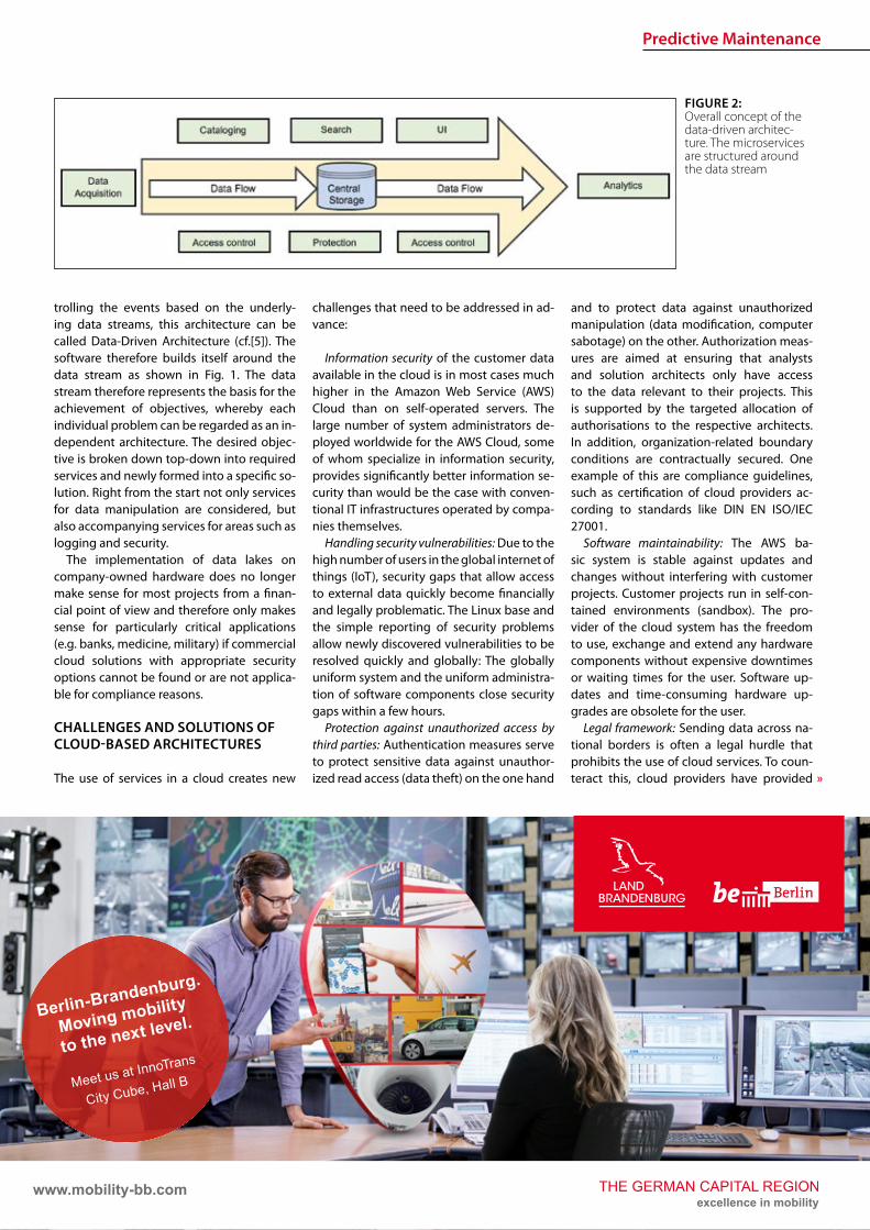
Predictive Maintenance
raquo
trolling the events based on the underly-ing data streams this architecture can be called Data-Driven Architecture (cf[5]) The software therefore builds itself around the data stream as shown in Fig 1 The data stream therefore represents the basis for the achievement of objectives whereby each individual problem can be regarded as an in-dependent architecture The desired objec-tive is broken down top-down into required services and newly formed into a specic so-lution Right from the start not only services for data manipulation are considered but also accompanying services for areas such as logging and security
The implementation of data lakes on company-owned hardware does no longer make sense for most projects from a nan-cial point of view and therefore only makes sense for particularly critical applications (eg banks medicine military) if commercial cloud solutions with appropriate security options cannot be found or are not applica-ble for compliance reasons
CHALLENGES AND SOLUTIONS OF CLOUD-BASED ARCHITECTURES
The use of services in a cloud creates new
challenges that need to be addressed in ad-vance
Information security of the customer data available in the cloud is in most cases much higher in the Amazon Web Service (AWS) Cloud than on self-operated servers The large number of system administrators de-ployed worldwide for the AWS Cloud some of whom specialize in information security provides signicantly better information se-curity than would be the case with conven-tional IT infrastructures operated by compa-nies themselves
Handling security vulnerabilities Due to the high number of users in the global internet of things (IoT) security gaps that allow access to external data quickly become nancially and legally problematic The Linux base and the simple reporting of security problems allow newly discovered vulnerabilities to be resolved quickly and globally The globally uniform system and the uniform administra-tion of software components close security gaps within a few hours
Protection against unauthorized access by third parties Authentication measures serve to protect sensitive data against unauthor-ized read access (data theft) on the one hand
and to protect data against unauthorized manipulation (data modication computer sabotage) on the other Authorization meas-ures are aimed at ensuring that analysts and solution architects only have access to the data relevant to their projects This is supported by the targeted allocation of authorisations to the respective architects In addition organization-related boundary conditions are contractually secured One example of this are compliance guidelines such as certication of cloud providers ac-cording to standards like DIN EN ISOIEC 27001
Software maintainability The AWS ba-sic system is stable against updates and changes without interfering with customer projects Customer projects run in self-con-tained environments (sandbox) The pro-vider of the cloud system has the freedom to use exchange and extend any hardware components without expensive downtimes or waiting times for the user Software up-dates and time-consuming hardware up-grades are obsolete for the user
Legal framework Sending data across na-tional borders is often a legal hurdle that prohibits the use of cloud services To coun-teract this cloud providers have provided
FIGURE 2 Overall concept of the data-driven architec-ture The microservices are structured around the data stream
wwwmobility-bbcom
Berlin-Brandenburg
Moving mobility
to the next level
Meet us at InnoTrans
City Cube Hall B
210x99_VML_InnoTrans_eng_ETRindd 1 19072018 081118
Predictive Maintenance
18 ETR | INTERNATIONAL EDITION | 22018 wwweurailpressdeetr
for the possibility of binding to regions that ensure that data does not leave certain pre-dened regions
Calculability of costs An AWS solution is about 90 cheaper than the operation of ldquoclassicrdquo infrastructures This value is also evi-dent in one of our customer projects where about 98 of the costs were saved on the development system and the eective sav-ings for the live system were interpolated to be at about 91 AWS provides a billing calculator that provides an estimate based on past months and previous monthly costs
SAMPLE IMPLEMENTATION STEPS FOR AMAZON WEB SERVICES
As an example implementation of a data lake the cloud environment AWS was used as described below During implementation four functionalities were clearly separated which are described in more detail below
rarr Data acquisition including pre-process-ing (ingestion)
rarr central data storage rarr Cataloging of data rarr Preparation of concrete analyses
DATA ACQUISITION (DATA INPUT) FOR DISTRIBUTED DATA SOURCES
In order to be able to ingest sensor data from vehicle eets the receiving system must be able to accept and store a large number of distinct data from many sensors On the senderrsquos side however data must be collected buered and regularly transmit-ted to the Data Lake To do this a periodic Internet connection must be ensured For
the frequency of data transfer an individual taring between the local data collection and the frequency of synchronization to the cloud must also be found Data transfers at low bandwidth should preferably rely on the collection of several data sets and trans-fer with a stable connection However this requires more memory in the local device With higher bandwidth and stable connec-tions the data can also be transferred more frequently This on the other hand leads to an increased load on the receiver A project-specic optimum must be found here
Finally it should be taken into account that the order of data sets should already be de-ned during ingestion even if the structure does not have to be xed from the outset To simplify later evaluations considerably data of the same type for which the uniformity is to be foreseen should be grouped logically This unies the data accesses of the evaluat-ing processes and thus minimizes the eort
From a specic project of a customer we know that the current data load of 6754 MBh will increase tenfold by 2020 due to an increase in the number of equipped vehicles and a simultaneous tripling of the number of sensors to approx 2GBh The distribution of the eets is Europe-wide with the focus on Central Europe
CENTRAL DATA STORAGE
In order to eciently persist the collected sensor data of vehicle eets the receiving system stores the data in a central location In AWS data is stored centrally in any size and in an automatically growing storage unit a so-called bucket The data is stored in ob-jects a logical data unit comparable to les in a classic le system To make searching
through data easier the objects are indexed based on their specic prexes and opti-mized for fast access Since the implementa-tion is based on RESTful and therefore each data record transmitted by sensors sends a PUT request a new object is created for each data record This creates an immense num-ber of objects in the long term This is irrele-vant in terms of costs and storage space For an analysis based on large amounts of data with low reaction times however a catalog-ing of the data is still necessary
CATALOGUING FOR VARIOUS APPLICATIONS
The exible NoSQL database DynamoDB oers an optimal possibility to catalog data without having dened a schema and still get extremely fast access speeds A Dy-namoDB table has a primary key which con-sists of a partitioning key and an optional sort key The partitioning key determines the automatic partitioning of the table and should therefore be very well selected (see [9]) An entry also supports update com-mands DynamoDB oers a very exible memory which can be written and read in dierent ways
New data arriving in Simple Storage Ser-vice (S3) can be automatically analyzed as a trigger for cataloging and added to cor-responding catalogs Since the analyses are usually very individual a pipeline must be created so that the new data arriving in S3 can be processed This can be achieved with minimal eort using the Microservice Lamb-da which makes it possible to execute small programs in the AWS landscape without any further integration eort Optional lters can be set for the triggers so that dierent pre-xes start dierent lambda functions
rarr Read The respective lambda function receives the bucket and the object name of the newly arrived object and can ex-amine this import and the content ac-cording to previously dened criteria and extract the corresponding values
rarr Write This data can then be written to a DynamoDB table regardless of whether the data record already exists ie wheth-er it has to be updated or whether it is a new data record
This type of cataloging is the comparatively most complex but at the same time the ex-ibility exceeds that of other technologies by far The cost factor is also considerably lower here The costs for DynamoDB tables are cal-culated according to provisioned capacities for read and write accesses This is under-
FIGURE 3 Using cloud solutions brings new challenges
Predictive Maintenance
19ETR | INTERNATIONAL EDITION | 22018wwweurailpressdeetr
standable as an increase in capacity in the background is a real hardware replication This allows tables with costs of less than one euro per month for the minimum congura-tion and a separate table can be provided for each application case The requests for large amounts of data via the primary key or only a part of it can be retrieved extremely quickly whereby retrieval times in the low two-digit millisecond range are not uncommon
PREPARATION OF CONCRETE ANALYSES
The creation of analyses on the catalogued data is possible without great eort with the basis shown This is done in several consecu-tive steps
rarr Top-down analysis of the problem to be solved as there are various microservic-es for a wide variety of applications As a result individual use cases can be as-signed to the use cases
rarr Selection of suitable microservices De-pending on the target platform the ap-propriate microservices can be selected There are specic services that enable the further use of existing programs that work on relational databases for example Other microservices support machine learning or the visualization of complex interrelationships in informa-tive dashboards
rarr Bottom-up aggregation of specically congured microservices For this pur-pose services already congured for similar analyses can be reused or addi-tional instances with slightly modied conguration can be created
SUMMARY amp OUTLOOK
All in all Data Lakes oer an optimal solution from the initial setup of a collection of raw data from various sources without large upfront ef-fort or high costs to the data storage of many eets of dierent vehicles worldwide and the provision of data catalogs for various analyses of various kinds The collection of measure-ment data in persistent online data stores such as AWS buckets can be implemented within minutes and is operational from this point in time so that data can be collected and archived Even if no specic use cases are known at the time of implementation it is recommended to persist all data on low-cost cloud storage so that it is already available for possible evalua-tions at later points in time Since there is often no reason to process data without use cases favorable options for persistence of the data can be used To avoid vendor lock-in consider designing Data Lake to be adaptable to alter-native platforms Alternative options for data storage include the storage services of Google Cloud Services or Microsoft Azure Of course the use of a second service also doubles the total costs
References[1] Canalys (2017) Cloud service providersrsquo battle drives
the worldwide cloud infrastructure market up 42 in Q1 2017 httpswwwcanalyscomstaticpress_re-lease2017press-release-150517-cloud-service-providersE28099-battle-drives-worldwide-cloud-infrastructure-market-42_1pdf Palo Alto Shanghai Singapore and Reading (UK) Pressemit-teilung 15052017
[2] Amazon Web Services (2017) Building a Data Lake on AWS httpspagesawscloudcomrs112-TZM-766im-agesAWS_Data-Lake_eBookpdf 01112017
[3] Bundesministerium des Inneren (BMI) (2017) Polizeili-che Kriminalstatistik 2016 httpswwwbmibunddeSharedDocsdownloadsDEpublikationen2017pks-2016pdf Pressemitteilung 24042017
[4] Buschmann Frank and Christiane Loumlckenho eds (2000) Pattern-orientierte Softwarearchitektur ein Pat-tern-System 1 korr Nachdr Muumlnchen Addison-Wesley 2000
[5] Mahjourian Reza (2009) An Architectural Style for Data-Driven Systems Paper Gainesville FL 32611 USA httpswwwcsutexasedu~rezalesxpage-icsrpdf 22032009
[6] Tilkov Stefan (2009) REST und HTTP Einsatz der Ar-chitektur des Web fuumlr Integrationsszenarien 1 Au Hei-delberg dpunkt 2009 ISBN 9783898645836
[7] Hunkeler U H L Truong and A Stanford-Clark (2008) MQTT-S mdash A Publishsubscribe Protocol for Wireless Sensor Networks In Communication Systems Software and Middleware and Workshops 2008 COMSWARE 2008 3rd International Conference on 791ndash98 2008 httpsdoiorg101109COMSWA20084554519
[8] Manseld-Devine Steve (2016) DDoS Goes Main-stream How Headline-Grabbing Attacks Could Make This Threat an Organisationrsquos Biggest Nightmare Net-work Security 2016 no 11 (November 2016) 7ndash13 httpsdoiorg101016S1353-4858(16)30104-0
[9] Vyas Uchit (2014) DynamoDB Applied Design Patterns Birmingham United Kingdom Packt Publishing 2014
SAFERAILSYSTEMCOM
Guessing or GPR
bull GPR measurements and analysisbull Condition-based maintenance planningbull More than 25 years of working experience - worldwide
BIM
20 ETR | INTERNATIONAL EDITION | 22018 wwweurailpressdeetr
ABOUT SIEMENS MOBILITYrsquoS TURNKEY RAIL SOLUTIONS BUSINESS
Siemens AG is a global technology power-house that has stood for engineering ex-cellence innovation quality reliability and internationality for more than 170 years The company is a pioneer in supplying in-frastructure solutions Siemens Mobility is an experienced provider of complete turn-key solutions for rail systems having already carried out more than 50 various and major rail projects worldwide The organization is home to experts in project management and system integration as well as key prod-ucts of rail infrastructure These specialists develop and implement projects for all types of rail vehicle systems from metros trams and light rail vehicles and automated peo-ple-movers to Intercity and high-speed train units ndash all designed for maximum reliability availability and eciency
THE CHALLENGES OF RAIL INFRASTRUCTURE PROJECTS
Projects to install new rail infrastructure and expand existing systems are growing steadily more complex The rising number of project participants and stakeholders presenting a broad range of specic require-ments planning teams in dierent locations and time zones having to coordinate and
Digital twin serving rail infrastructure How turnkey rail infrastructure projects are beneting from applying Building Information Modeling (BIM) how Siemens Mobility is pursuing virtual planning of projects with project partners and custom-ers such as in the Riyadh Metro Project and what added value this methodology is creating
integrate their civil and rail engineering and planning and the ever increasing time and cost pressures exemplify this problematic complexity
There are an enormous number of inter-faces and requirements involved especially in large rail infrastructure projects and or-ganizing them demands extensive resources and absolute precision
AT THE VANGUARD OF DIGITAL PLANNING
Just as countless other sectors of the con-struction industry have already experienced digitalization is driving a para-digm shift in rail infrastructure away from analog meth-ods and embrac-ing digital and in-tegrated planning encompassing eve-rything from erec-tion planning installation and support for training to preparation and performance of repairs and maintenance all based on digital processes and data models
More than four years ago Siemens Mo-bility began applying building information modeling (BIM) techniques as well to project planning and execution of complete turnkey
solutions for rail systems As one of the trail-blazers of digitalization Siemens Mobility uses BIM to create a digital twin ndash a virtual model of major rail projects planned for im-plementation
This methodology focuses on achieving cost and time eciency while also ensuring the highest quality standards
Siemens Mobilityrsquos Turnkey Rail Solutions is using BIM in col-laboration with construction part-ners to optimize project planning and execution This involves the use of computer-generated 3D modeling and the
information integrated into or linked with the models
REFERENCE PROJECT RIYADH METRO
The Arriyadh Development Authority (ADA) ndash the executive arm of The High Commission
Both the implementing company and customer benet from the reduced risk of delays in planning as well as the prevention of defec-tive planning and resultant need to revise planning during ongoing installation
Dr Payam AminiHead of Digital Transformation Turnkey Projects amp Electrication Siemens Mobility Munich payamaminisiemenscom
A simulated view of the outside of the depot for which the path of sunlight can be simulated over time
raquo
BIM
21ETR | INTERNATIONAL EDITION | 22018wwweurailpressdeetr
for the Development of Arriyadh in Saudi Arabia ndash is currently building one of the larg-est metro projects in the world with six rail lines totaling 176 kilometers in length The system will be the backbone of the public rapid transit network serving Saudi Arabiarsquos capital city The order placed with Siemens Mobility covers supply of 67 Riyadh Metro model rail vehicles based on the Inspiro Plat-form series line electrication the signaling and communication systems for driverless service on Lines 1 and 2 as well as system integration and project management Sie-mens Mobility is part of the BACS consor-tium led by US company Bechtel along with Almabani General Contractors and Consoli-dated Contractors Company
The Riyadh Metro Project (RMP) kicked o by dening the information requirements and project-specic BIM objectives of the customer The BIM management team of Siemens Mobilityrsquos construction partner Be-chtel then used this information as the basis for elaborating in detail the BIM process for all project participants
The BIM execution plan that denes the BIM process for a specic project basi-cally provides the answers to the agreed require-ments In this key central document Turnkey Rail Solu-tions dened for all project participants in-volved in the infrastructure design the roles and scopes of responsibility the programs and le formats to be used what applica-tions are to be integrated into the BIM pro-cess the data-exchange process along the chain of project phases the quality review inspection and testing criteria procedures for coordination and collaboration and much more This was necessary in order to ensure smooth BIM implementation over the entire project cycle
Siemens Mobilityrsquos construction partner also generated the model element plan which denes in an overview who is to gen-erate what model content for the project by when and to what level of development (ie geometry information and coordination) In this project BIM standard the construc-tion partner also dened the details for modeling agreements and documentation standards
Model-based planning is one of the pro-jectrsquos centerpieces enabling comprehensive integration of all rail infrastructure systems such as rail electrication the depot and workshop equipment line signaling and communication technology and platform screen doors
CLARITY DRIVES THE EFFICIENCY OF WORKFLOWS
Siemens Mobilityrsquos infrastructure planning engineers used project-specic BIM software to share their model-based information with Siemens Mobilityrsquos suppliers and the con-
struction partner The program Pro-jectWise is used in combination with Aconex served and continues to
serve as a shared data platform accessible project-wide ensuring that each piece of information is retained only once and in its most recently valid version In this ldquosingle source of truthrdquo data are referenced rather than duplicated signicantly improving in-formation management increasing the reli-ability of data and eliminating any use of superseded obsolete data This provides full trans-parency for all pro-ject participants Photo-realistic displays and animated videos of the planning progress generated on the basis of the 3D planning information ensure transparency enhance understanding and support the iterative process
The permanent availability of data accel-erates collaboration across national borders and company boundaries These aspects are particularly benecial in the RMP Just Sie-mens Mobilityrsquos unit alone had colleagues based in 13 dierent cities working to de-sign the rail infrastructure coordinating and agreeing across national boundaries and dierent languages time zones and work capacities
In addition to the geometrical properties
of system components for example of fre-quency converters the participating plan-ning engineers also integrated non-geomet-rical information and requirements of their systems such as zones and clearance spaces that are essential for installation and mainte-nance Once work on a subarea of a model (work in progress) was approved for release this information was then available to all partners within the project (shared areas) In turn these partners reviewed the completed work for impacts on their own work scopes
In interdisciplinary collision reviews the design coordinators conducted collision tests with all other draft components Such reviews examined for example the civil struc-tures technical building equipment systems and Siemens Mobilityrsquos systems such as the signaling equipment and traction power supply grid to identify any conicts between
the systems them-selves or with the civil structures
In this way structural imple-mentation of the overall project as
well as individual subareas can be digitally tested at any time
As a provider of turnkey infrastructure solutions Siemens Mobilityrsquos unit was in-volved early in the RMP through BIM help-ing to prevent planning errors and leading to quicker validation of draft planning such as for spatial requirements of infrastructure equipment free clearance proles and pre-venting collisions
The RMP oers a basis for further infra-structure projects using BIM methodology The stock of digital objects available in the component library continues to grow Exist-ing digitally modeled components can be directly used for the next digital twin This
BIM creates full transparency for everyone participating in the plan-ning of infrastructure projects
The Control Center of the Riyadh Metro Project for Line 1 was fully planned digitally Once that design process was completed actual construction started
BIM enables earlier design valida-tion of rail infrastructure technol-ogy and engineering as well as civil construction
BIM
22 ETR | INTERNATIONAL EDITION | 22018 wwweurailpressdeetr
accelerates digital planning from one pro-ject to the next
Siemens Mobility Turnkey Rail Solutions sees particular potential for BIM in integrating the necessary man-agement process-es BIM supports the management of interfaces requirements congurations and project documentation This improved management leads to accelerated project execution And although project execution in Riyadh is still underway the added value created by the BIM method is already clearly evident today ndash for both Siemens Mobility and the customer
DIGITAL SCAN OF THE INFRASTRUCTURE CREATED
Siemens Mobility Turnkey Rail Solutions is utilizing other digital solutions as well for the Riyadh Metro Project that further optimize pro-ject execution Siemens Mobility-owned track measuring vehicles and 3D laser scanners are deployed to eciently compare the progress
of as-built construction and installation against the design target data These units travel along the existing sections scanning and thereby
digitalizing the as-built environment The object-specic information collect-ed by this measur-ing system whether on track position-
ing platform edges or technical spaces is com-pared with the digital design thereby directly revealing any deviations from planning
This produces a 100 -accurate database of the existing as-built status Particularly when projects aim to expand exist-ing infrastructure such transparency prevents costly conicts when equipping existing civil structures with new infrastructure equip-ment Besides the hardware procurement Siemens Mobility is banking in this context on developing the expertise of its own per-sonnel to cover planning of measuring cam-paigns kinematic and static imaging and evaluations such as review for collisions
PROMISING OUTLOOK
Siemens Mobilityrsquos Turnkey Rail Solutions has ceaselessly invested in implementing and further developing digital methods to keep pace with steadily growing deadline and cost pressures and the increasingly stringent demands of complex rail infra-structure projects These efforts are now empowering Siemens Mobility to better assess the sometimes extremely demand-ing detailed requirements early already in the project bidding phase and estimate costs more reliably thereby minimizing risks
In previous projects utilizing BIM meth-odology Siemens Mobilityrsquo experts identi-ed a shifting of eort into the early project phases
Siemens Mobilityrsquo experts see opportuni-ties in doing so particularly in the assess-ment of design modications in terms of im-pacts on costs and in early application when the leverage for such optimization can still prove very eective
Yet BIM doesnrsquot end when construction work on an infra-structure project has been complet-ed By developing a digital twin of the as-built infrastruc-ture and applying
that model over its entire lifecycle these sets of digital data can be used to optimize asset management
The BIM method harbors major potential for signicantly shaping the rail infrastruc-ture sector in the coming years
A view of the digital model of the King Abdullah Financial District Station on Line 1 which can be viewed in the computer pro-gram from all sides
Photo-realistic displays and animat-ed videos of the planning progress ensure transparency and enhance understanding
BIM provides the basis for simpler and ecient interface management and contributes signicantly to accelerating project execution
5 | 2017 Mai wwweurailpressdesd
109 Jahrgang
SIGNALLING amp DATACOMMUNICATION
Oumlsterreich Gut gesichertAustria Well-protected
13 Kostenguumlnstige Sicherung von Eisenbahnkreuzungen Cost-effective protection of level crossings
36 Finnland Gegen den Instandhaltungsruumlckstand Finland Reducing maintenance backlog
21 Schweiz Weltpremiere auf der Toumlsstalstrecke Switzerland A world premiere on the Toumlsstal line
Your contact person Silvia Sander +4940237 14-171 silviasanderdvvmediacom wwweurailpressde
Leader in Signalling and Datacommunication
No 1ad medium
SIGNALLING AND
DATACOMMUNICATION
AUTONOMOUS DRIVING
CYBE
R SE
CURI
TY
LEVEL CROSSING TECHNOLOGY
OPERATIONS MANAGEMENT SYSTEMS
MOBILE COMMUNICATIONETCS
REPUTABLE
UN
IQU
E
ESTABLISHEDTELECOMMUNICATION
OPERATIONS CONTROL TECHNOLOGY
INFORMATION TECHNOLOGYBILINGUAL
Book your advert right now
raquo
Ground Penetrating Radar
23ETR | INTERNATIONAL EDITION | 22018wwweurailpressdeetr
1 INTRODUCTION
Many countries allocate large amounts for the modernization and upgrading of their railway networks in order to meet the de-mands of increasingly dense rail trac with higher axle loads at ever higher speeds However this can only be achieved if all rel-evant key gures and geotechnical condi-
Ground Penetrating Radar ndash Basis for eective Track MaintenanceThis article describes the capabilities and functionality of Ground Penetrating Radar (GPR) for higher speeds GPR is a train-borne technology for a continuous inspection of the geotechnical conditions of railway tracks The basic principles of the GPR technology are explained with particular reference to all relevant railway specic tasks namely the identication qualication and quantication of ballast fouling by using a fouling index the determination of the quality of track drainage and its quantication through a drainage index and the calculation of the track modulus (TM) Special emphasis in the context of GPR investigations is placed on the mapping of sections with clay foulingmud spots inside the ballast bed or at its base and respectively inside intermediate layer formation or subsoil In the past such weak-spots have caused derailment they could represent a risk for rail-trac [11 13 14 15 16] Besides their late detection implies exceedingly high maintenance costs
tions of the respective tracks can be reliably evaluated On this basis only the necessary investments in track maintenance moderni-zation and support can be dened in the ap-propriate size and can be placed correctly This is particularly true when budgets are tight
The demands exerted on the track in terms of safety grow with increasing speed
FIGURE 1a) Trajectories of radar waves which are reected at the layer boundary between two media
with dierent dielectric constant (laquo)b) Due to the dierent travel time of the reections the layer boundary is reproduced in the
radargram (reference Ground Control and IEV)
Dipl-Geophys Giuseppe StacconeDirector of Ground Control GmbH MunichGermanystacconesaferailsystemcom
David Camacho MScDoktorand am Institut fuumlr Eisen-bahn- und Verkehrswesen der Universitaumlt Stuttgart (IEV)davidcamacho ievvwiuni-stuttgartde
Moritz SchebuchMitarbeiter am Institut fuumlr Eisen-bahn- und Verkehrswesen der Universitaumlt Stuttgart (IEV)moritzschebuch ievvwiuni-stuttgartde
Prof Dr-Ing Ullrich MartinDirektor des Instituts fuumlr Eisenbahn- und Verkehrswesen der Universitaumlt Stuttgart (IEV) und des Verkehrswis-senschaftlichen Instituts an der Universitaumlt Stuttgart eV (VWI eV)ullrichmartin ievvwiuni-stuttgartde
Dipl-Ing Sebastian RappAkademischer Mitarbeiter am Institut fuumlr Eisenbahn- und Verkehrswesen der Universitaumlt Stuttgart (IEV)sebastianrapp ievvwiuni-stuttgartde
Ground Penetrating Radar
24 ETR | INTERNATIONAL EDITION | 22018 wwweurailpressdeetr
Therefore failing to detect track damages or obtaining inadequate information on track damages represents a hazard for every kind of railway trac For this reason a decision guidance that facilitates a systematic and ecient renewal of the tracks is important The more intensive the rail trac and the higher the trac speed the bigger the re-quirements in terms of an ecient and reli-able track inspection
The mapping of clay fouling or mud sec-tions is of special importance Fine-grained soil material such as silt or clay wells up from the formation and reaches the ballast base or even penetrates the ballast layer itself As a consequence track drainage and track stability (ie bearing capacity) are strongly reduced This results in lasting deformations that require complex maintenance work and high costs If weak-spots are not identied or not detected in time clay fouling can in the worst case scenario lead to derailment [10 13 14 15 16]
During the past 25 years Ground Control GmbH which is placed in Munich Germany has surveyed more than 100000 km of rail-way tracks in many countries in Europe and all over the world Recently with information obtained from GPR results and other data (ie track geometry and track dynamics) a continuous and complete assessment of the trackrsquos structural condition is possible
2 MEASURING PROCESS
The GPR method is an electromagnetic re-ection method Radar pulses are transmit-ted into the subsoil by a transmitter antenna The energy of the electromagnetic waves is partly reected at interfaces between layers with dierent dielectric properties and re-transmitted to the receiver antenna Based on the measured travel time of the signals and knowing the propagation speed of the waves in the medium depth and surface of the layer can be computed
In order to dene the depth of the re-ector from the surveyed travel time the propagation speed of the radar waves in the subsoil has to be determined The speed of electromagnetic waves in the subsoil is re-lated to the water content of the individual material Therefore it is generally not pos-sible to refer to reference values for certain rock or soil types Thus the radar wave speed has to be calibrated for each project area
The penetration of electromagnetic waves mainly depends on the electric conductivity of the soil and the applied antenna frequen-cy By using low frequency antennae on low conductive subsoil the largest investigation depth can be achieved
PERFORMING SURVEYS WITH MODERN HIGH-SPEED-GPR
Todayrsquos GPR surveys are carried out with train mounted systems at speeds up to 160 kmh As a general rule the antennae system is fastened at the carrier vehiclersquos buers A precise positioning is achieved by an inte-grated Dierential Global Positioning Sys-tem (DGPS) and Doppler radar
The characteristics of modern GPR sys-tems are
rarr The equipment can be installed and run on a wide range of track-bound vehicles (including regular trains or vehicles on Hy-Rail)
rarr They are fast enough to be integrated into the regular trac schedule Hence expensive track closure is no longer nec-essary
rarr DGPS and Doppler radar are used for an accurate (ie precision within a meter) positioning of the antenna independ-ent of the speed and length of the track surveyed
rarr Measurement data resolution and data quality are equally high no matter what length and what speed
rarr All GPR components are eectively
shielded against interferences from sig-nalling and communication systems
3 GPR TASKS
In contrast with punctual boreholes and trenches modern GPR systems provide con-tinuous information about the geotechnical condition of the track performing the fol-lowing tasks
rarr Continuous mapping of track-bed-thick-ness and layers below (ie intermediate layer protective layers)
rarr Distinction between clean and fouled ballast and calculation of Fouling Index
rarr Mapping of mud spots or clay fouling sections inside ballast bed at its base or inside substructure layers respectively
rarr Detection of sections with drainage problems and calculation of ldquoWet Bed Indexrdquo
rarr Mapping of areas with insucient bearing capacity (eg settlements) and evaluation of the dynamics of track set-tlement
rarr Control and evaluation of the quality of maintenancerenewalconstruction work (quality of cleaned or exchanged ballast thickness of a new ballast bed quality and thickness of soil layers)
rarr Estimation of track condition based on track modulus (TM) calculation
Additionally GPR data allow for the deni-tion of a sustainable cause-based and there-fore eective track renewal recommenda-tions and programs Optionally GPR oers the possibility to accurately map cables pipes and other objects in the track sub-structure creating the possibility to provide a complete picture of the entire system
31 CLAY FOULING ndash STRONG EFFECT ON TRACK STABILITY
Clay Fouling is one of the main reasons for the reduction of the load bearing capacity of the track in a relatively short period of time Several derailments in the past were caused by mud spots [10 13 14 15 16] even when the limit values for track geometry failures according to [2] have not been exceeded [13 14] It is therefore and because of safety reasons of particular importance to detect clay fouling areas reliably in their precise dimension and as early as possible The rec-ognition of the problem should be irrespec-tive of whether the clay fouling exists in the substructure at the base of the ballast bed or in the ballast bed itself Clay fouling can
FIGURE 2 Figure 2 Antenna mounted on the train buers of a mainte-nance vehicle(reference Ground Control)
Ground Penetrating Radar
25ETR | INTERNATIONAL EDITION | 22018wwweurailpressdeetr
raquo
rapidly deteriorate the stiness of the track and its quality The trackrsquos lateral stability is massively reduced longitudinal errors along the rails arise
Clay fouling is also a serious decit from an economic point of view Its timely iden-tication allows for avoiding slow speed sections thus sparing time and money for maintenance procedures Detecting clay fouling before it reaches the ballast bed ena-bles cost eective renewal Otherwise it will be very expensive There is no option for bal-last cleaning a suciently compacted pro-tection layer built of the appropriate materi-al is essential the installation of composites does not prevent clay fouling from entering the ballast bed (see Fig 3)
Save few exceptions clay fouling spots are not visible at the track surface and since drill-ings and trenches do only provide punctual results reliable information is only achievable through GPR measurements (see Fig 4)
A frequency analysis of the measured data results in a typical change of the signal spectrum in the area of clay fouling Based on the GPR results borehole program can be implemented which can be used for further analysis GPR surveys to detect ballast foul-ing have been carried out for years in Swit-zerland Austria the Netherlands and France among others
32 TRACK MODULUS (TM)
Examining the geotechnical conditions of railway tracks requires an index which in-forms about state and quality of the tracks in a quantitative manner The challenge has
been to dene the track condition continu-ously This has been achieved by combin-ing TM with the results of continuous GPR-measurements
It is possible based on [3 4 5 6 7] to es-timate quality and bearing capacity of the railway track Therefore the TM describes the relation between vertical load and elas-tic deection of the sleeper-bearings
On the one hand the TM can be calculated based on the measured deection under load [18 20] on the other hand according to the soil properties [8 9 11] The measuring principle for determining the load deec-tion is described in detail in [12] and [17] The properties of the system components such as the area of inuence of the sleepers under load can greatly aect the TM Hence around turnouts the area of inuence of sleepers deviates from the standard track This is because an increased area of inu-ence causes an increase in the distribution of the load reducing the deection of the
rail Notwithstanding to simplify the calcula-tion of the TM the inuence area of sleepers around turnouts are assumed to be constant assuming the values of the standard track Depending on the type of sleepers installed the value of the TM can increase sharply around turnouts (Fig 5) In addition cavities under the sleepers increase the deection of the track under load which in turn inu-ences the calculation of the TM decreasing its value
An additional and new approach for calcu-lating the TM is based upon the soil proper-ties which can be described by the Poissonrsquos Ratio or the material density of the soil The soil properties derive from the GPR data This methodrsquos advantage is to be completely in-dependent from superstructure conditions The individual layers are assigned soil values according to condition and bulk density Averaged soil properties are calculated ac-cording to [1 19] The TM can be estimated according to [9] and [11] Previous studies
FIGURE 4 Visual analysis of GPR data depicting clay fouling along a track (reference Ground Control and IEV)
FIGURE 3 Geotextile or composite does not stop ne particle migration to the surface (reference Ground Control)
Ground Penetrating Radar
26 ETR | INTERNATIONAL EDITION | 22018 wwweurailpressdeetr
indicate that this method has signicantly lower value variations along the track axis compared to the approach based on the use of track displacement data (Figure 5)
The example in Fig 5 shows two track moduli based on the measured displacement under load (red line) and the soil properties (blue line) Around the turnouts a signicant increase of the TM is visible if the calculation is based on the measured deection By divid-ing the TM into quality classes according to [3 4 5 6 7] the condition of the track can be sat-isfactorily estimated (Fig 6)
33 TRACK ANALYZER ndash CONTINUOUS PRESENTATION OF ALL MEASUREMENT AND TEST RESULTS
Results from GPR surveys along with all identied soil parameters and indices cal-
culated can be displayed in comprehensive track analysis software called ldquoTrack Analyz-errdquo In order to provide all information for in-frastructure managers track geometry and track dynamics data are also integrated and displayed in the software (see Fig 7) which also oers the exibility to incorporate other tasks and aspects as required by the user
The Track Analyzer provides infrastructure managers continuous information about the geotechnical conditions of the track with regard to all relevant issues Moreover it provides a better understanding of the sub-structuresubgrade conditions and their in-uence on the superstructure This allows for a signicantly increased track quality pro-viding higher route availability and safety
A big advantage of the GPR method is the minimization of the need for intensive direct outcropping (probing drilling scooping)
to characterize the underlying geotechni-cal characteristics of the track substructuresubgrade which results in signicant cost reductions
4 SUMMARY
This paper describes a modern train-borne technology for the inspection of the geo-technical conditions of railway tracks It is based on High Speed GPR and on classical procedures for providing continuous infor-mation about geotechnical parameters and indices A new quality of GPR measurements is to provide quantitative indices in addition to qualitative results to full the require-ments of the railway engineers in the best possible way
Special attention is paid to the detection of mud spots and clay fouling sections as a risk for derailment [10 13 14 15 16] To date track inspection with GPR is more appropri-ate than any other inspection method to de-tect map and qualify areas with geotechni-cal problems
The Track Analyzer software combines GPR results with track geometry and track dynamics data This allows for cause-based track renewal and targeted investment and provides signicantly more reliable results than conventional methods This approach is especially relevant for limited budgets
Literature [1] Adam D Kopf F Dynamische Eekte durch bewegte
Lasten auf Fahrwegen In Bauingenieur Ausgabe 01-2003 2003
FIGURE 5 TM calculated from measured displacement under load (red graph) and soil proper-ties (blue graph) (reference IEV)
FIGURE 6 TM divided in dierent quality classes (reference IEV)
Ground Penetrating Radar
27ETR | INTERNATIONAL EDITION | 22018wwweurailpressdeetr
FIGURE 7 Track Analyzer(reference Ground Control)
[2] DB Netz AG Ril 821 Oberbau inspizieren Deutsche Bahn AG guumlltig ab 01052004
[3] Eisenmann J Stuumltzpunktelastizitaumlt bei einer Festen Fahrbahn In ZEV + DET Glasers Analen 111999
[4] Fendrich L (Hrsg) Handbuch Eisenbahninfrastruktur Springer-Verlag Berlin Heidelberg 2007
[5] Goumlbel C Lieberenz K (Hrsg) Handbuch Erdbau-werke der Bahnen DVV Media Group GmbH 2013
[6] Leykauf G Lothar M Elastisches Verformungsver-halten des Eisenbahnoberbaus ndash Eigenschaften und Anforderungen In EI ndash Eisenbahningenieur 031990
[7] Lichtberger B Handbuch Gleis DVV Media Group GmbH 2010
[8] Martin U Rapp S Ansatz zur Erfassung der Bodenei-genschaften am Bahnkoumlrper in Schotterbauweise In ETR ndash Eisenbahntechnische Rundschau 042017
[9] Martin U Rapp S Camacho D Moormann C Lehn J Prakaso P Abschaumltzung der Untergrundverhaumllt-nisse am Bahnkoumlrper anhand des Bettungsmoduls In ETR - Eisenbahntechnische Rundschau 052016
[10] Rail Accident Investigation Branch Freight train de-railment near Gloucester 15 October 2013 Rail Acci-dent Report102014
[11] Rapp S Modell zur Identizierung von punktuel-len Instabilitaumlten am Bahnkoumlrper in konventioneller Schotterbauweise Dissertation ndash Institut fuumlr Eisen-bahn- und Verkehrswesen der Universitaumlt Stuttgart 072017
[12] Soldati G Meier M Zurkirchen M Kontinuierliche Messung der Gleiseinsenkung mit 20 t Achslast In EI ndash Eisenbahningenieur 022016
[13] Untersuchungszentrale der Eisenbahn-Unfalluntersu-chungsstelle des Bundes Untersuchungsbericht Ak-tenzeichen 60 ndash 60uu2011-0200041 Zugentgleisung Groumlbers ndash Groszligkugel 062013
[14] Untersuchungszentrale der Eisenbahn-Unfalluntersu-chungsstelle des Bundes Untersuchungsbericht Ak-tenzeichen 60uu2013-06047-3323 Zugentgleisung Kaub ndash Lorch (Rhein) 062013
[15] Untersuchungszentrale der Eisenbahn-Unfalluntersu-chungsstelle des Bundes Untersuchungsbericht Ak-tenzeichen 60 ndash 60uu2011-0400043 Zugentgleisung Bf Hannover ndash Linden 092013
[16] Versa Verkehrssicherheitsarbeit fuumlr Oumlsterreich Unter-suchungsbericht Sicherheitsuntersuchungsstelle des Bundes BMVIT-795336-IVBAVUUBSCH2013 Ent-gleisung eines Guumlterzugs am 14 Februar 2013 2013
[17] Wang P Wang L Chen R Xu J Overview and out-look on railway track stiness measurement Jour-nal of Modern Transportation Volume 24 Issue 2 062016
[18] Winkler E Die Lehre von der Elastizitaumlt und Festigkeit Verlag von H Dominicus 1967
[19] Wolf J P Foundation Vibration Analysis using Simple Physical Models Swiss Federal Institute of Technology 1994
[20] Zimmermann H Die Berechnung des Eisenbahn-oberbaus 1888
wwwrex-industrie-produktede
INSULATING JACKETS FORHIGH TEMPERATURE INSULATION
high temperature resistant up to 1000degC
incombustible
high insulation performance
tailor made according to your wishes
New test reports for fire protection according to EN 45545-2 available R1R7R17 with Hazard Level HL 3
Distributed Acoustic Sensing
28 ETR | INTERNATIONAL EDITION | 22018 wwweurailpressdeetr
Dip-Ing FH MScMartin RosenbergerCTO Frauscher Sensor Technology martinrosenberger frauschercom
This involves planning and controlling maintenance measures based on the actual condition of the equipment systems and components (assets) Unexpected events due to faulty components and unnecessary work on fully intact elements can thus be reduced This is possible thanks to the ever increasing amount of reliable data about the condition of the asset that is available in real time
Continuous acoustic condition monitor-ing of the infrastructure based on Distribut-ed Acoustic Sensing (DAS) is a key building block of future solutions This technology can considerably increase the availability of rail networks since it continuously delivers very precise information about the condi-tion of the infrastructure and any changes thereby fullling a key prerequisite for the use of CBM solutions
The sensor technology and inspections form and remain the basis for condition-based maintenance of the track These in-clude track recording vehicles xed meas-urement points sensor technology on
How Distributed Acoustic Sensing supports condition based maintenance strategiesCurrent technological developments are opening up new opportunities for the railway industry in a whole range of application areas Most notably these include networking digitalization and the Inter-net of Things (IoT) This trend is also having a growing impact on processes and strategies for maintain-ing rolling stock and infrastructure Traditional maintenance philosophies which are based on xed intervals or in the case of vehicles on mileage are increasingly being replaced by predictive condition based maintenance (CBM)
standard trains track-side sensor technol-ogy selectively deployed manual measur-ing instruments and self-monitoring infra-structure systems Data from these sources must be consolidated and if applicable combined with information about rolling stock and system-side infrastructure data such as a system directory or inputs from other sensors
DAS enables a sensor solution to be cre-ated which fulls several of the specied re-quirements this technology allows railway networks to be monitored continuously in real time and with respect to a huge num-ber of dierent events Frauscher has devel-oped its own DAS solution for the railway sector Frauscher Tracking Solutions FTS The manufacturerrsquos team tested the tech-nology and through intensive develop-ment eliminated constraints with respect to use for rail trac To create this in-depth knowledge of DAS as well as requirements and standards in the railway industry was required
1 DAS FUNCTIONAL PRINCIPLE
DAS-based systems use laser pulses sent in a glass bre to detect events on or in the vicinity of the track part of the laser pulse is reected back out of the bre to the transmitting unit The sound and vibration waves impacting on the cable result in signicant shifts in the reection (Fig 1) The maximum frequency range of the vibrations detected in this man-ner is 125 kHz Using specically developed algorithms the acquired data can be used to calculate specic signatures in real time These describe highly precise locations and types of processes in the vicinity of the track
One of the advantages of installing a DAS system is that the bre optic cables it requires are often already laid next to the tracks These are normally used for commu-nication purposes As the optical bres used require practically no maintenance the sys-tem can be rolled out to large sections of the route extremely economically and ecient-ly In practice a single DAS unit can eective-ly cover up to 40 kilometres of glass bre in each direction so 80 kilometres in total [1]
2 CONTINUOUS MONITORING OF WHEEL-RAIL INTERACTION
The ongoing analysis of infrastructure us-ing FTS is based on continuous monitoring
FIG 1 Distributed Acoustic Sensing (DAS) allows for the detection of vibrations and sound waves caused by trains component defects people or other sources
raquo
Distributed Acoustic Sensing
29ETR | INTERNATIONAL EDITION | 22018wwweurailpressdeetr
of wheel-rail interaction (Fig 2) On the one hand this enables the detection of changes that arise slowly over the course of time To do so the system compares the relevant signatures that are captured each time a railway vehicle passes a spot On the other hand events that occur suddenly can also be reliably detected
21 TREND ANALYSIS FOR LOCALISATION OF CONDITION CHANGES
The wheel-rail interactions quality is the most important factor when it comes to the service life of both system components and the rolling stock This quality is derived from various parameters such as the roundness of the wheel the surface of the rail and the track design Even slight deviations from the ideal parameters result in increased signs of wear and tear over a certain amount of time Ultimately these can also lead to critical op-erating conditions Which is why continu-ous detection and thus early recognition of changes in condition along the entire route is extremely useful
This is where the FTS come into play by evaluating the signatures in the laser signal feedback it is possible to determine wheth-er a sp ecic anomaly in wheel-rail interac-tion comes from the train or from the infra-structure This is possible because the FTS system uses a glass bre as a permanent sen-sor along the track thus allowing the wheel-rail interaction for each individual axle on all train journeys to be permanently monitored along the entire route Changes are detected in real time and the method does not de-pend on a xed measurement point
If a notication is triggered by an out-of-round wheel for instance then this pattern will be part of the train signature and be de-tected in association with the moving train This allows the event to be clearly attributed to vehicle damage
By contrast if there is a change to the in-frastructure several axles will have a notice-able signature in one specic position The system uses this to determine an indicator Based on this trend analyses are formed for individual ten-metre long infrastruc-ture segments Warning or alarm notica-tions can now be created and transmitted through dened user-congured threshold values These indicate the type of change as well as the location With good georefer-encing for the bre optic cable the position identied via FTS can be localised to an accu-racy of up to ve metres and made available via machine-readable interfaces
Frauscher oers powerful interfaces for employees in railway infrastructure compa-
nies In particular these include a graphical user interface with map view and heat maps and depiction of the infrastructure condition in denable categories The zoom function can be used to display the entire route or a position with relevant localisation in route kilometres or GPS data the actual condition and the change in condition over a specic period Filters can be set for even more de-tailed analyses and evaluation
22 EVALUATION OF CHANGES IN CONDITION AS A PROCESS
To determine the relevance for a specic rail-way operation simply identifying a change in condition is not enough The trend analy-sis must also be correlated with the trains and their speeds After all identical techni-cal non-conformities will result in indicators with completely dierent frequencies and intensities when a heavy long freight train and when a lighter short passenger train travels over a position with a fault
Therefore a basic condition must rst be dened for the infrastructure and stored in the FTS The trend analyses can then be ap-plied to this To do so the system structure (primarily bridges tunnels or points) must be logged in the system and the sensor must be calibrated accordingly Data that needs to be entered includes rail joints or transitions from a point for example They create similar patterns to those of a rail defect but must be evaluated and examined dierently
It may also be necessary to lter out am-bient noise from stationary systems such as pumps and generators so that this does not have a negative eect on the detailed analy-sis of the wheel-rail interaction signature
These adjustments are currently carried out manually during the installation and com-missioning process However Frauscher is developing tools to automate these process-es These steps form part of the technologyrsquos path towards serial production
Once the basic condition has been dened then depending on the model the operator will receive regular reports or warning and alarm notications via dened interfaces The DAS systems that are currently available are not yet able to classify and quantify the changes detected with sucient accuracy Maintenance personal therefore take on the task of evaluating suspect positions through inspection actions during the development and installation phase A visual inspection is often enough to identify the cause of the warning classify the change and take the necessary action within a dened period
Based on experience with several installa-tions and Frauscherrsquos collaboration with op-erators there are essentially three relevant classications
rarr No detectable or only minimal damage rarr Non-critical damage rarr Critical damage
What is important is that this evaluation and classication is understood and followed as part and parcel of the maintenance process Dening the threshold values and deter-mining the sensitivity of the system is a key step in this regard Experienced specialist sta who evaluate and process the notica-tions can shape the system to suit their own needs This allows CBM concepts to be ap-plied even more eciently for practical sup-port and to build expertise (Fig 3)
The high sensitivity level of the system
FIG 2 By continuously monitoring the acoustic signature of the wheel-rail contact the FTS support condition based maintenance strategies
Distributed Acoustic Sensing
30 ETR | INTERNATIONAL EDITION | 22018 wwweurailpressdeetr
means that a range of errors can be detected at a very early stage However this also in-creases the risk that positions that are not relevant for maintenance will be displayed This is where empirical values are really needed so that the optimum setting can be tuned for the operator It is crucial to involve the maintenance personnel in this whether through the operator or the service contrac-tor After all only experts on the ground can evaluate the condition of the infrastructure and determine the necessary measures Maintenance employee experience thus re-mains essential for training the algorithms and evaluating the results the maintenance personnel must use their knowledge of routes and systems to determine whether a notication is in fact relevant or not
Not detectable or only minimal damageIn this case no maintenance measures are needed There are three main reasons why the system has indicated a potential fault in this case First there may be a structural fac-tor in the infrastructure or a factor in the en-vironment of the trigger In this case the in-uencing factor can be ltered out in future Secondly it could be that a visual inspection reveals no detectable fault but there are already signs of wear In this case the user
would add information to the system stating that this section is to be kept under observa-tion or specically monitored over a certain period of time ndash for example by adjusting the threshold value If the system contin-ues to exhibit a fault it is advisable to apply analysis methods that go beyond a visual inspection of this point or use other meas-urement data as a comparison Thirdly this could be due to a minor surface fault on the rail for example which does not require any action since scheduled surface processing measures are due to be carried out (Fig 4) In this case the fault message can be acknowl-edged
Non-critical damageIn this case the system has identied a rel-evant fault but it does not need to be cor-rected right away (Fig 5) The main advan-tage of this is that early detection allows the necessary measures to be planned in good time so these can be put into eect during quiet periods or eciently combined with other measures thus reducing the number of expensive individual activities
Critical damageIf such changes are detected then measures must be initiated immediately in order to re-
solve the safety-critical operating condition and minimise any expensive subsequent damage Experience shows that such critical conditions can develop over just a few days or can even be triggered by acute short-term factors Examples include ballast voids due to washout rail head cracks and broken rails
Critical conditions can arise during the analysis cycles even if the rail network is monitored regularly with track recording ve-hicles for example Continuous monitoring of the wheel-rail interaction enables quicker intervention and minimises personal injury and damage to property
23 EMPIRICAL RESULTS
In addition to various applications which can be used in real time on the basis of train lo-calisation over the last two years Frauscher has been taking a closer look at infrastruc-ture maintenance In particular at the po-tential that continuous monitoring of the wheel-rail interaction has to oer in the fol-lowing scenarios
rarr Rail monitoring rarr Rail fastening and sleeper monitoring rarr Track substructure and superstructure
monitoring
Practical application has shown that the data that can be provided via the FTS system al-ready oers a range of interesting options it helps users to plan and control maintenance measures in good time To do so Frauscher implements technology such as machine learning pattern recognition and articial
FIG 3 When developing advanced main-tenance solutions various levels within a railway network have to work together closely
FIG 4 Changes in the trackrsquos surface can be detected evaluated and considered when planning maintenance works
FIG 5 Detecting small defects allows for a targeted monitoring in order to generate alarms when their condition deteriorates
Distributed Acoustic Sensing
31ETR | INTERNATIONAL EDITION | 22018wwweurailpressdeetr
intelligence However in order to move to the next level a solid base of empirical val-ues and a library of signatures from a variety of sources of damage are needed
The company is working very closely with the operators of several installations select-ed from approximately 30 projects that are currently ongoing worldwide They are joint-ly considering the evaluation interpretation and derivation of measures Specic issues and ideas for further development of the evaluation software and logic are directly incorporated into Frauscherrsquos development processes using agile methods
Rail monitoringAll types of rail damage that cause vibrations or a noise spectrum that deviates from the norm are detected This ranges from surface damage such as rail corrugation squats rail head cracks wheel burns or corrosion and dents to cracking and ssuring or even bro-ken rails
Unsurprisingly the algorithm for detect-ing rail damage also detects rail joints After all the signature of a gap as in an isolation joint could be exactly the same as that for a break in part of the rail In this case depend-ing on requirements these rail joints can be suppressed or specically monitored with their own threshold values (Fig 6 7) The sensitive sensor system can detect broken rails as a train passes over them with high probability However due to the many dif-ferent forms and physical basic conditions a warning system with a 100 percent de-tection rate and zero error rate cannot be achieved
In addition there are still no empirical val-ues for broken rails which can be traced back to warping and thermal eects without the eect of the train Noises that arise due to warping (thermal popping) were detected during tests designed to identify and local-ise landslides and rock fall These are hard to classify or uniquely identify using the cur-rently available hardware and software It is to be assumed that a rail that breaks for thermal reasons generates a similar if more intensive signature and it is not possible to clearly distinguish this from the ldquothermal poprdquo
Therefore it is important to consider whether continuous monitoring of the tracks with appropriate trend analyses does not provide more information about the safety of the route than a warning system for broken rails Last but not least broken rails should generally be reduced by as-required maintenance measures
Rail fastening and sleeper monitoringIn several installations positions were de-
tected that exhibited increased vibration due to damaged or missing rail connections or broken sleepers These are typically faults that do not necessarily require action to be taken right away Instead they are classied in such a way that these tasks will be car-ried out during upcoming scheduled on-site maintenance
Track substructure and superstructure monitoringThe FTS system is able to localise weakness-es in the substructure and track superstruc-ture such as ballast voids under sleepers cavities or compacted areas The condition of the track bed may under certain circum-stances also lead to a critical situation in a relatively short period of time particularly in mountainous regions where heavy rain or mudslides can also make the track position unstable Practical examples also exist for these scenarios where FTS localised critical positions where ballast voids under sleepers were later identied
3 SUMMARY
Continuous monitoring of wheel-rail interac-tion based on FTS opens up numerous pos-sibilities for the user in terms of timely detec-tion of weaknesses and changes in condition on the route Thus targeted and as-required maintenance measures can be dened planned and eciently controlled This is a paradigm shift in terms of maintenance strategy similar to that which is emerging for vehicles Before xed periods based on theoretically calculated average loads were
key to the strategy Now the actual wear and condition of the specic component (rail surface fastening sleeper substructure or track superstructure) are the trigger for maintenance repair or servicing work
These new options for monitoring infra-structure will not replace existing measure-ment systems instead they will enhance them They will change the maintenance processes mainly through the high-pre-cision and early detection of continuous changes By determining individual thresh-old values necessary work can be planned and carried out preventively before critical damage arises
In addition to such continuous changes the FTS is also able to detect vehicle faults and short-term sporadic inuences on trackside infrastructure This includes natu-ral hazard management such as falling rocks and trees catenary ashover or protecting infrastructure from vandalism cable theft or unauthorised access to track systems
Even in times of advancing digitalisation employee experience forms an indispensa-ble basis for railway operations Manufac-turers and operators must work together to develop systems for CBM concepts and individually calibrate them so they become helpful tools which raise eciency while re-ducing ongoing costs
Literature[1] Rosenberger Martin Lancaster Gavin Real-time track
monitoring for sustainable maintenance strategies ETR International 12017 P 20-23
FIG 6 Rail joints are specic points which can be monitored via FTS by storing their base signature in a rst place
FIG 7 If the condition of the rail joint chang-es its acoustic signature will do the same
Smart Tamping
32 ETR | INTERNATIONAL EDITION | 22018 wwweurailpressdeetr
Plasser amp Theurerrsquos development of the turnout tamping assistance system ldquoPlasserSmartTamping ndash The Assistantrdquo has been an important step towards the further automation of tamping machines The assis-tance system provides automated support for tamping works in turnouts and crossings It recommends specic actions which must be conrmed by the operator before they are carried out As a result operators increasingly monitor processes intervening manually only in exceptional cases A new recording module allows for a completely new form of tamping documentation It increases transparency working quality and process reliability For the rst time the turnout tamping simulator ndash not a tamping machine ndash was used to develop all of the software modules of the turnout tamping assistance system In an extended hardware-in-the-loop application the turnout tamping assistance system was developed and tested using the simulator
David BuchbauerProject Manager for tamping and measuring technologydavidbuchbauer plassertheurercom
Dipl-Ing Martin BuumlrgerHead of Digital Track Systemsmartinbuerger plassertheurercom
Andreas Theiszlig MScProduct Owner Smart Tamping minus The Assistantandreastheissplassertheurercom
Dipl-Ing Georg JodlbauerHead of Research and Testinggeorgjodlbauer plassertheurercom
Dr techn Gerald ZaunerDigital Track Systemsgeraldzaunerplassertheurercom
Dipl-Ing Dr techn Florian AuerDirector of Technology and Innovationorianauerplassertheurercom
1 THE DEVELOPMENT
In modern track maintenance the conven-tional distinction between track inspection vehicles and track construction and main-tenance machines has increasingly been blurred To optimise processes track con-struction and maintenance machines are t-ted with the latest sensor technology turn-ing them into ldquosmart machinesrdquo Inertial track measuring systems used up to now only on track inspection vehicles have increasingly been installed on tamping machines This makes it possible to use tamping machines for separate track measuring runs to calcu-late the required track geometry correction values
The use of inertial track measuring sys-tems optimises the track geometry quality In addition laser scanners and light section sensors make it possible to create a ldquodigital track twinrdquo which provides the data base of the turnout tamping assistance system
2 THE OBJECTIVE OF THE TURNOUT TAMPING ASSISTANCE SYSTEM
Turnout tamping (Figure 1) requires consid-erable knowledge of several areas of exper-tise (track surveying machine technology track technology regulations) The most im-portant tasks include
Smart Tamping ndash Fields of Application of the Turnout Tamping Assistance System
rarr In the main tamping cabin Controlling the tamping unit including the turnta-ble opening width and tilting motion of the tines
rarr In the co-tamping cabin Controlling the lifting and lining unit the parts of the tamping units in the diverging track and the additional lifting unit
The turnout tamping assistance system com-plies with level 3 of the standard SAE J3016 The standard denes terms related to on-
road motor vehicle automated driving sys-tems and has been applied correspondingly On the automation level 3 the system rec-ommends specic actions which must be conrmed by the operator before they are carried out with the operator as fallback The design of the turnout tamping assis-tance system also allows for higher levels of automation However for reasons of liability automation options such as remote control or robot operation are not oered
The turnout tamping assistance system
Smart Tamping
33ETR | INTERNATIONAL EDITION | 22018wwweurailpressdeetr
raquo
oered to machine operators and infrastruc-ture managers consists of four product parts in modular design
rarr recording module for recommendations and operations
rarr operation assistant for the lifting and lin-ing unit
rarr operation assistant for the additional lift-ing unit
rarr operation assistant for the tamping unit
The modular design makes it easier to put the turnout tamping assistance system into operation for the rst time In a testing phase recording modes can be used to verify the accuracy of the recommended measures (comparison of the actual taming operations and the actions recommended by the assis-tance system) Upgrading to a higher level is possible if it has been taken into account in the design of the machine The modules are activated step by step to allow sta to famil-iarize themselves with the assistance system and to coordinate the work processes
3 THE RECORDING MODULE ldquo DIGITAL TRACK TWINrdquo
The rst step is to develop the digital track twin When selecting the hardware compo-nents of the turnout tamping assistance sys-tem (one rotation laser four light section sen-sors and one colour camera) it was ensured that the hardware can be exchanged and that the software can be adapted modularly
When designing the hardware components a particular focus was placed on meeting the accuracy requirements In addition it was ensured that the system is highly robust and easy to maintain
The recording module of the turnout tamping assistance system connects the digital twin of the track with the working parameters of the machine As a result the quality control of tamping works reaches a new transparency level Infrastructure op-erators can easily access all parameters rel-
FIG 1 Operators of turnout tamping machines must meet high requirements
FIG 2 Tamping docu-mentation using multi-layer technol-ogy (schematic representation)
evant to quality and work (such as the tine position tamping depth or squeeze time) digitally and immediately when connected to the Internet
In the future the recording document will also include the rolling marks of the rails and the position of the aluminothermic welds As the software is developed in-house we can meet our customersrsquo requirements exibly (Fig 2) For instance it will be possible to ex-port the ldquodigital twinrdquo for use on the tamping simulators
Smart Tamping
34 ETR | INTERNATIONAL EDITION | 22018 wwweurailpressdeetr
4 OPERATION ASSISTANCE
Based on their position at the time of record-ing the individual scans and recordings are merged to form a 3D image of the reality showing the exact position At the same time the position of the machine and every indi-vidual work unit is continually updated As a result a 3D image of the relevant machine parts is imported into the overall model pro-viding the basis for every decision of the as-
Federal Railways (OumlBB) and experience from practical operation A specic adaptation to the infrastructure managerrsquos requirements is possible
Figure 4 shows a list of position sensors angle sensors and actuators operated by the assistance system The values of the lin-ing adjustment the lifting operation and the tamping parameters (multiple tamping tamping vibration frequency squeeze force tamping depth) are not controlled by the as-sistance system
The turnout tamping assistance system has been designed for two applications In the rst design version (the separate view) separate measures are recommended to the operators in the main tamping cabin and the co-tamping cabin The second design version (the combined view) is the current develop-ment focus Both assistance modules are merged into a combined view in the main tamping cabin enabling the operator in the main tamping cabin to control the entire turn-out tamping process by himself (Figure 5)
The application focus of the rst genera-tion of the turnout tamping assistance sys-tem is on turnouts that have not yet been fully ballasted As a result the surface of the sleepers is visible Specic recommenda-tions require a good view onto most of the turnout area the sleepers and obstacles (such as switching contacts turnout operat-ing units)
In a next stage we plan to t the turnout tamping assistance system with sensors (eddy current sensors) for the detection of sleepers in ballasted areas (newly laid track)
Completed tamping works in turnouts can be duplicated using the machine control module turnout programming automation In a combined application of the turnout tamping assistance system and the turnout programming automation it is in principle possible to scan turnouts in advance while they have not yet been fully covered with ballast and to provide the turnout program-ming automation module with the recom-mendations to allow for their duplication Turnout tamping machines with the inte-grated supply of new ballast generally allow for the use of the turnout tamping assis-tance system as the turnout is not ballasted at the scan position at the front end of the machine
The prototype of the turnout tamping as-sistance system was introduced to the ex-pert audience at the trade show iaf 2017 in Muumlnster The positive feedback proves the great potential of the technology In practi-cal operation the turnout tamping assis-tance system is currently prepared for series production for the work unit types ldquo275rdquo ldquo475rdquo and ldquo4x4rdquo
FIG 3 Overview of the control recommen-dations
FIG 4 Position sensors angle sensors and actuators operated by the assistance system
FIG 5 Tamping cabin with the assistance system ldquoPlasserS-martTamping ndash The Assistantrdquo
sistant The data is processed with the lowest possible latency and highly parallel data pro-cessing to ensure fast operation The system recommends the respective actions several metres ahead of the tamping unit (Fig 3) to provide the operators with sucient time to analyse and modify the recommendation if necessary The recommendation of the as-sistance system is checked directly at the tamping position before the tamping unit is lowered At the same time the congura-tion of the lifting and lining unit (hock and tongue position) for the transfer to and the lifting operation at the next tamping posi-tion is checked prior to transfer travelling At this point the operator can take action at any time and further adjust the settings The operation of the additional lifting unit is checked in a similar way
To allow for tamping recommendations the track sections requiring actions must be located in an automated process To ensure this dierent image processing systems are combined with articial intelligence and connected systemically
The basic tamping scheme was developed on the basis of regulations and specications of German Federal Railway (DB) Austrian
Digital technologies are key to maximising track availability and planning forward-looking maintenance The ability to check the line at any time thanks to networked data capture in real time with innovative products reliable materials and optimised maintenance concepts for every aspect of rail infrastructure Thatrsquos what we mean by ldquoThe Smart Rail Track by Vosslohrdquo
Next stop Berlin InnoTrans 2018 Hall 26
wwwvossloh-innotranscom
The Smart Rail Track by Vossloh
DIN A4_Stadtmotiv_US_InnoTrans_Internet neuindd 1 12072018 131049
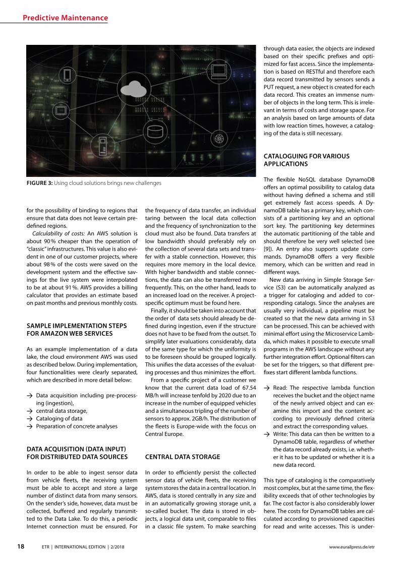
Predictive Maintenance
18 ETR | INTERNATIONAL EDITION | 22018 wwweurailpressdeetr
for the possibility of binding to regions that ensure that data does not leave certain pre-dened regions
Calculability of costs An AWS solution is about 90 cheaper than the operation of ldquoclassicrdquo infrastructures This value is also evi-dent in one of our customer projects where about 98 of the costs were saved on the development system and the eective sav-ings for the live system were interpolated to be at about 91 AWS provides a billing calculator that provides an estimate based on past months and previous monthly costs
SAMPLE IMPLEMENTATION STEPS FOR AMAZON WEB SERVICES
As an example implementation of a data lake the cloud environment AWS was used as described below During implementation four functionalities were clearly separated which are described in more detail below
rarr Data acquisition including pre-process-ing (ingestion)
rarr central data storage rarr Cataloging of data rarr Preparation of concrete analyses
DATA ACQUISITION (DATA INPUT) FOR DISTRIBUTED DATA SOURCES
In order to be able to ingest sensor data from vehicle eets the receiving system must be able to accept and store a large number of distinct data from many sensors On the senderrsquos side however data must be collected buered and regularly transmit-ted to the Data Lake To do this a periodic Internet connection must be ensured For
the frequency of data transfer an individual taring between the local data collection and the frequency of synchronization to the cloud must also be found Data transfers at low bandwidth should preferably rely on the collection of several data sets and trans-fer with a stable connection However this requires more memory in the local device With higher bandwidth and stable connec-tions the data can also be transferred more frequently This on the other hand leads to an increased load on the receiver A project-specic optimum must be found here
Finally it should be taken into account that the order of data sets should already be de-ned during ingestion even if the structure does not have to be xed from the outset To simplify later evaluations considerably data of the same type for which the uniformity is to be foreseen should be grouped logically This unies the data accesses of the evaluat-ing processes and thus minimizes the eort
From a specic project of a customer we know that the current data load of 6754 MBh will increase tenfold by 2020 due to an increase in the number of equipped vehicles and a simultaneous tripling of the number of sensors to approx 2GBh The distribution of the eets is Europe-wide with the focus on Central Europe
CENTRAL DATA STORAGE
In order to eciently persist the collected sensor data of vehicle eets the receiving system stores the data in a central location In AWS data is stored centrally in any size and in an automatically growing storage unit a so-called bucket The data is stored in ob-jects a logical data unit comparable to les in a classic le system To make searching
through data easier the objects are indexed based on their specic prexes and opti-mized for fast access Since the implementa-tion is based on RESTful and therefore each data record transmitted by sensors sends a PUT request a new object is created for each data record This creates an immense num-ber of objects in the long term This is irrele-vant in terms of costs and storage space For an analysis based on large amounts of data with low reaction times however a catalog-ing of the data is still necessary
CATALOGUING FOR VARIOUS APPLICATIONS
The exible NoSQL database DynamoDB oers an optimal possibility to catalog data without having dened a schema and still get extremely fast access speeds A Dy-namoDB table has a primary key which con-sists of a partitioning key and an optional sort key The partitioning key determines the automatic partitioning of the table and should therefore be very well selected (see [9]) An entry also supports update com-mands DynamoDB oers a very exible memory which can be written and read in dierent ways
New data arriving in Simple Storage Ser-vice (S3) can be automatically analyzed as a trigger for cataloging and added to cor-responding catalogs Since the analyses are usually very individual a pipeline must be created so that the new data arriving in S3 can be processed This can be achieved with minimal eort using the Microservice Lamb-da which makes it possible to execute small programs in the AWS landscape without any further integration eort Optional lters can be set for the triggers so that dierent pre-xes start dierent lambda functions
rarr Read The respective lambda function receives the bucket and the object name of the newly arrived object and can ex-amine this import and the content ac-cording to previously dened criteria and extract the corresponding values
rarr Write This data can then be written to a DynamoDB table regardless of whether the data record already exists ie wheth-er it has to be updated or whether it is a new data record
This type of cataloging is the comparatively most complex but at the same time the ex-ibility exceeds that of other technologies by far The cost factor is also considerably lower here The costs for DynamoDB tables are cal-culated according to provisioned capacities for read and write accesses This is under-
FIGURE 3 Using cloud solutions brings new challenges
Predictive Maintenance
19ETR | INTERNATIONAL EDITION | 22018wwweurailpressdeetr
standable as an increase in capacity in the background is a real hardware replication This allows tables with costs of less than one euro per month for the minimum congura-tion and a separate table can be provided for each application case The requests for large amounts of data via the primary key or only a part of it can be retrieved extremely quickly whereby retrieval times in the low two-digit millisecond range are not uncommon
PREPARATION OF CONCRETE ANALYSES
The creation of analyses on the catalogued data is possible without great eort with the basis shown This is done in several consecu-tive steps
rarr Top-down analysis of the problem to be solved as there are various microservic-es for a wide variety of applications As a result individual use cases can be as-signed to the use cases
rarr Selection of suitable microservices De-pending on the target platform the ap-propriate microservices can be selected There are specic services that enable the further use of existing programs that work on relational databases for example Other microservices support machine learning or the visualization of complex interrelationships in informa-tive dashboards
rarr Bottom-up aggregation of specically congured microservices For this pur-pose services already congured for similar analyses can be reused or addi-tional instances with slightly modied conguration can be created
SUMMARY amp OUTLOOK
All in all Data Lakes oer an optimal solution from the initial setup of a collection of raw data from various sources without large upfront ef-fort or high costs to the data storage of many eets of dierent vehicles worldwide and the provision of data catalogs for various analyses of various kinds The collection of measure-ment data in persistent online data stores such as AWS buckets can be implemented within minutes and is operational from this point in time so that data can be collected and archived Even if no specic use cases are known at the time of implementation it is recommended to persist all data on low-cost cloud storage so that it is already available for possible evalua-tions at later points in time Since there is often no reason to process data without use cases favorable options for persistence of the data can be used To avoid vendor lock-in consider designing Data Lake to be adaptable to alter-native platforms Alternative options for data storage include the storage services of Google Cloud Services or Microsoft Azure Of course the use of a second service also doubles the total costs
References[1] Canalys (2017) Cloud service providersrsquo battle drives
the worldwide cloud infrastructure market up 42 in Q1 2017 httpswwwcanalyscomstaticpress_re-lease2017press-release-150517-cloud-service-providersE28099-battle-drives-worldwide-cloud-infrastructure-market-42_1pdf Palo Alto Shanghai Singapore and Reading (UK) Pressemit-teilung 15052017
[2] Amazon Web Services (2017) Building a Data Lake on AWS httpspagesawscloudcomrs112-TZM-766im-agesAWS_Data-Lake_eBookpdf 01112017
[3] Bundesministerium des Inneren (BMI) (2017) Polizeili-che Kriminalstatistik 2016 httpswwwbmibunddeSharedDocsdownloadsDEpublikationen2017pks-2016pdf Pressemitteilung 24042017
[4] Buschmann Frank and Christiane Loumlckenho eds (2000) Pattern-orientierte Softwarearchitektur ein Pat-tern-System 1 korr Nachdr Muumlnchen Addison-Wesley 2000
[5] Mahjourian Reza (2009) An Architectural Style for Data-Driven Systems Paper Gainesville FL 32611 USA httpswwwcsutexasedu~rezalesxpage-icsrpdf 22032009
[6] Tilkov Stefan (2009) REST und HTTP Einsatz der Ar-chitektur des Web fuumlr Integrationsszenarien 1 Au Hei-delberg dpunkt 2009 ISBN 9783898645836
[7] Hunkeler U H L Truong and A Stanford-Clark (2008) MQTT-S mdash A Publishsubscribe Protocol for Wireless Sensor Networks In Communication Systems Software and Middleware and Workshops 2008 COMSWARE 2008 3rd International Conference on 791ndash98 2008 httpsdoiorg101109COMSWA20084554519
[8] Manseld-Devine Steve (2016) DDoS Goes Main-stream How Headline-Grabbing Attacks Could Make This Threat an Organisationrsquos Biggest Nightmare Net-work Security 2016 no 11 (November 2016) 7ndash13 httpsdoiorg101016S1353-4858(16)30104-0
[9] Vyas Uchit (2014) DynamoDB Applied Design Patterns Birmingham United Kingdom Packt Publishing 2014
SAFERAILSYSTEMCOM
Guessing or GPR
bull GPR measurements and analysisbull Condition-based maintenance planningbull More than 25 years of working experience - worldwide
BIM
20 ETR | INTERNATIONAL EDITION | 22018 wwweurailpressdeetr
ABOUT SIEMENS MOBILITYrsquoS TURNKEY RAIL SOLUTIONS BUSINESS
Siemens AG is a global technology power-house that has stood for engineering ex-cellence innovation quality reliability and internationality for more than 170 years The company is a pioneer in supplying in-frastructure solutions Siemens Mobility is an experienced provider of complete turn-key solutions for rail systems having already carried out more than 50 various and major rail projects worldwide The organization is home to experts in project management and system integration as well as key prod-ucts of rail infrastructure These specialists develop and implement projects for all types of rail vehicle systems from metros trams and light rail vehicles and automated peo-ple-movers to Intercity and high-speed train units ndash all designed for maximum reliability availability and eciency
THE CHALLENGES OF RAIL INFRASTRUCTURE PROJECTS
Projects to install new rail infrastructure and expand existing systems are growing steadily more complex The rising number of project participants and stakeholders presenting a broad range of specic require-ments planning teams in dierent locations and time zones having to coordinate and
Digital twin serving rail infrastructure How turnkey rail infrastructure projects are beneting from applying Building Information Modeling (BIM) how Siemens Mobility is pursuing virtual planning of projects with project partners and custom-ers such as in the Riyadh Metro Project and what added value this methodology is creating
integrate their civil and rail engineering and planning and the ever increasing time and cost pressures exemplify this problematic complexity
There are an enormous number of inter-faces and requirements involved especially in large rail infrastructure projects and or-ganizing them demands extensive resources and absolute precision
AT THE VANGUARD OF DIGITAL PLANNING
Just as countless other sectors of the con-struction industry have already experienced digitalization is driving a para-digm shift in rail infrastructure away from analog meth-ods and embrac-ing digital and in-tegrated planning encompassing eve-rything from erec-tion planning installation and support for training to preparation and performance of repairs and maintenance all based on digital processes and data models
More than four years ago Siemens Mo-bility began applying building information modeling (BIM) techniques as well to project planning and execution of complete turnkey
solutions for rail systems As one of the trail-blazers of digitalization Siemens Mobility uses BIM to create a digital twin ndash a virtual model of major rail projects planned for im-plementation
This methodology focuses on achieving cost and time eciency while also ensuring the highest quality standards
Siemens Mobilityrsquos Turnkey Rail Solutions is using BIM in col-laboration with construction part-ners to optimize project planning and execution This involves the use of computer-generated 3D modeling and the
information integrated into or linked with the models
REFERENCE PROJECT RIYADH METRO
The Arriyadh Development Authority (ADA) ndash the executive arm of The High Commission
Both the implementing company and customer benet from the reduced risk of delays in planning as well as the prevention of defec-tive planning and resultant need to revise planning during ongoing installation
Dr Payam AminiHead of Digital Transformation Turnkey Projects amp Electrication Siemens Mobility Munich payamaminisiemenscom
A simulated view of the outside of the depot for which the path of sunlight can be simulated over time
raquo
BIM
21ETR | INTERNATIONAL EDITION | 22018wwweurailpressdeetr
for the Development of Arriyadh in Saudi Arabia ndash is currently building one of the larg-est metro projects in the world with six rail lines totaling 176 kilometers in length The system will be the backbone of the public rapid transit network serving Saudi Arabiarsquos capital city The order placed with Siemens Mobility covers supply of 67 Riyadh Metro model rail vehicles based on the Inspiro Plat-form series line electrication the signaling and communication systems for driverless service on Lines 1 and 2 as well as system integration and project management Sie-mens Mobility is part of the BACS consor-tium led by US company Bechtel along with Almabani General Contractors and Consoli-dated Contractors Company
The Riyadh Metro Project (RMP) kicked o by dening the information requirements and project-specic BIM objectives of the customer The BIM management team of Siemens Mobilityrsquos construction partner Be-chtel then used this information as the basis for elaborating in detail the BIM process for all project participants
The BIM execution plan that denes the BIM process for a specic project basi-cally provides the answers to the agreed require-ments In this key central document Turnkey Rail Solu-tions dened for all project participants in-volved in the infrastructure design the roles and scopes of responsibility the programs and le formats to be used what applica-tions are to be integrated into the BIM pro-cess the data-exchange process along the chain of project phases the quality review inspection and testing criteria procedures for coordination and collaboration and much more This was necessary in order to ensure smooth BIM implementation over the entire project cycle
Siemens Mobilityrsquos construction partner also generated the model element plan which denes in an overview who is to gen-erate what model content for the project by when and to what level of development (ie geometry information and coordination) In this project BIM standard the construc-tion partner also dened the details for modeling agreements and documentation standards
Model-based planning is one of the pro-jectrsquos centerpieces enabling comprehensive integration of all rail infrastructure systems such as rail electrication the depot and workshop equipment line signaling and communication technology and platform screen doors
CLARITY DRIVES THE EFFICIENCY OF WORKFLOWS
Siemens Mobilityrsquos infrastructure planning engineers used project-specic BIM software to share their model-based information with Siemens Mobilityrsquos suppliers and the con-
struction partner The program Pro-jectWise is used in combination with Aconex served and continues to
serve as a shared data platform accessible project-wide ensuring that each piece of information is retained only once and in its most recently valid version In this ldquosingle source of truthrdquo data are referenced rather than duplicated signicantly improving in-formation management increasing the reli-ability of data and eliminating any use of superseded obsolete data This provides full trans-parency for all pro-ject participants Photo-realistic displays and animated videos of the planning progress generated on the basis of the 3D planning information ensure transparency enhance understanding and support the iterative process
The permanent availability of data accel-erates collaboration across national borders and company boundaries These aspects are particularly benecial in the RMP Just Sie-mens Mobilityrsquos unit alone had colleagues based in 13 dierent cities working to de-sign the rail infrastructure coordinating and agreeing across national boundaries and dierent languages time zones and work capacities
In addition to the geometrical properties
of system components for example of fre-quency converters the participating plan-ning engineers also integrated non-geomet-rical information and requirements of their systems such as zones and clearance spaces that are essential for installation and mainte-nance Once work on a subarea of a model (work in progress) was approved for release this information was then available to all partners within the project (shared areas) In turn these partners reviewed the completed work for impacts on their own work scopes
In interdisciplinary collision reviews the design coordinators conducted collision tests with all other draft components Such reviews examined for example the civil struc-tures technical building equipment systems and Siemens Mobilityrsquos systems such as the signaling equipment and traction power supply grid to identify any conicts between
the systems them-selves or with the civil structures
In this way structural imple-mentation of the overall project as
well as individual subareas can be digitally tested at any time
As a provider of turnkey infrastructure solutions Siemens Mobilityrsquos unit was in-volved early in the RMP through BIM help-ing to prevent planning errors and leading to quicker validation of draft planning such as for spatial requirements of infrastructure equipment free clearance proles and pre-venting collisions
The RMP oers a basis for further infra-structure projects using BIM methodology The stock of digital objects available in the component library continues to grow Exist-ing digitally modeled components can be directly used for the next digital twin This
BIM creates full transparency for everyone participating in the plan-ning of infrastructure projects
The Control Center of the Riyadh Metro Project for Line 1 was fully planned digitally Once that design process was completed actual construction started
BIM enables earlier design valida-tion of rail infrastructure technol-ogy and engineering as well as civil construction
BIM
22 ETR | INTERNATIONAL EDITION | 22018 wwweurailpressdeetr
accelerates digital planning from one pro-ject to the next
Siemens Mobility Turnkey Rail Solutions sees particular potential for BIM in integrating the necessary man-agement process-es BIM supports the management of interfaces requirements congurations and project documentation This improved management leads to accelerated project execution And although project execution in Riyadh is still underway the added value created by the BIM method is already clearly evident today ndash for both Siemens Mobility and the customer
DIGITAL SCAN OF THE INFRASTRUCTURE CREATED
Siemens Mobility Turnkey Rail Solutions is utilizing other digital solutions as well for the Riyadh Metro Project that further optimize pro-ject execution Siemens Mobility-owned track measuring vehicles and 3D laser scanners are deployed to eciently compare the progress
of as-built construction and installation against the design target data These units travel along the existing sections scanning and thereby
digitalizing the as-built environment The object-specic information collect-ed by this measur-ing system whether on track position-
ing platform edges or technical spaces is com-pared with the digital design thereby directly revealing any deviations from planning
This produces a 100 -accurate database of the existing as-built status Particularly when projects aim to expand exist-ing infrastructure such transparency prevents costly conicts when equipping existing civil structures with new infrastructure equip-ment Besides the hardware procurement Siemens Mobility is banking in this context on developing the expertise of its own per-sonnel to cover planning of measuring cam-paigns kinematic and static imaging and evaluations such as review for collisions
PROMISING OUTLOOK
Siemens Mobilityrsquos Turnkey Rail Solutions has ceaselessly invested in implementing and further developing digital methods to keep pace with steadily growing deadline and cost pressures and the increasingly stringent demands of complex rail infra-structure projects These efforts are now empowering Siemens Mobility to better assess the sometimes extremely demand-ing detailed requirements early already in the project bidding phase and estimate costs more reliably thereby minimizing risks
In previous projects utilizing BIM meth-odology Siemens Mobilityrsquo experts identi-ed a shifting of eort into the early project phases
Siemens Mobilityrsquo experts see opportuni-ties in doing so particularly in the assess-ment of design modications in terms of im-pacts on costs and in early application when the leverage for such optimization can still prove very eective
Yet BIM doesnrsquot end when construction work on an infra-structure project has been complet-ed By developing a digital twin of the as-built infrastruc-ture and applying
that model over its entire lifecycle these sets of digital data can be used to optimize asset management
The BIM method harbors major potential for signicantly shaping the rail infrastruc-ture sector in the coming years
A view of the digital model of the King Abdullah Financial District Station on Line 1 which can be viewed in the computer pro-gram from all sides
Photo-realistic displays and animat-ed videos of the planning progress ensure transparency and enhance understanding
BIM provides the basis for simpler and ecient interface management and contributes signicantly to accelerating project execution
5 | 2017 Mai wwweurailpressdesd
109 Jahrgang
SIGNALLING amp DATACOMMUNICATION
Oumlsterreich Gut gesichertAustria Well-protected
13 Kostenguumlnstige Sicherung von Eisenbahnkreuzungen Cost-effective protection of level crossings
36 Finnland Gegen den Instandhaltungsruumlckstand Finland Reducing maintenance backlog
21 Schweiz Weltpremiere auf der Toumlsstalstrecke Switzerland A world premiere on the Toumlsstal line
Your contact person Silvia Sander +4940237 14-171 silviasanderdvvmediacom wwweurailpressde
Leader in Signalling and Datacommunication
No 1ad medium
SIGNALLING AND
DATACOMMUNICATION
AUTONOMOUS DRIVING
CYBE
R SE
CURI
TY
LEVEL CROSSING TECHNOLOGY
OPERATIONS MANAGEMENT SYSTEMS
MOBILE COMMUNICATIONETCS
REPUTABLE
UN
IQU
E
ESTABLISHEDTELECOMMUNICATION
OPERATIONS CONTROL TECHNOLOGY
INFORMATION TECHNOLOGYBILINGUAL
Book your advert right now
raquo
Ground Penetrating Radar
23ETR | INTERNATIONAL EDITION | 22018wwweurailpressdeetr
1 INTRODUCTION
Many countries allocate large amounts for the modernization and upgrading of their railway networks in order to meet the de-mands of increasingly dense rail trac with higher axle loads at ever higher speeds However this can only be achieved if all rel-evant key gures and geotechnical condi-
Ground Penetrating Radar ndash Basis for eective Track MaintenanceThis article describes the capabilities and functionality of Ground Penetrating Radar (GPR) for higher speeds GPR is a train-borne technology for a continuous inspection of the geotechnical conditions of railway tracks The basic principles of the GPR technology are explained with particular reference to all relevant railway specic tasks namely the identication qualication and quantication of ballast fouling by using a fouling index the determination of the quality of track drainage and its quantication through a drainage index and the calculation of the track modulus (TM) Special emphasis in the context of GPR investigations is placed on the mapping of sections with clay foulingmud spots inside the ballast bed or at its base and respectively inside intermediate layer formation or subsoil In the past such weak-spots have caused derailment they could represent a risk for rail-trac [11 13 14 15 16] Besides their late detection implies exceedingly high maintenance costs
tions of the respective tracks can be reliably evaluated On this basis only the necessary investments in track maintenance moderni-zation and support can be dened in the ap-propriate size and can be placed correctly This is particularly true when budgets are tight
The demands exerted on the track in terms of safety grow with increasing speed
FIGURE 1a) Trajectories of radar waves which are reected at the layer boundary between two media
with dierent dielectric constant (laquo)b) Due to the dierent travel time of the reections the layer boundary is reproduced in the
radargram (reference Ground Control and IEV)
Dipl-Geophys Giuseppe StacconeDirector of Ground Control GmbH MunichGermanystacconesaferailsystemcom
David Camacho MScDoktorand am Institut fuumlr Eisen-bahn- und Verkehrswesen der Universitaumlt Stuttgart (IEV)davidcamacho ievvwiuni-stuttgartde
Moritz SchebuchMitarbeiter am Institut fuumlr Eisen-bahn- und Verkehrswesen der Universitaumlt Stuttgart (IEV)moritzschebuch ievvwiuni-stuttgartde
Prof Dr-Ing Ullrich MartinDirektor des Instituts fuumlr Eisenbahn- und Verkehrswesen der Universitaumlt Stuttgart (IEV) und des Verkehrswis-senschaftlichen Instituts an der Universitaumlt Stuttgart eV (VWI eV)ullrichmartin ievvwiuni-stuttgartde
Dipl-Ing Sebastian RappAkademischer Mitarbeiter am Institut fuumlr Eisenbahn- und Verkehrswesen der Universitaumlt Stuttgart (IEV)sebastianrapp ievvwiuni-stuttgartde
Ground Penetrating Radar
24 ETR | INTERNATIONAL EDITION | 22018 wwweurailpressdeetr
Therefore failing to detect track damages or obtaining inadequate information on track damages represents a hazard for every kind of railway trac For this reason a decision guidance that facilitates a systematic and ecient renewal of the tracks is important The more intensive the rail trac and the higher the trac speed the bigger the re-quirements in terms of an ecient and reli-able track inspection
The mapping of clay fouling or mud sec-tions is of special importance Fine-grained soil material such as silt or clay wells up from the formation and reaches the ballast base or even penetrates the ballast layer itself As a consequence track drainage and track stability (ie bearing capacity) are strongly reduced This results in lasting deformations that require complex maintenance work and high costs If weak-spots are not identied or not detected in time clay fouling can in the worst case scenario lead to derailment [10 13 14 15 16]
During the past 25 years Ground Control GmbH which is placed in Munich Germany has surveyed more than 100000 km of rail-way tracks in many countries in Europe and all over the world Recently with information obtained from GPR results and other data (ie track geometry and track dynamics) a continuous and complete assessment of the trackrsquos structural condition is possible
2 MEASURING PROCESS
The GPR method is an electromagnetic re-ection method Radar pulses are transmit-ted into the subsoil by a transmitter antenna The energy of the electromagnetic waves is partly reected at interfaces between layers with dierent dielectric properties and re-transmitted to the receiver antenna Based on the measured travel time of the signals and knowing the propagation speed of the waves in the medium depth and surface of the layer can be computed
In order to dene the depth of the re-ector from the surveyed travel time the propagation speed of the radar waves in the subsoil has to be determined The speed of electromagnetic waves in the subsoil is re-lated to the water content of the individual material Therefore it is generally not pos-sible to refer to reference values for certain rock or soil types Thus the radar wave speed has to be calibrated for each project area
The penetration of electromagnetic waves mainly depends on the electric conductivity of the soil and the applied antenna frequen-cy By using low frequency antennae on low conductive subsoil the largest investigation depth can be achieved
PERFORMING SURVEYS WITH MODERN HIGH-SPEED-GPR
Todayrsquos GPR surveys are carried out with train mounted systems at speeds up to 160 kmh As a general rule the antennae system is fastened at the carrier vehiclersquos buers A precise positioning is achieved by an inte-grated Dierential Global Positioning Sys-tem (DGPS) and Doppler radar
The characteristics of modern GPR sys-tems are
rarr The equipment can be installed and run on a wide range of track-bound vehicles (including regular trains or vehicles on Hy-Rail)
rarr They are fast enough to be integrated into the regular trac schedule Hence expensive track closure is no longer nec-essary
rarr DGPS and Doppler radar are used for an accurate (ie precision within a meter) positioning of the antenna independ-ent of the speed and length of the track surveyed
rarr Measurement data resolution and data quality are equally high no matter what length and what speed
rarr All GPR components are eectively
shielded against interferences from sig-nalling and communication systems
3 GPR TASKS
In contrast with punctual boreholes and trenches modern GPR systems provide con-tinuous information about the geotechnical condition of the track performing the fol-lowing tasks
rarr Continuous mapping of track-bed-thick-ness and layers below (ie intermediate layer protective layers)
rarr Distinction between clean and fouled ballast and calculation of Fouling Index
rarr Mapping of mud spots or clay fouling sections inside ballast bed at its base or inside substructure layers respectively
rarr Detection of sections with drainage problems and calculation of ldquoWet Bed Indexrdquo
rarr Mapping of areas with insucient bearing capacity (eg settlements) and evaluation of the dynamics of track set-tlement
rarr Control and evaluation of the quality of maintenancerenewalconstruction work (quality of cleaned or exchanged ballast thickness of a new ballast bed quality and thickness of soil layers)
rarr Estimation of track condition based on track modulus (TM) calculation
Additionally GPR data allow for the deni-tion of a sustainable cause-based and there-fore eective track renewal recommenda-tions and programs Optionally GPR oers the possibility to accurately map cables pipes and other objects in the track sub-structure creating the possibility to provide a complete picture of the entire system
31 CLAY FOULING ndash STRONG EFFECT ON TRACK STABILITY
Clay Fouling is one of the main reasons for the reduction of the load bearing capacity of the track in a relatively short period of time Several derailments in the past were caused by mud spots [10 13 14 15 16] even when the limit values for track geometry failures according to [2] have not been exceeded [13 14] It is therefore and because of safety reasons of particular importance to detect clay fouling areas reliably in their precise dimension and as early as possible The rec-ognition of the problem should be irrespec-tive of whether the clay fouling exists in the substructure at the base of the ballast bed or in the ballast bed itself Clay fouling can
FIGURE 2 Figure 2 Antenna mounted on the train buers of a mainte-nance vehicle(reference Ground Control)
Ground Penetrating Radar
25ETR | INTERNATIONAL EDITION | 22018wwweurailpressdeetr
raquo
rapidly deteriorate the stiness of the track and its quality The trackrsquos lateral stability is massively reduced longitudinal errors along the rails arise
Clay fouling is also a serious decit from an economic point of view Its timely iden-tication allows for avoiding slow speed sections thus sparing time and money for maintenance procedures Detecting clay fouling before it reaches the ballast bed ena-bles cost eective renewal Otherwise it will be very expensive There is no option for bal-last cleaning a suciently compacted pro-tection layer built of the appropriate materi-al is essential the installation of composites does not prevent clay fouling from entering the ballast bed (see Fig 3)
Save few exceptions clay fouling spots are not visible at the track surface and since drill-ings and trenches do only provide punctual results reliable information is only achievable through GPR measurements (see Fig 4)
A frequency analysis of the measured data results in a typical change of the signal spectrum in the area of clay fouling Based on the GPR results borehole program can be implemented which can be used for further analysis GPR surveys to detect ballast foul-ing have been carried out for years in Swit-zerland Austria the Netherlands and France among others
32 TRACK MODULUS (TM)
Examining the geotechnical conditions of railway tracks requires an index which in-forms about state and quality of the tracks in a quantitative manner The challenge has
been to dene the track condition continu-ously This has been achieved by combin-ing TM with the results of continuous GPR-measurements
It is possible based on [3 4 5 6 7] to es-timate quality and bearing capacity of the railway track Therefore the TM describes the relation between vertical load and elas-tic deection of the sleeper-bearings
On the one hand the TM can be calculated based on the measured deection under load [18 20] on the other hand according to the soil properties [8 9 11] The measuring principle for determining the load deec-tion is described in detail in [12] and [17] The properties of the system components such as the area of inuence of the sleepers under load can greatly aect the TM Hence around turnouts the area of inuence of sleepers deviates from the standard track This is because an increased area of inu-ence causes an increase in the distribution of the load reducing the deection of the
rail Notwithstanding to simplify the calcula-tion of the TM the inuence area of sleepers around turnouts are assumed to be constant assuming the values of the standard track Depending on the type of sleepers installed the value of the TM can increase sharply around turnouts (Fig 5) In addition cavities under the sleepers increase the deection of the track under load which in turn inu-ences the calculation of the TM decreasing its value
An additional and new approach for calcu-lating the TM is based upon the soil proper-ties which can be described by the Poissonrsquos Ratio or the material density of the soil The soil properties derive from the GPR data This methodrsquos advantage is to be completely in-dependent from superstructure conditions The individual layers are assigned soil values according to condition and bulk density Averaged soil properties are calculated ac-cording to [1 19] The TM can be estimated according to [9] and [11] Previous studies
FIGURE 4 Visual analysis of GPR data depicting clay fouling along a track (reference Ground Control and IEV)
FIGURE 3 Geotextile or composite does not stop ne particle migration to the surface (reference Ground Control)
Ground Penetrating Radar
26 ETR | INTERNATIONAL EDITION | 22018 wwweurailpressdeetr
indicate that this method has signicantly lower value variations along the track axis compared to the approach based on the use of track displacement data (Figure 5)
The example in Fig 5 shows two track moduli based on the measured displacement under load (red line) and the soil properties (blue line) Around the turnouts a signicant increase of the TM is visible if the calculation is based on the measured deection By divid-ing the TM into quality classes according to [3 4 5 6 7] the condition of the track can be sat-isfactorily estimated (Fig 6)
33 TRACK ANALYZER ndash CONTINUOUS PRESENTATION OF ALL MEASUREMENT AND TEST RESULTS
Results from GPR surveys along with all identied soil parameters and indices cal-
culated can be displayed in comprehensive track analysis software called ldquoTrack Analyz-errdquo In order to provide all information for in-frastructure managers track geometry and track dynamics data are also integrated and displayed in the software (see Fig 7) which also oers the exibility to incorporate other tasks and aspects as required by the user
The Track Analyzer provides infrastructure managers continuous information about the geotechnical conditions of the track with regard to all relevant issues Moreover it provides a better understanding of the sub-structuresubgrade conditions and their in-uence on the superstructure This allows for a signicantly increased track quality pro-viding higher route availability and safety
A big advantage of the GPR method is the minimization of the need for intensive direct outcropping (probing drilling scooping)
to characterize the underlying geotechni-cal characteristics of the track substructuresubgrade which results in signicant cost reductions
4 SUMMARY
This paper describes a modern train-borne technology for the inspection of the geo-technical conditions of railway tracks It is based on High Speed GPR and on classical procedures for providing continuous infor-mation about geotechnical parameters and indices A new quality of GPR measurements is to provide quantitative indices in addition to qualitative results to full the require-ments of the railway engineers in the best possible way
Special attention is paid to the detection of mud spots and clay fouling sections as a risk for derailment [10 13 14 15 16] To date track inspection with GPR is more appropri-ate than any other inspection method to de-tect map and qualify areas with geotechni-cal problems
The Track Analyzer software combines GPR results with track geometry and track dynamics data This allows for cause-based track renewal and targeted investment and provides signicantly more reliable results than conventional methods This approach is especially relevant for limited budgets
Literature [1] Adam D Kopf F Dynamische Eekte durch bewegte
Lasten auf Fahrwegen In Bauingenieur Ausgabe 01-2003 2003
FIGURE 5 TM calculated from measured displacement under load (red graph) and soil proper-ties (blue graph) (reference IEV)
FIGURE 6 TM divided in dierent quality classes (reference IEV)
Ground Penetrating Radar
27ETR | INTERNATIONAL EDITION | 22018wwweurailpressdeetr
FIGURE 7 Track Analyzer(reference Ground Control)
[2] DB Netz AG Ril 821 Oberbau inspizieren Deutsche Bahn AG guumlltig ab 01052004
[3] Eisenmann J Stuumltzpunktelastizitaumlt bei einer Festen Fahrbahn In ZEV + DET Glasers Analen 111999
[4] Fendrich L (Hrsg) Handbuch Eisenbahninfrastruktur Springer-Verlag Berlin Heidelberg 2007
[5] Goumlbel C Lieberenz K (Hrsg) Handbuch Erdbau-werke der Bahnen DVV Media Group GmbH 2013
[6] Leykauf G Lothar M Elastisches Verformungsver-halten des Eisenbahnoberbaus ndash Eigenschaften und Anforderungen In EI ndash Eisenbahningenieur 031990
[7] Lichtberger B Handbuch Gleis DVV Media Group GmbH 2010
[8] Martin U Rapp S Ansatz zur Erfassung der Bodenei-genschaften am Bahnkoumlrper in Schotterbauweise In ETR ndash Eisenbahntechnische Rundschau 042017
[9] Martin U Rapp S Camacho D Moormann C Lehn J Prakaso P Abschaumltzung der Untergrundverhaumllt-nisse am Bahnkoumlrper anhand des Bettungsmoduls In ETR - Eisenbahntechnische Rundschau 052016
[10] Rail Accident Investigation Branch Freight train de-railment near Gloucester 15 October 2013 Rail Acci-dent Report102014
[11] Rapp S Modell zur Identizierung von punktuel-len Instabilitaumlten am Bahnkoumlrper in konventioneller Schotterbauweise Dissertation ndash Institut fuumlr Eisen-bahn- und Verkehrswesen der Universitaumlt Stuttgart 072017
[12] Soldati G Meier M Zurkirchen M Kontinuierliche Messung der Gleiseinsenkung mit 20 t Achslast In EI ndash Eisenbahningenieur 022016
[13] Untersuchungszentrale der Eisenbahn-Unfalluntersu-chungsstelle des Bundes Untersuchungsbericht Ak-tenzeichen 60 ndash 60uu2011-0200041 Zugentgleisung Groumlbers ndash Groszligkugel 062013
[14] Untersuchungszentrale der Eisenbahn-Unfalluntersu-chungsstelle des Bundes Untersuchungsbericht Ak-tenzeichen 60uu2013-06047-3323 Zugentgleisung Kaub ndash Lorch (Rhein) 062013
[15] Untersuchungszentrale der Eisenbahn-Unfalluntersu-chungsstelle des Bundes Untersuchungsbericht Ak-tenzeichen 60 ndash 60uu2011-0400043 Zugentgleisung Bf Hannover ndash Linden 092013
[16] Versa Verkehrssicherheitsarbeit fuumlr Oumlsterreich Unter-suchungsbericht Sicherheitsuntersuchungsstelle des Bundes BMVIT-795336-IVBAVUUBSCH2013 Ent-gleisung eines Guumlterzugs am 14 Februar 2013 2013
[17] Wang P Wang L Chen R Xu J Overview and out-look on railway track stiness measurement Jour-nal of Modern Transportation Volume 24 Issue 2 062016
[18] Winkler E Die Lehre von der Elastizitaumlt und Festigkeit Verlag von H Dominicus 1967
[19] Wolf J P Foundation Vibration Analysis using Simple Physical Models Swiss Federal Institute of Technology 1994
[20] Zimmermann H Die Berechnung des Eisenbahn-oberbaus 1888
wwwrex-industrie-produktede
INSULATING JACKETS FORHIGH TEMPERATURE INSULATION
high temperature resistant up to 1000degC
incombustible
high insulation performance
tailor made according to your wishes
New test reports for fire protection according to EN 45545-2 available R1R7R17 with Hazard Level HL 3
Distributed Acoustic Sensing
28 ETR | INTERNATIONAL EDITION | 22018 wwweurailpressdeetr
Dip-Ing FH MScMartin RosenbergerCTO Frauscher Sensor Technology martinrosenberger frauschercom
This involves planning and controlling maintenance measures based on the actual condition of the equipment systems and components (assets) Unexpected events due to faulty components and unnecessary work on fully intact elements can thus be reduced This is possible thanks to the ever increasing amount of reliable data about the condition of the asset that is available in real time
Continuous acoustic condition monitor-ing of the infrastructure based on Distribut-ed Acoustic Sensing (DAS) is a key building block of future solutions This technology can considerably increase the availability of rail networks since it continuously delivers very precise information about the condi-tion of the infrastructure and any changes thereby fullling a key prerequisite for the use of CBM solutions
The sensor technology and inspections form and remain the basis for condition-based maintenance of the track These in-clude track recording vehicles xed meas-urement points sensor technology on
How Distributed Acoustic Sensing supports condition based maintenance strategiesCurrent technological developments are opening up new opportunities for the railway industry in a whole range of application areas Most notably these include networking digitalization and the Inter-net of Things (IoT) This trend is also having a growing impact on processes and strategies for maintain-ing rolling stock and infrastructure Traditional maintenance philosophies which are based on xed intervals or in the case of vehicles on mileage are increasingly being replaced by predictive condition based maintenance (CBM)
standard trains track-side sensor technol-ogy selectively deployed manual measur-ing instruments and self-monitoring infra-structure systems Data from these sources must be consolidated and if applicable combined with information about rolling stock and system-side infrastructure data such as a system directory or inputs from other sensors
DAS enables a sensor solution to be cre-ated which fulls several of the specied re-quirements this technology allows railway networks to be monitored continuously in real time and with respect to a huge num-ber of dierent events Frauscher has devel-oped its own DAS solution for the railway sector Frauscher Tracking Solutions FTS The manufacturerrsquos team tested the tech-nology and through intensive develop-ment eliminated constraints with respect to use for rail trac To create this in-depth knowledge of DAS as well as requirements and standards in the railway industry was required
1 DAS FUNCTIONAL PRINCIPLE
DAS-based systems use laser pulses sent in a glass bre to detect events on or in the vicinity of the track part of the laser pulse is reected back out of the bre to the transmitting unit The sound and vibration waves impacting on the cable result in signicant shifts in the reection (Fig 1) The maximum frequency range of the vibrations detected in this man-ner is 125 kHz Using specically developed algorithms the acquired data can be used to calculate specic signatures in real time These describe highly precise locations and types of processes in the vicinity of the track
One of the advantages of installing a DAS system is that the bre optic cables it requires are often already laid next to the tracks These are normally used for commu-nication purposes As the optical bres used require practically no maintenance the sys-tem can be rolled out to large sections of the route extremely economically and ecient-ly In practice a single DAS unit can eective-ly cover up to 40 kilometres of glass bre in each direction so 80 kilometres in total [1]
2 CONTINUOUS MONITORING OF WHEEL-RAIL INTERACTION
The ongoing analysis of infrastructure us-ing FTS is based on continuous monitoring
FIG 1 Distributed Acoustic Sensing (DAS) allows for the detection of vibrations and sound waves caused by trains component defects people or other sources
raquo
Distributed Acoustic Sensing
29ETR | INTERNATIONAL EDITION | 22018wwweurailpressdeetr
of wheel-rail interaction (Fig 2) On the one hand this enables the detection of changes that arise slowly over the course of time To do so the system compares the relevant signatures that are captured each time a railway vehicle passes a spot On the other hand events that occur suddenly can also be reliably detected
21 TREND ANALYSIS FOR LOCALISATION OF CONDITION CHANGES
The wheel-rail interactions quality is the most important factor when it comes to the service life of both system components and the rolling stock This quality is derived from various parameters such as the roundness of the wheel the surface of the rail and the track design Even slight deviations from the ideal parameters result in increased signs of wear and tear over a certain amount of time Ultimately these can also lead to critical op-erating conditions Which is why continu-ous detection and thus early recognition of changes in condition along the entire route is extremely useful
This is where the FTS come into play by evaluating the signatures in the laser signal feedback it is possible to determine wheth-er a sp ecic anomaly in wheel-rail interac-tion comes from the train or from the infra-structure This is possible because the FTS system uses a glass bre as a permanent sen-sor along the track thus allowing the wheel-rail interaction for each individual axle on all train journeys to be permanently monitored along the entire route Changes are detected in real time and the method does not de-pend on a xed measurement point
If a notication is triggered by an out-of-round wheel for instance then this pattern will be part of the train signature and be de-tected in association with the moving train This allows the event to be clearly attributed to vehicle damage
By contrast if there is a change to the in-frastructure several axles will have a notice-able signature in one specic position The system uses this to determine an indicator Based on this trend analyses are formed for individual ten-metre long infrastruc-ture segments Warning or alarm notica-tions can now be created and transmitted through dened user-congured threshold values These indicate the type of change as well as the location With good georefer-encing for the bre optic cable the position identied via FTS can be localised to an accu-racy of up to ve metres and made available via machine-readable interfaces
Frauscher oers powerful interfaces for employees in railway infrastructure compa-
nies In particular these include a graphical user interface with map view and heat maps and depiction of the infrastructure condition in denable categories The zoom function can be used to display the entire route or a position with relevant localisation in route kilometres or GPS data the actual condition and the change in condition over a specic period Filters can be set for even more de-tailed analyses and evaluation
22 EVALUATION OF CHANGES IN CONDITION AS A PROCESS
To determine the relevance for a specic rail-way operation simply identifying a change in condition is not enough The trend analy-sis must also be correlated with the trains and their speeds After all identical techni-cal non-conformities will result in indicators with completely dierent frequencies and intensities when a heavy long freight train and when a lighter short passenger train travels over a position with a fault
Therefore a basic condition must rst be dened for the infrastructure and stored in the FTS The trend analyses can then be ap-plied to this To do so the system structure (primarily bridges tunnels or points) must be logged in the system and the sensor must be calibrated accordingly Data that needs to be entered includes rail joints or transitions from a point for example They create similar patterns to those of a rail defect but must be evaluated and examined dierently
It may also be necessary to lter out am-bient noise from stationary systems such as pumps and generators so that this does not have a negative eect on the detailed analy-sis of the wheel-rail interaction signature
These adjustments are currently carried out manually during the installation and com-missioning process However Frauscher is developing tools to automate these process-es These steps form part of the technologyrsquos path towards serial production
Once the basic condition has been dened then depending on the model the operator will receive regular reports or warning and alarm notications via dened interfaces The DAS systems that are currently available are not yet able to classify and quantify the changes detected with sucient accuracy Maintenance personal therefore take on the task of evaluating suspect positions through inspection actions during the development and installation phase A visual inspection is often enough to identify the cause of the warning classify the change and take the necessary action within a dened period
Based on experience with several installa-tions and Frauscherrsquos collaboration with op-erators there are essentially three relevant classications
rarr No detectable or only minimal damage rarr Non-critical damage rarr Critical damage
What is important is that this evaluation and classication is understood and followed as part and parcel of the maintenance process Dening the threshold values and deter-mining the sensitivity of the system is a key step in this regard Experienced specialist sta who evaluate and process the notica-tions can shape the system to suit their own needs This allows CBM concepts to be ap-plied even more eciently for practical sup-port and to build expertise (Fig 3)
The high sensitivity level of the system
FIG 2 By continuously monitoring the acoustic signature of the wheel-rail contact the FTS support condition based maintenance strategies
Distributed Acoustic Sensing
30 ETR | INTERNATIONAL EDITION | 22018 wwweurailpressdeetr
means that a range of errors can be detected at a very early stage However this also in-creases the risk that positions that are not relevant for maintenance will be displayed This is where empirical values are really needed so that the optimum setting can be tuned for the operator It is crucial to involve the maintenance personnel in this whether through the operator or the service contrac-tor After all only experts on the ground can evaluate the condition of the infrastructure and determine the necessary measures Maintenance employee experience thus re-mains essential for training the algorithms and evaluating the results the maintenance personnel must use their knowledge of routes and systems to determine whether a notication is in fact relevant or not
Not detectable or only minimal damageIn this case no maintenance measures are needed There are three main reasons why the system has indicated a potential fault in this case First there may be a structural fac-tor in the infrastructure or a factor in the en-vironment of the trigger In this case the in-uencing factor can be ltered out in future Secondly it could be that a visual inspection reveals no detectable fault but there are already signs of wear In this case the user
would add information to the system stating that this section is to be kept under observa-tion or specically monitored over a certain period of time ndash for example by adjusting the threshold value If the system contin-ues to exhibit a fault it is advisable to apply analysis methods that go beyond a visual inspection of this point or use other meas-urement data as a comparison Thirdly this could be due to a minor surface fault on the rail for example which does not require any action since scheduled surface processing measures are due to be carried out (Fig 4) In this case the fault message can be acknowl-edged
Non-critical damageIn this case the system has identied a rel-evant fault but it does not need to be cor-rected right away (Fig 5) The main advan-tage of this is that early detection allows the necessary measures to be planned in good time so these can be put into eect during quiet periods or eciently combined with other measures thus reducing the number of expensive individual activities
Critical damageIf such changes are detected then measures must be initiated immediately in order to re-
solve the safety-critical operating condition and minimise any expensive subsequent damage Experience shows that such critical conditions can develop over just a few days or can even be triggered by acute short-term factors Examples include ballast voids due to washout rail head cracks and broken rails
Critical conditions can arise during the analysis cycles even if the rail network is monitored regularly with track recording ve-hicles for example Continuous monitoring of the wheel-rail interaction enables quicker intervention and minimises personal injury and damage to property
23 EMPIRICAL RESULTS
In addition to various applications which can be used in real time on the basis of train lo-calisation over the last two years Frauscher has been taking a closer look at infrastruc-ture maintenance In particular at the po-tential that continuous monitoring of the wheel-rail interaction has to oer in the fol-lowing scenarios
rarr Rail monitoring rarr Rail fastening and sleeper monitoring rarr Track substructure and superstructure
monitoring
Practical application has shown that the data that can be provided via the FTS system al-ready oers a range of interesting options it helps users to plan and control maintenance measures in good time To do so Frauscher implements technology such as machine learning pattern recognition and articial
FIG 3 When developing advanced main-tenance solutions various levels within a railway network have to work together closely
FIG 4 Changes in the trackrsquos surface can be detected evaluated and considered when planning maintenance works
FIG 5 Detecting small defects allows for a targeted monitoring in order to generate alarms when their condition deteriorates
Distributed Acoustic Sensing
31ETR | INTERNATIONAL EDITION | 22018wwweurailpressdeetr
intelligence However in order to move to the next level a solid base of empirical val-ues and a library of signatures from a variety of sources of damage are needed
The company is working very closely with the operators of several installations select-ed from approximately 30 projects that are currently ongoing worldwide They are joint-ly considering the evaluation interpretation and derivation of measures Specic issues and ideas for further development of the evaluation software and logic are directly incorporated into Frauscherrsquos development processes using agile methods
Rail monitoringAll types of rail damage that cause vibrations or a noise spectrum that deviates from the norm are detected This ranges from surface damage such as rail corrugation squats rail head cracks wheel burns or corrosion and dents to cracking and ssuring or even bro-ken rails
Unsurprisingly the algorithm for detect-ing rail damage also detects rail joints After all the signature of a gap as in an isolation joint could be exactly the same as that for a break in part of the rail In this case depend-ing on requirements these rail joints can be suppressed or specically monitored with their own threshold values (Fig 6 7) The sensitive sensor system can detect broken rails as a train passes over them with high probability However due to the many dif-ferent forms and physical basic conditions a warning system with a 100 percent de-tection rate and zero error rate cannot be achieved
In addition there are still no empirical val-ues for broken rails which can be traced back to warping and thermal eects without the eect of the train Noises that arise due to warping (thermal popping) were detected during tests designed to identify and local-ise landslides and rock fall These are hard to classify or uniquely identify using the cur-rently available hardware and software It is to be assumed that a rail that breaks for thermal reasons generates a similar if more intensive signature and it is not possible to clearly distinguish this from the ldquothermal poprdquo
Therefore it is important to consider whether continuous monitoring of the tracks with appropriate trend analyses does not provide more information about the safety of the route than a warning system for broken rails Last but not least broken rails should generally be reduced by as-required maintenance measures
Rail fastening and sleeper monitoringIn several installations positions were de-
tected that exhibited increased vibration due to damaged or missing rail connections or broken sleepers These are typically faults that do not necessarily require action to be taken right away Instead they are classied in such a way that these tasks will be car-ried out during upcoming scheduled on-site maintenance
Track substructure and superstructure monitoringThe FTS system is able to localise weakness-es in the substructure and track superstruc-ture such as ballast voids under sleepers cavities or compacted areas The condition of the track bed may under certain circum-stances also lead to a critical situation in a relatively short period of time particularly in mountainous regions where heavy rain or mudslides can also make the track position unstable Practical examples also exist for these scenarios where FTS localised critical positions where ballast voids under sleepers were later identied
3 SUMMARY
Continuous monitoring of wheel-rail interac-tion based on FTS opens up numerous pos-sibilities for the user in terms of timely detec-tion of weaknesses and changes in condition on the route Thus targeted and as-required maintenance measures can be dened planned and eciently controlled This is a paradigm shift in terms of maintenance strategy similar to that which is emerging for vehicles Before xed periods based on theoretically calculated average loads were
key to the strategy Now the actual wear and condition of the specic component (rail surface fastening sleeper substructure or track superstructure) are the trigger for maintenance repair or servicing work
These new options for monitoring infra-structure will not replace existing measure-ment systems instead they will enhance them They will change the maintenance processes mainly through the high-pre-cision and early detection of continuous changes By determining individual thresh-old values necessary work can be planned and carried out preventively before critical damage arises
In addition to such continuous changes the FTS is also able to detect vehicle faults and short-term sporadic inuences on trackside infrastructure This includes natu-ral hazard management such as falling rocks and trees catenary ashover or protecting infrastructure from vandalism cable theft or unauthorised access to track systems
Even in times of advancing digitalisation employee experience forms an indispensa-ble basis for railway operations Manufac-turers and operators must work together to develop systems for CBM concepts and individually calibrate them so they become helpful tools which raise eciency while re-ducing ongoing costs
Literature[1] Rosenberger Martin Lancaster Gavin Real-time track
monitoring for sustainable maintenance strategies ETR International 12017 P 20-23
FIG 6 Rail joints are specic points which can be monitored via FTS by storing their base signature in a rst place
FIG 7 If the condition of the rail joint chang-es its acoustic signature will do the same
Smart Tamping
32 ETR | INTERNATIONAL EDITION | 22018 wwweurailpressdeetr
Plasser amp Theurerrsquos development of the turnout tamping assistance system ldquoPlasserSmartTamping ndash The Assistantrdquo has been an important step towards the further automation of tamping machines The assis-tance system provides automated support for tamping works in turnouts and crossings It recommends specic actions which must be conrmed by the operator before they are carried out As a result operators increasingly monitor processes intervening manually only in exceptional cases A new recording module allows for a completely new form of tamping documentation It increases transparency working quality and process reliability For the rst time the turnout tamping simulator ndash not a tamping machine ndash was used to develop all of the software modules of the turnout tamping assistance system In an extended hardware-in-the-loop application the turnout tamping assistance system was developed and tested using the simulator
David BuchbauerProject Manager for tamping and measuring technologydavidbuchbauer plassertheurercom
Dipl-Ing Martin BuumlrgerHead of Digital Track Systemsmartinbuerger plassertheurercom
Andreas Theiszlig MScProduct Owner Smart Tamping minus The Assistantandreastheissplassertheurercom
Dipl-Ing Georg JodlbauerHead of Research and Testinggeorgjodlbauer plassertheurercom
Dr techn Gerald ZaunerDigital Track Systemsgeraldzaunerplassertheurercom
Dipl-Ing Dr techn Florian AuerDirector of Technology and Innovationorianauerplassertheurercom
1 THE DEVELOPMENT
In modern track maintenance the conven-tional distinction between track inspection vehicles and track construction and main-tenance machines has increasingly been blurred To optimise processes track con-struction and maintenance machines are t-ted with the latest sensor technology turn-ing them into ldquosmart machinesrdquo Inertial track measuring systems used up to now only on track inspection vehicles have increasingly been installed on tamping machines This makes it possible to use tamping machines for separate track measuring runs to calcu-late the required track geometry correction values
The use of inertial track measuring sys-tems optimises the track geometry quality In addition laser scanners and light section sensors make it possible to create a ldquodigital track twinrdquo which provides the data base of the turnout tamping assistance system
2 THE OBJECTIVE OF THE TURNOUT TAMPING ASSISTANCE SYSTEM
Turnout tamping (Figure 1) requires consid-erable knowledge of several areas of exper-tise (track surveying machine technology track technology regulations) The most im-portant tasks include
Smart Tamping ndash Fields of Application of the Turnout Tamping Assistance System
rarr In the main tamping cabin Controlling the tamping unit including the turnta-ble opening width and tilting motion of the tines
rarr In the co-tamping cabin Controlling the lifting and lining unit the parts of the tamping units in the diverging track and the additional lifting unit
The turnout tamping assistance system com-plies with level 3 of the standard SAE J3016 The standard denes terms related to on-
road motor vehicle automated driving sys-tems and has been applied correspondingly On the automation level 3 the system rec-ommends specic actions which must be conrmed by the operator before they are carried out with the operator as fallback The design of the turnout tamping assis-tance system also allows for higher levels of automation However for reasons of liability automation options such as remote control or robot operation are not oered
The turnout tamping assistance system
Smart Tamping
33ETR | INTERNATIONAL EDITION | 22018wwweurailpressdeetr
raquo
oered to machine operators and infrastruc-ture managers consists of four product parts in modular design
rarr recording module for recommendations and operations
rarr operation assistant for the lifting and lin-ing unit
rarr operation assistant for the additional lift-ing unit
rarr operation assistant for the tamping unit
The modular design makes it easier to put the turnout tamping assistance system into operation for the rst time In a testing phase recording modes can be used to verify the accuracy of the recommended measures (comparison of the actual taming operations and the actions recommended by the assis-tance system) Upgrading to a higher level is possible if it has been taken into account in the design of the machine The modules are activated step by step to allow sta to famil-iarize themselves with the assistance system and to coordinate the work processes
3 THE RECORDING MODULE ldquo DIGITAL TRACK TWINrdquo
The rst step is to develop the digital track twin When selecting the hardware compo-nents of the turnout tamping assistance sys-tem (one rotation laser four light section sen-sors and one colour camera) it was ensured that the hardware can be exchanged and that the software can be adapted modularly
When designing the hardware components a particular focus was placed on meeting the accuracy requirements In addition it was ensured that the system is highly robust and easy to maintain
The recording module of the turnout tamping assistance system connects the digital twin of the track with the working parameters of the machine As a result the quality control of tamping works reaches a new transparency level Infrastructure op-erators can easily access all parameters rel-
FIG 1 Operators of turnout tamping machines must meet high requirements
FIG 2 Tamping docu-mentation using multi-layer technol-ogy (schematic representation)
evant to quality and work (such as the tine position tamping depth or squeeze time) digitally and immediately when connected to the Internet
In the future the recording document will also include the rolling marks of the rails and the position of the aluminothermic welds As the software is developed in-house we can meet our customersrsquo requirements exibly (Fig 2) For instance it will be possible to ex-port the ldquodigital twinrdquo for use on the tamping simulators
Smart Tamping
34 ETR | INTERNATIONAL EDITION | 22018 wwweurailpressdeetr
4 OPERATION ASSISTANCE
Based on their position at the time of record-ing the individual scans and recordings are merged to form a 3D image of the reality showing the exact position At the same time the position of the machine and every indi-vidual work unit is continually updated As a result a 3D image of the relevant machine parts is imported into the overall model pro-viding the basis for every decision of the as-
Federal Railways (OumlBB) and experience from practical operation A specic adaptation to the infrastructure managerrsquos requirements is possible
Figure 4 shows a list of position sensors angle sensors and actuators operated by the assistance system The values of the lin-ing adjustment the lifting operation and the tamping parameters (multiple tamping tamping vibration frequency squeeze force tamping depth) are not controlled by the as-sistance system
The turnout tamping assistance system has been designed for two applications In the rst design version (the separate view) separate measures are recommended to the operators in the main tamping cabin and the co-tamping cabin The second design version (the combined view) is the current develop-ment focus Both assistance modules are merged into a combined view in the main tamping cabin enabling the operator in the main tamping cabin to control the entire turn-out tamping process by himself (Figure 5)
The application focus of the rst genera-tion of the turnout tamping assistance sys-tem is on turnouts that have not yet been fully ballasted As a result the surface of the sleepers is visible Specic recommenda-tions require a good view onto most of the turnout area the sleepers and obstacles (such as switching contacts turnout operat-ing units)
In a next stage we plan to t the turnout tamping assistance system with sensors (eddy current sensors) for the detection of sleepers in ballasted areas (newly laid track)
Completed tamping works in turnouts can be duplicated using the machine control module turnout programming automation In a combined application of the turnout tamping assistance system and the turnout programming automation it is in principle possible to scan turnouts in advance while they have not yet been fully covered with ballast and to provide the turnout program-ming automation module with the recom-mendations to allow for their duplication Turnout tamping machines with the inte-grated supply of new ballast generally allow for the use of the turnout tamping assis-tance system as the turnout is not ballasted at the scan position at the front end of the machine
The prototype of the turnout tamping as-sistance system was introduced to the ex-pert audience at the trade show iaf 2017 in Muumlnster The positive feedback proves the great potential of the technology In practi-cal operation the turnout tamping assis-tance system is currently prepared for series production for the work unit types ldquo275rdquo ldquo475rdquo and ldquo4x4rdquo
FIG 3 Overview of the control recommen-dations
FIG 4 Position sensors angle sensors and actuators operated by the assistance system
FIG 5 Tamping cabin with the assistance system ldquoPlasserS-martTamping ndash The Assistantrdquo
sistant The data is processed with the lowest possible latency and highly parallel data pro-cessing to ensure fast operation The system recommends the respective actions several metres ahead of the tamping unit (Fig 3) to provide the operators with sucient time to analyse and modify the recommendation if necessary The recommendation of the as-sistance system is checked directly at the tamping position before the tamping unit is lowered At the same time the congura-tion of the lifting and lining unit (hock and tongue position) for the transfer to and the lifting operation at the next tamping posi-tion is checked prior to transfer travelling At this point the operator can take action at any time and further adjust the settings The operation of the additional lifting unit is checked in a similar way
To allow for tamping recommendations the track sections requiring actions must be located in an automated process To ensure this dierent image processing systems are combined with articial intelligence and connected systemically
The basic tamping scheme was developed on the basis of regulations and specications of German Federal Railway (DB) Austrian
Digital technologies are key to maximising track availability and planning forward-looking maintenance The ability to check the line at any time thanks to networked data capture in real time with innovative products reliable materials and optimised maintenance concepts for every aspect of rail infrastructure Thatrsquos what we mean by ldquoThe Smart Rail Track by Vosslohrdquo
Next stop Berlin InnoTrans 2018 Hall 26
wwwvossloh-innotranscom
The Smart Rail Track by Vossloh
DIN A4_Stadtmotiv_US_InnoTrans_Internet neuindd 1 12072018 131049
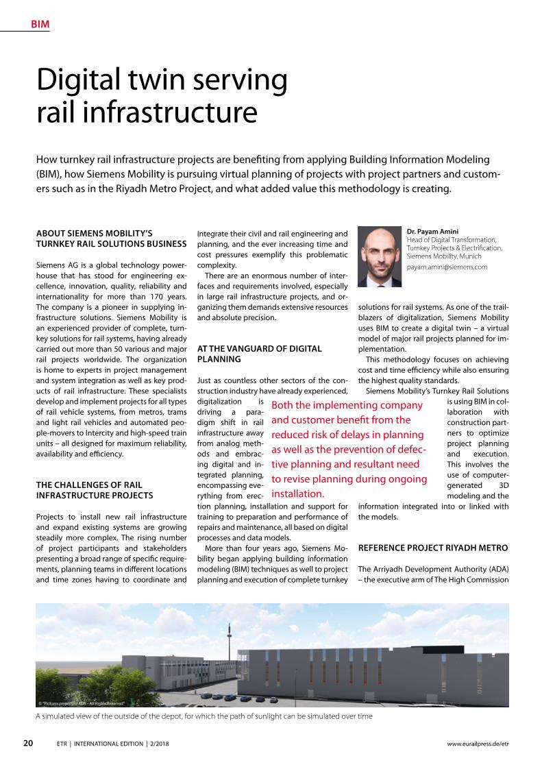
BIM
20 ETR | INTERNATIONAL EDITION | 22018 wwweurailpressdeetr
ABOUT SIEMENS MOBILITYrsquoS TURNKEY RAIL SOLUTIONS BUSINESS
Siemens AG is a global technology power-house that has stood for engineering ex-cellence innovation quality reliability and internationality for more than 170 years The company is a pioneer in supplying in-frastructure solutions Siemens Mobility is an experienced provider of complete turn-key solutions for rail systems having already carried out more than 50 various and major rail projects worldwide The organization is home to experts in project management and system integration as well as key prod-ucts of rail infrastructure These specialists develop and implement projects for all types of rail vehicle systems from metros trams and light rail vehicles and automated peo-ple-movers to Intercity and high-speed train units ndash all designed for maximum reliability availability and eciency
THE CHALLENGES OF RAIL INFRASTRUCTURE PROJECTS
Projects to install new rail infrastructure and expand existing systems are growing steadily more complex The rising number of project participants and stakeholders presenting a broad range of specic require-ments planning teams in dierent locations and time zones having to coordinate and
Digital twin serving rail infrastructure How turnkey rail infrastructure projects are beneting from applying Building Information Modeling (BIM) how Siemens Mobility is pursuing virtual planning of projects with project partners and custom-ers such as in the Riyadh Metro Project and what added value this methodology is creating
integrate their civil and rail engineering and planning and the ever increasing time and cost pressures exemplify this problematic complexity
There are an enormous number of inter-faces and requirements involved especially in large rail infrastructure projects and or-ganizing them demands extensive resources and absolute precision
AT THE VANGUARD OF DIGITAL PLANNING
Just as countless other sectors of the con-struction industry have already experienced digitalization is driving a para-digm shift in rail infrastructure away from analog meth-ods and embrac-ing digital and in-tegrated planning encompassing eve-rything from erec-tion planning installation and support for training to preparation and performance of repairs and maintenance all based on digital processes and data models
More than four years ago Siemens Mo-bility began applying building information modeling (BIM) techniques as well to project planning and execution of complete turnkey
solutions for rail systems As one of the trail-blazers of digitalization Siemens Mobility uses BIM to create a digital twin ndash a virtual model of major rail projects planned for im-plementation
This methodology focuses on achieving cost and time eciency while also ensuring the highest quality standards
Siemens Mobilityrsquos Turnkey Rail Solutions is using BIM in col-laboration with construction part-ners to optimize project planning and execution This involves the use of computer-generated 3D modeling and the
information integrated into or linked with the models
REFERENCE PROJECT RIYADH METRO
The Arriyadh Development Authority (ADA) ndash the executive arm of The High Commission
Both the implementing company and customer benet from the reduced risk of delays in planning as well as the prevention of defec-tive planning and resultant need to revise planning during ongoing installation
Dr Payam AminiHead of Digital Transformation Turnkey Projects amp Electrication Siemens Mobility Munich payamaminisiemenscom
A simulated view of the outside of the depot for which the path of sunlight can be simulated over time
raquo
BIM
21ETR | INTERNATIONAL EDITION | 22018wwweurailpressdeetr
for the Development of Arriyadh in Saudi Arabia ndash is currently building one of the larg-est metro projects in the world with six rail lines totaling 176 kilometers in length The system will be the backbone of the public rapid transit network serving Saudi Arabiarsquos capital city The order placed with Siemens Mobility covers supply of 67 Riyadh Metro model rail vehicles based on the Inspiro Plat-form series line electrication the signaling and communication systems for driverless service on Lines 1 and 2 as well as system integration and project management Sie-mens Mobility is part of the BACS consor-tium led by US company Bechtel along with Almabani General Contractors and Consoli-dated Contractors Company
The Riyadh Metro Project (RMP) kicked o by dening the information requirements and project-specic BIM objectives of the customer The BIM management team of Siemens Mobilityrsquos construction partner Be-chtel then used this information as the basis for elaborating in detail the BIM process for all project participants
The BIM execution plan that denes the BIM process for a specic project basi-cally provides the answers to the agreed require-ments In this key central document Turnkey Rail Solu-tions dened for all project participants in-volved in the infrastructure design the roles and scopes of responsibility the programs and le formats to be used what applica-tions are to be integrated into the BIM pro-cess the data-exchange process along the chain of project phases the quality review inspection and testing criteria procedures for coordination and collaboration and much more This was necessary in order to ensure smooth BIM implementation over the entire project cycle
Siemens Mobilityrsquos construction partner also generated the model element plan which denes in an overview who is to gen-erate what model content for the project by when and to what level of development (ie geometry information and coordination) In this project BIM standard the construc-tion partner also dened the details for modeling agreements and documentation standards
Model-based planning is one of the pro-jectrsquos centerpieces enabling comprehensive integration of all rail infrastructure systems such as rail electrication the depot and workshop equipment line signaling and communication technology and platform screen doors
CLARITY DRIVES THE EFFICIENCY OF WORKFLOWS
Siemens Mobilityrsquos infrastructure planning engineers used project-specic BIM software to share their model-based information with Siemens Mobilityrsquos suppliers and the con-
struction partner The program Pro-jectWise is used in combination with Aconex served and continues to
serve as a shared data platform accessible project-wide ensuring that each piece of information is retained only once and in its most recently valid version In this ldquosingle source of truthrdquo data are referenced rather than duplicated signicantly improving in-formation management increasing the reli-ability of data and eliminating any use of superseded obsolete data This provides full trans-parency for all pro-ject participants Photo-realistic displays and animated videos of the planning progress generated on the basis of the 3D planning information ensure transparency enhance understanding and support the iterative process
The permanent availability of data accel-erates collaboration across national borders and company boundaries These aspects are particularly benecial in the RMP Just Sie-mens Mobilityrsquos unit alone had colleagues based in 13 dierent cities working to de-sign the rail infrastructure coordinating and agreeing across national boundaries and dierent languages time zones and work capacities
In addition to the geometrical properties
of system components for example of fre-quency converters the participating plan-ning engineers also integrated non-geomet-rical information and requirements of their systems such as zones and clearance spaces that are essential for installation and mainte-nance Once work on a subarea of a model (work in progress) was approved for release this information was then available to all partners within the project (shared areas) In turn these partners reviewed the completed work for impacts on their own work scopes
In interdisciplinary collision reviews the design coordinators conducted collision tests with all other draft components Such reviews examined for example the civil struc-tures technical building equipment systems and Siemens Mobilityrsquos systems such as the signaling equipment and traction power supply grid to identify any conicts between
the systems them-selves or with the civil structures
In this way structural imple-mentation of the overall project as
well as individual subareas can be digitally tested at any time
As a provider of turnkey infrastructure solutions Siemens Mobilityrsquos unit was in-volved early in the RMP through BIM help-ing to prevent planning errors and leading to quicker validation of draft planning such as for spatial requirements of infrastructure equipment free clearance proles and pre-venting collisions
The RMP oers a basis for further infra-structure projects using BIM methodology The stock of digital objects available in the component library continues to grow Exist-ing digitally modeled components can be directly used for the next digital twin This
BIM creates full transparency for everyone participating in the plan-ning of infrastructure projects
The Control Center of the Riyadh Metro Project for Line 1 was fully planned digitally Once that design process was completed actual construction started
BIM enables earlier design valida-tion of rail infrastructure technol-ogy and engineering as well as civil construction
BIM
22 ETR | INTERNATIONAL EDITION | 22018 wwweurailpressdeetr
accelerates digital planning from one pro-ject to the next
Siemens Mobility Turnkey Rail Solutions sees particular potential for BIM in integrating the necessary man-agement process-es BIM supports the management of interfaces requirements congurations and project documentation This improved management leads to accelerated project execution And although project execution in Riyadh is still underway the added value created by the BIM method is already clearly evident today ndash for both Siemens Mobility and the customer
DIGITAL SCAN OF THE INFRASTRUCTURE CREATED
Siemens Mobility Turnkey Rail Solutions is utilizing other digital solutions as well for the Riyadh Metro Project that further optimize pro-ject execution Siemens Mobility-owned track measuring vehicles and 3D laser scanners are deployed to eciently compare the progress
of as-built construction and installation against the design target data These units travel along the existing sections scanning and thereby
digitalizing the as-built environment The object-specic information collect-ed by this measur-ing system whether on track position-
ing platform edges or technical spaces is com-pared with the digital design thereby directly revealing any deviations from planning
This produces a 100 -accurate database of the existing as-built status Particularly when projects aim to expand exist-ing infrastructure such transparency prevents costly conicts when equipping existing civil structures with new infrastructure equip-ment Besides the hardware procurement Siemens Mobility is banking in this context on developing the expertise of its own per-sonnel to cover planning of measuring cam-paigns kinematic and static imaging and evaluations such as review for collisions
PROMISING OUTLOOK
Siemens Mobilityrsquos Turnkey Rail Solutions has ceaselessly invested in implementing and further developing digital methods to keep pace with steadily growing deadline and cost pressures and the increasingly stringent demands of complex rail infra-structure projects These efforts are now empowering Siemens Mobility to better assess the sometimes extremely demand-ing detailed requirements early already in the project bidding phase and estimate costs more reliably thereby minimizing risks
In previous projects utilizing BIM meth-odology Siemens Mobilityrsquo experts identi-ed a shifting of eort into the early project phases
Siemens Mobilityrsquo experts see opportuni-ties in doing so particularly in the assess-ment of design modications in terms of im-pacts on costs and in early application when the leverage for such optimization can still prove very eective
Yet BIM doesnrsquot end when construction work on an infra-structure project has been complet-ed By developing a digital twin of the as-built infrastruc-ture and applying
that model over its entire lifecycle these sets of digital data can be used to optimize asset management
The BIM method harbors major potential for signicantly shaping the rail infrastruc-ture sector in the coming years
A view of the digital model of the King Abdullah Financial District Station on Line 1 which can be viewed in the computer pro-gram from all sides
Photo-realistic displays and animat-ed videos of the planning progress ensure transparency and enhance understanding
BIM provides the basis for simpler and ecient interface management and contributes signicantly to accelerating project execution
5 | 2017 Mai wwweurailpressdesd
109 Jahrgang
SIGNALLING amp DATACOMMUNICATION
Oumlsterreich Gut gesichertAustria Well-protected
13 Kostenguumlnstige Sicherung von Eisenbahnkreuzungen Cost-effective protection of level crossings
36 Finnland Gegen den Instandhaltungsruumlckstand Finland Reducing maintenance backlog
21 Schweiz Weltpremiere auf der Toumlsstalstrecke Switzerland A world premiere on the Toumlsstal line
Your contact person Silvia Sander +4940237 14-171 silviasanderdvvmediacom wwweurailpressde
Leader in Signalling and Datacommunication
No 1ad medium
SIGNALLING AND
DATACOMMUNICATION
AUTONOMOUS DRIVING
CYBE
R SE
CURI
TY
LEVEL CROSSING TECHNOLOGY
OPERATIONS MANAGEMENT SYSTEMS
MOBILE COMMUNICATIONETCS
REPUTABLE
UN
IQU
E
ESTABLISHEDTELECOMMUNICATION
OPERATIONS CONTROL TECHNOLOGY
INFORMATION TECHNOLOGYBILINGUAL
Book your advert right now
raquo
Ground Penetrating Radar
23ETR | INTERNATIONAL EDITION | 22018wwweurailpressdeetr
1 INTRODUCTION
Many countries allocate large amounts for the modernization and upgrading of their railway networks in order to meet the de-mands of increasingly dense rail trac with higher axle loads at ever higher speeds However this can only be achieved if all rel-evant key gures and geotechnical condi-
Ground Penetrating Radar ndash Basis for eective Track MaintenanceThis article describes the capabilities and functionality of Ground Penetrating Radar (GPR) for higher speeds GPR is a train-borne technology for a continuous inspection of the geotechnical conditions of railway tracks The basic principles of the GPR technology are explained with particular reference to all relevant railway specic tasks namely the identication qualication and quantication of ballast fouling by using a fouling index the determination of the quality of track drainage and its quantication through a drainage index and the calculation of the track modulus (TM) Special emphasis in the context of GPR investigations is placed on the mapping of sections with clay foulingmud spots inside the ballast bed or at its base and respectively inside intermediate layer formation or subsoil In the past such weak-spots have caused derailment they could represent a risk for rail-trac [11 13 14 15 16] Besides their late detection implies exceedingly high maintenance costs
tions of the respective tracks can be reliably evaluated On this basis only the necessary investments in track maintenance moderni-zation and support can be dened in the ap-propriate size and can be placed correctly This is particularly true when budgets are tight
The demands exerted on the track in terms of safety grow with increasing speed
FIGURE 1a) Trajectories of radar waves which are reected at the layer boundary between two media
with dierent dielectric constant (laquo)b) Due to the dierent travel time of the reections the layer boundary is reproduced in the
radargram (reference Ground Control and IEV)
Dipl-Geophys Giuseppe StacconeDirector of Ground Control GmbH MunichGermanystacconesaferailsystemcom
David Camacho MScDoktorand am Institut fuumlr Eisen-bahn- und Verkehrswesen der Universitaumlt Stuttgart (IEV)davidcamacho ievvwiuni-stuttgartde
Moritz SchebuchMitarbeiter am Institut fuumlr Eisen-bahn- und Verkehrswesen der Universitaumlt Stuttgart (IEV)moritzschebuch ievvwiuni-stuttgartde
Prof Dr-Ing Ullrich MartinDirektor des Instituts fuumlr Eisenbahn- und Verkehrswesen der Universitaumlt Stuttgart (IEV) und des Verkehrswis-senschaftlichen Instituts an der Universitaumlt Stuttgart eV (VWI eV)ullrichmartin ievvwiuni-stuttgartde
Dipl-Ing Sebastian RappAkademischer Mitarbeiter am Institut fuumlr Eisenbahn- und Verkehrswesen der Universitaumlt Stuttgart (IEV)sebastianrapp ievvwiuni-stuttgartde
Ground Penetrating Radar
24 ETR | INTERNATIONAL EDITION | 22018 wwweurailpressdeetr
Therefore failing to detect track damages or obtaining inadequate information on track damages represents a hazard for every kind of railway trac For this reason a decision guidance that facilitates a systematic and ecient renewal of the tracks is important The more intensive the rail trac and the higher the trac speed the bigger the re-quirements in terms of an ecient and reli-able track inspection
The mapping of clay fouling or mud sec-tions is of special importance Fine-grained soil material such as silt or clay wells up from the formation and reaches the ballast base or even penetrates the ballast layer itself As a consequence track drainage and track stability (ie bearing capacity) are strongly reduced This results in lasting deformations that require complex maintenance work and high costs If weak-spots are not identied or not detected in time clay fouling can in the worst case scenario lead to derailment [10 13 14 15 16]
During the past 25 years Ground Control GmbH which is placed in Munich Germany has surveyed more than 100000 km of rail-way tracks in many countries in Europe and all over the world Recently with information obtained from GPR results and other data (ie track geometry and track dynamics) a continuous and complete assessment of the trackrsquos structural condition is possible
2 MEASURING PROCESS
The GPR method is an electromagnetic re-ection method Radar pulses are transmit-ted into the subsoil by a transmitter antenna The energy of the electromagnetic waves is partly reected at interfaces between layers with dierent dielectric properties and re-transmitted to the receiver antenna Based on the measured travel time of the signals and knowing the propagation speed of the waves in the medium depth and surface of the layer can be computed
In order to dene the depth of the re-ector from the surveyed travel time the propagation speed of the radar waves in the subsoil has to be determined The speed of electromagnetic waves in the subsoil is re-lated to the water content of the individual material Therefore it is generally not pos-sible to refer to reference values for certain rock or soil types Thus the radar wave speed has to be calibrated for each project area
The penetration of electromagnetic waves mainly depends on the electric conductivity of the soil and the applied antenna frequen-cy By using low frequency antennae on low conductive subsoil the largest investigation depth can be achieved
PERFORMING SURVEYS WITH MODERN HIGH-SPEED-GPR
Todayrsquos GPR surveys are carried out with train mounted systems at speeds up to 160 kmh As a general rule the antennae system is fastened at the carrier vehiclersquos buers A precise positioning is achieved by an inte-grated Dierential Global Positioning Sys-tem (DGPS) and Doppler radar
The characteristics of modern GPR sys-tems are
rarr The equipment can be installed and run on a wide range of track-bound vehicles (including regular trains or vehicles on Hy-Rail)
rarr They are fast enough to be integrated into the regular trac schedule Hence expensive track closure is no longer nec-essary
rarr DGPS and Doppler radar are used for an accurate (ie precision within a meter) positioning of the antenna independ-ent of the speed and length of the track surveyed
rarr Measurement data resolution and data quality are equally high no matter what length and what speed
rarr All GPR components are eectively
shielded against interferences from sig-nalling and communication systems
3 GPR TASKS
In contrast with punctual boreholes and trenches modern GPR systems provide con-tinuous information about the geotechnical condition of the track performing the fol-lowing tasks
rarr Continuous mapping of track-bed-thick-ness and layers below (ie intermediate layer protective layers)
rarr Distinction between clean and fouled ballast and calculation of Fouling Index
rarr Mapping of mud spots or clay fouling sections inside ballast bed at its base or inside substructure layers respectively
rarr Detection of sections with drainage problems and calculation of ldquoWet Bed Indexrdquo
rarr Mapping of areas with insucient bearing capacity (eg settlements) and evaluation of the dynamics of track set-tlement
rarr Control and evaluation of the quality of maintenancerenewalconstruction work (quality of cleaned or exchanged ballast thickness of a new ballast bed quality and thickness of soil layers)
rarr Estimation of track condition based on track modulus (TM) calculation
Additionally GPR data allow for the deni-tion of a sustainable cause-based and there-fore eective track renewal recommenda-tions and programs Optionally GPR oers the possibility to accurately map cables pipes and other objects in the track sub-structure creating the possibility to provide a complete picture of the entire system
31 CLAY FOULING ndash STRONG EFFECT ON TRACK STABILITY
Clay Fouling is one of the main reasons for the reduction of the load bearing capacity of the track in a relatively short period of time Several derailments in the past were caused by mud spots [10 13 14 15 16] even when the limit values for track geometry failures according to [2] have not been exceeded [13 14] It is therefore and because of safety reasons of particular importance to detect clay fouling areas reliably in their precise dimension and as early as possible The rec-ognition of the problem should be irrespec-tive of whether the clay fouling exists in the substructure at the base of the ballast bed or in the ballast bed itself Clay fouling can
FIGURE 2 Figure 2 Antenna mounted on the train buers of a mainte-nance vehicle(reference Ground Control)
Ground Penetrating Radar
25ETR | INTERNATIONAL EDITION | 22018wwweurailpressdeetr
raquo
rapidly deteriorate the stiness of the track and its quality The trackrsquos lateral stability is massively reduced longitudinal errors along the rails arise
Clay fouling is also a serious decit from an economic point of view Its timely iden-tication allows for avoiding slow speed sections thus sparing time and money for maintenance procedures Detecting clay fouling before it reaches the ballast bed ena-bles cost eective renewal Otherwise it will be very expensive There is no option for bal-last cleaning a suciently compacted pro-tection layer built of the appropriate materi-al is essential the installation of composites does not prevent clay fouling from entering the ballast bed (see Fig 3)
Save few exceptions clay fouling spots are not visible at the track surface and since drill-ings and trenches do only provide punctual results reliable information is only achievable through GPR measurements (see Fig 4)
A frequency analysis of the measured data results in a typical change of the signal spectrum in the area of clay fouling Based on the GPR results borehole program can be implemented which can be used for further analysis GPR surveys to detect ballast foul-ing have been carried out for years in Swit-zerland Austria the Netherlands and France among others
32 TRACK MODULUS (TM)
Examining the geotechnical conditions of railway tracks requires an index which in-forms about state and quality of the tracks in a quantitative manner The challenge has
been to dene the track condition continu-ously This has been achieved by combin-ing TM with the results of continuous GPR-measurements
It is possible based on [3 4 5 6 7] to es-timate quality and bearing capacity of the railway track Therefore the TM describes the relation between vertical load and elas-tic deection of the sleeper-bearings
On the one hand the TM can be calculated based on the measured deection under load [18 20] on the other hand according to the soil properties [8 9 11] The measuring principle for determining the load deec-tion is described in detail in [12] and [17] The properties of the system components such as the area of inuence of the sleepers under load can greatly aect the TM Hence around turnouts the area of inuence of sleepers deviates from the standard track This is because an increased area of inu-ence causes an increase in the distribution of the load reducing the deection of the
rail Notwithstanding to simplify the calcula-tion of the TM the inuence area of sleepers around turnouts are assumed to be constant assuming the values of the standard track Depending on the type of sleepers installed the value of the TM can increase sharply around turnouts (Fig 5) In addition cavities under the sleepers increase the deection of the track under load which in turn inu-ences the calculation of the TM decreasing its value
An additional and new approach for calcu-lating the TM is based upon the soil proper-ties which can be described by the Poissonrsquos Ratio or the material density of the soil The soil properties derive from the GPR data This methodrsquos advantage is to be completely in-dependent from superstructure conditions The individual layers are assigned soil values according to condition and bulk density Averaged soil properties are calculated ac-cording to [1 19] The TM can be estimated according to [9] and [11] Previous studies
FIGURE 4 Visual analysis of GPR data depicting clay fouling along a track (reference Ground Control and IEV)
FIGURE 3 Geotextile or composite does not stop ne particle migration to the surface (reference Ground Control)
Ground Penetrating Radar
26 ETR | INTERNATIONAL EDITION | 22018 wwweurailpressdeetr
indicate that this method has signicantly lower value variations along the track axis compared to the approach based on the use of track displacement data (Figure 5)
The example in Fig 5 shows two track moduli based on the measured displacement under load (red line) and the soil properties (blue line) Around the turnouts a signicant increase of the TM is visible if the calculation is based on the measured deection By divid-ing the TM into quality classes according to [3 4 5 6 7] the condition of the track can be sat-isfactorily estimated (Fig 6)
33 TRACK ANALYZER ndash CONTINUOUS PRESENTATION OF ALL MEASUREMENT AND TEST RESULTS
Results from GPR surveys along with all identied soil parameters and indices cal-
culated can be displayed in comprehensive track analysis software called ldquoTrack Analyz-errdquo In order to provide all information for in-frastructure managers track geometry and track dynamics data are also integrated and displayed in the software (see Fig 7) which also oers the exibility to incorporate other tasks and aspects as required by the user
The Track Analyzer provides infrastructure managers continuous information about the geotechnical conditions of the track with regard to all relevant issues Moreover it provides a better understanding of the sub-structuresubgrade conditions and their in-uence on the superstructure This allows for a signicantly increased track quality pro-viding higher route availability and safety
A big advantage of the GPR method is the minimization of the need for intensive direct outcropping (probing drilling scooping)
to characterize the underlying geotechni-cal characteristics of the track substructuresubgrade which results in signicant cost reductions
4 SUMMARY
This paper describes a modern train-borne technology for the inspection of the geo-technical conditions of railway tracks It is based on High Speed GPR and on classical procedures for providing continuous infor-mation about geotechnical parameters and indices A new quality of GPR measurements is to provide quantitative indices in addition to qualitative results to full the require-ments of the railway engineers in the best possible way
Special attention is paid to the detection of mud spots and clay fouling sections as a risk for derailment [10 13 14 15 16] To date track inspection with GPR is more appropri-ate than any other inspection method to de-tect map and qualify areas with geotechni-cal problems
The Track Analyzer software combines GPR results with track geometry and track dynamics data This allows for cause-based track renewal and targeted investment and provides signicantly more reliable results than conventional methods This approach is especially relevant for limited budgets
Literature [1] Adam D Kopf F Dynamische Eekte durch bewegte
Lasten auf Fahrwegen In Bauingenieur Ausgabe 01-2003 2003
FIGURE 5 TM calculated from measured displacement under load (red graph) and soil proper-ties (blue graph) (reference IEV)
FIGURE 6 TM divided in dierent quality classes (reference IEV)
Ground Penetrating Radar
27ETR | INTERNATIONAL EDITION | 22018wwweurailpressdeetr
FIGURE 7 Track Analyzer(reference Ground Control)
[2] DB Netz AG Ril 821 Oberbau inspizieren Deutsche Bahn AG guumlltig ab 01052004
[3] Eisenmann J Stuumltzpunktelastizitaumlt bei einer Festen Fahrbahn In ZEV + DET Glasers Analen 111999
[4] Fendrich L (Hrsg) Handbuch Eisenbahninfrastruktur Springer-Verlag Berlin Heidelberg 2007
[5] Goumlbel C Lieberenz K (Hrsg) Handbuch Erdbau-werke der Bahnen DVV Media Group GmbH 2013
[6] Leykauf G Lothar M Elastisches Verformungsver-halten des Eisenbahnoberbaus ndash Eigenschaften und Anforderungen In EI ndash Eisenbahningenieur 031990
[7] Lichtberger B Handbuch Gleis DVV Media Group GmbH 2010
[8] Martin U Rapp S Ansatz zur Erfassung der Bodenei-genschaften am Bahnkoumlrper in Schotterbauweise In ETR ndash Eisenbahntechnische Rundschau 042017
[9] Martin U Rapp S Camacho D Moormann C Lehn J Prakaso P Abschaumltzung der Untergrundverhaumllt-nisse am Bahnkoumlrper anhand des Bettungsmoduls In ETR - Eisenbahntechnische Rundschau 052016
[10] Rail Accident Investigation Branch Freight train de-railment near Gloucester 15 October 2013 Rail Acci-dent Report102014
[11] Rapp S Modell zur Identizierung von punktuel-len Instabilitaumlten am Bahnkoumlrper in konventioneller Schotterbauweise Dissertation ndash Institut fuumlr Eisen-bahn- und Verkehrswesen der Universitaumlt Stuttgart 072017
[12] Soldati G Meier M Zurkirchen M Kontinuierliche Messung der Gleiseinsenkung mit 20 t Achslast In EI ndash Eisenbahningenieur 022016
[13] Untersuchungszentrale der Eisenbahn-Unfalluntersu-chungsstelle des Bundes Untersuchungsbericht Ak-tenzeichen 60 ndash 60uu2011-0200041 Zugentgleisung Groumlbers ndash Groszligkugel 062013
[14] Untersuchungszentrale der Eisenbahn-Unfalluntersu-chungsstelle des Bundes Untersuchungsbericht Ak-tenzeichen 60uu2013-06047-3323 Zugentgleisung Kaub ndash Lorch (Rhein) 062013
[15] Untersuchungszentrale der Eisenbahn-Unfalluntersu-chungsstelle des Bundes Untersuchungsbericht Ak-tenzeichen 60 ndash 60uu2011-0400043 Zugentgleisung Bf Hannover ndash Linden 092013
[16] Versa Verkehrssicherheitsarbeit fuumlr Oumlsterreich Unter-suchungsbericht Sicherheitsuntersuchungsstelle des Bundes BMVIT-795336-IVBAVUUBSCH2013 Ent-gleisung eines Guumlterzugs am 14 Februar 2013 2013
[17] Wang P Wang L Chen R Xu J Overview and out-look on railway track stiness measurement Jour-nal of Modern Transportation Volume 24 Issue 2 062016
[18] Winkler E Die Lehre von der Elastizitaumlt und Festigkeit Verlag von H Dominicus 1967
[19] Wolf J P Foundation Vibration Analysis using Simple Physical Models Swiss Federal Institute of Technology 1994
[20] Zimmermann H Die Berechnung des Eisenbahn-oberbaus 1888
wwwrex-industrie-produktede
INSULATING JACKETS FORHIGH TEMPERATURE INSULATION
high temperature resistant up to 1000degC
incombustible
high insulation performance
tailor made according to your wishes
New test reports for fire protection according to EN 45545-2 available R1R7R17 with Hazard Level HL 3
Distributed Acoustic Sensing
28 ETR | INTERNATIONAL EDITION | 22018 wwweurailpressdeetr
Dip-Ing FH MScMartin RosenbergerCTO Frauscher Sensor Technology martinrosenberger frauschercom
This involves planning and controlling maintenance measures based on the actual condition of the equipment systems and components (assets) Unexpected events due to faulty components and unnecessary work on fully intact elements can thus be reduced This is possible thanks to the ever increasing amount of reliable data about the condition of the asset that is available in real time
Continuous acoustic condition monitor-ing of the infrastructure based on Distribut-ed Acoustic Sensing (DAS) is a key building block of future solutions This technology can considerably increase the availability of rail networks since it continuously delivers very precise information about the condi-tion of the infrastructure and any changes thereby fullling a key prerequisite for the use of CBM solutions
The sensor technology and inspections form and remain the basis for condition-based maintenance of the track These in-clude track recording vehicles xed meas-urement points sensor technology on
How Distributed Acoustic Sensing supports condition based maintenance strategiesCurrent technological developments are opening up new opportunities for the railway industry in a whole range of application areas Most notably these include networking digitalization and the Inter-net of Things (IoT) This trend is also having a growing impact on processes and strategies for maintain-ing rolling stock and infrastructure Traditional maintenance philosophies which are based on xed intervals or in the case of vehicles on mileage are increasingly being replaced by predictive condition based maintenance (CBM)
standard trains track-side sensor technol-ogy selectively deployed manual measur-ing instruments and self-monitoring infra-structure systems Data from these sources must be consolidated and if applicable combined with information about rolling stock and system-side infrastructure data such as a system directory or inputs from other sensors
DAS enables a sensor solution to be cre-ated which fulls several of the specied re-quirements this technology allows railway networks to be monitored continuously in real time and with respect to a huge num-ber of dierent events Frauscher has devel-oped its own DAS solution for the railway sector Frauscher Tracking Solutions FTS The manufacturerrsquos team tested the tech-nology and through intensive develop-ment eliminated constraints with respect to use for rail trac To create this in-depth knowledge of DAS as well as requirements and standards in the railway industry was required
1 DAS FUNCTIONAL PRINCIPLE
DAS-based systems use laser pulses sent in a glass bre to detect events on or in the vicinity of the track part of the laser pulse is reected back out of the bre to the transmitting unit The sound and vibration waves impacting on the cable result in signicant shifts in the reection (Fig 1) The maximum frequency range of the vibrations detected in this man-ner is 125 kHz Using specically developed algorithms the acquired data can be used to calculate specic signatures in real time These describe highly precise locations and types of processes in the vicinity of the track
One of the advantages of installing a DAS system is that the bre optic cables it requires are often already laid next to the tracks These are normally used for commu-nication purposes As the optical bres used require practically no maintenance the sys-tem can be rolled out to large sections of the route extremely economically and ecient-ly In practice a single DAS unit can eective-ly cover up to 40 kilometres of glass bre in each direction so 80 kilometres in total [1]
2 CONTINUOUS MONITORING OF WHEEL-RAIL INTERACTION
The ongoing analysis of infrastructure us-ing FTS is based on continuous monitoring
FIG 1 Distributed Acoustic Sensing (DAS) allows for the detection of vibrations and sound waves caused by trains component defects people or other sources
raquo
Distributed Acoustic Sensing
29ETR | INTERNATIONAL EDITION | 22018wwweurailpressdeetr
of wheel-rail interaction (Fig 2) On the one hand this enables the detection of changes that arise slowly over the course of time To do so the system compares the relevant signatures that are captured each time a railway vehicle passes a spot On the other hand events that occur suddenly can also be reliably detected
21 TREND ANALYSIS FOR LOCALISATION OF CONDITION CHANGES
The wheel-rail interactions quality is the most important factor when it comes to the service life of both system components and the rolling stock This quality is derived from various parameters such as the roundness of the wheel the surface of the rail and the track design Even slight deviations from the ideal parameters result in increased signs of wear and tear over a certain amount of time Ultimately these can also lead to critical op-erating conditions Which is why continu-ous detection and thus early recognition of changes in condition along the entire route is extremely useful
This is where the FTS come into play by evaluating the signatures in the laser signal feedback it is possible to determine wheth-er a sp ecic anomaly in wheel-rail interac-tion comes from the train or from the infra-structure This is possible because the FTS system uses a glass bre as a permanent sen-sor along the track thus allowing the wheel-rail interaction for each individual axle on all train journeys to be permanently monitored along the entire route Changes are detected in real time and the method does not de-pend on a xed measurement point
If a notication is triggered by an out-of-round wheel for instance then this pattern will be part of the train signature and be de-tected in association with the moving train This allows the event to be clearly attributed to vehicle damage
By contrast if there is a change to the in-frastructure several axles will have a notice-able signature in one specic position The system uses this to determine an indicator Based on this trend analyses are formed for individual ten-metre long infrastruc-ture segments Warning or alarm notica-tions can now be created and transmitted through dened user-congured threshold values These indicate the type of change as well as the location With good georefer-encing for the bre optic cable the position identied via FTS can be localised to an accu-racy of up to ve metres and made available via machine-readable interfaces
Frauscher oers powerful interfaces for employees in railway infrastructure compa-
nies In particular these include a graphical user interface with map view and heat maps and depiction of the infrastructure condition in denable categories The zoom function can be used to display the entire route or a position with relevant localisation in route kilometres or GPS data the actual condition and the change in condition over a specic period Filters can be set for even more de-tailed analyses and evaluation
22 EVALUATION OF CHANGES IN CONDITION AS A PROCESS
To determine the relevance for a specic rail-way operation simply identifying a change in condition is not enough The trend analy-sis must also be correlated with the trains and their speeds After all identical techni-cal non-conformities will result in indicators with completely dierent frequencies and intensities when a heavy long freight train and when a lighter short passenger train travels over a position with a fault
Therefore a basic condition must rst be dened for the infrastructure and stored in the FTS The trend analyses can then be ap-plied to this To do so the system structure (primarily bridges tunnels or points) must be logged in the system and the sensor must be calibrated accordingly Data that needs to be entered includes rail joints or transitions from a point for example They create similar patterns to those of a rail defect but must be evaluated and examined dierently
It may also be necessary to lter out am-bient noise from stationary systems such as pumps and generators so that this does not have a negative eect on the detailed analy-sis of the wheel-rail interaction signature
These adjustments are currently carried out manually during the installation and com-missioning process However Frauscher is developing tools to automate these process-es These steps form part of the technologyrsquos path towards serial production
Once the basic condition has been dened then depending on the model the operator will receive regular reports or warning and alarm notications via dened interfaces The DAS systems that are currently available are not yet able to classify and quantify the changes detected with sucient accuracy Maintenance personal therefore take on the task of evaluating suspect positions through inspection actions during the development and installation phase A visual inspection is often enough to identify the cause of the warning classify the change and take the necessary action within a dened period
Based on experience with several installa-tions and Frauscherrsquos collaboration with op-erators there are essentially three relevant classications
rarr No detectable or only minimal damage rarr Non-critical damage rarr Critical damage
What is important is that this evaluation and classication is understood and followed as part and parcel of the maintenance process Dening the threshold values and deter-mining the sensitivity of the system is a key step in this regard Experienced specialist sta who evaluate and process the notica-tions can shape the system to suit their own needs This allows CBM concepts to be ap-plied even more eciently for practical sup-port and to build expertise (Fig 3)
The high sensitivity level of the system
FIG 2 By continuously monitoring the acoustic signature of the wheel-rail contact the FTS support condition based maintenance strategies
Distributed Acoustic Sensing
30 ETR | INTERNATIONAL EDITION | 22018 wwweurailpressdeetr
means that a range of errors can be detected at a very early stage However this also in-creases the risk that positions that are not relevant for maintenance will be displayed This is where empirical values are really needed so that the optimum setting can be tuned for the operator It is crucial to involve the maintenance personnel in this whether through the operator or the service contrac-tor After all only experts on the ground can evaluate the condition of the infrastructure and determine the necessary measures Maintenance employee experience thus re-mains essential for training the algorithms and evaluating the results the maintenance personnel must use their knowledge of routes and systems to determine whether a notication is in fact relevant or not
Not detectable or only minimal damageIn this case no maintenance measures are needed There are three main reasons why the system has indicated a potential fault in this case First there may be a structural fac-tor in the infrastructure or a factor in the en-vironment of the trigger In this case the in-uencing factor can be ltered out in future Secondly it could be that a visual inspection reveals no detectable fault but there are already signs of wear In this case the user
would add information to the system stating that this section is to be kept under observa-tion or specically monitored over a certain period of time ndash for example by adjusting the threshold value If the system contin-ues to exhibit a fault it is advisable to apply analysis methods that go beyond a visual inspection of this point or use other meas-urement data as a comparison Thirdly this could be due to a minor surface fault on the rail for example which does not require any action since scheduled surface processing measures are due to be carried out (Fig 4) In this case the fault message can be acknowl-edged
Non-critical damageIn this case the system has identied a rel-evant fault but it does not need to be cor-rected right away (Fig 5) The main advan-tage of this is that early detection allows the necessary measures to be planned in good time so these can be put into eect during quiet periods or eciently combined with other measures thus reducing the number of expensive individual activities
Critical damageIf such changes are detected then measures must be initiated immediately in order to re-
solve the safety-critical operating condition and minimise any expensive subsequent damage Experience shows that such critical conditions can develop over just a few days or can even be triggered by acute short-term factors Examples include ballast voids due to washout rail head cracks and broken rails
Critical conditions can arise during the analysis cycles even if the rail network is monitored regularly with track recording ve-hicles for example Continuous monitoring of the wheel-rail interaction enables quicker intervention and minimises personal injury and damage to property
23 EMPIRICAL RESULTS
In addition to various applications which can be used in real time on the basis of train lo-calisation over the last two years Frauscher has been taking a closer look at infrastruc-ture maintenance In particular at the po-tential that continuous monitoring of the wheel-rail interaction has to oer in the fol-lowing scenarios
rarr Rail monitoring rarr Rail fastening and sleeper monitoring rarr Track substructure and superstructure
monitoring
Practical application has shown that the data that can be provided via the FTS system al-ready oers a range of interesting options it helps users to plan and control maintenance measures in good time To do so Frauscher implements technology such as machine learning pattern recognition and articial
FIG 3 When developing advanced main-tenance solutions various levels within a railway network have to work together closely
FIG 4 Changes in the trackrsquos surface can be detected evaluated and considered when planning maintenance works
FIG 5 Detecting small defects allows for a targeted monitoring in order to generate alarms when their condition deteriorates
Distributed Acoustic Sensing
31ETR | INTERNATIONAL EDITION | 22018wwweurailpressdeetr
intelligence However in order to move to the next level a solid base of empirical val-ues and a library of signatures from a variety of sources of damage are needed
The company is working very closely with the operators of several installations select-ed from approximately 30 projects that are currently ongoing worldwide They are joint-ly considering the evaluation interpretation and derivation of measures Specic issues and ideas for further development of the evaluation software and logic are directly incorporated into Frauscherrsquos development processes using agile methods
Rail monitoringAll types of rail damage that cause vibrations or a noise spectrum that deviates from the norm are detected This ranges from surface damage such as rail corrugation squats rail head cracks wheel burns or corrosion and dents to cracking and ssuring or even bro-ken rails
Unsurprisingly the algorithm for detect-ing rail damage also detects rail joints After all the signature of a gap as in an isolation joint could be exactly the same as that for a break in part of the rail In this case depend-ing on requirements these rail joints can be suppressed or specically monitored with their own threshold values (Fig 6 7) The sensitive sensor system can detect broken rails as a train passes over them with high probability However due to the many dif-ferent forms and physical basic conditions a warning system with a 100 percent de-tection rate and zero error rate cannot be achieved
In addition there are still no empirical val-ues for broken rails which can be traced back to warping and thermal eects without the eect of the train Noises that arise due to warping (thermal popping) were detected during tests designed to identify and local-ise landslides and rock fall These are hard to classify or uniquely identify using the cur-rently available hardware and software It is to be assumed that a rail that breaks for thermal reasons generates a similar if more intensive signature and it is not possible to clearly distinguish this from the ldquothermal poprdquo
Therefore it is important to consider whether continuous monitoring of the tracks with appropriate trend analyses does not provide more information about the safety of the route than a warning system for broken rails Last but not least broken rails should generally be reduced by as-required maintenance measures
Rail fastening and sleeper monitoringIn several installations positions were de-
tected that exhibited increased vibration due to damaged or missing rail connections or broken sleepers These are typically faults that do not necessarily require action to be taken right away Instead they are classied in such a way that these tasks will be car-ried out during upcoming scheduled on-site maintenance
Track substructure and superstructure monitoringThe FTS system is able to localise weakness-es in the substructure and track superstruc-ture such as ballast voids under sleepers cavities or compacted areas The condition of the track bed may under certain circum-stances also lead to a critical situation in a relatively short period of time particularly in mountainous regions where heavy rain or mudslides can also make the track position unstable Practical examples also exist for these scenarios where FTS localised critical positions where ballast voids under sleepers were later identied
3 SUMMARY
Continuous monitoring of wheel-rail interac-tion based on FTS opens up numerous pos-sibilities for the user in terms of timely detec-tion of weaknesses and changes in condition on the route Thus targeted and as-required maintenance measures can be dened planned and eciently controlled This is a paradigm shift in terms of maintenance strategy similar to that which is emerging for vehicles Before xed periods based on theoretically calculated average loads were
key to the strategy Now the actual wear and condition of the specic component (rail surface fastening sleeper substructure or track superstructure) are the trigger for maintenance repair or servicing work
These new options for monitoring infra-structure will not replace existing measure-ment systems instead they will enhance them They will change the maintenance processes mainly through the high-pre-cision and early detection of continuous changes By determining individual thresh-old values necessary work can be planned and carried out preventively before critical damage arises
In addition to such continuous changes the FTS is also able to detect vehicle faults and short-term sporadic inuences on trackside infrastructure This includes natu-ral hazard management such as falling rocks and trees catenary ashover or protecting infrastructure from vandalism cable theft or unauthorised access to track systems
Even in times of advancing digitalisation employee experience forms an indispensa-ble basis for railway operations Manufac-turers and operators must work together to develop systems for CBM concepts and individually calibrate them so they become helpful tools which raise eciency while re-ducing ongoing costs
Literature[1] Rosenberger Martin Lancaster Gavin Real-time track
monitoring for sustainable maintenance strategies ETR International 12017 P 20-23
FIG 6 Rail joints are specic points which can be monitored via FTS by storing their base signature in a rst place
FIG 7 If the condition of the rail joint chang-es its acoustic signature will do the same
Smart Tamping
32 ETR | INTERNATIONAL EDITION | 22018 wwweurailpressdeetr
Plasser amp Theurerrsquos development of the turnout tamping assistance system ldquoPlasserSmartTamping ndash The Assistantrdquo has been an important step towards the further automation of tamping machines The assis-tance system provides automated support for tamping works in turnouts and crossings It recommends specic actions which must be conrmed by the operator before they are carried out As a result operators increasingly monitor processes intervening manually only in exceptional cases A new recording module allows for a completely new form of tamping documentation It increases transparency working quality and process reliability For the rst time the turnout tamping simulator ndash not a tamping machine ndash was used to develop all of the software modules of the turnout tamping assistance system In an extended hardware-in-the-loop application the turnout tamping assistance system was developed and tested using the simulator
David BuchbauerProject Manager for tamping and measuring technologydavidbuchbauer plassertheurercom
Dipl-Ing Martin BuumlrgerHead of Digital Track Systemsmartinbuerger plassertheurercom
Andreas Theiszlig MScProduct Owner Smart Tamping minus The Assistantandreastheissplassertheurercom
Dipl-Ing Georg JodlbauerHead of Research and Testinggeorgjodlbauer plassertheurercom
Dr techn Gerald ZaunerDigital Track Systemsgeraldzaunerplassertheurercom
Dipl-Ing Dr techn Florian AuerDirector of Technology and Innovationorianauerplassertheurercom
1 THE DEVELOPMENT
In modern track maintenance the conven-tional distinction between track inspection vehicles and track construction and main-tenance machines has increasingly been blurred To optimise processes track con-struction and maintenance machines are t-ted with the latest sensor technology turn-ing them into ldquosmart machinesrdquo Inertial track measuring systems used up to now only on track inspection vehicles have increasingly been installed on tamping machines This makes it possible to use tamping machines for separate track measuring runs to calcu-late the required track geometry correction values
The use of inertial track measuring sys-tems optimises the track geometry quality In addition laser scanners and light section sensors make it possible to create a ldquodigital track twinrdquo which provides the data base of the turnout tamping assistance system
2 THE OBJECTIVE OF THE TURNOUT TAMPING ASSISTANCE SYSTEM
Turnout tamping (Figure 1) requires consid-erable knowledge of several areas of exper-tise (track surveying machine technology track technology regulations) The most im-portant tasks include
Smart Tamping ndash Fields of Application of the Turnout Tamping Assistance System
rarr In the main tamping cabin Controlling the tamping unit including the turnta-ble opening width and tilting motion of the tines
rarr In the co-tamping cabin Controlling the lifting and lining unit the parts of the tamping units in the diverging track and the additional lifting unit
The turnout tamping assistance system com-plies with level 3 of the standard SAE J3016 The standard denes terms related to on-
road motor vehicle automated driving sys-tems and has been applied correspondingly On the automation level 3 the system rec-ommends specic actions which must be conrmed by the operator before they are carried out with the operator as fallback The design of the turnout tamping assis-tance system also allows for higher levels of automation However for reasons of liability automation options such as remote control or robot operation are not oered
The turnout tamping assistance system
Smart Tamping
33ETR | INTERNATIONAL EDITION | 22018wwweurailpressdeetr
raquo
oered to machine operators and infrastruc-ture managers consists of four product parts in modular design
rarr recording module for recommendations and operations
rarr operation assistant for the lifting and lin-ing unit
rarr operation assistant for the additional lift-ing unit
rarr operation assistant for the tamping unit
The modular design makes it easier to put the turnout tamping assistance system into operation for the rst time In a testing phase recording modes can be used to verify the accuracy of the recommended measures (comparison of the actual taming operations and the actions recommended by the assis-tance system) Upgrading to a higher level is possible if it has been taken into account in the design of the machine The modules are activated step by step to allow sta to famil-iarize themselves with the assistance system and to coordinate the work processes
3 THE RECORDING MODULE ldquo DIGITAL TRACK TWINrdquo
The rst step is to develop the digital track twin When selecting the hardware compo-nents of the turnout tamping assistance sys-tem (one rotation laser four light section sen-sors and one colour camera) it was ensured that the hardware can be exchanged and that the software can be adapted modularly
When designing the hardware components a particular focus was placed on meeting the accuracy requirements In addition it was ensured that the system is highly robust and easy to maintain
The recording module of the turnout tamping assistance system connects the digital twin of the track with the working parameters of the machine As a result the quality control of tamping works reaches a new transparency level Infrastructure op-erators can easily access all parameters rel-
FIG 1 Operators of turnout tamping machines must meet high requirements
FIG 2 Tamping docu-mentation using multi-layer technol-ogy (schematic representation)
evant to quality and work (such as the tine position tamping depth or squeeze time) digitally and immediately when connected to the Internet
In the future the recording document will also include the rolling marks of the rails and the position of the aluminothermic welds As the software is developed in-house we can meet our customersrsquo requirements exibly (Fig 2) For instance it will be possible to ex-port the ldquodigital twinrdquo for use on the tamping simulators
Smart Tamping
34 ETR | INTERNATIONAL EDITION | 22018 wwweurailpressdeetr
4 OPERATION ASSISTANCE
Based on their position at the time of record-ing the individual scans and recordings are merged to form a 3D image of the reality showing the exact position At the same time the position of the machine and every indi-vidual work unit is continually updated As a result a 3D image of the relevant machine parts is imported into the overall model pro-viding the basis for every decision of the as-
Federal Railways (OumlBB) and experience from practical operation A specic adaptation to the infrastructure managerrsquos requirements is possible
Figure 4 shows a list of position sensors angle sensors and actuators operated by the assistance system The values of the lin-ing adjustment the lifting operation and the tamping parameters (multiple tamping tamping vibration frequency squeeze force tamping depth) are not controlled by the as-sistance system
The turnout tamping assistance system has been designed for two applications In the rst design version (the separate view) separate measures are recommended to the operators in the main tamping cabin and the co-tamping cabin The second design version (the combined view) is the current develop-ment focus Both assistance modules are merged into a combined view in the main tamping cabin enabling the operator in the main tamping cabin to control the entire turn-out tamping process by himself (Figure 5)
The application focus of the rst genera-tion of the turnout tamping assistance sys-tem is on turnouts that have not yet been fully ballasted As a result the surface of the sleepers is visible Specic recommenda-tions require a good view onto most of the turnout area the sleepers and obstacles (such as switching contacts turnout operat-ing units)
In a next stage we plan to t the turnout tamping assistance system with sensors (eddy current sensors) for the detection of sleepers in ballasted areas (newly laid track)
Completed tamping works in turnouts can be duplicated using the machine control module turnout programming automation In a combined application of the turnout tamping assistance system and the turnout programming automation it is in principle possible to scan turnouts in advance while they have not yet been fully covered with ballast and to provide the turnout program-ming automation module with the recom-mendations to allow for their duplication Turnout tamping machines with the inte-grated supply of new ballast generally allow for the use of the turnout tamping assis-tance system as the turnout is not ballasted at the scan position at the front end of the machine
The prototype of the turnout tamping as-sistance system was introduced to the ex-pert audience at the trade show iaf 2017 in Muumlnster The positive feedback proves the great potential of the technology In practi-cal operation the turnout tamping assis-tance system is currently prepared for series production for the work unit types ldquo275rdquo ldquo475rdquo and ldquo4x4rdquo
FIG 3 Overview of the control recommen-dations
FIG 4 Position sensors angle sensors and actuators operated by the assistance system
FIG 5 Tamping cabin with the assistance system ldquoPlasserS-martTamping ndash The Assistantrdquo
sistant The data is processed with the lowest possible latency and highly parallel data pro-cessing to ensure fast operation The system recommends the respective actions several metres ahead of the tamping unit (Fig 3) to provide the operators with sucient time to analyse and modify the recommendation if necessary The recommendation of the as-sistance system is checked directly at the tamping position before the tamping unit is lowered At the same time the congura-tion of the lifting and lining unit (hock and tongue position) for the transfer to and the lifting operation at the next tamping posi-tion is checked prior to transfer travelling At this point the operator can take action at any time and further adjust the settings The operation of the additional lifting unit is checked in a similar way
To allow for tamping recommendations the track sections requiring actions must be located in an automated process To ensure this dierent image processing systems are combined with articial intelligence and connected systemically
The basic tamping scheme was developed on the basis of regulations and specications of German Federal Railway (DB) Austrian
Digital technologies are key to maximising track availability and planning forward-looking maintenance The ability to check the line at any time thanks to networked data capture in real time with innovative products reliable materials and optimised maintenance concepts for every aspect of rail infrastructure Thatrsquos what we mean by ldquoThe Smart Rail Track by Vosslohrdquo
Next stop Berlin InnoTrans 2018 Hall 26
wwwvossloh-innotranscom
The Smart Rail Track by Vossloh
DIN A4_Stadtmotiv_US_InnoTrans_Internet neuindd 1 12072018 131049

raquo
BIM
21ETR | INTERNATIONAL EDITION | 22018wwweurailpressdeetr
for the Development of Arriyadh in Saudi Arabia ndash is currently building one of the larg-est metro projects in the world with six rail lines totaling 176 kilometers in length The system will be the backbone of the public rapid transit network serving Saudi Arabiarsquos capital city The order placed with Siemens Mobility covers supply of 67 Riyadh Metro model rail vehicles based on the Inspiro Plat-form series line electrication the signaling and communication systems for driverless service on Lines 1 and 2 as well as system integration and project management Sie-mens Mobility is part of the BACS consor-tium led by US company Bechtel along with Almabani General Contractors and Consoli-dated Contractors Company
The Riyadh Metro Project (RMP) kicked o by dening the information requirements and project-specic BIM objectives of the customer The BIM management team of Siemens Mobilityrsquos construction partner Be-chtel then used this information as the basis for elaborating in detail the BIM process for all project participants
The BIM execution plan that denes the BIM process for a specic project basi-cally provides the answers to the agreed require-ments In this key central document Turnkey Rail Solu-tions dened for all project participants in-volved in the infrastructure design the roles and scopes of responsibility the programs and le formats to be used what applica-tions are to be integrated into the BIM pro-cess the data-exchange process along the chain of project phases the quality review inspection and testing criteria procedures for coordination and collaboration and much more This was necessary in order to ensure smooth BIM implementation over the entire project cycle
Siemens Mobilityrsquos construction partner also generated the model element plan which denes in an overview who is to gen-erate what model content for the project by when and to what level of development (ie geometry information and coordination) In this project BIM standard the construc-tion partner also dened the details for modeling agreements and documentation standards
Model-based planning is one of the pro-jectrsquos centerpieces enabling comprehensive integration of all rail infrastructure systems such as rail electrication the depot and workshop equipment line signaling and communication technology and platform screen doors
CLARITY DRIVES THE EFFICIENCY OF WORKFLOWS
Siemens Mobilityrsquos infrastructure planning engineers used project-specic BIM software to share their model-based information with Siemens Mobilityrsquos suppliers and the con-
struction partner The program Pro-jectWise is used in combination with Aconex served and continues to
serve as a shared data platform accessible project-wide ensuring that each piece of information is retained only once and in its most recently valid version In this ldquosingle source of truthrdquo data are referenced rather than duplicated signicantly improving in-formation management increasing the reli-ability of data and eliminating any use of superseded obsolete data This provides full trans-parency for all pro-ject participants Photo-realistic displays and animated videos of the planning progress generated on the basis of the 3D planning information ensure transparency enhance understanding and support the iterative process
The permanent availability of data accel-erates collaboration across national borders and company boundaries These aspects are particularly benecial in the RMP Just Sie-mens Mobilityrsquos unit alone had colleagues based in 13 dierent cities working to de-sign the rail infrastructure coordinating and agreeing across national boundaries and dierent languages time zones and work capacities
In addition to the geometrical properties
of system components for example of fre-quency converters the participating plan-ning engineers also integrated non-geomet-rical information and requirements of their systems such as zones and clearance spaces that are essential for installation and mainte-nance Once work on a subarea of a model (work in progress) was approved for release this information was then available to all partners within the project (shared areas) In turn these partners reviewed the completed work for impacts on their own work scopes
In interdisciplinary collision reviews the design coordinators conducted collision tests with all other draft components Such reviews examined for example the civil struc-tures technical building equipment systems and Siemens Mobilityrsquos systems such as the signaling equipment and traction power supply grid to identify any conicts between
the systems them-selves or with the civil structures
In this way structural imple-mentation of the overall project as
well as individual subareas can be digitally tested at any time
As a provider of turnkey infrastructure solutions Siemens Mobilityrsquos unit was in-volved early in the RMP through BIM help-ing to prevent planning errors and leading to quicker validation of draft planning such as for spatial requirements of infrastructure equipment free clearance proles and pre-venting collisions
The RMP oers a basis for further infra-structure projects using BIM methodology The stock of digital objects available in the component library continues to grow Exist-ing digitally modeled components can be directly used for the next digital twin This
BIM creates full transparency for everyone participating in the plan-ning of infrastructure projects
The Control Center of the Riyadh Metro Project for Line 1 was fully planned digitally Once that design process was completed actual construction started
BIM enables earlier design valida-tion of rail infrastructure technol-ogy and engineering as well as civil construction
BIM
22 ETR | INTERNATIONAL EDITION | 22018 wwweurailpressdeetr
accelerates digital planning from one pro-ject to the next
Siemens Mobility Turnkey Rail Solutions sees particular potential for BIM in integrating the necessary man-agement process-es BIM supports the management of interfaces requirements congurations and project documentation This improved management leads to accelerated project execution And although project execution in Riyadh is still underway the added value created by the BIM method is already clearly evident today ndash for both Siemens Mobility and the customer
DIGITAL SCAN OF THE INFRASTRUCTURE CREATED
Siemens Mobility Turnkey Rail Solutions is utilizing other digital solutions as well for the Riyadh Metro Project that further optimize pro-ject execution Siemens Mobility-owned track measuring vehicles and 3D laser scanners are deployed to eciently compare the progress
of as-built construction and installation against the design target data These units travel along the existing sections scanning and thereby
digitalizing the as-built environment The object-specic information collect-ed by this measur-ing system whether on track position-
ing platform edges or technical spaces is com-pared with the digital design thereby directly revealing any deviations from planning
This produces a 100 -accurate database of the existing as-built status Particularly when projects aim to expand exist-ing infrastructure such transparency prevents costly conicts when equipping existing civil structures with new infrastructure equip-ment Besides the hardware procurement Siemens Mobility is banking in this context on developing the expertise of its own per-sonnel to cover planning of measuring cam-paigns kinematic and static imaging and evaluations such as review for collisions
PROMISING OUTLOOK
Siemens Mobilityrsquos Turnkey Rail Solutions has ceaselessly invested in implementing and further developing digital methods to keep pace with steadily growing deadline and cost pressures and the increasingly stringent demands of complex rail infra-structure projects These efforts are now empowering Siemens Mobility to better assess the sometimes extremely demand-ing detailed requirements early already in the project bidding phase and estimate costs more reliably thereby minimizing risks
In previous projects utilizing BIM meth-odology Siemens Mobilityrsquo experts identi-ed a shifting of eort into the early project phases
Siemens Mobilityrsquo experts see opportuni-ties in doing so particularly in the assess-ment of design modications in terms of im-pacts on costs and in early application when the leverage for such optimization can still prove very eective
Yet BIM doesnrsquot end when construction work on an infra-structure project has been complet-ed By developing a digital twin of the as-built infrastruc-ture and applying
that model over its entire lifecycle these sets of digital data can be used to optimize asset management
The BIM method harbors major potential for signicantly shaping the rail infrastruc-ture sector in the coming years
A view of the digital model of the King Abdullah Financial District Station on Line 1 which can be viewed in the computer pro-gram from all sides
Photo-realistic displays and animat-ed videos of the planning progress ensure transparency and enhance understanding
BIM provides the basis for simpler and ecient interface management and contributes signicantly to accelerating project execution
5 | 2017 Mai wwweurailpressdesd
109 Jahrgang
SIGNALLING amp DATACOMMUNICATION
Oumlsterreich Gut gesichertAustria Well-protected
13 Kostenguumlnstige Sicherung von Eisenbahnkreuzungen Cost-effective protection of level crossings
36 Finnland Gegen den Instandhaltungsruumlckstand Finland Reducing maintenance backlog
21 Schweiz Weltpremiere auf der Toumlsstalstrecke Switzerland A world premiere on the Toumlsstal line
Your contact person Silvia Sander +4940237 14-171 silviasanderdvvmediacom wwweurailpressde
Leader in Signalling and Datacommunication
No 1ad medium
SIGNALLING AND
DATACOMMUNICATION
AUTONOMOUS DRIVING
CYBE
R SE
CURI
TY
LEVEL CROSSING TECHNOLOGY
OPERATIONS MANAGEMENT SYSTEMS
MOBILE COMMUNICATIONETCS
REPUTABLE
UN
IQU
E
ESTABLISHEDTELECOMMUNICATION
OPERATIONS CONTROL TECHNOLOGY
INFORMATION TECHNOLOGYBILINGUAL
Book your advert right now
raquo
Ground Penetrating Radar
23ETR | INTERNATIONAL EDITION | 22018wwweurailpressdeetr
1 INTRODUCTION
Many countries allocate large amounts for the modernization and upgrading of their railway networks in order to meet the de-mands of increasingly dense rail trac with higher axle loads at ever higher speeds However this can only be achieved if all rel-evant key gures and geotechnical condi-
Ground Penetrating Radar ndash Basis for eective Track MaintenanceThis article describes the capabilities and functionality of Ground Penetrating Radar (GPR) for higher speeds GPR is a train-borne technology for a continuous inspection of the geotechnical conditions of railway tracks The basic principles of the GPR technology are explained with particular reference to all relevant railway specic tasks namely the identication qualication and quantication of ballast fouling by using a fouling index the determination of the quality of track drainage and its quantication through a drainage index and the calculation of the track modulus (TM) Special emphasis in the context of GPR investigations is placed on the mapping of sections with clay foulingmud spots inside the ballast bed or at its base and respectively inside intermediate layer formation or subsoil In the past such weak-spots have caused derailment they could represent a risk for rail-trac [11 13 14 15 16] Besides their late detection implies exceedingly high maintenance costs
tions of the respective tracks can be reliably evaluated On this basis only the necessary investments in track maintenance moderni-zation and support can be dened in the ap-propriate size and can be placed correctly This is particularly true when budgets are tight
The demands exerted on the track in terms of safety grow with increasing speed
FIGURE 1a) Trajectories of radar waves which are reected at the layer boundary between two media
with dierent dielectric constant (laquo)b) Due to the dierent travel time of the reections the layer boundary is reproduced in the
radargram (reference Ground Control and IEV)
Dipl-Geophys Giuseppe StacconeDirector of Ground Control GmbH MunichGermanystacconesaferailsystemcom
David Camacho MScDoktorand am Institut fuumlr Eisen-bahn- und Verkehrswesen der Universitaumlt Stuttgart (IEV)davidcamacho ievvwiuni-stuttgartde
Moritz SchebuchMitarbeiter am Institut fuumlr Eisen-bahn- und Verkehrswesen der Universitaumlt Stuttgart (IEV)moritzschebuch ievvwiuni-stuttgartde
Prof Dr-Ing Ullrich MartinDirektor des Instituts fuumlr Eisenbahn- und Verkehrswesen der Universitaumlt Stuttgart (IEV) und des Verkehrswis-senschaftlichen Instituts an der Universitaumlt Stuttgart eV (VWI eV)ullrichmartin ievvwiuni-stuttgartde
Dipl-Ing Sebastian RappAkademischer Mitarbeiter am Institut fuumlr Eisenbahn- und Verkehrswesen der Universitaumlt Stuttgart (IEV)sebastianrapp ievvwiuni-stuttgartde
Ground Penetrating Radar
24 ETR | INTERNATIONAL EDITION | 22018 wwweurailpressdeetr
Therefore failing to detect track damages or obtaining inadequate information on track damages represents a hazard for every kind of railway trac For this reason a decision guidance that facilitates a systematic and ecient renewal of the tracks is important The more intensive the rail trac and the higher the trac speed the bigger the re-quirements in terms of an ecient and reli-able track inspection
The mapping of clay fouling or mud sec-tions is of special importance Fine-grained soil material such as silt or clay wells up from the formation and reaches the ballast base or even penetrates the ballast layer itself As a consequence track drainage and track stability (ie bearing capacity) are strongly reduced This results in lasting deformations that require complex maintenance work and high costs If weak-spots are not identied or not detected in time clay fouling can in the worst case scenario lead to derailment [10 13 14 15 16]
During the past 25 years Ground Control GmbH which is placed in Munich Germany has surveyed more than 100000 km of rail-way tracks in many countries in Europe and all over the world Recently with information obtained from GPR results and other data (ie track geometry and track dynamics) a continuous and complete assessment of the trackrsquos structural condition is possible
2 MEASURING PROCESS
The GPR method is an electromagnetic re-ection method Radar pulses are transmit-ted into the subsoil by a transmitter antenna The energy of the electromagnetic waves is partly reected at interfaces between layers with dierent dielectric properties and re-transmitted to the receiver antenna Based on the measured travel time of the signals and knowing the propagation speed of the waves in the medium depth and surface of the layer can be computed
In order to dene the depth of the re-ector from the surveyed travel time the propagation speed of the radar waves in the subsoil has to be determined The speed of electromagnetic waves in the subsoil is re-lated to the water content of the individual material Therefore it is generally not pos-sible to refer to reference values for certain rock or soil types Thus the radar wave speed has to be calibrated for each project area
The penetration of electromagnetic waves mainly depends on the electric conductivity of the soil and the applied antenna frequen-cy By using low frequency antennae on low conductive subsoil the largest investigation depth can be achieved
PERFORMING SURVEYS WITH MODERN HIGH-SPEED-GPR
Todayrsquos GPR surveys are carried out with train mounted systems at speeds up to 160 kmh As a general rule the antennae system is fastened at the carrier vehiclersquos buers A precise positioning is achieved by an inte-grated Dierential Global Positioning Sys-tem (DGPS) and Doppler radar
The characteristics of modern GPR sys-tems are
rarr The equipment can be installed and run on a wide range of track-bound vehicles (including regular trains or vehicles on Hy-Rail)
rarr They are fast enough to be integrated into the regular trac schedule Hence expensive track closure is no longer nec-essary
rarr DGPS and Doppler radar are used for an accurate (ie precision within a meter) positioning of the antenna independ-ent of the speed and length of the track surveyed
rarr Measurement data resolution and data quality are equally high no matter what length and what speed
rarr All GPR components are eectively
shielded against interferences from sig-nalling and communication systems
3 GPR TASKS
In contrast with punctual boreholes and trenches modern GPR systems provide con-tinuous information about the geotechnical condition of the track performing the fol-lowing tasks
rarr Continuous mapping of track-bed-thick-ness and layers below (ie intermediate layer protective layers)
rarr Distinction between clean and fouled ballast and calculation of Fouling Index
rarr Mapping of mud spots or clay fouling sections inside ballast bed at its base or inside substructure layers respectively
rarr Detection of sections with drainage problems and calculation of ldquoWet Bed Indexrdquo
rarr Mapping of areas with insucient bearing capacity (eg settlements) and evaluation of the dynamics of track set-tlement
rarr Control and evaluation of the quality of maintenancerenewalconstruction work (quality of cleaned or exchanged ballast thickness of a new ballast bed quality and thickness of soil layers)
rarr Estimation of track condition based on track modulus (TM) calculation
Additionally GPR data allow for the deni-tion of a sustainable cause-based and there-fore eective track renewal recommenda-tions and programs Optionally GPR oers the possibility to accurately map cables pipes and other objects in the track sub-structure creating the possibility to provide a complete picture of the entire system
31 CLAY FOULING ndash STRONG EFFECT ON TRACK STABILITY
Clay Fouling is one of the main reasons for the reduction of the load bearing capacity of the track in a relatively short period of time Several derailments in the past were caused by mud spots [10 13 14 15 16] even when the limit values for track geometry failures according to [2] have not been exceeded [13 14] It is therefore and because of safety reasons of particular importance to detect clay fouling areas reliably in their precise dimension and as early as possible The rec-ognition of the problem should be irrespec-tive of whether the clay fouling exists in the substructure at the base of the ballast bed or in the ballast bed itself Clay fouling can
FIGURE 2 Figure 2 Antenna mounted on the train buers of a mainte-nance vehicle(reference Ground Control)
Ground Penetrating Radar
25ETR | INTERNATIONAL EDITION | 22018wwweurailpressdeetr
raquo
rapidly deteriorate the stiness of the track and its quality The trackrsquos lateral stability is massively reduced longitudinal errors along the rails arise
Clay fouling is also a serious decit from an economic point of view Its timely iden-tication allows for avoiding slow speed sections thus sparing time and money for maintenance procedures Detecting clay fouling before it reaches the ballast bed ena-bles cost eective renewal Otherwise it will be very expensive There is no option for bal-last cleaning a suciently compacted pro-tection layer built of the appropriate materi-al is essential the installation of composites does not prevent clay fouling from entering the ballast bed (see Fig 3)
Save few exceptions clay fouling spots are not visible at the track surface and since drill-ings and trenches do only provide punctual results reliable information is only achievable through GPR measurements (see Fig 4)
A frequency analysis of the measured data results in a typical change of the signal spectrum in the area of clay fouling Based on the GPR results borehole program can be implemented which can be used for further analysis GPR surveys to detect ballast foul-ing have been carried out for years in Swit-zerland Austria the Netherlands and France among others
32 TRACK MODULUS (TM)
Examining the geotechnical conditions of railway tracks requires an index which in-forms about state and quality of the tracks in a quantitative manner The challenge has
been to dene the track condition continu-ously This has been achieved by combin-ing TM with the results of continuous GPR-measurements
It is possible based on [3 4 5 6 7] to es-timate quality and bearing capacity of the railway track Therefore the TM describes the relation between vertical load and elas-tic deection of the sleeper-bearings
On the one hand the TM can be calculated based on the measured deection under load [18 20] on the other hand according to the soil properties [8 9 11] The measuring principle for determining the load deec-tion is described in detail in [12] and [17] The properties of the system components such as the area of inuence of the sleepers under load can greatly aect the TM Hence around turnouts the area of inuence of sleepers deviates from the standard track This is because an increased area of inu-ence causes an increase in the distribution of the load reducing the deection of the
rail Notwithstanding to simplify the calcula-tion of the TM the inuence area of sleepers around turnouts are assumed to be constant assuming the values of the standard track Depending on the type of sleepers installed the value of the TM can increase sharply around turnouts (Fig 5) In addition cavities under the sleepers increase the deection of the track under load which in turn inu-ences the calculation of the TM decreasing its value
An additional and new approach for calcu-lating the TM is based upon the soil proper-ties which can be described by the Poissonrsquos Ratio or the material density of the soil The soil properties derive from the GPR data This methodrsquos advantage is to be completely in-dependent from superstructure conditions The individual layers are assigned soil values according to condition and bulk density Averaged soil properties are calculated ac-cording to [1 19] The TM can be estimated according to [9] and [11] Previous studies
FIGURE 4 Visual analysis of GPR data depicting clay fouling along a track (reference Ground Control and IEV)
FIGURE 3 Geotextile or composite does not stop ne particle migration to the surface (reference Ground Control)
Ground Penetrating Radar
26 ETR | INTERNATIONAL EDITION | 22018 wwweurailpressdeetr
indicate that this method has signicantly lower value variations along the track axis compared to the approach based on the use of track displacement data (Figure 5)
The example in Fig 5 shows two track moduli based on the measured displacement under load (red line) and the soil properties (blue line) Around the turnouts a signicant increase of the TM is visible if the calculation is based on the measured deection By divid-ing the TM into quality classes according to [3 4 5 6 7] the condition of the track can be sat-isfactorily estimated (Fig 6)
33 TRACK ANALYZER ndash CONTINUOUS PRESENTATION OF ALL MEASUREMENT AND TEST RESULTS
Results from GPR surveys along with all identied soil parameters and indices cal-
culated can be displayed in comprehensive track analysis software called ldquoTrack Analyz-errdquo In order to provide all information for in-frastructure managers track geometry and track dynamics data are also integrated and displayed in the software (see Fig 7) which also oers the exibility to incorporate other tasks and aspects as required by the user
The Track Analyzer provides infrastructure managers continuous information about the geotechnical conditions of the track with regard to all relevant issues Moreover it provides a better understanding of the sub-structuresubgrade conditions and their in-uence on the superstructure This allows for a signicantly increased track quality pro-viding higher route availability and safety
A big advantage of the GPR method is the minimization of the need for intensive direct outcropping (probing drilling scooping)
to characterize the underlying geotechni-cal characteristics of the track substructuresubgrade which results in signicant cost reductions
4 SUMMARY
This paper describes a modern train-borne technology for the inspection of the geo-technical conditions of railway tracks It is based on High Speed GPR and on classical procedures for providing continuous infor-mation about geotechnical parameters and indices A new quality of GPR measurements is to provide quantitative indices in addition to qualitative results to full the require-ments of the railway engineers in the best possible way
Special attention is paid to the detection of mud spots and clay fouling sections as a risk for derailment [10 13 14 15 16] To date track inspection with GPR is more appropri-ate than any other inspection method to de-tect map and qualify areas with geotechni-cal problems
The Track Analyzer software combines GPR results with track geometry and track dynamics data This allows for cause-based track renewal and targeted investment and provides signicantly more reliable results than conventional methods This approach is especially relevant for limited budgets
Literature [1] Adam D Kopf F Dynamische Eekte durch bewegte
Lasten auf Fahrwegen In Bauingenieur Ausgabe 01-2003 2003
FIGURE 5 TM calculated from measured displacement under load (red graph) and soil proper-ties (blue graph) (reference IEV)
FIGURE 6 TM divided in dierent quality classes (reference IEV)
Ground Penetrating Radar
27ETR | INTERNATIONAL EDITION | 22018wwweurailpressdeetr
FIGURE 7 Track Analyzer(reference Ground Control)
[2] DB Netz AG Ril 821 Oberbau inspizieren Deutsche Bahn AG guumlltig ab 01052004
[3] Eisenmann J Stuumltzpunktelastizitaumlt bei einer Festen Fahrbahn In ZEV + DET Glasers Analen 111999
[4] Fendrich L (Hrsg) Handbuch Eisenbahninfrastruktur Springer-Verlag Berlin Heidelberg 2007
[5] Goumlbel C Lieberenz K (Hrsg) Handbuch Erdbau-werke der Bahnen DVV Media Group GmbH 2013
[6] Leykauf G Lothar M Elastisches Verformungsver-halten des Eisenbahnoberbaus ndash Eigenschaften und Anforderungen In EI ndash Eisenbahningenieur 031990
[7] Lichtberger B Handbuch Gleis DVV Media Group GmbH 2010
[8] Martin U Rapp S Ansatz zur Erfassung der Bodenei-genschaften am Bahnkoumlrper in Schotterbauweise In ETR ndash Eisenbahntechnische Rundschau 042017
[9] Martin U Rapp S Camacho D Moormann C Lehn J Prakaso P Abschaumltzung der Untergrundverhaumllt-nisse am Bahnkoumlrper anhand des Bettungsmoduls In ETR - Eisenbahntechnische Rundschau 052016
[10] Rail Accident Investigation Branch Freight train de-railment near Gloucester 15 October 2013 Rail Acci-dent Report102014
[11] Rapp S Modell zur Identizierung von punktuel-len Instabilitaumlten am Bahnkoumlrper in konventioneller Schotterbauweise Dissertation ndash Institut fuumlr Eisen-bahn- und Verkehrswesen der Universitaumlt Stuttgart 072017
[12] Soldati G Meier M Zurkirchen M Kontinuierliche Messung der Gleiseinsenkung mit 20 t Achslast In EI ndash Eisenbahningenieur 022016
[13] Untersuchungszentrale der Eisenbahn-Unfalluntersu-chungsstelle des Bundes Untersuchungsbericht Ak-tenzeichen 60 ndash 60uu2011-0200041 Zugentgleisung Groumlbers ndash Groszligkugel 062013
[14] Untersuchungszentrale der Eisenbahn-Unfalluntersu-chungsstelle des Bundes Untersuchungsbericht Ak-tenzeichen 60uu2013-06047-3323 Zugentgleisung Kaub ndash Lorch (Rhein) 062013
[15] Untersuchungszentrale der Eisenbahn-Unfalluntersu-chungsstelle des Bundes Untersuchungsbericht Ak-tenzeichen 60 ndash 60uu2011-0400043 Zugentgleisung Bf Hannover ndash Linden 092013
[16] Versa Verkehrssicherheitsarbeit fuumlr Oumlsterreich Unter-suchungsbericht Sicherheitsuntersuchungsstelle des Bundes BMVIT-795336-IVBAVUUBSCH2013 Ent-gleisung eines Guumlterzugs am 14 Februar 2013 2013
[17] Wang P Wang L Chen R Xu J Overview and out-look on railway track stiness measurement Jour-nal of Modern Transportation Volume 24 Issue 2 062016
[18] Winkler E Die Lehre von der Elastizitaumlt und Festigkeit Verlag von H Dominicus 1967
[19] Wolf J P Foundation Vibration Analysis using Simple Physical Models Swiss Federal Institute of Technology 1994
[20] Zimmermann H Die Berechnung des Eisenbahn-oberbaus 1888
wwwrex-industrie-produktede
INSULATING JACKETS FORHIGH TEMPERATURE INSULATION
high temperature resistant up to 1000degC
incombustible
high insulation performance
tailor made according to your wishes
New test reports for fire protection according to EN 45545-2 available R1R7R17 with Hazard Level HL 3
Distributed Acoustic Sensing
28 ETR | INTERNATIONAL EDITION | 22018 wwweurailpressdeetr
Dip-Ing FH MScMartin RosenbergerCTO Frauscher Sensor Technology martinrosenberger frauschercom
This involves planning and controlling maintenance measures based on the actual condition of the equipment systems and components (assets) Unexpected events due to faulty components and unnecessary work on fully intact elements can thus be reduced This is possible thanks to the ever increasing amount of reliable data about the condition of the asset that is available in real time
Continuous acoustic condition monitor-ing of the infrastructure based on Distribut-ed Acoustic Sensing (DAS) is a key building block of future solutions This technology can considerably increase the availability of rail networks since it continuously delivers very precise information about the condi-tion of the infrastructure and any changes thereby fullling a key prerequisite for the use of CBM solutions
The sensor technology and inspections form and remain the basis for condition-based maintenance of the track These in-clude track recording vehicles xed meas-urement points sensor technology on
How Distributed Acoustic Sensing supports condition based maintenance strategiesCurrent technological developments are opening up new opportunities for the railway industry in a whole range of application areas Most notably these include networking digitalization and the Inter-net of Things (IoT) This trend is also having a growing impact on processes and strategies for maintain-ing rolling stock and infrastructure Traditional maintenance philosophies which are based on xed intervals or in the case of vehicles on mileage are increasingly being replaced by predictive condition based maintenance (CBM)
standard trains track-side sensor technol-ogy selectively deployed manual measur-ing instruments and self-monitoring infra-structure systems Data from these sources must be consolidated and if applicable combined with information about rolling stock and system-side infrastructure data such as a system directory or inputs from other sensors
DAS enables a sensor solution to be cre-ated which fulls several of the specied re-quirements this technology allows railway networks to be monitored continuously in real time and with respect to a huge num-ber of dierent events Frauscher has devel-oped its own DAS solution for the railway sector Frauscher Tracking Solutions FTS The manufacturerrsquos team tested the tech-nology and through intensive develop-ment eliminated constraints with respect to use for rail trac To create this in-depth knowledge of DAS as well as requirements and standards in the railway industry was required
1 DAS FUNCTIONAL PRINCIPLE
DAS-based systems use laser pulses sent in a glass bre to detect events on or in the vicinity of the track part of the laser pulse is reected back out of the bre to the transmitting unit The sound and vibration waves impacting on the cable result in signicant shifts in the reection (Fig 1) The maximum frequency range of the vibrations detected in this man-ner is 125 kHz Using specically developed algorithms the acquired data can be used to calculate specic signatures in real time These describe highly precise locations and types of processes in the vicinity of the track
One of the advantages of installing a DAS system is that the bre optic cables it requires are often already laid next to the tracks These are normally used for commu-nication purposes As the optical bres used require practically no maintenance the sys-tem can be rolled out to large sections of the route extremely economically and ecient-ly In practice a single DAS unit can eective-ly cover up to 40 kilometres of glass bre in each direction so 80 kilometres in total [1]
2 CONTINUOUS MONITORING OF WHEEL-RAIL INTERACTION
The ongoing analysis of infrastructure us-ing FTS is based on continuous monitoring
FIG 1 Distributed Acoustic Sensing (DAS) allows for the detection of vibrations and sound waves caused by trains component defects people or other sources
raquo
Distributed Acoustic Sensing
29ETR | INTERNATIONAL EDITION | 22018wwweurailpressdeetr
of wheel-rail interaction (Fig 2) On the one hand this enables the detection of changes that arise slowly over the course of time To do so the system compares the relevant signatures that are captured each time a railway vehicle passes a spot On the other hand events that occur suddenly can also be reliably detected
21 TREND ANALYSIS FOR LOCALISATION OF CONDITION CHANGES
The wheel-rail interactions quality is the most important factor when it comes to the service life of both system components and the rolling stock This quality is derived from various parameters such as the roundness of the wheel the surface of the rail and the track design Even slight deviations from the ideal parameters result in increased signs of wear and tear over a certain amount of time Ultimately these can also lead to critical op-erating conditions Which is why continu-ous detection and thus early recognition of changes in condition along the entire route is extremely useful
This is where the FTS come into play by evaluating the signatures in the laser signal feedback it is possible to determine wheth-er a sp ecic anomaly in wheel-rail interac-tion comes from the train or from the infra-structure This is possible because the FTS system uses a glass bre as a permanent sen-sor along the track thus allowing the wheel-rail interaction for each individual axle on all train journeys to be permanently monitored along the entire route Changes are detected in real time and the method does not de-pend on a xed measurement point
If a notication is triggered by an out-of-round wheel for instance then this pattern will be part of the train signature and be de-tected in association with the moving train This allows the event to be clearly attributed to vehicle damage
By contrast if there is a change to the in-frastructure several axles will have a notice-able signature in one specic position The system uses this to determine an indicator Based on this trend analyses are formed for individual ten-metre long infrastruc-ture segments Warning or alarm notica-tions can now be created and transmitted through dened user-congured threshold values These indicate the type of change as well as the location With good georefer-encing for the bre optic cable the position identied via FTS can be localised to an accu-racy of up to ve metres and made available via machine-readable interfaces
Frauscher oers powerful interfaces for employees in railway infrastructure compa-
nies In particular these include a graphical user interface with map view and heat maps and depiction of the infrastructure condition in denable categories The zoom function can be used to display the entire route or a position with relevant localisation in route kilometres or GPS data the actual condition and the change in condition over a specic period Filters can be set for even more de-tailed analyses and evaluation
22 EVALUATION OF CHANGES IN CONDITION AS A PROCESS
To determine the relevance for a specic rail-way operation simply identifying a change in condition is not enough The trend analy-sis must also be correlated with the trains and their speeds After all identical techni-cal non-conformities will result in indicators with completely dierent frequencies and intensities when a heavy long freight train and when a lighter short passenger train travels over a position with a fault
Therefore a basic condition must rst be dened for the infrastructure and stored in the FTS The trend analyses can then be ap-plied to this To do so the system structure (primarily bridges tunnels or points) must be logged in the system and the sensor must be calibrated accordingly Data that needs to be entered includes rail joints or transitions from a point for example They create similar patterns to those of a rail defect but must be evaluated and examined dierently
It may also be necessary to lter out am-bient noise from stationary systems such as pumps and generators so that this does not have a negative eect on the detailed analy-sis of the wheel-rail interaction signature
These adjustments are currently carried out manually during the installation and com-missioning process However Frauscher is developing tools to automate these process-es These steps form part of the technologyrsquos path towards serial production
Once the basic condition has been dened then depending on the model the operator will receive regular reports or warning and alarm notications via dened interfaces The DAS systems that are currently available are not yet able to classify and quantify the changes detected with sucient accuracy Maintenance personal therefore take on the task of evaluating suspect positions through inspection actions during the development and installation phase A visual inspection is often enough to identify the cause of the warning classify the change and take the necessary action within a dened period
Based on experience with several installa-tions and Frauscherrsquos collaboration with op-erators there are essentially three relevant classications
rarr No detectable or only minimal damage rarr Non-critical damage rarr Critical damage
What is important is that this evaluation and classication is understood and followed as part and parcel of the maintenance process Dening the threshold values and deter-mining the sensitivity of the system is a key step in this regard Experienced specialist sta who evaluate and process the notica-tions can shape the system to suit their own needs This allows CBM concepts to be ap-plied even more eciently for practical sup-port and to build expertise (Fig 3)
The high sensitivity level of the system
FIG 2 By continuously monitoring the acoustic signature of the wheel-rail contact the FTS support condition based maintenance strategies
Distributed Acoustic Sensing
30 ETR | INTERNATIONAL EDITION | 22018 wwweurailpressdeetr
means that a range of errors can be detected at a very early stage However this also in-creases the risk that positions that are not relevant for maintenance will be displayed This is where empirical values are really needed so that the optimum setting can be tuned for the operator It is crucial to involve the maintenance personnel in this whether through the operator or the service contrac-tor After all only experts on the ground can evaluate the condition of the infrastructure and determine the necessary measures Maintenance employee experience thus re-mains essential for training the algorithms and evaluating the results the maintenance personnel must use their knowledge of routes and systems to determine whether a notication is in fact relevant or not
Not detectable or only minimal damageIn this case no maintenance measures are needed There are three main reasons why the system has indicated a potential fault in this case First there may be a structural fac-tor in the infrastructure or a factor in the en-vironment of the trigger In this case the in-uencing factor can be ltered out in future Secondly it could be that a visual inspection reveals no detectable fault but there are already signs of wear In this case the user
would add information to the system stating that this section is to be kept under observa-tion or specically monitored over a certain period of time ndash for example by adjusting the threshold value If the system contin-ues to exhibit a fault it is advisable to apply analysis methods that go beyond a visual inspection of this point or use other meas-urement data as a comparison Thirdly this could be due to a minor surface fault on the rail for example which does not require any action since scheduled surface processing measures are due to be carried out (Fig 4) In this case the fault message can be acknowl-edged
Non-critical damageIn this case the system has identied a rel-evant fault but it does not need to be cor-rected right away (Fig 5) The main advan-tage of this is that early detection allows the necessary measures to be planned in good time so these can be put into eect during quiet periods or eciently combined with other measures thus reducing the number of expensive individual activities
Critical damageIf such changes are detected then measures must be initiated immediately in order to re-
solve the safety-critical operating condition and minimise any expensive subsequent damage Experience shows that such critical conditions can develop over just a few days or can even be triggered by acute short-term factors Examples include ballast voids due to washout rail head cracks and broken rails
Critical conditions can arise during the analysis cycles even if the rail network is monitored regularly with track recording ve-hicles for example Continuous monitoring of the wheel-rail interaction enables quicker intervention and minimises personal injury and damage to property
23 EMPIRICAL RESULTS
In addition to various applications which can be used in real time on the basis of train lo-calisation over the last two years Frauscher has been taking a closer look at infrastruc-ture maintenance In particular at the po-tential that continuous monitoring of the wheel-rail interaction has to oer in the fol-lowing scenarios
rarr Rail monitoring rarr Rail fastening and sleeper monitoring rarr Track substructure and superstructure
monitoring
Practical application has shown that the data that can be provided via the FTS system al-ready oers a range of interesting options it helps users to plan and control maintenance measures in good time To do so Frauscher implements technology such as machine learning pattern recognition and articial
FIG 3 When developing advanced main-tenance solutions various levels within a railway network have to work together closely
FIG 4 Changes in the trackrsquos surface can be detected evaluated and considered when planning maintenance works
FIG 5 Detecting small defects allows for a targeted monitoring in order to generate alarms when their condition deteriorates
Distributed Acoustic Sensing
31ETR | INTERNATIONAL EDITION | 22018wwweurailpressdeetr
intelligence However in order to move to the next level a solid base of empirical val-ues and a library of signatures from a variety of sources of damage are needed
The company is working very closely with the operators of several installations select-ed from approximately 30 projects that are currently ongoing worldwide They are joint-ly considering the evaluation interpretation and derivation of measures Specic issues and ideas for further development of the evaluation software and logic are directly incorporated into Frauscherrsquos development processes using agile methods
Rail monitoringAll types of rail damage that cause vibrations or a noise spectrum that deviates from the norm are detected This ranges from surface damage such as rail corrugation squats rail head cracks wheel burns or corrosion and dents to cracking and ssuring or even bro-ken rails
Unsurprisingly the algorithm for detect-ing rail damage also detects rail joints After all the signature of a gap as in an isolation joint could be exactly the same as that for a break in part of the rail In this case depend-ing on requirements these rail joints can be suppressed or specically monitored with their own threshold values (Fig 6 7) The sensitive sensor system can detect broken rails as a train passes over them with high probability However due to the many dif-ferent forms and physical basic conditions a warning system with a 100 percent de-tection rate and zero error rate cannot be achieved
In addition there are still no empirical val-ues for broken rails which can be traced back to warping and thermal eects without the eect of the train Noises that arise due to warping (thermal popping) were detected during tests designed to identify and local-ise landslides and rock fall These are hard to classify or uniquely identify using the cur-rently available hardware and software It is to be assumed that a rail that breaks for thermal reasons generates a similar if more intensive signature and it is not possible to clearly distinguish this from the ldquothermal poprdquo
Therefore it is important to consider whether continuous monitoring of the tracks with appropriate trend analyses does not provide more information about the safety of the route than a warning system for broken rails Last but not least broken rails should generally be reduced by as-required maintenance measures
Rail fastening and sleeper monitoringIn several installations positions were de-
tected that exhibited increased vibration due to damaged or missing rail connections or broken sleepers These are typically faults that do not necessarily require action to be taken right away Instead they are classied in such a way that these tasks will be car-ried out during upcoming scheduled on-site maintenance
Track substructure and superstructure monitoringThe FTS system is able to localise weakness-es in the substructure and track superstruc-ture such as ballast voids under sleepers cavities or compacted areas The condition of the track bed may under certain circum-stances also lead to a critical situation in a relatively short period of time particularly in mountainous regions where heavy rain or mudslides can also make the track position unstable Practical examples also exist for these scenarios where FTS localised critical positions where ballast voids under sleepers were later identied
3 SUMMARY
Continuous monitoring of wheel-rail interac-tion based on FTS opens up numerous pos-sibilities for the user in terms of timely detec-tion of weaknesses and changes in condition on the route Thus targeted and as-required maintenance measures can be dened planned and eciently controlled This is a paradigm shift in terms of maintenance strategy similar to that which is emerging for vehicles Before xed periods based on theoretically calculated average loads were
key to the strategy Now the actual wear and condition of the specic component (rail surface fastening sleeper substructure or track superstructure) are the trigger for maintenance repair or servicing work
These new options for monitoring infra-structure will not replace existing measure-ment systems instead they will enhance them They will change the maintenance processes mainly through the high-pre-cision and early detection of continuous changes By determining individual thresh-old values necessary work can be planned and carried out preventively before critical damage arises
In addition to such continuous changes the FTS is also able to detect vehicle faults and short-term sporadic inuences on trackside infrastructure This includes natu-ral hazard management such as falling rocks and trees catenary ashover or protecting infrastructure from vandalism cable theft or unauthorised access to track systems
Even in times of advancing digitalisation employee experience forms an indispensa-ble basis for railway operations Manufac-turers and operators must work together to develop systems for CBM concepts and individually calibrate them so they become helpful tools which raise eciency while re-ducing ongoing costs
Literature[1] Rosenberger Martin Lancaster Gavin Real-time track
monitoring for sustainable maintenance strategies ETR International 12017 P 20-23
FIG 6 Rail joints are specic points which can be monitored via FTS by storing their base signature in a rst place
FIG 7 If the condition of the rail joint chang-es its acoustic signature will do the same
Smart Tamping
32 ETR | INTERNATIONAL EDITION | 22018 wwweurailpressdeetr
Plasser amp Theurerrsquos development of the turnout tamping assistance system ldquoPlasserSmartTamping ndash The Assistantrdquo has been an important step towards the further automation of tamping machines The assis-tance system provides automated support for tamping works in turnouts and crossings It recommends specic actions which must be conrmed by the operator before they are carried out As a result operators increasingly monitor processes intervening manually only in exceptional cases A new recording module allows for a completely new form of tamping documentation It increases transparency working quality and process reliability For the rst time the turnout tamping simulator ndash not a tamping machine ndash was used to develop all of the software modules of the turnout tamping assistance system In an extended hardware-in-the-loop application the turnout tamping assistance system was developed and tested using the simulator
David BuchbauerProject Manager for tamping and measuring technologydavidbuchbauer plassertheurercom
Dipl-Ing Martin BuumlrgerHead of Digital Track Systemsmartinbuerger plassertheurercom
Andreas Theiszlig MScProduct Owner Smart Tamping minus The Assistantandreastheissplassertheurercom
Dipl-Ing Georg JodlbauerHead of Research and Testinggeorgjodlbauer plassertheurercom
Dr techn Gerald ZaunerDigital Track Systemsgeraldzaunerplassertheurercom
Dipl-Ing Dr techn Florian AuerDirector of Technology and Innovationorianauerplassertheurercom
1 THE DEVELOPMENT
In modern track maintenance the conven-tional distinction between track inspection vehicles and track construction and main-tenance machines has increasingly been blurred To optimise processes track con-struction and maintenance machines are t-ted with the latest sensor technology turn-ing them into ldquosmart machinesrdquo Inertial track measuring systems used up to now only on track inspection vehicles have increasingly been installed on tamping machines This makes it possible to use tamping machines for separate track measuring runs to calcu-late the required track geometry correction values
The use of inertial track measuring sys-tems optimises the track geometry quality In addition laser scanners and light section sensors make it possible to create a ldquodigital track twinrdquo which provides the data base of the turnout tamping assistance system
2 THE OBJECTIVE OF THE TURNOUT TAMPING ASSISTANCE SYSTEM
Turnout tamping (Figure 1) requires consid-erable knowledge of several areas of exper-tise (track surveying machine technology track technology regulations) The most im-portant tasks include
Smart Tamping ndash Fields of Application of the Turnout Tamping Assistance System
rarr In the main tamping cabin Controlling the tamping unit including the turnta-ble opening width and tilting motion of the tines
rarr In the co-tamping cabin Controlling the lifting and lining unit the parts of the tamping units in the diverging track and the additional lifting unit
The turnout tamping assistance system com-plies with level 3 of the standard SAE J3016 The standard denes terms related to on-
road motor vehicle automated driving sys-tems and has been applied correspondingly On the automation level 3 the system rec-ommends specic actions which must be conrmed by the operator before they are carried out with the operator as fallback The design of the turnout tamping assis-tance system also allows for higher levels of automation However for reasons of liability automation options such as remote control or robot operation are not oered
The turnout tamping assistance system
Smart Tamping
33ETR | INTERNATIONAL EDITION | 22018wwweurailpressdeetr
raquo
oered to machine operators and infrastruc-ture managers consists of four product parts in modular design
rarr recording module for recommendations and operations
rarr operation assistant for the lifting and lin-ing unit
rarr operation assistant for the additional lift-ing unit
rarr operation assistant for the tamping unit
The modular design makes it easier to put the turnout tamping assistance system into operation for the rst time In a testing phase recording modes can be used to verify the accuracy of the recommended measures (comparison of the actual taming operations and the actions recommended by the assis-tance system) Upgrading to a higher level is possible if it has been taken into account in the design of the machine The modules are activated step by step to allow sta to famil-iarize themselves with the assistance system and to coordinate the work processes
3 THE RECORDING MODULE ldquo DIGITAL TRACK TWINrdquo
The rst step is to develop the digital track twin When selecting the hardware compo-nents of the turnout tamping assistance sys-tem (one rotation laser four light section sen-sors and one colour camera) it was ensured that the hardware can be exchanged and that the software can be adapted modularly
When designing the hardware components a particular focus was placed on meeting the accuracy requirements In addition it was ensured that the system is highly robust and easy to maintain
The recording module of the turnout tamping assistance system connects the digital twin of the track with the working parameters of the machine As a result the quality control of tamping works reaches a new transparency level Infrastructure op-erators can easily access all parameters rel-
FIG 1 Operators of turnout tamping machines must meet high requirements
FIG 2 Tamping docu-mentation using multi-layer technol-ogy (schematic representation)
evant to quality and work (such as the tine position tamping depth or squeeze time) digitally and immediately when connected to the Internet
In the future the recording document will also include the rolling marks of the rails and the position of the aluminothermic welds As the software is developed in-house we can meet our customersrsquo requirements exibly (Fig 2) For instance it will be possible to ex-port the ldquodigital twinrdquo for use on the tamping simulators
Smart Tamping
34 ETR | INTERNATIONAL EDITION | 22018 wwweurailpressdeetr
4 OPERATION ASSISTANCE
Based on their position at the time of record-ing the individual scans and recordings are merged to form a 3D image of the reality showing the exact position At the same time the position of the machine and every indi-vidual work unit is continually updated As a result a 3D image of the relevant machine parts is imported into the overall model pro-viding the basis for every decision of the as-
Federal Railways (OumlBB) and experience from practical operation A specic adaptation to the infrastructure managerrsquos requirements is possible
Figure 4 shows a list of position sensors angle sensors and actuators operated by the assistance system The values of the lin-ing adjustment the lifting operation and the tamping parameters (multiple tamping tamping vibration frequency squeeze force tamping depth) are not controlled by the as-sistance system
The turnout tamping assistance system has been designed for two applications In the rst design version (the separate view) separate measures are recommended to the operators in the main tamping cabin and the co-tamping cabin The second design version (the combined view) is the current develop-ment focus Both assistance modules are merged into a combined view in the main tamping cabin enabling the operator in the main tamping cabin to control the entire turn-out tamping process by himself (Figure 5)
The application focus of the rst genera-tion of the turnout tamping assistance sys-tem is on turnouts that have not yet been fully ballasted As a result the surface of the sleepers is visible Specic recommenda-tions require a good view onto most of the turnout area the sleepers and obstacles (such as switching contacts turnout operat-ing units)
In a next stage we plan to t the turnout tamping assistance system with sensors (eddy current sensors) for the detection of sleepers in ballasted areas (newly laid track)
Completed tamping works in turnouts can be duplicated using the machine control module turnout programming automation In a combined application of the turnout tamping assistance system and the turnout programming automation it is in principle possible to scan turnouts in advance while they have not yet been fully covered with ballast and to provide the turnout program-ming automation module with the recom-mendations to allow for their duplication Turnout tamping machines with the inte-grated supply of new ballast generally allow for the use of the turnout tamping assis-tance system as the turnout is not ballasted at the scan position at the front end of the machine
The prototype of the turnout tamping as-sistance system was introduced to the ex-pert audience at the trade show iaf 2017 in Muumlnster The positive feedback proves the great potential of the technology In practi-cal operation the turnout tamping assis-tance system is currently prepared for series production for the work unit types ldquo275rdquo ldquo475rdquo and ldquo4x4rdquo
FIG 3 Overview of the control recommen-dations
FIG 4 Position sensors angle sensors and actuators operated by the assistance system
FIG 5 Tamping cabin with the assistance system ldquoPlasserS-martTamping ndash The Assistantrdquo
sistant The data is processed with the lowest possible latency and highly parallel data pro-cessing to ensure fast operation The system recommends the respective actions several metres ahead of the tamping unit (Fig 3) to provide the operators with sucient time to analyse and modify the recommendation if necessary The recommendation of the as-sistance system is checked directly at the tamping position before the tamping unit is lowered At the same time the congura-tion of the lifting and lining unit (hock and tongue position) for the transfer to and the lifting operation at the next tamping posi-tion is checked prior to transfer travelling At this point the operator can take action at any time and further adjust the settings The operation of the additional lifting unit is checked in a similar way
To allow for tamping recommendations the track sections requiring actions must be located in an automated process To ensure this dierent image processing systems are combined with articial intelligence and connected systemically
The basic tamping scheme was developed on the basis of regulations and specications of German Federal Railway (DB) Austrian
Digital technologies are key to maximising track availability and planning forward-looking maintenance The ability to check the line at any time thanks to networked data capture in real time with innovative products reliable materials and optimised maintenance concepts for every aspect of rail infrastructure Thatrsquos what we mean by ldquoThe Smart Rail Track by Vosslohrdquo
Next stop Berlin InnoTrans 2018 Hall 26
wwwvossloh-innotranscom
The Smart Rail Track by Vossloh
DIN A4_Stadtmotiv_US_InnoTrans_Internet neuindd 1 12072018 131049

raquo
Ground Penetrating Radar
23ETR | INTERNATIONAL EDITION | 22018wwweurailpressdeetr
1 INTRODUCTION
Many countries allocate large amounts for the modernization and upgrading of their railway networks in order to meet the de-mands of increasingly dense rail trac with higher axle loads at ever higher speeds However this can only be achieved if all rel-evant key gures and geotechnical condi-
Ground Penetrating Radar ndash Basis for eective Track MaintenanceThis article describes the capabilities and functionality of Ground Penetrating Radar (GPR) for higher speeds GPR is a train-borne technology for a continuous inspection of the geotechnical conditions of railway tracks The basic principles of the GPR technology are explained with particular reference to all relevant railway specic tasks namely the identication qualication and quantication of ballast fouling by using a fouling index the determination of the quality of track drainage and its quantication through a drainage index and the calculation of the track modulus (TM) Special emphasis in the context of GPR investigations is placed on the mapping of sections with clay foulingmud spots inside the ballast bed or at its base and respectively inside intermediate layer formation or subsoil In the past such weak-spots have caused derailment they could represent a risk for rail-trac [11 13 14 15 16] Besides their late detection implies exceedingly high maintenance costs
tions of the respective tracks can be reliably evaluated On this basis only the necessary investments in track maintenance moderni-zation and support can be dened in the ap-propriate size and can be placed correctly This is particularly true when budgets are tight
The demands exerted on the track in terms of safety grow with increasing speed
FIGURE 1a) Trajectories of radar waves which are reected at the layer boundary between two media
with dierent dielectric constant (laquo)b) Due to the dierent travel time of the reections the layer boundary is reproduced in the
radargram (reference Ground Control and IEV)
Dipl-Geophys Giuseppe StacconeDirector of Ground Control GmbH MunichGermanystacconesaferailsystemcom
David Camacho MScDoktorand am Institut fuumlr Eisen-bahn- und Verkehrswesen der Universitaumlt Stuttgart (IEV)davidcamacho ievvwiuni-stuttgartde
Moritz SchebuchMitarbeiter am Institut fuumlr Eisen-bahn- und Verkehrswesen der Universitaumlt Stuttgart (IEV)moritzschebuch ievvwiuni-stuttgartde
Prof Dr-Ing Ullrich MartinDirektor des Instituts fuumlr Eisenbahn- und Verkehrswesen der Universitaumlt Stuttgart (IEV) und des Verkehrswis-senschaftlichen Instituts an der Universitaumlt Stuttgart eV (VWI eV)ullrichmartin ievvwiuni-stuttgartde
Dipl-Ing Sebastian RappAkademischer Mitarbeiter am Institut fuumlr Eisenbahn- und Verkehrswesen der Universitaumlt Stuttgart (IEV)sebastianrapp ievvwiuni-stuttgartde
Ground Penetrating Radar
24 ETR | INTERNATIONAL EDITION | 22018 wwweurailpressdeetr
Therefore failing to detect track damages or obtaining inadequate information on track damages represents a hazard for every kind of railway trac For this reason a decision guidance that facilitates a systematic and ecient renewal of the tracks is important The more intensive the rail trac and the higher the trac speed the bigger the re-quirements in terms of an ecient and reli-able track inspection
The mapping of clay fouling or mud sec-tions is of special importance Fine-grained soil material such as silt or clay wells up from the formation and reaches the ballast base or even penetrates the ballast layer itself As a consequence track drainage and track stability (ie bearing capacity) are strongly reduced This results in lasting deformations that require complex maintenance work and high costs If weak-spots are not identied or not detected in time clay fouling can in the worst case scenario lead to derailment [10 13 14 15 16]
During the past 25 years Ground Control GmbH which is placed in Munich Germany has surveyed more than 100000 km of rail-way tracks in many countries in Europe and all over the world Recently with information obtained from GPR results and other data (ie track geometry and track dynamics) a continuous and complete assessment of the trackrsquos structural condition is possible
2 MEASURING PROCESS
The GPR method is an electromagnetic re-ection method Radar pulses are transmit-ted into the subsoil by a transmitter antenna The energy of the electromagnetic waves is partly reected at interfaces between layers with dierent dielectric properties and re-transmitted to the receiver antenna Based on the measured travel time of the signals and knowing the propagation speed of the waves in the medium depth and surface of the layer can be computed
In order to dene the depth of the re-ector from the surveyed travel time the propagation speed of the radar waves in the subsoil has to be determined The speed of electromagnetic waves in the subsoil is re-lated to the water content of the individual material Therefore it is generally not pos-sible to refer to reference values for certain rock or soil types Thus the radar wave speed has to be calibrated for each project area
The penetration of electromagnetic waves mainly depends on the electric conductivity of the soil and the applied antenna frequen-cy By using low frequency antennae on low conductive subsoil the largest investigation depth can be achieved
PERFORMING SURVEYS WITH MODERN HIGH-SPEED-GPR
Todayrsquos GPR surveys are carried out with train mounted systems at speeds up to 160 kmh As a general rule the antennae system is fastened at the carrier vehiclersquos buers A precise positioning is achieved by an inte-grated Dierential Global Positioning Sys-tem (DGPS) and Doppler radar
The characteristics of modern GPR sys-tems are
rarr The equipment can be installed and run on a wide range of track-bound vehicles (including regular trains or vehicles on Hy-Rail)
rarr They are fast enough to be integrated into the regular trac schedule Hence expensive track closure is no longer nec-essary
rarr DGPS and Doppler radar are used for an accurate (ie precision within a meter) positioning of the antenna independ-ent of the speed and length of the track surveyed
rarr Measurement data resolution and data quality are equally high no matter what length and what speed
rarr All GPR components are eectively
shielded against interferences from sig-nalling and communication systems
3 GPR TASKS
In contrast with punctual boreholes and trenches modern GPR systems provide con-tinuous information about the geotechnical condition of the track performing the fol-lowing tasks
rarr Continuous mapping of track-bed-thick-ness and layers below (ie intermediate layer protective layers)
rarr Distinction between clean and fouled ballast and calculation of Fouling Index
rarr Mapping of mud spots or clay fouling sections inside ballast bed at its base or inside substructure layers respectively
rarr Detection of sections with drainage problems and calculation of ldquoWet Bed Indexrdquo
rarr Mapping of areas with insucient bearing capacity (eg settlements) and evaluation of the dynamics of track set-tlement
rarr Control and evaluation of the quality of maintenancerenewalconstruction work (quality of cleaned or exchanged ballast thickness of a new ballast bed quality and thickness of soil layers)
rarr Estimation of track condition based on track modulus (TM) calculation
Additionally GPR data allow for the deni-tion of a sustainable cause-based and there-fore eective track renewal recommenda-tions and programs Optionally GPR oers the possibility to accurately map cables pipes and other objects in the track sub-structure creating the possibility to provide a complete picture of the entire system
31 CLAY FOULING ndash STRONG EFFECT ON TRACK STABILITY
Clay Fouling is one of the main reasons for the reduction of the load bearing capacity of the track in a relatively short period of time Several derailments in the past were caused by mud spots [10 13 14 15 16] even when the limit values for track geometry failures according to [2] have not been exceeded [13 14] It is therefore and because of safety reasons of particular importance to detect clay fouling areas reliably in their precise dimension and as early as possible The rec-ognition of the problem should be irrespec-tive of whether the clay fouling exists in the substructure at the base of the ballast bed or in the ballast bed itself Clay fouling can
FIGURE 2 Figure 2 Antenna mounted on the train buers of a mainte-nance vehicle(reference Ground Control)
Ground Penetrating Radar
25ETR | INTERNATIONAL EDITION | 22018wwweurailpressdeetr
raquo
rapidly deteriorate the stiness of the track and its quality The trackrsquos lateral stability is massively reduced longitudinal errors along the rails arise
Clay fouling is also a serious decit from an economic point of view Its timely iden-tication allows for avoiding slow speed sections thus sparing time and money for maintenance procedures Detecting clay fouling before it reaches the ballast bed ena-bles cost eective renewal Otherwise it will be very expensive There is no option for bal-last cleaning a suciently compacted pro-tection layer built of the appropriate materi-al is essential the installation of composites does not prevent clay fouling from entering the ballast bed (see Fig 3)
Save few exceptions clay fouling spots are not visible at the track surface and since drill-ings and trenches do only provide punctual results reliable information is only achievable through GPR measurements (see Fig 4)
A frequency analysis of the measured data results in a typical change of the signal spectrum in the area of clay fouling Based on the GPR results borehole program can be implemented which can be used for further analysis GPR surveys to detect ballast foul-ing have been carried out for years in Swit-zerland Austria the Netherlands and France among others
32 TRACK MODULUS (TM)
Examining the geotechnical conditions of railway tracks requires an index which in-forms about state and quality of the tracks in a quantitative manner The challenge has
been to dene the track condition continu-ously This has been achieved by combin-ing TM with the results of continuous GPR-measurements
It is possible based on [3 4 5 6 7] to es-timate quality and bearing capacity of the railway track Therefore the TM describes the relation between vertical load and elas-tic deection of the sleeper-bearings
On the one hand the TM can be calculated based on the measured deection under load [18 20] on the other hand according to the soil properties [8 9 11] The measuring principle for determining the load deec-tion is described in detail in [12] and [17] The properties of the system components such as the area of inuence of the sleepers under load can greatly aect the TM Hence around turnouts the area of inuence of sleepers deviates from the standard track This is because an increased area of inu-ence causes an increase in the distribution of the load reducing the deection of the
rail Notwithstanding to simplify the calcula-tion of the TM the inuence area of sleepers around turnouts are assumed to be constant assuming the values of the standard track Depending on the type of sleepers installed the value of the TM can increase sharply around turnouts (Fig 5) In addition cavities under the sleepers increase the deection of the track under load which in turn inu-ences the calculation of the TM decreasing its value
An additional and new approach for calcu-lating the TM is based upon the soil proper-ties which can be described by the Poissonrsquos Ratio or the material density of the soil The soil properties derive from the GPR data This methodrsquos advantage is to be completely in-dependent from superstructure conditions The individual layers are assigned soil values according to condition and bulk density Averaged soil properties are calculated ac-cording to [1 19] The TM can be estimated according to [9] and [11] Previous studies
FIGURE 4 Visual analysis of GPR data depicting clay fouling along a track (reference Ground Control and IEV)
FIGURE 3 Geotextile or composite does not stop ne particle migration to the surface (reference Ground Control)
Ground Penetrating Radar
26 ETR | INTERNATIONAL EDITION | 22018 wwweurailpressdeetr
indicate that this method has signicantly lower value variations along the track axis compared to the approach based on the use of track displacement data (Figure 5)
The example in Fig 5 shows two track moduli based on the measured displacement under load (red line) and the soil properties (blue line) Around the turnouts a signicant increase of the TM is visible if the calculation is based on the measured deection By divid-ing the TM into quality classes according to [3 4 5 6 7] the condition of the track can be sat-isfactorily estimated (Fig 6)
33 TRACK ANALYZER ndash CONTINUOUS PRESENTATION OF ALL MEASUREMENT AND TEST RESULTS
Results from GPR surveys along with all identied soil parameters and indices cal-
culated can be displayed in comprehensive track analysis software called ldquoTrack Analyz-errdquo In order to provide all information for in-frastructure managers track geometry and track dynamics data are also integrated and displayed in the software (see Fig 7) which also oers the exibility to incorporate other tasks and aspects as required by the user
The Track Analyzer provides infrastructure managers continuous information about the geotechnical conditions of the track with regard to all relevant issues Moreover it provides a better understanding of the sub-structuresubgrade conditions and their in-uence on the superstructure This allows for a signicantly increased track quality pro-viding higher route availability and safety
A big advantage of the GPR method is the minimization of the need for intensive direct outcropping (probing drilling scooping)
to characterize the underlying geotechni-cal characteristics of the track substructuresubgrade which results in signicant cost reductions
4 SUMMARY
This paper describes a modern train-borne technology for the inspection of the geo-technical conditions of railway tracks It is based on High Speed GPR and on classical procedures for providing continuous infor-mation about geotechnical parameters and indices A new quality of GPR measurements is to provide quantitative indices in addition to qualitative results to full the require-ments of the railway engineers in the best possible way
Special attention is paid to the detection of mud spots and clay fouling sections as a risk for derailment [10 13 14 15 16] To date track inspection with GPR is more appropri-ate than any other inspection method to de-tect map and qualify areas with geotechni-cal problems
The Track Analyzer software combines GPR results with track geometry and track dynamics data This allows for cause-based track renewal and targeted investment and provides signicantly more reliable results than conventional methods This approach is especially relevant for limited budgets
Literature [1] Adam D Kopf F Dynamische Eekte durch bewegte
Lasten auf Fahrwegen In Bauingenieur Ausgabe 01-2003 2003
FIGURE 5 TM calculated from measured displacement under load (red graph) and soil proper-ties (blue graph) (reference IEV)
FIGURE 6 TM divided in dierent quality classes (reference IEV)
Ground Penetrating Radar
27ETR | INTERNATIONAL EDITION | 22018wwweurailpressdeetr
FIGURE 7 Track Analyzer(reference Ground Control)
[2] DB Netz AG Ril 821 Oberbau inspizieren Deutsche Bahn AG guumlltig ab 01052004
[3] Eisenmann J Stuumltzpunktelastizitaumlt bei einer Festen Fahrbahn In ZEV + DET Glasers Analen 111999
[4] Fendrich L (Hrsg) Handbuch Eisenbahninfrastruktur Springer-Verlag Berlin Heidelberg 2007
[5] Goumlbel C Lieberenz K (Hrsg) Handbuch Erdbau-werke der Bahnen DVV Media Group GmbH 2013
[6] Leykauf G Lothar M Elastisches Verformungsver-halten des Eisenbahnoberbaus ndash Eigenschaften und Anforderungen In EI ndash Eisenbahningenieur 031990
[7] Lichtberger B Handbuch Gleis DVV Media Group GmbH 2010
[8] Martin U Rapp S Ansatz zur Erfassung der Bodenei-genschaften am Bahnkoumlrper in Schotterbauweise In ETR ndash Eisenbahntechnische Rundschau 042017
[9] Martin U Rapp S Camacho D Moormann C Lehn J Prakaso P Abschaumltzung der Untergrundverhaumllt-nisse am Bahnkoumlrper anhand des Bettungsmoduls In ETR - Eisenbahntechnische Rundschau 052016
[10] Rail Accident Investigation Branch Freight train de-railment near Gloucester 15 October 2013 Rail Acci-dent Report102014
[11] Rapp S Modell zur Identizierung von punktuel-len Instabilitaumlten am Bahnkoumlrper in konventioneller Schotterbauweise Dissertation ndash Institut fuumlr Eisen-bahn- und Verkehrswesen der Universitaumlt Stuttgart 072017
[12] Soldati G Meier M Zurkirchen M Kontinuierliche Messung der Gleiseinsenkung mit 20 t Achslast In EI ndash Eisenbahningenieur 022016
[13] Untersuchungszentrale der Eisenbahn-Unfalluntersu-chungsstelle des Bundes Untersuchungsbericht Ak-tenzeichen 60 ndash 60uu2011-0200041 Zugentgleisung Groumlbers ndash Groszligkugel 062013
[14] Untersuchungszentrale der Eisenbahn-Unfalluntersu-chungsstelle des Bundes Untersuchungsbericht Ak-tenzeichen 60uu2013-06047-3323 Zugentgleisung Kaub ndash Lorch (Rhein) 062013
[15] Untersuchungszentrale der Eisenbahn-Unfalluntersu-chungsstelle des Bundes Untersuchungsbericht Ak-tenzeichen 60 ndash 60uu2011-0400043 Zugentgleisung Bf Hannover ndash Linden 092013
[16] Versa Verkehrssicherheitsarbeit fuumlr Oumlsterreich Unter-suchungsbericht Sicherheitsuntersuchungsstelle des Bundes BMVIT-795336-IVBAVUUBSCH2013 Ent-gleisung eines Guumlterzugs am 14 Februar 2013 2013
[17] Wang P Wang L Chen R Xu J Overview and out-look on railway track stiness measurement Jour-nal of Modern Transportation Volume 24 Issue 2 062016
[18] Winkler E Die Lehre von der Elastizitaumlt und Festigkeit Verlag von H Dominicus 1967
[19] Wolf J P Foundation Vibration Analysis using Simple Physical Models Swiss Federal Institute of Technology 1994
[20] Zimmermann H Die Berechnung des Eisenbahn-oberbaus 1888
wwwrex-industrie-produktede
INSULATING JACKETS FORHIGH TEMPERATURE INSULATION
high temperature resistant up to 1000degC
incombustible
high insulation performance
tailor made according to your wishes
New test reports for fire protection according to EN 45545-2 available R1R7R17 with Hazard Level HL 3
Distributed Acoustic Sensing
28 ETR | INTERNATIONAL EDITION | 22018 wwweurailpressdeetr
Dip-Ing FH MScMartin RosenbergerCTO Frauscher Sensor Technology martinrosenberger frauschercom
This involves planning and controlling maintenance measures based on the actual condition of the equipment systems and components (assets) Unexpected events due to faulty components and unnecessary work on fully intact elements can thus be reduced This is possible thanks to the ever increasing amount of reliable data about the condition of the asset that is available in real time
Continuous acoustic condition monitor-ing of the infrastructure based on Distribut-ed Acoustic Sensing (DAS) is a key building block of future solutions This technology can considerably increase the availability of rail networks since it continuously delivers very precise information about the condi-tion of the infrastructure and any changes thereby fullling a key prerequisite for the use of CBM solutions
The sensor technology and inspections form and remain the basis for condition-based maintenance of the track These in-clude track recording vehicles xed meas-urement points sensor technology on
How Distributed Acoustic Sensing supports condition based maintenance strategiesCurrent technological developments are opening up new opportunities for the railway industry in a whole range of application areas Most notably these include networking digitalization and the Inter-net of Things (IoT) This trend is also having a growing impact on processes and strategies for maintain-ing rolling stock and infrastructure Traditional maintenance philosophies which are based on xed intervals or in the case of vehicles on mileage are increasingly being replaced by predictive condition based maintenance (CBM)
standard trains track-side sensor technol-ogy selectively deployed manual measur-ing instruments and self-monitoring infra-structure systems Data from these sources must be consolidated and if applicable combined with information about rolling stock and system-side infrastructure data such as a system directory or inputs from other sensors
DAS enables a sensor solution to be cre-ated which fulls several of the specied re-quirements this technology allows railway networks to be monitored continuously in real time and with respect to a huge num-ber of dierent events Frauscher has devel-oped its own DAS solution for the railway sector Frauscher Tracking Solutions FTS The manufacturerrsquos team tested the tech-nology and through intensive develop-ment eliminated constraints with respect to use for rail trac To create this in-depth knowledge of DAS as well as requirements and standards in the railway industry was required
1 DAS FUNCTIONAL PRINCIPLE
DAS-based systems use laser pulses sent in a glass bre to detect events on or in the vicinity of the track part of the laser pulse is reected back out of the bre to the transmitting unit The sound and vibration waves impacting on the cable result in signicant shifts in the reection (Fig 1) The maximum frequency range of the vibrations detected in this man-ner is 125 kHz Using specically developed algorithms the acquired data can be used to calculate specic signatures in real time These describe highly precise locations and types of processes in the vicinity of the track
One of the advantages of installing a DAS system is that the bre optic cables it requires are often already laid next to the tracks These are normally used for commu-nication purposes As the optical bres used require practically no maintenance the sys-tem can be rolled out to large sections of the route extremely economically and ecient-ly In practice a single DAS unit can eective-ly cover up to 40 kilometres of glass bre in each direction so 80 kilometres in total [1]
2 CONTINUOUS MONITORING OF WHEEL-RAIL INTERACTION
The ongoing analysis of infrastructure us-ing FTS is based on continuous monitoring
FIG 1 Distributed Acoustic Sensing (DAS) allows for the detection of vibrations and sound waves caused by trains component defects people or other sources
raquo
Distributed Acoustic Sensing
29ETR | INTERNATIONAL EDITION | 22018wwweurailpressdeetr
of wheel-rail interaction (Fig 2) On the one hand this enables the detection of changes that arise slowly over the course of time To do so the system compares the relevant signatures that are captured each time a railway vehicle passes a spot On the other hand events that occur suddenly can also be reliably detected
21 TREND ANALYSIS FOR LOCALISATION OF CONDITION CHANGES
The wheel-rail interactions quality is the most important factor when it comes to the service life of both system components and the rolling stock This quality is derived from various parameters such as the roundness of the wheel the surface of the rail and the track design Even slight deviations from the ideal parameters result in increased signs of wear and tear over a certain amount of time Ultimately these can also lead to critical op-erating conditions Which is why continu-ous detection and thus early recognition of changes in condition along the entire route is extremely useful
This is where the FTS come into play by evaluating the signatures in the laser signal feedback it is possible to determine wheth-er a sp ecic anomaly in wheel-rail interac-tion comes from the train or from the infra-structure This is possible because the FTS system uses a glass bre as a permanent sen-sor along the track thus allowing the wheel-rail interaction for each individual axle on all train journeys to be permanently monitored along the entire route Changes are detected in real time and the method does not de-pend on a xed measurement point
If a notication is triggered by an out-of-round wheel for instance then this pattern will be part of the train signature and be de-tected in association with the moving train This allows the event to be clearly attributed to vehicle damage
By contrast if there is a change to the in-frastructure several axles will have a notice-able signature in one specic position The system uses this to determine an indicator Based on this trend analyses are formed for individual ten-metre long infrastruc-ture segments Warning or alarm notica-tions can now be created and transmitted through dened user-congured threshold values These indicate the type of change as well as the location With good georefer-encing for the bre optic cable the position identied via FTS can be localised to an accu-racy of up to ve metres and made available via machine-readable interfaces
Frauscher oers powerful interfaces for employees in railway infrastructure compa-
nies In particular these include a graphical user interface with map view and heat maps and depiction of the infrastructure condition in denable categories The zoom function can be used to display the entire route or a position with relevant localisation in route kilometres or GPS data the actual condition and the change in condition over a specic period Filters can be set for even more de-tailed analyses and evaluation
22 EVALUATION OF CHANGES IN CONDITION AS A PROCESS
To determine the relevance for a specic rail-way operation simply identifying a change in condition is not enough The trend analy-sis must also be correlated with the trains and their speeds After all identical techni-cal non-conformities will result in indicators with completely dierent frequencies and intensities when a heavy long freight train and when a lighter short passenger train travels over a position with a fault
Therefore a basic condition must rst be dened for the infrastructure and stored in the FTS The trend analyses can then be ap-plied to this To do so the system structure (primarily bridges tunnels or points) must be logged in the system and the sensor must be calibrated accordingly Data that needs to be entered includes rail joints or transitions from a point for example They create similar patterns to those of a rail defect but must be evaluated and examined dierently
It may also be necessary to lter out am-bient noise from stationary systems such as pumps and generators so that this does not have a negative eect on the detailed analy-sis of the wheel-rail interaction signature
These adjustments are currently carried out manually during the installation and com-missioning process However Frauscher is developing tools to automate these process-es These steps form part of the technologyrsquos path towards serial production
Once the basic condition has been dened then depending on the model the operator will receive regular reports or warning and alarm notications via dened interfaces The DAS systems that are currently available are not yet able to classify and quantify the changes detected with sucient accuracy Maintenance personal therefore take on the task of evaluating suspect positions through inspection actions during the development and installation phase A visual inspection is often enough to identify the cause of the warning classify the change and take the necessary action within a dened period
Based on experience with several installa-tions and Frauscherrsquos collaboration with op-erators there are essentially three relevant classications
rarr No detectable or only minimal damage rarr Non-critical damage rarr Critical damage
What is important is that this evaluation and classication is understood and followed as part and parcel of the maintenance process Dening the threshold values and deter-mining the sensitivity of the system is a key step in this regard Experienced specialist sta who evaluate and process the notica-tions can shape the system to suit their own needs This allows CBM concepts to be ap-plied even more eciently for practical sup-port and to build expertise (Fig 3)
The high sensitivity level of the system
FIG 2 By continuously monitoring the acoustic signature of the wheel-rail contact the FTS support condition based maintenance strategies
Distributed Acoustic Sensing
30 ETR | INTERNATIONAL EDITION | 22018 wwweurailpressdeetr
means that a range of errors can be detected at a very early stage However this also in-creases the risk that positions that are not relevant for maintenance will be displayed This is where empirical values are really needed so that the optimum setting can be tuned for the operator It is crucial to involve the maintenance personnel in this whether through the operator or the service contrac-tor After all only experts on the ground can evaluate the condition of the infrastructure and determine the necessary measures Maintenance employee experience thus re-mains essential for training the algorithms and evaluating the results the maintenance personnel must use their knowledge of routes and systems to determine whether a notication is in fact relevant or not
Not detectable or only minimal damageIn this case no maintenance measures are needed There are three main reasons why the system has indicated a potential fault in this case First there may be a structural fac-tor in the infrastructure or a factor in the en-vironment of the trigger In this case the in-uencing factor can be ltered out in future Secondly it could be that a visual inspection reveals no detectable fault but there are already signs of wear In this case the user
would add information to the system stating that this section is to be kept under observa-tion or specically monitored over a certain period of time ndash for example by adjusting the threshold value If the system contin-ues to exhibit a fault it is advisable to apply analysis methods that go beyond a visual inspection of this point or use other meas-urement data as a comparison Thirdly this could be due to a minor surface fault on the rail for example which does not require any action since scheduled surface processing measures are due to be carried out (Fig 4) In this case the fault message can be acknowl-edged
Non-critical damageIn this case the system has identied a rel-evant fault but it does not need to be cor-rected right away (Fig 5) The main advan-tage of this is that early detection allows the necessary measures to be planned in good time so these can be put into eect during quiet periods or eciently combined with other measures thus reducing the number of expensive individual activities
Critical damageIf such changes are detected then measures must be initiated immediately in order to re-
solve the safety-critical operating condition and minimise any expensive subsequent damage Experience shows that such critical conditions can develop over just a few days or can even be triggered by acute short-term factors Examples include ballast voids due to washout rail head cracks and broken rails
Critical conditions can arise during the analysis cycles even if the rail network is monitored regularly with track recording ve-hicles for example Continuous monitoring of the wheel-rail interaction enables quicker intervention and minimises personal injury and damage to property
23 EMPIRICAL RESULTS
In addition to various applications which can be used in real time on the basis of train lo-calisation over the last two years Frauscher has been taking a closer look at infrastruc-ture maintenance In particular at the po-tential that continuous monitoring of the wheel-rail interaction has to oer in the fol-lowing scenarios
rarr Rail monitoring rarr Rail fastening and sleeper monitoring rarr Track substructure and superstructure
monitoring
Practical application has shown that the data that can be provided via the FTS system al-ready oers a range of interesting options it helps users to plan and control maintenance measures in good time To do so Frauscher implements technology such as machine learning pattern recognition and articial
FIG 3 When developing advanced main-tenance solutions various levels within a railway network have to work together closely
FIG 4 Changes in the trackrsquos surface can be detected evaluated and considered when planning maintenance works
FIG 5 Detecting small defects allows for a targeted monitoring in order to generate alarms when their condition deteriorates
Distributed Acoustic Sensing
31ETR | INTERNATIONAL EDITION | 22018wwweurailpressdeetr
intelligence However in order to move to the next level a solid base of empirical val-ues and a library of signatures from a variety of sources of damage are needed
The company is working very closely with the operators of several installations select-ed from approximately 30 projects that are currently ongoing worldwide They are joint-ly considering the evaluation interpretation and derivation of measures Specic issues and ideas for further development of the evaluation software and logic are directly incorporated into Frauscherrsquos development processes using agile methods
Rail monitoringAll types of rail damage that cause vibrations or a noise spectrum that deviates from the norm are detected This ranges from surface damage such as rail corrugation squats rail head cracks wheel burns or corrosion and dents to cracking and ssuring or even bro-ken rails
Unsurprisingly the algorithm for detect-ing rail damage also detects rail joints After all the signature of a gap as in an isolation joint could be exactly the same as that for a break in part of the rail In this case depend-ing on requirements these rail joints can be suppressed or specically monitored with their own threshold values (Fig 6 7) The sensitive sensor system can detect broken rails as a train passes over them with high probability However due to the many dif-ferent forms and physical basic conditions a warning system with a 100 percent de-tection rate and zero error rate cannot be achieved
In addition there are still no empirical val-ues for broken rails which can be traced back to warping and thermal eects without the eect of the train Noises that arise due to warping (thermal popping) were detected during tests designed to identify and local-ise landslides and rock fall These are hard to classify or uniquely identify using the cur-rently available hardware and software It is to be assumed that a rail that breaks for thermal reasons generates a similar if more intensive signature and it is not possible to clearly distinguish this from the ldquothermal poprdquo
Therefore it is important to consider whether continuous monitoring of the tracks with appropriate trend analyses does not provide more information about the safety of the route than a warning system for broken rails Last but not least broken rails should generally be reduced by as-required maintenance measures
Rail fastening and sleeper monitoringIn several installations positions were de-
tected that exhibited increased vibration due to damaged or missing rail connections or broken sleepers These are typically faults that do not necessarily require action to be taken right away Instead they are classied in such a way that these tasks will be car-ried out during upcoming scheduled on-site maintenance
Track substructure and superstructure monitoringThe FTS system is able to localise weakness-es in the substructure and track superstruc-ture such as ballast voids under sleepers cavities or compacted areas The condition of the track bed may under certain circum-stances also lead to a critical situation in a relatively short period of time particularly in mountainous regions where heavy rain or mudslides can also make the track position unstable Practical examples also exist for these scenarios where FTS localised critical positions where ballast voids under sleepers were later identied
3 SUMMARY
Continuous monitoring of wheel-rail interac-tion based on FTS opens up numerous pos-sibilities for the user in terms of timely detec-tion of weaknesses and changes in condition on the route Thus targeted and as-required maintenance measures can be dened planned and eciently controlled This is a paradigm shift in terms of maintenance strategy similar to that which is emerging for vehicles Before xed periods based on theoretically calculated average loads were
key to the strategy Now the actual wear and condition of the specic component (rail surface fastening sleeper substructure or track superstructure) are the trigger for maintenance repair or servicing work
These new options for monitoring infra-structure will not replace existing measure-ment systems instead they will enhance them They will change the maintenance processes mainly through the high-pre-cision and early detection of continuous changes By determining individual thresh-old values necessary work can be planned and carried out preventively before critical damage arises
In addition to such continuous changes the FTS is also able to detect vehicle faults and short-term sporadic inuences on trackside infrastructure This includes natu-ral hazard management such as falling rocks and trees catenary ashover or protecting infrastructure from vandalism cable theft or unauthorised access to track systems
Even in times of advancing digitalisation employee experience forms an indispensa-ble basis for railway operations Manufac-turers and operators must work together to develop systems for CBM concepts and individually calibrate them so they become helpful tools which raise eciency while re-ducing ongoing costs
Literature[1] Rosenberger Martin Lancaster Gavin Real-time track
monitoring for sustainable maintenance strategies ETR International 12017 P 20-23
FIG 6 Rail joints are specic points which can be monitored via FTS by storing their base signature in a rst place
FIG 7 If the condition of the rail joint chang-es its acoustic signature will do the same
Smart Tamping
32 ETR | INTERNATIONAL EDITION | 22018 wwweurailpressdeetr
Plasser amp Theurerrsquos development of the turnout tamping assistance system ldquoPlasserSmartTamping ndash The Assistantrdquo has been an important step towards the further automation of tamping machines The assis-tance system provides automated support for tamping works in turnouts and crossings It recommends specic actions which must be conrmed by the operator before they are carried out As a result operators increasingly monitor processes intervening manually only in exceptional cases A new recording module allows for a completely new form of tamping documentation It increases transparency working quality and process reliability For the rst time the turnout tamping simulator ndash not a tamping machine ndash was used to develop all of the software modules of the turnout tamping assistance system In an extended hardware-in-the-loop application the turnout tamping assistance system was developed and tested using the simulator
David BuchbauerProject Manager for tamping and measuring technologydavidbuchbauer plassertheurercom
Dipl-Ing Martin BuumlrgerHead of Digital Track Systemsmartinbuerger plassertheurercom
Andreas Theiszlig MScProduct Owner Smart Tamping minus The Assistantandreastheissplassertheurercom
Dipl-Ing Georg JodlbauerHead of Research and Testinggeorgjodlbauer plassertheurercom
Dr techn Gerald ZaunerDigital Track Systemsgeraldzaunerplassertheurercom
Dipl-Ing Dr techn Florian AuerDirector of Technology and Innovationorianauerplassertheurercom
1 THE DEVELOPMENT
In modern track maintenance the conven-tional distinction between track inspection vehicles and track construction and main-tenance machines has increasingly been blurred To optimise processes track con-struction and maintenance machines are t-ted with the latest sensor technology turn-ing them into ldquosmart machinesrdquo Inertial track measuring systems used up to now only on track inspection vehicles have increasingly been installed on tamping machines This makes it possible to use tamping machines for separate track measuring runs to calcu-late the required track geometry correction values
The use of inertial track measuring sys-tems optimises the track geometry quality In addition laser scanners and light section sensors make it possible to create a ldquodigital track twinrdquo which provides the data base of the turnout tamping assistance system
2 THE OBJECTIVE OF THE TURNOUT TAMPING ASSISTANCE SYSTEM
Turnout tamping (Figure 1) requires consid-erable knowledge of several areas of exper-tise (track surveying machine technology track technology regulations) The most im-portant tasks include
Smart Tamping ndash Fields of Application of the Turnout Tamping Assistance System
rarr In the main tamping cabin Controlling the tamping unit including the turnta-ble opening width and tilting motion of the tines
rarr In the co-tamping cabin Controlling the lifting and lining unit the parts of the tamping units in the diverging track and the additional lifting unit
The turnout tamping assistance system com-plies with level 3 of the standard SAE J3016 The standard denes terms related to on-
road motor vehicle automated driving sys-tems and has been applied correspondingly On the automation level 3 the system rec-ommends specic actions which must be conrmed by the operator before they are carried out with the operator as fallback The design of the turnout tamping assis-tance system also allows for higher levels of automation However for reasons of liability automation options such as remote control or robot operation are not oered
The turnout tamping assistance system
Smart Tamping
33ETR | INTERNATIONAL EDITION | 22018wwweurailpressdeetr
raquo
oered to machine operators and infrastruc-ture managers consists of four product parts in modular design
rarr recording module for recommendations and operations
rarr operation assistant for the lifting and lin-ing unit
rarr operation assistant for the additional lift-ing unit
rarr operation assistant for the tamping unit
The modular design makes it easier to put the turnout tamping assistance system into operation for the rst time In a testing phase recording modes can be used to verify the accuracy of the recommended measures (comparison of the actual taming operations and the actions recommended by the assis-tance system) Upgrading to a higher level is possible if it has been taken into account in the design of the machine The modules are activated step by step to allow sta to famil-iarize themselves with the assistance system and to coordinate the work processes
3 THE RECORDING MODULE ldquo DIGITAL TRACK TWINrdquo
The rst step is to develop the digital track twin When selecting the hardware compo-nents of the turnout tamping assistance sys-tem (one rotation laser four light section sen-sors and one colour camera) it was ensured that the hardware can be exchanged and that the software can be adapted modularly
When designing the hardware components a particular focus was placed on meeting the accuracy requirements In addition it was ensured that the system is highly robust and easy to maintain
The recording module of the turnout tamping assistance system connects the digital twin of the track with the working parameters of the machine As a result the quality control of tamping works reaches a new transparency level Infrastructure op-erators can easily access all parameters rel-
FIG 1 Operators of turnout tamping machines must meet high requirements
FIG 2 Tamping docu-mentation using multi-layer technol-ogy (schematic representation)
evant to quality and work (such as the tine position tamping depth or squeeze time) digitally and immediately when connected to the Internet
In the future the recording document will also include the rolling marks of the rails and the position of the aluminothermic welds As the software is developed in-house we can meet our customersrsquo requirements exibly (Fig 2) For instance it will be possible to ex-port the ldquodigital twinrdquo for use on the tamping simulators
Smart Tamping
34 ETR | INTERNATIONAL EDITION | 22018 wwweurailpressdeetr
4 OPERATION ASSISTANCE
Based on their position at the time of record-ing the individual scans and recordings are merged to form a 3D image of the reality showing the exact position At the same time the position of the machine and every indi-vidual work unit is continually updated As a result a 3D image of the relevant machine parts is imported into the overall model pro-viding the basis for every decision of the as-
Federal Railways (OumlBB) and experience from practical operation A specic adaptation to the infrastructure managerrsquos requirements is possible
Figure 4 shows a list of position sensors angle sensors and actuators operated by the assistance system The values of the lin-ing adjustment the lifting operation and the tamping parameters (multiple tamping tamping vibration frequency squeeze force tamping depth) are not controlled by the as-sistance system
The turnout tamping assistance system has been designed for two applications In the rst design version (the separate view) separate measures are recommended to the operators in the main tamping cabin and the co-tamping cabin The second design version (the combined view) is the current develop-ment focus Both assistance modules are merged into a combined view in the main tamping cabin enabling the operator in the main tamping cabin to control the entire turn-out tamping process by himself (Figure 5)
The application focus of the rst genera-tion of the turnout tamping assistance sys-tem is on turnouts that have not yet been fully ballasted As a result the surface of the sleepers is visible Specic recommenda-tions require a good view onto most of the turnout area the sleepers and obstacles (such as switching contacts turnout operat-ing units)
In a next stage we plan to t the turnout tamping assistance system with sensors (eddy current sensors) for the detection of sleepers in ballasted areas (newly laid track)
Completed tamping works in turnouts can be duplicated using the machine control module turnout programming automation In a combined application of the turnout tamping assistance system and the turnout programming automation it is in principle possible to scan turnouts in advance while they have not yet been fully covered with ballast and to provide the turnout program-ming automation module with the recom-mendations to allow for their duplication Turnout tamping machines with the inte-grated supply of new ballast generally allow for the use of the turnout tamping assis-tance system as the turnout is not ballasted at the scan position at the front end of the machine
The prototype of the turnout tamping as-sistance system was introduced to the ex-pert audience at the trade show iaf 2017 in Muumlnster The positive feedback proves the great potential of the technology In practi-cal operation the turnout tamping assis-tance system is currently prepared for series production for the work unit types ldquo275rdquo ldquo475rdquo and ldquo4x4rdquo
FIG 3 Overview of the control recommen-dations
FIG 4 Position sensors angle sensors and actuators operated by the assistance system
FIG 5 Tamping cabin with the assistance system ldquoPlasserS-martTamping ndash The Assistantrdquo
sistant The data is processed with the lowest possible latency and highly parallel data pro-cessing to ensure fast operation The system recommends the respective actions several metres ahead of the tamping unit (Fig 3) to provide the operators with sucient time to analyse and modify the recommendation if necessary The recommendation of the as-sistance system is checked directly at the tamping position before the tamping unit is lowered At the same time the congura-tion of the lifting and lining unit (hock and tongue position) for the transfer to and the lifting operation at the next tamping posi-tion is checked prior to transfer travelling At this point the operator can take action at any time and further adjust the settings The operation of the additional lifting unit is checked in a similar way
To allow for tamping recommendations the track sections requiring actions must be located in an automated process To ensure this dierent image processing systems are combined with articial intelligence and connected systemically
The basic tamping scheme was developed on the basis of regulations and specications of German Federal Railway (DB) Austrian
Digital technologies are key to maximising track availability and planning forward-looking maintenance The ability to check the line at any time thanks to networked data capture in real time with innovative products reliable materials and optimised maintenance concepts for every aspect of rail infrastructure Thatrsquos what we mean by ldquoThe Smart Rail Track by Vosslohrdquo
Next stop Berlin InnoTrans 2018 Hall 26
wwwvossloh-innotranscom
The Smart Rail Track by Vossloh
DIN A4_Stadtmotiv_US_InnoTrans_Internet neuindd 1 12072018 131049
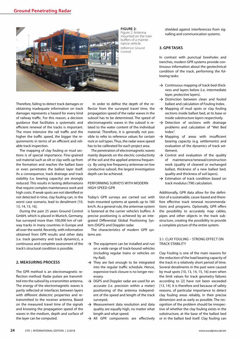
Ground Penetrating Radar
24 ETR | INTERNATIONAL EDITION | 22018 wwweurailpressdeetr
Therefore failing to detect track damages or obtaining inadequate information on track damages represents a hazard for every kind of railway trac For this reason a decision guidance that facilitates a systematic and ecient renewal of the tracks is important The more intensive the rail trac and the higher the trac speed the bigger the re-quirements in terms of an ecient and reli-able track inspection
The mapping of clay fouling or mud sec-tions is of special importance Fine-grained soil material such as silt or clay wells up from the formation and reaches the ballast base or even penetrates the ballast layer itself As a consequence track drainage and track stability (ie bearing capacity) are strongly reduced This results in lasting deformations that require complex maintenance work and high costs If weak-spots are not identied or not detected in time clay fouling can in the worst case scenario lead to derailment [10 13 14 15 16]
During the past 25 years Ground Control GmbH which is placed in Munich Germany has surveyed more than 100000 km of rail-way tracks in many countries in Europe and all over the world Recently with information obtained from GPR results and other data (ie track geometry and track dynamics) a continuous and complete assessment of the trackrsquos structural condition is possible
2 MEASURING PROCESS
The GPR method is an electromagnetic re-ection method Radar pulses are transmit-ted into the subsoil by a transmitter antenna The energy of the electromagnetic waves is partly reected at interfaces between layers with dierent dielectric properties and re-transmitted to the receiver antenna Based on the measured travel time of the signals and knowing the propagation speed of the waves in the medium depth and surface of the layer can be computed
In order to dene the depth of the re-ector from the surveyed travel time the propagation speed of the radar waves in the subsoil has to be determined The speed of electromagnetic waves in the subsoil is re-lated to the water content of the individual material Therefore it is generally not pos-sible to refer to reference values for certain rock or soil types Thus the radar wave speed has to be calibrated for each project area
The penetration of electromagnetic waves mainly depends on the electric conductivity of the soil and the applied antenna frequen-cy By using low frequency antennae on low conductive subsoil the largest investigation depth can be achieved
PERFORMING SURVEYS WITH MODERN HIGH-SPEED-GPR
Todayrsquos GPR surveys are carried out with train mounted systems at speeds up to 160 kmh As a general rule the antennae system is fastened at the carrier vehiclersquos buers A precise positioning is achieved by an inte-grated Dierential Global Positioning Sys-tem (DGPS) and Doppler radar
The characteristics of modern GPR sys-tems are
rarr The equipment can be installed and run on a wide range of track-bound vehicles (including regular trains or vehicles on Hy-Rail)
rarr They are fast enough to be integrated into the regular trac schedule Hence expensive track closure is no longer nec-essary
rarr DGPS and Doppler radar are used for an accurate (ie precision within a meter) positioning of the antenna independ-ent of the speed and length of the track surveyed
rarr Measurement data resolution and data quality are equally high no matter what length and what speed
rarr All GPR components are eectively
shielded against interferences from sig-nalling and communication systems
3 GPR TASKS
In contrast with punctual boreholes and trenches modern GPR systems provide con-tinuous information about the geotechnical condition of the track performing the fol-lowing tasks
rarr Continuous mapping of track-bed-thick-ness and layers below (ie intermediate layer protective layers)
rarr Distinction between clean and fouled ballast and calculation of Fouling Index
rarr Mapping of mud spots or clay fouling sections inside ballast bed at its base or inside substructure layers respectively
rarr Detection of sections with drainage problems and calculation of ldquoWet Bed Indexrdquo
rarr Mapping of areas with insucient bearing capacity (eg settlements) and evaluation of the dynamics of track set-tlement
rarr Control and evaluation of the quality of maintenancerenewalconstruction work (quality of cleaned or exchanged ballast thickness of a new ballast bed quality and thickness of soil layers)
rarr Estimation of track condition based on track modulus (TM) calculation
Additionally GPR data allow for the deni-tion of a sustainable cause-based and there-fore eective track renewal recommenda-tions and programs Optionally GPR oers the possibility to accurately map cables pipes and other objects in the track sub-structure creating the possibility to provide a complete picture of the entire system
31 CLAY FOULING ndash STRONG EFFECT ON TRACK STABILITY
Clay Fouling is one of the main reasons for the reduction of the load bearing capacity of the track in a relatively short period of time Several derailments in the past were caused by mud spots [10 13 14 15 16] even when the limit values for track geometry failures according to [2] have not been exceeded [13 14] It is therefore and because of safety reasons of particular importance to detect clay fouling areas reliably in their precise dimension and as early as possible The rec-ognition of the problem should be irrespec-tive of whether the clay fouling exists in the substructure at the base of the ballast bed or in the ballast bed itself Clay fouling can
FIGURE 2 Figure 2 Antenna mounted on the train buers of a mainte-nance vehicle(reference Ground Control)
Ground Penetrating Radar
25ETR | INTERNATIONAL EDITION | 22018wwweurailpressdeetr
raquo
rapidly deteriorate the stiness of the track and its quality The trackrsquos lateral stability is massively reduced longitudinal errors along the rails arise
Clay fouling is also a serious decit from an economic point of view Its timely iden-tication allows for avoiding slow speed sections thus sparing time and money for maintenance procedures Detecting clay fouling before it reaches the ballast bed ena-bles cost eective renewal Otherwise it will be very expensive There is no option for bal-last cleaning a suciently compacted pro-tection layer built of the appropriate materi-al is essential the installation of composites does not prevent clay fouling from entering the ballast bed (see Fig 3)
Save few exceptions clay fouling spots are not visible at the track surface and since drill-ings and trenches do only provide punctual results reliable information is only achievable through GPR measurements (see Fig 4)
A frequency analysis of the measured data results in a typical change of the signal spectrum in the area of clay fouling Based on the GPR results borehole program can be implemented which can be used for further analysis GPR surveys to detect ballast foul-ing have been carried out for years in Swit-zerland Austria the Netherlands and France among others
32 TRACK MODULUS (TM)
Examining the geotechnical conditions of railway tracks requires an index which in-forms about state and quality of the tracks in a quantitative manner The challenge has
been to dene the track condition continu-ously This has been achieved by combin-ing TM with the results of continuous GPR-measurements
It is possible based on [3 4 5 6 7] to es-timate quality and bearing capacity of the railway track Therefore the TM describes the relation between vertical load and elas-tic deection of the sleeper-bearings
On the one hand the TM can be calculated based on the measured deection under load [18 20] on the other hand according to the soil properties [8 9 11] The measuring principle for determining the load deec-tion is described in detail in [12] and [17] The properties of the system components such as the area of inuence of the sleepers under load can greatly aect the TM Hence around turnouts the area of inuence of sleepers deviates from the standard track This is because an increased area of inu-ence causes an increase in the distribution of the load reducing the deection of the
rail Notwithstanding to simplify the calcula-tion of the TM the inuence area of sleepers around turnouts are assumed to be constant assuming the values of the standard track Depending on the type of sleepers installed the value of the TM can increase sharply around turnouts (Fig 5) In addition cavities under the sleepers increase the deection of the track under load which in turn inu-ences the calculation of the TM decreasing its value
An additional and new approach for calcu-lating the TM is based upon the soil proper-ties which can be described by the Poissonrsquos Ratio or the material density of the soil The soil properties derive from the GPR data This methodrsquos advantage is to be completely in-dependent from superstructure conditions The individual layers are assigned soil values according to condition and bulk density Averaged soil properties are calculated ac-cording to [1 19] The TM can be estimated according to [9] and [11] Previous studies
FIGURE 4 Visual analysis of GPR data depicting clay fouling along a track (reference Ground Control and IEV)
FIGURE 3 Geotextile or composite does not stop ne particle migration to the surface (reference Ground Control)
Ground Penetrating Radar
26 ETR | INTERNATIONAL EDITION | 22018 wwweurailpressdeetr
indicate that this method has signicantly lower value variations along the track axis compared to the approach based on the use of track displacement data (Figure 5)
The example in Fig 5 shows two track moduli based on the measured displacement under load (red line) and the soil properties (blue line) Around the turnouts a signicant increase of the TM is visible if the calculation is based on the measured deection By divid-ing the TM into quality classes according to [3 4 5 6 7] the condition of the track can be sat-isfactorily estimated (Fig 6)
33 TRACK ANALYZER ndash CONTINUOUS PRESENTATION OF ALL MEASUREMENT AND TEST RESULTS
Results from GPR surveys along with all identied soil parameters and indices cal-
culated can be displayed in comprehensive track analysis software called ldquoTrack Analyz-errdquo In order to provide all information for in-frastructure managers track geometry and track dynamics data are also integrated and displayed in the software (see Fig 7) which also oers the exibility to incorporate other tasks and aspects as required by the user
The Track Analyzer provides infrastructure managers continuous information about the geotechnical conditions of the track with regard to all relevant issues Moreover it provides a better understanding of the sub-structuresubgrade conditions and their in-uence on the superstructure This allows for a signicantly increased track quality pro-viding higher route availability and safety
A big advantage of the GPR method is the minimization of the need for intensive direct outcropping (probing drilling scooping)
to characterize the underlying geotechni-cal characteristics of the track substructuresubgrade which results in signicant cost reductions
4 SUMMARY
This paper describes a modern train-borne technology for the inspection of the geo-technical conditions of railway tracks It is based on High Speed GPR and on classical procedures for providing continuous infor-mation about geotechnical parameters and indices A new quality of GPR measurements is to provide quantitative indices in addition to qualitative results to full the require-ments of the railway engineers in the best possible way
Special attention is paid to the detection of mud spots and clay fouling sections as a risk for derailment [10 13 14 15 16] To date track inspection with GPR is more appropri-ate than any other inspection method to de-tect map and qualify areas with geotechni-cal problems
The Track Analyzer software combines GPR results with track geometry and track dynamics data This allows for cause-based track renewal and targeted investment and provides signicantly more reliable results than conventional methods This approach is especially relevant for limited budgets
Literature [1] Adam D Kopf F Dynamische Eekte durch bewegte
Lasten auf Fahrwegen In Bauingenieur Ausgabe 01-2003 2003
FIGURE 5 TM calculated from measured displacement under load (red graph) and soil proper-ties (blue graph) (reference IEV)
FIGURE 6 TM divided in dierent quality classes (reference IEV)
Ground Penetrating Radar
27ETR | INTERNATIONAL EDITION | 22018wwweurailpressdeetr
FIGURE 7 Track Analyzer(reference Ground Control)
[2] DB Netz AG Ril 821 Oberbau inspizieren Deutsche Bahn AG guumlltig ab 01052004
[3] Eisenmann J Stuumltzpunktelastizitaumlt bei einer Festen Fahrbahn In ZEV + DET Glasers Analen 111999
[4] Fendrich L (Hrsg) Handbuch Eisenbahninfrastruktur Springer-Verlag Berlin Heidelberg 2007
[5] Goumlbel C Lieberenz K (Hrsg) Handbuch Erdbau-werke der Bahnen DVV Media Group GmbH 2013
[6] Leykauf G Lothar M Elastisches Verformungsver-halten des Eisenbahnoberbaus ndash Eigenschaften und Anforderungen In EI ndash Eisenbahningenieur 031990
[7] Lichtberger B Handbuch Gleis DVV Media Group GmbH 2010
[8] Martin U Rapp S Ansatz zur Erfassung der Bodenei-genschaften am Bahnkoumlrper in Schotterbauweise In ETR ndash Eisenbahntechnische Rundschau 042017
[9] Martin U Rapp S Camacho D Moormann C Lehn J Prakaso P Abschaumltzung der Untergrundverhaumllt-nisse am Bahnkoumlrper anhand des Bettungsmoduls In ETR - Eisenbahntechnische Rundschau 052016
[10] Rail Accident Investigation Branch Freight train de-railment near Gloucester 15 October 2013 Rail Acci-dent Report102014
[11] Rapp S Modell zur Identizierung von punktuel-len Instabilitaumlten am Bahnkoumlrper in konventioneller Schotterbauweise Dissertation ndash Institut fuumlr Eisen-bahn- und Verkehrswesen der Universitaumlt Stuttgart 072017
[12] Soldati G Meier M Zurkirchen M Kontinuierliche Messung der Gleiseinsenkung mit 20 t Achslast In EI ndash Eisenbahningenieur 022016
[13] Untersuchungszentrale der Eisenbahn-Unfalluntersu-chungsstelle des Bundes Untersuchungsbericht Ak-tenzeichen 60 ndash 60uu2011-0200041 Zugentgleisung Groumlbers ndash Groszligkugel 062013
[14] Untersuchungszentrale der Eisenbahn-Unfalluntersu-chungsstelle des Bundes Untersuchungsbericht Ak-tenzeichen 60uu2013-06047-3323 Zugentgleisung Kaub ndash Lorch (Rhein) 062013
[15] Untersuchungszentrale der Eisenbahn-Unfalluntersu-chungsstelle des Bundes Untersuchungsbericht Ak-tenzeichen 60 ndash 60uu2011-0400043 Zugentgleisung Bf Hannover ndash Linden 092013
[16] Versa Verkehrssicherheitsarbeit fuumlr Oumlsterreich Unter-suchungsbericht Sicherheitsuntersuchungsstelle des Bundes BMVIT-795336-IVBAVUUBSCH2013 Ent-gleisung eines Guumlterzugs am 14 Februar 2013 2013
[17] Wang P Wang L Chen R Xu J Overview and out-look on railway track stiness measurement Jour-nal of Modern Transportation Volume 24 Issue 2 062016
[18] Winkler E Die Lehre von der Elastizitaumlt und Festigkeit Verlag von H Dominicus 1967
[19] Wolf J P Foundation Vibration Analysis using Simple Physical Models Swiss Federal Institute of Technology 1994
[20] Zimmermann H Die Berechnung des Eisenbahn-oberbaus 1888
wwwrex-industrie-produktede
INSULATING JACKETS FORHIGH TEMPERATURE INSULATION
high temperature resistant up to 1000degC
incombustible
high insulation performance
tailor made according to your wishes
New test reports for fire protection according to EN 45545-2 available R1R7R17 with Hazard Level HL 3
Distributed Acoustic Sensing
28 ETR | INTERNATIONAL EDITION | 22018 wwweurailpressdeetr
Dip-Ing FH MScMartin RosenbergerCTO Frauscher Sensor Technology martinrosenberger frauschercom
This involves planning and controlling maintenance measures based on the actual condition of the equipment systems and components (assets) Unexpected events due to faulty components and unnecessary work on fully intact elements can thus be reduced This is possible thanks to the ever increasing amount of reliable data about the condition of the asset that is available in real time
Continuous acoustic condition monitor-ing of the infrastructure based on Distribut-ed Acoustic Sensing (DAS) is a key building block of future solutions This technology can considerably increase the availability of rail networks since it continuously delivers very precise information about the condi-tion of the infrastructure and any changes thereby fullling a key prerequisite for the use of CBM solutions
The sensor technology and inspections form and remain the basis for condition-based maintenance of the track These in-clude track recording vehicles xed meas-urement points sensor technology on
How Distributed Acoustic Sensing supports condition based maintenance strategiesCurrent technological developments are opening up new opportunities for the railway industry in a whole range of application areas Most notably these include networking digitalization and the Inter-net of Things (IoT) This trend is also having a growing impact on processes and strategies for maintain-ing rolling stock and infrastructure Traditional maintenance philosophies which are based on xed intervals or in the case of vehicles on mileage are increasingly being replaced by predictive condition based maintenance (CBM)
standard trains track-side sensor technol-ogy selectively deployed manual measur-ing instruments and self-monitoring infra-structure systems Data from these sources must be consolidated and if applicable combined with information about rolling stock and system-side infrastructure data such as a system directory or inputs from other sensors
DAS enables a sensor solution to be cre-ated which fulls several of the specied re-quirements this technology allows railway networks to be monitored continuously in real time and with respect to a huge num-ber of dierent events Frauscher has devel-oped its own DAS solution for the railway sector Frauscher Tracking Solutions FTS The manufacturerrsquos team tested the tech-nology and through intensive develop-ment eliminated constraints with respect to use for rail trac To create this in-depth knowledge of DAS as well as requirements and standards in the railway industry was required
1 DAS FUNCTIONAL PRINCIPLE
DAS-based systems use laser pulses sent in a glass bre to detect events on or in the vicinity of the track part of the laser pulse is reected back out of the bre to the transmitting unit The sound and vibration waves impacting on the cable result in signicant shifts in the reection (Fig 1) The maximum frequency range of the vibrations detected in this man-ner is 125 kHz Using specically developed algorithms the acquired data can be used to calculate specic signatures in real time These describe highly precise locations and types of processes in the vicinity of the track
One of the advantages of installing a DAS system is that the bre optic cables it requires are often already laid next to the tracks These are normally used for commu-nication purposes As the optical bres used require practically no maintenance the sys-tem can be rolled out to large sections of the route extremely economically and ecient-ly In practice a single DAS unit can eective-ly cover up to 40 kilometres of glass bre in each direction so 80 kilometres in total [1]
2 CONTINUOUS MONITORING OF WHEEL-RAIL INTERACTION
The ongoing analysis of infrastructure us-ing FTS is based on continuous monitoring
FIG 1 Distributed Acoustic Sensing (DAS) allows for the detection of vibrations and sound waves caused by trains component defects people or other sources
raquo
Distributed Acoustic Sensing
29ETR | INTERNATIONAL EDITION | 22018wwweurailpressdeetr
of wheel-rail interaction (Fig 2) On the one hand this enables the detection of changes that arise slowly over the course of time To do so the system compares the relevant signatures that are captured each time a railway vehicle passes a spot On the other hand events that occur suddenly can also be reliably detected
21 TREND ANALYSIS FOR LOCALISATION OF CONDITION CHANGES
The wheel-rail interactions quality is the most important factor when it comes to the service life of both system components and the rolling stock This quality is derived from various parameters such as the roundness of the wheel the surface of the rail and the track design Even slight deviations from the ideal parameters result in increased signs of wear and tear over a certain amount of time Ultimately these can also lead to critical op-erating conditions Which is why continu-ous detection and thus early recognition of changes in condition along the entire route is extremely useful
This is where the FTS come into play by evaluating the signatures in the laser signal feedback it is possible to determine wheth-er a sp ecic anomaly in wheel-rail interac-tion comes from the train or from the infra-structure This is possible because the FTS system uses a glass bre as a permanent sen-sor along the track thus allowing the wheel-rail interaction for each individual axle on all train journeys to be permanently monitored along the entire route Changes are detected in real time and the method does not de-pend on a xed measurement point
If a notication is triggered by an out-of-round wheel for instance then this pattern will be part of the train signature and be de-tected in association with the moving train This allows the event to be clearly attributed to vehicle damage
By contrast if there is a change to the in-frastructure several axles will have a notice-able signature in one specic position The system uses this to determine an indicator Based on this trend analyses are formed for individual ten-metre long infrastruc-ture segments Warning or alarm notica-tions can now be created and transmitted through dened user-congured threshold values These indicate the type of change as well as the location With good georefer-encing for the bre optic cable the position identied via FTS can be localised to an accu-racy of up to ve metres and made available via machine-readable interfaces
Frauscher oers powerful interfaces for employees in railway infrastructure compa-
nies In particular these include a graphical user interface with map view and heat maps and depiction of the infrastructure condition in denable categories The zoom function can be used to display the entire route or a position with relevant localisation in route kilometres or GPS data the actual condition and the change in condition over a specic period Filters can be set for even more de-tailed analyses and evaluation
22 EVALUATION OF CHANGES IN CONDITION AS A PROCESS
To determine the relevance for a specic rail-way operation simply identifying a change in condition is not enough The trend analy-sis must also be correlated with the trains and their speeds After all identical techni-cal non-conformities will result in indicators with completely dierent frequencies and intensities when a heavy long freight train and when a lighter short passenger train travels over a position with a fault
Therefore a basic condition must rst be dened for the infrastructure and stored in the FTS The trend analyses can then be ap-plied to this To do so the system structure (primarily bridges tunnels or points) must be logged in the system and the sensor must be calibrated accordingly Data that needs to be entered includes rail joints or transitions from a point for example They create similar patterns to those of a rail defect but must be evaluated and examined dierently
It may also be necessary to lter out am-bient noise from stationary systems such as pumps and generators so that this does not have a negative eect on the detailed analy-sis of the wheel-rail interaction signature
These adjustments are currently carried out manually during the installation and com-missioning process However Frauscher is developing tools to automate these process-es These steps form part of the technologyrsquos path towards serial production
Once the basic condition has been dened then depending on the model the operator will receive regular reports or warning and alarm notications via dened interfaces The DAS systems that are currently available are not yet able to classify and quantify the changes detected with sucient accuracy Maintenance personal therefore take on the task of evaluating suspect positions through inspection actions during the development and installation phase A visual inspection is often enough to identify the cause of the warning classify the change and take the necessary action within a dened period
Based on experience with several installa-tions and Frauscherrsquos collaboration with op-erators there are essentially three relevant classications
rarr No detectable or only minimal damage rarr Non-critical damage rarr Critical damage
What is important is that this evaluation and classication is understood and followed as part and parcel of the maintenance process Dening the threshold values and deter-mining the sensitivity of the system is a key step in this regard Experienced specialist sta who evaluate and process the notica-tions can shape the system to suit their own needs This allows CBM concepts to be ap-plied even more eciently for practical sup-port and to build expertise (Fig 3)
The high sensitivity level of the system
FIG 2 By continuously monitoring the acoustic signature of the wheel-rail contact the FTS support condition based maintenance strategies
Distributed Acoustic Sensing
30 ETR | INTERNATIONAL EDITION | 22018 wwweurailpressdeetr
means that a range of errors can be detected at a very early stage However this also in-creases the risk that positions that are not relevant for maintenance will be displayed This is where empirical values are really needed so that the optimum setting can be tuned for the operator It is crucial to involve the maintenance personnel in this whether through the operator or the service contrac-tor After all only experts on the ground can evaluate the condition of the infrastructure and determine the necessary measures Maintenance employee experience thus re-mains essential for training the algorithms and evaluating the results the maintenance personnel must use their knowledge of routes and systems to determine whether a notication is in fact relevant or not
Not detectable or only minimal damageIn this case no maintenance measures are needed There are three main reasons why the system has indicated a potential fault in this case First there may be a structural fac-tor in the infrastructure or a factor in the en-vironment of the trigger In this case the in-uencing factor can be ltered out in future Secondly it could be that a visual inspection reveals no detectable fault but there are already signs of wear In this case the user
would add information to the system stating that this section is to be kept under observa-tion or specically monitored over a certain period of time ndash for example by adjusting the threshold value If the system contin-ues to exhibit a fault it is advisable to apply analysis methods that go beyond a visual inspection of this point or use other meas-urement data as a comparison Thirdly this could be due to a minor surface fault on the rail for example which does not require any action since scheduled surface processing measures are due to be carried out (Fig 4) In this case the fault message can be acknowl-edged
Non-critical damageIn this case the system has identied a rel-evant fault but it does not need to be cor-rected right away (Fig 5) The main advan-tage of this is that early detection allows the necessary measures to be planned in good time so these can be put into eect during quiet periods or eciently combined with other measures thus reducing the number of expensive individual activities
Critical damageIf such changes are detected then measures must be initiated immediately in order to re-
solve the safety-critical operating condition and minimise any expensive subsequent damage Experience shows that such critical conditions can develop over just a few days or can even be triggered by acute short-term factors Examples include ballast voids due to washout rail head cracks and broken rails
Critical conditions can arise during the analysis cycles even if the rail network is monitored regularly with track recording ve-hicles for example Continuous monitoring of the wheel-rail interaction enables quicker intervention and minimises personal injury and damage to property
23 EMPIRICAL RESULTS
In addition to various applications which can be used in real time on the basis of train lo-calisation over the last two years Frauscher has been taking a closer look at infrastruc-ture maintenance In particular at the po-tential that continuous monitoring of the wheel-rail interaction has to oer in the fol-lowing scenarios
rarr Rail monitoring rarr Rail fastening and sleeper monitoring rarr Track substructure and superstructure
monitoring
Practical application has shown that the data that can be provided via the FTS system al-ready oers a range of interesting options it helps users to plan and control maintenance measures in good time To do so Frauscher implements technology such as machine learning pattern recognition and articial
FIG 3 When developing advanced main-tenance solutions various levels within a railway network have to work together closely
FIG 4 Changes in the trackrsquos surface can be detected evaluated and considered when planning maintenance works
FIG 5 Detecting small defects allows for a targeted monitoring in order to generate alarms when their condition deteriorates
Distributed Acoustic Sensing
31ETR | INTERNATIONAL EDITION | 22018wwweurailpressdeetr
intelligence However in order to move to the next level a solid base of empirical val-ues and a library of signatures from a variety of sources of damage are needed
The company is working very closely with the operators of several installations select-ed from approximately 30 projects that are currently ongoing worldwide They are joint-ly considering the evaluation interpretation and derivation of measures Specic issues and ideas for further development of the evaluation software and logic are directly incorporated into Frauscherrsquos development processes using agile methods
Rail monitoringAll types of rail damage that cause vibrations or a noise spectrum that deviates from the norm are detected This ranges from surface damage such as rail corrugation squats rail head cracks wheel burns or corrosion and dents to cracking and ssuring or even bro-ken rails
Unsurprisingly the algorithm for detect-ing rail damage also detects rail joints After all the signature of a gap as in an isolation joint could be exactly the same as that for a break in part of the rail In this case depend-ing on requirements these rail joints can be suppressed or specically monitored with their own threshold values (Fig 6 7) The sensitive sensor system can detect broken rails as a train passes over them with high probability However due to the many dif-ferent forms and physical basic conditions a warning system with a 100 percent de-tection rate and zero error rate cannot be achieved
In addition there are still no empirical val-ues for broken rails which can be traced back to warping and thermal eects without the eect of the train Noises that arise due to warping (thermal popping) were detected during tests designed to identify and local-ise landslides and rock fall These are hard to classify or uniquely identify using the cur-rently available hardware and software It is to be assumed that a rail that breaks for thermal reasons generates a similar if more intensive signature and it is not possible to clearly distinguish this from the ldquothermal poprdquo
Therefore it is important to consider whether continuous monitoring of the tracks with appropriate trend analyses does not provide more information about the safety of the route than a warning system for broken rails Last but not least broken rails should generally be reduced by as-required maintenance measures
Rail fastening and sleeper monitoringIn several installations positions were de-
tected that exhibited increased vibration due to damaged or missing rail connections or broken sleepers These are typically faults that do not necessarily require action to be taken right away Instead they are classied in such a way that these tasks will be car-ried out during upcoming scheduled on-site maintenance
Track substructure and superstructure monitoringThe FTS system is able to localise weakness-es in the substructure and track superstruc-ture such as ballast voids under sleepers cavities or compacted areas The condition of the track bed may under certain circum-stances also lead to a critical situation in a relatively short period of time particularly in mountainous regions where heavy rain or mudslides can also make the track position unstable Practical examples also exist for these scenarios where FTS localised critical positions where ballast voids under sleepers were later identied
3 SUMMARY
Continuous monitoring of wheel-rail interac-tion based on FTS opens up numerous pos-sibilities for the user in terms of timely detec-tion of weaknesses and changes in condition on the route Thus targeted and as-required maintenance measures can be dened planned and eciently controlled This is a paradigm shift in terms of maintenance strategy similar to that which is emerging for vehicles Before xed periods based on theoretically calculated average loads were
key to the strategy Now the actual wear and condition of the specic component (rail surface fastening sleeper substructure or track superstructure) are the trigger for maintenance repair or servicing work
These new options for monitoring infra-structure will not replace existing measure-ment systems instead they will enhance them They will change the maintenance processes mainly through the high-pre-cision and early detection of continuous changes By determining individual thresh-old values necessary work can be planned and carried out preventively before critical damage arises
In addition to such continuous changes the FTS is also able to detect vehicle faults and short-term sporadic inuences on trackside infrastructure This includes natu-ral hazard management such as falling rocks and trees catenary ashover or protecting infrastructure from vandalism cable theft or unauthorised access to track systems
Even in times of advancing digitalisation employee experience forms an indispensa-ble basis for railway operations Manufac-turers and operators must work together to develop systems for CBM concepts and individually calibrate them so they become helpful tools which raise eciency while re-ducing ongoing costs
Literature[1] Rosenberger Martin Lancaster Gavin Real-time track
monitoring for sustainable maintenance strategies ETR International 12017 P 20-23
FIG 6 Rail joints are specic points which can be monitored via FTS by storing their base signature in a rst place
FIG 7 If the condition of the rail joint chang-es its acoustic signature will do the same
Smart Tamping
32 ETR | INTERNATIONAL EDITION | 22018 wwweurailpressdeetr
Plasser amp Theurerrsquos development of the turnout tamping assistance system ldquoPlasserSmartTamping ndash The Assistantrdquo has been an important step towards the further automation of tamping machines The assis-tance system provides automated support for tamping works in turnouts and crossings It recommends specic actions which must be conrmed by the operator before they are carried out As a result operators increasingly monitor processes intervening manually only in exceptional cases A new recording module allows for a completely new form of tamping documentation It increases transparency working quality and process reliability For the rst time the turnout tamping simulator ndash not a tamping machine ndash was used to develop all of the software modules of the turnout tamping assistance system In an extended hardware-in-the-loop application the turnout tamping assistance system was developed and tested using the simulator
David BuchbauerProject Manager for tamping and measuring technologydavidbuchbauer plassertheurercom
Dipl-Ing Martin BuumlrgerHead of Digital Track Systemsmartinbuerger plassertheurercom
Andreas Theiszlig MScProduct Owner Smart Tamping minus The Assistantandreastheissplassertheurercom
Dipl-Ing Georg JodlbauerHead of Research and Testinggeorgjodlbauer plassertheurercom
Dr techn Gerald ZaunerDigital Track Systemsgeraldzaunerplassertheurercom
Dipl-Ing Dr techn Florian AuerDirector of Technology and Innovationorianauerplassertheurercom
1 THE DEVELOPMENT
In modern track maintenance the conven-tional distinction between track inspection vehicles and track construction and main-tenance machines has increasingly been blurred To optimise processes track con-struction and maintenance machines are t-ted with the latest sensor technology turn-ing them into ldquosmart machinesrdquo Inertial track measuring systems used up to now only on track inspection vehicles have increasingly been installed on tamping machines This makes it possible to use tamping machines for separate track measuring runs to calcu-late the required track geometry correction values
The use of inertial track measuring sys-tems optimises the track geometry quality In addition laser scanners and light section sensors make it possible to create a ldquodigital track twinrdquo which provides the data base of the turnout tamping assistance system
2 THE OBJECTIVE OF THE TURNOUT TAMPING ASSISTANCE SYSTEM
Turnout tamping (Figure 1) requires consid-erable knowledge of several areas of exper-tise (track surveying machine technology track technology regulations) The most im-portant tasks include
Smart Tamping ndash Fields of Application of the Turnout Tamping Assistance System
rarr In the main tamping cabin Controlling the tamping unit including the turnta-ble opening width and tilting motion of the tines
rarr In the co-tamping cabin Controlling the lifting and lining unit the parts of the tamping units in the diverging track and the additional lifting unit
The turnout tamping assistance system com-plies with level 3 of the standard SAE J3016 The standard denes terms related to on-
road motor vehicle automated driving sys-tems and has been applied correspondingly On the automation level 3 the system rec-ommends specic actions which must be conrmed by the operator before they are carried out with the operator as fallback The design of the turnout tamping assis-tance system also allows for higher levels of automation However for reasons of liability automation options such as remote control or robot operation are not oered
The turnout tamping assistance system
Smart Tamping
33ETR | INTERNATIONAL EDITION | 22018wwweurailpressdeetr
raquo
oered to machine operators and infrastruc-ture managers consists of four product parts in modular design
rarr recording module for recommendations and operations
rarr operation assistant for the lifting and lin-ing unit
rarr operation assistant for the additional lift-ing unit
rarr operation assistant for the tamping unit
The modular design makes it easier to put the turnout tamping assistance system into operation for the rst time In a testing phase recording modes can be used to verify the accuracy of the recommended measures (comparison of the actual taming operations and the actions recommended by the assis-tance system) Upgrading to a higher level is possible if it has been taken into account in the design of the machine The modules are activated step by step to allow sta to famil-iarize themselves with the assistance system and to coordinate the work processes
3 THE RECORDING MODULE ldquo DIGITAL TRACK TWINrdquo
The rst step is to develop the digital track twin When selecting the hardware compo-nents of the turnout tamping assistance sys-tem (one rotation laser four light section sen-sors and one colour camera) it was ensured that the hardware can be exchanged and that the software can be adapted modularly
When designing the hardware components a particular focus was placed on meeting the accuracy requirements In addition it was ensured that the system is highly robust and easy to maintain
The recording module of the turnout tamping assistance system connects the digital twin of the track with the working parameters of the machine As a result the quality control of tamping works reaches a new transparency level Infrastructure op-erators can easily access all parameters rel-
FIG 1 Operators of turnout tamping machines must meet high requirements
FIG 2 Tamping docu-mentation using multi-layer technol-ogy (schematic representation)
evant to quality and work (such as the tine position tamping depth or squeeze time) digitally and immediately when connected to the Internet
In the future the recording document will also include the rolling marks of the rails and the position of the aluminothermic welds As the software is developed in-house we can meet our customersrsquo requirements exibly (Fig 2) For instance it will be possible to ex-port the ldquodigital twinrdquo for use on the tamping simulators
Smart Tamping
34 ETR | INTERNATIONAL EDITION | 22018 wwweurailpressdeetr
4 OPERATION ASSISTANCE
Based on their position at the time of record-ing the individual scans and recordings are merged to form a 3D image of the reality showing the exact position At the same time the position of the machine and every indi-vidual work unit is continually updated As a result a 3D image of the relevant machine parts is imported into the overall model pro-viding the basis for every decision of the as-
Federal Railways (OumlBB) and experience from practical operation A specic adaptation to the infrastructure managerrsquos requirements is possible
Figure 4 shows a list of position sensors angle sensors and actuators operated by the assistance system The values of the lin-ing adjustment the lifting operation and the tamping parameters (multiple tamping tamping vibration frequency squeeze force tamping depth) are not controlled by the as-sistance system
The turnout tamping assistance system has been designed for two applications In the rst design version (the separate view) separate measures are recommended to the operators in the main tamping cabin and the co-tamping cabin The second design version (the combined view) is the current develop-ment focus Both assistance modules are merged into a combined view in the main tamping cabin enabling the operator in the main tamping cabin to control the entire turn-out tamping process by himself (Figure 5)
The application focus of the rst genera-tion of the turnout tamping assistance sys-tem is on turnouts that have not yet been fully ballasted As a result the surface of the sleepers is visible Specic recommenda-tions require a good view onto most of the turnout area the sleepers and obstacles (such as switching contacts turnout operat-ing units)
In a next stage we plan to t the turnout tamping assistance system with sensors (eddy current sensors) for the detection of sleepers in ballasted areas (newly laid track)
Completed tamping works in turnouts can be duplicated using the machine control module turnout programming automation In a combined application of the turnout tamping assistance system and the turnout programming automation it is in principle possible to scan turnouts in advance while they have not yet been fully covered with ballast and to provide the turnout program-ming automation module with the recom-mendations to allow for their duplication Turnout tamping machines with the inte-grated supply of new ballast generally allow for the use of the turnout tamping assis-tance system as the turnout is not ballasted at the scan position at the front end of the machine
The prototype of the turnout tamping as-sistance system was introduced to the ex-pert audience at the trade show iaf 2017 in Muumlnster The positive feedback proves the great potential of the technology In practi-cal operation the turnout tamping assis-tance system is currently prepared for series production for the work unit types ldquo275rdquo ldquo475rdquo and ldquo4x4rdquo
FIG 3 Overview of the control recommen-dations
FIG 4 Position sensors angle sensors and actuators operated by the assistance system
FIG 5 Tamping cabin with the assistance system ldquoPlasserS-martTamping ndash The Assistantrdquo
sistant The data is processed with the lowest possible latency and highly parallel data pro-cessing to ensure fast operation The system recommends the respective actions several metres ahead of the tamping unit (Fig 3) to provide the operators with sucient time to analyse and modify the recommendation if necessary The recommendation of the as-sistance system is checked directly at the tamping position before the tamping unit is lowered At the same time the congura-tion of the lifting and lining unit (hock and tongue position) for the transfer to and the lifting operation at the next tamping posi-tion is checked prior to transfer travelling At this point the operator can take action at any time and further adjust the settings The operation of the additional lifting unit is checked in a similar way
To allow for tamping recommendations the track sections requiring actions must be located in an automated process To ensure this dierent image processing systems are combined with articial intelligence and connected systemically
The basic tamping scheme was developed on the basis of regulations and specications of German Federal Railway (DB) Austrian
Digital technologies are key to maximising track availability and planning forward-looking maintenance The ability to check the line at any time thanks to networked data capture in real time with innovative products reliable materials and optimised maintenance concepts for every aspect of rail infrastructure Thatrsquos what we mean by ldquoThe Smart Rail Track by Vosslohrdquo
Next stop Berlin InnoTrans 2018 Hall 26
wwwvossloh-innotranscom
The Smart Rail Track by Vossloh
DIN A4_Stadtmotiv_US_InnoTrans_Internet neuindd 1 12072018 131049
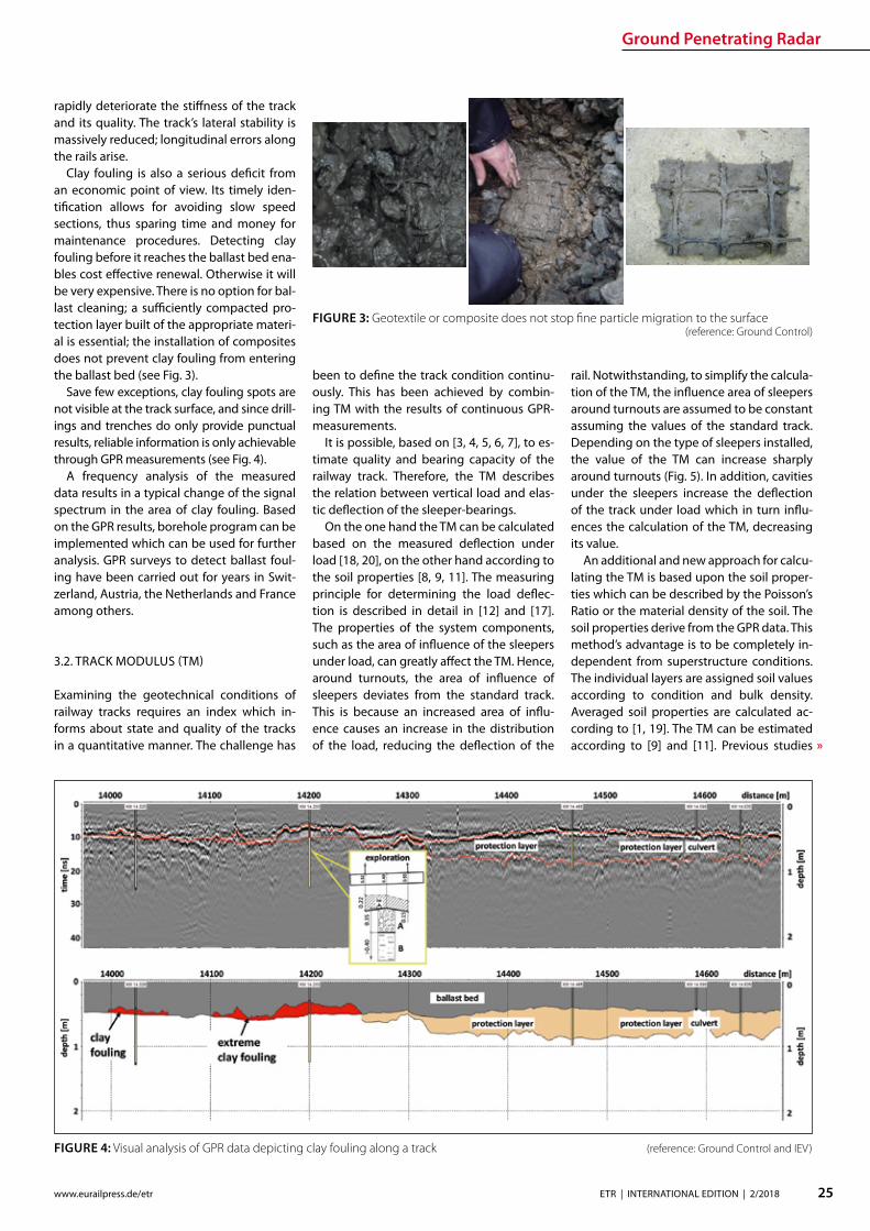
Ground Penetrating Radar
26 ETR | INTERNATIONAL EDITION | 22018 wwweurailpressdeetr
indicate that this method has signicantly lower value variations along the track axis compared to the approach based on the use of track displacement data (Figure 5)
The example in Fig 5 shows two track moduli based on the measured displacement under load (red line) and the soil properties (blue line) Around the turnouts a signicant increase of the TM is visible if the calculation is based on the measured deection By divid-ing the TM into quality classes according to [3 4 5 6 7] the condition of the track can be sat-isfactorily estimated (Fig 6)
33 TRACK ANALYZER ndash CONTINUOUS PRESENTATION OF ALL MEASUREMENT AND TEST RESULTS
Results from GPR surveys along with all identied soil parameters and indices cal-
culated can be displayed in comprehensive track analysis software called ldquoTrack Analyz-errdquo In order to provide all information for in-frastructure managers track geometry and track dynamics data are also integrated and displayed in the software (see Fig 7) which also oers the exibility to incorporate other tasks and aspects as required by the user
The Track Analyzer provides infrastructure managers continuous information about the geotechnical conditions of the track with regard to all relevant issues Moreover it provides a better understanding of the sub-structuresubgrade conditions and their in-uence on the superstructure This allows for a signicantly increased track quality pro-viding higher route availability and safety
A big advantage of the GPR method is the minimization of the need for intensive direct outcropping (probing drilling scooping)
to characterize the underlying geotechni-cal characteristics of the track substructuresubgrade which results in signicant cost reductions
4 SUMMARY
This paper describes a modern train-borne technology for the inspection of the geo-technical conditions of railway tracks It is based on High Speed GPR and on classical procedures for providing continuous infor-mation about geotechnical parameters and indices A new quality of GPR measurements is to provide quantitative indices in addition to qualitative results to full the require-ments of the railway engineers in the best possible way
Special attention is paid to the detection of mud spots and clay fouling sections as a risk for derailment [10 13 14 15 16] To date track inspection with GPR is more appropri-ate than any other inspection method to de-tect map and qualify areas with geotechni-cal problems
The Track Analyzer software combines GPR results with track geometry and track dynamics data This allows for cause-based track renewal and targeted investment and provides signicantly more reliable results than conventional methods This approach is especially relevant for limited budgets
Literature [1] Adam D Kopf F Dynamische Eekte durch bewegte
Lasten auf Fahrwegen In Bauingenieur Ausgabe 01-2003 2003
FIGURE 5 TM calculated from measured displacement under load (red graph) and soil proper-ties (blue graph) (reference IEV)
FIGURE 6 TM divided in dierent quality classes (reference IEV)
Ground Penetrating Radar
27ETR | INTERNATIONAL EDITION | 22018wwweurailpressdeetr
FIGURE 7 Track Analyzer(reference Ground Control)
[2] DB Netz AG Ril 821 Oberbau inspizieren Deutsche Bahn AG guumlltig ab 01052004
[3] Eisenmann J Stuumltzpunktelastizitaumlt bei einer Festen Fahrbahn In ZEV + DET Glasers Analen 111999
[4] Fendrich L (Hrsg) Handbuch Eisenbahninfrastruktur Springer-Verlag Berlin Heidelberg 2007
[5] Goumlbel C Lieberenz K (Hrsg) Handbuch Erdbau-werke der Bahnen DVV Media Group GmbH 2013
[6] Leykauf G Lothar M Elastisches Verformungsver-halten des Eisenbahnoberbaus ndash Eigenschaften und Anforderungen In EI ndash Eisenbahningenieur 031990
[7] Lichtberger B Handbuch Gleis DVV Media Group GmbH 2010
[8] Martin U Rapp S Ansatz zur Erfassung der Bodenei-genschaften am Bahnkoumlrper in Schotterbauweise In ETR ndash Eisenbahntechnische Rundschau 042017
[9] Martin U Rapp S Camacho D Moormann C Lehn J Prakaso P Abschaumltzung der Untergrundverhaumllt-nisse am Bahnkoumlrper anhand des Bettungsmoduls In ETR - Eisenbahntechnische Rundschau 052016
[10] Rail Accident Investigation Branch Freight train de-railment near Gloucester 15 October 2013 Rail Acci-dent Report102014
[11] Rapp S Modell zur Identizierung von punktuel-len Instabilitaumlten am Bahnkoumlrper in konventioneller Schotterbauweise Dissertation ndash Institut fuumlr Eisen-bahn- und Verkehrswesen der Universitaumlt Stuttgart 072017
[12] Soldati G Meier M Zurkirchen M Kontinuierliche Messung der Gleiseinsenkung mit 20 t Achslast In EI ndash Eisenbahningenieur 022016
[13] Untersuchungszentrale der Eisenbahn-Unfalluntersu-chungsstelle des Bundes Untersuchungsbericht Ak-tenzeichen 60 ndash 60uu2011-0200041 Zugentgleisung Groumlbers ndash Groszligkugel 062013
[14] Untersuchungszentrale der Eisenbahn-Unfalluntersu-chungsstelle des Bundes Untersuchungsbericht Ak-tenzeichen 60uu2013-06047-3323 Zugentgleisung Kaub ndash Lorch (Rhein) 062013
[15] Untersuchungszentrale der Eisenbahn-Unfalluntersu-chungsstelle des Bundes Untersuchungsbericht Ak-tenzeichen 60 ndash 60uu2011-0400043 Zugentgleisung Bf Hannover ndash Linden 092013
[16] Versa Verkehrssicherheitsarbeit fuumlr Oumlsterreich Unter-suchungsbericht Sicherheitsuntersuchungsstelle des Bundes BMVIT-795336-IVBAVUUBSCH2013 Ent-gleisung eines Guumlterzugs am 14 Februar 2013 2013
[17] Wang P Wang L Chen R Xu J Overview and out-look on railway track stiness measurement Jour-nal of Modern Transportation Volume 24 Issue 2 062016
[18] Winkler E Die Lehre von der Elastizitaumlt und Festigkeit Verlag von H Dominicus 1967
[19] Wolf J P Foundation Vibration Analysis using Simple Physical Models Swiss Federal Institute of Technology 1994
[20] Zimmermann H Die Berechnung des Eisenbahn-oberbaus 1888
wwwrex-industrie-produktede
INSULATING JACKETS FORHIGH TEMPERATURE INSULATION
high temperature resistant up to 1000degC
incombustible
high insulation performance
tailor made according to your wishes
New test reports for fire protection according to EN 45545-2 available R1R7R17 with Hazard Level HL 3
Distributed Acoustic Sensing
28 ETR | INTERNATIONAL EDITION | 22018 wwweurailpressdeetr
Dip-Ing FH MScMartin RosenbergerCTO Frauscher Sensor Technology martinrosenberger frauschercom
This involves planning and controlling maintenance measures based on the actual condition of the equipment systems and components (assets) Unexpected events due to faulty components and unnecessary work on fully intact elements can thus be reduced This is possible thanks to the ever increasing amount of reliable data about the condition of the asset that is available in real time
Continuous acoustic condition monitor-ing of the infrastructure based on Distribut-ed Acoustic Sensing (DAS) is a key building block of future solutions This technology can considerably increase the availability of rail networks since it continuously delivers very precise information about the condi-tion of the infrastructure and any changes thereby fullling a key prerequisite for the use of CBM solutions
The sensor technology and inspections form and remain the basis for condition-based maintenance of the track These in-clude track recording vehicles xed meas-urement points sensor technology on
How Distributed Acoustic Sensing supports condition based maintenance strategiesCurrent technological developments are opening up new opportunities for the railway industry in a whole range of application areas Most notably these include networking digitalization and the Inter-net of Things (IoT) This trend is also having a growing impact on processes and strategies for maintain-ing rolling stock and infrastructure Traditional maintenance philosophies which are based on xed intervals or in the case of vehicles on mileage are increasingly being replaced by predictive condition based maintenance (CBM)
standard trains track-side sensor technol-ogy selectively deployed manual measur-ing instruments and self-monitoring infra-structure systems Data from these sources must be consolidated and if applicable combined with information about rolling stock and system-side infrastructure data such as a system directory or inputs from other sensors
DAS enables a sensor solution to be cre-ated which fulls several of the specied re-quirements this technology allows railway networks to be monitored continuously in real time and with respect to a huge num-ber of dierent events Frauscher has devel-oped its own DAS solution for the railway sector Frauscher Tracking Solutions FTS The manufacturerrsquos team tested the tech-nology and through intensive develop-ment eliminated constraints with respect to use for rail trac To create this in-depth knowledge of DAS as well as requirements and standards in the railway industry was required
1 DAS FUNCTIONAL PRINCIPLE
DAS-based systems use laser pulses sent in a glass bre to detect events on or in the vicinity of the track part of the laser pulse is reected back out of the bre to the transmitting unit The sound and vibration waves impacting on the cable result in signicant shifts in the reection (Fig 1) The maximum frequency range of the vibrations detected in this man-ner is 125 kHz Using specically developed algorithms the acquired data can be used to calculate specic signatures in real time These describe highly precise locations and types of processes in the vicinity of the track
One of the advantages of installing a DAS system is that the bre optic cables it requires are often already laid next to the tracks These are normally used for commu-nication purposes As the optical bres used require practically no maintenance the sys-tem can be rolled out to large sections of the route extremely economically and ecient-ly In practice a single DAS unit can eective-ly cover up to 40 kilometres of glass bre in each direction so 80 kilometres in total [1]
2 CONTINUOUS MONITORING OF WHEEL-RAIL INTERACTION
The ongoing analysis of infrastructure us-ing FTS is based on continuous monitoring
FIG 1 Distributed Acoustic Sensing (DAS) allows for the detection of vibrations and sound waves caused by trains component defects people or other sources
raquo
Distributed Acoustic Sensing
29ETR | INTERNATIONAL EDITION | 22018wwweurailpressdeetr
of wheel-rail interaction (Fig 2) On the one hand this enables the detection of changes that arise slowly over the course of time To do so the system compares the relevant signatures that are captured each time a railway vehicle passes a spot On the other hand events that occur suddenly can also be reliably detected
21 TREND ANALYSIS FOR LOCALISATION OF CONDITION CHANGES
The wheel-rail interactions quality is the most important factor when it comes to the service life of both system components and the rolling stock This quality is derived from various parameters such as the roundness of the wheel the surface of the rail and the track design Even slight deviations from the ideal parameters result in increased signs of wear and tear over a certain amount of time Ultimately these can also lead to critical op-erating conditions Which is why continu-ous detection and thus early recognition of changes in condition along the entire route is extremely useful
This is where the FTS come into play by evaluating the signatures in the laser signal feedback it is possible to determine wheth-er a sp ecic anomaly in wheel-rail interac-tion comes from the train or from the infra-structure This is possible because the FTS system uses a glass bre as a permanent sen-sor along the track thus allowing the wheel-rail interaction for each individual axle on all train journeys to be permanently monitored along the entire route Changes are detected in real time and the method does not de-pend on a xed measurement point
If a notication is triggered by an out-of-round wheel for instance then this pattern will be part of the train signature and be de-tected in association with the moving train This allows the event to be clearly attributed to vehicle damage
By contrast if there is a change to the in-frastructure several axles will have a notice-able signature in one specic position The system uses this to determine an indicator Based on this trend analyses are formed for individual ten-metre long infrastruc-ture segments Warning or alarm notica-tions can now be created and transmitted through dened user-congured threshold values These indicate the type of change as well as the location With good georefer-encing for the bre optic cable the position identied via FTS can be localised to an accu-racy of up to ve metres and made available via machine-readable interfaces
Frauscher oers powerful interfaces for employees in railway infrastructure compa-
nies In particular these include a graphical user interface with map view and heat maps and depiction of the infrastructure condition in denable categories The zoom function can be used to display the entire route or a position with relevant localisation in route kilometres or GPS data the actual condition and the change in condition over a specic period Filters can be set for even more de-tailed analyses and evaluation
22 EVALUATION OF CHANGES IN CONDITION AS A PROCESS
To determine the relevance for a specic rail-way operation simply identifying a change in condition is not enough The trend analy-sis must also be correlated with the trains and their speeds After all identical techni-cal non-conformities will result in indicators with completely dierent frequencies and intensities when a heavy long freight train and when a lighter short passenger train travels over a position with a fault
Therefore a basic condition must rst be dened for the infrastructure and stored in the FTS The trend analyses can then be ap-plied to this To do so the system structure (primarily bridges tunnels or points) must be logged in the system and the sensor must be calibrated accordingly Data that needs to be entered includes rail joints or transitions from a point for example They create similar patterns to those of a rail defect but must be evaluated and examined dierently
It may also be necessary to lter out am-bient noise from stationary systems such as pumps and generators so that this does not have a negative eect on the detailed analy-sis of the wheel-rail interaction signature
These adjustments are currently carried out manually during the installation and com-missioning process However Frauscher is developing tools to automate these process-es These steps form part of the technologyrsquos path towards serial production
Once the basic condition has been dened then depending on the model the operator will receive regular reports or warning and alarm notications via dened interfaces The DAS systems that are currently available are not yet able to classify and quantify the changes detected with sucient accuracy Maintenance personal therefore take on the task of evaluating suspect positions through inspection actions during the development and installation phase A visual inspection is often enough to identify the cause of the warning classify the change and take the necessary action within a dened period
Based on experience with several installa-tions and Frauscherrsquos collaboration with op-erators there are essentially three relevant classications
rarr No detectable or only minimal damage rarr Non-critical damage rarr Critical damage
What is important is that this evaluation and classication is understood and followed as part and parcel of the maintenance process Dening the threshold values and deter-mining the sensitivity of the system is a key step in this regard Experienced specialist sta who evaluate and process the notica-tions can shape the system to suit their own needs This allows CBM concepts to be ap-plied even more eciently for practical sup-port and to build expertise (Fig 3)
The high sensitivity level of the system
FIG 2 By continuously monitoring the acoustic signature of the wheel-rail contact the FTS support condition based maintenance strategies
Distributed Acoustic Sensing
30 ETR | INTERNATIONAL EDITION | 22018 wwweurailpressdeetr
means that a range of errors can be detected at a very early stage However this also in-creases the risk that positions that are not relevant for maintenance will be displayed This is where empirical values are really needed so that the optimum setting can be tuned for the operator It is crucial to involve the maintenance personnel in this whether through the operator or the service contrac-tor After all only experts on the ground can evaluate the condition of the infrastructure and determine the necessary measures Maintenance employee experience thus re-mains essential for training the algorithms and evaluating the results the maintenance personnel must use their knowledge of routes and systems to determine whether a notication is in fact relevant or not
Not detectable or only minimal damageIn this case no maintenance measures are needed There are three main reasons why the system has indicated a potential fault in this case First there may be a structural fac-tor in the infrastructure or a factor in the en-vironment of the trigger In this case the in-uencing factor can be ltered out in future Secondly it could be that a visual inspection reveals no detectable fault but there are already signs of wear In this case the user
would add information to the system stating that this section is to be kept under observa-tion or specically monitored over a certain period of time ndash for example by adjusting the threshold value If the system contin-ues to exhibit a fault it is advisable to apply analysis methods that go beyond a visual inspection of this point or use other meas-urement data as a comparison Thirdly this could be due to a minor surface fault on the rail for example which does not require any action since scheduled surface processing measures are due to be carried out (Fig 4) In this case the fault message can be acknowl-edged
Non-critical damageIn this case the system has identied a rel-evant fault but it does not need to be cor-rected right away (Fig 5) The main advan-tage of this is that early detection allows the necessary measures to be planned in good time so these can be put into eect during quiet periods or eciently combined with other measures thus reducing the number of expensive individual activities
Critical damageIf such changes are detected then measures must be initiated immediately in order to re-
solve the safety-critical operating condition and minimise any expensive subsequent damage Experience shows that such critical conditions can develop over just a few days or can even be triggered by acute short-term factors Examples include ballast voids due to washout rail head cracks and broken rails
Critical conditions can arise during the analysis cycles even if the rail network is monitored regularly with track recording ve-hicles for example Continuous monitoring of the wheel-rail interaction enables quicker intervention and minimises personal injury and damage to property
23 EMPIRICAL RESULTS
In addition to various applications which can be used in real time on the basis of train lo-calisation over the last two years Frauscher has been taking a closer look at infrastruc-ture maintenance In particular at the po-tential that continuous monitoring of the wheel-rail interaction has to oer in the fol-lowing scenarios
rarr Rail monitoring rarr Rail fastening and sleeper monitoring rarr Track substructure and superstructure
monitoring
Practical application has shown that the data that can be provided via the FTS system al-ready oers a range of interesting options it helps users to plan and control maintenance measures in good time To do so Frauscher implements technology such as machine learning pattern recognition and articial
FIG 3 When developing advanced main-tenance solutions various levels within a railway network have to work together closely
FIG 4 Changes in the trackrsquos surface can be detected evaluated and considered when planning maintenance works
FIG 5 Detecting small defects allows for a targeted monitoring in order to generate alarms when their condition deteriorates
Distributed Acoustic Sensing
31ETR | INTERNATIONAL EDITION | 22018wwweurailpressdeetr
intelligence However in order to move to the next level a solid base of empirical val-ues and a library of signatures from a variety of sources of damage are needed
The company is working very closely with the operators of several installations select-ed from approximately 30 projects that are currently ongoing worldwide They are joint-ly considering the evaluation interpretation and derivation of measures Specic issues and ideas for further development of the evaluation software and logic are directly incorporated into Frauscherrsquos development processes using agile methods
Rail monitoringAll types of rail damage that cause vibrations or a noise spectrum that deviates from the norm are detected This ranges from surface damage such as rail corrugation squats rail head cracks wheel burns or corrosion and dents to cracking and ssuring or even bro-ken rails
Unsurprisingly the algorithm for detect-ing rail damage also detects rail joints After all the signature of a gap as in an isolation joint could be exactly the same as that for a break in part of the rail In this case depend-ing on requirements these rail joints can be suppressed or specically monitored with their own threshold values (Fig 6 7) The sensitive sensor system can detect broken rails as a train passes over them with high probability However due to the many dif-ferent forms and physical basic conditions a warning system with a 100 percent de-tection rate and zero error rate cannot be achieved
In addition there are still no empirical val-ues for broken rails which can be traced back to warping and thermal eects without the eect of the train Noises that arise due to warping (thermal popping) were detected during tests designed to identify and local-ise landslides and rock fall These are hard to classify or uniquely identify using the cur-rently available hardware and software It is to be assumed that a rail that breaks for thermal reasons generates a similar if more intensive signature and it is not possible to clearly distinguish this from the ldquothermal poprdquo
Therefore it is important to consider whether continuous monitoring of the tracks with appropriate trend analyses does not provide more information about the safety of the route than a warning system for broken rails Last but not least broken rails should generally be reduced by as-required maintenance measures
Rail fastening and sleeper monitoringIn several installations positions were de-
tected that exhibited increased vibration due to damaged or missing rail connections or broken sleepers These are typically faults that do not necessarily require action to be taken right away Instead they are classied in such a way that these tasks will be car-ried out during upcoming scheduled on-site maintenance
Track substructure and superstructure monitoringThe FTS system is able to localise weakness-es in the substructure and track superstruc-ture such as ballast voids under sleepers cavities or compacted areas The condition of the track bed may under certain circum-stances also lead to a critical situation in a relatively short period of time particularly in mountainous regions where heavy rain or mudslides can also make the track position unstable Practical examples also exist for these scenarios where FTS localised critical positions where ballast voids under sleepers were later identied
3 SUMMARY
Continuous monitoring of wheel-rail interac-tion based on FTS opens up numerous pos-sibilities for the user in terms of timely detec-tion of weaknesses and changes in condition on the route Thus targeted and as-required maintenance measures can be dened planned and eciently controlled This is a paradigm shift in terms of maintenance strategy similar to that which is emerging for vehicles Before xed periods based on theoretically calculated average loads were
key to the strategy Now the actual wear and condition of the specic component (rail surface fastening sleeper substructure or track superstructure) are the trigger for maintenance repair or servicing work
These new options for monitoring infra-structure will not replace existing measure-ment systems instead they will enhance them They will change the maintenance processes mainly through the high-pre-cision and early detection of continuous changes By determining individual thresh-old values necessary work can be planned and carried out preventively before critical damage arises
In addition to such continuous changes the FTS is also able to detect vehicle faults and short-term sporadic inuences on trackside infrastructure This includes natu-ral hazard management such as falling rocks and trees catenary ashover or protecting infrastructure from vandalism cable theft or unauthorised access to track systems
Even in times of advancing digitalisation employee experience forms an indispensa-ble basis for railway operations Manufac-turers and operators must work together to develop systems for CBM concepts and individually calibrate them so they become helpful tools which raise eciency while re-ducing ongoing costs
Literature[1] Rosenberger Martin Lancaster Gavin Real-time track
monitoring for sustainable maintenance strategies ETR International 12017 P 20-23
FIG 6 Rail joints are specic points which can be monitored via FTS by storing their base signature in a rst place
FIG 7 If the condition of the rail joint chang-es its acoustic signature will do the same
Smart Tamping
32 ETR | INTERNATIONAL EDITION | 22018 wwweurailpressdeetr
Plasser amp Theurerrsquos development of the turnout tamping assistance system ldquoPlasserSmartTamping ndash The Assistantrdquo has been an important step towards the further automation of tamping machines The assis-tance system provides automated support for tamping works in turnouts and crossings It recommends specic actions which must be conrmed by the operator before they are carried out As a result operators increasingly monitor processes intervening manually only in exceptional cases A new recording module allows for a completely new form of tamping documentation It increases transparency working quality and process reliability For the rst time the turnout tamping simulator ndash not a tamping machine ndash was used to develop all of the software modules of the turnout tamping assistance system In an extended hardware-in-the-loop application the turnout tamping assistance system was developed and tested using the simulator
David BuchbauerProject Manager for tamping and measuring technologydavidbuchbauer plassertheurercom
Dipl-Ing Martin BuumlrgerHead of Digital Track Systemsmartinbuerger plassertheurercom
Andreas Theiszlig MScProduct Owner Smart Tamping minus The Assistantandreastheissplassertheurercom
Dipl-Ing Georg JodlbauerHead of Research and Testinggeorgjodlbauer plassertheurercom
Dr techn Gerald ZaunerDigital Track Systemsgeraldzaunerplassertheurercom
Dipl-Ing Dr techn Florian AuerDirector of Technology and Innovationorianauerplassertheurercom
1 THE DEVELOPMENT
In modern track maintenance the conven-tional distinction between track inspection vehicles and track construction and main-tenance machines has increasingly been blurred To optimise processes track con-struction and maintenance machines are t-ted with the latest sensor technology turn-ing them into ldquosmart machinesrdquo Inertial track measuring systems used up to now only on track inspection vehicles have increasingly been installed on tamping machines This makes it possible to use tamping machines for separate track measuring runs to calcu-late the required track geometry correction values
The use of inertial track measuring sys-tems optimises the track geometry quality In addition laser scanners and light section sensors make it possible to create a ldquodigital track twinrdquo which provides the data base of the turnout tamping assistance system
2 THE OBJECTIVE OF THE TURNOUT TAMPING ASSISTANCE SYSTEM
Turnout tamping (Figure 1) requires consid-erable knowledge of several areas of exper-tise (track surveying machine technology track technology regulations) The most im-portant tasks include
Smart Tamping ndash Fields of Application of the Turnout Tamping Assistance System
rarr In the main tamping cabin Controlling the tamping unit including the turnta-ble opening width and tilting motion of the tines
rarr In the co-tamping cabin Controlling the lifting and lining unit the parts of the tamping units in the diverging track and the additional lifting unit
The turnout tamping assistance system com-plies with level 3 of the standard SAE J3016 The standard denes terms related to on-
road motor vehicle automated driving sys-tems and has been applied correspondingly On the automation level 3 the system rec-ommends specic actions which must be conrmed by the operator before they are carried out with the operator as fallback The design of the turnout tamping assis-tance system also allows for higher levels of automation However for reasons of liability automation options such as remote control or robot operation are not oered
The turnout tamping assistance system
Smart Tamping
33ETR | INTERNATIONAL EDITION | 22018wwweurailpressdeetr
raquo
oered to machine operators and infrastruc-ture managers consists of four product parts in modular design
rarr recording module for recommendations and operations
rarr operation assistant for the lifting and lin-ing unit
rarr operation assistant for the additional lift-ing unit
rarr operation assistant for the tamping unit
The modular design makes it easier to put the turnout tamping assistance system into operation for the rst time In a testing phase recording modes can be used to verify the accuracy of the recommended measures (comparison of the actual taming operations and the actions recommended by the assis-tance system) Upgrading to a higher level is possible if it has been taken into account in the design of the machine The modules are activated step by step to allow sta to famil-iarize themselves with the assistance system and to coordinate the work processes
3 THE RECORDING MODULE ldquo DIGITAL TRACK TWINrdquo
The rst step is to develop the digital track twin When selecting the hardware compo-nents of the turnout tamping assistance sys-tem (one rotation laser four light section sen-sors and one colour camera) it was ensured that the hardware can be exchanged and that the software can be adapted modularly
When designing the hardware components a particular focus was placed on meeting the accuracy requirements In addition it was ensured that the system is highly robust and easy to maintain
The recording module of the turnout tamping assistance system connects the digital twin of the track with the working parameters of the machine As a result the quality control of tamping works reaches a new transparency level Infrastructure op-erators can easily access all parameters rel-
FIG 1 Operators of turnout tamping machines must meet high requirements
FIG 2 Tamping docu-mentation using multi-layer technol-ogy (schematic representation)
evant to quality and work (such as the tine position tamping depth or squeeze time) digitally and immediately when connected to the Internet
In the future the recording document will also include the rolling marks of the rails and the position of the aluminothermic welds As the software is developed in-house we can meet our customersrsquo requirements exibly (Fig 2) For instance it will be possible to ex-port the ldquodigital twinrdquo for use on the tamping simulators
Smart Tamping
34 ETR | INTERNATIONAL EDITION | 22018 wwweurailpressdeetr
4 OPERATION ASSISTANCE
Based on their position at the time of record-ing the individual scans and recordings are merged to form a 3D image of the reality showing the exact position At the same time the position of the machine and every indi-vidual work unit is continually updated As a result a 3D image of the relevant machine parts is imported into the overall model pro-viding the basis for every decision of the as-
Federal Railways (OumlBB) and experience from practical operation A specic adaptation to the infrastructure managerrsquos requirements is possible
Figure 4 shows a list of position sensors angle sensors and actuators operated by the assistance system The values of the lin-ing adjustment the lifting operation and the tamping parameters (multiple tamping tamping vibration frequency squeeze force tamping depth) are not controlled by the as-sistance system
The turnout tamping assistance system has been designed for two applications In the rst design version (the separate view) separate measures are recommended to the operators in the main tamping cabin and the co-tamping cabin The second design version (the combined view) is the current develop-ment focus Both assistance modules are merged into a combined view in the main tamping cabin enabling the operator in the main tamping cabin to control the entire turn-out tamping process by himself (Figure 5)
The application focus of the rst genera-tion of the turnout tamping assistance sys-tem is on turnouts that have not yet been fully ballasted As a result the surface of the sleepers is visible Specic recommenda-tions require a good view onto most of the turnout area the sleepers and obstacles (such as switching contacts turnout operat-ing units)
In a next stage we plan to t the turnout tamping assistance system with sensors (eddy current sensors) for the detection of sleepers in ballasted areas (newly laid track)
Completed tamping works in turnouts can be duplicated using the machine control module turnout programming automation In a combined application of the turnout tamping assistance system and the turnout programming automation it is in principle possible to scan turnouts in advance while they have not yet been fully covered with ballast and to provide the turnout program-ming automation module with the recom-mendations to allow for their duplication Turnout tamping machines with the inte-grated supply of new ballast generally allow for the use of the turnout tamping assis-tance system as the turnout is not ballasted at the scan position at the front end of the machine
The prototype of the turnout tamping as-sistance system was introduced to the ex-pert audience at the trade show iaf 2017 in Muumlnster The positive feedback proves the great potential of the technology In practi-cal operation the turnout tamping assis-tance system is currently prepared for series production for the work unit types ldquo275rdquo ldquo475rdquo and ldquo4x4rdquo
FIG 3 Overview of the control recommen-dations
FIG 4 Position sensors angle sensors and actuators operated by the assistance system
FIG 5 Tamping cabin with the assistance system ldquoPlasserS-martTamping ndash The Assistantrdquo
sistant The data is processed with the lowest possible latency and highly parallel data pro-cessing to ensure fast operation The system recommends the respective actions several metres ahead of the tamping unit (Fig 3) to provide the operators with sucient time to analyse and modify the recommendation if necessary The recommendation of the as-sistance system is checked directly at the tamping position before the tamping unit is lowered At the same time the congura-tion of the lifting and lining unit (hock and tongue position) for the transfer to and the lifting operation at the next tamping posi-tion is checked prior to transfer travelling At this point the operator can take action at any time and further adjust the settings The operation of the additional lifting unit is checked in a similar way
To allow for tamping recommendations the track sections requiring actions must be located in an automated process To ensure this dierent image processing systems are combined with articial intelligence and connected systemically
The basic tamping scheme was developed on the basis of regulations and specications of German Federal Railway (DB) Austrian
Digital technologies are key to maximising track availability and planning forward-looking maintenance The ability to check the line at any time thanks to networked data capture in real time with innovative products reliable materials and optimised maintenance concepts for every aspect of rail infrastructure Thatrsquos what we mean by ldquoThe Smart Rail Track by Vosslohrdquo
Next stop Berlin InnoTrans 2018 Hall 26
wwwvossloh-innotranscom
The Smart Rail Track by Vossloh
DIN A4_Stadtmotiv_US_InnoTrans_Internet neuindd 1 12072018 131049
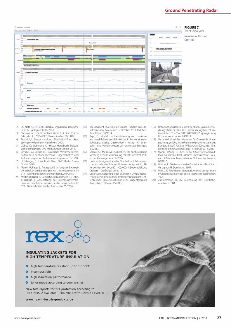
Ground Penetrating Radar
27ETR | INTERNATIONAL EDITION | 22018wwweurailpressdeetr
FIGURE 7 Track Analyzer(reference Ground Control)
[2] DB Netz AG Ril 821 Oberbau inspizieren Deutsche Bahn AG guumlltig ab 01052004
[3] Eisenmann J Stuumltzpunktelastizitaumlt bei einer Festen Fahrbahn In ZEV + DET Glasers Analen 111999
[4] Fendrich L (Hrsg) Handbuch Eisenbahninfrastruktur Springer-Verlag Berlin Heidelberg 2007
[5] Goumlbel C Lieberenz K (Hrsg) Handbuch Erdbau-werke der Bahnen DVV Media Group GmbH 2013
[6] Leykauf G Lothar M Elastisches Verformungsver-halten des Eisenbahnoberbaus ndash Eigenschaften und Anforderungen In EI ndash Eisenbahningenieur 031990
[7] Lichtberger B Handbuch Gleis DVV Media Group GmbH 2010
[8] Martin U Rapp S Ansatz zur Erfassung der Bodenei-genschaften am Bahnkoumlrper in Schotterbauweise In ETR ndash Eisenbahntechnische Rundschau 042017
[9] Martin U Rapp S Camacho D Moormann C Lehn J Prakaso P Abschaumltzung der Untergrundverhaumllt-nisse am Bahnkoumlrper anhand des Bettungsmoduls In ETR - Eisenbahntechnische Rundschau 052016
[10] Rail Accident Investigation Branch Freight train de-railment near Gloucester 15 October 2013 Rail Acci-dent Report102014
[11] Rapp S Modell zur Identizierung von punktuel-len Instabilitaumlten am Bahnkoumlrper in konventioneller Schotterbauweise Dissertation ndash Institut fuumlr Eisen-bahn- und Verkehrswesen der Universitaumlt Stuttgart 072017
[12] Soldati G Meier M Zurkirchen M Kontinuierliche Messung der Gleiseinsenkung mit 20 t Achslast In EI ndash Eisenbahningenieur 022016
[13] Untersuchungszentrale der Eisenbahn-Unfalluntersu-chungsstelle des Bundes Untersuchungsbericht Ak-tenzeichen 60 ndash 60uu2011-0200041 Zugentgleisung Groumlbers ndash Groszligkugel 062013
[14] Untersuchungszentrale der Eisenbahn-Unfalluntersu-chungsstelle des Bundes Untersuchungsbericht Ak-tenzeichen 60uu2013-06047-3323 Zugentgleisung Kaub ndash Lorch (Rhein) 062013
[15] Untersuchungszentrale der Eisenbahn-Unfalluntersu-chungsstelle des Bundes Untersuchungsbericht Ak-tenzeichen 60 ndash 60uu2011-0400043 Zugentgleisung Bf Hannover ndash Linden 092013
[16] Versa Verkehrssicherheitsarbeit fuumlr Oumlsterreich Unter-suchungsbericht Sicherheitsuntersuchungsstelle des Bundes BMVIT-795336-IVBAVUUBSCH2013 Ent-gleisung eines Guumlterzugs am 14 Februar 2013 2013
[17] Wang P Wang L Chen R Xu J Overview and out-look on railway track stiness measurement Jour-nal of Modern Transportation Volume 24 Issue 2 062016
[18] Winkler E Die Lehre von der Elastizitaumlt und Festigkeit Verlag von H Dominicus 1967
[19] Wolf J P Foundation Vibration Analysis using Simple Physical Models Swiss Federal Institute of Technology 1994
[20] Zimmermann H Die Berechnung des Eisenbahn-oberbaus 1888
wwwrex-industrie-produktede
INSULATING JACKETS FORHIGH TEMPERATURE INSULATION
high temperature resistant up to 1000degC
incombustible
high insulation performance
tailor made according to your wishes
New test reports for fire protection according to EN 45545-2 available R1R7R17 with Hazard Level HL 3
Distributed Acoustic Sensing
28 ETR | INTERNATIONAL EDITION | 22018 wwweurailpressdeetr
Dip-Ing FH MScMartin RosenbergerCTO Frauscher Sensor Technology martinrosenberger frauschercom
This involves planning and controlling maintenance measures based on the actual condition of the equipment systems and components (assets) Unexpected events due to faulty components and unnecessary work on fully intact elements can thus be reduced This is possible thanks to the ever increasing amount of reliable data about the condition of the asset that is available in real time
Continuous acoustic condition monitor-ing of the infrastructure based on Distribut-ed Acoustic Sensing (DAS) is a key building block of future solutions This technology can considerably increase the availability of rail networks since it continuously delivers very precise information about the condi-tion of the infrastructure and any changes thereby fullling a key prerequisite for the use of CBM solutions
The sensor technology and inspections form and remain the basis for condition-based maintenance of the track These in-clude track recording vehicles xed meas-urement points sensor technology on
How Distributed Acoustic Sensing supports condition based maintenance strategiesCurrent technological developments are opening up new opportunities for the railway industry in a whole range of application areas Most notably these include networking digitalization and the Inter-net of Things (IoT) This trend is also having a growing impact on processes and strategies for maintain-ing rolling stock and infrastructure Traditional maintenance philosophies which are based on xed intervals or in the case of vehicles on mileage are increasingly being replaced by predictive condition based maintenance (CBM)
standard trains track-side sensor technol-ogy selectively deployed manual measur-ing instruments and self-monitoring infra-structure systems Data from these sources must be consolidated and if applicable combined with information about rolling stock and system-side infrastructure data such as a system directory or inputs from other sensors
DAS enables a sensor solution to be cre-ated which fulls several of the specied re-quirements this technology allows railway networks to be monitored continuously in real time and with respect to a huge num-ber of dierent events Frauscher has devel-oped its own DAS solution for the railway sector Frauscher Tracking Solutions FTS The manufacturerrsquos team tested the tech-nology and through intensive develop-ment eliminated constraints with respect to use for rail trac To create this in-depth knowledge of DAS as well as requirements and standards in the railway industry was required
1 DAS FUNCTIONAL PRINCIPLE
DAS-based systems use laser pulses sent in a glass bre to detect events on or in the vicinity of the track part of the laser pulse is reected back out of the bre to the transmitting unit The sound and vibration waves impacting on the cable result in signicant shifts in the reection (Fig 1) The maximum frequency range of the vibrations detected in this man-ner is 125 kHz Using specically developed algorithms the acquired data can be used to calculate specic signatures in real time These describe highly precise locations and types of processes in the vicinity of the track
One of the advantages of installing a DAS system is that the bre optic cables it requires are often already laid next to the tracks These are normally used for commu-nication purposes As the optical bres used require practically no maintenance the sys-tem can be rolled out to large sections of the route extremely economically and ecient-ly In practice a single DAS unit can eective-ly cover up to 40 kilometres of glass bre in each direction so 80 kilometres in total [1]
2 CONTINUOUS MONITORING OF WHEEL-RAIL INTERACTION
The ongoing analysis of infrastructure us-ing FTS is based on continuous monitoring
FIG 1 Distributed Acoustic Sensing (DAS) allows for the detection of vibrations and sound waves caused by trains component defects people or other sources
raquo
Distributed Acoustic Sensing
29ETR | INTERNATIONAL EDITION | 22018wwweurailpressdeetr
of wheel-rail interaction (Fig 2) On the one hand this enables the detection of changes that arise slowly over the course of time To do so the system compares the relevant signatures that are captured each time a railway vehicle passes a spot On the other hand events that occur suddenly can also be reliably detected
21 TREND ANALYSIS FOR LOCALISATION OF CONDITION CHANGES
The wheel-rail interactions quality is the most important factor when it comes to the service life of both system components and the rolling stock This quality is derived from various parameters such as the roundness of the wheel the surface of the rail and the track design Even slight deviations from the ideal parameters result in increased signs of wear and tear over a certain amount of time Ultimately these can also lead to critical op-erating conditions Which is why continu-ous detection and thus early recognition of changes in condition along the entire route is extremely useful
This is where the FTS come into play by evaluating the signatures in the laser signal feedback it is possible to determine wheth-er a sp ecic anomaly in wheel-rail interac-tion comes from the train or from the infra-structure This is possible because the FTS system uses a glass bre as a permanent sen-sor along the track thus allowing the wheel-rail interaction for each individual axle on all train journeys to be permanently monitored along the entire route Changes are detected in real time and the method does not de-pend on a xed measurement point
If a notication is triggered by an out-of-round wheel for instance then this pattern will be part of the train signature and be de-tected in association with the moving train This allows the event to be clearly attributed to vehicle damage
By contrast if there is a change to the in-frastructure several axles will have a notice-able signature in one specic position The system uses this to determine an indicator Based on this trend analyses are formed for individual ten-metre long infrastruc-ture segments Warning or alarm notica-tions can now be created and transmitted through dened user-congured threshold values These indicate the type of change as well as the location With good georefer-encing for the bre optic cable the position identied via FTS can be localised to an accu-racy of up to ve metres and made available via machine-readable interfaces
Frauscher oers powerful interfaces for employees in railway infrastructure compa-
nies In particular these include a graphical user interface with map view and heat maps and depiction of the infrastructure condition in denable categories The zoom function can be used to display the entire route or a position with relevant localisation in route kilometres or GPS data the actual condition and the change in condition over a specic period Filters can be set for even more de-tailed analyses and evaluation
22 EVALUATION OF CHANGES IN CONDITION AS A PROCESS
To determine the relevance for a specic rail-way operation simply identifying a change in condition is not enough The trend analy-sis must also be correlated with the trains and their speeds After all identical techni-cal non-conformities will result in indicators with completely dierent frequencies and intensities when a heavy long freight train and when a lighter short passenger train travels over a position with a fault
Therefore a basic condition must rst be dened for the infrastructure and stored in the FTS The trend analyses can then be ap-plied to this To do so the system structure (primarily bridges tunnels or points) must be logged in the system and the sensor must be calibrated accordingly Data that needs to be entered includes rail joints or transitions from a point for example They create similar patterns to those of a rail defect but must be evaluated and examined dierently
It may also be necessary to lter out am-bient noise from stationary systems such as pumps and generators so that this does not have a negative eect on the detailed analy-sis of the wheel-rail interaction signature
These adjustments are currently carried out manually during the installation and com-missioning process However Frauscher is developing tools to automate these process-es These steps form part of the technologyrsquos path towards serial production
Once the basic condition has been dened then depending on the model the operator will receive regular reports or warning and alarm notications via dened interfaces The DAS systems that are currently available are not yet able to classify and quantify the changes detected with sucient accuracy Maintenance personal therefore take on the task of evaluating suspect positions through inspection actions during the development and installation phase A visual inspection is often enough to identify the cause of the warning classify the change and take the necessary action within a dened period
Based on experience with several installa-tions and Frauscherrsquos collaboration with op-erators there are essentially three relevant classications
rarr No detectable or only minimal damage rarr Non-critical damage rarr Critical damage
What is important is that this evaluation and classication is understood and followed as part and parcel of the maintenance process Dening the threshold values and deter-mining the sensitivity of the system is a key step in this regard Experienced specialist sta who evaluate and process the notica-tions can shape the system to suit their own needs This allows CBM concepts to be ap-plied even more eciently for practical sup-port and to build expertise (Fig 3)
The high sensitivity level of the system
FIG 2 By continuously monitoring the acoustic signature of the wheel-rail contact the FTS support condition based maintenance strategies
Distributed Acoustic Sensing
30 ETR | INTERNATIONAL EDITION | 22018 wwweurailpressdeetr
means that a range of errors can be detected at a very early stage However this also in-creases the risk that positions that are not relevant for maintenance will be displayed This is where empirical values are really needed so that the optimum setting can be tuned for the operator It is crucial to involve the maintenance personnel in this whether through the operator or the service contrac-tor After all only experts on the ground can evaluate the condition of the infrastructure and determine the necessary measures Maintenance employee experience thus re-mains essential for training the algorithms and evaluating the results the maintenance personnel must use their knowledge of routes and systems to determine whether a notication is in fact relevant or not
Not detectable or only minimal damageIn this case no maintenance measures are needed There are three main reasons why the system has indicated a potential fault in this case First there may be a structural fac-tor in the infrastructure or a factor in the en-vironment of the trigger In this case the in-uencing factor can be ltered out in future Secondly it could be that a visual inspection reveals no detectable fault but there are already signs of wear In this case the user
would add information to the system stating that this section is to be kept under observa-tion or specically monitored over a certain period of time ndash for example by adjusting the threshold value If the system contin-ues to exhibit a fault it is advisable to apply analysis methods that go beyond a visual inspection of this point or use other meas-urement data as a comparison Thirdly this could be due to a minor surface fault on the rail for example which does not require any action since scheduled surface processing measures are due to be carried out (Fig 4) In this case the fault message can be acknowl-edged
Non-critical damageIn this case the system has identied a rel-evant fault but it does not need to be cor-rected right away (Fig 5) The main advan-tage of this is that early detection allows the necessary measures to be planned in good time so these can be put into eect during quiet periods or eciently combined with other measures thus reducing the number of expensive individual activities
Critical damageIf such changes are detected then measures must be initiated immediately in order to re-
solve the safety-critical operating condition and minimise any expensive subsequent damage Experience shows that such critical conditions can develop over just a few days or can even be triggered by acute short-term factors Examples include ballast voids due to washout rail head cracks and broken rails
Critical conditions can arise during the analysis cycles even if the rail network is monitored regularly with track recording ve-hicles for example Continuous monitoring of the wheel-rail interaction enables quicker intervention and minimises personal injury and damage to property
23 EMPIRICAL RESULTS
In addition to various applications which can be used in real time on the basis of train lo-calisation over the last two years Frauscher has been taking a closer look at infrastruc-ture maintenance In particular at the po-tential that continuous monitoring of the wheel-rail interaction has to oer in the fol-lowing scenarios
rarr Rail monitoring rarr Rail fastening and sleeper monitoring rarr Track substructure and superstructure
monitoring
Practical application has shown that the data that can be provided via the FTS system al-ready oers a range of interesting options it helps users to plan and control maintenance measures in good time To do so Frauscher implements technology such as machine learning pattern recognition and articial
FIG 3 When developing advanced main-tenance solutions various levels within a railway network have to work together closely
FIG 4 Changes in the trackrsquos surface can be detected evaluated and considered when planning maintenance works
FIG 5 Detecting small defects allows for a targeted monitoring in order to generate alarms when their condition deteriorates
Distributed Acoustic Sensing
31ETR | INTERNATIONAL EDITION | 22018wwweurailpressdeetr
intelligence However in order to move to the next level a solid base of empirical val-ues and a library of signatures from a variety of sources of damage are needed
The company is working very closely with the operators of several installations select-ed from approximately 30 projects that are currently ongoing worldwide They are joint-ly considering the evaluation interpretation and derivation of measures Specic issues and ideas for further development of the evaluation software and logic are directly incorporated into Frauscherrsquos development processes using agile methods
Rail monitoringAll types of rail damage that cause vibrations or a noise spectrum that deviates from the norm are detected This ranges from surface damage such as rail corrugation squats rail head cracks wheel burns or corrosion and dents to cracking and ssuring or even bro-ken rails
Unsurprisingly the algorithm for detect-ing rail damage also detects rail joints After all the signature of a gap as in an isolation joint could be exactly the same as that for a break in part of the rail In this case depend-ing on requirements these rail joints can be suppressed or specically monitored with their own threshold values (Fig 6 7) The sensitive sensor system can detect broken rails as a train passes over them with high probability However due to the many dif-ferent forms and physical basic conditions a warning system with a 100 percent de-tection rate and zero error rate cannot be achieved
In addition there are still no empirical val-ues for broken rails which can be traced back to warping and thermal eects without the eect of the train Noises that arise due to warping (thermal popping) were detected during tests designed to identify and local-ise landslides and rock fall These are hard to classify or uniquely identify using the cur-rently available hardware and software It is to be assumed that a rail that breaks for thermal reasons generates a similar if more intensive signature and it is not possible to clearly distinguish this from the ldquothermal poprdquo
Therefore it is important to consider whether continuous monitoring of the tracks with appropriate trend analyses does not provide more information about the safety of the route than a warning system for broken rails Last but not least broken rails should generally be reduced by as-required maintenance measures
Rail fastening and sleeper monitoringIn several installations positions were de-
tected that exhibited increased vibration due to damaged or missing rail connections or broken sleepers These are typically faults that do not necessarily require action to be taken right away Instead they are classied in such a way that these tasks will be car-ried out during upcoming scheduled on-site maintenance
Track substructure and superstructure monitoringThe FTS system is able to localise weakness-es in the substructure and track superstruc-ture such as ballast voids under sleepers cavities or compacted areas The condition of the track bed may under certain circum-stances also lead to a critical situation in a relatively short period of time particularly in mountainous regions where heavy rain or mudslides can also make the track position unstable Practical examples also exist for these scenarios where FTS localised critical positions where ballast voids under sleepers were later identied
3 SUMMARY
Continuous monitoring of wheel-rail interac-tion based on FTS opens up numerous pos-sibilities for the user in terms of timely detec-tion of weaknesses and changes in condition on the route Thus targeted and as-required maintenance measures can be dened planned and eciently controlled This is a paradigm shift in terms of maintenance strategy similar to that which is emerging for vehicles Before xed periods based on theoretically calculated average loads were
key to the strategy Now the actual wear and condition of the specic component (rail surface fastening sleeper substructure or track superstructure) are the trigger for maintenance repair or servicing work
These new options for monitoring infra-structure will not replace existing measure-ment systems instead they will enhance them They will change the maintenance processes mainly through the high-pre-cision and early detection of continuous changes By determining individual thresh-old values necessary work can be planned and carried out preventively before critical damage arises
In addition to such continuous changes the FTS is also able to detect vehicle faults and short-term sporadic inuences on trackside infrastructure This includes natu-ral hazard management such as falling rocks and trees catenary ashover or protecting infrastructure from vandalism cable theft or unauthorised access to track systems
Even in times of advancing digitalisation employee experience forms an indispensa-ble basis for railway operations Manufac-turers and operators must work together to develop systems for CBM concepts and individually calibrate them so they become helpful tools which raise eciency while re-ducing ongoing costs
Literature[1] Rosenberger Martin Lancaster Gavin Real-time track
monitoring for sustainable maintenance strategies ETR International 12017 P 20-23
FIG 6 Rail joints are specic points which can be monitored via FTS by storing their base signature in a rst place
FIG 7 If the condition of the rail joint chang-es its acoustic signature will do the same
Smart Tamping
32 ETR | INTERNATIONAL EDITION | 22018 wwweurailpressdeetr
Plasser amp Theurerrsquos development of the turnout tamping assistance system ldquoPlasserSmartTamping ndash The Assistantrdquo has been an important step towards the further automation of tamping machines The assis-tance system provides automated support for tamping works in turnouts and crossings It recommends specic actions which must be conrmed by the operator before they are carried out As a result operators increasingly monitor processes intervening manually only in exceptional cases A new recording module allows for a completely new form of tamping documentation It increases transparency working quality and process reliability For the rst time the turnout tamping simulator ndash not a tamping machine ndash was used to develop all of the software modules of the turnout tamping assistance system In an extended hardware-in-the-loop application the turnout tamping assistance system was developed and tested using the simulator
David BuchbauerProject Manager for tamping and measuring technologydavidbuchbauer plassertheurercom
Dipl-Ing Martin BuumlrgerHead of Digital Track Systemsmartinbuerger plassertheurercom
Andreas Theiszlig MScProduct Owner Smart Tamping minus The Assistantandreastheissplassertheurercom
Dipl-Ing Georg JodlbauerHead of Research and Testinggeorgjodlbauer plassertheurercom
Dr techn Gerald ZaunerDigital Track Systemsgeraldzaunerplassertheurercom
Dipl-Ing Dr techn Florian AuerDirector of Technology and Innovationorianauerplassertheurercom
1 THE DEVELOPMENT
In modern track maintenance the conven-tional distinction between track inspection vehicles and track construction and main-tenance machines has increasingly been blurred To optimise processes track con-struction and maintenance machines are t-ted with the latest sensor technology turn-ing them into ldquosmart machinesrdquo Inertial track measuring systems used up to now only on track inspection vehicles have increasingly been installed on tamping machines This makes it possible to use tamping machines for separate track measuring runs to calcu-late the required track geometry correction values
The use of inertial track measuring sys-tems optimises the track geometry quality In addition laser scanners and light section sensors make it possible to create a ldquodigital track twinrdquo which provides the data base of the turnout tamping assistance system
2 THE OBJECTIVE OF THE TURNOUT TAMPING ASSISTANCE SYSTEM
Turnout tamping (Figure 1) requires consid-erable knowledge of several areas of exper-tise (track surveying machine technology track technology regulations) The most im-portant tasks include
Smart Tamping ndash Fields of Application of the Turnout Tamping Assistance System
rarr In the main tamping cabin Controlling the tamping unit including the turnta-ble opening width and tilting motion of the tines
rarr In the co-tamping cabin Controlling the lifting and lining unit the parts of the tamping units in the diverging track and the additional lifting unit
The turnout tamping assistance system com-plies with level 3 of the standard SAE J3016 The standard denes terms related to on-
road motor vehicle automated driving sys-tems and has been applied correspondingly On the automation level 3 the system rec-ommends specic actions which must be conrmed by the operator before they are carried out with the operator as fallback The design of the turnout tamping assis-tance system also allows for higher levels of automation However for reasons of liability automation options such as remote control or robot operation are not oered
The turnout tamping assistance system
Smart Tamping
33ETR | INTERNATIONAL EDITION | 22018wwweurailpressdeetr
raquo
oered to machine operators and infrastruc-ture managers consists of four product parts in modular design
rarr recording module for recommendations and operations
rarr operation assistant for the lifting and lin-ing unit
rarr operation assistant for the additional lift-ing unit
rarr operation assistant for the tamping unit
The modular design makes it easier to put the turnout tamping assistance system into operation for the rst time In a testing phase recording modes can be used to verify the accuracy of the recommended measures (comparison of the actual taming operations and the actions recommended by the assis-tance system) Upgrading to a higher level is possible if it has been taken into account in the design of the machine The modules are activated step by step to allow sta to famil-iarize themselves with the assistance system and to coordinate the work processes
3 THE RECORDING MODULE ldquo DIGITAL TRACK TWINrdquo
The rst step is to develop the digital track twin When selecting the hardware compo-nents of the turnout tamping assistance sys-tem (one rotation laser four light section sen-sors and one colour camera) it was ensured that the hardware can be exchanged and that the software can be adapted modularly
When designing the hardware components a particular focus was placed on meeting the accuracy requirements In addition it was ensured that the system is highly robust and easy to maintain
The recording module of the turnout tamping assistance system connects the digital twin of the track with the working parameters of the machine As a result the quality control of tamping works reaches a new transparency level Infrastructure op-erators can easily access all parameters rel-
FIG 1 Operators of turnout tamping machines must meet high requirements
FIG 2 Tamping docu-mentation using multi-layer technol-ogy (schematic representation)
evant to quality and work (such as the tine position tamping depth or squeeze time) digitally and immediately when connected to the Internet
In the future the recording document will also include the rolling marks of the rails and the position of the aluminothermic welds As the software is developed in-house we can meet our customersrsquo requirements exibly (Fig 2) For instance it will be possible to ex-port the ldquodigital twinrdquo for use on the tamping simulators
Smart Tamping
34 ETR | INTERNATIONAL EDITION | 22018 wwweurailpressdeetr
4 OPERATION ASSISTANCE
Based on their position at the time of record-ing the individual scans and recordings are merged to form a 3D image of the reality showing the exact position At the same time the position of the machine and every indi-vidual work unit is continually updated As a result a 3D image of the relevant machine parts is imported into the overall model pro-viding the basis for every decision of the as-
Federal Railways (OumlBB) and experience from practical operation A specic adaptation to the infrastructure managerrsquos requirements is possible
Figure 4 shows a list of position sensors angle sensors and actuators operated by the assistance system The values of the lin-ing adjustment the lifting operation and the tamping parameters (multiple tamping tamping vibration frequency squeeze force tamping depth) are not controlled by the as-sistance system
The turnout tamping assistance system has been designed for two applications In the rst design version (the separate view) separate measures are recommended to the operators in the main tamping cabin and the co-tamping cabin The second design version (the combined view) is the current develop-ment focus Both assistance modules are merged into a combined view in the main tamping cabin enabling the operator in the main tamping cabin to control the entire turn-out tamping process by himself (Figure 5)
The application focus of the rst genera-tion of the turnout tamping assistance sys-tem is on turnouts that have not yet been fully ballasted As a result the surface of the sleepers is visible Specic recommenda-tions require a good view onto most of the turnout area the sleepers and obstacles (such as switching contacts turnout operat-ing units)
In a next stage we plan to t the turnout tamping assistance system with sensors (eddy current sensors) for the detection of sleepers in ballasted areas (newly laid track)
Completed tamping works in turnouts can be duplicated using the machine control module turnout programming automation In a combined application of the turnout tamping assistance system and the turnout programming automation it is in principle possible to scan turnouts in advance while they have not yet been fully covered with ballast and to provide the turnout program-ming automation module with the recom-mendations to allow for their duplication Turnout tamping machines with the inte-grated supply of new ballast generally allow for the use of the turnout tamping assis-tance system as the turnout is not ballasted at the scan position at the front end of the machine
The prototype of the turnout tamping as-sistance system was introduced to the ex-pert audience at the trade show iaf 2017 in Muumlnster The positive feedback proves the great potential of the technology In practi-cal operation the turnout tamping assis-tance system is currently prepared for series production for the work unit types ldquo275rdquo ldquo475rdquo and ldquo4x4rdquo
FIG 3 Overview of the control recommen-dations
FIG 4 Position sensors angle sensors and actuators operated by the assistance system
FIG 5 Tamping cabin with the assistance system ldquoPlasserS-martTamping ndash The Assistantrdquo
sistant The data is processed with the lowest possible latency and highly parallel data pro-cessing to ensure fast operation The system recommends the respective actions several metres ahead of the tamping unit (Fig 3) to provide the operators with sucient time to analyse and modify the recommendation if necessary The recommendation of the as-sistance system is checked directly at the tamping position before the tamping unit is lowered At the same time the congura-tion of the lifting and lining unit (hock and tongue position) for the transfer to and the lifting operation at the next tamping posi-tion is checked prior to transfer travelling At this point the operator can take action at any time and further adjust the settings The operation of the additional lifting unit is checked in a similar way
To allow for tamping recommendations the track sections requiring actions must be located in an automated process To ensure this dierent image processing systems are combined with articial intelligence and connected systemically
The basic tamping scheme was developed on the basis of regulations and specications of German Federal Railway (DB) Austrian
Digital technologies are key to maximising track availability and planning forward-looking maintenance The ability to check the line at any time thanks to networked data capture in real time with innovative products reliable materials and optimised maintenance concepts for every aspect of rail infrastructure Thatrsquos what we mean by ldquoThe Smart Rail Track by Vosslohrdquo
Next stop Berlin InnoTrans 2018 Hall 26
wwwvossloh-innotranscom
The Smart Rail Track by Vossloh
DIN A4_Stadtmotiv_US_InnoTrans_Internet neuindd 1 12072018 131049
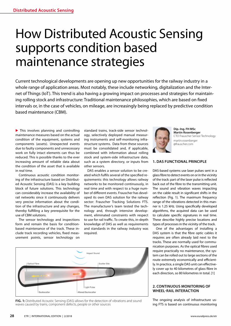
Distributed Acoustic Sensing
28 ETR | INTERNATIONAL EDITION | 22018 wwweurailpressdeetr
Dip-Ing FH MScMartin RosenbergerCTO Frauscher Sensor Technology martinrosenberger frauschercom
This involves planning and controlling maintenance measures based on the actual condition of the equipment systems and components (assets) Unexpected events due to faulty components and unnecessary work on fully intact elements can thus be reduced This is possible thanks to the ever increasing amount of reliable data about the condition of the asset that is available in real time
Continuous acoustic condition monitor-ing of the infrastructure based on Distribut-ed Acoustic Sensing (DAS) is a key building block of future solutions This technology can considerably increase the availability of rail networks since it continuously delivers very precise information about the condi-tion of the infrastructure and any changes thereby fullling a key prerequisite for the use of CBM solutions
The sensor technology and inspections form and remain the basis for condition-based maintenance of the track These in-clude track recording vehicles xed meas-urement points sensor technology on
How Distributed Acoustic Sensing supports condition based maintenance strategiesCurrent technological developments are opening up new opportunities for the railway industry in a whole range of application areas Most notably these include networking digitalization and the Inter-net of Things (IoT) This trend is also having a growing impact on processes and strategies for maintain-ing rolling stock and infrastructure Traditional maintenance philosophies which are based on xed intervals or in the case of vehicles on mileage are increasingly being replaced by predictive condition based maintenance (CBM)
standard trains track-side sensor technol-ogy selectively deployed manual measur-ing instruments and self-monitoring infra-structure systems Data from these sources must be consolidated and if applicable combined with information about rolling stock and system-side infrastructure data such as a system directory or inputs from other sensors
DAS enables a sensor solution to be cre-ated which fulls several of the specied re-quirements this technology allows railway networks to be monitored continuously in real time and with respect to a huge num-ber of dierent events Frauscher has devel-oped its own DAS solution for the railway sector Frauscher Tracking Solutions FTS The manufacturerrsquos team tested the tech-nology and through intensive develop-ment eliminated constraints with respect to use for rail trac To create this in-depth knowledge of DAS as well as requirements and standards in the railway industry was required
1 DAS FUNCTIONAL PRINCIPLE
DAS-based systems use laser pulses sent in a glass bre to detect events on or in the vicinity of the track part of the laser pulse is reected back out of the bre to the transmitting unit The sound and vibration waves impacting on the cable result in signicant shifts in the reection (Fig 1) The maximum frequency range of the vibrations detected in this man-ner is 125 kHz Using specically developed algorithms the acquired data can be used to calculate specic signatures in real time These describe highly precise locations and types of processes in the vicinity of the track
One of the advantages of installing a DAS system is that the bre optic cables it requires are often already laid next to the tracks These are normally used for commu-nication purposes As the optical bres used require practically no maintenance the sys-tem can be rolled out to large sections of the route extremely economically and ecient-ly In practice a single DAS unit can eective-ly cover up to 40 kilometres of glass bre in each direction so 80 kilometres in total [1]
2 CONTINUOUS MONITORING OF WHEEL-RAIL INTERACTION
The ongoing analysis of infrastructure us-ing FTS is based on continuous monitoring
FIG 1 Distributed Acoustic Sensing (DAS) allows for the detection of vibrations and sound waves caused by trains component defects people or other sources
raquo
Distributed Acoustic Sensing
29ETR | INTERNATIONAL EDITION | 22018wwweurailpressdeetr
of wheel-rail interaction (Fig 2) On the one hand this enables the detection of changes that arise slowly over the course of time To do so the system compares the relevant signatures that are captured each time a railway vehicle passes a spot On the other hand events that occur suddenly can also be reliably detected
21 TREND ANALYSIS FOR LOCALISATION OF CONDITION CHANGES
The wheel-rail interactions quality is the most important factor when it comes to the service life of both system components and the rolling stock This quality is derived from various parameters such as the roundness of the wheel the surface of the rail and the track design Even slight deviations from the ideal parameters result in increased signs of wear and tear over a certain amount of time Ultimately these can also lead to critical op-erating conditions Which is why continu-ous detection and thus early recognition of changes in condition along the entire route is extremely useful
This is where the FTS come into play by evaluating the signatures in the laser signal feedback it is possible to determine wheth-er a sp ecic anomaly in wheel-rail interac-tion comes from the train or from the infra-structure This is possible because the FTS system uses a glass bre as a permanent sen-sor along the track thus allowing the wheel-rail interaction for each individual axle on all train journeys to be permanently monitored along the entire route Changes are detected in real time and the method does not de-pend on a xed measurement point
If a notication is triggered by an out-of-round wheel for instance then this pattern will be part of the train signature and be de-tected in association with the moving train This allows the event to be clearly attributed to vehicle damage
By contrast if there is a change to the in-frastructure several axles will have a notice-able signature in one specic position The system uses this to determine an indicator Based on this trend analyses are formed for individual ten-metre long infrastruc-ture segments Warning or alarm notica-tions can now be created and transmitted through dened user-congured threshold values These indicate the type of change as well as the location With good georefer-encing for the bre optic cable the position identied via FTS can be localised to an accu-racy of up to ve metres and made available via machine-readable interfaces
Frauscher oers powerful interfaces for employees in railway infrastructure compa-
nies In particular these include a graphical user interface with map view and heat maps and depiction of the infrastructure condition in denable categories The zoom function can be used to display the entire route or a position with relevant localisation in route kilometres or GPS data the actual condition and the change in condition over a specic period Filters can be set for even more de-tailed analyses and evaluation
22 EVALUATION OF CHANGES IN CONDITION AS A PROCESS
To determine the relevance for a specic rail-way operation simply identifying a change in condition is not enough The trend analy-sis must also be correlated with the trains and their speeds After all identical techni-cal non-conformities will result in indicators with completely dierent frequencies and intensities when a heavy long freight train and when a lighter short passenger train travels over a position with a fault
Therefore a basic condition must rst be dened for the infrastructure and stored in the FTS The trend analyses can then be ap-plied to this To do so the system structure (primarily bridges tunnels or points) must be logged in the system and the sensor must be calibrated accordingly Data that needs to be entered includes rail joints or transitions from a point for example They create similar patterns to those of a rail defect but must be evaluated and examined dierently
It may also be necessary to lter out am-bient noise from stationary systems such as pumps and generators so that this does not have a negative eect on the detailed analy-sis of the wheel-rail interaction signature
These adjustments are currently carried out manually during the installation and com-missioning process However Frauscher is developing tools to automate these process-es These steps form part of the technologyrsquos path towards serial production
Once the basic condition has been dened then depending on the model the operator will receive regular reports or warning and alarm notications via dened interfaces The DAS systems that are currently available are not yet able to classify and quantify the changes detected with sucient accuracy Maintenance personal therefore take on the task of evaluating suspect positions through inspection actions during the development and installation phase A visual inspection is often enough to identify the cause of the warning classify the change and take the necessary action within a dened period
Based on experience with several installa-tions and Frauscherrsquos collaboration with op-erators there are essentially three relevant classications
rarr No detectable or only minimal damage rarr Non-critical damage rarr Critical damage
What is important is that this evaluation and classication is understood and followed as part and parcel of the maintenance process Dening the threshold values and deter-mining the sensitivity of the system is a key step in this regard Experienced specialist sta who evaluate and process the notica-tions can shape the system to suit their own needs This allows CBM concepts to be ap-plied even more eciently for practical sup-port and to build expertise (Fig 3)
The high sensitivity level of the system
FIG 2 By continuously monitoring the acoustic signature of the wheel-rail contact the FTS support condition based maintenance strategies
Distributed Acoustic Sensing
30 ETR | INTERNATIONAL EDITION | 22018 wwweurailpressdeetr
means that a range of errors can be detected at a very early stage However this also in-creases the risk that positions that are not relevant for maintenance will be displayed This is where empirical values are really needed so that the optimum setting can be tuned for the operator It is crucial to involve the maintenance personnel in this whether through the operator or the service contrac-tor After all only experts on the ground can evaluate the condition of the infrastructure and determine the necessary measures Maintenance employee experience thus re-mains essential for training the algorithms and evaluating the results the maintenance personnel must use their knowledge of routes and systems to determine whether a notication is in fact relevant or not
Not detectable or only minimal damageIn this case no maintenance measures are needed There are three main reasons why the system has indicated a potential fault in this case First there may be a structural fac-tor in the infrastructure or a factor in the en-vironment of the trigger In this case the in-uencing factor can be ltered out in future Secondly it could be that a visual inspection reveals no detectable fault but there are already signs of wear In this case the user
would add information to the system stating that this section is to be kept under observa-tion or specically monitored over a certain period of time ndash for example by adjusting the threshold value If the system contin-ues to exhibit a fault it is advisable to apply analysis methods that go beyond a visual inspection of this point or use other meas-urement data as a comparison Thirdly this could be due to a minor surface fault on the rail for example which does not require any action since scheduled surface processing measures are due to be carried out (Fig 4) In this case the fault message can be acknowl-edged
Non-critical damageIn this case the system has identied a rel-evant fault but it does not need to be cor-rected right away (Fig 5) The main advan-tage of this is that early detection allows the necessary measures to be planned in good time so these can be put into eect during quiet periods or eciently combined with other measures thus reducing the number of expensive individual activities
Critical damageIf such changes are detected then measures must be initiated immediately in order to re-
solve the safety-critical operating condition and minimise any expensive subsequent damage Experience shows that such critical conditions can develop over just a few days or can even be triggered by acute short-term factors Examples include ballast voids due to washout rail head cracks and broken rails
Critical conditions can arise during the analysis cycles even if the rail network is monitored regularly with track recording ve-hicles for example Continuous monitoring of the wheel-rail interaction enables quicker intervention and minimises personal injury and damage to property
23 EMPIRICAL RESULTS
In addition to various applications which can be used in real time on the basis of train lo-calisation over the last two years Frauscher has been taking a closer look at infrastruc-ture maintenance In particular at the po-tential that continuous monitoring of the wheel-rail interaction has to oer in the fol-lowing scenarios
rarr Rail monitoring rarr Rail fastening and sleeper monitoring rarr Track substructure and superstructure
monitoring
Practical application has shown that the data that can be provided via the FTS system al-ready oers a range of interesting options it helps users to plan and control maintenance measures in good time To do so Frauscher implements technology such as machine learning pattern recognition and articial
FIG 3 When developing advanced main-tenance solutions various levels within a railway network have to work together closely
FIG 4 Changes in the trackrsquos surface can be detected evaluated and considered when planning maintenance works
FIG 5 Detecting small defects allows for a targeted monitoring in order to generate alarms when their condition deteriorates
Distributed Acoustic Sensing
31ETR | INTERNATIONAL EDITION | 22018wwweurailpressdeetr
intelligence However in order to move to the next level a solid base of empirical val-ues and a library of signatures from a variety of sources of damage are needed
The company is working very closely with the operators of several installations select-ed from approximately 30 projects that are currently ongoing worldwide They are joint-ly considering the evaluation interpretation and derivation of measures Specic issues and ideas for further development of the evaluation software and logic are directly incorporated into Frauscherrsquos development processes using agile methods
Rail monitoringAll types of rail damage that cause vibrations or a noise spectrum that deviates from the norm are detected This ranges from surface damage such as rail corrugation squats rail head cracks wheel burns or corrosion and dents to cracking and ssuring or even bro-ken rails
Unsurprisingly the algorithm for detect-ing rail damage also detects rail joints After all the signature of a gap as in an isolation joint could be exactly the same as that for a break in part of the rail In this case depend-ing on requirements these rail joints can be suppressed or specically monitored with their own threshold values (Fig 6 7) The sensitive sensor system can detect broken rails as a train passes over them with high probability However due to the many dif-ferent forms and physical basic conditions a warning system with a 100 percent de-tection rate and zero error rate cannot be achieved
In addition there are still no empirical val-ues for broken rails which can be traced back to warping and thermal eects without the eect of the train Noises that arise due to warping (thermal popping) were detected during tests designed to identify and local-ise landslides and rock fall These are hard to classify or uniquely identify using the cur-rently available hardware and software It is to be assumed that a rail that breaks for thermal reasons generates a similar if more intensive signature and it is not possible to clearly distinguish this from the ldquothermal poprdquo
Therefore it is important to consider whether continuous monitoring of the tracks with appropriate trend analyses does not provide more information about the safety of the route than a warning system for broken rails Last but not least broken rails should generally be reduced by as-required maintenance measures
Rail fastening and sleeper monitoringIn several installations positions were de-
tected that exhibited increased vibration due to damaged or missing rail connections or broken sleepers These are typically faults that do not necessarily require action to be taken right away Instead they are classied in such a way that these tasks will be car-ried out during upcoming scheduled on-site maintenance
Track substructure and superstructure monitoringThe FTS system is able to localise weakness-es in the substructure and track superstruc-ture such as ballast voids under sleepers cavities or compacted areas The condition of the track bed may under certain circum-stances also lead to a critical situation in a relatively short period of time particularly in mountainous regions where heavy rain or mudslides can also make the track position unstable Practical examples also exist for these scenarios where FTS localised critical positions where ballast voids under sleepers were later identied
3 SUMMARY
Continuous monitoring of wheel-rail interac-tion based on FTS opens up numerous pos-sibilities for the user in terms of timely detec-tion of weaknesses and changes in condition on the route Thus targeted and as-required maintenance measures can be dened planned and eciently controlled This is a paradigm shift in terms of maintenance strategy similar to that which is emerging for vehicles Before xed periods based on theoretically calculated average loads were
key to the strategy Now the actual wear and condition of the specic component (rail surface fastening sleeper substructure or track superstructure) are the trigger for maintenance repair or servicing work
These new options for monitoring infra-structure will not replace existing measure-ment systems instead they will enhance them They will change the maintenance processes mainly through the high-pre-cision and early detection of continuous changes By determining individual thresh-old values necessary work can be planned and carried out preventively before critical damage arises
In addition to such continuous changes the FTS is also able to detect vehicle faults and short-term sporadic inuences on trackside infrastructure This includes natu-ral hazard management such as falling rocks and trees catenary ashover or protecting infrastructure from vandalism cable theft or unauthorised access to track systems
Even in times of advancing digitalisation employee experience forms an indispensa-ble basis for railway operations Manufac-turers and operators must work together to develop systems for CBM concepts and individually calibrate them so they become helpful tools which raise eciency while re-ducing ongoing costs
Literature[1] Rosenberger Martin Lancaster Gavin Real-time track
monitoring for sustainable maintenance strategies ETR International 12017 P 20-23
FIG 6 Rail joints are specic points which can be monitored via FTS by storing their base signature in a rst place
FIG 7 If the condition of the rail joint chang-es its acoustic signature will do the same
Smart Tamping
32 ETR | INTERNATIONAL EDITION | 22018 wwweurailpressdeetr
Plasser amp Theurerrsquos development of the turnout tamping assistance system ldquoPlasserSmartTamping ndash The Assistantrdquo has been an important step towards the further automation of tamping machines The assis-tance system provides automated support for tamping works in turnouts and crossings It recommends specic actions which must be conrmed by the operator before they are carried out As a result operators increasingly monitor processes intervening manually only in exceptional cases A new recording module allows for a completely new form of tamping documentation It increases transparency working quality and process reliability For the rst time the turnout tamping simulator ndash not a tamping machine ndash was used to develop all of the software modules of the turnout tamping assistance system In an extended hardware-in-the-loop application the turnout tamping assistance system was developed and tested using the simulator
David BuchbauerProject Manager for tamping and measuring technologydavidbuchbauer plassertheurercom
Dipl-Ing Martin BuumlrgerHead of Digital Track Systemsmartinbuerger plassertheurercom
Andreas Theiszlig MScProduct Owner Smart Tamping minus The Assistantandreastheissplassertheurercom
Dipl-Ing Georg JodlbauerHead of Research and Testinggeorgjodlbauer plassertheurercom
Dr techn Gerald ZaunerDigital Track Systemsgeraldzaunerplassertheurercom
Dipl-Ing Dr techn Florian AuerDirector of Technology and Innovationorianauerplassertheurercom
1 THE DEVELOPMENT
In modern track maintenance the conven-tional distinction between track inspection vehicles and track construction and main-tenance machines has increasingly been blurred To optimise processes track con-struction and maintenance machines are t-ted with the latest sensor technology turn-ing them into ldquosmart machinesrdquo Inertial track measuring systems used up to now only on track inspection vehicles have increasingly been installed on tamping machines This makes it possible to use tamping machines for separate track measuring runs to calcu-late the required track geometry correction values
The use of inertial track measuring sys-tems optimises the track geometry quality In addition laser scanners and light section sensors make it possible to create a ldquodigital track twinrdquo which provides the data base of the turnout tamping assistance system
2 THE OBJECTIVE OF THE TURNOUT TAMPING ASSISTANCE SYSTEM
Turnout tamping (Figure 1) requires consid-erable knowledge of several areas of exper-tise (track surveying machine technology track technology regulations) The most im-portant tasks include
Smart Tamping ndash Fields of Application of the Turnout Tamping Assistance System
rarr In the main tamping cabin Controlling the tamping unit including the turnta-ble opening width and tilting motion of the tines
rarr In the co-tamping cabin Controlling the lifting and lining unit the parts of the tamping units in the diverging track and the additional lifting unit
The turnout tamping assistance system com-plies with level 3 of the standard SAE J3016 The standard denes terms related to on-
road motor vehicle automated driving sys-tems and has been applied correspondingly On the automation level 3 the system rec-ommends specic actions which must be conrmed by the operator before they are carried out with the operator as fallback The design of the turnout tamping assis-tance system also allows for higher levels of automation However for reasons of liability automation options such as remote control or robot operation are not oered
The turnout tamping assistance system
Smart Tamping
33ETR | INTERNATIONAL EDITION | 22018wwweurailpressdeetr
raquo
oered to machine operators and infrastruc-ture managers consists of four product parts in modular design
rarr recording module for recommendations and operations
rarr operation assistant for the lifting and lin-ing unit
rarr operation assistant for the additional lift-ing unit
rarr operation assistant for the tamping unit
The modular design makes it easier to put the turnout tamping assistance system into operation for the rst time In a testing phase recording modes can be used to verify the accuracy of the recommended measures (comparison of the actual taming operations and the actions recommended by the assis-tance system) Upgrading to a higher level is possible if it has been taken into account in the design of the machine The modules are activated step by step to allow sta to famil-iarize themselves with the assistance system and to coordinate the work processes
3 THE RECORDING MODULE ldquo DIGITAL TRACK TWINrdquo
The rst step is to develop the digital track twin When selecting the hardware compo-nents of the turnout tamping assistance sys-tem (one rotation laser four light section sen-sors and one colour camera) it was ensured that the hardware can be exchanged and that the software can be adapted modularly
When designing the hardware components a particular focus was placed on meeting the accuracy requirements In addition it was ensured that the system is highly robust and easy to maintain
The recording module of the turnout tamping assistance system connects the digital twin of the track with the working parameters of the machine As a result the quality control of tamping works reaches a new transparency level Infrastructure op-erators can easily access all parameters rel-
FIG 1 Operators of turnout tamping machines must meet high requirements
FIG 2 Tamping docu-mentation using multi-layer technol-ogy (schematic representation)
evant to quality and work (such as the tine position tamping depth or squeeze time) digitally and immediately when connected to the Internet
In the future the recording document will also include the rolling marks of the rails and the position of the aluminothermic welds As the software is developed in-house we can meet our customersrsquo requirements exibly (Fig 2) For instance it will be possible to ex-port the ldquodigital twinrdquo for use on the tamping simulators
Smart Tamping
34 ETR | INTERNATIONAL EDITION | 22018 wwweurailpressdeetr
4 OPERATION ASSISTANCE
Based on their position at the time of record-ing the individual scans and recordings are merged to form a 3D image of the reality showing the exact position At the same time the position of the machine and every indi-vidual work unit is continually updated As a result a 3D image of the relevant machine parts is imported into the overall model pro-viding the basis for every decision of the as-
Federal Railways (OumlBB) and experience from practical operation A specic adaptation to the infrastructure managerrsquos requirements is possible
Figure 4 shows a list of position sensors angle sensors and actuators operated by the assistance system The values of the lin-ing adjustment the lifting operation and the tamping parameters (multiple tamping tamping vibration frequency squeeze force tamping depth) are not controlled by the as-sistance system
The turnout tamping assistance system has been designed for two applications In the rst design version (the separate view) separate measures are recommended to the operators in the main tamping cabin and the co-tamping cabin The second design version (the combined view) is the current develop-ment focus Both assistance modules are merged into a combined view in the main tamping cabin enabling the operator in the main tamping cabin to control the entire turn-out tamping process by himself (Figure 5)
The application focus of the rst genera-tion of the turnout tamping assistance sys-tem is on turnouts that have not yet been fully ballasted As a result the surface of the sleepers is visible Specic recommenda-tions require a good view onto most of the turnout area the sleepers and obstacles (such as switching contacts turnout operat-ing units)
In a next stage we plan to t the turnout tamping assistance system with sensors (eddy current sensors) for the detection of sleepers in ballasted areas (newly laid track)
Completed tamping works in turnouts can be duplicated using the machine control module turnout programming automation In a combined application of the turnout tamping assistance system and the turnout programming automation it is in principle possible to scan turnouts in advance while they have not yet been fully covered with ballast and to provide the turnout program-ming automation module with the recom-mendations to allow for their duplication Turnout tamping machines with the inte-grated supply of new ballast generally allow for the use of the turnout tamping assis-tance system as the turnout is not ballasted at the scan position at the front end of the machine
The prototype of the turnout tamping as-sistance system was introduced to the ex-pert audience at the trade show iaf 2017 in Muumlnster The positive feedback proves the great potential of the technology In practi-cal operation the turnout tamping assis-tance system is currently prepared for series production for the work unit types ldquo275rdquo ldquo475rdquo and ldquo4x4rdquo
FIG 3 Overview of the control recommen-dations
FIG 4 Position sensors angle sensors and actuators operated by the assistance system
FIG 5 Tamping cabin with the assistance system ldquoPlasserS-martTamping ndash The Assistantrdquo
sistant The data is processed with the lowest possible latency and highly parallel data pro-cessing to ensure fast operation The system recommends the respective actions several metres ahead of the tamping unit (Fig 3) to provide the operators with sucient time to analyse and modify the recommendation if necessary The recommendation of the as-sistance system is checked directly at the tamping position before the tamping unit is lowered At the same time the congura-tion of the lifting and lining unit (hock and tongue position) for the transfer to and the lifting operation at the next tamping posi-tion is checked prior to transfer travelling At this point the operator can take action at any time and further adjust the settings The operation of the additional lifting unit is checked in a similar way
To allow for tamping recommendations the track sections requiring actions must be located in an automated process To ensure this dierent image processing systems are combined with articial intelligence and connected systemically
The basic tamping scheme was developed on the basis of regulations and specications of German Federal Railway (DB) Austrian
Digital technologies are key to maximising track availability and planning forward-looking maintenance The ability to check the line at any time thanks to networked data capture in real time with innovative products reliable materials and optimised maintenance concepts for every aspect of rail infrastructure Thatrsquos what we mean by ldquoThe Smart Rail Track by Vosslohrdquo
Next stop Berlin InnoTrans 2018 Hall 26
wwwvossloh-innotranscom
The Smart Rail Track by Vossloh
DIN A4_Stadtmotiv_US_InnoTrans_Internet neuindd 1 12072018 131049
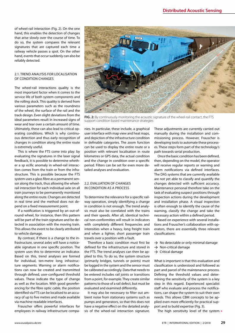
raquo
Distributed Acoustic Sensing
29ETR | INTERNATIONAL EDITION | 22018wwweurailpressdeetr
of wheel-rail interaction (Fig 2) On the one hand this enables the detection of changes that arise slowly over the course of time To do so the system compares the relevant signatures that are captured each time a railway vehicle passes a spot On the other hand events that occur suddenly can also be reliably detected
21 TREND ANALYSIS FOR LOCALISATION OF CONDITION CHANGES
The wheel-rail interactions quality is the most important factor when it comes to the service life of both system components and the rolling stock This quality is derived from various parameters such as the roundness of the wheel the surface of the rail and the track design Even slight deviations from the ideal parameters result in increased signs of wear and tear over a certain amount of time Ultimately these can also lead to critical op-erating conditions Which is why continu-ous detection and thus early recognition of changes in condition along the entire route is extremely useful
This is where the FTS come into play by evaluating the signatures in the laser signal feedback it is possible to determine wheth-er a sp ecic anomaly in wheel-rail interac-tion comes from the train or from the infra-structure This is possible because the FTS system uses a glass bre as a permanent sen-sor along the track thus allowing the wheel-rail interaction for each individual axle on all train journeys to be permanently monitored along the entire route Changes are detected in real time and the method does not de-pend on a xed measurement point
If a notication is triggered by an out-of-round wheel for instance then this pattern will be part of the train signature and be de-tected in association with the moving train This allows the event to be clearly attributed to vehicle damage
By contrast if there is a change to the in-frastructure several axles will have a notice-able signature in one specic position The system uses this to determine an indicator Based on this trend analyses are formed for individual ten-metre long infrastruc-ture segments Warning or alarm notica-tions can now be created and transmitted through dened user-congured threshold values These indicate the type of change as well as the location With good georefer-encing for the bre optic cable the position identied via FTS can be localised to an accu-racy of up to ve metres and made available via machine-readable interfaces
Frauscher oers powerful interfaces for employees in railway infrastructure compa-
nies In particular these include a graphical user interface with map view and heat maps and depiction of the infrastructure condition in denable categories The zoom function can be used to display the entire route or a position with relevant localisation in route kilometres or GPS data the actual condition and the change in condition over a specic period Filters can be set for even more de-tailed analyses and evaluation
22 EVALUATION OF CHANGES IN CONDITION AS A PROCESS
To determine the relevance for a specic rail-way operation simply identifying a change in condition is not enough The trend analy-sis must also be correlated with the trains and their speeds After all identical techni-cal non-conformities will result in indicators with completely dierent frequencies and intensities when a heavy long freight train and when a lighter short passenger train travels over a position with a fault
Therefore a basic condition must rst be dened for the infrastructure and stored in the FTS The trend analyses can then be ap-plied to this To do so the system structure (primarily bridges tunnels or points) must be logged in the system and the sensor must be calibrated accordingly Data that needs to be entered includes rail joints or transitions from a point for example They create similar patterns to those of a rail defect but must be evaluated and examined dierently
It may also be necessary to lter out am-bient noise from stationary systems such as pumps and generators so that this does not have a negative eect on the detailed analy-sis of the wheel-rail interaction signature
These adjustments are currently carried out manually during the installation and com-missioning process However Frauscher is developing tools to automate these process-es These steps form part of the technologyrsquos path towards serial production
Once the basic condition has been dened then depending on the model the operator will receive regular reports or warning and alarm notications via dened interfaces The DAS systems that are currently available are not yet able to classify and quantify the changes detected with sucient accuracy Maintenance personal therefore take on the task of evaluating suspect positions through inspection actions during the development and installation phase A visual inspection is often enough to identify the cause of the warning classify the change and take the necessary action within a dened period
Based on experience with several installa-tions and Frauscherrsquos collaboration with op-erators there are essentially three relevant classications
rarr No detectable or only minimal damage rarr Non-critical damage rarr Critical damage
What is important is that this evaluation and classication is understood and followed as part and parcel of the maintenance process Dening the threshold values and deter-mining the sensitivity of the system is a key step in this regard Experienced specialist sta who evaluate and process the notica-tions can shape the system to suit their own needs This allows CBM concepts to be ap-plied even more eciently for practical sup-port and to build expertise (Fig 3)
The high sensitivity level of the system
FIG 2 By continuously monitoring the acoustic signature of the wheel-rail contact the FTS support condition based maintenance strategies
Distributed Acoustic Sensing
30 ETR | INTERNATIONAL EDITION | 22018 wwweurailpressdeetr
means that a range of errors can be detected at a very early stage However this also in-creases the risk that positions that are not relevant for maintenance will be displayed This is where empirical values are really needed so that the optimum setting can be tuned for the operator It is crucial to involve the maintenance personnel in this whether through the operator or the service contrac-tor After all only experts on the ground can evaluate the condition of the infrastructure and determine the necessary measures Maintenance employee experience thus re-mains essential for training the algorithms and evaluating the results the maintenance personnel must use their knowledge of routes and systems to determine whether a notication is in fact relevant or not
Not detectable or only minimal damageIn this case no maintenance measures are needed There are three main reasons why the system has indicated a potential fault in this case First there may be a structural fac-tor in the infrastructure or a factor in the en-vironment of the trigger In this case the in-uencing factor can be ltered out in future Secondly it could be that a visual inspection reveals no detectable fault but there are already signs of wear In this case the user
would add information to the system stating that this section is to be kept under observa-tion or specically monitored over a certain period of time ndash for example by adjusting the threshold value If the system contin-ues to exhibit a fault it is advisable to apply analysis methods that go beyond a visual inspection of this point or use other meas-urement data as a comparison Thirdly this could be due to a minor surface fault on the rail for example which does not require any action since scheduled surface processing measures are due to be carried out (Fig 4) In this case the fault message can be acknowl-edged
Non-critical damageIn this case the system has identied a rel-evant fault but it does not need to be cor-rected right away (Fig 5) The main advan-tage of this is that early detection allows the necessary measures to be planned in good time so these can be put into eect during quiet periods or eciently combined with other measures thus reducing the number of expensive individual activities
Critical damageIf such changes are detected then measures must be initiated immediately in order to re-
solve the safety-critical operating condition and minimise any expensive subsequent damage Experience shows that such critical conditions can develop over just a few days or can even be triggered by acute short-term factors Examples include ballast voids due to washout rail head cracks and broken rails
Critical conditions can arise during the analysis cycles even if the rail network is monitored regularly with track recording ve-hicles for example Continuous monitoring of the wheel-rail interaction enables quicker intervention and minimises personal injury and damage to property
23 EMPIRICAL RESULTS
In addition to various applications which can be used in real time on the basis of train lo-calisation over the last two years Frauscher has been taking a closer look at infrastruc-ture maintenance In particular at the po-tential that continuous monitoring of the wheel-rail interaction has to oer in the fol-lowing scenarios
rarr Rail monitoring rarr Rail fastening and sleeper monitoring rarr Track substructure and superstructure
monitoring
Practical application has shown that the data that can be provided via the FTS system al-ready oers a range of interesting options it helps users to plan and control maintenance measures in good time To do so Frauscher implements technology such as machine learning pattern recognition and articial
FIG 3 When developing advanced main-tenance solutions various levels within a railway network have to work together closely
FIG 4 Changes in the trackrsquos surface can be detected evaluated and considered when planning maintenance works
FIG 5 Detecting small defects allows for a targeted monitoring in order to generate alarms when their condition deteriorates
Distributed Acoustic Sensing
31ETR | INTERNATIONAL EDITION | 22018wwweurailpressdeetr
intelligence However in order to move to the next level a solid base of empirical val-ues and a library of signatures from a variety of sources of damage are needed
The company is working very closely with the operators of several installations select-ed from approximately 30 projects that are currently ongoing worldwide They are joint-ly considering the evaluation interpretation and derivation of measures Specic issues and ideas for further development of the evaluation software and logic are directly incorporated into Frauscherrsquos development processes using agile methods
Rail monitoringAll types of rail damage that cause vibrations or a noise spectrum that deviates from the norm are detected This ranges from surface damage such as rail corrugation squats rail head cracks wheel burns or corrosion and dents to cracking and ssuring or even bro-ken rails
Unsurprisingly the algorithm for detect-ing rail damage also detects rail joints After all the signature of a gap as in an isolation joint could be exactly the same as that for a break in part of the rail In this case depend-ing on requirements these rail joints can be suppressed or specically monitored with their own threshold values (Fig 6 7) The sensitive sensor system can detect broken rails as a train passes over them with high probability However due to the many dif-ferent forms and physical basic conditions a warning system with a 100 percent de-tection rate and zero error rate cannot be achieved
In addition there are still no empirical val-ues for broken rails which can be traced back to warping and thermal eects without the eect of the train Noises that arise due to warping (thermal popping) were detected during tests designed to identify and local-ise landslides and rock fall These are hard to classify or uniquely identify using the cur-rently available hardware and software It is to be assumed that a rail that breaks for thermal reasons generates a similar if more intensive signature and it is not possible to clearly distinguish this from the ldquothermal poprdquo
Therefore it is important to consider whether continuous monitoring of the tracks with appropriate trend analyses does not provide more information about the safety of the route than a warning system for broken rails Last but not least broken rails should generally be reduced by as-required maintenance measures
Rail fastening and sleeper monitoringIn several installations positions were de-
tected that exhibited increased vibration due to damaged or missing rail connections or broken sleepers These are typically faults that do not necessarily require action to be taken right away Instead they are classied in such a way that these tasks will be car-ried out during upcoming scheduled on-site maintenance
Track substructure and superstructure monitoringThe FTS system is able to localise weakness-es in the substructure and track superstruc-ture such as ballast voids under sleepers cavities or compacted areas The condition of the track bed may under certain circum-stances also lead to a critical situation in a relatively short period of time particularly in mountainous regions where heavy rain or mudslides can also make the track position unstable Practical examples also exist for these scenarios where FTS localised critical positions where ballast voids under sleepers were later identied
3 SUMMARY
Continuous monitoring of wheel-rail interac-tion based on FTS opens up numerous pos-sibilities for the user in terms of timely detec-tion of weaknesses and changes in condition on the route Thus targeted and as-required maintenance measures can be dened planned and eciently controlled This is a paradigm shift in terms of maintenance strategy similar to that which is emerging for vehicles Before xed periods based on theoretically calculated average loads were
key to the strategy Now the actual wear and condition of the specic component (rail surface fastening sleeper substructure or track superstructure) are the trigger for maintenance repair or servicing work
These new options for monitoring infra-structure will not replace existing measure-ment systems instead they will enhance them They will change the maintenance processes mainly through the high-pre-cision and early detection of continuous changes By determining individual thresh-old values necessary work can be planned and carried out preventively before critical damage arises
In addition to such continuous changes the FTS is also able to detect vehicle faults and short-term sporadic inuences on trackside infrastructure This includes natu-ral hazard management such as falling rocks and trees catenary ashover or protecting infrastructure from vandalism cable theft or unauthorised access to track systems
Even in times of advancing digitalisation employee experience forms an indispensa-ble basis for railway operations Manufac-turers and operators must work together to develop systems for CBM concepts and individually calibrate them so they become helpful tools which raise eciency while re-ducing ongoing costs
Literature[1] Rosenberger Martin Lancaster Gavin Real-time track
monitoring for sustainable maintenance strategies ETR International 12017 P 20-23
FIG 6 Rail joints are specic points which can be monitored via FTS by storing their base signature in a rst place
FIG 7 If the condition of the rail joint chang-es its acoustic signature will do the same
Smart Tamping
32 ETR | INTERNATIONAL EDITION | 22018 wwweurailpressdeetr
Plasser amp Theurerrsquos development of the turnout tamping assistance system ldquoPlasserSmartTamping ndash The Assistantrdquo has been an important step towards the further automation of tamping machines The assis-tance system provides automated support for tamping works in turnouts and crossings It recommends specic actions which must be conrmed by the operator before they are carried out As a result operators increasingly monitor processes intervening manually only in exceptional cases A new recording module allows for a completely new form of tamping documentation It increases transparency working quality and process reliability For the rst time the turnout tamping simulator ndash not a tamping machine ndash was used to develop all of the software modules of the turnout tamping assistance system In an extended hardware-in-the-loop application the turnout tamping assistance system was developed and tested using the simulator
David BuchbauerProject Manager for tamping and measuring technologydavidbuchbauer plassertheurercom
Dipl-Ing Martin BuumlrgerHead of Digital Track Systemsmartinbuerger plassertheurercom
Andreas Theiszlig MScProduct Owner Smart Tamping minus The Assistantandreastheissplassertheurercom
Dipl-Ing Georg JodlbauerHead of Research and Testinggeorgjodlbauer plassertheurercom
Dr techn Gerald ZaunerDigital Track Systemsgeraldzaunerplassertheurercom
Dipl-Ing Dr techn Florian AuerDirector of Technology and Innovationorianauerplassertheurercom
1 THE DEVELOPMENT
In modern track maintenance the conven-tional distinction between track inspection vehicles and track construction and main-tenance machines has increasingly been blurred To optimise processes track con-struction and maintenance machines are t-ted with the latest sensor technology turn-ing them into ldquosmart machinesrdquo Inertial track measuring systems used up to now only on track inspection vehicles have increasingly been installed on tamping machines This makes it possible to use tamping machines for separate track measuring runs to calcu-late the required track geometry correction values
The use of inertial track measuring sys-tems optimises the track geometry quality In addition laser scanners and light section sensors make it possible to create a ldquodigital track twinrdquo which provides the data base of the turnout tamping assistance system
2 THE OBJECTIVE OF THE TURNOUT TAMPING ASSISTANCE SYSTEM
Turnout tamping (Figure 1) requires consid-erable knowledge of several areas of exper-tise (track surveying machine technology track technology regulations) The most im-portant tasks include
Smart Tamping ndash Fields of Application of the Turnout Tamping Assistance System
rarr In the main tamping cabin Controlling the tamping unit including the turnta-ble opening width and tilting motion of the tines
rarr In the co-tamping cabin Controlling the lifting and lining unit the parts of the tamping units in the diverging track and the additional lifting unit
The turnout tamping assistance system com-plies with level 3 of the standard SAE J3016 The standard denes terms related to on-
road motor vehicle automated driving sys-tems and has been applied correspondingly On the automation level 3 the system rec-ommends specic actions which must be conrmed by the operator before they are carried out with the operator as fallback The design of the turnout tamping assis-tance system also allows for higher levels of automation However for reasons of liability automation options such as remote control or robot operation are not oered
The turnout tamping assistance system
Smart Tamping
33ETR | INTERNATIONAL EDITION | 22018wwweurailpressdeetr
raquo
oered to machine operators and infrastruc-ture managers consists of four product parts in modular design
rarr recording module for recommendations and operations
rarr operation assistant for the lifting and lin-ing unit
rarr operation assistant for the additional lift-ing unit
rarr operation assistant for the tamping unit
The modular design makes it easier to put the turnout tamping assistance system into operation for the rst time In a testing phase recording modes can be used to verify the accuracy of the recommended measures (comparison of the actual taming operations and the actions recommended by the assis-tance system) Upgrading to a higher level is possible if it has been taken into account in the design of the machine The modules are activated step by step to allow sta to famil-iarize themselves with the assistance system and to coordinate the work processes
3 THE RECORDING MODULE ldquo DIGITAL TRACK TWINrdquo
The rst step is to develop the digital track twin When selecting the hardware compo-nents of the turnout tamping assistance sys-tem (one rotation laser four light section sen-sors and one colour camera) it was ensured that the hardware can be exchanged and that the software can be adapted modularly
When designing the hardware components a particular focus was placed on meeting the accuracy requirements In addition it was ensured that the system is highly robust and easy to maintain
The recording module of the turnout tamping assistance system connects the digital twin of the track with the working parameters of the machine As a result the quality control of tamping works reaches a new transparency level Infrastructure op-erators can easily access all parameters rel-
FIG 1 Operators of turnout tamping machines must meet high requirements
FIG 2 Tamping docu-mentation using multi-layer technol-ogy (schematic representation)
evant to quality and work (such as the tine position tamping depth or squeeze time) digitally and immediately when connected to the Internet
In the future the recording document will also include the rolling marks of the rails and the position of the aluminothermic welds As the software is developed in-house we can meet our customersrsquo requirements exibly (Fig 2) For instance it will be possible to ex-port the ldquodigital twinrdquo for use on the tamping simulators
Smart Tamping
34 ETR | INTERNATIONAL EDITION | 22018 wwweurailpressdeetr
4 OPERATION ASSISTANCE
Based on their position at the time of record-ing the individual scans and recordings are merged to form a 3D image of the reality showing the exact position At the same time the position of the machine and every indi-vidual work unit is continually updated As a result a 3D image of the relevant machine parts is imported into the overall model pro-viding the basis for every decision of the as-
Federal Railways (OumlBB) and experience from practical operation A specic adaptation to the infrastructure managerrsquos requirements is possible
Figure 4 shows a list of position sensors angle sensors and actuators operated by the assistance system The values of the lin-ing adjustment the lifting operation and the tamping parameters (multiple tamping tamping vibration frequency squeeze force tamping depth) are not controlled by the as-sistance system
The turnout tamping assistance system has been designed for two applications In the rst design version (the separate view) separate measures are recommended to the operators in the main tamping cabin and the co-tamping cabin The second design version (the combined view) is the current develop-ment focus Both assistance modules are merged into a combined view in the main tamping cabin enabling the operator in the main tamping cabin to control the entire turn-out tamping process by himself (Figure 5)
The application focus of the rst genera-tion of the turnout tamping assistance sys-tem is on turnouts that have not yet been fully ballasted As a result the surface of the sleepers is visible Specic recommenda-tions require a good view onto most of the turnout area the sleepers and obstacles (such as switching contacts turnout operat-ing units)
In a next stage we plan to t the turnout tamping assistance system with sensors (eddy current sensors) for the detection of sleepers in ballasted areas (newly laid track)
Completed tamping works in turnouts can be duplicated using the machine control module turnout programming automation In a combined application of the turnout tamping assistance system and the turnout programming automation it is in principle possible to scan turnouts in advance while they have not yet been fully covered with ballast and to provide the turnout program-ming automation module with the recom-mendations to allow for their duplication Turnout tamping machines with the inte-grated supply of new ballast generally allow for the use of the turnout tamping assis-tance system as the turnout is not ballasted at the scan position at the front end of the machine
The prototype of the turnout tamping as-sistance system was introduced to the ex-pert audience at the trade show iaf 2017 in Muumlnster The positive feedback proves the great potential of the technology In practi-cal operation the turnout tamping assis-tance system is currently prepared for series production for the work unit types ldquo275rdquo ldquo475rdquo and ldquo4x4rdquo
FIG 3 Overview of the control recommen-dations
FIG 4 Position sensors angle sensors and actuators operated by the assistance system
FIG 5 Tamping cabin with the assistance system ldquoPlasserS-martTamping ndash The Assistantrdquo
sistant The data is processed with the lowest possible latency and highly parallel data pro-cessing to ensure fast operation The system recommends the respective actions several metres ahead of the tamping unit (Fig 3) to provide the operators with sucient time to analyse and modify the recommendation if necessary The recommendation of the as-sistance system is checked directly at the tamping position before the tamping unit is lowered At the same time the congura-tion of the lifting and lining unit (hock and tongue position) for the transfer to and the lifting operation at the next tamping posi-tion is checked prior to transfer travelling At this point the operator can take action at any time and further adjust the settings The operation of the additional lifting unit is checked in a similar way
To allow for tamping recommendations the track sections requiring actions must be located in an automated process To ensure this dierent image processing systems are combined with articial intelligence and connected systemically
The basic tamping scheme was developed on the basis of regulations and specications of German Federal Railway (DB) Austrian
Digital technologies are key to maximising track availability and planning forward-looking maintenance The ability to check the line at any time thanks to networked data capture in real time with innovative products reliable materials and optimised maintenance concepts for every aspect of rail infrastructure Thatrsquos what we mean by ldquoThe Smart Rail Track by Vosslohrdquo
Next stop Berlin InnoTrans 2018 Hall 26
wwwvossloh-innotranscom
The Smart Rail Track by Vossloh
DIN A4_Stadtmotiv_US_InnoTrans_Internet neuindd 1 12072018 131049

Distributed Acoustic Sensing
30 ETR | INTERNATIONAL EDITION | 22018 wwweurailpressdeetr
means that a range of errors can be detected at a very early stage However this also in-creases the risk that positions that are not relevant for maintenance will be displayed This is where empirical values are really needed so that the optimum setting can be tuned for the operator It is crucial to involve the maintenance personnel in this whether through the operator or the service contrac-tor After all only experts on the ground can evaluate the condition of the infrastructure and determine the necessary measures Maintenance employee experience thus re-mains essential for training the algorithms and evaluating the results the maintenance personnel must use their knowledge of routes and systems to determine whether a notication is in fact relevant or not
Not detectable or only minimal damageIn this case no maintenance measures are needed There are three main reasons why the system has indicated a potential fault in this case First there may be a structural fac-tor in the infrastructure or a factor in the en-vironment of the trigger In this case the in-uencing factor can be ltered out in future Secondly it could be that a visual inspection reveals no detectable fault but there are already signs of wear In this case the user
would add information to the system stating that this section is to be kept under observa-tion or specically monitored over a certain period of time ndash for example by adjusting the threshold value If the system contin-ues to exhibit a fault it is advisable to apply analysis methods that go beyond a visual inspection of this point or use other meas-urement data as a comparison Thirdly this could be due to a minor surface fault on the rail for example which does not require any action since scheduled surface processing measures are due to be carried out (Fig 4) In this case the fault message can be acknowl-edged
Non-critical damageIn this case the system has identied a rel-evant fault but it does not need to be cor-rected right away (Fig 5) The main advan-tage of this is that early detection allows the necessary measures to be planned in good time so these can be put into eect during quiet periods or eciently combined with other measures thus reducing the number of expensive individual activities
Critical damageIf such changes are detected then measures must be initiated immediately in order to re-
solve the safety-critical operating condition and minimise any expensive subsequent damage Experience shows that such critical conditions can develop over just a few days or can even be triggered by acute short-term factors Examples include ballast voids due to washout rail head cracks and broken rails
Critical conditions can arise during the analysis cycles even if the rail network is monitored regularly with track recording ve-hicles for example Continuous monitoring of the wheel-rail interaction enables quicker intervention and minimises personal injury and damage to property
23 EMPIRICAL RESULTS
In addition to various applications which can be used in real time on the basis of train lo-calisation over the last two years Frauscher has been taking a closer look at infrastruc-ture maintenance In particular at the po-tential that continuous monitoring of the wheel-rail interaction has to oer in the fol-lowing scenarios
rarr Rail monitoring rarr Rail fastening and sleeper monitoring rarr Track substructure and superstructure
monitoring
Practical application has shown that the data that can be provided via the FTS system al-ready oers a range of interesting options it helps users to plan and control maintenance measures in good time To do so Frauscher implements technology such as machine learning pattern recognition and articial
FIG 3 When developing advanced main-tenance solutions various levels within a railway network have to work together closely
FIG 4 Changes in the trackrsquos surface can be detected evaluated and considered when planning maintenance works
FIG 5 Detecting small defects allows for a targeted monitoring in order to generate alarms when their condition deteriorates
Distributed Acoustic Sensing
31ETR | INTERNATIONAL EDITION | 22018wwweurailpressdeetr
intelligence However in order to move to the next level a solid base of empirical val-ues and a library of signatures from a variety of sources of damage are needed
The company is working very closely with the operators of several installations select-ed from approximately 30 projects that are currently ongoing worldwide They are joint-ly considering the evaluation interpretation and derivation of measures Specic issues and ideas for further development of the evaluation software and logic are directly incorporated into Frauscherrsquos development processes using agile methods
Rail monitoringAll types of rail damage that cause vibrations or a noise spectrum that deviates from the norm are detected This ranges from surface damage such as rail corrugation squats rail head cracks wheel burns or corrosion and dents to cracking and ssuring or even bro-ken rails
Unsurprisingly the algorithm for detect-ing rail damage also detects rail joints After all the signature of a gap as in an isolation joint could be exactly the same as that for a break in part of the rail In this case depend-ing on requirements these rail joints can be suppressed or specically monitored with their own threshold values (Fig 6 7) The sensitive sensor system can detect broken rails as a train passes over them with high probability However due to the many dif-ferent forms and physical basic conditions a warning system with a 100 percent de-tection rate and zero error rate cannot be achieved
In addition there are still no empirical val-ues for broken rails which can be traced back to warping and thermal eects without the eect of the train Noises that arise due to warping (thermal popping) were detected during tests designed to identify and local-ise landslides and rock fall These are hard to classify or uniquely identify using the cur-rently available hardware and software It is to be assumed that a rail that breaks for thermal reasons generates a similar if more intensive signature and it is not possible to clearly distinguish this from the ldquothermal poprdquo
Therefore it is important to consider whether continuous monitoring of the tracks with appropriate trend analyses does not provide more information about the safety of the route than a warning system for broken rails Last but not least broken rails should generally be reduced by as-required maintenance measures
Rail fastening and sleeper monitoringIn several installations positions were de-
tected that exhibited increased vibration due to damaged or missing rail connections or broken sleepers These are typically faults that do not necessarily require action to be taken right away Instead they are classied in such a way that these tasks will be car-ried out during upcoming scheduled on-site maintenance
Track substructure and superstructure monitoringThe FTS system is able to localise weakness-es in the substructure and track superstruc-ture such as ballast voids under sleepers cavities or compacted areas The condition of the track bed may under certain circum-stances also lead to a critical situation in a relatively short period of time particularly in mountainous regions where heavy rain or mudslides can also make the track position unstable Practical examples also exist for these scenarios where FTS localised critical positions where ballast voids under sleepers were later identied
3 SUMMARY
Continuous monitoring of wheel-rail interac-tion based on FTS opens up numerous pos-sibilities for the user in terms of timely detec-tion of weaknesses and changes in condition on the route Thus targeted and as-required maintenance measures can be dened planned and eciently controlled This is a paradigm shift in terms of maintenance strategy similar to that which is emerging for vehicles Before xed periods based on theoretically calculated average loads were
key to the strategy Now the actual wear and condition of the specic component (rail surface fastening sleeper substructure or track superstructure) are the trigger for maintenance repair or servicing work
These new options for monitoring infra-structure will not replace existing measure-ment systems instead they will enhance them They will change the maintenance processes mainly through the high-pre-cision and early detection of continuous changes By determining individual thresh-old values necessary work can be planned and carried out preventively before critical damage arises
In addition to such continuous changes the FTS is also able to detect vehicle faults and short-term sporadic inuences on trackside infrastructure This includes natu-ral hazard management such as falling rocks and trees catenary ashover or protecting infrastructure from vandalism cable theft or unauthorised access to track systems
Even in times of advancing digitalisation employee experience forms an indispensa-ble basis for railway operations Manufac-turers and operators must work together to develop systems for CBM concepts and individually calibrate them so they become helpful tools which raise eciency while re-ducing ongoing costs
Literature[1] Rosenberger Martin Lancaster Gavin Real-time track
monitoring for sustainable maintenance strategies ETR International 12017 P 20-23
FIG 6 Rail joints are specic points which can be monitored via FTS by storing their base signature in a rst place
FIG 7 If the condition of the rail joint chang-es its acoustic signature will do the same
Smart Tamping
32 ETR | INTERNATIONAL EDITION | 22018 wwweurailpressdeetr
Plasser amp Theurerrsquos development of the turnout tamping assistance system ldquoPlasserSmartTamping ndash The Assistantrdquo has been an important step towards the further automation of tamping machines The assis-tance system provides automated support for tamping works in turnouts and crossings It recommends specic actions which must be conrmed by the operator before they are carried out As a result operators increasingly monitor processes intervening manually only in exceptional cases A new recording module allows for a completely new form of tamping documentation It increases transparency working quality and process reliability For the rst time the turnout tamping simulator ndash not a tamping machine ndash was used to develop all of the software modules of the turnout tamping assistance system In an extended hardware-in-the-loop application the turnout tamping assistance system was developed and tested using the simulator
David BuchbauerProject Manager for tamping and measuring technologydavidbuchbauer plassertheurercom
Dipl-Ing Martin BuumlrgerHead of Digital Track Systemsmartinbuerger plassertheurercom
Andreas Theiszlig MScProduct Owner Smart Tamping minus The Assistantandreastheissplassertheurercom
Dipl-Ing Georg JodlbauerHead of Research and Testinggeorgjodlbauer plassertheurercom
Dr techn Gerald ZaunerDigital Track Systemsgeraldzaunerplassertheurercom
Dipl-Ing Dr techn Florian AuerDirector of Technology and Innovationorianauerplassertheurercom
1 THE DEVELOPMENT
In modern track maintenance the conven-tional distinction between track inspection vehicles and track construction and main-tenance machines has increasingly been blurred To optimise processes track con-struction and maintenance machines are t-ted with the latest sensor technology turn-ing them into ldquosmart machinesrdquo Inertial track measuring systems used up to now only on track inspection vehicles have increasingly been installed on tamping machines This makes it possible to use tamping machines for separate track measuring runs to calcu-late the required track geometry correction values
The use of inertial track measuring sys-tems optimises the track geometry quality In addition laser scanners and light section sensors make it possible to create a ldquodigital track twinrdquo which provides the data base of the turnout tamping assistance system
2 THE OBJECTIVE OF THE TURNOUT TAMPING ASSISTANCE SYSTEM
Turnout tamping (Figure 1) requires consid-erable knowledge of several areas of exper-tise (track surveying machine technology track technology regulations) The most im-portant tasks include
Smart Tamping ndash Fields of Application of the Turnout Tamping Assistance System
rarr In the main tamping cabin Controlling the tamping unit including the turnta-ble opening width and tilting motion of the tines
rarr In the co-tamping cabin Controlling the lifting and lining unit the parts of the tamping units in the diverging track and the additional lifting unit
The turnout tamping assistance system com-plies with level 3 of the standard SAE J3016 The standard denes terms related to on-
road motor vehicle automated driving sys-tems and has been applied correspondingly On the automation level 3 the system rec-ommends specic actions which must be conrmed by the operator before they are carried out with the operator as fallback The design of the turnout tamping assis-tance system also allows for higher levels of automation However for reasons of liability automation options such as remote control or robot operation are not oered
The turnout tamping assistance system
Smart Tamping
33ETR | INTERNATIONAL EDITION | 22018wwweurailpressdeetr
raquo
oered to machine operators and infrastruc-ture managers consists of four product parts in modular design
rarr recording module for recommendations and operations
rarr operation assistant for the lifting and lin-ing unit
rarr operation assistant for the additional lift-ing unit
rarr operation assistant for the tamping unit
The modular design makes it easier to put the turnout tamping assistance system into operation for the rst time In a testing phase recording modes can be used to verify the accuracy of the recommended measures (comparison of the actual taming operations and the actions recommended by the assis-tance system) Upgrading to a higher level is possible if it has been taken into account in the design of the machine The modules are activated step by step to allow sta to famil-iarize themselves with the assistance system and to coordinate the work processes
3 THE RECORDING MODULE ldquo DIGITAL TRACK TWINrdquo
The rst step is to develop the digital track twin When selecting the hardware compo-nents of the turnout tamping assistance sys-tem (one rotation laser four light section sen-sors and one colour camera) it was ensured that the hardware can be exchanged and that the software can be adapted modularly
When designing the hardware components a particular focus was placed on meeting the accuracy requirements In addition it was ensured that the system is highly robust and easy to maintain
The recording module of the turnout tamping assistance system connects the digital twin of the track with the working parameters of the machine As a result the quality control of tamping works reaches a new transparency level Infrastructure op-erators can easily access all parameters rel-
FIG 1 Operators of turnout tamping machines must meet high requirements
FIG 2 Tamping docu-mentation using multi-layer technol-ogy (schematic representation)
evant to quality and work (such as the tine position tamping depth or squeeze time) digitally and immediately when connected to the Internet
In the future the recording document will also include the rolling marks of the rails and the position of the aluminothermic welds As the software is developed in-house we can meet our customersrsquo requirements exibly (Fig 2) For instance it will be possible to ex-port the ldquodigital twinrdquo for use on the tamping simulators
Smart Tamping
34 ETR | INTERNATIONAL EDITION | 22018 wwweurailpressdeetr
4 OPERATION ASSISTANCE
Based on their position at the time of record-ing the individual scans and recordings are merged to form a 3D image of the reality showing the exact position At the same time the position of the machine and every indi-vidual work unit is continually updated As a result a 3D image of the relevant machine parts is imported into the overall model pro-viding the basis for every decision of the as-
Federal Railways (OumlBB) and experience from practical operation A specic adaptation to the infrastructure managerrsquos requirements is possible
Figure 4 shows a list of position sensors angle sensors and actuators operated by the assistance system The values of the lin-ing adjustment the lifting operation and the tamping parameters (multiple tamping tamping vibration frequency squeeze force tamping depth) are not controlled by the as-sistance system
The turnout tamping assistance system has been designed for two applications In the rst design version (the separate view) separate measures are recommended to the operators in the main tamping cabin and the co-tamping cabin The second design version (the combined view) is the current develop-ment focus Both assistance modules are merged into a combined view in the main tamping cabin enabling the operator in the main tamping cabin to control the entire turn-out tamping process by himself (Figure 5)
The application focus of the rst genera-tion of the turnout tamping assistance sys-tem is on turnouts that have not yet been fully ballasted As a result the surface of the sleepers is visible Specic recommenda-tions require a good view onto most of the turnout area the sleepers and obstacles (such as switching contacts turnout operat-ing units)
In a next stage we plan to t the turnout tamping assistance system with sensors (eddy current sensors) for the detection of sleepers in ballasted areas (newly laid track)
Completed tamping works in turnouts can be duplicated using the machine control module turnout programming automation In a combined application of the turnout tamping assistance system and the turnout programming automation it is in principle possible to scan turnouts in advance while they have not yet been fully covered with ballast and to provide the turnout program-ming automation module with the recom-mendations to allow for their duplication Turnout tamping machines with the inte-grated supply of new ballast generally allow for the use of the turnout tamping assis-tance system as the turnout is not ballasted at the scan position at the front end of the machine
The prototype of the turnout tamping as-sistance system was introduced to the ex-pert audience at the trade show iaf 2017 in Muumlnster The positive feedback proves the great potential of the technology In practi-cal operation the turnout tamping assis-tance system is currently prepared for series production for the work unit types ldquo275rdquo ldquo475rdquo and ldquo4x4rdquo
FIG 3 Overview of the control recommen-dations
FIG 4 Position sensors angle sensors and actuators operated by the assistance system
FIG 5 Tamping cabin with the assistance system ldquoPlasserS-martTamping ndash The Assistantrdquo
sistant The data is processed with the lowest possible latency and highly parallel data pro-cessing to ensure fast operation The system recommends the respective actions several metres ahead of the tamping unit (Fig 3) to provide the operators with sucient time to analyse and modify the recommendation if necessary The recommendation of the as-sistance system is checked directly at the tamping position before the tamping unit is lowered At the same time the congura-tion of the lifting and lining unit (hock and tongue position) for the transfer to and the lifting operation at the next tamping posi-tion is checked prior to transfer travelling At this point the operator can take action at any time and further adjust the settings The operation of the additional lifting unit is checked in a similar way
To allow for tamping recommendations the track sections requiring actions must be located in an automated process To ensure this dierent image processing systems are combined with articial intelligence and connected systemically
The basic tamping scheme was developed on the basis of regulations and specications of German Federal Railway (DB) Austrian
Digital technologies are key to maximising track availability and planning forward-looking maintenance The ability to check the line at any time thanks to networked data capture in real time with innovative products reliable materials and optimised maintenance concepts for every aspect of rail infrastructure Thatrsquos what we mean by ldquoThe Smart Rail Track by Vosslohrdquo
Next stop Berlin InnoTrans 2018 Hall 26
wwwvossloh-innotranscom
The Smart Rail Track by Vossloh
DIN A4_Stadtmotiv_US_InnoTrans_Internet neuindd 1 12072018 131049
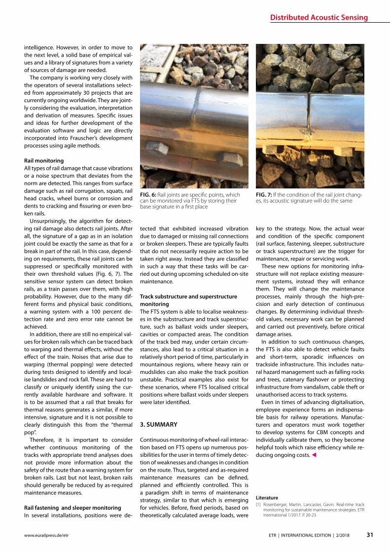
Distributed Acoustic Sensing
31ETR | INTERNATIONAL EDITION | 22018wwweurailpressdeetr
intelligence However in order to move to the next level a solid base of empirical val-ues and a library of signatures from a variety of sources of damage are needed
The company is working very closely with the operators of several installations select-ed from approximately 30 projects that are currently ongoing worldwide They are joint-ly considering the evaluation interpretation and derivation of measures Specic issues and ideas for further development of the evaluation software and logic are directly incorporated into Frauscherrsquos development processes using agile methods
Rail monitoringAll types of rail damage that cause vibrations or a noise spectrum that deviates from the norm are detected This ranges from surface damage such as rail corrugation squats rail head cracks wheel burns or corrosion and dents to cracking and ssuring or even bro-ken rails
Unsurprisingly the algorithm for detect-ing rail damage also detects rail joints After all the signature of a gap as in an isolation joint could be exactly the same as that for a break in part of the rail In this case depend-ing on requirements these rail joints can be suppressed or specically monitored with their own threshold values (Fig 6 7) The sensitive sensor system can detect broken rails as a train passes over them with high probability However due to the many dif-ferent forms and physical basic conditions a warning system with a 100 percent de-tection rate and zero error rate cannot be achieved
In addition there are still no empirical val-ues for broken rails which can be traced back to warping and thermal eects without the eect of the train Noises that arise due to warping (thermal popping) were detected during tests designed to identify and local-ise landslides and rock fall These are hard to classify or uniquely identify using the cur-rently available hardware and software It is to be assumed that a rail that breaks for thermal reasons generates a similar if more intensive signature and it is not possible to clearly distinguish this from the ldquothermal poprdquo
Therefore it is important to consider whether continuous monitoring of the tracks with appropriate trend analyses does not provide more information about the safety of the route than a warning system for broken rails Last but not least broken rails should generally be reduced by as-required maintenance measures
Rail fastening and sleeper monitoringIn several installations positions were de-
tected that exhibited increased vibration due to damaged or missing rail connections or broken sleepers These are typically faults that do not necessarily require action to be taken right away Instead they are classied in such a way that these tasks will be car-ried out during upcoming scheduled on-site maintenance
Track substructure and superstructure monitoringThe FTS system is able to localise weakness-es in the substructure and track superstruc-ture such as ballast voids under sleepers cavities or compacted areas The condition of the track bed may under certain circum-stances also lead to a critical situation in a relatively short period of time particularly in mountainous regions where heavy rain or mudslides can also make the track position unstable Practical examples also exist for these scenarios where FTS localised critical positions where ballast voids under sleepers were later identied
3 SUMMARY
Continuous monitoring of wheel-rail interac-tion based on FTS opens up numerous pos-sibilities for the user in terms of timely detec-tion of weaknesses and changes in condition on the route Thus targeted and as-required maintenance measures can be dened planned and eciently controlled This is a paradigm shift in terms of maintenance strategy similar to that which is emerging for vehicles Before xed periods based on theoretically calculated average loads were
key to the strategy Now the actual wear and condition of the specic component (rail surface fastening sleeper substructure or track superstructure) are the trigger for maintenance repair or servicing work
These new options for monitoring infra-structure will not replace existing measure-ment systems instead they will enhance them They will change the maintenance processes mainly through the high-pre-cision and early detection of continuous changes By determining individual thresh-old values necessary work can be planned and carried out preventively before critical damage arises
In addition to such continuous changes the FTS is also able to detect vehicle faults and short-term sporadic inuences on trackside infrastructure This includes natu-ral hazard management such as falling rocks and trees catenary ashover or protecting infrastructure from vandalism cable theft or unauthorised access to track systems
Even in times of advancing digitalisation employee experience forms an indispensa-ble basis for railway operations Manufac-turers and operators must work together to develop systems for CBM concepts and individually calibrate them so they become helpful tools which raise eciency while re-ducing ongoing costs
Literature[1] Rosenberger Martin Lancaster Gavin Real-time track
monitoring for sustainable maintenance strategies ETR International 12017 P 20-23
FIG 6 Rail joints are specic points which can be monitored via FTS by storing their base signature in a rst place
FIG 7 If the condition of the rail joint chang-es its acoustic signature will do the same
Smart Tamping
32 ETR | INTERNATIONAL EDITION | 22018 wwweurailpressdeetr
Plasser amp Theurerrsquos development of the turnout tamping assistance system ldquoPlasserSmartTamping ndash The Assistantrdquo has been an important step towards the further automation of tamping machines The assis-tance system provides automated support for tamping works in turnouts and crossings It recommends specic actions which must be conrmed by the operator before they are carried out As a result operators increasingly monitor processes intervening manually only in exceptional cases A new recording module allows for a completely new form of tamping documentation It increases transparency working quality and process reliability For the rst time the turnout tamping simulator ndash not a tamping machine ndash was used to develop all of the software modules of the turnout tamping assistance system In an extended hardware-in-the-loop application the turnout tamping assistance system was developed and tested using the simulator
David BuchbauerProject Manager for tamping and measuring technologydavidbuchbauer plassertheurercom
Dipl-Ing Martin BuumlrgerHead of Digital Track Systemsmartinbuerger plassertheurercom
Andreas Theiszlig MScProduct Owner Smart Tamping minus The Assistantandreastheissplassertheurercom
Dipl-Ing Georg JodlbauerHead of Research and Testinggeorgjodlbauer plassertheurercom
Dr techn Gerald ZaunerDigital Track Systemsgeraldzaunerplassertheurercom
Dipl-Ing Dr techn Florian AuerDirector of Technology and Innovationorianauerplassertheurercom
1 THE DEVELOPMENT
In modern track maintenance the conven-tional distinction between track inspection vehicles and track construction and main-tenance machines has increasingly been blurred To optimise processes track con-struction and maintenance machines are t-ted with the latest sensor technology turn-ing them into ldquosmart machinesrdquo Inertial track measuring systems used up to now only on track inspection vehicles have increasingly been installed on tamping machines This makes it possible to use tamping machines for separate track measuring runs to calcu-late the required track geometry correction values
The use of inertial track measuring sys-tems optimises the track geometry quality In addition laser scanners and light section sensors make it possible to create a ldquodigital track twinrdquo which provides the data base of the turnout tamping assistance system
2 THE OBJECTIVE OF THE TURNOUT TAMPING ASSISTANCE SYSTEM
Turnout tamping (Figure 1) requires consid-erable knowledge of several areas of exper-tise (track surveying machine technology track technology regulations) The most im-portant tasks include
Smart Tamping ndash Fields of Application of the Turnout Tamping Assistance System
rarr In the main tamping cabin Controlling the tamping unit including the turnta-ble opening width and tilting motion of the tines
rarr In the co-tamping cabin Controlling the lifting and lining unit the parts of the tamping units in the diverging track and the additional lifting unit
The turnout tamping assistance system com-plies with level 3 of the standard SAE J3016 The standard denes terms related to on-
road motor vehicle automated driving sys-tems and has been applied correspondingly On the automation level 3 the system rec-ommends specic actions which must be conrmed by the operator before they are carried out with the operator as fallback The design of the turnout tamping assis-tance system also allows for higher levels of automation However for reasons of liability automation options such as remote control or robot operation are not oered
The turnout tamping assistance system
Smart Tamping
33ETR | INTERNATIONAL EDITION | 22018wwweurailpressdeetr
raquo
oered to machine operators and infrastruc-ture managers consists of four product parts in modular design
rarr recording module for recommendations and operations
rarr operation assistant for the lifting and lin-ing unit
rarr operation assistant for the additional lift-ing unit
rarr operation assistant for the tamping unit
The modular design makes it easier to put the turnout tamping assistance system into operation for the rst time In a testing phase recording modes can be used to verify the accuracy of the recommended measures (comparison of the actual taming operations and the actions recommended by the assis-tance system) Upgrading to a higher level is possible if it has been taken into account in the design of the machine The modules are activated step by step to allow sta to famil-iarize themselves with the assistance system and to coordinate the work processes
3 THE RECORDING MODULE ldquo DIGITAL TRACK TWINrdquo
The rst step is to develop the digital track twin When selecting the hardware compo-nents of the turnout tamping assistance sys-tem (one rotation laser four light section sen-sors and one colour camera) it was ensured that the hardware can be exchanged and that the software can be adapted modularly
When designing the hardware components a particular focus was placed on meeting the accuracy requirements In addition it was ensured that the system is highly robust and easy to maintain
The recording module of the turnout tamping assistance system connects the digital twin of the track with the working parameters of the machine As a result the quality control of tamping works reaches a new transparency level Infrastructure op-erators can easily access all parameters rel-
FIG 1 Operators of turnout tamping machines must meet high requirements
FIG 2 Tamping docu-mentation using multi-layer technol-ogy (schematic representation)
evant to quality and work (such as the tine position tamping depth or squeeze time) digitally and immediately when connected to the Internet
In the future the recording document will also include the rolling marks of the rails and the position of the aluminothermic welds As the software is developed in-house we can meet our customersrsquo requirements exibly (Fig 2) For instance it will be possible to ex-port the ldquodigital twinrdquo for use on the tamping simulators
Smart Tamping
34 ETR | INTERNATIONAL EDITION | 22018 wwweurailpressdeetr
4 OPERATION ASSISTANCE
Based on their position at the time of record-ing the individual scans and recordings are merged to form a 3D image of the reality showing the exact position At the same time the position of the machine and every indi-vidual work unit is continually updated As a result a 3D image of the relevant machine parts is imported into the overall model pro-viding the basis for every decision of the as-
Federal Railways (OumlBB) and experience from practical operation A specic adaptation to the infrastructure managerrsquos requirements is possible
Figure 4 shows a list of position sensors angle sensors and actuators operated by the assistance system The values of the lin-ing adjustment the lifting operation and the tamping parameters (multiple tamping tamping vibration frequency squeeze force tamping depth) are not controlled by the as-sistance system
The turnout tamping assistance system has been designed for two applications In the rst design version (the separate view) separate measures are recommended to the operators in the main tamping cabin and the co-tamping cabin The second design version (the combined view) is the current develop-ment focus Both assistance modules are merged into a combined view in the main tamping cabin enabling the operator in the main tamping cabin to control the entire turn-out tamping process by himself (Figure 5)
The application focus of the rst genera-tion of the turnout tamping assistance sys-tem is on turnouts that have not yet been fully ballasted As a result the surface of the sleepers is visible Specic recommenda-tions require a good view onto most of the turnout area the sleepers and obstacles (such as switching contacts turnout operat-ing units)
In a next stage we plan to t the turnout tamping assistance system with sensors (eddy current sensors) for the detection of sleepers in ballasted areas (newly laid track)
Completed tamping works in turnouts can be duplicated using the machine control module turnout programming automation In a combined application of the turnout tamping assistance system and the turnout programming automation it is in principle possible to scan turnouts in advance while they have not yet been fully covered with ballast and to provide the turnout program-ming automation module with the recom-mendations to allow for their duplication Turnout tamping machines with the inte-grated supply of new ballast generally allow for the use of the turnout tamping assis-tance system as the turnout is not ballasted at the scan position at the front end of the machine
The prototype of the turnout tamping as-sistance system was introduced to the ex-pert audience at the trade show iaf 2017 in Muumlnster The positive feedback proves the great potential of the technology In practi-cal operation the turnout tamping assis-tance system is currently prepared for series production for the work unit types ldquo275rdquo ldquo475rdquo and ldquo4x4rdquo
FIG 3 Overview of the control recommen-dations
FIG 4 Position sensors angle sensors and actuators operated by the assistance system
FIG 5 Tamping cabin with the assistance system ldquoPlasserS-martTamping ndash The Assistantrdquo
sistant The data is processed with the lowest possible latency and highly parallel data pro-cessing to ensure fast operation The system recommends the respective actions several metres ahead of the tamping unit (Fig 3) to provide the operators with sucient time to analyse and modify the recommendation if necessary The recommendation of the as-sistance system is checked directly at the tamping position before the tamping unit is lowered At the same time the congura-tion of the lifting and lining unit (hock and tongue position) for the transfer to and the lifting operation at the next tamping posi-tion is checked prior to transfer travelling At this point the operator can take action at any time and further adjust the settings The operation of the additional lifting unit is checked in a similar way
To allow for tamping recommendations the track sections requiring actions must be located in an automated process To ensure this dierent image processing systems are combined with articial intelligence and connected systemically
The basic tamping scheme was developed on the basis of regulations and specications of German Federal Railway (DB) Austrian
Digital technologies are key to maximising track availability and planning forward-looking maintenance The ability to check the line at any time thanks to networked data capture in real time with innovative products reliable materials and optimised maintenance concepts for every aspect of rail infrastructure Thatrsquos what we mean by ldquoThe Smart Rail Track by Vosslohrdquo
Next stop Berlin InnoTrans 2018 Hall 26
wwwvossloh-innotranscom
The Smart Rail Track by Vossloh
DIN A4_Stadtmotiv_US_InnoTrans_Internet neuindd 1 12072018 131049

Smart Tamping
34 ETR | INTERNATIONAL EDITION | 22018 wwweurailpressdeetr
4 OPERATION ASSISTANCE
Based on their position at the time of record-ing the individual scans and recordings are merged to form a 3D image of the reality showing the exact position At the same time the position of the machine and every indi-vidual work unit is continually updated As a result a 3D image of the relevant machine parts is imported into the overall model pro-viding the basis for every decision of the as-
Federal Railways (OumlBB) and experience from practical operation A specic adaptation to the infrastructure managerrsquos requirements is possible
Figure 4 shows a list of position sensors angle sensors and actuators operated by the assistance system The values of the lin-ing adjustment the lifting operation and the tamping parameters (multiple tamping tamping vibration frequency squeeze force tamping depth) are not controlled by the as-sistance system
The turnout tamping assistance system has been designed for two applications In the rst design version (the separate view) separate measures are recommended to the operators in the main tamping cabin and the co-tamping cabin The second design version (the combined view) is the current develop-ment focus Both assistance modules are merged into a combined view in the main tamping cabin enabling the operator in the main tamping cabin to control the entire turn-out tamping process by himself (Figure 5)
The application focus of the rst genera-tion of the turnout tamping assistance sys-tem is on turnouts that have not yet been fully ballasted As a result the surface of the sleepers is visible Specic recommenda-tions require a good view onto most of the turnout area the sleepers and obstacles (such as switching contacts turnout operat-ing units)
In a next stage we plan to t the turnout tamping assistance system with sensors (eddy current sensors) for the detection of sleepers in ballasted areas (newly laid track)
Completed tamping works in turnouts can be duplicated using the machine control module turnout programming automation In a combined application of the turnout tamping assistance system and the turnout programming automation it is in principle possible to scan turnouts in advance while they have not yet been fully covered with ballast and to provide the turnout program-ming automation module with the recom-mendations to allow for their duplication Turnout tamping machines with the inte-grated supply of new ballast generally allow for the use of the turnout tamping assis-tance system as the turnout is not ballasted at the scan position at the front end of the machine
The prototype of the turnout tamping as-sistance system was introduced to the ex-pert audience at the trade show iaf 2017 in Muumlnster The positive feedback proves the great potential of the technology In practi-cal operation the turnout tamping assis-tance system is currently prepared for series production for the work unit types ldquo275rdquo ldquo475rdquo and ldquo4x4rdquo
FIG 3 Overview of the control recommen-dations
FIG 4 Position sensors angle sensors and actuators operated by the assistance system
FIG 5 Tamping cabin with the assistance system ldquoPlasserS-martTamping ndash The Assistantrdquo
sistant The data is processed with the lowest possible latency and highly parallel data pro-cessing to ensure fast operation The system recommends the respective actions several metres ahead of the tamping unit (Fig 3) to provide the operators with sucient time to analyse and modify the recommendation if necessary The recommendation of the as-sistance system is checked directly at the tamping position before the tamping unit is lowered At the same time the congura-tion of the lifting and lining unit (hock and tongue position) for the transfer to and the lifting operation at the next tamping posi-tion is checked prior to transfer travelling At this point the operator can take action at any time and further adjust the settings The operation of the additional lifting unit is checked in a similar way
To allow for tamping recommendations the track sections requiring actions must be located in an automated process To ensure this dierent image processing systems are combined with articial intelligence and connected systemically
The basic tamping scheme was developed on the basis of regulations and specications of German Federal Railway (DB) Austrian
Digital technologies are key to maximising track availability and planning forward-looking maintenance The ability to check the line at any time thanks to networked data capture in real time with innovative products reliable materials and optimised maintenance concepts for every aspect of rail infrastructure Thatrsquos what we mean by ldquoThe Smart Rail Track by Vosslohrdquo
Next stop Berlin InnoTrans 2018 Hall 26
wwwvossloh-innotranscom
The Smart Rail Track by Vossloh
DIN A4_Stadtmotiv_US_InnoTrans_Internet neuindd 1 12072018 131049