RAILWAY CONSTRUCTION
12
- 1 - UNIVERSITY OF GAZİANTEP FACULTY OF ENGINEERING CIVIL ENGINEERING DEPARTMENT INTRODUCTION TO CIVIL ENGINEERING RAILWAY CONSTRUCTION Submitted by : Ahmad Ganjeena Khoshnaw Submitted to : Instructor ENVER KILINC Date : 13/ 12/ 2012
Transcript of RAILWAY CONSTRUCTION

- 1 -
UNIVERSITY OF GAZİANTEP
FACULTY OF ENGINEERING
CIVIL ENGINEERING DEPARTMENT
INTRODUCTION TO CIVIL ENGINEERING
RAILWAY CONSTRUCTION
Submitted by : Ahmad Ganjeena Khoshnaw
Submitted to : Instructor ENVER KILINC
Date : 13/ 12/ 2012

- 2 -
1- Railway Construction - Introduction:
The selection of lines of railway is mainly governed by the same principles as hold good for roads, but the cost of the rails renders it of greater importance to shorten the length of the route than to make slight savings in embankments and cuttings. The first step in the survey is to ascertain the positions of the watercourse and watershed lines of the district to be passed through. The general direction having been selected by the help of an ordnance map, a sketch-map, or a special reconnaissance survey, the river-crossings are to be examined and decided upon, and the points determined at which the watersheds are to be crossed and the approaches to bridges set out. Trial lines should be run between the points thus fixed, and the country should be carefully examined on each side of these before the route is finally decided on. Sharp curves and steep gradients are in themselves evils, involving special cost for maintenance and for working, although original outlay may be economized by the adoption of them. A straight and horizontal surface is assumed as the standard of perfection; and the proper business of the engineer in laying out a railway is to harmonize the engineering and the financial conditions of the problem so as to yield the highest practicable return on the money expended, and to see that, whilst the railway may be neither quite straight nor quite level, it shall not be unduly costly in construction from excessive cutting, tunnelling, and making of embankments, in order to obviate severe curves and gradients, nor excessively cheap from following the surface of the ground too closely and incurring heavy gradients and severe curves, and as a consequence heavy working expenditure.
2- Railway Signals: Signals; Block System; Interlocking System:
The earliest passenger railways were opened without any fixed signals. Flags and disks, elevated on posts and pillars, where first employed, in various forms, and were worked on various codes. Sir Charles Hutton Gregory, about the year 1841, designed and erected at form of
- 3 -
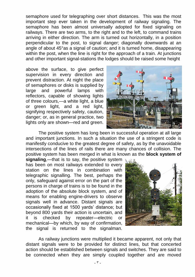
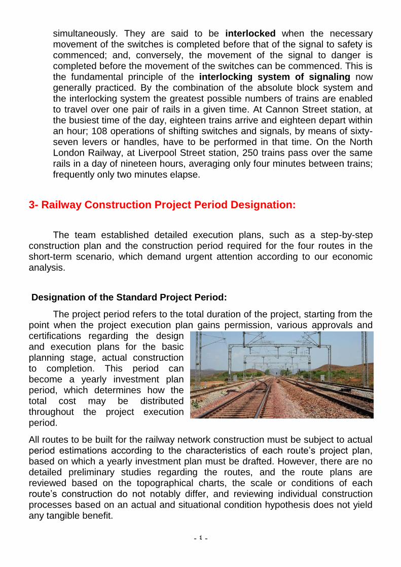
semaphore used for telegraphing over short distances. This was the most important step ever taken in the development of railway signaling. The semaphore has been almost universally adopted for fixed signaling on railways. There are two arms, to the right and to the left, to command trains arriving in either direction. The arm is turned out horizontally, in a position perpendicular to the post, to signal danger; diagonally downwards at an angle of about 45°as a signal of caution; and it is turned home, disappearing within the post, when the line is right for the approach of a train. At junctions and other important signal-stations the lodges should be raised some height above the surface, to give perfect supervision in every direction and prevent distraction. At night the place of semaphores or disks is supplied by large and powerful lamps with reflectors, capable of showing lights of three colours,—a white light, a blue or green light, and a red light, signifying respectively safety, caution, danger; or, as in general practice, two lights only are shown—red and green. The positive system has long been in successful operation at all large and important junctions. In such a situation the use of a stringent code is manifestly conducive to the greatest degree of safety, as by the unavoidable intersections of the lines of rails there are many chances of collision. The positive system has been merged in what is known as the block system of signaling,—that is to say, the positive system has been on most railways extended to every station on the lines in combination with telegraphic signalling. The best, perhaps the only, safeguard against error on the part of the persons in charge of trains is to be found in the adoption of the absolute block system, and of means for enabling engine-drivers to observe signals well in advance. Distant signals are occasionally fixed at 1500 yards’ distance; but beyond 800 yards their action is uncertain, and it is checked by repeater—electric or mechanical—by which, by way of confirmation, the signal is returned to the signalman. As railway junctions were multiplied it became apparent, not only that distant signals were to be provided for distinct lines, but that concerted action should be established between signals and switches. They are said to be connected when they are simply coupled together and are moved
- 4 -
simultaneously. They are said to be interlocked when the necessary movement of the switches is completed before that of the signal to safety is commenced; and, conversely, the movement of the signal to danger is completed before the movement of the switches can be commenced. This is the fundamental principle of the interlocking system of signaling now generally practiced. By the combination of the absolute block system and the interlocking system the greatest possible numbers of trains are enabled to travel over one pair of rails in a given time. At Cannon Street station, at the busiest time of the day, eighteen trains arrive and eighteen depart within an hour; 108 operations of shifting switches and signals, by means of sixty-seven levers or handles, have to be performed in that time. On the North London Railway, at Liverpool Street station, 250 trains pass over the same rails in a day of nineteen hours, averaging only four minutes between trains; frequently only two minutes elapse.
3- Railway Construction Project Period Designation:
The team established detailed execution plans, such as a step-by-step construction plan and the construction period required for the four routes in the short-term scenario, which demand urgent attention according to our economic analysis.
Designation of the Standard Project Period:
The project period refers to the total duration of the project, starting from the point when the project execution plan gains permission, various approvals and certifications regarding the design and execution plans for the basic planning stage, actual construction to completion. This period can become a yearly investment plan period, which determines how the total cost may be distributed throughout the project execution period.
All routes to be built for the railway network construction must be subject to actual period estimations according to the characteristics of each route’s project plan, based on which a yearly investment plan must be drafted. However, there are no detailed preliminary studies regarding the routes, and the route plans are reviewed based on the topographical charts, the scale or conditions of each route’s construction do not notably differ, and reviewing individual construction processes based on an actual and situational condition hypothesis does not yield any tangible benefit.

- 5 -
The standard project period as proposed here allows one to obtain a general picture of a specific route’s overall project period, but as the construction conditions for each route have not been determined, it may not be viewed as an executable construction process.
The standard project period for each route is categorized into project preparation, construction and completion periods. Standard periods for each type of work were determined based on comparisons of theoretical estimations and the actual construction periods of other similar projects. A. Project Preparation Process: The general process for preparing for the
railway construction project goes as follows: after the basic plans are established, base and actual designs are conducted, followed by the acquisition of various approvals and certifications and discussions with related agencies and organizations. Then, the land for facility construction sites is acquired, and construction begins. The minimum time length for each stage is as shown below:
B. Construction Period Estimation: In railway construction, estimating the construction period may be very complicated depending on the selected routes. Also, the construction periods may vary by construction method, equipment implementation conditions, and the usage of earthwork materials. Therefore, it is difficult to formulate a model for estimating the preliminary construction period for reviewing the railway construction project, and the team presented the standard construction period for the economic analysis of railway construction.
1) Construction Zone Division by Line 2) Roadbed Construction Period Estimation
a) S-1 Route
b) S-2 Route c) S-3 Route d) S-4 Route e) Estimation of the Roadbed Construction Period by Line
3) Track Construction Period Estimation
4) Construction Work

- 6 -
Establishing Railway Construction Project Periods for Each Line:
To estimate the construction period for the railway, the team set the preparation period as 2 years as shown above, and applied the time-limit determining zones in each line as the standard for estimating the roadbed construction period. Systems (electric, signal, communication), stations, and tracks will be built when the roadbed work is about 50% complete. Also, considering the possibility of building new railways, the construction period for each line includes a test driving period of about six months
Total Project Period of the Short-Term Railway Network Project:
Also, analysis showed that the S-1 and S-2 routes will take 7.5 years and the S-3 and S-4 routes 8 years to complete. If construction begins in 2012, the S-1,S-2 and S-3 routes can initiate operation in 2019 and the construction of the S-4 route should be started in 2025 when operation in 2033.

- 7 -
3- Step By Step Railway Construction Plan:
Among the lines planned for the national railway network plan, the short-
term routes of S-1 and S-3 which are connected to the existing narrow gauge tracks, could be applied in the types of standard gauge and narrow gauge, and the means of railway operation will be changed based on the gauge type.
Edea~Lolabe: (S-1) Line Construction
A. First Switching Point Construction Plan
B. Station Construction Plan
Mbalam~Lolabe: (S-2) Line Construction
A. Selecting the Optimum Transport Path
B. Roadbed and Station Construction Plan
Douala~Limbe: (S-3) Line Construction
A. Station Construction Plan
The New Ngaoundere~Douala: (S-4) Line
Step-by-Step Depot Construction Plan Yearly Investment Plan:
The yearly investment plan for each project must reflect the project cost expenses depending on the project period. Therefore, various factors such as the consignment method and zone division based on the construction plan and detailed designs must be taken into consideration, but it is difficult to estimate the precise construction period and investment cost in this stage, due to the characteristics of this study. Also, as the investment plans for each project does not take into consideration the available finances that may be invested in the railway project, the yearly investment plan for the overall project must be adjusted in accordance with the priorities of each project.
4- Railway Construction Materials:
Modern building and structure designs combine aesthetic appearance and a
requirement for an extended life. As a result stainless steel, once the preserve of prestige projects is becoming an everyday material due to its strength, corrosion resistance and appearance. In particular the development of high strength duplex steels allows most building requirements to be reached with the added corrosion resistance that helps to increase the structure lifespan. Nowhere is this more apparent than in reinforcement bar where longer bridge and harbour design life requires the better protection from chloride ingress that stainless steel can provide. Other structural steels such as steel beams and structural profiles are
- 8 -
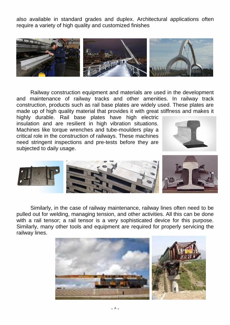
also available in standard grades and duplex. Architectural applications often require a variety of high quality and customized finishes
Railway construction equipment and materials are used in the development and maintenance of railway tracks and other amenities. In railway track construction, products such as rail base plates are widely used. These plates are made up of high quality material that provides it with great stiffness and makes it highly durable. Rail base plates have high electric insulation and are resilient in high vibration situations. Machines like torque wrenches and tube-moulders play a critical role in the construction of railways. These machines need stringent inspections and pre-tests before they are subjected to daily usage.
Similarly, in the case of railway maintenance, railway lines often need to be pulled out for welding, managing tension, and other activities. All this can be done with a rail tensor; a rail tensor is a very sophisticated device for this purpose. Similarly, many other tools and equipment are required for properly servicing the railway lines.

- 9 -
For embankments aconventional fill materials are liable to excessive settlement
on railway embankments. The high strength-to-weight ratio of Fillmaster provides
a cost-effective solution to withstand the mechanical loads encountered in railway
construction.
5- Railway Plat Form:
A railway platform is a section of pathway, alongside rail tracks at a railway station at which passengers may board or alight from trains or trams. Almost all stations used for rail transport have some form of platform, with larger stations having multiple platforms. Most stations have their platforms numbered consecutively from 1, 0 or use letters as platform names. In the case of Waterloo East this is to distinguish the platforms from those that are numerically numbered at the adjoining Waterloo station.
Plat form characteristics: The most basic form of platform consists of an area at the same level as the track, usually resulting in a fairly large height difference between the 'platform' and the train floor. This would often not be considered a true platform. The more traditional platform is situated at an elevated level relative to the track, but often lower than the train floor, although ideally the platform should be at the same level as the train floor. Occasionally the platform is at a higher level than the train floor. This may be the case when a train with a low floor level serves a station built for trains with a higher floor level, for example at the Dutchstations of the DB Regionalbahn Westfalen (see Enschede). Likewise, on the London Underground some stations are served by both District Line and Piccadilly Line trains, and the Piccadilly trains have lower floors.

- 11 -
A tram stop is often in the middle of the street; usually it has as a platform a refuge area of a similar height to that of the sidewalk (e.g. 10 cm), and sometimes has no platform at all. The latter requires extra care for the boarding and unboarding passengers and for the other traffic to avoid accidents.
Plat form facilities: Part of the station facilities are usually on the platforms. Where the platforms are not situated within a station building, often some form of shelter or waiting room is provided. The protection offered by such varies greatly – some being little more than a roof with open sides, others being a closed room with heating or air-conditioning.
Also there may be benches, lighting,garbage boxes and static timetables or dynamic displays with information about the next train. There are often loudspeakers as part of a public addresssystem. The PA system is often found where dynamic timetables or electronic displays are not present. A variety of information is presented, usually pertaining to departures, but often arrivals also. This concerns destinations and, delays, cancellations, platform changes, changes in routes and destinations, and supplemental fee or reservation requirements.
Markings: Platforms usually have some form of warnings or measures to keep passengers away from the tracks and moving trains. The simplest measure is markings near the edge of the platform to demarcate the distance back from the platform edge that passengers should remain. Often a special tiled surface is used as well as a painted line, to help blind people using a walking aid, and aid in preventing wheelchairs from accidentally rolling too near the platform edge.
6- General Equipment Requirements:
Design Life: All fare collection equipment shall be designed for a minimum service life of 15 years. All equipment shall operate seven days per week and 24 hours per day. Codes and Standards: The fare collection equipment shall be designed to meet the latest revision of applicable codes such as the National Electrical Code (NEC), National Electrical Safety Code (NESC), and Underwriters' Laboratories, Inc. (UL), and the local codes of authorities having jurisdiction. Americans with Disabilities Act (ADA) Requirements: The fare collection equipment shall comply with applicable requirements of the ADA. Fare equipment shall meet the rules in Title 49, Code of Federal Regulations, Part 37 resulting from the Americans with Disabilities Act. In particular, rules related to Automated Teller Machines and appended guidelines for Controls and Operating Mechanisms must be addressed in the fare collection equipment design. In addition, the TVM shall provide digitally recorded voice messages that ―read‖ the contents of the patron display to assist visually impaired and illiterate patrons through the transaction process.

- 11 -
Climate and Environment: The fare collection equipment shall be installed in locations to avoid the affects of direct sunlight and offer passenger protection from rain, direct sun, and other harsh environmental elements. Electrical Design Requirements: All electrical designs shall comply with UL Standard 751, ―Vending Machines,‖ NFPA 70, ―National Electric Code,‖ and applicable guidelines, codes, or standards of the authority having jurisdiction. Transaction Speeds: TVMs shall have an average transaction time of thirty seconds, including all passenger interactions; measured from the time a passenger approaches the machine to completing the transaction. Magnetic Ticket Processors shall average six seconds or less per transaction, including time for the patron to orient and insert the ticket for processing. Modularity and Maintainability: All parts, components, modules, assemblies, and removable devices shall be interchangeable among machines without the need to make adjustment for proper compatibility. All replaceable devices shall combine mounting designed for simple removal/exchange and easy access to facilitate maintenance. All maintenance and service access to TVM components shall be through the front door of the TVM. Reliability: TVMs and Magnetic Ticket Processors shall be of service-proven designs with acceptable performance in revenue service of at least three years. The equipment shall have a design life of a minimum of 15 years. Safety: The Fare Collection System shall be free from hazards. The exterior surfaces of fare collection equipment, including all controls and appurtenances, shall have no sharp edges. The cabinet shall have no protrusions extending beyond its vertical surfaces that could be bumped by persons with a visual impairment or by a person passing by or using the TVM or MTP. All interior surfaces and components with which patrons and/or maintenance personnel could come in contact shall be free of sharp edges or other hazards. Security: The design and installation of the fare collection equipment shall discourage and minimize the effects of vandalism and theft, prevent unauthorized access to the interior of the equipment, and prevent unauthorized removal of the equipment from its installed location. Access to the TVM for maintenance functions shall not provide access to the money vaults. All exterior doors shall be locked with at least a three-point latching device with a bascule bolt and a hook locking bar, or approved equivalent. Handheld Verifier: Operational Requirements:
The AFCS design shall include Handheld Verifiers (HHV) to allow fare inspectors to interrogate and verify validity of fare media, including magnetic fare and smart cards. The HHV shall be a portable unit, similar in size and form factor to a PDA class device. It shall be powered by a rechargeable battery system. Ticket data and inspection transactions shall be capable of being stored, batched, and forwarded, via docking the unit in a compatible cradle, to a PC based data collection system.
- 12 -
Resources:
1- http://www.rff.fr/en/the-network/europe-on-rails/building-a-europe-on-rails// railway construction steps.
2- http://en.wikipedia.org/wiki/Railway_signal. 3- http://en.wikipedia.org/wiki/Railway_platform. 4- http://www.valleymetro.org/images/uploads/lightrail_publicati
ons/Design_Criteria_Manual_FINAL_030207.pdf.