S 20 - Indian Railway
63
-
Upload
khangminh22 -
Category
Documents
-
view
1 -
download
0
Transcript of S 20 - Indian Railway


S 20 LEVER LOCK, CIRCUIT CONTROLLERS,
ELECTRICAL KEY TRANSMITTER,ELECTRICAL
SIGNAL REVERSERS, INTER CABIN SLOTTING &
ELECTRIC LIFTING BARRIER
INDIAN RAILWAYS INSTITUTE OF
SIGNAL ENGINEERING & TELECOMMUNICATIONS
SECUNDERABAD - 500 017
Issued in June, 2013
VISION :
MISSION :
TO MAKE IRISET AN INSTITUTE OF INTERNATIONAL REPUTE, SETTING ITS OWN STANDARDS AND BENCHMARKS
TO ENHANCE QUALITY AND INCREASE PRODUCTIVITY OF SIGNALLING & TELECOMMUNICATION PERSONNEL THROUGH TRAINING
The Material Presented in this IRISET Notes is for guidance only. It does
not over rule or alter any of the Provisions contained in Manuals or Railway
Board’s directives.

S-20: LEVER LOCK, CIRCUIT CONTROLLERS,
ELECTRICAL KEY TRANSMITTER, ELECTRICAL SIGNAL REVERSERS,
INTER CABIN SLOTTING & ELECTRIC LIFTING BARRIER
CONTENTS
Sl.no. Chapter Page No.
1. LEVER LOCK CIRCUIT CONTROLLERS 1
2. ELCETRICAL KEY TRANSMITTER 10
3. ELECTRIC SIGNAL REVERSER 19
4. INTER CABIN SLOTTING 28
5. ELECTRIC LIFTING BARRIER 37
6. REVIEW QUESTIONS 59
Checked By IOS5,SSE(D),LS2,PS1
No. of Pages 60
Date of Issue June, 2013
Version A3
In case of any suggestions please write to LS2/PS1 or mail to LS2/PS1 at email address
[email protected]/[email protected]
© IRISET
http://www.iriset.indianrailways.gov.in
“This is the Intellectual property for exclusive use of Indian Railways. No part of this publication may be stored in a retrieval system, transmitted or reproduced in any way, including but not limited to photo copy, photograph, magnetic, optical or other record without the prior agreement and written
permission of IRISET, Secunderabad, India”

INTRODUCTION
Page 1 (S-20) LEVER LOCK,EKT/RKT
REVERSER, SLOT CCT. EOLB.
CHAPTER 1: LEVER LOCKS AND CIRCUIT CONTROLLERS
1.1 Introduction
In mechanical installations, the functions are operated by levers, whose stroke is transmitted by rod transmission for Points and by wire transmission for signals. As the medium is rigid, lever and concerned function are in correspondence. But in Electro-mechanical installations, though functions are operated by a mechanical lever but transmission medium is cable carrying Electrical Power. In case of any disconnection in cables, function may go out of correspondence with the lever. To avoid this, electrical locks are required on the mechanical levers at various positions in order to synchronise lever positions with concerned function at site. This is implemented by means of “Electrical lever lock”. Electric Lever Lock: Electric lever lock is used where an electrical control on a mechanical lever is required. Levers controlling points and signals are equipped with electric locks to prevent or limit their movements. The lock pawl holds the lever mechanically so that the lever cannot be operated when the condition for its operation is not safe. In figure 5.1 shown the armature extension (lock pawl) engages in the notch cut on the lever plunger (slide) in order to lock the lever when the electro-magnet is de-energised. Consequently, the lever cannot be operated till the lever lock coil is energised. When the armature is attracted and the lock pawl comes out of the notch on the lever slide and permitting the plunger to move.
Fig. 1.1 LEVER LOCK
1.2 Lever Lock consists of
(a) Electromagnet,
(b) Force drop device,
(c) Economiser contact and
(d) Lock proving contact.
1.2.1 Electromagnet: The armature and magnet core are laminated and it can be used with AC/DC current.
1.2.2 Force Drop Device: Sometimes the armature of the lever lock may not release after de-energisation of lock coil due to residual magnetism or any other mechanical holding, which may lead to unsafe conditions by allowing the lock to release without proving the required safety condition. To ensure that the lock pawl is positively pushed inside the locking notch before every unlocking operation, a mechanical arrangement called “Force drop” is provided. The force drop pins/nibs are riveted on the lever slide and a bevel shaped extension is provided on the lock pawl. The force drop pins/nibs force the lock pawl to drop into the locking notch through its bevel shaped extension before each pick up.
LOCK PAWL
NOTCH
ARMATURE

LEVER LOCKS & CIRCUIT CONTROLLERS
IRISET Page 2
1.2.3 Economiser Contact: The economiser contact is provided with the electric lever lock and circuit controllers to cut off the power to the lock coil at the end of each stroke/ each operation. It makes between A and E positions of the lever and remains disconnected in N and R positions of the lever. This connects supply to lock coil proving other required conditions after initiating the operation of the lever from its Normal or Reverse position thus economising the power consumption. In absence of "Economiser contact" the same purpose is served by AE band of circuit controller. In both the cases feed is disconnected in 'N' or 'R' position of the lever. Initial feed is controlled by track clear condition as shown in Fig 1.2
TR
LOCK
E.C
Fig. 1.2.3 ECONOMISER CONTACT (E.C)
TR
LOCK
E.C.
AE
CONTACTSLOCK PROVING
Fig. 1.2.4 LOCK PROVING CONTACTS
1.2.4 Lock Proving Contacts: A set of contacts are actuated when the lock is de-energised and lock pawl drops into the locking notch, proving that the lever is locked positively. An electrical circuit taken through these proving contact, proves that the armature is de-energised and consequently the lever is locked. Fig 1.2.1
1.3 Indication Locking Circuit
It is a locking provided on ‘B’ and ‘D’ position of point lever slide and in the case of signals on ‘B’ position only.
Fig. 1.3 INDICATION CIRCUIT
1.4 Track Locking Circuit
It is held in ‘A’ and ‘E’ positions of the lever and lock are released when the lever is either in ‘A’ or ‘E’ position with track clear condition. Locking of the point levers provides safe operation of the point. Since track locking and indication locking are provided on the point lever, combined track locking and indication locking is used as shown in Fig. 1.4.1
Fig. 1.4 TRACK LOCKING CIRCUIT
TPR
(ABDE) L
E.C
A
E
B
D
NWKR
RWKR
Fig. 1.4.1COMBINED CIRCUIT OF TRACK AND INDICATION LOCKING
B (BD)L
D
NWKR
RWKR
A (AE)L
E
TPR

CIRCUIT CONTROLLERS
Page 3 (S-20) LEVER LOCK,EKT/RKT
REVERSER, SLOT CCT. EOLB.
1.5 Circuit Controllers
Circuit Controller is a device by which electrical circuits can be made or broken according to requirements. It has fixed springs and corresponding numbers of rotating contacts. The rotating contacts may be of different positions such as N, R., NB, RD, etc. The contact segments are rotated by a plunger connected to the lever. Each rotating segment can be adjusted in steps of few degree (3 ¾ deg in SGE circuit controller) and locked in position. Though the lever lock and circuit controllers may be used separately, they can also be combined together on a lever lock circuit controller.
A sketch showing the relative positions of circuit controller contacts to that of the lever controlling them are shown in Fig.5.5 for converting the linear motion of the plunger to the circular motion of the contact segments, different methods such as cam path, rack and pinion, crank motion etc., are used by different manufacturers.
N = Full normal position of lever.
A = Normal Economiser Position.
B = Normal Indication Position.
C = Centre position
D = Reverse Indication position.
E= Reverse Economiser potion.
R = Full Reverse Position.
Fig. 1.5 CIRCUIT CONTROLLERS
N
A
BC D
E R
CBAN D E R
B
C
D
N
R
NA
RE
AB
DE
BC
CD
NB
RD
BD
ND
RB
NC
RC
AE
195º
220º
240º
280º
(5" STROKE) (8" STROKE)
125 mm 200 mm
(0.64" STROKE) (0.85" STROKE)
14 mm 21 mm
(1.43" STROKE) (2.28" STROKE)
36 mm 57 mm
(2.14" STROKE) (3.43" STROKE)
54 mm 86 mm
(3.57" STROKE) (5.72" STROKE)
89 mm 143 mm
SLIDE TRAVEL BETWEEN
MAKE AND BRAKE OF
CONTROLLER CONTACT

LEVER LOCKS & CIRCUIT CONTROLLERS
IRISET Page 4
1.6 Electrical Lever Locks and circuit controllers
Electrical Lever Locks and circuit controllers are classified into (depending upon installation) single wire and double wire lever lock and circuit controllers.
(a) Single Wire Lever Lock and Circuit Controller. These are of three types:
(i) S.G.E. (Siemens General Electric) lever lock and circuit controller.
(ii) I.R.S. (Indian Railway Signalling) lever lock and circuit controller.
(iii) S&F (Saxby and Farmer) lever lock and circuit controller.
(b) Double wire lever lock and circuit controller: In this only ‘T-2’ type lever lock of circuit controller is available.
1.6.1 S.G.E. (Siemens General Electric) Lever Lock and Circuit Controller (SA 21301)
This lever lock and circuit controller is used in single wire lever frame installation. It can
be mounted in both positions i.e., vertical position and horizontal position. In horizontal mounting, the counter weight has to be removed to avoid unsafe side condition. It has two coils each of 6.25 Ohms resistance. It can be connected in Series or parallel for supply AC/DC. When two coils are connected in series, the lock coil operates on 12 VDC; whereas 2 coil connected in parallel, the lever lock operates on 110 VAC. The lever lock coils are shown in the Fig 1.6.2 a&b. It has a vertical position. Lock plunger having stroke of 125 mm to 200 mm according to the requirement. Depending upon the application, this lever lock and circuit controller is used either for point operation or signal operation.
1.6.2 S.G.E. Coil Connections
Y
1
2 BLUEBLACK
R1
R2
R
SERIES CONNECTION
P1
P2
(a)
EC
Y
1
2 BLUEBLACK
R1
R2
R
PARALLEL CONNECTION
P1
P2
(b)
EC
TERMINAL PLATE
Fig 1.6.2 a & b SGE COIL SERIES AND PARALLEL CONNECTIONS
NOTE: The lever locks can be worked either by D.C. or A.C. They are generally made to work either on 110V AC or 12 DC. Some lever locks are double wound. When two coils are connected in series, the lever lock operates on 12 VDC Whereas when the two coils are connected in parallel the lever lock can operate on 110 VAC Fig. 1.6.2 a & b.

ELECTRICAL LEVER LOCKS
Page 5 (S-20) LEVER LOCK,EKT/RKT
REVERSER, SLOT CCT. EOLB.
1.6.3 SGE Plunger
The lever locks may be fitted vertically or horizontally and the stroke of the lock slide is 125 to 200 mm according to requirement. The locks can be made to function in different
positions of the lever by cutting notches in suitable places on the slide as shown in Fig. 1.6.3 Notches may be cut like a small travel of the lever which is available is utilised for making an electrical contact to energise the lock. The contact is known as economiser contact and is fitted on the lock itself. In lever locks designed for 200 mm stroke, the N and R notches can be cut with centres 200 mm apart. ‘B’ and ‘D’ notches shall be equidistant from the centre and the notches centres shall be about 106 mm apart.
Fig. 1.6.3 SGE PLUNGER
1.6.4 S.G.E. Point Lever Plunger
Lever lock used for point operation has different locking such as ‘A’, ‘B’, ‘D’ and ‘E’ positions. Before operating point lever it has to be ensured that point zone is clear of vehicles or not. For this purpose, track locking is required at ‘A’ position and ‘E’ position of the point lever and the functions has to be synchronised with the help of indication locking at ‘B’ position and ‘D’ positions of the point lever as shown in the fig.1.6.4
FORCE DROP
PINS (4 Nos)
22 22 22 22
32 25 106 25 32
STROKE LIMITING
PIN
10
10
50
ALL DIMENSIONS ARE IN mm
220
N A B D E R
Fig. 1.6.4 SGE POINT LOCK SLIDE
Simultaneously the force drop pins are required to be riveted on the point slide/plunger and lock pawl is made bevel shape for the purpose of force drop arrangement.
Economiser contact pins are provided to economise the power supply. It makes from ‘A’
position to ‘E’ position of the operating lever.
1.6.5 SGE Lever Lock used for Signals
The notches of signal slide has shown in the fig.1.6.5 On signal slide only ‘B’ position notch is required whereas ‘A’, ‘E’ and ‘D’ position notches are not required like point operation. Because, on signal slide, track locking, indication locking at ‘D’ position are not required, if the signal is not operated to OFF position, then the failure is on safe side only. The indication locking at ‘B’ position is required to ensure that signal has been put back to ON position.

LEVER LOCKS & CIRCUIT CONTROLLERS
IRISET Page 6
22
10
50
FORCE DROP
PIN
B
STROKE LIMITING
PIN
ALL DIMENSIONS ARE IN mm
Fig 1.6.5 SGE SIGNAL LOCK SLIDE WITH ‘B’ NOTCH
1.6.6 Procedure for Cutting of the Notches
On lock slide/plunger of the lever locks to the Drawing No: SA21301/M, for providing track locking and indication locking on a point lever.
(a) Connect the lock slide to the lever tail through a connecting rod provided with
adjustable coupling.
(b) Balance the stroke of the lever imparted to the lock slide by means of the adjustable coupling so that on the operation of the lever to ‘N’ or ‘R’ the respective stopper should butt against the body of the lever lock with equal force. This ensures that the full 200 mm (8”) stroke is imparted to the lock slide.
(c) Keeping the lever in ‘N’ position. Mark the normal position on lock slide coinciding with the Outer edge of the slot on the body of the lever lock for insertion of the lock dog.
(d) Keeping the lever in ‘R’ position, mark the reverse position on the lock slide
coinciding with the inner edge of the slot on the body of the lever lock for insertion of lock dog.
(e) Take out the lock slide from the lever lock and ensure that the distance between the
two markings 220 mm (8 ¾”) i.e., the travel of the lock slide plus width of the lock dog.
(f) Cut the notches as per the dimensions shown in sketch. (Fig 1.6.4 or 1.6.5)
(g) Rivet the casehardened force drop pins to the holes drilled in the slide for this purpose.
(h) Re-insert the lock slide in the lever lock.
Note: When lever worked for N to R the A and D notch and when R to N the E and B notch are available.

SGE CIRCUIT CONTROLLERS
Page 7 (S-20) LEVER LOCK,EKT/RKT
REVERSER, SLOT CCT. EOLB.
1.7 SGE Circuit Controllers
In this circuit controller, bands are adjustable type. The rotating segment can be adjusted in steps of 3 ¾’ degree and locked in its position. The circuit controllers can be rotated by cam and roller arrangement or rack and pinion arrangement to convert linear movement of slide into circular motion of circuit controller.
1.7.1 Procedure for Circuit Controller adjustment
(a) Loose the adjusting nut of circuit controller.
(b) Separate copper band of the circuit controller from the serrations of Bakelite contact holder.
(c) Rotate copper band as per the requirement of the lock positions.
(d) Re-insert copper band in to the Bakelite contact holder.
(e) After tightening the adjusting nut, test the adjusted copper band position once again.
1.8 S&F Type Lever Lock and Circuit Controller
It has the same features of SGE type lever lock and current controller except the coil resistance. In this coil resistance is 7.5 Ohms each (two coils).
1.9 IRS type Lever Lock and Circuit Controller (SA 22701)
It has only one coil of 4.5 Ohms resistance. It can be connected to 110V AC or 12V DC. It has horizontal stroke plunger so that there will not be worn out of the notches. For force drop arrangement bevel shape segments are provided on both sides of the notches. There is no counter weight in this lever lock. So, it can be mounted either horizontal or vertical position without any changes in the lever lock. Economiser contact notches are provided on the plunger instead of pin (in SGE) to have more reliability limiting the strike of lever plunger or solid strip provided on either side of plunger instead of stroke limiting pins as provided in SGE. IRS lever lock can be used for signal lever or point lever.
1.9.1 IRS type Circuit Controllers: In this, circuit controllers are fixed type and according to the site requirement this bands has to be marked and cut carefully.
Fig 1.9.1 IRS POINT SLIDE
1.9.2 Double Wire Lever Lock and Circuit Controller (T2-type): It has a single coil of 150 Ohms resistance and operates only with 12V DC power supply. The stroke of the plunger is 40 mm. It can be mounted only in vertical position. Economiser contact is not provided. So, one of the circuit controller band may be used as economizer contact purpose. The stroke plunger is of rotary type because of these the size of lever lock and circuit controller is smaller. The force drop is provided inside the rotary segment and different locking notches for point and signals are on the periphery of the segment. These notches are difficult to cut at site. So while indenting itself it has to be ensured. As shown in Fig 1.9.2a&b

LEVER LOCKS & CIRCUIT CONTROLLERS
IRISET Page 8
Fig: 1.9.2 Double Wire lever lock and circuit controller (T2-type)
Fig 1.9.2a T-2 Signal Notch Segment Fig 1.9.2bT-2 Point Notch Segment
BEVELED
PROJECTIONS FOR
FORCE DROPPING
46º
46º
46º
46º
BEVELED
PROJECTIONS FOR
FORCE DROPPING
14º
32º
14º
32º

TESTING OF LEVER LOCK AND
CIRCUIT CONTROLLERS
Page 9 (S-20) LEVER LOCK,EKT/RKT
REVERSER, SLOT CCT. EOLB.
Particulars of lever lock and circuit controllers Lock dog width = 20 mm
Type Resistance
of coil Working voltage
Plunger Stroke
Force drop arrangement
Economiser contact
For Horizontal/
Vertical Mounting
SGE 6.25 Ω coil Total = 12.5Ω Series connection
230 VAC 50 W or 12 VDC
200 mm Provided Provided For both
Total = 3.125 Parallel connection
110 VAC 50 W or 6 VDC
200 mm Provided Provided For both
IRS 4.5 Ω single coil
110 VAC 50 W or 10-12 VDC
200 mm Provided Provided For both
T-2 for DW
150 Ω single coil
10-12 VDC 40 mm Provided Not Provided Vertical mounting
only
1.10 Testing of Lever Lock and Circuit Controllers
(a) Check that all moving parts are clean, oiled and they work freely.
(b) The lock armature works freely.
(c) Check the proper functioning of force drop device. This can be tested by holding the armature loosely by hand and operating the lever from locked position. If a downward force is experienced on hand, it indicates that the force drop device is functioning properly.
(d) Check the faces of the locking notches on the lock slide and the lock piece any where.
(e) Check all terminals, Screws and nuts for proper tightness.
(f) Ensure that the circuit controller contact bands and springs are cleaned and they make contacts with proper tension.
(g) Check the terminal blocks of circuit controller for their proper fitting and intactness.
(h) Check the economiser contacts and lock proving contacts for their proper functioning.
(i) Ensure that the split pins are in position and properly opened.
(j) Check the wiring of any damage of insulation especially at cable inlets.
(k) Measure the operating voltage and current at lock coil terminals.
(l) Carryout the test to ensure that the lever cannot be operated when the required safety conditions for its operation are not fulfilled.
(m) Ensure that the staff operating the levers are familiar with the operation of the levers fitted with electric lever locks. Such levers should be operated gently without jerk after the lever getting unlocked electrically.

ELECTRIC KEY TRANSMITTER
IRISET Page 10
CHAPTER - 2: ELECTRIC KEY TRANSMITTER (SPECIFICATION IRS S21-64)
2.1 Introduction
The physical transmission of the key from ASM office or Cabin to the controlled gear at site entails delay, Electrical Key Transmitters (EKT) are provided in which key is normally kept locked in a EKT at site and a similar EKT is fixed in Station Master’s room. The Keys are transferred electrically to avoid delay in Rail traffic.
EKT is combination of E-Type Lock and an electromagnet. When key in EKT is inserted and turned to RHS then the key get locked inside EKT.The locked key can only be released when Electromagnet in EKT is energized.
The key can be maintained in locked or free condition by controlling feed (power supply) to electromagnet in-side EKT. The simplest way of controlling a signal, point, or level crossing gate for the SM is to retain the key of the controlled apparatus (which is normally locked) and issue the key for releasing the apparatus when required.
2.2 Application of Key Transmitter Normally key transmitters are used in pairs or otherwise.
(a) L.C. Gate and Station Master/ Cabin (to transfer the key electrically from L.C. Gate
Lodge to Station Master/ Cabin man and vice-versa.)
(b) Locally operated siding point (to transfer the key electrically from Station Master/ Cabin man to locally operated siding point.)
(c) Crank handle locking (to prove Crank handle of a point machine in lock condition
(d) Electrical locking of key is in locked condition. (Shunting key attached to Block instrument)
(e) Along with token key exchanger at intermediate sidings
2.3 Approved type of Electrical Key Transmitter is Rotary key Transmitter & other are obsolete
Electric key transmitter (Rotary Key Transmitter)
2.4 Nominal Electrical Parameters
(a) Resistance of coil (electromagnet.) is 12.5 Ω.
(b) Normal working voltage is 3.75 V D.C. plus line drop.
2.5 General requirements
The EKT shall be such as to receive an interlocking Key of an approved type.
It shall not be possible to insert and operate in the lock any other key except the one for which the EKT is intended.
The tumblers proving the wards of the key shall be provided with an arrangement to force them back to their normal position before the key can be extracted.
The transmitting key shall get locked in the EKT before the control can be transmitted to the EKT at the other end.

EKT/RKT COMPONENTS
Page 11 (S-20) REVERSERS, SLOT CIRCUITS,
EOLB, EKT/RKT & LLCC.
It shall not be possible to extract a key once inserted and locked in the EKT unless it is released by the electrical control received from the other end.
It shall not be possible to transmit control to the instrument at the other end and simultaneously release the key from the EKT transmitting the control.
It shall not be possible to release the key by jerks or any other irregular means.
The EKT shall be suitable for operation on two wires. A suitable design of LED based Indication shall be provided. There must not be any opening giving access to the interior of the EKT through which it is possible to operate the mechanism by any irregular means.
Facility shall be provided for locking and/or sealing the EKT.
The EKT is shall be of robust construction fit to withstand rough handling.
2.6 EKT In General
EKT are electrically interconnected. The instruments have galvanoscopes to indicate visually that a key is ‘transmitted’ for calling attention either a bell or phone connection is provided between the ends. The EKT are of robust construction and are normally fixed close to the appliances, which is to be released by the key. The keys are so designed that one does not enter in any other instrument of its kind. They are provided with locking or sealing arrangements for security reasons.
2.7 Working Principle
When key is placed inside EKT and turned to RHS then key get locked in EKT the removal of key from EKT is prevented by locking the movement of tumblers and rotation of drum in which tumbler are placed. The drum is maintained in lock condition with help of lock pawl, which is intruded inside a notch on periphery of drum. Lock pawl is attached to armature of electromagnet. When electromagnet energises armature pulls the lock pawl out of the notch on drum and hence allow the movement of drum and key.
To transfer the key, feed to receiving end EKT is extended through a switch on operating panel or by turning the key of transmitter to right hand side at key transferring end. The electromagnet in the receiving end EKT gets energized. Energized electromagnet turns visual indication to show that EKT is ready for releasing locked Key and Energized electromagnet pull the lock pawl out and locked Key is free (can be extracted out).
2.8 Parts of RKT (Rotary Key Transmitter)
An RKT comprises of two portions Outer portion and Inner Portion 2.8.1 Outer Portion: It is rectangular cast iron cover which encloses all internal parts of RKT. RKT cover provides access to RKT Key through a key hole to insert key for transmission. RKT essentially consist of a glass window at the top for visual indication and a sealing stud to seal the equipment.
2.8.2 Inner Portion: Inner portion comprises of an electromagnet with two poles, locking assembly and spring contacts. The RKT is of robust construction. It consist of following parts (Fig.4.9)

ELECTRIC KEY TRANSMITTER
IRISET Page 12
2.9 Detail description of different components of RKT shown in figure is as follows
Fig. 2.9 Rotary type Electric key transmitter
a) Armature for lock pawl b) Terminals c) Shorting segment for spring
contact d) Stud for key e) Contact spring Assembly f) Armature for indicator

EKT/RKT COMPONENTS
Page 13 (S-20) REVERSERS, SLOT CIRCUITS,
EOLB, EKT/RKT & LLCC.
2.9.1 Electromagnet
When electromagnet gets supply, its main pole face attracts armature which in turn helps in releasing the key, while auxiliary pole face deflects the indicator. Electromagnet is fixed in upper portion of the case.
Electromagnet comprises of following parts (a) Electromagnet coil (resistance 12.5 Ω)
(b) Two-magnet pole, Main and Auxiliary
(c) Two armature worked by two magnet pole
(d) Armature for lock pawl
(e) Armature for lock indicator
(f) Force drop gear
2.9.2 Contact Spring assembly
It consists of five numbers of finger contacts, which are insulated from each other. There are two sets of Contact Spring assembly fixed on either side of drum assembly. Generally contact spring is numbered as follows.
One set on the left hand side of drum assembly contain contact spring no: 1 and contact spring . no:2 Others set on the right hand side of drum assembly contain contact spring no:3, contact spring no:4 and contact spring no:5 with, spring no:3 in centre. These contact spring makes or opens with rotation drum assembly.
Key Position
Contact spring (Finger) Position at transmitting END
Contact spring (Finger) Position at receiving
END
1. When key is “IN” and locked 1&2,3&4 1&2,3&4
2. When key is “IN” and locked And turn to RHS forcefully.
1&2,3&5 1&2,3&4
3. When key is OUT at receiving end
1&2,3&4 Al l contacts open
2.9.3 Quick Return Gear
It is necessary that drum assembly should rotate very fast once the force drop arrangement is actuated to avoid releasing of key without cooperation of transmitting end. Spring loaded quick return gear attached with the drum assembly with split cotter pin help to force the drum assembly back to its normal position.
The gear is fixed with the thumb screw on the metallic base.
2.9.4 Drum assembly
Rotary type drum assembly is very important part of locking arrangement of RKT. It has a slot on its outer periphery which engages the lock pawl to lock the key when electromagnet in de-energized condition. Drum assembly provided with two metallic contact segment on its outer periphery. These two metallic pieces are insulated from drum and riveted on drum assembly. These two metallic pieces helps to make and break finger contact. Drum accommodates Tumbler assembly. It is attached to quick return gear.

ELECTRIC KEY TRANSMITTER
IRISET Page 14
Fig. 2.9.4 (a) Quick Return Gear Fig. 2.9.4 (b) Tumbler Housing Assembly
Fig. 2.9.4 (c) Operating Piece
Quick Return Gear
Cotter pin
Thumb
Screw

EKT/RKT COMPONENTS
Page 15 (S-20) REVERSERS, SLOT CIRCUITS,
EOLB, EKT/RKT & LLCC.
2.9.5 Tumbler Housing Assembly: Tumbler wards 1, 2 and 3 are housed under the tumbler housing assembly and hold with LH pin and RH screw. 2.9.5.1 Tumbler Wards: Three numbers of brass tumblers control the movement of key. A proper combination of wards and tumblers ensures that only right key can be inserted with the transmitter.
2.9.6 Operating Piece: Operating piece is placed inside the drum assembly. On operation of key, the operating piece rotates the drum assembly with the help of extension portion provided to it. It allows only nominated key to enter in RKT and once key turned it maintain Key in locked condition.
2.9.7 Force Drop arrangement & Lock Pawl: To avoid unsafe extraction of key due to residual magnetism or mechanical jamming force drop arrangement is provided in this instrument too, as provided in other electromagnetic signalling devices Force drop arrangement is provided by means of a counter weight attached with the armature which causes the armature to drop forcefully.
2.9.8 Lock Pawl: Lock pawl engages with the drum assembly when the Electromagnet is de-energized. When the Electromagnet is energized, lock armature attracts and the lock moves up and releases drum assembly. Lock pawl is a rectangular metal bar with circular bar on vertical end and it is placed in rear of electromagnet.
2.10 The wiring of EKT changes as per site condition such as in RE area or in Non- RE area
2.10.1 Wiring diagram for Electrical Key Transmitter in Non- RE AREA (with Earth Return)
Fig. 2.10.1 E.K.T.WIRING DIAGRAM IN NON RE-AREA
When a key is inserted at cabin 1&2, 3&4 will made, now turned to R.H.S. contact 3 & 4 will break and 3&5 along with 1&2 will made, feed extends from cabin to location/Gate. As in location/Gate key was in inserted position 1&2 and 3&4 will made and gets the path through the earth, and Coil energies and key can be extracted.
GALVO
COIL
GALVO
COIL
1 B N
EEEEKT at CABIN EKT at LOCATION
2 3 4 5 21 NB543LINE

ELECTRIC KEY TRANSMITTER
IRISET Page 16
2.10.2 Wiring diagram for Electrical Key Transmitter in RE AREA The working of the instrument in RE area from the given circuit diagram and bring out the important difference in the circuit arrangement.
RE AREA NON-RE AREA
1. Separate AC immunized line relays are used. 1. Separate AC immunized line relays are not used.
2. Telephone must be required because no bell is there for indication (audible).
2. No telephone is required due to the presence of bell.
3. Two sets of supply are required (24V and 12V). 3. One set of supply is required.(12V)
4. KTR (250 Ohms) relay is used. 4. KTR relay is not used.
5. Circuit is not completed through earth because no earthing is permitted.
5. Circuit is completed through earth.
Electrical Key Transmitter Instrument working in RE area: The working of the instrument in RE area is as follows:
B12/24
R1
LINE RELAYLINE RELAY
STATION GATE
12.5 OPush Button
B12/24
R3
12.5 OPush Button
Key is in.& Turned to RHS
Key Out
(All contact open)
1&2, 3&5 will make
Key is in.1&2, 3&4 will make
Position of Contacts
250 Ohms250 Ohms
Fig. 2.10.2 E.K.T.WIRING DIAGRAM IN RE-AREA

MAINTENANCE
Page 17 (S-20) REVERSERS, SLOT CIRCUITS,
EOLB, EKT/RKT & LLCC.
Key transmission from ‘STATION’ end to ‘GATE’ end: As the key is inserted in EKT at ’STATION’ end contact No 1&2, 3&4 is made now and when turned to right 3&4 will break and 3&5 will make along with 1&2 and ‘R1’ relay energised and through front contact of ‘R1’ relay feed extends to ‘GATE’ location, since KTR relay ‘R3’ is in de-energised, through the drop contact of ‘R3’ relay ‘R4’ relay energised and through front contact ‘R4’ relay, coil energises in GATE and Key can be extracted by pressing the push button.
2.11 Maintenance
The following maintenance checks shall be carried/ observed out during inspection
(a) Cleanliness
(b) All working parts are clean and work freely.
(c) All contact spring are kept clean, tensioned and shaped.
(d) All keys turn freely in the transmitter when the cover is correctly secured.
(e) The keyhole is such that only correct key can be inserted in each transmitter and is in proper shape.
(f) Check that brass tumblers are proper and not worn out.
2.12 Testing of Key Transmitter
Key transmitters are periodically tested to ensure that key cannot be extracted by jerk or irregularly.
(a) Check that buzzer is ringing or LED lit up properly while electrical control is received
from the other end.
(b) Check that indicator disc is deflecting properly while electrical control is received from the other end.
(c) Insert key in EKT / RKT and turn to RHS and check that shelf type relay is pickup and line voltage is going out on line while electrical control is transmitted.
(d) Check that in case of double key transmitter, the key for transmitting the electrical control, released by other key mechanically get locked which is turn, not to be released by jerks or any other irregular means.
(e) Check that any opening giving across to the interior of the EKT / RKT through which it is possible to operate the mechanism by any irregular means.
(f) Check that once key inserted and locked in EKT / RKT, extracted of key is not possible unless it is released by electrical control received from the other end.
(g) Check that correct spring contacts are making when key is IN or in TURNED position.
2.12.1 Wiring
(a) All wiring is in good condition and properly protected.
(b) All screw and nut are properly tight.
2.12.2 Sealing: Check that EKT / RKT is properly sealed.
2.12.3 Battery
(a) Ensure that internal and external battery set used in RE area are separate.
(b) All batteries must be kept clean and terminals must be free from dirt and corrosion.

ELECTRIC KEY TRANSMITTER
IRISET Page 18
2.12.4 Earth
(a) Check and ensure that earth and earth connections are effective and good condition in case of earth return circuit is in use.
(b) Ensure that common earth is not used for EKT / RKT with any other circuit.
2.13 Do’s and Don’ts
Do’s
(a) Get Disconnect before Maintenance on prescribed form.
(b) Provide lightening dischargers in line circuits.
(c) Check the insertion of wrong key.
(d) Check the earth circuit if any is working properly.
(e) Ensure sealing after maintenance.
(f) Operational test should be done after providing cover with nut and bolt.
Don’ts
(a) Forget to check the LED and buzzer.
(b) Allow the worn out brass tumbler.
(c) Allow earth resistance more than 10 Ohms.
(d) Forget to seal after maintenance.
(e) Do not replace AC immunised line relay with non immunised relay in RE area.
(f) Do not combine external and internal battery set.
2.14 Schedule of Maintenance
S.No. Maintenance work to be done SEM-II Reference
Tech JE (Sig)
SSE(Sig)
2.14.1 Check lubrication & free working f all moving parts.
19.144.1 F M Q
2.14.2 Check cleanliness & good adjustment of all contact springs.
19.144.1 F M Y
2.14.3 Check the key of one transmitter does not fit in any other transmitter at that station.
19.144.3 ….. M Q
2.14.4 Check and ensure that key cannot be extracted irregularly
19.145( c) F M Q
2.14.5 Check the seals are intact …… F M Q

SIGNAL REVERSER
Page 19 (S-20) REVERSERS, SLOT CIRCUITS,
EOLB, EKT/RKT & LLCC.
CHAPTER -3: ELECTRIC SIGNAL REVERSER
Specification for DC IRS POST TYPE ELECTRIC SIGNAL REVERSER - S19-65
3.1 Topics covered in this chapter are
(a) Reverser
(b) Functions of reverser
(c) Working principle of reverser
(d) Application of reverser
(e) Electrical parameters of reverser
(f) Maintenance of reverser
3.2 Electric Signal Reverser is electromagnetic equipment and used in the Mechanical Transmission of Semaphore Signals.
Function: To establish an electrical control over the semaphore signal.
(Example: SM`s control on Home / Advanced Starters operated by cabins)
3.3 What can be a part of an electrical control?
(a) Track circuit in the route and/ OR overlap
(b) Point indication (NWKR/ RWKR) in the route and/ OR overlap
(c) Inter cabin control / slot control (Bands of Station Master slide control & Bands of lever of controlling cabin)
(d) Any other control to fulfill interlocking requirement as per site.
3.4 The slot-receiving and granting agencies
(a) The slot-receiving agency can be Cabin in which lever operating that Signal is situated.
(b) The slot-granting agency can be
(i) Controlling cabins other than slot receiving cabin.
(ii) Station Master’s Control and
(iii) Clearance Control Track Contacts.
3.5 Application: To establish an electrical control over,
(a) Semaphore signal lower quadrant
(b) Semaphore signal upper quadrant
It can be fixed in between the wire transmission of single wire or double wire and semaphore signal to which an electrical control is to be established and fixed on signal post and connected to down rod of signal one side and to the operating mechanism on other side.
3.6 Reversers
There were several types of reversers, but presently style ‘B’ post type reverser is the only approved reverser.

ELECTRIC SIGNAL REVERSER
IRISET Page 20
3.6.1 Reverser in general Refer Fig: 1.6.1(a) & (b) Reverser is placed on signal post. It contains an electromagnet attached with armature and two moveable levers. These levers fixed on casing and coupled together with help of one coupling lever. These levers are attached to two cranks externally. Two cranks are attached to two down rods (down rod cut in two pieces). Out of two rods, one rod is connected to signal arm and other is connected to counter weight. When electromagnet is in de-energized condition then there is no coupling action between two-levers/ cranks and even when signal lever is pulled, signal cannot operate to OFF. Coupling of two cranks/ lever is possible only when electromagnet coil is energized.
When control to reverser is extended to coil (Coil is energised) then coupling of two cranks takes place and signal can be taken to OFF by pulling the signal lever to reverse.
Fig: 3.6.1 (a) (STYLE – B) REVERSER - SINGLE WIRE WORKING (signal at ON)
Operating Mechanism

SIGNAL REVERSER WORKING PRINCIPLE
Page 21 (S-20) REVERSERS, SLOT CIRCUITS,
EOLB, EKT/RKT & LLCC.
Fig: 3.6.1 (b) (STYLE – B) REVERSER - SINGLE WIRE WORKING (signal at OFF)
3.7 Working principle Energised electromagnet couples two down rod pieces to work as one piece (rigid connection) and signal can be taken to OFF position.
When no feed is make available to electromagnet then two down rod pieces made independent of each other, hence stroke cannot be extended to signal arm and signal cannot taken to OFF position. If signal is at OFF and any of the control is removed, armature disengages the coupling arrangement and signal automatically fly back to ON position even when signal lever remain in reverse position.
An arrangement is made to prevent pulling the signal arm to OFF directly to avoid outside interference/ unauthorised operation.
3.8 Nominal Electrical parameters
(a) Resistance of coil 600 Ω
(b) Normal working Voltage 10 Volt (7.5 Volt min.)
(c) Normal working current 16.5 mA
Operating Mechanism

ELECTRIC SIGNAL REVERSER
IRISET Page 22
3.9 Post Type Reverser (Style - B)
The electromagnet has a resistance of 600 Ω Normal working is 10V and minimum working 7.5V DC. Spectacle crank and spectacle levers are connected rigidly with each other. Similarly operating crank and operating lever are connected with each other. Operating lever, Spectacle lever coupling lever with roller bearing assembled with the bridge strip. Spectacle lever and operating lever having arrows are to be aligned with bridge stripe marks at the time of installation.
3.10 The main parts of STYLE “B” reverser
The main parts of STYLE “B” reverser can be divide in two portion that is Inner portion and Outer portion
Outer portion: Outer portion comprises of, Spectacle crank, Operating crank and Casing with cover Spectacle crank: This crank is externally fixed in rear side of casing and connected to spectacle lever present inside the casing semaphore signal Spectacle down rod is connected to spectacle crank. Operating crank: This crank is externally fixed in rear side of casing and connected to operating lever present inside the casing. Counter weight side down rod is connected to Operating crank. Casing with cover: The casing is in round shape, made of cast iron with a mild steel cover hinged to it. Casing provides facility to fix all the parts of reverser in secured, watertight and dust proof semicircular metal lugs are fixed on outer rear side to facilitate mounting arrangement. The cover is provided with drawer type lock to prevent unauthorised interference with the mechanism.
Inner portion: It is comprises of laminated Electromagnet core, winding and Armature, Coupling lever, Spectacle lever, Operating lever, Supporting lever, Dash Pot, Lock pawl and gear teeth on Spectacle lever, Contact arrangement, Terminal Block and Lightning Arrester.
Electro Magnet: This consists of Electro-magnetic coil core, armature lever with springs. The core and armature are laminated to overcome the effect of eddy currents. Unauthorised resetting of the signal arm to “OFF” position by physically pulling, the arm downwards is prevented by the teeth of the pawl engaging in the toothed portion of the spectacle lever.
Spectacle lever: Spectacle lever is rigidly connected to other end of Spectacle crank and teeth also provided which engages with lock pawl, to prevent outside interference.
Operating lever: Operating lever is rigidly connected to other end of operating crank.
Coupling lever: Coupling lever is accommodated between Spectacle lever and Operating lever, which couples both Spectacle lever and Operating lever when armature is in attracted condition.
Spectacle crank: This crank in rear is connected with the Spectacle lever.
Operating crank: Operating crank is connected in rear with the operating lever.

POST TYPE REVERSER L.Q.
Page 23 (S-20) REVERSERS, SLOT CIRCUITS,
EOLB, EKT/RKT & LLCC.
Supporting lever: Supporting lever supports Coupling lever, Operating lever and thus spectacle lever when the armature is in attracted condition. Dash Pot: This consists of a sliding cylinder, plunger, guide block and a helical spring assembled together. It is mounted at the top of the reverser and guided in the guide block. Oil level in the dash pot must be at least 35 mm. above the bottom of the sliding cylinder. Dash pot acts as shock absorber when signal arm along with spectacle fly back to “ON” position. Lock pawl and gear teeth: Lock pawl and gear teeth on Spectacle lever with sliding bar arrangement is provided to prevent outside interference of signal arm moving to “OFF” position. During reverser operation lock pawl is kept away from spectacle teeth by sliding bar, which is held by armature lever. Sliding bar moves upward when armature is attracted.
Contact arrangement: To provide ON and OFF positions of semaphore arm,circuit controllers are used. Contact arrangement can be provided inside the reverser itself (or) outside. Outside contact arrangement are in two ways or four ways. Arrangement is mounted at the upper left quadrant of the reverser. The contact assembly is connected by means of links and cranks to the Spectacle lever.
Terminal Block and Lightning Arrester: Terminal Block along with lighting Arrester are provided for wiring purpose.
Fig: 3.10 POST TYPE (STYLE – B) REVERSER L.Q.

ELECTRIC SIGNAL REVERSER
IRISET Page 24
3.11 Performance of STYLE “B” Reverser: 3.11.1 Normal Position: Operating Lever connected with Operating Crank keeps Armature Lever in the lifted position with help of reverser springs i.e., closer to the Electromagnetic Core. Spectacle lever connected with the Spectacle Crank is in released position from the pawl. Signal is in “ON” position corresponding to the normal position of the lever.
Fig.3.11 LEVER NORMAL “ON” (STYLE – B) REVERSER L.Q.
Operation: When the Coil is energised and the Signal Lever is pulled, the Operating Crank is pushed and the Operating Lever moves downwards. Roller of the Operating Lever comes in contact with the cam surface of the Coupling Lever. Since the Armature Lever, which is electrically held, holds the ball bearing of the support lever connected to the coupling lever,
Fig: 3.11(a) LEVER REVERSED SIGNAL “OFF” TO 45 (STYLE – B) REVERSER L.Q.

MAINTENANCE
Page 25 (S-20) REVERSERS, SLOT CIRCUITS,
EOLB, EKT/RKT & LLCC.
The pressing of the Roller on the cam surface of the Coupling lever pulls the spectacle lever. The spectacle crank is thus pushed up and the signal is lowered. It may be noted that in this position the holding of the armature lever by the operating lever is no longer exist. However, the signal remains in the off position. This is due to the fact that the tip of the armature that comes in contact with the roller is shaped in such a manner that releasing force of the armature is independent of the load of the spectacle crank/lever.
Once the armature lever is disengaged, the Armature cannot pick up again electrically but the same must be mechanically reset. The lever operating the signal must be put back to normal, which imparts a stroke of the Operating Crank and in turn the Operating Lever which moves upwards, presses down the Spring of the Armature Lever bringing the other end closer to the Electromagnet Core. This pushes the sliding bar on electromagnet, which in turn pushes the pawl thus making the spectacle lever free for the next operation.
3.12 The following checks should be made before installation
(a) Oil level in the dash pot should be at least 35 mm above the bottom of the sliding cylinder.
(b) Check whether all the parts are there in the reverser and check the tightness of bolts and nuts. See that all split pins are in proper position and their ends are opened.
(c) Check the correctness of internal wiring up to the terminal board.
(d) Lubricate the parts wherever necessary and operate and ensure smooth working.
(e) Fix the reverser as per standard drawings and connect the signal down rod to the semaphore crank and the down rod to the operating cranks.
(f) Adjust the down rod such that in the normal position the operating and semaphore levers are in proper position. This can be done by aligning them to the arrow mark made on the bridge and the levers.
(g) Ensure that the armature houses properly on the core face of the electromagnet in the normal position.
(h) Ensure that the clearance between the Lock pawl and the spectacle lever is not more than 1 mm.
(i) Holding the armature by hand or by suitably clamping the operating lever and by pulling the signal lever observe the following:
I. Signal is cleared
II. The operating lever roller is in contact with coupling lever
III. Circuit controller contacts for “OFF” position are made
IV. All the cranks and levers are at their respective reverse stops.
(j) Put back the signal lever and ensure that the cranks and levers are at their respective normal positions.
(k) Check the circuit controller for correct adjustment of its contact bands.
The counter weight lever is connected to the operating crank and the spectacle to the semaphore crank.

ELECTRIC SIGNAL REVERSER
IRISET Page 26
When the lever is normalised the operating lever (which is connected to the operating crank) presses the spring connected to the armature to maintain only the minimum air gap between the armature and the electromagnet. With the electromagnet energised the armature lever holds the ball bearing of the support lever and prevents the movement of support lever. Consequently the coupling lever cannot move towards the armature but is free to move down wards. When the lever is operated the roller of the operating lever rests over the cam surface of the coupling lever which connected to the semaphore arm lever causes the movement of this lever also downwards imparting a stroke to operate the signal. By suitably positioning the cranks the reverser can be used for L.Q. and U.Q signals. When the supply to the electromagnet is disconnected the armature is released the support lever is forced to move below the armature lever by the coupling lever thereby releasing the semaphore arm lever. The signal returns to “ON” due to gravity. In connection with working of style “B” reverser, its armature does not share the entire load of the signal arm due to the lever arrangement.
3.13 Performance Test
(a) When the electromagnet is energised at 10V and the signal lever is pulled, see whether the signal is reversed to fully operated position.
(b) Strain the transmission and ensure that the armature does not disengage and the signal does not fly back to on position.
(c) With signal in “OFF” position disconnect the supply, it should return to “ON” smoothly.
(d) Now force the signal arm manually and ensure that the link lever locks the semaphore arm lever and the signal arm remains in “ON” position.
(e) Put back the lever, check whether the armature houses close to the core face or not. Check the position of different levers. They should be in their normal position.
(f) Without energising the electromagnet, operate the lever, the signal should remain “ON”.
(g) Check whether link lever has engaged with the semaphore arm lever. Check whether the armature is disengaged from the core or not. It should be disengaged.
(h) Put back the lever and strain the transmission the signal should not be lowered and the armature should disengage from the core face.
3.14 Maintenance
(a) At regular intervals all the moving parts must be well cleaned and oiled. Oiling must be done at least once in a fortnight. Excessive oiling should be avoided. Ball bearings should not be oiled but greased.
(b) Screws, split pins and nuts must be checked and if loose tightened immediately.
(c) Check the oil content and level of the dash pot once in year. If the height of the oil is reduced fill up to the required level with the insulating oil from the transformer. If the oil is found sludgy replace with new oil.
(d) The contacts of the circuit controller should be kept cleaned and free from dust.
(e) Check the alignment of levers, adjust suitably if necessary.
(f) The surface of the core and the armature should be cleaned free from dust. The electromagnet sliding bar should be lubricated and see that it slides freely.

MAINTENANCE
Page 27 (S-20) REVERSERS, SLOT CIRCUITS,
EOLB, EKT/RKT & LLCC.
(g) If it is observed that at any time the armature sticks due to residual magnetism. The polarity of supply to the Electromagnet must be changed to nullify this effect. If it still exists, replace the core.To prevent acquisition of residual magnetism the manufacture has provided laminated core and laminated armature.
(h) Sometimes the armature sticks mechanically due to bending of the fulcrum pin of the armature. Under such circumstances the reverser should be sent to workshop for repairs.
(i) If the reverser does not function at the rated voltage the voltage should not be increased, but the reverser sent to workshop.
(j) It should be periodically overhauled after every 7 years.
3.15 Trouble Shooting and Maintenance
(a) To avoid unsafe effect of residual magnetism, change the polarity of the Coil at every 15 days.
(b) Use grafted grease for smooth working of ball bearing.
(c) Oil all moving parts with light grade oil once in 15 days for smooth Working.
(d) Check dashpot oil level and oil condition once in a year.
(e) Dashpot spring must be checked once in 15 days, replace if necessary.
(f) Sliding bar should move freely so apply oil on sliding bar.
(g) There must not be any dust, oil or grease on armature & core.
(h) For cleaning the contacts, armature & core use chamois leather.
(i) Align arrow of bridge with levers arrow.
(j) Armature lever face must be smooth.

INTER CABIN SLOTTING
IRISET Page 28
CHAPTER- 4: INTER CABIN SLOTTING
4.1 What is Inter cabin slotting?
When a Signalling gear is controlled by more than one agencies then that gear is called as slotted gear and when such controlling is achieved through two or more cabins then such controlling is called as inter cabin slotting.
Locally operated Interlocked Level crossing Gate and siding point controlled from cabin or centralised panel is an example of slotted signalling gears.
4.2 Why inter cabin slotting is required?
When length of berthing line track is increased or size of yard increases for the purpose of better traffic facility, then signalling gear such as point placed beyond their permissible range of operation. Hence to increase operational facility and to bring the gears within range of operation more than one cabin are required in a station.
In Station Yard having two or more cabins, a stop signal operated by one cabin may have its overlap in the portion of track, controlled by another cabin. In such situations inter cabin control is required to comply with SEM Para 7.82 (essentials of interlocking) and GR Para 3.40, 3.41, 3.42 (condition to take OFF a signal), The cabin operating such slotted signal should not be able to take off the slotted signal, without the co-operation of the other agencies, which have to ensure the safe conditions on the portion of rout/ overlap of a slotted signal controlled by them. Under such conditions, it is necessary that the agency giving such permission should after setting and locking the route and ensuring that the concerned track is free of any obstruction, release his control by means of operating a slot lever. The slot lever in turn holds the route set for lowering of signal till the arrival of the train after which the slot lever is put back.
While the cabin operating the signal is referred to as operating agency, the cabin ASM and / OR other end cabin giving the slot is referred to as the controlling agency.
4.3 Relevant Para of the Signal Engineering Manual is provided below
As per SEM 7.88.1: The Station Master shall be provided with Interlocked Mechanical or Electrical control over the home and last stop signals. Separate control on Warner and calling –on signal may be provided where required.
4.4 Essential Principles of Slotting
(a) It should not be possible to take ‘’OFF’’ a signal, which is slotted by one or more agencies, unless the corresponding slots have been received from these agencies.
(b) Visual indication should be provided in the cabin to indicate the receipt of slot.
(c) In case of any emergency it should be possible for any operating or slotting agency to put back the signal arm to ‘’ON’’ position independently.
(d) Where track circuits are provided, the concerned slot circuits should prove clearance of track circuit.
(e) Where track circuits are provided, the occupation of any of these track circuits should replace the signal to ‘’ON‘’ automatically.
(f) Suitable cross protections should be provided against any contact fault or cross feed voltage.
(g) When a slotted signal is replaced to ‘’ON’’ either by withdrawal of slot or actuation of TC by a train, other signals, which are released by the slotted signal should also be replaced to ‘’ON’’ automatically. (Example: An outer signal should be replaced to ‘’ON’’ when the slot for Homes Signal is withdrawn.

SLOT INDICATORS
Page 29 (S-20) REVERSERS, SLOT CIRCUITS,
EOLB, EKT/RKT & LLCC.
4.5 Methods of Slotting
These are 5 different methods used to achieve inter-cabin control or slotted signal
I. Mechanically by 3 lever slot method (It is absolute)
II. By electrical transmission of E type key released from a lock fixed on the slot ever. This key is used to release the slotted signal.
III. By providing an electrical lever lock and circuit controller on the operating lever of the slotted signal.
IV. By using an electrical signal reverser on the slotted signal.
V. By using Relay controlled slot circuit.
4.6 Different equipments used in slotting of signal.
(a) SM’s slide control
(b) Slot indicators
(c) Circuit controller
(d) Reverser
(e) Relays
4.7 SM’s Slide Control
SM’s control boxes manufactured to standard patterns are 10 ways, 16 ways and 20 ways. In addition, another slide called as station Master slide is provided to lock the SM’s control slides both in normal and reverse positions to prevent unauthorised operation. Arrangement to lock this SM’s slide in reverse position is also provided by means of a drawer type lock, the key of which will be in the personal custody of on duty SM. Mechanical locking is provided between the slides.
Each control slide consists two sets of normal and reverse contacts. These are used for electrical slot and cross protection circuits.
Locking and sealing arrangements are provided to guard against unauthorised opening of the SM slide control box.
4.8 Slot Indicators Slot indicator is require to display visual indication at place of operation of slotted signal. As per essential of slotting, a visual indication indicating reception of slot control shall made available to cabin man/ switchman. The position of slot indicator confirms that he has obtained the permission from the slotting agencies. A Slot indicator is required for every slotted signal. There are 3 types of indicators 1.Disc type, 2.Banner type and 3.Luminous indicator. 4.8.1 Disc and Banner type indicators
Disc and Banner type indicators have a circular disc attached to an electromagnet, which rotated when supply to coil of electromagnet is extended. Resistance of Disc and Banner type indicator coil is 1000 Ω and works on a few milli-amperes and are not sensitive to the polarity. Nominal working voltage is 12 V DC.

INTER CABIN SLOTTING
IRISET Page 30
4.8.2 Luminous indicator
In Electro- mechanical signalling areas luminous indicators are provided instead of Disc/ Banner type indicators, which are provided with SL-5 12V/4W lamps. Power Supply to these indicator lamps is control through slot relay front contact.
4.9 Circuit explanation The inter cabin slot control circuit are designed to follow the principles of slotting. The different activities takes place at controlling and controlled agencies are
(a) Slot granting cabin man sets the overlap and pulls nominated slot lever to lock the overlap.
(b) Station master pulls the nominated SM slide and extend control to slot receiving cabin
(c) Slot receiving cabin (controlled agency) confirms reception of slot by verifying slot indication and set the route to take OFF the signal.
4.9.1 The Relays used in circuit design are as follows:- YSR (Slot stick relay): Normal position of YSR is pick up. YSR is control by (FVT) home track circuit of distant cabin and normal bands of concerned slot lever. YSR used to achieve one slot one train principle.
SM-YSR (Station master Slot stick relay): Normal position of SM YSR is pick up. SMYSR is controlled by all normal bands of concerned station master control slides.
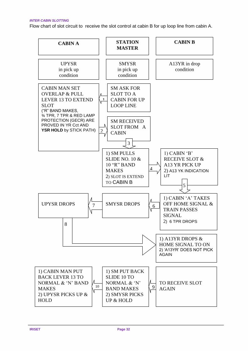
YR (Slot relay): Normal position of YR is drop. YR is controlled by YSR and reverse bands of concerned Slot Lever/ SM slide. Other control like track circuits in overlap, in route, berthing line shall be added to YR circuit as per interlocking requirement. Train control in general: Normally trains movement are controlled from centralised place by section controller. Station master plans reception and dispatch of running trains as per advice of section controller regarding halting, precedence or run-through conditions of trains. 4.9.2 Circuit explanation for UP Loop line slot (13YR)
(a) As train is planned to receive on UP loop line (cabin B Home signal), hence slot shall be received from cabin A and Station Master to pick up 13 YR in relay room of B cabin.
Even if switchman of B cabin tries to take off home signal after setting the route, it is not possible unless slot control for reception of train on UP loop line is obtained (13 YR drop) from A cabin and Station master. The front contact of 13 YR is used in UP HOME HR circuit.
(b) Station master advice switchman of cabin A to extend slot control to receive train on
UP loop line.
(c) Cabin man of ‘A’ cabin sets the overlap and pulls the slot lever no:13 and reverse band of slot lever 13 is available. Even though N band of lever 13 is not available now, UPYSR does not drop as stick path is provided at cabin ’A’. Slot control can be extended only if YSR is in pick up condition.
Cabin man of A cabin informs SM that slot for UP Loop line is given.

SLOT INDICATORS
Page 31 (S-20) REVERSERS, SLOT CIRCUITS,
EOLB, EKT/RKT & LLCC.
(d) SM pulls slide number 10 nominated for UP Loop line and R band of slide number 10 is now available and SM informs Cabin man of B cabin that slot for UP Loop line is given.
(e) Slot Relay 13 YR picks up at B cabin and slot indication (13 YK) available on the top of lever for UP Loop line on lever no: 13.
(f) Cabin man of cabin B confirms reception of slot by verifying slot indication and set the route to receive the train on UP Loop line by reversing lever no:13.
(g) Train crosses home signal which causes (FVT) 6 TPR to drop, hence UP YSR & UP SMYSR at cabin A and SM location drops respectively.
(h) Dropping of UP YSR at cabin A causes 13 YR to drop at cabin B and signal goes to danger.
(i) Ones 13 YR drops it does not pick again unless all the controls (lever no 13 at cabin A and SM slide 10 are made normal and one slot one train principle is achieved.
INTER CABIN SLOTTING
IRISET Page 32
Flow chart of slot circuit to receive the slot control at cabin B for up loop line from cabin A.
SM ASK FOR
SLOT TO A
CABIN FOR UP
LOOP LINE
SM RECEIVED
SLOT FROM A
CABIN
4
3
2
4
UPYSR
in pick up
condition
A13YR in drop
condition
CABIN MAN SET
OVERLAP & PULL
LEVER 13 TO EXTEND
SLOT (“R” BAND MAKES, ¾ TPR, 7 TPR & RED LAMP PROTECTION (GECR) ARE PROVED IN YR Cct AND
YSR HOLD by STICK PATH)
1) CABIN MAN PUT
BACK LEVER 13 TO
NORMAL & ‘N’ BAND
MAKES
2) UPYSR PICKS UP &
HOLD
1) CABIN ‘A’ TAKES
OFF HOME SIGNAL &
TRAIN PASSES
SIGNAL
2) 6 TPR DROPS
1) CABIN ‘B’
RECEIVE SLOT &
A13 YR PICK UP
2) A13 YK INDICATION
LIT
1) A13YR DROPS &
HOME SIGNAL TO ON 2) ‘A13YR’ DOES NOT PICK AGAIN
STATION
MASTER
SMYSR
in pick up
condition
1
1) SM PULLS
SLIDE NO. 10 &
10 “R” BAND
MAKES
2) SLOT IS EXTEND
TO CABIN B
SMYSR DROPS
UPYSR DROPS 7 6
8
1) SM PUT BACK
SLIDE 10 TO
NORMAL & ‘N’
BAND MAKES
2) SMYSR PICKS
UP & HOLD
CABIN B
CABIN A
TO RECEIVE SLOT
AGAIN 9 10
0
5

IRISET YARD
Page 33 (S-20) REVERSERS, SLOT CIRCUITS,
EOLB, EKT/RKT & LLCC.
IRISET YARD NO.-4
SIGG.PLAN
3/4
DISTANT
11TB2- 2 -DN.M/H
B4- 3 -DN.L/H
P
6T
10
A15- 11 -UP M/H
A13- 10 -UP L/H
`A'CABIN
16-LEVER FRAME
16-LEVER FRAME
S.M' CONTROL
12 SLIDES
6
7
SPARE: 1.2.5.6.8.9.10.16.
SPARE: 1.4.5.8.9.12
B4
B2
A13
A15
SPARES: 1.7.8.11,12.15.16.
`B'CABIN
DN
UP
35
DISTANT
14/13
6
7
14
12
11
INTER CABIN SLOTTING
IRISET Page 34
S.M
`S O
FF
ICE
`B' C
AB
IN`A
' C
AB
IN
6T
PR
N11
N10
UP
SM
YS
R
N11
N10
UP
SM
YS
R
UP
SM
YS
R
B24
6
TP
RN
24
YS
R
UP
R2
R1
UP
YS
R
UP
YS
R
11 R R11 R10R10
YR
14
R1
R2
YR
13
R1
R2
N24
B24
YR6
R1
R2
R6R6
N24
B24
15 N
13 N
13 RR R 13 R15
15
7R
WK
R
7
RW
KR
7N
WK
R
7
NW
KR
15 N
13 N
UP
YS
R
UP
YS
RU
P
SM
YS
R
SM
YS
RU
P

CIRCUITS
Page 35 (S-20) REVERSERS, SLOT CIRCUITS,
EOLB, EKT/RKT & LLCC.
N24
11
TP
R
11
TP
R
10
RW
KR
10
RW
KR
R2 R2 3 R 3 R
10
10
R4 R4R2 R2
YR4
R1
R2
DN
YS
R
DN
YS
R
YR3
R1
R2
B24
N24
DN
SM
YS
R
DN
YS
R
YS
R
DN
R1
R2
4 N
2 N
3 N
2 N
3 N
2 N
B24`A
' CA
BIN
`B' C
AB
INS
.M`S
OF
FIC
E
DN
YS
R
4 N
2 N
YR7
R2
R1
R77 R
B24
N24
NW
KR
NW
KR
DN
SM
YS
R
SM
YS
R
DN
R1
R2
DN
SM
YS
R
DN
SM
YS
R
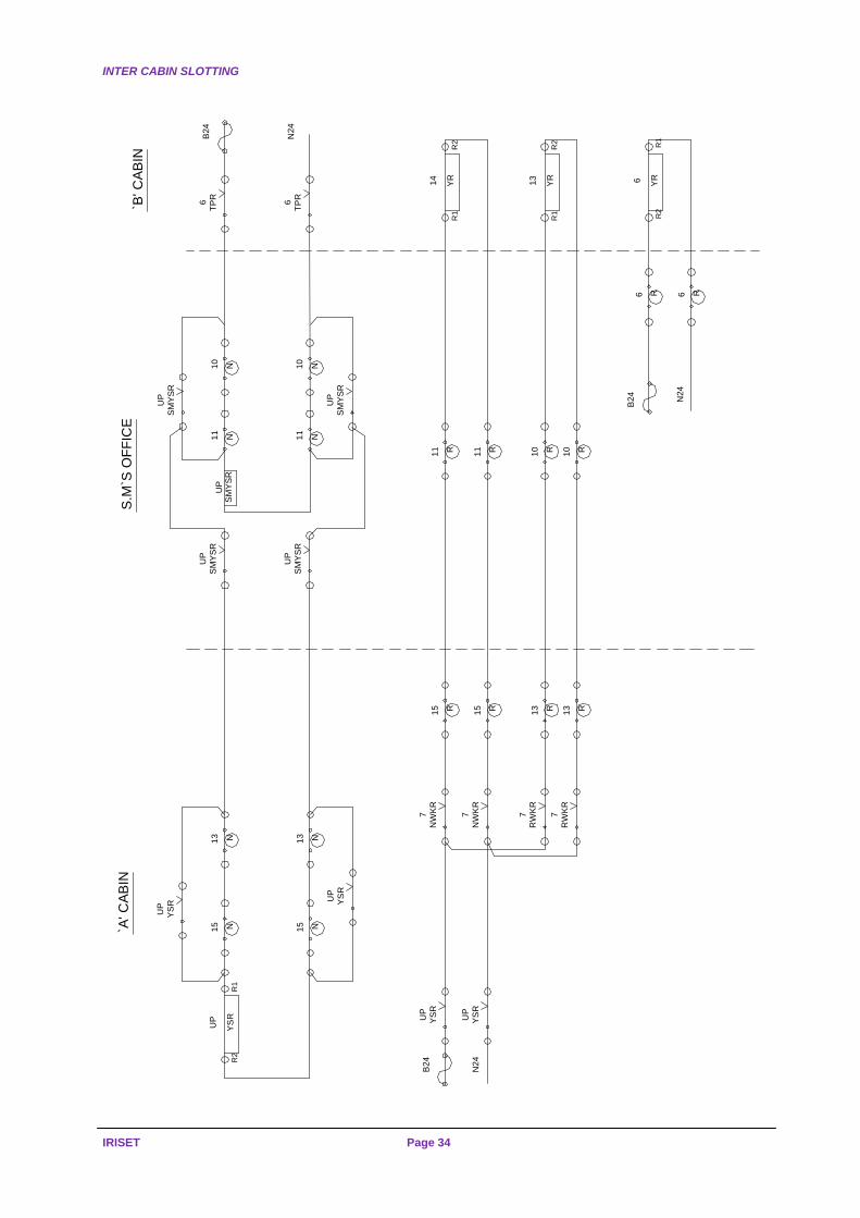
INTER CABIN SLOTTING
IRISET Page 36
N 12
B - CABINRELAY ROOM
YK
6
YR
YR 14
YK
B 12 13YR
YK
N 12
A - CABINRELAY ROOM
YK
YR
YR
YK
B 12 YR
YK
13
14
6
3
4
11
3
4
11

INTRODUCTION
Page 37 (S-20) REVERSERS, SLOT CIRCUITS,
EOLB, EKT/RKT & LLCC.
CHAPTER – 5: ELECTRIC LIFTING BARRIER
Electric lifting barrier with hand generator back up RDSO/SPN/180/2005 Amendment -1 & Electric lifting barrier without hand generator
IRS – SPEC. S- 41/70
5.1 Introduction Level crossing gates are classified as Special, A, B, C & D class depending on importance and volume of road & rail - road traffic All Special, A & B class level crossings are protected/gradually being protected by signals. These level crossings are operated at least 30 times on average per shift of gate man and as rail-road traffic goes up, the number of operations will increase. The level crossings are provided with lifting barriers, which are operated by a central winch through wire transmission. The lifting barriers are locked through rod operated mechanism (boom lock / lock post). As road and rail traffic are increasing, introducing electrically operated lifting barriers on Special, A & B class level crossing gates necessitated.
Signals Road Light
Boom Lock,Detector
Barrier
Pedstal
Relay roomIPS
BOOM LOCKDETECTOR
LIFTINGBARRIER
ROADSIGNAL
RO
AD
GATE LODGE
EQUIPMENT
ROOM
GP
RO
AD
G P
Road Light
Control
panel for
operation
of Gate
Fig: 5.1 A TYPICAL DIAGRAM OF ELECTRICALLY OPERATED LIFTING BARRIER GATE

ELECTRIC LIFTING BARRIER
IRISET Page 38
5.2 Drawbacks of mechanical lifting barrier
(a) Present design is maintenance oriented. Wire transmission is prone to failures and outside interference. Hence, there is need for minimum maintenance system.
(b) Mechanical operations, demands physical exertion with frequent opening & closing of gate.
(c) Mechanical gate pedestals erection on same side of road i.e. both barriers are operated in parallel. This impedes flow of road traffic in one direction.
5.2.1 Advantages of Electrically Operated Lifting Barrier
Electrically operated lifting barriers are very simple in design. Electric motor, motor speed reduction gear and cam operated switches can be of highest quality. The main bearings of barrier are designed for more than 5 years of failure free service. The system is almost maintenance free.
The other advantages are
(a) Easy operation to avoid physical strain on gate man.
(b) Crank handle facilitate manual operation of gate in case of power or hand generator failure, the mechanical advantage can be kept high for effortless operation. (both barriers have to be cranked separately as they are not mechanically linked).
(c) Barrier pedestals can be erected on opposite sides of roads for equal flow of road traffic when barriers are raised. If barrier pedestals are erected on LHS of road at entry ends, road vehicles get more time to clear while closing the barriers.
(d) The time of operation is only 10 sec. against 60 sec. for manual operation.
(e) Barrier width is enlarged to increase its visibility to road users.
(f) Boom Segments are bolted together and facilitate easy replacement in case of damage to barrier by road vehicles, hence break down time can be reduced
(g) Increased safety due to boom lock / lock post and lock detection
(h) Feasibility of remote operation in conjunction with close circuit TV
(i) Effortless operation and hence improved service condition of gate man.
The power requirement for electrical lifting barriers only will be around 200 Watt for 10 seconds. In CLS territory (both RE & non-RE) and in semaphore signal territory with electrical circuitry, this much power can be derived from existing power source for signals. For semaphore signal territory, where gate signals are purely mechanical, solar power with battery backup will be adequate.
5.3 Application of electric lifting barrier The system should comprise of following and should be integrated for maximum benefits

TERMINOLOGY
Page 39 (S-20) REVERSERS, SLOT CIRCUITS,
EOLB, EKT/RKT & LLCC.
5.4 Terminology
Electric lifting barrier: An electrically operated device for closing the level crossing gate against road traffic and comprises of an electric motor, operating mechanisms, Circuit controller, road signals, and audible device and Boom etc.
Level crossing: The section of a road at which, the railway track and road crosses each other at the same level.
Operating mechanisms: Consisting of clutch, reduction gear, boom shaft and suitable Locking device.
Boom:
1) Boom is part of the barrier, which in horizontal position prevents passage of road traffic across the level crossing.
2) The shape of the boom w.r.t specification no: RDSO/SPN/180/2005 with Amd.1 is mentioned below
3) Boom is light weight and made of aluminium flat plate bended at the edges.
4) Boom length up to 32 ft is available in four pieces. Each piece is eight feet length.
5) A slotted metal strip is fixed on end of boom, which is fixed on main boom shaft.
6) Boom is mounted on forked shaped balance channel which is fixed on main boom shaft.
7) Two sets of adjustable M.S. counter weights (3 long & 2 small sizes) are fixed in slotted holes on balance channel.
8) A red color boom light is fixed in the centre of boom facing towards road and works on 24VDC/110AC. Due to frequent damage of boom the Red light can be fixed on Height gauge in front of the Gate.
9) Boom first section is 2mm thickness, and 1.5mm in the later sections.
10) The cross section used is rectangular.
11) Mettuguda W.S. prepared 1st section 3mm, next section of 2mm and the last section of 1.5mm.
12) Metallic stays used to avoid boom bending due to wind pressure.
The height of the boom from road level shall not be more than 1000 mm.
As per specification no: RDSO/SPN/180/2005 with Amd.2 the boom shall withstand wind pressure, the boom shall be made of galvanized iron sheet and Octagonal in shape with Telescope view (fig.5.4)
Snubbing device: A device employed apart from the clutch, to minimise the physical
shock- due to stopping the mechanisms at the end of its stroke. Time of operation: The time required to operate the barrier form horizontal to the
vertical position and Vice versa, but does not include the warning time. Short time rating: A rating which specifies the load at which the motor, starting at the
ambient temperature may be operated for the period and under the conditions specified on the rating plate, while complying with the requirements of this specifications.
Crank handle: An appliance by which electrically operated lifting barrier may be manually operated.

ELECTRIC LIFTING BARRIER
IRISET Page 40
2440
2440
2440
2440
300
400
400
SLE
EV
E S
PO
T W
ELD
ED
ON
3rd
SE
CT
ION
AN
D
BO
LT
ED
ON
4th
SE
CT
ION
SLE
EV
E S
PO
T W
ELD
ED
ON
2rd
SE
CT
ION
AN
D
BO
LT
ED
ON
3rd
SE
CT
ION
SLE
EV
E S
PO
T W
ELD
ED
ON
1st S
EC
TIO
N A
ND
BO
LT
ED
ON
2nd
SE
CT
ION
40
04
5
ED
CB
A
97
97
118.5
118.5
140
140
183
183
SE
CT
ION
4S
EC
TIO
N 3
SE
CT
ION
2S
EC
TIO
N 1
HO
LD
ING
BR
AC
KE
T P
LA
TE
S W
ELD
ED
ON
1st
SE
CT
ION
OF
BO
OM
50
4
200
25
25
170
180
400
Octa
go
na
l Jo
intin
g S
leeve S
pot
We
lde
d T
o L
arg
er
Se
ctio
n F
abricate
d
Fro
m 2
0G
GI
Sheet.
Sm
alle
r S
ectio
n F
ixe
d T
o J
oin
ting
Sle
eve
By 8
No
s.
SS
-202 H
ex.B
olts
10
mm
Fo
r E
ach
Join
t.
FIR
ST
AN
D S
EC
ON
D J
OIN
T
Go
lde
n Y
ello
w P
ow
der
Co
atin
g f
ollo
we
d b
y B
lack
30
0m
m B
an
d w
ith
Bru
sh P
ain
ting.
Ye
llow
Re
fle
ctive T
ape
to b
e f
ixe
d o
n a
ll fr
ont &
ba
ck f
ace
s o
f Y
ello
w
Ba
nd
s o
f boom
.
PA
INT
ING
ALL
DIM
EN
SIO
NS
AR
E IN
MM
(
NO
T T
O S
CA
LE
)
HO
LD
ING
BR
AC
KE
T P
LA
TE
S
2 H
ole
s D
ia.
12
mm
,150m
m A
part
161.5
161.5
Fig: 5.4
A TYPICAL DIAGRAM OF OCTAGONAL SHAPE BARRIER WITH TELESCOPE VIEW

GENERAL REQUIREMENTS
Page 41 (S-20) REVERSERS, SLOT CIRCUITS,
EOLB, EKT/RKT & LLCC.
5.5 General requirements of Lifting Barrier
Lifting barrier shall be robust in construction and the operating mechanism shall be protected from unauthorized interference.
The boom of the barrier shall be light in construction and shall extend across the full width of the road.
The height of the boom from the rail level shall be 0.8 m to 1.0 m (As per SEM-II-14.2.9).
A support mounted on a base shall be provided for the tip of the boom in the horizontal position.
The lifting barrier shall be provided with a pedestal suitable for mounting on a base.
Fringes, if provided, shall be clear of road surface by not more than 15 cm. When the boom is in the horizontal position.
The raised or open position of the lifting barrier shall be within 80 to 85 from the
horizontal and the lowered or closed position shall be within 10 from the horizontal. (As per
SEM-II Para 14.2.10)
At the centre of the boom, the lifting barrier shall be provided with a 600 mm diameter. Red disc having red reflector buttons facing the road traffic.
The boom shall be painted / pasted with radium sticker alternately with 300 mm Bands of black and yellow. The fringes, if provided, shall also be painted similarly.
Lifting barrier shall be so designed that it can be stopped or reversed its movement when its movement is obstructed at any point during operation without damage.
The mechanism shall be designed to prevent movement of the lifting barrier due to vibration or any external force applied to the mechanical connections or boom.
The design of mechanism shall be such that the boom should be balanced that in case of failure of power supply, the barrier shall remain in the position last assumed.
The mechanism shall be so designed that if the boom is obstructed during operation it shall stop and on removal of the obstruction shall assume the position corresponding to the control apparatus, unless protective devices have operated.
The movement of the lifting barrier shall be arranged to prevent any undue shock on the mechanism. Suitable snubbing device capable of operating efficiently under all weather conditions shall be provided.
Means shall be provided to adjust the counter-balance of the lifting barrier.
The operating mechanism shall include a suitable device to lock the lifting barrier in the vertical and horizontal positions.
Electrical contacts shall be easily accessible and independently adjustable. Electrical contacts shall be of low resistance, quick acting, self-aligning and wiping type and shall conform to IRS Specification No.S-23 [Electrical Signalling and Interlocking Equipment (Tentative)].
In addition to regular contacts for controlling the lifting barrier, a minimum of 4-additional contacts shall be provided for controlling the external circuits, unless otherwise specified by the Purchaser.
Bearings shall be of ample dimensions to ensure durability and conform to IRS Specification No.S-23 [Electrical Signalling and Interlocking Equipment (Tentative)] and shall be so constructed as to prevent entry of water.
Provision shall be made for proper lubrication at convenient locations of the bearing surfaces and moving parts of the machine wherever necessary.
Exposed oil holes, cups or grease nipples shall be provided with weatherproof spring loaded covers.

ELECTRIC LIFTING BARRIER
IRISET Page 42
Lifting barrier shall have two booms, one across the road on either side of the track operated by independent mechanism.
Means shall be provided for manual operation of the lifting barrier by a hand-crank in case of power failure. The insertion of hand-crank shall disconnect the power supply to the motor and it shall not be possible to reconnect the power supply until the hand-crank is withdrawn.
A separate fracture segment shall connect the boom with the mechanism near the pivot. Fracture segment mounting shall be of such a design that it can be replaced easily and quickly, and in case of a mighty hit, shall allow for the break of the boom segment without endangering mechanism itself.
Where required, audible and/or visual warning arrangements for the road traffic shall be provided along with the lifting barrier.
Audible and visual warning arrangements for the road traffic shall start operating 6 to 8 seconds before operation of the barrier from its vertical or open position and shall continue till both the booms reach within 10 of the horizontal position.
The audible warning arrangement for road traffic shall consist of an electric bell operating on the same voltage as of the boom. One bell shall be provided at each side of the level crossing.
The bell warning shall operate with a clear ringing sound and shall be audible for a distance of not less than 300 metres in a direction that the sound waves are not obstructed on a clear day, with the wind velocity and the extraneous noises negligible.
The visual warning arrangement shall consist of a road signal of the colour light signal type and the range of visibility shall not be less than 180m, burning at 90% of the rated voltage.
The colour light signal may display either a steady red light or a pair of horizontally mounted flashing red lights as specified by the Purchaser.
Where a steady red light is specified to be provided, it shall continue to be displayed when the boom is horizontal and when the boom is being raised till the boom assumes the vertical position. Thereafter a steady yellow / white shall be exhibited to the road traffic.
Flashing red lights, where provided, shall flash alternately @ 45 to 55 flashes per minute, so phased that one of the pair of red lights is always exhibited to the road traffic during
the flashing period. They shall become steady once the boom reaches within 10 of the horizontal or closed position and shall continue to display a steady red indication, when the boom is being raised till it assumes the vertical position. Thereafter, a steady white light shall be exhibited to the road traffic. The operation of road signal aspects shall be on the same voltage as of the barrier operation.
The roundels used for the road signals shall have 30 horizontal spread light with 15
downward deflections.
5.6 Sequence of Operation
The operation of the lifting barrier shall takes place in the following sequence
(a) Open the detection contacts
(b) Unlock the boom
(c) Move the boom
(d) Lock the boom in the full horizontal or vertical position
(e) Close the detection contacts

ELECTRICAL PARAMETERS
Page 43 (S-20) REVERSERS, SLOT CIRCUITS,
EOLB, EKT/RKT & LLCC.
5.7 Electrical parameters
OPERATING CHARACTERISTICS
Low voltage 24VDC 6-8 Amps for boom lengths up to 8 metres
Low voltage 24VDC 8-12 Amps for boom lengths above 8 metres
High voltage 110VAC 50 Hz single phase
2 Amps. For Normal length of boom
Note : As per specification No.S:41/70
For barriers without Hand generator:
Type Rated
Voltage
Normal (max.)Operating Current / barrier for boom
length up to 9.76 m (≈10 m)
Maximum rated Current for each barrier for boom length
up to 9.76 m (≈10 m)
AC 110V 2.5 Amps 4 Amps
DC 24V 4 Amps 7 Amps
DC 110V 1.0 Amps 1.8 Amps
For barrier`s Hand generator:
Type Rated
Voltage
Normal (max.)Operating Current / barrier for boom
length up to 9.76 m (≈10 m)
Maximum rated Current for each barrier for boom length
up to 9.76 m (≈10 m)
DC 24V 3 Amps 5 Amps
DC 110V 0.7 Amps 1.2 Amps
Time of operation of the lifting barrier shall not exceed 10 seconds at rated voltage and 20 seconds at 75% of rated voltage at the motor terminals.

ELECTRIC LIFTING BARRIER
IRISET Page 44
5.8 Some typical wiring diagram for power operation (Heidz Make)
+ -
+ -
+ -
AA
A
M
90°- 0°
0°- 90°
Cut-out ContactD.P.D.T.
SwitchB24+ ve
N24- ve
Crank Handle
Fig: 5.8 (a) WIRING DIAGRAM FOR ELECTRICALLY OPERATED
LIFTING BARRIER PERMANET MAGNET TYPE
F2
F1
A1
A2
LIMITSWITCH
LS 2LS 1
LS 2LS 1D.P.D.T.
B24V
+
-M
( 90°- 0° )
( 0°- 90° )N24V
Cut-out Contact
Crank Handle
0°- 90° 90°- 0°
SWITCH
Fig: 5.8 (b) WIRING DIAGRAM FOR ELECTRICALLY OPERATED LIFTING BARRIER WITH SHUNT MOTOR

LIFTING BARRIER (MODEL ELB-206)
Page 45 (S-20) REVERSERS, SLOT CIRCUITS,
EOLB, EKT/RKT & LLCC.
5.9 LC Gate in general. Heidz India limited New Delhi has low voltage and high voltage electrically operated lifting barrier gates with OR without hand generator facility. The local as well as remote operation is possible.
5.10 Working principle The shunt / permanent magnet motor provide require torque and desired mechanical advantage is derived through gearbox. Gearbox is designed to stop in last operated position in case of power failure during course of operation OR otherwise. A series of Link is provided between Gear Box Shaft & Boom Shaft extend mechanical movement from gearbox to main boom shaft. Crank and link system also provides Speed Control. The necessary snubbing arrangement is achieved by controlling speed of motor with help of limiting resistance. Synchronisation of different functions such as controlling feed to motor, road signal and snubbing arrangement are achieved through limiting switches.
5.11 The different electrical parameters
S.No. Description Parameter
1 System voltage 24DC Model
110DC Model
110 AC Model
2 Power rating 120 watts for DC model
250 watts for AC model
3 Operating time Approximate 10 sec for per operation
4 Boom length 32 Ft. (9.75Mt) Max.
Though the specification No: RDSO/SPN/180/2005 with Amd.1 allows 24V DC/ 110V DC motor only but Heidz Pvt Ltd., come up with 110V AC motor also.
5.12 The main parts of electric lifting barrier (Model ELB-206).
The parts are Control panel and hand generator, Pedestal, Barrier, channels weights and boom, and Boom rest with solenoid boom lock / lock posting 5.12.1 Control panel and hand generator
It is small rectangular metal case with door and placed in gate lodge at appropriate place so as to have adequate visibility of track and road on both sides of gate lodge. Control panel provides different operational facilities. It accommodates cable terminals and hand generator it has console on the one of the door and four buttons and switches are provided to used during different mode of operation
The switches are
(a) Auto/ manual Selector switch
(b) Barrier Motor Toggle button (close) (Red colour)
(c) Barrier Motor Toggle button (open) (Green colour)
(d) Barrier B Selector switch (ON/ OFF)
(e) Barrier A Selector switch (ON/ OFF)
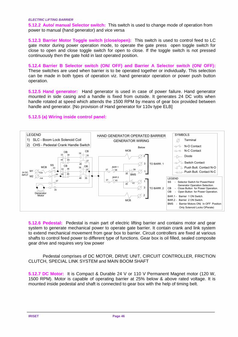
ELECTRIC LIFTING BARRIER
IRISET Page 46
5.12.2 Auto/ manual Selector switch: This switch is used to change mode of operation from power to manual (hand generator) and vice versa
5.12.3 Barrier Motor Toggle switch (close/open): This switch is used to control feed to LC gate motor during power operation mode, to operate the gate press open toggle switch for close to open and close toggle switch for open to close. If the toggle switch is not pressed continuously then the gate hold in last operated position. 5.12.4 Barrier B Selector switch (ON/ OFF) and Barrier A Selector switch (ON/ OFF): These switches are used when barrier is to be operated together or individually. This selection can be made in both types of operation viz. hand generator operation or power push button operation.
5.12.5 Hand generator: Hand generator is used in case of power failure. Hand generator mounted in side casing and a handle is fixed from outside. It generates 24 DC volts when handle rotated at speed which attends the 1500 RPM by means of gear box provided between handle and generator. [No provision of Hand generator for 110v type ELB] 5.12.5 (a) Wiring inside control panel:
5.12.6 Pedestal: Pedestal is main part of electric lifting barrier and contains motor and gear system to generate mechanical power to operate gate barrier. It contain crank and link system to extend mechanical movement from gear box to barrier. Circuit controllers are fixed at various shafts to control feed power to different type of functions. Gear box is oil filled, sealed composite gear drive and requires very low power
Pedestal comprises of DC MOTOR, DRIVE UNIT, CIRCUIT CONTROLLER, FRICTION CLUTCH, SPECIAL LINK SYSTEM and MAIN BOOM SHAFT
5.12.7 DC Motor: It is Compact & Durable 24 V or 110 V Permanent Magnet motor (120 W, 1500 RPM). Motor is capable of operating barrier at 25% below & above rated voltage. It is mounted inside pedestal and shaft is connected to gear box with the help of timing belt.
LEGEND
SS - Selector Switch for Power/Hand
M1
M2
GeneratorMotor
MCBSS
OB CB
2
3
1
1
3
2
24 DCINPUT
+ive
-ive
33
44
37
35
33 34
BAR 1
37 38
BAR 2
37 40
44 45
CB33 36
44 46
3435
37
45OB36
37
3546
MCB
38
39
40 41
MCB
BMS
TO BARR. 1
TO BARR. 2
LEGEND
1) SLC - Boom Lock Solenoid Coil
2) CHS - Pedestal Crank Handle Switch
Generator Operation Selection.CB - Close Button for Power Operation.
OB - Open Button for Power Operation.
BAR.1 - Barrier 1 ON Switch.
BAR.2 - Barrier 2 ON Switch.
BMS - Barrier Motors ON(In OFF Position
Only Solenoid Locks OPerate)
HAND GENERATOR OPERATED BARRIER
GENERATOR WIRING
Below
Terminal
N-O Contact
N-C Contact
Diode
Switch Contact
Push Butt. Contact N-O
Push Butt. Contact N-C
SYMBOLS

LIFTING BARRIER (MODEL ELB-206)
Page 47 (S-20) REVERSERS, SLOT CIRCUITS,
EOLB, EKT/RKT & LLCC.
5.12.8 Drive Unit: It is an oil filled, sealed composite gear drive requires minimum maintenance and provides required mechanical advantage. It is designed to hold in last operated position when power supply to motor is cut OFF hence barrier do not fall down if power supply is disrupted due to any reason. Drive unit shaft has two ends, friction clutch is fixed on one end and other end is used for crank handle.
5.12.9 Circuit Controller: There are 8 Contact Circuit Controller, called as limit switch (Top Roller Type Highly Durable Limit Switches) and actuated by Nylon66 Cams. Cams are adjustable for full 360 deg for accurate adjustment of make/ break angle
Nylon66 cams fixed on the boom shaft actuate the limit switches, and the position of these cams are adjustable. LIMIT SWITCHES provided are LS1, LS2, LS3, LS4, LS5, and LS6 (Crank handle cut out contact). The location and function of these switches are as follows.
5.12.9.1 Function of Limit Switches
Limit Switches LS1 & LS2: Two limit switches LS1 & LS2 are provided on the gear
box shaft and LS1 control feed to the motor while closing the gate and open the contacts when gate is closed. LS2 control feed to the motor while opening the gate and open the contacts when gate is completely opened.
Limit Switches LS3: Limit switches, LS3 is provided on main boom shaft, and control the snubbing circuit to slow down the motor while gate is being closed so that boom will not bounce back from boom rest. It also controls supply to solenoid lock while opening & closing.
Limit Switches LS4 & LS5: Two more Limit switches, LS4 & LS5 are also provided on main boom shaft, to give feedback indications in the fully open & closed positions of gate.
5.12.9.2 The cams can be adjusted as follows
(a) Loosen the cam fixing screws using an Allen Key.
(b) Adjust the position of the cam as required, by rotating it on the boom shaft.
(c) Tighten one of the cam fixing screws, and check the position of the cam by operating the barrier.
(d) Tighten all fixing screws after cam position is properly adjusted. 5.12.9.3 The Position of the cams is to be adjusted as follows:
(a) The cam for LS1 is to be adjusted such that its N-O Contact just breaks in the fully
closed position of barrier.
(b) The Cam for LS2 is to be adjusted such that its N–O contact just breaks in the fully open position of barrier.
(c) The cam for LS3 is to be adjusted such that its N-O contact just makes at about 20 – 30 deg to horizontal
(d) The Cam for LS4 are to be adjusted such that it’s N-O contact just makes in the fully closed position of barrier.
(e) The Cam for LS5 is to be adjusted such that its contact just makes in the fully Open position of barrier.

ELECTRIC LIFTING BARRIER
IRISET Page 48
5.12.9.3 (a) Wiring inside Pedestal
5.13 Friction Clutch
It provides overload protection to motor. The friction clutch is mounted on the input shaft of the gear drive unit, and connected with the motor by a Timing Belt. Slippage torque (slipping currant) can be adjusted by adjusting Spring Tension. Clutch slips in case boom is obstructed, and automatically re-engages if obstruction is removed. An adjusting nut is provided on the clutch. Tightening this nut, increases spring tension, and hence the slippage torque.
5.13.1 The slippage torque adjustment is done as follows (Adjustment of FRICTION
CLUTCH)
(a) Completely loosen adjusting nut until gate fails to operate when motor is started, and the clutch slips continuously.
(b) Tighten the nut in 1-1/2 turn stages and check for gate operation at every stage to locate the position of the nut where the slippage torque of clutch is just sufficient to drive the barrier.
(c) Tighten the adjusting nut by another ½ turn.
Note: In case clutch is observed to be slipping and the barrier is not moving, please check that there is no physical obstruction to boom or counterbalance channels, before tampering with clutch adjustment.
5.14 Special Link System
Specially Designed Link System between gear box Shaft & Boom Shaft and Controls speed of main shaft and hence speed of boom is controlled. Crank and link system extend mechanical movement from gear box to main boom shaft. Boom movement starts at slow speed; it picks up speed in middle of stroke & again slows down before end of stroke. This links require adjustment at installation stage to have proper speed and position of boom
1 2 43 5 6 8 9 14131211107
1 1
23 24
LS5A
25 26
LS5B
27 28
CHS2
17 18
LS1A
19 20
LS4A
21 22
LS4B
Terminal
N-O Contact
N-C Contact
SYMBOLSCIRCUIT CONTROLLER CONTACTS
LS1 - Breaks 5 Deg & Below
LS2 - Breaks 85 Deg & AboveLS3 - Makes 25 Deg & Below
LS4A.B - Makes 5 Deg & Below
LS5A,B - Makes 85 Deg & AboveMotor
15 16
Boom Light 24V DC
SLC
FROM GENERATOR
LS1
LS2 LS3 CHS1
CONTACTS FOR RAILWAY SIGNALLING
HAND GENERATOR OPERATED BARRIER
PEDESTAL WIRING
(REVISION OCT 05 WITH SNUBBING RESISTOR )
(This wiring provided for each Pedestal 1&2)
LS3 30
0-10 Ohm Resistor(Set at approx. 5 Ohms)

FRICTION CLUTCH
Page 49 (S-20) REVERSERS, SLOT CIRCUITS,
EOLB, EKT/RKT & LLCC.
Fig. No. 5.14(a) SPECIAL LINK SYSTEM
Ch
an
nel
Bo
om
Pe
de
sta
l M
ain
Barr
ier
Ma
in s
ha
ft lin
k
Con
ne
cti
ng l
ink
Ge
ar
box
Lin
kP
ack
ing
Shim
sG
ea
r B
ox
Rem
ark
s
Adju
st
In c
orr
ect
Pos
itio
n
Ch
an
nel
Bo
om
Pe
de
sta
l M
ain
Barr
ier
Ma
in s
ha
ft lin
k
Con
ne
cti
ng l
ink
Ge
ar
box
Lin
kP
ack
ing
Shim
sG
ea
r B
ox
In c
orr
ect
Pos
itio
n
of
links
Ch
an
nel
Bo
om
Pe
de
sta
l M
ain
Barr
ier
Ma
in s
ha
ft lin
k
Con
ne
cti
ng l
ink
Ge
ar
box
Lin
kP
ack
ing
Shim
sG
ea
r B
ox
Re
move
Pack
ing
sh
ims to
Ge
ar
Box
So
luti
ons:
In c
orr
ect
Pos
itio
no
f li
nks
Add
Pack
ing
sh
ims to
Ge
ar
Box
So
luti
ons:
Fig. No. 5.14(b) Adjustment of link position for optimum operation of Boom
MAIN
SHAFT
LINK
CONNECTING
LINK
GEAR
BOX
LINK
STOPPER
FOR O˚
STOPPER
FOR 9O˚
TIMING
BELT

ELECTRIC LIFTING BARRIER
IRISET Page 50
5.15 Main Boom Shaft
It is strong iron shaft and barrier is mounted on its two end. When Link System operates main boom shaft barrier also operates. Limit switch LS3 is mounted on this shaft.
5.16 Barrier pedestal, channels weights and boom
Fig: 5.16 Balance channel with Balance weight and aluminium boom
Boom is light weight and made of aluminium. Boom can be lengthen up to 32 ft as it is available in four pieces (each piece is 8 ft. in length). A slotted metal strip is fixed on end of boom, which is used in boom lock / lock posting. Boom is mounted on forked shape balance channel, which is fixed on main boom shaft. Two sets of adjustable M.S. counter weights (Maximum 3 long size & 2 small size) are fixed in slotted holes on balance channel. Slotted hole facilitate balancing of counter weight. A red coloured boom light is fixed in the centre of boom facing towards road and work on 24 volts DC/AC. If 110 V supply is to be given, an approx 12-15 K Ohm resistor should be fixed in series with light circuit.
5.17 Boom rest with solenoid boom lock / lock posting
It is a MS stand on which boom rest in closed position. A small box with door is fixed on boom rest and has locking arrangement. Box has a small window opposite to door and used in case, boom lock / lock posting fails to release electrically. Key of window remains with Gateman in sealed condition. Small Box accommodates, Solenoid, Locking lever and Read switch (boom lock / lock post contact) 5.17.1 Solenoid
It is an Electromagnet and designed to work on 24 volts DC/ 110 volts Ac. It is used to unlock the boom when gate is to be open. It generates stroke of 25 mm and pull of 2.25 Kg. Feed to solenoid is control automatically through limit switch LS3.

MODE OF OPERATION
Page 51 (S-20) REVERSERS, SLOT CIRCUITS,
EOLB, EKT/RKT & LLCC.
Fig: 5.17.1 Boom lock / lock post lever and Boom lock / lock post proving contact arrangement
5.17.2 Locking lever: It “L” shape MS lever with fulcrum in centre of corner and has a counter weight at one end and lock hook at other. It locks boom when boom stops on boom rest. 5.17.3 Read switch (Boom lock / lock post contact): This contact is used to prove that the boom is in fully closed position and that the solenoid controlled boom lock / lock posting lever has moved to the “Locked” position over the boom hook. If either of these conditions is not met with the contact of the switch will not make. A special non-contact type magnetic proximity switch has been used for this boom lock / lock post proving. It consists of 2 parts. One part, (with 2 wires protruding from the casing) is read switch, and is fixed to the boom-locking lever inside boom lock / lock post. The second part is the magnet actuator and is fixed to the boom hook. As soon as the 2 parts of the switch come within 0-25 mm of each other, the magnet actuates the read switch and switch contact makes. Maximum 25 mm distance shall be maintained so that magnet should actuate positively to make read contact.
5.18 Mode of operation
Electrically operated LC gate has three modes of operations and both the barrier can
operates simultaneously or individually. Modes of operation are Power operation, Manual Hand Generator Operation, Emergency Direct Crank Operation, Individual Barrier Operation.

ELECTRIC LIFTING BARRIER
IRISET Page 52
5.18.1 Power operation: It is done from control panel by pressing concerned push button.
Steps involved are (a) Select Auto mode, on Auto/ manual Selector switch (b) Select ON, on Barrier Motor Toggle switch (c) Select barrier for individual barrier operation OR both at a time on barrier selection
switch
For Opening: Press OPEN push button, and keep it pressed. Barrier start opening and automatically stop in fully open position. Keep the button pressed for 2-3 seconds even after barriers reach open position, to ensure full opening. (In case of low supply voltage, you may have to first put Motor Toggle Switch to “Off”, press Open Button for 1-2 sec, and while keeping Open button pressed, put motor switch to “On”. This will ensure that solenoid boom lock / lock posts operate first before motor starts opening the barriers)
For Closing: Press CLOSE push button, and keep it pressed. Barrier starts closing and automatically stops in fully closed position. Keep the button pressed for 2-3 seconds even after barriers reach full closed position, to ensure full closing & locking.
For Stopping In The Middle: Release the OPEN/ CLOSE push button, Barriers stop in required mid -position.
5.18.2 Individual Barrier Operation
Facility has also been provided for individual operation of the 2 barriers A & B if required. This selection can be made in both types of operation viz. hand generator operation or power operation.
In case, only barrier A/B is required to be operated, turn the Barrier B/A Selector switch provided to OFF position respectively.
5.18.3 Manual Hand Generator Operation: It is achieved by operating a hand generator after switching to manual mode on control panel. Steps involve in the gate Manual Hand Generator Operation of barrier are,
For Opening
(a) Select Auto/ manual Selector switch to manual mode.
(b) Select barrier selection switch for individual barrier operation OR both at a time on barrier selection switch.
(c) Rotate the crank of the hand generator in anti-clockwise direction, and build up some speed so that boom lock / lock post coils can operate to open boom lock / lock posts. (Crank for About 2-3 sec)
(d) Continue cranking till barriers reach fully open position, and hand generator crank handle runs freely.
For Closing
(a) Select Auto/ manual Selector switch to manual mode
(b) Select barrier selection switch for individual barrier operation OR both at a time on barrier selection switch.
(c) Rotate the crank of the hand generator in clockwise direction. Continue cranking till barriers reach fully closed position, and hand generator crank handle runs freely. (Do not stop cranking untill hand generator crank runs freely.)
For Stopping In The Middle And Reversing
(a) Stop Cranking of hand generator, Barriers stop in this position. (b) For reversing - Stop cranking and start cranking of hand generator in opposite
direction.

HEIDZ LIFTING BARRIER WIRING
Page 53 (S-20) REVERSERS, SLOT CIRCUITS,
EOLB, EKT/RKT & LLCC.
Emergency Direct Crank Operation: In case both power and hand generator operation fails then gate can be operated by crank handling gate barrier one by one.
I. Insert the barrier crank into the hole provided in the Pedestal (mechanism box) rear door & then into the shaft of the gear drive unit
II. Rotate handle in clockwise direction for closing
III. Rotate handle in anti-clockwise direction for opening
IV. As soon as Crank handle inserted electrical operation remains cut off till crank handle is removed.
5.19 Important Recommendations Made by Manufacturer for Installation Of Electric Lifting Barriers
(a) Matching: The serial number of machine is marked on rear door, on the counterbalance channels and aluminium boom. The care shall be that number on the boom and boom hook shall match with the respective machine. The counter weights, circular target & control panel are interchangeable.
(b) Cable Required: The minimum cable requirement is as follows :-
(i) 4-core cable between each barrier machine & relay rack for motor and solenoid lock
(ii) 22-core cable between each barrier machine & relay rack for circuit controller contacts & boom light.
(iii) Min.4-core cable between each barrier machine & its corresponding boom lock / lock post fixed at the other end of road.
(iv) Cables for road signal/ audio warning as per requirement.
(v) Cable between barrier control panel and relay rack as per requirement.
(c) Motor Wiring: The motor provided is a Permanent Magnet DC 2 wire motor. The current in armature shall be reversed for every next operation, which may be achieved at circuit level. Separate contractor units are also provided in location box for same purpose.
The control circuit for operating motor contactor unit should also take care of following:
The 2 contactors should be interlocked so that when one is picked up, the other does not pick up.
If either of the 2 crank handle cut-out switches (for the 2 barriers of a set) are operated, electrical operation of both the barriers of the set should be cut off.
The boom lock / lock post proving contact (which proves that boom hook is inside locking device & lock lever in locked position) should be suitably wired up in the barrier closed proving circuit/s.
(d) Solenoid Lock: The solenoid lock works on 24 V & 110V DC supply. Following
points should be taken care while controlling feed to solenoid coil. It is to be ensures that the
solenoid gets feed when boom is at 25°while closing through Switch LS3 and also gate feed at
0°while opening. Feed to motor & solenoid coil may be given simultaneously at the start of
opening.
(e) Boom Light: The boom light is LED based & works on 24 V AC or DC. If 110 V supply is to be given, an approx 12-15 K Ohm resistor should be fixed in series with light circuit.

ELECTRIC LIFTING BARRIER
IRISET Page 54
(f) Boom Balancing: Unbalanced boom, over load motor hence boom must be properly
balanced. Adjust balance weights until current is almost the same in both opening & closing.
The balancing should be slightly towards the boom side, so that the boom tip rests properly on the boom stand rubber. It can be checked by lifting the boom with very minimal effort and check
that you could able to lift the boom for 30 – 40 mm easily and after removal of effort on the
boom should again close & rest on the rubber pads. This balancing will ensure proper working of the solenoid lock system.
(g) Connecting Link Position Adjustment: The link system connecting the gear box with the main boom shaft is so designed as to provide a short idle stroke of gear link while opening, so that boom lock / lock post can operate before barrier actually starts moving up. This setting of links can be achieved by providing necessary packing at the mounting of gear box. Refer. Fig. No.3.15 (A) & Fig No: 3.15 (B )
(h) Snubbing Resistor Setting: Smooth stop at the end of the closed position is achieved by selecting proper value of the variable snubbing resistor (depend upon the input voltage available at the pedestal) the snubbing resister is brought in to circuit at start and end of operation with the help of LS3 limiting switch. For input voltage of 23- 24 V DC, the snubbing resistor may be set at about 4-6 Ω. For Lower Voltage setting should be lower, while for higher voltages, Resistor value setting should be higher. If resistance value is set very high then it may leads to the motor failure.
Groutng Bolts
BARRIER FOUNDATION
500 mm Pipe for Cable
900 mm
Depth
Groutng Bolts
BOOM LOCK FOUNDATION
500 mm Pipe for Cable
600 mm
Depth
70 mm
70 mm
Fig: 5.19 Foundation details for different parts of LC Gate.
(16mm 300mm)(16mm 300mm)
Represents Foundation BoltRepresents Foundation Bolt
200 mm
200 mm
450 mm
450 mm
343mm
343mm
600
mm
700 mm

HEIDZ LIFTING BARRIER WIRING
Page 55 (S-20) REVERSERS, SLOT CIRCUITS,
EOLB, EKT/RKT & LLCC.
Fig: 5.19 (a) Terminal particulars available in side pedestal
24V DC HEIDZ LIFTING BARRIER
PEDESTAL WIRING
LS3B Breaks
25 Deg & Below29 30
21
Motor
0 - 10 Ohm Resistor
(Set at approx. 5 Ohms)
Solenoid Lock
Coil3
27 28
4
LS3A Makes
25 Deg & Below
5 6 Contact Breaks 5 deg & below
LS1 - A
7 8 Contact Breaks 85 deg & above
LS2
9 10 Contact Makes 85 deg & above
LS4 - A
11 12 Contact Makes 85 deg & above
LS4 - B
13 14 Contact Makes 5 deg & below
LS5 - A
15 16 Contact Makes 5 deg & below
LS5 - B
17 18 Contact Makes 5 deg & below
LS1 - C
19 20 Contact Makes 5 deg & below
LS1 - D
21 22 Contact Breaks when crank is inserted.
CHS - C
23 24
CHS - D
25 26 Boom Light 24V DC
Contact Breaks when crank is inserted.

ELECTRIC LIFTING BARRIER
IRISET Page 56
5.20 Maintenance recommended by Manufacturers
Some periodic maintenance checks are recommended by Heidz India, they are as follows
(a) Fortnightly Maintenance
(i) Check for smooth operation of Barrier.
(ii) Clean the inside & outside of mechanism, boom & channels. And Hand Generator
(iii) Check for auto stop of Barrier (power supply cuts OFF) in the fully open and closed position. Adjust limit switches if required.
(iv) Check tightness of all fixing nuts and bolts of the mechanism base, gear box, motor, boom & counterbalance channels, & the adjusting screws of the cams, which operate the limit switches.
(v) Clean the inside of solenoid locking device and ensure that the lever falls to lock position by gravity.
(b) Quarterly Maintenance
(i) Check clutch slippage torque. Adjust if required.
(ii) Check Timing Belt tension for both barriers & Hand Generator. Adjust if required.
(iii) Check contacts of limit switches. Replace switch if required.
(iv) Apply a little grease to the cam surfaces, which operate the limit switches.
(v) Check contact of Boom lock / lock post Proving switch. Replace if required
(c) Annual Maintenance
(i) Replace the oil in the barrier & Hand Generator gear unit. Old oil is removed from the bottom of the gear unit by opening the bottom plug. New oil is filled from the top of the gear unit, by opening the top plug provided.
(ii) Use gear oil SAE 90 or equivalent. Qty. 1.5 litres in each barrier & 0.3 Litres in each hand generator gear box.
(iii) Replace Timing Belts if worn out.
(iv) Replace Clutch plate if required.
(d) Suppliers Of E.O.L.B : (as per RDSO approved list Of 30.03.12)
M/s Global devices / New Delhi,
M/s Arvind Enterprises / Chennai,
M/s S&T Workshop, Mettuguda / SCRly,
M/s Heidz India / New Delhi,
M/s Dasmesh Industries / New Delhi,
M/s G.K.Engg Works &Stores (P) Ltd / Howrah
M/s S&T Workshop, Byculla /CRly

MAINTENANCE GUIDE LINES
Page 57 (S-20) REVERSERS, SLOT CIRCUITS,
EOLB, EKT/RKT & LLCC.
5.21 Maintenance guide lines of SEM-II (Annexure-11) on Electric Lifting Barrier:
1) Machines must be kept in good condition, free from rust, dust and dirt. The bearing surface and moving parts of the electric lifting barrier shall be lubricated properly.
2) Contacts must be kept clean and in proper adjustment. If contact surfaces are pitted, they must be replaced.
3) Commutator and Brushes:- Commutator must be clean, smooth and have a bright appearance and Brushes must be kept clean and properly bedded on the commutator. Brushes should have proper pressure and should be free in brush holders.
4) Friction clutch must be so adjusted that the same should get de-clutched when the boom is raised or lowered fully and the power supply is not cut off.
5) The shock absorber at the boom rest (stop post) must be kept properly adjusted. The time of operation of electric lifting barrier shall not exceed stipulated time. Measured value of current should not exceed rated values.
6) The satisfactory functioning of the lifting barrier by a hand crank shall be checked.
7) All gate locking apparatus must be examined regularly and working parts kept oiled. Gate locks must be kept in good working order.
8) Proper working of audio/visual warning shall be ensured. Approach warning arrangement where provided, is working satisfactorily and effectiveness of Approach and Back locking provided shall be ensured.
9) The telephone communication facilities where provided between Level Crossing gates and the adjoining stations shall be checked in regard to their satisfactory functioning.
10) Heavy repairs, renewals or alterations to gate interlocking must not be carried out until Jr. Engineer/Section Engineer/Sr. Section Engineer (Signal) concerned has arranged for the protection of the road traffic by the concerned department and the work shall be carried out under proper disconnection & supervision.
11) Sectional Signal engineer shall maintain a register indicating details of each class of level crossing gate in regard to its location, number, type of gate provided, provision of communication, interlocking arrangement, provision of approach warning and flash lights etc., pertaining to his section. A statement in regard to the above should be submitted on first January and first July every year, to the Sr. Divisional Signal and Telecommunication Engineer/Divisional Signal and Telecommunication Engineer.
12) Maintenance Schedule as laid down in Annexure-11 shall be followed. This may be modified by CSTE of the Railway to suit local needs.
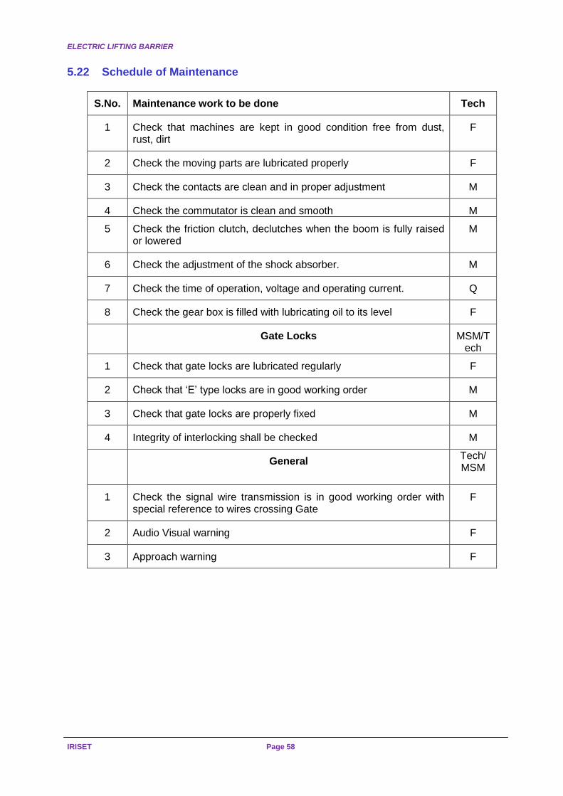
ELECTRIC LIFTING BARRIER
IRISET Page 58
5.22 Schedule of Maintenance
S.No. Maintenance work to be done Tech
1 Check that machines are kept in good condition free from dust, rust, dirt
F
2 Check the moving parts are lubricated properly F
3 Check the contacts are clean and in proper adjustment M
4 Check the commutator is clean and smooth M
5 Check the friction clutch, declutches when the boom is fully raised or lowered
M
6 Check the adjustment of the shock absorber. M
7 Check the time of operation, voltage and operating current. Q
8 Check the gear box is filled with lubricating oil to its level F
Gate Locks MSM/Tech
1 Check that gate locks are lubricated regularly F
2 Check that ‘E’ type locks are in good working order M
3 Check that gate locks are properly fixed M
4 Integrity of interlocking shall be checked M
General
Tech/ MSM
1 Check the signal wire transmission is in good working order with special reference to wires crossing Gate
F
2 Audio Visual warning F
3 Approach warning F

REVIEW QUESTIONS
Page 59 (S-20) REVERSERS, SLOT CIRCUITS,
EOLB, EKT/RKT & LLCC.
CHAPTER-1 Subjective question
1. Write short notes on signal Reverser and also write down power supply used, their application and inspection.
Objective questions
State true OR false
1. Reverser can be placed on shunt signal also
2. Reverser is can be used for slot control only.
3. The L-Q. & U-Q Reverse are inter convertible.
4. It is possible to pull the arm of the signal provided with Reverser to OFF position
Fill up the Blanks
1. Normal working voltage of Reverse________________________
2. The Resistance of coil of the Reverse is ____________________
3. Normal working current of Reverse is ______________________
4. The core and the armature are to eliminated effect of _________
CHAPTER-2 Subjective questions
1. Write down the essential principal of slotting
2. Refer Circuit Diagram on page 17 to 20 and explain how principal of slotting is achieved.
Objective questions
Fill up the Blanks.
1. YSR stands for ______________________
2. YK stands for _______________________ Choose the correct Answer.
1. YSR relay ensures __________________ feature
a) One slot one train b) one signal one train c) run trough d) a&b
CHAPTER-3
Subjective questions
1. Write down the general requirement of Electrical operated LC gate.
2. Write down the advantages of Electrical operated LC Gate over Mechanical gate.

REVIEW QUESTIONS
IRISET Page 60
Objective questions
Fill up the Blanks
1. The height of boom from the rail level shall be ____________________________
2. The motor used in HEIDZ Electrically lifting Barrier is _______________________
3. The Level of the boom can be adjusted with the help of _____________________
4. Power supply to motor is controlled though limit switch Number _______________
5. Proving of boom lock / lock posting is achieved through______________________
Chapter-4
Subjective questions
1. Write short notes on RKT and also write down power supply used, their application
and inspection.
2. Draw circuit diagram for RKT in non RE area.
Objective questions
Choose the Correct Answer
1. When RKT key is locked in condition then _______________ contacts is/are in make condition
a) 1&2 b) 3&4 c) 3&5 d) a&b
2. When RKT key is out then ________________ contact/s is/are in open condition
a) 1&2 b) 3&4 c) 3&5 d) all
3. Normal working voltage of RKT is _______________
a) 3.75 DC volt b) 3.75 volt DC plus line drop c) 10 volt DC d) 12 volt DC
4. Resistance of the coil RKT is ___________________
a) 12.5 Ohms b) 600 Ohms c) 15 Ohms d) 22 Ohms
State true OR false
1. RKTs are used in pair always. ( )
2.The indicator and lock of RKT are worked with one armature only ( )
Chapter- 5
Subjective questions
1. Write the features of lever lock and circuit controllers
2. Write short notes on Forced drop arrangement. 3. Discuss about Track Locking and Indication Locking
State true OR false
1. The purpose of Force drop arrangement is to prevent Mechanical / magnetic Stuck up ( )